organisation internationale de métrologie lé · pdf fileorganisation...
TRANSCRIPT

Pure-tone audiometersAnnex F: Test report format
Audiomètres à sons pursAnnexe F: Format du rapport d’essai
Organisation Internationale
de Métrologie Légale
INTERNATIONAL RECOMMENDATION
OIML R 104Annex F
Edition 1997 (E)

– 2 –
CONTENTS
Foreword ................................................................................................................................................... 3
General information concerning the pattern .......................................................................................... 5
Summary of tests ...................................................................................................................................... 6
F.1 Electrical safety .............................................................................................................................. 7
F.2 Subject’s response system .............................................................................................................. 7
F.3 Warm-up time ................................................................................................................................ 8
F.4 Sensitivity to temperature and humidity ...................................................................................... 9
F.5 Supply voltage ................................................................................................................................ 10
F.6 Electrostatic and electromagnetic interference ........................................................................... 12
F.7 Unwanted sound ............................................................................................................................ 13
F.8 External signal input ...................................................................................................................... 15
F.9 Frequency and hearing level range ............................................................................................... 16
F.10 Frequency accuracy ....................................................................................................................... 17
F.11 Harmonic distortion ...................................................................................................................... 18
F.12 Rate of frequency change .............................................................................................................. 20
F.13 Frequency modulation ................................................................................................................... 21
F.14 Level accuracy ................................................................................................................................ 22
F.15 Hearing level control ...................................................................................................................... 25
F.16 Tone switching ............................................................................................................................... 28
F.17 Level range (Masking sound) ........................................................................................................ 30
F.18 Frequency spectrum (Masking sound) ......................................................................................... 31
F.19 Level accuracy (Masking sound) ................................................................................................... 35
F.20 Level control (Masking sound) ...................................................................................................... 36
F.21 Earphones ....................................................................................................................................... 37
F.22 Bone vibrator .................................................................................................................................. 38
F.23 Inscriptions and marks .................................................................................................................. 39
F.24 Instruction manual ........................................................................................................................ 40

– 3 –
FOREWORD
The International Organization of Legal Metrology (OIML) is a worldwide, intergovernmental organizationwhose primary aim is to harmonize the regulations and metrological controls applied by the national metro-logical services, or related organizations, of its Member States.
The two main categories of OIML publications are:
1) International Recommendations (OIML R), which are model regulations that establish the metrologicalcharacteristics required of certain measuring instruments and which specify methods and equipment forchecking their conformity; the OIML Member States shall implement these Recommendations to thegreatest possible extent;
2) International Documents (OIML D), which are informative in nature and intended to improve the workof the metrological services.
OIML Draft Recommendations and Documents are developed by technical committees or subcommitteeswhich are formed by the Member States. Certain international and regional institutions also participate on aconsultation basis.
Cooperative agreements are established between OIML and certain institutions, such as ISO and IEC, withthe objective of avoiding contradictory requirements; consequently, manufacturers and users of measuringinstruments, test laboratories, etc. may apply simultaneously OIML publications and those of other insti-tutions.
International Recommendations and International Documents are published in French (F) and English (E)and are subject to periodic revision.
OIML publications may be obtained from the Organization's headquarters:
Bureau International de Métrologie Légale11, rue Turgot - 75009 Paris - FranceTelephone: 33 (0)1 48 78 12 82 and 42 85 27 11Fax: 33 (0)1 42 82 17 27
** *
This publication - reference OIML R 104, Annex F, edition 1997 (E) - was developed by the OIML technicalcommittee TC 13 Measuring instruments for acoustics and vibration. It was approved for final publication bythe International Committee of Legal Metrology in 1995.

PURE-TONE AUDIOMETERS
ANNEX F
TEST REPORT FORMAT
Note: This annex is informative with regard to the implementation of InternationalRecommendation OIML R 104 in national regulations; however, use of the testreport format is mandatory for application of the Recommendation within theOIML Certificate System.
The “Test report format”, the subject of this Annex, aims at presenting, in a stand-ardized format, the results of the various tests to which a pattern of a pure-toneaudiometer shall be submitted with a view to its approval. These tests are listed inAnnex D of International Recommendation OIML R 104.
All metrology services or laboratories evaluating patterns of pure-tone audiometersaccording to national regulations based on R 104 are strongly advised to use this “Testreport format” directly or after translation into a language other than English orFrench. Its direct use in English or in French, or in both languages, is even morestrongly recommended whenever test results are transmitted by the countryperforming these tests to the approving authorities of another country, under bi- ormulti-lateral cooperation agreements.
EXPLANATORY NOTES
Key to symbols and expressions used in the following pages:
+ = Approved– = Not approvedmpe = Maximum permissible error as specified in clause 2 of R 104
+ –
The “Summary of tests” and the tables on × Approved“Inscriptions and marks” and the “Instruction × Not approvedmanual” shall be completed according to / / Not applicablethis example.
“Date” in the test reports refers to the date of testing.
“Deviation” means the difference between the measured value and the expectedvalue. In some cases, deviation is to be understood as the relative deviation.
– 4 –

GENERAL INFORMATION CONCERNING THE PATTERN
Application No:
Manufacturer:
Applicant:
Representative (name, telephone):
Model designation:
Type of audiometer (claimed by manufacturer):
Model designations of transducers:
Earphone(s):
Insert earphone:
Loudspeaker(s):
Bone vibrator:
Type(s) of acoustic couplers/ear simulator used for acoustic tests:
Accessories:
Handswitch:
Battery (if applicable): type: ...................................................nominal voltage: ...............................number required: ..............................
Remarks:
– 5 –

SUMMARY OF THE TESTS
Remarks:
– 6 –
No. Test + –
F.1 Electrical safety
F.2 Subject’s response system
F.3 Warm-up time
F.4 Sensitivity to temperature and humidity
F.5 Supply voltage
F.6 Electrostatic and electromagnetic interference
F.7 Unwanted sound
F.8 External signal input
F.9 Frequency and hearing level range
F.10 Frequency accuracy
F.11 Harmonic distortion
F.12 Rate of frequency change
F.13 Frequency modulation
F.14 Level accuracy
F.15 Hearing level control
F.16 Tone switching
F.17 Level range (Masking sound)
F.18 Frequency spectrum (Masking sound)
F.19 Level accuracy (Masking sound)
F.20 Level control (Masking sound)
F.21 Earphones
F.22 Bone vibrator
F.23 Inscriptions and marks
F.24 Instruction manual

F.1 Electrical safetyThe test refers to IEC 645-1, clause 5.1.
Application No: Date:
Model designation: Observer:
Do the instruments conform to minimum IEC safety requirements (IEC 601-1)?
n yes see Certificate No ...........................................................of testing laboratory .......................................................
n no
Remarks:
F.2 Subject’s response systemThe test refers to IEC 645-1, clauses 5.2 and 10.2o.
Application No: Date:
Model designation: Observer:
Serial No:
Does the switch enable easy and reliable operation using one hand without generating anynoise that might disturb the hearing threshold level measurement? (tested subjectively with arecommended minimum number of ten press/release sequences).
n yes n no
In the case of a computer-controlled audiometer:Is an information given about the time window for the subject’s response?
n yes n no
Remarks:
– 7 –

F.3 Warm-up timeThe test refers to IEC 645-1, clause 5.3.
Application No: Date:
Model designation: Observer:
Serial No: Temperature:
Unit stored during the last 5 hours at a temperature of ............... °C
Nominal frequency and hearing level chosen: ............... Hz, ............... dB
Corresponding RETSPL: .....................................
Minimum warm-up time: ................................ min
Minimum warm-up time specified by the manufacturer: ........................... min
Remarks:
– 8 –
Period Measured Measured Measuredafter frequency hearing level total mpe
switch-on distortionmin Hz dB %
Frequency:Type 1: 1 %Type 2: 2 %Types 3 to 5: 3 %Hearing level:125 Hz to 4 000 Hz: ± 3 dB> 4 000 Hz: ± 5 dB
Total distortion :
see clause 11 of this report

F.4 Sensitivity to temperature and humidityThe test refers to IEC 645-1, clauses 5.4.1 and 5.4.4.
Application No: Date:
Model designation: Observer:
Serial number:
Ambient pressure between: ........................ kPa and ........................ kPa
Hearing level control LHL: ......................... dB
Remarks:
– 9 –
Test conditions: One earphone; 1 000 Hz indicated frequency (or, for a Type 5 audiometer,the nearest frequency if 1 000 Hz is not provided); hearing level of 100 dBor at the maximum hearing level, whichever is the lower; a minimum offour combinations of values of temperature (15 °C to 35 °C) and relativehumidity (30 % to 90 %).
Ambient Relative Frequency Measured Relativetemperature humidity setting frequency deviation mpe
°C % Hz Hz %Type 1: 1 %Type 2: 2 %Types 3 to 5: 3 %
Ambient Relative Measured RETSPL Deviationtemperature humidity SPL Lm LRETSPL Lm – LRETSPL – LHL mpe
°C % dB dB dB
± 3 dB
Ambient Relative Frequency Hearing Totaltemperature humidity setting level harmonic mpe
control distortion°C % Hz dB %
2.5 %

F.5 Supply voltage
Application No: Date:
Model designation: Observer:
Serial No: Temperature:
F.5.a Battery operationThe test refers to IEC 645-1, clauses 5.4.2, 5.4.4 and 10.2b.
Are the limits of battery voltages within which the specifications will be met stated by themanufacturer?
n yes n no
Is a suitable indicator provided?
n yes n no
Lower limit of battery voltage used for the results in the following tables: ... V
Remarks:
– 10 –
Test conditions: One earphone; 1 000 Hz indicated frequency (or the nearest frequency if1 000 Hz is not provided); hearing level of 100 dB or at the maximumhearing level, whichever is the lower.
Frequency Measured Relativesetting frequency deviation mpe
Hz Hz %Type 1: 1 %Type 2: 2 %Types 3 to 5: 3 %
Hearing level Measured RETSPL Deviationcontrol LHL SPL Lm LRETSPL Lm – LRETSPL – LHL mpe
dB dB dB dB
± 3 dB
Frequency Hearing level Total harmonicsetting control distortion mpe
Hz dB %
2.5 %

F.5 Supply voltage (cont.)
F.5.b Mains operationThe test refers to IEC 645-1, clauses 5.4.3, 5.4.4 and 10.2b.
Least favorable combination within the limits of ± 10 % supply voltage and ± 5 % mainsfrequency used for the results in the following table:
..........................V, .......................... Hz
For the following requirement no test method is specified in IEC 645-1. The testing laboratoryshould describe the method employed, and state the results.
Are the specifications also met for the following short term voltage reductions of the mainssupply: reduction by 100 % for 10 ms, by 50 % for 20 ms, and by 20 % for 50 ms?
n yes n no
Remarks:
– 11 –
Test conditions: One earphone; indicated frequency 1 000 Hz (or the nearest frequency if1 000 Hz is not provided); hearing level of 100 dB or at the maximumhearing level, whichever is the lower.
Frequency Measured Relativesetting frequency deviation mpe
Hz Hz %Type 1: 1 %Type 2: 2 %Types 3 to 5: 3 %
Hearing level Measured RETSPL Deviationcontrol LHL SPL Lm LRETSPL Lm – LRETSPL – LHL mpe
dB dB dB dB
± 3 dB
Frequency Hearing level Total harmonicsetting control distortion mpe
Hz dB %
2.5 %

F.6 Electrostatic and electromagnetic interferenceThe test refers to IEC 645-1, clause 5.4.5.
Application No: Date:
Model designation: Observer:
Serial number:
Note: IEC 645-1 does not specify, and in general it is not yet possible to specify, a method ofevaluating the effect of these fields, applicable to all types of audiometers. The testinglaboratory should describe the method employed, state the pass/fail criteria and state theresults.It is recommended that the unwanted sound from the transducer produced in thepresence of the electromagnetic field should not exceed a level corresponding to 60 dBhearing level.
Remarks:
– 12 –

F.7 Unwanted soundThe test refers to IEC 645-1, clause 5.5.
Application No: Date:
Model designation: Observer:
Serial number:
F.7.a Unwanted sounds from an earphone
a.1 Either measured by an indirect electrical method:
a.1.1 Hearing level control setting at 60 dB, tone switched “off ”:Was the electrical signal in each 1/3-octave band within the range 125 Hz to 8 kHz at least 10 dB below the signal corresponding to the RETSPL?
n yes
n no, at frequencies ........................................................................................................................
a.1.2 Hearing level control set to 70 dB or greater, tone switched “on”:Was the unwanted signal in the non-test earphone or a substitute dummy load at least 70 dBbelow the test tone?
n yes
n no, at frequencies ........................................................................................................................
a.2 Or measured by a subjective method:
Did any test subject detect sound other than the test sound from the test earphone or the non-test earphone respectively?
n no
n yes, at frequencies and settings of ..............................................................................................
Remarks:
– 13 –
Test conditions: r.m.s. voltage (time weighted F) measured across a dummy load in placeof the test earphone.
Test conditions: At least 2 otologically normal test subjects (HTL ≤ 10 dB up to 4 kHz and ≤15 dB above); test room appropriate according to clause 11 of ISO 8253-1;tests conducted in both “ON” and “OFF” position of tone switch;measurements at any setting of hearing level control; above 70 dB(250 Hz to 6 kHz) or 50 dB (outside 250 Hz to 6 kHz) with insertedelectrical attenuator in the earphone connection.

F.7 Unwanted sound (cont.)
F.7.b Unwanted sound from a bone vibrator
Model designation of bone vibrator: .............................................................
At the following test frequencies the bone vibrator will radiate sound to such an extent that thevalidity of the bone conduction measurement might be impaired:
The results above were measured by the following testing laboratory: ........................................................................................................................................................................................................
according to the measurement procedure given in clause 5.5.3 of IEC 645-1 by means of anumber of .............. test subjects.
Note: If test results for the bone vibrator are available from a former test the measurementsneed not be repeated.
F.7.c Unwanted sound radiated by the audiometer
For the purpose of the following tests, the electrical output of the audiometer was terminatedwith a resistive load of ........... Ω.
c.1 Test subjects with unoccluded ears (in the case of bone conduction):Was any sound audible to the test subjects due to the operation of the audiometer controls?
n yes, at frequencies .......................................................................................
n no
c.2 Test subjects wearing a pair of disconnected earphones:Was any sound audible to the test subjects due to the operation of the audiometer controls?
n yes, at frequencies .......................................................................................
n no
Remarks:
– 14 –
Frequency Measured mean Measured maximum No impairmentimpairment impairment detected (+)
Hz dB dB......... ( )2 000 ( )3 000 ( )
4 000 ( )6 000 ( )8 000 ( )
Test conditions: At least two test subjects (HTL ≤ 10 dB up to 4 kHz and ≤ 15 dB above),located at a distance of 1 m from the audiometer; electrical output of theaudiometer absorbed in a resistive load; each setting of the hearing leveldial up to and including 50 dB; the limitation on noise from controlsapplies only to noise that could furnish the patient with a clue whichmight influence the test result.Note: The test is only to be performed for audiometers which are intended
to be used in the same room as the test subject.

F.8 External signal inputThe test refers to IEC 645-1, clauses 6.2 and 7.2.
Application No: Date:
Model designation: Observer:
Are the frequency response characteristics of the acoustic output specified by themanufacturer (250 Hz to 8 000 Hz)?
n yes n no
Is the external signal capable of being monitored by a signal indicator?
n yes n no
If a signal indicator is provided:
Is the reading of the signal indicator that is considered to be a reference point for a 1 kHz puretone specified by the manufacturer?
n yes n no
Are the characteristics of the signal indicator (i.e. time weighting, dynamic range and rectifiercharacteristics) specified by the manufacturer?
n yes n no
Is the signal indicator connected to a point in the circuit before the hearing level control?
n yes n no
Is a 20 dB-gain adjustment provided in the overall level of the signal presented?
n yes n no
Is the output level which is required to bring the monitor indicator to its reference indicationstated by the manufacturer?
n yes n no
Remarks:
– 15 –

F.9 Frequency and hearing level rangeThe test refers to IEC 645-1, clauses 6.1.1, 8.1 and 8.2.1.
Application No: Date:
Model designation: Observer:
Serial number:
Remarks:
– 16 –
Provided Air conduction Bone conduction Provided min. Requirementfrequency Provided max. Provided max. hearing level of Table 4 of
hearing level hearing level IEC 645-1Hz dB dB dB fulfilled?
+ –

F.10 Frequency accuracyThe test refers to IEC 645-1, clauses 6.1.2 and 8.
Application No: Date:
Model designation: Observer:
Serial number: Temperature:
Remarks:
– 17 –
Nominal Measured Relativefrequency frequency deviation mpe
Hz Hz %
a) fixed frequency audiometersType 1: 1 %Type 2: 2 %Types 3 to 5: 3 %
b) continuous sweep frequency audiometers:5 %

F.11 Harmonic distortionThe test refers to IEC 645-1, clauses 6.1.3 and 8.
Application No: Date:
Model designation: Observer:
Serial number: Temperature:
F.11.a Air conduction
Remarks:
– 18 –
Hearing level: 75 dB for frequencies 125 Hz to 250 Hz, 90 dB for 315 Hz to 400 Hz,110 dB for 500 Hz to 5 000 Hz, or relevant maximum output level for theaudiometer, whichever is the lower.
Nominal 2nd harm. 3rd harm. 4th harm. Sub-harm. Total harm.frequency distortion distortion distortion distortion distortion
and higherHz % % % % %
mpe for125 Hz to 2 2 0.3 0.3 2.55 000 Hz (only 315 Hzas % of sound to 5 000 Hz)pressure

F.11 Harmonic distortion (cont.)
F.11.b Bone conduction
Remarks:
– 19 –
Hearing level: 20 dB for frequencies 250 Hz to 400 Hz, 50 dB for 500 Hz to 800 Hz,60 dB for 1 000 Hz to 5 000 Hz, or relevant maximum output level for theaudiometer, whichever is the lower.
Nominal 2nd harm. 3rd harm. 4th harm. Total harm.frequency distortion distortion distortion distortion
and higherHz % % % %
mpe for 250 Hz to5 000 Hz as % of 5 2 1 5.5vibratory force

F.12 Rate of frequency changeThe test refers to IEC 645-1, clauses 6.1.4.
Application No: Date:
Model designation: Observer:
Serial number: Temperature:
F.12.a Sweep frequency audiometers
Remarks:
F.12.b Automatic recording audiometers with fixed frequencies
Remarks:
– 20 –
Center octave Rate offrequency frequency change mpe
Hz octave/minone of the rates shall be:1 octave/min ± 20 %
Frequency Period LimitHz s
≥ 30 s at each frequency

F.13 Frequency modulationThe test refers to IEC 645-1, clauses 6.1.5 and 10.2i.
Application No: Date:
Model designation: Observer:
Where frequency modulated signals are provided, is the:
- frequency of the modulating signal stated?
n yes n no
- modulation wave form stated?
n yes n no
- modulation range stated?
n yes n no
Are the tolerances that apply to the above also stated?
n yes n no
Remarks:
– 21 –

F.14 Level accuracyThe test refers to IEC 645-1, clauses 7.3 and 8.2.4.
Application No: Date:
Model designation: Observer:
Serial number: Temperature:
F.14.a Air conduction
a.1 One channel connected to transducer
Remarks:
– 22 –
Frequency Hearing level Measured RETSPL Deviationcontrol LHL SPL Lm LRETSPL Lm – LRETSPL – LHL mpe
Hz dB dB dB dB
125 Hz to4 000 Hz:
± 3 dB
> 4 000 Hz:± 5 dB

F.14 Level accuracy (cont.)
F.14.a Air conduction (cont.)
a.1 Two or more channels connected to transducer
Remarks:
– 23 –
Frequency Hearing One channel More channels Deviationlevel connected connected LC1-LCm mpe
control LHL Measured MeasuredSPL LC1 SPL LCm
Hz dB dB dB dB
For all LHL up toLHLmax –20 dB;125 Hz to4 000 Hz:± 1 dB> 4 000 Hz:± 2 dB

F.14 Level accuracy (cont.)
F.14.b Bone conduction
Remarks:
– 24 –
Frequency Hearing level Measured RETFL Deviationcontrol LHL FL Lm LRETFL Lm – LRETFL – LHL mpe
(re 1 µN) (re 1 µN)Hz dB dB dB dB
125 Hz to4 000 Hz:± 3 dB
> 4 000 Hz:± 5 dB

F.15 Hearing level controlThe test refers to IEC 645-1, clauses 7.4, 8.2.2, 8.2.4 and 8.2.5.
Application No: Date:
Model designation: Observer:
Serial number: Temperature:
F.15.a Signal level and reference level
For manual audiometers only:Does the hearing level indicator have only one scale and one reference point common to allfrequencies?
n yes n no
Does the hearing level indicator have calibrated intervals of 5 dB or lower (Types 1 to 4 only)?
n yes n no
Does the 0 dB setting of the hearing level indicator correspond to RETSPL at each frequency(Type 1 to 4 only)?
n yes n no
Remarks:
– 25 –
Hearing Lowest Difference 1 000 Hz Difference Highest Differencelevel frequency Lci – Lci+1 Measured Lci – Lci+1 frequency Lci – Lci+1 mpe
control Measured SPL Lci MeasuredSPL Lci SPL Lci
dB dB dB dB dB dB dBMeasureddifferencebetweentwosuccessiveindicationsof hearinglevel notmore than5 dB (manualaudiometers)or 10 dB(automaticrecordingaudiometers)apart:≤ 3/10 ofindicatedinterval indB, or 1 dBwhichever issmaller.

F.15 Hearing level control (cont.)
F.15.b Signal level
For automatic recording audiometers only:
Remarks:
– 26 –
Rate of change: At least 2.5 dB/s for Types 1 to 3 audiometers, 2.5 dB/s or 5 dB/s for Type 4audiometers; possible additional rates: 1.25 dB/s and 5 dB/s.
Provided Requirement Measured rate Relativerate of fulfilled? of change at difference mpechange ............ Hz
dB/s + – dB/s %
± 20 %

F.15 Hearing level control (cont.)
F.15.c Reference level
Is the test tone or the reference tone adjustable in intervals of 2.5 dB or less (Types 1 and 2only)?
n yes n no
Does the operation of the reference tone level control influence the output of the test tone bymore than ± 1 dB?
n yes n no
Note: More than one frequency shall be tested.
Remarks:
– 27 –
............ Hz Measured level Measured level DifferenceHearing level of test tone of reference of measured mpe
setting tone levelsdB dB dB dB
500 Hz to4 000 Hz:± 3 dB
all otherfrequencies:± 5 dB

F.16 Tone switchingThe test refers to IEC 645-1, clauses 7.6 and 8.
Application No: Date:
Model designation: Observer:
Serial number: Temperature:
F.16.a Manual and computer-controlled audiometersTest tones and reference tones
SPL rise between B and C without discontinuities?
n yes n no (.......... Hz)
SPL fall between E and G without discontinuities?
n yes n no (.......... Hz)
Overshoots larger than 1 dB?
n yes (.......... Hz) n no
Undershoots larger than 1 dB?
n yes (.......... Hz) n no
For computer-controlled audiometers only:Time available for a subject to respond to a test stimulus specified?
n yes n no
Algorithm for the test procedure specified?
n yes n no
Remarks:
– 28 –
Frequency On/off ratio Rise/fall times Rise/fall timesHearing level “On”-position “Off”-position Limits
< 60 dB > 60 dB AC BC DH EGHz dB dB s s s s
AC and DH:≤ 200 ms
BC and EG:≥ 20 ms

F.16 Tone switching (cont.)
F.16.b Automatic recording audiometers
Change from automatic pulsed to continuous test tones available?
n yes n no
SPL rise between B and C without discontinuities?
n yes n no (.......... Hz)
SPL fall between E and G without discontinuities?
n yes n no (.......... Hz)
Remarks:
– 29 –
Frequency On/off ratio Pulse sequenceRise time Fall time On phase On/off times Limits
BC EG CE FJ/JKHz dB s s s s
BC and EG each:≥ 20 ms; ≤ 50 ms
CE:≥ 150 ms
FJ and JK each:(225 ± 35) ms

F.17 Level range (Masking sound)The test refers to IEC 645-1, clauses 7.5.4.
Application No: Date:
Model designation: Observer:
Serial number:
Visual check:
Remarks:
– 30 –
Requirement: Maximum hearing level of masking sound at least:60 dB at 250 Hz, 75 dB at 500 Hz and 80 dB from 1 kHz to 4 kHz.
Frequency Maximum Requirement Level adjustable fromhearing level fulfilled? 0 dB to the required HL
of masking sound fulfilled?Hz dB + – + –

F.18 Frequency spectrum (Masking sound)The test refers to IEC 645-1, clauses 6.3 and 10.2n.
Application No: Date:
Model designation: Observer:
Serial number: Temperature:
F.18.a Narrow-band noise
a.1 Cut-off frequencies
Upper and lower cut-off frequencies:
Lower cut-off frequency f1 Upper cut-off frequency fu
Remarks:
– 31 –
Test conditions: Measurement of sound pressure spectrum density level LD; band limits at–3 dB points of LD, referred to LD at center frequency; couplermeasurements up to 5 kHz, electrical measurements across transducerterminals above 5 kHz.
mpe: Cut-off frequencies f1 and fu shall lie within the band limits f1 (min.),f1 (max.) or fu (min.), fu (max.) respectively, given in Table 6 of IEC 645-1.
Center f1 (min.) Measured f1 f1 (max.) fu (min.) Measured fu fu (max.)frequency
Hz Hz Hz Hz Hz Hz Hz

F.18 Frequency spectrum (Masking sound) (cont.)
F.18.a Narrow-band noise
a.2 Decay of LD outside band limits
Remarks:
– 32 –
Test conditions: Measurement of sound pressure spectrum density level shall be madeacoustically for frequencies up to 5 kHz and electrically across transducerterminals above 5 kHz. Measurements are not required outside the rangefrom 31.5 Hz to 10 kHz.
mpe: LD shall fall outside f1 or fu at a rate of at least 12 dB per octave for atleast 3 octaves and shall not rise above –36 dB relative to LD at centerfrequency f0 thereafter.
Frequencies in Hz< 1/8 f1 1/8 f1 1/4 f1 1/2 f1 f1 f0 fu 2 fu 4 fu 8 fu > 8 fu
Level LD (f) in dB
LD (f) – LD (f1) in dB ---------- LD (f) – LD (fu) in dB----------
----------
----------
----------
----------
F.18 Frequency spectrum (Masking sound) (cont.)
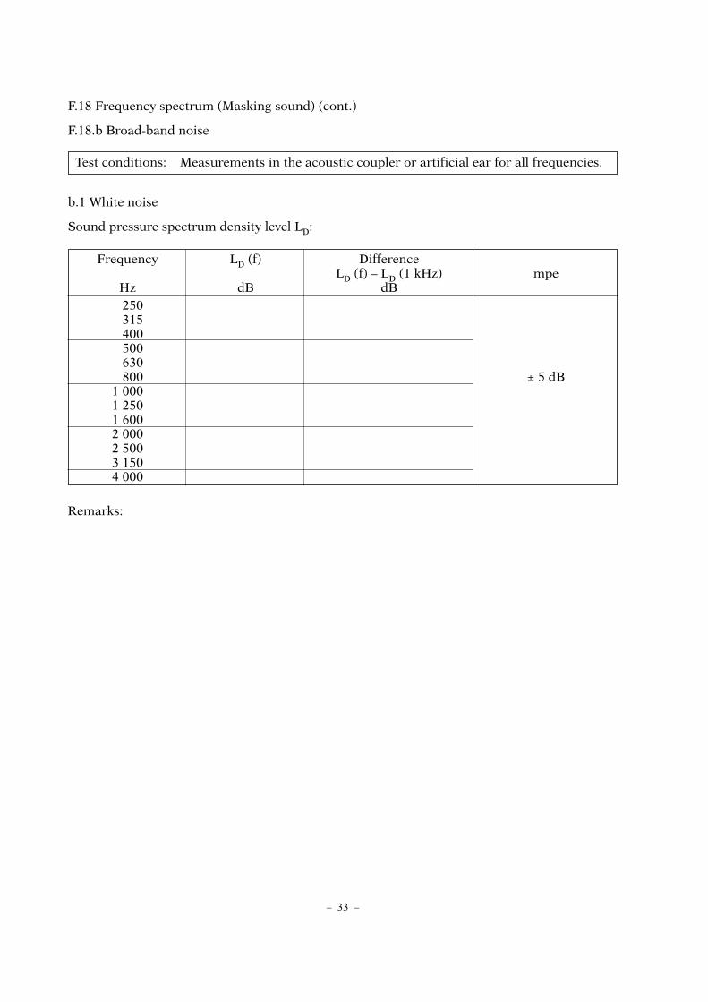
F.18.b Broad-band noise
b.1 White noise
Sound pressure spectrum density level LD:
Remarks:
– 33 –
Frequency LD (f) DifferenceLD (f) – LD (1 kHz) mpe
Hz dB dB250315400500630800 ± 5 dB
1 0001 2501 6002 0002 5003 1504 000
Test conditions: Measurements in the acoustic coupler or artificial ear for all frequencies.

F.18 Frequency spectrum (Masking sound) (cont.)
F.18.b Broad-band noise
b.2 Weighted broad-band noise
Sound pressure spectrum density level LD:
Remarks:
b.3 Other masking sounds
Are the spectral properties of the masking sound provided specified by the manufacturer?
n yes n no
– 34 –
Test conditions: Measurements in the acoustic coupler or artificial ear for all frequencies.
Frequency LD (f) RETSPL DifferenceLRETSPL LD (f) – LRETSPL mpe
Hz dB dB dB250315400500630800 ± 5 dB
1 0001 2501 6002 0002 5003 1504 000
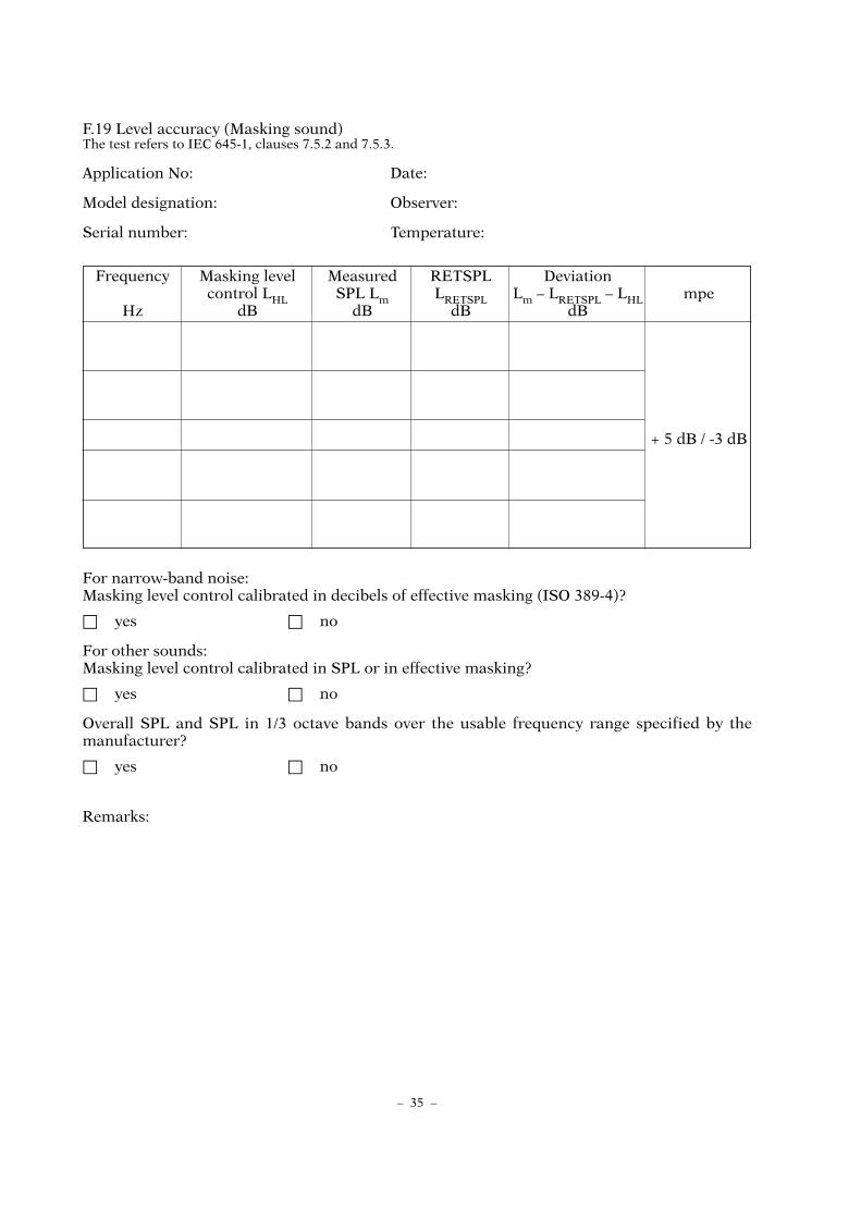
F.19 Level accuracy (Masking sound)The test refers to IEC 645-1, clauses 7.5.2 and 7.5.3.
Application No: Date:
Model designation: Observer:
Serial number: Temperature:
For narrow-band noise:Masking level control calibrated in decibels of effective masking (ISO 389-4)?
n yes n no
For other sounds:Masking level control calibrated in SPL or in effective masking?
n yes n no
Overall SPL and SPL in 1/3 octave bands over the usable frequency range specified by themanufacturer?
n yes n no
Remarks:
– 35 –
Frequency Masking level Measured RETSPL Deviationcontrol LHL SPL Lm LRETSPL Lm – LRETSPL – LHL mpe
Hz dB dB dB dB
+ 5 dB / -3 dB
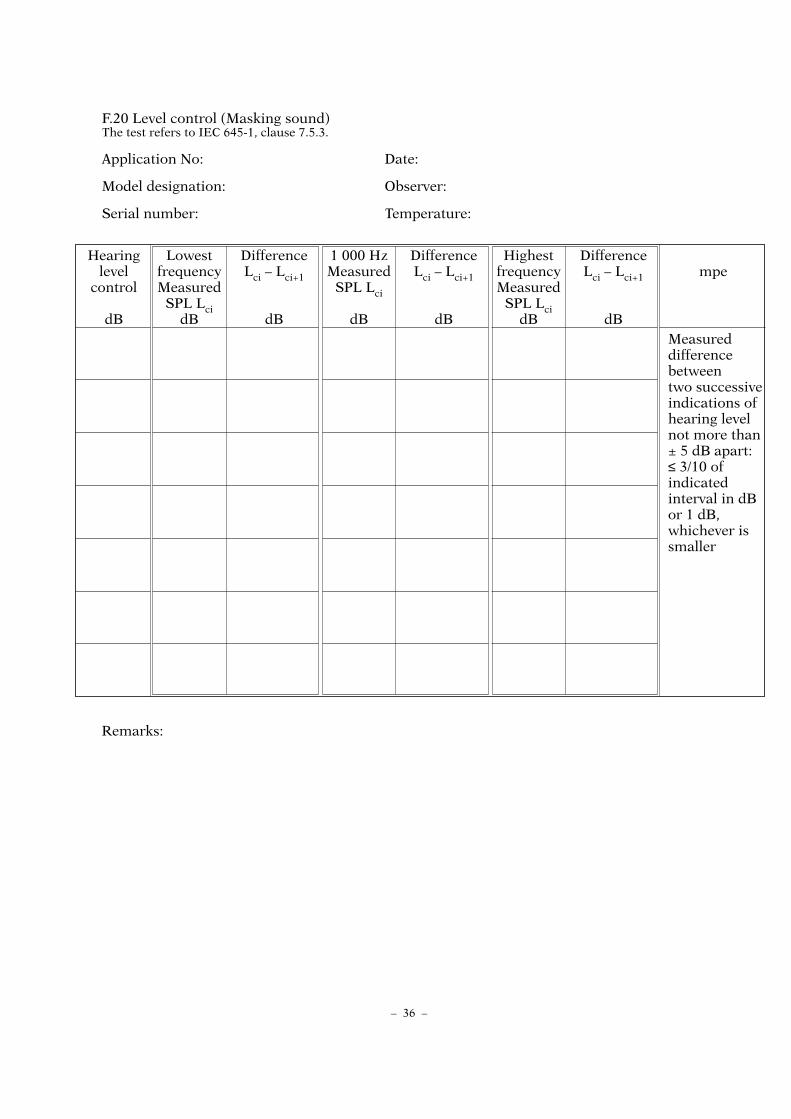
F.20 Level control (Masking sound)The test refers to IEC 645-1, clause 7.5.3.
Application No: Date:
Model designation: Observer:
Serial number: Temperature:
Remarks:
– 36 –
Hearing Lowest Difference 1 000 Hz Difference Highest Differencelevel frequency Lci – Lci+1 Measured Lci – Lci+1 frequency Lci – Lci+1 mpe
control Measured SPL Lci MeasuredSPL Lci SPL Lci
dB dB dB dB dB dB dBMeasureddifferencebetweentwo successiveindications of hearing level not more than± 5 dB apart:≤ 3/10 ofindicatedinterval in dBor 1 dB,whichever issmaller

F.21 EarphonesThe test refers to IEC 645-1, clauses 9.1 and 10.2j.
Application No: Date:
Model designation: Observer:
Model designation of earphone:
Type: supra-aural ....................... insert ...................... circum-aural ...................... (+)
Headband force: ........................N (Nominal value and tolerance: ............N ± ......... N)
Left and right earphone readily identifiable?
n yes n no n not applicable
RETSPL values standardized in ISO ............................ or measured by the following nationalmetrology institute: .............................................................................................................................Coupler used for calibration:..............................................................................................................
Sound attenuation measured in accordance with ISO 4869-1 by the following testinglaboratory: ...........................................................................................................................................
Note: If test results for the earphone are available from a former test the measurements neednot be repeated.
In the case of a supra-aural earphone: Does the earphone meet all requirements in clause 9.1.1of IEC 645-1?
n yes n no
Remarks:
– 37 –

F.22 Bone vibratorThe test refers to IEC 645-1, clauses 9.2 and 10.2d.
Application No: Date:
Model designation: Observer:
Model designation of bone vibrator:
Mastoid application (headband width 145 mm): .................................. (+)
Forehead application (headband width 190 mm): ................................. (+)
Headband force: ................... N (Nominal value and mpe: 5.4 N ± 0.5 N)
Does the vibrator meet the requirements of clause 9.2.1 of IEC 645-1?
n yes n no
Remarks:
– 38 –

F.23 Inscriptions and marks
Application No: Date:
Model designation: Observer:
Serial number:
Remarks:
– 39 –
Inscription or mark + –
Manufacturer’s name or trade mark
Model designation and serial number
Type of audiometer
Marking of transducers
List of accessories where appropriate
Seals or marks to protect
Place for verification mark

F.24 Instruction manual
Application No: Date:
Model designation: Observer:
Remarks:
Information + –
Description of facilities and full operating instructions
Permissible supply variation and environmental range
Installation of the audiometer in order to minimize unwanted sound
RETSPL or RETFL of all transducers and their origin
Coupler (s) used for calibration
Headband force (s)
Mastoid or forehead placement of bone vibrator
Frequency response characteristics and masking effect of the masking sounds provided
Warm-up time
Sensitivities and nominal impedances of all input facilities
Voltage and nominal impedances of all output facilities
Pin assignment of all external plug connections
Mode of operation and rate of change of SPL of automaticrecording audiometers
Rate of change of frequency for audiometers withcontinuously variable frequency
Characteristics of frequency modulated signals
Sound attenuation of earphones
Damage temperature
Maximum hearing level settings at each test frequency
Effects of airborne sound radiation of bone vibrator andmeans to obtain correct test results
Actual bandwidth of narrow-band masking sound
Method of calibration for broad-band masking sound
Time window for subject’s response of a computer-controlled audiometer
Type of battery, battery check and replacement, expected battery lifetime
Maintenance and calibration procedures and schedules
Interface (s) for a computer or printer
GRANDE IMPRIMERIE DE TROYESPrinted in France 130, rue Général-de-Gaulle, 10000 Troyes