netbackup 5220 and symantec storage shelf™ · netbackup 5220 and symantec storage shelf™:...
TRANSCRIPT

NetBackup 5220 and Symantec Storage
Shelf™
Safety Guide
Release 2.0

NetBackup 5220 and Symantec Storage Shelf™: Safety Guide
The software described in this book is furnished under a license agreement and may be used only in accordance with the terms of the agreement.
Last updated: June 10, 2011.
Legal Notice Copyright © 2011 Symantec Corporation. All rights reserved.
Symantec and the Symantec Logo are trademarks or registered trademarks of Symantec Corporation or its affiliates in the U.S. and other countries. Other names may be trademarks of their respective owners.
This Symantec product may contain third party software for which Symantec is required to provide attribution to the third party (“Third Party Programs”). Some of the Third Party Programs are available under open source or free software licenses. The License Agreement accompanying the Software does not alter any rights or obligations you may have under those open source or free software licenses. Please see the Third Party Software file accompanying this Symantec product for more information on the Third Party Programs.
The product described in this document is distributed under licenses restricting its use, copying, distribution, and decompilation/reverse engineering. No part of this document may be reproduced in any form by any means without prior written authorization of Symantec Corporation and its licensors, if any.
THE DOCUMENTATION IS PROVIDED "AS IS" AND ALL EXPRESS OR IMPLIED CONDITIONS, REPRESENTATIONS AND WARRANTIES, INCLUDING ANY IMPLIED WARRANTY OF MERCHANTABILITY, FITNESS FOR A PARTICULAR PURPOSE OR NON-INFRINGEMENT, ARE DISCLAIMED, EXCEPT TO THE EXTENT THAT SUCH DISCLAIMERS ARE HELD TO BE LEGALLY INVALID. SYMANTEC CORPORATION SHALL NOT BE LIABLE FOR INCIDENTAL OR CONSEQUENTIAL DAMAGES IN CONNECTION WITH THE FURNISHING, PERFORMANCE, OR USE OF THIS DOCUMENTATION. THE INFORMATION CONTAINED IN THIS DOCUMENTATION IS SUBJECT TO CHANGE WITHOUT NOTICE.
The Licensed Software and Documentation are deemed to be commercial computer software as defined in FAR 12.212 and subject to restricted rights as defined in FAR Section 52.227-19 "Commercial Computer Software - Restricted Rights" and DFARS 227.7202, "Rights in Commercial Computer Software or Commercial Computer Software Documentation", as applicable, and any successor regulations. Any use, modification, reproduction release, performance, display or disclosure of the Licensed Software and Documentation by the U.S. Government shall be solely in accordance with the terms of this Agreement.
Symantec Corporation, 350 Ellis Street, Mountain View, CA 94043 http://www.symantec.com

Technical Support Symantec Technical Support maintains support centers globally. Technical Support’s primary role is to respond to specific queries about product features and functionality. The Technical Support group also creates content for our online Knowledge Base. The Technical Support group works collaboratively with the other functional areas within Symantec to answer your questions in a timely fashion. For example, the Technical Support group works with Product Engineering and Symantec Security Response to provide alerting services and virus definition updates.
Symantec’s support offerings include the following:
A range of support options that give you the flexibility to select the right amount of service for any size organization
Telephone and/or Web-based support that provides rapid response and up-to-the-minute information
Upgrade assurance that delivers software upgrades
Global support purchased on a regional business hours or 24 hours a day, 7 days a week basis
Premium service offerings that include Account Management Services
For information about Symantec’s support offerings, you can visit our Web site at the following URL:
www.symantec.com/business/support/
All support services will be delivered in accordance with your support agreement and the then-current enterprise technical support policy.
Contacting Technical Support Customers with a current support agreement may access Technical Support information at the following URL:
www.symantec.com/business/support/
Before contacting Technical Support, make sure you have satisfied the system requirements that are listed in your product documentation. Also, you should be at the computer on which the problem occurred, in case it is necessary to replicate the problem.
When you contact Technical Support, please have the following information available:
Product release level
Hardware information

Available memory, disk space, and NIC information
Operating system
Version and patch level
Network topology
Router, gateway, and IP address information
Problem description:
Error messages and log files
Troubleshooting that was performed before contacting Symantec
Recent software configuration changes and network changes
Licensing and registration If your Symantec product requires registration or a license key, access our technical support Web page at the following URL:
www.symantec.com/business/support/
Customer service Customer service information is available at the following URL:
www.symantec.com/business/support/
Customer Service is available to assist with non-technical questions, such as the following types of issues:
Questions regarding product licensing or serialization
Product registration updates, such as address or name changes
General product information (features, language availability, local dealers)
Latest information about product updates and upgrades
Information about upgrade assurance and support contracts
Information about the Symantec Buying Programs
Advice about Symantec's technical support options
Nontechnical presales questions
Issues that are related to CD-ROMs or manuals
Support agreement resources If you want to contact Symantec regarding an existing support agreement, please contact the support agreement administration team for your region as follows:
Asia-Pacific and Japan [email protected]

5
Europe, Middle-East, and Africa [email protected]
North America and Latin America [email protected]

Contents
Chapter 1 Chapter 1 About this guide ................................................................ 9
Introducing this guide ............................................................................................................. 9 Product version ......................................................................................................................... 9 Intended audience ..................................................................................................................... 9 Product documentation ......................................................................................................... 10
NetBackup 5220 and Symantec Storage Shelf documents ................................... 10 NetBackup 5200 Series documentation .................................................................... 10
Chapter 2 Chapter 2 Installation/Assembly Safety Instructions ....................... 12
English ...................................................................................................................................... 12 Safety Steps – Chassis cover removal: ....................................................................... 12
Deutsch ...................................................................................................................................... 14 Français ..................................................................................................................................... 16 Español ...................................................................................................................................... 18 Italiano ....................................................................................................................................... 20
Chapter 3 Chapter 3 Detailed Safety Information ............................................ 22
Product safety information .......................................................................................... 22 Safety warnings and cautions ...................................................................................... 22 Applications ..................................................................................................................... 23 Equipment handling practices .................................................................................... 23 Power and electrical warnings .................................................................................... 24 Power cord usage ........................................................................................................... 24 System access warnings................................................................................................ 25 Rack mount guidelines.................................................................................................. 26 Electrostatic discharge (ESD) ..................................................................................... 27 Battery replacement ...................................................................................................... 27 Cooling and airflow ....................................................................................................... 29 Laser peripherals or devices ........................................................................................ 29
Chapter 4 Chapter 4 NetBackup 5220 and Symantec Storage Shelf description30
Features ............................................................................................................................ 31 Hot-swappable and non-hot-swappable components ............................................ 34 NetBackup 5220 components ...................................................................................... 35 NetBackup 5220 front view ......................................................................................... 39 NetBackup 5220 rear panel .......................................................................................... 40 NetBackup 5220 and Symantec Storage Shelf rack mounting ............................ 42

7
NetBackup 5220 and Symantec Storage Shelf chassis covers ............................. 43
Chapter 5 Chapter 5 Alarms .............................................................................. 44
System-induced power-off of the NetBackup 5220 ......................................................... 44
Chapter 6 Chapter 6 NetBackup 5220 hardware removal and replacement ... 48
Before you begin ..................................................................................................................... 48 Tools and supplies ......................................................................................................... 48
Unpacking the NetBackup 5220.......................................................................................... 48 NetBackup 5220 guide rails and rack ................................................................................. 49 Removing and re-installing the chassis cover ................................................................. 49
Removing the NetBackup 5220 chassis cover ........................................................ 49 Re-installing the NetBackup 5220 chassis cover ................................................... 51
Chapter 7 Chapter 7 Symantec Storage Shelf hardware removal and replacement ......................................................................................................... 54
Before you begin ..................................................................................................................... 54 Tools and supplies ......................................................................................................... 54
Unpacking the Symantec Storage Shelf ............................................................................ 55 Symantec Storage Shelf guide rails and rack ................................................................... 55 Symantec Storage Shelf cover/chassis .............................................................................. 56
Chapter 8 Appendix A: Technical References ................................................... 57
750W single power supply input voltages ....................................................................... 57 System Environmental Specifications ................................................................................ 58
Chapter 9 Appendix B: Regulatory and Certification Information .................... 59
Product Regulatory Compliance ......................................................................................... 60 Product Safety Compliance .................................................................................................. 60 Product EMC Compliance - Class A Compliance ........................................................... 61 Product Ecology Compliance .............................................................................................. 61 Certifications / Registrations / Declarations .................................................................. 62 Electromagnetic Compatibility Notices ............................................................................ 63
FCC Verification Statement (USA) ........................................................................... 63 ICES-003 (Canada) ........................................................................................................ 64 CE Declaration of Conformity (Europe) .................................................................. 64 VCCI (Japan) ................................................................................................................... 64 BSMI (Taiwan) ............................................................................................................... 64

8 Contents
Figures NetBackup 5220 chassis (top, external view) ..................................................................................... 30
NetBackup 5220 components ................................................................................................................. 35
NetBackup 5220 mainboard components ............................................................................................ 37
NetBackup 5220 front .............................................................................................................................. 39
NetBackup 5220 rear panel ..................................................................................................................... 40
NetBackup 5220 rear panel ports .......................................................................................................... 41
Removing the NetBackup 5220 chassis cover .................................................................................... 50
Chassis with cover removed .................................................................................................................... 51
Tables NetBackup 5220 and Symantec Storage Shelf documentation set ................................................ 10
NetBackup 5220 rear panel ports .......................................................................................................... 41
NIC port LED indications ...................................................................................................................... 42
Alarm information .................................................................................................................................... 45
NetBackup 5220 power supply input voltages ................................................................................... 57
System Environmental Specifications .................................................................................................. 58

Chapter 1
Chapter 1 About this guide
Introducing this guide This document provides detailed safety instructions related to the NetBackup 5220 and Symantec Storage Shelf. Safety information provides guidelines to protect personnel and equipment from injury or damage.
Product version The following table lists the product version related to this document.
Product Name Product Version
NetBackup 5220 2.0
Symantec Storage Shelf 2.0
Intended audience This document describes maintenance items of the NetBackup 5220 in terms of maintenance purpose, period, standards, and procedure.
This document is intended for:
Technical support engineers
System maintenance engineers

10 Chapter 1
About this guide
Product documentation
Product documentation
NetBackup 5220 and Symantec Storage Shelf documents The six documents listed below are specific to the NetBackup 5220 appliance and the Symantec Storage Shelf. Additional information can be obtained in NetBackup 5200 (52xx) Series documentation, listed in the next section.
NetBackup 5220 and Symantec Storage Shelf documentation set
Document
Product Description
Hardware Installation Guide
Hardware Troubleshooting Guide
Software Troubleshooting Guide
Safety Guide
Maintenance Guide
NetBackup 5200 Series documentation The NetBackup 5200 Series documentation has comprehensive software information. Features in the 5200 series documents may not be exactly the same as those in the NetBackup 5220 and Symantec Storage Shelf but these documents provide details, background information and usage scenarios.
Go to http://www.symantec.com/docs/DOC2792
NetBackup 5200 Series Administrator’s Guide
to download 5200 series documents.
This document contains the following types of information:
Deployment information
Administering your appliance
Monitoring information
Chapter 1
About this guide
Product documentation
11
NetBackup 5200 Series Command Reference Guide The NetBackup 5200 Series Command Reference Guide contains detailed information about the NetBackup appliance commands that you can run from the NetBackup appliance shell menu. Each command contains a brief description of the primary function of the command, a synopsis, and descriptions of each of the options listed in the synopsis. The NetBackup appliance shell menu is an interactive shell that is available on the 52xx appliances through SSH. This menu interface enables you to perform most of the administration functions that are necessary to administer a NetBackup 5200 series appliance.

12
Chapter 2 Installation/Assembly Safety Instructions
English The power supply in this product contains no user-serviceable parts. There may be more than one supply in this product. Refer servicing to qualified personnel only.
Do not attempt to modify or use the supplied AC power cord if it is not the exact type required. A product with more than one power supply will have a separate AC power cord for each supply.
The power button on the system does not turn off system AC power. To remove AC power from the system, you must unplug each AC power cord from the wall outlet or power supply.
The power cord(s) is considered the disconnect device to the main (AC) power. The socket outlet that the system plugs into shall be installed near the equipment and shall be easily accessible.
Safety Steps – Chassis cover removal: Whenever you remove the chassis cover to access the inside of the system, follow these steps:
1. Turn off all peripheral devices connected to the system.
2. Turn off the system by pressing the power button.
3. Unplug all AC power cords from the system or from wall outlets.
4. Label and disconnect all cables connected to I/O connectors or ports on the back of the system.

13
5. Provide some electrostatic discharge (ESD) protection by wearing an antistatic wrist strap attached to chassis ground of the system-any unpainted metal surface-when handling components.
6. Do not operate the system with the chassis covers removed.
After you have completed the six SAFETY steps above, you can remove the system covers:
1. Unlock and remove the padlock from the back of the system if a padlock has been installed.
2. Remove and save all screws from the covers.
3. Remove the cover(s).
For proper cooling and airflow, always reinstall the chassis cover before turning on the system. Operating the system without the cover in place can damage system parts. To install the cover:
1. Make sure you have not left loose tools or parts inside the system.
2. Check that cables, add-in boards, and other components are properly installed.
3. Attach the cover to the chassis with the screw(s) removed earlier, and tighten firmly.
4. Insert and lock the padlock to the system to prevent unauthorized access inside the system.
5. Connect all external cables and the AC power cord(s) to the system.
A microprocessor and heatsink may be hot if the system has been running. Also, there may be sharp pins and edges on some board and chassis parts. Contact should be made with care. Consider wearing protective gloves.
There is danger of explosion if the battery is incorrectly replaced. Replace it only with the same or equivalent type recommended by the equipment manufacturer. Dispose of used batteries according to manufacturer's instructions.
The system is designed to operate in a typical office environment.
Choose a site that is:
Clean and free of airborne particles (other than normal room dust).
Well ventilated and away from sources of heat including direct sunlight.
Away from sources of vibration or physical shock.
Isolated from strong electromagnetic fields produced by electrical devices.
In regions that are susceptible to electrical storms, we recommend you plug your system into a surge suppresser and disconnect telecommunication lines to your modem during an electrical storm.

14
Provided with a properly grounded wall outlet.
Provided with sufficient space to access the power supply cord(s).
Deutsch Benutzer können am Netzgerät dieses Produkts keine Reparaturen vornehmen. Das Produkt enthält möglicherweise mehrere Netzgeräte. Wartungsarbeiten müssen von qualifizierten Technikern ausgeführt werden.
Versuchen Sie nicht, das mitgelieferte Netzkabel zu ändern oder zu verwenden, wenn es sich nicht genau um den erforderlichen Typhandelt. Ein Produkt mit mehreren Netzgeräten hat für jedes Netzgerät ein eigenes Netzkabel.
Der Wechselstrom des Systems wird durch den Ein-/Aus-Schalter für Gleichstrom nicht ausgeschaltet. Ziehen Sie jedes Wechselstrom-Netzkabel aus der Steckdose bzw. dem Netzgerät, um den Stromanschluß des Systems zu unterbrechen.
Die Stromkabel sind das "Unterbrechungsgerät" zur Hauptstromquelle. Die Steckdose, in die das System gesteckt wird, sollte sich in der Nähe des Gerätes befinden und leicht zugänglich
sein.
SICHERHEITSMASSNAHMEN: Immer wenn Sie die Gehäuseabdeckung abnehmen um an das Systeminnere zu gelangen, sollten Sie folgende Schritte beachten:
1. Schalten Sie alle an Ihr System angeschlossenen Peripheriegeräte aus.
2. Schalten Sie das System mit dem Hauptschalter aus.
3. Ziehen Sie den Stromanschlußstecker Ihres Systems aus der Steckdose.
4. Auf der Rückseite des Systems beschriften und ziehen Sie alle Anschlußkabel von den I/O Anschlüssen oder Ports ab.
5. Tragen Sie ein geerdetes Antistatik Gelenkband, um elektrostatische Ladungen (ESD) über blanke Metallstellen bei der Handhabung der Komponenten zu vermeiden.
6. Schalten Sie das System niemals ohne ordnungsgemäß montiertes Gehäuse ein.
SICHERHEITSMASSNAHMEN: Immer wenn Sie die Gehäuseabdeckung abnehmen um an das Systeminnere zu gelangen, sollten Sie folgende Schritte beachten:
1. Schalten Sie alle an Ihr System angeschlossenen Peripheriegeräte aus.
2. Schalten Sie das System mit dem Hauptschalter aus.

15
3. Ziehen Sie den Stromanschlußstecker Ihres Systems aus der Steckdose.
4. Auf der Rückseite des Systems beschriften und ziehen Sie alle Anschlußkabel von den I/O Anschlüssen oder Ports ab.
5. Tragen Sie ein geerdetes Antistatik Gelenkband, um elektrostatische Ladungen (ESD) über blanke Metallstellen bei der Handhabung der Komponenten zu vermeiden.
6. Schalten Sie das System niemals ohne ordnungsgemäß montiertes Gehäuse ein.
Zur ordnungsgemäßen Kühlung und Lüftung muß die Gehäuseabdeckung immer wieder vor dem Einschalten installiert werden. Ein Betrieb des Systems ohne angebrachte Abdeckung
kann Ihrem System oder Teile darin beschädigen. Um die Abdeckung wieder anzubringen:
1. Vergewissern Sie sich, daß Sie keine Werkzeuge oder Teile im Innern des Systems zurückgelassen haben.
2. Überprüfen Sie alle Kabel, Zusatzkarten und andere Komponenten auf ordnungsgemäßen Sitz und Installation.
3. Bringen Sie die Abdeckungen wieder am Gehäuse an, indem Sie die zuvor gelösten Schrauben wieder anbringen. Ziehen Sie diese gut an.
4. Bringen Sie die Verschlußeinrichtung (Padlock) wieder an und schließen Sie diese, um ein unerlaubtes Öffnen des Systems zu verhindern.
5. Schließen Sie alle externen Kabel und den AC Stromanschlußstecker Ihres Systems wieder an.Der Mikroprozessor und der Kühler sind möglicherweise erhitzt, wenn das System in Betrieb ist. Außerdem können einige Platinen und Gehäuseteile scharfe Spitzen und Kanten aufweisen. Arbeiten an Platinen und Gehäuse sollten vorsichtig ausgeführt werden. Sie sollten Schutzhandschuhe tragen.
Bei falschem Einsetzen einer neuen Batterie besteht Explosionsgefahr. Die Batterie darf nur durch denselben oder einen entsprechenden, vom Hersteller empfohlenen Batterietyp ersetzt werden. Entsorgen Sie verbrauchte Batterien den Anweisungen des Herstellers entsprechend.
Das System wurde für den Betrieb in einer normalen Büroumgebung entwickelt. Der Standort sollte:
sauber und staubfrei sein (Hausstaub ausgenommen);
gut gelüftet und keinen Heizquellen ausgesetzt sein (einschließlich direkter Sonneneinstrahlung);
keinen Erschütterungen ausgesetzt sein;
keine starken, von elektrischen Geräten erzeugten elektromagnetischen Felder aufweisen;
16
in Regionen, in denen elektrische Stürme auftreten, mit einem
Überspannungsschutzgerät verbunden sein; während eines elektrischen Sturms sollte keine Verbindung der Telekommunikationsleitungen mit dem Modem bestehen;
mit einer geerdeten Wechselstromsteckdose ausgerüstet sein;
über ausreichend Platz verfügen, um Zugang zu den Netzkabeln zu gewährleisten, da der Stromanschluß des Produkts hauptsächlich über die Kabel unterbrochen wird
Français Le bloc d'alimentation de ce produit ne contient aucune pièce pouvant être réparée par l'utilisateur. Ce produit peut contenir plus d'un bloc d'alimentation. Veuillez contacter un technicien qualifié en cas de problème.
Ne pas essayer d'utiliser ni modifier le câble d'alimentation CA fourni, s'il ne correspond pas exactement au type requis. Le nombre de câbles d'alimentation CA fournis correspond au nombre de blocs d'alimentation du produit
Notez que le commutateur CC de mise sous tension /hors tension du panneau avant n'éteint pas l'alimentation CA du système. Pour mettre le système hors tension, vous devez débrancher chaque câble d'alimentation de sa prise.
C'est le câble d'alimentation qui est considéré comme le moyen de se déconnecter du CA. La prise à laquelle le système est branché doit se situer à proximité de l'équipement et être facilement accessible.
CONSIGNES DE SÉCURITÉ -Lorsque vous ouvrez le boîtier pour accéder à l'intérieur du système, suivez les consignes suivantes:
1. Mettez hors tension tous les périphériques connectés au système.
2. Mettez le système hors tension en mettant l'interrupteur général en position OFF (bouton-poussoir).
3. Débranchez tous les cordons d'alimentation c.a. du système et des prises murales.
4. Identifiez et débranchez tous les câbles reliés aux connecteurs d'E-S ou aux accès derrière le système.
5. Pour prévenir les décharges électrostatiques lorsque vous touchez aux composants, portez une bande antistatique pour poignet et reliez-la à la masse du système (toute surface métallique non peinte du boîtier).
6. Ne faites pas fonctionner le système tandis que le boîtier est ouvert.

17
Une fois TOUTES les étapes précédentes accomplies, vous pouvez retirer les panneaux du système. Procédez comme suit:
1. Si un cadenas a été installé sur à l'arrière du système, déverrouillez-le et retirez-le.
2. Retirez toutes les vis des panneaux et mettez-les dans un endroit sûr.
3. Retirez les panneaux.
Afin de permettre le refroidissement et l'aération du système, réinstallez toujours les panneaux du boîtier avant de mettre le système sous tension. Le fonctionnement du système en l'absence des panneaux risque d'endommager ses pièces. Pour installer les panneaux, procédez comme suit:
1. Assurez-vous de ne pas avoir oublié d'outils ou de pieces démontées dans le système.
2. Assurez-vous que les câbles, les cartes d'extension et les autres composants sont bien installés.
3. Revissez solidement les panneaux du boîtier avec les vis retirées plus tôt.
4. Remettez le cadenas en place et verrouillez-le afin de prévenir tout accès non autorisé à l'intérieur du système.
5. Rebranchez tous les cordons d'alimentation c. a. et cables externes au système. Le microprocesseur et le dissipateur de chaleur peuvent être chauds si le système a été sous tension. Faites également attention aux broches aiguës des cartes et aux bords tranchants du capot. Nous vous recommandons l'usage de gants de protection.
Danger d'explosion si la batterie n'est pas remontée correctement.
Remplacer uniquement avec une batterie du même type ou d'un type équivalent recommandé par le fabricant. Disposez des piles usées selon les instructions du fabricant.
Le système a été conçu pour fonctionner dans un cadre de travail normal. L'emplacement choisi doit être:
Propre et dépourvu de poussière en suspension (sauf la poussière normale).
Bien aéré et loin des sources de chaleur, y compris du soleil direct.
A l'abri des chocs et des sources de vibrations.
Isolé de forts champs électromagnétiques géenérés par des appareils électriques.
Dans les régions sujettes aux orages magnétiques il est recomandé de brancher votre système à un supresseur de surtension, et de débrancher toutes les lignes de télécommunications de votre modem durant un orage.
Muni d'une prise murale correctement mise à la terre.
Suffisamment spacieux pour vous permettre d'accéder aux câbles d'alimentation (ceux-ci étant le seul moyen de mettre le système hors tension).

18
Español El usuario debe abstenerse de manipular los componentes de la fuente de alimentación de este producto, cuya reparación debe dejarse exclusivamente en manos de personal técnico especializado. Puede que este producto disponga de más de una fuente de alimentación
No intente modificar ni usar el cable de alimentación de corriente alterna, si no corresponde exactamente con el tipo requerido. El número de cables suministrados se corresponden con el número de fuentes de alimentación de corriente alterna que tenga el product.
Nótese que el interruptor activado/desactivado en el panel frontal no desconecta la corriente alterna del sistema. Para desconectarla, deberá desenchufar todos los cables de corriente alterna de la pared o desconectar la fuente de alimentación.
Estos cables actúan como dispositivo de desconexión. La toma de corriente deberá estar situada cerca del equipo y ser de fácil acceso.
INSTRUCCIONES DE SEGURIDAD: Cuando extraiga la tapa del chasis para acceder al interior del sistema, siga las siguientes instrucciones:
1. Apague todos los dispositivos periféricos conectados al sistema.
2. Apague el sistema presionando el interruptor encendido/ apagado.
3. Desconecte todos los cables de alimentación CA del sistema o de las tomas de corriente alterna.
4. Identifique y desconecte todos los cables enchufados a los conectores E/S o a los puertos situados en la parte posterior del sistema.
5. Cuando manipule los componentes, es importante protegerse contra la descarga electrostática (ESD). Puede hacerlo si utiliza una muñequera antiestática sujetada a la toma de tierra del chasis - o a cualquier tipo de superficie de metal sin pintar.
6. No ponga en marcha el sistema si se han extraído las tapas del chasis.
Después de completar las seis instrucciones de SEGURIDAD mencionadas, ya puede extraer las tapas del sistema. Para ello:
1. Desbloquee y extraiga el bloqueo de seguridad de la parte posterior del sistema, si se ha instalado uno.
2. Extraiga y guarde todos los tornillos de las tapas.Extraiga las tapas.

19
Para obtener un enfriamiento y un flujo de aire adecuados, reinstale siempre las tapas del chasis antes de poner en marcha el sistema. Si pone en funcionamiento el sistema sin las tapas bien colocadas puede dañar los componentes del sistema. Para instalar las tapas:
1. Asegúrese primero de no haber dejado herramientas o componentes sueltos dentro del sistema.
2. Compruebe que los cables, las placas adicionales y otros componentes se hayan instalado correctamente.
3. Incorpore las tapas al chasis mediante los tornillos extraídos anteriormente, tensándolos firmemente.
4. Inserte el bloqueo de seguridad en el sistema y bloquéelo para impedir que pueda accederse al mismo sin autorización.
5. Conecte todos los cables externos y los cables de alimentación CA al sistema.
Si el sistema ha estado en funcionamiento, el microprocesador y el disipador de calor pueden estar aún calientes. También conviene tener en cuenta que en el chasis o en el tablero puede haber piezas cortantes o punzantes. Por ello, se recomienda precaución y el uso de guantes protectores.
Existe peligro de explosión si la pila no se cambia de forma adecuada. Utilice solamente pilas iguales o del mismo tipo que las recomendadas por el fabricante del equipo. Para deshacerse de las pilas usadas, siga igualmente las instrucciones del fabricante.
El sistema está diseñado para funcionar en un entorno de trabajo normal. Escoja un lugar:
Limpio y libre de partículas en suspensión (salvo el polvo normal).
Bien ventilado y alejado de fuentes de calor, incluida la luz solar directa.
Alejado de fuentes de vibración.
Aislado de campos electromagnéticos fuertes producidos por
dispositivos eléctricos.
En regiones con frecuentes tormentas eléctricas, se recomienda conectar su sistema a un eliminador de sobrevoltage y desconectar el módem de las líneas de telecomunicación durante las tormentas.
Provisto de una toma de tierra correctamente instalada.
Provisto de espacio suficiente como para acceder a los cables de alimentación, ya que éstos hacen de medio principal dedesconexión del sistema.

20
Italiano Rivolgersi ad un tecnico specializzato per la riparazione dei componenti dell'alimentazione di questo prodotto. È possibile che il prodotto disponga di più fonti di alimentazione.
Non modificare o utilizzare il cavo di alimentazione in c.a. fornito dal produttore, se non corrisponde esattamente al tipo richiesto. Ad ogni fonte di alimentazione corrisponde un cavo di alimentazione in c.a. separato
L'interruttore attivato/disattivato nel pannello anteriore non interrompe l'alimentazione in c.a. del sistema. Per interromperla, è necessario scollegare tutti i cavi di alimentazione in c.a. dalle prese a muro o dall'alimentazione di corrente.
Il cavo è considerato il dispositivo d'interruzione dell'alimentazione principale (in c.a.). La presa alla quale si collega il sistema deve essere installata vicino all'unità e deve essere facilmente accessibile.
PASSI DI SICUREZZA: Qualora si rimuovano le coperture del telaio per accedere all'interno del sistema, seguire i seguenti passi:
1. Spegnere tutti i dispositivi periferici collegati al sistema.
2. Spegnere il sistema, usando il pulsante spento/acceso dell'interruttore del sistema.
3. Togliere tutte le spine dei cavi del sistema dalle prese elettriche.
4. Identificare e sconnettere tutti i cavi attaccati ai collegamenti I/O od alle prese installate sul retro del sistema.
5. Qualora si tocchino i componenti, proteggersi dallo scarico elettrostatico (SES), portando un cinghia anti-statica da polso che è attaccata alla presa a terra del telaio del sistema - qualsiasi superficie non dipinta - .
6. Non far operare il sistema quando il telaio è senza le coperture. Dopo aver seguito i sei passi di SICUREZZA sopracitati, togliere le coperture del telaio del sistema come seque:
1. Aprire e rimuovere il lucchetto dal retro del sistema qualor ve ne fosse uno installato.
2. Togliere e mettere in un posto sicuro tutte le viti delle coperture.
3. Togliere le coperture. Per il giusto flusso dell'aria e raffreddamento del sistema, rimettere sempre le coperture del telaio prima di riaccendere il sistema. Operare il sistema senza le coperture al loro proprio posto potrebbe danneggiare i componenti del sistema. Per rimettere le coperture del telaio:
1. Controllare prima che non si siano lasciati degli attrezzi o dei componenti dentro il sistema.

21
2. Controllare che i cavi, dei supporti aggiuntivi ed altri componenti siano stati installati appropriatamente.
3. Attaccare le coperture al telaio con le viti tolte in precedenza e avvitarle strettamente.
4. Inserire e chiudere a chiave il lucchetto sul retro del sistema per impedire l'accesso non autorizzato al sistema.
5. Ricollegare tutti i cavi esterni e le prolunghe AC del sistema. Se il sistema è stato a lungo in funzione, il microprocessore e il dissipatore di calore potrebbero essere surriscaldati. Fare attenzione alla presenza di piedini appuntiti e parti taglienti sulle schede e sul telaio. È consigliabile l'uso di guanti di protezione. Esiste il pericolo di un esplosione se la pila non viene sostituita in modo corretto. Utilizzare solo pile uguali o di tipo equivalente a quelle consigliate dal produttore. Per disfarsi delle pile usate, seguire le istruzioni del produttore.
Il sistema è progettato per funzionare in un ambiente di lavoro tipo.
Scegliere una postazione che sia:
Pulita e libera da particelle in sospensione (a parte la normale
polvere presente nell'ambiente).
Ben ventilata e lontana da fonti di calore, compresa la luce solare diretta.
Al riparo da urti e lontana da fonti di vibrazione.
Isolata dai forti campi magnetici prodotti da dispositivi elettrici.
In aree soggette a temporali, è consigliabile collegare il
sistema ad un limitatore di corrente. In caso di temporali,
scollegare le linee di comunicazione dal modem.
Dotata di una presa a muro correttamente installata.
Dotata di spazio sufficiente ad accedere ai cavi di
alimentazione, i quali rappresentano il mezzo principale di
scollegamento del sistema.

22
Chapter 3 Detailed Safety Information
Product safety information This document applies to boards, the chassis and installed peripherals. To reduce the risk of bodily injury, electrical shock, fire, and equipment damage, read this document and observe all warnings and precautions in this guide before installing or maintaining your devices.
In the event of a conflict between the information in this document and information provided with the product for a particular product, the product documentation takes precedence.
Your device should be integrated and serviced only by technically qualified persons.
You must adhere to the guidelines in this guide and the assembly instructions in your server manuals to ensure and maintain compliance with existing product certifications and approvals. Use only the described, regulated components specified in this guide. Use of other products / components will void the UL Listing and other regulatory approvals of the product, and may result in noncompliance with product regulations in the region(s) in which the product is sold.
Safety warnings and cautions To avoid personal injury or property damage, before you begin installing the product, read, observe, and adhere to all of the following safety instructions and information. The following safety symbols may be used throughout the documentation and may be marked on the product and / or the product packaging.

23
Indicates the presence of a hazard that may cause minor personal injury or property damage if the CAUTION is ignored.
Indicates the presence of a hazard that may result in serious personnel injury if the WARNING is ignored.
Indicates potential hazard if indicated information is ignored.
Indicates shock hazards that result in serious injury or death if safety instructions are not followed.
Indicates hot components or surfaces.
Applications This product was evaluated as Information Technology Equipment (ITE), which may be installed in offices, schools, computer rooms, and similar commercial type locations. The suitability of this product for other product categories and environments (such as medical, industrial, residential, alarm systems, and test equipment), other than an ITE application, may require further evaluation.
Equipment handling practices To reduce the risk of personal injury or equipment damage:
Conform to local occupational health and safety requirements when moving and lifting equipment.
Use mechanical assistance or other suitable assistance when moving and lifting equipment.
To reduce the weight for easier handling, remove any easily detachable components.
Do not touch fan blades, to prevent injury.
Unplug all AC power cord(s) to disconnect AC power.
Please recycle all batteries

24
Power and electrical warnings The power button, indicated by the stand-by power marking, DOES NOT
completely turn off the system AC power, 5V standby power is active whenever the system is plugged in.
To remove power from system, you must unplug the AC power cord from the wall outlet.
Your system may use more than one AC power cord. Make sure all AC power cords are unplugged. Make sure the AC power cord(s) is/are unplugged before you open the chassis, or add or remove any non hot-plug components.
Do not attempt to modify or use an AC power cord if it is not the exact type required. A separate AC cord is required for each system power supply.
Some power supplies use Neutral Pole Fusing. To avoid risk of shock use caution when working with power supplies that use Neutral Pole Fusing.
The power supply in this product contains no user-serviceable parts. Do not open the power supply. Hazardous voltage, current and energy levels are present inside the power supply. Return to manufacturer for servicing.
When replacing a hot-plug power supply, unplug the power cord to the power supply being replaced before removing it from the server.
To avoid risk of electric shock, turn off the server and disconnect the power cord, telecommunications systems, networks, and modems attached to the server before opening it.
Power cord usage If an AC power cord was not provided with your product, purchase one that is approved for use in your country.
To avoid electrical shock or fire, check the power cords to be used with the product as follows:
Do not attempt to modify or use the AC power cord(s) if they are not the exact type required to fit into the grounded electrical outlets.
The power cord must have an electrical rating that is greater than that of the electrical current rating marked on the product.
The power cord must have a safety ground pin or contact that is suitable for the electrical outlet.
The power supply cord(s) is/are the main disconnect device to AC power. The sockets or outlets must be near the equipment and readily accessible for disconnection.

25
The power supply cords must be plugged into sockets or outlets provided with a suitable earth ground.
Power cord usage criteria You must use a power cord set that meets the following criteria:
Rating: In the U.S. and Canada, cords must be UL (Underwriters Laboratories, Inc.) Listed/CSA (Canadian Standards Organization) Certified type SJT, 18-3 AWG (American Wire Gauge). Outside of the U.S. and Canada, cords must be flexible harmonized (<HAR>) or VDE (Verband Deutscher Electrotechniker, German Institute of Electrical Engineers) certified cord with 3 x 0.75 mm conductors rated 250 VAC (Volts Alternating Current).
Connector, wall outlet end: Cords must be terminated in grounding-type male plug designed for use in your region. The connector must have certification marks showing certification by an agency acceptable in your region and for U.S. must be Listed and rated 125% of overall current rating of the server.
Connector, server end: The connectors that plug into the AC receptacle on the server must be an approved IEC (International Electrotechnical Commission) 320, sheet C13, type female connector.
Cord length and flexibility: Cords must be less than 4.5 meters (14.76 feet) long.
System access warnings
To avoid personal injury or property damage, the following safety instructions apply whenever accessing the inside of the product:
Turn off all peripheral devices connected to this product.
Turn off the system by pressing the power button to off.
Disconnect the AC power by unplugging all AC power cords from the system or wall outlet.
Disconnect all cables and telecommunication lines that are connected to the system.
Retain all screws or other fasteners when removing access cover(s). Upon completion of accessing inside the product, refasten access cover with original screws or fasteners.

26
Do not access the inside of the power supply. There are no serviceable parts in the power supply. Return to manufacturer for servicing.
Power down the server and disconnect all power cords before adding or replacing any non hot-plug component.
When replacing a hot-plug power supply, unplug the power cord to the power supply being replaced before removing the power supply from the server.
If the server has been running, any installed processor(s) and heatsink(s) may be hot. Unless you are adding or removing a hot-plug component, allow the system to cool before opening the covers.
To avoid the possibility of coming into contact with hot component(s) during a hot-plug installation, be careful when removing or installing the hot-plug component(s).
Rack mount guidelines The equipment rack must be anchored to an unmovable support to prevent it
from tipping when equipment is extended from it.
You must consider the weight of any other device installed in the rack. A crush hazard (serious injury) exists if the rack tilts forward.
The equipment rack must be installed according to the rack manufacturer's instructions.
Install equipment in the rack from the bottom up, with the heaviest equipment at the bottom of the rack.
Extend only one piece of equipment from the rack at a time.
You are responsible for installing a main power disconnect for the entire rack unit. This main disconnect must be readily accessible, and it must be labeled as controlling power to the entire unit, not just to the server(s).
To avoid risk of potential electric shock, a proper safety ground must be implemented for the rack and each piece of equipment installed in it.
The temperature in the room where the devices operate must not be below 5 °C (41 °F) or above 40 °C (104 °F). Extreme fluctuations in temperature can cause problems in your equipment.

27
The equipment rack must provide sufficient airflow to the front of the server to maintain proper cooling. The rack must include ventilation sufficient to exhaust a maximum of 2550 BTUs (British Thermal Units) per hour for the NetBackup 5220 and 1270 BTUs per hour for Symantec Storage Shelf.
The NetBackup 5220 is designed for an AC line voltage source with up to 20 amperes of overcurrent protection per cord feed. If the power system for the equipment rack is installed on a branch circuit with more than 20 amperes of protection, you must provide supplemental protection for the server.
Electrostatic discharge (ESD)
ESD can damage disk drives, boards, and other parts. We recommend that you perform all procedures at an ESD workstation. If one is not available, provide some ESD protection by wearing an antistatic wrist strap attached to chassis ground – any unpainted metal surface -- on your server when handling parts.
Always handle boards carefully. They can be extremely sensitive to ESD. Hold boards only by their edges. After removing a board from its protective wrapper or from the server, place the board component side up on a grounded, static free surface. Use a conductive foam pad if available but not the board wrapper. Do not slide board over any surface.
Battery replacement
There is danger of explosion if the battery is incorrectly replaced. When replacing the battery, use only the battery recommended by the equipment manufacturer.
Dispose of batteries according to local ordinances and regulations.
Do not attempt to recharge a battery.
Do not attempt to disassemble, puncture, or otherwise damage a battery.

28

29
Cooling and airflow
Carefully route cables as directed to minimize airflow blockage and cooling problems.
For proper cooling and airflow, operate the system only with the chassis covers installed.
Operating the system without the chassis cover in place can damage components due to unacceptable heat build-up. To install the cover:
Verify that you have not left tools or loose parts inside the system.
Check that cables, add-in boards, and other components are properly installed.
Attach the covers to the chassis according to the product instructions.
Laser peripherals or devices
Lasers may expose you to radiation.
To avoid risk of radiation exposure and/or personal injury:
Do not open the enclosure of any laser peripheral or device
Laser peripherals or devices are not user serviceable
Return to manufacturer for servicing

30
Chapter 4 NetBackup 5220 and Symantec Storage Shelf description
This chapter describes the basic physical features of the NetBackup 5220 and Symantec Storage Shelf,
NetBackup 5220 chassis (top, external view)

Chapter 4
NetBackup 5220 and Symantec Storage Shelf description
Italiano
31
Features Dimensions
3.44 inches (87.30 mm) high
16.93 inches (430 mm) wide
27.75 inches (704.8 mm) deep
65 pounds (29.5 kg) - maximum chassis weight
Server Board
Intel® Server Board S5520UR Processor
Support for one or two Intel® Xeon® processors in FC-LGA 1366 Socket B package with up to 95 W Thermal Design Power (TDP)
4.8 GT/s, 5.86 GT/s and 6.4 GT/s Intel® QuickPath Interconnect (Intel® QPI)
EVRD11.1
Memory
Support for 800/1066/1333 MT/s ECC registered (RDIMM) or unbuffered DIMM (UDIMM) DDR3 memory
Twelve DIMMs across six memory channels (three channels per processor)
Chipset
Intel® 5520 chipset I/O Hub
Intel® 82801Jx I/O Controller Hub
Peripheral Interfaces - external connections
Four USB 2.0 connectors (back)
One USB 2.0 connector (front)
RJ-45 serial Port A connector
Two RJ-45 10/100/1000 Mb Network connections
DB-15 video connector (front and back)
Peripheral interfaces - internal connections

32
One USB 2x5 pin header, which supports two USB 2.0 ports
One low-profile USB 2x5 pin header to support low-profile USB solid state drives
One DH-10 serial Port B header
Six Serial ATA II connectors
Two I/O module connectors
One SSI-EEB-compliant front panel header
One SSI-EEB-compliant 24-pin main power connector
One SSI-compliant 8-pin CPU power connectors
One SSI-compliant power supply SMBus connector
Video
On-board Server Engines* LLC Pilot II controller with
Integrated 2D Video Controller
32 MB DDR2 Memory
LAN
Two 10/100/1000 ports provided by Intel® 82575 PHYs
Expansion Capabilities (optional)
Three full-height PCI Express* slots (passive)
Two full-height PCI-X slots with an on-board PXH bridge chip + one full-height and two low-profile PCI Express* slots (active)
Five full-height PCI Express* slots (active)
Hard Drives
NetBackup 5220:
Eight 2.5-inch hot-swap SAS hard drives
Flex bay for two additional fixed 2.5-inch hard drives or 3.5- inch tape drive
Intel® Embedded Server RAID Technology II with SW RAID levels 0/1/10
Optional support for SW RAID 5 with activation key
Peripherals

Chapter 4
NetBackup 5220 and Symantec Storage Shelf description
Italiano
33
Slimline bay – not operational for the NetBackup 5220.
PCI Riser Assemby
Control Panel
LEDs and status messages, control panel
NIC1 Activity
NIC2 Activity
Power / Sleep
System Status
System Identification
Hard Drive Activity
Diagnostic LEDs
Fan Fault
DIMM Fault
CPU Fault
5V-STBY
System Status
System Identification
POST Code Diagnostics
Power Supply
Up to two 750-W power supply modules
Fans
Redundant fan modulc containing six system fans
Two non-redundant fans per power supply
System Management
Integrated Baseboard Management Controller (Integrated BMC), IPMI 2.0 compliant

34
Integrated Super I/O on LPC interface
Hot-swappable and non-hot-swappable components Some components of both devices are hot-swappable; they can be removed and replaced without powering down either device. Other components are not hot-swappable; they require powering down of the entire system and devices. Refer to the NetBackup 5220 and Symantec Storage Shelf Hardware Troubleshooting Guide for detailed lists of hot-swappable and non-hot-swappable components.

Chapter 4
NetBackup 5220 and Symantec Storage Shelf description
Italiano
35
NetBackup 5220 components This section helps you identify the components of your device. You can also use the reference information provided on the inside of the chassis cover.
NetBackup 5220 components
Letter Description
A Rack Handles
B1 Baffle, fan
B2 Baffle, air
C Power Distribution Module
D Power Supply Modules (qty 2)
E System Memory (qty 2)
36
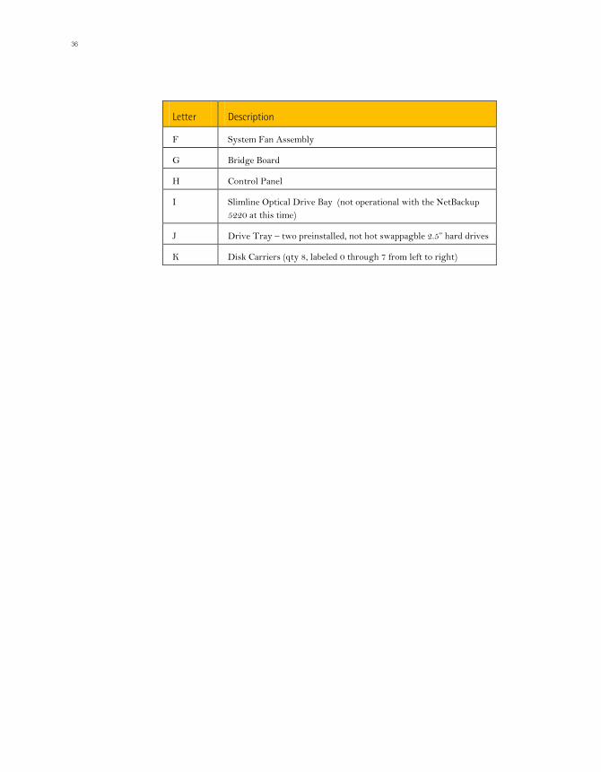
Letter Description
F System Fan Assembly
G Bridge Board
H Control Panel
I Slimline Optical Drive Bay (not operational with the NetBackup 5220 at this time)
J Drive Tray – two preinstalled, not hot swappagble 2.5” hard drives
K Disk Carriers (qty 8, labeled 0 through 7 from left to right)
Chapter 4
NetBackup 5220 and Symantec Storage Shelf description
Italiano
37
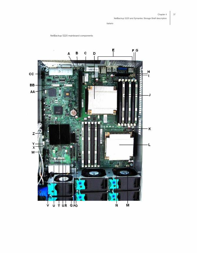
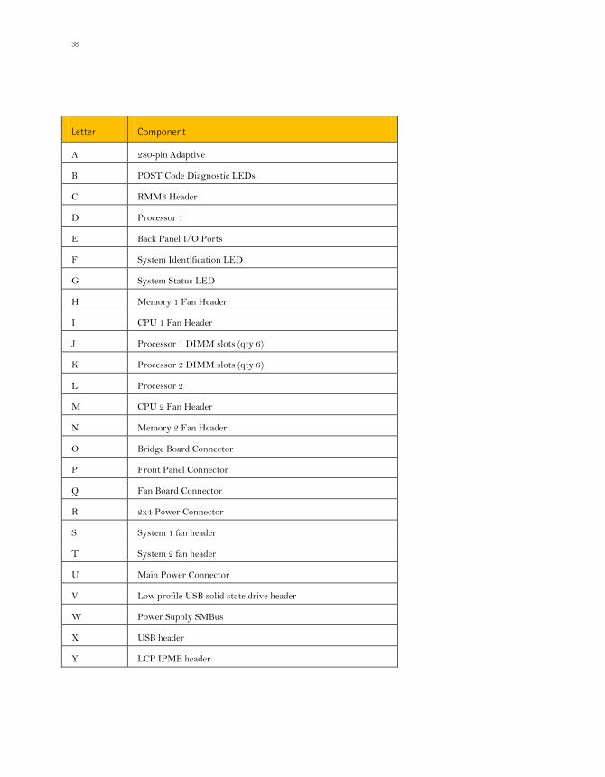
NetBackup 5220 mainboard components
38
Letter Component
A 280-pin Adaptive
B POST Code Diagnostic LEDs
C RMM3 Header
D Processor 1
E Back Panel I/O Ports
F System Identification LED
G System Status LED
H Memory 1 Fan Header
I CPU 1 Fan Header
J Processor 1 DIMM slots (qty 6)
K Processor 2 DIMM slots (qty 6)
L Processor 2
M CPU 2 Fan Header
N Memory 2 Fan Header
O Bridge Board Connector
P Front Panel Connector
Q Fan Board Connector
R 2x4 Power Connector
S System 1 fan header
T System 2 fan header
U Main Power Connector
V Low profile USB solid state drive header
W Power Supply SMBus
X USB header
Y LCP IPMB header

Chapter 4
NetBackup 5220 and Symantec Storage Shelf description
Italiano
39
Letter Component
Z SGPIO header
AA I/O module mezzanine connector 2
BB I/O module mezzanine connector 1
CC Serial port B header
NetBackup 5220 front view The NetBackup 5220 provides locations and hardware for installing 2.5-inch hard drives, a tape drive, CD-ROM drive, or DVD-ROM drive. The drives must be purchased separately.
NetBackup 5220 front
Letter Description
A Flex Bay – Tape drive or two fixed 2.5” hard (or boot) disk drives (optional)
B Slimline Drive Bay (not operational with the NetBackup 5220)
C 2.5” Hard Disk Drive Bays (qty 8)
Notes:
Drive Bay Addresses are 0-7 starting from the left.
Each drive has 2 LEDS, one red and one green.
The green LED flashes when drive activity occurs and is lit when no activity occurs.

40
The red LED is lit when drive faults occur.
Drives can consume up to 17 watts of power each. Drives must be specified to run at a maximum ambient temperature of 45°C.
Bezels The optional front bezel is made of molded plastic and provide a snap-on design that allows for maximum airflow through the server system. The bezel provides a lock to secure the hard drives, peripheral devices and the control panel.
NetBackup 5220 rear panel
NetBackup 5220 rear panel
Letter Description
A Low Profile PCI Express Add-in Card Slots (qty 2)
B Full-height PCI Add-in Card Slots (qty 3)
C Upper Power Supply Module
D Upper Power Receptacle
E Lower Power Receptacle
F Lower Power Supply Module
G I/O Expansion Module (optional)

Chapter 4
NetBackup 5220 and Symantec Storage Shelf description
Italiano
41
Letter Description
H Remote Management Module NIC (optional)
I NIC 1 Ethernet port
J NIC 2 Ethernet port
K USB 6
L USB 5
M DB-9 Serial B Connector
N Video
O RJ-45 Serial A Connector
Rear panel ports
NetBackup 5220 rear panel ports
NetBackup 5220 rear panel ports
Letter Name Qty Model Function
A Serial port 1 RJ45 Extends functions of the OS and third-party software.
B VGA (video) port
1 D15 Connects to a computer monitor.
C, D USB 2.0 ports
2 A Connects mouse, keyboard, or similar devices.
E NIC 1 Ethernet port
1 RJ-45 “private” network port provides for device management

42
Letter Name Qty Model Function
F NIC 2 Ethernet port
1 RJ-45 “service” network port provides input/output access to the device.
FC D
NIC port LED indications
LED State Indications
Left Off No network connection
Solid amber Network connection in place
Flashing amber Transmit/receive activity
Right Off 10 Mbps connection (if left LED is on or flashing)
Solid amber 100 Mbps connection
Solid green 1000 Mbps connection
NetBackup 5220 and Symantec Storage Shelf rack mounting The NetBackup 5220 should be mounted into a rack with the toolless guide rails provided with the device. These rails are installed into a standard (19 inches by up to 30 inches deep) EIA-310D compatible rack cabinet.
When installing the system into a rack, it is recommended that you install systems from the bottom of the rack first, and work towards the top.
Each left and right mounting rail for the Symantec Storage Shelf is shipped as a unit. The front and back of each rail slide apart a few inches to allow for precise fitting into the rack cabinet.
The bottom of each rail includes a sturdy metal ledge on which the Symantec Storage Shelf sits.

Chapter 4
NetBackup 5220 and Symantec Storage Shelf description
Italiano
43
NetBackup 5220 and Symantec Storage Shelf chassis covers The NetBackup 5220 must be operated with the chassis cover in place to ensure proper air flow and cooling. You need to remove the top cover to add or replace components inside of the device. Before removing the chassis cover, power down the device and any tasks or programs that are running. Then, unplug all peripheral devices and the AC power cable(s).
The Symantec Storage Shelf chassis should not be opened. The only front panel components that can be removed and replaced are the disk drive modules. On the rear panel, the two I/O modules and two power supply modules can be hot-swapped.

44
Chapter 5 Alarms
Do not power-on the NetBackup 5220 if power supply issues are not resolved. Damage to the device may result.
System-induced power-off of the NetBackup 5220
Definition: The terms “protection or protected” refer to a power supply that has shut down or locked up in order to protect itself and other components connected to the device. A short-circuit, voltage overload or power surge can cause self-protection.
If the NetBackup 5220 is powered on, the chassis cover should not be removed for more than 5 minutes. Leaving the chassis open for a longer time may result in decreased air flow and increased component temperatures.

45
Fan failure
If alarms in the monitoring systems indicate fan problems or high temperatures at the air intake vent, make sure room air cooling is adequate.
Temperature abnormality
Several problems may lead to high (great than 35C) temperatures of the device. Thoroughly check all aspects of the rack environment.
Make sure no other equipment is overly warm and close to the devices.
Make sure room temperature is within specifications.
Make sure AC power to the device is correct.
When the system alarm/location indicator is on and red, the alarm information is displayed on the browser-based monitoring interface.
Alarm information
Classification Type Device Description
Overtemperature of the CPU core
Temperature CPU Temperature is not critical yet but is approaching the upper limit of the range.
Overtemperature of the air intake of the chassis
Temperature Chassis air intakc
Temperature is not critical yet but is approaching the upper limit of the range.
Fan module absence Cooling device Fan Device absent
Investigate other possible problems
1. Make sure the front and back of the NetBackup 5220 are clear of any obstructions so that air can flow easily from front to back.
2. Verify that room temperature is within specifications.
3. Verify that any equipment near the device is at normal temperature.
If high temperatures or alarms persist, contact technical support.

46
Be sure that all devices are correctly shut down and all programs on any devices are not running. If you disconnect devices while programs are running, data loss may occur.
In order to maintain adequate thermal levels, you MUST install DIMMs and DIMM blanks in the appropriate DIMM slots.
All blue DIMM slots in CPU 1 and CPU 2 must either have a DIMM or DIMM blank installed. You may store extra DIMM blanks in any of the unused CPU 1 DIMM slots.
Note: It does not matter which DIMMs are installed into which slots, they are interchangeable.
The power supply is hot-swappable only when two power supplies are installed into the NetBackup 5220. If only one power supply is installed, the power supply can be replaced if it fails or if one of the fans installed into the power supply fails.
The fans in the power supply module are not removable. They remain inside the module as a complete unit. If there are problems with the fans, the entire power supply module must be removed and replaced.
You must power the device down, turn off all peripheral devices connected to the system, turn off the system by pressing the power button, and unplug the AC power cord from the main AC power source before removing or replacing the power supply.
Chassis issues Problems may occur because the chassis cover is damaged or improperly installed. Intake and output vents in the front and rear of the chassis may be blocked or damaged. A visual inspection of all parts of the chassis is required.

47

48
Chapter 6 NetBackup 5220 hardware removal and replacement
This chapter provides safety details regarding removal, installation and replacement of the NetBackup device, chassis, and components.
Before you begin Before working with your NetBackup 5220, read and understand the safety information in this manual.
Note: When you service the device, you must first power down the device through the OS. Make sure no programs or peripherals are running. Then unplug all peripheral devices and the AC power cord.
Tools and supplies Phillips (cross head) screwdrivers (#1 bit and #2 bit)
Needle nosed pliers
Anti-static wrist strap and gloves and conductive foam pad (recommended)
Unpacking the NetBackup 5220 The shipping box containing the NetBackup 5220 includes the following:
NetBackup 5220 (qty 1)
Network cables
Left and right rack mounting rails (1 each)

49
1 bezel (optional)
1.5m (4.9 ft) Power cords (qty 2)
PCI-E add-in cards
NetBackup 5220 guide rails and rack Before installing the devices in the rack cabinet, determine the installation positions of the guide rails according to the installation planning of the devices.
One fully-loaded device weighs up to 33 kg.(73 lbs). More than two persons are required to move and install the device.
Wear an ESD-preventive wrist strap and ESD-preventive gloves.
Note: Locate the three heavy screws projecting from the left and right sides of the NetBackup 5220. These three screws fit into the three slots in the rail extenders.
Removing and re-installing the chassis cover This section explains how to remove and re-install the chassic cover of the NetBackup 5220.
Removing the NetBackup 5220 chassis cover The NetBackup 5220 must be operated with the chassis cover in place to ensure proper air flow and cooling. You need to remove the top cover to add or replace components inside of the device. Before removing the top cover, power down the device and any tasks or programs that are running. Then, unplug all peripheral devices and the AC power cable(s).
You must remove the NetBackup 5220 from the rack prior to removing the cover.
Note: A nonskid surface or a stop behind the server system may be needed to prevent the server system from sliding on your work surface.
1. Shutdown the NetBackup 5220 and any peripherals.

50
Be sure that both devices are off and all programs on both devices are not running. If you connect these devices while programs are running, data loss may occur.
2. Disconnect the main AC power cord and peripheral cables/cords from the rear of the NetBackup 5220.
3. Wear ESD preventive wrist straps.
4. Carefully remove the NetBackup 5220 from the rack cabinet.
5. Place it on a grounded, ESD protective surface.
6. Remove the screw on the top, right-hand side of the chassis. Use the blue thumb grip on the top, left-hand side of the chassis to slide the cover towards the rear of the device.
Removing the NetBackup 5220 chassis cover
7. Remove the chassis cover completely.

51
Chassis with cover removed
You can refer to the information on the inside of the cover regarding components within the chassis.
Re-installing the NetBackup 5220 chassis cover 1. Replace the chassis cover at the top rear of the NetBackup 5220 enclosure.
2. Slide the cover from the rear of the device towards the front.
Carefully line up both sides of the cover with the sides of the chassis itself. Do not allow warping or damage to the cover.
3. Reinstall the single screw at the right front of the external chassis.

52
Be sure that all devices are correctly shut down and all programs on any devices are not running. If you disconnect devices while programs are running, data loss may occur.
Do not move or damage any cables or other connectors located near the air ducts.
PCI add-in cards are NOT hot-swappable. Before removing or replacing the riser card assembly, you must first take the device out of service. Turn off all peripheral devices connected to the system, turn off the system by pressing the power button, and unplug the AC power cord from the system or wall outlet.
Be sure that all devices are off and all programs on all devices are not running. If you disconnect any devices while programs are running, data loss may occur.
To prevent the possibility of installing the replacement PCI add-in card on the wrong side of the PCI riser assembly, carefully replace one card into slots 1 through 4, one at a time. Slot 5 is reserved for the RAID card.

53
Properly power down your NetBackup 5220, any running programs and peripherals before accessing the chassis and any baffles.
Always operate your device with the baffles in place, to ensure proper airflow.
54
Chapter 7 Symantec Storage Shelf hardware removal and replacement
This chapter provides information regarding the removal, installation, and replacement of the Symantec Storage Shelf device, components, and peripherals.
Before you begin Before working with your NetBackup 5220, read and understand the safety information in this manual.
Note: When you service the device, you must first power down the device through the OS. Make sure no programs or peripherals are running. Then unplug all peripheral devices and the AC power cord.
Tools and supplies Phillips (cross head) screwdrivers (#1 bit and #2 bit)
Needle nosed pliers
Anti-static wrist strap and gloves and conductive foam pad (recommended)

Chapter 7
Symantec Storage Shelf hardware removal and replacement
55
Unpacking the Symantec Storage Shelf The shipping box containing the storage shelf includes the following:
Symantec Storage Shelf (qty 1)
RJ11-to-DB9 serial data cables (qty 2)
Dual-controller models, (qty 2)
Left and right rack mounting rails (1 each)
1.5m (4.9 ft) Power cords (qty 2)
Symantec Storage Shelf guide rails and rack Each left and right mounting rail for the Symantec Storage Shelf is shipped as a unit. The front and back of each rail slide apart a few inches to allow for precise fitting into the rack cabinet.
The bottom of each rail includes a sturdy metal ledge on which the Symantec Storage Shelf sits.
Be sure to wear an ESD-preventive wrist strap and ESD-preventive gloves.
One fully-loaded or storage shelf weighs up to 33 kg.(73 lbs). More than two persons are required to move and install each device. You can remove the power supplies if you want to decrease the weight during installation.

56 Chapter 7
Symantec Storage Shelf hardware removal and replacement
Symantec Storage Shelf cover/chassis
Symantec Storage Shelf cover/chassis The Symantec Storage Shelf chassis should not be opened. The only front panel components that can be removed and replaced are the disk drive modules. On the rear panel, the two I/O modules and two power supply modules can be hot-swapped.
Never leave a power supply module bay empty. Proper air cooling through the entire device depends on having both power supply module bays installed with the proper components.

Appendix A: Technical References
57
Appendix A: Technical References
750W single power supply input voltages The power supply must operate within all specified limits over the input voltage range.
NetBackup 5220 power supply input voltages
Parameter Min Rated Max Startup VAC
Power-off VAC
Max input AC current
Max rate input AC current
Voltage (110) 90Vrms 100-127 Vrms
140 Vrms
85 VAC +/- 5 VAC
75 VAC +/- 5VAC
12Arms 1 11.0Arms3
Voltage (220) 180 Vrms
200-240 Vrms
264 Vrms
6.0Arms 2 5.5Arms 3
Frequency 47Hz 50/60 Hz
63Hz
Notes:
1. Maximum input current at low input voltage range is measured at 90 VAC, at maximum load.
2. Maximum input current at high input voltage range is measured at 180 VAC, at maximum load.
3. Maximum rated input current is measured at 100 VAC and 200 VAC.

58 Appendix A: Technical References
System Environmental Specifications
System Environmental Specifications The following table defines the system level operating and non-operating environmental limits.
System Environmental Specifications
Parameter State Details
Temperature Non-operating
Operating
-40°Fto 70°F
10°C to 35°C with the maximum rate of change not to exceed 10°C per hour
Humidity Non-operating 90% relative humidity (non-condensing) at 28°C.
Shock Operating
Packaged
Unpackaged
2.0 g peak, 11 msec, half sine
Non-palletized free fall in height 24” (> 40 lbs to < 80 lbs)
Operational after an 18" free fall.
Trapezoidal, 25 g, velocity change 136 inches/sec.
Vibration Unpackaged 5 Hz to 500 Hz, 2.20 g RMS random
Acoustic noise Sound Power: 7.0 BA in an idle state at typical office ambient temperature (23 +/- 2°C)
Electrostaticdischarge (ESD)
+/-12 KV except I/O port +/- 8 KV
System Cooling Requirement (BTU/Hr)
NetBackup 5220: 2550 BTU/Hr
Storage Shelf: 1270 BTU/Hr

59
Appendix B: Regulatory and Certification Information
WARNING:
To ensure regulatory compliance, you must adhere to the assembly instructions in this guide to ensure and maintain compliance with existing product certifications and approvals. Use only the described, regulated components specified in this guide. Use of other products/components will void the UL listing and other regulatory approvals of the product and will most likely result in noncompliance with product regulations in the region(s) in which the product is sold.
To help ensure EMC compliance with your local regional rules and regulations, before computer integration, make sure that the server system, power supply, and other modules have passed EMC testing using a server board with a microprocessor from the same family (or higher) and operating at the same (or higher) speed as the microprocessor used on this server board. The final configuration of your end system product may require additional EMC compliance testing.
This is an FCC Class A device. Integration of it into a Class B system does not result in a Class B device.

60 Appendix B: Regulatory and Certification Information
Product Regulatory Compliance The NetBackup 5220 product, when correctly integrated per this guide, complies with the following safety and electromagnetic compatibility (EMC) regulations.
Intended Application - This product was evaluated as Information Technology Equipment (ITE), which may be installed in offices, schools, computer rooms, and similar commercial type locations. The suitability of this product for other product categories and environments (such as: medical, industrial, telecommunications, NEBS, residential, alarm systems, test equipment, etc.), other than an ITE application, may require further evaluation.
Product Safety Compliance UL60950 - CSA 60950 (USA / Canada)
EN60950 (Europe)
IEC60950 (International)
CB Certificate & Report, IEC60950 (report to include all country national deviations)
GS Certification (Germany)
GOST R 50377-92 - Certification (Russia)
Belarus Certification (Belarus)
Ukraine Certification (Ukraine)
CE - Low Voltage Directive 73/23/EEE (Europe)
IRAM Certification (Argentina)
GB4943- CNCA Certification (China)

Appendix B: Regulatory and Certification Information
61
Product EMC Compliance - Class A Compliance FCC /ICES-003 - Emissions (USA/Canada) Verification
CISPR 22 - Emissions (International)
EN55022 - Emissions (Europe)
EN55024 - Immunity (Europe)
EN61000-3-2 - Harmonics (Europe)
EN61000-3-3 - Voltage Flicker (Europe)
CE - EMC Directive 89/336/EEC (Europe)
VCCI Emissions (Japan)
AS/NZS 3548 Emissions (Australia / New Zealand)
BSMI CNS13438 Emissions (Taiwan)
GOST R 29216-91 Emissions (Russia)
GOST R 50628-95 Immunity (Russia)
Belarus Certification (Belarus)
Ukraine Certification (Ukraine)
GB 9254 - CNCA Certification (China)
GB 17625 - (Harmonics) CNCA Certification (China)
Product Ecology Compliance Use of banned substances are restricted t in accordance with world wide regulatory requirements. A Material Declaration Data Sheet is available.
Europe - European Directive 2002/95/EC - Restriction of Hazardous Substances (RoHS) Threshold limits and banned substances are noted below.
Quantity limit of 0.1% by mass (1000 PPM) for: Lead, Mercury, Hexavalent Chromium, Polybrominated Biphenyls Diphenyl-Ethers (PBB/PBDE)
Quantity limit of 0.01% by mass (100 PPM) for: Cadmium
California Code of Regulations, Title 22, Division 4.5, Chapter 33: Best Management Practices for Perchlorate Materials
China - Restriction of Hazardous Substances (China RoHS)
WEEE Directive (Europe)
Packaging Directive (Europe)

62 Appendix B: Regulatory and Certification Information
Certifications / Registrations / Declarations NRTL Certification (US/Canada)
CE Declaration of Conformity (CENELEC Europe)
FCC/ICES-003 Class A Attestation (USA/Canada)
VCCI Certification (Japan)
C-Tick Declaration of Conformity (Australia)
MED Declaration of Conformity (New Zealand)
BSMI Certification (Taiwan)
GOST R Certification / Certification (Russia)
Belarus Certification / Certification (Belarus)
IRAM Certification (Argentina)
CNCA CCC Certification (China)
Ecology Declaration (International)
China RoHS Environmental Friendly Use Period
Packaging & Product Recycling Marks

Appendix B: Regulatory and Certification Information
63
Electromagnetic Compatibility Notices
FCC Verification Statement (USA) This device complies with Part 15 of the FCC Rules. Operation is subject to the following two conditions: (1) this device may not cause harmful interference, and (2) this device must accept any interference received, including interference that may cause undesired operation. This equipment has been tested and found to comply with the limits for a Class A digital device, pursuant to Part 15 of the FCC Rules. These limits are designed to provide reasonable protection against harmful interference in a residential installation. This equipment generates, uses, and can radiate radio frequency energy and, if not installed and used in accordance with the instructions, may cause harmful interference to radio communications. However, there is no guarantee that interference will not occur in a particular installation. If this equipment does cause harmful interference to radio or television reception, which can be determined by turning the equipment off and on, the user is encouraged to try to correct the interference by one or more of the following measures: Reorient or relocate the receiving antenna.
Increase the separation between the equipment and the receiver.
Connect the equipment to an outlet on a circuit other than the one to which the receiver is connected.
Consult the dealer or an experienced radio/TV technician for help. Any changes or modifications not expressly approved by the grantee of this device could void the user's authority to operate the equipment. The customer is responsible for ensuring compliance of the modified product. Only peripherals (computer input/output devices, terminals, printers, etc.) that comply with FCC Class A or B limits may be attached to this computer product. Operation with noncompliant peripherals is likely to result in interference to radio and TV reception. All cables used to connect to peripherals must be shielded and grounded. Operation with cables, connected to peripherals that are not shielded and grounded may result in interference to radio and TV reception.
64 Appendix B: Regulatory and Certification Information
ICES-003 (Canada) Cet appareil numérique respecte les limites bruits radioélectriques applicables aux appareils numériques de Classe A prescrites dans la norme sur le matériel brouilleur: "Apparelis Numériques", NMB-003 édictee par le Ministre Canadian des Communications.
English translation of the notice above:
This digital apparatus does not exceed the Class A limits for radio noise emissions from digital apparatus set out in the interference-causing equipment standard entitled: "Digital Apparatus," ICES-003 of the Canadian Department of Communications.
CE Declaration of Conformity (Europe) This product has been tested in accordance to, and complies with the Low Voltage Directive (73/23/EEC) and EMC Directive (89/336/EEC). The product has been marked with the CE Mark to illustrate its compliance.
VCCI (Japan) This is a Class A product based on the standard of the Voluntary Control Council for Interference (VCCI) from Information Technology Equipment. If this is used near a radio or television receiver in a domestic environment, it may cause radio interference. Install and use the equipment according to the instruction manual.
BSMI (Taiwan) The BSMI Certification Marking and EMC warning is located on the outside rear area of the product.