moving the focus from relay element testing to protection … · moving the focus from relay...
TRANSCRIPT

Moving the Focus from Relay Element Testing to Protection System Testing
Christopher Pritchard, OMICRON electronics ([email protected]); David Costello (Schweitzer Engineering Laboratories, Fair Oaks Ranch, Texas); Karl Zimmerman (Schweitzer
Engineering Laboratories, Fairview Heights, Illinois)
USA / Austria
Abstract
The last three decades have seen significant improvements in power system protection. With the rise of digital relays, recalibration during maintenance tests became obsolete. The model of one IEEE element per electromechanical relay is not the case anymore. Digital relays build a system of elements freely combinable with programmable logic conditions. Additionally, to be able to protect the increasingly complex power system, these relays communicate with other relays, building an even bigger system. This being said, with few exceptions, like the use of RTDS (real-time-digital simulator) to simulate real world test cases, protection testing has neither changed significantly since the days of one element per electromechanical relay, nor adapted to the new challenges.
Still the ultimate goal of testing stays the same - ensuring that life and equipment is protected and power system stability is maintained. To achieve this goal we have to test the protection system, and all processes leading to it, as a whole. The protection system of today is usually the product of a process involving several engineers, technicians, and in some cases, companies. Applying a test only to a relay, checking each individual element one by one, at the very end of the process is insufficient as it cannot cover all possible sources of error. This was underlined by the 2013 NERC Misoperations Report which showed that in today's protections systems, relay failures are not the single source of error anymore, but rather incorrect settings, logic and design errors already account for more misoperations.
This paper proposes quality assurance for the whole process from design to commissioning by using a system testing approach. By elaborating in detail the challenges and different sources of error in modern protection systems, we will show how system testing tools can complement current testing methods or even replace some tests that no longer add value. Different testing approaches will be measured against improved quality vs. effort to run. Finally, the paper will share experiences from several cases around the world where system testing approach was applied with great success, and cases where gaps in system traditional testing methods were identified as areas of improvement.
Introduction
The driving goal behind testing protection is to ensure that the equipment is protected and power system stability is maintained. In other words we aim to minimize misoperations of the protection system. Very often this gets reduced down to only testing single elements of a relay. This is ignoring the majority of causes for misoperations which were laid open by the 2013 NERC report for misoperations [1]. But before going into technical test methods the first chapter will review the processes and people responsible for the protection system because people are more important than tools. After some basic definition of how we define element and system testing we will investigate the root causes of misoperations described in the NERC report [1]. Additionally two real world cases will show where element testing failed to uncover errors and led to misoperations. Afterwards we will describe how a system testing approach could look like and show examples where system testing was applied with great success.
People and Processes Responsible for the Protection System
Processes and people responsible for the power system protection system play a much more important role in ensuring stability, speed, selectivity and sensitivity of the protection system than any test method.
Processes involved in power system protection
System Design OperationCommissioning
Protection SystemQuality Assurance
1
Test Objective
Choosing theright Test Tool
$ Benefit-Cost
Synchronize Test Tasks
23
4
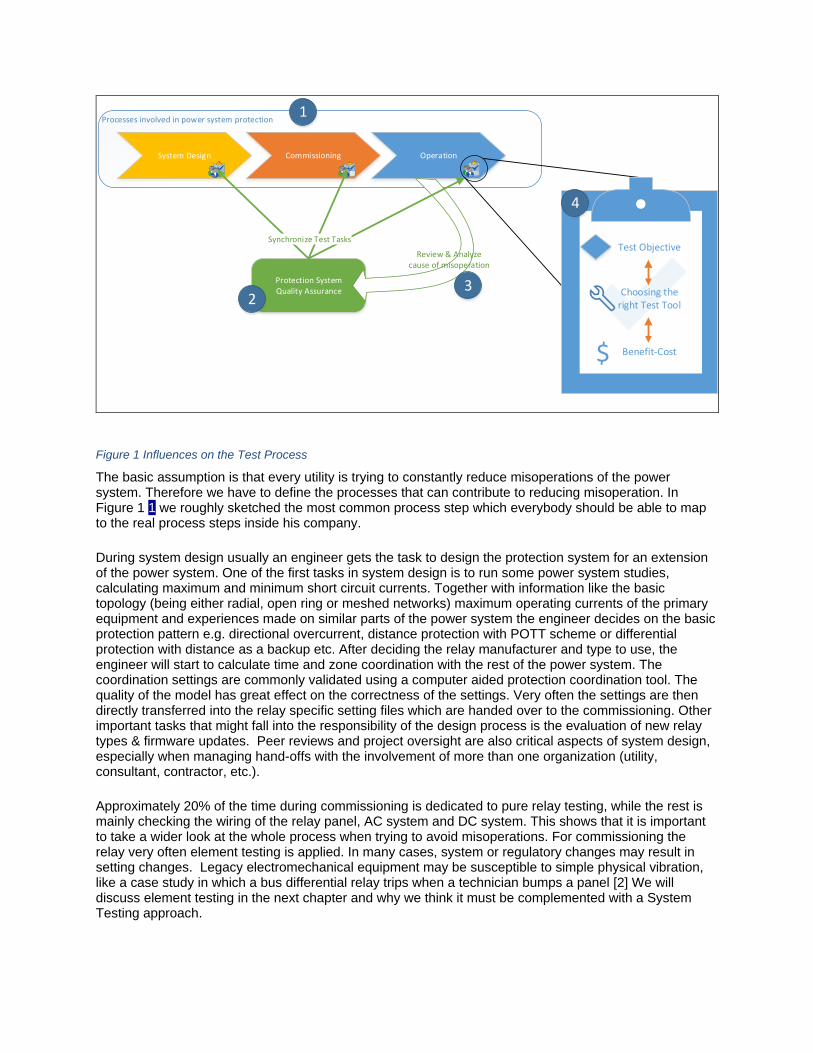
Figure 1 Influences on the Test Process
The basic assumption is that every utility is trying to constantly reduce misoperations of the power system. Therefore we have to define the processes that can contribute to reducing misoperation. In Figure 1 1 we roughly sketched the most common process step which everybody should be able to map to the real process steps inside his company.
During system design usually an engineer gets the task to design the protection system for an extension of the power system. One of the first tasks in system design is to run some power system studies, calculating maximum and minimum short circuit currents. Together with information like the basic topology (being either radial, open ring or meshed networks) maximum operating currents of the primary equipment and experiences made on similar parts of the power system the engineer decides on the basic protection pattern e.g. directional overcurrent, distance protection with POTT scheme or differential protection with distance as a backup etc. After deciding the relay manufacturer and type to use, the engineer will start to calculate time and zone coordination with the rest of the power system. The coordination settings are commonly validated using a computer aided protection coordination tool. The quality of the model has great effect on the correctness of the settings. Very often the settings are then directly transferred into the relay specific setting files which are handed over to the commissioning. Other important tasks that might fall into the responsibility of the design process is the evaluation of new relay types & firmware updates. Peer reviews and project oversight are also critical aspects of system design, especially when managing hand-offs with the involvement of more than one organization (utility, consultant, contractor, etc.).
Approximately 20% of the time during commissioning is dedicated to pure relay testing, while the rest is mainly checking the wiring of the relay panel, AC system and DC system. This shows that it is important to take a wider look at the whole process when trying to avoid misoperations. For commissioning the relay very often element testing is applied. In many cases, system or regulatory changes may result in setting changes. Legacy electromechanical equipment may be susceptible to simple physical vibration, like a case study in which a bus differential relay trips when a technician bumps a panel [2] We will discuss element testing in the next chapter and why we think it must be complemented with a System Testing approach.
After commissioning the protection system is handed over to the operations process. Depending on the relay technology each relay gets tested on a regular base. Very often the same test plan that was used for commissioning gets reused because it is convenient. In case of element testing all the associated risks are getting applied again. As maintenance testing is searching for error occurring over time cause e.g. by temperature, vibration etc. it is also important to check all of the protection subsystems.
To reach the goal of overall protection system quality assurance 2 it is indispensable to regularly review and analyze the cause of misoperations 3. This information can directly be used to avoid the occurrence of these issues in first place. But as long as humans are involved mistakes will happen. Therefore in a second step this information should be used to improve the different test procedures inside the different process steps and make sure that all test procedures together cover the whole process. Again this can either happen in a formalized process or just in an informal meeting between people working in the different process steps. When defining a test procedure 4 and before choosing a test method or tool, the objective should always be made clear e.g. testing for relay failures or logic errors. As there will be no 100% coverage for every possible cause for a misoperation the decision for a tool always has to balance cost & benefit. Continuous improvement of the relationship between operators and regulators is another increasingly important aspect of improving power system reliability, as reported in a recent report [3].
NERC Report Overview
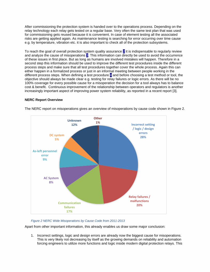
The NERC report on misoperations gives an overview of misoperations by cause code shown in Figure 2.
Figure 2 NERC Wide Misoperations by Cause Code from 2011-2013
Apart from other important information, this already enables us draw some major conclusion:
1. Incorrect settings, logic and design errors are already now the biggest cause for misoperations. This is very likely not decreasing by itself as the growing demands on reliability and automation forcing engineers to utilize more functions and logic inside modern digital protection relays. This
Incorrect setting / logic / design
errors28%
Relay failures / malfunctions
20%Communication
failures17%
AC System8%
As-left personnel error9%
DC system5%
Unknown12%
Other1%
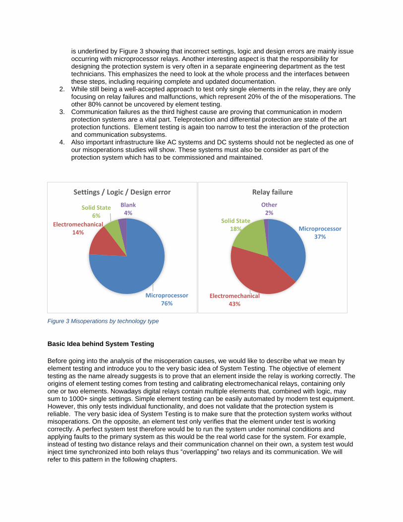
is underlined by Figure 3 showing that incorrect settings, logic and design errors are mainly issue occurring with microprocessor relays. Another interesting aspect is that the responsibility for designing the protection system is very often in a separate engineering department as the test technicians. This emphasizes the need to look at the whole process and the interfaces between these steps, including requiring complete and updated documentation.
2. While still being a well-accepted approach to test only single elements in the relay, they are only focusing on relay failures and malfunctions, which represent 20% of the of the misoperations. The other 80% cannot be uncovered by element testing.
3. Communication failures as the third highest cause are proving that communication in modern protection systems are a vital part. Teleprotection and differential protection are state of the art protection functions. Element testing is again too narrow to test the interaction of the protection and communication subsystems.
4. Also important infrastructure like AC systems and DC systems should not be neglected as one of our misoperations studies will show. These systems must also be consider as part of the protection system which has to be commissioned and maintained.
Figure 3 Misoperations by technology type
Basic Idea behind System Testing
Before going into the analysis of the misoperation causes, we would like to describe what we mean by element testing and introduce you to the very basic idea of System Testing. The objective of element testing as the name already suggests is to prove that an element inside the relay is working correctly. The origins of element testing comes from testing and calibrating electromechanical relays, containing only one or two elements. Nowadays digital relays contain multiple elements that, combined with logic, may sum to 1000+ single settings. Simple element testing can be easily automated by modern test equipment. However, this only tests individual functionality, and does not validate that the protection system is reliable. The very basic idea of System Testing is to make sure that the protection system works without misoperations. On the opposite, an element test only verifies that the element under test is working correctly. A perfect system test therefore would be to run the system under nominal conditions and applying faults to the primary system as this would be the real world case for the system. For example, instead of testing two distance relays and their communication channel on their own, a system test would inject time synchronized into both relays thus “overlapping” two relays and its communication. We will refer to this pattern in the following chapters.
Microprocessor76%
Electromechanical14%
Solid State6%
Blank4%
Settings / Logic / Design error
Microprocessor37%
Electromechanical43%
Solid State18%
Other2%
Relay failure
The system approach to testing is not a new concept, but has been highlighted in several papers and standards over the past few years. NERC Standard PRC-005-2 [4]provides detailed tables for testing of protection subsystems. References [5] and [6] provide guidance on what should be included in System testing. This includes considering all of the elements that must perform correctly to clear a fault or whose malfunction could cause an undesired operation:
Circuit breaker (mechanical and electrical trip coil)
Battery/dc system(s)
DC control wiring, including grounding
Primary bus and feeder conductor connections
Current transformers (CTs)
CT secondary wiring, including grounding
Voltage transformers (VTs)
VT secondary wiring, including grounding
Protective relay properly applied and set
Protective relay performance
Communications equipment properly set
Communications equipment performance
System testing requires making a commitment to
Requiring complete documentation, including logic diagrams, expected operation descriptions, and results of testing.
Performing peer review of designs, settings, and testing.
Developing and testing standard schemes in the lab.
Creating and using commissioning and testing checklists.
Moving element and scheme testing earlier in a project timeline, and perform this work in the lab versus in the field.
Making commissioning a separate line item, in budget and time, not easily dismissed.
Committing increased effort and resources to training and mentorship.
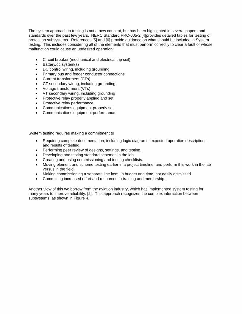
Another view of this we borrow from the aviation industry, which has implemented system testing for many years to improve reliability. [2]. This approach recognizes the complex interaction between subsystems, as shown in Figure 4.

The
System
RelaysBreakers
DC
System
Operators
VTs and
CTs
Engineers
TechniciansUtility
Comm
System
Test
Equip.
Contractors
Figure 4 System Testing Provides Overlapping between Subsystems
One study [7] quantifies the improvement in reliability of transmission line protection schemes when applying system testing. Table 1 shows the dependability (unavailability) and security (failure rate) with and without system testing. A lower value is better. By comparison, depending on the scheme, system testing improves dependability and security by 1 to 4 times.
Table 1 Effect Of System Testing On Line Protection Reliability
Protection Scheme Dependability (Unavailability • 106)
Security (Failure Rate • 106)
Normal Commissioning
Testing
System Testing
Normal Commissioning
Testing
System Testing
Basic POTT (microwave) 2,562 1,339
(1.9 times)
23,318 12,938
(1.8 times)
Basic POTT (optical fiber) 2,452 1,229
(2.0 times)
22,784 12,364
(1.8 times)
Basic DCB (power line carrier) 2,122 943
(2.3 times)
48,704 33,180
(1.5 times)
Dual-redundant POTT 168 162
(1.04 times)
27,052 16,072
(1.7 times)
Dual-redundant POTT with relays from different manufacturers
174 162
(1.07 times)
29,552 16,572
(1.8 times)
Dual-redundant POTT with common-mode failures
1,178 268
(4.4 times)
28,102 16,202
(1.7 times)

Fully redundant voting POTT 160 160
(1.0 times)
916 750
(1.2 times)
Voting POTT: two schemes share a dc power system
220 172
(1.3 times)
2,892 1,146
(2.5 times)
Voting POTT: two schemes also share a communications channel
1,120 992
(1.1 times)
6,592 4,224
(1.6 times)
Voting POTT: two schemes also share instrument transformers
1,464 1,136
(1.3 times)
10,182 6,826
(1.5 times)
Fully redundant voting POTT with common-mode failures
1,170 266
(4.4 times)
1,966 880
(2.2 times)
Note: The numbers in parentheses represent the effect of system testing. These numbers are the ratios of the unavailabilities or failure rates with normal testing to the unavailabilities or failure rates with system testing. POTT is permissive overreaching transfer trip. DCB is directional comparison blocking.
Derive Test Tasks by Analyzing Misoperation Causes
It should be stated that the NERC Report [1] also contains suggestions that should be considered first. This chapter tries to complement these suggestions with test methods able to support utilities.
We will start by looking at a selection of second & third level cause for settings, logic and design. General protection element setting errors, improper timing coordination and zone over reaching are the main cause inside the setting error cause code. While improper coordination timing and zone overreaches can be reduced by thorough system studies, the vast amount of relay functions and settings and their effect on the system protection is extremely challenging. Complete quality assurance often falls to the system design process, as an element test at best is able to test that the wrong setting are correctly transferred to the relay. To avoid the error propagation from the design step to the commissioning step we can use a process overlapping test method. Defining protection settings is mostly based on power system simulations of fault & non-fault scenarios. By injecting the calculated currents and voltages of these scenarios to the protection system we can assess much better if the protection is really doing its job – protecting the power system.
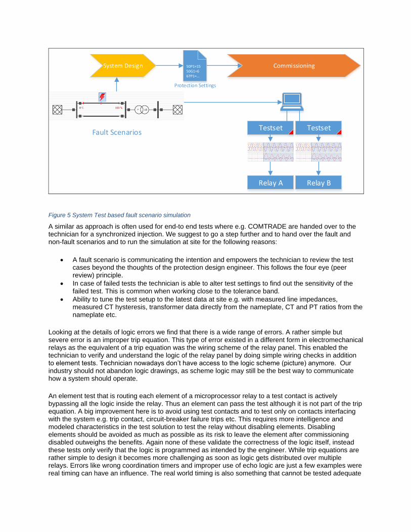
TestsetFault Scenarios
Relay BRelay A
Testset
Protection Settings
50P1=1550G1=667P1=...
System Design Commissioning
Figure 5 System Test based fault scenario simulation
A similar as approach is often used for end-to end tests where e.g. COMTRADE are handed over to the technician for a synchronized injection. We suggest to go a step further and to hand over the fault and non-fault scenarios and to run the simulation at site for the following reasons:
A fault scenario is communicating the intention and empowers the technician to review the test cases beyond the thoughts of the protection design engineer. This follows the four eye (peer review) principle.
In case of failed tests the technician is able to alter test settings to find out the sensitivity of the failed test. This is common when working close to the tolerance band.
Ability to tune the test setup to the latest data at site e.g. with measured line impedances, measured CT hysteresis, transformer data directly from the nameplate, CT and PT ratios from the nameplate etc.
Looking at the details of logic errors we find that there is a wide range of errors. A rather simple but severe error is an improper trip equation. This type of error existed in a different form in electromechanical relays as the equivalent of a trip equation was the wiring scheme of the relay panel. This enabled the technician to verify and understand the logic of the relay panel by doing simple wiring checks in addition to element tests. Technician nowadays don’t have access to the logic scheme (picture) anymore. Our industry should not abandon logic drawings, as scheme logic may still be the best way to communicate how a system should operate.
An element test that is routing each element of a microprocessor relay to a test contact is actively bypassing all the logic inside the relay. Thus an element can pass the test although it is not part of the trip equation. A big improvement here is to avoid using test contacts and to test only on contacts interfacing with the system e.g. trip contact, circuit-breaker failure trips etc. This requires more intelligence and modeled characteristics in the test solution to test the relay without disabling elements. Disabling elements should be avoided as much as possible as its risk to leave the element after commissioning disabled outweighs the benefits. Again none of these validate the correctness of the logic itself, instead these tests only verify that the logic is programmed as intended by the engineer. While trip equations are rather simple to design it becomes more challenging as soon as logic gets distributed over multiple relays. Errors like wrong coordination timers and improper use of echo logic are just a few examples were real timing can have an influence. The real world timing is also something that cannot be tested adequate
during system design. Using the fault and non-fault scenarios to define test cases can solve some issues here. A fault scenario communicates the intention of the piece of logic under test.
An important addition to simulating and injecting transient signals is the ability to react to relay reaction and adapt the transient output. This is important to test beyond the first trip e.g. for testing a reclosing cycle. With these capabilities such a system test only has to model the fault scenario independent of how many relays and logic gates are in use i.e. it scales very well. Misoperations caused by communication delays are covered as they are part of the system under test.
Although we promote that settings, logic and design errors should get more attention during testing, relay failures should not be neglected. Especially for electromechanical relays, element testing still has its eligibility where it serves not only as a testing method but also as calibration tool. For electromechanical relays it is an absolute must to do regular maintenance test as their setting values tend to drift and its mechanics are likely to fail if they are in service for multiple decades.
Microprocessor relays self-monitor internal components like power supply, memory and settings. Some components, like analog inputs, logic inputs and outputs can fail without producing an alarm, and these should be tested periodically [4]. Certainly an element test would uncover some of these failure during a maintenance test. But there are a few things that should be considered:
Disabling elements or manipulating the trip equation to test other hidden backup elements is causing more risk of elements not being enabled again than preventing a relay failure. In microprocessor relays it is usually the I/O unit that may fail. Element settings usually don’t drift in a digital relay making testing every single element at any price questionable.
Using test contacts is just proving the test contact but not the output contact tripping the coil.
Pulling settings from the relay is just testing against the actual values instead of testing against the desired values. Pulling an overcurrent threshold of 5A of the relay and testing that this value is really 5A on a microprocessor relay is only uncovering seldom firmware errors or internal component failure, but it is not uncovering that the intended value would have been 10A.
Other common practice to find relay failures are to check the meter value on the display during operation to compare them with other relay meters and to do a trip test with the real breaker. This is following the philosophy of System Testing by overlapping the relay and the AC System uncovering faults between the relay and power system. Another issue specific to microprocessor relays are firmware issues. Apart from the suggested firmware management in the NERC report [1] it is important to do a thorough acceptance test before spreading the new firmware company wide. For acceptance testing static accuracy and dynamic performance tests are a common practice [8]. The dynamic tests again could be executed using a power system simulation simulating fault scenarios.
As already mentioned this chapter has a great focus on relay testing but there are also other important steps in commission and maintenance testing like tugging the wires, wiring checks etc.
Real world misoperation studies and how System Testing applies
In practice, many misoperations can be avoided by applying a system testing approach.
In the following example [9], a feeder fault results in an undesired trip from a transformer differential and a transformer backup overcurrent, as shown in Figure 6:

OUT1
28 MVA
Delta-Wye
Sources
LG Fault
Load
AB
C
OUT2
50/51PN
87T, 86
50/51PN
Figure 6 External Fault results in an undesired transformer differential relay trip
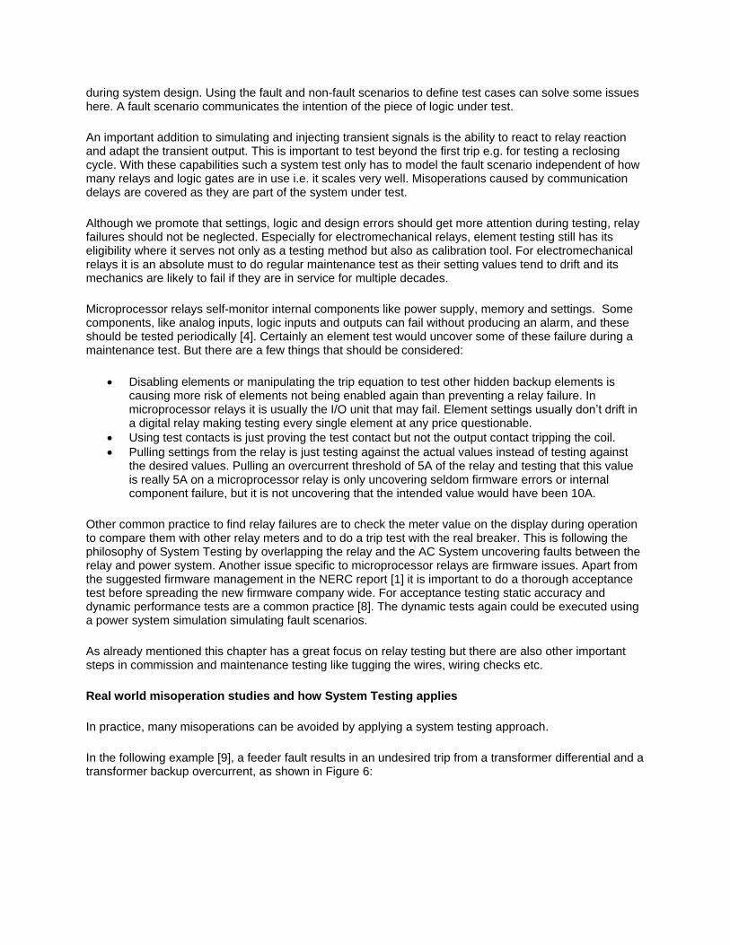
From the event report screen captures in Figure 7 and Figure 8, we can make the following observations:
The fault was an external fault.
The fault was a BG fault on the distribution side.
The transformer backup (B) tripped instantly (1.5 cycles).
87T (C) would have tripped even without miscoordination.
Figure 7 Event Recording from Transformer Differential Relay
87R = 87T Tripped
IN2 = Relay B Trip
External LG Fault Confirmed
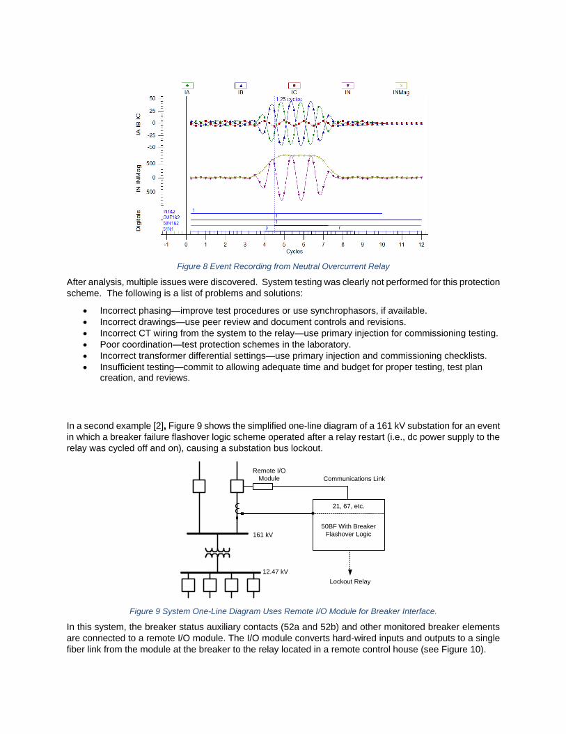
Figure 8 Event Recording from Neutral Overcurrent Relay
After analysis, multiple issues were discovered. System testing was clearly not performed for this protection
scheme. The following is a list of problems and solutions:
Incorrect phasing—improve test procedures or use synchrophasors, if available.
Incorrect drawings—use peer review and document controls and revisions.
Incorrect CT wiring from the system to the relay—use primary injection for commissioning testing.
Poor coordination—test protection schemes in the laboratory.
Incorrect transformer differential settings—use primary injection and commissioning checklists.
Insufficient testing—commit to allowing adequate time and budget for proper testing, test plan creation, and reviews.
In a second example [2], Figure 9 shows the simplified one-line diagram of a 161 kV substation for an event
in which a breaker failure flashover logic scheme operated after a relay restart (i.e., dc power supply to the
relay was cycled off and on), causing a substation bus lockout.
161 kV
12.47 kV
Lockout Relay
Communications Link
21, 67, etc.
50BF With Breaker
Flashover Logic
Remote I/O
Module
Figure 9 System One-Line Diagram Uses Remote I/O Module for Breaker Interface.
In this system, the breaker status auxiliary contacts (52a and 52b) and other monitored breaker elements
are connected to a remote I/O module. The I/O module converts hard-wired inputs and outputs to a single
fiber link from the module at the breaker to the relay located in a remote control house (see Figure 10).

Relay
Remote I/O
Module
Communications Link
52 Trip 1
52 Trip 2
52 Close
52 Low Gas Alarm
52 Low Gas Trip
I/O Module Alarm
52 Spring Charge Alarm
52 Trip Coil Monitor 1
52 Trip Coil Monitor 2
52a
52b
Figure 10 Monitored Points From the 161 kV Circuit Breaker Using a Remote I/O Module and Fiber Interface to the Relay.
The user applied the I/O module to eliminate extra wiring and inherent noise and hazards associated with
long (i.e., several hundred feet) runs of copper wire. Also, the fiber connection was continuously monitored.
The monitored communications link was set so that, if communications were lost (e.g., fiber was
disconnected or damaged or there was an I/O module failure), the breaker status would default to its last
known state before the communications interruption. However, when the dc is removed, then applied, all
inputs are de-asserted (logic 0) on initial power-up.
The breaker failure flashover logic shown in Figure 11 detects conditions where current (50FO) flows
through an open breaker (NOT 52a). When a breaker trips or closes, the logic is blocked with a 6-cycle
dropout delay. The user can define a time delay for breaker failure to be declared. In this case, it was
9 cycles.
The event data in Figure 12 show the status of the relay elements immediately after the power cycle. Current
is already present, but the breaker status (52AC1) is a logical 0 (not asserted). Thus, the breaker failure
flashover element (FOBF1) asserts and produces the breaker failure output (BFTRIP1), which subsequently
operates the substation lockout relay.
Breaker
Failure
Flashover
Trip
or
Close
50FO
52a S
R
Q
Breaker
Failure
Flashover
Timer
0
6
Dropout
Delay
9
0
Figure 11 Breaker Failure Flashover Logic
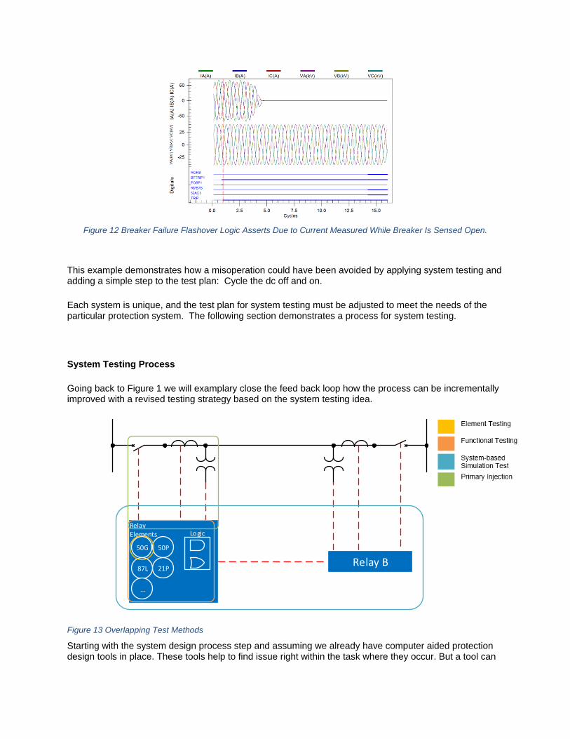
Figure 12 Breaker Failure Flashover Logic Asserts Due to Current Measured While Breaker Is Sensed Open.
This example demonstrates how a misoperation could have been avoided by applying system testing and adding a simple step to the test plan: Cycle the dc off and on.
Each system is unique, and the test plan for system testing must be adjusted to meet the needs of the particular protection system. The following section demonstrates a process for system testing.
System Testing Process
Going back to Figure 1 we will examplary close the feed back loop how the process can be incrementally improved with a revised testing strategy based on the system testing idea.
RelayElements
50G 50P
21P87L
...
Logic
Relay B
Figure 13 Overlapping Test Methods
Starting with the system design process step and assuming we already have computer aided protection design tools in place. These tools help to find issue right within the task where they occur. But a tool can
only be as good as the data fed into the model. Therefore it is important that this data gets peer reviewed and that the commissioning technician can give feedback if necessary e.g. about differences in nameplate data, relay panel wirings etc. Otherwise the design process can greatly support system testing by providing power system data and fault scenarios to the technicians in the field. The fault scenarios can also be extended by the technician.
During commissioning the most extensive testing is applied. We assume that wiring checks of the relay panels are already done. Figure 13 shows an example of a protection system to commission. Each box is showing roughly what is covered and how the tests methods overlap each other. The test plan should follow a systematic order. Visually speaking starting with a small box and expanding it over the system. If system-based simulation test for a fault on the protected object fails, it only gives you the information that the relays haven’t tripped. But within the protection system more than 20 element plus logic could or simple test set wiring error could be responsible for failing. This makes troubleshooting challenging. That is why it makes sense from a systematic standpoint to run a kind of element test with some restrictions - changes to the relay settings or routing to test contacts must be avoided. This sometimes requires a mind shift in how to test a relay. Instead of driving accessing the element directly the technician has to think from an application standpoint of view and think about what is the idea behind using that element or function. Instead of disabling the distance protection function to test an overcurrent backup function only one voltage phase has to drop to zero as this is indicating a voltage transformer fuse has fallen. This will disable the distance protection function and as planned the backup function will take over. This tests objective is to prove the relay is working according to its settings.
To prove that the relay settings and logic work properly with the real protection system is the objective of the system-based simulation test. This was already discussed in previous chapters. In Figure 13 this test is also serving as end-to-end test. When planning the usage of a system-based simulation test on a project, it is important to assess the benefit-cost ratio correctly. The biggest effort lies in the setup when testing a protection system consisting of multiple relays as this requires to setup a similar amount of test sets. Therefore it is important to choose a sensible size for a system-based simulation test. Instead of testing the whole substation a test can focus on the line, transformer and busbar protection separately. The test preparation of the fault scenarios or test cases is opposed to the initial conception very fast. After the power system is setup (with 10-20 parameters for a power system like in Figure 13) every test case is only placing a fault, changing load flows or changing breaker states. The biggest weakness of a simulation test is that its quality depends on the power system data for the model. Peer review in the design are definitely increasing the data quality. Other improvements would be to get as much information from the field e.g. transformer nameplate data or a line impedance measurement. Also worth considering is to use a system-based simulation test as an acceptance test when parts of the protection process are outsourced.
Finally before the protection system goes into operation, the connection between the protection and AC system can be covered in a few tests. A trip test that is operating the real circuit breaker ensures the connection to the trip coil. A primary injection into the current transformer proves that the CT circuit is closed, not shorted and polarity is correctly handled.
The operation process is only considered with maintenance testing. To rephrase it once more – changing settings on a commissioned relay must be avoided. Again the attitude to maintenance test the system instead of just a relay can reduce misoperations. With more and more electromechanical and solid state relays being replaced in the future maintenance cycle will extend. On the other hand the growing amount of distributed energy resources require constant network updates, which lead to regular protection system re-commissioning. A maintenance test being based on the most up-to-date power system data can double check if the protection system is still appropriate or has to be re-commissioned.

Field Test experiences with System Testing
While system testing is foremost a state of mind we also suggested system-based simulation test as a tool that could add great value for a lot of applications. We want to share some experiences of utilities that are already using system-based simulation tests with great success. Although widely usable the most common applications for this novel test approach are at the moment:
Multi-end-to-end testing
Busbar protection testing
Distribution loop scheme testing
The test setup in Figure 14 was intended to test the protection of a three terminal line. This topology was only intended to be in operation for half a year while the transmission line usually connecting the power plant (in substation C) was disassembled and upgraded to reduce contingency. The protection system at each end consists of:
Main 1 relay with differential and distance protection
Main 2 relay with distance protection and permissive overreach transfer tripping (POTT) scheme
Both relays have separate CT circuits but shared one VT so it was possible to connect both to a six phase test set, each synchronized with a GPS/PTP grandmaster clock. Each test set was connected with one PC, which were connected to the internet communicating via a cloud connection. Thus it was possible to control all test set from one master PC while the other PCs were acting as a proxy. This enabled the utility to add and change test cases on site opposed to preparing three sequencer files and send them out to each substation.
Substation A Substation B
System-basedSimulation Test
Proxy
Relay A
Relay C
Substation C
Relay B
Proxy
Cloud internetconnection
Test set Test set
Test set
Figure 14 Test setup for a three-terminal line protection
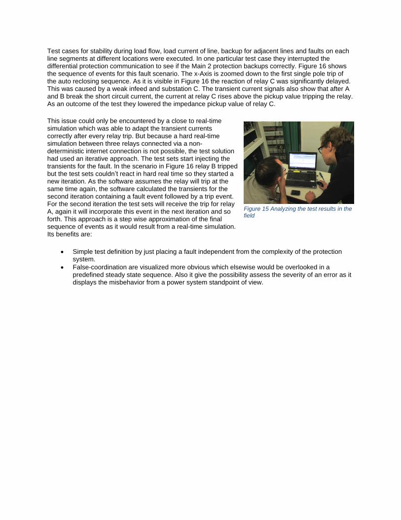
Test cases for stability during load flow, load current of line, backup for adjacent lines and faults on each line segments at different locations were executed. In one particular test case they interrupted the differential protection communication to see if the Main 2 protection backups correctly. Figure 16 shows the sequence of events for this fault scenario. The x-Axis is zoomed down to the first single pole trip of the auto reclosing sequence. As it is visible in Figure 16 the reaction of relay C was significantly delayed. This was caused by a weak infeed and substation C. The transient current signals also show that after A and B break the short circuit current, the current at relay C rises above the pickup value tripping the relay. As an outcome of the test they lowered the impedance pickup value of relay C.
This issue could only be encountered by a close to real-time simulation which was able to adapt the transient currents correctly after every relay trip. But because a hard real-time simulation between three relays connected via a non-deterministic internet connection is not possible, the test solution had used an iterative approach. The test sets start injecting the transients for the fault. In the scenario in Figure 16 relay B tripped but the test sets couldn’t react in hard real time so they started a new iteration. As the software assumes the relay will trip at the same time again, the software calculated the transients for the second iteration containing a fault event followed by a trip event. For the second iteration the test sets will receive the trip for relay A, again it will incorporate this event in the next iteration and so forth. This approach is a step wise approximation of the final sequence of events as it would result from a real-time simulation. Its benefits are:
Simple test definition by just placing a fault independent from the complexity of the protection system.
False-coordination are visualized more obvious which elsewise would be overlooked in a predefined steady state sequence. Also it give the possibility assess the severity of an error as it displays the misbehavior from a power system standpoint of view.
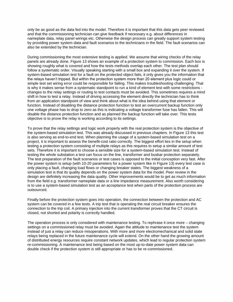
Figure 15 Analyzing the test results in the field
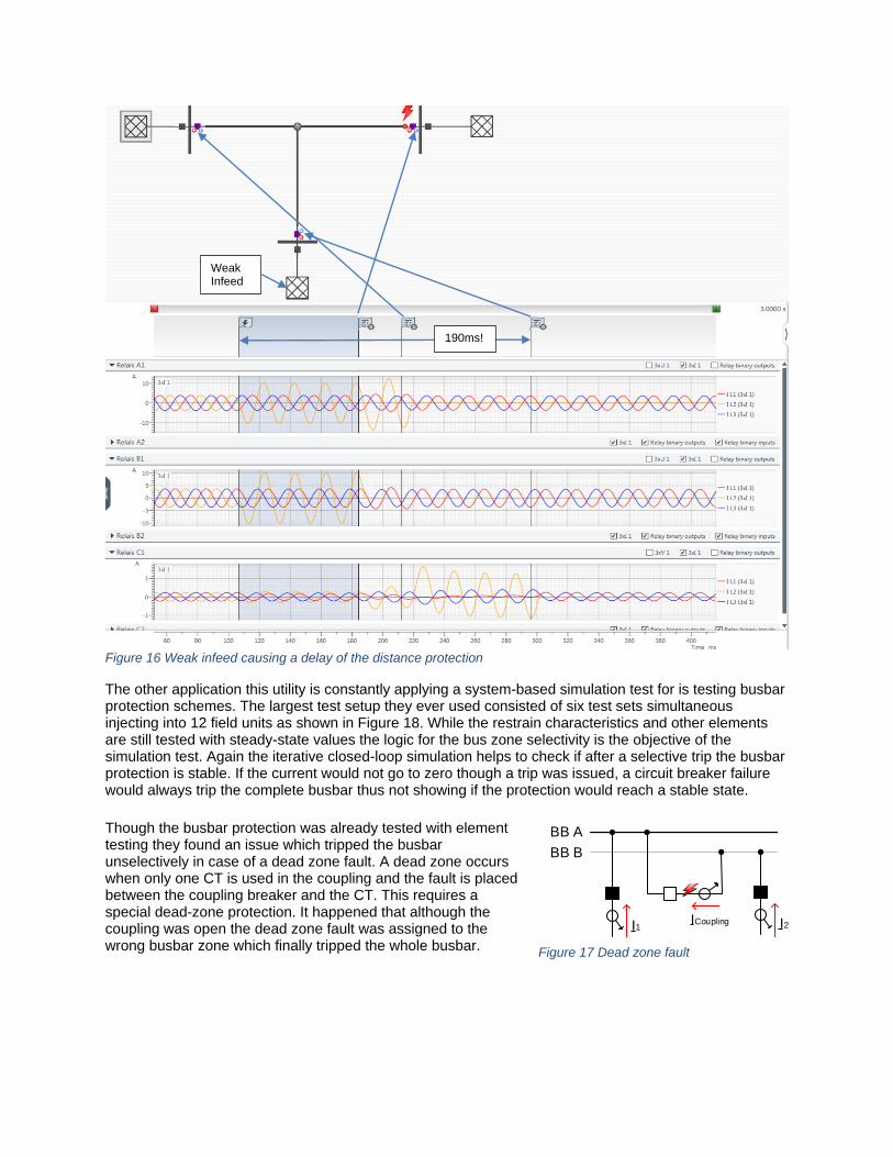
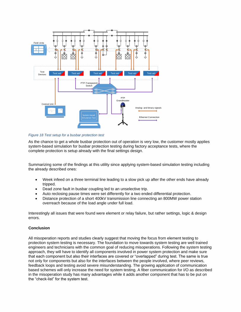
The other application this utility is constantly applying a system-based simulation test for is testing busbar protection schemes. The largest test setup they ever used consisted of six test sets simultaneous injecting into 12 field units as shown in Figure 18. While the restrain characteristics and other elements are still tested with steady-state values the logic for the bus zone selectivity is the objective of the simulation test. Again the iterative closed-loop simulation helps to check if after a selective trip the busbar protection is stable. If the current would not go to zero though a trip was issued, a circuit breaker failure would always trip the complete busbar thus not showing if the protection would reach a stable state.
Though the busbar protection was already tested with element testing they found an issue which tripped the busbar unselectively in case of a dead zone fault. A dead zone occurs when only one CT is used in the coupling and the fault is placed between the coupling breaker and the CT. This requires a special dead-zone protection. It happened that although the coupling was open the dead zone fault was assigned to the wrong busbar zone which finally tripped the whole busbar.
190ms!
Weak Infeed
Figure 16 Weak infeed causing a delay of the distance protection
BB A
BB B
I1 I2 ICoupling
Figure 17 Dead zone fault
System-basedSimulation Test
Field Units
Test
Devices
Central Unit
PTP
Grandmaster
PTP-Transparent
Switch
Analog- and binary signals
Ethernet Connection
Test set Test setTest setTest setTest set Test set
Figure 18 Test setup for a busbar protection test
As the chance to get a whole busbar protection out of operation is very low, the customer mostly applies system-based simulation for busbar protection testing during factory acceptance tests, where the complete protection is setup already with the final settings design.
Summarizing some of the findings at this utility since applying system-based simulation testing including the already described ones:
Week infeed on a three terminal line leading to a slow pick up after the other ends have already tripped.
Dead zone fault in busbar coupling led to an unselective trip.
Auto reclosing pause times were set differently for a two ended differential protection.
Distance protection of a short 400kV transmission line connecting an 800MW power station overreach because of the load angle under full load.
Interestingly all issues that were found were element or relay failure, but rather settings, logic & design errors.
Conclusion
All misoperation reports and studies clearly suggest that moving the focus from element testing to protection system testing is necessary. The foundation to move towards system testing are well trained engineers and technicians with the common goal of reducing misoperations. Following the system testing approach, they will have to identify all components involved in power system protection and make sure that each component but also their interfaces are covered or “overlapped” during test. The same is true not only for components but also for the interfaces between the people involved, where peer reviews, feedback loops and testing avoid severe misunderstanding. The growing application of communication based schemes will only increase the need for system testing. A fiber communication for I/O as described in the misoperation study has many advantages while it adds another component that has to be put on the “check-list” for the system test.

Additionally a system-based simulation tool can support system testing. While running system-based simulation test in the lab or factory is an important step, the field experiences showed that modern tooling makes this tool usable in the field, uncovering design, settings and logic errors, but also relay and communication path failures.
Protection testing is still indispensable or becoming even more important. But its focus has to move away from only element testing towards protection system testing.
References
[1] Protection System Misoperations Task Force, "Misoperations Report," North American Electric Reliability Corperation (NERC), Atlana, 2013.
[2] K. Zimmerman and D. Costello, "How Disruption in DC and Communications Circuits Can Affect Protection," in Proceedings of the 68th Anual Western Protective Relay Engineers, College Station, TX, 2015.
[3] D. Costello, "Reinventing the Relationship Between Operators and Regulators," in Proceedings of the 68th Annual Conference for Protective Relay Engineers, College Station, TX, 2015.
[4] N. S. PRC-005-2, "Protection System Maintenance," NERC, 2012.
[5] K. Zimmerman, "Commissioning of Protective Relay Systems," in Proceedings of the 34th Anual Western Protective Relay Conference, Spokane, 2007.
[6] K. Zimmerman and D. Costello, "Lessons learned from Commissioning Protective Relay Systems," in Proceedings of the 36th Anual Western Protective Relay Conference, Spokane, 2009.
[7] E. O. Schweitzer, III, D. Whitehead, H. J. Altuve Ferrer, D. A. Tziouvaras, D. A. Costello and D. Sánchez Escobedo, "Line Protection: Redundancy, Reliability, and Affordability," in Proceedings of the 37th Anual Western Protective Relay Conference, Spokane, 2010.
[8] TC 95 - Measuring relays and protection, "Measuring relays and protection equipment - Part 121: Functional requirements for distance protection," International Electrotechnical Commission, 2014.
[9] K. Zimmerman, "Advanced Event Analysis Tutorial Part 2: Answer Key," available at www.selinc.com, 2013.