modeling the concord stage coach - model expo · the abbot downing company employed leather strap...
TRANSCRIPT

1
Modeling the Concord Stage Coach Circa 1850
Design, plans, instructions, and prototype model by Bob Crane Technical Characteristics: Scale: 1” = 12” (1:12) • Overall length: 13 ¾” • Height: 8 ¾” The stagecoach is as much a part of the lore and romance of the “old west” as the horse and cowboy. Built almost entirely by hand at the Abbot Downing company in Concord, New Hampshire, more than 3500 of these coaches were shipped all over the world. The first Concord stagecoach was built in 1827. Costing $1200 - $1500, these coaches weighed more than two thousand pounds. The Abbot Downing Company employed leather strap braces, called thorough braces, under their stagecoach bodies which gave a swinging motion instead of the jolting up and down of a spring suspension. This was not for the comfort of the passengers but rather as shock absorbers for the team of six horses. The company manufactured over 40 different types of carriages and wagons at the wagon factory in Concord, New Hampshire. They continued to manufacture coaches, wagons, and carriages under that company's name until 1919. The Abbot-Downing Company employed about 300 people.
Each coach was given a number by the Abbot-Downing factory. The Concord Coaches had a reputation for being sturdy and reliable. At the front and back of the stagecoach were leather 'boots' where baggage, mail and
valuables were stored during the journey, with the remainder of the luggage being placed on top of the coach. Sometimes, even passengers sat atop the coach, but most chose to endure the rugged trip inside, if it wasn't too crowded. If it was, a single stagecoach would hold nine passengers inside, and a dozen or more on the roof. The windows of a stagecoach had leather roll-down curtains, and three leather-covered seats that offered little legroom. Most travelers had about fifteen inches to squeeze themselves into if the coach carried a capacity of nine passengers. The ones stuck in the middle usually had the worst of it, because there was no back support. Instead, they had to hold onto leather straps that hung from the ceiling. The average speed was only eight miles an hour.
In 1868 a trainload of thirty coaches with two carloads of harness was shipped to Wells Fargo and Co. in Omaha. These larger Concords, built for the West, weighed about 2500 pounds and carried nine passengers inside and as many more crowded on top. More than half a ton of baggage and express cargo could be loaded in the front and rear boots. During the Civil War, when

2
sectional tensions were tearing the United States apart, stagecoaches provided regular transportation and communication between St. Louis, Missouri in the East and San Francisco, California in the West.
Although the Pony Express is often credited with being the first fast mail line across the North American continent from the Missouri River to the Pacific Coast, the Butterfield Stage predated the Pony Express by nearly three years. Butterfield Overland Stage began rolling on September 15, 1858, when the twice-weekly mail service began. A Butterfield Overland Concord Stagecoach was started in San Francisco and another Overland Stage in Tipton, Missouri where they ran over the better roads. Each run encompassed 2,812 miles and had to be completed in 25 days or less in order to qualify for the $600,000 government grant for mail service.
The last American chapter in the use of the stage coaches took place between 1890 and about 1915. In the end, it was the motor bus, not the train that caused the final disuse of these horse-drawn vehicles. After the main railroad lines were established, it was frequently not practical to go to a place of higher elevation by rail lines if the distance was short. By 1918 stage coaches were only operating in a few mountain resorts or western National Parks as part of the "old west" romance for tourists. Before you Begin
The model kit was designed to be as faithful to historical stagecoach construction and detailing as reasonably possible. Research revealed a wealth of detail from reliable sources including the Smithsonian Institute and the Oregon Historical Society Research Library. There was a great deal of hand forged ironwork on these coaches which in a model might be beyond the ability of all but experienced modelers to create. We have included most of this ironwork in the form of Britannia metal castings and laser cut sheet material requiring only drilling and some shaping to add these essential details to the model. While it is possible to build the model omitting many of these details, we encourage you to include them resulting in a model that is as close to an historical stagecoach as possible. The results will be rewarding. Working With the Plans and Parts Before starting the model, carefully examine the kit and study the plans. First, locate all the parts as listed in the parts list. Handling the parts will produce a better understanding of the kit’s requirements. Try to visualize how each piece will look on the completed model. Study the building sequence on the plans and in the manual. While it is not strictly necessary to follow an exact sequence and in fact some parts of the model may be constructed simultaneously with other parts, for example, the coach body and the undercarriage, but keeping the sequence described will keep you out of trouble. A thorough knowledge of the plans and parts is essential.
1. The Plans Four plan sheets are provided. Many drawings on the plans are done in an isometric format illustrating the construction sequence and identifying the parts and their placement. Additional sheets identify the parts layout on the laser cut boards, the photo etched brass parts, and the Britannia castings. Another sheet contains patterns and templates that can be cut out for various items of construction without cutting up the plan sheets. 2. Making Allowances Along the Way Try to be exact when following the plans and instructions, but use common sense. Adjustments may be necessary to compensate for small differences in how your model is shaping up. Perhaps a bit of shaving here, a little shim there, a little filler there, etc., will alleviate any annoyances. Use logic and do not fret over exactness. An old saying in the building craft is that “if it looks right, it is right.” 3. Kit Lumber Strips, laser cut sheets of basswood and plywood, and dowels are supplied in the kit. The laser cut boards are labeled SC-1 through SC-11. Sorting the wood in the kit by dimension will save time. After selecting and cutting what you need, return the remaining stock to the proper dimension pile. Don’t worry about using a piece for one item intended for another. Model Trailways supplies enough extra wood to complete the model before running out. 4. Britannia Metal Parts There are quite a few Britannia fittings in this kit, many small parts and the large wheel castings. First, remove mold joint flash with a #11 hobby blade, then file or sand with fine sandpaper. Second, wash the parts in dishwashing liquid and warm water to remove traces of mold release agent and the body oils your fingers deposit. Allow the parts to dry thoroughly before applying primer and painting. 5. Other Materials In the course of designing the kit much effort was expended to find suitable real leather at the proper scale and finish to suit the model. It was found that thin leather is not available except in finishes unsuited and backed by fabric materials rendering them useless for out purposes. The thinnest natural leather available was too thick for our scale. A substitute material at the proper scale thickness and a very realistic leather appearance was found in a vegetable fiber gasket material. This material is approximately 1/64” thick which scales to 3/16” thickness, just right for our model. The thorough brace strips, front and rear boots, leather curtains, and leather strapping are cut from this material.

3
There are many iron parts on a stagecoach made from iron plate. At the correct scale thickness much of this iron is too thick to be made by photoetching brass and difficult for the modeler to fabricate from brass strip stock. A solution was found in another type of gasket material. This material is 1/32” thick, dark gray in color, and looks like forged iron plate. It can be laser cut, bends easily, and glues nicely. Another feature is that if you should decide to finish your model naturally and not painted it will appear to be iron. In the instructions and on the plans we will refer to this material simply as “iron”. This material is found as laser cut sheet SC-11. Glues White or woodworker’s glue in yellow or tan will suffice for most of the model. Five-minute epoxy provides extra strength for some cases. Super glues, such as Jet, Flash, or Zap, produce quick adhesion. For most applications, the medium viscosity, gap-filling variety is best. For some applications the gel type works best. The thin type is recommended for filling a narrow crack and wicking into laminate joints. The prototype model was built using tan woodworkers glue, gel type CA and an occasional use of epoxy and thin CA.
A word about gluing laser cut parts. Laser cutting burns through the wood and leaves a charred surface. This charred surface does not make good glue joints. It is recommended to lightly sand or scrape away the loose char before gluing. It is not necessary to remove all the char, just what comes off with light sanding or scraping. In most cases simply scraping with a no. 11 blade is sufficient. Clamps Clamps are an essential part of the model building experience. In the full size building arena it is often said, “A builder cannot have too many clamps.” This is true of model building also. There are so many situations in the course of building a model that require a particular type of clamp. The photo below shows a typical collection of clamps that are useful in model building.
Fortunately very few clamps were necessary in the course of building the prototype model.
Working With Brass There is no brass in the kit that cannot be cut with ordinary wire cutting pliers. After cutting smooth the cut edges with a file. Drilling holes in brass with a pin vise is a slow process. It is assumed that the kit builder will have on hand some sort of power drill. Especially handy for a modeler are the cordless tools such as the Dremel brand, readily available and reasonably priced. When drilling a hole to prevent the bit from wandering, mark the spot with a small center punch or awl. Lubricate the bit with light oil and drill slowly to avoid breakage. The brass can become hot, so watch your fingers.
Some brass parts need to be bent to shape. It is important to anneal the brass before attempting to shape it. Most brass that comes in kits and from hobby shops is in what is called a ‘half hard’ state. This makes it stiff and as such it is difficult to bend except for the gentlest of bends. Annealing is the process of heating the brass to a red glow and then quickly quenching it in water. A gas kitchen stove and a cup of water is ideal for this. A propane torch or most any means of obtaining a clean flame will work. Hold one end of the piece with pliers and heat the other end and quench. If necessary reverse ends and do it again. This softens the brass and allows it to be shaped easily. Clean the piece after annealing. It will be noted in the directions as to what parts need to be annealed as we proceed through the construction stages.
With the exception of the luggage rails on the roof, our stagecoach model may be built without soldering brass, but there are options for those who like to or choose to work in metal. In the past, many modelers used pure silver solder to avoid the corrosive qualities of lead in soft solder. Today, most solders are lead free. They’re composed of tin and antimony, or tin and a small amount of silver (3 to 4 %). These solders are strong and melt at approximately 430º F. Consequently, no reason exists to use pure silver solder (melts at 1300º F).
The key to soldering is keeping the brass clean. Lightly sand the piece and use a solvent such as acetone, denatured alcohol or lacquer thinner to remove finger oils. Once the parts are cleaned, don’t touch them. Your fingers will leave greasy spots. Soldering is easy if your work is set up properly. First, immobilize the parts in a fixture or other holding device, then add just enough rosin or acid paste flux to the joint to do the job. Solder flows where flux is applied. Next, heat the joint with a small torch or pencil soldering iron. This sequence is important. The larger the parts, the longer it takes to heat the brass and melt the solder. Remove excess solder with needle files. The joint should look like the real thing, not a big glob of fillets. Painting the Model Beginning this manual with directions on applying finishes may seem strange. Not so! Much time and effort can be saved and more professional results obtained if the finishing process is carried on throughout construction. Proper timing in applying finishes and using masking tape to define painted edges should eliminate unsightly glue

4
marks and splotchy, stained surfaces. Many parts in the kit can and should be pre-finished before assembly. This is much easier to do before assembly than after. If you are not in a hurry to begin construction, think through what kind of finish you like, what parts are going to be exposed, etc. The prototype model was finished in red and yellow with touches of black. This is the color scheme seen in most photographs of coach reconstructions. The prototype model was painted entirely with aerosol spray cans with occasional touch ups by brush. We will address the finishing of individual parts as we proceed through the construction sequence. Take advantage of these general suggestions: Sanding and cleaning: Rub down external surfaces with 220 grit sandpaper, and then wipe off every speck of dust. Give surfaces to be painted two light coats of primer and sand lightly after the last application. You may find fine steel wool helpful as it doesn’t load up with paint as sandpaper does. Don’t sand down to bare wood. After washing your hands, gently dust the hull with a soft brush and clean, soft cloth or tack rag. Use a spackling compound, such as Model Magic, Zar, DAP, or Elmer’s wood filler to fill any scratches and defects, then sand and prime again. Choosing paint: Glossy surfaces are not desirable on models. A flat finish or one with a slight sheen is best, because it doesn’t reflect daylight or artificial lights. Consequently, details show up better. However, the undercoat or primer should be dead flat. A primer gives the surface a little tooth and helps top coats adhere better. A quick finish procedure for basswood parts is to spray them where possible with common aerosol primers, then steel wool with 0000 steel wool, this fills and smoothes the surface for painting. Any of the hobby paints are satisfactory such as Model Shipways, Testors, Humbrol, and Tamiya. Jo Sonja artists’ paints (used by bird carvers) are also acceptable. They are a combination acrylic-gouache and dry dead flat. Hobby paints have a variety of reflectance levels from flat to gloss. When using a mixed group of reflectance levels, finish the completed model with a flat, clear coat. It also provides durability and seals any decals or dry transfer lettering. Brush painting: Painting with fine, soft bristle brushes is probably best for the beginner. Many skilled model makers prefer the brushed-on technique, because its subtle imperfections impart a more lifelike appearance to the model. Brushes must be soft and of the highest quality. Artist grade sable or synthetics are the best. Use wider brushes for painting broad surfaces. If too narrow, the bristles will cause excessive streaking. When applying paint or stain with a brush, lay down one thin coat in a single stroke, then move to an adjacent area and coat it with a single stroke. Never go back over fresh paint. That will tear up the surface. Wait until it has dried to a hard finish before applying a second coat. Spray painting: Although slightly expensive, a Paasche, Badger, Testors, Revell-Monogram, or similar airbrush will
produce a first-rate job and is worth the investment. Airbrushes are either single action (trigger controls only airflow) or double action (trigger controls air and paint) and easy to use. Spray patterns can vary from thin to about 1/2" wide by either adjusting the needle or installing a different, sealed nozzle. In some brands, paint travels through the airbrush body to the needle. These require disassembling to clean. Other designs bypass the body and bring paint directly to the nozzle. These clean by simply spraying solvent through them.
Paints are either water (acrylic) or solvent based. Solvent-based paints spray best. Acrylics are difficult to spray and must definitely be used with the manufacturer’s special thinner. Thinning water-based paints with water creates surface tension problems, resulting in poor coverage and spray atomization. If a manufacturer's thinner is not available, alcohol can be used as a substitute. Experiment when using acrylics as some modelers have success and others don’t. When using solvent-based paints, work outdoors or equip your shop with a spray booth. These fumes are toxic.
Many brands of aerosol paints produce good results. However, test them on scrap wood before spraying the model. Aerosols put out a lot more paint than an airbrush, so be careful to avoid runs. Spray on several light coats. A tip from the automotive industry is to heat the spray cans a bit which increases the internal pressure and produces a finer spray. Heat only in hot water from your household sink; do NOT use a flame of any kind or boiling water.
Most paint manufacturers have special thinners for their various paint lines. Follow each manufacturer’s recommendations. Mixing brands is not a good idea, because they may not be compatible. Sometimes, however, no other option exists. If so, apply each brand separately and allow to thoroughly dry before adding the next. Always test to make sure the final flat or gloss finish is compatible with the paint it will cover. TIP: If you are painting your model in the color scheme of the prototype model you will note that yellow paints do not cover well. It is best to first paint all parts to be yellow with a coat of flat white. This will likely allow you to achieve a good yellow color in one coat. Masking surfaces: Masking can be a tricky process. Some brands of masking tape are worthless for model work, because they allow paint to seep underneath their edges. For masking fine stripes or straight and curved lines, use a graphic arts tape such as Chart Pak. It comes in widths as fine as 1/64". Chart Pak tapes have superb adhesion and won’t bleed when firmly applied (burnishing is recommended). Scotch Removable Magic Tape is also excellent. Scotch tape has the same, low stick adhesive as its famous Post-It pads. In fact, Post-It tape flags can be used for masking.

5
Stage 1: Building the Undercarriage The undercarriage frame of a stagecoach is an assembly of heavy timbers comprised of 3 long pieces called the reaches, and shaped timbers called the front header and the rear header. The reaches are mortised into the headers with a tenon and securely held together with draw bolts, tie plates and nuts. The headers are reinforced with iron plates and held together with clips, clip plates, bolts and nuts. The headers bear the vertical iron pieces called standards which support the coach body. Reaches: Refer to plan sheet 1. Begin by completing the tenons by carving as shown on plan sheet 1. Carefully trim away to achieve a close fit into the mortises in the front and rear headers. Chamfer the reach corners as shown beginning about 1 inch from each end. Mark the location of the draw bolt holes on each end and drill through with a #55 drill. It is a good idea to drill these holes from both sides to ensure that the entry and exit holes are centered. TIP: Now is the time to finish sand these parts in preparation for painting. Locate the 12 cast Britannia draw bolts (part WP6005) and drill the holes with a #55 bit. It is best to use a sharp pointed object to indent the metal for a start for the drill to keep the drill bit from wandering.
In the days of the stagecoach era most bolts and nuts were square. This was especially true in the coach; wagon, carriage, and farm implement industries. Square nuts at our model scale are not available and are very expensive to manufacture in small quantities. We have solved the problem for the kit by using rod material and escutcheon pins to simulate bolts and providing laser cut square nuts. The nuts are cut from a homogeneous tough material and can be readily glued in place. These are found on laser cut sheet SC-11. Once painted this combination of rod or pin and nut represent scale bolted connections very well. Two nut sizes are provided, one scaled to fit a simulated bolt made from 18 gage escutcheon pins and our draw bolts, and one to fit a simulated bolt of 1/32” diameter. Our draw bolts require the larger of the two nuts.
To make square headed simulated bolts out of escutcheon pins, refer to the detail on plan sheet 1. The brass pins are soft and easily formed into square headed shapes. If you have a sturdy vise with smooth jaws you can squeeze the heads square. It is easy enough to just hold the pin head on a hard smooth surface and tap with a hammer. After forming the head square, file a bit of the roundness off, flattening the head. Make up six of these bolts, insert one through a drawbolt, through the reach and another drawbolt, slip a square nut on and secure with a dab of glue. A gel type CA glue works well for securing square nuts. Snip off the end of the pin and file it square. Repeat for all six ends of the reaches. Now is a good time to point out that the end of the reaches with the laser cut holes is the rear end of the reaches.
Building the Front Header:
Refer to the construction sequence depicted on plan sheet 1. The front header was a heavy wooden beam reinforced by iron plates top and bottom held to the beam with forged iron clips and bolted through clip plates. The header was drilled through for a king pin. This is the pin that allowed the front wheels to turn for steering and bore the pulling load of the coach. Our model header is of ¼” thick basswood. Locate the front header on board SC-2 and prepare by sanding off a bit of the laser char and lightly chamfering the corners all around. TIP: Now is the time to finish sand these parts in preparation for painting. Locate the front header upper and lower iron plates on board SC-11. Glue these in place taking care to accurately center them Drill the three holes as shown with a #55 drill bit. Take care to maintain these holes plumb. It’s best to drill down from the top and up from the bottom using the laser cut holes in the plates to line things up.
Locate the front standard metal castings, parts WP6001 and WP6002. Important: note that the front header standards are shorter than the rear ones. Front and rear standards are shown full size on plan sheet 1 and in various isometric views. These are cast without holes but with a slight indentation to serve as a hole locater and a starter for a drill bit. First drill through the upper ends with a #55 drill bit as shown on plan sheet 1. It is best to drill halfway through from each side to ensure that the exit holes are properly centered. Place a scrap piece of ¼ thick wood between the two legs of the standard and drill the 3 pin holes through one side with a #55 drill bit. Turn over and drill the other side in the same manner. Place the standard on the header and check that the holes line up from front to back. You may have to

6
insert pins and/or run the drill through to achieve alignment. Insert an 18 gauge pin through as shown on plan sheet 1 and snip it off with a bit of protrusion. It is important when riveting to cut off the pin to the proper length. If too long the pin will likely bend and not deform properly. If too short it will not deform and trying to deform it may damage the parts. Place the pin head on a hard surface and lightly tap the end with a small hammer forming a slight rivet. Deform the pin just enough to secure the joint without damaging the parts. If you are not comfortable with riveting you can also snip off the pins a bit long, file the ends square and glue on a square nut or simply cut them off near flush and use a bit of CA glue wicked into the joint. Complete all the rivets.
With the standards installed the clips, clip plates and nuts are next. We have provided two methods of making clips. There are quite a few clips on the model. For those who are comfortable with soldering and prefer to work in metal, photoetched brass clips and plates have been provided. Cut off over long lengths of 1/32” dia. brass rod. They will be trimmed to correct length later. Solder two lengths of 1/32 dia. brass rod to each clip as shown. A good way to do this is to use paste flux to stick the rod in place then clip off and place a short bit of wire solder on each side of the rod. Then heat the metal, not the solder, with a soldering iron or micro torch till the solder flows. Of course you need to do this on a suitable surface such as a thermo insulating sheet sold for this purpose or some type of masonry. Once the soldering is complete bend the clips to shape. Note that very small indentations have been etched into the clips at the bend points to guide the bends.
If you are uncomfortable with soldering another method is available to you. Patterns for clips are provided on a separate sheet. Common manila file folder material or card stock is about the same thickness as the 0.010 brass. Cut out the appropriate patterns for the clips you are working with and glue the patterns to the card stock. Cut out the clips to the outline. Ordinary carpenters glue can be used to attach the bolts/rods. Use a small puddle of glue, dip one end of the rod in glue and carefully place and position the rod on the clip. Let this dry completely. Then using a fine tipped glue applicator run a bead of glue along each side of the rod and over the top completely encasing the rod in glue. The glue will shrink and dry to look like a weld or solder fillet. Then make the bends using the lines on the pattern as a guide. Note that there is a right and left clip bent at a slight angle to compensate for the angled lower surface of the header beam. When painted they will look identical to soldered brass. All clips on the prototype model were made in this manner.
Glue the clips in place on the header and then glue on the 1/32 plywood clip plates and square nuts. Building the Rear Header: Refer to the construction sequence on plan sheet 1. The rear header is constructed just like the front header. The rear header is 3/16” thick. Locate the rear header on board SC-1 and sand off a bit of the laser char and chamfer the corners all around then finish sand the piece.
Glue on the top and bottom iron plates and drill the vertical holes as shown with a #55 drill. Drill all holes and Install the rear header standards (WP6003 and SP6004) just as you did for the front header. Then prepare and install the clips, clip plates, and square nuts. Assembling the frame:
Refer to plan sheet1 and Figure 2A. Insert the three reaches and drawbolts through the front header. It is a bit tricky to get all these bolts started at once. Patience is the key. When you have successfully started the front header bolts start the rear header bolts. With all drawbolts started apply white or carpenters glue to the tenons and push into place. In spite of the mortise and tenon construction it is still possible for the assembly to work out of square. Ensure that all is nicely squared up and let the assembly dry. The six drawbolt tie plates found on board SC-3 and square nuts may now be applied.

7
TIP: There are many situations in model building where a square is required to ensure integrity. Most squares, triangles, etc. will prove to be too large for use. Snip off a suitable size corner from a common 3” x 5” note card and you have an appropriate square for the task at hand. It is appropriate and advisable at this time to finish paint the frame assembly. Locate the brake rod pillow block bottom halves on board SC-4 glue them in place centered on the outboard reaches and butted to the back side of the front header as shown on plan sheet 1. It is best to mask off areas that will become gluing surfaces. Place a strip of masking tape on a suitable surface and using a metal ruler and knife slice off a strip of tape 3/16” wide. Measure and mark the locations of the brace header and the rear axle and apply the masking tape. The location of the brace header is 21/32 aft of the front header as shown on plan sheet 1 and figure 7 herein. Cut small squares of tape and mask the bearing surfaces of the pillow blocks. Finish paint the frame assembly to your desired paint scheme. Now is a good time to make up and install the sway strap anchors from 1/32” brass rod. Refer to plan sheet 2 for their location on the reaches. Building the brace header:
Refer to plan sheet 1 and Figure 3. The brace header was a heavy iron truss work that spanned the reaches and anchored the struts that braced and reinforced the front header. Our model brace header is constructed of brass and wood exactly like the full size stagecoach was made. Begin by locating the upper and lower filler blocks and the false reach blocks on board SC-1. There are two each of the upper and lower filler blocks. One pair is assembled as a construction jig; the other pair is for installation on the model. Glue up the jig as shown on plan sheet 1. The brace header is built on the construction jig and bolted together but not glued. Once complete the structure will be unbolted for later installation on the model. Locate the 1/16 x 3/16 brass bar for the top iron. If the top iron is not supplied pre-cut to length cut and file it to a 4” length. Do not anneal this piece. Mark, center punch and drill the two holes with a #55 drill bit. Cut a length of 1/32 x 3/16 brass to about 5” for the bottom iron. Anneal this piece and drill
a #55 hole in one end. Allow extra length for later trimming. Form the piece with pliers and fingers to the required shape. Bolt one end with the 00-90 hex head bolt supplied. TIP: There are three threaded fasteners in the kit, the two 00-90 bolts and nuts for the brace header, and the M1.2 metric threaded king pin and two nuts. These nuts are very small and have a way of slipping out of your fingers and disappearing. Cut a small square of double sided tape and apply to the end of a dowel or piece of strip stock. Stick a nut to the tape and use this device to start the nut on the threads. When started pull it away. Use the same method when removing a nut. Clamp the two brasses together at the other end and drill through the 1/32 piece then bolt together. Trim the ends flush to the 4” length of the top bar. Leave the bolts long for now; we’ll cut them off later after final installation. Form the u-bolts from 1/32 dia. brass rod and check the fit to the structure as shown in Figure 3 and plan sheet 1. It is helpful to anneal the rod before bending. Leave the u-bolts long for later trimming. On the prototype model the u-bolts were soldered to the bottom iron. Although not necessary it will help to facilitate installation on the frame later. Locate the four u-bolt plates on board SC-3 and fit to the u-bolts but do not glue. The brace header is now ready for installation on the frame, but first we will build the brake mechanism.
Photo 1: Completed Brace Header Building the brake mechanism: Refer to plan sheet 1 and Figure 4. Cut a length of 3/32 dowel to 3 5/16”. Locate the two 1/32 ply brake shaft keepers, the two 1/32 ply brake shaft cranks on board SC-3, and the 1/16” ply brake lever butt plate on board SC-10. Use a piece of 1/8 material scrap to space the keepers on the shaft and glue the keepers to the shaft. It is best to use just a tiny dab of glue to hold them in place and aligned and square to the shaft. When this dries put a fillet of glue all around the shaft. In the same manner measure and mark the location of the cranks referring to the dimensions on plan sheet 1 and glue those to the shaft taking care to align and square them properly.

8
Cut two lengths of 3/32 square stock to a length of 4 3/8”, these are the brake rods. Locate the brass rod ends on the photoetched brass sheet and shape them as shown on plan sheet 1. Note that there are small indentations on these parts indicating the bend lines. Use one of these parts to locate and drill the #72 holes on the fore end. Locate and use the brake beam on board SC-1 to spot and drill the holes in the aft end. Pin and rivet the brass rod ends to the fore end of the brake rod. Pin and rivet the brake rods to the cranks as shown on plan sheet 1. If you are uncomfortable with riveting this delicate part, it is possible to squeeze the protruding end of the pin with pliers to swell it out sufficiently to retain the pin. The brake lever found on board SC-1 may now be shaped and attached. The foot rest at the top of the lever is of photoetched brass and should be pinned in place. Carve a small flat on the lever for its placement. Photo 2 shows the entire assembly pre-finished and ready for installation. Mask off the bottom of the brake rods where they will be later glued to the brake beam and the areas on the brake shaft that will mate with the pillow blocks.
You may want to defer attachment of the brake lever until a later stage. It is very easy to bump the lever during further construction and perhaps damage it. Mask off the gluing surfaces of the lever and the butt plate if you are pre-finishing these parts.
The brake beam can now be assembled as shown on plan sheet 1. Locate the 1/32” ply brake beam wear plates on board SC-3, the brass brake beam keepers, the brake shoes on board SC-2, and the brake beam steps on SC-9. Assemble as shown. Important: note that the brake shoes are not symmetrical, there is a top and bottom. Lay the shoes on the side view of plan sheet 2 to determine how they are to be oriented.
Do not permanently glue the brass brake beam keepers until you have checked them for a free sliding fit on the reaches. Adjust as necessary, the brass can be easily rebent. This assembly may be pre-finished at this time. Mask off the areas that will later receive the brake rods.
Photo 2: Brake system assembly pre-finished
Now is a good time to discuss how fancy we want our coach to look. Many of these coaches were elaborately decorated with pin striping and painted deco. The prototype model was decorated in this fashion. If you choose to do so note that it is much easier to accomplish if you pre-finish parts as you go where possible. Of course, striping cannot be applied until final painting of parts is accomplished. There are striping tapes available in many widths such as Chart Pak brand. The striping on the prototype model was cut from commonly available auto pin striping tape. A length of tape was laid out on a glass plate and strips of appropriate width sliced off with a metal ruler and knife. Other shapes were cut from the same tape by first creating the shape in a cut out stencil made from card stock. Lay this stencil on the tape and cut out the shape.
It should be obvious that the brake beam cannot be attached until the brake system is installed in the frame. Note that in photo 2 the beam is not attached. Set the assembly aside for now and proceed with the rear axle assembly. Building the rear axle assembly: Begin by locating the cast Britannia metal rear axle and the basswood rear axle beam on board SC-1. Sand and clean up the beam and lightly chamfer the top corners. Check the fit of the beam to the curvature of the axle. The Britannia is soft and easily bent. If your axle has somehow deviated from the shape of the beam bend it to conform. TIP: If you have or have access to a 6-32 threading die you can easily thread the axle ends to accept a common 6-32 hex nut (not supplied) that has been filed or ground square. If not, laser cut square nuts to fit the axles are provided on board SC-4. These can simply be glued on at final assembly. If you choose to thread the axles do so now. Hold the axle in a modeling vise and thread the die

9
on by hand. The soft Britannia metal threads easily. Take care not to twist the axle spindles.
Sand the axle mating surface with rough sandpaper and use epoxy glue to attach the axle beam. As with the headers there are two methods of making the clips. Brass clips with soldered bolts or glued up clips from card stock and our iron material. Make up the clips by the method of your choice. The outboard clips are made from card stock, the inboard clips and the reach clips are made from laser cut parts found on board SC-11. If using this method round over the top corners of the axle beam a bit as shown on plan sheet 1. This will prevent the iron material, being thicker, from cracking at the outside of the bend when bent over the beam. Even if it does crack it will look like a welded joint when painted. Filling the crack with a little carpenters glue will help the appearance. All clip plates for the rear axle assembly are located on board SC-3. The outboard and inboard clips, plates, and square nuts may now be glued to the axle. Refer to the full size drawing on plan sheet 1 for location and spacing. Important: Do not clip off the bolt on the rear of the inboard clip or glue on a square nut. The lower rear strut will be attached to this bolt in the next step. Drill into the top of the axle beam at the inboard clip and install the 1/32 brass rod bolts. Make these long for later trimming. Do not glue these yet as they will need to be removed for later installation of the thrust braces. The reach clips and plates are not glued on until the axle assembly is glued to the frame assembly.
Roughen the bottom of the axle with sandpaper. Locate the axle assembly on the frame and mark locations to ensure that the axle assembly is centered. Glue the axle to the frame using epoxy glue. Check for proper location and square. When cured the reach clips, plates, and square nuts may be installed. Rear thrust braces and struts: Locate the rear thrust braces and struts WP6007 and WP 6008, as depicted in figure 6. Make up two square head bolts from 18 gage escutcheon pins. Begin with the upper strut. Note that the two struts are very similar but the upper one is a bit longer. Spot and drill the #66 hole in the forward end. Place this on the pin coming from the inboard clip and bend and form the strut to meet the bolt
hole in the top of the rear header. The struts have a slight S bend in both the vertical and horizontal planes. Spot and drill the #55 hole in the rear end of the strut. If you miss the hole a bit you can adjust the S bends to make it fit. If too long or too short you can also elongate the hole with a needle file.
In like manner drill and fit the lower strut from the rear bolt on the inboard axle clip to the bolt coming down through the rear header. Square nuts can now be glued to the lower strut keeping it in place.
The rear thrust brace is the same casting as the front thrust brace which is longer than the rear thrust brace. Consequently the rear thrust brace must be modified to fit. This amounts to flattening more of the brace lower end, bending to fit, drilling, and trimming off the excess material and rounding the end. Note that there is a slight bend in the U shaped upper end. A small groove at the joint has been designed into the casting allowing this bend to be easily made. Don’t overdo it, the bend is slight. The 1/32 pin/bolt on the axle will have to be removed in order to get the thrust brace properly fitted on top of the upper strut and snugged to the rear standard. When fitted glue in the pin, add a square nut and trim the bolt. Complete both left and right assemblies At this point the entire rear end of the structure may be finish painted. Mask the axle spindles of course. Photo 3 shows the completed assembly, upper and lower struts and thrust brace.

10
Photo 3: Rear struts and thrust braces Installing the brace header and brake system: As the brake rods run through the brace header between the upper and lower filler blocks these parts must be installed at the same time. Locate the second set of brace header filler blocks, upper and lower on board SC-1. It is convenient to finish paint these blocks before installation taking care not to paint the glue surfaces. Glue the lower filler block in place on the reaches 21/32” aft of the front header as shown on plan sheet 1 and figure 7. If you have previously located and masked this position remove the masking and proceed.
Locate the rub bar on board SC-1. Cut a piece of card stock 3/16” wide and 1 1/16” long and glue to the bottom of the rub bar. This is to simulate an iron plate. The rub bar may be finish painted before gluing to the center reach. If you have pre-finished the reaches scrape off enough paint for a good glue bond.
We are now ready to install the brake system assembly. Place the assembly in place on the pillow blocks and check for free operation. The brake shaft is held in place by the pillow block caps. There are 3
methods available to you to make the caps. Refer to sheet 1 and figure 8 below. The preferred method is to flatten a length of common wire solder and form the caps by bending over a piece of 3/32” dowel and shaping as shown. Solder of 1/16” diameter is about right. Solder is comprised of nearly the same elements as Britannia metal. The caps for the prototype model were made by this method.
Another method is to use the iron material caps on board SC-11. Also the cap blocks on board SC-4 may be used. Drill and pin the caps of your choice. Check that the brake shaft rotates freely. Adjust as necessary.
With the brake system assembly in place we can now attach the brake beam to the brake rods and install the two brake beam keepers, parts WP6019. Slide one of the rear wheels on the axle spindle and check for proper brake shoe clearance and operation of the brake system.
The brake system is somewhat fragile and if you wish it to operate take care to see that all parts are freely moving as intended. See that the caps are not too tight and the brake rod rotates freely, the brake beam keepers are not rubbing, etc. Warn your admiring friends not to yank on the brake lever. Front thrust braces, struts, sway braces, and steps: The upper filler block of the brace header may now be glued in place. Remove your brace header parts from the building jig and fit to the frame with loose bolts. Locate the Britannia castings WP6006, WP6007, WP6010, WP6011, and WP6012. With the brace header in place, spot the hole locations in the ends of the struts and drill the holes with a #55 drill. If you don’t quite get the holes perfect they may be elongated to lengthen or shorten with a needle file. TIP: This is a good place to note that if you should mangle a strut beyond repair it can easily be fabricated from 1/16” solid core wire solder. Fit a square head bolt made from an 18 gage pin down through the upper strut, the front header, and through the lower strut as shown in figure 9. With the struts fitted, shape, drill, and fit the thrust brace. Bend the clevis end downward slightly for a good fit to the standard. These

11
parts may now be permanently bolted in place. Repeat for the other end. Drill two holes with a #72 drill and fit the step brackets through the standards. Nail the bracket to the header as shown with 0940 nails. In like manner fit the sway brace and attach to the header with 0940 nails. The clevis of the sway brace is bent downward to fit the standard. Repeat for the other end. Bend the step brackets forward as shown in figure 9 and on plan sheet 1. With pliers twist and bend the flats for the steps into position. The round steps are found on board SC-3. File the gluing surfaces of the brackets flat and glue on the step. Epoxy is recommended here. Alternatively you may want to drill and rivet the steps to the bracket.
Photo 4 shows these completed assemblies after finishing.
Locate the thorough brace couplers on the photoetched brass sheet and remove. Make up 8 square head bolts from 18 gage pins. Test the fit of the bolts through the couplers. It will be noted that there are indentations and protrusions on the pin that may interfere with the fit of the pins through the holes in the couplers. This is a function of how the pins are manufactured. To remove them and obtain a good fit it is easy to chuck the pins in a drill and smooth them with a file. When fitted cut the pins to about a 5/16” length and file the ends square.
Photo 4: Front thrust braces, struts, and steps Install the couplers to front and rear standards with 4 bolts and square nuts. Set the other prepared bolts aside for later installation.
Now is a good time to make up the 4 sand bands. The sand bands were made up from sheet metal. Their purpose was to prevent dust and grit from getting into the space between the axle beam end and the wheel hub thus wearing the axle spindle. Our model sand bands are made from card stock. Refer to plan sheet 1. Locate the sand band patterns on the pattern sheet and glue them to suitable card stock such as manila file folder stock. Roll and form the band in your fingers into a conical shape and glue the tab end to the other end. When dry press the sand band formers found on board SC-3 into the band and apply a bead of glue around the inside of the assembly. The bands will look like the bottom of a round bucket. The bands may be painted and finished at this point. Note that the bands need not be glued to the axle assembly since when the wheels are installed they will hold the bands in place.
This completes the undercarriage as shown in photo 5. If you have pre-finished parts as you went there is little left to do with this assembly but touch up and perhaps some pin striping if you wish.

12
Photo 5: The completed undercarriage Stage 2: Building the Running Gear Front axle assembly: Refer to plan sheet 1. Locate the Britannia front axle and the front axle beam on board SC-1. Check the fit of the beam to the axle and adjust as necessary. Prepare the gluing surfaces of the beam by removing some of the char and sanding the axle to roughen it. Glue the axle to the beam using epoxy glue. Glue the head plate iron to the top of the axle beam taking care to center it. The head plate iron is found on board SC-11. Drill a hole down through the center of the beam and axle with a #55 drill bit. This hole will receive the king bolt which holds the running gear and undercarriage together. Take care to accurately keep the hole on center and at a right angle to the top of the beam. If you don’t have a drill press, use a square to mark a center line on the side of the assembly and across the bottom. Then drill slowly from both top and bottom to assure the exit holes are centered. Work the drill in the hole until it exits both top and bottom on center. Measure and mark the location of the two 1/32” dia. brass bolts on the bottom of the axle. Drill #66 and glue in the bolts. Leave these bolts long for later trimming. These bolts will later receive the bottom strut.
Make up the clips as shown on plan sheet 1 from your choice of brass or card stock. Referring to the full size drawing on plan sheet 1, mark the clips location and glue on the clips. Locate the 1/32” ply front axle clip
plates on board SC-3 and glue in place. Note the outboard clip protrudes forward and has a hole for later attachment of a strap. Glue on square nuts except at the forward bolt of the middle clip. This bolt is left long and will later receive one end of the side strut as shown on plan sheet 2. Running gear assembly:
Locate the parts, top and bottom turn plates, and front and rear hound irons, on board SC-3. Locate the swing bar on board SC-4 and the double tree top bearing on board SC-11. The hounds are on board SC-1. Prepare the hounds and swing bar by removing the char and sanding smooth rounding the corners a bit. Especially remove the char in the square hole in the axle beam that receive the hounds. Clip off two lengths of 1/32” dia. rod for the swing bar attachment bolts. Note that these must be long enough to protrude through the hounds and will receive a strut and square nut.

13
Now dry fit the assembly. Insert the hounds through the axle beam ensuring that you have the front of the beam facing forward. Insert the 1/32” dia. rods through the swing bar and through the hounds. Place the front and rear hound irons and pass an 18 gage pin through them. When all looks fit and square slide the axle rearward slightly exposing the gluing surfaces the hounds. Apply glue to the hounds and re-position the axle beam in place. Ensure all is correctly fitted and squared up and allow the assembly to dry.
The swing bar and all plates may now be glued in place. The turn plate is secured by four 1/32” dia. rods, flush on the top and with square nuts on the bottom. Other plates are fastened with 18 gage square head bolts as shown on plan sheet 2 and figure 11. Do not clip off or install a square nut on the rear hound iron and the swing bar bolts as the bottom struts will be attached there. The swing bar wear plate pattern is found on the pattern sheet. Glue to card stock, cut out and apply to the top of the swing bar.
Locate the struts, Britannia castings, WP6013 hound truss bottom, and WP6014 hound truss side. Refer to plan sheet 2 and figure 11. Begin with the bottom trusses. Spot and drill as #55 hole in the front pad of the trusses. Fit to the rear hound iron bolt then twist and bend the truss to proper shape to lay on the bottom of the axle and then to the swing bar bolts as shown. Drill #66 holes for these two bolts. As before if you miss the hole location slightly the holes may be elongated with a needle file. With the two bottom trusses fitted install appropriate square nuts.
Twist and bend the side struts to proper shape. Locate and drill three #66 holes through the front portion of the strut. Locate these holes so as not to interfere with existing bolts. Cut pieces of 1/32” dia. rod as shown and glue through the strut to the holes. The other end of the strut attaches to the front bolt of the middle clip on the axle beam. Glue on all remaining square nuts, clip the bolts to an appropriate length and file the ends square. This completes the Running gear and the assembly may now be finish painted.
Photo6: Running gear, top view

14
Photo 7: Running gear, bottom view
Double tree and single trees: The double tree is found on board SC-1 and the single trees are on board SC-2. Refer to plan sheet 2. Prepare the double tree by sanding smooth and chamfering the corners a bit as shown. Locate the brass wear plates and the double tree irons, WP60176 castings. Position the upper and lower wear plates, align with pins and an 18 gage square head bolt and glue in place. It is not necessary to pin these plates but if you do, remember the bottom of the pins must be flush with the plate. In full size practice these bolts were flatheads. Position and glue the double tree irons in place. This will hold them in place while drilling for the rivets or you may choose not to rivet them.
The single trees are laser cut with a taper on one side. First taper the other sides forming a square uniform taper as shown on plan sheet 2. Carve and sand to a round cross section. The iron fittings are formed from annealed 1/32” dia brass rod. The iron bands around the ends are made from black photo mounting paper or painted card stock. Drill and fit the u-bolt iron but do not glue as these must be attached to the front of the double tree irons. After finishing attach the single trees to the double tree as shown.
Photo 8: Double tree and single trees Making the thorough braces: The thorough braces upon which the coach body rests were heavy leather straps. The ideal leather was about ¼” thick. Since hides are about 7 to 8 feet in length it was necessary to skive (beveled joint) and sew 3 or more pieces together to form a loop of the required length. Depending on the thickness of the leather 7 to 10 of these individual loops were required per thorough brace. The
loops were made on the bench looping the leather around bolts set at the required distance apart, the innermost loop being the shortest and the outermost being the longest. Imagine the work!
We will simplify the making of our model thorough braces by using a single continuous wrap with simple glued butt joints. As before mentioned, real leather at our scale thickness was found to be not available. A very realistic substitute is a vegetable fiber gasket material which has the appearance of leather, is strong, and is about the right scale thickness and color. Herein we will just refer to it as leather. A piece of this material 7 1/2” by 36” is provided in your kit. We will need to cut 10 strips of this material 3/16” wide and 36” long. Each thorough brace will require 5 of these strips.
Lay the leather on a suitable cutting surface and clamp a metal yard stick so as to slice off a 3/16” wide strip with a hobby knife. Cut 10 strips. You may also do this by marking a line and cutting carefully with scissors. (Also used for boot leathers later) TIP: If your leather comes to you in a roll, lay it out on a flat surface. In a few hours or overnight it will lay reasonably flat. On a suitable working surface place 2 nails 7 7/16” apart as shown in figure 12 and plan sheet 2. Small finishing nails are ideal. You may also use the 18 gage pins in your kit.
Wrap the leather around the pins and join with a glued lap joint. White glue or carpenters glue is recommended. Try to keep the wrap as tight as possible and clamp the glue joint. Continue wrapping the strip and glue the end to the underlying layer. Glue the next strip to the first in a butt joint. Continue in like manner until you have completed all five strips ending in a glued joint. Tie the strips together with a couple of loops of thread around the bundle to prevent them from coming apart when handling. Remove the thorough brace from the pins and repeat for the second thorough brace. TIP: The leather material will hold a shape if wetted and held in a desired configuration and allowed to dry. The

15
final shape of the thorough braces is to conform to the bottom of the coach body and reach to the couplers. This shape can be encouraged by wetting the thorough brace bundle (wet and pat dry, do not soak) and forcing it against a form of the proper shape. Space two nails 7 3/16 apart on a suitable surface. Place the wetted thorough brace on the nails and push the coach body building jig, which has the same shape as the coach body, against the bundle forcing it to take the shape of the jig. Secure by tack nailing the jig or use suitable clamps. Allow this to dry overnight. Repeat for the other thorough brace bundle. Photo 9 shows the completed thorough braces that have been shaped. Photo 10 shows the method described.
Photo 9: Completed thorough braces
Photo 10: Method of shaping the thorough braces. For the prototype model it was thought that the leather would look more realistic if it was a darker color. This was accomplished by using a wash of acrylic burnt umber thinned with water. Stage 3: Assembly of Running Gear, Under Carriage, and Wheels With these parts finished you may be anxious to see what it all looks like when assembled and with wheels. So let’s build and finish the wheels.
The wheels are built much like the originals were except for modifications to suit modeling needs. The hubs are turned Aluminum and the wheels and spokes are laser cut. These parts are on boards SC12 and SC13. A
separate illustrated instruction sheet is included detailing the construction of the wheels.
The wheels for the prototype model were finished with aerosol spray paints. If following the prototype color scheme our wheels will by yellow. Spray on a coat of primer. If painting yellow use a white primer. If white primer is not available use any color, then follow with a coat of flat white before yellow. As before mentioned, yellow paint does not cover well. The white undercoat will give you a good yellow color in one coat.
The fancy work paint striping on the prototype wheels was achieved with Sharpie fine point and ultra fine point markers. A template with cutouts for the pens to locate against was used. The patterns for these templates are on the pattern sheet supplied. Glue these to poster board like material and carefully cut them out. Important: If you try to use the template as is you will likely find that the ink can bleed under the template ruining your work. The template must be raised slightly above the piece so that the working edge does not contact the piece. To accomplish this cut and glue scrap pieces of the poster board stock on the back side of the template slightly away from the working edges as shown in figure 13.
Place the template on the wheel as shown in photo 11 and first draw the chevron figure between each adjacent pair of spokes. Align the edges of the template just above the chevron cutout to the centers of the spokes. This will become clear when you try it. Allow each drawing to dry a few seconds before moving the template. When all the chevrons have been completed use the other end of the template to create the heavier black line in the center of the chevron figure. Finally, use the large circle to draw the black band across the spokes. TIP: Depending on the markers used note that if you overspray with a clear the ink may run and spoil your hard work. A very light spray will work but if the coat is too heavy it could cause trouble.

16
Photo 11: Fancy work template on the wheel
With the fancy work finished we can apply the iron bands to the outboard ends of the hubs. The iron bands are cut from black photo mount paper or you may use painted card stock. The bands are approximately 1/10 of an inch wide. CA gel glue was used on the prototype.
The finishing touch to the wheels is applying the tires. Wheels were made of many parts, hub, spokes and felloes. All were held tightly together with the iron ring called the tire. The tire was welded together in a ring whose diameter was slightly smaller than the wheel. The tire was them heated red hot in a fire to expand it, slipped over the wheel and then quenched with water. The tire shrinks and squeezes all the parts of the wheel together. Our tires are laser cut bands found on board SC-11. Use rough sandpaper to remove paint from the wheel rims and roughen the surface. Glue the tires on with gel type CA glue. A nice touch that adds realism is to use one of the rubbing type metallic finishes to give the tire a metallic sheen where the tire meets the road.
Now let’s put it all together at least temporarily and admire our work. If you have not installed the thorough braces you can do this now. Do not install permanently at this point, more on this later. Locate the king pin and two hex nuts and washers in your hardware pack. Thread a nut on one end of the pin and pass the bolt through a washer and the undercarriage and the running gear. Slide the sand bands on the axles and then the wheels. It is not necessary to glue the sand bands to the axles as the wheels will hold them in place. Admire your work then take it all apart again.
Photo 13: Assembled undercarriage and running gear

17
Stage 4: Building the stagecoach body Concord stagecoach bodies were built in the finest traditions and methods of fine joinery and craftsmanship. The frame of the sides was shaped and joined in the style of vertical curved members called stiles and horizontal curved members called rails. The sides of the bodies curved gracefully outward in a compound curvature. This bowed outward appearance is remindful of a classic chest style called bombe’. The side frames were covered with wood paneling in sections and the joints were covered with shaped molding. The front and rear lower quarter panels being the most pronounced in compound curvature
were carved from a solid block of wood, first shaping the outside, and then hollowing out the inside to yield a panel of the proper thickness. Our model accomplishes this effect by using thin plywood which will conform to the curvature required. Before we begin construction it is important to note that the coach sides are symmetrical with the exception of the differences required by the doors. The aft bottom corners of the doors are truncated. Refer to figure 17 and the plan sheets. This truncation was required for the door corners not to interfere with the rear wheel when opened. In addition the doors hinge on the forward side of the door frame. Study figure 17 and get this difference clearly in mind.

18
Building the coach side framework: A building jig is provided to ensure the accuracy of the body side construction. Locate the jig and the coach body frames on board SC-5. The body frames are identical. We will begin with the left side and this side will be shown in the figures herein. Locate the parts labeled A DOOR JAMB LEFT SIDE, A, two parts B, two parts C, and part D COACH SIDE TOP RAIL. Note where these parts will be glued and clean the gluing surfaces of char. Cover the jig with waxed paper or film wrap and tack nail the frame to it aligning with the laser engraved outline on the jig. Before proceeding it is advisable to cut out the hinge mortises on part A DOOR JAMB LEFT SIDE. Refer to figure 18.
The door jamb parts have a laser engraved line defining the mortises. Cut the mortises about 1/32” deep. Test fit a hinge and adjust the depth so that the hinge is flush with the surface of the jamb. Later we can adjust the mortise depth when the doors are fitted if necessary. For now we want to accomplish the majority of cutting the mortises while the jamb is easily accessible.
Note that all the vertical stile parts, A, B, C, and D have a lower extension that will be later removed. The purpose of this is to ensure that the frame parts are installed at the proper height above the jig and that they will be sufficiently strong to withstand the fairing process
to be done later. Refer to figure 19 and assemble the coach side parts as shown.
Now fair the structure to conform to the design curvature of the side. Use a sanding block and a strip of 1/16” x 1/8” called a batten to check the progress. Fairing is the process of shaping the edges of the parts and the notches so that they conform to a smooth curve allowing the paneling and rails to lay on the structure with intimate contact. Carefully sand the stiles and frequently check with the batten until you are satisfied with the fairness. Refer to figure 20.

19
Form a small bevel around the frame as shown in figure 20 to provide a gluing surface for the paneling. A laser engraved line is provided on the frame as a guide. Note that the notches which receive the 1/16” x 1/8” basswood strips must also be faired to allow the strips to seat fully. Refer to plan sheet 3 and the full size plan view of the coach body framework for parts identification. Cut a strip of 1/16” x 1/8” basswood to length for the top rail. Scarf the ends as shown to fair the top rail into the frame and glue in place. Cut, fit, and glue the window rails remembering to clean out the hinge mortise if necessary. Locate the upper bent rails on board SC-7. Refer to figure 21 and cut the notches which seat the bent rails to conform to the curvature of the rail. These notches are angled with respect to the stiles and it is not possible to cut them with a laser. The bent rails will be over long on both ends. Trim to correct length and scarf the ends to fair into the frame. Glue in place.
In a similar manner install the lower bent rails. Also
found on board SC-7 are the door sills. Install a door sill and we have completed the framework for the left side. Use a sanding block to fair the structure in preparation for the paneling.
The framework may now be removed from the jig.
In like manner complete the right side framework remembering the door jamb and hinge mortises will be on the other side of the door opening.
Photo 14: Completed coach side after fairing. Paneling the sides: Refer to plan sheet 3 and locate parts 1 through 6 on the 1/64 ply board SC-9. Observe the numbering sequence on plan sheet 3. Begin with part 1. Check the fit on the framework. Part 1 should fit flush with the top of the door opening and should extend down on the top rail about 1/16” or half the width of the top rail. Use carpenters glue and clamp till dry or gel type CA glue. The gel glue will give you sufficient time to adjust the part before the glue grabs. Part 2 is next and locates on the top rail, flush to the door jamb and extend about halfway on to the upper bent rail. Panel 3 fits flush to the door jamb and extends about halfway across the lower bent rail. These joints need not be perfect as they will be covered by molding. Panels 4 and 5 are shown on plan sheet 3 placed correctly for the left side of the coach. Of course these will be reversed when the right side is paneled. Panels 4 and 5 have a slight compound curvature but the thin plywood will conform if adequate care and clamping are used. Part 6 will be over size and needs to be trimmed to fit. The panels will extend into the window openings a bit; this is to allow for fitting. Use a hobby knife and sandpaper to trim the paneling back to the window openings. The extension of the frame above the top rail may be cut or sawed off now or later. The lower extensions of the stiles may now be removed and the backside of the stiles cleaned up. The extensions will easily break off. Line the small window with 1/16” square stock as shown on plan sheet 3. Set these pieces just below the 1/64” paneling. These pieces represent a window frame. Both these frames and the doors had glass windows which could be lowered into a pocket. We chose not to include this feature preferring to model the coach as if the windows were in a down position.
20
Building the doors: Locate the door stiles and rails on board SC-4. The door rails have an extension that raises their height to the level of the coach body sides. This extension will be later removed after construction. Cut the hinge mortises before assembly. Refer to plan sheet 3 and assemble the doors as shown. The door window panel and lower panel are found on board SC-9A and SC-9. Lay the door on a flat surface and overlay the coach side. Center the door in the opening, line up the hinge mortises, and mark the truncated corner to be cut off. Cut off the corner and check the door all around for fit and clearance in the opening. DO NOT remove the extensions on the upper and lower door rails. These will be removed after the hinging process. Applying the molding: Refer to plan sheet 3. All molding is 1/32” x 1/8” strip wood except the laser cut pieces, upper bent molding, lower bent molding, and the bottom molding. These pieces are found on board SC-8. Begin with the vertical strips on each side of the door opening. Glue these on leaving them a bit over long for later trimming. Next apply the bottom molding. The bottom molding and the bent moldings will be over long to allow for fitting. Determine the best fit and glue the bottom molding on. Follow the number sequence 1 through 10 on plan sheet 3 for fitting and applying the molding. Begin the door molding with the long vertical pieces. Place the door in the opening and fit the bottom molding to match the sweep of the bottom bent moldings. Cut away the molding in way of the mortises. Clean up both sides and doors inside and out. Sand smooth and if necessary fill any gaps and prepare the pieces for finishing.
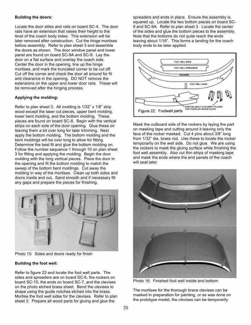
Photo 15: Sides and doors ready for finish Building the foot well: Refer to figure 22 and locate the foot well parts. The sides and spreaders are on board SC-6, the rockers on board SC-10, the ends on board SC-7, and the clevises on the photo etched brass sheet. Bend the clevises to shape using the guide notches etched into the brass. Mortise the foot well sides for the clevises. Refer to plan sheet 3. Prepare all wood parts for gluing and glue the
spreaders and ends in place. Ensure the assembly is squared up. Locate the two bottom pieces on board SC-9 and SC-9A. Refer to plan sheet 3. Locate the center of the sides and glue the bottom pieces to the assembly. Note that the bottoms do not quite reach the ends leaving about 1/16”. This forms a landing for the coach body ends to be later applied.
Mask the outboard side of the rockers by laying the part on masking tape and cutting around it leaving only the face of the rocker masked. Cut 4 pins about 3/8” long from 1/32” dia. brass rod. Use these to locate the rocker temporarily on the well side. Do not glue. We are using the rockers to mask the gluing surface while finishing the foot well assembly. Also cut thin strips of masking tape and mask the ends where the end panels of the coach will seat later.
Photo 16: Finished foot well inside and bottom The mortises for the thorough brace clevises can be masked in preparation for painting, or as was done on the prototype model, the clevises can be temporarily
21
tack glued in place. Thus they provide their own mask and can be finished along with the foot well assembly. With our gluing surfaces now protected we can finish paint the foot well assembly. When finished remove the rockers but do no remove the masking tape. Note the masked rocker area in photo 16. Remove the tack glued clevises. They will later be epoxied into the mortises. This needs to be a strong joint as the clevises are the only thing holding the coach body to the thorough braces. Finishing the sides and doors: Locate the rockers on the inside of the coach side with the 1/32” dia. rods and glue in place, masked side out.
Mask the area on the ends of the coach sides which will later receive the coach end panels. Refer to figure 23. Mask the hinge mortises on the coach sides and the doors. The sides and doors may now be finish painted inside and out. Adding interior upholstery: Stage coach interiors were upholstered in a variety of ways. Fancier coaches were upholstered in fine fabrics, usually for eastern service. The more rugged coaches destined for service in western areas were usually upholstered in leather. The upholstery panels and seats were stuffed with horsehair. The prototype model upholstery was finished with a spray coat of ‘suede’ paint which gives the surface the look of fabric. The pieces were given a wash coat of thinned acrylic burnt umber and wiped leaving the edges a bit darker for a shadow effect. A spray coat of Testor’s Dullcote removed any sheen.
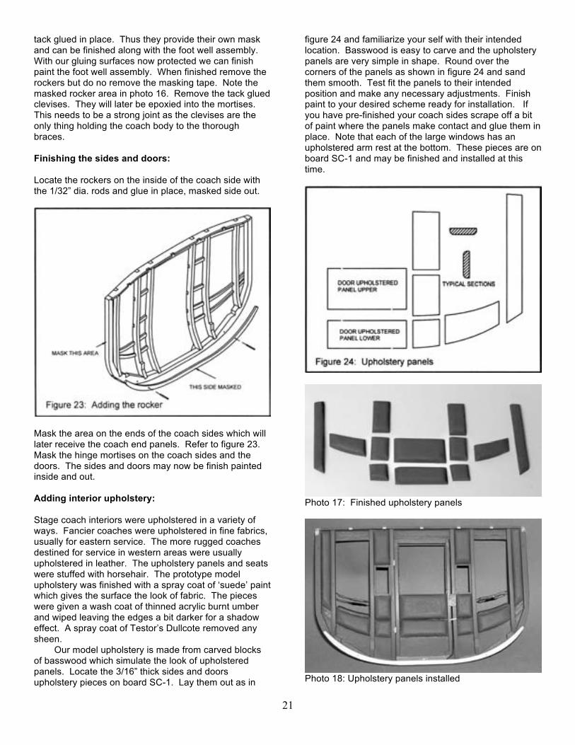
Our model upholstery is made from carved blocks of basswood which simulate the look of upholstered panels. Locate the 3/16” thick sides and doors upholstery pieces on board SC-1. Lay them out as in
figure 24 and familiarize your self with their intended location. Basswood is easy to carve and the upholstery panels are very simple in shape. Round over the corners of the panels as shown in figure 24 and sand them smooth. Test fit the panels to their intended position and make any necessary adjustments. Finish paint to your desired scheme ready for installation. If you have pre-finished your coach sides scrape off a bit of paint where the panels make contact and glue them in place. Note that each of the large windows has an upholstered arm rest at the bottom. These pieces are on board SC-1 and may be finished and installed at this time.
Photo 17: Finished upholstery panels
Photo 18: Upholstery panels installed

22
Photo 18 shows the upholstery panels installed. Note the rockers are clean of paint for later gluing and that other glue points have been also cleaned. Not visible are the cleaned locations where the seat supports will later be glued. Note that the leather straps and buckles have been installed in the window openings. These are called sway straps and were there for the passengers to brace themselves against the swaying and lurching of a bumpy ride. There are 12 leather straps and buckles on the model. This is a good place to discuss how they are made and make up the passenger sway straps. It is much easier to install them now rather than after the body is assembled. Refer to figure 25.
The passenger sway straps require 4 of the smaller of the buckles on the photo etched brass sheet. On the prototype model the buckles and hitch eyes were chemically blackened. Cut sufficient strips of the leather material to the width of the buckles. Make up the buckle ends as shown in figure 25. Tack two pins in your building board about 15/16” apart. Wrap the strap around the pins and mark where the hole needs to be for the tongue of the buckle. Drill a #66 hole. Thread two of the smaller brass hitch eyes on the strap and buckle the strap tightly around the pins. Secure the end of the strap with CA glue. Make up the strap keeper from a thinner strip of leather and glue in place. Now you have a belt loop with a hitch eye at each end.
Refer to figure 26 and drill #66 holes ½” above the window bottom. Use a pin vice and drill the holes at an angle so that your vice does not mar your finish. This will also give the hitch eyes some resistance from pulling out. Insert the hitch eyes and bend to align with window.
A touch of CA glue will secure them. A convenient and efficient method of applying small amounts of CA glue cleanly is illustrated in figure 27.
The applicator is made from a common needle with the end ground off as shown. If you heat the needle to a red state and let cool it will be soft enough to file if you wish. It is handy to drill a hole in a dowel or piece of strip wood and insert the needle for easier handling. Place a drop of two of thin CA glue on a suitable surface and dip the end of the needle in it. It will pick up a small amount of glue which then can be transferred to your work.
Touch the needle to the work and the glue will wick onto the place where you touch it. The little pool of CA glue will stay usable for quite some time. If your needle becomes clogged with use, a quick trip through a flame will clean it. Hinging the doors: Hinging the doors can be a bit tricky. Because of the curvature of the body the axis of the hinges must protrude a bit from the side of the coach. In addition the hinge line or axis must be collinear, that is on the same line. In order to accomplish this, a door hinge height gage has been provided on the pattern sheet. Cut this out and glue to a piece of card stock preferably the thickness of common poster board. Cut the gage to the line. Check that the hinge mortises are clean, that they line up properly, and they are the proper depth. CA gel type glue was used on the prototype model to install the hinges. Refer to photo 19. Note that a hole for the door handle has been drilled in the door. Refer to the plans for the proper location and drill #55. It is much easier to do this now than after the door has been hung.
Photo 19: Door hinge height gage Set the door on a flat surface as shown and check that all is ready for gluing. Sand the gluing surfaces of the brass hinges to clean and roughen them. Align hinges

23
to the top edge of the gage. Apply glue and press the hinges into the mortise holding until the glue grabs. Allow the glue to fully set.
Set the coach body side on a flat surface and insert the door into the opening. Check that all is ready for gluing. It is important that the hinges be firmly seated in the mortise. A means of doing this is to insert some resilient material between the leaves of the hinges so that when pressed into place the hinge leaf is forced into the mortise while the glue sets. This was accomplished on the prototype model by using double sided tape, the kind that is about 1/16” thick and made of a spongy material. Cut small hinge size squares of the tape and stick to one side of the hinge only. The door can now be placed into position and wedged into intimate contact with the mortises by toothpicks or similar. When the glue has set the extensions on the door top rail and bottom rail may be snapped off. Now see if the door will open without interference or rubbing. It may be necessary to shave a bit off of the door stile at an angle to provide clearance. The bare wood on the rails and perhaps the stile may be sanded and spot finished.
Locate the cast Britannia door handles, part WP6017. These were given a gold finish on the prototype model to simulate brass. Insert in the doors and bend over to form a latch. Snip off the excess. Note in photo 18 a door stop has been installed. Make this from 1/64” ply scrap and glue in place. Applying Decals: With the coach body sides finished, painted, and touched up we are ready for the decals. The decals in the kit are the fully coated type, that is, they will have to be cut out close to their outlines. The reason for this is that the surround you may be familiar with on other decals is not possible for our coach because they have to fit intimately into given spaces, namely the recessed panels.
Cut out a decal as close as possible to its outlines and check it for fit in its proper place. If you have accurately applied the moldings each should fit. If not you may have to make some adjustments such as cutting a figure in half and applying the halves with a slight overlap. This was not found to be a problem on the prototype model.
There are products on the market that greatly ease the application of decals and improve their appearance. They are usually referred to as “decal setting solution” and “decal softener”. If you have access to a hobby shop you will probably find them there. They are also available on the internet.
Gather a small bowl of water, a pair of tweezers, a soft clean brush, and a hobby knife. With tweezers dip a decal in water. Do not let it soak, remove it and set it decal side up on you bench. Leave it for one minute. Wet the surface of the model with water or setting solution. Slide the decal off of the paper into position. The trick is to get enough water or solution under the decal so that it may be maneuvered into final position without tearing the decal.
Allow the decals to dry thoroughly. If you have decal softener, apply after the decals have dried. The purpose of the softener is to encourage the decal to lay down intimately with the surface so that they appear to have been painted on. If any air bubbles occurred under the decals they may be pricked with a sharp knife and the softener will cause them to lie down.
Photo 20: Coach body side with decals
It is a good idea not to apply the fancy work and company name at the top of the coach body until later when the top has been added and finished so that the decals do not suffer damage. With the coach sides and foot well finished and prepped for assembly we could now put them together. But then we are ready for installation of the seats so let’s do them now. Building the coach seats: Locate the seat bottoms and backs on board SC-1, and the seat upholstery parts on board SC-2. There are a lot of pieces of upholstery and each will need to be carved. Begin with the seat bottoms. Refer to figure 28.
Observe the shape of the side view and carve to shape. If you have a disc sander it will make this job go faster. Round over the corners and sand to smooth contour. Use a new sharp #11 blade. If you wish you can add a bit of realism by lowering the center portion as shown as if the cushion had taken a set with age. After a bit of practice it will only take a few minutes to shape each cushion. Glue the cushions to the seat bottom and seat back.

24
The passenger seats on the prototype model were given a coat of “suede” spray paint to simulate a fabric texture. A wash coat of thinned burnt umber was applied and wiped to leave a bit of shadow effect. A coat of Dullcote removed any sheen.
The driver’s seat, the shotgun seat, the jump seats, and the topside passenger seat may also be finished at this time. Photo 21 shows the completed seats. These latter seats were finished as though covered with black leather. A coat of primer then flat black followed by Dullcote finished these parts. Note that carving a bit of undulation into these seats improves their realism. The jump seat verticals are located on board SC-7, the base on board SC-9, the cushions of board SC-2. The driver’s seat, the shotgun seat, and the topside passenger seat are on board SC-1.
On full size coaches the outboard sections of the jump seat were hinged so that they could be swung up and over the middle seat to facilitate ingress and egress of the passengers.
Photo 21: Completed seats
Assembling the coach body parts: Check the fit of the foot well to the coach sides with the alignment pins. All should align perfectly however sometimes things happen, wood warps, etc. Make any necessary adjustments and glue the foot well to one side, then the other. A combination of spots of CA gel glue and a bead of carpenters glue works well. With both sides glued place the center roof beam temporarily in position to space the coach sides while the glue dries.
The seat supports can now be installed. Cut two lengths of 3/32” square stock 3 13/16” long, two pieces of 3/32” square 3 5/8” long, and two pieces of 1/16” x 1/8” stock 3 5/8” long. Glue in place as shown in figure 30, plan sheet 3, and photo 22.

25
Photo 22: Seat supports and seat installation The front and rear seats and backs may now be glued in place. The jump seat rests on the sides of the foot well and is centered in the foot well. Use the seam at the center of the foot well floor as a guide. This completes the interior and we are ready to add the coach body front and rear end panels.
Locate the coach body end panels on board SC-9A and sand both sides smooth. Refer to figure 32, measure and mark off the front panel for the masked area and the locations of the driver’s seat rail brackets. The brackets are on board SC-9. Glue the brackets in place. A pattern for the masked area of the driver’s seat is supplied on the pattern sheet. Use this to mark off the area to be masked and apply masking tape.
Turn the panel over and mask the areas that will later be glued. Refer to photo 23 showing the front and back of the front panel as finished.
Photo 23: Coach body front end panel, masked and finished, front and back.
Locate the brass rear boot cover brackets and bend to shape as shown. Cut 5 lengths of 1/16” square strip wood to 1 1/2“ length. Mark off the locations as shown in figure 32 and glue in place. The strips are about 5/8” apart. Glue and rivet the boot cover brackets in place.
Photo 24: Coach body rear end panel, masked and finished front and back.
Cut a length of 1/32” dia. rod to span the brackets as shown in photo 24. Leave it long enough to receive square nuts later. The rear boot leather will be hung on this rod. Make up two hook eyes from the 0428 eyebolts as shown in figure 32. Set these aside, they will later be used to connect the rear boot support chains.
The two end roof beams can now be glued in place. Make sure you have which is the front and which is the

26
rear of the coach in mind. Glue the end panels to the body by first securing a glue joint at the juncture of the foot well bottom and the end panel. When this joint is secured apply glue to the remaining surfaces, the body ends and the end roof beams and bend the end panel in place. A combination of CA gel spots and carpenters glue works well for this step. Building the coach roof: Locate the remaining roof beams, pre-finish keeping the gluing surfaces free from paint, and glue in place. The coach roof is planked with 1/16” x 1/2“ basswood strips approximately 6 7/8” long. Nine strips are required. The roof planking should over hang the body by 1/32” all around. This will allow you to smooth the plank ends and edges without damaging the finish of the coach body.
Measure your coach for the correct plank length and cut nine pieces to that length. Refer to photo 25. Note the stand constructed of scrap wood. This will hold your coach firmly while you work on it and is recommended. Begin by establishing the center of the roof beams and glue on a strip exactly centered. Add adjacent planks until you reach the outermost one. Hold this plank in place and mark the curvature of the body side on the underside of the plank. Cut this plank to shape allowing for a 1/32” overhang and glue in place. Sand the roof smooth. Stagecoach roofs were covered with canvas and sealed with paint for waterproofing. We have supplied a piece of fine weave ballooner cloth to represent canvas.
Photo 25: Adding the roof planks Apply this cloth to the roof using thinned white glue. There is a product available in craft stores called “Mod Podge” which is used for such purposes saving you the trouble of mixing a batch of thinned white glue. Give the canvas a couple of coats of the glue to fill the weave somewhat. When dry, carefully trim the canvas to the roof edge. Edge the roof all around with strips of 1/16” square basswood. The corner joints ideally would be
miter joints but butt joints will scarcely be noticed. The roof will be painted black, so it is a good idea to paint the bottom and outside surfaces of these strips black before installing. This will alleviate the need for masking and provide a clean line between the red of the body and the black of the roof. The roof top rub rails may now be installed. Refer to the top view on plan sheet 4 for location and spacing. The 1/64” ply roof top rub rails are found on board SC-9A. Forming, soldering, and installing the rails: Before painting the roof the baggage rails should be made up and installed. The rails are made of 3/64” diameter brass rod. The brass rod is in a half hard state as supplied and must be annealed to successfully form the rails. This is important. There are two rails on the driver’s seat that can be made up at the same time as the baggage rails.
Photo 26: Forming and soldering jigs
Careful preparation, cleaning, and fitting are required to make these pieces. We have provided patterns and jigs to aid this step and are shown in photo 26. Locate the baggage rail soldering jig, the rail end forming jig, and the driver’s seat soldering jig on board SC-5. Locate the baggage rails soldering pattern on the pattern sheet and glue to the baggage rail soldering jig. This gives you a solid surface for the pattern to which you can easily clamp the parts for soldering. In like manner glue the driver’s seat soldering pattern to the driver’s seat soldering jig.
Cut 4 pieces of 1/8” dia. dowel to a length of about 3/4”. As shown in figure 33, these dowels are inserted in the holes numbered 1 through 4. The rails ends are formed around these dowels. There are 4 baggage rail ends and 2 driver’s seat rails that are formed on this jig.

27
Glue a piece of square stock to the forming jig to serve as a stop block as shown in figure 33. Anneal a length of brass rod by heating over a flame to a red state and quench in water. Do one end at a time while holding with pliers. Clean the rod with a piece of rolled sandpaper. It is much easier to do this when the rod is straight rather than bent. Remove dowels 2, 3, and 4 from the forming jig. Place the rod between dowel number 1 and the stop block. Do not try to get the end perfectly aligned but leave a little long for later trimming. Bend the rod just past hole number 2. Replace dowel number 2 and reverse the bend to just past hole number 3. Replace dowel number 3 and reverse the bend again until the rod lies along the line to hole number 4. Replace dowel number 4 and bend downward to the line. Snip the rod off a little long.
Make up 4 of these ends. The same jig is used to form the driver’s seat except the bend around dowel 4 is not done. With all the bending done, move to the soldering jigs. File the ends of the formed pieces square and to the length shown on the soldering jigs. Clamp a formed end to the soldering jig. Clean and anneal all brass to be used for the straight lengths. Cut and fit the two straight pieces that complete an end. It is important that all ends be filed square and form an intimate fit at the joint. Clamp the pieces to the jig and check that all is where you want it. Use a paste type soldering flux and place a dab on each joint. The paste is viscous and will help hold things in place while soldering. Heat the soldering iron and when ready clean the tip. A damp sponge is handy for this. Melt a dab of solder on the tip of the iron then place on a joint. The rod is thin and will heat up very quickly. When the solder flows into the joint remove the iron immediately. Do not fret about excess solder, this can be removed with a file later. Proceed with each piece keeping the structure a good match and fit with the pattern. If you have trouble with a joint sticking, clean the parts and try again. Complete two baggage rails and two driver’s seat rails. Clean up any excess solder blobs with a needle file and remove flux with a solvent.
Before installation the baggage rails must be bent slightly into a curve to conform to the curve of the coach roof. Refer to the top view on plan sheet 4. Being very
careful not to stress the solder joints hold the rails in your fingers, not touching the solder joints and gently induce a curve into each section of the rails between the vertical pieces. The bend is very slight and easily made if you have annealed the brass. If you stress the solder joints they will almost certainly break.
The rails are positioned about 3/16” inside the edge of the roof. Spot a rail on the roof in the desired position and mark the location of a hole at one end of the rail. Center mark and drill a #55 hole. Carefully start the end of a rail into the hole and mark the location of the next hole. Successively drill and fit until the entire rail is properly fit. When satisfied with the fit wick a bit of CA glue into the joints. Before painting the roof, glue down two strips of 1/16” x 1/8” that will serve as the mount for the roof top passenger seat to be installed later. Refer to the top view on plan sheet 4 for length and position. The roof and rails can now be painted flat black. Do not paint the tops of the seat mounts as that is a glue surface. Stage 5: Building the driver’s seat, front and rear boots: Driver’s seat: Locate the driver’s seat front, back, and ends on board SC-7. Refer to figure 34 and assemble the parts as shown ensuring the assembly is square. Plank the top with 1/16” x 1/2" strips 3 1/2" long. Note the foremost strip will need to be ripped to fit.
Cut notches for the driver’s seat braces as shown in figure 34. This assembly may now be masked and finished. Mask the rear of the assembly where it will be glued to the coach body. Mask the inner sides of the

28
ends as the leather boots will be glued there. Mask the areas where the seats will be glued.
After finishing the decorative decals may be applied to the ends of the seat. Glue the seat to the coach body in the previously marked and masked location. Drill #55 holes for the seat rails and install. Secure with CA glue. Form the seat braces, part no. WP6015, as shown and fit to the seat and coach top. Secure with brass pins. Cut off the pins protruding from the inside of the seat ends and apply a dab of CA glue. The assembly should now look like figure 35.
Front boot: Locate the two front boot rails on board SC-4. Cut 3 lengths of 1/8” square stock to 2 1/2" and glue to the rails as shown in figure 36. Ensure that all is square. Begin planking the boot top with the foot rest found on board SC-7. Continue planking with 1/16” x 1/2" pieces cut to 2 7/8” length. The final piece at the foot will have to be ripped to size.
Locate the brass front boot top and bottom irons. Shape and glue the top irons in place using CA gel glue. The top iron is inset from the edge about 1/32” to align it with the rails. Drill a #72 hole down through the top iron and the rail. Try to keep this hole plumb to the surface so that it emerges in the center of the rail. Insert a pin and locate the bottom iron using the pin and center it on the bottom of the rail. Glue in place on the bottom of the rail using CA gel. The holes for the remaining pins can now be drilled. Drill from both the top and bottom. Work the drill in the hole until it emerges. Pin and rivet all pins except the pins which accept the step brackets.
Locate the cast step brackets, part no. WP6018. Drill the step brackets to match the pins and rivet in place. The steps may be riveted to the bracket or glued to the bracket with epoxy. The bracket is easily bent to shape to make the step level upon final assembly. Insert
two eyebolts as shown and secure with a slight bend. Do not cut off or install permanently. The eyebolt lengths may require some adjustment when the support chains are installed later. The assembly may now be finish painted. Note that a decal is supplied to be centered on the bottom side of the foot rest.
Locate two brass boot brackets and bend to shape as shown. Prepare two square head bolts, cut to length, pass them through the brackets and secure with a square nut. Begin a bend in the bottom irons and pass through the bracket. Note that this bend must be such that the boot assembly can achieve the angle shown on the side view of the coach on plan sheet 4. In other words, don’t make the bend too close to the boot end. The bend need not be crimped tightly around the pin, just enough to hold the bracket in place while fitting the assembly to the coach. Place the assembly in position on the coach body and drill a #72 hole for each bracket. Pin these holes and drill the remainder.
For convenience the boot assembly may be removed from the brackets while the remaining pins are inserted. Note: that the pins may be long enough to reach the seat backs inside the coach. If you experience this it is best to cut the pins to a shorter length so as to not risk knocking the seats loose. Secure the pins with a dab of CA glue. The boot can be set aside while completing the remaining construction steps. Rear boot: Refer to figure 37. Cut two pieces of 1/16” x 1/8” to length of 3 7/16”. Cut 7 pieces of 1/16” x 1/2" to a length of 2 3/4". Glue together as shown in figure 37. The front most piece will have to be ripped to fit. Locate the brass rear boot irons and glue to the 1/8’ strips as shown. Drill #72 for the pins, insert pins from the top, cut off and rivet. Drill for the eyebolts but do not yet install. Locate the brass boot brackets and bend to shape. Fit them with square head bolts and square nuts.

29
Bend the ends of the boot irons to shape as shown and insert the boot brackets. Clinch the boot iron closed enough to hold the boot brackets. The rear boot may now be finish painted.
Place the assembly in position on the coach body referring to plan sheet 4 and drill holes for the pins. Attach to the coach as you did for the front boot, snipping off the pins if required and securing with CA glue. Form two hook eyes from eyebolts. Connect the hooks to chains with split rings as shown on plan sheet 4, measure the required length of chain and connect to eyebolts. Complete the support connections for the rear boot.
Place the front lower irons into the brackets on the front of the coach. Check to see that the front boot will rise to the required angle and bend over the irons to attach the boot permanently. Form the support chains with eyebolts and split rings and install as shown on plan sheet 4. Drill the front of the driver’s seat for the eyebolts. The length of the chains can be adjusted slightly with the exposed length of the eyebolts. This is why we didn’t glue them in until this step. Boot leathers: Patterns for the boot leathers are on a separate pattern sheet. A sheet of leather material is included in your kit for the boot leathers. Refer to figure 38. Use the patterns and the layout shown in figure 38 and cut out the leathers. Be sure to leave enough material for the four window curtains. Hides were not large enough to form the boot cover in one piece. Two pieces were sewn together with a seam down the middle as shown. To simulate this seam cut a thin strip of the leather material and glue in place as shown. To form the
rear boot, fold over the top, bottom, and sides as shown. Wrap the top around the 1/32” dia. rod previously made. Glue this flap to the underside of the leather. Ensure the rod is not glued to the leather. Glue the sides to the cover on the inside of the side flaps.
Make up the 4 buckle straps and glue in place. Added realism is attained by adding the trailing leather straps at the bottom edges as shown in figure 38. Install the rear boot by sliding the rod into the brackets on the rear panel of the coach. Secure the rod with square nuts on each end.
The front boot leather glues to the inside of the
driver’s seat ends. Refer to the illustration on plan sheet 4. The leathers for the prototype model were given and wash coat of thinned burnt umber acrylic for a more realistic leather look.
Photo 27: Rear boot detail

30
Photo 28: Front boot detail, roof top passenger seat Final details: Roof top passenger seat and back rest: The back rest was a fold down feature presumably to allow more luggage on the roof when the seat was not in use.
Refer to figure 39. If you have not finished the seat and back cushions in a previous step, do so now. These pieces are on board SC-1. Locate the brass backrest brackets, upper and lower. Note that there are small notches on the lower bracket indicating where the bend is to be for the foot. Use pliers to make the bend. Both the upper and lower brackets have a scalloped indentation locating the position of the 90 degree twist.
Grip the bracket with two pairs of pliers at the extremities of the scallops and twist 90 degrees. The brass will easily conform to the twist. Bend the tab as shown in figure 39. The tab serves as a stop, allowing the backrest to fold forward, but stop in an upright position. Assemble the brackets with a brass pin and rivet. Refer to plan sheet 4 for the location of the brackets on the back of the backrest and glue in place. Locate the position of the feet on the roof and glue and pin in place. The seat cushion may now be glued in place. Leather roll up window curtains: Cut out the four window curtains using the template provided. Wet these with water and wrap tightly around a 1/8” dia. dowel. Secure with thread or string and let dry. The material will retain its shape. Glue the roll fast along its length. Cut thin strips of the leather material and glue in position as shown. These were the straps which secured the curtain in it’s rolled up position. Make all ends and joints on the backside of the roll. There is not much to glue the roll to so cut a thin piece of 1/64” scrap plywood about 1/8” wide and long enough to just span the window frames. Glue one of these strips to the backside of each roll. Scrape off a bit of paint on the window frames and glue the rolls in place. If you have correctly sized the 1/64” strip it will not show. See photo 27 and 28.
The decal across the top of the coach many now be applied without fear of damage. Cut out the company name of choice and check that the curvature of the decal fits nicely to the arc of application. Probably best to cut this decal into two or more pieces for application. Thorough brace clevises: We have avoided gluing on the thorough brace clevises during the construction process to prevent them from being damaged. They can now be glued in place. Refer to figure 40.
Lay your coach on its side on a soft surface such as a folded bath towel. Inspect the mortises for the clevises for any paint or other debris. The joint of the clevises to the body must be a good one as they can be stressed during the installation of the thorough braces. These joints are the only thing holding the coach body in place. Toward this end it is a good idea to drill a couple of holes in the surface of the clevises in way of the joint as shown in figure 40. Rough up the area of the brass with rough sandpaper and avoid touching the surface with your fingers. Glue the clevises to one side of the coach with epoxy glue, preferably of the slow set type. While

31
waiting for the glue to cure make up the square head bolts from 18 gage pins as follows. Form and file the square head. Then chuck the pin in a drill and file the shaft smooth. Pay attention to the area just below the head as some swelling may have occurred there during their manufacture. Test each bolt for free and full entry into the clevis holes. Cut off to length and file the end square. Adding a slight chamfer will help ease entry into a hole. Make up 6 bolts for the clevises and 4 more for the thorough brace ends to be used later.
With ruler and square locate and mark the center of the thorough brace bundles. Place a thorough brace bundle in place within the clevises being sure to center it. Locate the brass thorough brace irons and form them into a curve and bend the tabs as shown on plan sheet 4. Note that there will be a right and left iron. Place the iron on the bottom of the thorough brace and insert the bolts. Turn the coach over and repeat for the other side. The bolts can now be secured with square nuts.
The coach body is now finally ready to be mounted to the standards. Remove the wheels if necessary. Carefully place the coach body into position and insert the bolts. This can be a bit tricky, patience is the key. Attach one end at a time. When mounted secure the bolts with square nuts.
Final details are the leather straps called the sway straps and the stay straps. The sway straps are shown on plan sheet 4 and connect the center thorough brace clevis to the sway strap anchor on the side of the frame. The stay straps connect the front axle to the double tree and are shown on plan sheet 3.
That’s it! You are finished. Install the wheels and secure. Stand back and admire your work and get ready for the accolades of family and friends. Robert M. Crane, Georgetown, Texas, 2008,2009
References:
Oregon historical society, “Wagons of America in Miniature”, Ivan Collins, 1973 Steffan, R., “Stagecoach”, Western Horseman, July, 1962 Lambert, Jay D., “The How to Book of Stagecoach Building”, privately published, 1988, 1996 Brentano, Ron, “Historic Vehicles in Miniature”, Oregon historical society press, 1998