mike garnett. dr. heiko manstein dipl.-ing. andreas
TRANSCRIPT
1
Title: Filter concept for gas turbines.
Overview and field report on utility value
enhancement with three-stage filtration.
Authors:
Mike Garnett.
Dr. Heiko Manstein
Dipl.-Ing. Andreas Rothmann
Company:
Freudenberg Filtration Technologies KG,
D-69465 Weinheim - Germany

2
Abstract
Efficient air filtration and its contribution towards cost-effective operation of gas turbines
offer an extensive field for continual design enhancements. The utility value of three-stage,
high-efficiency filter installations for gas-turbine air intake systems was in terms of its basics
covered by a previous publication.
Feedback from multi-stage systems installed in the field validates the applicability to
statically operated filter systems currently in common use, against the background of the
stipulations posed for particle arrestance, coalescence characteristics and pressure-loss
behavior. Though multi-stage systems have the disadvantage of an initially higher pressure
drop, they do in fact – thanks to almost complete avoidance of fouling and to increased
system availability – provide their users with significant, verifiable cost savings.
A typical comparative computation, revealing higher operating costs for a system with
cyclical washing routines than for a multi-stage filter system, is used to estimate and discuss
the cost advantage actually achievable. The computations presented are closely commensurate
with the empirical feedback obtained from existing applications, and are corroborated by two
examples from the field. Thanks to the avoidance of fouling, any performance potentials so
far untapped can be reliably opened up, availability levels substantially upped and additional
operating costs reduced. What’s more, the overall analysis reveals that dispensing with the
washing system is another conceivable option for a further system upgrade.
Introduction
Responsible deployment of the fossil resources at our disposal demands their maximally
efficient and eco-neutral use while simultaneously factoring in their cost-efficient utilization.
To reconcile both these aspects is the paramount goal governing the development efforts of
turbine manufacturers, system development engineers and system operators alike.
From a system operator’s viewpoint, it is primarily downtimes that are rated as lost profit, and
must therefore be avoided. High levels of availability and long running times for the systems
concerned are the declared goals. In particular, downtimes required for washing the
compressor stages inevitably cause non-productive periods, which need to be minimized or
altogether avoided. The aim of the washing routines is to remove any coatings and deposits on
the blades. The cause for any such deposits will usually be inadequate intake air filtration.
Innovative concepts for enhancing filtration quality by means of three-stage filter systems
were presented by Schroth et al. [1].
This paper provides an overview of filter systems in current use and an approach for
estimating the financial benefits accruing from system modification, an approach which is
illustrated by examples from actual operational practice.
Basic principles of particle filtration
The demand for efficient air filtration for internal combustion engines entails sophisticated
challenges in terms of adequate design for and implementation of the air intake systems being
used.
An air filter system is required to significantly reduce the penetration of solid and liquid
particles into the turbomachinery, while coping with temporally fluctuating environmental
conditions.
Arrestance of air-borne particles (which may be dust particles or droplets) depends most
particularly on the transport mechanisms effective at the location concerned. Electrostatic,
diffusion-, inertia-, and gravity-related effects are responsible for particle transport to the filter

3
media, which are usually made of fibers. The adhesion forces operating between particles and
fibers in their turn are determined by the interaction of Van der Waals forces, and electrostatic
and liquid-related effects, and enable dirt particles to be permanently arrested. When
developing filter elements, then, both these mechanisms, the transport and the adhesion
mechanism, must be given due consideration in the optimization process.
The concentration of air-borne dust particles is of crucial importance for the design of intake
air filtration systems. Over the past few years, measurements of dust concentrations have been
continuously expanded, so now there is a broad data base available [2]. The temporal
fluctuation band of the PM10 dust mass found here ranged from approx. 5 – 40 µg/m3 [3] in
Germany during 2007, and depends largely on the season of the year, on the surrounding
landscape and the degree of industrialization obtaining at the place where the measurements
are taken. In this context, PM10 denotes the dust fraction whose mean particle size
(aerodynamic equivalent diameter) is 10 µm, with 50 % of it being arrested. This dust fraction
exhibits a particle size distribution that may well contain particles of up to 20 – 30 µm in
diameter [4].
The fact that a very high and nonetheless limited proportion of the dust fraction is being
retained also means that there will always be particles penetrating the filter. As a consequence
of particles passing through a filter stage, deposits are formed on the blading, which results in
output losses at the gas turbine. In regions close to the coast, additional corrosion effects may
be encountered, due to air-borne salt particles. The aim of development work on filter systems
is accordingly to minimize precisely that proportion of the dust fraction which passes through
the filter. Filtration quality is rated in terms of collection efficiencies for individual particle
sizes or for the entire dust quantity in question [5].
Filtration concepts for GT applications
The temporal dust mass carried in determines the choice of a suitable intake air filter system.
The size of the particles of relevance for intake air filtration is typically to be found in a
bandwidth of around 0.01 µm to about 3 mm, and at locations exposed to high industrial
emissions an average mass concentration of up to 200 µg/m3 can occur [6].
It is only in a few regions (exposed to temporarily extra-high dust concentrations) that
regenerative operated systems are actually necessary, which, following the principle of
surface filtration, form a compact dust cake on the filter medium involved. Using the pulse-jet
cleaning method, the dust cake can subsequently be shaken off the filter medium at predefined
intervals. Filter systems of this kind are mostly in single-stage design and require precisely
harmonized and properly functioning cleaning systems. The drawback with these is a
relatively high degree of particle penetration during and shortly after the cleaning phase, since
it is precisely then that the filtration-supporting effect of the dust cake is absent; it will only be
built up again over the course of the cycle now commencing.
In most of the Earth’s regions, low to moderate dust masses are encountered, which can be
very successfully stored and lastingly retained in the element’s filter medium using the
principle of deep-bed filtration. If the dust-retention capacity is exhausted, the filters
concerned are replaced by new, non-loaded elements during the system’s overhaul and
standstill times. The salient features of static filtration systems are these: arrestance of large
particles in a pre-filter stage and storage of small particles in the fine-filter stage. Static air
filter systems of this kind can be supplied in multi-stage design, which offers scope for
optimizing the filter technology involved.
4
The task of a state-of-the-art design for intake air filters is to affordably reconcile the
paramount requirements posed for optimum system operation:
1. Maximized system protection = filtration with maximum efficiency and at a
consistently high level
2. High system availability = downtimes for replacing the filters are rare and short
3. High system efficiency = low pressure drop in the filter system
4. Reduction in unplanned downtimes of the filter system = failsafe product quality
One feature inherent in all filtration is the phenomenon that initially high efficiency levels and
the high dust storage volumes achieved during operation entail an initially high and steadily
increasing pressure drop during the filter’s useful lifetime, and that is deleterious for optimum
gas-turbine operation.
Optimization work on intake air systems, factoring in some basic considerations regarding the
comparison of two- and three-stage filtration systems, has been extensively dealt with in a
previous publication [1].
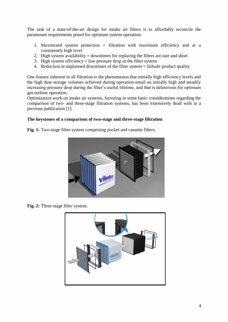
The keystones of a comparison of two-stage and three-stage filtration
Fig. 1: Two-stage filter system comprising pocket and cassette filters.
Fig. 2: Three-stage filter system.

5
Fig. 1 illustrates the basic set-up of a two-stage filter system, in which the final cassette filter
stage is protected by an upstream pocket filter stage. The core for top-quality filtration of a
three-stage filter system as depicted in Fig. 2 is the high-efficiency particulate air (HEPA)
filter (Filter Class H11 as defined in EN1822) installed in the third filter stage. The upstream
filter stages serve primarily to protect the HEPA filter in the final filter stage. The task of pre-
filtration is frequently handled by a pocket filter of Filter Class F6 (as defined in EN 779),
which in its turn is installed upstream of the intermediate stage comprising F8 or F9 cassette
filters. Which filters to choose for these two stages depends crucially on the environmental
conditions concerned and the building constraints encountered.
A reduction in the number of pre-filter stages or of the Filter Class will directly affect the dust
volume passing through the filter stages concerned, and thus the useful lifetime achievable for
the HEPA filter in the final filter stage. Moreover, possible effects exerted by the ambient
air’s humidity in conjunction with the dust arrested in the filter stages must be given due
consideration, particularly when they may increase in size (due to moisture) or sticky dust
constituents are involved. These might be responsible for an unforeseeable rise in the pressure
drop as a consequence of weather-related factors. Another task to be performed by the
upstream filters is to act as coalescence stages. Minute droplets of fog contained in the intake
air condensate at the fine fibers of the pre-filters and coalesce. Gradually, these droplets reach
a liquid state, and driven by gravity flow down so that they may exit at the filter’s base. When
the intake air is humidified by means of evaporation coolers, the effects described are
encountered even more often, and must be given particular attention in the run-up to filter
system dimensioning. In this case, it is absolutely imperative to use a two-stage pre-filter
system, in which droplets are arrested to a sufficient degree in the first filter stage so as to
prevent the final HEPA filter stage being soaked through. Tests are also currently ongoing
with filter systems comprising merely two filter stages at locations where only low humidity
levels can be anticipated. Here, F7 pocket filters are used in the pre-filter stage upstream of
the high-efficiency particulate air (HEPA) cassette filters of Filter Class H11. Initial results
look promising but evidence shows the need for a droplet separator to avoid flooding of the
pre-filter stage in coastal locations prone to heavy directional rainfalls and to stop salt
particles. Of course, protection of the gas turbine is here assured to the same degree as in
systems featuring two pre-filter stages. The results on the useful lifetime for the final HEPA
filter are being eagerly awaited.
The principal focus of the considerations described in the previous publication was on two
parameters, exhibiting both advantages and disadvantages [1].
1. The advantage offered by upgraded filtration is less fouling on the compressor section
of the gas turbine.
In this context, the values compiled in Table 1 illustrate the improvement in arrestance
achieved by the three-stage HEPA filter system as compared to a conventional two-stage fine-
filter system. When a HEPA filter system is used, the number of particles responsible for
compressor fouling in sizes ranging from 0.3 to 0.5 µm can be reduced by a further factor of
about 30, and the somewhat larger fraction of 0.5 to 1.0 µm in size by a factor of roughly 200.
The result of the empirical feedback so far obtained from the markets confirms these basic
considerations. By using upgraded filtration technology featuring HEPA filters, the fouling
customarily encountered on the compressor blades is avoided almost entirely. Feedback
likewise confirms that online and offline washing can be completely dispensed with, creating
the concomitant benefit that there is no longer any reduction in performance between one
6
washing routine and the next (otherwise an accepted fact), which in turn shows up
immediately as enhanced performance figures at the machine itself. What is more, non-
productive times, reduced output levels and fouling entrainment as side-effects of the washing
routines are a thing of the past.
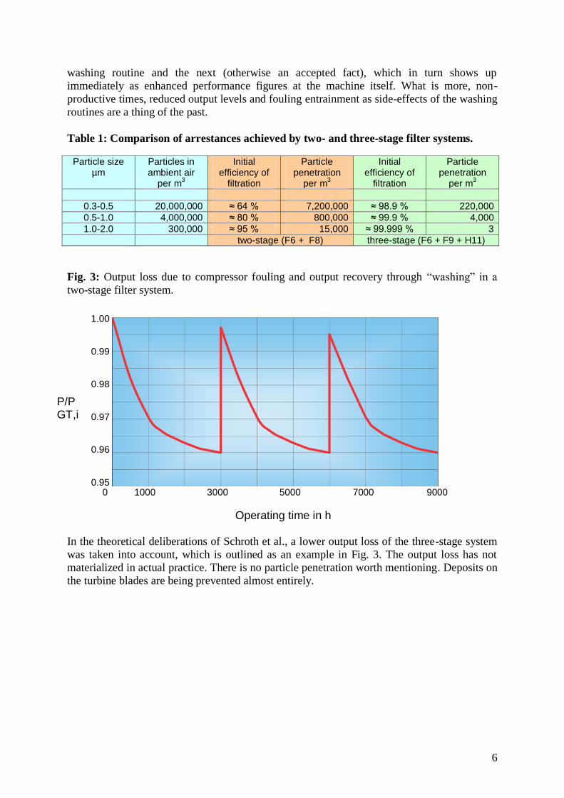
Table 1: Comparison of arrestances achieved by two- and three-stage filter systems.
Particle size µm
Particles in ambient air
per m3
Initial efficiency of
filtration
Particle penetration
per m3
Initial efficiency of
filtration
Particle penetration
per m3
0.3-0.5 20,000,000 ≈ 64 % 7,200,000 ≈ 98.9 % 220,000
0.5-1.0 4,000,000 ≈ 80 % 800,000 ≈ 99.9 % 4,000
1.0-2.0 300,000 ≈ 95 % 15,000 ≈ 99.999 % 3
two-stage (F6 + F8) three-stage (F6 + F9 + H11)
Fig. 3: Output loss due to compressor fouling and output recovery through “washing” in a
two-stage filter system.
0 1000 3000 5000 7000 9000
Operating time in h
In the theoretical deliberations of Schroth et al., a lower output loss of the three-stage system
was taken into account, which is outlined as an example in Fig. 3. The output loss has not
materialized in actual practice. There is no particle penetration worth mentioning. Deposits on
the turbine blades are being prevented almost entirely.
1.00 0.99 0.98 0.97 0.96 0.95
P/P GT,i

7
Fig. 4: Endoscopic image of the compressor blades in a Taurus 65 GT.
Fig. 4 shows the endoscopic image of the compressor blades surface in a Taurus 65 GT. After
having been in operation for approx. 9,000 hours without any washing routine at all, no
deposits whatsoever adhering to the blades are visible. This is an unequivocal success for the
three-stage HEPA filter system featuring the combination F6-F9-H11.
2. The disadvantage of a three-stage filter system is, quite naturally (due to the
contribution made by the third high-efficiency filter stage), the higher pressure drop
that must be anticipated in the filter system as a whole.
In Fig. 5, a pressure drop curve typical for a three-stage filter system is compared to that of a
two-stage system. Here, the hatched area marks the difference and/or increase of the pressure
drop over the entire operating period and thus provides a benchmark for the mechanical
energy yield actually achieved.
Fig. 5: Comparison of the energy yield between a two- and three-stage filter system.
0 1000 3000 5000 7000 9000
Operating time in h
800 700 600 500 400 300 200 100
3 stage 2 stage
ΔP in Pa

8
As experience has shown, the output loss of a gas turbine due to a higher pressure drop in the
intake system can be estimated at about 0.1 % efficiency loss for each 50 Pa of increase in
pressure drop, and the direct effects of an additional third filter stage can be evaluated. In the
analytical summary, the advantage of increased machine availability must at the very least
compensate for the deleterious contribution of a higher pressure drop in the system, or even
exceed it.
Typical computation for a system
With an empirically based computation program, it is possible to use the operator’s particulars
on the status of the existing system to compare it with the modified, three-stage filter system,
and to analyze the advantages and disadvantages involved. The particulars required from the
operator are the following (here reproduced as an example; see Table 2).
Table 2: Typical particulars serving as the computation basis.
Maximum power output 31 MW
Operating hours per year 5,600 h/a
Approx. volume flow at 20 °C 231,126 m3/h
Number of filter elements per filter stage 63 pcs
Loss due to fouling in 40 days 700 KW
Volume flow loading per filter 3,700 m3/h per filter
Further particulars given for the existing filter system serve to provide a comprehensive
overview of the application task involved and are factored into the computation if necessary.
Based on the operator’s particulars and the typical pressure-drop curves, on which the
computation is based, the anticipated average pressure drops are estimated as a characteristic
mean value over the entire period of operation for the individual filter stages. The results have
been compiled in Table 3.
Table 3: Computations for the two-stage system used.
Δp_Start Δp_End
Approx mean value for pressure drop
[Pa] [Pa] [Pa]
Current filter system:
1st stage Pocket filter F6 70 250 130
2nd
stage Cassette filter F8 120 400 213
Total 190 650 343

9
Table 4: Computations for the three-stage filter system planned.
Viledon Type Δp_Start Δp_End
Approx mean value for pressure drop
[Pa] [Pa] [Pa]
1st stage Pocket filter F6 45 250 113
2nd
stage Cassette filter F8 100 200 133
3rd
stage HEPA filter H11 220 300 247
Total 365 750 493
The operating values for the new filter system are now estimated within the framework of the
loadings stipulated by the operator (see Table 4) and then compared with the values for the
existing system.
In this comparison, the difference between the characteristic mean values produces an
anticipated pressure-drop increase of 493 Pa – 343 Pa = 150 Pa for the three-stage filter
system.
Output loss due to fouling up to turbine washing in the previous filter system
Fig. 3 shows an output curve typical for gas-turbine operation with washing routines, in the
shape of a classical sawtooth curve. The output loss caused by fouling during the load period
can be partly recovered by the washing routine. In a rough approximation, the hatched area
below the curve can be regarded as a triangle and its area adduced as a dimension for the
output loss involved.
In order to take into due account the performance curve actually encountered at the machine
(which frequently varies), the conservative estimate adduces only one third x H x W of the
area below the curve for triangle computation, to be on the safe side. This means that the
machine’s output loss with the existing two-stage filter system is in the computation given a
lower value than that actually occurring. The sub-areas computed within the period under
review are added together, and adduced for system comparison. For this purpose, particulars
from the operator on the number of washing routines within the period of operation are
required.
The gas turbine’s output loss stated in the example is 700 kW within 40 days of operation.
The system’s overall operating period is 5,600 hours, inside which 5.8 (mathematically
determined) washing routines occur, which have to be taken duly into account. (Operating
time between two washing routines = 960 h). As a total result of cyclically encountered
fouling, the gas turbine’s output loss in the period under review is:
P_Loss due to cyclical fouling = 1/3 * 0.7 MW * 960 h * 5.8 = 1299 MWh

10
Output loss due to higher initial pressure drop in the three-stage system
To start with, the output loss due to a higher initial pressure drop in the three-stage filter
system is estimated. This is obtained as:
Output loss = GT output * output loss per 50 Pa of pressure increase * pressure drop
P_GT_3-stage_i = P_GT_i * C_DP_50Pa * (DP_3-stage_i / 50 Pa)
where:
P_GT_3-stage_i Initial output loss of gas turbine in three-stage filtration system
P_GT_i Gas turbine’s rating
C_DP_50Pa Efficiency loss coefficient
DP_3-stage_i Initial pressure drop in the three-stage filter system
With the typical values, the gas turbine’s unavoidable output loss due to the higher initial
pressure drop in the three-stage filter systems is obtained as:
P_GT_3-stage_i = 31 MW * 0.001 * (150 Pa / 50 Pa) = 0.093 MW
The gas turbine’s output loss caused by the three-stage filter system within the period under
review is calculated as:
P_Loss due to 3-stage filter system = P_GT_3-stage_i * operating period in hours
P_Loss due to 3-stage filter system = 0.093 MW * 5,600 h = 520.8 MWh
Evaluation and discussion of the results
Due to cyclically occurring fouling, the gas turbine operated with the conventional two-stage
filter system and regular washing routines loses approx. 1,300 MWh within the period under
review. Taking an assumed remuneration for electricity of 65 €/MWh, this corresponds to a
financial loss of around 84,900 €. This loss can be avoided by installing a three-stage filter
system and profitably eliminated.
On the one hand, installation of a three-stage filter system increases the pressure drop, which
in our example corresponds to an output loss for the gas turbine of approx. 520 MWh or a
financial loss of around 33,800 €. On the other hand, this investment eliminates the two-stage
system’s output loss, which was hitherto unavoidable.
Avoiding the costs caused by compressor fouling, of: = + 84900 €
Accepting the additional costs incurred by a higher pressure drop: = - 33800 €
----------------
Within the period under review, a total cost advantage of = + 51100 € is thus
obtained.
An estimate, plus a cost comparison, must be performed individually for each system in
question. Note that further deleterious aspects have not yet been taken into account here,
particularly the irreversible degradation of the gas turbine due to fouling. In spite of regular
washing routines, the original performance level is impossible to reach again. With three-

11
stage filtration, this effect is almost entirely avoided. Nor have the costs for cleaning agents
and their disposal been factored into this computation. Effects improving the overall result,
such as its no longer being necessary to add to the running time equivalent operating hours for
the start-up procedures required after washing, and the increase in the gas turbine’s
availability levels, have likewise not yet been factored in.
Typical examples
The innovative filter concepts with upgraded filtration quality have been undergoing
applications-engineering trials since 2003, and currently comprise more than 30 intake air
systems from all front-ranking gas turbine manufacturers. One representative example each
for a three-stage filter system and the continuation of a two-stage high-performance system
with a final HEPA filter stage are adduced here to demonstrate the expectations posed for the
relevant performance capabilities.
Typical example of three-stage filtration in HEPA quality
System type 2xTaurus 65 GT
Place of installation Cardboard factory
Systems rated at 6,3 MW
Total volume flow per system 67,000 m3/h
1st filter stage 28 x F6 pocket filter T60
2nd filter stage 28 x F9 MaxiPleat MX 98
3rd filter stage 28 x H11 MaxiPleat MX100
Fig. 6: Image after approx. 9,000 operating hours without a compressor washing
routine.
12
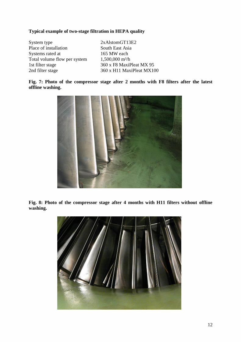
Typical example of two-stage filtration in HEPA quality
System type 2xAlstomGT13E2
Place of installation South East Asia
Systems rated at 165 MW each
Total volume flow per system 1,500,000 m³/h
1st filter stage 360 x F8 MaxiPleat MX 95
2nd filter stage 360 x H11 MaxiPleat MX100
Fig. 7: Photo of the compressor stage after 2 months with F8 filters after the latest
offline washing.
Fig. 8: Photo of the compressor stage after 4 months with H11 filters without offline
washing.

13
Summary and outlook
The empirical feedback and the results presented demonstrate that installing upgraded
filtration quality in the air intake systems for gas turbines definitely makes sense, with
concomitant benefits for the users concerned.
By means of systematically analyzed feedback from actual applications, characteristic
pressure-drop values can be computed for existing filter systems, which permit adequate
comparisons with planned modifications towards upgraded filtration quality. Upgrades to
three-stage filter systems already implemented with high-efficiency filter elements in the final
stage of filtration enable frequent compressor-stage washing routines to be dispensed with.
Note that modularized filter systems, which can be installed upstream without any structural
modifications and substantially increase filtration quality while only requiring very little
additional outlay, have proved their worth in actual operation. Obviating the need for
compressor-stage washing, and increased system availability, usually compensate many times
over for the slightly higher pressure drop in the upgraded filtration system. Trials in actual
practice with two-stage intake air systems that reach a filtration quality equivalent to that of
HEPA filters are currently in the test phase and may well prove to be a further step towards
optimization, targeting maximally cost-efficient system operation. The option for doing
without a washing system opens up yet another step towards cost optimization for turbine
manufacturers.
Bibliography:
[1] Schroth, T., Rothmann, A.; Schmitt, D.; Nutzwert eines dreistufigen Luftfiltersystems mit
innovativer Technologie für stationäre Gasturbinen; VGB PowerTech 10/2007, 48-51
[2] European Environment Agency, http://dataservice.eea.europa.eu
[3] Umweltbundesamt mit Daten der Messnetze der Länder and des Bundes,
http://www.umweltbundesamt.de
[4] M.Mattenklott, N.Höfert, Gefahrstoffe 69(2009) No. 4 April, P. 127
[5] Schmidt, E.; Löffler, F.; Filternde Abscheider. In: Brauer, H. Handbuch des
Umweltschutzes and der Umweltschutztechnik, Vol. 2, Chapter 5. Berlin: Springer 1996
[6] United Nations Environment Programme, Global Environment Outlook,
UNEP/DEWA/GRID-Europe, GEO Data Portal, Concentrations of Particulate Matter (PM10)
2005