microprocessor engine/generator controllerthe thomson technology mec 2 microprocessor-based...
TRANSCRIPT
9087A – 198th Street, Langley, BC Canada V1M 3B1 Telephone (604) 888-0110 Telefax (604) 888-3381 E-Mail: [email protected] www.thomsontechnology.com
MEC 2
MICROPROCESSOR ENGINE/GENERATOR CONTROLLER
(WITH EAP 110 REMOTE ANNUNCIATOR OPTIONS)
INSTALLATION, OPERATING & SERVICE MANUAL
Software Version 1.4
PM056 Rev 6 05/10/15


MEC 2 MICROPROCESSOR ENGINE/GENERATOR CONTROLLER
PM056 Rev 6 05/10/15 3 Thomson Technology
CONTENTS
1. INTRODUCTION 1
1.1. PRODUCT REVISION HISTORY 1
1.2. GENERAL DESCRIPTION 3
2. INSTALLATION 4
2.1. GENERAL INFORMATION 4
2.2. BATTERY SUPPLY INPUT 4
2.3. SPEED SENSING INPUT 5
2.4. DC VOLTAGE INPUTS 6
2.5. AC VOLTAGE INPUT 6
2.6. AC CURRENT INPUT 8
2.7. OUTPUTS 8
2.8. EXTERNAL PANEL CONTROL WIRING 8
2.9. REMOTE START CONTACT FIELD WIRING 9
2.10. MEC MOUNTING LOCATION/INSTALLATION 9
2.11. FACEPLATE MOUNTING DIMENSIONS 10
2.12. MEC 2 ASSEMBLY - SIDE VIEW 11
2.13. DIELECTRIC TESTING 12
3. DESCRIPTION 13
3.1. LEXAN FACEPLATE 13
3.2. PRINTED CIRCUIT BOARD 15
MEC 2 MICROPROCESSOR ENGINE/GENERATOR CONTROLLER
PM056 Rev 6 05/10/15 4 Thomson Technology
4. FAULT CIRCUIT DESCRIPTIONS 17
4.1. MEC 2 FUNCTIONAL BLOCK DIAGRAM 18
4.2. INTERNAL FAULT CIRCUITS 19
4.3. DIGITAL FAULT INPUT CIRCUITS 20
4.4. ANALOG FAULT INPUT CIRCUITS 21
5. CONTROL OUTPUT CONTACT DESCRIPTIONS 26
5.1. RUN, CRANK OUTPUT CONTACTS 26
5.2. PROGRAMMABLE OUTPUT CONTACT 27
6. EXPANSION OUTPUT MODULE OPTION 30
7. EAP 110 REMOTE ANNUNCIATOR OPTION 34
8. OPERATING INSTRUCTIONS 35
8.1. MEC 2 POWER-UP OPERATION SEQUENCE 35
8.2. MEC 2 DISPLAY MENUS 35
8.3. SEQUENCE OF OPERATION 43
8.4. CONTROL PUSHBUTTONS 49
9. PROGRAMMING INSTRUCTIONS 50
9.1. SECURITY PASSWORDS 50
9.2. BASIC PROGRAMMING OPERATION 52
9.3. MAIN PROGRAMMING MENU 53
9.4. ANALOG FAULT PROGRAMMING MENU 59
9.5. DIGITAL FAULT PROGRAMMING MENU 60

MEC 2 MICROPROCESSOR ENGINE/GENERATOR CONTROLLER
PM056 Rev 6 05/10/15 5 Thomson Technology
9.6. CALIBRATION MENU 62
10. PROGRAMMING SHEETS 73
10.1. SUMMARY CONFIGURATION DATA SHEET 73
11. MAIN CONFIGURATION 74
11.1. ANALOG FAULT PROGRAMMING MENU 76
11.2. DIGITAL FAULT PROGRAMMING MENU 77
11.3. CALIBRATION MENU 77
12. SPECIFICATIONS 80
13. CONNECTION DIAGRAM 81
14. TROUBLE SHOOTING 82
15. NOTES 85

MEC 2 MICROPROCESSOR ENGINE/GENERATOR CONTROLLER
PM056 Rev 6 05/10/15 Thomson Technology 1
1. INTRODUCTION
1.1. PRODUCT REVISION HISTORY The following information provides an historical summary of changes made to this
product since the original release.
Software Version
1.4 05/10/15 Added AC protection faults Under/Over Voltage, Under/Over Frequency and Over Current
Revised Idle circuit operation with digital faults #1 & 2
1.31 03/03/04 Changed Oil Pressure Sender Manufacturer requiring revised pressure/resistance calibration data
New Oil Pressure Sender Thomson p/n-003654, Manufacturer- Datcon, p/n 102227. Discontinued Oil Pressure Sender Thomson p/n-000772, Manufacturer- Isspro, p/n R9279C
Note: The oil pressure senders are not interchangeable with the software versions.
1.3 02/09/09 Added Programmable Output Feature “EPS Supplying Load”
Added Digital Input Feature “No-Load Test” Added New Digital Fault Names
Basin Rupture ATS in Bypass Fuel Leak Vent Damper Fail High Fuel Level Low Fuel Press Bat Charger Fail Fail to Sync HighIntkManfTemp
Added Independent Programming features for AMF Outputs Added references for EAP 110 Remote Annunciator
Misc. Display & Menu changes

MEC 2 MICROPROCESSOR ENGINE/GENERATOR CONTROLLER
PM056 Rev 6 05/10/15 Thomson Technology 2
1.2 02/01/31 Key changes implemented as follows: Auto Mains Failure (AMF) logic with new timers, control outputs
and display features Line to Neutral AC Voltage Display on 3 Phase 4 Wire Systems
(neutral connection required) Analog Shutdown Capability from Oil Pressure and
Temperature Senders Expanded oil pressure operation up to 150 PSI (was 100 PSI) Single Point Calibration for Oil Pressure/engine temperature
sender inputs (simplified calibration, field calibration is now mandatory)
3 Additional Programmable Outputs #2, #3, #4 Enabled Programmable Output features now expanded to map to every
available fault circuit Add new Programmable Output features Engine Ready &
Engine Run (Fuel) Expansion Port Enabled for optional relay expansion board
There were also minor changes that are reflected in the manual.
1.1 01/07/24 Add “Ready to Load”; changes in temperature and pressure calibrations; extended temperature
1.0 01/01/31 Original version
Operating & Service Manual Version
Rev 6 05/10/15 Added AC protection faults Over/Under Voltage, Over/Under Frequency and Over Current for software version 1.4
Rev 5 03/03/04 Changed Oil pressure/resistance calibration data and new software version 1.31.
Rev 4 02/09/09 Added descriptive information for new software version 1.3
Rev 3 02/01/31 Added descriptive information for new software version 1.2
Rev 2 01/07/25 Addition of “Static Precaution”; deletion of calibration jumpers to requiring external calibration resistors/potentiometers; Ready status changes to “Ready to Load”; changes in temperature and pressure calibrations; extended temperature ratings.
Rev 1 01/02/15 Minor corrections.
Rev 0 01/01/31 Original release.
MEC 2 MICROPROCESSOR ENGINE/GENERATOR CONTROLLER
PM056 Rev 6 05/10/15 Thomson Technology 3
Contact Thomson Technology, to obtain applicable instruction manuals. Soft copy of
most current version is available at www.thomsontechnology.com.
1.2. GENERAL DESCRIPTION
The Thomson Technology MEC 2 Microprocessor-based Engine/Generator Controller
utilizes the latest advancements in microprocessor design technology for the control and
monitoring of engine-generator sets. The MEC 2 provides a comprehensive array of
operational, protection and display features for automatically controlling an
engine/generator set. All standard and optional features of the MEC 2 are configurable
from the front panel LCD display and are security password protected. The LCD display
screen prompts are in plain English, providing a user-friendly operator interface with
many display options available. The microprocessor design provides high accuracy for
all voltage monitoring, current monitoring and timing functions as well as providing many
standard features which were previously only available as expensive add-on optional
features.
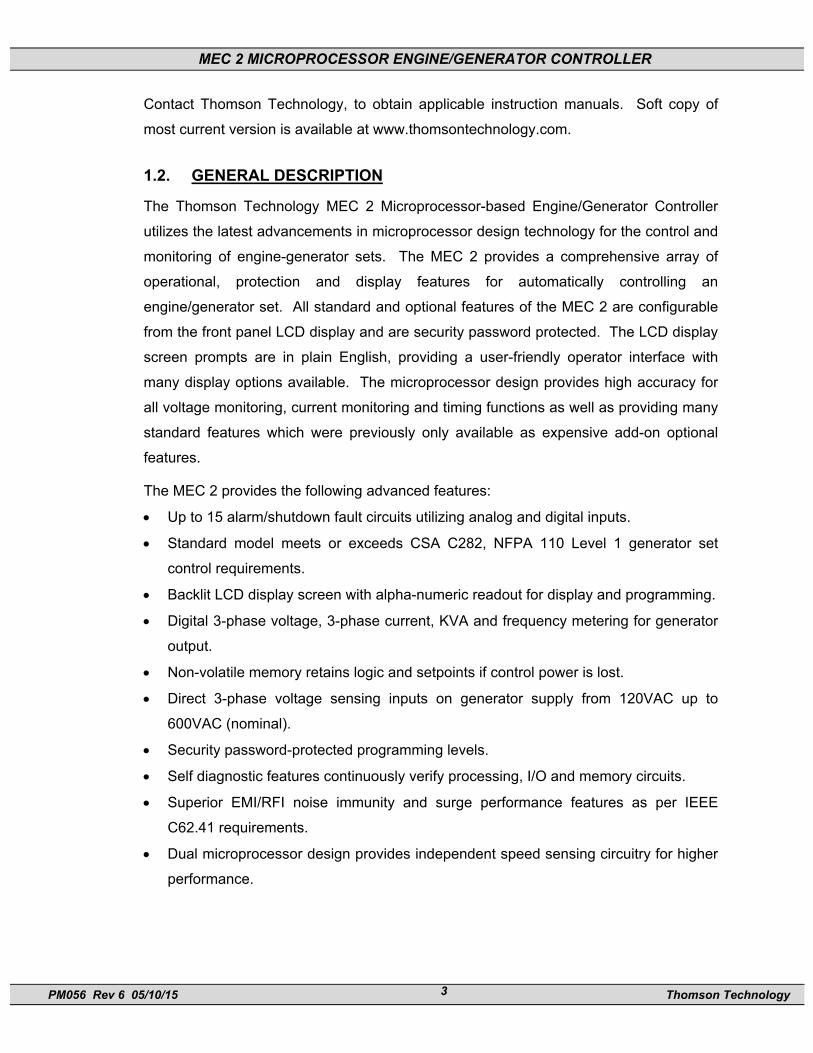
The MEC 2 provides the following advanced features:
• Up to 15 alarm/shutdown fault circuits utilizing analog and digital inputs.
• Standard model meets or exceeds CSA C282, NFPA 110 Level 1 generator set
control requirements.
• Backlit LCD display screen with alpha-numeric readout for display and programming.
• Digital 3-phase voltage, 3-phase current, KVA and frequency metering for generator
output.
• Non-volatile memory retains logic and setpoints if control power is lost.
• Direct 3-phase voltage sensing inputs on generator supply from 120VAC up to
600VAC (nominal).
• Security password-protected programming levels.
• Self diagnostic features continuously verify processing, I/O and memory circuits.
• Superior EMI/RFI noise immunity and surge performance features as per IEEE
C62.41 requirements.
• Dual microprocessor design provides independent speed sensing circuitry for higher
performance.

MEC 2 MICROPROCESSOR ENGINE/GENERATOR CONTROLLER
PM056 Rev 6 05/10/15 Thomson Technology 4
This equipment contains static-sensitive parts. Please observe the following anti-static
precautions at all times when handling this equipment. Failure to observe these
precautions may cause equipment failure and/or damage.
• Discharge body static charge before handling the equipment (contact a grounded
surface and maintain contact while handling the equipment, a grounded wrist strap
can/should also be utilized).
• Do not touch any components on the printed circuit board with your hands or any
other conductive equipment.
• Do not place the equipment on or near materials such as Styrofoam, plastic and
vinyl. Place the equipment on grounded surfaces and only use an anti-static bag for
transporting the equipment.
2. INSTALLATION
2.1. GENERAL INFORMATION
NOTE: Installations should be done according to all applicable electrical regulation codes as required.
The following installation guidelines are provided for general information only pertaining to typical site installations. For specific site installation information, consult Thomson Technology as required. Note: Factory installations of THOMSON TECHNOLOGY supplied control panels that have been tested and proven may deviate from these recommendations.
CAUTION!!! All installation and/or service work performed must be done by qualified personnel only. Failure to do so may cause personal injury or death.
2.2. BATTERY SUPPLY INPUT The MEC 2 can operate on any battery supply from 10 to 30 volts DC. The battery DC negative or common conductor must be grounded to the main generator-set frame
MEC 2 MICROPROCESSOR ENGINE/GENERATOR CONTROLLER
PM056 Rev 6 05/10/15 Thomson Technology 5
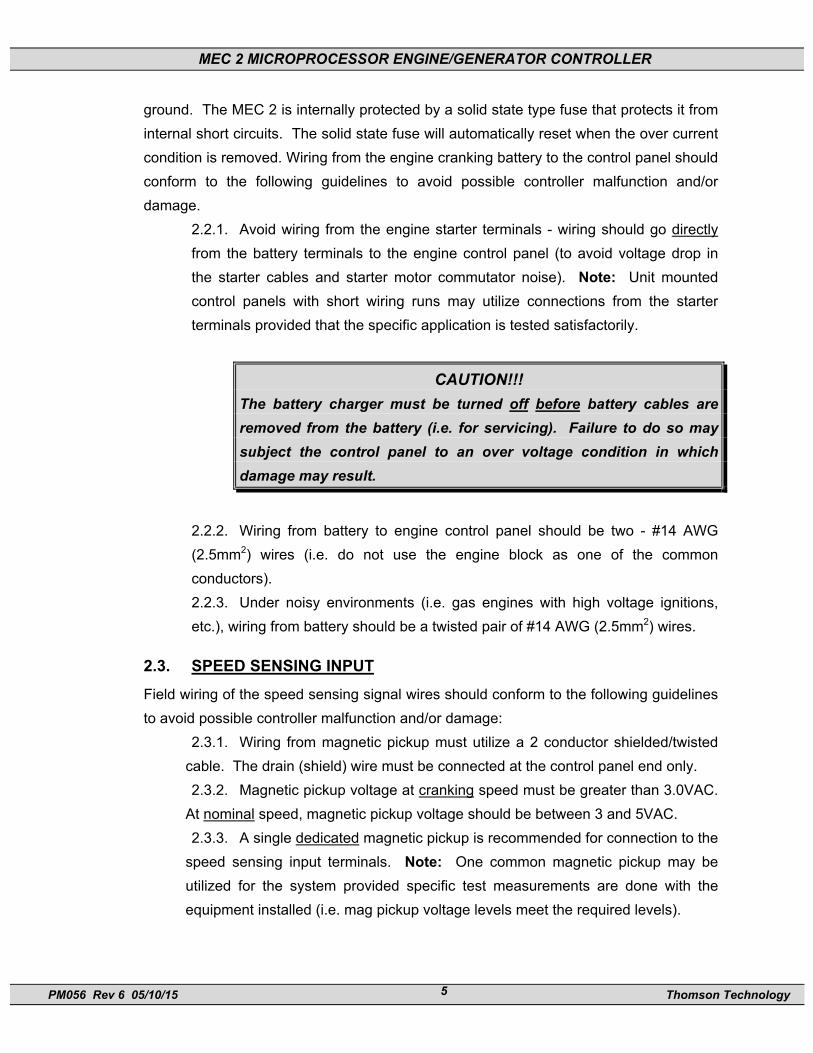
ground. The MEC 2 is internally protected by a solid state type fuse that protects it from internal short circuits. The solid state fuse will automatically reset when the over current condition is removed. Wiring from the engine cranking battery to the control panel should conform to the following guidelines to avoid possible controller malfunction and/or damage.
2.2.1. Avoid wiring from the engine starter terminals - wiring should go directly from the battery terminals to the engine control panel (to avoid voltage drop in the starter cables and starter motor commutator noise). Note: Unit mounted control panels with short wiring runs may utilize connections from the starter terminals provided that the specific application is tested satisfactorily.
CAUTION!!! The battery charger must be turned off before battery cables are removed from the battery (i.e. for servicing). Failure to do so may subject the control panel to an over voltage condition in which damage may result.
2.2.2. Wiring from battery to engine control panel should be two - #14 AWG (2.5mm2) wires (i.e. do not use the engine block as one of the common conductors). 2.2.3. Under noisy environments (i.e. gas engines with high voltage ignitions, etc.), wiring from battery should be a twisted pair of #14 AWG (2.5mm2) wires.
2.3. SPEED SENSING INPUT Field wiring of the speed sensing signal wires should conform to the following guidelines to avoid possible controller malfunction and/or damage:
2.3.1. Wiring from magnetic pickup must utilize a 2 conductor shielded/twisted cable. The drain (shield) wire must be connected at the control panel end only. 2.3.2. Magnetic pickup voltage at cranking speed must be greater than 3.0VAC.
At nominal speed, magnetic pickup voltage should be between 3 and 5VAC. 2.3.3. A single dedicated magnetic pickup is recommended for connection to the
speed sensing input terminals. Note: One common magnetic pickup may be utilized for the system provided specific test measurements are done with the equipment installed (i.e. mag pickup voltage levels meet the required levels).

MEC 2 MICROPROCESSOR ENGINE/GENERATOR CONTROLLER
PM056 Rev 6 05/10/15 Thomson Technology 6
2.4. DC VOLTAGE INPUTS All DC voltage inputs to the MEC 2 are optically isolated and filtered for protection from noise spikes and transients. Input wiring must be routed so that it is not near electrically "noisy" wiring such as ignition, starter wires or main AC power conductors. All contacts must be “dry” (i.e. non-powered) and one side must be connected to the common DC negative conductor.
2.5. AC VOLTAGE INPUT The MEC 2 can accept direct AC voltage input from 120-600VAC (nominal). Note: Direct input voltage sensing can only be used when the generator utilizes a single phase 3 wire or 3 phase, 4 wire distribution system with a solidly grounded neutral conductor. For 3 phase 3 wire systems (i.e. no neutral) or high voltage systems, potential transformers must be used. Refer to FIGURES #1 - 4 for voltage sensing connections. To display generator line to neutral voltage in a 3 phase 4 wire system, the neutral must be connected as shown.

MEC 2 MICROPROCESSOR ENGINE/GENERATOR CONTROLLER
PM056 Rev 6 05/10/15 Thomson Technology 7
������������������������������������������������������������������������������������������������������������������������������������������������������������������������������������������������������������
GRD
MEC 2
FIGURE #1
3Ø, 4W 208/380/480/600VAC DIRECT SENSINGSOLIDLY GROUNDED NEUTRAL SYSTEM
VOLTAGE INPUTS600VAC L-L, 347VAC L-N380VAC L-L, 220VAC L-N480VAC L-L, 277VAC L-N208VAC L-L, 120VAC L-N
VA
VB
VC
VN
GRD
BA C N
������������������������������������������������������������������������������������������������������������������������������������������������������������������������������������������������������������������������������
������������������������������������������������������������������������������������������������������������������������������������������������������������������������������������������������������
GEN. GRD
A B C
N
������������������������������������������������������������������������������������������������������������������������������������������������������������������������������������������������
GRD
MEC 2
FIGURE #2
1Ø, 3W 120/240VAC DIRECT SENSINGSOLIDLY GROUNDED NEUTRAL SYSTEM
VOLTAGE INPUTS240VAC L-L, 120VAC L-NNote: L1 and L2 phasevoltages must be 120Vacwhen referenced to commonneutral. (Delta connectedgenerators required PTs as perfigure#3 & no phase C PT)
VA
VB
VC
VN
GRD
L2L1 N
������������������������������������������������������������������������������������������������������������������������������������������������������������������������������������������������������������������������
������������������������������������������������������������������������������������������������������������������������������������������������������������������������������������������������
GEN. GRD
L1 L2
N
No Connection
����������������������������������������������������������������������������������������������������������������������������������������������������������������������������������������������������������������
GRD
MEC 2
FIGURE #3
3Ø, 4W WYE PT's
SECONDARY PT VOLTAGE208VAC L-L, 120VAC L-N120VAC L-L, 69VAC L-N
VA
VB
VC
VN
GRD
BA C N
������������������������������������������������������������������������������������������������������������������������������������������������������������������������������������������������������������������������������
���������������������������������������������������������������������������������������������������������������������������������������������������������������������������������������������������������������������������������������
GEN.N
120
120
120
GRD
A B C
����������������������������������������������������������������������������������������������������������������������������������������������������������������������������������������������������������������
GRD
MEC 2
FIGURE #4
3Ø, 3W DELTA PT's
SECONDARY PT VOLTAGE120VAC L-L(NO NEUTRAL)
VA
VB
VC
VN
GRD
120
120
GRD
BA C
������������������������������������������������������������������������������������������������������������������������������������������������������������������������������������������������������������������������������
���������������������������������������������������������������������������������������������������������������������������������������������������������������������������������������������������������������������������������������
GEN.
A B C
N
No Connection
G:\ENGINEER\PRODUCTS\MEC2\MEC2_08.VSD REV. 1 02/01/23

MEC 2 MICROPROCESSOR ENGINE/GENERATOR CONTROLLER
PM056 Rev 6 05/10/15 Thomson Technology 8
2.6. AC CURRENT INPUT Current transformers (CT’s) must be used to supply the MEC 2 current inputs. CT polarity is not critical for correct circuit operation. Note: The CT secondary common conductors must be externally grounded for correct operation. CT’s must be rated for a minimum of 1.5VA output at the specified accuracy.
CAUTION!!! When installing or performing any service work on CT circuits, always de-energize the system before proceeding with any work. Never open circuit an energized CT as extreme high voltages may result which may cause serious injury or death.
2.7. OUTPUTS All outputs from the MEC 2 are relay driven contacts. Relay contacts have a 10A/240VAC resistive (3 Amp inductive 0.4pf), 8A/24Vdc rating and are isolated Form A & Form C types. Interposing relays are recommended between the MEC 2 outputs and end devices to prevent internal damage due to possible excessive current draw and/or damage should an external fault occur. Note: These outputs will require external over current protection (Maximum 10 Amp). The use of AC or DC operated solenoids or relays in control systems can sometimes cause high voltage spikes on the DC power supply, which may cause electronic devices to fail. Transient suppression devices are recommended for all inductive devices sharing wiring or if physically located near engine/generator control panels. For DC operated relays or solenoids, use a suitably rated counter EMF Diode (or commonly known as “freewheeling” diode). For AC operated relays or solenoids, use a suitably rated metal oxide varistor (MOV) or capacitor/resistor suppressor.
2.8. EXTERNAL PANEL CONTROL WIRING As a minimum, all control wiring shall conform to the local regulatory authority on electrical installations. Specific wire sizes for typical circuits (of distances up to 100ft (30m) ) are as follows:
2.8.1. Battery Control Power #14 AWG (2.5mm2) 2.8.2. Engine Alarm/Shutdown Contacts #16 AWG (1.5mm2) 2.8.3. Remote Start Contact for Transfer Switch #14 AWG (2.5mm2)

MEC 2 MICROPROCESSOR ENGINE/GENERATOR CONTROLLER
PM056 Rev 6 05/10/15 Thomson Technology 9
2.8.4. Crank & Preheat Output Wiring #14 AWG (2.5mm2) (To pilot relays)
2.8.5. Speed Sensing Wiring #16 AWG (1.5mm2) 2 Conductor Shielded Cable
2.8.6. Metering Voltage Inputs #16 AWG (1.5mm2) 2.8.7. Metering Current Inputs (from CT’s) #14 AWG (2.5mm2) For distances exceeding 100 Ft. (30m) consult Thomson Technology. For unit mounted control panels, wire sizes may be reduced to the next smallest wire size available.
2.9. REMOTE START CONTACT FIELD WIRING Field wiring of a remote start contact from a transfer switch to a control panel should conform to the following guidelines to avoid possible controller malfunction and/or damage.
2.9.1. Remote start contact wires (2 - #14 AWG (2.5mm2) should be run in a separate conduit. 2.9.2. Avoid wiring near AC power cables to prevent pick-up of induced voltages. 2.9.3. An interposing relay may be required if field wiring distance is excessively long (i.e. greater than 100 feet (30m) and/or if a remote contact has a resistance of greater than 5.0 ohms. 2.9.4. The remote start contact must be voltage free (i.e. dry contact). The use of a “powered” contact will damage the engine controller.
2.10. MEC MOUNTING LOCATION/INSTALLATION The MEC 2 Engine-generator controller is designed for mounting directly onto a control panel door. Considerations should be given for the following:
• The controller should be installed in a dirt free, dry location away from extreme heat sources.
• The LCD window should be installed at an optimum height for operator viewing.
• Adequate space should be provided around the rear of the MEC 2 circuit board for control wiring.
• Verify that the intended AC voltage input to the controller does not exceed the maximum allowable level on the control panel door as per the applicable control panel certification standard.

MEC 2 MICROPROCESSOR ENGINE/GENERATOR CONTROLLER
PM056 Rev 6 05/10/15 Thomson Technology 10
The MEC 2 controller can be installed onto a door of a control panel using one of the following methods:
• The first method requires a special door cutout for the LCD display and LED’s as shown in FIGURE #6. This mounting method requires the lexan faceplate to be mounted directly onto the door of the control panel. The controller must be disassembled to mount on the door, then re-assembled. Refer to FIGURE #7 for correct assembly location of all parts.
• The second method of controller mounting requires a factory supplied adapter faceplate as shown in FIGURE #8. This method only requires a single large rectangular hole to be cut out of the door as shown in FIGURE #9.
2.11. FACEPLATE MOUNTING DIMENSIONS
��������
������
���� ���
268 mm.
126 mm.126 mm.
166
mm
.
49 mm.49 mm.
24 mm.24 mm.
75 m
m.
75 m
m.
OUTLINE OF PRINTED CIRCUITBOARD UNDER PANEL DOOR
4 HOLES4 mm. DIAMETER(3/16" DRILL)
33 m
m.
41 m
m.
7 mm.
16.5 mm.
20 m
m.
32 m
m.
�������������������������������������������������������������������������������������������������������������������������������������������������������������������������������������������������������������������������������������������������������������������������
80 mm.
���������������
���������������
����������
��������
����������
����������
��������
8 mm.8 mm.
TOP
CUTOUT
9 HOLES6 mm. DIAMETER(1/4" DRILL)
C
C
G:\ENGINEER\PRODUCTS\MEC20_07.VSD
FIGURE #6
MEC 2 MICROPROCESSOR ENGINE/GENERATOR CONTROLLER
PM056 Rev 6 05/10/15 Thomson Technology 11
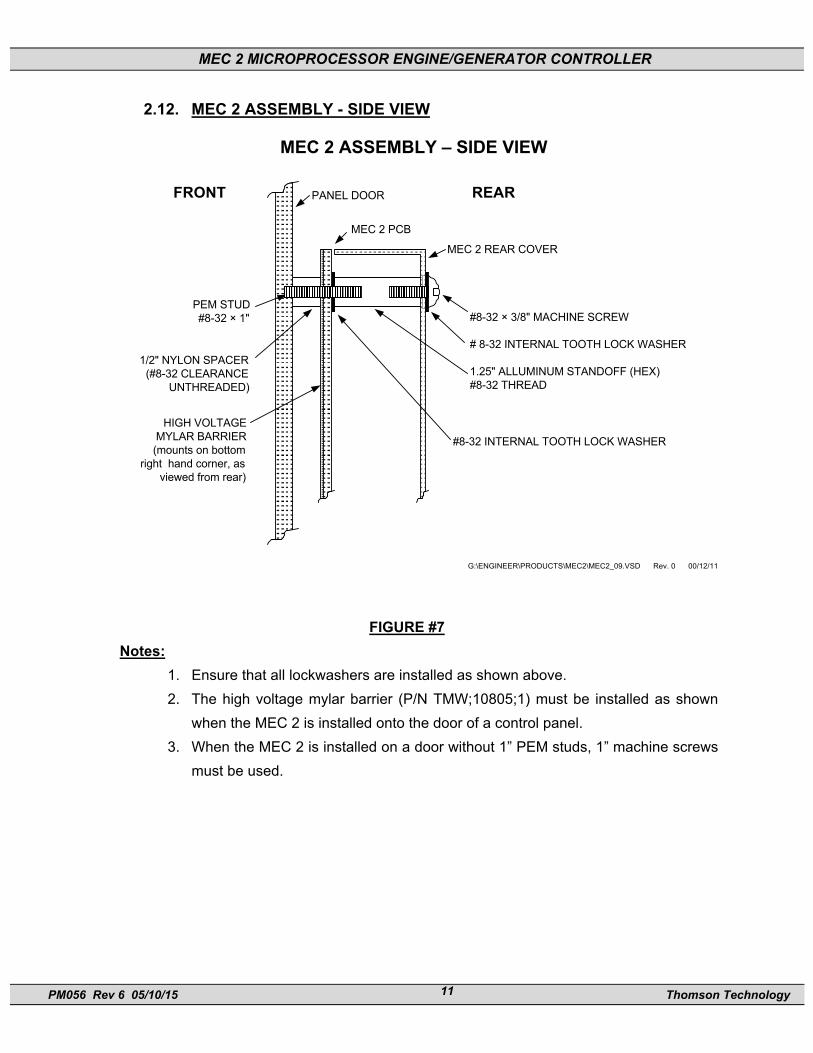
2.12. MEC 2 ASSEMBLY - SIDE VIEW
MEC 2 ASSEMBLY – SIDE VIEW������������������������������������������������������������������������������������������������������������������������������������������������������������������������������������������������
����������������������������������������������������������������������������������������������������������������������������������������������������������������������������������������������������������������������������������������������������������������������������������������������������������������������������������������������������������������������������������������������������������������������������������������������������������������������������������������������������������������������������������������������������������������������������������������������������������������������������������������������������������������������������������������������������������������������������������������������������������������������������������������������������������������������������������������������������������������������������������������������������������������������������������������������������������������������������������������������������������������������������������������������������������������������������������������������������������������������������������������������������������������������������������������������������������������������������������������������������������������������������������������������������������������������������������������������������������������������������������������������������������������������������������������������������������������������������������������������������������������������������������������������������������������������������������������������������������������������������������������������������������������������������������������������������������������������������������������������������������������������������������������������������������������������������������������������������������������������������������������������������������������������������������������������������������������������������������������������������������������������������������������������������������������������������������������������������������������������������������������������������������������������������������������������������������������������������������������������������������������������������������������������������������������������������������������������������������������������������������������������������������������������������������������������������������������������������������������������������������������������������������������������������������������������������������������������������������������������������������������������������������������������������������������������������������������������������������������������������������������������������������������������������������������������������������������������������������������������������������������������������������������������������������������������������������������������������������������������������������������������������������������������������������������������������������������������������������������������������������������������������������������������������������������������������������������������������������������������������������������������������������������������������������������������������������������������������������������������������������������������������������������������������������������������������������������������������������������������������������������������������������������������������������������������������������������������������������������������������������������������������������������������������������������������������������������������������������������������������������������������������������������������������������������������������������������������������������������������������������������������������������������������������������������������������������������������������������������������������������������������������������������������������������������������������������������������������������������������������������������������������������������������������������������������������������������������������������������������������������������������������������������������������������������������������������������������������������������������������������������������������������������������������������������������������������������������������������������������������������������������������������������������������������������������������������������������������������������������������������������������������������������������������������������������������������������������������������������������������������������������������������������������������������������������������������������������������������������������������������������������������������������������������������������������������������������������������������������������������������������������������������������������������������������������������������������������������������������������������������������������������������������������������������������������������������������������������������������������������������������������������������������������������������������������������������������������������������������������������������������������������������������������������������������������������������������������������������������������������������������������������������������������������������������������������������������������������������������������������������������������������������������������������������������������������������������������������������������������������������������������������������������������������������������������������������������������������������������������������������������������������������������������������������������������������������������������������������������������������������������������������������������������������������������������������������������������������������������������������������������������������������������������������������������������������������������������������������������������������������������������������������������������������������������������������������������������������������������������������������������������������������������������������������������������������������������������������������������������������������������������������������������������������������������������������������������������������������������������������������������������������������������������������������������������������������������������������������������������������������������������������������������������������������������������������������������������������������������������������������������������������������������������������������������������������������������������������������������������������������������������������������������������������������������������������������������������������������������������������������������������������������������������������������������������������������������������������������������������������������������������������������������������������������������������������������������������������������������������������������������������������������������������������������������������������������������������������������������������������������������������������������������������������������������������������������������������������������������������������������������������������������������������������������������������������������������������������������������������������������������������������������������������������������������������������������������������������������������������������������������������������������������������������������������������������������������������������������������������������������������������������������������������������������������������������������������������������������������������������������������������������������������������������������������������������������������������������������������������������������������������������������������������������������������������������������������������������������������������������������������������������������������������������������������������������������������������������������������������������������������������������������������������������������������������������������������������������������������������������������������������������������������������������������������������������������������������������������������������������������������������������������������������������������������������������������������������������������������������������������������������������������������������������������������������������������������������������������������������������������������������������������������������������������������������������������������������������������������������������������������������������������������������������������������������������������������������������������������������������������������������������������������������������������������������������������������������������������������������������������������������������������������������������������������������������������������������������������������������������������������������������������������������������������������������������������������������������������������������������������������������������������������������������������������������������������������������������������������������������������������������������������������������������������������������������������������������������������������������������������������������������������������������������������������������������������������������������������������������������������������������������������������������������������������������������������������������������������������������������������������������������������������������������������������������������������������������������������������������������������������������������������������������������������������������������������������������������������������������������������������������������������������������������������������������������������������������������������������������������������������������������������������������������������������������������������������������������������������������������������������������������������������������������������������������������������������������������������������������������������������������������������������������������������������������������������������������������������������������������������������������������������������������������������������������������������������������������������������������������������������������������������������������������������������������������������������������������������������������������������������������������������������������������������������������������������������������������������������������������������������������������������������������������������������������������������������������������������������������������������������������������������������������������������������������������������������������������������������������������������������������������������������������������������������������������������������������������������������������������������������������������������������
��������������������������������
PANEL DOOR
MEC 2 PCB
MEC 2 REAR COVER
#8-32 × 3/8" MACHINE SCREW
# 8-32 INTERNAL TOOTH LOCK WASHER
1.25" ALLUMINUM STANDOFF (HEX)#8-32 THREAD
#8-32 INTERNAL TOOTH LOCK WASHER
1/2" NYLON SPACER(#8-32 CLEARANCE
UNTHREADED)
PEM STUD#8-32 × 1"
G:\ENGINEER\PRODUCTS\MEC2\MEC2_09.VSD Rev. 0 00/12/11
��������������������������������������������������������������������
����������������������������������
REARFRONT
HIGH VOLTAGEMYLAR BARRIER(mounts on bottom
right hand corner, asviewed from rear)
��������������������������������������������������������������
FIGURE #7 Notes:
1. Ensure that all lockwashers are installed as shown above. 2. The high voltage mylar barrier (P/N TMW;10805;1) must be installed as shown
when the MEC 2 is installed onto the door of a control panel. 3. When the MEC 2 is installed on a door without 1” PEM studs, 1” machine screws
must be used.
MEC 2 MICROPROCESSOR ENGINE/GENERATOR CONTROLLER
PM056 Rev 6 05/10/15 Thomson Technology 12
������
������
��� ���
11.5 in
7.5
in
��������������������������������������������������������������������������������������������������������������������������������������������������������������������������������������������������������������������������������
���������������
���������������
����������
����������
����������
����������
����������
TOPC
C
CUTOUT
9 HOLES1/4" DIAMETER
4 STUDS #8/321/4"
1/4"
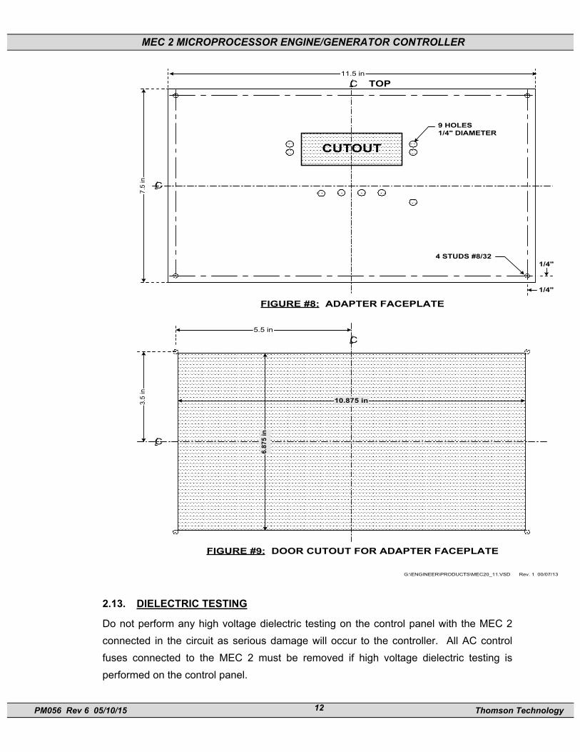
FIGURE #8: ADAPTER FACEPLATE
G:\ENGINEER\PRODUCTS\MEC20_11.VSD Rev. 1 00/07/13
��� ���
������
������
5.5 in
������������������������������������������������������������������������������������������������������������������������������������������������������������������������������������������������������������������������������������������������������������������������������������������������������������������������������������������������������������������������������������������������������������������������������������������������������������������������������������������������������������������������������������������������������������������������������������������������������������������������������������������������������������������������������������������������������������������������������������������������������������������������������������������������������������������������������������������������������������������������������������������������������������������������������������������������������������������������������������������������������������������������������������������������������������������������������������������������������������������������������������������������������������������������������������������������������������������������������������������������������������������������������������������������������������������������������������������������������������������������������������������������������������������������������������������������������������������������������������������������������������������������������������������������������������������������������������������������������������������������������������������������������������������������������������������������������������������������������������������������������������������������������������������������������������������������������������������������������������������������������������������������������������������������������������������������������������������������������������������������������������������������������������������������������������������������������������������������������������������������������������������������������������������������������������������������������������������������������������������������������������������������������������������������������������������������������������������������������������������������������������������������������������������������������������������������������������������������������������������������������������������������������������������������������������������������������������������������������������������������������������������������������������������������������������������������������������������������������������������������������������������������������������������������������������������������������������������������������������������������������������������������������������������������������������������������������������������������������������������������������������������������������������������������������������������������������������������������������������������������������������������������������������������������������������������������������������������������������������������������������������������������������������������������������������������������������������������������������������������������������������������������
3.5
in
C
C
FIGURE #9: DOOR CUTOUT FOR ADAPTER FACEPLATE
10.875 in
6.87
5 in
2.13. DIELECTRIC TESTING
Do not perform any high voltage dielectric testing on the control panel with the MEC 2 connected in the circuit as serious damage will occur to the controller. All AC control fuses connected to the MEC 2 must be removed if high voltage dielectric testing is performed on the control panel.

MEC 2 MICROPROCESSOR ENGINE/GENERATOR CONTROLLER
PM056 Rev 6 05/10/15 Thomson Technology 13
3. DESCRIPTION The MEC 2 controller consists of three parts; a Lexan faceplate which is mounted externally on the enclosure door, a printed circuit board (PCB) which is mounted inside the enclosure door, and a rear cover for the PCB.
3.1. LEXAN FACEPLATE The Lexan faceplate is shown as in FIGURE #10. The Lexan pushbuttons are connected to the main PCB via plug-in ribbon cable. The main features of the Lexan faceplate are described as follows with reference to FIGURE #10.
MEC2_03.VSD Rev. 0 00/12/11
DECREMENT INCREMENT
SILENCE RESET
SHUTDOWN
ALARM READY
SPEED SIGNAL
EMERGENCYSTOPRUN OFF AUTO LOAD
TEST
EXIT ENTER
14
3
2
13 1
6
7
4
11
12
5
8
9
10
LAMP TEST
MICROPROCESSOR ENGINE CONTROLLERMEC 2
FIGURE #10
LCD viewing window. The LCD display is mounted on the main PCB that is visible through the lexan faceplate viewing window.
EXIT pushbutton. The EXIT function is used to scroll backwards through the status menus or programming prompts to the previous item. The EXIT function is used to “exit” the programming menu by holding this button down for approximately 2 seconds while in the programming mode.
DECREMENT pushbutton. The DECREMENT function is used to change a programming value while in the programming mode. When this pushbutton is

MEC 2 MICROPROCESSOR ENGINE/GENERATOR CONTROLLER
PM056 Rev 6 05/10/15 Thomson Technology 14
held down, the displayed value will be “decremented” to a lower value as desired. Note: The longer the pushbutton is held down, the faster the value will be decremented.
INCREMENT pushbutton. The INCREMENT function is used to change a programming value while in the programming mode or to select a desired programming menu loop. When this pushbutton is held down, the displayed value will be “incremented” to a higher value as desired. Note: The longer the pushbutton is held down, the faster the value will be incremented.
ENTER pushbutton. The ENTER function is used to scroll forwards through the status menus or programming prompts to the next item. The ENTER function is used to “enter” a programming mode as well as accepting changed programming values. Note: In the programming mode, the longer the ENTER pushbutton is held down, the faster the next menu prompts will appear.
RUN pushbutton and LED light viewing window. The RUN function is used to initiate a manual start signal to the engine-generator set. Refer to the operating instructions for detailed information.
OFF pushbutton and LED light viewing window. The OFF function is used to initiate a stop signal to the engine-generator set. Refer to the operating instructions for detailed information.
AUTO pushbutton and LED light viewing window. The AUTO function is used to initiate automatic operation of the engine-generator set. Refer to the operating instructions for detailed information.
LOAD TEST pushbutton and LED light viewing window. The LOAD TEST function is used to initiate load test of the engine-generator set when connected to an associated transfer switch. Refer to the operating instructions for detailed information.
EMERGENCY STOP pushbutton and LED light viewing window. The EMERGENCY STOP function is used to initiate an emergency stop signal to the engine-generator set. Refer to the operating instructions for detailed information.
11 READY LED light viewing window. The READY LED illuminates when the engine-generator set is set for automatic operation and no shutdown or alarm faults have been activated.
12 SPEED SIGNAL LED light viewing window. The SPEED SIGNAL LED illuminates when the engines speed signal is detected (i.e. the engine is turning over).
13 ALARM LED light viewing window. The ALARM LED illuminates (flashes)

MEC 2 MICROPROCESSOR ENGINE/GENERATOR CONTROLLER
PM056 Rev 6 05/10/15 Thomson Technology 15
when any pre-programmed alarm fault has been activated. 14 SHUTDOWN LED light viewing window. The SHUTDOWN LED
illuminates (flashes) when any pre-programmed shutdown fault has been activated.
3.2. PRINTED CIRCUIT BOARD The printed circuit board (PCB) is shown in FIGURE #11. The PCB contains the following user interface items:
MEC 2 CIRCUIT BOARD LAYOUT
������������
�����������
����������
����������
�����
17MP1 MP2 1TB2
TB1
IN
IC
IB
IA
VN
VC
VB
VA
WATCHDOGREMOTE STARTCRANKRUNCOM FAIL
TB3 18 38
TB4
G:\ENGINEER\PRODUCTS\MEC2MEC2_02.VSD Rev.2 02/01/23DRAWING SCALE (mm) = .6:1
B+ B- GRD
R115
CONTRAST
J6
ExpansionPort
FIGURE #11

MEC 2 MICROPROCESSOR ENGINE/GENERATOR CONTROLLER
PM056 Rev 6 05/10/15 Thomson Technology 16
3.2.1. TERMINAL BLOCKS Four terminal blocks are located on the PCB as follows: TB1 AC Voltage and Current sensing terminal block (120-600VAC & 0-5AAC)
WARNING!!! Voltage sensing circuits are capable of lethal voltages while energized. Current transformer (CT) secondary circuits are capable of generating lethal voltages when open circuited with their primary circuit energized. Standard safety procedures should be followed and be performed by qualified personnel only. Failure to do so may cause personal injury and/or death.
TB2 Speed sensing and digital contact input terminal block TB3 Output contacts and engine temperature/pressure input signal terminal
block TB4 DC power input and ground connection terminal block
3.2.2. DIAGNOSTIC LED’S The MEC 2 controller provides five diagnostics LED lights that are mounted on the rear of the printed circuit board as per FIGURE #11. Their functions are described as follows:
3.2.2.1.WATCHDOG This LED flashes on and off at irregular intervals which indicates that the microprocessor is functioning normally. 3.2.2.2.REMOTE START This LED is illuminated whenever the MEC 2 has received a remote start signal. 3.2.2.3.CRANK This LED is illuminated whenever the MEC 2 is initiating an engine cranking signal. 3.2.2.4.RUN This LED is illuminated whenever the MEC 2 has called the engine to run. 3.2.2.5.COMMON FAIL This LED is illuminated whenever the MEC 2 has initiated a common fail signal (i.e. whenever an alarm or shutdown fault has been activated).
MEC 2 MICROPROCESSOR ENGINE/GENERATOR CONTROLLER
PM056 Rev 6 05/10/15 Thomson Technology 17
Note: All LED’s will be illuminated whenever a lamp test function is performed.
3.2.3. CONTRAST ADJUSTMENT (R115) A contrast adjustment potentiometer is located on the rear of the PCB and is factory set for ambient temperatures of 15° to 30° Celsius. For different ambient temperatures, consult the factory for adjustment procedures.
4. FAULT CIRCUIT DESCRIPTIONS The MEC 2 engine-generator controller utilizes many analog and digital inputs to perform both monitoring and control functions. Three types of fault circuits are used to monitor and control the engine-generator set. The first type is Internal Fault Circuits that are derived from a combination of digital and analog inputs. The second type is Digital Input Fault circuits that are initiated from external contact inputs. The third type is Analog Input Fault circuits that are initiated from external analog signal inputs. The following functional block diagram (FIGURE #12) shows how all input/output fault circuits are organized.

MEC 2 MICROPROCESSOR ENGINE/GENERATOR CONTROLLER
PM056 Rev 6 05/10/15 Thomson Technology 18
4.1. MEC 2 FUNCTIONAL BLOCK DIAGRAM
DIGITAL INPUTCONTACTS (N/O or N/C)
PROGRAMMABLECONTACT #110A, 240Vac, 8A/24VdcRESISTIVE
G:\ENGINEER\PRODUCTS\MEC2_05.VSD
Rev. 4 02/01/23
����������MAGNETICPICKUP
RPMDISPLAY
FAULTLOGIC
FEATURE
TEMP.DISPLAY
FAULTLOGIC
PRESS.DISPLAY
FAULTLOGIC
DCVOLT
DISPLAY
FAULTLOGIC
ACVOLT/FREQ.
DISPLAY
1
STANDARD FAULTS OUTPUT CONTACTS
ACCURRENTDISPLAY
FAULT
LOGIC
ENGINE TEMPERATURESENDER
ENGINE OIL PRESSURESENDER
OVERSPEEDSHUTDOWN
SWITCH NOT IN AUTOALARM
LOSS OF SPEEDALARM/SHUTDOWN
OVERCRANKSHUTDOWN
LOW ENGINE TEMP.ALARM
HIGH ENGINE TEMP.ALARM
LOW OIL PRESSUREALARM
LOW OIL PRESSURESHUTDOWN
HIGH ENGINE TEMP.SHUTDOWN
LOW COOLANTLEVEL SHUTDOWN
LOW FUEL LEVELALARM
CRANK10A, 240Vac, 8A/24VdcRESISTIVE
RUN10A, 240Vac, 8A/24VdcRESISTIVE
E. STOPEMERGENCY STOP
AUTO PUSHBUTTON
LOGIC
2
1
2
3
4
N/O
3 PHASE ACCURRENT
+–BATTERYVOLTAGE
3 PHASE ACVOLTAGE
V
LOW BATTERYVOLTAGE ALARM
HIGH BATTERYVOLTAGE ALARM
WEAK BATTERYALARM
DIGITAL FAULTLABEL LIST –EACH POINTPROGRAMMABLE
1
NOTES:
PROGRAMMABLEFUNCTION LIST
2
PROGRAMMABLECONTACT #210A, 240Vac, 8A/24VdcRESISTIVE
2
2
2
PROGRAMMABLECONTACT #310A, 240Vac, 8A/24VdcRESISTIVE
PROGRAMMABLECONTACT #410A, 240Vac, 8A/24VdcRESISTIVE
HIGH ENGINE TEMP.SHUTDOWN
LOW OIL PRESSURESHUTDOWN
UNDERVOLTAGESHUTDOWN
UNDERFREQUENCYSHUTDOWN
FIGURE #12
MEC 2 MICROPROCESSOR ENGINE/GENERATOR CONTROLLER
PM056 Rev 6 05/10/15 Thomson Technology 19
4.2. INTERNAL FAULT CIRCUITS The MEC 2 Engine Controller provides four internally activated fault circuits as described below. All internal fault circuits are provided as standard with every MEC 2 controller.
4.2.1. OVER CRANK The over crank fault circuit is initiated when the engine fails to start after the selected crank time or number of crank cycles. The over crank fault circuit is internally programmed as a latching shutdown fault and is not user programmable. Refer to the programming instructions for further information.
4.2.2. OVER SPEED The over speed fault circuit is initiated when the engine’s speed has increased above the over speed setpoint. The over speed fault circuit is internally programmed as a latching shutdown fault. The over speed shutdown fault circuit is programmable for the percentage of nominal engine speed (i.e. over speed setpoint) and for the transient time delay period. The programming prompts for over speed are located in the main menu programming loop. Refer to the programming instructions for further information.
4.2.3. LOSS OF SPEED The loss of speed fault circuit is initiated when the engine’s speed sensing circuit does not detect a speed signal for a period more than 2 seconds following a run signal. The loss of speed fault may be user programmed as a latching shutdown fault or alarm only. The programming prompts for loss of speed are located in the main menu programming loop. Refer to the programming instructions for further information.
4.2.4. SWITCH NOT IN AUTO The “Switch Not In Auto” fault circuit is initiated when the controller’s operating mode switch is changed from the auto position to any other position via the front mounted keypad. This fault is internally programmed as a non latching alarm. In the main programming loop, this alarm may be user programmed to initiate the common fail output relay.

MEC 2 MICROPROCESSOR ENGINE/GENERATOR CONTROLLER
PM056 Rev 6 05/10/15 Thomson Technology 20
4.3. DIGITAL FAULT INPUT CIRCUITS The MEC 2 Engine Controller provides four digital fault input circuits that are user programmable. Each digital fault input circuit is activated via a remote sensing contact that is external to the controller. Each digital fault input circuit may be programmed with a unique fault label description as stored in the controller’s non-volatile memory. The following digital fault labels are provided in each MEC 2 Engine Controller:
AIR DAMPER TRIPPED HIGH OIL LEVEL BAT CHARGER INPUT FAIL HIGH OIL TEMP BAT CHRG TROUBLE HIGH WINDING TEMP BREAKER TRIPPED LOW COOLANT LEVEL DC FAIL LOW ENGINE TEMP FAILED TO SYNC LOW FUEL PRESS GEN BREAKER OPEN LOW FUEL LEVEL GROUND FAULT LOW OIL LEVEL HIGH BEARING TEMP LOW OIL PRESSURE HIGH COOLER VIBRATION REMOTE EMERG. STOP HIGH ENGINE TEMP REVERSE POWER HIGH ENGINE VIBRATION BASIN RUPTURE HIGH FUEL LEVEL ATS IN BYPASS NO LOAD TEST FUEL LEAK *HIGHINTKMANFTEMP LOW FUEL PRESS VENT DAMPER FAIL BAT CHARGER FAIL HIGH FUEL LEVEL FAIL TO SYNC “Blank” (i.e. no text for unused inputs)
4.3.1. STANDARD DIGITAL FAULT CIRCUITS The MEC 2 is supplied from the factory with four standard digital fault circuits as follows:

MEC 2 MICROPROCESSOR ENGINE/GENERATOR CONTROLLER
PM056 Rev 6 05/10/15 Thomson Technology 21
FAULT NAME
FAULT ACTION
INPUT TERMINAL #
Low Oil Pressure Shutdown 1 High Engine Temperature Shutdown 2 Battery Charger Input Fail Alarm 3 Low Fuel Level Alarm 4
All faults require a customer connected contact to the MEC 2 input terminal as indicated. All fault circuits may be user field programmed for different control functions or alternate fault names. Note: Shutdown functions for Low Oil Pressure and High Engine Temperature may alternatively be provided via analog pressure and temperature sender inputs if programmed accordingly in the analog fault programming menu. Refer to Section 9.4 for further information.
4.4. ANALOG FAULT INPUT CIRCUITS The MEC 2 Engine Controller provides up to eight analog fault input circuits that are user programmable. Each analog fault input circuit is activated via specific analog signal type.
WARNING!!! The analog protection circuits for voltage, frequency, current, engine oil pressure, engine temperature and engine speed will be set at factory default settings only. Final settings will be required to be set by the commissioning authority. Failure to do so may result in severe equipment failure or damage.
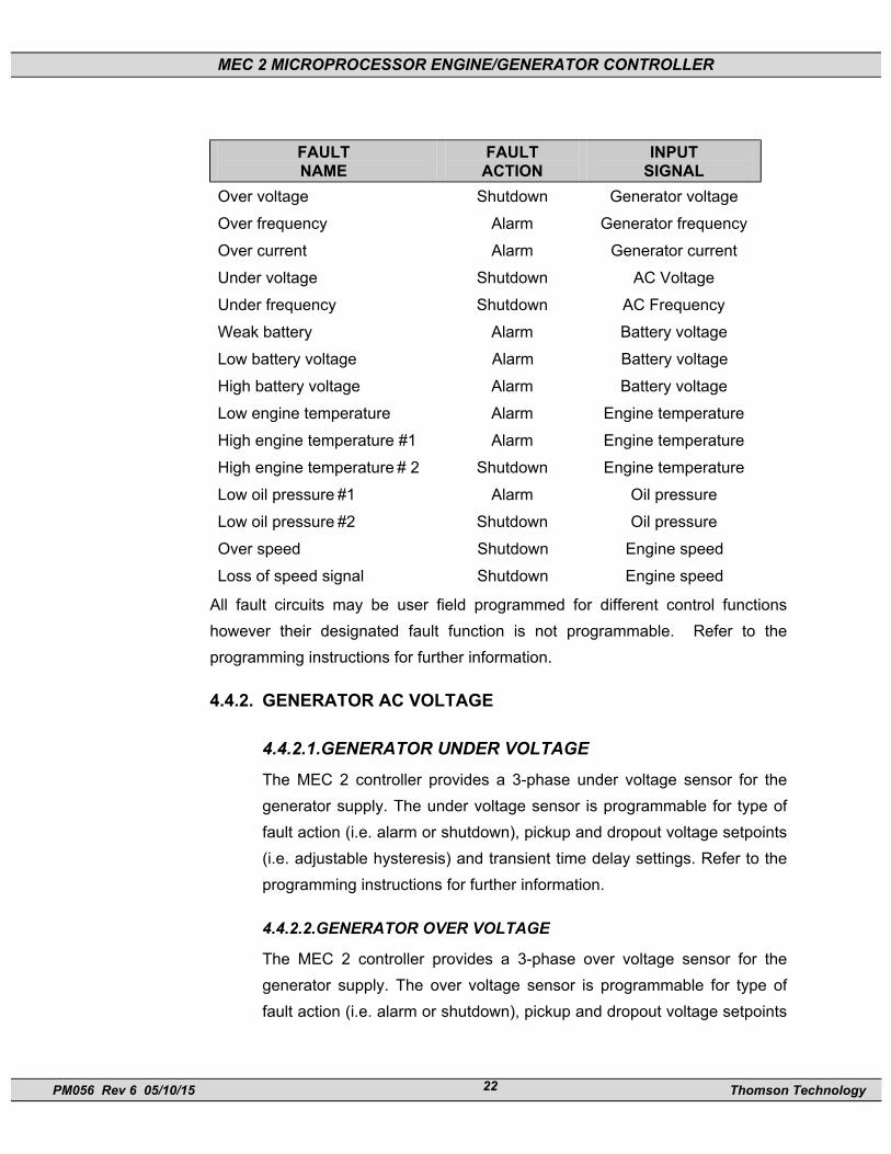
4.4.1. ANALOG FAULT CIRCUITS The MEC 2 is supplied from the factory with fifteen standard analog fault circuits as follows:
MEC 2 MICROPROCESSOR ENGINE/GENERATOR CONTROLLER
PM056 Rev 6 05/10/15 Thomson Technology 22
FAULT NAME
FAULT ACTION
INPUT SIGNAL
Over voltage Shutdown Generator voltage Over frequency Alarm Generator frequency Over current Alarm Generator current Under voltage Shutdown AC Voltage Under frequency Shutdown AC Frequency Weak battery Alarm Battery voltage Low battery voltage Alarm Battery voltage High battery voltage Alarm Battery voltage Low engine temperature Alarm Engine temperature High engine temperature #1 Alarm Engine temperature High engine temperature # 2 Shutdown Engine temperature Low oil pressure #1 Alarm Oil pressure Low oil pressure #2 Shutdown Oil pressure Over speed Shutdown Engine speed Loss of speed signal Shutdown Engine speed
All fault circuits may be user field programmed for different control functions however their designated fault function is not programmable. Refer to the programming instructions for further information.
4.4.2. GENERATOR AC VOLTAGE
4.4.2.1.GENERATOR UNDER VOLTAGE The MEC 2 controller provides a 3-phase under voltage sensor for the generator supply. The under voltage sensor is programmable for type of fault action (i.e. alarm or shutdown), pickup and dropout voltage setpoints (i.e. adjustable hysteresis) and transient time delay settings. Refer to the programming instructions for further information.
4.4.2.2.GENERATOR OVER VOLTAGE
The MEC 2 controller provides a 3-phase over voltage sensor for the generator supply. The over voltage sensor is programmable for type of fault action (i.e. alarm or shutdown), pickup and dropout voltage setpoints

MEC 2 MICROPROCESSOR ENGINE/GENERATOR CONTROLLER
PM056 Rev 6 05/10/15 Thomson Technology 23
(i.e. adjustable hysteresis) and transient time delay settings. Refer to the programming instructions for further information.
4.4.2.3.GENERATOR UNDER FREQUENCY The MEC 2 controller provides an under frequency sensor for the generator supply. The under frequency sensor is programmable for type of fault action (i.e. alarm or shutdown), frequency setpoint, and transient time delay settings. Refer to the programming instructions for further information.
4.4.2.4.GENERATOR OVER FREQUENCY
The MEC 2 controller provides an over frequency sensor for the generator supply. The over frequency sensor is programmable for type of fault action (i.e. alarm or shutdown), frequency setpoint, and transient time delay settings. Refer to the programming instructions for further information.
4.4.2.5.GENERATOR OVER CURRENT
The MEC 2 controller provides a 3-phase current sensor for the generator supply. The current sensor is programmable for type of fault action (i.e. alarm or shutdown), pickup current setpoint, and transient time delay settings. Refer to the programming instructions for further information.
4.4.3. BATTERY VOLTAGE ANALOG INPUT The MEC 2 battery voltage sensor measures DC voltage on terminals B+ and B- that are connected to the engines cranking battery. The battery voltage sensor provides information to perform the following control functions:
4.4.3.1.WEAK BATTERY ALARM The weak battery alarm fault circuit is activated when the battery voltage drops below a pre-determined setpoint for a specified time delay. The weak battery alarm will detect a low capacity (i.e. “weak”) battery condition during the cranking cycle. The weak battery alarm is programmed for a lower battery voltage setpoint and shorter time delay than the low battery alarm function. The weak battery alarm fault is programmable for voltage setpoint level, transient time delay settings and
MEC 2 MICROPROCESSOR ENGINE/GENERATOR CONTROLLER
PM056 Rev 6 05/10/15 Thomson Technology 24
other functions. Refer to the programming instructions for further information. 4.4.3.2.LOW BATTERY VOLTAGE ALARM The low battery voltage alarm fault circuit is activated when the battery voltage drops below a pre-determined setpoint for a specified time delay. The low battery voltage alarm fault is programmable for the voltage setpoint level, transient time delay settings and other functions. Refer to the programming instructions for further information. 4.4.3.3.HIGH BATTERY VOLTAGE ALARM The high battery voltage alarm fault circuit is activated when the battery voltage rises above a pre-determined setpoint for a specified time delay. The high battery voltage alarm fault is programmable for voltage setpoint level, transient time delay settings and other functions. Refer to the programming instructions for further information.
4.4.4. ENGINE TEMPERATURE ANALOG INPUT The MEC 2 engine temperature sensor measures a DC analog signal from an engine mounted sender. The MEC 2 software provides calibration for engine temperature to coordinate with the engine mounted sender and control logic to detect a wiring or sender failure (i.e. open or shorted signal). In case of a sender or wiring failure, the MEC 2 will display zero or 9999 °C and will initiate an alarm signal as programmed by the user. The engine temperature analog input provides the following control functions:
4.4.4.1.LOW ENGINE TEMPERATURE ALARM
The low engine temperature alarm fault circuit is activated when the engine temperature drops below a pre-determined setpoint for a specified time delay. The low engine temperature alarm fault is programmable for temperature setpoint level, transient time delay settings and other functions. Refer to the programming instructions for further information.
4.4.4.2.HIGH ENGINE TEMPERATURE #1 ALARM
The high engine temperature alarm fault circuit is activated when the engine temperature rises above a pre-determined setpoint for a specified time delay. The high engine temperature alarm fault is programmable for

MEC 2 MICROPROCESSOR ENGINE/GENERATOR CONTROLLER
PM056 Rev 6 05/10/15 Thomson Technology 25
the level of temperature setpoint, transient time delay settings and other functions. Refer to the programming instructions for further information.
4.4.4.3.HIGH ENGINE TEMPERATURE #2 SHUTDOWN
The high engine temperature shutdown fault circuit is activated when the engine temperature rises above a pre-determined setpoint for a specified time delay. The high engine temperature shutdown fault is programmable for the level of temperature setpoint, transient time delay settings and other functions. Refer to the programming instructions for further information. Note: High Engine Temperature shutdown may alternately be programmed and wired as a digital fault input contact. Refer to Section 9.5 for further details.
4.4.5. ENGINE OIL PRESSURE ANALOG INPUT The MEC 2 engine oil pressure sensor measures a DC analog signal from an engine mounted sender. The MEC 2 software provides calibration for oil pressure to coordinate with the engine mounted sender and control logic to detect a wiring or sender failure (i.e. open or shorted signal). In case of a sender or wiring failure, the MEC 2 will display zero or 9999 PSI and will initiate an alarm and/or shutdown signal as programmed by the user. The engine oil pressure analog input provides the following control function:
4.4.5.1.LOW OIL PRESSURE #1 ALARM
The low oil pressure alarm fault circuit is activated when the oil pressure drops below a pre-determined setpoint for a specified time delay. The low oil pressure alarm fault is programmable for pressure setpoint level, transient time delay settings and other functions. Refer to the programming instructions for further information.
4.4.5.2.LOW OIL PRESSURE #2 SHUTDOWN
The low oil pressure shutdown fault circuit is activated when the oil pressure drops below a pre-determined setpoint for a specified time delay. The low oil pressure shutdown fault is programmable for pressure setpoint level, transient time delay settings and other functions. Refer to the programming instructions for further information.
MEC 2 MICROPROCESSOR ENGINE/GENERATOR CONTROLLER
PM056 Rev 6 05/10/15 Thomson Technology 26
Note: Low Oil Pressure shutdown may alternately be programmed and wired as a digital fault input contact. Refer to Section 9.5 for further details.
4.4.6. ENGINE SPEED ANALOG INPUT The MEC 2 engine speed sensor measures AC voltage and frequency from an engine mounted magnetic pick-up. The engine speed sensor provides information to perform the following control functions:
Over speed shutdown Crank Disconnect control Loss of speed signal detection Starter Re-engage control RPM display
Refer to the programming instructions for further information.
5. CONTROL OUTPUT CONTACT DESCRIPTIONS All output contacts from the MEC 2 Engine Controller are non-powered (i.e. dry contacts) and are rated 10A/240VAC, 8A/28Vdc resistive (3A inductive, 0.4pf). Output contacts are not fused therefore external over current protection (maximum 10A) is required for all control circuits using these contacts. Contacts indicated on schematic drawings and connection diagrams are shown in a de-energized state and will change state upon activation of the specific control function.
5.1. RUN, CRANK OUTPUT CONTACTS The MEC 2 Controller provides two dedicated output contacts for basic control and alarm circuits as described below:
5.1.1. RUN OUTPUT The Run output contact is a Form A dry contact and is used to control the engines “run” circuit. This typically includes external control devices such as “fuel rack solenoids” or electronic governors. Note: An additional pilot relay will be required to energize high current devices that exceed the 10A resistive rating. The run output control logic provides an “energize to run signal” (i.e. the run contact closes when a run condition is activated). Note: For energize to stop control logic, refer to the programmable output control function.

MEC 2 MICROPROCESSOR ENGINE/GENERATOR CONTROLLER
PM056 Rev 6 05/10/15 Thomson Technology 27
5.1.2. CRANK OUTPUT The crank output contact is a Form A dry contact and is used to control an external crank pilot relay that directly controls the engine starter motor. Note: An external crank pilot relay is required to energize the high current starter motor pinion solenoid that exceeds the 10A resistive crank output contact rating. The crank output contact closes when a crank condition is activated and the contact will automatically open when crank disconnect speed is obtained and/or the generators output AC voltage exceeds 10% of nominal level. The generators output AC voltage is utilized for back-up crank disconnect protection should the speed sensor fail.
5.2. PROGRAMMABLE OUTPUT CONTACT The MEC 2 Controller provides four (4) standard programmable output contacts. Each programmable output is a Form C dry contact that is programmable for many different control functions. The programmable output may be user field programmed for the desired control function. The following programmable features are provided:
AIR FLAP UTILITY READY TO LOAD OIL BYPASS TIMER COMPLETE DIGITAL FAULTS #1 – #4 COMMON FAIL OVER SPEED SWITCH NOT IN AUTO LOSS OF SPEED SIGNAL ENGINE READY LOW BAT VOLTAGE ENGINE RUN (FUEL) HIGH BAT VOLTAGE PREHEAT WEAK BAT VOLTAGE ENGINE RUNNING LOW OIL PRESS #1 ALARM ATS TEST LOW OIL PRESS #2 SHUTDOWN COMMON ALARM HIGH ENG TEMP #1 ALARM COMMON SHUTDOWN HIGH ENG TEMP #2 SHUTDOWN EPS SUPPLYING LOAD OVER VOLTAGE OVER CURRENT OVER FREQUENCY UNDER VOLTAGE UNDER FREQUENCY
5.2.1. ENERGIZE TO STOP The designated programmable output relay will energize when a stop signal has been activated. The output will remain energized for 10 seconds once the engine has come to a complete stop, then de-energizes.

MEC 2 MICROPROCESSOR ENGINE/GENERATOR CONTROLLER
PM056 Rev 6 05/10/15 Thomson Technology 28
5.2.2. SWITCH NOT IN AUTO The designated programmable output relay will energize when the controller's operation mode switch is not in the auto position.
5.2.3. ENGINE READY The designated programmable output relay will energize when the engine controller's mode switch is in the auto mode and no shutdown or alarm conditions are present.
5.2.4. PREHEAT The designated programmable output relay will energize during the start delay timer period and cranking period until the engine starts and reaches crank disconnect speed. The preheat output is typically used for an engine starting aid such as glow plugs. Note: An external pilot relay is required to switch the high current glow plug load.
5.2.5. GEN READY TO LOAD The designated programmable output relay will energize when the generators
voltage and frequency exceeds predetermined setpoints (e.g. voltage 90%
nominal, frequency 95% nominal as user programmed) and a warmup time delay
period expires. Once the output has energized, it will remain latched on
irrespective of voltage/frequency levels until the controller either has a
stop/shutdown signal, or the engine’s speed drops below crank disconnect level.
The voltage, frequency and time delay levels are programmable. Refer to Section 9 for PROGRAMMING.
The Generator Ready To Load output is typically used in an Auto Mains Failure
(AMF) application. Refer to Section 8.3.5 for further details on sequence of
operation.
5.2.6. UTILITY READY TO LOAD
The designated programmable output relay will energize when the remote start
input has not been activated (i.e. contact on terminals 16 & 17 is not closed) and
the Return Delay & Neutral Delays have expired (if programmed). The output will
de-energize when the remote start input has been activated and the Engine Start
Delay & Warmup Delays have expired (if programmed). This output is typically
MEC 2 MICROPROCESSOR ENGINE/GENERATOR CONTROLLER
PM056 Rev 6 05/10/15 Thomson Technology 29
used for Auto Mains Failure (AMF) applications. Refer to Section 8.3.5 for further
details on the sequence of operation.
5.2.7. ENGINE RUNNING The designated programmable output relay will energize when the engine has started and has reached crank disconnect speed.
5.2.8. ENGINE RUN (FUEL) The designated programmable output relay will energize when the engine ”RUN”
(i.e. FUEL) energizes prior to the engine starting. The output will remain on until
the engine has reached a “stop” or “shutdown” command.
5.2.9. AIRFLAP The designated programmable output relay will energize when the engine’s speed exceeds the over speed setpoint level. The output will remain energized until the engine’s speed drops below the low speed setpoint (typically 5% of rated speed). Note: An external pilot relay will be required if the main air flap solenoid current rating exceeds the MEC 2 contact rating. (Refer to Section 2.7)
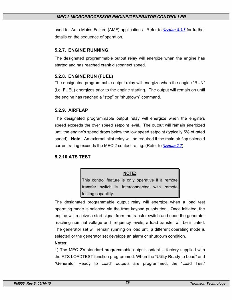
5.2.10.ATS TEST
NOTE: This control feature is only operative if a remote transfer switch is interconnected with remote testing capability.
The designated programmable output relay will energize when a load test operating mode is selected via the front keypad pushbutton. Once initiated, the engine will receive a start signal from the transfer switch and upon the generator reaching nominal voltage and frequency levels, a load transfer will be initiated. The generator set will remain running on load until a different operating mode is selected or the generator set develops an alarm or shutdown condition. Notes: 1) The MEC 2’s standard programmable output contact is factory supplied with the ATS LOADTEST function programmed. When the “Utility Ready to Load” and “Generator Ready to Load” outputs are programmed, the “Load Test”

MEC 2 MICROPROCESSOR ENGINE/GENERATOR CONTROLLER
PM056 Rev 6 05/10/15 Thomson Technology 30
programmable output is not required as the engine starting logic is internally initiated. 2) When both “Utility Ready to Load” and “Generator Ready to Load” programmable outputs are programmed and utilized in a AMF control configuration, the ATS Output is not utilized (i.e. engine start signal is internally generated).
5.2.11.OIL BYPASS TIMER COMPLETE The designated programmable output relay will energize upon the expiry of the controller's oil bypass delay timer function, following a normal start sequence.
5.2.12.COMMON ALARM The designated programmable output relay will energize when any alarm fault circuit has been activated.
5.2.13.COMMON FAIL The designated programmable output relay will energize when any alarm or shutdown fault circuit has been activated.
5.2.14.COMMON SHUTDOWN The designated programmable output relay will energize when any shutdown fault circuit has been activated.
5.2.15.EPS SUPPLYING LOAD The designated programmable output relay will energize when the engine is running and the generator is supplying current to the load more than or equal to 10% of nominal CT ratio.
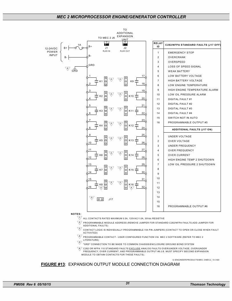
6. EXPANSION OUTPUT MODULE OPTION Optional expansion output modules are available for the MEC 2 engine generator controller. Each module can provide 16 individual fault output contacts for remote alarming or control purposes. The expansion modules are interconnected to the MEC 2 controller via RS422 communication link utilizing 8 conductor shielded cable with plug-in RJ45 connectors. Refer to FIGURE #13 for the expansion output module connection diagram.
MEC 2 MICROPROCESSOR ENGINE/GENERATOR CONTROLLER
PM056 Rev 6 05/10/15 Thomson Technology 31
17
18K9
3
19
20K10
3
21
22K11
3
23
24K12
3
25
26K13
3
27
28K14
3
29
30K15
3
31
32K16
3
1
2K1
3
3
4K2
3
5
6K3
3
7
8K4
3
9
10K5
3
11
12K6
3
13
14K7
3
15
16K8
3
4 4
2J17
B+
B-
GRD
GRD
B+1A
B-
12-24VDCPOW ER
INPUT
5
RELAYID C282/NFPA STANDARD FAULTS (J17 OFF)
1 EMERGENCY STOP
2 OVERCRANK
3 OVERSPEED
4 LOSS OF SPEED SIGNAL
5 W EAK BATTERY
6 LOW BATTERY VOLTAGE
7 HIGH BATTERY VOLTAGE
8 LOW ENGINE TEMPERATURE
9 HIGH ENGINE TEMPERATURE ALARM
10 LOW OIL PRESSURE ALARM
11 DIGITAL FAULT #1
12 DIGITAL FAULT #2
13 DIGITAL FAULT #3
14 DIGITAL FAULT #4
15 SW ITCH NOT IN AUTO
16 PROGRAMMABLE OUTPUT #5
1 UNDER VOLTAGE
2 OVER VOLTAGE
3 UNDER FREQUENCY
4 OVER FREQUENCY
5 OVER CURRENT
6 HIGH ENGINE TEMP 2 SHUTDOW N
7 LOW OIL PRESSURE 2 SHUTDOW N
8
9
10
11
12
13
14
15
16 PROGRAMMABLE OUTPUT #6
ADDITIONAL FAULTS (J17 ON)
1
2
3
4
5
6
G:\ENGINEER\PRODUCTS\MEC 2\MEC2_14.VSD
NOTES:
ALL CONTACTS RATED MAXIMUM 0.5A, 120VAC/1.0A, 30Vdc RESISTIVE
PROGRAMMABLE MODULE ADDRESS (REMOVE JUMPER FOR STANDARD C282/NFPA FAULTS,ADD JUMPER FORADDITIONAL FAULTS)
CONTACT LOGIC IS INDIVIDUALLY PROGRAMMABLE VIA PIN JUMPERS (CONTACT TO OPEN OR CLOSE W HEN FAULTACTIVATED)
PROGRAMMABLE CONTACT - USER CONFIGURED FUNCTION VIA MEC 2 SOFTW ARE (REFER TO MEC 2LITERATURE)
"GRD" CONNECTION TO BE MADE TO COMMON CHASSIS/ENCLOSURE GROUND BOND SYSTEM
C282 OR NFPA 110 STANDARD FAULTS EXCLUDE ANALOG FAULTS OVER/UNDER VOLTAGE, OVER/UNDERFREQUENCY, OVER CURRENT, AND PROGRAMMABLE OUTPUT #6 (I.E. MUST SPECIFY SECOND EXPANSION
MODULE TO OBTAIN CONTACTS FOR THESE FAULTS).
RJ45 IN RJ45 OUTJ1 J2
TO MEC 2 J6
TOADDITIONALEXPANSION
UNIT
FIGURE #13: EXPANSION OUTPUT MODULE CONNECTION DIAGRAM

MEC 2 MICROPROCESSOR ENGINE/GENERATOR CONTROLLER
PM056 Rev 6 05/10/15 Thomson Technology 32
The expansion module outputs are relay contacts that may be individually configured for normally open or normally closed contact position. Contact configuration is via circuit board mounted jumper pins and clips. Refer to FIGURE #18 for jumper pin location and configuration settings. Each output contact is rated maximum 0.5A 120VAC, 1.0A 30Vdc resistive. Each expansion module also provides one programmable contact for desired control function. Refer to Section 9.2 of this manual for programming functions and procedures for the programmable contact feature. Note: The communication cable between the MEC 2 and the expansion module must be ordered separately.
G:\ENGINEER\PRODUCTS\MEC2\MEC2_12.VSD
TB1B+ B- GRD 1 20
K10K9K8K7K6K5K4K3K2K1
21
32
RJ45(IN)
RJ45(OUT)
DIAGNOSTIC LED'S
K11
K12
K13
K14
K15
K16
OFF - STANDARD C282/NFPA FAULTS
J1
J2
JMP1 JMP2 JMP3 JMP4 JMP5 JMP6 JMP7 JMP8 JMP9 JMP10
JMP11
JMP12
JMP13
JMP14
JMP15
JMP16
JMP 17
JMP FORNORMALLY
OPEN CONTACT
JMP FOR NORMALLYCLOSED CONTACT
JMP1-10,
16
FIGURE #14: MEC 2 EXPANSION OUTPUT MODULE PRINTED CIRCUIT BOARD LAYOUT

MEC 2 MICROPROCESSOR ENGINE/GENERATOR CONTROLLER
PM056 Rev 6 05/10/15 Thomson Technology 33
Diagnostic LED’s are provided on each expansion module as shown in FIGURE #13. Their functions are described as follows: WATCHDOG - This LED flashes on and off at a very high rate which indicates that the expansion module microprocessor is functioning normally. MESSAGE - This LED flashes on and off at irregular intervals which indicates that the expansion module is correctly receiving all data messages from the MEC 2.
Two expansion modules may be connected to a single MEC 2 controller to provide additional output contacts. Two modules are interconnected together using a single communication cable to the MEC 2 controller. Refer to FIGURE #15 for interconnection details. The first expansion module addresses standard C282/NFPA110 MEC 2 fault circuits1 and the second expansion module addresses all additional fault circuits. To select which faults are addressed by each expansion module, jumper pins and clips are provided on the circuit boards. Refer to FIGURE #16 for jumper pin location and configuration settings.
1 C282 or NFPA 110 standard faults exclude analog faults Over/Under voltage, Over/Under Frequency, Overcurrent, spare digital inputs #5-#12 andprogrammable output #6 (i.e. must specify second expansion module to obtain contacts for these faults).
GRD
GRD
GRD
G:\ENGINEER\PRODUCTS\MEC20\MEC20_17.VSD
MEC 20Engine
ControllerJ7
J6
ExpansionModule #1
(C282/NFPA StandardFault Circuits)
ExpansionModule #2
(Additional Fault Circuits)
J17 offJ17 on
To remotecommunication
system (optional)
8 conductor ShieldedCable c/w RJ45 connectors
300M (~1000')maximum cable
length
FIGURE #15 MEC 2 EXPANSION MODULE INTERCONNECTION DIAGRAM
MEC 2 MICROPROCESSOR ENGINE/GENERATOR CONTROLLER
PM056 Rev 6 05/10/15 Thomson Technology 34
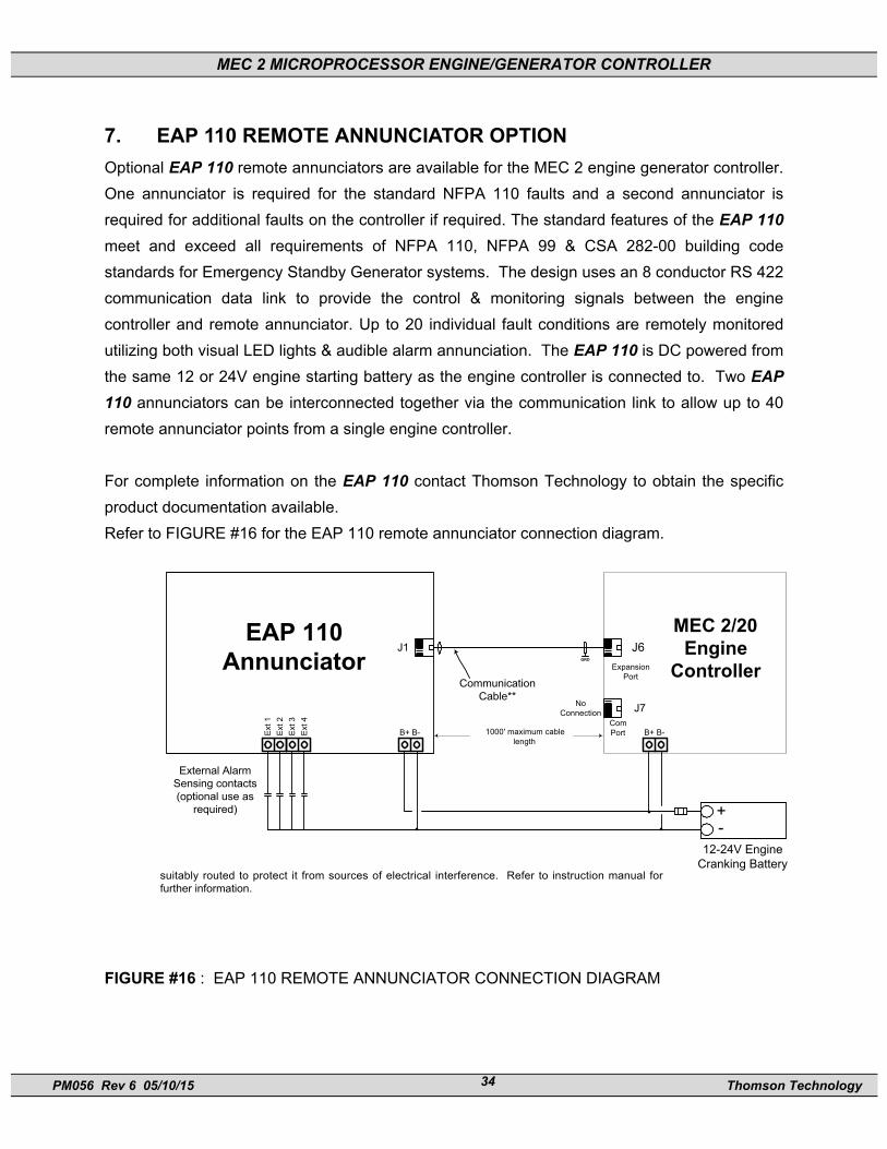
7. EAP 110 REMOTE ANNUNCIATOR OPTION Optional EAP 110 remote annunciators are available for the MEC 2 engine generator controller. One annunciator is required for the standard NFPA 110 faults and a second annunciator is required for additional faults on the controller if required. The standard features of the EAP 110 meet and exceed all requirements of NFPA 110, NFPA 99 & CSA 282-00 building code standards for Emergency Standby Generator systems. The design uses an 8 conductor RS 422 communication data link to provide the control & monitoring signals between the engine controller and remote annunciator. Up to 20 individual fault conditions are remotely monitored utilizing both visual LED lights & audible alarm annunciation. The EAP 110 is DC powered from the same 12 or 24V engine starting battery as the engine controller is connected to. Two EAP 110 annunciators can be interconnected together via the communication link to allow up to 40 remote annunciator points from a single engine controller. For complete information on the EAP 110 contact Thomson Technology to obtain the specific product documentation available. Refer to FIGURE #16 for the EAP 110 remote annunciator connection diagram.
GRD
EAP 110Annunciator
1000' maximum cablelength
MEC 2/20Engine
ControllerJ6
12-24V EngineCranking Battery
B+ B-B+ B-
suitably routed to protect it from sources of electrical interference. Refer to instruction manual forfurther information.
Ext 1
Ext 2
Ext 3
Ext 4
External AlarmSensing contacts(optional use as
required)
CommunicationCable**
J1
J7
ExpansionPort
ComPort
NoConnection
+-
FIGURE #16 : EAP 110 REMOTE ANNUNCIATOR CONNECTION DIAGRAM

MEC 2 MICROPROCESSOR ENGINE/GENERATOR CONTROLLER
PM056 Rev 6 05/10/15 Thomson Technology 35
8. OPERATING INSTRUCTIONS
8.1. MEC 2 POWER-UP OPERATION SEQUENCE When the MEC 2 is first energized with DC supply voltage at terminals B+ & B-, the
controller will power-up into a fail-safe mode, preventing possible engine operation. The
controller will default to an Emergency Stop failure mode and must be manually reset
before the controller is put into normal operation. To reset the Emergency Stop
condition, press the OFF pushbutton first, then press both INCREMENT and ENTER
pushbuttons simultaneously. The controller will then reset, provided a remote
emergency stop condition is not activated. The Utility Ready to Load programmable
output will energize if the remote start contact is open.
8.2. MEC 2 DISPLAY MENUS The MEC 2 contains a Liquid Crystal Display (LCD) which is visible through the front lexan faceplate viewing window. The LCD has pre-programmed display screens and menus that may be selected by pressing the ENTER or EXIT pushbuttons in succession until the desired screen or menu is displayed. The display screen types and order in which they are programmed are as follows:

MEC 2 MICROPROCESSOR ENGINE/GENERATOR CONTROLLER
PM056 Rev 6 05/10/15 Thomson Technology 36
OPERATING STATUS TIMER COUNTDOWN FAULT DISPLAY FAULT DISPLAY (Multiple Faults)
GENERATOR METERING (Average) GENERATOR PHASE VOLTAGES GENERATOR LINE TO NEUTRAL VOLTAGES GENERATOR PHASE CURRENTS GENERATOR KVA GENERATOR FREQUENCY/HOURMETER BATTERY VOLTAGE/ENGINE SPEED (TACH) ENGINE TEMPERATURE/OIL PRESSURE PROGRAM MENU
8.2.1. OPERATING STATUS MENU The operating status menu provides the operator with detailed information as to the status of the engine-generator set.
NOTE: The operating status screen may be momentarily replaced with a time delay countdown screen when a start or stop sequence is initiated. The display will automatically return to the previous menu following expiry of the timing sequence.
MEC 2 MICROPROCESSOR ENGINE/GENERATOR CONTROLLER
PM056 Rev 6 05/10/15 Thomson Technology 37
The operating status sub-menus are organized as follows: OPERATING STATUS UNIT READY SWITCH IN OFF
UNIT RUNNING UNIT SHUTDOWN UNIT ALARM
8.2.1.1.UNIT READY
This indicates that the controller is in “Auto” position and there are no active shutdowns or alarms.
8.2.1.2.SWITCH IN OFF
This indicates that the controller has been selected to the “off” position from the front panel keypad pushbutton.
8.2.1.3.UNIT RUNNING
This indicates that the engine is running and all conditions are normal.
8.2.1.4.UNIT SHUTDOWN
This indicates that a shutdown fault circuit is active. The specific fault condition will be automatically displayed.
8.2.1.5.UNIT ALARM
This indicates that one or more alarm fault circuits are active. The display will automatically scroll through all active faults at a rate of every two seconds.
8.2.2. FAULT DISPLAY MENU The fault display menu is automatically displayed when either an alarm or shutdown circuit is activated. The specific alarm or shutdown fault label will be displayed and if multiple alarm conditions are present, the display will automatically scroll through all active faults.
8.2.3. TIMER COUNTDOWN MENUS Timer countdown menus are automatically displayed when a specific time delay function occurs during a control sequence. When a time delay begins, the LCD display will indicate the time delay function name (i.e. ENGINE START DELAY)

MEC 2 MICROPROCESSOR ENGINE/GENERATOR CONTROLLER
PM056 Rev 6 05/10/15 Thomson Technology 38
and the current time remaining in the countdown sequence. When the timing function has expired, the LCD display will automatically change to either the next timing sequence countdown display or return to the original system status menu.
LCD DISPLAY
ENGINE START DELAY 45 SEC
Displays specific time delay function currently in operation Displays current time in seconds or minutes that are left in the specific timing
sequence.
NOTE: During a timer countdown sequence, a different display screen may be selected by pressing the ENTER pushbutton.
The following timer countdown screens are provided:
ENG START DELAY XX SEC. CRANK PERIOD XX SEC. REST PERIOD XX SEC. STARTER RE-ENGAGE DELAY XX SEC. BYPASS DELAY XX SEC. COOLDOWN DELAY XXXX SEC. WARMUP DELAY* XX SEC. RETURN DELAY* XXX SEC. NEUTRAL DELAY* XX SEC.
*Countdown screens only appear if Utility/Gen Read To Load outputs are programmed. 8.2.4. GENERATOR AC METERING Four generator AC metering screens are provided as described below.
8.2.4.1.AVERAGE VOLTAGE/CURRENT & FREQUENCY DISPLAY
The generator average voltage/current & frequency metering screen allows the operator to simultaneously view all the listed parameters.
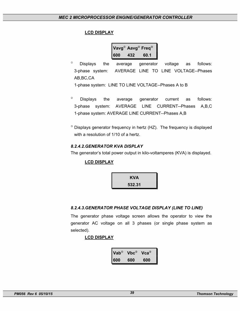
MEC 2 MICROPROCESSOR ENGINE/GENERATOR CONTROLLER
PM056 Rev 6 05/10/15 Thomson Technology 39
LCD DISPLAY
Vavg Aavg Freq
600 432 60.1
Displays the average generator voltage as follows: 3-phase system: AVERAGE LINE TO LINE VOLTAGE--Phases AB,BC,CA 1-phase system: LINE TO LINE VOLTAGE--Phases A to B
Displays the average generator current as follows: 3-phase system: AVERAGE LINE CURRENT--Phases A,B,C 1-phase system: AVERAGE LINE CURRENT--Phases A,B
Displays generator frequency in hertz (HZ). The frequency is displayed with a resolution of 1/10 of a hertz.
8.2.4.2.GENERATOR KVA DISPLAY The generator’s total power output in kilo-voltamperes (KVA) is displayed.
LCD DISPLAY
KVA 532.31
8.2.4.3.GENERATOR PHASE VOLTAGE DISPLAY (LINE TO LINE)
The generator phase voltage screen allows the operator to view the generator AC voltage on all 3 phases (or single phase system as selected).
LCD DISPLAY
Vab Vbc Vca 600 600 600

MEC 2 MICROPROCESSOR ENGINE/GENERATOR CONTROLLER
PM056 Rev 6 05/10/15 Thomson Technology 40
Displays generator voltage as follows: 3-phase system: LINE TO LINE VOLTAGE--Phases A to B 1-phase system: LINE TO LINE VOLTAGE--Phases A to B
Displays generator voltage as follows: 3-phase system: LINE TO LINE VOLTAGE--Phases B to C 1-phase system: LINE TO NEUTRAL VOLTAGE--Phases A-N
Displays generator voltage as follows: 3-phase system: LINE TO LINE VOLTAGE--Phases C-A 1-phase system: LINE TO NEUTRAL VOLTAGE--Phases B-N
8.2.4.4. GENERATOR PHASE/NEUTRAL VOLTAGE DISPLAY (LINE TO NEUTRAL)
The generator phase/neutral display allows the operator to view the
generator line to neutral voltage for all 3 phases of the system. Note: The generators neutral must be connected to MEC 2 terminal TB1-VN
and the “neutral connected” prompt in the main program menu must be
selected as “Yes”.
LCD DISPLAY
Van Vbn Vcn 347 347 347
Displays generator voltage Phase A to Neutral. Displays generator voltage Phase B to Neutral. Displays generator voltage Phase C to Neutral.
8.2.4.5.GENERATOR PHASE CURRENT DISPLAY
The generator phase current screen allows the operator to view the generator load current on all 3 phases (or single phase system as selected).
LCD DISPLAY
Amps a b c 408 451 415

MEC 2 MICROPROCESSOR ENGINE/GENERATOR CONTROLLER
PM056 Rev 6 05/10/15 Thomson Technology 41
Displays generator load current as follows: 3-phase system: PHASE A CURRENT 1-phase system: PHASE A CURRENT
Displays generator load current as follows: 3-phase system: PHASE B CURRENT 1-phase system: PHASE B CURRENT
Displays generator load current as follows: 3-phase system: PHASE C CURRENT 1-phase system: not applicable
8.2.4.6.GENERATOR FREQUENCY/HOURMETER DISPLAY
The generator frequency and operating hours are displayed simultaneously on this screen.
LCD DISPLAY
FREQ 60.1Hz
HOURS 56783 Hrs
Displays generator frequency in hertz (HZ). The frequency is displayed with a resolution of 1/10 of a hertz.
Displays unit operating hours
8.2.5. ENGINE PARAMETER DISPLAY Two engine operating parameter screens are provided as described below.
8.2.5.1.BATTERY VOLTAGE/ENGINE SPEED (tachometer)
The battery voltage and engine speed are displayed simultaneously on this screen.
LCD DISPLAY
BATTERY 27.0Vdc
SPEED 1800rpm

MEC 2 MICROPROCESSOR ENGINE/GENERATOR CONTROLLER
PM056 Rev 6 05/10/15 Thomson Technology 42
Displays battery voltage in DC volts. The voltage is displayed with a resolution of 1/10 of a volt.
Displays engine speed in revolutions per minute (RPM).
8.2.5.2.ENGINE TEMPERATURE/OIL PRESSURE
The engines operating temperature and oil pressure are displayed simultaneously on this screen.
LCD DISPLAY
ENG TEMP 57 Deg C
OIL PRESS 200 KPA
Displays engine temperature in either degrees Celsius or Fahrenheit (as selected).
Displays engine oil pressure in either pounds per square inch (PSI) or in Kilopascals (KPA) (as selected).
8.2.6. PROGRAM MENU The programming menu is used to access the MEC 2 programmable functions such as time delays, analog fault settings, digital fault settings and calibration. Access to the programming sub-menus may only be obtained with a security password number. The sub menus are organized as follows:
PROGRAMMING MENU NO YES PASSWORD LCD DISPLAY
PROGRAM MENU? NO
Displays two messages that may be toggled between YES and NO by pressing the INCREMENT pushbutton. Their functions are described as follows:
NO Programming sub-menus are disabled when NO is displayed. YES Programming sub-menus are enabled when YES is displayed and
a valid password number is entered.

MEC 2 MICROPROCESSOR ENGINE/GENERATOR CONTROLLER
PM056 Rev 6 05/10/15 Thomson Technology 43
8.3. SEQUENCE OF OPERATION
8.3.1. GENERAL The MEC 2 Engine-generator controller is designed to start and stop an engine from either a local (“manual”) or remote (“automatic”) command. When this command is issued, the controller issues a run and crank output signal. The controller then monitors engine speed and when crank disconnect speed is reached, the crank signal is terminated. While the engine accelerates to normal speed, the controller continuously monitors the engines speed signal. Should the engine speed exceed the maximum predetermined setpoint, the over speed shutdown fault circuit will activate, terminating the run signal. In addition to over speed shutdown, the engine controller also monitors many other engine protection circuits and should they be activated, the engine will be stopped and/or alarm initiated. The engine will automatically stop for any shutdown condition, or when the remote and/or local start signal is removed. The engine controller operation includes time delay circuits for normal operating conditions such as start delays, cooldown and cranking periods.
8.3.2. MANUAL START/STOP SEQUENCE When the “RUN” pushbutton on the front faceplate keypad is pressed, an ENGINE START DELAY timer will be initiated. Note: The start sequence will not be initiated if any shutdown fault condition is present. Once the engine start delay time expires, an engine RUN and CRANK output signal will be initiated. Note: The RUN output may be programmed to only energize when a start signal is initiated and an engine speed signal is detected. Once the engine starts to turn over and begins to accelerate to nominal speed, the controllers speed sensor will terminate the CRANK output when engine speed reaches approximately 20% speed (i.e. CRANK DISCONNECT speed setpoint). Immediately upon reaching crank disconnect speed, the controller will initiate the BYPASS DELAY time delay function. Following the BYPASS DELAY time period (typically 10 seconds) all fault circuits programmed as BYPASS DELAY=YES will be activated. Note: All fault circuits programmed as BYPASS DELAY=NO are continuously armed irrespective of any operation sequence. When the “OFF” pushbutton on the front keypad is depressed, the controllers RUN output will be immediately terminated which will initiate the engine to stop.

MEC 2 MICROPROCESSOR ENGINE/GENERATOR CONTROLLER
PM056 Rev 6 05/10/15 Thomson Technology 44
8.3.3. AUTOMATIC START/STOP SEQUENCE When the controller is selected for automatic operation (via the front keypad pushbutton), the engine will automatically start upon activation of the remote start contact input. Note: The remote initiates a start sequence upon contact closure. Once the remote start signal is activated, the engine will start as per the sequence of operation described for the manual start sequence. The automatic stop sequence will be initiated by removal of the remote start signal. Once the start signal is removed, a cooldown delay function will be initiated. Once the cooldown time delay period expires (typically programmed for 5 minutes), the controllers RUN output will be immediately terminated which will initiate the engine to stop.
8.3.4. AUTOMATIC FAULT SHUTDOWN SEQUENCE When a fault circuit is programmed as a SHUTDOWN, the engine will immediately stop once the fault circuit is activated. Note: A specific shutdown fault may be programmed with a definite time transient delay period that must expire before the shutdown is activated. The stop sequence will cause the controllers RUN output to be immediately terminated which will cause the engine to stop.
8.3.5. AUTO MAINS FAILURE (AMF) SEQUENCE When the controller is applied in an Auto Mains Failure (AMF) application with a
transfer switch, it must be wired as per FIGURE 21 shown at the end of this
section. Programmable output #3 must be selected for Utility Ready To Load
and programmable output #4 must be selected for Gen Ready To Load. Once
the controller is programmed and wired as per FIGURE 21, the AMF sequence of
operation will be as follows:
8.3.5.1.UTILITY NORMAL CONDITION: • Remote Start input signal (MEC terminals 16 & 17) is not activated
(i.e. Utility power is Normal).
• Utility Ready To Load output is energized (i.e. signal to transfer switch
to transfer to utility power).
• Generator Ready To Load output is de-energized.
MEC 2 MICROPROCESSOR ENGINE/GENERATOR CONTROLLER
PM056 Rev 6 05/10/15 Thomson Technology 45
8.3.5.2.UTILITY POWER FAILURE CONDITIONS: • Remote Start input signal is activated (i.e. remote start contact closes
when utility power fails, as sensed by utility voltage sensor).
• Engine starts following expiry of the Engine Start Delay timer (Utility
Ready To Load output stays energized).
• Once the engine has started and the generator output rises above the
programmed voltage and frequency limits, a Warmup timer is initiated.
• Once the Warmup timer expires the Utility Ready to Load output de-
energizes and the NEUTRAL Delay timer is initiated.
• Once the NEUTRAL DELAY timer expires the Gen Ready to Load
output energizes to signal the transfer switch to transfer to the
generator supply. Note: The neutral delay function is only operative
with an electrically-held type transfer switch mechanism (ie. electrical
contactor type).
8.3.5.3.UTILITY POWER RETURN: • Remote Start input signal is removed and the Return Delay timer is
initiated (i.e. Utility Voltage returns to normal and the Utility voltage
sensor contact opens).
• Once the Return Delay timer expires, the Generator Ready to Load
output de-energizes and the Neutral Delay timer is initiated.
• Once the Neutral Delay timer expires the Utility Ready to Load output
energizes to signal the transfer switch to transfer to the utility supply.
Note: If the generator has a shutdown during the Return or Neutral
Delay periods, the timers are bypassed, and the Utility Ready to Load
output immediately energizes.
• The generator Cooldown Timer starts timing following expiry of the
Return Delay timer.
• The generator stops following expiry of the Cooldown Timer.
MEC 2 MICROPROCESSOR ENGINE/GENERATOR CONTROLLER
PM056 Rev 6 05/10/15 Thomson Technology 46
8.3.5.4.MEC LOAD TEST PUSHBUTTON OPERATION
NOTE: The following sequence as described is applicable only if both “Utility Ready to Load” and Gen Ready to Load” outputs are programmed and used.
• When the MEC Load Test pushbutton is pressed, the controllers logic
will internally simulate receiving a remote start input.
• Engine starts following expiry of the Engine Start delay timer.
• Once the engine has started and the generator output rises above the
programmed voltage and frequency limits, a Warmup timer is initiated.
• Once the Warmup timer expires the Utility Ready to Load output de-
energizes and the Neutral Delay timer is initiated.
• Once the Neutral Timer expires the Gen Ready To Load output
energizes to signal the transfer switch to transfer to the generator
supply. Note: if a generator shutdown occurs during a Load Test
Operation, the Load Test mode will be de-activated.
When the MEC mode is re-selected to Auto Mode, the following
sequence occurs:
• Simulated Remote Start input signal is removed.
• Gen Ready To Load output de-energizes, and Neutral Delay timer is
initiated.
• Once the Neutral Delay timer expires The Utility Ready To Load
output energizes to signal the transfer switch to transfer to the utility
supply.
• The generator Cooldown timer starts timing following the transfer to
the utility supply.
• The generator stops following expiry of the Cooldown timer.
MEC 2 MICROPROCESSOR ENGINE/GENERATOR CONTROLLER
PM056 Rev 6 05/10/15 Thomson Technology 47
8.3.5.5.NO LOAD TEST: • To allow a timed No Load Test of the engine/generator set while using
the AMF control application, a digital input contact from an external
timer must be programmed for NO LOAD Test (Refer to Section 9.5 for
programming details).
The sequence of operation for a No Load Test condition is as follows: • With the utility supply normal and the generator stopped, a no load
test sequence may be initiated by closing an external exercise
timer contact to the programmed digital input for No Load Test.
• Once the external exercise timer contact closes, the engine will
start and come-up to normal operating speed and voltage. The
MEC will issue an alarm of a No Load Test condition. The
connected transfer switch will remain on the utility and the
generator will not transfer on load. Note: should the utility supply
fail, the generator will automatically transfer on load.
• The engine will continue to run as long as the external exercise
timer contact remains closed.
• Once the external exercise timer contact opens, the engine will
continue to run for its cooldown time as programmed, then it will
automatically stop.
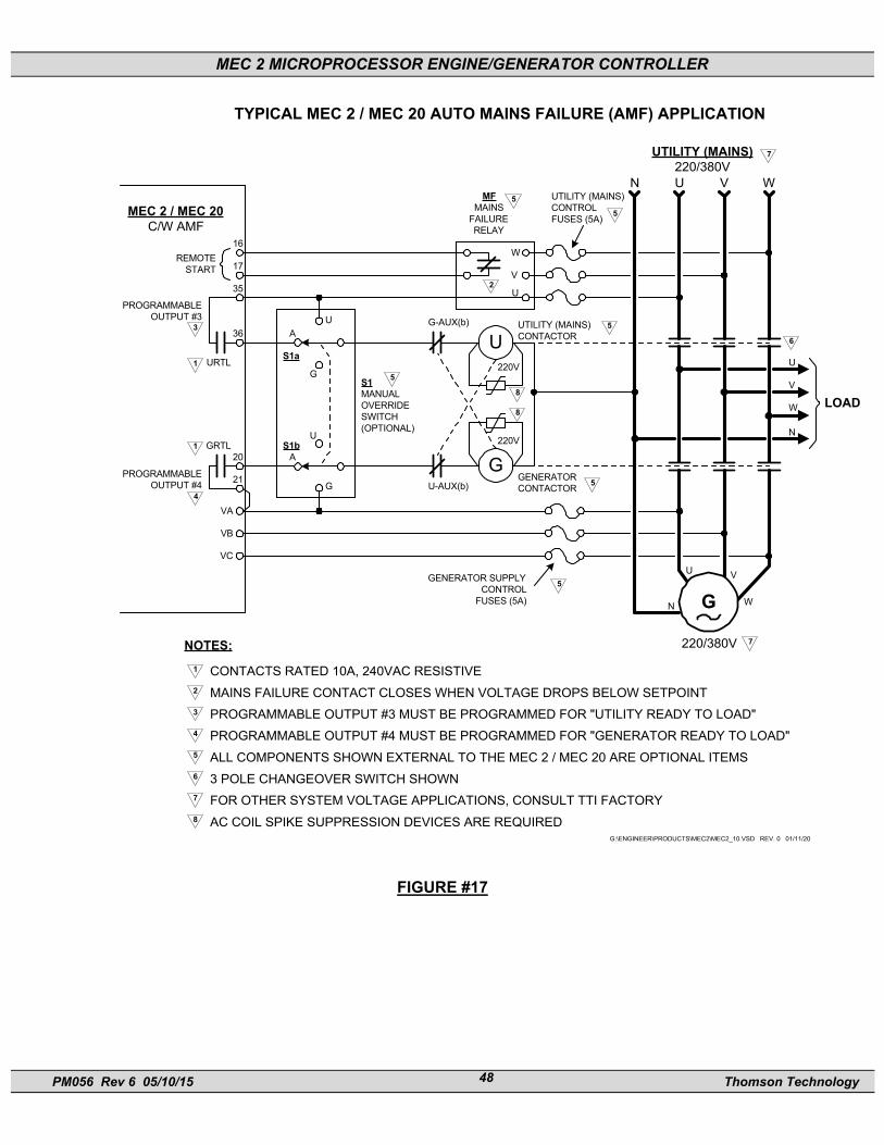
MEC 2 MICROPROCESSOR ENGINE/GENERATOR CONTROLLER
PM056 Rev 6 05/10/15 Thomson Technology 48
TYPICAL MEC 2 / MEC 20 AUTO MAINS FAILURE (AMF) APPLICATION
W
U
V
N U V W
U
V
W
N
LOAD
U V
WN
220/380V
UTILITY (MAINS)220/380V
UTILITY (MAINS)CONTROLFUSES (5A)
UTILITY (MAINS)CONTACTOR
GENERATOR SUPPLYCONTROL
FUSES (5A)
GENERATORCONTACTORU-AUX(b)
G-AUX(b)
MFMAINS
FAILURERELAY
1
UA
G
G
A
US1b
S1a
S1MANUALOVERRIDESWITCH(OPTIONAL)
REMOTESTART
MEC 2 / MEC 20C/W AMF
16
17
35
36
20
21
VA
VB
VC
PROGRAMMABLEOUTPUT #3
PROGRAMMABLEOUTPUT #4
3
URTL
GRTL1
4
5
G
5
5
5
5
5
7
6
7
220V
U
220V
G
8
8
2
G:\ENGINEER\PRODUCTS\MEC2\MEC2_10.VSD REV. 0 01/11/20
CONTACTS RATED 10A, 240VAC RESISTIVEMAINS FAILURE CONTACT CLOSES WHEN VOLTAGE DROPS BELOW SETPOINTPROGRAMMABLE OUTPUT #3 MUST BE PROGRAMMED FOR "UTILITY READY TO LOAD"PROGRAMMABLE OUTPUT #4 MUST BE PROGRAMMED FOR "GENERATOR READY TO LOAD"ALL COMPONENTS SHOWN EXTERNAL TO THE MEC 2 / MEC 20 ARE OPTIONAL ITEMS3 POLE CHANGEOVER SWITCH SHOWNFOR OTHER SYSTEM VOLTAGE APPLICATIONS, CONSULT TTI FACTORYAC COIL SPIKE SUPPRESSION DEVICES ARE REQUIRED
1
2
3
4
5
6
7
8
NOTES:
FIGURE #17

MEC 2 MICROPROCESSOR ENGINE/GENERATOR CONTROLLER
PM056 Rev 6 05/10/15 Thomson Technology 49
8.4. CONTROL PUSHBUTTONS The following control pushbuttons are located on the front faceplate keypad.
8.4.1. RUN/OFF/AUTO/LOAD TEST
8.4.1.1.RUN
In this position, the engine will start and operate continuously providing no shutdown circuits are active. All protective circuits will be operative in this mode. There will be no cooldown cycle at the end of a manual run sequence.
8.4.1.2.OFF
This position immediately stops the engine and locks it out from operation. The OFF position also allows any shutdowns to be reset.
8.4.1.3.AUTO
In this position, starting and stopping of the engine will be controlled by a remote contact. When the remote start signal is removed the engine will continue to run for the cooldown period (if selected) then stop. Re-selecting the Off position will stop the engine immediately, even if the cooldown period is not complete.
8.4.1.4.LOADTEST
NOTE: The control feature is only operative if used in the AMF application or if one of the programmable output contacts is configured for “ATS Test” and a remote transfer switch is interconnected with remote testing circuitry.
In this position, a signal will be issued to a remote transfer switch to permit an automatic engine start and load transfer. Once initiated, the engine will receive a start signal from the transfer switch and upon the generator reaching nominal voltage and frequency levels, a load transfer will be initiated. The generator set
MEC 2 MICROPROCESSOR ENGINE/GENERATOR CONTROLLER
PM056 Rev 6 05/10/15 Thomson Technology 50
will remain running on load until a different operating mode is selected or the generator set develops an alarm or shutdown condition.
8.4.2. EMERGENCY STOP PUSHBUTTON
This pushbutton will cause the engine to immediately stop and be locked out from operation. The engine cannot be restarted in this mode until the controller has been reset.
8.4.3. FAULT RESET FUNCTION
To initiate a fault reset function, both INCREMENT and ENTER pushbuttons must be simultaneously pressed. This function resets the controller when in a shutdown mode.
NOTE: To initiate a reset command, the engine must come to a complete stop and the controller’s switch must be placed in the Off position.
8.4.4. HORN SILENCE FUNCTION
To initiate a horn silence function, both EXIT & DECREMENT pushbuttons must be simultaneously pressed. This function will silence the audible alarm horn without resetting the fail condition.
8.4.5. LAMP TEST
A lamp test feature is provided to test all software controlled LED lights as well as the LCD display. To activate the lamp test feature, simultaneously push the INCREMENT and DECREMENT pushbuttons. The LED’s and LCD display will illuminate for approximately 2 seconds then return to their original status. Note: The emergency stop LED will not be activated by a software initiated test as it is controlled via independent hardware circuitry only.
9. PROGRAMMING INSTRUCTIONS
9.1. SECURITY PASSWORDS Access to the programmable parameters of the MEC 2 Controller is via a security password number. Three security password levels are provided as described below:

MEC 2 MICROPROCESSOR ENGINE/GENERATOR CONTROLLER
PM056 Rev 6 05/10/15 Thomson Technology 51
9.1.1. READ ONLY MODE User can view the programmable parameters only and cannot change any values. The factory default number for the read-only level is one (1).
9.1.2. READ / WRITE MODE User can view and modify any programming parameter as required. The Factory default number for the read/write level is two (2).
9.1.3. MASTER READ / WRITE MODE User can view/modify any programming parameter as well as view/modify the security password level numbers. Contact THOMSON TECHNOLOGY factory for master password if required.
To enter the programming mode, follow the procedure as shown:
PROGRAM MENU? YES
Select the Program Menu by scrolling through the display menus using the ENTER pushbutton. When displayed, use the INCREMENT pushbutton to select the YES prompt and push the ENTER button.
PASSWORD 0
Use the INCREMENT or DECREMENT pushbuttons to ramp the displayed number up or down to the desired password access number. Press the ENTER pushbutton when the correct number is displayed.
NOTE: If an invalid number is entered, programming access will be denied. To exit the programming mode, press and hold the EXIT pushbutton for more than two seconds until the display changes.
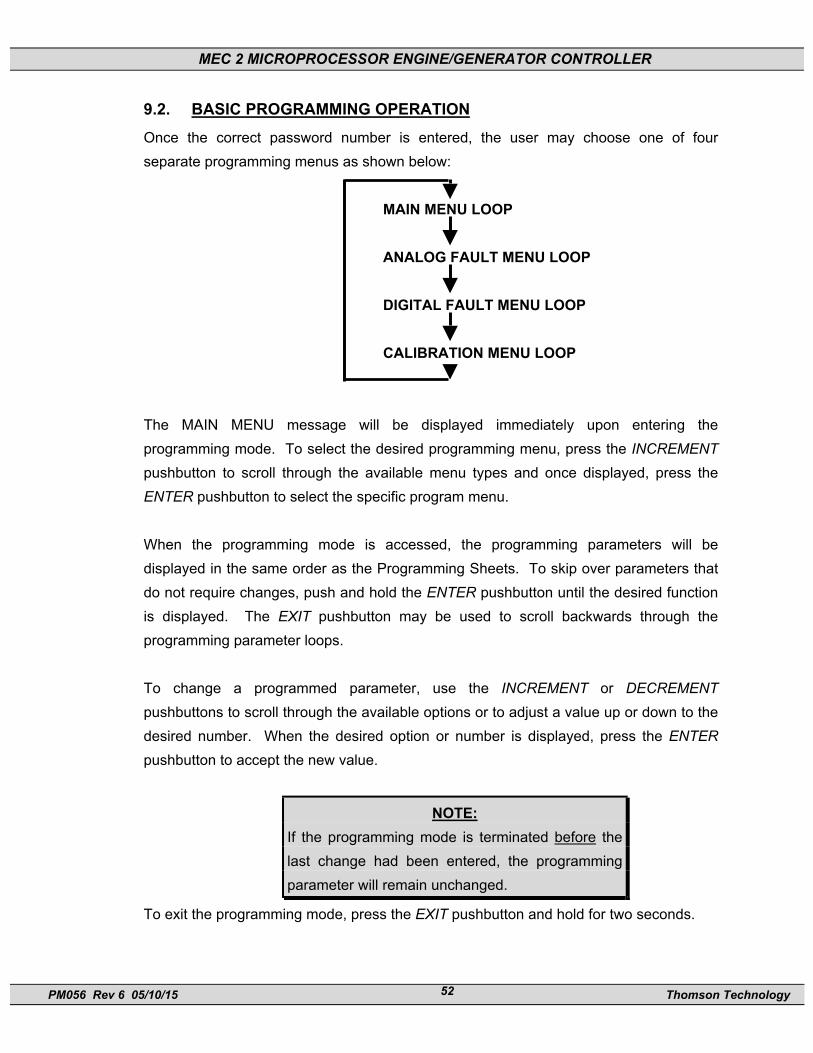
MEC 2 MICROPROCESSOR ENGINE/GENERATOR CONTROLLER
PM056 Rev 6 05/10/15 Thomson Technology 52
9.2. BASIC PROGRAMMING OPERATION Once the correct password number is entered, the user may choose one of four separate programming menus as shown below:
MAIN MENU LOOP
ANALOG FAULT MENU LOOP DIGITAL FAULT MENU LOOP CALIBRATION MENU LOOP
The MAIN MENU message will be displayed immediately upon entering the programming mode. To select the desired programming menu, press the INCREMENT pushbutton to scroll through the available menu types and once displayed, press the ENTER pushbutton to select the specific program menu.
When the programming mode is accessed, the programming parameters will be displayed in the same order as the Programming Sheets. To skip over parameters that do not require changes, push and hold the ENTER pushbutton until the desired function is displayed. The EXIT pushbutton may be used to scroll backwards through the programming parameter loops. To change a programmed parameter, use the INCREMENT or DECREMENT pushbuttons to scroll through the available options or to adjust a value up or down to the desired number. When the desired option or number is displayed, press the ENTER pushbutton to accept the new value.
NOTE: If the programming mode is terminated before the last change had been entered, the programming parameter will remain unchanged.
To exit the programming mode, press the EXIT pushbutton and hold for two seconds.

MEC 2 MICROPROCESSOR ENGINE/GENERATOR CONTROLLER
PM056 Rev 6 05/10/15 Thomson Technology 53
The controller will automatically exit the Program Mode when an internal timer set for 999 seconds, expires from when a key press was last received by the controller. Note: The display menu will automatically revert to a low power “sleep” mode following the expiry of the 999 second internal timer.
9.3. MAIN PROGRAMMING MENU The main programming menu contains general system configuration programming such as system input voltages, currents, transformer ratios, as well as standard operating time delay functions. The programming prompts are listed in order as they appear in the MEC 2 software. To program the specific MAIN MENU items, refer to the following descriptions:
9.3.1. SYSTEM VOLTAGE Set to nominal system voltage as expressed in “phase to phase” voltage (i.e. a 347/600 volt system would be entered as “600”). The programmable range of values is 120V-15,000V. 9.3.2. SYSTEM FREQUENCY Set to nominal system frequency of either 50Hz or 60Hz. 9.3.3. SYSTEM PHASES Set to match the power distribution system used on the generator set (i.e. either single phase or 3 phase system). 9.3.4. NEUTRAL CONNECTED Set to “Yes” if generator’s neutral conductor is connected to the MEC 2 controller terminal TB1-VN and it is desired to display line-neutral AC voltages for a 3 phase, 4 wire system. 9.3.5. VOLTAGE SENSING RATIO For direct voltage sensing wiring connections from 208 to 600 volts, enter “1” (i.e. a ratio of “1:1”). When potential transformers are utilized for voltage sensing, enter the calculated transformer ratio (e.g. when using 600:120 transformers, enter a number of “5”).
9.3.6. CURRENT SENSING RATIO For current sensing wiring connections from current transformers (CT’s), enter the calculated CT ratio (e.g. when using a 600:5 CT, enter a number of “120”).

MEC 2 MICROPROCESSOR ENGINE/GENERATOR CONTROLLER
PM056 Rev 6 05/10/15 Thomson Technology 54
9.3.7. TEMPERATURE SCALE Select the desired type of engineering units for the engine temperature display and analog setpoints as provided: Degrees Fahrenheit or Degrees Celsius. Note: Alarm setpoints do not automatically re-configure when changing between degrees Fahrenheit or degrees Celsius.
9.3.8. PRESSURE SCALE Select the desired type of engineering units for the engine pressure display and analog setpoints as provided: Pounds per square inch (PSI) or Kilopascals (KPA). Note: Alarm setpoints do not automatically re-configure when changing between PSI and KPA.
9.3.9. START DELAY Select desired engine start delay time in seconds. If engine start delay is not required, set to zero. Note: If preheat and / or prelube functions are utilized, the engine start delay time should be set as required for these functions.
9.3.10.CRANK TIME Select desired cranking time in seconds. If cycle cranking is selected, this time will be the crank time period on each attempt.
9.3.11.REST TIME Select desired rest time between cranking attempts. (Only valid if multiple crank attempts are selected). Note: This value will be ignored if only one attempt has been programmed.
9.3.12.STARTER RE-ENGAGE DURATION This feature will check for a speed signal while cranking. If no speed signal is sensed, the controller assumes that the engine starter is not turning the engine over (for whatever reason), and disengages it after the programmed time delay, and re-engages it again. This process will repeat until a speed signal is sensed or cranking time expires, whichever occurs first. If a speed signal is sensed, the cranking output will be maintained until the unit starts or an over crank condition occurs. Set time in seconds for desired sampling period, i.e. a setting of 5

MEC 2 MICROPROCESSOR ENGINE/GENERATOR CONTROLLER
PM056 Rev 6 05/10/15 Thomson Technology 55
seconds will attempt cranking for 5 seconds after which time if no speed signal is detected, the crank output will be removed for a preset 1 second delay before re-engaging. Note: This action is more than a cycle cranking function and is independent of the number of attempts selected, therefore, the "crank" time should be considered. To disable this feature, set to zero.
9.3.13.NUMBER OF CRANK CYCLES Set to the number of cranking cycles required. (Zero will default to one.)
9.3.14.BYPASS DELAY This setting is the time period that affected Alarm or Shutdown inputs will be ignored after crank disconnect, allowing the engine to settle into its normal operating mode (i.e. proper oil pressure, etc.). This is typically set to 10 seconds.
9.3.15.COOLDOWN TIME Set to desired cooldown time in seconds. Up to 9999 seconds of cooldown time may be programmed. Set to zero if not required. Note: If the controller is used in an AMF application it is recommended to set the cooldown timer to a minimum of 10 seconds to allow the generator to transfer Off Load before enabling the cooldown time. (Ensures the load is transferred off of generator prior to stopping the engine.)
9.3.16.NOMINAL ENGINE RPM Set to the nominal engine speed in revolutions per minute (RPM).
9.3.17.FLYWHEEL TEETH Set to the number of ring gear teeth on the engine flywheel. The magnetic pick-up must be installed to sense the same teeth for speed sensing as programmed.
9.3.18.CRANK DISCONNECT SPEED Set crank disconnect speed in percentage of nominal speed, i.e. 30% or 540 RPM on an 1800 RPM engine.
9.3.19.OVER SPEED Set over speed shutdown point in percentage of nominal speed (i.e. 110% or 1980 RPM on an 1800 RPM engine).

MEC 2 MICROPROCESSOR ENGINE/GENERATOR CONTROLLER
PM056 Rev 6 05/10/15 Thomson Technology 56
9.3.20.OVER SPEED TRANSIENT DELAY Select desired over speed transient delay time in seconds. Time setting may be entered in tenths of seconds.
9.3.21.RUN OUTPUT FAIL-SAFE When enabled, this feature will inhibit the run output until the controller receives a speed sensing signal, thus preventing possible damage from starting the engine with no speed sensing for crank disconnect and over speed. If selected, ensure that the speed signal is not less than 3.0VAC from the magnetic pick up while the engine is cranking. Note: If this feature is disabled, no over speed protection or crank disconnect will be provided if the speed signal fails. Should the user elect to disable this feature Thomson Technology strongly recommends that backup crank disconnect protection and additional over speed protection is utilized.
NOTE: The run output Fail-safe feature will be factory programmed as enabled. The user of this equipment may elect to change this feature dependent upon site conditions and does so at their discretion.
9.3.22.LOSS OF SPEED SIGNAL Select the desired action (i.e. alarm or shutdown) when a loss of speed signal is detected during operation. Note: A loss of speed signal must be detected for longer than 2 seconds to initiate the desired action.
9.3.23.COMMON FAIL FOR “NOT IN AUTO” FUNCTION Use this function to select if a “common fail” alarm condition is to be activated when the engine controller is not selected for “automatic” operation.
9.3.24.HORN FOR NOT IN AUTO The Horn may be programmed to sound when the controllers operating mode is
switched from the Auto position. If the Horn is not to sound, select program
setting “no”.

MEC 2 MICROPROCESSOR ENGINE/GENERATOR CONTROLLER
PM056 Rev 6 05/10/15 Thomson Technology 57
9.3.25.WARMUP DELAY The WARMUP Delay programming menu appears when the Gen Ready To Load
programmable output is selected as is typically used in an AMF application. Set
to the desired time in seconds, which the generator requires to effectively
“warmup” before accepting load. This is typically set for 3 seconds. The
Warmup Delay is initiated once the generator output rises above programmed
voltage and frequency limits (per the analog programming menus). Refer to
Section 9.4. for further details on this timing function.
9.3.26.NEUTRAL DELAY The Neutral Delay programming menu appears when the Utility Ready To Load
programmable output is selected as is typically used in an AMF application. The
Neutral Delay timer is initiated when transferring between the available sources.
When transferring from the utility supply to the generator supply, the Neutral
Delay timer will start when The Utility Ready To Load output de-energizes. Once
the Neutral Delay time period expires, The Generator Ready To Load output will
then be energized. The similar sequence will occur when transfer in the opposite
direction. The purpose of the Neutral Delay timer is to prevent out of phase
transfers, which may be caused by a fast transfer and the two sources of supply
are out of synchronism. The Neutral Delay timer ensures the load voltages
decay before the transfer is initiated.
Set to the desired time in seconds. The Neutral Delay timer is typically set for 3
seconds. Refer to Section 9.4 for further details on this timing function.
NOTE: The Neutral Delay feature is only effective when an
electrically held “contactor-type” transfer switch is
connected. Contact Thomson Technology for
further application information on use with other
types of transfer switch mechanisms.
9.3.27.RETURN DELAY The Return Delay programming menu appears when the Utility Ready To Load
programmable output is selected as is typically used in an AMF application. The
Return Delay is initiated once the remote start signal is removed, signaling that
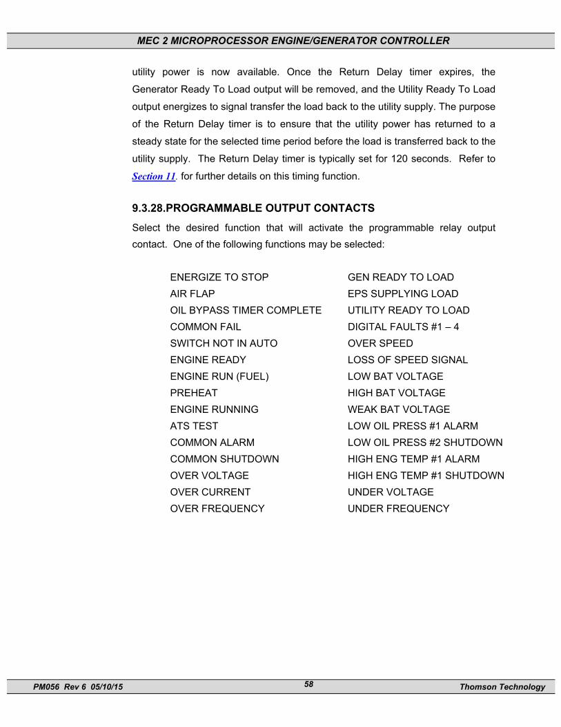
MEC 2 MICROPROCESSOR ENGINE/GENERATOR CONTROLLER
PM056 Rev 6 05/10/15 Thomson Technology 58
utility power is now available. Once the Return Delay timer expires, the
Generator Ready To Load output will be removed, and the Utility Ready To Load
output energizes to signal transfer the load back to the utility supply. The purpose
of the Return Delay timer is to ensure that the utility power has returned to a
steady state for the selected time period before the load is transferred back to the
utility supply. The Return Delay timer is typically set for 120 seconds. Refer to
Section 11. for further details on this timing function.
9.3.28.PROGRAMMABLE OUTPUT CONTACTS Select the desired function that will activate the programmable relay output contact. One of the following functions may be selected:
ENERGIZE TO STOP GEN READY TO LOAD AIR FLAP EPS SUPPLYING LOAD OIL BYPASS TIMER COMPLETE UTILITY READY TO LOAD COMMON FAIL DIGITAL FAULTS #1 – 4 SWITCH NOT IN AUTO OVER SPEED ENGINE READY LOSS OF SPEED SIGNAL ENGINE RUN (FUEL) LOW BAT VOLTAGE PREHEAT HIGH BAT VOLTAGE ENGINE RUNNING WEAK BAT VOLTAGE ATS TEST LOW OIL PRESS #1 ALARM COMMON ALARM LOW OIL PRESS #2 SHUTDOWN COMMON SHUTDOWN HIGH ENG TEMP #1 ALARM OVER VOLTAGE HIGH ENG TEMP #1 SHUTDOWN OVER CURRENT UNDER VOLTAGE OVER FREQUENCY UNDER FREQUENCY
MEC 2 MICROPROCESSOR ENGINE/GENERATOR CONTROLLER
PM056 Rev 6 05/10/15 Thomson Technology 59
CAUTION!!! The programming function selected must co-ordinate with external control wiring prior to energizing the control system. Failure to do so may cause severe equipment damage.
9.3.29.RESET RUN HOURS The controller’s engine hourmeter may be reset to zero hours when yes is programmed. Note: This programming prompt is only accessible while using the “Master” programming security password.
9.4. ANALOG FAULT PROGRAMMING MENU To program the controller’s analog fault circuits, refer to the following descriptions. Note: Certain programming functions listed below may not be provided for a specific fault. Refer to Section 11.1 for a table indicating programmable features provided.
9.4.1. LEVEL This setting determines the actual analog signal setpoint at which the selected fault type will be activated. Note: For AC voltage fault circuits, two levels (i.e. pick-up & drop-out) must be programmed.
9.4.2. ACTION This setting allows a fault circuit to be programmed as either an alarm or a shutdown.
9.4.3. ALARM LATCH If an alarm fault was programmed, it may be selected as a ”latching” alarm or “non-latching”. When “latching” is selected, it will not un-latch until a reset command clears it. Note: This programming prompt only appears if alarm faults are programmed. Shutdown faults are automatically set as latching.
9.4.4. BYPASS ON START DELAY This allows the alarm or shutdown circuit to be disabled until after the bypass timer has expired. Fault circuits that are not delayed will be enabled at all times (i.e. engine running or stopped).

MEC 2 MICROPROCESSOR ENGINE/GENERATOR CONTROLLER
PM056 Rev 6 05/10/15 Thomson Technology 60
9.4.5. TRANSIENT DELAY TIMES This allows the selected fault circuit to be inhibited from being activated until the specified time delay period has expired. Delay times from 0.0 to 999.9 seconds are available by entering the time required.
9.5. DIGITAL FAULT PROGRAMMING MENU To program the controller’s digital fault circuits, refer to the following descriptions.
9.5.1. DIGITAL FAULT LABEL To select the desired fault label description, use the INCREMENT key to scroll through the available labels. The digital fault labels are stored in non-volatile memory and are as follows:
AIR DAMPER TRIPPED HIGH OIL TEMP BAT CHARGER INPUT FAIL HIGH WINDING TEMP BAT CHRG TROUBLE LOW COOLANT LEVEL BREAKER TRIPPED LOW ENGINE TEMP DC FAIL LOW FUEL LEVEL FAILED TO SYNC LOW FUEL PRESS GEN BREAKER OPEN LOW OIL LEVEL GROUND FAULT LOW OIL PRESSURE HIGH BEARING TEMP REMOTE EMERG.STOP HIGH COOLER VIBRATION REVERSE POWER HIGH ENGINE TEMP BASIN RUPTURE HIGH ENGINE VIBRATION ATS IN BYPASS HIGH FUEL LEVEL FUEL LEAK HIGH OIL LEVEL LOW FUEL PRESS NO LOAD TEST BAT CHARGER FAIL *HIGHINTKMANFTEMP VENT DAMPER FAIL HIGH FUEL LEVEL FAIL TO SYNC “Blank” (i.e. no text for unused inputs)
Once the desired fault label is selected, press the ENTER key to accept the selection.
MEC 2 MICROPROCESSOR ENGINE/GENERATOR CONTROLLER
PM056 Rev 6 05/10/15 Thomson Technology 61
WARNING!!! The digital fault label programming must match with the external control wiring to the controller. Failure to do so may cause severe equipment damage.
9.5.2. ACTION This setting allows a fault circuit to be programmed as either an alarm or a shutdown. Note: All activated alarm and shutdown faults will energize the “common fail” circuit and sound the alarm horn.
9.5.3. ALARM LATCH If an alarm fault was programmed, it may be selected as a “latching” alarm or “non-latching”. When latching is selected, it will no unlatch until a reset command clears it. Note: This programming prompt only appears if alarm faults are programmed. Shutdown faults are automatically set as latching.
9.5.4. POLARITY This setting allows the digital fault circuit to be set for Open to Fail or Close to Fail sensing contacts.
9.5.5. BYPASS ON START DELAY This allows the alarm or shutdown circuit to be disabled until after the bypass timer has expired. Fault circuits that are not delayed will be enabled at all times (i.e. engine running or stopped).
9.5.6. TRANSIENT DELAY TIMES This allows the selected fault circuit to be inhibited from being activated until the specified time delay period has expired. Delay times from 0.0 to 999.9 seconds are available by entering the time required.
9.5.7. IDLE CONTROL DIGITAL INPUT PROGRAMMING When a digital input is programmed as Idle function, the following settings must be programmed to ensure correct operation.
MEC 2 MICROPROCESSOR ENGINE/GENERATOR CONTROLLER
PM056 Rev 6 05/10/15 Thomson Technology 62
ACTION Alarm ALARM LATCH No POLARITY Close BYPASS ON START No TRANSIENT TIME 0.1
NOTE: A programmable output must also be programmed
for IDLE to enable correct operation. Refer to
Section 5.2 for further details.
9.5.8. NO LOAD TEST CONTROL DIGITAL INPUT PROGRAMMING When a digital input is programmed as NO LOAD TEST, the following settings must be programmed to ensure correct operation.
ACTION Alarm ALARM LATCH No POLARITY Close or Open (dependent on external
circuit used) BYPASS ON START No TRANSIENT TIME 0.1
The No Load Test digital input feature is typically used in an AMF application where it is required to do an automatic timed No Load Test of the engine/generator set. A contact from an external exercise clock timer is required to be connected to the digital input circuit which is programmed for “No Load Test”. Refer to Section 8.3.5 for details on sequence of operation.
9.6. CALIBRATION MENU
9.6.1. GENERAL AC Voltage, AC current and battery voltage analog circuits are factory calibrated
before the product is shipped therefore these circuits should not require any field
calibration. Should field calibration be required refer to the applicable procedure
as described further in this section.
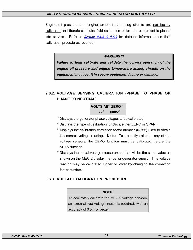
MEC 2 MICROPROCESSOR ENGINE/GENERATOR CONTROLLER
PM056 Rev 6 05/10/15 Thomson Technology 63
Engine oil pressure and engine temperature analog circuits are not factory
calibrated and therefore require field calibration before the equipment is placed
into service. Refer to Section 9.6.8 & 9.6.9 for detailed information on field
calibration procedures required.
WARNING!!! Failure to field calibrate and validate the correct operation of the engine oil pressure and engine temperature analog circuits on the equipment may result in severe equipment failure or damage.
9.6.2. VOLTAGE SENSING CALIBRATION (PHASE TO PHASE OR PHASE TO NEUTRAL)
VOLTS AB ZERO 99 600V
Displays the generator phase voltages to be calibrated. Displays the type of calibration function, either ZERO or SPAN. Displays the calibration correction factor number (0-255) used to obtain the correct voltage reading. Note: To correctly calibrate any of the voltage sensors, the ZERO function must be calibrated before the SPAN function.
Displays the actual voltage measurement that will be the same value as shown on the MEC 2 display menus for generator supply. This voltage reading may be calibrated higher or lower by changing the correction factor number.
9.6.3. VOLTAGE CALIBRATION PROCEDURE
NOTE: To accurately calibrate the MEC 2 voltage sensors, an external test voltage meter is required, with an accuracy of 0.5% or better.
MEC 2 MICROPROCESSOR ENGINE/GENERATOR CONTROLLER
PM056 Rev 6 05/10/15 Thomson Technology 64
Note: Zero Calibration must be completed before Span Calibration. To calibrate the generator supply voltage sensors, perform the following procedure:
9.6.3.1.ZERO CALIBRATION
Connect an external AC voltmeter of adequate voltage range and accuracy to the MEC 2 controller terminals associated with the voltage phases to be calibrated. With the generator stopped, confirm there is Zero volts on the phases to be calibrated. In the programming mode, scroll to each of the desired generator supply voltage phases (i.e. phase to phase or phase to neutral) with the ZERO function selected. Use the INCREMENT or DECREMENT pushbuttons to adjust the correction factor number to obtain zero volts on the right hand side of the display as confirmed with the external voltmeter. The factory default correction factor is 127. Increasing this will raise the displayed value, conversely decreasing this value will decrease the displayed value. Note: Adjusting the ZERO function with voltage applied will result in non-linear voltage readings. With the correct voltage displayed, press the ENTER pushbutton to accept the correction factor number. Record the correction factor number on the MEC 2 programming sheet for future reference. Repeat the above procedure for all remaining phases of the generator supply as required.
9.6.3.2.SPAN CALIBRATION
Energize the generator supply voltage to the controller at nominal level. Note: It may be necessary to program the optional under and over voltage shutdowns as alarms to ensure the generator will continue to operate during calibration. Caution must be taken to ensure the generator output voltage is set within nominal limits. In the programming mode, scroll to the desired generator supply voltage phases with the SPAN function selected. Connect an external AC voltmeter of adequate voltage range and accuracy to the MEC 2 controller terminals associated with the voltage phases to be calibrated.

MEC 2 MICROPROCESSOR ENGINE/GENERATOR CONTROLLER
PM056 Rev 6 05/10/15 Thomson Technology 65
WARNING!!! Voltage sensing circuits are capable of lethal voltages while energized. Standard safety procedures should be followed and be performed by qualified personnel only. Failure to do so may cause personnel injury and/or death.
Use the INCREMENT or DECREMENT pushbuttons to adjust the correction factor number while observing the displayed voltage level on the MEC 2. Adjust the correction factor number to obtain an identical voltage reading as measured with the external AC voltmeter. With the correct voltage displayed, press the ENTER pushbutton to accept the correction factor number. Record the correction factor number on the MEC 2 programming sheet for future reference if required. Repeat the above procedures for all remaining phases of the generator supply as required.
NOTE: Once the span calibration setting has been completed, re-confirm the zero calibration points. If the zero calibration setpoint needs further adjustment, the span calibration point must also be re-calibrated.
9.6.4. CURRENT SENSING CALIBRATION
CURRENT A ZERO 99 350A
Displays the generator load current (phase A, B or C) to be calibrated. Displays the type of calibration function, either ZERO or SPAN. Displays the calibration correction factor number (0-255) used to obtain the correct current reading. Note: To correctly calibrate any of the current sensors, the ZERO function must be calibrated before the SPAN function.
MEC 2 MICROPROCESSOR ENGINE/GENERATOR CONTROLLER
PM056 Rev 6 05/10/15 Thomson Technology 66
Displays the actual current measurement that will be the same value as shown on the MEC 2 display menus for generator supply. This current reading may be calibrated higher or lower by changing the correction factor number.
9.6.5. CURRENT CALIBRATION PROCEDURE
NOTE: To accurately calibrate the MEC 2 current sensors, an external test AC ammeter and current clamp is required, with an accuracy of 0.5% or better.
Note: Zero calibration must be completed before span calibration.
To calibrate the generator supply current sensors, perform the following procedure:
9.6.5.1.ZERO CALIBRATION
Connect an external AC ammeter with current clamp of adequate current range to the MEC 2 controller terminals associated with the current phases to be calibrated. With the generator stopped, confirm there is “0” current on the phases to be calibrated. In the programming mode, scroll to each of the desired generator supply current phases with the ZERO function selected. Use the INCREMENT or DECREMENT pushbuttons to adjust the correction factor number while observing the displayed current level. Adjust the correction factor number just until “0” amps on the display is obtained. With the correct current displayed, press the ENTER pushbutton to accept the correction factor number. Record the correction factor number on the MEC 2 programming sheet for future reference. Repeat the above procedure for all remaining generator current phases.
9.6.5.2.SPAN CALIBRATION
Apply 50%-100% load to the generator set. Note: It is recommended to load the generator set to 100% rated load for calibration purposes to obtain good accuracy throughout the full span of operation.
MEC 2 MICROPROCESSOR ENGINE/GENERATOR CONTROLLER
PM056 Rev 6 05/10/15 Thomson Technology 67
NOTE: Do not exceed the current rating of the CT. Non-linear output of the CT will result when the secondary current exceeds 5 amps and will similarly effect the MEC 2 displayed values.
In the programming mode, scroll to the desired generator supply current phases with the SPAN function selected. Connect an external AC ammeter and current clamp of adequate current range to the MEC 2 controller terminals associated with the current phases to be calibrated.
WARNING!!! Never open circuit an energized CT as extreme high voltages may result which may cause serious injury or death. Standard safety procedures should be followed and be performed by qualified personnel only. Failure to do so may cause personnel injury and/or death.
Use the INCREMENT or DECREMENT pushbuttons to adjust the correction factor number while observing the displayed current level on the MEC 2. Adjust the correction factor number to obtain an identical current reading as measured with the external AC ammeter. With the correct current displayed, press the ENTER pushbutton to accept the correction factor number. Record the correction factor number on the MEC 2 programming sheet for future reference if required. Repeat the above procedures for all remaining generator current phases.
NOTE: Once the span calibration setting has been completed, re-confirm the zero calibration points. If the zero calibration setpoint needs further adjustment, the span calibration point must also be re-calibrated.
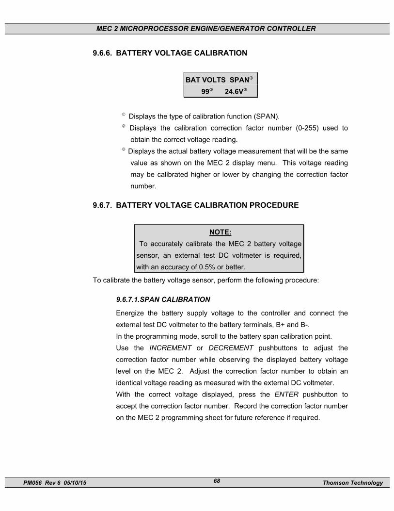
MEC 2 MICROPROCESSOR ENGINE/GENERATOR CONTROLLER
PM056 Rev 6 05/10/15 Thomson Technology 68
9.6.6. BATTERY VOLTAGE CALIBRATION
BAT VOLTS SPAN 99 24.6V
Displays the type of calibration function (SPAN). Displays the calibration correction factor number (0-255) used to
obtain the correct voltage reading. Displays the actual battery voltage measurement that will be the same
value as shown on the MEC 2 display menu. This voltage reading may be calibrated higher or lower by changing the correction factor number.
9.6.7. BATTERY VOLTAGE CALIBRATION PROCEDURE
NOTE: To accurately calibrate the MEC 2 battery voltage
sensor, an external test DC voltmeter is required, with an accuracy of 0.5% or better.
To calibrate the battery voltage sensor, perform the following procedure:
9.6.7.1.SPAN CALIBRATION
Energize the battery supply voltage to the controller and connect the external test DC voltmeter to the battery terminals, B+ and B-. In the programming mode, scroll to the battery span calibration point. Use the INCREMENT or DECREMENT pushbuttons to adjust the correction factor number while observing the displayed battery voltage level on the MEC 2. Adjust the correction factor number to obtain an identical voltage reading as measured with the external DC voltmeter. With the correct voltage displayed, press the ENTER pushbutton to accept the correction factor number. Record the correction factor number on the MEC 2 programming sheet for future reference if required.

MEC 2 MICROPROCESSOR ENGINE/GENERATOR CONTROLLER
PM056 Rev 6 05/10/15 Thomson Technology 69
9.6.8. ENGINE TEMPERATURE & OIL PRESSURE CALIBRATION
ENGINE TEMP 127 95 ºC
Displays the type of calibration function. Displays the calibration correction factor number (0-255) used to obtain the correct Temperature or Pressure reading.
Displays the actual temperature or pressure measurement that will be the same value as shown on the MEC 2 display menus. This reading may be calibrated higher or lower by changing the correction factor number.
9.6.9. TEMPERATURE CALIBRATION PROCEDURE Before the equipment is put into final operating service, the engine temperature analog circuit must be field calibrated to meet the performance accuracy as specified, to ensure correct operation. The engine temperature analog circuit must be calibrated with the engine temperature sender supplied with the controller and mounted on the engine.
WARNING!!! Failure to field calibrate and validate the correct operation of the temperature analog circuit on the equipment may result in severe equipment failure or damage.
To calibrate the MEC 2 temperature sensor, perform the following procedure:
NOTE: To accurately calibrate the MEC 2’s temperature
sensor, an external temporary engine mounted
temperature gauge is required. The external
temperature gauge should be connected as close
as possible to the temperature sender for the MEC
2.
MEC 2 MICROPROCESSOR ENGINE/GENERATOR CONTROLLER
PM056 Rev 6 05/10/15 Thomson Technology 70
The calibration procedure is to be done only at a single point, which is the normal
operating temperature of the engine.
Connect a temporary engine mounted temperature gauge of suitable accuracy
and start the engine. Once the engine reaches normal operating temperature,
enter the programming mode and scroll to the “Engine Temperature Offset”
calibration point.
Use the INCREMENT or DECREMENT pushbuttons to adjust the correction factor
number while observing the displayed temperature on the MEC 2. Adjust the
correction factor number to obtain the identical temperature reading as measured
with the external temperature gauge.
With the correct temperature displayed, press the ENTER pushbutton to accept
the correction factor number. Record the correction factor number on the MEC 2
programming sheet for future reference if required.
9.6.10. PRESSURE CALIBRATION PROCEDURE Before the equipment is put into final operating service, the engine pressure analog circuit must be field calibrated to meet the performance accuracy as specified, to ensure correct operation. The engine pressure analog circuit must be calibrated with the engine pressure sender supplied with the controller and mounted on the engine.
WARNING!!!
Failure to field calibrate and validate the correct operation of the pressure analog circuit on the equipment may result in severe equipment failure or damage.
To calibrate the MEC 2 pressure sensor, perform the following procedure:
NOTE: To accurately calibrate the MEC 2’s pressure
sensor, an external temporary engine mounted
pressure gauge is required. The external pressure
gauge should be connected as close as possible to
the pressure sender for the MEC 2.

MEC 2 MICROPROCESSOR ENGINE/GENERATOR CONTROLLER
PM056 Rev 6 05/10/15 Thomson Technology 71
The calibration procedure is to be done only at a single point, which is the normal
operating pressure of the engine.
Connect a temporary engine mounted pressure gauge of suitable accuracy and
start the engine. Once the engine reaches normal operating pressure and
temperature, enter the programming mode and scroll to the “Engine Pressure
Offset” calibration point.
Use the INCREMENT or DECREMENT pushbuttons to adjust the correction factor
number while observing the displayed pressure on the MEC 2. Adjust the
correction factor number to obtain the identical pressure reading as measured
with the external pressure gauge.
With the correct pressure displayed, press the ENTER pushbutton to accept the
correction factor number. Record the correction factor number on the MEC 2
programming sheet for future reference.

MEC 2 MICROPROCESSOR ENGINE/GENERATOR CONTROLLER
PM056 Rev 6 05/10/15 Thomson Technology 72
Engine Pressure
Sender Resistance1
Engine Temperature
Sensor Resistance
KPA PSI Ohms F C Ohms 1034 150 38 392 200 20 965 140 42 374 190 24 896 130 48 356 180 28 827 120 54 338 170 33 758 110 62 320 160 39 689 100 70 302 150 46 621 90 79 284 140 55 552 80 89 266 130 65 483 70 101 248 120 76 414 60 114 230 110 90 345 50 127 212 100 106 276 40 142 194 90 147 207 30 160 176 80 197 138 20 183 150 70 290 69 10 206 140 60 426
122 50 622
104 40 952
86 30 1486
68 20 2322
50 10 3644
32 0 6284 1 Sender resistance data shown are for Oil Pressure Sender p/n-003654
(Thomson p/n), Manufacturer- Datcon, p/n 102227. Datcon Sender must
be used with MEC software version 1.81 or greater (previous software
versions cannot be used).
Figure #18

MEC 2 MICROPROCESSOR ENGINE/GENERATOR CONTROLLER
PM056 Rev 6 05/10/15 Thomson Technology 73
10. PROGRAMMING SHEETS
10.1. SUMMARY CONFIGURATION DATA SHEET
MEC 2 MICROPROCESSOR ENGINE/GENERATOR CONTROLLER
SUMMARY CONFIGURATION DATA SHEET WORK ORDER #: REV: REV DATE:
INITIATED BY: CUSTOMER: DEFAULT PROGRAM:
DATE: PROJECT NAME: TPS VER:
NOTES:
ENGINE/GEN SYSTEM INPUTS
SYSTEM AC VOLTS: PHASES: FREQUENCY: DC VOLTAGE:
DIGITAL DISPLAY FEATURES
AC VOLTAGE AC CURRENT BATTERY VOLTAGE
ENGINE TEMPERATURE KVA TACHOMETER
OIL PRESSURE FREQUENCY HOURMETER
DIGITAL FAULT CIRCUITS (15) ANALOG FAULT CIRCUITS
FAULT NAME INPUT NAME FAULT NAME INPUT NAME
Over crank Shutdown Internal Over speed Shutdown Mag-Pickup
Switch Not in Auto Alarm Internal Loss of Speed Sig. Shtdn Mag-Pickup
Emergency Stop Internal/ext Under Voltage Shutdown AC Voltage
Ext Dig Input #1 Under Frequency Alarm AC Freq
Ext Dig Input #2 Weak Battery Alarm DC Volts
Internal Under Voltage AC Voltage
Internal Over Voltage AC Voltage
Internal Under Frequency AC Frequency
Internal Over Frequency AC Frequency
Internal Over Current AC Current
Ext Dig Input #3 Low Battery Voltage Alarm DC Volts
Ext Dig Input #4 High Battery Voltage Alarm DC Volts
Low Engine Temp. Alarm Temp. Sender
High Engine Temp #1 Alm Temp. Sender
High Engine Temp #2 Shdn Temp. Sender
Low Oil Pressure #1 Alarm Press. Sender
Low Oil Pressure #2 Shutdown Press. Sender
STANDARD OUTPUT CONTACTS
OUTPUT NAME OUTPUT TYPE
Run (Fuel) Form A
Crank Form A
PROGRAMMABLE CONTACTS
OUTPUT NAME OUTPUT TYPE
ATS Test (Std Default) or Custom _____________________________________ Programmable #1 – Form C
Common Alarm (Std Default) or Custom _________________________________ Programmable #2 – Form C
Common Shutdown (Std Default) or Custom _____________________________ Programmable #3 – Form C
Engine Running (Std Default) or Custom ________________________________ Programmable #4 – Form C
EPS Supplying Load/Engine Running (Std Default) or Custom _______________ Programmable #5 – Form A/B
(EAP 110/MEC 2 Exp –Group 1 Only)
Disabled (Std Default) or Custom _____________________________________ Programmable #6 – Form A/B]
(EAP 110/MEC 2 Exp –Group 2 Only)

MEC 2 MICROPROCESSOR ENGINE/GENERATOR CONTROLLER
PM056 Rev 6 05/10/15 Thomson Technology 74
11. MAIN CONFIGURATION
MAIN PROGRAMMING MENU
SYSTEM VOLTAGE LINE TO LINE VOLTAGE
XXXXX VAC 120-15000VAC
SYSTEM FREQUENCY
50HZ/60HZ TOGGLE BETWEEN 50/60HZ
SYSTEM PHASES
SINGLE PHASE/3 PHASE TOGGLE BETWEEN 1 & 3 PHASE
NEUTRAL CONNECTED TOGGLE BETWEEN YES/NO
VOLTAGE SENSING VOLTAGE SENSING PT RATIO
RATIO XXX ENTER NUMBER 1-208 (1=DIRECT)
CURRENT SENSING CURRENT SENSING CT RATIO
RATIO XXX ENTER NUMBER 1-999 (1=DIRECT)
TEMPERATURE SCALE
DEG C/DEG F TOGGLE BETWEEN DEG C/DEG F
PRESSURE SCALE
PSI/KPA TOGGLE BETWEEN PSI/KPA
START DELAY
XXX SECONDS 0-999 SECONDS
CRANK TIME
XX SECONDS 0-99 SECONDS
REST TIME
XX SECONDS 0-99 SECONDS
STARTER RE-ENGAGE
DELAY XX SECONDS 0-99 SECONDS 0=DISABLED
NUMBER OF CRANKS
XX 0-99 TIMES 0=CONTINUOUS

MEC 2 MICROPROCESSOR ENGINE/GENERATOR CONTROLLER
PM056 Rev 6 05/10/15 Thomson Technology 75
MAIN PROGRAMMING MENU
BYPASS DELAY
XX SECONDS 0-99 SECONDS
COOLDOWN DELAY
XX SECONDS 0-9999 SECONDS
NOMINAL RPM
XXXX RPM 0-4000RPM
FLYWHEEL TEETH ENGINE SPEED SENSING VIA MAGNETIC PICK UP
XXX 0-999 TEETH
CRANK DISCONNECT
XX PERCENT 0-100%
OVER SPEED
XX PERCENT 100-150%
OVER SPEED TRANSIENT
X.X SEC 0.0-9.9 SEC
RUN OUTPUT
FAIL SAFE YES/NO TOGGLE BETWEEN YES/NO
LOSS OF SPEED SIGNAL
SHUTDOWN ALARM/SHUTDOWN
TOGGLE BETWEEN ALARM/SHUTDOWN
COMMON FAIL FOR
NOT IN AUTO YES/NO TOGGLE BETWEEN YES/NO
HORN FOR NOT IN AUTO TOGGLE BETWEEN YES/NO
PROG OUTPUT #1 Common Fail (Factory default, unless otherwise specified)
PROG OUTPUT #2
PROG OUTPUT #3
PROG OUTPUT #4
PROG OUTPUT #5
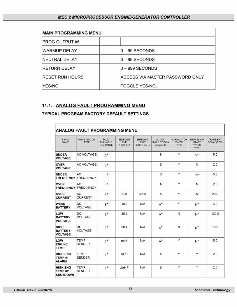
MEC 2 MICROPROCESSOR ENGINE/GENERATOR CONTROLLER
PM056 Rev 6 05/10/15 Thomson Technology 76
MAIN PROGRAMMING MENU
PROG OUTPUT #6
WARMUP DELAY 0 – 99 SECONDS
NEUTRAL DELAY 0 – 99 SECONDS
RETURN DELAY 0 – 999 SECONDS
RESET RUN HOURS ACCESS VIA MASTER PASSWORD ONLY
YES/NO TOGGLE YES/NO,
11.1. ANALOG FAULT PROGRAMMING MENU TYPICAL PROGRAM FACTORY DEFAULT SETTINGS
ANALOG FAULT PROGRAMMING MENU
FAULT NAME
INPUT ANALOG TYPE
FAULT E=ENABLE D=DISABLE
SETPOINT LEVEL
(PICK-UP)
SETPOINT LEVEL
(DROP-OUT)
ACTION S=SHUTDOWN
A=ALARM
ALARM LATCH Y=YES N=NO
BYPASS ON START Y=YES N=NO
TRANSIENT DELAY (SEC)
UNDER VOLTAGE
AC VOLTAGE E* S Y Y* 5.0
OVER VOLTAGE
AC VOLTAGE E* S Y N 2.0
UNDER FREQUENCY
AC FREQUENCY
E* S Y Y* 5.0
OVER FREQUENCY
AC FREQUENCY
E* A Y N 2.0
OVER CURRENT
AC CURRENT
E* 500 4990 A Y N 20.0
WEAK BATTERY
DC VOLTAGE
E* 18.0 N/A A* Y N* 3.0
LOW BATTERY VOLTAGE
DC VOLTAGE
E* 25.6 N/A A* N N* 120.0
HIGH BATTERY VOLTAGE
DC VOLTAGE
E* 30.4 N/A A* N N* 10.0
LOW ENGINE TEMP
TEMP SENDER
E* 95°F N/A A* Y N* 5.0
HIGH ENG TEMP #1 ALARM
TEMP SENDER
E* 198°F N/A A Y Y 2.0
HIGH ENG TEMP #2 SHUTDOWN
TEMP SENDER
E* 206°F N/A S Y Y 2.0

MEC 2 MICROPROCESSOR ENGINE/GENERATOR CONTROLLER
PM056 Rev 6 05/10/15 Thomson Technology 77
ANALOG FAULT PROGRAMMING MENU
FAULT NAME
INPUT ANALOG TYPE
FAULT E=ENABLE D=DISABLE
SETPOINT LEVEL
(PICK-UP)
SETPOINT LEVEL
(DROP-OUT)
ACTION S=SHUTDOWN
A=ALARM
ALARM LATCH Y=YES N=NO
BYPASS ON START Y=YES N=NO
TRANSIENT DELAY (SEC)
LOW OIL PRESS#1 ALARM
PRESS SENDER
E* 30PSI N/A A Y Y* 2.0
LOW OIL PRESS#2 SHUTDOWN
PRESS SENDER
E* 20PSI N/A S Y Y* 2.0
* Indicates feature is non-programmable (i.e. is fixed) in software
11.2. DIGITAL FAULT PROGRAMMING MENU TYPICAL PROGRAM FACTORY DEFAULT SETTINGS
DIGITAL FAULT PROGRAMMING MENU
FAULT NAME
INPUT # ACTION S=SHUTDOWN
A=ALARM ALARM LATCH
Y=YES N=NO
POLARITY O=OPEN C=CLOSE
BYPASS ON START Y=YES N=NO
TRANSIENT DELAY (SEC)
LOW OIL PRESSURE
1 S __ O Y 0.5
HIGH ENG TEMP
2 S __ O Y 1.0
BATT CHGR INPUT FAIL
3 A Y C N 30.0
LOW FUEL LEVEL
4 A N C N 0.1
11.3. CALIBRATION MENU
CALIBRATION MENU
VOLTS A-B
ZERO XXX XXXVAC
VOLTS A-B
SPAN XXX XXXVAC
VOLTS B-C
ZERO XXX XXXVAC
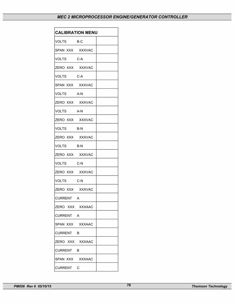
MEC 2 MICROPROCESSOR ENGINE/GENERATOR CONTROLLER
PM056 Rev 6 05/10/15 Thomson Technology 78
CALIBRATION MENU
VOLTS B-C
SPAN XXX XXXVAC
VOLTS C-A
ZERO XXX XXXVAC
VOLTS C-A
SPAN XXX XXXVAC
VOLTS A-N
ZERO XXX XXXVAC
VOLTS A-N
ZERO XXX XXXVAC
VOLTS B-N
ZERO XXX XXXVAC
VOLTS B-N
ZERO XXX XXXVAC
VOLTS C-N
ZERO XXX XXXVAC
VOLTS C-N
ZERO XXX XXXVAC
CURRENT A
ZERO XXX XXXAAC
CURRENT A
SPAN XXX XXXAAC
CURRENT B
ZERO XXX XXXAAC
CURRENT B
SPAN XXX XXXAAC
CURRENT C
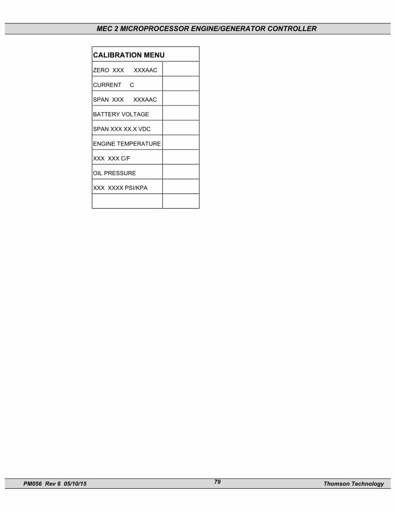
MEC 2 MICROPROCESSOR ENGINE/GENERATOR CONTROLLER
PM056 Rev 6 05/10/15 Thomson Technology 79
CALIBRATION MENU
ZERO XXX XXXAAC
CURRENT C
SPAN XXX XXXAAC
BATTERY VOLTAGE
SPAN XXX XX.X VDC
ENGINE TEMPERATURE
XXX XXX C/F
OIL PRESSURE
XXX XXXX PSI/KPA
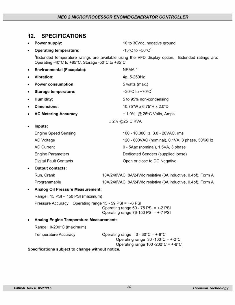
MEC 2 MICROPROCESSOR ENGINE/GENERATOR CONTROLLER
PM056 Rev 6 05/10/15 Thomson Technology 80
12. SPECIFICATIONS • Power supply: 10 to 30Vdc, negative ground
• Operating temperature: -15°C to +50°C1 1Extended temperature ratings are available using the VFD display option. Extended ratings are: Operating -40°C to +85°C, Storage -50°C to +85°C
• Environmental (Faceplate): NEMA 1
• Vibration: 4g, 5-250Hz
• Power consumption: 5 watts (max.)
• Storage temperature: -20°C to +70°C1
• Humidity: 5 to 95% non-condensing
• Dimensions: 10.75”W x 6.75”H x 2.0”D
• AC Metering Accuracy: ± 1.0%, @ 25°C Volts, Amps
± 2% @25°C KVA • Inputs:
Engine Speed Sensing 100 - 10,000Hz, 3.0 - 20VAC, rms
AC Voltage 120 - 600VAC (nominal), 0.1VA, 3 phase, 50/60Hz
AC Current 0 - 5Aac (nominal), 1.5VA, 3 phase
Engine Parameters Dedicated Senders (supplied loose)
Digital Fault Contacts Open or close to DC Negative
• Output contacts: Run, Crank 10A/240VAC, 8A/24Vdc resistive (3A inductive, 0.4pf), Form A
Programmable 10A/240VAC, 8A/24Vdc resistive (3A inductive, 0.4pf), Form A
• Analog Oil Pressure Measurement: Range: 15 PSI – 150 PSI (maximum)
Pressure Accuracy Operating range 15 - 59 PSI = +-6 PSI Operating range 60 - 75 PSI = +-2 PSI Operating range 76-150 PSI = +-7 PSI
• Analog Engine Temperature Measurement:
Range: 0-200°C (maximum)
Temperature Accuracy Operating range 0 - 30°C = +-8°C Operating range 30 -100°C = +-2°C Operating range 100 -200°C = +-8°C
Specifications subject to change without notice.
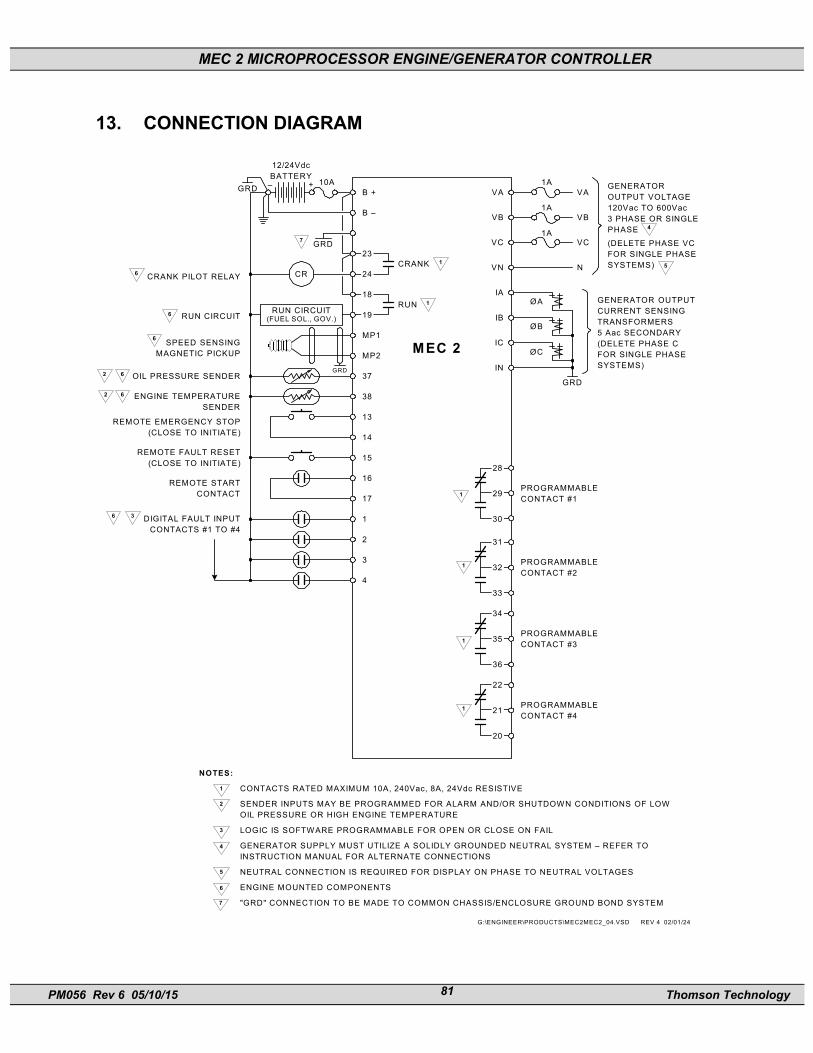
MEC 2 MICROPROCESSOR ENGINE/GENERATOR CONTROLLER
PM056 Rev 6 05/10/15 Thomson Technology 81
13. CONNECTION DIAGRAM
G:\ENGINEER\PRODUCTS\MEC2MEC2_04.VSD REV 4 02/01/24
1
2
3
4
17
16
15
14
13
38
37GRD
��������������������
CR
MP2
MP1
19
18
24
23
B –
B +GRD +–
12/24VdcBATTERY
CRANK PILOT RELAY
RUN CIRCUIT
SPEED SENSINGMAGNETIC PICKUP
OIL PRESSURE SENDER
ENGINE TEMPERATURESENDER
REMOTE EMERGENCY STOP(CLOSE TO INITIATE)
REMOTE FAULT RESET(CLOSE TO INITIATE)
REMOTE STARTCONTACT
DIGITAL FAULT INPUTCONTACTS #1 TO #4
CRANK
RUN
1
1
28
29
30
1PROGRAMMABLECONTACT #1
IN
IC
IB
IA
VN
VC
VB
VA
VC
VB
VA
1A
1A
1A
N
GRD
GENERATOR OUTPUTCURRENT SENSINGTRANSFORMERS5 Aac SECONDARY(DELETE PHASE CFOR SINGLE PHASESYSTEMS)
ØA
ØB
ØC
10A GENERATOROUTPUT VOLTAGE120Vac TO 600Vac3 PHASE OR SINGLEPHASE(DELETE PHASE VCFOR SINGLE PHASESYSTEMS) 5
MEC 2
RUN CIRCUIT(FUEL SOL., GOV.)
6
6
6
6
6
36
GRD7
4
NOTES:
CONTACTS RATED MAXIMUM 10A, 240Vac, 8A, 24Vdc RESISTIVE
SENDER INPUTS MAY BE PROGRAMMED FOR ALARM AND/OR SHUTDOWN CONDITIONS OF LOWOIL PRESSURE OR HIGH ENGINE TEMPERATURE
LOGIC IS SOFTWARE PROGRAMMABLE FOR OPEN OR CLOSE ON FAIL
GENERATOR SUPPLY MUST UTILIZE A SOLIDLY GROUNDED NEUTRAL SYSTEM – REFER TOINSTRUCTION MANUAL FOR ALTERNATE CONNECTIONS
NEUTRAL CONNECTION IS REQUIRED FOR DISPLAY ON PHASE TO NEUTRAL VOLTAGES
ENGINE MOUNTED COMPONENTS
"GRD" CONNECTION TO BE MADE TO COMMON CHASSIS/ENCLOSURE GROUND BOND SYSTEM
1
2
3
4
5
6
7
PROGRAMMABLECONTACT #2
PROGRAMMABLECONTACT #3
PROGRAMMABLECONTACT #4
33
36
20
35
21
32
31
34
22
1
1
1
2
2
MEC 2 MICROPROCESSOR ENGINE/GENERATOR CONTROLLER
PM056 Rev 6 05/10/15 Thomson Technology 82
14. TROUBLE SHOOTING A number of problems can cause the MEC 2 controller not to function properly. Refer to the following list of typical problems. Consult the factory for any detailed information or for any problems not listed.
CAUTION!!! Before opening the enclosure to perform any service task, it is imperative to isolate the control system from any possible source of power. Failure to do so may result in serious personal injury or death due to electrical shock.
Service procedures must be undertaken by qualified personnel only!
SYMPTOM CORRECTIVE ACTION Controller does not power up even with correct DC power applied
- Check that there are no wiring errors/short circuits connected to the controller. Note: The MEC 2 contains an electronic fuse that triggers upon an over load condition and does not reset until the supply voltage is removed, and over load condition is corrected.
LCD Display is not operational - Check that the controller’s microprocessor is running by observing a red flashing “watchdog” LED on the rear of the PCB.
- Check that there is sufficient DC supply voltage to input terminals B+ & B- (10-30Vdc).
- Verify that the LCD contrast potentiometer (R115) on rear of PCB is adjusted for good pixel resolution for the operating temperature of the unit.
Controller cannot be “Reset” - Check that the controller is set to the OFF mode before trying to reset.
- Check that the engine has come to a complete stop before trying to reset.
MEC 2 MICROPROCESSOR ENGINE/GENERATOR CONTROLLER
PM056 Rev 6 05/10/15 Thomson Technology 83
SYMPTOM CORRECTIVE ACTION No “RUN” output signal - Check that all shutdown circuits are reset
(red shutdown LED must be off). - Engine speed signal must be detected
(speed signal green LED on) during cranking if the “run-output fail safe” feature is enabled. Verify correct magnetic pick-up signal at cranking (2.0VAC min.).
- Check that the RUN output LED (on the rear of the PCB) is on. If yes, verify relay contact operation on terminals #18 & #19.
Over speed shutdown occurs at normal speed - Verify that the controller has been programmed with the correct values for the number of flywheel teeth, nominal RPM, and over speed setpoint percentage.
Voltage or current metering is reading incorrectly - Verify that the controller has been programmed with the correct values for the voltage sensing PT ratio and/or current sensing CT ratio.
- Verify that the battery supply DC negative conductor is properly grounded to the engine block (i.e. to a common ground point).
- Verify that the controller’s analog input has been properly calibrated as per manual instructions.
- Verify the voltage sensing wiring connection to the MEC 2 matches power distribution type. (Note: standard direct voltage connection requires that the generators neutral is solidly grounded.)
Engine temperature or oil pressure display is reading incorrectly
- Verify that the controller’s analog input has been properly calibrated as per manual instructions.
- Verify engine sensor wiring is correct.

MEC 2 MICROPROCESSOR ENGINE/GENERATOR CONTROLLER
PM056 Rev 6 05/10/15 Thomson Technology 84
SYMPTOM CORRECTIVE ACTION (Note: engine sensors must be factory supplied units only.)
- Verify that the battery supply DC negative conductor is properly grounded to the engine block (i.e. to a common ground point).
Engine temperature or oil pressure displays 9999 - Check the wiring from the MEC 2 terminal #37 & #38 to the engine mounted sender are correct (i.e. wiring is not open or shorted).
- Verify the engine mounted senders have correct resistance reading for corresponding input temperature or pressure (refer to the Analog Temperature and Pressure Calibration table for values).
- Verify calibration.
Engine alarms on high engine temperature or low oil pressure when engine is operating within normal limits
- Check the wiring from the MEC 2 terminals #37 & #38 to the engine mounted senders is correct (i.e. wiring is not open or shorted).
- Verify the engine mounted senders have correct resistance reading for corresponding input temperature or pressure (refer to the Analog Temperature and Pressure Calibration table for values).
Key presses on the lexan faceplate do not operate - Verify the interconnecting ribbon cable between the lexan faceplate and main printed circuit board is correctly connected.

MEC 2 MICROPROCESSOR ENGINE/GENERATOR CONTROLLER
PM056 Rev 6 05/10/15 Thomson Technology 85
15. NOTES