programmable audio generator · the anl-926 is a single-width module that contains a pure tone,...
TRANSCRIPT

instrumentation and software for research
PROGRAMMABLE AUDIO GENERATOR ANL-926 USER’S MANUAL
DOC-011 Rev. 4.7 Copyright ©2016 All Rights Reserved
Med Associates Inc. P.O. Box 319 St. Albans, Vermont 05478
Phone: 802.527.2343 Fax: 802.527.5095 www.med-associates.com


- ii -
DOC-011 Rev 4.7 Copyright © 2016 Med Associates, Inc.
Table of Contents
Chapter 1 | Introduction ................................................................................................ 1
Specifications.............................................................................................................................. 1
Chapter 2 | Switch Settings .......................................................................................... 2
Card Address .............................................................................................................................. 2
Card Offset ................................................................................................................................. 3
Chapter 3 | Operating Instructions ............................................................................. 5
ANL-926 Commands.................................................................................................................. 5
Chapter 4 | Sample A926FREQ.MPC Program ........................................................... 9
Chapter 5 | Testing the ANL-926 Using Med Test .................................................. 12
Chapter 6 | Contact Information ............................................................................... 13

- iii -
DOC-011 Rev 4.7 Copyright © 2016 Med Associates, Inc.
This page intentionally left blank

MED A S SOCI ATES I NC. ANL -92 6 PRO GR AMM ABLE AU DIO GE NERATOR
- 1 -
DOC-011 Rev 4.7 Copyright © 2016 Med Associates, Inc.
CHAPTER 1 | INTRODUCTION The ANL-926 is a single-width module that contains a pure tone, white noise, and click generator using a single microprocessor controller and audio amplifier. All aspects of the audio signal are user controllable by way of MED-PC® programming.
Specifications
Pure Tone:
Frequency range: 10 Hz to 35 KHz in 1 Hz increments.
Amplitude: 20 dB to 100 dB in 0.5 dB increments. ± 1 bit (0.125 dB).
Rise / Fall time: 1 millisecond to 1 second in 1 ms increments. The rise and fall times are added to the duration of the tone.
Sound duration: 1 ms to 65,535 ms in 1 ms increments. A continuous tone can also be timed by MED-PC® program.
White Noise:
Frequency: Broadband white noise selected by setting the frequency to 0.
All other white noise specs: Same as pure tone specs.
Click Noise:
Frequency: 1 Hz to 100 Hz.
Rise / Fall time: Disabled.
Amplitude: 20 to 100 dB in 1 dB increments.
Duration: Same as pure tone.
MED A S SOCI ATES I NC. ANL -92 6 PRO GR AMM ABLE AU DIO GE NERATOR
- 2 -
DOC-011 Rev 4.7 Copyright © 2016 Med Associates, Inc.
CHAPTER 2 | SWITCH SETTINGS If the ANL-926 was purchased as part of a system from Med Associates, Inc. the ANL-926’s address and offset were set at the factory. If the ANL-926 was purchased separately, or additional ANL-926s are being added to an existing system, the following information should be used to verify the address and offset of the card(s).
Be sure the power is turned off when removing cards from, or inserting cards into the interface cabinet. Removing or inserting cards while the interface cabinet power is on will likely result in damage to the system.
Card Address
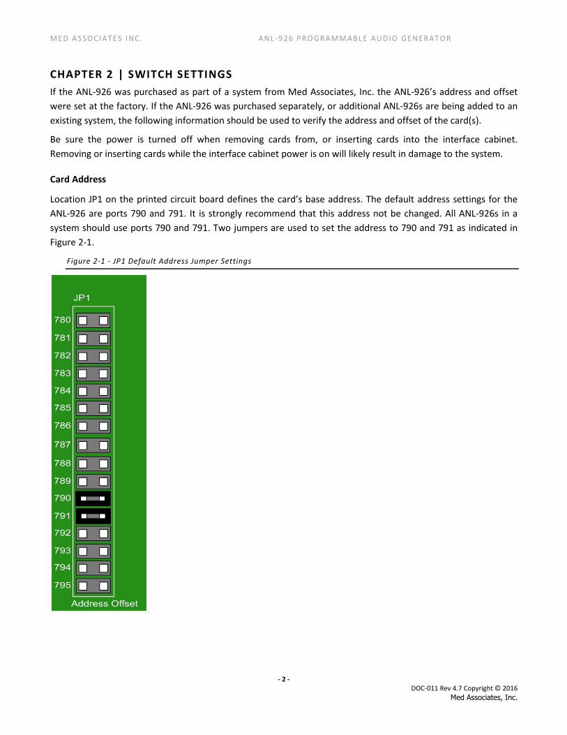
Location JP1 on the printed circuit board defines the card’s base address. The default address settings for the ANL-926 are ports 790 and 791. It is strongly recommend that this address not be changed. All ANL-926s in a system should use ports 790 and 791. Two jumpers are used to set the address to 790 and 791 as indicated in Figure 2-1.
Figure 2-1 - JP1 Default Address Jumper Settings
MED A S SOCI ATES I NC. ANL -92 6 PRO GR AMM ABLE AU DIO GE NERATOR
- 3 -
DOC-011 Rev 4.7 Copyright © 2016 Med Associates, Inc.
Card Offset
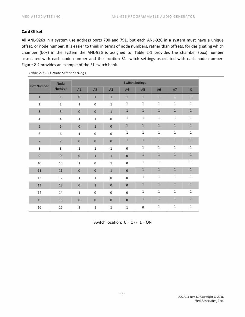
All ANL-926s in a system use address ports 790 and 791, but each ANL-926 in a system must have a unique offset, or node number. It is easier to think in terms of node numbers, rather than offsets, for designating which chamber (box) in the system the ANL-926 is assigned to. Table 2-1 provides the chamber (box) number associated with each node number and the location S1 switch settings associated with each node number. Figure 2-2 provides an example of the S1 switch bank.
Table 2-1 - S1 Node Select Settings
Box Number Node
Number
Switch Settings
A1 A2 A3 A4 A5 A6 A7 X
1 1 0 1 1 1 1 1 1 1
2 2 1 0 1 1 1 1 1 1
3 3 0 0 1 1 1 1 1 1
4 4 1 1 0 1 1 1 1 1
5 5 0 1 0 1 1 1 1 1
6 6 1 0 0 1 1 1 1 1
7 7 0 0 0 1 1 1 1 1
8 8 1 1 1 0 1 1 1 1
9 9 0 1 1 0 1 1 1 1
10 10 1 0 1 0 1 1 1 1
11 11 0 0 1 0 1 1 1 1
12 12 1 1 0 0 1 1 1 1
13 13 0 1 0 0 1 1 1 1
14 14 1 0 0 0 1 1 1 1
15 15 0 0 0 0 1 1 1 1
16 16 1 1 1 1 0 1 1 1
Switch location: 0 = OFF 1 = ON
MED A S SOCI ATES I NC. ANL -92 6 PRO GR AMM ABLE AU DIO GE NERATOR
- 4 -
DOC-011 Rev 4.7 Copyright © 2016 Med Associates, Inc.
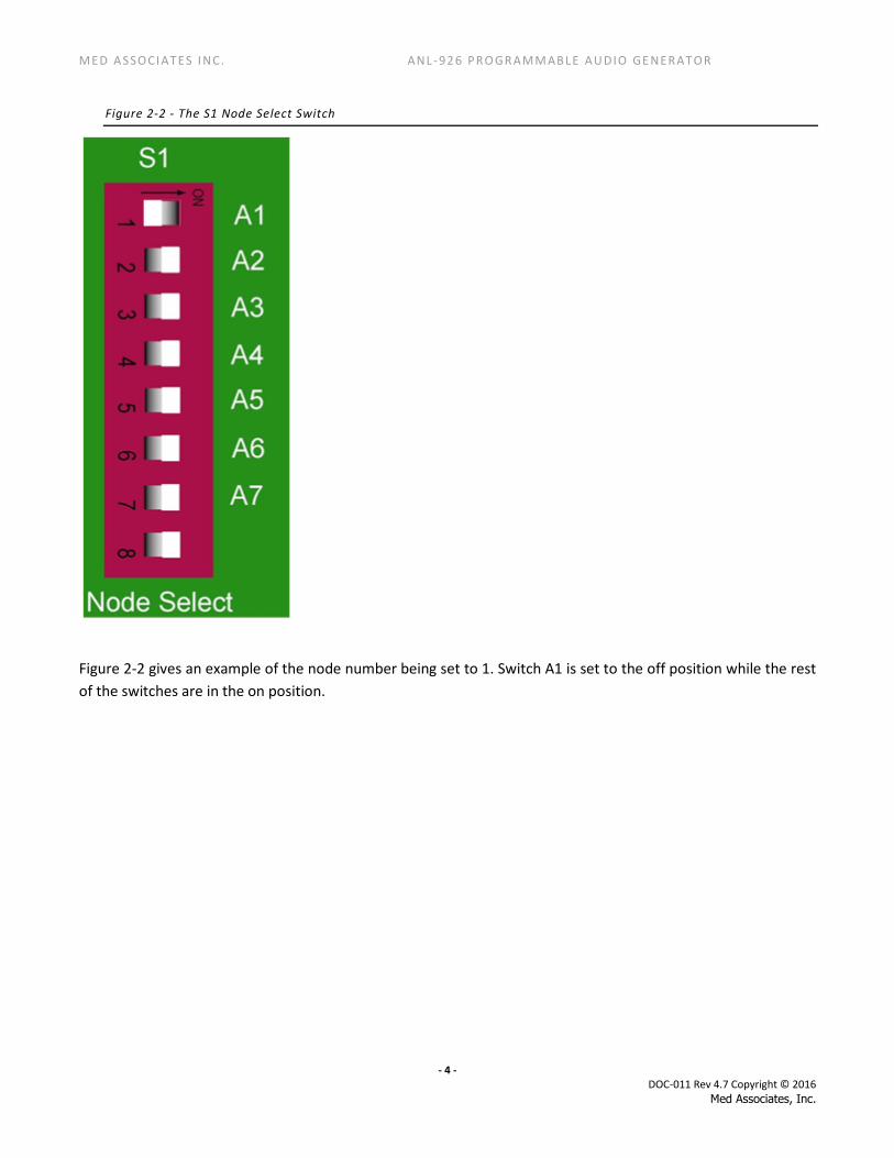
Figure 2-2 - The S1 Node Select Switch
Figure 2-2 gives an example of the node number being set to 1. Switch A1 is set to the off position while the rest of the switches are in the on position.
MED A S SOCI ATES I NC. ANL -92 6 PRO GR AMM ABLE AU DIO GE NERATOR
- 5 -
DOC-011 Rev 4.7 Copyright © 2016 Med Associates, Inc.
CHAPTER 3 | OPERATING INSTRUCTIONS MED-PC® programs issue commands to an ANL-926 card using a combination of three base commands that are combined with other key words. The Set and On base commands prefix the key words, while the RP base command suffixes the key words. The base commands are:
Set: Updates the key word value, but does not produce any sounds.
On: Updates the key word value and produces a sound for the defined duration.
RP: Updates the Rack and Port values, the key word value and then produces a sound for the defined duration
ANL-926 commands are calls to Pascal functions and must be prefixed with a tilde (~) and suffixed with a semi-colon and tilde (;~). For example, ~InitANL926;~ is used to call the InitANL926 command. The second tilde would be followed by another semi-colon to issue another MED-PC® output command. Descriptions of the base commands and key words will be provided below.
All non-RP type commands must include the variables MG and BOX. MG is a MED-PC® global variable that is used to pass back any error messages that might occur. BOX represents the box or chamber the ANL-926 is used in. For example, if the program is loaded into chamber 1, BOX will automatically be set to 1, the user does not have to do anything.
ANL-926 Commands
Initializing the ANL-926
Before the ANL-926 can be used in a MED-PC® program it must be initialized, or reset. This is done with the
InitANL926 or
InitANL926RP(MG, Rack, Port)
command. One of these two options must be the first ANL-926 command issued in the program. InitANL926 should be used unless the ANL-926 is not in rack 1 or the card is not set to the default ports of 790 and 791. For example, if the ANL-926 was in rack 2 and was set to ports 788 & 789 the command would be ~InitANL926RP(MG, 2, 788);~
Another possible approach is to precede the InitANL926 command with one or both of the following commands to change the rack and/or port values. The following two commands must occur before the InitANL926 command if they are used.
SetPort(MG, Port): If the port number is changed using the jumpers on JP1, then the SetPort command must be used to tell the DLL which port to use.
SetRack(MG, Rack): Tells the ANL-926 driver which rack holds all of the ANL-926 cards. It is a common practice to locate the SmartCtrl, SuperPort, and Standard cards in rack 1 and all of the ANL-926 cards in rack 2.
Once any of the initializing commands are called, they do not need to be used again in the program unless the rack or port value is changed.

MED A S SOCI ATES I NC. ANL -92 6 PRO GR AMM ABLE AU DIO GE NERATOR
- 6 -
DOC-011 Rev 4.7 Copyright © 2016 Med Associates, Inc.
ANL-926 Default Values
If an “On” command is issued before any “Set” commands are issued, the following default values will be used by the ANL-926:
Frequency = 1 KHz
Duration = 1 second
Rise/Fall Time = 10 ms
Click Frequency = 10 clicks/second
Amplitude = 64 dB
Frequency Commands
The ANL-926 can produce tones at frequencies from 10 Hz to 35 KHz in 1 Hz increments. Actual frequencies produced will be determined by the speaker’s frequency response curve and limitations. Set the frequency value to 0 Hz to produce a wide band white noise.
SetFreq(MG, BOX, Frequency): Sets the frequency to be produced, but does not issue a sound. Ex: ~SetFreq(MG, BOX, 2500);~
SetFreqRP(MG, Rack, Port, BOX, Frequency): Sets the desired frequency as well as the rack and port address to use, but does not produce a sound. Ex: ~SetFreqRP(MG, 2, 788, BOX, 2500);~
OnFreq(MG, BOX, Frequency): Sets the desired frequency and produces a sound. The sound will continue until the set duration is reached, or another command is issued. Ex: ~OnFreq(MG, BOX, 2500);~
OnFreqRP(MG, Rack, Port, BOX, Frequency): Sets the desired frequency, the rack and port to use and produces a sound until the set duration is reached, or another command is issued. Ex: ~OnFreqRP(MG, 2, 788, BOX, 2500);~
Amplitude Commands
The amplitude is entered as a real number in decibels (dB). The available range is 20 dB to 100 dB in 0.5 dB increments.
Amplitude, or sound pressure level (SPL), can vary with the frequency being produced, the distance from the speaker the measurement is taken and the speaker’s frequency response curve. If a precise output value is required the system should be calibrated using a SPL meter and Med Test. See DOC-200, Med Test, for information on calibrating the ANL-926
SetAmp(MG, BOX, Amplitude): Sets the amplitude of the sound, but does not produce a sound. Ex: ~SetAmp(MG, Box, 85);~
SetAmpRP(MG, Rack, Port, BOX, Amplitude): Sets the amplitude and the rack and port address to be used but does not produce a sound. Ex: ~SetAmp(MG, 2, 788, BOX, 85);~

MED A S SOCI ATES I NC. ANL -92 6 PRO GR AMM ABLE AU DIO GE NERATOR
- 7 -
DOC-011 Rev 4.7 Copyright © 2016 Med Associates, Inc.
OnAmp(MG, BOX, Amplitude): Sets the amplitude to the desired level and produces a sound for the set duration or until another command is issued. Ex: ~OnAmp(MG, BOX, 85);~
OnAmpRP(MG, Rack, Port, BOX, Amplitude): Sets the amplitude, rack and port to use and produces a sound until the set duration is reached or another command is issued. Ex: ~OnAmp(MG, 2, 788, BOX, 85);~
Rise / Fall Time Commands
The Rise/Fall time is real number entered in milliseconds. This value sets the duration of the gradual turn on and turn off period used to suppress the “pop” that may result when a transition from silence to a significant volume (or vice-versa) occurs. The available range is 1 to 1000 milliseconds in 1 millisecond increments.
SetRF(MG, BOX, Rise/Fall Time): Sets the rise/fall time but does not produce a sound. Ex: ~SetRF(MG, BOX, 3);~
SetRFRP(MG, Rack, Port, BOX, Rise/Fall Time): Sets the rise/fall time as well as the rack and port values, but does not produce a sound. Ex: ~SetRFRP(MG, 2, 788, BOX, 3);~
OnRF(MG, BOX, Rise/Fall Time): Sets the rise/fall time and produces a sound until the set duration is reached or another command is issued. Ex: ~OnRF(MG, BOX, 3);~
OnRFRP(MG, Rack, Port, BOX, Rise/Fall Time): Sets the rise/fall time, the rack or port values and produces a sound until the set duration is reached or another command is issued. Ex: ~OnRFRP(MG, 2, 788, BOX, 3);~
Duration Commands
The sound duration is adjustable from 1 to 65,535 milliseconds. The duration set with one of the SetDur commands is the duration that is used when OnFreq, OnAmp and OnRF commands are issued.
SetDur(MG, BOX, Duration): Sets the duration of the sound when an OnFreq, OnAmp or OnRF command is issued, but does not produce a sound. Ex: ~SetDur(MG, BOX, 2000);~
SetDurRP(MG, Rack, Port, BOX, Duration): Sets the sound duration as well as the rack and port to be used, but does not produce a sound. Ex: ~SetDurRP(MG, 2, 788, BOX, 2000);~
OnDur(MG, BOX, Duration): Sets the duration of the sound when an OnFreq, OnAmp or OnRF command is issued, and produces a sound for that duration. Ex: ~OnDur(MG, BOX, 2000);~
OnDurRP(MG, Rack, Port, BOX, Duration): Sets the sound duration as well as the rack and port to be used, and produces a sound for that duration. Ex: ~OnDurRP(MG, 2, 788, BOX, 2000);~
Tone On Commands
A ToneOn command locks the audio signal on until an OnFreq, OnAmp, OnRF or OnDur (“On” command) is issued or the ToneOff command is issued. This command ignores any previously set duration.
ToneOn(MG, BOX): Locks the audio signal on using the values for frequency, amplitude, and rise/fall set previously. Ex: ~ToneOn(MG, BOX);~

MED A S SOCI ATES I NC. ANL -92 6 PRO GR AMM ABLE AU DIO GE NERATOR
- 8 -
DOC-011 Rev 4.7 Copyright © 2016 Med Associates, Inc.
ToneOnRP(MG, Rack, Port, BOX): Locks the audio signal on using the specified port in the specified rack until an “On” command or ToneOff command issued. Ex: ~ToneOnRP(MG, 2, 788, BOX);~
ToneOff(MG, BOX): Turns off an audio signal that has been locked on or interrupts a timed audio signal. EX: ~ToneOff(MG, BOX);~
ToneOffRP(MG, Rack, Port, BOX): Turns off an audio signal that has been locked on or interrupts a timed audio signal using the specified port and rack. Ex: ~ToneOffRP(MG, 2, 788, BOX);~
Click Commands
The Click Frequency is the number of clicks per second. The possible range is 1 to 100 clicks per second.
SetClickFreq(MG, BOX, Click Frequency): Sets the click frequency but does not issue a sound. Ex: ~SetClickFreq(MG, BOX, 10);~
SetClickFreqRP(MG, Rack, Port, BOX, Click Frequency): Sets the click frequency and the rack and port to be used, but does not produce a sound. Ex: ~SetClickFreqRP(MG, 2, 788, BOX, 10);~
PulseClick(MG, BOX, Click Frequency): Sets the click frequency to be used and produces a sound for the set duration. Ex: ~PulseClick(MG, BOX, 15);~
PulseClickRP(MG, Rack, Port, BOX, Click Frequency): Sets the click frequency and the rack and port to be used and produces a sound for the set duration. Ex: ~SetClickFreqRP(MG, 2, 788, BOX, 15);~
ClickOn(MG, BOX)
ClickOnRP(MG, Rack, Port, BOX):
ClickOn commands will lock on the click signal until any other command is issued. A SetClickFreq or SetClickFreqRP command must be issued before a ClickOn command can be used. Ex: ~ClickOn(MG, BOX);~ or ~ClickOnRP(MG, 2, 788, BOX);~
ClickOff(MG, BOX)
ClickOffRP(MG, Rack, Port, Box):
A ClickOff command will turn off a click signal that was locked on and can be used to interrupt a timed pulse of clicks. Ex: ~ClickOff(MG, BOX);~ or ~ClickOffRP(MG, 2, 788, BOX);~

MED A S SOCI ATES I NC. ANL -92 6 PRO GR AMM ABLE AU DIO GE NERATOR
- 9 -
DOC-011 Rev 4.7 Copyright © 2016 Med Associates, Inc.
CHAPTER 4 | SAMPLE A926FREQ.MPC PROGRAM The sample A926Freq.mpc program is installed when Med-PC® is installed. After being compiled in Trans the program may be run in Med-PC®. By issuing K-Pulses the user can increase or decrease the sound frequency in 200 Hz steps, produce white noise, pulse click or reset the frequency to the default 1,000 Hz.
\ Copyright (C) 2016 MED Associates, All rights reserved.
\ A926Freq.mpc
\ When the program is started it will issue the starting stimulus. The program
\ will then wait for a K-pulse to be issued. There are five types of K-pulses
\ that the program will respond to. Each one causes the program to do a
\ different action.
\ K1 - The program will add 200 to the current Frequency and then turn on the
\ new Tone for the set Duration.
\ K2 - The program will subtract 200 from the current Frequency and then turn on
\ the new Tone for the set Duration.
\ K3 - The program will set the Frequency to White Noise (0 Hz) and then turn on
\ the White Noise for the set Duration.
\ K4 - The program will reset the Frequency to the default value of 1000 Hz and
\ then turn on the Tone for the set Duration.
\ K5 - Turn on the Pulse Click at the selected Pulse Click Frequency for the set
\ Duration.
\ The program records no data and has no end criteria.
\ A() = Control Variables with Assigned Aliases as Defined
Var_Alias Frequency (Hz) = A(0) \ Default = 1000 Hz
Var_Alias Amplitude (dB) = A(1) \ Default = 100 dB
Var_Alias Rise/Fall Time (ms) = A(2) \ Default = 10 ms
Var_Alias Duration (ms) = A(3) \ Default = 1000 ms
Var_Alias Pulse Click Frequency (pulse/s) = A(4) \ Default = 10 pulses/s
^Freq = 0
^Amp = 1

MED A S SOCI ATES I NC. ANL -92 6 PRO GR AMM ABLE AU DIO GE NERATOR
- 10 -
DOC-011 Rev 4.7 Copyright © 2016 Med Associates, Inc.
^RF = 2
^Dur = 3
^Click = 4
DIM A = 4
\***************************************************
\ A926FREQ Schedule
\ S1 - Set Default Values
\ Frequency (1000 Hz)
\ Amplitude (100 dB)
\ Rise/Fall Time (10 ms)
\ Duration (1000 ms)
\ Pulse Click Frequency (10 pulses/s)
\***************************************************
S.S.1,
S1,
0.01": SET A(^Freq) = 1000, A(^Amp) = 100, A(^RF) = 10;
SET A(^Dur) = 1000, A(^Click) = 10 ---> S2
S2, \ First Statement: Wait for START signal and then issue
\ starting stimulus
\ Second Statement: Update screen display with default values
\ for Control Variables. This will show any changes made via
\ the "Configure | Change Variables" Window prior to START.
#START: ~SetRack(MG, 1);~; \ The ANL-926 cards are in Rack 1
~InitANL926;~; \ Reset ANL-926
~SetFreq(MG, BOX, A[0]);~; \ Initialize Frequency
~SetAmp(MG, BOX, A[1]);~; \ Initialize Amplitude
~SetRF(MG, BOX, A[2]);~; \ Initialize Rise\Fall Time
~SetDur(MG, BOX, A[3]);~; \ Initialize Duration
~OnFreq(MG, BOX, A[0]);~; \ Issue Starting Stimulus
---> S3
1": SHOW 1,Frequency,A(^Freq), 2,Amplitude,A(^Amp), 3,Rise/Fall,A(^RF);
SHOW 4,Duration,A(^Dur), 5,Pulse Click,A(^Click) ---> S2
S3,
#K1: SET A(^Freq) = A(^Freq) + 200; \ Increase Frequency by 200 Hz
~OnFreq(MG, BOX, A[0]);~ ---> S3
#K2: SET A(^Freq) = A(^Freq) - 200; \ Decrease Frequency by 200 Hz

MED A S SOCI ATES I NC. ANL -92 6 PRO GR AMM ABLE AU DIO GE NERATOR
- 11 -
DOC-011 Rev 4.7 Copyright © 2016 Med Associates, Inc.
~OnFreq(MG, BOX, A[0]);~ ---> S3
#K3: SET A(^Freq) = 0; \ Select White Noise
~OnFreq(MG, BOX, A[0]);~ ---> S3
#K4: SET A(^Freq) = 1000; \ Reset Frequency to 1000 Hz
~OnFreq(MG, BOX, A[0]);~ ---> S3
#K5: ~PulseClick(MG, BOX, A[4]);~ ---> S3 \ Select Pulse Click
\***************************************************
\ UPDATE DISPLAY
\***************************************************
S.S.2,
S1,
#START: ---> S2
S2, \ Display the current Control Variable values to the screen
1": SHOW 1,Frequency,A(^Freq), 2,Amplitude,A(^Amp), 3,Rise/Fall,A(^RF);
SHOW 4,Duration,A(^Dur), 5,Pulse Click,A(^Click) ---> S2

MED A S SOCI ATES I NC. ANL -92 6 PRO GR AMM ABLE AU DIO GE NERATOR
- 12 -
DOC-011 Rev 4.7 Copyright © 2016 Med Associates, Inc.
CHAPTER 5 | TESTING THE ANL-926 USING MED TEST Open MED Test and select Misc Modules > ANL-926. The “Programmable Audio Generator (ANL-926)” window will open. The default values are set to test Node Number (box) 1 with a 80 dB tone at 3000 Hz. Press the Lock On or Stimulate button to produce the tone in chamber 1. The Stimulate button will turn on the tone for the default duration time (500 ms). The Lock On button will turn on the tone and keep it on until the Lock Off button is pressed. To test the white noise or click features, tick the corresponding White Noise or Click radio button, adjust other parameters as desired and press Lock On or Stimulate.
Figure 5-1 - Testing the ANL-926 in MED Test
While all ANL-926 cards are calibrated prior to shipping, it is recommended that an additional calibration be performed in the actual experiment setting. Use MED Test and a sound pressure level (SPL) meter or Med Associates’ ANL-929A-PC Sound Measurement Package to measure the sound amplitude.
The amplitude will vary depending on the microphone’s position relative to the source and the frequency being used. When calibrating multiple chambers, the microphone must be located in precisely the same position in each chamber with respect to the speaker.
Use a small screwdriver to adjust the Calibrate potentiometer on the front of the ANL-926. Rotate the potentiometer slowly and gently until the SPL indicated by the microphone matches the dB value in Med Test. The white noise calibration requires removal of the ANL-926 card from the interface cabinet in order to reach the adjustment potentiometer. Be sure to turn the interface cabinet power off before removing or inserting any cards. The white noise adjustment potentiometer is located on the circuit board near the face plate in a vertical orientation. Adjust the potentiometer, reinsert the ANL-926 in the cabinet, and test with the SPL meter or ANL-929A-PC microphone. Repeat until the dB value matches MED Test.

MED A S SOCI ATES I NC. ANL -92 6 PRO GR AMM ABLE AU DIO GE NERATOR
- 13 -
DOC-011 Rev 4.7 Copyright © 2016 Med Associates, Inc.
CHAPTER 6 | CONTACT INFORMATION Please contact Med Associates, Inc. for information regarding any of our products. Visit our website at www.med-associates.com for contact information. For technical assistance, call 802-527-2343 or email [email protected].