generator manual - · pdf filepage 1 generator manual installation • operation •...
TRANSCRIPT

Page 1
Generator ManualI n s t a l l a t i o n • O p e r a t i o n • M a i n t e n a n c e
Publication 62047802, 06/28/09
Packaged GeneratorSingle or double-bearingDrive-end air discharge

Page 2
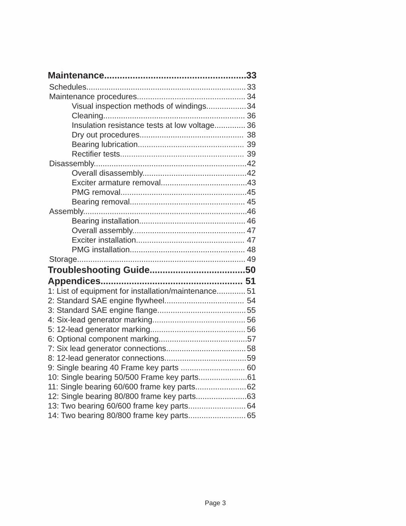
Table of ContentsIntroduction......................................................... 4 Foreword............................................................................ 4 Safety instructions.............................................................. 4 Ratings/description............................................................ 4Application.......................................................................... 4 Construction and Operating Principles............ 7 Stator................................................................................. 7 Rotor.................................................................................. 7 Bearings............................................................................ 7 Connection boxes.............................................................. 8 Excitation system............................................................... 8 Optional PMG system........................................................ 9 Other options..................................................................... 9 Installation......................................................... .10 Receiving inspection........................................................ 10 Unpacking and moving..................................................... 10 Location........................................................................... .10 Base design..................................................................... 10 Assemble to prime mover, alignment............................... 11 Two-bearing alignment........................................... 11 Two-bearing close-coupled alignment................... 13 Single-bearing alignment....................................... 19 Foot defl ection................................................................. 26 Doweling.......................................................................... 26 Electrical connections...................................................... 26 Space heaters................................................................. 26 Inspection before startup................................................. 27Operation........................................................... 28Initial startup: generators w/auto & manual control.......... 28Initial startup: generators w/auto control only................... 28Restoring residual magnetism/fi eld fl ashing..................... 29Continuous operation....................................................... 30Idling................................................................................. 31Parallel operation.............................................................. 31
Note: Because of rapid changes in designs and processes and the available variability of our products, information in this manual is not contractually binding and is subject to change without notice.
The image on the front cover is representa-tive only and may include optional features. Several variations are available within the range of generators covered within this manual.
Page 3
Maintenance....................................................... 33 Schedules........................................................................ 33 Maintenance procedures................................................. 34 Visual inspection methods of windings.................. 34 Cleaning................................................................ 36 Insulation resistance tests at low voltage.............. 36 Dry out procedures............................................... 38 Bearing lubrication................................................ 39 Rectifi er tests........................................................ 39 Disassembly..................................................................... 42 Overall disassembly............................................... 42 Exciter armature removal....................................... 43 PMG removal......................................................... 45 Bearing removal.................................................... 45 Assembly.......................................................................... 46 Bearing installation................................................ 46 Overall assembly................................................... 47 Exciter installation................................................. 47 PMG installation.................................................... 48 Storage............................................................................ 49Troubleshooting Guide..................................... 50Appendices....................................................... 511: List of equipment for installation/maintenance............. 512: Standard SAE engine fl ywheel.................................... 543: Standard SAE engine fl ange........................................ 554: Six-lead generator marking.......................................... 565: 12-lead generator marking........................................... 566: Optional component marking........................................577: Six lead generator connections.................................... 588: 12-lead generator connections..................................... 599: Single bearing 40 Frame key parts ............................. 6010: Single bearing 50/500 Frame key parts...................... 6111: Single bearing 60/600 frame key parts....................... 6212: Single bearing 80/800 frame key parts.......................6313: Two bearing 60/600 frame key parts.......................... 6414: Two bearing 80/800 frame key parts.......................... 65

Page 4
Introduction ForewordThis manual contains instructions for installing, operating and maintaining AC brushless revolving fi eld generators. These generators are manufactured in many sizes and ratings and with various options.
Please read this manual in its entirety before unpacking, installing, and operating your generator.
Safety instructionsIn order to prevent injury or equipment damage, everyone involved in installation, operating and maintenance of the generator described in this manual must be qualifi ed and trained in the current safety standards that govern his or her work.
The following paragraphs defi ne warnings, cautions, and notes as they are used in this manual:
Warning: Warnings identify an installation, operating or maintenance procedure, practice, condition, or statement that, if not strictly followed, could result in serious injury to personnel.
Caution: Cautions identify an installation, operating or maintenance procedure, practice, condition, or statement that, if not strictly followed, could result in destruction of or damage to equipment or serious impairment of system operation.
Note: Notes highlight an installation, operating or maintenance procedure, condition, or statement and are essential or helpful but are not of known hazardous nature as indicated by warnings and cautions.
Ratings/descriptionNameplates, which are located on the side of the generator, include serial and model number as well as rating information.
Application:The generators have been designed for use in a maximum ambient temperature of 40° C, and altitude less than 3300 ft (1000 meters) above sea level in accordance with NEMA MG1. Ambient temperatures in excess of 40° C, and altitudes above 3300 ft (1000 meters) can be tolerated with reduced ratings. Refer to the generator nameplate for rating and ambient temperature and to the factory for appropriate derating factors. Refer to NEMA MG1 for additional information on usual/unusual operating conditions.
Page 5
The generators are self ventilated screen protected designs and are not suitable for mounting outdoors unless adequately protected by enclosures. The enclosure must provide suffi cient cooling air so the generator does not overheat. The enclosure air intake must also be designed to prohibit the ingress of moisture. The air intake/outlet must be sized for the air fl ow required. Consult the factory for air fl ow and additional pressure drops.
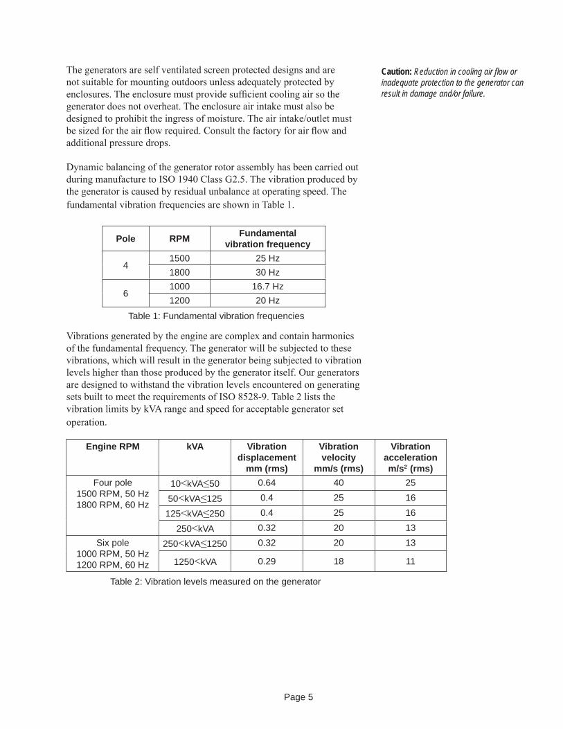
Dynamic balancing of the generator rotor assembly has been carried out during manufacture to ISO 1940 Class G2.5. The vibration produced by the generator is caused by residual unbalance at operating speed. The fundamental vibration frequencies are shown in Table 1.
Caution: Reduction in cooling air fl ow or inadequate protection to the generator can result in damage and/or failure.
Vibrations generated by the engine are complex and contain harmonics of the fundamental frequency. The generator will be subjected to these vibrations, which will result in the generator being subjected to vibration levels higher than those produced by the generator itself. Our generators are designed to withstand the vibration levels encountered on generating sets built to meet the requirements of ISO 8528-9. Table 2 lists the vibration limits by kVA range and speed for acceptable generator set operation.
Table 1: Fundamental vibration frequencies
Pole RPM Fundamental vibration frequency
41500 25 Hz1800 30 Hz
61000 16.7 Hz1200 20 Hz
Engine RPM kVA Vibration displacement
mm (rms)
Vibration velocity
mm/s (rms)
Vibration acceleration m/s2 (rms)
Four pole1500 RPM, 50 Hz1800 RPM, 60 Hz
10<kVA≤50 0.64 40 25
50<kVA≤125 0.4 25 16
125<kVA≤250 0.4 25 16
250<kVA 0.32 20 13Six pole
1000 RPM, 50 Hz1200 RPM, 60 Hz
250<kVA≤1250 0.32 20 13
1250<kVA 0.29 18 11
Table 2: Vibration levels measured on the generator
Page 6
It is the responsibility of the generating set designer/manufacturer to ensure the alignment of the genset, stiffness of the skid and mountings are such that the vibration limits as defi ned above are met.
If the vibration levels of the generating set are not within what is specifi ed in Table 2, then 1) Consult the genset builder. The genset builder should address the genset design to reduce the vibration levels as much as possible. 2) Consult the factory if the above levels cannot be met.
Torsional vibrations occur in all engine-driven shaft systems and may be of a magnitude to cause damage at certain critical speeds. It is therefore necessary to consider the torsional vibration effect on the generator shaft and couplings.
It is the responsibility of the generator set manufacturer to ensure compatibility. Rotor torsional data is available upon request for torsional analysis.
Grounding terminals are provided on the feet of the generator and inside the main terminal box. The neutral terminal is NOT connected to the frame.
Damage and decrement curves along with reactance and time constants are available upon request to assist the system designer with the coordination of the protection devices. It is the responsibility of the user, system designer and/or generator set manufacturer to coordinate protections on breakers installed or supplied with a generator.
Warning: Exceeding ISO 8528-9 vibration levels will have a detrimental effect on the generating set and also the life of the bearings. This will void the generator warranty. Refer to the product service group at the factory if you are in doubt.
Warning: Torsional incompatibility and/or excessive vibration levels can cause damage or failure of the generator and/or genset components.
Warning: Ground the neutral in accordance to local, national and international codes. Incorrect grounding and/or protection can result in personal injury and equipment damage.
Warning: Protection devices must be coordinated in order to prevent personal injury and equipment damage.
Page 7
Construction and Operating PrinciplesStatorThe stator consists of the supporting frame, core, and armature windings.
The stator core is made from laminations, thin sheets of electrical steel, which are stacked and held in place by steel end rings and support bars. The rings and bars are welded to or are part of the steel frame. Feet are welded to the bottom of the frame and allow the assembly to be mounted on the genset base.
The windings (coils) are constructed of layered and insulated copper wire. The coils are inserted in the core slots, connected together, and the entire assembly is dipped or vacuum-pressure impregnated with resin. Stator leads terminate in standard connection lug for ease of connection to the load.
RotorThe main rotor assembly is the revolving fi eld. It consists of windings in a core, which is in turn mounted on a steel shaft. The exciter armature assembly and optional permanent magnet generator (PMG) rotor are also mounted on the shaft as are the fan(s) and other optional accessories. The core consists of thin sheets of electrical steel, which are stacked together. The core makes the salient poles (four or six). The rotor windings consists of insulated magnet wire wound around each pole. V-blocks between each pole keep the rotor windings in place. Damper windings consist of aluminum or copper rods that are inserted through each pole surface and are attached to copper or aluminum damper end plates at each end of the lamination stack. The end plates are attached to adjacent poles to form a continuous damper winding. The ends of the windings are supported with bars or pole shoes. The rotor either has epoxy applied during the winding process or is impregnated with resin or epoxy.
The shaft is made from rolled or forged steel and machined to accommodate all the rotating generator components. Keyways in the shaft ensure precise positioning of the revolving fi eld, exciter armature, and optional PMG rotor. On the exciter side, the shaft has a slot or hole in its center line for running the revolving fi eld leads to the rectifi er.
BearingsThe generator will contain either one or two bearings. Bearings are typically ball or roller type and are either 1) heavy duty double shielded bearings, greased for life or 2) regreaseable bearings, which contain fi ll and drain ports for easy lubrication.
Page 8
Connection boxesThe main lead connection box houses the load lead terminals. In addition, the generator may have auxiliary terminal strips for temperature detectors, space heaters, sensing leads, and other accessories.
Excitation systemThe excitation system consists of the exciter stator assembly and the exciter armature assembly:
The exciter stator assembly consists of windings in a core. The core is made from steel laminations that are stacked and welded together. The main exciter stator coils are placed in slots in the core and form alternate North and South poles. The entire assembly is mounted to the end bracket. The stator is a stationary fi eld, which is powered by the voltage regulator.
The exciter armature assembly is keyed onto the generator shaft. A three-phase winding is inserted into slots in the laminations. The coils are held in place by insulating wedges. The coil extensions are braced with tape. Output leads from the winding are connected to the rotating rectifi er assembly.
The rotating rectifi er is a three-phase full wave bridge rectifi er, converting the AC from the exciter armature to DC, which is transferred to the revolving fi eld windings. Two designs are used. The standard design uses positive and negative diode cubes fi tted on an aluminum back plate along with the surge suppressor. The other design, used on special applications, has two stainless steel plates, each containing three rotating rectifi er diodes, which are mounted on each side of an insulating hub to form the negative and positive terminals. The plates also act as heat sinks for the diodes.
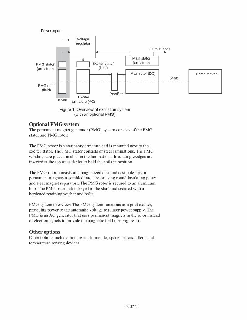
Excitation system functional overview: Exciter fi eld control is established by the strength of the exciter fi eld current developed by the voltage regulator system. The DC voltage and current levels of the exciter fi eld signal from the voltage regulator varies depending upon the generator output voltage and the loading of the output lines (see Figure 1). The voltage regulator system can be energized by the main stator (SHUNT excitation system) or by the optional PMG stator (PMG excitation system).
Page 9
Optional PMG systemThe permanent magnet generator (PMG) system consists of the PMG stator and PMG rotor:
The PMG stator is a stationary armature and is mounted next to the exciter stator. The PMG stator consists of steel laminations. The PMG windings are placed in slots in the laminations. Insulating wedges are inserted at the top of each slot to hold the coils in position.
The PMG rotor consists of a magnetized disk and cast pole tips or permanent magnets assembled into a rotor using round insulating plates and steel magnet separators. The PMG rotor is secured to an aluminum hub. The PMG rotor hub is keyed to the shaft and secured with a hardened retaining washer and bolts.
PMG system overview: The PMG system functions as a pilot exciter, providing power to the automatic voltage regulator power supply. The PMG is an AC generator that uses permanent magnets in the rotor instead of electromagnets to provide the magnetic fi eld (see Figure 1).
Other optionsOther options include, but are not limited to, space heaters, fi lters, and temperature sensing devices.
Figure 1: Overview of excitation system (with an optional PMG)
Output leads
Voltageregulator
Exciter stator(fi eld)
Main stator (armature)
ShaftMain rotor (DC)
Rectifi erExciter
armature (AC)
PMG stator(armature)
PMG rotor(fi eld)
Prime mover
Power input
Optional

Page 10
InstallationReceiving inspectionBefore accepting a shipment, examine the packaging for any sign of damage that might have occurred during transit. Report any damage to the transportation company and the factory. Unpacking and movingIf the generator is received during cold weather, reduce condensation on cold surfaces and failure due to wet windings by allowing the generator to reach room temperature before removing the protective packing.
Unpack the generator carefully to avoid scratching painted surfaces. Do not remove the protecting lubricant from the shaft end, drive plates, and fl ange machined surfaces. Inspect for loosely mounted components and the presence of moisture. Inspect to make certain foreign material, such as crating nails, loose bolts or packing material, which may have fallen into the machine during unpacking, is removed. If damage is noted, determine the extent of damage and immediately notify the transportation company claims offi ce and the factory. Be sure to give complete and accurate details when reporting damage.
Move the generator by attaching an overhead hoist to the lifting eyes installed on the generator frame or by lifting the generator from underneath the skid with a forklift.
Single-bearing generators are shipped with plastic strips between the main rotor and stator to maintain air gap and a shipping bar across the drive discs.
LocationInstall the generator in an area so it complies with all local and industrial regulations. Locate it in a clean, dry, well-vented area or area that is suitable for the generator enclosure. Make sure it is easily accessible for inspection and maintenance.
Protect generators operating intermittently in very damp locations with space heaters. Slowly warm generators placed in operation after being subjected to very low temperatures to prevent excessive condensation. Check winding and insulation resistance before placing the generator in operation (see instructions later in this manual).
Base designThe type of base to be used will depend upon the nature of the installation site. However, the generator base must be rigid, level, and free from vibration. Mounting holes must be larger than the fasteners to allow for alignment.
Warning: Be alert at all times when installing, operating and maintaining the generator. Avoid contact with the uninsulated metal parts of the generator. Most injuries occur from faulty ground connections on portable electrical equipment and failure to ground stationary equipment.
Test all portable devices frequently to prove that a solid electrical circuit exits from the metal frame though the grounding conductor, in the electrical cord, to the grounding contact in the attachment plug. Do not use electrical equipment with frayed, burned or damaged cords. Always take extreme care when moving the generator. Be careful to not strike objects or personnel.
Apply lifting force to structural points specifi cally provided for lifting. Do not use the enclosure lifting holes to lift the whole unit. Use lifting means adequate for the weight. Observe lifting notices attached to the generator. Failure to observe these instructions can result in personnel injury and damage to the generator.
Caution: Do not attempt to transport a single-bearing generator without maintaining proper rotor support. Failure to observe this warning can result in equipment damage.
Caution: Blocking or restriction of normal air fl ow into or out of the generator may cause damage to the electrical windings.
Page 11
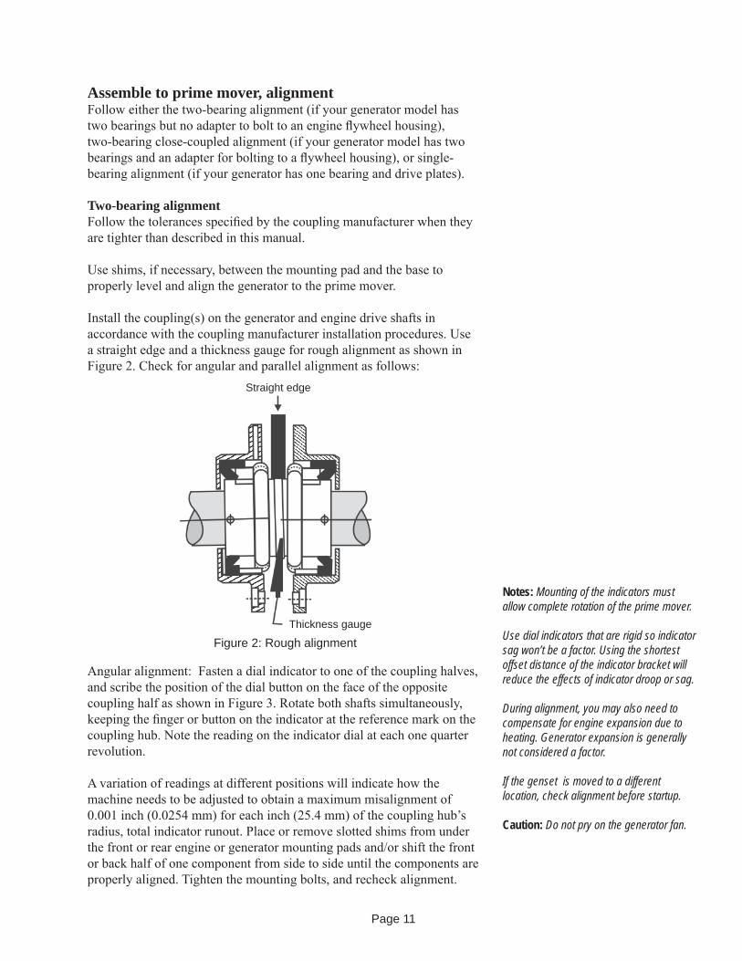
Assemble to prime mover, alignmentFollow either the two-bearing alignment (if your generator model has two bearings but no adapter to bolt to an engine fl ywheel housing), two-bearing close-coupled alignment (if your generator model has two bearings and an adapter for bolting to a fl ywheel housing), or single-bearing alignment (if your generator has one bearing and drive plates).
Two-bearing alignmentFollow the tolerances specifi ed by the coupling manufacturer when they are tighter than described in this manual.
Use shims, if necessary, between the mounting pad and the base to properly level and align the generator to the prime mover.
Install the coupling(s) on the generator and engine drive shafts in accordance with the coupling manufacturer installation procedures. Use a straight edge and a thickness gauge for rough alignment as shown in Figure 2. Check for angular and parallel alignment as follows:
Figure 2: Rough alignment
Straight edge
Thickness gauge
Notes: Mounting of the indicators must allow complete rotation of the prime mover.
Use dial indicators that are rigid so indicator sag won’t be a factor. Using the shortest offset distance of the indicator bracket will reduce the effects of indicator droop or sag.
During alignment, you may also need to compensate for engine expansion due to heating. Generator expansion is generally not considered a factor.
If the genset is moved to a different location, check alignment before startup.
Caution: Do not pry on the generator fan.
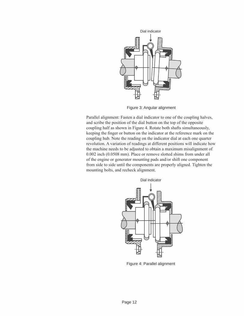
Angular alignment: Fasten a dial indicator to one of the coupling halves, and scribe the position of the dial button on the face of the opposite coupling half as shown in Figure 3. Rotate both shafts simultaneously, keeping the fi nger or button on the indicator at the reference mark on the coupling hub. Note the reading on the indicator dial at each one quarter revolution.
A variation of readings at different positions will indicate how the machine needs to be adjusted to obtain a maximum misalignment of 0.001 inch (0.0254 mm) for each inch (25.4 mm) of the coupling hub’s radius, total indicator runout. Place or remove slotted shims from under the front or rear engine or generator mounting pads and/or shift the front or back half of one component from side to side until the components are properly aligned. Tighten the mounting bolts, and recheck alignment.
Page 12
Parallel alignment: Fasten a dial indicator to one of the coupling halves, and scribe the position of the dial button on the top of the opposite coupling half as shown in Figure 4. Rotate both shafts simultaneously, keeping the fi nger or button on the indicator at the reference mark on the coupling hub. Note the reading on the indicator dial at each one quarter revolution. A variation of readings at different positions will indicate how the machine needs to be adjusted to obtain a maximum misalignment of 0.002 inch (0.0508 mm). Place or remove slotted shims from under all of the engine or generator mounting pads and/or shift one component from side to side until the components are properly aligned. Tighten the mounting bolts, and recheck alignment.
Dial indicator
Figure 3: Angular alignment
Dial indicator
Figure 4: Parallel alignment

Page 13
Two-bearing close-coupled alignmentCheck the engine fl ywheel housing pilot’s radial and face runout by mounting a dial indicator and measuring the fl ywheel to the fl ywheel housing as shown in Figure 5. See Table 3 for maximum allowable runout.
SAE housing number
654321
0.50
00
0.002 (0.051)0.003 (0.076)0.003 (0.076)0.004 (0.102)0.004 (0.102)0.005 (0.127)0.005 (0.127)0.006 (0.152)0.007 (0.178)
Allowable runout (TIR) inch (mm)
10.500 (266.70)12.375 (314.33)14.250 (361.95)16.125 (409.58)17.625 (447.68)20.125 (511.18)23.000 (584.20)25.500 (647.70)31.000 (787.40)
Housing inside dia., inch (mm)
Table 3: Maximum allowable fl ywheel housing runout
Figure 5: Flywheel housing check
Shaft
Flywheel
Flywheel housingDial indicator
pointer for radial runout
Dial indicator pointer for face runout
Notes: Mounting of the indicators must allow complete rotation of the prime mover.
Use dial indicators that are rigid so indicator sag won’t be a factor. Using the shortest offset distance of the indicator bracket will reduce the effects of indicator droop or sag.
During alignment, you may also need to compensate for engine expansion due to heating. Generator expansion is generally not considered a factor.
If the genset is moved to a different location, check alignment before startup.
Caution: Do not pry on the fan.

Page 14
Check the engine fl ywheel’s radial and face runout by mounting a dial indicator and measuring the fl ywheel housing to the fl ywheel as shown in Figure 6. See Table 4 for maximum allowable runout.
Table 4: Maximum allowable fl ywheel runout
Figure 6: Flywheel check
Shaft
Flywheel
Flywheel housing
Dial indicator pointer for radial runout
Dial indicator pointer for face
runout
6.57.58
1011.51416182124
0.002 (0.051)0.002 (0.051)0.002 (0.051)0.003 (0.076)0.003 (0.076)0.004 (0.102)0.005 (0.127)0.005 (0.127)0.006 (0.152)0.007 (0.178)
Pilot diameter
Allowable runout (TIR) inch (mm)
Page 15
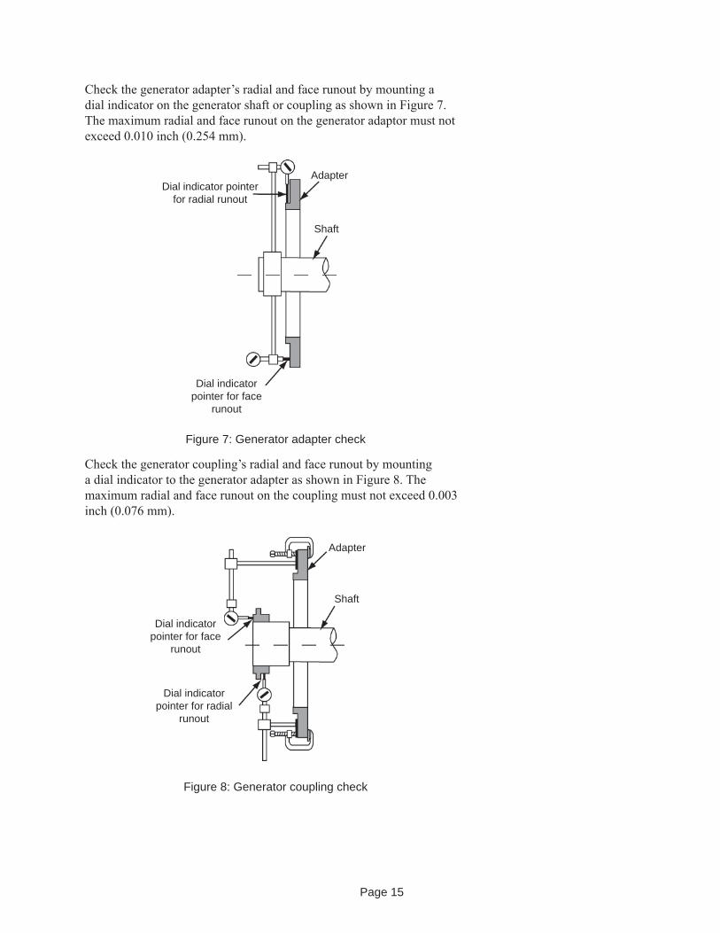
Figure 7: Generator adapter check
Shaft
AdapterDial indicator pointer
for radial runout
Dial indicator pointer for face
runout
Figure 8: Generator coupling check
Shaft
Adapter
Dial indicator pointer for radial
runout
Dial indicator pointer for face
runout
Check the generator adapter’s radial and face runout by mounting a dial indicator on the generator shaft or coupling as shown in Figure 7. The maximum radial and face runout on the generator adaptor must not exceed 0.010 inch (0.254 mm).
Check the generator coupling’s radial and face runout by mounting a dial indicator to the generator adapter as shown in Figure 8. The maximum radial and face runout on the coupling must not exceed 0.003 inch (0.076 mm).

Page 16
Measure and record the engine crank shaft end play and generator end play. Set the engine end play to the manufacturer’s recommended position for alignment. Verify the generator end play is set at a position of one half of the measured distance or at a position that will allow full thermal growth of the gen erator shaft when operated at rated temperatures.
Mount the generator on the skid, and move the generator to within 0.010 inch (0.254 mm) of the engine. Place two 0.010-inch (0.254 mm) shims in the horizontal (9 o’clock and 3 o’clock) positions between the generator adapter and the engine fl ywheel housing. Raising the rear, exciter end of the generator as necessary, place two 0.010-inch (0.254 mm) shims in the vertical (6 o’clock and 12 o’clock) positions between the generator adapter and the engine fl ywheel housing. This will give a good starting point for alignment. Remove the vertical shims at this time. (If necessary, mark holes to be drilled on the base, and remove the generator at this time.)
Shaft
Flywheel
Flywheel housing
Dial indicator pointer for radial runout
Dial indicator pointer for face
runout
Figure 9: Engine coupling check
Install the portion of the coupling that fi ts into the engine fl ywheel following the manufacturer’s recommended procedures and in accor dance with engine manufacturer’s specifi cations. Check the coupling’s radial and face runout by mounting a dial indicator to the engine fl ywheel housing as shown in Figure 9. The maximum radial and face runout on the coupling must not exceed 0.004 inch (0.102 mm).
Page 17
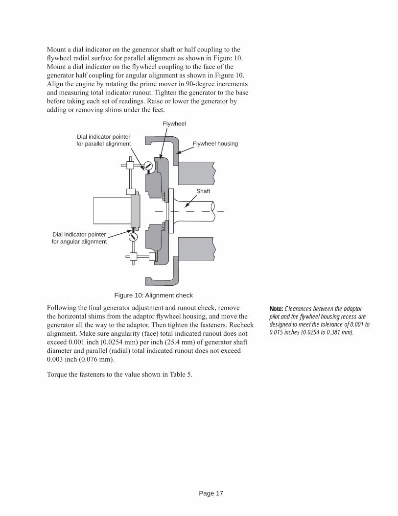
Mount a dial indicator on the generator shaft or half coupling to the fl ywheel radial surface for parallel alignment as shown in Figure 10. Mount a dial indicator on the fl ywheel coupling to the face of the generator half coupling for angular alignment as shown in Figure 10. Align the engine by rotating the prime mover in 90-degree incre ments and measuring total indicator runout. Tighten the generator to the base before taking each set of readings. Raise or lower the generator by adding or removing shims under the feet.
Shaft
Flywheel housing
Dial indicator pointer for angular alignment
Dial indicator pointer for parallel alignment
Flywheel
Figure 10: Alignment check
Following the fi nal generator adjustment and runout check, remove the horizontal shims from the adaptor fl ywheel housing, and move the generator all the way to the adaptor. Then tighten the fasteners. Recheck alignment. Make sure angularity (face) total indicated runout does not exceed 0.001 inch (0.0254 mm) per inch (25.4 mm) of generator shaft diameter and parallel (radial) total indicated runout does not exceed 0.003 inch (0.076 mm).
Torque the fasteners to the value shown in Table 5.
Note: Clearances between the adaptor pilot and the fl ywheel housing recess are designed to meet the tolerance of 0.001 to 0.015 inches (0.0254 to 0.381 mm).
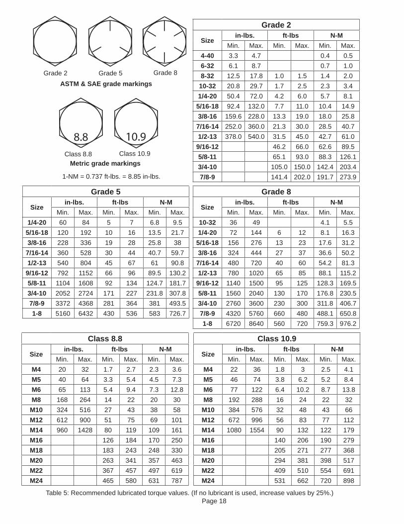
Page 18Table 5: Recommended lubricated torque values. (If no lubricant is used, increase values by 25%.)
Grade 2
Sizein-lbs. ft-lbs N-M
Min. Max. Min. Max. Min. Max.4-40 3.3 4.7 0.4 0.56-32 6.1 8.7 0.7 1.08-32 12.5 17.8 1.0 1.5 1.4 2.0
10-32 20.8 29.7 1.7 2.5 2.3 3.41/4-20 50.4 72.0 4.2 6.0 5.7 8.1
5/16-18 92.4 132.0 7.7 11.0 10.4 14.93/8-16 159.6 228.0 13.3 19.0 18.0 25.8
7/16-14 252.0 360.0 21.3 30.0 28.5 40.71/2-13 378.0 540.0 31.5 45.0 42.7 61.0
9/16-12 46.2 66.0 62.6 89.55/8-11 65.1 93.0 88.3 126.13/4-10 105.0 150.0 142.4 203.47/8-9 141.4 202.0 191.7 273.9
Grade 8
Sizein-lbs. ft-lbs N-M
Min. Max. Min. Max. Min. Max.10-32 36 49 4.1 5.51/4-20 72 144 6 12 8.1 16.3
5/16-18 156 276 13 23 17.6 31.23/8-16 324 444 27 37 36.6 50.2
7/16-14 480 720 40 60 54.2 81.31/2-13 780 1020 65 85 88.1 115.2
9/16-12 1140 1500 95 125 128.3 169.55/8-11 1560 2040 130 170 176.8 230.53/4-10 2760 3600 230 300 311.8 406.77/8-9 4320 5760 660 480 488.1 650.81-8 6720 8640 560 720 759.3 976.2
Grade 5
Sizein-lbs. ft-lbs N-M
Min. Max. Min. Max. Min. Max.1/4-20 60 84 5 7 6.8 9.5
5/16-18 120 192 10 16 13.5 21.73/8-16 228 336 19 28 25.8 387/16-14 360 528 30 44 40.7 59.71/2-13 540 804 45 67 61 90.89/16-12 792 1152 66 96 89.5 130.25/8-11 1104 1608 92 134 124.7 181.73/4-10 2052 2724 171 227 231.8 307.87/8-9 3372 4368 281 364 381 493.51-8 5160 6432 430 536 583 726.7
Class 8.8
Sizein-lbs. ft-lbs N-M
Min. Max. Min. Max. Min. Max.M4 20 32 1.7 2.7 2.3 3.6M5 40 64 3.3 5.4 4.5 7.3M6 65 113 5.4 9.4 7.3 12.8M8 168 264 14 22 20 30
M10 324 516 27 43 38 58M12 612 900 51 75 69 101M14 960 1428 80 119 109 161M16 126 184 170 250M18 183 243 248 330M20 263 341 357 463M22 367 457 497 619M24 465 580 631 787
Class 10.9
Sizein-lbs. ft-lbs N-M
Min. Max. Min. Max. Min. Max.M4 22 36 1.8 3 2.5 4.1M5 46 74 3.8 6.2 5.2 8.4M6 77 122 6.4 10.2 8.7 13.8M8 192 288 16 24 22 32M10 384 576 32 48 43 66M12 672 996 56 83 77 112M14 1080 1554 90 132 122 179M16 140 206 190 279M18 205 271 277 368M20 294 381 398 517M22 409 510 554 691M24 531 662 720 898
1-NM = 0.737 ft-lbs. = 8.85 in-lbs.
ASTM & SAE grade markings
Metric grade markings
Grade 2 Grade 5 Grade 8
Class 8.8 Class 10.9

Page 19
Single-bearing alignmentBefore assembling the generator to the prime mover, remove the exciter cover and adapter cover. Remove the blocking holding the drive discs to the adapter and the air gap spacers. Also make sure the generator bearing end clearance is not less than the total engine crankshaft axial movement plus 1/16 inch (1.59 mm). The generator is shipped from the factory with approximately 1/4-inch (6.36 mm) bearing endplay. (This dimension is specifi ed on the generator’s corresponding outline drawing.)
Check the engine fl ywheel housing pilots’s radial and face runout by mounting a dial indicator and measuring the fl ywheel to the fl ywheel housing as shown in Figure 5. See Table 3 for maximum allowable runout.
Check the engine fl ywheel’s radial and face runout by mounting a dial indicator and measuring the fl ywheel housing to the fl ywheel as shown in Figure 6. See Table 4 for maximum allowable runout.
Measure the generator drive plate diameter (dimension S of Figure 11) and fl ywheel bore diameter (dimension B of Figure 12). Drive plate diameter must not be greater than the fl ywheel bore diameter. Also check to make sure the hole centers match (dimension W of Figure 11 and dimension C of Figure 12).
Notes: Mounting of the indicators must allow complete rotation of the prime mover.
Use dial indicators that are rigid so indicator sag won’t be a factor. Using the shortest offset distance of the indicator bracket will reduce the effects of indicator droop or sag.
During alignment, you may also need to compensate for engine expansion due to heating. Generator expansion is generally not considered a factor.
If the genset is moved to a different location, check alignment before startup.
Caution: Do not pry on the generator fan.
Figure 11: Single bearing generator drive plate and adaptor
S
Y
WA
Adaptor
Bolt holes
Driveplates
Fan
Shaft
Caution: Never grind the OD of drive discs or attempt to drill out the holes. If the dive discs do not fi t properly, use different discs or a different fl ywheel.

Page 20
Figure 12: SAE fl ywheel and adapter
Caution: The number and thickness of drive discs are specifi ed for torque requirements. Do not remove drive discs to compensate for spacing.
BC
G
Tapped bolt holes
Flywheel
Measure the axial distance from the surface on the generator adapter to the outside surface on the drive disc coupling plates (dimension Y in Figure 11). This dimension is specifi ed on the generator’s corresponding outline drawing. If the dimensions do not match, move the rotor axially relative to the stator until the dimensions are equal, ensuring the bearing is not contacting either face. Approximately 0.060 inch (1.52 mm) gap is needed to avoid axial or thrust loading.
Measure the axial distance from the machined surface on the engine fl ywheel housing the bottom of the fl ywheel drive disc recess (dimension G in Figure 12). Make sure the difference between dimensions Y (of Figure 11) and G are less than 1/32 inch (0.79 mm). If G is more than Y, install additional spacers between the drive discs and the generator hub. If Y is more than G, remove spacers (if supplied) between the drive discs and generator hub. If not spacers were provided, move the rotor, ensuring the bearing is not contacting either face. Approximately 0.060 inch (1.52 mm) gap is needed to avoid axial or thrust loading.
Support the generator shaft to ease the mating process, and install the generator to the engine. Make sure the drive discs seat in the recess of the fl ywheel housing. Secure the generator to the engine (drive discs to fl ywheel, adapter to fl ywheel housing), and the base. Use lock washers on all bolts. Torque the adapter and drive discs in a criss-cross pattern to the values in Table 5.
Ensure that the bolts in the fl ywheel do not bottom out. If they are too long or cannot be tightened with a socket or box wrench, use a shorter bolt or spacers inserted in the bolts as shown in Figure 13 to increase the clearance between the bolt head and the fl ywheel.
Page 21
Figure 13: Disc-to-fl ywheel installation
Flywheel
Drive plates
Drive hub
Spacer
Bolt
Lock washer
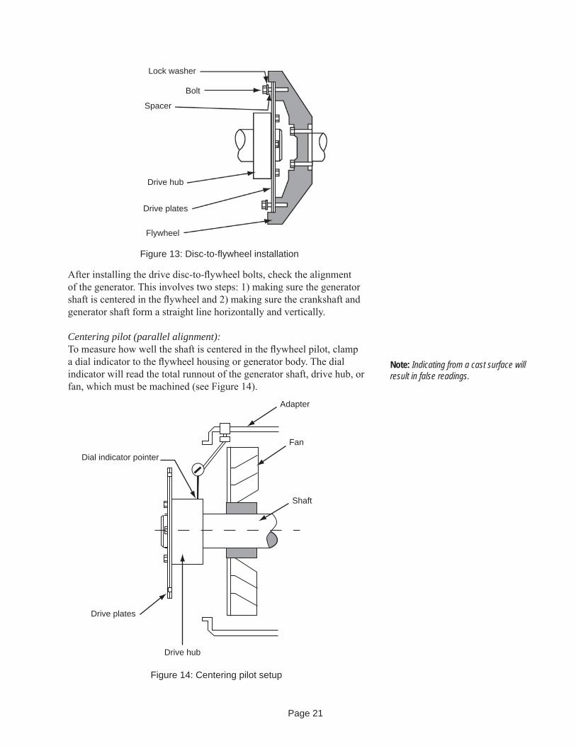
After installing the drive disc-to-fl ywheel bolts, check the alignment of the generator. This involves two steps: 1) making sure the generator shaft is centered in the fl ywheel and 2) making sure the crankshaft and generator shaft form a straight line horizontally and vertically.
Centering pilot (parallel alignment): To measure how well the shaft is centered in the fl ywheel pilot, clamp a dial indicator to the fl ywheel housing or generator body. The dial indicator will read the total runnout of the generator shaft, drive hub, or fan, which must be machined (see Figure 14).
Drive hub
Shaft
Fan
Adapter
Figure 14: Centering pilot setup
Drive plates
Dial indicator pointer
Note: Indicating from a cast surface will result in false readings.
Page 22
1. Clean the machined surface of any dirt, grease, rust, or paint. Use Emery cloth, if necessary, to ensure a smooth surface to measure from.
2. Mount a dial indicator to the fl ywheel housing or generator stator, to take the readings from the machined surface. Check for clearance before rotating the shaft.
3. Bar the engine over counterclockwise (facing the fl ywheel), and take a reading every 90º. A maximum of 0.005 inch (0.127 mm) total indicator runnout (TIR) is acceptable.
If the runnout exceeds this amount, roll the highest point to the top. Loosen the coupling bolts at this point to allow the shaft and coupling to drop in the fl ywheel counterbore. Once all the bolts are loose, re-torque the bolts.
4. Repeat steps 2 and 3, and, if TIR is still unacceptable, remove the coupling bolts, and rotate the generator shaft 90º with respect to the engine fl ywheel. Further adjustments can be made by rotating in additional 90º increments until the specifi cations are achieved.
Angular alignmentTo measure angular alignment, mount a dial indicator on the shaft of one machine to read against the shaft face of the other machine (see Figure 15. The dial indicator can be clamped to the generator fan and measured from the fl explate-to-fl ywheel mounting bolt.
Figure 15: Angular alignment
Generator fanFlywheel
Drive plates
Page 23
Before taking readings, roll the shaft in reverse 45º and then back 45º, and zero the dial indicator. This sets the axial position of the crankshaft and the generator shaft.
Take readings at the 12:00, 9:00, 6:00 and 3:00 o’clock positions. Readings in the 12:00 and 6:00 o’clock positions determine the vertical alignment, and readings in the 9:00 and 3:00 o’clock positions determine horizontal alignment.
A total indicator reading (TIR) is the difference between the two readings on opposites sides of the shafts. For example, in Figure 16, the horizontal TIR is (-0.009) and (+0.004), which is a difference of 0.013 in. (0.330 mm) or 13 thousandths of an inch TIR. Vertical TIR is (0) and (+0.005), which is a difference of 0.005 in. (0.127mm) or 5 thousandths of an inch TIR.
+0.004-0.009
-0.005
0
Figure 16: Example of runnout readings
The shaft shown in Figure 17 is angularly misaligned from that of the engine. This could either be vertical or horizontal misalignment.
The distance “S” divided by the distance to the bearing (or rear mount) “L” is equal to 1/2 TIR divided by the radius from the dial indicator to the center of the shaft “R.”
S 1/2 (TIR)L R
Thus, the amount of shimming or horizontal sliding required is
S = L x (1/2 TIR)/R
Figure 16: Exaggerated example of shaft misalignment
RS
L
=
Page 24
This relationship is used with the outboard mount or any inboard mount (closer to the fl ywheel) as long as the distance to the required mount is used for “L”.
Make vertical adjustments by adding or removing shims from the mounts on each end of the generator. Adjust the left-hand and right-hand inboard mounts the same, and adjust the left-hand and right-hand outboard mounts the same (see Figure 17).
Figure 17: Mount locations
Outboard mount Inboard mount
EngineGenerator
I-beam common skid
Make horizontal adjustments by loosening all the mounting bolts and moving the generator to the desired side. This can be done with a jacking screw or a pry bar in the bolt hole. Set up dial indicators to monitor how far the machine is moved, or, as a alternative method, rotate the shaft to the 3:00 or 9:00 o’clock position (see Figure 18), and make adjustments until 1/2 TIR is indicated by the angular dial indicator.
Page 25
Figure 18: Setup for horizontal adjustment
Angular alignment is acceptable when the TIR in all directions is less than 0.005 in (0.127 mm) measured at the fl explate-to-fl ywheel bolt, which is 14 in. (355.6 mm) from the shaft center.
Page 26
Foot defl ectionAfter alignment, check for foot defl ection or “soft foot” condition on each shim location to eliminate distortion of the generator frame. Do this by loosing one mounting bolt at a time and checking defl ection after retightening. Defl ection at the shim location from shims under compression to a loosened condition must not exceed 0.003 inch (0.076 mm).
DowelingIn case the mounting bolts loosen during operation, doweling will prevent movement of the generator. Dowel as follows:
Check the alignment after the generator has been in operation for at least 48 hours. If alignment is not satisfactory, realign.
Drill holes through the footpads and into the base in two mounting pads opposite each other. Drill the holes slightly smaller than the dowel pin.
Ream the holes to the proper diameter for the pin. Clean out chips, and install the pins. Electrical connectionsIf the generator was subjected to a rapid change in temperature, freezing or wet conditions during shipment or storage, measure the insulation resistance of each winding and dry the generator, if necessary, as described in the maintenance section.
Make all electrical connections (main load, temperature monitoring device, space heater, AVR) in accordance with local regulations and national/international electrical code requirements. Check the electrical diagrams provided with the generator or manual. The main terminals need to be properly spaced for the load connections. Refer to Table 5 for the proper torque values for the connections.
Grounding points are provided for properly grounding the system to the generator frame. The grounding wire must be sized per national/international codes.
Space heatersWhen the generator has optional space heaters to prevent water condensation during long periods of downtime, connect the space heaters so they start when the generator is turned off and stop when the generator is switched on. Refer to the electrical diagrams for the space heater characteristics.
Warning: The space heaters are designed to be energized when the generator is shut down. They are hot enough to cause skin burns. Terminals for power at the space heaters are live during operation. Disconnect power to the space heaters before removing the generator covers.
Page 27
Inspection before startupAfter electrical connections have been made, perform the following checks:
• Check all the connections to the electrical diagrams provided.
• Secure all covers and guards.
• Turn the rotor slowly with the appropriate starting mechanism (bar the engine or fl ywheel) through one revolution to see if the rotor turns freely.
• Determine the direction of the engine rotation, and make sure that it matches the rotation of the generator.
• Make sure the power requirements comply with the data on the generator nameplate.
• Make sure that the engine-generator set is protected with an adequate engine governor and against overspeed above 125% of rated speed.
• Make sure the output of the generator is protected with an overload protection device, such as circuit breakers or fuses, sized in accordance with national/international electrical code and local electrical code standards.
• Remove tools and other items from the vicinity of the generator.
Caution: Do not pry on the fan.
Page 28
OperationInitial startup: generators with both automatic and manual voltage control1. Disconnect the generator output from the load by opening the main
circuit breaker.
2. Turn the manual voltage adjust rheostat fully counterclockwise, and actuate the auto-manual switch to the manual position.
3. Start the prime mover, and bring the set to rated speed. Turn the manual voltage adjust rheostat to reach rated voltage. Close the output circuit breaker, and apply load in steps until the rated load is reached. Adjust the manual adjust rheostat as necessary to obtain the desired output voltage.
4. Gradually reduce load, and adjust the rheostat accordingly until no load is reached. Open the circuit breaker, and stop the prime mover.
5. Turn the voltage adjust rheostat on the voltage regulator fully counterclockwise.
6. Put the auto-manual switch in auto. Then start the genset, and bring it to rated speed. Adjust the voltage to the desired value.
7. Close the output circuit breaker. Then check the generator voltage and voltage regulation. Apply load in steps until the rated load is reached.
8. Check for vibration levels at no load and rated load. A slight increase is normal. As the load is maintained for 2-3 hours, the vibration levels will gradually increase and reach a fi nal level. See Table 2 for acceptable vibration levels .
Initial startup: Generators with automatic voltage control only (generator has an automatic voltage regulator (AVR) with no auto-manual switch)1. Disconnect the generator output from the load by opening the main
circuit breaker.
2. Turn the voltage adjust rheostat fully counterclockwise. Start the prime mover, and bring the set to rated speed. Turn the voltage adjust rheostat to obtain the desired voltage.
3. Close the output circuit breaker, and apply load in gradual steps until the rated load is reach. Note the voltage regulation with the changes in load steps.
Caution: Do not actuate the auto-manual switch with the full load applied to the generator. Whenever possible, stop the generator before switching.
Page 29
4. Check for vibration levels at no load and rated load. A slight increase is normal. As the load is maintained for 2-3 hours, the vibration levels will gradually increase and reach a fi nal level. See Table 2 for acceptable vibration levels .
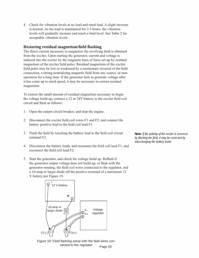
Restoring residual magnetism/fi eld fl ashingThe direct current necessary to magnetize the revolving fi eld is obtained from the exciter. Upon starting the generator, current and voltage is induced into the exciter by the magnetic lines of force set up by residual magnetism of the exciter fi eld poles. Residual magnetism of the exciter fi eld poles may be lost or weakened by a momentary reversal of the fi eld connection, a strong neutralizing magnetic fi eld from any source, or non-operation for a long time. If the generator fails to generate voltage after it has come up to rated speed, it may be necessary to restore residual magnetism.
To restore the small amount of residual magnetism necessary to begin the voltage build up, connect a 12 or 24V battery to the exciter fi eld coil circuit and fl ash as follows:
1. Open the output circuit breaker, and stop the engine.
2. Disconnect the exciter fi eld coil wires F1 and F2, and connect the battery positive lead to the fi eld coil lead F1.
3. Flash the fi eld by touching the battery lead to the fi eld coil circuit terminal F2.
4. Disconnect the battery leads, and reconnect the fi eld coil lead F1, and reconnect the fi eld coil lead F2.
5. Start the generator, and check for voltage build up. Refl ash if the generator output voltage does not build up, or fl ash with the generator running, the fi eld coil wires connected to the regulator, and a 10-amp or larger diode off the positive terminal of a maximum 12 V battery per Figure 19.
Figure 19: Field fl ashing setup with the fi eld wires con-nected to the regulator
12 V battery
+
-
10 amp or larger diode Voltage
regulatorF-F+
F1(+)F2 (-)
Note: If the polarity of the exciter is reversed by fl ashing the fi eld, it may be corrected by interchanging the battery leads.
Page 30
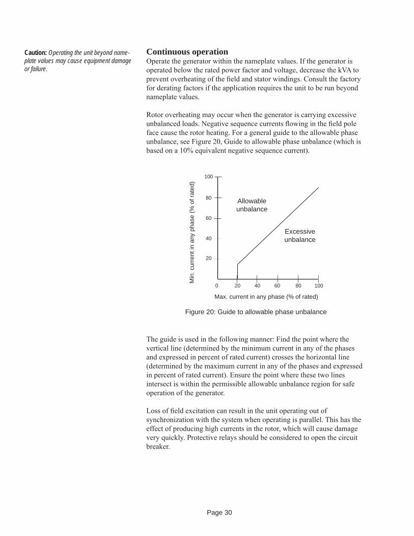
Continuous operationOperate the generator within the nameplate values. If the generator is operated below the rated power factor and voltage, decrease the kVA to prevent overheating of the fi eld and stator windings. Consult the factory for derating factors if the application requires the unit to be run beyond nameplate values.
Rotor overheating may occur when the generator is carrying excessive unbalanced loads. Negative sequence currents fl owing in the fi eld pole face cause the rotor heating. For a general guide to the allowable phase unbalance, see Figure 20, Guide to allowable phase unbalance (which is based on a 10% equivalent negative sequence current).
Figure 20: Guide to allowable phase unbalance
0 20 40 60 80 100
20
40
60
80
100
Max. current in any phase (% of rated)
Min
. cur
rent
in a
ny p
hase
(% o
f rat
ed)
Excessive unbalance
Allowable unbalance
Caution: Operating the unit beyond name-plate values may cause equipment damage or failure.
The guide is used in the following manner: Find the point where the vertical line (determined by the minimum current in any of the phases and expressed in percent of rated current) crosses the horizontal line (determined by the maximum current in any of the phases and expressed in percent of rated current). Ensure the point where these two lines intersect is within the permissible allowable unbalance region for safe operation of the generator.
Loss of fi eld excitation can result in the unit operating out of synchronization with the system when operating is parallel. This has the effect of producing high currents in the rotor, which will cause damage very quickly. Protective relays should be considered to open the circuit breaker.

Page 31
IdlingUnless the voltage regulator has V/Hz protection built in, having the generator set in operating mode while idling the engine can cause permanent equipment damage. If engine adjustments require that the engine be run at idle speed and the regulator does not have V/Hz protection, make the generator regulating system inoperative during idling by one of the following methods:
When the generator is provided with a voltage shutdown switch, be sure the switch is set to the idle position while the engine is running at idle speed.
Where the generator set is provided with fi eld circuit breakers, set the circuit breaker to the off position while the generator is running at idle speed.
Where the generator set is provided with an automatic/manual control switch that has an off position, switch it to off while the engine is running at idle speed.
Where the generator set does not have any of the above options, remove the wires from the voltage regulator input power terminals when the engine is running at less than rated speed.
Parallel operationFor the generator to operate in parallel with a system in operation, the phase sequences of the generator must be the same as that of the system. Use transformers to reduce the voltage to an acceptable level, and then use a phase rotation meter or incandescent lamp method, described in electrical machinery handbooks, for a phase sequence check.
The output voltage at the paralleling point must be the same as each instant, which requires that the two voltages be of the same frequency, same magnitude, same rotation, and in coincidence with each other.
Voltmeters indicate whether the voltage magnitude is the same, and frequency meters indicate whether the frequencies are the same. Whether the voltages are in phase and exactly at the same frequency is indicated by a synchroscope or by synchronizing lamps.
A synchroscope can be used to indicate the difference in phase angle between the incoming machine and the system. The generator can be paralleled by using incandescent lamps connected as shown in Figure 21. The voltage rating of the series lamps must equal the voltage rating of the transformer-low voltage winding.
Each prime mover in the system must have the same speed regulating characteristics, and the governors must be adjusted to give the same speed regulation as determined by applying load that is proportional to the full load rating of the generator.
Caution: Refer to the voltage regulator manual for complete details and possible additional instructions. Damage to the rotat-ing diodes, generator, and voltage regulator can be caused if the regulator is operated improperly.
Caution: Do not make connections or other-wise make contact with the generator leads or other devices connected to them unless the genset is stopped and the phase leads are grounded.

Page 32
The voltage regulator must include paralleling circuitry. In addition, the voltage, droop settings and the V/Hz regulation characteristics must be the same for all the voltage regulators. This will allow the generators to properly share reactive loads.
If cross-current compensation is used, paralleling current transformers must give the same secondary current.
Current transformer secondary windings provide reactive kVA droop signal to the voltage regulator. Accidental reversal of this electrical wiring will cause the voltage to attempt to rise with load rather than droop. If this occurs during paralleling, stop the unit and reverse the wires at the voltage regulator terminals.
If the set is provided with a unit/parallel switch, set the switch to the parallel position on the unit being synchronized.
Synchronize the generator by adjusting the speed (frequency) slightly higher than the system. Observe the synchroscope or the lamps. The lamps should fl uctuate from bright to dark at the rate of one cycle every 2 to 3 seconds. When the generator is in phase (the lights will be dark), close the circuit breaker. Immediately after closing the breaker, measure the line current of the generator. The readings must be within the rating of the unit. A high ammeter reading accompanied by a large kW reading indicates faulty governor control. A high ammeter reading accompanied by a large kVAR unbalance indicates problems with the voltage regulator. Adjusting the cross current or voltage droop rheostat should improve the sharing of kVAR.
To shut down the generator operating in parallel, gradually reduce the kW load using the governor to reduce fuel or power. When kW load and line current approach 0, open the generator circuit breaker. Operate the generator unloaded for several minutes to dissipate the heat in the windings. Refer to the prime mover manual for shutdown and cool-down procedures.
Figure 21: Synchronizing paralleled generators with test lamps
Load lines from the incoming generator
Loadswitch
Synchronizinglamps
System bus
Page 33
MaintenanceSchedulesA regular preventive maintenance schedule will ensure peak performance, minimize breakdowns and maximize generator life. The schedule listed below is a guide for operating under standard conditions. Specifi c operating conditions may require reduced or increased maintenance intervals. Also, if there is a different or more specifi c schedule for your generator than the schedule provided below, it will be included as a supplement to the manual package.
Every dayVisually check generator bearing housings for any sign of grease/oil seepage.
Check the operating temperatures of the generator stator windings.
Check the control panel voltmeter for proper stability and voltage output.
Monitor the power factor and generator loading during operation.
Every weekVisually inspect the bearing exterior for dirt, and clean if necessary.
Inspect any generator air fi lters for build up of contaminants, and clean or replace as required
Every 2000 Hours or 6 months of operationRemove generator outlet box cover. Visually inspect the stator output leads and insulation for cracking or damage. Check all exposed electrical connections for tightness. Check transformers, fuses, capacitors, and lightning arrestors for loose mounting or physical damage. Check all lead wires and electrical connections for proper clearance and spacing.
Clean the inside of the outlet box, air screens, and air baffl es with compressed air or electrical solvent if needed.
Check machine vibrations and bearing condition with a spectrum analyzer or shock pulse.
Regrease the optional regreaseable-type bearings.
Every 8000 hours or 1 year of operationCheck insulation resistance to ground on all generator windings, including the main rotating assembly, the main stator assembly, the exciter fi eld and armature assemblies, and the optional PMG assembly.
Check the space heaters for proper operation.
Check the rotating rectifi er connection tightness.
Warning: Do not service the generator or other electrical machinery without de-energizing and tagging the circuits as out of service. Dangerous voltages are present, which could cause serious or fatal shock.

Page 34
Every 20,000 hours or 3 years of operationRemove the endbrackets, and visually inspect the generator end windings for oil or dirt contamination. Excessive contamination may necessitate surface cleaning with compressed air and electrical solvent.
Replace the bearing(s) if dictated by operating conditions, otherwise inspect them for any indiction of wear or damage, and replace as needed.
Inspect the fan and fan hub for damage.
Every 30,000 hours or 5 years of operationDisassemble the generator (this includes rotor removal).
Clean the generator windings using either (depending upon the severity of contamination) 1) compressed air and electrical solvent or 2) de-greaser and high pressure hot water wash. Dry the windings to acceptable resistance levels (see the dry out procedure).
Inspect the rotor shaft bearing journals and bracket bearing cavity for wear or scoring.
Replace the bearings.
Maintenance procedures
Visual inspection of windingsElectric machines and their insulation systems are subjected to mechanical, electrical, thermal and environmental stresses that give rise to many deteriorating infl uences. The most signifi cant of these are the following:
Thermal aging: This is the normal service temperature deteriorating infl uence on insulation.
Over temperature: This is the unusually high temperature of operation caused by conditions such as overload, high ambient temperature, restricted ventilation, foreign materials deposited on windings, and winding faults.
Overvoltage: This is an abnormal voltage higher than the normal service voltage, such as caused by switching or lightning surges or non-linear loads. Operating above rated nameplate voltage will reduce insulation life.

Page 35
Contamination: This deteriorates electrical insulation by 1) conducting current over insulated surfaces 2) by attacking the material to reduce electrical insulation quality or physical strength, or by 3) thermally insulating the material so the generator operates at higher than normal temperatures. Such contaminants include water or extreme humidity, oil or grease including unstable anti-wear and extreme pressure lubricants, conducting and non-conducting dusts and particles, industrial chemicals such as acids, solvents, and cleaning solutions.
Physical damage: This contributes to electrical insulation failure by opening leakage paths through the insulation. Physical damages can be caused by physical shock, vibration, over-speed, short-circuit forces or line starting, out-of-phase paralleling, erosion by foreign matter, damage by foreign objects and thermal cycling.
Ionization effects: Ionization (corona), which may occur at higher operating voltages, is accompanied by several undesirable effects such as chemical action, heating, and erosion.
To achieve maximum effectiveness, set up a direct visual inspection program initially to those areas that are prone to damage or degradation caused by the infl uences listed above. The most suspect areas for deterioration or damage are 1) ground insulation, which is insulation intended to isolate the current carrying components from the non-current bearing components, and 2) support insulation, which includes blocks and slot wedges and are usually made from compressed laminates of fi brous materials, polyester, or similar felt pads impregnated with various types of bonding agents. Look for the following:
Deterioration or degradation of insulation from thermal aging: Coils with a general puffi ness, swelling into ventilation ducts, or a lack of fi rmness of the insulation, suggesting a loss of bond with consequent separation of the insulation layers from themselves or from the winding conductors or turns.
Abrasion: Abrasion or contamination from other sources, such as chemicals and abrasive or conducting substances, which damages coil(s) and connection surfaces.
Cracking: Cracking or abrasion of insulation resulting from prolonged or abnormal mechanical stress. In stator windings, looseness of the bracing structure is a certain sign of such phenomena and can itself cause further mechanical or electrical damage if allowed to go unchecked.
Erosion: Foreign substances impinging against coil insulation surfaces, which may cause erosion.
Page 36
CleaningRemove dust, preferably using a vacuum cleaner to prevent the redistribution of the contaminant. A small non-conducting nozzle or tube connected to the vacuum cleaner may be required to reach dusty surfaces or to enter into narrow openings. After most of the dust has been removed, a small brush can be affi xed to the vacuum nozzle to loosen and allow removal of dirt that is more fi rmly attached.
If compressed air must be used, exercise care in the application of pressure to prevent damage to the insulation. If available, (30 PSI (2 Bars) or less) instrument air should be used. In any case, the air must be clean, oil-free and dry.
Wipe all exposed surfaces with clean cloths to remove any remaining oil or dirt. It may be necessary to use a cleaning solution made of mild soap and water in order to effectively remove the dirt. Use clean water to remove any soap residues.
Any cleaning fl uid is more or less a solvent for insulating compounds, hence avoid the application of these fl uids in large quantities. They should not be allowed to remain in contact with the winding any longer than necessary to remove the oil and dirt. Also avoid excessive wetting because it washes impurities into inaccessible crevices.
Dry the machine according to the procedure in this manual until normal insulation resistance values are obtained at room temperature.
Inspect the generator for any signs of deterioration.
Clean electrical contacts, switch contacts and terminals with an approved contact cleaner. Do not fi le contacts.
Insulation resistance tests at low voltage Insulation tests are conducted for two reasons: to discern existing weakness or faults or to give some indication of expected service reliability.
Insulation resistance tests are based on determining the current through the insulation and across the surface when DC voltage is applied. The leakage current is dependent upon the voltage and time of application, the area and thickness of the insulation, and the temperature and humidity conditions during the test.
The insulation resistance test is used to determine the insulation condition prior to application of more extensive testing measures. Refer to the following electrical measurement procedures for testing detail. Contact the factory or refer to IEEE Standard. 432-1992 when more extensive insulation tests are required.
Warning: When using cleaning solvents, ensure adequate ventilation and user protection.
Warning: Exercise safety precautions when using compressed air.
Caution: Use only manufacturer-approved cleaning fl uids.
Page 37
Exciter fi eld (stator) and PMG armature (stator)
1. Disconnect the exciter leads from the terminals in the ter minal box or from the voltage regulator.
2. Connect exciter leads to one clamp of 500-volt megger, and connect the other clamp to the generator frame.
3. Apply 500 V from the megger, and measure the resistance reading after 1 minute. The reading must be a minimum of 1 megohm. If it is not, refer to the cleaning or dry out procedures.
4. Ground the exciter fi eld leads to the generator frame for several minutes after the megger has been disconnected. This will allow the voltage build up to be properly discharged.
Exciter armature
1. Disconnect the exciter armature leads from the rotating rec tifi ers.
2. Connect the leads of the exciter armature to one clamp of a 500-volt megger, and connect the other clamp to a suitable connection on the shaft.
3. Apply 500 V from the megger, and measure the resistance reading after 1 minute. The reading must be a minimum of 1 megohm. If it is not, refer to the cleaning or dry out procedures.
4. Ground the exciter leads to the shaft after disconnecting the megger. This will allow the voltage build up to be properly discharged.
Main rotor
1. Disconnect the generator fi eld leads from the posi tive and negative terminals of the rotating rectifi er assembly.
2. Connect the positive and negative leads to one clamp of the 500-volt megger, and connect the other clamp to the shaft.
3. Apply 500 V from the megger, and measure the resistance reading after 1 minute. The reading must be a minimum of 1 megohm. If it is not, refer to the cleaning or dry out procedures.
4. Ground the fi eld leads to the shaft after disconnecting the megger. This will allow the voltage build up to be properly discharged.
Caution: The insulation resistance tests are usually made on all or parts of an armature or fi eld circuit to ground. They primarily indicate the degree of contamination of the insulating surfaces or solid insulation by moisture and other conducting infl uences and will not usually reveal complete or uncontaminated ruptures.
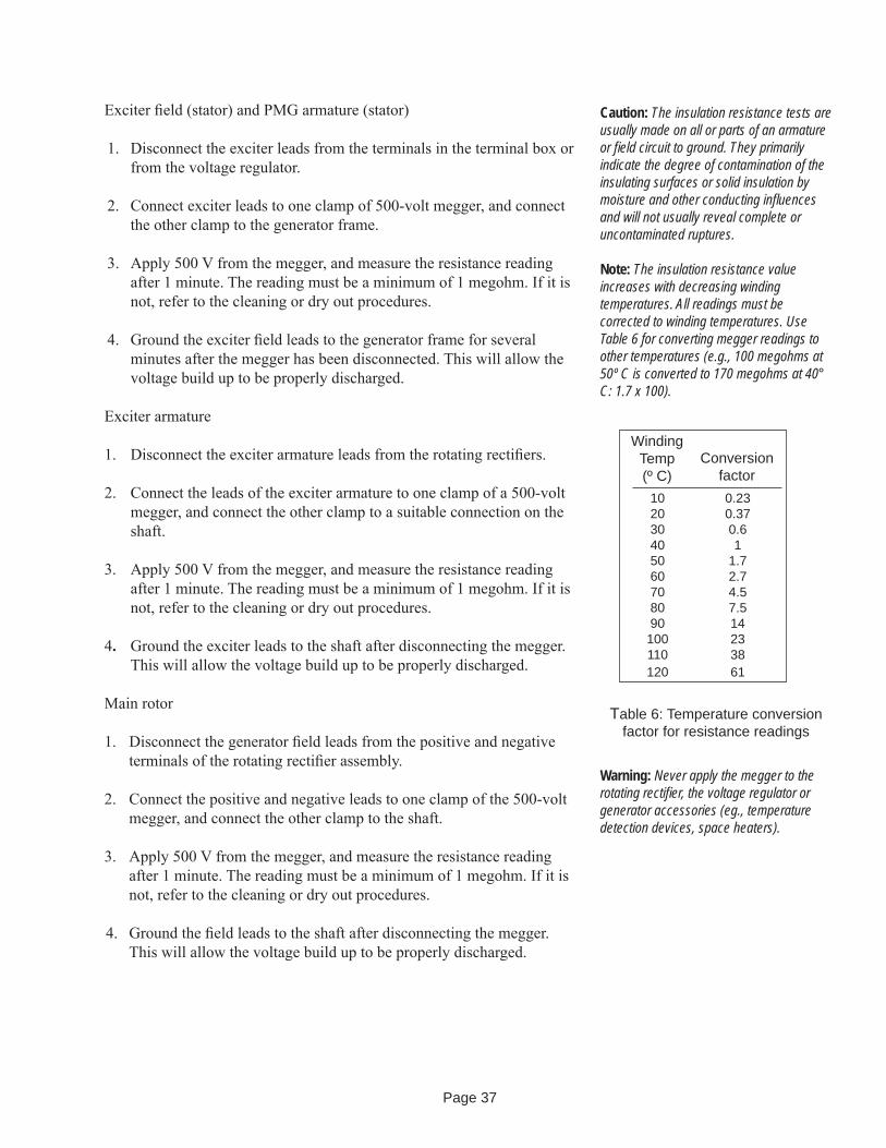
Note: The insulation resistance value increases with de creasing winding temperatures. All readings must be corrected to winding temperatures. Use Table 6 for converting megger readings to other temperatures (e.g., 100 megohms at 50º C is converted to 170 megohms at 40° C: 1.7 x 100).
Table 6: Temperature conversion factor for resistance readings
WindingTemp(º C)
0.230.370.61
1.72.74.57.514233861
Conversionfactor
102030405060708090
100110120
Warning: Never apply the megger to the rotating rectifi er, the voltage regulator or generator accessories (eg., temperature detection devices, space heaters).

Page 38
Main stator
1. Disconnect power connections and all control appara tus from the generator terminals.
2. Measure insulation resistance of each phase separately with the two other phases shorted to the frame.
3. Use a 500-volt megger connected between the leads of the phase to be measured and generator frame. The minimum 1-minute insulation resistance must not be less than that given by the following formula:
Resistancein megohms = Rated generator voltage + 1000 1000
If it is less than above, refer to cleaning or dry out procedures.
4. Ground the leads to the frame after the 1-minute megger test. This will allow the voltage build up to be properly discharged.
5. Repeat with the other phases.
Dry out proceduresIf the insulation resistance readings are below the recommended mini mum values specifi ed previously, use one of the dry out procedures described below. Select the procedure based on the size and location of the unit, available equipment, and experience of personnel. Before drying, remove the voltage regulator.
Drying with external heat: Place heat lamps or space heaters (in addition to the ones already supplied). Monitor winding temperatures. Raise winding temperature gradual ly at a rate of 50° F (28° C) per hour up to 200° F (93° C). Measure insulation resistance at 1-hour intervals. Typically the insulation resistance will slowly drop while the temperature is coming up, and then gradual ly increase and level out.
Drying with AC current in the armature: Short circuit the generator terminals. Provide DC excitation to the brushless exciter fi eld winding. Insert a current transformer and an ammeter to read full load current. Run the generator at rated speed. Apply excitation to the exciter fi eld until rated current is developed. Monitor winding temperatures until they stabilize. Continue running until insulation resistance values level off. Monitor winding temperatures. Raise winding temperature gradually at a rate of 50° F (28° C) per hour up to 200° F (93° C). Measure insulation resistance at 1-hour intervals. Typically, the insulation resistance will slowly drop while the temperature is coming up and then gradually increase and level out.
Caution: Do not apply heat too rapidly. It could damage the windings.
Page 39
Bearing lubrication Shielded or sealed ball bearings: Shielded or sealed ball bearings are factory packed with lubricants and generally can be operated several years without requiring replenishment or change of the grease.
Regreaseable ball or roller bearings: In applications where regreaseable bearings are used, grease fi ll fi ttings and relief valves are incorporated into the bearing housing. Lubricate the bearings in accordance with the lubricating instructions attached to the generator.
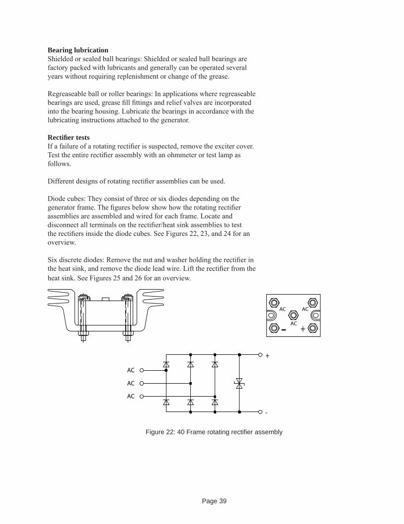
Rectifi er testsIf a failure of a rotating rectifi er is suspected, remove the exciter cover. Test the entire rectifi er assembly with an ohmmeter or test lamp as follows.
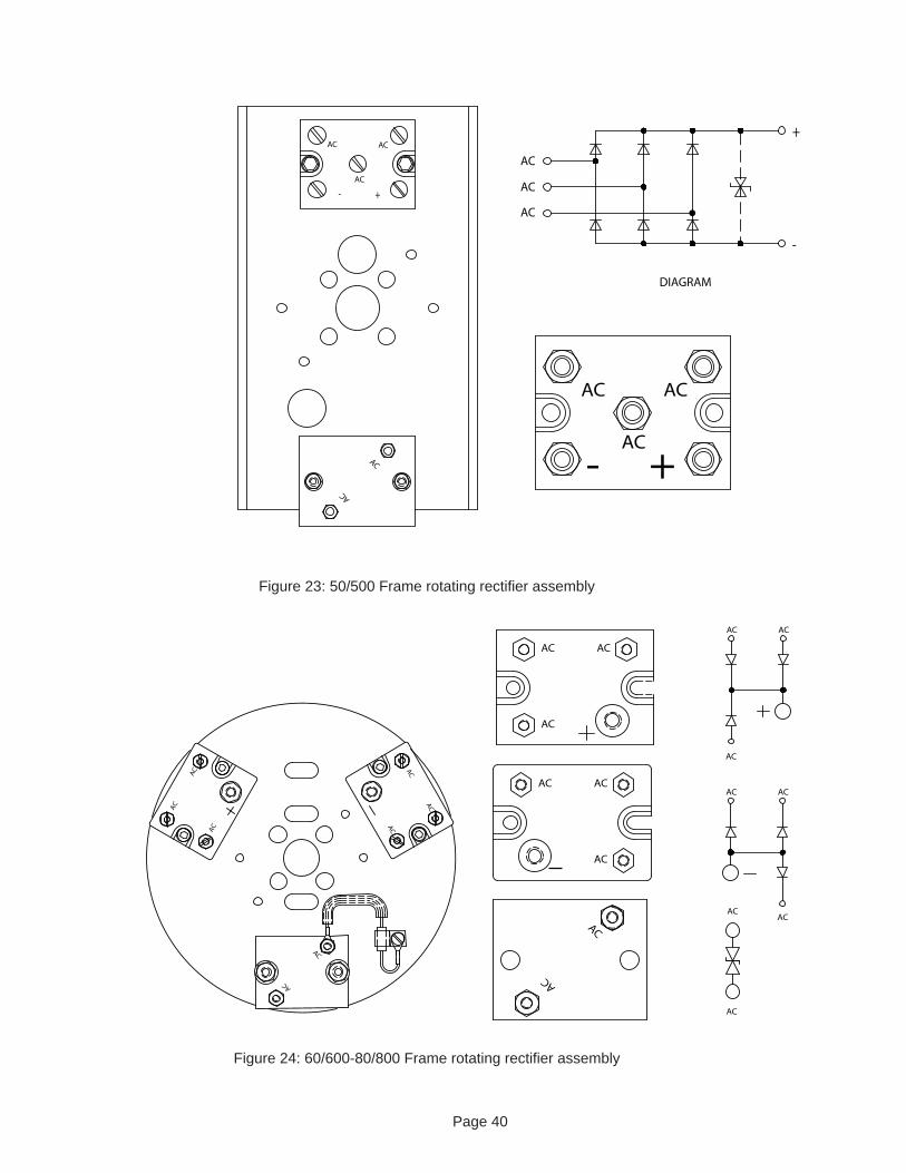
Different designs of rotating rectifi er assemblies can be used.
Diode cubes: They consist of three or six diodes depending on the generator frame. The fi gures below show how the rotating rectifi er assemblies are assembled and wired for each frame. Locate and disconnect all terminals on the rectifi er/heat sink assemblies to test the rectifi ers inside the diode cubes. See Figures 22, 23, and 24 for an overview.
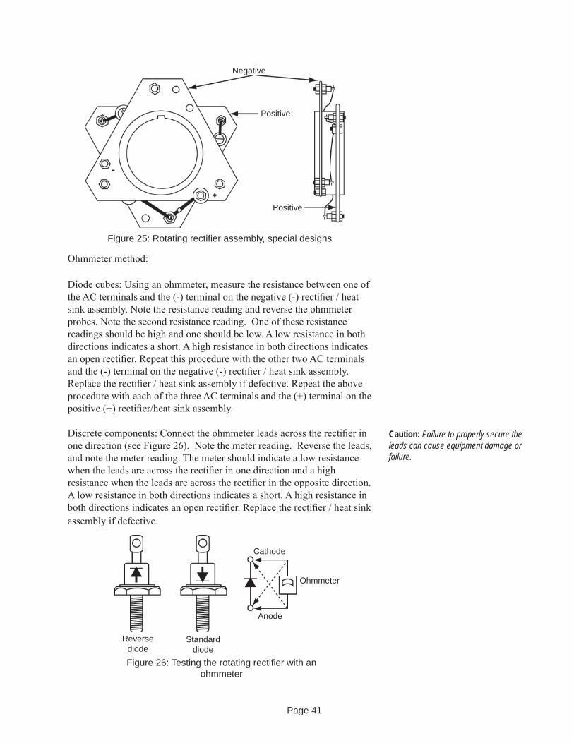
Six discrete diodes: Remove the nut and washer holding the rectifi er in the heat sink, and remove the diode lead wire. Lift the rectifi er from the heat sink. See Figures 25 and 26 for an overview.
Figure 22: 40 Frame rotating rectifi er assembly
Page 40
Figure 23: 50/500 Frame rotating rectifi er assembly
Figure 24: 60/600-80/800 Frame rotating rectifi er assembly
Page 41
Ohmmeter method:
Diode cubes: Using an ohmmeter, measure the resistance between one of the AC terminals and the (-) terminal on the negative (-) rectifi er / heat sink assembly. Note the resistance reading and reverse the ohmmeter probes. Note the second resistance reading. One of these resistance readings should be high and one should be low. A low resistance in both directions indicates a short. A high resistance in both directions indicates an open rectifi er. Repeat this procedure with the other two AC terminals and the (-) terminal on the negative (-) rectifi er / heat sink assembly. Replace the rectifi er / heat sink assembly if defective. Repeat the above procedure with each of the three AC terminals and the (+) terminal on the positive (+) rectifi er/heat sink assembly.
Discrete components: Connect the ohmmeter leads across the rectifi er in one direction (see Figure 26). Note the meter reading. Reverse the leads, and note the meter reading. The meter should indicate a low resistance when the leads are across the rectifi er in one direction and a high resistance when the leads are across the rectifi er in the opposite direction. A low resistance in both directions indicates a short. A high resistance in both directions indicates an open rectifi er. Replace the rectifi er / heat sink assembly if defective.
Figure 25: Rotating rectifi er assembly, special designs
Negative
Positive
Positive
Caution: Failure to properly secure the leads can cause equipment damage or failure.
Reversediode
Standarddiode
Anode
Cathode
Ohmmeter
Figure 26: Testing the rotating rectifi er with an ohmmeter

Page 42
Test lamp:
Connect the leads of a test lamp built as shown in Figure 27, consisting of standard fl ashlight batteries and a fl ashlight. Test the rotating rectifi ers as described above but using the two test probes of this makeshift tester instead of the ohmmeter probes. The light should light in one direction but not in the other. If the light lights in both directions, the rectifi er is shorted. If the light does not light in either direction, the rectifi er is open. Replace the rectifi er/heat sink assembly if defective.
Replace defective rectifi ers with rectifi ers of the same operating characteristics as rectifi ers installed in the generator at the factory. Order rectifi ers by part number, including the model, serial number and generator part number.
Surge protectors may be included on the rotating rectifi er assembly. Disconnect one lead of the surge protector, and connect the probes of an ohmmeter or makeshift test lamp as shown in Figure 23, across the surge protector in either direction. If the light comes on, the surge protector is defective. Order surge protectors by part number, including the model, serial number and generator part number. Following replacement, make sure that the revolving fi eld, exciter armature, and rotating diode leads are properly secured.
Disassembly
Overall disassembly1. Remove the terminal box cover, and disconnect the load leads and
all other generator leads. Tag the leads to ensure they are correctly connected when the generator is reassembled.
2. Remove the bolts securing the generator to the base and the engine, and move the generator to an area that allows suffi cient room for disassembly.
3. Remove the coupling or drive plates.
4. Remove the exciter cover, rotating diode assembly, optional PMG if necessary, and the exciter assembly as explained later.
5. Support the shaft. Remove the exciter-end bracket bolts, and remove the bracket. Tap lightly with a rubber or fi ber mallet to loosen the bracket if necessary. Repeat with the drive-end bracket (if applicable).
Figure 27: Test lamp
Caution: Failure to properly secure the leads can cause equipment damage or failure.
Note: The following procedures are meant to be a general guide. Procedures for your unit may vary.
Warning: Ensure the generator has stopped and is de-energized before disassembly.
Warning: Use a hoist and slings or chains to support components during removal. Use lifting devices that are selected for generator component weights, which can be found on the mechanical data sheet. Be extremely careful not to damage components.
Page 43
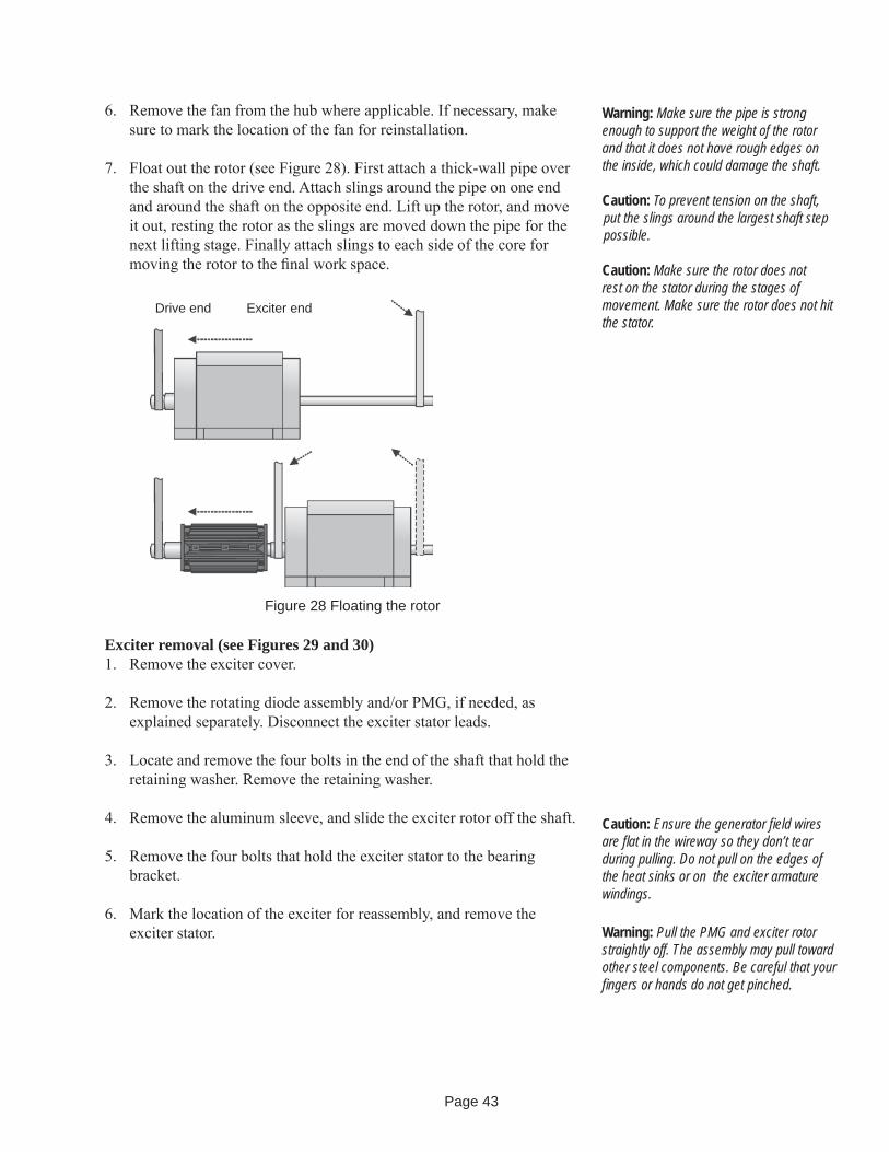
6. Remove the fan from the hub where applicable. If necessary, make sure to mark the location of the fan for reinstallation.
7. Float out the rotor (see Figure 28). First attach a thick-wall pipe over the shaft on the drive end. Attach slings around the pipe on one end and around the shaft on the opposite end. Lift up the rotor, and move it out, resting the rotor as the slings are moved down the pipe for the next lifting stage. Finally attach slings to each side of the core for moving the rotor to the fi nal work space.
Figure 28 Floating the rotor
Drive end Exciter end
Warning: Make sure the pipe is strong enough to support the weight of the rotor and that it does not have rough edges on the inside, which could damage the shaft.
Caution: To prevent tension on the shaft, put the slings around the largest shaft step possible.
Caution: Make sure the rotor does not rest on the stator during the stages of movement. Make sure the rotor does not hit the stator.
Caution: Ensure the generator fi eld wires are fl at in the wireway so they don’t tear during pulling. Do not pull on the edges of the heat sinks or on the exciter armature windings.
Warning: Pull the PMG and exciter rotor straightly off. The assembly may pull toward other steel components. Be careful that your fi ngers or hands do not get pinched.
Exciter removal (see Figures 29 and 30)1. Remove the exciter cover.
2. Remove the rotating diode assembly and/or PMG, if needed, as explained separately. Disconnect the exciter stator leads.
3. Locate and remove the four bolts in the end of the shaft that hold the retaining washer. Remove the retaining washer.
4. Remove the aluminum sleeve, and slide the exciter rotor off the shaft.
5. Remove the four bolts that hold the exciter stator to the bearing bracket.
6. Mark the location of the exciter for reassembly, and remove the exciter stator.
Page 44
Retainingbolts
PMG statorExciter stator
Retainingwasher
ShaftExciter armature
PMG rotor spacer
Bearing
Rotating diode assembly
Figure 29 Exciter armature assembly, PMG, 40, 50/500 Frames
Figure 30: Exciter armature assembly, 60/600 and 80/800 Frames
Retainingwasher
PMG rotor
Exciter armature
PMG rotor
Aluminumsleeve
PMG rotorspacer
Rotating diodeassembly
Shaft

Page 45
Optional PMG removal1. Remove the exciter cover.
2. Remove the rotating diode assembly and/or the exciter, if needed, as explained separately.
3. Disconnect the PMG stator leads.
4. Remove the four bolts that hold the PMG stator to the bearing bracket. Mark the location for reassembly, and remove the PMG stator.
4. Remove the PMG rotor spacer if supplied, and slide the PMG rotor assembly off the shaft.
5. Wrap the PMG rotor in plastic to avoid contamination as it will attract metal particles.
Bearing removal1. Remove the endbracket(s) to expose the bearing(s).
2. Use a puller to remove the bearing from the shaft end with a cap (see Figure 31). Replace it with a new bearing.
Figure 31: Pulling the bearing
Puller against bearing
Cap to protect shaft end
Outer ring Inner ring

Page 46
.Assembly
Bearing installation (done prior to installing the rotor)1. Heat the bearing to 220º to 250º F (104º to 121º C) in a clean oven or
with an induction heater.
2. Start the heated bearing on the shaft. Then use a fi ber or soft metal tube to tap the bearing into place.
3. Ensuring that pressure is applied only to the bearing inner ring, press the bearing onto the shaft until the inner ring seats against the bearing shoulder on the shaft.
4. Grease the generator bearing and/or bearing bracket cavity after the bearing has cooled according to bearing type as follows:
Shielded bearings are factory packed with grease. Fill the bearing bracket cavity to 40% with high quality ball bearing grease of NLGI #2 grade, which must be capable of lubricating satisfactorily over a temperature range of the lowest ambient temperature to 250° F (121° C). Standard grease is Chevron SRI or Polyrex EM with mineral oil base.
With optional regreaseable ball or roller bearings, fi ll the bearing to 30% with grease. Fill the bearing bracket cavity to 60%, and add 3 shots or 3 oz. (85 gr.) to the bearing cap with high quality ball bearing grease of NLGI #2 grade, which must be capable of lubricating satisfactorily over a temperature range of the lowest ambient temperature to 250° F (121° C). Standard grease is Chevron SRI or Polyrex EM with mineral oil base. Table 7 provides an indication of the amount of grease to add to the bearing.
Caution: Make sure all components are clean before assembly.
Note: Torque fasteners to the values speci-fi ed in Table 5 unless otherwise specifi ed.
Frame Bearing type Grams40 6016 C3 9 ± 2
50/500 6217 C3 26 ± 360 6322 C3 146 ± 7
600 6321 C3 123 ± 680/800 6326 C3 219 ± 11
Table 7: Optional regreaseable ball or roller bearing fi ll of 30%
Warning: Grease migrates between the shields and into the bearing. The same type of grease must be used. Grease incompatibly can cause bearing and generator failure.
Page 47
Overall assembly1. Float in the rotor until the rotor and stator laminations line up.
Position the rotor such that a full pole face is at the bottom.
2. Install the endbrackets. Support the rotor during installation. Put anti-corrosion agent on the bare mating surfaces.
3. Install the exciter, rotating diodes and optional PMG as described below.
4. Install the covers.
5. Install the coupling or drive plates.
6. Reconnect the load leads, exciter leads and accessories, if applicable.
Exciter installation (see Figures 29 and 30)1. Assemble the exciter stator to the bearing bracket with four retaining
bolts and washers.
2. Connect the exciter stator leads.
3. Clean the shaft and inside of the exciter laminations.
4. Place the key in the slot in the shaft, if applicable.
5. Lay the generator fi eld wires fl at in the wire slot with the wire ends protruding past the end of the shaft if applicable.
6. Position the exciter armature assembly in line with the shaft, and turn the assembly to the position where the keyway in the exciter laminations is in line with the key in the generator shaft.
7. With hand force, push the exciter armature assembly over the shaft, so the edge of the armature is against the shoulder on the shaft or sleeve.
8. Route the main rotor leads through the retaining washer.
9. Secure the exciter rotor assembly using the retaining washer and four retaining bolts at the end of the shaft.
10. Connect the exciter armature and evolving fi eld wires to the rectifi er terminals.
11. Measure the air gap between the exciter armature and exciter fi eld. Nominal values are shown in Table 8. If the air gap is less than 0.02 inch (0.058 mm), 1) check generator-engine alignment, 2) check for bearing wear, 3) check for misalignment of the exciter armature or stator.
Caution: Ensure the generator fi eld wires are fl at in the wire slot so they don’t tear during assembly. Do not pull on the edges of the heat sinks or on the exciter armature windings.
Caution: Do not pound on the rectifi er or armature windings.
Note: To measure air gap, measure com-pletely around the gap between the exciter armature and exciter fi eld with a feeler gauge. Keep the gauge at the tightest point, and turn the generator over to measure the air gap as the rotor turns.
Caution: Do not pry on the fan.

Page 48
Optional PMG installation (See Figures 25 and 26)1. Attach the PMG stator to the bearing bracket.
2. Place the main rotor leads in the shaft slot.
3. Carefully slide the PMG onto the shaft. Avoid contact between the rotor and stator that could damage the windings or the permanent magnets.
4. Connect the PMG stator leads.
5. Measure the air gap between the PMG rotor and PMG stator. Nominal values are shown in Table 8. If the air gap of the PMG is less than 0.020 inch (0.508 mm), 1) check generator-engine alignment, 2) check for bearing wear, 3) check for misalignment of the armature, PMG or stator.
Caution: Ensure the generator fi eld wires are fl at in the wire slot so they don’t tear during assembly. Do not pull on the edges of the heat sinks or on the exciter armature windings.
40 Frame 50/500 Frame 60/600 Frame 80/800 FrameInch mm Inch mm Inch mm Inch mm
Exciter stator ID 6.446 163.7 6.446 163.7 10.125 257.2 10.125 257.2Exciter rotor OD 6.318 160.5 6.318 160.5 9.98 253.5 9.98 253.5Exciter air gap* 0.0624 1.63 0.064 1.63 0.0725 1.84 0.0725 1.84PMG stator ID 7.187 182.5 9.9925 253.8 9.9925 253.8 9.9925 253.8PMG rotor OD 7.116 180.7 9.893 251.3 9.893 251.3 9.893 251.3PMG air gap* 0.0355 0.90 0.04975 1.26 0.4975 1.26 0.04975 1.26
Table 8: Exciter and PMG air gap
*Nominal values do not include varnish and red sealer buildup.

Page 49
StorageIf the generator is not installed in its operating location as soon as received, store it in a clean, dry area, not subject to vibrations or sudden temperature or humidity changes. Make sure the storage area temperature is between 10º F (-12º C) and 120º F (49º C) and the relative humidity is less than 60%. If possible, storage should be in an ambient temperature of approximately normal room temperature. Protect the shaft from corrosion by applying an anti-corrosion agent. Cover the unit with a durable cover.
Prepare units that cannot be stored in a temperature and humidity controlled area as follows:
Install desiccant bags in the exciter cover and inside the end bells.
Vacuum seal the unit in a covering of plastic or other material designed for that purpose.
Adequately tag the generator to ensure that preservative greases and desiccant bags are removed before the unit is placed in operation.
If space heaters are supplied, energize them to keep condensation from the windings.
For storage longer than 2 months, rotate the shaft a minimum of 10 revolutions every 60 days.
Warning: If necessary, remove the covers around the space heaters to reduce the risk of fi re.
Caution: Grease used in ball and roller bearing generators is subject to time deterioration. Before placing the unit into service after long-term storage, check the bearings for corrosion, and replace the grease or bearing(s).
Page 50
Troubleshooting Guide (corrective maintenance)Between regular preventive maintenance inspections, be alert for any signs of trouble. Correct any trouble immediately. See Table 9 for symptoms, causes and remedies.
Warning: Problems left uncorrected can result in injury or serious damage, which can result in costly repairs and downtime.
Symptom Cause RemedyNo Voltage Defective voltage regulator, opened circuit
breaker, or fuse(s)Check the voltage regulator. Reset the circuit breaker or replace fuses if open.
Overvoltage, undervoltage, or overloaddevices tripped (when protective devicesare incorporated into the circuit)
Check for the cause of the abnormal condition.Correct any defi ciencies. Reset devices.Check the generator nameplate for nominaloperating values.
Open circuit in exciter fi eld Check continuity of shunt fi eld and leadsto voltage control. (Use ohmmeter orwheatstone bridge) If open in fi eld coils,remove exciter fi eld assembly and returnassembly to factory for repair.
Loss of residual magnetism Restore residual magnetism or fl ash fi eld. When the voltage regulator is a model that requires fl ashing, install an automatic fi eld fl ashing system.
Open circuit in stator windings Check for continuity in the windings. Return the generator to the factory for repair if open.
Malfunction of automatic voltageregulator
See troubleshooting of voltage regulator.Correct defi ciencies.
Short-circuited generator output leads Clear lead to restore voltage buildup.Open in rotating rectifi ers Check rotating rectifi ers, and replace if
open.Open in generator fi eld Check for continuity and return rotor to
factory for repair if fi eld coils are open.Shorted or grounded surge protector Check for shorts or grounds. Replace .Shorted or grounded rotating rectifi er Check for shorts grounds. Replace or repair.Shorted or grounded exciter armature Check for shorts or grounds. Replace or repair.
Low voltage Shorted leads between the exciter armatureand generator fi eld
Test and repair.
Incorrect stator connections Check connections and reconnect

Page 51
Troubleshooting Guide (cont.)Symptom Cause RemedyLow voltage (cont.)
Improper adjustment of voltage adjustrheostat
Adjust rheostat.
Excessive load Reduce load. With three-wire, single-phase and four-wire, three-phase generators, the load on each leg must be as evenly balanced as possible and must not exceed the rated current on any leg.
Line loss Increase the size of the line wire.High resistance connections (hot) Make better connections.Shorted main or exciter fi eld Test the fi eld coils for possible short by
checking resistance with an ohmmeter orresistance bridge. Return the rotor assemblyto the factory for repair if fi eld coils are shorted.
Low power factor Reduce inductive (motor) load. Some acmotors draw approximately the samecurrent regardless of load. Do not usemotors of larger horsepower rating thanis necessary to carry the mechanicalload.
Weak fi eld due to operating in a warmtemperature
Improve the ventilation of the generator.Field current can be increased providingthe generator temperature ratingstamped on the nameplate is notexceeded.
Defective rectifi ers in rectifi er assembly(stationary)
Check rectifi er assembly. Replacedefective fuses or rectifi ers.
Excessive load Reduce load to rated value.Defective bearing Replace the bearing.Improper speed of engine drivengenerator set due to defective governor,ignition system, or carburetor
Check and correct defi ciencies.
Voltage regulator not operating properly Check the regulator. Adjust, repair or replace.Fluctuating voltage
Prime mover speed fl uctuating Check frequency and voltage of incomingpower when the generator set is motordriven. Check engine governor onengine-driven generator sets.
Loose internal or load connections Tighten all connections.Generator overloaded Reduce load to rated value.dc excitation voltage fl uctuating Trace dc excitation circuit. Correct any
defects.Overspeed Correct speed of prime mover.Voltage regulator not operating properly Check the regulator. Adjust, repair or replace.
High voltage Improper adjustment of voltage adjustrheostat or voltage regulator
Adjust rheostat and/or voltage regulator.
Voltage regulator not operating properly Check the regulator. Adjust, repair or replace.
Page 52
Troubleshooting Guide (cont.)Symptom Cause RemedyOverheating Clogged ventilating screens and air
passagesClean all screens and air passages.
Dry or defective bearings Replace defective bearings.Coupling misaligned Align the generator set.Generator fi eld coils shorted orgrounded
Test fi eld coils for shorts. Replaceshorted rotor or return it to the factory forrepair.
Unbalanced load or overload, low PF Adjust load to nameplate rating.Vibrations Defective or dry bearings Replace defective bearings.
Misalignment of generator and primemover
Align the generator set.
Generator not properly mounted Check mounting. Correct defectivemounting.
Transfer of vibration from anothersource
Isolate the generator set from the source ofvibration by installing vibration dampeners between generator set base and foundation.
Table 9: Troubleshooting
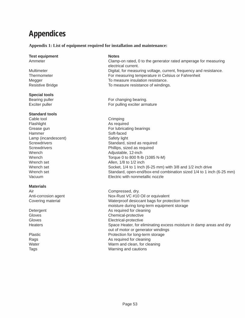
Page 53
AppendicesAppendix 1: List of equipment required for installation and maintenance:
Test equipment NotesAmmeter Clamp-on rated, 0 to the generator rated amperage for measuring
electrical cur rent.Multimeter Digital, for measuring voltage, current, frequency and resistance.Thermometer For measuring temperature in Celsius or FahrenheitMegger To measure insulation resistance.Resistive Bridge To measure resistance of windings.
Special toolsBearing puller For changing bearing.Exciter puller For pulling exciter armature
Standard toolsCable tool CrimpingFlashlight As requiredGrease gun For lubricating bearingsHammer Soft-facedLamp (incandescent) Safety lightScrewdrivers Standard, sized as requiredScrewdrivers Phillips, sized as requiredWrench Adjustable, 12-inchWrench Torque 0 to 800 ft-lb (1085 N-M)Wrench set Allen, 1/8 to 1/2 inchWrench set Socket, 1/4 to 1 Inch (6-25 mm) with 3/8 and 1/2 inch driveWrench set Standard, open-end/box-end combination sized 1/4 to 1 inch (6-25 mm)Vacuum Electric with nonmetallic nozzle
MaterialsAir Compressed, dry.Anti-corrosion agent Nox-Rust VC #10 Oil or equivalentCovering material Waterproof desiccant bags for protection from moisture during long-term equipment storageDetergent As required for cleaningGloves Chemical-protectiveGloves Electrical-protectiveHeaters Space Heater, for eliminating excess moisture in damp areas and dry out of motor or generator windings Plastic Protection for long-term storageRags As required for cleaningWater Warm and clean, for cleaningTags Warning and cautions
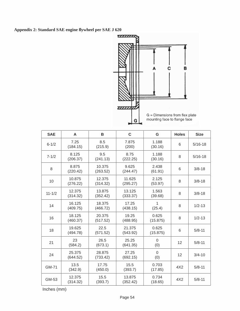
Page 54
Appendix 2: Standard SAE engine fl ywheel per SAE J 620
SAE A B C G Holes Size
6-1/2 7.25(184.15)
8.5(215.9)
7.875(200)
1.188(30.16) 6 5/16-18
7-1/2 8.125(206.37)
9.5(241.13)
8.75(222.25)
1.188(30.16) 8 5/16-18
8 8.875(220.42)
10.375(263.52)
9.625(244.47)
2.438(61.91) 6 3/8-18
10 10.875(276.22)
12.375(314.32)
11.625(295.27)
2.125(53.97) 8 3/8-18
11-1/2 12.375(314.32)
13.875(352.42)
13.125(333.37)
1.563(39.68) 8 3/8-18
14 16.125(409.75)
18.375(466.72)
17.25(438.15)
1(25.4) 8 1/2-13
16 18.125(460.37)
20.375(517.52)
19.25(488.95)
0.625(15.875) 8 1/2-13
18 19.625(494.78)
22.5(571.52)
21.375(543.92)
0.625(15.875) 6 5/8-11
21 23(584.2)
26.5(673.1)
25.25(641.35)
0(0) 12 5/8-11
24 25.375(644.52)
28.875(733.42)
27.25(692.15)
0(0) 12 3/4-10
GM-71 13.5(342.9)
17.75(450.0)
15.5(393.7)
0.703(17.85) 4X2 5/8-11
GM-53 12.375(314.32)
15.5(393.7)
13.875(352.42)
0.734(18.65) 4X2 5/8-11
Inches (mm)

Page 55
Appendix 3: Standard SAE engine fl ange per SAE J 617
SAE A B C Holes Size
00 31.00(787.37)
34.750(862.62)
33.500(850.87) 16 1/2-13
0 25.500(647.67)
28.00(711.17)
26.750(679.42) 16 1/2-13
1/2 23.00(584.18)
25.500(647.67)
24.375(619.10) 12 1/2-13
1 20.125(511.25)
21.750(552.43)
20.875(530.20) 12 7/16-14
2 17.625(447.66)
19.250(488.93)
18.375(466.70) 12 3/8-16
3 16.125(409.56)
17.750(450.83)
16.875(428.61) 12 3/8-16
4 14.25(361.94)
15.875(403.21)
15.00(380.99) 12 3/8-16
5 12.375(314.31)
14.00(355.59)
13.125(333.36) 18 3/8-16
6 10.500(266.69)
12.125(307.96)
11.250(285.74) 18 3/8-16
Inches (mm)
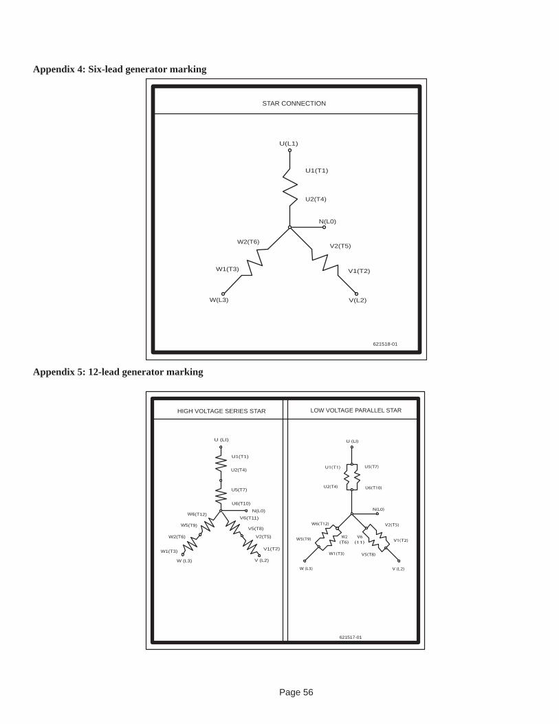
Page 56
Appendix 4: Six-lead generator marking
Appendix 5: 12-lead generator marking
HIGH VOLTAGE SERIES STAR LOW VOLTAGE PARALLEL STAR
U (LI)
U1(T1)
U2(T4)
U5(T7)
U6(T10)
V5(T8)
W (L3)
W1(T3)
V2(T5)W2(T6)
N(L0)V6(T11)
V1(T2)
V (L2)
W5(T9)
W6(T12)
621517-01
U(L1)
U1(T1)
U2(T4)
W1(T3)
W2(T6)V2(T5)
V1(T2)
W(L3) V(L2)
N(L0)
621518-01
STAR CONNECTION
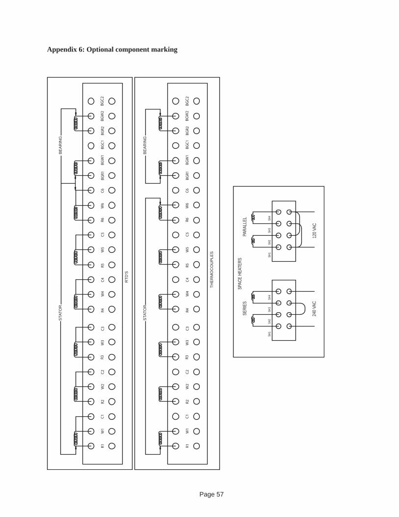
Page 57
Appendix 6: Optional component marking
RTD
'S
THE
RM
OC
OU
PLE
S
SERI
ESPA
RALL
EL
120
VAC
240
VAC
SPAC
E HE
ATER
S
SH1
SH2
SH3
SH4
SH1
SH2
SH3
SH4
STA
TOR
STA
TOR
BE
AR
ING
BE
AR
ING
Page 58
SY
MB
OLS
CR
1-C
R6
RO
TATI
NG
RE
CTI
FIE
RS
CR
7-C
R8
SU
RG
E S
UP
PR
ES
SIO
N D
IOD
ES
E1
PO
SIT
IVE
HE
ATS
INK
E2
NE
GAT
IVE
HE
ATS
INK
L1
E
XC
ITE
R S
TATO
R
L2
E
XC
ITE
R A
RM
ATU
RE
L3
R
EV
OLV
ING
FIE
LDL4
STA
TOR
R5
SU
PP
RE
SS
ION
RE
SIS
TOR
RFA
RE
VO
LVIN
G F
IELD
AS
SE
MB
LY
PO
LAR
TY M
AR
K
OP
TIO
NA
LP
MG
FUSE
FUSE
L1
OP
TIO
NA
L PA
RA
LLE
LIN
G C
UR
RE
NT
TRA
NS
FOR
ME
R
OP
TIO
NA
L S
EN
SIN
G T
RA
NS
FOR
ME
RS
T3
26242220 28 30 F1 F265
CR7
RFA
E1 R5
L2
CR3
CR2
CR1
E2
CR6
CR5
CR4
-+
+L3
CR8
-T
1
L4T2
T4T5
T6
Appendix 7: Six-lead generator connections
Page 59
Appendix 8: 12-lead generator connectionsSY
MBO
LSC
R1-
CR
6 R
OTA
TIN
G R
ECTI
FIER
SC
R7-
CR
8 SU
RG
E SU
PPR
ESSI
ON
DIO
DES
E1
P
OSI
TIVE
HEA
TSIN
KE2
NEG
ATIV
E H
EATS
INK
L1
E
XCIT
ER S
TATO
R
L2
E
XCIT
ER A
RM
ATU
RE
L3
R
EVO
LVIN
G F
IELD
L4
S
TATO
RR
5
S
UPP
RES
SIO
N R
ESIS
TOR
RFA
REV
OLV
ING
FIE
LD A
SSEM
BLY
P
OLA
RTY
MAR
K
OPT
ION
ALPM
G
FUSE
FUSE
L1
OPT
ION
AL
SEN
SIN
G T
RAN
SFO
RM
ERS
OPT
ION
AL P
ARAL
LELI
NG
CU
RR
ENT
TRAN
SFO
RM
ER
26242220 28 30 F1 F2
L4
T6
T3T4
T12
T9
T1
T7T10
T5
T8
T11
T2
65
CR7
RFA
E1 R5
L2
CR3
CR2
CR1
E2
CR6
CR5
CR4
-+
+L3
CR8
-
Page 60
Appendix 9: Single bearing 40 frame key parts (Shunt and PMG models)
Item Description1 Air outlet screen2 Bearing (Exciter end)3 Bracket (Exciter end)4 Drip proof cover5 Drive discs6 Exciter armature7 Exciter cover8 Exciter stator9 Fan11 PMG rotor12 PMG stator13 Revolving fi eld and shaft14 Rotating rectifi er assembly15 Stand-off / Buss bar assembly16 Stator assembly (wound)17 Terminal box assembly18 Terminal box top cover19 Voltage regulator
ShuntOptional PMG
4
19
18
5
9
38
6
7
2
1
1316
15
17
14
38
6 12
11
7
14

Page 61
Appendix 10: Single bearing 50/500 Frame key parts (Shunt and PMG models)
Item Description1 Air outlet screen2 Bearing (Exciter end)3 Bracket (Exciter end)4 Drip proof cover5 Drive discs6 Exciter armature7 Exciter cover8 Exciter stator9 Fan11 PMG rotor12 PMG stator13 Revolving fi eld and shaft14 Rotating rectifi er assembly15 Stand-off / Buss bar assembly16 Stator assembly (wound)17 Terminal box assembly18 Terminal box top cover
18
ShuntOptional PMG
83
7
6
1411
12 9
5
1
2
7
6
8 313
16
15
17
14

Page 62
Appendix 11: Single bearing 60/600 Frame key parts (Shunt and PMG models)
Item Description1 Air outlet screen2 Bearing (Exciter end)3 Bracket (Exciter end)4 Drip proof cover5 Drive discs6 Exciter armature7 Exciter cover8 Exciter stator9 Fan11 PMG rotor12 PMG stator13 Revolving fi eld and shaft14 Rotating rectifi er assembly15 Stand-off / Buss bar assembly16 Stator assembly (wound)17 Terminal box assembly18 Terminal box top cover19 Voltage regulator
Optional PMG
Shunt
NT0
UT1
W T3
V T2
3
2
8
7 1
5
9
6
15
1613
17
12
11
14
4
ROTATION
C3 C
3
F2 F2F1
T2T1
F1T2
T1
2224
20
2224
20
BG
WB
GY
BG
PBG
PB
GW
BG
Y
TC2+
TC2+
TC3+
TC3-
TC2-
TC3+
TC3-
TC2-
TC1-
TC1+
TC1-
TC1+
C6
TC5+
C6
TC6+
TC6-
TC5-
TC4-
TC4+
TC5+
TC6+
TC6-
TC5-
TC4-
TC4+
SH
4 SH
4
SH
3S
H2
SH
1
SH
3S
H2
SH
1
18
19

Page 63
Appendix 12: Single bearing 80/800 Frame key parts (Shunt and PMG models)
Item Description1 Air outlet screen2 Bearing (Exciter end)3 Bracket (Exciter end)4 Drip proof cover5 Drive discs6 Exciter armature7 Exciter cover8 Exciter stator9 Fan
10 PMG mounting ring11 PMG rotor12 PMG stator13 Revolving fi eld and shaft14 Rotating rectifi er assembly15 Stand-off / Buss bar assembly16 Stator assembly (wound)17 Terminal box assembly18 Terminal box top cover19 Voltage regulator
ROTATION
C3C
3
BGP
C6
BGW
BGY
C6
TC2-
TC2-
TC3-
TC3+
TC3-
TC3+
TC1-
TC2+
TC1+
TC1-
TC2+
TC1+
TC5-
TC5-
TC6-
TC6+
TC6-
TC6+
TC4-
TC5+
TC4+
TC4-
TC5+
TC4+
BGP
SH4
BGW
BGY
SH3
SH2
SH1
SH4
SH3
SH2
SH1
18
419
Optional PMG
Shunt
17 15
161310
12
11
14
3
2
9
5
1
8
6
7
Page 64
Appendix 13: Double bearing 60/600 Frame key parts (Shunt and PMG models)
NT0T0
UT1T1
W W T3T3
V V T2T2
83
17
12Optional PMG
Shunt
14
7
9
15
1613
1
220
21
6
11
Item Description1 Air outlet screen2 Bearing (Exciter end)3 Bracket (Exciter end)4 Drip proof cover5 Drive discs6 Exciter armature7 Exciter cover8 Exciter stator9 Fan11 PMG rotor12 PMG stator13 Revolving fi eld and shaft14 Rotating rectifi er assembly15 Stand-off / Buss bar assembly16 Stator assembly (wound)17 Terminal box assembly18 Terminal box top cover19 Voltage regulator20 Bearing (drive end)21 Bracket (drive end)
4
18
19
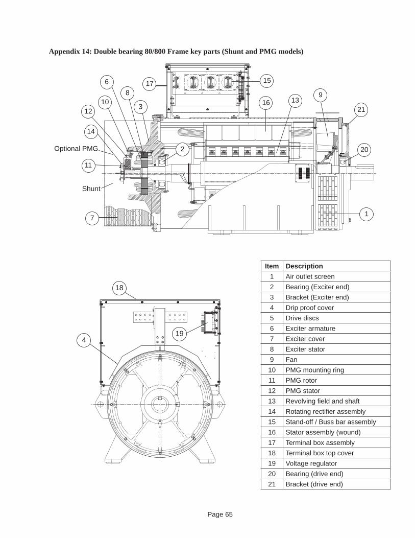
Page 65
Appendix 14: Double bearing 80/800 Frame key parts (Shunt and PMG models)
4
18
19
ENCLOSUREOVERSPEED
RATING
PHASE
RPM
Hz
ROTATION
ARRANGEMENT
STATOR CONN
WEIGHT
INSULATION
AMPS
VOLTS
P.F.
KW
kVA
EMI
MODEL
EXC VOLTS
AMB
DATE
SERIAL NO
ALT
EXC AMPS
TEMP RISE
Shunt
17
7
3
810
12
Optional PMG
11
14
6
91316
15
21
20
1
2
Item Description1 Air outlet screen2 Bearing (Exciter end)3 Bracket (Exciter end)4 Drip proof cover5 Drive discs6 Exciter armature7 Exciter cover8 Exciter stator9 Fan
10 PMG mounting ring11 PMG rotor12 PMG stator13 Revolving fi eld and shaft14 Rotating rectifi er assembly15 Stand-off / Buss bar assembly16 Stator assembly (wound)17 Terminal box assembly18 Terminal box top cover19 Voltage regulator20 Bearing (drive end)21 Bracket (drive end)

Page 66
Kato Engineering Inc.P.O. Box 8447Mankato, MN USA56002-8447Tel: 507-625-4011Fax: 507-345-2798Email: [email protected]