interiores butterfly_valves_rev.11_ 2013.indd
TRANSCRIPT
Butterfl y Valveswww.comeval.es
Unival®
www.comeval.es
Unival®Excelling the best.

2
Uni
val®
- © D
ata
subj
ect t
o ch
ange
with
out p
rior n
otic
e
55
Uni
val®
- © D
ata
subj
ect t
o ch
ange
with
out p
rior n
otic
e

IndexGeneral Design ConsiderationsValve Coding SystemEngineering & Performance Data for Unival Concentric Valves Working Parameters & Chemical Resistance Flow Data Torque ValuesConcentric Butterfl y Valves Attributes of Design - VF700/750/7U0Wafer Style Concentric Butterfl y Valves Parts and materials - VF700/750/7U0 Dimensions & Design Standards - VF700 DN32-600 Dimensions & Design Standards - VF700 DN700-1200Lug Style Concentric Butterfl y Valves Dimensions & Design Standards - VF750U Style Concentric Butterfl y Valves Dimensions & Design Standards - VF7U0Double Flange Concentric Butterfl y Valves Attributes of Design - VF790 Parts and Materials - VF790 Dimensions & Design Standards - VF790Wafer Split Body PTFE Lined Concentric Butterfl y Valves Attributes of Design - VF775 Parts and Materials - VF775 Dimensions & Design Standards - VF775Actuation and Accesories on Manual Butterfl y ValvesPneumatic Actuators CMVL T Series Attributes of Design General Design Considerations Bi-Directional Patented Travel Stop Illustration Special Coatings Dimensions Spring Return Actuator Sizing Parts and Materials Options and AccessoriesAssembly Dimensions of Pneumatic Actuators on Wafer Style Concentric Butterfl y Valves - VF700 on Lug Style Concentric Butterfl y Valves - VF750Multi-Voltage Electric Actuators Attributes of Design Main Data Options and AccessoriesAssembly Dimensions of Electric Actuators on Wafer Style Concentric Butterfl y Valves - VF700 on Lug Style Concentric Butterfl y Valves - VF750Wafer & Lug Concentric Butterfl y Valves Assembly SetInstallation, Start-Up and MaintenanceMaterial Selection GuidanceMarketing Tools Available to DistributorsGet in touch
4-56
7- 89
10
11
121314
15
16
171819
20212223
2425262728293031
3233
343536
3738
3940-4546-52
5354
3
Unival® Butterfl y Valves Index
Uni
val®
- © D
ata
subj
ect t
o ch
ange
with
out p
rior n
otic
e
4
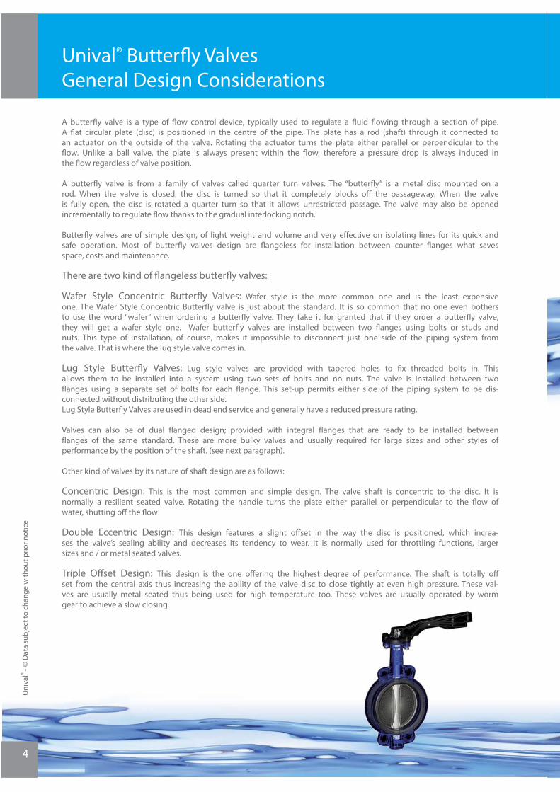
A butterfl y valve is a type of fl ow control device, typically used to regulate a fl uid fl owing through a section of pipe. A fl at circular plate (disc) is positioned in the centre of the pipe. The plate has a rod (shaft) through it connected to an actuator on the outside of the valve. Rotating the actuator turns the plate either parallel or perpendicular to the fl ow. Unlike a ball valve, the plate is always present within the fl ow, therefore a pressure drop is always induced in the fl ow regardless of valve position.
A butterfl y valve is from a family of valves called quarter turn valves. The “butterfl y” is a metal disc mounted on a rod. When the valve is closed, the disc is turned so that it completely blocks off the passageway. When the valve is fully open, the disc is rotated a quarter turn so that it allows unrestricted passage. The valve may also be opened incrementally to regulate fl ow thanks to the gradual interlocking notch.
Butterfl y valves are of simple design, of light weight and volume and very eff ective on isolating lines for its quick and safe operation. Most of butterfl y valves design are fl angeless for installation between counter fl anges what saves space, costs and maintenance.
There are two kind of fl angeless butterfl y valves:
Wafer Style Concentric Butterfl y Valves: Wafer style is the more common one and is the least expensive one. The Wafer Style Concentric Butterfl y valve is just about the standard. It is so common that no one even bothers to use the word “wafer” when ordering a butterfl y valve. They take it for granted that if they order a butterfl y valve, they will get a wafer style one. Wafer butterfl y valves are installed between two fl anges using bolts or studs and nuts. This type of installation, of course, makes it impossible to disconnect just one side of the piping system from the valve. That is where the lug style valve comes in.
Lug Style Butterfl y Valves: Lug style valves are provided with tapered holes to fi x threaded bolts in. This allows them to be installed into a system using two sets of bolts and no nuts. The valve is installed between two fl anges using a separate set of bolts for each fl ange. This set-up permits either side of the piping system to be dis-connected without distributing the other side.Lug Style Butterfl y Valves are used in dead end service and generally have a reduced pressure rating.
Valves can also be of dual fl anged design; provided with integral fl anges that are ready to be installed between fl anges of the same standard. These are more bulky valves and usually required for large sizes and other styles of performance by the position of the shaft. (see next paragraph).
Other kind of valves by its nature of shaft design are as follows:
Concentric Design: This is the most common and simple design. The valve shaft is concentric to the disc. It is normally a resilient seated valve. Rotating the handle turns the plate either parallel or perpendicular to the fl ow of water, shutting off the fl ow
Double Eccentric Design: This design features a slight off set in the way the disc is positioned, which increa-ses the valve’s sealing ability and decreases its tendency to wear. It is normally used for throttling functions, larger sizes and / or metal seated valves.
Triple Off set Design: This design is the one off ering the highest degree of performance. The shaft is totally off set from the central axis thus increasing the ability of the valve disc to close tightly at even high pressure. These val-ves are usually metal seated thus being used for high temperature too. These valves are usually operated by worm gear to achieve a slow closing.
Unival® Butterfl y Valves General Design Considerations
Uni
val®
- © D
ata
subj
ect t
o ch
ange
with
out p
rior n
otic
e
5
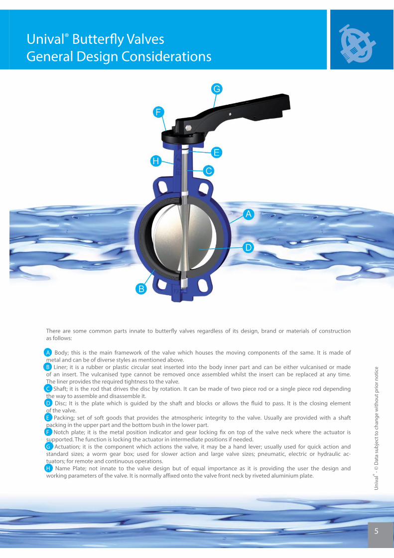
There are some common parts innate to butterfl y valves regardless of its design, brand or materials of construction as follows:
A Body; this is the main framework of the valve which houses the moving components of the same. It is made of metal and can be of diverse styles as mentioned above.B Liner; it is a rubber or plastic circular seat inserted into the body inner part and can be either vulcanised or made of an insert. The vulcanised type cannot be removed once assembled whilst the insert can be replaced at any time. The liner provides the required tightness to the valve.C Shaft; it is the rod that drives the disc by rotation. It can be made of two piece rod or a single piece rod depending the way to assemble and disassemble it.D Disc; It is the plate which is guided by the shaft and blocks or allows the fl uid to pass. It is the closing element of the valve.E Packing; set of soft goods that provides the atmospheric integrity to the valve. Usually are provided with a shaft packing in the upper part and the bottom bush in the lower part.F Notch plate; it is the metal position indicator and gear locking fi x on top of the valve neck where the actuator is supported. The function is locking the actuator in intermediate positions if needed.G Actuation; it is the component which actions the valve, it may be a hand lever; usually used for quick action and standard sizes; a worm gear box; used for slower action and large valve sizes; pneumatic, electric or hydraulic ac-tuators; for remote and continuous operations.H Name Plate; not innate to the valve design but of equal importance as it is providing the user the design and working parameters of the valve. It is normally affi xed onto the valve front neck by riveted aluminium plate.
Uni
val®
- © D
ata
subj
ect t
o ch
ange
with
out p
rior n
otic
e
Unival® Butterfl y Valves General Design Considerations
Uni
val®
- © D
ata
subj
ect t
o ch
ange
with
out p
rior n
otic
e
6
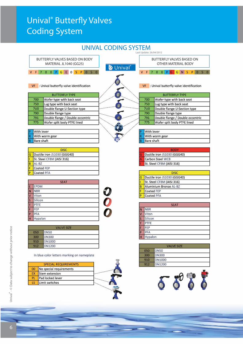
Unival® Butterfl y Valves Coding System
BUTTERFLY VALVES BASED ON BODY MATERIAL JL1040 (GG25)
BUTTERFLY VALVES BASED ON OTHER MATERIAL BODY
UNIVAL CODING SYSTEMLast Update: 26/04/2012

7
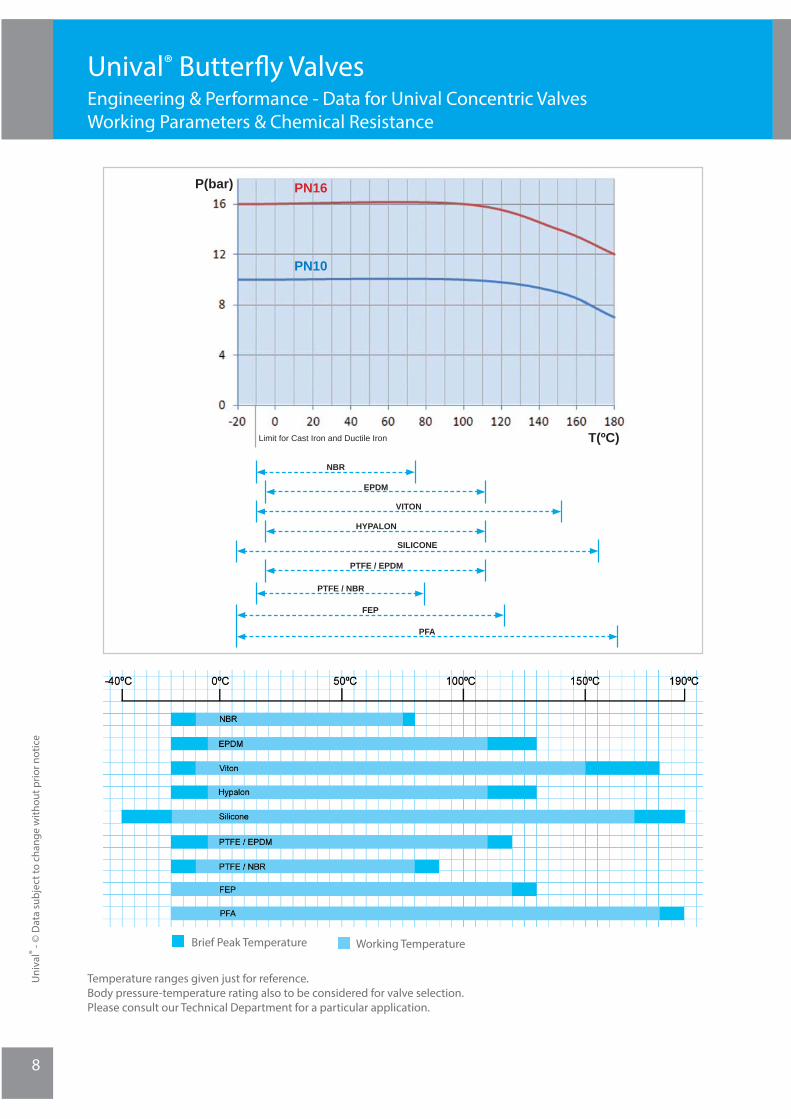
NBR Butadiene Acrylonitrile (-20ºC) -10ºC ... 75ºC (80ºC) Lubricating oil, cutting oils, fuel oils, animal and vegetable oils, aviation kerosen, LPG, oily air. Generally resistant to oils and solvents. Limited resistance to ozone and wheather.
EPDM Ethylene Propylene Diene (-20ºC) -5ºC ... 110ºC (130ºC) Salts in water, diluted acids, alkaline solutions, ester, ketones, alcohols, glycols, hot water, intermittent steam, ste-rilisation Good resistance to ozone and wheather. It is attacked by hydrocarbon solutions, chlorinated hydrocarbons and other petroleum based oils.
Viton (FPM) Vinylidenefl uoride-hexafl uoro-propyleneco-polymer (-20ºC) -10ºC ... 150ºC (180º) Strong and weak mineral acids, aliphatic hydrocarbons, chlorine gas, oils, aliphatic acids, phosporic acids, ozone, certain aromatic solvents Not suitable for hot water, steam and dry heat.
Hypalon (CSM) Chlorosulfonated polyethylene (-20ºC) -10ºC ... 110ºC (130ºC)Good chlorine and weather resistance. Low resistance to oil and fats
Silicone (-40ºC) -20ºC ... 170ºC (190ºC)Good wheather resistance. Recommended for hot air applications. Not resistant to mineral oils. Moderate mecha-nical properties.
PTFE PTFE/EPDM (-20ºC) -5ºC ... 110ºC (120ºC) - PTFE/NBR (-20ºC) -10ºC ... 80ºC (90ºC) Excellent resistance to chemicals or biopharmaceuticals, strong acids and solvents, alkalies and salts in water. Ex-cellent resistance to weather.
FEP -20ºC ... 120ºC (130ºC) Similar properties to PTFE but more translucent and with lower porosity, so most suitable for concentrated mineral acids, aromatic, aliphatic and chlorinated solvents.
PFA -20ºC ... 180ºC (190ºC)Similar to FEP but with smoother surface texture and for higher continuos service temperatures.
Unival® Butterfl y Valves Engineering & Performance - Data for Unival Concentric ValvesWorking Parameters & Chemical Resistance
Uni
val®
- © D
ata
subj
ect t
o ch
ange
with
out p
rior n
otic
e
Uni
val®
- © D
ata
subj
ect t
o ch
ange
with
out p
rior n
otic
e
8
Brief Peak Temperature Working Temperature
Temperature ranges given just for reference.Body pressure-temperature rating also to be considered for valve selection.Please consult our Technical Department for a particular application.
PN16
PN10
P(bar)
T(ºC)Limit for Cast Iron and Ductile Iron
NBR
EPDM
VITON
HYPALON
SILICONE
PTFE / EPDM
PTFE / NBR
FEP
PFA
Unival® Butterfl y Valves Engineering & Performance - Data for Unival Concentric ValvesWorking Parameters & Chemical Resistance
9
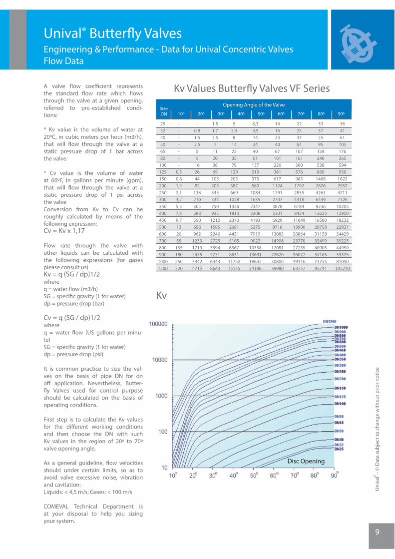
Disc Opening
Kv
Kv Values Butterfl y Valves VF SeriesA valve fl ow coeffi cient represents the standard fl ow rate which fl ows through the valve at a given opening, referred to pre-established condi-tions:
* Kv value is the volume of water at 20ºC, in cubic meters per hour (m3/h), that will fl ow through the valve at a static pressure drop of 1 bar across the valve
* Cv value is the volume of water at 60ºF, in gallons per minute (gpm), that will fl ow through the valve at a static pressure drop of 1 psi across the valveConversion from Kv to Cv can be roughly calculated by means of the following expression:Cv = Kv x 1,17
Flow rate through the valve with other liquids can be calculated with the following expressions (for gases please consult us)Kv = q (SG / dp)1/2whereq = water fl ow (m3/h)SG = specifi c gravity (1 for water)dp = pressure drop (bar)
Cv = q (SG / dp)1/2whereq = water fl ow (US gallons per minu-te)SG = specifi c gravity (1 for water)dp = pressure drop (psi)
It is common practice to size the val-ves on the basis of pipe DN for on off application. Nevertheless, Butter-fl y Valves used for control purpose should be calculated on the basis of operating conditions.
First step is to calculate the Kv values for the diff erent working conditions and then choose the DN with such Kv values in the region of 20º to 70º valve opening angle.
As a general guideline, fl ow velocities should under certain limits, so as to avoid valve excessive noise, vibration and cavitation: Liquids: < 4,5 m/s; Gases: < 100 m/s
COMEVAL Technical Department is at your disposal to help you sizing your system.
Unival® Butterfl y Valves Engineering & Performance - Data for Unival Concentric Valves Flow Data
SizeDN 10º
Opening Angle of the Valve
253240506580
100125150200250300350400450500600700800900
10001200
364161
105176265594950
1622295747117126
102051395018232229373442939225449505952581050
105210
33375595
159240538860
14682676426364499236
126251650020758311583549940905541657375595741
22253764
107161360576983
17922855431861848454
1104913900208642377027239360724911663757
1416234067
101226361617
1124179127073878530169298716
130831490617081226203080039980
8,39,514244061
137219373680
10841639234732084193527579199022
10338136911864224198
55,38
14233578
129205387669
102813261813237029814431510563678631
1175215155
1,51,73,57
11203869
105205345534750935
12121595224627253394473164438643
-0,81,52,559
16264482
138210305388550658962
12331719247533424715
-------
0,50,81,32,13,75,57,49,7132055
135180250320
20º 30º 40º 50º 60º 70º 80º 90º
Uni
val®
- © D
ata
subj
ect t
o ch
ange
with
out p
rior n
otic
e
Uni
val®
- © D
ata
subj
ect t
o ch
ange
with
out p
rior n
otic
e
10
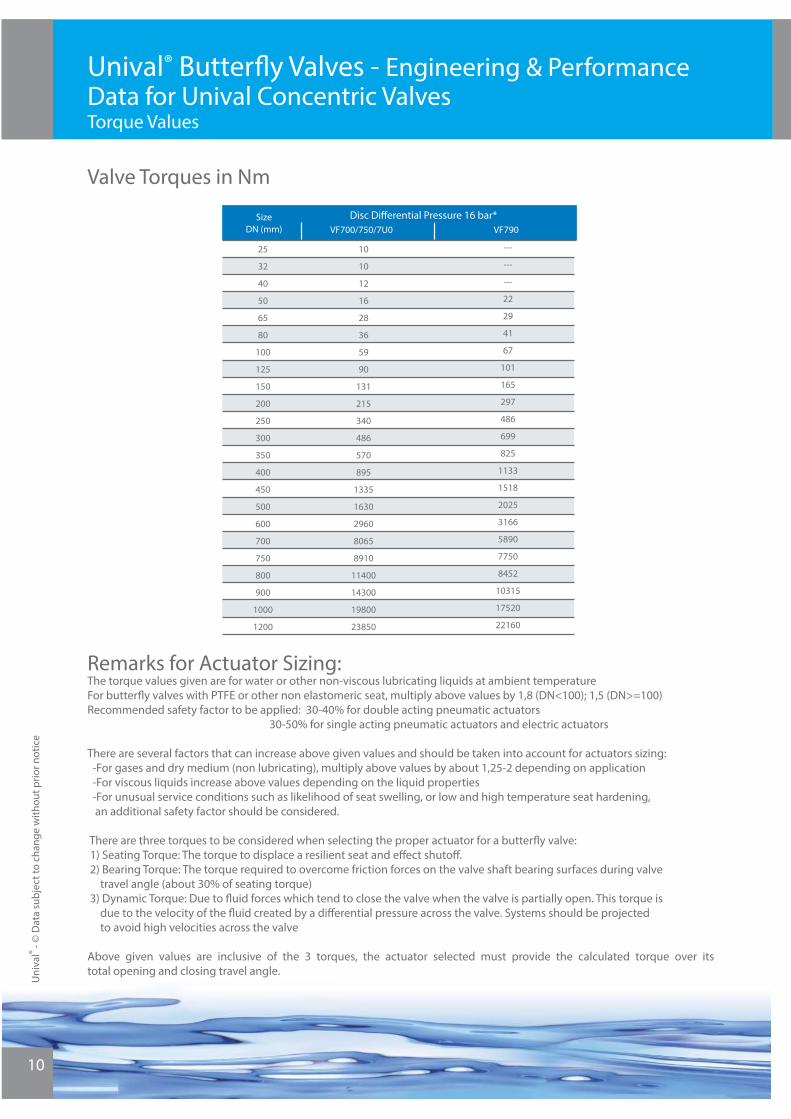
Remarks for Actuator Sizing: The torque values given are for water or other non-viscous lubricating liquids at ambient temperature For butterfl y valves with PTFE or other non elastomeric seat, multiply above values by 1,8 (DN<100); 1,5 (DN>=100) Recommended safety factor to be applied: 30-40% for double acting pneumatic actuators 30-50% for single acting pneumatic actuators and electric actuators There are several factors that can increase above given values and should be taken into account for actuators sizing: -For gases and dry medium (non lubricating), multiply above values by about 1,25-2 depending on application -For viscous liquids increase above values depending on the liquid properties -For unusual service conditions such as likelihood of seat swelling, or low and high temperature seat hardening, an additional safety factor should be considered. There are three torques to be considered when selecting the proper actuator for a butterfl y valve: 1) Seating Torque: The torque to displace a resilient seat and eff ect shutoff . 2) Bearing Torque: The torque required to overcome friction forces on the valve shaft bearing surfaces during valve travel angle (about 30% of seating torque) 3) Dynamic Torque: Due to fl uid forces which tend to close the valve when the valve is partially open. This torque is due to the velocity of the fl uid created by a diff erential pressure across the valve. Systems should be projected to avoid high velocities across the valve
Above given values are inclusive of the 3 torques, the actuator selected must provide the calculated torque over its total opening and closing travel angle.
Valve Torques in Nm
Unival® Butterfl y Valves - Engineering & Performance Data for Unival Concentric ValvesTorque Values
SizeDN (mm)
Disc Diff erential Pressure 16 bar*
25
32
40
50
65
80
100
125
150
200
250
300
350
400
450
500
600
700
750
800
900
1000
1200
VF700/750/7U0 VF790
10
10
12
16
28
36
59
90
131
215
340
486
570
895
1335
1630
2960
8065
8910
11400
14300
19800
23850
---
---
---
22
29
41
67
101
165
297
486
699
825
1133
1518
2025
3166
5890
7750
8452
10315
17520
22160
11
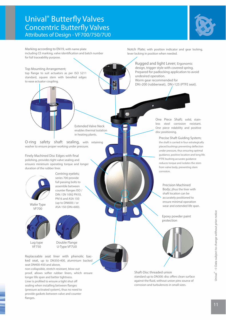
Rugged and light Lever; Ergonomic design, trigger style with covered spring.Prepared for padlocking application to avoid undesired operation.Worm gear recommended for DN>200 (rubberseat), DN>125 (PTFE seat).
Notch Plate; with position indicator and gear locking, lever locking in position when needed.
Top Mounting Arrangement; top fl ange to suit actuators as per ISO 5211 standard, square stem with bevelled edges to ease actuator coupling.
O-ring safety shaft sealing, with retaining washer to ensure proper working under pressure.
Extended Valve Neck enables thermal isolation in heating plants.
Centring eyelets; series 700 provide full passing bolts to assemble between counter fl anges ISO / DIN / EN 1092 PN10, PN16 and ASA 150 (up to DN600) / or ASA 150 (DN>600).
Finely Machined Disc Edges with fi nal polishing, provides tight valve sealing and ensures minimum operating torque and longer duration of the rubber liner.
One Piece Shaft; solid, stain-less steel corrosion resistant. One piece ndability and positive disc positioning.
Precise Shaft Guiding System; the shaft is carried in four estrategically placed bushings preventing defl ection under pressure, thus ensuring optimal guidance, positive location and long life. PTFE bushing accurate guidancereduces torque and isolates the stemfrom valve body, preventing stem corrosion.
Precision Machined Body; ¡thus the liner with shaft location can be accurately positioned to ensure minimal operation wear and extended life span.
Epoxy powder paint protection
Replaceable seat liner with phenolic bac-ked seat, up to DN350-400, aluminium backed seat DN400-450 and above,non-collapsible, stretch resistant, blow out proof, allows softer rubber liners, which ensure longer life span and better tightness.Liner is profi led to ensure a tight shut off sealing when installing between fl anges(pressure activated system), thus no need toprovide gaskets between valve and counter fl anges.
Shaft-Disc threaded unionstandard up to DN300: disc off ers clean surface against the fl uid, without union pins source of corrosion and turbulences in small sizes.
Marking according to EN19, with name plate including CE marking, valve identifi cation and batch number for full traceability purpose.
Wafer TypeVF700
Lug typeVF750
Double Flange U-Type VF7U0
Unival® Butterfl y Valves Concentric Butterfl y ValvesAttributes of Design - VF700/750/7U0
Uni
val®
- © D
ata
subj
ect t
o ch
ange
with
out p
rior n
otic
e
Uni
val®
- © D
ata
subj
ect t
o ch
ange
with
out p
rior n
otic
e
12
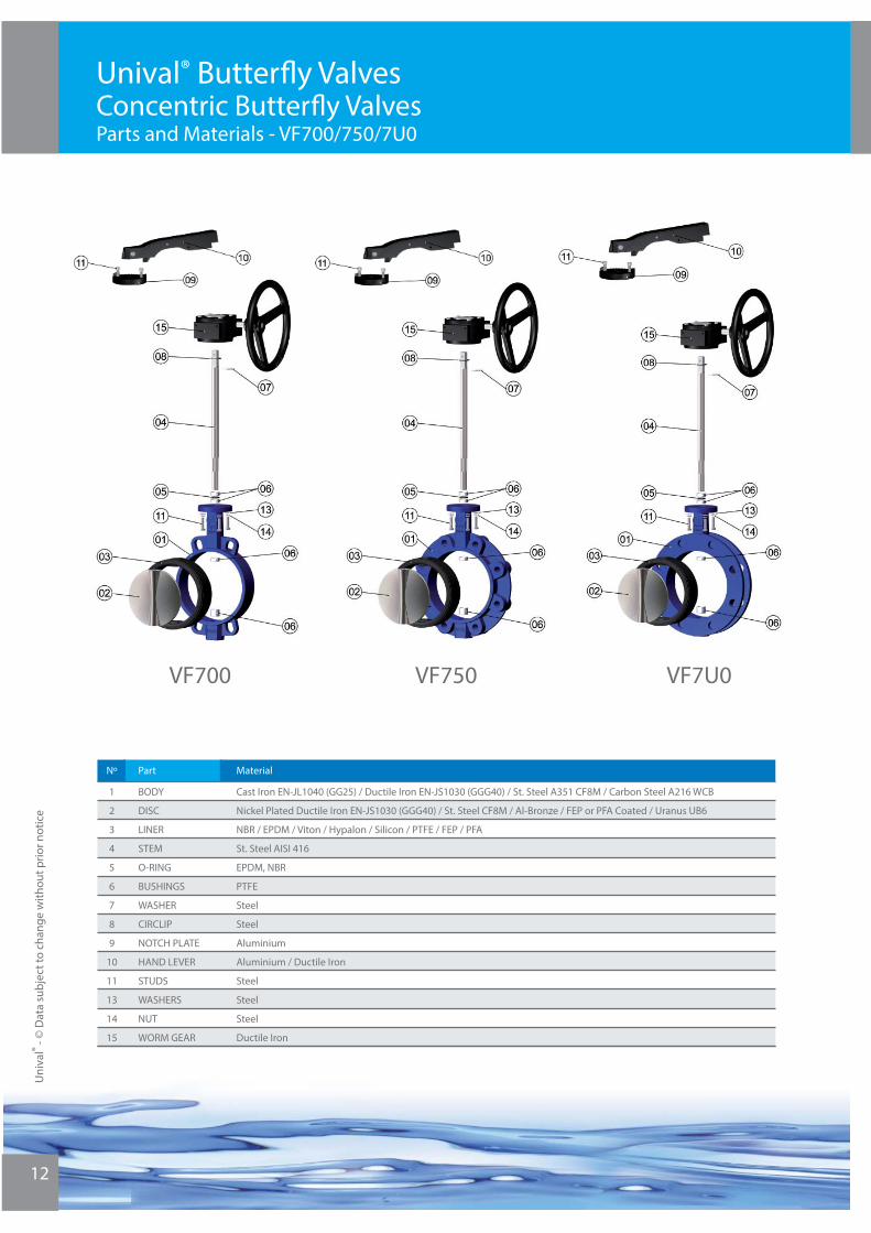
VF750VF700 VF7U0
Unival® Butterfl y Valves Concentric Butterfl y ValvesParts and Materials - VF700/750/7U0
Nº Part
Butyl Rubber (BR)
1
2
3
4
5
6
7
8
9
10
11
13
14
15
Material
BODY
DISC
LINER
STEM
O-RING
BUSHINGS
WASHER
CIRCLIP
NOTCH PLATE
HAND LEVER
STUDS
WASHERS
NUT
WORM GEAR
Cast Iron EN-JL1040 (GG25) / Ductile Iron EN-JS1030 (GGG40) / St. Steel A351 CF8M / Carbon Steel A216 WCB
Nickel Plated Ductile Iron EN-JS1030 (GGG40) / St. Steel CF8M / Al-Bronze / FEP or PFA Coated / Uranus UB6
NBR / EPDM / Viton / Hypalon / Silicon / PTFE / FEP / PFA
St. Steel AISI 416
EPDM, NBR
PTFE
Steel
Steel
Aluminium
Aluminium / Ductile Iron
Steel
Steel
Steel
Ductile Iron
13
Dimensions are expressed in mm, and subjected to manufacturing tolerances. Data can be altered without notice by our Design Department for the product benefi t.
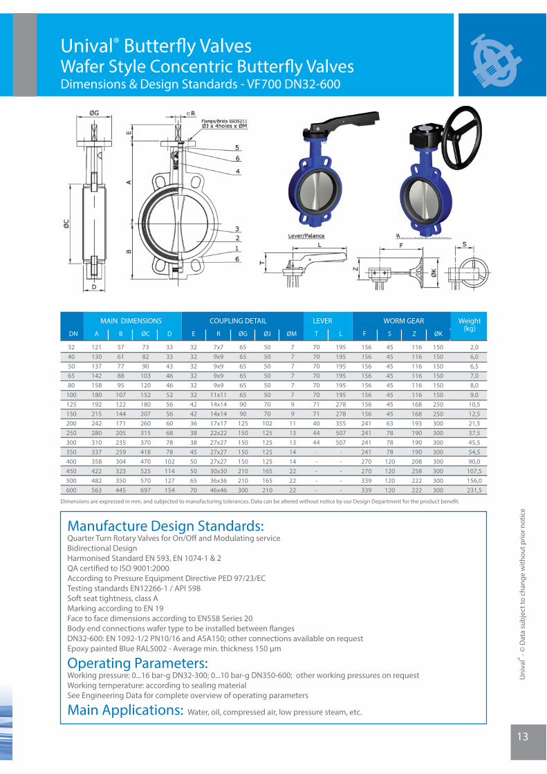
Unival® Butterfl y Valves Wafer Style Concentric Butterfl y ValvesDimensions & Design Standards - VF700 DN32-600
Manufacture Design Standards:Quarter Turn Rotary Valves for On/Off and Modulating serviceBidirectional DesignHarmonised Standard EN 593, EN 1074-1 & 2QA certifi ed to ISO 9001:2000According to Pressure Equipment Directive PED 97/23/ECTesting standards EN12266-1 / API 598Soft seat tightness, class AMarking according to EN 19Face to face dimensions according to EN558 Series 20Body end connections wafer type to be installed between fl angesDN32-600: EN 1092-1/2 PN10/16 and ASA150; other connections available on requestEpoxy painted Blue RAL5002 - Average min. thickness 150 μm
Operating Parameters:Working pressure: 0...16 bar-g DN32-300; 0...10 bar-g DN350-600; other working pressures on requestWorking temperature: according to sealing materialSee Engineering Data for complete overview of operating parameters
Main Applications: Water, oil, compressed air, low pressure steam, etc.
DN A
MAIN DIMENSIONS COUPLING DETAIL WORM GEARLEVER
3240506580
100125150200250300350400450500600
B
121130137142158180192215242280310337358422482563
2,06,06,57,08,09,0
10,512,521,537,545,554,590,0
107,5156,0231,5
150150150150150150250250300300300300300300300300
116116116116116116168168193190190190208258222222
7x79x99x99x99x9
11x1114x1414x1417x1722x2227x2727x2727x2730x3036x3646x46
32323232323242423638384550506570
333343464652565660687878
102114127154
738290
103120152180207260315370418470525570697
5761778895
107122144171205235259304323350445
454545454545454563787878
120120120120
ØK
156156156156156156156156241241241241270270339339
77777799
1113131414222222
7070707070707171404444-----
195195195195195195278278355507507
-----
6565656565659090
125150150150150210210300
5050505050507070
102125125125125165165210
REDØC F S ZØG ØJ ØM T L
Weight (kg)
Uni
val®
- © D
ata
subj
ect t
o ch
ange
with
out p
rior n
otic
e
Uni
val®
- © D
ata
subj
ect t
o ch
ange
with
out p
rior n
otic
e
14
Dimensions are expressed in mm, and subjected to manufacturing tolerances. Data can be altered without notice by our Design Department for the product benefi t.
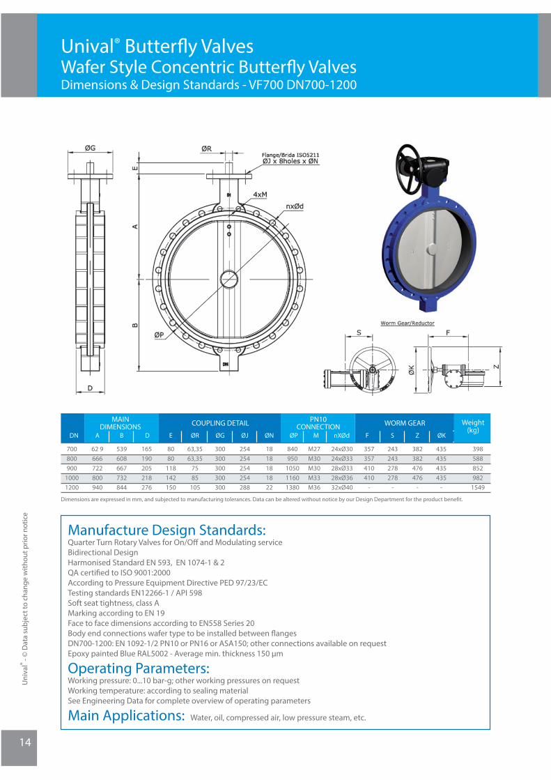
Unival® Butterfl y Valves Wafer Style Concentric Butterfl y ValvesDimensions & Design Standards - VF700 DN700-1200
Manufacture Design Standards:Quarter Turn Rotary Valves for On/Off and Modulating serviceBidirectional DesignHarmonised Standard EN 593, EN 1074-1 & 2QA certifi ed to ISO 9001:2000According to Pressure Equipment Directive PED 97/23/ECTesting standards EN12266-1 / API 598Soft seat tightness, class AMarking according to EN 19Face to face dimensions according to EN558 Series 20Body end connections wafer type to be installed between fl angesDN700-1200: EN 1092-1/2 PN10 or PN16 or ASA150; other connections available on requestEpoxy painted Blue RAL5002 - Average min. thickness 150 μm
Operating Parameters:Working pressure: 0...10 bar-g; other working pressures on requestWorking temperature: according to sealing materialSee Engineering Data for complete overview of operating parameters
Main Applications: Water, oil, compressed air, low pressure steam, etc.
DN A
MAIN DIMENSIONS COUPLING DETAIL WORM GEARPN10
CONNECTION
700800900
10001200
B
62 9666722800940
398588852982
1549
435435435435
-
382382476476
-
300300300300300
63,3563,35
7585
105
8080
118142150
165190205218276
539608667732844
243243278278
-
ØK
357357410410
-
840950
105011601380
M27M30M30M33M36
24xØ3024xØ3328xØ3328xØ3632xØ40
254254254254288
1818181822
ØGØRED F S ZØJ ØN ØP M nXØd
Weight (kg)
15
Dimensions are expressed in mm, and subjected to manufacturing tolerances. Data can be altered without notice by our Design Department for the product benefi t.
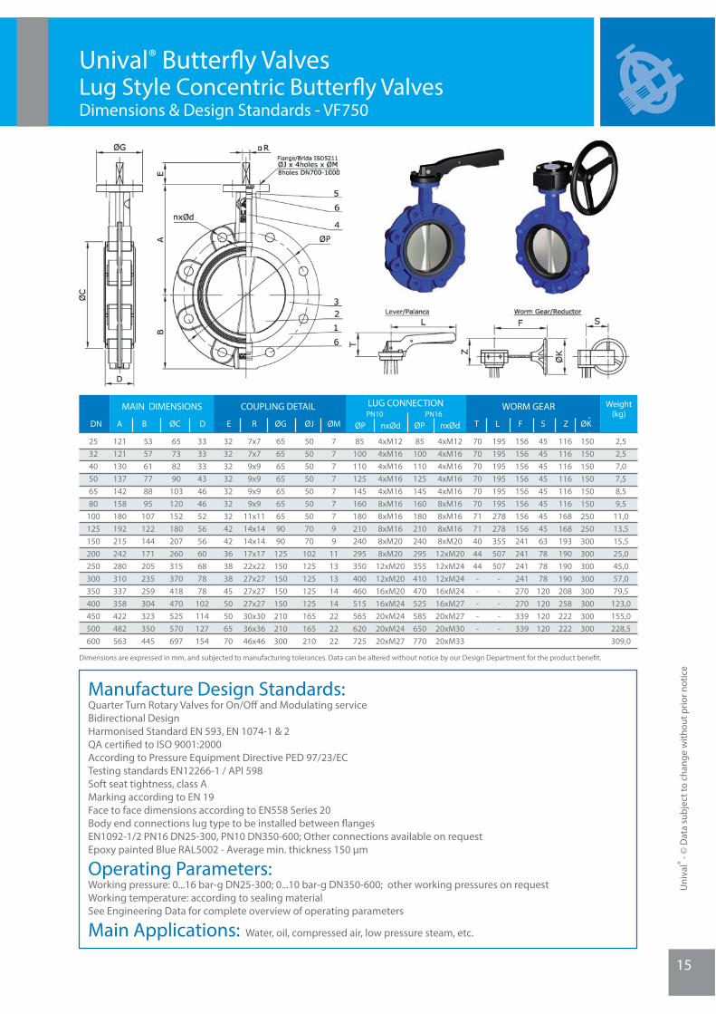
Unival® Butterfl y Valves Lug Style Concentric Butterfl y ValvesDimensions & Design Standards - VF750
Manufacture Design Standards:Quarter Turn Rotary Valves for On/Off and Modulating serviceBidirectional DesignHarmonised Standard EN 593, EN 1074-1 & 2QA certifi ed to ISO 9001:2000According to Pressure Equipment Directive PED 97/23/ECTesting standards EN12266-1 / API 598Soft seat tightness, class AMarking according to EN 19Face to face dimensions according to EN558 Series 20Body end connections lug type to be installed between fl angesEN1092-1/2 PN16 DN25-300, PN10 DN350-600; Other connections available on requestEpoxy painted Blue RAL5002 - Average min. thickness 150 μm
Operating Parameters:Working pressure: 0...16 bar-g DN25-300; 0...10 bar-g DN350-600; other working pressures on requestWorking temperature: according to sealing materialSee Engineering Data for complete overview of operating parameters
Main Applications: Water, oil, compressed air, low pressure steam, etc.
DN A
MAIN DIMENSIONS COUPLING DETAIL LUG CONNECTION WORM GEAR
253240506580
100125150200250300350400450500600
B
121121130137142158180192215242280310337358422482563
2,52,57,07,58,59,5
11,013,515,525,045,057,079,5
123,0155,0228,5309,0
150150150150150150250250300300300300300300300300
116116116116116116168168193190190190208258222222
7x77x79x99x99x99x9
11x1114x1414x1417x1722x2227x2727x2727x2730x3036x3646x46
3232323232323242423638384550506570
33333343464652565660687878
102114127154
65738290
103120152180207260315370418470525570697
535761778895
107122144171205235259304323350445
454545454545454563787878
120120120120
ØK
156156156156156156156156241241241241270270339339
777777799
1113131414222222
7070707070707171404444-----
195195195195195195278278355507507
-----
656565656565659090
125150150150150210210300
505050505050507070
102125125125125165165210
REDØC F S ZØG ØJ ØM T L
Weight (kg)
nxØdØP
85100110125145160180210240295350400460515565620725
4xM124xM164xM164xM164xM168xM168xM168xM168xM208xM20
12xM2012xM2016xM2016xM2420xM2420xM2420xM27
4xM124xM164xM164xM164xM168xM168xM168xM168xM20
12xM2012xM2412xM2416xM2416xM2720xM2720xM3020xM33
85100110125145160180210240295355410470525585650770
PN16PN10
nxØdØP
Uni
val®
- © D
ata
subj
ect t
o ch
ange
with
out p
rior n
otic
e
Uni
val®
- © D
ata
subj
ect t
o ch
ange
with
out p
rior n
otic
e
16
Dimensions are expressed in mm, and subjected to manufacturing tolerances. Data can be altered without notice by our Design Department for the product benefi t.
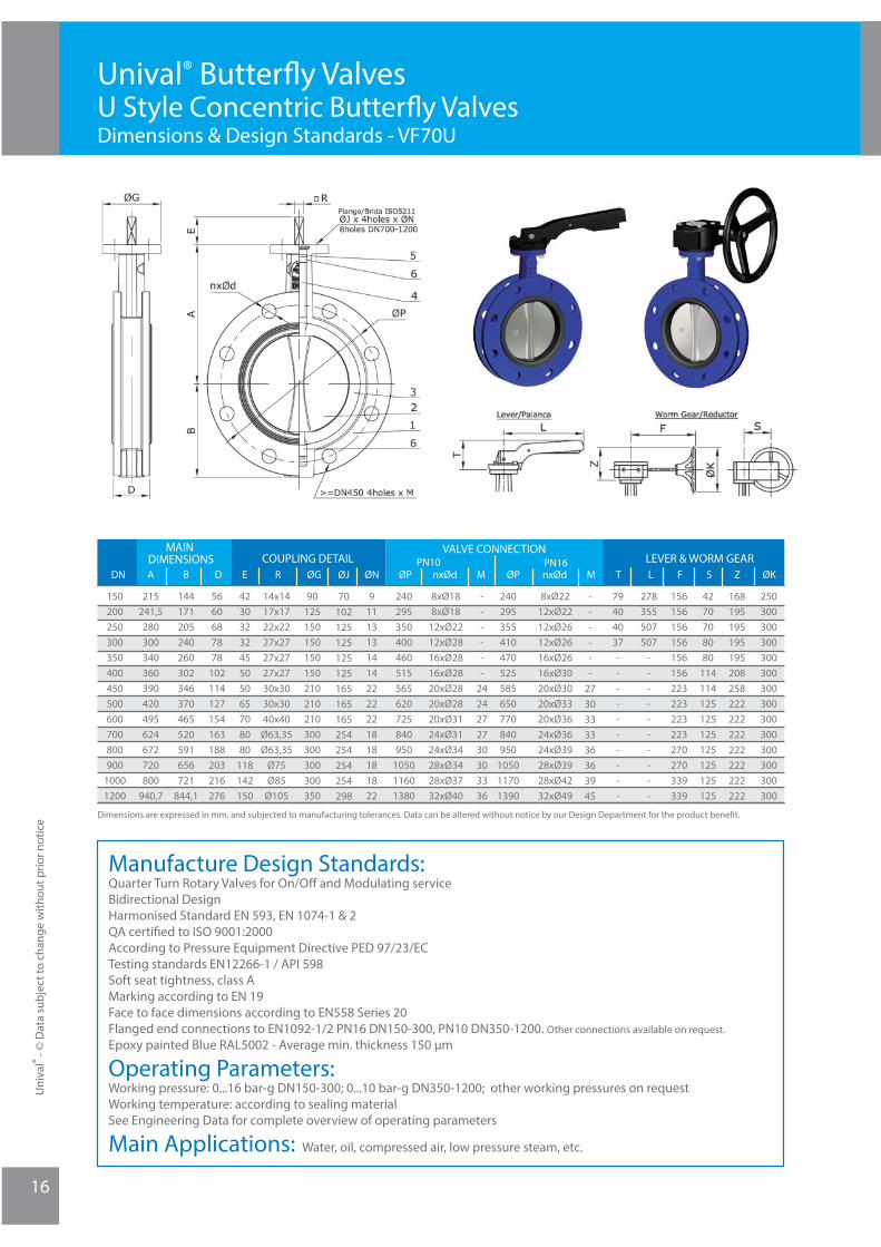
Unival® Butterfl y Valves U Style Concentric Butterfl y ValvesDimensions & Design Standards - VF70U
Manufacture Design Standards:Quarter Turn Rotary Valves for On/Off and Modulating serviceBidirectional DesignHarmonised Standard EN 593, EN 1074-1 & 2QA certifi ed to ISO 9001:2000According to Pressure Equipment Directive PED 97/23/ECTesting standards EN12266-1 / API 598 Soft seat tightness, class AMarking according to EN 19Face to face dimensions according to EN558 Series 20Flanged end connections to EN1092-1/2 PN16 DN150-300, PN10 DN350-1200. Other connections available on request.Epoxy painted Blue RAL5002 - Average min. thickness 150 μm
Operating Parameters:Working pressure: 0...16 bar-g DN150-300; 0...10 bar-g DN350-1200; other working pressures on requestWorking temperature: according to sealing materialSee Engineering Data for complete overview of operating parameters
Main Applications: Water, oil, compressed air, low pressure steam, etc.
DN A
MAIN DIMENSIONS COUPLING DETAIL
VALVE CONNECTIONLEVER & WORM GEAR
150200250300350400450500600700800900
10001200
B nxØdØP
215241,5280300340360390420495624672720800
940,7
250300300300300300300300300300300300300300
ØKZ
168195195195195208258222222222222222222222
4270708080
114114125125125125125125125
911131314142222221818181822
70102125125125125165165165254254254254298
90125150150150150210210210300300300300350
14x1417x1722x2227x2727x2727x2730x3030x3040x40
Ø63,35Ø63,35
Ø75Ø85
Ø105
4230323245505065708080
118142150
144171205240260302346370465520591656721
844,1
156156156156156156223223223223270270339339
S
278355507507
----------
79404037----------
------
2730333336363945
240295355410470525585650770840950
105011701390
8xØ2212xØ2212xØ2612xØ2616xØ2616xØ3020xØ3020xØ3320xØ3624xØ3624xØ3928xØ3928xØ4232xØ49
240295350400460515565620725840950
105011601380
8xØ188xØ18
12xØ2212xØ2816xØ2816xØ2820xØ2820xØ2820xØ3124xØ3124xØ3428xØ3428xØ3732xØ40
ØNØGE R nxØdØPPN16PN10
M L FTM
------
2424272730303336
5660687878
102114127154163188203216276
D ØJ
17
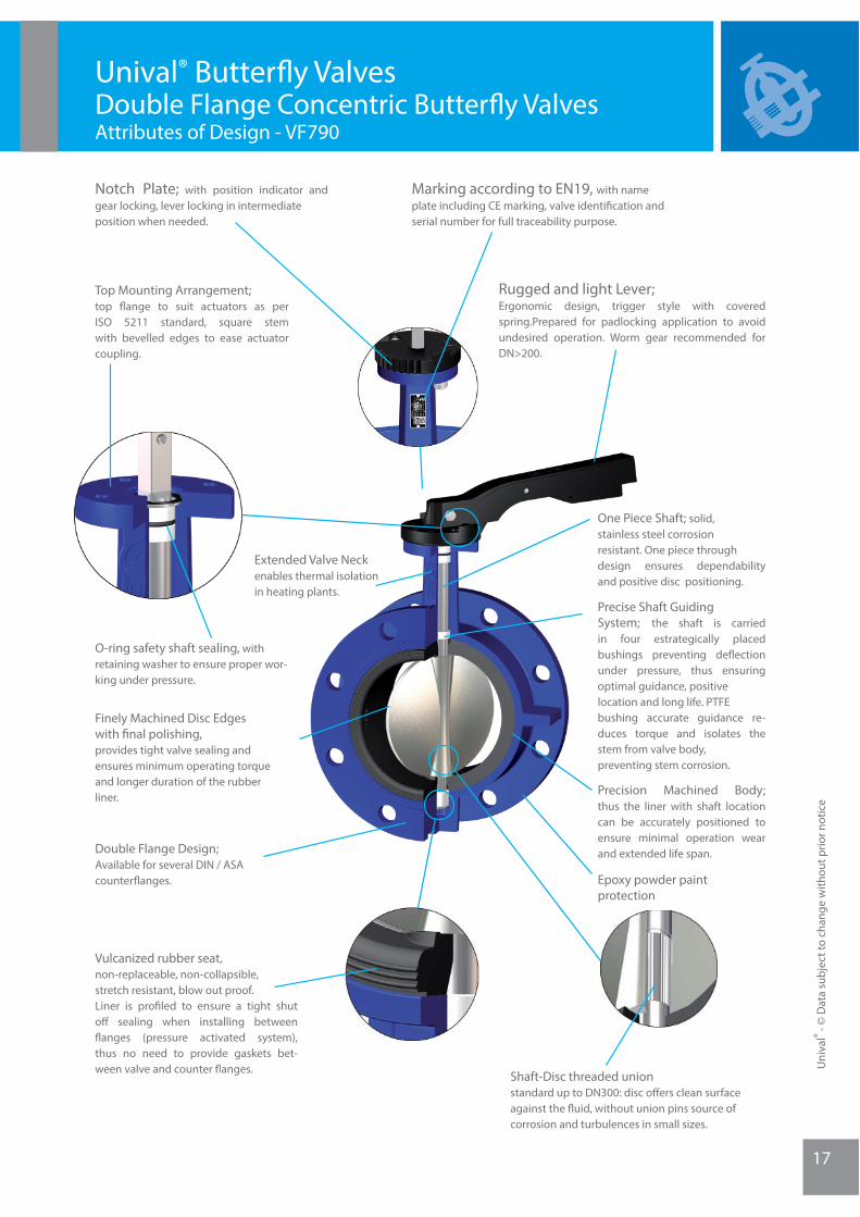
Unival® Butterfl y Valves Double Flange Concentric Butterfl y ValvesAttributes of Design - VF790
Rugged and light Lever; Ergonomic design, trigger style with covered spring.Prepared for padlocking application to avoid undesired operation. Worm gear recommended for DN>200.
Notch Plate; with position indicator and gear locking, lever locking in intermediate position when needed.
Top Mounting Arrangement; top fl ange to suit actuators as per ISO 5211 standard, square stem with bevelled edges to ease actuator coupling.
O-ring safety shaft sealing, with retaining washer to ensure proper wor-king under pressure.
Extended Valve Neck enables thermal isolation in heating plants.
Double Flange Design; Available for several DIN / ASA counterfl anges.
Finely Machined Disc Edges with fi nal polishing, provides tight valve sealing and ensures minimum operating torque and longer duration of the rubber liner.
One Piece Shaft; solid, stainless steel corrosion resistant. One piece through design ensures dependability and positive disc positioning.
Precise Shaft Guiding System; the shaft is carried in four estrategically placed bushings preventing defl ection under pressure, thus ensuring optimal guidance, positive location and long life. PTFEbushing accurate guidance re-duces torque and isolates the stem from valve body, preventing stem corrosion.
Precision Machined Body; thus the liner with shaft location can be accurately positioned to ensure minimal operation wear and extended life span.
Epoxy powder paint protection
Vulcanized rubber seat, non-replaceable, non-collapsible, stretch resistant, blow out proof.Liner is profi led to ensure a tight shut off sealing when installing between fl anges (pressure activated system), thus no need to provide gaskets bet-ween valve and counter fl anges. Shaft-Disc threaded union
standard up to DN300: disc off ers clean surface against the fl uid, without union pins source of corrosion and turbulences in small sizes.
Marking according to EN19, with name plate including CE marking, valve identifi cation and serial number for full traceability purpose.
Uni
val®
- © D
ata
subj
ect t
o ch
ange
with
out p
rior n
otic
e

18
Unival® Butterfl y Valves Double Flange Concentric Butterfl y ValvesParts and Materials - VF790
Nº Part
Butyl Rubber (BR)
1
2
3
4
5
6
7
8
9
10
11
13
14
15
Material
BODY
DISC
LINER
STEM
O-RING
BUSHINGS
WASHER
CIRCLIP
NOTCH PLATE
HAND LEVER
STUDS
WASHERS
NUT
WORM GEAR
Cast Iron EN-JL1040 (GG25) / Ductile Iron EN-JS1030 (GGG40) / St. Steel A351 CF8M / Carbon Steel A216 WCB
Nickel Plated Ductile Iron EN-JS1030 (GGG40) / St. Steel CF8M / Al-Bronze / FEP or PFA Coated
NBR / EPDM / Viton / Hypalon / Silicon / PTFE / FEP / PFA
St. Steel AISI 416
NBR, EPDM
PTFE
Steel
Steel
Aluminium
Aluminium / Ductile Iron
Steel
Steel
Steel
Ductile Iron
Uni
val®
- © D
ata
subj
ect t
o ch
ange
with
out p
rior n
otic
e
19
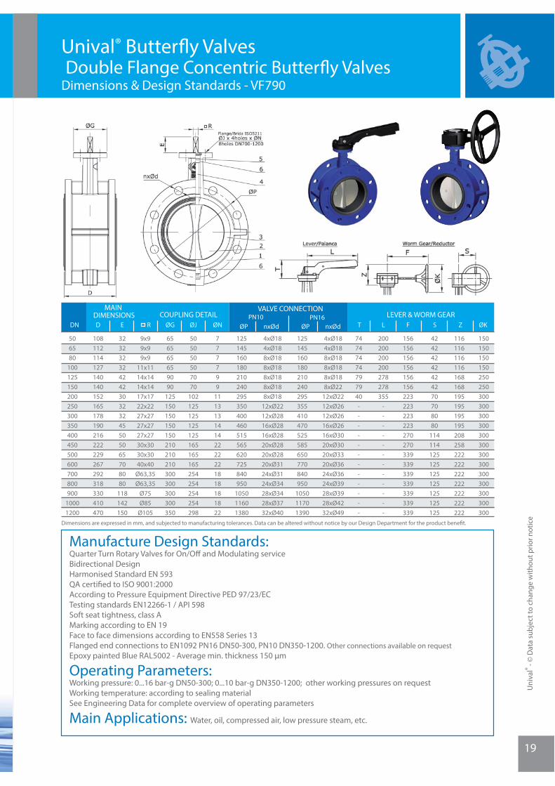
Unival® Butterfl y Valves Double Flange Concentric Butterfl y ValvesDimensions & Design Standards - VF790
Manufacture Design Standards:Quarter Turn Rotary Valves for On/Off and Modulating serviceBidirectional DesignHarmonised Standard EN 593QA certifi ed to ISO 9001:2000According to Pressure Equipment Directive PED 97/23/ECTesting standards EN12266-1 / API 598Soft seat tightness, class AMarking according to EN 19Face to face dimensions according to EN558 Series 13Flanged end connections to EN1092 PN16 DN50-300, PN10 DN350-1200. Other connections available on requestEpoxy painted Blue RAL5002 - Average min. thickness 150 μm
Operating Parameters:Working pressure: 0...16 bar-g DN50-300; 0...10 bar-g DN350-1200; other working pressures on requestWorking temperature: according to sealing materialSee Engineering Data for complete overview of operating parameters
Main Applications: Water, oil, compressed air, low pressure steam, etc.
Uni
val®
- © D
ata
subj
ect t
o ch
ange
with
out p
rior n
otic
eDimensions are expressed in mm, and subjected to manufacturing tolerances. Data can be altered without notice by our Design Department for the product benefi t.
DN D
MAIN DIMENSIONS COUPLING DETAIL
VALVE CONNECTIONLEVER & WORM GEAR
506580
100125150200250300350400450500600700800900
10001200
E nxØdØP
108112114127140140152165178190216222229267292318330410470
150150150150250250300300300300300300300300300300300300300
ØKZ
116116116116168168195195195195208258222222222222222222222
42424242424270708080
114114125125125125125125125
777799
11131314142222221818181822
505050507070
102125125125125165165165254254254254298
656565659090
125150150150150210210210300300300300350
9x99x99x9
11x1114x1414x1417x1722x2227x2727x2727x2730x3030x3040x40
Ø63,35Ø63,35
Ø75Ø85
Ø105
32323232424230323245505065708080
118142150
156156156156156156223223223223270270339339339339339339339
S
200200200200278278355
------------
74747474797940------------
125145160180210240295355410470525585650770840950
105011701390
4xØ184xØ188xØ188xØ188xØ188xØ22
12xØ2212xØ2612xØ2616xØ2616xØ3020xØ3020xØ3320xØ3624xØ3624xØ3928xØ3928xØ4232xØ49
125145160180210240295350400460515565620725840950
105011601380
4xØ184xØ188xØ188xØ188xØ188xØ188xØ18
12xØ2212xØ2816xØ2816xØ2820xØ2820xØ2820xØ3124xØ3124xØ3428xØ3428xØ3732xØ40
ØNØJØGR nxØdØPPN16PN10
T L F
Uni
val®
- © D
ata
subj
ect t
o ch
ange
with
out p
rior n
otic
e
20
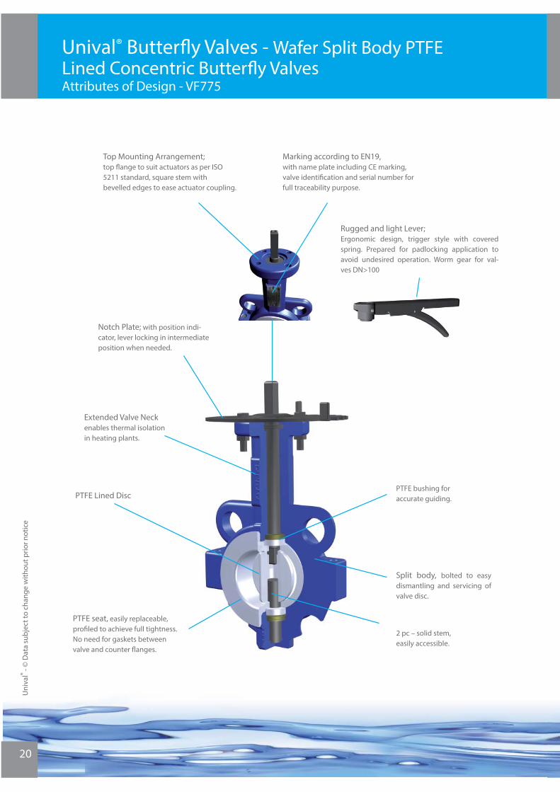
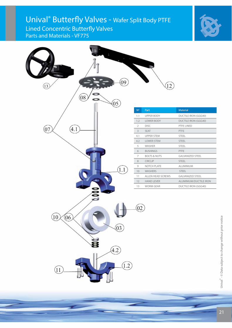
Unival® Butterfl y Valves - Wafer Split Body PTFE Lined Concentric Butterfl y ValvesAttributes of Design - VF775
Rugged and light Lever; Ergonomic design, trigger style with covered spring. Prepared for padlocking application to avoid undesired operation. Worm gear for val-ves DN>100
Notch Plate; with position indi-cator, lever locking in intermediate position when needed.
Top Mounting Arrangement;top fl ange to suit actuators as per ISO 5211 standard, square stem with bevelled edges to ease actuator coupling.
Extended Valve Neck enables thermal isolation in heating plants.
PTFE Lined Disc
Split body, bolted to easy dismantling and servicing of valve disc.
PTFE bushing for accurate guiding.
2 pc – solid stem, easily accessible.
PTFE seat, easily replaceable, profi led to achieve full tightness.No need for gaskets between valve and counter fl anges.
Marking according to EN19, with name plate including CE marking, valve identifi cation and serial number for full traceability purpose.
21
Unival® Butterfl y Valves - Wafer Split Body PTFELined Concentric Butterfl y ValvesParts and Materials - VF775
Nº Part
Butyl Rubber (BR)
1.1
1.2
2
3
4.1
4.2
5
6
7
8
9
10
11
12
13
Material
UPPER BODY
LOWER BODY
DISC
SEAT
UPPER STEM
LOWER STEM
WASHER
BUSHINGS
BOLTS & NUTS
CIRCLIP
NOTCH PLATE
WASHERS
ALLEN HEAD SCREWS
HAND LEVER
WORM GEAR
DUCTILE IRON (GGG40)
DUCTILE IRON (GGG40)
PTFE LINED
PTFE
STEEL
STEEL
STEEL
PTFE
GALVANIZED STEEL
STEEL
ALUMINIUM
STEEL
GALVANIZED STEEL
ALUMINIUM/DUCTILE IRON
DUCTILE IRON (GGG40)
Uni
val®
- © D
ata
subj
ect t
o ch
ange
with
out p
rior n
otic
e
Uni
val®
- © D
ata
subj
ect t
o ch
ange
with
out p
rior n
otic
e
22
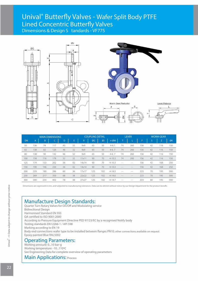
Unival® Butterfl y Valves - Wafer Split Body PTFE Lined Concentric Butterfl y ValvesDimensions & Design S tandards - VF775
Manufacture Design Standards:Quarter Turn Rotary Valves for On/Off and Modulating serviceBidirectional DesignHarmonised Standard EN 593QA certifi ed to ISO 9001:2000According to Pressure Equipment Directive PED 97/23/EC by a recognised Notify bodyTesting standards EN12266-1 / API 598Marking according to EN 19Body end connections wafer type to be installed between fl anges PN10; other connections available on requestEpoxy painted Blue RAL5002
Operating Parameters:Working pressure: 0...10 bar-gWorking temperature: -10...110ºCSee Engineering Data for complete overview of operating parameters
Main Applications: Process
Dimensions are expressed in mm, and subjected to manufacturing tolerances. Data can be altered without notice by our Design Department for the product benefi t.
DN A
COUPLING DETAILMAIN DIMENSIONS
Butyl Rubber (BR)
50
65
80
100
125
150
200
250
300
REB C D F
LEVERLTn-ØMØJØG
WORM GEARØKZS
136
138
138
158
174
190
229
269
300
74
82
90
116
133
146
180
217
254
43
46
46
52
56
56
60
68
78
117
126
142
178
202
234
286
350
402
32
32
32
32
42
42
36
38
38
9x9
9x9
9x9
11x11
14x14
14x14
17x17
22x22
27x27
65
65
65
90
90
90
125
125
125
50
50
50
70
70
70
102
102
102
4-6.7
4-6. 7
4-6. 7
4-10.3
4-10.3
4-10.3
4-14.5
4-14.6
4-14.7
74
74
74
74
---
---
---
---
---
260
260
260
200
---
---
---
---
---
156
156
156
156
156
156
223
223
223
42
42
42
42
42
42
70
70
80
116
116
116
116
168
168
195
195
195
150
150
150
150
250
250
300
300
300
23
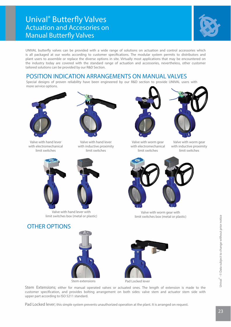
UNIVAL butterfl y valves can be provided with a wide range of solutions on actuation and control accessories which is all packaged at our works according to customer specifi cations. The modular system permits to distributors and plant users to assemble or replace the diverse options in site. Virtually most applications that may be encountered on the industry today are covered with the standard range of actuation and accessories, nevertheless, other customer tailored solutions can be provided by our R&D Section.
POSITION INDICATION ARRANGEMENTS ON MANUAL VALVES
Valve with worm gear withlimit switches box (metal or plastic)
Valve with hand leverwith electromechanical
limit switches
Valve with hand leverwith inductive proximity
limit switches
Valve with hand lever withlimit switches box (metal or plastic)
Valve with worm gearwith electromechanical
limit switches
Valve with worm gearwith inductive proximity
limit switches
Special designs of proven reliability have been engineered by our R&D section to provide UNIVAL users with more service options.
Pad Locked lever
OTHER OPTIONS
Stem extensions
Stem Extensions; either for manual operated valves or actuated ones. The length of extension is made to the customer specifi cation, and provides bolting arrangement on both sides: valve stem and actuator stem side with upper part according to ISO 5211 standard.
Pad Locked lever; this simple system prevents unauthorized operation at the plant. It is arranged on request.
Unival® Butterfl y Valves Actuation and Accesories on Manual Butterfl y Valves
Uni
val®
- © D
ata
subj
ect t
o ch
ange
with
out p
rior n
otic
e
Uni
val®
- © D
ata
subj
ect t
o ch
ange
with
out p
rior n
otic
e
24
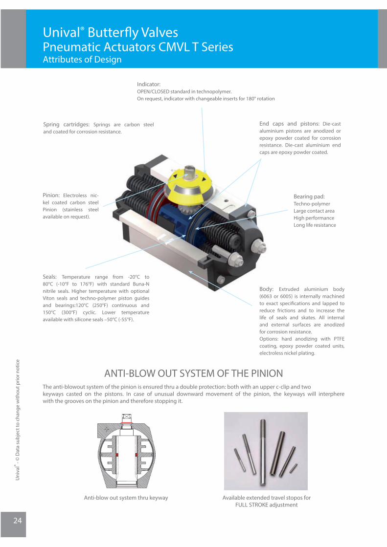
Unival® Butterfl y ValvesPneumatic Actuators CMVL T SeriesAttributes of Design
Spring cartridges: Springs are carbon steel and coated for corrosion resistance.
Pinion: Electroless nic-kel coated carbon steel Pinion (stainless steel available on request).
Seals: Temperature range from -20°C to 80°C (-10°F to 176°F) with standard Buna-N nitrile seals. Higher temperature with optional Viton seals and techno-polymer piston guides and bearings:120°C (250°F) continuous and 150°C (300°F) cyclic. Lower temperature available with silicone seals –50°C (-55°F).
Indicator:OPEN/CLOSED standard in technopolymer.On request, indicator with changeable inserts for 180° rotation
End caps and pistons: Die-cast aluminium pistons are anodized or epoxy powder coated for corrosion resistance. Die-cast aluminium end caps are epoxy powder coated.
Bearing pad:Techno-polymerLarge contact areaHigh performanceLong life resistance
Body: Extruded aluminium body (6063 or 6005) is internally machined to exact specifi cations and lapped to reduce frictions and to increase the life of seals and skates. All internal and external surfaces are anodized for corrosion resistance. Options: hard anodizing with PTFE coating, epoxy powder coated units, electroless nickel plating.
Anti-blow out system thru keyway Available extended travel stopos forFULL STROKE adjustment
ANTI-BLOW OUT SYSTEM OF THE PINIONThe anti-blowout system of the pinion is ensured thru a double protection: both with an upper c-clip and two keyways casted on the pistons. In case of unusual downward movement of the pinion, the keyways will interphere with the grooves on the pinion and therefore stopping it.

25
Unival® Butterfl y Valves Pneumatic Actuators CMVL T SeriesGeneral Design Considerations
• The CMVL T rack & pinion pneumatic actuator produces linear torque output in a compact design utilizing the same body and end caps for double acting and spring return units.
• Namur VDI/VDE 3845 and ISO 5211 dimensions on all sizes. No special blocks are required to mount solenoid valves, limit switches or positioners.
• The standard angle of rotation is 90°. Additional travel rotations of 120°, 135°, 150° and 180° are available. T15 and upper sizes feature a travel stop with ± 10° in both open and close directions (International Patent).
• The female pinion drive is standard with a double square output drive, and optional with a double-D drive, keyed drive and designs to meet your specifi c requirements.
• Shaft bearings isolate the pinion gear from the housing and support the shaft for high cycle applications.
• The pinion teeth are engaged for the full length and stroke of the piston.
• The pinion height allows manual override without disturbing the indicated positions.
• External open/closed indicator is standard, available indicators for all the rotations.
• Pistons incorporate double wear pads to separate the rack from the actuator wall and serve as both guide and wear bearings.
• T series pistons feature a keyway as anti-blowout system.
• All internal and external components are treated to increase corrosion resistance.
• Epoxy coated special steel springs are pre-loaded.
• The stainless steel end cap fasteners are extra long to allow for spring relaxation. All parts are corrosion resistant.
• Air pressure operation from 2 to 10 Bar (40 – 150 PSI). Water, nitrogen and compatible hydraulic fl uids may also be used to power the actuator.
• All external fasteners are corrosion resistant stainless steel.
• All units are permanently lubricated at the factory with non-silicone grease.
• All units are externally stamped with a progressive traceable serial number.
• 100% of all units are factory pressure leak tested, and individually boxed for shipment.
OPEN/CLOSED standard for 90°
Indicator with changeable inserts for 180° and special
rotation.
Indicator with metallic insert to activate external proximity
sensors.
INDICATORS
Uni
val®
- © D
ata
subj
ect t
o ch
ange
with
out p
rior n
otic
e
Uni
val®
- © D
ata
subj
ect t
o ch
ange
with
out p
rior n
otic
e
26
Unival® Butterfl y ValvesPneumatic Actuators CMVL T SeriesBi-Directional Patented Travel Stop Illustration
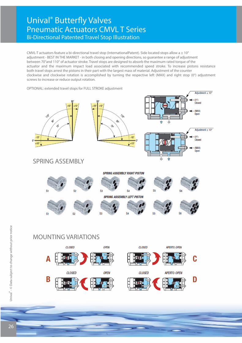
CMVL-T actuators feature a bi-directional travel stop (InternationalPatent). Side located stops allow a ± 10° adjustment - BEST IN THE MARKET - in both closing and opening directions, so guarantee a range of adjustment between 70°and 110° of actuator stroke. Travel stops are designed to absorb the maximum rated torque of the actuator and the maximum impact load associated with recommended speed stroke. To increase pistons resistance both travel stops arrest the pistons in their part with the largest mass of material. Adjustment of the counter clockwise and clockwise rotation is accomplished by turning the respective left (MAX) and right stop (0°) adjustment screws to increase or reduce output rotation.
OPTIONAL: extended travel stops for FULL STROKE adjustment
SPRING ASSEMBLY
MOUNTING VARIATIONS

27
Unival® Butterfl y Valves Pneumatic Actuators CMVL T SeriesSpecial Coatings
ANODIZED
ANODIZED WITH EXPOY COATING
ELECTROLESS NICKEL INFUSED
ANODIZED WITH PTFE COATING
Descripción Color Application
Uniform coating of 25 μ thickness, extremely hard (45-65 HRC) and resistan to abra-sion.Good corrosion resistance in environments with pH from 4.5 to 8.5 and salt fog test.
Silver-gray Industry general use.Non recommended for Highly acidic or basic environments
Descripción Color Application
Thick powder coating (80 – 100 μ ) which creates a barrier against many of the chemicals which anodizing alone can not adequately resist. It will resist more acidic or basic environ-ments than anodizing alone. Good results in salt fog test.
Black (standard)Other color available
Industry general use.Suitable for low concentra-tions of caustic washdown solution. Will not withstand high acids and alkali.
Descripción Color Application
Uniform coating of 20 – 30 μ , also on sharp corners, holes and threads, with 45-55 HRC hardness and therefore resis-tant to incidental damages. The coating will provide en-hanced corrosion protection in very acidic environments but will not withstand attack from strong alkaline media.
Shiny silver, similar to stainless steel
Industry general use. Suitable for low to medium concentra-tions of caustic washdown solutions. Also suitable for low alkaline solutions and de-tergents in food and sanitary applications.
Descripción Color Application
This coating provides comple-te surface coverage and ex-hibits excellent corrosion re-sistance properties in a wide variety of applications.
Black These coatings are resistant to any environment into which an actuator would be insta-lled. Provided the integrity of the surface is intact, the coa-ting can resist a broad array of chemical environments, low alcaline and low acid so-lutions, marine environment, even at high temperature
Uni
val®
- © D
ata
subj
ect t
o ch
ange
with
out p
rior n
otic
e
Uni
val®
- © D
ata
subj
ect t
o ch
ange
with
out p
rior n
otic
e
28
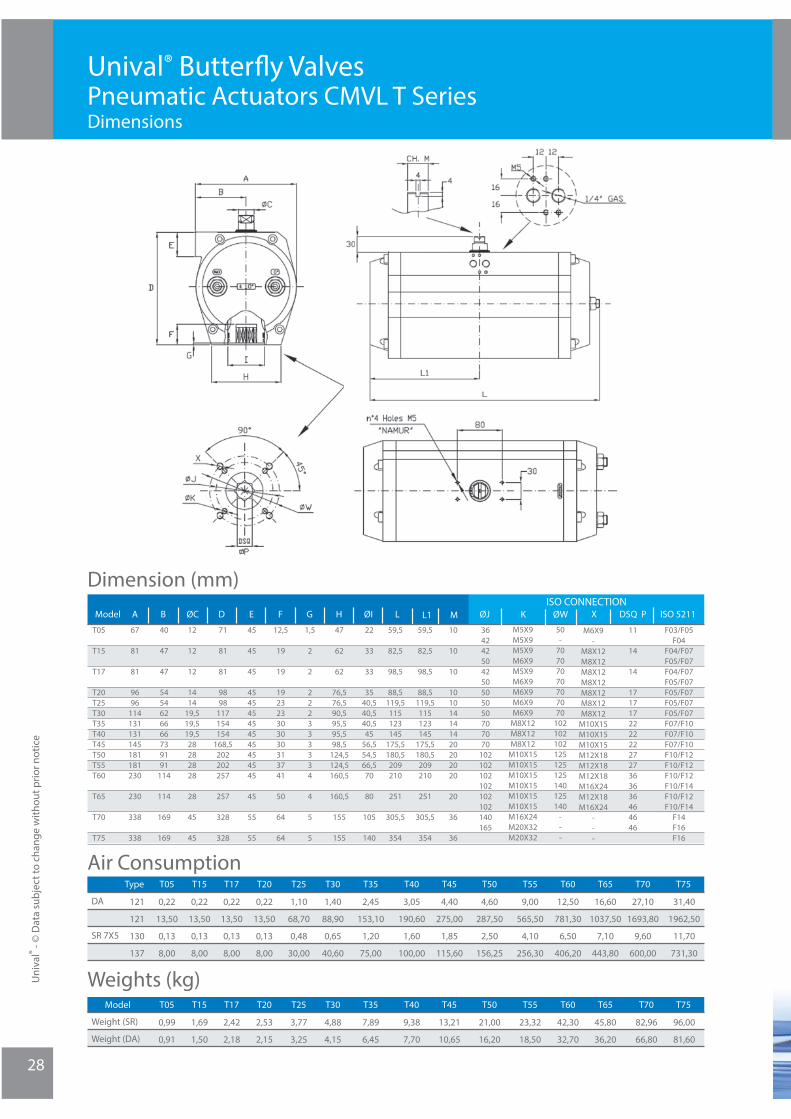
Unival® Butterfl y Valves Pneumatic Actuators CMVL T SeriesDimensions
Dimension (mm)
Air Consumption
Weights (kg)
Model A B ØC ISO 5211DSQ PXØWKØJISO CONNECTION
67
81
81
9696
114131131145181181230
230
338
338
40
47
47
5454626666739191
114
114
169
169
12
12
12
1414
19,519,519,528282828
28
45
45
45
45
45
454545454545454545
45
55
55
12,5
19
19
192323303030313741
50
64
64
1,5
2
2
222333334
4
5
5
47
62
62
76,576,590,595,595,598,5
124,5124,5160,5
160,5
155
155
22
33
33
3540,540,540,545
56,554,566,570
80
105
140
59,5
82,5
98,5
88,5119,5115123145
175,5180,5209210
251
305,5
354
D
71
81
81
9898
117154154
168,5202202257
257
328
328
E F G H ØI L L1 M
59,5
82,5
98,5
88,5119,5115123145
175,5180,5209210
251
305,5
354
10
10
10
101014141420202020
20
36
36
F03/F05F04
F04/F07F05/F07F04/F07F05/F07F05/F07F05/F07F05/F07F07/F10F07/F10F07/F10F10/F12F10/F12F10/F12F10/F14F10/F12F10/F14
F14F16F16
364242504250505050707070
102102102102102102140165
M5X9 M5X9M5X9M6X9M5X9 M6X9M6X9M6X9M6X9
M8X12M8X12M8X12
M10X15M10X15M10X15M10X15M10X15M10X15M16X24M20X32M20X32
50-
707070 70707070
102102102125125125140125140
---
M6X9-
M8X12M8X12M8X12M8X12M8X12M8X12M8X12
M10X15M10X15M10X15M12X18M12X18M12X18M16X24M12X18M16X24
---
11
14
14
1717172222222727363636464646
T05
T15
T17
T20T25T30T35T40T45T50T55T60
T65
T70
T75
Butyl Rubber (BR)
DA
SR 7X5
T25T20
121
121
130
137
T05 T15 T17 T55T50T45T35T30 T75T70T65T60T40Type
0,22
13,50
0,13
8,00
0,22
13,50
0,13
8,00
0,22
13,50
0,13
8,00
0,22
13,50
0,13
8,00
1,10
68,70
0,48
30,00
1,40
88,90
0,65
40,60
2,45
153,10
1,20
75,00
3,05
190,60
1,60
100,00
4,40
275,00
1,85
115,60
4,60
287,50
2,50
156,25
9,00
565,50
4,10
256,30
12,50
781,30
6,50
406,20
16,60
1037,50
7,10
443,80
27,10
1693,80
9,60
600,00
31,40
1962,50
11,70
731,30
Weight (SR)
Weight (DA)
T25T20T05 T15 T17 T55T50T45T35T30 T75T70T65T60T40Model
0,99
0,91
1,69
1,50
2,42
2,18
2,53
2,15
3,77
3,25
4,88
4,15
7,89
6,45
9,38
7,70
13,21
10,65
21,00
16,20
23,32
18,50
42,30
32,70
45,80
36,20
82,96
66,80
96,00
81,60
29
Unival® Butterfl y Valves Pneumatic Actuators CMVL T SeriesSpring Return Actuator Sizing
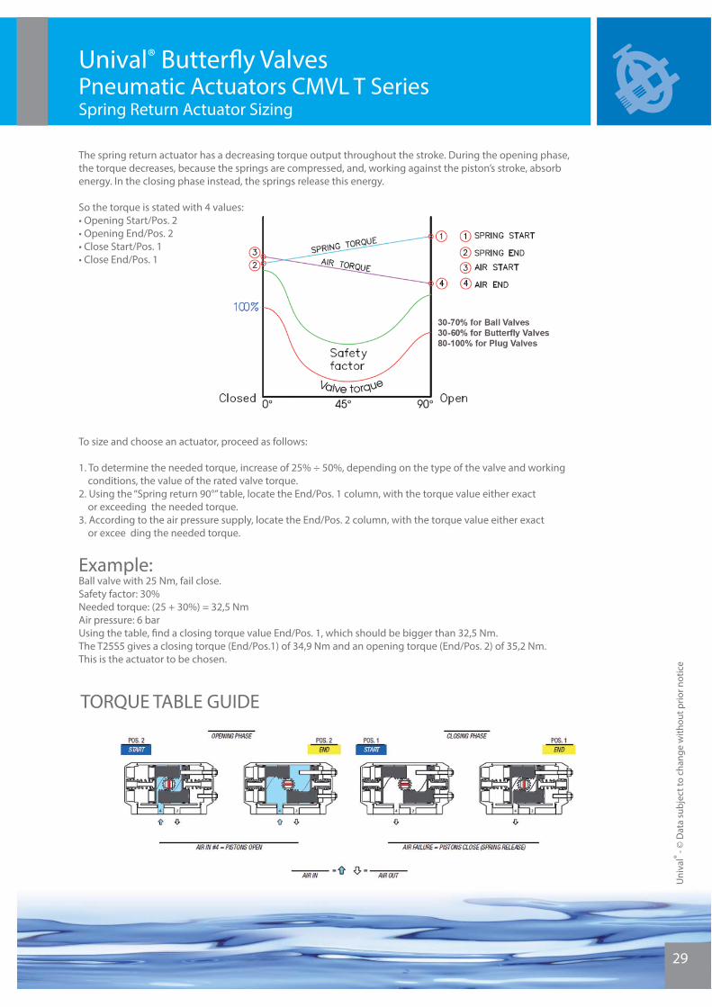
To size and choose an actuator, proceed as follows:
1. To determine the needed torque, increase of 25% ÷ 50%, depending on the type of the valve and working conditions, the value of the rated valve torque.2. Using the “Spring return 90°” table, locate the End/Pos. 1 column, with the torque value either exact or exceeding the needed torque.3. According to the air pressure supply, locate the End/Pos. 2 column, with the torque value either exact or excee ding the needed torque.
Example:Ball valve with 25 Nm, fail close.Safety factor: 30%Needed torque: (25 + 30%) = 32,5 NmAir pressure: 6 barUsing the table, fi nd a closing torque value End/Pos. 1, which should be bigger than 32,5 Nm.The T25S5 gives a closing torque (End/Pos.1) of 34,9 Nm and an opening torque (End/Pos. 2) of 35,2 Nm.This is the actuator to be chosen.
TORQUE TABLE GUIDE
The spring return actuator has a decreasing torque output throughout the stroke. During the opening phase, the torque decreases, because the springs are compressed, and, working against the piston’s stroke, absorb energy. In the closing phase instead, the springs release this energy.
So the torque is stated with 4 values:• Opening Start/Pos. 2• Opening End/Pos. 2• Close Start/Pos. 1• Close End/Pos. 1
Uni
val®
- © D
ata
subj
ect t
o ch
ange
with
out p
rior n
otic
e
Uni
val®
- © D
ata
subj
ect t
o ch
ange
with
out p
rior n
otic
e
30
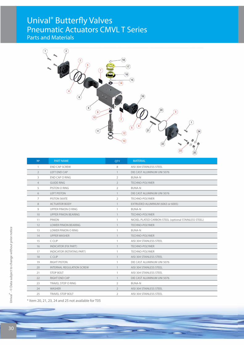
Unival® Butterfl y ValvesPneumatic Actuators CMVL T SeriesParts and Materials
* Item 20, 21, 23, 24 and 25 not available for T05
Nº PART NAME
Butyl Rubber (BR)
QTY MATERIAL
1
2
3
4
5
6
7
8
9
10
11
12
13
14
15
16
17
18
19
20
21
22
23
24
25
END CAP SCREW
LEFT END CAP
END CAP O RING
GUIDE RING
PISTON O RING
LEFT PISTON
PISTON SKATE
ACTUATOR BODY
UPPER PINION O RING
UPPER PINION BEARING
PINION
LOWER PINION BEARING
LOWER PINION O RING
UPPER WASHER
C CLIP
INDICATOR (FIX PART)
INDICATOR (ROTATING PART)
C CLIP
RIGHT PISTON
INTERNAL REGULATION SCREW
STOP BOLT
RIGHT END CAP
TRAVEL STOP O RING
WASHER
TRAVEL STOP BOLT
8
1
2
2
2
1
2
1
1
1
1
1
1
1
1
1
1
1
1
1
1
1
2
2
2
AISI 304 STAINLESS STEEL
DIE CAST ALUMINUM UNI 5076
BUNA-N
TECHNO-POLYMER
BUNA-N
DIE CAST ALUMINUM UNI 5076
TECHNO-POLYMER
EXTRUDED ALUMINUM (6063 or 6005)
BUNA-N
TECHNO-POLYMER
NICKEL PLATED CARBON STEEL (optional STAINLESS STEEL)
TECHNO-POLYMER
BUNA-N
TECHNO-POLYMER
AISI 304 STAINLESS STEEL
TECHNO-POLYMER
TECHNO-POLYMER
AISI 304 STAINLESS STEEL
DIE CAST ALUMINUM UNI 5076
AISI 304 STAINLESS STEEL
AISI 304 STAINLESS STEEL
DIE CAST ALUMINUM UNI 5076
BUNA-N
AISI 304 STAINLESS STEEL
AISI 304 STAINLESS STEEL

Unival® Butterfl y ValvesPneumatic Actuators CMVL T SeriesOptions and Accesories
Intermediate Gear Box for emergency manual actuation
Inductive proximity limit switches
Metal or plastic limit switches boxes
Solenoid Valves for On/Off control
Pneumatic or Electropneumatic, Standard or Intelligent Positionners
Valve position indication can be provided by some arrangements such as Limit Switches that can be mounted either onto the actuator shell or cased into plastic or metal boxes.
Solenoid Valves in diverse materials and confi gurations can be provided as the most common accessories on pneumatic actuators. For throttling services a range of standard or smart Positionners can be adapted onto the actuators. Intermediate Gear Boxes can be fi tted in all cases for emergency manual actuation.
Uni
val®
- © D
ata
subj
ect t
o ch
ange
with
out p
rior n
otic
e
31
Uni
val®
- © D
ata
subj
ect t
o ch
ange
with
out p
rior n
otic
e
32
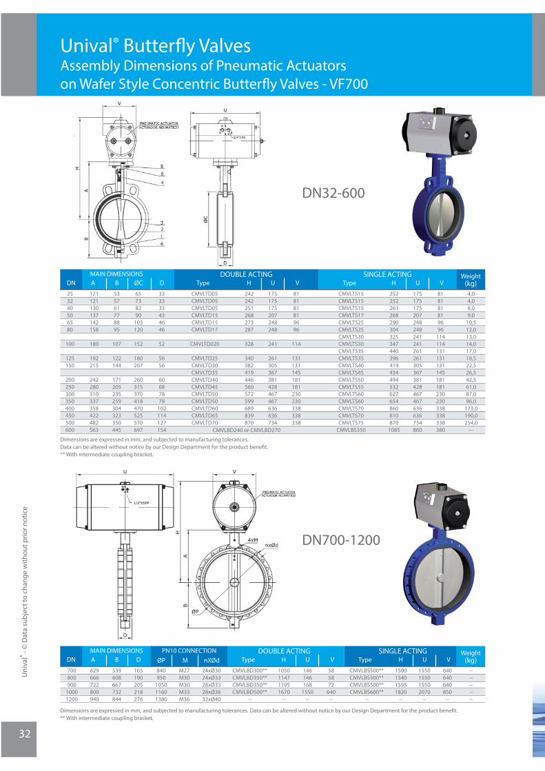
Unival® Butterfl y ValvesAssembly Dimensions of Pneumatic Actuators on Wafer Style Concentric Butterfl y Valves - VF700
Dimensions are expressed in mm, and subjected to manufacturing tolerances. Data can be altered without notice by our Design Department for the product benefi t.** With intermediate coupling bracket.
Dimensions are expressed in mm, and subjected to manufacturing tolerances. Data can be altered without notice by our Design Department for the product benefi t.** With intermediate coupling bracket.
DN32-600
DN700-1200
DN AMAIN DIMENSIONS Weight
(kg)PN10 CONNECTION
nXØdØP MB DDOUBLE ACTING
700800900
10001200
629666722800940
539608667732844
165190205218276
840950
105011601380
M27M30M30M33M36
24xØ3024xØ3328xØ3328xØ3632xØ40
VUHType
1050114711951670
--
146146168
1550--
585872
640--
CMVLBD300**CMVLBD350**CMVLBD350**CMVLBD500**
--
VUHType
1500154015951820
--
1550155015502070
--
640640640850
--
CMVLBS500**CMVLBS500**CMVLBS500**CMVLBS600**
--
SINGLE ACTING
----------
DN AMAIN DIMENSIONS Weight
(kg)B ØCDOUBLE ACTING
VUHTypeSINGLE ACTING
253240506580
100
125150
200250300350400450500600
121121130137142158
180
192215
242280310337358422482563
535761778895
107
122144
171205235259304323350445
65738290
103120
152
180207
260315370418470525570697
VUHType
242242251268273287
328
340382419446560572599689839870
175175175207248248
241
261305367381428467467636636734
818181819696
114
131131145181181230230338338338
CMVLTD05CMVLTD05CMVLTD05CMVLTD15CMVLTD15CMVLTD17
CMVLTD020
CMVLTD25CMVLTD30CMVLTD35CMVLTD40CMVLTD45CMVLTD50CMVLTD50CMVLTD60CMVLTD65CMVLTD70
252252261268290304325347440396419434494532627654860810870
1085
175175175207248248241241261261305367381428467467636636734860
818181819696
114114131131131145181181230230338338338380
CMVLTS15CMVLTS15CMVLTS15CMVLTS17CMVLTS25CMVLTS25CMVLTS30CMVLTS30CMVLTS35CMVLTS35CMVLTS40CMVLTS45CMVLTS50CMVLTS55CMVLTS60CMVLTS60CMVLTS70CMVLTS70CMVLTS75
CMVLBS350
4,04,08,09,0
10,512,013,014,017,018,522,526,542,561,087,096,0
173,0190,0254,0
---
D
333333434646
52
5656
60687878
102114127154 CMVLBD240 or CMVLBD270

33
Dimensions are expressed in mm, and subjected to manufacturing tolerances. Data can be altered without notice by our Design Department for the product benefi t.** With intermediate coupling.
Unival® Butterfl y ValvesAssembly Dimensions of Pneumatic Actuators on Lug Style Butterfl y Valves - VF750
DN APN16
LUG CONNECTIONMAIN DIMENSIONSWeight
(kg)
Butyl Rubber (BR)
25
32
40
50
65
80
100
125
150
200
250
300
350
400
450
500
600
PN10
nxØdØP
121
121
130
137
142
158
180
192
215
242
280
310
337
357,3
422
482
563
53
57
61
77
87,5
95
107
121,5
144
171
205
235
258,5
303,3
323
350
445
65
73
82
90
103
120
152
180
207
260
315
370
418
470
525
570
697
33
33
33
43
46
46
52
56
56
60
68
78
78
102
114
127
154
85
100
110
125
145
160
180
210
240
295
350
400
460
515
565
620
725
4xM12
4xM16
4xM16
4xM16
4xM16
8xM16
8xM16
8xM16
8xM20
8xM20
12xM20
12xM20
16xM20
16xM24
20xM24
20xM24
20xM27
B ØP D
85
100
110
125
145
160
180
210
240
295
355
410
470
525
585
650
770
4,0
4,0
8,0
9,0
10,5
12,0
13,0
14,0
18,5
20,0
24,5
29,5
47,5
66,0
99,0
122,0
208,0
238,0
327,0
---
V
DOUBLE ACTING
UHType
CMVLTD05
CMVLTD05
CMVLTD05
CMVLTD15
CMVLTD15
CMVLTD17
CMVLTD20
CMVLTD25
CMVLTD30
CMVLTD35
CMVLTD40
CMVLTD45
CMVLTD50
CMVLTD50
CMVLTD60
CMVLTD65
CMVLTD70
242
242
251
268
273
287
328
340
382
419
446
560
572
599
689
839
870
175
175
175
207
248
248
241
261
305
367
381
428
467
467
636
636
734
81
81
81
81
96
96
114
131
131
145
181
181
230
230
338
338
338
4xM12
4xM16
4xM16
4xM16
4xM16
8xM16
8xM16
8xM16
8xM20
12xM20
12xM24
12xM24
16xM24
16xM27
20xM27
20xM30
20xM33
nxØdØP V
SINGLE ACTING
UHType
CMVLTS15
CMVLTS15
CMVLTS15
CMVLTS17
CMVLTS25
CMVLTS25
CMVLTS30
CMVLTS30
CMVLTS35
CMVLTS35
CMVLTS40
CMVLTS45
CMVLTS50
CMVLTS55
CMVLTS60
CMVLTS60
CMVLTS270
CMVLTS270
CMVLTS75
CMVLBS350
252
252
261
268
290
304
325
347
440
396
419
434
494
532
627
654
860
810
870
1085
175
175
175
207
248
248
241
241
261
261
305
367
381
428
467
467
636
636
734
860
81
81
81
81
96
96
114
114
131
131
131
145
181
181
230
230
338
338
338
380CMVLBD240 or CMVLBD270
Uni
val®
- © D
ata
subj
ect t
o ch
ange
with
out p
rior n
otic
e
Uni
val®
- © D
ata
subj
ect t
o ch
ange
with
out p
rior n
otic
e
34
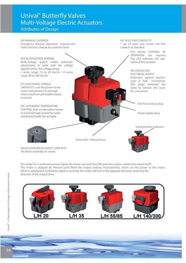
Unival® Butterfl y Valves Multi-Voltage Electric Actuators Attributes of Design
On receipt of a continuous power signal, the motor runs and via a fl at gear box system, rotates the output shaft. The motor is stopped by internal cams fi tted the output striking microswitches, which cut the power to the motor. When a subsequent continuous signal is received, the motor will turn in the opposite direction, reversing the direction of the output drive
ATC AUTOMATIC TEMPERATURE CONTROL Anti-condensation heater to avoid damage caused by water condensed inside the actuator
AVS AUTOVOLTAGE SENSINGMulti-voltage system makes automatic adjustments to work with the voltage applied within the voltage range.L series range: 12 to 24 Vac/dc - H series range: 85 to 240 Vac/dc
ETL ELECTRONIC TORQUE LIMITER ETL cuts the power to the motor and prevents its damage when maximum permisible torqueis exceed.
MO MANUAL OVERRIDEEmergency Manual Operation, manual-auto-matic function change by a selector lever.
PES PROTECTED ELECTRICAL SUPPLYProtection against shortcir-cuits or bad connection. DIN plugs eliminate the need to remove the cover for connection.
VC0 VISUAL CONTROL OF OPERATION (on request) Top LED indicates the ope-ration of the actuator
VFC VOLT FREE CONTACTS1 set of open and closed volt free contacts as standard
VALVE COUPLING to ISO5211/DIN 3337 for direct assembly on valves
Automatic / Manual lever
Volt free contact plug
Power supply plug
Visual position indicator

35
Unival® Butterfl y Valves Multi-Voltage Electric ActuatorsMain Data
*Working Angle: 90º - 180º - 270º * Duty Rating: 75 % * IP Rating IEC 60529: IP-65 * Temperature: -20º + 60º (-4º + 140ºF) * Limit Switch: 4 SPDT micro * Heater: 4W * Plugs: DIN 43650 ISO 4400 & C192
Main Parts and Materials
Main Dimensions (mm)L/H 20
L/H 55
L/H 140
L/H 300
Technical Data
Specifi cations
Voltage
Maximum Operational Torque
Maximum Torque Break
Multifl ange
Double sq. hole
Mod. H300Mod. L300
300 Nm
380 Nm
300 Nm
380 Nm
F07 & F10
Standard 22 mm / option 17 mm
Operation Time (s/90º)No load +/- 10%
12 – 24 VAC 50/60 HZ / VDC
60 sec.
85 – 240 VAC 50/60 HZ / VDC
60 sec.
Specifi cations
Voltage
Maximum Operational Torque
Maximum Torque Break
Multifl ange
Double sq. hole
Mod. H140Mod. L140
140 Nm
25 Nm
140 Nm
25 Nm
F07 & F10
Standard 22 mm / option 17 mm
Operation Time (s/90º)No load +/- 10%
80 – 240 VAC 50/60 HZ / VDC
33 sec.
15 - 48 VAC 50/60 HZ / 12 - 48 VDC
33 sec.
Specifi cations
Voltage
Maximum Operational Torque
Maximum Torque Break
Multifl ange
Double sq. hole
Mod. H55Mod. L55
55 Nm
60 Nm
55 Nm
60 Nm
F07 & F10
Standard 17 mm / option 14 mm
Operation Time (s/90º)No load +/- 10%
80 – 240 VAC 50/60 HZ / VDC
10 sec.
15 - 48 VAC 50/60 HZ / 12 - 48 VDC
10 sec.
Specifi cations
Voltage
Maximum Operational Torque
Maximum Torque Break
Multifl ange
Double sq. hole
Mod. H20Mod. L20
20 Nm
25 Nm
20 Nm
25 Nm
F03, F04 & F05
Standard 14 mm / option 9 or 11 mm
Operation Time (s/90º)No load +/- 10%
85 – 240 VAC 50/60 HZ / VDC
15 sec.
12 – 24 VAC 50/60 HZ / VDC
15 sec.
Part Material
Butyl Rubber (BR)
Enclosure:
Internal cams:
Main external shaft:
Gears
Position indicator
Fastening
Anticorrosive Polyamide
Glass fi lled Polyamide
Stainless Steel
Steel and Polyamide
Glass fi lled Polyamide
Stainless Steel
Uni
val®
- © D
ata
subj
ect t
o ch
ange
with
out p
rior n
otic
e

Uni
val®
- © D
ata
subj
ect t
o ch
ange
with
out p
rior n
otic
e
36
Unival® Butterfl y Valves Multi-Voltage Electric ActuatorsOptions and Accesories
The DPS 2005 is a device for the J3 electric actuator that turns the actuator in a valve positioner servo controled.
The DPS 2005 is a modulus with a microprocessor (CPU) which ma-nages digitally the analogical input and output and compare them with the position of the actuator to stablish an uniform relation. The analogical inputs are sent to CPU where they are processed for his continous comparison with the position of the actuator, this allows to obtain a very high sensitivity next to a very high repetitivity of the position (see characteristics).
The DPS 2005 in communication with the electronic system of the actuator provides an integral management of the motion on the ac-tuator.
The DPS 2005 is available for the ”H” and “L” series.
Digital Positionner
Main Advantages and Features
The BSR safety blok system is an automatism that when couple to the L & H Series multivoltage electric actuators lets the valve situate in a prefereable position NC or NA when there is a power supply failure.Inside of the housing actuator there are BSR’s print circuit board and the battery pack which are kept in continuous charge.
In case of the valve is not in the prefereable position and there is the power supply cut, the BSR system returns the valve back to the prefereable position by means of the batteries tension opera-ting as a “single acting” actuator.
Safety Block System
Automatic Reset
Automatic Setup
Possibility of using the DPS 2005 for regulations 90º, 180º
and 270º acted on the setup only.
Input signal: 4 - 20 mA / 0- 10 V
Output signal: 4 - 20 mA / 0- 10 V
Precision: better than 1%
Settings: max - min.
Lineality: better than 1%
Hysteresis: better than 1%
Min. resolution: better than 1%

37
Unival® Butterfl y Valves Assembly Dimensions of Electric Actuators on Wafer Style Concentric Butterfl y Valves - VF700
Dimensions are expressed in mm, and subjected to manufacturing tolerances. Data can be altered without notice by our Design Department for the product benefi t.** With intermediate coupling bracket.
DN A V
MAIN DIMENSIONSWeight
(kg)
Butyl Rubber (BR)
32
40
50
65
80
100
125
150
200
250
300
350
400
450
500
600
ELECTRIC ACTUATOR
WUHType
121
130
137
142
158
180
192
215
242
280
310
337
358
422
482
563
57
61
77
88
95
107
122
144
171
205
235
259
304
323
350
445
73
82
90
103
120
152
180
207
260
315
370
418
470
525
570
687
33
33
43
46
46
52
56
56
60
68
78
78
102
114
127
154
B ØP D
CMVLU0
CMVLU0
CMVLH20
CMVLH55
CMVLH55
CMVLH55
CMVLH140
CMVLH140
CMVLH300
CMVLH300**
--
--
--
--
--
--
3,0
3,5
4,0
5,5
6,0
7,0
11,5
13,5
18,0
29,0
--
--
--
--
--
--
104
104
104
104
105
105
105
214
214
214
--
--
--
--
--
--
122
122
122
122
122
122
122
128
128
128
169
169
169
169
169
169
169
235
235
235
--
--
--
--
--
--
280
280
290
295
350
365
390
455
480
510
--
--
--
--
--
--
Uni
val®
- © D
ata
subj
ect t
o ch
ange
with
out p
rior n
otic
e

Uni
val®
- © D
ata
subj
ect t
o ch
ange
with
out p
rior n
otic
e
38
Unival® Butterfl y Valves Assembly Dimensions of Electric Actuators on Lug Style Butterfl y Valves - VF750
Dimensions are expressed in mm, and subjected to manufacturing tolerances. Data can be altered without notice by our Design Department for the product benefi t.** With intermediate coupling bracket.
Bolts Flanges PN10*
DN A nxØd
PN16
V
LUG CONNECTIONMAIN DIMENSIONSWeight
(kg)
Butyl Rubber (BR)
25
32
40
50
65
80
100
125
150
200
250
300
350
400
450
500
600
ELECTRIC ACTUATOR
WUHType
PN10
ØPnxØdØP
121
121
130
137
142
158
180
192
215
242
280
310
337
358
422
482
563
53
57
61
77
88
95
107
122
144
171
205
235
259
304
323
350
445
65
73
82
90
103
120
152
180
207
260
315
370
418
470
525
570
687
33
33
33
43
46
46
52
56
56
60
68
78
78
102
114
127
154
85
100
110
125
145
160
180
210
240
295
350
400
460
515
565
620
725
4xM12
4xM16
4xM16
4xM16
4xM16
8xM16
8xM16
8xM16
8xM20
8xM20
12xM20
12xM20
16xM20
16xM24
20xM24
20xM24
20xM27
B ØP D
85
100
110
125
145
160
180
210
240
295
355
410
470
525
585
650
770
CMVLU0
CMVLU0
CMVLU0
CMVLH20
CMVLH55
CMVLH55
CMVLH55
CMVLH140
CMVLH140
CMVLH300
CMVLH300**
--
--
--
--
--
--
3,5
4,0
4,5
5,0
6,5
7,5
9,0
14,5
16,5
21,0
37,0
--
--
--
--
--
--
104
104
104
104
105
105
105
214
214
214
214
--
--
--
--
--
--
122
122
122
122
122
122
122
128
128
128
128
--
--
--
--
--
--
169
169
169
169
169
169
169
235
235
235
235
--
--
--
--
--
--
280
280
290
295
350
365
390
455
480
510
570
--
--
--
--
--
--
4xM12
4xM16
4xM16
4xM16
4xM16
8xM16
8xM16
8xM16
8xM20
12xM20
12xM24
12xM24
16xM24
16xM27
20xM27
20xM30
20xM33
39
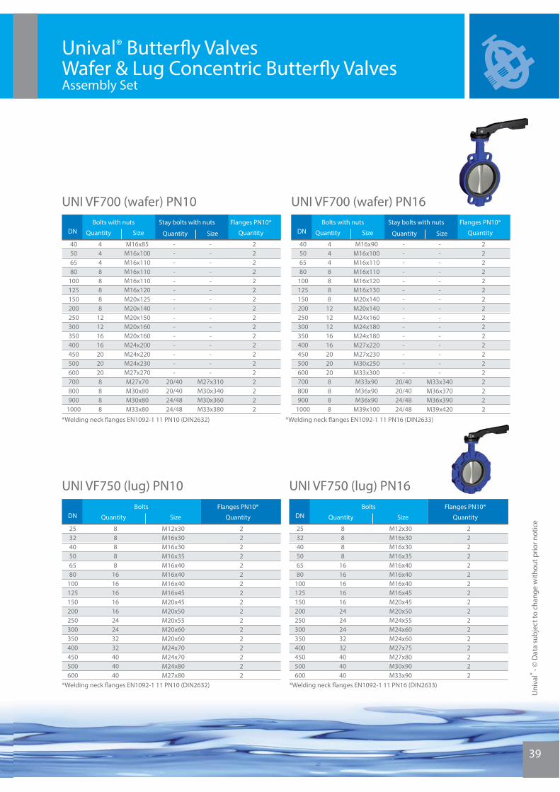
Unival® Butterfl y Valves Wafer & Lug Concentric Butterfl y ValvesAssembly Set
UNI VF700 (wafer) PN10
UNI VF750 (lug) PN16
UNI VF700 (wafer) PN16
*Welding neck fl anges EN1092-1 11 PN10 (DIN2632)
*Welding neck fl anges EN1092-1 11 PN10 (DIN2632) *Welding neck fl anges EN1092-1 11 PN16 (DIN2633)
*Welding neck fl anges EN1092-1 11 PN16 (DIN2633)
UNI VF750 (lug) PN10
DNBolts with nuts Stay bolts with nuts Flanges PN10*
Quantity Size Quantity Size Quantity
M16x85M16x100M16x110M16x110M16x110M16x120M20x125M20x140M20x150M20x160M20x160M24x200M24x220M24x230M27x270M27x70M30x80M30x80M33x80
---------------
20/4020/4024/4824/48
---------------
M27x310M30x340M30x360M33x380
2222222222222222222
40506580
100125150200250300350400450500600700800900
1000
44488888
121216162020208888
DNBolts with nuts Stay bolts with nuts Flanges PN10*
Quantity Size Quantity Size Quantity
M16x90M16x100M16x110M16x110M16x120M16x130M20x140M20x140M24x160M24x180M24x180M27x220M27x230M30x250M33x300M33x90M36x90M36x90
M39x100
---------------
20/4020/4024/4824/48
---------------
M33x340M36x370M36x390M39x420
2222222222222222222
40506580
100125150200250300350400450500600700800900
1000
4448888
12121216162020208888
DNBolts Flanges PN10*
QuantityQuantity Size
M12x30M16x30M16x30M16x35M16x40M16x40M16x40M16x45M20x45M20x50M20x55M20x60M20x60M24x70M24x70M24x80M27x80
22222222222222222
253240506580
100125150200250300350400450500600
88888
161616161624243232404040
DNBolts Flanges PN10*
QuantityQuantity Size
M12x30M16x30M16x30M16x35M16x40M16x40M16x40M16x45M20x45M20x50M24x55M24x60M24x60M27x75M27x80M30x90M33x90
22222222222222222
253240506580
100125150200250300350400450500600
8888
16161616162424243232404040
Uni
val®
- © D
ata
subj
ect t
o ch
ange
with
out p
rior n
otic
e
Uni
val®
- © D
ata
subj
ect t
o ch
ange
with
out p
rior n
otic
e
40
1. – GENERAL INFORMATION. WORKING PRINCIPLE.UNIVAL® Concentric Resilient Butterfl y Valves are rotation motion bidirectional valves to stop or restrict the fl ow of fl uids. The valves close by turning the disc 90º clockwise. The valve is open when the lever is parallel to the pipe. The valves can also be used for throttling purpose by fi xing the lever, worm gear or actuator in intermediate positions.
The equipment is designed and manufactured following procedures and high quality standards dictated by the EN ISO 9001. They conform to PED 97/23/CE and are CE marked when applicable. The equipment is inspected and tested to EN 12266-1.
The label in the product states maximum pressure, temperature, body, disc and seat materials & counterfl an- ges for installation. For complete technical description (dimensions, connections, pressure-temperature ra- ting, materials of constructions, applications, etc.) please refer to the corresponding approved order drawing, our Data Sheets at www.comeval.es or contact us at +34 961479011.
2. – GUARANTEE.UNIVAL®Butterfl y Valves are guaranteed against any manufacturing default in accordance with Sound Enginee-ring Practice and provided the application, installation and maintenance operations have been properly followed, according to our General Sales Terms.
The guarantee coverage does not apply to eventual damages caused by operation under duties other than described in our Data Sheet and product label. No claims derived from wrong handling and/or lack of obser- vation of General Technical Rules will be accepted.
Our guarantee coverage does not cover for any commissioning or in site maintenance jobs or either products proved to have been tampered with or faulted by material wear and tear.
The Purchaser is responsible for checking that the in-coming product is received in good condition and con- forms to the ordered specifi cations. In case of damage caused during transit it is necessary to immediately complain to the carrier within 24 hours. After this time carriers could not assume the derived costs.
3. – ESSENTIAL SAFETY GUIDELINES- Read this manual before installing the product.- Always use the product within the scope of intended service and operating duties.- Essential safety working regulations are to be strictly kept.- Only qualifi ed personnel should start up and regularly follow maintenance jobs at the plant.- Any deviation from the usual installation guidelines should be notifi ed to us for approval.
4. – PRESERVATION, STORAGE & TRANSPORTATION- Keep storage protection. Always use right handling means and proper packing for transportation.- Do not make use of stems, handwheels or actuators for valve weightlifting purpose.- Keep the valves with disc slightly open without coming out from the valve profi le.- Avoid extreme temperatures, high environmental humidity or corrosive environment. Keep the valves away from direct sunlight, dust, fl ames or rain to avoid damage and rust of the valve surface.- Some materials are coated by a paint layer against corrosion, do not damage this layer.- Avoid bumping or external vibrations. Do not pile up excessive weight. In case of severe bumping inspect the ma-terial for any damage and replace if necessary.
Unival® Butterfl y Valves Installation, Start-Up and Maintenance
41
5. – INSTALLATIONBear in mind the following guidelines along with general installation practice:
Check the equipment design codes in relation with the applicable plant codes.
Ensure that pressure design, temperature design, fl ow direction, valve construction materials compatibility and other essential parameters conform with the duty. (Check operating limits on the Data Sheets, approved drawing and valve marking).Consider the interaction between the system and the equipment. Avoid water hammers caused by a suddenopen or close of the valve. Foresee elements to absorb vibrations, pipe dilatations, guides, anchoring and proper support according to the weight of the components.
Avoid turbulences in the pipe that generate hydrodynamic forces increasing operating torque of the valve. Avoid high velocities in the system.
Downstream from a disruptive element (pump, valve, elbow, pipe reduction…) leave as much distance as possible, minimum distance recommended: 5-6 times the valve DN (5-6DN).
Upstream from a disruptive element, leave at least a distance of 2DN.
All steam systems in the plant should be designed to prevent condensate depots which could lead to water ham-mers.
Allow enough space to ease maintenance operations.
Remove carefully the storage protection if any just before installation. Special care to be taken in order not to dama-ge the soft parts.
Ensure that the valve inside and the piping system are free from dirt, rust, pipe, scale, welding slag or any other foreign material. Flush the pipe and set strainers with proper size mesh to protect the valve.Attention! In case of use of use of cleaning or anticorrosive products, ensure that their composition and tempe-rature are compatible with the valve materials of construction
- Installation position:
These valves are generally bidirectional.
Wafer and Lug type valves and double fl ange valves are to be installed between counter fl anges.
Stem preferable position is horizontal, with the lower edge of the disc opening with the direction of the fl ow. This prevents deposition of slurries and contamination in the shaft sealing area. Valve of small sizes in clean systems can be also installed with the stem in vertical position, never downwards to avoid that any leakage could damage the actuator.
Avoid gradients, excessive rotation and pipe misalignment that could cause pipe stress once installed in the pipe work. Ensure that contact faces of valve and counterfl anges are in good condition and free from impurities. Counter-fl anges should fi t smoothly. Make sure that the gap between the 2 counterfl anges has enough clearance to fi t the valve without damaging the rubber faces (carefully retract slightly counterfl anges if necessary), but the gap shall not be larger than necessary to limit additional pipe load.be larger than necessary to limit additional pipe load. U
niva
l® - ©
Dat
a su
bjec
t to
chan
ge w
ithou
t prio
r not
ice
Unival® Butterfl y Valves Installation, Start-Up and Maintenance

Uni
val®
- © D
ata
subj
ect t
o ch
ange
with
out p
rior n
otic
e
42
Unival® Butterfl y Valves Installation, Start-Up and Maintenance
To protect damage of the valve disc, be sure that the clearance of the adjacent counterfl anges and pipe is enough for the disc in full open position. Otherwise please use extension pipe.
Counterfl anges according to EN 1092-1 PN10 and/or PN16, and/or ANSI B16.5 ASA150 welding neck type are sui-table for UNIVAL butterfl y valves depending on valve type (see valve label). For installation between other fl ange types please consult us. Slip-on fl anges have a larger inside diameter, requiring a perfect centering and hindering the tightness between valve and counterfl anges, even aff ecting to stem tightness; we do not recommend this type of counterfl anges.
Tightness gaskets or grease are not required between the valve and the pipe counterfl anges. The valve rubber facing is used for this purpose. If installed between slip-on fl anges, gaskets could be needed.
Attention! It is very important to ensure the correct centring of the valve between the counterfl anges. An inco-rrect centring of the valve with the counterfl anges will cause leakage. An excessive or irregular tighte- ning onto the rubber facing, or tightening with the valve not correctly centred, could cause damages in the rubber leading to further leakage.
Valves should be installed with disc slightly open without coming out from the valve profi le. Carefully centre the valve between counter fl anges and fi t all the screws and nuts. Then open completely the valve.With the valve disc open, tighten opposing bolts gradually until getting contact between the body and fl ange face, according to the following sequence.
Attention! Tightening the valve in close position causes sleeve deformation, torque increase and leakage.
Do not exceed the maximum tightening torque values given in this table just as extreme limit:
Bolt Size M16 M20 M24 M27 M33Max Torque (Nm) 150 270 540 730 1250
Attention! Protect the valve rubber seats from heating caused by welding works at the plant during commissio-ning.
END OF LINE POSITION: Attention! For end-of-line position use lug type or fl anged butterfl y valve. Do not use wafer type butterfl y valvesfor such purpose.
Attention! If a valve at end-of-line position has to be open under pressure, do it carefully since the fl uid splashes at high velocity, and mind your hands when closing.
Attention! We recommend the use of an additional blind fl ange (specially in the event of dangerous fl uids) and make sure that the valve is blocked in closed position during normal service.
43
ATEX: For application in Ex-atmosphere of zones 1, 2, 21, 22, the butterfl y has to be used with an earth clip or conductive fl ange gaskets. The shunt resistor must be less than 106 Ohms. Elastomeric or fl uoropolymer surfaces should be cleaned if necessary with a wet cloth to avoid electrostatic charge.
ACTUATOR: If the valve requires pneumatic, electric or hydraulic actuators, separate actuator IOMs shall be also followed. Make sure that the actuator is suitable for service particular requirements, valve adaptability, function needed, adequate torque for the valve, operation speed, need for limit switches, etc. Ensure correct adjustment of stop limits and torque setting. Contact our Technical Department for advice.Anchoring should be required depending on the complete valve and actuator assembly weight and installation posi-tion.
Project engineers and contractors are responsible for the right placement and commissioning of the valve.
6. – START UP & OPERATION- Recheck all the issues raised in previous chapter “Installation”.
- Once the valve installed, make an initial opening and closure manoeuvre to check its proper operability.
- Valve operation, fi lling, warming-up and starting-up shall be gradual so as to avoid any inadmissible stress.
- Attention! Do not pressurize if the valve does not have actuator device. Butterfl y valves are not self locking.
- Check for tightness in valve connections and stem sealing. Retighten fl ange bolts crosswise and gradually if neces-sary until leakage elimination (never retighten with the valve fully closed!), making sure that operating torque is not signifi cantly aff ected. If leakage persists, correct alignment and centring of the valve should be checked, and surfa-ces should be thoroughly cleaned. If contact surfaces are irreversibly damaged replace them. If valve leaks through the stem please contact us for advice.
- Maximum hydraulic test pressure at valve open is 1,5 x PN (Pmax or Ps in the label).
- Maximum hydraulic test pressure at valve close is 1,1 x PN (Pmax or Ps in the label). Pressure medium to be water at ambient temperature.
- We recommend control operation in the range of 15º to 75º disc open angle only.
- Warning! Temperatures above 50ºC or below 0ºC may cause personnel injuries if valves are touched. Ensure that the corresponding warning signs are displayed on the valve or surrounding area, or isolate the equipment in case of danger.
IT IS THE RESPONSIBILITY OF THE INSTALLER / OPERATOR TO ENSURE THAT ALL HEALTH & SAFETY REQUI-REMENTS ARE FOLLOWED AS LAID DOWN BY THE CONTROLLING COMPANY
Uni
val®
- © D
ata
subj
ect t
o ch
ange
with
out p
rior n
otic
e
Unival® Butterfl y Valves Installation, Start-Up and Maintenance
Uni
val®
- © D
ata
subj
ect t
o ch
ange
with
out p
rior n
otic
e
44
Unival® Butterfl y Valves Installation, Start-Up and Maintenance
7. – MAINTENANCE AND SPARE PARTS.
Maintenance and corresponding intervals should be defi ned and scheduled by the plant operation personnel accor-ding to service level.
In the event of infrequent use, operate the valve as frequently as possible to avoid deposits of dirt as well as valve blocking.
Check for body and seat tightness and valve smooth operation without additional tools.
Before starting any maintenance work at the plant, wait for the valve medium to cool down and release the pressu-re from the system. Clean the pipe system thoroughly in the event of toxic, corrosive, fl ammable or caustic fl uids. Remove the valve with the disc slightly open.
Attention! A butterfl y valve is not self locking, so that the actuation device (lever, gear or actuator) should only be disassembled after pressure release.
- Warning! when used in ATEX zone, there is the risk of electrostatic charges created by the fl ow. The user is responsible to avoid the risk. Read chapter 5 – Installation.
Check the valve surface inside and outside. If advanced corrosion or erosion is observed double check ser- vice and valve features and replace the valve properly.
Check the valve seat and disc surfaces as well as the stem sealing, and replace if necessary.
Valve rubber seats are replaceable in most of Unival® range. However, given the reasonably low cost of the entire valve thanks to the serial and bulk production, sometimes it is not economically wise to replace them. Should seats or stem seal are to be replaced, please get in touch with our specialised personnel for technical assistance.
Always refer to chapters “Installation” and “Start Up” when mounting the valve back in line.
Recommended Spare PartsType and number of each spare part to be stored according to service level and valves quantity. Spare seats, stem seals and discs can be supplied as spare parts depending on models and sizes. Concentric Resilient Butterfl y valves are in many models and sizes highly serialized manufactured items at relatively low cost thus complete valves are often the best option.
45
Unival® Butterfl y Valves Installation, Start-Up and Maintenance
Full technical support always available through our website www.comeval.es.
8. – TROUBLE SHOOTING CHART
Uni
val®
- © D
ata
subj
ect t
o ch
ange
with
out p
rior n
otic
e
SYMPTOM LIKELY REASON CORRECTIVE ACTION(always follow this manual for any corrective action)
No fl owNot enough fl ow
Valve closed or partially closed Check valve position
Valve protections / packing not removed Remove protections
Pipe system or strainer clogged Check and clean system
Atmospheric leakage through the stem
Counterfl anges tightening not uniform or not suffi cient, valve not properly cente-red or not well aligned pipe
Revise assembly and tightening, dismou-nt and mount back properly if needed
Stem seals or stem damaged or worn down
Revise and replace if needed
Excessive pressure or temperature, fl uid not compatible
Revise working conditions
Leakage between body and counter-fl anges
Counterfl anges tightening not uniform or not suffi cient, valve not properly cente-red or not well aligned pipe
Revise assembly and tightening, dismount and mount back properly if needed
Counterfl anges or rubber lining face dirty, scratched or damaged
Dismount the valve from pipeline, clean, correct damages or replace parts
Counterfl anges type is not well suitable (example: slip-on fl anges)
Revise counterfl anges type
Diffi cult to operate or blocked / not able to achieve full closing / not able to open
Wrong rotary movement operation Operate rightly. Clockwise to closeExcesssive differential pressure, high turbulences, working conditions beyond allowable limits
Check working conditions and system. Replace by correct valveRubber damaged, swollen, hardened or
aged, not compatible fl uidDisc corroded or damaged by cavitation or impuritiesCounterfl anges tightening with valve disc in closed position, causing a protusion in the sealing area
Replace the seat or the valve
Impurities trapped between disc and seat
Open and close the valve under pressu-re to sweep the dirt trapped. Clean the system and set a strainer upstream of the valve. Repair or replace the valve if needed
Valve body broken Assembly bolts with counterfl anges has been wrongly tightened or counterfl an-ges are misaligned or with too much gap
Revise installation and tightening accor-ding to this manual
Wafer valve installed at the end of a pipeline
Replace by lug or double fl ange type
Pressures or temperatures beyond allowable limits
Replace by suitable valve

Uni
val®
- © D
ata
subj
ect t
o ch
ange
with
out p
rior n
otic
e
46
The below chart is intended to provide the end user and valve selection staff with a useful guide to material compatibility. No contractual responsibility is accepted by our company as result of wrong use of this list of compounds and materials. It has to be born in mind that the process may change behavior depending on other parameters such as pressure, temperature, concentration, fl uid velocity…etc. The Valve materials are wide in their specifi cation, i.e: Iron foundry refers to Cast Iron, Ductile Iron and other Iron alloys. Carbon Steel applies to A216 WCB however other cast steel alloys such as LCB, WCC have to be interpolated between this cast steel and the superior Stainless Steel. Other materials and elastomeric compounds not covered in this table can be advised by our technical team.
SELECTION CODE:A= EXCELLENTB= IT MAY BE USEDC= USE WITH CAUTIOND= NO,DO NOT USE
MATERIALS SEAT ELASTOMER
IRONFOUNDRY
CARBONSTEEL
ALUMINIUM356
STAINLESSSTEEL
303
STAINLESSSTEEL
316 EPDM / EPRBUNA N VITON PTFE
ACETALDEHYDEACETATE SOLVENTSACETIC ACID (AERATED)ACETIC ACID (AIR FREE)ACETIC ACID (CRUDE)ACETIC ACID (PURE)ACETIC ACID (10%)ACETIC ACID (80%)ACTIC ANHYDRIDEACETONEACETYLENE (DRY ONLY)ACRYLONITRILEAIRALCOHOLS METHYL ETHYLALCOHOLS AMYLACOHOS BUTYLALIMINIUM CHLORIDE (DRY)ALIMINIUM SULFATE (ALUMS)ALUMSAMINESAMMONIA ANHYDROUSAMMONIA (AQUEOUS)AMMONIA SOLUTIONSAMMONIUM BICARBONATEAMMONIUM CARBONATEAMMONIUM CHLORIDEAMMONIUM HYDROIXIDE (28%)AMMONIUM HYDROXIDE (CONC)AMMONIUM MOMOPHOPHATEAMMONIUM NITRATEAMMONIUM PHOSPHATE (DIBASIC)AMMONIUM PHOSPHATE (TRIBASICAMMONIUM SULFATEAMYL ACETATEANILINEANILINE DYESANTIMONY TRICHLORIDEAPPLE JUICEARSENIC ACIDASPHALT EMULSIONASPHALT LIQUIDBARIUM CARBONATEBARIUM CHOLORIDEBARIUM SULFATEBARIOUM SULFIDEBEER (ALCOHOL INDUSTRY)BEER (BEVERAGE INDUSTRY)BEET SUGAR LIQUORSBENZENE (BENZOL)BENEZALDEHYDEBENZOIC ACID
CBDDCCCCDAACABBBBCCABABBBDCCDDDDCCCCDDDAABCBCCCBBBD
BABBBBBBBAABAAAABBBABBDBBCCCBBBBBBCCDBDCCBDDDDAAAAB
CADDCCCDAAAAABBBBCCAAABCBDCCDDDDCCCCDDDAABCCCCCBBAD
AAAAAAABAAAAAAAAAAAAAAABBCBBBABBBBBADDBAABCBBBAAAAA
AAAAAAABAAAAAAAAAAAAAAABBCBCBAAAABBCDBBAABCBBBAAAAA
DDCCDDDDCDADAAAABAADBBBBBBBAAAAAADCADAABCAAAAAAAADD
BXXXXXBCCAADAAACAAXCBXBAAABAAAXXABCCXBBDDAABABBBDAD
CDDDDDDDDDACAAAAAAAACAAABAAAAAAAADCBAAAAAAAAAAA
AAD
AAAAAAAAAAAAAAAAAAAAAAAAAAAAAAAAAAAAAAAAAAAAAAAAAAA
Unival® Butterfl y Valves Material Selection Guidance

47
The below chart is intended to provide the end user and valve selection staff with a useful guide to material compatibility. No contractual responsibility is accepted by our company as result of wrong use of this list of compounds and materials. It has to be born in mind that the process may change behavior depending on other parameters such as pressure, temperature, concentration, fl uid velocity…etc. The Valve materials are wide in their specifi cation, i.e: Iron foundry refers to Cast Iron, Ductile Iron and other Iron alloys. Carbon Steel applies to A216 WCB however other cast steel alloys such as LCB, WCC have to be interpolated between this cast steel and the superior Stainless Steel. Other materials and elastomeric compounds not covered in this table can be advised by our technical team.
SELECTION CODE:A= EXCELLENTB= IT MAY BE USEDC= USE WITH CAUTIOND= NO,DO NOT USE
MATERIALS SEAT ELASTOMER
IRONFOUNDRY
CARBONSTEEL
ALUMINIUM356
STAINLESSSTEEL
303
STAINLESSSTEEL
316 EPDM / EPRBUNA N VITON PTFE
BORAX LIQUORSBORIC ACIDBRINESBUTADIENEBUTANECALCIUM BISULFITECALCIUM CARBONATECALCIUM CHLORIDECARBOLIC ACIDCARBON TETRACHLORIDECASTOR OILCHLOROFORM (DRY)CHROME ALUMCOCONUT OILCOPPER ACETATECOPPER CHLORIDECOPPER NITRATECRUDE OIL SWEETCRUDE OIL SOURTCYCLOHEXANEDIACTONE ALCOHOLDIESEL FUELSDRILLING MUDDRYING OILEPSOM SALTETHANEETHERETHYL ACETATEETHYL CHLORIDEETHYLENE CLYCOLETHYLENE OXIDEFERRIC NITRATEFERRIC SULFATEFERROUS CHLORIDEFERROUS SULFATEFISH OILSFLOURINEFOOD FLUID AND PASTESFORMALDEHYDE (COLD)FORMALDEHYDE (HOT)FORMIC ACID (COLD)FORMIC ACID (HOT)FREONFUEL OILGALLIC ACIDGAS NATURALGAS ODDORIZERSGASOLINE (LEADED)GASOLINE (UNLEADED)GASOLINE (AVIATION)GASOLINE (MOTOR)GASOLINE (SOUR)
CDCBBDDCDBBBBCDDDBCAAABBCABCBBCDDDDBDCBDDDBBDBBBBBBB
CBBAACCCABADCBCCCAAAAABBAAAABAADDDDBDAABDDBAABAAAAAA
CDCDBDDCDBBBBCDDDBBAAABBCAABBBBDDDDBDCADDDBBDBBAAAAB
BBBAACBCBAAAABACBAAAAAAABAABABBCBDBADAACCCAABABAAAAA
BBBAABBBBAADABACBAAAAAAABAABABBCBDBADAACBBAABABAAAAA
AAACAAAADDADAA
AAAACDAACAACDCADAAAAA
BBBDDCAAABCCCCC
ABACDDBBBDBDBABXBXDDXDAXXDCCBADAAAADXXBXXXCDCDXXXXDD
AAAAAAAABBABBA
AAAAA
AAAAACD
ADAAAAA
CA
AAAAAAA
AAAAAAAAAAAAAAAAAAAAAAAAAA
AAAAAAAAACAAAAAAAAAAAAAAA
Unival® Butterfl y Valves Material Selection Guidance
Uni
val®
- © D
ata
subj
ect t
o ch
ange
with
out p
rior n
otic
e
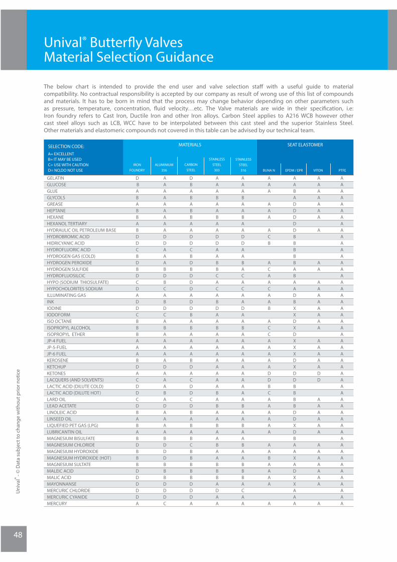
Uni
val®
- © D
ata
subj
ect t
o ch
ange
with
out p
rior n
otic
e
48
The below chart is intended to provide the end user and valve selection staff with a useful guide to material compatibility. No contractual responsibility is accepted by our company as result of wrong use of this list of compounds and materials. It has to be born in mind that the process may change behavior depending on other parameters such as pressure, temperature, concentration, fl uid velocity…etc. The Valve materials are wide in their specifi cation, i.e: Iron foundry refers to Cast Iron, Ductile Iron and other Iron alloys. Carbon Steel applies to A216 WCB however other cast steel alloys such as LCB, WCC have to be interpolated between this cast steel and the superior Stainless Steel. Other materials and elastomeric compounds not covered in this table can be advised by our technical team.
SELECTION CODE:A= EXCELLENTB= IT MAY BE USEDC= USE WITH CAUTIOND= NO,DO NOT USE
MATERIALS SEAT ELASTOMER
IRONFOUNDRY
CARBONSTEEL
ALUMINIUM356
STAINLESSSTEEL
303
STAINLESSSTEEL
316 EPDM / EPRBUNA N VITON PTFE
GELATINGLUCOSEGLUEGLYCOLSGREASEHEPTANEHEXANEHEXANOL TERTIARYHYDRAULIC OIL PETROLEUM BASEHYDROBROMIC ACIDHIDRICYANIC ACIDHYDROFLUORIC ACIDHYDROGEN GAS (COLD)HYDROGEN PEROXIDEHYDROGEN SULFIDEHYDROFLUOSILCICHYPO (SODIUM THIOSULFATE)HYPOCHOLORITES SODIUMILLUMINATING GASINKIODINEIODOFORMISO OCTANEISOPROPYL ALCOHOLISOPROPYL ETHERJP-4 FUELJP-5-FUELJP-6 FUELKEROSENEKETCHUPKETONESLACQUERS (AND SOLVENTS)LACTIC ACID (DILUTE COLD)LACTIC ACID (DILUTE HOT)LARD OILLEAD ACETATELINOLEIC ACIDLINSEED OILLIQUEFIED PET GAS (LPG)LUBRICANTIN OILMAGNESIUM BISULFATEMAGNESIUM CHLORIDEMAGNESIUM HYDROXIDEMAGNESIUM HYDROXIDE (HOT)MAGNESIUM SULTATEMALEIC ACIDMALIC ACIDMAYONNANSEMERCURIC CHLORIDEMERCURIC CYANIDEMERCURY
D BABABBABDDCBDBDCDADDCBBBAAABDACDDCDBABABDBBBDDDDDA
DBABABBAADDCBDBDDDADDBABAAAABDACDDCDBABABCBBBBBDDDA
AAABAABAADDAABBCACABDAABAAAAAAAAABABAABAABAABBBADAA
AAABAABAADDAABACACAADAABAAAAAAAAAAABAABAABAABBBACAA
AAA
AAA
ACB
ACAACAAB
ACCAAAAADDBCAAAAAA
AABAAAA
A
AABADDDDDBBBBBABAADBXXDXDXXXDXDDBBBBDDXDBAAXADXXAAA
AAAAAAA
A
AA
AAAAAAAA
AAAAADD
AAAAAA
AAAAAAA
A
AAAAAAAAAAAAAAAAAAAAAAAAAAAAAAAAAAAAAAAAAAAAAAAAAAA
AAAAAAAAADDAAABDBCABDCABAAAAADAAABADAAAABDDDBBBDDDC
Unival® Butterfl y Valves Material Selection Guidance

49
The below chart is intended to provide the end user and valve selection staff with a useful guide to material compatibility. No contractual responsibility is accepted by our company as result of wrong use of this list of compounds and materials. It has to be born in mind that the process may change behavior depending on other parameters such as pressure, temperature, concentration, fl uid velocity…etc. The Valve materials are wide in their specifi cation, i.e: Iron foundry refers to Cast Iron, Ductile Iron and other Iron alloys. Carbon Steel applies to A216 WCB however other cast steel alloys such as LCB, WCC have to be interpolated between this cast steel and the superior Stainless Steel. Other materials and elastomeric compounds not covered in this table can be advised by our technical team.
SELECTION CODE:A= EXCELLENTB= IT MAY BE USEDC= USE WITH CAUTIOND= NO,DO NOT USE
MATERIALS SEAT ELASTOMER
IRONFOUNDRY
CARBONSTEEL
ALUMINIUM356
STAINLESSSTEEL
303
STAINLESSSTEEL
316 EPDM / EPRBUNA N VITON PTFE
METHANEMETHYL ACETATEMETHYL ACETONEMETHYLAMINEMETHYL CELLOSOLVEMETHYL CHORIDEMETHYL ETHYL KETONEMETHYL FORMATEMETHYLENE CHORIDEMILKMINE WATERS (ACID)MINERAL OILMIXED ACIDS (COLD)MOLASSES EDIBLEMOLASSES CRUDEMURIATIC ACIDMUSTARDNAPHTHANAPHALENENICKEL AMMONIUM SULFATENICKEL CHORIDENICKEL NITRATENICKEL SULFATENICOTINIC ACIDNITRIC ACID (10%)NITRIC ACID (30%)NITRIC ACID (80%)NITRIC ACID (100%)NITRIC ACID ANHYDROUSNITROBENZENENITROGENNITROUS ACID (10%)NITROUS GASES NITROUS OXIDE OILS AMINALOILS COTTONSEEDOILS FISHOILS FUELOILS LUBEOILS MINERALOILS PETROLEUM (REFINED)OILS PETROLEUM (SOUR)OILS WATER MIXTURESOLEIC ACIDOLEUMOLIVE OILOXALIC ACIDOXYGENOZONEPALMITIC ACIDPALM OIL
BBABBBACBDDBCAADBBBDDDDBDDDAABADCCACBBABBCBBDBDBCCC
BBABBBACBDDBCAADBBADDDBBDDDAABADBBACBBABABBBBADBCCC
BAAAABABAABABAADABBABBBAAAAAABABABABAAAAAAAABABAABB
BAAAAAABAABAAAADABBABBBAAAAAABABABABAAAAAAAABABAABB
ADD
CDDDAAA
AABAA
AAAA
CCDD
DAC
BAAAAAAAAAACACC
BB
XBABBDBBDA
DDXX
XDDBBABDXBDDDCBXXXB
DDXDDBBAABD
ADD
D
CAAA
AAAAAA
AAA
AABB
CAA
AAAAAAACAAB
AA
AAAAAAAAAAAAAAAAAAAAAAAAAAAAAAAAAAAAAAAAAAAAAAAAAAA
AAAAADACAADACAADBABDDCDADDBBBCADBCABBAAAAAAABACABBA
Unival® Butterfl y Valves Material Selection Guidance
Uni
val®
- © D
ata
subj
ect t
o ch
ange
with
out p
rior n
otic
e

Uni
val®
- © D
ata
subj
ect t
o ch
ange
with
out p
rior n
otic
e
50
Unival® Butterfl y Valves Material Selection Guidance
The below chart is intended to provide the end user and valve selection staff with a useful guide to material compatibility. No contractual responsibility is accepted by our company as result of wrong use of this list of compounds and materials. It has to be born in mind that the process may change behavior depending on other parameters such as pressure, temperature, concentration, fl uid velocity…etc. The Valve materials are wide in their specifi cation, i.e: Iron foundry refers to Cast Iron, Ductile Iron and other Iron alloys. Carbon Steel applies to A216 WCB however other cast steel alloys such as LCB, WCC have to be interpolated between this cast steel and the superior Stainless Steel. Other materials and elastomeric compounds not covered in this table can be advised by our technical team.
SELECTION CODE:A= EXCELLENTB= IT MAY BE USEDC= USE WITH CAUTIOND= NO,DO NOT USE
MATERIALS SEAT ELASTOMER
IRONFOUNDRY
CARBONSTEEL
ALUMINIUM356
STAINLESSSTEEL
303
STAINLESSSTEEL
316 EPDM / EPRBUNA N VITON PTFE
PARAFINPARAFORMALDEHYDEPETANEPERCHLORETHYLENEPETROLATUMPHENOLPHOSPHORIC ACID (10%) COLDPHOSPHORIC ACID (10%) HOTPHOSPHORIC ACID (50%) COLDPHOSPHORIC ACID (50%) HOTPHOSPHORIC ACID (80%) COLDPHOSPHORIC ACID (80%) HOTPHTHALIC ACIDPHTHALIC ANHYDRIDEPIRIC ACIDPINE OILPINEAPPLE JUICEPOTASSIUM BISULFITEPOTASSIUM BROMIDEPOTASSIUM CARBONATEPOTASSIUM CHLORATEPOTASSIUM CHLORIDEPOTASSIUM CYANIDEPOTTASIUM DICHROMATEPOTASSIUM FERRICYANIDEPOTASSIUM FERROCYANIDEPOTASSIUM HYDROXIDEPOTASSIUM IODIDEPOTASSIUM NITRATEPOTASSIUM PERMANGANATEPOTASSIUM SULFATEPOTASSIUM SULFITEPRODUCER GASPROPANEPROPYLENE CLYCOLPYROGALIC ACIDQUENCH OILRESSING AND ROSINSROAD TARROOF PILCHRP-1 FUELRUBBER LATEX EMULSIONSRUBBER SONVENTSALAT OILSALIEYLIC ACIDSALTSEA WATERSHEALLAC (ORANGE)SILVER NITRTESEAP SOLUTIONS (STEARATES)SOSIUM ACETATE
BBBBCBDDDDBCCCCBCDDBBBBBBBACBBCBBBBBBCAAABACDCDBDAB
BBBBCBDDDDBCCCCBCDDBBCBBBBACBBBBBBBBBCAAABACDCDADAB
ABAABABDBDAABBBAABABBCBAAAAAAAAABBBBAAAAAAABABAAAAA
ABAABABDBDAABBBAABABBCBAAAAAAAAABBBBAAAA
AABABAAAAA
ABADADBBBBCCCCCAAAAAAAAAAAAAAAAAAAAAACBBA
DAAAAACAB
DDDDXDBBBBXXXXBDXBBBBAABBXBBBBABDDBXXXDXXXXBBXAX
AB
AAAAABAAAA
A
AAAAAAAAAAAA
AAAA
AAAAA
AAAADAAAA
AAA
AAAAAAAAAAAAAAAAAAAAAAAAAAAAAAAAAAAAAAAAAAAAAAAAAAA
ABAABADDDDDDBBBAACCCCBDABADCAAABBAABAAAAAAABCBCADCA

51
The below chart is intended to provide the end user and valve selection staff with a useful guide to material compatibility. No contractual responsibility is accepted by our company as result of wrong use of this list of compounds and materials. It has to be born in mind that the process may change behavior depending on other parameters such as pressure, temperature, concentration, fl uid velocity…etc. The Valve materials are wide in their specifi cation, i.e: Iron foundry refers to Cast Iron, Ductile Iron and other Iron alloys. Carbon Steel applies to A216 WCB however other cast steel alloys such as LCB, WCC have to be interpolated between this cast steel and the superior Stainless Steel. Other materials and elastomeric compounds not covered in this table can be advised by our technical team.
SELECTION CODE:A= EXCELLENTB= IT MAY BE USEDC= USE WITH CAUTIOND= NO,DO NOT USE
MATERIALS SEAT ELASTOMER
IRONFOUNDRY
CARBONSTEEL
ALUMINIUM356
STAINLESSSTEEL
303
STAINLESSSTEEL
316 EPDM / EPRBUNA N VITON PTFE
SODIUM ALUMINATESODIUM BICARBONATESODIUM BISULFATE (10%)SODIUM BISULFITE (10%)SODIUM BORATESODIUM BROMIDE (10%)SODIUM CARBONATESODIUM CHORATESODIUM CHLORIDESODIUM CHOROMATESODIUM CYANIDESODIUM FLUORIDESODIUM HYDROXIDE (COLD) 20%SODIUM HYDROXIDE (HOT) 20%SODIUM HYDROXIDE (COLD) 50%SODIUM HYDROXIDE (HOT) 50%SODIUM HYDROXIDE (COLD) 70%SODIUM HYDROXIDE (HOT) 70%SODIUM HYPOCHIORIDESODIUM METAPHOSPHATESODIUM METASSILICATE (COLD)SODIUM METASSILICATE (HOT)SODIUM NITRADESODIUM PERBORATESODIUM PEROXIDESODIUM PHOSPHATE (DIBASIC)SODIUM PHOSPHATE (TRIBASIC)SODIUM SILICATESODIUM SILICATE (HOT)SODIUM SULFATESODIUM SULFIDESODIUM SULFIDE (HOT)SODIUM THIOSULFATESOYBEAN OILSTANNIE CHORIDESTARCHSTEAM (212ºF)STEARIC ACIDSTODDARD SOLVENTSTYRENESUGAR LIQUIDSSULFATE BLACK LIQUORSULFATE GREEN LIQUORSULFATE WHITE LIQUORSULPHURSULPHUR DIOXIDESULPHUR TRIOXIDESULFURIC ACID (0-7%)SULFURIC ACID (20%)SULFURIC ACID (50%)SULFURIC ACID (100%)
CCDDCDACCBADABABABDBCDBBCBBABBBCBCDAACBBACCCCBBDDDB
CCDDCCACCBADABABABDBCDBBCBBABBBCBCDAACBAACCCCBBDDDB
BBAABBAABAABAAAAAADAAABBBAAABABBA ADAAABAABBBBAACDDA
BBAABBAABAABAAAAAADAAABBBAAABABBA ADAAABAABBBBAACDDA
AAAAAAAAAAAAABAB
A
CCCABA
AA
AAAACAADACCCDCCBCCD
BABBBBBBBBBBBBBXBBXBXXBAAAABBABBAB
CBB
DBBXXBAXXXXC
AAAAAAAAAAAABCCCCC
AAAAAA
AA
AAAABAA
AAAA
A
AAAB
AAAAAAAAAAAAAAAAAAAAAAAAAAAAAAAAAAAAAAAAAAAAAAAAAAA
CBDDBBDBBDDCDDDDDDDABBABCDDBCACDBBDAAAAABBBBAAABDDD
Unival® Butterfl y Valves Material Selection Guidance
Uni
val®
- © D
ata
subj
ect t
o ch
ange
with
out p
rior n
otic
e
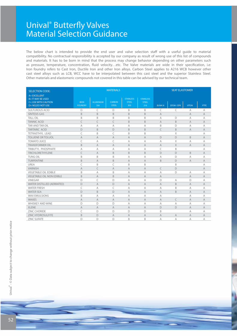
Unival® Butterfl y ValvesMaterial Selection Guidance
SELECTION CODE:A= EXCELLENTB= IT MAY BE USEDC= USE WITH CAUTIOND= NO,DO NOT USE
MATERIALS SEAT ELASTOMER
IRONFOUNDRY
CARBONSTEEL
ALUMINIUM356
STAINLESSSTEEL
303
STAINLESSSTEEL
316 EPDM / EPRBUNA N VITON PTFE
SULFUROUS ACIDSÍNTESIS GASTALL OILTANNIC ACIDTAR AND TAR OILTARTARIC ACIDTETRAETHYL LEADTOLUENE OR TOLUOLTOMATO JUICETRANSFORMER OILTRIBUTYL PHOSPHATETRICHLORETHYLENETUNG OILTURPENTINEUREAVARNISHVEGETABLE OIL EDIBLEVEGETABLE OIL NON EDIBLEVINEGARWATER DISTILLED (AERRATED)WATER FRESHWATER SEAWAX EMULSIONSWAXESWHISKEY AND WINEXLENEZINC CHORIDEZINC HYDROSULFITEZINC SUFATE
DBBCADCACBACBBCABBDDCDBADACBD
DBBCADCACAABBBCABBDDCDAADADAD
BBBBABBAAAABAABAAAAAAAAAAADAB
BBBBABBAAAABAABAAAAAAAAAAADAB
CAAABC
DAACDAB
CAADAAAAAADBAA
C
DBDBXDXXBDDDBDD
ABBB
CAD
AA
AAAAAA
BAA
BAA
AADAAAAAAAAAA
AAAAAAAAAAAAAAAAAAAAAAAAAAAAA
CBBCABBAAAAABABCAACAABAADADDD
The below chart is intended to provide the end user and valve selection staff with a useful guide to material compatibility. No contractual responsibility is accepted by our company as result of wrong use of this list of compounds and materials. It has to be born in mind that the process may change behavior depending on other parameters such as pressure, temperature, concentration, fl uid velocity…etc. The Valve materials are wide in their specifi cation, i.e: Iron foundry refers to Cast Iron, Ductile Iron and other Iron alloys. Carbon Steel applies to A216 WCB however other cast steel alloys such as LCB, WCC have to be interpolated between this cast steel and the superior Stainless Steel. Other materials and elastomeric compounds not covered in this table can be advised by our technical team.
Uni
val®
- © D
ata
subj
ect t
o ch
ange
with
out p
rior n
otic
e
52
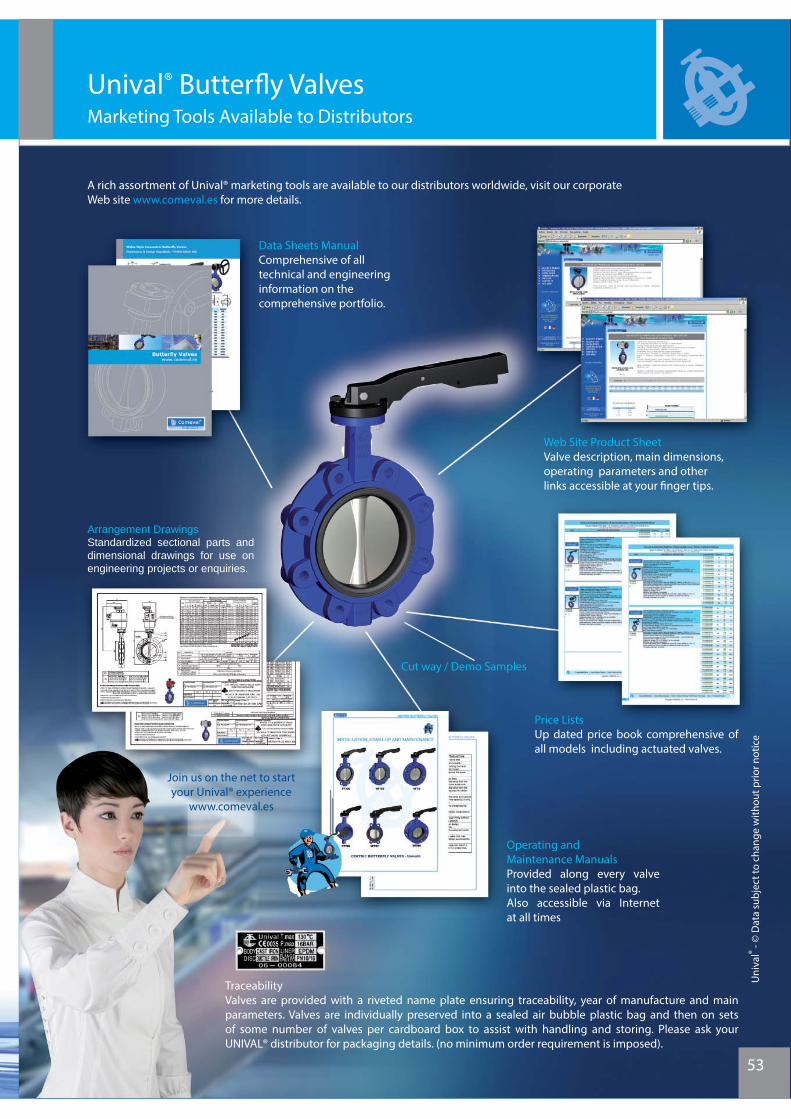
53
Unival® Butterfl y ValvesMarketing Tools Available to Distributors
A rich assortment of Unival® marketing tools are available to our distributors worldwide, visit our corporateWeb site www.comeval.es for more details.
Data Sheets ManualComprehensive of all technical and engineering information on the comprehensive portfolio.
Web Site Product SheetValve description, main dimensions, operating parameters and other links accessible at your fi nger tips.
TraceabilityValves are provided with a riveted name plate ensuring traceability, year of manufacture and main parameters. Valves are individually preserved into a sealed air bubble plastic bag and then on sets of some number of valves per cardboard box to assist with handling and storing. Please ask your UNIVAL® distributor for packaging details. (no minimum order requirement is imposed).
Price ListsUp dated price book comprehensive of all models including actuated valves.
Operating and Maintenance ManualsProvided along every valve into the sealed plastic bag. Also accessible via Internet at all times
Arrangement DrawingsStandardized sectional parts and dimensional drawings for use on engineering projects or enquiries.
Cut way / Demo Samples
Join us on the net to start your Unival® experience
www.comeval.es
Uni
val®
- © D
ata
subj
ect t
o ch
ange
with
out p
rior n
otic
e
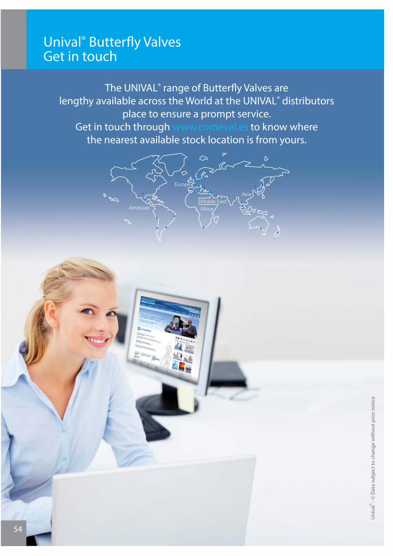
Unival® Butterfl y ValvesGet in touch
54
Uni
val®
- © D
ata
subj
ect t
o ch
ange
with
out p
rior n
otic
e
The UNIVAL® range of Butterfl y Valves are lengthy available across the World at the UNIVAL® distributors
place to ensure a prompt service. Get in touch through www.comeval.es to know where
the nearest available stock location is from yours.
2
Uni
val®
- © D
ata
subj
ect t
o ch
ange
with
out p
rior n
otic
e
55
Uni
val®
- © D
ata
subj
ect t
o ch
ange
with
out p
rior n
otic
e
Butterfl y Valveswww.comeval.es
Unival®
www.comeval.es
Unival®Excelling the best.