instruction manual - plate heat exchangers it · plate-and-frame heat exchanger. safety...
TRANSCRIPT

Instruction Manual - Plate Heat Exchangers
M15, TL10, TL15, T20, TS20, MX25, MA30, WideGap 100, WideGap 200
3490017598-EN 2016-06
Original manual
EN
IT
FI
LT


Table of contents
Preface .. . . . . . . . . . . . . . . . . . . . . . . . . . . . . . . . . . . . . . . . . . . . . . . . . . . . . . . . . . . . . . . . . . . . . . . . . . . . . . . . . . . . . . . . . . . . . . . . . . . . . . 4Safety considerations . . . . . . . . . . . . . . . . . . . . . . . . . . . . . . . . . . . . . . . . . . . . . . . . . . . . . . . . . . . . . . . . . . . . . . . . . . . . . . . . . . 4Prior knowledge .. . . . . . . . . . . . . . . . . . . . . . . . . . . . . . . . . . . . . . . . . . . . . . . . . . . . . . . . . . . . . . . . . . . . . . . . . . . . . . . . . . . . . . . 4Definitions of expressions .. . . . . . . . . . . . . . . . . . . . . . . . . . . . . . . . . . . . . . . . . . . . . . . . . . . . . . . . . . . . . . . . . . . . . . . . . . . . 4PHE drawings .. . . . . . . . . . . . . . . . . . . . . . . . . . . . . . . . . . . . . . . . . . . . . . . . . . . . . . . . . . . . . . . . . . . . . . . . . . . . . . . . . . . . . . . . . . 4Warranty conditions . .. . . . . . . . . . . . . . . . . . . . . . . . . . . . . . . . . . . . . . . . . . . . . . . . . . . . . . . . . . . . . . . . . . . . . . . . . . . . . . . . . . 4Advice . .. . . . . . . . . . . . . . . . . . . . . . . . . . . . . . . . . . . . . . . . . . . . . . . . . . . . . . . . . . . . . . . . . . . . . . . . . . . . . . . . . . . . . . . . . . . . . . . . . . 4Storage of the heat exchanger . . . . . . . . . . . . . . . . . . . . . . . . . . . . . . . . . . . . . . . . . . . . . . . . . . . . . . . . . . . . . . . . . . . . . . . 4Storage in packing box .. . . . . . . . . . . . . . . . . . . . . . . . . . . . . . . . . . . . . . . . . . . . . . . . . . . . . . . . . . . . . . . . . . . . . . . . . . . . . . . 5Taken out of service . .. . . . . . . . . . . . . . . . . . . . . . . . . . . . . . . . . . . . . . . . . . . . . . . . . . . . . . . . . . . . . . . . . . . . . . . . . . . . . . . . . . 5Environmental compliance .. . . . . . . . . . . . . . . . . . . . . . . . . . . . . . . . . . . . . . . . . . . . . . . . . . . . . . . . . . . . . . . . . . . . . . . . . . . 5
Description .. . . . . . . . . . . . . . . . . . . . . . . . . . . . . . . . . . . . . . . . . . . . . . . . . . . . . . . . . . . . . . . . . . . . . . . . . . . . . . . . . . . . . . . . . . . . . . . . . . 6Components . . . . . . . . . . . . . . . . . . . . . . . . . . . . . . . . . . . . . . . . . . . . . . . . . . . . . . . . . . . . . . . . . . . . . . . . . . . . . . . . . . . . . . . . . . . . 6Name plate .. . . . . . . . . . . . . . . . . . . . . . . . . . . . . . . . . . . . . . . . . . . . . . . . . . . . . . . . . . . . . . . . . . . . . . . . . . . . . . . . . . . . . . . . . . . . . 8Function . . . . . . . . . . . . . . . . . . . . . . . . . . . . . . . . . . . . . . . . . . . . . . . . . . . . . . . . . . . . . . . . . . . . . . . . . . . . . . . . . . . . . . . . . . . . . . . . . 9Multi-pass . .. . . . . . . . . . . . . . . . . . . . . . . . . . . . . . . . . . . . . . . . . . . . . . . . . . . . . . . . . . . . . . . . . . . . . . . . . . . . . . . . . . . . . . . . . . . . . 10Identification of plate side .. . . . . . . . . . . . . . . . . . . . . . . . . . . . . . . . . . . . . . . . . . . . . . . . . . . . . . . . . . . . . . . . . . . . . . . . . . . . 10
Installation .. . . . . . . . . . . . . . . . . . . . . . . . . . . . . . . . . . . . . . . . . . . . . . . . . . . . . . . . . . . . . . . . . . . . . . . . . . . . . . . . . . . . . . . . . . . . . . . . . . 11Before installation . . . . . . . . . . . . . . . . . . . . . . . . . . . . . . . . . . . . . . . . . . . . . . . . . . . . . . . . . . . . . . . . . . . . . . . . . . . . . . . . . . . . . . 11Requirements . . . . . . . . . . . . . . . . . . . . . . . . . . . . . . . . . . . . . . . . . . . . . . . . . . . . . . . . . . . . . . . . . . . . . . . . . . . . . . . . . . . . . . . . . . . 11Lifting . . . . . . . . . . . . . . . . . . . . . . . . . . . . . . . . . . . . . . . . . . . . . . . . . . . . . . . . . . . . . . . . . . . . . . . . . . . . . . . . . . . . . . . . . . . . . . . . . . . . . 13Raising .. . . . . . . . . . . . . . . . . . . . . . . . . . . . . . . . . . . . . . . . . . . . . . . . . . . . . . . . . . . . . . . . . . . . . . . . . . . . . . . . . . . . . . . . . . . . . . . . . . 13
Operation . .. . . . . . . . . . . . . . . . . . . . . . . . . . . . . . . . . . . . . . . . . . . . . . . . . . . . . . . . . . . . . . . . . . . . . . . . . . . . . . . . . . . . . . . . . . . . . . . . . . 15Start-up .. . . . . . . . . . . . . . . . . . . . . . . . . . . . . . . . . . . . . . . . . . . . . . . . . . . . . . . . . . . . . . . . . . . . . . . . . . . . . . . . . . . . . . . . . . . . . . . . . 15Unit in operation .. . . . . . . . . . . . . . . . . . . . . . . . . . . . . . . . . . . . . . . . . . . . . . . . . . . . . . . . . . . . . . . . . . . . . . . . . . . . . . . . . . . . . . . 17Shut-down ... . . . . . . . . . . . . . . . . . . . . . . . . . . . . . . . . . . . . . . . . . . . . . . . . . . . . . . . . . . . . . . . . . . . . . . . . . . . . . . . . . . . . . . . . . . . . 17
Maintenance .. . . . . . . . . . . . . . . . . . . . . . . . . . . . . . . . . . . . . . . . . . . . . . . . . . . . . . . . . . . . . . . . . . . . . . . . . . . . . . . . . . . . . . . . . . . . . . . . 18Cleaning – Non-product side ... . . . . . . . . . . . . . . . . . . . . . . . . . . . . . . . . . . . . . . . . . . . . . . . . . . . . . . . . . . . . . . . . . . . . . . 18Opening .. . . . . . . . . . . . . . . . . . . . . . . . . . . . . . . . . . . . . . . . . . . . . . . . . . . . . . . . . . . . . . . . . . . . . . . . . . . . . . . . . . . . . . . . . . . . . . . . . 20Manual cleaning of opened units . . . . . . . . . . . . . . . . . . . . . . . . . . . . . . . . . . . . . . . . . . . . . . . . . . . . . . . . . . . . . . . . . . . . . 23Closing .. . . . . . . . . . . . . . . . . . . . . . . . . . . . . . . . . . . . . . . . . . . . . . . . . . . . . . . . . . . . . . . . . . . . . . . . . . . . . . . . . . . . . . . . . . . . . . . . . . 25Closing – TL15-B .. . . . . . . . . . . . . . . . . . . . . . . . . . . . . . . . . . . . . . . . . . . . . . . . . . . . . . . . . . . . . . . . . . . . . . . . . . . . . . . . . . . . . . 27Pressure test after maintenance .. . . . . . . . . . . . . . . . . . . . . . . . . . . . . . . . . . . . . . . . . . . . . . . . . . . . . . . . . . . . . . . . . . . . 28Regasketing . . . . . . . . . . . . . . . . . . . . . . . . . . . . . . . . . . . . . . . . . . . . . . . . . . . . . . . . . . . . . . . . . . . . . . . . . . . . . . . . . . . . . . . . . . . . . 29
How to contact Alfa Laval
Contact details for all countries are
continually updated on our website.
Please visit www.alfalaval.com to access the information directly.
© Alfa Laval Corporate AB
This document and its contents is owned by Alfa Laval Corporate AB and protected by laws governing intellectual property and
thereto related rights. It is the responsibility of the user of this document to comply with all applicable intellectual property laws.
Without limiting any rights related to this document, no part of this document may be copied, reproduced or transmitted in any
form or by any means (electronic, mechanical, photocopying, recording, or otherwise), or for any purpose, without the expressed
permission of Alfa Laval Corporate AB. Alfa Laval Corporate AB will enforce its rights related to this document to the fullest
extent of the law, including the seeking of criminal prosecution.
Document ID Language Edition
3490017599 EN 2016-06 Instruction Manual - Plate Heat Exchangers 3
EN

Preface
Preface
This manual provides information needed to install,
operate and carry out maintenance of your gasketed
plate-and-frame heat exchanger.
Safety considerationsThe heat exchanger shall be used and maintained in
accordance with Alfa Laval’s instructions in this manual.
Incorrect handling of the heat exchanger may result in
serious consequences with injuries to persons and/or
property damage. Alfa Laval will not accept responsibility
for any damage or injury resulting from not following the
instructions in this manual.
Your heat exchanger should be used in accordance
with the specified configuration of material, media
types, temperatures and pressure for your specific heat
exchanger.
The following models are covered in this manual:
• M15• TL10• TL15• T20• TS20• MX25• MA30• WideGap 100• WideGap 200
Prior knowledgeThe heat exchanger shall be operated by persons who have
studied the instructions in this manual and have knowledge
of the process. This includes knowledge of precautions
regarding media type, pressures, temperatures in the heat
exchanger as well as specific precautions required by the
process.
Maintenance and installation of the heat exchanger shall be
done by persons who have knowledge and authorization
according to local regulations. This may include actions
such as piping, welding and other kind of maintenance.
For maintenance actions not described in this manual,
contact your Alfa Laval representative for advice.
Definitions of expressions
Warning!
Type of hazard
WARNING indicates a potentially hazardous
situation which, if not avoided, could result in death
or serious injury.
Caution!
Type of hazard
CAUTION indicates a potentially hazardous
situation which, if not avoided, may result in minor
or moderate injury.
Note!
NOTE indicates a potentially hazardous situation
which, if not avoided, may result in property
damage.
PHE drawingsPHE (plate heat exchanger) drawings mentioned in the
manual are the drawings included in the delivery of the
heat exchanger.
Warranty conditionsThe warranty conditions are usually included in the
signed sales contract prior to the order of the delivered
heat exchanger. Alternatively, the warranty conditions
are included in the sales offer documentation or with a
reference to the document specifying the valid conditions.
If faults occur during the specified warranty period, always
consult your local Alfa Laval representative for advice.
Report the date when the heat exchanger was put into
operation to the local Alfa Laval representative.
AdviceAlways consult your local Alfa Laval representative for
advice on:
• New plate pack dimensions if you intend to change thenumber of plates
• Selection of gasket material if operating temperaturesand pressures are permanently changed, or if anothermedium is to be processed in the heat exchanger
Storage of the heat exchangerAlfa Laval delivers the heat exchanger ready to be put
into service upon arrival, if nothing else has been agreed.
Nevertheless, keep the heat exchanger in the packing box
until installation.
If storing for longer periods of time, such as one month
or longer, certain precautions should be made to avoid
unnecessary damage to the heat exchanger. Refer to
“Outdoor storage” and “Indoor storage” on page 5 .
Note!
Alfa Laval and its representatives reserve the right
to inspect the storage space and/or equipment
whenever necessary until the expiration of
the warranty period stipulated in the contract.
Notification must be given 10 days prior to the date
of inspection.
If there is any uncertainty about the storage of the heat
exchanger, consult an Alfa Laval representative.
Document ID Language Edition
4 Instruction Manual - Plate Heat Exchangers 3490017599 EN 2016-06

Preface
Storage in packing boxIf storage of the heat exchanger after delivery is known
in advance, inform Alfa Laval when ordering the heat
exchanger to ensure that it will be properly prepared for
storage before packing.
Indoor storage• Store inside a room with the temperature between
15 and 20°C (60–70°F) and humidity up to 70%. Foroutdoor storage read “Outdoor storage” on this page.
• To prevent damage to the gaskets, there should not beany ozone-producing equipment in the room such aselectric motors or welding equipment.
• To prevent damage to the gaskets, do not store organicsolvents or acids in the room and avoid direct sunlight,intensive heat radiation or ultraviolet radiation.
• The tightening bolts should be well covered with a thinlayer of grease. Refer to “Closing” on page 25.
Outdoor storage
If you need to store your heat exchanger outdoors, follow
all the precautions in the “Indoor storage” section as well as
the precautions listed below.
The stored heat exchanger shall be visually checked every
third month. When closing the packing it shall be restored
to original condition. The check includes:
• Greasing of the tightening bolts• Metal port covers• Protection of the plate pack and gaskets• The packing
Taken out of serviceIf, for any reason, the heat exchanger is shut down and
taken out of service for a long period of time, follow the
precautions in the section ”Indoor storage” on this page.
However, before storage the following actions must be
done.
• Check the measurement of the plate pack (measurebetween frame plate and pressure plate, the Adimension).
• Drain both media sides of the heat exchanger.• Depending on media, the heat exchanger should be
rinsed and then dried.• The connection should be covered if the piping system
is not connected. Use a plastic or plywood cover forthe connection.
• Cover the plate pack with non-transparent plastic film.
Start-up after long-term out of service
If the heat exchanger has been taken out of service for an
extensive period of time, longer than one year, the risk of
leakage when starting up increases. To avoid this problem
it is recommended to let the gasket rubber rest to regain
most of its elasticity.
1. If the heat exchanger is not in position, follow theinstructions “Installation” on page 11.
2. Note the measurement between frame plate andpressure plate (A dimension).
3. Remove the feet attached to the pressure plate.4. Loosen the tightening bolts. Follow the instructions
“Opening” on page 20. Open the heat exchanger untilthe measure A is 1.25.
5. Leave the heat exchanger for 24–48 hours, the longerthe better, for gaskets to relax.
6. Re-tighten according to the instructions “Closing” onpage 25.
7. Alfa Laval recommends a hydraulic test should becarried out. The media, usually water, should beentered at intervals to avoid sudden shocks to the heatexchanger. It is recommended to test up to the DesignPressure. Refer to the PHE drawing.
Environmental complianceAlfa Laval endeavours to perform its own operations
as cleanly and efficiently as possible, and to take
environmental aspects into consideration when developing,
designing, manufacturing, servicing and marketing its
products.
Unpacking
Packing material consists of wood, plastics, cardboard
boxes and, in some cases, metal straps.
• Wood and cardboard boxes can be reused, recycled orused for energy recovery.
• Plastics should be recycled or burnt at a licensed wasteincineration plant.
• Metal straps should be sent for material recycling.
Maintenance• All metal parts should be sent for material recycling.• Oil and all non-metal wear parts must be taken care of
in accordance with local regulations.
Scrapping
At end of use, the equipment shall be recycled according
to relevant, local regulations. Besides the equipment itself,
any hazardous residues from the process liquid must be
considered and dealt with in a proper manner. When in
doubt, or in the absence of local regulations, please contact
the local Alfa Laval sales company.
Document ID Language Edition
3490017599 EN 2016-06 Instruction Manual - Plate Heat Exchangers 5
EN

Description
Description
Components
8
3
5
6
24
1
7
Main components
1 Frame plate Fixed plate with a various number of portholes for the connection of the piping system.
The carrying and guiding bar are attached to the frame plate.
2 Carrying bar Carries the plate pack and the pressure plate.
3 Plate pack Heat is transferred from one media to the other through the plates. The plate pack
consists of channel plates, end plates, gaskets and in some cases transition plates. The
measurement of the plate pack is the A dimension, i.e the measurement between frame
plate and pressure plate. Refer to the PHE drawing.
4 Pressure plate Moveable plate that can contain a various number of portholes for the connection of
the piping system.
5 Guiding bar Keeps the channel plates, connection plates and the pressure plate alligned at their
lower end.
6 Support column Supports carrying and guiding bars.
7 Tightening bolts Compress the plate pack between the frame plate and the pressure plate.
The bolts with bearing boxes are identified as tightening bolts.
Remaining bolts are used as locking bolts.
8 Portholes Portholes through the frame plate allow the media to enter into or exit from the heat
exchanger.
Document ID Language Edition
6 Instruction Manual - Plate Heat Exchangers 3490017599 EN 2016-06

Description
Connections
Stud bolts Threaded stud bolts around the portholes secure the flange connections to the apparatus.
Multi-section
Partition plates Solid carbon steel plates used in multi-pass configurations. Strengthens the turning
plate when needed.
Optional components
Foot Gives stability and is used to secure the heat exchanger with bolts to the foundation.
Protection sheets Cover the plate pack and protect against leakage of hot or aggressive fluids and the
hot plate pack.
Bolt protection Plastic tubes that protect the threads of the tightening bolts.
Insulation For applications where the heat exchanger surface will be hot or cold, insulation can
be used.
Lifting device Separate device that are attached on the heat exchanger used for lifting the heat
exchanger.
Earthing lug An earthing connection is used to eliminate the risk of static electricity building up in
the equipment.
Nozzle cover Protection to avoid particles to enter into the heat exchanger during transportation.
Drip tray Depending on the type of fluid in the heat exchanger and the type of installation, a drip tray
(drainage box) may be necessary to avoid injury to personnel and damage to equipment.
Document ID Language Edition
3490017599 EN 2016-06 Instruction Manual - Plate Heat Exchangers 7
EN
Description
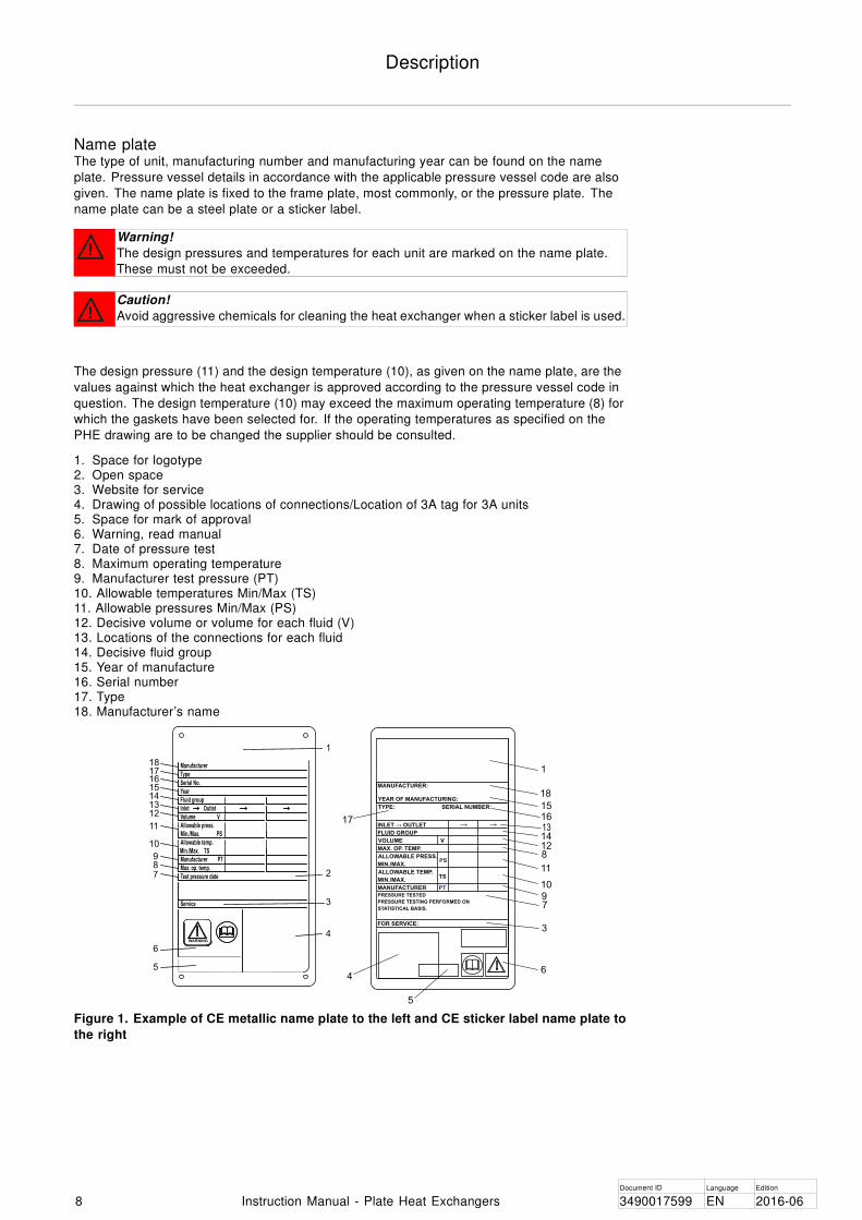
Name plateThe type of unit, manufacturing number and manufacturing year can be found on the name
plate. Pressure vessel details in accordance with the applicable pressure vessel code are also
given. The name plate is fixed to the frame plate, most commonly, or the pressure plate. The
name plate can be a steel plate or a sticker label.
Warning!
The design pressures and temperatures for each unit are marked on the name plate.
These must not be exceeded.
Caution!
Avoid aggressive chemicals for cleaning the heat exchanger when a sticker label is used.
The design pressure (11) and the design temperature (10), as given on the name plate, are the
values against which the heat exchanger is approved according to the pressure vessel code in
question. The design temperature (10) may exceed the maximum operating temperature (8) for
which the gaskets have been selected for. If the operating temperatures as specified on the
PHE drawing are to be changed the supplier should be consulted.
1. Space for logotype2. Open space3. Website for service4. Drawing of possible locations of connections/Location of 3A tag for 3A units5. Space for mark of approval6. Warning, read manual7. Date of pressure test8. Maximum operating temperature9. Manufacturer test pressure (PT)10. Allowable temperatures Min/Max (TS)11. Allowable pressures Min/Max (PS)12. Decisive volume or volume for each fluid (V)13. Locations of the connections for each fluid14. Decisive fluid group15. Year of manufacture16. Serial number17. Type18. Manufacturer’s name
1
2
3
4
18171615141312
11
10
987
6
5
1
18
15
1314128
11
10
9
6
5
4
17
7
3
TS
V
INLET → OUTLET
VOLUME
MIN./MAX.
ALLOWABLE PRESS.
→ →
STATISTICAL BASIS.
MANUFACTURER
FOR SERVICE:
PRESSURE TESTING PERFORMED ON
PRESSURE TESTED
MAX. OP. TEMP.
FLUID GROUP
YEAR OF MANUFACTURING:
MANUFACTURER:
ALLOWABLE TEMP.
MIN./MAX.
TYPE: SERIAL NUMBER:
PT
PS
Service
Year
Manufacturer
Fluid group
Inlet Outlet
Allowable press.
Allowable temp.
Volume V
Manufacturer
Serial No.
Type
Max. op. temp.
Test pressure date
WARNING
Min./Max. PS
Min./Max. TS
PT
16
Figure 1. Example of CE metallic name plate to the left and CE sticker label name plate to
the right
Document ID Language Edition
8 Instruction Manual - Plate Heat Exchangers 3490017599 EN 2016-06

Description
FunctionThe heat exchanger consists of a pack of corrugated metal plates with portholes for the input
and output of the two separate fluids. The heat transfer between the two fluids takes place
through the plates.
The plate pack is assembled between a frame plate and a pressure plate and compressed by
tightening bolts. The plates are fitted with a gasket which seals the channel and directs the
fluids into alternate channels. The plate corrugation promotes fluid turbulence and supports the
plates against differential pressure.
Figure 2. Example of a single-pass set up.
Document ID Language Edition
3490017599 EN 2016-06 Instruction Manual - Plate Heat Exchangers 9
EN

Description
Multi-passMulti-pass sections can be created by using turning plates with 1, 2 or 3 unholed ports. The
main purpose is to change the flow direction of one or both fluids.
For some units, a partition plate is required to support the unholed ports in the turning plates. A
transition plate also needs to be added to the pack to prevent media from coming into contact
with the partition plate or pressure plate.
An example of where multi-pass can be used is in processes that require longer heating periods
if the media requires slower heating.
1. End plate I
2. End plate II
3. Channel plate
4. Transition plate
5. Turning plate
6. Partition plate
3 3 12 4 45 56
Figure 3. Example of a multi-pass set up
Identification of plate sideThe A side of the plate is identified by a stamp with the letter A or the model name, in some
cases both, at the top of the plate (refer to image 1. below).
The WideGap unit has two possible channel configurations: wide-wide and wide-narrow. The
two plate pattern is marked R for Ridge-side image 2 and V for Valley-side image 3.
R
v
2. 3.
AXXX
1.
AXXX AXXX
Document ID Language Edition
10 Instruction Manual - Plate Heat Exchangers 3490017599 EN 2016-06

Installation
Installation
Before installation
To consider before installation• Before connecting any piping, make sure all foreign objects have been flushed out of the
piping system that should be connected to the heat exchanger.• Before start-up, check that all the tightening bolts are firmly tightened and that the plate pack
has the correct measurements. Refer to the PHE drawing.• When connecting the piping system, make sure the pipes do not subject the heat exchanger
to stress or strain.• To avoid water hammer, do not use fast-closing valves.• Make sure that no air remains inside the heat exchanger.• Safety valves shall be installed according to current pressure vessel regulations.• It is recommended that protection sheets are used to cover the plate pack. Protect against
the leakage of hot or aggressive fluids and the hot plate pack.• If the heat exchanger surface temperature is expected to be hot or cold, take protective
actions, such as insulate the heat exchanger, to avoid risk for personnel injuries. Alwaysensure that required actions are according to local regulations.
• Design pressures and temperatures for each model are marked on the name plate. Theseshall not be exceeded.
Requirements
4
1
3
2
Space
Please refer to the delivered PHE drawing for actual measurements.
1. Free space is required for lifting plates in and out.
2. Free space is required under the lower tightening/locking bolt for maintenance. This space
must be at least the length of the bolt.
3. Supports for the guiding bar may be needed.
4. Do not use fixed pipes or other fixed parts like feet, fasteners etc. inside the shaded area.
Foundation
Install on a flat foundation giving enough support to the frame.
Document ID Language Edition
3490017599 EN 2016-06 Instruction Manual - Plate Heat Exchangers 11
EN

Installation
Elbow
To make it easier to disconnect the heat exchanger, an elbow should be fitted to the connection
in the pressure plate, directed upwards or sideways, and with another flange located just outside
the contour of the heat exchanger.
Shut-off valve
To be able to open the heat exchanger, shut-off valves should be provided in all connections.
Connection
Different types of connections can be used to connect the piping system to the apparatus.
Flanged connections shall be attached with pin bolts.
Avoid excessive loads from the piping system.
Connections in the pressure plate
It is important that the plate pack has been tightened to the correct dimension A (check against
the PHE drawing) before the piping system is connected.
When opening the heat exchanger, the pressure plate must be moved. Do not use fixed pipes or
other parts like feet, fasteners etc. inside the shaded area.
Drip tray (optional)
Depending on the type of fluid in the heat exchanger and the type of installation, a drip tray
(drainage box) may be necessary to avoid injury to personnel and damage to equipment.
Note!
Put the drip tray in place before positioning the heat exchanger.
Document ID Language Edition
12 Instruction Manual - Plate Heat Exchangers 3490017599 EN 2016-06
Installation
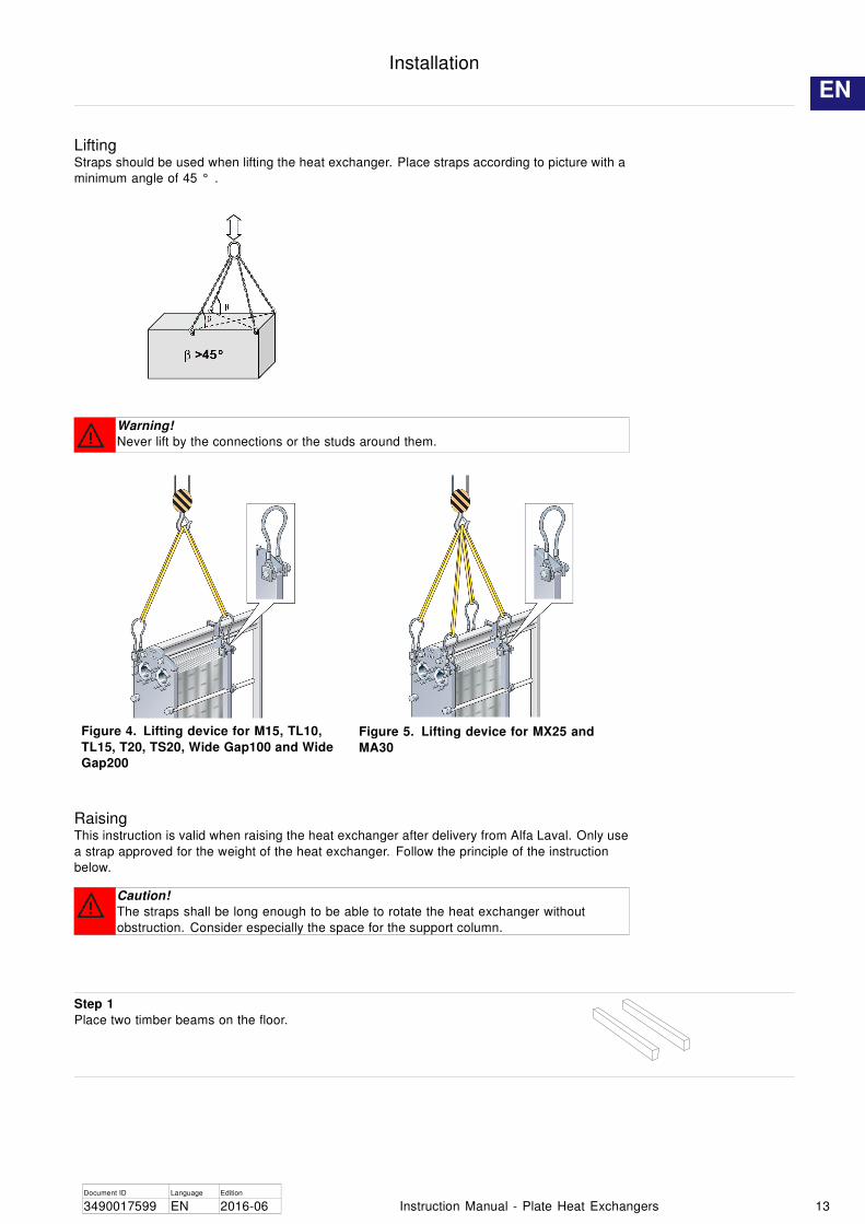
LiftingStraps should be used when lifting the heat exchanger. Place straps according to picture with a
minimum angle of 45 ° .
Warning!
Never lift by the connections or the studs around them.
Figure 4. Lifting device for M15, TL10,
TL15, T20, TS20, Wide Gap100 and Wide
Gap200
Figure 5. Lifting device for MX25 and
MA30
RaisingThis instruction is valid when raising the heat exchanger after delivery from Alfa Laval. Only use
a strap approved for the weight of the heat exchanger. Follow the principle of the instruction
below.
Caution!
The straps shall be long enough to be able to rotate the heat exchanger without
obstruction. Consider especially the space for the support column.
Step 1
Place two timber beams on the floor.
Document ID Language Edition
3490017599 EN 2016-06 Instruction Manual - Plate Heat Exchangers 13
EN

Installation
Step 2
Lift the heat exchanger off the pallet using e.g. straps.
Step 3
Place the heat exchanger on the timber beams.
Step 4
Place straps around one bolt on each side.
Step 5
Lift the heat exchanger off the timber beams.
Step 6
Lower the heat exchanger into a horizontal position and place
it on the floor.
Document ID Language Edition
14 Instruction Manual - Plate Heat Exchangers 3490017599 EN 2016-06

Operation
Operation
Start-upDuring the start-up, check that there are no visible leakages from the plate pack, valves or
piping system.
Caution!
Before pressurizing the heat exchanger, it is important to ensure that the temperature of
the heat exchanger is within the temperature range as stated in the PHE drawing.
Caution!
If the temperature of the heat exchanger is below the minimum temperature for the
gaskets prior to the service, it is recommended to heat the heat exchanger above this
limit to avoid cold leakage.
Note!
If several pumps are included in the system, make sure you know which one should be
activated first.
Centrifugal pumps must be started with valves closed and the valves must be operated as
smoothly as possible.
Do not run pumps temporarily empty on the suction side.
Note!
Adjustments of flow rates should be made slowly in order to avoid the risk of pressure
surge (water hammer).
Water hammer is a short lasting pressure peak that can appear during the start-up or
shut-down of a system, causing liquids to travel along a pipe as a wave at the speed of
sound. This can cause considerable damage to the equipment.
Step 1
Before start-up, check that all the tightening bolts are firmly
tightened and that the dimension A is correct. Refer to the PHE
drawing.
A
Step 2
Check that the valve is closed between the pump and the unit
controlling the system flow rate to avoid pressure surge.
Document ID Language Edition
3490017599 EN 2016-06 Instruction Manual - Plate Heat Exchangers 15
EN

Operation
Step 3
If there is a vent valve installed at the exit, make sure it is fully
open.
Step 4
Increase the flow rate slowly.
Step 5
Open the air vent and start the pump.A
Step 6
Open the valve slowly.
Note!
Avoid rapid temperature changes in the heat exchanger.
With media temperatures over 100°C, slowly increase
the temperature, preferably at least for one hour.
Step 7
When all the air is expelled, close the air vent.
Step 8
Repeat Step 1 to Step 7 for the second media.
Document ID Language Edition
16 Instruction Manual - Plate Heat Exchangers 3490017599 EN 2016-06

Operation
Unit in operationAdjustments of flow rates should be made slowly in order to protect the system against sudden
and extreme variations of temperature and pressure.
During operation, check that media temperatures and pressures are within the limits stated on
the name plate and the PHE drawing.
Warning!
In case of failures that endanger safety operation, turn off the flow to the heat exchanger
in order to decrease the pressure and stop heat transfer.
Shut-down
Note!
If several pumps are included in the system, make sure you know which one should be
stopped first.
Step 1
Slowly close the valve controlling the flow rate of the pump you
are about to stop.
Step 2
When the valve is closed, stop the pump.
Step 3
Repeat Step 1 and Step 2 for the other side for the second
media.
Step 4
If the heat exchanger is shut down for several days or longer, it
should be drained. Draining should also be done if the process
is shut down and the ambient temperature is below the freezing
temperature of the media. Depending on the media processed,
it is also recommended to rinse and dry the heat exchanger
plates and connections.
Note!
Avoid vacuum in the heat exchanger by opening the
vent valves.
Document ID Language Edition
3490017599 EN 2016-06 Instruction Manual - Plate Heat Exchangers 17
EN
Maintenance
Maintenance
To keep the heat exchanger in good condition, regular maintenance is required. It is
recommended to record all maintenance of the heat exchanger.
The plates need to be cleaned on a regular basis. The frequency depends on several factors
such as type of media and temperature. Different methods can be used for cleaning (refer
to “Cleaning – Non-product side” on page 18) or reconditioning can be performed at an Alfa
Laval service center.
After a long period of use, it can be required to regasket the heat exchanger. Refer to
“Regasketing” on page 29.
Other maintenance that should be performed regulary:
• Keep the carrying bar and guiding bar clean and grease.• Keep the tightening bolts cleaned and greased.• Check that all the tightening bolts are firmly tightened and that the dimension A is correct.
Refer to the PHE drawing.
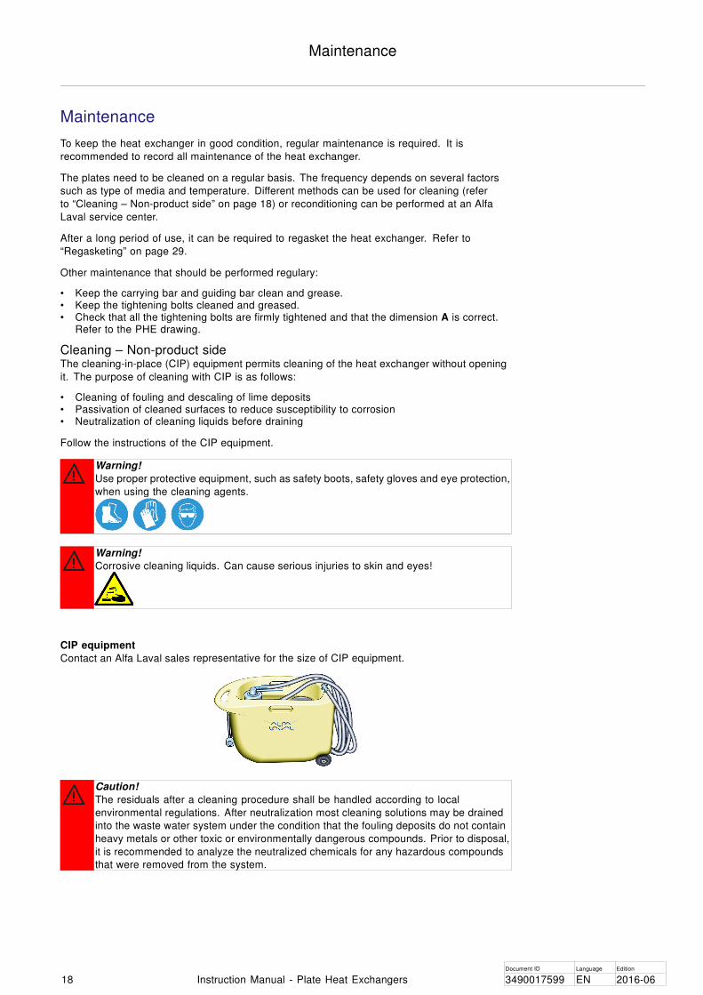
Cleaning – Non-product sideThe cleaning-in-place (CIP) equipment permits cleaning of the heat exchanger without opening
it. The purpose of cleaning with CIP is as follows:
• Cleaning of fouling and descaling of lime deposits• Passivation of cleaned surfaces to reduce susceptibility to corrosion• Neutralization of cleaning liquids before draining
Follow the instructions of the CIP equipment.
Warning!
Use proper protective equipment, such as safety boots, safety gloves and eye protection,
when using the cleaning agents.
Warning!
Corrosive cleaning liquids. Can cause serious injuries to skin and eyes!
CIP equipment
Contact an Alfa Laval sales representative for the size of CIP equipment.
Caution!
The residuals after a cleaning procedure shall be handled according to local
environmental regulations. After neutralization most cleaning solutions may be drained
into the waste water system under the condition that the fouling deposits do not contain
heavy metals or other toxic or environmentally dangerous compounds. Prior to disposal,
it is recommended to analyze the neutralized chemicals for any hazardous compounds
that were removed from the system.
Document ID Language Edition
18 Instruction Manual - Plate Heat Exchangers 3490017599 EN 2016-06

Maintenance
Cleaning liquids
Liquid Description
AlfaCaus A strong alkaline liquid, for removing paint, fat, oil and
biological deposits.
AlfaPhos An acid cleaning liquid for removing metallic oxides, rust,
lime and other inorganic scale. Contains repassivation
inhibitor
AlfaNeutra A strong alkaline liquid for neutralization of AlfaPhos before
drainage.
Alfa P-Neutra For neutralization of Alfa P-Scale.
Alfa P-Scale An acidic powder cleaner for the removal of primary
carbonate scale but also other inorganic scale.
AlfaDescalent A non-hazardous acidic cleaning agent for the removal of
inorganic scale.
AlfaDegreaser A non-hazardous cleaning agent for the removal of oil,
grease or wax deposits. Also prevents foaming when using
Alpacon Descaler.
AlfaAdd AlfaAdd is a neutral cleaning strengthener designed to be
used with AlfaPhos, AlfaCaus and Alfa P-Scale. 0.5–1
vol% is added to the total diluted cleaning solution to
provide better cleaning results on oily and fatty surfaces
and where biological growth occurs. AlfaAdd also reduces
any foaming.
If CIP cannot be done, cleaning must be done manually. Refer to “Manual cleaning of opened
units” on page 23.
Chlorine as a growth inhibitor
Chlorine, commonly used as a growth inhibitor in cooling water systems, reduces the corrosion
resistance of stainless steels (including high alloys like Alloy 254).
Chlorine weakens the protection layer of these steels making them more susceptible to corrosion
attacks then they otherwise would be. It is a matter of time of exposure and concentration.
In all cases where the chlorination of non-titanium equipment cannot be avoided, your local
representative must be consulted.
Water of more than 330 ppm Cl ions may not be used in the preparation of cleaning solutions.
Caution!
Ensure that the handling of residuals after using chlorines follow local envionmental
regulations.
Document ID Language Edition
3490017599 EN 2016-06 Instruction Manual - Plate Heat Exchangers 19
EN

Maintenance
OpeningDuring manual cleaning, it is necessary to open the heat exchanger to clean the plates.
Note!
Before opening the heat exchanger, check the warranty conditions. If in any doubt,
contact the Alfa Laval sales representative. Refer to “Warranty conditions” on page 4 .
Warning!
If the heat exchanger is hot, wait until it has cooled down to about 40°C (104°F).
Warning!
If necessary, use proper protective equipment, such as safety boots, safety gloves and
eye protection, depending on the type of media in the heat exchanger.
Bolt configuration
The bolt configuration of the heat exchanger varies between different models. The major force
of the plate pack is held by the tightening bolts (TB). To distribute the force evenly over the
frame plate and pressure plate, locking bolts (LB) are used as well. The locking bolts can be
shorter and can have smaller dimensions. In the opening and closing procedure, it is important
to identify the tightening bolts (TB) and the locking bolts (LB). Refer to the picture below.
TB TB
TB TB
LB LB
LB
LB
LB
LB
Step 1
Shut down the heat exchanger.
Step 2
Close the valves and isolate the heat exchanger from the rest
of the system.
Document ID Language Edition
20 Instruction Manual - Plate Heat Exchangers 3490017599 EN 2016-06

Maintenance
Step 3
Drain the heat exchanger.
Note!
Avoid vacuum in the heat exchanger by opening the
vent valves.
Step 4
Remove the protection sheets, if any.
Step 5
Dismantle pipes from the pressure plate so that the pressure
plate are free to move along the carrying bar.
Step 6
Inspect the sliding surfaces of the carrying bar and wipe clean
and grease.
Step 7
Mark the plate assembly on the outside by a diagonal line.
Step 8
Measure and note the dimension A.
A
A
Document ID Language Edition
3490017599 EN 2016-06 Instruction Manual - Plate Heat Exchangers 21
EN

Maintenance
Step 9
Loosen and remove the locking bolts. Identify them according to
“Bolt configuration” on page 20.
Note!
Brush the threads of the tightening bolts with a steel wire
brush and then grease the threads before loosening the
tigthening bolts.
Step 10
Use the tightening bolts to open the heat exchanger. During
the opening procedure keep the frame plate and pressure plate
parallel. Skewing of the pressure plate during opening must not
exceed 10 mm (2 turns per bolt) across the width and 25 mm (5
turns per bolt) vertically.
Loosen the four tightening bolts (1), (2), (3), (4) diagonally until
the plate pack A measure is 1.05 making sure that the frame
plate and pressure plate are parallel while opening. Continue
alternating between each bolt until all reaction forces of the plate
pack have disappeared. Then remove the bolts.A
A
3
1
2
4
Step 11
Open the plate pack by letting the pressure plate glide on the
carrying bar. Usually it is not necessary to remove the plates
to clean them.
Caution!
To avoid hand injuries owing to sharp edges, protective
gloves should always be worn when handling plates and
protection sheets.
If plates are to be numbered, do this before removing the plates.
Plates need not be removed if cleaning is done using only water,
i.e. without a cleaning agent.
Warning!
The plate pack may still contain a small residual amount
of liquid after draining. Depending on the type of
product and type of installation, special arrangements,
e.g. drainage box, may be necessary to avoid injury to
personnel and damage to equipment.
Document ID Language Edition
22 Instruction Manual - Plate Heat Exchangers 3490017599 EN 2016-06

Maintenance
Manual cleaning of opened units
Caution!
Never use hydrochloric acid with stainless steel plates. Water of more than 330 ppm Cl
may not be used in the preparation of cleaning solutions.
It is very important that aluminium carrying bars and support columns are protected
against chemicals.
Note!
Be careful not to damage the gasket during manual cleaning.
Warning!
Use proper protective equipment, such as safety boots, safety gloves and eye protection,
when using the cleaning agents.
Warning!
Corrosive cleaning liquids. Can cause serious injuries to skin and eyes!
Deposits removable with water and brush
Plates do not need to be removed from the heat exchanger during cleaning.
Step 1
Start cleaning when the heating surface is still wet and the plates
are hanging in the frame.
Step 2
Remove deposits using a soft brush and running water.
Step 3
Rinse with water using a high pressure hose.
Document ID Language Edition
3490017599 EN 2016-06 Instruction Manual - Plate Heat Exchangers 23
EN

Maintenance
Deposits not removable with water and brush
Plates must be removed from the heat exchanger during cleaning. For a choice of cleaning
agents, refer to “Cleaning liquids” on page 19.
Step 1
Brush with cleaning agent.
Step 2
Rinse immediately with water.
Note!
Long exposure to the cleaning agents can damage the
gasket glue.
Document ID Language Edition
24 Instruction Manual - Plate Heat Exchangers 3490017599 EN 2016-06

Maintenance
ClosingFollow the instructions below to ensure that the heat exchanger will be properly closed.
For bolt identification, refer to “Bolt configuration” on page 20.
Step 1
Check that all the sealing surfaces are clean.
Step 2
Brush the threads of the bolts clean, using a steel wire brush or
the Alfa Laval thread cleaner. Lubricate the threads with a thin
layer of grease, e.g. Gleitmo 800 or its equivalent.
Step 3
Attach the gaskets to the plates or check that all gaskets
are properly attached. Check that all gaskets are correctly
positioned in the grooves.
Note!
If the gasket is wrongly positioned, it will show by the
fact that it rises out of the gasket groove or that it is
positioned outside the groove.
Step 4
If the plates have been removed, insert them in alternate
directions and with the gaskets turned towards the frame plate
or pressure plate as specified on the plate hanging list. Use
the marked line that was made when the heat exchanger was
opened, refer to Step 7 in “Opening” on page 20.
Step 5
If the plate pack has been marked on the outside, check this
(see Step 7 in “Opening” on page 20).
If the plates are correctly assembled (A/B/A/B etc.), the edges
form a “honeycomb” pattern, see picture.
Document ID Language Edition
3490017599 EN 2016-06 Instruction Manual - Plate Heat Exchangers 25
EN

Maintenance
Step 6
Press the plate pack together. Position the four tightening bolts
according to the figure.
Tighten the four bolts (1), (2), (3), (4) until the plate pack
measure A is 1.10 making sure the frame plate and pressure
plate are parallel when closing.
A
A
3
1
2
4
Step 7
Tighten the four bolts (1), (2), (3), (4) evenly until dimension A
has been reached.
When a pneumatic tightening device is used, see table below for
maximum torque. Measure dimension A during tightening.
Bolt with bearing box Bolt with washerBolt size
Nm kpm Nm kpm
M30 900 90
M39 1300 130 2000 200
M48 2100 210 3300 330
For manual tightening, the tightening torque has to be estimated.
If dimension A cannot be reached:• Check the number of plates and the dimension A.• Check that all the nuts and bearing boxes are running freely.
If not, clean and lubricate, or replace.
A
A
3
1
6
5
2
4
Step 8
Mount the remaining locking bolts and check measurement A
on both sides, top and bottom.
Step 9
Mount protection sheets (if provided).
Step 10
Connect pipes.
Step 11
If the heat exchanger does not seal when measurement A has
been reached, it can be tightened further to A minus 1.0%.
Document ID Language Edition
26 Instruction Manual - Plate Heat Exchangers 3490017599 EN 2016-06

Maintenance
Closing – TL15-BFollow the instructions below to ensure that the heat exchanger will be properly closed.
Closing instructions
Step 1
1. Check that all the sealing surfaces are clean.
Step 2
2. Brush the threads of the bolts clean, using a steel wire brush
or the Alfa Laval thread cleaner. Lubricate the threads with a thin
layer of grease, e.g. Gleitmo 800 Lubriplate or its equivalent.
Step 3
3. Attach the gaskets to the plates or check that all gaskets are
properly attached.
Note!
If the gasket is wrongly positioned, it will show by the
fact that it rises out of the gasket groove or that it is
positioned outside the groove.
Step 4
Insert the plates in alternate directions and with the gaskets
turned towards the frame plate or pressure plate as specified on
the plate hanging list. Use the marked line that was made when
the heat exchanger was opened, refer to Step 7 in “Opening”
on page 20.
Step 5
5. Press the plate pack together and put the tightening bolts in
their positions. Tighten the bolts alternately in numeric order,
1 to 6 until.the plate pack measure A is 1.10. Alternatively
tighten the bolts alternately in numeric order, 1 to 8 until.the plate
pack measure A is 1.10A. Make sure that the frame plate and
pressure plate are in parallel during the closing procedure.
Step 6
6. Tighten the bolts alternately in numeric order, 1 to 6.
Alternatively tighten the bolts alternately in numeric order, 1 to 8.
Repeat this procedure until dimension A is reached.
Note!
Make sure that the frame plate and the pressure plate are
always positioned in parallel (within maximum 10 mm). 1
5
4
3
6
2
1
5
7
4
3
8
6
2
Document ID Language Edition
3490017599 EN 2016-06 Instruction Manual - Plate Heat Exchangers 27
EN
Maintenance
Pressure test after maintenanceBefore the start-up of production, whenever plates or gaskets have been removed, inserted or
exchanged, it is strongly recommended to perform a pressure test to confirm the internal and
external sealing function of the heat exchanger. In this test, one media side at a time must be
tested with the other side open to the ambient pressure. When multi-pass set up, all sections of
the same side must be tested simultaneously.
Caution!
The pressure testing shall be performed at a pressure equal to the operating pressure of
the actual unit but never above the design pressure as stated on the name plate.
The recommended test time is 10 minutes for each media.
Consult your local Alfa Laval representative for advice on the pressure testing procedure.
Document ID Language Edition
28 Instruction Manual - Plate Heat Exchangers 3490017599 EN 2016-06

Maintenance
RegasketingThe procedures below concern field gaskets, ring gaskets and end gaskets.
Note!
Before removing the old gaskets, check how they are attached.
Clip-on / ClipGrip
Step 1
Open the heat exchanger, refer to “Opening” on page 20, and
remove the plate that is to have a new gasket.
Note!
Before opening the heat exchanger, check the warranty
conditions. If in any doubt, contact the Alfa Laval sales
representative. Refer to “Warranty conditions” on page
4 .
Step 2
Remove the old gasket.
Step 3
Make sure that all sealing surfaces are dry, clean and free of
foreign matter such as fat, grease or similar.
Step 4
Check the gasket and remove rubber residual before attaching it.
Note!
Especially the end plate gasket!
Step 5
Attach the gasket to the plate. Slip the gasket tabs under the
edge of the plate.
Note!
Make sure the two gasket prongs are in the correct
position.
Clip-on
ClipGrip
Step 6
Repeat the procedure until all plates that are needed to be
regasketed are done. Close the heat exchanger according to
“Closing” on page 25.
Document ID Language Edition
3490017599 EN 2016-06 Instruction Manual - Plate Heat Exchangers 29
EN

Maintenance
Clip-ad gaskets (MX25 and TL15)
The Clip-ad gasket represents a system with the conventional Clip-on fastening around the ports and fastening by means of
adhesive tape along the sides of the plates.
The use of the adhesive tape (GC1) is a simple way to obtain secure gasket positioning. It is adhered to the gasket groove
by means of a special tape gun, making it easy to apply the tape exactly where wanted.
Step 1
Open the heat exchanger (refer to “Opening” on page 20) and
remove the plate that is to have a new gasket.
Note!
Before opening the heat exchanger, check the warranty
conditions. If in any doubt, contact an Alfa Laval sales
representative. Refer to “Warranty conditions” on page
4 .
Step 2
Remove the old gasket.
Step 3
It is not necessary to remove old tape as the film is very thin.
Make sure, however, that the gasket groove is clean and dry.
Step 4
Adhere tape, using the tape gun.
Step 5
Attach the gasket to the plate. Slip the gasket prongs under the
edge of the plate.
Step 6
Close the heat exchanger according to “Closing” on page 25.
Glued gaskets
Use glue recommended by Alfa Laval. Separate gluing instructions will be delivered together with the glue.
Caution!
Other glues than those recommended can contain chlorides that can damage the plates.
Warning!
Do not use sharp tools when removing the glued gasket to avoid damage to the plates.
Document ID Language Edition
30 Instruction Manual - Plate Heat Exchangers 3490017599 EN 2016-06