gasketed plate heat exchanger
TRANSCRIPT
GASKETED PLATE HEAT EXCHANGERMME 9516 HVAC 1 PROJECT PRESENTATION
BY - SALEEM MOHAMMED HAMZA (250873614)
OVERVIEW
INTRODUCTION CONSTRUCTION FLOW PATTERN IN A PHE PLATES PLATE MATERIALS DESIGN LOGIC FOR HEAT EXCHANGERS MEAN FLOW GAP CHANNEL HYDRAULIC DIAMETER HEAT TRANSFER COEFFICIENT CHANNEL MASS VELOCITY PRESSURE DROP OVERALL HEAT TRANSFER COEFFICIENT HEAT TRANSFER SURFACE AREA
INTRODUCTION
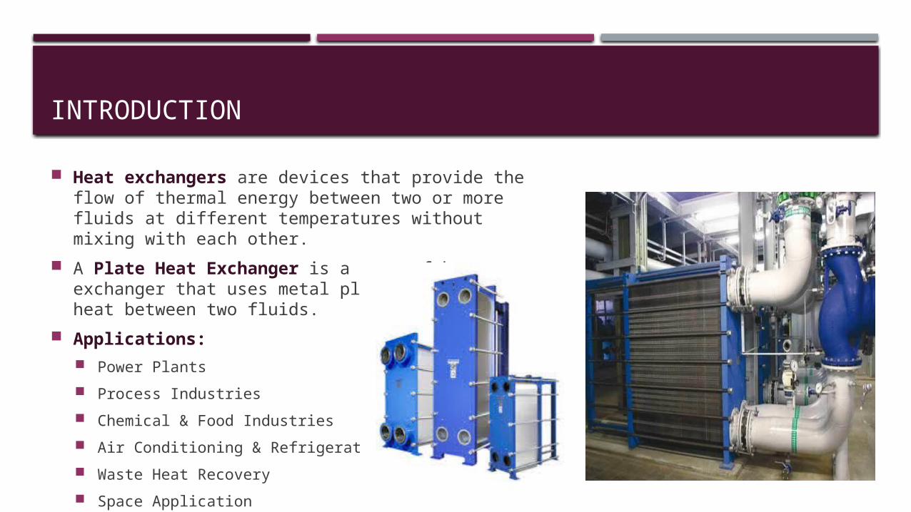
Heat exchangers are devices that provide the flow of thermal energy between two or more fluids at different temperatures without mixing with each other.
A Plate Heat Exchanger is a type of heat exchanger that uses metal plates to transfer heat between two fluids.
Applications: Power Plants Process Industries Chemical & Food Industries Air Conditioning & Refrigeration Waste Heat Recovery Space Application
CONSTRUCTION
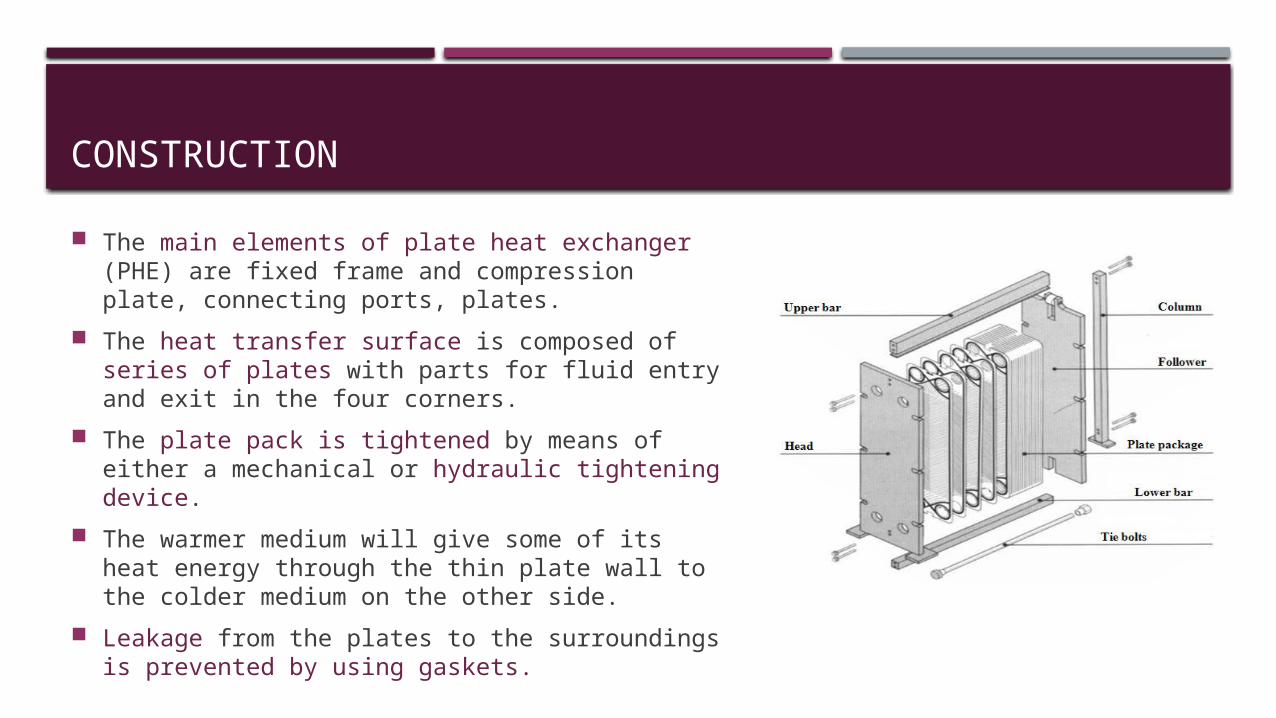
The main elements of plate heat exchanger (PHE) are fixed frame and compression plate, connecting ports, plates.
The heat transfer surface is composed of series of plates with parts for fluid entry and exit in the four corners.
The plate pack is tightened by means of either a mechanical or hydraulic tightening device.
The warmer medium will give some of its heat energy through the thin plate wall to the colder medium on the other side.
Leakage from the plates to the surroundings is prevented by using gaskets.
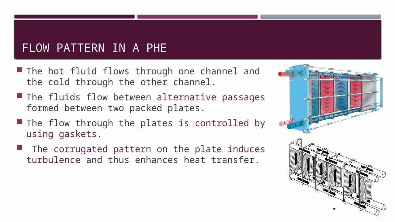
FLOW PATTERN IN A PHE The hot fluid flows through one channel and the cold
through the other channel. The fluids flow between alternative passages formed
between two packed plates. The flow through the plates is controlled by using
gaskets. The corrugated pattern on the plate induces
turbulence and thus enhances heat transfer.
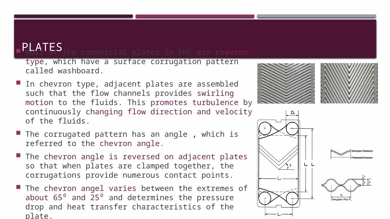
PLATES Most of the commercial plates in PHE are chevron type,
which have a surface corrugation pattern called washboard.
In chevron type, adjacent plates are assembled such that the flow channels provides swirling motion to the fluids. This promotes turbulence by continuously changing flow direction and velocity of the fluids.
The corrugated pattern has an angle , which is referred to the chevron angle.
The chevron angle is reversed on adjacent plates so that when plates are clamped together, the corrugations provide numerous contact points.
The chevron angel varies between the extremes of about 65⁰ and 25⁰ and determines the pressure drop and heat transfer characteristics of the plate.
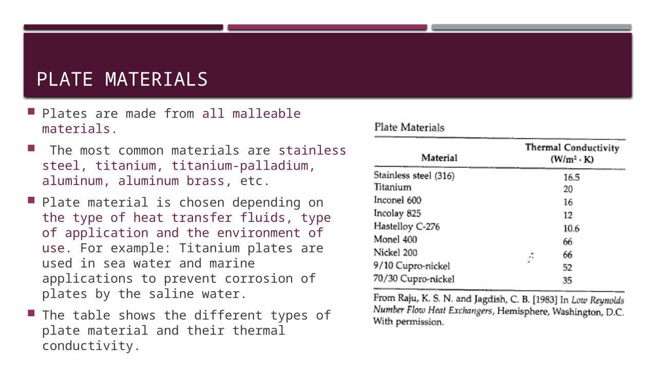
PLATE MATERIALS Plates are made from all malleable
materials. The most common materials are stainless
steel, titanium, titanium-palladium, aluminum, aluminum brass, etc.
Plate material is chosen depending on the type of heat transfer fluids, type of application and the environment of use. For example: Titanium plates are used in sea water and marine applications to prevent corrosion of plates by the saline water.
The table shows the different types of plate material and their thermal conductivity.
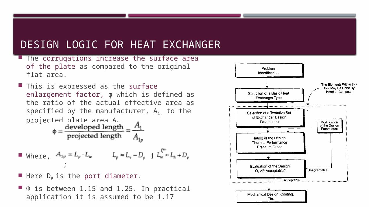
DESIGN LOGIC FOR HEAT EXCHANGER The corrugations increase the surface area of
the plate as compared to the original flat area. This is expressed as the surface enlargement
factor, φ which is defined as the ratio of the actual effective area as specified by the manufacturer, A1, to the projected plate area A1p
Where, and ; Here DP is the port diameter. Φ is between 1.15 and 1.25. In practical application it is
assumed to be 1.17
MEAN FLOW GAP
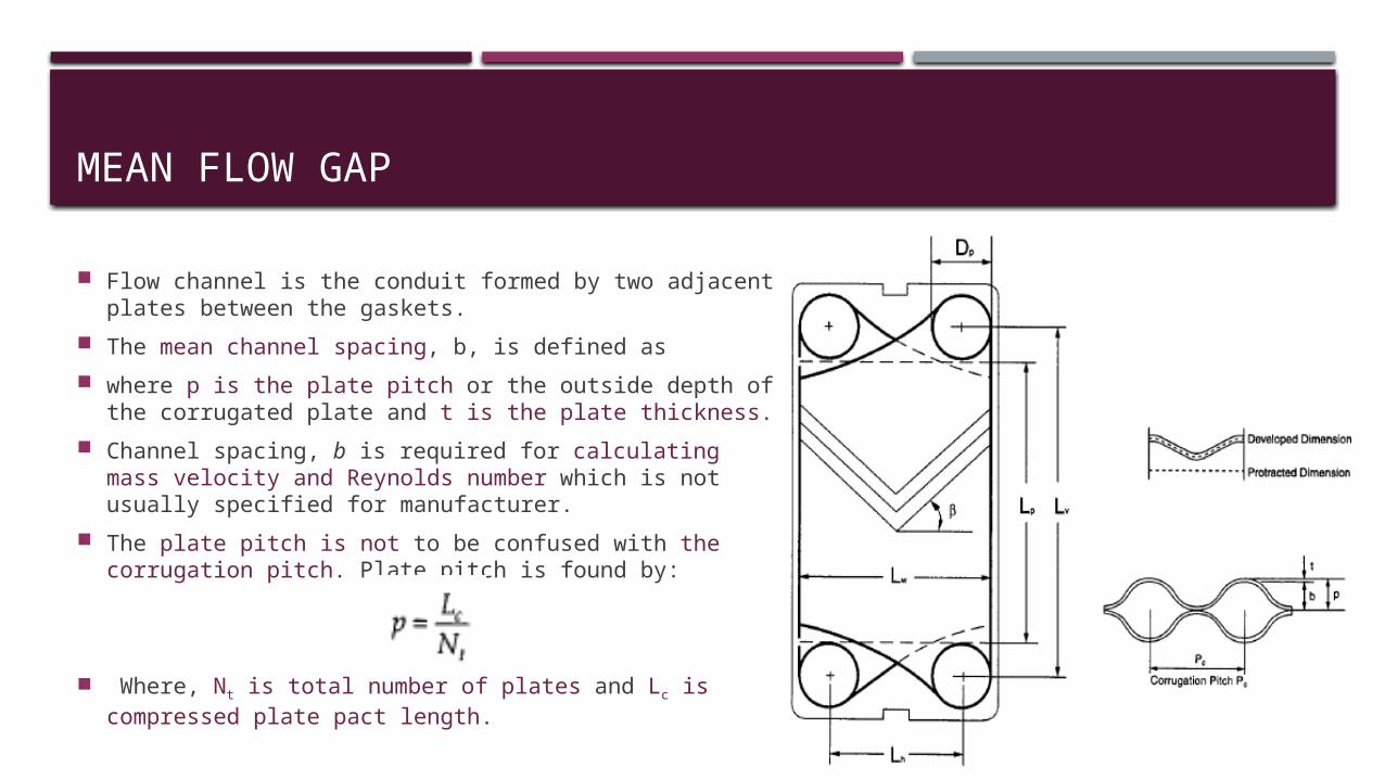
Flow channel is the conduit formed by two adjacent plates between the gaskets.
The mean channel spacing, b, is defined as where p is the plate pitch or the outside depth of the
corrugated plate and t is the plate thickness. Channel spacing, b is required for calculating mass
velocity and Reynolds number which is not usually specified for manufacturer.
The plate pitch is not to be confused with the corrugation pitch. Plate pitch is found by:
Where, Nt is total number of plates and Lc is
compressed plate pact length.
CHANNEL HYDRAULIC DIAMETER
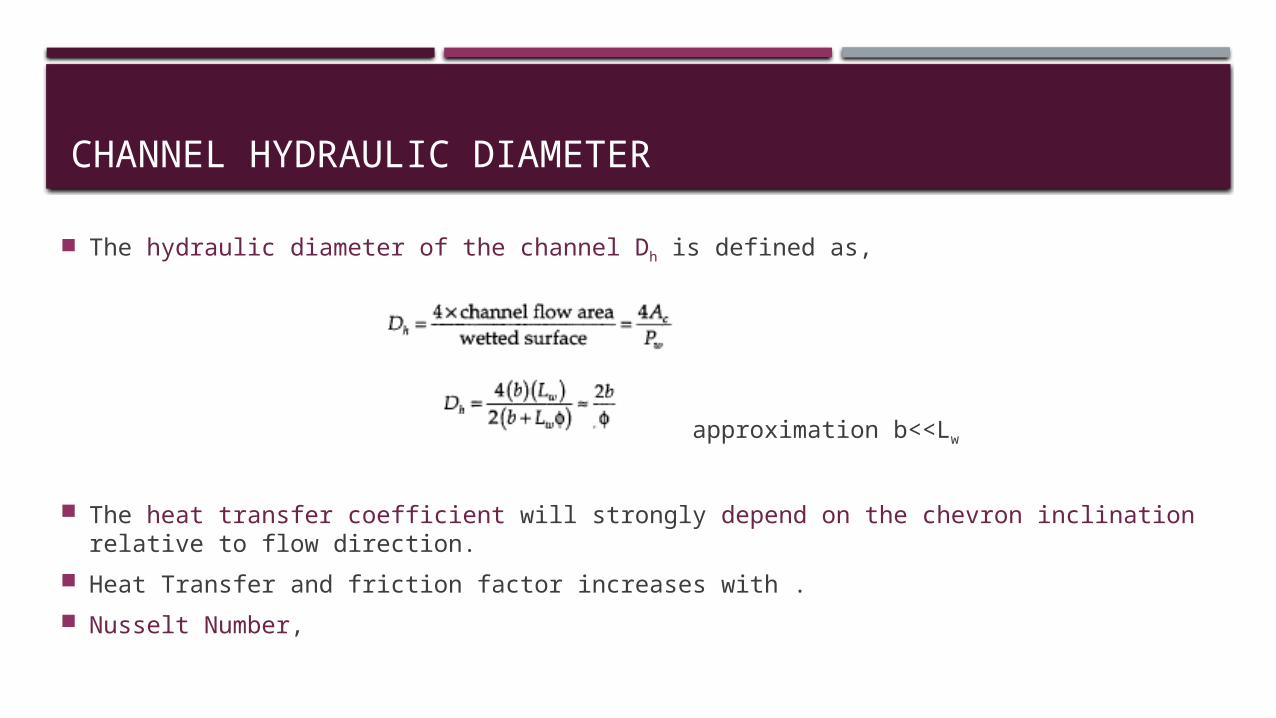
The hydraulic diameter of the channel Dh is defined as,
with approximation b<<Lw
The heat transfer coefficient will strongly depend on the chevron inclination relative to flow direction.
Heat Transfer and friction factor increases with . Nusselt Number,
HEAT TRANSFER COEFFICIENT
CHANNEL MASS VELOCITY
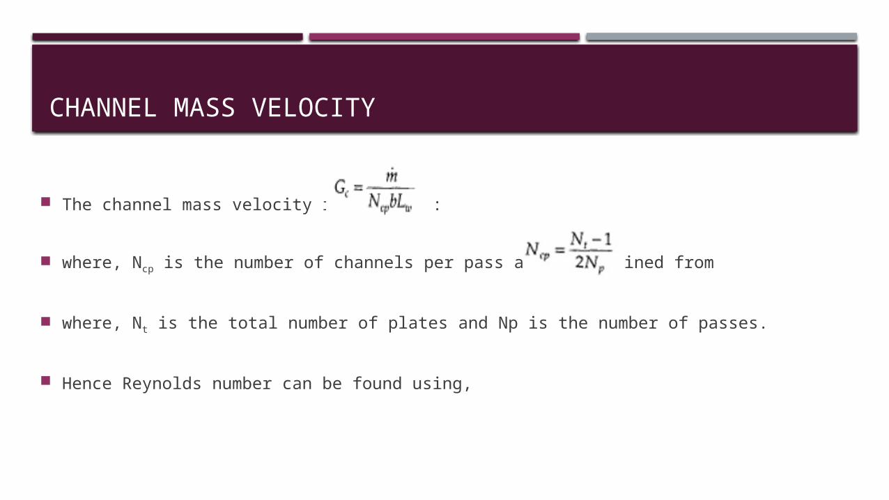
The channel mass velocity is given by:
where, Ncp is the number of channels per pass and is obtained from
where, Nt is the total number of plates and Np is the number of passes.
Hence Reynolds number can be found using,
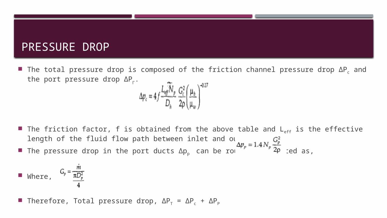
PRESSURE DROP The total pressure drop is composed of the friction channel pressure drop ΔPc and the port
pressure drop ΔPp.
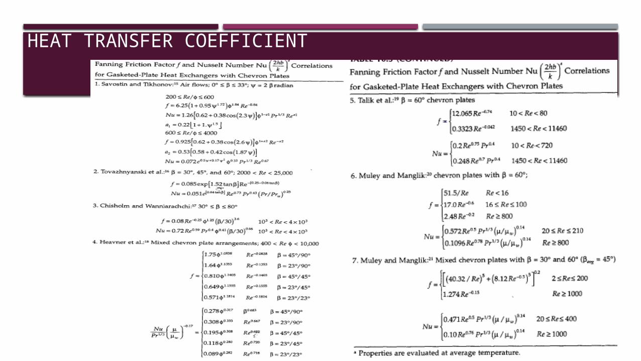
The friction factor, f is obtained from the above table and Leff is the effective length of the fluid flow path between inlet and outlet ports.
The pressure drop in the port ducts Δpp can be roughly estimated as,
Where,
Therefore, Total pressure drop, ΔPT = ΔPc + ΔPP
OVERALL HEAT TRANSFER COEFFICIENT
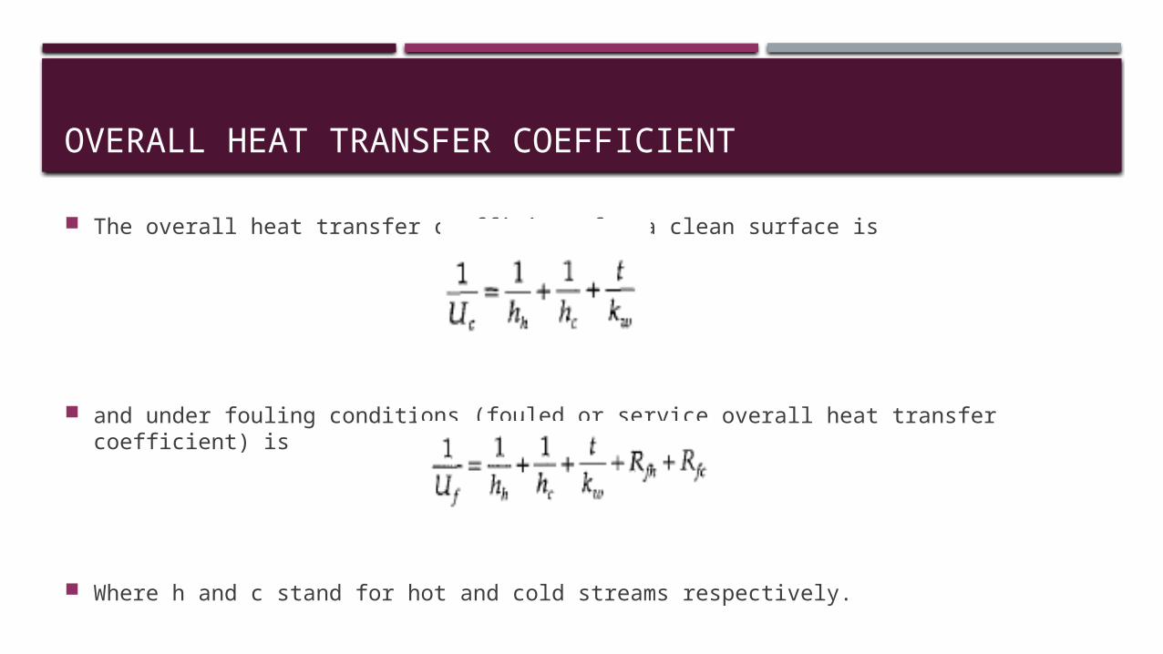
The overall heat transfer coefficient for a clean surface is
and under fouling conditions (fouled or service overall heat transfer coefficient) is
Where h and c stand for hot and cold streams respectively.
HEAT TRANSFER SURFACE AREA
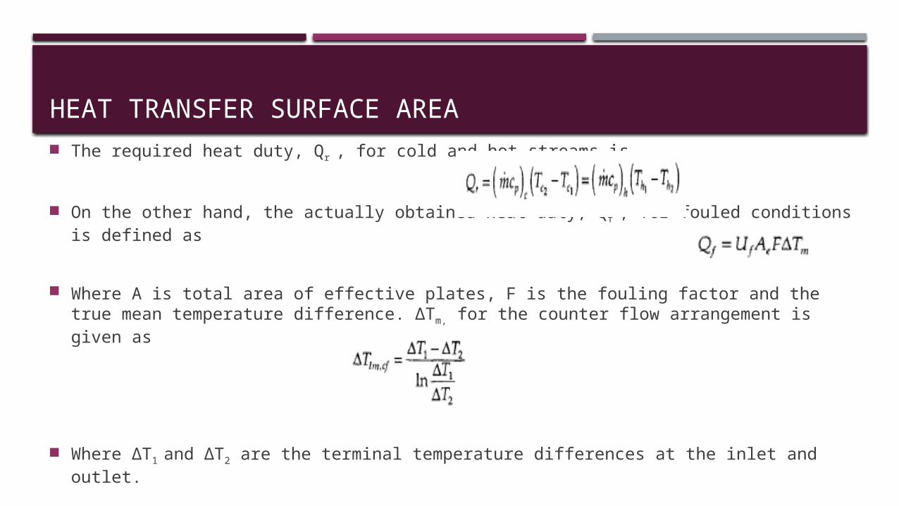
The required heat duty, Qr , for cold and hot streams is
On the other hand, the actually obtained heat duty, Qf , for fouled conditions is defined as
Where A is total area of effective plates, F is the fouling factor and the true mean temperature difference. ΔTm, for the counter flow arrangement is given as
Where ΔT1 and ΔT2 are the terminal temperature differences at the inlet and outlet.
ADVANTAGES
The gasket design minimizes the risk of internal leakage. Any failure in the gasket results in leakage to the atmosphere which is easily detectable on the exterior of the unit.
Flexibility of design through a variety of plate sizes and pass arrangements. Efficient heat transfer, high heat transfer coefficient for both fluids because of turbulence
and a small hydraulic diameter. Very compact (large heat transfer area to volume ratio) and low in weight in spite of their
compactness. The heat losses are negligible and no insulation is required as only the plate edges are
exposed to the atmosphere. Plate units exhibits low fouling characteristics due to high turbulence.