installation guide zenoss resource manager · zenoss resource manager installation guide 6 resource...
TRANSCRIPT

Zenoss Resource ManagerInstallation Guide
Release 6.2.0
Zenoss, Inc.
www.zenoss.com

2
Zenoss Resource Manager Installation Guide
Copyright © 2018 Zenoss, Inc. All rights reserved.
Zenoss, Own IT, and the Zenoss logo are trademarks or registered trademarks of Zenoss, Inc., in the United States and other countries. All othertrademarks, logos, and service marks are the property of Zenoss or other third parties. Use of these marks is prohibited without the express writtenconsent of Zenoss, Inc., or the third-party owner.
Amazon Web Services, AWS, and EC2 are trademarks of Amazon.com, Inc. or its affiliates in the United States and/or other countries.
Flash is a registered trademark of Adobe Systems Incorporated.
Oracle, the Oracle logo, Java, and MySQL are registered trademarks of the Oracle Corporation and/or its affiliates.
Linux is a registered trademark of Linus Torvalds.
RabbitMQ is a trademark of Pivotal Software, Inc.
SNMP Informant is a trademark of Garth K. Williams (Informant Systems, Inc.).
Sybase is a registered trademark of Sybase, Inc.
Tomcat is a trademark of the Apache Software Foundation.
VMware is a registered trademark or trademark of VMware, Inc. in the United States and/or other jurisdictions.
Windows is a registered trademark of Microsoft Corporation in the United States and other countries.
All other companies and products mentioned are trademarks and property of their respective owners.
Part Number: 1652.18.163.52
Zenoss, Inc.11305 Four Points DriveBldg 1 - Suite 300Austin, Texas 78726

3
Contents
About this guide.......................................................................................................................5Tested operating environments....................................................................................................................5Resource Manager publications...................................................................................................................6Change history............................................................................................................................................. 7
Part I: Appliance deployments....................................................................... 10Scope.......................................................................................................................................................... 10
Chapter 1: Installing a master host....................................................... 11Creating a virtual machine............................................................................................................ 11Configuring the Control Center master host................................................................................. 16Editing a connection to configure static IPv4 addressing.............................................................16Setting the system hostname......................................................................................................... 18Adding the master host to a resource pool................................................................................... 19Deploying Resource Manager....................................................................................................... 20
Chapter 2: Installing delegate hosts...................................................... 22Creating a virtual machine............................................................................................................ 22Configuring the virtual machine....................................................................................................26Editing a connection to configure static IPv4 addressing.............................................................27Setting the system hostname......................................................................................................... 29Editing the /etc/hosts file...............................................................................................................30
Chapter 3: Configuring a multi-host deployment................................ 32Delegate host authentication..........................................................................................................32
Chapter 4: Configuring a ZooKeeper ensemble...................................35ZooKeeper and Control Center..................................................................................................... 35Understanding the configuration process...................................................................................... 35Configuring the master host as a ZooKeeper node.......................................................................37Configuring delegate host A as a ZooKeeper node...................................................................... 38Configuring delegate host B as a ZooKeeper node...................................................................... 39Starting a ZooKeeper ensemble for the first time.........................................................................40Updating delegate hosts.................................................................................................................41
Part II: Non-appliance deployments.............................................................. 43Scope.......................................................................................................................................................... 43
Chapter 5: Adding Resource Manager to a standard deployment.... 44Downloading template and image files.........................................................................................44Installing the Resource Manager template.................................................................................... 44Importing Resource Manager images............................................................................................45Deploying Resource Manager....................................................................................................... 45

4
Chapter 6: Adding Resource Manager to a high-availabilitydeployment............................................................................................47
Downloading template and image files.........................................................................................47Installing the Resource Manager template.................................................................................... 48Importing Resource Manager images............................................................................................48Deploying Resource Manager....................................................................................................... 48
Appendix A: Enabling NTP on Microsoft Hyper-V guests..........................50Configuring NTP for public time servers................................................................................................. 50Configuring an NTP master server........................................................................................................... 51Configuring NTP clients............................................................................................................................52
About this guide
5
About this guideZenoss Resource Manager Installation Guide provides detailed procedures for installing Zenoss ResourceManager (short name: Resource Manager).
This guide supports the following, mutually-exclusive installation paths:
Part I: Appliance deployments: Install a Control Center and Resource Manager virtual appliance as guestsystems on VMWare vSphere or Microsoft Hyper-V hypervisors. For more information about using thispart, refer to the Zenoss Resource Manager Planning Guide.Part II: Non-appliance deployments: Add Resource Manager to an existing Control Center deployment.For more information about creating Control Center deployments, refer to the Zenoss Resource ManagerPlanning Guide.
For the latest information about this release of Resource Manager, refer to the Zenoss Resource ManagerRelease Notes.
Tested operating environments
The Resource Manager application is deployed in and managed by Control Center. The operating environmentsof Resource Manager are the Control Center environments that are tested with a given release. The followingsections identify the tested operating environments of Resource Manager and Control Center.
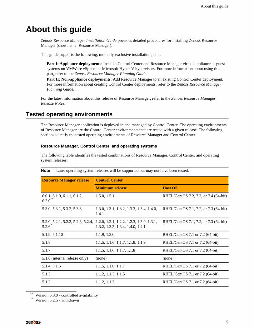
Resource Manager, Control Center, and operating systems
The following table identifies the tested combinations of Resource Manager, Control Center, and operatingsystem releases.
Note Later operating system releases will be supported but may not have been tested.
Control CenterResource Manager release
Minimum release Host OS
6.0.1, 6.1.0, 6.1.1, 6.1.2,6.2.0**
1.5.0, 1.5.1 RHEL/CentOS 7.2, 7.3, or 7.4 (64-bit)
5.3.0, 5.3.1, 5.3.2, 5.3.3 1.3.0, 1.3.1, 1.3.2, 1.3.3, 1.3.4, 1.4.0,1.4.1
RHEL/CentOS 7.1, 7.2, or 7.3 (64-bit)
5.2.0, 5.2.1, 5.2.2, 5.2.3, 5.2.4,5.2.6*
1.2.0, 1.2.1, 1.2.2, 1.2.3, 1.3.0, 1.3.1,1.3.2, 1.3.3, 1.3.4, 1.4.0, 1.4.1
RHEL/CentOS 7.1, 7.2, or 7.3 (64-bit)
5.1.9, 5.1.10 1.1.9, 1.2.0 RHEL/CentOS 7.1 or 7.2 (64-bit)
5.1.8 1.1.5, 1.1.6, 1.1.7. 1.1.8, 1.1.9 RHEL/CentOS 7.1 or 7.2 (64-bit)
5.1.7 1.1.5, 1.1.6, 1.1.7, 1.1.8 RHEL/CentOS 7.1 or 7.2 (64-bit)
5.1.6 (internal release only) (none) (none)
5.1.4, 5.1.5 1.1.5, 1.1.6, 1.1.7 RHEL/CentOS 7.1 or 7.2 (64-bit)
5.1.3 1.1.2, 1.1.3, 1.1.5 RHEL/CentOS 7.1 or 7.2 (64-bit)
5.1.2 1.1.2, 1.1.3 RHEL/CentOS 7.1 or 7.2 (64-bit)
** Version 6.0.0 - controlled availability* Version 5.2.5 - withdrawn

Zenoss Resource Manager Installation Guide
6
Control CenterResource Manager release
Minimum release Host OS
5.1.1 1.1.1, 1.1.2 RHEL/CentOS 7.1 or 7.2 (64-bit)
Hypervisors
Hypervisor Versions
VMware vSphere 5.0, 5.1, 5.5, 6.0, 6.5
Version 2.0 with Windows Server 2008 R2 SP1Microsoft Hyper-V
Version 3.0 with Windows Server 2012 and 2012 R2
Public cloud platforms
Amazon Web Services (AWS) is fully tested.
Microsoft Azure has been tested only for collector pools. Creating a full Control Center deployment to operateResource Manager has NOT been tested on Microsoft Azure.
Supported clients and browsers
The following table identifies the supported combinations of client operating systems and web browsers.
Client OS Supported browsers
Internet Explorer 11*
Firefox 56 and later
Windows 7, 10
Chrome 61 and later
Firefox 56 and latermacOS 10.12.3, 10.13
Chrome 61 and later
Firefox 56 and laterUbuntu 14.04 LTS
Chrome 61 and later
Resource Manager publications
Title Description
Zenoss Resource Manager AdministrationGuide
Provides an overview of Resource Manager architecture andfeatures, as well as procedures and examples to help use thesystem.
Zenoss Resource Manager ConfigurationGuide
Provides required and optional configuration procedures forResource Manager, to prepare your deployment for monitoring inyour environment.
* Enterprise mode only; compatibility mode is not tested.

About this guide
7
Title Description
Zenoss Resource Manager InstallationGuide
Provides detailed information and procedures for creatingdeployments of Control Center and Resource Manager.
Zenoss Resource Manager Planning Guide Provides both general and specific information for preparing todeploy Resource Manager.
Zenoss Resource Manager Release Notes Describes known issues, fixed issues, and late-breakinginformation not already provided in the published documentationset.
Zenoss Resource Manager Upgrade Guide Provides detailed information and procedures for upgradingdeployments of Resource Manager.
Additional information and comments
If you have technical questions about this product that are not answered in this guide, please visit the ZenossSupport site or contact Zenoss Support.
Zenoss welcomes your comments and suggestions regarding our documentation. To share your comments,please send an email to [email protected]. In the email, include the document title (Zenoss ResourceManager Installation Guide) and part number (1652.18.163.52).
Change history
The following list associates document part numbers and the important changes to this guide since the previousrelease. Some of the changes involve features or content, but others do not. For information about new orchanged features, refer to the Zenoss Resource Manager Release Notes.
1652.18.163.52 (6.2.0)
Update release numbers.
1652.18.081.40 (6.1.2)
Update release numbers.
1652.18.009 (6.1.0)
Update release numbers.
1652.17.320 (6.0.1)
Replace Leapfile.net with delivery.zenoss.com.
Update release numbers.
1652.17.311.1 (6.0.0)
Restructure appliance installation procedures.
Update non-appliance procedures for offline installation requirements.
Update release numbers.
1052.17.268 (5.3.2)
Update release numbers.
1052.17.242 (5.3.1)
Update release numbers.
1052.17.229 (5.3.0)
Beginning with this release, you can download and install the appliance artifacts or a converged set ofartifacts. This document was reorganized and updated with associated information.
Update release numbers.

Zenoss Resource Manager Installation Guide
8
1052.17.191 (5.2.6)
Update release numbers.
About 5.2.5
Version 5.2.5 was withdrawn.
1052.17.123 (5.2.4)
Update release numbers.
1052.17.100 (5.2.3)
Add a chapter for high-availability installations.
New procedures for installing the appliance with Hyper-V.
Update release numbers.
1052.17.58 (5.2.2)
Remove procedure for adding storage for backups (no longer required for appliances).
1052.17.044 (5.2.1)
Update release numbers.
1052.16.335 (5.2.0)
Add a section detailing the tested operating environments.
Remove procedures for installing Control Center. That information is now in the Control CenterInstallation Guide.
Remove the high-availability chapters. High-availability installations are now performed by Zenosspersonnel.
Remove the appliance installation chapters. The chapters will be replaced when the appliances are available.
The instructions for downloading and installing the software artifacts for offline deployments are now in anappendix.
1052.16.316
Update release numbers.
1052.16.291
Update release numbers.
1052.16.277
Update release numbers.
1052.16.264
Update release numbers.
1052.16.257
Added tested operating environments and updated release numbers.
1052.16.207
Update release numbers.
1052.16.176
Update release numbers.
1052.16.153
Update release numbers.
1052.16.146
Update release numbers.
1052.16.125
Refine the procedure for creating the application data thin pool.

About this guide
9
1052.16.118
Add Resource Manager 5.1.2.
Add a substep to create the docker override directory.
1052.16.111
Add this document change history.
Add chapters describing how to install the Resource Manager appliance.
Chapters are organized into parts.
Docker configuration steps now add the storage driver flag (-s devicemapper) to the /etc/sysconfig/docker file.
Docker needs a longer startup timeout value, to work around a known Docker issue with thedevicemapper driver. Docker configuration steps now include adding TimeoutSec=300.
Rather than editing /lib/systemd/system/docker.service, Docker configuration steps nowinclude adding a systemd override file.
Add a symlink to /tmp in /var/lib/docker.
Update the commands for starting and testing a ZooKeeper ensemble.
Add a procedure for updating the SERVICED_ZK value on delegate hosts that are not members of aZooKeeper ensemble.
Add a reference topic for the ZooKeeper variables required on Control Center hosts.
Add procedures for configuring an NTP server and clients for offline deployments.
Add step to install the Nmap Ncat package, which is used to check ZooKeeper ensemble status.
1052.16.060
Planning information is now in the Zenoss Resource Manager Planning Guide.
Information about how to start and configure Resource Manager is now in the Zenoss Resource ManagerConfiguration Guide.
New procedures are included, for installing without internet access, and for installing high-availabilitydeployments.

Zenoss Resource Manager Installation Guide
10
Appliance deploymentsScope
The chapters in this part describe how to install the Resource Manager appliance, a pre-configured virtualmachine that is ready to deploy to your hypervisor. The instructions include a variety of options for customizingyour deployment for your environment.
Note Resource Manager 6.1.x is compatible with Zenoss Service Impact version 5.2.3 or later. The latestversion of Zenoss Service Impact is included in the appliance.

Installing a master host
11
Installing a master host 1This chapter describes how to install a Resource Manager appliance package as a Control Center master host.All Resource Manager deployments require a Control Center master host.
Creating a virtual machine
You can create a virtual machine for the Resource Manager appliance with VMware vSphere or MicrosoftHyper-V. Choose one of the procedures in this section.
Creating a virtual machine with vSphere
To perform this task, you need:
■ A VMware vSphere client■ Permission to download files from delivery.zenoss.com. Customers can request permission by filing a ticket
at the Zenoss Support site.
This procedure installs Resource Manager OVA packages as a virtual machine managed by vSphere Serverversion 6.5.0, using VMware vSphere Web Client 6.5. The procedure might differ with other versions ofVMware vSphere Client.
1 In a web browser, navigate to the download site, and then log in.
The download site is delivery.zenoss.com.2 Download the Resource Manager master host OVA file.
zenoss-zsd-6.2.0-1-master.vmware.ova
3 Use the VMware vSphere Client to log in to vCenter as root, or as a user with superuser privileges, andthen display the Home view.

Zenoss Resource Manager Installation Guide
12
4 Choose VMs and Templates.5 In the top navigation bar, choose Actions > Deploy OVF Template.
Figure 1: Deploy OVF Template
6 Use panels in the Deploy OVF Template wizard to select the OVF package:
a To choose the package from a drive on your workstation or network share, browse to the location andchoose the OVA file. Click Next.
b Select name and location: Specify a name for the OVF, select a datacenter or folder as the deploymentlocation, and then click Next.
c Select a resource: Select the host, cluster, or other resource on which to run the deployed template, andthen click Next.

Installing a master host
13
d Review details: Verify the template details, and then click Next.e Select storage: In Select virtual disk format, choose Thin Provison, accept defaults for other fields,
and then click Next.f Select networks: Accept defaults and click Next.g Ready to Complete: Verify the deployment settings, and then click Finish.
The Recent Tasks pane displays deployment progress and status information.7 Navigate to the new virtual machine's Getting Started tab, and then click Edit virtual machine settings.8 For a multi-host deployment, edit the Virtual Hardware settings of the virtual machine.
a Change the settings.
■ Reduce the number of CPUs from 8 to 4.■ Reduce the amount of memory from 32 to 16.
b Click OK.9 On the new virtual machine's Getting Started tab, click Power on virtual machine.10 In the top navigation bar, choose Actions > Open console.
Proceed with Configuring the Control Center master host on page 16.
Creating a virtual machine with Hyper-V
To perform this task, you need:
■ Microsoft Remote Desktop Connection■ Administrator privileges on a Microsoft Hyper-V server■ Permission to download files from delivery.zenoss.com.
Use this procedure to install the Resource Manager master host appliance as a virtual machine managed byMicrosoft Hyper-V.
1 Use a Microsoft Remote Desktop Connection to log in to a Hyper-V host as Administrator, or as a user withAdministrator privileges.
2 In a web browser, navigate to the download site, and then log in.
The download site is delivery.zenoss.com.3 Download the Resource Manager master host ISO file.
zenoss-zsd-6.2.0-1-master.x86_64.iso
4 Open Hyper-V Manager.5 In the left navigation pane, choose a server to host the virtual machine.6 From the Action menu, choose New > Virtual Machine.
The New Virtual Machine Wizard opens.7 In the New Virtual Machine Wizard dialog, display the Specify Name and Location panel.
If the first panel displayed is the Before You Begin panel, click Next.8 In the Specify Name and Location panel, provide a name for the virtual machine, and then click Next.9 In the Specify Generation panel, choose Generation 1, and then click Next.10 In the Assign Memory panel, specify the memory for the virtual machine.
a In the Startup memory field, enter the amount of memory for the host.
■ For multi-host deployments, enter 16384 (16GB).■ For single-host deployments, enter 32768 (32GB).
b Optional: Check Use Dynamic Memory for this virtual machine.
Resource Manager is tested with dynamic memory enabled.c Click Next.

Zenoss Resource Manager Installation Guide
14
11 In the Configure Networking panel, choose a virtual switch, and then click Next.12 In the Connect Virtual Hard Disk panel, specify a new disk on which to install the guest operating system.
a Choose Create a virtual hard disk.b Specify a name.c In the Size field, enter 30.d Click Next.
13 In the Installation Options panel, specify the master host ISO file.
a Choose Install an operating system from a bootable CD/DVD-ROM.b Choose Image file (.iso).c Specify or browse to the location of the master host ISO file.d Click Next.
14 In the Completing the New Virtual Machine Wizard panel, verify the description, and then click Finish.
Hyper-V Manager creates the new virtual machine, and then closes the wizard.
Configuring and starting a Hyper-V master host
To perform this task, you need:
■ A Microsoft Remote Desktop Connection■ Administrator privileges on a Microsoft Hyper-V server■ The master host created in the previous procedure (Creating a virtual machine with Hyper-V on page
13)
The Resource Manager master host virtual machine requires a total of 7 virtual hard disks. The following tableidentifies the purpose and size of each disk.
Table 1: Master host disks
Purpose Size
1 Root (/) 30GB
2 Swap 16GB
3 Temporary (/tmp) 16GB
4 Docker data 50GB
5 Control Center internal services data 50GB
6 Application data 200GB
7 Application data backups 150GB
Disk 1 was created when the virtual machine was created, in the previous procedure. Use this procedure toconfigure hardware resources, create disks 2-6, and start the master host.
1 Use a Microsoft Remote Desktop Connection to log in to a Hyper-V host as Administrator, or as a user withAdministrator privileges.
2 Open Hyper-V Manager.3 In the Hyper-V Manager Virtual Machines area, right-click the new virtual machine, and then choose
Settings.The Settings dialog displays.
4 In the Hardware area, locate the virtual hard disk created previously, and then determine whether it isattached to an IDE controller.
Hyper-V guest machines can only boot from an IDE drive.

Installing a master host
15
5 In the Hardware area, choose Processor, and then change the number of processors assigned to themachine.
a In Number of virtual processors, enter the value for your deployment.
■ For single-host deployments, enter 8.■ For multi-host deployments, enter 4.
b Click Apply.6 In the Hardware area on the left, choose SCSI Controller, and then create additional virtual hard disks.
Repeat the following substeps to create new disks in the following sizes:
■ 50GB■ 150GB■ 50GB■ 200GB■ 16GB■ 16GB
a In the controller area on the right, choose Hard Drive, and then click Add.b In the Location field, choose an unused location number.c In the Media area, choose Virtual hard disk, and then click New.d Complete panels in the New Virtual Hard Disk Wizard as follows:
1 Choose Disk Format: Choose VHDX, and then click Next.2 Choose Disk Type: Choose Dynamically expanding, and then click Next.3 Specify Name and Location: Enter the disk name, and then click Next.4 Configure Disk:
a Choose Create a new blank virtual hard disk.b Size: Enter a disk size from the list at the beginning of this step.c Click Next.
5 Summary/New Virtual Hard Disk Wizard: Verify the description, and then click Finish.e At the bottom of the Settings window, click Apply.
When all of the disks are created, click OK.7 In the Hyper-V Manager Virtual Machines area, right-click the new virtual machine, and then choose
Start.
Figure 2: Starting a virtual machine
8 In the Hyper-V Manager Virtual Machines area, right-click the new virtual machine, and then chooseConnect.
9 In the Virtual Machine Connection window, press Enter.
The appliance installation process takes about 15 minutes, and should complete with no additional input.
If received, disregard the Fast TSC calibration failure message.

Zenoss Resource Manager Installation Guide
16
Configuring the Control Center master hostPerform this procedure immediately after creating and starting a Control Center host. All Control Centerdeployments must include one system that is configured as the master host.
1 Gain access to the console interface of the Control Center host through your hypervisor console interface.
Figure 3: Initial hypervisor console login prompt
2 Log in as the root user.The initial password is provided in the console.
3 The system prompts you to enter a new password for root.
Note Passwords must include a minimum of eight characters, with at least one character from three ofthe following character classes: uppercase letter, lowercase letter, digit, and special.
4 The system prompts you to enter a new password for ccuser.
The ccuser account is the default account for gaining access to the Control Center browser interface.
Editing a connection to configure static IPv4 addressingThe default configuration for network connections is DHCP. To configure static IPv4 addressing, perform thisprocedure.
To navigate in the text user interface (TUI):
■ To move forward or backward through options, press the arrow keys.■ To display a menu or choose an option, press Enter.
1 Gain access to the Control Center host, through the console interface of your hypervisor, or through a remoteshell utility such as PuTTY.
2 Log in as the root user.

Installing a master host
17
3 Select the NetworkManager TUI menu as follows:
a In the Appliance Administration menu, select Configure Network and DNS, and then press Enter.
4 On the NetworkManager TUI menu, select Edit a connection, and then press Enter.The TUI displays the connections that are available on the host.
Figure 4: Example: Available connections

Zenoss Resource Manager Installation Guide
18
Note Do not use this procedure to modify the docker0 connection.
5 Select the virtual connection, and then press Enter.
Figure 5: Example: Edit Connection screen
6 Optional: If the IPv4 CONFIGURATION area is not visible, select its display option (<Show>), and thenpress Enter.
7 In the IPv4 CONFIGURATION area, select <Automatic>, and then press Enter.
Figure 6: Example: IPv4 Configuration options
8 Configure static IPv4 networking as follows:
a Select Manual, and then press Enter.b Beside Addresses, select <Add>, and then press Enter.c In the Addresses field, enter an IPv4 address for the virtual machine, and then press Enter.d Repeat the preceding two steps for the Gateway and DNS servers fields.
9 Tab to the bottom of the Edit Connection screen to select OK, and then press Enter.10 Return to the Appliance Administration menu: On the NetworkManager TUI screen, select Quit, and
then press Enter.11 Reboot the operating system as follows:
a In the Appliance Administration menu, select Reboot / Poweroff System.b Select Reboot.c Select OK, and then press Enter.
Setting the system hostname
The default hostname is zsd-master for the Resource Manager master host and is zsd-delegate forResource Manager delegate hosts. To change the default hostname, perform this procedure.
1 Gain access to the Control Center host, through the console interface of your hypervisor, or through a remoteshell utility such as PuTTY.
2 Select the NetworkManager TUI menu as follows:
a In the Appliance Administration menu, select Configure Network and DNS, and then press Enter.

Installing a master host
19
3 Display the hostname entry field.
a In the NetworkManager TUI menu, select Set system hostname.b Select OK, and then press Enter.
4 In the Hostname field, enter the hostname or a fully qualified domain name.5 Press Tab twice to select OK, and then press Enter.
6 In the confirmation dialog box, press Enter.7 Return to the Appliance Administration menu: On the NetworkManager TUI screen, select Quit, and
then press Enter.8 Reboot the operating system as follows:
a In the Appliance Administration menu, select Reboot / Poweroff System.b Select Reboot.c Select OK, and then press Enter.
Adding the master host to a resource pool
Complete this procedure to add the Control Center master host to the default resource pool or to a newresource pool named master.
1 Gain access to the Control Center host, through the console interface of your hypervisor, or through a remoteshell utility such as PuTTY.
2 Start a command-line session as root.
a In the Appliance Administration menu, select Root Shell.b Select Run, and then press Enter.
The menu is replaced by a command prompt similar to the following example:
[root@hostname ~]#
3 Optional: Create a new resource pool, if necessary.
■ For single-host deployments, skip this step.■ For multi-host deployments, perform the following substeps.

Zenoss Resource Manager Installation Guide
20
a Create a new pool named master.
serviced pool add master
b Assign administrative and distributed file system (DFS) permissions to the new resource pool.
serviced pool set-permission --admin --dfs master
4 Add the master host to a resource pool.For single-host deployments, add the master host to the default resource pool.
Replace Hostname-Or-IP with the hostname or IP address of the Control Center master host:
serviced host add Hostname-Or-IP:4979 default
If you enter a hostname, all hosts in your Control Center deployment must be able to resolve the name, eitherthrough an entry in /etc/hosts, or through a nameserver on your network.For multi-host deployments, add the master host to the master resource pool and register itsauthentication token.
Replace Hostname-Or-IP with the hostname or IP address of the Control Center master host:
serviced host add --register Hostname-Or-IP:4979 master
If you enter a hostname, all hosts in your Control Center deployment must be able to resolve the name, eitherthrough an entry in /etc/hosts, or through a nameserver on your network.
5 To exit the command-line session, at the command prompt, enter exit.
Deploying Resource ManagerUse this procedure to add the Resource Manager application to Control Center and tag application images in thelocal registry.
1 Log in to the Control Center master host as a user with serviced CLI privileges.2 Add the Resource Manager application template to Control Center.
serviced template add /opt/serviced/templates/zenoss*.json
On success, the serviced command returns the template ID.3 Identify the resource pool to which the host belongs.
serviced host list
4 Deploy the application.
■ Replace Template-ID with the identifier Resource Manager template■ Replace Pool with the name of the resource pool to which the master host belongs (single-host system)
or to which the delegate hosts belong (multi-host system)■ Replace Deployment-ID with a name for this deployment (for example, Test or Production)
serviced template deploy Template-ID Pool Deployment-ID
Control Center tags Resource Manager images in the local registry.

Installing a master host
21
■ If you are creating a single-host deployment, proceed to the Zenoss Resource Manager Configuration Guide.■ If you are creating a multi-host deployment, proceed to the next chapter.

Zenoss Resource Manager Installation Guide
22
Installing delegate hosts 2This chapter describes how to install a Resource Manager appliance package as a Control Center delegate host.You can add as many delegate hosts as you need to a Control Center deployment.
Perform the procedures in Installing a master host on page 11 before performing the procedures in this chapter.
Creating a virtual machine
You can create a virtual machine for the Resource Manager delegate appliance with VMware vSphere orMicrosoft Hyper-V. Choose one of the procedures in this section.
Creating a virtual machine with vSphere
To perform this task, you need:
■ A VMware vSphere client■ Permission to download files from delivery.zenoss.com. Customers can request permission by filing a ticket
at the Zenoss Support site.
This procedure installs Resource Manager OVA packages as a virtual machine managed by vSphere Serverversion 6.5.0, using VMware vSphere Web Client 6.5. The procedure might differ with other versions ofVMware vSphere Client.
1 In a web browser, navigate to the download site, and then log in.
The download site is delivery.zenoss.com.2 Download the Resource Manager delegate host OVA file.
zenoss-zsd-6.2.0-1-delegate.vmware.ova
3 Use the VMware vSphere Client to log in to vCenter as root, or as a user with superuser privileges, andthen display the Home view.

Installing delegate hosts
23
4 In the top navigation bar, choose Actions > Deploy OVF Template.
Figure 7: Deploy OVF Template
5 Use panels in the Deploy OVF Template wizard to select the OVF package:
a To choose the package from a drive on your workstation or network share, browse to the location andchoose the OVA file. Click Next.
b Select name and location: Specify a name for the OVF, select a datacenter or folder as the deploymentlocation, and then click Next.
c Select a resource: Select the host, cluster, or other resource on which to run the deployed template, andthen click Next.
d Review details: Verify the template details, and then click Next.

Zenoss Resource Manager Installation Guide
24
e Select storage: In Select virtual disk format, choose Thin Provison, accept defaults for other fields,and then click Next.
f Select networks: Accept defaults and click Next.g Ready to Complete: Verify the deployment settings, and then click Finish.
The Recent Tasks pane displays deployment progress and status information.6 Navigate to the new virtual machine's Getting Started tab, and then click Edit virtual machine settings.7 On the new virtual machine's Getting Started tab, click Power on virtual machine.
Creating a virtual machine with Hyper-V
To perform this task, you need:
■ Microsoft Remote Desktop Connection■ Administrator privileges on a Microsoft Hyper-V server■ Permission to download files from delivery.zenoss.com.
Use this procedure to install the Resource Manager delegate host appliance as a virtual machine managed byMicrosoft Hyper-V.
1 Use a Microsoft Remote Desktop Connection to log in to a Hyper-V host as Administrator, or as a user withAdministrator privileges.
2 In a web browser, navigate to the download site, and then log in.
The download site is delivery.zenoss.com.3 Download the Resource Manager delegate host ISO file.
zenoss-zsd-6.2.0-1-delegate.x86_64.iso
4 Open Hyper-V Manager.5 In the left navigation pane, choose a server to host the virtual machine.6 From the Action menu, choose New > Virtual Machine.
The New Virtual Machine Wizard opens.7 In the New Virtual Machine Wizard dialog, display the Specify Name and Location panel.
If the first panel displayed is the Before You Begin panel, click Next.8 In the Specify Name and Location panel, provide a name for the virtual machine, and then click Next.9 In the Specify Generation panel, choose Generation 1, and then click Next.10 In the Assign Memory panel, specify the memory for the virtual machine.
a In the Startup memory field, enter 32768 (32GB).b Optional: Check Use Dynamic Memory for this virtual machine.
Resource Manager is tested with dynamic memory enabled.c Click Next.
11 In the Configure Networking panel, choose a virtual switch, and then click Next.12 In the Connect Virtual Hard Disk panel, specify a new disk on which to install the guest operating system.
a Choose Create a virtual hard disk.b Specify a name.c In the Size field, enter 30.d Click Next.
13 In the Installation Options panel, specify the delegate host ISO file.
a Choose Install an operating system from a bootable CD/DVD-ROM.b Choose Image file (.iso).c Specify or browse to the location of the delegate host ISO file.d Click Next.
14 In the Completing the New Virtual Machine Wizard panel, verify the description, and then click Finish.

Installing delegate hosts
25
Hyper-V Manager creates the new virtual machine, and then closes the wizard.
Configuring and starting a Hyper-V delegate host
To perform this task, you need:
■ A Microsoft Remote Desktop Connection■ Administrator privileges on a Microsoft Hyper-V server■ The delegate host created in the previous procedure (Creating a virtual machine with Hyper-V on page
24)
Resource Manager delegate host virtual machines requires a total of 4 virtual hard disks. The following tableidentifies the purpose and size of each disk.
Table 2: Delegate host disks
Purpose Size
1 Root (/) 30GB
2 Swap 16GB
3 Temporary (/tmp) 16GB
4 Docker data 50GB
Disk 1 was created when the virtual machine was created, in the previous procedure. Use this procedure toconfigure hardware resources, create disks 2-4, and start the master host.
1 Use a Microsoft Remote Desktop Connection to log in to a Hyper-V host as Administrator, or as a user withAdministrator privileges.
2 Open Hyper-V Manager.3 In the Hyper-V Manager Virtual Machines area, right-click the new virtual machine, and then choose
Settings.The Settings dialog displays.
4 In the Hardware area, locate the virtual hard disk created previously, and then determine whether it isattached to an IDE controller.
Hyper-V guest machines can only boot from an IDE drive.5 In the Hardware area, choose Processor, and then change the number of processors assigned to the
machine.
a In Number of virtual processors, enter 8.b Click Apply.
6 In the Hardware area on the left, choose SCSI Controller, and then create additional virtual hard disks.
Repeat the following substeps to create new disks in the following sizes:
■ 50GB■ 16GB■ 16GB
a In the controller area on the right, choose Hard Drive, and then click Add.b In the Location field, choose an unused location number.c In the Media area, choose Virtual hard disk, and then click New.d Complete panels in the New Virtual Hard Disk Wizard as follows:
1 Choose Disk Format: Choose VHDX, and then click Next.2 Choose Disk Type: Choose Dynamically expanding, and then click Next.

Zenoss Resource Manager Installation Guide
26
3 Specify Name and Location: Enter the disk name, and then click Next.4 Configure Disk:
a Choose Create a new blank virtual hard disk.b Size: Enter a disk size from the list at the beginning of this step.c Click Next.
5 Summary/New Virtual Hard Disk Wizard: Verify the description, and then click Finish.e At the bottom of the Settings window, click Apply.
When all of the disks are created, click OK.7 In the Hyper-V Manager Virtual Machines area, right-click the new virtual machine, and then choose
Start.
Figure 8: Starting a virtual machine
8 In the Hyper-V Manager Virtual Machines area, right-click the new virtual machine, and then chooseConnect.
9 In the Virtual Machine Connection window, press Enter.
The appliance installation process takes about 15 minutes, and should complete with no additional input.
If received, disregard the Fast TSC calibration failure message.
Configuring the virtual machineThis procedure configures the new virtual machine as a delegate host.
1 Gain access to the console interface of the Control Center host through your hypervisor console interface.
Figure 9: Initial hypervisor console login prompt
2 Log in as the root user.

Installing delegate hosts
27
The initial password is provided in the console.3 The system prompts you to enter a new password for root.
Note Passwords must include a minimum of eight characters, with at least one character from three ofthe following character classes: uppercase letter, lowercase letter, digit, and special.
4 The system prompts you to enter a new password for ccuser.
The ccuser account is the default account for gaining access to the Control Center browser interface.5 In the IP field, enter the hostname, fully qualified domain name, or IPv4 address of the master host.
Note If you enter the hostname or fully qualified domain name of the master host, you need an entry inthe /etc/hosts file of the delegate host or a nameserver on your network that resolves the name to itsIPv4 address.
a Press Tab to select Ok, and then press Enter.
The system reboots.
Editing a connection to configure static IPv4 addressingThe default configuration for network connections is DHCP. To configure static IPv4 addressing, perform thisprocedure.
To navigate in the text user interface (TUI):
■ To move forward or backward through options, press the arrow keys.■ To display a menu or choose an option, press Enter.
1 Gain access to the Control Center host, through the console interface of your hypervisor, or through a remoteshell utility such as PuTTY.
2 Log in as the root user.

Zenoss Resource Manager Installation Guide
28
3 Select the NetworkManager TUI menu as follows:
a In the Appliance Administration menu, select Configure Network and DNS, and then press Enter.
4 On the NetworkManager TUI menu, select Edit a connection, and then press Enter.The TUI displays the connections that are available on the host.
Figure 10: Example: Available connections

Installing delegate hosts
29
Note Do not use this procedure to modify the docker0 connection.
5 Select the virtual connection, and then press Enter.
Figure 11: Example: Edit Connection screen
6 Optional: If the IPv4 CONFIGURATION area is not visible, select its display option (<Show>), and thenpress Enter.
7 In the IPv4 CONFIGURATION area, select <Automatic>, and then press Enter.
Figure 12: Example: IPv4 Configuration options
8 Configure static IPv4 networking as follows:
a Select Manual, and then press Enter.b Beside Addresses, select <Add>, and then press Enter.c In the Addresses field, enter an IPv4 address for the virtual machine, and then press Enter.d Repeat the preceding two steps for the Gateway and DNS servers fields.
9 Tab to the bottom of the Edit Connection screen to select OK, and then press Enter.10 Return to the Appliance Administration menu: On the NetworkManager TUI screen, select Quit, and
then press Enter.11 Reboot the operating system as follows:
a In the Appliance Administration menu, select Reboot / Poweroff System.b Select Reboot.c Select OK, and then press Enter.
Setting the system hostname
The default hostname is zsd-master for the Resource Manager master host and is zsd-delegate forResource Manager delegate hosts. To change the default hostname, perform this procedure.
1 Gain access to the Control Center host, through the console interface of your hypervisor, or through a remoteshell utility such as PuTTY.
2 Select the NetworkManager TUI menu as follows:
a In the Appliance Administration menu, select Configure Network and DNS, and then press Enter.

Zenoss Resource Manager Installation Guide
30
3 Display the hostname entry field.
a In the NetworkManager TUI menu, select Set system hostname.b Select OK, and then press Enter.
4 In the Hostname field, enter the hostname or a fully qualified domain name.5 Press Tab twice to select OK, and then press Enter.
6 In the confirmation dialog box, press Enter.7 Return to the Appliance Administration menu: On the NetworkManager TUI screen, select Quit, and
then press Enter.8 Reboot the operating system as follows:
a In the Appliance Administration menu, select Reboot / Poweroff System.b Select Reboot.c Select OK, and then press Enter.
Editing the /etc/hosts fileThis procedure is conditional. Perform this procedure only if you use hostnames or fully qualified domainnames instead of IPv4 addresses, and only after all delegate hosts are installed and renamed. Perform thisprocedure on the Control Center master host and on each delegate host.
1 Gain access to the Control Center host, through the console interface of your hypervisor, or through a remoteshell utility such as PuTTY.
2 Start a command-line session as root.
a In the Appliance Administration menu, select Root Shell.b Select Run, and then press Enter.
The menu is replaced by a command prompt similar to the following example:
[root@hostname ~]#
3 Open the /etc/hosts file in a text editor.
The following steps use the nano editor.

Installing delegate hosts
31
a Start the editor.
nano /etc/hosts
Figure 13: Example nano session
b Optional: On delegate hosts, the file might include two entries with the same IP address. Remove the firstof the two entries, which maps the IP address to the zsd-master hostname.
c Add entries for the Control Center master host and for each delegate host.d To save, press Control-o.e To exit, press Control-x.
4 Return to the Appliance Administration menu.
exit
5 Exit the Appliance Administration menu.
a Use the down-arrow key to select Exit.b Press Tab, and then press Enter.

Zenoss Resource Manager Installation Guide
32
Configuring a multi-host deployment 3This chapter describes how to configure an appliance-based multi-host deployment, which includes one ControlCenter master host and one or more delegate hosts. Zenoss recommends deploying at least two delegate hosts, toenable creating a ZooKeeper ensemble.
Note If you are creating a multi-host deployment on a Hyper-V system, you must perform the procedures inEnabling NTP on Microsoft Hyper-V guests on page 50, in addition to the procedures in this chapter.
Delegate host authentication
Control Center uses RSA key pairs to create the authentication tokens that are required for all delegatecommunications. When you add a host to a resource pool, the serviced instance on the master host createsa private key for the delegate and bundles it with its own public key. The serviced instance on the delegatehost uses the bundle to sign messages with its unique tokens.
Key bundles are installed by using an SSH connection or a file.
■ The command to add a host to a pool can initiate an SSH connection with the delegate and install the keybundle. This option is the most secure, because no file is created. However, it requires either public keyauthentication or password authentication between the master and delegate hosts.
■ When no SSH connection is requested, the command to add a host to a pool creates a file containing the keybundle. You can move the key bundle file to the delegate host with any file transfer method, and then installit on the delegate.
The following procedures demonstrate how to add a host to a resource pool and install its key bundle.
Adding a delegate host through an SSH connection
To succeed, the following statements about the login account used to perform this procedure must be true:
■ The account exists on both the master host and on the delegate host.■ The account has serviced CLI privileges.■ The account has either public key authentication or password authentication enabled on the master host and
on the delegate host.
Use this procedure to add a delegate host to a resource pool through an SSH connection. Repeat this procedureon each delegate in your Resource Manager deployment.

Configuring a multi-host deployment
33
1 Gain access to the Control Center host, through the console interface of your hypervisor, or through a remoteshell utility such as PuTTY.
2 Start a command-line session as root.
a In the Appliance Administration menu, select Root Shell.b Select Run, and then press Enter.
The menu is replaced by a command prompt similar to the following example:
[root@hostname ~]#
3 Add a delegate host to a resource pool.
If the master and delegate host are configured for key-based access, the following command does not promptyou to add the delegate to the list of known hosts or to provide the password of the remote user account.
Use the hostname or IP address to identify a Control Center host. If you use a hostname, all Control Centerhosts must be able to resolve it, either through an entry in /etc/hosts or through a nameserver on thenetwork. In the following example, replace Hostname-Or-IP with the hostname or IP address of a delegatehost, and replace Resource-Pool with the name of a resource pool.
If the host is behind a router or firewall for network address translation (NAT), include the option --nat-address to specify the NAT device's hostname or IP address and port of the delegate host.
serviced host add --register Hostname-Or-IP:4979 Resource-Pool \ --nat-address==NAT-Hostname-Or-IP:NAT-Port
Adding a delegate host using a file
Use this procedure to add a delegate host to a resource pool by using a key bundle file. Repeat this procedure oneach delegate in your Resource Manager deployment.
1 Gain access to the Control Center host, through the console interface of your hypervisor, or through a remoteshell utility such as PuTTY.
2 Start a command-line session as root.
a In the Appliance Administration menu, select Root Shell.b Select Run, and then press Enter.
The menu is replaced by a command prompt similar to the following example:
[root@hostname ~]#
3 Add a delegate host to a resource pool.
Use the hostname or IP address to identify a Control Center host. If you use a hostname, all Control Centerhosts must be able to resolve it, either through an entry in /etc/hosts or through a nameserver on thenetwork. In the following example, replace Hostname-Or-IP with the hostname or IP address of a delegatehost, and replace Resource-Pool with the name of a resource pool.
If the host is behind a router or firewall for network address translation (NAT), include the option --nat-address to specify the NAT device's hostname or IP address and port of the delegate host.
serviced host add Hostname-Or-IP:4979 Resource-Pool \ --nat-address==NAT-Hostname-Or-IP:NAT-Port
The command creates a unique key bundle file in the local directory.4 Use a file transfer utility such as scp to copy the key bundle file to the delegate host.
After you copy it to the delegate host, you can delete the key bundle file from the master host.

Zenoss Resource Manager Installation Guide
34
5 Log in to the Control Center delegate host as a user with serviced CLI privileges.6 Install the key bundle.
Replace Key-Bundle-Path with the pathname of the key bundle file:
serviced host register Key-Bundle-Path
7 Delete the key bundle file.
The file is no longer needed on the delegate host.
Replace Key-Bundle-Path with the pathname of the key bundle file:
rm Key-Bundle-Path

Configuring a ZooKeeper ensemble
35
Configuring a ZooKeeper ensemble 4This chapter describes how to create a ZooKeeper ensemble (cluster) for a multi-host Control Centerdeployment that includes a minimum of three hosts. If your deployment includes just one host or two hosts, skipthis chapter.
ZooKeeper and Control Center
Control Center relies on Apache ZooKeeper to distribute and manage application services. ZooKeeper maintainsthe definitions of each service and the list of services assigned to each host. The scheduler, which runs on themaster host, determines assignments and sends them to the ZooKeeper node that is serving as the ensembleleader. The leader replicates the assignments to the other ensemble nodes, so that the other nodes can assume therole of leader if the leader node fails.
All Control Center hosts retrieve assignments and service definitions from the ZooKeeper ensemble leaderand then start services in Docker containers as required. So, the Control Center configuration files of allControl Center hosts must include a definition for the SERVICED_ZK variable, which specifies the ZooKeeperendpoints of the ensemble nodes. Additional variables are required on ensemble nodes.
A ZooKeeper ensemble requires a minimum of three nodes, which is sufficient for most environments. An oddnumber of nodes is recommended and an even number of nodes is strongly discouraged. A five-node ensembleimproves failover protection during maintenance windows but larger ensembles yield no benefits.
The Control Center master host is always an ensemble node. All ensemble nodes should be on the same subnet.
Understanding the configuration process
The procedures in this chapter instruct you to create temporary variables that are used as building blocks, toconstruct Control Center configuration variables accurately. You append the Control Center variables to /etc/default/serviced, and then edit the file to move the variables to more appropriate locations.
The most important temporary variables specify the IP address or hostname of each host in the ZooKeeperensemble. The following table identifies these important variables, the names and values of which must beidentical on every Control Center host.
Variable name Placeholder value Actual value
node1 Master The IP address or hostname of the master host.
node2 Delegate-A The IP address or hostname of delegate host A.

Zenoss Resource Manager Installation Guide
36
Variable name Placeholder value Actual value
node3 Delegate-B The IP address or hostname of delegate host B.
Note All ensemble hosts should be on the same subnet.
ZooKeeper variables
The variables in the following table are set only on ZooKeeper ensemble nodes, except SERVICED_ZK, whichmust be identical on all Control Center hosts.
Variable Where to set
SERVICED_ISVCS_START ZooKeeper ensemble nodes
SERVICED_ISVCS_ZOOKEEPER_ID ZooKeeper ensemble nodes
SERVICED_ISVCS_ZOOKEEPER_QUORUM ZooKeeper ensemble nodes
SERVICED_ZK All Control Center hosts
SERVICED_ZK_SESSION_TIMEOUT ZooKeeper ensemble nodes
Example multi-host ZooKeeper configuration
This example shows the ZooKeeper variables in the /etc/default/serviced configuration file of eachhost in a 4-node Control Center deployment. For convenience, the relevant settings for each node or host arealso included in subsequent procedures.
Note The value of the SERVICED_ISVCS_ZOOKEEPER_QUORUM variable is formatted to fit theavailable space. In the configuration file, the variable and value are on the same line.
Master host and ZooKeeper ensemble node, 198.51.100.135:
SERVICED_ISVCS_ZOOKEEPER_ID=1SERVICED_ZK=198.51.100.135:2181,198.51.100.136:2181,198.51.100.137:[email protected]:2888:3888,\ [email protected]:2888:3888,[email protected]:2888:3888SERVICED_ZK_SESSION_TIMEOUT=15
Delegate host and ZooKeeper ensemble node, 198.51.100.136:
SERVICED_ISVCS_START=zookeeperSERVICED_ISVCS_ZOOKEEPER_ID=2SERVICED_ZK=198.51.100.135:2181,198.51.100.136:2181,198.51.100.137:[email protected]:2888:3888,\ [email protected]:2888:3888,[email protected]:2888:3888SERVICED_ZK_SESSION_TIMEOUT=15
Delegate host and ZooKeeper ensemble node, 198.51.100.137:
SERVICED_ISVCS_START=zookeeperSERVICED_ISVCS_ZOOKEEPER_ID=3SERVICED_ZK=198.51.100.135:2181,198.51.100.136:2181,198.51.100.137:[email protected]:2888:3888,\

Configuring a ZooKeeper ensemble
37
[email protected]:2888:3888,[email protected]:2888:3888SERVICED_ZK_SESSION_TIMEOUT=15
Delegate host, 198.51.100.138:
SERVICED_ZK=198.51.100.135:2181,198.51.100.136:2181,198.51.100.137:2181
Configuring the master host as a ZooKeeper node
This procedure configures the Control Center master host as a node in a ZooKeeper ensemble.
1 Log in to the master host as root, or as a user with superuser privileges.2 Define the IP address variables for each node in the ZooKeeper ensemble.
Replace Master with the IP address or hostname of the Control Center master host, and replace Delegate-Aand Delegate-B with the IP addresses or hostnames of the delegate hosts to include in the ensemble:
node1=Masternode2=Delegate-Anode3=Delegate-B
3 Set the ZooKeeper node ID to 1.
echo "SERVICED_ISVCS_ZOOKEEPER_ID=1" >> /etc/default/serviced
4 Specify the nodes in the ZooKeeper ensemble.You can copy the following text and paste it in your console:
echo "SERVICED_ZK=${node1}:2181,${node2}:2181,${node3}:2181" \ >> /etc/default/serviced
5 Specify the nodes in the ZooKeeper quorum.
ZooKeeper requires a unique quorum definition for each node in its ensemble. To achieve this, replace the IPaddress or hostname of the master host with 0.0.0.0.
You can copy the following text and paste it in your console:
q1="[email protected]:2888:3888"q2="2@${node2}:2888:3888"q3="3@${node3}:2888:3888"echo "SERVICED_ISVCS_ZOOKEEPER_QUORUM=${q1},${q2},${q3}" \ >> /etc/default/serviced
6 Specify the timeout for inactive connections.You can copy the following text and paste it in your console:
echo "SERVICED_ZK_SESSION_TIMEOUT=15" >> /etc/default/serviced
7 Verify the ZooKeeper environment variables.
grep -E '^\b*SERVICED' /etc/default/serviced | grep -E '_Z(OO|K)'
The following example shows the environment variables for a master host with IP address 198.51.100.135.

Zenoss Resource Manager Installation Guide
38
Note The value of the SERVICED_ISVCS_ZOOKEEPER_QUORUM variable is formatted to fit theavailable space. The result of the grep command shows the variable and value on the same line.
SERVICED_ZK=198.51.100.135:2181,198.51.100.136:2181,198.51.100.137:2181SERVICED_ISVCS_ZOOKEEPER_ID=1SERVICED_ISVCS_ZOOKEEPER_QUORUM=1@0.0.0.0:2888:3888,\ [email protected]:2888:3888,[email protected]:2888:3888SERVICED_ZK_SESSION_TIMEOUT=15
Configuring delegate host A as a ZooKeeper nodeUse this procedure to configure the delegate host designated as Delegate-A as a ZooKeeper node.
1 Log in to the delegate host as root, or as a user with superuser privileges.2 Define the IP address variables for each node in the ZooKeeper ensemble.
Replace Master with the IP address or hostname of the Control Center master host, and replace Delegate-Aand Delegate-B with the IP addresses or hostnames of the delegate hosts to include in the ensemble:
node1=Masternode2=Delegate-Anode3=Delegate-B
3 Set the ID of this node in the ZooKeeper ensemble.
echo "SERVICED_ISVCS_ZOOKEEPER_ID=2" >> /etc/default/serviced
4 Remove the existing definition of the SERVICED_ZK variable, which specifies only the Control Centermaster host.
sed -i.bak '/SERVICED_ZK=/d' /etc/default/serviced
5 Specify the nodes in the ZooKeeper ensemble.You can copy the following text and paste it in your console:
echo "SERVICED_ZK=${node1}:2181,${node2}:2181,${node3}:2181" \ >> /etc/default/serviced
6 Specify the nodes in the ZooKeeper quorum.
ZooKeeper requires a unique quorum definition for each node in its ensemble. To achieve this, replace the IPaddress or hostname of delegate host A with 0.0.0.0.
You can copy the following text and paste it in your console:
q1="1@${node1}:2888:3888"q2="[email protected]:2888:3888"q3="3@${node3}:2888:3888"echo "SERVICED_ISVCS_ZOOKEEPER_QUORUM=${q1},${q2},${q3}" \ >> /etc/default/serviced
7 Specify the timeout for inactive connections.You can copy the following text and paste it in your console:
echo "SERVICED_ZK_SESSION_TIMEOUT=15" >> /etc/default/serviced
8 Configure Control Center to start the ZooKeeper service.

Configuring a ZooKeeper ensemble
39
You can copy the following text and paste it in your console:
echo "SERVICED_ISVCS_START=zookeeper" >> /etc/default/serviced
9 Verify the ZooKeeper environment variables.
grep -E '^\b*SERVICED' /etc/default/serviced \ | grep -E '(CS_ZO|_ZK|CS_ST)'
The following example shows the environment variables for a delegate host with IP address 198.51.100.136.
Note The value of the SERVICED_ISVCS_ZOOKEEPER_QUORUM variable is formatted to fit theavailable space. The result of the grep command shows the variable and value on the same line.
SERVICED_ZK=198.51.100.135:2181,198.51.100.136:2181,198.51.100.137:2181SERVICED_ISVCS_START=zookeeperSERVICED_ISVCS_ZOOKEEPER_ID=2SERVICED_ISVCS_ZOOKEEPER_QUORUM=1@198.51.100.135:2888:3888,\ [email protected]:2888:3888,[email protected]:2888:3888SERVICED_ZK_SESSION_TIMEOUT=15
Configuring delegate host B as a ZooKeeper nodeUse this procedure to configure the delegate host designated as Delegate-B as a ZooKeeper node.
1 Log in to the delegate host as root, or as a user with superuser privileges.2 Define the IP address variables for each node in the ZooKeeper ensemble.
Replace Master with the IP address or hostname of the Control Center master host, and replace Delegate-Aand Delegate-B with the IP addresses or hostnames of the delegate hosts to include in the ensemble:
node1=Masternode2=Delegate-Anode3=Delegate-B
3 Set the ID of this node in the ZooKeeper ensemble.
echo "SERVICED_ISVCS_ZOOKEEPER_ID=3" >> /etc/default/serviced
4 Remove the existing definition of the SERVICED_ZK variable, which specifies only the Control Centermaster host.
sed -i.bak '/SERVICED_ZK=/d' /etc/default/serviced
5 Specify the nodes in the ZooKeeper ensemble.You can copy the following text and paste it in your console:
echo "SERVICED_ZK=${node1}:2181,${node2}:2181,${node3}:2181" \ >> /etc/default/serviced
6 Specify the nodes in the ZooKeeper quorum.
ZooKeeper requires a unique quorum definition for each node in its ensemble. To achieve this, replace the IPaddress or hostname of delegate host B with 0.0.0.0.
You can copy the following text and paste it in your console:
q1="1@${node1}:2888:3888"

Zenoss Resource Manager Installation Guide
40
q2="2@${node2}:2888:3888"q3="[email protected]:2888:3888"echo "SERVICED_ISVCS_ZOOKEEPER_QUORUM=${q1},${q2},${q3}" \ >> /etc/default/serviced
7 Specify the timeout for inactive connections.You can copy the following text and paste it in your console:
echo "SERVICED_ZK_SESSION_TIMEOUT=15" >> /etc/default/serviced
8 Configure Control Center to start the ZooKeeper service.You can copy the following text and paste it in your console:
echo "SERVICED_ISVCS_START=zookeeper" >> /etc/default/serviced
9 Verify the ZooKeeper environment variables.
grep -E '^\b*SERVICED' /etc/default/serviced \ | grep -E '(CS_ZO|_ZK|CS_ST)'
The following example shows the environment variables for a delegate host with IP address 198.51.100.137.
Note The value of the SERVICED_ISVCS_ZOOKEEPER_QUORUM variable is formatted to fit theavailable space. The result of the grep command shows the variable and value on the same line.
SERVICED_ZK=198.51.100.135:2181,198.51.100.136:2181,198.51.100.137:2181SERVICED_ISVCS_START=zookeeperSERVICED_ISVCS_ZOOKEEPER_ID=3SERVICED_ISVCS_ZOOKEEPER_QUORUM=1@198.51.100.135:2888:3888,\ [email protected]:2888:3888,[email protected]:2888:3888SERVICED_ZK_SESSION_TIMEOUT=15
Starting a ZooKeeper ensemble for the first timeUse this procedure to start a ZooKeeper ensemble.
The goal of this procedure is to restart Control Center on each ensemble node at about the same time, so thateach node can participate in electing the leader.
1 Log in to the Control Center master host as root, or as a user with superuser privileges.2 In a separate window, log in to the second node of the ZooKeeper ensemble (Delegate-A) as root, or as a
user with superuser privileges.3 In a different window, log in to the third node of the ZooKeeper ensemble (Delegate-B) as root, or as a
user with superuser privileges.4 On all ensemble hosts, stop serviced.
systemctl stop serviced
5 When serviced is stopped on all ensemble hosts, start serviced on all ensemble hosts at the same time.
systemctl start serviced
6 On the master host, check the status of the ZooKeeper ensemble.

Configuring a ZooKeeper ensemble
41
a Attach to the container of the ZooKeeper service.
docker exec -it serviced-isvcs_zookeeper /bin/bash
b Query the master host and identify its role in the ensemble.Replace Master with the hostname or IP address of the master host:
{ echo stats; sleep 1; } | nc Master 2181 | grep Mode
The result includes leader or follower.c Query delegate host A and identify its role in the ensemble.
Replace Delegate-A with the hostname or IP address of delegate host A:
{ echo stats; sleep 1; } | nc Delegate-A 2181 | grep Mode
d Query delegate host B and identify its role in the ensemble.Replace Delegate-B with the hostname or IP address of delegate host B:
{ echo stats; sleep 1; } | nc Delegate-B 2181 | grep Mode
e Detach from the container of the ZooKeeper service.
exit
If none of the hosts reports that it is the ensemble leader within a few minutes of starting serviced, rebootthe hosts.
Updating delegate hostsThe default configuration of delegate hosts sets the value of the SERVICED_ZK variable to the master host only.Use this procedure to update the setting to include all of the hosts in the ZooKeeper ensemble. Perform thisprocedure on each delegate host that is not an ensemble node.
1 Log in to the delegate host as root, or as a user with superuser privileges.2 Define the IP address variables for each node in the ZooKeeper ensemble.
Replace Master with the IP address or hostname of the Control Center master host, and replace Delegate-Aand Delegate-B with the IP addresses or hostnames of the delegate hosts to include in the ensemble:
node1=Masternode2=Delegate-Anode3=Delegate-B
3 Remove the existing definition of the SERVICED_ZK variable, which specifies only the Control Centermaster host.
sed -i.bak '/SERVICED_ZK=/d' /etc/default/serviced
4 Specify the nodes in the ZooKeeper ensemble.You can copy the following text and paste it in your console:
echo "SERVICED_ZK=${node1}:2181,${node2}:2181,${node3}:2181" \ >> /etc/default/serviced

Zenoss Resource Manager Installation Guide
42
5 Verify the setting.
grep -E '^\b*SERVICED_ZK' /etc/default/serviced
The following example shows the environment variable for a delegate host that is not a node in theZooKeeper ensemble:
SERVICED_ZK=198.51.100.135:2181,198.51.100.136:2181,198.51.100.137:2181
6 Restart Control Center.
systemctl restart serviced

Non-appliance deployments
43
Non-appliance deploymentsScope
The chapters in this part describe how to add the Resource Manager application to a Control Center deployment.You can add Resource Manager to a standard deployment of Control Center or to a high-availabilitydeployment.
Note Resource Manager 6.1.x is compatible with Zenoss Service Impact version 5.2.3 or later. If you useZenoss Service Impact and install Resource Manager 6.1.x, you must also install Zenoss Service Impact 5.2.3 orlater.

Zenoss Resource Manager Installation Guide
44
Adding Resource Manager to a standarddeployment 5
This chapter describes how to add the Resource Manager application to a standard deployment of ControlCenter. For more information about creating a standard Control Center deployment, refer to the followingdocuments:
■ Zenoss Resource Manager Planning Guide■ Control Center Installation Guide
Downloading template and image filesTo perform this procedure, you need:
■ A workstation with internet access■ Permission to download files from delivery.zenoss.com. Customers can request permission by filing a ticket
at the Zenoss Support site.■ A secure network copy program
Use this procedure to
■ download required files to a workstation■ copy the files to a Control Center master host
1 In a web browser, navigate to the download site, and then log in.
The download site is delivery.zenoss.com.2 Download the self-installing Docker image files for Resource Manager.
■ install-zenoss-hbase-24.0.8.run
■ install-zenoss-opentsdb-24.0.8.run
■ install-zenoss-resmgr_6.2-6.2.0_1.run
3 Download the Resource Manager service definition, which is distributed as an RPM file.
zenoss-resmgr-service-6.2.0-1.noarch.rpm
4 Use a secure copy program to copy the files to the Control Center master host.
Installing the Resource Manager templateUse this procedure to install the Resource Manager service definition template on the Control Center masterhost.

Adding Resource Manager to a standard deployment
45
1 Log in to the Control Center master host as root, or as a user with superuser privileges.2 Move the RPM file to /tmp.
mv zenoss-resmgr-service-6.2.0-1.noarch.rpm /tmp
3 Install the Resource Manager template file.
yum install /tmp/zenoss-resmgr-service-6.2.0-1.noarch.rpm
The template file is stored in /opt/serviced/templates.
Importing Resource Manager imagesUse this procedure to import the Resource Manager images into the local registry.
1 Log in to the Control Center master host as root, or as a user with superuser privileges.2 Move the Docker image files to /root.
mv install-zenoss-*.run /root
3 Add execute permission to the image files.
chmod +x /root/install-zenoss-*.run
4 Change directory to /root.
cd /root
5 Import the images.
The images are contained in self-extracting archive files.
for image in install-zenoss-*.rundo /bin/echo -en "\nLoading $image..." yes | ./$imagedone
6 List the images in the registry.
docker images
The result should include one image for each archive file.7 Optional: Delete the archive files.
rm -i ./install-zenoss-*.run
Deploying Resource ManagerUse this procedure to add the Resource Manager application to Control Center, and to tag application images inthe local registry.
1 Log in to the Control Center master host as a user with serviced CLI privileges.

Zenoss Resource Manager Installation Guide
46
2 Add the Resource Manager application template to Control Center.
serviced template add /opt/serviced/templates/zenoss*.json
On success, the serviced command returns the template ID.3 Identify the resource pool to which the host belongs.
serviced host list
4 Deploy the application.
■ Replace Template-ID with the identifier Resource Manager template■ Replace Pool with the name of the resource pool to which the master host belongs (single-host system)
or to which the delegate hosts belong (multi-host system)■ Replace Deployment with a name for this deployment (for example, Test or Production)
serviced template deploy Template-ID Pool Deployment
Control Center tags Resource Manager images in the local registry.
Resource Manager is ready to be configured for your environment. For more information, refer to the ZenossResource Manager Configuration Guide.

Adding Resource Manager to a high-availability deployment
47
Adding Resource Manager to a high-availability deployment 6
This chapter describes how to add the Resource Manager application to a high-availability deployment ofControl Center. For more information about creating a high-availability Control Center deployment, refer to thefollowing documents:
■ Control Center Installation Guide for High-Availability Deployments■ Zenoss Resource Manager Planning Guide
Downloading template and image filesTo perform this procedure, you need:
■ A workstation with internet access■ Permission to download files from delivery.zenoss.com. Customers can request permission by filing a ticket
at the Zenoss Support site.■ A secure network copy program
Use this procedure to
■ download required files to a workstation■ copy the files to a Control Center master host
1 On your workstation, open a web browser and navigate to the download site.
The download site is delivery.zenoss.com.2 Log in with the account provided by Zenoss Support.3 Download the self-installing Docker image files for Resource Manager.
■ install-zenoss-hbase-24.0.8.run
■ install-zenoss-opentsdb-24.0.8.run
■ install-zenoss-resmgr_6.2-6.2.0_1.run
4 Download the Resource Manager service definition, which is distributed as an RPM file.
zenoss-resmgr-service-6.2.0-1.noarch.rpm
5 Use a secure copy program to copy the files to both Control Center master host nodes.

Zenoss Resource Manager Installation Guide
48
Installing the Resource Manager templateUse this procedure to install the Resource Manager service definition template on a Control Center master hostnode. Perform this procedure on both master host nodes.
1 Log in to the Control Center master host as root, or as a user with superuser privileges.2 Move the RPM file to /tmp.
mv zenoss-resmgr-service-6.2.0-1.noarch.rpm /tmp
3 Install the Resource Manager template file.
yum install /tmp/zenoss-resmgr-service-6.2.0-1.noarch.rpm
The template file is stored in /opt/serviced/templates.
Importing Resource Manager imagesUse this procedure to import the Resource Manager images into the local registry. Perform this procedure onboth master host nodes.
1 Log in to the Control Center master host as root, or as a user with superuser privileges.2 Move the Docker image files to /root.
mv install-zenoss-*.run /root
3 Add execute permission to the image files.
chmod +x /root/install-zenoss-*.run
4 Change directory to /root.
cd /root
5 Import the images.
The images are contained in self-extracting archive files.
for image in install-zenoss-*.rundo /bin/echo -en "\nLoading $image..." yes | ./$imagedone
6 List the images in the registry.
docker images
The result should include one image for each archive file.7 Optional: Delete the archive files.
rm -i ./install-zenoss-*.run
Deploying Resource ManagerUse this procedure to install the Resource Manager template and then deploy the application.

Adding Resource Manager to a high-availability deployment
49
1 Use the virtual hostname (HA-Virtual-Name) or virtual IP address (HA-Virtual-IP) of the high-availabilitycluster to start a Bash shell on the Control Center master host as root, or as a user with superuserprivileges.
2 Display the public hostname of the current node.
uname -n
The result is either Primary-Public-Name or Secondary-Public-Name.3 Place the other node in standby mode.
This step avoids potential conflicts and errors in the event of an unexpected serviced shutdown duringthe initial deployment.
Replace Other-Node-Hostname with the public hostname of the other node:
pcs cluster standby Other-Node-Hostname
4 Add the Resource Manager application template to Control Center.
serviced template add /opt/serviced/templates/zenoss*.json
On success, the serviced command returns the template ID.5 Identify the resource pool to which the master host belongs.
serviced host list
6 Deploy the application.
■ Replace Template-ID with the identified Resource Manager template.■ Replace Pool with the name of the resource pool to which the master host belongs (single-host system)
or to which the delegate hosts belong (multi-host system).■ Replace Deployment with a name for this deployment (for example, Test or Production).
serviced template deploy Template-ID Pool Deployment
Control Center tags the Resource Manager images.7 Restore the cluster.
Replace Standby-Node-Hostname with the public hostname of the node that is in standby mode:
pcs cluster unstandby Standby-Node-Hostname
Resource Manager is ready to be configured for your environment. For more information, refer to the ZenossResource Manager Configuration Guide.
Note In high-availability deployments, the mariadb-events and mariadb-model services must be in thesame resource pool as the master host nodes. A procedure for moving the services from their default pool isprovided in the Zenoss Resource Manager Configuration Guide.

Zenoss Resource Manager Installation Guide
50
Enabling NTP on Microsoft Hyper-V guests AControl Center requires a common time source. The procedures in this appendix configure NTP to synchronizethe system clocks of Control Center hosts.
Note The procedures in this appendix are required only for multi-host deployments running as MicrosoftHyper-V guests. VMware vSphere guests use an hourly cron job to synchronize their system clocks with thehost.
Configure NTP to rely on a time source as follows, depending on internet access of the Control Center hosts:
■ If all hosts can access the internet, configure NTP to rely on public time servers.■ If no host can access the internet, configure NTP to rely on a private master server.
Configuring NTP for public time serversThis procedure uses the default configuration of NTP to synchronize system clocks with public time servers.If all Control Center hosts can access the internet, repeat this procedure on each host, starting with the ControlCenter master host.
1 Gain access to the Control Center host, through the console interface of your hypervisor, or through a remoteshell utility such as PuTTY.
2 Start a command-line session as root.
a In the Appliance Administration menu, select Root Shell.b Select Run, and then press Enter.
The menu is replaced by a command prompt similar to the following example:
[root@hostname ~]#
3 Stop Control Center.
systemctl stop serviced
4 Synchronize the system clock, and then enable and start the NTP service.
a Set the system time.
ntpd -gq
Enabling NTP on Microsoft Hyper-V guests
51
b Enable and start the ntpd service.
systemctl enable ntpd && systemctl start ntpd
5 Start Control Center.
systemctl start serviced
Configuring an NTP master server(Hyper-V only) This procedure configures an NTP master server on the Control Center master host. Perform thisprocedure only if the host does not have internet access.
1 Gain access to the Control Center host, through the console interface of your hypervisor, or through a remoteshell utility such as PuTTY.
2 Start a command-line session as root.
a In the Appliance Administration menu, select Root Shell.b Select Run, and then press Enter.
The menu is replaced by a command prompt similar to the following example:
[root@hostname ~]#
3 Create a backup of the NTP configuration file.
cp -p /etc/ntp.conf /etc/ntp.conf.orig
4 Edit the NTP configuration file.
a Open /etc/ntp.conf with a text editor.b Replace all of the lines in the file with the following lines:
# Use the local clockserver 127.127.1.0 preferfudge 127.127.1.0 stratum 10driftfile /var/lib/ntp/driftbroadcastdelay 0.008
# Give localhost full access rightsrestrict 127.0.0.1
# Grant access to client hostsrestrict Address-Range mask Netmask nomodify notrap
c Replace Address-Range with the range of IPv4 network addresses that are allowed to query this NTPserver.
For example, the following IP addresses are assigned to Control Center hosts:
203.0.113.10
203.0.113.11
203.0.113.12
203.0.113.13
For the preceding addresses, the value for Address-Range is 203.0.113.0.d Replace Netmask with the IPv4 network mask that corresponds with the address range.

Zenoss Resource Manager Installation Guide
52
For example, a valid network mask for 203.0.113.0 is 255.255.255.0.e Save the file and exit the editor.
5 Stop Control Center.
systemctl stop serviced
6 Enable and start the NTP service.
systemctl enable ntpd && systemctl start ntpd
7 Start Control Center.
systemctl start serviced
Configuring NTP clients(Hyper-V only) This procedure configures delegates to synchronize their clocks with the NTP server on theControl Center master host. Perform this procedure only if the delegates do not have internet access. Repeat thisprocedure on each Control Center delegate host.
1 Gain access to the Control Center host, through the console interface of your hypervisor, or through a remoteshell utility such as PuTTY.
2 Start a command-line session as root.
a In the Appliance Administration menu, select Root Shell.b Select Run, and then press Enter.
The menu is replaced by a command prompt similar to the following example:
[root@hostname ~]#
3 Create a backup of the NTP configuration file.
cp -p /etc/ntp.conf /etc/ntp.conf.orig
4 Edit the NTP configuration file./
a Open /etc/ntp.conf with a text editor.b Replace all of the lines in the file with the following lines:
# Point to the master time serverserver Master-Address
restrict default ignorerestrict 127.0.0.1restrict Master-Address mask 255.255.255.255 nomodify notrap noquery
driftfile /var/lib/ntp/drift
c Replace both instances of Master-Address with the IPv4 address of the host where the NTP server isrunning (the Control Center master host).
d Save the file and exit the editor.5 Stop Control Center.
systemctl stop serviced

Enabling NTP on Microsoft Hyper-V guests
53
6 Synchronize the clock with the master server.
ntpd -gq
7 Enable and start the NTP service.
systemctl enable ntpd && systemctl start ntpd
8 Start Control Center.
systemctl start serviced