innovative repairs to terra cotta parapets and...
TRANSCRIPT

Innovative Repairs to Terra Cotta Parapets and Cornices
Steven P. Bentz, RBEC, PE, and Michael Payne, EITFacility Engineering Associates, P.C.
12701 fair lakes Circle, suite 101, fairfax, Va 22033Phone: 703-591-4855 • fax: 703-591-4857 • e-mail: [email protected]
3 0 t h R C I I n t e R n a t I o n a l C o n v e n t I o n a n d t R a d e S h o w • M a R C h 5 - 1 0 , 2 0 1 5 B e n t z a n d p a y n e • 9 9

Abstract
This presentation will cover intermediate and advanced topics in historical restoration of terra cotta and stone masonry. The successful restoration project was driven by the implementation of innovative approaches to terra cotta and stone water table stabilization, including a unique use of nelson stud-welding technology. Selective rebuild of the parapet, resetting of coping stones, addition of through-wall flashings, and recoating of terra cotta completed the restoration and created a long-lasting repair for a project budget that was approximately $30 million less than that of the original estimates.
Speakers
Steven P. Bentz, RBEC, PE — Facility Engineering Associates, P.C.
STEVE BEnTz is a registered professional engineer in five states and the District of Columbia and a registered roof Consultant, registered Waterproofing Consultant, registered Exterior Wall Consultant, and registered Building Envelope Consultant with rCi, inc. He has been involved in hundreds of projects with Facility Engineering associates, P.C. (FEa), including in-field investigation; testing and evaluation; preparation of construc-tion documents; bidding; and construction administration of roof replacement, façade repair, and historical rehabilitation projects. He is currently a senior engineer specializing in building envelope repair and assessment at the Fairfax, Va, office of FEa and an associ-ate member of the Sealant, Waterproofing, and restoration institute, as well as secretary of the Mid Atlantic Chapter of RCI.
Michael G. Payne, EIT — Facility Engineering Associates, P.C.
miCHaEl PaYnE is a project engineer with the Engineering Services Group at FEa. His project roles include field assessment and reporting, design of repairs, and contract administration during construction. in his time at FEa, michael has assisted in consulting building owners and property managers on implementing repair and maintenance plans to correct numerous deficiencies with building components. He has a growing experience with evaluation and repairs of concrete, masonry, steel, and wood structures; building enclosure and roofing systems; parking garages and pavements; waterproofing; historical rehabilita-tion; and various other building systems.
1 0 0 • B e n t z a n d p a y n e 3 0 t h R C I I n t e R n a t I o n a l C o n v e n t I o n a n d t R a d e S h o w • M a R C h 5 - 1 0 , 2 0 1 5

3 0 t h R C I I n t e R n a t I o n a l C o n v e n t I o n a n d t R a d e S h o w • M a R C h 5 - 1 0 , 2 0 1 5 B e n t z a n d p a y n e • 1 0 1
imagine walking down a busy city street where everyone is in a rush and no one takes a moment’s notice of what is around, when you come upon an ancient-looking building at a street corner. This building sticks out from the others, with large stone columns and an ornate portico off the busy street. intrigued, you take a moment to stop and gaze at the beauty of the building and notice that the ornament and detailed arti-sanship continues throughout the façade. it is unbelievable that man was able to con-struct something so stunning and make it last for such a long time. The moment ends, and you continue on your way; but there is a feeling of satisfaction knowing that you witnessed a small glimpse of history.
This country, like many other countries around the world, takes great pride in try-ing to preserve its history. Whether it be a landmark of constitutional significance or a century-old building that has withstood the test of time, historical pieces of architecture have become intertwined into the fabric that makes our society what it is today.
However, all too often, that fabric becomes too tightly bound, and the gen-eral mindset would have us believe that, because these buildings have survived the trials of times past, they will continue standing for centuries to come with little to no care. In fact, it is often not until a threat
of failure occurs that the mortality of these historical pieces of architecture is realized.
It is at this point, when conditions deteriorate to the point of endangering the public on the streets and sidewalks below, that many landmark buildings require specialized thinking and understanding to assess how known issues, such as thermal expansion and contraction (also referred to as thermal movement) and irreversible moisture expansion have had centuries or decades of effects on the buildings, leading to failure. Simultaneously, proper repairs need to be developed so that the problem is adequately addressed with minimal change to historical components.
a recent restoration project of an his-torical government building within a popu-lated city highlighted the significance of proper historical restoration techniques. Understanding of the historical construction allowed for a thorough and strategic assess-ment. This translated to the identification of several incorrect failure modes about why the building’s parapet wall was moving and the root cause of the problem with the ornate terra cotta cornice.
The successful restoration project was driven by the implementation of
innovative approaches to terra cotta and stone water table stabilization, including a unique use of nelson stud welding tech-nology. Selective rebuild of the parapet, resetting of coping stones, the addition of through-wall flashings, and recoating of the terra cotta completed the restoration and created a long-lasting repair for a project budget that was approximately $30 million less than that of the original estimates.
ABOUT THE PROJECT The subject property, seen in Photo 1,
was a nine-story historical municipal gov-ernment building constructed in 1913 and occupying an entire city block in Pittsburgh, Pennsylvania. The 144-foot-tall building was built with a structural steel frame and structural clay tile floor system. The exte-rior cladding was comprised of granite and terra cotta masonry, including an ornate terra cotta cornice and parapet (see Photo 2). in 1968, the building was recognized as an historical landmark by the city. Maintenance of the parapet and cornice had been deferred for many years.
Innovative Repairs to Terra Cotta Parapets and Cornices
Photo 1 – Façade overview of the subject building.
Photo 2 – Ornate terra cotta cornice and parapet wall.

In 2011, small pieces of terra cotta from the ornate cornice fell to the sidewalk and street below, prompting the city to close the sidewalks around the building and take emergency measures to protect the public. initially, the first team of consultants developed a recommendation to completely remove and replace the parapet and cornice. it was believed that the parapet wall and cornice were moving due to corrosion of embedded steel and iron components, a phenomenon referred to as oxide or rust-jacking. Complete removal and replacement of the parapet was estimated at $34 million, and an initial emergency repair project was pushed through to stabilize the parapet in the interim.
along with falling pieces of cornice, the parapet wall was believed to be lean-ing towards the street. initial thoughts pointed towards rotation of the wall due to rust-jacking, omission of terra cotta anchorages and grouted terra cotta cavities during construction that were specified in the original design drawing, aging of the exterior components, and excessive corrosion of structural framing and masonry fasteners as the potential reasons for these failures. it was believed that a pivot action failure (rotation of the wall due to uneven uplift forces) was occurring at the bottom of the parapet wall, causing the entire wall (coping included) to lean as a single element. This was presumed to be partly due to issues with the terra cotta hangers (shown on the original details but not observed in the construction), along with rust jacking of steel framing, pushing the wall up and outward. This assessment summary can be observed in the diagram in Figure 1.
LOOKS AREN’T ALWAYS WHAT THEY SEEMin early 2012, a second team of consultants was brought in with a differ-
ent approach to the project. a better understanding of the failures based on an understanding of failure modes of historical structures was applied, and the previous conclusions were reviewed. The new approach first had to show that the previous ideas about missing tie rods, excessive corrosion, and rust jacking were not causing the parapet wall to shift towards collapse.
The omitted tie rods at the cornice that were referenced in the previous report were typical in construction of that time, as their use during construction was as a formwork, and they were removed once mortar set and the cornice developed arch action. missing grout may not have been a defect, as numerous grouted terra cotta assemblies on buildings built at that time have shown severe corrosion of embed-ded steel due to moisture in the grout being held close to the steel and iron components. With further study of the available drawings and investigation into the openings created by the previous team, it was found that corrosion of steel members at the cornice and roof level were mainly in supplemental framing rather than main structural components as first thought. rust jacking at the pivot point shown in Figure 1 would result in upward movement and a backward tilt, which was not observed at the building.
The second team of consultants focused on the idea that pivot action failure was not occurring at a single location. Based on the observed movement and deterioration, the team concluded that vari-ous failure modes were occurring at specific elements of the parapet wall and cornice simultaneously, causing the misconception that the entire wall was leaning from a single point. in this second opinion, it was believed that the cornice and parapet were failing due to expan-sive forces of the adjacent parapet walls, expansive forces within each wall, and movement and deterioration of the cornice elements below, as indicated in Figure 2.
IRREVERSIBLE MOISTURE EXPANSIONPorous materials, such as clay brick, expand when they absorb
water. When a brick is taken from a kiln and is at its driest state, it
1 0 2 • B e n t z a n d p a y n e 3 0 t h R C I I n t e R n a t I o n a l C o n v e n t I o n a n d t R a d e S h o w • M a R C h 5 - 1 0 , 2 0 1 5
Figure 1 – Diagram indicating initial failure mode and pivot point of the parapet wall and terra cotta cornice.
Figure 2 – Diagram indicating revised failure mode of the parapet wall and cornice. Thick black lines at the coping indicate erosion of mortar joints that result in rotation of the terra cotta base and coping. The black arrows along the parapet wall represent the irreversible expansion of the masonry due to the absorption of moisture. The stone anchor highlighted at the water table was typically failed due to corrosive section loss of the anchor and resulted in rotation of the water table ledge.

immediately begins to absorb moisture and expand. at first, this absorptive expansion is quite extreme, but slowly levels off within the first few weeks. During the typical life of a brick, this absorptive expansion contin-ues to increase parabolically and is typically very small (hundredths of a percent). This process, in which brick continues to slightly swell over its lifetime, is referred to as irre-versible moisture expansion.
Unlike thermal expansion and contrac-tion, which is a reversible volume-changing process in which a material, such as brick or steel, can increase/decrease in size due to change in temperature, moisture expan-sion is an irreversible process. That means as brick or other fire masonry is subjected to moisture after the initial drying pro-cess, it permanently absorbs a portion of the moisture and swells in all directions, expanding the brick.
as the brick continues to experience expansive wet cycles over a long period of time—say decades or centuries—the addi-tive volume of the brick due to irreversible moisture absorption can slowly add up. at first, the shrinkage properties of the cementitious mortar beds in brick walls balance out the effects of the swelling brick. However, as time continues, brick can begin to swell to the point that stresses begin to develop against adjacent surfaces. in extreme conditions, this stress can become strong enough to crack mortar beds or adja-cent brick.
Swelling can also become additive, allowing whole walls to expand in all direc-tions, increasing the wall’s overall volume. Expansion occurs in a similar ratio in all directions. Typically, the amount of expan-sion caused by moisture absorption, often denoted by ke, is approximately 3 to 5 x 10⁻⁴ in./in. for brick masonry.1 That is, per every inch of wall in each direction, it can be expected that a gradual increase in size of approximately 0.05% occurs over the lifetime of the brick.
THERMAL EXPANSIONThermal expansion and contraction is
directly related to the coefficient of thermal expansion of a specific material. in the simplest case, the equation used to analyze the thermal expansion or contraction of a certain object (in this case linearly) is:
where the change in length, ∆l, is found by multiplying the original length of the object, l, by the coefficient of thermal expan-sion for that particular object, αT, and the change in temperature, ∆T.
Often, issues arise in buildings where the original design does not take thermal expansion into proper consideration, and certain building components are allowed to increase/decrease in size beyond what would be considered an allowable design limit. Once thermal expansion/contraction reaches that limit, that material can begin to cause tensile or compressive stress to form on adjacent materials as it pushes against or pulls away from the adjacent material, leading to failure in extreme cases.
LACK OF EXPANSION JOINTSUnlike today, where buildings are often
broken into isolated sections by horizon-tal and vertical control joints, construc-tion joints, and expansion joints, buildings that were part of early 1900s construction typically did not include adequate detail-ing to withstand differential movements. This differential movement can be caused by phenomena such as ground settlement, cyclical loading of the structure, or even changing wind pressures along a building façade. One of the most common types of
differential movement, however, is caused by thermal and moisture expansion.
in the case of the leaning parapet wall, it was found that the original parapet wall design did not account for enough thermal and moisture expansion of each perimeter edge. The corners of the roof did not include any type of joint to take the movement caused by an increase in temperature and swell at the long-axis parapet walls. This created a force at the adjacent parapet wall perpendicular to it, pushing the wall out-ward (see Photo 3).
Stress caused by thermal and moisture expansion can be determined by the follow-ing equation, where E is Young’s modulus of the material:
Taking into account that the long-axis walls of the subject building were 300 feet long with no control joints, and using the coefficient of thermal expansion of brick at 3.1*10-6 in./in. ºF, the irreversible moisture expansion coefficient of brick is 5.0*10-4 in./in.; the Young’s modulus of brick is 2.1*106
psi; and expansive change in length of the wall over a period when the brick tempera-ture cycles through a 100ºF temperature change is approximately 1.25 inches due to thermal and 1.75 inches due to moisture
3 0 t h R C I I n t e R n a t I o n a l C o n v e n t I o n a n d t R a d e S h o w • M a R C h 5 - 1 0 , 2 0 1 5 B e n t z a n d p a y n e • 1 0 3
Photo 3 – Thermal and moisture expansion within the brick and granite parapet wall elements caused a pushing motion to occur at the corners of the perimeter wall.

expansion (3 inches of total expansion from initial length). Or, assuming no movement is accommodated at the corners, where perpendicular parapet walls abut the long walls, a stress of over 1,700 psi is developed pushing on the adjacent wall. The force is substantial, and the movement that is occurring must go somewhere, with the end result being that the perpendicular walls must be forced outward. When the thermal movement relaxes, the long wall returns to its original position, but the perpendicular wall is left dis-placed. Over time, this cycle results in cracks at the corners (Photo 3).
LIFT AND ROCKirreversible moisture expansion
appeared to have been the cause of several failure modes at the leaning wall. in addition to creating a pushing motion from adjacent walls, moisture expansion also created swell within the subject wall that caused the wall to lift upward. Because the wall was built with a clay brick backup (interior face) and a terra cotta fac-ing (exterior face), this lift was not uniform along the width (interior to
exterior face) of the wall, causing a rocking action to occur at the granite coping stone.
The inside faces of the parapet walls were constructed of two wythes of brick,
while the outside face was of terra cotta. The brick face at the inside wall was previously covered by an EPDm membrane to help protect the wall from absorbing water. However, moisture found a way into the bricks over time by other means, such as failed sealants at coping stones above. The membrane then acted as a cover to prevent normal drying of the masonry at the inside face, thus exacerbating moisture levels and allowing the brick face to swell at an increased rate from the other wythes (as well as the terra cotta face) due to irreversible moisture expansion. Brick and mortar differ-ences between the two wythes may have also played a role.
Swelling of individual brick caused height expansion within the brick courses. This expansion slowly created stresses within the brick-layers and began to push the wall slightly upward. Because expansion was unequal among the different layers of the wall, a differential lift was created, causing the coping-stone atop the wall to rock toward
the street. The amount of lift caused by irreversible moisture expansion in the brick can be seen in Photo 4.
1 0 4 • B e n t z a n d p a y n e 3 0 t h R C I I n t e R n a t I o n a l C o n v e n t I o n a n d t R a d e S h o w • M a R C h 5 - 1 0 , 2 0 1 5
Photo 4 – Cross-section of parapet coping. Arrows indicate rotation of coping. Solid line is approximately level to show amount of rotation. Dashed lines indicate differential amount of heave in back-up masonry due to irreversible moisture expansion.
Photo 5 – Mortar deterioration at joints below coping stone.
MORTAR DETERIORATION It seems that the lift was not the only
action occurring at the parapet wall. The rocking of the coping was intensified by the erosion of mortar joints along the front face of the coping stone between the coping and terra cotta base course, as well as the joint between the terra cotta base course and decorative terra cotta weave (as seen in Photo 5). mortar joint deterioration was widespread throughout the parapet and cornice, however, not just at these joints.
moisture intrusion and freeze/thaw cycles had caused the mortar within these joints to severely deteriorate. among other outcomes, this allowed cornice and wall elements, such as the terra cotta base course and coping stone above, to settle at the outside face, while the brick backup and steel framing remained intact to support the remaining sections, thus creating the appearance of an outward-leaning parapet wall.
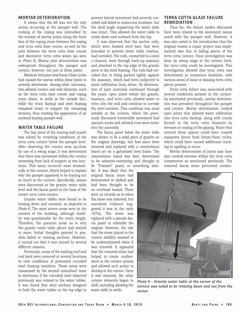
WATER TABLE FAILURE The last piece of the leaning-wall puzzle
was solved by reviewing conditions of the terra cotta cornice below the parapet level. after observing the cornice area up-close by use of a swing stage, it was determined that there was movement within the cornice stemming from lack of support at two loca-tions. This issue occurred most dramati-cally at the corners, which helped to explain why the parapet appeared to be leaning out so much at the corners. Specifically, issues were discovered at the granite water table level and the fascia panel at the base of the ornate terra cotta cornice.
Granite water tables were found to be leaning down and outward, as depicted in Photo 6. The most severe areas were at the corners of the building, although stabil-ity was questionable for the entire length. Therefore, the question arose as to why the granite water table pieces had started to move. initial thoughts pointed to pos-sible failed or missing anchors. However, it turned out that it was caused by several different reasons.
Previously, areas of the existing roof and roof deck were removed at several locations to view conditions of presumed corroded steel framing members. These areas were reassessed by the second consultant team to determine if the corroded steel observed previously was related to the water tables. it was found that steel anchors designed to hold the water tables at the top edge to
prevent lateral movement had severely cor-roded and failed in numerous locations, but the shelf angle supporting the water table was intact. This allowed the water table to rotate down and outward from the top.
it was observed that the anchor rods, which were hooked steel bars that were intended to prevent water table rotation, had corroded. The rods, connected to a steel c-channel, went through back-up masonry and attached to the top edge of the granite piece to the steel framing. The rods had cor-roded due to being packed tightly against the masonry, which had been subjected to water infiltration from above. as deteriora-tion of joint materials continued through the years, open joints within the granite, masonry, and terra cotta allowed water to enter into the wall and continue to corrode the steel anchors. This condition was most notable at the corners, where the previ-ously discussed irreversible movement had opened cracks and allowed even more water into the assembly.
The fascia panel below the water table was shown to be a solid piece of granite on the original drawings, but had since been removed and replaced with a cementitious board set on a galvanized steel frame. The cementitious board was later determined to be asbestos-containing and thought to be “Transite” panel, or something simi-lar. It was likely that the original fascia stone had deteriorated or shifted and had been thought to be an overhead hazard. There were no records as to when the stone was removed, but anecdotal evidence sug-gested it was in the early 1970s. The stone was replaced with a pseudo fas-cia panel to resemble the original. However, the role that the stone played in the cornice stability seemed to be underestimated when it was removed. It appeared that the removed stone had helped to create confine-ment in the cornice system and allowed arch action to develop in the cornice. Once it was removed, the other cornice elements began to shift, including allowing the water table to settle.
TERRA COTTA GLAZE FAILURE REMEDIATION
Thus far, the failure modes discussed have been related to the movement issues noted with the parapet wall. However, it was also noted in the introduction that the original reason a repair project was imple-mented was due to falling pieces of the terra cotta cornice. Once investigation was done by swing stage at the cornice level, the terra cotta could be investigated. This investigation showed that terra cotta was deteriorated in numerous locations, with various areas of loose or missing terra cotta pieces present.
Terra cotta failure was associated with several conditions present in the cornice. As mentioned previously, mortar deteriora-tion was prevalent throughout the parapet and cornice. Mortar deterioration created open joints that allowed water infiltration into terra cotta backup, along with cracks formed in the terra cotta elements by stresses or crazing of the glazing. Water that entered these spaces could have created expansive forces from freeze/thaw cycles, which could have caused additional crack-ing or spalling to occur.
mortar deterioration at joints may have also created stresses within the terra cotta components as mentioned previously. The removed fascia stone prevented confine-
3 0 t h R C I I n t e R n a t I o n a l C o n v e n t I o n a n d t R a d e S h o w • M a R C h 5 - 1 0 , 2 0 1 5 B e n t z a n d p a y n e • 1 0 5
Photo 6 – Granite water table at the corner of the cornice was noted to be rotating down and out from the corner
ment, which allowed for movement of terra cotta pieces at the soffit. Together with mortar deterioration and thermal cycling (differential expansion and contraction) of adjacent pieces of terra cotta, this allowed abutting pieces to pinch together, causing additional stresses. This stress may have also caused cracking and spalling of pieces to occur.
although the above conditions were present and were assumed to be contributing factors to terra cotta failure, there was a more gener-al issue that was occurring at the entirety of the terra cotta pieces at the parapet, cornice, and soffit. The terra cotta elements had been subject to widespread glaze failure. What was initially thought to be a “speckled” finish in the glaze (see Photo 7) was found, upon close-up inspection, to be defects in the glaze. The exact cause of the glaze degrada-tion failure was not determined, but it was suspected that it was related to atmospheric conditions (possibly acid rain) or a very aggressive prior cleaning of the building (anecdotal evidence suggests that the building may have been sand-blasted in the late 1960s). regardless of the cause, glaze failure was allowing water into
the terra cotta bisque (bisque is the term for the clay mixture that, when fired, becomes terra cotta) throughout the parapet, and trapped moisture within the terra cotta
body was leading to spalls, cracks, and other terra cotta failures.
UNIQUE RESTORATION SUITED FOR HISTORICAL BUILDING
Discovering the origins of the issues that were causing the historical building’s cornice and parapet wall to fail was just the first step in the restoration process. Once this information was gathered and there was a good indication of the actual failure modes present, repairs had to be designed and implemented. like the assessment pro-cess, recommending and designing repairs for an historical restoration project can be challenging. it takes creative and innovative thinking, paired with a good experience of repairing historical elements on a building, to come up with a strategy and design for proper repairs that will be effective, afford-able, and long-lasting.
Case in point, as mentioned earlier in this paper, the original proposal for the par-apet wall and cornice was to simply demol-ish everything at these levels and rebuild from the roof up. although this would have likely been a successful solution, it could have created numerous construction issues, such as with the fragile terra cotta pieces
1 0 6 • B e n t z a n d p a y n e 3 0 t h R C I I n t e R n a t I o n a l C o n v e n t I o n a n d t R a d e S h o w • M a R C h 5 - 1 0 , 2 0 1 5
Photo 7 – Glazing degradation failure at terra cotta parapet, as well as areas of cracked and spalled terra cotta.
Photo 8 – Limited rebuild of masonry parapet wall and installation of metal through-wall flashing. Note half brick (approximately 2 in. high) used at top of wall; this represents the amount of swell in the remainder of the wall due to irreversible expansion of the masonry.

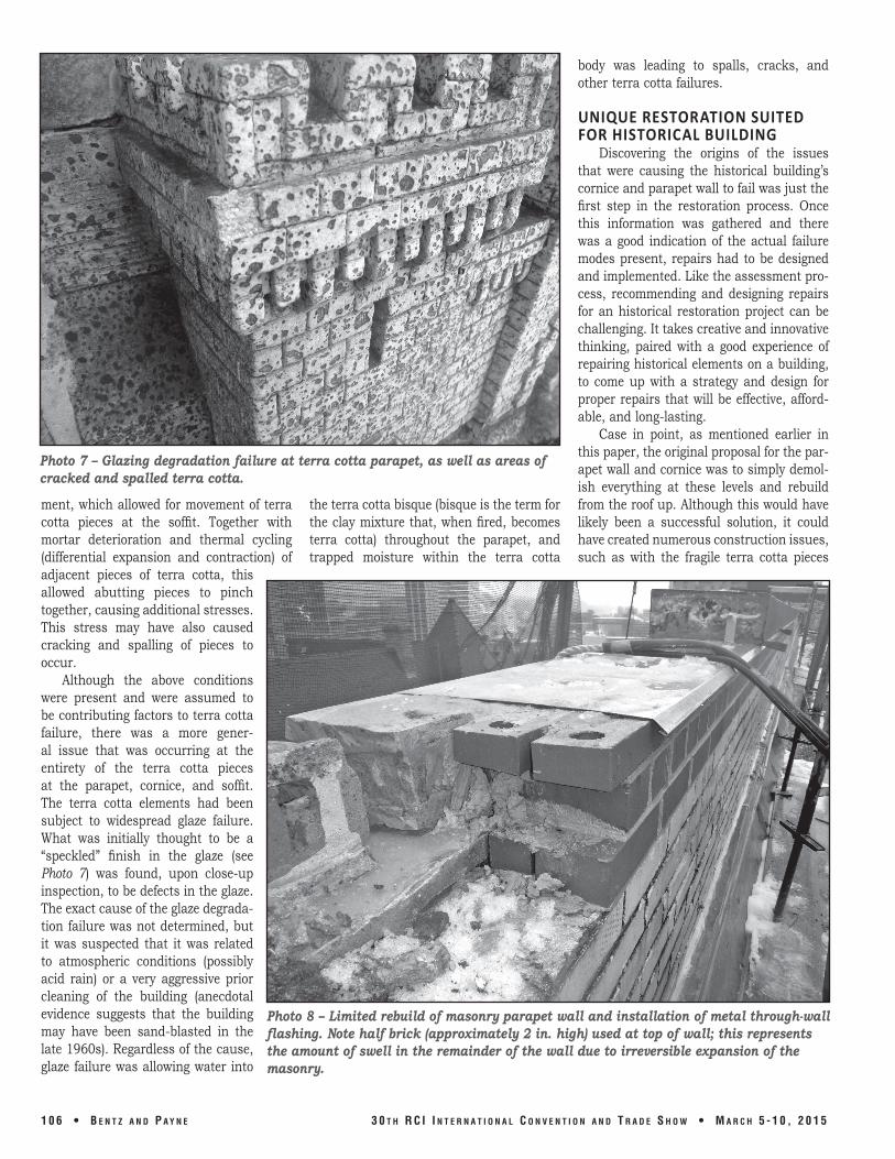
during removal, stor-age, and replacement; as well as cost a large amount of money to perform. Instead, the revised restoration program focused on preserving as much of the original construc-tion as possible and concentrated on five key repairs.
1. adding joints to accommo-date expan-sive movement caused by thermal and moisture expansion
2. resetting parapet wall brick and coping stone and installing through-wall flashing
3. Stabilizing the loose water table granite
4. adding confinement steel and replacing the fascia at the fascia panels to help stabilize the cornice
5. repairing joints and terra cotta to allow for a more water-resistant system.
The first two repairs focused on the parapet wall. To ensure that thermal and moisture expansion did not create fur-ther stresses on adjacent parapet walls, it was recommended that masonry expansion joints be installed at all four of the build-ing’s main corners to allow for movement. To correct the heaving motion caused by moisture expansion within the parapet walls itself, the coping stones, brick backup, and terra cotta base course were removed and rebuilt to reestablish the back-slope pro-file of the coping as shown in the original drawings (see Photo 8). additionally, the EPDm membrane was removed from the back wall to allow for proper drying, and a metal through-wall flashing was installed under the copingstones to prevent addi-tional moisture from accessing the backup wall. The coping stones were secured with stainless steel dovetail anchors in slotted holes to allow for movement. The skyward-facing joints in the coping were sealed with caulking. a rain-screen cladding on the interior face of the wall is recommended for future installation.
The stabilization of the water table was an integral part of stabilizing the overall
cornice, but determining how to re-anchor the stone and access the steel framing sup-ports without removing the roof along the entire perimeter of the building required an innovative repair. That is where a unique use of a process often referred to as nelson stud welding was employed. in this tech-nique, typically an electrical current from a specialized welding gun is run through a steel stud to create an electrical arc at the tip of the stud that welds the end of the stud to a metal surface. it was decided that, by
drilling holes into the existing granite water table pieces until the steel support chan-nel was reached, the nelson stud welding technique could be used to pin the stone to the steel angle (See Figure 3). as the studs were meant to take lateral load only, the technique did not require a large force to be supported. This was accomplished by
3 0 t h R C I I n t e R n a t I o n a l C o n v e n t I o n a n d t R a d e S h o w • M a R C h 5 - 1 0 , 2 0 1 5 B e n t z a n d p a y n e • 1 0 7
Photo 9 – Mock-up example of Nelson stud used for repairs.
Figure 3 – Repair detail for granite water table stabilization.
Figure 4 – Repair detail for new fascia board and fascia support angle.

stud-welding two ½-in.-diameter nelson studs with washers and nuts at the end through each granite piece onto the steel channel (see stud mock-up in Photo 9). The holes were covered with a stone patch repair mortar material, and the granite water table was stabilized without the removal of any stone or adjacent component.
Another issue that arose concerned the fas-cia board repairs. The missing granite fascia stone was causing con-finement issues with the arched terra cotta soffit and other adjoining ele-ments of the cornice. It would have been mon-etarily unrealistic to replace the existing cov-erboard with a new gran-ite band to match the existing one, but stabi-lization was required in some way. To accomplish this, a new steel angle was welded to the bottom leg of the then-abandoned granite fascia support angle, and a stainless steel threaded rod was drilled into the existing terra cotta at the top of the soffit arch and epoxied into place (see Figure 4). This replaced the lost con-finement from the removed granite band and helped to restore stability in the entire cornice system. The new angle was then covered by a new painted galvanized steel fascia panel that matched the adjacent stone pieces. Similarly, the granite and terra cotta base courses were reinstalled with new, stainless steel masonry anchors to tie them to the backup material. This helped to stabilize the parapet level.
The final repair area was focused on closing the gaps and sealing the cornice system from water infiltration. To do this, two methods were employed. First, joint sealants and mortar joints that had deterio-rated previously, causing open joints into granite and terra cotta, were pointed and sealed. Cracks that were found within terra cotta pieces were routed and sealed to close the cracks and prevent water infiltration
within. Second, to prevent the porous sur-face of the terra cotta where glazing failure had occurred from absorbing water from the surface in the future, a breathable pro-tective elastomeric coating was applied to the surfaces of all the terra cotta elements within the parapet, cornice, and soffit. This process sealed the terra cotta system (but allows it to breath or release trapped mois-ture vapor) and had the added benefit of creating a uniform, clean look to the entire ornate cornice (see Photo 10). The repairs to the parapet above were intended to limit water entering the cornice.
CONCLUSIONWith a clear understanding of the his-
torical systems involved, it was possible to reevaluate assumed conditions at the sub-ject property and determine the root causes of deterioration at the parapet and ornate cornice. Furthermore, innovative thinking and design approaches allowed a preser-vation/restoration approach to the repair methodology to be implemented without causing a large variation from the historical
appearance of the building. The resulting project was completed in november of 2013, ahead of schedule and under budget at a cost of approximately $4 million, or close to a $30-million savings from the original proposed restoration project.
REFERENCES1 rCi educational program, “masonry
Wall Systems.”
1 0 8 • B e n t z a n d p a y n e 3 0 t h R C I I n t e R n a t I o n a l C o n v e n t I o n a n d t R a d e S h o w • M a R C h 5 - 1 0 , 2 0 1 5
Photo 10 – Completed repairs at terra cotta cornice and parapet.