indian journal of science and technology, vol 10(25), doi
TRANSCRIPT
*Author for correspondence
Indian Journal of Science and Technology, Vol 10(25), DOI: 10.17485/ijst/2017/v10i25/113816, July 2017ISSN (Print) : 0974-6846
ISSN (Online) : 0974-5645
Finite Element Analysis of Skirt to Shell Junction in a Pressure Vessel
Deepali Mathur1*, Mandar Sapre1 and Chintan Hingoo2
1Symbiosis Institute of Technology, Lavale, Pune – 412115, Maharashtra, India; [email protected], [email protected]
2Larsen and Toubro, Ranoli, Vadodara –391350, Gujarat, India; [email protected]
AbstractObjectives: The objective of this research work is to find the effect of providing hotbox at skirt to shell junction of a pressure vessel on the stresses induced at this junction. Methods/Statistical Analysis: In present work, since the vessel is to be supported at some elevation from ground, a conical skirt support is used. Two models of skirt to shell junction are made, in Unigraphics 10, one without hotbox while other with hotbox. A thermo-structural analysis of models is performed using ANSYS Workbench15. Stress linearization is done and stresses are limited to code allowable to ensure protection against plastic collapse and local failure. Findings: The result of finite element analysis for the case of model without hotbox shows that thermal stresses as high as 329 MPa are induced at the y-ring, which is much higher than the allowable stress at that temperature. When a hotbox is provided at this region, the stress is found to be reduced to 35.082 MPa, which is less than the allowable stress. So, the vessel will work safely if a hotbox of minimum 480 mm length is provided at the critical junction of skirt and shell. Stress is linearized at five stress classification lines. The linearized stresses and their combinations for four load cases are compared with the code allowable limit, and are found to be less than allowable stress. This ensures the protection of vessel against plastic collapse and local failure. Application/Improvements: Such analysis is needed to be performed for long vessels supported on skirt type of support, as the total vessel loads will be transferred to skirt from this junction only.
Keywords: Finite Element Analysis, Hotbox Analysis, Pressure Vessel, Skirt to Shell Junction, Stress Linearization
NomenclatureFEA Finite Element AnalysisSST Steady State ThermalSS Static StructuralSCP Stress Classification PlaneSCL Stress Classification LinePm General Primary Membrane Stress(MPa)PL Local Primary Membrane Stress(MPa)Pb Primary Bending Stress(MPa)Q Secondary Membrane plus Bending Stress(MPa)σ1 Linearized Maximum Principal Stress(MPa)σ2 Linearized Middle Principal Stress(MPa)
σ3 Linearized Minimum Principal Stress(MPa)σth Theoretical Circumferential Stress(MPa)R Inside Radius of Shell(mm)D Inside Diameter of Shell(mm)t Thickness of Shell(mm)S Maximum Allowable Stress at Design Temperature
(MPa)Smin. Minimum of the Allowable Stresses for SA-240
and SA-516, at a temperature (MPa)P Maximum Allowable Working Pressure(MPa)W Dead Weight of Vessel(N)T Design Temperature(oC)E SeismicLoad
Indian Journal of Science and TechnologyVol 10 (25) | July 2017 | www.indjst.org 2
Finite Element Analysis of Skirt to Shell Junction in a Pressure Vessel
1. Introduction
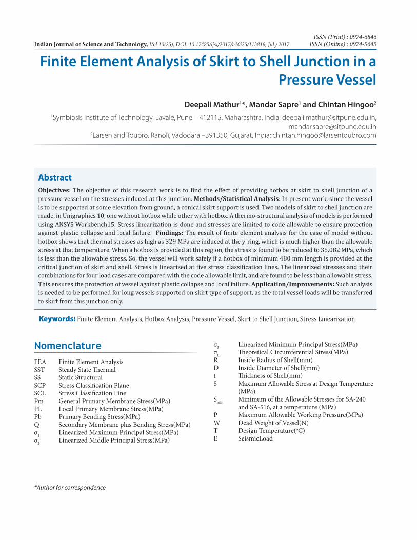
A pressure vessel is one of the most vital components of a petrochemical refinery. These are used either to store solid, liquid or gaseous products, or to process a prod-uct to convert into another useful product. In case of the present work, a chemical process takes place in vessel, using a catalyst. Due to dissipation of heat during process, there will be mechanical load (pressure and temperature), acting at the inner wall of vessel. There will be other loads acting, like, self-weight and environmental loads (wind and seismic). High stresses will be produced due to these loads and their combinations, at critical region such as skirt to shell junction. In present case, the junc-tion is a forged y-ring, as shown in Figure 1. The vessel is designed as per procedures provided in ASME Section VIII Division 1. The wind and seismic load calculations are done as per NBCC2010.
1 Authors have performed experiments on finite ele-ment analysis of pressure vessels with different type of head skeeping the same cylindrical volume and thick-ness, for the cause of finding stress concentration zone for each head, under the same volume and pressure. The Maximum von-misses stresses were found to be mini-mum for Elliptical Head.
2 Authors has performed finite element analysis to determine a Hot-box geometry which will minimize the thermal gradient stresses and improve fatigue life. Study demonstrates that modifying the dimensions of the hot box such as length, will affects the fatigue life of coke drum. The results indicate that by increasing the length of hot box, maximum Von Misses stress is reduced.
3 Authors have discussed the modeling, analysis, and monitoring of hot box designs. The importance of performing detailed sensitivity analyses is addressed if unknown thermal loading conditions exist. Additionally, this paper discusses the importance of making field mea-surements to enhance modeling assumptions.
4 Authors represents the guidelines in structural analy-sis for skirt to dished end junction. Analysis is carried out in compliance with ASME Section VIII Division 2. Finite elemental model of junction is prepared using UG-NX. It is then loaded in ANSYS 12.0 and results obtained are compared to code allowable.
5 Authors have performed stress analysis at skirt to dished end junction. They plotted a graph showing
stresses at various parts of vessel. By this they concluded that maximum stresses generated are at skirt to shell junction. The analysis is carried out in ASME section VIII, Div. 1.Themodel is made in Creo/Pro-E and then imported in ANSYSR15 and simulation is checked with ASME code.
6 Authors have performed elastic stress analysis of skirt to dished end joint, and concluded that by providing hot box at junction gives lower thermal gradient as compared to the case of junction without hot box case. Also, the cen-ter line matching method for the junction is found to be most suitable, as it can take more radiation heat transfer compared to the outer diameter matching method.
7 Authors have compared two methods, namely, stress classification method and direct route method, used for analysis of hydrogenation reactor skirt structure. The founding was, Stress classification method is an engineer-ing approximation. The analysis is simple, mature, low computation cost. The direct route method avoids the problems caused by stress classification, the results are more reasonable. It is suitable for complex and important pressure equipment.
2. Geometric Model
A three dimensional 360o model of skirt to shell junction is prepared using UG NX 10. But, for clear visualization, results are shown on an 180o model.
2.1 Dimensions of ModelTable 1 show the dimensions of the geometric model and Figure 1 shows the geometric model of the skirt to shell junction, used for analysis
Table 1. Dimensions of ModelSpecification DimensionInside diameter of shell 2950mmThickness of shell 35mmOuter diameter of skirt at base 2300mmThickness of skirt 35mmLength of skirt 2721mmAngle of inclination of skirt 15o to verticalLength of Hotbox 480mmThickness of Insulation 240mmLength of insulation on skirt 2193mm
Deepali Mathur, Mandar Sapre and Chintan Hingoo
Indian Journal of Science and Technology 3Vol 10 (25) | July 2017 | www.indjst.org
Figure 1. Geometric Model - 180o view
2.2 Material of ConstructionTable 2 enlists the material of construction for shell, skirt, and, inside and outside insulation.
Table 2. Material of ConstructionSr. No. Element Material of Construction1 Shell, Skirt top
part, Y-ringSA 240M Grade 304H
2 Skirt bottom part, Base ring
SA 516M Grade 485
3 Insulation ASTM C1393 Type VI-B
3. Meshing of Model
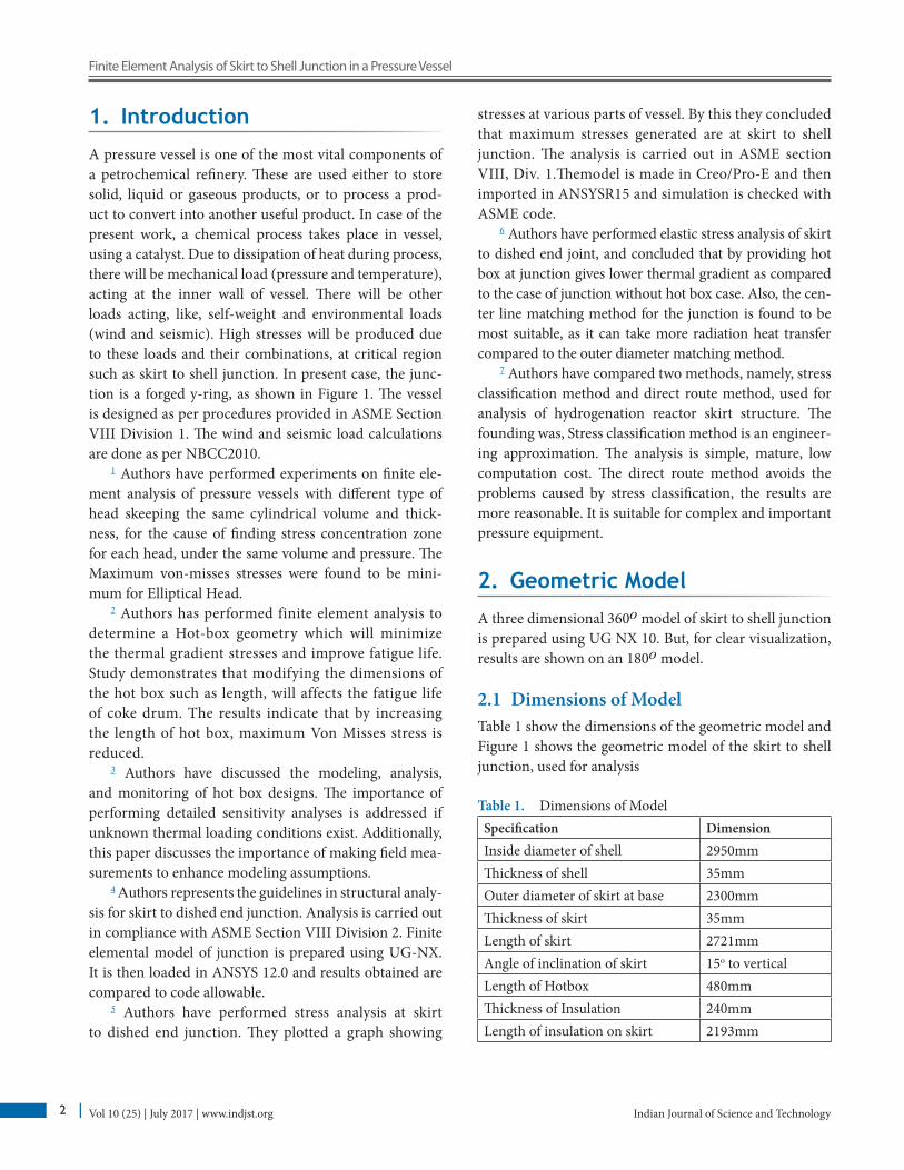
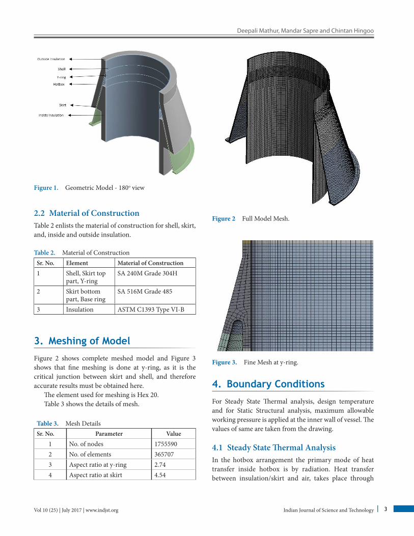
Figure 2 shows complete meshed model and Figure 3 shows that fine meshing is done at y-ring, as it is the critical junction between skirt and shell, and therefore accurate results must be obtained here.
The element used for meshing is Hex 20. Table 3 shows the details of mesh.
Table 3. Mesh DetailsSr. No. Parameter Value
1 No. of nodes 17555902 No. of elements 3657073 Aspect ratio at y-ring 2.744 Aspect ratio at skirt 4.54
Figure 2 Full Model Mesh.
Figure 3. Fine Mesh at y-ring.
4. Boundary Conditions
For Steady State Thermal analysis, design temperature and for Static Structural analysis, maximum allowable working pressure is applied at the inner wall of vessel. The values of same are taken from the drawing.
4.1 Steady State Thermal AnalysisIn the hotbox arrangement the primary mode of heat transfer inside hotbox is by radiation. Heat transfer between insulation/skirt and air, takes place through
Indian Journal of Science and TechnologyVol 10 (25) | July 2017 | www.indjst.org 4
Finite Element Analysis of Skirt to Shell Junction in a Pressure Vessel
convection. Emissivity values for steel and insulation are taken as 0.9 and 0.8 respectively and the convective heat transfer coefficients for pair of surfaces, namely, insula-tion-air and stainless steel-air, are taken to be 1 x 10⁻⁵W/mm2 °C and 2.5 x 10⁻⁵W/mm2 °C respectively.
Figure 4 shows the Steady State Thermal boundary condition for model with hotbox.
Figure 4. SST Boundary Conditions.
4.2 Static Structural AnalysisFor static structural analysis, the base ring is constrained in all directions.
Internal pressure is applied at inside wall of vessel. An equivalent pressure thrust is applied at top and bot-tom faces of shell. Dead weights of upper and lower vessel are applied at respective center of gravities, and, seismic shear force and bending moment is applied at remote points taken individually for top and bottom vessel, which are connected to top and bottom faces of shell.
5. Analyses of Model
Analysis of model is performed in accordance with ASME code8. A thermo-mechanical system, in ANSYS Work- bench 15, is used to perform analyses. Two cases, as listed below, are considered, so that the effect of providing hotbox at skirt to shell junction can be observed.
• Case 1 : Model Without Hotbox• Case 2 : Model With Hotbox
Firstly, Steady State Thermal analysis is performed at design temperature to obtain temperature gradient through the length of skirt.
The solution of SST is then imported in SS sys-tem, to get induced thermal stress. Also, various load combinations comprising of internal pressure, dead weight and seismic shear force and bending moment are applied, and stresses induced due to these are evaluated at different stress classification lines and are limited to ASME code allowable limits, as discussed in Section 6.2.
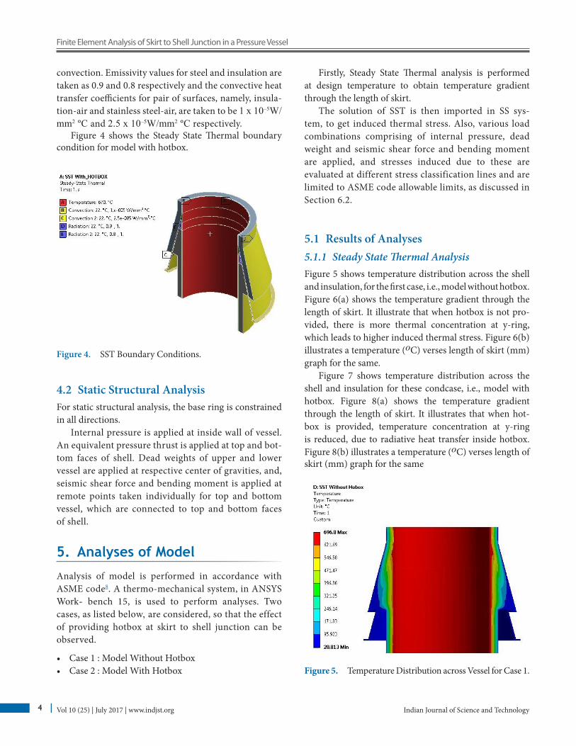
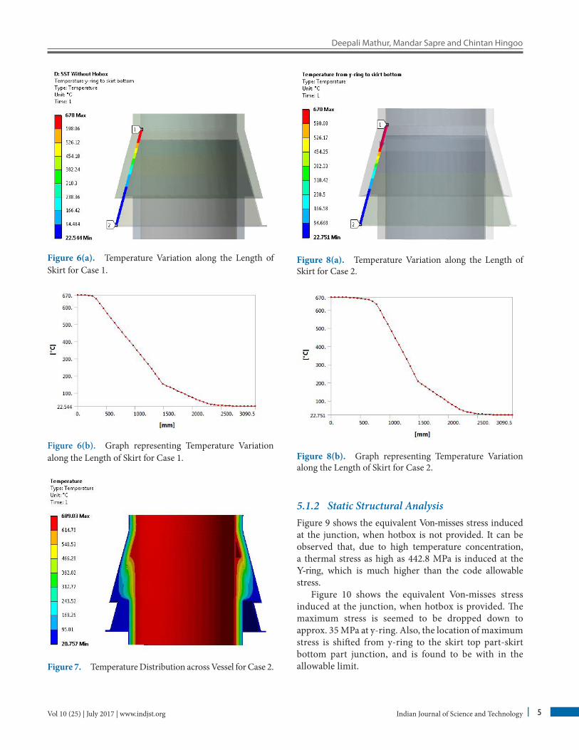
5.1 Results of Analyses5.1.1 Steady State Thermal AnalysisFigure 5 shows temperature distribution across the shell and insulation, for the first case, i.e., model without hotbox. Figure 6(a) shows the temperature gradient through the length of skirt. It illustrate that when hotbox is not pro-vided, there is more thermal concentration at y-ring, which leads to higher induced thermal stress. Figure 6(b) illustrates a temperature (oC) verses length of skirt (mm) graph for the same.
Figure 7 shows temperature distribution across the shell and insulation for these condcase, i.e., model with hotbox. Figure 8(a) shows the temperature gradient through the length of skirt. It illustrates that when hot-box is provided, temperature concentration at y-ring is reduced, due to radiative heat transfer inside hotbox. Figure 8(b) illustrates a temperature (oC) verses length of skirt (mm) graph for the same
Figure 5. Temperature Distribution across Vessel for Case 1.
Deepali Mathur, Mandar Sapre and Chintan Hingoo
Indian Journal of Science and Technology 5Vol 10 (25) | July 2017 | www.indjst.org
Figure 6(a). Temperature Variation along the Length of Skirt for Case 1.
Figure 6(b). Graph representing Temperature Variation along the Length of Skirt for Case 1.
Figure 7. Temperature Distribution across Vessel for Case 2.
Figure 8(a). Temperature Variation along the Length of Skirt for Case 2.
Figure 8(b). Graph representing Temperature Variation along the Length of Skirt for Case 2.
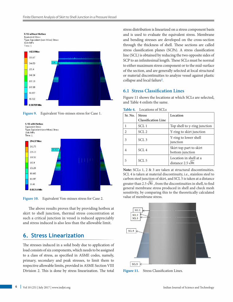
5.1.2 Static Structural AnalysisFigure 9 shows the equivalent Von-misses stress induced at the junction, when hotbox is not provided. It can be observed that, due to high temperature concentration, a thermal stress as high as 442.8 MPa is induced at the Y-ring, which is much higher than the code allowable stress.
Figure 10 shows the equivalent Von-misses stress induced at the junction, when hotbox is provided. The maximum stress is seemed to be dropped down to approx. 35 MPa at y-ring. Also, the location of maximum stress is shifted from y-ring to the skirt top part-skirt bottom part junction, and is found to be with in the allowable limit.
Indian Journal of Science and TechnologyVol 10 (25) | July 2017 | www.indjst.org 6
Finite Element Analysis of Skirt to Shell Junction in a Pressure Vessel
Figure 9. Equivalent Von-misses stress for Case 1.
Figure 10. Equivalent Von-misses stress for Case 2.
The above results proves that by providing hotbox at skirt to shell junction, thermal stress concentration at such a critical junction in vessel is reduced appreciably and stress induced is also less than the allowable limit.
6. Stress LinearizationThe stresses induced in a solid body due to application of load consists of six components, which needs to be assigned to a class of stress, as specified in ASME codes, namely, primary, secondary and peak stresses, to limit them to respective allowable limits, provided in ASME Section VIII Division 2. This is done by stress linearization. The total
stress distribution is linearized on a stress component basis and is used to evaluate the equivalent stress. Membrane and bending stresses are developed on the cross-section through the thickness of shell. These sections are called stress classification planes (SCPs). A stress classification line (SCL) is obtained by reducing the two opposite sides of SCP to an infinitesimal length. These SCLs must be normal to either maximum stress component or to the mid-surface of the section, and are generally selected at local structural or material discontinuities to analyze vessel against plastic collapse and local failure9.
6.1 Stress Classification LinesFigure 11 shows the locations at which SCLs are selected, and Table 4 enlists the same.
Table 4. Locations of SCLsSr. No. Stress
Classification LineLocation
1 SCL 1 Top shell to y-ring junction2 SCL 2 Y-ring to skirt junction
3 SCL 3 Y-ring to lower shell junction
4 SCL 4 Skirt top part to skirt bottom junction
5 SCL 5Location in shell at a distance 2.5 Rt
Note: SCLs 1, 2 & 3 are taken at structural discontinuities. SCL 4 is taken at material discontinuity, i.e., stainless steel to carbon steel junction of skirt, and SCL 5 is taken at a distance greater than 2.5 Rt , from the discontinuities in shell, to find general membrane stress produced in shell and check mesh sensitivity, by comparing this to the theoretically calculated value of membrane stress.
Figure 11. Stress Classification Lines.
Deepali Mathur, Mandar Sapre and Chintan Hingoo
Indian Journal of Science and Technology 7Vol 10 (25) | July 2017 | www.indjst.org
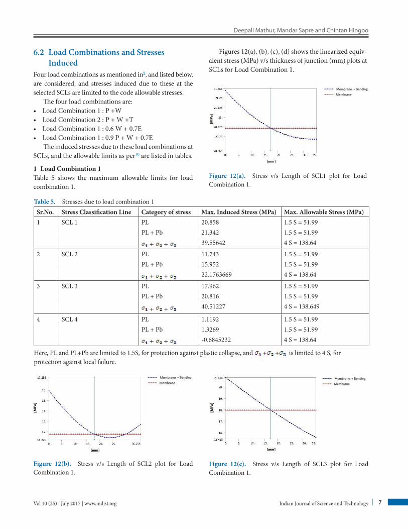
Table 5. Stresses due to load combination 1Sr.No. Stress Classification Line Category of stress Max. Induced Stress (MPa) Max. Allowable Stress (MPa)1 SCL 1 PL 20.858 1.5 S = 51.99
PL + Pb 21.342 1.5 S = 51.99
+ + 39.55642 4 S = 138.64
2 SCL 2 PL 11.743 1.5 S = 51.99PL + Pb 15.952 1.5 S = 51.99
+ + 22.1763669 4 S = 138.64
3 SCL 3 PL 17.962 1.5 S = 51.99PL + Pb 20.816 1.5 S = 51.99
+ + 40.51227 4 S = 138.649
4 SCL 4 PL 1.1192 1.5 S = 51.99PL + Pb 1.3269 1.5 S = 51.99
+ + -0.6845232 4 S = 138.64
Here, PL and PL+Pb are limited to 1.5S, for protection against plastic collapse, and + + is limited to 4 S, for protection against local failure.
Figure 12(b). Stress v/s Length of SCL2 plot for Load Combination 1.
Figure 12(c). Stress v/s Length of SCL3 plot for Load Combination 1.
6.2 Load Combinations and Stresses Induced
Four load combinations as mentioned in9, and listed below, are considered, and stresses induced due to these at the selected SCLs are limited to the code allowable stresses.
The four load combinations are:• Load Combination 1 : P +W• Load Combination 2 : P + W +T• Load Combination 1 : 0.6 W + 0.7E• Load Combination 1 : 0.9 P + W + 0.7E
The induced stresses due to these load combinations at SCLs, and the allowable limits as per10 are listed in tables.
1 Load Combination 1Table 5 shows the maximum allowable limits for load combination 1.
Figures 12(a), (b), (c), (d) shows the linearized equiv-alent stress (MPa) v/s thickness of junction (mm) plots at SCLs for Load Combination 1.
Figure 12(a). Stress v/s Length of SCL1 plot for Load Combination 1.
Indian Journal of Science and TechnologyVol 10 (25) | July 2017 | www.indjst.org 8
Finite Element Analysis of Skirt to Shell Junction in a Pressure Vessel
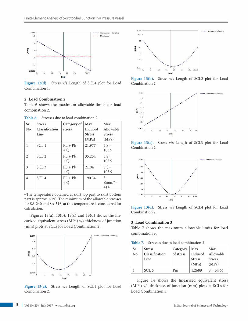
Figure 12(d). Stress v/s Length of SCL4 plot for Load Combination 1.
2 Load Combination 2Table 6 shows the maximum allowable limits for load combination 2.
Table 6. Stresses due to load combination 2Sr.No.
Stress ClassificationLine
Category of stress
Max. InducedStress (MPa)
Max. AllowableStress (MPa)
1 SCL 1 PL + Pb + Q
21.977 3 S = 103.9
2 SCL 2 PL + Pb + Q
35.254 3 S = 103.9
3 SCL 3 PL + Pb + Q
21.04 3 S = 103.9
4 SCL 4 PL + Pb + Q
190.34 3 Smin.∗= 414
∗The temperature obtained at skirt top part to skirt bottom part is approx. 65oC. The minimum of the allowable stresses for SA-240 and SA-516, at this temperature is considered for calculation.
Figures 13(a), 13(b), 13(c) and 13(d) shows the lin-earized equivalent stress (MPa) v/s thickness of junction (mm) plots at SCLs for Load Combination 2.
Figure 13(a). Stress v/s Length of SCL1 plot for Load Combination 2.
Figure 13(b). Stress v/s Length of SCL2 plot for Load Combination 2.
Figure 13(c). Stress v/s Length of SCL3 plot for Load Combination 2.
Figure 13(d). Stress v/s Length of SCL4 plot for Load Combination 2.
3 Load Combination 3Table 7 shows the maximum allowable limits for load combination 3.
Table 7. Stresses due to load combination 3Sr.No.
Stress ClassificationLine
Category of stress
Max. InducedStress (MPa)
Max. AllowableStress (MPa)
1 SCL 5 Pm 1.2689 S = 34.66
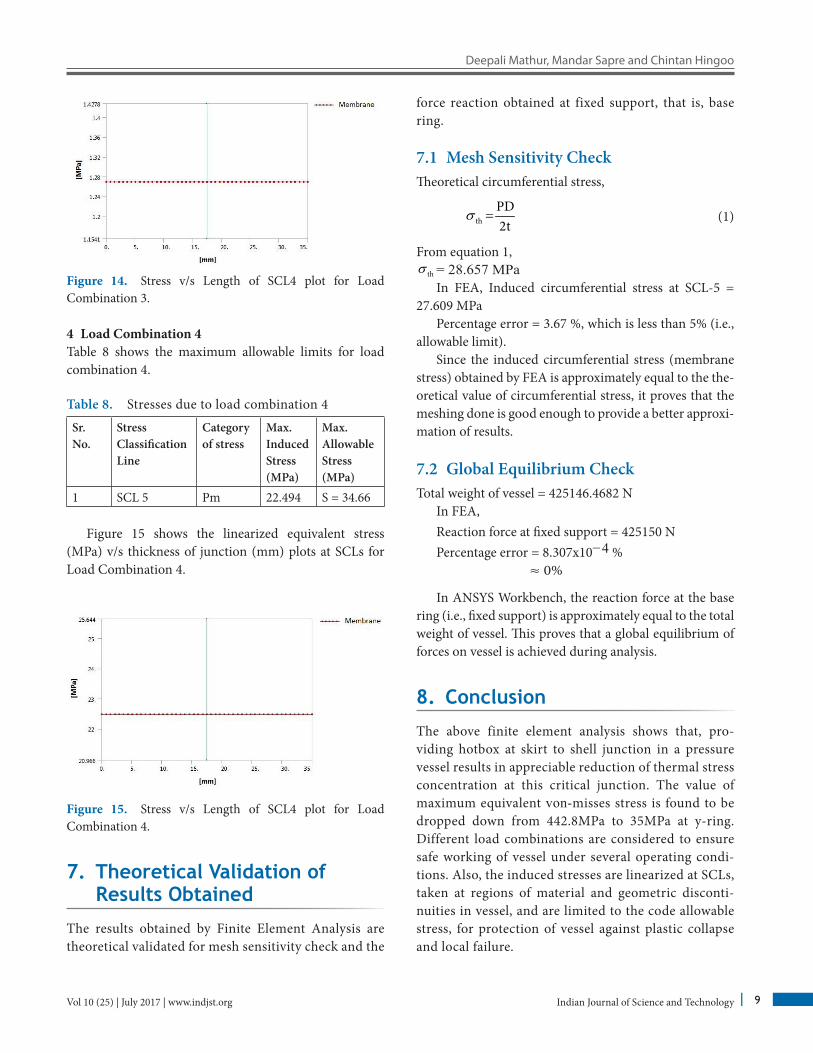
Figure 14 shows the linearized equivalent stress (MPa) v/s thickness of junction (mm) plots at SCLs for Load Combination 3.
Deepali Mathur, Mandar Sapre and Chintan Hingoo
Indian Journal of Science and Technology 9Vol 10 (25) | July 2017 | www.indjst.org
Figure 14. Stress v/s Length of SCL4 plot for Load Combination 3.
4 Load Combination 4Table 8 shows the maximum allowable limits for load combination 4.
Table 8. Stresses due to load combination 4
Sr.No.
Stress ClassificationLine
Category of stress
Max. InducedStress (MPa)
Max. AllowableStress (MPa)
1 SCL 5 Pm 22.494 S = 34.66
Figure 15 shows the linearized equivalent stress (MPa) v/s thickness of junction (mm) plots at SCLs for Load Combination 4.
Figure 15. Stress v/s Length of SCL4 plot for Load Combination 4.
7. Theoretical Validation of Results Obtained
The results obtained by Finite Element Analysis are theoretical validated for mesh sensitivity check and the
force reaction obtained at fixed support, that is, base ring.
7.1 Mesh Sensitivity CheckTheoretical circumferential stress,
σ =th
PD2t
(1)
From equation 1,σ th = 28.657 MPa
In FEA, Induced circumferential stress at SCL-5 = 27.609 MPa
Percentage error = 3.67 %, which is less than 5% (i.e., allowable limit).
Since the induced circumferential stress (membrane stress) obtained by FEA is approximately equal to the the-oretical value of circumferential stress, it proves that the meshing done is good enough to provide a better approxi-mation of results.
7.2 Global Equilibrium CheckTotal weight of vessel = 425146.4682 N
In FEA,Reaction force at fixed support = 425150 N Percentage error = 8.307x10⁻⁴ %
≈ 0%
In ANSYS Workbench, the reaction force at the base ring (i.e., fixed support) is approximately equal to the total weight of vessel. This proves that a global equilibrium of forces on vessel is achieved during analysis.
8. Conclusion
The above finite element analysis shows that, pro-viding hotbox at skirt to shell junction in a pressure vessel results in appreciable reduction of thermal stress concentration at this critical junction. The value of maximum equivalent von-misses stress is found to be dropped down from 442.8MPa to 35MPa at y-ring. Different load combinations are considered to ensure safe working of vessel under several operating condi-tions. Also, the induced stresses are linearized at SCLs, taken at regions of material and geometric disconti-nuities in vessel, and are limited to the code allowable stress, for protection of vessel against plastic collapse and local failure.
Indian Journal of Science and TechnologyVol 10 (25) | July 2017 | www.indjst.org 10
Finite Element Analysis of Skirt to Shell Junction in a Pressure Vessel
9. References1. Kolekar D, Jewargi SS. Stress analysis of pressure vessel
with different type of end connections by fea. International Journal of Innovative Research in Science, Engineering and Technology. 2015; 4(5):2769–75. Crossref
2. Chandra NP, Belkar SB. Analytical study of coke drum skirt support hot box. International Journal of Emerging Science and Engineering. 2014; 2(9):7–11.
3. Alexander C, Boswell R. Techniques For Modeling Thermal and Mechanical Stresses Generated in Catalytic Cracker and Coke Drum Hot- Boxes, Proceedings of ASME Pressure Vessels and Piping Conference, Denver, Colorado, USA: 2005. p. 527–37. Crossref
4. Sagar P, Sachin TS, Barve. Finite element analysis of skirt to dished junction in a pressure vessel. International Journal of Modern Engineering Research. 2013; 3(4):1–4.
5. Attar PR, Agiwale MC. Analysis of dished head and skirt joint of pressure vessel using fea method. International Journal of Recent Technology and Engineering (IJRTE). 2015; 23(1):49–52.
6. Makwana MM, Parmar G, Badi M. Thermal analysis of dif-ferent attachment of skirt to dished end joint of stainless steel vessel. International Journal for Scientific Research Development. 2016; 4(3):826–8.
7. Pan J, Chen X, Jun C. Comparison of different analysis design methods in the calculation of hydrogenation reactor skirt structure, Proceedings of ASME 2014 pressure vessels and piping conference, Anaheim, California, USA: 2014. p. 1–5. Crossref
8. ASME Boiler and Pressure Vessel Committee on Pressure Vessels. 8 Division 2, Alternative Rules, Rules for Construction of Pressure Vessels. Addison-Wesley; 2010.
9. ASME Boiler and Pressure Vessel Committee on Pressure Vessels. Linearization of Stress Results for Stress Classification. In 8 Division 2, Alternative Rules, Rules for Construction of Pressure Vessels. Addison-Wesley; 2010.
10. ASME Boiler and Pressure Vessel Committee on Pressure Vessels II Part D, Properties (Metric) Materials. Addison-Wesley; 2010.