indian journal of science and technology, vol 9(23), doi
TRANSCRIPT

AbstractBackground/Objectives: Most of the seismic codes used today, incorporate the nonlinear response of a structure by the provision of an appropriate response reduction factor ‘R’ so that a linear elastic force based approach can be used for design. The value of R factor varies from 3 to 5 in IS 1893 for RC moment resisting frames, but it does not provide information on the components of R factor. This study focuses on the evaluation of the actual value of R for stepped buildings. Methods/Statistical Analysis: Three dimensional models with varying number of storeys in each step were created, consisting of both ordinary RC moment resisting frame and special RC moment resisting frame having 3, 6 and 9 storeys. Nonlinear static pushover analysis is carried out on the analytical models using finite element analysis software SAP 2000. The R factor components such as ductility and over strength factors were computed from the results obtained from the nonlinear static pushover analysis and finally the response reduction factor is calculated for all the models. The pattern of variation in R factor with the increase in the number of stories is investigated for both OMRF and SMRF in this study. Findings: The actual value of the R factor was found to be less than the value assumed during the design process and its value was found to decrease with the increase in the number of storeys. A certain percentage reduction in the response reduction factor has to be considered for irregular buildings. Application/Improvements: This study is focused only on the influence of height on the value of response reduction factor. Further research is needed considering a wider set of parameters.
*Author for correspondence
Indian Journal of Science and Technology, Vol 9(23), DOI: 10.17485/ijst/2016/v9i23/95981, June 2016ISSN (Print) : 0974-6846
ISSN (Online) : 0974-5645
Evaluation of Response Reduction Factor of Irregular Reinforced Concrete Framed Structures
Divya Brahmavrathan* and C. Arunkumar
Department of Civil Engineering, SRM University, Kattankulathur, Chennai - 603203, Tamil Nadu, India; [email protected], [email protected]
1. IntroductionModern day infrastructure is mainly constituted by a large number of irregular buildings. Designers usually resort to irregular structures to fulfill functional, aes-thetic and economic demands of clients. Experiences from the past prove that irregular structures are prone to severe damage than regular structures in the event of an earthquake. Vertical irregularities are characterized by vertical discontinuities in the geometry, distribution of mass, rigidity and strength1. A common form of ver-tical discontinuity occurs when there is a reduction in the lateral dimension of the building along its height and
such buildings are known as ‘setback’ or ‘stepped’ build-ings2. The actual earthquake force is much greater than what the structures are designed for and it is impossible to design earthquake-proof buildings as they would prove to be highly uneconomical. This is where a factor known as the response reduction factor ‘R’ comes into play. Different seismic codes specify the response reduction factor to scale down the elastic response of a structure and include the nonlinear response of the structure. The value of response reduction factor varies from 3 to 5 in IS 1893 (Part 1):2002 depending on the type of moment resisting frame for reinforced concrete structures3, but the existing literature does not provide information on what
Keywords: Irregular RC Buildings, Nonlinear Static Pushover Analysis, Response Reduction Factor, Vertical Geometric Irregularity

Evaluation of Response Reduction Factor of Irregular Reinforced Concrete Framed Structures
Indian Journal of Science and TechnologyVol 9 (23) | June 2016 | www.indjst.org 2
(2R) = (Elastic strength demand) / (Design strength) = Rμ × Ω (2)
2.1 Ductility Factor (Rμ)In the event of an earthquake, ductile structures have been found to perform better than brittle structures. High ductility enables structures to undergo large defor-mations and hence results in the dissipation of a large amount of energy before the collapse of the structure occurs. Ductility factor is a measure of the global non-linear response of a structure4. It is a function of both, the characteristics of the structure including ductility, damp-ing and fundamental period of vibration (T), as well as the characteristics of earthquake ground motion. Also, from existing literatures, it can be seen that significant worksto find the ductility factor has been carried out by Newmark and Hall (1982), Krawinkler and Nassar (1992),Fajfar (2000) and by Priestley.
The global ductility or displacement ductility ‘μ’is represented as:
μ = (Δu)/(Δy) (3)
where Δu and Δy are the ultimate displacement and yield displacement respectively10. The value of the yield base shear and yield displacement is arrived at by an idealiza-tion of the capacity curve6. The bilinear idealization of the capacity curve is done as per FEMA 356. Different formulations have been proposed by researchers for the determination of the ductility factor. The R - μ– T relation-ships4 developed by Newmark and Hall have been used in this study to calculate the ductility factor Rμ. According to Newmark and Hall:
basis these values are considered. From previous studies it can be seen that the response reduction factor for regu-lar framed structures varies with the number of stories4. The necessity for the provision of corresponding ductility and overstrength factors for the response reduction fac-tor given in IS 1893 as provided in other seismic codes has also been proposed5. The R factor has been found to be sensitive to both geometric configuration and mate-rial strength6. Studies on the response reduction factor of reinforced concrete structures have been limited to regular buildings and hence the response reduction fac-tor for irregular buildings needs to be investigated. This paper focuses on the evaluation of response reduction factor for irregular reinforced concrete framed structures and attempts to study its variation with the increase in the number of stories using static nonlinear pushover analysis which previous studies have proven to be less tedious and complex than nonlinear dynamic analyses but at the same time practical, accurate and hence suitable for research and design7. Stepped building models exhibiting vertical discontinuity have been chosen for this paper.
2. Response Reduction Factor (R)Most of the seismic codes use the concept of response reduction factor to account for the nonlinear response of the structure. R is, in fact, an approximate ratio of seismic forces that the structure would experience if its response would be completely elastic to the seismic forces used for the design. IS 1893 (Part 1): 2002 defines R as ‘Response reduction factor’3, ASCE 7:2005 defines it as ‘Response modification coefficient’8 and the Eurocode - 8 defines it as ‘Behaviour factor’ (q)9. The value of R varies from 3 to 5 in IS 1893 depending on the type of resisting frame (OMRF and SMRF). From the review of existing literature it can be seen that the response reduction factor depends upon four parameters; ductility, overstrength, redundancy and damping (see Figure 1). The ATC-19 also calculates the response modification factor as the product of three parameters that influence the seismic response of the structure4. The relation between R and the above mentioned parameters is mathematically expressed as:
R = RμΩRRRξ (1)
whereRμ, Ω, RR andRξ stand for ductility, overstength, redundancy and damping factors.
Considering the Indian seismic code provisions the response reduction factor may be represented as given below6:
Figure 1. Conceptualization of response reduction factor.

Divya Brahmavrathan and C. Arunkumar
Indian Journal of Science and Technology 3Vol 9 (23) | June 2016 | www.indjst.org
Rμ = 1 for T < 0.2 s (4)
Rμ = for 0.2 s < T < 0.5 s (5)
Rμ = μ for T > 0.5 s (6)
2.2 Overstrength Factor (Ω)The overstrength factor is a measure of the additional strength a structure has beyond its design strength. The additional strength exhibited by structures is due to various reasons, including sequential yielding of critical points, factor of safety considered for the materials, load combinations considered for design, member size ductile detailing etc. The overstrength factor may be expressed as:
Ω = Vu / Vd (7)
where Vu is the maximum base shear and Vd is the design base shear. As per the formulation presented in exist-ing literature6, the overstrength factor is suggested to be a combination of actual overstrength factor and redun-dancy factor as given in Eqn. (8) and the same has been adopted for this study.
Ω =Vu/Vd = (Vu)/(Vy) × (Vy)/(Vd) = Ωo × RR (8)
whereΩo is the actual overstrength and RR is the redun-dancy factor.
2.3 Redundancy Factor (RR)Structures that have a greater number of vertical members fall into the category of redundant structural systems. ASCE 7:20058 suggests a redundancy factor RRof 1 conser-vatively. In this study, the redundancy factor is assumed to be 1 (as per ATC-19, Table 4.3)11.
2.4 Damping Factor (Rξ)Damping factor Rξ is used for structures which are provided with additional energy dissipating (viscous damping) devices. The damping factor is assumed as 1 for buildings without such devices. In this study, the damping factor is assumed to be 1.
3. Stepped BuildingStepped building forms have been recognized by several design codes as a typical form of vertical geometric irreg-ularity which requires special design considerations. As per IS 18933, such building forms are treated as vertically
irregular when the lateral dimension of the maximum offset (A) at the roof level exceeds 25% of the lateral dimension of the building at the base (L), as shown in Figure 2.
4. Model DescriptionThree reinforced concrete 3D framed structures having the same number of bays, but different number of storeys are considered in this study. Three, six and nine storey mod-els were created for both OMRF and SMRF cases. Each storey height is 3 m and the total width of the building in X-direction is 15 m and the total width in Y-direction is 12 m. The building elevation for a 3 storey model is shown in Figure 3. For the 6 and 9 storey models, the number of storeys within each step increases to 2 and 3 respec-tively. The plan views at each step level changes as there is a reduction in the number of bays in the X –direction as the height of the building increases. The plan view for 3, 6 and 9 storeyed stepped buildings at different step levels is shown in Figure 4.
Figure 2. Vertical geometric irregularity according to IS 1893 (Part 1):2002.
Figure 3. Elevation of three-storeyed frame.
Evaluation of Response Reduction Factor of Irregular Reinforced Concrete Framed Structures
Indian Journal of Science and TechnologyVol 9 (23) | June 2016 | www.indjst.org 4
As per IS 1893 (Part 1): 2002, a building is said to possess vertical geometrical irregularity if A/L ratio is greater than 0.25. The three framed structures assumed for this study has an A/L ratio of 0.67.
The stepped building considered in this study is assumed to be a mercantile, ordinary moment resisting reinforced concrete framed building located in seismic zone III. M-25 grade of concrete and Fe-415 grade of reinforcing steel are used for all the models in this study. A slab of thickness of 150 mm, wall of thickness of 230 mm and height 3 m, a parapet of height 1 m and thickness 150 mm were assumed. The dead loads were assigned as per IS 875 (Part 1)12 and live loads as perIS 875 (Part 2)13. Seismic loads were computed as per IS 18933. The seismic parameters assumed are zone III, medium soil condition, R=3 for OMRF and R=5 for SMRF, damping 5%, impor-tance factor 1. The members were designed as per the limit state method of design in accordance with the code IS 45614. The detailing for beams and columns are presented in Table 1 and Table 2.
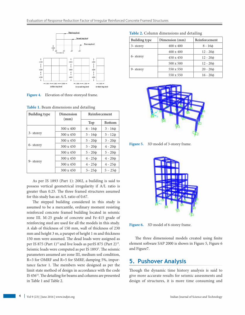
The three dimensional models created using finite element software SAP 2000 is shown in Figure 5, Figure 6 and Figure7.
5. Pushover AnalysisThough the dynamic time history analysis is said to give more accurate results for seismic assessments and design of structures, it is more time consuming and
Figure 4. Elevation of three-storeyed frame.
Figure 5. 3D model of 3-storey frame.
Figure 6. 3D model of 6-storey frame.
Table 1. Beam dimensions and detailing
Building type Dimension(mm)
Reinforcement
Top Bottom
3- storey300 x 400 6 - 16ϕ 3 - 16ϕ300 x 450 5 - 16ϕ 5 - 12ϕ
6- storey300 x 450 5 - 20ϕ 3 - 20ϕ300 x 450 5 - 20ϕ 4 - 20ϕ
9- storey
300 x 450 5 - 20ϕ 5 - 20ϕ300 x 450 4 - 25ϕ 4 - 20ϕ300 x 450 4 - 25ϕ 4 - 25ϕ300 x 450 5– 25ϕ 5 – 25ϕ
Table 2. Column dimensions and detailing
Building type Dimension (mm) Reinforcement 3- storey 400 x 400 8 - 16ϕ
6- storey400 x 400 12 - 20ϕ450 x 450 12 - 20ϕ500 x 500 12 - 20ϕ
9- storey 550 x 550 20 - 20ϕ550 x 550 16 - 20ϕ

Divya Brahmavrathan and C. Arunkumar
Indian Journal of Science and Technology 5Vol 9 (23) | June 2016 | www.indjst.org
demands too much computational efforts. In order to overcome these difficulties and perform nonlinear seismic analysis in a practical but still accurate way, a method called the Nonlinear Static Procedure (NSP) was developed. The detailed procedures are given in ATC-4015 and FEMA 35616.
In this study, non-linear static pushover analysis of the three stepped building models was carried out using finite element software, SAP 2000 to estimate their duc-tility and overstrength factors which are required for computing R factor for each model. The pushover curve or the capacity curves were obtained. Auto hinges from SAP 2000 were assigned as per FEMA 356 for beams and columns separately. The analysis was performed based on a displacement controlled procedure. In this study, the performance point was obtained as per ATC-4015 using SAP 2000 and the overstrength and ductility factors required for the computation of R factor were obtained from the pushover curve by its bilinear idealization as per FEMA 35616.
6. Results and DiscussionThe nonlinear static pushover analysis was performed for both sets of models i.e. for Ordinary Moment Resisting Frame (OMRF) models and special moment resist-ing frame models (each with 3, 6 and 9 storeys). The performance point for each case was obtained as per ATC-4015. Using this performance point, an approximate
value of the response reduction factor was estimated. The values obtained for OMRF and SMRF models are shown in Table 3 and Table 4.
The value of the response reduction factor calculated using Eqn. (2) is presented in Table 5 for OMRF models and Table-6 for SMRF models. The global ductility μ was calculated as per Eqn. (3) using values of ultimate dis-placement and yield displacement. The yield base shear and yield displacement were obtained by the bilinear idealization of the pushover curve. The pushover curves obtained for OMRF case is shown in Figure 8, Figure 9 and Figure 10 and those obtained for SMRF case is shown in Figure 11, Figure 12 and Figure 13.
Figure 7. 3D model of 9-storey frame.
Table 3. Approximate R-value for OMRF models
No. of storeys
Design base shear (Vd)
(kN)
Performance point R = V/Vd
V (kN) D (m)
3 427.88 1016.852 0.014 2.3766 578.695 1404.717 0.034 2.4379 694.001 1633.801 0.045 2.350
Table 4. Approximate R-value for SMRF models
No. of storeys
Design base shear (Vd)
(kN)
Performance point R = V/VdV (kN) D (m)
3 256.728 1025.631 0.014 3.9956 347.217 1404.717 0.034 4.0469 416.4 1633.801 0.045 3.924
Table 5. R factor for OMRF models studied
No. of storeys μ Ω Rμ R
3 3.357 1.76 2.39 2.1036 2.257 1.638 2.257 1.8489 2.262 1.474 2.262 1.670
Table 6. R factor for SMRF models studied
No. of storeys μ Ω Rμ R3 8.93 1.967 4.106 4.0386 4.14 1.554 4.14 3.2169 4.075 1.519 4.075 3.09

Evaluation of Response Reduction Factor of Irregular Reinforced Concrete Framed Structures
Indian Journal of Science and TechnologyVol 9 (23) | June 2016 | www.indjst.org 6
Figure 8. Pushover curve for OMRF – 3 storey.
Figure 11. Pushover curve for SMRF – 3 storey.
Figure 12. Pushover curve for SMRF – 6 storey.
Figure 9. Pushover curve for OMRF – 6storey.
Figure 10. Pushover curve for OMRF - 9storey.
From the pushover curves obtained for OMRF models as shown in Figure 8 to Figure 10, it can be seen that the structures exhibit low ductility. But in the case of SMRF models (Figure 11 to Figure 13), structures exhibit good ductility and the curve enters well into the plastic region.
7. ConclusionThe Indian code for earthquake resistant design of struc-tures IS 1893 (Part 1):2002, incorporates the nonlinear response of a structure by the provision of a response

Divya Brahmavrathan and C. Arunkumar
Indian Journal of Science and Technology 7Vol 9 (23) | June 2016 | www.indjst.org
Figure 13. Pushover curve for SMRF – 9storey.
reduction factor ‘R’ so as to scale down the elastic response of the structure and such that a linear elastic force based approach can be used for design. In the early years, the value assigned to this factor was based on engineering judgement. But today literature exist which suggests a formulation for the response reduction factor. These for-mulations have been modified over a period of time and details regarding this have been mentioned in ATC-1911. The value of R factor varies from 3 to 5 in IS 1893 for RC moment resisting frames, but it does not provide infor-mation on the components of R factor, i.e. the ductility factor, overstrength factor and redundancy factor.
In this study, the following attempts have been made:
• To calculate the actual value of response reduction factor ‘R’ for reinforced concrete stepped building models for both OMRF and SMRF cases.
• To compare the values of R obtained from interpreta-tion of analysis results with the values assumed during the design process.
• To obtain a pattern in the variation of R value as the number of storeys within each step increases.
After the interpretation of analysis results and com-parison of values, the conclusions drawn from this study are as summarized below:
• The actual value of the response reduction factor for stepped building frames are lower than the values of R provided in IS 1893 for OMRF and SMRF structures.
• The value of R factor shows an average decrease of 37.53% for the OMRF case models and an average decrease of 31.04% for SMRF structures.
• The value of the response reduction factor decreases with the increase in the number of stories.
• Similar to the percentage reduction in R factor for irregular buildings as mentioned in Eurocode 89, there is a need to reduce the R factor given in IS 1893 for irregular buildings. The corresponding ductility and overstength factors also need to be mentioned.
• The ductility factor actually depends on the percentage of steel reinforcements. From trials, it was seen that within an optimum percentage of steel reinforcement the value of R increases and for reinforcements beyond the optimum value, R factor showed a decreasing trend.
• As the height of the structure increases, they become more flexible and their time period also increases such that it lies in the constant velocity region of the response spectrum. Thus, subjected to less force.
These conclusions are limited to the stepped building models considered and other data assumed in this study. This study is focused only on the influence of height on the value of response reduction factor. Further study is required including the consideration of the effect of percentage steel on the value of R factor and hence the performance of the structure in the event of an earth-quake. Further studies need to be carried out considering a wider set of geometrical parameters.
8. References1. Devesh P, Bharat B. Qualitative review of seismic response
of vertically irregular building frames. ISET Journal of Earthquake Technology. 2006 Dec; 43(4):121–32.
2. Sarkar P, Prasad MA, Menon D. Vertical geometric irregu-larity in stepped building frames. Engineering Structures. 2010 Aug; 32(8):2175–82.
3. IS 456: Plain and Reinforced Concrete - Code of Practice, Bureau of Indian Standards, New Delhi. 2000.
4. Louzai A, Abed A. Evaluation of seismic behaviour factor of reinforced concrete frame structures based on comparative analysis between non-linear static pushover and incre-mental dynamic analyses. Bull Earthquake Eng. 2014 Oct; 1773–93.
5. Goud SS, Ramancharla PK. Rationalizing Response Reduction Factor R for better Performance of Reinforced Concrete Framed Buildings. National Conference on Recent Research Advances in Civil Engineering, India, 2014.

Evaluation of Response Reduction Factor of Irregular Reinforced Concrete Framed Structures
Indian Journal of Science and TechnologyVol 9 (23) | June 2016 | www.indjst.org 8
6. Chaulagain H, Rodrigues H, Spacone E, Guragain R, Mallik R, Varum H. Response reduction factor of irreg-ular RC buildings in Kathmandu valley. Earthquake Engineering and Engineering Vibration. 2014 Apr; 13(3):455–70.
7. Hakim RA, Alama MS, Ashour SA. Application of Pushover Analysis for Evaluating Seismic Performance of RC Building. International Journal of Engineering Research and Technology. 2014 Jan; 3(1):1657–62.
8. ASCE SEI/ASCE, Minimum Design Loads for Buildings and Other Structures, Reston (USA): American Society of Civil Engineers. 2005.
9. Eurocode, Design of structures for earthquake resistance, part 1: general rules, seismic actions and rules for buildings, European standard EN 1998-1. European Committee for Standardization (CEN), Brussels. 2004 Apr.
10. Chopra AK. Dynamics of Structures, Theory and Applications to Earthquake Engineering, Pearson
Education, Inc. and Dorling Kindersley Publishing, Inc., New Delhi, 2007.
11. Salem YS. ATC 19, Seismic Response Modification Factors, Applied Technical Council, Redwood City, California. 1995.
12. IS 875 (Part 1), Code of Practice for Design Loads (Other than Earthquake) for Building and Structures, Bureau of Indian Standards, New Delhi. 1987.
13. IS 875 (Part 2), Code of Practice for Design Loads (Other than Earthquake) for Building and Structures, Bureau of Indian Standards, New Delhi. 1987.
14. IS 456, Plain and Reinforced Concrete - Code of Practice , Bureau of Indian Standards, New Delhi. 2000.
15. Lakshmanan N. ATC 40, Seismic Evaluation and Retrofit of Concrete Buildings, Applied Technical Council, Redwood City, California.1996.
16. FEMA 356, Prestandard and Commentary for the Seismic Rehabilitation of Buildings, Federal Emergency Management Agency, Washington, DC. 2000.