gse scale systems · 5. figure 1-1 profibus communications module . cn2 ps ms cn1 to gse comm1 +5v...
TRANSCRIPT

GSE Scale Systems
GSE 60-Series Instruments
Profibus Communications Option and Application Note
Ver 1.0.1 3/13/09
P/N 39-10-39398
Published by GSE Scale Systems 1525 Fairlane Circle. Allen Park, MI 48101 USA Copyright © 2008 GSE Scale Systems, All Rights reserved. Information in this manual is subject to change without notice for correction or enhancement. Profibus™ and PTO™ are trademarks of their respective owners.

2
Table of Contents
1 GSE ____________________________________________________________________ 3 1.1 Profibus Basics - GSE Scale 60 Series Indicators (Profibus Slaves). ----------------------------- 4
1.1.1 Profibus Master: .................................................................................................................................................... 4
1.1.2 Profibus Slaves ..................................................................................................................................................... 4
1.1.3 GSD File ............................................................................................................................................................... 4
1.1.4 I/O Module ............................................................................................................................................................ 4
1.1.5 I/O Assemblies ...................................................................................................................................................... 4
1.1.6 Explicit Messaging ................................................................................................................................................ 4
1.1.7 Overview of the GSE Profibus Option ................................................................................................................... 4 1.1.7.1 GSE Profibus Option Board .............................................................................................................................. 4 1.1.7.2 Profibus and the GSE 60 Series Indicators ...................................................................................................... 5
1.2 Initial Setup of indicator ------------------------------------------------------------------------------------------- 5 1.3 Serial Port One Settings ------------------------------------------------------------------------------------------ 6 1.4 Initial Profibus Master Setup ------------------------------------------------------------------------------------ 6 1.5 The I/O Modules ------------------------------------------------------------------------------------------------------ 7
Table 1.5 ....................................................................................................................................................................... 7
1.6 The I/O Assemblies ------------------------------------------------------------------------------------------------- 7 Table 1.6 Scale Registers for I/O Assemblies .............................................................................................................. 8
1.7 Explicit Messaging -------------------------------------------------------------------------------------------------- 9 Table 1.7 Explicit Messaging Address Chart .............................................................................................................. 10
1.8 Advanced Profibus Setup and Modification --------------------------------------------------------------- 19 1.8.1 How to Modify the Profibus Register Map ........................................................................................................... 19
1.8.1.1 Examples of replacing Register Values .......................................................................................................... 19
1.8.2 Reclaiming Setup Memory .................................................................................................................................. 22
1.9 Setpoints -------------------------------------------------------------------------------------------------------------- 23 Table 1.9 Setpoint Target Variables ........................................................................................................................... 23
1.10 Informational Parameters for Profibus ---------------------------------------------------------------------- 24 1.10.1 P60000 FRam (E2) Available .............................................................................................................................. 24
1.10.2 Profibus Specific ................................................................................................................................................. 24 1.10.2.1 Using P60301 Reg Check ............................................................................................................................... 24
1.11 New Weigh Mode Parameter 95 – Network Status, Option Board LEDs ------------------------- 25 Table 1.11 Defines the meaning of each digit displayed at parameter 95 “Profibus Stat”. .......................................... 25
1.12 New Scale Parameter P96 --------------------------------------------------------------------------------------- 26 Table 1.12 Bit Definition for Scale Parameter 96 ........................................................................................................ 26
1.13 Communicating with the device ------------------------------------------------------------------------------- 27 1.13.1 OUTPUT DATA .................................................................................................................................................. 27
Table 1.13.1 Output Data Format .............................................................................................................................. 27

3
1.13.2 INPUT DATA ...................................................................................................................................................... 27 Table 1.13.2 Intput Data Format ................................................................................................................................ 28
1.13.3 COMMUNICATION EXAMPLES ........................................................................................................................ 28 1.13.3.1 Get I/O Assembly data for one scale .............................................................................................................. 28 1.13.3.2 Get I/O Assembly data for two scales ............................................................................................................. 29 1.13.3.3 Request model number of indicator ................................................................................................................ 29 1.13.3.4 Read a Register (word) ................................................................................................................................... 30 1.13.3.5 Read a Register (long) .................................................................................................................................... 30 1.13.3.6 Write a Register (word) ................................................................................................................................... 30 1.13.3.7 Write a Register (long) .................................................................................................................................... 31 1.13.3.8 Read a Register (string) .................................................................................................................................. 31 1.13.3.9 Write a Register (string) .................................................................................................................................. 32 1.13.3.10 Turn a coil on .................................................................................................................................................. 32 1.13.3.11 Turn a coil off .................................................................................................................................................. 33 1.13.3.12 Read coil status .............................................................................................................................................. 33 1.13.3.13 Run a user created macro .............................................................................................................................. 34 1.13.3.14 Check if user created macro running .............................................................................................................. 34 1.13.3.15 Run a built-in macro ........................................................................................................................................ 34 1.13.3.16 Check if built-in macro running ....................................................................................................................... 35
1.13.4 RETURNED ERROR CODES ............................................................................................................................ 35 1.13.4.1 ERROR Trying to Read a Register (word) ...................................................................................................... 36
1.14 TroubleShooting and Profibus related Error Messages ----------------------------------------------- 36 1.14.1 Framing or other Comm Port Errors when attempting Setup (Script or Upload). ................................................ 36
1.14.2 Error Codes ***See the 60 Series Tech Manual Appendix E for the description of other Codes ....................... 36
1 GSE

4
2
GSE 1.1 PROFIBUS BASICS - GSE SCALE 60 SERIES INDICATORS (PROFIBUS SLAVES). GSE 60 Series Indicators have passed conformance testing for Profibus.
1.1.1 Profibus Master: The device that requests information from or sends information to the slave.
1.1.2 Profibus Slaves Equipment on a Profibus Network that provides information to and or are controlled by the Master. Profibus architecture allows for 32 stations per network segment, 126 total if multiple segments are connected using repeaters. The GSE 60 Series Indicators perform as Slaves on the Profibus Network.
1.1.3 GSD File A computer file of information that configures the master for interfacing with a slave device. Not all Masters have the capability of using an GSD File and depend on the person programming the master for configuration. PTO Approved GSE GSD Files are available at www.profibus.com.
1.1.4 I/O Module The I/O module is selected at the master while creating the slave device. The GSE Indicator has sixteen possible modules to select from. Which module gets selected will depend on how many scales are attached to the unit, and whether string data will be communicated. While the largest module could always be chosen, this will cause the transfer of more data bytes than is required, needlessly using network bandwidth.
Profibus has two main methods of communicating information. I/O Assemblies and Explicit Messaging.
1.1.5 I/O Assemblies The main block of information that is regularly communicated to the Master. If, for example, four fields of information need to be rapidly and regularly supplied to the Master, they would be included in the I/O Assembly. In this case, a single transmission supplies four answers. The assembly being used can be changed at anytime, all that is required is the data fit within the I/O module that is being used. Large I/O assemblies that provide unneeded information decrease system performance.
1.1.6 Explicit Messaging Any other information that is available through the GSE Profibus Interface may be read or written in this way. It is information that is generally set or requested as one piece of information at a time, and is piggy backed onto the end of the i/o assembly data. This type of communication is suited to information that is not rapidly changing.
1.1.7 Overview of the GSE Profibus Option The Profibus Option for GSE 60-Series Instruments operates as a slave on the Profibus network. It utilizes the Master/Slave Connection Set, as defined in the Profibus Specifications. It supports Explicit and I/O Assemblies. The GSE Profibus Option communicates with the GSE 60-Series Instrument on the Comm 1 serial port.
1.1.7.1 GSE Profibus Option Board The Profibus Option mounts inside the enclosure of a GSE 60-Series Instrument on 4 mounting posts (See Quick Start Guide). A 4-pin connector (CN1) is wired to the Instrument to provide power and communications to the GSE Profibus Option Board. A 5-pin Open Pluggable connector (CN2) provides an optically-isolated connection to the Profibus network. Three LEDs provide status (see Figure 1.1).

5
Figure 1-1 Profibus Communications Module
CN2
PS MS
CN1
To GSE Comm1 +5VTo GSE Comm1 GNDTo GSE Comm1 TxDTo GSE Comm1 RxD
Shld/NCBusABusBV+V-
ProgrammingConnector
Comm 1Connector
Profibus StatusLEDs
ProfibusConnector
Perr
1.1.7.2 Profibus and the GSE 60 Series Indicators Each GSE 60 Series Indicator has a built in Profibus setup script, which puts the indicator into a known setup state with selectable I/O assemblies and most scale parameters available through Explicit Messages.
The programmability of the 60 Series Indicators is still available for you to collaborate with the programmer of the Master to customize an I/O Assembly that will efficiently supply virtually any combination of scale information from weight, future weight and rate to blocks of relay status. The number of bytes in the I/O assemblies must remain the same but the information that is contained in these bytes can be easily changed for a specific application.
1.2 INITIAL SETUP OF INDICATOR IMPORTANT*** The 66x Series Indicators require the installation of an additional 8K FRam (EEProm on older units) to provide enough memory to run this setup.
WARNING*** Do not change the length of the strings of Var# 15, 30 ,45 and 60 or change a Numeric Var to a String. Doing so will shift all data stored above the Var and make the registers above this Var Profibus registers unuseable by Profibus. See “Advanced Profibus Setup and Modification”.

6
Detailed installation information is provided in the “Quick Start Guide”. 1 Install any Multi-Scale Options and the Profibus Option per “Quick Start Guide”.
Power up the indicator with the [CLR] key held. After it states that macros are disabled, a prompt will appear for disabling comm1. Press [ENTER].
2 Go into setup and enable the scales to be used. 3 Go to parameter 65002. “Deflt – Cal” 4 Press the Tare Key until “Profibus” is displayed. 5 Press Enter, read the prompts and Press Enter the required number of times for your model.
a. The scale will load its Profibus Setup Script. b. Any scale that was disabled will have been changed to saved. c. The Indicator is now configured to communicate on Profibus and Port 1 is not available for other
communication. 6 To test the complete interface, leave the unused scales “Saved" This will cause zero values to be returned for
the “Saved” scales. For normal operation, disabling the “Saved” scales will cause the interface to return resource unavailable for the disabled scales, a more reasonable response for scales that don’t exist.
1.3 SERIAL PORT ONE SETTINGS Serial port number one is used for profibus communications. The port is automatically configured when the built-in profibus script is run. Once the script has run, P200 and P209 can be changed if necessary.
Once the Receive (P205) is set to Profibus “253 [ENTER]”, changes that are made to any other Port #1 Parameter that are Identified as PFbus on the lower 2x5 Display will be saved but suppressed until P205 is changed to another Receive choice. P200 Baud Profibus Baud – Auto, 9.6K, 19.2K, 31.2K, 45.5K, 93.7K, 187K, 500K, 1.5M, 3M, 6M, 12M
(auto will detect from: 19.2K, 187.5K, 500K, 1.5M, 3M, 6M, 12M)(Curr UnKwn flashes if not connected)
P201 Data Bits Suppressed P202 Parity Suppressed P203 Stop Bits Suppressed P204 Flow Control Suppressed P205 ReceiveMode Profibus = 253 P206 Full Suppressed P207 Tx Buffer Suppressed P208 Rx Buffer Suppressed P209 PFad This is the address that the Master refers to to communicate with this device. All devices on the
network must have a unique address. (Address choices 2-125/126) (address 126 indicates the Master should assign a value)
P210 MbMd Suppressed P211 Word Order Suppressed P212 I/O Assy Informational only, indicates which i/o assembly is being used. P213 Ptime You may slow the updates of the I/O Assys by setting this value above 16 ms (actual value based
on indicator model). This could be used when the Indicator is running a large CPU intensive program. It sets how often the I/O Assy data is updated to free some CPU time. Profibus response time is the same.
1.4 INITIAL PROFIBUS MASTER SETUP Every master is different, so the exact steps required will vary. Place the GSD and DIB files supplied by GSE into the folders appropriate for your master. Select one of the sixteen defined I/O Modules, this will instruct the master and slave how many data bytes will be exchanged between them. The following graphics are for use by the master software for pictorially representing the GSE Indicator.

7
1.5 THE I/O MODULES I/O modules define how many bytes are exchanged between the master and slave device. I/O modules do not give any meaning to the bytes. Which module to use is selected when setting up slaves in the master, once setup in the master this value will probably never be changed (it will probably require deleting and recreating the slave device). GSE indicators support sixteen I/O modules. Modules #1-8 do not support transferring string data. Module #1 supports polled data for one scale, #2 supports polled data for two scales, etc. Modules #9-16 support transferring string data. Module #9 supports polled data for one scale, #10 supports polled data for two scales, etc. Which module you select will be based on the configuration of the indicator and how it is being used. Make sure chosen module is large enough to transfer the amount of data required by your setup.
TABLE 1.5
I/O Module I/O Assembly Numbers usable in this I/O module
Comment
1 8 Bytes Out, 16 Bytes In 1, 9-10 No Strings 2 8 Bytes Out, 24 Bytes In 1-2, 9-12 3 8 Bytes Out, 32 Bytes In 1-3, 9-14 4 8 Bytes Out, 40 Bytes In 1-4, 9-16 5 8 Bytes Out, 48 Bytes In 1-5, 9-16 6 8 Bytes Out, 56 Bytes In 1-6, 9-16 7 8 Bytes Out, 64 Bytes In 1-7, 9-16 8 8 Bytes Out, 72 Bytes In 1-8, 9-16 9 22 Bytes Out, 30 Bytes In 1, 9-10 Supports Strings 10 22 Bytes Out, 38 Bytes In 1-2, 9-12 11 22 Bytes Out, 46 Bytes In 1-3, 9-14 12 22 Bytes Out, 54 Bytes In 1-4, 9-16 13 22 Bytes Out, 62 Bytes In 1-5, 9-16 14 22 Bytes Out, 70 Bytes In 1-6, 9-16 15 22 Bytes Out, 78 Bytes In 1-7, 9-16 16 22 Bytes Out, 86 Bytes In 1-8, 9-16
1.6 THE I/O ASSEMBLIES The I/O Assemblies are used to communicate the most frequently required data. The assembly requested must fit within the I/O module that was setup in the master. Any data beyond the I/O module length will be lost. Any data less than the I/O module length will be zero filled. The information is arranged in logical blocks in the indicator. The register numbers identify the order of available data. Table 1.6 shows the logical I/O Assembly blocks in order from Assy 1-to Assy-8 and from Assy-9 to Assy-16. For example, Assembly 3 would include all the information from Assy 1, 2 and 3. Assembly 12 would include Assy 9, 10, 11 and 12. I/O assemblies 1 to 8 are in blocks of 8 Bytes. Two bytes for each of three 16 bit integers and two bytes for the status word. I/O assemblies 9 to 16 are in blocks of four Bytes. Four bytes for each 32 bit IEE floating point number. One of the following I/O Assemblies will be selected, at run time, by the Master. Indicators with less than eight scale capability will have the highest available scale data duplicated in the I/O assemblies in place of higher scale information. See section 1.8 for how to change the assembly data sent.

8
TABLE 1.6 SCALE REGISTERS FOR I/O ASSEMBLIES
Scale Parm Registers
Scaled Y/N Type Scale Value
8 7 6 5 4 3 2 1 6001 40001 Y INT16 Gross Scale 18 7 6 5 4 3 2 1 6002 40002 Y INT16 Future Gross 18 7 6 5 4 3 2 1 6003 40003 Y INT16 Rate Scale 18 7 6 5 4 3 2 1 6004 40004 N High/ Low Byte Scaling/ Stat Scale 18 7 6 5 4 3 2 6005 40005 Y INT16 Gross Scale 28 7 6 5 4 3 2 6006 40006 Y INT16 Future Gross 28 7 6 5 4 3 2 6007 40007 Y INT16 Rate Scale 28 7 6 5 4 3 2 6008 40008 N High/Low Byte Scaling/Stat Scale 28 7 6 5 4 3 6009 40009 Y INT16 Gross Scale 38 7 6 5 4 3 6010 40010 Y INT16 Future Gross 38 7 6 5 4 3 6011 40011 Y INT16 Rate Scale 38 7 6 5 4 3 6012 40012 N High/ Low Byte Scaling/ Stat Scale 38 7 6 5 4 6013 40013 Y INT16 Gross Scale 48 7 6 5 4 6014 40014 Y INT16 Future Gross 48 7 6 5 4 6015 40015 Y INT16 Rate Scale 48 7 6 5 4 6016 40016 N High/Low Byte Scaling/Stat Scale 48 7 6 5 6017 40017 Y INT16 Gross Scale 58 7 6 5 6018 40018 Y INT16 Future Gross 58 7 6 5 6019 40019 Y INT16 Rate Scale 58 7 6 5 6020 40020 N High/ Low Byte Scaling/ Stat Scale 58 7 6 6021 40021 Y INT16 Gross Scale 68 7 6 6022 40022 Y INT16 Future Gross 68 7 6 6023 40023 Y INT16 Rate Scale 68 7 6 6024 40024 N High/Low Byte Scaling/Stat Scale 68 7 6025 40025 Y INT16 Gross Scale 78 7 6026 40026 Y INT16 Future Gross 78 7 6027 40027 Y INT16 Rate Scale 78 7 6028 40028 N High/ Low Byte Scaling/ Stat Scale 78 6029 40029 Y INT16 Gross Scale 88 6030 40030 Y INT16 Future Gross 88 6031 40031 Y INT16 Rate Scale 88 6032 40032 N High/Low Byte Scaling/Stat Scale 8
I/O Assys 1 - 8
Assembly Numbers
See Section 02 for Bit Definition of Scale Parameter 96 Scaling / Stat
Scale Parm Registers
Scaled Y/N Type Scale Value
16 15 14 13 12 11 10 9 6033 40033 / 40034 N IEE FLOAT 32 Rounded Gross Sc 116 15 14 13 12 11 10 6034 40035 / 40036 N IEE FLOAT 32 Rounded Gross Sc 216 15 14 13 12 11 6035 40037 / 40038 N IEE FLOAT 32 Rounded Gross Sc 316 15 14 13 12 6036 40039 / 40040 N IEE FLOAT 32 Rounded Gross Sc 416 15 14 13 6037 40041 / 40042 N IEE FLOAT 32 Rounded Gross Sc 516 15 14 6038 40043 / 40044 N IEE FLOAT 32 Rounded Gross Sc 616 15 6039 40045 / 40046 N IEE FLOAT 32 Rounded Gross Sc 716 6040 40047 / 40048 N IEE FLOAT 32 Rounded Gross Sc 8
Assembly Numbers
I/O Assys 9-16
***See Section 1.7 for Explicit Message Addressing.

9
1.7 EXPLICIT MESSAGING Explicit messages are used to set or retrieve specific data, set or check the status of a coil, run a macro or see if it is currently running. Tables 1.6 and 1.7 show the predefined register map for the data and controls that can be accessed using explicit messages. Note that the data in Table 1.6 is already being polled constantly by the master. In the tables, the register number is used to reference the data item, and the get/set field indicates how the data may be accessed.

10
TABLE 1.7 EXPLICIT MESSAGING ADDRESS CHART
6000 Param Registers
Scaled Y/N Type Get/Set Parameter Name
Parm Number
6041 40049 N IEE Float Get/Set APW34 Common
400506042 40051 Y INT32 Get Scales Common
6043 40053 Y INT32 Get Combined Net of All Scales41 Common
6044 40055 Y INT32 Get Combined Tare of All Scales42 Common
6045 40057 N INT32 Get Scales Common
6046 40059 Y INT16 Get Gross 0 Scale 16047 40060 Y INT16 Get Net 1 Scale 16048 40061 Y INT16 Get/Set Tare 2 Scale 16049 40062 Y INT16 Get Average Gross 15 Scale 16050 40063 Y INT16 Get Average Net 16 Scale 16051 40064 Y INT16 Get Peak Gross 18 Scale 16052 40065 Y INT16 Get Peak Net 19 Scale 1
6053 40066 .01 Sec. INT16 Get/Set Free Fall 24 Scale 16054 40067 Y INT16 Get Future Gross 25 Scale 16055 40068 Y INT16 Get Future Net 26 Scale 16056 40069 N INT16 Get Count (Qty) 30 Scale 16057 40070 Y INT32 Get/Set Gross Total 3 Scale 16058 40072 Y INT32 Get/Set Net Total 6 Scale 16059 40074 Y INT32 Get/Set # Accumulations 9 Scale 16060 40076 N INT32 Get Count Total (Qty) 31 Scale 1
6061 40078 Y INT16 Get Gross 0 Scale 26062 40079 Y INT16 Get Net 1 Scale 26063 40080 Y INT16 Get/Set Tare 2 Scale 26064 40081 Y INT16 Get Average Gross 15 Scale 26065 40082 Y INT16 Get Average Net 16 Scale 26066 40083 Y INT16 Get Peak Gross 18 Scale 26067 40084 Y INT16 Get Peak Net 19 Scale 2
6068 40085 .01 Sec. INT16 Get/Set Free Fall 24 Scale 26069 40086 Y INT16 Get Future Gross 25 Scale 26070 40087 Y INT16 Get Future Net 26 Scale 26071 40088 N INT16 Get Count (Qty) 30 Scale 26072 40089 Y INT32 Get/Set Gross Total 3 Scale 26073 40091 Y INT32 Get/Set Net Total 6 Scale 26074 40093 Y INT32 Get/Set # Accumulations 9 Scale 26075 40095 N INT32 Get Count Total (Qty) 31 Scale 2
6076 40097 Y INT16 Get/Set SP1 Target Var 80.16077 40098 Y INT16 Get/Set SP2 Target Var 80.26078 40099 Y INT16 Get/Set SP3 Target Var 80.36079 40100 Y INT16 Get/Set SP4 Target Var 80.46080 40101 Y INT16 Get/Set SP5 Target Var 80.56081 40102 Y INT16 Get/Set SP6 Target Var 80.66082 40103 Y INT16 Get/Set SP7 Target Var 80.7
Setpoints set to act never deact
Explicit Messaging
These Six are common to all enabled scales
The following block is common to All Series

11
6083 40104 Y INT16 Get/Set SP8 Target Var 80.86084 40105 Y INT16 Get/Set Var # 9 Var 80.96085 40106 Y INT16 Get/Set Var # 10 Var 80.106086 40107 Y INT16 Get/Set Var # 11 Var 80.116087 40108 Y INT32 Get/Set Var # 12 Var 80.126088 40110 Y INT32 Get/Set Var # 13 Var 80.136089 40112 N IEE Float Get/Set Var # 14 Var 80.14
6090 40114 NString 18 Char=9 Reg Get/Set Var # 15 Var 80.15
6091 40123 N 16 Bits Get SetPoint 1 - 16 Status
6092 40124 Y INT16 Get Gross 0 Scale 36093 40125 Y INT16 Get Net 1 Scale 36094 40126 Y INT16 Get/Set Tare 2 Scale 36095 40127 Y INT16 Get Average Gross 15 Scale 36096 40128 Y INT16 Get Average Net 16 Scale 36097 40129 Y INT16 Get Peak Gross 18 Scale 36098 40130 Y INT16 Get Peak Net 19 Scale 36099 40131 .01 INT16 Get/Set Free Fall 24 Scale 36100 40132 Y INT16 Get Future Gross 25 Scale 36101 40133 Y INT16 Get Future Net 26 Scale 36102 40134 N INT16 Get Count (Qty) 30 Scale 36103 40135 Y INT32 Get/Set Gross Total 3 Scale 36104 40137 Y INT32 Get/Set Net Total 6 Scale 36105 40139 Y INT32 Get/Set # Accumulations 9 Scale 36106 40141 N INT32 Get Count Total (Qty) 31 Scale 3
6107 40143 Y INT16 Get Gross 0 Scale 46108 40144 Y INT16 Get Net 1 Scale 46109 40145 Y INT16 Get/Set Tare 2 Scale 46110 40146 Y INT16 Get Average Gross 15 Scale 46111 40147 Y INT16 Get Average Net 16 Scale 46112 40148 Y INT16 Get Peak Gross 18 Scale 46113 40149 Y INT16 Get Peak Net 19 Scale 4
6114 40150.01 Sec. INT16 Get/Set Free Fall 24 Scale 4
6115 40151 Y INT16 Get Future Gross 25 Scale 46116 40152 Y INT16 Get Future Net 26 Scale 46117 40153 N INT16 Get Count (Qty) 30 Scale 46118 40154 Y INT32 Get/Set Gross Total 3 Scale 46119 40156 Y INT32 Get/Set Net Total 6 Scale 46120 40158 Y INT32 Get/Set # Accumulations 9 Scale 46121 40160 N INT32 Get Count Total (Qty) 31 Scale 4
6122 40162 Y INT16 Get/Set SP Target 9 Var 80.166123 40163 Y INT16 Get/Set SP Target 10 Var 80.176124 40164 Y INT16 Get/Set SP Target 11 Var 80.186125 40165 Y INT16 Get/Set SP Target 12 Var 80.196126 40166 Y INT16 Get/Set SP Target 13 Var 80.206127 40167 Y INT16 Get/Set SP Target 14 Var 80.216128 40168 Y INT16 Get/Set SP Target 15 Var 80.226129 40169 Y INT16 Get/Set SP Target 16 Var 80.236130 40170 Y INT16 Get/Set Var # 24 Var 80.246131 40171 Y INT16 Get/Set Var # 25 Var 80.256132 40172 Y INT16 Get/Set Var # 26 Var 80.266133 40173 Y INT32 Get/Set Var # 27 Var 80.276134 40175 Y INT32 Get/Set Var # 28 Var 80.28
************************************* END OF 460 SERIES************************************
The following block is common to 560 and 660 Series

12
6135 40177 N IEE Float Get/Set Var # 29 Var 80.29
6136 40179 NString 18 Char=9 Reg Get/Set Var # 30 Var 80.30
6137 40188 Y INT16 Get/Set SP Target 17 Var 80.316138 40189 Y INT16 Get/Set SP Target 18 Var 80.326139 40190 Y INT16 Get/Set SP Target 19 Var 80.336140 40191 Y INT16 Get/Set SP Target 20 Var 80.346141 40192 Y INT16 Get/Set SP Target 21 Var 80.356142 40193 Y INT16 Get/Set SP Target 22 Var 80.366143 40194 Y INT16 Get/Set SP Target 23 Var 80.376144 40195 Y INT16 Get/Set SP Target 24 Var 80.386145 40196 Y INT16 Get/Set Var # 39 Var 80.396146 40197 Y INT16 Get/Set Var # 40 Var 80.406147 40198 Y INT16 Get/Set Var # 41 Var 80.416148 40199 Y INT32 Get/Set Var # 42 Var 80.426149 40201 Y INT32 Get/Set Var # 43 Var 80.436150 40203 N IEE Float Get/Set Var # 44 Var 80.44
6151 40205 NString 18 Char=9 Reg Get/Set Var # 45 Var 80.45
6152 40214 Y INT16 Get/Set SP Target 25 Var 80.466153 40215 Y INT16 Get/Set SP Target 26 Var 80.476154 40216 Y INT16 Get/Set SP Target 27 Var 80.486155 40217 Y INT16 Get/Set SP Target 28 Var 80.496156 40218 Y INT16 Get/Set SP Target 29 Var 80.506157 40219 Y INT16 Get/Set SP Target 30 Var 80.516158 40220 Y INT16 Get/Set SP Target 31 Var 80.526159 40221 Y INT16 Get/Set SP Target 32 Var 80.536160 40222 Y INT16 Get/Set Var # 54 Var 80.546161 40223 Y INT16 Get/Set Var # 55 Var 80.556162 40224 Y INT16 Get/Set Var # 56 Var 80.566163 40225 Y INT32 Get/Set Var # 57 Var 80.576164 40227 Y INT32 Get/Set Var # 58 Var 80.586165 40229 N IEE Float Get/Set Var # 59 Var 80.59
6166 40231 NString 18 Char=9 Reg Get/Set Var # 60 Var 80.60
6167 40240 N 16 Bits Get SetPoint 17 - 32 Status
6168 40241 Y INT16 Get Gross 0 Scale 56169 40242 Y INT16 Get Net 1 Scale 56170 40243 Y INT16 Get/Set Tare 2 Scale 56171 40244 Y INT16 Get Average Gross 15 Scale 56172 40245 Y INT16 Get Average Net 16 Scale 56173 40246 Y INT16 Get Peak Gross 17 Scale 56174 40247 Y INT16 Get Peak Net 18 Scale 5
6175 40248.01 Sec. INT16 Get/Set Free Fall 19 Scale 5
6176 40249 Y INT16 Get Future Gross 20 Scale 56177 40250 Y INT16 Get Future Net 21 Scale 56178 40251 N INT16 Get Count (Qty) 22 Scale 56179 40252 Y INT32 Get/Set Gross Total 23 Scale 56180 40254 Y INT32 Get/Set Net Total 24 Scale 56181 40256 Y INT32 Get/Set # Accumulations 25 Scale 56182 40258 N INT32 Get/Set Count Total (Qty) 26 Scale 5
6185 40260 Y INT16 Get Gross 0 Scale 6
The following block applys to the 660 Series
******************************* END OF 560 SERIES *********************************************

13
6186 40261 Y INT16 Get Net 1 Scale 66187 40262 Y INT16 Get/Set Tare 2 Scale 66188 40263 Y INT16 Get Average Gross 15 Scale 66189 40264 Y INT16 Get Average Net 16 Scale 66190 40265 Y INT16 Get Peak Gross 17 Scale 66191 40266 Y INT16 Get Peak Net 18 Scale 6
6192 40267.01 Sec. INT16 Get/Set Free Fall 19 Scale 6
6193 40268 Y INT16 Get Future Gross 20 Scale 66194 40269 Y INT16 Get Future Net 21 Scale 66195 40270 N INT16 Get Count (Qty) 22 Scale 66196 40271 Y INT32 Get/Set Gross Total 23 Scale 66197 40273 Y INT32 Get/Set Net Total 24 Scale 66198 40275 Y INT32 Get/Set # Accumulations 25 Scale 66199 40277 N INT32 Get/Set Count Total (Qty) 26 Scale 6
6198 40279 Y INT16 Get Gross 0 Scale 76199 40280 Y INT16 Get Net 1 Scale 76200 40281 Y INT16 Get/Set Tare 2 Scale 76201 40282 Y INT16 Get Average Gross 15 Scale 76202 40283 Y INT16 Get Average Net 16 Scale 76203 40284 Y INT16 Get Peak Gross 17 Scale 76204 40285 Y INT16 Get Peak Net 18 Scale 7
6205 40286.01 Sec. INT16 Get/Set Free Fall 19 Scale 7
6206 40287 Y INT16 Get Future Gross 20 Scale 76207 40288 Y INT16 Get Future Net 21 Scale 76208 40289 N INT16 Get Count (Qty) 22 Scale 76209 40290 Y INT32 Get/Set Gross Total 23 Scale 76210 40292 Y INT32 Get/Set Net Total 24 Scale 76211 40294 Y INT32 Get/Set # Accumulations 25 Scale 76212 40296 N INT32 Get/Set Count Total (Qty) 26 Scale 7
6213 40298 Y INT16 Get Gross 0 Scale 86214 40299 Y INT16 Get Net 1 Scale 86215 40300 Y INT16 Get/Set Tare 2 Scale 86216 40301 Y INT16 Get Average Gross 15 Scale 86217 40302 Y INT16 Get Average Net 16 Scale 86218 40303 Y INT16 Get Peak Gross 17 Scale 86219 40304 Y INT16 Get Peak Net 18 Scale 8
6220 40305.01 Sec. INT16 Get/Set Free Fall 19 Scale 8
6221 40306 Y INT16 Get Future Gross 20 Scale 86222 40307 Y INT16 Get Future Net 21 Scale 86223 40308 N INT16 Get Count (Qty) 22 Scale 86224 40309 Y INT32 Get/Set Gross Total 23 Scale 86225 40311 Y INT32 Get/Set Net Total 24 Scale 86226 40313 Y INT32 Get/Set # Accumulations 25 Scale 86227 40315 N INT32 Get/Set Count Total (Qty) 26 Scale 8
6228 40317 Y INT16 Get/Set SP Target 33 Var 80.616229 40318 Y INT16 Get/Set SP Target 34 Var 80.626230 40319 Y INT16 Get/Set SP Target 35 Var 80.636231 40320 Y INT16 Get/Set SP Target 36 Var 80.646232 40321 Y INT16 Get/Set SP Target 37 Var 80.656233 40322 Y INT16 Get/Set SP Target 38 Var 80.666234 40323 Y INT16 Get/Set SP Target 39 Var 80.676235 40324 Y INT16 Get/Set SP Target 40 Var 80.686236 40325 Y INT16 Get/Set Var # 69 Var 80.69

14
6237 40326 Y INT16 Get/Set Var # 70 Var 80.706238 40327 Y INT16 Get/Set Var # 71 Var 80.716239 40328 Y INT16 Get/Set Var # 72 Var 80.726240 40329 Y INT32 Get/Set Var # 73 Var 80.736241 40331 Y INT32 Get/Set Var # 74 Var 80.746242 40333 N IEE Float Get/Set Var # 75 Var 80.75
6243 40335 Y INT16 Get/Set SP Target 41 Var 80.766244 40336 Y INT16 Get/Set SP Target 42 Var 80.776245 40337 Y INT16 Get/Set SP Target 43 Var 80.786246 40338 Y INT16 Get/Set SP Target 44 Var 80.796247 40339 Y INT16 Get/Set SP Target 45 Var 80.806248 40340 Y INT16 Get/Set SP Target 46 Var 80.816249 40341 Y INT16 Get/Set SP Target 47 Var 80.826250 40342 Y INT16 Get/Set SP Target 48 Var 80.836251 40343 Y INT16 Get/Set Var # 84 Var 80.846252 40344 Y INT16 Get/Set Var # 85 Var 80.856253 40345 Y INT16 Get/Set Var # 86 Var 80.866254 40346 Y INT16 Get/Set Var # 87 Var 80.876255 40347 Y INT32 Get/Set Var # 88 Var 80.886256 40349 Y INT32 Get/Set Var # 89 Var 80.896257 40351 N IEE Float Get/Set Var # 90 Var 80.906258 40353 N 16 Bits Get SetPoint 33 - 48 Status
6259 40354 Y INT16 Get/Set SP Target 49 Var 80.916260 40355 Y INT16 Get/Set SP Target 50 Var 80.926261 40356 Y INT16 Get/Set SP Target 51 Var 80.936262 40357 Y INT16 Get/Set SP Target 52 Var 80.946263 40358 Y INT16 Get/Set SP Target 53 Var 80.956264 40359 Y INT16 Get/Set SP Target 54 Var 80.966265 40360 Y INT16 Get/Set SP Target 55 Var 80.976266 40361 Y INT16 Get/Set SP Target 56 Var 80.986267 40362 Y INT16 Get/Set Var # 99 Var 80.996268 40363 Y INT16 Get/Set Var # 100 Var 80.1006269 40364 Y INT16 Get/Set Var # 101 Var 80.1016270 40365 Y INT16 Get/Set Var # 102 Var 80.1026271 40366 Y INT32 Get/Set Var # 103 Var 80.1036272 40368 Y INT32 Get/Set Var # 104 Var 80.1046273 40370 N IEE Float Get/Set Var # 105 Var 80.105
6274 40372 Y INT16 Get/Set SP Target 57 Var 80.1066275 40373 Y INT16 Get/Set SP Target 58 Var 80.1076276 40374 Y INT16 Get/Set SP Target 59 Var 80.1086277 40375 Y INT16 Get/Set SP Target 60 Var 80.1096278 40376 Y INT16 Get/Set SP Target 61 Var 80.1106279 40377 Y INT16 Get/Set SP Target 62 Var 80.1116280 40378 Y INT16 Get/Set SP Target 63 Var 80.1126281 40379 Y INT16 Get/Set SP Target 64 Var 80.1136282 40380 Y INT16 Get/Set Var # 114 Var 80.1146283 40381 Y INT16 Get/Set Var # 115 Var 80.1156284 40382 Y INT16 Get/Set Var # 116 Var 80.1166285 40383 Y INT16 Get/Set Var # 117 Var 80.1176286 40384 Y INT32 Get/Set Var # 118 Var 80.1186287 40386 Y INT32 Get/Set Var # 119 Var 80.1196288 40388 N IEE Float Get/Set Var # 120 Var 80.1206289 40390 N 16 Bits Get SetPoint 49 - 64 Status
6290 40391 Y INT16 Get/Set SP Target 65 Var 80.1216291 40392 Y INT16 Get/Set SP Target 66 Var 80.122

15
6292 40393 Y INT16 Get/Set SP Target 67 Var 80.1236293 40394 Y INT16 Get/Set SP Target 68 Var 80.1246294 40395 Y INT16 Get/Set SP Target 69 Var 80.1256295 40396 Y INT16 Get/Set SP Target 70 Var 80.1266296 40397 Y INT16 Get/Set SP Target 71 Var 80.1276297 40398 Y INT16 Get/Set SP Target 72 Var 80.1286298 40399 Y INT16 Get/Set Var # 129 Var 80.1296299 40400 Y INT16 Get/Set Var # 130 Var 80.1306300 40401 Y INT16 Get/Set Var # 131 Var 80.1316301 40402 Y INT16 Get/Set Var # 132 Var 80.1326302 40403 Y INT32 Get/Set Var # 133 Var 80.1336303 40405 Y INT32 Get/Set Var # 134 Var 80.1346304 40407 N IEE Float Get/Set Var # 135 Var 80.135
6305 40409 Y INT16 Get/Set SP Target 73 Var 80.1366306 40410 Y INT16 Get/Set SP Target 74 Var 80.1376307 40411 Y INT16 Get/Set SP Target 75 Var 80.1386308 40412 Y INT16 Get/Set SP Target 76 Var 80.1396309 40413 Y INT16 Get/Set SP Target 77 Var 80.1406310 40414 Y INT16 Get/Set SP Target 78 Var 80.1416311 40415 Y INT16 Get/Set SP Target 79 Var 80.1426312 40416 Y INT16 Get/Set SP Target 80 Var 80.1436313 40417 Y INT16 Get/Set Var # 144 Var 80.1446314 40418 Y INT16 Get/Set Var # 145 Var 80.1456315 40419 Y INT16 Get/Set Var # 146 Var 80.1466316 40420 Y INT16 Get/Set Var # 147 Var 80.1476317 40421 Y INT32 Get/Set Var # 148 Var 80.1486318 40423 Y INT32 Get/Set Var # 149 Var 80.1496319 40425 N IEE Float Get/Set Var # 150 Var 80.1506320 40127 N 16 Bits Get SetPoint 65 - 80 Status
6321 40428 Y INT16 Get/Set SP Target 81 80.1516322 40429 Y INT16 Get/Set SP Target 82 80.1526323 40430 Y INT16 Get/Set SP Target 83 80.1536324 40431 Y INT16 Get/Set SP Target 84 80.1546325 40432 Y INT16 Get/Set SP Target 85 80.1556326 40433 Y INT16 Get/Set SP Target 86 80.1566327 40434 Y INT16 Get/Set SP Target 87 80.1576328 40435 Y INT16 Get/Set SP Target 88 80.1586329 40436 Y INT16 Get/Set Var # 151 80.1596330 40437 Y INT16 Get/Set Var # 152 80.1606331 40438 Y INT16 Get/Set Var # 153 80.1616332 40439 Y INT16 Get/Set Var # 154 80.1626333 40440 Y INT32 Get/Set Var # 155 80.1636334 40442 Y INT32 Get/Set Var # 156 80.1646335 40444 N IEE Float Get/Set Var # 157 80.165
6336 40446 Y INT16 Get/Set SP Target 89 80.1666337 40447 Y INT16 Get/Set SP Target 90 80.1676338 40448 Y INT16 Get/Set SP Target 91 80.1686339 40449 Y INT16 Get/Set SP Target 92 80.1696340 40450 Y INT16 Get/Set SP Target 93 80.1706341 40451 Y INT16 Get/Set SP Target 94 80.1716342 40452 Y INT16 Get/Set SP Target 95 80.1726343 40453 Y INT16 Get/Set SP Target 96 80.1736344 40454 Y INT16 Get/Set Var # 174 80.1746345 40455 Y INT16 Get/Set Var # 175 80.1756346 40456 Y INT16 Get/Set Var # 176 80.1766347 40457 Y INT16 Get/Set Var # 177 80.177

16
6348 40458 Y INT32 Get/Set Var # 178 80.1786349 40460 Y INT32 Get/Set Var # 179 80.1796350 40462 N IEE Float Get/Set Var # 180 80.1806351 40464 N 16 Bits Get SetPoint 81 - 96 Status
6352 40465 Y INT16 Get/Set SP Target 97 80.1816353 40466 Y INT16 Get/Set SP Target 98 80.1826354 40467 Y INT16 Get/Set SP Target 99 80.1836355 40468 Y INT16 Get/Set SP Target 100 80.1846356 40469 Y INT16 Get/Set SP Target 101 80.1856357 40470 Y INT16 Get/Set SP Target 102 80.1866358 40471 Y INT16 Get/Set SP Target 103 80.1876359 40472 Y INT16 Get/Set SP Target 104 80.1886360 40473 Y INT16 Get/Set Var # 189 80.1896361 40474 Y INT16 Get/Set Var # 190 80.1906362 40475 Y INT16 Get/Set Var # 191 80.1916363 40476 Y INT16 Get/Set Var # 192 80.1926364 40477 Y INT32 Get/Set Var # 193 80.1936365 40479 Y INT32 Get/Set Var # 194 80.1946366 40481 N IEE Float Get/Set Var # 195 80.195
6367 40483 Y INT16 Get/Set SP Target 105 80.1966368 40484 Y INT16 Get/Set SP Target 106 80.1976369 40485 Y INT16 Get/Set SP Target 107 80.1986370 40486 Y INT16 Get/Set SP Target 108 80.1996371 40487 Y INT16 Get/Set SP Target 109 80.2006372 40488 Y INT16 Get/Set SP Target 110 80.2016373 40489 Y INT16 Get/Set SP Target 111 80.2026374 40490 Y INT16 Get/Set SP Target 112 80.2036375 40491 Y INT16 Get/Set Var # 204 80.2046376 40492 Y INT16 Get/Set Var # 205 80.2056377 40493 Y INT16 Get/Set Var # 206 80.2066378 40494 Y INT16 Get/Set Var # 207 80.2076379 40495 Y INT32 Get/Set Var # 208 80.2086380 40497 Y INT32 Get/Set Var # 209 80.2096381 40499 N IEE Float Get/Set Var # 210 80.2106382 40501 N 16 Bits Get SetPoint 97 - 112 Status
6383 40502 Y INT16 Get/Set SP Target 113 80.2116384 40503 Y INT16 Get/Set SP Target 114 80.2126385 40504 Y INT16 Get/Set SP Target 115 80.2136386 40505 Y INT16 Get/Set SP Target 116 80.2146387 40506 Y INT16 Get/Set SP Target 117 80.2156388 40507 Y INT16 Get/Set SP Target 118 80.2166389 40508 Y INT16 Get/Set SP Target 119 80.2176390 40509 Y INT16 Get/Set SP Target 120 80.2186391 40510 Y INT16 Get/Set Var # 219 80.2196392 40511 Y INT16 Get/Set Var # 220 80.2206393 40512 Y INT16 Get/Set Var # 221 80.2216394 40513 Y INT16 Get/Set Var # 222 80.2226395 40514 Y INT32 Get/Set Var # 223 80.2236396 40516 Y INT32 Get/Set Var # 224 80.2246397 40518 N IEE Float Get/Set Var # 225 80.225
6398 40520 Y INT16 Get/Set SP Target 121 80.2266399 40521 Y INT16 Get/Set SP Target 122 80.2276400 40522 Y INT16 Get/Set SP Target 123 80.2286401 40523 Y INT16 Get/Set SP Target 124 80.2296402 40524 Y INT16 Get/Set SP Target 125 80.230

17
Run Macro
Number to pass
ON / READ
1 301 [ F1 ]2 302 [ F2 ]3 303 [ F3 ]4 304 [ F4 ]5 305 [ F5 ]6 306 [Start]7 307 [Stop ]8 308 [Setup]
9 - 250 309-550 N/A
All of these functions are affected by the Motion Inhibit Settings. When one of these functions is called, reading the instance will return true until the function completes. In addition to this, the motion inhibited status bit, in the scale status word, is set until all motion inhibited functions have completed.
Tare Scale 3
Zero Scale 8Zero Scale 7Zero Scale 6Zero Scale 5Zero Scale 4
Accumulate Scale 8
Scale Specific Commands
ON- This will queue the macro on the stack. It will run when it reaches the top of the stack. Immediately if no other macros are running.(or queued ahead of it)
Tare Scale 8
Accumulate Scale 1
Also Simulates Front Panel Keypress
Add 300 to the macro number you wish to run or get status on (I.e. Pass 301 for macro 1).
READ Status- Whenever the macro is called with this method, reading the instance will return “on” if the macro has not yet run or is running. It will return “off” if the macro has completed.
Accumulate Scale 7Accumulate Scale 6Accumulate Scale 5Accumulate Scale 4Accumulate Scale 3Accumulate Scale 2
Tare Scale 5Tare Scale 4
Zero Scale 3
Tare Scale 7
Zero Scale 2Zero Scale 1
Tare Scale 2Tare Scale 1
Tare Scale 6

18
601602603604605606607608
621622623624625626627628
641642643644645646647648
Accumulate Scale 3
All of these functions are affected by the Motion Inhibit Settings. When one of these functions is called, reading the instance will return true until the function completes. In addition to this, the motion inhibited status bit, in the scale status word, is set until all motion inhibited functions have completed. Zero scale is macro #601-608. Tare scale is macro #621-628. Accumulate scale is macro #641-648.
Tare Scale 3
Zero Scale 8Zero Scale 7Zero Scale 6Zero Scale 5Zero Scale 4
Accumulate Scale 8Accumulate Scale 7Accumulate Scale 6Accumulate Scale 5Accumulate Scale 4
Tare Scale 7
Zero Scale 2Zero Scale 1
Tare Scale 2Tare Scale 1
Zero Scale 3
Tare Scale 6
The following do not require preassigned Data Registers
Accumulate Scale 2
Tare Scale 5Tare Scale 4
Tare Scale 8
Accumulate Scale 1
Scale Specific CommandsNumber to pass

19
1.8 ADVANCED PROFIBUS SETUP AND MODIFICATION
1.8.1 How to Modify the Profibus Register Map Care must be taken when modifying the register map. All data structures above an incorrect change will be shifted. The best case in this situation is that the Indicator will return an error. Worst case is that it will return the wrong information. Each of the data registers (identified as 40001 and up) hold two bytes of data. Parameters can use one, two, or nine registers, depending on the data type. A 16 bit integer, a scale status word and a block of setpoint status are each 2 bytes long and each would require one data register for storage. i.e. The first two bytes of I/O Assy #1, 40001 is a 16 bit integer representation of the gross weight on scale #1 in graduations. (engineering units) A 32 bit integer and an IEEE Float are 4 bytes long and require 2 consecutive data registers for storage. The data registers in the chart in Italic indicate the second register used by 32 bit values. i.e. The four bytes of I/O Assy #9, 40033 and 40034 are a 32 bit floating point representation of the gross weight on scale #1. Any 2 byte value can replace another 2 byte value and any 4 byte value can replace another 4 byte value and 6xxx (scale param 6xxx) will still match the chart above. I/O Assys Only: Two 2 byte values can replace one 4 byte value and one 4 byte value can replace two 2 byte values. It takes two 16 bit 6xxx entries to replace one 32 bit 6xxx entry and it takes one 32 bit 6xxx entry to replace two 16 bit 6xxx entries. *** 6xxx (scale param) WILL NO LONGER MATCH the chart above as a different number of 6xxx entries will be used to complete the change. Any combination of data that exactly fills the number of bytes in the I/O Assembly that will be used would be an acceptable configuration. Example of using I/O Assy 3 (24 Bytes total): One 20 Char String and one 4 Byte Number (Float or 32 bit Int) would correctly fill the I/O Assy. In this case I/O Assys #1 and #2 would no longer be useable by Profibus as the data crosses the assembly boundaries. ***Make changes to the I/O Assemblies only in cooperation with the programmer of the Master. Changes made otherwise are useless at best!
1.8.1.1 Examples of replacing Register Values
A. Example of replacing a 2 byte value with another 2 byte value.
This example will replace the 6002 / 40002 Value. This is part of I/O assemblies 1 – 8. DO RESULT / COMMENT 1 Do 6002 [SELECT] “FutGr” 2 [CLEAR] The scale is always in the insert mode for these parameters. You
must press [CLEAR] to delete values when replacing them. Failure to do this will cause all higher values to shift upward in the registers and will be in unknown locations.
3 [ENTER] “Parm=Gross” 4 KEY IN THE PARAMETER NUMBER (WE WILL USE 1)
[ENTER] “Okay? Net”
5 [ENTER] “Inst 0 Net” 6 Key in the instance (we will use scale 1)
[ENTER] “Okay1 Net”
7 [ENTER] ‘Set Format” then “Float” (the type of variable) “Int16”(the type to convert to for the Profibus)

20
8 0 [ENTER] 16 Bit Integer (we will enter this) 1 [ENTER] 32 Bit Integer 2 [ENTER] IEEE Float – If the scale internally treats a value as an integer, the IEEE float selection will not be accepted. (**Note: Count is treated as a Float) 3 [ENTER] String – only accepted if parameter is a string type
“Float Int16”
9 [ENTER] “PFbus Net” You have finished the entry. * Press the Down Arrow Key. “40002 Int16” * Press [SELECT] until the 4xxxx value is 40049. ”40049 Int16” * Press the Down Arrow Key. “PFbus APW”
Whenever you complete a change, you should always go to this Register Number and make sure that 40049 and APW match. This is an indication that you have used the correct number of registers. The indicator will not allow you to exit setup if an I/O Boundary is incorrect.
B. Example of replacing a 4 byte value with another 4 byte value
This example will replace the 6034 / 40035 and 40036 Value. This is part of I/O assemblies 10 – 16.
Do Result / Comment 1 Do 6034 [SELECT] “RndGr” 2 [CLEAR]
In this case you will be deleting 2 registers. 40035 and 40036. The deletion will not be obvious because the next register is also set up as Rounded Gross and the display will look the same.
The scale is always in the insert mode for these parameters. You must press [CLEAR] to delete values when replacing them. Failure to do this will cause all higher values to shift upward in the registers and will be in unknown locations.
3 [ENTER] “Parm=Gross” 4 Key in the parameter number (we will use 21)
[ENTER] “Okay? RndNt”
5 [ENTER] “Inst 0 RndNt” 6 Key in the instance (we will use scale 1) [ENTER] “Okay1 RndNt” 7 [ENTER] ‘Set Format” then “Float” (the type of variable) “Int16”(the
type to convert to for the Profibus) 8 1 [ENTER] 32 Bit Integer (enter this only)
0 [ENTER] 16 Bit Integer 2 [ENTER] IEEE Float – If the scale internally treats a value as an integer, the IEEE float selection will not be accepted. (**Note: Count is treated as a Float) 3 [ENTER] String – only accepted if parameter is a string type
“Float Int32”
9 [ENTER] “PFbus RndNt” YOU HAVE FINISHED THE ENTRY.
* Press the Down Arrow Key. “40035 Int32” * Press [SELECT] until the 4xxxx value is 40049. ”40049 Int16” * Press the Down Arrow Key. “PFbus APW”
Whenever you complete a change, you should always go to this Register Number and make sure that 40049 and APW match. This is an indication that you have used the correct number of registers. The indicator will not allow you to exit setup if an I/O Boundary is incorrect.

21
C. Example of replacing a 4 byte value with Two 2 byte values (I/O Assemblies Only)
This example will replace the 6033 / 40033 and 40034 Value. This is part of I/O assemblies 9 – 16. We will replace the 32 Bit IEE Float of Rounded Gross with a 16 Bit Gross and 16 Bit Net.
Do Result / Comment 1 Do 6033 [SELECT] “RndGr” 2 [CLEAR]
In this case you will be deleting 2 registers. 40033 and 40034. The deletion will not be obvious because the next register is also set up as Gross and the display will look the same.
The scale is always in the insert mode for these parameters. You must press [CLEAR] to delete values when replacing them. Failure to do this will cause all higher values to shift upward in the registers and will be in unknown locations.
3 [ENTER] “Parm=Gross” 4 Key in the parameter number (we will use 0) [ENTER] “Okay? Gross” 5 [ENTER] “Inst 0 Gross” 6 Key in the instance (we will use scale 1) [ENTER] “Okay1 Gross” 7 [ENTER] ‘Set Format” then “Float” (the type of variable) “Int16”(the
type to convert to for the Profibus) 8 0 [ENTER] 16 Bit Integer “Float Int16” 9 [ENTER] “PFbus Gross” 10 [ENTER] “Parm=Gross” 11 Key in the parameter number (we will use 1) [ENTER] “Okay? Net” 12 [ENTER] “Inst 0 Gross” 13 Key in the instance (we will use scale 1) [ENTER] “Okay1 Net” 14 [ENTER] ‘Set Format” then “Float” (the type of variable) “Int16”(the
type to convert to for the Profibus) 15 0 [ENTER] 16 Bit Integer “Float Int16” 16 [ENTER] “PFbus Net” You have finished the entry. * Press the Down Arrow Key. “40034 Int16” * Press [SELECT] until the 4xxxx value is 40049. ”40049 Int16” * Press the Down Arrow Key. “PFbus APW”
Whenever you complete a change, you should always go to this Register Number and make sure that 40049 and APW match. This is an indication that you have used the correct number of registers. The indicator will not allow you to exit setup if an I/O Boundary is incorrect.
** Once you have replaced 4 byte data with two 2 byte pieces or two 2 byte pieces with one 4 byte, the 6xxx numbers will no longer match the chart. The register number of the first piece of information at each I/O Assy choice will always be the same if no errors are made.
D. Example of replacing Two 2 byte values with One 4 byte value (I/O Assemblies Only)
This example will replace the 6009-10 / 40009-10 Value. This is part of I/O assemblies 3 – 8. We will replace 16 Bit Gross and 16 Bit Future Gross with IEE Float of Rounded Net.
Do Result / Comment 1 Do 6009 [SELECT] “Gross”
*** IMPORTANT: The above two procedures may also be used to replace data in the higher numbered registers used for “Explicit Messaging”. You may not use the following two examples to change data used for “Explicit Messaging” (boundary changes would make some data unavailable to Profibus).

22
2 [CLEAR][CLEAR] We press clear twice to remove two 16 bit registers.
The scale is always in the insert mode for these parameters. You must press [CLEAR] to delete values when replacing them. Failure to do this will cause all higher values to shift upward in the registers and will be in unknown locations.
3 [ENTER] “Parm=Gross” 4 Key in the parameter number (we will use 21) 1
[ENTER] “Okay? RndNt”
5 [ENTER] “Inst 0 RndNt” 6 Key in the instance (we will use scale 1) 1
[ENTER] “Okay1 RndNt”
7 [ENTER] ‘Set Format” then “Float” (the type of variable) “Int16”(the type to convert to for the Profibus)
8 2 [ENTER] IEEE Float (we will enter this) – If the scale internally treats a value as an integer, the IEEE float selection will not be accepted. (**Note: Count is treated as a Float) (You would enter a 1 for a 32 Bit Integer)
“Float FltIE”
9 [ENTER] “PFbus RndNt” You have finished the entry. * Press the Down Arrow Key. “40009 Int32” * Press [SELECT] until the 4xxxx value is 40049. ”40049 Int16” * Press the Down Arrow Key. “PFbus APW”
Whenever you complete a change, you should always go to this Register Number and make sure that 40049 and APW match. This is an indication that you have used the correct number of registers. The indicator will not allow you to exit setup if an I/O Boundary is incorrect.
** Once you have replaced 4 byte data with two 2 byte pieces or two 2 byte pieces with one 4 byte, the 6xxx numbers will no longer match the chart. The register number of the first piece of information at each I/O Assy choice will always be the same if no errors are made.
***Make changes to the I/O Assemblies only in cooperation with the programmer of the Master. Changes made otherwise are useless at best!
1.8.2 Reclaiming Setup Memory You may reduce the scale memory requirements for a specific Profibus application to free more memory for scale programming providing the needed Profibus information is not removed. 1. You may not remove any I/O Assembly Registers. 2. Look in Section 1.7 Explicit Messaging Addressing to find the highest numbered Explicit Message Register that would be
required by your application. 3. Go to one register higher than this register in the scales P6xxx settings. 4. Hold down the clear key until the scale displays clear all then press clear one more time. 5. Note the Var # of the Explicit Message Register chosen in the Table (or the var# closest to the register chosen) . You may
change the number of Vars at Param 680 down to this number or any value higher than this number. 6. You should disable any unused setpoints.
23
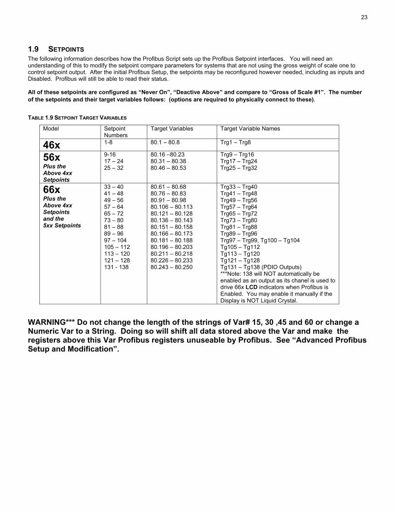
1.9 SETPOINTS The following information describes how the Profibus Script sets up the Profibus Setpoint interfaces. You will need an understanding of this to modify the setpoint compare parameters for systems that are not using the gross weight of scale one to control setpoint output. After the initial Profibus Setup, the setpoints may be reconfigured however needed, including as inputs and Disabled. Profibus will still be able to read their status. All of these setpoints are configured as “Never On”, “Deactive Above” and compare to “Gross of Scale #1”. The number of the setpoints and their target variables follows: (options are required to physically connect to these). TABLE 1.9 SETPOINT TARGET VARIABLES
Model Setpoint Numbers
Target Variables Target Variable Names
46x 1-8 80.1 – 80.8 Trg1 – Trg8
56x Plus the Above 4xx Setpoints
9-16 17 – 24 25 – 32
80.16 –80.23 80.31 – 80.38 80.46 – 80.53
Trg9 – Trg16 Trg17 – Trg24 Trg25 – Trg32
66x Plus the Above 4xx Setpoints and the 5xx Setpoints
33 – 40 41 – 48 49 – 56 57 – 64 65 – 72 73 – 80 81 – 88 89 – 96 97 – 104 105 – 112 113 – 120 121 – 128 131 - 138
80.61 – 80.68 80.76 – 80.83 80.91 – 80.98 80.106 – 80.113 80.121 – 80.128 80.136 – 80.143 80.151 – 80.158 80.166 – 80.173 80.181 – 80.188 80.196 – 80.203 80.211 – 80.218 80.226 – 80.233 80.243 – 80.250
Trg33 – Trg40 Trg41 – Trg48 Trg49 – Trg56 Trg57 – Trg64 Trg65 – Trg72 Trg73 – Trg80 Trg81 – Trg88 Trg89 – Trg96 Trg97 – Trg99, Tg100 – Tg104 Tg105 – Tg112 Tg113 – Tg120 Tg121 – Tg128 Tg131 – Tg138 (PDIO Outputs) ***Note: 138 will NOT automatically be enabled as an output as its chanel is used to drive 66x LCD indicators when Profibus is Enabled. You may enable it manually if the Display is NOT Liquid Crystal.
WARNING*** Do not change the length of the strings of Var# 15, 30 ,45 and 60 or change a Numeric Var to a String. Doing so will shift all data stored above the Var and make the registers above this Var Profibus registers unuseable by Profibus. See “Advanced Profibus Setup and Modification”.

24
1.10 INFORMATIONAL PARAMETERS FOR PROFIBUS
1.10.1 P60000 FRam (E2) Available The top 2x5 prompt for a unit with FRam will be FrInst and FrAvl, E2Ins and E2Avl for a unit with E2 .
Indicator 46x 56x 66x
P60000 4096 8192 8192 expandable to 16384, expansion is required for Profibus (8176, 16352 for E2)
FRam Used for Profibus
627 Default + 1182 for Profibus = 1809
721 Default + 3340 for Profibus = 4061
1045 Default + 11461 for Profibus = 12056
P60001 Fram Available
4131 2287 3878 (3846 E2)
The Memory requirement to integrate a custom program into a Profibus setup can be calculated by first loading your custom program and reading the ram available parameter, 60001. Add the additional Profibus memory required for Profibus listed in the above table. You will undoubtably have some overlap (var and setpoint setups in common would use less memory) but could safely assume that manually integrating your program into a Profibus script will fit into the memory calculated. Refer to 0 for information about reclaiming Setup Memory.
The 660 Series Indicators only, require a second 8 K Fram (EEProm on older units) to be installed to provide enough memory to complete this setup.
1.10.2 Profibus Specific P60300 Network Interface Adapter Version & Serial Number
P60300 only exists if a Profibus or Device Net network is installed and setup. On initial selection it displays “PFbus Ser #”. After a second, the display will be updated. The top line of the 2 x 5 display will then show Vnnnn. Where nnnn is the version of the firmware in the Network Interface Adapter. The second line will show #0000.
P60301 PFbus Map Check. If this display shows STD then all original register setups are in the scripted Profibus configuration and the scale has the standard register setup. IF IT DOESN’T SAY STD: Press the enter key and the scale will momentarily display Reg Check and either STD or a number. If this displays STD, the register boundaries are correct and the scale will operate with data that has been replaced with acceptable data. A number will indicate that register boundaries have been changed in some way but not necessarily in a bad way. See “Using P60301 Reg Check” to verify correct setup changes.
1.10.2.1 Using P60301 Reg Check Acceptable Reasons Reg Check would indicate a number.
1. Information in the data registers has been replaced by other correctly sized information. Two bytes for two bytes, four bytes for four bytes, two 2 byte registers for one four byte or one 4 byte registers for two 2 byte.
2. The register setup has been trimmed down to recapture setup memory. Unneeded Registers higher than the I/O Assys may be removed. This may only be done starting with the highest register, working downward. If any register is removed from the middle of the setup, all higher registers will be shifted and incorrect data or an error will be returned.
Unacceptable Reasons Reg Check would indicate a number.
1. Incorrectly sized data has been placed in the data setup. 2. A register has been deleted from the middle of the data. All higher data is now shifted downward. 3. A register has been inserted into the middle of the data. All higher registers are now shifted
upward. *****Important Incorrect modification of the I/O Assemblies. This is an unacceptable
error and the scale will not allow you to save this setup configuration.
WARNING*** Do not change the length of the strings of Var# 15, 30 ,45 and 60 or change a Numeric Var to a String. Doing so will shift all data stored above the Var and make the registers above this Var Profibus registers unuseable by Profibus. See “Advanced Profibus Setup and Modification”

25
1.11 NEW WEIGH MODE PARAMETER 95 – NETWORK STATUS, OPTION BOARD LEDS This parameter is accessed from the Weigh Mode. Press 95 [SELECT]. It allows viewing of network status information without opening the enclosure to see the Option Board Status LEDs or putting the scale into Setup. It is possible that an error could occur that would not update this display. To force a re-initialization with the network: 1. Press [CLR] – the display will change to 00000. 2. Wait for the numbers to change again – This may take several seconds, up to the setting of P213 (Ptime). TABLE 1.11 DEFINES THE MEANING OF EACH DIGIT DISPLAYED AT PARAMETER 95 “PROFIBUS STAT”.
PFbusStat
PFbusStat
PFbusStat
PFbusStat
New Scale Parameter 95 (95 Select from the weigh mode)
I/O Module
000 00Values from 1 to 16
Network Status
00 0 00 LEDs
0=No Connection to Host Off1=Connected to Host Green
Network Error Status
0 0 000 LEDs
0=No Error Off
1=Error Detected Flashing Red
Module Status
0 0000 LEDs
0=non-existant (no power or not running, can't report this) Off
3=Error Red
1=Configuring Solid Green
2=Operational Flashing GreenTalking to indicator, steady flash.
Not talking to indicator (also in setup), flashing with pauses.
26
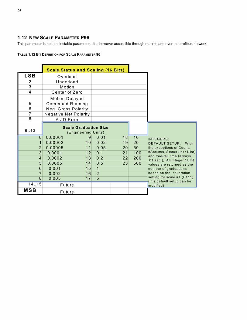
1.12 NEW SCALE PARAMETER P96 This parameter is not a selectable parameter. It is however accessible through macros and over the profibus network.
TABLE 1.12 BIT DEFINITION FOR SCALE PARAMETER 96
LSB 234
5678
9..13
0 0.00001 9 0.01 18 101 0.00002 10 0.02 19 202 0.00005 11 0.05 20 503 0.0001 12 0.1 21 1004 0.0002 13 0.2 22 2005 0.0005 14 0.5 23 5006 0.001 15 17 0.002 16 28 0.005 17 5
14..15MSB
INTEGERS: DEFAULT SETUP: W ith the exceptions of Count, #Accum s, Status (Int / U Int) and free-fall tim e (always .01 sec.), A ll Integer / U Int values are returned as the number of graduations based on the calibration setting for scale #1 (P111). (this default setup can be modified)
Future
Center of ZeroM otion Delayed
Command RunningNeg. Gross Polarity
Negative Net PolarityA / D Error
Future
Scale Status and Scaling (16 Bits)Overload
UnderloadMotion
Scale Graduation Size (Engineering Units)

27
1.13 COMMUNICATING WITH THE DEVICE Communications between the master and device involves sending defined requests for data and receiving defined responses. The following sections show the format of these requests and responses, as well as a few examples.
1.13.1 OUTPUT DATA The Profibus Output Data consists of 8 bytes or 22 bytes:
a) A byte with a value of 1-16 that specifies which I/O Assembly to send. b) A byte that acts as a Command Byte with the following two nibbles:
i) Low Nibble (1) 0 Non command, clear out explicit message area (2) 1 for a read register (3) 2 for a write register (4) 3 for read coil or get macro status (5) 4 for force coil or run macro (6) 5 Identify Indicator Model Number Index
ii) High Nibble (1) Number of words to send
(a) only values 1-9 are allowed for Read Register or Write Register (b) only values 1-2 are allowed for Identify Indicator Model Index, Force Coil, or Read Coil. (a 1 means the
number is a word value, and a 2 means the number is a Motorola format long) c) A word to specify the register number or coil number or macro number. Registers start at 40001, Coils at 1, and Macros at
301 or 601. See the predefined register map (Table 1.7). d) The Explicit Message Data area (Motorola format) consisting of :
i) A Int 16/32 containing the data to be used with a write register, force coil or run macro command. Int 16 are to be located in bytes 5 & 6 with 7 & 8 zeroed.
ii) Eighteen bytes (14 bytes in addition to the four bytes from item i) above). Unused bytes will be filled with zeroes.
TABLE 1.13.1 OUTPUT DATA FORMAT
Output Data (8 or 22 bytes) Byte 1 Byte 2 Byte 3 & 4 Bytes
5 & 6 Bytes 7 & 8
Bytes 9-22
Requested I/O
Assembly
Command
Register or Coil(word)
Int 16 Zero Filled with zeroes Int 32
Motorola Format String (unused bytes zeroed)
NOTE: To send the same explicit command repeatedly, a different command (like command zero) must be sent between each occurance.
1.13.2 INPUT DATA The Profibus Input Data will consist of two sections:
a) The Status & Explicit Data Section. This can be either 8 or 22 bytes i) A byte with a value of 1-16 that echoes the I/O Assembly that is currently being sent (0=>none). The I/O Assembly is
being continuously updated by the Interface Adapter. ii) A byte that acts as a Command Byte with the following values (when the Interface Adapter has the new data):
(1) 0 Ready for next command (required when one wants to reissue the same explicit command) (2) 1 in the lower nibble and 1-9 in the upper nibble - for a Read Register completed. (3) 2 in the lower nibble and 1-9 in the upper nibble - for a Write Register completed. (4) 3 in the lower nibble and 1-2 in the upper nibble – for a Force Coil or macro run completed. (5) 4 in the lower nibble and 1-2 in the upper nibble - for Read Coil or check macro running completed. (6) 5 in the lower nibble and 1-2 in the upper nibble - Identify Scale Model Index (1=660, 2=5500, 3=560, 4=460) (7) 255 for an error
iii) A word to specify the register number, coil number or macro number. See the predefined register map used (Table 1.7).
iv) The Explicit Message Data area (Motorola format). If the Output Command Byte does not require data from the Interface Adapter the Explicit Data area of the Output data will be echoed

28
(1) A Motorola Int 16/32 containing the data to received. Int 16 are to be located in bytes 5 & 6 with 7 & 8 zeroed. If a error exists the command byte (item ii above) is set to 255 and the Int 32 will consist of: (a) MS word: The Output command byte that produced the error (both nibbles) (b) LS word: The actual error code (See item 1.13.4)
(2) Eighteen bytes (14 bytes in addition to the four bytes from item i) above). Unused bytes will be filled with zeroes. b) The I/O Assembly Section which can be one of eight sizes consisting of 16, 24, 32, 40, 48, 56, 64 or 72 bytes. The data in
this section will be stored in Motorola format. The unneeded data bytes will filled with zeroes and if the I/O Assembly requested is too large for the Module size selected then it will simply be truncated.
TABLE 1.13.2 INTPUT DATA FORMAT
Input Data Status & Explicit Data Section (8 or 22 bytes corresponding to output data)
Byte 1 Byte 2 Byte 3 & 4 Bytes 5 & 6
Bytes 7 & 8
Bytes 9-22
Requested I/O
Assembly
Command
Register or Coil(word)
Int 16 Zero Filled with zeroes Int 32
Motorola Format String (unused bytes zeroed)
I/O Assembly Data Section I/O Assembly Data (balanced filled with zeroes or truncated dependent on module size selected) (8, 16, 24, 32, 40, 48, 56, or 64 bytes dependent on Module selected in GDS)
NOTE: The I/O Assembly and command requested in the output data will be echoed in the input data if they are accepted. Bytes 3-8 may also be echoed.
1.13.3 COMMUNICATION EXAMPLES
1.13.3.1 Get I/O Assembly data for one scale (using i/o module 1 (8 out, 16 in), and i/o assembly 1) Byte Output Data
(request) Input Data (response)
Meaning
1 0x01 0x01 Byte, Assembly# 2 0 0 3 0 0 4 0 0 5 0 0 6 0 0 7 0 0 8 0 0 9
Gw I/O DATAWord, gross weight
10 Gw 11 Fg Word, future gross 12 Fg 13 R Word, rate 14 R 15 Scal/stat Word, bit structure, scale & status 16 Scal/stat Note: Issuing a command of zero causes all bytes between the Assembly# to the I/O Data to be returned as zero. This effectively clears out the explicit message area.

29
Note: see table 1.6 and table 1.12 for polled data information
1.13.3.2 Get I/O Assembly data for two scales (using i/o module 2 (8 out, 24 in), and i/o assembly 2) Byte Output Data
(request) Input Data (response)
Meaning
1 0x02 0x02 Byte, Assembly# 2 0 0 3 0 0 4 0 0 5 0 0 6 0 0 7 0 0 8 0 0 9
Gw I/O DATAWord, gross weight
10 Gw 11 Fg Word, future gross 12 Fg 13 R Word, rate 14 R 15 Scal/stat Word, bit structure, scale & status 16 Scal/stat 17
Gw I/O DATAWord, gross weight
18 Gw 19 Fg Word, future gross 20 Fg 21 R Word, rate 22 R 23 Scal/stat Word, bit structure, scale & status 24 Scal/stat
1.13.3.3 Request model number of indicator (using i/o module 1 (8 out, 16 in), and i/o assembly 1) Byte Output Data
(request) Input Data(response)
Meaning
1 0x01 0x01 Byte, Assembly# 2 0x15 0x15 Byte, Cmd 3 0 0 4 0 0 5 0 0x00 Word, model#, 660 6 0 0x01 7 0 0 8 0 0 9
Gw I/O DATAWord, gross weight
10 Gw 11 Fg Word, future gross 12 Fg 13 R Word, rate 14 R 15 Scal/stat Word, bit structure, scale & status 16 Scal/stat
30
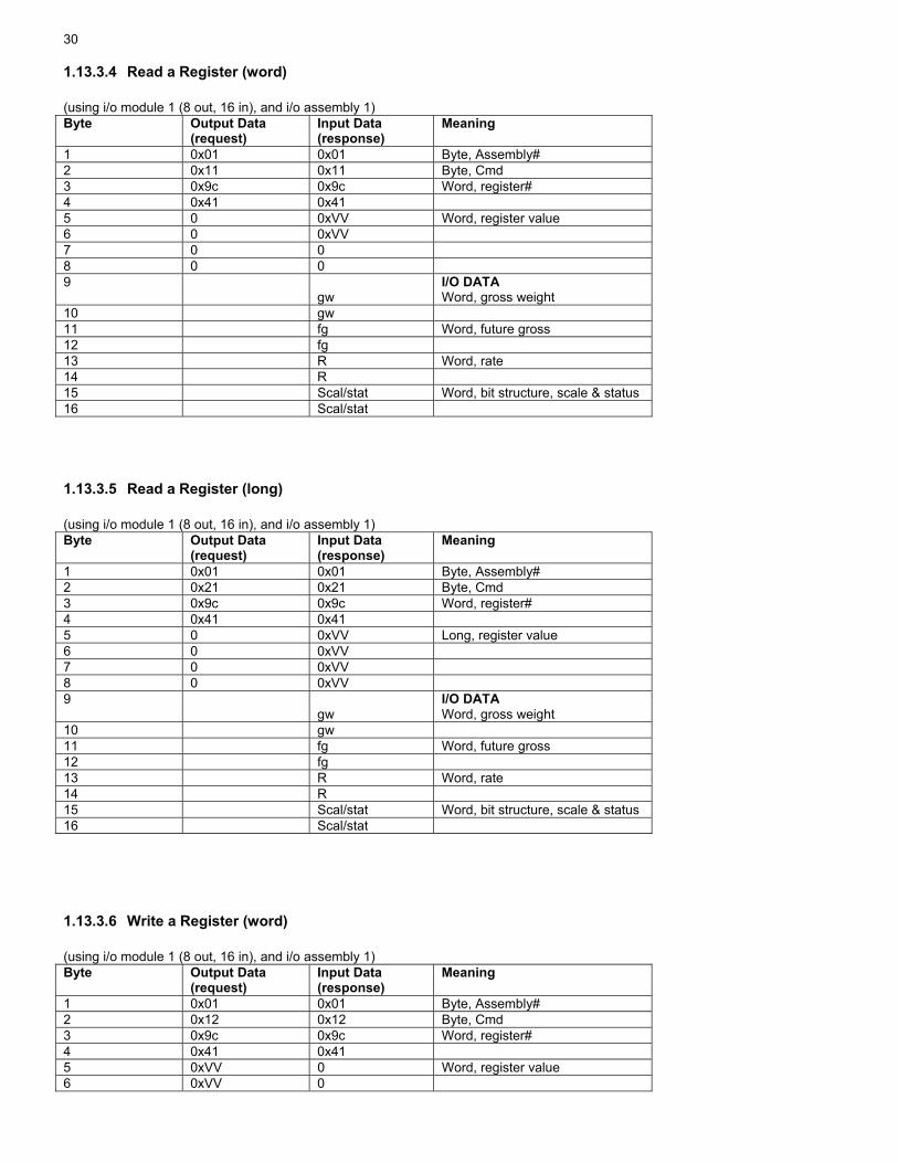
1.13.3.4 Read a Register (word) (using i/o module 1 (8 out, 16 in), and i/o assembly 1) Byte Output Data
(request) Input Data (response)
Meaning
1 0x01 0x01 Byte, Assembly# 2 0x11 0x11 Byte, Cmd 3 0x9c 0x9c Word, register# 4 0x41 0x41 5 0 0xVV Word, register value 6 0 0xVV 7 0 0 8 0 0 9
gw I/O DATAWord, gross weight
10 gw 11 fg Word, future gross 12 fg 13 R Word, rate 14 R 15 Scal/stat Word, bit structure, scale & status 16 Scal/stat
1.13.3.5 Read a Register (long) (using i/o module 1 (8 out, 16 in), and i/o assembly 1) Byte Output Data
(request) Input Data (response)
Meaning
1 0x01 0x01 Byte, Assembly# 2 0x21 0x21 Byte, Cmd 3 0x9c 0x9c Word, register# 4 0x41 0x41 5 0 0xVV Long, register value 6 0 0xVV 7 0 0xVV 8 0 0xVV 9
gw I/O DATAWord, gross weight
10 gw 11 fg Word, future gross 12 fg 13 R Word, rate 14 R 15 Scal/stat Word, bit structure, scale & status 16 Scal/stat
1.13.3.6 Write a Register (word) (using i/o module 1 (8 out, 16 in), and i/o assembly 1) Byte Output Data
(request) Input Data (response)
Meaning
1 0x01 0x01 Byte, Assembly# 2 0x12 0x12 Byte, Cmd 3 0x9c 0x9c Word, register# 4 0x41 0x41 5 0xVV 0 Word, register value 6 0xVV 0

31
7 0 0 8 0 0 9
gw I/O DATAWord, gross weight
10 gw 11 fg Word, future gross 12 fg 13 R Word, rate 14 R 15 Scal/stat Word, bit structure, scale & status 16 Scal/stat
1.13.3.7 Write a Register (long) (using i/o module 1 (8 out, 16 in), and i/o assembly 1) Byte Output Data
(request) Input Data (response)
Meaning
1 0x01 0x01 Byte, Assembly# 2 0x22 0x22 Byte, Cmd 3 0x9c 0x9c Word, register# 4 0x41 0x41 5 0xVV 0 Long, register value 6 0xVV 0 7 0xVV 0 8 0xVV 0 9
gw I/O DATAWord, gross weight
10 gw 11 fg Word, future gross 12 fg 13 R Word, rate 14 R 15 Scal/stat Word, bit structure, scale & status 16 Scal/stat
1.13.3.8 Read a Register (string) (using i/o module 9 (22 out, 30 in), and i/o assembly 1) Byte Output Data
(request) Input Data (response)
Meaning
1 0x01 0x01 Byte, Assembly# 2 0x91 0x91 Byte, Cmd 3 0x9c 0x9c Word, register# 4 0xb2 0xb2 5 0 0xVV Up to 9 words, String value 6 0 0xVV 7 0 0xVV 8 0 0xVV 9 0 0xVV 10 0 0xVV 11 0 0xVV 12 0 0xVV 13 0 0xVV 14 0 0xVV 15 0 0xVV 16 0 0xVV 17 0 0xVV 18 0 0xVV

32
19 0 0xVV 20 0 0xVV 21 0 0xVV 22 0 0xVV 23
gw I/O DATAWord, gross weight
24 gw 25 fg Word, future gross 26 fg 27 R Word, rate 28 R 29 Scal/stat Word, bit structure, scale & status 30 Scal/stat
1.13.3.9 Write a Register (string) (using i/o module 9 (22 out, 30 in), and i/o assembly 1) Byte Output Data
(request) Input Data (response)
Meaning
1 0x01 0x01 Byte, Assembly# 2 0x92 0x92 Byte, Cmd 3 0x9c 0x9c Word, register# 4 0xb2 0xb2 5 0xVV 0 Up to 9 words, String value 6 0xVV 0 7 0xVV 0 8 0xVV 0 9 0xVV 0 10 0xVV 0 11 0xVV 0 12 0xVV 0 13 0xVV 0 14 0xVV 0 15 0xVV 0 16 0xVV 0 17 0xVV 0 18 0xVV 0 19 0xVV 0 20 0xVV 0 21 0xVV 0 22 0xVV 0 23
gw I/O DATAWord, gross weight
24 gw 25 fg Word, future gross 26 fg 27 R Word, rate 28 R 29 Scal/stat Word, bit structure, scale & status 30 Scal/stat
1.13.3.10 Turn a coil on (using i/o module 1 (8 out, 16 in), and i/o assembly 1) Byte Output Data
(request) Input Data (response)
Meaning
1 0x01 0x01 Byte, Assembly# 2 0x14 0x14 Byte, Cmd

33
3 0x00 0x00 Word, coil# 4 0x01 0x01 5 0x00 0 Word, coil on or off 6 0x01 0 7 0 0 8 0 0 9
gw I/O DATAWord, gross weight
10 gw 11 fg Word, future gross 12 fg 13 R Word, rate 14 R 15 Scal/stat Word, bit structure, scale & status 16 Scal/stat
1.13.3.11 Turn a coil off (using i/o module 1 (8 out, 16 in), and i/o assembly 1) Byte Output Data
(request) Input Data (response)
Meaning
1 0x01 0x01 Byte, Assembly# 2 0x14 0x14 Byte, Cmd 3 0x00 0x00 Word, coil# 4 0x01 0x01 5 0x00 0 Word, coil on or off 6 0x00 0 7 0 0 8 0 0 9
Gw I/O DATAWord, gross weight
10 Gw 11 Fg Word, future gross 12 Fg 13 R Word, rate 14 R 15 Scal/stat Word, bit structure, scale & status 16 Scal/stat
1.13.3.12 Read coil status (using i/o module 1 (8 out, 16 in), and i/o assembly 1) Byte Output Data
(request) Input Data (response)
Meaning
1 0x01 0x01 Byte, Assembly# 2 0x13 0x13 Byte, Cmd 3 0x00 0x00 Word, coil# 4 0x01 0x01 5 0 0xSS Word, coil status 6 0 0xSS 7 0 0 8 0 0 9
gw I/O DATAWord, gross weight
10 gw 11 fg Word, future gross 12 fg

34
13 R Word, rate 14 R 15 Scal/stat Word, bit structure, scale & status 16 Scal/stat
1.13.3.13 Run a user created macro (using i/o module 1 (8 out, 16 in), and i/o assembly 1) Byte Output Data
(request) Input Data (response)
Meaning
1 0x01 0x01 Byte, Assembly# 2 0x14 0x14 Byte, Cmd 3 0x01 0x01 Word, macro# + 300 4 0x2d 0x2d 5 0x00 0 Word, macro on 6 0x01 0 7 0 0 8 0 0 9
gw I/O DATAWord, gross weight
10 gw 11 fg Word, future gross 12 fg 13 R Word, rate 14 R 15 Scal/stat Word, bit structure, scale & status 16 Scal/stat NOTE: user macros are 300 + macro#, which gives #301-550.
1.13.3.14 Check if user created macro running (using i/o module 1 (8 out, 16 in), and i/o assembly 1) Byte Output Data
(request) Input Data (response)
Meaning
1 0x01 0x01 Byte, Assembly# 2 0x13 0x13 Byte, Cmd 3 0x01 0x01 Word, macro# + 300 4 0x2d 0x2d 5 0 0xSS Word, macro status 6 0 0xSS 7 0 0 8 0 0 9
gw I/O DATAWord, gross weight
10 gw 11 fg Word, future gross 12 fg 13 R Word, rate 14 R 15 Scal/stat Word, bit structure, scale & status 16 Scal/stat
1.13.3.15 Run a built-in macro

35
(using i/o module 1 (8 out, 16 in), and i/o assembly 1) Byte Output Data
(request) Input Data (response)
Meaning
1 0x01 0x01 Byte, Assembly# 2 0x14 0x14 Byte, Cmd 3 0x02 0x02 Word, macro# + 600 4 0x59 0x59 5 0x00 0 Word, macro on 6 0x01 0 7 0 0 8 0 0 9
Gw I/O DATAWord, gross weight
10 Gw 11 Fg Word, future gross 12 Fg 13 R Word, rate 14 R 15 Scal/stat Word, bit structure, scale & status 16 Scal/stat NOTE: built-in macros are 600 + macro#, which gives #601-608 (zero), 621-628 (tare), 641-648 (accumulate).
1.13.3.16 Check if built-in macro running (using i/o module 1 (8 out, 16 in), and i/o assembly 1) Byte Output Data
(request) Input Data (response)
Meaning
1 0x01 0x01 Byte, Assembly# 2 0x13 0x13 Byte, Cmd 3 0x02 0x02 Word, macro# + 600 4 0x59 0x59 5 0 0xSS Word, macro status 6 0 0xSS 7 0 0 8 0 0 9
gw I/O DATAWord, gross weight
10 gw 11 fg Word, future gross 12 fg 13 R Word, rate 14 R 15 Scal/stat Word, bit structure, scale & status 16 Scal/stat
1.13.4 RETURNED ERROR CODES The Indicator can send the following codes:
a) ILLEGAL_FUNCTION = 1: Used when unsupported function is called b) ILLEGAL_DATA_ADDRESS =2: Used when partial parm data set, exceed number of setpoints, or bad register starting
address c) ILLEGAL_DATA_VALUE=3: used when command contains invalid data when issuing force single coil or trying set a
Indicator parameter that is not settable d) SLAVE_DEVICE_FAILURE=4: Could not get the value of a selected parameter. This can be caused because a scale has
been disabled or saved instead of enabled. It can be caused if the requested parameter no longer exists. It can also occur if an invalid translation type is requested for the type of parameter requested.

36
e) SLAVE_DEVICE_BUSY=6: Used when we enter weigh mode in response to all functions codes except 17, 18, & 19 until we receive at least one function 17
f) LENGTH_INVALID=0x100: The number of words requested (byte 2, upper nibble) is not valid. (1-9 for read register and write register, 1–2 for Identify Scale Model Index, Force or Read coil.)
g) COMMAND_INVALID=0x101: The command send (byte 2) is not valid. Only 0, 1,2,3,4, & 5 are valid. h) REGISTER_INVALID=0x102: The requested register (byte 3&4) is not valid (only 40000-49999 are valid) or the requested
coil number is not valid (only 1-999 are valid).
1.13.4.1 ERROR Trying to Read a Register (word) The following shows an error response to an invalid explicit message request for data. (using i/o module 1 (8 out, 16 in), and i/o assembly 1) Byte Output Data
(request) Input Data (response)
Meaning
1 0x01 0x01 Byte, Assembly# 2 0x11 0xff Byte, ERROR 3 0x80 0x80 Word, register# 4 0x00 0x00 5 0 0x00 Word, ERROR CMD 6 0 0x11 7 0 0x00 Word, ERROR NUMBER 8 0 0x02 9
gw I/O DATAWord, gross weight
10 gw 11 fg Word, future gross 12 fg 13 R Word, rate 14 R 15 Scal/stat Word, bit structure, scale & status 16 Scal/stat
1.14 TROUBLESHOOTING AND PROFIBUS RELATED ERROR MESSAGES
1.14.1 Framing or other Comm Port Errors when attempting Setup (Script or Upload). The Profibus interface board attempts to initiate conversation with the main board at power up. This communication will cause errors in the loading of the Script or Upload. If the Profibus Board is installed and you have not yet run the Profibus Setup Script or uploaded one, Hold the [CLR] key down during power up and answer yes to the prompt to disable comm 1. You will also need to perform this before uploading a setup file through one of the other Comm Ports.
1.14.2 Error Codes ***See the 60 Series Tech Manual Appendix E for the description of other Codes
Error Code Prompt Description 24 NVRam
Full The scale is out of setup memory. The 66x indicators require the installation of an additional 8K FRam (or E2), for a total of 16K, to load its internal Profibus Script. If the indicator does not have this installed (go to Scale Parameter 60000 to view the installed Setup Memory), the load of the Profibus script will fail when its Setup memory is filled. The display will indicate NV Ram Full and the script will stop loading.
50 Port Clash The indicator is attempting some other form of communication through the Profibus Port. e.g. Macro doing a write to port 1. Custom Transmit initiated to Port 1.
55 Check Parm Map
The 6000 entries for the Profibus register map has an unacceptable setup. 1. An I/O Assembly boundary has been violated. 2 An Explicit message boundary has been violated. 3. There are more registers set up in the map than the scripted amount. See 1.10.2 and 0.