g.h. raisoni college of engineering, nagpur. department of ... · g.h. raisoni college of...
TRANSCRIPT
G.H. Raisoni College of Engineering, Nagpur.
Department of Information Technology
Fifth Semester Computer Graphics
G.H. Raisoni College of Engineering, Nagpur.
Department of Information Technology
Fifth Semester Computer Graphics
Practical List
1) WAP to implement line generation using DDA algorithm
2) WAP to implement line using Bresenham’s line generation algorithm.
3) WAP to generate circle using circle generation algorithm
4) WAP to draw a polygon using DDA
5) Write a Program to fill polygon using Edge flag algorithm.
6) WAP to implement ellipse using ellipse generation algorithm
7) WAP to perform translation, rotation scaling on 2-D transformation
8) WAP to fill polygon using seed fill algorithm
G.H. Raisoni College of Engineering, Nagpur.
Department of Information Technology
Fifth Semester Computer Graphics
EXPREMENT NO.1
Aim : - Write a program to implement line generation using DDA
Theory :- The simplest way to rasterize a line is to solve the governing differential
equation:
Equation of the straight line is
Y = mx + c
Differential with respect to x
∆dy/ ∆dy = m = constant --------------(1)
Assume that the ∆y and ∆x are the small increment in x and y direction along the path
respectively along the path.
Equation (1) can be written as ∆y/ ∆x =y2 - y1/ x2 – x1 = constant --------- (2)
Equation (2) has one solution
Yi +1 = yi + ∆y
= yi + (y2 - y1/ x2 – x1) ---------------- (3)
equation (3) represents a recursive relation for successive values of y along the required
line x1, y1, x2, y2 are the end points of the required line .
when equation (3) is used to rasterise the line then it is called as digital
differential analyzer (DDA).
ALGORITHM
Step 1). Initialize(x1,y1), (x2,y2)
if abs(x2 – x1) ≥ abs(y2 – y1) then
len = abs(x2 – x1)
else
len = abs(y2 – y1)
∆x = (x2 – x1)/len
∆y = (y2 – y1)/len
x = x1 + 0.5 * sign(∆x)
y = y1 + 0.5 * sign(∆y)
Step 2). begin main loop
i=1
while( i ≤ len)
plot (integer(x),integer(y))
x = (x + ∆x)
y = (y + ∆y)
i = i + 1
end while
finish
G.H. Raisoni College of Engineering, Nagpur.
Department of Information Technology
Fifth Semester Computer Graphics
VIVA VOICE
Q 1. What will happen if the line endpoints are assumed equal?
Q 2. What is the value of Integer( -8.5 )?
Q 3. What is the value of Integer( 8.5 )?
Q 4. Which modifications are necessary to generate dashed line from DDA algorithm.
Q 5. Which modifications are necessary to generate dotted line from DDA algorithm.
Q 6. Write the algorithm for DDA.
Q 7. What is rasterization?
Q 8. Give the drawbacks of DDA algorithm.
Q9. What is DDA?
G.H. Raisoni College of Engineering, Nagpur.
Department of Information Technology
Fifth Semester Computer Graphics
Experiment No.2
Aim : - To implement Bresenham’s line generation algorithm
Theory : - This algorithm seeks to select the optimum raster location to represents a
straight line. To achieve this, the algorithm always implemented by one unit in either x or
y directions depending on the slope of the line.
The increment in the other variables either 0 or 1, is determined by examining the
distance between the actual line location and the nearest grid location. This distance is
called the error and only error term is needed to be examined.
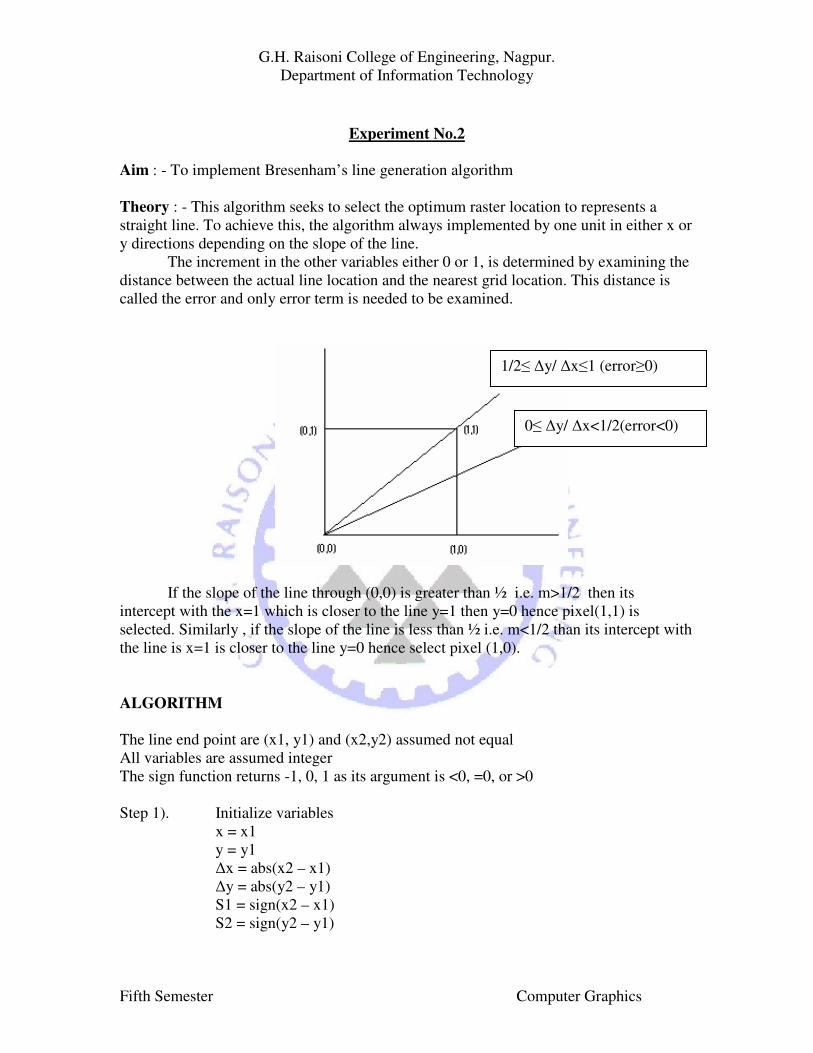
If the slope of the line through (0,0) is greater than ½ i.e. m>1/2 then its
intercept with the x=1 which is closer to the line y=1 then y=0 hence pixel(1,1) is
selected. Similarly , if the slope of the line is less than ½ i.e. m<1/2 than its intercept with
the line is x=1 is closer to the line y=0 hence select pixel (1,0).
ALGORITHM
The line end point are (x1, y1) and (x2,y2) assumed not equal
All variables are assumed integer
The sign function returns -1, 0, 1 as its argument is <0, =0, or >0
Step 1). Initialize variables
x = x1
y = y1
∆x = abs(x2 – x1)
∆y = abs(y2 – y1)
S1 = sign(x2 – x1)
S2 = sign(y2 – y1)
0≤ ∆y/ ∆x<1/2(error<0)
1/2≤ ∆y/ ∆x≤1 (error≥0)
G.H. Raisoni College of Engineering, Nagpur.
Department of Information Technology
Fifth Semester Computer Graphics
Step 2). Interchange ∆x and ∆y depending on slope of the line
Temp = ∆x
∆x = ∆y
∆y = Temp
Interchange = 1
else Interchange = 2
end if
Step 3). Initialize the error term to compensate for a nonzero intercept
ē = 2 * ∆y – ∆x
Step 4). Main loop
for I = 1 to ∆x
plot(x,y)
while ( ē ≥ 0)
if interchange = 1 then
x = x + s1
else
y = y + s2
end if
ē = ē – 2 * ∆x
end while
if interchange = 1 then
y = y + s2
else
x = x +s2
end if
ē = ē – 2 * ∆y
next i
finish
VIVA VOICE
1) What is an Error term in Bresenham’s algo?
2) What will happen if we will not use error term?
3) Give the advantages of Bresenham’s algo over DDA algo.
4) Give the significance of error term.
5) Give the Advantages of Bresenham’s algorithm.
G.H. Raisoni College of Engineering, Nagpur.
Department of Information Technology
Fifth Semester Computer Graphics
EXPERIMENT NO 3
AIM :- To generate a circle using Bresenham’s circle algorithm
THEORY : - To draw a circle, only first octant of the circle is required to be generated
and other parts can be obtained by successive reflections. The circle generation is done
by using Bresenham’s algorithm.
If the first octant is generated, the second octant is obtained by reflection through
the line y = x to yield the first quadrant . The results in the first quadrant are reflected
through the line x = 0 to obtain those in second quadrant. The combined results in the
upper semicircle are reflected through the line y = 0 to complete the circle.
ALGORITHM
Initialize the variables
xi = 0
yi = R
∆i = 2(1- R)
Limit = 0
Step 1). Plot(xi , yi)
if yi ≤ Limit then 4
Determine the case 1 or 2, 4 or 5, or 3
if ∆i < 0 then 2
if ∆i > 0 then 3
if ∆i = 0 then 20
Determine whether case 1 or 2
1) δ = 2 ∆i + 2 yi -1
if δ ≤ 0 then 10
if δ > 0 then 20
determine whether case 4 or 5
3) δ’ = 2 ∆i - 2 xi -1
if δ’ ≤ 0 then 20
if δ’ >0 then 30
perform the moves
move mH
10) xi = 2 xi + 1
∆i = ∆i + 2 xi +
go to 1
move mD
20) xi = 2 xi + 1
yi = 2 yi - 1
∆i = ∆i + 2 xi - 2 yi + 2
go to 1
move mv
30) yi = yi – 1
∆i = ∆i - 2 yi + 1
go to 1
finish
G.H. Raisoni College of Engineering, Nagpur.
Department of Information Technology
Fifth Semester Computer Graphics
VIVA VOICE
1. How to generate the circle in 2nd
quadrant from 1st quadrant clockwise ?
2. How to generate the circle in 2nd
quadrant from 1st quadrant anticlockwise?
3. How to generate the circle in 3rd
quadrant from 1st quadrant clockwise ?
4. How to generate the circle in 3rd
quadrant from 1st quadrant anticlockwise?
5. Explain the Bresenham’s circle algorithm.
6. Explain the different moves in this algorithm.
7. When to choose vertical move?
8. When to choose horizontal move?
9. When to choose diagonal move?
10. Generate the circle in 1st quadrant having radius 8 and center is origin.
G.H. Raisoni College of Engineering, Nagpur.
Department of Information Technology
Fifth Semester Computer Graphics
EXPERIMENT NO 4
AIM :- To generate a polygon using any line generation algorithm
THEORY :- A polygon can be represented as a number of line segments connected end
to end to form a close figure. Alternatively, it may be represented as the points where the
sides of the polygon are connected. The line segments which make up the the polygon
boundary are called sides or edges. The end points of the sides are called the polygon
vertices.
ALGORITHM:
Step 1. Eenter number of vertices in n
Step2. Enter the co-ordinates of each vertex
Step 3. Repeat the following steps for n number of times
Step 4. Initialize(x1,y1), (x2,y2)
if abs(x2 – x1) ≥ abs(y2 – y1) then
len = abs(x2 – x1)
else
len = abs(y2 – y1)
∆x = (x2 – x1)/len
∆y = (y2 – y1)/len
x = x1 + 0.5 * sign(∆x)
y = y1 + 0.5 * sign(∆y)
Step 5. begin main loop
i=1
while( i ≤ len)
plot (integer(x),integer(y))
x = (x + ∆x)
y = (y + ∆y)
i = i + 1
end while
finish
VIVA QUESTION
1) What is scan conversion?
2) How will you generate a polygon?
3) Which algorithms can be used to generate a polygon?
G.H. Raisoni College of Engineering, Nagpur.
Department of Information Technology
Fifth Semester Computer Graphics
EXPERIMENT NO 5
Aim :- Write a Program to fill polygon using Edge flag algorithm.
Theory :- It’s a technique to fill the polygon by two steps.The first step is to outline the
contour.This establishes pairs of span bounding pixels on each scanline.The second step
is to fill between these bounding pixels.
Algorithm :- 1> For contour outline :
Using the half scan line convention for each edge intersecting the polygon, set the
leftmost pixel whose midpoint lies to the right of the intersection, i.e. for x+1/2 >
Xintersection ,to the boundary value.
2> For Filling :
For each scanline intersecting the polygon
Inside = FALSE
For X = 0 (left) to X = X max(right)
If the pixel at X is set to the boundary value then negate inside
If Inside = TRUE then
Set the pixel at X to the Polygon value
Else
Reset the pixel at X to the Background value
Endif
Next x
Viva-voce :-
Qu 1 Can this algo visits each pixel more than once?
Qu 2 Explain this algo by giving example.
Qu 3 Give the advantages of this algorithm
.
Qu 4 Give the Disadvantages of this algorithm.
Qu 5 How can we overcome the disadvantage of this algorithm.
Qu 6 Do you feel that this algo is best suited amongst all ?
Qu 7. Why this algo is best suited?
G.H. Raisoni College of Engineering, Nagpur.
Department of Information Technology
Fifth Semester Computer Graphics
EXPERIMENT NO. 6
AIM : - Write program to generate an ellipse
THEORY : - Equation of an origin centered axis aligned ellipse is given by
x2/a
2 + y
2/b
2 = 1
Where, a is the semi major axis and b is semi minor axis
Rewrite the equation as
1. b2x
2 + a
2y
2 – a
2b
2 = 0
Consider the generation of ellipse in first quadrant in clockwise direction.
∆i is a distance of diagonal pixel from the centre of ellipse.
∆i = b2 (xi + 1)
2 +a
2 (y1 -1)
2 – a
2b
2
If ∆i < 0, means diagonal pixel lies inside the ellipse, so consider case 1
If ∆i > 0 , means diagonal pixel lies outside the ellipse
If ∆i = 0 , means ellipse passes through the diagonal pixel.
ALGORITHM
Step 1). Initialize the variables
xi = 0
yi = b
∆i = a2 + b
2 – 2ab
2
Limit = 0
Step 2). if yi ≥ limit
then plot (xi, yi)
else
exit
Step 3). if ∆i < 0
Then go to step 4
else
if ∆i > 0
then go to step 5
else
if ∆i = 0
then xi = xi + 1
yi = yi + 1
∆i = ∆i + b2(2(xi + 1) + 1) – a
2 (2(y-1) – 1)
else
then go to step 6
G.H. Raisoni College of Engineering, Nagpur.
Department of Information Technology
Fifth Semester Computer Graphics
Step 4). d1 = 2 ∆i + (2yi – 1) a2
if d1 ≤ 0 then
xi = xi +1
∆i = ∆i + b2 *(2*(x+1)+1)
Step 5) d2 = 2*∆i – (2 * x + 1) * b2
If d2 <=0 then
x = x + 1
y = y + 1
∆i = ∆i + b2 [2(x + 1) + 1] – a
2 (2(y – 1)- 1)
Else
y = y – 1
Step 6) x = x + 1
y = y + 1
∆i = ∆i + b2[2(x + 1) + 1] – a2(2(y – 1)- 1)
VIVA VOICE
1) What is the equation of origin centered axis.
2) How will you generate an ellipe.
3) What is the difference between circle generation and ellipse generation
algorithm
4) Explain the different moves in this algorithm.
5) When to choose vertical move?
6) When to choose horizontal move?
7) When to choose diagonal move?
G.H. Raisoni College of Engineering, Nagpur.
Department of Information Technology
Fifth Semester Computer Graphics
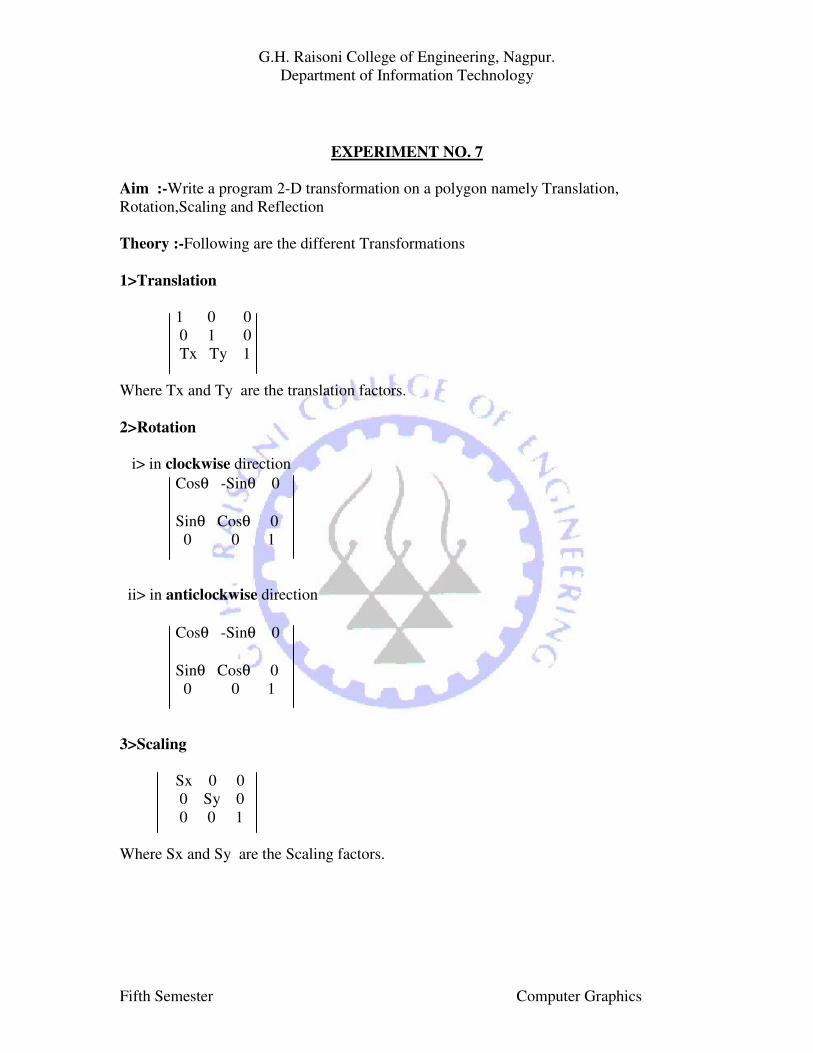
EXPERIMENT NO. 7
Aim :-Write a program 2-D transformation on a polygon namely Translation,
Rotation,Scaling and Reflection
Theory :-Following are the different Transformations
1>Translation
1 0 0
0 1 0
Tx Ty 1
Where Tx and Ty are the translation factors.
2>Rotation
i> in clockwise direction
Cosθ -Sinθ 0
Sinθ Cosθ 0
0 0 1
ii> in anticlockwise direction
Cosθ -Sinθ 0
Sinθ Cosθ 0
0 0 1
3>Scaling
Sx 0 0
0 Sy 0
0 0 1
Where Sx and Sy are the Scaling factors.
G.H. Raisoni College of Engineering, Nagpur.
Department of Information Technology
Fifth Semester Computer Graphics
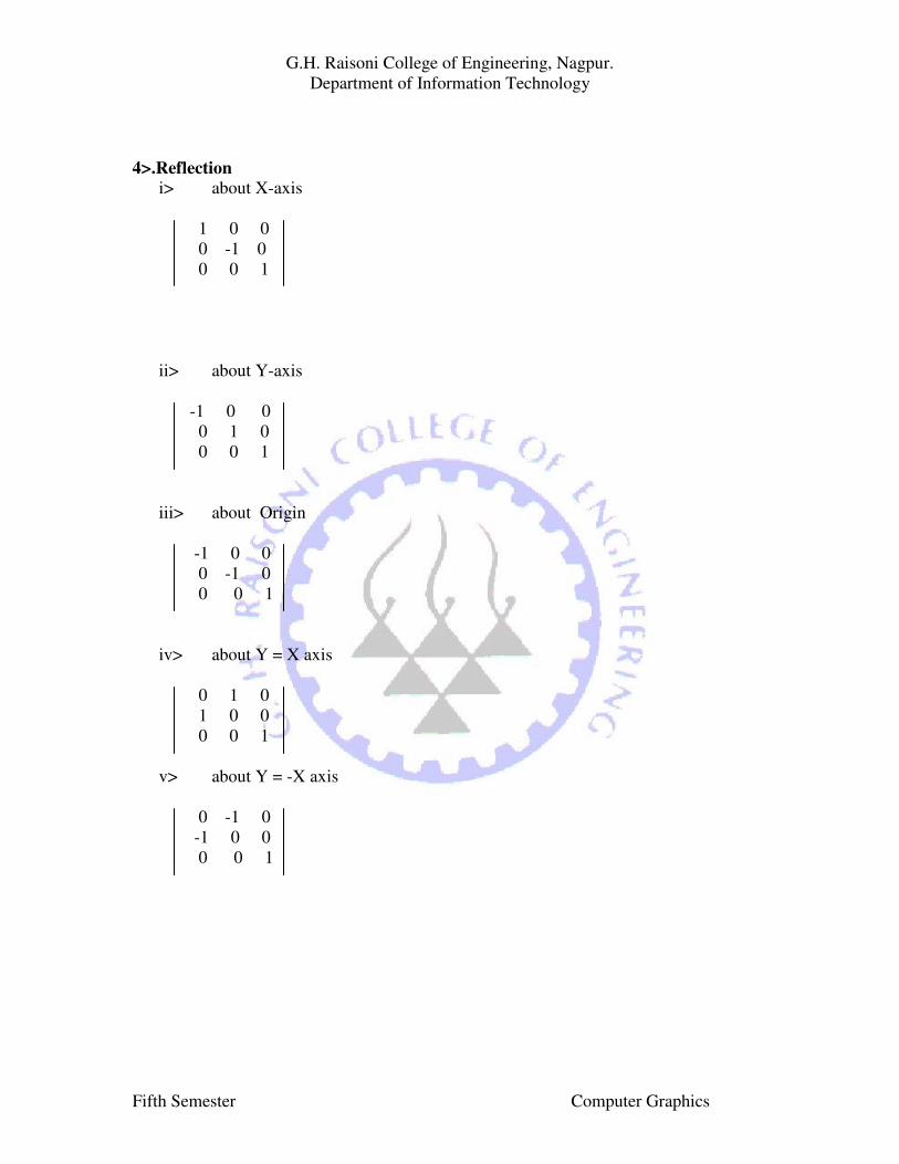
4>.Reflection
i> about X-axis
1 0 0
0 -1 0
0 0 1
ii> about Y-axis
-1 0 0
0 1 0
0 0 1
iii> about Origin
-1 0 0
0 -1 0
0 0 1
iv> about Y = X axis
0 1 0
1 0 0
0 0 1
v> about Y = -X axis
0 -1 0
-1 0 0
0 0 1
G.H. Raisoni College of Engineering, Nagpur.
Department of Information Technology
Fifth Semester Computer Graphics
Viva-voce
Q1 Which are the real life examples of transformations?
Q2 Write the transformation matrix for Translation.
Q3 Write the transformation matrix for Rotation in clockwise direction.
Q4 Write the transformation matrix for Rotation in anticlockwise direction.
Q5 Write the transformation matrix for Scaling.
Q6 Write the transformation matrix for reflection about X-axis.
Q 7 Write the transformation matrix for reflection about Y-axis.
Q8 Write the transformation matrix for reflection about Origin.
Q9 Write the transformation matrix for reflection about X=Y axis
Q10 Write the transformation matrix for reflection about Y=-X axis.
G.H. Raisoni College of Engineering, Nagpur.
Department of Information Technology
Fifth Semester Computer Graphics
EXPERIMENT NO. 8
AIM : - Write a program to implement seed fill algorithm for polygon filling
THEORY : - Generation of solid areas from the simple edge of the vertex description is
referred as solid scan conversion or polygon filling or contour filling.
There are two techniques used to fill a polygon namely scan conversion and seed
fill technique.
The seed fill algorithm required one of the pixel position inside the polygon or
region to be filled. This pixel is inside the region and set to polygon value. This pixel is
referred as seed pixel. The algorithm continues to search the pixels which are adjacent to
the current seed pixel to see whether they are boundary pixels or the pixels inside the
region. All the pixels interior to the region and are adjacent to the seed pixel are set to the
polygon value.
ALGORITHM : -
Seed(x,y) is the seed pixel
Push is a function for placing a pixel on the stack
Pop is a function for removing a pixel from the stack
Pixel(x,y) = seed(x,y)
Initialize stack
Push pixel(x,y)
While (stack not empty)
get a pixel from the stack
Pop Pixel (x,y)
If Pixel(x,y) <> New value then
Pixel(x,y) = New value
Else
If (Pixel(x+1,y) <> New value and
Pixel(x+1,y) <> Boundary value then
Push Pixel(x+1,y)
if Pixel(x,y+1) <> New value and
Pixel(x,y+1) <> Boundary value then
Push Pixel(x,y+1)
If Pixel(x-1,y) <> New value and
Pixel(x+1,y) <> Boundary value then
Push Pixel(x-1,y)
If Pixel(x,y-1) <> New value and
Pixel(x,y-1) <> Boundary value then
Push pixel(x,y-1)
End if
End while
G.H. Raisoni College of Engineering, Nagpur.
Department of Information Technology
Fifth Semester Computer Graphics
VIVA VOICE
Q 1 Explain the Seed fill algorithm.
Q 2 Give the advantages of this algorithm.
Q 3 Give the disadvantages of this algorithm.
Q 4 Can we choose any pixel as seed pixel?
Q 5 Which are the two conditions are required before setting the pixel?
Q 6 If the pixel is Boundary pixel ,can we set it ?
Q 7 If the pixel is already setted , can we set it ?
Q 8 Is there any modifications are required in this algorithm?
Q 9 Which modifications are required?
Q 10 Is there any other algorithm available to avoid the drawbacks ? Explain.
G.H. Raisoni College of Engineering, Nagpur.
Department of Information Technology
Fifth Semester Computer Graphics