gas turbine engine driven aviation … · army tm 5-6115-612-12 marine corptm 6115-12/s 7 air force...
TRANSCRIPT

A R M Y TM 5 -6115 -612 -12
M A R I N E C O R P S TM 6115-12/7A I R F O R C E T O 3 5 C 2 - 3 - 4 7 1 - 1
N A V Y A G - 3 2 0 B 0 - O M M - O O O
O P E R A T O R ’ S A N D U N I T
M A I N T E N A N C E M A N U A L
GAS TURBINE ENGINE DRIVEN
A V I A T I O N G E N E R A T O R S E T ,
N S N 6 1 1 5 - 0 1 - 1 6 1 - 3 9 9 2
This manual supersedes TM 5-6115-612-12/TM 6115-12/7/TO 35C2-3-471-1/AG-320B0-OMM-000, 21 July 1986
Approved for public release; distribution is unlimited
PUBLISHED UNDER THE AUTHORITY OF THE DEPARTMENTS OF THE ARMY,AIR FORCE, NAVY AND HEADQUARTERS U.S. MARINE CORPS
1 9 N O V E M B E R 1 9 8 7


ARMY TM 5-6115-612-12NAVY AG-320BO-OMM-000
C6
CHANGE HEADQUARTERSDEPARTMENTS OF THE ARMY AND NAVY
NO 6 WASHINGTON, D C,10 October 1996
Operator’s and Unit Maintenance Manual
GAS TURBINE ENGINE DRIVENAVIATION GENERATOR SET,
NSN 6115-01-161-3992
DISTRIBUTION STATEMENT A Approved for public release, distribution is unlimited
TM 5-6115-612-12/NAVY AG-320B0-OMM-000,19 November 1987, Is changed as follows
1. Remove and insert pages as Indicated below. New or changed text material is indicated by a vertical bar in themargin An Illustration change is indicated by a miniature pointing hand
Remove pages Insert pages
I through v/(vi blank) i through vi1-1 and 1-2 1-1 and 1-24-15 and 4-16 4-15 and 4-164-35 and 4-36 4-35 and 4-36
2 Retain this sheet in front of manual for reference purposes
By Order of the Secretaries of the Army and Navy:
DENNIS J REIMEROfficial: General, United States Army
Chief of StaffJOEL B HUDSON
Administrative Assistant to theSecretary of the Army
02234J. E. BUFFINGTONRear Admiral, CEC, US NavyCommanderNavy Facilities EngineeringCommand
DISTRIBUTIONTo be distributed in accordance with DA Form 12-25-E, block no 3853, requirements for TM 5-6115-612-12

CHANGE
NO. 5
TM 5-6115-612-12AG-320B0-0MM-000
C 5
HEADQUARTERSDEPARTMENTS OF THE ARMY AND NAVY
WASHINGTON, D.C., 1 February 1994
Operator’s and Unit Maintenance Manual
GAS TURBINE ENGINE DRIVENAVIATION GENERATOR SET,
NSN 6115-01-161-3992
DISTRIBUTION STATEMENT A: Approved for public release; distribution is unlimited.
TM 5-6115-612-12/NAVFAC AG-320B0-0MM-000, 19 November 1987, is changed as follows:
1. Remove and insert pages as indicated below. New or changed text materialis indicated by a vertical bar in the margin. An illustration change isindicated by a miniature pointing hand.
Remove pages Insert pages
4-23 through 4-26 4-23 through 4-26C-5 and C-6 C-5 and C-6C-13 and C-14 C-13 and C-14
2. Retain this sheet in front of manual for reference purposes.
By Order of the Secretaries of the Army and Navy:
GORDON R. SULLIVANGeneraI, United States Army
Official: Chief of Staff
MILTON H. HAMILTONAdministrative Assistant to the
Secretary of the Army0 6 1 0 9
DAVID E. BOTTORFFRear Admiral, CEC, US NavyCommanderNavy Facilities EngineeringCommand
DISTRIBUTION:To be distributed in accordance with DA Form12-25-E, block no. 3853, requirements for
TM 5-6115-612-12.


ARMY TM 5-6115-612-12MARINE CORPS TM 6115-12/7AIR FORCE TO 35C2-3-471-1NAVY A G - 3 2 0 B 0 - 0 M M - 0 0 0
U S A R M Y
A/(B Blank)


ARMY TM 5-6115–612–12NAVY AG–320B0–0MM–000
WARNING
All specific cautions and warnings contained in this manualshall be strictly adhered to.
Failure to do so may result in severe injury,death, and/or damage to the equipment.
HIGH VOLTAGE
testing may cause serious or fatal injury from electrical shock.Avoid bodily contact with test probes and perform testing on a woodenbench, or place an insulated mat under test items. The electricalcharge stored in turbine engine ignition exciters may be lethal.
Ground Igniter plug and lead and do not touch or put hand near baseof plug while igniter unit is activated. Take precautionswhen discharging igniters. A special enclosed box with a
viewing window should be used. Handle batteries with caution,verifying that all switches and controls on the control panel are off
or neutralized prior to hookup of battery terminals.Disconnect battery cable plug connector prior to performing
maintenance on electrical components.
DEATH
or severe burns may result if personnel fail to observesafety precautions. To avoid electrocution, the generator set
must always be grounded. Do not operate the generator set untilthe ground terminal stud has been properly connected to a
suitable ground. When performing maintenance on this equipment,personnel should remove all jewelry and secure loose-fitting clothing
to prevent it from catching in moving parts. Do not attempt toInspect, service, adjust, repair, or replace parts until generator set
has been completely shut down.
SEVERE INJURY
and equipment damage could result from foreign material entering thecompressor inlet causing violent turbine or compressor failure.
Do not operate generator set with engine access cover or foreignobject deflection shield removed.
Shut down unit and stow cable prior to towing.
a

ARMY TM5-6115-612-12NAVY AG-320B0-0MM-000
EXPLOSION, FIRE OR ELECTROCUTION
may be induced by frayed, cut or missing insulation on power supplycable. Exercise care in handling power supply cable. Do not route over airframe.
Fuels used in the generator set are flammable; cleaning solvents areflammable; and batteries, when shorted, can deliver high currents and a spark
may cause cells to explode. To prevent explosion or fire, use andstore fuels and solvents in a well-ventilated area, do not smoke, and keep area
free of spark and open flame.
DANGEROUS MATERIALS
Personnel must be adequately protected to prevent injury resultingfrom contact with heated or chilled parts; toxic primer and paint; solvents used
in cleaning parts; corrosive chemicals contained in batteries;compressed air used for cleaning or drying; and radiation, sparks and airborne
particles produced during welding activity. Personnel should useproper equipment and wear protective clothing such as goggles/face shields
with tinted lenses, rubber gloves, boots, and aprons. MIL-L-7808lubricant contains a poisonous additive readily absorbed by the skin. Use
appropriate personnel protective equipment as designated by localoccupational health authority. Dry cleaning solvent P-D-680 is flammable and
toxic to the skin, eyes, and respiratory tract. All activities requiringexposure to these materials should be performed in well-ventilated areas with
extinguishers and vat or tank covers on hand in case of fire.
Injury to personnel may result from improper lifting or movement of thegenerator set. Do not attempt to lift the front of the generator set with
less than two persons. Set handbrake and chock both wheels to preventaccidental movement during inspection and maintenance. Exercise
care when releasing handbrake to prevent inadvertent movement. When hoistinggenerator set, use hoisting device with lifting capacity
of 2000 pounds (907.2 Kg).
WARNING
The hot refueling of generators, while they are operating, poses asafety hazard and should not be attempted. Hot engine surfaces and sparks
produced from the engine and the generator circuitry are possiblesources of ignition. Death or personnel injury may result if personnel fail to
follow this warning.
b Change 2

ARMY TM 5-6115-612-12NAVY AG-320BO-OMM-000
TECHNICAL MANUAL HEADQUARTERS,DEPARTMENTS OF THE ARMY AND NAVY
NO. 5-6115-612-12 WASHINGTON, D.C., 19 NOVEMBER 1987
OPERATOR’S AND UNITMAINTENANCE MANUAL
GAS TURBINE ENGINE DRIVENAVIATION GENERATOR SET,
NSN 6115-01-161-3992
REPORTING ERRORS AND RECOMMENDING IMPROVEMENTS
You can help Improve this manual If you find any mistakes, or if you know of a way to improve theseprocedures, please let us know Mail your letter or DA Form 2028 (Recommended Changes toPublications and Blank Forms), or DA Form 2028-2 located in the back of this manual directly to:Commander, US Army Aviation and Troop Command, ATTN. AMSAT-I-MP, 4300 Goodfellow Blvd, StLouis, MO 63120-1798 You may also submit your recommended changes by E-mail directly to<mpmt/[email protected]> A reply will be furnished directly to you Instructions forsending an electronic 2028 may be found at the back of this manual immediately preceding the hard copy2028.
DISTRIBUTION STATEMENT A: Approved for public release; distribution is unlimited
TABLE OF CONTENTS
NOTE
An alphabetical Index is located at the back of this manual.
PAGECHAPTER 1 INTRODUCTION ................................................................................................................ 1-1
Section I General ............................................................................................................................... 1-1
1-1 Scope.................................................................................................................................. 1-11-2 Limited Applicability . .......................................................................................................... 1-11-3 Maintenance Forms and Records ...................................................................................... 1-11-4 Reporting of Errors ............................................................................................................. 1-11-5 Reporting Equipment Improvement Recommendations (EIRs) ......................................... 1-11-6 Levels of Maintenance Accomplishment ............................................................................ 1-11-7 Destruction of Army Material to Prevent Enemy Use ......................................................... 1-11-8 Administrative Storage........................................................................................................ 1-11-9 Preparation for Shipment and Storage ............................................................................... 1-1
Section II Description and Data .......................................................................................................... 1-21-10 Description.......................................................................................................................... 1-21-11 Tabulated Data ................................................................................................................... 1-5
Change 7 i

ARMY TM 5-6115-612-12NAVY AG-320B0-0MM-000
TABLE OF CONTENTS (Continued)
CHAPTER 2 OPERATING INSTRUCTIONS .....................................................................................2-1
Section I OPERATING PROCEDURES .......................................................................................2-12-1 General ..........................................................................................................................2-12-2 Controls and Indicators..................................................................................................2-12-3 Starting the Generator Set ............................................................................................2-42-4 Slave Start Operation ...................................................................................................2-92-5 Removing Generator Set from Operation....................................................................2-10
Section II OPERATION UNDER UNUSUAL CONDITION .........................................................2-102-6 General ........................................................................................................................2-102-7 Operation in Extreme Heat .........................................................................................2-102-8 Operation in Extreme Cold .........................................................................................2-102-9 Operation in High Humidity..........................................................................................2-122-10 Operation in Dusty and Sandy Areas ..........................................................................2-122-11 Operation in Salt Water Areas ....................................................................................2-122-12 Operation at High Altitudes..........................................................................................2-122-13 Operation Under Snowy Conditions.............................................................................2-12
CHAPTER 3 OPERATOR/CREW MAINTENANCE INSTRUCTIONS ..............................................3-1
Section I CONSUMABLE OPERATING AND MAINTENANCE SUPPLIES ................................3-13-1 General ..........................................................................................................................3-1
Section II LUBRICATION INSTRUCTIONS ..................................................................................3-33-2 General ..........................................................................................................................3-1
Section III PREVENTIVE MAINTENANCE CHECKS AND SERVICES (PMCS) ..........................3-63-3 General .........................................................................................................................3-63-4 (A, N, MC) Preventive Maintenance Checks and Services ..........................................3-6
Section IV TROUBLESHOOTING .................................................................................................3-83-5 General ..........................................................................................................................3-8
Section V OPERATOR/CREW MAINTENANCE INSTRUCTIONS ..............................................3-93-6 General .........................................................................................................................3-93-7 Frame and Housing ......................................................................................................3-93-8 DC Electrical and Control System ..............................................................................3-123-9 Fuel System.................................................................................................................3-153-10 Lubrication Assembly...................................................................................................3-153-11 Engine and Generator Controls and Instruments ........................................................3-173-12 Load Connection .........................................................................................................3-173-13 Running Gear .............................................................................................................3-20
ii Change 6

ARMY TM 5-6115-612-12NAVY AG-320B0-OMM-000
TABLE OF CONTENTS (Continued)
CHAPTER 4 ORGANIZATIONAL MAINTENANCE............................................................................4-1
Section I SERVICE UPON RECEIPT OF EQUIPMENT ..............................................................4-14-1 Inspecting and Servicing the Equipment .......................................................................4-14-2 Installation......................................................................................................................4-4
Section II MOVEMENT TO A NEW WORKSITE ..........................................................................4-94-3 Moving the Generator Set..............................................................................................4-94-4 Reinstallation After Movement.....................................................................................4-10
Section III REPAIR PARTS; SPECIAL TOOLS, SPECIAL TOOLS; SPECIAL TEST,MEASUREMENT AND DIAGNOSTIC EQUIPMENT (TMDE), AND
SPECIAL SUPPORT EQUIPMENT .........................................................................................................4-134-5 Tools and Equipment...................................................................................................4-134-6 Maintenance Repair Parts ...........................................................................................4-13
Section IV LUBRICATION INSTRUCTIONS ................................................................................4-144-7 General ........................................................................................................................4-144-8 Lubrication by Organizational Maintenance.................................................................4-14
Section V PREVENTIVE MAINTENANCE CHECKS AND SERVICES.......................................4-164-9 General ........................................................................................................................4-16
Section VI TROUBLESHOOTING ................................................................................................4-204-10 General ........................................................................................................................4-20
Section VII RADIO INTERFERENCE SUPRESSION....................................................................4-484-11 General Method Used to Attain Proper Suppression...................................................4-484-12 Interference Suppression Components .......................................................................4-48
Section VIII MAINTENANCE OF FRAME AND HOUSING ............................................................4-494-13 General ........................................................................................................................4-494-14T Tiedown Rings .............................................................................................................4-494-15 Battery Holddown.........................................................................................................4-494-16 Access Doors...............................................................................................................4-514-17 Access Covers.............................................................................................................4-554-18 Bleed Air Connector.....................................................................................................4-594-19 Bleed Air Line...............................................................................................................4-594-20 Air Filter .......................................................................................................................4-604-21 Air Filter Muffler Housing ............................................................................................4-604-22 Air Baffle ......................................................................................................................4-624-23 Engine Housing ...........................................................................................................4-634-24 Engine Support Assembly ...........................................................................................4-63
Change 6 iii

ARMY TM 5-6115-612-12NAVY AG-320BO-0MM-000
TABLE OF CONTENTS (Continued)
Section IX MAINTENANCE OF DC ELECTRICAL AND CONTROL SYSTEM ...... .....................4-654-25 General ........ ...........................................................................4-654-26 Battery Cable Assembly...............................................................................................4-654-27 Battery..........................................................................................................................4-684-28 Wiring Harness ............................................................................................................4-704-29 Slave Receptacle.........................................................................................................4-724-30 Generator Electronic Control Module ..........................................................................4-744-31 Circuit Breaker .............................................................................................................4-744-32 Starter Assembly .........................................................................................................4-774-33 Current Shunt (20 Amp)...............................................................................................4-81
Section X MAINTENANCE OF SYSTEM.....................................................................................4-844-34 General ........................................................................................................................4-844-35 Fuel Lines, Valves, Fittings (Engine Housing).............................................................4-874-36 Fuel Lines, Valves, Fittings (Internal) ..........................................................................4-874-37 Electrical Fuel Transfer Pump .....................................................................................4-904-38 Primary Fuel (Fluid) Filter ............................................................................................4-924-39 Engine Fuel Tank Assembly ........................................................................................4-934-40 Secondary Fuel Tank Assembly ..................................................................................4-954-41 Electrical High Pressure Fuel Pump............................................................................4-954-42 Solenoid Valve.............................................................................................................4-984-43 Fuel Injection Nozzles..................................................................................................4-98
Section XI MAINTENANCE OF IGNITION SYSTEM..................................................................4-1014-44 General ......................................................................................................................4-1014-45 Ignition System Test ..................................................................................................4-1014-46 High Tension Lead.....................................................................................................4-1034-47 Spark Igniter ..............................................................................................................4-1044-48 Ignition Coil ................................................................................................................4-106
Section XII MAINTENANCE OF LUBRICATION SYSTEM .........................................................4-1074-49 General ......................................................................................................................4-1074-50 Oil Filter/Breather Assembly ......................................................................................4-1074-51 Oil Filter Assembly.....................................................................................................4-1094-52 Oil Drains ...................................................................................................................4-1094-53 Lines and Fittings (External0 .....................................................................................4-1094-54 Oil Cooler...................................................................................................................4-110
iv Change 6

ARMY TM 5-6115-612-12NAVY AG-320BO-OMM-000
TABLE OF CONTENTS (Continued)
Section XIII MAINTENANCE OF ENGINE....................................................................................4-1134-55 General ......................................................................................................................4-1134-56 Foreign Object Deflection Shield ...............................................................................4-1134-57 Rim Clenching Clamp................................................................................................4-1154-58 Combustor Housing ...................................................................................................4-1154-59 Compressor Inlet Housing .........................................................................................4-1154-60 Gearbox Assembly ....................................................................................................4-1154-61 Oil Cooler...................................................................................................................4-1174-62 Oil Cooler...................................................................................................................4-117
Section XIV MAINTENANCE OF ENGINE AND GENERATOR CONTROLS ANDINSTRUMENTS.........................................................................................................4-118
4-63 General ......................................................................................................................4-1184-64 Engine Electric Control Module .................................................................................4-1224-65 Monopole Speed Sensor ...........................................................................................4-1244-66 Exhaust Gas Temperature Thermocouple ................................................................4-1264-67 Low Oil Pressure Shutdown Switch...........................................................................4-1284-68 Control Panel Assembly ............................................................................................4-1304-69 Battery Charging Ammeter ........................................................................................4-1314-70 Master Switch ............................................................................................................4-1334-71 Hourmeter..................................................................................................................4-1354-72 Panel Lights ...............................................................................................................4-1354-73 Indicator Lights ..........................................................................................................4-1364-74 Incandescent Lamps .................................................................................................4-1384-75 Voltmeter ...................................................................................................................4-1384-76 Ammeter ....................................................................................................................4-1384-77 Potentiometer ............................................................................................................4-1384-78 Switches ....................................................................................................................4-1404-79 Wiring Harnesses ......................................................................................................4-141
Section XV MAINTENANCE OF LOAD CONNECTION ..............................................................4-1474-80 General ......................................................................................................................4-1474-81 Power Cable Assembly..............................................................................................4-1474-82 Component Mounting Panel ......................................................................................4-1494-83 Magnetic Contractor ..................................................................................................4-1514-84 Current Shunt (1000 Amp).........................................................................................4-1544-85 Terminal Boards ........................................................................................................4-1564-86 RF Filter (FL 1) ..........................................................................................................4-1584-87 Capacitor (C4) ...........................................................................................................4-1584-88 Resistor (R5)..............................................................................................................4-159
Change 6 v

ARMY TM 5-6115-612-12NAVY AG-320BO-OMM-000
TABLE OF CONTENTS (Continued)
Section XVI MAINTENANCE OF RUNNING GEAR .....................................................................4-1604-89 General ......................................................................................................................4-1604-90 Brake Control.............................................................................................................4-1604-91 Torsion Axle Assembly ..............................................................................................4-1644-92 Wheel Assembly ........................................................................................................4-1664-93 Tires/Tubes................................................................................................................4-1664-94 Brake Assembly.........................................................................................................4-1674-95 Lunette Eye................................................................................................................4-1704-96 Swivel Caster Wheel and Tire ...................................................................................4-172
Appendix A REFERENCES . ......................................................................................................... A-1Appendix B BASIC ISSUE ITEMS LIST AND TROOP INSTALLED OR AUTHORIZED
ITEMS LIST .................................................................................................................. B-1Appendix C MAINTENANCE ALLOCATION CHART ...................................................................... C-1
vi Change 6

ARMY TM 5-6115-612-12MARINE CORPS TM 6115-12/7AIR FORCE T0 35C2-3-471-1NAVY AG-320B0-0MM-000
Figure
1-11-21-31-4
2-12-22-32-42-52-6
3-13-23-33-43-53-63-73-83-93-10
4-14-24-34-44-54-64-7
4-104-11
4-84-9
4-12
4-134-144-154-164-174-18
LIST OF ILLUSTRATIONS
Title
Aviation Generator Set, Front 3/4 View . . . . . . . . . . . . .Aviation Generator Set, Rear Views . . . . . . . . . . . . . . .Fuel System Schematic. . . . . . . . . . . . . . . . . . . . . .Lubrication System Simplified Block Diagram. . . . . . . . . . .
Control Panel Controls and Indicators. . . . . . . . . . . . . .Generator Set Operating Instructions Plate . . . . . . . . . . .Sequence of Operation, Generator Set Start (Steps 1 thru 3). . .Sequence of Operation, Generator Set Start (Steps 4 and 5) . . .Slave Start Connection . . . . . . . . . . . . . . . . . . . . .Draining Primary Fuel Filter . . . . . . . . . . . . . . . . . .
Checking Lubricating Oil... . . . . . . . . . . . . . . . . .Lubrication Order. . . . . . . . . . . . . . . . . . . . . . . .Battery Holddown Inspection. . . . . . . . . . . . . . . . . . .Access Covers and Doors Inspection . . . . . . . . . . . . . . .Chassis Frame Inspection.. . . . . . . . . . . . . . . . . . .Battery and Battery Cable Inspection . . . . . . . . . . . . . .Inspection of Internal Fuel System Components. . . . . . . . . .Inspection of Control Panel. . . . . . . . . . . . . . . . . . . .Inspection of Power Cable Assembly . . . . . . . . . . . . . . .Inspection of Running Gear. . . . . . . . . . . . . . . . . . .
Battery Service. . . . . . . . . . . . . . . . . . . . . . . . .Installation Clearances. . . . . . . . . . . . . . . . . . . . .Grounding the Generator Set. . . . . . . . . . . . . . . . . . .Setting the Handbrake. . . . . . . . . . . . . . . . . . . . . .Cable/Sling Hookup for Moving Generator Set. . . . . . . . . . .Movement by Forklift. . . . . . . . . . . . . . . . . . . . . .Lubrication by Organizational Maintenance. . . . . . . . . . . .Tiedown Ring and Battery Holddown Replacement. . . . . . . . . .Access Door Replacement. . . . . . . . . . . . . . . . . . . . .Access Cover Replacement.. . . . . . . . . . . . . . . . . . .Bleed Air Connector and Bleed Air Line Replacement . . . . . . .Air Filter, Air Filter Muffler Housing, and Air Baffle . . . . .
Maintenance. . . . . . . . . . . . . . . . . . . . . . . . . .Engine Support Inspection. . . . . . . . . . . . . . . . . . . .Battery Cable Replacement. . . . . . . . . . . . . . . . . . . .Generator to GECM Hiring Harness . . . . . . . . . . . . . . . .Slave Receptacle Maintenance . . . . . . . . . . . . . . . . . .GECM Replacement. . . . . . . . . . . . . . . . . . . . . . . .Circuit Breaker Test and Replacement . . . . . . . . . . . . . .
Page
1-31-4
1-151-16
2-32-52-62-72-9
2-11
3-33-4
3-103-113-133-143-163-183-193-21
4-34-54-64-9
4-114-124-144-504-524-564-58
4-614-644-664-714-734-754-76
v i i

ARMY TM 5-6115-612-12MARINE CORPS TM 6115-12/7AIR FORCENAVY
Figure
4-194-204-214-224-234-244-254-26
4-274-284-29
4-304-314-324-334-344-354-364-374-384-394-404-414-424-434-444-454-464-474-484-494-504-514-524-534-544-554-564-574-584-594-604-61
v i i i
TO 35C2-3-471-1 AG-320B0-0MM-000
LIST OF ILLUSTRATIONS (Continued)
Title
Starter Test Point Locations . . . . . . . . . . . . . . . . . .Starter Replacement. . . . . . . . . . . . . . . . . . . . . . .Current Shunt (20 Amp) Replacement . . . . . . . . . . . . . . .Fuel System Components . . . . . . . . . . . . . . . . . . . . .Fuel System Block Diagram.. . . . . . . . . . . . . . . . . . .Fuel Manifold Removal. . . . . . . . . . . . . . . . . . . . . .Fuel Line Layout (Internal). . . . . . . . . . . . . . . . . . .Electrical Fuel Pump (Transfer) and Fuel (Fluid) Filter(Primary ) . . . . . . . . . . . . . . . . . . . . . Engine Fuel Tank Replacement . . . . . . . . . . . . . . . . . .Fuel Filter (Secondary). . . . . . . . . . . . . . . . . . . . .Electrical Fuel Pump (High Pressure) and Solenoid Valve. . . . .
Removal. . . . . . . . . . . . . . . . . . . . . . . . . . . .Fuel Injection Nozzles. . . . . . . . . . . . . . . . . . . . .Ignition System Components . . . . . . . . . . . . . . . . . . .Typical Electrode Erosion. . . . . . . . . . . . . . . . . . . .Oil Filler/Breather Assembly . . . . . . . . . . . . . . . . . .Oil Cooler Service. . . . . . . . . . . . . . . . . . . . .Foreign Object Deflection Shield Removal . . . . . . . . . . . .Turbine Maintenance Points . . . . . . . . . . . . . . . . . . .Control Panel and Control Panel Wiring Harness . . . . . . . . .Engine and Generator Controls and Instruments Block Diagram. . .EECM Replacement. . . . . . . . . . . . . . . . . . . . . . . .Monopole Speed Sensor Replacement. . . . . . . . . . . . . . . .EGT Thermocouple Replacement . . . . . . . . . . . . . . . . . .Low Oil Pressure Shutdown Switch Replacement . . . . . . . . . .Control Panel Component Replacement. . . . . . . . . . . . . . .Master Switch Continuity Check . . . . . . . . . . . . . . . . .Indicator Lamp Test. . . . . . . . . . . . . . . . . . . . . . .Contactor Switch Test. . . . . . . . . . . . . . . . . . . . . .Wiring Harness Loop Clamp and Grommet Plate Detail . . . . . . .Power Cable Replacement. . . . . . . . . . . . . . . . . . .Component Mounting Panel Replacement . . . . . . . . . . . . . .Magnetic Contactor Schematic (Off Position). . . . . . . . . . .Magnetic Contactor/Capacitor (C4) Replacement. . . . . . . . . .Current Shunt (1000 Amp)/Resistor (R5) Replacement . . . . . . .Terminal Board/RF Filter (FL1) Replacement . . . . . . . . . . .Brake Control Adjustment. . . . . . . . . . . . . . . . Brake Control Replacement. . . . . . . . . . . . . . . . . Torsion Axle Assembly and Wheel Assembly . . . . . . . . . . . .Tire and Tube Replacement.. . . . . . . . . . . . . .Brake Assembly Inspection. . . . . . . . . . . . . . . . . Brake Assembly Replacement . . . . . . . . . . . . . . . . . Lunette Eye Replacement. . . . . . . . . . . . . . . . . . Swivel Caster Wheel and Tire . . . . . . . . . . . . . . . . . .
Page
4-784-804-824-854-864-884-89
4-914-944-96
4-974-994-1024-1054-1084-1114-1144-1164-1194-1204-1234-1254-1274-1294-1324-1344-1374-1404-1444-1484-1504-1524-1534-1554-1574-1614-1634-1654-1674-1684-1694-1714-173

Figure
ARMY TM 5-6115-612-12MARINE CORPS TM 6115-12/7AIR FORCE T0 35C2-3-471-1NAVY AG-320B0-0MM-000
LIST OF ILLUSTRATIONS (Continued)
Title Page
FO-1 Generator Set Wiring Installation FP-1/FP-2FO-2 Generator Set System Schematic FP-3/FP-4FO-3 Generator Set Wiring Diagram FP-5/FP-6FO-4 Control Panel Wiring Diagram FP-7/FP-8
ix

ARMY TM 5-6115-612-12MARINE CORPS TM 6115-12/7AIR FORCENAVY
Number
1-11-2
2-1
3-13-23-3
4-14-24-3
T0 35C2-3-471-1AG-320B0-0MM-000
LIST OF TABLES
Title
Torque Specifications. . . . . . . . . . . . . . . . . . . . . .Identification and Instruction Plates. . . . . . . . . . . . . .
Controls and Indicators. . . . . . . . . . . . . . . . . . . . .
Consumable Operating and Maintenance Supplies. . . . . . . . . .Preventive Maintenance Checks and Services (PMCS). . . . . . . .Troubleshooting. . . . . . . . . . . . . . . . . . . . . . . . .
Preventive Maintenance Checks and Services . . . . . . . . . . .Troubleshooting Index . . . . . . . . . . . . . . . . . . . . .Organizational Troubleshooting . . . . . . . . . . . . . . . . .
Page
1-121-14
2-1
3-13-63-8
4-164-204-23
x

ARMY TM 5-6115-612-12NAVY AG-3208-OMM-000
CHAPTER 1
INTRODUCTION
SECTION I. GENERAL
1-1. SCOPE. This manual is for your use In with the10kW, 28Vdc, Aviation Generator Set, MEP 362A Thetype I (tactical), class 1 (precise), mode IV (dc output) setIs used where precise power Is required. This manualcovers operation, lubrication, and maintenance Themaintenance procedures may be performed by theoperator/crew and organizational maintenance personnelas determined by the Maintenance Allocation Chart(MAC)
1-2. LIMITED APPLICABILITY. Some portions ofthis publication are not applicable to all services and areprefixed to Indicate the services to which they pertain,(A) Army, and (N) Navy Portions not prefixed areapplicable to all services
1-3. MAINTENANCE FORMS AND RECORDS.a. (A) Maintenance forms and records used by
Army personnel are prescribed by DA PAM 738-750b. (N) Navy users should refer to their service
peculiar directives to determine applicable maintenanceforms and records to be used
1-4. REPORTING OF ERRORS. Reporting of errors,omissions, and recommendations for Improvement ofthis publication by the Individual user Is encouragedReports should be submitted as follows
a (A) Army--DA Form 2028 (RecommendedChanges to Publications, and Blank Forms), or DA Form2028-2 located In the back of this manual directly toCommander, U S Army Aviation and Troop Command,ATTN AMSAT-I-MP, 4300 Goodfellow Boulevard, StLouis, MO 63120-1798 A reply will be furnished directlyto you
b. (N) Navy--by letter, directly to CommandingOfficer, Naval Construction Battalion Center, ATTN Code15741, Port Hueneme, CA 93043-5000
1-5. (A) REPORTING EQUIPMENT IMPROVEMENTRECOMMENDATIONS (EIRs). An EIR will be preparedusing DA Form 2407, Maintenance Request Instructionsfor preparing EIRs are provided In DA PAM 738-750,The Army Maintenance Management System (TAMMS)EIRs should be mailed directly to US Army Aviation andTroop Command, ATTN AMSAT-I-MDO, 4300Goodfellow Boulevard. St Louis, MO 63120-1798 A replywill be furnished directly to you1-6. LEVELS OF MAINTENANCEACCOMPLISHMENT.
a. (A) Army users shall refer to the Maintenance Allocation Chart (MAC) for tasks and levels ofmaintenance to be performed
b. (N) Navy users shall determine theirmaintenance levels in accordance with their servicedirectives1-7. DESTRUCTION OF ARMY MATERIEL TOPREVENT ENEMY USE. (A) Destruction of materiel toprevent enemy use shall be In accordance with therequirements of TM 750-244-3, Procedures ForDestruction of Equipment to Prevent Enemy Use
1-8. ADMINISTRATIVE STORAGE. (A) forprocedures to accomplish storage. Air Force personnelshould refer to TO 35-1-4, Processing and Inspection ofAerospace Ground Equipment for Storage and ShipmentArmy personnel should refer to TM 740-90-1,Administrative Storage
1-9. PREPARATION FOR SHIPMENT ANDSTORAGE.
a. (A) Army Refer to TB 740-97-2 and TM740-90-1
b. (N) Navy. Refer to service directives forrequirements
Change 6 1-1

ARMY TM 5-6115-612-12NAVY AG-32080-OMM-000
SECTION II. DESCRIPTION AND DATA
1-10. DESCRIPTION. The MEP 362A AviationGenerator Set (figures 1-1 and 1-2) consists of agenerator and gas turbine engine assembly enclosed Inan all-weather frame and housing. The frame andhousing are mounted on a running gear assembly tofacilitate towing and positioning of the generator set Afuel system consisting of a series of pumps and filters,fuel lines, and a fuel tank pro-
videos a clean, controlled flow of fuel to the turbineengine A control panel mounted In the control fendercontains the controls and Indicators to operate thegenerator set and monitor Its systems. A 40-foot powercable connects the generator set to an aircraft. A slavestart receptacle Is provided for use when normal startingprocedures are not possible.
1-2 Change 6

1-10. DESCRIPTION. (cont)
ARMY TM 5-6115-612-12MARINE CORPS TM 6115-12/7AIR FORCE TO 35C2-3-471-1NAVY AG-320B0-0MM-000
Figure 1-1. Aviation Generator Set, Front 3/4 View
1-3

ARMY TM 5-6115-612-12MARINE CORPS TM 6115-12/7AIR FORCE T0 35C2-3-471-1NAVY AG-320B0-0MM-000
1-10. DESCRIPTION. (cont)
Figure 1-2. Aviation Generator Set, Rear Views
1-4

ARMY T M 5 - 6 1 1 5 - 6 1 2 - 1 2MARINE CORPS TM 6115-12/7AIR FORCE T 0 3 5 C 2 - J - 4 7 1 - 1NAVY A G - 3 2 0 B 0 - 0 M M - 0 0 0
1-11. TABULATED DATA.
Tabulated Data
1. GENERATOR SETDOD Drawing NumberManufacturerModelModeClassFuel ConsumptionOperating Altitude RangeOperating Temperature Range
83-362Tiernay Turbines IncMEP 362A28 Vdc (IV)1 (precise)52 PPH (23.6kg/h) (8 gal/30.3 1)0 to 8000 ft (O to 2438 m)-65°F (53.9°C) to 125°F (51.7°C) with107°F (41.7°C) max at 5000 ft (1524 m)
Capacities:
Lube Oil System 4 qt (3.785 1)Fuel System 32 gal (121.13 1) (208 lb/94.4kg)
Dimensions and Heights:
Overall Length (max) 89 in. (226.06 cm)Overall Width (max) 71 in. (180.34 cm)Overall Height (max) 49 in. (124.46 cm)Clearance (rein) 9 in. (22.86 cm)Net Weight (wet) 1175 lbs (533 kg)Net Height (dry) 960 lbs (435.45 kg)
2. FRAME AND HOUSING
Air Filter
DOD Drawing NumberManufacturer
3. DC ELECTRICAL AND CONTROL SYSTEM
Battery (Lead-Acid)
SpecificationManufacturer
83-14441Pall Land Marine
M83769/6-1Concorde Battery
1-5
ARMY TM 5-6115-612-12MARINE CORPS TM 6115-12/7AIR FORCE T0 35C2-3-471-1NAVY AG-320B0-0MM-000
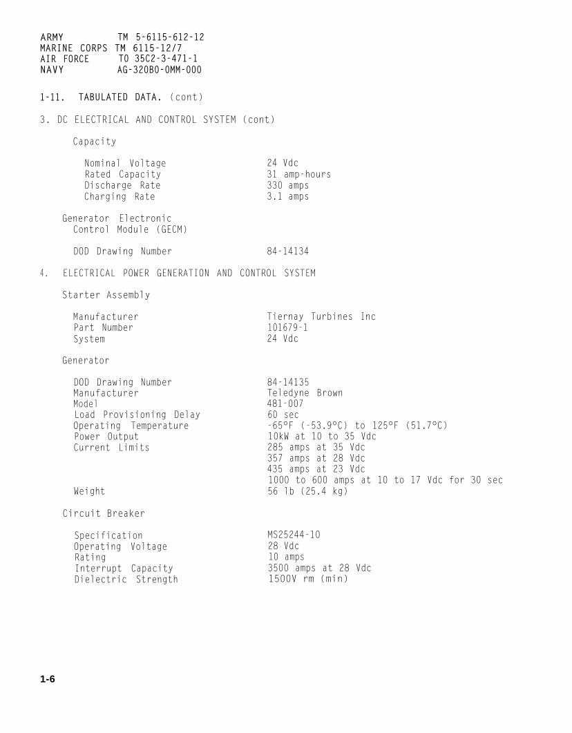
1-11. TABULATED DATA. (cont)
3. DC ELECTRICAL AND CONTROL SYSTEM (cont)
Capacity
Nominal Voltage 24 VdcRated Capacity 31 amp-hoursDischarge Rate 330 ampsCharging Rate 3.1 amps
Generator ElectronicControl Module (GECM)
DOD Drawing Number 84-14134
4. ELECTRICAL POWER GENERATION AND CONTROL SYSTEM
Starter Assembly
Manufacturer Tiernay Turbines IncPart Number 101679-1System 24 Vdc
Generator
DOD Drawing NumberManufacturerModelLoad Provisioning DelayOperating TemperaturePower OutputCurrent Limits
Weight
84-14135Teledyne Brown481-00760 sec-65°F (-53.9°C) to 125°F (51.7°C)10kW at 10 to 35 Vdc285 amps at 35 Vdc357 amps at 28 Vdc435 amps at 23 Vdc1000 to 600 amps at 10 to 17 Vdc for 30 sec56 lb (25.4 kg)
Circuit Breaker
Specification MS25244-10Operating Voltage 28 VdcRating 10 ampsInterrupt Capacity 3500 amps at 28 VdcDielectric Strength 1500V rm (min)
1-6

ARMY TM 5-6115-612-12MARINE CORPS TM 6115-12/7AIR FORCE T0 35C2-3-471-1NAVY AG-320B0-0MM-000
1-11. TABULATED DATA. (cont)
5. FUEL SYSTEM
Electrical Fuel Pump (Transfer Pump)
DOD Drawing Number 83-14281Manufacturer Tiernay Turbines IncCapacity 25 gph (94.64 Lph)output 7 psi (48.26 Pa)
Fluid Filter (Primary)
DOD Drawing Number 83-14283Manufacturer Parker HannifinPart Number PFF-1-XX-14383Specification MIL-F-20627, Type I, Class IFilter Element
Part Number MIL-F-20627, Type II, Class 5Filtration Rating 40 microns
Fluid Filter (Secondary)
DOD Drawing Number 83-14279Manufacturer Parker HannifinPart Number 15P-1-XX-14256Filter Element
Part Number 927472Filtration Rating 5 microns
Engine Fuel Tank
DOD Drawing NumberManufacturerCapacityOperating Time
Electrical Fuel Pump
DOD Drawing NumberManufacturerPart NumberRated Capacity
Solenoid Valve
DOD Drawing NumberManufacturerPart Number
83-14108Tiernay Turbines Inc32 gal (121.13 1)4 hours
(High Pressure Pump)
83-14280Tiernay Turbines Inc101537-110.3 gph (38.99 Lph) at 200 psi (1379 kPa)
83-14251Tiernay Turbines Inc101541-1
1-7

ARMY TM 5-6115-612-12MARINE CORPS TM 6115-12/7AIR FORCE TO 35C2-3-471-1NAVY AG-320B0-0MM-000
1-11. TABULATED DATA. (cont)
5. FUEL system (cont)
Atomizers
Part NumberManufacturer
6. IGNITION SYSTEM
Ignition Coil
DOD Drawing NumberManufacturerPart NumberEnergy Level
Input VoltageOutput VoltageInput CurrentSpark RateDuty Cycle
Spark Igniter
ManufacturerPart Number
7. LUBRICATION ASSEMBLY
Oil Filter
ManufacturerPart Number
Oil Pump
ManufacturerPart NumberRated Capacity
Oil Cooler
DOD Drawing NumberManufacturerPart Number
101488-1Tiernay Turbines Inc
83-14249Tiernay Turbines Inc83-142490.3 Joules min spare energy
1.0-1.5 Joules stored energy10-30 Vdc5 Kv minimum1.5 amps maximum4 sparks/see minimum at 14 VdcIntermittent - 1 minute on, 15 seconds off,
for 3 cycles, then 5 min off
Tiernay Turbines Inc101420-1
Tiernay Turbines Inc101483-1
Tiernay Turbines Inc101683-25.3 gpm at 70 psi (482.63 kPa)
83-14165Air Draulics010231, TU1041465
1-8
1-11. TABULATED DATA. (cont)
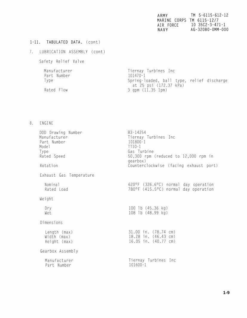
7. LUBRICATION ASSEMBLY (cont)
Safety Relief Valve
ManufacturerPart NumberType
Rated Flow
8. ENGINE
DOD Drawing NumberManufacturerPart NumberModelTypeRated Speed
Rotation
Exhaust Gas Temperature
NominalRated Load
Weight
DryWet
Dimensions
Length (max)Width (max)Height (max)
Gearbox Assembly
ManufacturerPart Number
ARMY TM 5-6115-612-12MARINE CORPS TM 6115-12/7AIR FORCE 10 35C2-3-471-1NAVY AG-320B0-0MM-000
Tiernay Turbines Inc101470-1Spring-loaded, ball type, relief discharge
at 25 psi (172.37 kPa)3 gpm (11.35 1pm)
83-14254Tiernay Turbines Inc101800-1TT1O-1Gas Turbine50,300 rpm (reduced to 12,000 rpm ingearbox)Counterclockwise (facing exhaust port)
620°F (326.6°C) normal day operation780°F (415.5°C) normal day operation
100 lb (45.36 kg)108 lb (48.99 kg)
31.00 in. (78.74 cm)18.28 in. (46.43 cm)16.05 in. (40.77 cm)
Tiernay Turbines Inc101600-1
1-9

ARMY TM 5-6115-612-12MARINE CORPS TM 6115-12/7AIR FORCE TO 35C2-3-471-1NAVY AG-320B0-0MM-000
1-11. TABULATED DATA. (cont)
9. ENGINE/GENERATOR CONTROLS AND INSTRUMENTS
Engine Electronic Control Module (EECM)
DOD Drawing Number 84-14133Manufacturer Tiernay Turbines IncPart Number 101700
Panel Lights Switch
Specification MS24523-22Type One pole toggleLamp Load Circuit 5 ampsResistive Circuit 20 ampsInductive Circuit 15 ampsOperating Voltage 28 Vdc
Master Switch
Specification MS27407-5Type Two pole toggleLamp Load Circuit 5 ampsResistive Circuit 18 ampsInductive Circuit 10 ampsOperating Voltage 28 Vdc
Contactor Switch
Specification MS24523-27Type One pole toggleLamp Load Circuit 4 ampsResistive Circuit 15 ampsInductive Circuit 10 ampsOperating Voltage 28 Vdc
DC Circuit Breaker Switch
Specification MS25244-10Type Trip free circuit breakerInductive Endurance 2500 cyclesResistive Endurance 5000 cyclesOperating Force Pull - 8 lb (9.6 Kg) max
Reset - 12 lb (14.4 Kg) max
Incandescent Lamps
Specification 69-594
1-10
ARMY TM 5-6115-612-12MARINE CORPS TM 6115-12/7AIR FORCE T0 35C2-3-471-1NAVY AG-320B0-0MM-000
1-11. TABULATED DATA. (cont)
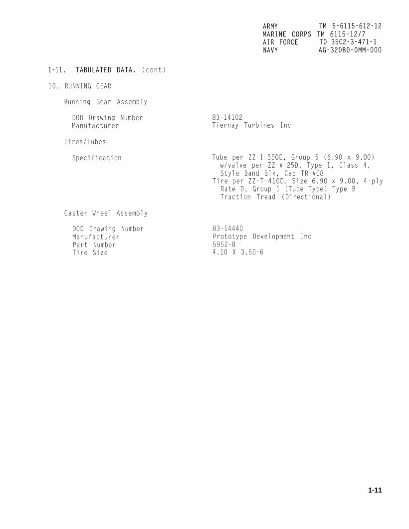
10. RUNNING GEAR
Running Gear Assembly
DOD Drawing NumberManufacturer
Tires/Tubes
Specification
Caster Wheel Assembly
DOD Drawing NumberManufacturerPart NumberTire Size
83-14102Tiernay Turbines Inc
Tube per ZZ-I-550E, Group 5 (6.90 x 9.00)w/valve per ZZ-V-25D, Type I, Class 4,Style Band Blk, Cap TR-VC8
Tire per ZZ-T-410D, Size 6.90 x 9.00, 4-plyRate D, Group 1 (Tube Type) Type BTraction Tread (Directional)
83-14440Prototype Development Inc5952-84.10 X 3.50-6
1-11

ARMY TM 5-6115-612-12MARINE CORPS TM 6115-12/7AIR FORCE T0 35C2-3-471-1NAVY AG-320B0-0MM-000
1-11. TABULATED DATA. (cont)
Torque Specifications. Table1-1 lists the torque specificationsapplicable to the operator/crew andorganizational levels of maintenance.
a. c.
b. Location and Description ofIdentification and Instruction Plates.The locations and content of all ident-ification and instruction plates arelisted in table 1-2.
Diagrams and Schematics. FigureFO-1 shows a generator set wiring in-stallation. Figure FO-2 is a generatorset schematic. FO-3 is a generator setwiring diagram. FO-4 is a wiring dia-gram of the control panel. Foldoutsare located at the back of thismanual. Figure 1-3 is a schematic ofthe fuel system. Figure 1-4 is a simplified block diagram of thelubrication system.
TABLE 1-1.
FINE THREAD SERIES NUTS , BOLTS, SCREWS
Recommended tension Maximum
Size Inch pounds Newton meters Inch pounds Newton meters
8-3610-32
1/4-285/16-243/8-24
7/16-201/2-20
9/16-185/8-183/4-167/8-14
1-14
12-1520-2550-70100-140160-190450-500480-690800-10001100-13002300-25002500-30003700-5500
1.4-1.72.3-2.85.7-7.911.3-15.818.1-21.550.9-56.554.2-78.090.4-113.0124.3-146.9259.9-282,5282.5-339.0418.1-621.5
204010022539084011001600240
5000700010000
2.34.511.325.444.194.9124.3180.8271.2565.0791.01130.0
1-12

ARMY TM 5-6115-612-12MARINE CORPS TM 6115-12/7AIR FORCE T0 35C2-3-471-1
1-11. TABULATED DATA. (cont)
NAVY AG-320B0-0MM-000
TABLE 1-1. Torque Specifications - Continued
Size
8-3210-24
1/4-205/16-183/8-16
7/16-141/2-13
9/16-12518-113/4-107/8-9
1-8
Tubedash #
234568
101218
COARSE THREAD SERIES NUTS, BOLTS, SCREWS
Recommended tension Maximum
Inch pounds Newton meters Inch pounds Newton meters
12-1520-2540-5080-90160-185235-255400-480500-700700-9001150-16002200-30003700-5000
Fittingthread size
5/16-243/8-24
7/16-241/2-20
9/16-183/4-1 87/8-14
1-1/16-121-5/16-121-5/8-12
1.4-1.72.3-2.84.5-5.79.0-10.218.1-20.926.6-28.845.2-54.256.5-79.179.1-101.7129.6-180.8248.6-339.0418.1-565.0
203575
16027547588011001500250046007600
2.34.08.5
18.131.153.799.4
124.3169.5282.5519.8858.3
FLARED TUBING AND HOSE FITTINGS
All aluminum parts Steel tube, aluminumor steel nuts
Inch pounds Newton meters Inch pounds Newton meters
None None 35-40 4.0-4.520-50 2.3-5.7 90-100 10.2-11.340-60 4.5-6.8 135-150 15.3-17.060-80 6.8-9.0 180-200 20.3-22.675-125 8.5-14.1 270-300 30.5-33.9150-250 17.0-28.2 450-550 50.8-62.2200-350 22.6-39.6 650-770 73.5-87.0300-492 33.9-55.6 900-1092 101 .7-123.4492-696 55.6-78.6 1200-1536 135.6-173.6600-900 67.8-101.7 1500-1800 169.5-203.420
24 1-7/8-12 600-900 67.8-101.7 1896-2196 214.2-248.1
1-13

ARMY TM 5-6115-612-12MARINE CORPS TM 6115-12/7AIR FORCE TO 35C2-3-471-1NAVY AG-320B0-0MM-000
1-11. TABULATED DATA. (cont)
Table 1-2. Identification and Instruction Plates
Plate name Plate location Plate information
Towing Speed
Tire InflationPressure
Slave Receptacle
Ground Stud
Generator SetIdentification
OperatingInstructions
Wiring andSchematicDiagrams
Fuel andLubricantSpecifications
System Schematic
Front of generator set
Left side of generator set oncontrol panel access door
Back of generator set
Located on left side of tonguein front of fuel tank
Located center of control panelaccess door on left side ofgenerator set
Inside control panel access door
Inside control panel access door
Inside control panel access dooron front of EECM access cover
On back of EECM access cover
Shows maximum towing speedand plate ID/drawing number
Shows proper tire inflationpressures and plate ID/drawing number
Identifies location of slavereceptacle with plate ID/drawing number
Identifies location of groundwith plate ID/drawing number
Shows identification numberand certain operating charac-teristics of the generatorset, and plate ID/drawingnumber.
Shows preoperating andoperating procedures, acaution note, and plate ID/drawing number.
Shows wiring diagramsof electrical componentsand plate ID/drawing number
Provides fuel and lubricantspecifications with temper-ature ranges and plate/IDdrawing number
Shows system schematicand plate/ID drawing number.
1-14

1-11.
ARMY TM 5-6115-612-12MARINE CORPS TM 6115-12/7AIR FORCE T0 35C2-3-471-1N A V Y AG-320B0-0MM-000
Figure 1-3. Fuel System Schematic
1-15

1-11.
ARMY TM 5-6115-612-12MARINE CORPS TM 6115-12/7AIR FORCE T0 35C2-3-471-1NAVY AG-320130-0MM-000
Figure 1-4. Lubrication System Simplified Block Diagram
1-16

FAARMY TM 5-6115-612-12MARINE CORPS TM 6115-12/7AIR FORCE TO 35C2-3-471-1NAVY AG-320B0-0MM-000
CHAPTER 2
OPERATING INSTRUCTIONS
Section I. OPERATING PROCEDURES
2-1. GENERAL. This section contains 2-2. CONTROLS AND INDICATORS. In-procedures for operating the generator formation on description, function, andset under normal conditions. These normal operating positions of controlsprocedures are intended to familiarize and indicators is listed in table 2-1.the operator with control and operation Control panel controls and indicatorsof the generator set. are shown in figure 2-1.
Table 2-1. Controls and IndicatorsControl or Function Normal operatingindicator position
MASTER SWITCHToggle switch
CONTACTORToggle switch
READY TO LOADLight indicator
CLOSEDLight indicator
VOLTAGEDC voltmeter
VOLTAGE ADJUSTPotentiometer
OUTPUT CURRENTOutput ammeter
BATTERY CHARGINGBattery charg-ing ammeter
DC CIRCUIT BREAKER(Pushbutton -press-to-reset)
Three-position toggle switch. RUNRUN activates electricaland fuel systems. STARTposition starts engine. OFFposition shuts generator set OFF.
Opens and closes contactor.
Illuminates when set is run-ning at 100% rpm (green).
Illuminates when contactoris closed (yellow).
Provides indication of dc volts.
Adjusted to maintainoutput voltage.
Provides indication of outputamperage.
Provides indication of batterycharging rate.
Provides protection for dcelectrical system.
CLOSED
off
On
28 Vdc
Midrange
Variable
To right ofzero
Reset buttonpushed in
2-1

ARMY TM 5-6115-612-12MARINE CORPS TM 6115-12/7AIR FORCE TO 35C2-3-471-1NAVY AG-320B0-0MM-000
2-2. CONTROLS AND INDICATORS. (cont)
Table 2-1. Controls and Indicators - ContinuedControl or Function Normal operatingindicator position
HOURMETERTime totalizingmeter
PANEL LIGHTSToggle switch
LOW FUELIndicator light(press-to-test)
LOW OIL PRESSIndicator light(press-to-test)
OVERTEMPIndicator light(press-to-test)
OVERSPEEDIndicator light(press-to-test)
OVERLOADIndicator light(press-to-test)
OVERVOLTAGEIndicator light(press-to-test)
OVERTEMPIndicator light(press-to-test)
UNDERVOLTAGEIndicator light(press-to-test)
Manual ControlLever handbrake
Indicates total engine operatinghours at 100% rated load.
Turns on control panel lights.
Installed - not functional.
Red light indicates low oilpressure in lubrication system.
Red light indicates highengine temperature.
Red light indicates engineoverspeed. Will also comeon to indicate underspeed.
Red light indicates excessivecurrent demand.
Red light indicates excessiveoutput voltage.
Red light indicates excessivegenerator temperature.
Red light indicates undervoltageoutput .
Sets or releases brake system.
OFF
- -
off
off
off
off
off
off
off
Set
2-2

2-2.
ARMY TM 5-6115-612-12MARINE CORPS TM 6115-12/7AIR FORCE TO 35C2-3-471-1NAVY AG-320B0-0MM-000
Figure 2-1. Control Panel Controls and Indicators
Change 1 2 - 3

ARMY TM 5-6115-612-12MARINE CORPS TM 6115-12/7AIR FORCE TO 35C2-3-471-1NAVY AG-320B0-0MM-000
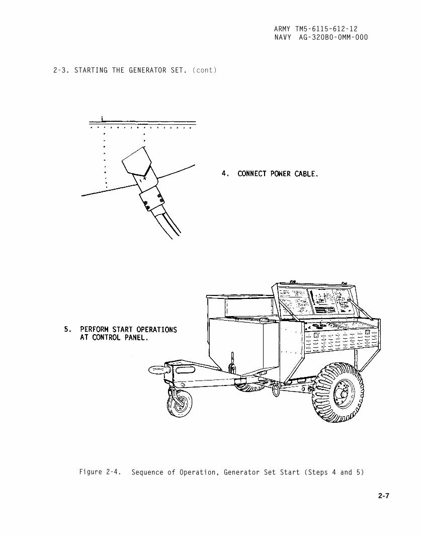
2-3. STARTING THE GENERATOR SET.The detailed start procedures describedin this manual are given in a quickreference form on the operating in-structions plate (figure 2-2). Seetable 1-2 for plate location. Positiongenerator set on a level surface.Generator set start is illustrated infigures 2-3 and 2-4.
WARNING
To prevent accidental movement,ensure that handbrake is set whengenerator set is parked.
Set the Handbrake.handbrake lever (figure 2-3,in ON position to set parking
Placestep 1)brakes.
WARNING
Explosion, fire, or electrocutionmay result from frayed, cut, ormissing insulation - on powercable. Do not place power cableon airframe. Failure to observethis warning could result in injury to personnel or equipmentdamage.
e. Connect Power Cable. Insertpower cable into aircraft receptacle asfar as it will go. (See figure 2-4,step 4.)
f. Startinq Procedures. See figure 2-4, step 5, and proceed as follows.
WARNINGWARNING
To prevent injury, ensure thatgenerator set is grounded beforeoperation.
b. Grounding the Generator Set.Ground the generator set in accordancewith paragraph 4-2 and as shown infigure 2-3, step 2.
c. Perform PMCS. Refer to table 3-2and perform before operation (B) Pre-ventive Maintenance Checks and Services(PMCS) . Ensure that fuel and oillevels are at full.
d. Raise Control Panel AccessDoor. Unlatch, raise, and secure con-trol panel access door. Ensure thatfuels and lubricant being used are inaccordance with temperature rangesshown on Fuel and Lubricant Specifi-cations plate located on top of engineelectronic control module (EECM) accesscover. (See figure 2-3, step 3.)
To prevent injury, ensure thatear protection is worn whenoperating generator set.
CAUTION
To prevent damage, do not attemptto start generator set untilengine and generator shafts havecompletely stopped rotating.
CAUTION
Do not operate generator set withengine housing access coverremoved. Severe damage to enginecompressor could result.
(1) Set VOLTAGE ADJUST knob (5,figure 2-1) to midrange.
2-4

2-3. STARTING THE GENERATOR SET. (cont)
ARMY TM 5-6115-612-12MARINE CORPS TM 6115-12/7AIR FORCE t0 35C2-3-471-1NAVY AG-320B0-0MM-000
Figure 2-2. Generator Set Operating Instructions Plate
2-5

ARMY TM 5-6115-612-12MARINE CORPS TM 6115-12/7AIR FORCE T0 35C2-3-471-1NAVY AG-320B0-0MM-000
2-3. STARTING THE GENERATOR SET. (cont)
Figure 2-3. Sequence of Operation, Generator Set Start (Steps 1 thru 3)
2-6
ARMY TM5-6115–612-12NAVY AG-320B0-0MM-000
2-3. STARTING THE GENERATOR SET. (cont)
Figure 2-4. Sequence of Operation, Generator Set Start (Steps 4 and 5)
2-7

ARMY TM 5-6115-612-12NAVY AG-320B0-0MM-000
2-3. STARTING THE GENERATOR SET. (cont)
f. Starting Procedures. (cont)
(2) Move MASTER SWITCH (l), to RUNposition. LOW OIL PRESS indicator will come on andstay on until pressure in Lubrication system reachesapproximately 4 psi (0.11 MPa). UNDERVOLTAGEindicator will come on and stay on until engine reaches100% rpm and generator is enabled.
CAUTION
To prevent equipment damage, ensure thatred MALFUNCTION indicator lights (2) areclosely monitored during operation. Normally,when a red light comes on the engine willautomatically shut down. If automatic shut-down does not occur, immediately moveMASTER SWITCH (1) to OFF position. Do notattempt restart until reason for malfunctionhas been determined and corrected.
(3) Move MASTER SWITCH to START posi-tion and release. Engine should start and accelerate torated speed within 1 minute.
CAUTION
If engine rotates but no ignition occurs, do notattempt restart. Check malfunction indicatorlights and perform trouble-shooting as neces-sary.
(4) Allow engine to run a minimum of 5minutes to allow generator set temperatures and elec-tronics to stabilize. Observe READY TO LOAD light(4). Green light indicates engine is at rated speed.
(5) Use VOLTAGE ADJUST knob (5) toadjust VOLTAGE meter (6) reading to 28 Vdc. Clock-wise adjustment will increase voltage.
(6) Move CONTACTOR switch (7) toCLOSED position and release. Yellow light will comeon. Signal pilot to start aircraft.
CAUTION
Do not attempt to adjust VOLTAGE ADJUSTknob in respose to increases in load demandor decreases in voltage shown on VOLTAGEmeter. These adjustments could cause stresson the equipment once the load is removed.
NOTE
The generator set provides constant dcvoltage except during aircraft starting. Thegenerator electronic control module (GECM)senses voltage at the output connector of theaircraft and automatically adjusts volt/ampereratio to prevent exceeding 10 kW during air-craft starting.
NOTE NOTE
Engine life can be enhanced by allowing Engine life can be enhanced by allowingengine to run for a short time under no load engine to run for a short time under no loadbefore closing CONTACTOR. before shutdown.
2-8 Change 2

ARMY TM5–6115–612-12NAVY AG-320B0-0MM-000
2-3. STARTING THE GENERATOR(cont)
f. starting Procedures. (cont)
SET.
exhaust gases. Do not exceed 5
(7) Once aircraft start is accom-mph while moving set with enginerunning.
plished, move CONTACTOR switch toOPEN. Yellow CLOSED light Will gooff. Allow generator set to run for a 2-4. SLAVE START OPERATION.minimum of one minute andSWITCH to OFF.
NOTE
It is not necessary todown when moving shortto provide continued
move MASTERa. General. This procedure is
used in the event normal startingoperations for the generator setcannot be accomplished. A slavestart can be accomplished using a
shut set jeep, a truck, another generatordistances set, or other vehicle using a jumperservice. connecting cable with proper
Common sense precautions connection for the slave receptacle.follow Include ensuring thatcontactor switch is open; power b. Slave Start Procedure.cable is disconnected fromaircraft, ground cable is (1) Remove dust cap (figuredisconnected, and avoiding hot 2-5) from slave receptacle.
Figure 2-5. Slave Start Connection
2-9

ARMY TM 5-6115-612-12NAVY AG-320B0-0MM-000
2-4. SLAVE START OPERATION.(cont)
b. Slave Start Procedure. (cont)
(2) Insert jumper cable from vehicle intoslave receptacle of generator set.
(3) Start generator set in accordance withparagraph 2-3.
(4) When generator set is started, removejumper cable. Install dust cap on slave receptacle.
MASTER SWITCH to OFF position. Close and securecontrol panel access door.
NOTE
When generator set is shut down, the fuelshutoff solenoid valve will discharge a smallamount of fuel out the bottom of the cartbeneath the fuel housing.
b. Disconnect Power Cable.2-5. REMOVING GENERATOR SET FROM Disconnect power cable and stow on cable support atOPERATION. rear of generator set.
Stop Generator Set Engine. Perform After Operation PMCS.Place CONTACTOR switch in OPEN position. Refer to Table 3-2 and perform after operation (A)Allow engine to run a minimum of one minute, Move PMCS. Ensure that fuel and oil levels are at full.
Section II. OPERATION UNDER UNUSUAL CONDITIONS
2-6. GENERAL. The generator set is designed tooperate in ambient temperatures of -65°F (-53.9°C)to 125°F (51.70°C). This section provides informationfor operating the set in extreme environmental condi-tions.
2-7. OPERATION IN EXTREME HEAT.Procedures for operation of the generator set inextreme heat (ambient temperatures up to 125°F(51.7°C) are identical to normal operating proce-dures. Allow engine to run a minimum of 10 minutesprior to moving the CONTACTOR switch to theCLOSED position.
2-8. OPERATION IN EXTREME COLD.Procedures for operation of the generator set inextreme cold (defined as ambient temperatures below-25°F (-32°C)) are identical to normal operating pro-cedures. During operation in extreme cold, keep fueltank full to reduce condensation, The primary fuelfilter should be drained of condensation before andafter operation.
a. Open Fuel Housing.
(1) Set handbrake.
(2) Open control panel access door. EnsureMASTER SWITCH is in OFF position. Close controlpanel access door.
(3) Remove power cable (1, figure 2-6)from cable support assembly (2).
(4) Unlatch and open fuel housing accessdoor (3).
b. Drain Primary Filter.
(1) Place clear container (4) under fuel drainvalve (5) of primary fuel filter (6).
2-10 Change 2

ARMY TM 5-6115-612-12MARINE CORPS TM 6115-12/7AIR FORCE TO 35C2-3-471-1NAVY AG-320B0-0MM-000
2-8. OPERATION IN EXTREME COLD. (cont)
Figure 2-6. Draining Primary Fuel Filter
2-11

ARMY TM 5-6115-612-12MARINE CORPS TM 6115-12/7AIR FORCE TO 35C2-3-471-1NAVY AG-320B0-0MM-000
2-8. OPERATION IN EXTREME COLD. (cont)
(2) Open fuel drain valve andallow any water and sediment to drainoff.
(3) When fuel is clear, closefuel drain valve.
c.
(1)access
Secure Fuel Housing.
Close and secure fuel housingdoor.
(2) Stow power cable on cablesupport assembly.
2-9. OPERATION IN HIGH HUMIDITY.Procedures for operation of thegenerator set in high humidity or rainare identical to normal operatingprocedures.
2-10. OPERATION IN DUSTY AND SANDYAREAS. Procedures for operation ofthe generator set In dusty and sandyareas are identical to normal operatingprocedures.
Protecting Internal Components.Keep access doors and covers closed formaximum security of component parts andfilters against dust, dirt, and sand.
b. Preventive Maintenance. Morefrequent cleaning of the generator setmay be required when operating in dustyor sandy areas. Accumulated dust andsand shall be removed using a vacuumwith a nonmetallic nozzle. Removegrease or fuel deposits and accumulateddust, dirt, and sand.
2-11. OPERATION IN SALT WATERAREAS. Procedures for operation ofthe generator set in salt water areasare identical to normal operatingprocedures, except that more frequentcleaning and inspection of thegenerator set may be required.
2-12. OPERATION AT HIGH ALTITUDES.Procedures for operation of thegenerator set at altitudes up to 8000feet (2438 meters) above sea level areidentical to normal operatingprocedures.
2-13. OPERATION UNDER SNOWYCONDITIONS. Procedures for operationof the generator set in snowyconditions are identical to normaloperating procedures. Ensure that allair flow louvers are free of snow andice. Keep snow from accumulating undergenerator set. Remove all snow and icefrom generator set before openingaccess covers and doors.
2-12

ARMY TM 5-6115-612-12NAVY AG-320BO-OMM-000
CHAPTER 3
OPERATOR/CREW MAINTENANCE INSTRUCTIONS
Section I. CONSUMABLE OPERATING AND MAINTENANCE SUPPLIES
3-1. GENERAL. Consumable operating andmaintenance supplies required to perform maintenanceor operate the generator set are listed In
Table 3-1. Items listed are identified by assignedNational Stock Numbers (NSN)
Table 3-1. Consumable Operating and Maintenance Supplies
Component National Description Qty. required Qty. Required NotesApplication Stock for initial 8 hours
Number operation operation
Engine 9150-00- Lubricant 4 quarts For temperatures270-4057 MIL-L-7808 (3 785 liters) -65° F (-53.9° C)
to 125° F (51 7° C)
9150-00- MIL-L-23699 4 quarts For temperatures985-7099 (3 785 liters) -40° F (-40° C) to
400° F (204.4° C)
Fuel System 9130-00- FUEL 32 gallons 64 gallons256-8613 MIL-T-5624 (121.1 liters) (242 3 liters)
JP-4/JP-5
6810-00- Ethyl Alcohol O-E-760 General Cleaning782-2686
6850-00- Solvent PD-680, General Cleaning331-3350 Type III
Banned From Trichloroethylene General CleaningUse O-T-634
Tnchloroethylene Vapor Degreasing1. 1. 1MIL-T-81533
Battery 6810-00- Electrolyte Battery Fluid249-9354
Distilled Water Battery Service8040-00- Adhesive, Locking General Repair826-3535 MIL-A-46050
Power Cable This Is no longerused.
Spark Igniter 8030-00- Anti-seize Compound059-2761 MIL-A-907E FSC
8030 (MO11-2836)
Change 7 3-1

ARMY TM 5-6115-612-12NAVY AG-320BO-OMM-000
Table 3-1. Consumable Operating and Maintenance Supplies - Continued
Component National Description Qty. required Qty. required NotesApplication Stock for initial 8 hours
Number operation operation
Turnlock 8030-00- Thread-lockingFasteners 180-6150 Compound
MIL-S46163AFSC 8030(MO11-3301)
Fasteners 8030-00- Sealing Compound Reassembly292-1102 MIL-R-46082B Procedures
FSC 8030(X550-2193)MIL-S-22473EFSC ,8030(X552-2455)
Swivel Caster 9150-00- Grease, Automotive See Lubrication721-8570 and Artillery Order (LO)
MIL-G-10924-27FSC 9150(M117-2717)
Fasteners 6850-00- Silicone Compound Reassembly880-7616 MIL-S-8660 Procedures
Hose Fittings Petrolatum, Technical Assembly andVV-P-236 Repair
5350-00- Cloth, Abrasive, General Repair268-3116 Crocus P-C-458
Fuel Nozzles 6850-00- Orthodichlorobenzene Carbon Removaland Atomizers 965-2332 MIL-C-25107B
FCS 6850(M 101-2742)Calibrating Fluid TestingMIL-C-7024, Type II
Insulation Edge Sealer 1 gallon InstallationADM6SE80-PB (3 78 liters)Wire, Lock ReassemblyMS20995-NC20 ProceduresFSC 95-5(D 401-1357
3439-00- Solder Electrical Repair184-8960 SN60WRMAP3
(QQ-S-571)
6850-00- Alkaline Carbon Removal550-5565
3-2 Change 7

ARMY TM 5-6115-612-12MARINE CORPS TM 6115-12/7AIR FORCE T0 35C2-3-471-1NAVY AG-320B0-0MM-000
Section II. LUBRICATION INSTRUCTIONS
3-2. GENERAL. This section contains b. Checking and Adding Lubricationa reproduction of the lubrication order oil.and lubrication instructions that aresupplemental to, and not specifically (1) Unscrew and remove oil fillercovered in, the lubrication order. The cap (figure 3-1).lubrication order is an exact repro-duction of the approved lubrication (2) Wipe oil level gage clean.order. Refer to Army LO 5-6115-612-12.
(3) Reinsert oil level gage andtighten oil filler cap finger tight.
(4) Unscrew and remove oil fillercap.
Lubricant and EquipmentStorage. Keep all lubricants in closedcontainers and store in a clean, dryplace away from external heat. Allowno dust, dirt, or other foreignmaterial to mix with the lubricants.Keep all lubrication equipment cleanand ready to use.
a. (5) Check oil level on oil levelgage. Add lubricating oil as neces-sary to obtain FULL reading on oillevel gage. Refer to lubrication order(figure 3-2) for proper lubricating oil.
(6) Reinsert oil level gage andhand tighten oil filler cap.
Figure 3-1. Checking Lubricating Oil
3-3

LO5-6115-612-12
TM 5-6115-612-12
ARMY TM 5-6115-612-12MARINE CORPS TM 6115-12/7AIR FORCE TO 35C2-3-471-1NAVY AG-320B0-0MM-000
3-2. GENERAL. (cont)
Figure 3-2. Lubrication Order (Sheet 1 of 2)
3-4

3-2.
ARMY TM 5-6115-612-12MARINE CORPS TM 6115-12/7AIR FORCE T0 35C2-3-471-1NAVY AG-320B0-0MM-000
GENERAL. (cont)
Figure 3-2. Lubrication Order (Sheet 2 of 2)
3-5

ARMY TM 5-6115-612-12MARINE CORPS TM 6115-12/7AIR FORCE TO 35C2-3-471-1NAVY AG-320B0-0MM-000
Section III. PREVENTIVE MAINTENANCE CHECKS AND SERVICES (PMCS)
3-3. GENERAL. TO ensure that thegenerator set is ready for operation atall times, it must be inspected system-atically so that defects may be dis-covered and corrected before they re-sult in serious damage or failure. Thenecessary preventive maintenance checksand services (PMCS) that are to beperformed by Operator/Crew personnelare listed and described in table 3-2.Defects discovered during operationshall be noted for future correction.Stop operation immediately if a de-ficiency is noted that could damage theequipment. All deficiencies andshortcomings shall be recorded on theapplicable form together with the cor-rective actions taken. Air Force users
shall refer to the applicable in-spection manuals and work card sets inthe TO 35C2-3 series for periodic re-quirements, and table 3-2 for detailedprocedures. Marine Corps users shallrefer to current issue of TM 11275-15-1.
3-4. (A, N, MC) PREVENTIVE MAIN-TENANCE CHECKS AND SERVICES. Table3-2 provides a listing of PMCS thatshall be performed by the Operator/Crewpersonnel. The item numbers are listedconsecutively and indicate the sequenceof performance.
Table 3-2. Preventive Maintenance Checks and Services (PMCS)
B - Before operation 0.5D - During operation 0.2A - After operation 0.1
Total M/H: 0.8
Interval
Operator WorkDaily Items to be inspected Time
B D A Inspection procedures ___ M/H
1 GENERATOR SET 0.1Set handbrake. Visually inspect unit forphysical damage. Check ground cable andensure that generator set is properlygrounded. Ensure that set is free oftools and rags and that there is nospilled fuel or lubricating oil.
2 CONTROL PANELEnsure MASTER SWITCH is in OFF position.Ensure that panel lights and press-to-test indicators operate properly.Inspect meters and indicators for brokenglass and missing indicator lamps.
0.1
3-6

ARMY TM 5-6115-612-12NAVY AG-32080-0MM-000
3-4. (A, N, Mc) (PREVENTIVE MAINTENANCECHECKS AND SERVICES. (cont)
Table 3-2. Preventive Maintenance Checks and Services (PMCS) - Continued
Change 4 3-7

ARMY TM 5-6115-612-12MARINE CORPS TM 6115-12/7AIR FORCE TO 35C2-3-471-1NAVY AG-320B0-0MM-000
Section IV. TROUBLESHOOTING
3-5. GENERAL.
a. Table 3-3 provides trouble-shooting information for locating andcorrecting problems that may develop inthe generator set. Each malfunctionfor an individual component, unit, orsystem is followed by a list of testsor Inspections that will help determineprobable causes and corrective actionsto take. Perform the tests/inspectionsand corrective actions in the orderlisted.
b. This manual cannot list allmalfunctions that may occur. If amalfunction is not listed or cannot becorrected by listed corrective actions,notify supervisor.
NOTE
Before using this table, ensurethat all applicable operatingchecks have been performed.
Table 3-3. Troubleshooting
MALFUNCTIONTEST OR INSPECTION
CORRECTIVE ACTION
1. STARTER ROTATES ENGINE, BUT COMBUSTION DOES NOT OCCUR.
Step 1. Check to ensure adequate fuel supply.
Fill fuel tank.
Step 2. Unit still fails to operate.
Refer to next higher level of maintenance.
2. MASTER SWITCH IS PLACED IN THE START POSITION, BUT ENGINE DOES NOT ROTATE.
Step 1. Check that
Refer to
Step 2. Check that
Press DC
no malfunction indicator light is on.
higher level of maintenance if malfunction light is on.
DC CIRCUIT BREAKER reset button is pressed in.
CIRCUIT BREAKER reset button to reset.
Step 3. Check battery cable plug connector.
Tighten battery connector.
Step 4. Unit still fails to operate.
Refer to next higher level of maintenance.
3-8
PIN: 060184-004

ARMY TM 5-6115-612-12MARINE CORPS TM 6115-12/7AIR FORCE T0 35C2-3-471-1NAVY AG-320B0-0MM-000
Section V. OPERATOR/CREW MAINTENANCE INSTRUCTIONS
3-6. GENERAL. This section providesinstructions to assist the operator inmaintaining the generator set. Ifdefective components are noted duringinspections or operation, refer to thenext higher level of maintenance forrepair or replacement.
3-7. FRAME AND HOUSING.
a. Tiedown Rinqs. See figures 1-1and 1-2 for locations and ensure thattiedown rings are in place, firmlyattached, and rotate freely.
b. Cable Support Assembly. Seefigure 1-2.
(1) Ensure that cable supportassembly is in place and firmlyattached.
(2) Inspect all surfaces forcorrosion and cracked or chipped paint.
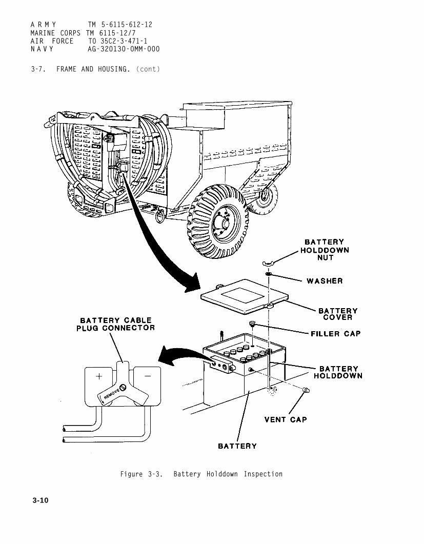
Battery Holddown. See figure3-3.
CAUTION
Battery holddown needs to besecure; however, excessivepressure may cause battery tobuckle causing internal shorting.
(1) Ensure that battery holddownis firmly attached.
(2) Inspect battery holddown forrust or corrosion.
d. Access Doors and Covers. Seefigure 3-4.
(1) Ensure that access doors andcovers are free of dents, sharp edges,and holes.
(2) Inspect all surfaces forcorrosion and cracked or chipped paint.
(3) Inspect gaskets for damage.
e. Control Fender and ExhaustFender Assemblies. See figures 1-1 and1-2.
(1) Ensure that control fenderand exhaust fender assemblies are freeof dents, holes, and sharp edges.
(2) Inspect for corrosion andcracked or chipped paint.
(3) Ensure that louvers are freeof obstructions.
(4) Ensure that hinges andlatches are securely attached.
(5) Inspect identification platesfor corrosion, legibility, and secureattachment. See table 1-2 for locationof plates.
f. Fuel and Inlet Air Housings.See figure 1-2.
(1) Ensure that fuel and inletair housings are free of dents, holes,and sharp edges.
(2) Inspect for corrosion, andcracked or chipped paint.
(3) Ensure all fasteners aresecurely attached.
3-9
A R M Y TM 5-6115-612-12MARINE CORPS TM 6115-12/7AIR FORCE TO 35C2-3-471-1N A V Y AG-320130-0MM-000
3-7. FRAME AND HOUSING. (cont)
Figure 3-3. Battery Holddown Inspection
3-10

A R M Y TM 5-6115-612-12MARINE CORPS TM 6115-12/7AIR FORCE TO 35C2-3-471-1NAVY AG-320B0-0MM-000
3-7. FRAME AND HOUSING. (cont)
Figure 3-4. Access Covers and Doors Inspection
3-11
ARMY TM 5-6115-612-12MARINE CORPS TM 6115-12/7AIR FORCE TO 35C2-3-471-1NAVY AG-320B0-0MM-000
3-7. FRAME AND HOUSING. (cont)
Chassis Frame Assembly. Seefigure 3-5.
(1) Check for dents, holes, war-page, and cracks.
(2) Check battery holding areafor corrosion from battery acid.
(3) Ensure that all bolts andfasteners are tight.
(4) Check forklift tubes fordamage.
3-8. DC ELECTRICAL AND CONTROLSYSTEM.
a. Batterv Cable Assembly.figure 3-6.
(1) Visually inspect lengthbattery cable for cracks, abrasionscuts.
See
ofand
(2) Check battery cable connectorfor damaged knob, cracks in case, dam-aged threads, and loose connections.
(3) Ensure that female contactsare securely in place and undamaged.
b. Battery.
(1) Inspect casingbroken caps, and corrosion.
(2) Check electrolyte
for cracks,
level.
WARNING
To prevent injury, ensure thatbattery is disconnected beforeperforming maintenance onelectrical components.
(a) Disconnect battery cableplug connector.
3-12
(b) Loosen nuts and washers andremove battery holddowns.
(c) Remove battery cover andfiller caps.
(d) Add distilled water to fillbattery up to vent filler slots.
(e) Install filler caps andbattery cover.
(f) Install battery holddownand tighten washers and wingnuts.Ensure that battery is secure.
(g) Connect battery cable plugconnector.
Slave Receptacle. See figure2-5.
(1) Remove dust cap.
(2) Check for loose mounting.
(3) Check for damaged contactpins and foreign material.
(4) Inspect receptacle body forcracks, dents, and corrosion.
(5) Install dust cap.
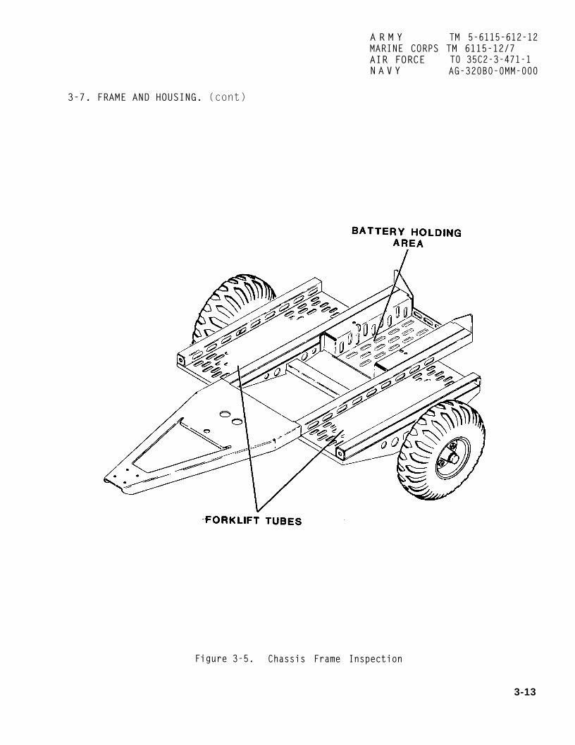
A R M Y TM 5-6115-612-12MARINE CORPS TM 6115-12/7AIR FORCE T0 35C2-3-471-1N A V Y AG-320B0-0MM-000
3-7. FRAME AND HOUSING. (cont)
Figure 3-5. Chassis Frame Inspection
3-13

ARMY TM 5-6115-612-12MARINE CORPS TM 6115-12/7AIR FORCE TO 35C2-3-471-1N A V Y AG-320B0-0MM-000
3-8. DC ELECTRICAL AND CONTROL SYSTEM. (cont)
Figure 3-6. Battery and Battery Cable Inspection
3-14

ARMY TM 5-6115-612-12MARINE CORPS TM 6115-12/7AIR FORCE TO 35C2-3-471-1NAVY AG-320B0-0MM-000
3-9. FUEL SYSTEM.
Internal Fuel System Com-ponents. (See figure 3-7.)
(1) Remove power cable from cablesupport assembly.
(2) Unlatch and open fuel housingaccess door. Secure in open position.
(3) Inspect for loose fastenersand loose electrical connections onfuel transfer pump, high pressure fuelpump, and solenoid valve.
(4) Open control panel accessdoor and place MASTER SWITCH in RUNposition. This will actuate fueltransfer pump and pressurize fuelsystem up to high pressure fuel pumpwith 7 psi (48.26 kPa).
(5) Inspect for leaks at fuelline connections at ports of primaryfilter. Inspect for leaks at gasketwhere bowl fits into housing.
(6) Inspect for leaks at fuelline connections at ports of secondaryfuel filter. Inspect for leaks atgasket where bowl fits into housing.
(7) Inspect for leaks at fuelline connections on fuel transfer pump,high pressure fuel pump, and solenoidvalve.
(8) Ensure that fuel lines infuel housing are securely fastened.
(9) Inspect fueltank to fuel housingloose fasteners.
(10) Place MASTERposition.
(11) Close and
line from fuelfor leaks and
SWITCH in OFF
securely latchcontrol panel access door.
(12) Close and securely latchfuel housing access door.
(13) Stow power cable on cablesupport assembly.
b. Fuel Tank.
(1) Inspect fuel tank for leaks.
(2) Ensure that fuel tank issecurely attached to generator set.
(3) Check filler cap and gasketfor damage.
(4) Ensure that fuel gage issecurely mounted.
3-10. LUBRICATION ASSEMBLY. Seefigure 3-1 and inspect oil level gage.
a. Ensure that MASTER SWITCH is OFF.
b. Unscrew and remove oil fillercap.
Inspect gasket and threads fordamage.
d. Inspect oil level gage fordamage.
Install oil filler cap. Turnuntil hand tight.
3-15

ARMY TM 5-6115-612-12MARINE CORPS TM 6115-12/7AIR FORCE TO 35C2-3-471-1NAVY AG-320B0-0MM-000
3-9. FUEL SYSTEM. (CONT)
Figure 3-7. Inspection of Internal Fuel System Components
3-16

3-11. ENGINE AND GENERATOR CONTROLSAND INSTRUMENTS. Operator maintenanceis limited to inspection of meters,indicators and lights. Component loca-tions are shown in figure 3-8.
a. Meters.
door (1) Open control panel access
(2) Inspect meter faces forbroken glass.
(3) Ensure that meters are se-curely attached to control panel and donot move when gently pressed.
b. Panel Lights. Indicator Lights.and Incandescent Lamps.
(1) Inspect panel light coversfor damage.
(2) Inspect indicator lights fordamage and missing or broken lenses.
(3) Ensure that DC CIRCUITBREAKER reset button is pressed all theway in.
(4) Place PANEL LIGHTS toggleswitch in ON position. Incandescentlamps will come on if good. Placeswitch in OFF position.
(5) Each indicator light has itsown press-to-test feature. Press firm-ly each indicator light to be tested.Incandescent lamp will come on ifgood . Release. If damage or mal-function is observed, refer to nexthigher level of maintenance.
(6) Close control panel accessdoor.
ARMY TM 5-6115-612-12MARINE CORPS TM 6115-12/7AIR FORCE TO 35C2-3-471-1NAVY AG-320B0-0MM-000
3-12. LOAD CONNECTION. Operatormaintenance is limited to inspection ofthe power cable assembly (figure 3-9).
a. Open control panel access door.
b. Ensure that MASTER SWITCH is inOFF position.
c. Close control panel access door
WARNING
To prevent injury, ensure thatbattery cabledisconnectedmaintenance.
d. Disconnectconnector.
plug connector isbefore performing
battery cable plug
e. Remove power cable from cablesupport assembly.
f. Inspect length of cable forcuts, abrasions, and any other evidenceof damage. If damage is observed,refer to next higher level ofmaintenance.
g. Check output connector for dam-age to pins and backshell. Ensuretightness of assembly. If connector isloose, refer to next higher level ofmaintenance for repair.
h. Ensure that output connector isfree of foreign material.
i. Connect battery cable plug con-nector.
j. Stow power cable on cable sup-port assembly.
3-17

A R M Y TM 5-6115-612-12MARINE CORPS TM 6115-12/7AIR FORCE T0 35C2-3-471-1NAVY AG-320B0-0MM-000
3-11. ENGINE AND GENERATOR CONTROLSAND INSTRUMENTS. (cont)
Figure 3-8. Inspection of Control Panel
3-18

3-12. LOAD CONNECTION. (cont)
ARMY TM 5-6115-612-12MARINE CORPS TM 6115-12/7AIR FORCE TO 35C2-3-471-1NAVY AG-320B0-0MM-000
Figure 3-9. Inspection of Power Cable Assembly
3-19

ARMY TM 5-6115-612-12MARINE CORPS TM 6115-12/7AIR FORCE T0 35C2-3-471-1NAVY AG-320B0-0MM-000
3-13. RUNNING GEAR. Maintenance ofthe running gear (figure 3-10) is lim-ited to inspection.
a. Brake Control Installation.Inspection of the brake control in-stallation (handbrake and linkage) isas follows:
(1) Set handbrake.
(2) Attempt to move generatorset. If generator set does not move,handbrake and linkage operate properly.If generator set moves, refer to nexthigher level of maintenance.
b. Wheel Assembly.assembly as follows:
(1) Check for loose
(2) Inspect wheelsIf looseness or damage
Inspect wheel
lug nuts.
for damage.is observed,
refer to next higher level ofmaintenance.
c. Tires/Tubes. Inspect and ser-vice tires and tubes as follows:
(1) Inspect tires for cuts,abrasions, excessive/uneven wear, treadseparation, nails, or foreign materialin tread.
(2) Inspect valve stem for damageor leaks in valve core. If any damageis observed on tires or valve stem,refer to next higher level ofmaintenance.
(3) Ensure that tires are in-flated
d.eye as
to 30 psi (206.8kPa).
Lunette Eye. Inspect lunettefollows.
(1) Inspect for damage, cracks,and distortion.
3-20
(2) Check for loose mountingbolt. If damage or looseness is ob-served, refer to next higher level ofmaintenance.
e. Swivel Caster Assembly. Inspectthe swivel caster assembly as follows:
WARNING
To prevent injury, do not attemptto lift front of generator setwith less than two persons.
(1) Raise and block front ofgenerator set to provide ground clear-ance for swivel caster. Blocks shouldbe placed under fuel tank or chassis.Do not place block under lunette eye.
(2) Rotate swivel caster 360degrees. Swivel caster assembly shouldnot bind or drag.
(3) Pull release pin and raiseswivel caster. Release pin will engagehole and secure swivel caster in raisedposition.
(4) Check for loose wheel nut andbolt.
(5) Ensure that lubrication fit-tings are tight. If any damage orbinding is observed, refer to nexthigher level of maintenance.
(6) Pull release pin and lowerswivel caster.
(7) Inspect tire for cuts andabrasions. Ensure that tire isinflated to 30 psi.
(8) Remove block from generatorset and lower front to ground.

3-13. RUNNING GEAR. (cont)
ARMY TM 5-6115-612-12MARINE CORPS TM 6115-12/7AIR FORCE TO 35C2-3-471-1NAVY AG-320B0-OMM-000
Figure 3-10. Inspection of Running Gear
3-21 (3-22 blank)


ARMY TM 5-6115-612-12MARINE CORPS TM 6115-12/7AIR FORCE T0 35C2-3-471-1NAVY AG-320B0-0MM-000
CHAPTER 4
ORGANIZATIONAL MAINTENANCE
Section I. SERVICE UPON RECEIPT OF EQUIPMENT
4-1. INSPECTING AND SERVICING THEEQUIPMENT.
a. General. The generator setshall be uncrated, inspected, and ser-viced in accordance with the followingprocedures.
b. Remove Generator Set fromPacking Crate.
(1) Cut and remove steel band-ing. Carefully disassemble or lift topportion of crate from generator set.
(2) Remove all dunnage, cush-ioning, blocking, and bracing materialaway from generator set.
(3) Remove blocking and attachinghardware anchoring generator set toskid.
(4) Remove all sealing tape. Openall access doors and covers. Remove alldesiccants, packings, and barriers frominside all compartments.
c. Inspect Generator Set forDamage. The generator set shall beinspected for damage, disconnections,and missing parts. See figures 1-1 and1-2 for locations.
(1) Raise control panel accessdoor. Inspect control panel for evi-dence of cracked and broken instrumentsand controls. All gage readings excepthourmeter should be at zero. Hourmeterwill show number of test hours ongenerator set.
(2) Loosen turnlock fasteners andopen control panel. Ensure that allwiring is in place with connectorstight at terminals of controls,indicators, and terminal strip. Removeand discard all desiccant, packing, andbarriers. Close and secure controlpanel .
(3) Remove power cable from cablesupport assembly and inspect cable forcracks, abrasions, and cuts. Checkoutput connector for damage.
(4) Unlatch and open fuel housingaccess door. Secure door in open posi-tion. Inspect fuel system lines andcomponents for damage. Ensure thatfuel lines are tight. Close and se-curely latch fuel housing access door.
(5) Inspect battery for damage.
(6) Unlatch and open inlet airhousing access door. Secure door inopen position.
(7) Check air baffle, air filterand air inlet louvers for damage andforeign material. Ensure that alllines, fittings, wiring, and connectorsare secure. Close and securely latchinlet air housing access door.
(8) Stow power cable on cablesupport assembly.
(9) Ensure that exhaust door isfree of obstruction.
(10) Loosen turnlock fastenersand remove engine housing access cover.
4-1

ARMY TM 5-6115-612-12MARINE CORPS TM 6115-12/7AIR FORCE TO 35C2-3-471-1NAVY AG-320B0-0MM-000
4-1. INSPECTING AND SERVICING THEEQUIPMENT. (cont)
c . Inspect Generator Set forDamage. (cont)
CAUTION
To prevent damage, ensure thatair intake to engine is free ofobstruction. WARNING
(11) Inspect turbine engine andgenerator for damage. Ensure that allattaching parts and components aresecure and undamaged. Check tightnessof lines, fittings, wiring, and con-nectors. Ensure that air inlet is freeof obstruction.
(12) Install engine housing ac-cess cover and secure with turnlockfasteners.
d. Servicing the Generator Set.Use the following procedure to provideinitial service to the generator set.
(1) Lubricate generator set inaccordance with lubrication order(figure 3-2).
(2) Service of the fuel systemconsists of inspection of system com-ponents, fuel lines, and fittings.Refer to paragraph 3-9. If damage isfound, refer to Maintenance AllocationChart (MAC) to determine level at whichrepairs are to be accomplished.
(3) Service the battery (figure4-1) in accordance with the followingprocedure.
(a) Remove power cable fromcable support.
(b) Disconnect battery cableplug connector.
(c) Loosen battery holddownnuts and remove battery holddown.Remove battery cover and filler caps.
To prevent injury,or use open flameSpark or flame maycells to explode.
WARNING
To prevent injury,
do not smokenear battery.cause battery
use extremecaution when ‘handling electro-lyte. Electrolyte will causesevere burns on contact. Wearappropriate face and eye pro-tection, rubber gloves, and arubber apron.
(d) Fill battery with electro-lyte up to vent filler slots. Useelectrolyte with specific gravity of1.285 at 80°F (27°C).
NOTE
Battery and electrolyte must be60°F (16°C) or higher, but below100°F (38°C), to ensure propercharging reaction.
(e) Let battery stand, withcaps off, for 30 minutes.
(f) Test specific gravity ineach cell using a hydrometer.
4-2

ARMY TM 5-6115-612-12NAVY AG320B0-0MM-000
4-1. INSPECTING AND SERVICING THE EQUIPMENT. (cont)
Figure 4-1. Battery Service
4-3
ARMY TM 5-6115-612-12NAVY AG-320B0-0MM-000
4-1. INSPECTING ANDEQUIPMENT. (cont)
d. Servicing the
SERVICING THE
Generator Set.(cont)
NOTE
Correct the hydrometer reading to 80°F(27°C) by adding 0.004 for each 10°F thatambient temperature exceeds 80°F (27°C),or by subtracting 0.004 for each 10°F thatambient temperature is below 80°F (27°C).
(g) if, after correction, the specific gravity ofany cell measures below 1.270, the battery should becharged (Para 4.27.b (2)). If any cell cannot becharged to a specific gravity of at least 1.270, thebattery is not acceptable and should be replaced.
(h) lnstall filler caps and battery cover.Install battery hold-down and tighten.
(i) Connect battery cable plug connector tobattery.
(4) Open control panel access door andcheck all press-to-test fault indicators.
(5) Test operate generator set in accordancewith the following procedure.
(a) Start engine (paragraph 2-3) and run forfive minutes. Shut engine down (paragraph 2-5).
(b) Loosen turnlock fasteners and removeengine housing access cover. Inspect oil filter, oil linesand fittings, and fuel lines and fittings in the enginecompartment for leaks. Tighten all lines and fittings asneeded.
(c) Remove oil filler cap and check oil levelon dipstick. If necessary, add oil in accordance withlubrication order (figure 3-2).
(d) Install oil filler cap hand tight.
(e) Unlatch and open fuel housing accessdoor. Secure in open position.
(f) Inspect fuel lines, fittings, connections,and components for leaks. Tighten fittings and con-nections as needed.
(g) Close and securely latch fuel housing access door.
(h) Stow power cable on cable supportassembly.
(i) Install engine housing access cover andsecure with turnlock fasteners.
(j) Check tires for proper inflation (30 psi-206.84kPa).
4-2. INSTALLATION.
a. General. Installation procedures includepositioning the generator set on a level surface in awell-ventilated area and setting the handbrake. Selecta site that allows for the clearances shown in figure4-2, plus working room. Additionally, the generatorset should be within easy access of an approvedgrounding facility. Approved grounding facilities canbe attained using either of the procedures described inthe following paragraph. See figure 4-3.
4-4 Change 2

4-2. INSTALLATION. (cont)
ARMY TM 5-6115-612-12MARINE CORPS TM 6115-12/7AIR FORCE TO 35C2-3-471-1NAVY AG-320B0-0MM-000
Figure 4-2. Installation Clearances
4-5
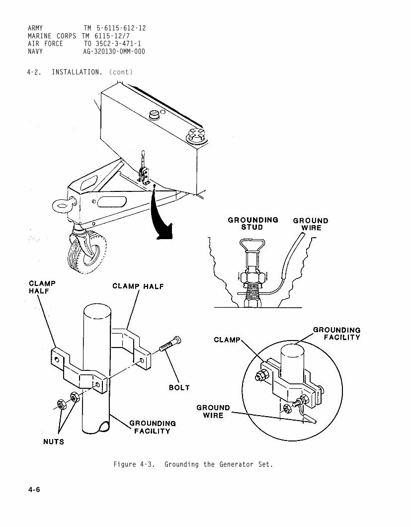
ARMY TM 5-6115-612-12MARINE CORPS TM 6115-12/7AIR FORCE TO 35C2-3-471-1NAVY AG-320130-0MM-000
4-2. INSTALLATION. (cont)
Figure 4-3. Grounding the Generator Set.
4-6

4-2. INSTALLATION. (cont)
a. General. (cont)
NOTE
If the generator set cannot begrounded using the followingmethods, refer to FM20-31.
b. Flightline Hardstand Ground Stud.
(1) Position generator set withineasy access of hardstand ground studand set handbrake.
(2) Using at least No. 6 AWG(American Wire Gauge) copper wire, cutlength of wire to fit between groundingstud on generator set and hardstandground stud.
(3) Strip 1-1/2 inches (38 mm)insulation, if any, from one end ofwire. Attach to grounding stud.
(4) Strip insulation from otherend of wire. Crimp wire on mountinglug. Attach mounting lug to hardstandground stud. Tighten connections toensure a good electrical bond.
c. underground Metallic Water Pipe.
(1) Uncover metallic water pipefor at least 10 feet (3.05 m) to ensurethat sufficient length is availablebetween any insulatedsections.
joints or
NOTE
If the distance betweenjoints or sections is10 feet (3.05 m), thismethod is unacceptable.
insulatedless thangrounding
4-3)inchfrom
ARMY TM 5-6115-612-12MARINE CORPS TM 6115-12/7AIR FORCE TO 35C2-3-471-1NAVY AG-320B0-0MM-000
(2) Attach ground rod (figureto ground cable by stripping 1(25 mm) of insulation, if any,ground cable. Insert stripped end
of cable in clamp enough to insure agood electrical bond.
(3) Place ground rod with at-tached ground cable along water pipe.Attach ground rod securely to waterpipe to ensure a good electrical bond.
(4) Cover water pipe with dirt.
(5) Position generator set withineasy access of grounding facility andset handbrake.
(6)(Americanlength ofstud onfacility.
(7)
Using at least No. 6 AWGWire Gauge) copperwire to fit betweengenerator set and
Strip 1-1/2 inches
wire, cutgroundinggrounding
(38 mm)insulation. if anv, from one end ofwire. Attach to grounding stud.
(8) Strip insulation from otherend of wire. Crimp wire on mountinglug. Attach mounting lug to hardstandground stud. Tightenensure a good electrical
d. Driven Metal Rod.
NOTE
connection tobond.
A driven metal ground rod musthave a minimum diameter of 5/8inch (16 mm) if solid, or 3/4inch (19 mm) if pipe. Rod mustbe driven to a minimum of 8 feet(2.45 m).
4-7

ARMY TM 5-6115-612-12MARINE CORPS TM 6115-12/7AIR FORCE TO 35C2-3-471-1NAVY AG-320B0-0MM-000
4-2. INSTALLATION. (cont)
d. Driven Metal Rod. (cont)
(1) Drive rod into ground a min-imum of 8 feet (2.45 m).
(2) Attach ground clamp securelyto top of rod.
(3) Position generator set withineasy access of grounding facility andset handbrake.
(4) Using at least No. 6 AWG(American Wire Gauge) copper wire, cutlength of wire to fit between groundingstud on generator set and groundingfacility.
(5) Strip 1-1/2 inches (38 mm)insulation, if any, from one end ofwire. Attach to grounding stud.
(6) Strip insulation from otherend of wire. Crimp wire or mountinglug. Attach mounting lug to hardstandground stud. Tighten connection toensure a good electrical bond.
e. Buried Metal Ground Plate.
NOTE
Metal groundminimum area(0.85 sq m),of 1/4 inchburied to afeet (1.22 m).
plate must have aof 9 square feeta minimum thickness(6.4 mm), and beminimum depth of 4
(1) Dig hole to size of plate.Ensure that bottom of hole is level sothat plate will rest evenly.
(2) Attach a spare service postconnector or ground stud to groundplate by drilling appropriate sizedholes and securing stud to plate withwasher, lockwasher, and nut. Attachground wire to stud.
(3) Cover ground plate with dirtand pack ground firmly over plate.
(4) Position generator set withineasy access of grounding facility andset handbrake.
(5) Using at least No. 6 AWG(American Wire Gauge) copper wire, cutlength of wire to fit between groundingstud on generator set” and groundingfacility.
(6) Strip 1-1/2 inches (38 mm) insulation, if any, from end of wire.Attach to grounding stud.
(7) Strip insulation from otherend of wire. Crimp wire on mountinglug. Attach mounting lug to hardstandground stud . Tighten connection toensure a good electrical bond.
4-8

ARMY TM 5-6115-612-12MARINE CORPS TM 6115-12/7AIR FORCE T0 35C2-3-471-1N A V Y AG-320B0-0MM-000
Section II. MOVEMENT TO A NEW WORKSITE
4-3. MOVING THE GENERATOR SET. The (2) Open pintle.generator set can be moved by forklift,towed by vehicle, moved with a hoistingdevice or helicopter, or manually moved WARNINGby two persons. Steps to prepare thegenerator set for movement are the same To prevent injury, do not attemptfor each method. to lift the front of the
a. Preparation for Movement.generator set with less than twopersons.
(1) Ensure that MASTER SWITCH isOFF and control panel access door issecured. (3) Raise front of generator set
(2) Ensure that all access coversand lock lunette eye into pintle.
and doors are secure.
(3) Ensure that power cable is(4) Pull release pin and swing
swivel caster into stowed positionproperly stowed and that ground wire isdisconnected.
until release pin engages hole.
b. Movement by Vehicle.c. Movement by Hoisting Device or
(1) Release handbrake (figure Helicopter. Refer to FM 55-450-1 for4-4) and guide generator set toward additional information on performingpintle of tow vehicle. helicopter external load missions.
Figure 4-4. Setting the Handbrake
4-9

ARMY TM 5-6115-612-12MARINE CORPS TM 6115-12/7AIR FORCE TO 35C2-3-471-1NAVY AG-320B0-0MM-000
4-3. MOVING THE GENERATOR SET. (cont)
c. Movement by Hoisting Deviceor Helicopter. (cont)
WARNING
The generator set weighs approx-imately 1175 pounds (533 kg). Toprevent injury, ensure that allcables. shackles. and the hoist-ing device are capable ofgenerator set.
CAUTION
To prevent damage, do notto lift the generatortiedown rings are damaged.
lifting
attemptset if
(1) Inspect tiedown rings.
(2) Attach appropriate cables andshackles to tiedown rings (figure4-5). Lift point shall be centeredabove the generator set.
(3) Attach cables and shackles tohoisting device. Using hoisting de-vice, slOWlY take a strain on cables.If necessary, placecables and generatorprevent damage.
padding betweenset housing to
W A R N I N G
To prevent injury, ensure thatall personnel stand clear whilegenerator set is suspended fromhoisting device.
(4) Slowly lift generator set andmove to new worksite.
4-10
d. Movement by Forklift. The gen-erator set can be moved short distanceswith a forklift. The generator setmust be lifted from the rear using theforklift tubes (figure 4-6).
e. Manual Movement. The generatorset can be manually moved by twopersons. One person is stationed atthe rear of the generator set to pushand the other person is stationed atthe front to guide/steer the generatorset.
4-4.Afterusing
a.
REINSTALLATION AFTER MOVEMENT.moving, install the generator setthe following procedures.
Movement by Vehicle.
(1) Pull release pin and lowerswivel caster to down position. Ensurethat release pin is securely engaged.
WARNING
To prevent injury, do not attempt tolift the front of the generator setwith less than two persons.
(2) Open pintle and disengagefrom lunette eye. Lower front of gen-erator set to ground.
WARNING
To prevent injury, ensure thathandbrake is set whenever thegenerator set is parked.
(3) Set handbrake (figure 4-4).

ARMY TM 5-6115-612-12MARINE CORPS TM 6115-12/7AIR FORCE TO 35C2-3-471-1NAVY AG-320B0-0MM-000
4-3. MOVING THE GENERATOR SET. (cont)
Figure 4-5. Cable/Sling Hookup for Moving Generator Set
4-11

ARMY TM 5-6115-612-12MARINE CORPS TM 6115-12/7AIR FORCE TO 35C2-3-471-1NAVY AG-320B0-0MM-000
4-3. MOVING THE GENERATOR SET. (cont)
Figure 4-6. Movement by Forklift
4-12

ARMY TM 5-6115-612-12MARINE CORPS TM 6115-12/7AIR FORCE T0 35C2-3-471-1
4-4. REINSTALLATION AFTER MOVEMENT.(cont)
a. Movement by Vehicle. (cont)
NAVY AG-320B0-0MM-000
(2) Set handbrake (figure 4-4).
(4) Continue installation (para-graph 4-2).
(3) Remove padding, if installed.b. Movement by Hoisting Device or
Helicopter.(4) Remove shackles and cables
from hoisting device.WARNING
To prevent injury, ensure thatall personnel stand clear while (5) Remove shackles and cablesgenerator set is suspended from from tiedown rings.hoisting device.
(1) Lower generator set to new (6) Continue installation (para-worksite. graph 4-2).
Section III. REPAIR PARTS; SPECIAL TOOLS; SPECIAL TEST,
MEASUREMENT AND DIAGNOSTIC EQUIPMENT (TMDE)
AND SPECIAL SUPPORT EQUIPMENT
4-5. TOOLS AND EQUIPMENT. N O 4-6. MAINTENANCE REPAIR PARTS.special tools or equipment are required Repair parts and equipment are listedby organizational maintenance personnel and illustrated in the Organizational,for maintenance of the generator set. Intermediate (Field), (Direct and Gen-
eral Support). and Depot MaintenanceRepair Parts and Special Tools Listmanual, TM 5-6115-612-24P.
4-13

A R M Y TM 5-6115-612-12MARINE CORPS TM 6115-12/7AIR FORCE TO 35C2-3-471-1N A V Y AG-320B0-0MM-000
Section IV. LUBRICATION INSTRUCTIONS
4-7. GENERAL. This section containsspecial organizational lubricationinstructions not included in the lubri-cation order. Army personnel shouldrefer to DA Pam 310-4 and Marine Corpspersonnel to SL-1-3 to ensure thelatest edition of the lubrication orderis used.
4-8. LUBRICATION BY ORGANIZATIONALMAINTENANCE. Lubrication tasks notcovered by the lubrication order(figure 3-2) consist of changing theoil and oil filter. Refer to figure4-7.
a. Draining Oil.
WARNING
To prevent injury, ensure thatthe handbrake is set whenever thegenerator set is parked.
(1) Set handbrake.
(2) Loosen turnlock fasteners andremove engine housing access cover.
Figure 4-7. Lubrication by Organizational Maintenance
4-14

ARMY TM 5-6115-612-12NAVY AG-320B0-0MM-000
4-8. LUBRICATION BY ORGANIZATIONALMAINTENANCE. (cont)
a. Dralning Oil. (cont)
(3) Unscrew and remove oil filtercap and oil level gage.
set, loosen (4) On underside of generator
turnlock fasteners andremove fuel/oil drain access cover.
(5) Position container belowdrain area. Container must be cap-able of holding a minimum of 5 quarts.
(6) Pull drain hose to outside ofgenerator set. Remove hose drainplug. Allow oil to drain completely.
(7) Using a filter wrench,unscrew and remove oil filter.
b. Filling the Reservoir.
of new
ToOilOil
(1) Lightly coat sealing gasketfilter with lubricating oil.
CAUTION
prevent damage, ensure thatfilter is replaced only withfilter P/N 101483 that
includes special packing (O-ring)requirements.
(2) Install new Oil filter.Tighten until just snug.
(3) Install hose drain plug indrain hose.
(4) Stow drain hose in generatorset.
(5) Install fuel/oil drain accesscover and secure with turnlockfasteners.
(6) Refer to lubrication plate ongenerator set for correct oil and fillreservoir with 4 quarts lubricating oil.Ensure that there is no leakage atdrain.
(7) Install oil level gage andoil filler cap. Hand tighten only.
(8)cover and
(9)Refer tothere are
Install engine housing accesssecure with turnlock fasteners
Perform operational check.paragraph 2-3. Ensure thatno leaks.
c. Changing Types of LubricationOil.
(1) Drain oil in accordancewith paragraph 4-8a.
(2) Refer to lubrication plateor lubrication order and select alter-nate type of oil. Fill reservoir inaccordance with paragraph 4-8b.
(3) Start generator set inaccordance with paragraph 2-3g and runfor 5 minutes. Secure generator set inaccordance with paragraph 2-5.
(4) Drain Oil in accordancewith paragraph 4-8a.
(5) Fill reservoir with alter-nate type of oil in accordance withparagraph 4-8b.
Change 1 4-15
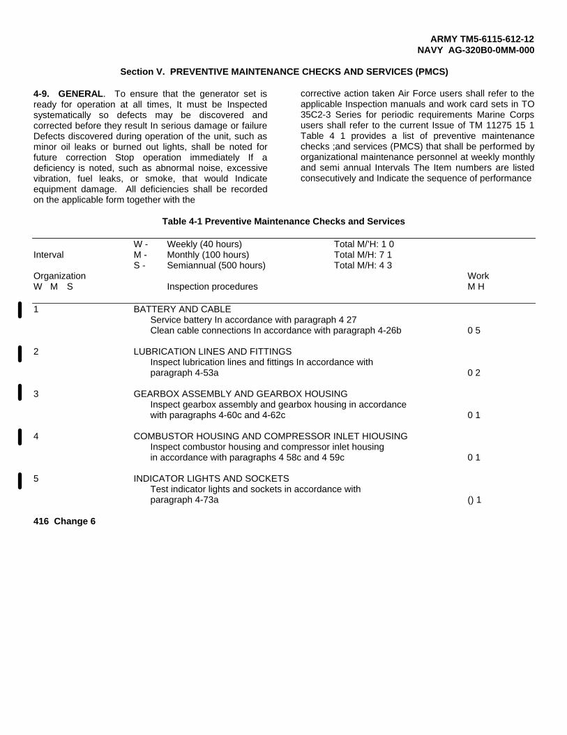
ARMY TM5-6115-612-12NAVY AG-320B0-0MM-000
Section V. PREVENTIVE MAINTENANCE CHECKS AND SERVICES (PMCS)
4-9. GENERAL. To ensure that the generator set isready for operation at all times, It must be Inspectedsystematically so defects may be discovered andcorrected before they result In serious damage or failureDefects discovered during operation of the unit, such asminor oil leaks or burned out lights, shall be noted forfuture correction Stop operation immediately If adeficiency is noted, such as abnormal noise, excessivevibration, fuel leaks, or smoke, that would Indicateequipment damage. All deficiencies shall be recordedon the applicable form together with the
corrective action taken Air Force users shall refer to theapplicable Inspection manuals and work card sets in TO35C2-3 Series for periodic requirements Marine Corpsusers shall refer to the current Issue of TM 11275 15 1Table 4 1 provides a list of preventive maintenancechecks ;and services (PMCS) that shall be performed byorganizational maintenance personnel at weekly monthlyand semi annual Intervals The Item numbers are listedconsecutively and Indicate the sequence of performance
Table 4-1 Preventive Maintenance Checks and Services
W - Weekly (40 hours) Total M/’H: 1 0Interval M - Monthly (100 hours) Total M/H: 7 1
S - Semiannual (500 hours) Total M/H: 4 3Organization WorkW M S Inspection procedures M H
1 BATTERY AND CABLEService battery In accordance with paragraph 4 27Clean cable connections In accordance with paragraph 4-26b 0 5
2 LUBRICATION LINES AND FITTINGSInspect lubrication lines and fittings In accordance withparagraph 4-53a 0 2
3 GEARBOX ASSEMBLY AND GEARBOX HOUSINGInspect gearbox assembly and gearbox housing in accordancewith paragraphs 4-60c and 4-62c 0 1
4 COMBUSTOR HOUSING AND COMPRESSOR INLET HIOUSINGInspect combustor housing and compressor inlet housingin accordance with paragraphs 4 58c and 4 59c 0 1
5 INDICATOR LIGHTS AND SOCKETSTest indicator lights and sockets in accordance withparagraph 4-73a () 1
416 Change 6

ARMY TM5–6115–612–12NAVY AG-320B0-0MM-000
4-9. GENERAL. (cont)
Table 4-1. Preventive Maintenance Checks and Services
W - Weekly (40 hours) Total M/H: 1.0Interval M - Monthly (100 hours) Total M/H: 7.1
S - Semiannual (500 hours) Total M/H: 4.3
Organization WorkW M S Inspection procedures M/H
6
7
8
9
10
11
29
30
12
31
13
14
BLEED AIR CONNECTOR AND BLEED AIR LINEInspect bleed air line connector and bleed air line in accordancewith paragraphs 4-18a and 4-19a.
GECM WIRING HARNESSESInspect GECM wiring harnesses in accordance with paragraph 4-28a
SLAVE RECEPTACLEInspect slave receptacle for damage.
GENERATOR ELECTRONIC CONTROL MODULE (GECM)Inspect GECM for damage and loose connections.
CIRCUIT BREAKERInspect circuit breaker for damage and proper operation.
ELECTRICAL FUEL TRANSFER PUMPInspect and service electrical fuel transfer pump in accordance withparagraphs 4-37a, 4-37b and 4-37c.
Test semiannually in accordance with paragraph 4-37a.
PRIMARY FUEL (FLUID) FILTERChange filter element in accordance with paragraph 4-38a.
ENGINE FUEL TANKInspect engine fuel tank in accordance with paragraph 3-9b.
SECONDARY FUEL (FLUID) FILTERChange filter element (paragraph 4-40).
SOLENOID VALVEInspect valve in accordance with paragraph 3-9.
FUEL INJECTION NOZZLESInspect atomizers in accordance with paragraph 4-43.
0.1
0.1
0.1
0.1
0.1
0.4
0.5
0.2
0.2
0.1
0.2
2.5
Change 2 4-17

ARMY TM 5-6115-612-12NAVY AG-320B0-0MM-000
4-9. GENERAL. (cont)
Table 4-1. Preventive Maintenance Checks and Services
W - Weekly (40 hours) Total M/H: 1.0Interval M - Monthly (100 hours) Total M/H: 7.1
S - Semiannual (500 hours) Total M/H: 4.3
Organization WorkW M S Inspection procedures M/H
32
15
33
16
34
17
18
35
19
20
21
22
23
Service semiannually in accordance with paragraph 4-43c.
IGNITION SYSTEM HIGH TENSION LEADInspect spark igniter in accordance with paragraph 4-46b.
Test semiannually in accordance with paragraph 4-45.
SPARK IGNITERInspect spark igniter in accordance with paragraph 4-47c.
Test semiannually in accordance with paragraph 4-45.
OIL DRAINInspect oil drain for leaks in accordance with paragraph 4-52.
OIL COOLERInspect oil cooler in accordance with paragraph 4-54a.
Service oil cooler semiannually in accordance with paragraph 4-54b.
ENGINE RIM CLENCHING CLAMPInspect rim clenching clamp (V-clamp) in accordance withparagraph 4-57.
STARTER MOUNTING PLATEInspect and service starter mounting plate in accordance withparagraph 4-61.
ENGINE ELECTRONIC CONTROL MODULE (EECM)Inspect EECM for damage and loose connections.
LOW OIL PRESSURE SHUTDOWN SWITCHInspect low oil pressure shutdown switch in accordance withparagraph 4-67a.
CONTROL PANELInspect control panel in accordance with paragraph 4-68a.
0.5
0.2
0.4
0.2
0.4
0.1
0.6
0.4
0.1
0.2
0.1
0.2
0.2
4-18 Change 2

ARMY TM 5-6115-612–12NAVY AG–320B0–0MM–000
4-9. GENERAL. (cont)
Table 4-1. Preventive Maintenance Checks and Services
W-Weekly (40 hours) Total M/H: 1.0Interval M - Monthly (100 hours) Total M/H: 7.1
S - Semiannual (500 hours) Total M/H: 4.3
Organization WorkW M S Inspection procedures M/H
24
25
26
27
36
28
37
38
39
MASTER SWITCHTest MASTER SWITCH in accordance with paragraph 4-70a.
POTENTIOMETER (VOLTAGE ADJUST)Test potentiometer in accordance with paragraph 4-77a.
SWITCHESTest switches in accordance with paragraph 4-78a.
MAGNETIC (OUTPUT) CONTACTORInspect magnetic contactor in accordance with paragraph 4-83a.
Test semiannually in accordance with paragraph 4-83b.
BRAKE CONTROLService the brake control in accordance with paragraph 4-90a.
IGNITION COILTest ignition coil in accordance with paragraph 4-45.
MONOPOLE SPEED SENSORTest monopole speed sensor in accordance with paragraph 4-65a.
THERMOCOUPLETest thermocouple in accordance with paragraph 4-66a.
0.2
0.3
0.5
0,3
0.6
0.5
0.4
0.4
0.4
Change 2 4-19

ARMYNAVY
4-10.
a.
TM 5-6115-612-12AG-320B0-0MM-000
Section VI. TROUBLESHOOTING
GENERAL.
Troubleshooting Procedures. This b. Tests /Inspect ions and Correctivesection consists of a troubleshooting Actions. Perform the tests/inspectionsindex and organizational trouble=shooting procedures. Table 4-2 pro-vides an index to assist in locating aspecific malfunction. The first columnlists the operational mode or conditionof the generator set. The secondcolumn gives a very brief descriptionof the malfunction indication (usuallya red malfunction indicator light onthe control panel). The third columnprovides the malfunction number thatrefers maintenance personnel to thetroubleshooting procedures in table4-3. Table 4-3 lists the malfunctionsby number and provides troubleshootingprocedures. malfunction followed by tests and inspections thatwill help determine the probable causeand the corrective action to take.Refer also to the foldout schematicsFO-3 and FO-4 in the back of thismanual.
and corrective actions in the orderlisted. After repair, always repeatthe step or corrective action in table4-3 to make sure the fault has beencorrected or traced properly, or thatother faults do not exist. This manualcannot list all malfunctions that mayoccur, nor all tests or inspections andcorrective actions. If a malfunctionis not listed or cannot be corrected bylisted corrective actions, notifysupervisor.
NOTEE a c h
Before using this table, ensurethat al 1 applicable operatingchecks have been performed and itis verified that a malfunctionexists.
Table 4-2. Troubleshooting Index
Mode/condition Malfunction indication Malfunction
Prestart PANEL LIGHTS DO NOT COME ON. 1
DC CIRCUIT BREAKER TRIPS WHEN BATTERYIS CONNECTED. 2
DC CIRCUIT BREAKER TRIPS WHEN MASTERSWITCH IS SET TO RUN. 3
NO ELECTRICAL POWER TO CONTROL PANELAND DC CIRCUIT BREAKER HAS BEEN RESET. 4
No starter engagement PLACING MASTER SWITCH IN START POSITIONDOES NOT CRANK ENGINE. 5
4-20

ARMY TM 5-6115-612-12MARINE CORPS TM 6115-12/7AIR FORCE TO 35C2-3-471-1NAVY AG-320B0-0MM-000
4-10. GENERAL. (cont)
Table 4-2. Troubleshooting Index
Mode/condition Malfunction indication Malfunction
Before READY TO LOAD-starter engages
After READY TO LOAD -no load condition
ENGINE OVERTEMP INDICATOR COMES ON BEFOREENGINE START.
STARTER ATTEMPTS TO OPERATE BUT CHATTERS,ENGAGES BUT DOES NOT TURN, OR TURNS BUTNO INDICATION OF IGNITION.
STARTER ENGAGES BUT UNIT SHUTS DOWN WITHENGINE OVERTEMP LIGHT.
ENGINE STARTS TO ACCELERATE BUT SHUTSDOWN WITH OVERSPEED LIGHT.
UNIT ATTAINS IGNITION AND RUNS BUT READYTO LOAD LIGHT DOES NOT COME ON. NOMALFUNCTION LIGHTS.
GENERATOR SET SHUTS DOWN WITH LOW OILPRESS MALFUNCTION LIGHT AFTER READYTO LOAD BUT STILL IN NO LOAD.
GENERATOR SET REACHES READY TO LOAD BUTSHUTS DOWN WITH ENGINE OVERTEMP MALFUNC-TION LIGHT WHILE STILL IN NO LOAD.
GENERATOR SET REACHES READY TO LOAD BUTSHUTS DOWN WITH ENGINE OVERSPEED MAL-FUNCTION LIGHT WHILE STILL IN NO LOAD.
GENERATOR SET REACHES READY TO LOAD BUTSHUTS DOWN WITH OVERLOAD MALFUNCTIONLIGHT WHILE STILL IN NO LOAD.
GENERATOR SET REACHES READY TO LOAD BUTSHUTS DOWN WITH OVERVOLTAGE MALFUNCTIONLIGHT.
GENERATOR SET REACHES READY TO LOAD BUTSHUTS DOWN WITH GENERATOR OVERTEMPMALFUNCTION LIGHT.
GENERATOR SET REACHES READY TO LOAD BUTSHUTS DOWN WITH UNDERVOLTAGE MALFUNCTIONLIGHT.
6
7
8
9
10
11
12
13
14
15
16
17
Change 1 4-21

A R M Y TM 5-6115-612-12MARINE CORPS TM 6115-12/7AIR FORCE T0 35C2-3-471-1NAVY AG-320B0-0MM-000
4-10. GENERAL. (cont)
Table 4-2. Troubleshooting Index
Mode/condition Malfunction indication Malfunction
During full loadcondition
INTERMITTENT OR NO INDICATION OF BATTERYCHARGE CURRENT ON BATTERY CHARGING METER.
PLACING CONTACTOR SWITCH IN CLOSED POSI-TION DOES NOT CAUSE CLOSED INDICATORLIGHT TO COME ON.
HOURMETER DOES NOT OPERATE.
NO VOLTAGE INDICATED ON VOLTAGE METER.
AN ATTEMPT TO LOAD DOES NOT SHOW ANYINDICATION ON OUTPUT CURRENT METER.
VOLTAGE METER INDICATES VOLTAGE BUTUNABLE TO ADJUST WITH VOLTAGE ADJUSTKNOB.
GENERATOR SET SHUTS DOWN UNDER FULL LOADWITH ENGINE OVERTEMP MALFUNCTION LIGHT.
GENERATOR SET SHUTS DOWN UNDER FULL LOADWITH OVERSPEED MALFUNCTION LIGHT.
GENERATOR SET SHUTS DOWN UNDER FULL LOADWITH OVERLOAD MALFUNCTION LIGHT.
GENERATOR SET SHUTS DOWN UNDER FULL LOADWITH OVERVOLTAGE MALFUNCTION LIGHT.
GENERATOR SET SHUTS DOWN UNDER FULL LOAD
18
19
20
21
22
23
24
25
26
27
28WITH GENERATOR OVERTEMP MALFUNCTION LIGHT.
GENERATOR SET SHUTS DOWN UNDER FULL LOAD 29WITH UNDERVOLTAGE MALFUNCTION LIGHT.
Any mode/condition - OIL SMOKE COMING FROM EXHAUST DURING 30no malfunction lights OPERATION.or automatic shutdown
SCRAPING/RUBBING NOISES DURING SHUTDOWN. 31
4 - 2 2

ARMY TM 5-6115-612-12NAVY AG-320B0-0MM-000
4-10. GENERAL. (cont)
Table 4-3. Organizational Troubleshooting
MALFUNCTIONTEST OR INSPECTION
CORRECTIVE ACTION
1. PANEL LIGHTS DO NOT COME ON.
Step 1. Ensure that battery cable plug connector is securely connected.
Tighten battery cable plug connector.
Step 2. Ensure that DC CIRCUIT BREAKER is pressed in.
If pressed in, go to Step 3.
If DC CIRCUIT BREAKER does not stay pressed in, test/replace DC CIRCUITBREAKER (paragraph 4-31).
Step 3. Check light bulbs by replacing with new ones.
If still no lights, go to Step 4.
Step 4. Place PANEL LIGHTS switch in ON position. Check for 24 Vdc between terminal 1 (+)and terminal 2(-) of affected light (DS11 or DS12).
If no voltage, go to Step 5.
If voltage is good, replace lamp socket (paragraph4-31).
Step 5. Check for 24 Vdc at PANEL LIGHTS switch S3-3(+) and TB3(-).
If no voltage, go to Step 6.
WARNING
To prevent injury, ensure that battery is disconnectedbefore repairing or replacing damaged wires.
If voltage is present, disconnect battery. Visually inspect and perform continuitycheck on wires U128A18 and V102U18N. Replace wires if damaged or nocontinuity.
Step 6. Check for 24 Vdc at PANEL LIGHTS switch S3-2 and TB3-2.
If no voltage, go to Step 7.
Change 5 4-23

ARMY TM 5-6115-612-12NAVY AG-320B0-0MM-000
4-10. GENERAL. (cont)
Table 4-3. Organizational Troubleshooting - Continued
MALFUNCTIONTEST OR INSPECTION
CORRECTIVE ACTION
If voltage present, replace PANEL LIGHTS switch (paragraph 4-78b).
Step 7. Check for 24 Vdc at DC CIRCUIT BREAKER CB1-2(+) and TB3-2(-).
If no voltage, perform steps under Malfunction 4.
2. DC CIRCUIT BREAKER TRIPS WHEN BATTERY IS CONNECTED.
Step 1.
Step 2.
Step 3.
Step 4.
WARNING
To prevent injury, ensure that battery is disconnectedbefore repairing or replacing damaged wires.
Visually inspect the underside of control panel for shorts and damaged wires.
Remove shorts and repair damaged wires.
Disconnect battery cable plug connector. Disconnect P105A14 from TB3-5. Reset DCCIRCUIT BREAKER by pressing in reset button.
If reset button remains in, go to Step 3.
If breaker trips, visually check wire P105B14 for shorts to control panel. Replaceas necessary.
Connect battery plug connector to battery. Reconnect wire P105A14. Disconnect wireP105C18 from TB3-5. Reset DC CIRCUIT BREAKER.
If breaker trips, go to Step 4.
If reset button remains in, visually check wire P105C18 and malfunction indicatorlight sockets (DS3-DS10) for shorts to control panel. Replace as necessary.
Reconnect wire P105C18. Disconnect wire P105D18 from TB3-6. Reset DC CIRCUITBREAKER.
4-24

ARMY TM 5-6115-612-12NAVY AG-320B0-0MM-000
4-10. GENERAL. (cont)
Table 4-3. Organizational Troubleshooting - Continued
MALFUNCTIONTEST OR INSPECTION
CORRECTIVE ACTION
If reset button remains in, check wire P105D18 and malfunction indicator lightsockets (DS3-DS10) for damage and shorts to control panel. Repair or replace asnecessary.
If breaker trips, check wire P105F18 to MASTER SWITCH (S1) for shorts tocontrol panel. Replace as necessary.
3. DC CIRCUIT BREAKER TRIPS WHEN MASTER SWITCH IS SET TO RUN.
Step 1.
Step 2.
Step 3.
Step 4.
Reset circuit breaker. With MASTER SWITCH in OFF position, disconnect P2 fromGECM. Move MASTER SWITCH to RUN.
If breaker trips, reconnect P2 and go to Step 2.
If reset button remains in, replace GECM (paragraph 4-30).
Reset circuit breaker. With MASTER SWITCH in OFF position, disconnect P6 fromEECM. Move MASTER SWITCH to RUN.
If breaker trips, reconnect P6 and go to Step 3.
If reset button stays in, replace EECM (paragraph 4-64).
Reset circuit breaker. With MASTER SWITCH in OFF position, disconnect P17 fromtransfer pump. Move MASTER SWITCH to RUN.
If breaker trips, reconnect PI 7 and go to Step 4.
If reset button stays in, check pump (paragraph 4-37).
Disconnect wire U117B1 8 from TB3-19. Measure resistance from disconnect wire toTB3-1.
WARNING
To prevent injury, ensure that battery is disconnectedbefore repairing or replacing damaged wires.
If resistance is less than 2 ohms, check wires U117B18 and U117C18, MASTERSWITCH, and connector P6 for shorts. Replace as necessary.
Change 5 4-25

ARMY TM 5-6115-612-12NAVY AG-320BO-OMM-OO0
4-10. GENERAL. (cont)
Table 4-3. Organizational Troubleshooting - Continued
MALFUNCTIONTEST OR INSPECTION
CORRECTIVE ACTION
If resistance more than 2 ohms, check wire U117A16 from P17-A to TB3-19.Repair or replace as necessary.
4. NO ELECTRICAL POWER TO CONTROL PANEL AND DC CIRCUIT BREAKER HAS BEEN RESET.
Step 1.
Step 2.
Step 3.
Check for loose battery cable plug connector at battery.
Tighten loose connector.
Remove air baffle (paragraph 4-22a). Check for 24 Vdc at terminal board TB1-2(-) andterminal TB1-3(+).
If 24 Vdc present, go to Step 3.
WARNING
To prevent injury, ensure that battery is disconnectedbefore repairing or replacing damaged wires.
If no voltage present, visually inspect for damage and perform continuity checkson following:
P103C00 (TB1-4 to bulkhead connector)V102H00 (TB1-2 to bulkhead connector)P103A00 (bulkhead connector to P20(+))V102AJ00 (bulkhead connector to P20(-))
Replace wires if damaged or no continuity.
Ensure that DC CIRCUIT BREAKER is reset. Check for 24 Vdc between DC CIRCUITBREAKER pin 2(+) and terminal board TB3-2(-).
If 24 Vdc present, go to Step 4.
If no voltage, check for 24 Vdc between DC CIRCUIT BREAKER pin 1(+) andterminal board TB3-2(-). If voltage present, replace DC CIRCUIT BREAKER(paragraph 4-78b). If no voltage, visually inspect for damage and perform continu-ity check on wires P103E14 (20 amp shunt R1-A to TB3-4), P103B14 (20 ampshunt R1-B to TB1-3), and V012J18 (TB3-2 to TB1-2). Replace wires if damagedor no continuity.
4-26

ARMY TM 5-6115-612-12MARINE CORPS TM 6115-12/7AIR FORCE T0 35C2-3-471-1NAVY AG-320B0-0MM-000
4-10. GENERAL. (cont)
Table 4-3. Organizational Troubleshooting - Continued
MALFUNCTIONTEST OR INSPECTION
CORRECTIVE ACTION
5.
Step 4. Check for 24 Vdc between MASTER SWITCH S1 pin 2(+) and TB3-2(-).
If 24 Vdc present, go to Step 5.
If no voltage, disconnect battery cable plug connector.Perform continuity checks on wire P105F18 (S1-5 to TB3-6)and jumper (TB3-5 to TB3-6). Replace if damaged or nocontinuity.
Step 5. Move MASTER SWITCH to RUN position and check for 24 Vdc on S1-1.
If 24 Vdc present, go to Step 6.
If no voltage, replace MASTER SWITCH (paragraph 4-70b).
Step 6. Remove connector P6 from EECM. Check for 24 Vdc betweenP6-M(+) and P6-N(-).
If 24 Vdc present, replace EECM (paragraph 4-64).
If no voltage, disconnect battery cable plug connector frombattery. Visually inspect for damaqe and performcontinuity check V102N18N (TB3-1 to
Replace if damaged
on wires U117C18 (S1-1 to P6-M) andP6-N) .
or no continuity.
PLACING MASTER SWITCH IN START POSITION DOES NOT CRANK
Step 1. Perform Malfunction 1, Steps 6 and 7.
If voltage present, go to Step 2.
If no voltage, go to Malfunction 4.
Step 2. Disconnect connector P6 from EECM. With
ENGINE.
MASTER SWITCH in STARTposition, check for 24 Vdc between P6-J(+) and P6-N(-).
If voltage present, go to Step 3.
If no voltage, go to Step 4.
Change 1 4-27

ARMY TM 5-6115-612-12MARINE CORPS TM 6115-12/7AIR FORCE T0 35C2-3-471-1NAVY AG-320B0-0MM-000
4-10. GENERAL. (cont)
Table 4-3. Organizational Troubleshooting - Continued
MALFUNCTIONTEST OR INSPECTION
CORRECTIVE ACTION
Step 3. Move MASTER SWITCH to START position and release to RUNposition. Check for 24 Vdc at small stud on starter where wireK154A18(+) connects, and at ground stud(-) on starter.
If no voltage, go to Step 5.
If voltage present, perform maintenance on starter(paragraph 4-32).
Step 4. Check for 24 Vdc at MASTER SWITCH S1-4(+) and TB3-2(-) withMASTER SWITCH in START position.
If no voltage, perform maintenance on MASTER SWITCH(paragraph 4-70).
WARNING
To prevent injury, ensure thatbattery is disconnected beforerepairing or replacing damagedwires.
If voltage present, disconnect battery cable plugconnector. Visually check and perform continuity check onwire U120A18 (S1-4 to P6-J). Replace wire if damaged or nocontinuity.
Step 5. Check for 24 Vdc between positive (+) and negative (-) starterterminals.
If voltage present, go to Step 6.
If no voltage, replace EECM (paragraph 4-64).
Step 6. Disconnect P5 from EECM and check for 24 Vdc between J5-K(+)and J5-P(-).
If no voltage
If voltageconnector. Viwire K154A18damaged or no
replace EECM (paragraph 4-64).
present, disconnect battery cable plugsually check and perform continuity checks on(P5-K to starter solenoid). Replace wire ifcontinuity.
4-28

ARMY TM 5-6115-612-12MARINE CORPS TM 6115-12/7AIR FORCE T0 35C2-3-471-1
4-10. GENERAL. (cont)
NAVY AG-320B0-0MM-000
Table 4-3. Organizational Troubleshooting - Continued
MALFUNCTIONTEST OR INSPECTION
CORRECTIVE ACTION
6. ENGINE OVERTEMP INDICATOR COMES ON BEFORE ENGINE START.
WARNING
To prevent injury, ensure thatbattery is disconnected beforerepairing or replacing damagedwires.
Step 1. Disconnect connector P5 from EECM. Disconnect battery cableplug connector. Check continuity between P5-R and P5-S.Reading should be less than 100 ohms.
If open, go to Step 2.
If continuity indicated, measure P5-R and P5-S to good caseground. Reading should show infinity. If reading showsInfinity, replace EECM (paragraph 4-64). If resistance ismeasured, go to Step 2.
Step 2. Disconnect one connector from thermocouple. Perform continuitycheck between thermocouple terminals. Reading should show lessthan 100 ohms.
If no continuity is indicated, replace thermocouple(paragraph 4-66b).
If continuity is indicated, visually inspect for damage andperform continuity checks on wires U145A (to P5-R) andU146A (to P5-S). Repair or replace wires if damaged or nocontinuity.
7. STARTER ATTEMPTS TO OPERATE BUT CHATTERS, ENGAGES BUT DOES NOT TURN, OR TURNSBUT NO INDICATION OF IGNITION.
Step 1. Move MASTER SWITCH to START position and check voltage at largestuds on starter.
If voltage is below 14 Vdc, test battery (paragraph 4-27).Replace or recharge as necessary.
If voltage is above 14 Vdc, perform maintenance on starter(paragraph 4-32).
4-29

ARMY TM 5-6115-612-12MARINE CORPS TM 6115-12/7AIR FORCE TO 35C2-3-471-1NAVY AG-320B0-0MM-000
4-10. GENERAL. (cont)
Table 4-3. Organizational Troubleshooting - Continued
MALFUNCTIONTEST OR INSPECTION
CORRECTIVE ACTION
If voltage is above 14 Vdc and starter chatters, removestarter (paragraph 4-32b) and send to Direct Support.
8. STARTER ENGAGES BUT UNIT SHUTS DOWN WITH ENGINE OVERTEMP LIGHT.
Step 1. Check air filter and compressor inlet housing for obstructions.
Clear obstructions.
Step 2. Check exhaust door for obstructions and proper operation.
Clear obstructions. Refer to Direct Support formaintenance of inoperable exhaust door.
Step 3. Unscrew cover from slave receptacle. Move MASTER SWITCH toSTART while measuring voltage at slave receptacle contacts.
If voltage remains above 14 Vdc, go to Step 4.
If voltage below 14Vdc, check battery (paragraph 4-27).
Step 4. Connect thermometer (for K-type thermocouple) to E G Tthermocouple. Start engine and monitor temperature.
If temperature remains below 1360°F, perform tests andinspections under Malfunction 6.
If temperature is abovelevel of maintenance.
9. ENGINE STARTS TO ACCELERATE BUT SHUTS DOWN
Step 1. Ensure that EECM connectorare securely connected.
1360°F, refer engine to next higher
WITH OVERSPEED LIGHT.
P5 and speed sensor connector P13
Tighten loose connectors.
Step 2. Disconnect P5 from EECM. Measure resistance from P5-F to P5-G.
If resistance is less than 1.8k ohms or greater than 2.2kohms, go to Step 3.
If resistance is OK, go to Step4.
4-30

4-10. GENERAL. (cont)
ARMY TM 5-6115-612-12MARINE CORPS TM 6115-12/7AIR FORCE TO 35C2-3-471-1NAVY AG-320B0-0MM-000
Table 4-3. Organizational Troubleshooting - Continued
MALFUNCTIONTEST OR INSPECTION
CORRECTIVE ACTION
Step 3. Reconnect P5. Disconnect P13 from speed sensor and measureresistance between pins of speed sensor and between eachand case of speed sensor.
If resistance is less than 1.8k ohms or greater thanohms or if resistance between either pin and case isthan 200k ohms, replace speed sensor (paragraph 4-65).
WARNING
To prevent injury, ensure thatbattery is disconnected beforerepairing or replacing damagedwires.
If resistance is OK. disconnect batterv cable
pin
2.0kless
plugconnector. Visually inspect and perform continuity checkson wires U150A18 and U151A18. Replace if necessary.
Step 4. Open exhaust door and check for heat, an indication that enginehas had ignition.
If no heat, go to Step 5.
If heat present, replace EECM (paragraph 4-64) with knowngood unit and attempt restart. If problem still exists,refer engine to next higher level of maintenance.
Step 5. Check for odor of fuel and fuel sprayed in exhaust duct.
If no strong fuel odor or sign of fuel, go to Step 6.
If fuel or fuel odor is present, perform complete test ofignition system (paragraph 4-45).
Step 6. Place MASTER SWITCH in RUN position and verify that transferpump is running. There isthe pump is running.
If pump is not running,
If pump is running,
a very distinct clicking noise when
go to Step 7.
service and test pump (paragraph4-37). If pump tests OK, go to Step 9.
4-31

ARMY TM 5-6115-612-12MARINE CORPS TM 6115-12/7AIR FORCE TO 35C2-3-471-1NAVY AG-320B0-0MM-000
4-10. GENERAL. (cont)
Table 4-3. Organizational Troubleshooting - Continued
MALFUNCTIONTEST OR INSPECTION
CORRECTIVE ACTION
Step 7. Disconnect connector P17 from transfer pump and check for 16-24Vdc between pins A and B.
If no voltage, go to Step 8.
If voltage present, service and test transfer pump inaccordance with paragraph 4-37. If transfer pump tests OK, go to Step 9.
Step 8. Disconnect battery cable plug connector from battery. Checkfor continuity between TB3-19 and P17-A, and between TB3-1 andP17-B.
If there is continuity, replace EECM (paragraph 4-64).
If no continuity, repair or replace wires as necessary.
Step 9. Service primary fuel filter (paragraph 4-38a) and secondaryfuel filter (paragraph 4-40a).
Step 10. Disconnect connector P14 from high pressure fuel pump.Carefully connect voltmeter across connector pins P14-A andP14-B. Check for voltage that varies between 6 and 22 Vdc.
If voltage incorrect, go to Step 11.
If voltage correct, replace high pressure fuel pump inaccordance with paragraph 4-41. If problem continues, goto Step 12.
Step 11. Disconnect P5 from EECM and check continuity between P5-L and P14-A and between P5-M and P14-B.
Replace wires if damaged or no continuity.
If there is continuity, replace EECM (paragraph 4-64).
Step 12. Disconnect P12 from solenoid valve. Attempt restart whilechecking for 16-24 Vdc between pins P12-A and P12-B.
If no voltage, go to Step 13.
If voltage present, replace solenoid valve (paragraph 4-42).
4-32

ARMY TM 5-6115-612-12MARINE CORPS TM 6115-12/7AIR FORCE T0 35C2-3-471-1
4-10. GENERAL. (cont)
NAVY AG-320B0-OMM-000
Table 4-3. Organizational Troubleshooting - Continued
MALFUNCTIONTEST OR INSPECTION
CORRECTIVE ACTION
Step 13. Disconnect P5 from EECM and check continuity between P5-D andP12-A, and between P5-E and P12-B.
Replace wires if damaged or no continuity.
If there is continuity, replace EECM (paragraph 4-64).
10. UNIT ATTAINS IGNITION AND RUNS BUT READY TO LOAD LIGHT DOES NOT COME ON.NO MALFUNCTION LIGHTS.
WARNING
To prevent injury, ensure thatbattery is disconnected beforerepairing or replacing damagedwires.
Step 1. Check VOLTAGE meter on control panel for voltage indication of20-35 Vdc.
If VOLTAGE meter reads zero or very low voltage, go toStep 2.
If voltage is correct, shut down generator set. Press totest READY TO LOAD light. If light does not come on,replace lamp (paragraph 4-74). If lamp is good, opencontrol panel and check for 24 Vdc between pins of READY TOLOAD light (DS1). If voltage is correct, replace socket(paragraph 4-73b). If no voltage, disconnect battery cableplug connector. Inspect and check continuity on wiresU122A18 and V102S18N. Replace if damaged or no continuity.
Step 2. With unit running, monitor BATTERY CHARGING meter.
If BATTERY CHARGING meter reads less than -5 amps, shutdown generator set and go to Step 3.
If BATTERY CHARGING meter reads more than -5 amps and morethan 20 seconds have passed since attempted start, shutdown generator set. It may be necessary to disconnectbattery to stop unit. Inspect starter and solenoid fordamage and to see if starter is engaged. Replace starterif necessary (paragraph 4-32b).
4-33

ARMY TM 5-6115-612-12MARINE CORPS TM 6115-12/7AIR FORCE TO 35C2-3-471-1NAVY AG-320B0-0MM-000
4-10. GENERAL. (cont)
Table 4-3. Organizational Troubleshooting - Continued
MALFUNCTIONTEST OR INSPECTION
CORRECTIVE ACTION
Step 3. While starting generator set, check voltage on high pressurefuel pump connector J14-A(+) and J14-B(-).
If voltage is 16-24 Vdc, go to Step 4.
If voltage less than 16 Vdc, check battery voltage.Replace or recharge battery (paragraph 4-27). If batterygood, replace EECM (paragraph 4-64).
Step 4. Check for 24 Vdc on transfer pump connector P17-A(+) andP17-B(-).
If 16-24Vdc present, go to Step 6.
If no voltage, disconnect battery cable plug connector.Visually inspect for damage and check continuity on wiresU117A16 (TB3-19 to P17-A) and V102AF16 (TB3-1 to P17-B).Replace if damaged, shorted, or no continuity.
Step 5. Check fuel flow of transfer pump (paragraph 4-37).
If fuel flow is correct, go to Step 6.
If fuel flow is low, service transfer pump (paragraph 4-37)and connecting fuel lines. Replace pump if necessary.
Step 6. Disconnect outlet fuel line from solenoid valve. Direct fueloutlet line into a suitable container. Start generator set andcheck fuel flow.
If fuel flow good, refer to next higher maintenance level.
If fuel flow appears low, ensure that solenoid valve fuellines are not restricted. If no restrictions, replacesolenoid valve (paragraph 4-42).
11. GENERATOR SET SHUTS DOWN WITH LOW OIL PRESS MALFUNCTION LIGHT AFTER READY TOLOAD BUT STILL IN NO LOAD.
Step 1. Inspect generator set lubrication system for leaks and damagedhoses (Section XII).
Tighten loose fittings and replace damaged hoses.
4-34

ARMY TM 5-6115-612-12NAVY AG-320B0-OMM-000
4-10. GENERAL. (cont)
Table 4-3. Organizational Troubleshooting - Continued
MALFUNCTIONTEST OR INSPECTION
CORRECTIVE ACTION
Step 2. Check oil levelAdd oil as required.
WARNINGTo prevent Injury, ensure that battery Is disconnected before repairing or replacing damaged wires.
Step 3 Disconnect connector P10 from low oil pressure switch Install jumper wire between pins Aand B of connector Place MASTER SWITCH In RUN position
If LOW OIL PRESS light goes off, go to Step 4.
If LOW OIL PRESS light stays on, visually inspect and check continuity on wiresQ147A18 (P10-A to P5-A) and U148A18 (P10-B to P5-B) Replace if damaged or nocontinuity. If wires good, replace EECM (paragraph 4-64).
Step 4. Install pressure gage between oil pump and low oil pressure switch. Disconnect connectorP10 from switch and install jumper wire between pins A and B of connector Start generatorset and check for correct oil pressure (25-40psi)
If oil pressure Is normal, perform maintenance on low oil pressure switch(paragraph 4-67)
If oil pressure Is low, refer to next higher level of maintenance.
If oil pressure is high, refer to Section XII and inspect for clogged oil cooler, hoses, oilfilter, or gearbox vent Unclog and clean as necessary.
12 GENERATOR SET REACHES READY TO LOAD BUT SHUTS DOWN WITH ENGINE OVERTEMP MALFUNCTIONLIGHT WHILE STILL IN NO LOAD
Step 1. Perform Step 1 of Malfunction 6.
Step 2. Perform Step 4 of Malfunction 8.
Change 6 4-35

ARMY TM 5-6115-612-12MARINE CORPS TM 6115-12/7AIR FORCE TO 35C2-3-471-1NAVY AG-320B0-0MM-000
4-10. GENERAL. (cont)
Table 4-3. Organizational Troubleshooting - Continued
MALFUNCTIONTEST OR INSPECTION
CORRECTIVE ACTION
13. GENERATOR REACHES READY TO LOAD BUT SHUTS DOWN WITH OVERSPEED MALFUNCTIONLIGHT WHILE STILL IN NO LOAD.
Step 1. Ensure that generator set has not run out of fuel.
Fill fuel tank.
Step 2. Determine if there was a noticeable change in engine RPM priorto shutdown. This condition can be identified by a change inpitch while engine is running.
If RPM increased, perform maintenance on monopole speedsensor (paragraph 4-65). If speed sensor OK, replace EECM(paragraph 4-64).
If RPM decreased, inspect all fuel fittings for leaks(paragraphs 4-35, 4-36). Tighten as necessary. If problemstill exists, replace high pressure pump (paragraph 4-41).
14. GENERATOR SET REACHES READY TO LOAD BUT SHUTS DOWN WITH OVERLOAD MALFUNCTIONLIGHT WHILE STILL IN NO LOAD.
WARNING
To prevent injury, ensure thatbattery is disconnected beforerepairing or replacing damagedwires.
Step 1. Monitor VOLTAGE and OUTPUT CURRENT meters with generator setrunning at READY TO LOAD and CONTACTOR switch set at OPEN.
If VOLTAGE meter reads 20-35 Vdc and OUTPUT CURRENT meterreads 0, go to Step 2.
If VOLTAGE reads other than 20-35 Vdc or if OUTPUT CURRENTmeter reads other than 0,following wires for damage,
U109A18 (R2-D to TB3-14)U110A18 (R2-C to TB3-13)U109C18 (TB3-14 to P2-J)U110C18 (TB3-13 to P2-K)
check current shunt R2 and theshorts, and continuity.
P107B18 (S4-A1 to S4-23)P106A18 (S4-B1 to S4-13)U113A18 (TB3-7 to S4-22)U114A18 (TB3-8 to S4-12)
4-36

4-10. GENERAL. (cont)
ARMY TM 5-6115-612-12MARINE CORPS TM 6115-12/7AIR FORCE T0 35C2-3-471-1NAVY AG-320B0-0MM-000
Step. 1 When READY TOOPEN positionADJUST knob is
If voltage(paragraph 4-30)
LOAD light comes on, place CONTACTOR switch inand monitor VOLTAGE meter. Ensure that VOLTAGEadjusted to mid-range.
indicated is greater than 35 Vdc, replace GECMand repeat Step 1. If generator set still
Table 4-3. Organizational Troubleshooting - Continued
MALFUNCTIONTEST OR INSPECTION
CORRECTIVE ACTION
Replace damaged or shorted wires. If problem still exists,replace GECM (paragraph 4-30).
Step 2. Disconnect connector P4 from EECM. Restart generator set. Donot apply load.
If unit shuts down, replace EECM (paragraph 4-64).
If unit does not shut down, place MASTER SWITCH in OFFposition. Check for shorts and continuity between P4-C andP4-E. Repair or replace as required. If wires OK, replaceGECM (paragraph 4-30).
15. GENERATOR SET REACHES READY TO LOAD BUT SHUTS DOWN WITH OVERVOLTAGEMALFUNCTION LIGHT.
WARNING
To prevent injury, ensure thatbattery is disconnected beforerepairing or replacing damagedwires.
shuts down, refer generator set to next higher level ofmaintenance for testing of generator.
If voltage indicated is less than 35 Vdc, shut downgenerator set and allow generator set to cool. Disconnectconnector P4 from EECM. Place MASTER SWITCH in RUNposition. If OVERVOLTAGE malfunction indicator light comeson, replace EECM. If OVERVOLTAGE malfunction indicatorlight stays off, disconnect battery cable plug connectorand check wire U138A18 (P4-B to P2-B) for continuity andshorts. Repair or replace as necessary. If problem stillexists, replace GECM (paragraph 4-30). If generator setstill shuts down, refer generator set to next higher levelof maintenance for testing of generator.
4-37

ARMY TM 5-6115-612-12MARINE CORPS TM 6115-12/7AIR FORCE TO 35C2-3-471-1NAVY AG-320B0-0MM-000
4-10. GENERAL. (cont)
Table 4-3. Organizational Troubleshooting - Continued
MALFUNCTIONTEST OR INSPECTION
CORRECTIVE ACTION
16. GENERATOR SET REACHES READY TO LOAD BUT SHUTS DOWN WITH GENERATOR OVERTEMPMALFUNCTION LIGHT.
WARNING
To prevent injury, ensure thatbattery is disconnected beforerepairing or replacing damagedwires.
Step 1. Place MASTER SWITCH in OFF position. Disconnect connector P1from GECM. Check resistance across J1-D and J1-F.
If resistance is more than 10k ohms or less than 100 ohms,refer generator set to next higher level of maintenance.
If resistance is correct, check for shorts between GECMinterconnect points J1-D, J1-F, P1-B, P1-C and ground.Remove or repair shorts. If no shorts found, go to Step 2.
Step 2. Disconnect connector P4 from EECM. Restart unit with no load.
If generator set shuts down, replace EECM (paragraph 4-64).
If unit does not shut down, place MASTER SWITCH in OFFposition. Disconnect battery and check for continuitybetween P4-B and P4-E. If good, refer generator set tonext higher level of maintenance for testing of generator.If generator tests good, replace GECM (paragraph 4-30).
17. GENERATOR SET REACHES READY TO LOAD BUT SHUTS DOWN WITH UNDERVOLTAGE MALFUNCTION LIGHT.
Step 1. Ensure that VOLTAGE ADJUST knob is set at mid-range. CheckVOLTAGE meter for correct range (20-35 Vdc).
If voltage is correct, go to Step 2.
If voltage is below 20 Vdc, check generator output cablesP107AOO (G1(+) to S4-A1) and P108AOO (G1(-) to R2-B) forshorts. If no shorts, replace GECM (paragraph 4-30). Ifproblem still exists, refer generator set to next higherlevel of maintenance for testing of generator.
4-38
ARMY TM 5-6115-612-12MARINE CORPS TM 6115-12/7AIR FORCE T0 35C2-3-471-1
4-10. GENERAL. (cont)
NAVY AG-320B0-0MM-000
Table 4-3. Organizational Troubleshooting - Continued
MALFUNCTIONTEST OR INSPECTION
CORRECTIVE ACTION
Step 2. Disconnect connector P4 from EECM. Restart generator set. Donot apply load.
If generator set shuts down, replace EECM (paragraph 4-64).
If generator set does not shut down, place MASTER SWITCH inOFF position. Check for continuity and shorts between P4-Band P4-E. Repair or replace wires as necessary. If noshorts and continuity is good, replace GECM (paragraph4-30).
18. INTERMITTENT OR NO INDICATION OF BATTERY CHARGE CURRENT ON BATTERY CHARGINGMETER.
WARNING
To prevent injury, ensure thatbattery is disconnected beforerepairing or replacing damagedwires.
Step 1. Test battery (paragraph 4-27a).
Recharge or replace battery as necessary. If battery isgood, go to Step 2.
Step 2. With generator set running at READY TO LOAD, disconnect batterycable plug connector. Measure voltage at connector. Voltageshould be 25-28 Vdc.
If voltage is not present, is low, or is unstable, go toStep 3.
If voltage is correct and stable, check continuity offollowing wires.
U111A18 (R1-C to TB3-16) U112A18 (R1-D to TB3-15)U111B18 (TB3-16 to M3(+)) U112B18 (TB3-15 to M3(-))
Repair or replace wires as necessary. If wires and continuityare good, inspect 20 amp current shunt (R1) (paragraph 4-33a)and BATTERY CHARGING ammeter (M3) (paragraph 4-69). Replace asnecessary.
4-39

ARMY TM 5-6115-612-12MARINE CORPS TM 6115-12/7AIR FORCE TO 35C2-3-471-1NAVY AG-320B0-0W-000
4-10. GENERAL. (cont)
Table 4-3. Organizational Troubleshooting - Continued
MALFUNCTIONTEST OR INSPECTION
CORRECTIVE ACTION
Step 3. Shut down generator set. Disconnect connector P3 from GECM andconnector P20 from battery. Connect ohmmeter between TB3-17and TB3-18. Tap on resistor R3 and check resistance. Readingshould be constant and between 90 and 110 ohms.
If R3 reads open or out of tolerance, replace R3.
If R3 is good, disconnect battery cable plug connector.Visually inspect and check continuity of following wires.
P103D14 (P3-A to TB3-4) P103C00 (TB1-4 to bulkheadconnector)
P103E14 (TB3-4 to R1-A) P103A00 (bulkhead connector toP20(+))
P103B14 (R1-B to TB1-3)
Repair or replace wires as necessary. If checks good, visuallyInspect and check continuity of following wires.
V102M14 (P3-C to TB3-1) V102H00 (TB1-2 to bulkheadconnector)
V102J18 (TB3-2 to TB1-2) V102AJ00 bulkhead connectorto P20(-))
Repair or replace wires as necessary. If checks good, replaceGECM (paragraph 4-30).
19. PLACING CONTACTOR SWITCH IN CLOSED POSITION DOES NOT CAUSE CLOSED INDICATORLIGHT TO COME ON.
WARNING
To prevent injury, ensure thatbattery is disconnected beforerepairing or replacing damagedwires.
Step 1. Check press-to-test feature of CLOSED indicator light.
If light does not come on, replace lamp (paragraph 4-74).
If light still does not come on, test/replace indicatorlight socket (paragraph 4-73).
4-40

ARMY TM 5-6115-612-12MARINE CORPS TM 6115-12/7AIR FORCE T0 35C2-3-471-1
4-10. GENERAL. (cont)
NAVY AG-320B0-0MM-000
Table 4-3. Organizational Troubleshooting - Continued
MALFUNCTIONTEST OR INSPECTION
CORRECTIVE ACTION
Step 2. Check for 24 Vdc at end of power cable using voltmeter or bychecking aircraft indicator.
If no voltage present, go to Step 3.
If voltage is present, place CONTACTOR switch in CLOSEDposition and check for 28 Vdc across magnetic outputcontactor terminals S4-31 and S4-32. If voltage ispresent, replace magnetic output contactor (paragraph4-83c). If no voltage, check for shorts and continuity inwires U116A18 (S4-31 to TB3-9) and P105T18 (S4-32 toTB3-6). Repair or replace as necessary.
Step 3. With MASTER SWITCH in OFF position, disconnect connector P6from EECM. Connect voltmeter between P6-T and ground. PlaceMASTER SWITCH in RUN position and CONTACTOR switch in CLOSEDposition.
If 28 Vdc present, go to Step 4.
If no voltage, check continuity in wires U126A18 (P6-T toS2-3) and P105B14 (CB1-2 to S3-2). Repair or replace asnecessary. Test/replace CONTACTOR switch (paragraph 4-78).
Step 4. With generator set running and CONTACTOR switch in CLOSEDposition, measure voltage across magnetic output contactorS4-X1 and S4-X2.
If voltage reads 28 Vdc, replace magnetic output contactor(paragraph 4-83c).
If no voltage, check for shorts and continuity in wiresU115A18 (S4-X1 to TB3-11) and V102AD18N (S4-X2 to TB3-12).Repair or replace as necessary. If good, replace EECM(paragraph 4-64).
20. HOURMETER DOES NOT OPERATE.
Step 1. Ensure that VOLTAGE meter indicates 20-35 Vdc.
If no voltage indicated, go to Malfunction 21.
If voltage present, go to Step 2.
4-41

ARMY TM 5-6115-612-12MARINE CORPS TM 6115-12/7AIR FORCE TO 35C2-3-471-1NAVY AG-320B0-0MM-000
4-10. GENERAL. (cont)
Table 4-3. Organizational Troubleshooting - Continued
MALFUNCTIONTEST OR INSPECTION
CORRECTIVE ACTION
WARNING
To prevent injury, ensure thatbattery is disconnected beforerepairing or replacing damagedwires.
Step 2. Measure voltage on terminals of HOURMETER. Voltage should besame as indicated on VOLTAGE meter.
If voltage is same, replace HOURMETER (paragraph 4-71).
If no voltage, disconnect battery cable plug connector.Visually inspect for damage and shorts and performcontinuity check on following wires.
P106D18 (M4(-) to TB3-20) P107E18 (M4(+) to TB3-10)P107D18 (TB3-1O to S4-23) P106C18 (TB3-20 to S4-13)
Repair or replace wires as necessary.
21. NO VOLTAGE INDICATED ON VOLTAGE METER.
WARNING
To prevent injury, ensure thatbattery is disconnected beforerepairing or replacing damagedwires.
Step 1. Check for 20-35 Vdc on output contactor S4-A1 and S4-B1.
If no voltage, inspect power leads from generator to outputcontactor. Replace if damaged. If good, go to Step 3.
If voltage present, check for 20-35 Vdc at output contactorS4-12 and S4-22. If voltage present, go to Step 2. If novoltage, disconnect battery cable plug connector. Checkcontinuity of jumper wire between S4-B1 and S4-13 andbetween S4-A1 and S4-23. Repair or replace wires asnecessary. Reconnect battery cable plug connector.
4-42

ARMY TM 5-6115-612-12MARINE CORPS TM 6115-12/7AIR FORCE T0 35C2-3-471-1
4-10. GENERAL. (cont)
NAVY AG-320B0-0MM-000
Table 4-3. Organizational Troubleshooting - Continued
MALFUNCTIONTEST OR INSPECTION
Step 2. Ensure that CONTACTOR switch is in CLOSED position. Measurevoltage between S4-11 and S4-21.
If no voltage, replace contactor (paragraph 4-83c).
If voltage present, check voltage on back of VOLTAGEmeter. If voltage present, replace VOLTAGE meter(paragraph 4-75b). If no voltage, disconnect battery cableplug connector. Check continuity of wires U113C18 (M1(+)to P2-F) and U114C18 (M1(-) to P2-E). Replace asnecessary. Reconnect battery cable plug connector.
Step 3. Disconnect connector P2 from GECM. Measure voltage betweenP2-M and P2-L.
If 3-5 Vdc present, go to Step 4.
If no voltage, check continuity of U141A18 (P2-M to P4-E)and U142A18 (P2-L to P4-F). If no continuity, repair orreplace as necessary. If wires are good, replace EECM.
Step 4. Remove backshell of connector P1. Measure AC voltage betweenP1-B and P1-C.
If voltage is present, replace GECM (paragraph 4-30).
If no voltage, disconnect battery cable plug connector.Check continuity of wires U161A12 (P1-B to P16-B) andU162A12 (P1-C to P16-C). Repair or replace as necessary.If wires are good, refer to next higher level ofmaintenance for generator replacement.
22. AN ATTEMPT TO LOAD DOES NOT SHOW ANY INDICATION ON OUTPUT CURRENT METER.
Step 1. Ensure that CONTACTOR CLOSED light is on and that VOLTAGE meterindicates 20-35 Vdc.
If CONTACTOR CLOSED light is on and VOLTAGE meter indicates20-35 Vdc, go to Step 2.
If CONTACTOR CLOSED light is not on, go to Malfunction 19.
4-43

ARMY TM 5-6115-612-12MARINE CORPS TM 6115-12/7AIR FORCE TO 35C2-3-471-1NAVY AG-320B0-0MM-000
4-10. GENERAL. (cont)
Table 4-3. Organizational Troubleshooting - Continued
MALFUNCTIONTEST OR INSPECTION
CORRECTIVE ACTION
If VOLTAGE meter incorrect, go to Malfunction 21.
Step 2. Verify that voltage is present and power is available for load.
If power available, ensure connections C and D on currentshunt (R2) are secure. Check continuity of following wires.
U110A18 (R2-C to TB3-13) U109A18 (R2-D to TB3-14)U110B18 (TB3-13 to M2(+)) U109B18 (TB3-14 to M2(-))
Repair or replace wires as necessary. If wires check good,replace OUTPUT CURRENT meter (paragraph 4-76).
If no power is available, check continuity of wires V101B00(S4-A2 to bulkhead connector) and V102B00N (S4-B2 tobulkhead connector).
If wires check good, replace contactor (paragraph 4-83c).
23. VOLTAGE METER INDICATES VOLTAGE BUT UNABLE TO ADJUST WITH VOLTAGE ADJUST KNOB.
WARNING
To prevent injury, ensure thatbattery is disconnected beforerepairing or replacing damagedwires.
Step 1. Disconnect connector P2 from GECM. Check continuity on wiresU114C18 (M1(-) to P2-E) and U113C18 (M1(+) to P2-F).
If continuity good, go to Step 2.
If no continuity, repair or replace wires,
Step 2. With connector P2 disconnected from GECM, measure resistancebetween P2-P and P2-N while rotating VOLTAGE ADJUST knob.
If resistance measures between O and 10k ohms and isadjustable with VOLTAGE ADJUST knob, go to Step 3.
If resistance is not adjustable or is above 10k ohms,replace VOLTAGE ADJUST knob (paragraph (4-77b).
4 - 4 4

ARMY TM 5-6115-612-12MARINE CORPS TM 6115-12/7AIR FORCE TO 35C2-3-471-1
4-10. GENERAL. (cont)
NAVY AG-320B0-0MM-000
Table 4-3. Organizational Troubleshooting - Continued
MALFUNCTIONTEST OR INSPECTION
CORRECTIVE ACTION
Step 3.
24. GENERATOR SETLIGHT.
Step 1.
25. GENERATOR SET
Step 1.
Reconnect connector P2 to GECM. Remove backshell of connectorP1. Measure AC voltage between P1-B and P1-C while rotatingVOLTAGE ADJUST knob.
If voltage adjusts, replace GECM in accordance withparagraph 4-30.
If voltage does not adjust, refer to next higher level ofmaintenance for generator replacement.
SHUTS DOWN UNDER FULL LOAD WITH ENGINE OVERTEMP MALFUNCTION
Ensure that operating load and temperature limits were notexceeded.
If load and temperature were within limits, go toMalfunction 8.
If limits were exceeded, allow generator set to cool.Restart and observe correct operating limits.
SHUTS DOWN UNDER FULL LOAD WITH OVERSPEED MALFUNCTION LIGHT.
Determine if there was a noticeable increase or decrease inengine RPM just prior to shutdown. This condition can beidentified by a change in pitch while engine is running. Ahigher pitch indicates an increase in RPM.
If engine RPM decreased, calculate load on generator set.This is determined by multiplying the reading on theVOLTAGE meter by the reading on the OUTPUT CURRENT meter.If load is 11 kW, go to Malfunction 13 and perform Steps1,3, and 4. If load is less than 11 kW, go to Malfunction29, Step 2. If load is greater than 11 kW, replace GECM(paragraph 4-30.)
If engine RPM increased, verify that load limits were notexceeded. If established operating load limits wereexceeded, allow generator set to cool. Restart generatorset and operate within established operating limits. Ifestablished operating load limits were not exceeded, go toMalfunction 13, Step 3.
4-45

ARMY TM 5-6115-612-12MARINE CORPS TM 6115-12/7AIR FORCE TO 35C2-3-471-1NAVY AG-320B0-0MM-000
4-10. GENERAL. (cont)
Table 4-3. Organizational Troubleshooting - Continued
MALFUNCTIONTEST OR INSPECTION
CORRECTIVE ACTION
26. GENERATOR SET
Step 1.
27. GENERATOR SET
SHUTS DOWN UNDER FULL LOAD WITH OVERLOAD MALFUNCTION LIGHT.
Ensure that load on generator set did not exceed 11kW. This isdetermined by multiplying the reading on the VOLTAGE meter bythe reading on the OUTPUT CURRENT meter.
If the result exceeds 11kW, inspect for shorts in load orpower cable. Remove shorts and restart generator set.
If the result is 11kW or less, go to Malfunction 14.
SHUTS DOWN UNDER FULL LOAD WITH OVERVOLTAGE MALFUNCTION LIGHT.
Step 1.
Step 2.
WARNING
To prevent injury, ensure thatbattery is disconnected beforerepairing or replacing damagedwires.
Determine if reading on VOLTAGE meter exceeded 35 Vdc.
If voltage exceeded 35 Vdc, go to Step 2.
If voltage did not exceed 35 Vdc, shut down generator setand disconnect connector P4 from EECM. Place MASTER SWITCHin RUN position. If OVERVOLTAGE malfunction light comeson, replace EECM (paragraph 4-64) . If OVERVOLTAGEmalfunction light stays off, disconnect battery cable plugconnector. Check wire U138A18 (P4-B to P2-B) forcontinuity and shorts. Repair as necessary. If problemstill exists, replace GECM (paragraph 4-30). If generatorset still shuts down, refer generator set to next higherlevel of maintenance for testing of generator.
Ensure that VOLTAGE ADJUST knob was not set above 35 Vdc.
If knob set above 35 Vdc, restart and set knob in 20-35 Vdcrange.
If knob is set within range and set still shuts down, go toMalfunction 15.
4-46

ARMY TM 5-6115-612-12MARINE CORPS TM 6115-12/7AIR FORCE TO 35C2-3-471-1
4-10. GENERAL. (cont)
NAVY AG-320B0-0MM-000
Table 4-3. Organizational Troubleshooting - Continued
MALFUNCTIONTEST OR INSPECTION
CORRECTIVE ACTION
28. GENERATOR SET SHUTS DOWN UNDER FULL LOAD WITH GENERATOR OVERTEMP MALFUNCTIONLIGHT.
Step 1. Determine if generator set has been running for an extendedperiod of time above rated load and established operatingtemperature.
If generator set has been running above rated load andestablished operating temperature, allow generator set tocool. Restart and observe proper operating loads andtemperatures.
If generator set has been running within rated limits,remove engine housing access cover. Check for obstructionsin generator air intake. Ensure that generator fan turnsfreely.
If generator set continues to shut down with GENERATOROVERTEMP malfunction light, go to Malfunction 16.
29. GENERATOR SET SHUTS DOWN UNDER FULL LOAD WITH UNDERVOLTAGE MALFUNCTION LIGHT.
Step 1. Calculate load on generator set. This is determined bymultiplying the reading on the VOLTAGE meter by the reading onthe OUTPUT CURRENT meter.
If the calculated load is less than 11kW, go to Step 2.
If the calculated load exceeds 11kW, replace GECM(paragraph 4-30).
Step 2. With generator set under full load, measure voltage at magneticoutput contactor S4-A1(+) and S4-B1(-). Multiply that voltageby reading on OUTPUT CURRENT meter.
If result is more than 150% of the calculated load obtainedin Step 1, check power leads for excessive heat and signsof arcing (indication of poor/loose connections). Tightenconnections.
If result is less than 150% of the calculated load obtainedin Step 1, go to Malfunction 17.
4-47

ARMY TM 5-6115-612-12MARINE CORPS TM 6115-12/7AIR FORCE T0 35C2-3-471-1NAVY AG-320B0-0MM-000
4-10. GENERAL. (cont)
Table 4-3. Organizational Troubleshooting - Continued
MALFUNCTIONTEST OR INSPECTION
CORRECTIVE ACTION
30. OIL SMOKE COMING FROM EXHAUST DURING OPERATION.
NOTE
It is not abnormal to occasion-ally see smoke come from theexhaust during startup andshutdown. This malfunctionrefers to steady oi1 smokeappearing during operation.
Step 1. Check oil level.
If normal or low, go to Step 2.
If high, drain to correct operating level (paragraph 4-8).
Step 2. Check for oil leaks throughout lubrication system and wheregearbox mates with compressor inlet housing.
If no leaks, go to Step 3.
Repair leaks as necessary.
Step 3. Inspect exhaust duct for oil streaks.
If streaks present, refer engine to depot level forinspection and maintenance.
31. SCRAPING/RUBBING NOISES DURING SHUTDOWN.
Step 1. Refer generator set to next higher level of maintenance.
Section VII. RADIO INTERFERENCE SUPPRESSION
4-11. GENERAL METHOD USED TO ATTAIN 4-12. INTERFERENCE SUPPRESSION COM-PROPER SUPPRESSION. Suppression is PONENTS. There are no componentsthrough a low resistance path to specifically Identified to accomplishground. The methods include shielding, radio Interference suppression.grounding, and filtering systems.
4-48
ARMY TM 5-6115-612-12MARINE CORPS TM 6115-12/7AIR FORCE T0 35C2-3-471-1NAVY AG-320B0-0MM-000
Section VIII. MAINTENANCE OF FRAME AND HOUSING
4-13. GENERAL. The generator set isenclosed in an all-weather housingmounted on a towable frame. Four tie-down rings provide attaching points forlifting the generator set with a craneor helicopter. The rings can also beused as tiedown points. Forklift tubesform a part of the chassis frame. Acable support assembly provides storagefor the power cable when the generatorset is not in operation. A batteryholddown, consisting of two hook bolts,prevents shifting or movement of thebattery. There are four access doors:the control panel access door thatallows access to the control panel; theexhaust door that allows exhaust gas todischarge to the atmosphere; the fuelhousing access door that allows accessto fuel system components; and theinlet air housing access door thatallows access to the air filter andelectrical connections. Lifting thecontrol panel allows access to thegenerator electronic control module(GECM). Four removable covers allowaccess to the plenum, engine housing,engine electronic control module(EECM), and, on the underside of thegenerator set, access to the fuel andoil drains. A bleed air connector isinstalled in the bleedport on top ofthe combustor housing and is connectedto the air filter by the bleed airline. Bleed air from the combustor isdirected to the air filter to help keepit free of foreign material.
NOTE
If not specified in maintenanceprocedure, apply torque inaccordance with-table 1-1, TorqueSpecifications.
4-14. TIEDOWNthe tiedownlimited to repl
RINGS. Maintenance ofrings (figure 4-8) isacement.
a. Removal.
(1) Firmly grasp tiedown ringretainer (3) with wrench or socket.
(2) Unscrew and remove tiedownring (1). Remove washer (2).
(3) Remove tiedown ring retainer(3) from chassis frame (4).
b. Installation.
(1) Place new tiedown ringretainer (3) in chassis frame (4).
(2) Lightly coat threaded portionof new tiedown ring (1) with thread-locking compound (MIL-S-46163).
(3) Place washer (2) overthreaded portion of tiedown ring.
(4) Use wrench or socket to holdtiedown ring retainer. Screw tiedownring securely into retainer.
4-15. BATTERY HOLDDOWN. Maintenanceof the battery holddown (figure 4-8)consists of repair and
a. Removal.
WARNING
To prevent injury,
replacement.
avoid contactwith white - powdery chemicaldeposits around battery.
(1) Remove power cable from cablesupport assembly.
(2) Remove wingnuts (5) andwashers (6) from top of hook bolts (7).
4-49

ARMY TM 5-6115-612-12MARINE CORPS TM 6115-12/7AIR FORCE TO 35C2-3-471-1NAVY AG-320B0-0MM-000
4-15. BATTERY HOLDOWN. (cont)
Figure 4-8. Tiedown Ring and Battery Holddown Replacement
4-50

ARMY TM 5-6115-612-12MARINE CORPS TM 6115-12/7AIR FORCE T0 35C2-3-471-1NAVY AG-320B0-0MM-000
4-15. BATTERY HOLDDOWN. (cont)
a. Removal.
(3) Unhook and remove hook boltsfrom battery support (8).
b. Repair. Repair by straighteningbent hook bolts and replacing anymissing or defective attaching parts.
c. Installation.
(1) Install hook bolts (7) inbattery support (8).
CAUTION
Battery holddown needs to besecure; however, excessivepressure may cause battery tobuckle, causing internal shorting.
(2) Install washers (6) on top ofhook bolts and secure firmly with wing-nuts (5). Do not overtighten.
(3) Stow power cable on cablesupport assembly.
4-16. ACCESS DOORS. Maintenance ofaccess doors is limited to replace-ment.
a. control Panel Access Door.
(1) Removal.
(a) Unlatch and open controlpanel access door (1, figure 4-9).Ensure that both support bars (2) arelocked.
(b) Remove screws (3) andclamping catch (4).
(c) Remove screws (5), nuts(6), and washers (7) that securesupport bars to door.
(d) Remove screws(9), and washers (10) thatto hinge (11). Remove door.
(e) Remove screws(13), and lockwashers (14)
(8), nutssecure door
(12), nutsthat secure
operating instructions plate (15) andwiring diagram plate (16) to door.
(2) Installation.
(a) Install operating instruc-tions plate (15) and wiring diagramplate (16) with screws (12),lockwashers (14), and nuts (13).
(b) Secure door to hinge (11)with screws (8), lockwashers (10), andnuts (9). Torque to 32-35 inch pounds(3.6-4 Nm).
(c) Aline support bars (2) withdoor and secure with screws (5),lockwashers (7), and nuts (6). (Torqueto 32-35 inch pounds (3.6-4 Nm).
(d) Install clamping catches(4) and secure with screws (3). Torqueto 32-35 inch pounds (3.6-4 Nm).
(e) Close control panel accessdoor.
b. Exhaust Door.
(1) Removal. Remove screws (17),nuts (18), and lockwashers (19) thatsecure exhaust door (20) to hinge(21). Remove screws (22), and washers(23) to remove hinge.
4-51

ARMY TM 5-6115-612-12MARINE CORPS TM 6115-12/7AIR FORCE TO 35C2-3-471-1NAVY AG-320B0-0MM-000
4-16. ACCESS DOORS. (cont)
Figure 4-9. Access Door Replacement (Sheet 1 of 3)
4-52

4-16. ACESS DOORS. (cont)
ARMY TM 5-6115-612-12MARINE CORPS TM 6115-12/7AIR FORCE TO 35C2-3-471-1NAVY AG-320E30-0MM-000
Figure 4-9. Access Door Replacement (Sheet 2 of 3)
4-53

ARMY TM 5-6115-612-12MARINE CORPS TM 6115-12/7AIR FORCE T0 35C2-3-471-1NAVY AG-320B0-0MM-000
4-16. ACCESS DOORS. (cont)
LEGEND (cont)
Figure 4-9. Access Door Replacement (Sheet 3 of 3)
4-54

4-16. ACCESS DOORS. (cont)
b. Exhaust Door.
(2) Installation. Attach hinge(21) to exhaust with screws (22), andwashers (23). Secure exhaust door (20)to hinge with screws (17), washers(19). and nuts (18). Torque to 36-40Inch-pounds (4-4.5 Nm). ‘
c. Fuel Housing Access Door.
(1) Removal.
(a) Remove power cablecable support assembly.
(b) Unlatch and open doorfigure 4-8).
(c) Remove screws(26), and washers (27) thatto hinge (28). Remove door.
(d) Remove screws(30), washers (31), and door
(2) Installation.
(a) Install doorsecure with screws (29),and nuts (30). Torquepounds (1.3-1.5 Nm).
(b) Secure door(28) with scand nuts (26pounds (4-4.5
(c)door.
rews (25),TorqueNm).
(25),secure
(29),
from
(24,
nutsdoor
nutslatch (32).
ARMY TM 5-6115-612-12MARINE CORPS TM 6115-12/7AIR FORCE TO 35C2-3-471-1NAVY AG-320B0-0MM-000
d. Inlet Air Housing AccessDoor. Procedure for removal andinstallation of the inlet air housingaccess door is the same as for removaland installation of the fuel housingaccess door.
4-17. ACCESS COVERS. Organizationalmaintenance of access covers (figure4-10) consists of replacement. Duringreplacement procedures on all accesscovers, inspect the gasketing, in-sulation, and turnlock fasteners fordamage or defect. If damage or defectis found, refer to direct support main-tenance.
a. Plenum Access Cover.
(1) Removal. Loosen turnlockfasteners and remove plenum accesscover (1).
(2) Installation.
(a) Ensure that gasket andinsulation are securely in place andundamaged.
(b) Aline plenum access cover(1) with mounting holes and secure withturnlock fasteners.
latch (32) andwashers (31),to 12-14 inch
(24) to hingewashers (27),to 36-40 inch
Close and securely latch
(d) Stow power cable on cableSuPPOrt assembly.
b. Engine Housing Access Cover.
(1) Removal. Loosen turnlockfasteners and remove engine housingaccess cover (2).
(2) Installation.
(a)insulationundamaged.
(b)cover (2)secure with
Ensure thatare securely
Aline engine
gasket andin place and
housing accesswith mounting holes andturnlock fasteners.
4-55

ARMY TM 5-6115-612-12MARINE CORPS TM 6115-12/7AIR FORCE TO 35C2-3-471-1NAVY AG-320B0-0MM-000
4-17. ACCESS COVERS. (cont)
Figure 4-10. Access Cover Replacement
4-56

4-17. ACCESS COVERS. (cont)
ARMY TM 5-6115-612-12MARINE CORPS TM 6115-12/7AIR FORCE TO 35C2-3-471-1NAVY AG-320B0-0MM-000
c. Engine Electronic Control Module (b) Install fuel/oil drain(EECM) Access Cover. access cover (4) and secure with
turnlock fasteners.(1) Removal.
(a) Open control panel access (c) Remove chocks and releasedoor. handbrake.
(b) Loosen turnlock fastenersand remove EECM access cover (3). e. Oil Cooler Housing Access Cover.
(2) Installation.(1) Removal.
(a) Ensure that gasket issecurely in place and undamaged.
(b) Aline EECM access cover (3)with mounting holes and secure withturnlock fasteners.
(c) Close control panel accessdoor.
(a) Remove screws (5) andwashers (6) that secure oil cooleraccess cover (7) to generator set.
(b) Remove bolts (8), nuts (9),washers (10), and standoffs (11) thatconnect oil cooler shield (12) toaccess cover.d. Fuel/Oil Drain Access Cover.
(1) Removal.(2) Installation.
WARNING
To prevent injury, ensure thathandbrake is set and wheels arechocked while working undergenerator set.
(a) Set handbrake and chockboth wheels.
(b) On underside of generatorset, loosen turnlock fasteners andremove fuel/oil drain access cover (4).
(2) Installation.
(a) Ensure that gasket issecurely in place and undamaged.
(a) Place washers (10) on bolts(8). Insert bolts into oil cooleraccess cover (7).
(b) Place standoffs (11) onbolts (8).
(c) Place oil cooler shield(12) in position on bolts (8). Securewith remaining washers (10) and nuts(9). Torque to 24-36 inch pounds(2.7-4 Nm).
(d) Secure access cover (7) togenerator set with washers (6) andscrews (5).
4-57

ARMY TM 5-6115-612-12MARINE CORPS TM 6115-12/7AIR FORCE TO 35C2-3-471-1NAVY AG-320B0-0MM-000
4-17. ACCESS COVERS. (cont)
Figure 4-11. Bleed Air Connector and Bleed Air Line Replacement
4-58

4-18. BLEED AIR CONNECTOR. Thebleed air connector (1, figure 4-11) isInstalled in the top of the inlet hous-ing (2) and connected to the air filter(5) by the bleed air line (3). Bleedair at approximately 25 psi (172.38kPa) goes from the inlet housing to theair filter where it is used to removeforeign matter. Foreign matter isremoved from the air in the air filtertube assemblies.
a. Inspection.
(1) Loosen turnlock fasteners andremove engine housing access cover.
(2) Ensure that bleed air connec-tor (1) is secure in compressor inlethousing (2). Torque to 135-150 inchpounds (15.3-17.0 Nm).
(3) Ensure that bleed air line(3) is securely attached.
(4) Install engine housing accesscover and secure with turnlockfasteners.
b. Removal.
WARNING
To prevent injury, ensure thatbattery is disconnected beforeperforming maintenance.
(1) Disconnect battery cable plugconnector.
(2) Loosen turnlock fasteners andremove engine housing access cover.
(3) Unscrew bleed air line (3)from bleed air connector (1).
ARMY TM 5-6115-612-12MARINE CORPS TM 6115-12/7AIR FORCE TO 35C2-3-471-1NAVY AG-320B0-0MM-000
(4) Remove bleed air connectorand preformed packing (4) fromcompressor inlet housing (2).
c. Installation.
(1) Place new preformed packing(4) on bleed air connector (1).
(2) Install bleed air connectorin compressor inlet housing (2) andtorque 135-150 inch pounds(15.3-17.0 Nm).
(3) Connect bleed air line (3) tobleed air connector (l).
(4) Install engine housing accesscover and secure with turnlockfasteners.
(5) Connect battery cable plugconnector.
4-19. BLEED AIR LINE. The bleed airline (3, figure 4-11) is connectedbetween the bleed air connector (1) andthe air filter (5). It provides apassage for bleed air at approximately25 psi (172.38 kPa) from the compressorinlet housing (2) to the air filter.
a. Inspection.
(1) Loosen turnlock fasteners andremove engine housing access cover.
(2). Make sure that connectors aretight. Tighten if loose.
(3) Check hose for abrasions,kinks, or twists. Replace if damaged.
(4) Install engine housing accesscover and secure with turnlockfasteners.
4-59

ARMY TM 5-6115-612-12MARINE CORPS TM 6115-12/7AIR FORCE TO 35C2-3-471-1NAVY AG-320B0-0MM-000
4-19. BLEED AIR LINE. (cont)
b. Removal.
W A R N I N G
To prevent Injury, ensure thatbattery is disconnected beforeperforming maintenance.
(1) Disconnect battery cable plugconnector.
(2) Loosen turnlock fasteners andremove engine housing access cover.
(3) Unscrew bleed air line (3)from bleed air connector (1) and fromair filter (5).
c. Installation.
(1) Connect bleed air line (3) tobleed air connector (1) and tightensecurely.
(2) Connect bleed air line (3) toair cleaner (5) and tighten securely.
(3) Install engine housing accesscover and secure with turnlockfasteners.
4-20. AIR FILTER. Maintenance ofthe air filter (1, figure 4-12)consists of Inspection.
(1) Open control panel access door.
(2) Ensure that MASTER SWITCH isin OFF position.
(3) Close control panel access door.
WARNING
To prevent injury, ensure that battery is disconnected beforeperforming maintenance.
(4) Disconnect battery cable plugconnector from battery.
(5) Loosen turnlock fasteners andremove engine housing access cover.
(6) Ensure that air filter issecurely mounted and that filter is notdamaged. Report damage to next higherlevel of maintenance.
(7) Ensure that bleed air line (2)is properly secured.
(8) Ensure that louvers of airinlet housing are free of obstruction.
(9) Install engine housing accesscover and secure with turnlockfasteners.
(10) Connect battery cable plugconnector to battery.
4-21. AIR FILTER MUFFLER HOUSING.Maintenance of the air filter mufflerhousing (5, figure 4-12) consists ofinspection, replacement, and repair.
a. Removal. Remove screws (3)and washers (4) that secure air filtermuffler housing (5) to generator set.The housing is removed by liftingstraight up.
b. Inspection. Inspect housingfor damage. Ensure that soundcontrolling blanket (6) is securely inplace and undamaged.
4-60

Figure 4-12.
ARMY TM 5-6115-612-12MARINE CORPS TM 6115-12/7AIR FORCE T0 35C2-3-471-1NAVY AG-320B0-0MM-000
4-21. AIR FILTER MUFFLER HOUSING.(cont)
4-61
ARMY TM 5-6115-612-12MARINE CORPS TM 6115-12/7AIR FORCE TO 35C2-3-471-1NAVY AG-320B0-0MH-000
4-21. AIR FILTER MUFFLER HOUSING.(cont)
C. Repair. Repair of the air (2) Remove power cable from cablefilter muffler housing is limited to support.replacing the sound controlling blanketmaterial on the inside of the housing. (3) Open inlet air housing access
door. Secure in open position.(1) Clean surfaces of housing
with alcohol. Ensure that all dirt and (4) Loosen turnlock fasteners andgrease are removed. remove engine housing access cover.
(2) Cut new piece of sound (5) Refer to inset in figure 4-12controlling blanket to fit area to be and note location of air bafflecovered. attaching parts.
(3) Seal cut edges of blanket (6) Remove screws (7) and washerswith edge sealer (ADM6SE80-PB). (8) that secure air baffle (9).
Carefully remove air baffle from inlet(4) Peel covering from side of air housing.
self-stick blanket that will face metalsurface. b. Inspection. Inspect air baffle
for damage. Ensure that sound(5) Press blanket firmly into controlling blanket (10) is securely in
place in housing. place and undamaged.
d. Installation. Aline air c. Repair. Repair of the airfilter muffler housing (5) with baffle is limited to replacing themounting holes and secure with washers(4) and screws (3).
sound controlling blanket.Torque to 24-36
inch pounds (2.7-4.1 Nm). (1) Clean surface of air bafflewith alcohol. Ensure that all dirt andgrease are removed.
4-22. AIR BAFFLE. Maintenance ofthe air baffle (9, figure 4-12) (2) cut new piece of soundconsists of inspection, replacement, controlling blanket to fit area to beand repair. covered.
a. Removal. (3) Seal cut edges of blanketwith edge sealer (ADM6SE80-PB).
WARNING(4) Peel covering from side of
To prevent injury, ensure that self-stick blanket that will face metalbattery is disconnected before surface.performing maintenance.
(1) Disconnect battery cable plug (5) Press blanket firmly intoconnector from battery. place on air baffle.
4-62

4-22. AIR BAFFLE. (cont)
d. Installation.
(1) Carefully guide air baffle(9) into position in inlet air housing.
(2) Secure with washers (8) andscrews (7).
(3) Torque to 36-40 inch pounds(4.1-4.6 Nm).
(4) Install engine housing accesscover and secure with turnlockfasteners.
(5) Close inlet air housingaccess door.
(6) Stow power cable on cablesupport.
(7) Connect battery cable plugconnector to battery.
4-23. ENGINE HOUSING. The enginehousing contains the gas turbineengine, the generator, fuel lines,bleed air line, and electrical wiring.It provides access for clean inletair. To ensure proper operation of thegenerator set, the engine housing mustbe inspected for damage or foreignobjects that could hamper operations.See figure 1-1 for location of theengine housing. Use the followingprocedure to inspect the engine housing.
a. Loosen turnlock fasteners andremove engine housing access cover.
b. Check engine housing for dents,holes, sharp edges or damagedinsulation.
ARMY TM 5-6115-612-12MARINE CORPS TM 6115-12/7AIR FORCE T0 35C2-3-471-1NAVY AG-320B0-0MM-000
Check for corrosion and chippedpaint.
d. Check for fuel/oil leaks.
e. Report any damage to directsupport maintenance.
f. Remove any tools, rags, or otherforeign material from engine housing.
g. Install engine housing accesscover and secure with turnlockfasteners.
4-24. ENGINE SUPPORTengine support assemblyconsists of the engineand resilient mounts.
ASSEMBLY. The(figure 4-13)mounting frame
It providessupport, thermal expansion, and vibra-tion isolation for the gas turbineengine and gearbox. Use the followingprocedure to inspect the engine supportassembly.
a. Loosen turnlock fasteners andremove engine housing access cover.
b. Feel resilient mounts and checkfor cracking and other damage. Ifdamaged, notify direct supportmaintenance.
c. Check for cracked welds.
d. Ensure that all fasteners aretight. If the fasteners are not tight,notify direct support maintenance.
e. Install engine housing accesscover and secure with turnlockfasteners.
4-63

ARMY TM 5-6115-612-12MARINE CORPS TM 6115-12/7AIR FORCE T0 35C2-3-471-1NAVY AG-320B0-0MM-000
4-24. ENGINE SUPPORT ASSEMBLY.(cont)
Figure 4-13. Engine Support Inspection
4-64

ARMY TM 5-6115-612-12MARINE CORPS TM 6115-12/7AIR FORCE T0 35C2-3-471-1NAVY AG-320B0-0MM-000
Section IX. MAINTENANCE OF DC ELECTRICAL AND CONTROL SYSTEM
4-25. GENERAL. This section pro-vides maintenance procedures for the DCelectrical and control system. Thesystem provides turbine rotation duringstartup, generator output control andsensing, generator protection, andbattery charging. The system consistsof the battery cable, battery wiringharness (W1), slave receptacle, genera-tor electronic control module (GECM),circuit breaker, starter, and the 20amp current shunt.
NOTE
If not specified in maintenanceprocedure, apply torque inaccordance with table 1-1, TorqueSpecifications.
4-26. BATTERY CABLE ASSEMBLY. Main-tenance of the battery cable (figure4-14) consists of servicing, replace-ment, and repair.
a. Removal.
(1) Remove power cable from cablesupport assembly.
WARNING
To prevent Injury, ensure thatbattery is disconnected beforeperforming maintenance onelectrical components.
(2) Disconnect battery cable plugconnector.
(3) Remove screws (1), washers(2), and output/slave housing accesscover (3).
(4) Remove screws (4), washers(5), nuts (6), and loop clamps (7).Nuts (6) are located in inlet airhousing.
(5) Remove nuts (8) and washers(9). Tag slave receptacle leads (10)and battery cable leads (11) and removefrom feedthrough terminals (12). Pullbattery cable leads through bottom ofoutput/slave housing (13).
(6) Loosen screw (14) to separateknob (15) and connector adapter (16)from case (17).
(7) Remove screws (18) toseparate two halves of case.
(8) Tag battery cable. Removenuts (19) and lockwashers (20) todisconnect battery cable from mountingstuds (21).
b. Service.
WARNING
To prevent injury, use cleaningsolvent in well-ventilated areaand avoid prolonged breathing offumes. Ensure that protectiveclothing is worn to preventcontact with skin.
Clean cable and cable connectorcomponents with dry cleaniP-D-680, type II.
c. Repair.
ng solvent
(1) cut damaged terminalfrom cable.
lugs
(2) If necessary to replacecable, use 2/0 AN black cable and cutpositive (+) cable 41 inches (104 cm)and negative (-) cable 36 inches (91cm).
4-65

ARMY TM 5-6115-612-12MARINE CORPS TM 6115-12/7AIR FORCE T0 35C2-3-471-1NAVY AG-320B0-0MM-000
4-26. BATTERY CABLE ASSEMBLY. (cont)
Figure 4-14. Battery Cable Replacement (Sheet 1 of 2)
4-66

ARMY TM 5-6115-612-12NAVY AG-320B0-0MM-000
4-26. BATTERY CABLE ASSEMBLY. (cont)
14.15.16.17.18.19.20.21.
LEGEND (cont)
SCREWKNOBCONNECTOR ADAPTERCASESCREWNUTLOCKWASHERMOUNTING STUD
Figure 4-14. Battery Cable Replacement (Sheet 2 of 2)
4-67
ARMYNAVY
4-26.
c.
TM 5-6115-612-12AG-320B0-0MM-000
BATTERY CABLE ASSEMBLY. (cont)
Repair. (cont)
(3) Strip 3/4 inch (1.91 cm) insulation fromcable ends.
(4) Install new terminal lugs on cable endsand crimp securely in place.
(5) Install shrink tube on cables. Markpolarity on both ends of each cable. a. Test.
d. Installation.
(1) Place terminal lugs on mounting studs(21). Secure with Iockwashers (20) and nuts (19).Torque to 5-10 ft lb (6.8-13.6 Nm).
W A R N I N G
(2) Place two halves of case (17) togetherand secure with screws (18).
(3) Install connector adapter (16) and knob(15) in case. Secure with screw (14).
(4) Pass battery cable (11) through bottomof output/slave housing (13).
(5) Install slave receptacle leads (10) andbattery leads (11) on feed through terminals (12).Secure leads with washer (9) and nut (8). Torque nuton 3/8 inch stud 200-275 inch pounds (22.6-31.1Nm). Torque nut on 1/2 inch stud 500-650 inchpounds (56.5-73.4 Nm).
(6) Install loop clamps (7) and secure withwashers (5), and screws (4), and nuts (6). Torque to36-40 inch pounds (4-4.5 Nm).
(7) Install output/slave housing accesscover (3) and secure with washers (2) and screws (1).Torque to 24-36 inch pounds (2.7-4 Nm).
(8) Connect battery cable plug connector tobattery.
(9) Stow power cable on cable supportassembly.
4-27. BATTERY. Maintenance of the battery con-sists of test, servicing, and replacement.
(1) Remove power cable from cablesupport.
To prevent injury, do not smoke or use openflame near battery. Spark or flame may causebattery cells to explode.
(2) Use multimeter to check voltagebetween positive ( + ) and negative (-) terminals. Nor-mal voltage is 24 Vdc.
(3) Use hydrometer to check specific gravityof electrolyte in each cell.
NOTECorrect the hydrometer reading to 80°F(27°C) by adding 0.004 for each 10°F(-5.5°C) that ambient temperature exceeds80°F (27°C) or subtracting 0.004 for each10°F (-5.5°C) that ambient temperature isbelow 80°F (27°C).
(4) If, after correction, the specific gravity ofany cell measures below 1.270, the battery should becharged. If any cell cannot be charged (Para 4.27.b(2)) to a specific gravity of at least 1.270, the battery isnot acceptable and should be replaced.
4-68 Change 2

ARMY TM5–6115–612–12NAVY AG-320B0–0MM–000
4-27. BATTERY. (cont) c. Removal.
b. Service.
(1) Fill each cell with distilled water up tovent filler slots.
(2) The battery may now be charged at arate equal to 1/10th of the one hour capacity rating asfollows:
M83769/1-1 . . . . . . . . . . . . . . . . . ..3.0AmperesM83769/2-1 . . . . . (CB 24-20) . . . . 1.8 AmperesM83769/3-1 . . . . . . . . . . . . . . . . .. 0.8AmperesM83769/4-1 . . . . . . . . . . . . . . . . . .1.8 AmperesM83769/5-1 . . . . . . . . . . . . . . . . . ..3.0AmperesM83769/6-1 ... . . . . . . . . . . . . . . ..3.0AmperesM83769/7-1 . . . . . (CB 12-88) . . ... 5.0 Amperes
W A R N I N G
Charge for a period of 16 to 24 hours or untilvoltage readings remain either unchanged or decreaseslightly for three successive one-hour readings. Donot allow the battery temperature to rise above 46°(115°F) during the charge. Keep the battery and thesurrounding area well ventilated during the charge. “
WARNING
When the battery is completely charged, thespecific gravity of the electrolyte should be between1.275 and 1.295. Adjust specific gravity, if necessary,by removing electrolyte and adding suitable water orstronger electrolyte. Continue this process until allgravities are in the proper range. The battery will thenbe ready for service. Replace vent plugs in cells andwash off any spilled electrolyte.
W A R N I N G
To prevent injury, use cleaning solvent in well-ventilated area and avoid prolonged breathingof fumes. Ensure that protective clothing isworn to prevent contact with skin.
WARNING
(3) Clean parts with dry cleaning solventP-D-680, type II, and dry thoroughly.
(4) Clean battery posts with battery terminalcleaner.
(1) Remove power cable from cable sup-port.
(2) Remove battery cable plug connectorfrom battery.
(3) Loosen wingnuts and washers andremove battery holddown,
(4) Loosen turnlock fasteners and removebattery retainer.
Front end of generator set may raise offground if battery is removed when gas tank isless than full,
The battery weighs approximately 76 pounds(35 kg). To prevent injury, use caution whenlifting.
(5) Slide battery to front of battery supportand remove from generator set.
d. Installation.
WARNlNG
The battery weighs approximately 76 pounds(35 kg). To prevent injury, use caution whenlifting.
Front end of generator set may raise offground if battery is placed in generator setwhen gas tank is less than full,
(1) Place battery in generator set.
(2) Install battery retainer and secure withturnlock fasteners.
Change 2 4-69

ARMYNAVY
4-27.
d.
TM5-6115-612-12AG-320B0-0MM-000
BATTERY. (cont)
Installation. (cont)
CAUTION
To prevent damage, do not overtighten batteryholddown. Excessive tightening may bucklebattery and cause internal shorts.
(3) Put battery holddowns in place. Securebattery with washers and wingnuts.
(4) Install battery cable plug connector onbattery.
(5) Stow power cable on cable support.
4-28. WIRING HARNESS. See 1, F0-1 for loca-tion of wiring harness, W1. Maintenance of the wiringharness (figure 4-15) connecting the generator to theGECM consists of inspection, test, replacement, andrepair,
a. lnspection.
WARNING
To prevent injury, ensure that battery is dis-connected before performing maintenance onelectrical components.
(1) Disconnect battery cable plug connectorfrom battery.
(2) Loosen turnlock fasteners and removeengine housing access cover.
(3) Open control panel access door.
(4) Loosen turnlock fasteners and open controlpanel.
(5) Inspect for loose connections on GECMand generator. Tighten loose connections.
(6) Inspect for broken wires. Replace bro-ken wires (paragraph 4-28d).
(7) Inspect for damaged insulation. If insula-tion is damaged to extent that bare wire is exposed,replace wire (paragraph 4-28d).
(8) Close control panel and secure withturnlock fasteners.
(9) Close control panel access door.
(10) Install engine housing access cover andsecure with turnlock fasteners.
(11) Connect battery cable plug connector tobattery.
b. Test. Testing consists of performing conti-nuity checks on the wiring harness. All readingsshould show continuity and low resistance.
c. Removal.
WARNING
To prevent injury, ensure that battery is dis-connected before performing maintenance onelectrical components.
(1) Disconnect battery cable plug connectorfrom battery.
(2) Loosen turnlock fasteners and removeengine housing access cover.
(3) Open control panel access door,
(4) Loosen turnlock fasteners and open control panel.
(5) Disconnect wiring harness from GECMand generator. Remove harness from generator set.Refer to figure 4-48 for grommet plate details.
d. Repair. Remove and replace damaged wir-ing and connectors as necessary. Refer to figure 4-15for wire numbers and pin connections. Retest toensure proper repair.
4-70 Change 2

4-28. WIRING HARNESS. (cont)
ARMY TM 5-6115-612-12MARINE CORPS TM 6115-12/7AIR FORCE T0 35C2-3-471-1NAVY AG-320B0-0MM-000
HARNESS WIRE TERMINATIONS
Wire No. From To
P160A12U161A12U162A12U163A12P164A12U165A12U167A12P166A12
P1-AP1-BP1-CP1-DP1-EP1-FP1-GP1-H
P16-AP16-BP16-CP16-DP16-EP16-FP16-GP16-H
Figure 4-15. Generator to GECM Wiring Harness
4-71

ARMY TM 5-6115-612-12MARINE CORPS TM 6115-12/7AIR FORCE T0 35C2-3-471-1NAVY AG-320B0-0MM-000
4-28. WIRING HARNESS. (cont)
e. Installation.
(1) Feed wiring harness throughbulkhead and secure with grommetplate. Refer to figure 4-48 forgrommet plate detail.
(2) Connect connector P1 toterminal J1 on GECM.
(3) Connect connector P16 toterminal J16 on generator.
(4) Close control panel andsecure with turnlock fasteners.
(5) Check for continuity betweennegative (-) pin on J18 through wireV102AK0 to feedthrough terminal.Reading should show continuity and lowresistance.
(6) If readings do not show con-tinuity, r e p l a c e slave receptacle(paragraph 4-29b).
(7) Install output/slave housingaccess cover (3) and secure withwashers (2) and screws (1). Torque to24-36 inch pounds (2.7-4 Nm).
(8) Stow power cable on cablesupport assembly.
(5) Close control panel accessdoor.
b. Removal.(6) Install engine housing access
cover secure with turnlockfasteners.
WARNING(7) Connect battery cable plug
connector to battery.
4-29. SLAVE RECEPTACLE. Maintenanceof the slave receptacle (figure 4-16)consists of testing and replacement.
a. Test.
(1) Remove power cable from cablesupport assembly.
(2) Remove screws (1), washers(2), and output/slave housing accesscover (3).
(3) Set multimeter to OHMS scale.
(4) Check for continuity betweenpositive (+) pin on slave receptacle(J18) through wire P103D0 tofeedthrough terminal. Reading shouldshow continuity.
To preventbattery isperforming
injury, ensure thatdisconnected beforemaintenance on
electrical components.
(1) Disconnect battery cable plugconnector from battery.
(2) Remove power cable from cablesupport assembly.
(3) Remove screws (1), washers(2), and output/slave housing accesscover (3).
(4) Tag slave receptacle leads(4). Remove nuts (5), washers (6), andleads from feedthrough terminals (7).
(5) Remove screws (8), washers(9), self-locking nuts (10), and slavereceptacle (11) from output/slavehousing (12).
4-72
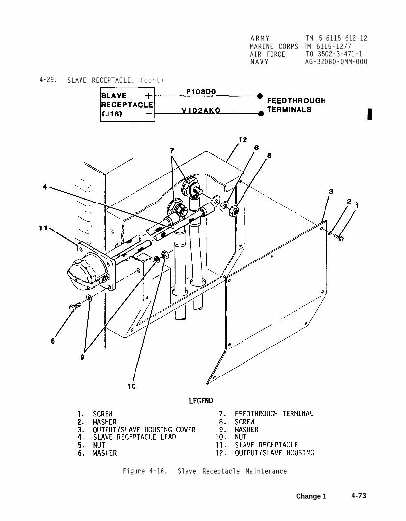
ARMY TM 5-6115-612-12MARINE CORPS TM 6115-12/7AIR FORCE T0 35C2-3-471-1NAVY AG-320B0-0MM-000
4-29. SLAVE RECEPTACLE. (cont)
Figure 4-16. Slave Receptacle Maintenance
Change 1 4-73

ARMY TM 5-6115-612-12MARINE CORPS TM 6115-12/7AIR FORCE TO 35C2-3-471-1NAVY AG-320B0-0MM-000
4-29. SLAVE RECEPTACLE.
c. Insta llation.
(1) Install slavein output/slave housing
(cont)
receptacle (11)(12) and secure
with screws (8), washers (9), andself-locking nuts (10). Torque to74-82 inch pounds (8.4-9.3 Nm).
(2) Install slave receptacleleads (4) on feedthrough terminals (7)and secure with washers (6) and nuts(5). Torque nut on 3/8 inch stud to200-275 inch pounds (22.6-31.1 Nm).Torque nut on 1/2 inch stud 500-650inch pounds (56.5-73.4 Nm).
(3) Install output/slave housingaccess cover (3) and secure withwashers (2) and screws (1). Torque to24-36 inch pounds (2.7-4 Nm).
(4) Stow power cable on cablesupport assembly.
(5) Connect battery cable plugconnector to battery.
4-30. GENERATOR ELECTRONIC CONTROLMODULE. Maintenance of the generatorelectronic control module (GECM)(figure 4-17) consists of replacement.When testing/troubleshooting proce-dures isolate the GECM as the cause ofa malfunction, remove the GECM and sendto direct support maintenance forrepair.
a. Removal.
WARNING
To prevent injury, ensure thatbattery is disconnected beforeperforming maintenance onelectrical components.
(1)connector
4-74
Disconnect battery cable plugfrom battery.
(2) Open control panel accessdoor.
(3) Loosen turnlock fasteners and open control panel.
(4) Tag and disconnect cables from GECM connectors Jl, J2, and J3.
(5) On underside of controlfender, remove nuts (1) and washers (2).
(6) Remove capscrews (3) that secure GECM (4) in control fender.
(7) Lift GECM (4) out of controlfender.
b. Installation.
(1) Place GECM (4) in controlfender. Ensure that mounting holes arealined.
(2) Secure with capscrews (3),washers (2), and, nuts (1). Torque to74-82 inch pounds (8.4-9.3 Nm).
(3) Connect cables to GECMconnectors Jl, J2, and J3.
(4) Close control panel andsecure with turnlock fasteners.
(5) Close control panel accessdoor.
(6) Connect battery cable plugconnector to battery. -
4-31. CIRCUIT BREAKER. Seelocation of circuit breakercontrol panel. Maintenancecircuit breaker (figure 4-18)of testing and replacement.
FO-1 for(CB1) onof theconsists

ARMY TM 5-6115-612-12MARINE CORPS TM 6115-12/7AIR FORCE T0 35C2-3-471-1NAVY AG-320B0-0MM-000
4-30. GENERATOR ELECTRONIC CONTROLMODULE. (cont)
Figure 4-17. GECM Replacement
Change 1 4-75

ARMY TM 5-6115-612-12MARINE CORPS TM 6115-12/7AIR FORCE T0 35C2-3-471-1NAVY AG-320B0-0MM-000
4-31. CIRCUIT BREAKER. (cont)
Figure 4-18. Circuit Breaker Test and Replacement
4-76

4-31. CIRCUIT BREAKER. (cont)
a. Test.
WARNING
To prevent injury, ensure thatbattery is disconnected beforeperforming maintenance onelectrical components.
(1)connector
(2)door.
(3)
Disconnect battery cable plugfrom battery.
Open control panel access
Loosen turnlock fasteners andopen control panel.
(4) Set voltmeter to read resis-tance on the low scale.
(5) Connect positive (+) lead toCB1 terminal 1.
(6) Connect negative (-) lead toCB1 terminal 2.
(7) Press CB1 reset button.Meter should read zero ohms or fullscale deflection. If not, replace CB1.
(8) Open circuit byon CB1. Repeat steps 5,Meter should read infinitydeflection. If resistancereplace CB1.
(9) Close control
pulling out6, and 7.
and show nois present,
panel andsecure with turnlock fasteners.
(10) Close control panel accessdoor.
(11) Connect battery cable plugconnector to battery.
ARMY TM 5-6115-612-12MARINE CORPS TM 6115-12/7AIR FORCE TO 35C2-3-471-1NAVY AG-320B0-0MM-000
b. Removal.
WARNING
To prevent injury, ensure thatbattery is disconnected beforeperforming maintenance onelectrical components.
(1)connector
(2)door.
(3)
Disconnect battery cable plugfrom battery.
Open control panel access
Loosen turnlock fasteners andopen control panel.
(4) Tag and disconnect wires fromterminals 1 and 2 of CB1.
(5) Remove nut and circuitbreaker.
c. Installation.
(1) Insert circuit breaker intomounting hole. Secure with nut.
(2) Connect wires to terminals.
(3) Ensure that circuit breakerreset button is pushed all the way in.
(4) Close control panel andsecure with turnlock fasteners.
(5) Close control panel accessdoor.
(6) Connect battery cable plugconnector to battery.
4-32. STARTERof the starterreplacement.
ASSEMBLY. Maintenanceconsists of testing and
4-77

ARMY TM 5-6115-612-12MARINE CORPS TM 6115-12/7AIR FORCE TO 35C2-3-471-1NAVY AG-320B0-0MM-000
4-32. STARTER ASSEMBLY. (cont)
Figure 4-19. Starter Test Point Locations
4-78
ARMY TM 5-6115-612-12MARINE CORPS TM 6115-12/7AIR FORCE TO 35C2-3-471-1
4-32. STARTER ASSEMBLY. (cont)
a. Test. Refer to figure 4-19 forstarter test point locations.
(1) Loosen turnlock fasteners andremove engine housing access cover.
(2) Using multimeter, place posi-tive lead on battery connector terminaland negative lead on starter powerreturn post. Multimeter should read 24Vdc. If not, check battery cable(paragraph 4-26).
(3) Move negative lead to sole-noid return post. Multimeter shouldread 24V. If not, wire from solenoidreturn post to starter power returnpost is damaged and should be replaced.
(4) Open control panel accessdoor.
(5) Move MASTER SWITCH to STARTposition.
(6) Watch yoke for forward move-ment and listen for sound of solenoidmoving. If no movement or sound, checkvoltage between starter enable terminal(+) and starter power return post (-).If 24 Vdc present, replace solenoid.
(7) If yoke moves but starterdoes not rotate, check for 24V atstarter input terminal. If 24V arepresent, starter is bad. If no 24Vreading, solenoid is bad.
(8) Move MASTER SWITCH to OFFposition.
(9) Close control panel accessdoor.
(10) Install engine housingaccess cover and secure- with turnlockfasteners.
NAVY AG-320B0-0MM-000
b. Removal.
WARNING
To prevent injury, ensure thatbattery is disconnected beforeperforming maintenance onelectrical components.
(1) Disconnect battery cable plugconnector from battery.
(2) Loosen turnlock fasteners andremove engine housing access cover.
(3) Tag and disconnect allelectrical connections to starter.
CAUTION
To prevent damage, do not letstarter rest unsupported in gear-box . Severe damage to startershaft or gearbox could result.
(4) Support starter. Removelockwire, bolts (1, figure 4-20), andwashers (2) that secure starter (3) tostarter mounting plate (4).
(5) Carefully pull starterstraight out of gearbox.
c. Installation.
CAUTION
To prevent damage, do not letstarter rest unsupported in gear-box. Severe damage to startershaft or gearbox could result.
(1) Carefully install startershaft in gearbox. Support starter andinstall washers (2) and bolts (1).Torque to 45-55 inch pounds (5.1-6.2Nm). Lockwire bolts.
4-79

ARMY TM 5-6115-612-12MARINE CORPS TM 6115-12/7AIR FORCE T0 35C2-3-471-1NAVY AG-320E30-0W-000
4-32. STARTER ASSEMBLY. (cont)
Figure 4-20. Starter Replacement
4-80

4-32. STARTER ASSEMBLY. (cont)
c. Insta llation. (cont)
C A U T I O N
To preventcover and toapplication,be used whenjamnut (5).
damage to solenoidensure proper torquea backup wrench musttorque is applied to
(2) Connect wiring to starter.When attaching positive battery cable(6) to starter terminal, use backupwrench on bottom nut while applyingtorque to jamnut (5). Torque jamnut(5) to 50-70 inch pounds (5.7-7.9 Nm).
(3) Install engine housing accesscover and secure with turnlockfasteners.
(4) Connect battery cable plugconnector to battery.
4-33. CURRENT SHUNT (20 AMP).Maintenance of the 20 amp current shunt(figure 4-21) consists of inspectionand replacement.
a. Inspection.
(1) Remove power cable from cablesupport assembly.
W A R N I N G
To preventbattery isPerforming
injury, ensure thatdisconnected beforemaintenance on
electrical components.
(2) Disconnect battery cable plugconnector.
(3) Unlatch and open inlet airhousing access door. Secure in openposition.
ARMY TM 5-6115-612-12MARINE CORPS TM 6115-12/7AIR FORCE TO 35C2-3-471-1NAVY AG-320B0-0MM-000
(4) Check mounting points ofcurrent shunt. Tighten securely, ifloose.
(5) Check input and output lugsfor discoloration. Discoloration oflugs indicates loosening of connectionsduring operation. Tighten any looseconnections.
(6) Inspect for dirt on currentshunt. If dirt is found, first trycleaning with compressed air. Ifunsuccessful, clean with electricalgrade solvent.
(7) Check current shunt for phy-sical damage. If damage is found,replace shunt.
(8) Close and securely latchinlet air housing access door.
(9) Connect battery plugconnector.
(10) Stow power cable on cablesupport assembly.
b. Removal.
(1) Removesupport assembly.
power cable from cable
WARNING
To prevent injury, ensure thatbattery is disconnected beforeperforming maintenance onelectrical components.
(2) Disconnect battery cable plugconnector.
(3) From terminal(1) figure 4-21washer (3), andwire U111A18.
C, remove screw), lockwasher (2),terminal lug (4) of
4-81

ARMY TM 5-6115-612-12MARINE CORPS TM 6115-12/7AIR FORCE TO 35C2-3-471-1NAVY AG-320B0-0MM-000
4-33. CURRENT SHUNT (20 AMP). (cont)
Figure 4-21. Current Shunt (20 Amp) Replacement
4-82

4-33. CURRENT SHUNT (20 AMP). (cont)
b. Removal. (cont)
(4) From terminal D. remove screw(5), lockwasher (6), washer (7),terminal lug (8) of wire U112A18.
(5) From terminal A, remove(9), lockwasher (10), terminal luq
and
nut(11)
of wire P103E14, nut (12), and washer(13) from terminal post.
(6) From terminal B, remove nut(14), lockwasher (15), terminal lug(16) of wire P103B14, nut (17), andwasher (18) from terminal post.
(7) Remove self-locking nuts(19), washers (20), and screws (21)that secure current shunt (22) tobulkhead.
c. Installation.
(1) Secure current shunt (22) tobulkhead of inlet air housing withscrews (21), washers (20), andself-locking nuts (19). Torque to36-40 inch pounds (4-4.5 Nm).
ARMY TM 5-6115-612-12MARINE CORPS TM 6115-12/7AIR FORCE T0 35C2-3-471-1NAVY AG-320B0-0MM-000
(2) At terminal B, install washer(18), nut (17), and terminal lug (16)of wire P103B14. Secure with lockwasher(15) and nut (14).
(3) At terminal A, install washer(13), nut (12), and terminal lug (11)of wire P103E14. Secure withlockwasher (10) and nut (9).
(4) At terminal D, install termi-nal lug (8) of wire U112A18 and washer(7). Secure with lockwasher (6) andscrew (5).
(5) At terminal C, install termi-nal lug (4) of wire U111A18 and washer(3). Secure with lockwasher (2) andscrew (1).
(6) Closeinlet air housing
(7) Connectconnector.
and securely latchaccess door.
battery cable plug
(8) Stow power cable on cablesupport assembly.
4-83

ARMY TM 5-6115-612-12MARINE CORPS TM 6115-12/7AIR FORCE T0 35C2-3-471-1NAVY AG-320B0-0MM-000
Section X.
4-34. GENERAL. The fuel(figure 4-22) provides aefficient flowing supply of fuel
MAINTENANCE OF FUEL SYSTEM
systemclean,to the
turbine engine. The system issupported by an externally mounted,32-gallon (121.13 1) fuel tank. A fulltank provides approximately four hoursoperating time. Components mounted inthe fuel housing are the fuel transferpump, primary fuel filter, secondaryfuel filter, high pressure pump, andt h e f u e l shutdown/drain solenoidv a l v e . These components combine tocontrol the fuel flow to the fuelmanifold mounted on the turbinee n g i n e . The fuel manifold has threefuel Injection nozzles that provide afine mist of fuel to support combustionin the turbine combustion chamber. Thefuel system provides the turbine enginewith a fuel flow at the rate requiredto maintain proper combustion ande n g i n e speed under all loadconditions. A block diagram of thefuel system is shown in figure 4-23.
NOTE
If not specified inprocedure, applyaccordance with table 1-1,Specifications.
maintenancetorque inT o r q u e
a. Fuel Housing Access.
(1) Remove power cable from cablesupport assembly.
WARNING
To prevent injury, ensure thatbattery cable plug connector isdisconnected from battery beforeperforming maintenance.
(2) Disconnect battery cable plugconnector from battery.
(3) Unlatch and open fuel housingaccess door. Secure in open position.
b. Draining the Fuel system.
(1) Gain access to fuel housing(paragraph 4-34a).
(2) Place suitable containerunder drain of primary fuel filter.
WARNING
To prevent injury from explosionor fire, drain fuel in awell-ventilated area. Keep awayfrom all open flames and sparks.Do notup all
(3)line fromline.
smoke. Immediately cleanspilled fuel.
Tag and, disconnect inlet fueltransfer fuel pump. Cap fuel
(4) Openprimary filter.stops draining.
fuel drain valve onClose drain when fuel
(5) Carefully unscrew and removebowl of secondary fuel filter. Dumpfuel into container. Install bowl onfilter and tighten hand tight.
c. Closinq the Fuel Housing.
(1) Close and securely latch fuelhousing access door.
(2) Connect battery cable plugconnector to battery.
(3) Stow power cable on cablesupport assembly.
4-84

ARMY TM 5-6115-612-12MARINE CORPS TM 6115-12/7AIR FORCE TO 35C2-3-471-1NAVY AG-320B0-0MM-000
4-34. GENERAL. (cont)
Figure 4-22. Fuel System Components
4-85
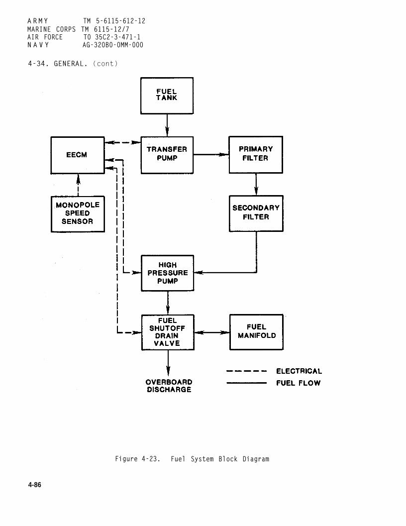
ARMY TM 5-6115-612-12MARINE CORPS TM 6115-12/7AIR FORCE T0 35C2-3-471-1N A V Y AG-320B0-0MM-000
4-34. GENERAL. (cont)
Figure 4-23. Fuel System Block Diagram
4-86

4-35. FUEL LINES, VALVES , FITTINGS(ENGINE HOUSING). Maintenance of thefuel lines, valves, and fittingslocated in the engine housing consistsof inspection and replacement of thefuel manifold (figure 4-24).
a. Inspection.
WARNING
To prevent injury, ensure thatbattery cable plug connector isdisconnected from battery beforeperforming maintenance.
(1) Disconnect battery cable plugconnector from battery.
(2) Loosen turnlock fasteners andremove engine housing access cover.
(3) Inspect for signs of leakageat solenoid valve bulkhead connection.Ensure that connection is secure.
(4) Inspect for signs of leakageat fuel manifold and fuel injectionnozzle connections. Ensure thatconnections are secure.
ARMY TM 5-6115-612-12MARINE CORPS TM 6115-12/7AIR FORCE TO 35C2-3-471-1N A V Y AG-320B0-0MM-000
(2) Loosen turnlock fasteners andremove engine housing access cover.
(3) Disconnect fuel line fromsolenoid valve bulkhead connection.
(4) Remove lockwire, bolts (1),washers (2), and spacers (3) so thatfuel manifold (4) can be removed.
(5) Remove loop clamps (5) fromfuel lines only if damaged.
(6) Disconnect damaged fuel linesfrom tube cross (6).
c. Installation.
(1) Connect fuel lines to tubecross (6).
(2) Position loop clamps (5), ifremoved, on fuel lines.
(3) Position fuel manifold andspacers (3). Secure with washers (2)and bolts (1). Torque to 10-15 inchpounds (1-1.7 Nm).
(4) Connect fuel line to solenoidvalve.
(5) Install engine housing access (5) Install engine housing accesscover a n d secure with turnlock cover and secure with turnlockfasteners. fasteners.
(6) Connect battery cable plug (6) Connect battery cable plugconnector to battery. connector to battery.
b. Removal. 4-36. FUEL LINES, VALVES, FITTINGS(INTERNAL). Maintenance of theinternal fuel lines, valves, and
WARNING fittings is limited to replacement.
To prevent injury, ensure that a. Removal.battery cable plug connector isdisconnected from battery before (1) Gain access to fuel housingperforming maintenance. (paragraph 4-34a).
(1) Disconnect battery cable plug (2) Drain fuel system (paragraphconnector from battery. 4-34b).
4-87

IA R M Y TM 5-6115-612-12MARINE CORPS TM 6115-12/7AIR FORCE TO 35C2-3-471-1NAVY AG-320B0-0MM-000
4-35. FUEL LINES, VALVES, FITTINGS(ENGINE HOUSING). (cont)
Figure 4-24. Fuel Manifold Removal
4-88

ARMY TM 5-6115-612-12MARINE CORPS TM 6115-12/7AIR FORCE T0 35C2-3-471-1NAVY AG-320B0-0MM-000
4-35. FUEL LINES, VALVES, FITTINGS(ENGINE HOUSING). (cont)
Figure 4-25. Fuel Line Layout (Internal)
4-89

ARMY TM 5-6115-612-12MARINE CORPS TM 6115-12/7AIR FORCE T0 35C2-3-471-1NAVY AG-320B0-0MM-000
4-36. FUEL LINES, VALVES, FITTINGS(INTERNAL). (cont)
a. Removal. (cont)
(3) Refer to figure 4-25 forlayout of fuel lines, valves, andfittings. Remove attaching parts anddamaged components as required.
b. Installation.
(1) Install new components andsecure with attaching parts.
(2) Close fuel housing (paragraph4-34C).
4-37. ELECTRICAL FUEL TRANSFER PUMP.Maintenance of the electrical fueltransfer pump consists of testing,servicing, and replacement.
a. Test.
(1) Gain access to fuel housing(paragraph 4-34a).
(2) Open control panel accessdoor. Ensure that MASTER SWITCH is inOFF position.
(3) Disconnect fuel line atoutlet port (8, figure 4-26) of fueltransfer pump. Connect direct readingpressure gage to outlet port.
(4) Place MASTER SWITCH in RUNposition to pressurize fuel system.Pressure gage should read 5-7 psi(34-48 kPa). If not, pump is faultyand should be serviced (paragrah4-37b) or
(5)positiondoor.
(6)pressurereconnect
4-90
replaced (paragraph 4-37c).
Place MASTER SWITCH in OFFClose control panel access
Remove direct readinggage from outlet port andfuel line.
(7) Close fuel housing (paragraph4-34C).
b. Service.
(1) Gain access to fuel housing(paragraph 4-34a).
(2) Place suitable containerunder fuel transfer pump.
(3) Remove screws (1, figure 4-26), cover (2), gasket (3), andfilter (4) from body (5).
WARNING
Compressed air used for cleaningor drying can create airborneparticles that may enter theeyes. Pressure shall not exceed30 psi (207 kPa). Wear eyeprotection to prevent eye Injury.
(4) Clean filter (4) withcompressed air.
(5) Install filter (4) and newgasket (3).
(6) Install cover (2) and securewith screws (1).
(7) Close fuel housing (paragraph4-34C).
c. Removal.
(1) Gain access to fuel housing(paragraph 4-34a).
(2) Drain fuel system (paragraph4-34b).
(3) Tag and disconnect fueltransfer pump electrical connector (6).

ARMY TM 5-6115-612-12
4-37. ELECTRICAL FUEL TRANSFERPUMP. (cont)
MARINE CORPS TM 6115-12/7AIR FORCE TO 35C2-3-471-1NAVY AG-320B0-0MM-000
Figure 4-26. Electrical Fuel Pump (Transfer) andFuel (Fluid) Filter (Primary)
4-91

A R M Y TM 5-6115-612-12MARINE CORPS TM 6115-12/7AIR FORCE TO 35C2-3-471-1NAVY AG-320B0-0MM-OOO
4-37. ELECTRICAL FUEL TRANSFERPUMP . (cont)
c. Removal. (cont)
(4) Tag and disconnect fuel linesfrom inlet (7) and outlet (8) ports.
(5) Remove nuts (9), washers(10), and capscrews (11) that securep u m p . Remove pump.
d. Installatlon.
(1) Aline pump with mounting holes and secure with capscrews (11),washers (10), and nuts (9). Torque to40-60 inch pounds (4.5-6.8 Nm).
(2) Remove tags and connect inletline to inlet port (7) and outlet lineto outlet port (8).
(3) Remove tags and connect electrical connector (6).
(4) Close fuel housing (paragraph 4-34c).
4-38. PRIMARY FUEL (FLUID) FILTER. Maintenance of the primary fuel (fluid)filter is limited to servicing andreplacement. F i l t e r elementreplacement is recommended every 300hours minimum.
a. service
(1) Gain access to fuel housing(paragraph 4-34a).
(2) Place suitable containerunder filter. Open fuel drain valve
and drain all fuel from filter.
(3) Remove retaining screw (12,figure 4-26), washer (13), and
preformed packing (14) to separate bowl(15) from housing (17). It may benecessary to use a pick to removegasket (16) from housing (17).
(4) Remove and discard filterelement (18).
(5) Clean bowl and housing withP-D-680. Dry thoroughly.
(6) Install new filter element(18) in bowl (15).
(7) Install new gasket (16) inhousing (17).
(8) Install bowl in housing.Install new preformed packing (14) ontop of housing. Secure assembly withwasher (13) and retaining screw (12).
(9) Close fuel housing (paragraph4-34c).
b. Removal.
(1) Gain access to fuel housing(paragraph 4-34a).
(2) Drain fuel system (paragraph4-34b).
(3) Tag and disconnect inlet andoutlet fuel lines.
(4) Remove capscrews (19), lock-washers (20), and spacers (21) thatsecure filter to mounting bracket.
c. Insta llation.
4-92
ARMY TM5–6115–612–12NAVY AG-320B0–0MM-000
4-38. PRIMARY FUEL (FLUID) FILTER.(cont)
c. Installation. (cont)
(3) Close fuel housing (paragraph 4-34c)
4-39. ENGINE FUEL TANK ASSEMBLY.Maintenance of the engine fuel tank (figure 4-27)consists of replacement.
a. Removal.
(1) Ensure that fuel tank has been com-pletely drained. There is a drain plug located on bot-tom of tank.
(7) Remove capscrews (2), nuts (3), wash-ers (4), and tank support channels (5). Nuts, washers,and tank support channels are located in engine hous-ing and plenum.
(8) Remove capscrews (6), nuts (7), andwashers (8).
(9) Carefully lift fuel tank (9) off generatorset.
(10) Replace pad (10) if damaged.
b. Installation.(2) When removing fuel tank it is necessary
to also remove the oil cooler (figure 4-34; Para. 4-54). W A R N I N G
WARNING
To prevent injury, ensure that handbrake is setand both wheels are chocked while perform-ing maintenance under the generator set.
(3) Set handbrake and chock both wheels.
W A R N I N G
To prevent injury, ensure that battery cableplug connector is disconnected from batterybefore performing maintenance.
(4) Disconnect battery cable plug connectorfrom battery,
(5) Disconnect fuel line (1) from bottom offuel tank. Install protective cap.
(6) Loosen turnlock fasteners and removeengine housing access cover and plenum accesscover.
To prevent injury, ensure that the handbrake isset and both wheels are chocked while per-forming maintenance under the generator set,
(1) Set handbrake and chock both wheels.
(2) Install pad (10).
(3) Lift fuel tank (9) and position in place ongenerator set.
(4) Secure top of tank to generator set withcapscrews (6), washers (8), and nuts (7).
(5) Secure bottom of tank to generator setwith capscrews (2), tank support channels (5), wash-ers (4), and nuts (3).
(6) Torque fasteners to 160-175 inchpounds (18-20 Nm).
(7) Remove protective cap and connect fuelline to fuel tank.
Change 2 4 -93

ARMY TM5-6115-612-12NAVY AG-320B0-0MM-000
4-39. ENGINE FUEL TANK ASSEMBLY.(cont)
Figure 4-27. Engine Fuel Tank Replacement
4-94
4-39. ENGINE FUEL TANK ASSEMBLY.(cont)
b. Installation. (cont)
(8) Install engine housing andplenum access covers and secure withturnlock fasteners.
(9) Connect battery cable plugconnector to battery.
(10) Removehandbrake.
4-40. SECONDARYMaintenance of(fluid) filter is
chocks and release
FUEL (FLUID) FILTER.the secondary fuellimited to servicing
and replacement. Filter elementreplacement is recommended every 300hours minimum.
a. Service.
(1) Gain access to fuel housing(paragraph 4-34a).
(2) Unscrew filter bowl (1,figure 4-28) from filter housing (7).Discard fuel in filter bowl.
from
with
(3) Remove filter element (2)filter housing and discard.
(4) Thoroughly clean filter bowlP-D-680.
(5) Remove packing (3) fromfilter housing (7).
(6) Install new preformed packing(3) in filter housing (7).
(7) Install new filter element(2) in filter housing (7).
(8) Screw bowl (1) into filterhousing (7) hand tight.
(9) Close fuel4-31C).
housing (paragraph
ARMY TM 5-6115-612-12MARINE CORPS TM 6115-12/7AIR FORCE TO 35C2-3-471-1N A VY AG-320B0-0MM-000
b. Removal.
(1) Gain access to fuel housing(paragraph 4-34a).
(2) Drain fuel system (paragraph4-34b).
(3) Tag and disconnect filterinlet and outlet fuel lines.
(4) Remove nuts (4), washers (5),and capscrews (6) that secure filterhousing (7) to filter bracket (8).
c. Installation.
(1) Install washers (5) oncapscrews (6). Insert capscrewsthrough filter housing (7) and secureto filter bracket (8) with remainingwashers (5) and nuts (4). Torque to40-60 inch pounds (4.5-6.8 Nm).
(2) Remove tags and connectfilter inlet and outlet fuel lines.
(3) Close fuel housing (paragraph4-34C).
4-41. ELECTRICAL HIGH PRESSURE FUELPUMP. Maintenance of the electricalhigh pressure fuel pump is limited toreplacement. When testing/trouble-shooting procedures isolate the highpressure pump as the cause of amalfunction, remove the pump and sendto direct support for repair.
a. Removal
(1) Gain access to fuel housing(paragraph 4-34a).
(2) Drain fuel4-34b).
system (paragraph
4-95

ARMY TM 5-6115-612-12MARINE CORPS TM 6115-12/7AIR FORCE TO 35C2-3-471-1NAVY AG-320B0-0MM-0004-40. SECONDARY FUEL (FLUID) FILTER.(cont)
Figure 4-28. Fuel Filter (Secondary)
4-96

ARMY TM 5-6115-612-12MARINE CORPS TM 6115-12/7AIR FORCE 10 35C2-3-471-1
4-41. ELECTRICAL HIGH PRESSURE FUELPUMP. (cont)
NAVY AG-320B0-0MM-000
Figure 4-29. Electrical Fuel Pump (High Pressure) andSolenoid Valve Removal
4-97
ARMY TM 5-6115-612-12MARINE CORPS TM 6115-12/7AIR FORCE T0 35C2-3-471-1NAVY AG-320B0-0MM-000
4-41. ELECTRICAL HIGH PRESSURE FUELPUMP. (cont)
a. Removal. (cont)
(3) Tag and disconnect fuel pumpelectrical connector.
(4) Tag and disconnect fuel pumpinlet (1, figure 4-29) and outlet fuellines (2).
(5) Remove self-locking nuts (3),washers (4), and capscrews (5) thatsecure fuel pump (7), in mountingbrackets (6).
(6) Remove pump (7).
b. Installation.
(1) Install fuel pump (7) in mounting brackets (6) and secure with
capscrews (5), washers (4), andself-locking nuts (3). Torque to 40-60Inch pounds (4.5-6.8 Nm).
(2) Remove tags and connectoutlet (2) and inlet (1) fuel lines topump.
(3) Remove tag and connect pumpelectrical connector.
(4) Close fuel housing (paragraph4-34C).
4-42. SOLENOIDof the solenoid replacement.
VALVE. Maintenancevalve is limited to
a. Removal.
(1) Gain access to fuel housing(paragraph 4-34a).
(2) Tag and disconnect solenoidvalve electrical connector.
4-98
(3) Tag and disconnect valveinlet (2, figure 4-29) drain (8), andoutlet (9) lines from solenoid valve(13).
(4) Remove screws (10),lockwashers (11), washers (12) andsolenoid valve (13) from mountingbracket (14).
b. Installation.
(1) Install solenoid valve (13)on mounting bracket (14) and securewith washers (12), lockwashers (11),and screws (10). Torque to 10-20 inchpounds (1-2.3 Nm).
(2) Remove tags and connectsolenoid valve inlet (2), drain (8),and outlet (9) lines.
(3) Remove tag and connectelectrical connector to solenoid valve.
(4) Close fuel housing (paragraph4-34C).
4-43. FUEL INJECTION NOZZLES.Maintenance of the fuel injectionnozzles is limited to inspection,servicing, and replacement.
a. Removal.
WARNING
To prevent injury, ensure thatbattery cable plug connector isdisconnected from battery beforeperforming maintenance.
(1) Disconnect battery cable plugconnector from battery.

ARMY TM 5-6115-612-12MARINE CORPS TM 6115-12/7AIR FORCE TO 35C2-3-471-1NAVY AG-320B0-0MM-000
4-43. FUEL INJECTION NOZZLES. (cont)
Figure 4-30. Fuel Injection Nozzles
4-99

ARMY TM 5-6115-612-12MARINE CORPS TM 6115-12/7AIR FORCE TO 35C2-3-471-1NAVY
4-43.(cont)
a.
AG-320B0-0MM-000
FUEL INJECTION NOZZLES.
Removal. (cont)
(2) Loosen turnlock fasteners andremove engine housing access cover.
(3) Remove lockwire, bolts (1, figure 4-30), washers (2), and spacers
(3) so that fuel manifold (4) can beremoved.
(4) Remove loop clamps (5) from fuel line only if damaged.
(5) Disconnect fuel manifold (4)from fuel injection nozzles (6).
(6) Remove lockwire, bolts (7), washers (8), and fuel injection nozzles
(6) from nozzle covers (9).
(7) Remove atomizers (10) fromfuel Injection nozzles (6).
b. Inspection.
(1) Inspect fuel injectionnozzles for wear and damage. Replaceif excessively worn or damaged.
(2) Inspect orifice in atomizer(10) for damage and carbon deposits.
C. Service.
(1) Soak parts in P-D-680 toremove dirt and grease. Refer to table3-1 for approved compound for carbonremoval.
CAUTION
To prevent damage, do not usewire brush or abrasive material.
(2) Use soft-bristled brush toremove deposits.
4-100
WARNING
Compressed air used for cleaningor drying can create airborneparticles that may enter theeyes. Pressure shall not exceed30 psi (207 kPa). Wear eyeprotection to prevent injury.
(3) Dry parts thoroughly withcompressed air.
d. Installation.
(1) Install atomizers (10) infuel injection nozzles (6). Torque to85-95 inch pounds (9.6-10.8 Nm).
(2) Install fuel (9) injectionnozzles into nozzle covers. Secure toengine with washers (8) and bolts (7).Torque to 20-25 inch pounds (2.3-2.8Nm). Lockwire with 0.032 inch (0.081m)diameter lockwire.
(3) Connect fuel manifold (4) tofuel injection nozzles (6). Torquefittings to 130-140 inch pounds(14.7-15.8 Nm).
(4) Position loop clamps (5), ifremoved, on fuel manifold (4).
and(2)inch
(5) Position fuel manifold (4)spacers (3). Secure with washersand bolts (1). Torque to 10-15pounds (1-1.7 Nm).
(6) Install engine housing accesscover and secure with turnlockfasteners.
(7) Connect battery cable plugconnector to battery.

ARMY TM 5-6115-612-12MARINE CORPS TM 6115-12/7AIR FORCE TO 35C2-3-471-1NAVY AG-320B0-0MM-000
Section XI. MAINTENANCE OF IGNITION SYSTEM
4-44. GENERAL. The ignition systemconsists of a spark igniter, ignitioncoi1, and the high tension electricalleads. The purpose of the ignitionsystem is to ignite the fuel-air mix-ture in the engine combustor. Inputvoltage to the ignition coil charges acapacitor. As the capacitor becomesfully charged, current is forced fromthe ignition coil, through the hightension electrical leads, to the sparkigniter. As this action continues,resistance in the air gap of the sparkigniter is overcome, causing the capa-citor to discharge completely. Thedischarge is in the form of a sparkwith a minimum 5000 volts. This entireprocess is repeated 240 times perminute.
NOTE
If not specified in maintenanceprocedure, apply torque inaccordance with table 1-1, TorqueSpecifications.
4-45. IGNITION SYSTEM TEST. Thefollowing test procedure can be used toisolate the ignition system componentrequiring service or replacement.
a. Access.
(1) Gain access to fuel housing(paragraph 4-34a).
(2) Disconnect electrical con-nector from electrical high pressurefuel pump.
(3) Loosen turnlock fasteners andremove engine housing access cover.
(4) Open control panel access door.
b. Test.
WARNING
High voltage is present whenignition system is energized. Toprevent injury, use extreme cau-tion when working with energizedequipment.
(1) Remove spark igniter (1,figure 4-31) and place on top of engine.
(2) On the control panel, moveMASTER SWITCH to RUN, then place inSTART position.
(3) Observe sparking on sparkigniter.
(4) If there is a steady, bluespark, ignition system components areoperating properly.
(5) If there is a weak,intermittent orange spark, disconnectinput lead (4) from ignition coil(13). Check voltage at input lead.Voltage should read 16-24 Vdc.
(6) If voltage is incorrect andbattery is good, problem is in engineelectronic control module (EECM) orassociated wiring. Refer to paragraph4-64.
(7) If voltage is correct, recon-nect input lead (4) to ignition coil(13) and replace high tension lead (9)(paragraph 4-46).
(8) Repeat test. If spark isstill weak, intermittent, and orange,service or replace spark Igniter(paragraph 4-47).
(9) Repeat test. If spark isstill weak, intermittent, and orange,replace ignition coil (paragraph 4-48).
4-101
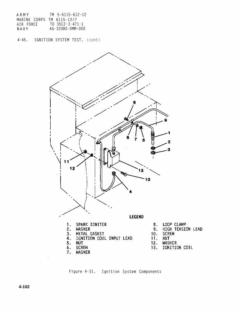
A R M Y TM 5-6115-612-12MARINE CORPS TM 6115-12/7AIR FORCE TO 35C2-3-471-1NAVY AG-320B0-0MM-000
4-45. IGNITION SYSTEM TEST. (cont)
Figure 4-31. Ignition System Components
4-102

4-45. IGNITION SYSTEM TEST. (cont)
b. Test. (cont)
(10) Ensure that MASTER SWITCH isin OFF position.
door.
to e
(11) Close control panel access
(12) Connect electrical connectorlectrical high pressure fuel pump.
(13) Close fuel housing(paragraph 4-34c).
(14) Install engine housingaccess door and secure with turnlockfasteners.
4-46. HIGH TENSION LEAD. Main-tenance of thefigure 4-31) isand replacement.
a. Removal.
(1) Loosen
high tension lead (9,limited to inspection
turnlock fasteners andremove engine housing access cover andplenum access cover.
WARNING
To prevent injury, ensure thatbattery cable plug connector isdisconnected from battery beforeperforming maintenance.
(2)connector
(3)
Disconnect battery cable plugfrom battery.
Remove nuts (5), screws (6),washers (7), and loop clamps (8) thatsecure high tension lead (9) to enginehousing.
Hightionset
ARMY TM 5-6115-612-12MARINE CORPS TM 6115-12/7AIR FORCE T0 35C2-3-471-1NAVY AG-320B0-0MM-000
WARNING
voltage may exist in igni-system even though generatoris shut down. To prevent
injury, ensure that ignitionsystem components are dischargedto ground before performingmaintenance.
(4) Disconnect high tension lead(9) from spark igniter (1) anddischarge to ground. -
(5) Disconnect high tension lead(9) from ignition coil (13).
b.
for
Inspection.
(1) Inspect high tension lead (9)loose connectors, chafing,
areas. andabrasions. cuts. burned -
insulation breakdown. Replace lead ifany of these conditions are present.
(2) Inspect high tension leadconnectors for cracks, pitting, anddamage caused by arcing. Replace hightension lead (9) if connectors aredamaged.
Test. Test high tension lead inaccordance with paragraph 4-45.
d. Installation.
(1) Connect high tension lead (9)to output of ignition coil (13).
(2) Connect highto spark igniter (1).
(3) Secure highto engine housing wall
tension lead (9)
tension lead (9)with loop clamps
(8), screws (6), washers (7), and nuts(5). Torque to 36-40 inch pounds(4-4.5 Nm).
4-103

ARMY TM 5-6115-612-12MARINE CORPS TM 6115-12/7AIR FORCE TO 35C2-3-471-1NAVY AG-320B0-0MM-000
4-46. HIGH TENSION LEAD. (cont)
d. Installation. (cont)
(4) Connect battery cable plugconnector to battery.
(5) Install engine housing accesscover and plenum access cover. Securewith turnlock fasteners.
4-47. SPARK IGNITER. Maintenance ofthe spark Igniter (1, figure 4-31) islimited to test, Inspection, serviceand replacement.
a. Test. Test spark igniter in accordance with paragraph 4-45.
b. Removal.
(1) Loosen turnlock fasteners andremove engine housing access cover.
WARNING
To prevent injury, ensure thatbattery cable plug connector isdisconnected from battery beforeperforming maintenance.
(2) Disconnect battery cable plugconnector from battery.
WARNING
High voltage may exist in igni-tion system even though generatorset is shut down. To preventinjury, ensure that ignitionsystem components are dischargedt o ground before performingmaintenance.
(3) Disconnect high tension lead (9) from spark igniter (1) and
discharge to ground.
(4) Remove spark igniter (1),washer (2), and metal gasket (3) fromcombustor housing.
c. Inspection.
CAUTION
To prevent damage, do not attemptto remove deposits or residuefrom the firing end. Spark igni-ter utilizes a semiconductormaterial at the firing end thatcan be damaged through impropercleaning.
(1) If necessary, carefully brushfiring end with stiff-bristled non-metallic brush, or carefully wipe withP-D-680 and cloth.
(2) Use dry cloth or fiberbristle brush to remove residue fromexterior of spark igniter shell.
(3) Inspect spark igniter forelectrical or thermal damage. Replaceif damaged.
(4) Inspect threads for damage.Replace spark igniter if damaged.
(5) Inspect thermal well forcracked or loose ceramic. Replacespark igniter if damaged.
(6) Inspect firing end insulator for chips, grooves, and cracks.Replace spark igniter if damaged.
(7) Inspect mounting flange fordamage.
(8) Inspect electrode for exces-sive erosion. See figure 4-32. Compareelectrode with electrode on new sparkigniter. If electrode has eroded morethan 50%, replace spark igniter.
4-104

ARMY TM 5-6115-612-12MARINE CORPS TM 6115-12/7AIR FORCE T0 35C2-3-471-1NAVY AG-320B0-0MM-000
4-47. SPARK IGNITER. (cont)
Figure 4-32. Typical Electrode Erosion
d. Service.
CAUTION
To prevent damage, do not attemptto remove deposits or residuefrom the firing end. Spark igni-ter utilizes a semiconductormaterial at the firing end thatcan be damaged through impropercleaning.
(1) Use a wire brush or a stiff-bristled fiber brush to remove residuefrom shell and shield threads.
WARNING
To prevent injury, all cleaningsolvents shall be used in a well-ventilated area. Avoid prolongedbreathing and skin contact. Donot take- internally. Do not usenear open flame.
CAUTION
To prevent damage, do not use anabrasive blast to clean sparkigniter shield.
(2) Clean spark igniter shieldwith decreasing agent suchtrichloroethylene 1,1,1 (MIL-T-81533).Dry with clean cloth.
(3) Clean interior of ceramicupper barrel with soft swab soaked inP-D-680. Dry with compressed air.
e. Installation.
(1) Apply anti seize compound(MIL-A-907) to first two threads ofspark igniter (1).
(2) Install gasket (3), washer(2), and spark igniter (1). Torque to120-160 inch pounds (13.5-18 Nm).
4-105

A R M Y TM 5-6115-612-12MARINE CORPS TM 6115-12/7AIR FORCE TO 35C2-3-471-1N A V Y AG-320B0-0MM-000
4-47. SPARK IGNITER. (cont)
e. Installation. (cont)
(3) Connect high tension lead (9)to spark igniter.
(4) Connect battery cable plugconnector to battery.
(5) Install engine housing accesscover and secure with turnlock
fasteners.
4-48. IGNITION COIL. Maintenance ofthe ignition coil (13, figure 4-31) islimited to test and replacement.
a. Test. Test ignition coil inaccordance with paragraph 4-45.
b. Removal.
(1) Loosen turnlock fasteners andremove engine housing and plenum accesscovers.
WARNING
To prevent injury, ensure thatbattery cable plug connector isdisconnected from battery beforeperforming maintenance.
(2) Disconnect battery cable plugconnector from battery.
WARNING
High voltage may exist inignition system even thoughgenerator set is shut down. Toprevent injury, ensure thatignition system components aredischarged to ground beforeperforming maintenance.
(3) Disconnect ignition coilinput lead (4) and discharge to ground.
(4) Disconnect high tension lead (9) and discharge to ground.
(5) Remove screws (10), nuts(11), and washers (12) to separateignition coil (13) from engine housing.
c. Installation.
(1) Aline ignition coil (13) withmounting holes in engine housing.Secure with screws (10), washers (12),and nuts (11). Torque to 24-36 inchpounds (2.7-4 Nm).
(2) Connect high tension lead (9)to ignition coil (13).
(3) Connect input lead (4) toignition coil (3).
(4) Install engine housing accesscover and plenum access cover. Securewith turnlock fasteners.
(5) Connect battery cable plugconnector to battery.
4-106
ARMY TM 5-6115-612-12MARINE CORPS TM 6115-12/7AIR FORCE TO 35C2-3-471-1N A V Y AG-320B0-0MM-000
Section XII. MAINTENANCE OF LUBRICATION SYSTEM
4-49. GENERAL. The lubricationsystem consists of an oil reservoir.
(4) Inspect filler hose (3) fordamage. Replace if damaged.
Oil filler/breather assembly, oilfilter, oil drains, lines and fittings,oil pressure relief valve, oil cooler,and an oil pump. The purpose of thesystem is to lubricate rotatingcomponents within the gearbox.Lubrication is begun when the controlpanel MASTER SWITCH is placed in START,causing the starter shaft to rotate.The starter shaft rotates the oil pumpshaft until the turbine shaft can takeover. The oil pump draws lubricatingoil from the reservoir through a smallstrainer. The oil is then pumpedthrough the oil filter and into thelubrication system where it lubricatesgears and bearings on the turbine shaftand the generator shaft.
NOTE
If not specified in maintenanceprocedure, apply torque inaccordance with table 1-1, TorqueSpecifications.
4-50. OIL FILLER/BREATHER ASSEMBLY.The oil filler/breather assembly(figure 4-33) provides the means forchecking and adding oil. It alsoprovides ventilation for thereservoir. It consists of a filler capand oil level gage and a breather.Maintenance consists of inspection,replacement, and repair.
a. Inspection.
(1) Loosen turnlock fasteners andremove engine housing and plenum accesscovers.
(2) Make sure breather vent tubeis securely in place. Inspect tube fordamage. Replace if damaged.
(3) Tighten hose clamps (2).
(5) Unscrew and remove filler capand oil level gage (1). Inspectthreads in cap and threaded adapter inmounting bracket (10) for damage.Replace damaged components as necessary.
(6) Inspect mounting bracketdrain tube (13) for damage or obstruc-tion. Remove obstruction or replacedamaged drain tube.
(7) Inspect breather housingdrain tube (5) for damage orobstruction. Remove obstruction orreplace damaged breather drain.
(8) Install engine housing andplenum access covers. Secure withturnlock fasteners.
b. Removal
(1) Loosen turnlock fasteners andremove engine housing and plenum accesscovers.
WARNING
To prevent injury, ensure thatbattery cable plug connector isdisconnected from battery beforeperforming maintenance.
(2) Disconnect battery cable plugconnector from battery.
(3) Unscrew and remove filler capand oil level gage (1).
(4) Loosen hose clamps (2) andremove filler hose (3).
(5) Disconnect breather vent tube(4) from breather housing (9). Replacehose clamps (15) and gasket (16) ifdamaged.
Change 1 4-107

ARMY TM 5-6115-612-12MARINE CORPS TM 6115-12/7AIR FORCE TO 35C2-3-471-1NAVY AG-320B0-0MM-000
4-50. OIL FILLER/BREATHER ASSEMBLY.(cont)
Figure 4-33. Oil Filler/Breather Assembly
4-108 Change 1

ARMY TM5–6115–612–12NAVY AG-320B0-0MM-000
4-50. OIL FILLER/BREATHER ASSEMBLY.(cont)
b. Removal. (cont)
(6) Disconnect breather housingdrain tube (5) from breather housing(9).
(7) Remove screws (6), nuts (7),and washers (8) to separate breatherhousing (9) from mounting bracket (10).
(8) Remove and discard(11).
gasket
(9) Remove and discard breatherseparator wool (12).
(10) Remove mounting bracketdrain tube (13) and grommet (14) frommounting bracket (10).
c. Rerair. Repair consists ofreplacing damaged components.
d. Installation.
(1) Install mounting bracketdrain tube (13) and grommet (14) inmounting bracket (10).
(2) Coil new breather separatingwool (12) around a mandrel with adiameter of 1.25 inch (3.2 cm). Coilwool to a maximum outside diameter of4.44 inch (11.3 cm).
(3) Install coiled wool inbreather housing (9).
(4) Install gasket (11).
(5) Aline breather housing andgasket with holes in mounting bracket(10). Secure with screws (6), washers(8), and locknuts (7).
(6) Connect breather housingdrain tube (5) to breather housing (9).
(7) Connect breather vent tube(4) to breather housing (9).
(8) Install filler hose (3) andsecure with hose clamps (2).
(9) Install filler cap and oillevel gage (1) and hand tighten.
(10) Install engine housing andplenum access covers and secure withturnlock fasteners.
(11) Connect battery cable plugconnector to battery.
4-51. OIL FILTER ASSEMBLY. Main-tenance of the oil filter is limited toreplacement. Refer to paragraph 4-8.
4-52. OIL DRAINS. Maintenance ofthe oil drains (figure 4-7) is limitedto inspection and replacement. The oildrains consist of the reservoir drainhose and the output pad seal drain.They are reached by removing thefuel/oil drain access cover on thebottom of the generator set. Thereservoir drain allows for draining ofthe gearbox. The output pad seal drainallows for drainage of oil that hasseeped past the generator drive seal onthe gearbox. The oil drains should beinspected for damaged threads, hoses,and fittings each time the oil ischanged. Refer to paragraph 4-8.
4-53. LINES AND FITTINGS ( EX-TERNAL). Maintenance of the externallines and fittings is limited toinspection and replacement. Thelubrication system lines and fittingsconsist of oil lines and flare adapterfittings used to connect thelubrication system to the oil cooler.
4-109

ARMYNAVY
4-53.(cont)
a.
TM5-6115-612-12AG-320B0-0MM-000
LINES AND FITTINGS (EXTERNAL).
Inspection.
(1) Loosen turnlock fasteners and removeengine housing access cover and plenum accesscover.
(2) Inspect oil lines and cooler lines for weardue to chafing or rubbing. Inspect fittings for evidenceof leakage or damage. Replace damaged lines andfittings as necessary.
(3) Inspect flare fittings for damage or leak-age. Inspect T-fittings for damage or leakage. Tightenor replace as necessary.
(4) Install engine housing and plenumaccess covers. Secure with turnlock fasteners.
b. Removal.
(1) Drain oil from lubrication system (para-graph 4-8a).
(2) To prevent tvvisting or damaging tubing,use two wrenches. Hold fitting stationary with onewrench while loosening flare nuts with other wrench.Remove damaged lines and fittings as necessary.
c. Installation.
(1) To prevent cross-threading and damageto fittings or nuts, start all flare nuts on fittings byhand.
(2) To prevent twisting or damaging tubing,use two wrenches. Hold fitting stationary with onewrench while tightening flare nuts with other wrench.Install new lines and fittings as necessary. Afterinstalling new lines, ensure that tubes will not rub orvibrate against engine or housing during operation.
(3) Fill reservior (paragraph 4-8 b).
Change 2
4-54. OIL COOLER. Maintenance of the oil cooler(figure 4-34) is limited to inspection and service. Oil ispumped from the gearbox reservoir, through the lowoil pressure switch, and then to the oil cooler where itis cooled. The oil then flows through the return lineback to the reservoir.
a. Inspection.
(1) Loosen turnlock fasteners and removeengine housing and plenum access covers.
(2) Ensure that oil cooler supply line issecurely connected to low oil pressure switch (figure4-7).
(3) Ensure that oil cooler return line issecurely connected to reservior return port (figure4-7).
WARNING
To prevent injury, ensure that handbrake is setand wheels are chocked while working undergenerator set.
(4) Set handbrake and chock both wheels.
(5) Remove screws (1, figure 4-34), washer(2), and oil cooler housing (3).
(6) Inspect oil cooler fins for bends or tears.Straighten bent fins. If fins are torn, refer to directsupport for maintenance.
(7) Ensure that oil cooler supply and returnlines (7) are securely connected.
4-110

ARMY TM 5-6115-612-12MARINE CORPS TM 6115-12/7AIR FORCE T0 35C2-3-471-1NAVY AG-320B0-0MM-000
4-54. OIL COOLER. (cont)
Figure 4-34. Oil Cooler Service
4-111

A R M Y TM 5-6115-612-12MARINE CORPS TM 6115-12/7AIR FORCE TO 35C2-3-471-1N A V Y AG-320B0-0MM-000
4-54. OIL COOLER. (cont)
a. Inspection. (cont)
(8) Ensure that oil cooler (8) issecurely attached to mounting brackets
(6).
(9) Install oil cooler housing(3) and secure with washers (2) andscrews (1).
(10) Install plenum and enginehousing access covers. Secure with
turnlock fasteners.
(11) Remove chocks and release handbrake.
b. service.
WARNING
To prevent Injury, ensure thathandbrake is set and wheels arechocked while working undergenerator set.
(1) Set handbrake and chock both wheels.
(2) Remove screws (l), washers(2), and oil cooler housing (3).
(3) Remove screws (4) and washers (5) that secure 0il cooler mounting brackets (6) to generator set.
(4) Tag, disconnect, and cap oilcooler supply and return lines (7).Remove oil cooler (8), with mountingbrackets (6) attached, from generator
WARNING
Dry cleaning solvent, P-D-680,type II, is flammable and toxict o the skin, eyes, andrespiratory tract. Skin, eye,and respiratory protection isrequired.
(5) Using a soft bristle brush and cleaning solvent P-D-680, type II,clean core and cooling f i n s . Straighten bent fins.
WARNING
Compressed air used for cleaningor drying can create airborneparticles that may enter theeyes. Pressure shall not exceed30 psi (207 kPa). Wear eyeprotection to prevent injury.
(6) Dry core and fins bydirecting compressed air over the finsand through the core.
(7) Place oil cooler (8), withmounting brackets (6) attached, intogenerator set.
(8) Uncap and connect oil coolersupply and return lines (7). Removetags.
(9) Secure oil cooler mountingbrackets (6) to generator set withwashers (5) and screws (4). Torque to24-36 inch pounds (2.7-4.1 Nm).
(10) Put oil cooler housing (3)into position and secure with washers(2) and screws (1).
set.(11) Remove chocks and release
handbrake.
4-112

4-55. GENERAL. Theengine consists ofturbine, compressor,assemblies. The gas
ARMY TM 5-6115-612-12MARINE CORPS TM 6115-12/7AIR FORCE TO 35C2-3-471-1NAVY AG-320B0-0MM-000
Section XIII. MAINTENANCE OF ENGINE
gas turbinethe combustor,
and gearboxturbine engine
provides rotational-force at a constantspeed to drive the 10kW generatormounted on the front of the gearbox.In addition, the engine provides bleedair to the air filter. The engine is asingle-shaft design with the compressorand turbine wheels mounted on a commonshaft. Air is drawn in through thecompressor air inlet, compressed by thevanes of the compressor wheel, anddistributed to the outer chamber of thecombustor housing. The air then passesthrough holes in the combustor linerand through three fuel injectionnozzles spaced evenly around theliner. Fuel is atomized in the fuelInjection nozzles, mixed with the air,and injected into the combustor, whereit is ignited. The burning fuelexpands rapidly and is forced throughthe vanes of the turbine nozzle andagainst the vanes of the turbine wheelcausing the turbine wheel to rotate.Power produced by the rotating turbinewheel is transmitted by the turbineshaft to the generator drive assembliesin the gearbox.
NOTE
If not specified inprocedure, applyaccordance with table 1-1,Specifications.
4-56. FOREIGN OBJECTSHIELD. Maintenance ofobject deflection shieldis limited to replacement.
maintenancetorque inT o r q u e
DEFLECTIONthe foreign
(figure 4-35)
a. Removal.
WARNING
To prevent injury, ensure thatbattery cable plug connector isdisconnected from battery beforeperforming maintenance.
(1) Disconnect battery cable plugconnector from battery.
(2) Loosen turnlock fasteners andremove engine housing access cover.
(3) Disconnect electricalconnector (1) from monopole speedsensor (2).
(4) Remove lockwire, bolts (3),and washers (4) that secure foreignobject deflection shield (5) and padeye(6) to compressor inlet housing (7).
(5) Carefully lift foreign objectdeflection shield (5) off monopolespeed sensor (2).
b. Installation.
(1) Carefully slide foreignobject deflection shield (5) overmonopole speed sensor (2).
(2) Aline mounting holes incompressor inlet housing (7), padeye(6), and foreign object deflectionshield (5). Secure with washers (4)and. bolts (3). Torque to 50-70 inchpounds (5.6-7.9 Nm).
(3) Connect electrical connector(1) to monopole speed sensor (2).
4-113

ARMY TM 5-6115-612-12MARINE CORPS TM 6115-12/7AIR FORCE TO 35C2-3-471-1NAVY AG-320B0-0MM-000
4-56. FOREIGN OBJECT DEFLECTIONSHIELD. (cont)
Figure 4-35. Foreign Object Deflection Shield Removal
4-114

ARMY TM 5-6115-612-12MARINE CORPS TM 6115-12/7AIR FORCE TO 35C2-3-471-1NAVY AG-320B0-0MM-000
4-56. FOREIGN OBJECT DEFLECTIONSHIELD. (cont)
b. Installation. (cont)
(4) Install lockwire as required.
(5) Install engine housing accesscover and secure with turnlockfasteners.
(6) Connect battery cable plugconnector to battery.
4-57. RIM CLENCHING CLAMP. Main-tenance of the rim clenching (V-band)clamp (1, figure 4-36) is limited toinspection.
a. Loosen turnlock fasteners andremove engine housing access cover.
b. Check rim clenching clamp fortightness, cracks, and other damage.
Check for loose, missing, orbroken lockwire.
d. If clamp is damaged in any way,refer to direct support for maintenance.
e. Install engine housing accesscover and secure with turnlockfasteners.
4-58. COMBUSTOR HOUSING. Main-tenance of the combustor housing (2,figure 4-36)
a.remove
b.
is limited to inspection.
Loosen turnlock fasteners andengine housing access cover.
Inspect for loose alinementbolts (3). Tighten as required. Boltsshould be torqued to 30-40 inch pounds(3.4-4.5 Nm).
c. Inspect for cracks and otherdamage to housing. If repair isrequired, notify direct supportmaintenance.
d. Install engine housing accesscover and secure with turnlockfasteners.
4-59. COMPRESSOR INLET HOUSING.Maintenance of the compressor inlethousing (4, figure 4-36) is limited toinspection.
a. Loosen turnlock fasteners andremove engine housing access cover.
b. Remove foreign object deflectionshield (paragraph 4-56).
c. Inspect for foreign objectdamage, cracks, and broken or missinglockwire.
d. Ensure monopole speed sensor issecurely mounted. Bolt should betorqued to 70-80 inch pounds (7.9-9Nm). Ensure that lockwire is secure.
e. If compressor inlet housing isdamaged in any way, refer to depotlevel for maintenance.
f. Install foreign objectdeflection shield (paragraph 4-56).
g. Install engine housing accesscover and secure with turnlockfasteners.
4-60. GEARBOX ASSEMBLY. Main-tenance of the gearbox assembly (5,figure 4-36) is limited to inspection.
4-115

A R M Y TM 5-6115-612-12MARINE CORPS TM 6115-12/7AIR FORCE TO 35C2-3-471-1N A V Y AG-320B0-0MM-000
4-57. RIM CLENCHING CLAMP. (cont)
Figure 4-36. Turbine Maintenance Points
4-116

4-60.
a.remove
b.shield
GEARBOX ASSEMBLY. (cont)
Loosen turnlock fasteners andengine housing access cover.
Remove foreign object deflection(paragraph 4-56).
Inspect for oil leaks. If oilare present, notify depot for
C. leaksmaintenance.
d. Ensure that gearbox is securelymounted to engine. Tighten asrequired. Nuts (6) should be torquedto 70-80 inch pounds (7.9-9 Nm).Ensure that nuts are properly lockwired.
e. Install foreign objectdeflection shield (paragraph 4-56).
f. Installcover andfasteners.
4-61. STARTER
engine housing accesssecure with turnlock
MOUNTING PLATE.Maintenance of the starter mountingplate (7, figure 4-36) is limited toinspection and service.
a. Inspection.
(1) Loosen turnlock fasteners andremove engine housing access cover.
(2) Check for loose, missing, ordamaged attaching parts. Tighten orreplace as necessary. Bolts (8) shouldbe torqued to 45-55 inch pounds (5-6.2Nm). Ensure that lockwire is secure.
ARMY TM 5-6115-612-12MARINE CORPS TM 6115-12/7AIR FORCE T0 35C2-3-471-1NAVY AG-320B0-0MM-000
(3) Check for oil leaks aroundmounting plate. If leaking, notifydepot for repair.
(4) Check vent plug (9) forobstructions.
(5) If starter mounting plate isdamaged, refer to depot level formaintenance.
(6) Clean starter mounting plate(paragraph 4-61b).
b. Service.
(1) Use approved cleaningsolvent (P-D-680) to remove accumulatedoil and dirt. Ensure that vent plug isclean.
(2) Dry with clean, lint-freecloth.
(3) Install engine housing accesscover and secure with turnlockfasteners.
4-62. GEARBOX HOUSING. Main-tenance of the gearbox housing (5,figure 4-36) is limited to inspection.
a. Loosen turnlock fasteners andremove engine housing access cover.
b. Inspect gearbox housing forcracks and other damage. If damaged,notify depot for maintenance.
c. Install engine housing accesscover and secure with turnlockfasteners.
4-117

ARMY TM 5-6115-612-12
MARINE CORPS TM 6115-12/7AIR FORCE TO 35C2-3-471-1N A V Y AG-320B0-0MM-000
Section XIV.
4-63. GENERAL.tains information
MAINTENANCE OF ENGINE AND GENERATOR CONTROLS AND INSTRUMENTS
This section con-on the engine and
generator controls and instruments.The controls and instruments includethe engine electronic control module(EECM), monopole speed sensor, exhaustgas temperature (EGT) thermocouple e,c o n t r o l p a n e l , and the associatedwiring harnesses.
a. Purpose. The engine and genera-tor controls and instruments controland monitor operation of the gas tur-bine engine and generator, and controlpower to the aircraft being serviced.Controls on the control panel allow the
(2) Exhaust Gas Temperature Ther-mocouple. The exhaust gas temperature(EGT) thermocouple is about four incheslong with a pointed probe tip on oneend and a housing on the other on whichare mounted two electrical terminals.A collar nut on the shaft of the probesecures the probe in the engine housing.
(3) Monopole Speed Sensor. Themonopole speed sensor is mounted at oneend of an aluminum housing and iselectrically connected to a two-pinconnector at the other end of the hous-ing. The entire assembly slides intothe engine block and is fastened to theblock by a screw-down mounting collar
o p e r a t o r to start the gas turbine that fits around a mounting. ring on theengine and to apply generated power to sensor body.the aircraft.show generatorcurrent, totalbattery currentEECM monitorssensor, the EGTgenerator power
Control panel metersset voltage, outputoperating hours, andcharging rate. Thethe monopole speedthermocouple, and theoutput. Sensors tell
the EECM how the engine is running.Malfunctions in the engine and genera-tor are sensed by the EECM and sent tothe control panel. Malfunction indi-cater lamps on the control panel willthen come on to alert the operator. Avoltage adjust control allows the oper-ator to adjust load voltage. Panellights are provided for night operation.
b. Physical Des cription.
(1) Engine Electronic ControlM o dule. There are three multi-pinconnectors and four finned heat sinksmounted on the outside of the EECM.Three transistors and a voltage regula-tor are mounted on the heat sinks. Allother electrical components of the EECMare on printed circuit cards inside theEECM housing.
(4) Control Panel and HiringHarness. Figure 4-37 shows the controlpanel and a view of the control panelwith the wiring harness attached.Components mounted on the control panelinclude incandescent lamps, meters, avoltage adjust knob, panel lights,toggle switches, and a circuit break-
The purpose and function of eachcontrol are listed in table 2-1.
C. Electrical Function. This para-graph covers operation of the equipmentfrom engine startup through the timewhen power from the generator isapplied to the load, and then toshutdown. Refer to figures 4-37 and4-38.
(1) Initial Power Application.Power from the battery is applied tothe control panel through terminalboard (TB1). When the MASTER SWITCH isplaced in the RUN position, two signalsare sent to the EECM. One signal pro-vides power to run the circuits in theEECM. The other signal indicates to
4-118

ARMY TM5-6115-612–12NAVY AG-320B0–0MM-000
4-63. GENERAL. (cont)
Figure 4-37. Control Panel and Control Panel Wiring Harness
Change 2 4-119

ARMY TM5-6115-612-12NAVY AG-320B0-0MM-000
4-63. GENERAL. (cont)
Figure 4-38. Engine and Generator Controls and Instruments Block Diagram
4 - 1 2 0

4-63. GENERAL. (cont)
c. Elec trical Function. (cont)
the EECM logic that an engine startupis beginning, and it begins to monitorthe status of the engine. Power isalso provided to the electric fueltransfer pump. The pump operates topressurize the fuel system.
(2) Enqine Startup. When theMASTER SWITCH is momentarily placed inthe START position and then released, astart signal is sent to the EECM. TheEECM then checks the status of themonopole speed sensor. If the EECMsenses a reading of other than zero, itwill not continue the start sequence.If it senses a reading of zero, itshows that the engine is not runningand the EECM will provide a signal tostart the high pressure fuel pump. Italso sends signals to the Igniter, fuelshutoff/drain solenoid valve, and thestarter. The starter turns and cranksthe engine. As the engine starts, theEECM monitors engine speed through themonopole speed sensor, and exhaust gastemperature through the EGT thermo-couple. If engine speed does not reach10 percent of full speed within 5seconds, the EECM will disable theigniter, high pressure fuel pump, andstarter, stopping the engine. Ifengine speed is correct, the engine isallowed to continue building speed. Ifexhaust temperature does not rise afterthe start signal is sent, the EECMsenses that ignition did not take placeand will stop the engine. If exhausttemperature does rise, the engine isallowed to continue building speed. TheEECM continues to monitor engine speedthrough the monopole speed sensor.Engine speed is compared to speedvalues stored in the EECM. If there isa difference between engine speed andthe stored value, the EECM will signalthe fuel system to increase or decrease
ARMY TM 5-6115-612-12MARINE CORPS TM 6115-12/7AIR FORCE TO 35C2-3-471-1NAVY AG-320B0-0MM-000
fuel flow. This allows the engine tobuild speed at the proper rate. Whenthe engine reaches 60 percent of maxi-mum speed, the EECM will disable thestart sequence and allow the engine tobuild speed by itself.
(3) Contactor Enablinq. When theengine reaches maximum speed, the EECMwill turn on the CONTACTOR READY TOLOAD lamp and start the HOURMETER. Thistells the operator that the generatorhas developed rated load and is readyto supply electrical power. When theCONTACTOR switch is momentarily placedin the CLOSED position, the EECM sensesthe signal and generates an enablesignal through the control panel to thecontactor relay. This closes the con-tactor relay and allows electricalpower to pass from the generator,through the power cable, to the air-craft. It also turns on the CONTACTORCLOSED lamp on the control panel toshow the operator that the circuit iscomplete between the generator set andthe aircraft.
(4) Output Power Adjustment.Output power can be adjusted by usingthe VOLTAGE ADJUST knob on the controlpanel. The knob controls a potenti-ometer that will send signals from thecontrol panel to the generator elec-tronic control module (GECM). The GECMwill signal the generator to adjustoutput to the load.
(5) Battery Charqinq Ammeter. Thebattery is continually being chargedwhen the engine is running. Thecharging rate is shown on the BATTERYCHARGING ammeter on the control panel.The signal displayed on the ammeter isbrought to the control panel by a linefrom a shunt located in the inlet airhousing.
4-121

A R M Y TMMARINE CORPS TMAIR FORCE T0
5-6115-612-126115-12/735C2-3-471-1
N A V Y AG-320B0-0MM-000
4-63. GENERAL. (cont)
c. Electrical Function. (cont)
(6) Status Monitoring and Con-t r o l . Engine and generator status aremonitored by the EECM. Ifmalfunction is detected, the EECMeither corrects the problem or shutsdown the engine. The EECM checks forlow oil pressure, overtemperature, andoverspeed. T h e EECM checks thegenerator for an overload, overvoltage,overtemperature, and undervoltage. Ifa malfunction is detected, the EECMwaits three-fourths of a second beforetaking action. The EECM will try tocorrect a detected malfunction beforean automatic shutdown is Initiated. Anautomatic shutdown decision causes theEECM to deenergize the contactorr e l a y . The EECM then signals thecontactor control and status line toturn off the READY TO LOAD lamp andstop the HOURMETER. The EECM enablesthe shutdown control line, shuts offthe high pressure fuel pump and thefuel solenoid valve, and stops thee n g i n e . When the automatic shutdowno c c u r s , the EECM signals the enginestatus/generator status lines on thecontrol panel to light the appropriateMALFUNCTION indicater Light. The mal-function must be corrected beforeattempting to restart the engine.
(7) Manual Contactor Disabling.Placing the CONTACTOR switch in theO P E N position opens the contactorrelay, stops electric power, and turnsoff the CONTACTOR CLOSED lamp. Theengine will continue to run.
(8) Manual Shutdown. Placing theMASTER SWITCH in the OFF positioncauses the EECM to deenergize the con-tactor relay, activate engine shutdowncontrol line, deenergize the solenoidvalve and the high pressure fuel pump,shutting down the engine.
NOTE
If not specified in maintenanceprocedure, apply torque inaccordance with table 1-1, TorqueSpecifications.
4-64. ENGINE ELECTRONIC CONTROLMODULE. Maintenance of the engineelectronic control module (EECM) con-sists of replacement. When test-ing/troubleshooting procedures isolatethe EECM as the cause of a malfunction,remove the EECM andsupport maintenance for
a. Removal.
send to directrepair.
WARNING
To prevent injury, ensure thatbattery is disconnected beforeperforming maintenance onelectrical components.
(1) Disconnect battery cable plugconnector from battery.
(2) Open control panel accessdoor.
(3) Loosen turnlock fasteners andremove EECM access cover (1, figure4-39).
(4) Remove nuts (2) and washers (3).
(5) Lift EECM off resilientmounts (7) and out of control fender.
(6) Tag and disconnect electricalconnectors J4 (4), J5 (5), and J6 (6).
(7) Inspect resilient mounts (7)and ground strap (8). Replace ifdamaged.
4 - 1 2 2

ARMY TM 5-6115-612-12MARINE CORPS TM 6115-12/7AIR FORCE TM 35C2-3-471-1N A V Y AG-320B0-0MM-000
4-64. ENGINE ELECTRONIC CONTROLMODULE. (cont)
Figure 4-39. EECM Replacement
4-123

A R M Y TMMARINE CORPS TMAIR FORCE TO
5-6115-612-126115-12/735C2-3-471-1
N A V Y AG-320B0-0MM-000
4-64. ENGINE ELECTRONIC CONTROLMODULE. (cont)
b. Installation.
(1) Ensure that rubber shockmounts (1) and ground strap (8) are inp l a c e .
(2) Remove tagselectrical connectors to EECM
and connect
(3) Place EECM on resilientmounts (7).
(4) Install washers (3) and nuts( 2 ) . Torque to 74-82 inch pounds(8.4-9.3).
(5) Install EECM access cover (1)and secure with turnlock fasteners.
(6) Close and secure controlpanel access cover.
(7) Connect battery cable plugconnector to battery.
(2) Loosen turnlock fasteners andremove engine housing access cover.
(3) Disconnect electrical con-nector from monopole speed sensor.
(4) Set multimeter on R1 andmeasure resistance across sensor termi-nals. If no continuity is indicated,monopole speed sensor is faulty andshould be replaced (paragraph 4-65b).
(5) If continuity in excess of1000 ohms is indicated, monopole speedsensor is good.
(6) Connect electrical connectorto monopole speed sensor.
(7) Install engine housing accesscover and secure with turnlockfasteners.
(8) Connect battery cable plugconnector to battery.
b. Removal.
4-65. MONOPOLE SPEED SENSOR. Main-tenance of the monopole speed sensorconsists of testing and replacement. WARNING
a. Test
W A R N I N G
To preventbattery isperformingelectrical components.
(1) Disconnect batteryconnector from battery.
injury, ensure thatdisconnected beforemaintenance on
cable plug
To prevent injury, ensure thatbattery is disconnected beforeperforming maintenance onelectrical components.
(1) Disconnect battery cable plugconnector from battery.
(2) Loosen turnlock fasteners andremove engine housing access cover.
(3) Disconnect electricalconnector (1, figure 4-40) frommonopole speed sensor (10)
4-124

ARMY TM 5-6115-612-12MARINE CORPS TM 6115-12/7AIR FORCE T0 35C2-3-471-1NAVY AG-320B0-0MM-000
4-65. MONOPOLE SPEED SENSOR. (cont)
Figure 4-40. Monopole Speed Sensor Replacement
4-125
A R M Y TM 5-6115-612-12MARINE CORPS TM 6115-12/7AIR FORCE TO 35C2-3-471-1N A V Y AG-320B0-0MM-000
4-65. MONOPOLE SPEED SENSOR. (cont)
b. Removal. (cont)
(4) Remove lockwire, bolts (2),and washers (3) that secure foreignobject deflection shield (4) and padeye(5) to compressor inlet housing.
(5) Carefully lift foreign objectdeflection shield (4) off monopolespeed sensor (10).
C A U T I O N
To prevent damage, use cautionwhen removing speed sensor clipso that washer under clip doesnot fall into compressor inlet.
(6) Remove lockwire, bolt (6),washer (7), speed sensor clip (8), andwasher (9).
(7) Remove monopole speed sensor(10) from compressor inlet housing.
(8) Remove w a s h e r (11) fromcompressor inlet housing.
(9) Remove and discard preformedpacking (12).
c. Installation.
(1) Install new preformed packing( 1 2 ) .
(2) Install washer (11).
(3) Install monopole speed sensor(10) in compressor inlet housing.
(4) Install washer (9), speedsensor clip (8), washer (7), and bolt(6). Torque to 70-80 inch pounds(7. 9-9 Nm). Install lockwire.
(5) Carefully slide foreigno b j e c t deflection shield (4) overmonopole speed sensor.
(6) Aline mounting holes incompressor inlet housing, padeye (5),and foreign object deflection shield(4). Secure with washers (3) and bolts(2).
(7) Torque to 50-70 inch pounds(5.6-7.9 Nm) and lockwire.
(8) Connect electrical connector(1) to monopole speed sensor.
(9) Install engine housing accesscover and secure with turnlockfasteners.
(10) Connect battery cable plugconnector to battery.
4-66. EXHAUST GAS TEMPERATURE THERMO-COUPLE. Maintenance of the exhaustg a s temperature (EGT) thermocoupleconsists of testing and replacement.
a. Test.
WARNING
To prevent injury, ensure thatbattery is disconnected beforeperforming maintenance o nelectrical components.
(1) Disconnect battery cable plugconnector from battery.
(2) Loosen turnlock fasteners andremove engine housing access cover.
(3) Disconnect electricalconnections f r o m EGT thermocoupleterminals. Larger terminal is negative(-) and smaller terminal is positive(+).
4-126

ARMY TM 5-6115-612-12MARINE CORPS TM 6115-12/7AIR FORCE T0 35C2-3-471-1N A V Y AG-320B0-0MM-000
4-66. EXHAUST GAS TEMPERATURE THERMO-COUPLE. (cont)
Figure 4-41. EGT Thermocouple Replacement
4-127

ARMYMARINE CORPS AIR FORCE
TM 5-6115-612-12TM 6115-12/7TO 35C2-3-471-1
NAVY AG-320B0-0MM-000
4-66. EXHAUST GAS TEMPERATURE THERMO-COUPLE. (cont)
a. Test. (cont)
(4) With multimeter set on R1,measure resistance across EGT thermo-couple terminals. Resistance should beless than 1 ohm.
(5) If resistance reading isgreater than 1 ohm, or if an open cir-c u i t i s indicated, replace EGTthermocouple (paragraph 4-66b).
(6) Connect electrical con-nections to EGT thermocouple.
(7) Install engine housing accessc o v e r s e c u r e w i t h turnlockfasteners.
(8) Connect battery cable plugconnector to battery.
b. Removal.
W A R N I N G
To preventbattery isperformingelectrical components.
(1) Disconnect battery cable plugconnector from battery.
injury, ensure thatdisconnected beforemaintenance o n
(2) Loosen turnlock fasteners andremove engine housing access cover.
(3) Tag and disconnect electricalconnections from E G T thermocoupleterminals (1, figure 4-41). Largerterminal is negative (-), smaller ispositive (+).
(4) Unscrew mounting collar nut(2) and remove EGT thermocouple (3).
c. Installation.
(1) Coat mounting collar nutthreads with antisieze compound.
(2) Install EGT thermocouple andtighten mounting collar nut (2).Torque to 150-250 inch pounds(16.9-28.3 Nm).
(3) Connect electrical connec-tions to EGT thermocouple terminals (1).
(4) Install engine housing accesscover and secure with turnlockfasteners.
(5) Connect battery cable plugconnector to battery.
4-67. LOW OIL PRESSURE SHUTDOHNSWITCH. Maintenance of the low oilpressure shutdown switch consists ofinspection, testing, and replacement.
a. Inspection.
WARNING
To prevent injury, ensure thatbattery is disconnected beforeperforming maintenance o nelectrical components.
(1) Disconnect battery cable plug connector from battery.
(2) Loosen turnlock fasteners andremove engine housing access cover.
(3) Inspect switch fittings (1,figure 4-42) and area between switch(2) and tube cross (5) for leaks.Tighten fittings as necessary. Ifleaks persist between switch and tubecross, replace preformed packing (4).
4-128

A R M Y TM 5-6115-612-12MARINE CORPS TM 6115-12/7AIR FORCE TO 35C2-3-471-1N A V Y AG-320B0-0MM-000
4-67. LOW OIL PRESSURE SHUTDOWNSWITCH. (Cont)
Figure 4-42. Low Oil Pressure Switch Replacement
Change 1 4-129

A R M Y TM 5-6115-612-12MARINE CORPS TM 6115-12/7AIR FORCE TO 35C2-3-471-1N A V Y AG-320B0-0MM-000
4-67. LOW OIL PRESSURESWITCH. (cont)
SHUTDOWN
a. Inspection. (cont)
(4) Inspect switch (2) for cracksor other damage. Replace switch ifcracked or damaged.
(5) Inspect electrical connector(3) for damaged pins, burns, or corro-sion. Replace switch if connector isdamaged.
(6) Install engine housing accesscover and secure with turnlockfasteners.
(7) Connect battery cable plugconnector to battery.
b. Test.
WARNING
To prevent injury, ensure thatbattery is disconnected beforeperforming maintenance o nelectrical components.
(1) Disconnect battery cable plugconnector from battery.
(2) Loosen turnlock fasteners andremove engine housing access cover.
(3) Disconnect electrical connector from low oil pressure switch( 2 ) . U s e multimeter and measureresistance between contacts of switchelectrical connector (3). Resistanceshould be a minimum of 5.0 megohms.
(4) If resistance is not withinlimits, replace switch.
(5) Install engine housing accessc o v e r and secure with turnlockf a s t e n e r s .
(6) Connect battery cable plugconnector to battery.
c. Removal.
WARNING
To prevent injury, ensure thatbattery is disconnected beforeperforming maintenance onelectrical components.
(1) Disconnect battery cable plugconnector from battery.
(2) Loosen turnlock fasteners andremove engine housing access cover.
(3) Disconnect electrical con-nector from oil pressure switchelectrical connector (3).
(4) Remove oil pressure switch(2) and preformed packing (4) from tubecross (5). Discard packing.
d. Installation.
(1) Install new preformed packingand oil pressure switch (2) into tubecross (5).
(2) Connect electrical connectorto switch electrical connector (3).
(3) Install engine housing accesscover and secure with turnlockfasteners.
(4) Connect battery cable plugconnector to battery.
4-68. CONTROL PANEL ASSEMBLY. Main-tenance of control panel (figures 4-43and FO-4) consists of inspection,testing, and repair.
4-130

4-68. CONTROL PANEL ASSEMBLY. (cont)
ARMY TM 5-6115-612-12MARINE CORPS TM 6115-12/7AIR FORCE T0 35C2-3-471-1NAVY AG-320B0-0MM-000
a. Inspection.
WARNING
To prevent injury, ensure thatbattery is disconnected beforeperforming maintenance onelectrical components.
(1) Disconnect battery cable plugconnector from battery.
(2) Open control panel accessdoor.
(3) Inspect front of panel forbroken or missing turnlock fasteners,cracked meter faces, chipped paint, andmissing knobs or lamps.
open
forbent
(4) Loosen turnlock fasteners andcontrol panel.
(5) Inspect rear of control panelloose, broken, or detached wires,or broken connector pins, missing
tie wraps, or missing mounting or con-necting hardware. Refer to paragraph4-68c for repair procedures.
(6) Close control panel andsecure with turnlock fasteners.
(7) Close control panel accessdoor.
(8) Connect battery cable plugconnector to battery.
b. Test. Testing of the controlpanel consists of resistance and conti-nuity checks of the wires running fromcomponent to component and to the fourconnectors on the back of the panel.
WARNING
To prevent injury, ensure thatbattery is disconnected beforeperforming maintenance o nelectrical components.
(1)connector
(2)door.
(3)
Disconnect battery cable plugfrom battery.
Open control panel access
Loosen turnlock fasteners andopen control panel.
(4) Refer to control panelelectrical wiring diagram (FO-4).Disconnect cable connectors that mateto panel connectors P2 and P6.
(5) With multimeter, make conti-nuity checks between connector termi-nals and connection points on eachpanel component. All readings shouldbe less than 1.0 ohm. If readingsexceed limit, notify direct support.
(6)secure wi
(7)door.
(8)
Close control panel andth turnlock fasteners.
Close control panel access
Connect battery cable plugconnector to battery.
c. Repair/Replacement. Repair ofthe control panel consists of replace-ment of individual panel components.Replacement procedures are described inparagraphs below under a heading foreach component.
4-69. BATTERY CHARGING AMMETER.Maintenance of the BATTERY CHARGINGammeter (4, figure 4-43) consists ofadjustment and replacement.
4-131

ARMY TM 5-6115-612-12MARINE CORPS TM 6115-12/7AIR FORCE TO 35C2-3-471-1NAVY AG-320B0-0MM-000
4-68. CONTROL PANEL ASSEMBLE. (cont)
Figure 4-43. Control Panel Component Replacement
4-132

4-69. BATTERY CHARGING AMMETER.(cont)
Adjustment. Adjustment of theBATTERY CHARGING ammeter consists ofzero setting the meter needle. Noother adjustment shall be attempted.
(1) Open control panel accessdoor.
(2) Ensure that MASTER SWITCH isin OFF position.
(3) Needle adjustment screw islocated on face of meter just belowcenter of dial face.
(4) Looking straight down onmeter face, use screwdriver and care-fully turn needle adjustment screwuntil needle points directly at “O”tick mark on meter scale.
(5) Close control panel accessdoor.
b. Removal.
WARNING
To prevent injury, ensure thatbattery is disconnected beforeperforming maintenance o nelectrical components.
a. Test.
(1) Disconnect battery cable plugconnector from battery.
(2) Open control panel accessd o o r .
(3) Loosen turnlock fasteners andopen control panel.
(4) Tag and disconnect wiringfrom back of BATTERY CHARGING ammeter(4, figure 4-43).
ARMY TM 5-6115-612-12MARINE CORPS TM 6115-12/7AIR FORCE T0 35C2-3-471-1NAVY AG-320B0-0MM-000
(5) Remove nuts (1), lockwashers(2), and screws (3).
(6) Remove BATTERY CHARGINGammeter from control panel.
c. Installation.
(1) Carefully place BATTERYCHARGING ammeter (4) in control panel.
(2) Install screws (3),lockwashers (2), and nuts (1). Tightensecurely.
(3) Remove tags and connectwiring to back of ammeter. Adjustmeter (paragraph 4-69a).
(4) Close control panel andsecure with turnlock fasteners.
(5) Close and latch control panelaccess door.
(6) Connect battery cable plugconnector to battery.
4-70. MASTER SWITCH. Maintenance ofthe MASTER SWITCH (8, figure 4-43)consists of testing and replacement.
To preventbattery is
WARNING
injury, ensure thatdisconnected before
performing maintenance onelectrical components.
(1) Disconnect battery cable plugconnector from battery.
(2) Open control panel accessdoor.
4-133
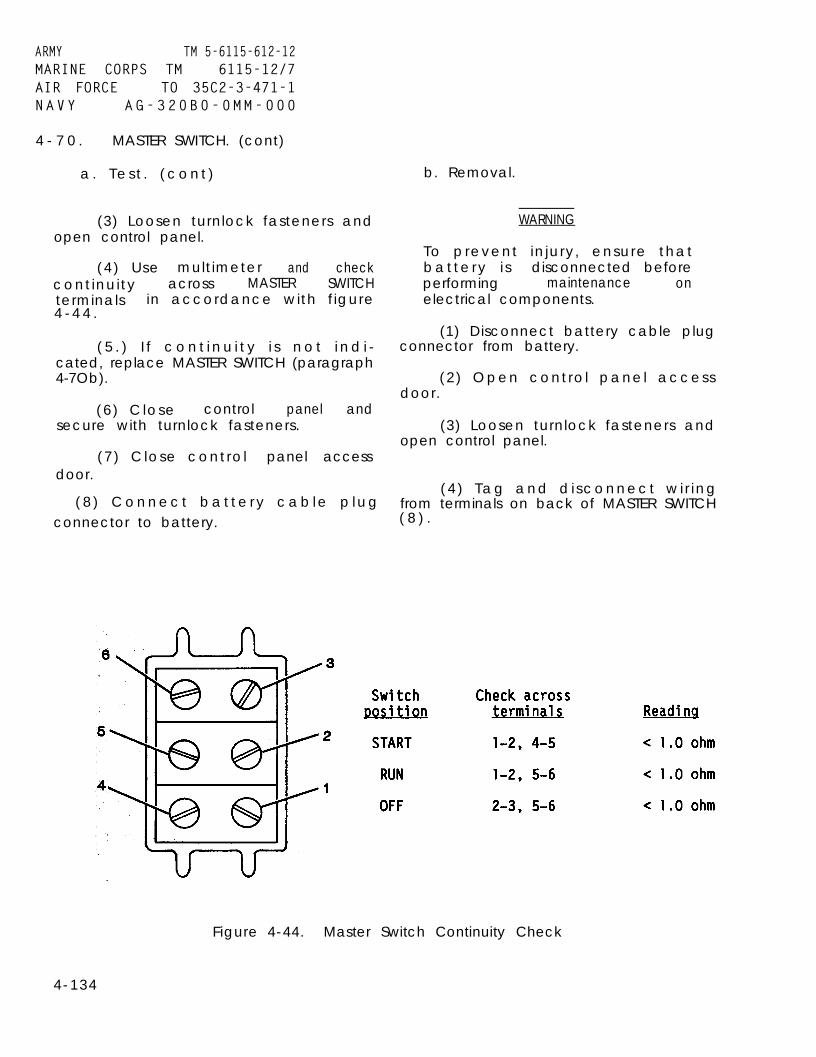
ARMY TM 5-6115-612-12MARINE CORPS TM 6115-12/7AIR FORCE TO 35C2-3-471-1NAVY AG-320B0-0MM-000
4 - 7 0 . MASTER SWITCH. (cont)
a . T e s t . ( c o n t )
(3) Loosen turnlock fasteners andopen control panel.
(4) Use multimeter and checkcont inuity across MASTER SWITCHterminals in accordance with f igure4 - 4 4 .
( 5 . ) I f c o n t i n u i t y i s n o t i n d i -cated, replace MASTER SWITCH (paragraph4-7Ob).
b. Removal.
WARNING
To prevent in jury, ensure thatbat te ry i s disconnected beforeperforming maintenance onelectrical components.
(6) Close control panel andsecure with turnlock fasteners.
(7) Close contro l panel accessdoor.
(1) Disconnect battery cable plugconnector from battery.
(2) Open contro l panel accessdoor.
(3) Loosen turnlock fasteners andopen control panel.
(4 ) Tag and d i sconnect w i r ingfrom terminals on back of MASTER SWITCH( 8 ) .
( 8 ) C o n n e c t b a t t e r y c a b l e p l u gconnector to battery.
Figure 4-44. Master Switch Continuity Check
4-134

4-70. MASTER SWITCH. (cont)
b. Removal. (cont)
(5) On front of panel, remove nut(5). This allows removal of MASTERSWITCH from back of control panel.
(6) Remove lockwasher (6) andlocking ring (7) from MASTER SWITCH.
c. Installation.
(1) Screw locking ring (7) ontoMASTER SWITCH (8).
(2) Place lockwasher (6) on topof locking ring.
(3) From back of control panel,insert threaded portion of new switchthrough mounting hole.
(4) On front of control panel,secure switch with nut. Tighten nutuntil switch is securely mounted.
A R M Y TM 5-6115-612-12MARINE CORPS TM 6115-12/7AIR FORCE TO 35C2-3-471-1N A V Y AG-320B0-0MM-000
a. Removal.
WARNING
To prevent injury, ensure thatbattery is disconnected beforeperforming maintenance onelectrical components.
(1) Disconnect battery cable plugconnector from battery.
(2) Open controld o or.
open
from(15,
(11)
(3) Loosen turnlockcontrol panel.
panel access
fasteners and
(4) Tag and disconnect wiringterminals of panel light socketfigure 4-43).
(5) Remove cover (10) and lampfrom front of control panel.
(5) Remove tags and connectwiring to terminals on back of MASTERSWITCH.
(6) Close control panel andsecure with turnlock fasteners.
(7) Close control panel accessdoor.
(8) Connect battery cable plugconnector to battery.
4-71. HOURMETER. Maintenance of theHOURMETER (9, figure 4-43) con-sistsof replacement. Replacement proceduresfor the HOURMETER are the same as thosefor the BATTERY CHARGING ammeter(paragraph 4-69).
4-72. PANEL LIGHTS. Maintenance ofthe panel lights consists ofreplacement of the lamp socket.
(6) Remove nut (12). This allowsremoval of the panel light socket fromback of panel.
(7) Remove lockwasher (13) andlocking ring (14) from panel lightsocket (15).
b. Installation.
(1) Screw locking ring (14) ontopanel light socket (15).
(2) Place lockwasher (13) on topof locking ring.
(3) From back of control panel,insert new panel light socket throughmounting hole.
(4) On front of panel, securesocket with nut (12). Tighten nutuntil socket is securely mounted.
4-135

A R M Y T M 5 - 6 1 1 5 - 6 1 2 - 1 2MARINE CORPS TM 6115-12/7AIR FORCE TO 35C2-3-471-1N A V Y A G - 3 2 0 B 0 - 0 M M - 0 0 0
4-72. PANEL LIGHTS. (cont)
b. Installation. (cont)
(5) Install lamp (11) and (12)cover.
(6) Remove tags and connectwiring to terminals on back of socket.
(7) Close control panel andsecure with turnlock fasteners.
(8) Close control panel accessd o o r .
(9) Connect battery cable plugconnector to battery.
4-73. INDICATOR LIGHTS. Maintenanceof indicator lights (2, 4, 8, figure4-37) consists of testing a n d
a. Test.
(1) Open control panel accessdoor.
(2) Check press-to-test featureof each indicator light. If lightfails to come on, replace lamp (para-graph 4-74). If light still fails tocome on, proceed to next step.
WARNING
TO Prevent Injury, ensure thatb a t t e r y is disconnected beforeperforming maintenance
electrical components.o n
(3) Disconnect battery cable plugconnector from battery.
(4) Loosen turnlock fasteners andopen control panel.
(5) Use multimeter and checkcontinuity between pin 1 and pin 2.(See figure 4-45. ) If continuity is notIndicated, replace lamp socket(paragraph 4-73 b).
(6) Place multimeter leadsbetween pins 2 and 3. Press lamp hous-ing inward. If continuity is notindicated, replace lamp socket(paragraph 4-73 b).
(7) Close control panel a n dsecure with turnlock fasteners.
(8) Close control panel accessdoor.
(9) Connect battery cable plugconnector to battery.
b. Removal.
WARNING
To prevent injury, ensure thatbattery is disconnected beforeperforming maintenance onelectrical components.
(1)connector
(2)door.
(3)
Disconnect battery cable plugfrom battery.
Open control panel access
Loosen fasteners and opencontrol panel.
(4) Tag and disconnect wiringfrom terminals of indicator lightsocket (20, figure 4-43).
4 - 1 3 6

ARMY TM5-6115–612-12NAVY AG–320B0-0MM-000
4-73. INDICATOR LAMPS. (cont)
Figure 4-45. Indicator Lamp Test
b. Removal. (cont)
(5) Unscrew a n d remove lamphousing (16) and lamp (17).
(6) Remove nut (18). This allowsremoval of indicator light socket fromback of panel.
(7) Remove nut (19) fromindicator light socket (20).
c. Installation.
(1) Screw nut (19) onto indicatorlight socket (20).
(2) From back of panel, insertnew indicator light socket intomounting hole.
(3) On front of panel, securesocket with nut (18). Tighten nutuntil socket is securely mounted.
(4) Install lamp (17) and lamphousing (16).
(5) Remove tags and connectwiring to terminals on back of socket.
(6) Close control panel andsecure with turnlock fasteners. Retestlights and adjust dimmers.
(7) Close control panel accessdoor.
(8) Connect battery cable plugconnector to battery.
4-137

ARMYNAVY
4-74.
TM5-6115-612-12AG-320B0-0MM-000
INCANDESCENT LAMPS. Maintenance ofthe incandescent lamps (17, figure 4-43) is limited toreplacement.
a. Removal.
W A R N I N G
To prevent injury, ensure that battery is dis-connected before performing maintenance onelectrical components.
(1) Disconnect battery cable plug connectorfrom battery.
(2) Open control panel access door.
.(3) Unscrew and remove light cover.
Remove lamp from cover.
b. Installation.a. Test.
(1) lnsert new lamp into cover. Ensure thatlamp base sticks out of light cover.
(2) Insert light cover with lamp into lighthousing and screw in finger tight. Do not use a tool.
(3) Close control panel access door.
(4) Connect battery cable plug connector tob a t t e r y .
4-75. VOLTMETER. Maintenance of the voltmeter(21, figure 4-43) consists of adjustment and replace-m e n t .
a. Adjustment. The procedure for adjustingthe voltmeter is the same as that for adjusting theBATTERY CHARGING ammeter (paragraph 4-69a).
b. Replacement. The procedure for replacingthe voltmeter is the same as that for replacing theBATTERY CHARGING ammeter (paragraph 4-69b).
4-76. AMMETER. Maintenance of the OUTPUTCURRENT ammeter (22, figure 4-43) consists ofadjustment and replacement.
a. Adjustment. The procedure for adjustingthe OUTPUT CURRENT ammeter is the same as thatfor adjusting the BATTERY CHARGING ammeter(paragraph 4-69a).
b. Replacement. The procedure for replacingthe OUTPUT CURRENT ammeter is the same as thatfor replacing the BATTERY CHARGING ammeter(paragraph 4-69b).
4-77. POTENTIOMETER. Maintenance of theVOLTAGE ADJUST potentiometer consists of testingand replacement.
WARNING
To prevent injury, ensure that battery is dis-connected before performing maintenance onelectrical components.
(1) Disconnect battery cable plug connectorfrom battery.
(2) Open control panel access door.
(3) Loosen turnlock fasteners and opencontrol panel.
(4) Tag and disconnect wires from poten-tiometer (27, figure 4-43).
4 - 1 3 8 Change 2

ARMY TM5-6115–612-12NAVY AG-320B0-0MM–000
4-77. POTENTIOMETER. (cont)
a. Tes t . (cont)
(5) Set multimeter to measure resistance.Place one probe on right contact and one on centercontact.
(6) On front of control panel, turn VOLTAGEADJUST knob (24) from all the way to the Ieft to all theway to the right. Resistance reading should go from 0to 10k ohms. If not, replace potentiometer (paragraph4-77b.)
(7) Remove tag and connect wires to poten-tiometer.
(8) Close control panel and secure withturnlock fasteners.
(9) Close control panel access door.
(10) Connect battery cable plug connector tobattery.
b. Removal.
WARNING
To prevent injury, ensure that battery is dis-connected before performing maintenance onelectrical components.
(1) Disconnect battery cable plug connectorfrom battery.
(2) Open control panel access door.
(3) Loosen turnlock fasteners and opencontrol panel.
(4) Tag and disconnect wiring from termi-nals of VOLTAGE ADJUST potentiometer (27).
(5) Turn VOLTAGE ADJUST knob (24)counterclockwise until it stops.
(6) Remove setscrew (23) and VOLTAGEADJUST knob (24).
(7) Remove nut (25). This allows removal ofpotentiometer from back of panel.
(8) Remove washer (26) from potentiome-ter (27).
c. Installation.
(1) Turn shaft on new potentiometer (27)counterclockwise until it stops.
(2) Place washer (26) on potentiometer.
(3) From back of panel, insert new poten-tiometer into mounting hole.
(4) Secure potentiometer with nut (25).Before tightening nut, ensure that potentiometer shaftis positioned so that VOLTAGE ADJUST knob will bepointing all the way left when looking at front ofcontrol panel. Tighten nut until potentiometer issecurely mounted.
(5) Place VOLTAGE ADJUST knob (24) onshaft and secure with setscrew (23).
(6) Remove tags and connect wiring to ter-minals on back of potentiometer.
(7) Close control panel and secure withturnlock fasteners.
(8) Close control panel access door.
(9) Connect battery cable plug connector tobattery.
Change 2 4-139

ARMYNAVY
TM5-6115-612-12AG-320BO-OMM-OO0
4-78. SWITCHES. Maintenance of the control panel switches consists oftesting and replacement.
a. Test.
WARNING
To prevent Injury, ensure thatbattery is disconnected beforeperforming maintenance o nelectrical components.
(1) Disconnect battery cable plugconnector from battery.
(2) Open control panel accessdoor.
(3) Loosen turnlock fasteners andopen control panel.
(4) Perform continuity check onDC CIRCUIT BREAKER (28, figure 4-43).
(a) Ensure that reset button onfront of panel is pressed in.
(b) Place multimeter probesacross terminals of DC CIRCUITBREAKER. Multimeter reading shouldshow less than 1 ohm. If reading ismore than 1 ohm, replace DC CIRCUITBREAKER (paragraph 4-78b).
(5) Perform continuity check onCONTACTOR switch (29, figure 4-43.)
(a) Refer to figure 4-46 andplace multimeter probes on terminals 2and 3 of CONTACTOR switch.
(b) Place CONTACTOR switch inOPEN position. Multimeter readingshould be less than one ohm. If read-ing is more than one ohm, replaceCONTACTOR switch (paragraph 4-78b).
Figure 4-46. Contactor Switch Test
4-140

ARMY TM 5-6115-612-12MARINE CORPS TM 6115-12/7AIR FORCE TO 35C2-3-471-1N A VY AG-320B0-0MM-000
4-78. SWITCHES. (cont)
a. Test. (cont)
(c) Place multimeter probes onterminals 1 and 2 of CONTACTOR switch.
(d) Place CONTACTOR switch inCLOSED position. Multimeter readingshould be less than one ohm. If read-ing is more than one ohm, replaceCONTACTOR switch (paragraph 4-78b).
(6) Tag and disconnect wires andperform continuity check on PANELLIGHTS switch (30, figure 4-43).
(a) Place multimeter probesacross terminals of PANEL LIGHTS switch.
(b) Move switch between ON andOFF. Multimeter reading should go fromabout one ohm (ON) to a very highresistance (OFF). If not, replacePANEL LIGHTS switch (paragraph 4-78b).
(7) Close control panel andsecure with turnlock fasteners.
(8) Close control panel accessdoor.
(9) Connect battery cable plugconnector to battery.
b. Replacement. Replacement pro-cedures for the DC CIRCUIT BREAKERswitch, CONTACTOR switch, and the PANELLIGHTS switch are the same as those forthe MASTER SWITCH (paragraph 4-70).
4-79. HIRING HARNESSES. Maintenanceof the wiring harnesses consists ofinspection, testing, repair, andreplacement. Each wiring harness ismade up of tie-wrapped cables thatinterconnect all of the sensing/controlinputs and outputs leading to theengine and generator. See F0-1 forwiring harness locations.
a. Inspection.
WARNING
To prevent injury, ensure thatbattery is disconnected beforeperforming maintenance onelectrical components.
(1)connector
(2)door.
(3)
Disconnect battery cable plugfrom battery.
Open control panel access
Loosen turnlock fasteners andopen control panel.
(4) Disconnect wiring harnessconnectors one at a time from terminalson back of control panel.
(5) Inspect wiring harness con-nectors for evidence of excess wear ordamage such as broken or bent connectorpins, broken wires, or unsoldered wires.
(6) Connect wiring harness con-nectors to control panel.
(7) Close control p a nel a n dsecure with turnlock fasteners.
(8) Loosen turnlock fasteners andremove EECM access cover.
(9) Disconnect wiring harnessesthat mate to EECM. Inspect for bentpins, loose or broken wires, or damagedmechanical parts on the connectorbodies.
(10) Connect wiring harnessconnectors to EECM.
4-141

ARMY TM 5-6115-612-12MARINE CORPS TM6115-12/7AIR FORCE TO 35C2-3-471-1N A V Y AG-320B0-0MM-000
4-79. WIRING HARNESSES. (cont)
a. Inspection. (cont)
(11) Gain access to other areasof generator set where wiring harnessesconnect (EGT thermocouple, monopolespeed sensor, engine, and generator).Inspect each connecting wire for brokenconnections, bent connecting terminals,or loose or broken terminals.
(12) Close and secure all accesspoints.
(13) Connect battery cable plugconnector to battery.
b. Test. Testing the wiring har-nesses is done by making continuitychecks from point to point on the har-nesses wires and connectors. Access mustbe gained to every location where awiring harness terminates in a con-nector, lug, or other terminal. Inter-connecting points on the harness areshown in F0-3. If any abnormalindication is noted during thefollowing procedure, refer to paragraph4-79d for repair.
WARNING
To prevent injury, ensure that
p e r f o r m i n gbattery is disconnected before
maintenance o nelectrical components.
.
(1) Disconnect battery cable plugconnector from battery.
(2) Gain access to areas wherewiring harness ends in a connectionpoint and testing is to be done.
(3) Use multitinuity checks. Ifdiscovred, refer
meter to make con-an open circuit isto paragraph 4-79d
c. Wiring Harness W2 Removal.
WARNING
To prevent injury, ensure thatbattery is disconnected beforeperforming maintenance o nelectrical components.
(1) Disconnect battery cable plugconnector.
(2) Open control panel accessdoor.
(3) Loosen turnlock fasteners andopen control panel.
(4) Tag and disconnect wiringharness W2 from GECM connectors J2 andJ3.
(5) On back of control panel, tagand disconnect all wiring connectionsto control panel components andterminal board TB3.
(6) Close control panel.
(7) Loosen turnlock fasteners andremove EECM access cover.
(8) Tag and disconnect wiringharness W2 from EECM connectors J4 andJ6.
(9) Remove power cable from cablesupport.
(10) Unlatch and open inlet airhousing access door. Secure in openposition.
for repair.(11) Remove air baffle (paragraph
4-22).
4-142

ARMY TM 5-6115-612-12MARINE CORPS TM 6115-12/7AIR FORCE TO 35C2-3-471-1NAVY AG-320B0-0MM-000
4-79. HIRING HARNESSES. (cont)
Hiring Harness W2 Removal.(Cont)
(12) Pull wiring harness W2 outof control fender and into inlet airhousing.
(13) Tag and disconnect wiringharness W2 connections from terminalboard T B 1 a n d other electricalcomponents mounted in inlet air housing.
(14) Remove wiring harness W2from inlet air housing.
d. Wirinq Harness W2 Repair.Remove connectors and replace damagedwiring as necessary.
e. Wirinq Harness W2 Installation.
(1) Pass wiring harness W2through inlet air housing into controlfender.
(2) Remove tags and connect wir-ing harness W2 connections to terminalboard TB1 and other electricalcomponents mounted in inlet air housing.
(3) Install air baffle (paragraph4-22).
(4) Close and securely latchinlet air housing access door.
(5) Stow power cable on cablesupport.
(6) Remove tags and connect wir-ing harness W2 to EECM connectors J4and J6.
(7) Install EECM access cover andsecure with turnlock fasteners.
(8) Open control panel.
(9) On back of control panel,connect wiring harness W2 to controlpanel components.
(10) Remove tags and connect wir-ing harness W2 to GECM connectors J2and J3.
(11) Close control panel a n dsecure with turnlock fasteners.
(12) Close control panel accessdoor.
(13) Connect battery cable plugconnector to battery.
f. Wiring Harness W3 Removal,
WARNING
To prevent injury, ensure thatbattery is disconnected beforeperforming maintenance onelectrical components.
(1) Disconnect battery cable plugconnector from battery.
(2) Remove power cable from cablesupport.
(3) Unlatch and open fuel housingaccess door. Secure in open position.
(4) Tag and disconnect electricalconnectors from transfer pump, solenoidvalve, and high pressure pump.
(5) Remove nuts, washers, andscrews to free wiring harness from loopclamps in fuel housing. (See figure4-47.)
(6) Loosen turnlock fasteners andremove engine housing access cover.
4-143
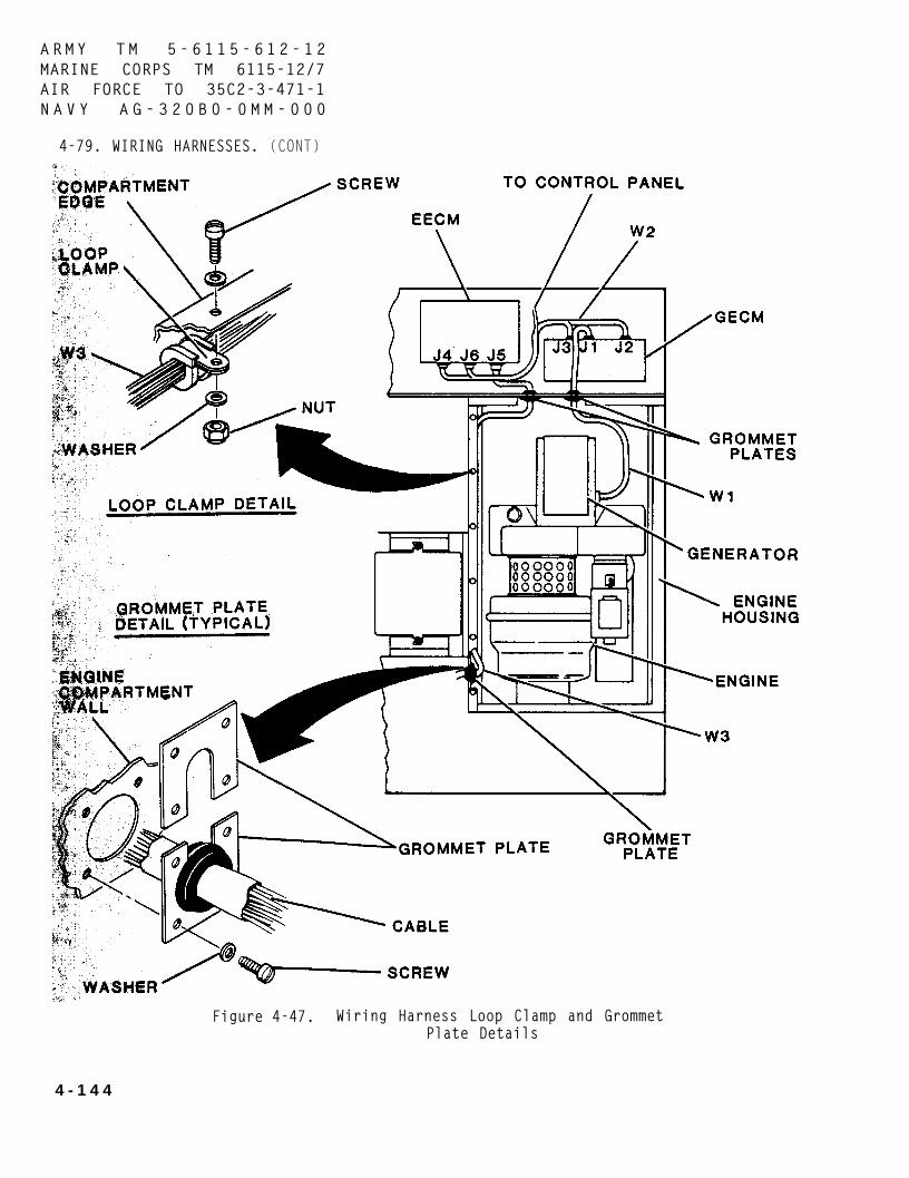
ARMY TM 5-6115-612-12MARINE CORPS TM 6115-12/7AIR FORCE TO 35C2-3-471-1N A V Y A G - 3 2 0 B 0 - 0 M M - 0 0 0
4-79. WIRING HARNESSES. (CONT)
Figure 4-47. Wiring Harness Loop Clamp and GrommetPlate Details
4 - 1 4 4

4-79. WIRING HARNESSES. (cont)
f. Wiring Harness W3 Removal.(cont)
(7) Tag and disconnect electricalconnectors/leads from low oil pressureswitch, monopole speed sensor, EGTthermocouple, ignition coil, andstarter.
(8) Where wiring harness W3passes through engine housing bulkheadto fuel housing, remove screws andwasher that secure grommet plate tobulkhead. See figure 4-44. Carefullypull wiring harness W3 through bulkheadinto engine housing.
(9) Remove nuts, washers, andscrews and loop clamps that securewiring harness W3 to engine housing.
(10) Open control panel accessd o o r .
(11) Loosen turnlock fastenersand open control panel.
(12)harnessterminals
(13)
(14)and remove
(15)harness W3
(16)
Tag and disconnect wiringW 3 connections on TB3,1 and 19.
Close control panel.
Loosen turnlock fastenersEECM access cover.
Tag and disconnect wiringfrom EECM connector J5.
In engine housing, locategrommet plate mounted on bulkhead sepa-rating engine housing from EECMcompartment. Remove screws and washersthat secure grommet plate to bulkhead.
(17) Carefully pull wiringharness W3 through-bulkhead into enginehousing.
ARMY TM 5-6115-612-12MARINE CORPS TM 6115-12/7AIR FORCE TO 35C2-3-471-1NAVY AG-320B0-0MM-000
(18) Remove wiring harness W3from engine housing.
g.Removewiring
h.
Wiring Harness W3 Repair.connectors and replace damagedas necessary.
Wiring Harness W3 Installation.
(1) Carefully place wiringharness W3 in engine housing.
(2) Pass connector throughbulkhead into EECM housing. Connect toEECM connector J5.
(3) Install EECM access cover andsecure with turnlock fasteners.
(4) Open control panel.
(5) Remove tags and connectwiring harness W3 connections to TB3,terminals 1 and 19.
(6) Close control panel andsecure with turnlock fasteners.
(7) Close control panel accessdoor.
(8) Use washers and screws tosecure grommet plate to bulkheadseparating engine housing from EECM.See figure 4-47.
(9) Secure wiring harness W3 toedge of engine housing compartment withLoop clamps, screws, washers, andnuts. See figure 4-44.
(10) Remove tag and connect leadto starter.
4-145

A R M Y TM 5-6115-612-12MARINE CORPS TM 6115-12/7AIR FORCE TO 35C2-3-471-1N A V Y AG-320B0-0MM-000
4-79. WIRING HARNESSES. (cont)
h. Wiring Harness W3 Installation.(cont)
(11) Remove tag and connectwiring harness W3 electrical connectorsto low oil pressure switch, monopolespeed sensor, EGT thermocouple, andignition coil.
(12) Pass remainder of wharness W3 through bulkhead intohousing.
(13) Secure grommet platebulkhead with washers and screws.
iringfuel
t oSee
(14) Remove tags a n d connectwiring harness W3 electrical connectorsto transfer pump, solenoid valve, andhigh pressure pump.
(15) Install loop clamps withscrews, washers, and nuts.
(16) Close and securely latchfuel housing access door.
(17) Install engine housingaccess cover and secure with turnlockfasteners.
(18) Stow power cable on cablesupport.
(19) Connect battery cable plugconnector to battery.figure 4-47.
4 - 1 4 6

ARMY TM 5-6115-612-12MARINE CORPS TM 6115-12/7AIR FORCE TO 35C2-3-471-1NAVY AG-320B0-0MM-000
Section XV. MAINTENANCE OF LOAD CONNECTION
4-80. GENERAL. The load connectionprovides a central location for con-necting all electrical components thatprovide power for generator set opera-tion and aircraft startup. The loadconnection is located in the inlet airhousing. The system includes the powercable assembly. The remaining compo-nents are mounted on a componentmounting panel and include the magneticoutput contactor, 1000 amp currentshunt, terminal boards, an RF filter,capacitor, and a resistor.
NOTE
If not specified in maintenanceprocedure, apply torque inaccordance with table 1-1, TorqueSpecifications.
4-81. POWER CABLE ASSEMBLY. Mainte-nance of the power cable assembly islimited to replacement. Refer tofigure 4-48.
a. Removal.
(1) Remove power cable from cablesupport.
WARNING
To prevent injury, ensure thatbattery is disconnected beforeperforming maintenance onelectrical components.
(2) Disconnect battery cable plugconnector from battery.
(3) Remove screws (1), washers(2), and output/slave housing accesscover (3).
(4) Unlatch and open inlet airhousing access door. Secure in openposition.
(5) Tag power cable sense wireleads. Remove nuts (4), washers (5),and power cable sense wire leads fromterminal board (TB6). This connectionis located on the component mountingpanel in the inlet air housing. Pullpower cable sense wire through bulkheadgrommet into battery housing.
(6) Remove screws (6), washers(7), and output cable housing (8). Thescrews and washers are mounted in theinlet air housing.
(7) Remove screws (9), washers(10), nuts (11), and loop clamps (12).
(8) Remove nuts (13), washers(14), and power cable lugs from bulk-head feedthrough studs. Pull leadsthrough bottom of output/slave housing.
(9) If necessary to removecapacitors (18), remove nut (15),washers (16), and screw (17).
b. Installation.
(1) If necessarycapacitors (18), install(17), washers (16), andTorque to 36-40 inch pounds
to replacewith screwnut (15).
(4-4.5 Nm).
(2) Pass power cable leadsthrough bottom of output/slavehousing. Install leads on bulkheadfeedthrough studs and secure withwashers (14) and nuts (13). Torqueassembly on smaller stud 200-270 inchpounds (22.6-30.5 Nm). Torque assemblyon larger stud 500-650 inch pounds(56.5-73.4 Nm).
(3) Pass power cable sense wirethrough bulkhead grommet into inlet airhousing. Install sense wire leads onterminal board (TB6) and secure with
4-147

A R M Y TM 5-6115-612-12MARINE CORPS TM 6115-12/7AIR FORCEN A V Y
T0 35C2-3-471-1AG-320B0-0MM-000
4 - 8 1 . POWER CABLE ASSEMBLY. (cont)
Figure 4-48. Power Cable Replacement
4 - 1 4 8

4-81. POWER CABLE ASSEMBLY.
b. Installation. (cont)
washers (5) and nuts (4).24-36 inch pounds (2.7-4 Nm)
(cont)
Torque to
(4) Install loop clamps (12) andsecure with washers (10), screws (9),and nuts (11). Torque to 36-40 inchpounds (4-4.5 Nm).
(5) Install output cable housing(8) and secure with washers (7) andscrews (6).
(6) Close and securely latchinlet air housing access door.
(7) Install output/slave housingaccess cover (3) and secure withwashers (2) and screws (1). Torque to24-36 inch pounds (2.7-4 Nm).
(8) Connect battery cable plugconnector to battery.
(9) Install power cable on cablesupport.
4-82. COMPONENT MOUNTING PANEL.Maintenance of the component mountingpanel (figure 4-49) is limited toreplacement.
a. Removal.
(1) Remove power cable from cablesupport.
WARNING
To prevent injury, ensure thatbattery is disconnected beforeperforming maintenance onelectrical components.
b. Installation.
(2) Disconnect battery cable plugconnector.
ARMY TM 5-6115-612-12MARINE CORPS TM 6115-12/7AIR FORCE TO 35C2-3-471-1NAVY AG-320B0-0MM-000
(3) Unlatch and open inlet airhousing access door. Secure in openposition.
(4) Loosen turnlock fasteners andremove engine housing access cover.
(5) Remove air baffle from inletair housing (paragraph 4-22).
(6) Carefully tag and disconnectall wiring connected to componentsinstalled on mounting panel.
(7) Remove screws (l), washers(2), and self-locking nuts (3) thatsecure mounting panel (4) in inlet airhousing. Carefully remove panel.
(8) Remove components frommounting panel . Component removalprocedures are presented in paragraphs4-83 through 4-88.
(1) Refer to paragraphs 4-83through 4-88 and install components onmounting panel (4).
(2) Carefully place panel inposition in inlet air housing. Securewith bolts (1), washers (2), andself-locking nuts (3). Torque to 36-40inch pounds (4-4.5 Nm).
(3) Connect wiring tocomponents. Remove tags.
(4) Refer to paragraph 4-22 andinstall air baffle.
(5) Install engine housing accesscover and secure with turnlockfasteners.
(6) Close a n d securely latchinlet air housing access door.
4-149
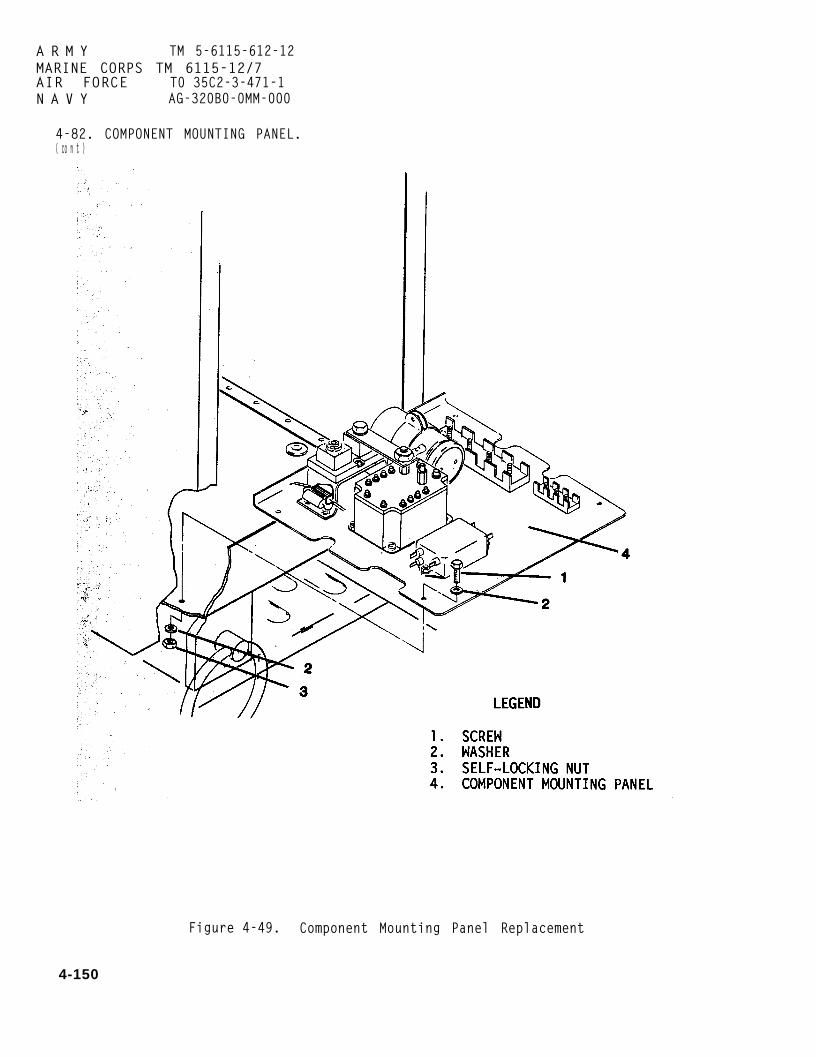
A R M Y TM 5-6115-612-12MARINE CORPS TM 6115-12/7AIR FORCE T0 35C2-3-471-1N A V Y AG-320B0-0MM-000
4-82. COMPONENT MOUNTING PANEL.( co n t )
Figure 4-49. Component Mounting Panel Replacement
4-150

ARMY TM 5-6115-612-12MARINE CORPS TM 6115-12/7AIR FORCE T0 35C2-3-471-1N A VY AG-320B0-0MM-000
4-82. COMPONENT MOUNTING PANEL.(cont)
b. Installation. (cont)
(7) Connect battery cable plugconnector.
(8) Stow power cable on cablesupport.
4-83. MAGNETIC CONTACTOR. Mainte-nance of the magnetic (output)contactor consists of inspection,testing, and replacement.
a. Inspection.
(1) Remove power cable from cablesupport.
WARNING
To prevent injury, ensure thatbattery is disconnected beforeperforming maintenance o nelectrical components.
(2) Disconnect battery cable plugconnector from battery.
(3) Unlatch and open inlet airhousing access door. Secure in openposition.
(4) Loosen turnlock fasteners andremove engine housing access cover.
(5) Remove air baffle from inletair housing (paragraph 4-22).
(6) Inspect output contactterminals for loose connections.Tighten if necessary.
(7) Inspect for corrosion andsigns of arcing. Replace if damaged.
(8) Ensure that output contactoris securely mounted. Tighten ifnecessary.
(9) Install air baffle (paragraph4-22) .
(10) Installaccess cover andfasteners.
(11) Close
engine housingsecure with turnlock
and securely latchinlet air housing access door.
(12) Connect battery cable plugconnector.
(13) Stow power cable on cablesupport.
b. Test Refer to the magneticcontactor schematic (figure 4-50).
(1) Remove power cable from cablesupport.
WARNING
To prevent injury, ensure thatbattery is disconnected beforeperforming maintenance o nelectrical components.
(2) Disconnect battery cable plugconnector from battery.
(3) Unlatch and open inlet airhousing access door. Secure in openposition.
(4) Loosen turnlock fasteners andremove engine housing access cover.
(5) Remove air baffle from inletair housing (paragraph 4-22).
4-151

A R M Y TM 5-6115-612-12MARINE CORPS TM 6115-12/7AIR FORCE TO 35C2-3-471-1N A V Y AG-320B0-0MM-000
4-83. MAGNETIC CONTACTOR. (cont)
b. Test. (cont)
(6) Tag and disconnect wiring.perform continuity check on outputcontactor. If shorts and opens arepresent, replace output contactor.
(7) Install air baffle (paragraph4 - 2 2 ) .
(8) Install engine housing accesscover and secure with turnlockfasteners.
(9) Close and securely latchInlet air housing access door.
(10) Connect battery cable plugconnector.
(11) Stow power cable on cable
c. Removal. Refer to figure 4-51.
(1) Remove component mountingpanel (paragraph 4-82).
(2) Tag and disconnect all wiringfrom output contactor (6).
(3) Disconnect conductor bus (1)from current shunt (2).
(4) Remove nuts (3), washers (4),and self-locking nuts (5) that securecontactor to component mounting panel.
d. Installation.
(1) Place contactor (6) in posi-tion on component mounting panel.Secure with screws (5), washers (4),and nuts (3). Torque to 32-35 inchpounds (3.6-3.9 Nm).support.
Figure 4-50. Magnetic Contactor Schematic (Off Position)
4-152

4-83. MAGNETIC CONTACTOR. (cont)
ARMY TM 5-6115-612-12MARINE CORPS TM 6115-12/7AIR FORCE TO 35C2-3-471-1NAVY AG-320B0-0MM-000
Figure 4-51. Magnetic Contactor/Capacitor (C4) Replacement
4-153

A R M Y TM 5-6115-612-12MARINE CORPS TM6115-12/7AIR FORCE. TO 35C2-3-471-1NAVY AG-320B0-0MM-000
4-83. MAGNETIC CONTACTOR. (cont)
d. Installation. (cont)
(2) Connect conductor bus (1) tocurrent shunt (2).
(3) Connect wiring to contactor.Remove all tags.
(4) Install component mountingPanel (paragraph 4-82).
4-84. CURRENT SHUNT (1000 AMP).Maintenance of the 1000 amp currentshunt (figure 4-52) is limited toinspection and replacement.
a. Inspection.
(1) Remove power cable from cableSupport.
W A R N I N G
To prevent injury, ensure thatbattery is disconnected beforeperforming maintenance onelectrical components.
(2) Disconnect battery cable plugconnector.
(3) Unlatch and open inlet airhousing access door. Secure in openposition.
(4) Loosen turnlock fasteners andremove engine housing access cover.
(5) Remove air baffle from inletair housing (paragraph 4-22).
(6) Ensure that current shunt (9,figure 4-52) is securely mounted.Tighten any loose connections.
(7) Check input and output lugsfor discoloration. Discoloration couldindicate a loosening of connectionswhile the generator set is operating.Tighten any loose connections.
(8) If current shunt is dirty,clean with compressed air or with anelectrical grade solvent.
(9) Check current shunt fordamage. Replace shunt if physicallydamaged.
(10) Install air baffle(paragraph 4-22).
(11) Install engine housingaccess cover and secure with turnlockfasteners.
(12) Close and securely latchinlet air housing access door.
(13) Connect battery cable plugconnector.
(14) Stow power cable on cablesupport.
b. Removal.
(1) Remove component mountingpanel (paragraph 4-82).
(2) Tag wire U109A18 (1, figure4-52). Remove screw (2) and lockwasher(3) to disconnect wire from terminal D.
(3) Tag wire U110A18 (4). Removescrew (5) and lockwasher (6) todisconnect wire from terminal C.
(4) Tag wire P108A00 (9). Removebolt (7), lockwasher (8), wire P108AOO(9), and washer (10) from current shunt(11).
4-154

ARMY TM 5-6115-612-12MARINE CORPS TM 6115-12/7AIR FORCE TO 35C2-3-471-1N A V Y AG-320B0-0MM-000
4-84. CURRENT SHUNT (1000 AMP).(cont)
Figure 4-52. Current Shunt (1000 Amp)/Resistor (R5)Replacement
4-155

ARMY T M 5 - 6 1 1 5 - 6 1 2 - 1 2M A R I N E C O R P S T M 6 1 1 5 - 1 2 / 7AIR FORCE T O 3 5 C 2 - 3 - 4 7 1 - 1NAVY A G - 3 2 0 B 0 - 0 M M - 0 0 0
4 - 8 4 . CURRENT SHUNT ( 1 0 0 0 AMP) .(cont)
b. Removal. (cont)
(5) Loosen nut (12).
(6) Remove bolt (13) andlockwasher (14). Rotate conductor bus(15) away from current shunt. Removewasher (16).
(7) Remove self-locking nut (17),washer (18), and screw (19) that securecurrent shunt to shunt mounting bracket(20). Remove current shunt.
c. Installation.
(1) Place current shunt (11) onshunt mounting bracket (20).
(2) Install screw (19) throughshunt and shunt mounting bracket.Secure with washers (18) andself-locking nuts (17). Torque to32-35 inch pounds (3.6-3.9 Nm).
(3) Place washer (16) on terminalA of current shunt. Rotatebus (15) toward terminalmounting holes are alined.conductor bus to terminallockwasher (14) and bolt (13).
(4) Tighten nut (12).
(5) Place washer (10)
conductorA until
SecureA with
and wireP108AOO (9) on terminal B. Secure withlockwasher (6) and bolt (7).
(6) Connect wire U109A18 (1) toterminal D with lockwasher (3) andscrew (2) and tighten, Remove tag.
(7) Connect wire U11OA18 (4) withlockwasher (6) and screw (5) andtighten. Remove tag.
4 - 1 5 6
(8) Install component mountingpanel (paragraph 4-82).
4 - 8 5 . TERMINAL BOARDS . Mainte-nance of terminal boards TB1 and TB6(figure 4-53) consists of inspectionand replacement. Procedures are thesame for both boards.
a. Inspection.
(1) Remove powersupport.
cable from cable
WARNING
To prevent injury, ensure thatbattery is disconnected beforeperforming maintenance onelectrical components.
(2) Disconnect battery cable plugconnector.
(3) Unlatch and open inlet airhousing access door. Secure in openposition.
(4) Loosen turnlock fasteners andremove engine housing access cover.
(5) Remove air baffle (paragraph4-22).
(6) Ensure thatare securely mounted.
(7) Ensure that
terminal boardsTighten if loose.
all wires aresecurely attached. Tighten if loose.
(8) If terminal boards are dirty,clean with compressed air or electricalgrade solvent.
(9) Replacedamaged.
terminal b o a r d s i f

4-85. TERMINAL BOARDS. (cont)
ARMY TM 5-6115-612-12MARINE CORPS TM 6115-12/7AIR FORCE TO 35C2-3-471-1NAVY AG-320B0-0MM-000
Figure 4-53. Terminal Board/RF Filter (FL1) Replacement
4-157
ARMY T M 5 - 6 1 1 5 - 6 1 2 - 1 2M A R I N E C O R P S T M 6 1 1 5 - 1 2 / 7AIR FORCE T O 3 5 C 2 - 3 - 4 7 1 - 1NAVY A G - 3 2 0 B 0 - 0 M M - 0 0 0
4 - 8 5 . TERMINAL BOARDS. (cont)
a. Inspection. (cont)
(10) Install air(paragraph 4-22).
(11) Install engineaccess cover and secure withfasteners.
(12) Close and securelyinlet air housing access door.
baffle
housingturnlock
latch
(13) Connect battery cable plugconnector.
(14) Stow power cable on cablesupport.
b. Removal.
(1) Remove component mountingpanel (paragraph 4-82).
(2) Tag and disconnect wiringfrom terminal board to be replaced.
(3) Remove screws (1, figure4-53), washers (2) and nuts (3) thatsecure terminal board to componentmounting panel.
c. Repair. The terminal boards arenot repairable. If damaged, replacewith a new terminal board.
d. Installation.
(1) Put terminal board inposition and secure with screws (1),washers (2), and nuts (3). Torque onTB1 is 12-14 inch pounds (1.3-1.5 Nm).Torque on TB6 is 4.5-6 inch pounds(0.5-0.6 Nm).
(2) Connect wiring to terminalboard. Remove tags.
(3) Install component mountingpanel (paragraph 4-82).
4 - 8 6 . R F F I L T E R ( F L 1 ) . Maintenanceof the RF filter (figurelimited to replacement.
a. Removal.
(1) Remove componentpanel (paragraph 4-82).
(2) Tag and disconnectleads from filter terminals.
(3) Remove screws (4),
4-53) is
mounting
electrical
washers(5), and self-locking nuts (6) thatsecure filter (7) to component mountingpanel.
b. Installation.
(1) Place filter (7) in positionon component mounting panel and securewith screws (4), washers (5), andself-locking nuts (6). Torque to 23-26inch pounds (2.6-2.9 Nm).
(2) Connect electrical leads tofilter terminals with screws. Removetags.
(3) Install component mountingpanel (paragraph 4-82).
4 - 8 7 . CAPACITOR ( C 4 ) . Maintenanceof capacitor C4 (10, figure 4-51) islimited to replacement.
a. Removal.
(1) Remove component mountingpanel (paragraph 4-82).
WARNING
To prevent injury, ensure thatcapacitor is discharged to groundprior to removal.
(2) Discharge capacitor to ground.
4 - 1 5 8

4-87. CAPACITOR (C4). (cont)
a. Removal. (cont)
(3) Tag and disconnect electricalcads (12, 13) from capacitor.
(4) Remove screw (7), washers(8), and self-locking nut (9) thatsecure capacitor (10) in mountingbracket (11). Remove capacitor.
b. Installation.
(1) Place capacitor (10) inmounting bracket (11) and secure withscrew (7), washers (8), and nut (9).Torque to 74-82 inch pounds (8.4-9.3Nm).
(2) Connect electrical leads (12,13) to capacitor. Remove tags.
(3) Install component mountingpanel (paragraph 4-82).
4-88. RESISTOR (R5). Maintenance ofresistor R5 (24, figure 4-52) islimited to replacement.
ARMY TM 5-6115-612-12MARINE CORPS TM 6115-12/7AIR FORCE TO 35C2-3-471-1NAVY AG-320B0-0MM-000
a. Removal.
(1) Remove component mountingpanel (paragraph 4-82).
(2) Tag and disconnect electricalleads from resistor.
(3) Remove screws (21), nuts(22), and lockwashers (23) that secureresistor (24) to current shunt mountingbracket (20).
b. Installation.
(1) Position resistor (24) oncurrent shunt mounting bracket (20) andsecure with screws (21), washers (23),and nuts (22). Torque to 2-4 inchpounds (0.2-0.5 Nm).
(2) Connect electrical leads toresistor.
(3) Install component mountingpanel (paragraph 4-82).
4-159

ARMY TM 5-6115-612-12MARINE CORPS TM 6115-12/7AIR FORCE TO 35C2-3-471-1NAVY AG-320B0-0MM-000
S e c t i o n X V I . MAINTENANCE OF RUNNING GEAR
4 - 8 9 . GENERAL. The running gearprovides the means for moving thegenerator set manually or with a towvehicle. The brake control, consistingof a handbrake and adjustable linkage,will prevent movement of the generatorset when the handbrake lever is placedin the set position. A torsion axleand the associated wheels, tires, andtubes are the components that alloweasy movement of the generator set.The lunette eye is the connecting pointfor a towing vehicle. A swivel casterprovides support for the front of thegenerator set and can be rotated fromthe down position when the set is beingtowed.
NOTE
If not specified in maintenanceprocedure, apply torque inaccordance with table 1-1, TorqueSpecifications.
WARNING
To prevent injury, ensure thatboth wheels are chocked whileperforming maintenance on thebrakes.
(3) If both wheels continue tomove with handbrake set and gripadjusted, chock both wheels.
(4) Remove cotter pin (1, figure4-54) and straight pin (2) that attachclevis (3) to cable equalizing bar (4).
(5) Loosen jamnut (5). Turnclevis clockwise.
(6) Tighten jamnut and attachclevis to cable equalizing bar withstraight pin and cotter pin. Repeatprocedure until wheels no longer move.
(7) If only one wheel moves, an4 - 9 0 . BRAKE CONTROL. Maintenance ofthe brake control consists of ser-vicing, adjustment, replacement, andrepair.
adjustment of the brake cablethat wheel is required.
a. Service. Ensure that all con-nection points are kept clean andproperly lubricated.
b. Adjustment.
(1) Set handbrake and attempt tomove generator set. If neither wheelmoves, brakes do not requireadjustment. If both wheels move,proceed to step (2). If only one wheelmoves, proceed to step (7).
(2) If both wheels move, a minoradjustment can be accomplished byturning the grip on the handbrake leverclockwise.
To preventboth wheelsperformingbrakes.
WARNING
injury, ensureare chocked
maintenance on
link to
thatwhile
the
(8) Chock both wheels.
(9) On side that moves, removecotter pin (6) and straight pin (7)that attach clevis (8) to cableequalizing bar (4).
(10) Loosen jamnut (9). T u r nclevis clockwise.
4 - 1 6 0

4-90. BRAKE CONTROL. (cont)
A R M Y TM 5-6115-612-12MARINE CORPS TM 6115-12/7AIR FORCE T0 35C2-3-471-1N A V Y AG-320B0-0MM-000
Figure 4-54. Brake Control Adjustment
4-161

ARMY T M 5 - 6 1 1 5 - 6 1 2 - 1 2M A R I N E C O R P S T M 6 1 1 5 - 1 2 / 7AIR FORCE T O 3 5 C 2 - 3 - 4 7 1 - 1NAVY A G - 3 2 0 B 0 - 0 M M - 0 0 0
4 - 9 0 . BRAKE CONTROL. (cont)
b. Adjustment. (cont)
(11) Tighten jamnut and attachclevis to cable equalizing bar withstraight pin and cotter pin. Repeatprocedure until wheel no longer
c. Removal.
WARNING
To prevent injury, ensureboth wheels are chockedperforming maintenance onbrakes.
(1) Chock both wheels.
(2) On inside of wheel.
moves.
thatwhile
the
removecotter pins (1, figure 4-55) andstraight pins (2) that release brakecables (17) fromon brake.
(3) Removecapscrews (5),retaining straps
remote control levers
nuts (3), washers (4),lockwashers (6), and(7) to release brake
cables (17) from cable mountingbrackets (8) and generator set frame.
(4) Remove cotter pin (9) andstraight pin (10) to disconnect clevis(11) from cable equalizing bar (12).
(5) Remove cotter pins (13) andstraight pins (17) to disconnect brakecables (17) from cable equalizing bar(12).
(6) Unscrew clevis (15) andjamnut (16) from brake cables (17).
4 - 1 6 2
(7) Unscrew jamnuts (18, 19) toremove brake rod (20) from clevis (11)and clevis (21).
(8) Remove cotter pin (22) andstraight pin (23) to remove clevis (21)from bellcrank (24).
(9) Remove cotter pinstraight pin (26) to free(24) from bellcrank mounting(36).
(10) Remove cotter pinstraight pin (28) to remove(24) from clevis (30).
(22) andbellcrankbrackets
(27) andbellcrank
(11) Unscrew jamnuts (29) andclevis (30) to remove those items andbrake rod (31) from handbrake controllever (32).
(12) Remove nuts (33), washers(34), capscrews (35), and bellcrankmounting brackets (36).
(13) Remove(38), spacers (39),washers (41) tomounting bracketscontrol lever.
nuts (37), washerscapscrews (40), andseparate handbrake(42) from handbrake
d. Repair. Repair is accomplishedby replacing damaged parts.
e. Installation.
(1) Alinemounting holesbrackets (42).
(2) Placecapscrews (40).position inside(32) and insert
handbrake control leverin handbrake mounting
washers (41) onPlace spacers (39) in
handbrake control levercapscrews.
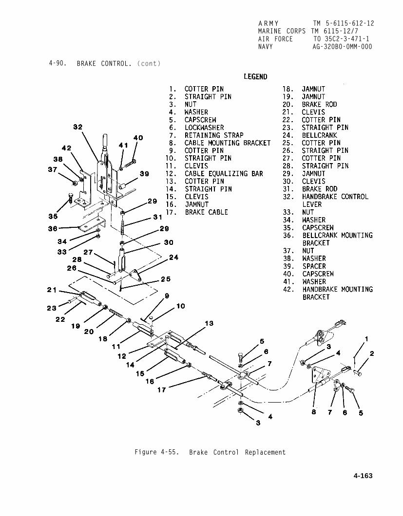
ARMY TM 5-6115-612-12MARINE CORPS TM 6115-12/7AIR FORCE TO 35C2-3-471-1NAVY AG-320B0-0MM-000
4-90. BRAKE CONTROL. (cont)
Figure 4-55. Brake Control Replacement
4-163

ARMY TM 5-6115-612-12M A R I N E CORPS TM 6115-12/7AIR FORCE T O 3 5 C 2 - 3 - 4 7 1 - 1NAVY A G - 3 2 0 B 0 - 0 M M - 0 0 0
4 - 9 0 . BRAKE CONTROL. (cont)
e. Installation. (cont)
(3) Install washers (38) and nuts(37). Torque to 270-300 inch pounds(30.5-33.9 Nm).
(4) Install bellcrank mountingbrackets (36) and secure with capscrews(35), washers (34), and nuts (33).Torque to 74-82 inch pounds (8.4-9.3Nm).
(5) Screw jamnuts (29) on brakerod (31). Screw one end of brake rodinto clevis (30) and one end intohandbrake control lever.
(6) Secure clevis (30) tobellcrank (24) with straight pin (28)and cotter pin (27).
(7) Secure bellcrank mountingbracket (36) with straight pin (26) andcotter pin (25).
(8) Securebellcrank withcotter pin (22).
(9) Screwbrake rod (20).one end of brakeother end.
clevis (21) tostraight pin (23) and
jamnuts (18, 19) onScrew clevis (12) on
rod and clevis (21) on
(10) Attach clevisequalizing bar (12) with(10) and cotter pin (9).
(21) to cablestraight pin
(11) Screw jamnuts (16) andclevis (15) on ends of brake cables(17).
(12) Secure clevis (15) to cableequalizing bar with straight pins (14)and cotter pins (13).
4 - 1 6 4
(13) Secure brake cable togenerator set frame with retainingstraps (7), lockwashers (6), capscrews(5), washers (4), and nuts (3). Torqueto 50-70 inch pounds (5.6-7.9 Nm).
(14) Secure brake cable to cablemounting brackets (8) with remainingretaining straps, lockwashers,capscrews, washers, and nuts. Torqueto 50-70 inch pounds (5.6-7.9 Nm).
(15) Secure end of brake cablesto remote control levers on brake withstraight pins (2) and cotter pins (1).
(16) Adjust handbrake asnecessary (paragraph 4-90b).
4 - 9 1 . TORSIONtenance of the(figure 4-56) is
AXLE ASSEMBLY. Main-torsion axle assemblylimited to inspection.
WARNING
To prevent injury, ensure thathandbrake is set and wheels arechocked before inspecting torsionaxle.
a. Set handbrake and chock bothwheels.
b. Inspectfor damage anding parts.Report damagemaintenance.
c. Remove
torsion axle assemblyloose or missing attach-Tighten loose parts.to direct support for
grease cap and ensurethat cotter pin is securely installedthrough spindle.
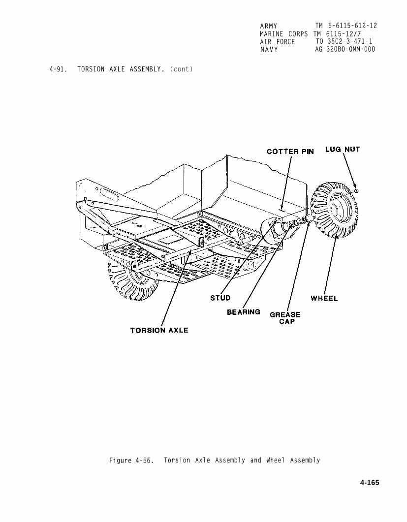
ARMY TM 5-6115-612-12MARINE CORPS TM 6115-12/7AIR FORCE TO 35C2-3-471-1NAVY AG-320B0-0MM-000
4-91. TORSION AXLE ASSEMBLY. (cont)
Figure 4-56. Torsion Axle Assembly and Wheel Assembly
4-165

ARMY T M 5 - 6 1 1 5 - 6 1 2 - 1 2M A R I N E C O R P S T M 6 1 1 5 - 1 2 / 7AIR FORCE T O 3 5 C 2 - 3 - 4 7 1 - 1NAVY A G - 3 2 0 B 0 - 0 M M - 0 0 0
4 - 9 1 . TORSION AXLE ASSEMBLY. (cont)
d. Ensure that bearings areproperly greased, Grease should appearwet and cover all bearing surfaces. Ifgrease appears dry, is thin ornon-existent, bearings should becleaned and greased.
e. Jack generator set up to allowwheel to rotate freely.
f. Release handbrake and rotatewheel. If wheel drags or makes unusualnoise, refer to direct support formaintenance.
g. Replace grease cap and lowergenerator set to ground.
h. Remove chocks and releasehandbrake.
4 - 9 2 . WHEEL ASSEMBLY. Maintenanceof the wheel assembly is limited toreplacement (figure 4-56).
a. Removal.
WARNING
To prevent injury,handbrake is setwheel is chocked.
ensure thatand opposite
(1) Set handbrake and chock wheelopposite one to be replaced.
(2) Loosen lug nuts.
(3) JackRemove lug nuts
4 - 1 6 6
generator set up.and wheel.
b. Installation.
(1) Install wheel on studs.Install lug nuts.
(2) Lower generator set toground. Tighten lug nuts and torque to580 inch pounds (65.53 Nm).
4 - 9 3 . TIRES/TUBES. Maintenance fortires and tubes (figure 4-57) islimited to replacement and repair.
a. Removal.
(1) Remove wheel from generatorset in accordance with paragraph 4-92a.
WARNING
To prevent injury, do not disas-semble wheel until air pressurein tube has been discharged toless than 5 psi (34.47 kPa).
(2) Release air pressure in tubeby removing cap (1, figure 4-57) andthreaded valve (2) from tube stem (3).
(3) Remove nuts (4), washers (5),and capscrews (6) to separate wheelhalves (7).
(4) Remove tube (8) from tire (9).
b. Repair.
(1) Use standard procedureplug punctures in tires.
(2) Use standard procedurepatch damaged inner tubes.
to
to

ARMY TM 5-6115-612-12MARINE CORPS TM 6115-12/7AIR FORCE T0 35C2-3-471-1
4-93. TIRES/TUBES. (cont)
N A V Y AG-320B0-0MM-000
c. Installation. 4-94. BRAKE ASSEMBLY. Maintenanceof the brake assembly consists ofinspection, replacement, and repair.
(1) Install tube in tire. Removefolds and kinks from tube. a. Inspection.
(2) Place tire (9) on front wheelhalf. Pull tube stem (3) throughopening in wheel. Place back half ofwheel on and secure with capscrews (6),washers (5), and nuts (4). Torque to180 inch pounds (20.34 Nm).
(3) Install valve (2) in tubestem.
(4) Inflate tire to approximately30 psi (206.84 kPa).
(1) Remove wheel (paragraph4-92a).
(2) Remove grease cap (1, figure4-58).
(3) Remove cotter pin (2), nut(3), washer (4), and bearing (5).
(4) Remove hub and drum assembly(6) from brake assembly (7).
(5) Ensure that shoe retainingand return springs are secure.
(5) Install wheel on generator (6) Ensure that bellcrank isset in accordance with paragraph 4-92b. securely installed.
Figure 4-57. Tire and Tube Replacement
4-167

ARMY TM 5-6115-612-12MARINE CORPS TM 6115-12/7AIR FORCE TO 35C2-3-471-1NAVY AG-320B0-0MM-000
4-94. BRAKE ASSEMBLY. (cont)
Figure 4-58. Brake Assembly Inspection
4-168

4-94. BRAKE ASSEMBLY. (cont)
ARMY TM 5-6115-612-12MARINE CORPS TM 6115-12/7AIR FORCE TO 35C2-3-471-1N A VY AG-320B0-0MM-000
Figure 4-59. Brake Assembly Replacement
4-169

ARMY TM 5-6115-612-12MARINE CORPS TM 6115-12/7AIR FORCE TO 35C2-3-471-1NAVY AG-320B0-0MM-000
4-94. BRAKE ASSEMBLY. (cont)
a. INSPECTION. (cont)
(7) Inspect brake shoe lining forcracks, excessive wear, exposed shoemetal and rivets. If metal or rivetsare exposed, inspect drum for scoring.Replace damaged components.
WARNING
To prevent injury, ensure that proper eye and skin protection isworn when using compressed air.
(8) Use compressed air to removedirt and residue from around brakeshoes, backing plate, and drum.
(9) Install wheel in accordancewith paragraph 4-92b.
b. Removal.
(1) Remove wheel in accordancewith paragraph 4-92a.
(2) Release handbrake.
(3) Remove grease cap (1, figure4-59).
(4) Remove cotter pin (2), nut(3), washer (4) and bearing (5).
(5) Remove hub and drum assembly(6) from brake assembly (7).
(6) Remove shoe return spring(8), shoe retaining springs (9) andboth brake shoes (10) and (11) frombacking plate (12).
c. Repair. Replace damagedcomponents noted during inspection.Use standard procedure to clean andrepack bearings.
4-170 Change 1
(1) Install shoes (10, 11) inbacking plate (12) and secure with shoeretaining springs (9).
(2) Attach shoe return spring (8)t o each shoe. Lightly tap shoeassembly with rubber mallet to firmlyseat shoe in backing plate.
(3) Install bearing (5) andwasher (4).
(4) Install nut (3) on spindleand tighten snugly. Loosen nut untilhub and drum assembly rotates freely.Aline hole in spindle.
(5) Insert new cotter pin (2) inspindle. Bend both legs of cotter pinto secure installation.
(6) Install grease cap (1).
(7) Install wheel assembly inaccordance with paragraph 4-92b.
4-95. LUNETTE EYE. Maintenance ofthe lunette eye (figure 4-60) islimited to replacement.
a. Removal. Remove capscrew (1)and lunette eye (2).
b. Installation.
(1) Secure lunette eye (2) togenerator set with capscrew (1).
(2) Torque assemblv to 208-237foot pounds (282-321 Nm).

A R M Y T M 5 - 6 1 1 5 - 6 1 2 - 1 2M A R I N E C O R P S T M 6 1 1 5 - 1 2 / 7A I R F O R C E T O 3 5 C 2 - 3 - 4 7 1 - 1N A V Y A G - 3 2 0 B 0 - 0 M M - 0 0 0
4 - 9 5 . LUNETTE EYE. (cont)
Figure 4-60. Lunette Eye Replacement
Change 1 4-171

ARMY TM 5-6115-612-12MARINE CORPS TM 6115-12/7AIR FORCE TO 35C2-3-471-1NAVY AG-320B0-0MM-000
4 - 9 5 . LUNETTE EYE. (cont)
b. Installation. (cont)
(3) Deleted.
4 - 9 6 . SWIVEL CASTER WHEEL AND TIRE.Maintenance of swivel caster wheel andtire consists of service, replacement,and repair.
a. Service.
(1) Inflate tire to 35-40 psi(241.3-275.8 kPa).
(2) Lubricate in accordance withlubrication order (figure 3-2).
b. Removal.
WARNING
To prevent injury, ensure thathandbrake is set and both wheelsare chocked to prevent accidentalmovement of generator set duringmaintenance.
(1) Set handbrake and chock bothwheels.
(2) Loosen nut (1, figure 4-61).
WARNING
To prevent injury, do not attemptto lift front of generator setwith less than two persons.
(3) Raise generator set and blockfront corners.
(4) Remove nut (1) and bolt (2)to remove wheel and tire assembly fromfork.
4-172 Change 1
(5) Deflate tire (3).
(6) Remove inner tube (4) fromtire.
(7) Remove tire from wheel rim.
(8) Remove nuts (5), lockwashers(6), and bolts (7).
(9) Remove tapered nuts (8) andknurled bolts (9). Separatefemale wheel disk (10) anddisk (11) from flanged tube
(10) Remove bearing(12) and roller bearingsflanged tube (15).
(11) Remove grease fifrom flanged tube (15).
c. Repair. Use standard
and removemale wheel(15).
retainers(13) from
tting (14)
proceduresto plug tire punctures and to patchdamaged inner tube. Replace damagedrim components.
d. Installation.
(1) Install grease fitting (14)in flanged tube (15).
(2) Place roller bearings (13) inflanged tube (15) and secure withbearing retainers (12).
(3) Aline female wheel disk (10)and male wheel disk (11) with mountingholes in flange of flanged tube (15).Secure with knurled bolts (9) andtapered nuts (8).
(4) Install bolts (7) and securewith lockwashers (6) and nuts (5).
(5) Install tire (3) on wheel rim(5).

4-96. SWIVEL CASTER WHEEL AND TIRE.(cont)
ARMY TM 5-6115-612-12MARINE CORPS TM 6115-12/7AIR FORCE TO 35C2-3-471-1NAVY AG-320B0-0MM-000
Figure 4-61. Swivel Caster Wheel and Tire
4-173

ARMY TM 5-6115-612-12MARINE CORPS TM 6115-12/7AIR FORCE T0 35C2-3-471-1N A V Y AG-320B0-0MM-000
4-96. SWIVEL CASTER WHEEL AND TIRE.( c o n t )
d. Installation. (cont)
(6) Place Inner tube (4) intire. Ensure that valve stem isproperly placed in opening in rim.
(7) Ensure that all folds andkinks are removed from tube.
(8) Inflate tire to approximately35 psi (241.3 kPa).
(9) Install wheel in fork andsecure with bolt (2) and nut (1).
(10) Remove blocks and Lowergenerator set to ground.
(11) Remove chocks and releasehandbrake.
4-174

A R M Y TM 5-6115-612-12MARINE CORPS TM 6115-12/7AIR FORCE TO 35C2-3-471-1N A V Y AG-320B0-0MM-000
APPENDIX A
REFERENCES
A-1. SCOPE. Operation and maintenance procedures for the generator set specifiedin this technical manual may be supplemented by use of additional reference manualsand specifications listed in this appendix.
A-2. GENERAL INFORMATION. The reference manuals listed below are coded toindicate the service to which they pertain. The codes are (A) Army, (F) Air Force,(N) Navy, and (MC) Marine Corps. Reference manuals with no code are applicable toall services.
1. FIRE PROTECTION
TB 5-4200-200-10 (A)
TB MED 251
2. LUBRICATION
C91OO-IL
C6800-IL
LO 5-6115-612-12
3. PAINTING
TM 9-213 (A)
4. RADIO SUPPRESSION
MIL-STD-461
TM 11-483 (A)
5. MAINTENANCE
AMCR 700-11 (A)
AR 750-43 (A)
Hand Portable Fire Extinguishers Approved for Army Use
Noise and Conservation of Hearing
Fuels, Lubricants, Oils and Waxes
Chemicals and Chemical Products
Lubrication Order
Painting Instructions for Field Use
Radio Interference Suppression
Radio Interference Suppression
Equipment Data Plates and Data Marking
Test, Measurement, and Diagnostic Equipment (includingPrognostic Equipment and Calibration Test/MeasurementEquipment) with Supplement 1
A-1

ARMY TM 5-6115-612-12MARINE CORPS TM 6115-12/7AIR FORCE TO 35C2-3-471-1N A V Y AG-320B0-0MM-000
A-2. GENERAL INFORMATION. (cont)
5. MAINTENANCE (cont)
DAPAM 738-750 (A)
DARCOM-R 702-7 (A)
DESCOM-R 702-1 (A)
FM 20-31
MIL-C-5541
MIL-HDBK-705
MIL-I-45208A
MIL-I-45607B
MIL-P-514
MIL-STD-109
MIL-STD-248
MIL-STD-41O
MIL-STD-481A
MIL-STD-705
MIL-STD-794
MIL-STD-1595
MIL-W-8604
TB 55-1500-307-24
The Army Maintenance Management System (TAMMS)
Logistics Product Assurance
Depot Quality System
Grounding Techniques
Chemical Conversion Coatings on Aluminum and AluminumAlloys
Generator Sets, Electrical, Measurements andInstrumentations
Inspection System Requirements
Inspection Equipment, Acquisition, Maintenance andDisposition of
Plate, Identification, Instruction and Marking, Blank
Quality Assurance Terms and Definitions
Welding and Brazing Procedure and PerformanceQualification
Nondestructive Testing Personnel Qualification andCertification (Eddy Current, Liquid Penetrant, MagneticParticle, Radiographic and Ultrasonic)
Configuration Control-Engineering Changes, Deviationsand Waivers (Short Form)
Generator Sets, Engine Driven, Methods of Test andInstructions
Part and Equipment, Procedures for Packaging and Packingof
Aerospace Welder Performance Qualification (Supplementto ASME Boiler, Section IX, 1974)
Welding of Aluminum Alloys, Process for
Aircraft Components Requiring Maintenance Management andHistorical Data
A - 2

ARMY TM5–6115–612-12NAVY AG-320B0-0MM-000
A-2. GENERAL INFORMATION.
5. MAINTENANCE (cont)
TM 9-6140-200-14(A)24 Sept 1981
TM 55-1500-323-25(A)14 Aug 1968
TM 9-2610-200-20(A)28 Feb 1977
TM 5-6115-612-24P
TM 5-6115-612-34
6. SHIPMENT AND STORAGE
MIL-STD-129
MlL-STD-1188
PPP-8-601
PP-8-636
TM 38-230-1 (A)TM 38-230-2 (A)
TB 740-97-2
TM 740-90-1 (A)12 Mar 1971
(cont)
Maintenance of Storage Batteries; Lead Acid Type
Installation Practices for Aircraft Electric and Electronic Wiring
Organizational Care, Maintenance and Repair of Pneumatic Tires and InnerTubes
Organizational, Intermediate (Field) (Direct Support and General Support)and Depot Maintenance Repair Parts and Special Tools List
Intermediate (Field) (Direct and General Support) and Depot Level Mainte-nance Manual
Marking for Shipment and Storage
Commerical Packaging of Supplies and Equipment
Boxes, Wood, Cleated Plywood
Box, Shipping, Fiberboard
Preservation, Packaging and Packing of Military Supplies and Equipment
Preservation of USA Mechanical Equipment for Shipment and Storage
Administrative Storage of Equipment
7. DESTRUCTION TO PREVENT ENEMY USE
TM 750-244-3 (A) Procedures for Destruction of Equipment to Prevent Enemy Use14 Dec 1971
8. FIRST AID
FM21-11 First Aid for Soldiers
Change 2 A-3/(A-4 blank)


ARMY TM 5-6115-612-12MARINE CORPS TM 6115-12/7AIR FORCE T0 35C2-3-471-1NAVY AG-320B0-0MM-000
APPENDIX B
BASIC ISSUE ITEMS LIST AND TROOP INSTALLED OR AUTHORIZED ITEMS LIST
Section I. INTRODUCTION
B-1. SCOPE. This appendix lists basic issue and troop installed or authorizeditems.
B-2. EXPLANATION OF COLUMNS. The following provides an explanation of columnsin the tabular list of basic issue items, Section II.
a. Source. Maintenance. and Recoverability (SMR) Codes (column a).
(1) source code. Source codes are assigned to show the manner of acquiringbasic issue and troop installed items. The two-letter codes are entered in thefirst and second positions of the SMR code. The following are source codedefinitions.
Code Definition
PA Item procured
PB Item procureddictates that
PC Item procuredshelf life is
PD Support item,Initial issue
and stocked for normal usage.
and stocked for insurance purposes because essentialitya minimum quantity be available in the supply systems.
and stocked which otherwise would be coded PA except thatless than 60 months.
excluding support equipment, procured and stocked foror outfitting only. Not subject to automatic replenishment.
PE Support equipment procured and stocked for initial issue or outfitting tospecified maintenance repair activities.
PF Support equipment which will not be stocked, but which will be procuredon demand.
PG Item procured and stocked to provide for sustained support for the lifeof the equipment. This code is applied to an item peculiar to theequipment which, because of probable discontinuance or shutdown ofproduction facilities, would prove uneconomical to reproduce at a latertime.
An item of a depot overhaul/repair kit and not purchased separately.depot kit is one that provides items required at the time of overhaul
K D Aor
repair.
B-1

ARMY TM 5-6115-612-12MARINE CORPS TM 6115-12/7AIR FORCE TO 35C2-3-471-1NAVY AG-320B0-0MM-000
B-2. EXPLANATION OF COLUMNS. (cont)
Code Definition
KF An item of a maintenance kit and not purchased separately. Amaintenance kit is one that provides an item that can be replaced atorganizational or intermediate levels of maintenance.
KB Item included in both a depot overhaul/repair kit and a maintenancekit.
MO Item to be manufactured or fabricated at organizational level.
MF Item to be manufactured or fabricated at direct support maintenancelevel.
MD Item to be manufactured or fabricated at depot maintenance level.
AO Item to be assembled at organization levels.
AF Item to be assembled at direct support maintenance levels.
AH Item to be assembled at general support maintenance level.
AD Item to be assembled at depot maintenance level.
XA Item is not procured or stocked. Order the next higher assembly.
XB Item is not procured or stocked. If not available through salvage,order by part number.
xc Installation drawings, diagram, instruction sheet, field servicedrawing, that is identified by manufacturer’s part number.
XD A support item that is not stocked. When required, item will beprocured through normal supply channels.
(2) Use (third position). The maintenance code entered in the third positionindicates the lowest maintenance level authorized to use, remove, and replace theitem.
Code Definition
C Operator/Crew
O Organizational
B-2

A R M Y TM 5-6115-612-12MARINE CORPS TM 6115-12/7AIR FORCE TO 35C2-3-471-1N A V Y AG-320B0-0MM-000
B-2. EXPLANATION OF COLUMNS. (cont)
Code Definition
F Direct Support
H General Support
D Depot
b. National Stock Number (column b). This column indicates the nationalstock number assigned to the item and is used for requisitioning purposes.
c. Description (column c). This column indicates the federal item name andany additional description of the item required.
d. Unit of Measure (column d). A two-character alphabetic abbreviationindicating the amount or quantity of the item upon which the allowances are based,e.g., ft, ea, pr, etc.
e. Quantity Authorized (column e). This column indicates the quantity of anitem furnished with the equipment.
B-3

A R M Y TM 5-6115-612-12MARINE CORPS TM 6115-12/7AIR FORCE TO 35C2-3-471-1N A V Y AG-320B0-0MM-000
Section II. BASIC ISSUE ITEMS LIST
B-4 Change 1
ARMY TM 5-6115-612-12MARINE CORPS TM 6115-12/7AIR FORCE T0 35C2-3-471-1NAVY AG-320B0-0MM-000
APPENDIX C
MAINTENANCE ALLOCATION CHART
Section I.
C-1. GENERAL.
a. This section provides a general explanation of all maintenance andrepair functions authorized at various maintenance levels.
b. Section II designates overall responsibility for the performance ofmaintenance functions on the identified end item or component. Theimplementation of the maintenance functions upon the end item or componentwill be consistent with the assigned maintenance functions.
c. Section III lists the tools and test equipment required for eachmaintenance function as referenced from Section II.
d. Section IV contains SUPPlemental instructions, explanatory notes,and/or illustrations required for a particular maintenance function.
C-2. EXPLANATION OF COLUMNS IN SECTION II.
a. Group Number. Column 1. The assembly group is a numerical groupassigned to each assembly in a top down breakdown sequence. The applicableassembly groups are listed on the MAC in disassembly sequence beginning withthe first assembly removed in a top down disassembly sequence.
b. Assembly Group. Column 2. This column contains a brief description ofthe components of each assembly group.
c. Maintenance Functions. Column 3. This column lists the variousmaintenance functions (A through K) and indicates the lowest maintenancecategory authorized to perform these functions. The symbol designations forthe various maintenance categories are as follows:
c -o -F -H -D -
Operator or crewOrganizational maintenanceDirect support maintenanceGeneral support maintenanceDepot maintenance
The maintenance functions are defined as follows:
A - Inspect. To determine serviceability of an item by comparing itsphysical, mechanical, and electrical characteristics with establishedstandards.
C -1

ARMY TM 5-6115-612-12MARINE CORPS TM 6115-12/7AIR FORCE TO 35C2-3-471-1NAVY AG-320B0-0MM-000
C-2. EXPLANATION OF COLUMNS IN SECTION II. (cont)
B - Test. To verify serviceability andmechanical failure by use of test equipment.
C - Service. To clean, to preserve, to
to detect electrical or
charge, and add fuel,lubricants, cooling agent, and air. If it is desired that elements, such aspainting and lubricating, be defined separately, they may be so listed.
D - Adjust. To rectify to the extent necessary to bring into properoperating range.
E - Align. To adjust specified variable elements of an item to bring tooptimum performance.
F - Calibrate. To determine the corrections to be made in the readingsof instruments or test equipment used in precise measurement. Consists ofthe comparison of two instruments, one of which is a certified standard ofknown accuracy, to detect and adjust any discrepancy in the accuracy of theinstrument being compared with the certified standard.
G- Install. To set up for use in an operational environment such as anemplacement, site, or vehicle.
H - Replace. To replace unserviceable items with serviceable like items.
I - Repair. Those maintenance operations necessary to restore an itemto serviceable condition through correction of material damage or a specificfailure. Repair may be accomplished at each category of maintenance.
J -Overhaul. Normally the highest degree of maintenance performed bythe Army. In order to minimize time, work in process is consistent withquality and economy of operation. It consists of that maintenance necessaryto restore an item to completely serviceable condition as prescribed bymaintenance standard in technical publications for each item of equipment.Overhaul normally does not restore an item to like new, zero mileage, or zerohour condition.
K- Rebuild. The highest degree of material maintenance. It consistsof restoring equipment as nearly as possible to new condition in accordancewith original manufacturing standards. Rebuild is performed only whenrequired by operational considerations or other paramount factors and thenonly at the depot maintenance category. Rebuild reduces to zero the hours ormiles the equipment or component thereof, has been in use.
C - 2

A R M Y TM 5-6115-612-12MARINE CORPS TM 6115-12/7AIR FORCE TO 35C2-3-471-1N A V Y AG-320B0-0MM-000
C-2. EXPLANATION OF COLUMNS IN SECTION II. (cont)
d. Symbols. The uppercase letter placed in the appropriate columnindicates the lowest level at which that particular maintenance fucntion isto be performed.
e. Tools and Equipment. Column 4. This column is provided forreferencing by code the special tools and test equipment (Section III)required to perform the maintenance functions (Section II).
f. Remarks. Column 5. This column is provided for referencing by codethe remarks (Section IV) pertinent to the maintenance functions.
C-3. EXPLANATION OF COLUMNS IN SECTION III.
a. Referance Code. This column consists of a number and a letterseparated by a dash. The number references the T and TE requirements columnon the MAC. The letter represents the specific maintenance function the itemis to be used with. The letter is representative of columns A through K onthe MAC.
b. Maintenance Category. This column shows the lowest level ofmaintenance authorized to use the special tool or test equipment.
c. Nomenclature. This column lists the name or identification of thetool or test equipment.
d. Tool Number. This column lists the manufacturer’s code and partnumber or National Stock Number of tools and test equipment.
C-4. EXPLANATION OF COLUMNS IN SECTION IV.
a. Referance Code. This column consists of two letters separated by adash, both of which are references to Section II. The first letterreferences column 5, and the second letter references a maintenance functionfrom column 3, A through K.
b. Remarks. This column lists information pertinent to the maintenancefunction being performed, as indicated on the MAC, Section II.
C-3
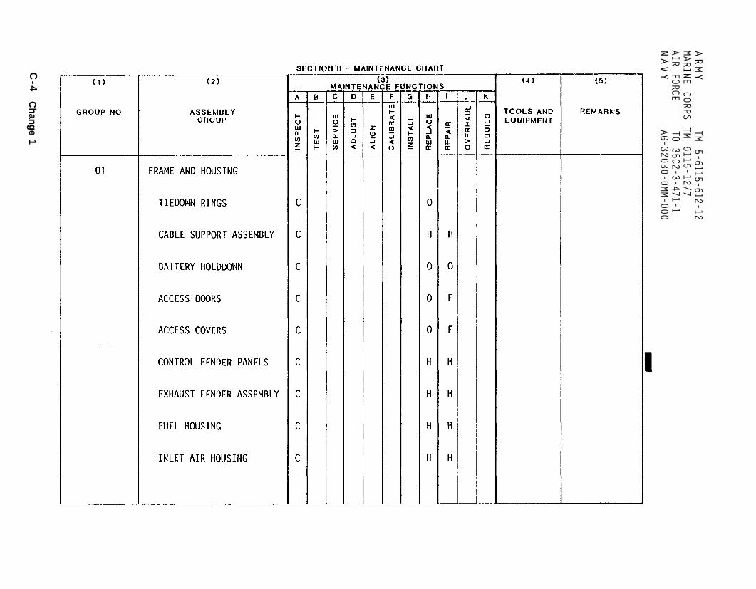
Section II
GR
OU
P N
O. 01
ARMY
TM 5-6115-612-12
MARINE CORPS
TM 6115-12/7
AIR FORCE
T0 35C2-3-471-1NAVY
AG-320B0-0MM-000
C-4
Change 1

Section II
GR
OU
P N
O. 01
TM 5-6115-612-12NAVFAC
AG-320BO-OMM-OO0
Ch
ang
e 1 C
-5

Seaction II
GR
OU
P N
O. 02
TM 5-6115-612-12
NAVFAC AG-320B0-0MM-000
C-6
Change 5
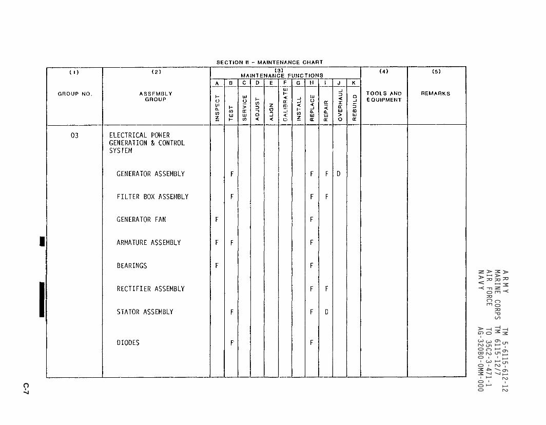
SE
CT
ION
II
GR
OU
P N
O. 03
ARMY
TM 5-6115-612-12
MARINE CORPS
TM 6115-12/7
AIR FORCE
TO 35C2-3-471-1
NAVY
AG-320B0-0MM-000
C-7

SE
CT
ION
II
GR
OU
P N
O. 04
ARMY
TM
5-6115-612-12
MARINE CORPS
TM 6115-12/7
AIR FORCE
TO 35C2-3-471-1
NAVY
AG-320B0-0MM-000
C-
8

SE
CT
ION
II
GR
OU
P N
O. 04
GR
OU
P N
O. 05
GR
OU
P N
O. 06
ARMYTM
5-6115-612-12MARINE
CORPS TM
6115-12/7AIR
FORCET0 35C2-3-471-1
NAVYAG-320B0-0MM-000
C-9

SE
CT
ION
II
GR
OU
P N
O. 06
GR
OU
P N
O. 07
ARMY
TM 5-6115-612-12
MARINE CORPS
TM 6115-12/7
AIR FORCE
TO 35C2-3-471-1NAVY
AG-320B0-0MM-000
C-10

ARMY TM 5-6115-612-12MARINE CORPS TM 6115-12/7
AIR FORCE TO 35C2-3-471-1NAVY A-320B0-OMM 000
SECTION II MAINTENANCE CHART
(1) (2) (3) (4) (5)GROUP MAINTENANCE FUNCTIONS TOLS AND REMARKS
NUMBER FUNCTIONAL GROUP A B C D E F G H I J K EQUIPMENT
07 ENGINE (cont)
RIM CLENCHING CLAMP O F
COMBUSTION CHAMBER CASE F F D
COMBUSTION CHAMBER F F D
TURBINE NOZZLE D D 1-H, 8-A,H
TURBINE WHEEL D D 8-H, 17-H
TURBINE BACKSHROUD D D
COMPRESSOR DIFFUSE D D D 8-H
BEARING AND SEAL D D 1-H, 8-H, 18-H E-D, F-F
ASSEMBLY
Change 7 C11

SE
CT
ION
II
GR
OU
P N
O. 07
ARMY
TM 5-6115-612-12
MARINE CORPS
TM 6115-12/7
AIR FORCE
TO 35C2-3-471-1
NAVYAG-320B0-0MM-000
C-12
Change 1

SE
CT
ION
II
GR
OU
P N
O. 07
GR
OU
P N
O. 08
TM 5-6115-612-12NAVFAC
AG-320B0-0MM-000
C-1 3

SE
CT
ION
II
GR
OU
P N
O.08
GR
OU
P N
O. 09
TM 5-6115-612-12NAVFAC
AG-320B0-0MM-000
C-14
Ch
an
ge
5
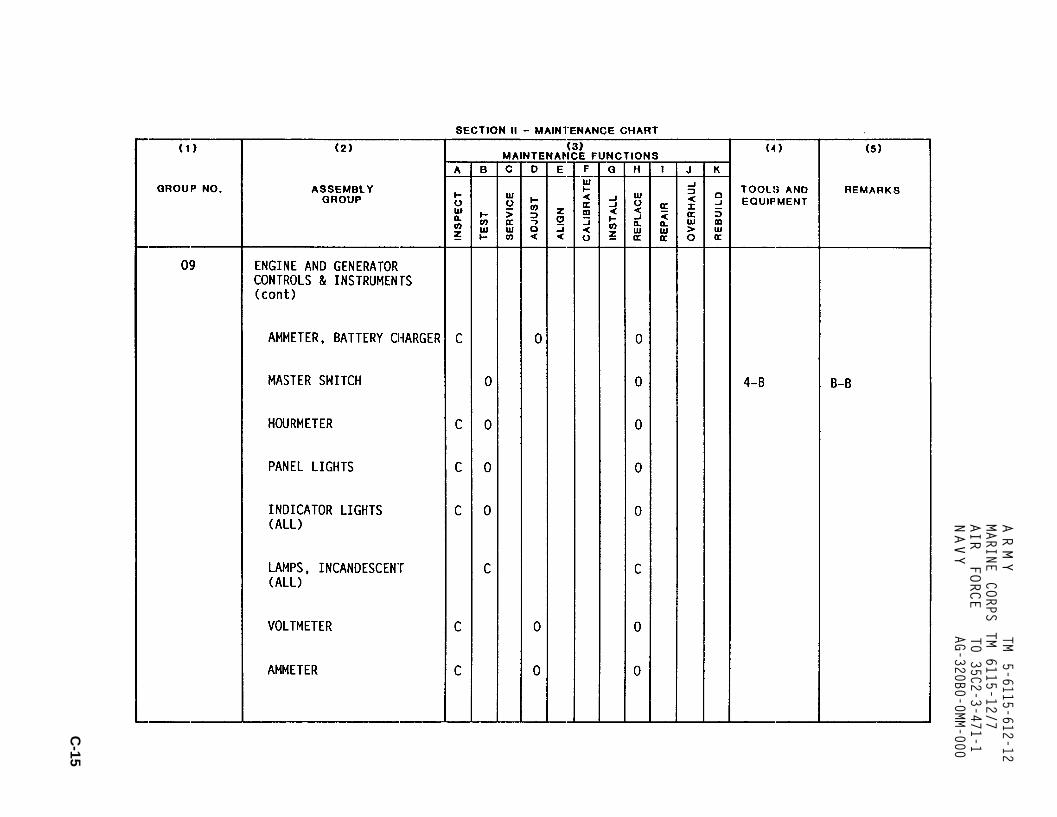
SE
CT
ION
II
GR
OU
P N
O. 09
ARMY
TM 5-6115-612-12
MARINE CORPS
TM 6115-12/7
AIR FORCE
TO 35C2-3-471-1NAVY
AG-320B0-0MM-000
C-15

SE
CT
ION
II
GR
OU
P N
O. 09
GR
OU
P N
O. 10
ARMYTM
5-6115-612-12MARINE
CORPS TM
6115-12/7AIR
FORCET0 35C2-3-471-1
NAVYAG-320B0-0MM-000
C-
16

SE
CT
ION
II
GR
OU
P N
O. 11
GR
OU
P N
O. 10
ARMY
TM 5-6115-612-12
MARINE CORPS
TM 6115-12/7
AIR FORCE
TO 35C2-3-471-1
NAVY
AG-320B0-0MM-000
Change 1
C-1 7

SE
CT
ION
II
GR
OU
P N
O. 11
ARMY TM
5-6115-612-12MARINE
CORPS TM
6115-12/7AIR
FORCE TO
35C2-3-471-1NAVY
AG-320B0-0MM-000
C-18

ARMY TM 5-6115-612-12MARINE CORPS TM 6115-12/7AIR FORCE T0 35C2-3-471-1NAVY AG-320B0-0MM-000
Section III. TOOLS, TEST AND SUPPORT EQUIPMENT REQUIREMENTS
Reference Maintenancecode category Nomenclature NSN
1-A,H,I,J
2-B
3-B
4-B
5-B
6-B,I
7-B,I
8-A,H,I,J
9-B,I
1O-B,I
11-B,I
12-B,I
13-B,I
14-B,H
15-B,I
16-B,C
17-H,I,J
18-H,I,J
19-1
20-1
O,F,H,D
D
D
O,F,H,D
O,F
F,H,D
F,H,D
F,D
O,D
O,D
O,D
O,D
O,D
O
O,D
o
O,F,H,D
D
D
F,H
Micrometers (inside, outside)
Wheatstone Bridge
Kelvin Bridge
Multimeter
Pressure Gage (0-25 psig)
Variable DC Power Supply (15 Amp)
Frequency Meter
Thickness Gage
Decade Resistance Box
Digital Counter
Digital Multimeter
Pulse Generator
Oscilloscope
Thermocouple Calibrator
Power Supply
Hydrometer
Torque Wrench (0-600 inch pound)
Universal Puller Kit
Engine Electronic Control Module(EECM) Test Fixture
Hydraulic Installation ToolNose Assembly
6625-00-581-2466
5210-00-221-1999
(44655) 3420
(80009) DC509
(80009) DC5024
(80009) PG508
(80009) 2465
(80009) CL-505
(85604) ATE36-15M
6630-00-171-5126
5180-00-701-8046
(51913)
(29666) 211, 223(29666) 99-1121
C-19
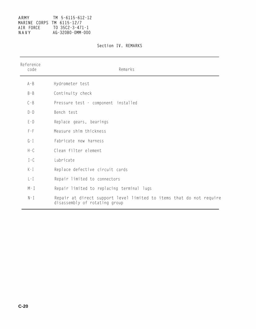
ARMY TM 5-6115-612-12MARINE CORPS TM 6115-12/7AIR FORCE TO 35C2-3-471-1NAVY AG-320B0-0MM-000
Section IV. REMARKS
Referencecode Remarks
A-B
B-B
C-B
D-D
E-D
F-F
G-I
H-C
Hydrometer test
Continuity check
Pressure test - component installed
Bench test
Replace gears, bearings
Measure shim thickness
Fabricate new harness
Clean filter element
I-C Lubricate
K-I Replace defective
L-I Repair limited to
M-I Repair limited to
circuit cards
connectors
replacing terminal lugs
N-I Repair at direct support level limited to items that do not requiredisassembly of rotating group
C-20

Subject
ARMY TM 5-6115-612-12MARINE CORPS TM 6115-12/7AIR FORCE TO 35C2-3-471-1NAVY AG-320B0-0MM-000
INDEX
Paragraph,Figure, Table
Number
A
Access Covers. . . . . . . . . . . . . . . . . . . . . . . 3-7, F3-4, 4-17, F4-10Access Doors . . . . . . . . . . . . . . . . . . . . . . . . 3-7, F3-4,4-16, F4-9Administrative Storage. . . . . . . . . . . . . . . . . . . . . . . . . . . . 1-8Air Baffle. . . . . . . . . . . . . . . . . . . . . . . . . . . . . . 4-22, F4-12Air Filter. . . . . . . . . . . . . . . . . . . . . . . . . . . . . . 4-20, F4-12Air Filter Muffler Housing. . . . . . . . . . . . . . . . . . . . . . 4-21, F4-12Allocation Chart, Maintenance (MAC). . . . . . . . . . . . . . . . . . . . . . C-1Ammeter, Battery Charging (See Battery Charging Ammeter)Ammeter (Output Current) . . . . . . . . . . . . . . . . . . . . . . . 4-76, F4-43
B
Basic Issue Items List. . . . . . . . . . . . . . . . . . . . . . . . . . . . B-4Battery. . . . . . . . . . . . . . . . . . . . . . . . 3-8, F3-3, F3-6,4-27, F4-1Battery Cable Assembly . . . . . . . . . . . . . . . . . . 3-8, F3-6, 4-26, F4-14Battery Charging Ammeter . . . . . . . . . . . . . . . . . 4-69, F2-1, F4-43, T2-1Battery Holddown . . . . . . . . . . . . . . . . . . . . . . 3-7, F3-3, 4-15, F4-8Bleed Air Connector. . . . . . . . . . . . . . . . . . . . . . . . . . 4-18, F4-11Bleed Air Line. . . . . . . . . . . . . . . . . . . . . . . . . . . . 4-19, F4-11Brake Assembly. . . . . . . . . . . . . . . . . . . . . . . .4-94, F4-58, F4-59Brake Control. . . . . . . . . . . . . . . . . . . . . .3-13, 4-90, F4-54, F4-55Buried Metal Ground Plate . . . . . . . . . . . . . . . . .2-3, F2-3, 4-2, F4-3
C
Cable Support Assembly . . . . . . . . . . . . . . . . . . . . . . . . . ...3-7Capacitor . . . . . . . . . . . . . . . . . . . . . . . . . . . . .4-87, F4-51Changing Types of Lubrication Oil. . . . . . . . . . . . . . . . . . . 4-8, F4-7Chassis Frame Assembly . . . . . . . . . . . . . . . . . . . . . . . . ..3-7, F3-5Checking and Adding Lubrication Oil. . . . . . . . . . 3-2, F3-1 , F3-2, 4-8, F4-7Circuit Breaker. . . . . . . . . . . . . . . . . . . 2-2, F2-1 , T2-1 , 4-31, F4-18Combustor Housing. . . . . . . . . . . . . . . . . . . . . . . . . . . 4-58, F4-36Component Mounting Panel . . . . . . . . . . . . . . . . . . . . . . . 4-82, F4-49Compressor Inlet Housing . . . . . . . . . . . . . . . . . . . . . . . .4-59, F4-36Consumable Operating and Maintenance Supplies. . . . . . . . . . . . . . . T3-1Control Fender and Exhaust Fender Assemblies . . . . . . . . . . . . . .F1-2, 3-7Control Panel Access Door. . . . . . . . . . . .. . . . . . . . . 3-7, F3-4, 4-16Control Panel Assembly . . . . . . . . . . . . . . . F2-1, 3-11, F3-8, 4-68,Controls and Indicators. . . . . . . . . . . . . . . . . . . . . 2-2, F2-1,Covers (See Access Covers)
F4-43 T2-1
Index 1

ARMY TM 5-6115-612-12MARINE CORPS TM 6115-12/7AIR FORCE TO 35C2-3-471-1NAVY AG-320B0-0MM-000
INDEX (Continued)
Subject Paragraph,Figure, Table
Number
Current Shunt (1000 AMP) . . . . . . . . . . . . . . . . . . . . . . . 4-84, F4-52Current Shunt (20 AMP) . . . . . . . . . . . . . . . . . . . .4-33. F4-21
D
DC Electrical and Control System. . . . . . . . . . . . . . . . . . . . 3-8, 4-25Description, Generator Set. . . . . . . . . . . . . . . . . . . . 1-10, F1-1, F1-2Destruction of Army Materiel to Prevent Enemy Use . . . . . . . . . . . . . . 1-7Diagrams and Schematics. . . . . . . . . . . . . . . . . . . . . . . . . . . 1-11Doors (See Access Doors)Draining Oil. . . . . . . . . . . . . . . . . . . . . . . . . . . . . . . . . .4-8Draining the Fuel System. . . . . . . . . . . . . . . . . . . . . . . . . . . 4-34Driven Metal Rod (Grounding) . . . . . . . . . . . . . . . . . . . . . 4-2, F4-3
E
EECM (See Engine Electronic Control Module)EGT (See Exhaust Gas Temperature Thermocouple)Electrical Fuel Transfer Pump. . . . . . . . . . . . . . .3-9, F3-7 , 4-37, F4-26Electrical High Pressure Fuel Pump . . . . . . . . . . . .3-9, F3-7, 4-41, F4-29Engine and Generator Controls and Instruments. . . . . . . . . . 3-11, 4-63, F4-38Engine Electronic Control Module (EECM). . . . . . . . . . . . . . . . 4-64, F4-39Engine Electronic Control Module (EECM) Access Cover . . . . . . . . . .4-17, F4-10Engine Fuel Tank Assembly. . . . . . . . . . . . . . . . . 3-9, F3-7 , 4-39, F4-27Engine Housing . . . . . . . . . . . . . . . . . . . . . . . . . . . . . . . 4-23Engine Housing Access Cover. . . . . . . . . . . . . . . . 3-7, F3-4, 4-17, F4-10Engine Support Assembly. . . . . . . . . . . . . . . . . . . . . . . . 4-24, F4-13Equipment Improvement Recommendations (EIRs), Reporting. . . . . . . . . . . . 1-5Errors, Reporting of....... . . . . . . . . . . . . . . . . . . . . ...1-4Exhaust Door . . . . . . . . . . . . . . . . . . . . . . . .3-7, F3-4, 4-16, F4-9Exhaust Fender. . . . . . . . . . . . . . . . . . . . . . . . . . . . . F1-2, 3-7Exhaust Gas Temperature Thermocouple. . . . . . . . . . . . . . . . . 4-66, F4-41
F
Filter, Air (See Air Filter)Filter, Oil (See Oil Filter Assembly)Filter, Primary Fuel (See Primary Fuel Filter)Filter, Secondary Fuel (See Secondary Fuel Filter)Flightline Hardstand Ground Stud (Grounding). . . . . . . . . 2-3, F2-3, 4-2, F4-3Foreign Object Deflection Shield. . . . . . . . . . . . . . . . . . .4-56, F4-35
Index 2

ARMY TM 5-6115-612-12MARINE CORPS TM 6115-12/7AIR FORCE TO 35C2-3-471-1NAVY AG-320B0-0MM-000
INDEX (Continued)
Subject Paragraph,Figure, Table
Number
Frame and Housing. . . . . . . . . . . . . . . . . . . . . . . . . . . 3-7, 4-13Fuel Housing Access Door..... . . . . . . . . . . . . . 3-7, F3-4, 4-16, F4-9Fuel Injection Nozzles. . . . . . . , . . . . . . . . . . . . . . . . 4-43, F4-30Fuel Lines, Valves, Fittings (Engine Housing). . . . . . . . . . . . . 4-35, F4-24Fuel Lines, Valves, Fittings (Internal). . . . . . . . . . . . . . . . 4-36, F4-25Fuel System. . . . . . . . . . . . . . . . . . . . . 3-9, F3-7, 4-34, F4-22, F4-23Fuel Tank (See Engine Fuel Tank)Fuel and Inlet AirHousings. . . . . . . . . . . . . . . . . . . . . . .. F1-2, 3-7Fuel/Oil Drain Access Cover... . . . . . . . . . . . . . 3-7, F3-4, 4-17, F4-10
G
Gearbox Assembly . . . . . . . . . . . . . . . . . . . . . . . . . . . 4-60, F4-36Gearbox Housing. . . . . . . . . . . . . . . . . . . . . . . . . . . .4-62, F4-36GECM (See Generator Electronic Control Module)General Method Used to Attain Proper Suppression. . . . . . . . . . . . . . . 4-11Generator Electronic Control Module . . . . . . . . . . . . . . . . . . . . . 4-30Grounding the Generator Set . . . . . . . . . . . . . . . . . 2-3, F2-3, 4-2, F4-3
H
High Tension Lead. . . . . . . . . . . . . . . . . . . . . . . . . . . . . . 4-46Holddown, Battery (See Battery Holddown)Hourmeter. . . . . . . . . . . . . . . . . . . . . . . . . 2-2, F2-1, T2-1, 4-71
I
Igniter, Spark (See Spark Igniter)Ignition Coil . . . . . . . . . . . . . . . . . . . . . . . ...4-44. 4-48, F4-31Ignition System Test . . . . . . . . . . . . . . . . . . . . . . 4-44, 4-45, F4-31Incandescent Lamps . . . . . . . . . . . . . . . . . . . . . . . . ..4-74. F4-43Indicator Lights . . . . . . . . . . . . . . . . . . . . . . . 4-73, F4-43, F4-45Inlet Air Housing Access Door. . . . . . . . . . . . . . . . 3-7, F3-4, F4-16, F4-9Inspecting and Servicing the Equipment . . . . . . . . . . . . . . . . . . . . 4-1Installation. . . . . . . . . . . . . . . . . . . . . . . . . . . 4-2, F4-2, F4-3Interference Suppression Components. . . . . . . . . . . . . . . . . . . . . . 4-12Internal Fuel System Components. . . . . . . . . . . . . . . . . . . . . 3-9, F3-7
Index 3

ARMY TM 5-6115-612-12MARINE CORPS TM 6115-12/7AIR FORCE TO 35C2-3-471-1NAVY AG-320B0-0MM-000
INDEX (Continued)
Subject
L
Levels of Maintenance Accomplishment. . . . . . . . . . . . . . . .Limited Applicability. . . . . . . . . . . . . . . . . . . . . . .Lines and Fittings (External) . . . . . . . . . . . . . . . . . . .Load Connection. . . . . . . . . . . . . . . . . . . . . . . . . .Location and Description of Identification and Instruction Plates .Low Oil Pressure Shutdown Switch. . . . . . . . . . . . . . . . . .Lubricant and Equipment Storage . . . . . . . . . . . . . . . . . .Lubrication Assembly. . . . . . . . . . . . . . . . . . . . . . . .Lubrication by Organizational Maintenance . . . . . . . . . . . .Lubrication Instructions. . . . . . . . . . . . . . . . . . . . . .Lubrication Oil, Adding Checking. . . . . . . . . . . . . . . . .Lubrication Order. . . . . . . . . . . . . . . . . . . . . . . . .Lunette Eye. . . . . . . . . . . . . . . . . . . . . . . 3-13, F3-10,
Paragraph,Figure, Table
Number
. . . . . 1-6
. . . . . 1-2
. . . . . 4-53
. . 3-12, F-80
. . 1-10, T1-2
. 4-67, F4-42
. . . . . . 3-2
. . .3-10, 4-49F3-2, F4-7, 4-8. . . . . . 3 - 23-2, F3-1, F3-2. . . . . . F 3 - 24-95, F4-60
M
MAC (See Maintenance Allocation Chart)Magnetic Contactor. . . . . . . . . . . . . . . . . . . . . . . 4-83, F4-50, F4-51Maintenance Allocation Chart (MAC). . . . . . . . . . . . . . . . . . . . . . C-1Maintenance Forms and Records . . . . . . . . . . . . . . . . . . . . . . . . 1-3Maintenance Instructions, Operator/Crew. . . . . . . . . . . . . . . . . . . . 3-6Maintenance ofMaintenance ofMaintenance ofMaintenance ofMaintenance ofMaintenance ofMaintenance ofMaintenance ofMaintenance of
DC Electrical and Control System. . . . . . .Engine. . . . . . . . . . . . . . . . . . . .Engine and Generator Controls and Instruments . . . . . . . .Frame and Housing . . . . . . . . . . . . . .Fuel System. . . . . . . . . . . . . . . . .Ignition System . . . . . . . . . . . . . . .Load Connection . . . . . . . . . . . . . . .Lubrication System. . . . . . . . . . . . . .Running Gear. . . . . . . . . . . . . . . . .
3-8, 4-254-55
3-11, 4-633-7, 4-133-9, 4-34.....4-443-12, 4-803-10, 4-493-13, 4-89
Maintenance Repair Parts. . . . . . . . . . . . . . . . . . . . . . . . . . . 4-6Manual Movement (of Generator Set). . . . . . . . . . . . . . . . . . . . . . 4-3Master Switch . . . . . . . . . . . . . . . . . . . . . . . .4-70, F4-43. F4-44Monopole Speed Sensor. . . . . . . . . . . . . . . . . . . . . . . .4-65, F4-40Movement by Forklift . . . . . . . . . . . . . . . . . . . . . . . . . .4-3, F4-6Movement by Hoisting Device or Helicopter. . . . . . . . . . . . . . . . 4-3, F4-5Movement by Vehicle. . . . . . . . . . . . . . . . . . . . . . . . . . . . . . 4-3Moving the Generator Set. . . . . . . . . . . . . . . . . . . . . . . . . . . 4-3
Index 4

A R M Y TM 5-6115-612-12MARINE CORPS TM 6115-12/7AIR FORCE TO 35C2-3-471-1N A V Y AG-320B0-0MM-000
INDEX (Continued)
Subject Paragraph,Figure, Table
Number
N
Nozzles, Fuel Injection (See Fuel Injection Nozzle)
0ilOilOilOilOil
O
Cooler. . . . . . . . . . . . . . . . . . . . . . . . . . . 4-53, 4-54, F4-34Cooler Housing Access Cover. . . . . . . . . . . . . .3-7. F3-4, 4-17, F4-10Drains. . . . . . . . . . . . . . . . . . . . . . . . . . . . . . . 4-52Filler/Breather Assembly . . . . . . . . . . . . . . . . . . . . . 4-50, F4-33Filter Assembly. . . . . . . . . . . . . . . . . . . . . . . F4-7, F3-2, 4-51
Operating Instructions . . . . . . . . . . . . . . . . . . . 2-1, F2-2, F2-3, F2-4Operation Under Snowy Conditions . . . . . . . . . . . . . . . . . . . . . 2-13Operation at High Altitudes. . . . . . . . . . . . . . . . . . . . . . . . . 2-12Operation in Dusty and Sandy Areas . . . . . . . . . . . . . . . . . . . . . 2-10Operation in Extreme Cold. . . . . . . . . . . . . . . . . . . . . . . . . . . 2-8Operation in Extreme Heat. . . . . . . . . . . . . . . . . . . . . . . . . . . 2-7Operation in High Humidity. . . . . . . . . . . . . . . . . . . . . . . . . . 2-9Operation in Salt Water Areas. . . . . . . . . . . . . . . . . . . . . . . . 2-11Operator/Crew Maintenance Instructions . . . . . . . . . . . . . . . . . . . . 3-6Organizational Troubleshooting . . . . . . . . . . . . . . . . 4-10, T4-2, T4-3
P
Panel Lights. . . . . . . . . . . . . . . . . . . . . . . . . . . . . 4-72, F4-43Plenum Access Cover. . . . . . . . . . . . . . . . . . . . 3-7, F3-4, 4-17, F4-10PMCS (See Preventive Maintenance Checks and Services)Potentiometer. . . . . . . . . . . . . . . . . . . . . . . . . . . . . 4-77, F4-43Power Cable Assembly . . . . . . . . . . . . . . . . . . . 3-12, F3-9, 4-81, F4-48Preparation for Movement. . . . . . . . . . . . . . . . . . . . . . . . . . . 4-3Preparation for Shipment and Storage . . . . . . . . . . . . . . . . . . . . . 1-9Preventive Maintenance Checks and Services. . . . . . . . . . 3-4, T3-2, 4-9, T4-1Primary Fuel (Fluid) Filter . . . . . . . . . . . . . . . . . . . . . . 4-38, F2-6
R
RF Filter (FL1) . . . . . . . . . . . . . . . . . . . . . . . . . . . . . 4-86, F4-53Reinstallation After Movement. . . . . . . . . . . . . . . . . . . . . . . . . 4-4Removing Generator Set from Operation. . . . . . . . . . . . . . . . . . . . . 2-5Repair Parts, Special Tools, TMDE. . . . . . . . . . . . . . . . . . . . 4-5, 4-6Reporting Equipment Improvement Recommendations (EIRs) . . . . . . . . . . . . 1-5
Index 5

A R M YMARINE CORPSAIR FORCEN A V Y
TM 5-6115-612-12TM 6115-12/7T0 35C2-3-471-1AG-320B0-0MM-000
INDEX (Continued)
Paragraph,Figure, Table
Number
Subject
Reporting of Errors.................................................................1-4Resistor (R5). . . .................................................4-88, F4-52Rim ClenchingClamp ................................................4-57, F4-36Running Gear.................................................3-13, F3-10, 4-89
S
Schematics and Diagrams (See Diagrams and Schematics)Secondary Fuel Fluid Filter.............................3-9, F3-7, 4-40, F4-28Service Upon Receipt of Equipment............................................4-1Servicing the Generator Set...................................................4-1Slave Receptacle.................................................F2-5, 3-8, 4-29, F4-16Slave Start Operation...........................................................2-4, F2-5Solenoid Valve..............................................................4-42, F4-29Spark Igniter.........................................................4-44, 4-47, F4-31Starter Assembly...............................................4-32, F4-19, F4-20Starter Mounting Plate.....................................................4-61, F4-36Starting the Generator Set.................................2-3, F2-2, F2-3, F2-4Switches................................................................4-78Swivel Caster Wheel and Tire...................................................4-96, F4-61Swivel Caster Assembly............................................................3-13, F3-10
T
Tabulated Data......................................................................1-11Terminal Boards.......................................................... 4-85, F4-53Tests/Inspections and Corrective Actions.......................................4-10Tiedown Rings.................................................................4-14, F4-8Tires/Tubes.........................................................4-93, F4-57Tools and Equipment.........................................................4-5Torque Specifications...............................................................1-10Torsion Axle Assembly.......................................................4-91, F4-56Troubleshooting Index........................................................4-10, T4-2Troubleshooting (Operator/Crew)..............................................3-5, T3-3Troubleshooting, Organization......................................4-10, T4-2, T4-3
U
Underground Metallic Hater Pipe (Grounding)...........................................4-2, F4-3
Index 6

INDEX (Continued)
Subject
ARMY TM 5-6115-612-12MARINE CORPS TM 6115-12/7AIR FORCE TO 35C2-3-471-1N A V Y AG-320B0-0MM-000
Paragraph,Figure, Table
Number
V
Valve, Solenoid (See Solenoid Valve)Voltage AdjustVoltmeter. . .
Wheel AssemblyHiring Harness
Knob (See Potentiometer). . . . . . . . . . . . . . . . . . . . . . F2-1, T2-1, 4-75, F4-43
H
4-92, F4-56 (Generator to GECM, W1) . . . . . . . . . . . . . . . . 4-28, F4-15
Hiring Harnesses (W2, W3). . . . . . . . . . . . . . . . . . . . . . . 4-79, F4-47
Index 7 (Index 8 blank)


TM 5-6115-612-12TM 6115-12/7TO 35C2-3-471-1AG-320B0-OMM-000
By Order of the Secretaries of the Army, the Navy, and the Air Force:
CARL E. VUONO
Official: General, United States ArmyChief of Staff
R. L. DILWORTHBrigadier General, United States Army
The Adjutant Geneml
Official:
ALFRED G. HANSENGeneral, USAF, Commander, Air Force
Logistics Command
J. J. WENTLieutenant General, USMCDeputy Chief of Staff for Installations and Logistics
B. F. MONTOYARear Admirnal, CEC, US NavyCommanderNaval Facilities Engineering Command
CHARLES A. GABRIEL, General USAFChief of Staff
DISTRIBUTION:To be distributed in accordance with DA Form 12-25A, Operational and Unit Mainte-nance requirements for Generator Set, Gas Driven, 2 Wheel Mounted, 28V, DC, 7.5 KW(JHGV7.5A) (TM 5-6115-440 Series).


A R M Y TM 5-6115-612-12MARINE CORPS TM 6115-12/7AIR FORCE TO 35C2-3-471-1NAVY AG-320B0-0MM-000
FO-1. Generator Set Wiring Installation
FP-1/(FP-2 Blank)

FO-2.
ARMY TM 5-6115-612-12MARINE CORPS TM 6115-12/7AIR FORCE TO 35C2-3-471-1NAVY AG-320B0-0MM-000
FP-3/(FP-4 Blank)

ARMY TM 5-6115-612-12MARINE CORPS TM 6115-12/7AIR FORCE T0 35C2-3-471-1NAVY AG-320B0-0MM-000
FO-3. Generator Set Wiring Diagram
Change 1 FP-5/(FP-6 Blank)

A R M Y T M 5 - 6 1 1 5 - 6 1 2 - 1 2M A R I N E C O R P S T M 6 1 1 5 - 1 2 / 7AIR FORCE T O 3 5 C 2 - 3 - 4 7 1 - 1N A V Y A G - 3 2 0 B 0 - 0 M M - 0 0 0
FO-4. Control Panel Wiring Diagram
FP-7/(FP-8 Blank)


PIN: 060184-000

This fine document...
Was brought to you by me:
Liberated Manuals -- free army and government manuals
Why do I do it? I am tired of sleazy CD-ROM sellers, who take publicly available information, slap “watermarks” and other junk on it, and sell it. Those masters of search engine manipulation make sure that their sites that sell free information, come up first in search engines. They did not create it... They did not even scan it... Why should they get your money? Why are not letting you give those free manuals to your friends?
I am setting this document FREE. This document was made by the US Government and is NOT protected by Copyright. Feel free to share, republish, sell and so on.
I am not asking you for donations, fees or handouts. If you can, please provide a link to liberatedmanuals.com, so that free manuals come up first in search engines:
<A HREF=http://www.liberatedmanuals.com/>Free Military and Government Manuals</A>
– SincerelyIgor Chudovhttp://igor.chudov.com/
– Chicago Machinery Movers