air force t.o.35c2!3!442-2 tm5-6115-457-34 army navy navfac p-8-627-34 marine corps
TRANSCRIPT
AIR FORCE T.O.35C2-3-442-2ARMY TM5-6115-457-34NAVY NAVFAC P-8-627-34MARINE CORPS TM-07464A-35
TECHNICAL MANUAL
INTERMEDIATE [FIELD][DIRECT AND GENERAL SUPPORT]AND DEPOT LEVEL MAINTENANCE
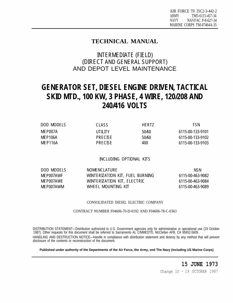
GENERATOR SET, DIESEL ENGINE DRIVEN, TACTICALSKID MTD., 100 KW, 3 PHASE, 4 WIRE, 120/208 AND 240/416 VOLTS
DOD MODELS CLASS HERTZ NSNMEPO07A UTILITY 50/60 6115-00-133.9101MEP106A PRECISE 50/60 6115-00-133.9102MEP116A PRECISE 400 6115-00-133-9103
INCLUDING OPTIONAL KITSDOD MODELS NOMENCLATURE NSNMEPO07AWF WINTERIZATION KIT, FUEL BURNING 6115-00-463-9082MEPO07AWE WINTERIZATION KIT, ELECTRIC 6115-00-463-9084MEPO07ALM DUMMY LOAD KIT 6115-00-463-9086MEPO07AWM WHEEL MOUNTING KIT 6115-00-463-9089
Consolidated Diesel Electric Company
Contract Number FO4606-70-D-0192 and F04606-78-C-0363
This publication incorporates PCN numbers 1 through 1301 and 1318
Published under authority of the
Departments of the Air Force, the Army, and the Navy
(Including U. S. Marine Corps) 15 JUNE 1973


AIR FORCE TO 35C2-3-442-2ARMY TM5-6115-457-34NAVY NAVFAC P-8-627-34MARINE CORPS TM-07464A-34
TECHNICAL MANUAL
INTERMEDIATE (FIELD)(DIRECT AND GENERAL SUPPORT)AND DEPOT LEVEL MAINTENANCE
GENERATOR SET, DIESEL ENGINE DRIVEN,TACTICAL SKID MTD., 100 KW, 3 PHASE,
4 WIRE, 120/208 AND 240/416 VOLTS
DOD MODELS CLASS HERTZ FSN
MEP007A UTILITY 50/60 6115-00-133-9101MEP106A PRECISE 50/60 6115-00-133-9102MEP116A PRECISE 400 6155-00-133-9103
INCLUDING OPTIONAL KITS
DOD MODELS NOMENCLATURE NSN
MEP007AWF WINTERIZATION KIT, FUEL BURNING 6115-00-463-9082MEP007AWE WINTERIZATION KIT, ELECTRIC 6115-00-463-9084MEP007AWM WHEEL MOUNTING KIT 6115-00-463-9089
CONSOLIDATED DIESEL ELECTRIC COMPANY
CONTRACT NUMBER F04606-70-D-0192 AND F04606-78-C-0363
DISTRIBUTION STATEMENT - Distribution authorized for public release; distribution is unlimited, 20 August 1991. Otherrequests for this document must be referred to Sacramento ALC/TILBE, McClellan AFB, CA 95652-5990.
HANDLING AND DESTRUCTION NOTICE - Handle in compliance with distribution statement and destroy by any methodthat will prevent disclosure of the contents or reconstruction of the document.
PUBLISHED UNDER AUTHORITY OF THE SECRETARY OF THE AIR FORCE
15 JUNE 1973CHANGE 12- 20 AUGUST 1991
TO 35C2-3-442-2
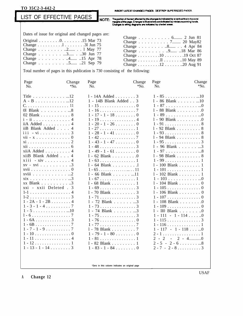
LIST OF EFFECTIVE PAGES
Dates of issue for original and changed pages are:Change . . . . . . . . . . 6........ 2 Jun 81
Original . . . . . . . .0. . . . . . . .15 Mar 73Change . . . . . . . . . .l . . . . . . . .3l Jun 75
Change . . . . . . . . . . 7........ 20 May82
Change . . . . . . . . ..2...... . . l May 77Change . . . . . . . . ..8...... . . 4 Apr 84Change . . . . . . . . ..9...... ..18 Mar 86
Change . . . . . . . ...3..... . ..30 Jun 77Change . . . . . . . . ..4...... ..15 Apr 78
Change . . . . . . . . .10 . . . . . . . .19 Oct 87
Change . . . . . . . . ..5...... ..21 Sep 79Change . . . . . . . . .ll . . . . . . ..10 May 89Change . . . . . . . . .12 . . . . . . ..20 Aug 91
Total nurnber of pages in this publication is 730 consisting of the following:
Page ChangeNo. *No.
Title . . . . . . . . . . . ...12A - B . . . . . . . . . . . ...12C. . . . . . . . . . . . . . . . . . 110l Blank . . . . . . . . ...802 Blank . . . . . . . . . . . 8i - ii . . . . . . . . . . . . . 4iiA Added . . . . . . . . . . 4iiB Blank Added . . . . 4i i i - vi . . . . . . . . . . . 3vii - x . . . . . . . . . . . . 0xi . . . . . . . . . . . . . . . . . 2xii . . . . . . . . . . . . . . . . 6xiiA Added . . . . . . . . . 4xiiB Blank Added . . . 4x i i i - xiv . . . . . . . . . 4xv - xvi . . . . . . . . . ..3xvii . . . . . . . . . . . . . . . 0xviii . . . . . . . . . . . ...2xix . . . . . . . . . . . . . ...3xx Blank . . . . . . . . . ..3xxi - xxii Deleted . 31-1 . . . . . . . . . . . . . . . . 41-2 . . . . . . . . . . . . . . . . 31 - 2A - 1 - 2B . . . . . . . . 41 - 3 - 1 - 4 . . . . . . . . . . 71 - 5 . . . . . . . . . . . . . ...10l - 6 . . . . . . . . . . . . . . . . 71 - 6A . . . . . . . . . . . . . . . 31 - 6B . . . . . . . . . . . . . . . 71 - 7 - 1 - 9 . . . . . . . . . . 71 - 10 . . . . . . . . . . . . . . . 01 - 11 . . . . . . . . . . . . . . . 41 - 12 . . . . . . . . . . . . . . . 11 - 13 - 1 - 14 . . . . . . . . 3
Page ChangeNo. *No.
l - 14A Added . . . . . . . . 31 - 14B Blank Added . . 31 - 15 . . . . . . . . . . . . . . . 01 - 16 . . . . . . . . . . . . . . . 71 - 17 - 1 - 18 . . . . . . . . 01 - 19 . . . . . . . . . . . . . . . 41 - 20 - 1 - 26 . . . . . . . . 01 - 27 . . . . . . . . . . . . . . . 11 - 28 - 1 - 41 . . . . . . . . 01 - 42 . . . . . . . . . . . . . . . 71 - 43 - 1 - 47 . . . . . . . . 01 - 48 . . . . . . . . . . . . . . . 31 - 49 - 1 - 61 . . . . . . . . 0l - 62 Blank . . . . . . . . .01 - 63 . . . . . . . . . . . . . . . 1l - 64 Blank . . . . . . . . .l1 - 65 . . . . . . . . . . . . . ... . . 11l - 66 Blank . . . . . . ...111 - 67 . . . . . . . . . . . . . . . 1l - 68 Blank . . . . . . . . . 11 - 69 . . . . . . . . . . . . . . . 3l - 70 Blank . . . . . . . . . 31 - 71 . . . . . . . . . . . . . . . 3l - 72 Blank . . . . . . ...31 - 73 . . . . . . . . . . . . . . . 3l - 74 Blank . . . . . . ...31 - 75 . . . . . . . . . . . . . . . 31 - 76 . . . . . . . . . . . . . . . 01 - 77 . . . . . . . . . . . . . . . 7l - 78 Blank . . . . . . . . . 71 - 79 - 1 - 80 . . . . . . . . 01 - 81 . . . . . . . . . . . . . . . 1l - 82 Blank . . . . . . . . . 11 - 83 - 1 - 84 . . . . . . . . 0
Page ChangeNo. *No.
1 - 85 . . . . . . . . . . . . ...10l - 86 Blank . . . . . . ...101 - 87 . . . . . . . . . . . . ...0l - 88 Blank . . . . . . . . .01 - 89 . . . . . . . . . . . . ...0l - 90 Blank . . . . . . . . .01 - 91 . . . . . . . . . . . . . . . 8l - 92 Blank . . . . . . . . . 81 - 93 . . . . . . . . . . . . . . . 8l - 94 Blank . . . . . . . . . 81 - 95 . . . . . . . . . . . . . . . 3l - 96 Blank . . . . . . ...31 - 97 . . . . . . . . . . . . ...8l - 98 Blank . . . . . . . . . 81 - 99 . . . . . . . . . . . . . . . 1l - 100 Blank . . . . . . . . 11 - 101 . . . . . . . . . . . . . . 1l - 102 Blank . . . . . . . . 11 - 103 . . . . . . . . . . . ...0l - 104 Blank . . . . . . . . 01 - 105 . . . . . . . . . . . . . . 0l - 106 Blank . . . . . . . . 01 - 107 . . . . . . . . . . . . . . 0l - 108 Blank . . . . . . . .01 - 109 . . . . . . . . . . . . . . 0l - ll0 Blank . . . . . . ..01 - 111 - 1 - 114 . . . . ..01 - 115 . . . . . . . . . . . . . . 31 - 116 . . . . . . . . . . . . . . 11 - 117 - 1 - 118 . . . ...02 - 1 . . . . . . . . . . . . . . . . 12 - 2 - 2 - 4.........02 - 5 - 2 - 6 . . . . . . . ...82 - 7 - 2 - 8 . . . . . . . . . . 3
*Zero in this column indicates an original page
USAFA Change 12
TO 35C2-3-442-2
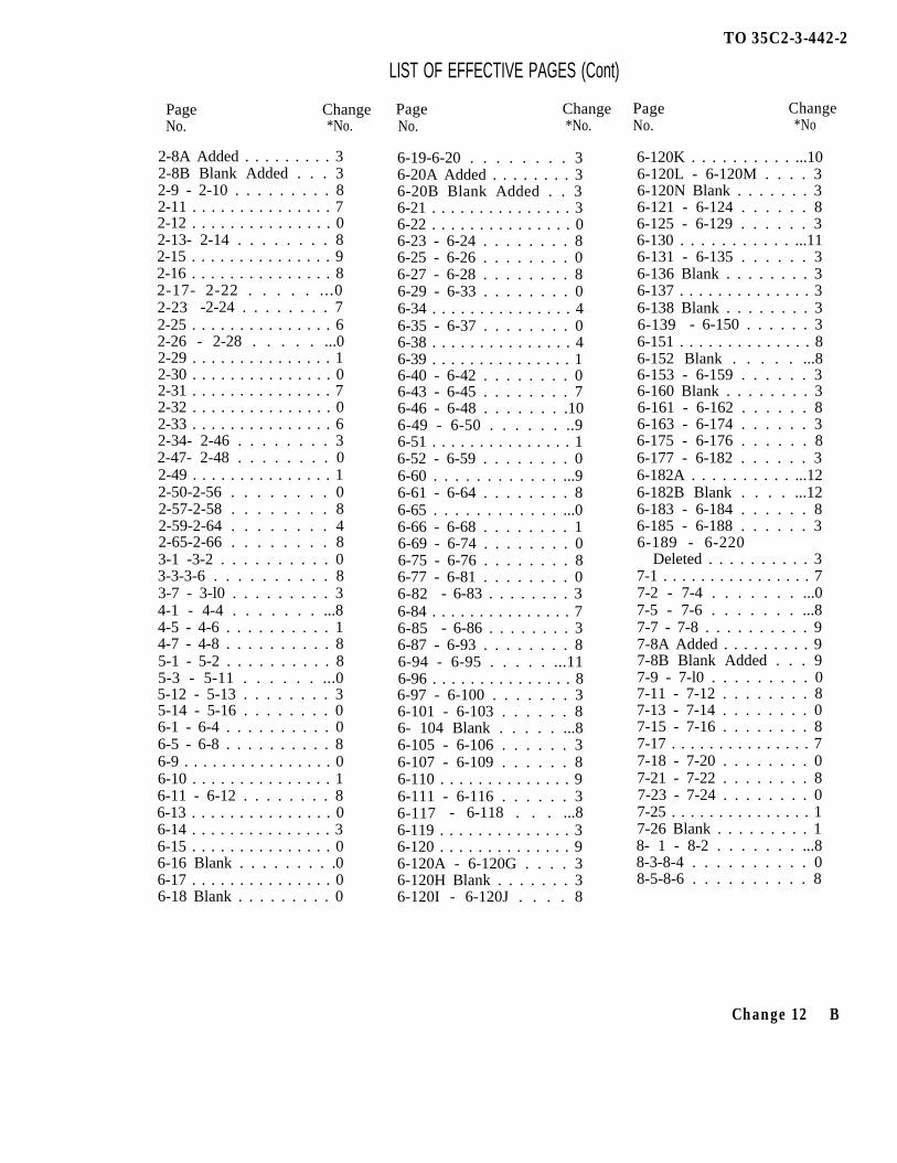
LIST OF EFFECTIVE PAGES (Cont)
Page ChangeNo. *No.
2-8A Added . . . . . . . . . 32-8B Blank Added . . . 32-9 - 2-10 . . . . . . . . . 82-11 . . . . . . . . . . . . . . . 72-12 . . . . . . . . . . . . . . . 02-13- 2-14 . . . . . . . . 82-15 . . . . . . . . . . . . . . . 92-16 . . . . . . . . . . . . . . . 82-17- 2-22 . . . . . ...02-23 -2-24 . . . . . . . . 72-25 . . . . . . . . . . . . . . . 62-26 - 2-28 . . . . . ...02-29 . . . . . . . . . . . . . . . 12-30 . . . . . . . . . . . . . . . 02-31 . . . . . . . . . . . . . . . 72-32 . . . . . . . . . . . . . . . 02-33 . . . . . . . . . . . . . . . 62-34- 2-46 . . . . . . . . 32-47- 2-48 . . . . . . . . 02-49 . . . . . . . . . . . . . . . 12-50-2-56 . . . . . . . . 02-57-2-58 . . . . . . . . 82-59-2-64 . . . . . . . . 42-65-2-66 . . . . . . . . 83-1 -3-2 . . . . . . . . . . 03-3-3-6 . . . . . . . . . . 83-7 - 3-l0 . . . . . . . . . 34-1 - 4-4 . . . . . . . ...84-5 - 4-6 . . . . . . . . . . 14-7 - 4-8 . . . . . . . . . . 85-1 - 5-2 . . . . . . . . . . 85-3 - 5-11 . . . . . . ...05-12 - 5-13 . . . . . . . . 35-14 - 5-16 . . . . . . . . 06-1 - 6-4 . . . . . . . . . . 06-5 - 6-8 . . . . . . . . . . 86-9 . . . . . . . . . . . . . . . . 06-10 . . . . . . . . . . . . . . . 16-11 - 6-12 . . . . . . . . 86-13 . . . . . . . . . . . . . . . 06-14 . . . . . . . . . . . . . . . 36-15 . . . . . . . . . . . . . . . 06-16 Blank . . . . . . . . .06-17 . . . . . . . . . . . . . . . 06-18 Blank . . . . . . . . . 0
Page ChangeNo. *No.
6-19-6-20 . . . . . . . . 36-20A Added . . . . . . . . 36-20B Blank Added . . 36-21 . . . . . . . . . . . . . . . 36-22 . . . . . . . . . . . . . . . 06-23 - 6-24 . . . . . . . . 86-25 - 6-26 . . . . . . . . 06-27 - 6-28 . . . . . . . . 86-29 - 6-33 . . . . . . . . 06-34 . . . . . . . . . . . . . . . 46-35 - 6-37 . . . . . . . . 06-38 . . . . . . . . . . . . . . . 46-39 . . . . . . . . . . . . . . . 16-40 - 6-42 . . . . . . . . 06-43 - 6-45 . . . . . . . . 76-46 - 6-48 . . . . . . . .106-49 - 6-50 . . . . . . ..96-51 . . . . . . . . . . . . . . . 16-52 - 6-59 . . . . . . . . 06-60 . . . . . . . . . . . . ...96-61 - 6-64 . . . . . . . . 86-65 . . . . . . . . . . . . ...06-66 - 6-68 . . . . . . . . 16-69 - 6-74 . . . . . . . . 06-75 - 6-76 . . . . . . . . 86-77 - 6-81 . . . . . . . . 06-82 - 6-83 . . . . . . . . 36-84 . . . . . . . . . . . . . . . 76-85 - 6-86 . . . . . . . . 36-87 - 6-93 . . . . . . . . 86-94 - 6-95 . . . . . ...116-96 . . . . . . . . . . . . . . . 86-97 - 6-100 . . . . . . . 36-101 - 6-103 . . . . . . 86- 104 Blank . . . . . ...86-105 - 6-106 . . . . . . 36-107 - 6-109 . . . . . . 86-110 . . . . . . . . . . . . . . 96-111 - 6-116 . . . . . . 36-117 - 6-118 . . . ...86-119 . . . . . . . . . . . . . . 36-120 . . . . . . . . . . . . . . 96-120A - 6-120G . . . . 36-120H Blank . . . . . . . 36-120I - 6-120J . . . . 8
Page ChangeNo. *No
6-120K . . . . . . . . . . ...106-120L - 6-120M . . . . 36-120N Blank . . . . . . . 36-121 - 6-124 . . . . . . 86-125 - 6-129 . . . . . . 36-130 . . . . . . . . . . . ...116-131 - 6-135 . . . . . . 36-136 Blank . . . . . . . . 36-137 . . . . . . . . . . . . . . 36-138 Blank . . . . . . . . 36-139 - 6-150 . . . . . . 36-151 . . . . . . . . . . . . . . 86-152 Blank . . . . . ...86-153 - 6-159 . . . . . . 36-160 Blank . . . . . . . . 36-161 - 6-162 . . . . . . 86-163 - 6-174 . . . . . . 36-175 - 6-176 . . . . . . 86-177 - 6-182 . . . . . . 36-182A . . . . . . . . . . ...126-182B Blank . . . . ...126-183 - 6-184 . . . . . . 86-185 - 6-188 . . . . . . 36-189 - 6-220
Deleted . . . . . . . . . . 37-1 . . . . . . . . . . . . . . . . 77-2 - 7-4 . . . . . . . ...07-5 - 7-6 . . . . . . . ...87-7 - 7-8 . . . . . . . . . . 97-8A Added . . . . . . . . . 97-8B Blank Added . . . 97-9 - 7-l0 . . . . . . . . . 07-11 - 7-12 . . . . . . . . 87-13 - 7-14 . . . . . . . . 07-15 - 7-16 . . . . . . . . 87-17 . . . . . . . . . . . . . . . 77-18 - 7-20 . . . . . . . . 07-21 - 7-22 . . . . . . . . 87-23 - 7-24 . . . . . . . . 07-25 . . . . . . . . . . . . . . . 17-26 Blank . . . . . . . . . 18- 1 - 8-2 . . . . . . . ...88-3-8-4 . . . . . . . . . . 08-5-8-6 . . . . . . . . . . 8
Change 12 B
TO 35C2-3-442-2
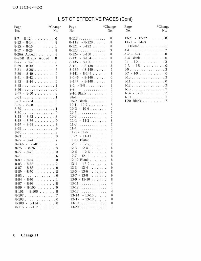
LIST OF EFFECTIVE PAGES (Cont)
Page *ChangeNo. No.
8-7 - 8-12 . . . . . . . . 08-13 - 8-14 . . . . . . . 88-15 - 8-16 . . . . . . . 18-17 - 8-26 . . . . . . . 88-26A Added . . . . . . . 88-26B Blank Added . 88-27 - 8-28 . . . . . . . 88-29 - 8-30 . . . . . . . 78-31 - 8-38 . . . . . . . 88-39 - 8-40 . . . . . . . 08-41 - 8-42 . . . . . . . 88-43 - 8-44 . . . . . . . 08-45 . . . . . . . . . . . . . . 18-46 . . . . . . . . . . . . . . 08-47 - 8-50 . . . . . . . 88-51 . . . . . . . . . . . . . . 18-52 - 8-54 . . . . . . . 08-55 - 8-58 . . . . . . . 88-59 . . . . . . . . . . . . . . 18-60 . . . . . . . . . . . . . . 08-61 - 8-62 . . . . . . . 88-63 - 8-66 . . . . . . . 08-67 - 8-68 . . . . . . . 88-69 . . . . . . . . . . . . . . 98-70 . . . . . . . . . . . . . . 28-71 . . . . . . . . . . . . . . 08-72 - 8-74 . . . . . . . 28-74A - 8-74B . . . . . 28-75 - 8-76 . . . . . . . 88-77 - 8-78 . . . . . . . 08-79 . . . . . . . . . . . . . . 68-80 - 8-84 . . . . . . . 08-85 - 8-86 . . . . . . . 28-87 - 8-88 . . . . . . . 08-89 - 8-92 . . . . . . . 88-93 . . . . . . . . . . . . . . 08-94 - 8-96 . . . . . . . 18-97 - 8-98 . . . . . . . 88-99 - 8-100 . . . . . . 08-101 - 8-106 . . . . . 88-107 . . . . . . . . . . . . . 78-108 . . . . . . . . . . . . . 08-109 - 8-114 . . . . . 88-115 - 8-117 . . . . . 1
Page *ChangeNo. No.
8-118 . . . . . . . . . . . . .8-119 - 8-120 . . . . .8-121 - 8-122 . . . . .8-123 . . . . . . . . . . . . .8-124 - 8-130 . . . . .8-131 - 8-134 . . . . .8-135 - 8-136 . . . . .8-137 - 8-138 . . . . .8-139 - 8-140 . . . . .8-141 - 8-144 . . . . .8-145 - 8-146 . . . . .8-147 - 8-148 . . . . .9-1 - 9-8 . . . . . . . . .9-9 . . . . . . . . . . . . . . .9-10 Blank . . . . . . . .9A-l . . . . . . . . . . . . . .9A-2 Blank . . . . . . . .10-1 - 10-2 . . . . . . .10-3 - 10-6 . . . . . . .10-7 . . . . . . . . . . . . . .10-8 . . . . . . . . . . . . . .11-1 - 11-2 . . . . . . .11-3 . . . . . . . . . . . . . .11-4 . . . . . . . . . . . . . .11-5 - 11-6 . . . . . . .11-7 - 11-11 . . . . . .11-12 Blank . . . . . . .12-1 - 12-2, . . . . . .12-3 - 12-4 . . . . . . .12-5 - 12-6, . . . . . .12-7 - 12-11 . . . . . .12-12 Blank . . . . . . .13-1 - 13-2 . . . . . . .13-3 - 13-4 . . . . . . .13-5 - 13-6 . . . . . . .13-7 - 13-8 . . . . . . .13-9 - 13-10 . . . . . .13-11 . . . . . . . . . . . . .13-12 . . . . . . . . . . . . .13-13 . . . . . . . . . . . . .13-14 - 13-16 . . . . .13-17 - 13-18 . . . . .13-19 . . . . . . . . . . . . .13-20 . . . . . . . . . . . . .
08098018080280066807081080008088808084140801
Page *ChangeNo. No.
13-21 - 13-22 . . . . . 814-1 - 14-8
Deleted . . . . . . . . . 1A-l . . . . . . . . . . . . . . . 7A-2 - A-3 . . . . . . . . . 0A-4 Blank . . . . . . . . . 0I-1 - I-2 . . . . . . . . . 3I - 3 - I-5 . . . . . . . . . 0I-6 . . . . . . . . . . . . . . . 3I-7 - I-9 . . . . . . . . . 0I-10 . . . . . . . . . . . . . . 3I-11 . . . . . . . . . . . . . . 0I-12 . . . . . . . . . . . . . . 3I-13 . . . . . . . . . . . . . . 7I-14 - 1-18 . . . . . . . 3I-19 . . . . . . . . . . . . . . 7I-20 Blank . . . . . . . . 7
C Change 11

AIR FORCE TO 35C2-3-442-2ARMY TM5-6115-457-34NAVY NAVFAC P-8-627-34MARINE CORPS TM-07464A-34
TECHNICAL MANUAL
INTERMEDIATE (FIELD)(DIRECT AND GENERAL SUPPORT)AND DEPOT LEVEL MAINTENANCE
GENERATOR SET, DIESEL ENGINE DRIVEN,TACTICAL SKID MTD., 100 KW, 3 PHASE,
4 WIRE, 120/208 AND 240/416 VOLTS
DOD MODELS CLASS HERTZ FSN
MEP007A UTILITY 50/60 6115-00-133-9101MEP106A PRECISE 50/60 6115-00-133-9102MEP116A PRECISE 400 6155-00-133-9103
INCLUDING OPTIONAL KITS
DOD MODELS NOMENCLATURE NSN
MEP007AWF WINTERIZATION KIT, FUEL BURNING 6115-00-463-9082MEP007AWE WINTERIZATION KIT, ELECTRIC 6115-00-463-9084MEP007AWM WHEEL MOUNTING KIT 6115-00-463-9089
CONSOLIDATED DIESEL ELECTRIC COMPANY
CONTRACT NUMBER F04606-70-D-0192 AND F04606-78-C-0363
DISTRIBUTION STATEMENT- Distribution authorized to U.S. Government agencies only, for administrative or operationaluse, 19 October 1987. Other requests for this document shall be referred to Sacramento ALC/MMDDCC, McClellan AFB,CA 95652-5609.
HANDLING AND DESTRUCTION NOTICE - Handle in compliance with distribution statement and destroy by any methodthat will prevent disclosure of the contents or reconstruction of the document.
PUBLISHED UNDER AUTHORITY OF THE SECRETARY OF THE AIR FORCE
15 JUNE 1973CHANGE 11 - 10 MAY 1989

TO 35C2-3-442-2
Dates of issue for original and changed pages are:
Original . . . . . . .0 . . . . . . .l5 Mar 73 Change . . . . . . . . .6 . . . . . . . . 2 Jun81Change . . . . . . . . .l . . . . . . . 31 Jun 75 Change . . . . . . . . .7....... 20 May 82Change . . . . . . . . .2. . . . . . . .l May 77 Change . . . . . . . . .8. . . . . . . .4 Apr 84Change . . . . . . . . .3....... 30 Jun 77 Change . . . . . . . . .9....... 18 Mar 86Change . . . . . . . . .4....... 15 Apr 78 Change . . . . . . ..10 . . . . . . . 19 0ct 87Change . . . . . . . ..5...... .21 Sep 79 Change . . . . . . . .ll . . . . . ..l0 May 89
Total number of pages in this manual is 730 consisting of the following:
Page *ChangeNo. No.
Title . . . . . . . . . . . . . 11A - C . . . . . . . . . . . . . 1101 Blank . . . . . . . . . . 802 Blank . . . . . . . . . . 8i - ii . . . . . . . . . . . . 4iiA Added . . . . . . . . . 4iiB Blank Added . . . 4iii - vi . . . . . . . . . . 3vii - x . . . . . . . . . . . 0xi . . . . . . . . . . . . . . . . 2xii . . . . . . . . . . . . . . . 6xiiA Added . . . . . . . . 4xiiB Blank Added . . 4x i i i - xiv . . . . . . . . 4xv - xvi . . . . . . . . . . 3xvii . . . . . . . . . . . . . . 0xviii . . . . . . . . . . . . . 2xix . . . . . . . . . . . . . . . 3xx Blank . . . . . . . . . . 3x x i - x x i i D e l e t e d 31-1 . . . . . . . . . . . . . . . 41-2 . . . . . . . . . . . . . . . 31-2A - 1-2B . . . . . . . 41-3 - 1-4 . . . . . . . . . 71-5 . . . . . . . . . . . . . . . 101-6 . . . . . . . . . . . . . . . 71-6A . . . . . . . . . . . . . . 31-6B . . . . . . . . . . . . . . 71-7 - 1-9 . . . . . . . . . 7l-l0 . . . . . . . . . . . . . . 01-11 . . . . . . . . . . . . . . 41-12 . . . . . . . . . . . . . . 11-13 - 1-14 . . . . . . . 3
Page ‘ChangeNo. No.
l-14A Added . . . . . . . 31-14B Blank Added . 31-15 . . . . . . . . . . . . . . 01-16 . . . . . . . . . . . . . . 71-17 - 1-18 . . . . . . . 01-19 . . . . . . . . . . . . . . 41-20 - 1-26 . . . . . . . 01-27 . . . . . . . . . . . . . . 11-28 - 1-41 . . . . . . . 01-42 . . . . . . . . . . . . . . 71-43 - 1-47 . . . . . . . 01-48 . . . . . . . . . . . . . . 31-49 - 1-61 . . . . . . . 0l-62 Blank . . . . . . . . 01-63 . . . . . . . . . . . . . . 1l-64 Blank . . . . . . . . 11-65 . . . . . . . . . . . . . . 11l-66 Blank . . . . . . . . 111-67 . . . . . . . . . . . . . . 1l-68 Blank . . . . . . . . 11-69 . . . . . . . . . . . . . . 3l-60 Blank . . . . . . . . 31-71 . . . . . . . . . . . . . . 3l-72 Blank . . . . . . . . 31-73 . . . . . . . . . . . . . . 3l-74 Blank . . . . . . . . 31-75 . . . . . . . . . . . . . . 31-76 . . . . . . . . . . . . . . 01-77 . . . . . . . . . . . . . . 7l-78 Blank . . . . . . . . 71-79 - 1-80 . . . . . . . 01-81 . . . . . . . . . . . . . . 1l-82 Blank . . . . . . . . 1
*Zero in this column indicates an original page.
USAF
Page l ChangeNo. No.
1-83 - 1-84 . . . . . . . 01-85 . . . . . . . . . . . . . . 10l-86 Blank . . . . . . . . 101-87 . . . . . . . . . . . . . . 0l-88 Blank . . . . . . . . 01-89 . . . . . . . . . . . . . . 0l-90 Blank . . . . . . . . 01-91 . . . . . . . . . . . . . . 8l-92 Blank . . . . . . . . 81-93 . . . . . . . . . . . . . . 8l-94 Blank . . . . . . . . 81-95 . . . . . . . . . . . . . . 3l-96 Blank . . . . . . . . 31-97 . . . . . . . . . . . . . . 8l-98 Blank . . . . . . . . 81-99 . . . . . . . . . . . . . . 11-100 Blank . . . . . . . 11-101 . . . . . . . . . . . . . 1l-102 Blank . . . . . . . 11-103 . . . . . . . . . . . . . 0l-104 Blank . . . . . . . 01-105 . . . . . . . . . . . . . 0l-106 Blank . . . . . . . 01-107 . . . . . . . . . . . . . 0l-108 Blank . . . . . . 01-109 . . . . . . . . . . . . . 01-110 Blank . . . . . . . 01-111 - 1-114 . . . . . 01-115 . . . . . . . . . . . . . 31-116 . . . . . . . . . . . . . 11-117 - 1-118 . . . . . 02-1 . . . . . . . . . . . . . . . 12-2 - 2-4 . . . . . . . . . 0
A Change 11
TO 35C2-3-442-2
LIST OF EFFECTIVE PAGES (Cont)Page *ChangeNo. No.
2-5 - 2-6 . . . . . . . . . 82-7 - 2-8 . . . . . . . . . 32-8 A Added . . . . . . . . 32-8B Blank Added . . 32-9 - 2-10 . . . . . . . . 82-11 . . . . . . . . . . . . . . 72-12 . . . . . . . . . . . . . . 02-13 - 2-14 . . . . . . . 82-15 . . . . . . . . . . . . . . 92-16 . . . . . . . . . . . . . . 82-17 - 2-22 . . . . . . . 02-23 - 2-24. . . . . . . 72-25, . . . . . . . . . . . . . 62-26 - 2-28 . . . . . . . 02-29 . . . . . . . . . . . . . . 12-30 . . . . . . . . . . . . . . 02-31, . . . . . . . . . . . . . 72-32 . . . . . . . . . . . . . . 02-33 . . . . . . . . . . . . . . 62-34 - 2-46 . . . . . . . 32-47 - 2-48 . . . . . . . 02-49 . . . . . . . . . . . . . . 12-50 - 2-56 . . . . . . . 02-57 - 2-58 . . . . . . . 82-59 - 2-64 . . . . . . . 42-65 - 2-66 . . . . . . . 83-1 - 3-2 . . . . . . . . . 03-3 - 3-6 . . . . . . . . . 83-7 - 3-l0 . . . . . . . . 34-1 - 4-4 . . . . . . . . . 84-5 - 4-6 . . . . . . . . . 14-7 - 4-8 . . . . . . . . . 85-1 - 5-2 . . . . . . . . . 85-3 - 5-11 . . . . . . . . 05-12 - 5-13 . . . . . . . 35-14 - 5-16 . . . . . . . 06-1 - 6-4 . . . . . . . . . 06-5 - 6-8 . . . . . . . . . 86-9 . . . . . . . . . . . . . . . 06-10 . . . . . . . . . . . . . . 16-11 - 6-12 . . . . . . . 86-13, . . . . . . . . . . . . . 06-14 . . . . . . . . . . . . . . 36-15 . . . . . . . . . . . . . . 06-16 Blank . . . . . . . . 0
Page *ChangeNo. No.
6-17 . . . . . . . . . . . . . . 06-18 Blank . . . . . . . . 06-19 - 6-20 . . . . . . . 36-20A Addded . . . . . . 36-20B Blank Added . 36-21 . . . . . . . . . . . . . . 36-22 . . . . . . . . . . . . . . 06-23 - 6-24 . . . . . . . 86-25 - 6-26 . . . . . . . 06-27 - 6-28 . . . . . . . 86-29 - 6-33 . . . . . . . 06-34 . . . . . . . . . . . . . . 46-35 - 6-37 . . . . . . . 06-38 . . . . . . . . . . . . . . 46-39 . . . . . . . . . . . . . . 16-40 - 6-42 . . . . . . . 06-43 - 6-45 . . . . . . . 76-46 - 6-48 . . . . . . . 106-49 - 6-50 . . . . . . . 96-51 . . . . . . . . . . . . . . 16-52 - 6-59 . . . . . . . 06-60 . . . . . . . . . . . . . . 96-61 - 6-64 . . . . . . . 86-65 . . . . . . . . . . . . . . 06-66 - 6-68 . . . . . . . 16-69 - 6-74 . . . . . . . 06-75 - 6-76 . . . . . . . 86-77 - 6-81 . . . . . . . 06-82 - 6-83 . . . . . . . 36-84 . . . . . . . . . . . . . . 76-85 - 6-86 . . . . . . . 36-87 - 6-93 . . . . . . . 86-94 - 6-95 . . . . . . . 116-96 . . . . . . . . . . . . . . 86-97 - 6-100 . . . . . . 36-101- 6-103 . . . . . . 86-104 Blank . . . . . . . . 86-105 - 6-106 . . . . . 36-107 - 6-109 . . . . . 86-110 . . . . . . . . . . . . . 96-111 - 6-116 . . . . . 36-117 - 6-118 . . . . . 86-119 . . . . . . . . . . . . . 36-120 . . . . . . . . . . . . . 96-120A - 6-120G . . . 36-120H Blank . . . . . . 3
Page *ChangeNo. No.
6-1201 - 6-120J . . . 86-120K . . . . . . . . . . . . 106-120L - 6-120M . . . 36-120N Blank . . . . . . 36-121 - 6-124 . . . . . 86-125 - 6-129 . . . . . 36-130 . . . . . . . . . . . . . 116-131 - 6-135 . . . . . 36-136 Blank . . . . . . . 36-137 . . . . . . . . . . . . . 36-138 Blank . . . . . . . 36-139 - 60-150 . . . . 36-151 . . . . . . . . . . . . . 86-152 Blank . . . . . . . 86-153 - 6-159 . . . . . 36-160 Blank . . . . . . . 36-161 - 6-162 . . . . . 86-163 - 6-174 . . . . . 36-175 - 6-176 . . . . . 86-177 - 6-182 . . . . . 36-182A . . . . . . . . . . . . 96-182B Blank . . . . . . 96-183 - 6-184 . . . . . 86-185 - 6-188 . . . . . 36-189 - 6-220
Deleted . . . . . . . . . 37-1 . . . . . . . . . . . . . . . 77-2 - 7-4 . . . . . . . . . 07-5 - 7-6 . . . . . . . . . 87-7 - 7-8 . . . . . . . . . 97-8A Added . . . . . . . . 97-8B Blank Added . . 97-9 - 7-10 . . . . . . . . 07-11 - 7-12 . . . . . . . 87-13 - 7-14 . . . . . . . 07-15 - 7-16 . . . . . . . 87-17 . . . . . . . . . . . . . . 77-18 - 7-20 . . . . . . . 07-21 - 7-22 . . . . . . . 87-23 - 7-24 . . . . . . . 07-25 . . . . . . . . . . . . . . 17-26 Blank . . . . . . . . 18-1 - 8-2 . . . . . . . . . 88-3 - 8-4 . . . . . . . . . 08-5 - 8-6 . . . . . . . . . 8
Change 11 B
TO 35C2-3-442-2
LIST OF EFFECTIVE PAGES (Cont)Page *ChangeNo. No.
8-7 - 8-12 . . . . . . . . 08- 13 - 8-14 . . . . . . . 88-15 - 8-16 . . . . . . . 18-17 - 8-26 . . . . . . . 88-26A Added . . . . . . . 88-26B Blank Added . 88-27 - 8-28 . . . . . . . 88-29 - 8-30 . . . . . . . 78-31 - 8-38 . . . . . . . 88-39 - 8-40 . . . . . . . 08-41 - 8-42 . . . . . . . 88-43 - 8-44 . . . . . . . 08-45 . . . . . . . . . . . . . . 18-46 . . . . . . . . . . . . . . 08-47 - 8-50 . . . . . . . 88-51 . . . . . . . . . . . . . . 18-52 - 8-54 . . . . . . . 08-55 - 8-58 . . . . . . . 88-59 . . . . . . . . . . . . . . 18-60 . . . . . . . . . . . . . . 08-61 - 8-62 . . . . . . . 88-63 - 8-66 . . . . . . . 08-67 - 8-68 . . . . . . . 88-69 . . . . . . . . . . . . . . 98-70 . . . . . . . . . . . . . . 28-71 . . . . . . . . . . . . . . 08-72 - 8-74 . . . . . . . 28-74A - 8-74B . . . . . 28-75 - 8-76 . . . . . . . 88-77 - 8-78 . . . . . . . 08-79 . . . . . . . . . . . . . . 68-80 - 8-84 . . . . . . . 08-85 - 8-86 . . . . . . . 28-87 - 8-88 . . . . . . . 08-89 - 8-92 . . . . . . . 88-93 . . . . . . . . . . . . . . 08-94 - 8-96 . . . . . . . 18-97 - 8-98 . . . . . . . 88-99 - 8-100 . . . . . . 08-101 - 8-106 . . . . . 88-107 . . . . . . . . . . . . . 78- 108 . . . . . . . . . . . . . 08-109 - 8-114 . . . . . 88-115 - 8-117 . . . . . 1
Page *ChangeNo. No.
8-118 . . . . . . . . . . . . . 08-119 - 8-120 . . . . . 88-121 - 8-122 . . . . . 08-123 . . . . . . . . . . . . . 98-124 - 8-130 . . . . . 88-131 - 8-134 . . . . . 08-135 - 8-136 . . . . . 18-137 - 8-138 . . . . . 88-139 - 8-140 . . . . . 08-141 - 8-144 . . . . . 88-145 - 8-146 . . . . . 08-147 - 8-148 . . . . . 29-1 - 9-8 . . . . . . . . . 89-9 . . . . . . . . . . . . . . . 09-10 Blank . . . . . . . . 09A-l . . . . . . . . . . . . . . 69A-2 Blank . . . . . . . . 610-1 - 10-2 . . . . . . . 810-3 - 10-6 . . . . . . . 010-7 . . . . . . . . . . . . . . 710-8 . . . . . . . . . . . . . . 011-1 - 11-2 . . . . . . . 811-3 . . . . . . . . . . . . . . 111 -4 . . . . . . . . . . . . . . 011-5 - 11-6 . . . . . . . 811-7 - 11-11 . . . . . . 011-12 Blank. . . . . . . . . . 012-1 - 12-2 . . . . . . . 012-3 - 12-4 . . . . . . . 812-5 - 12-6 . . . . . . . 012-7 - 12-11 . . . . . . 812-12 Blank . . . . . . . 813-1 - 13-2 . . . . . . . 813-3- 13-4 . . . . . . . 013-5 - 13-6 . . . . . . . 813-7 - 13-8 . . . . . . . 013-9- 13-10 . . . . . . 813-11 . . . . . . . . . . . . . 413-12 . . . . . . . . . . . . . 113-13 . . . . . . . . . . . . . 413-14 - 13-16 . . . . . 013-17 - 13-18 . . . . . 813-19 . . . . . . . . . . . . . 013-20 . . . . . . . . . . . . . 1
Page *ChangeNo. No.
13-21 - 13-22 . . . . . 814-1 - 14-8
Deleted . . . . . . . . . 1A-l . . . . . . . . . . . . . . . 7A-2 - A-3 . . . . . . . . . 0A-4 Blank . . . . . . . . . 0I-l - I-2 . . . . . . . . . 3I-3 - I-5 . . . . . . . . . 0I-6 . . . . . . . . . . . . . . . 3I-7 - I-9 . . . . . . . . . 0I-10 . . . . . . . . . . . . . . 3I- 11 . . . . . . . . . . . . . . 0I- 12 . . . . . . . . . . . . . . 3I-13 . . . . . . . . . . . . . . 7I-14 - 1-18 . . . . . . . 3I-19 . . . . . . . . . . . . . . 7I-20 Blank . . . . . . . . 7
C Change 11
AIR FORCE T0 35C2-3-442-2ARMY TM5-6115-457-34NAVY NAVFAC P-8-627-34MARINE CORPS TM-07464A-35
TECHNICAL MANUAL
INTERMEDIATE (FIELD)(DIRECT AND GENERAL SUPPORT)
AND DEPOT LEVEL MAINTENANCE
GENERATOR SET, DIESEL ENGINE DRIVEN, TACTICALSKID MTD., 100 KW, 3 PHASE, 4 WIRE, 120/208 AND
240/416 VOLTS
DOD MODELS
MEP007AMEP106AMEP116A
CLASS HERTZ
UTILITY 50/60PRECISE 50/60PRECISE 400
INCLUDING OPTIONAL KITS
DOD MODELS NOMENCLATUREMEP007AWF WINTERIZATION KIT, FUEL BURNINGMEP007AWE WINTERIZATION KIT, ELECTRICMEP007AWM WHEEL MOUNTING KIT
FSN
6115-00-133-91016115-00-133-91026115-00-133-9103
NSN6115-00-463-90826115-00-463-90846115-00-463-9089
CONSOLIDATED DIESEL ELECTRIC COMPANY
CONTRACT NUMBER F04606-70-D-0192 AND F04606-78-C-0363
DISTRIBUTION STATEMENT—Distribution authorized to U.S. Government agencies only for administrative or operational use (19 October1987). Other requests for this document shall be referred to Sacramento AL C/MMEDTD, McClellan AFB, CA 95652-5609.HANDLING AND DESTRUCTION NOTICE—Handle in compliance with distribution statement and destroy by any method that will preventdisclosure of the contents or reconstruction of the document.
Published under authority of the Departments of the Air Force, the Army, end The Navy (including US Marine Corps)
15 JUNE 1973Change 10 – 19 OCTOBER 1987
P-8-627-34 TO 35C2-3-442-2TM-07464A-35 TM 5-6115-457-34
INSERT LATEST CHANGED PAGES. DESTROY SUPERSEDED PAGES.
Dates of issue for original and changed pages are:Original . . . . . . . . . . ..0 . . . . . . . 15 Mar 73 Change . . . . . . . . . . . ..4 . . . . . . . . 15 Apr 78 Change . . . . . . . . . . . ..8 . . . . . . . ...4 Apr 84Change . . . . . . . . . . . ..1 . . . . . . ...31 Jun 75 Change . . . . . . . . . . . ..5 . . . . . ...21 Sep 79 Change . . . . . . . . . . . ..9 . . . . . . . 18 Mar 86Change . . . . . . . . . . . ..2 . . . . . . . . . 1 May 77 Change . . . . . . . . . . . ..6 . . . . . . . . ...2 Jun 81 Change . . . . . . . . . . ..10 . . . . ...19 Oct 87Change . . . . . . . . . . . ..3 . . . . . . ...30 Jun 77 Change . . . . . . . . . . . ..7 . . . . ...20 May 82
TOTAL NUMBER OF PAGES IN THIS PUBLICATION IS 30 CONSISTING OF THE FOLLOWING:
Page No. *Change No.Title . . . . . . . . . . . . . . . . . . . . . . . . . . . . . . . . . . . . . . . . . 10A - C . . . . . . . . . . . . . . . . . . . . . . . . . . . . . . . . . . . . . . . . 1001 Blank . . . . . . . . . . . . . . . . . . . . . . . . . . . . . . . . . ...802 Blank . . . . . . . . . . . . . . . . . . . . . . . . . . . . . . . . . ...8i - ii . . . . . . . . . . . . . . . . . . . . . . . . . . . . . . . . . . . . . . . . . ...4iiA Added . . . . . . . . . . . . . . . . . . . . . . . . . . . . . . . ...4iiB Blank Added . . . . . . . . . . . . . . . . . . . . . ...4iii- vi . . . . . . . . . . . . . . . . . . . . . . . . . . . . . . . . . . . . . . . ..3vii - x . . . . . . . . . . . . . . . . . . . . . . . . . . . . . . . . . . . . . . ...0xi . . . . . . . . . . . . . . . . . . . . . . . . . . . . . . . . . . . . . . . . . . . . . ...2xii . . . . . . . . . . . . . . . . . . . . . . . . . . . . . . . . . . . . . . . . . . . ...6xiiA Added . . . . . . . . . . . . . . . . . . . . . . . . . . . . . ...4xiiB Blank Added . . . . . . . . . . . . . . . . . . . ...4xiii - xiv . . . . . . . . . . . . . . . . . . . . . . . . . . . . . . . . . . ...4xv - xvi .. . . . . . . . . . . . . . . . . . . . . . . . . . . . . . ...3xvii . . . . . . . . . . . . . . . . . . . . . . . . . . . . . . . . . . . . . . . . . ...0xviii . . . . . . . . . . . . . . . . . . . . . . . . . . . . . . . . . . . . . . . . . . .2xix . . . . . . . . . . . . . . . . . . . . . . . . . . . . . . . . . . . . . . . . . . . ...3xx Blank . . . . . . . . . . . . . . . . . . . . . . . . . . . . . . . . . ...3xxi - xxii Deleted . . . . . . . . . . . . . . . . . . . . ...31-1 . . . . . . . . . . . . . . . . . . . . . . . . . . . . . . . . . . . . . . . . . . ...41-2 . . . . . . . . . . . . . . . . . . . . . . . . . . . . . . . . . . . . . . . . . . ...31-2A - 1-2B . . . . . . . . . . . . . . . . . . . . . . . . . . . . ...41-3 -1-4 . . . . . . . . . . . . . . . . . . . . . . . . . . . . . . . . . . ...71-5 . . . . . . . . . . . . . . . . . . . . . . . . . . . . . . . . . . . . . . . . . . . 101-6 . . . . . . . . . . . . . . . . . . . . . . . . . . . . . . . . . . . . . . . . . . ...71-6A . . . . . . . . . . . . . . . . . . . . . . . . . . . . . . . . . . . . . . . ...31-6B -1-9 . . . . . . . . . . . . . . . . . . . . . . . . . . . . . . . ...71-10 . . . . . . . . . . . . . . . . . . . . . . . . . . . . . . . . . . . . . . . . ...01-11 . . . . . . . . . . . . . . . . . . . . . . . . . . . . . . . . . . . . . . . . ...41-12 . . . . . . . . . . . . . . . . . . . . . . . . . . . . . . . . . . . . . . . . ...11-13-1-14 . . . . . . . . . . . . . . . . . . . . . . . . . . . . . . ...31-14A Added . . . . . . . . . . . . . . . . . . . . . . . . . . ...31-14B Blank Added . . . . . . . . . . . . . . . ...31-15 . . . . . . . . . . . . . . . . . . . . . . . . . . . . . . . . . . . . . . . . ...01-16 . . . . . . . . . . . . . . . . . . . . . . . . . . . . . . . . . . . . . . . . ...71-17- 1-18 . . . . . . . . . . . . . . . . . . . . . . . . . . . . . . ...01-19 . . . . . . . . . . . . . . . . . . . . . . . . . . . . . . . . . . . . . . . . ...41-20- 1-26 . . . . . . . . . . . . . . . . . . . . . . . . . . . . . . ...0
Page No. *Change No.1-27 . . . . . . . . . . . . . . . . . . . . . . . . . . . . . . . . . . . . . . . . . . . 11-28-1-41 . . . . . . . . . . . . . . . . . . . . . . . . . . . . . . ...01-42 . . . . . . . . . . . . . . . . . . . . . . . . . . . . . . . . . . . . . . . . ...71-43-1-47 . . . . . . . . . . . . . . . . . . . . . . . . . . . . . . . . . 01-48 . . . . . . . . . . . . . . . . . . . . . . . . . . . . . . . . . . . . . . . . ...31-49-1-61 . . . . . . . . . . . . . . . . . . . . . . . . . . . . . . ...01-62 Blank . . . . . . . . . . . . . . . . . . . . . . . . . . . . . . ...01-63 . . . . . . . . . . . . . . . . . . . . . . . . . . . . . . . . . . . . . . . . . . . 11-64 Blank . . . . . . . . . . . . . . . . . . . . . . . . . . . . . . . . . 11-65 . . . . . . . . . . . . . . . . . . . . . . . . . . . . . . . . . . . . . . . . ...31-66 Blank . . . . . . . . . . . . . . . . . . . . . . . . . . . . . . ...31-67 . . . . . . . . . . . . . . . . . . . . . . . . . . . . . . . . . . . . . . . . . . . 11-68 Blank . . . . . . . . . . . . . . . . . . . . . . . . . . . . . . . . . 11-69 . . . . . . . . . . . . . . . . . . . . . . . . . . . . . . . . . . . . . . . . ...31-70 Blank . . . . . . . . . . . . . . . . . . . . . . . . . . . . . . ...31-71 . . . . . . . . . . . . . . . . . . . . . . . . . . . . . . . . . . . . . . . . ...31-72 Blank . . . . . . . . . . . . . . . . . . . . . . . . . . . . . . ...31-73 . . . . . . . . . . . . . . . . . . . . . . . . . . . . . . . . . . . . . . . . ...31-74 Blank . . . . . . . . . . . . . . . . . . . . . . . . . . . . . . ...31-75 . . . . . . . . . . . . . . . . . . . . . . . . . . . . . . . . . . . . . . . . ...31-76 . . . . . . . . . . . . . . . . . . . . . . . . . . . . . . . . . . . . . . . . ...01-77 . . . . . . . . . . . . . . . . . . . . . . . . . . . . . . . . . . . . . . . . ...71-78 Blank . . . . . . . . . . . . . . . . . . . . . . . . . . . . . . ...71-79- 1-80 . . . . . . . . . . . . . . . . . . . . . . . . . . . . . . ...01-81 . . . . . . . . . . . . . . . . . . . . . . . . . . . . . . . . . . . . . . . . . . . 11-82 Blank . . . . . . . . . . . . . . . . . . . . . . . . . . . . . . . . . 11-83-1-84 . . . . . . . . . . . . . . . . . . . . . . . . . . . . . . ...01-85 . . . . . . . . . . . . . . . . . . . . . . . . . . . . . . . . . . . . . . . . . 101-86 Blank . . . . . . . . . . . . . . . . . . . . . . . . . . . . . . . . . 11-87 . . . . . . . . . . . . . . . . . . . . . . . . . . . . . . . . . . . . . . . . ...01-88 Blank . . . . . . . . . . . . . . . . . . . . . . . . . . . . . . ...01-89 . . . . . . . . . . . . . . . . . . . . . . . . . . . . . . . . . . . . . . . . ...01-90 Blank . . . . . . . . . . . . . . . . . . . . . . . . . . . . . . ...01-91 . . . . . . . . . . . . . . . . . . . . . . . . . . . . . . . . . . . . . . . . ...81-92 Blank . . . . . . . . . . . . . . . . . . . . . . . . . . . . . . ...81-93 . . . . . . . . . . . . . . . . . . . . . . . . . . . . . . . . . . . . . . . . ...81-94 Blank . . . . . . . . . . . . . . . . . . . . . . . . . . . . . . ...81-95 . . . . . . . . . . . . . . . . . . . . . . . . . . . . . . . . . . . . . . . . ...31-96 Blank . . . . . . . . . . . . . . . . . . . . . . . . . . . . . . ...3
Page No. *Change No.1-97 . . . . . . . . . . . . . . . . . . . . . . . . . . . . . . . . . . . . . . . . ...81-98 Blank . . . . . . . . . . . . . . . . . . . . . . . . . . . . . . ...81-99 . . . . . . . . . . . . . . . . . . . . . . . . . . . . . . . . . . . . . . . . . . . 11-100 Blank . . . . . . . . . . . . . . . . . . . . . . . . . . . . . . . 11-101 . . . . . . . . . . . . . . . . . . . . . . . . . . . . . . . . . . . . . . . . . 11-102 Blank . . . . . . . . . . . . . . . . . . . . . . . . . . . . . . . 11-103 . . . . . . . . . . . . . . . . . . . . . . . . . . . . . . . . . . . . . . ...01-104 Blank . . . . . . . . . . . . . . . . . . . . . . . . . . . . ...01-105 . . . . . . . . . .. . . . . . . . . . . . . . . . . . . . . . . . . . . . . .01-106 Blank . . . . . . . . . . . . . . . . . . . . . . . . . . . . ...01-107 . . . . . . . . . . . . . . . . . . . . . . . . . . . . . . . . . . . . . . ...0l-108 Blank . . . . . . . . . . . . . . . . . . . . . . . . . . . . . . .01-109 . . . . . . . . . . . . . . . . . . . . . . . . . . . . . . . . . . . . . . .0l-ll0 Blank . . . . . . . . . . . . . . . . . . . . . . . . . . . . . . .01-111-1-114 . . . . . . . . . . . . . . . . . . . . . . . . . . ...01-115 . . . .. . . . . . . . . . . . . . . . . . . . . . . . . . . . . . . ...31-116 . . . . . . . . . . . . . . . . . . . . . . . . . . . . . . . . . . . . . . . . . 11-117- 1-118 . . . . . . . . . . . . . . . . . . . . . . . . . . ...02-1 . . . . . . . . . . . . . . . . . . . . . . . . . . . . . . . . . . . . . . . . . . . . . 12-2- 2-4 . . . . . . . . . . . . . . . . . . . . . . . . . . . . . . . . . . ...02-5- 2-6 . . . . . . . . . . . . . . . . . . . . . . . . . . . . . . . . . . ...82-7- 2-8 . . . . . . . . . . . . . . . . . . . . . . . . . . . . . . . . . . ...32-8A Added . . . . . . . . . . . . . . . . . . . . . . . . . . . . . . . 32-8B Blank Added . . . . . . . . . . . . . . . . . ...32-9- 2-10 . . . . . . . . . . . . . . . . . . . . . . . . . . . . . . . . ...82-11 . . . . . . . . . . . . . . . . . . . . . . . . . . . . . . . . . . . . . . . . ...72-12 . . . . . . . . . . . . . . . . . . . . . . . . . . . . . . . . . . . . . . . . ...02-13-2-14 . . . . . . . . . . . . . . . . . . . . . . . . . . . . ...82-15 . . . . . . . . . . . . . . . . . . . . . . . . . . . . . . . . . . . . . . . . ...92-16 . . . . . . . . . . . . . . . . . . . . . . . . . . . . . . . . . . . . . . . . ...82-17-2-22 . . . . . . . . . . . . . . . . . . . . . . . . . . . . . . ...02-23-2-24 . . . . . . . . . . . . . . . . . . . . . . . . . . . . . . ...72-25 . . . . . . . . . . . . . . . . . . . . . . . . . . . . . . . . . . . . . . . . ...62-26-2-28 . . . . . . . . . . . . . . . . . . . . . . . . . . . . . . ...02-29 . . . . . . . . . . . . . . . . . . . . . . . . . . . . . . . . . . . . . . . . . . . 12-30 . . . . . . . . . . . . . . . . . . . . . . . . . . . . . . . . . . . . . . . . ...02-31 . . . . . . . . . . . . . . . . . . . . . . . . . . . . . . . . . . . . . . . . ...72-32 . . . . . . . . . . . . . . . . . . . . . . . . . . . . . . . . . . . . . . . . ...02-33 . . . . . . . . . . . . . . . . . . . . . . . . . . . . . . . . . . . . . . . . ...6
“Zero in this column indicates an original page
A Change 10 USAF
P-8-627-34 TO 35C2-3-442-2TM-07464A-35 TM 5-6115-457-34
LIST OF EFFECTIVE
Page No. *Change No.2-34- 2-46., . . . . . . . . . . . . . . . . . . . . . . . . . . . . ...32-47- 2-48 . . . . . . . . . . . . . . . . . . . . . . . . . . . . . . ...02-49. . . . . . . . . . . . . . . . . . . . . . . . . . . . . . . . . . . . . . . 12-50- 2-56 . . . . . . . . . . . . . . . . . . . . . . . . . . . . . . ...02-57-2-58 . . . . . . . . . . . . . . . . . . . . . . . . . . . . . . ...82-59- 2-64 . . . . . . . . . . . . . . . . . . . . . . . . . . . . . . ...42-65- 2-66 . . . . . . . . . . . . . . . . . . . . . . . . . . . . . . ...83-1- 3-2 . . . . . . . . . . . . . . . . . . . . . . . . . . . . . . . . . . ...03-3- 3-6 . . . . . . . . . . . . . . . . . . . . . . . . . . . . . . . . . . ...83-7- 3-10 . . . . . . . . . . . . . . . . . . . . . . . . . . . . . . . . ...34-1 -4-4 . . . . . . . . . . . . . . . . . . . . . . . . . . . . . . . . . . ...84-5- 4-6 . . . . . . . . . . . . . . . . . . . . . . . . . . . . . . . . . . . . . 14-7- 4-8 . . . . . . . . . . . . . . . . . . . . . . . . . . . . . . . . . . ...85-1- 5-2 . . . . . . . . . . . . . . . . . . . . . . . . . . . . . . . . . . ...85-3-5-11 ... . . . . . . . . . . . . . . . . . . . . . . . . . . . . . ...05-12- 5-13, . . . . . . . . . . . . . . . . . . . . . . . . . . . . . ...35-14- 5-16 . . . . . . . . . . . . . . . . . . . . . . . . . . . . . . ...06-1 -6-4 . . . . . . . . . . . . . . . . . . . . . . . . . . . . . . . . . . ...06-5- 6-8 . . . . . . . . . . . . . . . . . . . . . . . . . . . . . . . . . . ...86-9 . . . . . . . . . . . . . . . . . . . . . . . . . . . . . . . . . . . . . . . . . ...06-10 . . . . . . . . . . . . . . . . . . . . . . . . . . . . . . . . . . . . . . . . . . . 16-11- 6-12 . . . . . . . . . . . . . . . . . . . . . . . . . . . . . . ...86-13 . . . . . . . . . . . . . . . . . . . . . . . . . . . . . . . . . . . . . . . . ...06-14 . . . . . . . . . . . . . . . . . . . . . . . . . . . . . . . . . . . . . . . ...36-15 . . . . . . . . . . . . . . . . . . . . . . . . . . . . . . . . . . . . . . . . ...06-16 Blank . . . . . . . . . . . . . . . . . . . . . . . . . . . . . . ...06-17 . . . . . . . . . . . . . . . . . . . . . . . . . . . . . . . . . . . . . . . . ...06-18 Blank . . . . . . . . . . . . . . . . . . . . . . . . . . . . . . . . .06-19- 6-20 . . . . . . . . . . . . . . . . . . . . . . . . . . . . . . ...36-20A Added . . . . . . . . . . . . . . . . . . . . . . . . . . ...36-20B Blank Added . . . . . . . . . . . . . . . ...36-21 . . . . . . . . . . . . . . . . . . . . . . . . . . . . . . . . . . . . . . . . ...36-22 . . . . . . . . . . . . . . . . . . . . . . . . . . . . . . . . . . . . . . . . ...06-23- 6-24 . . . . . . . . . . . . . . . . . . . . . . . . . . . . . . ...86-25- 6-26 . . . . . . . . . . . . . . . . . . . . . . . . . . . . . . ...06-27- 6-28 . . . . . . . . . . . . . . . . . . . . . . . . . . . . . . ...86-29-6-33 . . . . . . . . . . . . . . . . . . . . . . . . . . . . . . ...06-34 ... . . . . . . . . . . . . . . . . . . . . . . . . . . . . . . . . . . . . . ...46-35-6-37 . . . . . . . . . . . . . . . . . . . . . . . . . . . . . . ...06-38 . . . . . . . . . . . . . . . . . . . . . . . . . . . . . . . . . . . . . . . . ...46-39 . . . . . . . . . . . . . . . . . . . . . . . . . . . . . . . . . . . . . . . . . . . 16-40- 6-42, . . . . . . . . . . . . . . . . . . . . . . . . . . . . . ...06-43- 6-45 . . . . . . . . . . . . . . . . . . . . . . . . . . . . . . ...76-46- 6-48 . . . . . . . . . . . . . . . . . . . . . . . . . . . . ...106-49- 6-50, . . . . . . . . . . . . . . . . . . . . . . . . . . . . . ...96-51 . . . . . . . . . . . . . . . . . . . . . . . . . . . . . . . . . . . . . . . . . . . 16-52- 6-59 . . . . . . . . . . . . . . . . . . . . . . . . . . . . . . ...06-60 . . . . . . . . . . . . . . . . . . . . . . . . . . . . . . . . . . . . . . . . ...96-61-6-64 . . . . . . . . . . . . . . . . . . . . . . . . . . . . . . ...86-65 . . . . . . . . . . . . . . . . . . . . . . . . . . . . . . . . . . . . . . . . ...06-66- 6-68 . . . . . . . . . . . . . . . . . . . . . . . . . . . . . . . . . 1
PAGES (cont)
Page No. *Change No.6-69-6-74 . . . . . . . . . . . . . . . . . . . . . . . . . . . . . . ...06-75- 6-76 . . . . . . . . . . . . . . . . . . . . . . . . . . . . . . ...86-77-6-81 . . . . . . . . . . . . . . . . . . . . . . . . . . . . . . ...06-82-6-83 . . . . . . . . . . . . . . . . . . . . . . . . . . . . . . ...36-84 . . . . . . . . . . . . . . . . . . . . . . . . . . . . . . . . . . . . . . . . ...76-85- 6-86 . . . . . . . . . . . . . . . . . . . . . . . . . . . . . . ...36-87- 6-96 . . . . . . . . . . . . . . . . . . . . . . . . . . . . . . ...86-97- 6-100 . . . . . . . . . . . . . . . . . . . . . . . . . . . . ...36-101- 6-103 . . . . . . . . . . . . . . . . . . . . . . . ...86-104 Blank . . . . . . . . . . . . . . . . . . . . . . . . . . . . ...86-105- 6-106 . . . . . . . . . . . . . . . . . . . . . . . . . . ...36-107- 6-109 . . . . . . . . . . . . . . . . . . . . . . . . . . ...86-110 . . . . . . . . . . . . . . . . . . . . . . . . . . . . . . . . . . . . . . ...96-111 -6-116 . . . . . . . . . . . . . . . . . . . . . . . . . . ...36-117- 6-118 . . . . . . . . . . . . . . . . . . . . . . . . . ...86-119 . . . . . . . . . . . . . . . . . . . . . . . . . . . . . . . . . . . . . . ...36-120 . . . . . . . . . . . . . . . . . . . . . . . . . . . . . . . . . . . . . . ...96-120A - 6-120G . . . . . . . . . . . . . . . . . . . . ...36-120H Blank . . . . . . . . . . . . . . . . . . . . . . . . . ...36-1201- 6-120J . . . . . . . . . . . . . . . . . . . . . . . ...86-120K . . . . . . . . . . . . . . . . . . . . . . . . . . . . . . . . . ...106-120L - 6-120M. . . . . . . . . . . . . . . . . ...36-120N Blank . . . . . . . . . . . . . . . . . . . . . . . . . ...36-121- 6-124 . . . . . . . . . . . . . . . . . . . . . . . . . . ...86-125- 6-135 . . . . . . . . . . . . . . . . . . . . . . . . . . ...36-136 Blank. . . . . . . . . . . . . . . . . . . . . . . . . . ...36-137 . . . . . . . . . . . . . . . . . . . . . . . . . . . . . . . . . . . . . . ...36-138 Blank . . . . . . . . . . . . . . . . . . . . . . . . . . . . ...36-139- 6-150 . . . . . . . . . . . . . . . . . . . . . . . . . . ...36-151 . . . . . . . . . . . . . . . . . . . . . . . . . . . . . . . . . . . . . . ...86-152 Blank . . . . . . . . . . . . . . . . . . . . . . . . . . . . ...86-153- 6-159 . . . . . . . . . . . . . . . . . . . . . . . . . . ...36-160 Blank . . . . . . . . . . . . . . . . . . . . . . . . . . . . ...36-161- 6-162 . . . . . . . . . . . . . . . . . . . . . . . . . . ...86-163- 6-174 . . . . . . . . . . . . . . . . . . . . . . . . . . ...36-175- 6-176 ... . . . . . . . . . . . . . . . . . . . . . . . ...86-177 -6-182 . . . . . . . . . . . . . . . . . . . . . . . . ...36-182A . . . . . . . . . . . . . . . . . . . . . . . . . . . . . . . . . . . ...96-182B Blank . . . . . . . . . . . . . . . . . . . . . . . . . ...96-183- 6-184, . . . . . . . . . . . . . . . . . . . . . . . . . ...86-185-6-188 . . . . . . . . . . . . . . . . . . . . . . . . . . ...36-189-6-220 Deleted . . . . . . . . . . . . ...37-1 . . . . . . . . . . . . . . . . . . . . . . . . . . . . . . . . . . . . . . . . ...77-2- 7-4 . . . . . . . . . . . . . . . . . . . . . . . . . . . . . . . . . . ...07-5- 7-6 . . . . . . . . . . . . . . . . . . . . . . . . . . . . . . . . . . ...87-7-7-8 . . . . . . . . . . . . . . . . . . . . . . . . . . . . . . . . . . . ...97-8A Added . . . . . . . . . . . . . . . . . . . . . . . . . . . . ...97-8B Blank Added . . . . . . . . . . . . . . . . . ...97-9- 7-10 . . . . . . . . . . . . . . . . . . . . . . . . . . . . . . . . ...07-11 - 7-12 . . . . . . . . . . . . . . . . . . . . . . . . . . . . . . ...87-13-7-14 . . . . . . . . . . . . . . . . . . . . . . . . . . . . . . ...0
Page No. *Change No.7-15- 7-16, . . . . . . . . . . . . . . . . . . . . . . . . . . . . . ...87-17 . . . . . . . . . . . . . . . . . . . . . . . . . . . . . . . . . . . . . . . . ...77-18- 7-20 . . . . . . . . . . . . . . . . . . . . . . . . . . . . . . ...07-21- 7-22 . . . . . . . . . . . . . . . . . . . . . . . . . . . ...87-23-7-24 . . . . . . . . . . . . . . . . . . . . . . . . . . . . . . ...07-25 . . . . . . . . . . . . . . . . . . . . . . . . . . . . . . . . . . . . . . . . . . . 17-26 Blank . . . . . . . . . . . . . . . . . . . . . . . . . . . . . . . . . 18-1- 8-2 . . . . . . . . . . . . . . . . . . . . . . . . . . . . . . . . . . ...88-3- 8-4 . . . . . . . . . . . . . . . . . . . . . . . . . . . . . . . . . . ...08-5- 8-6 . . . . . . . . . . . . . . . . . . . . . . . . . . . . . . . . . . ...88-7- 8-12 . . . . . . . . . . . . . . . . . . . . . . . . . . . . . . . . ...08-13- 8-14 . . . . . . . . . . . . . . . . . . . . . . . . . . . . . . ...88-15- 8-16 . . . . . . . . . . . . . . . . . . . . . . . . . . . . . . ...18-17- 8-26 . . . . . . . . . . . . . . . . . . . . . . . . . . . . . . ...88-26A Added . . . . . . . . . . . . . . . . . . . . . . . . . . ...88-26B Blank Added . . . . . . . . . . . . . ...88-27- 8-28 . . . . . . . . . . . . . . . . . . . . . . . . . . . . . . ...88-29- 8-30 . . . . . . . . . . . . . . . . . . . . . . . . . . . . . . ...78-31-8-38 . . . . . . . . . . . . . . . . . . . . . . . . . . . . . . ...88-39- 8-40 . . . . . . . . . . . . . . . . . . . . . . . . . . . . . . ...08-41- 8-42 . . . . . . . . . . . . . . . . . . . . . . . . . . . . . . ...88-43-8-44 . . . . . . . . . . . . . . . . . . . . . . . . . . . . . . ...08-45 . . . . . . . . . . . . . . . . . . . . . . . . . . . . . . . . . . . . . . . . . . . 18-46 . . . . . . . . . . . . . . . . . . . . . . . . . . . . . . . . . . . . . . . . ...08-47- 8-50 . . . . . . . . . . . . . . . . . . . . . . . . . . . . . . ...88-51 . . . . . . . . . . . . . . . . . . . . . . . . . . . . . . . . . . . . . . . . . . . 18-52-8-54 . . . . . . . . . . . . . . . . . . . . . . . . . . . . . . ...08-55-8-58 . . . . . . . . . . . . . . . . . . . . . . . . . . . . . ...88-59 . . . . . . . . . . . . . . . . . . . . . . . . . . . . . . . . . . . . . . . . . . . 18-60 . . . . . . . . . . . . . . . . . . . . . . . . . . . . . . . . . . . . . . . . ...08-61-8-62 . . . . . . . . . . . . . . . . . . . . . . . . . . . . . ...88-67-8-66 . . . . . . . . . . . . . . . . . . . . . . . . . . . . . ...08-67-8-68 . . . . . . . . . . . . . . . . . . . . . . . . . . . . . ...88-69 . . . . . . . . . . . . . . . . . . . . . . . . . . . . . . . . . . . . . . . . ...98-70 . . . . . . . . . . . . . . . . . . . . . . . . . . . . . . . . . . . . . . . . ...28-71 . . . . . . . . . . . . . . . . . . . . . . . . . . . . . . . . . . . . . . . . ...08-72-8-74 . . . . . . . . . . . . . . . . . . . . . . . . . . . . . ...28-74A - 8-74B . . . . . . . . . . . . . . . . . . . . . . . . ...28-75-8-76 . . . . . . . . . . . . . . . . . . . . . . . . . . . . . ...88-77-8-78 . . . . . . . . . . . . . . . . . . . . . . . . . . . . . ...08-79 . . . . . . . . . . . . . . . . . . . . . . . . . . . . . . . . . . . . . . . . ...68-80 - 8-84 . . . . . . . . . . . . . . . . . . . . . . . . . . . . . ...08-85-8-86 . . . . . . . . . . . . . . . . . . . . . . . . . . . . . ...28-87-8-88 . . . . . . . . . . . . . . . . . . . . . . . . . . . . . ...08-89-8-92 . . . . . . . . . . . . . . . . . . . . . . . . . . . . . ...88-93 . . . . . . . . . . . . . . . . . . . . . . . . . . . . . . . . . . . . . . . . ...08-94-8-96 . . . . . . . . . . . . . . . . . . . . . . . . . . . . . . . . 18-97-8-98 . . . . . . . . . . . . . . . . . . . . . . . . . . . . . ...88-99-8-100 . . . . . . . . . . . . . . . . . . . . . . . . . . . ...08-101-8-106 . . . . . . . . . . . . . . . . . . . . . . . . . ...88-107 . . . . . . . . . . . . . . . . . . . . . . . . . . . . . . . . . . . . . . ...7
Change 10 B
P-8-627-34 TO 35C2-3-442-2TM 07464A-35 TM5-6115-457-34
LIST OF EFFECTIVE PAGES (cont)
Page No. *Change No.8-108 . . . . . . . . . . . . . . . . . . . . . . . . . . . . . . . . . . . . . . ...08-109-8-114 . . . . . . . . . . . . . . . . . . . . . . . . . ...88-115-8-117 . . . . . . . . . . . . . . . . . . . . . . . . . . . . 18-118 . . . . . . . . . . . . . . . . . . . . . . . . . . . . . . . . . .. . . . ..08-119-8-120 . . . . . . . . . . . . . . . . . . . . . . . . . ...88-121-8-122 . . . . . . . . . . . . . . . . . . . . . . . . . ...08-123 . . . . . . . . . . . . . . . . . . . . . . . . . . . . . . . . . . . . . . ...98-124-8-130 . . . . . . . . . . . . . . . . . . . . . . . . . ...88-131-8-134 . . . . . . . . . . . . . . . . . . . . . . . . . ...08-135-8-136 . . . . . . . . . . . . . . . . . . . . . . . . . . . . 18-137 -8-138 . . . . . . . . . . . . . . . . . . . . . . . . . ...88-139 -8-140 . . . . . . . . . . . . . . . . . . . . . . . . . ...08-141-8-144 . . . . . . . . . . . . . . . . . . . . . . . . . ...88-145-8-146 . . . . . . . . . . . . . . . . . . . . . . . . . ...08-147-8-148 . . . . . . . . . . . . . . . . . . . . . . . . . ...29-1 -9-8 . . . . . . . . . . . . . . . . . . . . . . . . . . . . . . . . . ...89-9 . . . . . . . . . . . . . . . . . . . . . . . . . . . . . . . . . . . . . . . . . . ...09-10 Blank . . . . . . . . . . . . . . . . . . . . . . . . . . . . . . ...09A-1 . . . . . . . . . . . . . . . . . . . . . . . . . . . . . . . . . . . . . . . . ...69A-2 Blank . . . . . . . . . . . . . . . . . . . . . . . . . . . . . ...610-1 -10-2 . . . . . . . . . . . . . . . . . . . . . . . . . . . . . ...8
Page No. *Change No.10-3 -10-6 . . . . . . . . . . . . . . . . . . . . . . . . . . . . . ...010-7 . . . . . . . . . . . . . . . . . . . . . . . . . . . . . . . . . . . . . . . ...710-8 . . . . . . . . . . . . . . . . . . . . . . . . . . . . . . . . . . . . . . . . ...011-1 -11-2 . . . . . . . . . . . . . . . . . . . . . . . . . . . . . ...811-3 . . . . . . . . . . . . . . . . . . . . . . . . . . . . . . . . . . . . . . . . . . . 111-4 . . . . . . . . . . . . . . . . . . . . . . . . . . . . . . . . . . . . . . . . ...011-5 -11-6 . . . . . . . . . . . . . . . . . . . . . . . . . . . . . ...811-7-11-11 . . . . . . . . . . . . . . . . . . . . . . . . . . . ...011-12 Blank ., . . . . . . . . . . . . . . . . . . . . . . . . . . ...012-1 -12-2 . . . . . . . . . . . . . . . . . . . . . . . . . . . . . ...012-3 -12-4 . . . . . . . . . . . . . . . . . . . . . . . . . . . . . ...812-5 -12-6 . . . . . . . . . . . . . . . . . . . . . . . . . . . . . ...012-7-12-11 . . . . . . . . . . . . . . . . . . . . . . . . . . . ...812-12 Blank . . . . . . . . . . . . . . . . . . . . . . . . . . . . ...813-1 -13-2 . . . . . . . . . . . . . . . . . . . . . . . . . . . . . ...813-3 -13-4 . . . . . . . . . . . . . . . . . . . . . . . . . . . . . ...013-5 -13-6 . . . . . . . . . . . . . . . . . . . . . . . . . . . . . ...813-7 -13-8 . . . . . . . . . . . . . . . . . . . . . . . . . . . . . ...013-9-13-10 . . . . . . . . . . . . . . . . . . . . . . . . . . . ...813-11 . . . . . . . . . . . . . . . . . . . . . . . . . . . . . . . . . . . . . . ...413-12 . . . . . . . . . . . . . . . . . . . . . . . . . . . . . . . . . . . . . . ...1
Page No. *Change No.13-13 . . . . . . . . . . . . . . . . . . . . . . . . . . . . . . . . . . . . . . ...413-14-13-16 . . . . . . . . . . . . . . . . . . . . . . . . . ...013-17-13-18 . . . . . . . . . . . . . . . . . . . . . . . . . ...813-19 . . . . . . . . . . . . . . . . . . . . . . . . . . . . . . . . . . . . . . ...013-20 . . . . . . . . . . . . . . . . . . . . . . . . . . . . . . . . . . . . . . . . . 113-21-13-22 . . . . . . . . . . . . . . . . . . . . . . . . . ...814-1 – 14-8 Deleted . . . . . . . . . . . . . . . . ...1A-l . . . . . . . . . . . . . . . . . . . . . . . . . . . . . . . . . . . . . . . . . . ...7A-2 - A-3 . . . . . . . . . . . . . . . . . . . . . . . . . . . . . . . ...0A-4 Blank . . . . . . . . . . . . . . . . . . . . . . . . . . . . . . . ...0I-1 - I-2 . . . . . . . . . . . . . . . . . . . . . . . . . . . . . . . . . . ...3I-3 - I-5 . . . . . . . . . . . . . . . . . . . . . . . . . . . . . . . . . . ...0I-6 . . . . . . . . . . . . . . . . . . . . . . . . . . . . . . . . . . . . . . . . . . . ...3I-7 - I-9 . . . . . . . . . . . . . . . . . . . . . . . . . . . . . . . . . . ...0I-10 . . . . . . . . . . . . . . . . . . . . . . . . . . . . . . . . . . .. . . . . ...3I-11 . . . . . . . . . . . . . . . . . . . . . . . . . . . . . . . . . . . . . . . . . ...0I-12 . . . . . . . . . . . . . . . . . . . . . . . . . . . . . . . . . . . . . . . . . ...3I-13 . . . . . . . . . . . . . . . . . . . . . . . . . . . . . . . . . . . . . . . . . ...7I-14 - I-18 . . . . . . . . . . . . . . . . . . . . . . . . . . . . . . ...3I-19 . . . . . . . . . . . . . . . . . . . . . . . . . . . . . . . . . . . . . . . . . ...7I-20 Blank . . . . . . . . . . . . . . . . . . . . . . . . . . . . . . . ...7
C Change 10
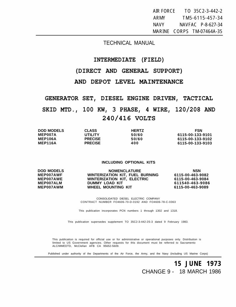
AIR FORCE TO 35C2-3-442-2ARMY TM5-6115-457-34NAVY NAVFAC P-8-627-34MARINE CORPS TM-07464A-35
TECHNICAL MANUAL
INTERMEDIATE (FIELD)
(DIRECT AND GENERAL SUPPORT)
AND DEPOT LEVEL MAINTENANCE
GENERATOR SET, DIESEL ENGINE DRIVEN, TACTICAL
SKID MTD., 100 KW, 3 PHASE, 4 WIRE, 120/208 AND240/416 VOLTS
DOD MODELS CLASS HERTZ FSNMEP007A UTILITY 50/60 6115-00-133-9101MEP106A PRECISE 50/60 6115-00-133-9102MEP116A PRECISE 400 6115-00-133-9103
DOD MODELSMEP007AWFMEP007AWEMEP007ALMMEP007AWM
INCLUDING OPTIONAL KITS
NOMENCLATURE NSNWINTERIZATION KIT, FUEL BURNING 6115-00-463-9082WINTERIZATION KIT, ELECTRIC 6115-00-463-9084DUMMY LOAD KIT 611540-463-9086WHEEL MOUNTING KIT 6115-00-463-9089
CONSOLIDATED DIESEL ELECTRIC COMPANYCONTRACT NUMBER FO4606-70-D-0192 AND FO4606-78-C-0363
This publication incorporates PCN numbers 1 through 1302 and 1318.
This publication supersedes supplement TO 35C2-3-442-2S-3 dated 9 February 1983.
This publication is required for official use or for administrative or operational purposes only. Distribution islimited to US Government agencies. Other requests for this document must be referred to SacramentoALC/MMEDTD, McClellan AFB CA 95652-5609.
Published under authority of the Departments of the Air Force, the Army, and the Navy (including US Marine Corps)
15 JUNE 1973CHANGE 9 - 18 MARCH 1986

P-8-627-34 TO 35C2-3-442-2TM-O7464A-35 TM 5-6115-457-34
INSERT LATEST CHANGED PAGES. DESTROY SUPERSEDED PAGES.
Dates of issue for original and changed pages are:
Original. .0. .15 Mar 73 Change. .4. .15 Apr 78 Change. .8. . 4 Apr 84Change. . . . 1. .31 Jun 75 Change. .5. .21 Sep 79 Change. .9. .18 Mar 86Change. . . . 2. . 1 May 77 Change. .6. . 2 Jun 81Change. . . . 3. .30 Jun 77 Change. .7. .20 May 82TOTAL NUMBER OF PAGES IN THIS PUBLICATION IS 724 CONSISTING OF THE FOLLOWING:
Page *ChangeNo. No.
Title . . . . . . . . . . . . . . 9A - C . . . . . . . . . . . . . . 901 . . . . . . . . . . . . . . . . . 802 Blank . . . . . ... 8i- i i . . . . . . . . . . . . . 4iiA Added . . . . . . . . . . 4iiB Blank Added . . . . 4i i i - vi . . . . ..... 3v i i - x . . . . . . . 0xi . . . . . . . . .... .. 2xii . . . . . . . . . . . . . . . . 6xiiA Added . . . . . . 4xiiB Blank Added. . . . . . . 4xiii - xiv . . . . . . . . 4xv - xvi. . . . . . . . . . 3xvii . . . . . . . . . . . . . . 0xviii . . . . . . . . . . . 2xix. . . . . . . . . . . . . . . . 3xx Blank . . . . .. . . . 3xx i - xxii Deleted. 31-1 . . . . . . . . . . . . . . . . 41-2 . . . . . . . . . . . . . . . 31-2A - 1-28 . . . . . . . . 41-3 - 1-6 . . . . . . . . . . 71-6A. . . . . . . . . . . . . . . 31-6B - 1-9 . . . . . . . . . 71-10 . . . . . . . . . . . . . . . 01-11 . . . . . . . . . . . . . . . 41-12 . . . . . . . . . . . . . . . 11-13 - 1-14.0 . . . . . . 3l-14A Added . . . . . . . . 31-14B Blank Added. .3
Page *ChangeNo.
1 - 1 5 . . . . . . . . . . . . . . 01-16. . . . . . . . . . . . . . . 71-17 - l-18 . . . . . . . . . 01-19 . . . . . . . . . . . . . . . 4l-20 - l-26 . . . . . . . . .01-27. . . . . . . . . . . . . . 11-28 - 1-41. . . . . . . . 01-42. . . . . . . . . . . . 71-43 - 147 . . . . . . . . 01-48 . . . . . . . . . . . . . . . 31-49 - 1-61 . . . . . . . . 01-62 Blank . . . . . . . . . 01-63 . . . . . . . . . . . . . . . 1l-64 Blank . . . . . . . . . 11-65 . . . . . . . . . . . . . . . 3l-66 Blank . . . . . . . . . 31-67 . . . . . . . . . . . . . . . 1l-68 Blank . . . . . . . . 1149 . . . . . . . . . . . . . . . 3l-70 Blank. . . . . . . . . 31-71 . . . . . . . . . . . . . . . 3l-72 Blank . . . . . . . 31-73. . . . . . . . . . . . . . . 3l-74 Blank. . . . . . . 31-75 . . . . . . . . . . . . . . . 31-76 . . . . . . . . . . . . . . . 01-77 . . . . . . . . . . . . . . . 7l-78 Blank . . . . . . . 71-79 - 1-80 . . . . . . . . 01-81 . . . . . . . . . . . . . . . 11-82 Blank . . . . . . . . . 11-83 - 1-84 . . . . . . . . 0
*Zero in this column indicates l original page.
Page *ChangeNo.
1-85 . . . . . . . . . . . . . . . 1l-86. . . . . . . . . . ..... 11-87 . . . . . . . . . . . . . . . 0l-88 Blank . . . . . . .. 01-89. . . . . . . . ... 0l-90 Blank . . . . . . . . . 01-91 . . . . . . . . . . . . . . . 8l-92 Blank. . . . . . . .81-93. . . . . . . . . .. 8l-94 Blank . . . . . . . . . 81-95 . . . . . . . . . . . . . . . 3l-96 Blank . . . . . . . . 31-97 . . . . . . . . . . . . . . . 8l-98 Blank . . . . . . . 81-99. . . . . . . . .. 1l-l00 Blank. . . . . . . . . . 11-101 . . . . . . . . . . . . . . 11-102 Blank . . . . . . . 11-103 . . . . . . . . . . . . . . 0l-l04 Blank . . . . . . . . 01-105 . . . . . . . . . . . . . . 0l-l06 Blank. . . . . . . . . . . 01-107 . . . . . . . . . . . . . . 0l-108 Blank. . . . . . . . . . . . . 01-109 . . . . . . . . . . . . . . 0l-ll0Blank . . . . . . . . 01-111 - 1-114. .000. 01-115 . . . . . . . . . . . . . . 31-116 . . . . . . . . . . . . . . 11-117 - 1-118.0000. 02-1 . . . . . . . . . . . . . . . . 12 - 2 - 2 - 4 . . . . . . 0
A
USAF
Change 9
P-8-627-34 TO 35C2-3-442-2TM-07464A-35 TM 5-6115-457-34
Page l ChangeNo. No.
2-5 - 2-6 . . . . . . . . . . 82-7 - 2-8 . . . . . . . . 32-8A Added. . . . . . . . . 32-8B Blank Added. . . 32-9 - 2-10. . . . . . . . 82-11 . . . . . . . . . . . . . . . 72-12 . . . . . . . . . . . . . . . 02-13 - 2-14. . . . . . . . . .. 82-15. . . . . . . . . . . . . . . 92 - 1 6 . . . . . . . . . 82-17 - 2-22 . . . . . . . . 02-23 - 2-24. . . . . . . . . . . . 72-25. . . . . . . . . . . . . . . 62-26 - 2-28. . . . . . . 02-29 . . . . . . . . . . . . . . 12-30 . . . . . . . . . . . . . . . 02-31 . . . . . . . . . . . . . . . 72-32 . . . . . . . . . . . . . 02-33. .. . . . . . . . . . 62-34 - 2-46 . . . . . . . . 32-47 - 2-48 . . . . . .. 02-49. .... . . . . . . . 12 - 5 0 - 2-56..... . . . . . . . . 02-57 - 2-58 . . . . ... 82-59 - 2-64 . . . . . ...42-65 - 2-66...................... 83-1 - 3-2. . . . . . . . . . . 03-3 - 3-6 . . . . . . . . . . 83-7- 3-l0 . . . . . . . . . 34 - 1 - 4 - 4 . . . . . . . . . 84 -5 - 4-6.. . . . . . . . . . 14-7 - 4-8. . . . . . . . . . . . . . .. 85-1 - 5-2 . . . . . . . . . . 85-3 - 5-11 . . . . . . . . . 05-12 - 5-13 . . . . . . . . 35-14 - 5-16 . . . . . . . . 06-1 - 6-40 . . . . . . . . 06-5 - 6-8 . . . . . . . . . . 86-9 . . . . . . . . . . . . . . . 06-10 . . . . . . . . . . . . . . . 16-11 - 6-12 . . . . . . . . 86-13. . . . . . . . . . . . . . . 06-14. . . . . . . . . . . . . . . . 36-15 . . . . . . . . . . . . . . . 06-16 Blanke . . . . . . . 06-17 . . . . . . . . . . . . . . . 06-18 Blank . . . . . . . . 06-19 - 6-20 . . . . . . . . . . . .36-20A Added . . . . . . . 36-208 Blank Added. . . 36-21 . . . . . . . . . . . . . . . 36-22 . . . . . . . ....... 0
LIST OF EFFECTIVE PAGES (cont)
Page *ChangeNo. No.
6-23 - 6-24 . . . . . . . . 86-25 - 6-26 . . . . . . . . 06-27 - 6-28 . . . . . . . . 86-29 - 6-33 . . . . . . . . 06-34 . . . . . . . . . . . . . . . 46-35 - 6-37 . . . . . . . . 06-38 . . . . . . . . . . . . . . . 46-39 . . . . . . . . . . . . . . . 1640 - 642 . . . . . . . . 06 4 3 - 645 . . . . . . . . 7646 . . . . . . . . . . . . . . . 06 4 7 - 6 4 8 . 0 . 0 0 0 0 . 76-49 - 6-50 . . . . . . . . 96-51 . . . . . . . . . . . . . . . 16-52 - 6-59 . . . . . . . 06-60 . . . . . . . . . . . . . . . 96-61 - 6-64 . . . . . . . . 86-65 . . . . . . . . . . . . . . . 06-66 - 6-68 . . . . . . . 16-69 - 6-74 . . . . . . . . 06-75 - 6-76 . . . . . . . . 86-77 - 6-81 . . . . . . . . 06-82 - 6-83 . . . . . . . 36-84 . . . . . . . . . . . . . . . 76-85 - 6-860.0 . . . . . 36-87 - 6-96 . . . . . . . . 86-97 -6-l00. . . . . 36-101 - 6-103 . . . . . . 86-104 Blank . . . . . . . . 86-105 - 6-106 . . . . . . 36-107 - 6-109 . . . . . . 86 - 1 1 0 . . . . . . . . . . . . . 96-111 - 6-116 . . . . . . 36-117 - 6-1180 . . . . . 86-119 . . . . . . . . . . . . . . 36-120 . . . . . . . . . . . . . . 96-120 - 6-120G. . . . . 36-120H Blank . . . . . . . 36-1201 - 6-120J. . . . 86-120K- 6-120M . . . . 36-l0N Blank . . . . . . . 36-121 - 6-124 . . . . . . 86-125 - 6-130 . . . . . . 36-130A - 6-130D
Deleted . . . . . . . . . . 36-131 - 6-132C
Deleted . . . . . . . . . . 36-132D Blank
Deleted . . . . . . . . . . 36-133 - 6-135 . . . . . . 36-136 Blank . . . . . . . . 36-137 . . . . . . . . . . . . . . 3
Page *ChangeNo. No.
6-138 Blank. . . . . 36-139 - 6-150. . . . 36-151. . . . . . . . . . . . . 86-152 Blank . . . . . . . . . . . . 86-153 - 6-159. . . . . . . . . 36-160 Blank . . . . . . . . . . . .36-161 - 6-162 . . . . . . 86-163 - 6-174 . . . . . . 36-175 - 6-176 . . . . . . 86-177 - 6-182 . . . . . . 36-182A . . . . . . . . . . . . . 96-182B Blank . . . . . . . 96-183 - 6-184. . . . . 86-185 - 6-188 . . . . . . 36-189 - 6-220
Deleted . . . . . . . . . . 37-1 . . . . . . . . . . . . . . . . 77-2 - 7-4 . . . . . . . . . . 07-5 - 7-6 . . . . . . . . . . 87-7 - 7-8.. . . . . . 97-8A Added . . . . . . . . . 97-8B Blank Added. . . 97-9 - 7-10 . . . . . . . . . 07-11 - 7-12 . . . . . . . . 87-13 - 7-14 . . . . . . . . 07-15 - 7-16 . . . . . . . . 87-17 . . . . . . . . . . . . . . . 77-18 - 7-20 . . . . . . . . 07-21 - 7-22 . . . . . . . . 87-23 - 7-24 . . . . . . . . 07-25 . . . . . . . . . . . . . . . 17-26 Blank. . . . . . . . 18-1 - 8-2 . . . . . . . . . . 88-3 - 84 . . . . . . . . . . 08-5 - 8-6 . . . . . . . . . . 88-7 - 8-12 . . . . . . . . . 08-13 - 8-14 . . . . . . . . 88-15 - 8-16 . . . . . . . . 18-17 - 8-26 . . . . . . . . 88-26A Added. . . . . . 88-26B Blank Added. . 88-27 - 8-28 . . . . . . . . 88-29 - 8-30 . . . . . . . . 78-31 - 8-38 . . . . . . . . 88-39 - 840 . . . . . . . . 0841 - 842 . . . . . . . . 8843-844.. . . . . . . . . . . 0845 . . . . . . . . . . . . . . . 18-46. . . . . . . . . . . . . . 08 4 7 - 8-50. . . . . . 88-51 . . . . . . . . . . . . . . . 18-52 - 8-54 . . . . . . . . 0
Change 9 B
P-8-627-34 TO 35C2-3-442-2TM-07464A-35 TM 5-6115-457-34
LIST OF EFFECTIVE PAGES (cont)
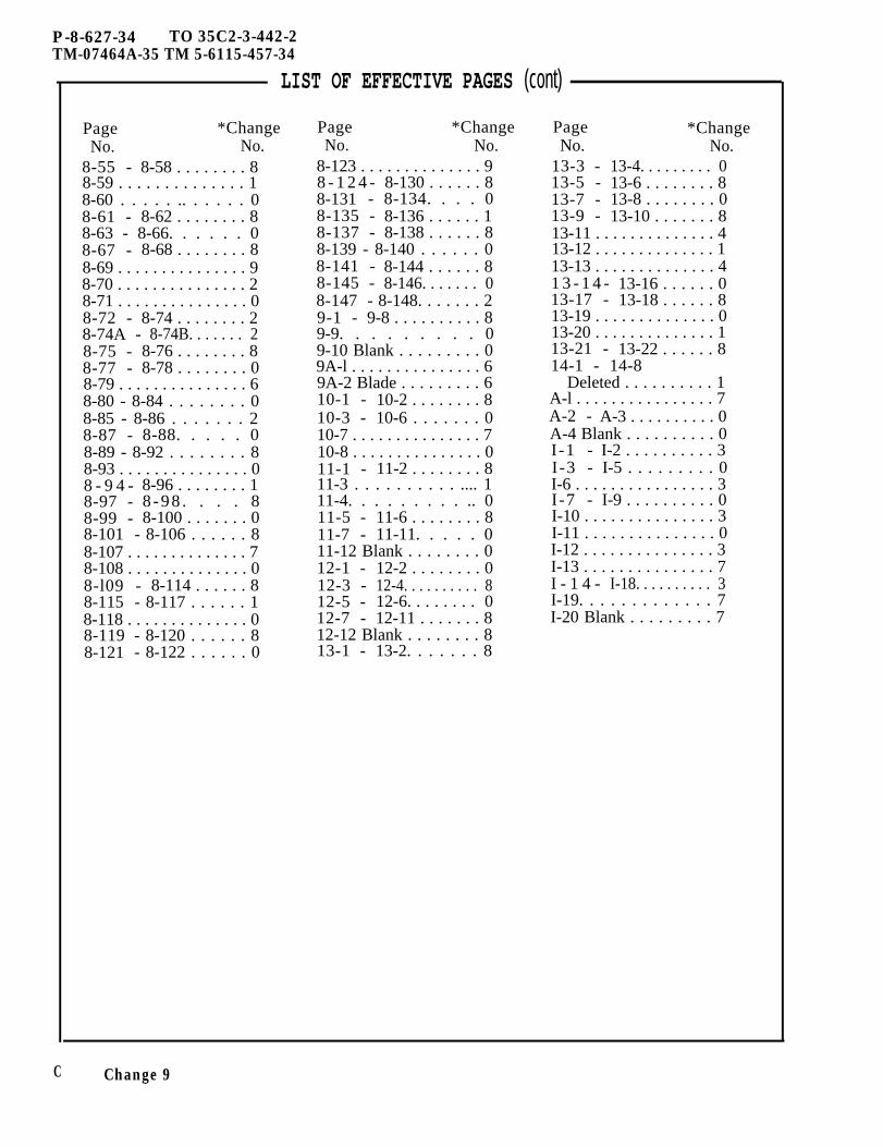
Page *ChangeNo. No.
8-55 - 8-58 . . . . . . . . 88-59 . . . . . . . . . . . . . . 18-60 . . . . . .. . . . . . 08-61 - 8-62 . . . . . . . . 88-63 - 8-66. . . . . . 08-67 - 8-68 . . . . . . . . 88-69 . . . . . . . . . . . . . . . 98-70 . . . . . . . . . . . . . . . 28-71 . . . . . . . . . . . . . . . 08-72 - 8-74 . . . . . . . . 28-74A - 8-74B. . . . . . . 28-75 - 8-76 . . . . . . . . 88-77 - 8-78 . . . . . . . . 08-79 . . . . . . . . . . . . . . . 68-80 - 8-84 . . . . . . . . 08-85 - 8-86 . . . . . . . 28-87 - 8-88. . . . . 08-89 - 8-92 . . . . . . . . 88-93 . . . . . . . . . . . . . . . 08 - 9 4 - 8-96 . . . . . . . . 18-97 - 8 -98 . . . . 88-99 - 8-100 . . . . . . . 08-101 - 8-106 . . . . . . 88-107 . . . . . . . . . . . . . . 78-108 . . . . . . . . . . . . . . 08-l09 - 8-114 . . . . . . 88-115 - 8-117 . . . . . . 18-118 . . . . . . . . . . . . . . 08-119 - 8-120 . . . . . . 88-121 - 8-122 . . . . . . 0
Page *ChangeNo. No.
8-123 . . . . . . . . . . . . . . 98 - 1 2 4 - 8-130 . . . . . . 88-131 - 8-134. . . . 08-135 - 8-136 . . . . . . 18-137 - 8-138 . . . . . . 88-139 - 8-140 . . . . . . 08-141 - 8-144 . . . . . . 88-145 - 8-146. . . . . . . 08-147 - 8-148. . . . . . . 29-1 - 9-8 . . . . . . . . . . 89-9. . . . . . . . . 09-10 Blank . . . . . . . . . 09A-l . . . . . . . . . . . . . . . 69A-2 Blade . . . . . . . . . 610-1 - 10-2 . . . . . . . . 810-3 - 10-6 . . . . . . . 010-7 . . . . . . . . . . . . . . . 710-8 . . . . . . . . . . . . . . . 011-1 - 11-2 . . . . . . . . 811-3 . . . . . . . . . . .... 111-4. . . . . . . . . .. 011-5 - 11-6 . . . . . . . . 811-7 - 11-11. . . . . 011-12 Blank . . . . . . . . 012-1 - 12-2 . . . . . . . . 012-3 - 12-4. . . . . . . . . . 812-5 - 12-6. . . . . . . . 012-7 - 12-11 . . . . . . . 812-12 Blank . . . . . . . . 813-1 - 13-2. . . . . . . 8
Page *ChangeNo. No.
13-3 - 13-4. . . . . . . . . 013-5 - 13-6 . . . . . . . . 813-7 - 13-8 . . . . . . . . 013-9 - 13-10 . . . . . . . 813-11 . . . . . . . . . . . . . . 413-12 . . . . . . . . . . . . . . 113-13 . . . . . . . . . . . . . . 41 3 - 1 4 - 13-16 . . . . . . 013-17 - 13-18 . . . . . . 813-19 . . . . . . . . . . . . . . 013-20 . . . . . . . . . . . . . . 113-21 - 13-22 . . . . . . 814-1 - 14-8
Deleted . . . . . . . . . . 1A-l . . . . . . . . . . . . . . . . 7A-2 - A-3 . . . . . . . . . . 0A-4 Blank . . . . . . . . . . 0I-1 - I-2 . . . . . . . . . . 3I-3 - I-5 . . . . . . . . . 0I-6 . . . . . . . . . . . . . . . . 3I-7 - I-9 . . . . . . . . . . 0I-10 . . . . . . . . . . . . . . . 3I-11 . . . . . . . . . . . . . . . 0I-12 . . . . . . . . . . . . . . . 3I-13 . . . . . . . . . . . . . . . 7I - 1 4 - I-18. . . . . . . . . . 3I-19. . . . . . . . . . . . . 7I-20 Blank . . . . . . . . . 7
C Change 9
AIR FORCE T0 35C2-3-442-2ARMY TM5-6115-457-34NAVY NAVFAC P-8-627-34MARINE CORPS TM-07464A-35
TECHNICAL MANUAL
INTERMEDIATE (FIELD)(DIRECT AND GENERAL SUPPORT)AND DEPOT LEVEL MAINTENANCE
GENERATOR SET, DIESEL ENGINE DRIVEN,SKID MTD., 100 KW, 3 PHASE, 4 WIRE, 120/208 AND
D0D MODELS CLASS HERTZMEPO07A UTILITY 50/60MEP106A PRECISE 50/60MEP116A PRECISE 400
INCLUDING OPTIONAL KITS
DOD MODELS NOMENCLATUREMEP007AWF WINTERIZATION KIT, FUEL BURNINGMEPO07AWE WINTERIZATION KIT, ELECTRICMEPO07ALM DUMMY L0AD KITMEPO07AWM WHEEL MOUNTING KIT
TACTICAL240/416 VOLTS
FSN6115-OO-133-91O16115-OO-133-91O26115-OO-133-91O3
NSN6115-00-463-90826115-00-463-90846115-00-463-90866115-00-463-9089
Consolidated Diesel Electric CompanyContract Number FO4606.70.D.0192 and FO4606-78-C.-0363
This publication incorporates PCN numbers 1 through 1302 and 1318
Distribution Statement - This publication is required for official use or for administrative oroperational purposes only. Distribution is limited to US Government agencies. other requests forthis document must be referred to Sacramento ALC/MMEDTD, McClellan AFB, CA 95652-5609.
Published under authority of the
Departments of the Air Force, the Army, and the Navy
(Including U.S. Marine Corps) 15 JUNE 1973CHANGE 8 - 4 APRIL 1984
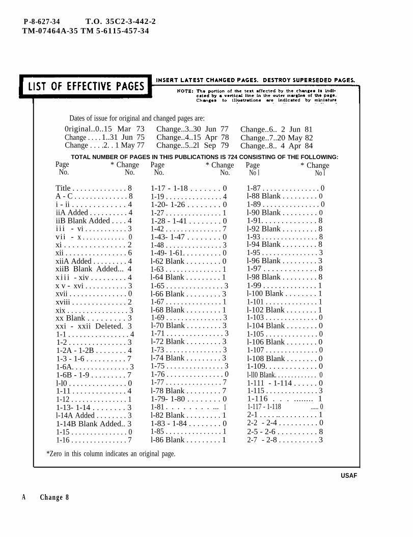
P-8-627-34 T.O. 35C2-3-442-2TM-07464A-35 TM 5-6115-457-34
Dates of issue for original and changed pages are:0riginal..0..15 Mar 73 Change..3..30 Jun 77 Change..6.. 2 Jun 81Change . . . . 1..31 Jun 75 Change..4..15 Apr 78 Change..7..20 May 82Change . . . .2. . 1 May 77 Change..5..2l Sep 79 Change..8.. 4 Apr 84
TOTAL NUMBER OF PAGES IN THIS PUBLICATIONS IS 724 CONSISTING OF THE FOLLOWING:
A
Page * ChangeNo. No.
Title . . . . . . . . . . . . . . 8A - C . . . . . . . . . . . . . . 8i - ii . . . . . . . . . . . . . 4iiA Added . . . . . . . . . . 4iiB Blank Added . . . . 4i i i - vi . . . . . . . . . . . 3vii - x . . . . . . . . . . . . 0xi . . . . . . . . . . . . . . . 2xii . . . . . . . . . . . . . . . . 6xiiA Added . . . . . . . . . 4xiiB Blank Added... 4x i i i - xiv . . . . . . . . . 4x v - xvi . . . . . . . . . . . 3xvii . . . . . . . . . . . . . . . 0xviii . . . . . . . . . . . . . . 2xix . . . . . . . . . . . . . . . . 3xx Blank . . . . . . . . . 3xxi - xxii Deleted. 31-1 . . . . . . . . . . . . . . . . 41-2 . . . . . . . . . . . . . . . 31-2A - 1-2B . . . . . . . . 41-3 - 1-6 . . . . . . . . . . 71-6A. . . . . . . . . . . . . . . 31-6B - 1-9 . . . . . . . . . 7l-l0 . . . . . . . . . . . . . . . 01-11 . . . . . . . . . . . . . . 41-12 . . . . . . . . . . . . . . . 11-13- 1-14 . . . . . . . . 3l-14A Added . . . . . . . . 31-14B Blank Added.. 31-15 . . . . . . . . . . . . . . . 01-16 . . . . . . . . . . . . . . . 7
Page * ChangeNo. No.
1-17 - 1-18 . . . . . . . 01-19 . . . . . . . . . . . . . . . 41-20- 1-26 . . . . . . . . 01-27 . . . . . . . . . . . . . . . 11-28 - 1-41 . . . . . . . . 01-42 . . . . . . . . . . . . . . . 71-43- 1-47 . . . . . . . . 01-48 . . . . . . . . . . . . . . . 31-49- 1-61. . . . . . . . . . 0l-62 Blank . . . . . . . . . 01-63 . . . . . . . . . . . . . . . 1l-64 Blank . . . . . . . . . 11-65 . . . . . . . . . . . . . . . 3l-66 Blank . . . . . . . . . 31-67 . . . . . . . . . . . . . . . 1l-68 Blank . . . . . . . . . 11-69 . . . . . . . . . . . . . . . 3l-70 Blank . . . . . . . . . 31-71 . . . . . . . . . . . . . . . 3l-72 Blank . . . . . . . . . 31-73 . . . . . . . . . . . . . . . 3l-74 Blank . . . . . . . . . 31-75 . . . . . . . . . . . . . . . 31-76 . . . . . . . . . . . . . . . 01-77 . . . . . . . . . . . . . . . 7l-78 Blank . . . . . . . . . 71-79- 1-80 . . . . . . . . 01-81 . . . . . . . . ... 1l-82 Blank . . . . . . . . . 11-83 - 1-84 . . . . . . . . 01-85 . . . . . . . . . . . . . . . 1l-86 Blank . . . . . . . . . 1
*Zero in this column indicates an original page.
Page * ChangeNo l No l
1-87 . . . . . . . . . . . . . . . 0l-88 Blank . . . . . . . . . 01-89 . . . . . . . . . . . . . . . 0l-90 Blank . . . . . . . . . 01-91. . . . . . . . . . . . . . 8l-92 Blank . . . . . . . . . 81-93 . . . . . . . . . . . . . . . 8l-94 Blank . . . . . . . . . 81-95 . . . . . . . . . . . . . . . 3l-96 Blank . . . . . . . . . 31-97 . . . . . . . . . . . . . 8l-98 Blank . . . . . . . . . 81-99 . . . . . . . . . . . . . . 1l-100 Blank . . . . . . . . 11-101 . . . . . . . . . . . . . . 1l-102 Blank . . . . . . . . 11-103 . . . . . . . . . . . . . . 0l-104 Blank . . . . . . . . 01-105 . . . . . . . . . . . . . . 0l-106 Blank . . . . . . . . 01-107 . . . . . . . . . . . . . . 0l-108 Blank . . . . . . . . 01-109. . . . . . . . . . . . . 0l-ll0 Blank. . . . . . . . . . . . . 01-111 - 1-114 . . . . . . 01-115 . . . . . . . . . . . . . . 31-116 . . . ........ 11-117 - 1-118 ..... 02-1 . . . . .. . . . . . . . . . 12-2 - 2-4 . . . . . . . . . . 02-5 - 2-6 . . . . . . . . . . 82-7 - 2-8 . . . . . . . . . . 3
USAF
Change 8

P-8-627-34 T.O. 35C2-3-442-2TM-07464A-35 TM 5-6115-457-34
LIST OF EFFECTIVE PAGES (cont)Page *Change
No. No.
2-8A Added . . . . . . . . . 32-8B Blank Added . . . 32-9 - 2-10 . . . . . . . . . 82 - 1 1 . . . . . . . . . . . . . 72-12 . . . . . . . . . . 02-13 - 2-16 . . . . . . . . 82-17 -2-22. . . . . . 02-23 - 2-24 . . . . . . . . 72-25 . . . . . . . . . . . . . . . 62-26 - 2-28 . . . . . . . . 02-29 . . . . . . . . . . . . . . . 12-30. . . . . . . . . . . .. 02-31 . . . . . . . . . . . . . . . 72-32 . . . . . . . . . . . . . . . 02-33 . . . . . . . . . . . . . . . 62-34 - 2-46 . . . . . . . . 32-47 - 2-48 . . . . . ...02-49 . . . . . . . . . . . . . . . 12-50 - 2-56 . . . . . ...02-57 - 2-58 . . . . . . . . 82-59 - 2-64 . . . . . . . . 42-65 - 2-66 . . . . . . . . 83-1 - 3-2 . . . . . . . ...03-3 - 3-6 . . . . . . . . . . 83-7 - 3-10. . . . . . 34-1 - 4-4 . . . . . . . . . . 84-5 - 4-6 . . . . . . . . . . 14-7 - 4-8 . . . . . . . . . . 85-1 - 5-2 . . . . . . . . . . 85-3 - 5-110 . . . . . . . . 05-12 - 5-13 . . . . . . . . 35-14 - 5-16. . . . . . . 06-1 - 6-4 . . . . . . . . . . 06-5 - 6-8 . . . . . . . . . . 86-9 . . . . . . . . . . . . . . . . 06-10 . . . . . . . . . . . . . . . 16-11 - 6-12 . . . . . . . . 86-13 . . . . . . . . . . . . . . . 06-14 . . . . . . . . . . . . . . . 36-15 . . . . . . . . . . . . . . . 06-16 Blank . . . . . . . . . 06-17 . . . . . . . . . . . . . . . 06-18 Blank . . . . . . . . . 06-19 - 6-20 . . . . . . . . 36-20A Added . . . . . . . . 36-20B Blank Added.. 36-21 . . . . . . . . . . . . . . . 36-22 . . . . . . . . . . . . . . . 06-23 - 6-24 . . . . . . . . 86-25 - 6-26 . . . . . . . . 06-27 - 6-28 . . . . . . . . 8
Page *ChangeNo. No.
6-29 - 6-33 . . . . . . . . 06-34 . . . . . . . . . . . . . . . 46-35 - 6-37 . . . . . . . . 06-38 . . . . . . . . . . . . . . . 46-390 . . . . . . . . . . . . . . 16-40 - 6-42 . . . . . . . . 06-43 - 6-45 . . . . . . . . 76-46 . . . . . . . . . . . . . . . 06-47 - 6-48 . . . . . . . . 76-49 - 6-50 . . . . . . . . 86-51 . . . . . . . . . . . . . . . 16-52 - 6-59 . . . . . . . . 06-60 . . ..00 . . . . . . . . . 16-61 - 6-64 . . . . . . . . 86-65 . . . . . . . . . . . ... 06-66-6-68. . . . . . . . 16-69 - 6-74 . . . . . . . . 06-75 - 6-76 . . . . . . . . 86-77 - 6-81.. . . . . . 06-82 - 6-83 . . . . . . . . 36-84 . . . . . . . . . .. 76-85 - 6-86 . . . . . . . . 36-87 - 6-96 . . . . . . . . 86-97 - 6-100. . . . . . 36-101 - 6-103 . . . . . . 86-104 Blank. . . . . . . 86-105 - 6-106 . . . . . . 36-107 - 6-110. . . . . . . . 86-111 - 6-116. . . . . 36-117 - 6-118 . . . . . . 86-119 - 6-120. . . . 36-120A - 6-120G . . . . 36-120H Blank . . . . . 36-1201- 6-120J . . . . 86-120K - 6-120M. . . 36-120N Blank . . . . . . . 36-121 - 6-124 . . . . . . 86-125 - 6-130 . . . . . . 36-130A - 6-130D
Deleted . . . . . . . . . . 36-131 - 6-132C Deleted . . . . . . . . . . 36-132D Blank
Deleted . . . . . . . . . . 36-133 - 6-135 . . . . . . 36-136 Blank . . . . . . . . 36-137 . . . . . . . . . . . . . . 36-138 Blank . . . . . . . . 36-139 - 6-150 . . . . . . 36-151 . . . . . . . . .. 86-152 Blank . . . . . . . . 8
Page *ChangeNo. No.
6-153 - 6-159 . . . . . . 36-160 Blank . . . . . . . . 36-161 - 6-162 . . . . . . 86-163 - 6-174 . . . . . . 36-175 - 6-176 . . . . . . 86-177 - 6-182 . . . . . . 36-182A . . . . . . . . . . . . . 86-182B Blank . . . . . . . 86-183 - 6-184 . . . . . . 86-185- 6-219 . . . . . . 36-220 Deleted . . . . . . 37-1 . . . . . . . . . . . . . . . . 77-2 - 7-4 . . . . . . . . . . 07-5 - 7-8 . . . . . . . . . . 87-9 - 7-10. . . . . 07-11 - 7-12 . . . . . . . . 87-13 - 7-140. . . . . .07-15- 7-16 . . . . . . . . 87-17. . . . . . . . . . . . . . . 77-18 - 7-20 . . . . . . . . 07-21 - 7-22 . . . . . . . . 87-23 - 7-24 . . . . . ...07-25 . . . . . . . . . . . . . . . 17-26 Blank . . . . . . . . . 18-1 - 8-2 . . . . . . . . . . 88-3 - 8-4 . . . . . . . ...08-5 - 8-6 . . . . . . . . . . 88-7 - 8-12 . . . . . . . . . 08-13 - 8-14 . . . . . . . . 88-15 - 8-16 . . . . . . . . 18-17 - 8-26 . . . . . . . . 88-26A Added . . . . . . . . 88-26B Blank Added.. 88-27 - 8-28 . . . . . . . . 88-29 -8-30. . . . . . 78-31 - 8-38 . . . . . . . . 88-39 - 8-40 . . . . . . . . 08-41 - 8-42 . . . . . . . . 88-43 - 8-44 . . . . . . . . 08-45 . . . . . . . . . . . . . . . 18-46 . . . . . . . . . . . . . . . 08-47 - 8-50 . . . . . . . . 88-51 . . . . . . . . . . . . . . . 18-52 - 8-54 . . . . . . . . 08-55 - 8-58 . . . . . . . . 88-59 . . . . . . . . . . . . . . . 18-60 . . . . . . . . . . . . . . 08-61 - 8-62 . . . . . . . . 88-63 - 8-66 . . . . . . . . 08-67 - 8-68 . . . . . . . . 88-69 . . . . . . . . . . . . . . . 0
Change 8 B
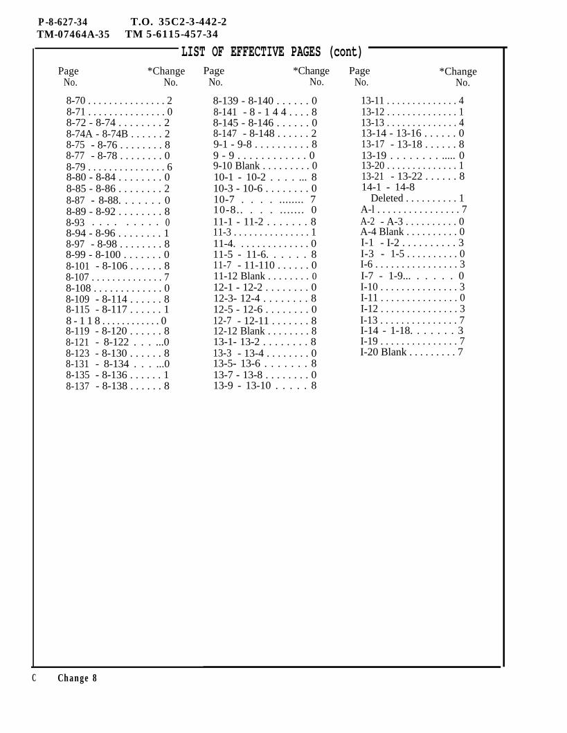
P-8-627-34 T.O. 35C2-3-442-2TM-07464A-35 TM 5-6115-457-34
LIST OF EFFECTIVE PAGES (cont)Page *Change
No. No.
8-70 . . . . . . . . . . . . . . . 28-71 . . . . . . . . . . . . . . . 08-72 - 8-74 . . . . . . . . 28-74A - 8-74B . . . . . . 28-75 - 8-76 . . . . . . . . 88-77 - 8-78 . . . . . . . . 08-79 . . . . . . . . . . . . . . . 68-80 - 8-84 . . . . . . . . 08-85 - 8-86 . . . . . . . . 28-87 - 8-88. . . . . . . 08-89 - 8-92 . . . . . . . . 88-93 . . . . . . . . . 08-94 - 8-96 . . . . . . . . 18-97 - 8-98 . . . . . . . . 88-99 - 8-100 . . . . . . . 08-101 - 8-106 . . . . . . 88-107 . . . . . . . . . . . . . . 78-108 . . . . . . . . . . . . . 08-109 - 8-114 . . . . . . 88-115 - 8-117 . . . . . . 18 - 1 1 8 . . . . . . . . . . . . 08-119 - 8-120 . . . . . . 88-121 - 8-122 . . . ...08-123 - 8-130 . . . . . . 88-131 - 8-134 . . . ...08-135 - 8-136 . . . . . . 18-137 - 8-138 . . . . . . 8
Page *ChangeNo. No.
8-139 - 8-140 . . . . . . 08-141 - 8 - 1 4 4 . . . . 88-145 - 8-146 . . . . . . 08-147 - 8-148 . . . . . . 29-1 - 9-8 . . . . . . . . . . 89 - 9 . . . . . . . . . . . . 09-10 Blank . . . . . . . . . 010-1 - 10-2 . . . . ... 810-3 - 10-6 . . . . . . . . 010-7 . . . . ........ 710-8.. . . . . . . . . . . 011-1 - 11-2 . . . . . . . 811-3 . . . . . . . . . . . . . . . 111-4. . . . . . . . . . . . . . 011-5 - 11-6. . . . . . 811-7 - 11-110 . . . . . . 011-12 Blank . . . . . . . . 012-1 - 12-2 . . . . . . . . 012-3- 12-4 . . . . . . . . 812-5 - 12-6 . . . . . . . . 012-7 - 12-11 . . . . . . . 812-12 Blank . . . . . . . . 813-1- 13-2 . . . . . . . . 813-3 - 13-4 . . . . . . . . 013-5- 13-6 . . . . . . . 813-7 - 13-8 . . . . . . . . 013-9 - 13-10 . . . . . 8
Page *ChangeNo. No.
13-11 . . . . . . . . . . . . . . 413-12 . . . . . . . . . . . . . . 113-13 . . . . . . . . . . . . . . 413-14 - 13-16 . . . . . . 013-17 - 13-18 . . . . . . 813-19 . . . . . . . . ..... 013-20 . . . . . . . . . . . . . . 113-21 - 13-22 . . . . . . 814-1 - 14-8
Deleted . . . . . . . . . . 1A-l . . . . . . . . . . . . . . . . 7A-2 - A-3 . . . . . . . . . . 0A-4 Blank . . . . . . . . . . 0I-1 - I-2 . . . . . . . . . . 3I-3 - 1-5 . . . . . . . . . . 0I-6 . . . . . . . . . . . . . . . . 3I-7 - 1-9... . . . . . 0I-10 . . . . . . . . . . . . . . . 3I-11 . . . . . . . . . . . . . . . 0I-12 . . . . . . . . . . . . . . . 3I-13 . . . . . . . . . . . . . . . 7I-14 - 1-18. . . . . . . 3I-19 . . . . . . . . . . . . . . . 7I-20 Blank . . . . . . . . . 7
C Change 8
AIR FORCE T.O. 35C2-3-442-2ARMY TM5-6115-457-34NAVY NAVFAC P-8-627-34MARINE CORPS TM-07464A-35
TECHNICAL MANUAL
INTERMEDIATE (FIELD)(DIRECT AND GENERAL SUPPORT)AND DEPOT LEVEL MAINTENANCE
GENERATOR SET, DIESEL ENGINE DRIVEN, TACTICALSKID MTD., 100 KW, 3 PHASE, 4 WIRE, 120/208 AND 240/416 VOLTS
DOD MODELSMEPO07AMEP106AMEP116A
DOD MODELSMEPO07AWFMEPO07AWEMEPO07ALMMEPO07AWM
CLASS HERTZUTILITY 50/60PRECISE 50/60PRECISE 400
INCLUDING OPTIONAL KITSNOMENCLATURE
WINTERIZATION KIT, FUEL BURNINGWINTERIZATION KIT, ELECTRICDUMMY L0AD KITWHEEL MOUNTING KIT
FSN6115-0O-133-91O16115-00-133-91026115-00-133-9103
NSN6115-00-463-90826115-00-463-90846115-00-463-90866115-00-463-9089
Consolidated Diesal Electric CompanyContract Number FO4606-70-D.0192 and FO4606-78-C-0363
This publication incorporates PCN numbers 1 through 1302 and 1318
Distribution Statement. This publication is required for official use or for administrative oroperational purposes onlu. Distribution is limited to US Government agencies. Other requestsfor this document must be referred to Sacremento ALC/MMEDPD< McClellan AFB, CA 95652.
Published under authority of the
Departments of the Air Force, the Army, and the Navy
(Including U. S. Marine Corps) 15 JUNE 1973CHANGE 7-20 MAY 1982
P-9-TM-457-35 T O 35C2-3-442-2TM-07464A-35 TM 5-6115-457-34
LIST OF EFFECTIVE PAGESInsert latest changed pages; dispose of superseded pages in accordance with aplicable regu-lations.
NOTE: On a changed page, the portion of the text affected by the latest change is indicated by a verticalline, or other change symbol. in the outer margin of the page. Changes to illustrations are indicated byminiature pointing hands. Changes to wiring diagrams are indicated by shaded areas.
Total number of pages in this manual is 724 consisting of the following:
Page No. # Change No.
Title . . . . . . . . . . . . . . . . . .A . . . . . . . . . . . . . . . . . . . .B . . . . . . . . . . . . . . . . . . . .c . . . . . . . . . . . . . . . . . . . .i - i i . . . . . . . .iiA Added . . . . . . . . .iiB Blank Added . . . .iii-vi . . . . . . . . . . .vii-x . . . . . . . . . .xi . . . . . . . . . . . .CFL . . . . . . . . . .xiiA Added . . . . . . . .xiiB Blank Added . . . . .xiii-xiv . . . . . . .xv-xvi . . . . . . . . . .xvii . . . . . . . . . . . .xviii . . . . . . . . . .xix . . . . . . . . xx Blank . . . . . . . . .xxi-xxii Deleted . . . . .1-1 . . . . . . . . . . .1-2 . . . . . . . . ..1-2A - 1-2B . . . . . . . .1-3 - 1-6 . . . . . . . . . . ...71-6A . . . . . . . . . . . . . ...31-6B . . . . . . . . . . . . . . . ...71-7 - 1-9 . . . . . . . . . . . ...71-8 - 1-9 . . . . . . . . . 1l-l0 . . . . . . . . . . . . 01 - 1 1 . . . . . . . . . . . 41-12 . . . . . . . . .. 11-13-1-14 . . . . ... 3l-l4A Added . . . . . . . 3l-14B Blank Added . . . . 31-15 . . . . . . . . . . . . 01-16 . . . . . . . . . . . . 71-17-1-18 . . . . . . . . 01-19 . . . . . . . . . . . . 4
77774443026444302333434
Page No. # Change No.
1-27. . . . . . . . . . . . .1-28 - 1-41 . . . . . .1-42 . . . . . . . . . . .1 - 4 3 - 1 - 4 7 . . . . . .1-48 . . . . . . . . . . .1-49 - 1-61 . . . . . . . .l-62 Blank . . . . . . . .1-63 . . . . . . . . . . . .l-64 Blank . . . . . . . .1-65 . . . . . . . . . . . .l-66 Blank . . . . . . . .1-67 . . . . . . . . . . .l-68 Blank . . . . . . .1-69 . . . . . . . . . . . .l-70 Blank . . . . . . . .1-71 . . . . . . . . . . .l-72 Blank . . . . . . . .1 - 7 3 . . . . . . .l-74 Blank . . . . . . . .1-75 . . . . . . . . .1-76 . . . . . . . . . . . .1-77 . . . . . . . . .l-78 Blank . . . . . . . .1-79 - 1-80 . . . . . . . .1-81 . . . . . . . . . ..l-82 Blank . . . . . . . .1-83-1-64 . . . . . . . .1-65 . . . . . . . . . . .l-86 Blank . . . . . . . . . 1-87 . . . . . . . . . . . .l-88 Blank . . . . .1-89 . . . . . . . . . . .l-90 Blank . . . . . . . .1-91 . . . . . . . . . . . .l-92 Blank . . . . . . . .1-93 . . . . . . . . . . . .l-64 Blank . . . . . . . .1 - 9 5 . . . . . . . . . .l-96 Blank . . . . . .1-97 . . . . . . . . .
1070300103010303030307001001000003030303
Page No. # Change No.
l-98 Blank . . . . . . . .1-99 . . . . . . . . . . . .l-100 Blank . . . . . . .1-101 . . . . . . . .l-102 Blank . . . . . . .1 - 1 0 3 . . . . . . . . .l-104 Blank . . . . . . .l - l 0 5 . . . . . . .l-108 Blank . . . . . . .l-l07 . . . . . . . . . .l-108 Blank . . . . . .1-108 . . . . . . . . . . .l-ll0 Blank . . . . . . .1-111 - 1-114 . . . . . .1-115 . . . . . . . . .1-116 . . . . . . . . . . .1-117-1-118 . . . . . .2-1. . . . . . . . . . . . . .
010100000000003101
2-2 - 2-4 . . . . . . . . . . . ...02-5 . . . . . . . . . .2-6 - 2-8 . . . . .2-8A Added. . . .2-8B Blank Added2-9 - 2-10. . . . .
2-13 . . . . . . . . .2-14 . . . . . . . . .2-15 . . . . . . . . .2-16 - 2-23 . . . .2-24 . . . . . . . . .2-25 . . . . . . . . .2-26 - 2-28 . . . .2-29 . . . . . . . . .2-30 . . . . . . . . .
. . . . . . . .
. . . . . . . .
. . . . . . . .
. . . . . . . .
. . . . . . . .
. . . . . . . .
. . . . . . . .
7333070
. . . . . . . .
. . . . . . . .
. . . . . . . .
. . . . . . . .
. . . . . . . .
. . . . . . . .
. . . . . . . .
. . . . . . . .
. . . . . . . .
101076010
2-31 . . . . . . . . . . . . . . . . 72-32 . . . . . . . . . . . . . . . ...02-33 . . . . . . . . . . . . . . . ...62-34 – 2-46 . . . . . . . . . . ...32-47–2-48 . . . . . . . . . . . ..02-49 . . . . . . . . . . . . . . . ...12-50 – 2-56 . . . . . . . . . . . ..02-57 - 2-66 . . . . . . . . . . ...4
. . . . . . . . . . . . . . 03-1 - 3-61-20 - 1-26 . . . . . . . . 0
A Change 7
AIR FORCE T.O. 35C2-3-442-2ARMY TM5-6115-457-34NAVY NAVFAC P-8-627-34MARINE CORPS TM-07464A-35
TECHNICAL MANUAL
INTERMEDIATE (FIELD)(DIRECT AND GENERAL SUPPORT]AND DEPOT LEVEL MAINTENANCE
GENERATOR SET, DIESEL ENGINE DRIVEN, TACTICALSKID MTD., 100 KW, 3 PHASE, 4 WIRE, 120/208 AND 240/416 VOLTS
DOD MODELS CLASS HERTZ FSNMEPO07A UTILITY 50/60 6115-00-133-9101MEP106A PRECISE 50/60 6115-00-133-9102MEP116A PRECISE 400 6115-00-133-9103
INCLUDING OPTIONAL KITS
DOD MODELS NOMENCLATURE NSNMEPO07AWF WINTERIZATION KIT, FUEL BURNING 6115-00-463-9082MEPO07AWE WINTERIZATION KIT, ELECTRIC 6115-00-463-9084MEPO07ALM DUMMY L0AD KIT 6115-00-463-9088MEPO07AWM WHEEL MOUNTING KIT 6115-00-463-9089
THIS PUBLICATION REPLACES TO 35c2-3-442-2s-2 DATED 8 JULY 1980 AND TO3502-3-442-2C DATED 29 AUGUST 1978.
Consolidated Diesel Electric CompanyContract Number FO4606-70-D-0192 and FO4606-78-C-0363
This publication incorporates PCN numbers 1 through 1302 and 1318
Distribution Statement - This publication is required for official use or for administrativeoperational purposes only. Distribution is limited to US Government agencies. Other requestsfor this document must be referred to Sacramento ALC/MMEDPD, McClellan AFB, CA 95652.
Published under authority of the
Departments of the Air Force, the Army, and the Navy
(Including U.S. Marine Corps) 15 JUNE 1973CHANGE 6-2 JUNE 1981
P-9-TM-457-35 T O 35C2-3-442-2TM-07464A-35 TM 5-6115 -457-34
LIST OF EFFECTIVE PAGESInsert latest changed pages; dispose of superseded pages in accordance with applicable regu-lations.
NOTE: On a changed page, the poetion of the text affected by the latest change is indicated by a verticalline, or other change symbol, in the outer margin of the page. Changes to illustrations are indicated byminiature pointing hands. Changes to wiring diagrams are indicated by shaded areas.
Total number of pages in this manual is 724 consisting of the following:
Page No. # Change No. Page No. # Change No.
Title . . . . . . . . . . . .A . . . . . . . . . . ..B . . . . . . . . . . . . .c . . . . . . . . . . . . .i-ii . . . . . . . . . . .iiA Added . . . . . . . . .iiB Blank Added . . . . . .iii-vi . . . . . . . . . . .vii - x . . . . . . . . . . .xi . . . . . . . . . . . .xii . . . . . . . . . . . .xiiA Added . . . . . . . .xiiB Blank Added . . . . .xiii - xiv. . . . . . . . .xv - xvi . . . . . . . . . .xvii . . . . . . . . . . . .xviii . . . . . . . . . . . .xix . . . . . . . . . . . .xx Blank . . . . . . . . .xxi-xxii Deleted . . . . .1-1 . . . . . . . . . . . .1-2 . . . . . . . . . . . .1-2A - 1-2B . . . . . . . .1-3 . . . . . . . . . . . .1-4 . . . . . . . . . . . .1-5 - 1-6 . . . . . . . . .1-6A - 1-6B Added . . . .1-7 . . . . . . . . ...1-8 - 1-9 . . . . . . . . .l-l0 . . . . . . . . . . . .1-11 . . . . . . . . . . . .1-12 . . . . . . . . . . . .1-13-1-14 . . . . . . . .l-14A Added . . . . . . .l-14B Blank Added . . . .1-15 . . . . . . . . . . . .1-16 . . . . . . . . . . . .1-17-1-18 . . . . . . . .1-19 . . . . . . . . . . . .1-20-1-26 . . . . . . . .
6666444302644430233343430333104133301040
1-27 . . . . . . . . . . . . . .1-28 - 1-41 . . . . . . . .1-42. . . . . . . . . . . . . . . 1-43 -1-47 . . . . . . . .1-48 . . . . . . . . . . . .1-49 - 1-61 . . . . . . . .l-62 Blank . . . . . . . .1-63 . . . . . . . . . . . .l-64 Blank . . . . . . . .1-65 . . . . . . . . . . . .l-66 Blank . . . . . . . .1-67 . . . . . . . . . . . .l-68 Blank . . . . . . .1-69 . . . . . . . . . . . .l-70 Blank . . . . . . . .1-71 . . . . . . . . . . . .l-72 Blank . . . . . . . .1-73 . . . . . . . . . . . .l-74 Blank . . . . . . . .1-75 . . . . . . . . . . . .1-76 . . . . . . . . . . . .1-77 . . . . . . . . . . . .l-78 Blank . . . . . . . .1-79 - 1-80 . . . . . . . .1-81 . . . . . . . . . . . .l-82 Blank . . . . . . . .1-83 - 1-64 . . . . . . . .1-85 . . . . . . . . . . . .l-86 Blank . . . . . . . .1-87 . . . . . . . . . . . .l-88 Blank . . . . . . . .1-89 . . . . . . . . . . . .l-90 Blank . . . . . . . .1-91 . . . . . . . . . . . .l-92 Blank . . . . . . . .1-93 . . . . . . . . . . . .l-94 Blank . . . . . . . .1-95 . . . . . . . . . . . .l-96 Blank . . . . . . . .1-97 . . . . . . . . . . .
1060300103010303030301001001000003030303
Page No. #Change No.
l-96 Blank . . . . . . . .1 - 9 9 . . . . . . . . .l-100 Blank . . . . . . .1-101 . . . . . . . . . . .l-102 Blank . . . . . . .1-103 . . . . . . . . . . .l-104 Blank . . . . . . .1-105 . . . . . . . . . . .l-106 Blank . . . . . . .1-107 . . . . . . . . . . .l-108 Blank . . . . . . .1-109 . . . . . . . . . . .1-110 Blank . . . . . . .1-111 - 1-114 . . . . . .1-115 . . . . . . . . . . .1-116 . . . . . . . . . . .1-117 - 1-118 . . . . . .2-1 . . . . . . . . . . . .2-2 - 2-5 . . . . . . . . .2-6 - 2-8 . . . . . . . . .2-8A Added . . . . . . .2-8B Blank Added . . . .2-9 - 2-10 . . . . . . . .2-11 . . . . . . . . . . .2 - 1 2 . . . . . . . .2-13 . . . . . . . . . . .2-14 . . . . . . . . . .2-15 . . . . . . . . . . .
0101000000000031010333040101
2-16 - 2-24 . . . . . . . . 02-25 . . . . . . . . . . 62-26 - 2-28. . . . . . . . . 02-29. . . . . . . . . . . . . . . 12-30-2-32. . . . . . . . . . . . . 0243 . . . . . . . . . ...62-34 -246 . . . . . . ...32-47-2-48 . . . . . . . 0249 . . . . . . . . . . . 12-50-2-58 . . . . . . . 02-57-2-66 . . . . . . . 43-1 -3-6 . . . . . . . . 0
A Change 6

P-9-TM-457-35 T O 35C2-3-442-2TM-07464A-35 TM 5-6115 -457-34
LIST OF EFFECTIVE PAGES
Change 7 B
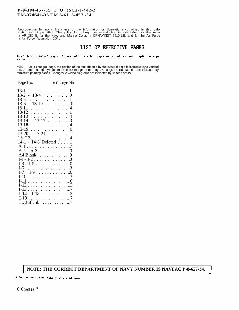
P-9-TM-457-35 T O 35C2-3-442-2TM-074641-35 TM 5-6115-457 -34
Reproduction for non-military use of the information or illustrations contained in thid pub-lication is not permitted. The policy for military use reproduction is established for the Armyin AR 380 5. for the Navy and Marine Corps in OPNAVINST 5510.1.B. and for the Air Forcein Air Force Regulation 205-1.
LIST OF EFFECTIVE PAGES
NOTE: On a changed page, the portion of the text affected by the latest change is indicated by a verticalInc. or other change symbol, in the outer margin of the page. Changes to illustrations are indicated byminiature pointing hands. Changes to wiring diagrams are indicated by shaded areas.
Page No. # Change No.
13-1 . . . . . . . . . . 113-2 - 13-4 . . . . . . . 013-5 . . . . . . . 113-6 - 13-10 . . . . . . . 013-11 . . . . . . . . . . 413-12 . . . . . . . . . . . 113-13 . . . . . . . . . . . 413-14 - 13-17 . . . . . . 013-18 . . . . . . . . . . . 413-19 . . . . . . . . . . . 013-20 - 13-21 . . . . . . 113-22. . . . . . . . . 414-1 - 14-8 Deleted . . . . 1A-1 . . . . . . . . . . . . . . . ...7A-2 – A-3 . . . . . . . . . . . . . .0A4 Blank . . . . . . . . . . . . . .0I-l - I-2 . . . . . . . . . . . . ...3I-3 – I-5 . . . . . . . . . . . . ...0I-6 . . . . . . . . . . . . . . . . ...3I-7 – I-9 . . . . . . . . . . . ...0I-10 . . . . . . . . . . . . . . ...3I-11 . . . . . . . . . . . . . . . ...0I-12 . . . . . . . . . . . . . . . ...3I-13 . . . . . . . . . . . . . . . ...7I-14 – I-18 . . . . . . . . . . ...3I-19 . . . . . . . . . . . . . . . ...7I-20 Blank . . . . . . . . . . . ...7
NOTE: THE CORRECT DEPARTMENT OF NAVY NUMBER IS NAVFAC P-8-627-34.
C Change 7
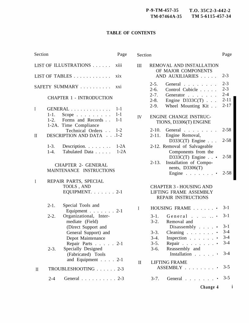
P-9-TM-457-35 T.O. 35C2-3-442-2TM-07464A-35 TM 5-6115-457-34
TABLE OF CONTENTS
Section
LIST OF
LIST OF
SAFETY
I
II
I
II
ILLUSTRATIONS . . . . . .
TABLES . . . . . . . . . . . .
SUMMARY . . . . . . . . . .
CHAPTER 1 - INTRODUCTION
GENERAL . . . . . . . . . . .1-1. Scope . . . . . . .1-2. Forms and Records1-2A. Time Compliance
Technical OrdersDESCRIPTION AND DATA
1-3. Description. . . . . .
. .. .. .
. .
Page
xiii
xix
xxi
1-11-11-1
1-2. . .1-2
. . 1-2A1-4. Tabulated Data . . . . . 1-2A
CHAPTER 2- GENERALMAINTENANCE INSTRUCTIONS
REPAIR PARTS, SPECIAL
2-1.
2-2.
2-3.
TOOLS , ANDEQUIPMENT. . . . . . . 2-1
Special Tools andEquipment . . . . . . . 2-1
Organizational, Inter-mediate (Field)(Direct Support andGeneral Support) andDepot MaintenanceRepair Parts . . . . . 2-1
Specially Designed(Fabricated) Toolsand Equipment . . . . 2-1
TROUBLESHOOTING . . . . . . 2-3
2-4 General . . . . . . . . . . 2-3
Section
III REMOVAL AND INSTALLATIONOF MAJOR COMPONENTSAND AUXILIARIES . . . . .
2-5. General . . . . . . . .2-6. Control Cubicle . . . . .2-7. Generator . . . . . . .2-8. Engine D333C(T) . . .2-9. Wheel Mounting Kit . .
IV ENGINE CHANGE INSTRUC-TIONS, D3306(T) ENGINE
2-10. General . . . . . . . .2-11. Engine Removal,
D333C(T) Engine . . .2-12. Removal of Salvageable
Components from theD333C(T) Engine . .
2-13. Installation of Compo-nents, D3306(T)Engine . . . . . . .
CHAPTER 3 - HOUSING ANDLIFTING FRAME ASSEMBLY
REPAIR INSTRUCTIONS
I HOUSING FRAME . . . . . .
3-1. G e n e r a l . . . . . .3-2. Removal and
Disassembly . . . .3-3. Cleaning . . . . . . .3-4. Inspection . . . . . .3-5. Repair . . . . . . . .3-6. Reassembly and
Installation . . . . .
II LIFTING FRAMEASSEMBLY . . . . . . . .
3-7. General . . . . . . .
Change 4
Page
2-3
2-32-32-42-112-17
2-58
2-58
2-58
2-58
3-1
3-1
3-13-43-43-4
3-4
3-5
3-5
i
P-9-TM-457-35 T.O. 35C2-3-442-2TM-07464A-35 TM 5-6115-457-34
TABLE OF CONTENTS (Continued)
Section Page Section P a g e
3-8. Removal . . . . . . . 3-5 3-12. Repair . . . . . . . . . 3-63-9. Disassembly . . . . 3-5 3-13. Reassembly . . . . . . 3-73-10. Cleaning . . . . . . .3-5 3-14. Installation . . . . . . 3-73-11. Inspection . . . . . . 3-5
ii Change 4
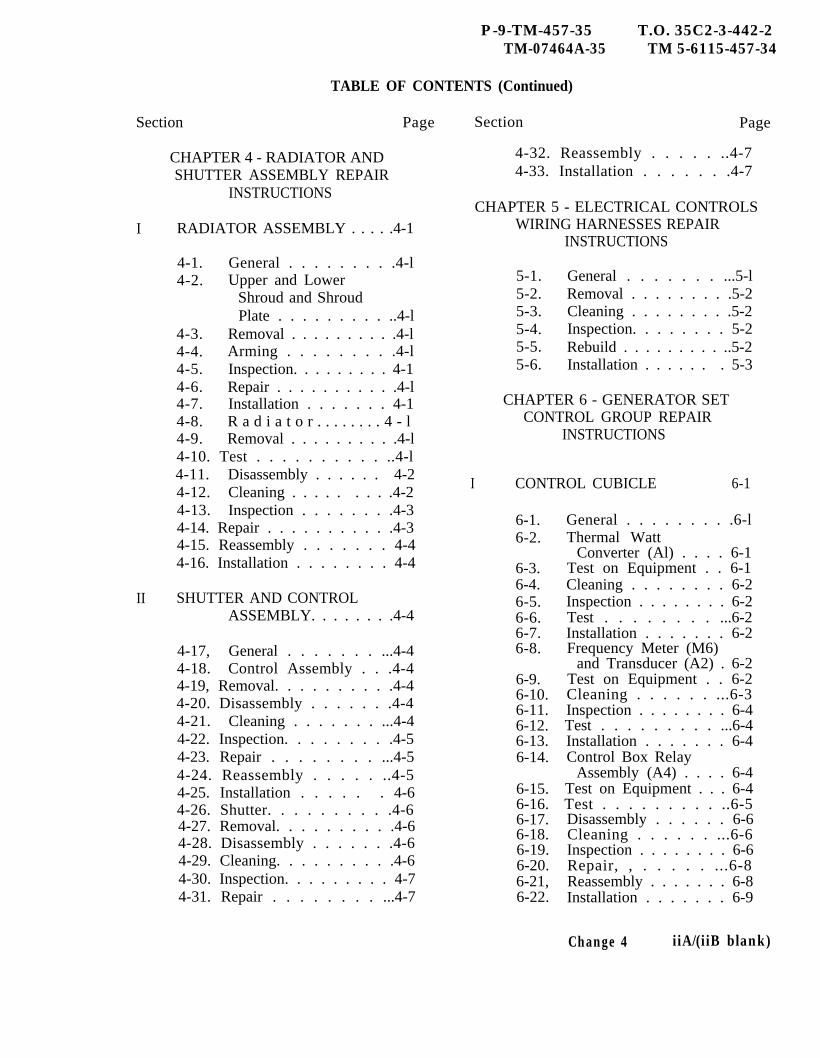
P-9-TM-457-35 T.O. 35C2-3-442-2TM-07464A-35 TM 5-6115-457-34
TABLE OF CONTENTS (Continued)
Section Page
CHAPTER 4 - RADIATOR ANDSHUTTER ASSEMBLY REPAIR
INSTRUCTIONS
I RADIATOR ASSEMBLY . . . . .4-1
4-1. General . . . . . . . . .4-l4-2. Upper and Lower
Shroud and ShroudPlate . . . . . . . . . ..4-l
4-3. Removal . . . . . . . . . .4-l4-4. Arming . . . . . . . . .4-l4-5. Inspection. . . . . . . . . 4-14-6. Repair . . . . . . . . . . .4-l4-7. Installation . . . . . . . 4-14-8. R a d i a t o r . . . . . . . . 4 - l4-9. Removal . . . . . . . . . .4-l4-10. Test . . . . . . . . . . ..4-l4-11. Disassembly . . . . . . 4-24-12. Cleaning . . . . . . . . .4-24-13. Inspection . . . . . . . .4-34-14. Repair . . . . . . . . . . .4-34-15. Reassembly . . . . . . . 4-44-16. Installation . . . . . . . . 4-4
II SHUTTER AND CONTROLASSEMBLY. . . . . . . .4-4
4-17, General . . . . . . . ...4-44-18. Control Assembly . . .4-44-19, Removal. . . . . . . . . .4-44-20. Disassembly . . . . . . .4-44-21. Cleaning . . . . . . . ...4-44-22. Inspection. . . . . . . . .4-54-23. Repair . . . . . . . . ...4-54-24. Reassembly . . . . . ..4-54-25. Installation . . . . . . 4-64-26. Shutter. . . . . . . . . .4-64-27. Removal. . . . . . . . . .4-64-28. Disassembly . . . . . . .4-64-29. Cleaning. . . . . . . . . .4-64-30. Inspection. . . . . . . . . 4-74-31. Repair . . . . . . . . ...4-7
Section Page
4-32. Reassembly . . . . . ..4-74-33. Installation . . . . . . .4-7
CHAPTER 5 - ELECTRICAL CONTROLSWIRING HARNESSES REPAIR
INSTRUCTIONS
5-1. General . . . . . . . ...5-l5-2. Removal . . . . . . . . .5-25-3. Cleaning . . . . . . . . .5-25-4. Inspection. . . . . . . . 5-25-5. Rebuild . . . . . . . . . ..5-25-6. Installation . . . . . . . 5-3
CHAPTER 6 - GENERATOR SETCONTROL GROUP REPAIR
INSTRUCTIONS
I CONTROL CUBICLE 6-1
6-1.6-2.
6-3.6-4.6-5.6-6.6-7.6-8.
6-9.6-10.6-11.6-12.6-13.6-14.
6-15.6-16.6-17.6-18.6-19.6-20.6-21,6-22.
General . . . . . . . . .6-lThermal Watt
Converter (Al) . . . . 6-1Test on Equipment . . 6-1Cleaning . . . . . . . . 6-2Inspection . . . . . . . . 6-2Test . . . . . . . . ...6-2Installation . . . . . . . 6-2Frequency Meter (M6)
and Transducer (A2) . 6-2Test on Equipment . . 6-2Cleaning . . . . . . ...6-3Inspection . . . . . . . . 6-4Test . . . . . . . . . ...6-4Installation . . . . . . . 6-4Control Box Relay
Assembly (A4) . . . . 6-4Test on Equipment . . . 6-4Test . . . . . . . . . ..6-5Disassembly . . . . . . 6-6Cleaning . . . . . . ...6-6Inspection . . . . . . . . 6-6Repair, , . . . . . ...6-8Reassembly . . . . . . . 6-8Installation . . . . . . . 6-9
Change 4 iiA/(iiB blank)

Section
6-23.6-24.6-25.6-26.6-27.6-28.6-29.6-30,6-31.6-32.6-33.6-34.6-35.6-36.6-37.6-38.6-39.
P-9-TM-457-35 T.O. 35C2-3-442-2TM-07464A-35 TM 5-6115-457-34
TABLE OF CONTENTS (Continued)
Page
AC Current Meter (M8) 6-9Test on Equipment . . 6-9Cleaning . . . . . . . . .6-l0Inspection . . . . . . . . 6-10Test . . . . . . . . . ...6-10Installation . . . . . . . 6-10Control Cubicle . . . . 6-10Test on Equipment. . . 6-10Disassembly . . . . . . 6-10Cleaning . . . . . . . . .6-11Inspection . . . . . . . . 6-11Repair . . . . . . . . . .6-11Rebuild . . . . . . . . . .6-l3Reassembly . . . . . . . 6-13Test . . . . . . . . . ...6-13Installation . . . . . . 6-13Adjustment . . . . . . . 6-13
II DC CIRCUIT BREAKERBOX. . . . . . . . . . .6-20
6-40. General . . . . . . . . . .6-206-41. Removal. . . . . . . . .6-206-42. Disassembly . . . . . ..6-206-43. Cleaning. . . . . . . . . 6-206-44. Inspection . . . . . . . .6-206-45. Repair . . . . . . . . . . .6-216-46. Reassembly . . . . . . 6-216-47. Installation . . . . . . . . 6-21
III FAULT LOCATING INDICATORBOX. . . . . . . . .6-22
6-48. General . . . . . . . ...6-226-49. Test On Equip-
merit . . . . . . . . ...6-226-50. Test . . . . . . . . . ...6-236-51. Disassembly . . . . . . .6-236-52. Cleaning . . . . . . . ...6-236-53. Inspection. . . . . . . . .6-236-54. Repair . . . . . . . ...6-276-55. Reassembly . . . . . .6-276-56. Installation . . . . . . . .6-29
Section Page
IV CONVENIENCE RECEPTACLEASSEMBLY . . . . . ...6-33
6-57.6-58.
6-59.6-60.6-61.6-62.6-63.6-64.6-65.6-66,
6-67,6-68.6-69.6-70.6-71.6-72.6-73.
General . . . . . . . ...6-3350/60 Hertz Con-
venience ReceptacleAssembly . . . . . ...6-33
Removal . . . . . ...6-33Disassembly . . . . .. 6-33Cleaning . . . . . . . ...6-33Inspection . . . . . . . . 6-33Repair, . . . . . . . ...6-33Reassembly . . . . . .. 6-33Installation . . . . . . . .6-33400 Hertz Conveni-
ence ReceptacleAssembly . . . . . . .. 6-35
Removal . . . . . . . ...6-35Disassembly . . . . . . .6-35Cleaning . . . . . . . ...6-35Inspection. . . . . . . . . 6-35Repair . . . . . . . . ...6-35Reassembly . . . . . .. 6-39Installation . . . . . ...6-39
V EXCITER-REGULATOR . . .. 6-39
6-74.6-75.
6-76.6-77.6-78.6-79.6-80.6-81.6-82.6-83.6-84.
General . . . . . . . ...6-39Test and
Removal . . . . . . . ..6-40Test . . . . . . . . . . ...6-42Disassembly . . . . . , .6-42Cleaning . . . . . . . ...6-49Inspection. . . . . . . . .6-49Repair . . . . . . . . ...6-49Rebuild . . . . . . . ...6-49Reassembly . . . . . . .6-49Installation . . . . . . .. 6-51Adjustment . . . . . . . .6-51
Change 3 iii
P-9-TM-457-35 T.O. 35C2-3-442-2TM-07464A-35 TM 5-6115-457-34
TABLE OF CONTENTS (Continued)
Section Page
VI MODE I RELAY BOXASSEMBLY . . . . . . . 6-59
6-85. General . . . . . . . . 6-596-86. DC Relay Assembly
(A5) . . . . . . . ...6-596-87, On Equipment Test . . 6-596-88. Test . . . . . . . . . . . .6-6l6-89. Disassembly . . . . . . 6-616-90. Cleaning . . . . . 6-616-91. Inspection . . . . . . . . 6-626-92. Repair . . . . . 6-626-93. Reassembly . . . . . . . 6-626-94. Installation . . . . ...6-666-95. Mode I Relay Box
Assembly . . . . . . . 6-666-96. On Equipment Test . . 6-666-97. Bench Test . . . . . . . 6-676-98. Disassembly . . . . . .6-676-99. Cleaning . . . . . . . . . 6-756-100. Inspection and
Bench Test . . . . ...6-756-101. Repair . . . . . . . . . . 6-756-102. Reassembly . . . . . . . 6-756-103. Installation . . . . . . . 6-77
VII MODE II RELAY BOXASSEMBLY .. . . . . . . 6-82
6-104.6-105.
6-106.
6-107.
6-108.6-109.6-110.
6-111.6-112.6-113.6-114.
6-115.
General . . . . . . ...6-82DC Relay Assembly
(A5) . . . . . . . . . . 6-83400 Hertz Under
Frequency Relay . . . 6-83On Equipment
Test . . . . . . . ...6-83Bench Test . . . . ...6-84Installation . . . . ...6-85400 Hertz Under-voltage Relay(K1l) . . . . . . . . . . . . . . 6-85
On Equipment Test . . 6-85Bench Test . . . . ...6-85Installation . . . . ...6-86Permissive Parallel
Relay (K16),400 Hertz . . . . ...6-86
On Equipment Test . . 6-86
Section
6-116.6-117.6-118.
6-119.6-120.6-121.6-122.6-123.6-124.6-125.6-126.6-127.
6-128.6-129.6-130,6-131.6-132.6-133.6-134.6-135.
Page
Bench Test . . . . . . . 6-87Installation . . . . . . 6-87400 Hertz ElectronicComponentsAssembly (A6) . . . . 6-87
On Equipment Test . . 6-87Bench Test . . . . ...6-87Disassembly . . . . . . 6-88Cleaning . . . . . . ...6-88Inspection . . . . . . . . 6-88Repair . . . . . . . ...6-89Reassembly . . . . . . . 6-89Installation l . . . . . . 6-89Mode 11 Relay Box
Assembly (A27),400 Hertz . . . . ...6-90
On Equipment Test . . 6-90Bench Test . . . . . . . 6-91Disassembly . . . . . .6-91Cleaning . . . . . . . . 6-98Inspection . . . . . . . . 6-98Repair . . . . . . . . . .6-l02Reassembly . . . . . . . 6-102Installation . . . . ...6-10.
VIII RECONNECTION BOARD ASSEMBLYLOAD CONTACTOR, MOTOROPERATED CIRCUIT BREAKER,LOAD BOARD ASSEMBLY, ANDTRANSFORMER ASSEMBLY. 6-108
6-136.6-137.
6-138.6-139.6-140.6-141.6-142.6-143.6-144.6-145.
6-145A.6-146.
6-146A.6-146B.6-146C.6-146D.
General . . . . . . . . .6-108Reconnection Board
Assembly . . . . . . . 6-l08Removal . . . . . . . . .6-l08Disassembly . . . . . . . . . 6-108Cleaning . . . . . . . . . 6-109Inspection . . . . . . . . 6-109
Installation . . . . . . . 6-109Reassembly . . . . . . .6-109
Load Contactor . . . . 6-109On Equipment Test . . 6-109Removal . . . . . . ...6-117Bench Test . . . . ...6-117Disassembly . . . ...6-117Cleaning . . . . . . . . .6-117Inspection . . . . . . . . 6-118Repair . . . . . . . ...6-118
iv Change 3
P-9-TM-457-35 T.O. 35C2-3-442-2
Section
6-146E .6-146F.6-147.6-147A.
6-147B.6-147C.6-147D.6-147E.6-147F.6-147G.6-147H.6-1471.6-148.6-149.
6-150.6-151.6-152.
6-153.
6-154.6-155.6-156.6-157.6-158.6-159.6-160.
TM-07464A-35 TM 5-6115-457-34
TABLE OF CONTENTS (Continued)
Reassembly . . . . . .Adjustment . . . . . .Installation . . . . . .Circuit Breaker
Assembly . . . . . .Test on Equipment . .Test . . . . . . . . . .Disassembly . . . . .Cleaning. . . . . . . .Inspection . . . . . . .Repair . . . . . . . . .Reassembly . . . . . .Installation . . . . . .Load Board AssemblyRemoval and
Disassembly . . . . .Cleaning. . . . . . . .Inspection . . . . . . .Reassembly and
Installation . . . . .Transformer
Assembly . . . . , .Removal . . . . . . .Disassembly . . . . .Cleaning . . . . . . .Inspection . . . . . . .Repair . . . . . . . . .Reassembly . . . . . .Installation . . . . . .
IX TACTICAL RELAY BOX . . . .
6-161.6-162.6-163.6-164.6-165.6-166.
6-167.6-168.6-169.6-170.
General . . . . . . . .Overvoltage Relay (K2)On Equipment Test . .Bench Test , . . . . .Installation . . . . . .Reverse Power
Relay (K15) . . . . .On Equipment Test . .Bench Test . . . . . .Installation . . . . . .Short Circuit
Relay (K13) . . . . .
Page
6-1186-1196-120
6-1206-1206-120A6-120A6-120I6-120I6-120I6-120I6-120M6-121
6-1216-1216-121
6-121
6-1216-1216-1236-1236-1236-1236-1236-123
6-126
6-1266-1266-1266-1276-129
6-1296-1296-1306-131
6-131
Section
6-171.6-172.6-173.6-174.6-175.6-176.6-177.6-178.
6-179.6-180.6-181.6-182.6-183.6-184.6-185.6-186.
Page
On Equipment Test . . . 6-131Bench Test . . . . . . . 6-132Installation . . . , . . . 6-132Overload Relay (K14) . 6-132On Equipment Test . . . 6-132Bench Test . . . . . . . 6-133Installation . . . . . . . 6-133Tactical Relay
B OX (A29) . . . . . . . 6-134On Equipment Test . . . 6-134Bench Test . . . . . . . 6-135Disassembly . . . . . . 6-135Cleaning . , . . . . . . 6-143Inspection and Test . . 6-143Repair . . . . . . . . . 6-l43Reassembly . . . . . . 6-143Installation . . . . . . . 6-146
X PRECISE RELAY BOX . . . . . 6-146
6-187. General . . . . . . . . . 6-1466-188. 50/60 Hertz Under-
frequency Relay (K12) 6-1476-189. On Equipment Test . . . 6-1476-190. Bench Test . . . . . . . 6-1496-191. Installation . . . . . . . 6-1506-192. Precise Relay
B OX (A25) . . . . . . . 6-1506-193. Test and Removal . . . 6-1506-194. Bench Test . . . . . . . 6-1506-195. Disassembly . . . . . . 6-1506-196. Cleaning. . . . . . . . . 6-1536-197. Inspection and Test . . 6-1576-198. Repair . . . . . . . . 6-l576-199. Reassembly . . . . . . 6-1576-200. Installation . . . . . . 6-161
XI PRECISE GOVERNOR CONTROLCONTROL UNIT . . . . . . . 6-161
6-201. General . . . . . . . . . 6-1616-202. On Equipment Test . . . 6-1626-203. Bench Test . . . . . . . 6-1646-204. Disassembly . . . . . . 6-164
Change 3 v
P-9-TM-457-35 T.O. 35C2-3-442-2TM-07464A-35 TM 5-6115-457-34
TABLE OF CONTENTS (Continued)
Section Page
6-205.6-206.6-207.6-208.6-209.6-210.6-211.6-211A.
Cleaning . . . . . . .Inspection . . . . . .Repair . . . . . . . .Rebuild . . . . . . .Reassembly . . . . .Installation . . . . .Alignment . . . . . .Alignment Procedures
6-1736-1736-1736-1736-1736-1756-175
Peculiar to Opera-tion of 400 HertzGenerator Sets inSupport of E3AAircraft . . . . . . 6-182
XII LOAD MEASUREMENT UNIT . 6-182A
6-212.6-213.6-214.6-215.6-216.6-217.6-218.6-219.6-220.
General . . . . . . .On Equipment Test .Test and AdjustmentDisassembly. . . . .Cleaning . . . . . . .Inspection . . . . . .Repair . . . . . . . .Reassembly . . . . .Installation . . . . .
6-182A6-1836-1836-1836-1836-1846-1846-1846-187
CHAPTER 7- GENERATOR ASSEMBLYREPAIR INSTRUCTIONS
7-1.7-2.7-3.7-4.7-5.7-6.7-7.7-8.7-9.
General . . . . . . .On Equipment Test .Disassembly . . . .Cleaning . . . . . . .Inspection . . . . . .Repair or Rebuild . .Reassembly . . . . .High Potential Test .Installation . . . . .
7-17-17-47-77-77-87-87-247-25
Section P a g e
CHAPTER 8- ENGINE GROUPREPAIR INSTRUCTIONS
I ENGINE COMPONENTS . . . . . 8-1
8-1. General . . . . . . . . .8-l8-2. Removal . . . . . . . .8-l8-3. Disassembly . . . . . . 8-18-4. Reassembly . . . . . . 8-18-5. Installation . . . . . . . 8-2
II ENGINE HARNESS GROUP . . . 8-2
8-6. General . . . . . ...8-28-7. Removal . . . . . . . .8-28-8. Cleaning . . . . . . . .8-28-9. Inspection . . . . . . . 8-28-10. Rebuild . . . . . . . . .8-38-11. Installation . . . . . . 8-3
III ALTERNATOR. . . . . . . . . . 8-6
8-12. General . . . . . ...8-68-13. R e m o v a l . . . . . . . . 8 -8-14. Disassembly . . . . . . 8-68-15. Cleaning . . . . . . . .8-68-16. Inspection . . . . . . . 8-78-17. Repair . . . . . . ...8-98-18. Reassembly . . . . . . 8-108-19. Test and Adjustment . . 8-108-20. Installation . . . . . . . 8-13
IV STARTING MOTOR . . . . . . . 8-14
8-21.8-22.8-23.8-24.8-25,8-26.8-27.8-28.8-29.
General . . . . . . . .8-l4Removal . . . . . . . . 8-14Disassembly . . . . . . 8-14Cleaning . . . . . . . .8-l4Inspection . . . . . . . 8-14Repair . . . . . . . . .8-l5Reassembly . . . . . . 8-15Testing . . . . . . . . .8-18Installation . . . . . . 8-20
vi Change 3
P-9-TM-457-35 T.O. 35C2-3-442-2TM-O7464A-35 TM 5-6115-457-34
TABLE OF CONTENTS (Continued)
Section Page
V
VI
VII
FAN MOUNTING GROUP. , . ..8-22
8-30. General . . . .8-31. Removal . . . . . ..8-32. Disassembly . . . . .8-33. Cleaning. . . . . .8-34. Inspection. . . . .8-35. Repair . . . . .8-36. Reassembly .8-37. Installation . .
DAY TANK ASSEMBLY
8-38. General . . . . .8-39. Removal and
Disassembly8-40. Cleaning. . . .8-41. Inspection . .8-42. Repair . . . . .
. . . . . . 8-22
. . . . . . . 8-22
. . . . . . 8-22
. . . . 8-22
. . . . . 8-22
. . . . . 8-22
. . . . . . 8-22
. . . . . 8-24
. . . . . 8-25
. . . . 8-25
. . . . . 8-25. . . . . . 8-25. . . . . . .. 8-25 . . . . 8-25
8-43. Reassembly andInstallation .
OVERSPEED SWITCH.
8-44. General . . . .8-45. Removal . . .8-46. Disassembly .8-47. Cleaning. . . .8-48. Inspection. . .8-49. Repair . . , . .8-50. Reassembly .8-51. Adjustment . .8-52. Installation . .
VIII TACHOMETER DRIVEGROUP . . . .
8-53. General . . . .8-54. Removal. . . .8-55. Disassembly .8-56. Cleaning. . . .
. . . . 8-25
. . . . . . 8-26
. . . . . . 8-26
. . . . . . 8-26
. . . . . . 8-26
. . . . . . 8-26
. . . . . . 8-26
. . . . . . 8-27
. . . . . . 8-27
. . . . . 8-27
. . . . . . 8-30
. . . . . 8-31
. . . . 8-31
. . . . . . 8-31
. . . . . . 8-31
. . . . . . 8-318-57. Inspection . . . . . . . 8-318-58. Repair . . . . . . . . . . .8-318-59. Reassembly . . . . .8-318-60. Installation . . . . . . .8-33
Section Page
IX FUEL PUMP GROUP . . . . . . . 8-33
8-61. General . . . . . . . ...8-338-62. Removal . . . . . . ...8-338-63. Disassembly . . . . . .. 8-338-64. Cleaning. . . . . . . . .. 8-338-65. Inspection. . . . . . . . . 8-338-66. Repair . . . . . . . . ...8-358-67. Reassembly . . . . . .. 8-358-68. Installation . . . . . . .. 8-35
X TURBOCHARGER GROUP . . . 8-36
XI
8-69.8-70.8-71.8-72.8-73.8-74.8-75.8-76.
General . . .Removal. . .DisassemblyCleaning. . .Inspection .Repair . . . .ReassemblyInstallation .
OIL COOLER GROUT
8-77.8-78.8-79.8-80.8-81.8-82.8-83.8-84.
General . . .Removal . .DisassemblyCleaning . .Inspection. .Repair . . . .ReassemblyInstallation .
. . . . . . . 8-36
. . . . . . . 8-36
. . . . . . . 8-36
. . . . . . . 8-37
. . . . . . . 8-37
. . . . . . . 8-39
. . . . . . . 8-40
. . . . . . . 8-40
. . . . . . . 8-41
. . . . . . . 8-41
. . . . . . . 8-41
. . . . . . . 8-41
. . . . . . . 8-41
. . . . . . . 8-43
. . . . . . . 8-43
. . . . . . . 8-43
. . . . . . . 8-43
XII HYDRAULIC TANK (PRECI5ESETS ONLY) . . . . ...8-45
8-85. General . . . . . . . ...8-458-86. Removal . . . . . . . ...8-458-87. Disassembly . . . . . ..8-458-88. Cleaning . . . . . . . ...8-478-89. Inspection . . . . . ...8-478-90. Repair . . . . . . . . ...8-478-91. Reassembly . . . . . .. 8-478-92. Installation . . . . . . . .8-47
XIII HYDRAULIC PUMP (PRECISESETS ONLY) . . . . . .8-48
8-93. General . . . . . . . ...8-488-94. Removal . . . . . . . ...8-48
vii

P-9-TM-457-35 T.O. 35C2-3-442-2TM-07464A-35 TM 5-6115-457-34
TABLE OF CONTENTS (Continued)
Section Page Section Page
8-95. Cleaning . . . . . . . .8-96. Inspection . . . . . . .8-97. Repair . . . . . . . . . .8-98. Hydraulic Pump Test
and Adjustment (OnPrecise GeneratorSets Only) . . . . . .
8-99. Installation . . . . . .
8-488-488-48
8-122. Repair . . . . . . . . . .8-123. Reassembly . . . . . .8-124. Installation . . . . . .
8-638-638-63
XVII CRANKSHAFT PULLEY,DAMPER ANDTIMING GEARCOVER GROUP . . .
8-498-49 8-65
XIV HYDRAULIC PUMP DRIVEGROUP . . . . . . . . .
8-125.8-126.8-127.8-128.8-129.8-130.8-131.8-132.
General . . . . . . . . .Removal . . . . . . . .Disassembly . . . . . .Cleaning . . . . . . . .Inspection . . . . . . .Repair . . . . . . . . .Reassembly . . . . . .Installation . . . . . .
8-658-658-658-678-688-688-688-69
8-50
8-100.8-101.8-102.8-103.8-104.8-105.8-106.8-107.
General . . . . . . . . .Removal . . . . . . . . .Disassembly . . . . . .Cleaning. . . . . . . . .Inspection . . . . . . .Repair . . . . . . . . . .Reassembly . . . . . .Installation . . . . . .
8-508-508-508-508-508-518-518-51
XVIII UTILITY GOVERNORGROUP . . . . . . . . . 8-69
XV GOVERNOR ACTUATOR 8-133.8-134.8-135.8-136.8-137.8-138.8-139.8-140.
General . . . . . . . . .Removal . . . . . . . .Disassembly . . . . . .Cleaning . . . . . . . . .Inspection . . . . . . .Repair . . . . . . . . . .Reassembly . . . . . .Installation . . . . . .
8-698-708-708-758-758-808-808-81
UNIT (PRECISESETS ONLY) . . . . . 8-53
8-108.8-109.8-110.8-111.8-112.8-113.8-114.8-115.8-116.
XVI WATER
8-117.8-118.8-119.8-120.8-121.
General . . . . . . . . .Removal . . . . . . . .Disassembly . . . . . .Cleaning . . . . . . . . .Inspection . . . . . . .Repair . . . . . . . . . .Reassembly . . . . . .Test and Adjustment.Installation . . . . . . .
8-538-538-548-558-558-578-578-598-60
XIX FUEL INJECTION GROUP . . 8-86
8-141.8-142.8-143.8-144.8-145.8-146.8-147.8-148.8-149.
General . . . . . . . . .Removal . . . . . . . .Disassembly . . . . . .Cleaning . . . . . . . .Inspection . . . . . . .Repair . . . . . . . . . .Reassembly . . . . . .Installation . . . . . .Testing . . . . . . . . .
8-868-868-898-908-908-918-918-928-92
PUMP GROUP . . . . 8-62
8-628-628-628-628-62
General . . . . . . . . .Removal . . . . . . . .Disassembly . . . . . .Cleaning . . . . . . . .Inspection . . . . . . .
viii
P-9-TM-457-35 T. O. 35C2-3-442-2TM-07464A-35 TM 5-6115-457-34
TABLE OF CONTENTS (Continued)
Section Page
XX ACCESSORY DRIVE GROUP. . .8-96
8-150. General . . . .8-151. Removal . . .8-152. Disassembly .8-153. Cleaning . . .8-154. Inspection . .8-155. Repair . . . . .8-156. Reassembly .8-157. Installation .
XXI EXHAUST MANIFOLDGROUP . . . .
8-158. General . . . .
. . . . . . 8-96
. . . . . . 8-96
. . . . . . 8-97
. . . . . . 8-97
. . . . . . 8-97
. . . . . . 8-99
. . . . . . 8-99
. . . . . . 8-100
. . . . . . 8-101
. . . . . . 8-1018-159. Removal and Dis-
assembly . . . . . . . .8-1018-160. Cleaning . . . . . . . . .8-1018-161. Inspection . . . . . . . 8-1018-162. Repair . . . . . . . ...8-1018-163. Reassembly and
Installation . . . . . .8-101
XXII OIL PAN GROUP ANDRELATED PARTS . .8-103
8-164. General . . . . . . . . .8-1038-165. Removal . . . . . . . . .8-1038-166. Disassembly . . . . . . .8-1038-167. Cleaning . . . . . . . . .8-1038-168. Inspection . . . . . . . .8-1038-169. Repair . . . . . . . . . ..8-l058-170. Reassembly . . . . . . .8-1058-171. Installation . . . . . . .8-105
XXIII OIL PUMP GROUP. . . . . . . . .8-106
8-172. General . . . . . . . . .8-l068-173. Removal . . . . . . . .8-1068-174. Disassembly . . . . . .8-l068-175. Cleaning . . . . . . . .8-1068-176. Inspection . . . . . . . .8-106
Section
8-177. Repair . . . . . . . . .8-178. Reassembly . . . . . .8-179. Installation . . . . . .
XXIV VALVE COVER AND VALVEMECHANISM GROUP
8-180.8-181.8-182.8-183.8-184.8-185.8-186.8-187.
General . . . . . . . . .Removal . . . . . . . .Disassembly . . . . . .Cleaning . . . . . . . . .Inspection . . . . . . .Repair . . . . . . . . . .Reassembly . . . . . .Installation . . . . . .
XXV CYLINDER HEAD GROUP . .
8-188.8-189.8-190.8-191.8-192.8-193.8-194.8-195.
General . . . . . . . . .Removal . . . . . . . .Disassembly . . . . .Cleaning . . . . . . . .Inspection . . . . . . .Repair . . . . . . . . . .Reassembly . . . . . .Installation . . . . . .
XXVI FLYWHEEL AND FLYWHEELHOUS1NG GROUP . .
8-196.8-197.8-198.8-199.8-200.8-201.8-202.8-203.
General . . . . . . . . .Removal . . . . . . . .Disassembly . . . . .Cleaning . . . . . . . .Inspection . . . . . . .Repair . . . . . . . . . .Reassembly . . . . . .Installation . . . . . .
XXVII CAMSHAFT GROUP . . . . . .
8-204. General . . . . . . . . .8-205. Removal . . . . . . . .
Page
8-1079-1098-109
8-110
8-1108-1108-1108-1108-1128-1128-1128-113
8-113
8-1138-1138-1138-1148-1148-1158-1158-119
8-120
8-1208-1208-1208-1208-1218-1218-1218-126
8-126
8-1268-126
ix
P-9-TM-457-35 T.O. 35C2-3-442-2TM-07464A-35 TM 5-6115-457-34
TABLE OF CONTENTS (Continued)
Section
8-206. Disassembly . . . . . .8-207. Cleaning . . . . . . . .8-208. Inspection . . . . . . .8-209. Repair . . . . . . . . . .8-210. Reassembly . . . . . .8-211. Installation . . . . . .
XXVIII CONNECTING RODS ANDPISTONS GROUP . .
8-212.8-213.8-214.8-215.8-216.8-217.8-218.8-219.
General . . . . . . . . .Removal . . . . . . . .Disassembly . . . . . .Cleaning . . . . . . . .Inspection . . . . . . .Repair . . . . . . . . .Reassembly . . . . . .Installation . . . . . .
XXIX CRANKSHAFT GROUP ANDMAIN BEARINGS . .
8-220.8-221.8-222.8-223.8-224.8-225.8-226.8-227.
General . . . . . . . . .Removal . . . . . . . .Disassembly . . . . . .Cleaning . . . . . . . .Inspection . . . . . . .Repair . . . . . . . . . .Reassembly . . . . . .Installation . . . . . .
XXX CYLINDER BLOCK ANDCOVERS GROUP . . .
8-228.8-229.8-230.8-231.8-232.8-233.8-234.8-235.
General . . . . . . . .Removal . . . . . . . .Disassembly . . . . . .Cleaning . . . . . . . .Inspection . . . . . . .Repair . . . . . . . . . .Reassembly . . . . . .Installation . . . . . .
Page
8-1278-1278-1278-1298-1298-129
8-129
8-1298-1308-1308-1308-1318-1318-1318-133
8-134
8-1348-1348-1358-1378-1378-1388-1388-139
8-139
8-1398-1408-1418-1418-1418-1418-1418-145
Section Page
XXXI ENGINE TEST AFTER OVER-HAUL . . . . . . . . ...8-146
8-236. General . . . . . . . ...8-1468-237. Engine Assembly
Run-in andAdjustments . . . , . . 8-146
CHAPTER 9- BASE ASSEMBLY,STOWAGE TOOL BOX, AND FUEL
TANK REPAIR . . , . . 9-1
I BASE ASSEMBLY . . . . . . ...9-1
9-1. General . . . . . . . . . .9-l9-2. Removal . . . . . . ...9-19-3. Disassembly . . . . . . . 9-19-4. Cleaning . . . . . . . . .9-l9-5. Inspection . . . . . . . . 9-39-6. Repair . . . . . . . . ...9-39-7. Reassembly . . . . . . . 9-39-8. Installation . . . . . . .9-4
II STOWAGE TOOL BOX . . . . ..9-4
9-9. General . . . . . . . ...9-49-10. Removal . . . . . . ...9-49-11. Disassembly . . . . . . . 9-49-12. Cleaning . . . . . . ...9-49-13. Inspection . . . . . . . . 9-59-14. Repair . . . . . . . . ...9-59-15. Reassembly . . . . . . .9-59-16. Installation . . . . ...9-5
III FUEL TANK ASSEMBLY . . . . 9-6
9-17. General . . . . . . . ...9-69-18. Removal . . . . . . ...9-69-19. Disassembly . . . . . .. 9-69-20. Cleaning . . . . . . ...9-69-21. Inspection . . . . . . . . 9-69-22. Repair . . . . . . . . . . .9-8
P-9-TM-457-35 T.O. 35C2-3-442-2TM-07464A-35 TM 5-6115-457-34
TABLE OF CONTENTS (Continued)
Section9-23. Reassembly . . . . . .9-24. Installation. . . . . .
CHAPTER 9A - PAINT AND MARKINGREQUIREMENTS AFTER OVERHAUL
9A-1. General . . . . . . . . . .9A-2. Noise Level Warning Sign.
CHAPTER 10 - TEST AFTER OVERHAUL
I PRETEST CHECKS ANDADJUSTMENTS . . . . . . . . . .
10-1. General . . . . . . . . . .10-2. Pretest Checks and
Adjustments. . . . .
I I TEST AFTER OVERHAUL . . . . . . .
10-3.10-4.10-5.10-6.
10-7.
10-8.
10-9.
10-10.
10-11.
10-12.
10-13.10-14.
10-15.
General . . . . . . . . .Start and Stoutest. .Instrument Check . .Low Oil Pressure
Trip Test. . . . . .High Coolant Tem-
perature TripTest . . . . . . . . . .
Low Fuel LevelTrip Test . . . . . . .
Short Circuit TripTest . . . . . . . . . .
Over and UnderVoltage TripTest . . . . . . . . . .
Under FrequencyTrip Test (PreciseGenerator SetsOnly) . . . . . . . . .
Phase SequenceCheck . . . . . . . . .
Phase Balance Test .Frequency Adjustment
Range Test . . . . .Regulator Range
Test . . . . . . . . . .
Page
9-89-8
9A-19A-1
10-1
10-1
10-1
10-1
10-110-110-2
10-2
10-3
10-3
10-3
10-4
10-4
10-410-5
10-5
10-6
Section Page
10-16. Exciter Regulatorand Governor Sta-bility and TransientResponse Test .
10-17. Long Term SteadyState StabilityTest . . . . . . . .
10-18. Parallel Operationand ReversePower Test . . .
10-19. Engine EfficiencyTest . . . . . . . .
. . 10-6
. . 10-7
. . 10-7
. . 10-8
CHAPTER 1l - FUEL BURNINGWINTERIZATION KIT REPAIR
INSTRUCTIONS
I CONTROL BOX . . . . . . . . . 11-1
11-1. General . . . . . . . . . 11-111-2. Removal . . . . . . . . 11-111-3. Disassembly. . . . . . 11-111-4. Cleaning . . . . . . . . 11-111-5. Inspection . . . . . . . 11-111-6. Repair . . . . . . . . . . 11-411-7. Reassembly . . . . . . 11-411-8. Installation . . . . . . 11-4
II HEATER . . . . . . . . . . . . . . 11-4
11-9. General . . . . . . . . . 11-411-10. Removal . . . . . . . . 11-411-11. Disassembly . . . . . . 11-511-12. Cleaning . . . . . . . . 11-511-13. Inspection . . . . . . . 11-511-14. Repair . . . . . . . . . . 11-811-15. Reassembly . . . . . . 11-911-16. Component Test and
Adjustments . . . . 11-1011-17. Installation . . . . . . . 11-11
Change 2 xi

P-9-TM-457-35 T O 35C2-3-442-2TM-07464A-35 TM 5-6115-457-34
TABLE OF CONTENTS (Continued)
Section Page
CHAPTER 12 - ELECTRIC WINTERIZATIONKIT REPAIR INSTRUCTIONS
I CONTROL BOX . . . . . . . . .12-1
12-1. General ... . . . . . . .l2-l12-2. Removal . . . . . . . l2- l12-3. Test . . . . . . . . . . . .12-l12-4. Disassembly . . . . . . 12-112-5. Cleaning. . . . . . . . . . 12-412-6. Inspection . . . . . . . 12-412-7. Repair . . . . . . . . . . .l2-412-8. Reassembly . . . . . . . 12-712-9. Installation . . . . . . . . 12-7
II ELECTRIC HEATER . . . . . . .12-7
12-10. General . . . . . . . . . .l2-712-11. Removal . . . . . . . ...12-712-12. Disassembly . . . . . . 12-712-13. Cleaning . . . . . . . . . 12-812-14. Inspection. . . . . . . . 12-812-15. Reassembly . . . . . . 12-812-16. Installation . . . . . . 12-8
II: COOLANT PUMP . . . . . . . ...12-8
12-17. General . . . . . . . . .l2-812-18. Removal . . . . . . . . . .l2-912-19. Test . . . . . . . . . .l2-912-20. Disassembly . . . . . . . 12-912-21. Cleaning . . . . . . . . . 12-912-22. Inspection . . . . . . . . 12-912-23, Repair . . . . . . . . ...12-1012-24, Reassembly . . . . . . . 12-1112-25. Installation . . , . . . . . 12-11
CHAPTER 13 - DUMMY LOAD KITREPAIR INSTRUCTIONS
I DUMMY LOAD KIT. . . . . .13-1
13-1. General . . . . . . . . . .l3-l13-2. Removal . . . . . . . . . .l3-l
Section Page
13-3. Disassembly . . . . . 13-113-4. Cleaning . . . . . . . . 13-113-5. Inspection . . . . . , . 13-113-6. Repair . . . . . . . . . . 13-513-7. Wiring Harness
Rebuild . .13-8. Reassembly13-9. Installation
H CONTROL BOX . . .
13-10. General . . .
. . . . . . 13-5
. . . . . . 13-5
. . . . . . 13-5
. . . . . . 13-10
. . . . . . 13-1013-11.
13-12.13-13.13-14.13-15.13-16.13-17.13-18.13-19.13-20.13-21.13-22.13-23.13-24.13-25.13-26.13-27.
13-28.13-29.
Load DumpingRelay (K5) . . . . . .
Removal . . . . . . . .Test . . . . . . . . . . .Disassembly . , . . , .Cleaning . . . . . . . . .Inspection , . . . . . .Repair . . . . . . . . . .Reassembly . . . . . .Installation . . . . . . .Control Box . . . . . .Removal . . . . . . . .Disassembly . . . . . .Cleaning . . . . . . . . .Inspection . . . . . . .Test . . . . . . . . . . .Repair . . . . . . . . . .Wiring Harness
Rebuild . . . . . . . .Reassembly . . . . . .Installation . . . . . . .
13-1013-1013-1013-1013-1013-1013-1013-1013-1713-1713-1713-1813-1813-1813-1813-21
13-2113-2113-22
CHAPTER 14- DELETED
APPENDIX A . . . . . . . . . . . . A-1
xii Change 6
P-9-TM-457-35 T.O. 35C2-3-442-2TM-07464A-35 TM 5-6115-457-34
LIST OF ILLUSTRATIONS
Number Title Page
1-1. Hydraulic system schematicPrecise Generator Sets . . . . 1-61
1-2. 50/60 Hertz DC systemschematic . . . . . . . . . . . .. 1-63
1-3. 400 Hertz DC systemschematic . . . . . . . . . . . .. 1-65
1-4. 50/60 Hertz AC systemschematic . . . . . . . . . . . .. 1-67
1-5. 400 Hertz AC systemschematic . . . . . . . . . ...1-69
1-6. Control cubicle (A3)schematic . . . . . . . . . . . . . 1-71
1-7. Control cubicle (A3) wiringdiagram . . . . . . . . . . . . .. l-73
1-8. Fault locating indicator (A9)schematic . . . . . . . . . . . . 1-75
1-9. Fault locating indicator (A9)wiring diagram . . . . . . . . . 1-76
1-10. Exciter regulator (A10 andAll) 50/60 Hertzschematic . . . . . . . . . . . . 1-77
1-11. Exciter regulator (A10 andAll) 50/60 Hertz wiringdiagram (2 sheets) . . . . . .. 1-79
1-12. Exciter regulator (A10 andAll) 400 Hertzschematic . . . . . . . . . . . .. 1-81
1-13. Exciter regulator (A10 andAll) 400 Hertz wiringdiagram (2 sheets) . . . . ...1-83
1-14. Mode I relay box (A27)schematic diagram 50/60Hertz generator sets. . . ...1-85
1-15. Mode I relay box (A27)wiring diagram 50/60 Hertzgenerator sets (2 sheets) . ..1-87
1-16. Mode II relay box (A27)schematic 400 HertzGenerator Sets . . . . . . ...1-91
1-17. Mode II relay box (A27) wiringdiagram 400 Hertzgenerator sets (3 sheets). .. 1-93
Number Title Page
1-18. Tactical relay box (A7)schematic diagram . . . . . . 1-99
1-19. Tactical relay box (A7)wiring diagram . . . . . . . . 1-101
1-20. Precise relay box (A25)schematic precise 50/60Hertz generator sets. . . . . 1-103
1-21. Precise relay box (A25) wiringdiagram precise 50/60Hertz generator sets. . . . . 1-105
1-22. 50/60 Hertz precise governorsystem schematic, precisegenerator sets . . . . . . . . . 1-107
1-23.400 Hertz precise governorsystem schematic, precisegenerator sets . . . . . . . . . 1-109
1-24. 50/60 Hertz precise governorcontrol unit (A23)wiring diagram . . . . . . . . 1-111
1-25.400 Hertz precise governorcontrol unit (A23)wiring diagram . . . . . . . . 1-112
1-26. Precise governor actuator(A24) wiring diagram . . . . 1-113
1-27. Load measuring unit (A8)wiring diagram . . . . . . . . 1-114
1-28. Generator assembly simplifiedschematic diagram . . . . . . 1-115
1-29. Fuel burning winterizationkit (A17) schematic . . . . . 1-115
1-30. Electric winterization kit(A18) schematic . . . . . . . 1-116
1-31. Dummy load (A28) schematic(2 sheets) . . . . . . . . . . . .l-117
2-1. Specially Designed Tools(Fabricated) (3 sheets) . . . 2-1
2-2. Control Cubicle, Removaland Installation . . . . . . . . 2-4
2-3. Rear Housing and Upper SidesHousing, Removal andInstallation . . . . . . . . ...2-5
Change 4 xiiA/(xiiB blank)


P-9-TM-457-35 T.O. 35C2-3-442-2TM-07464A-35 TM 5-6115-457 -34
LIST OF ILLUSTRATIONS (Continued)
Number Title Page Number Title Page
2-4. Generator Controls, Removal 2-6. Engine, Removal andand Instillation (2 sheets) . 2-7 Installation . . . . . . . . . 2-14
2-5. Generator, Removal and 2-7. Wheel Mounting Kit, RemovalInstallation . . . . . . . . 2-8A and Installation . . . . . . 2-18
Change 4 xiii

P-9-TM-457-35 T.O. 35C2-3-442-2TM-07464A-35 TM 5-6115-457 -34
LIST OF ILLUSTRATIONS (Continued)
Number Title Page
2-8.
2-9.
3-1.3-2.
3-3*
4-1.4-2.
4-3.
5-1.
5-2.
5-3.
5-4.
5-5.
5-6.
5-7.
5-8.
5-9.
xiv
Engine Assembly, D3306(T)Engine (2 sheets) . . . . . 2-59
Front Lower Right PanelDrilling Dimensions for FuelBleed Line Tubing . . . . 2-66
Housing Frame, Exploded View 3-2Lifting Frame Assembly,
Exploded View . . . . . . . 3-6Housing, Partially Exploded
View (2 sheets) . . . . . . 3-8Radiator Assembly . . . . . 4-3Shutter Control Assembly,
Exploded View . . . . . . . 4-5Shutter, Exploded View . . . 4-6
Relay Box to Control CubicleWire Harness (2 sheets) .
Relay Box to Exciter Regu-lator Wire Harness . . . .
Tactical Relay Box to LoadMeasuring Unit WireHarness . . . . . . . . . .
Relay Box to Precise RelayBox Wire Harness, 50/60Hertz Generator Sets . . .
Relay Box to Governor Con-trol Unit Wire HarnessPrecise Generator Sets . .
Governor Control Unit toGovernor Actuator UnitWire Harness PreciseGenerator Sets. . . . . . .
Relay Box to ReconnectionPanel Wire Harness, 50/60Hertz GeneratorSets (2 sheets) . . . . . .
Relay Box to ReconnectionPanel Wire Harness, 400 HzGenerator Sets (2 sheets) .
Relay Box to Fault LocatorIndicator Wire Harness . .
Change 4
5-3
5-5
5-6
5-7
5-8
5-9
5-10
5-12
5-14
Number Title Page
5-10. Parallel receptacle wireharness . . . . . . . . . . . . .5-l5
5-11. Relay box to tactical relaybox wire harness . . . . ...5-16
6-1. Thermal Watt converter(Al) test setup . . . . . . ...6-3
6-2. Frequency meter (M6) andtransducer test setup . . . .6-4
6-3. Control Box relay assembly(A4) test setup . . . . . . ...6-6
6-4. Control Box relay assemblyexploded view . . . . . . ...6-8
6-5. Plug in relay test setup. . . .. 6-96-6. AC current meter (M8)
test setup . . . . . . . . . ...6-116-7. Control cubicle exploded view .6-126-8. Control cubicle wire
harness (4 sheets) . . . . . , 6-146-9. DC circuit breaker box,
exploded view . . . . . . . . . 6-20A6-10. Fault Locating indicator box
(A9), test setup . . . . . ...6-246-11. Fault locating indicator box,
exploded view . . . . . . . . . 6-286-12. Fault locating indicating box
wiring harness (2 sheets). . 6-316-13. 50/6 O Hertz convenience
receptacle assembly,exploded view . . . . . . . . . 6-34
6-14.400 Hertz conveniencereceptacle assembly,exploded view..... . . . . 6-38
6-15. Location of ExciterRegulator, and Mode I, ModeII, Precise and TacticalRelay Assemblies . . . . .. 6-41
6-16. Exciter Regulator (A10,All) Test Setup . . . . . ...6-43
6-17. Exciter Regulator explodedview . . . . . . . . . . . . . . .6-50
6-18. Voltage regulator explodedview . . . . . . . . . . . . . . . 6-52
6-19. Voltage regulator subassembly. 6-54
P-9-TM-457-35 T.O. 35C2-3-442-2TM-07464A-35 TM 5-6115-457-34
LIST OF ILLUSTRATIONS (Continued)
Number Title Page
6-20. Exciter Regulator WiringHarness (2 sheets) . . . . 6-55
6-21. Voltage Regulator WiringHarness . . . . . . . . . . . 6-57
6-22. Mode I and Mode II RelayBox Assembly, CoverRemoved . . . . . . . 6-60
6-23. DC Relay Assembly (A5)Test Setup . . . . . . . . . 6-62
6-24. DC Relay Assembly ExplodedView . . . . . . . . .. 6-66
6-25. Mode I Relay Box Assembly,(A27) Test Setup . . . . . . 6-68
6-26. Mode I Relay Box Assembly,(A27) Exploded View . . . 6-76
6-27. Mode I Relay Box WiringHarness (Dwg 70-4228)(4 sheets) . . . . . . . . . . 6-78
6-28. 400 Hertz Under FrequencyRelay (K12) Test Setup. . 6-84
6-29. Under Voltage Relay (Kll)Test Setup . . . . . . . . . . 6-86
6-30. Permissive Paralleling Relay(K16) Test Setup . . . . . 6-87
6-31. Electronic Components Assy.(A6) Test Data . . . . . . . 6-88
6-32. Electronic ComponentAssembly (A6),Exploded View . . . . . . . 6-89
6-33. Mode 11 Relay Box Assembly(A27) Test Setup . . . . . . 6-96
6-34. Mode II Relay Box Assembly(A27) Exploded View. . . 6-97
6-35. Mode II Relay Box Assembly(A27) Wiring Diagram(4 sheets) . . . . . . . 6-103
6-36. Reconnection Board Assembly,bad Contactor, and LoadBoard Assembly, Removaland Installation . . . . . . 6-110
6-36A. Main Load Contactor(2 sheets) . . . . . . . . . .6-l13
Number Title Page
6-37.
6-37A.
6-37B.
6-37C.
6-37D.
6-37E.
6-37F.
6-38.
6-39.
6-40.6-41.
6-42.
6-43.
6-44.
6-45.
6-46.
6-47.
6-48.
6-49.
Reconnection Board Assembly,Exploded View . . . . . . 6-116
Motor Operated CircuitBreaker Assembly (CB2),Removal and Installation 6-120B
Circuit Breaker Assembly(CB2), Test Setup . . . . 6-120C
Motor Operated CircuitBreaker Assembly (CB2),Exploded View . . . . . . 6-120F
Motor Operated CircuitBreaker Assembly (CB2),Wiring Diagram . . . . . 6-120J
Motor Operated CircuitBreaker Assembly (CB2)Schematic . . . . . . . . 6-120K
Motor Operated CircuitBreaker Assembly (CB2)Relay Box WiringDiagram . . . . . . . . . 6-120L
Transformer Assembly,Removal and Installation 6-122
Transformer Assembly,Exploded View . . . . . . 6-124
Transformer Inspection . . 6-125Tactical Relay Box (A29)
Cover Removed . . . . . 6-128Over Voltage Relay (K2)
Test Setup . . . . . . . . 6-129Reverse Power Relay
(K15) Test Setup . . . . 6-130Short Circuit Relay (K13)
Test Setup . . . . . . . . 6-132Overload Relay (K14)
Test Setup . . . . . . . . 6-134Tactical Relay Box (A29)
Test Setup . . . . . . . . 6-137Tactical Relay Box (A29)
Exploded View . . . . . 6-142Tactical Relay Box (A29)
Wiring Harness (2 sheets) 6-144Precise Relay Box (A25) 50/60
Hz Precise Generator SetsCover Removed . . . . . 6-148
Change 3 xv

P-9-TM-457-35 T. O. 35C2-3-442-2TM-07464A-35 TM 5-6115-457-34
LIST OF ILLUSTRATIONS (Continued)
Number Title Page
6-50.
6-51.
6-52.
6-53.
6-54.
6-55.
6-56.
6-57.
6-58.
6-59.
6-60.
6-61.
7-1.
7-2.
7-3.
7-4.
7-5.
xvi
50/60 Hertz, Under FrequencyRelay (K12), Test Setup . 6-149
Precise Relay Box (A25)Test Setup . . . . . . . . 6-151
Precise Relay Box (A25),Exploded View . . . . . . 6-156
Precise Relay Box (A 25) WireHarness (2 sheets) . . . 6-158
Precise Governor ControlUnit (A23) Adjustmentand Test Points . . . . . 6-164
Precise Governor Control Unit(A23) Test Setup . . . . 6-172
Precise Governor Control Unit(A23) Exploded View . . 6-174
Precise Governor ControlUnit (A23) Printed WiringBoard Assembly . . . . . 6-177
Precise Governor ControlUnit (A 23) Wiring HarnessDiagram (2 sheets) . . . 6-178
Load Measurement Unit, ‘Removal and Installation 6-185
Load Measurement Unit,Test Setup . . . . . . . . 6-185
Load Measurement Unit,Exploded View . . . . . . 6-186
Generator Assembly,Exploded View . . . . . . 7-3
50/6 O Hertz Generator, MainStator Rewind Data . . . 7-9
400 Hertz Generator, MainStator Rewind Data . . . 7-12
50/60 Hertz Generator, MainRotor Rewind Data. . . . 7-14
400 Hertz Generator, MainRotor Rewind Data . . . 7-16
Change 3
Number Title Page
7-6.
7-7.
7-8.
7-9.
8-1.
8-2.8-3.
8-4.
8-5.
8-6.8-7.
8-8.
8-9.
8-10.
8-11.
8-12.
8-13.
8-14.
50/60 Hertz Generator, ExciterRotor Rewind Data . . . . 7-18
400 Hertz Generator, ExciterRotor Rewind Data . . . . 7-20
50/60 Hertz Generator, ExciterStator Rewind Data . . . 7-22
400 Hertz Generator, ExciterStator Rewind Data . . . 7-23
Engine Wire Harness(sheets) . . . . . . . . . 8-4
Alternator Assembly (2 sheets) 8-8Voltage Regulator Excitation
Circuits . . . . . . . . .Alternator Schematic and
Wiring Diagram (2 sheets)Voltage Regulator Setting
Test . . . . . . . . . . .Alternator Output Test . . .Starter Motor, Exploded
View . . . . . . . . . . .
Starting Motor, TestSetup . . . . . . . . . . .
Starting Motor PinionPosition, Test Setup . . .
Fan and Fan Drive Group,Removal and Installation
Fan Drive Assembly,Exploded View . . . . . .
Over speed Switch,Exploded View . . . . . .
Overspeed Switch, TestSetup . . . . . . . . . . .
Tachometer Drive Group,Exploded View . . . . . .
8-10
8-11
8-138-13
8-16
8-19
8-21
8-23
8-24
8-28
8-29
8-32
P-9-TM-457-35 T.O. 35C2-3-442-2TM-07464A-35 TM 5-6115-457-34
LIST OF ILLUSTRATIONS (Continued)
Number Title Page
8-15 Fuel Pump Group, ExplodedView . . . . . . . . . . . . . ...8-34
8-16 Turbocharger Group,Exploded View . . . . . . . ...8-38
8-17 Pressing Shaft and TurbineWheel from CompressorWheel. . . . . . . . . . . . 8-40
8-18 Removing Thrust Plate . . . . . 8-408-19 Oil Cooler Group, Removal
Installation . . . . . . . . . 8-428-20 Oil Cooler Group, Exploded
View . . . . . . . . . . . 8-448-21 Hydraulic Tank Removal and
Installation . . . . . . . . . ...8-458-22 Hydraulic Tank, Exploded
View . . . . . . . . . . . . . . . . . . 8-468-23 Hydraulic pump, Exploded
View (Precise Sets Only) . ..8-488-24 Hydraulic Pump Drain Group,
Exploded View.. . . . . . . . . 8-528-25 Governor Actuator or Nut,
Removal and Installation(Precise Sets Only) . . . ...8-54
8-26 Governor Actuator Unit,Exploded View (PreciseSets Only) . . . . . . . . . . ...8-56
8-27 Governor Actuator Unit, Testand Adjustment . . . . . . . . . 8-58
8-28 Water Pump Group,Exploded View. . . . . . . ...8-64
8-29 Crankshaft Pulley, Damper, andTiming Gear Cover Group,Exploded View . . . . . . . ...8-66
8-30 Alignment of Timing Marks . .. 8-688-31 Utility Governor and Linkage,
Exploded View . . . . . . . ...8-728-32 Governor Drive Housing,
Removal and Installation . . .8-748-33 Utility Governor Assembly,
Exploded View. . . . . . . . . .8-76
Number Title Page
8-34 Governor Drive Housing,Exploded View. . . . . . . ...8-78
8-35 Dimensions For InstallingUtility Governor AssemblyBushings . . . . . . . . . . ...8-81
8-36 Engagement of Control RackTo Control Lever . . . . . . . . . . . 8-82
8-37 Installing Fuel Rack SettingGauge . . . . . . . . . . . . . . 8-84
8-38 Utility Governor Droop Setting. .8-858-39 Fuel Injection Group, Exploded
View (2 sheets) . . . . . . ...8-878-40 Removing Fuel Regulator
Rack Bearings. . . . . . . . . .8-908-41 Installing Regulator Fuel Rack. .8-918-42 Fuel Injection Pump Alignment .8-918-43 Correct Position of Gear
Segment and Rack . . . . . . .8-928-44 Fuel Injection Timing on The
Engine . . . . . . . . . . . . ...8-938-45 Aligning Timing Pointer On
Flywheel .0 .0 . . . . . . ...8-948-46 Fuel Injection Timing off the
Engine . . . . . . . .. . . . . . 8-958-47 Accessory Drive Group,
Exploded View . . . . . . . ...8-988-48 Accessory Drive Shaft Timing . .8-1008-49 Exhaust Manifold Group,
Exploded View . . . . . . ...8-1028-50 Oil Group and Related Parts,
Exploded View . . . . . . ...8-1048-51 Oil Pump Group, Removal and
Installation . . . . . . . . . ...8-1078-52 Oil Pump Group, Exploded
View . . . . . . . . . . . . . ...8-1088-53 Valve Cover and Valve
Mechanism Group, ExplodedView . . . . . . . . . . . . . . . .8-111
8-54 Cylinder Head Group, ExplodedView . . . . . . . . . . . . . . . .8-ll6
xvii

P-9-TM-457-35 T. O. 35C2-3-442-2TM-07464A-35 TM 5-6115-457-34
LIST OF ILLUSTRATIONS (Continued)
Number Title Page
8-55 Valve and Valve SeatSpecifications . . . . . . . . . . 8-118
8-56 Tightening Sequence ForCylinder Head . . . . . . . . . . 8-119
8-57 Flywheel and Flywheel HousingGroup, Exploded View . . . .8-122
8-58 Installing Crankshaft Seal . . . .8-1248-59 Flywheel Housing Bore
Concentricity Check . . . . . .8-1258-60 Flywheel Housing Face
Parallelism Check . . . . . . .8-1258-61 Camshaft Group, Exploded View
View . . . . . . . . . . . . . . . .8-l278-62 Connecting Rods and Pistons
Group, Exploded View . . . . .8-1328-63 Crankshaft Group and Main
Bearings, ExplodedView . . . . . . . . . . . . ...8-136
8-64 Cylinder Block and CoversGroup, Exploded View(2 sheets) . . . . . . . . . . . . .8-l42
8-65 Securing Cylinder Liner In ItsBore and Measuring HeightProjection . . . . . . . . . . . .8-l44
8-66 Location of Manual FuelShutdown Lever . . . . . . . .8-147
9-1 Base Assembly, ExplodedView . . . . . . . . . . . . . ...9-2
9-2 Stowage Tool Box, ExplodedView . . . . . . . . . . . . . ...9-5
9-3 Fuel Tank Assembly, ExplodedView . . . . . . . . . . . . . ...9-7
9A-1 Noise Level Warning Sign . . . . 9A-111-1 Fuel Burning Winterization Kit
Control Box, Exploded View .... 11-211-2 Fuel Burning Winterization Kit
Heater, Exploded View . . . . 11-611-3 Coolant Pump Wear Limits . . . . 11-911-4 Coolant Pump Test Set-up . . .. 11-11
Number Title P a g e
12-1 Electric Winterization KitControl Box, Test Setup . . . 12-1
12-2 Electric Winterization KitControl Box, Exploded View 12-3
12-3 Electric Winterization KitControl Box WiringHarness . . . . . . . . . . . . .l2-5
12-4 Electric Winterization KitControl Box ConnectorWiring Harness . . . . . . . . 12-6
12-5 Electric Winterization KitElectric Heater, ExplodedView . . . . . . . . . . . . . . .12-7
12-6 Electric Winterization KitCoolant Pump, ExplodedView . . . . . . . . . . . . ...12-10
13-1 Dummy Load Kit, ExplodedView (2 sheets) . . . . . . . . 13-2
13-2 Dummy had Kit Right SideWiring Harness (2 sheets) . 13-6
13-3 Dummy Load Kit (Left Side)Wiring Harness (2 sheets) . 13-8
13-4 Dummy Load Kit ControlBox, Exploded View(2 sheets) . . . . . . . . . . . .l3-ll
13-5 Dummy Load Kit LoadDumping Relay (K5),Test Setup . . . . . . . . ...13-14
13-6 Dummy Load Kits LoadDumping Relay (K5) . . . . . 13-17
13-7 Dummy Load Kit Control BoxHarness (3 sheets) . . . . . . 13-19
14-l Deleted . . . . . . . . . . ..14-2
14-2 Deleted, . . . . . . . . . .. 14-7
xviii Change 2

P-9-TM-457-35 T.O. 35C2-3-442-2TM-07464A-35 TM 5-6115-457-34
LIST OF TABLES
Number Title Page
1-1.
1-2.1-3.
2-1.
2-2.
2-3.
6-1.
6-2.
6-3.
6-4.
6-5.
6-6.
6-7.
6-8.
6-9.
Repair and ReplacementStand adds . . . . . . . . . . . . 1-30
Special Torque Data . . . . . . . 1-41Time Standards . . . . . . . . . . 1-43
Recommended Tools andEquipment . . . . . . . . . . 2-20
Specially Designed (Fabricated)Tools and Equipment . . . . . 2-32
Troubleshooting . . . . . . . . . 2-33
Control Box Relay Assembly(A4) Procedural Analysis . . 6-7
Circuit Breaker Box HookupWire Data . . . . . . . . . ...6-21
Fault Locating IndicatingBox (A9) ProceduralAnalysis . . . . . . . . . . ...6-25
Fault Locating Indicator (A 9)Hookup Wire Data . . .
50/60 Hertz ConvenienceReceptacle Assembly .
400 Hertz ConvenienceReceptacle Assembly .
Exciter Regulator (A10,A 11) ProceduralAnalysis . . . . . . . . .
. . . . 6-30
. . . 6-36
... . 6-37
● . . . 6-44Voltage Regulator Subassembly
Wire Data . . . . . . . . . ...6-58DC Relay Assembly (A 5)
Procedural Analysis . . . . . 6-63
Number Title
6-14. Mode II Relay Box Assembly(A27) ProceduralAnalysis . . . . . . . . .
6-15. Load Contactor (CB2) Test6-15A. Circuit Breaker Assembly
6-16.
6-17.
6-18.
6-19.
6-20.
6-21.
6-22.
7-1.
8-1.
11-1.
12-1.
13-1.
(C B2), ProceduralAnalysis . . . . . . . . .
Tactical Relay Box (A29)Continuity Test . . . . .
Tactical Relay Box (A7)Procedural Analysis . .
Precise Relay Box (A25)Continuity and ResistanceTest . . . . . . . . . . .
Precise Relay Box (A25)Procedural Analysis . .
Page
6-996-120
6-120D
6-135
6-139
6-153
6-154Precise Governor Control Unit
(A23) Resistance Checks 6-163Precise Governor Control Unit
(A23) Procedural AnalysisLoad Measurement Unit
Procedural Analysis . .
Generator Output LeadLengths . . . . . . . . .
Timing Plate Degree Setting
Fuel Burning Winter izationKit Control Box WireTermination Data . . . .
Electric WinterizationKit Control BoxProcedural Analysis . . .
Dummy Load Kit Load lhmp-
6-10. Mode I Relay Box Assembly(A27) Continuity Test ., . . 6-69
6-11. Mode I Relay Assembly (A27)Procedural Analysis . . . . . 6-73
6-12. Electronic ComponentsAssembly (A6) Hook-upWire Data . . . . . . . . ...6-90
6-13. Mode II Relay Box Assembly(A27) Continuity Test . . ...6-91 14-1. Deleted . . . . . . . . . . . .
ing Relay (K5) ProceduralAnalysis . . . . . . . . . .
6-165
6-188
7-11
8-95
11-3
12-2
13-15
14-3
Change 3 xix/(xx blank)

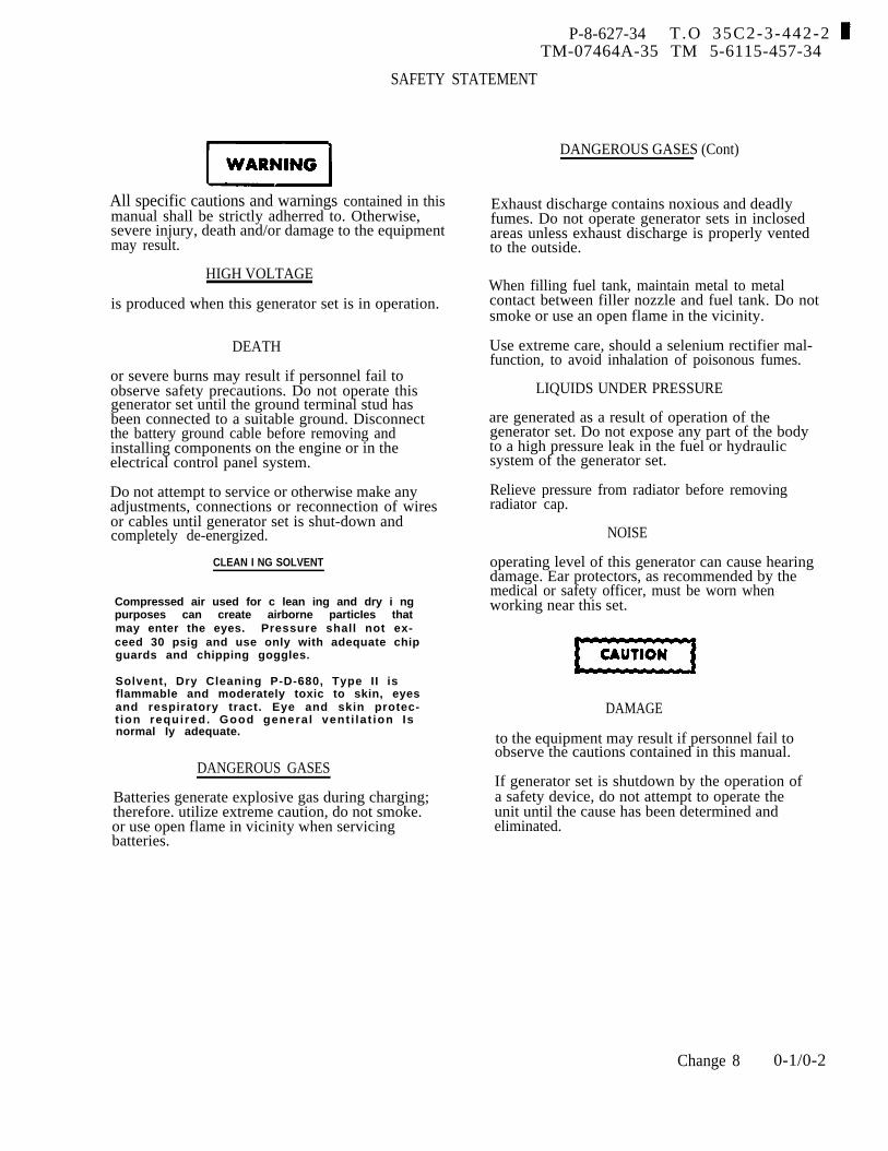
P-8-627-34 T.O 35C2-3-442-2 TM-07464A-35 TM 5-6115-457-34
SAFETY STATEMENT
All specific cautions and warnings contained in thismanual shall be strictly adherred to. Otherwise,severe injury, death and/or damage to the equipmentmay result.
HIGH VOLTAGE
is produced when this generator set is in operation.
DEATH
or severe burns may result if personnel fail toobserve safety precautions. Do not operate thisgenerator set until the ground terminal stud hasbeen connected to a suitable ground. Disconnectthe battery ground cable before removing andinstalling components on the engine or in theelectrical control panel system.
Do not attempt to service or otherwise make anyadjustments, connections or reconnection of wiresor cables until generator set is shut-down andcompletely de-energized.
CLEAN I NG SOLVENT
Compressed air used for c lean ing and dry i ngpurposes can create airborne particIes thatmay enter the eyes. Pressure shall not ex-ceed 30 psig and use only with adequate chipguards and chipping goggles.
Solvent, Dry Cleaning P-D-680, Type II isflammable and moderately toxic to skin, eyesand respiratory tract. Eye and skin protec-t ion required. Good general vent i la t ion Isnormal Iy adequate.
DANGEROUS GASES
Batteries generate explosive gas during charging;therefore. utilize extreme caution, do not smoke.or use open flame in vicinity when servicingbatteries.
DANGEROUS GASES (Cont)
Exhaust discharge contains noxious and deadlyfumes. Do not operate generator sets in inclosedareas unless exhaust discharge is properly ventedto the outside.
When filling fuel tank, maintain metal to metalcontact between filler nozzle and fuel tank. Do notsmoke or use an open flame in the vicinity.
Use extreme care, should a selenium rectifier mal-function, to avoid inhalation of poisonous fumes.
LIQUIDS UNDER PRESSURE
are generated as a result of operation of thegenerator set. Do not expose any part of the bodyto a high pressure leak in the fuel or hydraulicsystem of the generator set.
Relieve pressure from radiator before removingradiator cap.
NOISE
operating level of this generator can cause hearingdamage. Ear protectors, as recommended by themedical or safety officer, must be worn whenworking near this set.
DAMAGE
to the equipment may result if personnel fail toobserve the cautions contained in this manual.
If generator set is shutdown by the operation ofa safety device, do not attempt to operate theunit until the cause has been determined andeliminated.
Change 8 0-1/0-2


P-9-TM-457-35 T.O. 35 C2-3-442-2TM-07464A-35 TM 5-6115-457-34
1-1. SCOPE.
CHAPTER 1
INTRODUCTION
Section I.
a. This manual contains instructions forthe use of intermediate (field) (direct andgeneral support) and depot maintenancepersonnel maintaining the 100 KW DieselEngine Generator Set, Models MEP007A,ME P106A, and MEP1 16A, as allocated bythe Maintenance Allocation Chart. It pro-vides information on the maintenance ofequipment which is beyond the scope of thetools, equipment, personnel, or suppliesnormally available to operator and organi-zational level of maintenance. This manualis to be used in conjunction with the Operatorand Organizational Maintenance Manual.
b. THIS TECHNICAL MANUAL IS USEDBY THE ARMY, AIR FORCE, NAVY, ANDMARINE CORPS. THE USE OF FORMSAND COMPLIANCE WITH DIRECTIVES ASSTATED HEREIN WILL BE ACCOMPLISH-ED ONLY BY PERSONNEL OF THESERVICE TO WHICH THEY APPLY.
1-2. FORMS AND RECORDS.
a. Forms and Records used by theArmy will be only those prescribed byTM38-750. Those used by the Marine Corps
GENERAL
will be those prescribed by TM4700-15/1,Other service users should refer toappropriate specifications/publications forequipment maintenance forms and records.
b. Report of errors, omissions, andrecommendations for improvement of thispublication by the individual users is en-couraged. Reports should be submitted asfollows :
1. Air Force - AFTO Form 22 inaccordance with T. O. 00-5-1 and direct toCommander, Sacramento Air LogisticsCenter, ATTN: MMEDT, McClellan AFB,California 95652.
2. Army - DA Form 2028 direct to:Commanding General, U.S. Army TroopSupport and Aviation Material ReadinessCommand, ATTN: DRSTS-MTP, 4300Goodfellow Blvd., St. Louis, Missouri 63120.
3. Marine Corps - by letter directto: Commandant, U.S. Marine Corps,ATTN: Code LME, Washington, D. C. 20380.
4. Navy - by letter direct to:Commanding Officer, U.S. Navy ShipsParts Control Center, ATTN: Code 783,Mechanicsburg, Pennsylvania 17055.
Change 4 1-1
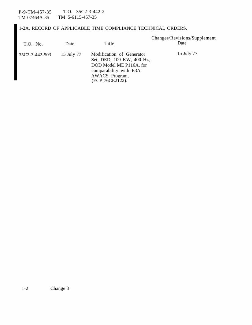
P-9-TM-457-35 T.O. 35C2-3-442-2TM-07464A-35 TM 5-6115-457-35
1-2A. RECORD OF APPLICABLE TIME COMPLIANCE TECHNICAL ORDERS.
Changes/Revisions/SupplementT.O. No. Date Title Date
35C2-3-442-503 15 July 77 Modification of Generator 15 July 77Set, DED, 100 KW, 400 Hz,DOD Model ME P116A, forcomparability with E3A-AWACS Program,(ECP 76CE2122).
1-2 Change 3
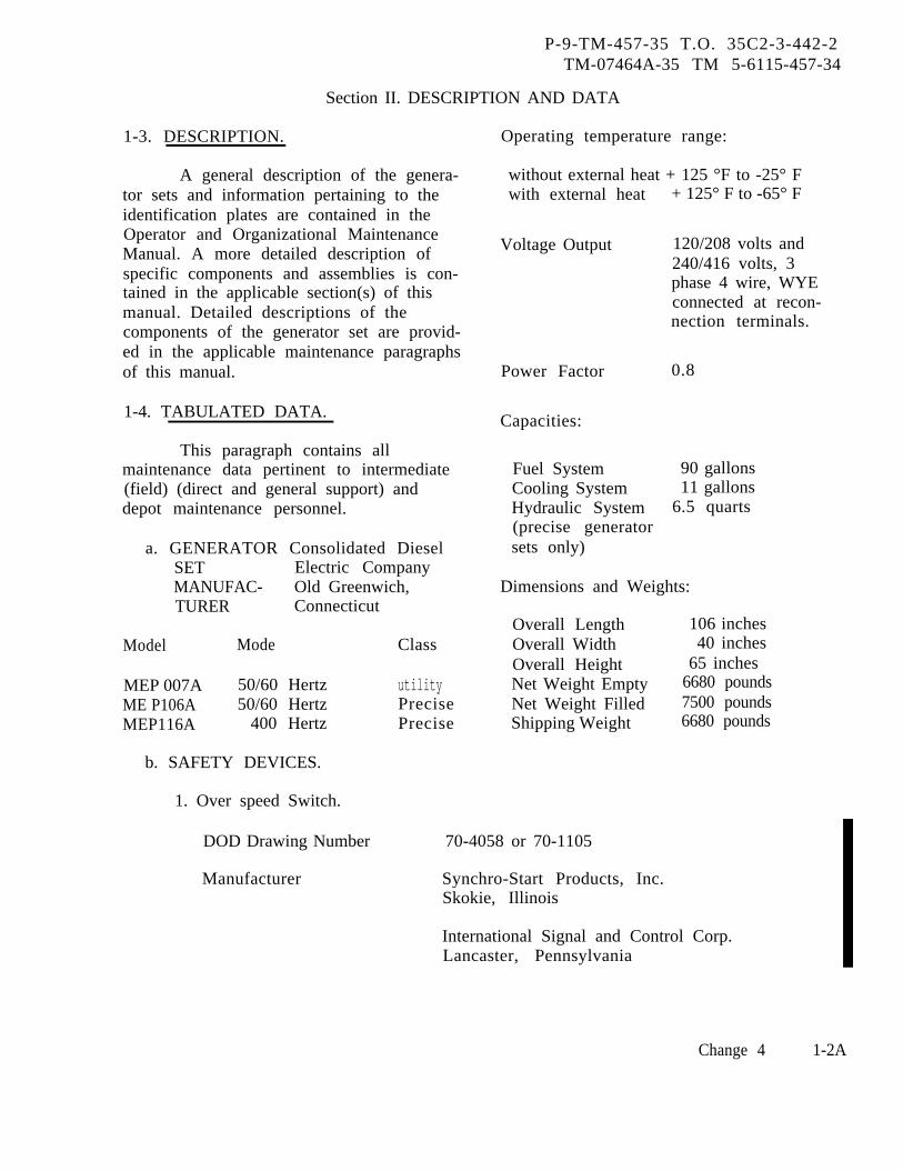
1-3. DESCRIPTION.
P-9-TM-457-35 T.O. 35C2-3-442-2TM-07464A-35 TM 5-6115-457-34
Section II. DESCRIPTION AND DATA
A general description of the genera-tor sets and information pertaining to theidentification plates are contained in theOperator and Organizational MaintenanceManual. A more detailed description ofspecific components and assemblies is con-tained in the applicable section(s) of thismanual. Detailed descriptions of thecomponents of the generator set are provid-ed in the applicable maintenance paragraphsof this manual.
1-4. TABULATED DATA.
This paragraph contains allmaintenance data pertinent to intermediate(field) (direct and general support) anddepot maintenance personnel.
a. GENERATOR Consolidated DieselSET Electric CompanyMANUFAC- Old Greenwich,TURER Connecticut
Model Mode
MEP 007A 50/60 HertzME P106A 50/60 HertzMEP116A 400 Hertz
b. SAFETY DEVICES.
1. Over speed Switch.
DOD Drawing Number
Manufacturer
Class
utilityPrecisePrecise
Operating temperature range:
without external heat + 125 °F to -25° Fwith external heat
Voltage Output
Power Factor
Capacities:
Fuel SystemCooling SystemHydraulic System(precise generatorsets only)
+ 125° F to -65° F
120/208 volts and240/416 volts, 3phase 4 wire, WYEconnected at recon-nection terminals.
0.8
90 gallons11 gallons
6.5 quarts
Dimensions and Weights:
Overall Length 106 inchesOverall Width 40 inchesOverall Height 65 inchesNet Weight Empty 6680 poundsNet Weight Filled 7500 poundsShipping Weight 6680 pounds
70-4058 or 70-1105
Synchro-Start Products, Inc.Skokie, Illinois
International Signal and Control Corp.Lancaster, Pennsylvania
Change 4 1-2A
P-9-TM-457-35 T.O. 35C2-3-442-2TM-07464A-35 TM 5-6115-457-34
Type Centrifugal, 3-element
Manufacturers Part Number 50/60 Hz; SA897-3DOB (Synchro-Start)72-2203-1 (International Signal)
400 Hz; SA1644-3DOB (Synchro-Start)72-2203-2 (International Signal)
1-2B Change 4
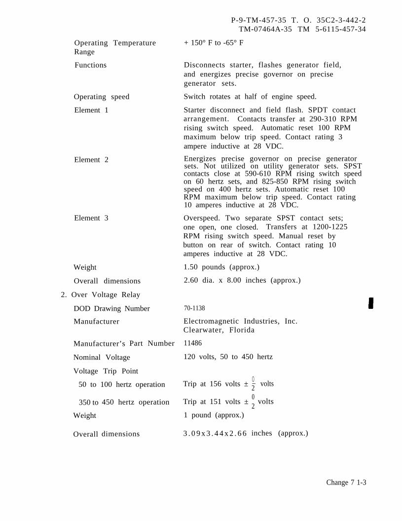
Operating TemperatureRange
Functions
Operating speed
Element 1
Element 2
Element 3
Weight
Overall dimensions
2. Over Voltage Relay
DOD Drawing Number
Manufacturer
Manufacturer’s Part Number
Nominal Voltage
Voltage Trip Point
50 to 100 hertz operation
350 to
Weight
Overall
450 hertz operation
dimensions
P-9-TM-457-35 T. O. 35C2-3-442-2TM-07464A-35 TM 5-6115-457-34
+ 150° F to -65° F
Disconnects starter, flashes generator field,and energizes precise governor on precisegenerator sets.
Switch rotates at half of engine speed.
Starter disconnect and field flash. SPDT contactarrangement. Contacts transfer at 290-310 RPMrising switch speed. Automatic reset 100 RPMmaximum below trip speed. Contact rating 3ampere inductive at 28 VDC.
Energizes precise governor on precise generatorsets. Not utilized on utility generator sets. SPSTcontacts close at 590-610 RPM rising switch speedon 60 hertz sets, and 825-850 RPM rising switchspeed on 400 hertz sets. Automatic reset 100RPM maximum below trip speed. Contact rating10 amperes inductive at 28 VDC.
Overspeed. Two separate SPST contact sets;one open, one closed. Transfers at 1200-1225RPM rising switch speed. Manual reset bybutton on rear of switch. Contact rating 10amperes inductive at 28 VDC.
1.50 pounds (approx.)
2.60 dia. x 8.00 inches (approx.)
70-1138
Electromagnetic Industries, Inc.Clearwater, Florida
11486
120 volts, 50 to 450 hertz
Trip at 156 volts ±
Trip at 151 volts ±
1 pound (approx.)
3 . 0 9 x 3 . 4 4 x 2 . 6 6
0- volts202
volts
inches (approx.)
Change 7 1-3

P-9-TM-457-35 T.O. 35 C2-3-442-2TM-07464A-35 TM 5-6115-457-34
Time Delay 0.18 to 0.8 second
Contact Rating 10 amperes, 28.5 VDC resistive
Temperature Limits -85° F to + 185° F
Temperature Effect On Changes ± 1 volt at -85°FPull-In Voltage Changes ± 1 volt at + 185° F
3. Under Voltage Relay
DOD Drawing Number 70-1120
Manufacturer Electromagnetic Industries, Inc.Clearwater, Florida
Manufacturer’s Part Number 11636
Nominal Input 120 volts, 50 to 400 Hz, 100 milliamperesmaximum
Dropout Voltage 99 volts
Dropout Voltage Tolerance ± 1 volt at 60 hertz and 75° F, ± 4 volts atany combination of frequency and temp-erature within specified limits.
Frequency Range
Temperature Limits
Time Delay
Pull In Voltage
Contact Arrangement
Contact Rating
Service Life
Weight
Overall dimensions
50 to 400 hertz. Frequency trip effect±1.5 volt
-65°F to + 170° F. Temperature trip effect±1.5 volt
6 ± 2 seconds above 72 volts, instantaneousbelow 48 volts
112 volts
DPDT. Terminals 3, 4 and 5 isolated fromterminals 6, 7 and 8. Normally closed contactsare terminals 3 to 4 and terminals 6 to 7.
10 ampere resistive or 5 ampereinductive, 28 VDC.
5, 000 hours minimum
1 pound (approx. )
4.28 x 3.375 x 3.53 inches (approx.)
1-4 Change 7
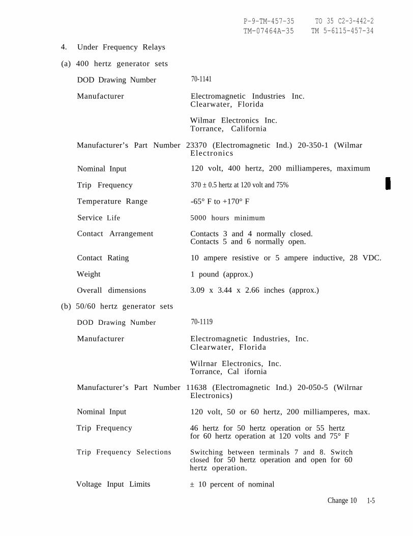
P-9-TM-457-35 TO 35 C2-3-442-2TM-07464A-35 TM 5-6115-457-34
4. Under Frequency Relays
(a) 400 hertz generator sets
DOD Drawing Number
Manufacturer
70-1141
Electromagnetic Industries Inc.Clearwater, Florida
Wilmar Electronics Inc.Torrance, California
Manufacturer’s Part Number 23370 (Electromagnetic Ind.) 20-350-1 (WilmarElectronics
Nominal Input 120 volt, 400 hertz, 200 milliamperes, maximum
Trip Frequency 370 ± 0.5 hertz at 120 volt and 75%
Temperature Range -65° F to +170° F
Service Life 5000 hours minimum
Contact Arrangement Contacts 3 and 4 normally closed.Contacts 5 and 6 normally open.
Contact Rating 10 ampere resistive or 5 ampere inductive, 28 VDC.
Weight 1 pound (approx.)
Overall dimensions 3.09 x 3.44 x 2.66 inches (approx.)
(b) 50/60 hertz generator sets
DOD Drawing Number 70-1119
Manufacturer Electromagnetic Industries, Inc.Clearwater, Florida
Wilrnar Electronics, Inc.Torrance, Cal ifornia
Manufacturer’s Part Number 11638 (Electromagnetic Ind.) 20-050-5 (WilrnarElectronics)
Nominal Input 120 volt, 50 or 60 hertz, 200 milliamperes, max.
Trip Frequency 46 hertz for 50 hertz operation or 55 hertzfor 60 hertz operation at 120 volts and 75° F
Trip Frequency Selections Switching between terminals 7 and 8. Switchclosed for 50 hertz operation and open for 60hertz operation.
Voltage Input Limits ± 10 percent of nominal
Change 10 1-5

P-9-TM-457-35 T.O. 35C2-3-442-2TM-07464A-35 TM 5-6115-457-34
Voltage Trip Effect
Temperature Range
Temperature Trip Effect
Service Life
Contact Arrangement
Contact Rating
Weight
Overall dimensions
5. Short Circuit Relay
(a) 50/60 hertz generator sets
DOD Drawing Number
Manufacturer
Manufacturer’s Part Number
Function
Trip Voltage
Trip Voltage Tolerance
Frequency Range
Temperature Limits
Operating Time
Contact Arrangement
Contact Rating
Service Life
Weight
Overall dimensions
1-6 Change 7
± 0. 2 hertz
-65° F to + 170° F
±0.2 hertz
5000 hours minimum
Contact 3 and 4 normally closed.Contact 5 and 6 normally open.
10 ampere resistive or 5 ampere inductive, 28 VDC
1 pound (approx.)
3.09 x 3.44 x 2.66 inches (approx.)
70-1137
Electromagnetic Wilmar Electronics, Inc.Industr ies , Inc. Torrance, CaliforniaClearwate r , F lo r ida
21380C 1 (Electromagnetic Ind.) 800 (WilmarElectronics)
Trips if generator set output current exceeds425 ± 25 percent of generator set rated current.
24 volts at 60 hertz and 75° F on any phase to neutral
±0.3 volt at 60 hertz and 75° F, ±1.5 volt at anycombination of frequency and temperaturedeviation within specified limits.
50 to 400 hertz. Frequency trip effect ±0.6 volt
-65° F to + 170°F. Temp. trip effect ±0.6 volt
Instantaneous
Contacts 5 and 6 normally closed.Contacts 7 and 8 normally open.
10 amperes resistive, 28 VDC
5000 hour minimum
1 pound (approx.)
3.09 x 3.44 x 2.66 inches (approx.)
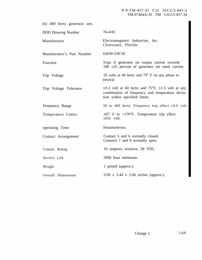
P-9-TM-457-35 T.O. 35C2-3-442-2TM-07464A-35 TM 5-6115-457-34
(b) 400 hertz generator sets
DOD Drawing Number 76-4181
Manufacturer Electromagnetic Industries, Inc.Clearwater, Florida
Manufacturer’s Part Number 63030-230-50
Function Trips if generator set output current exceeds180 ±25 percent of generator set rated current.
Trip Voltage 10 volts at 60 hertz and 75° F on any phase toneutral
Trip Voltage Tolerance ±0.3 volt at 60 hertz and 75°F, ±1.5 volt at anycombination of frequency and temperature devia-tion within specified limits.
Frequency Range
Temperature Limits
operating Time
Contact Arrangement
Contact Rating
Service Life
Weight
Overall Dimensions
50 to 400 hertz. Frequency trip effect ±0.6 volt.
-65° F to +170°F. Temperature trip effect±0.6 volt.
Instantaneous.
Contact 5 and 6 normally closed.Contacts 7 and 8 normally open.
10 amperes resistive, 28 VDC.
5000 hour minimum.
1 pound (approx.).
3.09 x 3.44 x 2.66 inches (approx.).
Change 3 1-6A
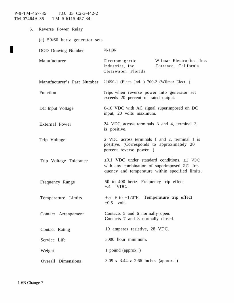
P-9-TM-457-35 T.O. 35 C2-3-442-2TM-07464A-35 TM 5-6115-457-34
6. Reverse Power Relay
(a) 50/60 hertz generator sets
DOD Drawing Number
Manufacturer
Manufacturer’s Part Number
Function
DC Input Voltage
External Power
Trip Voltage
Trip Voltage Tolerance
Frequency Range
Temperature Limits
Contact Arrangement
Contact Rating
Service Life
Weight
Overall Dimensions
70-1136
Electromagnetic Wilmar Electronics, Inc.Industr ies , Inc. Torrance, CaliforniaClearwate r , F lo r ida
21690-1 (Elect. Ind. ) 700-2 (Wilmar Elect. )
Trips when reverse power into generator setexceeds 20 percent of rated output.
0-10 VDC with AC signal superimposed on DCinput, 20 volts maximum.
24 VDC across terminals 3 and 4, terminal 3is positive.
2 VDC across terminals 1 and 2, terminal 1 ispositive. (Corresponds to approximately 20percent reverse power. )
±0.1 VDC under standard conditions. ±1 VDCwith any combination of superimposed AC fre-quency and temperature within specified limits.
50 to 400 hertz. Frequency trip effect±.4 VDC.
-65° F to +170°F. Temperature trip effect±0.5 volt.
Contacts 5 and 6 normally open.Contacts 7 and 8 normally closed.
10 amperes resistive, 28 VDC.
5000 hour minimum.
1 pound (approx. )
3.09 x 3.44 x 2.66 inches (approx. )
1-6B Change 7
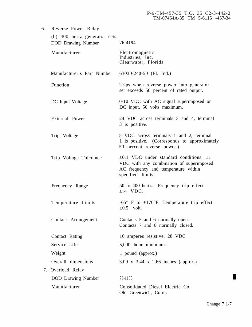
P-9-TM-457-35 T.O. 35 C2-3-442-2TM-07464A-35 TM 5-6115 -457-34
6. Reverse Power Relay
(b) 400 hertz generator setsDOD Drawing Number
Manufacturer
Manufacturer’s Part Number
Function
DC Input Voltage
External Power
Trip Voltage
Trip Voltage Tolerance
Frequency Range
Temperature Limits
Contact Arrangement
Contact Rating
Service Life
Weight
Overall dimensions
7. Overload Relay
DOD Drawing Number
Manufacturer
76-4194
ElectromagneticIndustries, Inc.Clearwater, Florida
63030-240-50 (El. Ind.)
Trips when reverse power into generatorset exceeds 50 percent of rated output.
0-10 VDC with AC signal superimposed onDC input, 50 volts maximum.
24 VDC across terminals 3 and 4, terminal3 is positive.
5 VDC across terminals 1 and 2, terminal1 is positive. (Corresponds to approximately50 percent reverse power.)
±0.1 VDC under standard conditions. ±1VDC with any combination of superimposedAC frequency and temperature withinspecified limits.
50 to 400 hertz. Frequency trip effect±.4 VDC.
-65° F to +170°F. Temperature trip effect±0.5 volt.
Contacts 5 and 6 normally open.Contacts 7 and 8 normally closed.
10 amperes resistive, 28 VDC
5,000 hour minimum.
1 pound (approx.)
3.09 x 3.44 x 2.66 inches (approx.)
70-1135
Consolidated Diesel Electric Co.Old Greenwich, Corm.
Change 7 1-7
P-9-TM-457-35 T.O. 35C2-3-442-2TM-07464A-35 TM 5-6115-457-34
Manufacturer’s Part Number 00000-4857
Function Trips if current in anyplace exceeds 110percent of rated current on an inverse timeprinciple.
AC Input (Signal) 3 wire, 3 phase 50/60 and 400 Hz 0.75ampere per phase (at 100 percent rated load)
DC Input 28 VDC 0.1 ampere maximum.
Time Delay Operates in a minimum of 8 minutes ±2minutes after the current in any phaseremains at 130 percent of rated current.
Temperature Limits -65° F to +140°F
Contact Arrangement Two contacts, 1 normally open, 1normally closed
Contact Rating 10 ampere resistive or 5 ampere inductive,28 VDC
Service Life 5,000 hour minimum
Weight 1 pound (approx.)
Overall dimensions 3.87 x 2.68 x 3.62 inches (approx.)
8. Permissive Paralleling Relay
DOD Drawing Number 70-1118
Manufacturer Electromagnetic Industries Inc.Clearwater, Florida
Manufacturer’s Part Number 23390
External Power Required 24 VDC, 200 milliamperes maximum.
Input Signal AC Burden 0-20 VAC, 60 to 400 hertz. At 300 VAC,40 milliamperes maximum.
Contact Operation 5 and 6 normally closed with AC signalabove 10 volts. 7 and 8 normally openwith AC signal above 8 ± 1 volt.
Contact Rating 28 VDC, 10 amperes resistive, 5 amperesinductive.
Life Expectancy 5,000 hours minimum
Weight 1 pound (approx.)
Overall dimensions 2.56 x 3.38 x 3,00 inches (approx.)
1-8 Change 7
P-9-TM-457-35 T.O. 35 C2-3-442-2TM-07464A-35 TM 5-6115-457-34
c. RADIATOR
DOD Drawing Number 70-4088
Manufacturer G & O Manufacturing Company,New Haven Corm.
Manufacturer’s Part Number X-1817
Coolant Capacity
Heat Rejection:
Water GPMflow
627080
Air Test Pressure
Operating Pressure
Weight
Overall dimensions
21.3 quarts
Engine RPM Heat BTU/rein.speed reject ion
1500 351800 342000 37
15 PSI
7 PSI
115 pounds (approx.)
28.25 x 39.0 x 10.00 inches (approx.)
d. RADIATOR SHUTTER AND CONTROL ASSEMBLY.
DOD Drawing Number
Manufacturer
Manufacturer’s Part Number
Type
Control Element Setting
Weight
Overall dimensions
70-4092
Evans Products CompanyColdwater, Michigan
1 G 409
16 vanes with left hand manual controlhandle, thermostat operated
Nominal 170” F (158° F crack open, 173° Ffull open)
10 pounds (approx.)
30.56 x 32.25 x 2.5 inches (approx.)
e. GENERATOR CONTROL ASSEMBLY
1. DC Circuit Breaker
DOD Drawing Number MS25244-7. 5
Rating 24 VDC 7.5 amperes
Change 7 1-9

P-9-TM-457-35 T.O. 35C2-3-442-2TM-07464A-35 TM 5-6115-457-34
Circuit Breaker Reset Manual
Contact Arrangement SPST
Weight 0.25 pounds (approx.)
Overall dimensions 2.00 x 1.80 x 0.75 inches (approx.)
2. Convenience Receptacle Box Assembly
(a) 50/60 hertz generator sets
DOD Drawing Number
Number of Receptacles
Voltage
Current
Circuit Breaker Reset
Weight
Overall dimensions
(b) 400 hertz generator sets
DOD Drawing Number
Number of Receptacles
Receptacle 1 rating
Receptacle 2 rating
Circuit breaker Reset
Weight
Overall dimensions
3. Exciter Regulator (Voltage)
DOD Drawing Number
Manufacturer
Voltage Regulation:
Precise SetsUtility Sets
70-4101
1 duplex
120 VAC
15 amperes
Manual
5 pounds (approx.)
9.62 x 3.0 x 5.50 inches (approx.)
70-4107
2
125/250 VAC, 30 amperes
125 VAC, 15 amperes
Manual
5 pounds (approx.)
9.62 x 3.0 x 5.50 inches (approx.)
70-4145 (50/60 Hertz generator sets)70-4235 (400 Hertz generator sets)
Consolidated Diesel Electric Co.Old Greenwich, Connecticut
Solid state, with capability to automaticallyflash field of generator.
1 percent of rated voltage3 percent of rated voltage
1-10
P-9-TM-457-35 T.O. 35C2-3-442-2TM-07464A-35 TM 5-6115-457-34
Voltage Stability:Short Term (30 seconds)
Precise Sets
Utility Sets
Long Term (4 hours)
Precise Sets
Utility Sets
Voltage Drift (8 hours)
Transient performance(application or rejectionof load).
Resumption of steadystate condition :
within bandwidth equal to 1 percent ofrated voltage.
within bandwidth equal to 2 percent ofrated voltage.
within bandwidth equal to 2 percent ofrated voltage.
within bandwidth equal to 4 percent ofrated voltage.
1 percent
Precise Sets within 0.5 seconds
Utility Sets within 3 seconds
Overshoot and Undershoot:
Precise Sets (50/60 Hertz) 15 percent of rated voltage
Precise Sets (400 Hertz) 12 percent of rated voltage
Utility Sets 20 percent of rated voltage
Weight 40 pounds (approx.)
Overall dimensions 20.0 x 6.50 x 9.88 inches (approx.)
4. Load Contactor (CB2) (50/60 hertz generator sets)
DOD Drawing Number 70-501
Manufacturer Hartman Electric ManufacturingMansfield, Ohio
HB Electrical Mfg. Co.Mansfield, Ohio
Manufacturer’s Part Number B-301E (Hartman Electric)HB200A (HB Electrical)
Change 4 1-11

P-9-TM-457-35 T.O. 35C2-3-442-2TM-07464A-35 TM 5-6115-457-34
KVA Rating 125 KVA
Mechanism Electrically held
Main Contacts 3 PST double break
AC Voltage 120/208-240/416 Volts50/60 and 400 Hertz
Frequency 50/60 and 400 HertzContinuous Current 350 amperes at 120/208 volts
50/60 and 400 hertzSecond Current 750 amperes at 120/208 volts
50/60 and 400 hertzInterrupting Capacity 5000 amperes at 120/208 volts
50/60 and 400 hertz2500 amperes at 240/416 volts50/60 and 400 hertz
Auxiliary Contacts 4 SPST normally open, 2 SPST normally closedand 1 SPDT.
DC VoltageCurrent
AC VoltageCurrentLamp Current
DC50/60 Hertz400 Hertz
32 Volts2.5 amperes maximum resistive orinductive120 Volts2.0 amperes maximum
4.0 amperes maximum1.5 amperes maximum3.0 amperes maximum
Auxiliary Contacts Trip Within 0.004 seconds of main contactsTime activation.
Coil Data
Operating Voltage 32 VDC Maximum16 VDC Minimum (without external seriesresistance)
Main Contacts MaximumOperating Time
Close
Open
0.050 Seconds at 24 to 32 VDC with 0.25 ohmsresistance in series with coil.
0.035 Seconds at 24 to 32 VDC with 0.25 ohmsresistance in series with coil.
1-12 Change 1
Electrical Life
P-9-TM-457-35 T.O. 35C2-3-442-2TM-07464A-35 TM 5-6115-457-34
Duty Cycle Continous
Maximum Holding Current 0.75 amperes at 32 VDC after 30minutes warmup.
Pulling Current Contactor shall close with 24 VDC appliedacross the operating coil and a 5.0 ohmresistor in series.
10,000 cycles at a duty cycle of not less than 325make and break operations per hour. With the ONportion of the cycle not less than 1.0 seconds andthe OFF portion of the cycle not more than10.0 seconds.
Mechanical Life 100,000 cycles
Weight 4 pounds (approx.)
Overall dimensions 4.80 x 6.06 x 4.80 inches (approx.)
4A. Circuit Breaker Assembly (CB2) (400 hertz generator sets)
DOD Drawing Number
Manufacturer
Main Contacts
Current Rating (minimum)
Interrupting Capability
Auxiliary Contacts
Temperature Range
Weight
Overall Dimensions
76-4191
Consolidated Diesel Electric Co.Old Greenwich, Connecticut
3 pole normally open, 400 ampere
350 amperes continuous at 208 volts and175 amperes at 416 volts1600 amperes for 4 seconds
42,000 amperes30,000 amperes at 416 volts
SPST normally open contacts,3 rated 10 amperes; 1 rated 5 amperes
-65°F to +135° F
25 pounds (approx.)
7.75 x 8.50 x 16.00 inches (approx.)
Change 3 1-13
P-9-TM-457-35 T.O. 35C2-3-442-2TM-07464A-35 TM 5-6115-457-34
5. Current Transformer Assembly
(a) Current transformer (CT1, CT2, and CT3)
DOD Drawing Number
Manufacturer
Manufacturing Part Number
Primary Current
Secondary Current
Turns Ratio
Frequency
Burden
Temperature Range
Weight
Overall Dimensions
70-4084
Electromagnetic Industries, Inc.Clearwater, Florida
51
464 amperes
1 ampere
1 primary to 464 secondar
50/60 and 400 hertz
12. 5VA minimum at 1 ampere secondary current.
-65° F to +155° F
3 pounds (approx.)
3.75 x 3.75 x 2,19 inches (approx.)
(b) Current Transformer Exciter CT 4 (400 Hertz Generator Sets)
DOD Drawing Number 71-4891
Manufacturer Consolidated Diesel Electric Co.Old Greenwich, Connecticut
1-14 Change 3
Manufacturing Part Number
Total Turns
Rated Voltage
Rated Current
Resistance
Frequency
Excitation Current
High Potential Rating
Temperature Range
Weight
Overall dimensions
P-9-TM-457-35 T. O. 35C2-3-442-2TM-07464A-35 TM 5-6115-457-34
00000-4928
94
40VAC
3.7 amperes
0.15 ohms ± 20 percent
400 hertz
With 40 volts RMS applied exciting currentis 0.5 amperes RMS maximum
2,000 volts between winding and core.
-65° F to + 155° F
3 pounds (approx.)
5.00 x 4.20 x 2.75 inches (approx.)
(c) Current Transformer CT 4 (50/60 Hertz Generator Sets)
DOD Drawing Number
Manufacturer
Manufacturing Part Number
Total Turns
Rated Voltage
Rated Current
Resistance
Frequency
Excitation Current
Temperature Range
Weight
Overall dimensions
70-4067
Consolidated Diesel Electric Co.Old Greenwich, Connecticut
00000-4921
260
60 VAC
2.7 amperes
0.83 ohms
60 hertz
With 60 volts RMS applied, exciting currentis 0.30 amperes maximum
-65° F to +155° F
3 pounds (approx.)
5.38 x 5.38 x 3.50 inches (approx.)
(d) Current Transformer Exciter CT5 and CT6 (400 Hertz Generator Sets)
DOD Drawing Number 71-4892
Manufacturer Consolidated Diesel Electric Co.Old Greenwich, Connecticut
Change 3 1-14A/( 1-14B blank)

Manufacturing Part Number
Total Turns
Rated Voltage
Rated Current
Resistance
Frequency
Excitation Current
High Potential Rating
Temperature Range
Weight
Overall dimensions
P-9-TM-457-35 T. O. 35C2-3-442-2TM-07464A-35 TM 5-6115-457-34
00000-4929
47
35 VAC
7.4 amperes
0.05 ohms ± 20 percent
400 hertz
With 35 volts RMS applied exciting currentis 1.0 amperes RMS maximum
2000 volts between winding and core
-65° F to +155° F
2 pounds (approx.)
5.00 x 4.12 x 3.25 inches (approx.)
(e) Current transformer CT5 and CT6 (50/60 Hertz Generator Sets)
DOD Drawing Number
Manufacturer
No Load Voltage
Current
Resistance
Frequency
Excitation Current
Total Turns
Temperature Range
Weight
Overall dimensions
(f) Current transformer CT7
DOD Drawing Number
Manufacturer
70-4086
Consolidated Diesel Electric CompanyOld Greenwich, Connecticut
60 volts
8.0 amperes
0.22 ohms
50/60 Hertz
0.90 amperes m aximum
87
-65° F to + 155° F
3 pounds (approx.)
5.38 x 5.63 x 6.0 inches (approx.)
70-4085
Electromagnetic Industries Inc.Clearwater, Florida
1-15
P-9-TM-457-35 T.O. 35C2-3-442-2TM-0746 4A-35 TM 5-6115-457-34
Manufacturing Part Number 6 (400/1 ratio)
Primary Current 600 amperes
Secondary Current 1.5 amperes
Turns Ratio 1 primary to 400 secondary
Frequency 50/60 and 400 hertz
Burden 25VA minimum
Temperature Range -65° F to + 155° F
Weight 3 pounds (approx.)
Overall dimensions 3.94 x 1.25 inches (approx.)
6. Precise Governor System (LEH GOVERNOR)
Type
(a) Governor control unit
Type
DOD Drawing Number
Manufacturer
Manufacturer Part Number
Input Voltage
Weight
Overall dimensions
(b) Governor actuator unit
DOD Drawing Number
Manufacturer
Type
Manufacturer Part Number
Piston PositionTransducer
Closed loop feedback system
Solid state
400 Hertz Generator Sets 69-80050/60 Hertz Generator Sets 69-700
Electromagnetic Industries, Inc.Clearwater, Florida
400 Hertz Generator Sets 2291050/60 Hertz Generator Sets 22810
24 VDC and single phase120 VAC from generator output
7 pounds (approx.)
10.41 x 10 x 4.06 inches (approx.)
69-790-3
Electromagnetic Industries, Inc.Clearwater, Florida
Hydraulic, differential pressure operated
23600-3
Variable reluctance type
1-16 Change 7

P-9-TM-457-35 T.O. 35 C2-3-442-2TM-07464A-35 TM 5-6115-457-34
Input Pressure 300 to 320 PSIHydraulic Fluid Type MIL-H-5606Input Voltage 120 voltsFrequency 50/60 or 400 hertzWeight 3 pounds (approx)Overall dimensions 6.00 x 2.91 x 4.90 inches (approx.)
(c) Hydraulic Pump
DOD Drawing Number 70-4038
Manufacturer John S. Barnes Corp.Rockford, Illinois
Type Gear driven, positive displacement
Manufacturer’s Part Number
Rating
Drive Type
Relief Valve TypePressureDrive SpeedsRotationWeightOverall dimensions
(d) Hydraulic Tank Assembly
DOD Drawing Number
Type
Capacity
Type Fluid
Weight
Overall dimensions
7. Load Measuring Unit
DOD Drawing Number
Manufacturer
Type
Manufacturer’s PartNumber
GC5100 - A-82-A
2 GPM
Tang with drive coupling
Adjustable plunger320 ± 10 PSI1500 to 2116 RPMClockwise (viewed from drive end)10 pounds (approx.)3.56 x 3.56 x 2.81 inches (approx.)
71-4476
Welded with filler cap level gauge.
6 quarts
MIL-H-5606
12 pounds (approx.)
3.75 x 16 x 8.50 inches (approx.)
69-785
Electromagnetic Industries, Inc.Clearwater, Florida
Electrical, three phase load sensing
69-500
1-17
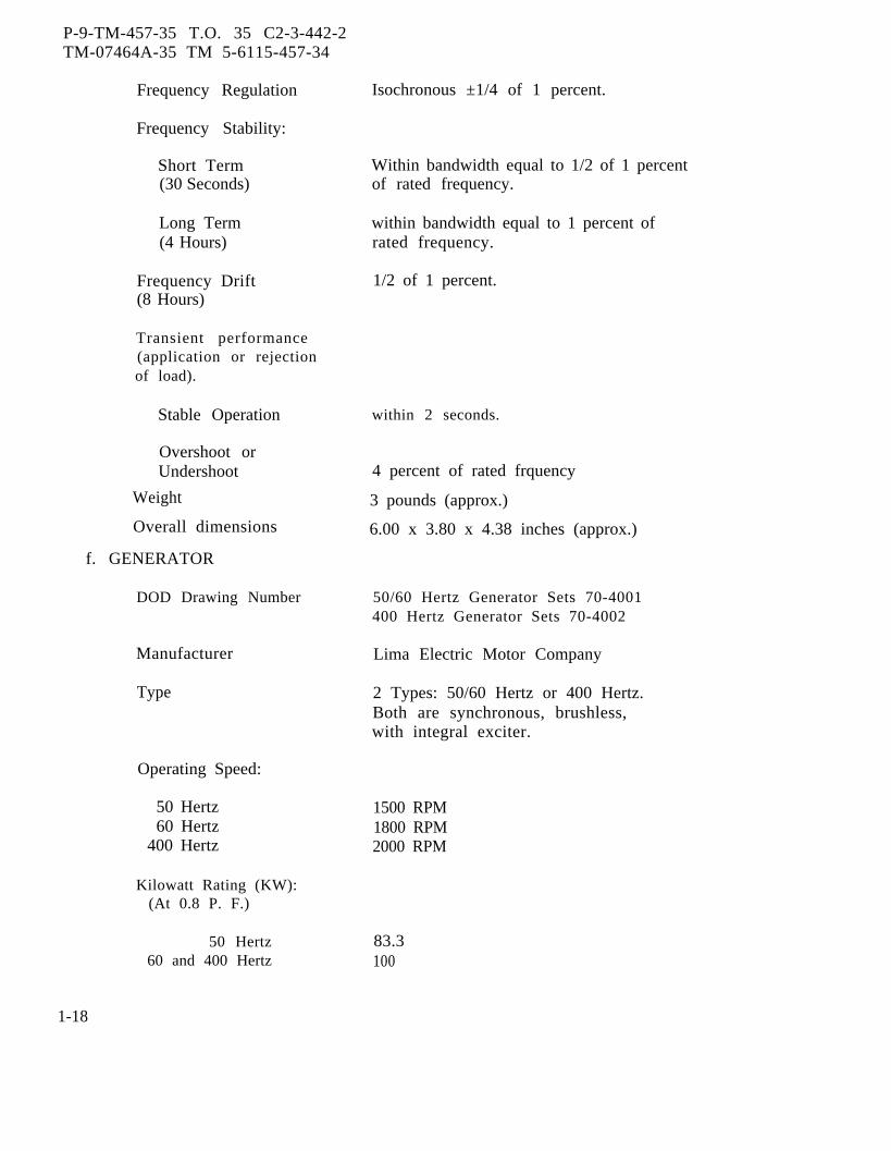
P-9-TM-457-35 T.O. 35 C2-3-442-2TM-07464A-35 TM 5-6115-457-34
Frequency Regulation Isochronous ±1/4 of 1 percent.
Frequency Stability:
Short Term Within bandwidth equal to 1/2 of 1 percent(30 Seconds) of rated frequency.
Long Term within bandwidth equal to 1 percent of(4 Hours) rated frequency.
Frequency Drift 1/2 of 1 percent.(8 Hours)
Transient performance(application or rejectionof load).
Stable Operation
Overshoot orUndershoot
Weight
Overall dimensions
f. GENERATOR
DOD Drawing Number
Manufacturer
Type
Operating Speed:
50 Hertz60 Hertz
400 Hertz
Kilowatt Rating (KW):(At 0.8 P. F.)
50 Hertz60 and 400 Hertz
within 2 seconds.
4 percent of rated frquency
3 pounds (approx.)
6.00 x 3.80 x 4.38 inches (approx.)
50/60 Hertz Generator Sets 70-4001400 Hertz Generator Sets 70-4002
Lima Electric Motor Company
2 Types: 50/60 Hertz or 400 Hertz.Both are synchronous, brushless,with integral exciter.
1500 RPM1800 RPM2000 RPM
83.3100
1-18

P-9-TM-457-35 T.O. 35C2-3-443-2TM-07464A-35 TM 5-6115-457-34
Kilovolt AmpereRating (KVA):
50 Hertz 10460 and 400 Hertz 125
Current rating for 3 phasebalanced rated load withgenerator coils connected inWYE at reconnection terminals.
50 Hertz:
120/208 Volts240/416 Volts
60 and 400 Hertz:
120/208 Volts240/416 Volts
Weight
Overall dimensions
g. ENGINE
DOD Drawing Number
Manufacturer
Model
Number of Cylinders
Piston Displacement
Rotation
Lubricating OilCapacity
Weight
Overall dimensions
288144
346173
1,500 pounds (approx.)
34 x 36 x 30 inches (approx.)
*70-4013
Caterpillar Tractor CompanyPeoria, Illinois
Four stroke cycle, liquid cooled, turbocharged, compression ignition, diesel.
*D333C(T)
six
638 cubic inches
Counterclockwise from flywheel end.
30 quarts
2,200 pounds (approx.)
53. 19 x 40,00 x 35.50 Inches (approx.)*At time of engine replacement, the D333C(T) engine is to be used until stock of theseengines is exhausted; at which point the D3306(T), (76-4106) engine will be used. Re-fer to paragraph 2-10 for engine change instructions. Refer to Generator Set “B”Model Manual for maintenance of the D3306(T) engine.
h. ENGINE ACCESSORIES
1. Battery Charging Alternator
Change 4 1-19
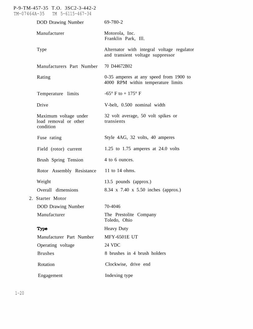
P-9-TM-457-35 T.O. 3SC2-3-442-2TM-07464A-35 TM 5-6115-467-34
DOD Drawing Number
Manufacturer
Type
Manufacturers Part Number
Rating
Temperature limits
Drive
Maximum voltage underload removal or othercondition
Fuse rating
Field (rotor) current
Brush Spring Tension
Rotor Assembly Resistance
Weight
Overall dimensions
2. Starter Motor
DOD Drawing Number
Manufacturer
Manufacturer Part Number
Operating voltage
Brushes
Rotation
Engagement
69-780-2
Motorola, Inc.Franklin Park, Ill.
Alternator with integral voltage regulatorand transient voltage suppressor
70 D44672B02
0-35 amperes at any speed from 1900 to4000 RPM within temperature limits
-65° F to + 175° F
V-belt, 0.500 nominal width
32 volt average, 50 volt spikes ortransients
Style 4AG, 32 volts, 40 amperes
1.25 to 1.75 amperes at 24.0 volts
4 to 6 ounces.
11 to 14 ohms.
13.5 pounds (approx.)
8.34 x 7.40 x 5.50 inches (approx.)
70-4046
The Prestolite CompanyToledo, Ohio
Heavy Duty
MFY-6501E UT
24 VDC
8 brushes in 4 brush holders
Clockwise, drive end
Indexing type
1-20
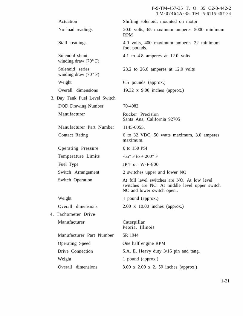
Actuation
No load readings
Stall readings
Solenoid shuntwinding draw (70° F)
Solenoid serieswinding draw (70° F)
Weight
Overall dimensions
3. Day Tank Fuel Level Switch
DOD Drawing Number
Manufacturer
Manufacturer Part Number
Contact Rating
Operating Pressure
Temperature Limits
Fuel Type
Switch Arrangement
Switch Operation
Weight
P-9-TM-457-35 T. O. 35 C2-3-442-2TM-07464A-35 TM 5-6115-457-34
Shifting solenoid, mounted on motor
20.0 volts, 65 maximum amperes 5000 minimumRPM
4.0 volts, 400 maximum amperes 22 minimumfoot pounds.
4.1 to 4.8 amperes at 12.0 volts
23.2 to 26.6 amperes at 12.0 volts
6.5 pounds (approx.)
19.32 x 9.00 inches (approx.)
70-4082
Rucker PrecisionSanta Ana, California 92705
1145-0055.
6 to 32 VDC, 50 watts maximum, 3.0 amperesmaximum.
0 to 150 PSI
-65° F to + 200” F
JP4 or W-F-800
2 switches upper and lower NO
At full level switches are NO. At low levelswitches are NC. At middle level upper switchNC and lower switch open..
1 pound (approx.)
2.00 x 10.00 inches (approx.)Overall dimensions
4. Tachometer Drive
Manufacturer CaterpillarPeoria, Illinois
Manufacturer Part Number 5R 1944
Operating Speed One half engine RPM
Drive Connection S.A. E. Heavy duty 3/16 pin and tang.
Weight 1 pound (approx.)
Overall dimensions 3.00 x 2.00 x 2. 50 inches (approx.)
1-21
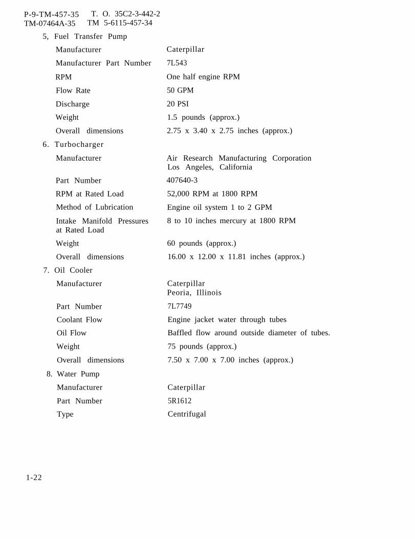
P-9-TM-457-35 T. O. 35C2-3-442-2TM-07464A-35 TM 5-6115-457-34
5, Fuel Transfer Pump
Manufacturer
Manufacturer Part Number
RPM
Flow Rate
Discharge
Weight
Overall dimensions
6. Turbocharger
Manufacturer
Part Number
RPM at Rated Load
Method of Lubrication
Intake Manifold Pressuresat Rated Load
Weight
Overall dimensions
7. Oil Cooler
Manufacturer
Part Number
Coolant Flow
Oil Flow
Weight
Overall dimensions
8. Water Pump
Manufacturer
Part Number
Type
Caterpillar
7L543
One half engine RPM
50 GPM
20 PSI
1.5 pounds (approx.)
2.75 x 3.40 x 2.75 inches (approx.)
Air Research Manufacturing CorporationLos Angeles, California
407640-3
52,000 RPM at 1800 RPM
Engine oil system 1 to 2 GPM
8 to 10 inches mercury at 1800 RPM
60 pounds (approx.)
16.00 x 12.00 x 11.81 inches (approx.)
CaterpillarPeoria, Illinois
7L7749
Engine jacket water through tubes
Baffled flow around outside diameter of tubes.
75 pounds (approx.)
7.50 x 7.00 x 7.00 inches (approx.)
Caterpillar
5R1612
Centrifugal
1-22

Type of Drive
Water Flow Rate
Weight
Overall dimensions
9. Utility Governor
Manufacturer
Type
Frequency Regulation
Part Number
Frequency Stability:
Short Term(30 Seconds)
Long Term(4 Hours)
Frequency Drift(8 Hours)
Transient Performance:(application or rejection ofload).
Stable OperationOvershootUndershootWeightOverall dimensions
10. Fuel Injection Pump
Manufacturer
Part Number
Firing Order
Injection Timing
P-9-TM-457-35 T. O. 35 C2-3-442-2TM-07464A-35 TM 5-6115-457-34
Gear driven
70 GPM at one half engine RPM engine speed.
15 pounds (approx.)
5.40 x 7.75 x 4.00 inches (approx.)
Woodward Governor CompanyRockford, Illinois
Hydraulic speed droop.
Adjustable from 1-1/2 to 3 percent of ratedfrequency.
8510-212
within bandwidth equal to 2 percent ofrated frequency.
within bandwidth equal to 3 percent ofrated frequency.
1 percent.
within 2 seconds4 percent of rated frequency.3 percent of rated frequency.7.00 pounds (approx.)5.30 x 7.50 x 6.25 inches (approx.)
CaterpillarPeoria, Illinois
5R1739
1-5-3-6-2-4.
13 degrees, 30 minutes before topdead center
1-23

P-9-TM-457-35 T.O. 35 C2-3-442-2TM-07464A-35 TM 5-6115-457-34
Number of Individual Pumps 6
Type of Drive Gear driven.
Speed One half engine RPM
Weight 20 pounds (approx.)
Overall dimensions 9.50 x 7.00 x 5.00 inches (approx.)
i. FUEL BURNING WINTERIZATION KIT (Optional)
DOD Drawing Number
Manufacturer
1. Engine Heater
DOD Drawing Number
Manufacturer
Manufacturer Part Number
Fuel
Fuel Rate
Fuel Pressure
Relief valve setting
Voltage
Radio InterferenceSuppression
Coolant Circulation
output
Transfer to CoolantUsable Exhaust Heat
71-4410
Consolidated Diesel Electric CompanyOld Greenwich, Connecticut
69-775
Test Institute CorporationBenmar Heater DivisionCleveland, Ohio
CP 3050-24
JP 4 Arctic diesel fuel
21 to 23 cc per minute
3 to 15 PSI
30 to 35 PSI
24 VDC
0.15 to 1000 mega-cycles
80-100 GPH at 10 PSI
30,000 BTU per hour maximum10,000 BTU per hour maximum
1-24
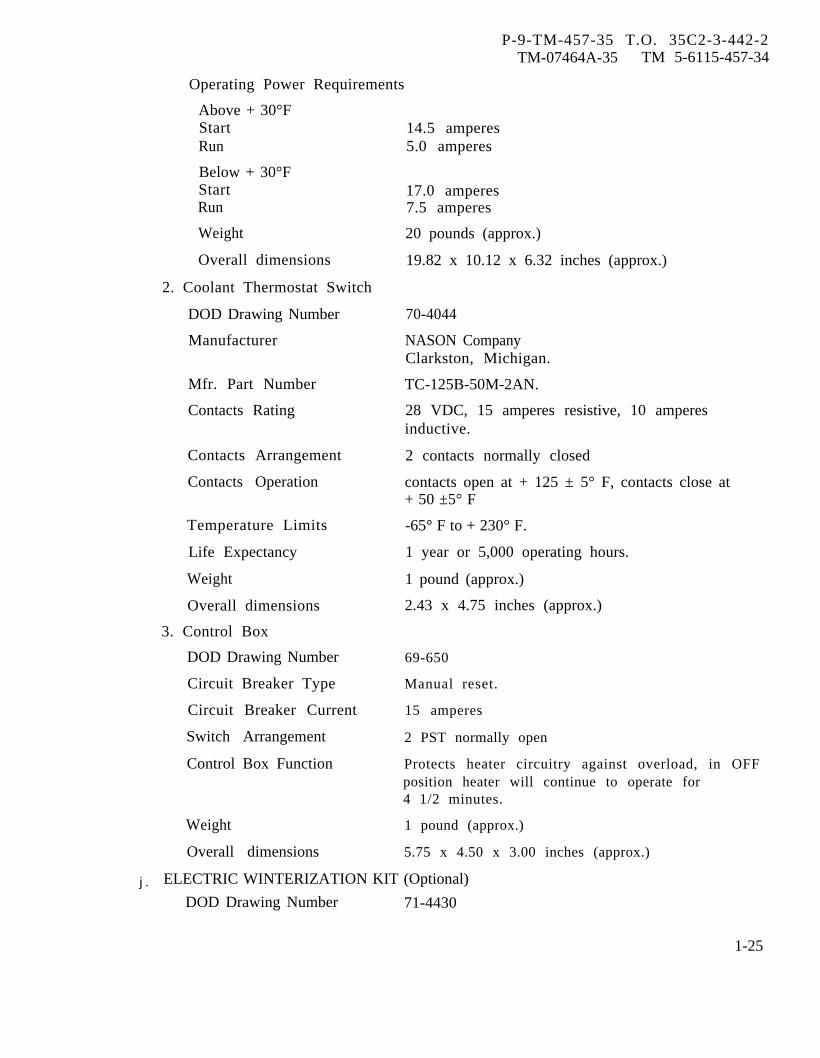
P-9-TM-457-35 T.O. 35C2-3-442-2TM-07464A-35 TM 5-6115-457-34
Operating Power Requirements
Above + 30°FStartRun
Below + 30°FStartRun
Weight
Overall dimensions
2. Coolant Thermostat Switch
DOD Drawing Number
Manufacturer
Mfr. Part Number
Contacts Rating
Contacts Arrangement
Contacts Operation
Temperature Limits
Life Expectancy
Weight
Overall dimensions
3. Control Box
DOD Drawing Number
Circuit Breaker Type
Circuit Breaker Current
Switch Arrangement
Control Box Function
Weight
Overall dimensions
14.5 amperes5.0 amperes
17.0 amperes7.5 amperes
20 pounds (approx.)
19.82 x 10.12 x 6.32 inches (approx.)
70-4044
NASON CompanyClarkston, Michigan.
TC-125B-50M-2AN.
28 VDC, 15 amperes resistive, 10 amperesinductive.
2 contacts normally closed
contacts open at + 125 ± 5° F, contacts close at+ 50 ±5° F
-65° F to + 230° F.
1 year or 5,000 operating hours.
1 pound (approx.)
2.43 x 4.75 inches (approx.)
69-650
Manual reset.
15 amperes
2 PST normally open
Protects heater circuitry against overload, in OFFposition heater will continue to operate for4 1/2 minutes.
1 pound (approx.)
5.75 x 4.50 x 3.00 inches (approx.)
j . ELECTRIC WINTERIZATION KIT (Optional)
DOD Drawing Number 71-4430
1-25
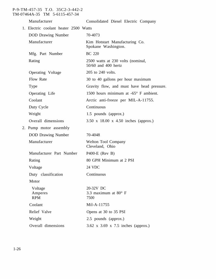
P-9-TM-457-35 T.O. 35C2-3-442-2TM-07464A-35 TM 5-6115-457-34
Manufacturer Consolidated Diesel Electric Company
1. Electric coolant heater 2500 Watts
DOD Drawing Number
Manufacturer
Mfg. Part Number
Rating
Operating Voltage
Flow Rate
Type
Operating Life
Coolant
Duty Cycle
Weight
Overall dimensions
2. Pump motor assembly
DOD Drawing Number
Manufacturer
Manufacturer Part Number
Rating
Voltage
Duty classification
Motor
VoltageAmperesRPM
Coolant
Relief Valve
Weight
Overall dimensions
70-4073
Kim Hotstart Manufacturing Co.Spokane Washington.
BC 220
2500 watts at 230 volts (nominal,50/60 and 400 hertz
205 to 240 volts.
30 to 40 gallons per hour maximum
Gravity flow, and must have head pressure.
1500 hours minimum at -65° F ambient.
Arctic anti-freeze per MIL-A-11755.
Continuous
1.5 pounds (approx.)
3.50 x 18.00 x 4.50 inches (approx.)
70-4048
Welton Tool CompanyCleveland, Ohio
P400-E (Rev B)
80 GPH Minimum at 2 PSI
24 VDC
Continuous
20-32V DC3.3 maximum at 80° F7500
Mil-A-11755
Opens at 30 to 35 PSI
2.5 pounds (approx.)
3.62 x 3.69 x 7.5 inches (approx.)
1-26
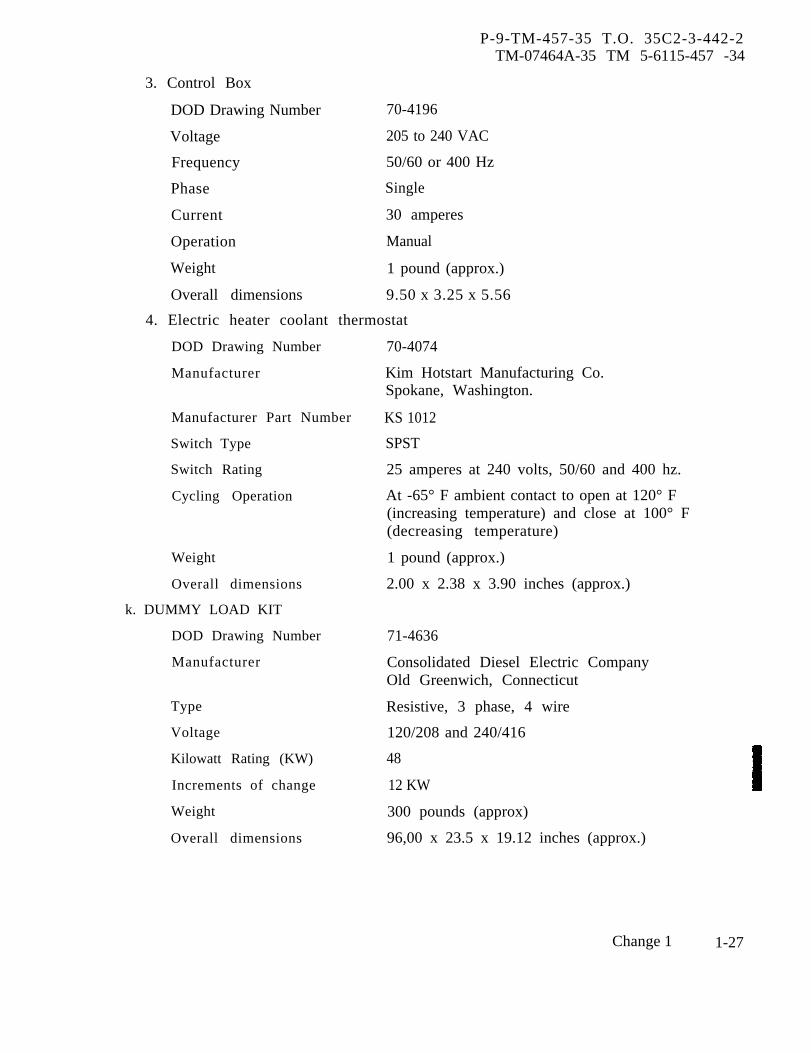
P-9-TM-457-35 T.O. 35C2-3-442-2TM-07464A-35 TM 5-6115-457 -34
3. Control Box
DOD Drawing Number 70-4196
Voltage 205 to 240 VAC
Frequency 50/60 or 400 Hz
Phase Single
Current 30 amperes
Operation Manual
Weight 1 pound (approx.)
Overall dimensions 9.50 x 3.25 x 5.56
4. Electric heater coolant thermostat
DOD Drawing Number
Manufacturer
Manufacturer Part Number
Switch Type
Switch Rating
Cycling Operation
Weight
Overall dimensions
k. DUMMY LOAD KIT
DOD Drawing Number
Manufacturer
Type
Voltage
Kilowatt Rating (KW)
Increments of change
Weight
Overall dimensions
70-4074
Kim Hotstart Manufacturing Co.Spokane, Washington.
KS 1012
SPST
25 amperes at 240 volts, 50/60 and 400 hz.
At -65° F ambient contact to open at 120° F(increasing temperature) and close at 100° F(decreasing temperature)
1 pound (approx.)
2.00 x 2.38 x 3.90 inches (approx.)
71-4636
Consolidated Diesel Electric CompanyOld Greenwich, Connecticut
Resistive, 3 phase, 4 wire
120/208 and 240/416
48
12 KW
300 pounds (approx)
96,00 x 23.5 x 19.12 inches (approx.)
Change 1 1-27
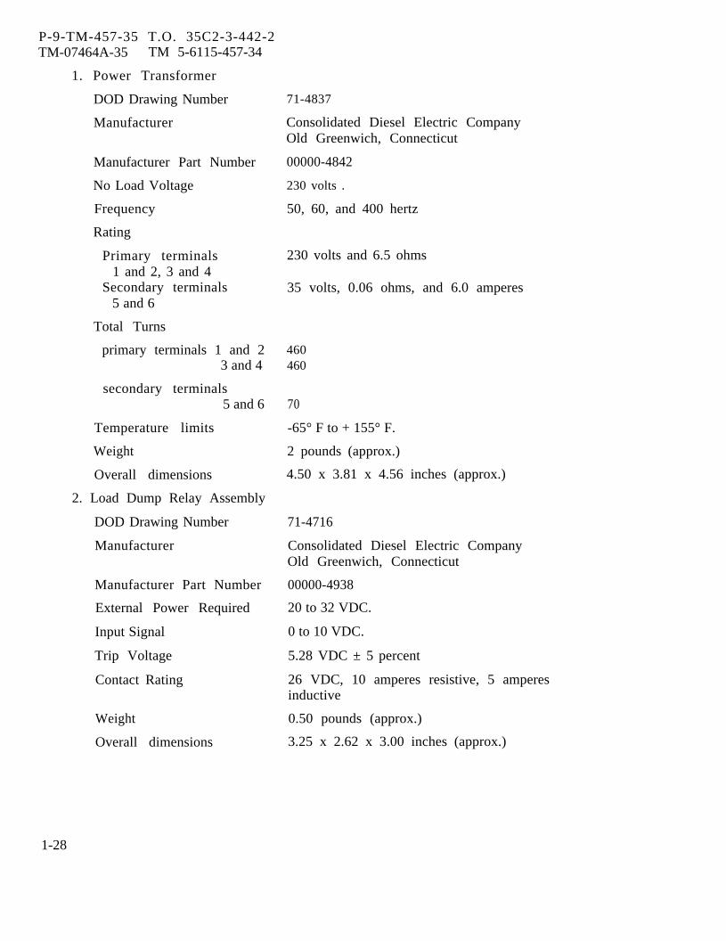
P-9-TM-457-35 T.O. 35C2-3-442-2TM-07464A-35 TM 5-6115-457-34
1. Power Transformer
DOD Drawing Number
Manufacturer
Manufacturer Part Number
No Load Voltage
Frequency
Rating
Primary terminals1 and 2, 3 and 4
Secondary terminals5 and 6
Total Turns
primary terminals 1 and 23 and 4
secondary terminals5 and 6
Temperature limits
Weight
Overall dimensions
2. Load Dump Relay Assembly
DOD Drawing Number
Manufacturer
Manufacturer Part Number
External Power Required
Input Signal
Trip Voltage
Contact Rating
Weight
Overall dimensions
71-4837
Consolidated Diesel Electric CompanyOld Greenwich, Connecticut
00000-4842
230 volts .
50, 60, and 400 hertz
230 volts and 6.5 ohms
35 volts, 0.06 ohms, and 6.0 amperes
460460
70
-65° F to + 155° F.
2 pounds (approx.)
4.50 x 3.81 x 4.56 inches (approx.)
71-4716
Consolidated Diesel Electric CompanyOld Greenwich, Connecticut
00000-4938
20 to 32 VDC.
0 to 10 VDC.
5.28 VDC ± 5 percent
26 VDC, 10 amperes resistive, 5 amperesinductive
0.50 pounds (approx.)
3.25 x 2.62 x 3.00 inches (approx.)
1-28

P-9-TM-457-35 T. O. 35C2-3-442-2TM-07464A-35 TM5-6115-457-34
3. Electrical Heating Element
DOD Drawing Number
Manufacturer
Manufacturer Part Number
Voltage Rating
Power Rating
Watts per Square Inch
Life Expectancy
Skin Temperature
Weight
Overall dimensions
4. Load Contactor
DOD Drawing Number
Manufacturer
Manufacturer Part Number
Contact Arrangement
Contact Rating at 50/60and 400 Hz.
Coil Data
Voltage RatingInput CurrentHolding Current
Temperature Range
Mounting Position
Weight
Overall dimensions
1. REPAIR AND REPLACEMENT
70-4047
General Electric CompanyShelbyville, Indiana
2A838B101
120 volts
1000 watts
7.8 watts
10,000 hours
1, 000° F
2 pounds (approx.)
38.50 x 1.50 x 1.00 inches (approx.)
71-4828
Rowan Controller Co.Westminster, Maryland
2200-EBH 330JA-11
3 pole normally open
42 amperes resistive at 208 volts and 21amperes at 416 volts
24 to 32 VDC4.5 amperes0.9 amperes
-65° F to + 125° F
Vertical only.
1 pound (approx.)
3.15 x 2.50 x 3.75 inches (approx.)
m. TORQUE DATA. ComponentsSTANDARDS. Table 1-1 list manufac- not listed in table 1-2 should be tightened toturer’s dimensions, tolerances, desired standard torque values. Table 1-2clearances, and maximum allowable wear lists components that require specialand clearances. torques.
1-29

P-9-TM-457-35 T.O. 35C2-3-442-2TM-07464A-35 TM 5-6115-457-34
n. TIME STANDARDS. Table 1-3 conditions with highly skilled mechanics,lists the number of man-hours required most of the operations can be accomplishedunder normal conditions to perform the in considerably less time.indicated maintenance and repair for thegenerator sets. Components are listed o. SCHEMATICS AND WIRING DIAGRAMS.under the appropriate functional index. The Figures 1-1 through 1-31 show the schematictimes listed are not intended to be rigid and wiring diagrams for the 50/60 and 400standards, Under adverse conditions, the hertz generator sets, their components andoperations will take longer, but under ideal auxiliaries.
Table 1-1. Repair and Replacement Standards
MANUFACTURER’S MAXIMUMDIM ENSIONS AND ALLOWABLE
TOLERANCES WEAR ANDCOMPONENT IN INCHES DESIRED CLEARANCE CLEARANCE
MIN MAX MIN MAX
tarting Motor Assembly:
Brush length 0.7500 - 0.3750
Thrust washer thickness(Commutator end ofarmature shaft). 0.0312 0.0930 0.0250
Thrust washer thickness(Drive end of armatureshaft). 0.0950 0.0900
Thrust washer thickness(Intermediate bearing) 0.0312 0.0280
Maximum end play ofarmature 0.0300 0.0500
Thrust washer thickness(Outer washers) 0.0650 *
Yoke pin diameter 0.2790 0.2810 0.2740
Yoke bore for pin 0.2820 0.2830 *
Fit of pin in yoke 0.0010L 0.0040L *
Fit of pin in cover 0.0010L 0.0050L *
1-30
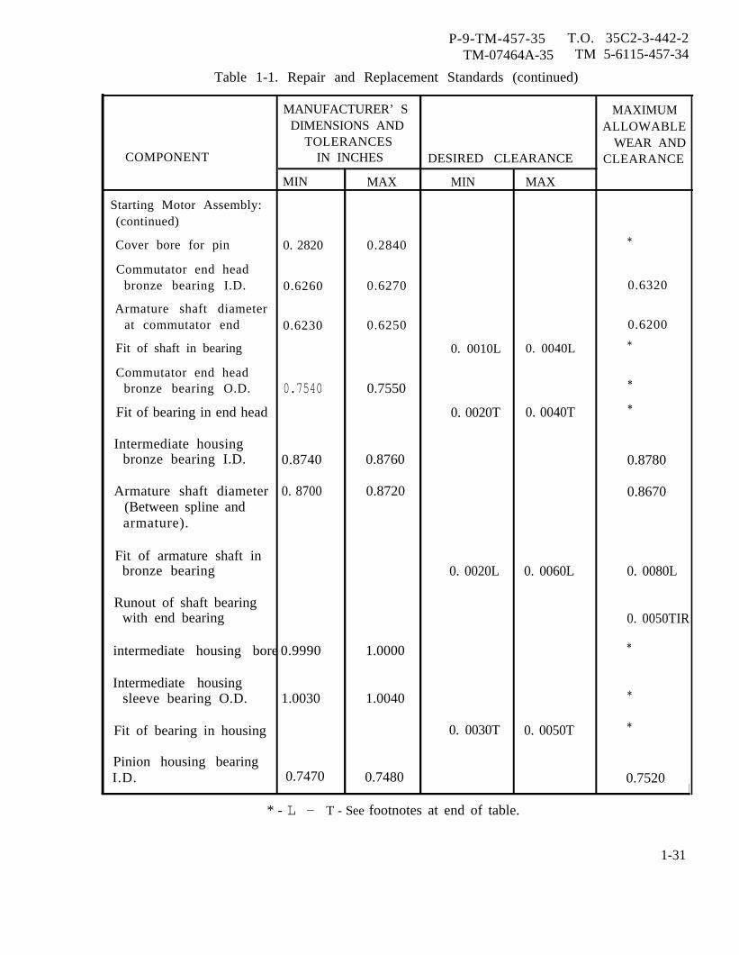
P-9-TM-457-35 T.O. 35C2-3-442-2TM-07464A-35 TM 5-6115-457-34
Table 1-1. Repair and Replacement Standards (continued)
MANUFACTURER’ S MAXIMUMDIMENSIONS AND ALLOWABLE
TOLERANCES WEAR ANDCOMPONENT IN INCHES DESIRED CLEARANCE CLEARANCE
MIN MAX MIN MAX
Starting Motor Assembly:(continued)
Cover bore for pin 0. 2820 0.2840 *
Commutator end headbronze bearing I.D. 0.6260 0.6270 0.6320
Armature shaft diameterat commutator end 0.6230 0.6250 0.6200
Fit of shaft in bearing 0. 0010L 0. 0040L *
Commutator end headbronze bearing O.D. 0.7540 0.7550 *
Fit of bearing in end head 0. 0020T 0. 0040T *
Intermediate housingbronze bearing I.D. 0.8740 0.8760 0.8780
Armature shaft diameter 0. 8700 0.8720 0.8670(Between spline andarmature).
Fit of armature shaft inbronze bearing 0. 0020L 0. 0060L 0. 0080L
Runout of shaft bearingwith end bearing 0. 0050TIR
intermediate housing bore 0.9990 1.0000 *
Intermediate housingsleeve bearing O.D. 1.0030 1.0040 *
Fit of bearing in housing 0. 0030T 0. 0050T *
Pinion housing bearingI.D. 0.7470 0.7480 0.7520
* - L - T - See footnotes at end of table.
1-31
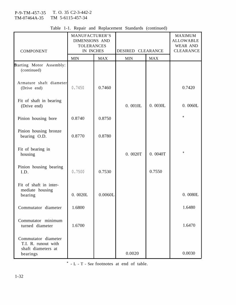
P-9-TM-457-35 T. O. 35 C2-3-442-2TM-07464A-35 TM 5-6115-457-34
Table 1-1. Repair and Replacement Standards (continued)
MANUFACTURER’S MAXIMUMDIMENSIONS AND ALLOWABLE
TOLERANCES WEAR ANDCOMPONENT IN INCHES DESIRED CLEARANCE CLEARANCE
MIN MAX MIN MAX
tarting Motor Assembly:(continued)
Armature shaft diameter(Drive end) 0.7450 0.7460 0.7420
Fit of shaft in bearing(Drive end) 0. 0010L 0. 0030L 0. 0060L
Pinion housing bore 0.8740 0.8750 *
Pinion housing bronzebearing O.D. 0.8770 0.8780
Fit of bearing inhousing 0. 0020T 0. 0040T *
Pinion housing bearingI.D. 0.7500 0.7530 0.7550
Fit of shaft in inter-mediate housingbearing 0. 0020L 0.0060L 0. 0080L
Commutator diameter 1.6800 1.6480
Commutator minimumturned diameter 1.6700 1.6470
Commutator diameterT.I. R. runout withshaft diameters atbearings 0.0020 0.0030
* - L - T - See footnotes at end of table.
1-32
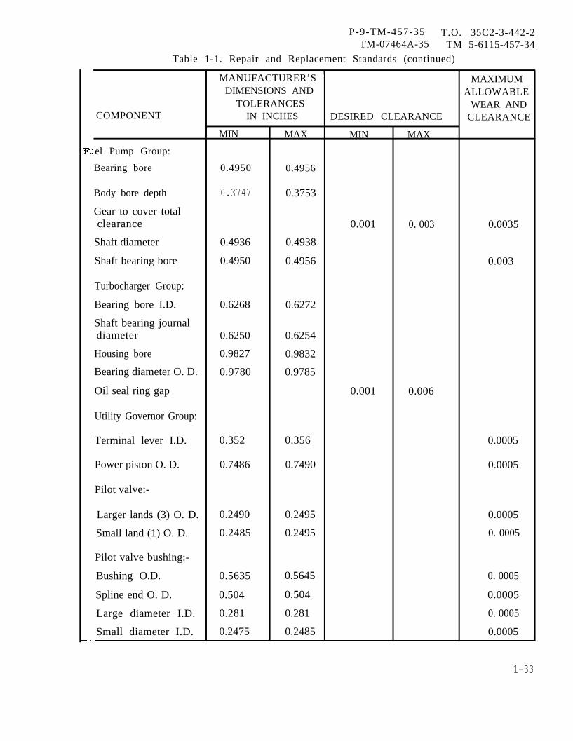
P-9-TM-457-35 T.O. 35C2-3-442-2TM-07464A-35 TM 5-6115-457-34
Table 1-1. Repair and Replacement Standards (continued)
MANUFACTURER’S1
MAXIMUMDIMENSIONS AND ALLOWABLE
TOLERANCES WEAR ANDCOMPONENT IN INCHES DESIRED CLEARANCE CLEARANCE
MIN MAX MIN MAX
el Pump Group:
Bearing bore 0.4950 0.4956
Body bore depth 0.3747 0.3753
Gear to cover totalclearance 0.001 0. 003 0.0035
Shaft diameter 0.4936 0.4938
Shaft bearing bore 0.4950 0.4956 0.003
Turbocharger Group:
Bearing bore I.D. 0.6268 0.6272
Shaft bearing journaldiameter 0.6250 0.6254
Housing bore 0.9827 0.9832
Bearing diameter O. D. 0.9780 0.9785
Oil seal ring gap 0.001 0.006
Utility Governor Group:
Terminal lever I.D. 0.352 0.356 0.0005
Power piston O. D. 0.7486 0.7490 0.0005
Pilot valve:-
Larger lands (3) O. D. 0.2490 0.2495 0.0005
Small land (1) O. D. 0.2485 0.2495 0. 0005
Pilot valve bushing:-
Bushing O.D. 0.5635 0.5645 0. 0005
Spline end O. D. 0.504 0.504 0.0005
Large diameter I.D. 0.281 0.281 0. 0005
Small diameter I.D. 0.2475 0.2485 0.0005
1-33

P-9-TM-457-35 T.O. 35 C2-3-442-2TM-07464A-35 TM 5-6115-457-34
Table 1-1. Repair and Replacement Standards (continued)
MANUFACTURER’S MAXIMUMDIMENSIONS AND ALLOWABLE
TOLERANCES WEAR ANDCOMPONENT IN INCHES DESIRED CLEARANCE CLEARANCE
MIN MAX MIN MAX
Utility Governor Group:(continued)
Gearlands (3) O.D. 0.5675 0.5685 0.0005
Bushing (2) I.D. 0.376 0.377 0.0005
Speed adjusting shaft O. D. 0.373 0.3735 0.001
Terminal shaft O.D. 0.373 0.374 0.001
Relief valve sleeve I.D. 0. 187 0.188 0.0005
Relief valve sleeve O.D. 0.4370 0.4373 0.0005
Idler gear stud O.D. 0.3130 0.3133 0.0005
Idler gear O.D. 1.120 1.216 0.0005
Idler gear 1. D.(measured over 0.148diameter pins) 0.3140 0.3150
Drive gear O. D. 1.120 1.126 0.001
Relief valve plunger O. D. 0.182 0.184 0.0005
Fuel Injection Group:
Rack bearing bore 0.5007 0.5013
Fuel rack diameter 0.4983 0.4987
Fuel rack bearingclearance 0.005
Pump plunger length 2.5931 2.5937 2.5881
Cam shaft bearing bore 1.875 1.876
Camshaft bearingjournal diameter 1.8725 1.8735
Camshaft bearingclearance 0.010
Accessory Drive Group:
Idler gear end clearance 0.004 0.016 0.018
Idler gear bearing bore 1.376 1.381
Idler gear shaft diameter 1.3736 1.3746 0.009
1-34
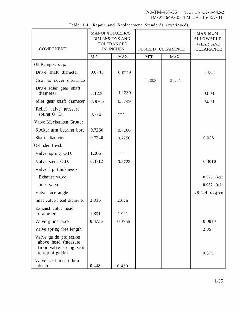
P-9-TM-457-35 T.O. 35 C2-3-442-2TM-07464A-35 TM 5-6115-457-34
Table 1-1. Repair and Replacement Standards (continued)
COMPONENT
Oil Pump Group:
Drive shaft diameter
Gear to cover clearance
Drive idler gear shaftdiameter
Idler gear shaft diameter
Relief valve pressurespring O. D.
Valve Mechanism Group:
Rocker arm bearing bore
Shaft diameter
Cylinder Head:
Valve spring O.D.
Valve stem O.D.
Valve lip thickness:-
Exhaust valve
Inlet valve
Valve face angle
Inlet valve head diameter
Exhaust valve headdiameter
Valve guide bore
Valve spring free length
VaIve guide projectionabove head (measurefrom valve spring seatto top of guide)
Valve seat insert boredepth
MANUFACTURER’SDIM ENSIONS AND
TOLERANCESIN INCHES
MIN
0.8745
1.1220
0. 8745
0.770
0.7260
0.7240
1.386
0.3712
2.015
1.891
0.3736
0.448
MAX
0.8749
1.1230
0.8749
- - -
0.7266
0.7250
- - -
0.3722
2.025
1.901
0.3756
0.450
DESIRED CLEARANCE
0.002
MAX
0.004
MAXIMUMALLOWABLE
WEAR ANDCLEARANCE
0.005
0.008
0.008
0.008
0.0010
0.070 (rein
0.057 (rein
29-1/4 degree
0.0010
2.05
0.875
1-35

P-9-TM-457-35 T.O. 35 C2-3-442-2TM-07464A-35 TM 5-6115-457-34
Table 1-1. Repair and Replacement Standards (continued)
COMPONENT
Cylinder Head: (continued)
Inlet valve seat insertdiameter
Bore in head for seatinsert
Exhaust valve seat insert
Bore in head for seatins ert
Valve seat face angle
Exhaust valve seat width
Inlet valve seat width
Maximum permissibleclosed valve projection:
Inlet valve
Exhaust valve
Inlet valve seat facediameter
Exhaust valve seat facediameter
Angle to grind insert seaface to reduce maximumseat diameter
Lifter diameter
Lifter bore in block
Camshaft Group:
Camshaft bearing journaldiameter
Camshaft bearing to shaftclearance
Camshaft end clearance
MANUFACTURER'SDIMENSIONS AND
TOLERANCESIN INCHES
MIN
2. 1280
2. 1250
2. 0030
2. 0000
1.3100
1.3135
2.3105
MAX
2.1290
2.1260
2.0040
2. 0010
1.3110
1.3155
2.3115
DESIRED CLEARANCE
MIN
0.002
0.004
MAX
0.006
0.010
MAXIMUMALLOWABLEWEAR AND
CLEARANCE
30 degrees
0.076
0.076
0.134
0.154
1.934 (Min)1.984 (Max
1.810 (Min)1.860 (Max
15 degrees
0.012
0.008
0.025
1-36

P-9-TM-457-35 T.0. 35C2-3-442-2TM-07464A-35 TM 5-6115-457-34
Table 1-1. Repair and Replacemment Standards (continued)
MANUFACTURER’S MAXIMUMDIMENSIONS AND ALLOWABLE
TOLERANCES WEAR ANDCOMPONENT IN INCHES DESIRED CLEARANCE CLEARANCE
MIN MAX MIN MAX
Connecting Rods:
Pin bearing bore 1.7009 1.7012 0.006
Center to center length 9.594 9.596
Bore in rod forbearing 3.2495 3.2505
Pin diameter 1.6997 1.7000
Crankshaft journalbearing bore 3.002 3.006 0.010
Piston Group:
Top ring to grooveclearance 0.0028 0.0046 0.006
Intermediate ring togroove clearance 0.0023 0.0041 0.006
Oil control ring to grooveclearance 0.0015 0.0033 0.006
Pin bore 1.6999 1.7001 0.006
Ring gap measured inunworn portion of linerbore size 4.750 in. **
Top ring 0.017 0.023
Intermediate ring 0.017 0.023
Oil control ring 0.013 0.023
‘*Increase in ring gapfor each 0.001 inincrease in linerbore 0.003
1-37
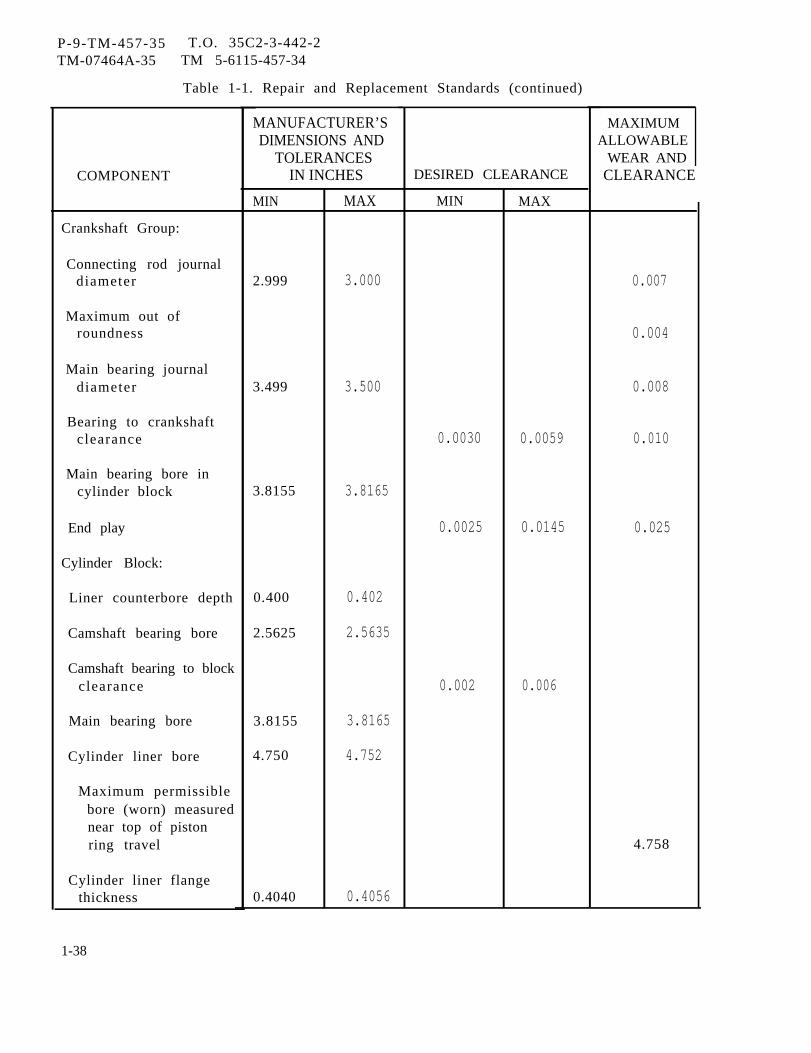
P-9-TM-457-35 T.O. 35C2-3-442-2TM-07464A-35 TM 5-6115-457-34
Table 1-1. Repair and Replacement Standards (continued)
COMPONENT
Crankshaft Group:
Connecting rod journaldiameter
Maximum out ofroundness
Main bearing journaldiameter
Bearing to crankshaftclearance
Main bearing bore incylinder block
End play
Cylinder Block:
Liner counterbore depth
Camshaft bearing bore
Camshaft bearing to blockclearance
Main bearing bore
Cylinder liner bore
Maximum permissiblebore (worn) measurednear top of pistonring travel
Cylinder liner flangethickness
1-38
MANUFACTURER’SDIMENSIONS AND
TOLERANCESIN INCHES
MIN
2.999
3.499
3.8155
0.400
2.5625
3.8155
4.750
0.4040
MAX
3.000
3.500
3.8165
0.402
2.5635
3.8165
4.752
0.4056
DESIRED CLEARANCE
MIN
0.0030
0.0025
0.002
MAX
0.0059
0.0145
0.006
MAXIMUMALLOWABLE
WEAR ANDCLEARANCE
0.007
0.004
0.008
0.010
0.025
4.758
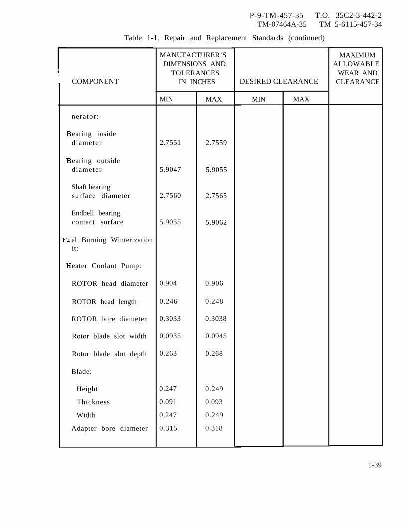
P-9-TM-457-35 T.O. 35C2-3-442-2TM-07464A-35 TM 5-6115-457-34
Table 1-1. Repair and Replacement Standards (continued)
COMPONENT
nerator:-
earing insidediameter
earing outsidediameter
Shaft bearingsurface diameter
Endbell bearingcontact surface
el Burning Winterizationit:
eater Coolant Pump:
ROTOR head diameter
ROTOR head length
ROTOR bore diameter
Rotor blade slot width
Rotor blade slot depth
Blade:
Height
Thickness
Width
Adapter bore diameter
MANUFACTURER’SDIMENSIONS AND
TOLERANCESIN INCHES
MIN
2.7551
5.9047
2.7560
5.9055
0.904
0.246
0.3033
0.0935
0.263
0.247
0.091
0.247
0.315
MAX
2.7559
5.9055
2.7565
5.9062
0.906
0.248
0.3038
0.0945
0.268
0.249
0.093
0.249
0.318
DESIRED CLEARANCE
MIN MAX
MAXIMUMALLOWABLE
WEAR ANDCLEARANCE
1-39
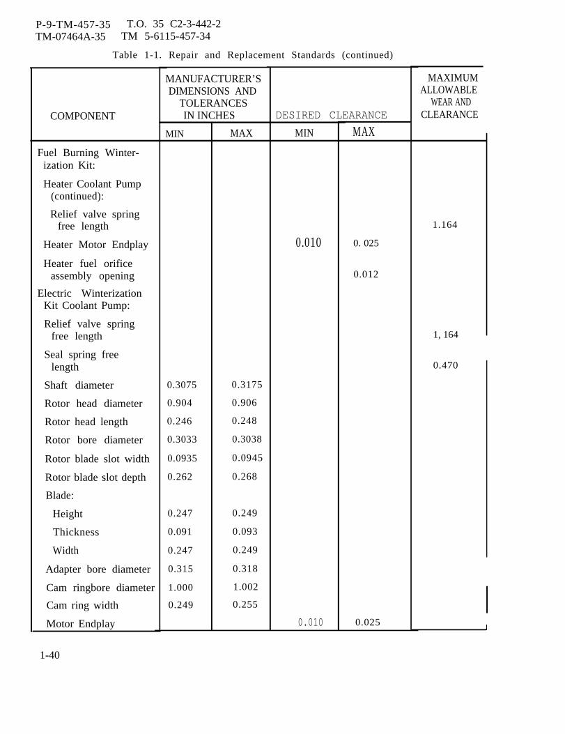
P-9-TM-457-35 T.O. 35 C2-3-442-2TM-07464A-35 TM 5-6115-457-34
Table 1-1. Repair and Replacement Standards (continued)
COMPONENT
Fuel Burning Winter-ization Kit:
Heater Coolant Pump(continued):
Relief valve springfree length
Heater Motor Endplay
Heater fuel orificeassembly opening
Electric WinterizationKit Coolant Pump:
Relief valve springfree length
Seal spring freelength
Shaft diameter
Rotor head diameter
Rotor head length
Rotor bore diameter
Rotor blade slot width
Rotor blade slot depth
Blade:
Height
Thickness
Width
Adapter bore diameter
Cam ringbore diameter
Cam ring width
Motor Endplay
1-40
MANUFACTURER’SDIMENSIONS AND
TOLERANCESIN INCHES
MIN
0.3075
0.904
0.246
0.3033
0.0935
0.262
0.247
0.091
0.247
0.315
1.000
0.249
MAX
0.3175
0.906
0.248
0.3038
0.0945
0.268
0.249
0.093
0.249
0.318
1.002
0.255
DESIRED CLEARANCE
MIN
0.010
0.010
MAX
0. 025
0.012
0.025
MAXIMUMALLOWABLE
WEAR ANDCLEARANCE
1.164
1, 164
0.470
I
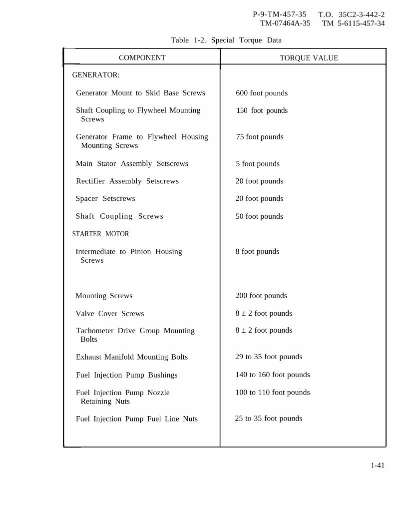
P-9-TM-457-35 T.O. 35C2-3-442-2TM-07464A-35 TM 5-6115-457-34
Table 1-2. Special Torque Data
COMPONENT TORQUE VALUE
GENERATOR:
Generator Mount to Skid Base Screws 600 foot pounds
Shaft Coupling to Flywheel Mounting 150 foot poundsScrews
Generator Frame to Flywheel Housing 75 foot poundsMounting Screws
Main Stator Assembly Setscrews 5 foot pounds
Rectifier Assembly Setscrews 20 foot pounds
Spacer Setscrews 20 foot pounds
Shaft Coupling Screws 50 foot pounds
STARTER MOTOR
Intermediate to Pinion Housing 8 foot poundsScrews
Mounting Screws 200 foot pounds
Valve Cover Screws 8 ± 2 foot pounds
Tachometer Drive Group Mounting 8 ± 2 foot poundsBolts
Exhaust Manifold Mounting Bolts 29 to 35 foot pounds
Fuel Injection Pump Bushings 140 to 160 foot pounds
Fuel Injection Pump Nozzle 100 to 110 foot poundsRetaining Nuts
Fuel Injection Pump Fuel Line Nuts 25 to 35 foot pounds
1-41
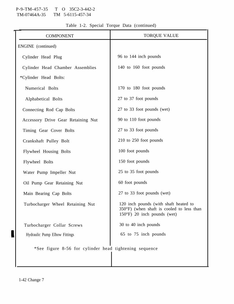
P-9-TM-457-35 T O 35C2-3-442-2TM-07464A-35 TM 5-6115-457-34
Table 1-2. Special Torque Data (continued)
COMPONENT TORQUE VALUE
ENGINE (continued)
Cylinder Head Plug 96 to 144 inch pounds
Cylinder Head Chamber Assemblies 140 to 160 foot pounds
*Cylinder Head Bolts:
Numerical Bolts 170 to 180 foot pounds
Alphabetical Bolts 27 to 37 foot pounds
Connecting Rod Cap Bolts 27 to 33 foot pounds (wet)
Accessory Drive Gear Retaining Nut 90 to 110 foot pounds
Timing Gear Cover Bolts 27 to 33 foot pounds
Crankshaft Pulley Bolt 210 to 250 foot pounds
Flywheel Housing Bolts 100 foot pounds
Flywheel Bolts 150 foot pounds
Water Pump Impeller Nut 25 to 35 foot pounds
Oil Pump Gear Retaining Nut 60 foot pounds
Main Bearing Cap Bolts 27 to 33 foot pounds (wet)
Turbocharger Wheel Retaining Nut 120 inch pounds (with shaft heated to350°F) (when shaft is cooled to less than150°F) 20 inch pounds (wet)
Turbocharger Collar Screws 30 to 40 inch pounds
Hydraulic Pump Elbow Fittings 65 to 75 inch pounds
*See figure 8-56 for cylinder head tightening sequence
1-42 Change 7
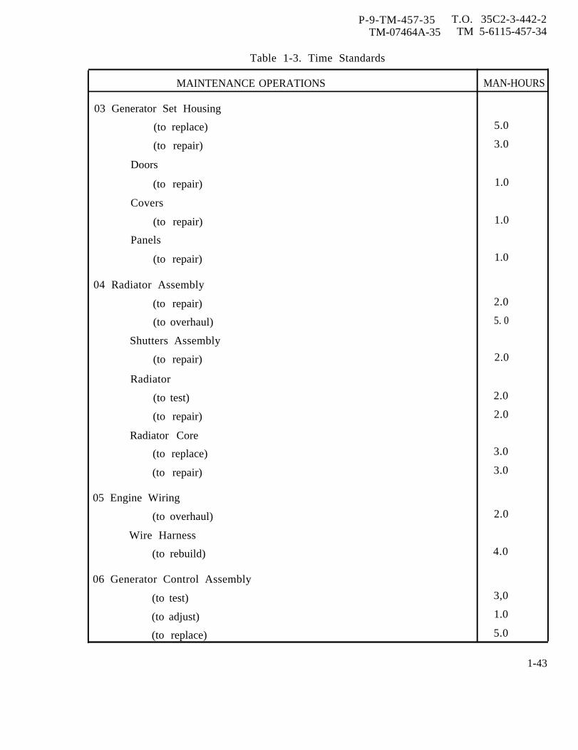
P-9-TM-457-35 T.O. 35C2-3-442-2TM-07464A-35 TM 5-6115-457-34
Table 1-3. Time Standards
MAINTENANCE OPERATIONS MAN-HOURS
03 Generator Set Housing
(to replace) 5.0
(to repair) 3.0
Doors
(to repair) 1.0
Covers
(to repair) 1.0
Panels
(to repair) 1.0
04 Radiator Assembly
(to repair) 2.0
(to overhaul) 5. 0
Shutters Assembly
(to repair) 2.0
Radiator
(to test) 2.0
(to repair) 2.0
Radiator Core
(to replace) 3.0
(to repair) 3.0
05 Engine Wiring
(to overhaul) 2.0
Wire Harness
(to rebuild) 4.0
06 Generator Control Assembly
(to test) 3,0
(to adjust) 1.0
(to replace) 5.0
1-43
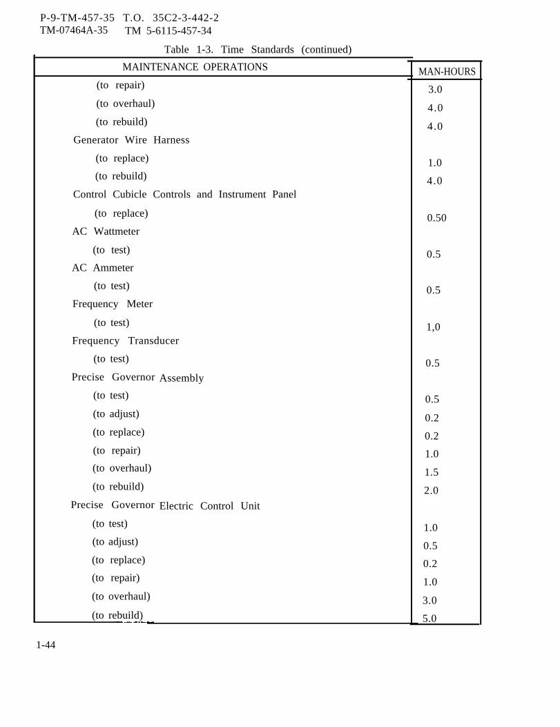
P-9-TM-457-35 T.O. 35C2-3-442-2TM-07464A-35 TM 5-6115-457-34
Table 1-3. Time Standards (continued)
MAINTENANCE OPERATIONS
(to repair)
(to overhaul)
(to rebuild)
Generator Wire Harness
(to replace)
(to rebuild)
Control Cubicle Controls and Instrument Panel
(to replace)
AC Wattmeter
(to test)
AC Ammeter
(to test)
Frequency Meter
(to test)
Frequency Transducer
(to test)
Precise Governor
(to test)
(to adjust)
(to replace)
(to repair)
(to overhaul)
(to rebuild)
Precise Governor
(to test)
(to adjust)
(to replace)
(to repair)
(to overhaul)
(to rebuild)
Assembly
Electric Control Unit
MAN-HOURS
3.0
4.0
4.0
1.0
4.0
0.50
0.5
0.5
1,0
0.5
0.5
0.2
0.2
1.0
1.5
2.0
1.0
0.5
0.2
1.0
3.0
5.0
1-44
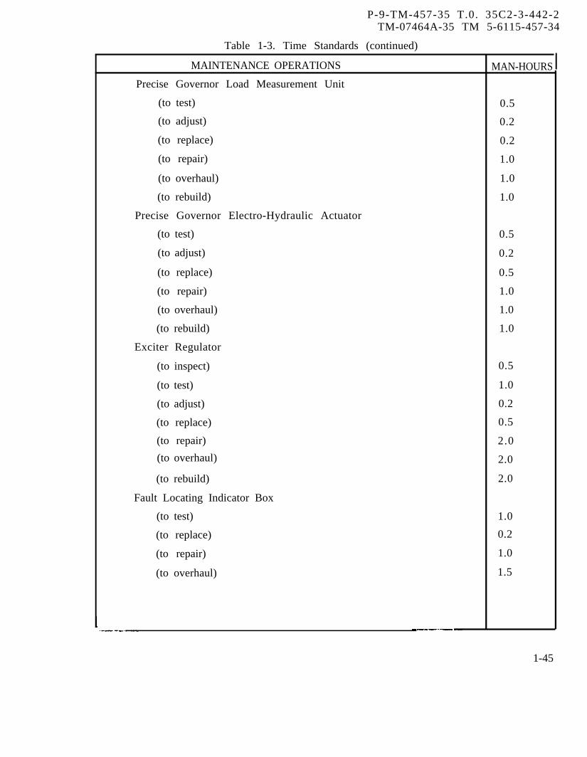
P-9-TM-457-35 T.0. 35C2-3-442-2TM-07464A-35 TM 5-6115-457-34
Table 1-3. Time Standards (continued)
MAINTENANCE OPERATIONS MAN-HOURS
Precise Governor Load Measurement Unit
(to test) 0.5
(to adjust) 0.2
(to replace) 0.2
(to repair) 1.0
(to overhaul) 1.0
(to rebuild) 1.0
Precise Governor Electro-Hydraulic Actuator
(to test) 0.5
(to adjust) 0.2
(to replace) 0.5
(to repair) 1.0
(to overhaul) 1.0
(to rebuild) 1.0
Exciter Regulator
(to inspect) 0.5
(to test) 1.0
(to adjust) 0.2
(to replace) 0.5
(to repair) 2.0
(to overhaul) 2.0
(to rebuild) 2.0
Fault Locating Indicator Box
(to test) 1.0
(to replace) 0.2
(to repair) 1.0
(to overhaul) 1.5
1-45

P-9-TM-457-35 T.O. 35C2-3-442-2TM-07464A-35 TM 5-6115-457-34
Table 1-3. Time Standards (continued)
MAINTENANCE OPERATIONS MAN-HOURSDC Circuit Breaker Box
(to test) 0.2(to replace) 0.1(to repair) 0.5(to overhaul) 0.5
Tactical Relay Box
(to replace) 0.2
(to repair) 2.0(to overhaul) 2.0
Over Voltage Relay
(to test) 0.5(to adjust) 0.2(to replace) 0.2(to repair) 1.0(to overhaul) 1.0
Reverse Power Relay
(to test) 0.2
(to adjust) 0.2
(to replace) 0.2(to repair) 1.0(to overhaul) 1.0
Short Circuit Relay
(to test) 0.2
(to adjust) 0.2(to replace) 0.2(to repair) 1.0(to overhaul) 1.0
1-46

P-9-TM-457-35 T.O. 35C2-3-442-2TM-07464A-35 TM 5-6115-457-34
Table 1-3. Time Standards (continued)
MAINTENANCE OPERATIONS MAN-HOURS
Precise Relay Box
(to replace) 0.5
(to repair) 2.0
(to overhaul) 2.0
Under Voltage Relay
(to test) 0.2
(to adjust) 0.2
(to replace) 0.2
(to repair) 1.0
(to overhaul) 1.0
Under Frequency Relay (50/60 Hertz)
(to test) 0.5
(to adjust) 0.2
(to replace) 0.2
(to repair) 1.0
(to overhaul) 1.0
Permissive Paralleling Relay
(to test) 0. 5
(to adjust) 0.2
(to replace) 0.2
(to repair) 1.0
(to overhaul) 1.0
Mode I Relay Box
(to test) 1.0
(to adjust) 0.2
(to replace) 0.5
(to repair) 2.0
(to overhaul) 2.0
1-47
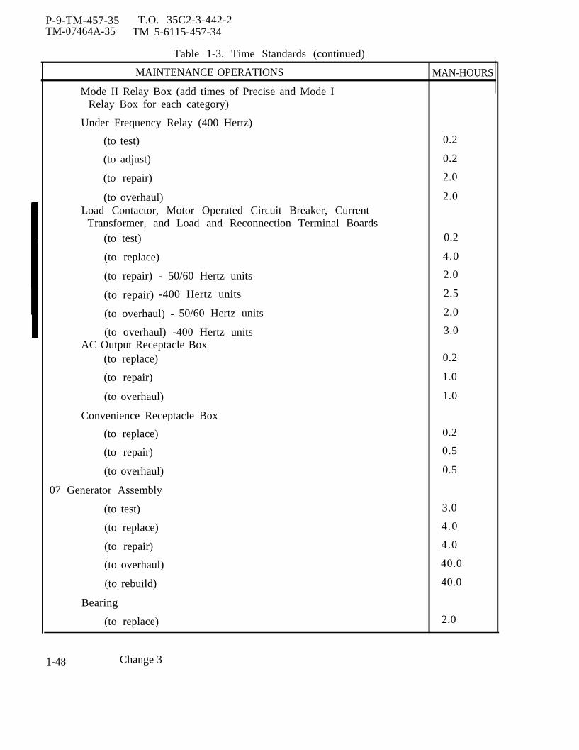
P-9-TM-457-35 T.O. 35C2-3-442-2TM-07464A-35 TM 5-6115-457-34
Table 1-3. Time Standards (continued)
MAINTENANCE OPERATIONS MAN-HOURS
Mode II Relay Box (add times of Precise and Mode IRelay Box for each category)
Under Frequency Relay (400 Hertz)
(to test) 0.2
(to adjust) 0.2
(to repair) 2.0
(to overhaul) 2.0Load Contactor, Motor Operated Circuit Breaker, Current
Transformer, and Load and Reconnection Terminal Boards(to test) 0.2
(to replace) 4.0
(to repair) - 50/60 Hertz units 2.0
(to repair) -400 Hertz units 2.5
(to overhaul) - 50/60 Hertz units 2.0
(to overhaul) -400 Hertz units 3.0AC Output Receptacle Box
(to replace) 0.2
(to repair) 1.0
(to overhaul) 1.0
Convenience Receptacle Box
(to replace) 0.2
(to repair) 0.5
(to overhaul) 0.5
07 Generator Assembly
(to test) 3.0
(to replace) 4.0
(to repair) 4.0
(to overhaul) 40.0
(to rebuild) 40.0
Bearing
(to replace) 2.0
1-48 Change 3
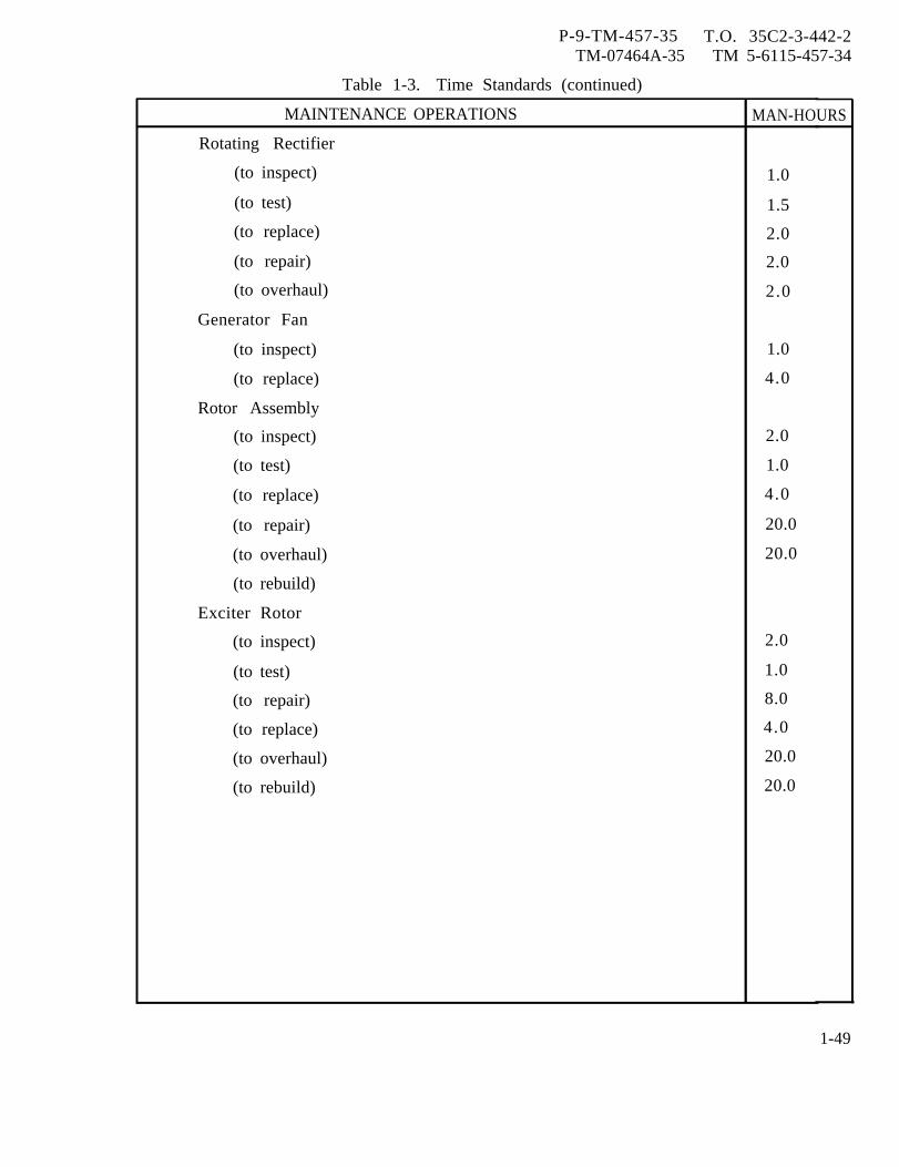
P-9-TM-457-35 T.O. 35C2-3-442-2TM-07464A-35 TM 5-6115-457-34
Table 1-3. Time Standards (continued)
MAINTENANCE OPERATIONS MAN-HOURS
Rotating Rectifier
(to inspect) 1.0
(to test) 1.5
(to replace) 2.0
(to repair) 2.0
(to overhaul) 2.0
Generator Fan
(to inspect) 1.0
(to replace) 4.0
Rotor Assembly
(to inspect) 2.0
(to test) 1.0
(to replace) 4.0
(to repair) 20.0
(to overhaul) 20.0
(to rebuild)
Exciter Rotor
(to inspect) 2.0
(to test) 1.0
(to repair) 8.0
(to replace) 4.0
(to overhaul) 20.0
(to rebuild) 20.0
1-49

P-9-TM-457-35 T. O. 35C2-3-442-2TM-07464A-35 TM 5-6115-457-34
Table 1-3. Time Standards (continued),
MAINTENANCE OPERATIONS MAN-HOURS
Main Stator Assembly
(to inspect) 1.0
(to test) 1.0
(to replace) 4.0
(to repair) 20.0
(to overhaul) 20.0
(to rebuild) 20.0
Exciter Stator
(to inspect) 1.0
(to test) 1.0
(to replace) 4.0
(to repair) 20.0
(to overhaul) 20.0
(to rebuild) 20.0
08 Engine
Engine Assembly
(to replace) 6.0
(to repair) 15.0
(to overhaul) 30.0
(to rebuild) 106
1-50
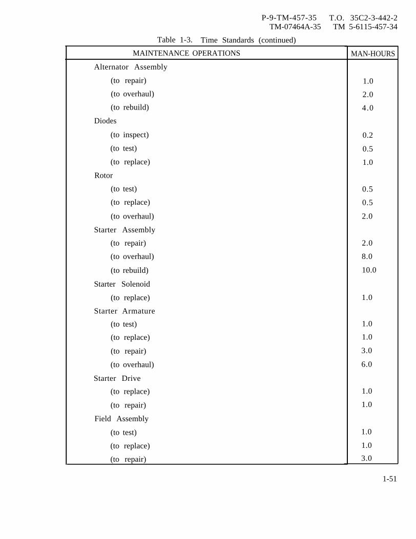
P-9-TM-457-35 T.O. 35C2-3-442-2TM-07464A-35 TM 5-6115-457-34
Table 1-3. Time Standards (continued)
MAINTENANCE OPERATIONS
Alternator Assembly
(to repair)
(to overhaul)
(to rebuild)
Diodes
(to inspect)
(to test)
(to replace)
Rotor
(to test)
(to replace)
(to overhaul)
Starter Assembly
(to repair)
(to overhaul)
(to rebuild)
Starter Solenoid
(to replace)
Starter Armature
(to test)
(to replace)
(to repair)
(to overhaul)
Starter Drive
(to replace)
(to repair)
Field Assembly
(to test)
(to replace)
(to repair)
MAN-HOURS
1.0
2.0
4.0
0.2
0.5
1.0
0.5
0.5
2.0
2.0
8.0
10.0
1.0
1.0
1.0
3.0
6.0
1.0
1.0
1.0
1.0
3.0
1-51

P-9-TM-457-35 T.O. 35C2-3-442-2TM-07464A-35 TM 5-6115-457-34
Table 1-3. Time Standards (continued)
MAINTENANCE OPERATIONS
Fan
Day
Mounting Group
(to replace)
(to repair)
Tank Assembly
(to adjust)
(to repair)
Over speed Governor Switch
(to adjust)
(to repair)
(to overhaul)
(to rebuild)
Tachometer Drive
(to replace)
(to repair)
Fuel Pump Group
(to replace)
(to repair)
Turbocharger Group
(to repair)
(to overhaul)
(to rebuild)
Oil Cooler Group
(to replace)
(to repair)
Water Pump Group
(to repair)
MAN-HOURS
0.4
0.1
0.5
1.0
0.5
1,0
2.0
2.0
0.2
1.0
0.4
0.4
2.4
2.5
3.3
2.0
4.0
1.2
1-52
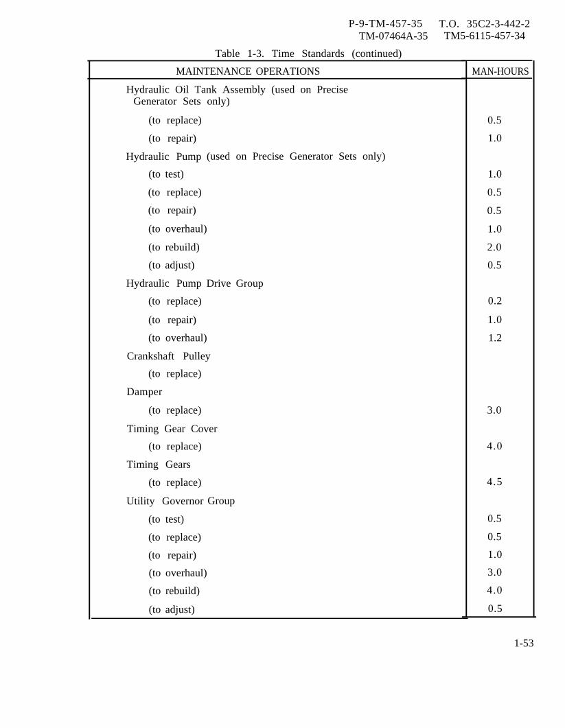
P-9-TM-457-35 T.O. 35C2-3-442-2TM-07464A-35 TM5-6115-457-34
Table 1-3. Time Standards (continued)
MAINTENANCE OPERATIONS
Hydraulic Oil Tank Assembly (used on PreciseGenerator Sets only)
(to replace)
(to repair)
Hydraulic Pump
(to test)
(to replace)
(to repair)
(to overhaul)
(to rebuild)
(to adjust)
Hydraulic Pump
(to replace)
(to repair)
(used on Precise Generator Sets only)
Drive Group
(to overhaul)
Crankshaft Pulley
(to replace)
Damper
(to replace)
Timing Gear Cover
(to replace)
Timing Gears
(to replace)
Utility Governor
(to test)
(to replace)
(to repair)
Group
(to overhaul)
(to rebuild)
(to adjust)
MAN-HOURS
0.5
1.0
1.0
0.5
0.5
1.0
2.0
0.5
0.2
1.0
1.2
3.0
4.0
4.5
0.5
0.5
1.0
3.0
4.0
0.5
1-53
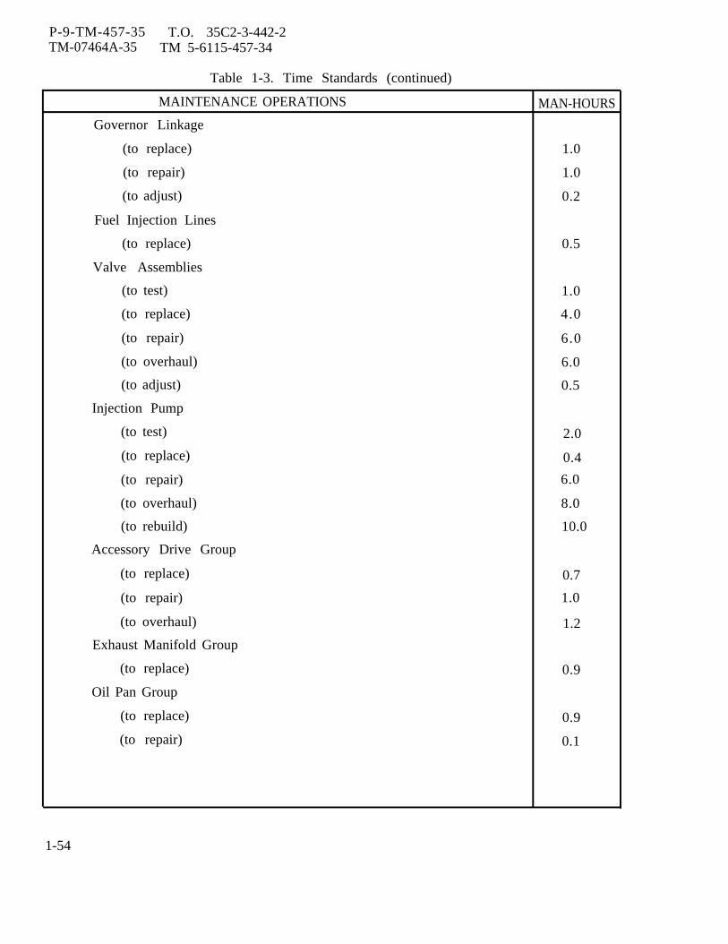
P-9-TM-457-35 T.O. 35C2-3-442-2TM-07464A-35 TM 5-6115-457-34
Table 1-3. Time Standards (continued)
MAINTENANCE OPERATIONS MAN-HOURS
Governor Linkage
(to replace) 1.0
(to repair) 1.0
(to adjust) 0.2
Fuel Injection Lines
(to replace) 0.5
Valve Assemblies
(to test) 1.0
(to replace) 4.0
(to repair) 6.0
(to overhaul) 6.0
(to adjust) 0.5
Injection Pump
(to test) 2.0
(to replace) 0.4
(to repair) 6.0
(to overhaul) 8.0
(to rebuild) 10.0
Accessory Drive Group
(to replace) 0.7
(to repair) 1.0
(to overhaul) 1.2
Exhaust Manifold Group
(to replace) 0.9
Oil Pan Group
(to replace) 0.9
(to repair) 0.1
1-54

P-9-TM-457-35 T.O. 35C2-3-442-2TM-07464A-35 TM 5-6115-457-34
Table 1-3. Time Standards (continued)
MAINTENANCE OPERATIONS MAN- HOURS
Oil Pump Group
(to test) 0.3
(to replace) 1.0
(to repair) 1.5
Valve Mechanism Group
(to replace) 0.5
(to repair) 0.8
Arm Assemblies
(to replace) 0.5
(to adjust) 0.6
Push Rods
(to replace) 0.5
Cylinder Head Group
(to replace) 5.0
(to repair) 2.0
(to overhaul) 4.0
(to rebuild) 4.0
Intake and Exhaust Valves
(to test) 0.5
(to replace) 1.6
(to repair) 2.0
Valve Springs
(to test) 1.0
(to replace) 1.6
Intake and Exhaust Valve Inserts
(to replace) 1.2
Valve Guides
(to replace) 2.4
Flywheel and Flywheel Housing Group
(to replace) 2.0
1-55

P-9-TM-457-35 T.0. 35C2-3-442-2TM-07464A-35 TM 5-6115-457-34
Table 1-3. Time Standards (continued)
MAINTENANCE OPERATIONS
Flywheel
(to replace)
Flywheel Ring Gear
(to replace)
Flywheel Housing
(to replace)
Camshaft Group
(to replace)
Connecting Rods
(to replace)
Connecting Rod
(to replace)
Rod Bearings
(to replace)
Piston Pins
(to replace)
Piston Rings
(to replace)
and Pistons Group
Crankshaft Group
(to replace)
Cylinder. Block
(to replace)
Cylinder Sleeves
(to replace)
and Main
Fuel Burning Winterization Kit
(to repair)
(to overhaul)
Heater Control Assembly
(to repair)
Bearings
(Regular)
0.3
0.9
1.7
7.0
6.0
0.2
0.4
0.2
0.5
5.0
48.0
0.5
1.0
2.0
0.5
1-56
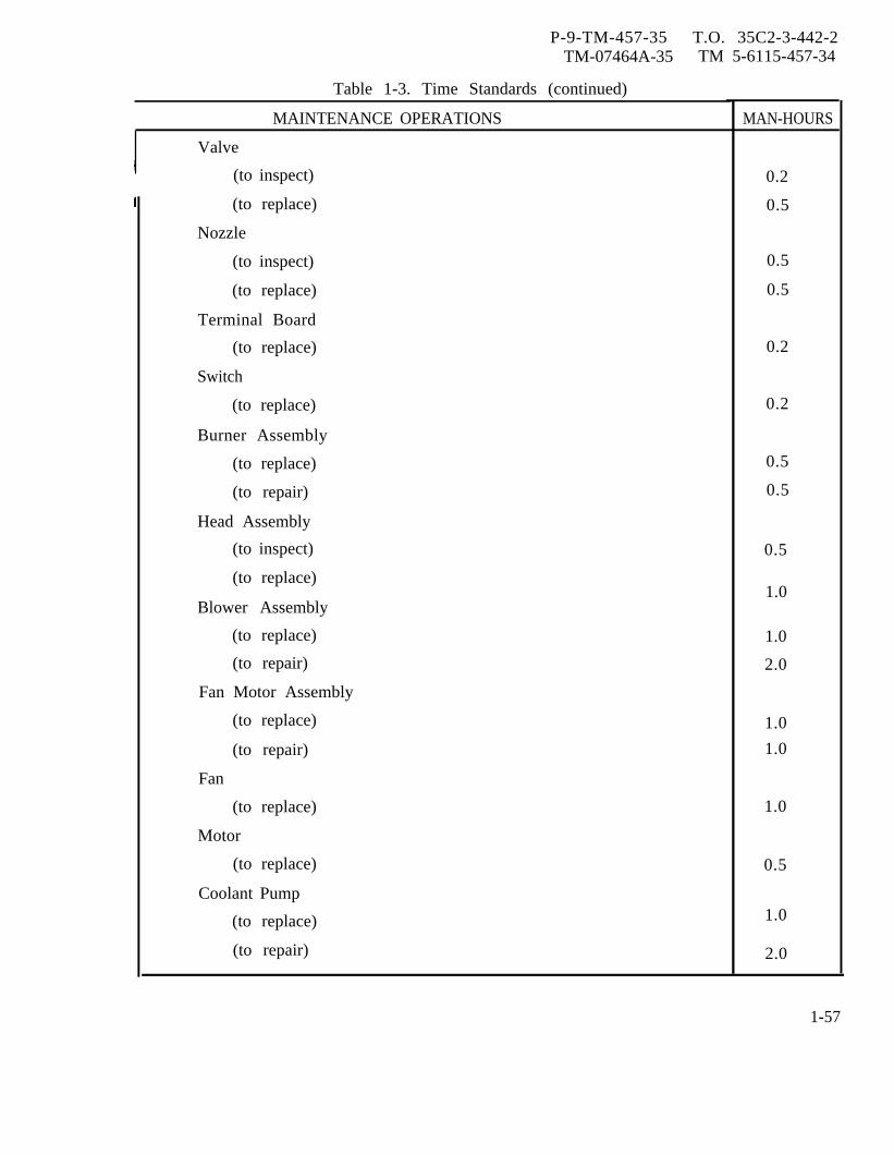
P-9-TM-457-35 T.O. 35C2-3-442-2TM-07464A-35 TM 5-6115-457-34
Table 1-3. Time Standards (continued)
MAINTENANCE OPERATIONS
Valve
(to inspect)
(to replace)
Nozzle
(to inspect)
(to replace)
Terminal Board
(to replace)
Switch
(to replace)
Burner Assembly
(to replace)
(to repair)
Head Assembly
(to inspect)
(to replace)
Blower Assembly
(to replace)
(to repair)
Fan Motor Assembly
(to replace)
(to repair)
Fan
(to replace)
Motor
(to replace)
Coolant Pump
(to replace)
(to repair)
MAN-HOURS
0.2
0.5
0.5
0.5
0.2
0.2
0.5
0.5
0.5
1.0
1.0
2.0
1.0
1.0
1.0
0.5
1.0
2.0
1-57
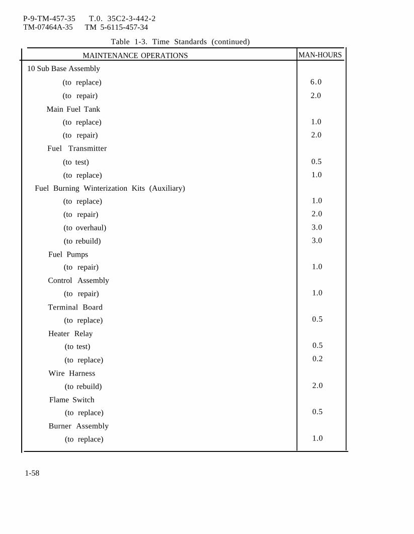
P-9-TM-457-35 T.0. 35C2-3-442-2TM-07464A-35 TM 5-6115-457-34
Table 1-3. Time Standards (continued)
MAINTENANCE OPERATIONS MAN-HOURS
10 Sub Base Assembly
(to replace) 6.0
(to repair) 2.0
Main Fuel Tank
(to replace) 1.0
(to repair) 2.0
Fuel Transmitter
(to test) 0.5
(to replace) 1.0
Fuel Burning Winterization Kits (Auxiliary)
(to replace) 1.0
(to repair) 2.0
(to overhaul) 3.0
(to rebuild) 3.0
Fuel Pumps
(to repair) 1.0
Control Assembly
(to repair) 1.0
Terminal Board
(to replace) 0.5
Heater Relay
(to test) 0.5
(to replace) 0.2
Wire Harness
(to rebuild) 2.0
Flame Switch
(to replace) 0.5
Burner Assembly
(to replace) 1.0
1-58
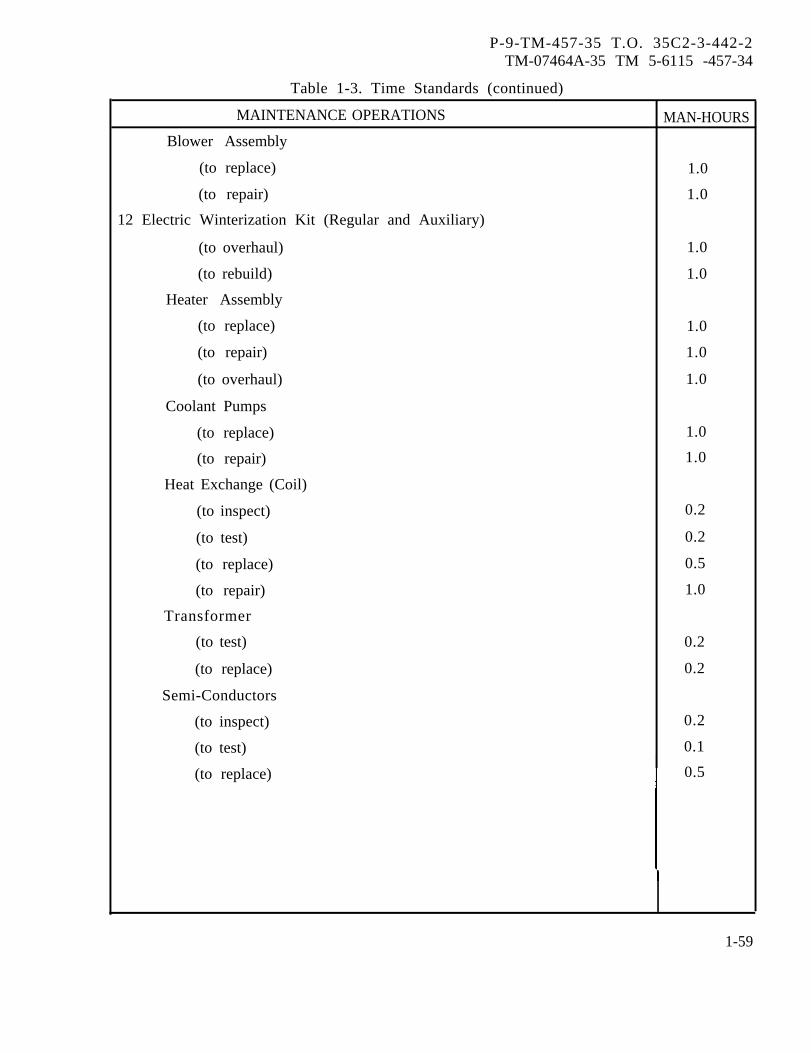
P-9-TM-457-35 T.O. 35C2-3-442-2TM-07464A-35 TM 5-6115 -457-34
Table 1-3. Time Standards (continued)
MAINTENANCE OPERATIONS MAN-HOURS
Blower Assembly
(to replace) 1.0
(to repair) 1.0
12 Electric Winterization Kit (Regular and Auxiliary)
(to overhaul) 1.0
(to rebuild) 1.0
Heater Assembly
(to replace) 1.0
(to repair) 1.0
(to overhaul) 1.0
Coolant Pumps
(to replace) 1.0
(to repair) 1.0
Heat Exchange (Coil)
(to inspect) 0.2
(to test) 0.2
(to replace) 0.5
(to repair) 1.0
Transformer
(to test) 0.2
(to replace) 0.2
Semi-Conductors
(to inspect) 0.2
(to test) 0.1
(to replace) 0.5
1-59
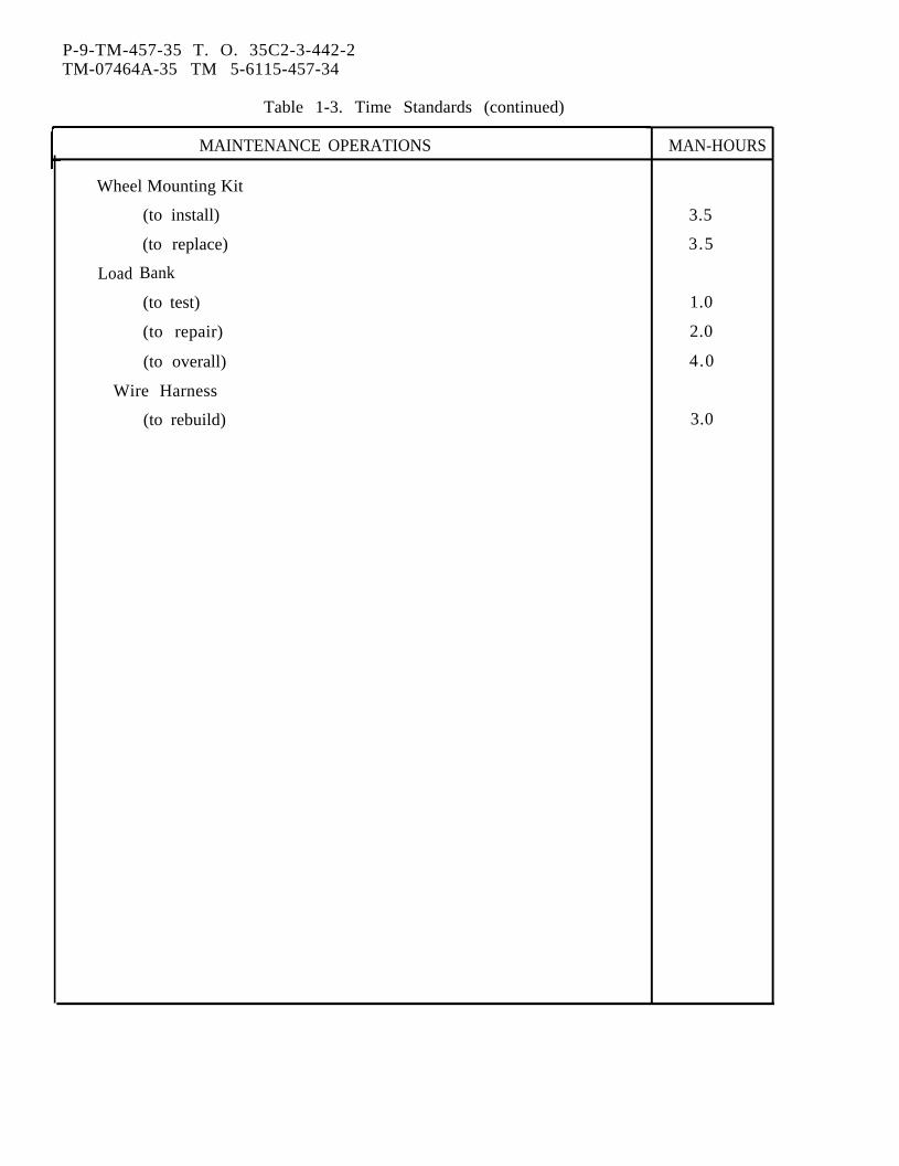
P-9-TM-457-35 T. O. 35C2-3-442-2TM-07464A-35 TM 5-6115-457-34
Table 1-3. Time Standards (continued)
MAINTENANCE OPERATIONS
Wheel Mounting Kit
Load
(to install)
(to replace)
Bank
(to test)
(to repair)
(to overall)
Wire Harness
(to rebuild)
MAN-HOURS
3.5
3.5
1.0
2.0
4.0
3.0

P-9-TM-457-35 T.O. 35C2-3-442-2TM-07464A-35 TM 5-6115-457-34
Figure 1-l. Hydraulic system schematic, precise generation sets.
1-61/(1-62 blank)

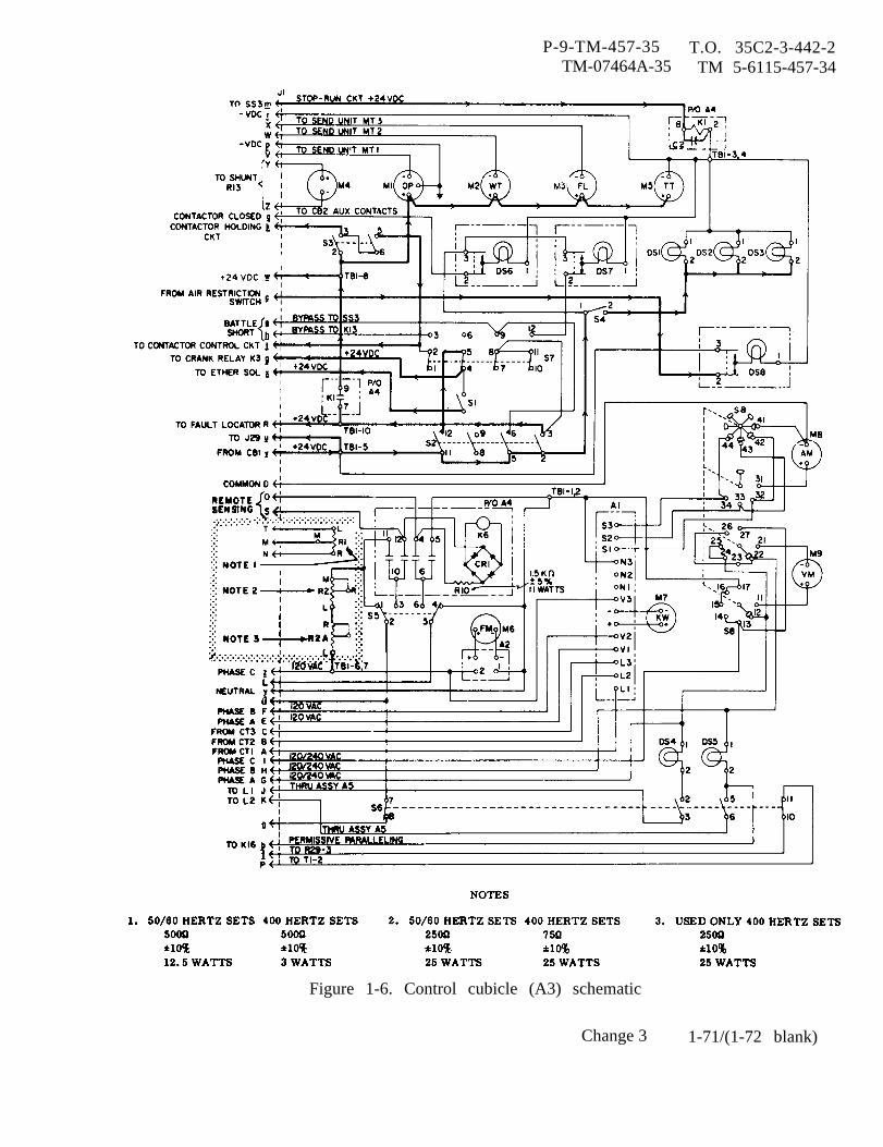
P-9-TM-457-35 T.O. 35C2-3-442-2TM-07464A-35 TM 5-6115-457-34
Figure 1-6. Control cubicle (A3) schematic
Change 3 1-71/(1-72 blank)


P-9-TM-457-35 T.O. 35C2-3-442-2TM-07464A-35 TM 5-6115-457-34
Figure 1-8. Fault locating indicator (A9) schematic
Change 3 1-75
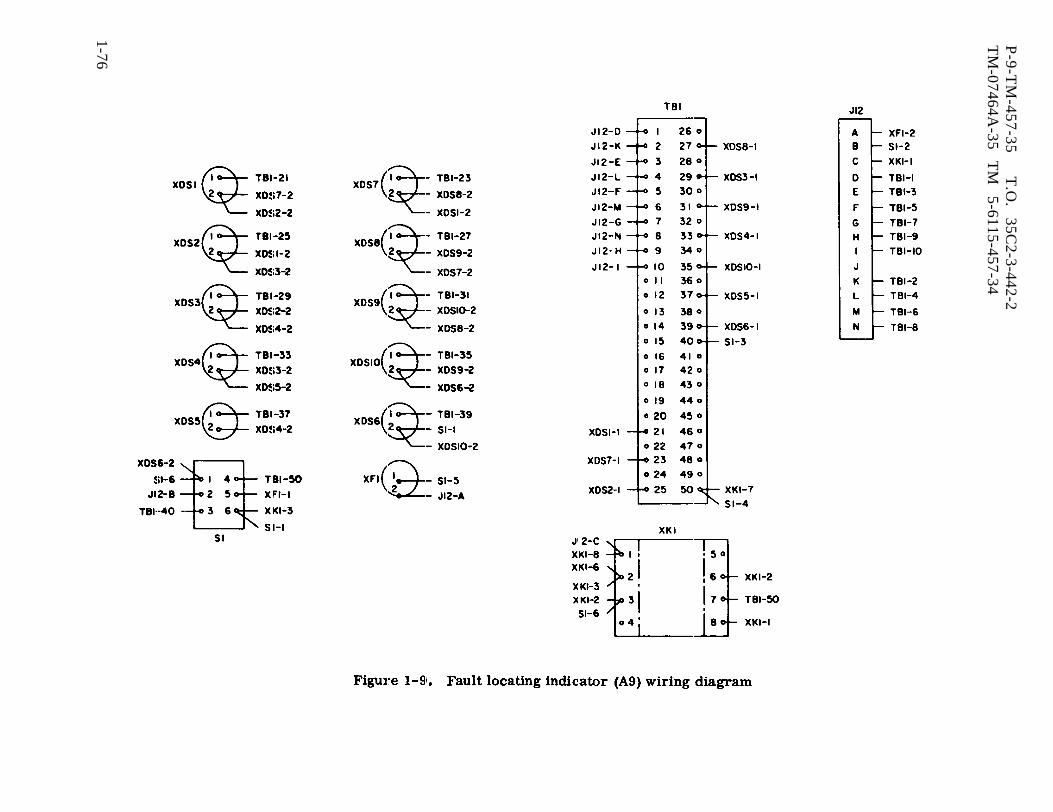
Figure 1-9.
P-9-T
M-457-35
T.O
. 35C
2-3-442-2T
M-07464A
-35 T
M
5-6115-457-34
1-76
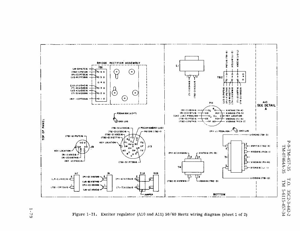
Figure 1-11.
P-9-T
M-457-35
T.O
. 35C
2-3-442-2T
M-07464A
-35T
M 5-6115-457-34
1-7
9

P-9-TM-457-35 T.O. 35C2-3-442-2TM-07464A-35 TM 5-6115-457-34
Figure 1-11. Exciter regulator (Al0 and Al1) 50/60 Hertz wiring diagram (sheet 2 of 2)
1-80

Figure 1-13. P
-9-TM
-457-35T
.O.
35C2-3-442-2
TM
-07464A-35
TM
5-6115-457-34
1-83

P-9-TM-457-35 T.O. 35C2-3-442-2TM-07464A-35 TM 5-6115-457-34
Figure 1-13. Exciter regulator (A10 and All) 400 Hertz wiring diagram (sheet 2 of 2)
1 - 8 4
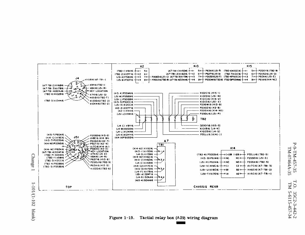
Figure 1-19.
P-9-T
M-457-35
TM
-07464A-35
T.O
. 35C
2-3-442-2T
M 5-6115-457-34
1-101/(1-102 blank)
Change 1

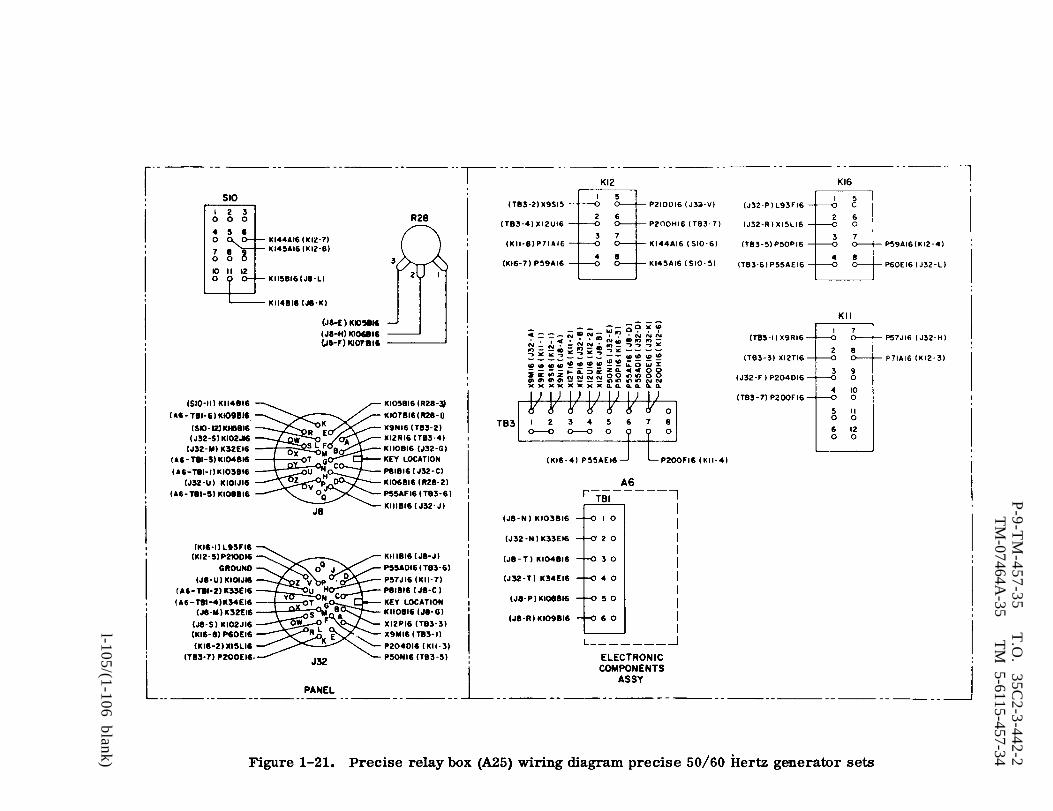
Figure 1-21.
P-9-T
M-457-35
T.O
. 35C
2-3-442-2T
M-07464A
-35T
M 5-6115-457-34
l-105/(1-106 blank)


Figure 1-24.
P-9-T
M-457-35
T.O
. 35C
2-3-442-2T
M-07464A
-35T
M 5-6115-457-34
1-111
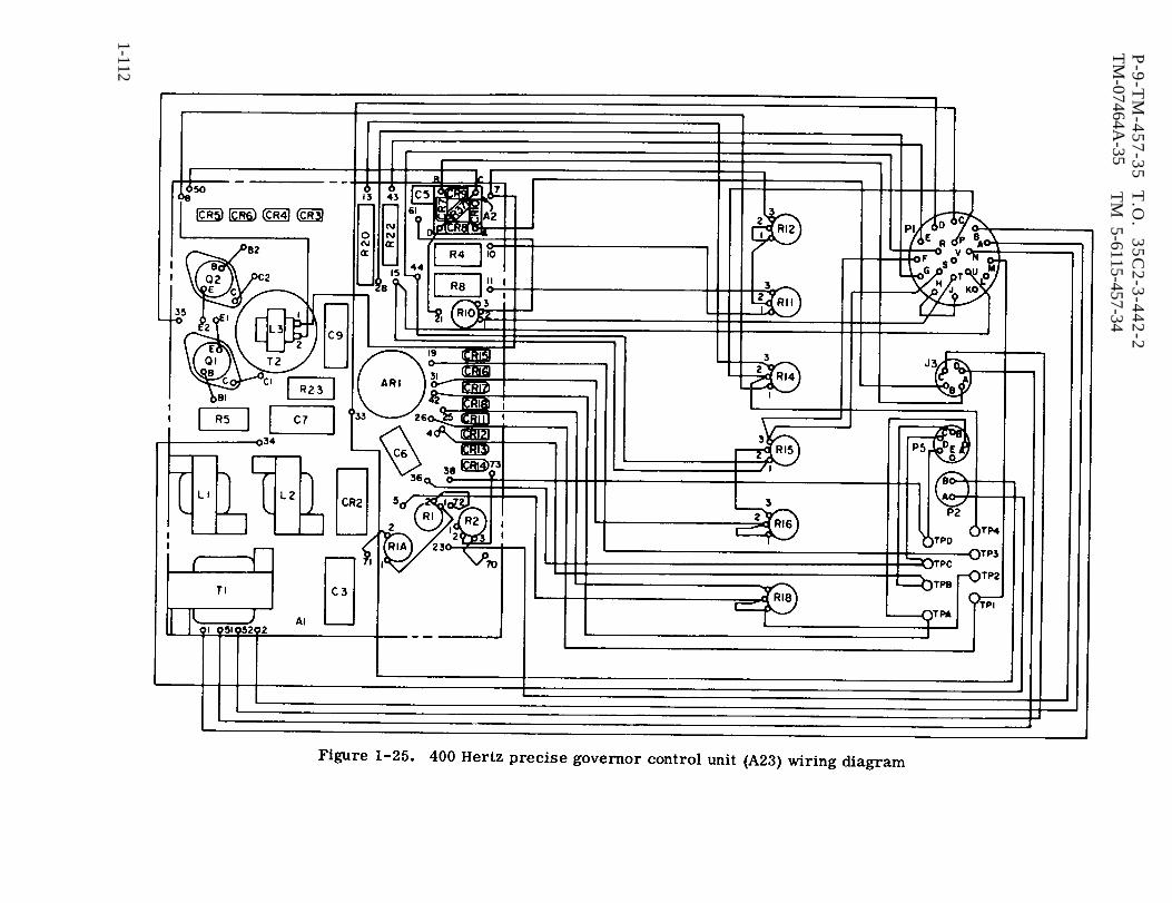
Figure 1-25.
P-9
-TM
-45
7-3
5
T.O
. 3
5C
2-3
-44
2-2
TM
-07464A-35
TM
5-6115-457-34
1-112
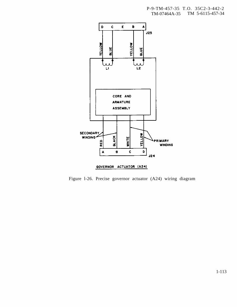
P-9-TM-457-35 T.O. 35C2-3-442-2TM-07464A-35 TM 5-6115-457-34
Figure l-26. Precise governor actuator (A24) wiring diagram
1-113

P-9-TM-457-35 T.O. 35C2-3-442-2TM-07464A-35 TM 5-6115-457-34
Figure 1-27. Load measuring unit (A8) wiring diagram
1-114
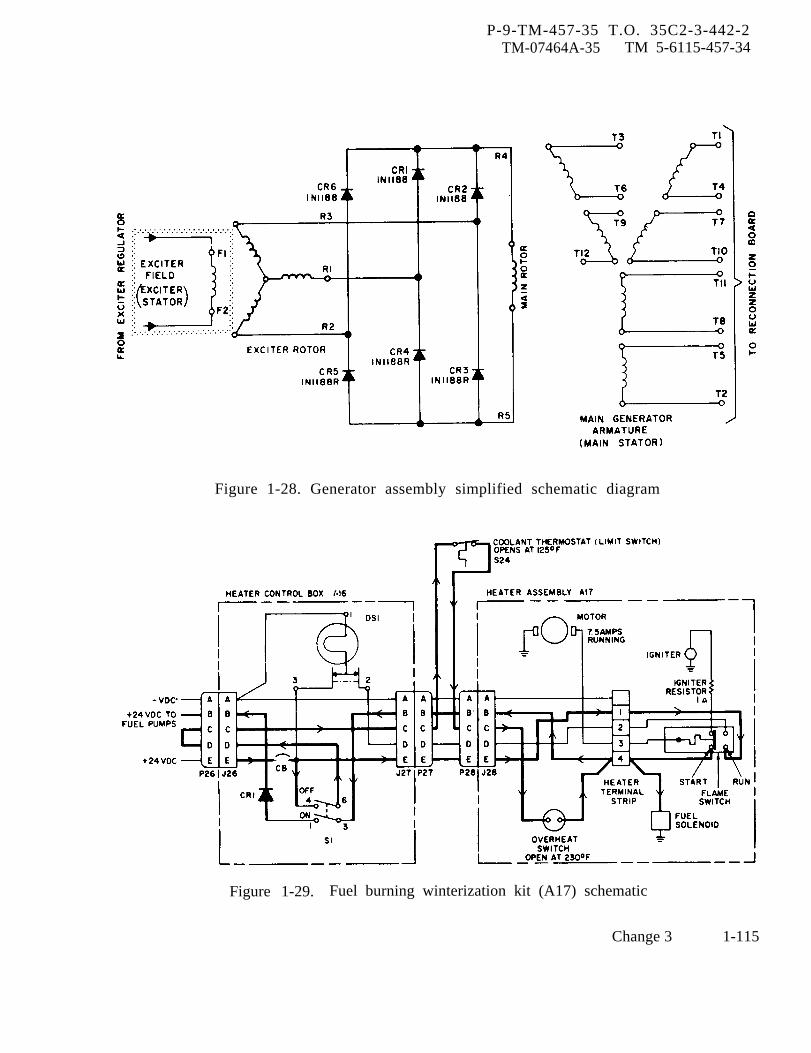
P-9-TM-457-35 T.O. 35C2-3-442-2TM-07464A-35 TM 5-6115-457-34
Figure 1-28. Generator assembly simplified schematic diagram
Figure 1-29. Fuel burning winterization kit (A17) schematic
Change 3 1-115
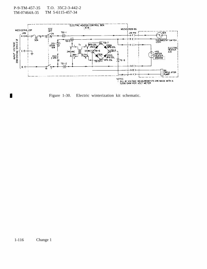
P-9-TM-457-35 T.O. 35C2-3-442-2TM-07464A-35 TM 5-6115-457-34
Figure 1-30. Electric winterization kit schematic.
1-116 Change 1
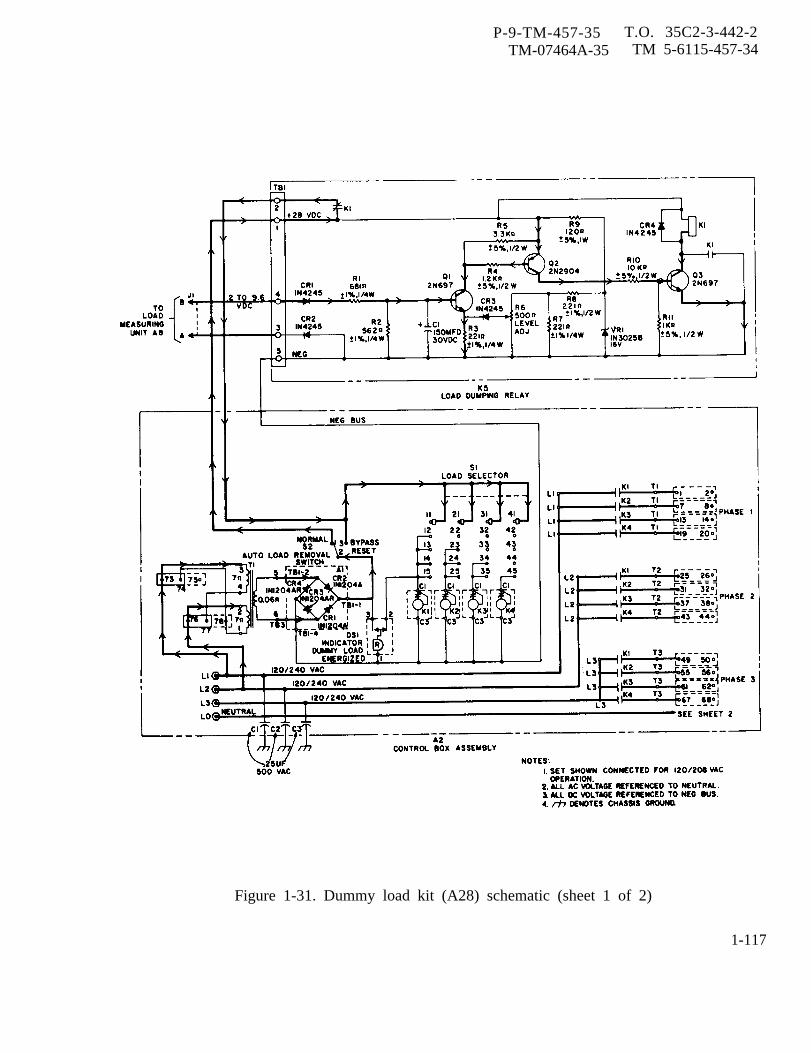
P-9-TM-457-35 T.O. 35C2-3-442-2TM-07464A-35 TM 5-6115-457-34
Figure 1-31. Dummy load kit (A28) schematic (sheet 1 of 2)
1-117

Figure 1-31.
P-9-T
M-457-35
T.O
. 35C
2-3-442-2T
M-07464A
-35T
M 5-6115-457-34
1-118

P-9-TM-457-35 T.O. 35C2-3-442-2TM-07464A-35 TM 5-6115-457-34
CHAPTER 2
GENERAL MAINTENANCE INSTRUCTIONS
Section I. REPAIR PARTS, SPECIAL TOOLS, AND EQUIPMENT
2-1. SPECIAL TOOLS AND EQUIPMENT.
There are no special tools and equip-ment required to perform intermediate(field) (direct and general support) anddepot maintenance on generator setsModels MEP007A, MEP106A, andMEP116A. Recommended tools are listedin table 2-1.
2-2. ORGANIZATIONAL. INTERMEDIATE(FIELD) (DIRECT SUPPORT ANDGENERAL SUPPORT) AND DEPOTMAINTENANCE REPAIR PARTS.
Refer to Organizational, Inter-mediate (Field) (Direct Support and General
Support) and Depot MaintenanceParts and Special Tools List.
Repair
2-3. SPECIALLY DESIGNED (FABRI-CATED) TOOLS AND EQUIPMENT.
The specially designed tools andequipment illustrated in figure 2-1 andlisted in table 2-2 are for intermediate(field) (direct and general support) anddepot maintenance personnel performingmaintenance on the generator set. Thetools and equipment listed in table 2-2are not available for issue, but must befabricated by qualified maintenancepersonnel.
Figure 2-1. Specially designed tools (fabricated)(sheet 1 of 3)
Change 1 2-1
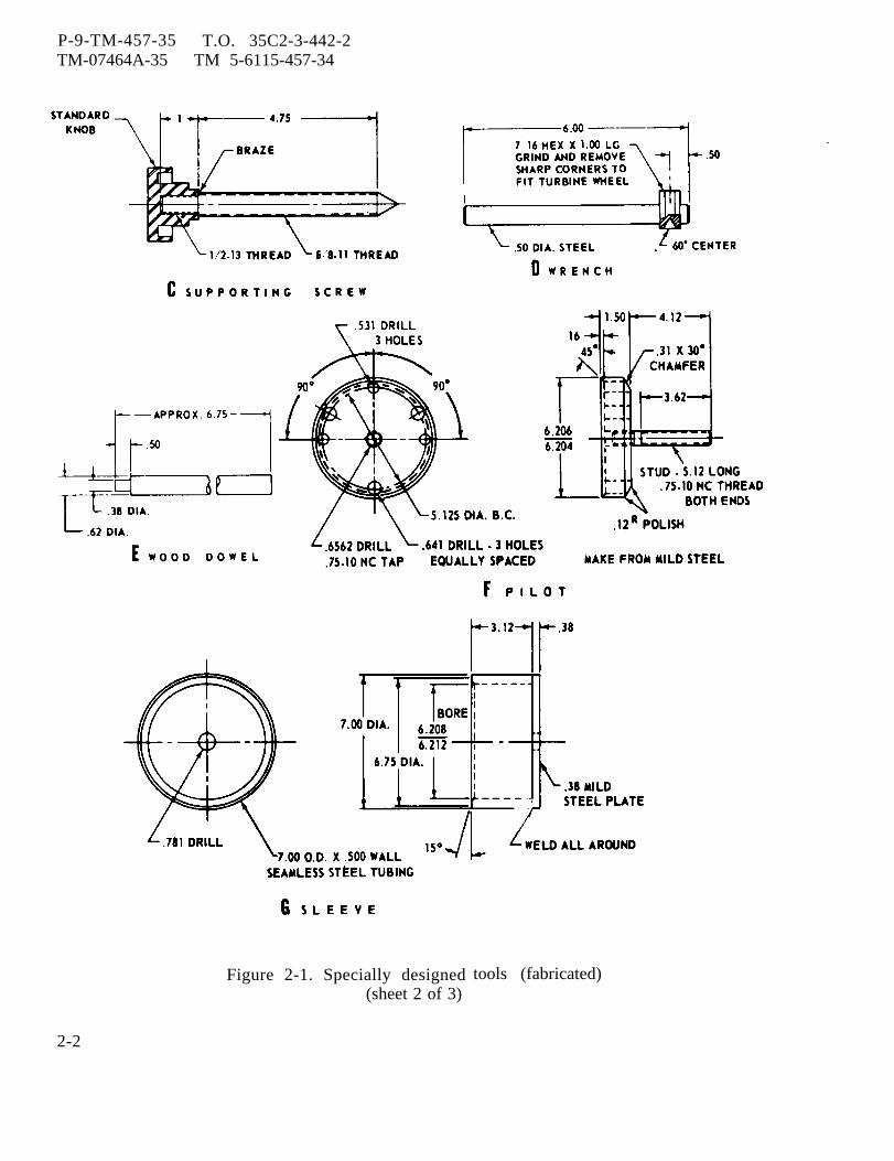
P-9-TM-457-35 T.O. 35C2-3-442-2TM-07464A-35 TM 5-6115-457-34
Figure 2-1. Specially designed(sheet 2 of 3)
tools (fabricated)
2-2
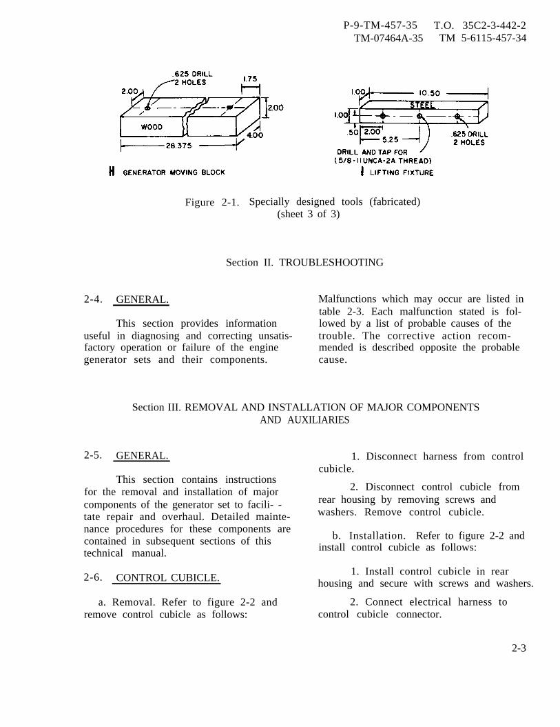
P-9-TM-457-35 T.O. 35C2-3-442-2TM-07464A-35 TM 5-6115-457-34
Figure 2-1. Specially designed tools (fabricated)(sheet 3 of 3)
Section II. TROUBLESHOOTING
2-4. GENERAL. Malfunctions which may occur are listed intable 2-3. Each malfunction stated is fol-
This section provides information lowed by a list of probable causes of theuseful in diagnosing and correcting unsatis- trouble. The corrective action recom-factory operation or failure of the engine mended is described opposite the probablegenerator sets and their components. cause.
Section III. REMOVAL AND INSTALLATION OF MAJOR COMPONENTSAND AUXILIARIES
2-5. GENERAL.
This section contains instructionsfor the removal and installation of majorcomponents of the generator set to facili- -tate repair and overhaul. Detailed mainte-nance procedures for these components arecontained in subsequent sections of thistechnical manual.
2-6. CONTROL CUBICLE.
a. Removal. Refer to figure 2-2 andremove control cubicle as follows:
1. Disconnect harness from controlcubicle.
2. Disconnect control cubicle fromrear housing by removing screws andwashers. Remove control cubicle.
b. Installation. Refer to figure 2-2 andinstall control cubicle as follows:
1. Install control cubicle in rearhousing and secure with screws and washers.
2. Connect electrical harness tocontrol cubicle connector.
2-3
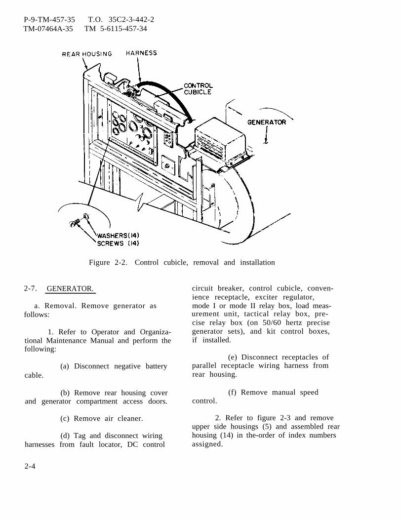
P-9-TM-457-35TM-07464A-35
T.O. 35C2-3-442-2TM 5-6115-457-34
Figure 2-2. Control cubicle, removal and installation
2-7. GENERATOR.
a. Removal. Remove generator asfollows:
1. Refer to Operator and Organiza-tional Maintenance Manual and perform thefollowing:
(a) Disconnect negative batterycable.
(b) Remove rear housing coverand generator compartment access doors.
(c) Remove air cleaner.
(d) Tag and disconnect wiringharnesses from fault locator, DC control
2-4
circuit breaker, control cubicle, conven-ience receptacle, exciter regulator,mode I or mode II relay box, load meas-urement unit, tactical relay box, pre-cise relay box (on 50/60 hertz precisegenerator sets), and kit control boxes,if installed.
(e) Disconnect receptacles ofparallel receptacle wiring harness fromrear housing.
(f) Remove manual speedcontrol.
2. Refer to figure 2-3 and removeupper side housings (5) and assembled rearhousing (14) in the-order of index numbersassigned.
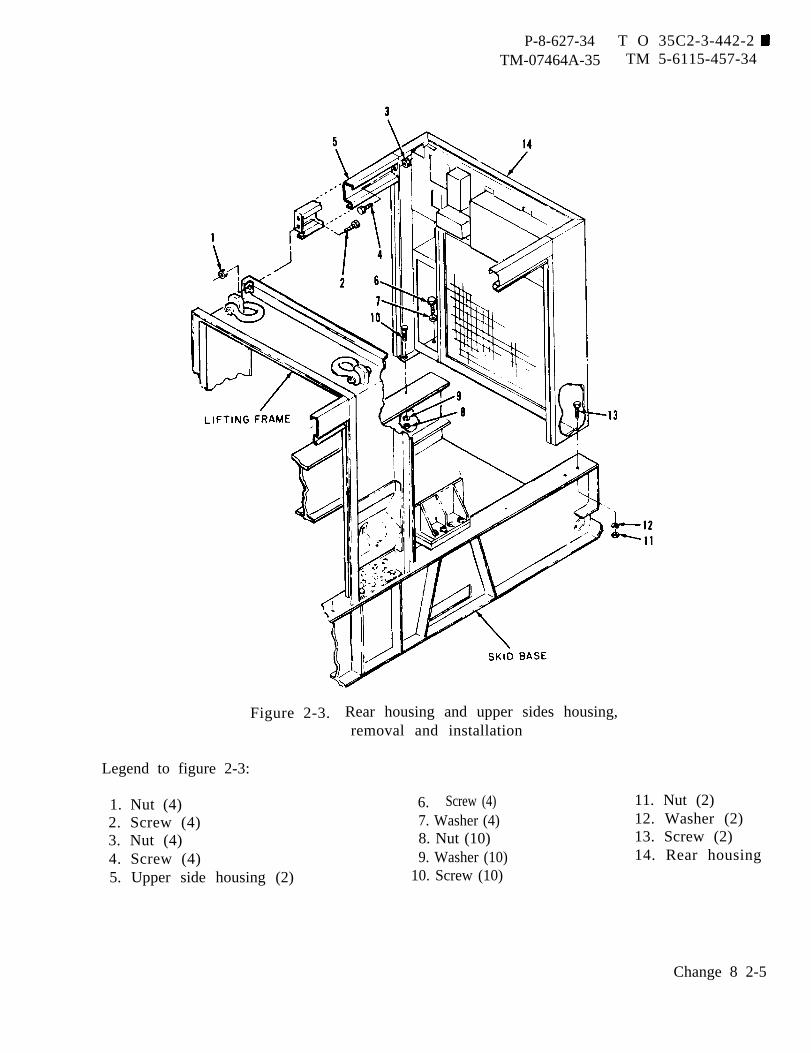
P-8-627-34 T O 35C2-3-442-2TM-07464A-35 TM 5-6115-457-34
Figure 2-3. Rear housing and upper sides housing,removal and installation
Legend to figure 2-3:
1. Nut (4)2. Screw (4)3. Nut (4)4. Screw (4)5. Upper side housing (2)
6. Screw (4)7. Washer (4)8. Nut (10)9. Washer (10)
10. Screw (10)
11. Nut (2)12. Washer (2)13. Screw (2)14. Rear housing
Change 8 2-5
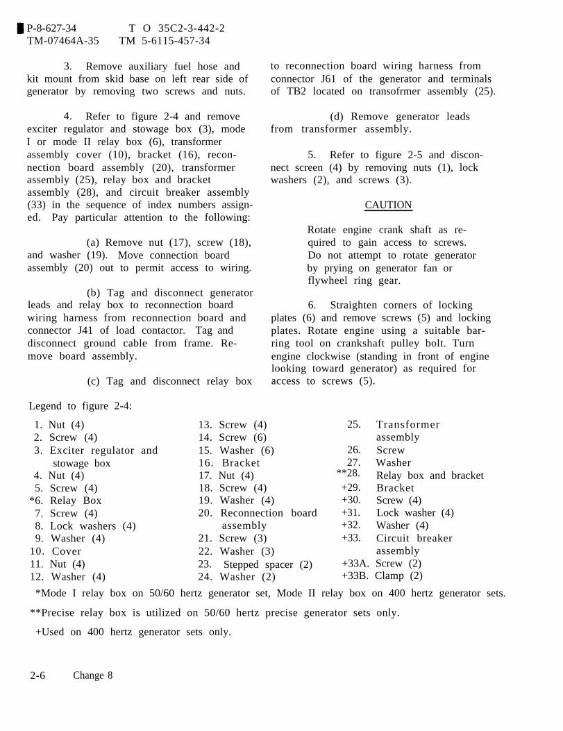
P-8-627-34 T O 35C2-3-442-2TM-07464A-35 TM 5-6115-457-34
3. Remove auxiliary fuel hose andkit mount from skid base on left rear side ofgenerator by removing two screws and nuts.
4. Refer to figure 2-4 and removeexciter regulator and stowage box (3), modeI or mode II relay box (6), transformerassembly cover (10), bracket (16), recon-nection board assembly (20), transformerassembly (25), relay box and bracketassembly (28), and circuit breaker assembly(33) in the sequence of index numbers assign-ed. Pay particular attention to the following:
(a) Remove nut (17), screw (18),and washer (19). Move connection boardassembly (20) out to permit access to wiring.
(b) Tag and disconnect generatorleads and relay box to reconnection boardwiring harness from reconnection board andconnector J41 of load contactor. Tag anddisconnect ground cable from frame. Re-move board assembly.
(c) Tag and disconnect relay box
Legend to figure 2-4:
to reconnection board wiring harness fromconnector J61 of the generator and terminalsof TB2 located on transofrmer assembly (25).
(d) Remove generator leadsfrom transformer assembly.
5. Refer to figure 2-5 and discon-nect screen (4) by removing nuts (1), lockwashers (2), and screws (3).
CAUTION
Rotate engine crank shaft as re-quired to gain access to screws.Do not attempt to rotate generatorby prying on generator fan orflywheel ring gear.
6. Straighten corners of lockingplates (6) and remove screws (5) and lockingplates. Rotate engine using a suitable bar-ring tool on crankshaft pulley bolt. Turnengine clockwise (standing in front of enginelooking toward generator) as required foraccess to screws (5).
1. Nut (4) 13. Screw (4) 25. Transformer2. Screw (4) 14. Screw (6) assembly3. Exciter regulator and 15. Washer (6) 26. Screw
stowage box 16. Bracket 27. Washer4. Nut (4) 17. Nut (4) **28. Relay box and bracket5. Screw (4) 18. Screw (4) +29. Bracket
*6. Relay Box 19. Washer (4) +30. Screw (4)7. Screw (4) 20. Reconnection board +31. Lock washer (4)8. Lock washers (4) assembly +32. Washer (4)9. Washer (4) 21. Screw (3) +33. Circuit breaker
10. Cover 22. Washer (3) assembly11. Nut (4) 23. Stepped spacer (2) +33A. Screw (2)12. Washer (4) 24. Washer (2) +33B. Clamp (2)
*Mode I relay box on 50/60 hertz generator set, Mode II relay box on 400 hertz generator sets.
**Precise relay box is utilized on 50/60 hertz precise generator sets only.
+Used on 400 hertz generator sets only.
2-6 Change 8
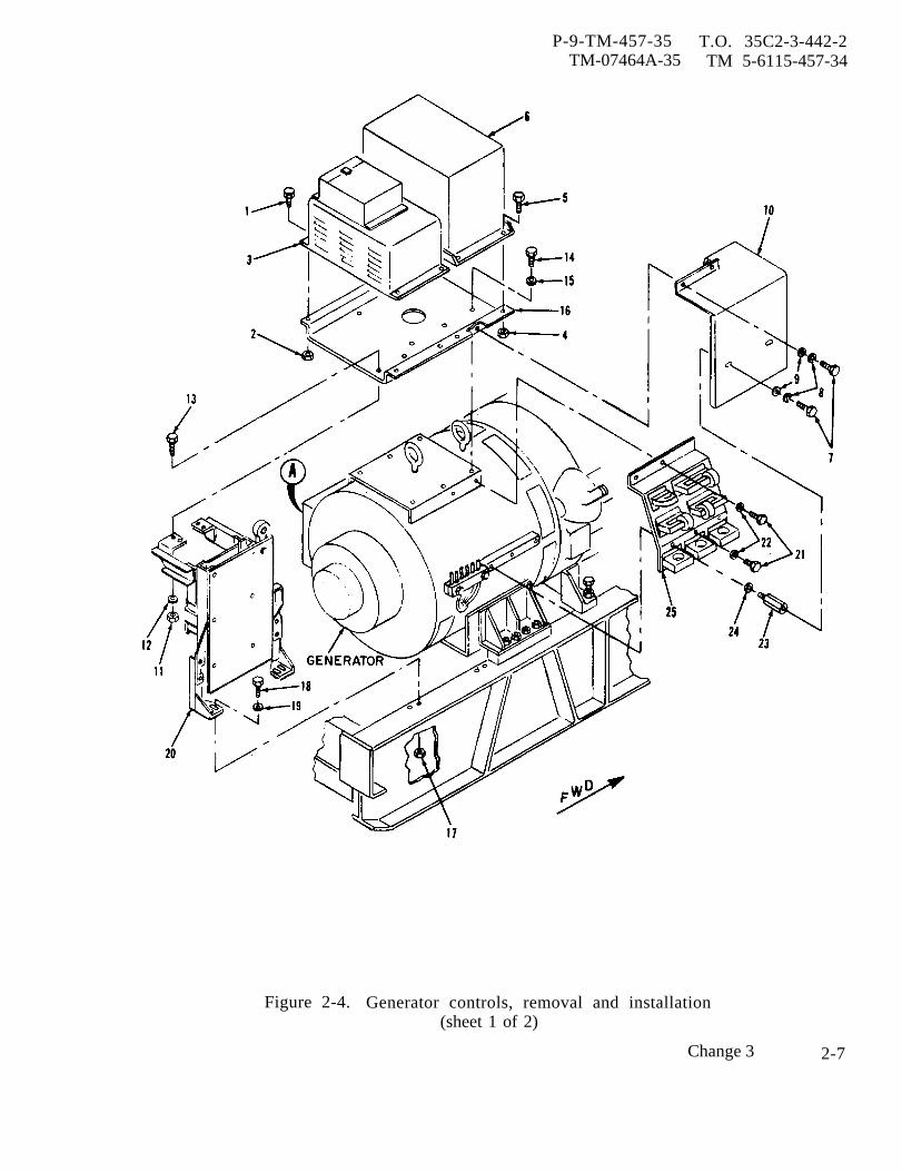
P-9-TM-457-35 T.O. 35C2-3-442-2TM-07464A-35 TM 5-6115-457-34
Figure 2-4. Generator controls, removal and installation(sheet 1 of 2)
Change 3 2-7
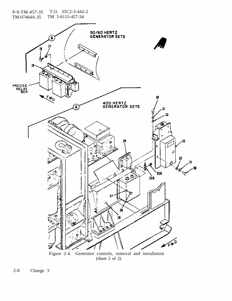
P-9-TM-457-35 T.O. 35C2-3-442-2TM-07464A-35 TM 5-6115-457-34
Figure 2-4. Generator controls, removal and installation(sheet 2 of 2)
2-8 Change 3
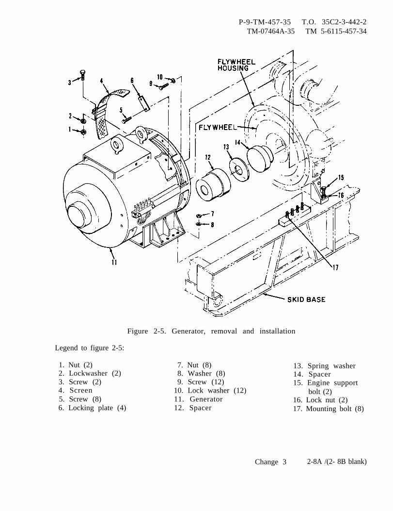
P-9-TM-457-35TM-07464A-35
T.O. 35C2-3-442-2TM 5-6115-457-34
Figure 2-5. Generator, removal and installation
Legend to figure 2-5:
1. Nut (2) 7. Nut (8) 13. Spring washer2. Lockwasher (2) 8. Washer (8) 14. Spacer3. Screw (2) 9. Screw (12) 15. Engine support4. Screen 10. Lock washer (12) bolt (2)5. Screw (8) 11. Generator 16. Lock nut (2)6. Locking plate (4) 12. Spacer 17. Mounting bolt (8)
Change 3 2-8A /(2- 8B blank)


P-8-627-34 T O 35C2-3-442-2TM-07464A-35 TM 5-6115-457-34
7. Connect a suitable overheadlifting device to both generator lifting eye-bolts and remove slack from lifting device.
NOTETo remove generator mountingbolts, the fuel tank must beremoved.
8. Remove nuts (7) and washer (8)and permit mounting bolts to rest on fueltank.
9. Loosen engine support bolts locknuts. Turn engine support bolts clockwiseto contact skid base. Simultaneously turnengine support bolts and lift generator withoverhead lifting device until generatorclears generator mounting bolt. Tightenengine support bolt lock nuts.
10. Install two suitable wooden block,180 degrees apart, between generatorframe and generator fan to prevent mainrotor assembly from sliding out of frameduring lifting. Remove screws (9) andlockwashers (10).
WARNING
Stay clear of generator duringlifting operations.
CAUTION
Do not lower generator on mount-ing bolts, weight of generator onbolts may damage fuel tank.
11. Remove generator from generatorset.
12. Lower generator to floor andblock generator to prevent tipping, remov-ing lifting device from generator.
13. Remove wooden blocks installedbetween generator frame and fan. Securefan to shaft couplings with two nuts andscrews 180 degrees apart.
14. Install screen (4) on generatorwith screws (3), lock washers (2), andnuts (7).
15. Install a suitable moving block(refer figure 2-1 view H) across enginemounting end of generator frame to supportmain rotor assembly and prevent it fromsliding out of frame during movement.
16. Place tag on generator stating;fan mounted to shaft coupling with twoscrews and nuts for moving purposes only.
17. If necessary, remove spacers(12 and 14) and spring washer (13) fromengine flywheel.
b. Installation. Install generator asfollows:
1. Move generator as close to gen-erator set as possible. Remove shippingblocks .
WARNING
Cleaning Solvents are flammable andmoderately toxic to skin, eyes andrespiratory tract. Eye and skinprotect ion required. Good generalventilation is normally adequate.
2. Make sure spacers (12 and 14)and spring washer (13) are installed in fly-wheel. Clean flywheel with an approvedcleaning solvent and dry thoroughly.Inspect flywheel for nicks and burrs.Remove nicks and burrs using a suitablefile or stone.
3. Remove screen (4) from gen-erator. If fan is bolted to shaft couplings,remove shipping screws and nuts.
4. Inspect generator shaft couplingsfor ragged edges and burrs. Touch upragged edges and burrs with a suitable file,exercising care to remove burrs and ragged
Change 8 2-9
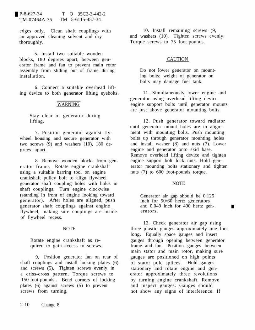
P-8-627-34 T O 35C2-3-442-2TM-07464A-35 TM 5-6115-457-34
edges only. Clean shaft couplings withan approved cleaning solvent and drythoroughly.
5. Install two suitable woodenblocks, 180 degrees apart, between gen-erator frame and fan to prevent main rotorassembly from sliding out of frame duringinstallation.
6. Connect a suitable overhead lift-ing device to both generator lifting eyebolts.
WARNING
Stay clear of generator duringlifting.
7. Position generator against fly-wheel housing and secure generator withtwo screws (9) and washers (10), 180 de-grees apart.
8. Remove wooden blocks from gen-erator frame. Rotate engine crankshaftusing a suitable barring tool on enginecrankshaft pulley bolt to align flywheelgenerator shaft coupling holes with holes inshaft couplings. Turn engine clockwise(standing in front of engine looking towardgenerator). After holes are aligned, pushgenerator shaft couplings against engineflywheel, making sure couplings are insideof flywheel recess.
NOTE
Rotate engine crankshaft as re-quired to gain access to screws.
9. Position generator fan on rear ofshaft couplings and install locking plates (6)and screws (5). Tighten screws evenly ina criss-cross pattern. Torque screws to150 foot-pounds . Bend corners of lockingplates (6) against screws (5) to preventscrews from turning.
10. Install remaining screws (9,and washers (10). Tighten screws evenly.Torque screws to 75 foot-pounds.
CAUTION
Do not lower generator on mount-ing bolts; weight of generator onbolts may damage fuel tank.
11. Simultaneously lower engine andgenerator using overhead lifting deviceengine support bolts until generator mountsare just above generator mounting bolts.
12. Push generator toward radiatoruntil generator mount holes are in align-ment with mounting bolts. Push mountingbolts up through generator mounting holesand install washer (8) and nuts (7). Lowerengine and generator onto skid base.Remove overhead lifting device and tightenengine support bolt lock nuts. Hold gen-erator mounting bolts stationary and tightennuts (7) to 600 foot-pounds torque.
NOTE
Generator air gap should be 0.125inch for 50/60 hertz generatorsand 0.049 inch for 400 hertz gen-erators.
13. Check generator air gap usingthree plastic gauges approximately one footlong. Equally space gauges and insertgauges through opening between generatorframe and fan. Position gauges betweenmain stator and main rotor, making suregauges are positioned on high pointsof stator pole splices. Hold gaugesstationary and rotate engine and gen-erator approximately three revolutionsby turning engine crankshaft. Removeand inspect gauges. Gauges shouldnot show any signs of interference. If
2-10 Change 8

interference is indicated, generator isdefective or engine flywheel is notconcentric.
14. Install screen (4) and securewith screws (3), washer (2), and nuts (1).
15. Refer to figure 2-4 and installrelay box and bracket assembly (28),transformer assembly (25), reconnectionboard assembly (20), bracket (16), cover(10), mode I or mode II relay box (6), andexciter regulator and stowage box (3) in thereverse order of index numbers assigned.Pay particular attention to the following:
NOTE
For wire routing and termination,refer to Operator and Organiza-tional Maintenance Manual.
(a) Install transformerbly (25) and route generator leadstransformers.
assem-through
(b) Connect relay box to reconnectionboard wiring harness and generator leads to reconnectionboard assembly. Secure reconnection board assembly toskid base. Assure that generator leads are routed andsecured in a manner that no chaffing occurs.
(c) Connect relay box to recon-nect on board harness to connector J41 ofthe load contactor, J61 of the generator,and terminal board TB2 located on trans-former assembly.
16. Position auxiliary fuel hose andmount on skid base at left side of generatorand secure with two screws and nuts.
17. Refer to figure 2-3 and installupper side housings (5) and assembled rearhousing (14) in the reverse order of indexnumbers assigned.
P-9-TM-457-35 T.O. 35C2-3-442-2TM-07464A-35 TM 5-6115-457-34
18. Refer to Operator and Organiza-tional Maintenance Manual and perform thefollowing:
(a) Install and adjust manualspeed control.
(b) Connect receptacles of par-allel receptacle wiring harness to rearhousing.
(c) Connect wiring harnesses tofault locator, DC control circuit breaker,control cubicle, convenience receptacle,exciter regulator, mode I or mode II relaybox, load measurement unit, tactical relaybox, precise relay box (on 50/60 hertzprecise generator sets), and kit controlboxes, if installed.
(d)
(e)and generator
(f)cable.
Install air cleaner.
Install rear basing covercompartment access doors.
Connect negative battery
2-8. ENGINE, D333C(T)
a. Removal. Remove the engine asfollows:
1. Refer to Operator and Organiza-tional Maintenance Manual and perform thefollowing:
(a) Drain fuel filter and strainer,secondary fuel filter, day tank, radiator,engine lubricating oil, and hydraulic tankon precise generator sets,
(b) Disconnect negative batterycable. Tag and disconnect cables fromslave receptacle SR2, starter and startersolenoid. Remove starter ground cablefrom skid base.
Change 7 2-11

P-9-TM-457-35 T.O. 35C2-3-442-2TM-07464A-35 TM 5-6115-457-34
(c) Disconnect muffler clampsfrom front housing cover. Remove frontand rear housing covers, engine, generator,and battery compartment access doors.
(d) Remove muffler, exhaustpipe, and crankcase breather tube. Removeengine breather assembly.
(e) Remove radiator and shutter.
(f) Disconnect manual speedcontrol from utility governor input shaftand lifting frame bracket.
(g) Remove air cleaner.
(h) If installed, remove winter-ization kit heaters and coolant lines fromoil pan heat exchanger tubes and engineblock. Disconnect kit harnesses from con-trol boxes and coil harness on engine.
(i) Tag and disconnect engineharness from connector J5 of mode I ormode II relay box, connector J39 of DCcontrol circuit breaker, connector J33 ofthe day tank float switch, connector J38 ofthe ether primer and fuel tank fuel leveltransmitter. Cut tiedown strap securingengine harness to other harnesses. Coilengine harness wires and secure wires toengine.
(j) Disconnect ether starting aidtube from atomizer at rear of cylinder headinlet elbow.
(k) Tag and disconnect electricalleads from radio suppression diode assem-bly mounted to day tank.
2. Disconnect four upper side hous-ing members from lifting frame by remov-ing eight screws and nuts securing membersto lifting frame.
(a) Remove two members fromrear housing by removing four screws andwashers.
3. Disconnect engine oil drain hosefrom engine oil drain valve at left side ofengine. Plug hose and valve opening.
4. Remove engine block coolantdrain hose from right side skid base fitting.
5. Loosen clamp and remove fuelfiller hose from fuel tank. Cover fuel tankopening. Disconnect fuel tank vent hosesfrom fuel filler neck. Tag and disconnectfuel hoses from fuel transfer valve,auxiliary fuel inlet fitting, fuel supply out-let fitting and day tank. Remove supplyhose from electric fuel transfer pump.Plug hoses. Disconnect two clamps secur-ing hoses to lifting frame; one clamp islocated on each inside wall of lifting frame.
NOTE
Governor control unit is mountedto lifting frame on the right side.
6. On precise generator sets, tagand disconnect connectors from governorcontrol unit. Remove harness from con-nector P8 of the precise relay box, cut tie-down strap and coil harness on engine.Disconnect governor control unit and mountfrom lifting frame by removing four screws,washers, and nuts.
7. Remove sixteen screws, washers,and nuts securing lifting frame to skid base.Using a suitable lifting device, remove lift-ing frame from generator set.
8. Tag and disconnect electricalconnectors from exciter regulator. Dis-connect exciter regulator and stowage box(3, figure 2-4) by removing nuts (1) and
2-12
screws (2). Remove nuts (11 and 17),screws (13 and 18), and washers (12 and19). Move reconnection board assembly(20) away from bracket (16).
9. Disconnect screen (4, figure 2-5)by removing nuts (l), washers (2), andscrews (3).
10. Disconnect auxiliary fuel hoseand mount from skid base at left rear ofgenerator by removing screws and nuts.
CAUTION
Rotate engine crankshaft as re-quired to gain access to screws.Do not attempt to rotate gen-erator by prying on generator fanor flywheel ring gear.
11. Straighten corners of lockingplates (6) and remove screws (5) and lock-ing plates. Rotate engine using a suitablebarring tool on crankshaft pulley bolt.Turn engine clockwise (standing in front ofengine looking toward generator) asrequired for access to screws (5). Holdbarring tool stationary to permit looseningscrews.
12. Remove nuts (7) and washers (8)and permit generator mounting bolts to reston fuel tank.
13. Connect a suitable overhead lift-ing device to both engine lifting eyebolts(figure 2-6). Remove slack from liftingdevice.
14. Disconnectfrom engine supportand washers.
engine trunion mountby removing bolts
P-8-627-34 T O 35C2-3-442-2TM-07464A-35 TM 5-6115-457-34
WARNING
Stay clear of engine during lifting.
CAUTION
During lifting operations, checkthat generator mounting bolts arenot binding on generator mount.
15. Slowly raise lifting device, pivot-ing f rent of engine up until there is suffi-cient clearance for engine oil pan to clearengine support.
16. Support f rent of engine to- preventit from swinging forward when generator toflywheel housing bolts are removed.
CAUTION
Generator must be blocked so thatgenerator weight is on skid base.
17. Block generator in raised posi-tion with suitable blocks that contact eachside of the skid base.
18. Remove screws (9, figure 2-5)and washers (10) securing generator to fly-wheel housing.
WARNING
Stay clear of engine during lifting.
19. Remove support from front ofengine and move engine free of generator.Remove engine from generator set. Placeengine on stand, cradle, or crib and block.
20. If necessary, remove spacers(12 and 14) and spring washer (13) fromflywheel.
WARNING
Steam cleaning creates hazardousnoise levels and severe bum andinjury potential. Eye, skin andear protection required.
21. Plug all engine openingssteam clean engine.
Change 8
and
2-13
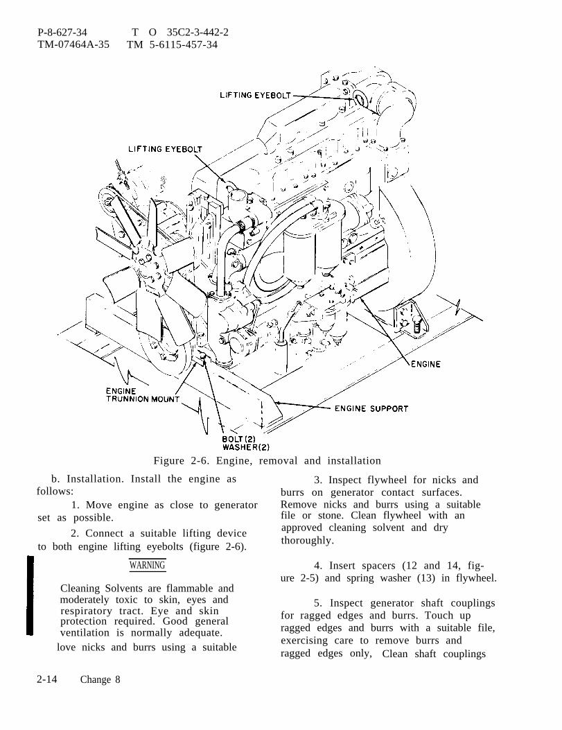
P-8-627-34 T O 35C2-3-442-2TM-07464A-35 TM 5-6115-457-34
Figure 2-6. Engine, removal and installation
b. Installation. Install the engine asfollows:
1. Move engine as close to generatorset as possible.
2. Connect a suitable lifting deviceto both engine lifting eyebolts (figure 2-6).
WARNING
Cleaning Solvents are flammable andmoderately toxic to skin, eyes andrespiratory tract. Eye and skinprotection required. Good generalventilation is normally adequate.
love nicks and burrs using a suitable
3. Inspect flywheel for nicks andburrs on generator contact surfaces.Remove nicks and burrs using a suitablefile or stone. Clean flywheel with anapproved cleaning solvent and drythoroughly.
4. Insert spacers (12 and 14, fig-ure 2-5) and spring washer (13) in flywheel.
5. Inspect generator shaft couplingsfor ragged edges and burrs. Touch upragged edges and burrs with a suitable file,exercising care to remove burrs andragged edges only, Clean shaft couplings
2-14 Change 8
P-8-627-34 T O 35C2-3-442-2TM-07464A-35 TM 5-6115-457-34
with an approved cleaning solvent and drythoroughly.
WARNING
Stay clear of engine during liftingoperations.
6. Position engine in generator set,aligning engine flywheel housing screwholes with generator frame holes. Installfour screws (9, figure 2-5) and washers(10), 90 degrees apart.
7. Raise lifting device so that blockcan be removed from under generator.Remove block and slowly lower engine inplace so that engine support bolt holes(figure 2-6) and trunion mount holes are inalignment. Secure trunion mount to enginesupport with bolts and washers. Make suregenerator mounting bolts are in alignmentwith generator mount holes and tightenengine mount bolts to 200 foot-poundstorque.
8. Remove four screws securinggenerator to engine to permit engine tomove forward.
9. Rotate engine crankshaft usingsuitable engine barring tool on crankshaftpulley bolt to align flywheel generator shaftcoupling holes with holes in generator shaftcouplings. Turn engine crankshaft clock-wise (standing in front of engine lookingtoward generator). After holes are aligned,push generator shaft couplings againstengine flywheel, making sure couplings areinside of flywheel recess.
NOTE
Rotate engine crankshaft as re-quired to gain access to screws.
10. Position generator fan onrear of shaft couplings and installlocking plates (6, figre 2-5) andscrews (5). Tighten screws evenly in acriss-cross pattern. Torque screws to150 foot-pounds. Bend corners of lock-ing plates (6) against screws (5) toprevent screws from turning.
11. Install screws (9) and was-hers (10). Tighten screws evenly and to75 foot-pounds torque.
12. Push mounting bolts upthrought generator mounting holes andinstall washer (8) and nuts (7). Holdgenerator mounting bi t s s ta t ionary andtighten nuts (7) to 500-550 foot-poundstorque.
NOTE
Generator air gap should be 0.125inch for 50/60 hertz generatorsand 0.049 inch for 400 hertz gen-erators.
13. Check generator air gap usingthree plastic gauges approximately one footlong. Equally space gauges and insertgauges through opening between generatorframe and fan. Position gauges betweenmain stator and main rotor, making suregauges are positioned on high points ofstator pole pieces. Hold gauges stationaryand rotate engine and generator approxi-mately three revolutions by turning enginecrankshaft. Remove and inspect gauges.Gauges should not show any signs ofinterference. If interference is indicated,generator is defective or engine flywheel isnot concentric.
14. Install screen (4) and securewith screws (3), washer (2), and nuts (1).
15. Secure reconnection board as-sembly (20) to skid base and bracket (16)
Change 9 2-15
P-8-627-34 T O 35C2-3-442-2TM-07464A-35 TM 5-6115-457-34
with screws (13 and 18), washers (12 and19), and nuts (11 and 17). Install exciterregulator and stowage box and secure withscrews (2) and nuts (l). Connect elec-trical connectors to exciter regulator.
16. Using a suitable lifting device,position lifting frame on generator set skidbase. Secure lifting frame to skid basewith sixteen screws, washers, and nuts.
17. On precise generator sets, posi-tion governor control unit on lifting frameand secure with four screws, washers, andnuts. Connect electrical connectors to gov-ernor control unit and governor actuator.Connect harness to connector P8 on preciserelay box. Secure harness to other har-nesses with tie down strap.
18. Connect fuel filler hose to fueltank and secure with clamp. Connect fueltank vent hoses to fuel filler neck. Connectfuel hoses to fuel transfer valve, auxiliaryfuel inlet fitting, fuel supply outlet fitting,day tank, and electric fuel transfer pump.Clamp hose to lifting frame.
19. Connect engine block coolantdrain hose to skid base fitting and securewith clamp.
20. Connect engine oil drain hose toengine oil drain valve.
21. Connect four upper side housingmembers to lifting frame and secure eightscrews and washers. Connect two mem-bers to rear housing and secure with fourscrews and washers.
22. Refer to Operator and Organiza-tional Maintenance Manual and perform thefollowing:
(a) Connect three electricalleads to radio suppression diode assembly.
(b) Connect ether starting tubeto atomizer at rear of cylinder head inletelbow.
(c) Connect engine harness toconnector J5 of mode I or mode II relay box,connector J33 of day tank float valve, con-nector J38 of ether primer, connector J39of DC control circuit breaker, and fuel tankfuel level send unit. Fasten harness toother harness with tiedown straps.
(d) If required, install winter-ization kit heaters and coolant lines. Con-nect kit harnesses to control boxes.
(e) Install air cleaner.
(f) Connect and adjust manualspeed control.
(g) Install radiator and shutter.
(h) Install engine crankcasebreather, crankcase breather tube, muffler,and exhaust pipe.
(i) Install front and rear housingcovers; battery, engine, and generatorcompartment access doors. Connect muf-fler clamps to front housing cover.
(j) Connect starter ground cableto skid base. Connect cables to slavereceptacle SR2. Install negative batterycable.
(k) Service radiator, engine andon precise generator sets hydraulic tank.
(l) Start engine and bleed fuelsystem and hydraulic system on precisegenerator sets.
2-16 Change 8

P-9-TM-457-35 T.O. 35C2-3-442-2TM-07464A-35 TM 5-6115-457-34
2-9. WHEEL MOUNTING KIT.
a. Removal. Refer to figure 2-7 andremove wheel mounting kit in the order ofindex numbers assigned. Pay particularattention to the following:
1. Using a suitable lifting device,lift generator set off ground. Place suitableblock under skid base and lower generatorset on blocks.
2. Place suitable hydraulic jackunder front axle assembly and raise jack soit will support axle assembly weight.
3, Disconnect brake cables.
4. Remove axle assembly attachinghardware and lower hydraulic jack, lower-ing wheels to ground. Remove axle assem-bly from under generator set.
5. Repeat steps 2. through 4. forrear axle.
b. Installation. Refer to figure 2-7and install wheel mounting kit in the reverseorder of index numbers assigned. Pay par-ticular attention to the following:
1. On initial installation, assemblekit components prior to performing steps 2.through 6. as follows:
(a) Install two nuts (16) andtwo yokes (15) on each stud (17), and attachyokes on one end to hand brake and shaftassembly (26).
(b) Attach brackets (20 and 25)to hand brake and shaft assembly.
2. Using a suitable lifting device,lift generator set off ground. Placesuitable block under skid base and lowergenerator set on blocks.
3. Place front axle assembly undergenerator set. Place suitable hydraulicjack under axle assembly and jack axle intoposition. Secure axle assembly to gener-ator set and remove hydraulic jack.
4. Repeat step 3. for rear axle.
5. Connect brake cables to eachwheel.
6. Lift generator set, removeblocks, and lower generator set.
2-17

P-9-TM-457-35 T.O. 35C2-3-442-2TM-07464A-35 TM 5-6115-457-34
Figure 2-7. Wheel mounting kit, removal and installation
2-18
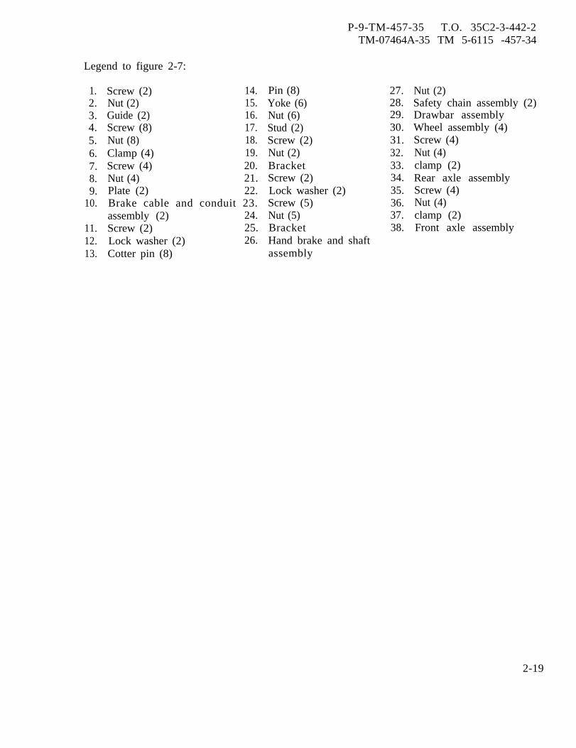
P-9-TM-457-35 T.O. 35C2-3-442-2TM-07464A-35 TM 5-6115 -457-34
Legend to figure 2-7:
1.2.3.4.5.6.7.8.9.
10.
11.12.13.
Screw (2) 14.Nut (2) 15.Guide (2) 16.Screw (8) 17.Nut (8) 18.Clamp (4) 19.Screw (4) 20.Nut (4) 21.Plate (2) 22.Brake cable and conduit 23.assembly (2) 24.Screw (2) 25.Lock washer (2) 26.Cotter pin (8)
Pin (8)Yoke (6)Nut (6)Stud (2)Screw (2)Nut (2)BracketScrew (2)Lock washer (2)Screw (5)Nut (5)BracketHand brake and shaftassembly
27.28.29.30.31.32.33.34.35.36.37.38.
Nut (2)Safety chain assembly (2)Drawbar assemblyWheel assembly (4)Screw (4)Nut (4)clamp (2)Rear axle assemblyScrew (4)Nut (4)clamp (2)Front axle assembly
2-19
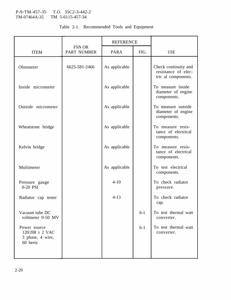
P-9-TM-457-35 T.O. 35C2-3-442-2TM-07464A-35 TM 5-6115-457-34
Table 2-1. Recommended Tools and Equipment
ITEM
Ohmmeter
Inside micrometer
Outside micrometer
Wheatstone bridge
Kelvin bridge
Multimeter
Pressure gauge0-20 PSI
Radiator cap tester
Vacuum tube DCvoltmeter 0-50 MV
Power source120/208 ± 2 VAC3 phase, 4 wire,60 hertz
FSN ORPART NUMBER
6625-581-2466
REFERENCE
PARA
As applicable
As applicable
As applicable
As applicable
As applicable
As applicable
4-10
4-13
FIG.
6-1
6-1
USE
Check continuity andresistance of elec-tric al components.
To measure insidediameter of enginecomponents.
To measure outsidediameter of enginecomponents.
To measure resis-tance of electricalcomponents.
To measure resis-tance of electricalcomponents.
To test electricalcomponents.
To check radiatorpressure.
To check radiatorcap.
To test thermalconverter.
To test thermalconverter.
watt
watt
2-20
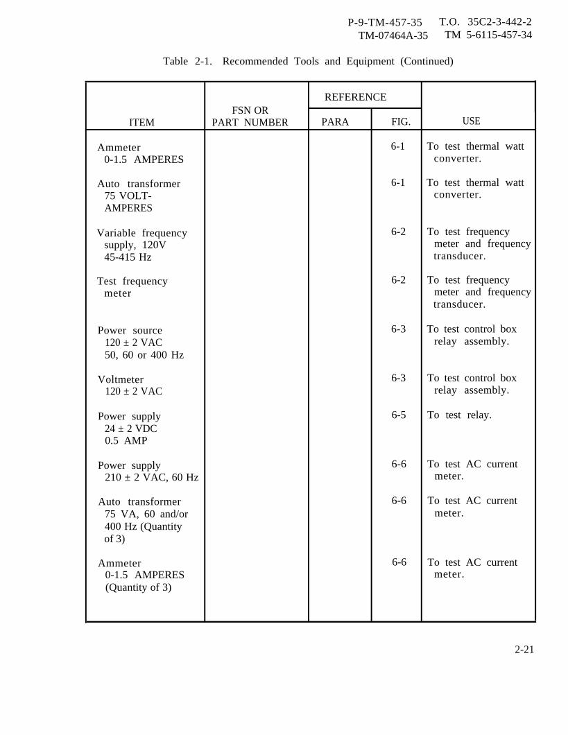
P-9-TM-457-35 T.O. 35C2-3-442-2TM-07464A-35 TM 5-6115-457-34
Table 2-1. Recommended Tools and Equipment (Continued)
REFERENCEFSN OR
ITEM PART NUMBER PARA FIG. USE
Ammeter 6-1 To test thermal watt0-1.5 AMPERES converter.
Auto transformer 6-1 To test thermal watt75 VOLT- converter.AMPERES
Variable frequency 6-2 To test frequencysupply, 120V meter and frequency45-415 Hz transducer.
Test frequency 6-2 To test frequencymeter meter and frequency
transducer.
Power source 6-3 To test control box120 ± 2 VAC relay assembly.50, 60 or 400 Hz
Voltmeter 6-3 To test control box120 ± 2 VAC relay assembly.
Power supply 6-5 To test relay.24 ± 2 VDC0.5 AMP
Power supply 6-6 To test AC current210 ± 2 VAC, 60 Hz meter.
Auto transformer 6-6 To test AC current75 VA, 60 and/or meter.400 Hz (Quantityof 3)
Ammeter 6-6 To test AC current0-1.5 AMPERES meter.(Quantity of 3)
2-21
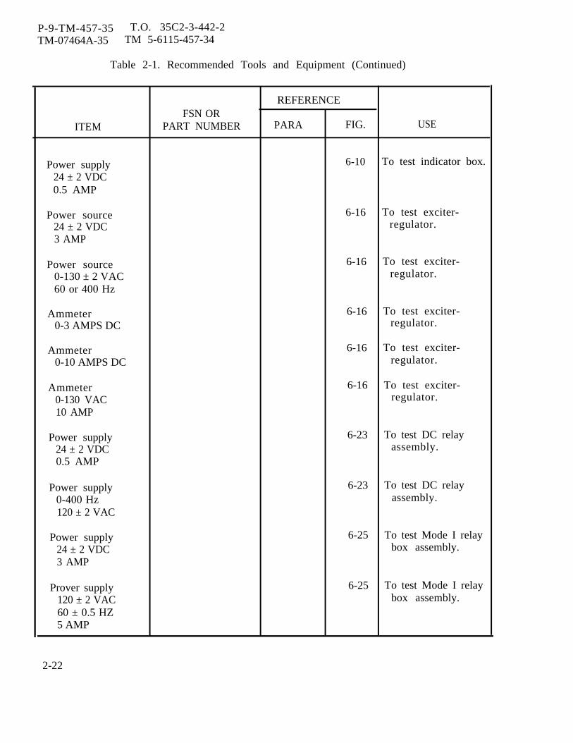
P-9-TM-457-35 T.O. 35C2-3-442-2TM-07464A-35 TM 5-6115-457-34
Table 2-1. Recommended Tools and Equipment (Continued)
REFERENCEFSN OR
ITEM PART NUMBER PARA FIG. USE
Power supply 6-10 To test indicator box.
24 ± 2 VDC0.5 AMP
Power source 6-16 To test exciter-24 ± 2 VDC regulator.3 AMP
Power source 6-16 To test exciter-0-130 ± 2 VAC regulator.60 or 400 Hz
Ammeter 6-16 To test exciter-0-3 AMPS DC regulator.
Ammeter 6-16 To test exciter-0-10 AMPS DC regulator.
Ammeter 6-16 To test exciter-0-130 VAC regulator.10 AMP
Power supply 6-23 To test DC relay24 ± 2 VDC assembly.0.5 AMP
Power supply 6-23 To test DC relay0-400 Hz assembly.120 ± 2 VAC
Power supply 6-25 To test Mode I relay24 ± 2 VDC box assembly.3 AMP
Prover supply 6-25 To test Mode I relay120 ± 2 VAC box assembly.60 ± 0.5 HZ5 AMP
2-22
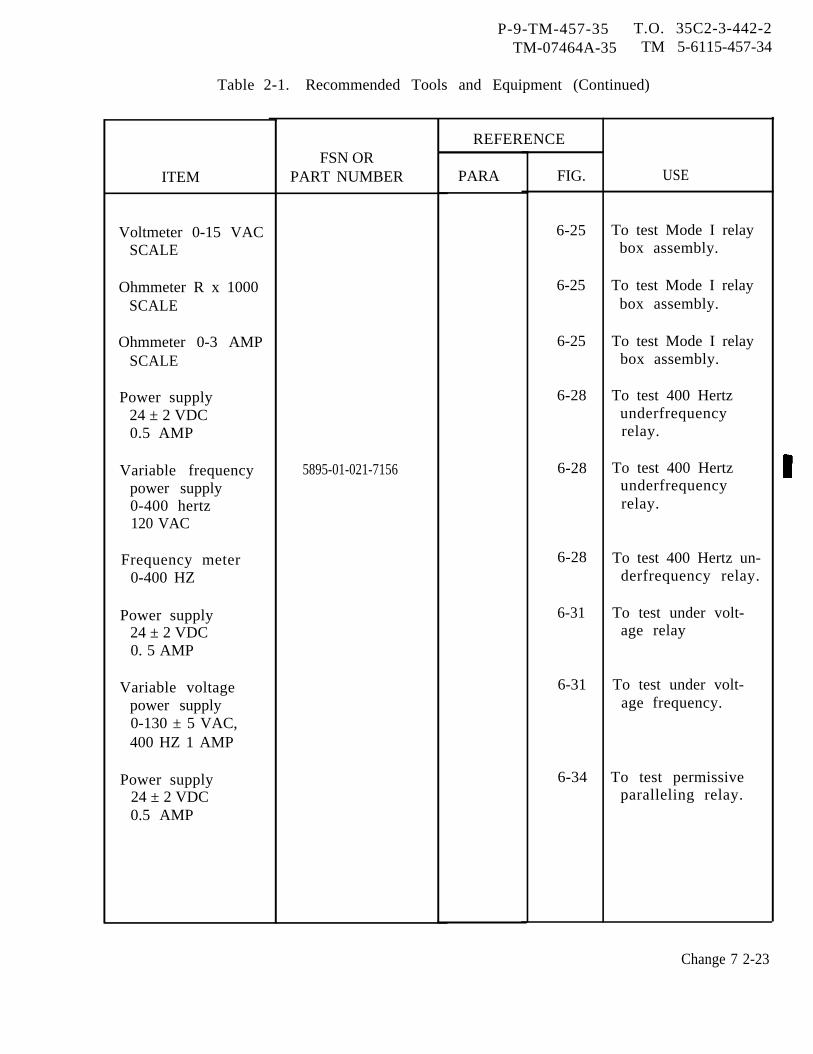
P-9-TM-457-35 T.O. 35C2-3-442-2TM-07464A-35 TM 5-6115-457-34
Table 2-1. Recommended Tools and Equipment (Continued)
ITEM
Voltmeter 0-15 VACSCALE
Ohmmeter R x 1000SCALE
Ohmmeter 0-3 AMPSCALE
Power supply24 ± 2 VDC0.5 AMP
Variable frequencypower supply0-400 hertz120 VAC
Frequency meter0-400 HZ
Power supply24 ± 2 VDC0. 5 AMP
Variable voltagepower supply0-130 ± 5 VAC,400 HZ 1 AMP
Power supply24 ± 2 VDC0.5 AMP
FSN ORPART NUMBER
5895-01-021-7156
REFERENCE
PARA FIG.
6-25
6-25
6-25
6-28
6-28
6-28
6-31
6-31
6-34
USE
To test Mode I relaybox assembly.
To test Mode I relaybox assembly.
To test Mode I relaybox assembly.
To test 400 Hertzunderfrequencyrelay.
To test 400 Hertzunderfrequencyrelay.
To test 400 Hertz un-derfrequency relay.
To test under volt-age relay
To test under volt-age frequency.
To test permissiveparalleling relay.
Change 7 2-23
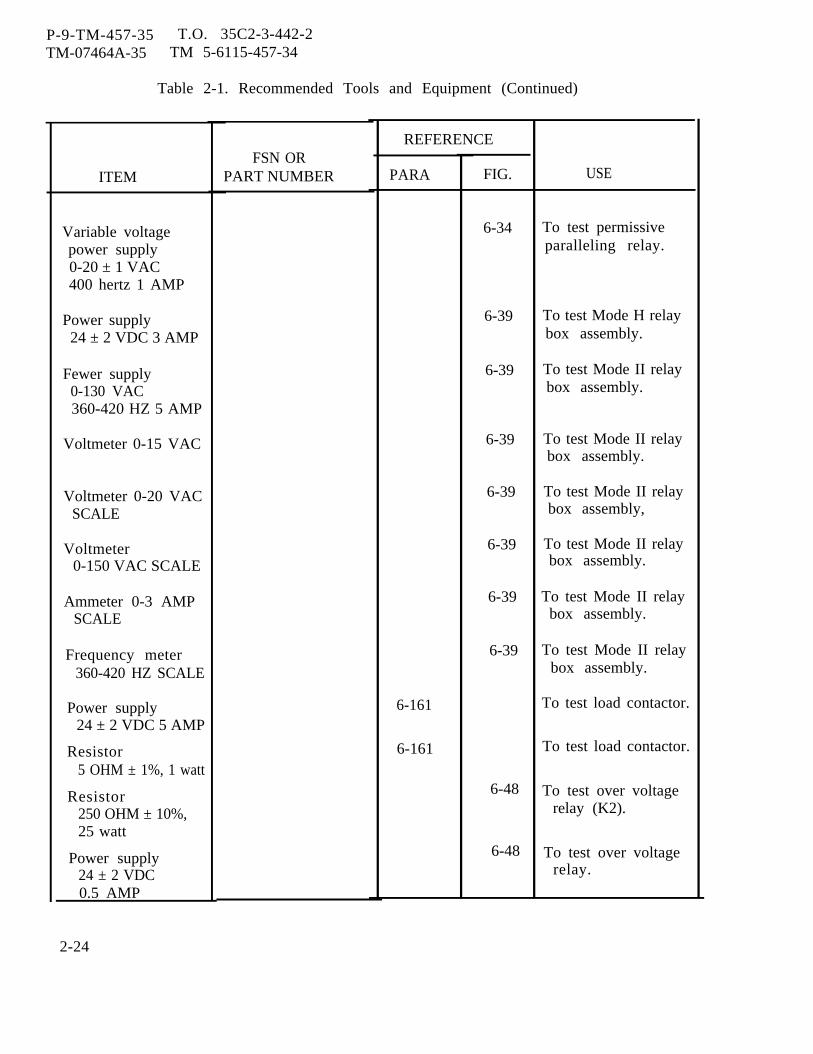
P-9-TM-457-35 T.O. 35C2-3-442-2TM-07464A-35 TM 5-6115-457-34
Table 2-1. Recommended Tools and Equipment (Continued)
ITEM
Variable voltagepower supply0-20 ± 1 VAC400 hertz 1 AMP
Power supply24 ± 2 VDC 3 AMP
Fewer supply0-130 VAC360-420 HZ 5 AMP
Voltmeter 0-15 VAC
Voltmeter 0-20 VACSCALE
Voltmeter0-150 VAC SCALE
Ammeter 0-3 AMPSCALE
Frequency meter360-420 HZ SCALE
Power supply24 ± 2 VDC 5 AMP
Resistor5 OHM ± 1%, 1 watt
Resistor250 OHM ± 10%,25 watt
Power supply24 ± 2 VDC0.5 AMP
FSN ORPART NUMBER
REFERENCE
PARA
6-161
6-161
FIG.
6-34
6-39
6-39
6-39
6-39
6-39
6-39
6-39
6-48
6-48
USE
To test permissiveparalleling relay.
To test Mode H relaybox assembly.
To test Mode II relaybox assembly.
To test Mode II relaybox assembly.
To test Mode II relaybox assembly,
To test Mode II relaybox assembly.
To test Mode II relaybox assembly.
To test Mode II relaybox assembly.
To test load contactor.
To test load contactor.
To test over voltagerelay (K2).
To test over voltagerelay.
2-24

P-9-TM-457-35 T O 35C2-3-442-2TM-07464A-35 TM 5-6115-457-34
Table 2-1. Recommended Tools and Equipment (Continued)
REFERENCEFSN OR
ITEM PART NUMBER PARA FIG. USE
Variable voltage 6-48 To test over voltagepower supply relay,0-160 VAC60 HERTZ
Variable volt age 6-48 To test over voltagepower supply relay.0-160 VAC400 HERTZ
Power supply 6-51 To test reverse pow-24 ± 2 VDC er relay.0.5 AMP
Oscillator 6-51 To test reverse pow-er relay.
Variable voltage 6-51 To test reverse pow-power supply er relay.0-10 ± 1 VDC1 AMP
Power supply 6-54 To test short circuit24 ± 2 VDC relay.0.5 AMP
Power source 6-54 To test short circuit0-50 ± 5 VAC relay.
60 hertz singlephase 1 AMP
Indica tor , 6625-00-414-6626 6-211 SCU alignmentDigi ta l 6-211A
Power supply 6-57 To test overload
24 ± 2 VDC relay.
0. 5 AMP
Change 6 2-25
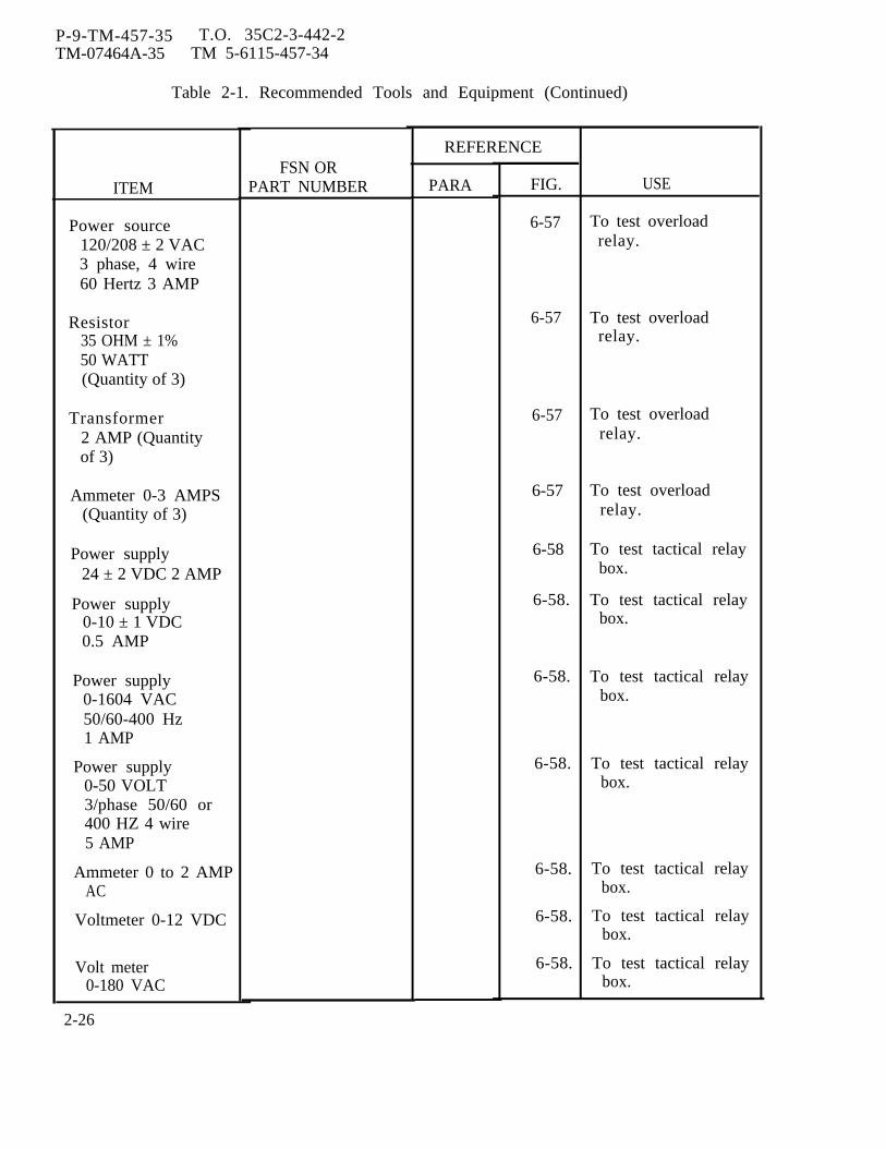
P-9-TM-457-35 T.O. 35C2-3-442-2TM-07464A-35 TM 5-6115-457-34
Table 2-1. Recommended Tools and Equipment (Continued)
ITEM
Power source120/208 ± 2 VAC3 phase, 4 wire60 Hertz 3 AMP
Resistor35 OHM ± 1%50 WATT(Quantity of 3)
Transformer2 AMP (Quantityof 3)
Ammeter 0-3 AMPS(Quantity of 3)
Power supply24 ± 2 VDC 2 AMP
Power supply0-10 ± 1 VDC0.5 AMP
Power supply0-1604 VAC50/60-400 Hz1 AMP
Power supply0-50 VOLT3/phase 50/60 or400 HZ 4 wire5 AMP
Ammeter 0 to 2 AMPAC
Voltmeter 0-12 VDC
Volt meter0-180 VAC
FSN ORPART NUMBER
REFERENCE
PARA FIG.
6-57
6-57
6-57
6-57
6-58
6-58.
6-58.
6-58.
6-58.
6-58.
6-58.
USE
To test overloadrelay.
To test overloadrelay.
To test overloadrelay.
To test overloadrelay.
To test tactical relaybox.
To test tactical relaybox.
To test tactical relaybox.
To test tactical relaybox.
To test tactical relaybox.
To test tactical relaybox.
To test tactical relaybox.
2-26
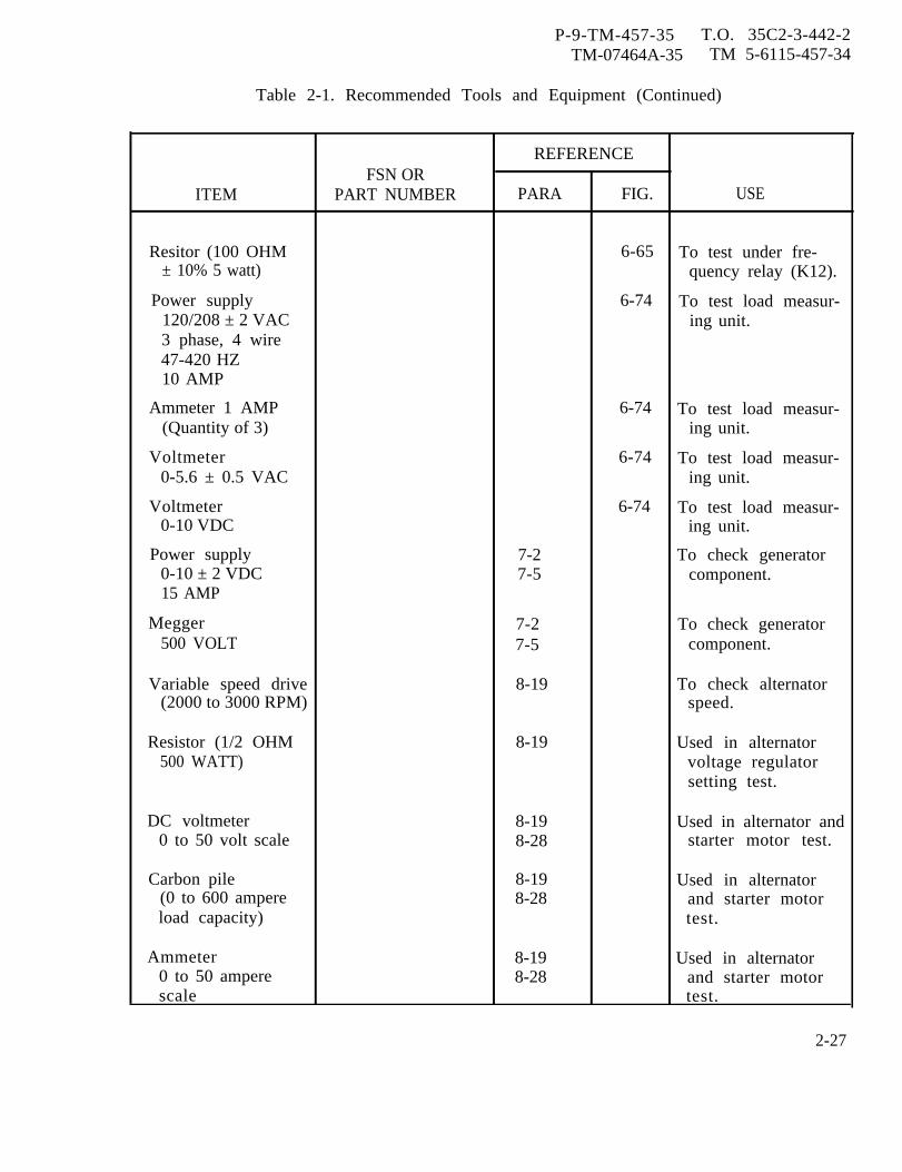
P-9-TM-457-35 T.O. 35C2-3-442-2TM-07464A-35 TM 5-6115-457-34
Table 2-1. Recommended Tools and Equipment (Continued)
REFERENCEFSN OR
ITEM PART NUMBER PARA FIG. USE
Resitor (100 OHM 6-65 To test under fre-± 10% 5 watt) quency relay (K12).
Power supply 6-74 To test load measur-120/208 ± 2 VAC ing unit.3 phase, 4 wire47-420 HZ10 AMP
Ammeter 1 AMP 6-74 To test load measur-(Quantity of 3) ing unit.
Voltmeter 6-74 To test load measur-0-5.6 ± 0.5 VAC ing unit.
Voltmeter 6-74 To test load measur-0-10 VDC ing unit.
Power supply 7-2 To check generator0-10 ± 2 VDC 7-5 component.15 AMP
Megger 7-2 To check generator500 VOLT 7-5 component.
Variable speed drive 8-19 To check alternator(2000 to 3000 RPM) speed.
Resistor (1/2 OHM 8-19 Used in alternator500 WATT) voltage regulator
setting test.
DC voltmeter 8-19 Used in alternator and0 to 50 volt scale 8-28 starter motor test.
Carbon pile 8-19 Used in alternator(0 to 600 ampere 8-28 and starter motorload capacity) test.
Ammeter 8-19 Used in alternator0 to 50 ampere 8-28 and starter motorscale test.
2-27
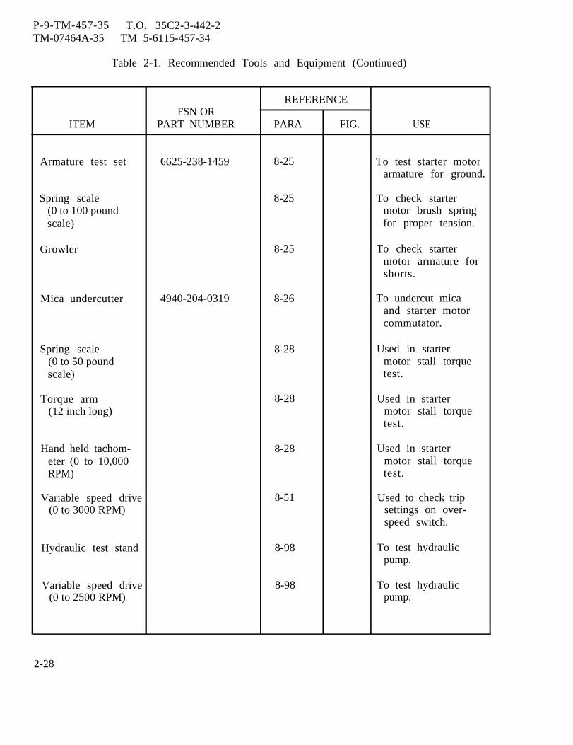
P-9-TM-457-35 T.O. 35C2-3-442-2TM-07464A-35 TM 5-6115-457-34
Table 2-1. Recommended Tools and Equipment (Continued)
REFERENCEFSN OR
ITEM PART NUMBER PARA FIG. USE
Armature test set 6625-238-1459 8-25 To test starter motorarmature for ground.
Spring scale 8-25 To check starter(0 to 100 pound motor brush springscale) for proper tension.
Growler 8-25 To check startermotor armature forshorts.
Mica undercutter 4940-204-0319 8-26 To undercut micaand starter motorcommutator.
Spring scale 8-28 Used in starter(0 to 50 pound motor stall torquescale) test.
Torque arm 8-28 Used in starter(12 inch long) motor stall torque
test.
Hand held tachom- 8-28 Used in startereter (0 to 10,000 motor stall torqueRPM) test.
Variable speed drive 8-51 Used to check trip(0 to 3000 RPM) settings on over-
speed switch.
Hydraulic test stand 8-98 To test hydraulicpump.
Variable speed drive 8-98 To test hydraulic(0 to 2500 RPM) pump.
2-28
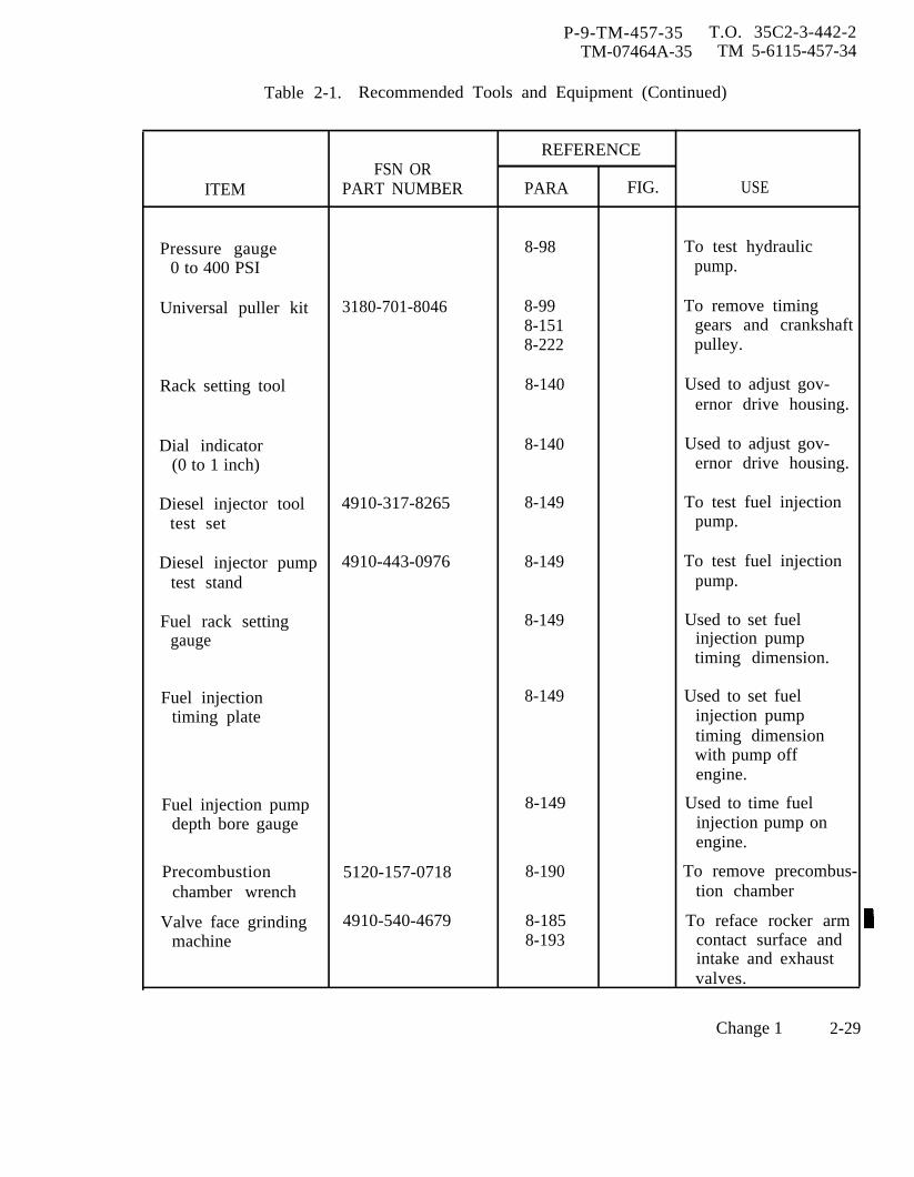
P-9-TM-457-35 T.O. 35C2-3-442-2TM-07464A-35 TM 5-6115-457-34
Table 2-1. Recommended Tools and Equipment (Continued)
REFERENCEFSN OR
ITEM PART NUMBER PARA FIG. USE
Pressure gauge 8-98 To test hydraulic0 to 400 PSI pump.
Universal puller kit 3180-701-8046 8-99 To remove timing8-151 gears and crankshaft8-222 pulley.
Rack setting tool 8-140 Used to adjust gov-ernor drive housing.
Dial indicator 8-140 Used to adjust gov-(0 to 1 inch) ernor drive housing.
Diesel injector tool 4910-317-8265 8-149 To test fuel injectiontest set pump.
Diesel injector pump 4910-443-0976 8-149 To test fuel injectiontest stand pump.
Fuel rack setting 8-149 Used to set fuelgauge injection pump
timing dimension.
Fuel injection 8-149 Used to set fueltiming plate injection pump
timing dimensionwith pump offengine.
Fuel injection pump 8-149 Used to time fueldepth bore gauge injection pump on
engine.
Precombustion 5120-157-0718 8-190 To remove precombus-chamber wrench tion chamber
Valve face grinding 4910-540-4679 8-185 To reface rocker armmachine 8-193 contact surface and
intake and exhaustvalves.
Change 1 2-29
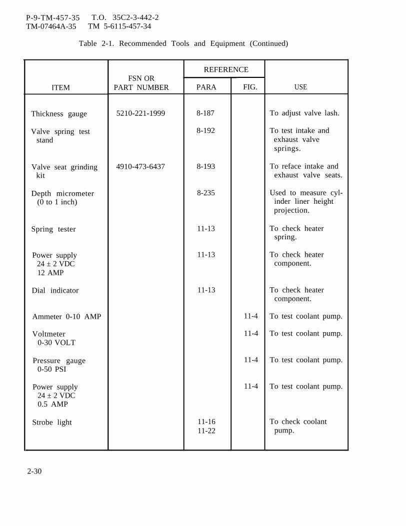
P-9-TM-457-35 T.O. 35C2-3-442-2TM-07464A-35 TM 5-6115-457-34
Table 2-1. Recommended Tools and Equipment (Continued)
ITEM
Thickness gauge
Valve spring teststand
Valve seat grindingkit
Depth micrometer(0 to 1 inch)
Spring tester
Power supply24 ± 2 VDC12 AMP
Dial indicator
Ammeter 0-10 AMP
Voltmeter0-30 VOLT
Pressure gauge0-50 PSI
Power supply24 ± 2 VDC0.5 AMP
Strobe light
FSN ORPART NUMBER
5210-221-1999
4910-473-6437
REFERENCE
PARA
8-187
8-192
8-193
8-235
11-13
11-13
11-13
11-1611-22
FIG.
11-4
11-4
11-4
11-4
USE
To adjust valve lash.
To test intake andexhaust valvesprings.
To reface intake andexhaust valve seats.
Used to measure cyl-inder liner heightprojection.
To check heaterspring.
To check heatercomponent.
To check heatercomponent.
To test coolant pump.
To test coolant pump.
To test coolant pump.
To test coolant pump.
To check coolantpump.
2-30
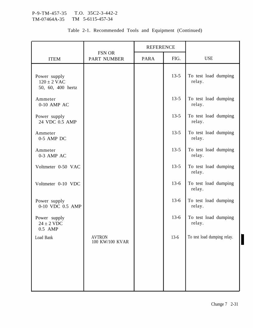
P-9-TM-457-35 T.O. 35C2-3-442-2TM-07464A-35 TM 5-6115-457-34
Table 2-1. Recommended Tools and Equipment (Continued)
REFERENCEFSN OR
ITEM PART NUMBER PARA FIG. USE
Power supply 13-5 To test load dumping120 ± 2 VAC relay.50, 60, 400 hertz
Ammeter 13-5 To test load dumping0-10 AMP AC relay.
Power supply 13-5 To test load dumping24 VDC 0.5 AMP relay.
Ammeter 13-5 To test load dumping0-5 AMP DC relay.
Ammeter 13-5 To test load dumping0-3 AMP AC relay.
Voltmeter 0-50 VAC 13-5 To test load dumpingrelay.
Voltmeter 0-10 VDC 13-6 To test load dumpingrelay.
Power supply 13-6 To test load dumping0-10 VDC 0.5 AMP relay.
Power supply 13-6 To test load dumping24 ± 2 VDC relay.0.5 AMP
Load Bank AVTRON 13-6 To test load dumping relay.100 KW/100 KVAR
Change 7 2-31

P-9-TM-457-35 T.O. 35C2-3-442-2TM-07464A-35 TM 5-6115-457-34
Table 2-2. Specially Designed (Fabricated) Tools and Equipment
REFERENCEITEM USE
FIGURE PARAGRAPH
Holding fixture 2-1A 8-71 Repair of turbocharger.
Holding fixture adapter 2-1B 8-71 Repair of turbocharger
Supporting screw 2-1C 8-71 Repair of turbocharger
Wrench 2-1D 8-71 Repair of turbocharger
Wooden dowel 2-1E 8-71 Repair of turbocharger
Pilot 2-1 F 8-202 Installation of crank-shaft seal
Sleeve 2-1G 8-202 Installation of crank-shaft seal
Generator moving 2-1H 7-3 Used when movingblock generator
Lifting fixture 2-1I 7-3 Used during disassem-bly of generator
2-32
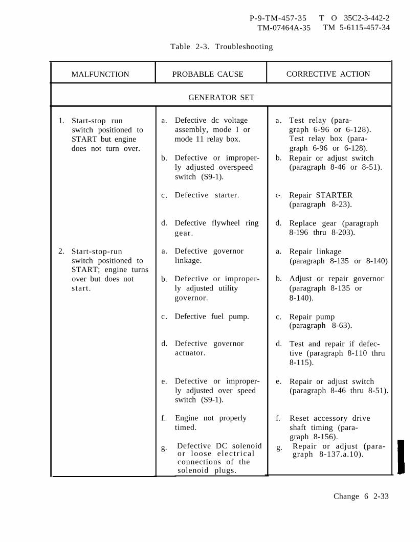
P-9-TM-457-35 T O 35C2-3-442-2TM-07464A-35 TM 5-6115-457-34
Table 2-3. Troubleshooting
MALFUNCTION PROBABLE CAUSE CORRECTIVE ACTION
GENERATOR SET
1.
2.
Start-stop runswitch positioned toSTART but enginedoes not turn over.
Start-stop-runswitch positioned toSTART; engine turnsover but does notstart.
a.
b.
c.
d.
a.
b.
c.
d.
e.
f.
g.
Defective dc voltageassembly, mode I ormode 11 relay box.
Defective or improper-ly adjusted overspeedswitch (S9-1).
Defective starter.
Defective flywheel ringgear.
Defective governorlinkage.
Defective or improper-ly adjusted utilitygovernor.
Defective fuel pump.
Defective governoractuator.
Defective or improper-ly adjusted over speedswitch (S9-1).
Engine not properlytimed.
Defective DC solenoidor loose e lec t r ica lconnections of thesolenoid plugs.
a.
b.
c-.
d.
a.
b.
c.
d.
e.
f.
g.
Test relay (para-graph 6-96 or 6-128).Test relay box (para-graph 6-96 or 6-128).Repair or adjust switch(paragraph 8-46 or 8-51).
Repair STARTER(paragraph 8-23).
Replace gear (paragraph8-196 thru 8-203).
Repair linkage(paragraph 8-135 or 8-140)
Adjust or repair governor(paragraph 8-135 or8-140).
Repair pump(paragraph 8-63).
Test and repair if defec-tive (paragraph 8-110 thru8-115).
Repair or adjust switch(paragraph 8-46 thru 8-51).
Reset accessory driveshaft timing (para-graph 8-156).Repair or adjust (para-graph 8-137.a.10).
Change 6 2-33
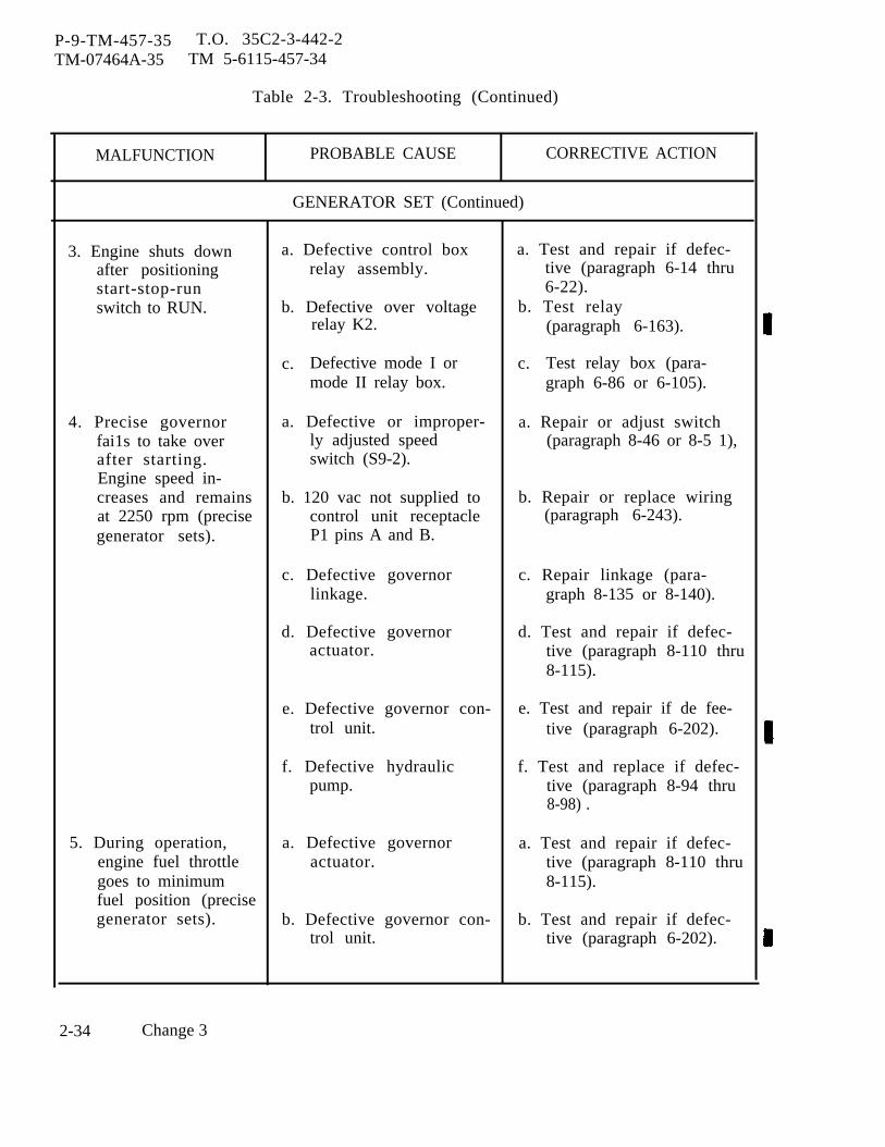
P-9-TM-457-35 T.O. 35C2-3-442-2TM-07464A-35 TM 5-6115-457-34
Table 2-3. Troubleshooting (Continued)
MALFUNCTION PROBABLE CAUSE CORRECTIVE ACTION
GENERATOR SET (Continued)
3. Engine shuts down a. Defective control box a. Test and repair if defec-after positioning relay assembly. tive (paragraph 6-14 thrustart-stop-run 6-22).switch to RUN. b. Defective over voltage b. Test relay
relay K2. (paragraph 6-163).
c. Defective mode I or c. Test relay box (para-mode II relay box. graph 6-86 or 6-105).
4. Precise governor a. Defective or improper- a. Repair or adjust switchfai1s to take over ly adjusted speed (paragraph 8-46 or 8-5 1),after starting. switch (S9-2).Engine speed in-creases and remains b. 120 vac not supplied to b. Repair or replace wiringat 2250 rpm (precise control unit receptacle (paragraph 6-243).generator sets). P1 pins A and B.
c. Defective governor c. Repair linkage (para-linkage. graph 8-135 or 8-140).
d. Defective governor d. Test and repair if defec-actuator. tive (paragraph 8-110 thru
8-115).
e. Defective governor con- e. Test and repair if de fee-trol unit. tive (paragraph 6-202).
f. Defective hydraulic f. Test and replace if defec-pump. tive (paragraph 8-94 thru
8-98) .
5. During operation, a. Defective governor a. Test and repair if defec-engine fuel throttle actuator. tive (paragraph 8-110 thrugoes to minimum 8-115).fuel position (precisegenerator sets). b. Defective governor con- b. Test and repair if defec-
trol unit. tive (paragraph 6-202).
2-34 Change 3
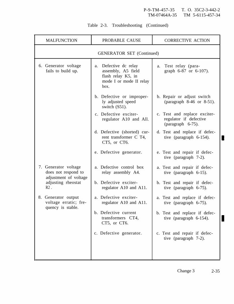
P-9-TM-457-35 T. O. 35C2-3-442-2TM-07464A-35 TM 5-6115-457-34
Table 2-3. Troubleshooting (Continued)
MALFUNCTION PROBABLE CAUSE CORRECTIVE ACTION
GENERATOR SET (Continued)
6. Generator voltage a. Defective dc relay a. Test relay (para-fails to build up. assembly, A5 field graph 6-87 or 6-107).
flash relay K5, inmode I or mode II relaybox.
b. Defective or improper- b. Repair or adjust switchly adjusted speed (paragraph 8-46 or 8-51).switch (S51).
c. Defective exciter- c. Test and replace exciter-regulator A10 and All. regulator if defective
(paragraph 6-75).
d. Defective (shorted) cur- d. Test and replace if defec-rent transformer C T4, tive (paragraph 6-154).CT5, or CT6.
e. Defective generator. e. Test and repair if defec-tive (paragraph 7-2).
7. Generator voltage a. Defective control box a. Test and repair if defec-does not respond to relay assembly A4. tive (paragraph 6-15).adjustment of voltageadjusting rheostat b. Defective exciter- b. Test and repair if defec-R2 . regulator A10 and A11. tive (paragraph 6-75).
8. Generator output a. Defective exciter- a. Test and replace if defec-voltage erratic; fre- regulator A10 and A11. tive (paragraph 6-75).quency is stable.
b. Defective current b. Test and replace if defec-transformers CT4, tive (paragraph 6-154).CT5, or CT6.
c. Defective generator. c. Test and repair if defec-tive (paragraph 7-2).
Change 3 2-35
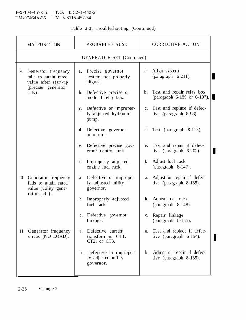
P-9-TM-457-35 T.O. 35C2-3-442-2TM-07464A-35 TM 5-6115-457-34
Table 2-3. Troubleshooting (Continued)
MALFUNCTION PROBABLE CAUSE CORRECTIVE ACTION
GENERATOR SET (Continued)
9.
10.
11.
Generator frequencyfails to attain ratedvalue after start-up(precise generatorsets).
Generator frequencyfails to attain ratedvalue (utility gene-rator sets).
Generator frequencyerratic (NO LOAD).
a.
b.
c.
d.
e.
f.
a.
b.
c.
a.
b.
Precise governorsystem not properlyaligned.
Defective precise ormode II relay box.
Defective or improper-ly adjusted hydraulicpump.
Defective governoractuator.
Defective precise gov-ernor control unit.
Improperly adjustedengine fuel rack.
Defective or improper-ly adjusted utilitygovernor.
Improperly adjustedfuel rack.
Defective governorlinkage.
Defective currenttransformers CT1.CT2, or CT3.
Defective or improper-ly adjusted utilitygovernor.
a.
b.
c.
d.
e.
f.
a.
b.
c.
a.
b.
Align system(paragraph 6-211).
Test and repair relay box(paragraph 6-189 or 6-107).
Test and replace if defec-tive (paragraph 8-98).
Test (paragraph 8-115).
Test and repair if defec-tive (paragraph 6-202).
Adjust fuel rack(paragraph 8-147).
Adjust or repair if defec-tive (paragraph 8-135).
Adjust fuel rack(paragraph 8-148).
Repair linkage(paragraph 8-135).
Test and replace if defec-tive (paragraph 6-154).
Adjust or repair if defec-tive (paragraph 8-135).
2-36 Change 3
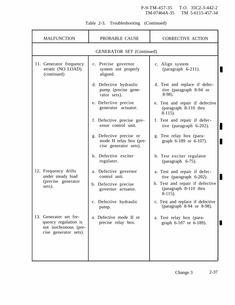
P-9-TM-457-35 T.O. 35C2-3-442-2TM-07464A-35 TM 5-6115-457-34
Table 2-3. Troubleshooting (Continued)
MALFUNCTION PROBABLE CAUSE CORRECTIVE ACTION
GENERATOR SET (Continued)
11. Generator frequency c. Precise governor c. Align systemerratic (NO LOAD). system not properly (paragraph 6-211).(continued) aligned.
d. Defective hydraulic d. Test and replace if defec-pump (precise gene- tive (paragraph 8-94 orrator sets). 8-98).
e. Defective precise e. Test and repair if defectivegenerator actuator. (paragraph 8-110 thru
8-115).
f. Defective precise gov- f. Test and repair if defec-ernor control unit. tive (paragraph 6-202).
g. Defective precise or g. Test relay box (para-mode H relay box (pre- graph 6-189 or 6-107).cise generator sets).
h. Defective exciter h. Test exciter regulatorregulater. (paragraph 6-75).
12. Frequency drifts a. Defective governor a. Test and repair if defec-under steady load control unit. tive (paragraph 6-202).(precise generatorsets). b. Defective precise b. Test and repair if defective
governor actuator. (paragraph 8-110 thru8-115).
c. Defective hydraulic c. Test and replace if defectivepump. (paragraph 8-94 or 8-98).
13. Generator set fre- a. Defective mode II or a. Test relay box (para-quency regulation is precise relay box. graph 6-107 or 6-189).not isochronous (pre-cise generator sets).
Change 3 2-37

P-9-TM-457-35 T.O. 35C2-3-442-2TM-07464A-35 TM 5-6115-457-34
Table 2-3. Troubleshooting (Continued)
MALFUNCTION PROBABLE CAUSE CORRECTIVE ACTION
GENERATOR SET (Continued)
ENGINE SHUTS DOWN AND/OR LOAD CONTACTOROR MOTOR OPERATED CIRCUIT BREAKER OPENSDUE TO PROTECTIVE FUNCTION AND FAULT LO-CATOR ILLUMINATES AS FOLLOWS:
14. Low oil pressure a. Broken oi1 line or a. Repair or replace.indicator DS1. fitting.
b. Defective oil pump. b. Repair pump(paragraph 8-174).
c. Clogged or defective oil c. Clean, inspect and repaircooler. cooler (paragraph 8-77
thru 8-84).
15. Overspeed indicator a. Defective or improp- a. Test and repair if defec-DS2. erly adjusted utility tive (paragraph 8-135 thru
governor. 8-140).
b. Defective governor b. Repair linkagelinkage. (paragraph 8-135).
c. Improperly adjusted c. Adjust rackfuel rack. (paragraph 8-148).
d. Defective precise gov- d. Test and repair if defec-ernor actuator (precise tive (paragraph 8-110 thrugenerator sets). 8-115).
e. Defective governor con- e. Test and repair if defec-trol unit (precise gene- tive (paragraph 6-202).rator sets).
f. Defective or improp- f. Repair or adjust switcherly adjusted speed (paragraph 8-46 or 8-51).switch (SS1).
2-38 Change 3
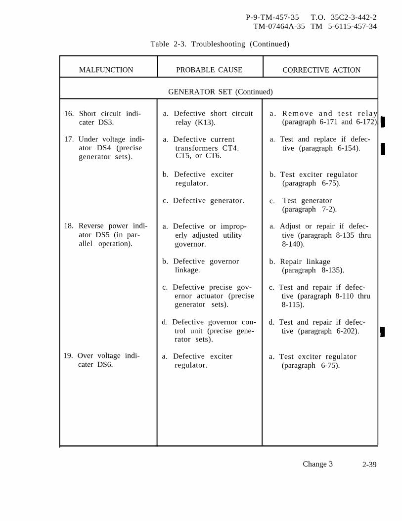
P-9-TM-457-35 T.O. 35C2-3-442-2TM-07464A-35 TM 5-6115-457-34
Table 2-3. Troubleshooting (Continued)
MALFUNCTION PROBABLE CAUSE CORRECTIVE ACTION
GENERATOR SET (Continued)
16. Short circuit indi- a. Defective short circuit a . R e m o v e a n d t e s t r e l a ycater DS3. relay (K13). (paragraph 6-171 and 6-172).
17. Under voltage indi- a. Defective current a. Test and replace if defec-ator DS4 (precise transformers CT4. tive (paragraph 6-154).generator sets). CT5, or CT6.
b. Defective exciter b. Test exciter regulatorregulator. (paragraph 6-75).
c. Defective generator. c. Test generator(paragraph 7-2).
18. Reverse power indi- a. Defective or improp- a. Adjust or repair if defec-ator DS5 (in par- erly adjusted utility tive (paragraph 8-135 thruallel operation). governor. 8-140).
b. Defective governor b. Repair linkagelinkage. (paragraph 8-135).
c. Defective precise gov- c. Test and repair if defec-ernor actuator (precise tive (paragraph 8-110 thrugenerator sets). 8-115).
d. Defective governor con- d. Test and repair if defec-trol unit (precise gene- tive (paragraph 6-202).rator sets).
19. Over voltage indi- a. Defective exciter a. Test exciter regulatorcater DS6. regulator. (paragraph 6-75).
Change 3 2-39
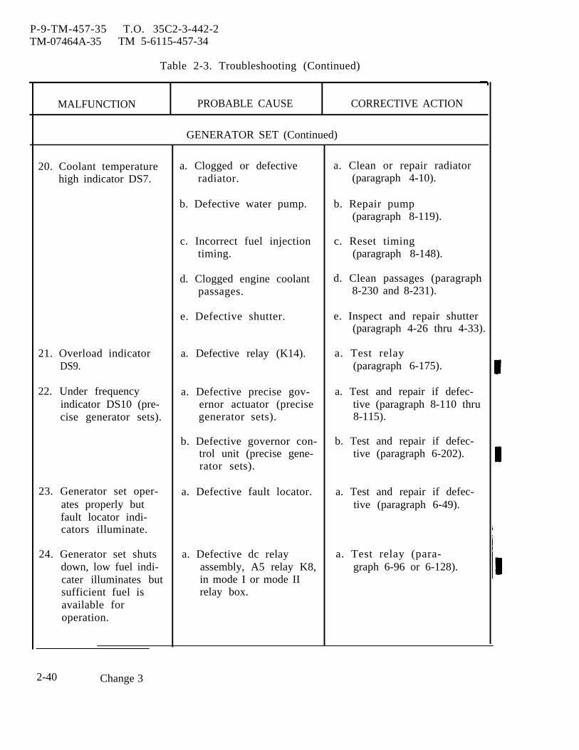
P-9-TM-457-35 T.O. 35C2-3-442-2TM-07464A-35 TM 5-6115-457-34
Table 2-3. Troubleshooting (Continued)
MALFUNCTION PROBABLE CAUSE CORRECTIVE ACTION
GENERATOR SET (Continued)
20. Coolant temperature a. Clogged or defective a. Clean or repair radiatorhigh indicator DS7. radiator. (paragraph 4-10).
b. Defective water pump. b. Repair pump(paragraph 8-119).
c. Incorrect fuel injection c. Reset timingtiming. (paragraph 8-148).
d. Clogged engine coolant d. Clean passages (paragraphpassages. 8-230 and 8-231).
e. Defective shutter. e. Inspect and repair shutter(paragraph 4-26 thru 4-33).
21. Overload indicator a. Defective relay (K14). a. Test relayDS9. (paragraph 6-175).
22. Under frequency a. Defective precise gov- a. Test and repair if defec-indicator DS10 (pre- ernor actuator (precise tive (paragraph 8-110 thrucise generator sets). generator sets). 8-115).
b. Defective governor con- b. Test and repair if defec-trol unit (precise gene- tive (paragraph 6-202).rator sets).
23. Generator set oper- a. Defective fault locator. a. Test and repair if defec-ates properly but tive (paragraph 6-49).fault locator indi-cators illuminate.
24. Generator set shuts a. Defective dc relay a. Test relay (para-down, low fuel indi- assembly, A5 relay K8, graph 6-96 or 6-128).cater illuminates but in mode I or mode IIsufficient fuel is relay box.available foroperation.
2-40 Change 3
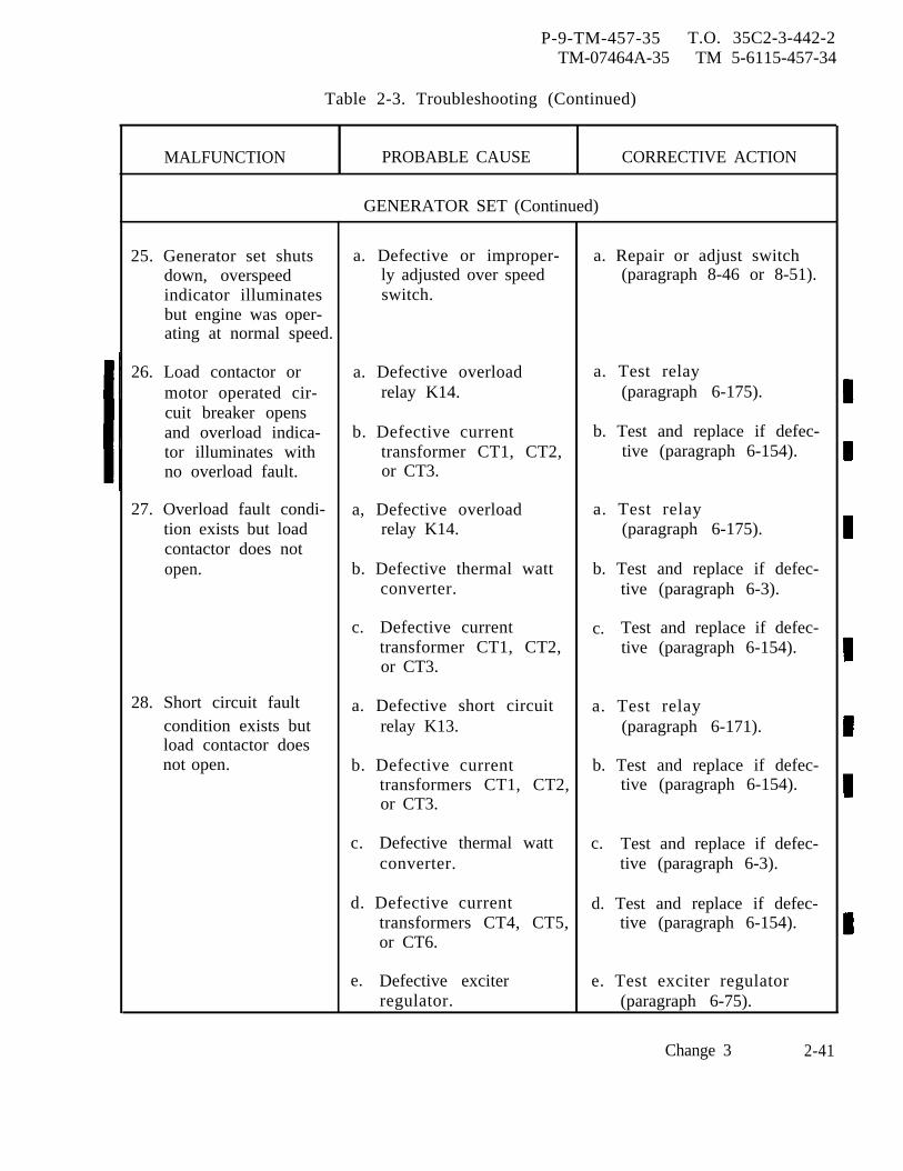
P-9-TM-457-35 T.O. 35C2-3-442-2TM-07464A-35 TM 5-6115-457-34
Table 2-3. Troubleshooting (Continued)
MALFUNCTION PROBABLE CAUSE CORRECTIVE ACTION
GENERATOR SET (Continued)
25. Generator set shuts a. Defective or improper- a. Repair or adjust switchdown, overspeed ly adjusted over speed (paragraph 8-46 or 8-51).indicator illuminates switch.but engine was oper-ating at normal speed.
26. Load contactor or a. Defective overload a. Test relaymotor operated cir- relay K14. (paragraph 6-175).cuit breaker opensand overload indica- b. Defective current b. Test and replace if defec-tor illuminates with transformer CT1, CT2, tive (paragraph 6-154).no overload fault. or CT3.
27. Overload fault condi- a, Defective overload a. Test relaytion exists but load relay K14. (paragraph 6-175).contactor does notopen. b. Defective thermal watt b. Test and replace if defec-
converter. tive (paragraph 6-3).
c. Defective current c. Test and replace if defec-transformer CT1, CT2, tive (paragraph 6-154).or CT3.
28. Short circuit fault a. Defective short circuit a. Test relaycondition exists but relay K13. (paragraph 6-171).load contactor doesnot open. b. Defective current b. Test and replace if defec-
transformers CT1, CT2, tive (paragraph 6-154).or CT3.
c. Defective thermal watt c. Test and replace if defec-converter. tive (paragraph 6-3).
d. Defective current d. Test and replace if defec-transformers CT4, CT5, tive (paragraph 6-154).or CT6.
e. Defective exciter e. Test exciter regulatorregulator. (paragraph 6-75).
Change 3 2-41
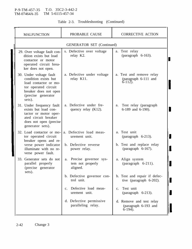
P-9-TM-457-35 T.O. 35C2-3-442-2TM-07464A-35 TM 5-6115-457-34
Table 2-3. Troubleshooting (Continued)
MALFUNCTION PROBABLE CAUSE CORRECTIVE ACTION
GENERATOR SET (Continued)
29. Over voltage fault con- s. Defective over voltage a. Test relaydition exists but load relay K2. (paragraph 6-163).contactor or motoroperated circuit brea-ker does not open.
30. Under voltage fault a. Defective under voltage a. Test and remove relaycondition exists but relay K11. (paragraph 6-111 andload contactor or mo- 6-112).tor operated circuitbreaker does not open(precise generatorsets).
31. Under frequency fault a. Defective under fre- a. Test relay (paragraphexists but load con- quency relay (K12). 6-189 and 6-190).tactor or motor oper-ated circuit breakerdoes not open (precisegenerator sets).
32. Load contactor or mo- a. Defective load meas- a. Test unittor operated circuit urement unit. (paragraph 6-213).breaker opens and re-verse power indicator b. Defective reverse b. Test and replace relayilluminate with no re- power relay. (paragraph 6-167).verse power fault.
33. Generator sets do not a. Precise governor sys- a. Align systemparallel properly tem not properly (paragraph 6-211).(precise generator aligned.sets).
b. Defective governor con- b. Test and repair if defec-trol unit. tive (paragraph 6-202).
c. Defective load meas- c. Test uniturement unit. (paragraph 6-213).
d. Defective permissive d. Remove and test relayparalleling relay. (paragraph 6-193 and
6-194).
2-42 Change 3

P-9-TM-457-35 T.O. 35C2-3-442-2TM-07464A-35 TM 5-6115-457-34
Table 2-3. Troubleshooting (Continued)
MALFUNCTION PROBABLE CAUSE CORRECTIVE ACTION
GENERATOR SET (Continued)
34. Attempting to par- a. Defective mode I or a. Test relay box (para-allel, without output mode II relay box. graph 6-96 or 6-128).connected for120/208 VAC, syn-chronizing lights arevery dim.
35. During parallel oper- a. Defective load contactor a. Test and replace if defec-ation, load contactor or motor operated cir- tive (paragraph 6-145).or motor operated cuit breaker.circuit breaker of set b. Defective permissive b. Test relay (paragraphnumber 2 will not paralleling relay K16 6-115).close. (precise generator
sets).
c. Defective dc relay as- C. Test relaysembly, A5 in mode I (paragraph 6-96 or 6-128).or mode II relay box.
36. During parallel oper- a. Defective or improp- a. Adjust or replace rheostatation, generator sets erly adjusted KVA (paragraph 6-104).do not share total rheostat R29.KVA equally.
b. Defective parallel b. Rebuild receptaclesreceptacles. (paragraph 5-5).
c. Defective mode I or c. Test relay box (para-mode II relay box. graph 6-96 or 6-128).
d. Defective exciter d. Test exciter regulatorregulator (paragraph 6-76).
e. Defective current e. Test and replace if defec-transformers CT4, CT5, tive (paragraph 6-154).or CT6.
f. Defective generator. f. Test and repair if defec-tive (paragraph 7-2).
Change 3 2-43
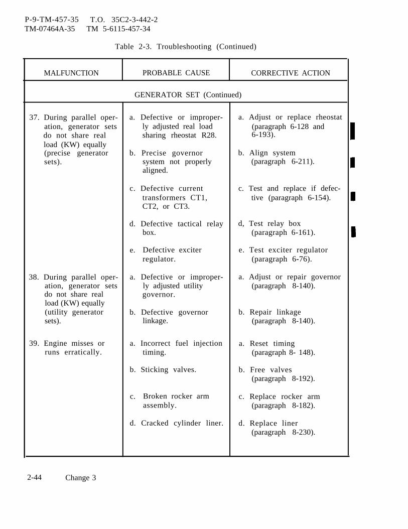
P-9-TM-457-35 T.O. 35C2-3-442-2TM-07464A-35 TM 5-6115-457-34
Table 2-3. Troubleshooting (Continued)
MALFUNCTION PROBABLE CAUSE CORRECTIVE ACTION
GENERATOR SET (Continued)
37. During parallel oper- a. Defective or improper- a. Adjust or replace rheostatation, generator sets ly adjusted real load (paragraph 6-128 anddo not share real sharing rheostat R28. 6-193).load (KW) equally(precise generator b. Precise governor b. Align systemsets). system not properly (paragraph 6-211).
aligned.
c. Defective current c. Test and replace if defec-transformers CT1, tive (paragraph 6-154).CT2, or CT3.
d. Defective tactical relay d, Test relay boxbox. (paragraph 6-161).
e. Defective exciter e. Test exciter regulatorregulator. (paragraph 6-76).
38. During parallel oper- a. Defective or improper- a. Adjust or repair governoration, generator sets ly adjusted utility (paragraph 8-140).do not share real governor.load (KW) equally(utility generator b. Defective governor b. Repair linkagesets). linkage. (paragraph 8-140).
39. Engine misses or a. Incorrect fuel injection a. Reset timingruns erratically. timing. (paragraph 8- 148).
b. Sticking valves. b. Free valves(paragraph 8-192).
c. Broken rocker arm c. Replace rocker armassembly. (paragraph 8-182).
d. Cracked cylinder liner. d. Replace liner(paragraph 8-230).
2-44 Change 3

P-9-TM-457-35 T.O. 35C2-3-442-2TM-07464A-35 TM 5-6115-457-34
Table 2-3. Troubleshooting (Continued)
MALFUNCTION PROBABLE CAUSE CORRECTIVE ACTION
GENERATOR SET (Continued)
39. Engine misses or e. Blown head gasket. e. Replace gasketruns erratically. (paragraph 8-189).(continued)
f. Broken valve spring. f. Replace spring(paragraph 8-182).
g. Defective fuel injection g. Replace nozzlenozzle. (paragraph 8-143).
h. Defective fuel injection h. Repair pumppump. (paragraph 8-143).
i. Bend or broken push i. Replace push rodrod. (paragraph 8-182).
j. Defective piston or j. Replace piston or ringsrings. (paragraph 8-214).
40. Engine hunts (pre - a. Defective exciter a. Remove, test and replacesise generator sets). regulator if defective (paragraph
6-75 and 6-76).
b. Defective or imp oper- b. Test and adjust trans-ly adjusted governor ducer (paragraph 6-202).actuator feedbacktransducer.
c. Defective electronic c. Replace assembly (para-component assembly, graph 6-194 or 6-128).A26 in precise ormode II relay box.
d. Defective governor d. Test and repair if defec-actuator. tive (paragraph 8-109).
e. Defective control unit. e. Test and repair if defec-tive (paragraph 6-202).
Change 3 2-45
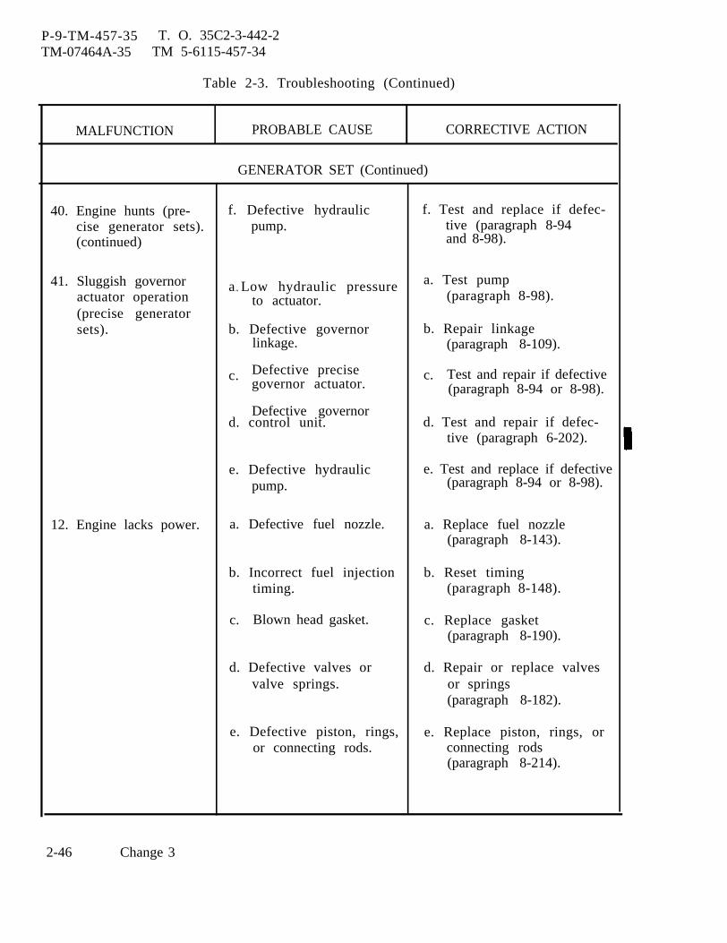
P-9-TM-457-35 T. O. 35C2-3-442-2TM-07464A-35 TM 5-6115-457-34
Table 2-3. Troubleshooting (Continued)
MALFUNCTION PROBABLE CAUSE CORRECTIVE ACTION
GENERATOR SET (Continued)
40. Engine hunts (pre- f. Defective hydraulic f. Test and replace if defec-cise generator sets). pump. tive (paragraph 8-94(continued) and 8-98).
41. Sluggish governor a “ Low hydraulic pressure a. Test pumpactuator operation to actuator. (paragraph 8-98).(precise generatorsets). b. Defective governor b. Repair linkage
linkage. (paragraph 8-109).
c. Defective precise c. Test and repair if defectivegovernor actuator. (paragraph 8-94 or 8-98).
Defective governord. control unit. d. Test and repair if defec-
tive (paragraph 6-202).
e. Defective hydraulic e. Test and replace if defectivepump. (paragraph 8-94 or 8-98).
12. Engine lacks power. a. Defective fuel nozzle. a. Replace fuel nozzle(paragraph 8-143).
b. Incorrect fuel injection b. Reset timingtiming. (paragraph 8-148).
c. Blown head gasket. c. Replace gasket(paragraph 8-190).
d. Defective valves or d. Repair or replace valvesvalve springs. or springs
(paragraph 8-182).
e. Defective piston, rings, e. Replace piston, rings, oror connecting rods. connecting rods
(paragraph 8-214).
2-46 Change 3
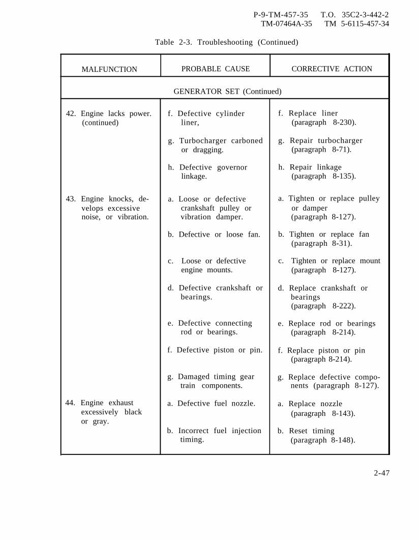
P-9-TM-457-35 T.O. 35C2-3-442-2TM-07464A-35 TM 5-6115-457-34
Table 2-3. Troubleshooting (Continued)
MALFUNCTION PROBABLE CAUSE CORRECTIVE ACTION
GENERATOR SET (Continued)
42. Engine lacks power. f. Defective cylinder f. Replace liner(continued) liner, (paragraph 8-230).
g. Turbocharger carboned g. Repair turbochargeror dragging. (paragraph 8-71).
h. Defective governor h. Repair linkagelinkage. (paragraph 8-135).
43. Engine knocks, de- a. Loose or defective a. Tighten or replace pulleyvelops excessive crankshaft pulley or or dampernoise, or vibration. vibration damper. (paragraph 8-127).
b. Defective or loose fan. b. Tighten or replace fan(paragraph 8-31).
c. Loose or defective c. Tighten or replace mountengine mounts. (paragraph 8-127).
d. Defective crankshaft or d. Replace crankshaft orbearings. bearings
(paragraph 8-222).
e. Defective connecting e. Replace rod or bearingsrod or bearings. (paragraph 8-214).
f. Defective piston or pin. f. Replace piston or pin(paragraph 8-214).
g. Damaged timing gear g. Replace defective compo-train components. nents (paragraph 8-127).
44. Engine exhaust a. Defective fuel nozzle. a. Replace nozzleexcessively black (paragraph 8-143).or gray.
b. Incorrect fuel injection b. Reset timingtiming. (paragraph 8-148).
2-47

P-9-TM-457-35 T. O. 35C2-3-442-2TM-07464A-35 TM 5-6115-457-34
Table 2-3. Troubleshooting (Continued)
MALFUNCTION PROBABLE CAUSE CORRECTIVE ACTION
GENERATOR SET (Continued)
45. Engine exhaust a. Defective valve guides. a. Repair cylinder headexcessively white (paragraph 8-143).or blue.
b. Defective piston rings. b. Replace rings(paragraph 8-214).
c. Incorrect fuel injection c. Reset timingtiming. (paragraph 8-148).
46. Excessive engine oil a. Excessive valve guide a. Repair cylinder headconsumption. wear. (paragraph 8-190).
b. High oil temperature b. Repair coolerdue to defective oil (paragraph 8-79).cooler.
c. Worn piston rings c. Replace piston ringsand/or cylinder liners. (paragraph 8-214) and/or
cylinder liners (para-graph 8-236).
47. Heavy engine com- a. Defective fuel injection a. Replace plunger and bar-bustion knock. pump plunger and rel assembly
barrel assembly. (paragraph 8-143).
b. Defective or leaking b. Replace fuel injectionfuel injection valve. valve (paragraph 8-143).
48. Engine valve train a. Defective valve spring. a. Replace springclicking noise. (paragraph 8-143).
b. Insufficient lubrication b. Clean oil passages lead-in valve compartment. ing to the cylinder head
(paragraph 8-191).
2-48

P-9-TM-457-35 T.O. 35C2-3-442-2TM-07464A-35 TM 5-6115-457-34
Table 2-3. Troubleshooting (Continued)
MALFUNCTION PROBABLE CAUSE CORRECTIVE ACTION
GENERATOR SET (Continued)
49. Engine lubricating a. Defective cylinder a. Replace gasketoil in coolant. head gasket. (paragraph 8-190).
b. Defective oil cooler b. Repair or replace coolercore. (paragraph 8-82).
50. Engine stalls at low a. Idle speed too low. a. Adjust governor low idlespeed. setting (paragraph 8-237).
b. Defective fuel injection b. Repair valvevalve. (paragraph 8-143).
51. Loud valve train a. Defective camshaft. a. Replace camshaftnoise in engine. (paragraph 8-206).
b. Defective valve lifters. b. Replace valve lifters(paragraph 8-182).
52. Little rocker arm a. Defective camshaft a. Replace camshaft and/ormovement and and/or followers. followersexcessive valve lash. (paragraph 8-206).
b. Defective valve lifters. b. Replace lifters(paragraph 8-182).
c. Defective push rod. c. Replace rod(paragraph 8-182).
d. Insufficient lubrication d. Clean oil passagesin valve compartment. (paragraph 8-185).
Change 1 2-49
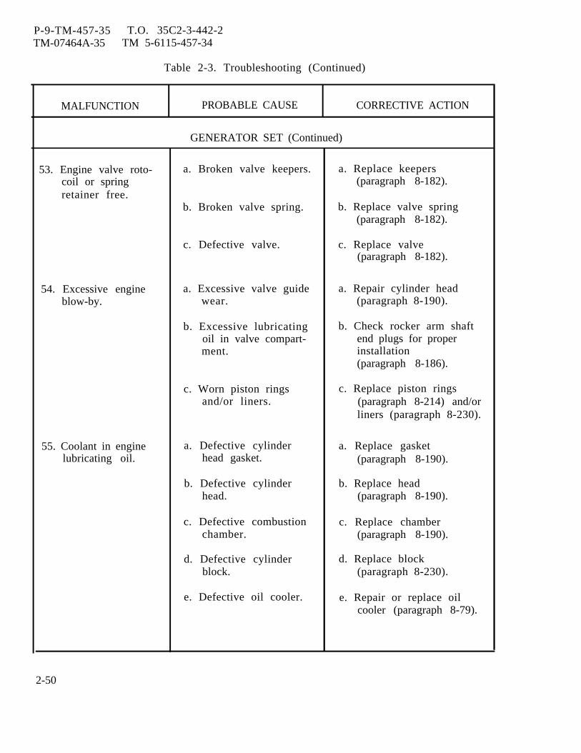
P-9-TM-457-35 T.O. 35C2-3-442-2TM-07464A-35 TM 5-6115-457-34
Table 2-3. Troubleshooting (Continued)
MALFUNCTION PROBABLE CAUSE CORRECTIVE ACTION
GENERATOR SET (Continued)
53. Engine valve roto- a. Broken valve keepers. a. Replace keeperscoil or spring (paragraph 8-182).retainer free.
b. Broken valve spring. b. Replace valve spring(paragraph 8-182).
c. Defective valve. c. Replace valve(paragraph 8-182).
54. Excessive engine a. Excessive valve guide a. Repair cylinder headblow-by. wear. (paragraph 8-190).
b. Excessive lubricating b. Check rocker arm shaftoil in valve compart- end plugs for properment. installation
(paragraph 8-186).
c. Worn piston rings c. Replace piston ringsand/or liners. (paragraph 8-214) and/or
liners (paragraph 8-230).
55. Coolant in engine a. Defective cylinder a. Replace gasketlubricating oil. head gasket. (paragraph 8-190).
b. Defective cylinder b. Replace headhead. (paragraph 8-190).
c. Defective combustion c. Replace chamberchamber. (paragraph 8-190).
d. Defective cylinder d. Replace blockblock. (paragraph 8-230).
e. Defective oil cooler. e. Repair or replace oilcooler (paragraph 8-79).
2-50
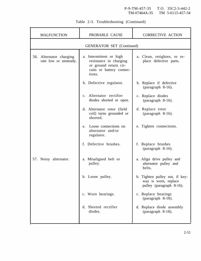
P-9-TM-457-35 T.O. 35C2-3-442-2TM-07464A-35 TM 5-6115-457-34
Table 2-3. Troubleshooting (Continued)
MALFUNCTION PROBABLE CAUSE CORRECTIVE ACTION
GENERATOR SET (Continued)
56. Alternator charging a. Intermittent or high a. Clean, retighten, or re-rate low or unsteady. resistance in charging place defective parts.
or ground return cir-cuits or battery connec-tions.
b. Defective regulator. b. Replace if defective(paragraph 8-16).
c. Alternator rectifier c. Replace diodesdiodes shorted or open. (paragraph 8-16).
d. Alternator rotor (field d. Replace rotorcoil) turns grounded or (paragraph 8-16).shorted.
e. Loose connections on e. Tighten connections.alternator and/orregulator.
f. Defective brushes. f. Replace brushes(paragraph 8-16).
57. Noisy alternator. a. Misaligned belt or a. Align drive pulley andpulley. alternator pulley and
belts.
b. Loose pulley. b. Tighten pulley nut, if key-way is worn, replacepulley (paragraph 8-16).
c. Worn bearings. c. Replace bearings(paragraph 8-18).
d. Shorted rectifier d. Replace diode assemblydiodes. (paragraph 8-18).
2-51
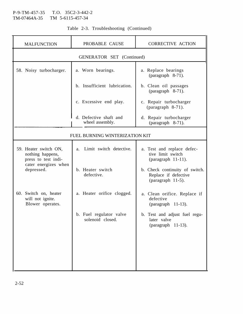
P-9-TM-457-35 T.O. 35C2-3-442-2TM-07464A-35 TM 5-6115-457-34
Table 2-3. Troubleshooting (Continued)
wheel assembly.
MALFUNCTION PROBABLE CAUSE CORRECTIVE ACTION
GENERATOR SET (Continued)
58. Noisy turbocharger. a. Worn bearings. a. Replace bearings(paragraph 8-71).
b. Insufficient lubrication. b. Clean oil passages(paragraph 8-71).
c. Excessive end play. c. Repair turbocharger(paragraph 8-71).
d. Defective shaft and d. Repair turbocharger(paragraph 8-71).
FUEL BURNING WINTERIZATION KIT
59. Heater switch ON, a. Limit switch detective. a. Test and replace defec-nothing happens, tive limit switchpress to test indi- (paragraph 11-11).cater energizes whendepressed. b. Heater switch b. Check continuity of switch.
defective. Replace if defective(paragraph 11-5).
60. Switch on, heater a. Heater orifice clogged. a. Clean orifice. Replace ifwill not ignite. defectiveBlower operates. (paragraph 11-13).
b. Fuel regulator valve b. Test and adjust fuel regu-solenoid closed. later valve
(paragraph 11-13).
2-52
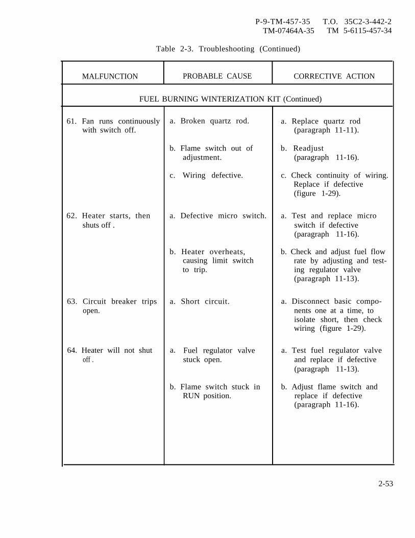
P-9-TM-457-35 T.O. 35C2-3-442-2TM-07464A-35 TM 5-6115-457-34
Table 2-3. Troubleshooting (Continued)
MALFUNCTION PROBABLE CAUSE CORRECTIVE ACTION
FUEL BURNING WINTERIZATION KIT (Continued)
61. Fan runs continuously a. Broken quartz rod. a. Replace quartz rodwith switch off. (paragraph 11-11).
b. Flame switch out of b. Readjustadjustment. (paragraph 11-16).
c. Wiring defective. c. Check continuity of wiring.Replace if defective(figure 1-29).
62. Heater starts, then a. Defective micro switch. a. Test and replace microshuts off . switch if defective
(paragraph 11-16).
b. Heater overheats, b. Check and adjust fuel flowcausing limit switch rate by adjusting and test-to trip. ing regulator valve
(paragraph 11-13).
63. Circuit breaker trips a. Short circuit. a. Disconnect basic compo-open. nents one at a time, to
isolate short, then checkwiring (figure 1-29).
64. Heater will not shut a. Fuel regulator valve a. Test fuel regulator valveoff . stuck open. and replace if defective
(paragraph 11-13).
b. Flame switch stuck in b. Adjust flame switch andRUN position. replace if defective
(paragraph 11-16).
2-53
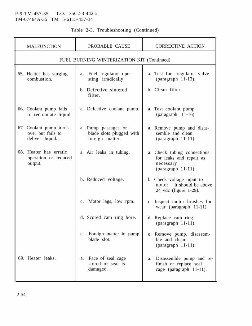
P-9-TM-457-35 T.O. 35C2-3-442-2TM-07464A-35 TM 5-6115-457-34
Table 2-3. Troubleshooting (Continued)
MALFUNCTION PROBABLE CAUSE CORRECTIVE ACTION
FUEL BURNING WINTERIZATION KIT (Continued)
65. Heater has surging a. Fuel regulator oper- a. Test fuel regulator valvecombustion. sting irradically. (paragraph 11-13).
b. Defective sintered b. Clean filter.filter.
66. Coolant pump fails a. Defective coolant pump. a. Test coolant pumpto recirculate liquid. (paragraph 11-16).
67. Coolant pump turns a. Pump passages or a. Remove pump and disas-over but fails to blade slots plugged with semble and cleandeliver liquid. foreign matter. (paragraph 11-11).
68. Heater has erratic a. Air leaks in tubing. a. Check tubing connectionsoperation or reduced for leaks and repair asoutput. necessary
(paragraph 11-11).
b. Reduced voltage. b. Check voltage input tomotor. It should be above24 vdc (figure 1-29).
c. Motor lags, low rpm. c. Inspect motor brushes forwear (paragraph 11-11).
d. Scored cam ring bore. d. Replace cam ring(paragraph 11-11).
e. Foreign matter in pump e. Remove pump, disassem-blade slot. ble and clean
(paragraph 11-11).
69. Heater leaks. a. Face of seal cage a. Disassemble pump and re-stored or seal is finish or replace sealdamaged. cage (paragraph 11-11).
2-54

P-9-TM-457-35 T.O. 35C2-3-442-2TM-07464A-35 TM 5-6115-457-34
Table 2-3. Troubleshooting (Continued)
MALFUNCTION PROBABLE CAUSE CORRECTIVE ACTION
ELECTRIC WINTERIZATION KIT
70. Switch on control box a. Defective electric a. Test electric heater andpositioned to ON; heater. replace if defectiveheater ON indicator (paragraph 12-14).energized, coolantpump operating butcoolant temperaturenot rising.
71. Switch on control box a. Defective thermo switch a. Check continuity of switchpositioned to ON; S2. at room temperature. Itindicator energized should have continuity.but coolant not being Immerse its temperaturecirculated and cool- sensing element in a waterant temperature not bath at a temperature ofrising. 120 + °F. There should be
no continuity now. Allowwater to cool below 100°F.There should be continuityagain.
b. Defective control box. b. Test control box(paragraph 12-3).
c. Defective heater. c. Repair heater(paragraph 12-14).
d. Defective coolant pump. d. Test pump(paragraph 12-19).
72. Switch on control box a. No power to input re- a. Remove cable and measurepositioned to ON and ceptacle J49, terminals voltage to these two ter-indicator does not A and B, figure 1-30. minals. It should be be-energize. tween 205 to 240 VAC,
50/60 or 400 hertz.
b. Defective control box. b. Test control box(paragraph 12-3).
2-55
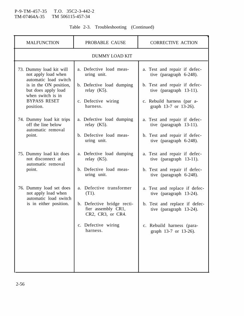
P-9-TM-457-35 T.O. 35C2-3-442-2TM-07464A-35 TM 506115-457-34
Table 2-3. Troubleshooting (Continued)
MALFUNCTION PROBABLE CAUSE CORRECTIVE ACTION
DUMMY LOAD KIT
73. Dummy load kit will a. Defective load meas- a. Test and repair if defec-not apply load when uring unit. tive (paragraph 6-248).automatic load switchis in the ON position, b. Defective load dumping b. Test and repair if defec-but does apply load relay (K5). tive (paragraph 13-11).when switch is inBYPASS RESET c. Defective wiring c. Rebuild harness (par a-position. harness. graph 13-7 or 13-26).
74. Dummy load kit trips a. Defective load dumping a. Test and repair if defec-off the line below relay (K5). tive (paragraph 13-11).automatic removalpoint. b. Defective load meas- b. Test and repair if defec-
uring unit. tive (paragraph 6-248).
75. Dummy load kit does a. Defective load dumping a. Test and repair if defec-not disconnect at relay (K5). tive (paragraph 13-11).automatic removalpoint. b. Defective load meas- b. Test and repair if defec-
uring unit. tive (paragraph 6-248).
76. Dummy load set does a. Defective transformer a. Test and replace if defec-not apply load when (T1). tive (paragraph 13-24).automatic load switchis in either position. b. Defective bridge recti- b. Test and replace if defec-
fier assembly CR1, tive (paragraph 13-24).CR2, CR3, or CR4.
c. Defective wiring c. Rebuild harness (para-harness. graph 13-7 or 13-26).
2-56
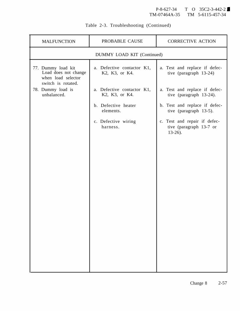
P-8-627-34 T O 35C2-3-442-2TM-07464A-35 TM 5-6115-457-34
Table 2-3. Troubleshooting (Continued)
MALFUNCTION PROBABLE CAUSE CORRECTIVE ACTION
DUMMY LOAD KIT (Continued)
77. Dummy load kit a. Defective contactor K1, a. Test and replace if defec-Load does not change K2, K3, or K4. tive (paragraph 13-24)when load selectorswitch is rotated.
78. Dummy load is a. Defective contactor K1, a. Test and replace if defec-unbalanced. K2, K3, or K4. tive (paragraph 13-24).
b. Defective heater b. Test and replace if defec-elements. tive (paragraph 13-5).
c. Defective wiring c. Test and repair if defec-harness. tive (paragraph 13-7 or
13-26).
Change 8 2-57

P-8-627-34 T O 35C2-3-442-2TM-07464A-35 TM 5-6115-457-34
Section IV. ENGINE CHANGE INSTRUCTIONS,
2-10. GENERAL.This section contains instructions
for the replacement of the existing D333C(T)engine, which is no longer manufactured,with the new D3306(T) engine.
2-11. ENGINE REMOVAL, D333C(T)ENGINE.Refer to paragraph 2-8 and remove
the existing D333C(T) engine.2-12. REMOVAL OF SALVAGABLE
COMPONENTS FROM THED333C(T) ENGINE.
The following components are to beremoved from the D333T engine and sal-vaged for installation on the D3306(T) engine.
a. Refer to Operation and Organi-zational Maintenance Manual and remove theoil pressure transmitter, low oil pressureswitch, coolant temperature transmitter,high coolant temperature switch, alternator,air cleaner, fuel filter and pump assembly,coolant drain valve, hydraulic tank andhydraulic filter assembly (MEP 116A only),starter motor, oil sump shut-off valve withhose assembly, elbow and nipple, and theturbocharger exhaust elbow.
b. Refer to paragraph 8-86 and re-move the hydraulic tank. Refer to figure 8-10 and remove the fan (3) in the sequence ofindex number assigned. Refer to figure 8-64 and remove the lube oil filler neck (30) inthe sequence of index numbers assigned.
2-13. INSTALLATION OF COMPONENTS,D3306(T) ENGINE.a . Installation of Salvaged and New
Components.
The following salvaged componentsfrom the D333C(T) engine are to be installedon the D3306(T) engine. Before installationof these components, completely remove allengine preservative packaging and proceed asfollows:
D3306(T) ENGINE
(1) Over speed Switch MagneticPickup. Before installing the D3306(T) en-gine into the generator set, refer to figure2-8 and install the magnetic pickup (85B) intothe engine flywheel housing. Pay particularattention to the following:
WARNING
Cleaning Solvents are flammable andmoderately toxic to skin, eyes andrespiratory tract. Eye and skinprotect ion required. Good generalventilation is normally adequate.
(a) Inspect flywheel for nicksand burrs on generator contact surfaces. Re-move nicks and burrs using a suitable file orstone. Clean flywheel with an approvedcleaning solvent and dry thoroughly.
(b) Run the locknut on thepickup (85B) to the electrical connector endof the pickup and thread the magnetic pickupinto the flywheel housing.
(c) Center one flywheel toothdirectly below the pickup head. Using a suit-able feeler gage, adjust the pickup to toothclearance to 0.015 to 0.020 inch gap. Pickupcan also be positioned by bottoming lightly ongear tooth and backing off 95° to 130° to ob-tain correct gap.
(d) Secure pickup and tightenlocknut. Recheck clearance.
(2) Engine. Refer to paragraph2-8 and install the D3306(T) engine into thegenerator set.
(3) Turbocharger Exhaust Elbow.Refer to figure 2-8 and install the salvagedturbocharger exhaust elbow (85E). Pay par-ticular attention to the following:
2-58 Change 8
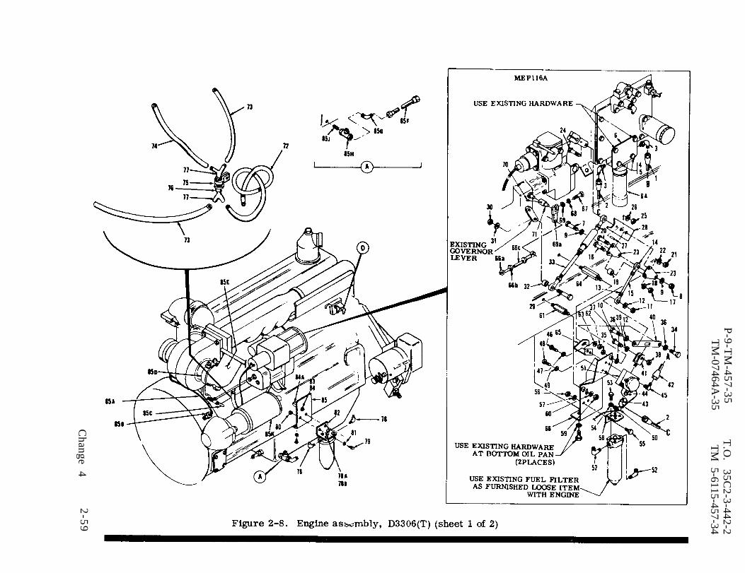
Figure 2-8.
P-9-T
M-457-35
T.O
. 35C
2-3-442-2T
M-07464A
-35T
M 5-6115-457-34
Change
42
-59
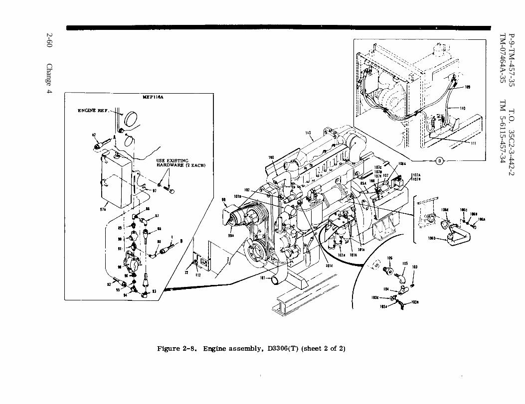
Figure 2-8.
P-9-T
M-457-35
T.O
. 35C
2-3-442-2T
M-07464A
-35T
M
5-6115-457-34
2-60C
hange 4

P-9-TM-457-35 T. O. 35C2-3-442-2TM-07464A-35 TM 5-6115-457-34
Legend to figure 2-8:
1.2.3.4.5.6.6A.7.8.9.
10.11.12.13.14.15.16.17.18.19.20.21.22.23.24.25.26.27.28.29.30.31.32.33.34.35.36.37.38.39.40.41.42.43.
Hose assemblyHose assemblyElbowScrew (2)Nut (2)Bracket, hydraulic filterHydraulic filter assy. (salvaged)ScrewNutWasherScrewNutWasherNutRod endThreaded rodScrewNutWasherRoller stopScrewNutWasherThrottle override plateScrewNutWasherSpring pinThrottle extension armScrewNutWasherLink spacerThrottle link assemblyScrewNutWasherScrewNutWasherGovernor throw extender linkHydraulic actuator clevisHose assemblyElbow
44.45.46.47.48.49.50.51.52.53.54.55.56.57.58.59.60.61.62.63.64.65.66.66A.66B.66C.67.68.69.69A.70.71.72.73.74•75.76.77.78.78A.78B.79.80.81.
ReducerElbowScrewWasherScrewWasherClampGovernor actuatorElbow (2)Screw (4)Washer (4)Screw (2)Nut (2)Washer (2)Fuel filter mounting bracketNutWasherStudNutWasherStudActuator mounting braceGovernor support bracketRod end bearingNutThreaded rodScrewWasherWasherSpeed control leverSetscrewShaft extenderPlastic tubingPlastic tubingPlastic tubingClampPlastic tubingPlastic fittingElbow (2)ScrewWasherScrew (2)Nut (2)Washer (2)
Change 4 2-61
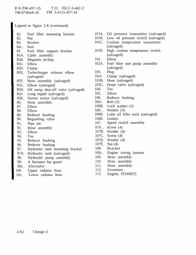
P-9-TM-457-35 T.O. 35C2-3-442-2TM-07464A-35 TM 5-6115-457-34
Legend to figure 2-8 (continued):
82.83.84.84A. .85.85A.85B.85C.85D.85E.
85F.85G.85H.85J.85K.86.87.88.89.90.910
92.93.94.95.96.97.97A.98.99.99A. .
100.101.
Fuel filter mounting bracketNutWasherStudFuel filter support bracketCable assemblyMagnetic pickupElbowClampTurbocharger exhaust elbow(salvaged)Hose assembly (salvaged)Elbow (salvaged)Oil sump shut-off valve (salvaged)Long nipple (salvaged)Starter motor (salvaged)Hose assemblyElbowElbowReducer bushingRegualting valvePipe teeHose assemblyElbowTeeReducer bushingReducer bushingHydraulic tank mounting bracketHydraulic tank (salvaged)Hydraulic pump assemblyA Iternator fan guardAlternatorUpper radiator hoseLower radiator hose
10 IA.101B.101C.
101D.
102.102A.
103.103A .103B.103C.104.105.106.106A. .106B.106C. .106D.106E.107.107A. .107B.107C.107D.107E.108.108A. .109.110.111.112.113.
Oil pressure transmitter (salvaged)Low oil pressure switch (salvaged)Coolant temperature transmitter(salvaged)High coolant temperature switch(salvaged)ElbowFuel filter and pump assembly(salvaged)PlugClamp (salvaged)Hose (salvaged)Drain valve (salvaged)TeeElbowReducer bushingBolt (3)Lock washer (3)Washer (3)Lube oil filler neck (salvaged)GasketSpeed switch assemblyScrew (4)Washer (4)Screw (4)Washer (4)Nut (4)BracketEngine wiring harnessHose assemblyHose assemblyHose assemblyGrommetEngine, D3306(T)
2-62 Change 4
P-9-TM-457-35 T.O. 35C2-3-442-2TM-07464A-35 TM 5-6115-457-34
(a) Remove the existingD3306(T) turbocharger exhaust elbow fromthe engine by removing the existing retain-ing clamp (85D).
(b) Install the salvagedturbocharger exhaust elbow (85E) onto theengine and secure with existing retainingclamp (85D). Make certain that water drainplug points directly downward.
(4) Oil Sump Shut-Off Valve.Refer to figure 2-8 and install the salvagedoil sump shut-off valve (85H), long nipple(85J), elbow (85G) and hose assembly (85F).
(5) Starter Motor. Refer tofigure 2-8 and install the salvaged startermotor (85K) and attaching hardware in theengine. Pay particular attention to thefollowing:
(a) Reconnect tagged elec-trical leads to the starter motor andsolenoid.
(6) Hydraulic Filter Assembly(MEP116A only). Refer to figure 2-8 andinstall the salvaged hydraulic filter assem-bly (6A) ) as shown. Pay particular attentionto the following:
(a) Assemble the hydraulicfilter bracket (6) to the salvaged filterassembly (6A) using screws (4) and self-locking nuts (5).
(b) Remove existing hard-ware as shown and mount the hydraulicfilter assembly to the engine.
(c) Connect elbows andhose assemblies as shown.
(7) Lube Oil Filler NeckAssembly. Refer to figure 2-8 and installthe saIvaged lube oil filler neck assembly(106D). Pay particular attention to thefollowing :
(a) Remove the existingD3306(T) lube oil filler neck assembly fromthe engine by removing three bolts (106A),three lockwashers (106B) and three washers(106C). Make certain not to damage existinggasket (106E).
(b) Install the salvaged lubeoil filler neck assembly (106D) to the engineusing the existing three bolts ( 106A), threelockwashers (106 B), three washers (106C)and gasket (106 E).
(8) Coolant Drain Valve. Referto figure 2-8 and install the salvaged coolantdrain valve (103C) as shown. Pay particularattention to the following:
(a) Apply thread sealingcompound conforming to Military SpecificationMIL-S-45180, type III to pipe threads prior toinstallation.
(b) Thread new reducerbushing (106) into engine block.
(c) Assemble tee (104), plug(103) and elbow (105). Thread assembly intoreducer bushing (106). Thread salvagedcoolant drain valve (103C) into tee (105) asshown.
(9) Fuel Filter and Pump Assem-bly. Refer to figure 2-8 and install the salva-ged fuel filter and pump assembly (102A) asshown. Pay particular attention to thefollowing:
(a) Connect tagged electricalleads and hoses.
(10) Alternator. Refer to figure2-8 and install the salvaged alternator (99A)as shown. Pay particular attention to thefollowing:
(a) Install new alternator fanguard (99) using salvaged hardware.
Change 4 2-63

P-9-TM-457-35 T.O. 35C2-3-442-2TM-07464A-35 TM 5-6115-457-34
(11) Fan. Refer to figure 8-10and install the salvaged fan in the reversesequence of index numbers assigned.
(12) Hydraulic Tank andHydraulic Pump (ME P116A only).
(a) Refer to figure 2-8 andremove the hydraulic tank mounting bracketfrom the salvaged hydraulic tank (97A).
(b) Install new mountingbracket (97) onto the hydraulic tank (97A).
(c) Refer to figure 2-8 andassemble the modified hydraulic tank (97A)and the new hydraulic pump (98) onto theengine as follows:
NOTE
Be sure hydraulic pumpgears mesh properly andthere is no binding.
1. Apply thread seal-ing compound conforming to Military Speci-fication MIL-S-45180, type III to pipethreads prior to installation.
2. Place hydraulicpump (98) into pump receptacle, makingcertain that gear teeth mesh properly and donot bind.
3. Place hydraulictank (97A) onto pump and secure bothassemblies with existing hardware.
hoses.4. Attach fittings and
(13) Alternator Belt and FanBelts. Refer to Operator and OrganizationalMaintenance Manual and install and adjustthe alternator belt and fan belts.
(14) High Coolant TemperatureSwitch. Refer to figure 2-8 and install thesalvaged high coolant temperature switch(101D) as shown. Apply thread sealing com-pound conforming to Military SpecificationMIL-S-45180, type III to pipe threads prior toinstallation.
(15) Coolant Temperature Trans-mitter. Refer to figure 2-8 and install thesalvaged coolant temperature transmitter(101C) as shown. Apply thread sealing com-pound conforming to Military SpecificationMIL-S-45180, type III, to pipe threads priorto installation.
(16) Low Oil Pressure Switch. Re-fer to figure 2-8 and install the salvaged lowoil pressure switch (101B) as shown. Applythread sealing compound conforming to Mili-tary Specification MIL-S-45180, type III topipe threads prior to installation.
(17) Oil Pressure Transmitter.Refer to figure 2-8 and install the salvaged oilpressure transmitter (101A) ) as shown. Applythread sealing compound conforming to Mili-tary Specification MIL-S-45180, type III topipe threads prior to installation.
(18) Over speed Switch. Refer tofigure 2-8 and install the overspeed switch(107). Pay particular attention to the following:
(a) Remove existing screws(107A) and washers (107B).
(b) Assemble the over speedswitch (107) to the over speed switch bracket(108) using screws (107C), washers (107D)and nuts (107E).
(c) Install the overspeedshutdown switch onto the generator as shown.
2-64 Change 4
P-8-627-34 T O 35C2-3-442-2TM-07464A-35 TM 5-6115-457-34
(d) Overspend switch cableassembly. Install connector P62 on thecable assembly (85A) to J62 on the over-speed switch (107). Connect loose end ofcable assembly (85A) to magnetic pickup(85B).
(19) Governor Actuator andLinkage (ME P116A only). Refer to figure2-8, sheet 1 and install the governor actua-tore (51) and the associated linkage as shown.Pay particular attention to the following:
(a) Install the final fuelfilter supplied with the 3306(T) engine to fuelfilter bracket (58) using screws (53) andwashers (54).
(20) Lifting Frame Assembly.Refer to paragraph 3-14 and install thelifting frame assembly onto the generatorskid base.
(21) Day Tank. Refer to Opera-tor and Organizational Maintenance Manualand install the day tank in the reverse se-quence of index numbers assigned.
(22) Engine Wiring Harness.Refer to figure 2-8 and Operator and Organi-zational Maintenance Manual and install theengine wiring harriess (108A). Pay parti-cular attention to the following:
(a) Install connector P37to J37 on overspeed switch (107).
(b) Connect harness con-nectors and wires.
(c) Secure harnesses withclamps.
(d) Join harnesses in com-mon run from one side of engine to oppositeside at six inch intervals with tiedown straps.
(23) Air Cleaner. Refer to Opera-tor and Organizational Maintenance Manualand install the air cleaner as shown.
(24) Manual Speed Control. Referto figure 2-8 and Operator and OrganizationalMaintenance Manual and connect the manualspeed control in the reverse sequence of in-dex numbers assigned.
(25) Radiator and Housing FrameAssembly. Refer to Operator and Organiza-tional Maintenance Manual and install theradiator and housing frame assembly in thereverse sequence of index numbers assigned.Pay particular attention to the following:
(a) Install new radiator hoses;upper hose (figure 2-8, 100) and lower hose(101).
(26) Doors and Covers. Refer toOperator and Organizational MaintenanceManual and install the doors and covers in thereverse sequence of index numbers assigned.
(27) Crankcase Breather Tube andHose. Refer to Operator and OrganizationalMaintenance Manual and install crankcasebreather tube and hose in reverse sequenceillustrated.
(28) Muffler and Exhaust Pipe.Refer to Operator and Organizational Main-tenance Manual and install muffler and ex-haust pipe.
(29) Engine Fuel Bleed LineInstallation. Refer to figures 2-8 and 2-9and install the engine fuel bleed line (72) asfollows:
WARNING
Drilling operations create metalchips which may enter the eye.Eye protection is required.
(a) Refer to figure 2-9 anddrill a 0.438 inch hole as illustrated.
(b) Refer to figure 2-8 and in-stall grommet (112). Install the engine fuelbleed line (72) as illustrated.
Change 8 2-65
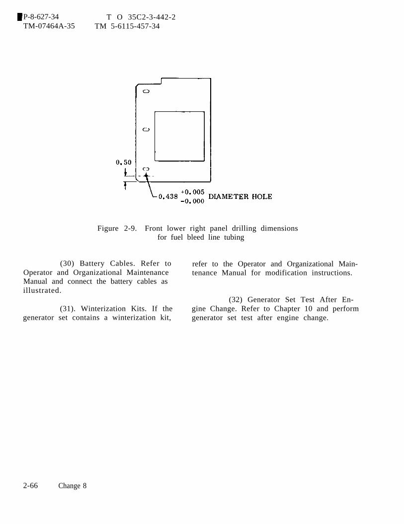
P-8-627-34 T O 35C2-3-442-2TM-07464A-35 TM 5-6115-457-34
Figure 2-9. Front lower right panel drilling dimensionsfor fuel bleed line tubing
(30) Battery Cables. Refer to refer to the Operator and Organizational Main-Operator and Organizational Maintenance tenance Manual for modification instructions.Manual and connect the battery cables asillustrated.
(32) Generator Set Test After En-(31). Winterization Kits. If the gine Change. Refer to Chapter 10 and perform
generator set contains a winterization kit, generator set test after engine change.
2-66 Change 8

P-9-TM-457-35 T.O. 35C2-3-442-2TM-07464A-35 TM 5-6115-457-34
CHAPTER 3
HOUSING AND LIFTING FRAME ASSEMBLY REPAIR INSTRUCTIONS
Section I. HOUSING FRAME
3-1. GENERAL.
a. HOUSING FRAME. The housingframe reinforces the housing panels anddoors. It provides interconnection betweenthe lifting frame and front and rear housings.
b. FRONT HOUSING. The front hous-ing is the mounting frame for the generatorset radiator and shutter assembly. It alsoprovides a connection point for the enginecrankcase breather tube and slave recepta-cle SR2.
c. REAR HOUSING. The rear housingprovides a mount for the control cubicle,fault locator panel, DC control cubicle,convenience receptacle, sleeve and plateassembly, parallel harness receptacles,manual speed control, and mounting open-ings for the controls of the generator setoptional kits which are covered by plates ifthe kits are not installed. It also containsthe air intake panel.
3-2. REMOVAL AND DISASSEMBLY.
Refer to figure 3-1 and remove anddisassemble the housing frame in the orderof index numbers assigned. Pay particularattention to the following:
a. Refer to Operator and OrganizationalMaintenance Manual and perform the follow-ing:
1. Disconnect negative battery cable.
2. Remove housing panels and doors.
3. Remove DC control circuitbreaker.
4. Disconnect parallel receptacleharness from rear housing.
5. Remove manual speed control.
6. Remove kit control panels fromrear housing, if installed.
7. Remove slave receptacles fromfront housing and receptacle mountingpanel.
8. Remove radiator and shutterassembly.
b. Remove control cubicle, as specifiedin paragraph 2-6.
c. Remove fault locator panel from rearhousing by disconnecting harness from rearof locator panel and removing four screwsattaching panel to rear housing.
d. Remove convenience receptacleassembly from rear housing by disconnect-ing harness from rear of assembly and re-moving six screws and washer securingassembly to rear housing.
3-1

P-9-TM-457-35 T.O. 35C2-3-442-2TM-07464A-35 TM 5-6115-457-34
Figure 3-1. Housing frame, exploded view
3-2

P-8-627-34 T O 35C2-3-442-2TM-07464A-35 TM 5-6115-457-34
Legend to figure 3-1:
2.3.4.5.6.7.
8.9.
10.11.12.13.14.15.16.17.18.19.20.21.22.23.24.25.26.27.28.29.
Screw assembly (2)Nut assembly (2)Connector coverScrew assembly (2)Nut assembly (2)Washer (2)External powerreceptacleScrew (4)Nut (4)Lock washer (4)Washer (4)BracketScrew (16)Nut (16)Upper side panel (4)Screw (3)Lock washer (3)Washer (4)Screw (4)Nut (4)Washer (8)Front housingScrew (4)Nut (4)Connector and leadScrew (4)Nut (4)Washer (8)Receptacle mountingpanel
30. Screw (4)31. Nut (4)32. Washer (8)33. Left side panel34. Screw (5)35. Nut (5)36. Washer (5)37. Bracket38. Screw (5)39. Nut (5)40. Washer (5)41. Bracket42. Screw (5)43. Nut (5)44. Washer (5)45. Bracket46. Screw (5)47. Nut (5)48. Washer (5)49. Bracket50. Screw (12)51. Lock washer (12)52. Washer (12)53. Air Intake panel54. Screw (4)55. Lock washer (4)56. Plate57. Screw (2)58. Lock washer (2)59. Plate60. Screw (6)
61.62.
63.64.
65.66.67.68.69.70.71.72.73.74.75.76.77.78.79.80.81.82.83.84.85.86.87.88.
Lock washer (6)Plate and sleeveassemblyScrew (4)Nut and washerassembly (4)BushingPlateSleevePlateScrew (6)Lock washer (6)PlateScrew (6)Lock washer (6)Washer (6)Screw (20)Lock washer (20)Washer (20)Screw (2)Lock washerWasher (2)SupportScrew (2)Lock washer (2)Washer (2)SupportScrew (2)Lock washer (2)Rear housing
Change 8 3-3
P-8-627-34 T O 35C2-3-442-2TM-07464A-35 TM 5-6115-457-34
3-3. CLEANING.
a. Clean electrical components with acloth moistened with an approved cleaningsolvent, and dry thoroughly.
WARNING
Cleaning Solvents are flammable andmoderately toxic to skin, eyes andrespiratory tract. Eye and skinprotection required. Good generalventilation is normally adequate.
b. Clean metal components with an ap-proved cleaning solvent, and dry thorough-ly.
3-4. INSPECTION.
a. Inspect slave receptacles and leadsfor continuity and for shorts to casing.
b. Inspect terminal lugs for securityand condition.
c. Inspect air intake panel screen forholes and tears.
d. Inspect components for dents,cracks, distortion.
e.
f.
3-5.
a .sheet
b.
Inspect threads for damage.
Inspector damage paint.
REPAIR.
Straighten dented and distortedmetal parts using suitable tools.
Remove damaged paint. Blend inedges, prime, and paint damaged areas.
3-6. REASSEMBLY AND INSTALLATION.
Refer to figure 3-1 and reassembleand install housing frame in the reverse
3-4 Change 8
order of index numbers assigned. Pay par-ticular attention to the following:
NOTE
Wiring harness interconnecting dia-gram is contained in Operator andOrganizational Maintenance Manual
a. Install convenience receptacle assem-bly in rear housing and secure with sixscrews and washers. Connect harness toassembly.
b. Install fault locater panel in rearhousing and secure with four screws. Con-nect harness to locator panel.
c. Install control cubicle, as specifiedin paragraph 2-6.
d. Refer to Operator and OrganizationalMaintenance Manual and perform the follow-ing:
1. Install radiator and shutterassembly.
2. Install slave receptacles and inf rent housing and receptacle mounting panel.
3. If necessary, install kit controlpanels.
4. Install manual speed control.
5. Connect parallel receptacle har-ness in rear housing.
6. Install DC control circuit breaker.
7. Install housing panels and doors.
8. Connect negative battery cable.
3-7.
to the
P-8-627-34 T O 35C2-3-442-2TM-07464A-35 TM 5-6115-457-34
Section II. LIFTING FRAME ASSEMBLY
GENERAL.
The lifting frame assembly is boltedskid base and provides the means of
lifting the generator set. Two clevis arelocated at the top of the lifting frame to per-mit attachment of a suitable lifting device.The lifting frame is the center support forthe housing assembly. Bolted to the liftingframe are the day tank,fuel tank filler neck andspeed control bracket.
3-8. REMOVAL.
fuel transfer valve,tube, and manual
Refer to figure 3-2 and remove lift-ing frame as follows:
a. Remove housing frame as specified inparagraph 3-2.
b. Refer to Operator and OrganizationalMaintenance Manual and perform the follow-ing:
1. Remove fuel transfer valve, fuelinlet fitting, and fuel supply outlet fitting.
2. Remove day tank.
3. Disconnect manualbracket from lifting frame.
speed control
4. Removal air cleaner.
c. Loosen clamp (1) securing hose (12)to fuel tank and remove hose from tank.Plug tank opening. Remove fuel linesconnected to filler neck.
d. Disconnect electrical connectors fromgovernor control unit (34) and lift governorcontrol unit (34) from retainer (41). Re-move guard (33) by removing screws (32).
e. Remove nuts (2 and 6), screws (4 and8), and washers (3, 5, 7, and 9). Connectan overhead lifting device to clevis (31) andremove lifting frame (10) from skid base.Guide lifting frame during lifting operationto prevent damage to components.
3-9. DISASSEMBLY.
Refer to figure 3-2 and disassemblelifting frame as follows:
a. Loosen clamp (11)(12).
b. Remove fuel filler
and remove hose
cap (13), pull capchain and remove filler tube (14) and capfrom filler neck (17).
c. Remove nuts (15), screws, (16),filler neck (17) and gasket (18) from liftingframe.
d. Remove nuts (19, 22, and 25),screws (20, 23, and 26), and plates (21, 24,and 27).
e. Remove cotter pins (28), nuts (29),screws (30), and clevis (31).
f. Remove retainer (41) and bracket (44)from lifting frame by removing screws (38and 42) nuts (39 and 43) and washers (40).Remove bracket (44) from retainer (41) byremoving screws (35), nuts (36) and washer(37).
3-10. CLEANING.
a. Clean old gasket from lifting frameand filler neck using a suitable scraper.
b. Clean parts with an approved clean-ing solvent, and dry thoroughly.
3-11. INSPECTION.
a. Inspect for damaged threads.
Change 8 3-5
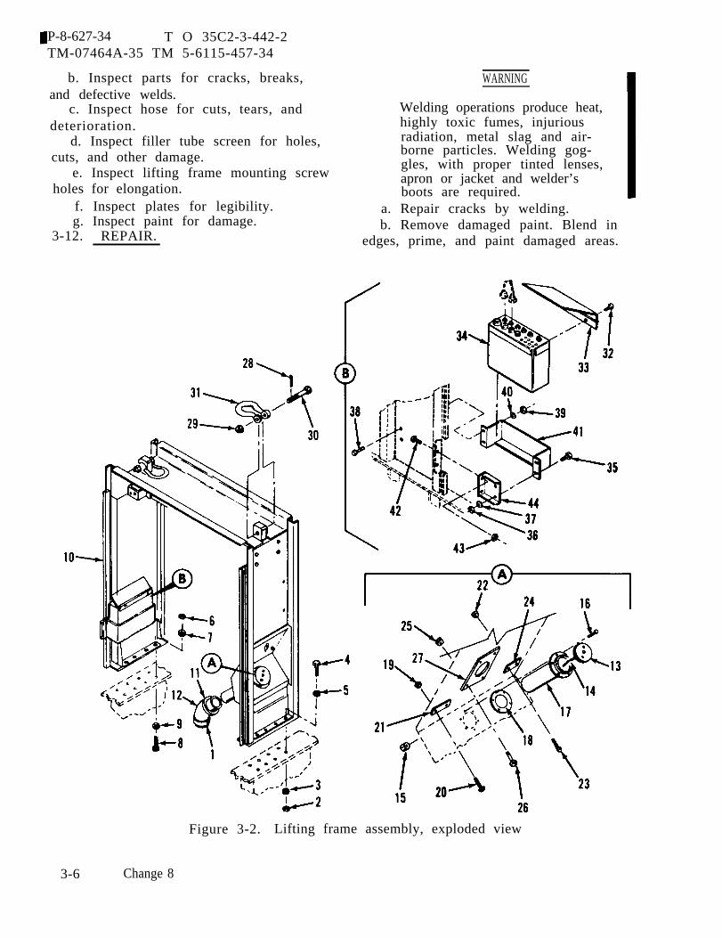
P-8-627-34 T O 35C2-3-442-2TM-07464A-35 TM 5-6115-457-34
b. Inspect parts for cracks, breaks,and defective welds.
c. Inspect hose for cuts, tears, anddeterioration.
d. Inspect filler tube screen for holes,cuts, and other damage.
e. Inspect lifting frame mounting screwholes for elongation.
f. Inspect plates for legibility.g. Inspect paint for damage.
3-12. REPAIR.
WARNING
Welding operations produce heat,highly toxic fumes, injuriousradiation, metal slag and air-borne particles. Welding gog-gles, with proper tinted lenses,apron or jacket and welder’sboots are required.
a. Repair cracks by welding.b. Remove damaged paint. Blend in
edges, prime, and paint damaged areas.
Figure 3-2. Lifting frame assembly, exploded view
3-6 Change 8
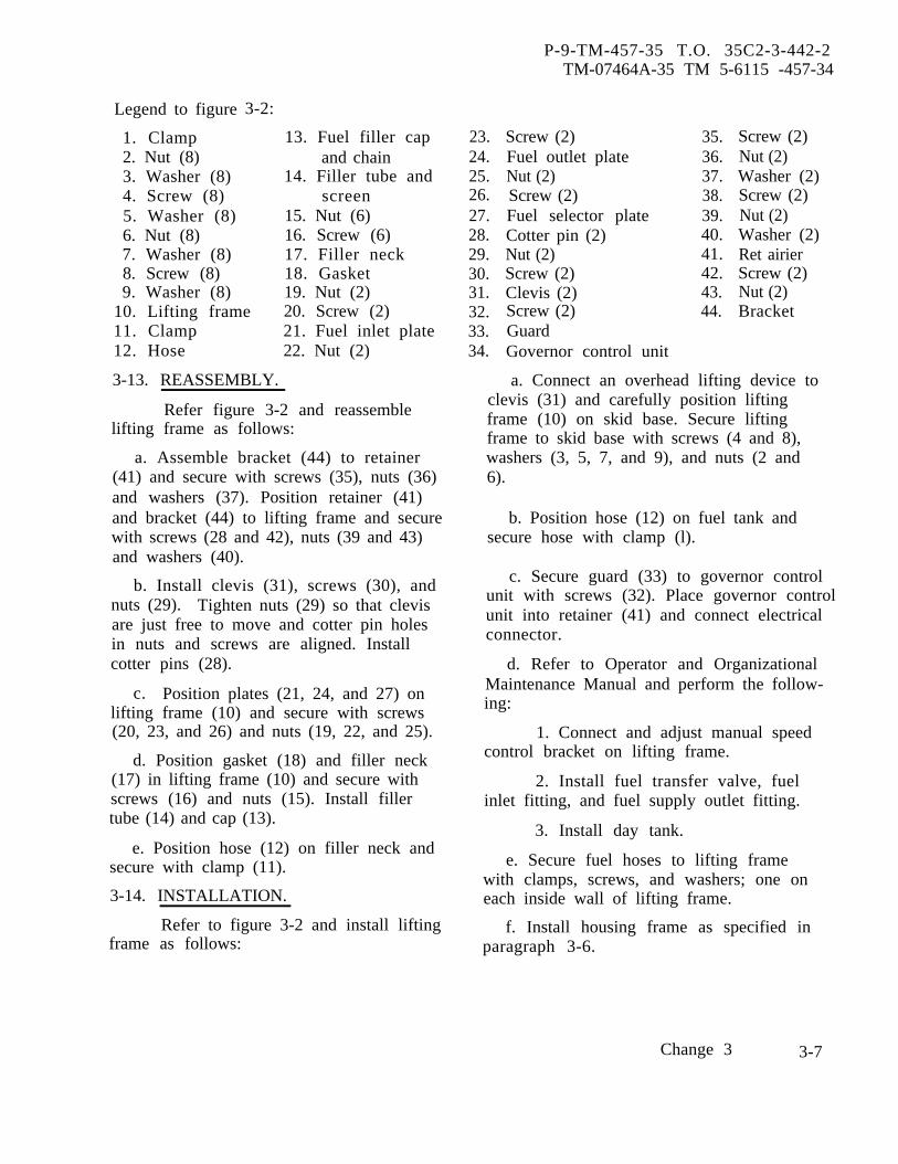
P-9-TM-457-35 T.O. 35C2-3-442-2TM-07464A-35 TM 5-6115 -457-34
Legend to figure
1. Clamp2. Nut (8)3. Washer (8)4. Screw (8)5. Washer (8)6. Nut (8)7. Washer (8)8. Screw (8)9. Washer (8)
3-2:
13. Fuel filler capand chain
14. Filler tube andscreen
15. Nut (6)16. Screw (6)17. Filler neck18. Gasket19. Nut (2)
10. Lifting frame 20. Screw (2)11. Clamp 21. Fuel inlet plate12. Hose 22. Nut (2)
3-13. REASSEMBLY.
Refer figure 3-2 and reassemblelifting frame as follows:
a. Assemble bracket (44) to retainer(41) and secure with screws (35), nuts (36)and washers (37). Position retainer (41)and bracket (44) to lifting frame and securewith screws (28 and 42), nuts (39 and 43)and washers (40).
b. Install clevis (31), screws (30), andnuts (29). Tighten nuts (29) so that clevisare just free to move and cotter pin holesin nuts and screws are aligned. Installcotter pins (28).
c. Position plates (21, 24, and 27) onlifting frame (10) and secure with screws(20, 23, and 26) and nuts (19, 22, and 25).
d. Position gasket (18) and filler neck(17) in lifting frame (10) and secure withscrews (16) and nuts (15). Install fillertube (14) and cap (13).
e. Position hose (12) on filler neck andsecure with clamp (11).
3-14. INSTALLATION.
Refer to figure 3-2frame as follows:
and install lifting
23.24.25.26.27.28.29.30.31.32.33.34.
Screw (2)Fuel outlet plateNut (2)Screw (2)Fuel selector plateCotter pin (2)Nut (2)Screw (2)Clevis (2)Screw (2)GuardGovernor control unit
35.36.37.38.39.40.41.42.43.44.
Screw (2)Nut (2)Washer (2)Screw (2)Nut (2)Washer (2)Ret airierScrew (2)Nut (2)Bracket
a. Connect an overhead lifting device toclevis (31) and carefully position liftingframe (10) on skid base. Secure liftingframe to skid base with screws (4 and 8),washers (3, 5, 7, and 9), and nuts (2 and6).
b. Position hose (12) on fuel tank andsecure hose with clamp (l).
c. Secure guard (33) to governor controlunit with screws (32). Place governor controlunit into retainer (41) and connect electricalconnector.
d. Refer to Operator and OrganizationalMaintenance Manual and perform the follow-ing:
1. Connect and adjust manual speedcontrol bracket on lifting frame.
2. Install fuel transfer valve, fuelinlet fitting, and fuel supply outlet fitting.
3. Install day tank.
e. Secure fuel hoses to lifting framewith clamps, screws, and washers; one oneach inside wall of lifting frame.
f. Install housing frame as specified inparagraph 3-6.
Change 3 3-7
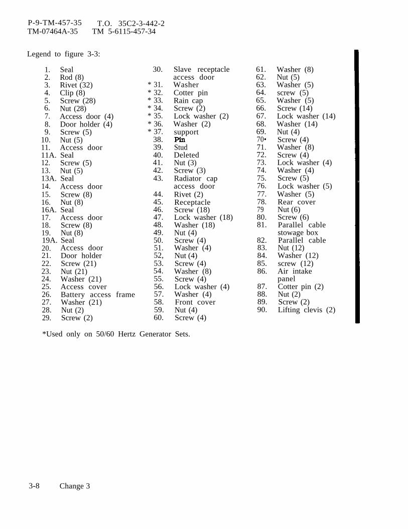
P-9-TM-457-35 T.O. 35C2-3-442-2TM-07464A-35 TM 5-6115-457-34
Legend to figure 3-3:
1. Seal2. Rod (8)3. Rivet (32)4. Clip (8)5. Screw (28)6. Nut (28)7. Access door (4)8. Door holder (4)9. Screw (5)
10. Nut (5)11. Access door11A. Seal12. Screw (5)13. Nut (5)13A. Seal14. Access door15. Screw (8)16. Nut (8)16A. Seal17. Access door18. Screw (8)19. Nut (8)19A. Seal20. Access door21. Door holder22. Screw (21)23. Nut (21)24. Washer (21)25. Access cover26. Battery access frame27. Washer (21)28. Nut (2)29. Screw (2)
30.
* 31.* 32.* 33.* 34.* 35.* 36.* 37.
38.39.40.41.42.43.
44.45.46.47.48.49.50.51.52,53.54.55.56.57.58.59.60.
Slave receptacleaccess doorWasherCotter pinRain capScrew (2)Lock washer (2)Washer (2)support
StudDeletedNut (3)Screw (3)Radiator capaccess doorRivet (2)ReceptacleScrew (18)Lock washer (18)Washer (18)Nut (4)Screw (4)Washer (4)Nut (4)Screw (4)Washer (8)Screw (4)Lock washer (4)Washer (4)Front coverNut (4)Screw (4)
*Used only on 50/60 Hertz Generator Sets.
3-8 Change 3
61.62.63.64.65.66.67.68.69.70•71.72.73.74.75.76.77.78.7980.81.
82.83.84.85.86.
87.88.89.90.
Washer (8)Nut (5)Washer (5)screw (5)Washer (5)Screw (14)Lock washer (14)Washer (14)Nut (4)Screw (4)Washer (8)Screw (4)Lock washer (4)Washer (4)Screw (5)Lock washer (5)Washer (5)Rear coverNut (6)Screw (6)Parallel cablestowage boxParallel cableNut (12)Washer (12)screw (12)Air intakepanelCotter pin (2)Nut (2)Screw (2)Lifting clevis (2)
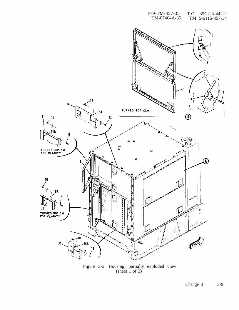
P-9-TM-457-35 T.O. 35C2-3-442-2TM-07464A-35 TM 5-6115-457-34
Figure 3-3. Housing, partially exploded view(sheet 1 of 2)
Change 3 3-9

P-9-TM-457-35 T.O. 35C2-3-442-2TM-07464A-35 TM 5-6115-457-34
Figure 3-3. Housing, partially exploded view(sheet 2 of 2)
3-10 Change 3
P-8-627-34 T O 35C2-3-442-2TM-07464A-35 TM 5-6115-457-34
CHAPTER 4
RADIATOR AND SHUTTER ASSEMBLY REPAIR INSTRUCTIONS
Section I. RADIATOR ASSEMBLY
4-1. GENERAL.
The radiator assembly consists oftop and bottom tanks, core assembly, venttube, mounting brackets, upper and lowershrouds, and shroud plate. The shroudsand shroud plate are bolted to the radiatorand insure that air drawn by the fan isforced through the radiator when exiting thegenerator set. The upper tanks and mount-ing brackets are soldered to the coreassembly, the brackets provide a means ofmounting’ the radiator and the tanks providearea for storage of coolant. The vent tubepermits overflowing coolant to leave theradiator. Refer to Appendix A for applica-ble technical manual for additional informa-tion pertaining to radiator.
4-2. UPPER AND LOWER SHROUD ANDSHROUD PLATE .
4-3. REMOVAL. Refer to Operator andOrganizational Maintenance Manual andremove upper and lower shrouds and shroudplate.
WARNING
Cleaning Solvents are flammable andmoderately toxic to skin, eyes andrespiratory tract. Eye and skinprotection required. Good generalventilation is normally adequate.
4-4. CLEANING. Clean parts with anapproved cleaning solvent and dry thoroughly.
4-5. INSPECTION. Inspect upper andlower shrouds and shroud plate for cracksand distortion.
Welding operations produce heat,highly toxic fumes, injuriousradiation, metal slag and air-borne particles. Welding gog-gles, with proper tinted lenses,apron or jacket and welder’sboots are required.
4-6. REPAIR. Repair cracks by weldingand straighten distorted parts using propertools .4-7. INSTALLATION. Refer to Operatorand Organizational Maintenance Manual andins tall upper and lower shrouds and shroudplate.4-8. RADIATOR.4-9. REMOVAL. Refer to Operator andOrganizational Maintenance Manual andremove the radiator.4-10. TEST,
a. Differential Pressure Test.1. Plug shutter power element port
on bottom radiator tank. Check that venttube is free of obstructions by forcing com-pressed air through tube. Install radiatorcap.
2. Connect a suitable water supplyto lower radiator hose cube and reverseflush radiator until water flowing fromupper radiator hose tube is clear.
3. Connect water supply to upperradiator hose tube and flush radiator untilwater flowing from lower tube is clear.
NOTE
All test equipment must have aminimum inside diameter of2.5 inches.
Change 8 4-1
P-8-627-34 T O 35C2-3-442-2TM-07464A-35 TM 5-6115-457-34
4. Connect 0 to 20 PSI pressuregauges to radiator hose tubes. Connectmanual shut off valve and then an 80 GPMwater supply to upper radiator hose tube.Connect return line from gauge at lowerradiator hose tube to water supply reser-voir. Close manual shut off valve.
CAUTION
Stop test immediately if pressuregauge at top hose port reaches15 PSI.
5. Start water supply. Slowly openmanual shutoff valve while observing gaugeat top hose tube. Stop test if pressurereaches 15 PSI. Fully open shutoff valveand record pressure on both gauges. Ifpressure differential between upper andlower gauges exceeds 1.8 PSI, the radiatoris restricted.
6. Shut down water supply, relievepressure, and remove test equipment fromradiator. If pressure differential exceeded1.8 PSI, remove radiator capthe following procedures.
CAUTION
and perform
Do not immerse cold radiator inboiling solution.
7. Mix a solution of one pound bakingsoda to each gallon. of water. Fill asuitable boiling tank with solution and placeradiator in tank. Bring solution to a boiland boil radiator for a minimum of 30 min-utes. Remove radiator and perform steps 2.through 6.
8. If pressure differential stillexceeds 1.8 PSI, the radiator must be dis-assembled and cleaned.
b. Pressure Test.
1. Plug radiator filler neck, hosetubes, and shutter power element port.Connect a regulated pressure air supplymanual shutoff valve, and 0-20 PSI pressuregauge, to radiator vent tube.
2. Place radiator in suitable tankfilled with water.
3. Slowly apply 15 PSI to radiatorand check for air bubbles that would indi-cate leaks. Mark leaks if any.
4. Remove radiator from tank.Relieve all air pressure and remove testequipment. Repair leaks.
4-11. DISASSEMBLY. Refer to figure 4-1and disassemble radiator as follows:
NOTE
Prior to disassembly of radiator,its condition should be analyzed byperforming test specified in para-graph 4-10.
a. Mark mounting brackets, top tank,and bottom tank in relation to core assem-bly to insure proper reassembly.
b. Remove oxide film on all solderedjoints.
c. Using suitable soldering tools,unsolder vent tube, mounting brackets, toptank, and bottom tank.
WARNING
Avoid breathing fumes generated byunsoldering/soldering. Eye pro-tection is required.
4-12. CLEANING.a. Remove excessive
suitable torch and rag.solder using a
4-2 Change 8

Figure 4-1. Radiator assembly
WARNING
Compressed air used for cleaning anddrying purposes can create airborneparticles that may enter the eyes.Pressure shall not exceed 30 psig.Eye protection is required.
b. Remove obstruction from radiatorcore fins using compressed air.
c. If core assembly tubes are clogged,boil core assembly in a solution of onepound of baking soda to each gallon of waterfor a minimum of 30 minutes or until clogis loosened.
d. Clean core assembly tubes using asuitable bristle brush or cleaning rod.Remove loosened particles using compressedair.
WARNING
Cleaning Solvents are flammable andmoderately toxic to skin, eyes andrespiratory tract. Eye and skinprotection required. Good generalventilation is normally adequate.
P-8-627-34 T O 35C2-3-442-2TM-07464A-35 TM 5-6115-457-34
e. Clean parts with an approved cleaningsolvent and dry thoroughly.
4-13. INSPECTION.
a. Test radiator cap using suitable captester. Cap setting should be approximately7 PSI. Check locking taps for condition.
b. Inspect mounting brackets for cracks,distortion, missing captive nuts. Inspectcaptive nuts for damaged threads.
c. Inspect tanks for cracks, holes, ordents. Check hose connection tubes forout-of-roundness, security, and damage.Check filler neck for damage and security.Check bottom tank flange for security, dam-aged threads, and damage to gasket contactsurface.
d. Inspect core assembly for loosetubes, bent or damaged cooling fins, anddamage to tank contact surfaces.
e.4-14.
Inspect paint for damage.REPAIR.
WARNING
Welding operations produce heat,highly toxic fumes, injuriousradiation, metal slag and air-borne particles. Welding gog-gles, with proper tinted lenses,apron or jacket and welder’sboots are required.Repair cracks in mounting bracketsa.
by welding. Straighten distorted partsusing proper tools.
b. Replace defective mounting bracketcaptive nuts.
c. Solder cracks and holes in tanks.Large holes or cracks may be repaired bysoldering as suitable patch over defect.Resolder loose hose connection tubes,filler neck, or bottom tank flange. Removeburrs from flange using suitable file orstone.
d. Solder loose core assembly tubes.To repair damaged tubes, remove coolingfins in area of leak and solder leak. Solder
Change 8 4-3
P-8-627-34 T O 35C2-3-442-2TM-07464A-35 TM 5-6115-457-34
cooling fin back into position. To replacea defective tube, unsolder tube from coreassembly and remove tube. Insert asuitable replacement tube in core assemblyand solder in position. Straighten bentcooling fins.
e. Remove damaged paint using asuitable scraper. Blend in edges, prime,and paint damaged areas.4-15. REASSEMBLY. Refer to figure 4-1and reassemble radiator as follows:
WARNING
Avoid breathing fumes generated byunsoldering/soldering. Eye pro-tection is required.
a. Using suitable soldering equipment,
fill core assembly tank contact surfacegrooves with solder.
b. Place upper tank on core assembly,making sure relationship marks are inalignment. Solder upper tank to coreassembly. Repeat procedure for lowertank.
c. Solder mounting brackets and venttube in position.
d. Test radiator as specified in para-graph 4-10. Perform necessary proce-dures if radiator does not meet requiredtest results.
4-16. INSTALLATION. Refer to Operatorand Organizational Maintenance Manual andinstall radiator.
Section II. SHUTTER AND CONTROL ASSEMBLY
4-17. GENERAL.
The shutter consists of movablevanes mounted in nylon bearings which areactuated by a control rod connected to thecontrol assembly. When engine coolanttemperature reaches 158°F, the controlassembly power element starts to extendwhich moves the control rod opening theshutter vanes. If coolant temperaturedecreases, the control assembly integralreturn spring moves the control rod closingthe shutter vanes. This modulated controlautomatically opens and closes the shuttervanes the amount necessary to maintain theengine at normal operating temperature.Opening and closing of the shutter vanesregulates cooling air flow through theradiator. The shutter assembly is equippedwith a manual control handle to permitmanual opening of the shutter vanes. Thehandle should be in the full up position dur-ing normal operation.
4-18. CONTROL ASSEMBLY.
4-19. REMOVAL. Refer to Operator andOrganizational Maintenance Manual andremove the control assembly.
4-20. DISASSEMBLY. Refer to figure 4-2and disassemble the control assembly inthe order of index numbers assigned. Payparticular attention to the following:
a. When removing retaining ring (14),press in on large seat (15) to relieve springtension on ring. Remove retaining ring andslowly remove large seat until springtension is relieved.
WARNING
Cleaning Solvents are flammable andmoderately toxic to skin, eyes andrespiratory tract. Eye and skinprotection required. Good generalventilation is normally adequate.
4-21. CLEANING. Clean parts in anapproved cleaning solvent and drythoroughly.
4-4 Change 8
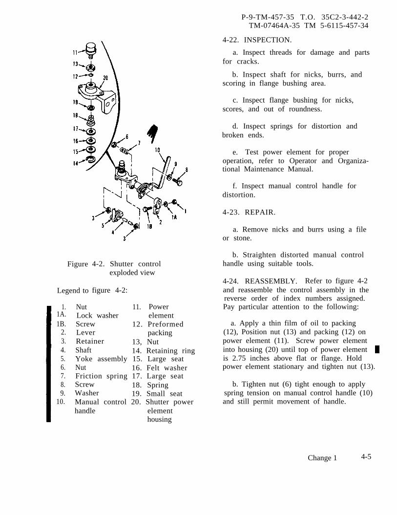
P-9-TM-457-35 T.O. 35C2-3-442-2TM-07464A-35 TM 5-6115-457-34
Figure
Legend to
4-2. Shutter controlexploded view
figure 4-2:
1.1A.1B.
2.3.4.5.6.7.8.9.
10.
11. PowerNutLock washer elementScrew 12. PreformedLever packingRetainer 13, NutShaft 14. Retaining ringYoke assembly 15. Large seatNut 16. Felt washerFriction spring 17. Large seatScrew 18. SpringWasher 19. Small seatManual control 20. Shutter powerhandle element
housing
4-22. INSPECTION.
a. Inspect threads for damage and partsfor cracks.
b. Inspect shaft for nicks, burrs, andscoring in flange bushing area.
c. Inspect flange bushing for nicks,scores, and out of roundness.
d. Inspect springs for distortion andbroken ends.
e. Test power element for properoperation, refer to Operator and Organiza-tional Maintenance Manual.
f. Inspect manual control handle fordistortion.
4-23. REPAIR.
a. Remove nicks and burrs using a fileor stone.
b. Straighten distorted manual controlhandle using suitable tools.
4-24. REASSEMBLY. Refer to figure 4-2and reassemble the control assembly in thereverse order of index numbers assigned.Pay particular attention to the following:
a. Apply a thin film of oil to packing(12), Position nut (13) and packing (12) onpower element (11). Screw power elementinto housing (20) until top of power elementis 2.75 inches above flat or flange. Holdpower element stationary and tighten nut (13).
b. Tighten nut (6) tight enough to applyspring tension on manual control handle (10)and still permit movement of handle.
Change 1 4-5

P-9-TM-457-35 T.O. 35C2-3-442-2TM-07464A-35 TM 5-6115-457-34
4-25. INSTALLATION. Refer to Operatorand Organizational Maintenance Manual andinstall control assembly.
4-26. SHUTTER.
to Operator and4-27. REMOVAL. ReferOrganizational Maintenance Manual andremove shutter.
4-28. DISASSEMBLY. Refer to figure 4-3and disassemble the shutter as follows:
a. Place shutter face down on a clean,dirt-free work bench. Secure spring (2)
and carefully remove cotter pin (1). Sliderod (3) free of block (4), Remove nut (5),lock washer (6) and screw (7) retainingblock (4) to control bar (12).
b. Remove closing spring (8) and un-screw spring studs (9) free, from left angle(21).
c. Carefully remove retaining rings (10).Slide control rods (11) and (12) clear of vanes(23). Remove bushings (13) from controlbars (11 and 12). Carefully remove re-taining rings (14).
Figure 4-3. Shutter, exploded view
4-6 Change 1

P-8-627-34 T O 35C2-3-442-2TM-07464A-35 TM 5-6115-457-34
Legend to figure 4-3:
1.2.3.4.5.6.7.8.9.
10.11.
Cotter pinSpringRodBlockNutLock washerScrewClosing springSpring studRetaining ring (8)Control bar
d. Remove nuts (15), lock washers (16)and screws (17). Remove the top rail (18)and the bottom rail (19) from the shutter.Carefully remove right angle (20) and leftangle (21) from vanes (23) and removebushings (22).
WARNING
Cleaning Solvents are flammable andmoderately toxic to skin, eyes andrespiratory tract. Eye and skinprotection required. Good generalventilation is normally adequate.
Compressed air used for cleaning anddrying purposes can create airborneparticles that may enter the eyes.Pressure shall not exceed 30 psig.Eye protection is required.
4-29. CLEANING. Clean all parts in anapproved cleaning solvent and dry thoroughlyusing filtered, low pressure compressedair and clean, lint-free cloth. If shutter isnot to be fully disassembled, utilize sameprocedure above.
4-30. INSPECTION.
a. Inspect threads for damage.
b. Inspect control rod assembly for dis-tortion and missing components.
c. Inspect spring for distortion andbroken ends.
12.13.14.15.16.17.18.19.20.21.22.23.
Control barBushingRetaining ring (8)NutLock washerScrewTop railBottom railRight angleLeft angleB u s h i n gVane (16)
d. Inspect bushings for out-of-roundness,cuts, and cracks.
e. Inspect channel for distortion and forelongated holes.
f. Inspect vanes for cracks and nicks,burrs, and grooves on bushing contactsurfaces.
4-31. REPAIR.
a. Straightensuitable tools.
distorted parts using
b. Remove nicks or burrs from vanebushing contact surfaces using a file orstone.
4-32. REASSEMBLY. Refer to figure 4-3and reassemble the shutter as follows:
a. On a clean, dirt-free work benchplace left angle (21) with vane pivot holesperpendicular to the work bench,
b. Place bushings (22) into left angle(21), Insert vane pivot arm closest to vaneinto bushings (22). Secure with retainingring (14); one on the top vane and everyfifth vane the reafter.
c. Repeat procedure b. above for theright angle (20).
Change 8 4-7
P-8-627-34 T O 35C2-3-442-2TM-07464A-35 TM 5-6115-457-34
d. Place top rail (18) between rightangle (20) and left angle (21) Secure withnut (15), lock washer (16) and screw (17).
e. Repeat procedure d. above for thebottom rail (19).
f. Place bushings (13) into control bar(12). Slide control bar (11) over vane pivotarm. Secure with retaining ring (10); oneon the top vane and every fifth vane there-after.
g. Repeat procedure f. above forcontrol bar (11).
h. Fasten spring studs (9) into left angle21. Secure closing spring (8) to spring studs(9).
i. Attach block (4) to control bar (11)utilizing nut (5) lock washer (6) and screw(7). Insert rod (3) through block (4); placespring (2) over rod (3) and secure withcotter pin (1).
4-33. INSTALLATION. Refer to Operatorand Organizational maintenance manual andinstall shutter.
4-8 Change 8

P-8-627-34 T O 35C2-3-442-2TM-07464A-35 TM 5-6115-457-34
CHAPTER 5
ELECTRICAL CONTROLS WIRING HARNESSESREPAIR INSTRUCTIONS
5-1. GENERAL.
The electrical controls wiring har-nesses interconnect the electrical compo-nents of the generator set.
NOTE
Mode I relay boxes are used on50/60 hertz generator sets andmode H relay boxes on 400 hertzgenerator sets.
a. Relay Box To Control Cubicle Har-ness. The harness is connected to connectorJ1 of the control cubicle (A3) ) and connectorJ2 of the mode I or mode II relay box (A27).
b. Relay Box To Exciter Regulator Har-ness. The harness is connected to connectorJ9 of the exciter regulator (A10 and All) andconnector J3 of the mode I or mode II relaybox (A27).
c. Tactical Relay Box To Load Measure-ment Unit Harness. The harness is con-nected to connector J4 of the tactical relaybox (A7) and connector J16 of the load meas-urement unit (A8).
d, Relay Box To Precise Relay Box Har-ness. The harness is connected to connectorJ32 of the precise relay box (A25) and con-nector J31 of the mode I relay box (A27).The harness is utilized on 50/60 hertz gen-erator sets only.
e. Relay Box To Governor Control UnitHarness. The harness is connected to con-nectors J21 and J17 of the governor control
unit (A23) and connector J8 of the preciserelay box (A25) on 50/60 hertz precise gen-erator sets or connector J8 of the mode IIrelay box on 400 hertz generator sets. Theharness is not used on utility generator sets.
f. Governor Control Unit To GovernorActuator Harness. The harness is connectedto connectors J22 and J23 of the governorcontrol unit (A23) and connectors J24 andJ25 of the governor actuator (A24). Theharness is not used on utility generator sets.
g. Relay BOX To Reconnection BoardHarness (50/60 Hertz Generator Sets). Theharness is connected to connector J10 of themode I relay box (A27), connector J13 of theexciter regulator (A10 and All), connectorJ41 of the. load contactor (C32), connectorJ48 of the convenience receptacle (A22),connector J61 of generator (G1), and to ter-minals of the load board and terminal boards(TB2 and TB6). The harness is not utilizedon 400 hertz generator sets.
h. Relay Box To Reconnection BoardHarness (400 Hertz Generator Sets). Theharness is connected to connector J10 of themode II relay box (A27), connector J13 ofthe exciter regulator (A10 and Al1), con-nector J48 of the convenience receptacle(A22), connector J61 of generator (G1), andto terminals of the load board and terminalboards (TB2 and TB6). The harness is notutilized on 50/60 hertz generator sets.
i. Relay Box To Fault Locator Indi-cator Harness. The harness is connectedto connector J12 of the fault locatorindicator (A9) and to connector J6
Change 8 5-1

P-8-627-34 T O 35C2-3-442-2TM-07464A-35 TM 5-6115-457-34
of the mode I or mode 11 relay box(A27).
j. Parallel Receptacle Harness. Theharness is connected to connector J15 ofthe mode I or mode II relay box (A27). Thethree connectors of the harness J45, J46,and J47 are the parallel receptacles locatedat the rear of the generator set.
k. Relay Box to Tactical Relay BoxHarness. The harness is connected to con-nector J51 of the tactical relay box (A29) andconnector J50 of the mode I or mode IIrelay box (A27).
5-2. REMOVAL.
Refer to Operator and OrganizationalMaintenance Manual and remove the wiringharnesses.
5-3. CLEANING.
WARNING
Compressed air used for cleaning anddrying purposes can create airborneparticles that may enter the eyes.Pressure shall not exceed 30 psig.Eye protection is required.
a. Clean connector pins with low pres-sure, filtered compressed air.
b. Clean connectors and terminal lugswith a clean lint-free cloth moistenedin an approved cleaning solvent and drythoroughly.
c. Remove oil and grease from wiresusing a clean lint-free cloth.5-4. INSPECTION.
a. Inspect connectors for loose, bent,and damaged pins; damaged threads; anddefective keys.
b. Check terminal lugs for securityand condition.
c. Inspect harness wires for defectiveinsulation, illegible
5-2 Change 8
wire numbers. Check
harness straps for condition, security, andproper spacing.
NOTE
Interconnecting wiring diagram iscontained in the Operator andOrganizational Maintenance Manual.
d. Check each harness wire for con-tinuity from connector pin to wire end.Check connector pins for shorts to caseand surrounding pins. Refer to figures 5-1through 5-11.
5-5. REBUILD.
a. Refer to figure 5-1 and rebuild relaybox to control cubicle harness.
b. Refer to figure 5-2 and rebuild relaybox to exciter regulator harness.
c. Refer to figure 5-3 and rebuildtactical relay box to load measurement unitharness.
d. Refer to figure 5-4 and rebuildbox to precise relay box harness on50/60 hertz precise generator sets.
e. Refer to figure 5-5 and rebuildbox to governor control unit harnessprecise generator sets.
f. Refer to figure 5-6 and rebuild
relay
relayon
gov-ernor control unit to governor actuatorharness on precise generator sets.
g. Refer to figure 5-7 and rebuild relaybox to reconnect on board harness on50/60 hertz generator sets.
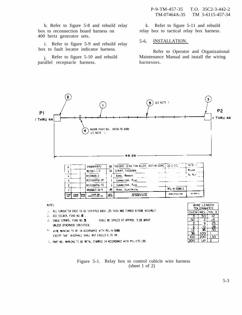
P-9-TM-457-35 T.O. 35C2-3-442-2TM-07464A-35 TM 5-6115-457-34
h. Refer to figure 5-8 and rebuild relaybox to reconnection board harness on400 hertz generator sets.
i. Refer to figure 5-9 and rebuild relaybox to fault locator indicator harness.
j. Refer to figure 5-10 and rebuildparallel receptacle harness.
k. Refer to figure 5-11 and rebuildrelay box to tactical relay box harness.
5-6. INSTALLATION.
Refer to Operator and OrganizationalMaintenance Manual and install the wiringharnesses.
Figure 5-1. Relay box to control cubicle wire harness(sheet 1 of 2)
5-3

P-9-TM-457-35 T.O. 35C2-3-442-2TM-07464A-35 TM 5-6115-457-34
Figure 5-1. Relay box to control cubicle wire harness(sheet 2 of 2)
5-4
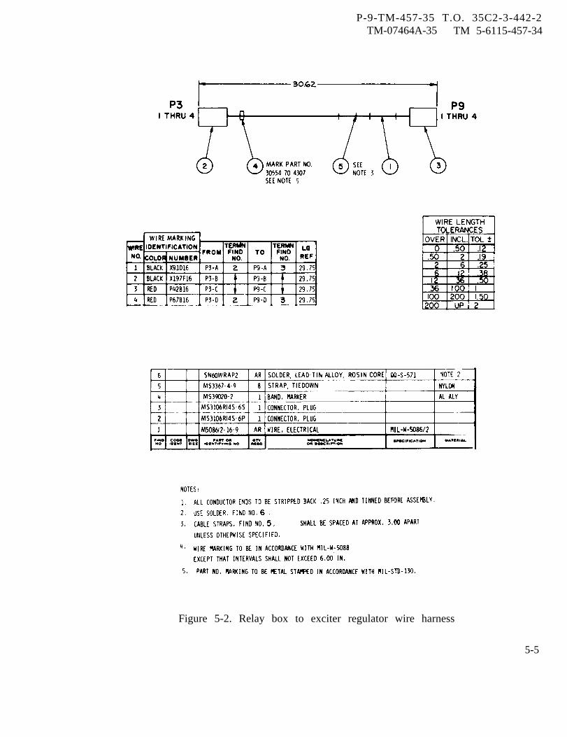
P-9-TM-457-35 T.O. 35C2-3-442-2TM-07464A-35 TM 5-6115-457-34
Figure 5-2. Relay box to exciter regulator wire harness
5-5
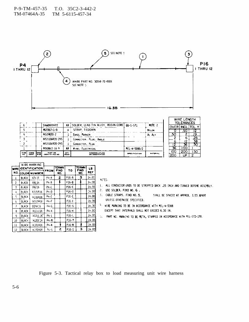
P-9-TM-457-35 T.O. 35C2-3-442-2TM-07464A-35 TM 5-6115-457-34
Figure 5-3. Tactical relay box to load measuring unit wire harness
5-6

P-9-TM-457-35 T.O. 35C2-3-442-2TM-07464A-35 TM 5-6115-457-34
Figure 5-4. Relay box to precise relay box wire harness, 50/60 Hertz generator sets
5-7
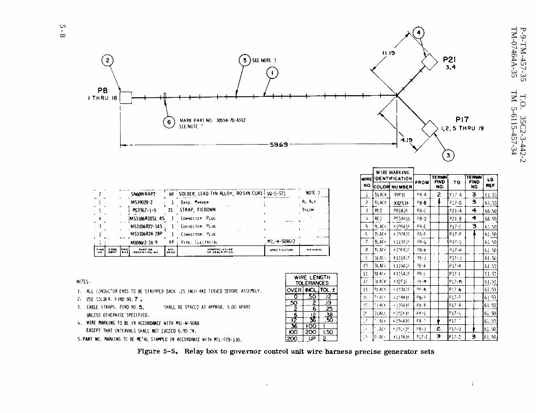
Figure 5-5.
P-9-T
M-457-35
T.O
. 35C
2-3-442-2T
M-07464A
-35T
M
5-6115-457-34
5-8
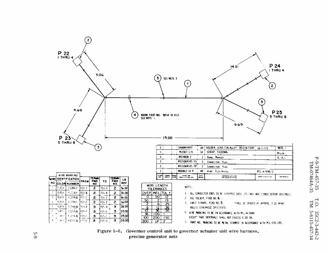
Figure 5-6.
P-9-T
M-457-35
T.O
. 35C
2-3-442-2T
M-07464A
-35T
M 5-6115-457-34
5-9
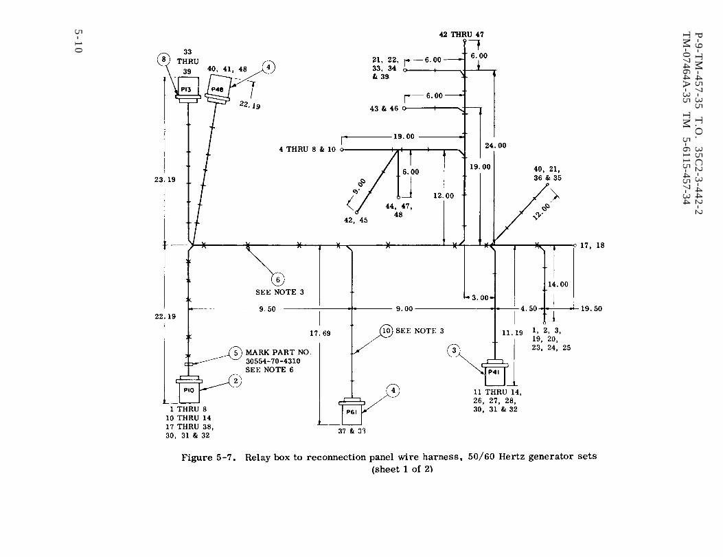
Figure 5-7.
P-9
-TM
-45
7-3
5
T.O
. 3
5C
2-3
-44
2-2
TM
-07464A-35
TM
5-6115-457-34
5-1
0

P-9-TM-457-35 T.O. 35C2-3-442-2TM-07464A-35 TM 5-6115-457-34
Figure 5-7. Relay box to reconnection panel wire harness, 50/60 Hertz generator sets(sheet 2 of 2)
5-11
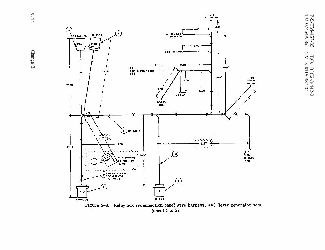
Figure 5-8.
P-9-T
M-457-35
T.O
. 35C
2-3-442-2T
M-07464A
-35T
M
5-6115-457-34
5-1
2C
hange 3
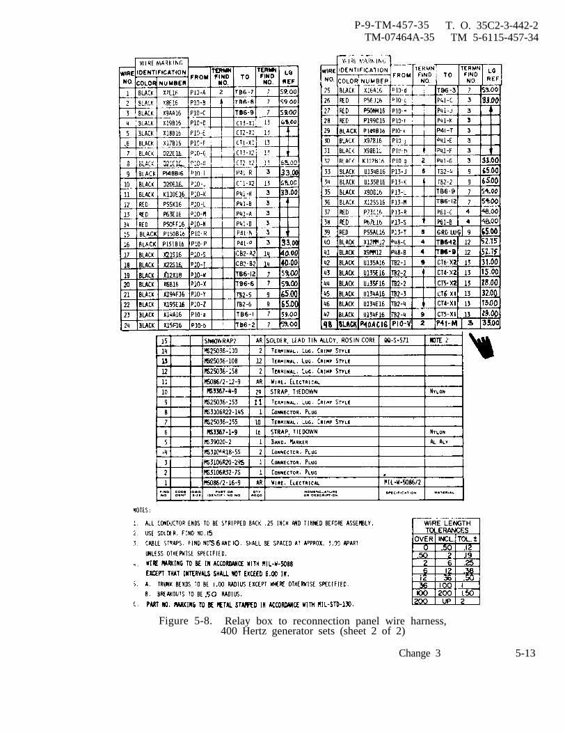
P-9-TM-457-35 T. O. 35C2-3-442-2TM-07464A-35 TM 5-6115-457-34
Figure 5-8. Relay box to reconnection panel wire harness,400 Hertz generator sets (sheet 2 of 2)
5-13Change 3
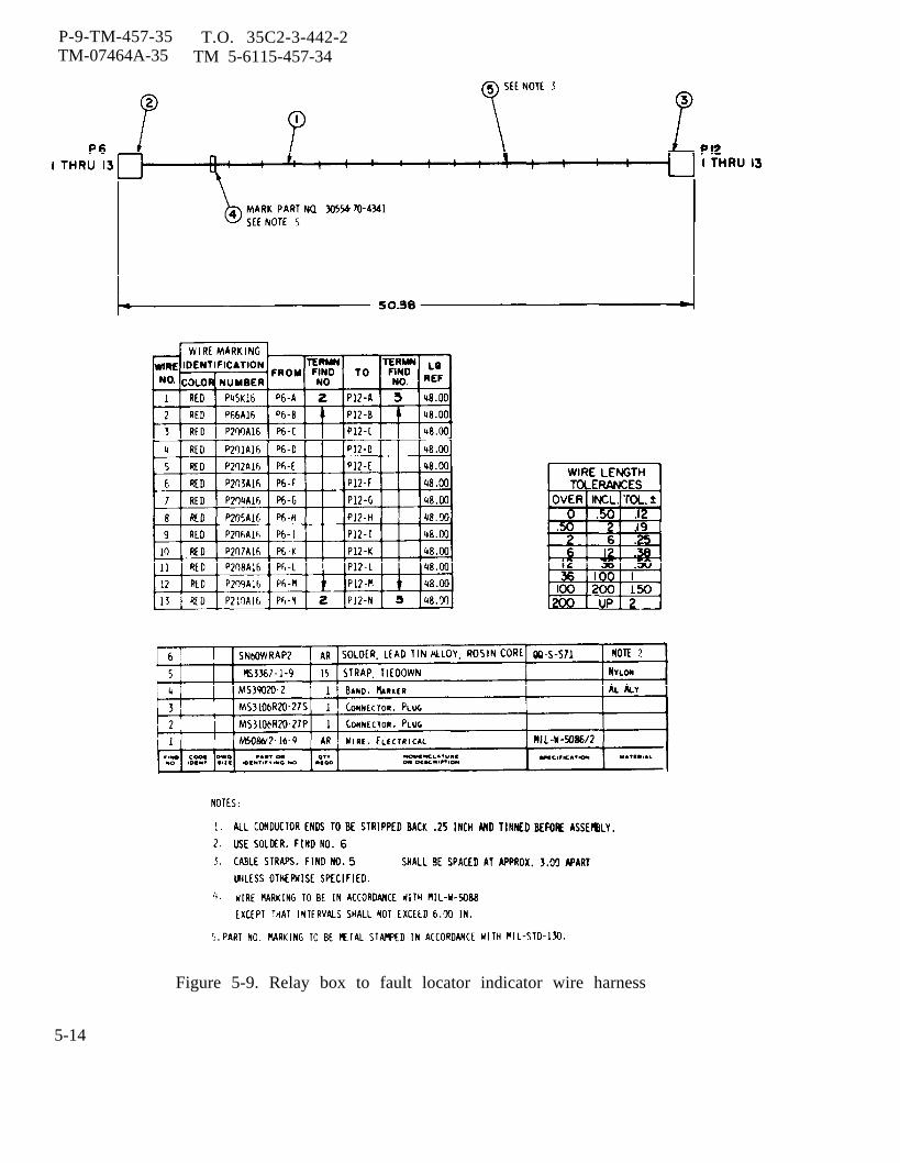
P-9-TM-457-35 T.O. 35C2-3-442-2TM-07464A-35 TM 5-6115-457-34
Figure 5-9. Relay box to fault locator indicator wire harness
5-14

Figure 5-10.
P-9
-TM
-45
7-3
5
T.O
. 3
5C
2-3
-44
2-2
TM
-07464A-35
TM
5-6115-457-34
5-1
5

P-9-TM-457-35 T.O. 35C2-3-442-2TM-074644-35 TM 5-6115-457-34
Figure 5-11. Relay box to tactical relay box wire harness
5-16

P-9-TM-457-35 T.O. 35C2-3-442-2TM-07464A-35 TM 5-6115-457-34
CHAPTER 6
GENERATOR SET CONTROL GROUP REPAIR INSTRUCTIONS
6-1. GENERAL.
Section I. CONTROL CUBICLE
The control cubicle is located at thegenerator end of the set. It contains con-trols, switches, instruments, and circuitrynecessary to start, operate, and monitorthe generator set. The instruments andcontrols are mounted on a hinged frontpanel of the cubicle which permit easy ac-cess to the interior of the cubicle. Deviceson the front panel are divided into an enginegroup and a generator group.
a. Instruments that monitor the genera-tor output are: frequency meter M6; kilo-watt meter M7; percent rated current meterM8; ac voltmeter M9; ammeter-voltmeterselector switch S8; and the synchronizinglights DS4 and DS5. Devices that controlthe generator output are: a frequency ad-just rheostat R1 for precise sets; a voltageadjust rheostat R2; parallel unit - singleunit operation switch S6; battle shortswitch S7 and indicator DS7; voltage sens-ing (remote-local) switch S5; and ac loadcontactor switch S3 and indicator DS6.Utility generator sets utilize a manualspeed control located adj scent to the con-trol cubicle, for adjustment of frequencythrough the utility governor.
b. Instruments that monitor engineoperation are: oil pressure meter Ml;coolant temperature indicator M2, fuellevel meter M3, battery charge ammeterM4, and total running time meter M5.
Devices that control the engine are aSTART-RUN-STOP switch S2 and an engineprimer switch S1. Also included is anengine air cleaner condition indicator DS8.
c. Located in the control cubicle arethe thermal watt converter Al, controlpanel relay assembly A4, frequency metertransducer A2, control box relay assem-bly, and a wire harness. The thermalwatt converter senses the generator poweroutput and converts it to a proportional dcsignal for display by the kilowatt meter.The frequency meter and transducer are amatched set. A single phase ac voltage ofthe generator output is applied to the trans-ducer which produces dc signal proportion-al to the generator frequency for display bythe frequency meter. The control boxrelay assembly contains stop-run relay K1,remote voltage sensing relay K6, rectifierbridge CR1, and resistor R10.
6-2. THERMAL WATT CONVERTER(A1).
6-3. TEST ON EQUIPMENT.
a. Symptoms and Isolation of Malfunc-tion. A malfunction of the thermal wattconverter is usually indicated by low or nokilowatt meter reading. An open circuitcoil in the thermal watt converter will alsoeffect the AC ammeter reading for thephase which is open. To isolate the mal-function, proceed as follows:
6-1
P-9-TM-457-35 T.O. 35C2-3-442-2TM-07464A-35 TM 5-6115-457-34
1. Loosen three captive studs andhinge control box door open.
2. Start generator set and applyload.
Exercise extreme care not to touchexposed electrical connections whenworking inside control cubicle withgenerator set operating.
3. Measure input voltages at ter-minals V1-N1, V2-N2 and V3-N3. Voltageshould be 120 VAC with the generator out-put voltage adjusted for rated output. Ifabove requirement is not met, check wiringback to voltage source.
4. Measure current to terminal L1,L2, and L3. The current should vary be-tween 0-0 75 AC amperes as the generatorset load is varied from 0 to 100 percent ofrated output. If there is no current shutdown generator set and check for continuitybetween terminals L1-S1, L2-S2 and L3-S3. If there is continuity, check wiringback to current source.
5. Measure the output signal at the(+) and (-) terminals with a vacuum tube DCvoltmeter. The output signal should varybetween 0 to 10.4 mv as the generator setload is varied between 0 and 100 percent ofrated output, If the above requirement isnot met and the inputs’ are correct, thethermal watt converter should be replaced.
b. Removal. Refer to Operator andOrganizational Maintenance Manual and re-move the thermal watt converter.
6-4. CLEANING. Clean the thermal wattconverter using a clean lint-free cloth,moistened with an approved cleaning solv-ent and dry thoroughly.
6-5. INSPECTION. Inspect case for evi-dence of cracks or tears and the terminalboard for cracked insulation, strippedthreads, and missing jumper strips.
6-6. TEST. Connect the thermal wattconverter to the test equipment as illustra-ted in figure 6-1 and proceed as follows:
Note
All test readings are ±20 percent.
a. Adjust all autotransformers T1, T2,and T3 to their MIN positions.
b. Close switch S1 and open switchesS2 and S3.
c. Energize the power source.
d. Adjust T1 until 1 ampere is indicatedon ammeter Al. Voltmeter V1 should in-dicate 6.4 mv.
e. Close switch S2 and adjust T2 until1 ampere is indicated on ammeter A2.Voltmeter V1 should indicate 13 mv.
f. Close switch S3 and adjust T3 until1 ampere is indicated on ammeter A3.Voltmeter should indicate 18.6 mv.
g. Remove test equipment. Replacedefective thermal watt converter.
6-7. INSTALLATION. Refer to Operatorand Organizational Maintenance Manual andinstall the thermal watt converter.
6-8. FREQUENCY METER (M 6) ANDTRANSDUCER (A2).
6-9. TEST ON EQUIPMENT.
a. Symptoms and Isolation of Malfunc-tion. A malfunction of the frequency meteror transducer is usually indicated by off
6-2
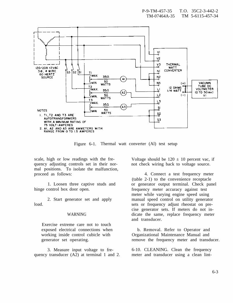
P-9-TM-457-35 T.O. 35C2-3-442-2TM-07464A-35 TM 5-6115-457-34
Figure 6-1. Thermal watt converter (Al) test setup
scale, high or low readings with the fre-quency adjusting controls set in their nor-mal positions. To isolate the malfunction,proceed as follows:
1. Loosen three captive studs andhinge control box door open.
2. Start generator set and applyload.
WARNING
Exercise extreme care not to touchexposed electrical connections whenworking inside control cubicle withgenerator set operating.
3. Measure input voltage to fre-quency transducer (A2) at terminal 1 and 2.
Voltage should be 120 ± 10 percent vac, ifnot check wiring back to voltage source.
4. Connect a test frequency meter(table 2-1) to the convenience receptacleor generator output terminal. Check panelfrequency meter accuracy against testmeter while varying engine speed usingmanual speed control on utility generatorsets or frequency adjust rheostat on pre-cise generator sets. If meters do not in-dicate the same, replace frequency meterand transducer.
b. Removal. Refer to Operator andOrganizational Maintenance Manual andremove the frequency meter and transducer.
6-10. CLEANING. Clean the frequencymeter and transducer using a clean lint-
6-3
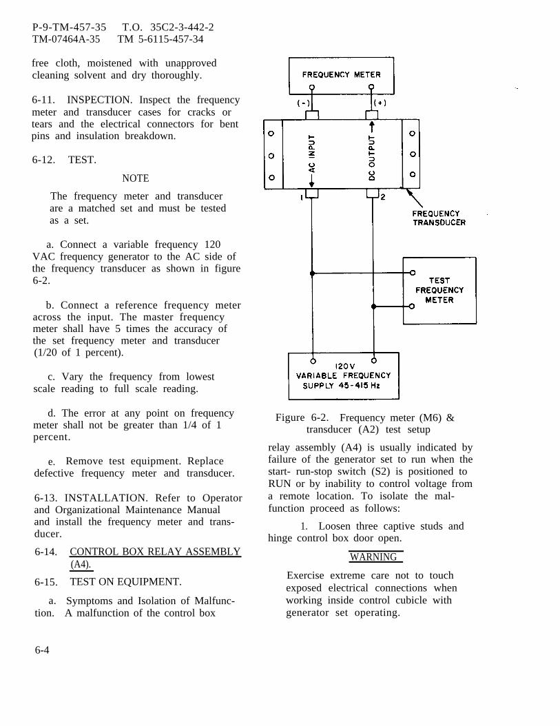
P-9-TM-457-35 T.O. 35C2-3-442-2TM-07464A-35 TM 5-6115-457-34
free cloth, moistened with unapprovedcleaning solvent and dry thoroughly.
6-11. INSPECTION. Inspect the frequencymeter and transducer cases for cracks ortears and the electrical connectors for bentpins and insulation breakdown.
6-12. TEST.
NOTE
The frequency meter and transducerare a matched set and must be testedas a set.
a. Connect a variable frequency 120VAC frequency generator to the AC side ofthe frequency transducer as shown in figure6-2.
b. Connect a reference frequency meteracross the input. The master frequencymeter shall have 5 times the accuracy ofthe set frequency meter and transducer(1/20 of 1 percent).
c. Vary the frequency from lowestscale reading to full scale reading.
d. The error at any point on frequencymeter shall not be greater than 1/4 of 1percent.
e. Remove test equipment. Replacedefective frequency meter and transducer.
6-13. INSTALLATION. Refer to Operatorand Organizational Maintenance Manualand install the frequency meter and trans-ducer.
6-14.
6-15.
a.tion.
CONTROL BOX RELAY ASSEMBLY(A4).
TEST ON EQUIPMENT.
Symptoms and Isolation of Malfunc-A malfunction of the control box
Figure 6-2. Frequency meter (M6) &transducer (A2) test setup
relay assembly (A4) is usually indicated byfailure of the generator set to run when thestart- run-stop switch (S2) is positioned toRUN or by inability to control voltage froma remote location. To isolate the mal-function proceed as follows:
1. Loosen three captive studs andhinge control box door open.
WARNING
Exercise extreme care not to touchexposed electrical connections whenworking inside control cubicle withgenerator set operating.
6-4
NOTE
Steps 2. through 7. pertain to stop-run relay K1 and steps 8. through10. pertain to remote voltage sensingrelay K6. All test readings shouldbe ±20 percent.
2. Energize DC circuit breaker.
3. Start engine. If engine shutsdown when start-run-stop switch is posi-tioned to RUN, restart engine and holdswitch to START. Measure voltage at re-lay assembly terminal board across ter-minals 2 and 8. Voltage should be 24 VDC.
4. If voltage across terminals 2 and8 is not 24 VDC, shut down generator set.Disconnect wire P50A from terminal 9 andinsulate wire end.
5. Restart generator set and mea-sure voltage across terminals 2 and 9.Voltage should be 24 VDC. Connect wireP50A.
6. If voltage across terminals 2 and9 is not 24 VDC, shut down generator set.Remove wire P80E from terminal 8 andcheck resistance across terminals 2 and 8.Resistance should be 300 ohms. If notreplace stop-run relay K1.
7. If values in steps 2. through 6.are met and circuit is still inoperative,remove control box relay assembly (A4)and bench test.
8. Connect a suitable cable betweenone of the convenience receptacle outlets(J55) and remote voltage sensing connector(J29). Position convenience receptacle cir-cuit breaker (CB3) OFF. Start engine andposition the remote local voltage switch(S5) to the REMOTE position and place con-venience receptacle circuit breaker (CB-3)ON. Measure voltage at relay assemblyterminal board across terminals 4 and 12, 5and 11, 6 and 10. Voltage should be 120VAC nominal.
P-8-627-34 T O 35C2-3-442-2TM-07464A-35 TM 5-6115-457-34
9. If voltages in step 8. are cor-rect and the remote voltage sensing circuitis still inoperative, shut down generatorset. Remove wires X29A and X31A fromterminals 4 and 12. Measure resistanceat terminals, resistance should be approxi-mately 7K ohms. If not replace remotevoltage sensing relay K6.
10. If values in steps 8. and 9. pre-ceding are obtained and circuit is still in-operative, replaceassembly (A4).
b. Removal.
control box relay
1. Disconnect harness at rear ofcontrol cubicle.
2. Loosen three captive studs andhinge open control box door.
3. Tag and disconnect wiring tocontrol box relay assembly terminalboards.
NOTE
The control box relay assembly ismounted inside the control box onthe lower center sections of therear wall.
4. Remove the four nuts located atthe back of the rear wall, securing the con-trol box relay to the control cubicle assem-bly.
6-16. TEST.
a. Connect the control box relay as-sembly to the test equipment as illustratedin figure 6-3.
b. Perform test specified in table 6-1.
NOTE
All voltage values are ±20 percent.
Change 8 6-5
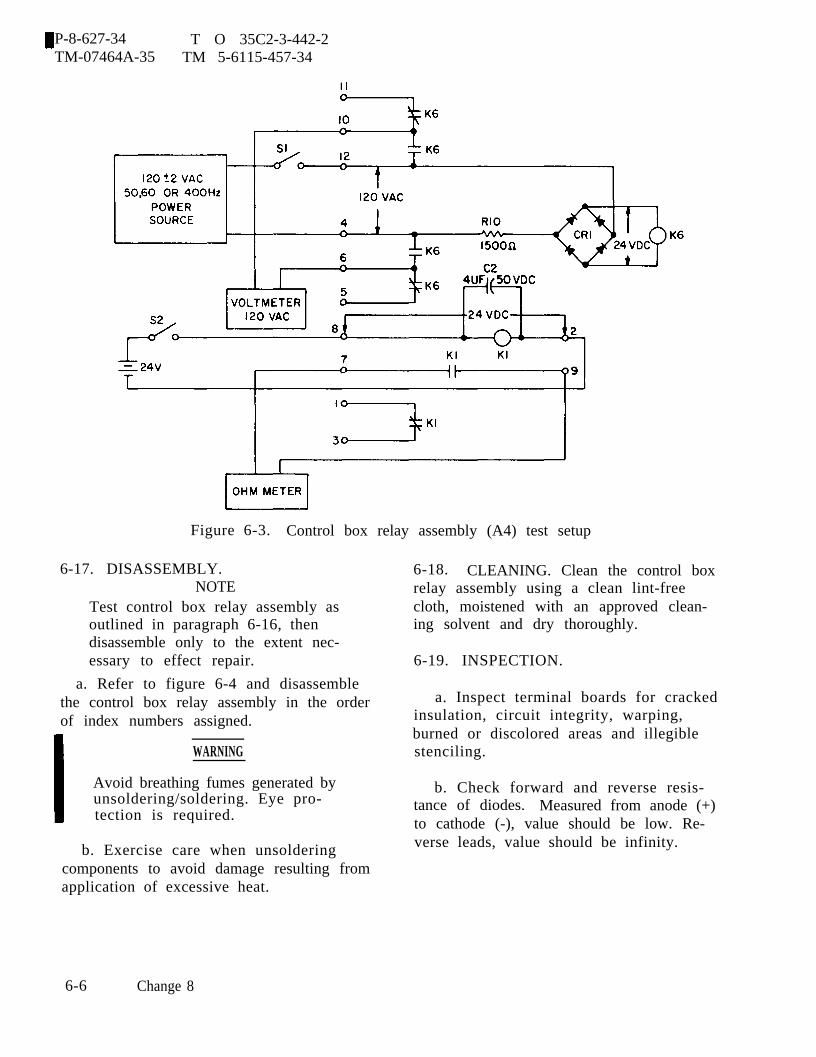
P-8-627-34 T O 35C2-3-442-2TM-07464A-35 TM 5-6115-457-34
Figure 6-3. Control box relay assembly (A4) test setup
6-17. DISASSEMBLY.NOTE
Test control box relay assembly asoutlined in paragraph 6-16, thendisassemble only to the extent nec-essary to effect repair.
a. Refer to figure 6-4 and disassemblethe control box relay assembly in the orderof index numbers assigned.
WARNING
Avoid breathing fumes generated byunsoldering/soldering. Eye pro-tection is required.
b. Exercise care when unsolderingcomponents to avoid damage resulting fromapplication of excessive heat.
6-18. CLEANING. Clean the control boxrelay assembly using a clean lint-freecloth, moistened with an approved clean-ing solvent and dry thoroughly.
6-19. INSPECTION.
a. Inspect terminal boards for crackedinsulation, circuit integrity, warping,burned or discolored areas and illegiblestenciling.
b. Check forward and reverse resis-tance of diodes. Measured from anode (+)to cathode (-), value should be low. Re-verse leads, value should be infinity.
6-6 Change 8
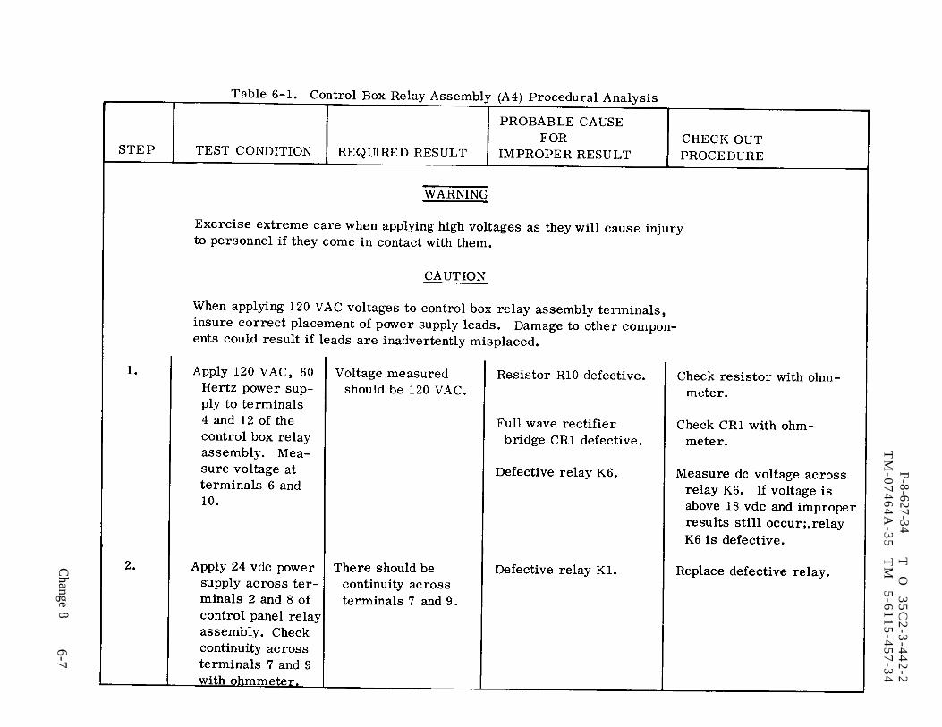
Table 6-1.
P-8-627-34
T
O
35
C2
-3-4
42
-2T
M-0
74
64
A-3
5
TM
5
-61
15
-45
7-3
4
Change 8
6-7

P-8-627-34 T O 35C2-3-442-2TM-07464A-35 TM 5-6115-457-34
Figure 6-4. Control box relay assem-bly, exploded view
Legend to figure 6-4:1. Nut (8) 10.2. Washer (4) 11.3. Screw (4) 12.4. Terminal 13.
board (2)5. Screw (4) 14.6. Washer (4) 15.7. Relay (2) 16.8. Nut (4)9. Washer (4)
Lock washer (4)Relay socket (2)SpacerSilicone bridgerectifierFixed resistorCapacitorTerminal board
c. Check resistor for proper ohmicvalue. (15 K Ohms.)
d. Check capacitor for proper capaci-tance value.
e. Inspect relay sockets for crackedinsulation and broken pin receptacles.
f. Test plug in relays for actuationas illustrated in
6-20. REPAIR.
a. Restencilnations.
figure 6-5.
illegible reference desig-
Avoid breathing fumes generated byunsoldering/soldering. Eye pro-tection is required.
6-8 Change 8
b. Repair printed circuits by solderinga jumper wire across defective area.
c.
d.using
Replace all defective components.
Solder replacement componentssolder conforming to Federal Speci-
fication QQ-S-571 Sn 60.
6-21. REASSEMBLY.
Refer to figure 6-4 and reassemblecontrol box relay assembly in reverseorder of index numbers assigned. Payparticular attention to the following.
a. When replacing soldered compon-ents, use a suitable heat sink. Solderjoints and/or component leads shall notproject more than 0.094 inch beyond thesurface of the board.
WARNING
Insulating Compound, MIL-I-46058 isflamable and slightly toxic to eyes,skin and respiratory tract. Eye andskin protection required. Good gen-eral ventilation is normally adequate.
b. Spray or brush a conformal coating,0.005 inch thick, of a transparent dielec-tric compound corresponding to Specifica-tion MIL-I-46058, Grade S, Type PUR tothe assembly.
NOTE
The compound shall securely anchorthe components to the terminalboard. Terminals for connection toexternal circuits shall not be coated.
c. Test control box relay assembly asoutlined in paragraph 6-16.
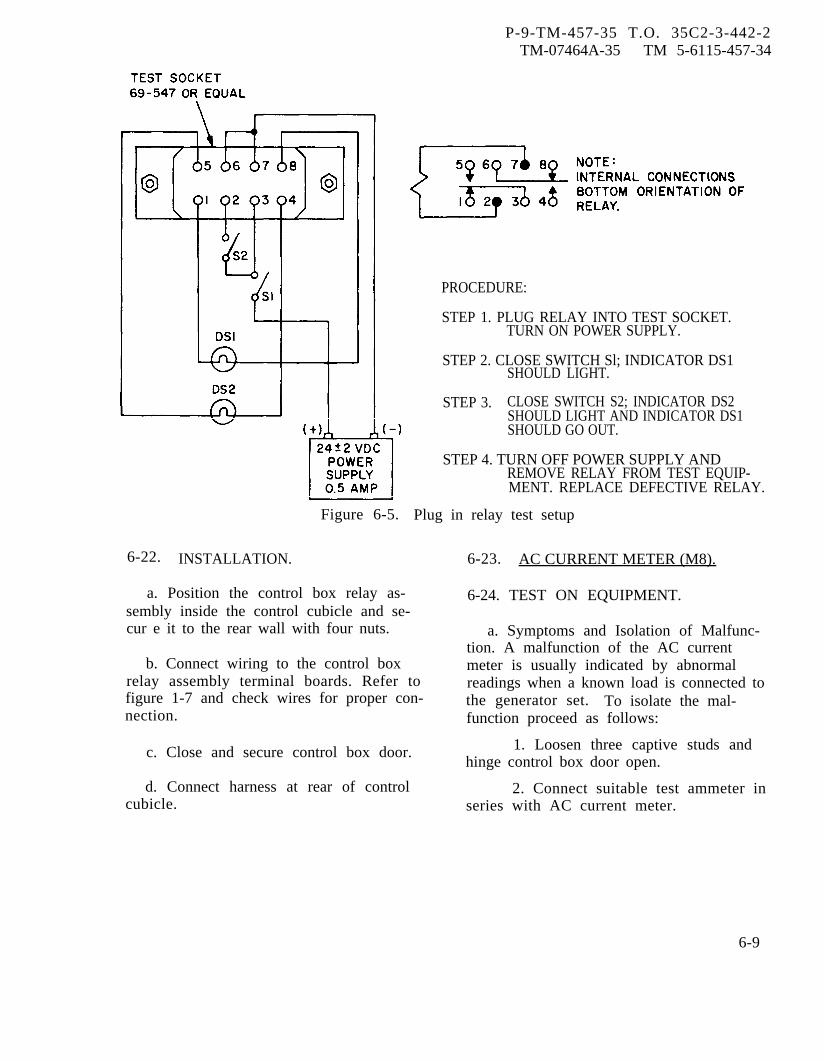
P-9-TM-457-35 T.O. 35C2-3-442-2TM-07464A-35 TM 5-6115-457-34
PROCEDURE:
STEP 1. PLUG RELAY INTO TEST SOCKET.TURN ON POWER SUPPLY.
STEP 2. CLOSE SWITCH Sl; INDICATOR DS1SHOULD LIGHT.
STEP 3. CLOSE SWITCH S2; INDICATOR DS2SHOULD LIGHT AND INDICATOR DS1SHOULD GO OUT.
STEP 4. TURN OFF POWER SUPPLY ANDREMOVE RELAY FROM TEST EQUIP-MENT. REPLACE DEFECTIVE RELAY.
6-22. INSTALLATION.
Figure 6-5. Plug in relay test setup
6-23. AC CURRENT METER (M8).
a. Position the control box relay as-sembly inside the control cubicle and se-cur e it to the rear wall with four nuts.
b. Connect wiring to the control boxrelay assembly terminal boards. Refer tofigure 1-7 and check wires for proper con-nection.
c. Close and secure control box door.
d. Connect harness at rear of controlcubicle.
6-24. TEST ON EQUIPMENT.
a. Symptoms and Isolation of Malfunc-tion. A malfunction of the AC currentmeter is usually indicated by abnormalreadings when a known load is connected tothe generator set. To isolate the mal-function proceed as follows:
1. Loosen three captive studs andhinge control box door open.
2. Connect suitable test ammeter inseries with AC current meter.
6-9

P-9-TM-457-35 T.O. 35C2-3-442-2TM-07464A-35 TM 5-6115-457-34
3. Start generator set and applyfull rated load.
4. Check meter indication, AC cur-rent meter should indicate 100 percentand test ammeter should indicate 0.75amperes. Check indication at each phaseby rotating voltmeter-ammeter selectorswitch (S8), readings should be the same.
5. If current reading is incorrectcheck wiring back to current source.
6. If current is correct removeAC current meter.
b. Removal. Refer to Operator andOrganizational Maintenance Manual andremove the AC current meter.
6-25. CLEANING. Clean the AC currentmeter using a clean, lint-free cloth,moistened with an approved cleaning solv-ent and dry thoroughly.
6-26. INSPECTION. Inspect case forevidence of cracks or tears and electricalconnector for security.
6-27. TEST. Connect the AC currentmeter to the test equipment as illustratedin figure 6-6 and proceed as follows:
a. Adjust auto-transformer T1 so-thatammeter Ml reads 1 ampere. AC currentmeter should indicate 133 percent load.
b. Adjust auto-transformer T1 so thatmeter Ml reads 0.75 ampere. AC currentmeter should indicate 100 percent load.
c. Remove test equipment. ReplaceAC current meter if meter error isgreater than 2 percent of full scale value.
6-28. INSTALLATION. Refer to Operatorand Organizational Maintenance Manualand install the AC current meter.
6-29. CONTROL CUBICLE.
6-30. TEST ON EQUIPMENT.
a. Symptoms and Isolation of Malfunc-tion. A malfunction of the control cubicleis usually indicated by the conditions des-cribed and isolated in paragraphs 6-3,6-9, 6-15 and 6-24. If a malfunctionexists which is not traceable to those as-semblies, perform a continuity check onthe wires comprising the control cubicleassembly harness.
b. Removal. Refer to paragraph 2-6and figure 2-2 and remove the controlcubicle assembly.
6-31. DISASSEMBLY. Refer to figure6-7 and disassemble control cubicle assem-bly in the order of index numbers assigned.Pay particular attention to the following:
a. Loosen three captive studs (23) andhinge open control box door (25).
b. Tag and disconnect wires of harness(15) from components.
c. Refer to Operator and Organization-al Maintenance Manual and remove com-ponents from control box door (25), andthe thermal watt converter and frequencytransducer from the box (36).
d. Remove the control box relay fromthe rear wall of box (36).
e. Hinge (32) and receptacle (35) areriveted to box (36) and should be removedonly if damaged.
6-10 Change 1

P-8-627-34 T O 35C2-3-442-2TM-07464A-35 TM 5-6115-457-34
Figure 6-6. AC current meter (M8) test setup
6-32. CLEANING.a. Clean electrical components and in-
struments with a clean lint-free clothmoistened in an approved cleaning solventand dry thoroughly.
Cleaning Solvents are flammable andmoderately toxic to skin, eyes andrespiratory tract. Eye and skinprotection required. Good generalventilation is normally adequate.
b. Clean metal parts in unapprovedcleaning solvent and dry thoroughly.
6-33. INSPECTION.
NOTE
Figure l-6 is the schematic for thecontrol cubicle.
a. Inspect meters and gauges for dam-aged cases and faces.
b. Check switches for continuity.
c. Inspect terminal boards for crackedinsulation, stripped threads, and missingjumper strips.
d. Check capacitors for opens andshorts.
e. Check resistor for continuity andproper ohmic values.
f. Check rheostats for continuity andfor proper adjustable range of resistance.
g. Inspect terminal lugs for securityand condition.
h. Inspect wiring for defective insula-tion and electrical connectors for damagedthreads; bent, loose, or missing pins.Check each harness wire from connectorpin to wire end for continuity, refer tofigure 6-8. Check connector pins for shortsto case and surrounding pins.
i. Inspect sheet metal parts for bentcorners, distortion, cracks, tears, anddents.6-34. REPAIR.
a. Straighten dents or distorted areasof the box using proper tools.
Welding operations produce heat,highly toxic fumes, injuriousradiation, metal slag and air-borne particles. Welding gog-gles, with proper tinted lenses,apron or jacket and welder’sboots are required.
b. Minor cracks may be repaired bywelding.
Change 8 6-11

P-8-627-34 T O 35C2-3-442-2TM-07464A-35 TM 5-6115-457-34
Figure 6-7. Control cubicle exploded view
6-12 Change 8

P-9-TM-457-35 T.O. 35C2-3-442-2TM-07464A-35 TM 5-6115-457-34
Legend to figure 6-7:
1.2.3.4.5.6.7.8.9.
10.11.12.13.14.15.16.17.18.
Nut (2)Clamp (2)Nut (2)Screw (2)NutScrewClampNutScrewClampInsulator (3)Insulator (3)Nut (4)Screw (4)HarnessNut (2)Washer (2)Screw (2)
c. Repaired areas and those surfacesrequiring refinishing shall be cleaned witha suitable abrasive paper, then primed andrepainted.
d. Re-stencil as required.
6-35. REBUILD. Rebuild the controlcubicle wire harness (15, figure 6-7) ac-cording to figure 6-8.
6-36. REASSEMBLY. Refer to figure6-7 and reassemble control cubicle assem-bly in the reverse order of index numbersassigned. Pay particular attention to thefollowing:
a. Install control box relay on rearwall of box (36). Secure in position withfour nuts.
b. Refer to Operator and OrganizationalMaintenance Manual and install components
19.20,21.22.23.24.25.26.27.28.29.30.31.32.33.34.35.36.
Door holder (2)Nut (6)Screw (6)Cross pin (3)Stud (3)Grommet (3)Control box doorScrew (6)Terminal board jumper (3)Nut (2)Screw (2)Terminal boardRivet (6)HingeSpacerRivet (6)Receptacle (3)Box
on control box door (25), and thermal wattconverter and frequency transducer inbox (36).
c. Install harness (15) connector inbox (36) with key way on top. Connectwires of harness to components, refer tofigure 1-7.
d. When installing clamp (2, figure6-7) nearest control box door (25), leavenut (1) loose enough to permit harness topivot when control box door is opened andclosed.
6-37. TEST. Refer to figure 1-7 andperform continuity test of circuitry.
6-38. INSTALLATION. Refer to para-graph 2-6 and figure 2-2 and install thecontrol cubicle assembly.
6-39. ADJUSTMENT. Refer to Operatorand Organizational Maintenance Manualand zero adjust all instruments.
6-13
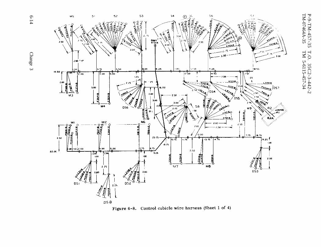
Figure 6-8.
P-9
-TM
-45
7-3
5
T.O
. 3
5C
2-3
-44
2-2
TM
-07464A-35
TM
5-6115-457-34
6-14C
hange 3
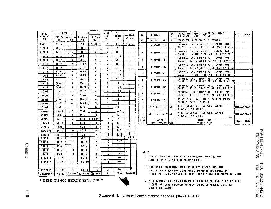
Figure 6-8.
P-9-T
M-457-35
T.O
. 35C
2-3-442-2T
M-07464A
-35T
M 5-6115-457-34
6-19C
hange 3
P-9-TM-457-35 T.O. 35C2-3-442-2TM-07464A-35 TM 5-6115-457-34
Section II. DC CIRCUIT BREAKER BOX
6-40. GENERAL.
The dc circuit breaker box is locatedat the rear of the generator set to the rightof the control cubicle assembly panel. Thecircuit breaker box contains a 7.5 amperecircuit breaker CBI, associated wiring, anda connector for electrical connection to thegenerator set dc system. 400 hertz genera-tor sets also include an expanded scalevoltmeter and generator/bus selector switch,used for paralleling operations. Circuitbreaker CB1 is electrically connected be-tween the batteries and the START-RUN-STOP switch S2 in the dc system. It pro-tects all control circuits energized fromthe batteries except those for the winteriza -tion heater and dc alternator. In the closeposition the pushbutton only shows black.When tripped, the button is extended andthe white portion is visible.
6-41. REMOVAL.
Refer to Operator and OrganizationalMaintenance Manual and remove dc circuitbreaker box.
6-42. DISASSEMBLY.
Refer to figure 6-9 and disassembledc circuit breaker box in the order of indexnumbers assigned. Pay particular attentionto the following:
a. Remove screws (1) and separatecover (6) and chassis (10) so that wires canbe disconnected from circuit breaker (9).and expanded scale voltmeter (9G).
b. Tag and disconnect electrical wiringfrom circuit breaker and voltmeter.
6-43. CLEANING.
Clean parts with a clean lint-freecloth moistened in an approved cleaningsolvent and dry thoroughly.
6-44. INSPECTION.
Inspect dc circuit breaker box com-ponents as follows:
a. Inspect sheet metal parts for dents,cracks, and distortion.
b. Inspect connectors for bent, broken,and missing pins. Refer to table 6-2 andtest wires and connectors for continuity,shorts to case and surrounding pins. Checkterminal lugs for condition and security.
c. Check circuit breaker automatictripping with load application above 7.5ampere.
6-45. REPAIR.
Repair defective wiring in accordancewith table 6-2.
6-46. REASSEMBLY.
Refer to figure 6-9 and reassembledc circuit breaker box in the reverse orderof index numbers assigned. Pay particularattention to the following:
a. Install connectors (5 and 5D) withkeyway up.
6-47. INSTALLATION.
Refer to Operator and OrganizationalMaintenance Manual and install DC circuitbreaker box.
6-20 Change 3
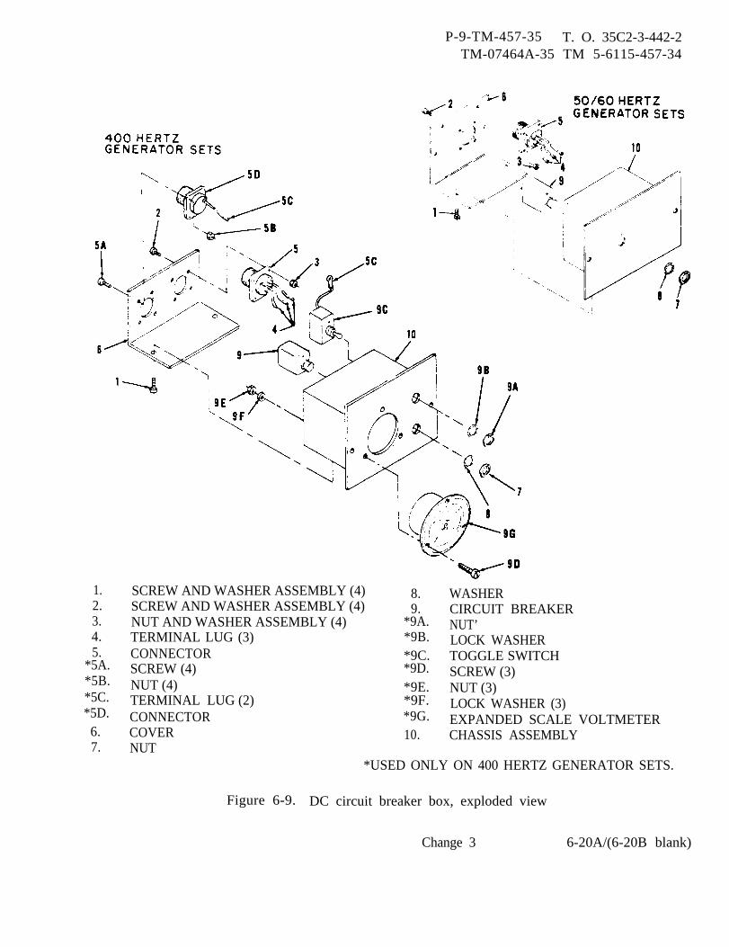
P-9-TM-457-35 T. O. 35C2-3-442-2TM-07464A-35 TM 5-6115-457-34
1.2.3.4.5.
*5A.*5B.*5C.*5D.6.7.
SCREW AND WASHER ASSEMBLY (4)SCREW AND WASHER ASSEMBLY (4)NUT AND WASHER ASSEMBLY (4)TERMINAL LUG (3)CONNECTORSCREW (4)NUT (4)TERMINAL LUG (2)CONNECTORCOVERNUT
*USED ONLY ON 400 HERTZ GENERATOR SETS.
8.9.
*9A.*9B.*9C.*9D.*9E.*9F.*9G.10.
WASHERCIRCUIT BREAKERNUT’LOCK WASHERTOGGLE SWITCHSCREW (3)NUT (3)LOCK WASHER (3)EXPANDED SCALE VOLTMETERCHASSIS ASSEMBLY
Figure 6-9. DC circuit breaker box, exploded view
Change 3 6-20A/(6-20B blank)

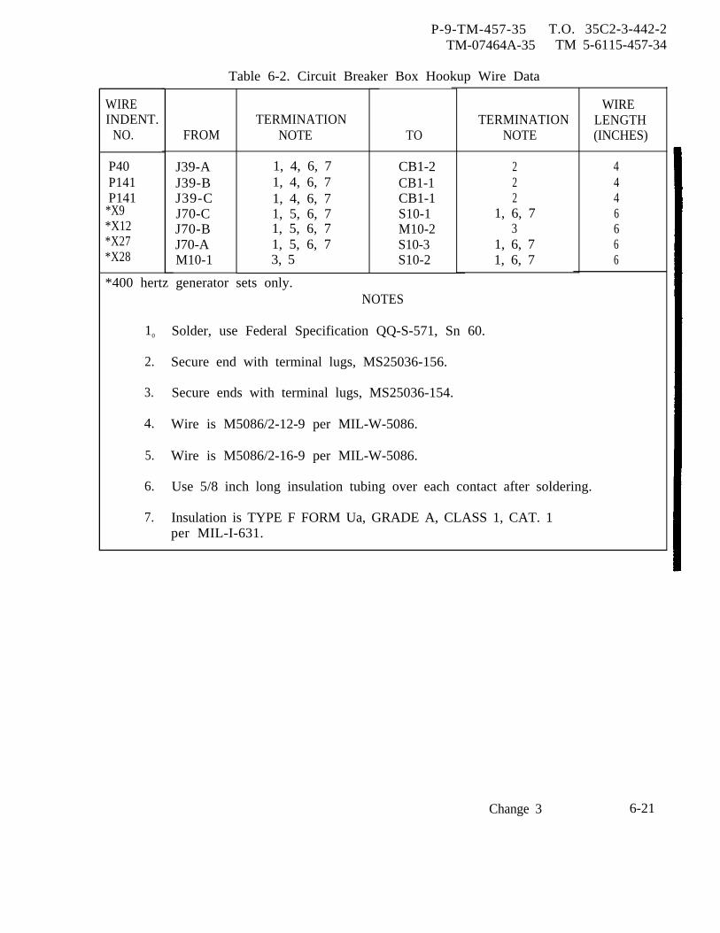
P-9-TM-457-35 T.O. 35C2-3-442-2TM-07464A-35 TM 5-6115-457-34
WIREINDENT.
NO.
P40P141P141
*X9*X12*X27*X28
Table 6-2. Circuit Breaker Box Hookup Wire Data
FROM
J39-AJ39-BJ39-CJ70-CJ70-BJ70-AM10-1
TERMINATIONNOTE
1, 4, 6, 71, 4, 6, 71, 4, 6, 71, 5, 6, 71, 5, 6, 71, 5, 6, 73, 5
TO
CB1-2CB1-1CB1-1S10-1M10-2S10-3S10-2
TERMINATIONNOTE
222
1, 6, 73
1, 6, 71, 6, 7
WIRELENGTH(INCHES)
4446666
*400 hertz generator sets only.NOTES
10 Solder, use Federal Specification QQ-S-571, Sn 60.
2. Secure end with terminal lugs, MS25036-156.
3. Secure ends with terminal lugs, MS25036-154.
4. Wire is M5086/2-12-9 per MIL-W-5086.
5. Wire is M5086/2-16-9 per MIL-W-5086.
6. Use 5/8 inch long insulation tubing over each contact after soldering.
7. Insulation is TYPE F FORM Ua, GRADE A, CLASS 1, CAT. 1per MIL-I-631.
Change 3 6-21
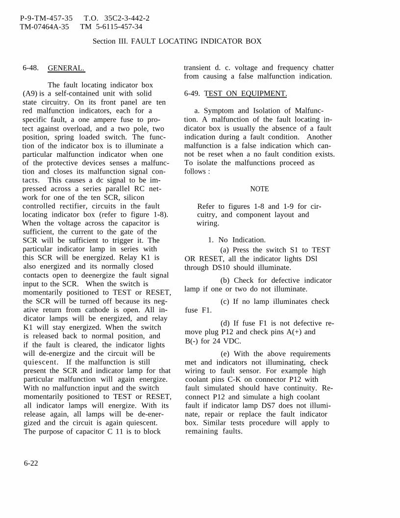
P-9-TM-457-35 T.O. 35C2-3-442-2TM-07464A-35 TM 5-6115-457-34
Section III. FAULT LOCATING INDICATOR BOX
6-48.
(A9) is
GENERAL.
The fault locating indicator boxa self-contained unit with solid
state circuitry. On its front panel are tenred malfunction indicators, each for aspecific fault, a one ampere fuse to pro-tect against overload, and a two pole, twoposition, spring loaded switch. The func-tion of the indicator box is to illuminate aparticular malfunction indicator when oneof the protective devices senses a malfunc-tion and closes its malfunction signal con-tacts. This causes a dc signal to be im-pressed across a series parallel RC net-work for one of the ten SCR, siliconcontrolled rectifier, circuits in the faultlocating indicator box (refer to figure 1-8).When the voltage across the capacitor issufficient, the current to the gate of theSCR will be sufficient to trigger it. Theparticular indicator lamp in series withthis SCR will be energized. Relay K1 isalso energized and its normally closedcontacts open to deenergize the fault signalinput to the SCR. When the switch ismomentarily positioned to TEST or RESET,the SCR will be turned off because its neg-ative return from cathode is open. All in-dicator lamps will be energized, and relayK1 will stay energized. When the switchis released back to normal position, andif the fault is cleared, the indicator lightswill de-energize and the circuit will bequiescent. If the malfunction is stillpresent the SCR and indicator lamp for thatparticular malfunction will again energize.With no malfunction input and the switchmomentarily positioned to TEST or RESET,all indicator lamps will energize. With itsrelease again, all lamps will be de-ener-gized and the circuit is again quiescent.The purpose of capacitor C 11 is to block
transient d. c. voltage and frequency chatterfrom causing a false malfunction indication.
6-49. TEST ON EQUIPMENT.
a. Symptom and Isolation of Malfunc-tion. A malfunction of the fault locating in-dicator box is usually the absence of a faultindication during a fault condition. Anothermalfunction is a false indication which can-not be reset when a no fault condition exists.To isolate the malfunctions proceed asfollows :
NOTE
Refer to figures 1-8 and 1-9 for cir-cuitry, and component layout andwiring.
1. No Indication.(a) Press the switch S1 to TEST
OR RESET, all the indicator lights DSlthrough DS10 should illuminate.
(b) Check for defective indicatorlamp if one or two do not illuminate.
(c) If no lamp illuminates checkfuse F1.
(d) If fuse F1 is not defective re-move plug P12 and check pins A(+) andB(-) for 24 VDC.
(e) With the above requirementsmet and indicators not illuminating, checkwiring to fault sensor. For example highcoolant pins C-K on connector P12 withfault simulated should have continuity. Re-connect P12 and simulate a high coolantfault if indicator lamp DS7 does not illumi-nate, repair or replace the fault indicatorbox. Similar tests procedure will apply toremaining faults.
6-22
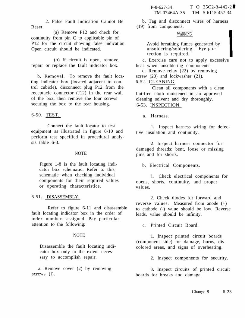
P-8-627-34 T O 35C2-3-442-2TM-07464A-35 TM 5-6115-457-34
2. False Fault Indication Cannot BeReset.
(a) Remove P12 and check forcontinuity from pin C to applicable pin ofP12 for the circuit showing false indication.Open circuit should be indicated.
(b) If circuit is open, remove,repair or replace the fault indicator box.
b. Removal. To remove the fault loca-ting indicator box (located adjacent to con-trol cubicle), disconnect plug P12 from thereceptacle connector (J12) in the rear wallof the box, then remove the four screwssecuring the box to the rear housing.
6-50. TEST.
Connect the fault locator to testequipment as illustrated in figure 6-10 andperform test specified in procedural analy-sis table 6-3.
NOTE
Figure 1-8 is the fault locating indi-cator box schematic. Refer to thisschematic when checking individualcomponents for their required valuesor operating characteristics.
6-51. DISASSEMBLY.
Refer to figure 6-11 and disassemblefault locating indicator box in the order ofindex numbers assigned. Pay particularattention to the following:
NOTE
Disassemble the fault locating indi-cator box only to the extent neces-sary to accomplish repair.
a. Remove cover (2) by removingscrews (l).
b. Tag and disconnect wires of harness(19) from components.
WARNING
Avoid breathing fumes generated byunsoldering/soldering. Eye pro-tection is required.
c. Exercise care not to apply excessiveheat when unsoldering components.
d. Remove relay (22) by removingscrew (20) and lockwasher (21).6-52. CLEANING.
Clean all components with a cleanlint-free cloth moistened in an approvedcleaning solvent and dry thoroughly.6-53. INSPECTION.
a. Harness.
1. Inspect harness wiring for defec-tive insulation and continuity.
2. Inspect harness connector fordamaged threads; bent, loose or missingpins and for shorts.
b. Electrical Components.
1. Check electrical components foropens, shorts, continuity, and propervalues.
2. Check diodes for forward andreverse values. Measured from anode (+)to cathode (-) value should be low. Reverseleads, value should be infinity.
c. Printed Circuit Board.
1. Inspect printed circuit boards(component side) for damage, burns, dis-colored areas, and signs of overheating.
2. Inspect components for security.
3. Inspect circuits of printed circuitboards for breaks and damage.
Change 8 6-23
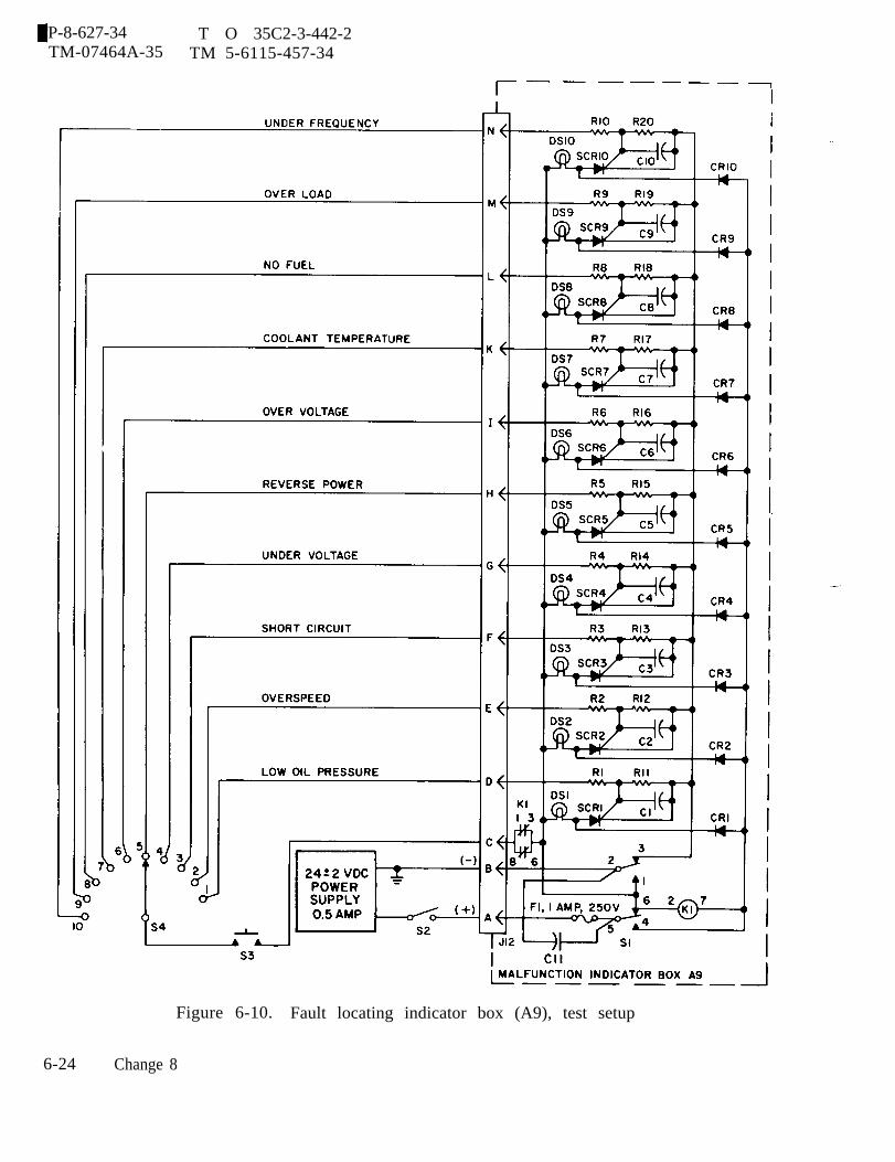
P-8-627-34 T O 35C2-3-442-2TM-07464A-35 TM 5-6115-457-34
6-24
Figure 6-10. Fault locating indicator box (A9), test setup
Change 8
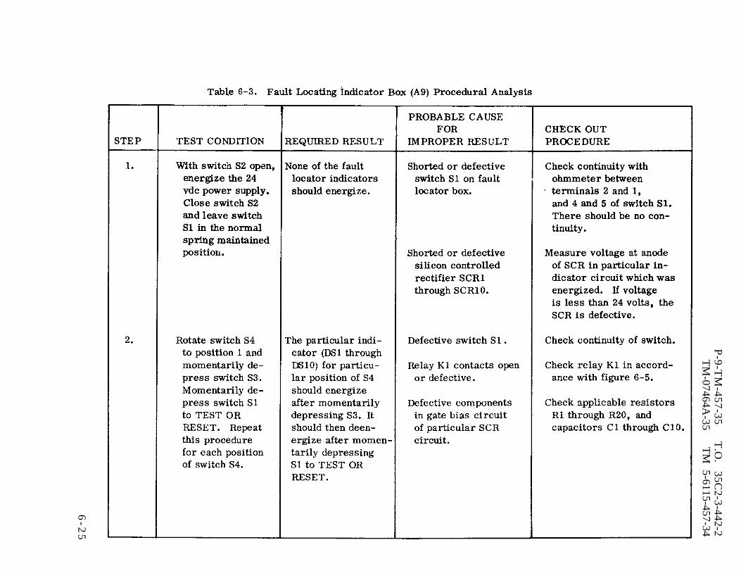
Table 6-3.
P-9-T
M-457-35
T.O
. 35C
2-3-442-2T
M-07464A
-35T
M
5-6115-457-34
6-2
5

Table 6-3.
P-9-T
M-457-35
T.O
. 35C
2-3-442-2T
M-07464A
-35T
M 5-6115-457134
6-26
4. Inspect base of printed circuitboard for cracks, warping, burned or dis-colored areas and illegible stenciling.
d. Inspect sheet metal parts for bentcorners, distortion, cracks, tears anddents.
e. Check terminal lugs for security andcondition.
f. Inspect relay socket for damage,shorts to case, and surrounding pins.
g. Inspect for damaged indicator lenses.
h. Check fuse for continuity.6-54. REPAIR.
a. Repair or fabricate fault locating in-dicator box wiring harness according tofigure 6-12.
b. Repair or fabricate fault locatingindicator box heating wire in accordancewith table 6-4.
c. Replace indicator lenses, if cracked.d. Replace fuse if defective.
e. When replacing feed thru terminals,swage in place.
f. Repair printed circuit board asfollows :
1. Restencil all illegible referencedesignations.
WARNING
Avoid breathing fumes generated byunsoldering/soldering. Eye pro-tection is required.
CAUTION
ing a
Prolonged use of soldering equip-ment could cause damage to com-ponents due to excessive heat.
2. Repair printed circuits by solder-jumper wire across defective area.
3. Replace all defective components.
4. Solder replacement componentson the printed circuit boards using solderconforming to Federal Specification QQ-S-571 Sn 60.
P-8-627-34 T OTM-07464A-35 TM
WARNING
35C2-3-442-25-6115-457-34
Insulating Compound, MIL-I-46058 isflammable and slightly toxic to eyes,skin and respiratory tract. Eye andskin protection required. Good gen-eral ventilation is normally adequate.
5. Solder joints and/or componentleads must not project more than O. 094inch beyond surface of board.
6. After replacement of componentson the printed circuit boards, coat theboards with protective coating, conformingto Military Specification MIL-I-46058,grade S, type PUR, 0.005 minimum thick-ness. Air bubbles should be preventedduring coating so that legibility of identifica-tion or information markings are not im-paired. The coating shall be applied sothat it anchors the components to the board.Terminals utilized for connection to exter-nal circuits shall not be coated.
g. Straighten dented or distorted sheetmetal parts using proper tools. Blend inrepaired area with suitable abrasive paper.Prime and touch up damaged painted sur-faces.
6-55. REASSEMBLY.
Refer to figure 6-11 and reassemblefault locating indicator box in the reverseorder of index numbers assigned. Pay par-ticular attention to the following:
NOTE
Mount connector (J12) with keywayin top position.
Change 8 6-27
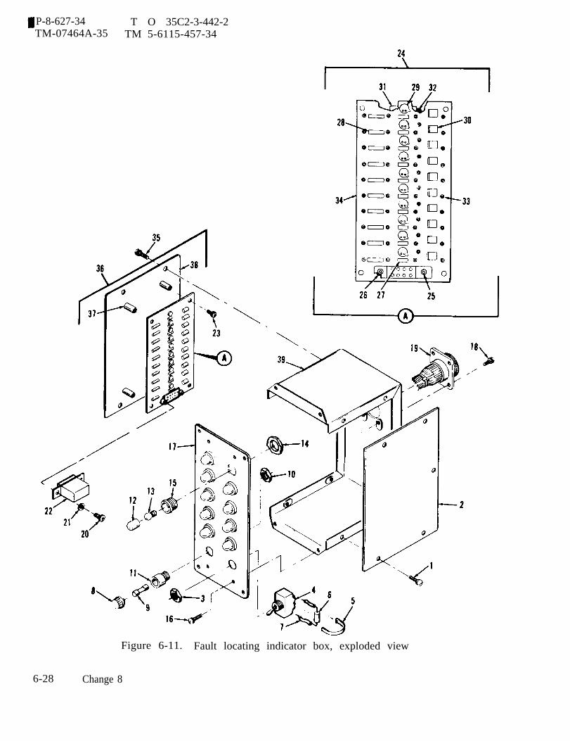
P-8-627-34 T O 35C2-3-442-2TM-07464A-35 TM 5-6115-457-34
Figure 6-11. Fault locating indicator box, exploded view
6-28 Change 8

P-9-TM-457-35 T.O. 35C2-3-442-2TM-07464A-35 TM 5-6115-457-34
Legend to figure 6-11:
1.2.3.4.5.6.7.8.9.
10.11.12.13.14.15.16.17.18.19.20.
Screw (5)CoverNutToggle switchStrap (2)CapacitorInsulation (2)Fuse capFuseNutFuseholderIndicator lenses (10)Incandescent lamp (10)Nut (10)Light indicator housing (10)Screw (4)Fault indicator panelScrew (4)Wiring harnessScrew (2)
a. Connect hookup wires and wires ofharness to components. Refer to tables6-4 and figures 6-12 and 1-9 for properconnection.
b. Exercise care not to apply excessiveheat to components when soldering connec-tions.
c. Install relay (22, figure 6-11) inrelay socket (25) squarely so as not to dam-age pins.
21.22.23.24.25.26.27.28.29.30.31.32.33.34.35.36.37.38.39.
Washer (2)RelayScrew (4)Fault indicator component boardRelay socketStandoffResistor (10)Resistor (10)Silicon controlled rectifier (10)Silicon rectifier (10)Capacitor (10)InsulationTerminal stud (50)BoardScrew (4)Bottom plateStandoff (4)PlateChassis
d. Test fault locating indicator box asspecified in paragraph 6-50.
e. Install cover (2) by installing screws(l).
6-56. INSTALLATION.
Install the fault locating indicatorbox in the rear housing and secure in posi-tion with four screws. Connect plug P12to receptacle connector J12 located in therear wall of the box.
6-29

P-9-TM-457-35 T.O. 35C2-3-442-2TM-07464A-35 TM 5-6115-457-34
Table 6-4. Fault Locating Indicator (A9) Hook Up Wire Data
WIRECOLOR WIRE LENGTH FROM TO
INCHES
WHT 27 1-1/2 S1-1 S1-6WHT 28 2-1/2 S1-6 XDS6WHT 29 1-1/4 XDS6 XDS10WHT 30 1-1/4 XDS10 XDS9WHT 31 1-1/4 XDS9 XDS8WHT 32 1-1/4 XDS8 XDS7WHT 33 1-1/4 XDS7 XDS1WHT 34 1-1/4 XDS1 XDS2WHT 35 1-1/4 XDS2 XDS3WHT 36 1-1/4 XDS3 XDS4WHT 37 1-1/4 XDS4 XDS5WHT 38 3/4 S1-5 XF1WHT 39 3/4 XK1-8WHT
XK1-140 1 XK1-6 XK1-2
WHT 41 1/2 XK1-3 XK1-2WHT 42 1-1/2 XK1-7 TB1-50
NOTES
1. Solder. Use Federal Specification QQ-S-571, Sn 60.
2. Wire is in accordance with MIL-STD-454, requirement 20.
3. Use wire conforming to MIL-W-16878, Type 22 black or white.
4. Protect capacitor C11 leads using insulated sleeving.
6-30
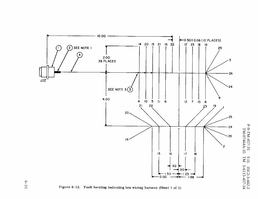
Figure 6-12.
P-9-T
M-457-35
T.O
. 35C
2-3-442-2T
M-07464A
-35 T
M
5-6115-457-34
6-3
1
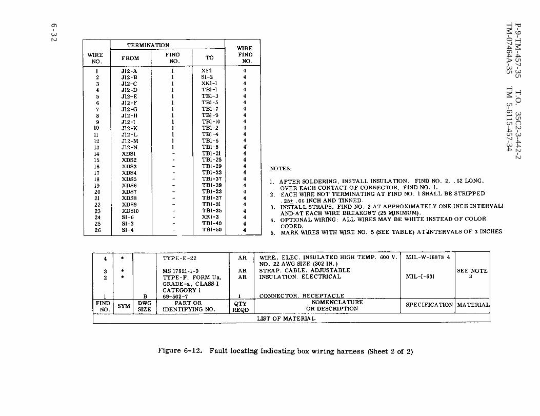
Figure 6-12.
P-9-T
M-457-35
T.O
. 35C
2-3-442-2T
M-07464A
-35T
M 5-6115-457-34
6-3
2

P-9-TM-457-35 T.O. 35C2-3-442-2TM-07464A-35 TM 5-6115-457-34
Section IV. CONVENIENCE RECEPTACLE ASSEMBLY
6-57. GENERAL.
The 50/60 hertz convenience recep-tacle assembly (A22) contains a 125 volt,15 ampere duplex receptacle, while the400 hertz type contains a 125 volt, 15 am-pere receptacle and a 125/250 volt, 30ampere receptacle. Each receptacle has aspring- loaded weatherproof cover. Bothtypes have their receptacles connected inparallel electrically, and have their recep-tacles protected by a 15 ampere circuitbreaker.
6-58. 50/60 HERTZ CONVENIENCERECEPTACLE ASSEMBLY.
6-59. REMOVAL, To remove the assem-bly (located below the control cubicle),disconnect plug P48 from the receptacleconnector J48 in the rear of the assembly,then remove the six screws and lockwasherssecuring the assembly to the rear housing.
6-60. DISASSEMBLY. Refer to figure6-13 and disassemble the 50/60 hertz con-venience receptacle assembly in the orderof index numbers assigned. Pay particularattention to the following:
a. Remove six screw assemblies (1)and separate the cover (9) from the housing(24).
b. Tag and disconnect wires from con-nector (4) circuit breaker (20) and theduplex receptacle (17).
6-61. CLEANING. Clean all componentswith a lint-free cloth moistened with anapproved cleaning solvent and dry thor-oughly.
6-62. INSPECTION.
a. Inspect connectors for bent, brokenand missing pins. Refer to table 6-5, andcheck wires for continuity, shorts to caseand surrounding pins.
b. Check terminal lugs and solderedconnections for condition and security.
c. Check circuit breakers and recep-tacles for continuity.
d. Inspect sheet metal parts for dents,cracks, and distortion.
6-63. REPAIR.
a. Repair defective wiring in accord-ance with table 6-5.
b. Straighten dented or distorted sheetmetal parts using proper tools.
6-64, REASSEMBLY. Refer to figure6-13 and reassemble 50/60 hertz electroniccomponent assembly in the reverse orderof index numbers assigned. Pay particularattention to the following:
a. Connect wires in accordance withtable 6-5.
b. Install connector plug (4) with key-way up.
6-65. INSTALLATION. Install the 50/60hertz convenience receptacle assembly inthe rear housing and secure in positionwith six screws and lockwashers. Connectplug P48 to connector J48 in the rear ofthe assembly.
6-33
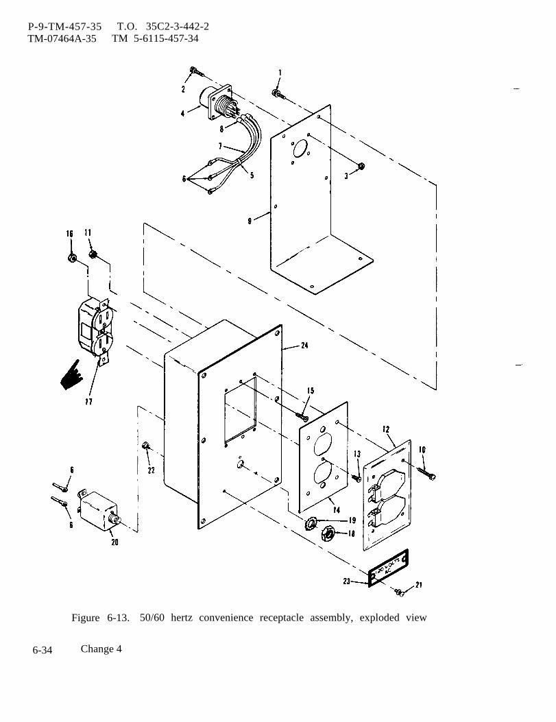
P-9-TM-457-35 T.O. 35C2-3-442-2TM-07464A-35 TM 5-6115-457-34
Figure 6-13. 50/60 hertz convenience receptacle assembly, exploded view
6-34 Change 4
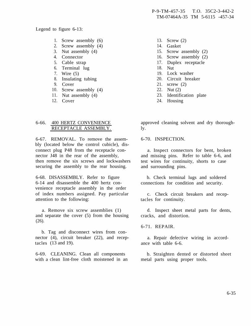
P-9-TM-457-35 T.O. 35C2-3-442-2TM-07464A-35 TM 5-6115 -457-34
Legend to figure 6-13:
6-66.
6-67.
1.2.3.4.5.6.7.8.9.
10.11.12.
Screw assembly (6)Screw assembly (4)Nut assembly (4)ConnectorCable strapTerminal lugWire (5)Insulating tubingCoverScrew assembly (4)Nut assembly (4)Cover
400 HERTZ CONVENIENCERECEPTACLE ASSEMBLY.
REMOVAL. To remove the assem-bly (located below the control cubicle), dis-connect plug P48 from the receptacle con-nector J48 in the rear of the assembly,then remove the six screws and lockwasherssecuring the assembly to the rear housing.
6-68. DISASSEMBLY. Refer to figure6-14 and disassemble the 400 hertz con-venience receptacle assembly in the orderof index numbers assigned. Pay particularattention to the following:
a. Remove six screw assemblies (1)and separate the cover (5) from the housing(26).
b. Tag and disconnect wires from con-nector (4), circuit breaker (22), and recep-tacles
6-69.with a
(13 and 19).
CLEANING. Clean all componentsclean lint-free cloth moistened in an
13.14.15.16.17.18.19.20.21.22.23.24.
Screw (2)GasketScrew assembly (2)Screw assembly (2)Duplex receptacleNutLock washerCircuit breakerscrew (2)Nut (2)Identification plateHousing
approved cleaning solvent and dry thorough-ly.
6-70. INSPECTION.
a. Inspect connectors for bent, brokenand missing pins. Refer to table 6-6, andtest wires for continuity, shorts to caseand surrounding pins.
b. Check terminal lugs and solderedconnections for condition and security.
c.tacles
d.
Check circuit breakers and recep-for continuity.
Inspect sheet metal parts for dents,cracks, and distortion.
6-71. REPAIR.
a. Repair defective wiring in accord-ance with table 6-6.
b. Straighten dented or distorted sheetmetal parts using proper tools.
6-35
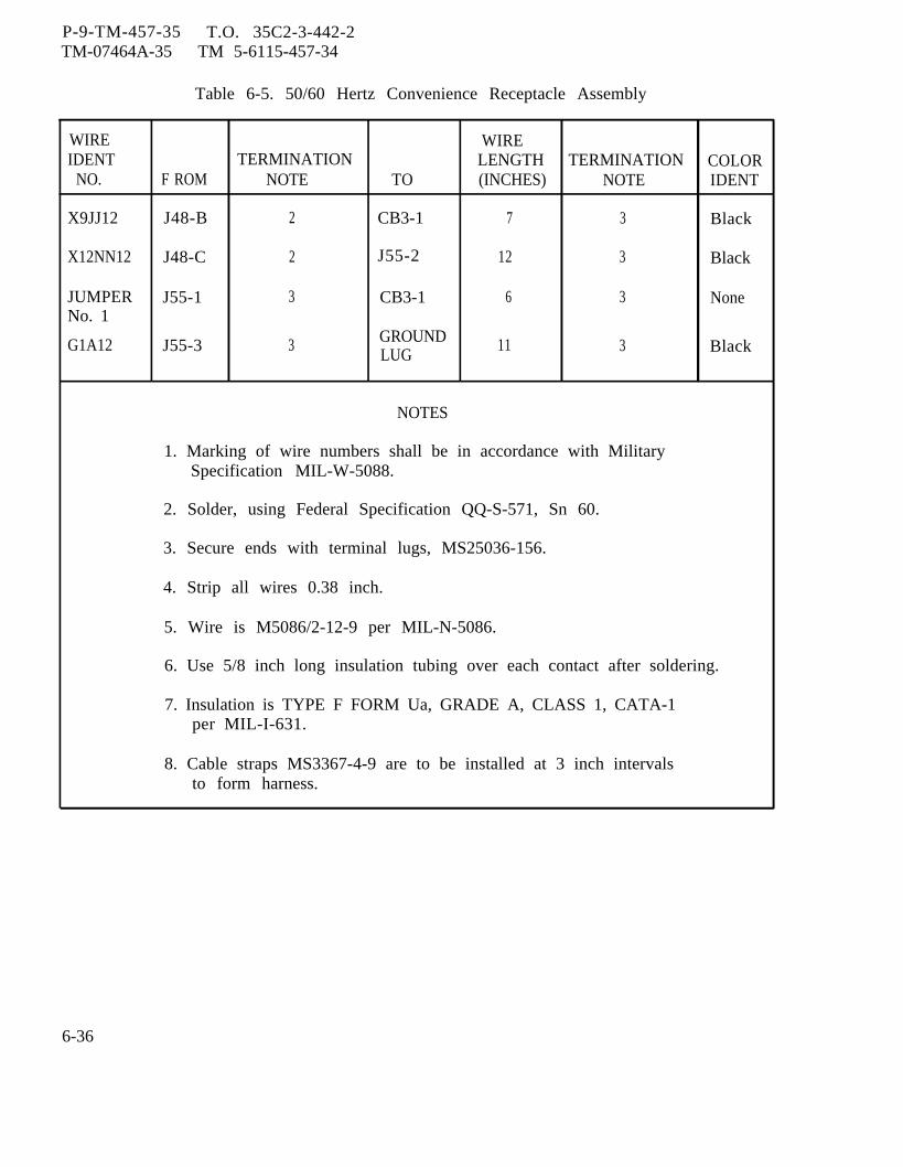
P-9-TM-457-35 T.O. 35C2-3-442-2TM-07464A-35 TM 5-6115-457-34
Table 6-5. 50/60 Hertz Convenience Receptacle Assembly
WIRE WIREIDENT TERMINATION LENGTH TERMINATION COLOR
NO. F ROM NOTE TO (INCHES) NOTE IDENT
X9JJ12 J48-B 2 CB3-1 7 3 Black
X12NN12 J48-C 2 J55-2 12 3 Black
JUMPER J55-1 3 CB3-1 6 3 NoneNo. 1
G1A12 J55-3 3 GROUNDLUG
11 3 Black
NOTES
1. Marking of wire numbers shall be in accordance with MilitarySpecification MIL-W-5088.
2. Solder, using Federal Specification QQ-S-571, Sn 60.
3. Secure ends with terminal lugs, MS25036-156.
4. Strip all wires 0.38 inch.
5. Wire is M5086/2-12-9 per MIL-N-5086.
6. Use 5/8 inch long insulation tubing over each contact after soldering.
7. Insulation is TYPE F FORM Ua, GRADE A, CLASS 1, CATA-1per MIL-I-631.
8. Cable straps MS3367-4-9 are to be installed at 3 inch intervalsto form harness.
6-36
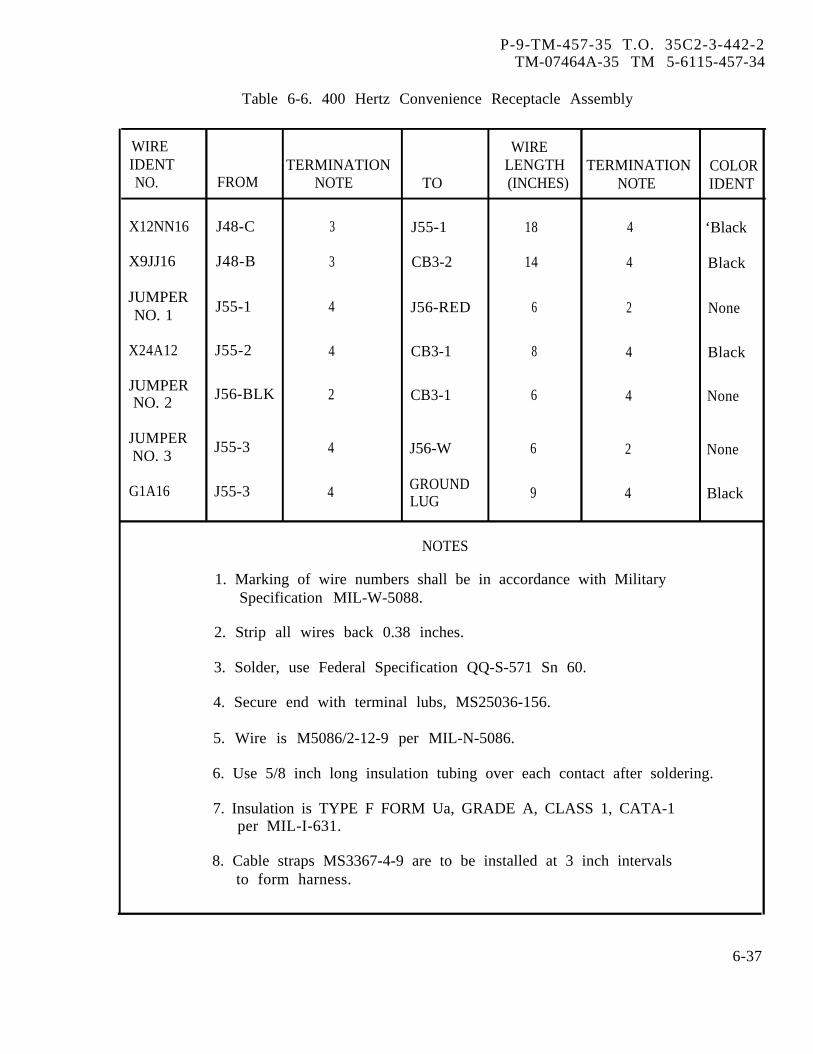
P-9-TM-457-35 T.O. 35C2-3-442-2TM-07464A-35 TM 5-6115-457-34
Table 6-6. 400 Hertz Convenience Receptacle Assembly
WIRE WIREIDENT TERMINATION LENGTH TERMINATION COLORNO. FROM NOTE TO (INCHES) NOTE IDENT
X12NN16 J48-C 3 J55-1 18 4 ‘Black
X9JJ16 J48-B 3 CB3-2 14 4 Black
JUMPERNO. 1 J55-1 4 J56-RED 6 2 None
X24A12 J55-2 4 CB3-1 8 4 Black
JUMPERNO. 2 J56-BLK 2 CB3-1 6 4 None
JUMPERNO. 3
J55-3 4 J56-W 6 2 None
G1A16 J55-3 4 GROUNDLUG 9 4 Black
NOTES
1. Marking of wire numbers shall be in accordance with MilitarySpecification MIL-W-5088.
2. Strip all wires back 0.38 inches.
3. Solder, use Federal Specification QQ-S-571 Sn 60.
4. Secure end with terminal lubs, MS25036-156.
5. Wire is M5086/2-12-9 per MIL-N-5086.
6. Use 5/8 inch long insulation tubing over each contact after soldering.
7. Insulation is TYPE F FORM Ua, GRADE A, CLASS 1, CATA-1per MIL-I-631.
8. Cable straps MS3367-4-9 are to be installed at 3 inch intervalsto form harness.
6-37
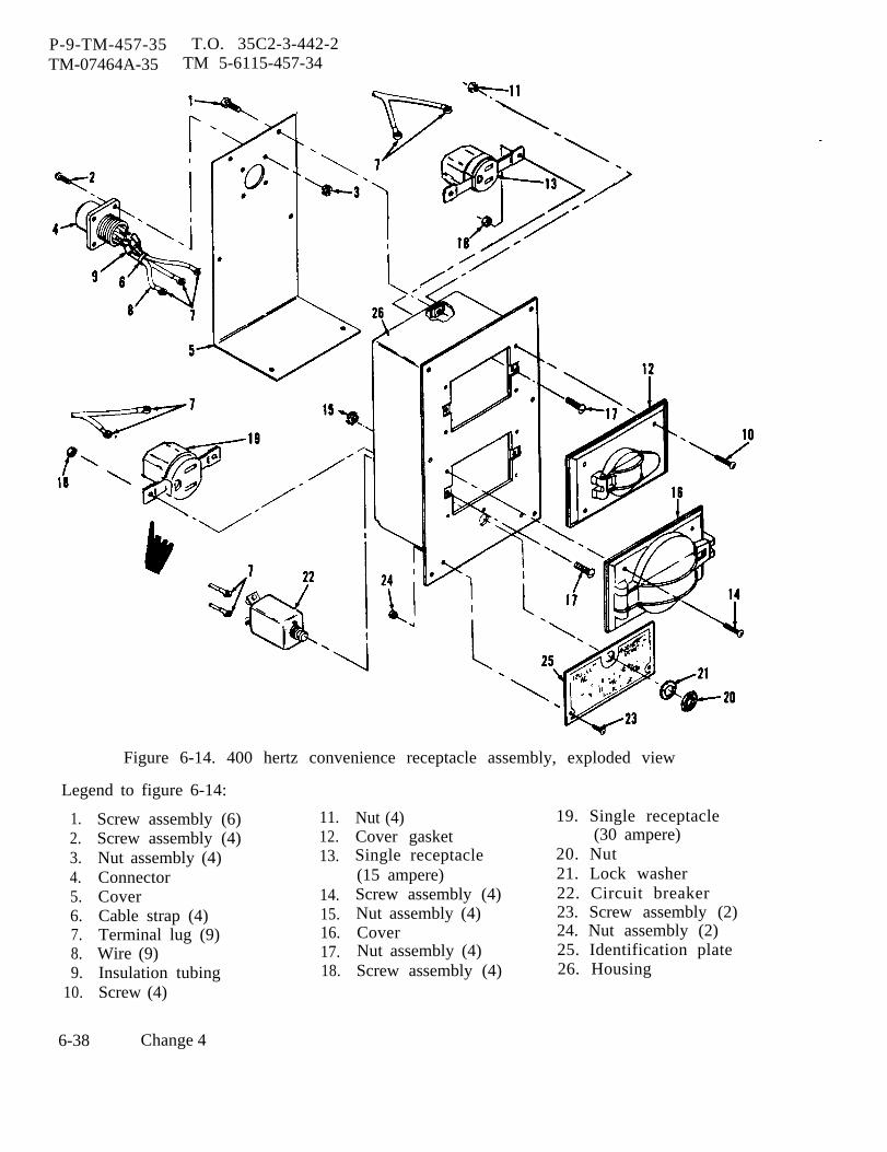
P-9-TM-457-35 T.O. 35C2-3-442-2TM-07464A-35 TM 5-6115-457-34
Figure 6-14. 400 hertz convenience receptacle assembly, exploded view
Legend to figure 6-14:
1.2.3.4.5.6.7.8.9.
10.
Screw assembly (6) 11.Screw assembly (4) 12.Nut assembly (4) 13.ConnectorCover 14.Cable strap (4) 15.Terminal lug (9) 16.Wire (9) 17.Insulation tubing 18.Screw (4)
Nut (4)Cover gasketSingle receptacle(15 ampere)Screw assembly (4)Nut assembly (4)CoverNut assembly (4)Screw assembly (4)
19. Single receptacle(30 ampere)
20. Nut21. Lock washer22. Circuit breaker23. Screw assembly (2)24. Nut assembly (2)25. Identification plate26. Housing
6-38 Change 4
P-9-TM-457-35 T.O. 35C2-3-442-2TM-07464A-35 TM 5-6115-457-34
6-72. REASSEMBLY, Refer to figure 6-14 b. Install connector (4) with keyway up.and reassemble 400 hertz electronic com-ponent assembly in the reverse order of 6-73. INSTALLATION. Install the 400index numbers assigned. Pay particular hertz convenience receptacle assembly inattention to the following: the rear housing and secure in position with
six screws and lock washers. Connect pluga. Connect wires in accordance with P48 to connector J48 in the rear of the
table 6-6. assembly.
Section V. EXCITER-REGULATOR
6-74. GENERAL.
a. The exciter All, (figures 1-11 and1-13) and voltage regulator A 10 operate asintegral components of the excitation sys-tem. The excitation system energizes themain rotor field coils of the generator andregulates the magnitude of the magneticfield thus produced so as to maintain a con-stant voltage output from the stator of thegenerator under all rated load conditions.
b. The excitation system is comprisedof a dynamic exciter, a static exciter as-sembly, a voltage regulator assembly,current transformers and a cross currentcompensation network to permit paralleloperation of two or more generator sets.
1. The static exciter and voltageregulator are electronic assemblies pack-aged in a single enclosure and mounted out-side the generator housing.
2. The dynamic exciter consists ofa field coil stator integral with the genera-tor housing, a set of rotor coils and solidstate rectifiers mounted on the generatorshaft. The static exciter energizes thefield coils of the dynamic exciter. Theresultant field couples with the rotor coilsof the exciter. The induced currents are
rectified and then fed to the coils of thegenerator rotor, the fields of which inducethe output currents in the coils of the gen-erator stator. Brushes or slip rings arenot required. The disposition of the rotorsand stators of both the dynamic exciter andthe generator including the rectifier ringare shown in figure 7-1.
c. The exciter-regulator circuitry isillustrated in figures 1-10 and 1-12. Theassembly operates as follows:
1. The regulated exciter field volt-age at pins S-R of connector J13 is obtainedby means of saturable core transformerT 1. The inductance of this transformercan be varied with the control winding 5-7so that the voltage ratio between the wind-ings 1-2 and 3-4 may be increased or de-creased in proportion to the direct currentflowing in the winding 5-7, When the mag-nitude of the control current increases theinductance decreases and there is a loweredmagnetic coupling between the windingswhich carry the alternating currents, hencea lowered voltage output. The reverseoccurs when the control current is de-creased.
2. The input at J-K of connectorJ13 derives from current transformers
Change 1 6-39
P-9-TM-457-35 T.O. 35C2-3-442-2TM-07464A-35 TM 5-6115-457-34
CT4, CT5, CT6, on the load lines of thegenerator (figures 1-4 and 1-5). The volt-age at L-M of connector J13 is from phaseC (T9 - T12 on generator). The two inputsare combined by T1 (figures 1-24 and 1-26)under control of winding 5-7, then rectifiedby bridge CR1 through CR4 and fed to theexciter field stator winding from S-R ofconnector J13. In the event of a short cir-cuit, the voltage at L-M can drop to zerobut there is a high voltage at J-K from thecurrent transformers so that the exciterprovides sufficient field for the generatoroutput to actuate the protective devices toshut down the set.
3. The voltage at S-R of connectorJ13 is compared to the reference voltage atQ1 (located in voltage regulator A10) andZener diode VR1 of the differential ampli-fier Q1 - Q2. Any difference or error sig-nal at the collector of Q2 is amplified byQ5 - Q6 and Q3 - Q4 and then fed to thecontrol winding 5-7 of the control trans -former T1 which increases or decreasesthe exciter field coil current to reduce theerror signal to zero thereby maintainingthe output of the generator set within therange as preset by R33. The networksR31-C1 and R32-C3 are utilized for phaseshift compensation. If hunting is present,adjustment of R32 will provide the properamount of feedback to eliminate the hunting.Adjustment of R31 will smooth and improvethe transient response.
4. The voltage at pins A-B of con-nector J9 is derived from phase C (T9 -T12 on generator) through the operatorsvoltage adjust rheostat and from the crosscurrent compensation network (figures 1-4and 1-5) when two or more generator setsare connected in parallel. This voltage isstepped down in transformer T5, rectifiedby bridge CR12 - 15, filtered by R16, R22,C2, C5 and fed to the reference side of thedifferential amplifier Q1- Q2.
5. The generator output voltage isdetermined by the level of the referencevoltage and is controlled by the setting ofR33 which adjusts the range voltage andoperators rheostat (R2, figures 1-4 and1-5 ) which sets the actual output. Duringparallel operation, the reference voltage isdependent on the cross current compensa-tion network. For example, if one genera-tor draws more current, the network willincrease the magnitude of the referencevoltage causing the voltage regulator tosense more voltage and thereby causing adecrease in current to the exciter fieldstator winding. This provided paralleloperation with droop.
6. Power for the transistor ampli-fiers and the control winding (5-7 of Tl)current is obtained from pins L-M of con-nector J13 thru stepdown transformer T4and bridge rectifier CR8 through CR11.Diode CR17 and resistor R21 provide posi-tive feedback to the amplifiers to enhancethe gain.
7. When the start switch of the gen-erator set is actuated, 24 volts D. C. isapplied to the exciter field stator windingsat pins S-R of connector J13 thru the limit-ing resistor R17A, R17B and isolation diodeCR16 from input pins C-D of connector J11(field flashing). The purpose is to quicklybuild up the magnetic field in the mainrotor windings to produce an immediateoutput from the generator. The flashingvoltage is then automatically removed.
6-75. TEST AND REMOVAL. .— ----
a. Symptom and Isolation of Malfunc-tion. A malfunction of the voltage regulatorsection (Al0) is usually indicated by a highgenerator output voltage with no control.A malfunction of the exciter section (A11)is usually indicated by no generator outputor by low output voltage when the load is
6-40
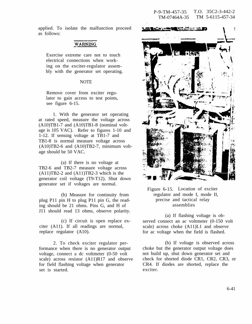
P-9-TM-457-35 T.O. 35C2-3-442-2TM-07464A-35 TM 5-6115-457-34
applied. To isolate the malfunction proceedas follows:
Exercise extreme care not to touchelectrical connections when work-ing on the exciter-regulator assem-bly with the generator set operating.
NOTE
Remove cover from exciter regu-lator to gain access to test points,see figure 6-15.
1. With the generator set operatingat rated speed, measure the voltage across(A10)TB1-7 and (A10)TB1-8 (nominal volt-age is 105 VAC). Refer to figures 1-10 and1-12. If sensing voltage at TB1-7 andTB1-8 is normal measure voltage across(A10)TB2-6 and (A10)TB2-7, minimum volt-age should be 50 VAC.
(a) If there is no voltage atTB2-6 and TB2-7 measure voltage across(A11)TB2-2 and (A11)TB2-3 which is thegenerator coil voltage (T9-T12). Shut downgenerator set if voltages are normal.
(b) Measure for continuity fromplug P11 pin H to plug P11 pin G, the read-ing should be 21 ohms. Pins G, and H ofJ11 should read 13 ohms, observe polarity.
(c) If circuit is open replace ex-citer (A11). If all readings are normal,replace regulator (A10).
2. To check exciter regulator per-formance when there is no generator outputvoltage, connect a dc voltmeter (0-50 voltscale) across resistor (A11)R17 and observefor field flashing voltage when generatorset is started.
Figure 6-15. Location of exciterregulator and mode I, mode II,precise and tactical relay
assemblies
(a) If flashing voltage is ob-served connect an ac voltmeter (0-150 voltscale) across choke (A11)L1 and observefor ac voltage when the field is flashed.
(b) If voltage is observed acrosschoke but the generator output voltage doesnot build up, shut down generator set andcheck for shorted diode CR1, CR2, CR3, orCR4. If diodes are shorted, replace theexciter.
6-41
P-9-TM-457-35 T.O. 35C2-3-442-2TM-07464A-35 TM 5-6115-457-34
(c) If diodes checkout, discon-nect wires U135C16 and U134C16 from(A11)TB1-2 and TBl-3, connect wirestogether.
(d) Start generator set; if voltagebuilds up check for short circuit in boostertransformers CT4, CT5, or CT6, refer tofigures 1-4 and 1-5. Check transformerwiring.
(e) If voltage doesn’t build up,transformer (A11)T1 is defective.
3. To inspect for the cause of lowoutput voltage when the generator set isunder load, shut down generator set andcheck for an open diode (A11)CR1, CR2,CR3, or CR4. If defective, replace theexciter assembly.
(a) If diodes are not defective,connect ac ammeter (0-25 amp scale) inseries with wire from TB1-6 and TB1-6terminal and measure current from thebooster transformers CT4, CT5 or CT6.
(b) With the generator set underfull rated load, the reading should be14 ± 2 amps. A low reading indicates anopen current transformer (CT4, CT5, orCT6).
(c) If voltage reading is normal,connect a dc ammeter (0-25 amp) in serieswith the exciter field and a dc voltmeter(0-30 volt scale) across (A1l)TB1-5(+) and(A1l)TB1-6.
(d) Start the generator set andmeasure exciter field voltage and currentunder full rated load. The reading shouldbe 10 ± 2 volts dc at 6 to 8 amps for 50/60hz units, and 22 ± 4 volts dc at 14 to 16amps for 400 hz units.
(e) If readings are low, replaceexciter-regulator. If readings are normalor high, test generator diodes for an opencondition.
b. Removal. Disconnect plug P13 andP9 from the exciter regulator, then removethe four screws and nuts securing the as-sembly in position. See figure 6-15.
6-76. TEST.
a. Connect the exciter-regulator totest equipment as illustrated in figure6-16 and perform test specified in proce-dural analysis table 6-7.
NOTE
Figures 1-10 and 1-12 are theexciter-regulator schematics.Refer to these schematics whenchecking individual componentsfor their required values oroperating characteristics.
b. Remove test equipment.
6-77. DISASSEMBLY.
Refer to figure 6-17 and disassem-ble the exciter regulator in the order ofindex numbers assigned. Pay particularattention to the following:
NOTE
The exciter-regulator assemblyshould be tested prior to disas-sembly as specified in paragraph6-76. Disassemble the exciter-regulator assembly to the extentnecessary to accomplish repair.
a. Remove cover (2, figure 6-17) byremoving eight screw assemblies (1).
6-42
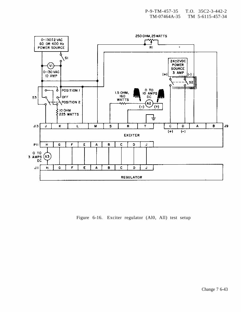
P-9-TM-457-35 T.O. 35C2-3-442-2TM-07464A-35 TM 5-6115-457-34
Figure 6-16. Exciter regulator (Al0, All) test setup
Change 7 6-43
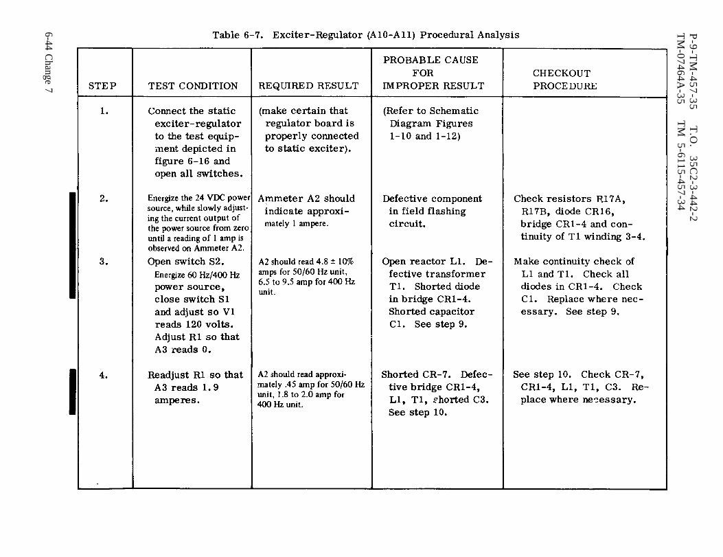
Table 6-7.
P-9
-TM
-45
7-3
5T
.O.
35C2-3-442-2
TM
-07464A-35
TM
5-6115-457-34
6-44 Change 7

Table 6-7.
P-9
-TM
-45
7-3
5T
.O.
35C2-3-442-2
TM
-07464A-35
TM
5-6115-457-34
Change 7 6-45
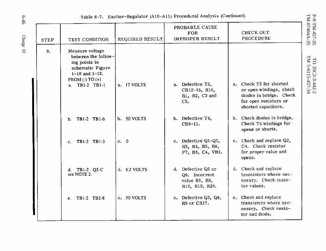
Table 6-7.
P-9-TM
-457-35T
O 35C
2-3-442-2T
M-07464A
-35T
M 5-6115-457-34
6-46Change 10
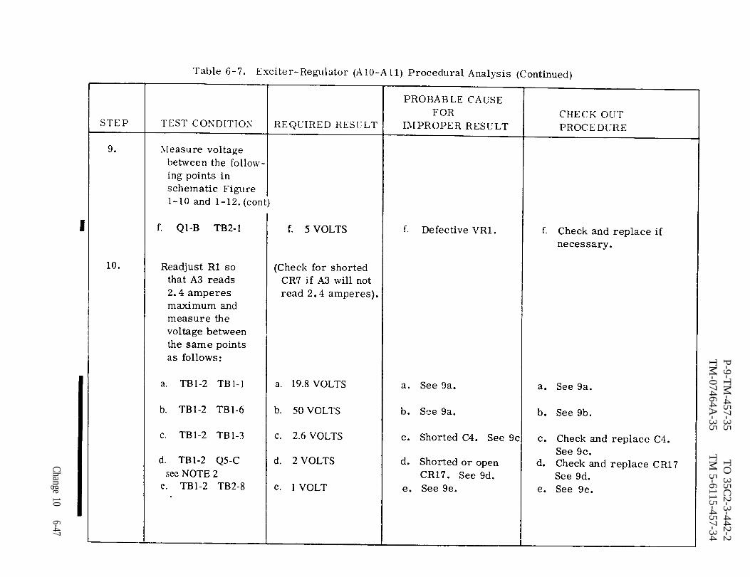
Table 6-7.
P-9-TM
-457-35T
O 35C
2-3-442-2T
M-07464A
-35T
M 5-6115-457-34
Change 106-47
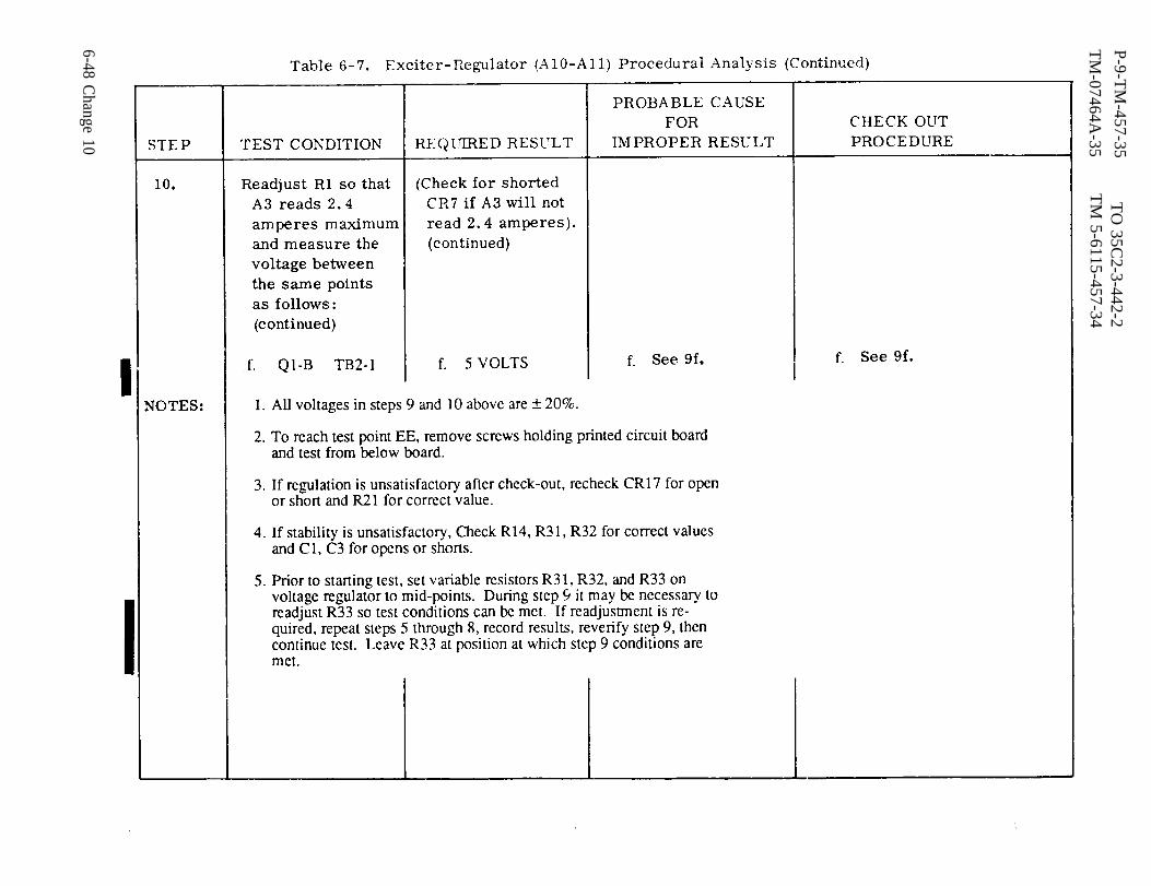
Table 6-7.
P-9-TM
-457-35T
O 35C
2-3-442-2T
M-07464A
-35T
M 5-6115-457-34
6-48 Change 10
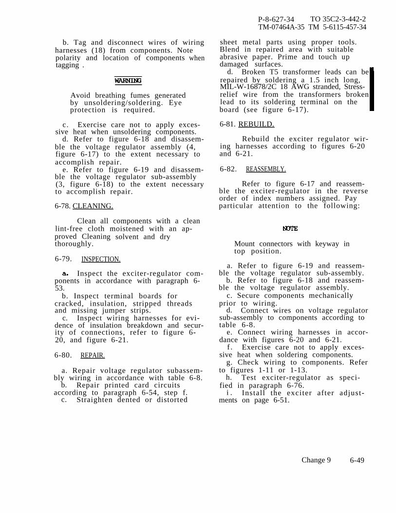
P-8-627-34 TO 35C2-3-442-2TM-07464A-35 TM 5-6115-457-34
b. Tag and disconnect wires of wiringharnesses (18) from components. Notepolarity and location of componentstagging .
when
Avoid breathing fumes generatedby unsoldering/soldering. Eyeprotection is required.
c. Exercise care not to apply exces-sive heat when unsoldering components.
d. Refer to figure 6-18 and disassem-ble the voltage regulator assembly (4,figure 6-17) to the extent necessary toaccomplish repair.
e. Refer to figure 6-19 and disassem-ble the voltage regulator sub-assembly(3, figure 6-18) to the extent necessaryto accomplish repair.
6-78. CLEANING.
Clean all components with a cleanlint-free cloth moistened with an ap-proved Cleaning solvent and drythoroughly.
6-79. INSPECTION.
Inspect the exciter-regulator com-ponents in accordance with paragraph 6-53.
b. Inspect terminal boards forcracked, insulation, stripped threadsand missing jumper strips.
c. Inspect wiring harnesses for evi-dence of insulation breakdown and secur-ity of connections, refer to figure 6-20, and figure 6-21.
6-80. REPAIR.
a. Repair voltage regulator subassem-bly wiring in accordance with table 6-8.
b. Repair printed card circuitsaccording to paragraph 6-54, step f.
c. Straighten dented or distorted
sheet metal parts using proper tools.Blend in repaired area with suitableabrasive paper. Prime and touch updamaged surfaces.
d. Broken T5 transformer leads can berepaired by soldering a 1.5 inch long,MIL-W-16878/2C 18 AWG stranded, Stress-relief wire from the transformers brokenlead to its soldering terminal on theboard (see figure 6-17).
6-81. REBUILD.
Rebuild the exciter regulator wir-ing harnesses according to figures 6-20and 6-21.
6-82. REASSEMBLY.
Refer to figure 6-17 and reassem-ble the exciter-regulator in the reverseorder of index numbers assigned. Payparticular attention to the following:
Mount connectors with keyway intop position.
a. Refer to figure 6-19 and reassem-ble the voltage regulator sub-assembly.
b. Refer to figure 6-18 and reassem-ble the voltage regulator assembly.
c. Secure components mechanicallyprior to wiring.
d. Connect wires on voltage regulatorsub-assembly to components according totable 6-8.
e. Connect wiring harnesses in accor-dance with figures 6-20 and 6-21.
f . Exercise care not to apply exces-sive heat when soldering components.
g. Check wiring to components. Referto figures 1-11 or 1-13.
h. Test exciter-regulator as speci-fied in paragraph 6-76.
i . Install the exciter after adjust-ments on page 6-51.
Change 9 6-49
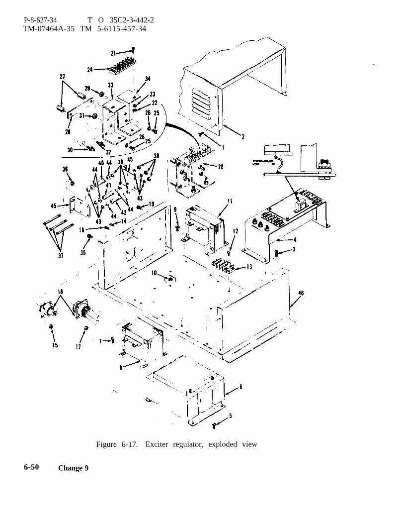
P-8-627-34 T O 35C2-3-442-2TM-07464A-35 TM 5-6115-457-34
Figure 6-17. Exciter regulator, exploded view
6-50 Change 9
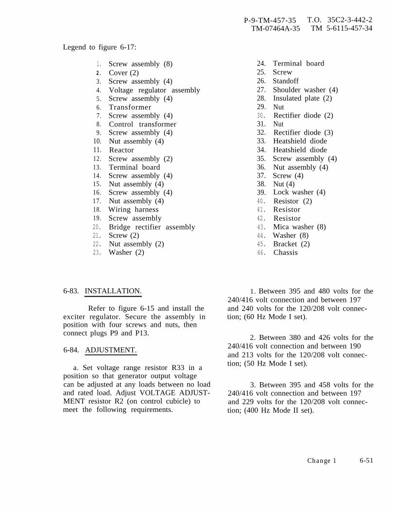
P-9-TM-457-35 T.O. 35C2-3-442-2TM-07464A-35 TM 5-6115-457-34
Legend to figure 6-17:
1.2.
3.4.5.6.7.8.9.
10.11.12.13.14.15.16.17.18.19.20.21.22.23.
Screw assembly (8)Cover (2)Screw assembly (4)Voltage regulator assemblyScrew assembly (4)TransformerScrew assembly (4)Control transformerScrew assembly (4)Nut assembly (4)ReactorScrew assembly (2)Terminal boardScrew assembly (4)Nut assembly (4)Screw assembly (4)Nut assembly (4)Wiring harnessScrew assemblyBridge rectifier assemblyScrew (2)Nut assembly (2)Washer (2)
6-83. INSTALLATION.
Refer to figure 6-15 and install theexciter regulator. Secure the assembly inposition with four screws and nuts, thenconnect plugs P9 and P13.
6-84. ADJUSTMENT.
a. Set voltage range resistor R33 in aposition so that generator output voltagecan be adjusted at any loads between no loadand rated load. Adjust VOLTAGE ADJUST-MENT resistor R2 (on control cubicle) tomeet the following requirements.
24.25.26.27.28.29.30.31.32.33.34.35.36.37.38.39.40.41.42.43.44.45.46.
Terminal boardScrewStandoffShoulder washer (4)Insulated plate (2)NutRectifier diode (2)NutRectifier diode (3)Heatshield diodeHeatshield diodeScrew assembly (4)Nut assembly (4)Screw (4)Nut (4)Lock washer (4)Resistor (2)ResistorResistorMica washer (8)Washer (8)Bracket (2)Chassis
1. Between 395 and 480 volts for the240/416 volt connection and between 197and 240 volts for the 120/208 volt connec-tion; (60 Hz Mode I set).
2. Between 380 and 426 volts for the240/416 volt connection and between 190and 213 volts for the 120/208 volt connec-tion; (50 Hz Mode I set).
3. Between 395 and 458 volts for the240/416 volt connection and between 197and 229 volts for the 120/208 volt connec-tion; (400 Hz Mode II set).
Change 1 6-51

P-9-TM-457-35 T.O. 35C2-3-442-2TM-07464A-35 TM 5-6115-457-35
Figure 6-18. Voltage regulator exploded view
6-52

P-9-TM-457-35 T.O. 35C2-3-442-2TM-07464A-35 TM 5-6115-457-34
Legend to figure 6-18:
1.2.3.4.5.6.7.8.9.
10.11.12.13.14.15.16.17.18.19.20.21.
Screw assembly (4)Standoff (4)Voltage regulatorScrew assembly (4)Nut assembly (4)Terminal board (2)NutVariable resistorVariable resistorVariable resistorScrew assembly (4)Nut assembly (4)Screw assembly (2)Self locking nut (2)Terminal lugShoulder washer (2)TransistorMica washerScrew assembly (4)Nut assembly (4)Terminal lug
22.23,24.25.26.27.28.29.30.31.32.33.34.35.36.37.38.39*40.41.
Wiring harnessScrew assembly (4)Self locking nut (4)Shoulder washer (8)Heatsink assemblyScrew assembly (2)Self locking nut (2)Terminal lugTransistorHeatsinkBracketScrew assembly (2)Standoff (2)Component board assemblyResistor (2)Transistor (2)ResistorEyelet (8)Component boardChassis assembly
b. Set feedback resistor R32 and rate feedback resistor R32 slowly counterclock-resistor R31 to mid-point, and start gen- wise until voltage is stable.erator set. If voltage is stable turn feed-back resistor R32 counterclockwise until 2. If voltage stability is still notvoltage becomes unstable, then turn clock-wise until voltage is stable.
achieved, adjust rate resistor R31 slightlycounterclockwise from mid-point and
1. If voltage is still unstable turn readjust with feedback resistor R32.
6-53
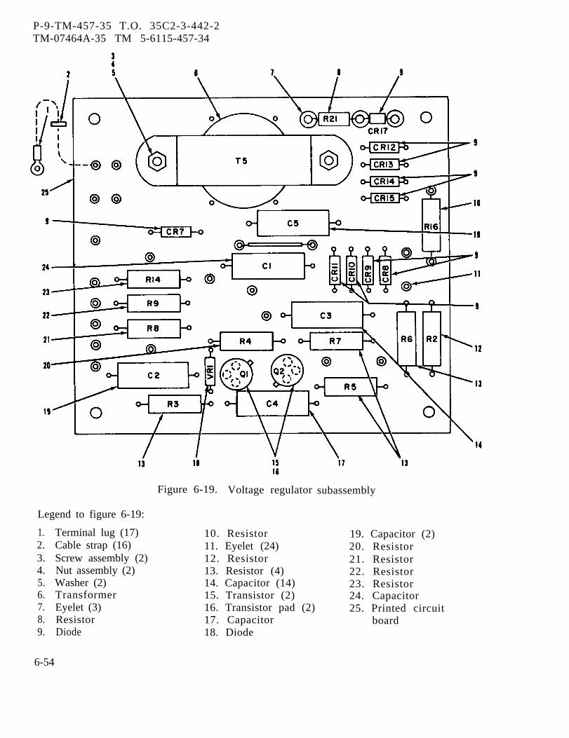
P-9-TM-457-35 T.O. 35C2-3-442-2TM-07464A-35 TM 5-6115-457-34
Figure 6-19. Voltage regulator
Legend to figure 6-19:
1.2.3.4.5.6.7.8.9.
Terminal lug (17) 10. ResistorCable strap (16) 11. Eyelet (24)Screw assembly (2) 12. ResistorNut assembly (2) 13. Resistor (4)Washer (2) 14. Capacitor (14)Transformer 15. Transistor (2)
subassembly
19. Capacitor (2)20. Resistor21. Resistor22. Resistor23. Resistor24. Capacitor
Eyelet (3) 16. Transistor pad (2) 25. Printed circuitResistor 17. Capacitor boardDiode 18. Diode
6-54

P-9-TM-457-35 T.O. 35C2-3-442-2TM-07464A-35 TM 5-6115-457-34
Figure 6-20. Exciter regulator wiring harness (Sheet 1 of 2)
6-55

P-9-TM-457-35 T.O. 35C2-3-442-2TM-07464A-35 TM 5-6115-457-35
Figure 6-20. Exciter regulator wiring harness (Sheet 2 of 2)
6-56
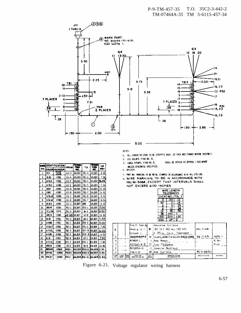
P-9-TM-457-35 T.O. 35C2-3-442-2TM-07464A-35 TM 5-6115-457-34
Figure 6-21. Voltage regulator wiring harness
6-57
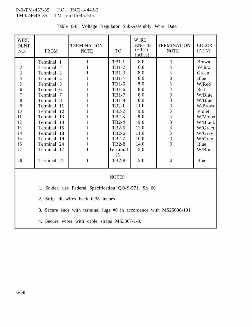
P-9-TM-457-35 T.O. 35C2-3-442-2TM-07464A-35 TM 5-6115-457-35
Table 6-8. Voltage Regulator Sub-Assembly Wire Data
WIRE W IREDENT TERMINATION LENGTH TERMINATION COLORNO. FROM NOTE TO (±0.25 NOTE IDE NT
inches)
1 Terminal 1 1 TB1-1 8.0 3 Brown2 Terminal 2 1 TB1-2 8.0 3 Yellow3 Terminal 3 1 TB1-3 8.0 3 Green4 Terminal 4 1 TB1-4 8.0 3 Blue5 Terminal 5 1 TB1-5 8.0 36
W/RedTerminal 6 1 TB1-6 8.0 3 Red
7 Terminal 7 1 TB1-7 8.0 3 W/Blue8 Terminal 8 1 TB1-8 8.0 3 W/Blue9 Terminal 11 1 TB2-1 11.0 3 W/Brown
10 Terminal 12 1 TB2-2 9.0 3 Violet11 Terminal 13 1 TB2-3 9.0 3 W/Violet12 Terminal 14 1 TB2-4 9.0 3 W/Black13 Terminal 15 1 TB2-5 12.0 3 W/Green14 Terminal 18 1 TB2-6 11.0 3 W/Grey15 Terminal 19 1 TB2-7 10.0 3 W/Grey16 Terminal 24 1 TB2-8 14.0 3 Blue17 Terminal 17 1 Terminal 5.0 1 W/Blue
2518 Terminal 27 1 TB2-8 5.0 3 Blue
NOTES
1. Solder, use Federal Specification QQ-S-571, Sn 60
2, Strip all wires back 0.38 inches.
3. Secure ends with terminal lugs #6 in accordance with MS25036-101.
4. Secure wires with cable straps MS3367-1-9.
6-58
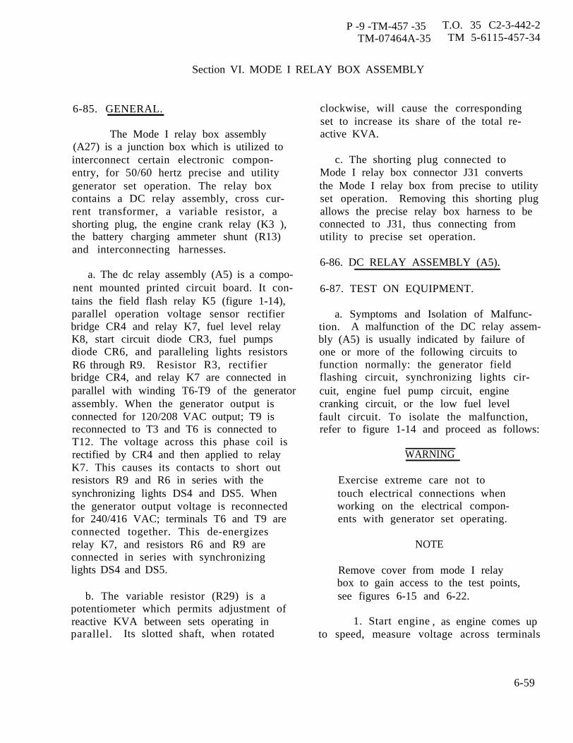
P -9 -TM-457 -35 T.O. 35 C2-3-442-2TM-07464A-35 TM 5-6115-457-34
Section VI. MODE I RELAY BOX ASSEMBLY
6-85. GENERAL.
The Mode I relay box assembly(A27) is a junction box which is utilized tointerconnect certain electronic compon-entry, for 50/60 hertz precise and utilitygenerator set operation. The relay boxcontains a DC relay assembly, cross cur-rent transformer, a variable resistor, ashorting plug, the engine crank relay (K3 ),the battery charging ammeter shunt (R13)and interconnecting harnesses.
a. The dc relay assembly (A5) is a compo-nent mounted printed circuit board. It con-tains the field flash relay K5 (figure 1-14),parallel operation voltage sensor rectifierbridge CR4 and relay K7, fuel level relayK8, start circuit diode CR3, fuel pumpsdiode CR6, and paralleling lights resistorsR6 through R9. Resistor R3, rectifierbridge CR4, and relay K7 are connected inparallel with winding T6-T9 of the generatorassembly. When the generator output isconnected for 120/208 VAC output; T9 isreconnected to T3 and T6 is connected toT12. The voltage across this phase coil isrectified by CR4 and then applied to relayK7. This causes its contacts to short outresistors R9 and R6 in series with thesynchronizing lights DS4 and DS5. Whenthe generator output voltage is reconnectedfor 240/416 VAC; terminals T6 and T9 areconnected together. This de-energizesrelay K7, and resistors R6 and R9 areconnected in series with synchronizinglights DS4 and DS5.
b. The variable resistor (R29) is apotentiometer which permits adjustment ofreactive KVA between sets operating inparallel. Its slotted shaft, when rotated
clockwise, will cause the correspondingset to increase its share of the total re-active KVA.
c. The shorting plug connected toMode I relay box connector J31 convertsthe Mode I relay box from precise to utilityset operation. Removing this shorting plugallows the precise relay box harness to beconnected to J31, thus connecting fromutility to precise set operation.
6-86. DC RELAY ASSEMBLY (A5).
6-87. TEST ON EQUIPMENT.
a. Symptoms and Isolation of Malfunc-tion. A malfunction of the DC relay assem-bly (A5) is usually indicated by failure ofone or more of the following circuits tofunction normally: the generator fieldflashing circuit, synchronizing lights cir-cuit, engine fuel pump circuit, enginecranking circuit, or the low fuel levelfault circuit. To isolate the malfunction,refer to figure 1-14 and proceed as follows:
WARNING
Exercise extreme care not totouch electrical connections whenworking on the electrical compon-ents with generator set operating.
NOTE
Remove cover from mode I relaybox to gain access to the test points,see figures 6-15 and 6-22.
1. Start engine , as engine comes upto speed, measure voltage across terminals
6-59
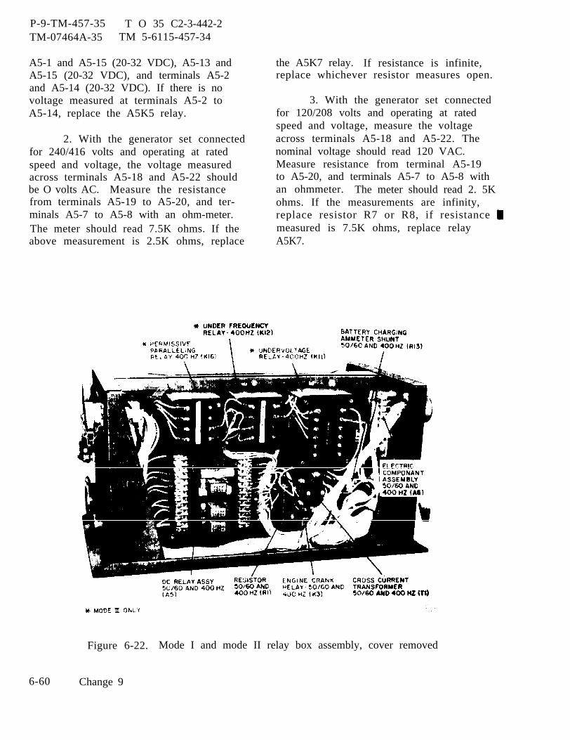
P-9-TM-457-35 T O 35 C2-3-442-2TM-07464A-35 TM 5-6115-457-34
A5-1 and A5-15 (20-32 VDC), A5-13 andA5-15 (20-32 VDC), and terminals A5-2and A5-14 (20-32 VDC). If there is novoltage measured at terminals A5-2 toA5-14, replace the A5K5 relay.
2. With the generator set connectedfor 240/416 volts and operating at ratedspeed and voltage, the voltage measuredacross terminals A5-18 and A5-22 shouldbe O volts AC. Measure the resistancefrom terminals A5-19 to A5-20, and ter-minals A5-7 to A5-8 with an ohm-meter.The meter should read 7.5K ohms. If theabove measurement is 2.5K ohms, replace
the A5K7 relay. If resistance is infinite,replace whichever resistor measures open.
3. With the generator set connectedfor 120/208 volts and operating at ratedspeed and voltage, measure the voltageacross terminals A5-18 and A5-22. Thenominal voltage should read 120 VAC.Measure resistance from terminal A5-19to A5-20, and terminals A5-7 to A5-8 withan ohmmeter. The meter should read 2. 5Kohms. If the measurements are infinity,replace resistor R7 or R8, if resistance measured is 7.5K ohms, replace relayA5K7.
Figure 6-22. Mode I and mode II relay box assembly, cover removed
6-60 Change 9

4. Place the battle short switch S7to the ON position and measure the voltageacross terminal A5-21 and terminal A5-15.The voltage should read 20-32 VDC. Whenthe start-run-stop switch S2 is placed inthe run position. Also measure voltageacross terminal A5-23 to terminal A5-15.The voltage should read 20-32 VDC. Ifvoltage is measured at A5-21 but not atA5-23, disconnect wire from A5-21 andcheck for continuity between terminal A5-21and terminal A5-23 with A5-21 positive. Ifthere is no continuity, replace diode CR6.
5. Measure the voltage across ter-minal A5-12 to terminal A5-15. The voltageshould read 20-32 VDC when the start-run-stop switch S2 is placed in the START posi-tion. Also measure voltage across terminalA5-9 to terminal A5- 15. The voltage shouldread 20-32 VDC. If voltage is measured atterminal A5-12 and not at terminal A5-9,disconnect wire from terminal A5-12 andcheck for continuity across terminals A5- 12to terminal A5-9 with A5-12 positive. Ifthere is no continuity, replace diode CR3.
6. Disconnect connector P33 fromthe float switch located in the day tank andinstall a jumper between pins C and D ofP33 to simulate a low fuel fault condition.Place the battle short switch S7 in the onposition. Place the start-run-stop switchS2 in the RUN position and measure thevoltage from terminal A5-6 to terminalA5-15. The voltage should read 20-32 VDC.Disconnect the wire from terminal A5-17and check continuity across terminal A5-5to terminal A5-17 with voltage applied toterminal A5-6. If voltage is measured atterminal A5-6 and there is no continuityfrom terminal A5-5 to terminal A5-17, re-place relay A5K8. Remove jumper frompins C and D of P33.
P-8-627-34TM-07464A-35
b. Removal. Refer
T O 35C2-3-442-2 TM 5-6115-457-34
to figure 6-22 andtag, then disconnect wiring to the DC relayterminal board. Remove the four nuts se-curing the relay in position.
6-88. TEST.
a. Connect the DC relay assembly totest equipment as illustrated in figure 6-23and perform test specified in proceduralanalysis table 6-9.
NOTE
Figure 1-14 illustrates the DC relayassembly schematic. Refer to thiss thematic when checking individualcomponents for required values.
b. Remove the DC relay from the testequipment.
6-89. DISASSEMBLY. Refer to figure6-24 and disassemble the DC relay assem-ble to the extent necessary to accomplishrepair. Pay particular attention to thefollowing:
WARNING
Avoid breathing fumes generated byunsoldering /soldering Eye pro-tection is required.
a. Exercise care not to apply excessiveheat when unsoldering components.
b. Remove relay socket (10) by remov-ing nut (7), lock washer (8) and washer (9),spacer (11) will fall free.
6-90. CLEANING. Clean all componentswith a clean lint-free cloth moistened withan approved cleaning solvent and drythoroughly.
Change 8 6-61
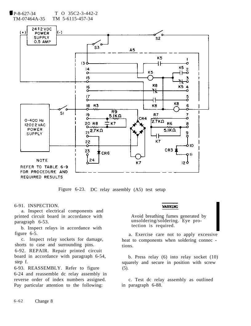
P-8-627-34 T O 35C2-3-442-2TM-07464A-35 TM 5-6115-457-34
Figure 6-23. DC relay assembly (A5) test setup
6-91. INSPECTION.a. Inspect electrical components and
printed circuit board in accordance with Avoid breathing fumes generated byparagraph 6-53. unsoldering/soldering. Eye pro-
b. Inspect relays in accordance with tection is required.
figure 6-5.c. Inspect relay sockets for damage,
shorts to case and surrounding pins.6-92. REPAIR. Repair printed circuitboard in accordance with paragraph 6-54,step f.6-93. REASSEMBLY. Refer to figure6-24 and reassemble dc relay assembly inreverse order of index numbers assigned.Pay particular attention to the following:
a. Exercise care not to apply excessiveheat to components when soldering connec -tions.
b. Press relay (6) into relay socket (10)squarely and secure in position with screw(5).
c. Test dc relay assembly as outlinedin paragraph 6-88.
6 - 6 2 Change 8
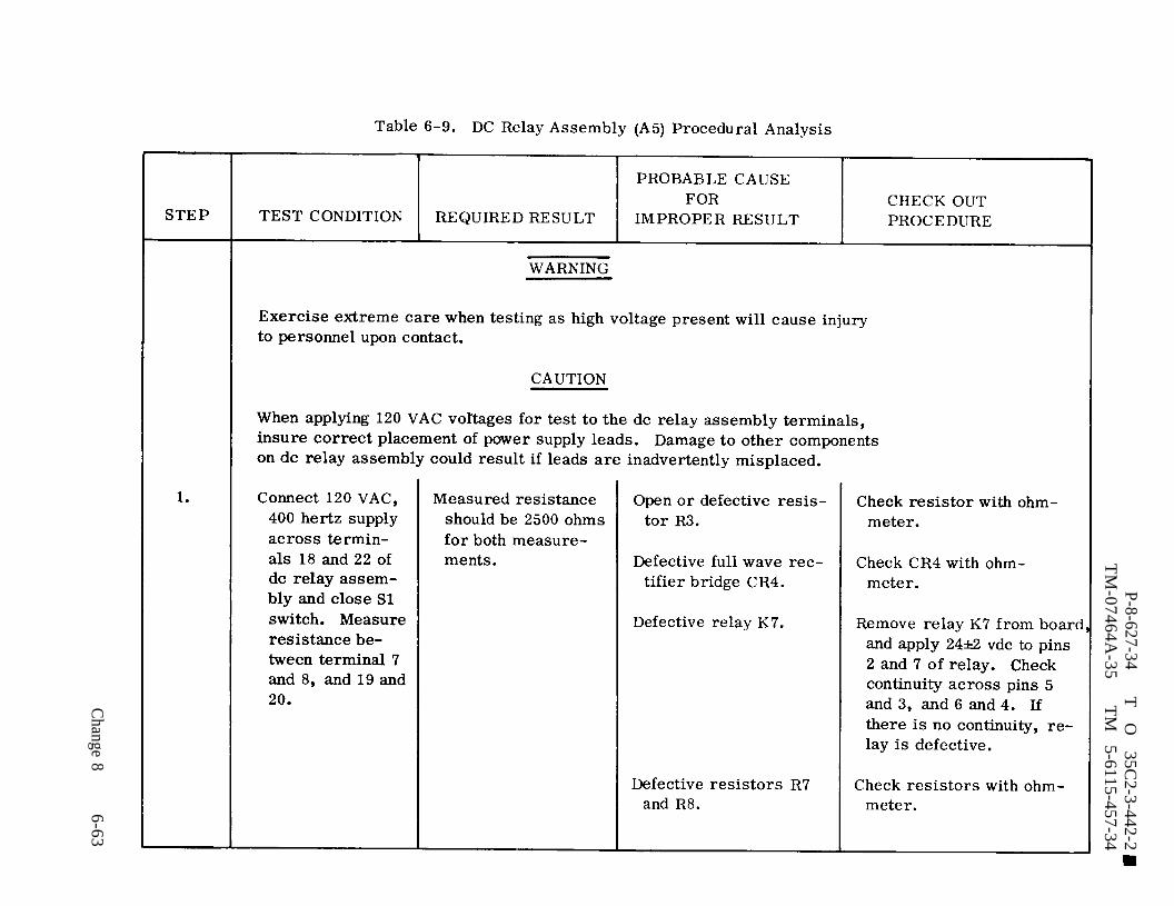
Table 6-9.
P-8-627-34T
O
35C
2-3-442-2 T
M-07464A
-35T
M
5-6115-457-34
Change 8
6-63
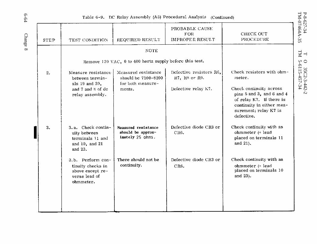
Table 6-9. (cont)
P-8-627-34T
O
35C
2-3-442-2T
M-07464A
-35T
M
5-6115-457-34
6-64C
hange 8
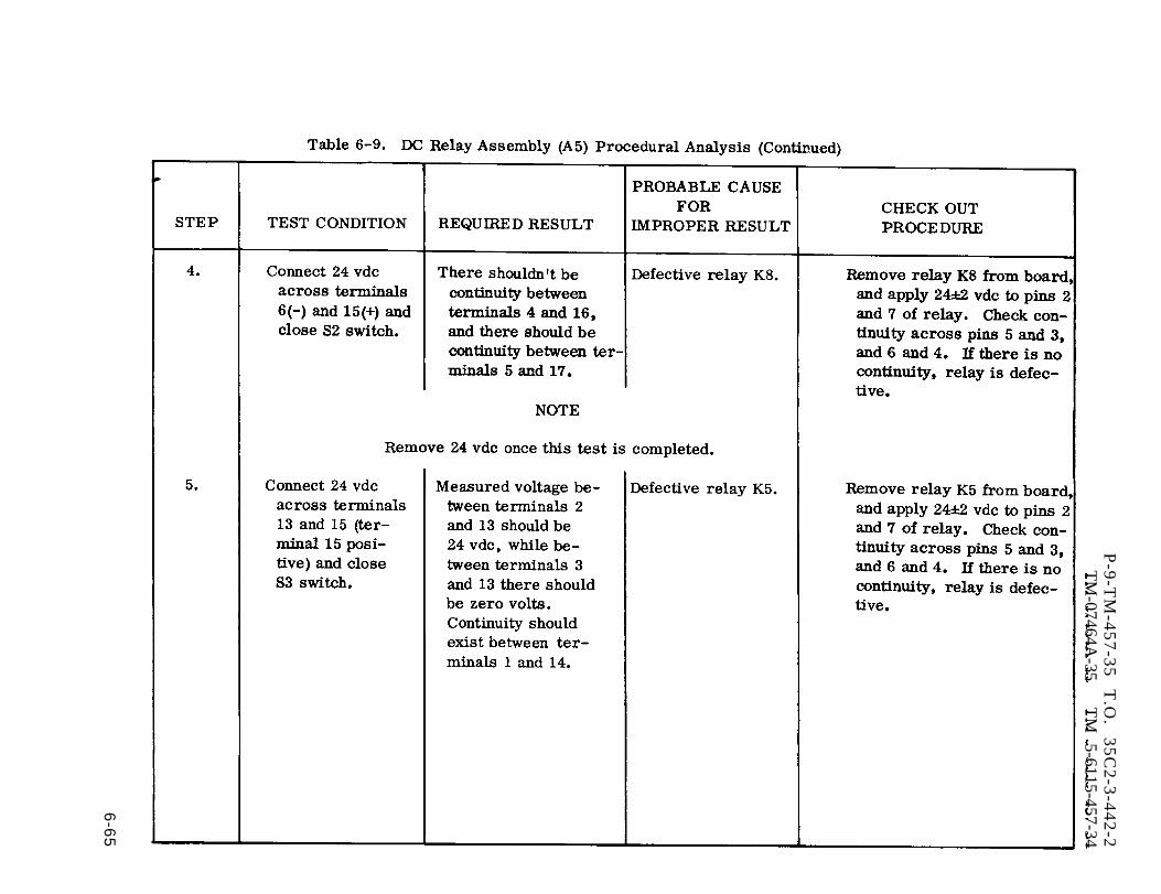
Table 6-9. (cont)
P-9
-TM
-45
7-3
5
T.O
. 3
5C
2-3
-44
2-2
TM
-07464A-35
TM
5-6115-457-34
6-6
5

P-9-TM-457-35 T.O. 35C2-3-442-2TM-07464A-35 TM 5-6115-457-34
F i g u r e
Legend to
1.2.3.4.5.6.7.8.9.
10.11.12.13.14.15.16.17.18.
6-24. DC relay assembly (A5)exploded view
figure 6-24:
Screw (4)Nut assembly (8)Washer (4)Terminal board (2)Screw assembly (6)Relay (3)Nut (6)Lock washer (6)Washer (6)Relay socket (3)SpacerResistor (2)Resistor (2)ResistorSilicone junction rectifierSilicone bridge rectifierSilicone junction rectifierBoard
6-94. INSTALLATION. Refer to figure6-22 and install the DC relay assembly.Secure the assembly in position with fournuts, then refer to figure 1-15 and recon-nect wiring to the relay terminal board.Replace mode I relay box cover.
6-95. MODE I RE LAY BOX ASSEMBLY(A27).
6-96. ON EQUIPMENT TEST.
a. Symptom and Isolation of Malfunc-tion. A malfunction of the mode I relaybox assembly is usually indicated by afailure of the DC relay assembly, failureof the engine to crank when the start-run-stop switch S2 is energized, and unequalreactive load sharing when the generatorset is operated in parallel. To isolate themalfunction, refer to figure 1-14 and pro-ceed as outlined in steps b. through d.
WARNING
Exercise extreme care not totouch electrical connections whenworking on the electrical compon-ents with the generator set opera-ting.
b. To isolate a malfunction of the DCrelay, refer to paragraph 6-87.
NOTE
Remove cover from mode I relaybox to gain access to the testpoints, see figures 6-15 and6-22.
6-66 Change 1
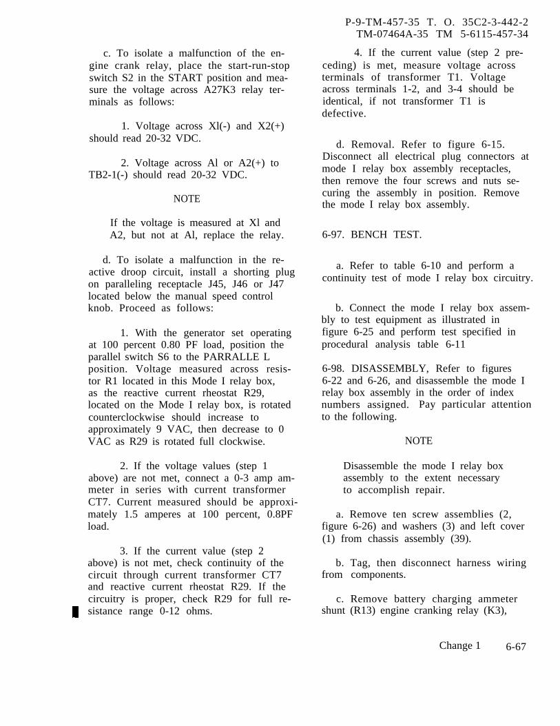
c. To isolate a malfunction of the en-gine crank relay, place the start-run-stopswitch S2 in the START position and mea-sure the voltage across A27K3 relay ter-minals as follows:
1. Voltage across Xl(-) and X2(+)should read 20-32 VDC.
2. Voltage across Al or A2(+) toTB2-1(-) should read 20-32 VDC.
NOTE
If the voltage is measured at Xl andA2, but not at Al, replace the relay.
d. To isolate a malfunction in the re-active droop circuit, install a shorting plugon paralleling receptacle J45, J46 or J47located below the manual speed controlknob. Proceed as follows:
1. With the generator set operatingat 100 percent 0.80 PF load, position theparallel switch S6 to the PARRALLE Lposition. Voltage measured across resis-tor R1 located in this Mode I relay box,as the reactive current rheostat R29,located on the Mode I relay box, is rotatedcounterclockwise should increase toapproximately 9 VAC, then decrease to 0VAC as R29 is rotated full clockwise.
2. If the voltage values (step 1above) are not met, connect a 0-3 amp am-meter in series with current transformerCT7. Current measured should be approxi-mately 1.5 amperes at 100 percent, 0.8PFload.
3. If the current value (step 2above) is not met, check continuity of thecircuit through current transformer CT7and reactive current rheostat R29. If thecircuitry is proper, check R29 for full re-sistance range 0-12 ohms.
P-9-TM-457-35 T. O. 35C2-3-442-2TM-07464A-35 TM 5-6115-457-34
4. If the current value (step 2 pre-ceding) is met, measure voltage acrossterminals of transformer T1. Voltageacross terminals 1-2, and 3-4 should beidentical, if not transformer T1 isdefective.
d. Removal. Refer to figure 6-15.Disconnect all electrical plug connectors atmode I relay box assembly receptacles,then remove the four screws and nuts se-curing the assembly in position. Removethe mode I relay box assembly.
6-97. BENCH TEST.
a. Refer to table 6-10 and perform acontinuity test of mode I relay box circuitry.
b. Connect the mode I relay box assem-bly to test equipment as illustrated infigure 6-25 and perform test specified inprocedural analysis table 6-11
6-98. DISASSEMBLY, Refer to figures6-22 and 6-26, and disassemble the mode Irelay box assembly in the order of indexnumbers assigned. Pay particular attentionto the following.
NOTE
Disassemble the mode I relay boxassembly to the extent necessaryto accomplish repair.
a. Remove ten screw assemblies (2,figure 6-26) and washers (3) and left cover(1) from chassis assembly (39).
b. Tag, then disconnect harness wiringfrom components.
c. Remove battery charging ammetershunt (R13) engine cranking relay (K3),
Change 1 6-67
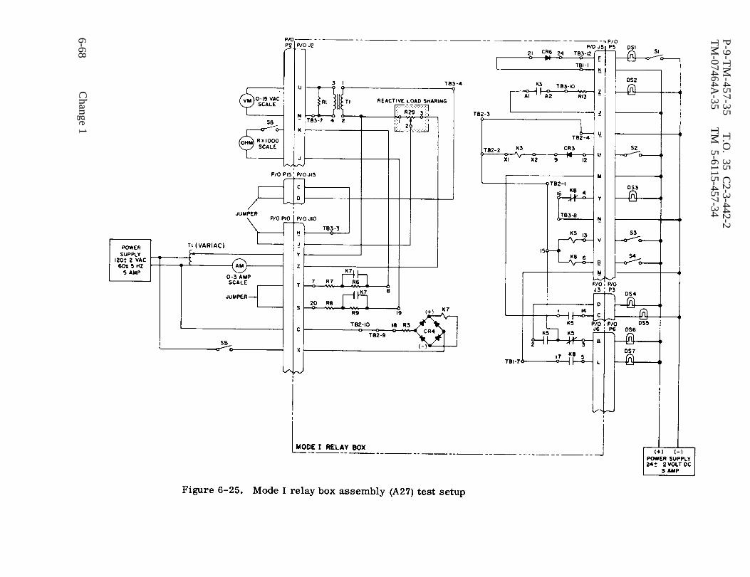
Figure 6-25.
P-9-T
M-457-35
T.O
. 35 C2-3-442-2
TM
-07464A-35
TM
5-6115-457-34
6-68C
hange 1

P-9-TM-457-35 T.O. 35C2-3-442-2TM-07464A-35 TM 5-6115-457-34
Table 6-10. Mode I Relay Box Assembly (A27) Continuity Test
FROM TO REQUIRED RESULT
J50-L J50-B ContinuityJ50-L J2-W ContinuityJ50-L J31-E ContinuityJ50-L J1O-N ContinuityJ50-L J10-E ContinuityJ50-L J5-K ContinuityJ50-L J5 -C ContinuityJ50-L J 5 - E ContinuityJ50-L A5-21 Continuity
J50-P J31-K ContinuityJ50-P J 6 - C ContinuityJ50-P J5-M ContinuityJ50-P J5-Z ContinuityJ50-P J5-W ContinuityJ50-P A5-17 Continuity
J50-R J2-F ContinuityJ50-R J10-B Continuity
J50-S J2-E ContinuityJ50-S J10-A Continuity
J50-H J50-B ContinuityJ50-H J 2 - H Continuity
J50-W J 2 - P ContinuityJ50-W J 2 - R ContinuityJ50-W J50-M ContinuityJ50-W J31-D ContinuityJ50-W J31-Z ContinuityJ50-W J7-A ContinuityJ50-W J10-L ContinuityJ50-W J29-E ContinuityJ50-W J5-T ContinuityJ50-W J 5 - U ContinuityJ50-W J5-H ContinuityJ50-W J 5 - G ContinuityJ50-W J5-S ContinuityJ50-W K3-X1 ContinuityJ50-W A5-15 Continuity
6-69
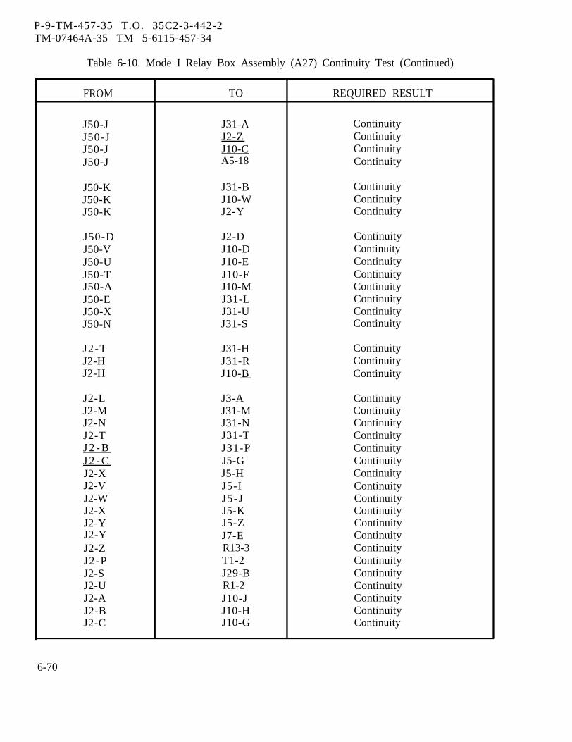
P-9-TM-457-35 T.O. 35C2-3-442-2TM-07464A-35 TM 5-6115-457-34
Table 6-10. Mode I Relay Box Assembly (A27) Continuity Test (Continued)
FROM TO REQUIRED RESULT
J50-J J31-A ContinuityJ50-J J2-Z ContinuityJ50-J J10-C ContinuityJ50-J A5-18 Continuity
J50-K J31-B ContinuityJ50-K J10-W ContinuityJ50-K J2-Y Continuity
J50-D J2-D ContinuityJ50-V J10-D ContinuityJ50-U J10-E ContinuityJ50-T J10-F ContinuityJ50-A J10-M ContinuityJ50-E J31-L ContinuityJ50-X J31-U ContinuityJ50-N J31-S Continuity
J2-T J31-H ContinuityJ2-H J31-R ContinuityJ2-H J10-B Continuity—
J2-L J3-A ContinuityJ2-M J31-M ContinuityJ2-N J31-N ContinuityJ2-T J31-T ContinuityJ 2 - B J31-P ContinuityJ 2 - C J5-G ContinuityJ2-X J5-H ContinuityJ2-V J5-I ContinuityJ2-W J5-J ContinuityJ2-X J5-K ContinuityJ2-Y J5-Z ContinuityJ2-Y J7-E ContinuityJ2-Z R13-3 ContinuityJ2-P T1-2 ContinuityJ2-S J29-B ContinuityJ2-U R1-2 ContinuityJ2-A J10-J ContinuityJ2-B J10-H ContinuityJ2-C J10-G Continuity
6-70

P-9-TM-457-35 T.O. 35 C2-3412-2TM-07464A-35 TM 5-6115-457-34
Table 6-10. Mode I Relay Box Assembly (A27) Continuity Test (Continued)
FROM TO REQUIRE D RESULT
J2-G J10-A ContinuityJ2-1 J10-D ContinuityJ2-J A5-19 ContinuityJ2-K A5-8 ContinuityJ2 -0 J29-C ContinuityJ2-A J10-F ContinuityJ2-U J29-A ContinuityJ2-V A5-1 Continuity
J2-K J29-H ContinuityJ2-K J10-C Continuity
J2-M J 5 - P ContinuityJ2-M J 5 - P ContinuityJ2-M J5-R Continuity
J2-N J2-V ContinuityJ2-N J3-B Continuity
J2-E J29-F ContinuityJ2 -E A5-16 ContinuityJ2 -E J 5 - N Continuity
J2-G J5-D ContinuityJ 2 - G J29-G Continuity
J2-R J6-A ContinuityJ2-R J29-D Continuity
J50-C J6-I ContinuityJ50-D J6-H ContinuityJ50-F J6-F ContinuityJ50-G J6-M ContinuityJ50-A J5-E Continuity
J5-F J31-C ContinuityJ 5 - J K3-A1 ContinuityJ5-W R13-4 ContinuityJ5-W K3-A2 ContinuityJ5-W J5-L Continuity
6-71
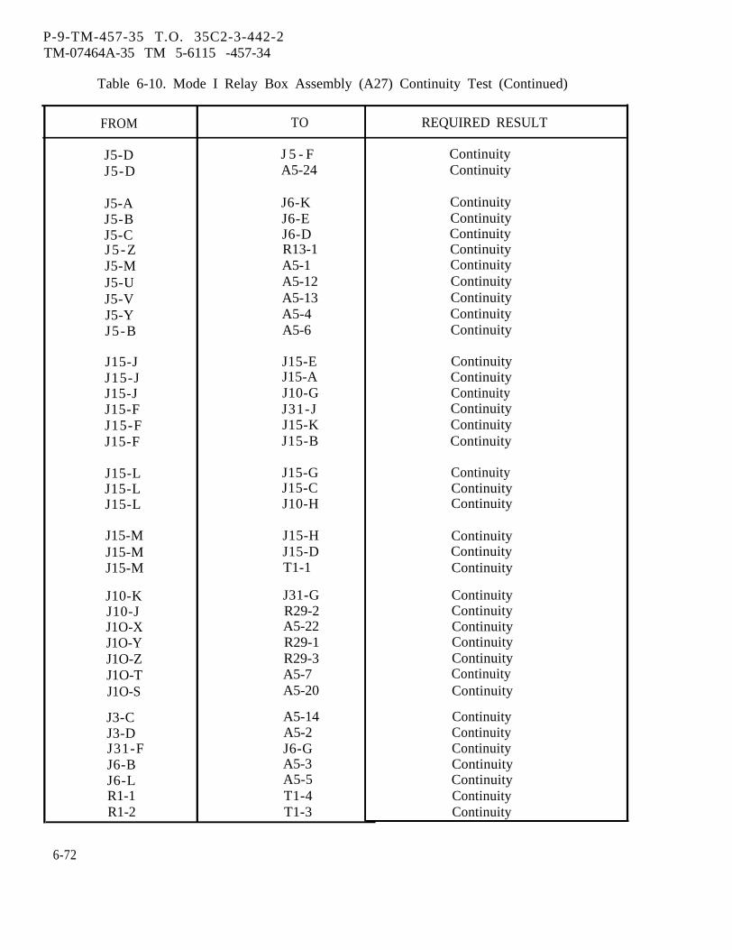
P-9-TM-457-35 T.O. 35C2-3-442-2TM-07464A-35 TM 5-6115 -457-34
Table 6-10. Mode I Relay Box Assembly (A27) Continuity Test (Continued)
FROM
J5-DJ5-D
J5-AJ5-BJ5-CJ5 -ZJ5-MJ5-UJ5-VJ5-YJ5-B
J15-JJ15-JJ15-JJ15-FJ15-FJ15-F
J15-LJ15-LJ15-L
J15-MJ15-MJ15-M
J10-KJ10-JJ1O-XJ1O-YJ1O-ZJ1O-TJ1O-S
J3-CJ3-DJ31-FJ6-BJ6-LR1-1R1-2
TO
J 5 - FA5-24
J6-KJ6-EJ6-DR13-1A5-1A5-12A5-13A5-4A5-6
J15-EJ15-AJ10-GJ31-JJ15-KJ15-B
J15-GJ15-CJ10-H
J15-HJ15-DT1-1
J31-GR29-2A5-22R29-1R29-3A5-7A5-20
A5-14A5-2J6-GA5-3A5-5T1-4T1-3
REQUIRED RESULT
ContinuityContinuity
ContinuityContinuityContinuityContinuityContinuityContinuityContinuityContinuityContinuity
ContinuityContinuityContinuityContinuityContinuityContinuity
ContinuityContinuityContinuity
ContinuityContinuityContinuity
ContinuityContinuityContinuityContinuityContinuityContinuityContinuity
ContinuityContinuityContinuityContinuityContinuityContinuityContinuity
6-72
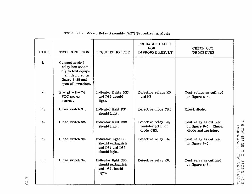
Table 6-11.
P-9
-TM
-45
7-3
5
T.O
. 3
5C
2-3
-44
2-2
TM
-07464A-35
TM
5-6115-457-34
6-7
3
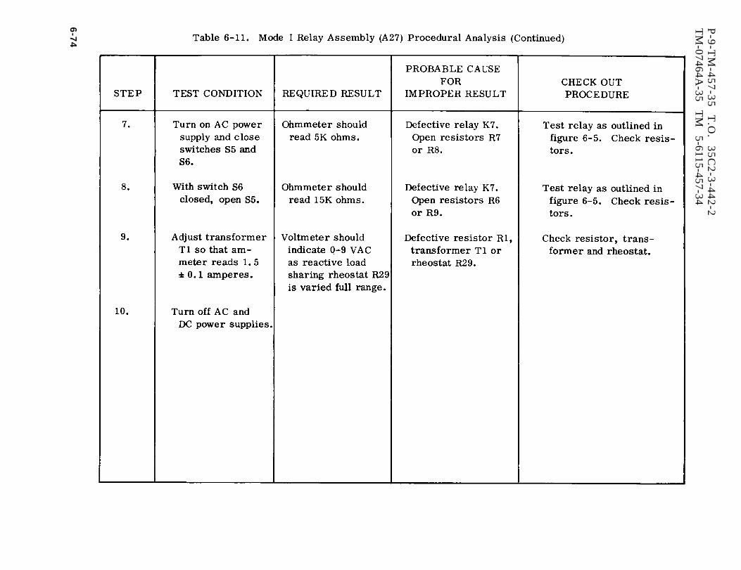
Table 6-11. (cont)
P-9
-TM
-45
7-3
5
T.O
. 3
5C
2-3
-44
2-2
TM
-07464A-35
TM
5-6115-457-34
6-7
4
transformermoving their
(T1) and resistor (R1) by re-attaching screws and nuts
(2 each). See figure 6-22.
d. Remove dc control relay assembly(A5) by removing the four nuts securingthe assembly in position.
NOTE
Refer to paragraph 6-86 for dcrelay assembly maintenance in-structions.
e. Remove nut (4, figure 6-26) andwasher (5) securing rheostat (6) to chassisassembly (39).
f. Remove wire harness (25) by re-moving the four screws and nuts securingeach of the ten connectors to the chassisassembly (39).
NOTE
Electrical connector covers (7 and8) will fall free.
6-99. CLEANING. Clean all componentswith a clean lint-free cloth moistened inan approved cleaning solvent and dry thor-oughly.
6-100. INSPECTION AND BENCH TEST.
a. Harness.
1. Inspect harness wiring for defec-tive insulation and continuity.
2. Inspect harness connectors fordamaged threads; bent, loose or missingpins and for shorts.
b. Test transformer T1 by applying9 VAC, to terminals 1 and 2. (Excitationcurrent shall be less than 0.1 ampere. )
P-8-627-34 T O 3 5 C 2 - 3 - 4 4 2 - 2TM-07464A-35 TM 5-6115-457-34
Output measured at terminals 3 and 4 shallbe 9 VAC.
c. Test engine cranking relay K3 byapplying 24 VDC to terminals Xl and X2.Normally open contacts A 1 -A2 shall close.
6-101. REPAIR.
a. Repair or fabricate mode I relay boxassembly wiring harness according to figure6-27.
b. Straighten dented or distorted sheetmetal parts using proper tools. Blend inrepaired area with a suitable abrasivepaper and touch up painted surfaces. Re-stencil panel markings as necessary.
6-102. REASSEMBLY. Refer to figure6-26 and reassemble the mode I relay boxassembly in reverse order of index num-bers assigned. Pay particular attention tothe following:
a. Assemble battery charging ammetershunt (R13), engine cranking relay (K3),transformer (T1), and resistor (R1) inposition using two each, screws and nuts.See figure 6-22.
b. Assemble DC control relay assembly(A5) in position using four nuts,
c. Install wire harness (25, figure6-26) in chassis (39) and secure in positionwith four screws and nuts at each of theten connectors.
WARNING
Avoid breathing fumes generated byunsoldering/soldering. Eye pro-tection is required.
d. Connect wire harness leads to com-ponentry using figure 1-15 as a guide.
NOTE
Solder connections shall be madeusing solder, Federal Specification
QQ-S-571, Sn 60.
Change 8 6-75
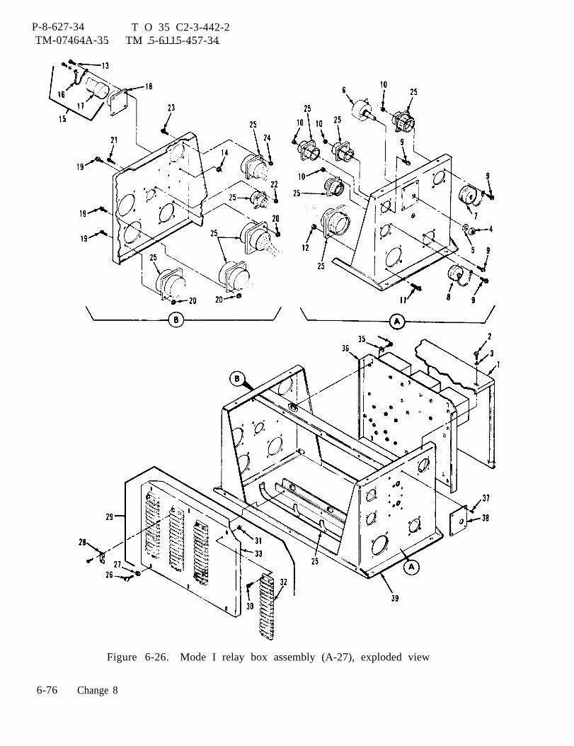
P-8-627-34 T O 35 C2-3-442-2TM-07464A-35 TM 5-6115-457-34
Figure 6-26. Mode I relay box assembly (A-27), exploded view
6-76 Change 8
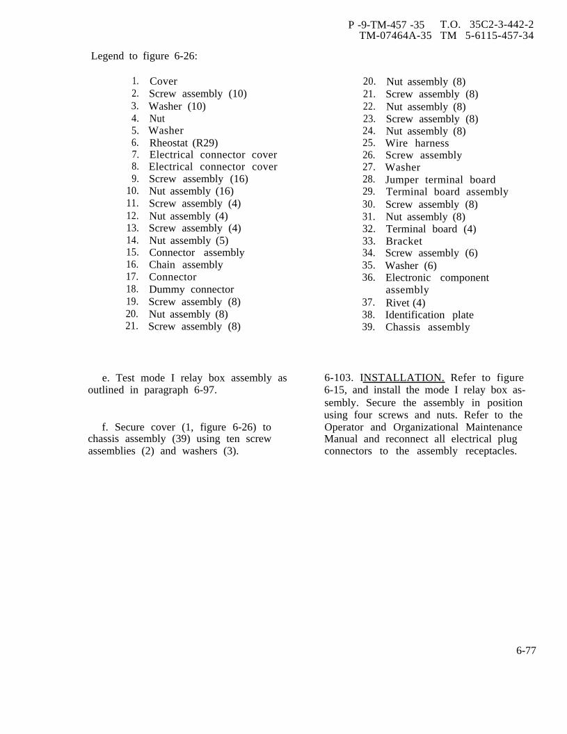
P -9-TM-457 -35 T.O. 35C2-3-442-2TM-07464A-35 TM 5-6115-457-34
Legend to figure 6-26:
1.2.3.4.5.6.7.8.9.
10.11.12.13.14.15.16.17.18.19.20.21.
CoverScrew assembly (10)Washer (10)NutWasherRheostat (R29)Electrical connector coverElectrical connector coverScrew assembly (16)Nut assembly (16)Screw assembly (4)Nut assembly (4)Screw assembly (4)Nut assembly (5)Connector assemblyChain assemblyConnectorDummy connectorScrew assembly (8)Nut assembly (8)Screw assembly (8)
20.21.22.23.24.25.26.27.28.29.30.31.32.33.34.35.36.
37.38.39.
Nut assembly (8)Screw assembly (8)Nut assembly (8)Screw assembly (8)Nut assembly (8)Wire harnessScrew assemblyWasherJumper terminal boardTerminal board assemblyScrew assembly (8)Nut assembly (8)Terminal board (4)BracketScrew assembly (6)Washer (6)Electronic componentassemblyRivet (4)Identification plateChassis assembly
e. Test mode I relay box assembly as 6-103. INSTALLATION. Refer to figureoutlined in paragraph 6-97. 6-15, and install the mode I relay box as-
sembly. Secure the assembly in positionusing four screws and nuts. Refer to the
f. Secure cover (1, figure 6-26) to Operator and Organizational Maintenancechassis assembly (39) using ten screw Manual and reconnect all electrical plugassemblies (2) and washers (3). connectors to the assembly receptacles.
6-77
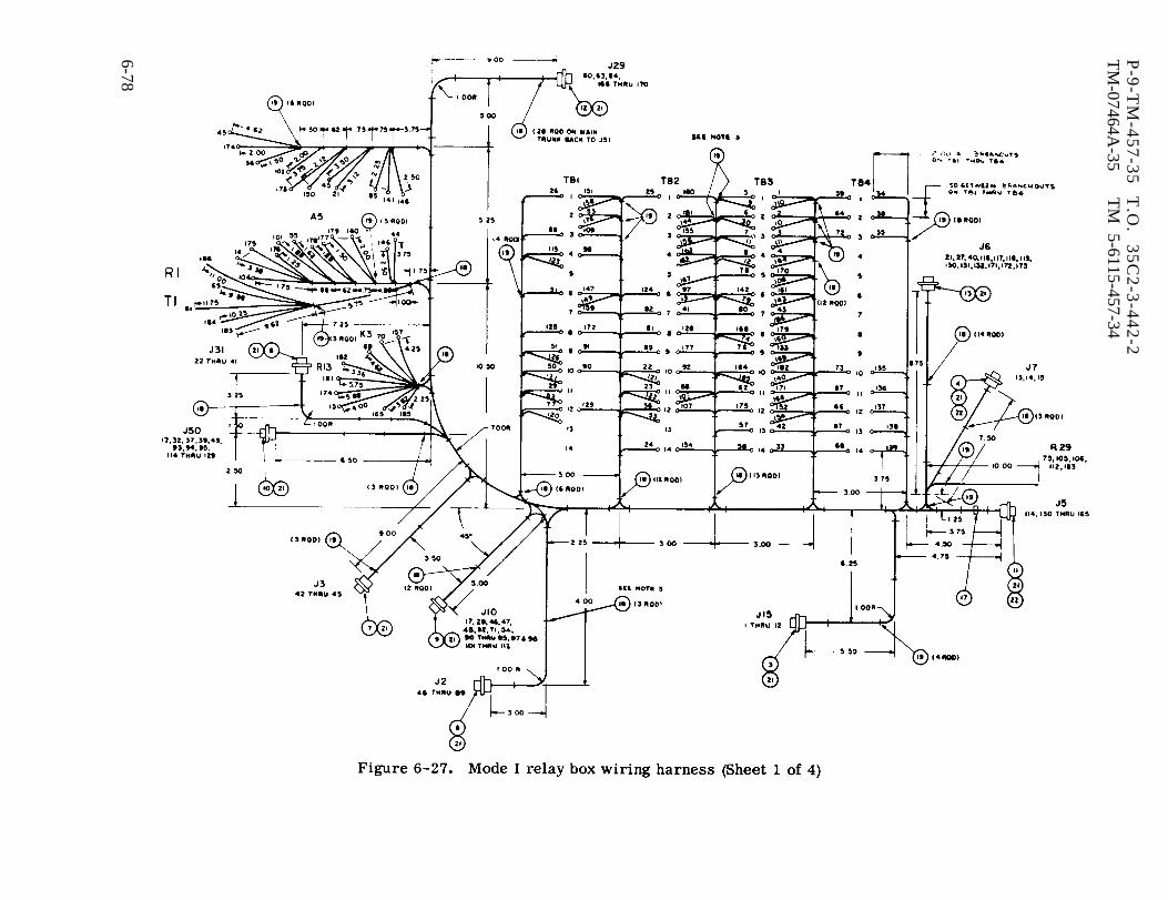
Figure 6-27.
P-9
-TM
-45
7-3
5
T.O
. 3
5C
2-3
-44
2-2
TM
-07464A-35
TM
5-6115-457-34
6-78
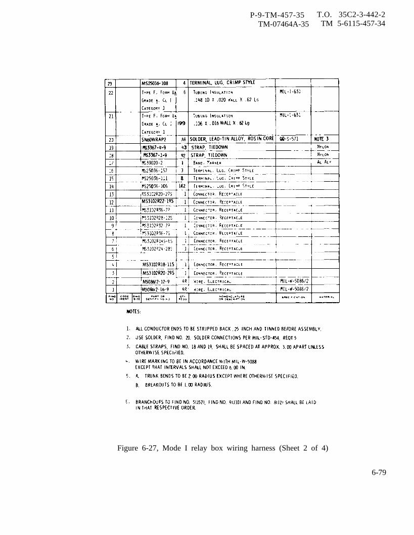
P-9-TM-457-35 T.O. 35C2-3-442-2TM-07464A-35 TM 5-6115-457-34
Figure 6-27, Mode I relay box wiring harness (Sheet 2 of 4)
6-79

P-9-TM-457-35 T.O. 35C2-2-442-2TM-07464A-35 TM 5-6115-457-34
Figure 6-27. Mode I relay box wiring harness (Sheet 3 of 4)
6-80

P-9-TM-457-35 T.O. 35C2-3-4TM-07464A-35 TM 5-6115-45
Figure 6-27. Mode I relay box wiring harness (Sheet 4 of 4)
42-27 -34
6-81

P-9-TM-457-35 T.O. 35C2-442-2TM-07464A-35 TM 5-6115-457-34
Section VII. MODE II RELAY BOX ASSEMBLY
6-104. GENERAL.
The mode II relay box assembly(A27) is a junction box which is utilized tointerconnect certain electronic componentryfor 400 hertz precise generators sets. Therelay box contains the dc relay assembly,the under frequency relay, under voltagerelay, permissive paralleling relay, enginecrank relay, governor paralleling control,voltage regulator paralleling control gov-ernor feedback capacitor, frequency adjustdevice fixed resistors, cross current trans-former and burden resistor, and the batterycharging ammeter shunt. Refer to schematicfigure 1-16.
a. The dc relay assembly (A5) is acomponent mounted printed circuit board.It contains the field flash relay K5, figure1-16, parallel operation voltage sensorrectifier bridge CR4 and relay K7, fuellevel relay K8, start circuit diode CR3,fuel pumps diode CR6, and paralleling lightsresisters R6 through R9. Resister R3,rectifier bridge CR4, and relay K7 are con-nected in parallel with winding T6-T9 of thegenerator assembly. When the generatoroutput is connected for 120/208 VAC output;T9 is reconnected to T3 and T6 is connectedto T12. The voltage across this phase coilis rectified by CR4 and then applier to relayK7. This causes its contacts to short outresisters R9 and R6 in series with thesynchronizing lights DS4 and DS5. When thegenerator output voltage is reconnected for240/416 VAC; terminals T6 and T9 are con-nected together. This de-energized relayK7, and resistors R6 and R9 are connectedin series with synchronizing lights DS4 andDS5.
b. The underfrequency relay (K12) isa solid state device which funtions to pro-tect the load in the event generator fre-quency decreases below preset limits. Itactuates when generator frequency dropsbelow 370 ± 5 hertz. Upon actuation, con-tacts within the underfrequency relay closeto signal the fault locator and open to de-energize the load contactor, resulting indisplay of fault condition and removal ofload from generator.
c. The under voltage relay (K11) is asolid state device which functions to protectthe load in the event generator voltage de-creases below preset limits. It sensessingle phase 120 VAC. The time lag be-tween an under voltage condition and activa-tion of relay switching depends upon themagnitude of the voltage sensed. When theinput voltage drops below 48 VAC, the de-vice shall operate instantaneously. Forvoltages above 72 VAC, the device shalloperate in 6 ± 2 seconds. Upon actuation,contacts within the under voltage relay,close to signal the fault locator and open tode-energize the load contactor, resultingin display of the fault condition and removalof the load from the generator.
d. The permissive paralleling relay(K16) is utilized only on precise generatorsets. Its function is to ensure that a gen-erator set cannot be paralleled with othergenerator sets until synchronization is ac-complished. It accomplishes this by sensingthe voltage drop across one of the synchron-ization lights. When the voltage exceeds 9VAC, the relay contacts are open. Whenthe voltage is less than 7 VAC, its contactsclose. Since its contacts are connected be-
6-82 Change 3

P-9-TM-457-35 T.O. 35 C2-3-442-2TM-07464A-35 TM 5-6115-457-34
tween the load contactor switch S3 and theload contactor relay coil CB2, it will allowor prevent the contactor from being ener-gized. When this generator set is perfectlysynchronized with the other sets, the volt-age across the synchronizing lights will beminimum (less than 7 VAC). This causesthe permissive paralleling relay to close itscontacts and allow the generator set to beparalleled with other generator sets by clos-ing of its load contactor switch S3. If thegenerator set is not perfectly synchronized,the voltage across the synchronizing lightswill be above 9 VAC. This causes the per-missive paralleling relay to have its con-tacts open and prevents the load contactorCB2 from closing.
e. The electronic components assembly(A6) consists of Cl, R4, and R5. The as-sembly connects to the ‘governor controlunit and acts as a feedback circuit to providethe governor with greater frequency stablil-zation.
f. The variable resistor (R29) is apotentiometer which permits adjustment ofthe reactive KVA between sets operating inparallel. Its slotted shaft, when rotatedclockwise, will cause the correspondingset to increase its share of the total reactiveKVA .
g. The governor paralleling control isa rheostat (R28) which permits initialmatching of the governor paralleling cir-cuits for sets operating in parallel. Itsfunction is to ensure proper real loadsharing. It has a slotted shaft with lockingdevice which when rotated counterclockwisewill cause an increase in signal appearingat paralleling receptacles, causing the gen-erator to assume a greater share of theload.
6-105. DC RELAY ASSEMBLY (A5).
Refer to paragraph 6-86 through6-94 for dc relay assembly (A5) maintenanceinstructions.
6-106. 400 HERTZ UNDER FREQUENCYRELAY (K12).
6-107. ON EQUIPMENT TEST
a. Symptom and Isolation of Malfunc-tion. A malfunction of the underfrequencyrelay K12 is usually indicated by the illu-mination of the UNDERFREQUENCY faultlight or by failure of the load contactor toclose with the generator output frequencynormal. To isolate the malfunction, pro-ceed as follows:
WARNING
Exercise extreme care not to touchexposed electrical connections whenworking inside mode II relay boxwith generator set operating.
NOTE
Remove cover from mode II relaybox to gain access to the test points,see figures 6-15 and 6-22.
1. With the generator set operat-ing at rated speed and voltage, measurethe voltage from terminal 1 to terminal2 of the K12 relay. The nominal voltageis 120 VAC.
2. If the voltage at terminals 1and 2 is normal and fault light is stillilluminated, remove the wire from ter-minal 6 of K12 relay and reset fault lamp.If fault lamp can be reset, relay K12 isdefective.
Change 3 6-83
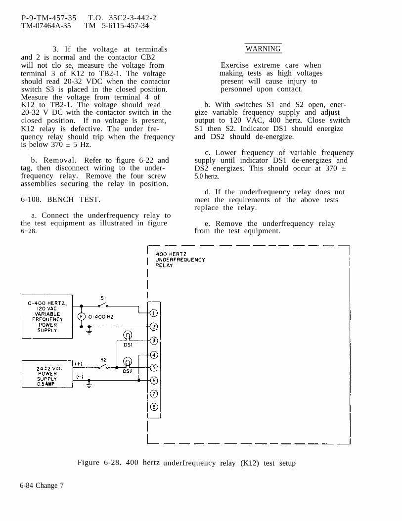
P-9-TM-457-35 T.O. 35C2-3-442-2TM-07464A-35 TM 5-6115-457-34
3. If the voltage at terminalsand 2 is normal and the contactor CB2
1
will not clo se, measure the voltage fromterminal 3 of K12 to TB2-1. The voltageshould read 20-32 VDC when the contactorswitch S3 is placed in the closed position.Measure the voltage from terminal 4 ofK12 to TB2-1. The voltage should read20-32 V DC with the contactor switch in theclosed position. If no voltage is present,K12 relay is defective. The under fre-quency relay should trip when the frequencyis below 370 ± 5 Hz.
b. Removal. Refer to figure 6-22 andtag, then disconnect wiring to the under-frequency relay. Remove the four screwassemblies securing the relay in position.
6-108. BENCH TEST.
a. Connect the underfrequency relay tothe test equipment as illustrated in figure6−28.
WARNING
Exercise extreme care whenmaking tests as high voltagespresent will cause injury topersonnel upon contact.
b. With switches S1 and S2 open, ener-gize variable frequency supply and adjustoutput to 120 VAC, 400 hertz. Close switchS1 then S2. Indicator DS1 should energizeand DS2 should de-energize.
c. Lower frequency of variable frequencysupply until indicator DS1 de-energizes andDS2 energizes. This should occur at 370 ±5.0 hertz.
d. If the underfrequency relay does notmeet the requirements of the above testsreplace the relay.
e. Remove the underfrequency relayfrom the test equipment.
Figure 6-28. 400 hertz
6-84 Change 7
underfrequency relay (K12) test setup

P-9-TM-457-35 T.O. 35C2-3-442-2TM-07464A-35 TM 5-6115-457-34
6-109. INSTALLATION. Refer to figure6-22 and install the underfrequency relayin the mode II relay box. Secure the re-lay in position with four screw assemblies,then refer to figure 1-17 and reconnectwiring. Replace mode II relay box cover.
6-110. 400 HERTZ UNDERVOLTAGERELAY (K11).
6-111. ON EQUIPMENT TEST.
a. Symptom and Isolation of Malfunc-tion. A malfunction of the undervoltagerelay K11 is usually indicated by the illu-mination of the UNDERVOLTAGE faultlight, or by failure of the load contactorto close with the generator output voltagenormal. To isolate the malfunction, pro-ceed as follows:
WARNING
Exercise extreme care not totouch exposed electrical connec-tions when working inside modeII relay box with generator setoperating.
NOTE
Remove cover from mode IIrelay box to gain access tothe test points, see figures6-15 and 6-22.
1. With the generator set operatingat rated speed and voltage, measure thevoltage from terminal 1 to terminal 2 ofthe K11 relay. The nominal voltage is 120VAC. Remove the wire from terminal 3 ofK11 and reset fault light. If fault light cannow be reset, relay K11 is defective.
2. If the voltage at terminals 1 and2 is normal and the contactor CB2 won'tclose, measure the voltage from terminal7 of K11 to TB2-1. The voltage should
read 20-32 VDC when the contactor switchS3 is placed to the clo se position.
3. Measure the voltage from ter-minal 8 of K11 to terminal board TB2-1.The voltage should read 20-32 VDC withcontactor switch to the close position; ifno voltage replace K11 relay. The under-voltage relay should trip when the voltageis lowered below 99 ± 4 volts in 6 ± 2seconds.
b. Removal. Refer to figure 6-22 andtag, then disconnect wiring to the under-voltage relay. Remove the four screwssecuring the relay in position.
6-112. BENCH TEST.
a. Connect the undervoltage relay tothe test equipment as illustrated infigure 6-29.
WARNING
Exercise extreme care whenmaking tests as high voltageswill cause injury to personnelupon contact.
b. Energize variable voltage AC supplyand adjust to 120 VAC, 400 hertz. Ener-gize 24VDC supply and close switches S2and S1. Indicator DS2 should energize andDS1 should deenergize.
c. Adjust the variable voltage supplyto 99 VAC. Indicator DS2 should de-energize and DS1 should energize after6 ± 2 seconds.
d. If the undervoltage relay does notmeet the requirements of the above test,replace the relay.
e. Remove the under voltage relayfrom the test equipment.
Change 3 6 - 8 5
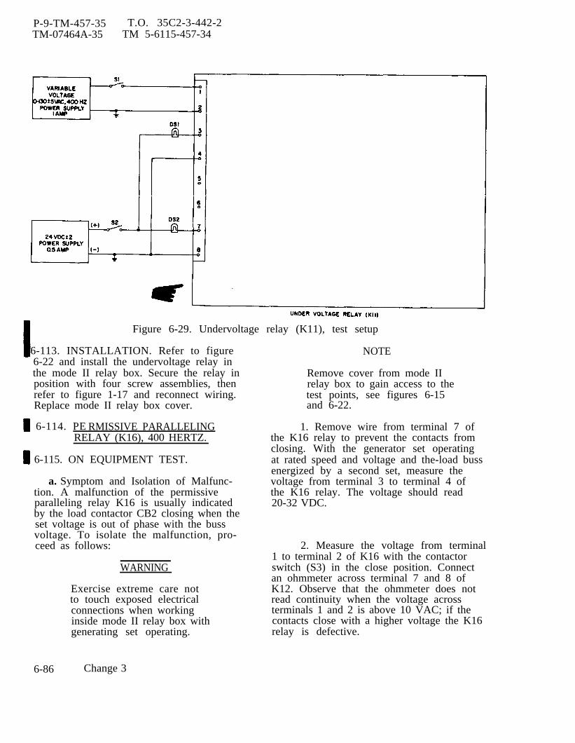
P-9-TM-457-35 T.O. 35C2-3-442-2TM-07464A-35 TM 5-6115-457-34
Figure 6-29. Undervoltage relay (K11), test setup
6-113. INSTALLATION. Refer to figure6-22 and install the undervoltage relay inthe mode II relay box. Secure the relay inposition with four screw assemblies, thenrefer to figure 1-17 and reconnect wiring.Replace mode II relay box cover.
6-114. PE RMISSIVE PARALLELINGRELAY (K16), 400 HERTZ.
6-115. ON EQUIPMENT TEST.
a. Symptom and Isolation of Malfunc-tion. A malfunction of the permissiveparalleling relay K16 is usually indicatedby the load contactor CB2 closing when theset voltage is out of phase with the bussvoltage. To isolate the malfunction, pro-ceed as follows:
WARNING
Exercise extreme care notto touch exposed electricalconnections when workinginside mode II relay box withgenerating set operating.
NOTE
Remove cover from mode IIrelay box to gain access to thetest points, see figures 6-15and 6-22.
1. Remove wire from terminal 7 ofthe K16 relay to prevent the contacts fromclosing. With the generator set operatingat rated speed and voltage and the-load bussenergized by a second set, measure thevoltage from terminal 3 to terminal 4 ofthe K16 relay. The voltage should read20-32 VDC.
2. Measure the voltage from terminal1 to terminal 2 of K16 with the contactorswitch (S3) in the close position. Connectan ohmmeter across terminal 7 and 8 ofK12. Observe that the ohmmeter does notread continuity when the voltage acrossterminals 1 and 2 is above 10 VAC; if thecontacts close with a higher voltage the K16relay is defective.
6-86 Change 3
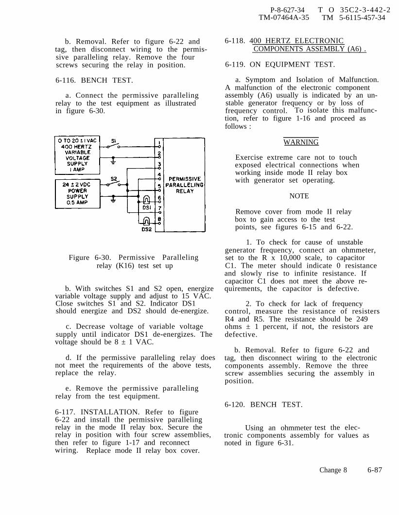
P-8-627-34 T O 35C2-3-442-2TM-07464A-35 TM 5-6115-457-34
b. Removal. Refer to figure 6-22 andtag, then disconnect wiring to the permis-sive paralleling relay. Remove the fourscrews securing the relay in position.
6-116. BENCH TEST.
a. Connect the permissive parallelingrelay to the test equipment as illustratedin figure 6-30.
Figure 6-30. Permissive Parallelingrelay (K16) test set up
b. With switches S1 and S2 open, energizevariable voltage supply and adjust to 15 VAC.Close switches S1 and S2. Indicator DS1should energize and DS2 should de-energize.
c. Decrease voltage of variable voltagesupply until indicator DS1 de-energizes. Thevoltage should be 8 ± 1 VAC.
d. If the permissive paralleling relay doesnot meet the requirements of the above tests,replace the relay.
e. Remove the permissive parallelingrelay from the test equipment.
6-117. INSTALLATION. Refer to figure6-22 and install the permissive parallelingrelay in the mode II relay box. Secure therelay in position with four screw assemblies,then refer to figure 1-17 and reconnectwiring. Replace mode II relay box cover.
6-118. 400 HERTZ ELECTRONICCOMPONENTS ASSEMBLY (A6) .
6-119. ON EQUIPMENT TEST.
a. Symptom and Isolation of Malfunction.A malfunction of the electronic componentassembly (A6) usually is indicated by an un-stable generator frequency or by loss offrequency control. To isolate this malfunc-tion, refer to figure 1-16 and proceed asfollows :
WARNING
Exercise extreme care not to touchexposed electrical connections whenworking inside mode II relay boxwith generator set operating.
NOTE
Remove cover from mode II relaybox to gain access to the testpoints, see figures 6-15 and 6-22.
1. To check for cause of unstablegenerator frequency, connect an ohmmeter,set to the R x 10,000 scale, to capacitorC1. The meter should indicate 0 resistanceand slowly rise to infinite resistance. Ifcapacitor C1 does not meet the above re-quirements, the capacitor is defective.
2. To check for lack of frequencycontrol, measure the resistance of resistersR4 and R5. The resistance should be 249ohms ± 1 percent, if not, the resistors aredefective.
b. Removal. Refer to figure 6-22 andtag, then disconnect wiring to the electroniccomponents assembly. Remove the threescrew assemblies securing the assembly inposition.
6-120. BENCH TEST.
Using an ohmmeter test the elec-tronic components assembly for values asnoted in figure 6-31.
Change 8 6-87
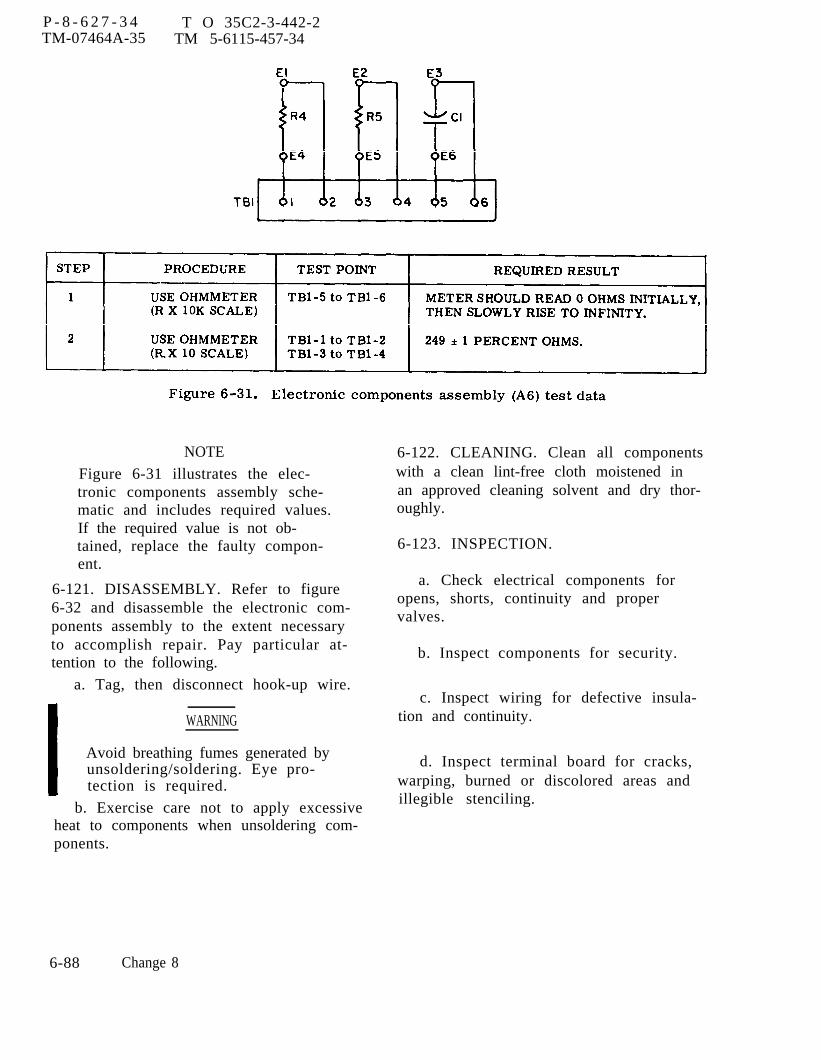
Figure 6-31.
P - 8 - 6 2 7 - 3 4 T O 35C2-3-442-2TM-07464A-35 TM 5-6115-457-34
NOTE
Figure 6-31 illustrates the elec-tronic components assembly sche-matic and includes required values.If the required value is not ob-tained, replace the faulty compon-ent.
6-121. DISASSEMBLY. Refer to figure6-32 and disassemble the electronic com-ponents assembly to the extent necessaryto accomplish repair. Pay particular at-tention to the following.
a. Tag, then disconnect hook-up wire.
WARNING
Avoid breathing fumes generated byunsoldering/soldering. Eye pro-tection is required.
b. Exercise care not to apply excessiveheat to components when unsoldering com-ponents.
6-122. CLEANING. Clean all componentswith a clean lint-free cloth moistened inan approved cleaning solvent and dry thor-oughly.
6-123. INSPECTION.
a. Check electrical components foropens, shorts, continuity and propervalves.
b. Inspect components for security.
c. Inspect wiring for defective insula-tion and continuity.
d. Inspect terminal board for cracks,warping, burned or discolored areas andillegible stenciling.
6-88 Change 8
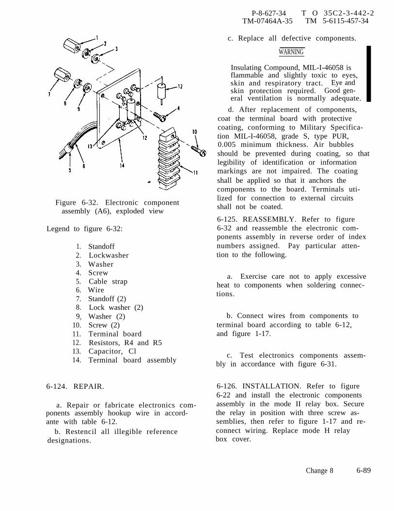
P-8-627-34 T O 35C2-3-442-2TM-07464A-35 TM 5-6115-457-34
Figure 6-32. Electronic componentassembly (A6), exploded view
Legend to figure 6-32:
1.2.3.4.5.6.7.8.90
10.11.12.13.14.
StandoffLockwasherWasherScrewCable strapWireStandoff (2)Lock washer (2)Washer (2)Screw (2)Terminal boardResistors, R4 and R5Capacitor, ClTerminal board assembly
c. Replace all defective components.
WARNING
Insulating Compound, MIL-I-46058 isflammable and slightly toxic to eyes,skin and respiratory tract. Eye andskin protection required. Good gen-eral ventilation is normally adequate.
d. After replacement of components,coat the terminal board with protectivecoating, conforming to Military Specifica-tion MIL-I-46058, grade S, type PUR,0.005 minimum thickness. Air bubblesshould be prevented during coating, so thatlegibility of identification or informationmarkings are not impaired. The coatingshall be applied so that it anchors thecomponents to the board. Terminals uti-lized for connection to external circuitsshall not be coated.
6-125. REASSEMBLY. Refer to figure6-32 and reassemble the electronic com-ponents assembly in reverse order of indexnumbers assigned. Pay particular atten-tion to the following.
a. Exercise care not to apply excessiveheat to components when soldering connec-tions.
b. Connect wires from components toterminal board according to table 6-12,and figure 1-17.
c. Test electronics components assem-bly in accordance with figure 6-31.
6-124. REPAIR. 6-126. INSTALLATION. Refer to figure6-22 and install the electronic components
a. Repair or fabricate electronics com- assembly in the mode II relay box. Secureponents assembly hookup wire in accord- the relay in position with three screw as-ante with table 6-12. semblies, then refer to figure 1-17 and re-
b. Restencil all illegible reference connect wiring. Replace mode H relaydesignations. box cover.
Change 8 6-89
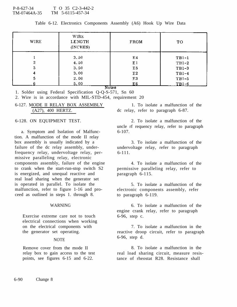
P-8-627-34 T O 35 C2-3-442-2TM-07464A-35 TM 5-6115-457-34
Table 6-12. Electronics Components Assembly (A6) Hook Up Wire Data
1. Solder using Federal Specification Q-Q-S-571, Sn 602. Wire is in accordance with MIL-STD-454, requirement 20
6-127. MODE II RELAY BOX ASSEMBLY(A27), 400 HERTZ.
6-128. ON EQUIPMENT TEST.
a. Symptom and Isolation of Malfunc-tion. A malfunction of the mode II relaybox assembly is usually indicated by afailure of the dc relay assembly, under-frequency relay, undervoltage relay, per-missive paralleling relay, electroniccomponents assembly, failure of the engineto crank when the start-run-stop switch S2is energized, and unequal reactive andreal load sharing when the generator setis operated in parallel. To isolate themalfunction, refer to figure 1-16 and pro-ceed as outlined in steps 1. through 8.
WARNING
Exercise extreme care not to touchelectrical connections when workingon the electrical components withthe generator set operating.
NOTE
Remove cover from the mode IIrelay box to gain access to the testpoints, see figures 6-15 and 6-22.
1. To isolate a malfunction of thedc relay, refer to paragraph 6-87.
2. To isolate a malfunction of theuncle rf requency relay, refer to paragraph6-107.
3. To isolate a malfunction of theundervoltage relay, refer to paragraph6-111.
4. To isolate a malfunction of thepermissive paralleling relay, refer toparagraph 6-115.
5. To isolate a malfunction of theelectronic components assembly, referto paragraph 6-119.
6. To isolate a malfunction of theengine crank relay, refer to paragraph6-96, step c.
7. To isolate a malfunction in thereactive droop circuit, refer to paragraph6-96, step d.
8. To isolate a malfunction in thereal load sharing circuit, measure resis-tance of rheostat R28. Resistance shall
6-90 Change 8

P-8-627-34 T O 35C2-3-442-2TM-07464A-35 TM 5-6115-457-34
readjustable in the range of 0-15K ohms± 10 percent. Refer figure 1-16 and 1-17.
b. Removal. Refer to figure 6-15, dis-connect all electrical plug connectors atmode II relay box assembly receptacles,then remove the four screws and nuts se-curing the assembly in position. Removethe mode II relay box assembly.
6-129. BENCH TEST.
a. Refer to table 6-13 and perform acontinuity test of mode II relay box cir-cuitry.
b. Connect the mode H relay box as-sembly to test equipment as illustrated infigure 6-33 and perform test specified inprocedural analysis table 6-14.
6-130. DISASSEMBLY. Refer to figures6-22 and 6-34 and disassemble the mode IIrelay box in the order of index numbersassigned. Pay particular attention to thefollowing.
NOTE
Disassemble the mode II relaybox to the extent necessary toaccomplish repair.
Table 6-13. Mode II Relay Box Assembly (A27) Continuity Test
Change 8 6-91

P-8-627-34 T O 35 C2-3-442-2TM-07464A-35 TM 5-6115-457-34
Table 6-13. Mode II Relay Box Assembly (A27) Continuity Test (Continued)
6-92 Change 8
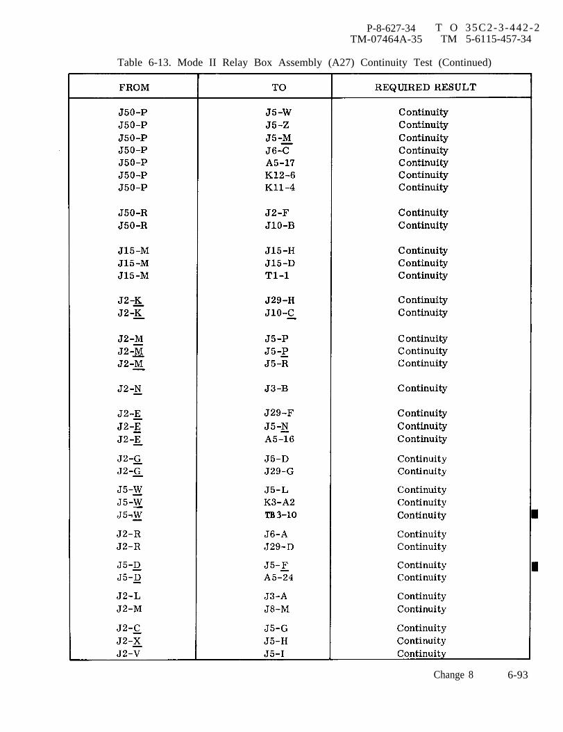
P-8-627-34 T O 35C2-3-442-2TM-07464A-35 TM 5-6115-457-34
Table 6-13. Mode II Relay Box Assembly (A27) Continuity Test (Continued)
Change 8 6-93

TO 35C2-3-442-2
Table 6-13. Mode II Relay Box Assembly (A27) Continuity Test (Continued)
6 - 9 4 Change 11
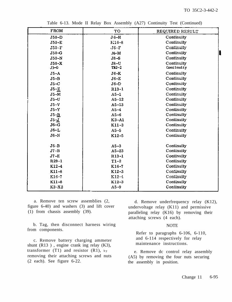
TO 35C2-3-442-2
Table 6-13. Mode II Relay Box Assembly (A27) Continuity Test (Continued)
a. Remove ten screw assemblies (2,figure 6-40) and washers (3) and lift cover(1) from chassis assembly (39).
b. Tag, then disconnect harness wiringfrom components.
c. Remove battery charging ammetershunt (R13 ) , engine crank ing relay (K3),transformer (T1) and resistor (R1), b y
removing their attaching screws and nuts(2 each). See figure 6-22.
d. Remove underfrequency relay (K12),undervoltage relay (K11) and permissiveparalleling relay (K16) by removing theirattaching screws (4 each).
NOTE
Refer to paragraphs 6-106, 6-110,and 6-114 respectively for relaymaintenance instructions.
e. Remove dc control relay assembly(A5) by removing the four nuts securingthe assembly in position.
Change 11 6-95

Figure 6-33.
P-8-627-34
T
O
35C2-3-442-2
TM
-07464A-35
TM
5-6115-457-34
6-96C
hange 8
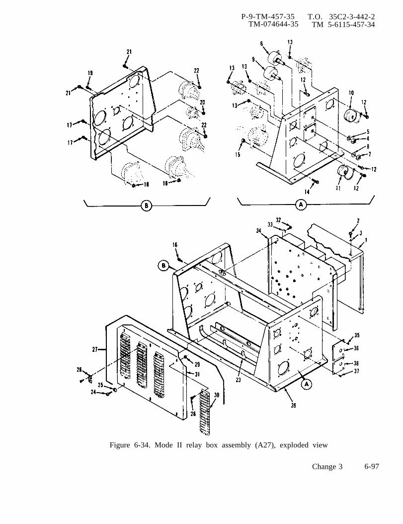
P-9-TM-457-35 T.O. 35C2-3-442-2TM-074644-35 TM 5-6115-457-34
Figure 6-34. Mode II relay box assembly (A27), exploded view
Change 3 6-97

P-9-TM-457-35 T.O. 35C2-3-442-2TM-07464A-35 TM 5-6115-457-34
Legend to figure 6-34:
1.2.3.4.5.6.7.8.9.
10.11.12.13.14.15.16.17.18.19.20.
CoverScrew assembly (10)Washer (10)NutWasherRheostat (R29)NutWasherRheostat (R28)Electrical connector coverElectrical connector coverScrew assembly (16)Nut assembly (16)Screw assembly (4)Nut assembly (4)Screw assembly (3)Screw assembly (8)Nut assembly (8)Screw assembly (8)Nut assembly (8)
NOTE
Refer to paragraph 6-86 for dcrelay assembly maintenance in-structions.
f. Remove electronic components as-sembly (A6) by removing the three screwassemblies securing the assembly in posi-tion.
NOTE
Refer to paragraph 6-118 for elec-tronic component assembly main-tenance instructions.
g. Remove nuts (4 and 7, figure 6-34)and washers (5 and 8) securing rheostats(6 and 9) to chassis assembly (39).
21.22.23.24.25.26.27.28.29.30.31.32.33.34.35.36.37.38.39,
Screw assembly (8)Nut assembly (8)Wiring harnessScrew assembly (6)Washer (6)Terminal board jumper (13)Terminal board assemblyScrew assembly (8)Nut assembly (8)Terminal board (4)BracketScrew assembly (6)Washer (6)Electronic component assemblyRivetIdentification plateRivetIdentification plateChassis assembly
h. Remove wire harness (23) by re-moving the four screws and nuts securingeach of the ten connectors to the chassisassembly (39).
NOTE
Electrical connector covers (10and 11) will fall free.
6-131. CLEANING. Clean all componentswith a clean lint-free cloth moistened inan approved cleaning solvent and dry thor-oughly.
6-132. INSPECTION.
a. Harness.
1. Inspect harness wiring for defec-tive insulation and continuity.
6-98 Change 3
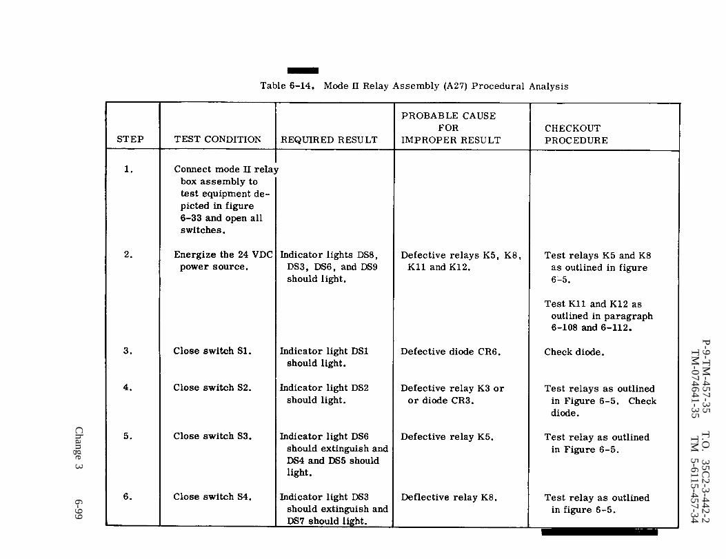
Table 6-14.
P-9-T
M-457-35
T.O
. 35C
2-3-442-2T
M-074641-35
TM
5-6115-457-34
Change 3
6-99

Table 6-14.
P-9-T
M-457-35
T.O
. 35C
2-3-442-2T
M-07464A
-35T
M 5-6115-45734
6-100C
hange 3

P-8-627-34T
O
35C
2-3-442-2T
M-074644-35
TM
5-6115-457-34
Change 8
6-101

P-8-627-34 T O 35C2-3-442-2TM-0746U-35 TM 5-6115-45734
2. Inspect harness connectors fordamaged threads; bent, loose or missingpins and for shorts.
6-133. REPAIR.
a. Repair or fabricate mode II relaybox assembly wiring harness according tofigure 6-35.
6. Straighten dented or distorted sheetmetal parts using proper tools. Blend inrepaired area with a suitable abrasivepaper and touch up painted surfaces. Re-stencil panel markings as necessary.
6-134. REASSEMBLY. Refer to figure6-34 and reassemble the mode II relay boxassembly in reverse order of index num-bers assigned. Pay particular attentionto the following:
a. Install wire harness (23) in chassis(39) and secure in position with fourscrews and nuts at each of the ten connec-tors .
b. Assemble electronic componentsassembly (A6) in position using threescrew assemblies. See figure 6-22.
c. Assemble dc control relay assembly(A5) in position using four nuts.
d. Assemble underfrequency relay(K12), undervoltage relay (K11) and per-
missive paralleling relay (K16), in positionusing four each, screws.
e. Assemble battery charging am-meter shunt (R13), engine cracking relay(K3), transformer (T1) and resistor (R1)into position using two each, screws and
nuts.
WARNING
Avoid breathing fumes generated byunsoldering/soldering. Eye pro -
tection is required.
f. Connect wire harness loads to com-ponentry using figure 1-17 as a guide.
Solder
NOTE
connections shall be madeusing solder, Federal SpecificationQQ-S-571, Sn 60.
g. Test mode II relay box assembly asoutlined in paragraph 6-129.
h. Secure cover (1, figure 6-34) tochassis assembly (39) using ten screwassemblies (2) and washers (3).
6-135. INSTALLATION. Refer to figure6-15, and install the mode II relay boxassembly. Secure the assembly in posi-tion using four screws and nuts. Refer tothe Operator and Organizational Mainte-nance Manual and reconnect all electricalplug connections to the assemblyreceptacles.
6-102 Change 8
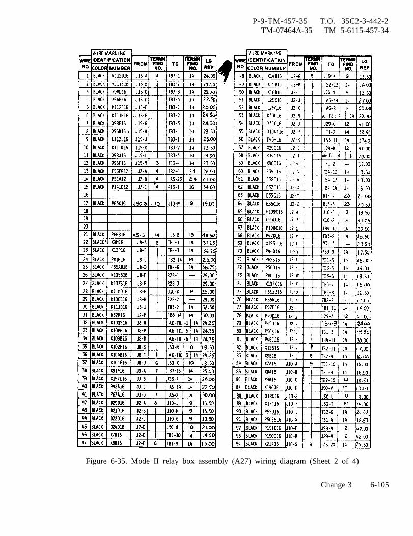
P-9-TM-457-35 T.O. 35C2-3-442-2TM-07464A-35 TM 5-6115-457-34
Figure 6-35. Mode II relay box assembly (A27) wiring diagram (Sheet 2 of 4)
Change 3 6-105
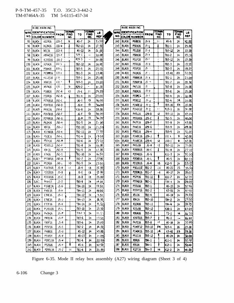
P-9-TM-457-35 T.O. 35C2-3-442-2TM-07464A-35 TM 5-6115-457-34
Figure 6-35. Mode II relay box assembly (A27) wiring diagram (Sheet 3 of 4)
6-106 Change 3

P-8-627-34 T O 35C2-3-442-2TM-07464A-35 TM 5-6115-457-34
Figure 6-35. Mode II relay box assembly (A27) wiring diagram (Sheet 4 of 4)
Change 8 6-107
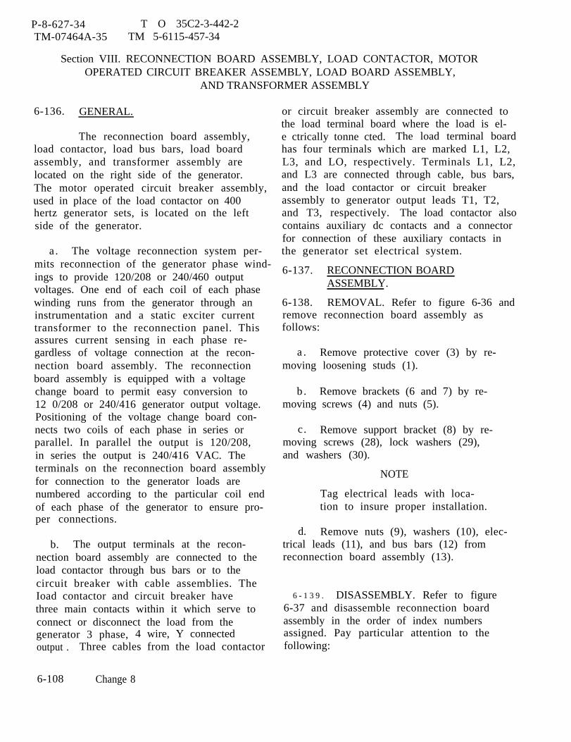
P-8-627-34 T O 35C2-3-442-2TM-07464A-35 TM 5-6115-457-34
Section VIII. RECONNECTION BOARD ASSEMBLY, LOAD CONTACTOR, MOTOROPERATED CIRCUIT BREAKER ASSEMBLY, LOAD BOARD ASSEMBLY,
AND TRANSFORMER ASSEMBLY
6-136. GENERAL.
The reconnection board assembly,load contactor, load bus bars, load boardassembly, and transformer assembly arelocated on the right side of the generator.The motor operated circuit breaker assembly,used in place of the load contactor on 400hertz generator sets, is located on the leftside of the generator.
a . The voltage reconnection system per-mits reconnection of the generator phase wind-ings to provide 120/208 or 240/460 outputvoltages. One end of each coil of each phasewinding runs from the generator through aninstrumentation and a static exciter currenttransformer to the reconnection panel. Thisassures current sensing in each phase re-gardless of voltage connection at the recon-nection board assembly. The reconnectionboard assembly is equipped with a voltagechange board to permit easy conversion to12 0/208 or 240/416 generator output voltage.Positioning of the voltage change board con-nects two coils of each phase in series orparallel. In parallel the output is 120/208,in series the output is 240/416 VAC. Theterminals on the reconnection board assemblyfor connection to the generator loads arenumbered according to the particular coil endof each phase of the generator to ensure pro-per connections.
b. The output terminals at the recon-nection board assembly are connected to theload contactor through bus bars or to thecircuit breaker with cable assemblies. TheIoad contactor and circuit breaker havethree main contacts within it which serve toconnect or disconnect the load from thegenerator 3 phase, 4 wire, Y connectedoutput . Three cables from the load contactor
or circuit breaker assembly are connected tothe load terminal board where the load is el-e ctrically tonne cted. The load terminal boardhas four terminals which are marked L1, L2,L3, and LO, respectively. Terminals L1, L2,and L3 are connected through cable, bus bars,and the load contactor or circuit breakerassembly to generator output leads T1, T2,and T3, respectively. The load contactor alsocontains auxiliary dc contacts and a connectorfor connection of these auxiliary contacts inthe generator set electrical system.
6-137. RECONNECTION BOARDASSEMBLY.
6-138. REMOVAL. Refer to figure 6-36 andremove reconnection board assembly asfollows:
a . Remove protective cover (3) by re-moving loosening studs (1).
b . Remove brackets (6 and 7) by re-moving screws (4) and nuts (5).
c. Remove support bracket (8) by re-moving screws (28), lock washers (29),and washers (30).
NOTE
Tag electrical leads with loca-tion to insure proper installation.
d. Remove nuts (9), washers (10), elec-trical leads (11), and bus bars (12) fromreconnection board assembly (13).
6 - 1 3 9 . DISASSEMBLY. Refer to figure6-37 and disassemble reconnection boardassembly in the order of index numbersassigned. Pay particular attention to thefollowing:
6-108 Change 8
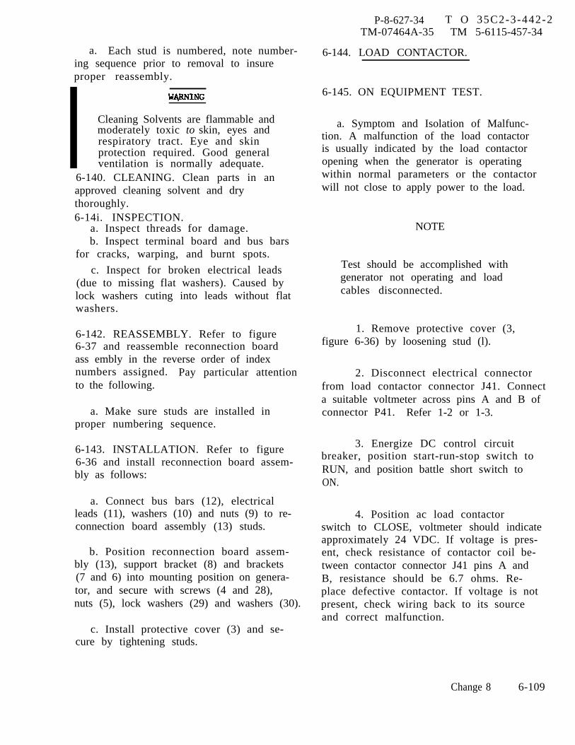
P-8-627-34 T O 35C2-3-442-2TM-07464A-35 TM 5-6115-457-34
a. Each stud is numbered, note number-ing sequence prior to removal to insureproper reassembly.
Cleaning Solvents are flammable andmoderately toxic to skin, eyes andrespiratory tract. Eye and skinprotection required. Good generalventilation is normally adequate.
6-140. CLEANING. Clean parts in anapproved cleaning solvent and drythoroughly.6-14i. INSPECTION.
a. Inspect threads for damage.b. Inspect terminal board and bus bars
for cracks, warping, and burnt spots.
c. Inspect for broken electrical leads(due to missing flat washers). Caused bylock washers cuting into leads without flatwashers.
6-142. REASSEMBLY. Refer to figure6-37 and reassemble reconnection boardass embly in the reverse order of indexnumbers assigned. Pay particular attentionto the following.
a. Make sure studs are installed inproper numbering sequence.
6-143. INSTALLATION. Refer to figure6-36 and install reconnection board assem-bly as follows:
a. Connect bus bars (12), electricalleads (11), washers (10) and nuts (9) to re-connection board assembly (13) studs.
b. Position reconnection board assem-bly (13), support bracket (8) and brackets(7 and 6) into mounting position on genera-tor, and secure with screws (4 and 28),nuts (5), lock washers (29) and washers (30).
c. Install protective cover (3) and se-cure by tightening studs.
6-144. LOAD CONTACTOR.
6-145. ON EQUIPMENT TEST.
a. Symptom and Isolation of Malfunc-tion. A malfunction of the load contactoris usually indicated by the load contactoropening when the generator is operatingwithin normal parameters or the contactorwill not close to apply power to the load.
NOTE
Test should be accomplished withgenerator not operating and loadcables disconnected.
1. Remove protective cover (3,figure 6-36) by loosening stud (l).
2. Disconnect electrical connectorfrom load contactor connector J41. Connecta suitable voltmeter across pins A and B ofconnector P41. Refer 1-2 or 1-3.
3. Energize DC control circuitbreaker, position start-run-stop switch toRUN, and position battle short switch toON.
4. Position ac load contactorswitch to CLOSE, voltmeter should indicateapproximately 24 VDC. If voltage is pres-ent, check resistance of contactor coil be-tween contactor connector J41 pins A andB, resistance should be 6.7 ohms. Re-place defective contactor. If voltage is notpresent, check wiring back to its sourceand correct malfunction.
Change 8 6-109
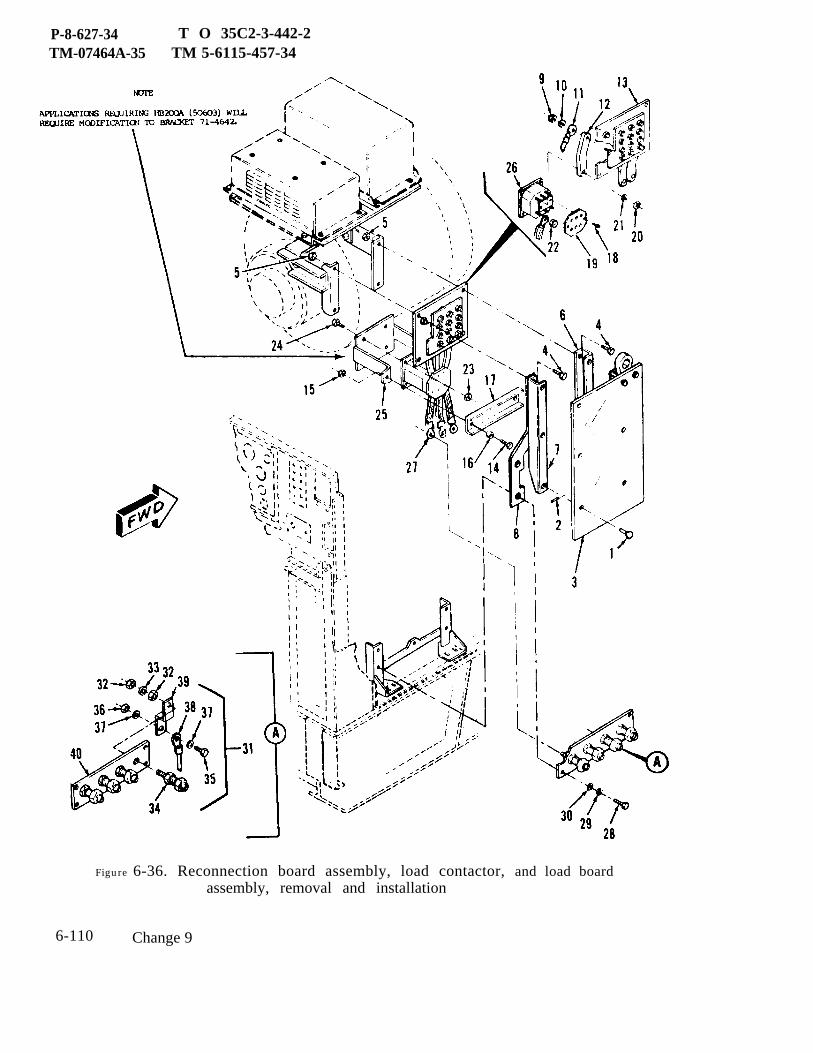
P-8-627-34 T O 35C2-3-442-2TM-07464A-35 TM 5-6115-457-34
Figure 6-36. Reconnection board assembly, load contactor, and load boardassembly, removal and installation
6-110 Change 9
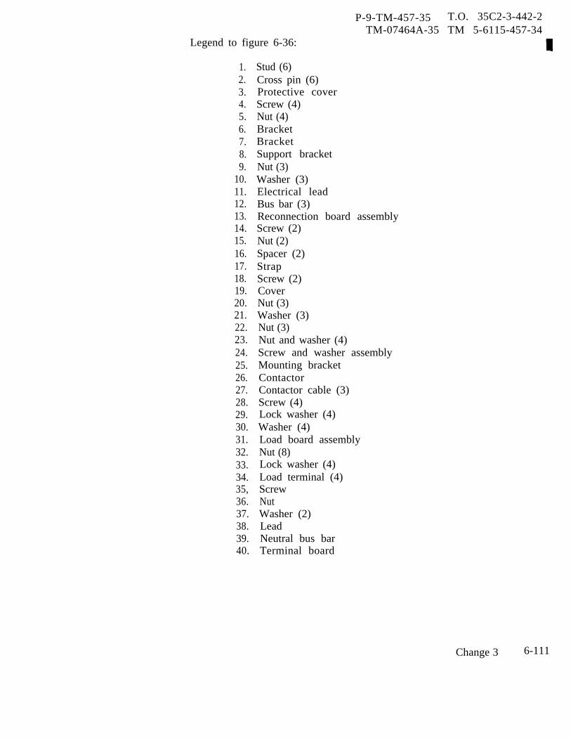
Legend to figure 6-36:
P-9-TM-457-35 T.O. 35C2-3-442-2TM-07464A-35 TM 5-6115-457-34
1.2.3.4.5.6.7.8.9.
10.11.12.13.14.15.16.17.18.19.20.21.22.23.24.25.26.27.28.29.30.31.32.33.34.35,36.37.38.39.40.
Stud (6)Cross pin (6)Protective coverScrew (4)Nut (4)BracketBracketSupport bracketNut (3)Washer (3)Electrical leadBus bar (3)Reconnection board assemblyScrew (2)Nut (2)Spacer (2)StrapScrew (2)CoverNut (3)Washer (3)Nut (3)Nut and washer (4)Screw and washer assemblyMounting bracketContactorContactor cable (3)Screw (4)Lock washer (4)Washer (4)Load board assemblyNut (8)Lock washer (4)Load terminal (4)ScrewNutWasher (2)LeadNeutral bus barTerminal board
Change 3 6-111

P-9-TM-457-35 T.O. 35C2-3-442-2TM-07464A-35 TM 5-6115-457-34
Legend to figure 6-36A:
1. IdentificationPlate
2. Wiring diagramPlate
3. Screw4. Lock washer5. Washer6. Terminal cover7. Screw8. Washer9. Screw
10. Lock washer11. Washer12. Gasket13. Gasket14. Cover assembly15. Primary contactor16. Screw17. Lock washer18. Washer19. Chamber base20. Gasket21. Main contact
operator assembly22. Nut23, Lock washer24. Adjusting bushing25. Retainer26. Locating bushing27. Spring28. Shim29. Main contact
bridge assembly30. Main contact31. Nut32. Lock washer33. Terminal washer34. Base assembly35. Arc chute36. Arc chute
spacer
37.38.39.40.41.42.43.44.45.46.
47.48.49.50.51.
52.53,54.55.56.57.58.59.
60.
GrommetNutLock washerWasherContact assemblyMain baseScrewWasherActuator assemblyAuxiliary contactassembly connectorScrewWasherScrewWasherAuxiliary contactassemblyNutLock washerSpringGuide rodNutLock washerSpacerCore and rodassemblyPost and operator
61. Screw62. Lock washer63. Washer64. Screw65. Lock washer66. Washer67. Screw68. Lock washer69. Switch bracket70. Licon switch71. End plate72. Coil73. Coil washer74. Core frame
6-112 Change 3
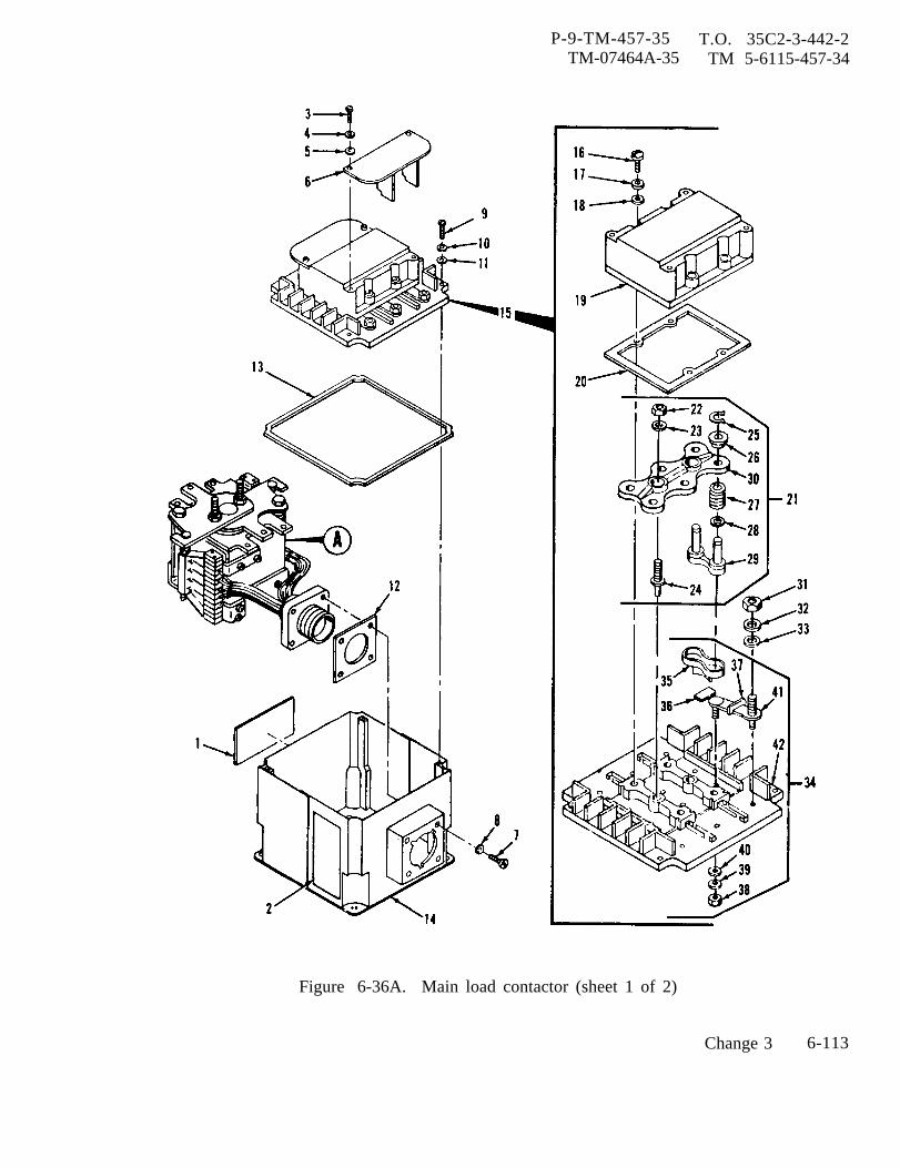
P-9-TM-457-35 T.O. 35C2-3-442-2TM-07464A-35 TM 5-6115-457-34
Figure 6-36A. Main load contactor (sheet 1 of 2)
Change 3 6-113
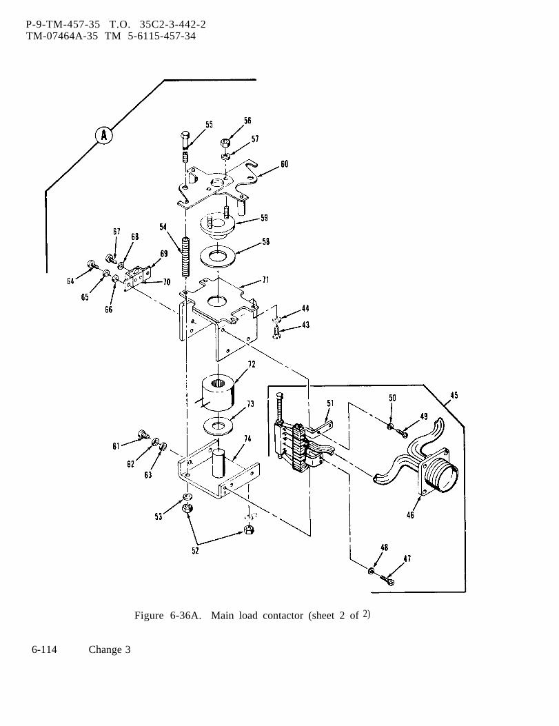
P-9-TM-457-35 T.O. 35C2-3-442-2TM-07464A-35 TM 5-6115-457-34
Figure 6-36A. Main load contactor (sheet 2 of 2)
6-114 Change 3
5. Position load contactor switchto OPEN, battle short switch to OFF, andstart-run-stop switch to STOP. De-ener-gize circuit breaker,
6. Connect connector to load con-tactor and install protective cover.
b. Removal. Refer to figure 6-36 andremove load contactor as follows:
1. Remove protective cover (3) byloosening studs (l).
2. Disconnect bracket (17) byremoving screws (14), spacers (16), andnuts (15).
P-9-TM-457-35 T.O. 35C2-3-442-2TM-07464A-35 TM 5-6115-457-34
3. Disconnect cover (19) from loadcontactor by removing screws (18). Dis-connect bus bar (12) and contactor cables(27) from load contactor by removing nutsand washers.
4. Loosen nuts (9) securing busbars (12) to reconnection board studs, toremove bus bars from contractors.
5. Disconnect electrical connectorfrom connector J41 of load contactor.
6. Disconnect load contactor (26)from mounting bracket (25) by removingnuts (23) and screws (24).
Change 3 6-115

P-9-TM-457-35 T.O. 35C2-3-442-2TM-07464A-35 TM 5-6115-457-34
Reconnection board assembly, exploded view
8. Bus bar
Figure 6-37.
Legend to figure 6-37:
1. Nut (13)2. Voltage change board 9. Stud (4)3. Rivet (12) 10. Stud Nut (9)4. Bus bar (6) 11. Stud Washer (9)5. Nut (4) 12. Stud Nut (9)6. Terminal board assembly 13. Stud (9)
washer (4) 14. Terminal board7. Nut (4)
6-116 Change 3
P-8-627-34 T O 35C2-3-442-2TM-07464A TM 5-6115-457-34
6-145A. REMOVAL. Refer to figure 6-36and remove the load contactor as follows:
a. Remove protective cover (3) byloosening studs (1). Disconnect strap (17)by removing screws (14), spacers (16), andnuts (15),
b. Disconnect cover (19) from loadcontactor by removing screws (18). Dis-connect bus bar (12) and contactor cables(27) from load contactor by removing nutsand washers.
c. Loosen nuts (9) securing bus bars(12) to reconnection board studs, to re-move bus bars from contractors. Dis-connect electrical connector from con-nector J41 of load contactor.
d. Disconnect load contactor (26) frommounting bracket (25) by removing nuts(23) and screws (24).
6-146. BENCH TEST.
a. Apply 24 Vdc at pins A and B ofmain load contactor (3) connector. Whenmain load contactor operates, it shouldcreate a distinctive noise.
b. With an ohmmeter, check for conti-nuity between terminal Al and A2, B1 toB2, and Cl to C2 on top of the main loadcontactor.
c. At the connector, check for conti-nuity between pins C to D, E to F, G to H,J to K, and R to T.
d. At the connector, check for an opencircuit between pins L to M, N to P, andR to S.
e. Remove the 24 Vdc and check for theopposite of the conditions (continuity or opencircuit) listed in steps (2), (3), and (4).
6-146A. DISASSEMBLY. Refer to figure6-36A and disassemble the main load con-tactor as follows:
a, Remove screws (3), lock washers(4), washers (5) and two terminal covers(6) from the primary contactor assembly(15). Remove screws (7) and washers (8)holding the auxiliary contact connector (46)to the cover assembly (14).
b. Remove screws (9), lock washer (10)and washers (11) from the primary con-tactor assembly (15). Push in on the aux-iliary contact connector (46) freeing it andthe gasket (12) from the cover assembly (14).Remove the primary contactor assembly (15)and gasket (13) from the cover assembly (14).
c. Remove screws (16), lock washers(17) and washers (18) from the chamber base(19), Remove the chamber base (19) andgasket (20) from the main base (42),
d. Disassemble the main contact oper-ator assembly (21) in the following manner.Remove nut (22) and lock washer (23) fromadjusting bushing (24). Remove retainer(25) and locating bushing (26) from the maincontact bridge assembly (29). Remove themain contact (30), spring (27) and shim (28)from the main contact bridge assembly (29).
e. Remove the arc chute (35), arc chutespacer (36) and grommet from the mainbase (42). Remove nuts (31 and 38), lockwashers (32 and 39), terminal washers (33)and washers (40) from contact assembly (41).Remove contact assembly (41) from mainbase (42).
WARNING
Avoid breathing fumes generated byunsoldering/soldering. Eye pro-tection is required. I
f. Remove screws (43) and washers (44)from the end plate (71) and remove samefrom the main base (42). Remove screws(47 and 49) and washers (48 and 50) and re-move the actuator assembly (45). Tag and
Change 8 6-117
P-8-627-34 T O 35C2-3-442-2TM-07464A-35 TM 5-6115-457-34
unsolder the leads from the connector (46) c. Repair damaged threads with a die
to the auxiliary contact assembly (51). or by filing with a fine mill file.
g. Remove nuts (52) and washer (53)from guide rod (55); carefully removespring (55). Remove nuts (56) and washers(57) and remove the post and operator (60),core and rod assembly (59) and spacer (58)from end plate (71).
h. Remove screws (61), lock washers(62) and washers (63) from the core frame(74). Carefully slide the core frame (74)containing the coil (72) and coil washer (73)out from the end plate (71). Remove screws(64 and 67), lock washers (65 and 68) andwashers (66) and remove the switch bracket(69) and licon switch (70) from the end plate(71).
6-146B. CLEANING. Clean all componentswith a clean lint-free cloth moistened withan approved cleaning solvent and dry thor-oughly .
6-146C. INSPECTION.
a. Inspect harness wiring for defectiveinsulation and continuity.
b. Inspect harness connector for dam-aged threads; bent, loose or missing pinsand for shorts.
c. Check electrical components foropens, shorts, continuity, and propervalues.
6-146D. REPAIR,
a. Replace contactor coil (72, figure6-36A) if defective.
b. Replace contacts if badly pitted orburned.
6-146E. REASSEMBLY. Refer to figure6-36A and reassemble the main load con-tactor as follows:
a. Install switch bracket (69) and liconswitch (70) to end plate (71) using screws(64 and 67), lock washers (65 and 68) andwashers (66).
b. Insert coil washer (73) and coil (72)over center pin on coil frame (74). Care-fully align end plate (71) over the coil (72)and coil frame (74). Place space (58), coreand rod assembly (59) and post and opera-tor (60) onto end plate (71). Fasten postand operator (60) to end plate (71) utilizingguide rod (55), spring (74), nuts (52) andwashers (53). Install screws (61), lockwashers (62) and washers (63) and tightensnug. Install nuts (56) and lock washers(57) to the core and rod assembly (59).
WARNING
Avoid breathing fumes generated byunsoldering/soldering. Eye pro-tection is required.
c. Connect and solder electrical leadsfrom connector (46) to auxiliary contactassembly (51). Install actuator assembly(45) to end plate (71) and core frame (74)using screws (47 and 49) and washers (48and 50). Carefully clamp post and operator(60) and the core frame (74), so that no airspace exists between the coil (72) and thecore and rod assembly (59). Also checkthat no air space exists between the spacer(58) and end plate (71). Tighten screws(47 and 61). Remove the clamp and inserta .150±. 010, feeler gage, between the coil(72) and core and rod assembly (59). Ad-just the guide rods (55) until the gage issnug. Secure after adjustment by tighteningnuts (52).
6-118 Change 8
d. Assemble the base assembly (34) byinstalling contact assembly (41) to mainbase (42). Secure with nut (38), lockwasher (39) and washer (40). Install nut(31), lock washer (32) and washer (33) tocontact assembly (41). Place the arc chute(35), arc chute spacer (36) and grommet(37) atop the contact assembly (41).
e, Assemble the main contact operatorassembly (21) by placing shim (28) andspring (27) onto the main contact bridgeassembly (29). Assemble three contactbridge assemblies and carefully insert intothe main contact (30). Press down on themain contact (30) and place the locatingbushings (26) and retainers (25) over themain contact bridge assembly (29) Afterreassembly of the main contact operatorassembly (21), check each individual con-tact at its edge with a suitable force gage,Preload shall be 1 1/2 - 2 1/2 lbs. Pre-load is checked by the initial breakaway ofthe retainer (25).
f. Fasten adjusting bushing (24) to themain base (42). Carefully seat the maincontact operator assembly (21) onto theadjusting bushings (24) and are chutes (35).Install nuts (22) and lock washers (23).Place gasket (20) and chamber base (19)onto base assembly (34) and fasten withscrews (16), lock washers (17) and washers(18).
NOTE
Before proceeding with the finalphase of reassembly, it is manda-tory that adjustment of the contactorbe performed, Refer to paragraph6-146E.
g. Seat gasket (13) into groove or mainbase (42). Place gasket (12) over the aux-
P-9-TM-457-35TM-07464A
iliary contact connector
T.O. 35C2-3-442-2TM 5-6115-457-34
(46). Insert theprimary contactor assembly (15) into thecover assembly (14), Insert and seat theconnector in the receptical opening of thecover assembly (14). Attach with screws(7) and washers (8). Carefully seat themain base (42) of the primary contactorassembly (15) onto the cover assembly (14);check that the gasket (13) forms an airtightseal. Install screws (9), lock washers (10)and washers (11). Place terminal cover (6)onto the primary contactor assembly (15).Secure with screws (3), lock washers (4)washers (5). Do not overly tighten screws(3) as the terminal cover (6) may crack.
6-146F. ADJUSTMENT.
a. Contact Overtravel. Adjust the mainload contactor for contact overt ravel asfollows:
1. Attach a suitable ohmmeter toterminals A1-A2 and C1-C2 on main base(42) .
2. Insert .035 feeler gage betweenthe coil (72) and core and rod assembly (59),
3. Apply 24VDC to the coil.
4. Adjust bushing (24) until conti-nuity is made at A1-A2 and C1-C2. Secureadjustment by tightening screw (22).
5. Check that continuity is attainedat .035 and no continuity at .040. Readjustif necessary,
b. Licon Switch. Adjust the main loadlican switch (70) as follows:
1. Adjust switch bracket (69) tolicon switch (70). Check that white buttonis fully depressed, and allow .010 clear-ance between white button and tap operator.
Change 3 6-119
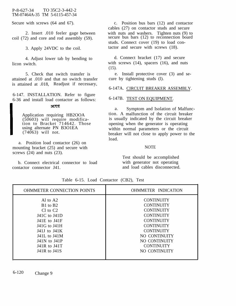
P-8-627-34 TO 35C2-3-442-2TM-07464A-35 TM 5-6115-457-34
Secure with screws (64 and 67).
2. Insert .010 feeler gage betweencoil (72) and core and rod assembly (59).
3. Apply 24VDC to the coil.
4. Adjust lower tab by bending tolicon switch.
5. Check that switch transfer isattained at .010 and that no switch transferis attained at .018, Readjust if necessary,
6-147. INSTALLATION. Refer to figure6-36 and install load contactor as follows:
Application requiring HB2OOA(50603) will require modifica-tion to Bracket 714642. Thoseusing alternate PN B3O1EA(74063) will not.
a. Position load contactor (26) onmounting bracket (25) and secure withscrews (24) and nuts (23).
b. Connect electrical connector to loadcontactor connector J41.
c. Position bus bars (12) and contactorcables (27) on contactor studs and securewith nuts and washers. Tighten nuts (9) tosecure bus bars (12) to reconnection boardstuds. Connect cover (19) to load con-tactor and secure with screws (18).
d. Connect bracket (17) and securewith screws (14), spacers (16), and nuts(15).
e. Install protective cover (3) and se-cure by tightening studs (l).
6-147A.
6-147B.
a.tion. A
CIRCUIT BREAKER ASSEMBLY.
TEST ON EQUIPMENT.
Symptom and Isolation of Malfunc-malfunction of the circuit breaker
is usually indicated by the circuit breakeropening when the generator is operatingwithin normal parameters or the circuitbreaker will not close to apply power to theload.
NOTE
Test should be accomplishedwith generator not operatingand load cables disconnected.
Table 6-15. Load Contactor (CB2), Test
OHMMETER CONNECTION POINTS OHMMETER INDICATION
Al to A2 CONTINUITYB1 to B2 CONTINUITYCl to C2 CONTINUITY
J41C to J41D CONTINUITYJ41E to J41F CONTINUITYJ41G to J41H CONTINUITYJ41J to J41K CONTINUITYJ41L to J41M NO CONTINUITYJ41N to J41P NO CONTINUITYJ41R to J41T CONTINUITYJ41R to J41S NO CONTINUITY
6-120 Change 9
1. Disconnect electrical connectorfrom circuit breaker relay box connectorJ41. Connect a suitable voltmeter acrosspins M and B with B negative. EnergizeDC control circuit breaker. There shouldbe approximately 24 volts.
2. Connect a suitable voltmeteracross pins A and B of J41. Positionstart-run-stop switch to RUN, and positionbattle short switch to ON.
3. Position circuit breaker switchto CLOSE; voltmeter should indicate approx-imately 24 volts.
4. If voltage is not present in eitherstep 2 or 3, check wiring back to its sourceand correct malfunctions.
5. If voltage is present but thecontactor still will not close, check K26Relay, OFF-ON Limit Switch, and MotorBl, and correct malfunction.
6. If the contactor closes and willnot stay in the closed position, check under-voltage relay inside the circuit breaker.
7. Position load contactor switch toOPEN, battle short switch to OFF, andstart-run-stop switch to STOP. De-energize circuit breaker.
8. Install connector plug P41 tocircuit breaker relay box.
b. Removal. Refer to figure 6-37A andremove circuit breaker assembly as follows:
1.
NOTETag electrical leads withlocation to insure properinstallation.
Tag and disconnect three top el-ectrical leads and electrical connector P41from circuit breaker assembly (7).
P-9-TM-457-35TM-07464A-35
2. Disconnecter electrical leads from
T. O. 35C2-3-442-2TM 5-6115-457-34
three circuit break-load board; loosen
clamp at base of generator.
3. Remove screws (1 and 4), lockwashers (2 and 5) and washers (3 and 6).
4. Remove clamps (7B) by re-moving screws (7B) and remove circuitbreaker and three electrical leads.
6-147C. TEST.
a. Connect circuit breaker assemblyto test equipment as illustrated in figure6-37B and perform test specified in pro-cedural analysis table 6-15A.
b. Remove test equipment.
6-147D. DISASSEMBLY. Refer to figure6-37C and disassemble circuit breakerassembly in the sequence of index numbersassigned. Pay particular attention to thefollowing’
Remove screws (1), lock washers(2) and washers (3). Remove bracket (4)from bracket (29).
b. Remove clamp (7) from bracket(29) by removing nut and washer assembly(5) and screw and washer (6).
Remove screw and washer assembl(8) securing relay box (9) to top of bracket(29).
d. Remove relay (11) from relaysocket (14) by removing screw and washerassemblies (10).
NOTEDo not disconnect electrical leadsfrom relay socket (14) unless re-placement is required.
Change 3 6-120A
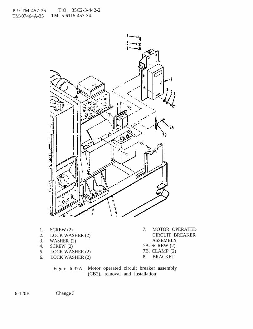
P-9-TM-457-35 T.O. 35C2-3-442-2TM-07464A-35 TM 5-6115-457-34
6-120B
1. SCREW (2) 7. MOTOR OPERATED2. LOCK WASHER (2) CIRCUIT BREAKER3. WASHER (2) ASSEMBLY4. SCREW (2) 7A. SCREW (2)5. LOCK WASHER (2) 7B. CLAMP (2)6. LOCK WASHER (2) 8. BRACKET
Figure 6-37A. Motor operated circuit breaker assembly(CB2), removal and installation
Change 3
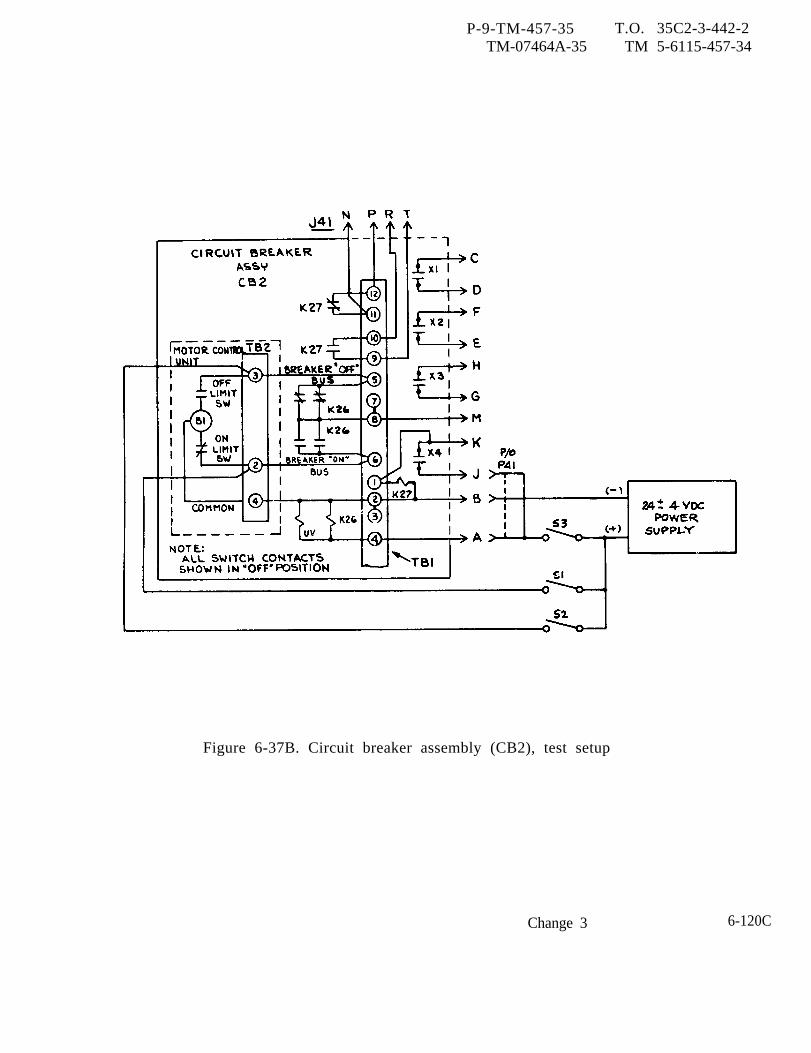
P-9-TM-457-35 T.O. 35C2-3-442-2TM-07464A-35 TM 5-6115-457-34
Figure 6-37B. Circuit breaker assembly (CB2), test setup
Change 3 6-120C

Table 6-15A
.
P-9-T
M-457-35
T.O
. 35C
2-3-442-2T
M-07464A
-35T
M 5-6115-457-34
6-120DC
hange 3

Table 6-15A
.
P-9-T
M-457-35
T.O
. 35C
2-3-442-2T
M-07464A
-35T
M 5-6115-457-34
Change 3
6-120E
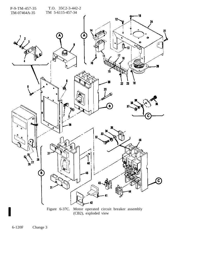
P-9-TM-457-35TM-07464A-35
T.O. 35C2-3-442-2TM 5-6115-457-34
Figure 6-37C. Motor operated circuit breaker assembly(CB2), exploded view
6-120F Change 3
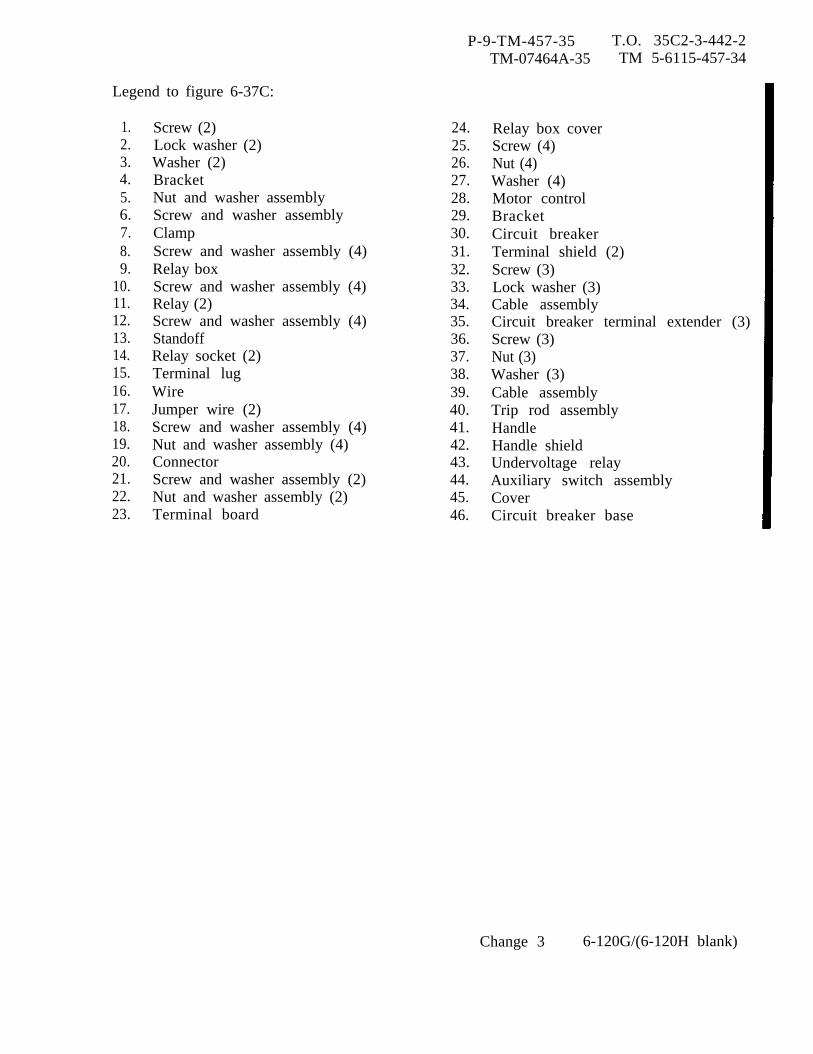
P-9-TM-457-35 T.O. 35C2-3-442-2TM-07464A-35 TM 5-6115-457-34
Legend to figure 6-37C:
1.2.3.4.5.6.7.8.9.
10.11.12.13.14.15.16.17.18.19.20.21.22.23.
Screw (2)Lock washer (2)Washer (2)BracketNut and washer assemblyScrew and washer assemblyClampScrew and washer assembly (4)Relay boxScrew and washer assembly (4)Relay (2)Screw and washer assembly (4)StandoffRelay socket (2)Terminal lugWireJumper wire (2)Screw and washer assembly (4)Nut and washer assembly (4)ConnectorScrew and washer assembly (2)Nut and washer assembly (2)Terminal board
24.25.26.27.28.29.30.31.32.33.34.35.36.37.38.39.40.41.42.43.44.45.46.
Relay box coverScrew (4)Nut (4)Washer (4)Motor controlBracketCircuit breakerTerminal shield (2)Screw (3)Lock washer (3)Cable assemblyCircuit breaker terminal extender (3)Screw (3)Nut (3)Washer (3)Cable assemblyTrip rod assemblyHandleHandle shieldUndervoltage relayAuxiliary switch assemblyCoverCircuit breaker base
Change 3 6-120G/(6-120H blank)

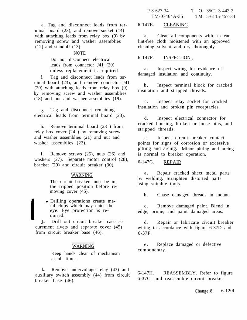
e. Tag and disconnect leads from ter-minal board (23), and remove socket (14)with attaching leads from relay box (9) byremoving screw and washer assemblies(12) and standoff (13).
NOTEDo not disconnect electricalleads from connector J41 (20)unless replacement is required.
f. Tag and disconnect leads from ter-minal board (23), and remove connector J41(20) with attaching leads from relay box (9)by removing screw and washer assemblies(18) and nut and washer assemblies (19).
g. Tag and disconnect remainingelectrical leads from terminal board (23).
h. Remove terminal board (23 ) fromrelay box cover (24 ) by removing screwand washer assemblies (21) and nut andwasher assemblies (22).
i . Remove screws (25), nuts (26) andwashers (27). Separate motor control (28),bracket (29) and circuit breaker (30).
WARNINGThe circuit breaker must be inthe tripped position before re-moving cover (45).
Drilling operations create me-tal chips which may enter theeye. Eye protection is re-quired.Drill out circuit breaker case se-
curement rivets and separate cover (45)from circuit breaker base (46).
WARNING
Keep hands clear of mechanismat all times.
k. Remove undervoltage relay (43) andauxiliary switch assembly (44) from circuitbreaker base (46).
P-8-627-34 T. O. 35C2-3-442-2TM-07464A-35 TM 5-6115-457-34
6-147E. CLEANING.
a . Clean all components with a cleanlint-free cloth moistened with an approvedcleaning solvent and dry thoroughly.
6-147F. INSPECTION ,
a . Inspect wiring for evidence ofdamaged insulation and continuity.
b . Inspect terminal block for crackedinsulation and stripped threads.
c. Inspect relay socket for crackedinsulation and broken pin receptacles.
d. Inspect electrical connector forcracked housing, broken or loose pins, andstripped threads.
e . Inspect circuit breaker contactpoints for signs of corrosion or excessivepitting and arcing. Minor pitting and arcingis normal to breaker operation.
6-147G. REPAIR.
a . Repair cracked sheet metal partsby welding. Straighten distorted partsusing suitable tools.
b . Chase damaged threads in mount.
c . Remove damaged paint. Blend inedge, prime, and paint damaged areas.
d. Repair or fabricate circuit breakerwiring in accordance with figure 6-37D and6-37F.
e . Replace damaged or defectivecomponentry.
6-147H. REASSEMBLY. Refer to figure6-37C. and reassemble circuit breaker
Change 8 6-120I

P-8-627-34 T.O. 35C2-3-442-2TM-07464A-35 TM 5-6115-457-34
Figure 6-37D. Motor operated circuit breaker assembly(CB2), wiring diagram
6-120J Change 8
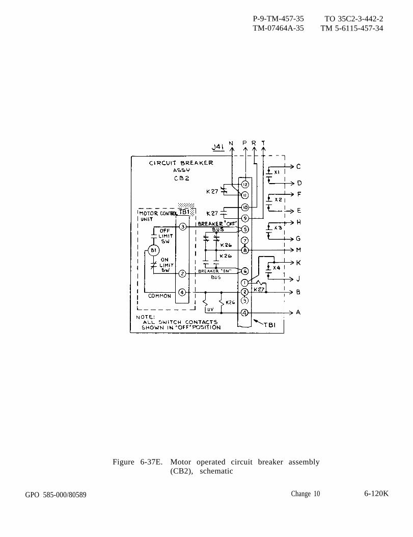
GPO 585-000/80589
P-9-TM-457-35 TO 35C2-3-442-2TM-07464A-35 TM 5-6115-457-34
Figure 6-37E. Motor operated circuit breaker assembly(CB2), schematic
Change 10 6-120K

assembly in the reversenumbers assigned. Paytion to the following:
sequence of indexparticular atten-
—WARNING
Keep hands clear of mechanismat all times.
a. Carefully install the auxiliary switchassembly (44) and undervoltage relay (43)into circuit breaker base (46). Be sureinsulative material surrounds both theauxiliary swtich assembly (44) and under-voltage relay (43 ) so as not to cause anyshorting.
NOTE
Insure that when circuit breakeris in the OPEN position, auxiliaryswitch actuator does not depressauxiliary buttons. Auxiliaryswitch buttons are depressedonly when the circuit breaker isin the ONE position.
b. Place handle shield (42) over handle(41) then install onto circuit breaker actua-tor assembly.
c. Apply a suitable grease to trip rodassembly (40) so as to retain it captive in thecircuit breaker cover (45) during assembly.
d. Install cover (45) onto circuit breakerbase (46).
e. Install motor control unit (28) on cir-cuit breaker (30) with cover open and circuitbreaker handle in the OFF position. Adjustthe motor control unit, sliding carriage, un-til it engages the circuit breaker handle.Adjustment is accomplished by turning slotat end of worm gear with a screw driver.Secure with washers (27), nuts (26) andscrews (25). Secure knurled locking knobon motor control.
P-9-TM-457-35 T. O. 35C2-3-442-2TM-07464A-35 TM 5-6115-457-34
f. Install terminal board (23) in relaybox cover (24) and secure with nut and washerassemblies (22) and screw and washer assem-blies (21).
g. Install connector (20) onto relay boxcover (24) and secure with nut and washerassemblies (19) and screw and washerassemblies (18).
h. Thread standoffs (13) onto relaysockets (14) and secure to relay box cover(24) using screw and washer assemblies (12)
i. Connect all tagged electrical leadsto existing terminals.
j . Install relays (11) into relay sockets(14; and secure with screw and washerassemblies (10).
k. Install relay box (9) onto bracket(29) and secure with screw and washerassemblies (8).
l. Secure clamp (7) to bracket (29)with nut and washer assembly (6) and screwand washer assembly (5).
m. Fasten bracket (4) to side ofbracket (29) with washers (3), lock washers(2) and screws (l).
6-1471. INSTALLATION. Refer to figure6-37A, and install circuit breaker assemblyin the reverse sequence of index numbersassigned. Pay particular attention to thefollowing:.
a. Place circuit breaker assembly (7)onto bracket (8) and install washers (7 and 6)lock washers (5 and 3) and screws (4 and 1).
b. Route three lower electrical leadsthrough clamp at base of generator and con-nect to load board terminals. Tighten clampSecure clamps (7B) using screws (7A).
c. Connect electrical connector J41and three top electrical leads to circuitbreaker assembly (7).
Change 3 6-120M/(6-120N blank)

6-148. LOAD BOARD ASSEMBLY.
6-149. REMOVAL AND DISASSEMBLY.Refer to figure 6-36 and remove and dis-assemble load board assembly as follows:
a . Remove protective cover (3) byloosening studs (l).
b. Disconnect lead (38) from bus bar(39). Tag and disconnect contactor cables(27) from load terminals (34) by removingnuts (32) and washers (33).
c. Disconnect load board assembly(21) by removing screws (28), lock washers(28), and washer (30).
d. Remove load terminals (34) andbus bar (39) from terminal board (40) byremoving nuts (32).
WARNING
Cleaning Solvents are flammable andmoderately toxic to skin, eyes andrespiratory tract. Eye and skinprotect ion required. Good generalventilation is normally adequate.
NOTE
Note position of terminalsprior to removal to insureproper installation.
6-150. CLEANING. Clean parts in anapproved cleaning solvent and drythoroughly.
6-151. INSPECTION .
a. Inspect threads for damage.
b. Inspect terminal board for cracks,warping, and burnt areas.
6-152. REASSEMBLY AND INSTALLA-TION.
P-8-627-34TM-07464A-35
Refer to figure
T O 35C2-3-442-2TM 5-6115-457-34
6-36 and reassembleand install load board assembly as follows:
a . Position load terminals (34) and busbar (39) on terminal board (40) and securewith nuts (32).
b. Position load board assembly (31)on bracket and secure with screws (28),lock washers (29), and washers (30).
c. Connect lead (38) to bus bar (39)and secure with screw (35), nuts (36), andwashers (37). Connect contactor cables(27) to load terminals (34) and secure withnuts (32) and washers (33).
d. Install protective cover (3) andsecure by tightening studs (1).
6-153. TRANSFORMER ASSEMBLY.
6-154. REMOVAL. Refer to figure 6-38and remove transformer assembly asfollows:
a. Remove shield cover (4) byremoving screws (l), lock washers (2)and washers (3).
b. Tag and disconnect electricalwiring from transformers and terminalboard.
c. Cut tiedown straps connectinggenerator leads together. Tag and dis-connect six generator leads that passthrough transformer from reconnection boardstuds. Remove leads from transformer.
d. Disconnect transformer assembly(9) from generator by removing spacers (2),screws (7), and lock washers (6 and 8).
Change 8 6-121
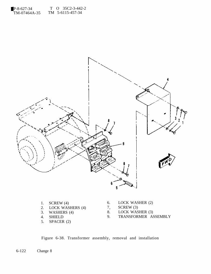
P-8-627-34 T O 35C2-3-442-2TM-07464A-35 TM 5-6115-457-34
1. SCREW (4)2. LOCK WASHERS (4)3. WASHERS (4)4. SHIELD5. SPACER (2)
6. LOCK WASHER (2)70 SCREW (3)8. LOCK WASHER (3)9. TRANSFORMER ASSEMBLY
Figure 6-38. Transformer assembly, removal and installation
6-122 Change 8
6-155. DISASSEMBLY. Refer to figure6-39 and disassemble transformer assem-bly in the order of index numbers assigned.Pay particular attention to the following.
a. Tag and disconnect transformerleads prior to transformer removal.
6-156. CLEANING.
a. Clean transformers with a cleanlint-free cloth moistened in an approvedcleaning solvent and dry thoroughly.
WARNING
Cleaning Solvents are flammable andmoderately toxic to skin, eyes andrespiratory tract. Eye and skinprotection required. Good generalventilation is normally adequate.
b. Clean remaining parts in an approvedcleaning solvent and dry thoroughly,
6-157. INSPECTION.
a. Inspect transformer leads for defec-tive insulation. Inspect terminal lugs forcondition and security.
b. Inspect terminal block for crackedinsulation, stripped threads and missingjumper strips.
c. Inspect sheet metal parts for dis-tortion and cracks.Legend to figure 6-39:
1.2.3.4.5.6.7.8.9.
Jumper (2)Screw (2)Terminal block TB2Screw assembly (4)Washer (4)Exciter transformer (CT4)Screw (4)Washer (4)Cross current transformerassembly
10. Nut (2)
P-8-627-34TM-07464A-35
d. Inspect threads
T. O. 35C2-3-442-2TM 5-6115-457-34
for damage.
e. Test transformers for properoperation; refer to figure 6-40.
f. Inspect paint for damage.
6-158. REPAIR.
WARNING
Welding operations produce heat,highly toxic fumes, injuriousradiation, metal slag and air-borne particles. Welding gog-gles, with proper tinted lenses,apron or jacket and welder'sboots are required.
a. Repair cracked sheet metal partsby welding. Straightened distorted partsusing
b.
c.edge,
suitable tools.
Chase damaged threads in bracket.
Remove damaged paint. Blend inprime, and paint damaged areas.
6-159. REASSEMBLY.
Refer to figure 6-39 and reassem-ble current transformer assembly in thereverse order of index numbers assigned,Connect transformer leads.6-160. INSTALLATION. Refer to figure6-38 and install transformer assembly asfollows.
11.12.13.14.15.16.17.18.19.
20.
Screw (2)Current transformer CT7BracketScrew (8)Washer (8)Exciter transformer (CT5, CT6)Screw (12)Washer (12)Instrument transformer (CT1,CT2, CT3)Bracket
Change 8 6-123
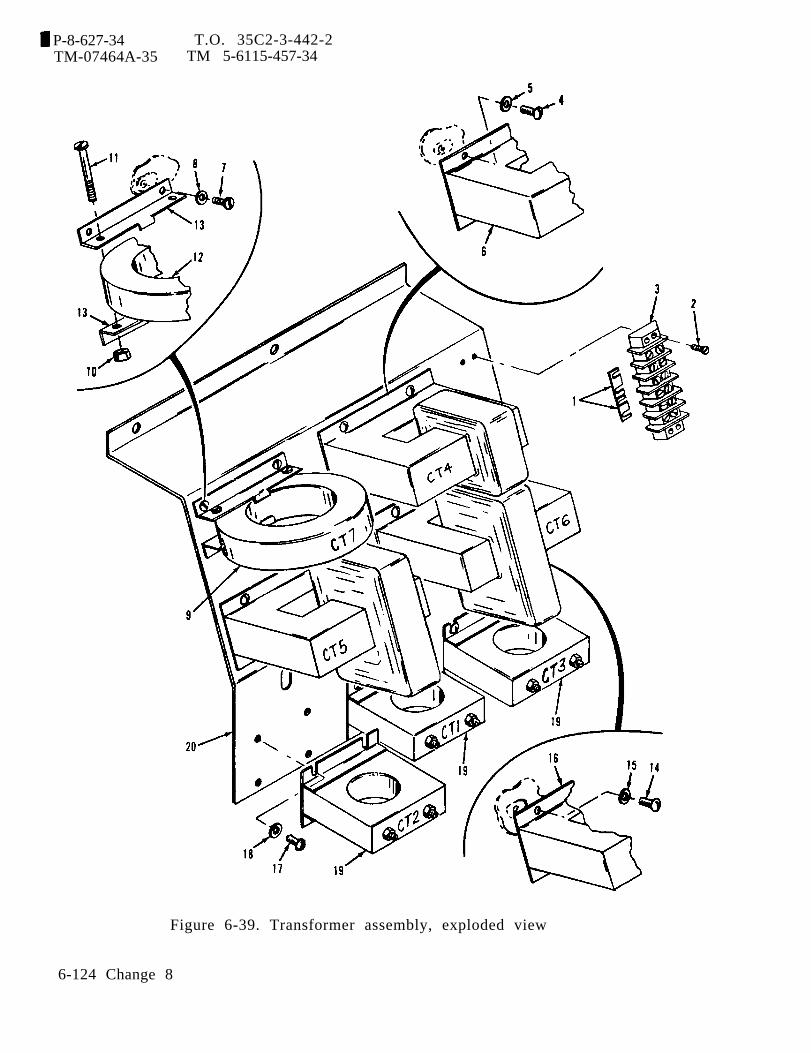
P-8-627-34 T.O. 35C2-3-442-2TM-07464A-35 TM 5-6115-457-34
Figure 6-39. Transformer assembly, exploded view
6-124 Change 8

P-9-TM-457-35 T.O. 35C2-3-442-2TM-07464A-35 TM 5-6115-457-34
Figure 6-40. Transformer inspection
a. Connect transformer assembly (9) togenerator and secure with spacers (2),screws (7), and lock washers (6 and 8).
b. Refer to Operator and OrganizationalMaintenance Manual and route six gene raterleads through transformers. Leads pass-ing through transformers CT4, CT5, andCT6 make two turns around transformers.
c. Connect generator leads to recon-nection board studs. Secure leads togetherwith tie straps.
NOTE
Interconnecting wiring diagram iscontained in Operator and Organi-zational Maintenance Manual.
d. Connect electrical wiring to trans-formers and terminal board.
e. Position shield over transformerassembly and secure with screws (1),lock washers (2) and washers (3).
Change 3 6-125
P-9-TM-457-35 T.O. 35C2-3-442-2TM-07464A-35 TM 5-6115-457-34
Section IX. TACTICAL RELAY BOX
6-161. GENERAL.
The tactical relay box (A29) is usedon both 50/60 and 400 hertz generator sets.It contains the over voltage relay, reversepower relay, short circuit relay, overloadrelay, and the three current transformerload resistors. Refer to schematicdiagram figure 1-18.
a. The over voltage relay (K2) is a solidstate device which functions to protect theload in the event that generator voltage ex-ceeds preset limits. It actuates after a timedelay from 180 to 800 milliseconds when gen-erator voltage rises above 156 VAC (both50/60 and 400 hertz sets). Upon actuation,contacts within the over voltage relay, closeto signal the fault locator and open to shut-down the generator set.
b. The reverse power relay (K15) is asolid state device which functions to protectthe generator in the event of a reverse poweroperating state during parallel operation. Itoperates in conjunction with the load measure-ment unit which produces a dc output voltagewhose polarity and magnitude is a function ofthe total load on the generator set, regard-less of phase or power factor. When the re-verse power flow into the generator exceedstwenty percent of rated load; the load meas-urement unit output has sufficient magnitudeand correct polarity to cause the reversepower relay to actuate. For 50/60 hertz setsthis reverse power rating pertains to the 60hertz rating. Upon actuation, contacts withthe reverse power relay; close to signal thefault locator and open to de-energize the loadcontactor, result in display of the fault con-dition and removal of the load from thegenerator.
c. The short circuit relay (K13) is asolid state device which functions to protectthe load in the event generator output currentin any phase exceeds 425 ± 25 percent ofrated current for 50/60 hertz sets and 180 ±
6-126 Change 3
percent for 400 hertz sets. For 50/60 hertzsets this current rating pertains to the 60hertz rating. When the above fault occurs,the short circuit relay will actuate. Uponactuation, contacts within the short circuitrelay; close to signal the fault locator andopen to de-energize the load contactor, re-sulting in display of the fault condition andremoval of the load from the generator.
d. The overload relay (K14) is a solidstate device whose function is to protect theload in the event of an overload condition.An overload condition is defined as the statewhen generator output current in any phaseexceeds 110 percent of rated value. Theoverload relay is a current sensing deviceand operates on an inverse time principle asthe current in any phase exceeds the over-load state. At the point just above 130 per-cent of rated current the overload relay willactuate within 8 ± 2 minutes. For 50/60hertz sets this current rating pertains to the60 hertz rating. Upon actuation, contactswithin the overload relay; close to signal thefault locator and open to de-energize the loadcontactor, resulting in display of the faultcondition and removal of the load from thegenerator.
6-162. OVER VOLTAGE RELAY (K2).
6-163. ON EQUIPMENT TEST.
a. Symptom and Isolation of Malfunction.A malfunction of the overvoltage relay K2 isusually indicated by failure of the generatorfault monitoring system to detect and reactto a voltage rise beyond preset limits. Toisolate the malfunction, proceed as follows:
WARNING
Exercise extreme care not to touchexposed electrical connections whenworking inside tactical relay boxwith generator set operating.

NOTE
Remove cover from tactical relaybox to gain access to test points,see figures 6-15 and 6-47.
1. With the generator set opera-ting at the rated speed and voltage, andwith the contactor closed, measure thevoltage from terminal 1 to terminal 2 ofthe K2 relay. Nominal voltage is 120 VAC.Voltage from TB2-5 to K2 terminals 3 and6 should measure 20-32 VDC. Shutdowngenerator set.
2. Install a 250 ohm, 25 watt resis-tor in series with voltage adjustment rheostatR2 between wire number X9F10 and TB1-7located in the control cubicle. With the gen-erator set operating at the rated speed andvoltage, increase output voltage such thatthe voltage across terminals 1 and 2 of K2relay measures 153 ± 3 volts. When the K2relay actuates there should be a momentarydc voltage measured from terminal 7 of K2to TB2-5 and there should be no dc voltagemeasured from terminal 3 of K2 to TB2-5.If the above conditions are not met, replacethe K2 relay.
b. Removal. Refer to figure 6-47 andtag, then disconnect wiring at the over-voltage relay terminals. Remove the fourscrew assemblies securing the relay inposition.
P-9-TM-457-35 T. O. 35C2-3-442-2TM-07464A-35 TM 5-6115-457-34
6-164. BENCH TEST.
a. Connect the overvoltage relay to thetest equipment as illustrated in figure 6-42.
WARNING
Exercise extreme care when makingtests as high voltages present willcause injury to personnel upon contact.
b. With all switches open, energize the60 hertz variable voltage supply and adjustvoltage to 120 VAC. Close switch S2 thenS3. Indicator DS1 should be energized andDS2 should be de-energized.
c. Adjust 60 hertz variable voltagesupply to 157 VAC. Indicator DS1 shouldde-energize and DS2 should energize.
d. Open switches S2 and S3 and energizethe 400 hertz variable voltage supply. Ad-just the voltage to 120 VAC. Close switchS1 then S3. Indicator DS1 should beenergized and DS2 de-energized.
e. Adjust 400 hertz variable voltagesupply to 151 VAC. Indicator DS1 shouldde-energize and DS2 should energize.
f. If the overvoltage relay does not meetthe requirements of the above tests, replacethe relay.
g. Remove the overvoltage relay fromthe test equipment.
Change 3 6-127

P-9-TM-457-35 T.O. 35C2-3-442-2TM-07464A-35 TM 5-6115-457-34
NOTES:1. REMOVE THE FOUR SCREWS AND WASHERS
SECURING THE COVER TO THE CHASSIS TOGAIN ACCESS TO THE TEST POINTS.
2. TACTICAL RELAY BOX MUST BE REMOVEDFROM GENERATOR SET TO ACCOMODATEREPLACEMENT OF RELAYS. TO REMOVE THEBOX ASSEMBLY, TAG AND DISCONNECT THETWO ELECTRICAL PLUG CONNECTORS AT J4AND J51, THEN REMOVE TWO SCREW’S ANDWASHERS SECURING THE BOX IN POSITION.
3. REPLACE ASSEMBLY BY REVERSING ABOVEPROCEDURES.
Figure 6-41. Tactical relay box (A29), cover removed
6-128 Change 3

P-9-TM-457-35 T.O. 35C2-3-442-2TM-07464A-35 TM 5-6115-457-34
6-165. INSTALLATION. Refer to figure6-41 and install the over voltage relayin position using four screw assemblies.Refer to figure 1-19 and reconnect wiring.Replace the tactical relay box and cover.
6-166. REVERSE POWER RELAY (K15).
6-167. ON EQUIPMENT TEST.
a. Symptom and Isolation of Malfunc-tion. A malfunction of the reverse powerrelay K15 is usually indicated by failureof the generator fault monitoring systemto detect and react to a reverse power con-dition when operating two or more generatorsets in parallel. To isolate the malfunc-tion, proceed as follows.
WARNING
Exercise extreme care not to touchexposed electrical connections whenworking inside tactical relay box withgenerator set operating.
NOTE
Remove cover from tactical relaybox to gain access to test points,see figures 6-15, 6-41, 6-43 andparagraph 6-87.
1. Operate the generator set inparallel with another like unit.
2. Adjust voltage and frequency torated value and mea sure the voltage acrossterminals 3 and 4 of relay K15. In addi-tion, measure the voltage from TB2-5 toK 15 relay terminals 5 and 8. Voltageshould be 20-32 VDC at all points.
3. Slowly reduce the generatorset (unit under test) speed while monitor-ing the voltage across terminals 1 and 2of relay K 15 (approximately 9.8 VDC,terminal 2 positive, at 100 percent load).When the voltage is zero, reverse the
Figure 6-42. Over voltage relay (K2), test setup
Change 3 6-129
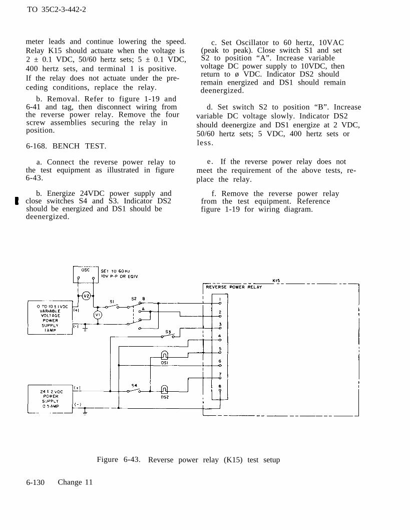
TO 35C2-3-442-2
meter leads and continue lowering the speed.Relay K15 should actuate when the voltage is2 ± 0.1 VDC, 50/60 hertz sets; 5 ± 0.1 VDC,400 hertz sets, and terminal 1 is positive.If the relay does not actuate under the pre-ceding conditions, replace the relay.
b. Removal. Refer to figure 1-19 and6-41 and tag, then disconnect wiring fromthe reverse power relay. Remove the fourscrew assemblies securing the relay inposition.
6-168. BENCH TEST.
a. Connect the reverse power relay tothe test equipment as illustrated in figure6-43.
b. Energize 24VDC power supply andclose switches S4 and S3. Indicator DS2should be energized and DS1 should bedeenergized.
c. Set Oscillator to 60 hertz, 10VAC(peak to peak). Close switch S1 and setS2 to position “A”. Increase variablevoltage DC power supply to 10VDC, thenreturn to ø VDC. Indicator DS2 shouldremain energized and DS1 should remaindeenergized.
d. Set switch S2 to position “B”. Increasevariable DC voltage slowly. Indicator DS2should deenergize and DS1 energize at 2 VDC,50/60 hertz sets; 5 VDC, 400 hertz sets orless.
e. If the reverse power relay does notmeet the requirement of the above tests, re-place the relay.
f. Remove the reverse power relayfrom the test equipment. Referencefigure 1-19 for wiring diagram.
Figure 6-43. Reverse power relay (K15) test setup
6-130 Change 11
P-9-TM-457-35 T.O. 35C2-3-442-2
6-169. INSTALLATION. Refer to figure6-41 and install the reverse power relayin position using four screw assemblies.Refer to figure 1-19 and reconnect wiring.Replace the tactical relay box and cover.
6-170. SHORT CIRCUIT RELAY (K13).
6-171. ON EQUIPMENT TEST.
a. Symptom and Isolation of Malfunc-tion. A malfunction of the short circuitrelay K13 is usually indicated by failureof the generator fault monitoring systemto detect and react to a rise in generatorcurrent output (in any phase) beyond presetlimits. To isolate the malfunction, pro-ceed as follows.
WARNING
Exercise extreme care not totouch exposed electrical connec-tions when working inside tacticalrelay box with generator setoperating.
TM-0746A-35 TM 5-6115-457-34
NOTE
Remove cover from tactical relaybox to gain access to test points,see figures 6-15 and 6-41.
1. With the generator set at ratedspeed and voltage, and with the contactorclosed, measure the voltage from terminals8 and 5 (+) of the K13 relay to TB 2-5 (-).Voltage should read 20-32 VDC.
2. Apply 100 percent of rated loadand measure the voltage from terminals1-4, 2-4 and 3-4 of short circuit relay K13.Voltage should read 5.6 ± 0.5 VAC. If thepreceding conditions are met and the shortcircuit relay K13 does not actuate with ap-plication of a short circuit, replace the K13relay.
b. Removal. Refer to figure 6-41 andtag, then disconnect wiring at the shortcircuit relay terminals, Remove the fourscrew assemblies securing the relay inposition.
Change 3 6-131
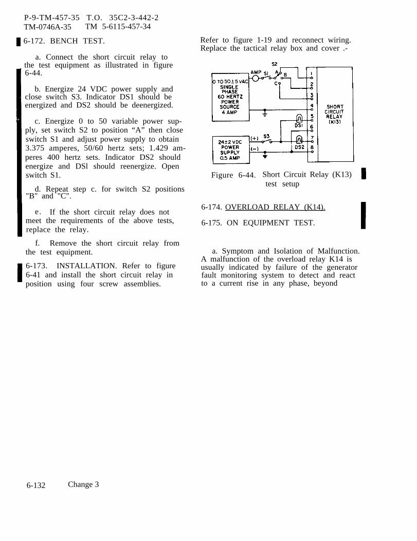
P-9-TM-457-35 T.O. 35C2-3-442-2TM-0746A-35 TM 5-6115-457-34
6-172. BENCH TEST.
a. Connect the short circuit relay tothe test equipment as illustrated in figure6-44.
b. Energize 24 VDC power supply andclose switch S3. Indicator DS1 should beenergized and DS2 should be deenergized.
c. Energize 0 to 50 variable power sup-ply, set switch S2 to position “A” then closeswitch S1 and adjust power supply to obtain3.375 amperes, 50/60 hertz sets; 1.429 am-peres 400 hertz sets. Indicator DS2 shouldenergize and DSl should reenergize. Openswitch S1.
d. Repeat step c. for switch S2 positions"B" and "C".
e. If the short circuit relay does notmeet the requirements of the above tests,replace the relay.
f. Remove the short circuit relay fromthe test equipment.
6-173. INSTALLATION. Refer to figure6-41 and install the short circuit relay inposition using four screw assemblies.
Refer to figure 1-19 and reconnect wiring.Replace the tactical relay box and cover .-
Figure 6-44. Short Circuit Relay (K13)test setup
6-174. OVERLOAD RELAY (K14).
6-175. ON EQUIPMENT TEST.
a. Symptom and Isolation of Malfunction.A malfunction of the overload relay K14 isusually indicated by failure of the generatorfault monitoring system to detect and reactto a current rise in any phase, beyond
6-132 Change 3

preset limits. To isolate the malfunction,proceed as follows.
WARNING
Exercise extreme care not totouch exposed electrical connec-tions when working inside tacticalrelay box with generator setoperating.
NOTE
Remove cover from tactical relaybox to gain access to test points,see figures 6-15 and 6-41.
1. With the generator set operatingat rated speed and voltage, and with thecontactor closed, the voltage measuredacross the plus (+) and minus (-) terminalsof the overload relay K14 should read20-32 VDC. The voltage from the NO ter-minal (wire P200X16) to TB2-5 and fromthe NC terminal (wire P62K16) to TB2-5should read 20-32 VDC.
2. Apply 130 percent load to thegenerator set. The relay should activatein 8 ± 2 minutes. Determine that the unitcurrent meter indicates 130% of current onall phases. No current reading would indi-cate an open current circuit. When therelay actuates a momentary dc voltageshould be measured from the NO terminal‘(wire P209D16) to TB2-5 and there shouldbe no dc voltage measured from the NCterminal (wire P62K16) to TB2-5. If theabove conditions are not met, the K14 relayshould be replaced.
NOTE
The K14 relay should not actuatewith less than 110% load, if it doesthe relay should be replaced.
P-9-TM-457-35 T.O. 35C2-3-442-2TM-07464A-35 TM 5-6115-457-34
b. Removal. Refer to figure 6-41 andtag, then disconnect wiring at the overloadrelay terminals. Remove the four screwassemblies securing the relay in position.
6-176. BENCH TEST.
a. Connect the overload relay to testequipment as illustrated in figure 6-45.
b. With the 120/208 VAC power sourcedeenergized, turn on the 24 vdc powersupply and close switch S1. Indicator DSlshould energize and indicator DS2 shouldbe deenergized.
c. Energize the 120/208 VAC powersource and adjust autotransformers untilammeters Al, A2, and A3 indicate 0. 75amperes. Indicators DSl and DS2 shouldnot change states.
d. Adjust autotransformer T 1 untilammeter A 1 indicates 0.975 amperes.After 8 ± 2 minutes indicator DS1should deenergize and indicator DS2 shouldenergize.
e. Repeat step d for autotransformerT2 and T3. The test results should be thesame as the results for adjustment of auto-transformer T1.
f. If the overload relay does not meetthe requirements of the above test, replacethe overload relay.
6-177. INSTALLATION. Refer to figure6-41 and install the overload relay inposition using four screw assemblies. Re-fer to figure 1-19 and reconnect wiring.Replace the tactical relay box and cover.
Change 3 6-133
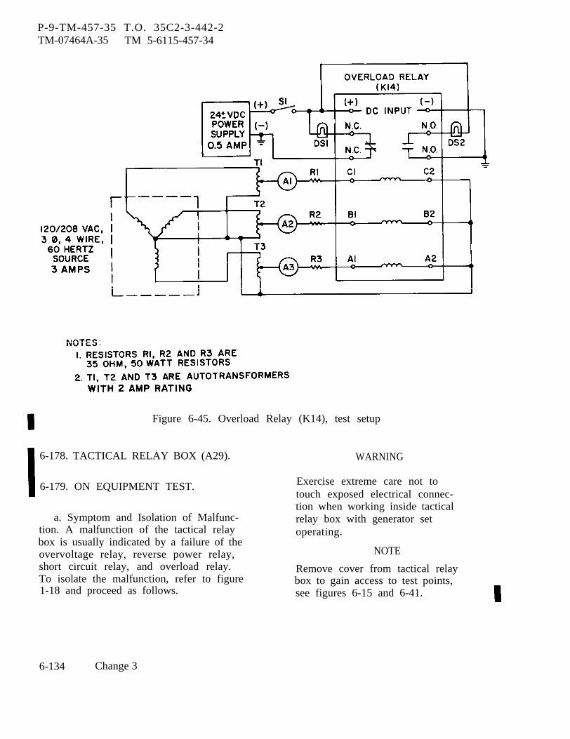
P-9-TM-457-35 T.O. 35C2-3-442-2TM-07464A-35 TM 5-6115-457-34
Figure 6-45. Overload Relay (K14), test setup
6-178. TACTICAL RELAY BOX (A29).
6-179. ON EQUIPMENT TEST.
a. Symptom and Isolation of Malfunc-tion. A malfunction of the tactical relaybox is usually indicated by a failure of theovervoltage relay, reverse power relay,short circuit relay, and overload relay.To isolate the malfunction, refer to figure1-18 and proceed as follows.
WARNING
Exercise extreme care not totouch exposed electrical connec-tion when working inside tacticalrelay box with generator setoperating.
NOTE
Remove cover from tactical relaybox to gain access to test points,see figures 6-15 and 6-41.
6-134 Change 3
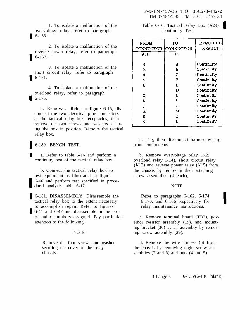
P-9-TM-457-35 T.O. 35C2-3-442-2TM-07464A-35 TM 5-6115-457-34
1. To isolate a malfunction of theovervoltage relay, refer to paragraph6-163.
2. To isolate a malfunction of thereverse power relay, refer to paragraph6-167.
3. To isolate a malfunction of theshort circuit relay, refer to paragraph6-171.
4. To isolate a malfunction of theoverload relay, refer to paragraph6-175.
b. Removal. Refer to figure 6-15, dis-connect the two electrical plug connectorsat the tactical relay box receptacles, thenremove the two screws and washers secur-ing the box in position. Remove the tacticalrelay box.
6-180. BENCH TEST.
a. Refer to table 6-16 and perform acontinuity test of the tactical relay box.
b. Connect the tactical relay box totest equipment as illustrated in figure6-46 and perform test specified in proce-dural analysis table 6-17.
6-181. DISASSEMBLY. Disassemble thetactical relay box to the extent necessaryto accomplish repair. Refer to figures6-41 and 6-47 and disassemble in the orderof index numbers assigned. Pay particularattention to the following.
NOTE
Remove the four screws and washerssecuring the cover to the relaychassis.
Table 6-16. Tactical Relay Box (A29)Continuity Test
a. Tag, then disconnect harness wiringfrom components.
b. Remove overvoltage relay (K2),overload relay K14), short circuit relay(K13) and reverse power relay (K15) fromthe chassis by removing their attachingscrew assemblies (4 each),
NOTE
Refer to paragraphs 6-162, 6-174,6-170, and 6-166 respectively forrelay maintenance instructions.
c. Remove terminal board (TB2), gov-ernor resistor assembly (19), and mount-ing bracket (30) as an assembly by remov-ing screw assembly (29).
d. Remove the wire harness (6) fromthe chassis by removing eight screw as-semblies (2 and 3) and nuts (4 and 5).
Change 3 6-135/(6-136 blank)

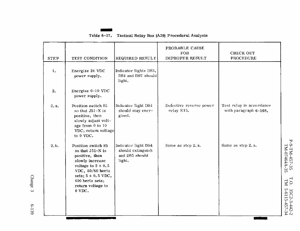
Table 6-17.
P-9-T
M-457-35
T.O
. 35C
2-3-442-2T
M-07464A
-35T
M 5-6115-457-34
Change 3
6-139
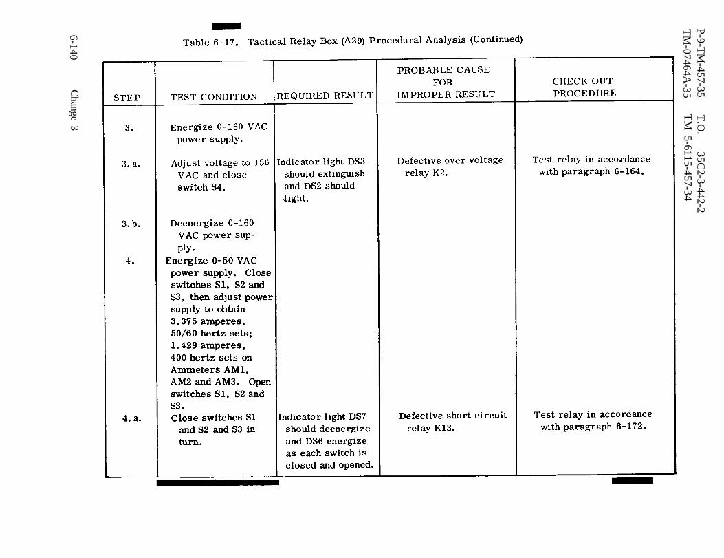
Table 6-17.
P-9-T
M-457-35
T.O
. 35C
2-3-442-2T
M 5-6115-457-34
TM
-07464A-35
6-140C
hange 3
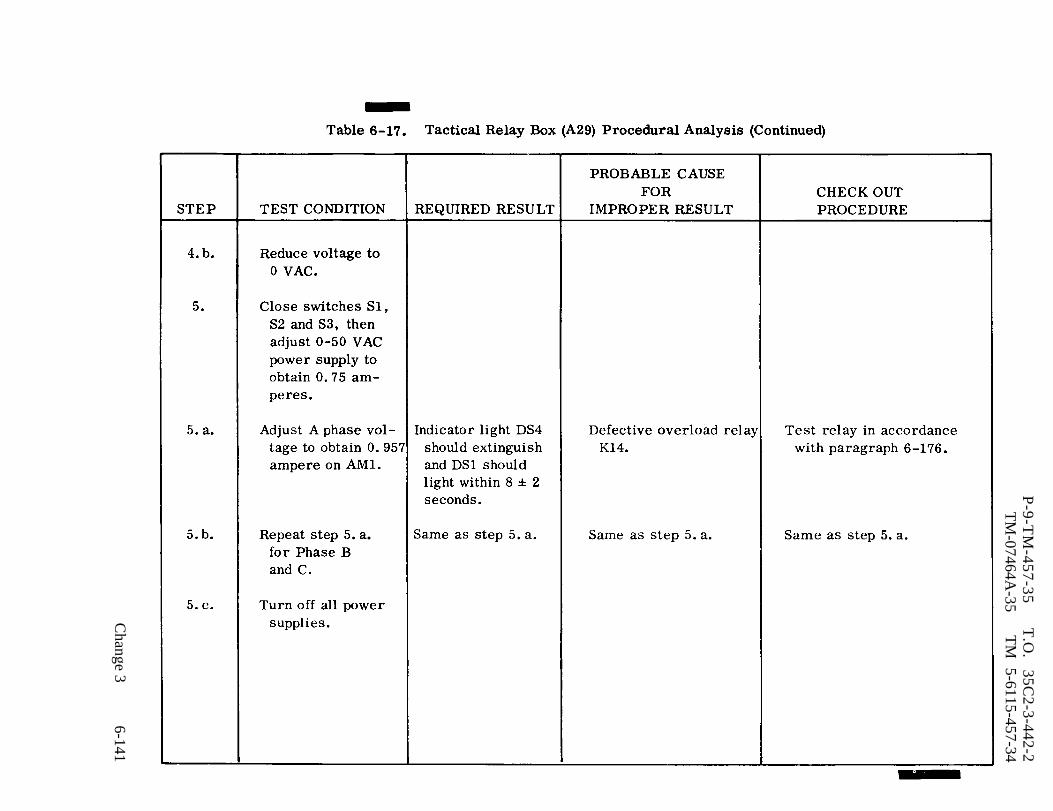
Table 6-17.
P-9-T
M-457-35
T.O
. 35C
2-3-442-2T
M-07464A
-35T
M
5-6115-457-34
Change 3
6-141
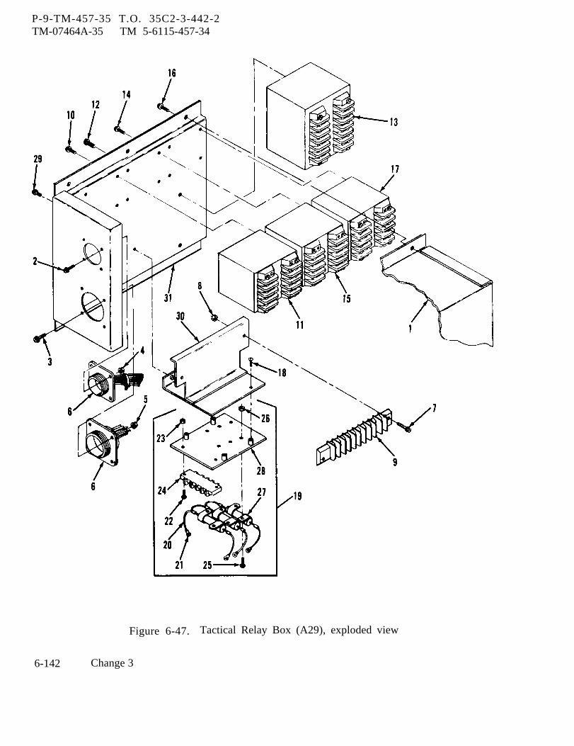
P-9-TM-457-35 T.O. 35C2-3-442-2TM-07464A-35 TM 5-6115-457-34
Figure 6-47. Tactical Relay Box (A29), exploded view
6-142 Change 3
P-9-TM-457-35 T.O. 35C2-3-442-2TM-07464A-35 TM 5-6115-457-34
Legend to figure 6-47:
1.2.3.4.5.6.7.8.9.
10.11.12.13.14.15.16.
CoverScrew assembly (4)Screw assembly (4)Nut (4)Nut (4)Harness assemblyScrew assembly (2)Nut assembly (2)Terminal boardScrew assembly (4)Over voltage relay (K2)Screw assembly (2)Overload relay (K14)Screw assembly (4)Short circuit relay (K13)Screw assembly (4)
6-182. CLEANING. Clean all componentswith a lint-free cloth moistened in an ap-proved cleaning solvent and dry thoroughly.
6-183. INSPECTION AND TEST.
a. Harness.
1. Inspect harness wiring for de-fective insulation and continuity.
2. Inspect harness connectors fordamaged threads; bent, loose or missingpins and for shorts.
b. Inspect resistors R23, R24 and R25for rated resistance; 7.5 ± 1 percent,10 watts.
c. Inspect terminal board (TB2 forcracks and missing hardware.
6-184. REPAIR.
a. Repair or fabricate tactical relaybox wire harness in accordance with figure6-48.
b. Straighten dented or distorted sheetmetal parts using proper tools. Blend inrepaired area with a suitable abrasive
17.18.19.20.21.22.23.24.25.26.27.28.29.30.31.
Reverse power relay (K15)Screw assembly (2)Governor resistor assemblyWireTerminal lug (4)Screw (2)Nut assembly (2)Terminal board TB2Screw (6)Nut (6)Resistor (R1, R2, R3)MountScrew assembly (6)BracketChassis assembly
paper and touch up painted surfaces. Re-stencil panel markings as necessary.
6-185. REASSEMBLY. Refer to figures6-41 and 6-47 and reassemble the tacticalrelay box in reverse order of index num-bers assigned. Pay particular attentionto the following.
a. Install wire harness (6) in chassisassembly (31) and secure in position witheight screw assemblies (2 and 3) and nuts(4 and 5).
b. Assemble governor resistor assem-bly (19) and terminal board (9) to bracket(30), then install the assembly in chassisassembly (31).
c. Install overvoltage relay (11),overload relay (13), short circuit relay (15),and reverse power relay (17) in positionusing four each screw assemblies.
d. Refer to figures 6-48 and 1-19 andconnect wire harness leads to componentry.
Change 3 6-143
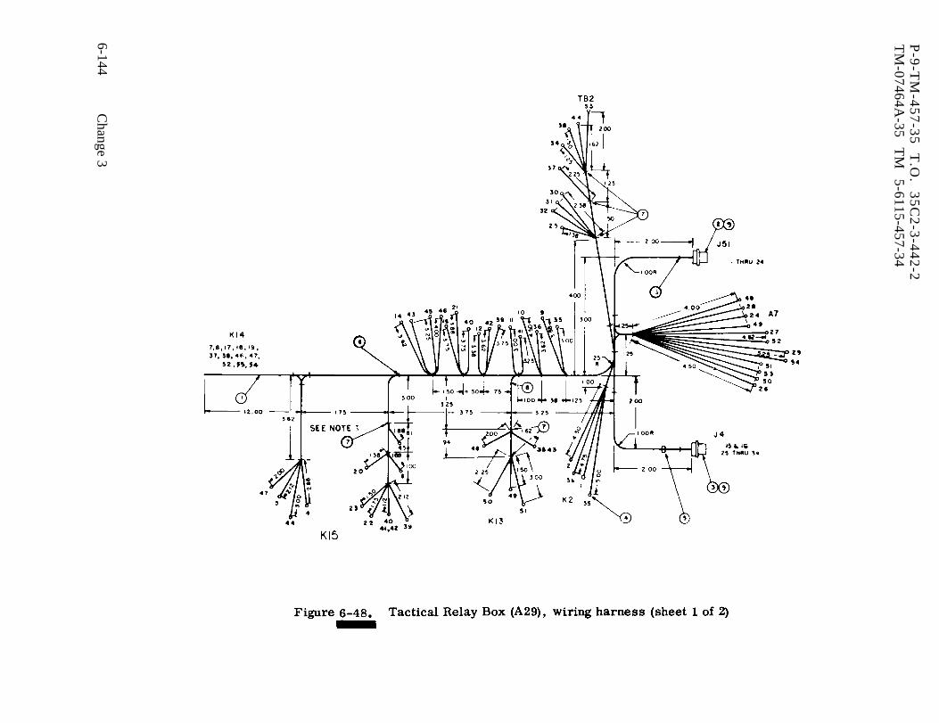
Table 6-48.
P-9
-TM
-45
7-3
5
T.O
. 3
5C
2-3
-44
2-2
TM
-07464A-35
TM
5-6115-457-34
6-144C
hange 3
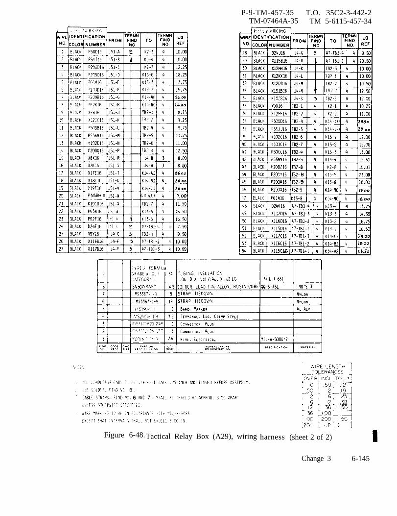
P-9-TM-457-35 T.O. 35C2-3-442-2TM-07464A-35 TM 5-6115-457-34
Figure 6-48.Tactical Relay Box (A29), wiring harness (sheet 2 of 2)
Change 3 6-145

P-9-TM-457-35 T.O. 35C2-3-442-2TM-07464A-35 TM 5-6115-457-34
e. Test tactical relay box as outlined 6-186. INSTALLATION. Refer to figurein paragraph 6-180. 6-15 and install the tactical relay box
in position using two screws and washers.f. Secure cover (1) to chassis assem- Reconnect electrical plug connector to
bly (31) using four screw assemblies (16). receptacles J4 and J51.
Section X. PRECISE RELAY BOX
6-187. GENERAL.
The precise relay box (A25) is-usedonly for precise, 50/60 hertz generatorsets . It contains the under frequency relay,under voltage relay, permissive parallel-ing relay, frequency mode selector switch,governor paralleling control or load shar-ing rheostat, governor feedback capacitor,and the frequency adjust device fixed re-s is tors . (Refer to schematic diagram,figure 1-20.
a. The 50/60 hertz under frequencyrelay (K12) is a solid state device whichfunctions to protect the load in the eventgenerator frequency decreases below pre-set limits. It actuates when frequency de-creases to 55 ± 1 hertz for 60 hertz opera-tion and 46 ± 1 hertz for 50 hertz opera-
tion. Upon actuation, contacts within theunderfrequency relay, close to signal thefault locator and open to deenergize theload contactor, resulting in display of thefault condition and removal of the load fromthe generator.
b. The under voltage relay (K11) is asolid state device which functions to protectthe load in the event generator voltage de-creases below preset limits. This relayis identical to the K11 relay used in themode II relay box assembly. Refer toparagraph 6-104, step c. for a descriptionof relay circuitry.
c. The permissive paralleling relay isutilized only on precise generator sets, Itsfunction is to ensure that a generator set
6-146 Change 3

P-9-TM-457-35 T.O. 35C2-3-442-2TM-07464A-35 TM 5-6115-457-34
cannot be paralleled with other generatorsets until synchronization is accomplished.This relay is identical to the K16 relay usedin the mode II relay box assembly. Referto paragraph 6-104, step d. for a descrip-tion of relay circuitry.
d. The electronic components assembly(A6) consists of C1, R4, and R5. Theassembly connects to the governor controlunit and acts as a feedback circuit to pro-vide the governor with greater frequencystabilization. This assembly is identicalto the A6 assembly used in the mode II relaybox assembly.
e. The governor paralleling control isa rheostat (R28) which permits initialmatching of the governor paralleling cir-cuits for sets operating in parallel. Itsfunction is to ensure proper real load shar-ing. It has a slotted shaft with lockingdevice which when rotated counterclockwisewill cause an increase in signal appearingat paralleling receptacles, causing the gen-erator to assume a greater share of theload. This rheostat is identical to the R28rheostat used in the mode II relay box as-sembly.
6-1880 50/60 HERTZ UNDER FREQUENCYRELAY (K12).
6-189. ON EQUIPMENT TEST.
a. Symptom and Isolation of Malfunc-tion. A malfunction of the underfrequencyrelay K12 is usually indicated by the illu-mination of the UNDER FREQUENCY faultlight or by failure of the load contactor toclose with the generator output frequencynormal. To isolate the malfunction, pro-ceed as follows:
WARNING
Exercise extreme care not totouch exposed electrical connec-tions when working inside preciserelay box with generator setoperating.
NOTE
Remove cover from precise relaybox to gain access to test points,see figures 6-15 and 6-49.
1. With the generator set at ratedspeed and voltage, measure the voltagefrom terminal 1 to terminal 2 of the K12relay. Nominal voltage is 120 VAC.
2. If the voltage at terminal 1 and 2is normal and fault light is still illuminated,remove the wire from terminal 6 of K12relay and reset fault 1 amp. If fault lampcan be reset, relay K12 is defective.
3. If the voltage at terminals 1 and2 is normal and the contactor CB2 will notclose, measure the voltage from terminal3 of K12 to TB3-1. Voltage should read20-32 VDC, with the contactor switch S3in the closed position. Measure the volt-age from terminal 4 of K12 to TB3-1.Voltage should read 20-32 vdc with thecontactor switch S3 in the closed position.If no voltage, is present, replace relay K12.
4. Reduce frequent y below 54 Hz(45 Hz for 50 Hz sets); relay should trip.If not, replace relay.
b. Removal. Refer to figure 6-49 andtag, then disconnect wiring to the under-frequency relay. Remove the four screwassemblies securing the relay in posi-tion.
Change 3 6-147
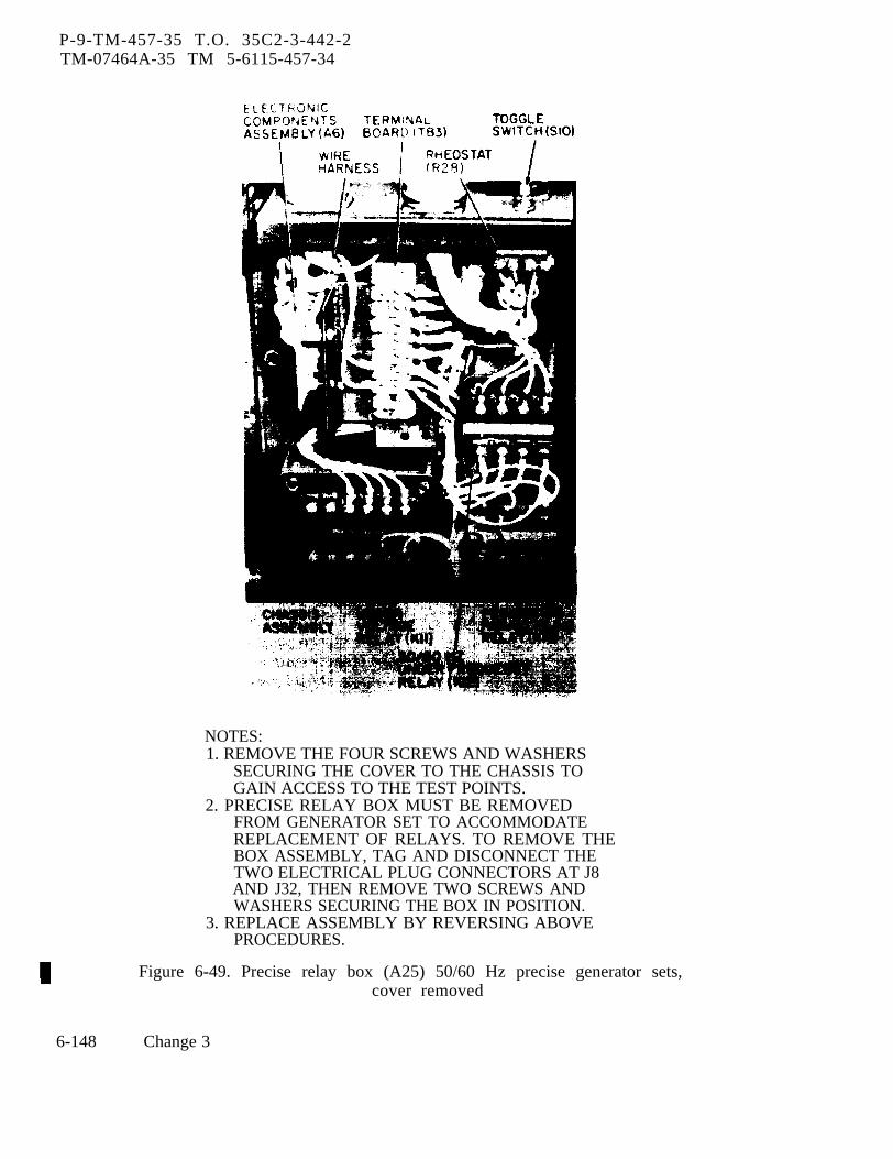
P-9-TM-457-35 T.O. 35C2-3-442-2TM-07464A-35 TM 5-6115-457-34
NOTES:1. REMOVE THE FOUR SCREWS AND WASHERS
SECURING THE COVER TO THE CHASSIS TOGAIN ACCESS TO THE TEST POINTS.
2. PRECISE RELAY BOX MUST BE REMOVEDFROM GENERATOR SET TO ACCOMMODATEREPLACEMENT OF RELAYS. TO REMOVE THEBOX ASSEMBLY, TAG AND DISCONNECT THETWO ELECTRICAL PLUG CONNECTORS AT J8AND J32, THEN REMOVE TWO SCREWS ANDWASHERS SECURING THE BOX IN POSITION.
3. REPLACE ASSEMBLY BY REVERSING ABOVEPROCEDURES.
Figure 6-49. Precise relay box (A25) 50/60 Hz precise generator sets,cover removed
6-148 Change 3
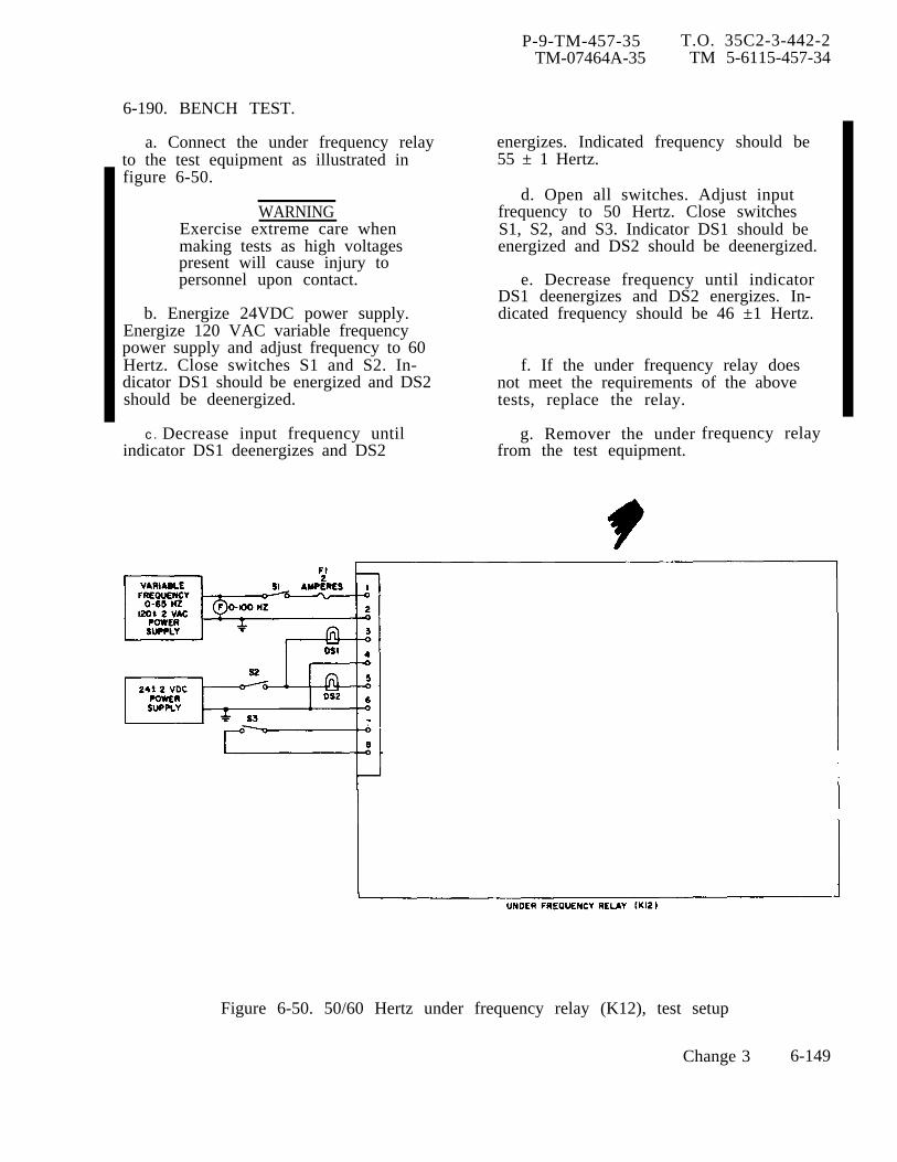
P-9-TM-457-35 T.O. 35C2-3-442-2TM-07464A-35 TM 5-6115-457-34
6-190. BENCH TEST.
a. Connect the under frequency relayto the test equipment as illustrated infigure 6-50.
WARNINGExercise extreme care whenmaking tests as high voltagespresent will cause injury topersonnel upon contact.
b. Energize 24VDC power supply.Energize 120 VAC variable frequencypower supply and adjust frequency to 60Hertz. Close switches S1 and S2. In-dicator DS1 should be energized and DS2should be deenergized.
c. Decrease input frequency untilindicator DS1 deenergizes and DS2
energizes. Indicated frequency should be55 ± 1 Hertz.
d. Open all switches. Adjust inputfrequency to 50 Hertz. Close switchesS1, S2, and S3. Indicator DS1 should beenergized and DS2 should be deenergized.
e. Decrease frequency until indicatorDS1 deenergizes and DS2 energizes. In-dicated frequency should be 46 ±1 Hertz.
f. If the under frequency relay doesnot meet the requirements of the abovetests, replace the relay.
g. Remover the underfrom the test equipment.
frequency relay
Figure 6-50. 50/60 Hertz under frequency relay (K12), test setup
Change 3 6-149
P-9-TM-457-35 T.O. 35C2-3-442-2TM-07464A-35 TM 5-6115-457-34
6-191. INSTALLATION. Refer to figure6-49 and install the under frequency relayin the precise relay box. Secure the relayin position with four screw assemblies,then refer to figure 1-21 and reconnectwiring. Replace precise relay box andcover.
6-192. PRECISE RELAY BOX (A25).
6-193. TEST AND REMOVAL.
a. Symptom and Isolation of Malfunc-tion. A malfunction of the precise relaybox is usually indicated by a failure of theunder frequency relay, under voltage relay,permissive paralleling relay, electroniccomponents assembly, and unequal realload sharing when the generator set isoperated in parallel. To isolate the mal-function, refer to figure 1-20 and proceedas follows.
WARNING
Exercise extreme care not totouch exposed electrical connec-tions when working inside preciserelay box with generator setoperating.
4. To isolate a malfunction of theelectronic components assembly, refer toparagraph 6-119.
5. To isolate a malfunction in thereal load sharing circuit, measure the re-sistance of rheostat R28. Resistanceshould be adjustable in the range of 15Kohms ±10 percent.
b. Removal. Refer to figure 6-15, dis-connect the two electrical plug connectorsat the precise relay box receptacles, thenremove the two screws and washers secur-ing the box in position. Remove the preciserelay box.
6-194. BENCH TEST.
a. Refer to table 6-18 and perform acontinuity and resistance test of the preciserelay box.
b. Connect the precise relay box totest equipment as illustrated in figure6-51 and perform test specified in pro-cedural analysis table 6-19.
6-195. DISASSEMBLY. Disassemble theprecise relay box to the extent necessaryto accomplish repair. Refer to figures6-49 and 6-52 and disassemble in the orderof index numbers assigned. Pay particularattention to the following.
NOTENOTE
Remove cover from precise relaybox to gain access to test points,see figures 6-15 and 6-49.
1. To isolate a malfunction of theunder frequency relay, refer to paragraph
6 - 1 8 9 .
2. To isolate a malfunction of theunder voltage relay, refer to paragraph
6 - 1 1 1 .
3. To isolate a malfunction of thepermissive paralleling relay, refer to
paragraph 6-115.
Remove the four screws and washerssecuring the cover to the relaychassis.
a. Tag, then disconnect harness wiringfrom components.
b. Remove under voltage relay (K11),under frequency relay (K12) and permissiveparalleling relay (16) from the chassis byremoving their attaching screw assembles(4 each).
6-150 Change 3

P-9-TM-457-35 T.O. 35C2-3-442-2TM-07464A-35 TM 5-6115-457-34
Table 6-18. Precise Relay Box (A25) Continuity and Resistance Test
NOTE NOTE
Refer to paragraphs 6-110, 6-188,and 6-114 respectively for relaymaintenance instructions.
Refer to paragraph 6-118 for as-sembly maintenance.
c. Remove terminal board (TB3) and e. Remove the wire harness from theelectronic components assembly (A6) and chassis by removing eight screw assem-mounting bracket from the chassis as an blies and nuts.assembly by removing two screw assem-blies (35, figure 6-52).
6-196. CLEANING. Clean all componentsd. Remove the three screw assemblies with a lint-free cloth moistened in an
(7) securing the electronic components approved cleaning solvent and dry thor-assembly (A6) to bracket (36). oughly.
Change 3 6-153

Table 6-19.
P-9-T
M-457-35
T.O
. 35C
2-3-442-2T
M-0746M
-35 T
M
5-6115-457-34
6-154C
hange 3

Table 6-19.
P-9-T
M-457-35
T.O
. 35C2-3-442-2
TM
-07464A-35
TM
5-6115-457-34
Change 3
6-155

P-9-TM-457-35 T.O. 35C2-3-442-2TM-07464A-35 TM 5-6115-457-34
Figure 6-52. Precise relay box (A25), exploded view
6-156 Change 3
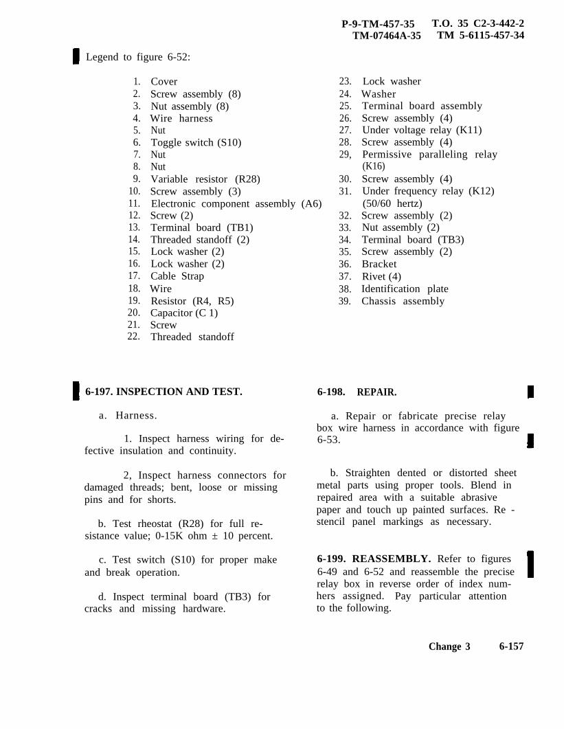
P-9-TM-457-35 T.O. 35 C2-3-442-2TM-07464A-35 TM 5-6115-457-34
Legend to figure 6-52:
1.2.3.4.5.6.7.8.9.
10.11.12.13.14.15.16.17.18.19.20.21.22.
CoverScrew assembly (8)Nut assembly (8)Wire harnessNutToggle switch (S10)NutNutVariable resistor (R28)Screw assembly (3)Electronic component assembly (A6)Screw (2)Terminal board (TB1)Threaded standoff (2)Lock washer (2)Lock washer (2)Cable StrapWireResistor (R4, R5)Capacitor (C 1)ScrewThreaded standoff
6-197. INSPECTION AND TEST.
a. Harness.
1. Inspect harness wiring for de-fective insulation and continuity.
2, Inspect harness connectors fordamaged threads; bent, loose or missingpins and for shorts.
b. Test rheostat (R28) for full re-sistance value; 0-15K ohm ± 10 percent.
c. Test switch (S10) for proper makeand break operation.
d. Inspect terminal board (TB3) forcracks and missing hardware.
23.24.25.26.27.28.29,
30.31.
32.33.34.35.36.37.38.39.
6-198.
Lock washerWasherTerminal board assemblyScrew assembly (4)Under voltage relay (K11)Screw assembly (4)Permissive paralleling relay(K16)Screw assembly (4)Under frequency relay (K12)(50/60 hertz)Screw assembly (2)Nut assembly (2)Terminal board (TB3)Screw assembly (2)BracketRivet (4)Identification plateChassis assembly
REPAIR.
a. Repair or fabricate precise relaybox wire harness in accordance with figure6-53.
b. Straighten dented or distorted sheetmetal parts using proper tools. Blend inrepaired area with a suitable abrasivepaper and touch up painted surfaces. Re -stencil panel markings as necessary.
6-199. REASSEMBLY. Refer to figures6-49 and 6-52 and reassemble the preciserelay box in reverse order of index num-hers assigned. Pay particular attentionto the following.
Change 3 6-157
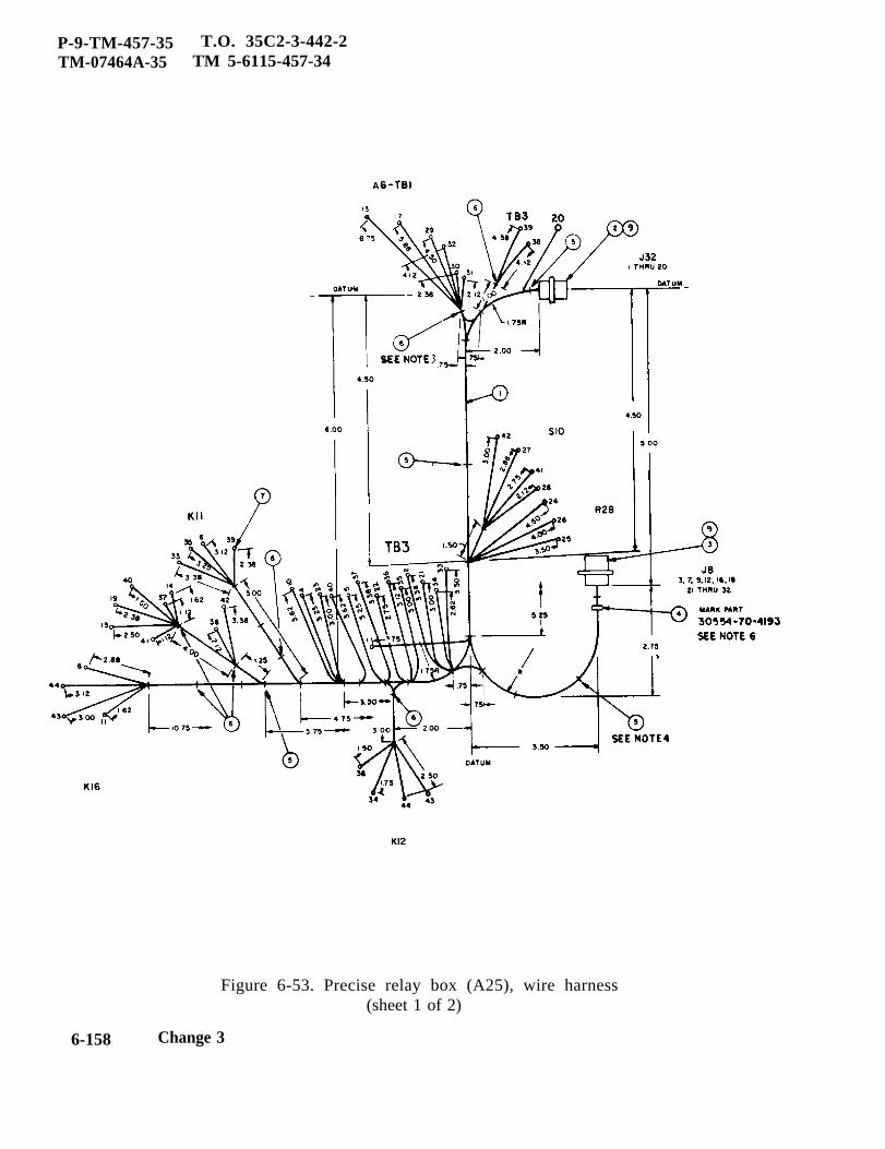
P-9-TM-457-35 T.O. 35C2-3-442-2TM-07464A-35 TM 5-6115-457-34
Figure 6-53. Precise relay box (A25), wire harness(sheet 1 of 2)
6-158 Change 3
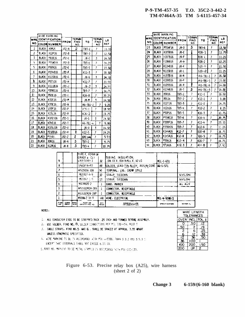
P-9-TM-457-35 T.O. 35C2-3-442-2TM-07464A-35 TM 5-6115-457-34
Figure 6-53. Precise relay box (A25), wire harness(sheet 2 of 2)
Change 3 6-159/(6-160 blank)

P-8-627-34 T O 35C2-3-442-2TM-07464A-35 TM 5-6115-457-34
a. Install wire harness (4) in chassisassembly (39) and secure in position witheight screw assemblies (2) and nuts (4).
b. Assemble electronic componentsassembly (11) and terminal board (34) tobracket (36), then install the assembly inchassis assembly (39).
c. Install under voltage relay (27),permissive paralleling relay (29), andunderfrequency relay (31) in position usingfour each, screw assemblies.
WARNING
Avoid breathing furies generated byUnsoldering/soldering. Eye pro-tection is required.
d. Refer to figures 6-53 and 1-21 andconnect wire harness leads to componentry.
NOTE
Solder connections shall be madeusing solder, Federal Specifica-tion QQ-S-571, Sn 60.
e. Test precise relay box as outlinedin paragraph 6-194.
f. Secure cover (1) to chassis assembly(39), using four screws and washers.
6-200. INSTALLATION. Refer to fig-ure 6-15 and install the precise relay boxin position using two screws and washers.Reconnect electrical plug connectors toreceptacles J8 and J32.
Section XI. PRECISE GOVERNOR CONTROL UNIT
6-201. GENERAL.
a. The precise governor control unit(A23), figure 3-2 is utilized only on pre-cise generator sets. The precise gover-nor is an engine speed frequency regulat-ing unit. It provides high control sensi-tivity, fast response, and minimum enginespeed frequency deviations with loadfluctuations. It senses electrical frequen-cy and load. Load sensing and sharingcircuitry permits paralleling of morethan two generator sets on an isochronousbasis.
b. The precise governor control unit isthe device that senses the change in gen-erator speed (frequency) and as a result,commands actuator to move the throttle.The governor circuits include:
1. A frequency error detection cir-cuit to measure the exact instantaneous fre-quency at which the generator is operating.
A frequency reference circuit to selectdesired frequency for operation.
2. A magnetic amplifier to amplifythe measured error between the outputs ofthe frequency measuring and frequencyreference circuits. This error signal isamplified to a level which is usable by thegovernor actuator.
3. A transistor inverter circuit toconvert 24 vdc to approximately 1000 hertzto power the magnetic amplifier.
4. A throttle position feedbackcircuit for governor stability.
5. Provisions for accepting the loadmeasurement unit signals to provideisochronous parallel operation,improved transient response.
Change 8
and
6-161
P-8-627-34 T O 35 C2-3-442-2TM-07464A-35 TM 5-6115-457-34
6-202. ON EQUIPMENT TEST
a. Symptom and Isolation of Malfunction.A malfunction of the governor control unitis usually indicated by loss of frequencycontrol, unstable frequency, or by instab-ility only when operating sets in parallel.To isolate the malfunction, proceed asfollows:
WARNING
Exercise extreme care not totouch exposed electrical connec-tions when working inside preciserelay box with generator setoperating.
NOTE
Fold hinge cover away from pre-cise governor control unit to gainaccess to test points as shown infigure 6-54.
1. Loss of Control. - With the setoperating under manual speed control,measure the input voltage to the P1 connec-tion, pins A and B (nominal 120 VAC). Alsomeasure input voltage to the P2 connection,pins A(+) and B(-) (20 to 32 VDC). If thecontrol unit is properly energized, measurethe voltage at test points A to B and C to Dwith A and D(+) (4 to 6 VDC). If either volt-age is approximately 15 VDC, check for anopen circuit to the actuator coils. Theactuator coil resistance should be 10 ohms±10%. If there is no voltage, the controlunit should be replaced. If the above read-ings are correct, check the circuit to thefrequency adjusting rheostat (R1) on controlcubicle from the PI connection. Pins N toT should measure 950 ohms ±10%, pins Mto N and M to T should measure 750 ohms ±10%. If the above checks have not indicatedthe malfunction, disconnect all cables fromthe control unit, rotate potentiometers R11,
R12, R14, R15, R16, and R18 full CW.Measure resistance between points indi-cated in table 6-20. Readings which do notagree with the values given in the tableindicate a malfunctioning component in thecontrol unit and it should be replaced.
2. Unstable frequency. - Refer tothe alignment procedures (paragraph 6-211)and check the adjustment of the magampbias gain R12, the load measurement gainR15, the frequency gain R18, and the feed-back gain R16. If the above adjustmentsare correct, connect a DC voltmeter(0 to 50 volt scale) across test points 1 and2 of the control unit. The voltage should bezero at rated speed and should swing as thefrequency is varied above and below ratedspeed by manually forcing the actuatorlinkage above and below its normal posi-tion. If the readings are correct, checkthe throttle position transducer circuit bymeasuring the voltage across test points 3and 4 (+) with a DC voltmeter. Operatethe set manually with connection P2 dis-connected and move the actuator manually,the voltage across TP3 and TP4 should varywith actuator movement. Capacitor (C1)can cause unstable frequency and should bechecked for a short or excessive currentleakage. If the cause of this unstable fre-quency is not located by the above checks,perform the resistance checks listed intable 6-20 and observe any intermittentreadings when the adjustment potentiom -eters are turned. Also check the resistanceof all pins to ground with an 100, 000 ohmscale. All readings shall be infinite resis-tances. Readings other than those speci-fied indicate replacement of the control unit.
3. Instability when operating inparallel. Check this setting of the loadsharing potentiometers (R28). Both unitsshould be set at 4.6 ± 0. 25 volts with Pi-Gpositive (pin A of the paralleling receptacle).Also the frequency gain (R18) and feedback
6-162 Change 8
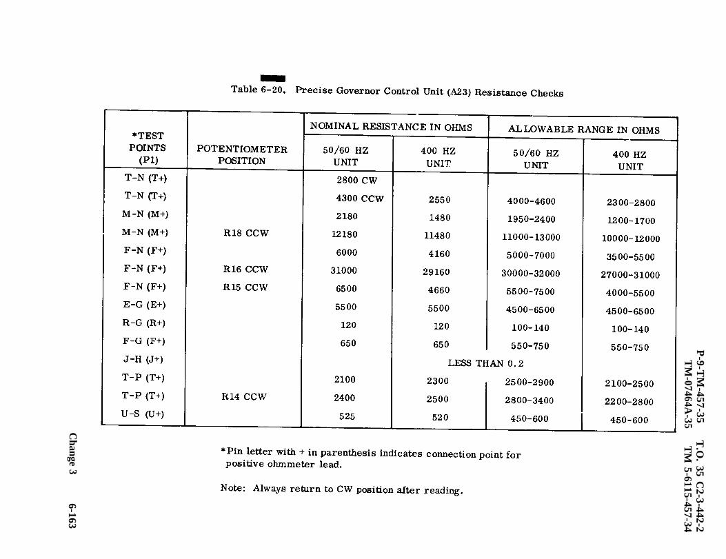
Table 6-20.
P-9-T
M-457-35
TM
-07464A-35
T.O
. 35 C2-3-442-2
TM
5-6115-457-34
Change 3
6-163
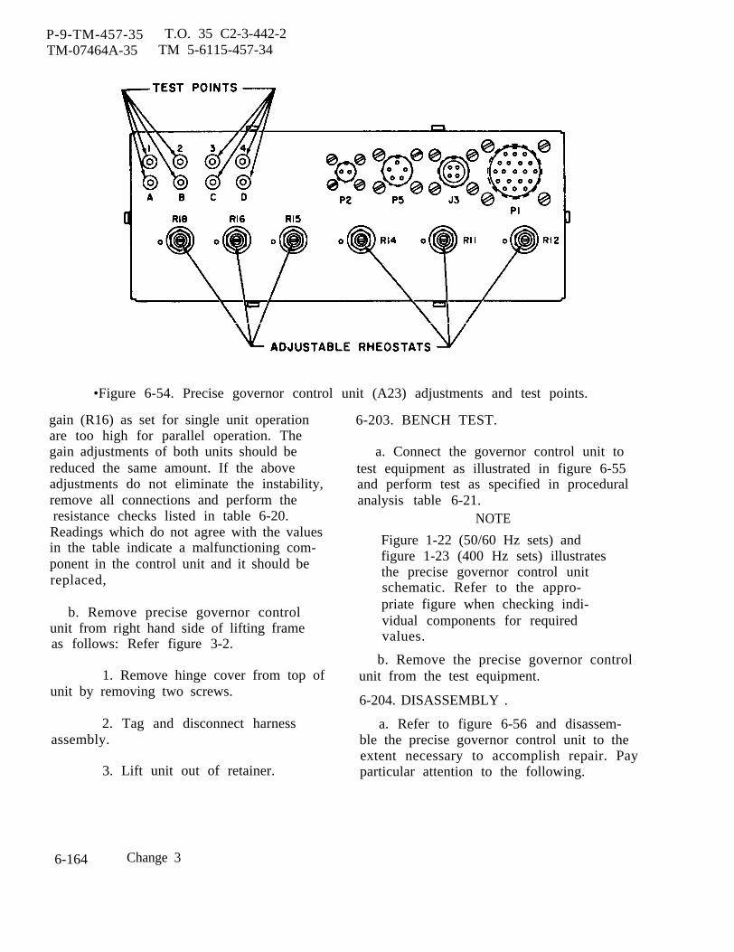
P-9-TM-457-35 T.O. 35 C2-3-442-2TM-07464A-35 TM 5-6115-457-34
•Figure 6-54. Precise governor control unit (A23) adjustments and test points.
gain (R16) as set for single unit operationare too high for parallel operation. Thegain adjustments of both units should bereduced the same amount. If the aboveadjustments do not eliminate the instability,remove all connections and perform the
resistance checks listed in table 6-20.Readings which do not agree with the valuesin the table indicate a malfunctioning com-ponent in the control unit and it should bereplaced,
b. Remove precise governor controlunit from right hand side of lifting frameas follows: Refer figure 3-2.
1. Remove hinge cover from top ofunit by removing two screws.
2. Tag and disconnect harnessassembly.
3. Lift unit out of retainer.
6-203. BENCH TEST.
a. Connect the governor control unit totest equipment as illustrated in figure 6-55and perform test as specified in proceduralanalysis table 6-21.
NOTE
Figure 1-22 (50/60 Hz sets) andfigure 1-23 (400 Hz sets) illustratesthe precise governor control unitschematic. Refer to the appro-priate figure when checking indi-vidual components for requiredvalues.
b. Remove the precise governor controlunit from the test equipment.
6-204. DISASSEMBLY .
a. Refer to figure 6-56 and disassem-ble the precise governor control unit to theextent necessary to accomplish repair. Payparticular attention to the following.
6-164 Change 3
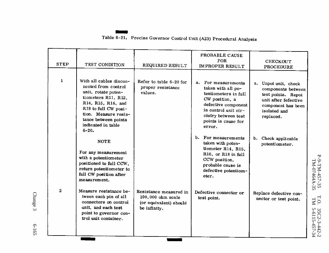
Table 6-21.
P-9-T
M-457-35
T.O
. 35C
2-3-442-2T
M-07464A
-35T
M 5-6115-457-34
Change 3
6-165
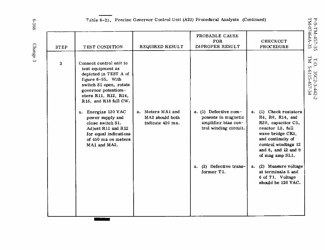
Table 6-21.
P-9-T
M-457-35
T.O
. 35C
2-3-442-2T
M-07464A
-35T
M 5-6115-457-34
6-166C
hange 3

Table 6-21.
P-9-T
M-457-35
T.O
. 35C
2-3-442-2T
M-07464A
-35T
M 5-6115-457-34
Change 3
6-167

Table 6-21.
P-9-T
M-457-35
T.O
. 35 C2-3-442-2
TM
-07464A-35
TM
5-6115-457-34
6-168C
hange 3

Table 6-21.
P-9-T
M-457-35
T.O
. 35C
2-3-442-2T
M-07464A
-35T
M 5-6115-457-34
Change
36
-16
9
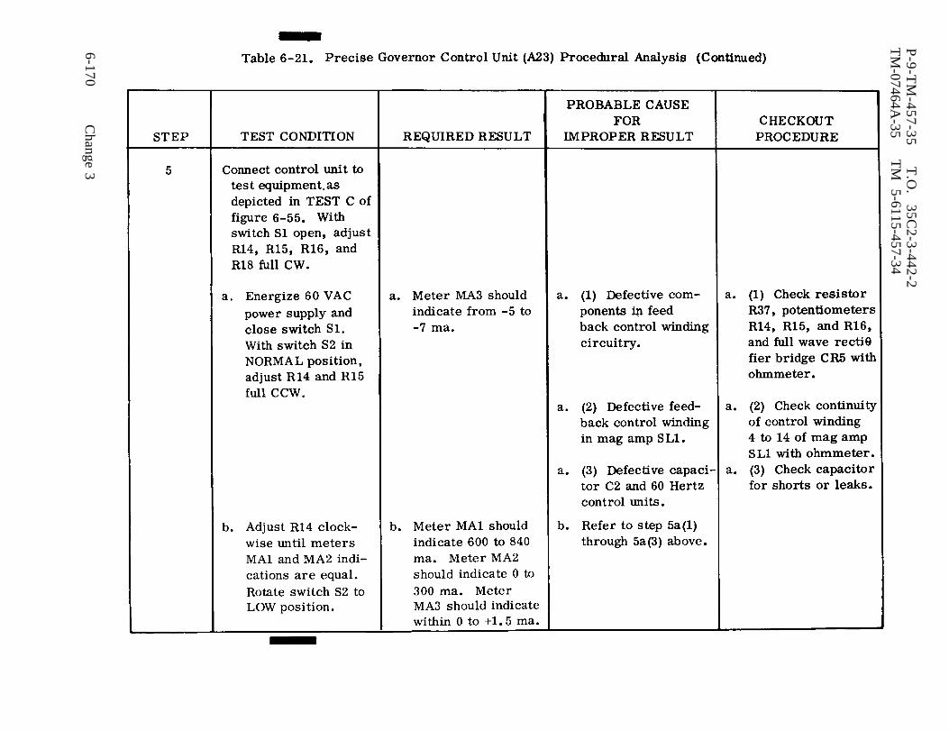
Table 6-21.
P-9-T
M-457-35
T.O
. 35C
2-3-442-2T
M-07464A
-35T
M
5-6115-457-34
6-170C
hange 3
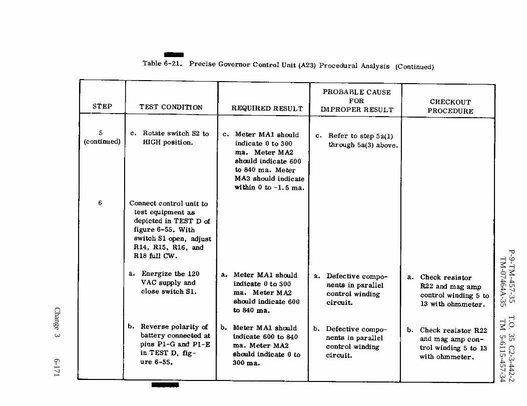
Table 6-21.
P-9-T
M-457-35
T.O
. 35 C2-3-442-2
TM
-07464A-35
TM
5-6115-457-34
Change 3
6-171

P-9-TM-457-35 T.O. 35C2-3-442-2TM-07464A-35 TM 5-6115-457-34
setupFigure 6-55. Precise governor control unit (A23), test
6-172 Change 3
P-9-TM-457-35 T.O. 35 C2-3-442-2TM -07464A -35 TM 5-6115-457-34
1. Remove potting from governorcontrol unit by performing steps 2. through6.
2. Remove six screws (1) and lockwashers (2) holding panel (20) to cabinet(25).
3. Lift off panel and set across topof cabinet at a slight angle to keep thepotentiometers out of the compound.
4. Place the complete unit in atemperature controlled oven large enoughto allow air to circulate completely aroundunit. Set oven temperature to 170°F.
CAUTION
The flash point of the compound is515°F. Do not unpot the unit byplacing it on a hot plate type sur-face or by using an open flame, ashigh temperatures (hot spots )could damage componentry.
NOTE
Melting usually occurs in eleven totwelve hours.
5. To remove printed wiring boardassembly (21) from cabinet, use heavygloves and remove entire unit from oven,being careful not to spill the wax from thecabinet or allow wax to get on the panel orpotentiometers.
WARNING
Use care in handling the hot waxas it can cause severe injury topersonnel.
6. Prior to making repairs, theprinted wiring board assembly must be
placed on a drain board and allowed to coolto room temperature.
b. Refer to figure 6-57 and disassemblethe governor printed wiring board assem-bly to the extent necessary to accomplishrepair. Pay particular attention to thefollowing:
NOTE
Exercise care not to apply excessiveheat to components when unsolder-ing connections.
6-205. CLEANING.
Clean all components with a cleanlint-free cloth moistened with an approvedcleaning solvent and dry thoroughly.
6-206. INSPECTION.
a. Inspect electrical components andprinted wiring board in accordance withparagraph 6-53.
b. Inspect wiring and electrical connec-tors for damage.
6-207. REPAIR.
Repair printed wiring board in ac-cordance with paragraph 6-54, step f.
6-208. REBUILD.
Refer to figure 6-58 and rebuildprecise governor control unit wiring har-ness.
6-209. REASSEMBLY.
a. Refer to figure 6-57 and reassemblethe precise governor printed wiring board.Pay particular attention to the following.
Change 3 6-173
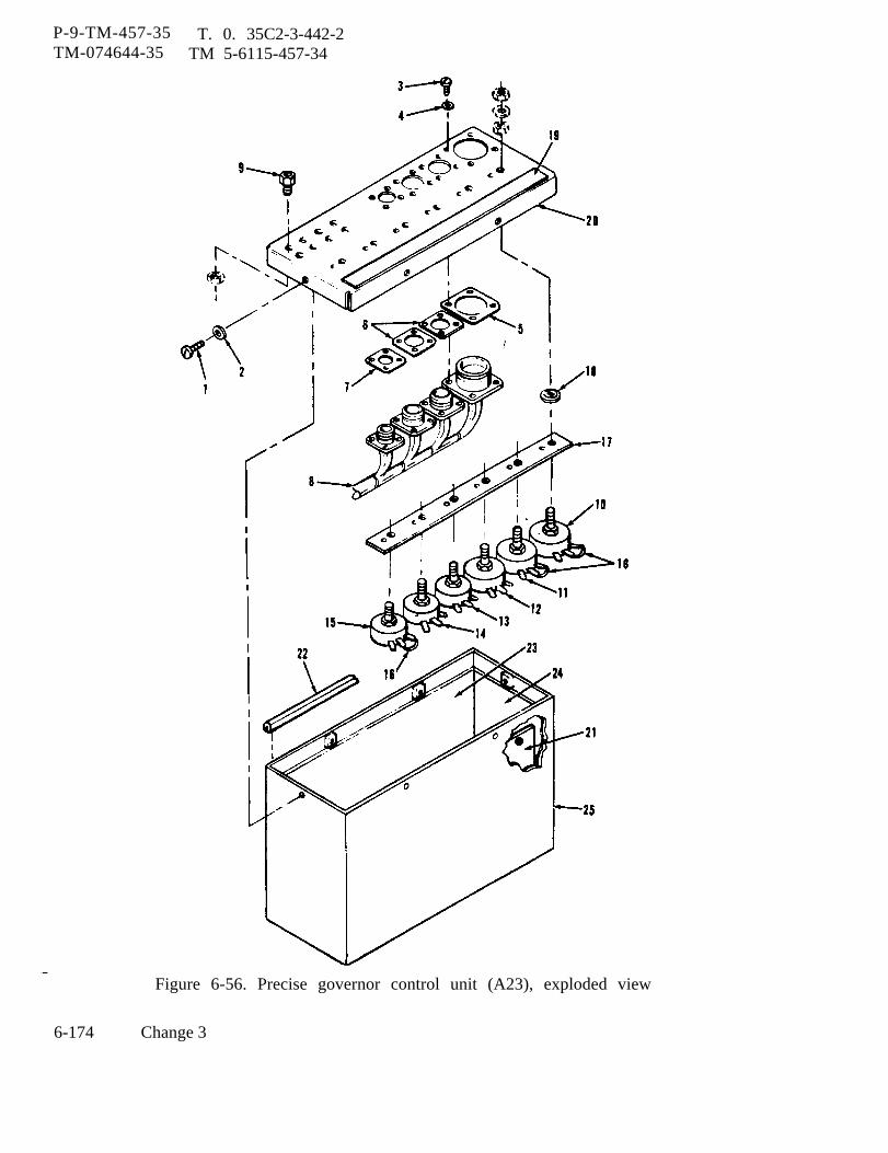
P-9-TM-457-35 T. 0. 35C2-3-442-2TM-074644-35 TM 5-6115-457-34
Figure 6-56. Precise governor control unit (A23), exploded view
6-174 Change 3
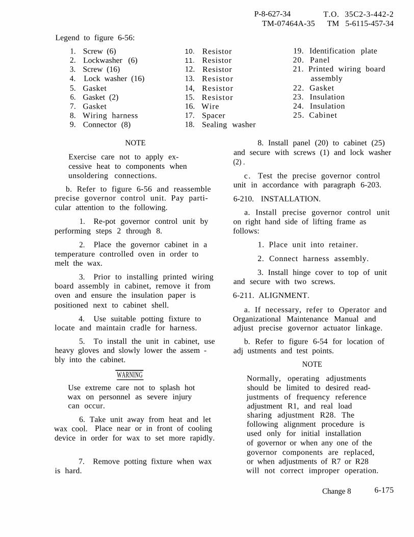
P-8-627-34 T.O. 35C2-3-442-2TM-07464A-35 TM 5-6115-457-34
Legend to figure 6-56:
1.2.3.4.5.6.7.8.9.
Screw (6)Lockwasher (6)Screw (16)Lock washer (16)GasketGasket (2)GasketWiring harnessConnector (8)
10.11.12.13.14,15.16.17.18.
ResistorResistorResistorResistorResistorResistorWireSpacerSealing washer
19. Identification plate20. Panel21. Printed wiring board
assembly22. Gasket23. Insulation24. Insulation25. Cabinet
NOTE
Exercise care not to apply ex-cessive heat to components whenunsoldering connections.
b. Refer to figure 6-56 and reassembleprecise governor control unit. Pay parti-cular attention to the following.
1. Re-pot governor control unit byperforming steps 2 through 8.
2. Place the governor cabinet in atemperature controlled oven in order tomelt the wax.
3. Prior to installing printed wiringboard assembly in cabinet, remove it fromoven and ensure the insulation paper ispositioned next to cabinet shell.
4. Use suitable potting fixture tolocate and maintain cradle for harness.
5. To install the unit in cabinet, useheavy gloves and slowly lower the assem -bly into the cabinet.
WARNING
Use extreme care not to splash hotwax on personnel as severe injurycan occur.
6. Take unit away from heat and letwax cool. Place near or in front of coolingdevice in order for wax to set more rapidly.
7. Remove potting fixture when waxis hard.
8. Install panel (20) to cabinet (25)and secure with screws (1) and lock washer(2) .
c . Test the precise governor controlunit in accordance with paragraph 6-203.
6-210. INSTALLATION.
a. Install precise governor control uniton right hand side of lifting frame asfollows:
1. Place unit into retainer.
2. Connect harness assembly.
3. Install hinge cover to top of unitand secure with two screws.
6-211. ALIGNMENT.
a. If necessary, refer to Operator andOrganizational Maintenance Manual andadjust precise governor actuator linkage.
b. Refer to figure 6-54 for location ofadj ustments and test points.
NOTE
Normally, operating adjustmentsshould be limited to desired read-justments of frequency referenceadjustment R1, and real loadsharing adjustment R28. Thefollowing alignment procedure isused only for initial installationof governor or when any one of thegovernor components are replaced,or when adjustments of R7 or R28will not correct improper operation.
Change 8 6-175

P-8-627-34 T.O. 35C2-3-442-2TM-07464A-35 TM 5-6115-457-34
1. Isochronous Operation frequency adjust rheostat R1, on maingenerator control panel for precise genera-
(a) Before starting engine, rotate tor sets to a mid-rotation position.
Legend to figure 6-57:
1.
2.3.4.5.6.7.8.9.
10.11.12.13.14.15.16.17.18.19.20.21.22.23.24.25.26.27.28.29.30.31.32.33.34.
Screw (2)Nut (2)Lock washer (2)Washer (4)Transformer T1Screw (2)Nut (2)Lock washer (2)Washer (4)Filter reactor (L2)Screw (2)Nut (2)Lock washer (2)Washer (4)Filter reactor (L1)Resistor (R23)Capacitor (C 7)Resistor (R5)Screw (2)Nut (2)Lock washer (2)Washer (2)Power transistor (2)Screw (2)Nut (2)Lock washer (2)Washer (4)Heat sink (2)Filter reactor (L3)Diode (CR3)Capacitor (C2)Resistor (R20)Resistor (R20)Nut (8)
35.36.37.38.39.40.
41.42.43.44.45.46.47.48.49.50.51.52.53.54.55.56.57.58.59.60.61.62.63.64.65.66.67.
Lock washer (8)Washer (8)Stud (8)Panel assemblyCapacitor (C 2)Rectifier (CR7, CR8, CR9,CR10)Resistor (R37)Terminal (4)PlateCapacitor (C 5)Resistor (R4 and R8)Screw (2)Nut (2)Lock washer (2)Washer (2)Washer (4)Washer (2)Adjustable resistor (R10)Magamp (SL1)Capacitor (C6)Screw (2)Nut (2)Lock washer (2)Washer (2)Washer (4)Washer (4)Resistor (R1 and R1A)Wire (8)Wire (3)Rectifier (CR2)Capacitor (C3, C4)Transformer (T2)Printed wiring board
6-176 Change 8

P-9-TM-457-35 T.O. 35C2-3-442-2TM-074641-35 TM 5-6115-457-34
Figure 6-57. Precise governor control unit (A23), printed wiring board assembly
Change 3 6-177

Figure 6-58.
P-9
-TM
-45
7-3
5
T.O
. 3
5C
2-3
-44
2-2
TM
-07464A-35
TM
5-6115-457-34
6-178C
hange 3
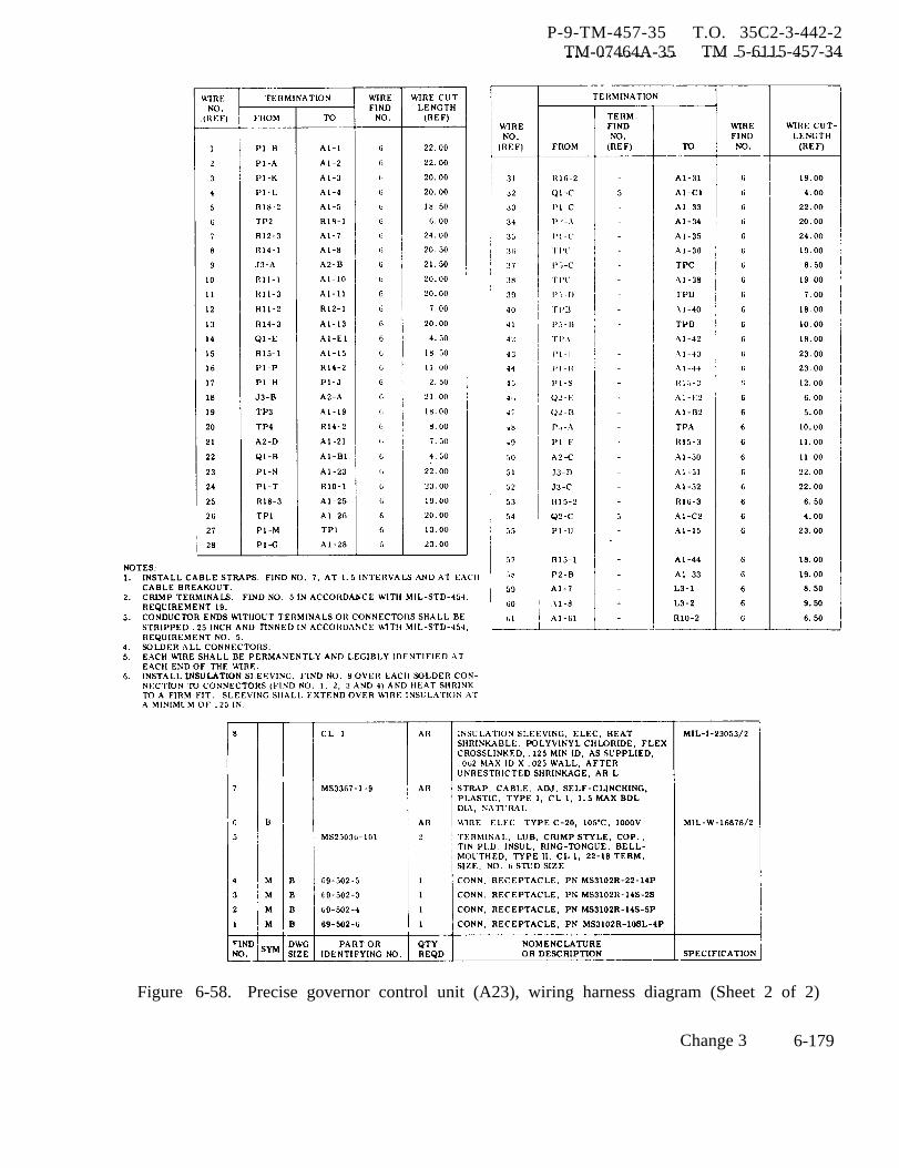
P-9-TM-457-35 T.O. 35C2-3-442-2TM-07464A-35 TM 5-6115-457-34
Figure 6-58. Precise governor control unit (A23), wiring harness diagram (Sheet 2 of 2)
Change 3 6-179

P-9-TM-457-35 T.O. 35 C2-3-442-2TM-07464A-35 TM 5-6115-457-34
(b) Before starting engine, ro-tate magamp bias balance adjustment po-tentiometer R11, feedback null adjustmentpotentiometer R14, feedback gain adjust-ment potentiometer R16, and frequencygain adjust potentiometer R18 on electricgovernor control unit to a mid-positionposition. Then rotate load measurementgain adjustment potentiometer R15 to afull-rotation counterclockwise position,and the magamp bias level adjustment po-tentiometer R12 to a three-quarter-rotationcounterclockwise position.
NOTE
To determine desired rotation posi-tion of a potentiometer or rheostat,turn shaft clockwise to stop. Thenrotate shaft counterclockwise tostop, counting the number of turnsbetween clockwise and counterclock-wise stops. Now, rotate shaftclockwise for a given number ofturns to obtain desired rotationposition.
(c) Start engine and observe fre-quenc y meter and voltmeter readings forindication of fluctuation in either voltage orfrequency. Also listen to engine for soundof engine hunting. If high frequency, lowamplitude engine hunting is observed, pro-ceed to step (d) and make the necessaryadjustment; if low frequency, high ampli-tude engine hunting is observed, proceedto step (e) and make the necessary adjust-ments. If frequency and voltage outputsare stabilized, skip steps (d) and (e), pro-ceed to step (f) and continue with alignmentprocedures.
(d) To eliminate a high frequency,low amplitude hunting condition, reducemagamp bias level by rotating potentiom-eter (R12) in a clockwise direction, and
reduce high feedback gain by rotating po-tentiometer (R16) counterclockwise,
(e) To eliminate a low frequency, high amplitude hunting condition, reducefrequency gain by rotating potentiometerR18 counterclockwise When a reductionof frequency gain does not correct the con-dition, increase feedback gain by rotatingpotentiometer R16 clockwise, When areduction of frequency gain and/or an in-crease in feedback gain does not eliminateslow hunting, rotate potentiometer r R1 2more in a counterclockwise direction toincrease magnetic amplifier bias level.Should none of the above adjustments cor-rect and stabilize the system, increase thecapacitance (non-polarized, 50 vdc, 25 mfdto 100 mfd electrolytic) of capacitor C1located in the governor resistor assemblyA6 in the precise relay box for 50/60 hertzsets or the mode II relay box for 400 hertzsets Refer to relay box diagram figures1-16 and 1-20. Alternately change capaci-tance value and repeat potentiometer R18,R16, and R12 adjustments until the systemis stabilized, thus eliminating the low fre-quenc y, high amplitude hunting condition.
(f) With the engine running andthe system stabilized, insert test probesof a 0-10 volt DC voltmeter in test jacks3 and 4 (test jack 4 is positive). Rotatefrequency adjust rheostat R1 for a 60-hertz(400 hertz on 400 hertz unit) reading on thefrequency meter. Then adjust potentiom-eter R14 for a zero voltage reading betweentest jacks 3 and 4 under no load condition.
(g) Before removing the volt-meter from test jack 3 and 4, install testprobes from a similar voltmeter in testjacks 1 and 2, (test jack 1 is positive) andalternately adjust potentiometer R11 and thefrequency adjust rheostat to obtain a zerovoltage across test points 1 and 2, and 3
6-180 Change 3
P-9-TM-457-35 T.O. 35 C2-3-442-2
TM-07464A-35 TM 5-6115-457-34
and 4, at 60-hertz or 400 hertz with noload. When adjustment will not provide azero reading across test points 1 and 2,then adjust for a minimum reading.
(h) Connect a 0 to 10 vdc volt-meter between test jacks A and B and checkfor a normal DC voltage reading of appro-ximately 4 to 6 volts. Adjust potentiometerR12 to obtain proper voltage readings.
(i) To achieve optimum transientperformance, adjust the load measurementgain control potentiometer R15. Adjust-ment of R15 to a full clockwise rotationposition provides maximum load measure-ment gain.
(j) To obtain optimum perform-ance, adjust potentiometer R18 to a maxi-mum clockwise rotation position and poten-tiometer R16 to a maximum counterclock-wise rotation position without causing anoscillation to develop for any position set-ting of potentiometer R15. The value ofcapacitor C 1 (referred to in precise modeII relay box schematic electronic compon-ent assembly A6) will also affect transientfrequency response. Small values of capa-citance will give faster transient frequencyresponse; however, if the capacitance ofC 1 is too small, the system will oscillate.
(k) For any position of poten-tiometer R18, there is an optimum positionsetting for potentiometer R16. To improvetransient performance even further, rotatepotentiometer R18 in a clockwise direction.If a hunt develops, re-adjust potentiometerR16 to achieve stability. If, however, nohunting condition develops, then apply andremove the load and observe stability ofgenerator under such transient conditions,while continuing to adjust potentiometerR18 in a clockwise direction. when a po-tentiometer R18 has been adjusted to a pointwhere adjustment of potentiometer R16 will
not stability the generator, then reducefrequency gain R18 to a stable region andoptimize generator stability and perform-ance by adjusting potentiometer R1 6.
NOTE
For long term generator stability,frequency gain should be reduced toa point where the system is not onthe edge of instability.
When a steady state frequency of full loadis slightly lower than no load steady statefrequency (droop), re-adjust potentiometersR12, R14, or R18 slightly. Rotating po-tentiometer R18 full clockwise for alloperating conditions will often eliminatedroop, and under certain circumstances,adjusting potentiometer R14 for voltagereading above zero at test jacks 3 and 4 willalso eliminate droop. A slight readjust-ment of the magamp bias lever potentiom-eter R12 will provide isochronous operationunder certain conditions.
2. Parallel Operation Alignment andAdjustment
(a) With the generator operatingunder no load, disconnect electrical con-nector J 17 at electric governor controlunit. Use a dc voltmeter and check for zerovoltage between pins G and J (pin G ispositive).
(b) With the DC voltmeter connectacross pins G and J of connector J17, applyfull load to generator set and adjust the realload sharing potentiometer R12 in the pre-cise relay box or the mode II relay boxthrough its full range. The dc voltmetershould indicate between 5 and 10 volts dc.Note and record the exact range of dc volt-age available on set number one by adjust-ing the real load sharing potentiometer.
Change 3 6-181
P-9-TM-457-35 T.O. 35 C2-3-442-2TM-07464A-35 TM 5-6115-457-34
(c) Repeat the procedures out-lined in steps (a) and (b) on set to be con-nected in parallel with set number one.
(d) Adjust the real load sharingpotentiometer R28 on each generator set sothat the voltage across pins G and J in con-nector J17 is identical.
Make sureoutlined in
NOTE
during the proceduresteps (a) and (b) that
the load contactor swtich is openso that pin G or J of one genera-tor set connector J17 is notconnected to pins G or J of an-other generator set contactorJ17.
Refer to Operator and OrganizationalMaintenance Manual and begin parallel opera-tion.
(e) If the generator sets tend tooscillate during the first attempt at paralleloperation, remove from parallel operation,readjust real load sharing potentiometerR28 for a lower voltage across pins G and Jin connector J17, and place generator setsin parallel operation again. It may be nec-e ssary to repeat this operation several timesuntil the proper voltage is obtained. Whenthe proper voltage setting on each generatorset has been obtained, and it will be possibleto parallel isochronously with equal loadsharing during each paralleling operation.
(f) If other than equal load shar-ing is desired, then adjust potentiometerR28 to obtain the proper ratio voltage de-sired.
NOTE
Under normal conditions, anyadjustment of potentiometer
R28 should be made when thegenerator set is not operatingin parallel. However, if aslight readjustment of loadsharing between paralleloperating sets is necessary,such a slight readjustmentis permissible. The sameresults can usually be ob-tained, however, by adjust-ing the frequency referenceadjustment potentiometer R1.
6-211A. ALIGNMENT PROCEDURESPECULIAR TO OPERATIONOF 400 HZ GENERATOR SETSIN SUPPORT OF E3A AIRCRAFT,
a. If necessary, refer to Operator andOrganizational Maintenance Manual and ad-just precise governor actuator linkage.
b. Refer to figure 6-54 for location ofadjustments and test points.
1. Isochronous Operation.
(a) Before starting engine,rotate frequency and adjust rheostat R1 onmain generator control panel for precisegenerator sets to a mid-rotation position.
(b) Before starting engine,rotate magamp bias balance potentiometerR11, feedback null adjustment potentiometerR14, feedback gain adjustment potentiometer]R16, and frequency gain adjust potentiometeR18 on precise governor control unit to amid-rotation position. Then rotate loadmeasurement gain adjustment potentiometerR15 to a three-quarter-rotation clockwiseposition.
(c) Start engine and operate at400 hertz, no load. Observe governor actu-ator unit piston for hunting. If governoractuator unit piston is hunting, adjust R18
6-182 Change 3
TO 35C2-3-442-2
counter clockwise to stop hunting. Ifactuator is still hunting after R18 wasadjusted, rotate R16 to stop hunting.
NOTE
It may require that R18 bereadjusted to a new positionand R16 rotated again to stophunting.
(d) With engine runningand the system stabilized. insert testprobes of a 0-10 volt dc voltmeter intest jacks 3 and 4 (test jack 4 ispositive) . Rotate frequency adjustrheostat R1 for a 400 Hz reading on thefrequency meter. Then adjust potenti-ometer R14 for a zero voltage readingbetween test jacks 3 and 4 under noload condition.
(e) Insert test probes ofa 0-10 volt dc voltmeter in test jacksA and B (test jack A is positive).Adjust potentiometer R12 for a voltagereading of 5.0 volts dc between testjacks A and B.
(f) Insert test probes ofa 0-10 volts dc voltmeter in test jacksA and B (test jack A is positive).Adjust potentiometer R12 for a voltagereading of 4.0 to 6.0 volts dc. Adjustto highest voltage within range thatdoes not allow actuator to hunt.
(g) Note governor actuatorpiston for no movement. If necessary
readjust R16 and R18 potentiometers tostop movement.
(h) Vary potentiometer R16either clockwise or counterclockwise toobtain best stability. If moving R16hs no effect. then set R16 at its mid-rotation position.
2. Parallel Operation Alignmentand Adjustment.
(a) Load unit with a loadbank set to obtain a load of 50 KW atunity power factor.
(b) Connect test probes ofa 0-10 volt dc voltmeter across pins Aand B (pin A is positive) of any paral-leling receptacle (J45. J46 or J47).Adjust the real load sharing potentiom-eter R28 on the precise relay box toobtain a reading of 1.5 volts dc.
(c) Place parallel/singleunit switch (S6) in the parallel posi-tion. Ensure shorting plug is removedthen connect test probes of a 0-10voltmeter across pins C and D of anyparalleling receptacle (J45, J46 orJ47) . Adjust reactive current sharingpotentiometer R29 on the precise relaybox to obtain a reading of 5.5 volts ac(7.5 volts ac with 50 KVA at 0.8 powerfactor) .
(d) When all alignmentprocedures have been complied with.ensure all locknuts on potentiometersare tightened.
Section XII. LOAD MEASUREMENT UNIT
6-212. GENERAL. set regardless of power factor or phaseand provides a dc voltage output pro-
The load measurement unit is portional to this load. On preciseutilized on both precise and utility generator sets this output signal isgenerator sets. The unit consists of a applied to the load-sensing circuits inthree phase transformer, rectifiers, the control unit to provide a load rateand a variable load resistor. It mea- signal to the feedback circuit, and a voltagesures the total load on the generator
Change 12 6-182A/(6-182B blank)

P-9-TM-457-35 T.O. 35C2-3-442-2TM-07464A-35 TM 5-6115-457-34
proportional to load that is used for theparallel system. If a dummy load kit isutilized with the generator set the loadmeasurement unit is interconnected withthe kit sensing circuit.
6-213. ON EQUIPMENT TEST.
a. Symptom and Isolation of Malfunc-tion. A malfunction of the load measure-ment unit is not easily detected duringsingle unit operation unless the set isequipped with a dummy load kit and theautomatic load removal feature is utilized.Then a malfunction is usually indicatedby failure of the dummy load kit automaticremoval circuit. When the unit malfunc-tions in a generator set that is operatingin parallel, the malfunction is usually in-dicated by unequal load sharing. To isolatethe malfunction, proceed as follows:
1. Remove connector P16 fromload measurement unit and with generatorset operating at rated speed and voltage,measure voltage at connector P16, pins Ato K, B to L, and C to M; voltage shouldbe 120 VAC nominal. Also measure volt-age across connector pins G to D, G to E,and G to F; voltage should be 5.6 VA C atrated load.
2. If above voltages are-met, con-nect connector P16 to load measurementunit. Operate generator set, controllingspeed with the manual speed control andcheck load measurement unit output by re-moving connector P1 from the governorcontrol unit. Measure voltage across con-nector P 1 pins U(+) and S, voltage shouldbe 9.8 VDC with generator set operatingat rated load.
3. If input voltages are correctand the output does not vary between 0 and
9.8 VDC proportional to load, the loadmeasurement unit should be replaced.
b. Removal. Refer to figure 6-59 andremove load measurement unit by remov-ing electrical connector and screws.
6-214. TEST AND ADJUSTMENT.
a. Connect load measurement unit tothe test equipment as illustrated in figure6-60.
b. Test and adjust load measurementunit as specified in table 6-22.
6-215. DISASSEMBLY.
Refer to figure 6-61 and disas-semble load measurement unit in the orderof index numbers assigned. Pay particularattention to the following.
a. Remove cover (5).
NOTE
Leave wires connected to recep-tacle (7).
b. Tag and unsolder wires from com-ponents, exercising care not to apply ex-cessive heat. Unsolder diodes (19) fromtransformer (24),
6-216. CLEANING.
a. Clean electrical components witha clean lint-free cloth moistened in anapproved cleaning solvent and dry thorough-ly ,
b. Clean remaining parts in an ap-proved cleaning solvent and dry thorough-ly .
Change 3 6-183
P-9-TM-457-35 T.O. 35C2-3-442-2TM-07464A-35 TM 5-6115-457-34
6-217. INSPECTION.
a. Inspect wire for defective insula-tion. Check each wire to connector pin forcontinuity. Check connector pins forshorts to case and surrounding pins. In-spect connector for damaged threads.
b . Check forward and reverse resis-tance of diodes. Measured from anode (+)to cathode (-) value should be low, reversemeter leads value should be infinity.
c. Check resistor for proper ohmicvalue, resistor should be adjustable from0 to 500 ohms.
d. Inspect transformer for burnt areas,defective insulation, and missing terminals.
e. Inspect threads for damage.
f. Inspect sheet metal parts for cracks,dents, and distortion.
g. Inspect nameplate for security andlegibility.
h. Inspect paint for damage.
6-218. REPAIR.
a. Repair defective wiring by remov-ing defective wire from connector and in-stalling wire of same size and length in itsplace.
b. Chase damaged threads.
c. Repair cracked sheet metal partsby welding. Straighten dented or distortedparts using suitable tools.
d. Fasten loose nameplate to coverusing a suitabe adhesive.
e. Remove damaged paint. Blend inedges, prime, and paint damaged areas.
6-219. REASSEMBLY.
Refer to figure 6-61 and re-assemble the load mea surement unit in thereverse order of index numbers assigned.
a. Solder diodes (19) and wires totransformer (24).
6-184 Change 3

P-8-627-34 T O 35C2-3-442-2TM-07464A-35 TM 5-6115-457-34
proportional to load that is used for theparallel system. If a dummy load kit isutilized with the generator set the loadmeasurement unit is interconnected withthe kit sensing circuit.
6-213. ON EQUIPMENT TEST.
a. Symptom and Isolation of Malfunc-tion. A malfunction of the load measure-ment unit is not easily detected duringsingle unit operation unless the set isequipped with a dummy load kit and theautomatic load removal feature is utilized.Then a malfunction is usually indicatedby failure of the dummy load kit automaticremoval circuit. When the unit malfunc-tions in a generator set that is operatingin parallel, the malfunction is usually in-dicated by unequal load sharing. To isolatethe malfunction, proceed as follows:
1. Remove connector P16 fromload measurement unit and with generatorset operating at rated speed and voltage,measure voltage at connector P1 6, pins Ato K, B to L, and C to M; voltage shouldbe 120 VAC nominal. Also measure volt-age across connector pins G to D, G to E,and G to F; voltage should be 5.6 VAC atrated load.
2. If above voltages are met, con-nect connector P16 to load measurementunit. Operate gene rator set, controllingspeed with the manual speed control andcheck load measurement unit output by re -moving connector P1 from the governorcontrol unit. Measure voltage across con-nector P1 pins U(+) and S, voltage shouldbe 9.8 VDC with generator set operatingat rated load.
3. If input voltages are correctand the output does not vary between 0 and9.8 VDC proportional to load, the loadmeasurement unit should be replaced.
b. Removal. Refer to figure 6-59 andremove load measurement unit by remov-ing electrical connector and screws.
6-214. TEST AND ADJUSTMENT.
a. Connect load measurement unit tothe test equipment as illustrated in figure6-60.
b. Test and adjust load measurementunit as specified in table 6-22.
6-215. DISASSEMBLY.
Refer to figure 6-61 and disas-semble load measurement unit in the orderof index numbers assigned. Pay particularattention to the following.
a. Remove cover (5).
WARNING
Avoid breathing fumes generated byUnsoldering/soldering. Eye pro-tection is required.
NOTE
Leave wires connected to recep-tacle (7).
b. Tag and unsolder wires from com-ponents, exercising care not to apply ex-cessive heat. Unsolder diodes (19) fromtransformer (24).6-216. CLEANING.
a. Clean electrical components witha clean lint-free cloth moistened in anapproved cleaning solvent and dry thorough-ly.
WARNING
Cleaning Solvents are f lammable andmoderately toxic to skin, eyes andrespiratory tract. Eye and skinprotect ion required. Good generalventilation is normally adequate.
b. Clean remaining parts in an ap-proved cleaning solvent and dry thorough-ly ●
Change 8 6-183
P-8-627-34 T O 35C2-3-442-2TM-07464A-35 TM 5-6115-457-34
6-217. INSPECTION.
a. Inspect wire for defective insula-tion. Check each wire to connector pin forcontinuity. Check connector pins forshorts to case and surrounding pins. In-spect connector for damaged threads.
b. Check forward and reverse resis-tance of diodes. Measured from anode (+)to cathode (-) value should be low, reversemeter leads value should be infinity.
c. Check resistor for proper ohmicvalue, resistor should be adjustable from0 to 500 ohms.
d. Inspect transformer for burnt areas,defective insulation, and missing terminals.
e .
f.dents,
g.
Inspect threads for damage.
Inspect sheet metal parts for cracks,and distortion.
Inspect nameplate for security andlegibility.
h. Inspect paint for damage.
6-218. REPAIR.
a. Repair defective wiring by remov-ing defective wire from connector and in-
stalling wire of same size and length in itsplace.
b. Chase damaged threads.
WARNING
Welding operations produce heat,highly toxic fumes, injuriousradiation, metal slag and air-borne particles. Welding gog-gles, with proper tinted lenses,apron or jacket and welder’sboots are required.
c. Repair cracked sheet metal partsby welding. Straighten dented or distortedparts using suitable tools.
d. Fasten loose nameplate to coverusing a suitabe adhesive.
e . Remove damaged paint. Blend inedges, prime, and paint damaged areas.
6-219. REASSEMBLY.
Refer to figure 6-61 and re-assemble the load measurement unit in thereverse order of index numbers assigned.
WARNING
Avoid breathing fumes generated byunsoldering/soldering. Eye pro-tection is required.
a. Solder diodes (19) and wires totransformer (24).
6-184 Change 8
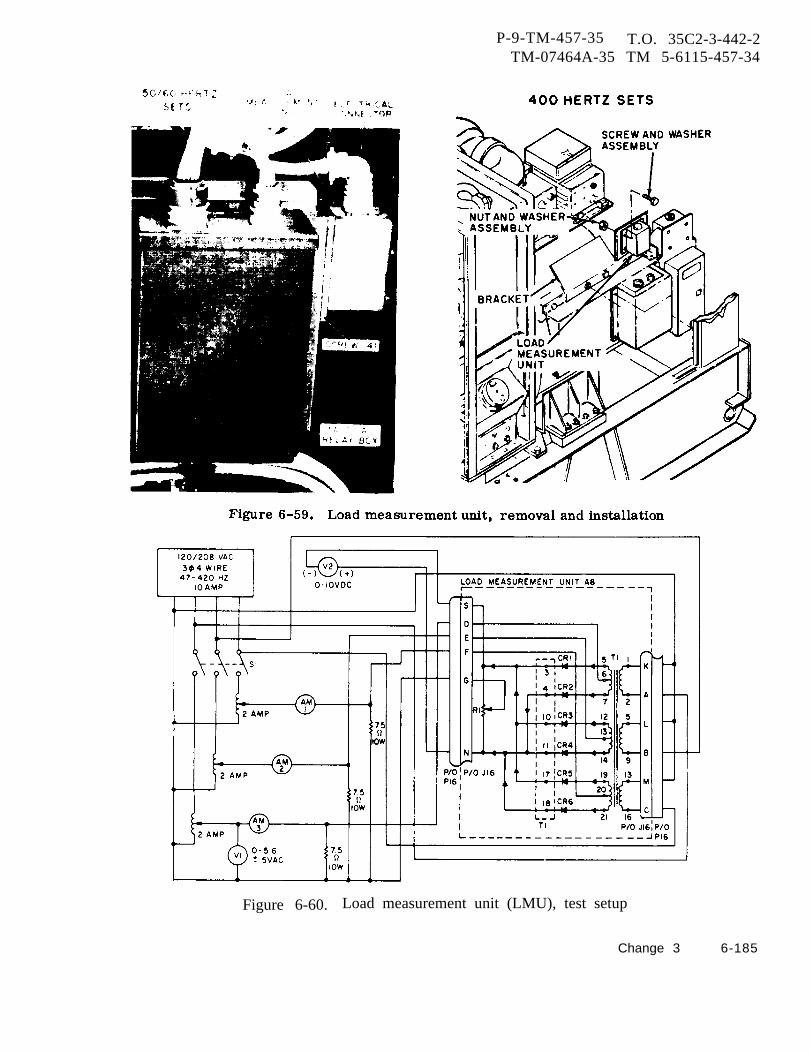
P-9-TM-457-35 T.O. 35C2-3-442-2TM-07464A-35 TM 5-6115-457-34
Figure 6-60. Load measurement unit (LMU), test setup
Change 3 6-185
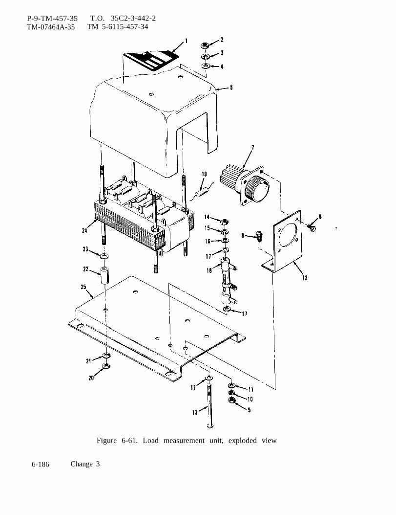
P-9-TM-457-35 T.O. 35C2-3-442-2TM-07464A-35 TM 5-6115-457-34
Figure 6-61. Load measurement unit, exploded view
6-186 Change 3
P-9-TM-457-35 T.O. 35C2-3-442-2TM-07464A-35 TM 5-6115-457-34
Legend to figure 6-61:
1.2.3.4.5.6.
6A.7.8.9.
10.11.12.
NameplateNut (4)Lock washer (4)Washer (4)CoverScrew (4)Washer (4)Receptacle (J16)Screw (2)Nut (2)Lock washer (2)Washer (2)Bracket
13.14.15.16.17.18.19.20.21.22.23.24.25.
ScrewNutLock washerWasher (2)Washer (2)Adjustable resistor (R1)Diode (CR1 through CR6)Nut (4)Lock washer (4)Tube (4)Washer (4)Transformer (T1)Bracket
b. Prior to installing cover (5) test and 6-220. INSTALLATION.adjust load measurement unit as specifiedin paragraph 6-214.
Refer to figure 6-59 and installload measurement unit on bracket and se-cure with screws. Connect electrical’
c. Install cover after test. connector to unit.
Change 3 6-187

Table 6-22.
P-9-T
M-457-35
T.O
. 35C
2-3-442-2T
M-07464A
-35T
M 5-6115-457-34
All data on pages 6-189 through 6-220,
6-1
88
Change 3
including figures 6-66 through 6-75 deleted.
P-9-TM-457-35 T.O. 35 C2-3-442-2TM-07464A-35 TM 5-611 5-457-34
7-1. GENERAL.
CHAPTER 7
GENE RATOR ASSEMBLY REPAIR INSTRUCTIONS
The generator is a brushless typewith a rotating exciter. The armature ofthe exciter, the field of the generator andthe rectifier assembly are mounted on thesame rot sting shaft. The field of the ex-citer and armature of the generator arestationary. The output of the generatorarmature is kept at a predetermined con-stant value by the generator set output. Inorder to build up the voltage of a generator,the residual magnetism of its pole pieces isgenerally relied upon to produce a smallinitial voltage which increases as the gen-erator comes up to speed. If this is notsufficient, the exciter regulator flashes thefield. This voltage is fed from the exciterarmature to the bridge rectifier assembly,the dc output of which is coupled to the gen-erator field rotating on the same shaft withthe exciter armature and rectifier assem-bly. The generator field induces an acvoltage in the stationary armature windings.
7-2. ON EQUIPMENT TEST.
a. Symptom and Isolation of Malfunc-tion. A malfunction of the generator isusually indicated by either low outputvoltage or no voltage output. To isolate themalfunction proceed as follows:
1. Disconnect generator set airintake doors, below control cubicle, by re-moving fourteen screws, washers, and nuts.
2. Disconnect generator set air inletlouver and screen assembly, by removingtwenty screws, forty washers and sixteennuts.
WARNING
Stay clear of generatoroutput leads.
3. Remove electrical connector P61from right side of generator endbell.
4. Connect a variable dc voltage sup-ply (0-10 volt, 15 amperes) in series witha 0-10 dc ammeter to connector J61 pin C(positive) and pin B (negative). Set variablevoltage supply to zero.
5. Start generator set and operateengine at rated speed, 1800 RPM, for50/60 hertz generator sets or 2000 RPMfor 400 hertz generator sets.
6. Adjust variable voltage supplyuntil normal generator output voltage isobtained (120/208 or 240/416). Test dcammeter should indicate 3 to 3.5 amperesfor 50/60 hertz generator sets and 6.25 to6.75 amperes for 400 hertz generator sets.
7. Remove external power supplyand shut down generator set.
8. If above requirements are met,refer to paragraph 6-76 and test the exciterregulator. If requirements are not met,proceed as indicated below.
NOTE
Generator temperature shouldbe approximately 77° F duringresistance test.
Change 7 7-1
P-9-TM-457-35 T.O. 35C2-3-442-2TM-07464A-35 TM 5-6115-457-34
9. Check resistance between con-nector J61 pins B and C using a WheatstoneBridge or other suitable low resistancemeasuring device. Resistance should be1.23 ohms ±10 percent for 50/60 hertzgenerator sets and 1.51 ohms ±10 percentfor 400 hertz generator sets.
10. Check insulation resistance ofexciter stator by electrically bonding con-nector J61 pins B and C together. Connectlead from pins to a 500 volt megger andconnect other megger lead to frame. Re-sistance reading should be a minimum of50K ohms.
NOTE
Interconnecting wiring informationis contained in Operator and Or-ganizational Maintenance Manual.
11. Remove plastic shield from re-connection panel. Remove voltage changeover board. Disconnect electrical connectorP10 from mode I or mode II relay box con-nector J10, and electrical connector P13from exciter regulator connector J13. Checkresistance between generator leads T1-T4,T2-T5, T3-T6, T7-T10, T8-T11, andT9-T12, using a Kelvin Bridge or othersuitable low resistance measuring device.Resistance should be 0.00974 ohm ±10 per-cent for 50/60 hertz generator sets and0.00490 ohm ±10 percent for 400 hertzgenerator sets.
12. Check insulation resistance ofmain stator by electrically bonding alltwelve leads (T1 thru T12) together. Con-nect a lead from the twelve generator leadsto a 500 volt megger and connect other meg-ger lead to frame. Resistance readingshould be a minimum of 50K ohms. Connectelectrical connector P10 to J10 on mode I ormode II relay box and electrical connectorP13 to J13 on exciter regulator. Installvoltage change over board and plastic shieldover the reconnection board.
NOTE
Figure 1-28 is the generator as-sembly simplified schematic.
13. Disconnect end bell and exciterstator assembly (61, figure 7-1) from gen-erator by removing screws (59) and lockwasher (60). Tag and disconnect six diodeleads from rectifier assembly (12) and testeach diode for an open or short.
14. Tag and disconnect two mainrotor leads from rectifier assembly. Checkresistance between two stator leads using aKelvin Bridge or other suitable low resis-tance measuring device. Resistance shouldbe 0.834 ohm ±10 percent for 50/60 hertzgenerator sets and 0.703 ohms ±10 percentfor 400 hertz generator sets.
15. Check insulation resistance ofmain rotor by electrically bonding the twoleads together. Connect leads to a 500 voltmegger and connect other megger lead torotor shaft. Resistance reading should bea minimum of 50K ohms.
16. Tag and disconnect three exciterrotor leads from rectifier assembly. Checkresistance between exciter rotor leadsR1-R2 and R1-R3, using a Kelvin Bridge orother suitable low resistance measuringdevice. Resistance should be 0.0772 ohm±10 percent.
17. Check insulation resistance ofexciter rotor by electrically bonding thethree leads together. Connect leads to a500 volt megger and connect other meggerlead to rotor shaft. Resistance readingshould be a minimum of 50K ohms.
18. Connect main stator, exciterrotor, and diode leads to rectifier assembly.Install endbell and exciter stator assembly(61). Connect electrical connector P61 toelectrical connector J61 on generator end-bell. Install generator air inlet louver and
7-2

P-9-TM-457-35TM-07464A-35
T. O. 35C2-3-442-2TM 5-6115-457-34
Figure 7-1. Generator assembly, exploded view(sheet 1 of 2)
7-3
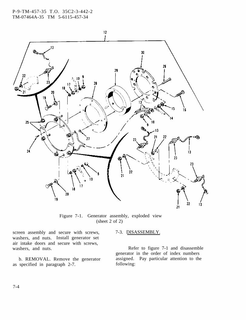
P-9-TM-457-35 T.O. 35C2-3-442-2TM-07464A-35 TM 5-6115-457-34
Figure 7-1. Generator assembly, exploded view(sheet 2 of 2)
screen assembly and secure with screws, 7-3. DISASSEMBLY.washers, and nuts. Install generator setair intake doors and secure with screws,washers, and nuts. Refer to figure 7-1 and disassemble
generator in the order of index numbersb. REMOVAL. Remove the generator assigned. Pay particular attention to the
as specified in paragraph 2-7. following:
7-4
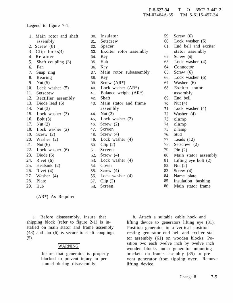
P-8-627-34 T O 35C2-3-442-2TM-07464A-35 TM 5-6115-457-34
Legend to figure 7-1:
1. Main rotorassembly
2. Screw (8)3. Clip locks4. Retainer5.6.7.8.9.
10.11.12.13.14.15.16.17.18.19.20.21.22.23.24.25.26.27.28.29.
and shaft
4)
Shaft coupling (3)FanSnap ringBearingNut (5)Lock washer (5)SetscrewRectifier assemblyDiode lead (6)Nut (3)Lock washer (3)Bolt (3)Nut (2)Lock washer (2)Screw (2)Washer (2)Nut (6)Lock washer (6)Diode (6)Rivet (6)Heatsink (2)Rivet (4)Washer (4)PlateHub
(AR*) As Required
30.31.32.33.34.35.36.37.38.39.40.41.42.43.
44.45,46.47.48.49.50.51.52.53.54.55.56.57.58.
InsulatorSetscrewSpacerExciter rotor assemblyKeyHubKeyMain rotor subassemblyKeyScrew (AR*)Lock washer (AR*)Balance weight (AR*)ShaftMain stator and frameassemblyNut (2)Lock washer (2)Screw (2)ScreenScrew (4)Lock washer (4)Clip (2)ScreenScrew (4)Lock washer (4)CoverScrew (4)Lock washer (4)Clip (2)Screen
a. Before disassembly, insure thatshipping block (refer to figure 2-1) is in-stalled on main stator and frame assembly(43) and fan (6) is secure to shaft couplings(5).
WARNING
Insure that generator is properlyblocked to prevent injury to per-sonnel during disassembly.
59.60.61.
62.63.64.65.66.67.68.
69.70.71.72.73.74.75.76.77.78.79.80.81.82.83.84.85.86.
Screw (6)Lock washer (6)End bell and exciterstator assemblyScrew (4)Lock washer (4)ConnectorScrew (6)Lock washer (6)Washer (6)Exciter statorassemblyEnd bellNut (4)Lock washer (4)Washer (4)clampclampc lampStudLeads (12)Setscrew (2)Pin (2)Main stator assemblyLifting eye bolt (2)Nut (2)Screw (4)Name plateInsulation bushingMain stator frame
b. Attach a suitable cable hook andlifting device to generators lifting eye (81).Position generator in a vertical positionresting generator end bell and exciter sta-tor assembly (61) on wooden blocks. Po-sition two each twelve inch by twelve inchwooden blocks under generator mountingbrackets on frame assembly (85) to pre-vent generator from tipping over. Removelifting device.
Change 8 7-5

P-8-627-34 T O 35C2-3-442-2TM-07464A-35 TM 5-6115-457-34
c. Remove shipping block. Bend downcorners of clip locks (3) and using a suitabletool hold shaft couplings (5) and remove twoscrews (2) 180 degrees apart. Install lift-ing fixture (figure 2-1, view I) and securewith two (0.500-20 x 3.00) screws to mainrotor and shaft assembly (l). Install lift-ing eyebolt (81) in lifting fixture. Using acable hook and lifting device, lift main rotorand shaft assembly (1) from main stator andframe assembly (43).
d. Place main rotor and shaft assembly(1) on a bench resting the main rotor sub-assembly (37) on cushion material, to pre-vent damage. Allow fan (6) and shaftcoupling (5) to hang over side of bench.
e. Remove lifting eyes from main rotorand shaft assembly (l).
f. Remove screws (2), clip locks (3),retainer (4), shaft couplings (5), and fan (6).Disconnect fan (6) from shaft couplings (5)by removing shipping screws and nuts.
CAUTION
Do not remove bearing (8) unlessproven defective at time of in-spection or further disassemblyis required.
g . Remove snap ring (7) and using asuitable puller, remove bearing (8) fromshaft (42).
h. Tag and disconnect electrical leadsfrom rectifier assembly (12) by removingnuts (9) and lock washers (10). Removesetscrew (11) and remove rectifier assem-bly (12) from shaft (42).
NOTE
Do not disassembly rectifier assem-bly unless proven defective at timeof inspection.
i . Disassembly of rectifier assembly(12) as follows:
1. Disconnect diode leads (13).2. Remove diodes (23) from heat
sinks (25).
WARNING
Avoid breathing fumes generated byunsoldering/soldering. Eye pro-tection is required.
3. Unsolder leads (13) from diodes(23) using suitable soldering equipment.
4. Remove heat sinks (25) fromplate (28) by removing rivet (24).
5. Separate insulator (30), hub (29),and plate (28).
j. Remove setscrew (31) and using asuitable puller, remove spacer (32), exciterrotor assembly (33), and key (34) fromshaft (42).
CAUTION
Do not remove main rotor sub-assembly (37) from shaft (42)unless found defective atinspection.
k. Using a suitable puller, remove hub(35) and key (36) from shaft (42).
1. Using a suitable press, press shaft(42) from main rotor subassembly (37) andremove key (38).
m. Turn main stator and frame assem-bly (43) over and position frame assemblyon wooden blocks with end bell on top. Blockassembly to prevent tipping.
n. Remove screens (47, 51, and 58) andcover (54).
o. Remove end bell and exciter statorassembly (61).
p. Lift connector (64) from side of endbell (69), tag and unsolder exciter stator(68) leads from connector (64). Removeexciter stator assembly (68) from end bellassembly.
7-6 Change 8

P-8-627-34 T O 35C2-3-442-2TM-07464A-35 TM 5-6115-457-34
CAUTION
Remove main stator assembly (80)only if found defective at time ofinspection.
q. Remove clamps (73, 74, and 75).
WARNING
Drilling operations create metal chipswhich may enter the eye. Eye protec-tion is required.r . Remove two setscrews (78) and using
0.1250 inch drill, drill a hole 0.375 inchdeep in each pin (79). Using an easy outtool remove pins and remove main statorassembly (80) from main stator frame (86)using a suitable puller.7-4. CLEANING.
WARNING
Compressed air used for cleaning anddrying purposes can create airborneparticles that may enter the eyes.Pressure shall not exceed 30 psig.Eye protection is required.
a. Use a clean cloth and low-pressurecompressed air (10-15 pounds pressure)and remove dust and dirt fro m windings andframe.
b. Use a clean lint-free cloth moistenedwith an approved cleaning solvent to removeheavy deposits from windings and drythoroughly.
c. Clean rectifier assembly with a cleanlint-free cloth moistened with an approvedcleaning solvent and dry thoroughly.
WARNING
Cleaning Solvents are flammable andmoderately toxic to skin, eyes andrespiratory tract. Eye and skinprotec t ion required. Good generalventilation is normally adequate.
d. Clean all metal parts with anapproved cleaning solvent and drythoroughly.
7-5.
a.
Appropriate glass head blastingmay be used toremove paint andcorrosion as necessary. Inaccordance with TO 1-1-2.
INSPECTION.
Inspect generator frames for cracksand burred mating surfaces.
b. Inspect generator frames for crackedwelds and distortion.
c. Inspect shaft couplings for distortionand elongated holes.
d. Inspect shaft for nicks and scratches.e. Inspect fan for distortion, elongated
holes, cracked welds or chipped blades.f. Inspect screens for distortion and
bent corners.g. Inspect nuts, bolts, and screws for
damaged threads and heads.h. Rotate bearing and check for free-
dom of movement, flat spots, binding, andsigns of overheating. Measure bearinginside diameter, diameter should be
+0. 00002.7559 -0.0008
inches. Measure bearing
outside diameter, diameter should be
5.9005 +0. 0000-0.0008
inches.
i. Measure shaft bearing contact sur-face, shaft should be 2.7565 to 2.7560 inches.
j . Measure end bell bearing contact,end bell should be 5.9062 to 5.9055 inches.
NOTE
Generator windings temperatureshould be approximately 77° F dur-ing resistance checks. Resistancechecks should be made using aKelvin Bridge for resistance valuesbelow one ohm, and a WhetstoneBridge for values above one ohm.Other suitable low resistance typemeasuring devices may be used.Resistance values of windings are tobe within a tolerance of ± 10 percent.
k. Check main stator resistance values
Change 9 7-7
P-8-627-34 T O 35C2-3-442-2TM-07464A-35 TM 5-6115-457-34
between leads: T1-T4, T2-T5, T3-T6,T7-T10, T8-T11, and T9-T12. Resistanceshould be 0.00974 ohm for 50/60 hertzgenerator sets and 0.00490 ohm for400 hertz generator sets.
1. Check main rotor resistance valuebetween leads R4 and R5. Resistanceshould be 0.834 ohm for 50/60 hertzgenerator sets and 0.750 ohm for 400 hertzgenerator sets.
m. Check exciter rotor resistancevalues between leads R1-R2 and R1-R3.Resistance should be 0.0772 ohms.
n. Check exciter stator resistancevalue between leads F1 and F2. Resistanceshould be 1.23 ohms for 50/60 hertz gen-erator sets and 1.51 ohms for 400 hertzgenerator sets.
NOTE
Generator windings insulationresistance checks should be madeusing a 500 volt megger. Resis-tance readings should be a mini-mum of 50K ohms.
o. Check insulation resistance of mainstator windings by electrically bonding alltwelve leads together and connecting amegger between leads and stator frame.
p. Check insulation resistance of mainrotor winding by electrically bonding rotorleads together and connect a megger be-tween leads and rotor frame or rotor shaft.
q. Check insulation resistance of exciterrotor winding by electrically bonding thethree rotor leads together and connecting amegger between leads and rotor frame orrotor shaft.
r. Check insulation resistance of exciterstator winding by electrically bonding statolleads together and connecting a meggerbetween leads and stator frame.
s. Inspect rectifier assembly as follows:
1. Disconnect diodes from the recti-fier assembly and test each diode separatelyusing a suitable multimeter
2. Connect the multimeter acrossthe diode, meter positive lead on the anode(back end of arrow) and negative meter leadon the cathode (tip of the arrow). A lowresistance should be indicated.
3. Reverse multimeter leads, ahigh resistance (several K ohms) should beindicated,
t. Inspect paint for damage.7-6. REPAIR OR REBUILD.
Welding operations produce heat,highly toxic fumes, injuriousradiation, metal slag and air-borne particles. Welding gog-gles, with proper tinted lenses,apron or jacket and welder’sboots are required.
a. Repair cracks by welding as long asit does not distort or empair strength ofpart.
b. Remove burrs or nicks using asuitable file or stone.
c. Straighten dented or distorted sheetmetal parts using suitable tools.
d. Repair or rebuild main statorassembly as specified in figure 7-2 for50/60 hertz generators or figure 7-3 for400 hertz generators.
e. Repair or rebuild main rotor assembly as speci-fied in figure 7-4 for 50/60 hertz generators or figure 7-5for 400 hertz generators.
NOTEApply 6 to 12 VDC to rotor leads.Pass a compass around the diameter ofthe rotor noting which pole of thecompass pointer is attracted to each ofthe wound poles. If the windings arecorrectly connected, all wound poleswill attract the same compass pole.
f. Repair or rebuild exciter rotor assembly asspecified in figure 7-6 for 50/60 hertz generators or fig-ure 7-7 for 400 hertz generators.
g. Repair or rebuild exciter stator assembly asspecified in figure 7-8 for 50/60 hertz generators or fig-ure 7-9 for 400 hertz generators.
h. Remove damaged paint with a suitable scraper.Blend in edges, prime, and paint damaged areas.
7-8 Change 9

P-86-27-34 T O 35C2-3-442-2TM-07464A-35 TM 5-6115-457-34
7-7. REASSEMBLY. numbers assigned. Pay particular atten-Refer to figure 7-1 and reassemble tion to the following.
generator in the reverse sequence of index
Change 9 7-8A/(7-8B Blank)

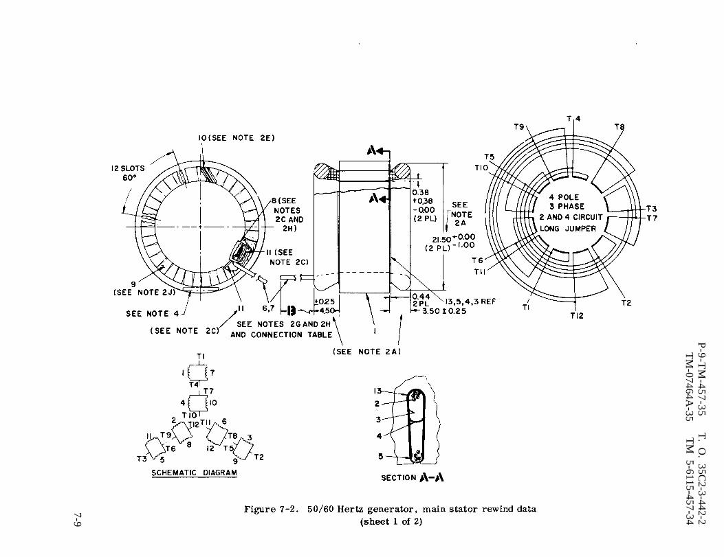
Figure 7-2.
P-9-T
M-457-35
T. O
. 35C2-3-442-2
TM
-07464A-35
TM
5-6115-457-34
7-9
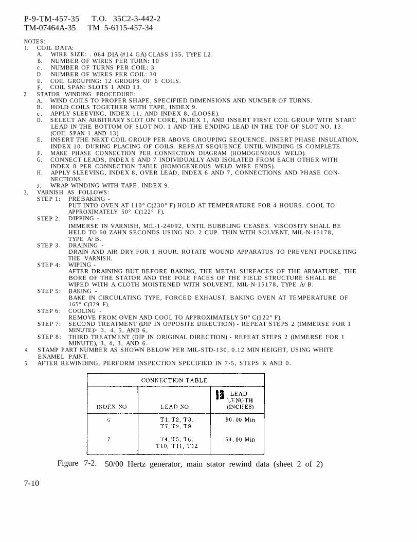
P-9-TM-457-35 T.O. 35C2-3-442-2TM-07464A-35 TM 5-6115-457-34
NOTES:1. COIL DATA:
A. WIRE SIZE: . 064 DIA (#14 GA) CLASS 155, TYPE L2.B. NUMBER OF WIRES PER TURN: 10c. NUMBER OF TURNS PER COIL: 3D. NUMBER OF WIRES PER COIL: 30E. COIL GROUPING: 12 GROUPS OF 6 COILS.F. COIL SPAN: SLOTS 1 AND 13.
2. STATOR WINDING PROCEDURE:A. WIND COILS TO PROPER SHAPE, SPECIFIED DIMENSIONS AND NUMBER OF TURNS.B. HOLD COILS TOGETHER WITH TAPE, INDEX 9.c . APPLY SLEEVING, INDEX 11, AND INDEX 8, (LOOSE).D. SELECT AN ARBITRARY SLOT ON CORE, INDEX 1, AND INSERT FIRST COIL GROUP WITH START
LEAD IN THE BOTTOM OF SLOT NO. 1 AND THE ENDING LEAD IN THE TOP OF SLOT NO. 13.(COIL SPAN 1 AND 13).
E. INSERT THE NEXT COIL GROUP PER ABOVE GROUPING SEQUENCE. INSERT PHASE INSULATION,INDEX 10, DURING PLACING OF COILS. REPEAT SEQUENCE UNTIL WINDING IS COMPLETE.
F. MAKE PHASE CONNECTION PER CONNECTION DIAGRAM (HOMOGENEOUS WELD).G. CONNECT LEADS, INDEX 6 AND 7 INDIVIDUALLY AND ISOLATED FROM EACH OTHER WITH
INDEX 8 PER CONNECTION TABLE (HOMOGENEOUS WELD WIRE ENDS).H. APPLY SLEEVING, INDEX 8, OVER LEAD, INDEX 6 AND 7, CONNECTIONS AND PHASE CON-
NECTIONS.J. WRAP WINDING WITH TAPE, INDEX 9.
3. VARNISH AS FOLLOWS:STEP 1:
STEP 2:
STEP 3.
STEP 4:
STEP 5:
STEP 6:
STEP 7:
STEP 8:
PREBAKING -PUT INTO OVEN AT 110° C(230° F) HOLD AT TEMPERATURE FOR 4 HOURS. COOL TOAPPROXIMATELY 50° C(122° F).DIPPING -IMMERSE IN VARNISH, MIL-1-24092, UNTIL BUBBLING CEASES. VISCOSITY SHALL BEHELD TO 60 ZAHN SECONDS USING NO. 2 CUP. THIN WITH SOLVENT, MIL-N-15178,TYPE A/B.DRAINING -DRAIN AND AIR DRY FOR 1 HOUR. ROTATE WOUND APPARATUS TO PREVENT POCKETINGTHE VARNISH.WIPING -AFTER DRAINING BUT BEFORE BAKING, THE METAL SURFACES OF THE ARMATURE, THEBORE OF THE STATOR AND THE POLE FACES OF THE FIELD STRUCTURE SHALL BEWIPED WITH A CLOTH MOISTENED WITH SOLVENT, MIL-N-15178, TYPE A/B.BAKING -BAKE IN CIRCULATING TYPE, FORCED EXHAUST, BAKING OVEN AT TEMPERATURE OF165° C(329 F),COOLING -REMOVE FROM OVEN AND COOL TO APPROXIMATELY 50° C(122° F).SECOND TREATMENT (DIP IN OPPOSITE DIRECTION) - REPEAT STEPS 2 (IMMERSE FOR 1MINUTE)> 3, 4, 5, AND 6,THIRD TREATMENT (DIP IN ORIGINAL DIRECTION) - REPEAT STEPS 2 (IMMERSE FOR 1MINUTE), 3, 4, 3, AND 6.
4. STAMP PART NUMBER AS SHOWN BELOW PER MIL-STD-130, 0.12 MIN HEIGHT, USING WHITEENAMEL PAINT.
5. AFTER REWINDING, PERFORM INSPECTION SPECIFIED IN 7-5, STEPS K AND 0.
Figure 7-2. 50/00 Hertz generator, main stator rewind data (sheet 2 of 2)
7-10

P-8-627-34 T O 35C2-3-442-2TM-07464A-35 TM 5-6115-457-34
Legend to figure 7-2:
1. Stator core2. Magnet wire 0.064 DIA (#14)3. Slot cell insulation (72)4. Center spacer 0.032 thick5. Wedge (72)6. Lead (6)7. Lead (6)
NOTE
Figure 1-28 is the generator as-sembly simplified schematicdiagram.
a. Heat main stator frame (86) in asuitable oven to 200°F for ease of in-stalling main stator assembly (80).
b. Place heated main stator frameassembly (86) in a vertical position, rest-ing exciter end on wooden blocks.
CAUTION
Exercise care when installing mainstator assembly (80) into mainstator frame (86) to prevent damageto windings.
c. Position main stator assembly (80)so that pin (79) holes are aligned with holesin main stator frame (86). Start leads (77)through insulation bushing (85). Pull leadsand slide main stator assembly (80) intomain stator frame (86) until pin (79) holesare aligned.
d. Install pin (79) and setscrew (78)tighten to 5 foot-pound torque.
e. Cut output leads (77) to lengthsspecified in table 7-1. Strip insulationback 0.62 inches and install terminal lugson leads (77).
8. Insulation sleeving 0.625 ID9. Untreated glass tape 0.010 x 0.75
10. Phase insulation11. Insulation sleeving 0.330 ID12. Varnish13. Insulation slot cell (72)
Table 7-1. Generator Output Lead Lengths
f. Position clamp (75) on generatorand install generator output leadsin the following sequence starting atexciter end: T12, T11, TI0, T9, T8, andT7. Install clamp (74) and install followingoutput leads starting at exciter end: T6,T5, T4, T3, T2, and T1. Install clamp(73) and tighten nuts (70) finger tight.
Change 8 7-11

P-8-627-34 T O 35C2-3-442-2TM-07464A-35 TM 5-6115-457-34
Figure 7-3. 400 Hertz generator, main stator rewind data(sheet 1 of 2)
7-12 Change 8

P-9-TM-457-35 T.O. 35C2-3-442-2TM-07464A-35 TM 5-6115-457-34
NOTES:1. COIL DATA
A. WIRE SIZE:0.051 DIA (#16 GA) CLASS 155, TYPE L2.B. NUMBER OF WIRES PER TURN: 20c . NUMBER OF TURNS PER COIL: 1D. NUMBER OF. WIRES PER COIL: 20E. COIL GROUPING: 36 GROUPS OF 2 COILS
36 GROUPS OF 1 COILF. COIL SPAN: SLOTS 1 & 4
2. STATOR WINDING PROCEDURE:A. WIND COILS TO PROPER SHAPE, SPECIFIED DIMENSIONS AND NUMBER OF TURNS.B. HOLD COILS TOGETHER WITH TAPE, INDEX NO. 9c . APPLY SLEEVING, INDEX NO. 11 & INDEX NO. 8( LOOSE).D. SELECT AN ARBITRARY SLOT ON CORE, INDEX NO. 1, AND INSERT FIRST COIL GROUP WITH
START LEAD IN THE BOTTOM OF SLOT NO. 1 AND THE ENDING LEAD IN THE TOP OF SLOTNO. 4, (COIL SPAN 1 & 4).
E. INSERT THE NEXT COIL GROUP PER ABOVE GROUPING SEQUENCE. INSERT PHASE INSULATION,INDEX NO. 10, DURING PLACING OF COILS. REPEAT SEQUENCE UNTIL WINDING IS COMPLETE.
F. MAKE PHASE CONNECTION PER CONNECTION DIAGRAM, HOMOGENEOUS WELD.G. CONNECT LEADS, INDEX NO. 6 TO T1, T2, T3, T7, T8, T9 AND LEADS, INDEX NO. 7 TO T4, T5,
T6, TI0, T11, T12" PER CONNECTION DIAGRAM & TABLE, HOMOGENEOUS WELD.H. APPLY SLEEVING, INDEX NO. 8 OVER LEAD, INDEX NO. 6 & 7, CONNECTIONS AND PHASE
CONNECTIONS.J. WRAP WINDING WITH TAPE, INDEX NO. 9.
3. VARNISH DATA SPECIFIED IN FIGURE 7-2 NOTE 3.4. STAMP PART NUMBER AS SHOWN BELOW PER MIL-STD-130, 0.12 MIN HEIGHT, USING WHITE ENAMEL
PAINT.30554 ASSY 70-4521MFG (MFG CODE)
5. AFTER REWINDING, PERFORM INSPECTION SPECIFIED IN PARAGRAPH 7-5. STEPS K AND O.
Figure 7-3. 400 Hertz generator, main stator rewind data(sheet 2 of 2)
Legend to figure 7-3:
1. Stator core2. Magnet wire 0.051 DIA (#16)3. Slot cell insulation (108)4. Center spacer 0.032 thick5. Wedge (108)6. Lead (6)7. Lead (6)
8. Insulation sleeving 0.625 ID9. Untreated glass tape 0.010 x 0.75
10. Phase insulation11. Insulation sleeving 0.330 ID12. Varnish13. Slot cell insulation (108)
7-13
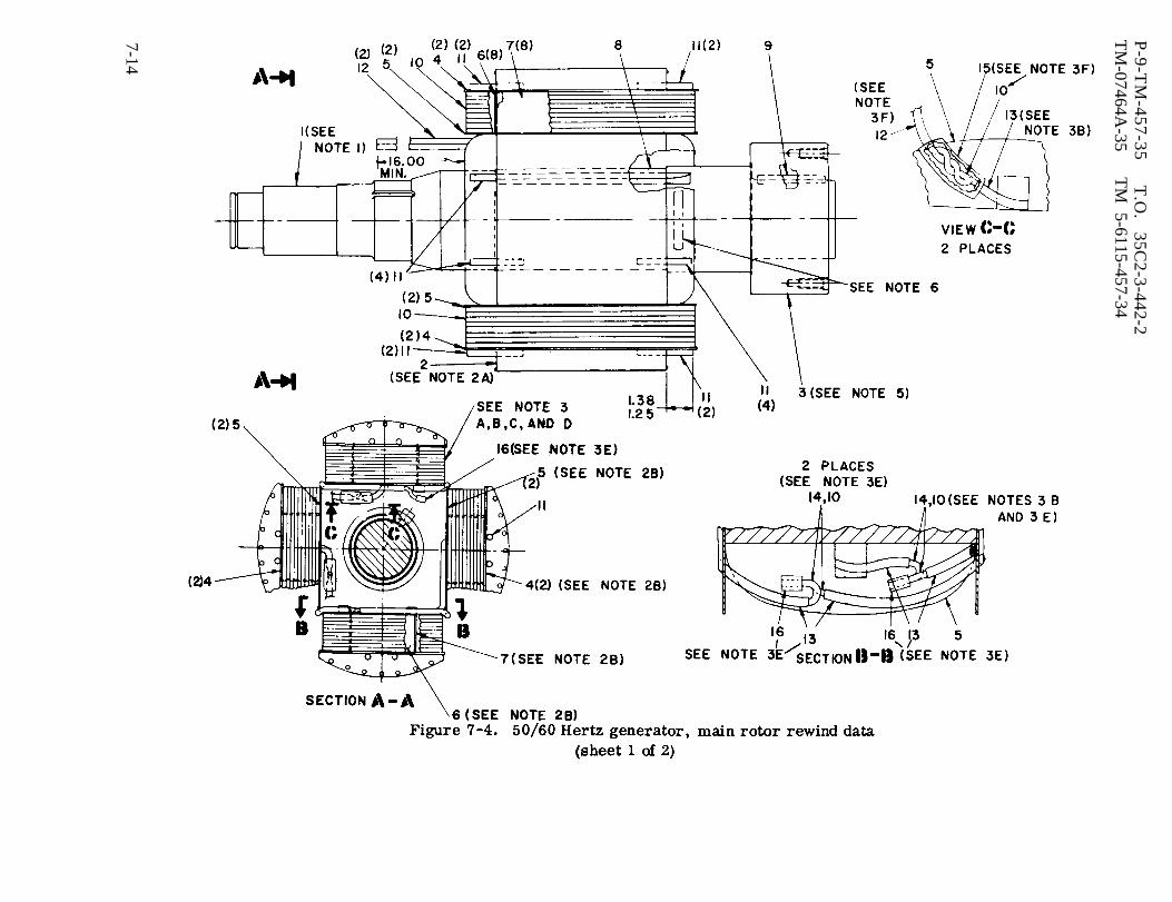
Figure 7-4.
P-9-T
M-457-35
T.O
. 35C
2-3-442-2T
M-07464A
-35T
M 5-6115-457-34
7-14

P-8-627-34 T O 35C2-3-442-2TM-07464A-35 TM 5-6115-457-34
NOTES:1. PRESS FIT SHAFT, INDEX 1, INTO CORE, INDEX 2, TO SHOULDER ON SHAFT INDEX 1.2. INSULATING:
A. APPLY EPOXY, INDEX 14, TO POLE BOTTOM, POLE SIDES AND POLE ENDS.B. INSTALL INSULATION, INDEX 5, ON BOTTOM POLE SIDES. INSTALL INSULATION, INDEX 4,
ON TOP POLE SIDES. INSTALL INSULATION, INDEX 6, ON POLE ENDS. INSTALL INSULATION,INDEX 7, ON POLE SIDES.
3. WINDING:A. ADJUST WIRE TENSION TO 70 LBS.B. APPLY SLEEVE, INDEX 13, TO START LEAD OF EACH COIL.c . WIND THE FIRST LAYER WITH 10 TURNS TO FILL THE WINDING SPACE. FORM THE COIL SIDES
WITH A FIBRE BLOCK TO OBTAIN FLAT AND TIGHT WINDING. DO NOT FORM COIL ENDS. APPLYEPOXY, INDEX 14.
D. CONTINUE WINDING COMPLETE COIL AS DESCRIBED IN WINDING NOTE 3B, MAKING SURE TOAPPLY EPOXY, INDEX 14, TO COVER ALL TURNS AND TO FILL ALL VOIDS THROUGH THE ENTIREWINDING. THIS WILL REQUIRE BRUSHING EPOXY ON ALL LAYERS. FORM COIL SIDES WHILEWINDING TO PRODUCE FLAT SIDES. WIND EACH COIL WITH 160 TURNS, 10 TURNS PER LAYER,4 COILS.
E. APPLY SLEEVING, INDEX 13, TO ENDING LEAD OF EACH COIL. SELECT START LEAD 0FARBITRARY COIL AND CONNECT COILS IN SERIES, HOMOGENOUS WELD, AND USE PARALLELSPLICE, INDEX 16.
F. CONNECT LEADS, INDEX 12, TO REMAINING TWO LEADS, SOLDERUSING SOLDER, INDEX 17.
4. BAKE COMPLETED ROTOR FOR A MIN. OF 24 HOURS AT 325” F to 35° F.5. HEAT HUB, INDEX 3, TO 400” F THEN SHRINK FIT ON SHAFT, INDEX 1, TO SHOULDER.6. STAMP PART NUMBER AS SHOWN BELOW PER MIL-STD-130, 0.12 MIN HEIGT. USING WHITE
ENAMEL PAINT.30554 ASSY 70-4509MFG (MFG CODE)
7. AFTER REWINDING, PERFORM INSPECTION SPECIFIED IN PARAGRAPH 7-5, STEPS I AND P.
Figure 7-4. 50/60 Hertz generator, main rotor rewind data(sheet 2 of 2)
Legend to figure 7-4:
1.2.3.4.5.6.7.
Form
Shaft 8. Key 13.Rotor core 9. KeyDrive hub coupling 10. Magnet wire HPT 14.Pole insulation (8) 0.085 X 0.200 15.Pole insulation (8) 11. Pin (16) 16.Pole insulation (8) 12. Lead (2) 17.Pole insulation (8)
Insulation sleeving0.234 IDEpoxy compoundInsulation sleevingSplice (3)Solder
an appropriate five inch loop in out- leads in connector (64) opening. Installputs leads between insulation bushing (85)and clamps. Make sure leads are inproper position and tighten nuts (70).
WARNING
Avoid breathing fumes generated byunsoldering/soldering. Eye pro-tection is required.
g. Insert exciter stator assembly (68)
exciter stator assembly into end bell (69),pulling leads through opening as exciterstator is installed. Cut exciter statorassembly leads to permit connection toconnector (64), when connector isapproximately one inch from end bell (69).Strip lead insulation back approximately0.375 inch and solder lead F1 to connectorpin C and lead F2 to connector pin B.Install connector (64) with key on top.
Change 8 7-15

P-8-627-34TM-07464A-35
T O 35C2-3-442-2TM 5-6115-457-34
Figure 7-5. 400 Hertz generator, main rot or rewind data(sheet 1 of 2)
7-16 Change 8

P-9-TM-457-35 T.O. 35C2-3-442-2TM-07464A-35 TM 5-6115-457-34
NOTES:1. IF HUB WAS REMOVED, HEAT HUB, INDEX 3, TO 450° F, THEN SHRINK-FIT ON SHAFT, INDEX 1, TO SHOULDER.2. COIL DATA:
A. WIRE SIZE: 0.040 DIA (#18 GA) CLASS 155, TYPE L2.B. NO. OF WIRES PER TURN: 16C. NO. OF TURNS PER COIL: 29D. COIL GROUPING: 1 GROUP OF 12 COILS.
3. WINDING PROCEDURE:A. WIND COILS TO PROPER SHAPE, SPECIFIED DIMENSIONS AND NUMBER OF TURNS.B. HOLD COILS TOGETHER WITH TAPE, INDEX 9.C. APPLY INSULATION SLEEVING, INDEX 8. AND INDEX 13 (LOOSE).D. SELECT AN ARBITRARY SLOT ON CORE, INDEX 2, AND INSERT FIRST COIL WITH START LEAD IN THE BOTTOM
OF SLOT NO. 1 AND THE ENDING LEAD IN THE BOTTOM OF SLOT NO. 2.E. REPEAT SEQUENCE UNTIL WINDING IS COMPLETE.
WARNINGWELDING OPERATIONS PRODUCE HEAT, HIGHLY TOXIC FUMES, INJURIOUS RADIA-TION, METAL SLAG AND AIRBORN PARTICLES. WELDING GOGGLES, WITH PROPERTINTED LENSES, APRON OR JACKET AND WELDER’S BOOTS ARE REQUIRED.
F. CONNECT ENDING LEAD OF ARBITRARY COIL TO STARTING LEAD OF ADJACENT COIL. CONTINUE CON-NECTING COIL ENDING LEAD TO ADJACENT COIL STARTING LEAD FOR ALL COILS UNTIL ONLY TWO LEADSREMAIN. HOMOGENEOUS WELD ALL CONNECTIONS.
G. CONNECT LEADS, INDEX 7, TO REMAINING TWO COIL LEADS AND HOMOGENEOUS WELD.H. WRAP WINDING WITH TAPE, INDEX 9.J. INSTALL RETAINER. INDEX 10. USING TAPE. INDEX 12.
4. VARNISH AS FOLLOWS:STEP 1:
STEP 2:
STEP 3:
STEP 4.
PREBAKING -PUT INTO OVEN AT 110” C (230° F). HOLD AT TEMPERATURE FOR 4 HOURS. COOL TO APPROXIMATELY50°c (122° F).DIPPINGIMMERSE IN VARNISH. 70-4560, UNTIL BUBBLING CEASES. VISCOSITY SHALL BE HELD 20 ZAHN SEC-ONDS USING A NO. 2 CUP. THIN WITH SOLVENT, MIL-N-15178, TYPE A/B TO MAINTAIN VISCOSITY.DRAINING -DRAIN AND AIR DRY FOR 1 HOUR. ROTATE WOUND APPARATUS TO PREVENT POCKETING THEVARNISH.WIPINGAFTER DRAINING BUT BEFORE BAKING, THE METAL SURFACES OF THE ARMATURE, THE BORE OFTHE ROTOR AND THE POLE FACES SHALL BE WIPED WITH A CLOTH MOISTENED WITH SOLVENT,MIL-M-15178. TYPE A/B.
STEP 5:
STEP 6:
STEP 7:
STEP 8:
B A K I N G -PUT INTO A CIRCULATING TYPE, FORCED EXHAUST, BAKING OVEN AT TEMPERATURE OF 80°C (176” F)FOR 3 HOURS, INCREASE TEMPERATURE TO 165°C (329” F) AND CONTINUE TO BAKE AN ADDITIONAL7 HOURS.COOLING -REMOVE FROM OVEN AND COOL TO APPROXIMATELY 50°C (122” F).SECOND TREATMENT (DIP IN OPPOSITE DIRECTION) - REPEAT STEPS 2 (IMMERSE FOR 1 MINUTE) 3,4,5, AND 6.THIRD TREATMENT (DIP IN ORIGINAL DIRECTION) - REPEAT STEPS 2 (IMMERSE FOR 1 MINUTE) 3,4,5. AND 6.
5. STAMP PART NUMBER AS SHOWN BELOW PER MIL-STD-130, 0.12 MIN HEIGHT, USING WHITE ENAMEL PAINT30554 ASSY 70-4518MFG (MFG CODE)
6. AFTER REWINDING, PERFORM INSPECTION SPECIFIED IN PARAGRAPH 7-5, STEPS I AND P.
Figure 7-5. 400 Hertz generator, main rotor rewind data(sheet 2 of 2)
Legend to figure 7-5:
1.2.3.4.5.
6.7.
ShaftRotor coreDrive hub couplingKeyMagnet wire0.40 DIA (#18)Slot cell insulation (24)Lead (2)
8. Insulation sleeving0.294 ID
9. Untreated glass tape0.010X0.75
10. Retainer (2)11. Insulation
wedge (24)12. Banding tape
13. Insulation sleeving0.330 ID
14. Varnish15. Yellow locking
compound GRB16. Screw17. Cable clamp (2)
Change 7 7-17

Figure 7-6.
P-9-T
M-457-35
T.O
. 35C
2-3-442-2T
M-07464A
-35T
M
5-6115-457-34
7-18
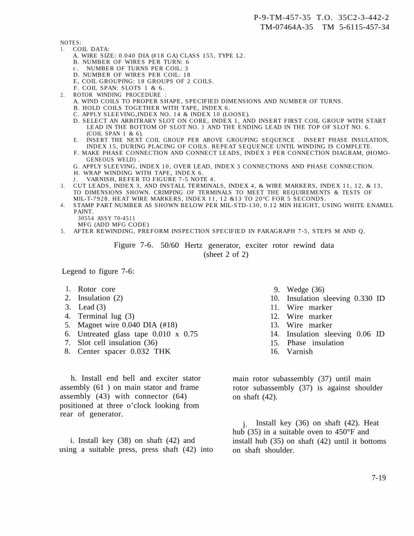
P-9-TM-457-35 T.O. 35C2-3-442-2TM-07464A-35 TM 5-6115-457-34
NOTES:1. COIL DATA:
A. WIRE SIZE: 0.040 DIA (#18 GA) CLASS 155, TYPE L2.B. NUMBER OF WIRES PER TURN: 6c . NUMBER OF TURNS PER COIL: 3D. NUMBER OF WIRES PER COIL: 18E, COIL GROUPING: 18 GROUPS OF 2 COILS.F. COIL SPAN: SLOTS 1 & 6.
2. ROTOR WINDING PROCEDURE :A. WIND COILS TO PROPER SHAPE, SPECIFIED DIMENSIONS AND NUMBER OF TURNS.B. HOLD COILS TOGETHER WITH TAPE, INDEX 6.C. APPLY SLEEVING,INDEX NO. 14 & INDEX 10 (LOOSE).D. SELECT AN ARBITRARY SLOT ON CORE, INDEX 1, AND INSERT FIRST COIL GROUP WITH START
LEAD IN THE BOTTOM OF SLOT NO. 1 AND THE ENDING LEAD IN THE TOP OF SLOT NO. 6.(COIL SPAN 1 & 6).
E. INSERT THE NEXT COIL GROUP PER ABOVE GROUPING SEQUENCE . INSERT PHASE INSULATION,INDEX 15, DURING PLACING OF COILS. REPEAT SEQUENCE UNTIL WINDING IS COMPLETE.
F. MAKE PHASE CONNECTION AND CONNECT LEADS, INDEX 3 PER CONNECTION DIAGRAM, (HOMO-GENEOUS WELD) .
G. APPLY SLEEVING, INDEX 10, OVER LEAD, INDEX 3 CONNECTIONS AND PHASE CONNECTION.H. WRAP WINDING WITH TAPE, INDEX 6.J. VARNISH, REFER TO FIGURE 7-5 NOTE 4.
3. CUT LEADS, INDEX 3, AND INSTALL TERMINALS, INDEX 4, & WIRE MARKERS, INDEX 11, 12, & 13,TO DIMENSIONS SHOWN. CRIMPING OF TERMINALS TO MEET THE REQUIREMENTS & TESTS OFMIL-T-7928. HEAT WIRE MARKERS, INDEX 11, 12 &13 TO 20°C FOR 5 SECONDS.
4. STAMP PART NUMBER AS SHOWN BELOW PER MIL-STD-130, 0.12 MIN HEIGHT, USING WHITE ENAMELPAINT.
30554 ASSY 70-4511MFG (ADD MFG CODE)
5. AFTER REWINDING, PREFORM INSPECTION SPECIFIED IN PARAGRAPH 7-5, STEPS M AND Q.
Figure 7-6. 50/60 Hertz generator, exciter rotor rewind data(sheet 2 of 2)
Legend to figure 7-6:
1.2.3.4.5.6.7.8.
Rotor coreInsulation (2)Lead (3)Terminal lug (3)Magnet wire 0.040 DIA (#18)Untreated glass tape 0.010 x 0.75Slot cell insulation (36)Center spacer 0.032 THK
h. Install end bell and exciter statorassembly (61 ) on main stator and frameassembly (43) with connector (64)positioned at three o’clock looking fromrear of generator.
i. Install key (38) on shaft (42) andusing a suitable press, press shaft (42) into
9.10.11.12.13.14.15.16.
Wedge (36)Insulation sleeving 0.330 IDWire markerWire markerWire markerInsulation sleeving 0.06 IDPhase insulationVarnish
main rotor subassembly (37) until mainrotor subassembly (37) is against shoulderon shaft (42).
j. Install key (36) on shaft (42). Heathub (35) in a suitable oven to 450°F andinstall hub (35) onon shaft shoulder.
shaft (42) until it bottoms
7-19
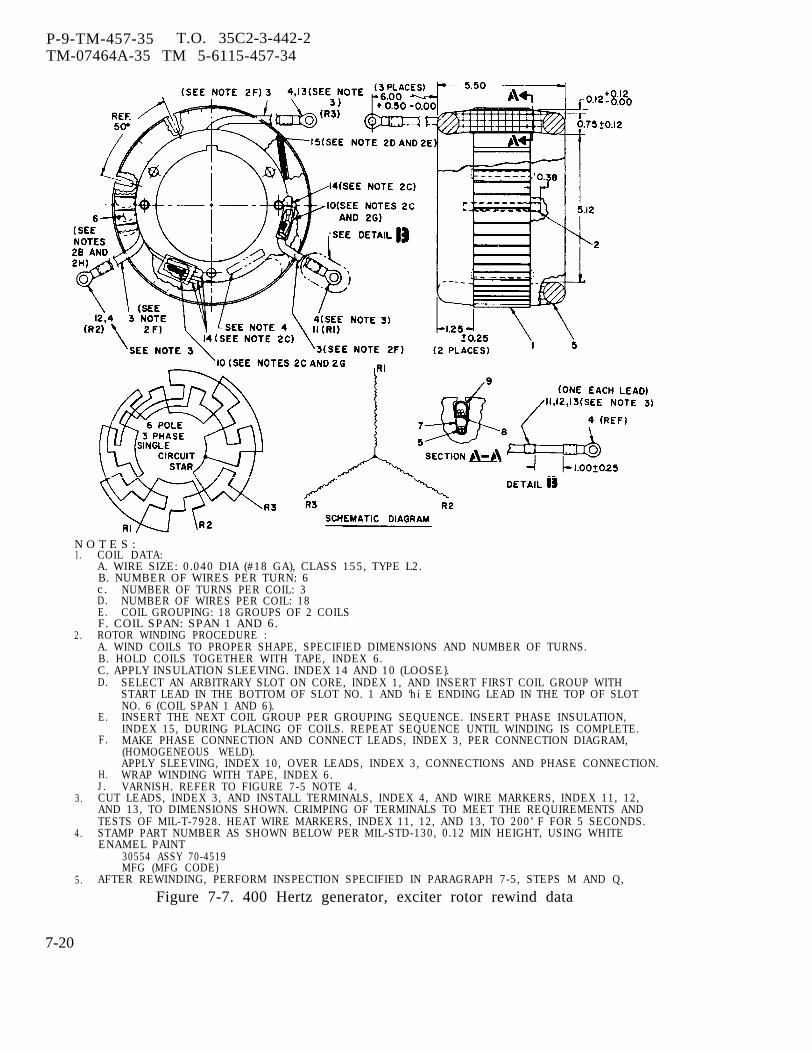
P-9-TM-457-35 T.O. 35C2-3-442-2TM-07464A-35 TM 5-6115-457-34
N O T E S :1. COIL DATA:
A. WIRE SIZE: 0.040 DIA (#18 GA), CLASS 155, TYPE L2.B. NUMBER OF WIRES PER TURN: 6c. NUMBER OF TURNS PER COIL: 3D. NUMBER OF WIRES PER COIL: 18E. COIL GROUPING: 18 GROUPS OF 2 COILSF. COIL SPAN: SPAN 1 AND 6.
2. ROTOR WINDING PROCEDURE :A. WIND COILS TO PROPER SHAPE, SPECIFIED DIMENSIONS AND NUMBER OF TURNS.B. HOLD COILS TOGETHER WITH TAPE, INDEX 6.C. APPLY INSULATION SLEEVING. INDEX 14 AND 10 (LOOSE}.D. SELECT AN ARBITRARY SLOT ON CORE, INDEX 1, AND INSERT FIRST COIL GROUP WITH
START LEAD IN THE BOTTOM OF SLOT NO. 1 AND ‘hi E ENDING LEAD IN THE TOP OF SLOTNO. 6 (COIL SPAN 1 AND 6).
E.
F.
INSERT THE NEXT COIL GROUP PER GROUPING SEQUENCE. INSERT PHASE INSULATION,INDEX 15, DURING PLACING OF COILS. REPEAT SEQUENCE UNTIL WINDING IS COMPLETE.MAKE PHASE CONNECTION AND CONNECT LEADS, INDEX 3, PER CONNECTION DIAGRAM,(HOMOGENEOUS WELD).APPLY SLEEVING, INDEX 10, OVER LEADS, INDEX 3, CONNECTIONS AND PHASE CONNECTION.WRAP WINDING WITH TAPE, INDEX 6.VARNISH. REFER TO FIGURE 7-5 NOTE 4.
H.J.
3. CUT LEADS, INDEX 3, AND INSTALL TERMINALS, INDEX 4, AND WIRE MARKERS, INDEX 11, 12,AND 13, TO DIMENSIONS SHOWN. CRIMPING OF TERMINALS TO MEET THE REQUIREMENTS ANDTESTS OF MIL-T-7928. HEAT WIRE MARKERS, INDEX 11, 12, AND 13, TO 200’ F FOR 5 SECONDS.
4. STAMP PART NUMBER AS SHOWN BELOW PER MIL-STD-130, 0.12 MIN HEIGHT, USING WHITEENAMEL PAINT
30554 ASSY 70-4519MFG (MFG CODE)
5. AFTER REWINDING, PERFORM INSPECTION SPECIFIED IN PARAGRAPH 7-5, STEPS M AND Q,
Figure 7-7. 400 Hertz generator, exciter rotor rewind data
7-20

P-8-627-34 T O 35C2-3-442-2TM-07464A-35 TM 5-6115-457-34
Legend to figure 7-7:
1. Rotor core2. Insulation (2)3. Lead (3)4. Terminal lug (3)5. Magnet wire 0.040 DIA (#18)6. Untreated glass tape
0.010 x 0.75
k. Install key (34) and exciterrotor assembly (33) on shaft (42). Usinga suitable press, press spacer (32) intoplace.
1. Assemble rectifier assembly (12)and position on shaft (42). Align setscrew(11) hole with hole in shaft (42).
m. Install setscrew (11 and 31) andtighten to 20 foot-pounds torque.
WARNING
Varnish, Insulating, is flammable andextremely toxic. Avoid eye and skincontact or breathing of vapors. Goodgeneral ventilation is normally ade-quate.
n. Apply insulation sleeving to mainrotor subassembly (37) leads R4 and R5.Position lead R5 at three o’clock and leadR4 at nine o’clock on shaft (42) looking frombearing end of shaft. Tape leads to shaft attwo evenly spaced positions between themain rotor subassembly (37) and exciterrotor assembly (33). Brush coat tape withvarnish. Position leads R4 and R5 throughtwo holes provided in exciter rotor assem-bly (33) and insulator (30). Cut leads longenough to connect a rectifier assembly (12).Strip lead insulation back 0.375 inch andinstall terminal lugs on leads. Connectleads R4 and R5 to rectifier assembly.
o. Position leads Rl, R2, and R3 fromexciter rotor assembly (33) through insu-lator (30) holes and cut leads long enough toconnect to rectifier assembly (12). Strip
7. Slot cell insulation 12. Wire marker8. Center spacer 13. Wire marker
0.032 thick 14. Insulation sleeving9. Wedge (36) O. 106 ID
10. Insulation sleeving 15. Phase insulation0.330 ID 16. Varnish
11. Wire marker
lead insulation back 0.375 inch and installterminal lugs and connect leads R1, R2, andR3 to rectifier assembly (12).
p. Using a suitable press, press bear-ing (8) against shoulder on shaft (42). In-stall snap ring (7) on shaft (42).
q. Place assembled shaft in a suitabledynamic balancing machine. Balanceassembled shaft in two planes. Rotateshaft at 600 to 800 RPM and balance shafton 50/60 hertz generators to 3.5 inch-ounceand on 400 hertz generators to 10 inch-ounceusing blance weights (41). To install bal-ance weight, place weight in proper positionon rotor and transfer two drill 0.2570 inchholes, one inch deep for each weight. Taphole for 5/16 - 18 UNC - 2B thread.Secure weights with screws (39) and lockwasher (40). Trim balance to 0.5 inch-ounce by removing metal from steel core ofmain rotor subassembly (37).
r . Place rotor and shaft assembly (1) ona bench resting main rotor subassembly (37)on a cushion material to prevent damage.Allow hub (35) to hang over side of bench.
NOTE
Securing fan to shaft couplings isonly to protect fan from damageand for ease of handling.
s. Position fan (6) on shaft couplings (5)and secure fan to shaft couplings with twosuitable screws and nuts 180 degrees apart.Install fan (6), shaft couplings (5), retainer
Change 8 7-21

P-8-627-34 T O 35C2-3-442-2TM-07464A-35 TM 5-6115-457-34
NOTES:1. COIL DATA:
A. WIRE SIZE: 0.057 DIA (#15GA), CLASS 155, TYPE L2.B. NUMBER OF POLES: 6c . NUMBER OF TURNS PER COIL: 85
2. STATOR WINDING PROCEDURE:A. INSULATE STATOR CORE, INDEX 1, COMPLETE USING INSULATION PLATE, INDEX 3, AND
SLOT CELL INSULATION, INDEX 4 AND INDEX 9.B. WIND STATOR COMPLETE, 6 COILS CONNECTED IN SERIES.c . CONNECT LEADS, INDEX 5, TO COILS, SEE DETAIL A, HOMOGENEOUS WELD.D. APPLY SLEEVING, INDEX 6.E. TIE LEADS AND ENDLOOPS WITH TAPE, INDEX 7.
3. VARNISH, REFER TO FIGURE 7-2 NOTE 3.4. STAMP PART NUMBER AS SHOWN BELOW PER MIL-STD-130, 0.12 MIN HEIGHT, USING WHITE
ENAMEL PAINT30554 ASSY 70-4514MFG (MFG CODE)
5. AFTER REWINDING, PERFORM INSPECTION SPECIFIED IN PARAGRAPH 7-5, STEPS N AND R.
Figure 7-8. 50/60 Hertz generator, exciter stator rewind data
Legend to figure 7-8:
1. Stator core 4. Slot cell insulation (6) 7. Untreated glass tape2. Magnet wire 5. Lead (2) 0.010X0.75
0.057 DIA (#15) 6. Insulation sleeving 8. Varnish3. Insulation plate (6) 0.330 ID 9. Slot cell insulation (6)
7-22 Change 8
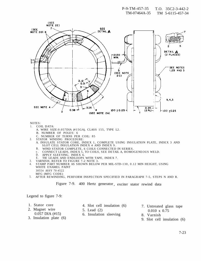
P-9-TM-457-35 T.O. 35C2-3-442-2TM-07464A-35 TM 5-6115-457-34
NOTES:1. COIL DATA:
A. WIRE SIZE:0.057DIA (#15GA), CLASS 155, TYPE L2.B. NUMBER OF POLES: 6C. NUMBER OF TURNS PER COIL: 85
2. STATOR WINDING PROCEDURE:A. INSULATE STATOR CORE, INDEX 1, COMPLETE USING INSULATION PLATE, INDEX 3 AND
SLOT CELL INSULATION INDEX 4 AND INDEX 9.B. WIND STATOR COMPLETE, 6 COILS CONNECTED IN SERIES.c . CONNECT LEADS, INDEX 5, TO COILS, SEE DETAIL A, HOMOGENEOUS WELD.D. APPLY SLEEVING. INDEX 6.E. TIE LEADS AND ENDLOOPS WITH TAPE, INDEX 7.
3. VARNISH, REFER TO FIGURE 7-2 NOTE 3.4. STAMP PART NUMBER AS SHOWN BELOW PER MIL-STD-130, 0.12 MIN HEIGHT, USING
WHITE ENAMEL PAINT30554 ASSY 70-4522MFG (MFG CODE)
5. AFTER REWINDING, PERFORM INSPECTION SPECIFIED IN PARAGRAPH 7-5, STEPS N AND R.
Figure 7-9. 400 Hertz generator , exciter stator rewind data
Legend to figure 7-9:
1. Stator core2. Magnet wire
0.057 DIA (#15)3. Insulation plate (6)
4. Slot cell insulation (6) 7. Untreated glass tape5. Lead (2) 0.010 x 0.756. Insulation sleeving 8. Varnish
9. Slot cell insulation (6)
7-23
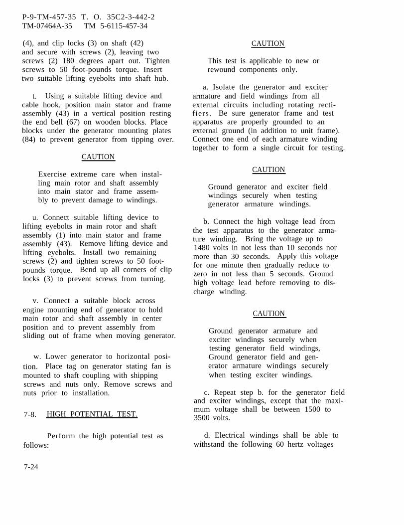
P-9-TM-457-35 T. O. 35C2-3-442-2TM-07464A-35 TM 5-6115-457-34
(4), and clip locks (3) on shaft (42)and secure with screws (2), leaving twoscrews (2) 180 degrees apart out. Tightenscrews to 50 foot-pounds torque. Inserttwo suitable lifting eyebolts into shaft hub.
t. Using a suitable lifting device andcable hook, position main stator and frameassembly (43) in a vertical position restingthe end bell (67) on wooden blocks. Placeblocks under the generator mounting plates(84) to prevent generator from tipping over.
CAUTION
Exercise extreme care when instal-ling main rotor and shaft assemblyinto main stator and frame assem-bly to prevent damage to windings.
u. Connect suitable lifting device tolifting eyebolts in main rotor and shaftassembly (1) into main stator and frameassembly (43). Remove lifting device andlifting eyebolts. Install two remainingscrews (2) and tighten screws to 50 foot-pounds torque. Bend up all corners of cliplocks (3) to prevent screws from turning.
v. Connect a suitable block acrossengine mounting end of generator to holdmain rotor and shaft assembly in centerposition and to prevent assembly fromsliding out of frame when moving generator.
w. Lower generator to horizontal posi-tion. Place tag on generator stating fan ismounted to shaft coupling with shippingscrews and nuts only. Remove screws andnuts prior to installation.
7-8. HIGH POTENTIAL TEST.
Performfollows:
7-24
the high potential test as
CAUTION
This test is applicable to new orrewound components only.
a. Isolate the generator and exciterarmature and field windings from allexternal circuits including rotating recti-fiers. Be sure generator frame and testapparatus are properly grounded to anexternal ground (in addition to unit frame).Connect one end of each armature windingtogether to form a single circuit for testing.
CAUTION
Ground generator and exciter fieldwindings securely when testinggenerator armature windings.
b. Connect the high voltage lead fromthe test apparatus to the generator arma-ture winding. Bring the voltage up to1480 volts in not less than 10 seconds normore than 30 seconds. Apply this voltagefor one minute then gradually reduce tozero in not less than 5 seconds. Groundhigh voltage lead before removing to dis-charge winding.
CAUTION
Ground generator armature andexciter windings securely whentesting generator field windings,Ground generator field and gen-erator armature windings securelywhen testing exciter windings.
c. Repeat step b. for the generator fieldand exciter windings, except that the maxi-mum voltage shall be between 1500 to3500 volts.
d. Electrical windings shall be able towithstand the following 60 hertz voltages

P-9-TM-457-35 T.O. 35C2-3-442-2TM-07464A-35 TM 5-6115-457-34
applied for one minute between the windings 7-9. INSTALLATION.and ground.
Generator armature windings -1480 voltsGenerator field and exciter windings - Install the generator as specified
1500 to 3500 Volta in paragraph 2-7.
Change 1 7-25/(7-26 blank)


P-8-627-34 T O 35C2-3-442-2TM-07464A-35 TM 5-6115-457-34
CHAPTER 8
ENGINE GROUP REPAIR INSTRUCTIONS
Section I. ENGINE COMPONENTS
8-1. GENERAL.
The engine is a six cylinder, 4 cycle,turbo charged, overhead valve diesel. Com-ponents covered in this chapter, in additionto the basic engine, are those which aremounted on the engine block.
8-2. REMOVAL.
Refer to paragraph 2-8 and removethe engine group.
8-3. DISASSEMBLY.
a. Tag and remove all hydraulic andfuel lines from engine. Cap lines and plugall openings.
b. Refer to Operator and OrganizationalMaintenance Manual and remove the follow-ing.
1. Alternator and fan drive belts
2. Alternator assembly
3. Fuel day tank
4. Manual speed controls
5. Fuel filter and pump assembly,threaded spacers and adapter.
6. Starter motor
7. Lubricating oil filters
8. Secondary fuel filter and reliefvalve
9. Breather assembly
10. Hydraulic filter (precise setsonly)
11. Atomizer tube, atomizer andbushing.
c. Remove oil pan shutoff cock.
d. Remove four screws and lockwasherssecuring two flywheel housing supports.
e. Remove components and disassembleengineof this
8-4.
a.engineof this
as specified in subsequent sectionschapter.
REASSEMBLY.
Replace components and reassembleas specified in subsequent sectionschapter.
b. Install two flywheel housing sup-ports and secure with four screws andlockwashers.
c. Install oil pan shutoff cock.
d. Refer to Operator and OrganizationalMaintenance Manual and install the follow-ing.
Change 8 8-1
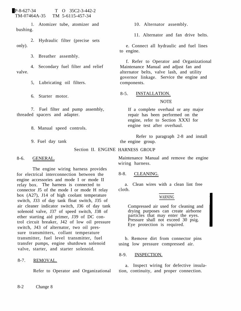
P-8-627-34 T O 35C2-3-442-2TM-07464A-35 TM 5-6115-457-34
1.bushing.
2.only).
3.
4.valve.
5,
6.
7.
Atomizer tube, atomizer and
Hydraulic filter (precise sets
Breather assembly.
Secondary fuel filter and relief
Lubricating oil filters.
Starter motor.
Fuel filter and pump assembly,threaded spacers and adapter.
8. Manual speed controls.
9. Fuel day tank
Section II. ENGINE
8-6. GENERAL.
The engine wiring harness providesfor electrical interconnection between theengine accessories and mode I or mode IIrelay box. The harness is connected toconnector J5 of the mode I or mode H relaybox (A27), J14 of high coolant temperatureswitch, J33 of day tank float switch, J35 ofair cleaner indicator switch, J36 of day tanksolenoid valve, J37 of speed switch, J38 ofether starting aid primer, J39 of DC con-trol circuit breaker, J42 of low oil pressureswitch, J43 of alternator, two oil pres-sure transmitters, collant temperaturetransmitter, fuel level transmitter, fueltransfer pumps, engine shutdown solenoidvalve, starter, and starter solenoid.
8-7.
8-2
REMOVAL.
Refer to Operator and Organizational
Change 8
10. Alternator assembly.
11. Alternator and fan drive belts.
e. Connect all hydraulic and fuel linesto engine.
f. Refer to Operator and OrganizationalMaintenance Manual and adjust fan andalternator belts, valve lash, and utilitygovernor linkage. Service the engine andcomponents.
8-5. INSTALLATION.
the
NOTE
If a complete overhaul or any majorrepair has been performed on theengine, refer to Section XXXI forengine test after overhaul.
Refer to paragraph 2-8 and installengine group.
HARNESS GROUP
Maintenance Manual and remove the enginewiring harness.
8-8. CLEANING.
a. Clean wires with a clean lint freecloth.
WARNING
Compressed air used for cleaning anddrying purposes can create airborneparticles that may enter the eyes.Pressure shall not exceed 30 psig.Eye protection is required.
b. Remove dirt from connector pinsusing low pressure compressed air.
8-9. INSPECTION.
a. Inspect wiring for defective insula-tion, continuity, and proper connection.

b. Inspect electrical connectors fordamaged threads; bent, loose, or missingpins; and for shorts to case and surround-ing pins.
c. Inspect terminal lugs for securityand condition.
d. Check each wire for continuity,refer to figure 8-1.
P-9-TM-457-35 T. O. 35C2-3-442-2TM-07464A-35 TM 5-6115-457-34
8-10. REBUILD.
Refer to figure 8-1 and rebuildengine wiring harness.
8-11. INSTALLATION.
Refer to Operator and OrganizationalMaintenance Manual and install the enginewire harness.
8-3
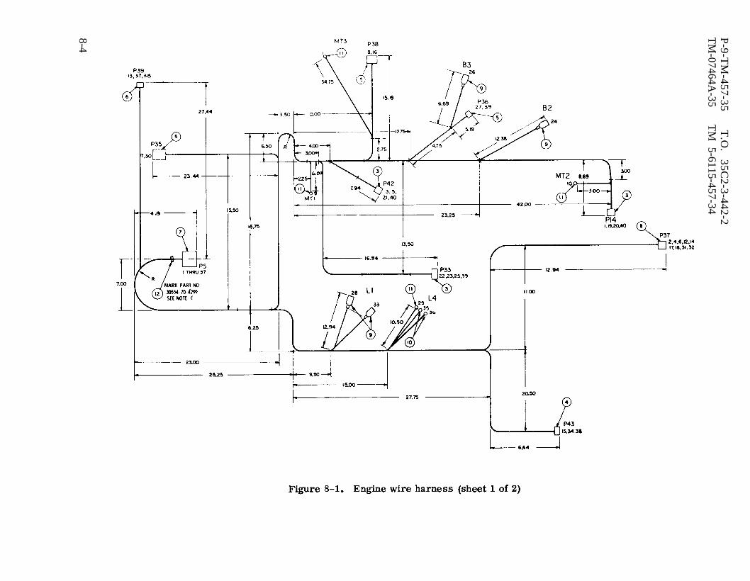
Figure 8-1.
P-9-T
M-457-35
T.O
. 35C
2-3-442-2T
M-07464A
-35T
M 5-6115-457-34
8-4

P-8-627-34 T O 35C2-3-442-2TM-07464A-35 TM 5-6115-457-34
Figure 8-1. Engine wire harness (sheet 2 of 2)
Change 8 8-5
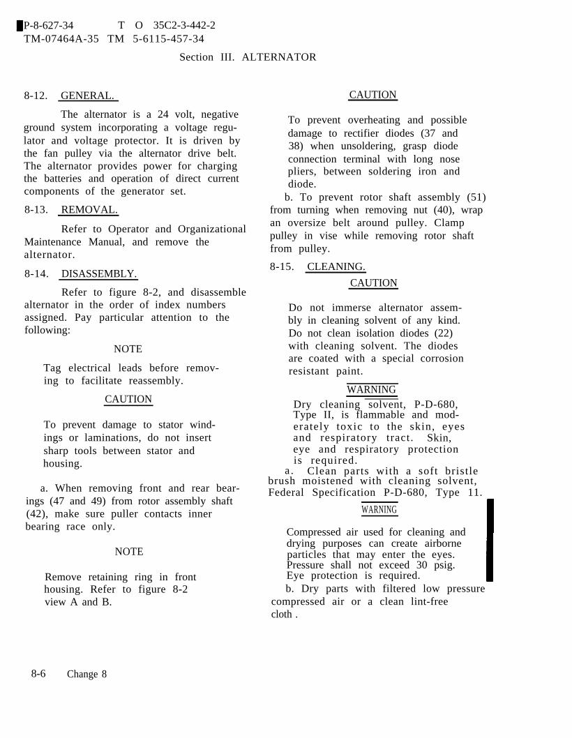
P-8-627-34 T O 35C2-3-442-2TM-07464A-35 TM 5-6115-457-34
Section III. ALTERNATOR
8-12. GENERAL.
The alternator is a 24 volt, negativeground system incorporating a voltage regu-lator and voltage protector. It is driven bythe fan pulley via the alternator drive belt.The alternator provides power for chargingthe batteries and operation of direct currentcomponents of the generator set.
8-13. REMOVAL.
Refer to Operator and OrganizationalMaintenance Manual, and remove thealternator.
8-14. DISASSEMBLY.
Refer to figure 8-2, and disassemblealternator in the order of index numbersassigned. Pay particular attention to thefollowing:
NOTE
Tag electrical leads before remov-ing to facilitate reassembly.
CAUTION
To prevent damage to stator wind-ings or laminations, do not insertsharp tools between stator andhousing.
a. When removing front and rear bear-ings (47 and 49) from rotor assembly shaft(42), make sure puller contacts innerbearing race only.
NOTE
Remove retaining ring in fronthousing. Refer to figure 8-2view A and B.
CAUTION
To prevent overheating and possibledamage to rectifier diodes (37 and38) when unsoldering, grasp diodeconnection terminal with long nosepliers, between soldering iron anddiode.
b. To prevent rotor shaft assembly (51)from turning when removing nut (40), wrapan oversize belt around pulley. Clamppulley in vise while removing rotor shaftfrom pulley.
8-15. CLEANING.
CAUTION
Do not immerse alternator assem-bly in cleaning solvent of any kind.Do not clean isolation diodes (22)with cleaning solvent. The diodesare coated with a special corrosionresistant paint.
WARNINGDry cleaning solvent, P-D-680,Type II, is flammable and mod-erately toxic to the skin, eyesand respiratory tract. Skin,eye and respiratory protectionis required.
a . Clean parts with a soft bristlebrush moistened with cleaning solvent,Federal Specification P-D-680, Type 11.
WARNING
Compressed air used for cleaning anddrying purposes can create airborneparticles that may enter the eyes.Pressure shall not exceed 30 psig.Eye protection is required.b. Dry parts with filtered low pressure
compressed air or a clean lint-freecloth .
8-6 Change 8

P-9-TM-457-35 T.O. 35C2-3-442-2TM-07464A-35 TM 5-6115-457-34
8-16. INSPECTION.
a. Inspect brush assembly (29, figure8-2) for excessive wear, replace brushassembly if 3/16 of an inch or less extendsbeyond bottom of holder.
b. Check brush assembly (29) springtension with suitable spring scale. Springtension should be 4 to 6 ounces.
c. Test rectifier diodes (37 and 38) inheat sinks connecting one of multimeterleads to the heat sink and the other multim-eter lead to the diode stem, and note thereading. Then reverse the multimeter leadconnections, and note the reading. If bothreadings are very low, of if both readingsare very high, the diode is defective. Agood diode will give one low reading and onehigh reading.
d. Test isolation diode assembly (22)by connecting one of the multimeter testleads to the output terminal stud of thediode, the other to the exposed metal areaon heat sink, and note reading. Then re-verse the lead connections and note thereading. If both readings are very low, orif both readings are very high, the diode isdefective. A good diode will give one lowreading and one high reading.
e. Test stator assembly (39) for groundsand opens as follows:
NOTE
These tests may be made with thestator leads disconnected from thediodes, or with the stator leads con-nected to the diodes provided all thediodes are in good condition. Scrapeenough insulation from the leads toinsure good contact with the testprods.
1. Connect the multimeter to twopairs of stator leads. Use a multimeterand set to the lowest range scale on themultimeter. If either reading is very high(infinite) the stator winding is open.
2. To test the stator for grounds,connect the multimeter from any stator leadto the ground screw or the shell, and notethe reading. Then reverse the multimeterlead connections, and note the reading. Ifboth readings are very low, the stator isgrounded.
f. Test rotor assembly (51) or groundedslip ring, using a multimeter. No circuitfrom either slip ring to shaft is correctcondition.
g. Perform resistance check on rotorassembly (51) windings using a multimeter.Resistance should be between 11 to 14 ohms.
h. Test voltage regulator (25) by con-necting multimeter leads to regulator leadsas follows: (See figure 8-3).
1. Multimeter lead (+) to regulatorlead yellow, multimeter lead (-) to regula-tor lead red. Multimeter should indicate300 to 350 ohms.
2. Multimeter lead (+) to regulatorlead red, multimeter lead (-) to regulatorlead yellow, multimeter should indicateopen circuit.
3. If above readings are not obtained,replace regulator.
i. Inspect fan (43) for cracked or brokenfins. Check fan bore for wear.
j . Inspect pulley (42) for worn drivesurfaces and condition of key groove. Checkpulley bore for wear.
8-7
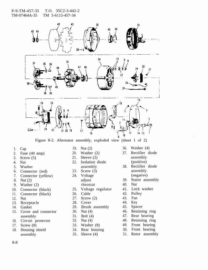
P-9-TM-457-35TM-07464A-35
T.O. 35C2-3-442-2TM 5-6115-457-34
1.2.3.4.5.6.7.8.9.
10.11.12.13.14.15.
16.17.18.
8-8
Figure 8-2. Alternator assembly, exploded view (sheet 1 of 2)
CapFuse (40 amp)Screw (5)NutWasherConnector (red)Connector (yellow)Nut (2)Washer (2)Connector (black)Connector (black)NutReceptacleGasketCover and connectorassemblyCircuit protectorScrew (8)Housing shieldassembly
19.20.21.22.
23.24.
25.26.27.28.29.30.31.32.33.34.35.
Nut (2)Washer (2)Sleeve (2)Isolation diodeassemblyScrew (3)VoltageadjustrheostatVoltage regulatorCableScrew (2)CoverBrush assemblyNut (4)Bolt (4)Nut (4)Washer (8)Rear housingSleeve (4)
36.37.
38.
39.40.41.42.43.44.45.46.47.48.49.50.51.
Washer (4)Rectifier diodeassembly(positive)Rectifier diodeassembly(negative)Stator assemblyNutLock washerPulleyFanKeySpacerRetaining ringRear bearingRetaining ringFront bearingFront bearingRotor assembly

P-9-TM-457-35 T.O. 35C2-3-442-2TM-07464A-35 TM 5-6115-457-34
Figure 8-2. Alternator assembly, exploded view (sheet 2 of 2)
k. Inspect front bearing cavity for 8-17. REPAIR.evidence of wear. Check condition of re-tainer recess.
CAUTION1. Check slip rings for pitting, rough-
ness or burned spots. If surface is wornbeyond repair, replace entire rotorassembly (42).
Do not attempt to turn slip ringin a lathe.
m. Inspect rotor shaft for key slotwear, worn bearing surfaces, scuff markson pole fingers, and condition of threads onpulley nut.
n. Inspect bearings (47 and 49) forscored, pitted, scratched, cracked orchipped races.
a. Slip rings may be cleaned up bycleaning contacting surfaces with a finecrocus cloth. Carefully wipe dust andresidue away after cleaning.
b. Repair minor thread damage onrotor shaft using a suitable thread chaser.
8-9
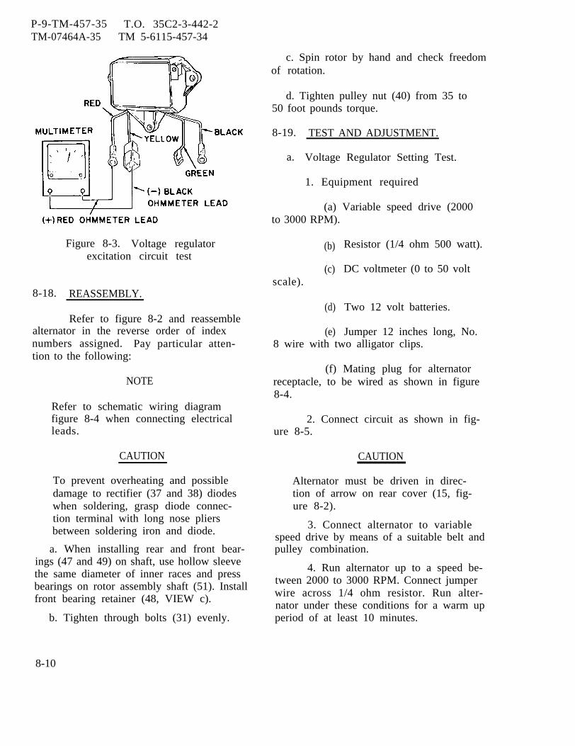
P-9-TM-457-35 T.O. 35C2-3-442-2TM-07464A-35 TM 5-6115-457-34
Figure 8-3. Voltage regulatorexcitation circuit test
8-18. REASSEMBLY.
Refer to figure 8-2 and reassemblealternator in the reverse order of indexnumbers assigned. Pay particular atten-tion to the following:
NOTE
Refer to schematic wiring diagramfigure 8-4 when connecting electricalleads.
CAUTION
To prevent overheating and possibledamage to rectifier (37 and 38) diodeswhen soldering, grasp diode connec-tion terminal with long nose pliersbetween soldering iron and diode.
a. When installing rear and front bear-ings (47 and 49) on shaft, use hollow sleevethe same diameter of inner races and pressbearings on rotor assembly shaft (51). Installfront bearing retainer (48, VIEW c).
b. Tighten through bolts (31) evenly.
c. Spin rotor by hand and check freedomof rotation.
d. Tighten pulley nut (40) from 35 to50 foot pounds torque.
8-19. TEST AND ADJUSTMENT.
a. Voltage Regulator Setting Test.
1. Equipment required
(a) Variable speed drive (2000to 3000 RPM).
(b)
(c)scale).
(d)
(e)
Resistor (1/4 ohm 500 watt).
DC voltmeter (0 to 50 volt
Two 12 volt batteries.
Jumper 12 inches long, No.8 wire with two alligator clips.
(f) Mating plug for alternatorreceptacle, to be wired as shown in figure8-4.
2. Connect circuit as shown in fig-ure 8-5.
CAUTION
Alternator must be driven in direc-tion of arrow on rear cover (15, fig-ure 8-2).
3. Connect alternator to variablespeed drive by means of a suitable belt andpulley combination.
4. Run alternator up to a speed be-tween 2000 to 3000 RPM. Connect jumperwire across 1/4 ohm resistor. Run alter-nator under these conditions for a warm upperiod of at least 10 minutes.
8-10
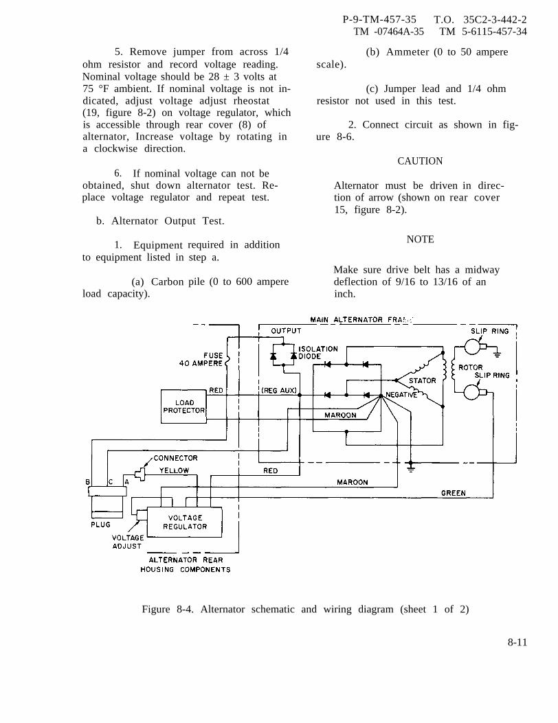
5. Remove jumper from across 1/4ohm resistor and record voltage reading.Nominal voltage should be 28 ± 3 volts at75 °F ambient. If nominal voltage is not in-dicated, adjust voltage adjust rheostat(19, figure 8-2) on voltage regulator, whichis accessible through rear cover (8) ofalternator, Increase voltage by rotating ina clockwise direction.
6. If nominal voltage can not beobtained, shut down alternator test. Re-place voltage regulator and repeat test.
b. Alternator Output Test.
1. Equipmentto equipment listed in
(a) Carbonload capacity).
required in additionstep a.
pile (0 to 600 ampere
P-9-TM-457-35TM -07464A-35
(b) Ammeterscale).
T.O. 35C2-3-442-2TM 5-6115-457-34
(0 to 50 ampere
(c) Jumper lead and 1/4 ohmresistor not used in this test.
2. Connect circuit as shown in fig-ure 8-6.
CAUTION
Alternator must be driven in direc-tion of arrow (shown on15, figure 8-2).
NOTE
rear cover
Make sure drive belt has a midwaydeflection of 9/16 to 13/16 of aninch.
Figure 8-4. Alternator schematic and wiring diagram (sheet 1 of 2)
8-11
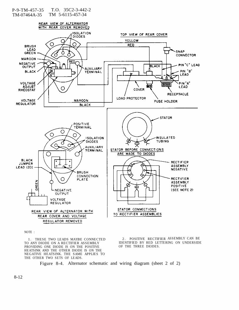
P-9-TM-457-35 T.O. 35C2-3-442-2TM-07464A-35 TM 5-6115-457-34
ASSEMBLY CAN BE
NOTE :
1. THESE TWO LEADS MAYBE CONNECTED 2. POSITIVE RECTIFIERTO ANY DIODE ON A RECTIFIER ASSEMBLY IDENTIFIED BY RED LETTERING ON UNDERSIDEPROVIDING ONE DIODE IS ON THE POSITIVE OF THE THREE DIODES.HEATSINK AND THE OTHER DIODE IS ON THENEGATIVE HEATSINK. THE SAME APPLIES TOTHE OTHER TWO SETS OF LEADS.
Figure 8-4. Alternator schematic and wiring diagram (sheet 2 of 2)
8-12
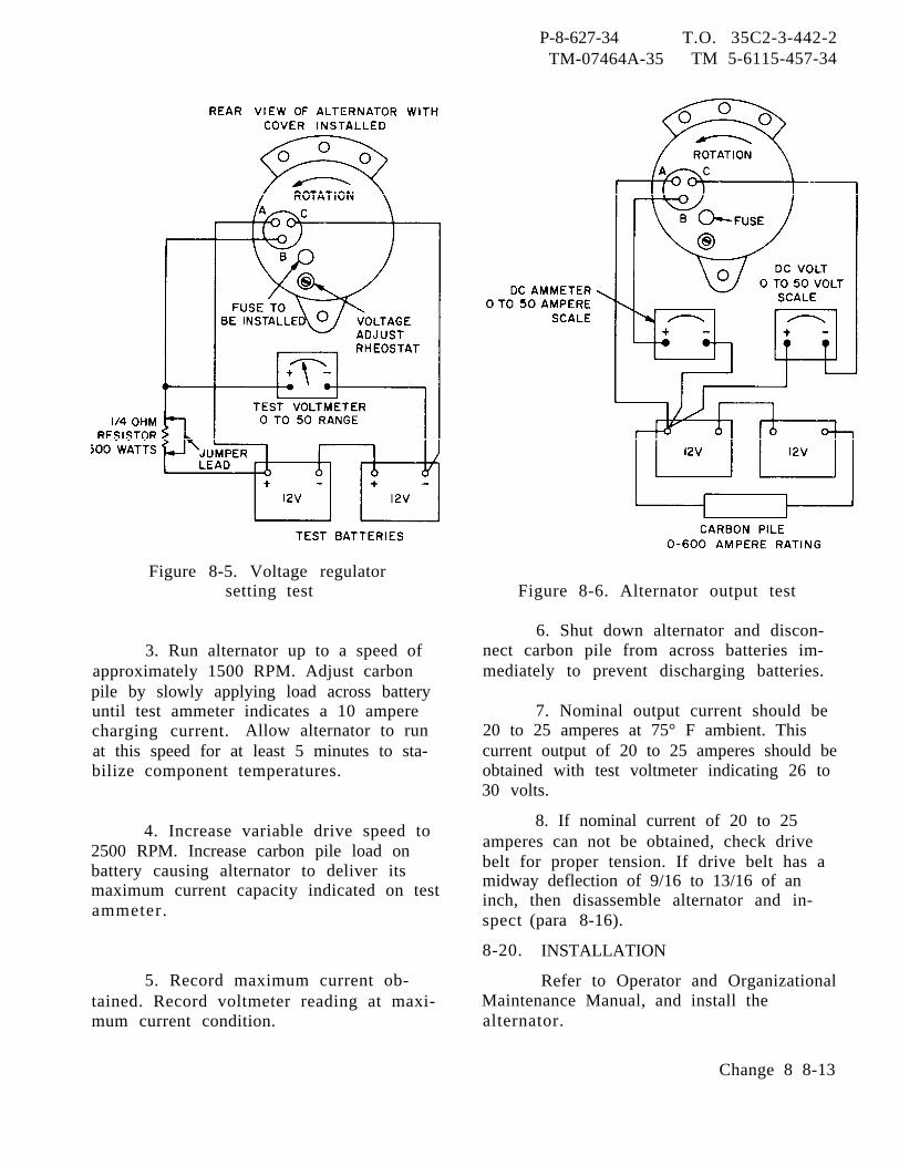
P-8-627-34 T.O. 35C2-3-442-2TM-07464A-35 TM 5-6115-457-34
Figure 8-5. Voltage regulatorsetting test
3. Run alternator up to a speed ofapproximately 1500 RPM. Adjust carbonpile by slowly applying load across batteryuntil test ammeter indicates a 10 amperecharging current. Allow alternator to runat this speed for at least 5 minutes to sta-bilize component temperatures.
4. Increase variable drive speed to2500 RPM. Increase carbon pile load onbattery causing alternator to deliver itsmaximum current capacity indicated on testammeter.
Figure 8-6. Alternator output test
6. Shut down alternator and discon-nect carbon pile from across batteries im-mediately to prevent discharging batteries.
7. Nominal output current should be20 to 25 amperes at 75° F ambient. Thiscurrent output of 20 to 25 amperes should beobtained with test voltmeter indicating 26 to30 volts.
8. If nominal current of 20 to 25amperes can not be obtained, check drivebelt for proper tension. If drive belt has amidway deflection of 9/16 to 13/16 of aninch,spect
8-20.
then disassemble alternator and in-(para 8-16).
INSTALLATION
5. Record maximum current ob-tained. Record voltmeter reading at maxi-mum current condition.
Refer to Operator and OrganizationalMaintenance Manual, and install thealternator.
Change 8 8-13
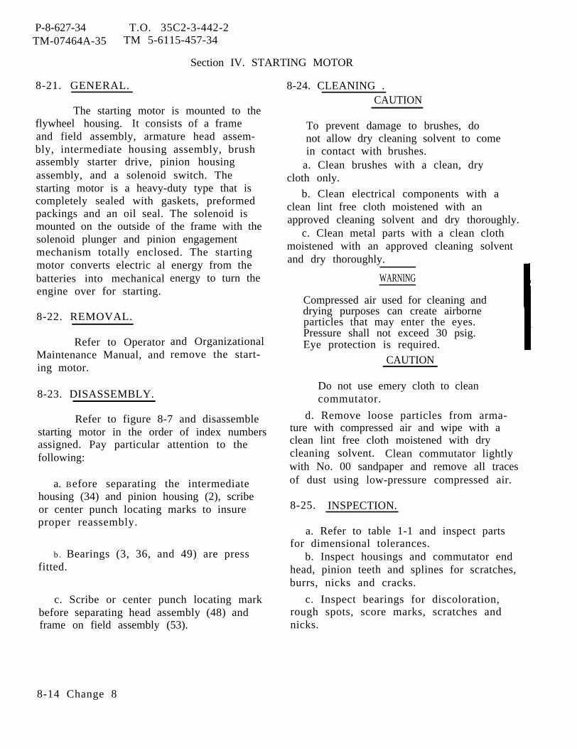
P-8-627-34 T.O. 35C2-3-442-2TM-07464A-35 TM 5-6115-457-34
Section IV. STARTING MOTOR
8-21. GENERAL.
The starting motor is mounted to theflywheel housing. It consists of a frameand field assembly, armature head assem-bly, intermediate housing assembly, brushassembly starter drive, pinion housingassembly, and a solenoid switch. Thestarting motor is a heavy-duty type that iscompletely sealed with gaskets, preformedpackings and an oil seal. The solenoid ismounted on the outside of the frame with thesolenoid plunger and pinion engagementmechanism totally enclosed. The startingmotor converts electric al energy from thebatteries into mechanicalengine over for starting.
8-22. REMOVAL.
energy to turn the
Refer to OperatorMaintenance Manual, anding motor.
8-23. DISASSEMBLY.
and Organizationalremove the start-
Refer to figure 8-7 and disassemblestarting motor in the order of index numbersassigned. Pay particular attention to thefollowing:
a. Before separating the intermediatehousing (34) and pinion housing (2), scribeor center punch locating marks to insureproper reassembly.
b. Bearings (3, 36, and 49) are pressfitted.
c. Scribe or center punch locating markbefore separating head assembly (48) andframe on field assembly (53).
8-24. CLEANING .CAUTION
To prevent damage to brushes, donot allow dry cleaning solvent to comein contact with brushes.
a. Clean brushes with a clean, drycloth only.
b. Clean electrical components with aclean lint free cloth moistened with anapproved cleaning solvent and dry thoroughly.
c. Clean metal parts with a clean clothmoistened with an approved cleaning solventand dry thoroughly.
WARNING
Compressed air used for cleaning anddrying purposes can create airborneparticles that may enter the eyes.Pressure shall not exceed 30 psig.Eye protection is required.
CAUTION
Do not use emery cloth to cleancommutator.
d. Remove loose particles from arma-ture with compressed air and wipe with aclean lint free cloth moistened with drycleaning solvent. Clean commutator lightlywith No. 00 sandpaper and remove all tracesof dust using low-pressure compressed air.
8-25. INSPECTION.
a. Refer to table 1-1 and inspect partsfor dimensional tolerances.
b. Inspect housings and commutator endhead, pinion teeth and splines for scratches,burrs, nicks and cracks.
c. Inspect bearings for discoloration,rough spots, score marks, scratches andnicks.
8-14 Change 8
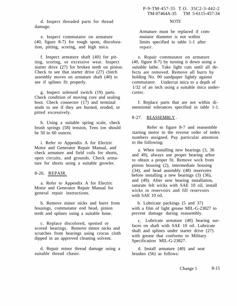
P-9-TM-457-35 T.O. 35C2-3-442-2TM-07464A-35 TM 5-6115-457-34
d. Inspect threaded parts for threaddamage.
e. Inspect commutator on armature(40, figure 8-7) for rough spots, discolora-tion, pitting, scoring, and high mica.
f. Inspect armature shaft (40) for pit-ting, scoring, or excessive wear. Inspectstarter drive (27) for broken teeth on pinion.Check to see that starter drive (27) clutchassembly moves on armature shaft (40) tosee if splines fit properly.
g. Inspect solenoid switch (19) parts.Check condition of moving core and sealingboot. Check connector (17) and terminalstuds to see if they are burned, eroded, orpitted excessively.
h. Using a suitable spring scale, checkbrush springs (58) tension, Tens ion shouldbe 50 to 60 ounces.
i. Refer to Appendix A for ElectricMotor and Generator Repair Manual, andcheck armature and field coils for shorts,open circuits, and grounds. Check arma-ture for shorts using a suitable growler.
8-26. REPAIR.
a. Refer to Appendix A for ElectricMotor and Generator Repair Manual forgeneral repair instructions.
b. Remove minor nicks and burrs fromhousings, commutator end head, pinionteeth and splines using a suitable hone.
c. Replace discolored, spotted orscored bearings. Remove minor nicks andscratches from bearings using crocus clothdipped in an approved cleaning solvent.
d. Repair minor thread damage using asuitable thread chaser.
NOTE
Armature must be replaced if com-mutator diameter is not withinlimits specified in table 1-1 afterrepair.
e. Repair commutator on armature(40, figure 8-7) by turning it down using asuitable lathe. Take light cuts until all de-fects are removed. Remove all burrs byholding No. 00 sandpaper lightly againstcommutator. Undercut mica to a depth of1/32 of an inch using a suitable mica under-cutter.
f. Replace parts that are not within di-mensional tolerances specified in table 1-1.
8-27. REASSEMBLY .
Refer to figure 8-7 and reassemblestarting motor in the reverse order of indexnumbers assigned. Pay particular attentionto the following:
a. When installing new bearings (3, 36and 49), always use proper bearing arborto obtain a proper fit. Remove wick frompinion housing (2), intermediate housing(34), and head assembly (48) reservoirsbefore installing a new bearings (3) (36),and (49). After new bearing installation,saturate felt wicks with SAE 10 oil, installwicks in reservoirs and fill reservoirswith SAE 10 oil.
b. Lubricate packings (5 and 37)with a film of light grease MIL-G-23827 toprevent damage during reassembly.
c. Lubricate armature (40) bearing sur-faces on shaft with SAE 10 oil. Lubricateshaft and splines under starter drive (27)with grease that conforms to MilitarySpecification MIL-G-23827.
d. Install armature (40) and seatbrushes (56) as follows:
Change 1 8-15
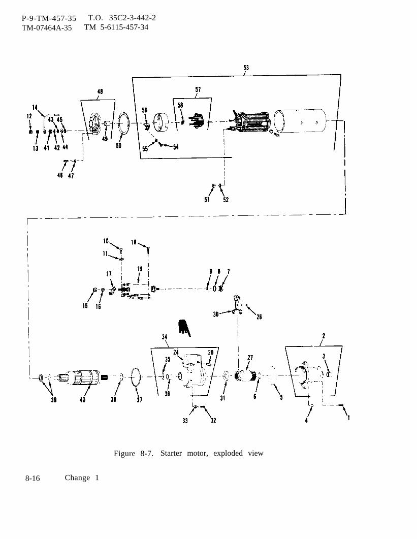
P-9-TM-457-35 T.O. 35C2-3-442-2TM-07464A-35 TM 5-6115-457-34
Figure 8-7. Starter motor, exploded view
8-16 Change 1
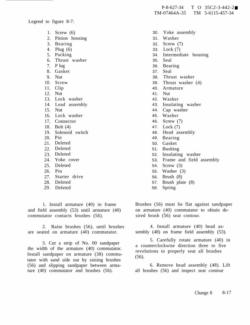
P-8-627-34 T O 35C2-3-442-2TM-07464A-35 TM 5-6115-457-34
Legend to figure 8-7:
1.2.3.4.5.6.7.8.9.
10.11.12.13.14.15.16.17,18.19.20.21.22.23.24.25.26.27.28.29.
Screw (6)Pinion housingBearingPlug (6)PackingThrust washerP lugGasketNutScrewClipNutLock washerLead assemblyNutLock washerConnectorBolt (4)Solenoid switchPinDeletedDeletedDeletedYoke coverDeletedPinStarter driveDeletedDeleted
1. Install armature (40) in frameand field assembly (53) until armature (40)commutator contacts brushes (56).
2. Raise brushes (56), until brushesare seated on armature (40) commutator.
3. Cut a strip of No. 00 sandpaperthe width of the armature (40) commutator.Install sandpaper on armature (38) commu-tator with sand side out by raising brushes(56) and slipping sandpaper between arma-ture (40) commutator and brushes (56).
30.31.32.33.34.35.36.37.38,39.40.41.42.43.44.45.46.47.48.49.50.51.52.53.54.55.56.57.58.
Yoke assemblyWasherScrew (7)Lock (7)Intermediate housingSealBearingSealThrust washerThrust washer (4)ArmatureNutWasherInsulating washerCap washerWasherScrew (7)Lock (7)Head assemblyBearingGasketBushingInsulating washerFrame and field assemblyScrew (3)Washer (3)Brush (8)Brush plate (8)Spring
Brushes (56) must lie flat against sandpaperon armature (40) commutator to obtain de-sired brush (56) seat contour.
4. Install armature (40) head as-sembly (48) on frame field assembly (53).
5. Carefully rotate armature (40) ina counterclockwise direction three to fiverevolutions to properly seat all brushes(56).
6. Remove head assembly (48). Liftall brushes (56) and inspect seat contour
Change 8 8-17
P-8-627-34 T O 35C2-3-442-2TM-07464A-35 TM 5-6115 -457-34
to determine whether or not sanding opera-tion is satisfactory. A satisfactorily seatedbrush (56) should show evidence of contacton at least 85 percent of its length and 100percent of its thickness.
7. Lift brushes (56) and removesandpaper from armature (40) commutator.
WARNING
Compressed air used for cleaning anddrying purposes can create airborneparticles that may enter the eyes.Pressure shall not exceed 30 psig.Eye protection is required.
8. Remove armature (40) fromframe and field assembly (53). Clean arma-ture (40), brushes (56) and frame and fieldassembly (53). Blow out sanding dust usingcompressed air.
9. Coat shaft and splines on arma-ture (40) with grease MIL-G-23827. Installarmature (40) (steps 1. and 2. above).
e. When assembling intermediate andpinion housing assemblies (2 and 34), torquehex head screws (1) to 8 foot pounds. Makesure locating marks are aligned.
WARNING
Sealant, Glytal is moderately toxicto eyes, skin and respiratory tract.Eye and skin protection required.Good general ventilation is norm-ally adequate.f. After assembly, the insulation on
both terminal studs on frame and field as-sembly (53) should be coated with glytalsealant. Keep sealant off of contact sur-faces of terminal studs and nuts.8-28. TESTING. (See figure 8-8).
a. The following equipment will be re-quired to perform the starter tests:
1. Two 12 volt batteries - 4 batterieswill be required if stall torque is to be per-formed.
2. D.C. voltmeter (0 to 50 voltscale).
3. D.C. ammeterscale).
4. Carbon pile (0capacity).
(0 to 500 amp
to 600 amp
5. Spring scale (0 to 50 lb scale).6. Pony brake arm 12 inch long.7. Hand held tachometer -0-
10,000 RPM.CAUTION
Never operate the starter motor morethan 30 seconds at a time during test.Allow the motor to cool for at least2 minutes between each crank cycle.
b. No load test.
1. Connect no load current test set-up as shown in view A.
2. Adjust carbon pile to obtain avoltage of 22 volts. Current drain shouldbe 90 amperes (maximum) at 7000 RPM.
3. Apply rubber tip of hand heldtachometer to end of shaft in drive housingsto read RPM.
4. If current is too high, checkbearing alignment end play. Two or threesharp raps with a rawhide hammer whilemotoring will often help align bearings andfree armature.
c. SOLENOID WINDING TEST.
1. Make solenoid winding test setupas shown in view B.
2. Test current draw and makeground and open test on winding. Serieswinding values at 7 0°F should be 23.2 to26.6 amperes at 12.9 volts. Shunt windingvalues at 70° F should be 4.1 to 4.8 am-peres at 12.9 volts. Adjust carbon pile toobtain 12.9 volts.
8-18 Change 8

P-8-627-34 T.O. 35C2-3-442-2TM-07464A-35 TM 5-6115-457-34
Figure 8-8. Starting motor, test setup
Change 8 8-19
P-8-627-34 T.O. 35C2-3-442-2TM-07464A-35 TM 5-6115-457-34
d. STALL TORQUE TEST.1. Make stall torque test setup as
shown in view C.2. The solenoid winding shall be
activated with a separate battery.3. Stall torque test values should
be 4.9 volts, 400 amperes (maximum), and22.0 foot pounds (minimum). Adjust variableresistance to obtain 4.9 volts at 400 amperes,
4. If stall torque values are toolow, check armature, brush spring tension,contact area, and switch contacts. If thesecomponents are not at fault, replace entirestarting motor.
e. ARMATURE END PLAY ADJUST-MENT. Adjust end play to 0.005 to 0.030inches by adding or removing thrust wash-ers on commutator end of armature shaft.
f. PINION POSITION ADJUSTMENT(See figure 8-9). This adjustment assurescorrect relation beween solenoid and in-dexing drive assembly. If adjustment isnot correct, damage may result to drivegear and/or flywheel ring gear.
WARNING
When connecting lead-acid batteriesconnect positive terminal first.
1. Connect a 12-volt battery asshown in view A.
2. Momentarily touch the jumperlead between terminal stud of solenoid andterminal stud in commutator and head.This will shift solenoid and drive solenoidand drive assembly into cranking positionuntil battery is disconnected,
3. Push drive assembly towardcommutator end of motor to eliminate anySlack movement in linkage.
WARNING
When disconnecting batteries (lead-acid) disconnect negative terminalf i r s t .
4. Measure distance between outsideedge of drive sleeve and thrust washer asshown in view B. This distance should be0.020 to 0.050 inches. If measurement isnot correct, remove plug and washer fromshift linkage cover and adjust nut as re-quired to obtain proper measurement. Dis-connect battery.
5, Make test setup as shown in viewC. Leave switch open.
6. Place suitable interference blockwith 0.983 inch side against drive gear asshown in view D.
CAUTION
Because of high amount of currentbeing passed through solenoid wind-ing, these tests should be made asbrief as possible.
7. Close switch in battery circuit.The 12-volt lamp should not light. Be sureinterference block is against drive gearand not against drive sleeve. If lamp doesnot light, proceed to step 8. If lamp lights,solenoid is defective. Replace solenoid,then repeat test.
8. If test lamp does not light, openswitch and connect a carbon pile and volt-meter into test circuit as shown in view E.
9. Place suitable interference blockwith 1/2-inch side against drive gear,Close switch and be sure interference blockis against drive gear and not against drivesleeve.
10. Adjust carbon pile and observevoltmeter. The test lamp must light beforethe voltmeter reads 16 volts. If lamp doesnot light, adjust nut view B until propersetting is obtained.
11. Reinstall plugshift linkage cover.
and washer in
8-29. INSTALLATION.
Refer to Operator and OrganizationalMaintenance Manual and install startingmotor.
8-20 Change 8
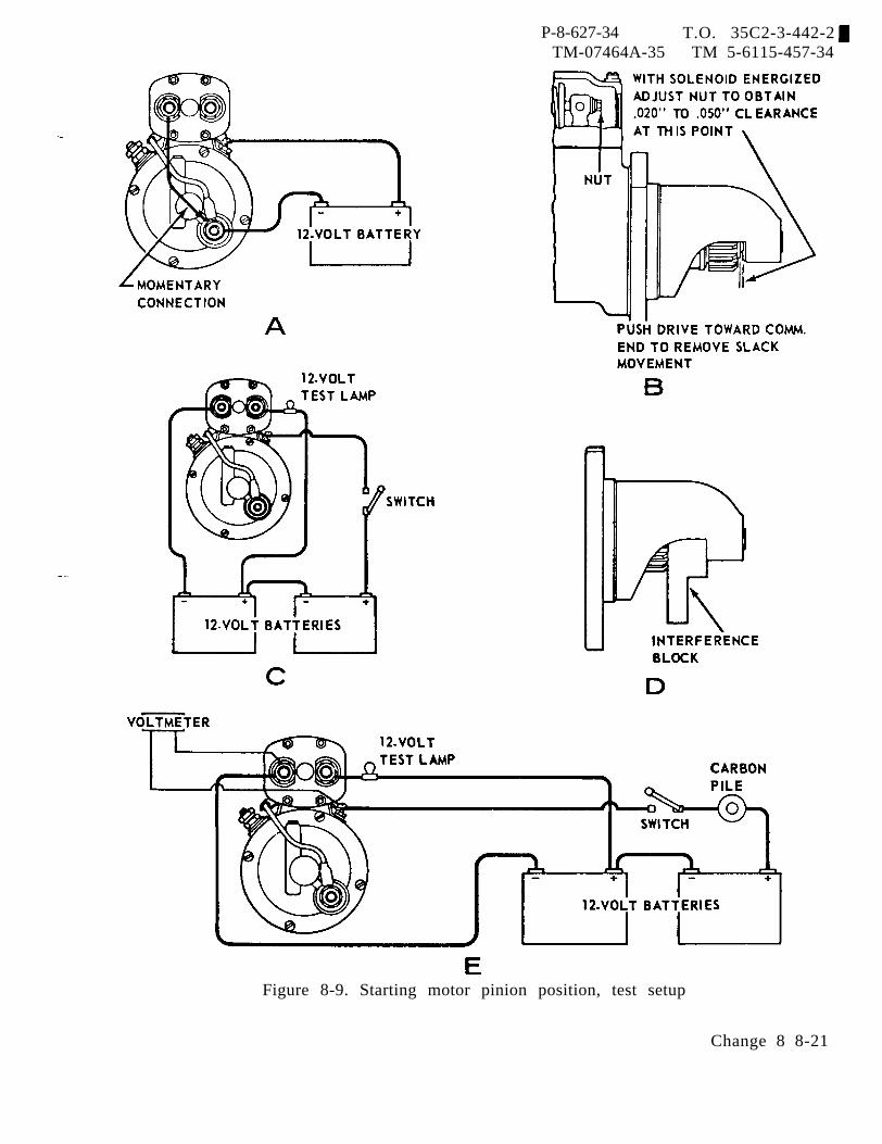
P-8-627-34 T.O. 35C2-3-442-2TM-07464A-35 TM 5-6115-457-34
Figure 8-9. Starting motor pinion position, test setup
Change 8 8-21
P-8-627-34 T.O. 35C2-3-442-2TM-07464A-35 TM 5-6115-457-34
Section V. FAN MOUNTING GROUP
8-30. GENERAL.
The fan mounting group is mountedat the front of the engine. It consists of afan, drive pulley, brackets, and mountinghardware. The fan and pulley are drivenby the crankshaft pulley via the fan drivebelts. The fan forces cooling air throughthe radiator.8-31. REMOVAL.
a. Refer to Operator and OrganizationalMaintenance Manual and remove alternatorbelts, fan drive belts, fan guard and orficering on radiator shroud.
CAUTION
Do not allow fan to hit radiator coreafter it is removed from fan hub.
b. Refer to figure 8-10 and remove fanand fan drive in the order of index numbersassigned.8-32. DISASSEMBLY .
Refer to figure 8-11 and disassemblefan drive assembly in the order of indexnumbers assigned.8-33. CLEANING.
WARNING
Cleaning Solvents are flammable andmoderately toxic to skin, eyes andrespiratory tract. Eye and skinprotection required. Good generalventilation is normally adequate.
Compressed air used for cleaning anddrying purposes can create airborneparticles that may enter the eyes.Pressure shall not exceed 30 psig.Eye protect ion is required.
CAUTIONDo not spin dry bearings.
a. Wash parts in an approved cleaningsolvent and dry thoroughly. Bearingsshould be dried with compressed air.
b. Clean pulley cavity of old grease.Flush with cleaning solvent and air dry.
8-22 Change 8
8-34. INSPECTION.
a. Inspect bearings for roughness ofrotation. Replace bearing if its rotationis rough after lubrication.
b. Inspect bearings for scoring, pitting,scratches, cracks and discoloration. Re-place defective bearing.
c. Inspect spindle and bracket assemblybearing surface for grooves, or galled con-ditions. Replace defective spindle andbracket assembly.
d. Inspect fan for distorted blades,worn pilot hole or elongated mounting holes.Replace defective fan.
e. Inspect pulley for worn grooves,nicks or cracks. Replace worn or crackedpulley.
f. Inspect threaded holes for threaddamage.
g. Discard gasket and seal.
8-35. REPAIR.
a. Minor nicks and burrs on fan andpulley may be removed using a suitablestone.
b. Repair minor thread damage usinga suitable thread chaser.
8-36. REASSEMBLY.
Refer to figure 8-11, and reassemblefan drive assembly in the reverse order ofindex numbers assigned. Pay particularattention to the following:
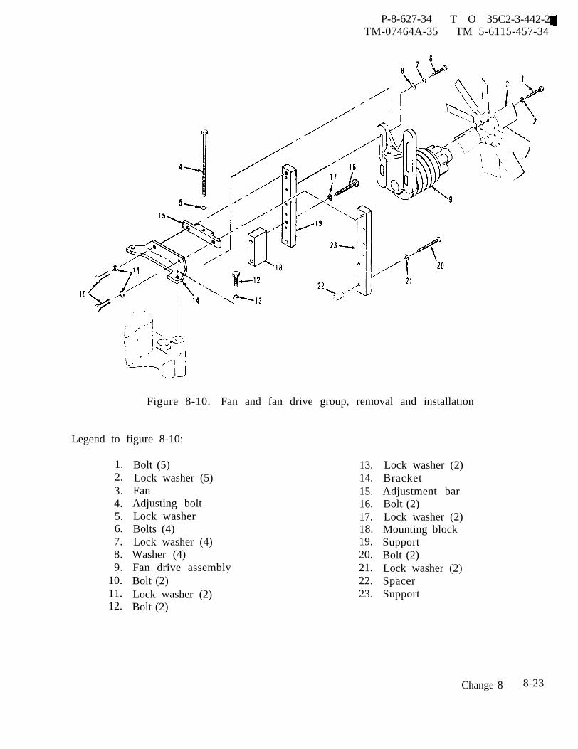
P-8-627-34 T O 35C2-3-442-2TM-07464A-35 TM 5-6115-457-34
Figure 8-10. Fan and fan drive group, removal and installation
Legend to figure 8-10:
1.2.3.4.5.6.7.8.9.
10.11.12.
Bolt (5)Lock washer (5)FanAdjusting boltLock washerBolts (4)Lock washer (4)Washer (4)Fan drive assemblyBolt (2)Lock washer (2)Bolt (2)
13.14.15.16.17.18.19.20.21.22.23.
Lock washer (2)BracketAdjustment barBolt (2)Lock washer (2)Mounting blockSupportBolt (2)Lock washer (2)SpacerSupport
Change 8 8-23

P-8-627-34 T O 35C2-3-442-2TM-07464A-35 TM 5-6115-457-34
Figure 8-11. Fan drive assembly, exploded view
Legend to figure 8-11:
1. Bolt (2) 7.2. Lock washer (2) 8.3. Washer (2) 9.4. Fan mounting hub 100
5. Gasket 11.6. Screw (2) 12.
a. Install seal (16) with lip away frombearing (13). Lubricate sealing lip (16)lightly with engine oil.
WARNING
Grease, (MIL-G-23827) is moderatelytoxic to skin, eyes and respiratoryt rac t . Eye and skin protection re-quired. Good general ventilationis normally adequate.
b. Hand pack bearings (9 and 13) withgrease MIL-G-23827 before reassembly.
c . Completely fill cavity between bear-ings (9 and 13) with grease MIL-G-23827.
8-37. INSTALLATION.
Lockplate 13. BearingPlate 14. PlugBearing 15. Pulley assemblyRetaining ring 16. SealSpacer 17. Spindle andRetaining ring bracket assembly
Refer to figure 8-10 and install fandrive group in reverse order of indexnumbers assigned. Pay particular attentionto the following.
a. Before installing fan drive assembly(9, figure 8-10), place fan belts and alter-nator belt on crankshaft pulley and fandrive pulley.
b. Refer to Operator and OrganizationalMaintenance Manual and tighten fan andalternator drive belts. Install fan guardand orfice ring on radiator shroud.
8-24 Change 8
P-8-627-34 T.O. 35C2-3-442-2TM -07464A-35 TM 5-6115-457-34
Section VI. DAY TANK ASSEMBLY
8-38. GENERAL.
The day tank is mounted on the unitlifting frame and is located on the left sideof the engine. It provides a gravity head offuel to the fuel injection pump. The daytank is non-pressurized and is equippedwith a fuel level switch, a drain cock, avent, a fuel inlet port, a fuel outlet port,and an excessive fuel return port. The fuellevel switch is one of the dual float type:the upper float, senses fuel level and pre-vents the overflow of fuel in day tank: thelower float senses fuel level and opens acircuit breaker to stop the engine after thefuel supply to the day tank has been shut offfor 4 minutes. The drain cock is providedto completely drain the day tank, and thevent prevents the system from becomingair bound. The day tank has a usable fuelcapacity sufficient for a minimum of 5 min-utes operation at rated load, after the fuelsupply to the day tank has been shut off.
8-39. REMOVAL AND DISASSEMBLY.
Refer to Operator and OrganizationalMaintenance Manual. Remove and disas-semble day tank assembly.
8-40. CLEANING .
WARNING
1,1,1 Trichloroethane (Methyl Chloro-form) is moderately toxic to skin,eyes and respiratory tract. Eye andskin protection required. Good gen-eral ventilation is normally adequate.
a. Clean fuel level switch with 1,1,1Trichloroethane MIL-T-81533.
WARNING
Fuel Oil if flammable and moderatelytoxic to skin, eyes and respiratoryt rac t . Eye and skin protection re-quired. Good general ventilationis normally adequate.
b. Clean the day tank using clean fueloil. Be sure that any sediment in thebottom of the tank is flushed out. Aftercleaning, dry tank thoroughly.
8-41. INSPECTION.
a. Refer to Operator and OrganizationalMaintenance Manual, and test fuel levelswitch.
b. Block openings in day tank and apply1 psi of air pressure to tank. Submergethe tank in water, leaks will be indicativeby air bubbles.
c. Inspect all threaded holes fordamaged threads.
8-42. REPAIR.
a. Replace defective fuel level switch.
WARNING
Make sure inside of day tank is freeof fuel fumes and all tank ports areopen before welding.
Welding operations produce heat,highly toxic fumes, injuriousradiation, metal slag and air-borne particles. Welding gog-gles, with proper tinted lenses,apron or jacket and welder’sboots are required.
Change 8 8-25
P-8-627-34 T.O. 35C2-3-442-2TM-07464A-35 TM 5-6115-457-34
b. Repair leaks in day tank by welding. 8-43. REASSEMBLY AND INSTALLATION.
c. Recheck day tank for leaks afterwelding (para 8-41 b.)
Refer to Operator and OrganizationalMaintenance Manual. Reassemble and in-
d. Repair minor thread damage, using stall day tank assembly.a suitable chaser.
Section VII. OVERSPEED SWITCH
8-44. GENERAL.
switch is mounted onThe overspeedthe tachometer drive and operates at onehalf engine speed. It is a three elementswitch. Switch 1, disconnects starter andinitiates field flashing of generator. Switch2, permits 24 VDC to energize precisegovernor. Switch 3, initiates shutdown se-quence of generator set in the event enginespeed increases to 2400-2450 RPM. Switch3 must be manually reset when tripped, bydepressing the reset button.
8-45. REMOVAL.
Refer to Operator and OrganizationalMaintenance Manual and remove overspeedswitch.
8-46. DISASSEMBLY.
Refer to figure 8-12 and disassembleoverspeed switch in the order of index num-bers assigned. Pay particular attention tothe following:
a. Remove lockwire (1) and removethree screws (2). Mark three hole centerlocation on cap and cover assembly (6) withscribe marks.
b. Separate cap and cover assembly (6)from body assembly (11).
c. Remove cap and cover retainingscrews (12) and lift cover from cover as-sembly (6).
d. Remove rotor assembly (9) by re-leasing retaining ring (8) which securesrotor assembly to body assembly (11).Retaining ring will come out with rotorassembly.
8-47. CLEANING.
CAUTION
Do not immerse overspeed switchin cleaning solvent.
a. Wipe outside of overspeed switchwith a clean cloth moistened with an ap-proved cleaning solvent and dry thoroughly.
WARNING
Compressed air used for cleaning anddrying purposes can create airborneparticles that may enter the eyes.Pressure shall not exceed 30 psig.Eye protection is required.
b. Low pressure compressed air maybe used to remove any dust or dirt depositsin switch assembly.
8-48. INSPECTION .
a. Inspect cap and cover assembly, andbody assembly for cracks and loose hard-ware.
b. Inspect rotor assembly (9) bearingfor freedom of rotation. Replace rotorassembly if bearing is frozen.
8-26 Change 8
c. Inspect switch assembly inside ofcap and cover assembly (6) for quality ofsolder connections on switch terminals.Check for corrosion on switch terminals.
d. Inspect for freedom of movement ofswitch contact actuator plate. Depressactuator plate with thumb on center ofactuator plate. There should be a total ofthree separate clicks as each micro switch
P-8-627-34 T.O. 35C2-3-442-2TM-07464A-35 TM 5-6115-457-34
is actuated while the actuator plate is de-pressed to its lower limit. If third clickis not indicated, reset manual reset button.Replace cover assembly (6) if switch/orswitches are defective.
e. Inspect inside of body assembly forsigns of moisture or corrosion.
Change 8 8-26A/(8-26B Blank)


f. Inspect governor weights for freedomof movement.
P-8-627-34 T O 35C2-3-442-2TM-07464A-35 TM 5-6115-457-34
Install screws (2) and washers (3), and alignassemblies with hole center location scribe
g. Inspect electrical wires inside of capand cover assembly (6) for insulation, con-tinuity and proper connection. Replacedefective wires.
h, Inspect electrical connector for dam-aged threads, bent, loose or missing pins;and for shorts. Replace defective con-nector.
i. Discard packing,
WARNING
Avoid breathing fumes generated byunsoldering/soldering. Eye pro-tection is required.
8-49. REPAIR.
a. If electrical connector (16) is de-fective, remove connector from cover byremoving screws (13), nuts (14) and washers(15). Tag electrical leads and unsolderwires from connector.
b. Install new electrical connector (16)to cover and secure with screws (13), nuts(14) and washers (15). Solder wires toconnector.
8-50. REASSEMBLY.
Refer to figure 8-12 and reassembleoverspeed switch in the reverse order ofindex numbers assigned. Pay particularattention to the following.
a. Position rotor assembly (9) into bodyassembly (11) and secure with retainingring (8).
b. Position cap onto cover assembly (6)and secure with screws (12).
c. Align cap and cover assembly (6) tobody assembly so the three slots match upwith screw holes in body assembly (11).
marks. Do not lockwiretime,
8-51. ADJUSTMENT.
screws (2) at this
a. MAJOR SPEED ADJUSTMENT.
NOTE
If speed switch has been disassem-bled, steps a. and b. both must beperformed. If switch has not beendisassembled and only a minor ad-justment is required, perform stepb. only.
1. Remove minor speed adjustmentaccess screws on top of cap which provideaccess to adjusting screws. Insert a 1/16inch hex Allen wrench into adjusting screws.
NOTE
Do not allow screw to be disengagedfrom lock nut assembly.
2. Turn switch 1 adjusting screw allthe way counterclockwise.
3. Turn switch 2 adjusting screwapproximately halfway between its minimumand maximum adjustment range.
4. Turn switch 3 adjusting screw ina clockwise direction until adjustment screwis flush with top of lock nut.
5. Rotate cap and cover assembly(6) counterclockwise to maximum extendedposition.
6. Connect overspeed switch to testsetup as shown in figure 8-13.
Change 8 8-27
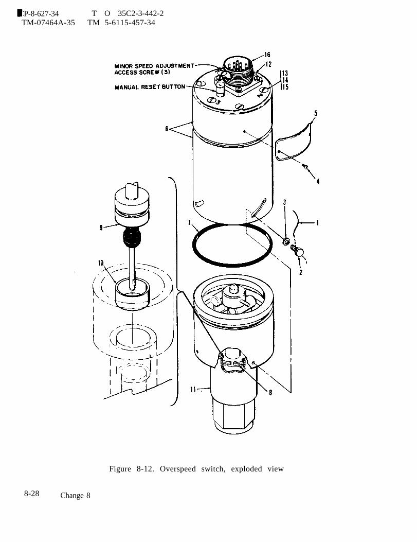
P-8-627-34 T O 35C2-3-442-2TM-07464A-35 TM 5-6115-457-34
Figure 8-12. Overspeed switch, exploded view
8-28 Change 8
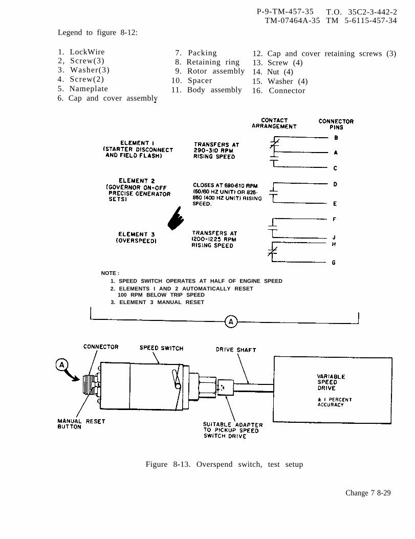
P-9-TM-457-35 T.O. 35C2-3-442-2TM-07464A-35 TM 5-6115-457-34
Legend to figure 8-12:
1. LockWire2, Screw(3)3. Washer(3)4. Screw(2)5. Nameplate6. Cap and cover assembly
7. Packing8. Retaining ring9. Rotor assembly
10. Spacer11. Body assembly
NOTE :
12. Cap and cover retaining screws (3)13. Screw (4)14. Nut (4)15. Washer (4)16. Connector
1. SPEED SWITCH OPERATES AT HALF OF ENGINE SPEED2. ELEMENTS I AND 2 AUTOMATICALLY RESET
100 RPM BELOW TRIP SPEED3. ELEMENT 3 MANUAL RESET
Figure 8-13. Overspend switch, test setup
Change 7 8-29
P-9-TM-457-35 T.O.35C2-3-442-2TM-07464A-35 TM 5-6115-457-34
7. Set variable speed drive at ap-proximately 200 RPM above actuation pointof switch 1. Speed of variable drive mustbe measured with a tachometer of ±1 per-cent accuracy.
8. Rotate cap and cover assembly(6) clockwise until switch 1 actuates. Scribethis position on body assembly (11) and capand cover assembly (6).
9. Rotate cap and cover assembly(6) clockwise an additional 1/16 of an inchand lock the three screws.
10 . Proceed to set trip points oftwo remaining switches, step b.
b. MINOR SPEED ADJUSTMENT.
CAUTION
Too many counterclockwise turnswill remove set screw from locknut assembly.
NOTE
All three switches may be individ-ually adjusted. Under certain con-ditions the adjustment of one switchmay slightly effect the speed settingof the other two. Compensating ad-justments may be required. Switch1 set screw will be turned clockwiseto increase speed to proper trip
while switch 3 set screw will beturned counterclockwise to decreasetrip point. Switch 3 set screw shouldrequire adjustment either clockwiseor counterclockwise (increase ordecrease) depending upon where itactuates.
1. Perform step a. , 1. above.
2. Turn adjusting screw clockwiseto increase trip point and counterclockwiseto decrease trip point. Set switches tospeeds indicated below by changing speedsetting of the test stand motor to a pointmidway in the speed band range.
Switch 1- set at 290 to 310 RPM
Switch 2- set at 590-610 RPM for60 hertz generator setsand 825-850 RPM, for 400hertz generator sets.
Switch 3- set at 1200 to 1225 RPM
3. Recheck all trip point settings.
4. After all bench adjustments havebeen made, tighten cover hardware (2 and3) and install lockwire.
8-52. INSTALLATION.
Refer to Operator and OrganizationalMaintenance Manual and install overspeedswitch. Check to be sure reset button hasnot tripped during installation.
8-30 Change 7

P-8-627-34 TO 35C2-3-442-2~TM-07464A-35 TM 5-6115-457-34
Section VIII. TACHOMETER DRIVE GROUP
8-53. GENERAL.
The tachometer drive group ismounted and driven off the fuel pump. Thetachometer drive senses engine speed andactuates the overspeed switch when enginespeed is between 2400 to 2450 RPM. Whenthe overspeed switch is actuated, the switchcontacts close and signals the STOP-RUN-RELAY to shut down the engine, this opera-tion protects the engine from being damageddue to overspeeding.
8-54. REMOVAL.
a. Refer to Operator and OrganizationalMaintenance Manual and remove overspeedswitch.
b. Refer to figure 8-14 and removetachometer drive group by removing bolts(1), lockwashers (2) and clamps (3 and 4).
8-55. DISASSEMBLY.
Refer to figure 8-14 and disassembletachometer drive group in the order of in-dex numbers assigned. Pay particularattention to the following.
Bearings (8, 15 and 21) are pressfitted. If necessary, remove bearingsusing suitable removal tools.8-56. CLEANING..
WARNING
Cleaning Solvents are flammable andmoderately toxic to skin, eyes andrespiratory tract. Eye and skinprotection required. Good generalventilation is normally adequate.
a. Clean parts with an approved clean-ing solvent. Scrub parts thoroughly usinga stiff bristle brush.
b. Dry parts with filtered low pressurecompressed air or a clean lint-free cloth.8-57. INSPECTION.
a. Inspect bearings (8, 15 and 21) forscoring, pitting, scratches and cracks.Replace defective bearings.
b, Inspect housing for cracks. Replacecracked housing.
c . Inspect gear teeth for nicks, burrs,cracks and broken teeth. Nicks and burrsthat extend below the hardened surface ofthe gear teeth are cause for rejection ofthe gear.
d. Inspect gear teeth for wear that mayhave destroyed the original tooth shape.If this condition is found, replace gear.
e. Inspect gear shafts for nicks, burrsand scratches.
f. Discard seal.
8-58. REPAIR.
a. Remove minor nicks and burrs fromgear teeth and gear shafts using a smoothfile or hone.
b. If gears must be replaced, pressgears from shaft using a suitable arborpress . Apply an approved adhesive to geardiameter of shaft and press gear onto shaft.Press fit must withstand 10 ft-lbs torque.
8-59, REASSEMBLY.
Compressed air used for cleaning anddrying purposes can create airborneparticles that may enter the eyes.Pressure shall not exceed 30 psig.Eye protection is required.
Refer to figure 8-14, and reassembletachometer drive group in the reverse orderof index numbers assigned. Pay particularattention to the following:
Change 8 8-31
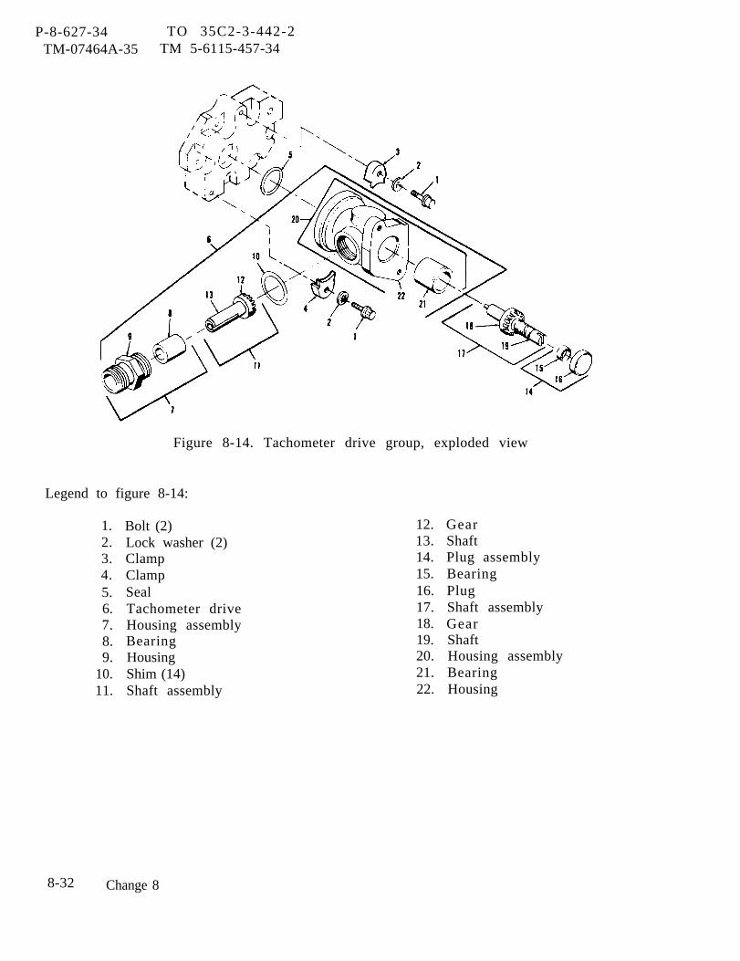
P-8-627-34 TO 35C2-3-442-2TM-07464A-35 TM 5-6115-457-34
Figure 8-14. Tachometer drive group, exploded view
Legend to figure 8-14:
1.2.3.4.5.6.7.8.9.
10.11.
Bolt (2)Lock washer (2)ClampClampSealTachometer driveHousing assemblyBearingHousingShim (14)Shaft assembly
12.13.14.15.16.17.18.19.20.21.22.
GearShaftPlug assemblyBearingPlugShaft assemblyGearShaftHousing assemblyBearingHousing
8-32 Change 8
a. If bearings (8, 15 and 21) were re- 8-60.moved, install new bearings. Bearingsare press fitted. a.
P-8-627-34 TO 35C2-3-442-2TM-07464A-35 TM 5-6115-457-34
INSTALLATION.
Refer to figure 8-14 and installtachometer drive group, secure with bolts
b. Pack housing assembly (22) cavity (1), lockwashers (2) and clamps (3 and 4).with 7 cc’s of approved lubricant. Torque bolts (1) from 6 to 10 foot pounds.
c . Use required number of shims to b. Refer to Operator and Organizationalproduce 0. 001 to 0, 005 inch end play on Maintenance Manual and install overspeedshaft (11). switch.
Section IX. FUEL PUMP GROUP
8-61. GENERAL.
The fuel pump is mounted to theaccessory drive group, the pump is drivenby a gear on the accessory drive shaft.The fuel pump consists of a gear drivenshaft, sleeve bearings, fuel propellinggears, and seals. The pump causes fuelto flow from the day tank into the fuel in-jection pump housing.
8-62. REMOVAL.
a. Refer to Operator and OrganizationalMaintenance Manual and remove over speedswitch.
b. Refer to Operator and OrganizationalMaintenance Manual and remove fuel hosefrom fuel pump.
c. Remove tachometer drive group(para 8-54).
d. Refer to figure 8-15 and remove fuelpump by removing bolts (4), lock washers(5) and gasket (7).
8-63. DISASSEMBLY.
Refer to figure 8-15 and disassemblefuel pump group in the order of index num-bers assigned. Pay particular attention tothe following:
NOTE
Pump body (30) and cover (22) shouldbe carefully separated due to thesealant that was used during assembly.
If necessary, remove gear (24)from shaft (25), using a suitable puller andstep
●
plate.
WARNING
Cleaning Solvents are flammable andmoderately toxic to skin, eyes andrespiratory tract. Eye and skinprotection required. Good generalventilation is normally adequate.
Compressed air used for cleaning anddrying purposes can create airborneparticles that may enter the eyes.Pressure shall not exceed 30 psig.Eye protection is required.
8-64. CLEANING .
Clean parts with an approved clean-ing solvent and dry parts with low pressurecompressed air.
8-65. INSPECTION .
a. Refer to table 1-1 and inspect fuelpump group for dimensional tolerances.Replace all parts that exceed maximumallowable wear and clearance.
b. Inspect pump cover for nicks, scor-ing and cracks. Replace defective cover.
c. Inspect gear teeth for nicks, burrs,cracks and broken teeth. Nicks and burrsthat extend below the hardened surface ofthe gear teeth are cause for rejection ofthe gear.
Change 8 8-33
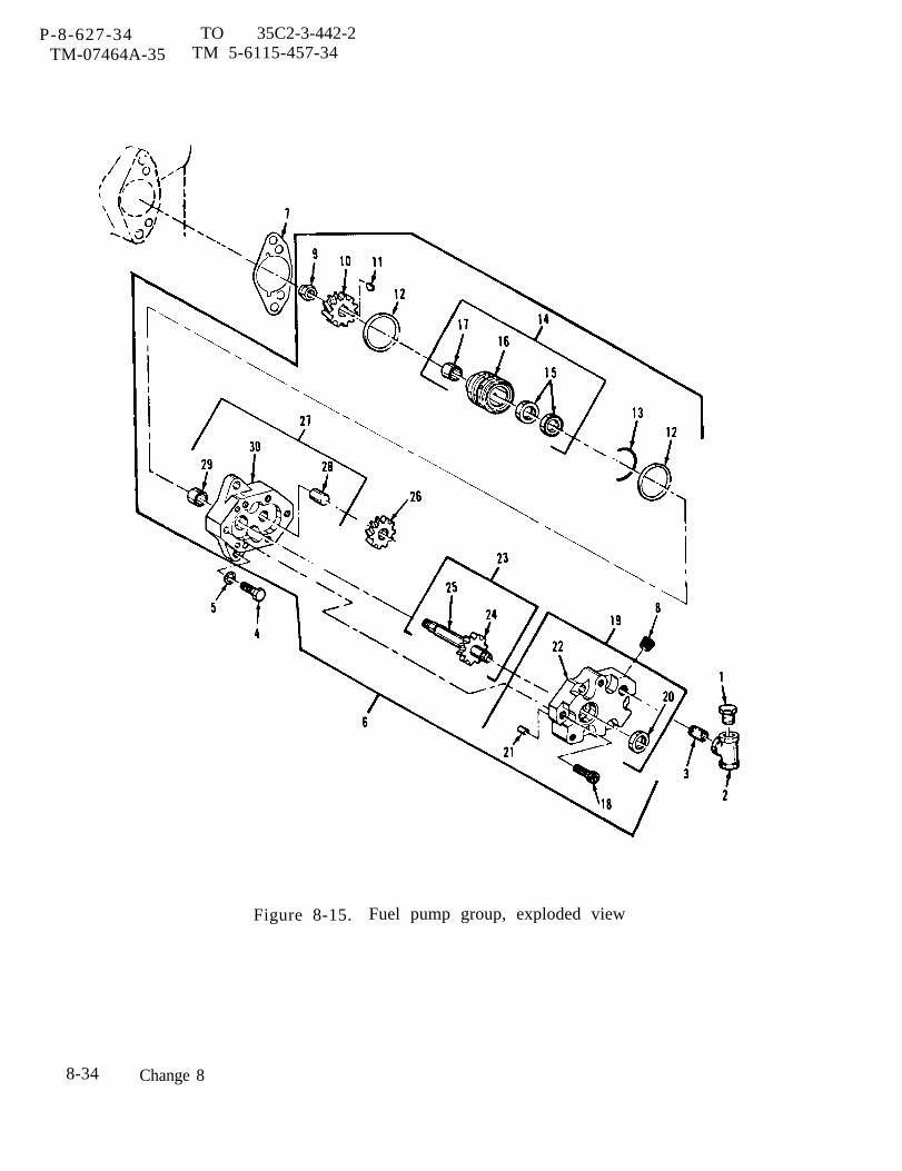
P-8-627-34 TO 35C2-3-442-2TM-07464A-35 TM 5-6115-457-34
Figure 8-15. Fuel pump group, exploded view
8-34 Change 8

P-8-627-34 TO 35C2-3-442-2TM-07464A-35 TM 5-6115-457-34
Legend to figure 8-15:
1. Plug2. Tee3. Nipple4. Bolt (2)5, Lock washer (2)6. Fuel pump7. Gasket8. Plug9. Nut
10. Gear11. Key12. Seal (2)13, Ring14. Gauge assembly15. Seal (2)
d. Inspect gear teeth for wear that mayhave destroyed the original tooth shape.If this condition is found, replace gear.
e. Inspect gear shafts for nicks, burrsand scratches.
f. Inspect bearings for scoring, pitting,scratches and cracks.
g. Inspect a defective bearing’s housingfor grooved, burred or galled conditionsthat would indicate that the bearing has beenturning in its housing.
8-66. REPAIR.
Remove minor nicks and burrs fromgear teeth and gear shafts using a smoothfile or hone.
8-67. REASSEMBLY .
Refer to figure 8-15 and reassemblefuel pump group in the reverse order ofindex numbers assigned. Pay particularattention to the following:
a. Before installation, lightly lubricateseals (12, 15 and 20) with clean engine oil.
16.17.18.19.20.21.22.23.24.25.26.27.28.29.30.
BearingGaugeScrew (6)Cover assemblySealFerruleCoverShaft assemblyGearShaftGearBody assemblyShaftBearingBody assembly
CAUTION
Do not allow permatex to enter pumpassembly.
b. Apply a thin coat of permatex be-tween body assembly (30) and cover (22).
c. Rotate pump shaft by hand to ensurethat pump parts rotate freely. If bindingexists, tap corner of pump cover with ahammer to relieve binding.
d. Torque nut (9) from 17 to 27 footpounds .
8-68. INSTALLATION.
a. Refer to figure 8-15 and install fuelpump, secure with bolts (4), lock washers(5) and gasket (7).
b. Install tachometer drive group(para 8-60).
c . Refer to Operator and OrganizationalMaintenance Manual and install overspeedswitch.
d. Refer to Operator and OrganizationalMaintenance Manual and connect fuel hoseto fuel pump.
C h a n g e 8 8 - 3 5
P-8-627-34 TO 35C2-3-442-2TM-07464A-35 TM 5-6115-457-34
Section X. TURBOCHARGER GROUP
8-69. GENERAL.
The turbocharger is mounted on theexhaust manifold. The Turbocharger con-sists of a turbine wheel and a compressorimpeller mounted on a common rotatingshaft, a bearing housing, compressorcover, and compressor back plate. Theturbocharger, which is driven by the engineexhaust gases, draws in ambient air, com-presses the air, and directs it into theengine intake manifold. This processsupercharges the engine which results ina greater power output.
8-70. REMOVAL.
Refer to Operator and Organiza-tional Maintenance Manual, and remove theturbocharger group.
8-71. DISASSEMBLY.
Refer to figure 8-16 and disassembleturbocharger in the order of index numbersassigned. Pay particular attention to thefollowing:
WARNING
Solvent, Dry Cleaning P-W680, Type IIis flammable and moderately toxic toskin, eyes and respiratory tract. Eyeand skin protection required. Goodgeneral ventilation is normally ade-quate.
a. Cover all turbocharger openings andclean all exterior surfaces using a cleaningsolvent that is in accordance with Federal
Specification P-D-680. Dry unit thoroughlyand remove opening coverings.
NOT E
Before removing wheel (48),mark shaft and wheel assembly(60). Rotating parts should bealigned during reassembly.
b. Before disassembly of parts, measurewheel (48) end clearance. End clearanceshould be O. 006 to O. 011 inches. Ifclearance is excessive, or if either theshaft and wheel assembly (60) or wheel (48)has rubbed against housing assembly (65)or shroud (61), the bearings (58) and/orthrust bearing (56) and collar (55) mustbe replaced.
c. Punch mark housing assembly (41),housing assembly (65) and housing (45) toensure correct positioning upon reassembly.
d. Fabricate a fixture, fixture adaptersupporting screw, wood dowel, and wrenchas shown in figure 2-1, These tools are tobe used for disassembly of rotating parts.
e. Bolt fixture adapter to fixture,figure 8-17. Attach bearing housing tofixture with shaft and wheel assembly(60) down.
CAUTION
Proper installation of supportingscrew is important so as to allow anunobstructed pressing action on shaftand still prevent turbine wheel frombeing damaged by striking againstfixture base.
8-36 Change 8
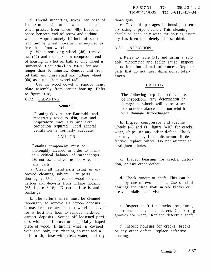
P-8-627-34 TO 35C2-3-442-2TM-07464A-35 TM 5-6115-457-34
f. Thread supporting screw into base offixture to contain turbine wheel and shaftwhen pressed from wheel (48), Leave aspace between end of screw and turbinewheel. Approximately l/2-inch of shaftand turbine wheel movement is required tofree them from wheel.
g. When removing wheel (48), removenut (47) and then position compressor endof housing in a hot oil bath so only wheel isimmersed. Heat wheel to 350°F for notlonger than 10 minutes. Remove unit fromoil bath and press shaft and turbine wheel(60) as a unit from wheel (48).
h. Use the wood dowel to remove thrustplate assembly from center housing. Referto figure 8-180
8-72. CLEANING.
Cleaning Solvents are flammable andmoderately toxic to skin, eyes andrespiratory tract. Eye and skinprotection required. Good generalventilation is normally adequate.
CAUTION
Rotating components must bethoroughly cleaned in order to main-tain critical balance of turbocharger.Do not use a wire brush or wheel onany parts.
a. Clean all metal parts using an ap-proved cleaning solvent. Dry partsthoroughly. Use a piece of wood to cleancarbon and deposits from turbine housing(65, figure 8-16). Discard all seals andpackings.
b. The turbine wheel must be cleanedthoroughly to remove all carbon deposits.It may be necessary to soak wheel in solventfor at least one hour to remove hardenedcarbon deposits. Scrape off loosened parti-cles with a stiff brush or a specially shapedpiece of wood, If turbine wheel is coveredwith soot only, use cleaning solvent and astiff brush, rinse with clean water, and dry
thoroughly.c. Clean oil passages in housing assem-
bly using a pipe cleaner. This cleaningshould be done only when the housing assem-bly has been completely disassembled.
8-73. INSPECTION .
a. Refer to table 1-1, and using a suit-able micrometer and feeler gauge, inspectparts for dimensional tolerances. Replaceparts that do not meet dimensional toler-ances.
CAUTION
The following step is a critical areaof inspection. Any deformation ordamage to wheels will cause a seri-ous out-of -balance condition whit hwill damage turbocharger.
b. Inspect compressor and turbinewheels (48 and 60, figure 8-16) for cracks,wear, chips, or any other defect. Checkcarefully for any blade distortion. If de-fective, replace wheel. Do not attempt tostraighten blades.
c. Inspect bearings for cracks, distor-tion, or any other defect,
d. Check runout of shaft. This can bedone by one of two methods, Use standardbearings and place shaft in vee blocks oruse a partially open vise.
e. Inspect shaft for cracks, roughness,distortion, or any other defect, Check ringgrooves for wear, Replace defective shaft.
f. Inspect housing for cracks, breaks,or any other defect. Replace defectivehousing,
Change 8 8-37
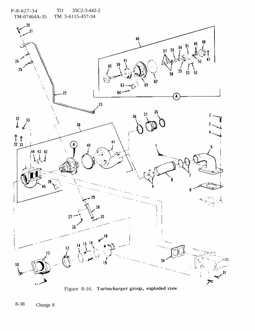
P-8-627-34 TO 35C2-3-442-2TM-07464A-35 TM 5-6115-457-34
Figure 8-16.
8-38 Change 8
P-9-TM-457-35 T.O. 35C2-3-442-2TM-07464A-35 TM 5-6115-457-34
Legend to figure 8-16:
1.2.3.4.5.6.7.8.9.
10.11.12.13.14.15.16.17.18.19.20.21.22.23.24.25.26.27.28.29.30.31.32.33.
PlugBolt (4)Lock washer (4)Washer (4)E lbowGasketSeal (2)PipeSeal (2)P lugPlugClampE lbowRingCouplingRingBolt (2)Nut (2)SupportBolt (2)Lock washer (2)Tube assemblyFittingGasketStrainer assemblyBolt (2)Lock washer (2)Tube assemblyGasketSealBolt (2)Nut (4)Washer (4)
g. Inspect all other parts for cracks,distortion, breaks, excessive wear, or anyother defect.
h. Inspect all attaching hardware fordamaged threads, distortion, cracks, orany other defect.
34.35.36.37.38.39.40.41.42.43.44.45.46.47.48.49•50.51.52.53.54.55.56.57.58.59.60.61.62.63.64.65.
GasketSealSealcouplingTurbocharger assemblyNameplateclampHousing assemblyBolt (6)Plate (3)Plate (3)HousingCartridge assemblyNutWheelRing (2)SpacerSealScrew (3)Plate (3)Plate assemblyCollarBearingRing (3)Bearing (2)RingShaft and wheel assemblyShroudSealNameplateScrew (2)Housing assembly
8-74. REPAIR.
Repair damaged threaded holes forthe oil pressure line flange bolts and for thedrain line flange bolts in the housing assem-bly by retapping holes to clean out burrsand other obstructions.
8-39
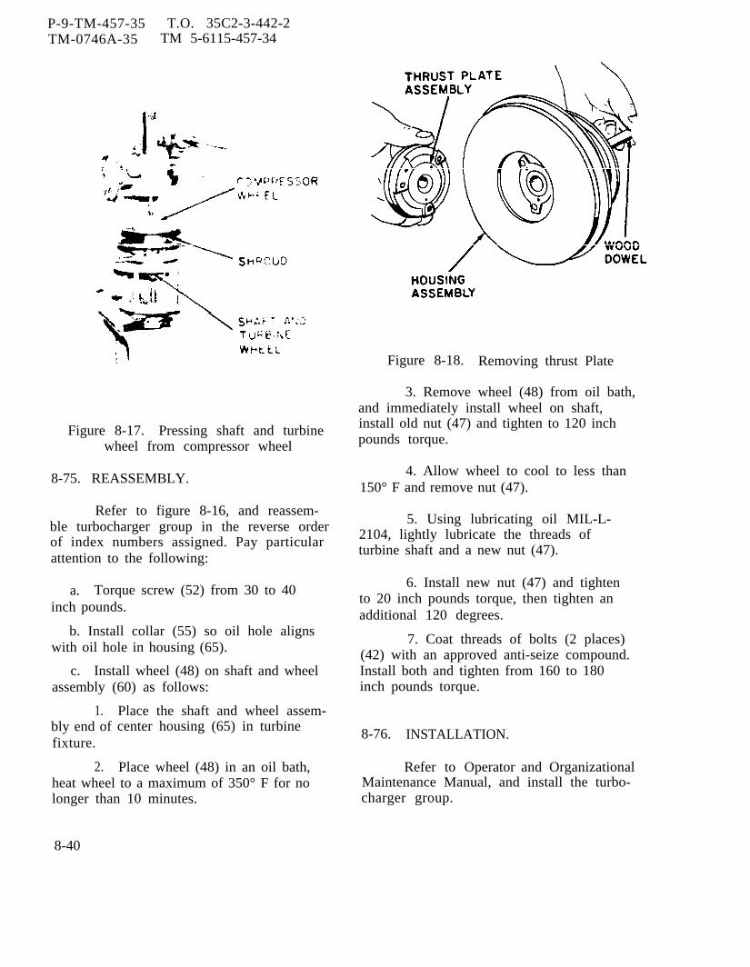
P-9-TM-457-35 T.O. 35C2-3-442-2TM-0746A-35 TM 5-6115-457-34
Figure 8-17. Pressing shaft and turbinewheel from compressor wheel
8-75. REASSEMBLY.
Refer to figure 8-16, and reassem-ble turbocharger group in the reverse orderof index numbers assigned. Pay particularattention to the following:
a. Torque screw (52) from 30 to 40inch pounds.
b. Install collar (55) so oil hole alignswith oil hole in housing (65).
c. Install wheel (48) on shaft and wheelassembly (60) as follows:
1.bly end offixture.
2.
Place the shaft and wheel assem-center housing (65) in turbine
Place wheel (48) in an oil bath,heat wheel to a maximum of 350° F for nolonger than 10 minutes.
Figure 8-18. Removing thrust Plate
3. Remove wheel (48) from oil bath,and immediately install wheel on shaft,install old nut (47) and tighten to 120 inchpounds torque.
4. Allow wheel to cool to less than150° F and remove nut (47).
5. Using lubricating oil MIL-L-2104, lightly lubricate the threads ofturbine shaft and a new nut (47).
6. Install new nut (47) and tightento 20 inch pounds torque, then tighten anadditional 120 degrees.
7. Coat threads of bolts (2 places)(42) with an approved anti-seize compound.Install both and tighten from 160 to 180inch pounds torque.
8-76. INSTALLATION.
Refer to Operator and OrganizationalMaintenance Manual, and install the turbo-charger group.
8-40
P-8-627-34 TO 35C2-3-442-2TM-07464A-35 TM 5-6115-457-34
Section XI. OIL COOLER GROUP
8-77. GENERAL.
The oil cooler group is mounted tothe engine block. It consists of the oilcooler assembly, a water bonnet, and as-sociated tubing and connections. The oilcooler assembly contains a tube bundle, twobypass valves, and a housing. On coldengine starts, the cool viscous oil does notflow immediately through the oil cooler andoil filter. The cool oil fore es bypass valves,located on the oil filter and oil cooler, toopen and the oil flows unrestricted throughthe engine and to the turbocharger. As thetemperature of the oil increases, the vis-cosity and pressure of the oil decreasesand the oil filter bypass valves close. Now,only filtered oil is delivered to all of theengine parts. As oil temperature continuesto increase, the oil cooler bypass valvesclose, allowing the oil to flow through theoil cooler prior to entering the oil filters.If an oil filter becomes clogged, that oilfilter bypass valve opens and allows the oilto flow directly from the oil cooler into theengine. Water from the engine cooling sys-tem flows through the tube bundle sectionof the oil cooler to reduce the heat of theengine lubricating oil.
8-78. REMOVAL.
a. Refer to Operator and OrganizationalMaintenance Manual and remove oil filtergroup.
b. Remove three bolts, lockwashersand washers, securing oil filler tube andgasket to cylinder block.
c. Refer to figure 8-19,cooler group in the order ofassigned.8-79. DISASSEMBLY .
Refer to figure 8-20
and remove oilindex numbers
, and disassem-
ble oil cooler groupnumbers assigned.
8-800 CLEANING,
in the order of index
a. If tube bundle is corroded, scaledeposits can be removed by either of thefollowing methods:
CAUTION
Care must be taken to avoid dam-aging sides of tubes.
1. Clean tubes with a suitable 5/32inch diameter rod long enoughlength of tubes.
WARNING
to penetrate
Wear protective clothing and useextreme caution when mixing acidsolution, and when cleaning oilcooler. Always add acid to waterwhen mixing; never add water toacid. Avoid any contact of solutionwith skin. Keep away from eyes.
2. Clean tubes with a solution of 15percent hydrochloric acid and 85 percentwater. The oil cooler should be immersedin or flushed with the solution until the scaleis softened. Wash cooler thoroughly withwater to remove scale and solution. Repeatprocedure as necessary to achieve propercleaning.
WARNING
Cleaning Solvents are flammable andmoderately toxic to skin, eyes andrespiratory tract. Eye and skinprotection required. Good generalventilation is normally adequate. I
b. Clean metal components with an ap-proved cleaning solvent, and dry thorough-ly.
Change 8 8-41
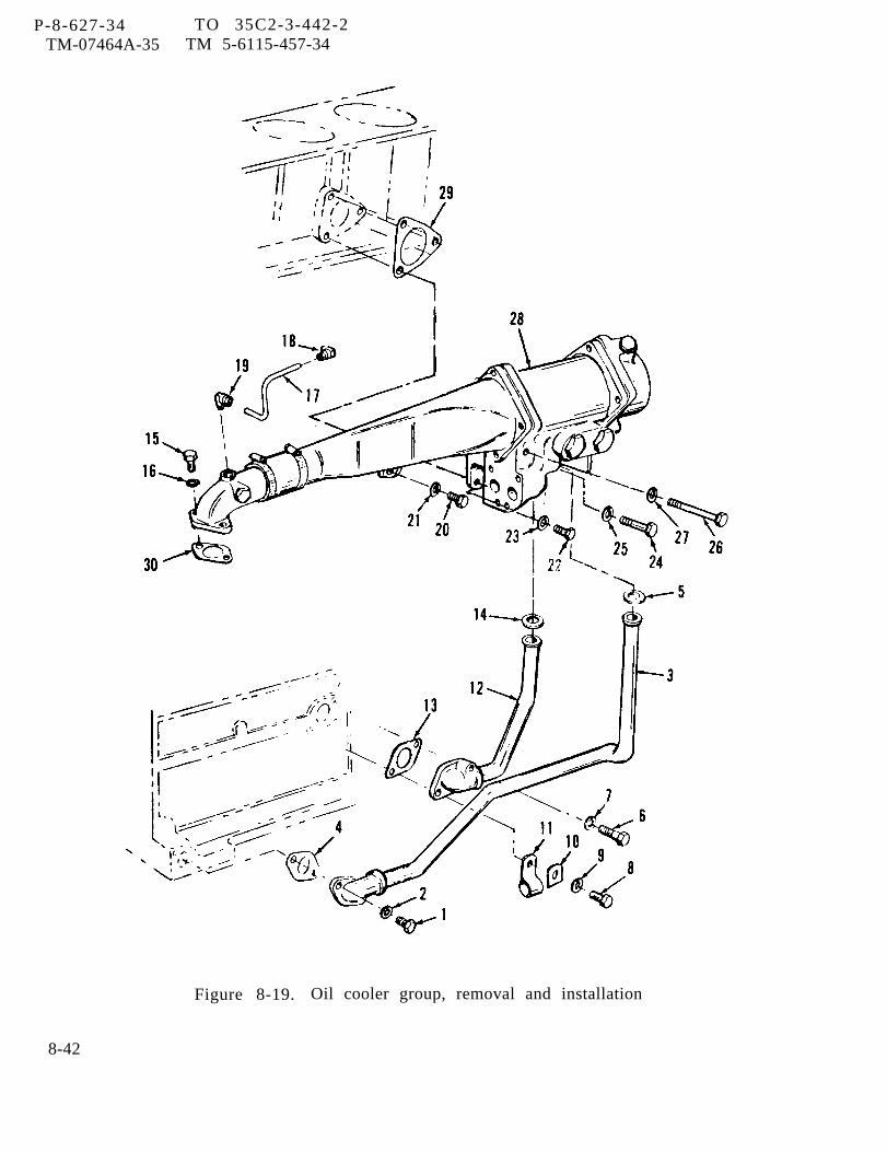
P-8-627-34TM-07464A-35
TO 35C2-3-442-2TM 5-6115-457-34
Figure 8-19. Oil cooler group, removal and installation
8-42
P-9-TM-457-35 T. 0. 35C2-3-442-2TM-07464A-35 TM 5-6115-457-34
Legend to figure 8-19:
1,2.3.4.5,6,7.8.9.
10.11.12.13.14.15.
Bolt (2)Lock washer (2)Tube assemblyGasketSealBoltLock washerBoltlock washerLugClipTube assemblyGasketSealBolt (2)
8-81. INSPECTION.
a. Inspect tube bundle and end bonnetsfor cracks, breaks, corrosion that cannotbe removed, and any other defects. Replacedefective components.
b. Inspect components for dents, cracks,distortion, and damaged threads.
c. Discard gaskets and seals,
d. Using a suitable spring compressor,apply a load of 8.92 Ibs. and compressrelief valve spring (10, figure 8-20) to alength of 2.5 inches. Replace relief valvespring (10) if free length after test is not3.61 inches.
8-82. REPAIR.
a. Repair dentsproper tools.
and distortion using
16.17.18.19.20.21•22.23.24.25.26.27.28.29.30.
Lock washer (2)TubeFittingFittingBoltLock washerBoltLock washerBoltLock washerBoltLock washerOil cooler groupGasketGasket
b. Repair minor thread damage usinga suitable thread chaser.
8-83. REASSEMBLY.
Refer to figure 8-20 and reassembleoil cooler group in the reverse order ofindex numbers assigned.
8-84. INSTALLATION.
a. Refer to figure 8-19, and install oilcooler group in the reverse order of indexnumbers assigned.
b. Install gasket and oil filler tube tocylinder block and secure with three wash-ers, lock washers and bolts.
c. Refer to Operator and OrganizationalMaintenance Manual and install oil filtergroup.
8-43
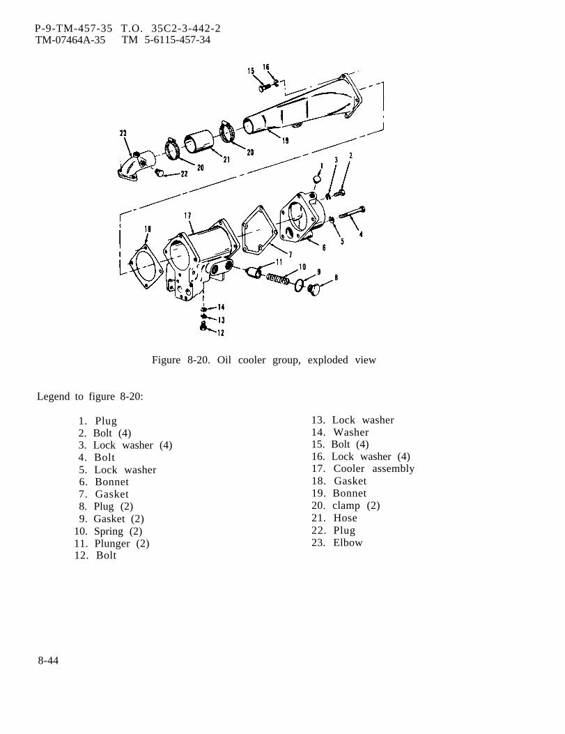
P-9-TM-457-35 T.O. 35C2-3-442-2TM-07464A-35 TM 5-6115-457-34
Figure 8-20. Oil cooler group, exploded view
Legend to figure 8-20:
1. Plug2. Bolt (4)3. Lock washer (4)4. Bolt5. Lock washer6. Bonnet7. Gasket8. Plug (2)9. Gasket (2)
10. Spring (2)11. Plunger (2)12. Bolt
13. Lock washer14. Washer15. Bolt (4)16. Lock washer (4)17. Cooler assembly18. Gasket19. Bonnet20. clamp (2)21. Hose22. Plug23. Elbow
8-44
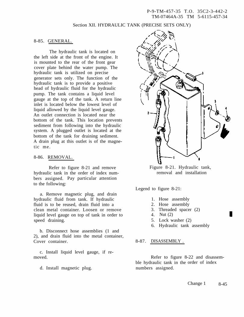
P-9-TM-457-35 T.O. 35C2-3-442-2TM-07464A-35 TM 5-6115-457-34
Section XII. HYDRAULIC TANK (PRECISE SETS ONLY)
8-85. GENERAL.
The hydraulic tank is located onthe left side at the front of the engine. Itis mounted to the rear of the front gearcover plate behind the water pump. Thehydraulic tank is utilized on precisegenerator sets only. The function of thehydraulic tank is to provide a positivehead of hydraulic fluid for the hydraulicpump. The tank contains a liquid levelgauge at the top of the tank. A return lineinlet is located below the lowest level ofliquid allowed by the liquid level gauge.An outlet connection is located near thebottom of the tank. This location preventssediment from following into the hydraulicsystem. A plugged outlet is located at thebottom of the tank for draining sediment.A drain plug at this outlet is of the magne-tic me.
8-86. REMOVAL.
Refer to figure 8-21 and removehydraulic tank in the order of index num-bers assigned. Pay particular attentionto the following:
a. Remove magnetic plug, and drainhydraulic fluid from tank. If hydraulicfluid is to be reused, drain fluid into aclean metal container. Loosen or removeliquid level gauge on top of tank in order tospeed draining.
b. Disconnect hose assemblies (1 and2), and drain fluid into the metal container,Cover container.
c. Install liquid level gauge, if re-moved.
d. Install magnetic plug.
Figure 8-21. Hydraulic tank,removal and installation
Legend to figure 8-21:
1.2.3.4.5.6.
Hose assemblyHose assemblyThreaded spacer (2)Nut (2)Lock washer (2)Hydraulic tank assembly
8-87. DISASSEMBLY .
Refer to figure 8-22 and disassem-ble hydraulic tank in thenumbers assigned.
order of index
Change 1 8-45
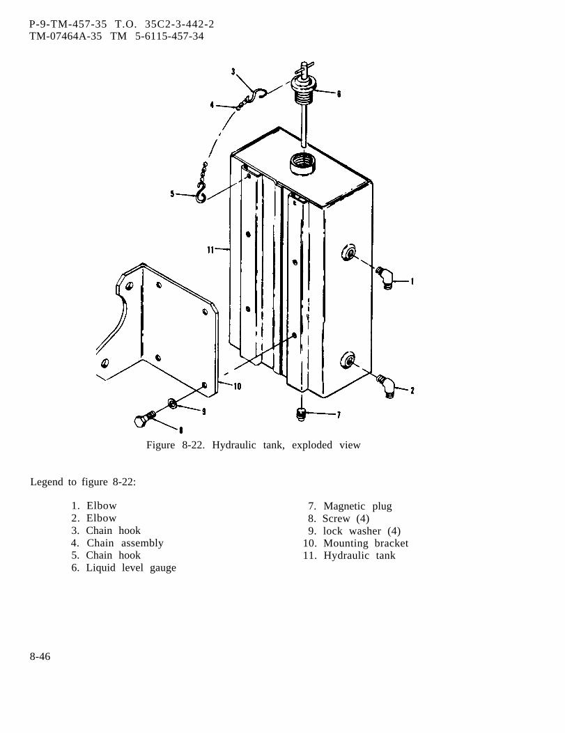
P-9-TM-457-35 T.O. 35C2-3-442-2TM-07464A-35 TM 5-6115-457-34
Figure 8-22. Hydraulic tank, exploded view
Legend to figure 8-22:
1. Elbow2. Elbow3. Chain hook4. Chain assembly5. Chain hook6. Liquid level gauge
7. Magnetic plug8. Screw (4)9. lock washer (4)
10. Mounting bracket11. Hydraulic tank
8-46
P-8-627-34 T O 3 5 C 2 - 3 - 4 4 2 - 2TM-07464A-35 TM 5-6115-457-34
Cleaning Solvents are flammable andmoderately toxic to skin, eyes andrespiratory tract. Eye and skinprotection required. Good generalventilation is normally adequate.
8-88. CLEANING.
Clean components with unapprovedcleaning solvent, and dry thoroughly. En-sure that all particles trapped on head ofmagnetic plug are removed.
8-89. INSPECTION.
a. Inspect tank for leakage by air test-ing as follows:
1. Connect a suitable air supply totank, and plug all openings.
2. Submerge tank in water, andapply air pressure of 1.5 PSI. Check forair bubbles.
b. Inspect liquid level gauge by holdinggauge in hand and twisting handle in aclockwise direction. The rubber seal ringshould swell slightly as handle is twisted.If rubber seal ring does not swell, replaceliquid level gauge.
c. Inspect magnetic plug for its capa-bility to pick up metal particles. If it haslost its magnetic capability, replace mag-netic plug.
d. Inspect threaded holes in tank fordam aged threads.
8-90. REPAIR.
a. Repair leakage or holes in tank asfollows:
1. Steam clean tank.
2. Fill tank with water.
WARNING
Welding operations produce heat,highly toxic fumes, injuriousradiation, metal slag and air-borne particles. Welding gog-gles, with proper tinted lenses,apron or jacket and welder'sboots are required.
3. Repair tank by welding.
4. Repair tank with large holes bywelding metal patches to tank.
5. After welding, drain water fromtank.
6. Pressure test tanks for leakagein accordance with paragraph 8-89, step a.
b. Repair damaged threaded holes byretapping holes.
8-91. REASSEMBLY
Refer to figure 8-22 and reassemblehydraulic tank in the reverse order of indexnumbers assigned.
8-92. INSTALLATION.
a. Refer to figure 8-21 and installhydraulic tank in the reverse order of in-dex numbers assigned.
b. Refer to Operator and OrganizationalMaintenance Manual, and service hydraulictank.
Change 8 8-47
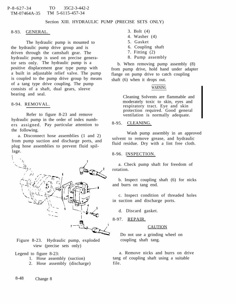
P-8-627-34 TO 35C2-3-442-2TM-07464A-35 TM 5-6115-457-34
Section XIII. HYDRAULIC PUMP (PRECISE SETS ONLY)
8-93. GENERAL.
The hydraulic pump is mounted tothe hydraulic pump drive group and isdriven through the camshaft gear. Thehydraulic pump is used on precise genera-tor sets only. The hydraulic pump is apositive displacement gear type pump witha built in adjustable relief valve. The pumpis coupled to the pump drive group by meansof a tang type drive coupling. The pumpconsists of a shaft, dual gears, sleevebearing and seal.
8-94. REMOVAL.
Refer to figure 8-23 and removehydraulic pump in the order of index numb-ers assigned. Pay particular attention tothe following.
a. Disconnect hose assemblies (1 and 2)from pump suction and discharge ports, andplug hose assemblies to prevent fluid spil-lage.
3. Bolt (4)4. Washer (4)5. Gasket6. Coupling shaft7. Fitting (2)8. Pump assembly
b. When removing pump assembly (8)from pump drive, hold hand under adapterflange on pump drive to catch couplingshaft (6) when it drops out.
WARNING
Cleaning Solvents are flammable andmoderately toxic to skin, eyes andrespiratory tract. Eye and skinprotection required. Good generalventilation is normally adequate. I
8-95. CLEANING.
Wash pump assembly in an approvedsolvent to remove grease, and hydraulicfluid residue. Dry with a lint free cloth.
8-96. INSPECTION.
a. Check pump shaft for freedom ofrotation.
b. Inspect coupling shaft (6) for nicksand burrs on tang end.
c. Inspect condition of threaded holesin suction and discharge ports.
d.
8-97.
Discard gasket.
REPAIR.
CAUTION
Do not use a grinding wheel onFigure 8-23. Hydraulic pump, exploded coupling shaft tang.
view (precise sets only)
Legend to figure 8-23: a. Remove nicks and burrs on drive1.2.
8-48
Hose assembly (suction) tang of coupling shaft using a suitableHose assembly (discharge) file.
Change 8
WARNING
Hydraulic Fluid is highly toxic toskin, eyes and respiratory tract.Eye and skin protection required.Good general ventilation is normal-ly adequate.
b, Damaged threads on suction and dis-charge ports may be retapped with a 1/2inch N.P.T.F. tap. Flush pump with cleanhydraulic fluid to remove cuttings aftertapping.
r e -
8-98. HYDRAULIC PUMP TEST ANDADJUSTMENT (ON PRECISEGENERATOR SETS ONLY).—Test and adjust the hydraulic pump
as follows:NOTE
Rotation of pump is clockwise asviewed from drive end.
a. Connect hydraulic pump drive shaftto suitable vary-drive capable of 0 to 2500RPM.
b. Connect supply line of suitable hy-draulic test stand to IN port of pump. Pumpshould have fluid reservoir mounted higherthan pump inlet.
NOTE
Test stand should have an adjustablerestriction valve in return line afterflow meter.
c. Connect a suitable 0 to 500 PSI gaugeand throttling valve to OUT port of pump.Connect out port of throttling valve to teststand flow meter.
d. Open throttling valve and test standrestriction valve. Start vary-drive andadjust speed to 1500 to 2116 RPM. Slowlyclose throttling valve and observe gaugereading. With valve fully closed, gauge
P-8-627-34 TO 35C2-3-442-29TM-07464A-35 TM 5-6115-457-34
should indicate 320 ±10 PSI. If not, re-move relief valve cap located next to pumpIN port. Adjust relief valve to obtain 320 ±10 PSI. Open throttling valve and permitapproximately one gallon to flow throughvalve. Close valve and check gauge, read-ing should be 320 ±10 PSI. If not, readjustrelief valve. Install relief valve cap afteradjustment is made.
e. Open throttling valve. Slowly closetest stand restriction valve until a flow of2 GPM is indicated on flow meter. Checkgauge, reading should be 320 ±10 PSI.
f. Remove pump from test equipment.Replace pump that does not provide a min-imum of 2 GPM at 320 ±10 PSI.
8-99. INSTALLATION .
Refer to figure 8-23 and reassemblehydraulic pump in reverse order of indexnumbers assigned. Pay particular atten-tion to the following.
a . Use one wrap of thread seal ing tapeor thread sealing compound MIL-T-5544 wheninstal l ing elbows (7) . Apply a l iberalamount of grease MIL-G-10924 to the pumps h a f t , coup l ing (6 ) and d r ive sha f t .Grease wil l prevent coupling from drop-ping when installing pump and reduce weardur ing ope ra t ion .
b . Pos i t ion pump so tha t r e l i e f va lveis point ing down.
c . Ro ta te sha f t w i th f inge r s to pos i -t ion tang drive to mate with couplings h a f t t a n g .
CAUTION
Do not force pump onto drive flange.
d. Pump must seat squarely on driveflange.
Change 8 8-49

■ P-8-627-34 TO 35C2-3-442-2TM-07464A-35 TM 5-6115-457-34
Section XIV. HYDRAULIC PUMP DRIVE GROUP
8-100. GENERAL. Ž Compressed air used for cleaning and
The hydraulic pump drive group ismounted to the engine front plate and is geardriven from the camshaft gear. It is util-ized on precise generator sets only. Thehydraulic pump drive group consists of ashaft, a gear, bearings, a seal and gaskets.The hydraulic pump drive group drives thehydraulic pump.
8-101. REMOVAL.
drying purposes can create airborneparticles that may enter the eyes.Pressure shall not exceed 30 psig.Eye protect ion is required.
CAUTION
Do not spin dry bearings.
Clean all parts with an approvedcleaning solvent and air dry. Drybearings with low pressure com-
a. Refer to paragraph 8-94 and removehydraulic pump (8) (precise generator setsonly).
b. Refer to figure 8-24 and remove thehydraulic pump drive group by removingscrews (1 and 4), nuts (2 and 5), lockwash-ers (3 and 6) and gasket (7).
8-102. DISASSEMBLY.
Refer to figure 8-24 and disassemblehydraulic pump drive group in the order ofindex numbers assigned. Pay particularattention to the following:
a. When removing adapter (14) noteposition of drain hole to ensure correctpositioning during reassembly.
b. If necessary, remove gear (21) andbearing (22) from shaft (23) using a suitablearbor press.
c. Press bearing (20) out of adapter (24),using a suitable arbor press.8-103. CLEANING .
Cleaning Solvents are flammable andmoderately toxic to skin, eyes andrespiratory tract. Eye and skinprotection required. Good generalventilation is normally adequate.
pressed air.
8-104. INSPECTION.
a. Check bearings for freedom of rota-tion. Replace a bearing if its rotation isrough.
b. Inspect bearings for pits, scratches,cracks or chipped races.
c . Inspect drive gear teeth for nicks,burrs, cracks and broken teeth. Nicks findburrs that extend below the hardened surfaceof the gear teeth arc cause for rejection ofthe gear.
d. Inspect. drive gear teeth for wearthat may have destroyed the original toothshape. If this condition is found, replacegear.
c. Inspect adapters for cracks. Replacecracked adapter.
f. Inspect adapter mounting surfaceand shaft for nicks and burrs.
g. Inspect threaded holes for threadeddamage.
8-50 Change 8
h. Discard seal, gasket and lockring.
i. Check tang drive end of shaft. Slotin shaft should be 0.253 to 0.257 inch wide.Replace shaft if slot is not within limits.
8-105, REPAIR.
a. Remove minor nicksa suitable file or hone.
b. Repair minor threada suitable thread chaser.
8-106. REASSEMBLY .
and burrs using
damage using
Refer to figure 8-24, and reassem-ble hydraulic pump drive group in the re-verse order of index numbers assigned.Pay particular attention to the following:
a. If removed, install gear (21) andbearing (22) on shaft (23) as follows:
1. Hand pack bearing (22) with anapproved grease. Install bearing ontoshaft (23) .
P-9-TM-457-35TM-07464A-35
2. Preheat gearof 600°F ●
T.O. 35C2-3-442-2TM 5-6115-457-34
(21) to a maximum
3. Using a suitable arbor press,press gear (21) onto shaft (23).
b. Hand pack bearing (20) with an ap-proved grease. Press bearing into adapter(14) .
c. Lubricate seal lip of seal (16) withan approved lubricant before installing onshaft (23) .
d. Locate oil drain hole in end adapter(14). Drain hole must be pointed downwardwhen drive is mounted in gear cover.
8-107. INSTALLATION.
a. Refer to figure 8-24 and install thehydraulic pump drive group, secure withbolts (1 and 4), nuts (2 and 5), lock washers(3 and 6) and gasket (7).
b. Refer to paragraph 8-99 and installhydraulic pump (precise generator setsonly).
Change 1 8-51
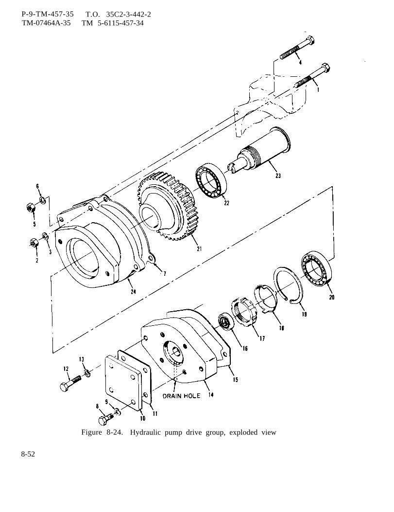
P-9-TM-457-35 T.O. 35C2-3-442-2TM-07464A-35 TM 5-6115-457-34
Figure 8-24. Hydraulic pump drive group, exploded view
8-52
P-9-TM-457-35 T.O. 35C2-3-442-2TM-07464A-35 TM 5-6115-457-34
Legend to figure 8-24:
1.2.3.4.5.6.7.8.9.
10.11.12.
Bolt (3)Nut (3)Lock washer (3)BoltNutLock washerGasketBolt (4)Lock washer (4)CoverGasketBolt (2)
13.14.15.16.17.18.19.20.21.22.23.24.
Lock washer (3)AdapterGasketSealNutLocknutRingBearingGearBearingShaftAdapter
Section XV. GOVERNOR ACTUATOR UNIT (PRECISE SET ONLY)
8-108. GENERAL.
The governor actuator unit is locatedon the right side of engine, mounted on topof the utility governor. The actuating unitis an electro-hydraulic servo motor thatreceives intelligence from the electric con-trol unit and converts this low level elec-trical information to proportional high levelhydraulic pressures that position the enginethrottle by the action of a piston and a float-ing lever pivot linkage system. The gover-nor actuator unit is composed of controlvalves, a piston, a linkage assembly andcore and armature assembly,
8-109. TEST AND REMOVAL.
a. Symptom and Isolation of malfunction.A malfunction of the hydraulic throttle actu-ator is usually indicated by engine shutdownor overspeed when the Start-Run-Stopswitch is transferred from the START tothe RUN position, frequency drift observedon the frequency meters, sluggish responseto load changes, or no response in loadchanges. To isolate the malfunction, pro-ceed as follows:
1. Check for 4 to 6 VDC at testpoints AB and CD of electric governor con-trol unit (A and D are positive), with engineoperating. If voltage at either point isapproximately 15 volts, the malfunction isa result of an open in an actuator valvecoil, or connecting circuit.
2. Check that the throttle linkage isnot badly worn or disconnected. A wornlinkage can cause sluggish response ordrifting frequency. A disconnected orbroken linkage can cause overspeed, shut-down, or no response. Also check linkagefor binding due to dirt or distortion.
3. Check condition of hydraulicfilter and the level of hydraulic oil. Eithera clogged or dirty filter or low oil levelcan reduce the hydraulic pressure requiredto operate the actuator.
4. Check pressure output of hydrau-lic actuator by removing plugs in ports Aland A2 (figure 8-25) and inserting 0 to 400PSI range gauges. The pressure at eachport should be 160 ±25 PSI and equal, withengine operating under governor control.
8-53

P-9-TM-457-35 T.O. 35C2-3-442-2TM-07464A-35 TM 5-6115-457-34
Operating under manual control, thepressure at port Al should be 180±20PSI and approximately 50 PSI higher than thepressure at port A2.
5. Check the transducer in theactuator for freedom of movement, Trans-ducer must move freely for good response.
6. If any of the above examinationsindicates that the actuator has failed, pro-ceed with removal, disassembly and repairinstructions.
b. Removal. Refer to figure 8-25 andremove governor actuator unit in order of
index numbers assigned. Pay particularattention to the following.
1. Disconnect harness plug fromgovernor actuator unit before removingfrom engine.
2. Plug hydraulic lines after re-moval.
8-110. DISASSEMBLY.
Refer to figure 8-26 and disassemblegovernor actuator unit in the ordernumbers assigned. Pay particularto the following.
of indexattention
Figure 8-25. Governor actuator unit, removal and installation (precise sets only)
8-54
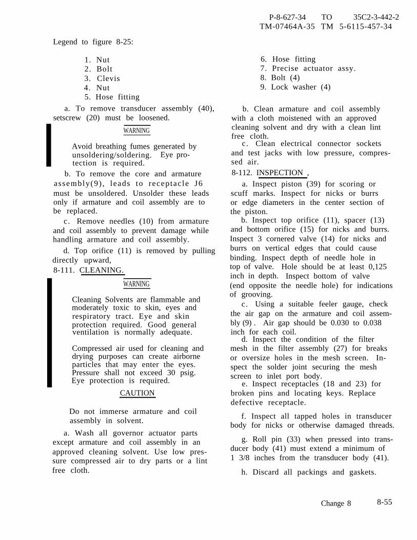
P-8-627-34 TO 35C2-3-442-2TM-07464A-35 TM 5-6115-457-34
Legend to figure 8-25:
1. Nut2. Bolt3. Clevis4. Nut5. Hose fitting
a. To remove transducer assembly (40),setscrew (20) must be loosened.
WARNING
Avoid breathing fumes generated byunsoldering/soldering. Eye pro-tection is required.
b. To remove the core and armatureassembly(9) , leads to receptac le J6must be unsoldered. Unsolder these leadsonly if armature and coil assembly are tobe replaced.
c. Remove needles (10) from armatureand coil assembly to prevent damage whilehandling armature and coil assembly.
d. Top orifice (11) is removed by pullingdirectly upward,8-111. CLEANING.
WARNING
Cleaning Solvents are flammable andmoderately toxic to skin, eyes andrespiratory tract. Eye and skinprotection required. Good generalventilation is normally adequate.
Compressed air used for cleaning anddrying purposes can create airborneparticles that may enter the eyes.Pressure shall not exceed 30 psig.Eye protection is required.
CAUTION
Do not immerse armature and coilassembly in solvent.
a. Wash all governor actuator partsexcept armature and coil assembly in anapproved cleaning solvent. Use low pres-sure compressed air to dry parts or a lintfree cloth.
6. Hose fitting7. Precise actuator assy.8. Bolt (4)9. Lock washer (4)
b. Clean armature and coil assemblywith a cloth moistened with an approvedcleaning solvent and dry with a clean lintfree cloth.
c. Clean electrical connector socketsand test jacks with low pressure, compres-sed air.8-112. INSPECTION ,
a. Inspect piston (39) for scoring orscuff marks. Inspect for nicks or burrsor edge diameters in the center section ofthe piston.
b. Inspect top orifice (11), spacer (13)and bottom orifice (15) for nicks and burrs.Inspect 3 cornered valve (14) for nicks andburrs on vertical edges that could causebinding. Inspect depth of needle hole intop of valve. Hole should be at least 0,125inch in depth. Inspect bottom of valve(end opposite the needle hole) for indicationsof grooving.
c. Using a suitable feeler gauge, checkthe air gap on the armature and coil assem-bly (9) . Air gap should be 0.030 to 0.038inch for each coil.
d. Inspect the condition of the filtermesh in the filter assembly (27) for breaksor oversize holes in the mesh screen. In-spect the solder joint securing the meshscreen to inlet port body.
e. Inspect receptacles (18 and 23) forbroken pins and locating keys. Replacedefective receptacle.
f. Inspect all tapped holes in transducerbody for nicks or otherwise damaged threads.
g. Roll pin (33) when pressed into trans-ducer body (41) must extend a minimum of1 3/8 inches from the transducer body (41).
h. Discard all packings and gaskets.
Change 8 8-55

P-8-627-34 TO 35C2-3-442-2TM-07464A-35 TM 5-6115-457-34
Figure 8-26. Governor actuator unit, exploded view (precise sets only)
8-56 Change 8
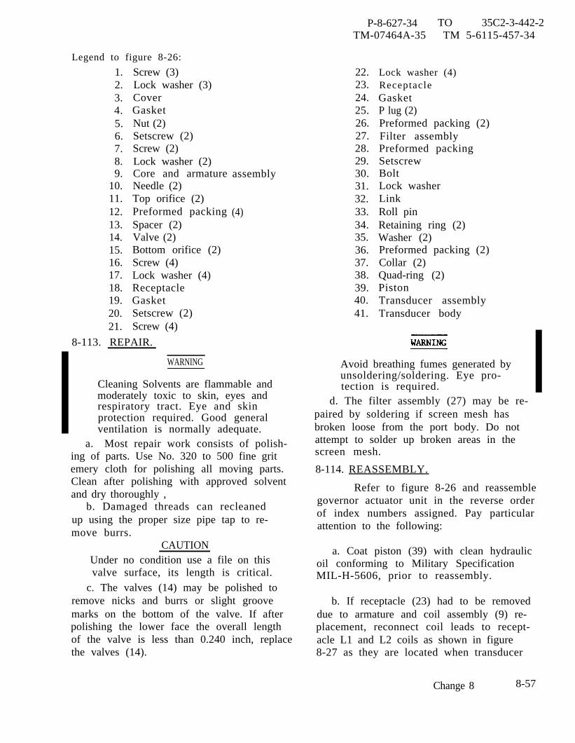
P-8-627-34 TO 35C2-3-442-2TM-07464A-35 TM 5-6115-457-34
Legend to figure 8-26:
1.2.3.4.5.6.7.8.9.
10.11.12.13.14.15.16.17.18.19.20.21.
Screw (3)Lock washer (3)CoverGasketNut (2)Setscrew (2)Screw (2)Lock washer (2)Core and armatureNeedle (2)Top orifice (2)Preformed packingSpacer (2)Valve (2)Bottom orifice (2)Screw (4)Lock washer (4)ReceptacleGasketSetscrew (2)Screw (4)
8-113. REPAIR.
a.
assembly
(4)
WARNING
Cleaning Solvents are flammable andmoderately toxic to skin, eyes andrespiratory tract. Eye and skinprotection required. Good generalventilation is normally adequate.
22.23.24.25.26.27.28.29.30.31.32.33.34.35.36.37.38.39.40.41.
Lock washer (4)ReceptacleGasketP lug (2)Preformed packing (2)Filter assemblyPreformed packingSetscrewBoltLock washerLinkRoll pinRetaining ring (2)Washer (2)Preformed packing (2)Collar (2)Quad-ring (2)PistonTransducer assemblyTransducer body
Avoid breathing fumes generated byunsoldering/soldering. Eye pro-tection is required.
d. The filter assembly (27) may be re-paired by soldering if screen mesh hasbroken loose from the port body. Do not
Most repair work consists of polish- attempt to solder up broken areas in the
ing of parts. Use No. 320 to 500 fine gritemery cloth for polishing all moving parts.Clean after polishing with approved solventand dry thoroughly ,
b. Damaged threads can recleanedup using the proper size pipe tap to re-move burrs.
CAUTIONUnder no condition use a file on thisvalve surface, its length is critical.
c. The valves (14) may be polished toremove nicks and burrs or slight groovemarks on the bottom of the valve. If afterpolishing the lower face the overall lengthof the valve is less than 0.240 inch, replacethe valves (14).
screen mesh.
8-114. REASSEMBLY.
Refer to figure 8-26 and reassemblegovernor actuator unit in the reverse orderof index numbers assigned. Pay particularattention to the following:
a. Coat piston (39) with clean hydraulicoil conforming to Military SpecificationMIL-H-5606, prior to reassembly.
b. If receptacle (23) had to be removeddue to armature and coil assembly (9) re-placement, reconnect coil leads to recept-acle L1 and L2 coils as shown in figure8-27 as they are located when transducer
Change 8 8-57
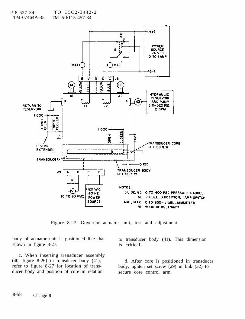
P-8-627-34TM-07464A-35
T O 3 5 C 2 - 3 4 4 2 - 2TM 5-6115-457-34
Figure 8-27. Governor actuator unit, test and adjustment
body of actuator unit is positioned like that to transducer body (41). This dimensionshown in figure 8-27. is critical.
c. When inserting transducer assembly(40, figure 8-26) in transducer body (41), d. After core is positioned in transducerrefer to figure 8-27 for location of trans- body, tighten set screw (29) in link (32) toducer body and position of core in relation secure core control arm.
8-58 Change 8
8-115. TEST AND ADJUSTMENT.
P-9-TM-457-35 T.O. 35C2-3-442-2TM-07464A-35 TM 5-6115-457-34
2, If gauges G1 and G2 do not indi-
a. Test equipment required.
1. Hydraulic pump (310 to 320 psiat 2 GPM).
2. Power source (120V 60 Hz).
3. D.C. power source (0 to 1 AMP24 V. D.C. ).
4. Switch, 2 pole,rating.
5. Meter (2) (0 toeter).
3 position, 1 amp
800 ma milliam-
6. Meter (1) (0 to 60 volts A.C.).r
7. Resistor (fixed -5000 ohms,1 watt).
8. Gauge (3) (pressure 0 to 400 psi).
b. Actuator Valve and Piston Test.Connect the governor actuator unit to testequipment as illustrated in figure 8-27 andproceed as follows:
1. With 24 vdc supply off, turn onthe hydraulic pump drive and adjust thepressure to port P until G3 indicates 320±10 psi. Adjust pressure by setting the relief valve in the pump.
NOTE
The actuator output shaft shall bein the fully extended position (throttleopen). Gauge G1 shall indicate 150±10 psi. Gauge G2 shall indicate200 ±10 psi.
cate the required pressures, adjustment ofvalve screws (6, figure 8-26) on the arma-ture and coil assembly (9) will have to bemade. Proceed as follows.
(a) Remove cover (3) andplace the governor actuator in a catch pan.The catch pan should drain back to thereservoir.
(b) Loosen lock nuts (5, figure8-26) on each valve adjustment screw (6).
(c) To adjust pressure at gaugeGl, insert an allen wrench in screw (6) oncoil L1 adjustment screw (6) and rotateclockwise (or in) to reduce pressure ongauge G1. Rotating screw (6) counterclock-wise will increase pressure on G1.
(d) Adjust pressure at gauge G1by rotating screw (6) on coil L2 in the samemanner as pressure adjustment on coil L1was preformed.
NOTE
Adjustment of one side (Ll) will insome degree effect the opposite side(L2); therefore, several adjustmentsof both sides will be required to ob-tain the setting specified in step c.
(e) Tighten lock nuts (5).
(f) Turn power supply on andposition switch S1 to B and adjust 24 vdcpower source until MA1 and MA2 indicate350 ±20 ma. The actuator output shaftshall remain in the extended position.Gauge G1 shall indicate 150 ±10 psi.Gauge G2 shall indicate 200 ±10 psi.
Change 1 8-59
P-9-TM-457-35 T.O. 35C2-3-442-2TM-07464A-35 TM 5-6115-457-34
(g) Position switch S1 to A. Ad-just 24 vdc power supply until MA2 indicates700 ±40 ma. Piston shall fully retract.Gauge G1 shall indicate 310 to 400 psi.Gauge G2 shall indicate 0 to 20 psi.
(h) Position switch S1 to C. Ad-just 24 vdc power supply until MA1 indicates700 ±40 ma. Piston shall fully extend.Gauge G1 shall indicate 0 to 40 psi. GaugeG2 shall indicate 310 to 400 psi.
c. Actuator Output Shaft Position Trans-ducer Test and Adjustment. Connect volt-meter V1 and power sources to receptacleJ4 on actuator as illustrated in figure 8-27and proceed as follows:
NOTE
Hydraulic system components are notused during this test.
CAUTION
The output shaft position transduceris factory aligned and does not norm-ally require readjustment.
1. Turn on the power supply.
2. Move the actuator output shaftto fully extended position. Transducerassembly (40) locked in place at dimensionsindicated in figure 8-27. V1 shall indicate0.5 to 2.5 volts. This shall be minimumvoltage regardless of what other positionthe output shaft is placed.
3. If voltage range on V1 is not withthe required 0.5 to 2.5 volts, loosen trans-ducer core set screw (29, figure 8-26) onlink (32) and move the core relative to thebody until the minimum voltage of 0.5 to
2.5 is obtained on meter VI. Adjust to 1volt as a starting point. Tighten the setscrew (29) in place.
d. Move the piston (39) graduallytowards the fully closed throttle position.The transducer secondary voltage shallincrease in a linear manner to a maximumof 48 to 55 volts. Loosen set screw (29) andadjust to 50 volts as a starting point. Re-peat core adjustment until the transducersecondary voltage increases linearly fromthe lowest possible value to a maximumvalue over the entire 1.0 inch travel of thepiston (39). The ideal voltage range wouldbe from 0.5 volt minimum to 55 volts max-imum. This range may not be possible toobtain so the widest voltage spread will beacceptable as long as the minimum andmaximum voltages are within the specifiedlimits.
e. Tighten transducer core set screw(29) .
8-116. INSTALLATION.
Refer to figure 8-25 and install pre-cise governor actuator in reverse order ofindex numbers assigned. Pay particularattention to the following.
a. Before connecting actuator clevis tolinkage, rotate fuel injection pump lever tomaximum throttle position and scribe anindicating mark for referent e. Then rotatefuel injection pump lever to minimumthrottle position and scribe an indicatingmark for reference.
NOTE
Fill FUEL POSITION on pump leveris when top of lever is pushed towardsf rent of engine.
b. Install actuator on mounting plate andsecure with four mounting bolts.
8-60
c. Connect hydraulic and electricalconnections.
d. Align actuator clevis hole with holein linkage.
e. Loosen bolts securing pin bracketand slide bracket forward. Pass pin throughclevis and pin bracket. Then tighten boltsand secure clevis to pin with cotter pin.
P-8-627-34 TO 35C2-3-442-2TM-07464A-35 TM 5-6115-457-34
f. Check that actuator output shaft canmove fuel inspection pump lever from fullthrottle to closed throttle position accord-ing to the scribe marks.
g. If full operating range cannot bereached, refer to linkage adjustment pro-cedure in the Operator and OrganizationalMaintenance Manual.
Change 8 8-61
P-8-627-34 TO 35C2-3-442-2TM-07464A-35 TM 5-6115-457-34
Section XVI. WATER PUMP GROUP
8-117. GENERAL
The water pump is mounted on thefront side of the timing gear cover. Thecentrifugal-type pump is driven by the cam-shaft gear. The pump consists of animpeller and drive gear mounted on acommon rotating shaft. Seals mounted onthe shaft prevent water from leaking intothe gear section and oil from leaking intothe impeller section. As the engine isrunning, the drive gear in the water pumpturns the shaft and impeller. The impellercreates a forceful flow of water through theengine cooling system.
8-118. REMOVAL
Refer to Operator and Organiza-tional maintenance Manual, and removewater pump.
8-119. DISASSEMBLY
Refer to figure 8-28, and disas-semble water pump in the order of indexnumbers assigned. Pay particular attentionto the following:
a. Remove impeller (30) by removingcotter pin (27), nut (28) and lock washer(29). Install three 5/16-18 inch bolts intapped holes provided on the impeller.Thread bolts evenly as they bottom out onhousing. As tension is increased,impeller will slide from tapered shaft.
b. When pressing shaft (35) and bearing(34) out of housing, place a nut on end ofshaft (35) to protect threads,
c . Press shaft (35) and bearing (34) outof housing (42). Press from impeller end.Do not remove bearing (34) and gear (23)front shaft (35) unless bearing (34), gear
(23) or shaft (35) is being replaced. Pressseal and ceramic ring assembly (33) outof impeller end of housing.
8-120. CLEANING
WARNING
Cleating Solvents are flammable andmoderately toxic to skin, eyes andrespiratory tract. Eye and skinprotect ion required. Good generalventilation is normally adequate. I
a. Clean all metal parts with an ap-proved cleaning solvent and dry thoroughly.
b. Clean calcium deposits from housingusing a stiff wire brush.
c . Remove all traces of old gasketmaterial from gear cover.
8-121. INSPECTION
a. Check bearings for freedom ofrotation. Replace a bearing if its rotationis rough.
b. Inspect bearings for pi ts , scratches,cracks or chipped races. Replacedefective bearing.
c . Inspect shaft for nicks, burrs, pitsc racks . Replace defective shaft.
d. Inspect threaded parts for threaddamage.
e. Inspect impeller for nicks, burrs ,erosion, or cracks, Replace erroded orcracked impeller .
f. Inspect cover and housing forc racks . Replace defective parts.
8-62 Change 8

P-9-TM-457-35 T.O. 35C2-3-442-2TM-07464A-35 TM 5-6115-457-34
g, Inspect gear teeth for nicks, burrs,cracks and broken teeth. Nicks and burrsthat extend below the hardened surface ofthe gear teeth are cause for rejection ofthe gear.
h. Inspect gear teeth for wear that mayhave destroyed the original tooth shape.If this condition is found, replace gear.
i. Discard seals and gaskets.
8-122. REPAIR.
a. Remove minor nicks and burrsusing a suitable file or hone.
b. Repair minor thread damage usinga suitable thread chaser.
8-123, REASSEMBLY.
Refer to figure 8-28, and reassemblewater pump in the reverse order of indexnumbers assigned. Pay particularattention to the following:
a. If bearing (34) is being replaced,gear (23) and bearing (22) must also beremoved from shaft (35) by preheatingshaft assembly in oil to a temperature of300° F. Reassemble in reverse order be-fore installing shaft (35) in housing (42).Make sure bearing housing (26) is installedon shaft after pressing bearing (34) onshaft (35).
b. Allow shaft assembly to cool. Installwater pump seal (36) in housing (42) usingan installation tool. Hand pack bearings(22 and 34) with an approved grease. Installshaft assembly into housing.
c. Place seal ring (33) and ceramicring (32) onto shaft and seat into housing(38) and press seal and spring assembly(31) until carbon washer contacts ceramicring.
d. Slide impeller (30) onto shaft (35).Install washer (29) and nut (28). Tightennut slowly forcing the impeller over thetappered shaft surface until washer (29)bottom out on shaft shoulder.
e. Torque impeller nut (28) from 25 to35 foot pounds.
f. Check impeller tip clearance betweenbackside of impeller and housing. Clear-ance should be between 0.010 and 0.030inch. If clearance is not within limitsdisassemble and reassemble pump toachieve proper clearance.
8-124. INSTALLATION.
Refer to Operator and Organiza-tional Maintenance Manual, and installwater pump group.
8-63
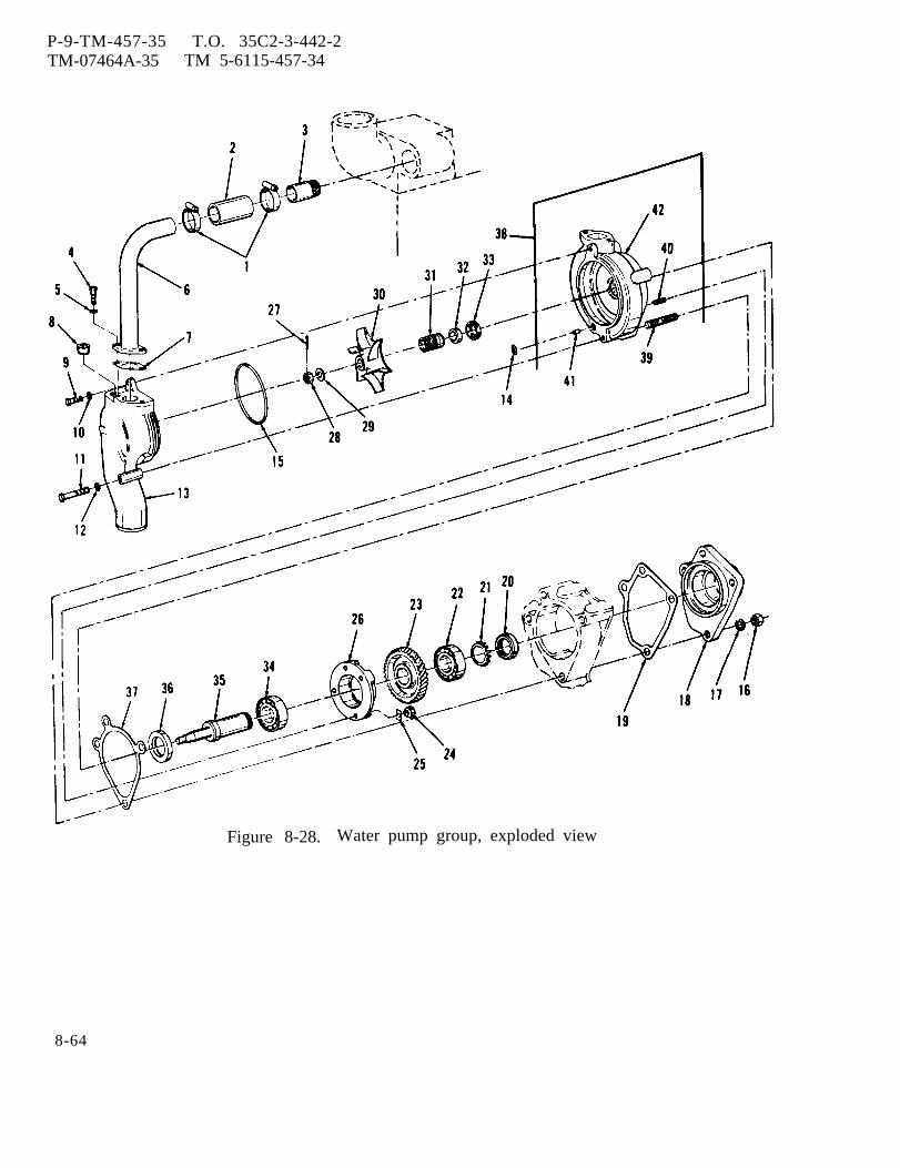
P-9-TM-457-35 T.O. 35C2-3-442-2TM-07464A-35 TM 5-6115-457-34
Figure 8-28. Water pump group, exploded view
8-64
P-9-TM-457-35 T.O. 35C2-3-442-2TM-07464A-35 TM 5-6115-457-34
Legend to figure 8-28:
1.2.3.4.5.6.7.8.9.
10.11.12.13.14.15.
clamp (2)HoseNippleBolt (2)Lock washer (2)Tube assemblyGasketPlugBoltWasherBoltWasherCoverSealSeal
16.17.18.19.20.21.22.23.24.25.26.27.28.29.
Nut (4)Lock washer (4)CoverGasketNutLockBearingGearNut (4)Lock (4)CageCotter pinNutWasher
30.31.32.
33.34.35.36.37.38.39.40.41.42.
ImpellerSeal and spring assemblyCeramicringSeal ringBearingShaftSealGasketHousing assemblyStud (4)Stud (4)FerruleHousing
Section XVII. CRANKSHAFT PULLEY, DAMPER AND TIMING GEAR COVER GROUP
8-125. GENERAL
The crankshaft pulley is installedon the front end of the engine crankshaftand, by means of V-type drive belts, drivesthe cooling fan pulley. The timing gearcover is sealed to protect the timing geartrain, which consists of five gears locatedat the front of the engine.
8-126. REMOVAL
a. Remove engine assembly (para 2-8).
b. Remove fan mounting group (para8-31).
c. Remove hydraulic tank (precise setsonly) (para 8-86).
d. Remove hydraulic pump (precisesets only) (para 8-94).
e. Remove hydraulic pump drive group(para 8-101).
f. Remove water pump group (para8-118).
g. Refer to Operator and Organiza-tional Maintenance Manual and removealternator .
h. Remove five bolts, washers andlockwashers securing oil pan to timinggear cover.
i. Removal of the crankshaft pulley,damper and timing gear cover group isaccomplished during disassembly (para8-127).
8-127. DISASSEMBLY
Refer to figure 8-29, and disas-semble crankshaft pulley, damper and tim-ing gear cover group in the order of indexnumbers assigned. Pay particular atten-tion to the following:
8-65

P-9-TM-457-35 T.O. 35C2-3-442-2TM-0746A-35 TM 5-6115-457-34
Figure 8-29. Crankshaft pulley, damper, and timing gear cover group,exploded view
8-66

P-8-627-34 TO 35C2-3-442-2TM-07464A-35 TM 5-6115-457-34
Legend to figure 8-29:1.2.3.4.5.6.7.8.9.
10.11.12.13.14.15.16.17.18.19.20.21.22.23.24.25.26.27,
Bolt (6)Washer (6)DamperBoltWasherPulleyBolt (2)Lock washer (2)CapShim (12)Shim (2)Bolt (3)Lock washer (3)Bolt (5)Lock washer (5)BoltNutLock washerTrunnion assemblyBushingTrunnion supportNut (4)Lock washer (4)CoverGasketStudBolt
a. Remove bolts (1) from face ofvibration damper (3) and separate damperfrom pulley (3).
b. After removing bolt (4), use a suit-able puller and remove crankshaft pulley(6).
c. Separate top half of trunnion (9) andretain shims (10 and 11) if present, forreuse.
d. Since the accessory drive gear,camshaft gear, crankshaft gear and oilpump gears are covered under separatesections that deal with these gears as partof other assemblies, their removal, clean-ing and inspection are covered in thefollowing sections.
Accessory drive gear, Section XX,Par 8-150
Oil pump gears, Section XXIII, Par 8-172Camshaft gear, Section XXVII, Par 8-204
28.29.30.31.32.33.34.35.36.37.38.39.40.41.42.43.44.45.46.47.48.49.50.51.52.53.
LockWasher
BoltNutLock washerWasherBoltLock washer (2)Washer (2)NutBoltNutLock washerWasherBolt (2)Lock washer (2)Washer (2)BoltLock washerWasherBolt (2)Lock washer (2)Lock washer (2)SealCoverGasket
Crankshaft gear, Section XXIX, Par 8-220e. If it is necessary to remove one of
the timing gears, bar engine over manuallyto bring all timing marks in line as shownin figure 8-30, before removing a gear.
WARNING
Cleaning Solvents are flammable andmoderately toxic to skin, eyes andrespiratory tract. Eye and skinprotect ion required. Good generalventilation is normally adequate.Compressed air used for cleaning anddrying purposes can create airborneparticles that may enter the eyes.Pressure shall not exceed 30 psig.Eye protection is required.
8-128.
and dry
CLEANINGClean all parts in approved solvent
using compressed air or a lint free
Change 8 8-67
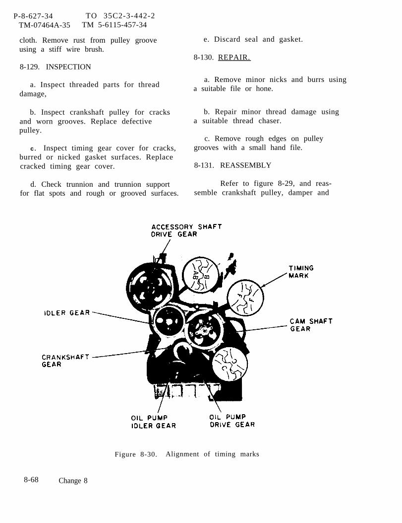
P-8-627-34 TO 35C2-3-442-2TM-07464A-35 TM 5-6115-457-34
cloth. Remove rust from pulley grooveusing a stiff wire brush.
8-129. INSPECTION
a. Inspect threaded parts for threaddamage,
b. Inspect crankshaft pulley for cracksand worn grooves. Replace defectivepulley.
c . Inspect timing gear cover for cracks,burred or nicked gasket surfaces. Replacecracked timing gear cover.
d. Check trunnion and trunnion supportfor flat spots and rough or grooved surfaces.
e. Discard seal and gasket.
8-130. REPAIR.
a. Remove minor nicks and burrs usinga suitable file or hone.
b. Repair minor thread damage usinga suitable thread chaser.
c. Remove rough edges on pulleygrooves with a small hand file.
8-131. REASSEMBLY
Refer to figure 8-29, and reas-semble crankshaft pulley, damper and
Figure 8-30. Alignment of timing marks
8-68 Change 8
timing gear cover group in the reverseorder of index numbers assigned. Payparticular attention to the following:
a. Apply a thin coat of approved sealantto timing gear cover studs (26) beforeinstalling cover (52).
b. When installing new gasket (53),trim gasket flush with bottom face ofcylinder block and top front flange of oilpan.
c. Torque all timing gear cover boltsfrom 27 to 37 foot pounds.
d. Lubricate seal (51) lightly withengine oil. Put MIL-S-22473 sealant onthe outer metal shell of the seal. In-stall seal into cover with flexible liptoward the engine.
e. Fill slot in trunnion (9) with an ap-proved grease. Install trunnion (9) andtrunnion support (21) using shims (10 and11) previously removed.
f. Place a feeler gauge between trun-nion (9) and bearing collar (19), add enoughshims to one side to maintain a clearanceof 0.002 inch to 0.003 inch tight.
P-9-TM-457-35 T O 35C2-3-442-2TM-07464A-35 TM 5-6115-457-34
g. Torque bolt (4) from 210 to 250 footpounds, tap bolt head with a hammer, andretighten to specified torque.
8-132. INSTALLATION
a. Installation of the crankshaft pulley,damper and timing gear cover group isaccomplished during reassembly (para8-131).
b. Install oil pan to timing gear coverand secure with five bolts, washers andlock washers.
c. Refer to Operator and Organiza-tional Maintenance Manual and installalternator.
d. Install water pump group (para 8-124).
e. Install hydraulic pump drive group(para 8-107).
f. Install hydraulic pump (precise setsonly) (para 8-99).
g. Install hydraulic tank (precise setsonly) (para 8-92).
h. Install fan mounting group (para8-37).
i. Install engine assembly (para 2-8).
Section XVIII. UTILITY GOVERNOR GROUP
8 - 1 3 3 .
The ulility governor group is madeup of two major assemblies mounted on theright side of the engine, the hydraulicgovernor assembly and the governor driveassembly. The governor consists of agovernor drive shaft, speed adjusting shaft,low speed and high speed stop screws, re-lated linkages, and shutdown solenoid valve.The speed adjusting shaft is used to set the
governor at the desired running speed. Lowspeed and high speed stop screws are pro-vided to limit the speed range of the gover-nor. The utility governor is mechanical-hydraulic type which senses engine speedby means of flyweights balancing against aspeeder spring. This governor is designedto correct the fuel rate as a result of anoff-speed condition only. On units equippedwith the precise governor, the utilitygovernor is adjusted to maintain an engine
C h a n g e 9 8 - 6 9

P-9-TM-457-35 T.O. 35C2-3-442-2TM-07464A-35 TM 5-6115-457-34
speed above the desired speed. Therefore,when the precise governor is controllingthe engine, the utility governor will moveto the position to deliver maximum fuel,while the precise governor controls the fuelrate so as to maintain the desired speed.
8-134. REMOVAL
a. Refer to Operator and Organiza-tional Maintenance Manual and removemanual speed control .
b. Remove governor actuator unit(p rec i se se t s on ly ) (pa ra 8 -109) .
c. UTILITY GOVERNOR, LINKAGE ANDOVERSPEED SHUTDOWN DEVICE. Refer tofigure 8-31 and remove utility governor,linkage, oil lines and overspeed shut-down device in the order of index num-bers assigned. Refer to f igure 8-31Awhen disassembly of overspeed shutdowndev ice i s r equ i red .
NOTE
Prior to removal of the utility gover-nor, make a note of the overall dis-tance between the ball joint centers(4, 5, and 6) so that this rod assem-bly can be reinstalled at the samedistance between ballpoint centers.
d. GOVERNOR DRIVE HOUSING. Referto figure 8-32 and remove governor drivehousing in the order of index numbers as-signed. Pay particular attention to thefollowing:
1. Remove governor drive coupling(1) before removing housing bolt.
2. When bolts (2, 4, and6) are re-moved. governor housing (10) may be sep-arated from rear plate assembly (12) bypulling housing (10) to the rear approxi-mately 1/2 inch. Allow housing (10) to dropapproximately 1/2 inch to disengage rack
control arm from injector rack. Removehousing, but do not force it.
3. Remove nut (8) and remove rearplate assembly (12) from rear of fuelinjection pump.
8-135. DISASSEMBLY
a. UTILITY GOVERNOR. Refer tofigure 8-33 and disassemble utility gover-nor assembly in the order of index numbersassigned. Pay particular attention to thefollowing:
1. Clamp the governor lightly in avise; vise jaws must grasp the base belowthe base case joint on the sides under” theterminal shaft.
2. Insert a 5/16 inch diameter rodin the opening left after removing shaft(13), and drive the other shaft (13) out.
3. Make a note of the distance thehigh speed stop screw (19) protrudes fromthe case (69) so that it can be set approxi-mately the same when reassembling.
4. Use a 1/8 inch diameter punch orrod to drive the pin (22) down from the topof lever (28) into the case (69).
5. Pull shaft (25) out of the case(69).
6. Lift out the assembly consistingof the lever (28), pilot valve plunger (49),bearing assembly (50), and connectingparts.
7. Remove plug (29), and gasket(30).
8. Remove springs (31 and 32).
8-70 Change 2

P-9-TM-457-35 T.O. 35C2-3-442-2TM-07464A-35 TM 5-6115-457-34
NOTE
If the valve (33) and sleeve assem-bly (34) cannot be removed easilywith a small pair of long-nosedpliers (or tweezers) and a hookscriber, leave them in the case (69)until step 14,
9. Remove the valve (33), andsleeve assembly (34).
10. Take the governor out of thevise and invert it, catching pin (39), piston(40), and rollpin (22) (driven out of thespeed adjusting lever earlier),
11. Use snap ring pliers to take outthe snap ring (53) under the ballarms. Liftout the ballhead assembly (57),
12. Remove snap ring (43) aroundthe bushing assembly (54) drive shaft spline,and drive out bushing assembly (54) frombase (62).
13 . Remove screws (42) from thebase (62) and remove the base (62). If thebase (62) does not easily detach from thecase (69), clamp base (62) (governor name-plate side of the case up) lightly in a vise;using a plastic or soft hammer, tap theunderside of case (69) to loosen it frombase (62).
CAUTION
Hold a hand under the base (62) andcase (69) joint to catch the pumpgears (58 and 59) which may dropout as the base (62) and case (69)are separated.
14. Remove pump gears (58 and 59)and gasket (61).
15. If the valve (33) and sleeve as-sembly (34) could not be removed in step 9,insert a 3/16 inch diameter rod in the tappedhole opposite the relief valve opening andpush the valve (33) out. Then insert asuitable extracting tool in the relief valveopening to pull out the sleeve assembly (34).
16. Clamp stud (66) in a vise.Twist and pull case (69) to remove stud.
CAUTION
Be careful not to score the groundbottom surface of case (69).
17. If necessary, drive out bushings(67 and 68) using a 3/8 diameter rod and asuitable piloted driving block. In each in-stance drive the bushing (67 and 68) out ofthe case (69) (rather than in towards thecenter) .
18. Clamp the fork (45) in a visewith a pin hole up; use a thin screwdriveror a small punch to drive the spring (46)Off of the fork (45).
19. Twist the spring (46) to detachit from the spring seat.
b. GOVERNOR DRIVE HOUSING. Referto figure 8-34 and disassemble governordrive housing in the order of index numbersassigned. Pay particular attention to thefollowing:
1. If maximum fuel stop assembly(1, 2, 3, 4, and 5) is not to be repaired itshould not be disassembled,
8-71
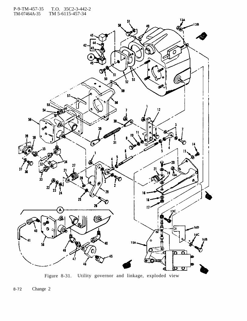
P-9-TM-457-35 T.O. 35C2-3-442-2TM-07464A-35 TM 5-6115-457-34
Figure 8-31. Utility governor and linkage, exploded view
8-72 Change 2

P-9-TM-457-35 T.O. 35C-3-442-2TM-07464A-35 TM 5-6115-457-34
Legend to figure 8-31:
1. Nut (2)2 Bolt (2)3. Lock washer (2)4. Rod end (2)5. Nut, lock (2)6. Rod7. Nut8. Bolt9. Bolt (2)
10. Lock washer11. Washer12. Lever13. Key13A. Nut13B. Washer13C. Screw14. Bolt (2)15. Lock washer (2)1A Overspeed shutdown device16. Bracket16A. Nut16B.Screw, cap16C. Washer16D. Bracket17. Nut18. Lock washer (2)19. Washer (2)20. Bolt21• Spring end (2)22. Nut23. Lock washer24. Washer25. Washer26. Bolt
27.28.29.30.31.32.33.34.35.36.37.38.39.40.41.42.43.44.45.46.47•48.49.50.51.52.53.54•55*56.57.58.59.
SpringScrew setLeverSpring end (2)SpringTube fitting (2)TubeElbow (2)CouplingBolt (2)Lock washer (2)FlangeGasketElbow (2)TubeTube AssemblyInverted flare nut (2)TubeElbow (2)Solenoid valveUnionElbow 45”Safety wireBolt (2)Lock washer (2)FlangeGasketNut (4)Lock washer (4)Ut i l i ty gov . assyGasketMounting plateGasket
Change 2 8-73

P-9-TM-457-35 T.O. 35C2-3-442-2TM-07464A-35 TM 5-6115-457-34
Figure 8-31A. Overspeed Shutdown Device
8-74 Change 2
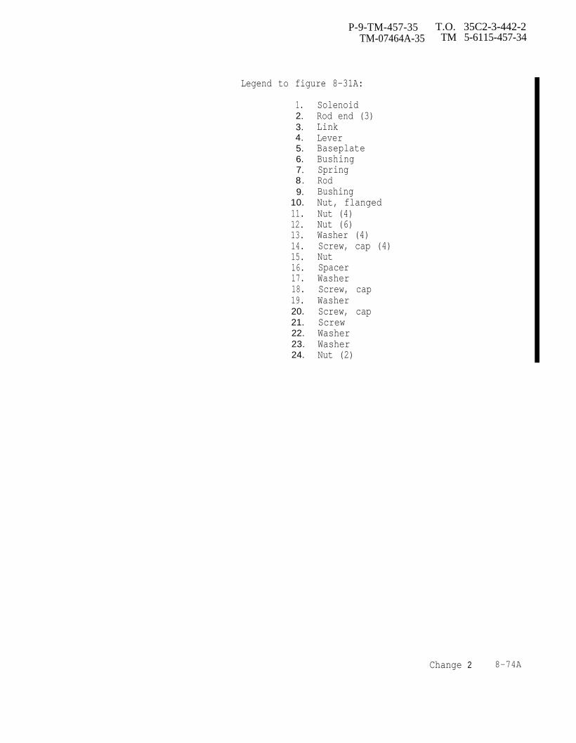
P-9-TM-457-35 T.O. 35C2-3-442-2TM-07464A-35 TM 5-6115-457-34
Legend to figure 8-31A:
1.2.3.4.5.6.7.8.9.
10.11.12.13.14.15.16.17.18.19.20.21.22.23.24.
SolenoidRod end (3)LinkLeverBaseplateBushingSpringRodBushingNut, flangedNut (4)Nut (6)Washer (4)Screw, cap (4)NutSpacerWasherScrew, capWasherScrew, capScrewWasherWasherNut (2)
Change 2 8-74A
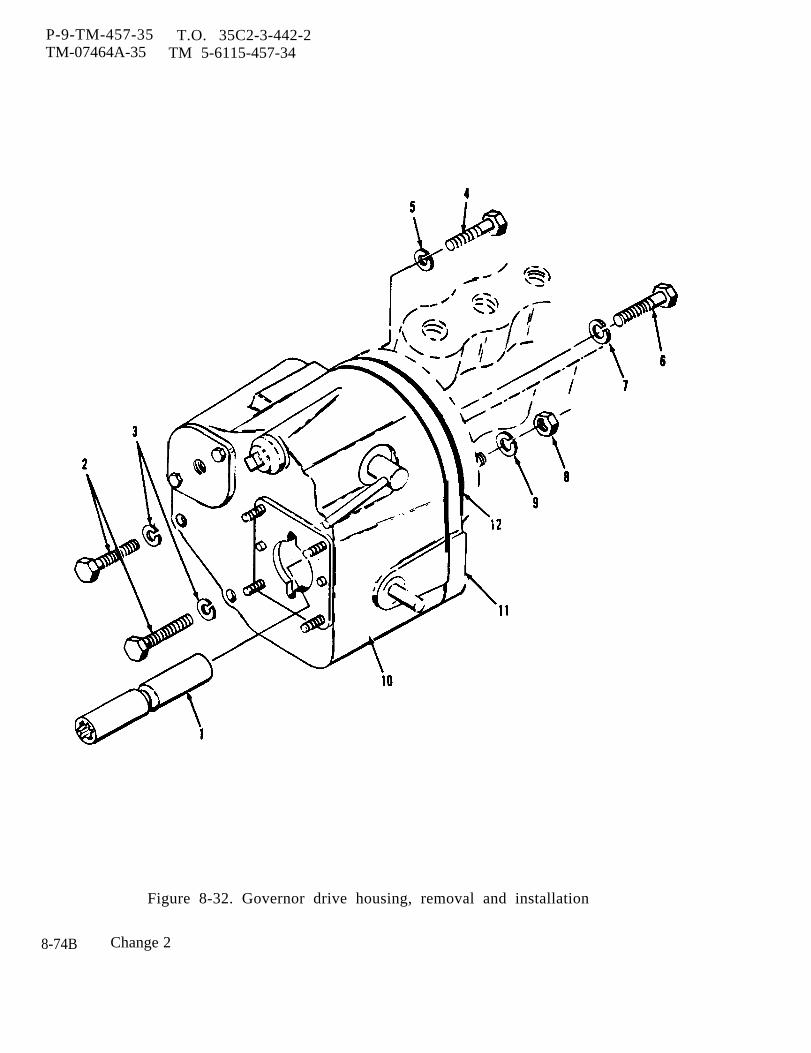
P-9-TM-457-35 T.O. 35C2-3-442-2TM-07464A-35 TM 5-6115-457-34
Figure 8-32. Governor drive housing, removal and installation
8-74B Change 2

P-8-627-34 TO 35C2-3-442-2TM-07464A-35 TM 5-6115-457-34
Legend to figure 8-32:
1. Coupling2 . B o l t ( 2 )3. Lock washer (2)4 . B o l t5. Lock washer6 . B o l t
2. Seals (50) must be removed fromthe outside of the housing. Do not attemptto push towards center of housing.
8-136. CLEANING.
a. UTILITY GOVERNOR.
WARNING
Cleaning Solvents are flammable andmoderately toxic to skin, eyes andrespiratory tract. Eye and skinprotection required. Good generalventilation is normally adequate.
Compressed air used for cleaning anddrying purposes can create airborneparticles that may enter the eyes.Pressure shall not exceed 30 psig.Eye protection is required.
1. Clean all parts in unapprovedcleaning solvent and dry with a lint freecloth.
CAUTION
Use extreme care when polishingthe pilot valve (49, figure 8-33)control land. Leave corners sharp;broken or rounded corners on thisland will ruin the valve.
2. Polish parts using No. 320 to500 fine grit emery cloth.
b. GOVERNOR DRIVE HOUSING. Cleanall parts in an approved cleaning solventand dry with a lint free cloth.8-137. INSPECTION.
a. UTILITY GOVERNOR1. Refer to table l-1, and using a
suitable micrometer, check the followingparts for wear:
(a) Power piston (40, figure8-33) O.D.
7. Lock washer8 . Nut9. Lock washer
10. Governor drive housing11 . Gaske t12. Plate assembly
(b) Pilot valve (49) lands.
(c) Bushing (55) O.D.
(d) Shaft (56) spline end,
(e) Speed adjusting shaft (13)O.D.
(f) Terminal shaft (25) O.D.
(g) Idler gear stud (66).
(h) Drive gear (59) O.D.
(i) Relief valve (33) O.D.
(j) Replace parts that have ex-ceeded maximum-allowable wear limits.
2. Inspect ground bottom surface ofcase (69) for grooves, scratches or wear.
3. Inspect the ground flat surfaceof the base (62) for warpage, nicks, ordeep scratches.
4. Inspect the pump gears (58 and59) as follows:
(a) Place the pump gears in thegear pockets and check for free rotation,
(b) If the gears turn roughly,inspect for nicks or wear of the gear teeth,and for interference at internal corners ofthe gear pockets in the base (62).
5. Check clearance between piston(40) and case (69), piston should movefreely without binding or catching.
NOTE
Excessive clearance between piston(40) and case (69), however, will re-sult in excessive oil leakage withinthe governor.
Change 8 8 - 7 5
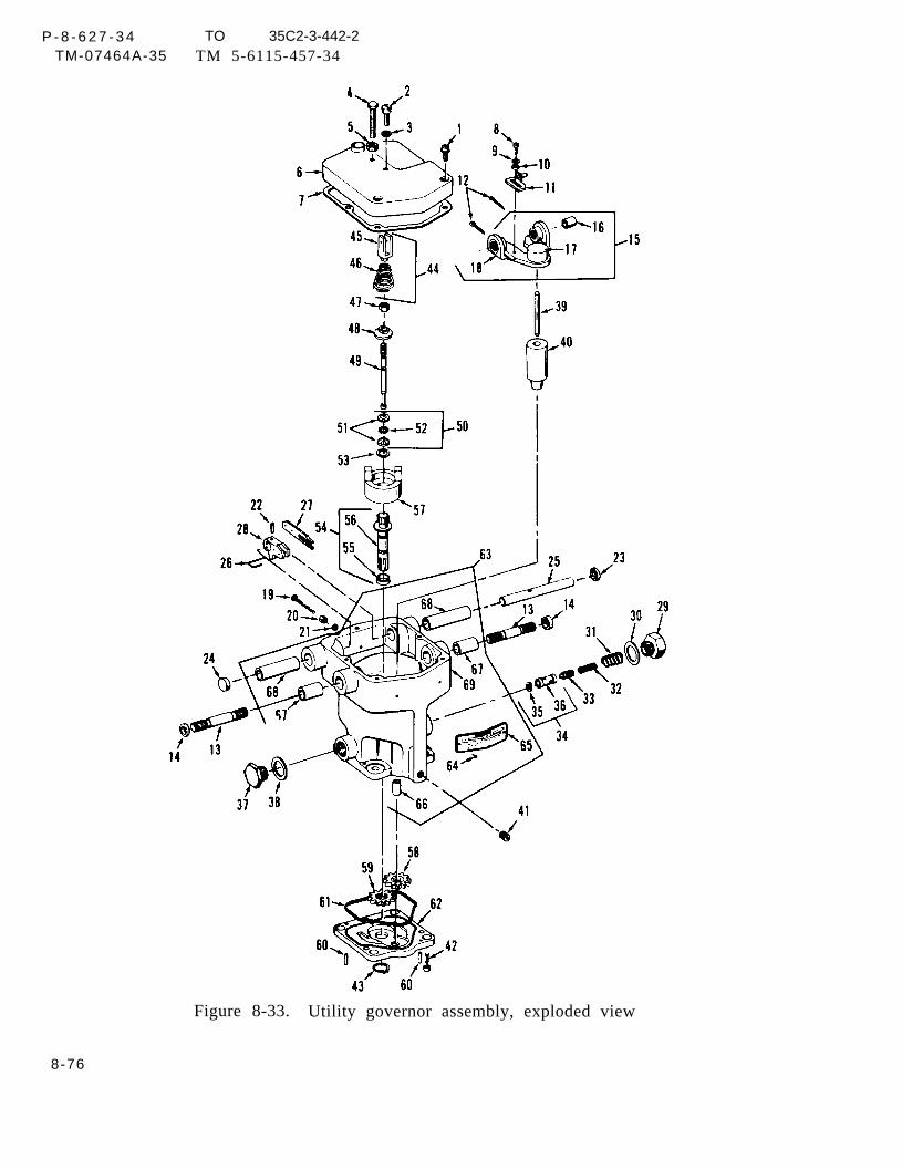
P - 8 - 6 2 7 - 3 4 TO 35C2-3-442-2TM-07464A-35 TM 5-6115-457-34
Figure 8-33. Utility governor assembly, exploded view
8-76

P-9-TM-457-35 T.O. 35C2-3-442-2TM-07464A-35 TM 5-6115-457-34
Legend to figure 8-33:
1.2.3.4.5.6.7.8.9.
10.11.12.13.14.15.16.17.18.19.20.21.22.23.24.25.26.27.28.29.30.31.32.33.34.35.
Screw (3)ScrewWasherScrewNutCoverGasketScrewLockwasherWasherBracketCotter pin (2)Shaft (2)Seal (2)Lever assemblyBushing (2)cupLeverScrewNutWasherRoll pinSealPlugShaftSpring wireLeverLeverPlugGasketSpringSpringValveSleeve assemblyWasher
36.37.38.39.40.41.42.43.44.45.46.47.48.49.50.51.52.53.54.55.56.57.58.59.60.61.62.63.64.65.66.67.68.69.
SleevePlugWasherPinPower pistonPlugScrew (3)Snap ringSpring assemblyForkSpringNutSpring retainerPilot valveBearing assemblyRaceBallsSnap ringBushing assemblyBushingShaftBall head assemblyGearGearPin (2)GasketBaseCase assemblyScrew (2)NameplateStudBushing (2)Bushing (2)Case
8-77
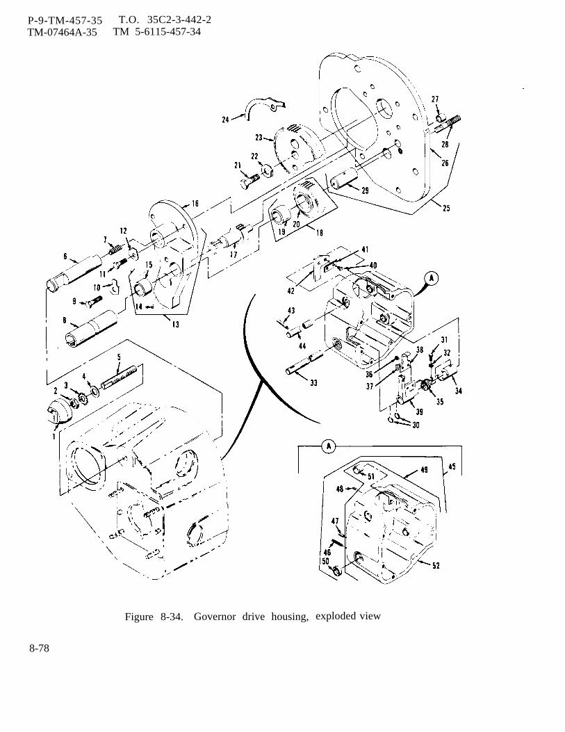
P-9-TM-457-35 T.O. 35C2-3-442-2TM-07464A-35 TM 5-6115-457-34
Figure 8-34. Governor drive housing, exploded view
8-78
P-9-TM-457-35 T O 35C2-3-442-2TM-07464A-35 TM 5-6115-457-34
Legend to figure 8-34:
1.2.3.4.5.6.7.8.9.
10.11.12.13.14.15.16.17.18.19.20.21.22.23. 24.25.26.
CapLocknutLock washerWasherThreaded rodRack extensionSpringDrive coupling (ref)BoltLockplateBoltLockplatePlate assemblyBallBushingPlateGearGear assemblyBushingGearBoltLockplateGearGasketCover plate assemblyCover plate
6. Inspect rod ends (4, figure8-31 and 6, figure 8-31A) for freedom ofmovement of the ball within the housingsocket. Replace rod ends that bind.
7. Inspect governor return spring(27, figure 8-31) for cracked coils andthe extremities (21) for worn/elongatedholes. Replace defective spring assembly.
8. Inspect overspeed shutdowndevice for worn or defective parts andlinkage for freedom of movement. Replaceworn or defective parts.
9. Discard gaskets (7 and 61,figure 8-33).
10. DC Solenoid - Refer toFigure 8-31.
a . Check DC solenoid forloose connection.
b. Check for foreign mater-ial causing poor electrical connection.
27.28.29.30.31.32.33,34.35.36.37.38.39.40.41,42,43.44.45.46.47.48.49.50.51.52.
BushingStudShaftSnap ring (2)BoltLock washerShaftCouplingSpringBolt (2)Lockplate (2)LeverLeverBolt (2)Lockplate (2)PlatePinHandleHousing assemblyStud (4)Dowel (2)PinHousing subassemblySeal (2)Bushing (4)Housing
c . Inspect DC solenoid valvefor worn or defective parts and valve forfreedom of movement. Replace worn ordefec t ive par t .
d . Check for proper voltage24 VDC at solenoid terminals.
b . GOVERNOR DRIVE HOUSING.1. Inspect bushings (15, 19,
and 27, figure 8-34) for scoring,excessive wear, and other damage. Re-place worn bushings.
2. Inspect drive gears (20 and23) for excessively worn gear teeth.
3. Inspect shaft (29) for wear.Check to see that all four oil holes areopen and clean.
4. Inspect shaft bushings (51)for excessive wear and for grooving.Replace defective bushings.
5. Discard gaskets (24) andseals (50).
Change 6 8-79

P-9-TM-457-35 T.O. 35C2-3-442-2TM-07464A-35 TM 5-6115-457-34
8-138. REPAIR
a. UTILITY GOVERNOR.
1. Most of the repair work consistsof cleaning and polishing of parts. UseNo. 320 to 500 fine grit emery cloth forpolishing. All pistons should move freelywithout binding or catching; excessiveclearance between mating parts, however,will result in excessive leakage of pressureoil within the governor.
2. Be extremely careful whenpolishing pilot valve (49, figure 8-33)control land. Leave the corners sharp;broken or rounded corners on this land willruin the pilot valve.
3. If ground bottom surface of thecase (69) is grooved or worn from rotationof the pump gears (58 and 59), or scratchedfrom mishandling, it may be surface ground.Up to 1/32 inch may be removed. Lap thesurf ace smooth on a flat plate if a surfacegrinder is not available.
CAUTION
Do not remove more stock thannecessary to clean up.
4. If the ground, flat surface of thebase (62) is warped, nicked, or deeplyscratched, it may be lapped smooth on aflat plate. If the depth of the gear pocketsis reduced, the gears will bind; in thisevent, the faces of the gears (58 and 59)must be lapped to provide clearance,
b. GOVERNOR DRIVE HOUSING.
1. Repair gear (20 and 23, figure8-34) teeth that have small nicks with afine hone.
2, Clean plugged oil holes in shaft(29) using a small piece of wire. Do notattempt to redrill holes.
8-139. REASSEMBLY
a. UTILITY GOVERNOR, Refer tofigure 8-33 and reassemble utility governorassembly in the reverse order of indexnumbers assigned. Pay particular attentionto the following:
1. Drive dowel pins (60) out of base(62).
2. If necessary to install new bush-ings (67 and 68), insert a suitable supportplate of exactly the correct width betweenthe inner walls of the case (69). Pressbushings (67 and 08) in with arbor press todimensions shown in figure 8-35. Press inidler gear stud (66) to depth shown infigure 8-35.
3. After installing bushings (67 and68, figure 8-33), line size or line reamwith standard 3/8 inch diameter linereamer.
4. Place pump gears (58 and 59) ingear pockets of base (62).
CAUTION
Do not use adhesive on surface ofbase (62).
5. Coat surface of base (62) withengine oil (precise generator sets only).
6. Place gasket (61) in groove ofbase (62).
7. Place case (69) on base (62), in-vert, and put the bushing assembly (54) in
8-80
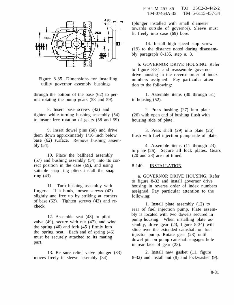
P-9-TM-457-35 T.O. 35C2-3-442-2TM-07464A-35 TM 5-6115-457-34
Figure 8-35. Dimensions for installingutility governor assembly bushings
through the bottom of the base (62) to per-mit rotating the pump gears (58 and 59).
8. Insert base screws (42) andtighten while turning bushing assembly (54)to insure free rotation of gears (58 and 59).
9. Insert dowel pins (60) and drivethem down approximately 1/16 inch belowbase (62) surface. Remove bushing assem-bly (54).
10. Place the ballhead assembly(57) and bushing assembly (54) into its cor-rect position in the case (69), and usingsuitable snap ring pliers install the snapring (43).
11. Turn bushing assembly withfingers. If it binds, loosen screws (42)slightly and free up by striking at cornersof base (62). Tighten screws (42) and re-check.
12. Assemble seat (48) to pilotvalve (49), secure with nut (47), and windthe spring (46) and fork (45 ) firmly intothe spring seat. Each end of spring (46)must be securely attached to its matingpart.
13. Be sure relief valve plunger (33)moves freely in sleeve assembly (34)
(plunger installed with small diametertowards outside of governor). Sleeve mustfit freely into case (69) bore.
14. Install high speed stop screw(19) to the distance noted during disassem-bly paragraph 8-135, step a. 3.
b. GOVERNOR DRIVE HOUSING. Referto figure 8-34 and reassemble governordrive housing in the reverse order of indexnumbers assigned. Pay particular atten-tion to the following:
1. Assemble items (30 through 51)in housing (52).
2. Press bushing (27) into plate(26) with open end of bushing flush withhousing side of plate.
3. Press shaft (29) into plate (26)flush with fuel injection pump side of plate.
4. Assemble items (11 through 23)to plate (26). Secure all lock plates. Gears(20 and 23) are not timed.
8-140. INSTALLATION
a. GOVERNOR DRIVE HOUSING. Referto figure 8-32 and install governor drivehousing in reverse order of index numbersassigned. Pay particular attention to thefollowing:
1. Install plate assembly (12) torear of fuel injection pump. Plate assem-bly is located with two dowels secured inpump housing. When installing plate as-sembly, drive gear (23, figure 8-34) willslide over the extended camshaft on fuelinjector pump. Rotate gear (23) untildowel pin on pump camshaft engages holein rear face of gear (23).
2. Install new gasket (11, figure8-32) and install nut (8) and lockwasher (9).
8-81
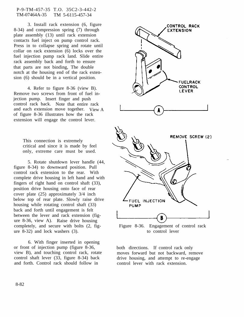
P-9-TM-457-35 T.O. 35C2-3-442-2TM-07464A-35 TM 5-6115-457-34
3. Install rack extension (6, figure8-34) and compression spring (7) throughplate assembly (13) until rack extensioncontacts fuel inject on pump control rack.Press in to collapse spring and rotate untilcollar on rack extension (6) locks over thefuel injection pump rack land. Slide entirerack assembly back and forth to ensurethat parts are not binding, The doublenotch at the housing end of the rack exten-sion (6) should be in a vertical position.
4. Refer to figure 8-36 (view B).Remove two screws from front of fuel in-jection pump. Insert finger and pushcontrol rack back. Note that entire rackand each extension move together. View Aof figure 8-36 illustrates how the rackextension will engage the control lever.
This connection is extremelycritical and since it is made by feelonly, extreme care must be used.
5. Rotate shutdown lever handle (44,figure 8-34) to downward position. Pullcontrol rack extension to the rear. Withcomplete drive housing in left hand and withfingers of right hand on control shaft (33),position drive housing onto face of rearcover plate (25) approximately 3/4 inchbelow top of rear plate. Slowly raise drivehousing while rotating control shaft (33)back and forth until engagement is feltbetween the lever and rack extension (fig-ure 8-36, view A). Raise drive housingcompletely, and secure with bolts (2, fig-ure 8-32) and lock washers (3).
6. With finger inserted in openingor front of injection pump (figure 8-36,view B), and touching control rack, rotatecontrol shaft lever (33, figure 8-34) backand forth. Control rack should follow in
Figure 8-36. Engagement of control rackto control lever
both directions. If control rack onlymoves forward but not backward, removedrive housing, and attempt to re-engagecontrol lever with rack extension.
8-82
P-9-TM-457-35 T.O. 35C2-3-442-2TM-07464A-35 TM 5-6115-457-34
NOTE
Under no condition should theengine be run unless the controlshaft can move the fuel injectionpump rack in both directions atthe point.
Under no condition should the con-trol lever (39, figure 8-34) or therack extension be filed to make aneasier fit. If the parts do notmate, it is only because the partsare damaged and should thereforebe replaced, or the parts havebeen assembled incorrectly,
7. If fuel rack stop assembly (1, 2,3, 4, and 5) has been removed, assembleto rear of housing but do not install cap (l).Fuel stop will have to be set. This iscovered under governor drive housingadjustment.
b. GOVERNOR DRIVE HOUSINGADJUSTMENT. Maximum fuel stop settingmust be checked whenever governor drivehousing is removed. Proceed as follows:
1. Using an approved rack settinggauge, refer to figure 8-36, view B, andremove two screws, flange, and gasketfrom flange at rear of accessory drivehousing.
2. Rotate knob of rack setting toolcounter clockwise until the number 3appears under the micrometer dial.Install tool in opening, using the samescrews that secure the flange. Do not usegasket or lockwasher. Tighten screwswith fingers just enough to engage threads.
3. Rotate shaft (33, figure 8-34)in a clockwise direction, pushing the pumprack toward the front of the unit. When endof rack contacts open end of rack setting
tool, wiggle the tool slightly so that rackslides inside of collar on the rack settingtool .
4. Tighten two screws holding racksetting tool until they are tight. Use awrench to tighten these two screws onlyenough to firmly anchor the tool against theflange face.
5. Turn micrometer dial clockwiseuntil the leading edge of the rotating diallines up with NO. 1. on the non-rotatingshaft and #0 on the rotating dial. Refer tofigure 8-37 (view A).
6. Rotate shaft (33, figure 8-34)clockwise, pushing fuel injection pumprack forward until it contacts rack settingtool; and hold in this position with righthand,
7. With the rack setting tool, set inposition as described in step 5. , slowlyrotate rack stop screw (5) clockwise with thefingers or a small flat bladed screw driveruntil contact is felt. While holding rackstop screw, remove right hand from shaft(33, figure 8-34) and tighten lock nut (2)without moving rack stop screw (5).
8. To check adjustment, turn therack setting tool micrometer dial a fewturns counterclockwise. Rotate shaft (33)back and forth a few times and end uprotating shaft (33) clockwise and hold infull fuel position. Rotate micrometer dialon rack setting tool clockwise until it con-tacts fuel injection pump rack. Dial shouldbe reading +1 on the shaft and “0” on therotating dial. Refer to figure 8-37 (view A)for allowable tolerances.
9. If reading is not within indicatedtolerances (figure 8-37, view A), repeatprocedure starting with step 5.
8-83

P-9-TM-457-35 T.O. 35C2-3-442-2TM-07464A-35 TM 5-6115-457-34
Figure 8-37.
10. Check to see that locknut
Installing fuel rack setting gauge
(2, from edge of lever (18) when viewed in thefigure 8-34) is secure, apply cap (1), and position shown.tighten. Secure with safety wire.
NOTEc. UTILITY GOVERNOR ADJUST-
MENT - OFF UNIT. Set utility governor This setting is nominal. Additionaldroop setting prior to installation on the adjustment may have to be made.engine. Refer to figure 8-38 and set droop Refer to paragraph 8-237 for finaladjust bracket (11, figure 8-33) 0.187 inch adjustments during engine operation.
8-84
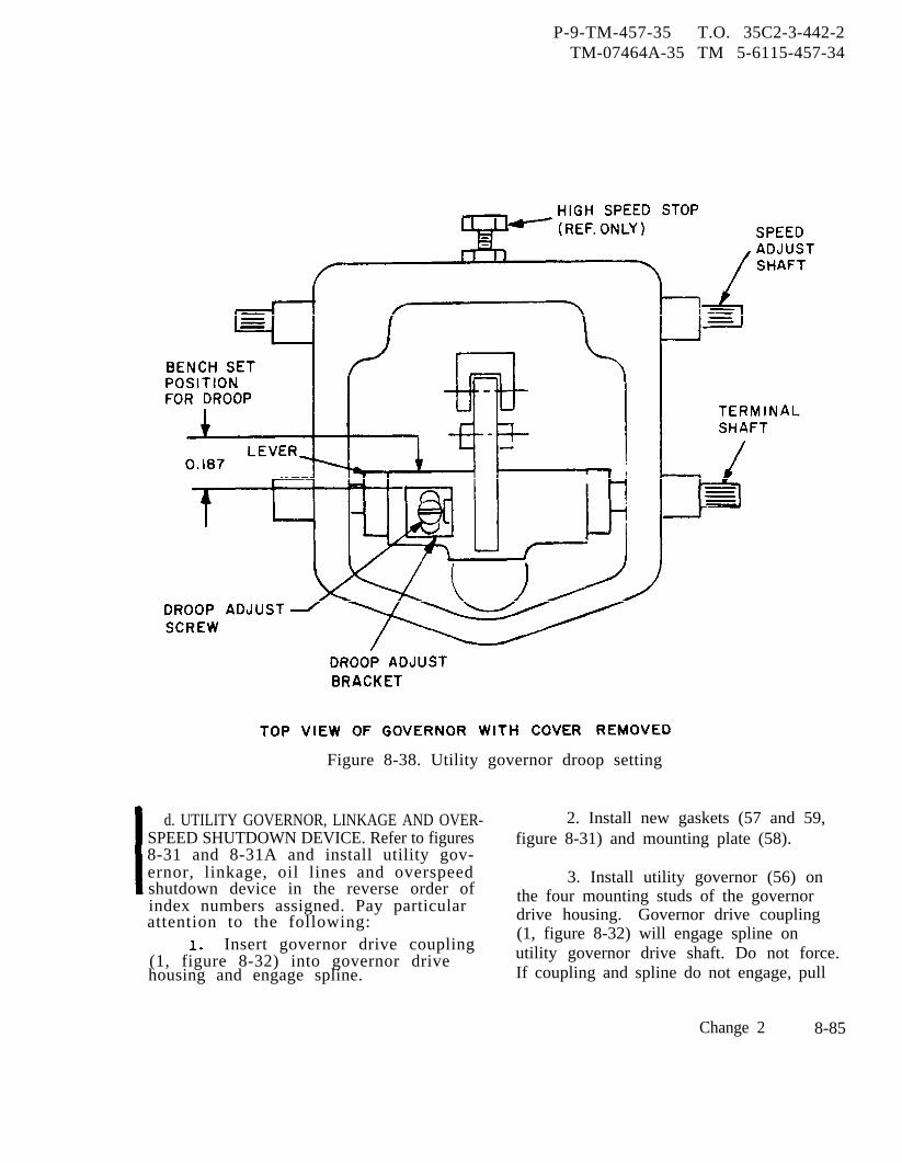
P-9-TM-457-35 T.O. 35C2-3-442-2TM-07464A-35 TM 5-6115-457-34
Figure 8-38. Utility governor droop setting
d. UTILITY GOVERNOR, LINKAGE AND OVER- 2. Install new gaskets (57 and 59,SPEED SHUTDOWN DEVICE. Refer to figures figure 8-31) and mounting plate (58).8-31 and 8-31A and install utility gov-ernor, linkage, oil lines and overspeed 3. Install utility governor (56) onshutdown device in the reverse order ofindex numbers assigned. Pay particular
the four mounting studs of the governor
attention to the following: drive housing. Governor drive coupling
Insert governor drive coupling(1, figure 8-32) will engage spline on
(1, figure 8-32) into governor drive utility governor drive shaft. Do not force.housing and engage spline. If coupling and spline do not engage, pull
Change 2 8-85
P-9-TM-457-35 T.O. 35C2-3-442-2TM-07464A-35 TM 5-6115-457-34
utility governor back just far enough torotate utility governor drive shaft withthe fingers, into a new position.
4. Install oil lines in such amanner that undue stress is not appliedto the tube assemblies when positioningthe f i t t ings .
5. Install governor linkage inaccordance with figure 8-31. Adjust rodassembly (4, 5, and 6) in accordancewith Operator and Organizational Mainte-nance Manual. Whenever precise governorlinkage is to be installed, refer toOperator and Organizational MaintenanceManual.
6. Adjust overspeed shutdowndevice linkage as follows:
(a) Disconnect governor rodassembly (6, figure 8-31) from the gov-ernor control fuel rack lever (12).
8-141.
(b) Adjust flanged nut (10,
GENERAL.
figure 8-31A)bracket (16D,approximately
against the spring limiterfigure 8-31) to allow.03 inch free travel of
governor control fuel rack lever (12,figure 8-31). This free travel measure-ment is made at the top of the lever.
(c) Tighten nut (11, figure8-31A) against flanged nut (10).
(d) Adjust lower bushing(6, figure 8-31A) to provide a measure-ment of 3.0 (+.125, -.062) inchesbetween the outside faces of bushings(6 and 9, figure 8-31A).
Install governor actuator unit(precise sets only) paragraph 8-116).
f . Refer to Operator and Organiza-tional Maintenance Manual for thefollowing:
1. Install manual speed control.
2. Make final adjustment.
Section XIX. FUEL INJECTION GROUP
The fuel injection group is mountedto the rear of the accessory drive housing.The fuel injection group consists of the fuelinjection pump housing, camshaft, fuelinjection pumps, fuel injection valves, andassociated tubing. Fuel, after passingthrough the filters, flows into the injectionpump housing manifold which distributesthe fuel to the injection pumps. The injec-tion pump for each cylinder measures anddelivers the fuel to its associated fuelinjection valve for insertion into the pre-combustion chamber. The amount of fuelpumped per stroke is varied by turning thepump plunger in the barrel. This turningis accomplished by governor action throughthe fuel regulator rack and gear arrange-ment. Injection pump plungers and liftersare lifted by lobes on the fuel injectioncamshaft.
8-86 Change 2
8-142. REMOVAL.
a. Refer to Operator and Organize-tional Maintenance Manual and removesecondary fuel filter and relief valvegroup, hydraulic oil filter (precise gener-ator sets only), and overspeed switch,
b. Remove utility governor group(paragraph 8-134).
c. Removal of the fuel injection groupis accomplished during disassembly (para-graph 8-143).
CAUTION
Do not rotate engine crankshaftafter fuel injection pump hasbeen disconnected from accessorydrive.
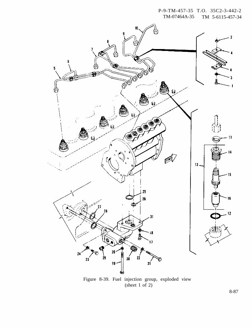
P-9-TM-457-35 T.O. 35C2-3-442-2TM-07464A-35 TM 5-6115-457-34
Figure 8-39. Fuel injection group, exploded view(sheet 1 of 2)
8-87
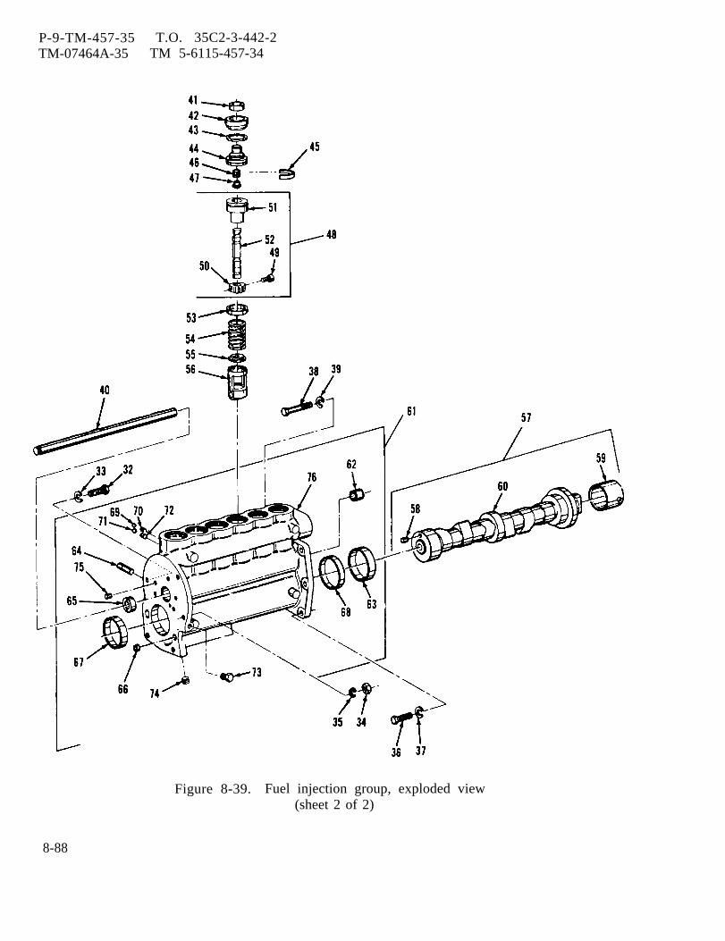
P-9-TM-457-35TM-07464A-35
T.O. 35C2-3-442-2TM 5-6115-457-34
Figure 8-39. Fuel injection group, exploded view(sheet 2 of 2)
8-88
P-8-627-34 T O 35C2-3-442-2TM-07464A-35 TM 5-6115-457-34
Legend to figure 8-39:
1.2.3.4.5.6.7.8.9.
10.11.12.13.14.15.16.17.18.19.20.21.22.23.24.25.26.
Bolt (5)Nut (5)Lock washer (5)Clamp (10)Fuel line assemblyFuel line assemblyFuel line assemblyFuel line assemblyFuel line assemblyFuel line assemblySeal assembly (6)Seal (6)Valve assembly (6)NutBodyNozzle assemblyBoltLock washerBoltLock washerBoltLock washerBolt (2)Lock washer (2)SealSeal
8-143. DISASSEMBLY.
27.28.29.30.31.32.33.34.35.36.37.38.39.40.41.42.43.44.45.46.47.48.
49.50.51.
Refer to figure 8-39 and disassemblefuel injection group in the order of indexnumbers assigned. Pay particular attentionto the following:
NOTE
Tag all lines from each cylinderfor ease of assembly.
a. Prior to disassembly of the valveassemblies (13) and the fuel injection pumps,perform tests outlined in paragraph 8-149,step a.
CAUTION
All service work should be done ata cleaning facility. Hands shouldbe clean and disassembly done on
SealSealPlugPlugBracketBoltLockwasherNutLock washerBolt (4)Lock washer (4)Bolt (2)Lock washer (2)Fuel regulator rackFelt washer (6)Bushing (6)Seal (6)Bonnet (6)Retainer ring (6)Spring (6)Check valve (6)Plunger and barrelassembly (6)ScrewGearBarrel
52.53.54.55.56.57.58.59.60.61.62.63.64.65.66.67.68.69.70.71.72.73.74.75.76.
PlungerSpacer (6)Spring (6)Washer (6)Lifter assembly (6)Camshaft assemblyDowelSleeveCamshaftHousing assemblyBearingBearingPin (3)BearingPlugBearingBearingBall (6)Dowel (6)Ball (6)Dowel (6)PlugPlugDowel (2)Housing
a clean, lint free cloth. Keepparts for each injection pumpseparate since each pump hasmatched parts that are notinterchangeable.
b. Using a suitable extracting tool,remove fuel pumps items (41 through 55,figure 8-39).
c. Fuel regulator rack (40) must beremoved before removing lifters (56).
d. Using a suitable driver, removebearings (67 and 68).
e. Using a suitable removal tool,remove camshaft bearing (63).
Change 8 8-89
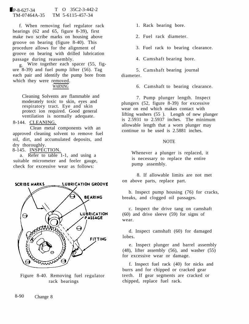
P-8-627-34 T O 35C2-3-442-2TM-07464A-35 TM 5-6115-457-34
f. When removing fuel regulator rackbearings (62 and 65, figure 8-39), firstmake two scribe marks on housing abovegroove on bearing (figure 8-40). Thisprocedure allows for the alignment ofgroove on bearing with drilled lubricationpassage during reassembly.
g. Wire together each spacer (55, fig-ure 8-39) and fuel pump lifter (56). Tageach pair and identify the pump bore fromwhich they were removed.
WARNING
Cleaning Solvents are flammable andmoderately toxic to skin, eyes andrespiratory tract. Eye and skinprotect ion required. Good generalventilation is normally adequate.
8-144. CLEANING.Clean metal components with an
approved cleaning solvent to remove fueloil, dirt, and accumulated deposits, anddry thoroughly.8-145. INSPECTION.
a. Refer to table 1-1, and using asuitable micrometer and feeler gauge,check for excessive wear as follows:
Figure 8-40. Removing fuelrack bearings
8-90 Change 8
regulator
1. Rack bearing bore.
2. Fuel rack diameter.
3. Fuel rack to bearing clearance.
4. Camshaft
5. Camshaftdiameter.
6. Camshaft
bearing bore.
bearing journal
to bearing clearance.
7. Pump plunger length. Inspectplungers (52, figure 8-39) for excessivewear on end which makes contact withlifting washers (55 ). Length of new plungeris 2.5931 to 2.5937 inches. The minimumallowable length that a worn plunger maycontinue to be used is 2.5881 inches.
NOTE
Whenever a plunger is replaced, itis necessary to replace the entirepump assembly.
8. If allowable limits are not meton above parts, replace part.
b. Inspect pump housing (76) for cracks,breaks, and clogged oil passages.
c. Inspect the drive tang on camshaft(60) and drive sleeve (59) for signs ofwear.
d. Inspect camshaft (60) for damagedlobes.
e. Inspect plunger and barrel assembly(48), lifter assembly (56), and washer (55)for excessive wear or damage.
f. Inspect fuel rack (40) for nicks andburrs and for chipped or cracked gearteeth. If gear segments are cracked orchipped, replace fuel rack.
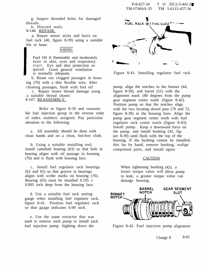
P-8-627-34 T O 35C2-3-442-2TM-07464A-35 TM 5-6115-457-34
g. Inspect threaded holes for damagedthreads.
h. Discard seals.8-146. REPAIR.
a. Repair minor nicks and burrs onfuel rack (40, figure 8-39) using a suitablefile or hone.
WARNING
Fuel Oil if flammable and moderatelytoxic to skin, eyes and respiratoryt rac t . Eye and skin protection re-quired. Good general ventilationis normally adequate.
b. Ream out clogged passages in hous-ing (76) with a thin flexible wire. Aftercleaning passages, flush with fuel oil.
c. Repair minor thread damage usinga suitable thread chaser.
8-147. REASSEMBLY.
Refer to figure 8-39 and reassem-ble fuel injection group in the reverse orderof index numbers assigned. Pay particularattention to the following:
a. All assembly should be done withclean hands and on a clean, lint-free cloth.
b. Using a suitable installing tool,install camshaft bearing (63) so that hole inbearing aligns with oil passage in housing(76) and is flush with housing face.
c. Install fuel regulator rack bearings(62 and 65) so that groove in bearingsaligns with scribe marks on housing (76).Bearing (65) must be installed 0.195 ±0.005 inch deep from the housing face.
d. Use a suitable fuel rack settinggauge when installing fuel regulator rack,figure 8-41. Position fuel regulator rackso that gauge indicates 0.00 inch.
e. Use the same extractor that wasused to remove each pump to install eachfuel injection pump. Sighting down the
Figure 8-41. Installing regulator fuel rack
pump, align the notches in the bonnet (44,figure 8-39), and barrel (51) with thealignment mark 180 degrees from the pumpgear segment center tooth {figure 8-42).Position pump so that the notches alignwith the two locating dowel pins (70 and 72,figure 8-39) in the housing bore. Align thepump gear segment center tooth with fuelregulator rack center notch (figure 8-43).Install pump. Keep a downward force onthe pump, and install bushing (42, fig-ure 8-39) until flush with the top of thehousing. If the bushing cannot be installed,this far by hand, remove bushing, realigncomponent parts, and install again.
CAUTION
When tightening bushinglesser torque value will
(42), aallow pump
to leak; a greater torque value candamage housing.
Figure 8-42. Fuel injection pump
Change 8
alignment
8-91
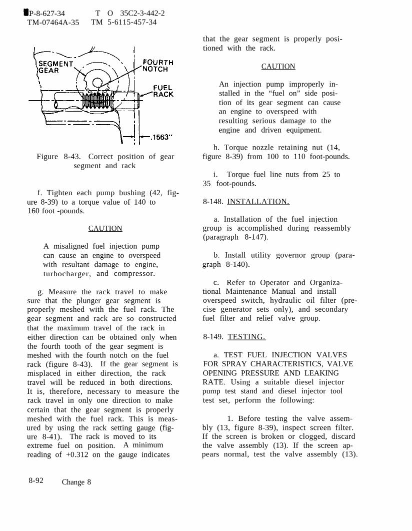
P-8-627-34 T O 35C2-3-442-2TM-07464A-35 TM 5-6115-457-34
Figure 8-43. Correct position of gearsegment and rack
f. Tighten each pump bushing (42, fig-ure 8-39) to a torque value of 140 to160 foot -pounds.
CAUTION
A misaligned fuel injection pumpcan cause an engine to overspeedwith resultant damage to engine,turbocharger, and compressor.
g. Measure the rack travel to makesure that the plunger gear segment isproperly meshed with the fuel rack. Thegear segment and rack are so constructedthat the maximum travel of the rack ineither direction can be obtained only whenthe fourth tooth of the gear segment ismeshed with the fourth notch on the fuelrack (figure 8-43). If the gear segment ismisplaced in either direction, the racktravel will be reduced in both directions.It is, therefore, necessary to measure therack travel in only one direction to makecertain that the gear segment is properlymeshed with the fuel rack. This is meas-ured by using the rack setting gauge (fig-ure 8-41). The rack is moved to itsextreme fuel on position. A minimumreading of +0.312 on the gauge indicates
that the gear segment is properly posi-tioned with the rack.
CAUTION
An injection pump improperly in-stalled in the “fuel on” side posi-tion of its gear segment can causean engine to overspeed withresulting serious damage to theengine and driven equipment.
h. Torque nozzle retaining nut (14,figure 8-39) from 100 to 110 foot-pounds.
i. Torque fuel line nuts from 25 to35 foot-pounds.
8-148. INSTALLATION.
a. Installation of the fuel injectiongroup is accomplished during reassembly(paragraph 8-147).
b. Install utility governor group (para-graph 8-140).
c. Refer to Operator and Organiza-tional Maintenance Manual and installoverspeed switch, hydraulic oil filter (pre-cise generator sets only), and secondaryfuel filter and relief valve group.
8-149. TESTING.
a. TEST FUEL INJECTION VALVESFOR SPRAY CHARACTERISTICS, VALVEOPENING PRESSURE AND LEAKINGRATE. Using a suitable diesel injectorpump test stand and diesel injector tooltest set, perform the following:
1. Before testing the valve assem-bly (13, figure 8-39), inspect screen filter.If the screen is broken or clogged, discardthe valve assembly (13). If the screen ap-pears normal, test the valve assembly (13).
8-92 Change 8
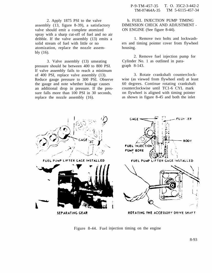
P-9-TM-457-35 T. O. 35C2-3-442-2TM-07464A-35 TM 5-6115-457-34
2. Apply 1875 PSI to the valveassembly (13, figure 8-39), a satisfactoryvalve should emit a complete atomizedspray with a sharp cut-off of fuel and no airdribble. If the valve assembly (13) emits asolid stream of fuel with little or noatomization, replace the nozzle assem-bly (16).
3. Valve assembly (13) unseatingpressure should be between 400 to 800 PSI.If valve assembly fails to reach a minimumof 400 PSI, replace valve assembly (13).Reduce gauge pressure to 300 PSI. Observethe gauge and note whether leakage causesan additional drop in pressure. If the pres-sure falls more than 100 PSI in 30 seconds,replace the nozzle assembly (16).
Figure 8-44. Fuel
b. FUEL INJECTION PUMP TIMINGDIMENSION CHECK AND ADJUSTMENT -ON ENGINE (See figure 8-44).
1. Remove two bolts and lockwash-ers and timing pointer cover from flywheelhousing.
2. Remove fuel injection pump forCylinder No. 1 as outlined in para-graph 8-143.
3. Rotate crankshaft counterclock-wise (as viewed from flywheel end) at least60 degrees. Continue rotating crankshaftcounterclockwise until TC1-6 CYL markon flywheel is aligned with timing pointeras shown in figure 8-45 and both the inlet
injection timing on the engine
8-93
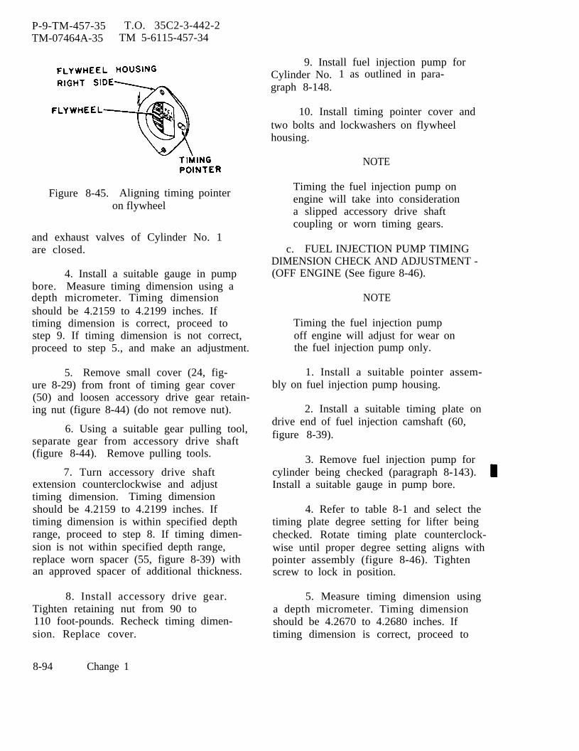
P-9-TM-457-35 T.O. 35C2-3-442-2TM-07464A-35 TM 5-6115-457-34
Figure 8-45. Aligning timing pointeron flywheel
and exhaust valves of Cylinder No. 1are closed.
4. Install a suitable gauge in pumpbore. Measure timing dimension using adepth micrometer. Timing dimensionshould be 4.2159 to 4.2199 inches. Iftiming dimension is correct, proceed tostep 9. If timing dimension is not correct,proceed to step 5., and make an adjustment.
5. Remove small cover (24, fig-ure 8-29) from front of timing gear cover(50) and loosen accessory drive gear retain-ing nut (figure 8-44) (do not remove nut).
6. Using a suitable gear pulling tool,separate gear from accessory drive shaft(figure 8-44). Remove pulling tools.
7. Turn accessory drive shaftextension counterclockwise and adjusttiming dimension. Timing dimensionshould be 4.2159 to 4.2199 inches. Iftiming dimension is within specified depthrange, proceed to step 8. If timing dimen-sion is not within specified depth range,replace worn spacer (55, figure 8-39) withan approved spacer of additional thickness.
8. Install accessory drive gear.Tighten retaining nut from 90 to110 foot-pounds. Recheck timing dimen-sion. Replace cover.
9. Install fuel injection pump forCylinder No. 1 as outlined in para-graph 8-148.
10. Install timing pointer cover andtwo bolts and lockwashers on flywheelhousing.
NOTE
Timing the fuel injection pump onengine will take into considerationa slipped accessory drive shaftcoupling or worn timing gears.
c. FUEL INJECTION PUMP TIMINGDIMENSION CHECK AND ADJUSTMENT -(OFF ENGINE (See figure 8-46).
NOTE
Timing the fuel injection pumpoff engine will adjust for wear onthe fuel injection pump only.
1. Install a suitable pointer assem-bly on fuel injection pump housing.
2. Install a suitable timing plate ondrive end of fuel injection camshaft (60,figure 8-39).
3. Remove fuel injection pump forcylinder being checked (paragraph 8-143).Install a suitable gauge in pump bore.
4. Refer to table 8-1 and select thetiming plate degree setting for lifter beingchecked. Rotate timing plate counterclock-wise until proper degree setting aligns withpointer assembly (figure 8-46). Tightenscrew to lock in position.
5. Measure timing dimension usinga depth micrometer. Timing dimensionshould be 4.2670 to 4.2680 inches. Iftiming dimension is correct, proceed to
8-94 Change 1
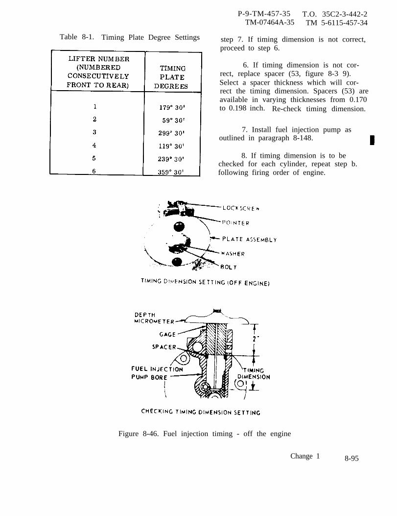
Table 8-1. Timing Plate Degree Settings
P-9-TM-457-35 T.O. 35C2-3-442-2TM-07464A-35 TM 5-6115-457-34
step 7. If timing dimension is not correct,proceed to step 6.
6. If timing dimension is not cor-rect, replace spacer (53, figure 8-3 9).Select a spacer thickness which will cor-rect the timing dimension. Spacers (53) areavailable in varying thicknesses from 0.170to 0.198 inch. Re-check timing dimension.
7. Install fuel injection pump asoutlined in paragraph 8-148.
8. If timing dimension is to bechecked for each cylinder, repeat step b.following firing order of engine.
Figure 8-46. Fuel injection timing - off the engine
Change 1 8-95

P-9-TM-457-35 T.O. 35C2-3-442-2TM-07464A-35 TM 5-6115-457-34
Section XX. ACCESSORY DRIVE GROUP
8-150. GENERAL.
The accessory drive group ismounted to the timing gear housing plate.The accessory drive group consists ofhousing assembly, gear assembly, driveshaft, bearing, sleeve, idler gear andshaft. The accessory drive shaft drivesthe utility governor, fuel injection pump,fuel supply pump, and speedswitch. Theaccessory drive gear is driven indirectlyby the crankshaft gear through an idlergear which reduces the accessory drive toone half engine speed.
8-151. REMOVAL.
NOTE
Removal of the accessory drivegroup does not require removalof the timing gear cover unlessthe drive gear on the accessorydrive shaft or the idler gear hasto be replaced. If removal of theaccessory drive group less acces-sory drive gear and idler gear isrequired, perform step a. Ifremoval of the accessory drivegear and idler gear is required,perform step b.
a. If only the removal of the accessorydrive group less the drive gear and idlergear is required, proceed as follows:
1. Remove utility governor group(paragraph 8- 134).
2, Remove fuel injection pump group(paragraph 8-142).
3. Refer to Operatorzational Maintenance Manual
8-96 Change 1
and Organi-and remove
fuel filter and relief valve, speedswitch,and hydraulic filter (precise sets only).
4. Remove fuel pump (para-graph 8-62).
b. If drive housing, drive shaft, drivegear, and idler gear are to be removed,proceed as follows:
1. Remove engine assembly(paragraph 2-8).
2. Refer to Operator and Organi-zational Maintenance Manual and removealternator.
3. Remove fan group (para-graph 8-3 1).
4. Remove water pump group(paragraph 8-118).
5. Remove hydraulic tank (precisesets only) (paragraph 8-86).
6. Remove hydraulic pump (precisesets only) (paragraph 8-94).
7. Remove hydraulic pump drivegroup (paragraph 8-101).
8. Remove crankshaft pulley,damper, and timing gear cover group (para-graph 8-126).
9. Refer to Operator and Organi-zational Maintenance Manual and removesecondary fuel filter and relief valve,speedswitch and hydraulic filter (precisesets only).
10. Remove fuel pump group(paragraph 8-62).
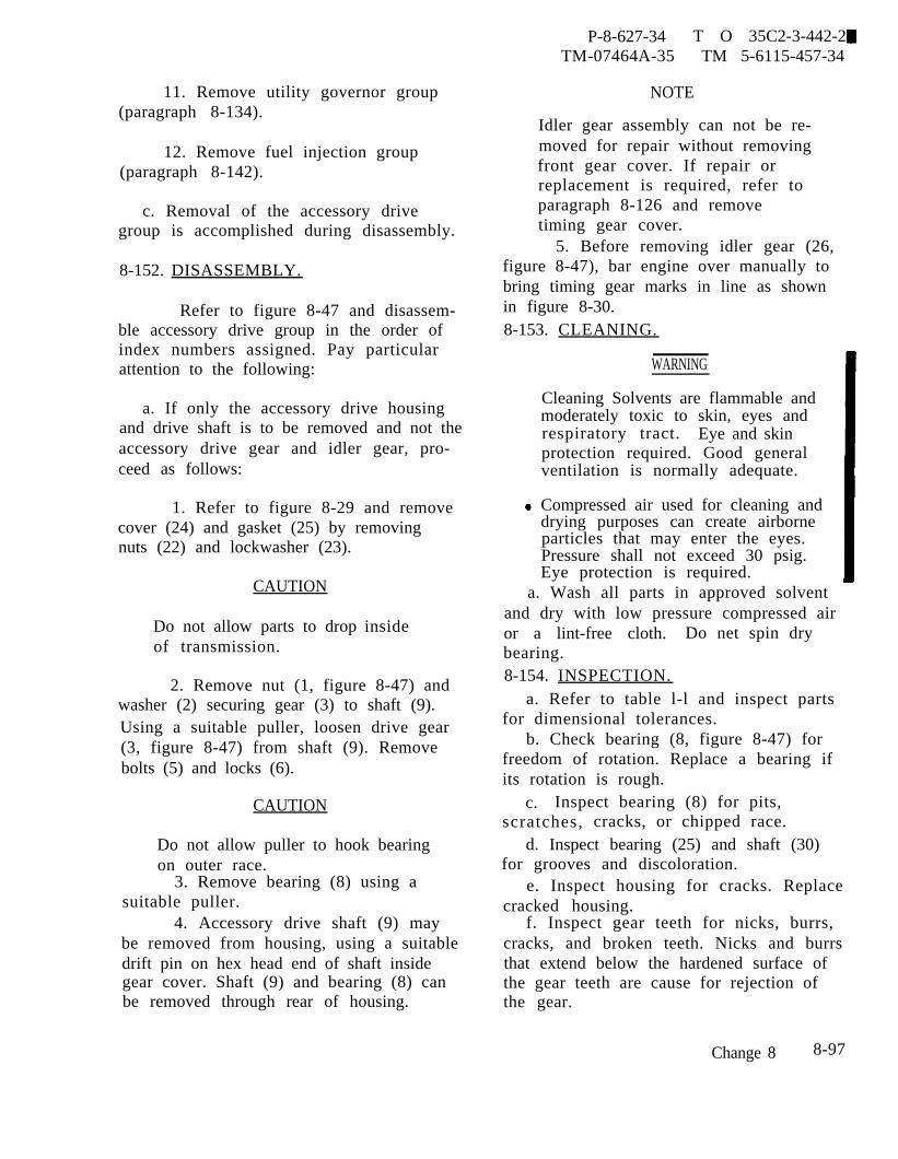
11. Remove utility governor group(paragraph 8-134).
12. Remove fuel injection group(paragraph 8-142).
c. Removal of the accessory drivegroup is accomplished during disassembly.
8-152. DISASSEMBLY.
Refer to figure 8-47 and disassem-ble accessory drive group in the order ofindex numbers assigned. Pay particularattention to the following:
a. If only the accessory drive housingand drive shaft is to be removed and not theaccessory drive gear and idler gear, pro-ceed as follows:
1. Refer to figure 8-29 and removecover (24) and gasket (25) by removingnuts (22) and lockwasher (23).
CAUTION
Do not allow parts to dropof transmission.
inside
2. Remove nut (1, figure 8-47) andwasher (2) securing gear (3) to shaft (9).Using a suitable puller, loosen drive gear(3, figure 8-47) from shaft (9). Removebolts (5) and locks (6).
CAUTION
Do not allow puller to hook bearingon outer race.
3. Remove bearing (8) using asuitable puller.
4. Accessory drive shaft (9) maybe removed from housing, using a suitabledrift pin on hex head end of shaft insidegear cover. Shaft (9) and bearing (8) canbe removed through rear of housing.
P-8-627-34 T O 35C2-3-442-2TM-07464A-35 TM 5-6115-457-34
NOTE
Idler gear assembly can not be re-moved for repair without removingfront gear cover. If repair orreplacement is required, refer toparagraph 8-126 and removetiming gear cover.
5. Before removing idler gear (26,figure 8-47), bar engine over manually tobring timing gear marks in line as shownin figure 8-30.8-153. CLEANING.
WARNING
Cleaning Solvents are flammable andmoderately toxic to skin, eyes andrespiratory tract. Eye and skinprotection required. Good generalventilation is normally adequate.
Compressed air used for cleaning anddrying purposes can create airborneparticles that may enter the eyes.Pressure shall not exceed 30 psig.Eye protection is required.
a. Wash all parts in approved solventand dry with low pressure compressed airor a lint-free cloth. Do net spin drybearing.8-154. INSPECTION.
a. Refer to table l-l and inspect partsfor dimensional tolerances.
b. Check bearing (8, figure 8-47) forfreedom of rotation. Replace a bearing ifits rotation is rough.
c. Inspect bearing (8) for pits,scratches, cracks, or chipped race.
d. Inspect bearing (25) and shaft (30)for grooves and discoloration.
e. Inspect housing for cracks. Replacecracked housing.
f. Inspect gear teeth for nicks, burrs,cracks, and broken teeth. Nicks and burrsthat extend below the hardened surface ofthe gear teeth are cause for rejection ofthe gear.
Change 8 8-97
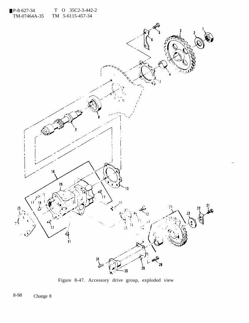
P-8-627-34 T O 35C2-3-442-2TM-07464A-35 TM 5-6115-457-34
Figure 8-47. Accessory drive group, exploded view
8-98 Change 8

P-9-TM-457-35 T.O. 35C2-3-442-2TM-07464A-35 TM 5-6115-457-34
Legend to figure 8-47:
1. Nut2. Washer3. Gear4. Sleeve5. Bolt (4)6. Lock (2)7. Retainer8. Bearing9. Shaft
10. Gasket11. Plug (2)
12.13.14.15.16.17.18.19.20.21.
Bolt (2)Lock washer (2)CoverGasketHousing assemblyDowel (3)DowelHousingGasketBolt
22. Lock23. Plate24. Gear assembly25. Bearing26. Gear27. Nut28. Bolt (2)29. Lock30. Shaft31. Stud
g. Inspect gear teeth for wear that mayhave destroyed the original tooth shape.If this condition is found, replace gear.
h. Inspect threaded parts for threaddamage.
i. Measure O. D. of rear bearing sur-face at tang end of shaft. Measure I.D. ofbearing surface at fuel pump end of housing.Maximum allowable clearance betweenshaft bearing surface and housing shouldnot exceed 0.006 inch.
j. Inspect tang at fuel pump end of shaftfor nicks, burrs, and damage. Replacedamaged shaft.
k. Discard gaskets.
8-155. REPAIR.
a. Remove minor nicks and burrs,using a suitable file or hone.
b. Repair minor thread damage usinga suitable thread chaser.
8-156. REASSEMBLY.
Refer to figure 8-47 and reassem-ble accessory drive group in the reverseorder of index numbers assigned. Payparticular attention to the following:
a. Install idler gear washer (23) withconcave side toward idler gear.
b. Remove timing pointer cover fromflywheel housing.
c. Rotate crankshaft counterclockwise(as viewed from flywheel end) at least60 degrees. Continue rotating crankshaftcounterclockwise until TC1-6-CYL mark onflywheel is aligned with timing pointer asshown in figure 8-45 and both the inlet andexhaust valves of Cylinder No. 1 areclosed.
d. Install timing plate on rear face ofaccessory drive housing as shown in fig-ure 8-48. If timing plate can be installed,timing is correct; proceed to step g. Iftiming plate cannot be installed, proceed tostep f. and adjust timing.
e. Turn accessory drive shaft, usingextension nut, as shown in figure 8-48until timing plate fits properly on accessorydrive housing. When plateagainst housing (19, figureshaft is properly timed.
fits flush8-47), drive
8-99

P-9-TM-457-35TM-07464A-35
T.O. 35C2-3-442-2TM 5-6115-457-34
Figure 8-48. Accessory drive shaft timing
f. Remove timing plate. Install acces-sory drive gear as shown in figure 8-30.Install conical washer with O.D. in contactwith gear, Align timing marks as shownin figure 8-30. Tighten retaining nut (1,figure 8-47) from 90 to 110 foot-pounds.
g. Refer to figure 8-29 and installcover (24) and gasket (25) and secure withnuts (22) and lockwashers (23).
8-157. INSTALLATION.
a. Installation of accessory drive groupis accomplished during reassembly(paragraph 8-156).
b. If only the accessory drive housingand drive shaft were removed, proceed asfollow s :
1. Install fuel injection group(paragraph 8-148).
2. Install utility governor group(paragraph 8-140).
3. Install fuel pump group (para-graph 8-68).
4. Refer to Operator and Organi-zational Maintenance Manual and installsecondary fuel filter tank, speed switch,and hydraulic filter (precise sets only).
c. If drive housing, drive shaft, drivegear, and idler gear were removed, pro-ceed as follows:
1. Install fuel injection group(paragraph 8-148).
2. Install utility governor group{paragraph 8-140).
3. Install fuel pump group(paragraph 8-68).
4. Refer to Operator and Organi-zational Maintenance Manual and installsecondary fuel filter and relief valve,speedswitch and hydraulic filter (precisesets only).
5. Install crankshaft pulley, damp-er, and timing gear cover group (para-graph 8-132).
6. Install hydraulic pump drivegroup (paragraph 8-107).
7.sets only)
Install hydraulic pump (precise(paragraph 8-99).
8-100

P-8-627-34 T O 35C2-3-442-2TM-07464A-35 TM 5-6115-457-34
8. Install hydraulic tank (precise 11. Refer to Operator and Organiza-sets only) (paragraph 8-92). tional Maintenance Manual and install
alternator.9. Install water pump group
(paragraph 8-124).12. Install engine assembly
10. Install fan group (paragraph 8-37). (paragraph 2-8).
Scction XXI. EXHAUST MANIFOLD GROUP
8-158. GENERAL.
The exhaust manifold group ismounted to the cylinder head. The exhaustmanifold group consists of a heat shield,manifold assembly, and gaskets. Theexhaust gases from the cylinders enter theexhaust manifold and are then directed tothe turbocharger.8-159. REMOVAL AND DISASSEMBLY.
Refer to figure 8-49 and removeand disassemble exhaust manifold groupin the order of index numbers assigned.Pay particular attention to the following:
Refer to Operator and Organiza-tional Maintenance Manual and removeturbocharger.8-160. CLEANING.
a. Remove any traces of old exhaustmanifold gaskets,
WARNING
Cleaning Solvents are flammable andmoderately toxic to skin, eyes andrespiratory tract. Eye and skinprotect ion required. Good generalventilation is normally adequate.
b. Use an approved cleaning solventand a stiff brush and remove all excessrust and carbon deposits from manifoldand manifold hardware. Dry thoroughly.Place hardware in a container of light
weight oil and allow to soak until neededfor reassembly.
c. Clean turbocharger mounting studswith a stiff brush to remove rust.
8-161. INSPECTION.
a. Inspect manifold for casting cracksaround mounting flange bolt holes. Replacedefective casting.
b. Inspect threaded parts for threaddamage.
c. Inspect manifold mating surfacesfor nicks and burrs.
d. Replace all gaskets.
e. Replace all locks and lockwashers.
8-162. REPAIR.
a. Remove minor nicks and burrs frommanifold mating surfaces, using a suitablefile or hone.
b. Repair minor thread damage usinga suitable thread chaser.
8-163. REASSEMBLY ANDINSTALLATION.
Refer to figure 8-49 and reassem-ble and install exhaust manifold group in
Change 8 8-101

P-8-627-34 T O 35C2-3-442-2TM-07464A-35 TM 5-6115-457-34
Figure 8-49. Exhaust manifold group, exploded view
Legend to figure 8-49:
1. Bolt (2)2. Lock washer (3)3. Shield4. Nut (2)5. Nut (8)6. Lock (5)7. Washer
8-102 Change 8
8. Nut9. Lock
10. Washer11. Manifold12. Nut13. Lock
14. Washer15. Plug16. Manifold assembly17. Stud (2)18. Manifold19. Gasket (3)

P-8-627-34TM-07464A-35
the reverse order of index numbers b. Torque manifoldassigned. Pay particular attention to the 35 foot-pounds.following:
T O 35C2-3-442-2TM 5-6115-457-34
bolts from 29 to
c. Refer to Operator and Organiza-a. Coat stud threads with an approved tional Maintenance Manual and install
antiseize compound. turbocharger.
8-164. GENERAL.
Section XXII. OIL PAN GROUP AND
The oil pan group is bolted to thebottom of the crankcase. The oil pan groupconsists of scavenge pump suction tube,fluid level indicator and drain plug. Theoil sump contains an oil heater tube withexternal water connections. The oil pan isthe reservoir which supplies the oil pumpwith lubricating oil.
8-165. REMOVAL.
NOTE
Fuel tank must be moved to therear approximately two feet if theoil pump is not to be removed.
a. Drain oil from oil pan.
b, Remove fuel fired heater if unit isso equipped.
c. Disconnect oil pan drain line at valve
d. Disconnect water connections at therear of oil pan if unit is equipped with aheater kit.
e, Refer to figure 8-50, and removeoil pan group as follows:
1. Remove bolts (6, 9, and 12),lockwashers (7, 10, and 13), and washers(8, 11, and 14). Remove pan (20) andgasket (15).
2. Remove bolts (21 and 23), lock-washers (22 and 24), and plates (25 and 26).
3. Remove bolts (27), lochwashers(28), plate assembly (34), and gasket (29).
8-166.
ble oil
RELATED PARTS
DISASSEMBLY.
Refer to figure 8-50 and disassem-pan group in the order of index
numbers assigned.
8-167. CLEANING.
WARNING
Cleaning Solvents are flammable andmoderately toxic to skin, eyes andrespiratory tract. Eye and skinprotection required. Good generalventilation is normally adequate.
a. Clean components with an approvedcleaning solvent, and dry thoroughly.
b. Flush interior of oil pan with anapproved cleaning solvent, and drythoroughly. Use a stiff brush to removeencrusted oil sediment in bottom of pan.
c. Flush tube (2, figure 8-50) with anapproved cleaning solvent, and drythoroughly.
d. Flush tube (19) with an approvedcleaning solvent to remove encrustedcalcium deposits, and dry thoroughly.
8-168. INSPECTION.
a. Inspect gasket seal surface at top ofoil pan for burrs, nicks, or other damage.
b. Inspect scavenge tube (33, fig-ure 8-50) to ensure that tube is openthroughout its length.
Change 8 8-103
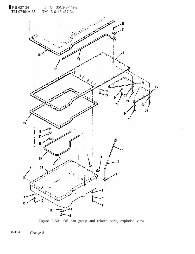
P-8-627-34 T O 35C2-3-442-2TM-07464A-35 TM 5-6115-457-34
Figure 8-50. Oil pan group and related parts, exploded view
8-104 Change 8
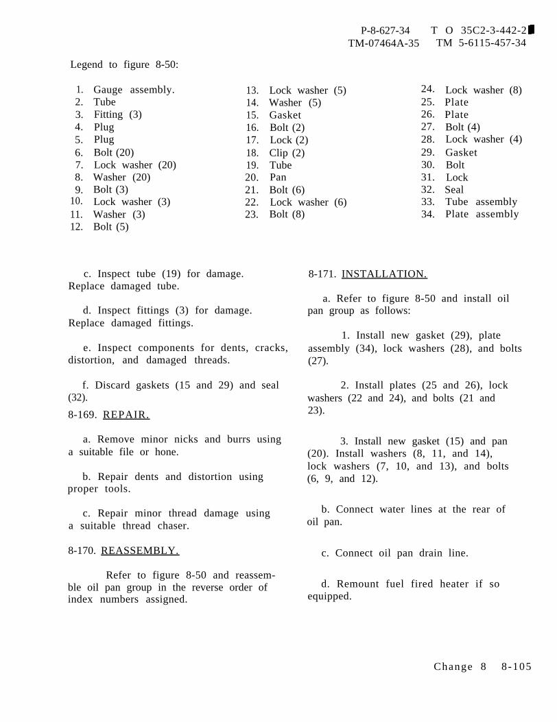
P-8-627-34 T O 35C2-3-442-2TM-07464A-35 TM 5-6115-457-34
Legend to figure 8-50:
1.2.3.4.5.6.7.8.9.
10.11.12.
Gauge assembly.TubeFitting (3)PlugPlugBolt (20)Lock washer (20)Washer (20)Bolt (3)Lock washer (3)Washer (3)Bolt (5)
c. Inspect tube (19) for damage.Replace damaged tube.
13.14.15.16.17.18.19.20.21.22.23.
d. Inspect fittings (3) for damage.Replace damaged fittings.
Lock washer (5)Washer (5)GasketBolt (2)Lock (2)Clip (2)TubePanBolt (6)Lock washer (6)Bolt (8)
e. Inspect components for dents, cracks,distortion, and damaged threads.
f. Discard gaskets (15 and 29) and seal(32).
8-169. REPAIR.
a. Remove minor nicks and burrs usinga suitable file or hone.
b. Repair dents and distortion usingproper tools.
c. Repair minor thread damage usinga suitable thread chaser.
8-170. REASSEMBLY.
Refer to figure 8-50 and reassem-ble oil pan group in the reverse order ofindex numbers assigned.
24.25.26.27.28.29.30.31.32.33.34.
8-171. INSTALLATION.
Lock washer (8)PlatePlateBolt (4)Lock washer (4)GasketBoltLockSealTube assemblyPlate assembly
a. Refer to figure 8-50 and install oilpan group as follows:
1. Install new gasket (29), plateassembly (34), lock washers (28), and bolts(27).
2. Install plates (25 and 26), lockwashers (22 and 24), and bolts (21 and23).
3. Install new gasket (15) and pan(20). Install washers (8, 11, and 14),lock washers (7, 10, and 13), and bolts(6, 9, and 12).
b. Connect water lines at the rear ofoil pan.
c. Connect oil pan drain line.
d. Remount fuel fired heater if soequipped.
Change 8 8-105
P-8-627-34 T O 35C2-3-442-2TM-07464A-35 TM 5-6115-457-34
Section XXIII. OIL PUMP GROUP
8-172. GENERAL.
The oil pump is mounted on thebottom face of the cylinder block at the frontof the engine. The pump is a two-section,positive displacement, gear-type pump.One section scavenges oil from the rear ofthe engine and dumps it into the oil pansump. The other section supplies lubrica-tion, under pressure, to the basic enginethrough passages in the cylinder block, andto external components through oil lines.The pump is driven by the crankshaftthrough the oil pump idler gear.
8-173. REMOVAL.
a. Remove fuel fired heater and mount-ing brackets on right side if so equipped.
b. Drain oil from oil pan.
c. Disconnect oil pan drain line at valve.
d. Disconnect water connections at therear of oil pan.
e. Refer to figure 8-50 and removebolts (6, 9, and 12), lock washers (7, 10,and 13), and washers (8, 11, and 14).Remove oil pan (20) and gasket (15). Dis-card gasket.
f. Refer to figure 8-51 and remove oilpump in the order of index numbers assigned.8-174. DISASSEMBLY.
Refer to figure 8-52 and disassem-ble oil pump group in the order of indexnumbers assigned. Pay particular attentionto the following:
a. Using a suitable puller, removegears (30, Figure 8-52) from shaft assem-blies (33 and 31).
b. Using a suitable puller, removegear (28) from shaft (33) and gear (37)
from shaft (41).c. Using a suitable arbor press,
remove bearings (22) from body (24)bearings (36 and 44) from body (45).
d. Using a suitable arbor press,remove shift (11) from body (45).
and
e. Do not remove ball (42) from body(45). If ball (42) is damaged, replacebody (45).
Cleaning Solvents are flammable andmoderately toxic to skin, eyes andrespiratory tract. Eye and skinprotection required. Good generalventilation is normally adequate.
8-175. CLEANING.
CLean components with an approvedcleaning solvent, and dry thoroughly.
8-176. INSPECTION.
a. Inspect gear teeth for nicks, burrs,cracks, and broken teeth. Nicks and burrsthat extend below the hardened surface ofthe gear teeth are cause for rejection ofgear.
b. Inspect gear teeth for wear that mayhave destroyed the original tooth shape.If this condition is found, replace gear.
c. Refer to table 1-1 and, using asuitable micrometer and feeler gauge,check for excessive wear as follows:
1. Drive gear shaft (33) diameter.
2. Gear to cover clearance.
8-106 Change 8
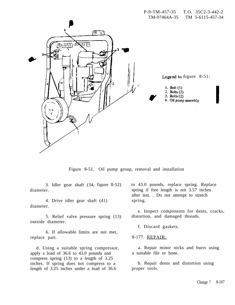
P-9-TM-457-35 T.O. 35C2-3-442-2TM-07464A-35 TM 5-6115-457-34
figure 8-51:
Figure 8-51.
3. Idler gear shaft (34,diameter.
Oil pump group, removal and installation
figure 8-52)
4. Drive idler gear shaft (41)diameter.
5. Relief valve pressure spring (13)outside diameter.
6. If allowable limits are not met,replace part.
d. Using a suitable spring compressor,apply a load of 36.6 to 43.0 pounds andcompress spring (13) to a length of 3.25inches. If spring does not compress to alength of 3.25 inches under a load of 36.6
to 43.0 pounds, replace spring. Replacespring if free length is not 3.57 inchesafter test. . Do not attempt to stretchspring.
e. Inspect components for dents, cracks,distortion, and damaged threads.
f. Discard gaskets.
8-177. REPAIR.
a. Repair minor nicks and burrs usinga suitable file or hone.
b. Repair dents and distortion usingproper tools.
Change 7 8-107
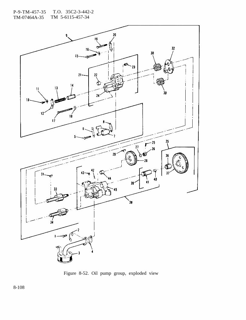
P-9-TM-457-35 T.O. 35C2-3-442-2TM-07464A-35 TM 5-6115-457-34
Figure 8-52. Oil pump group, exploded view
8-108
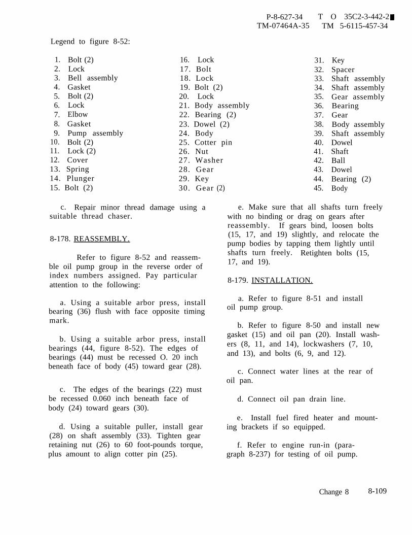
P-8-627-34 T O 35C2-3-442-2TM-07464A-35 TM 5-6115-457-34
Legend to figure 8-52:
1.2.3.4.5.6.7.8.9.
10.11.12.
Bolt (2)LockBell assemblyGasketBolt (2)LockElbowGasketPump assemblyBolt (2)Lock (2)Cover
16. Lock17. Bolt18. Lock19. Bolt (2)20. Lock21. Body assembly22. Bearing (2)23. Dowel (2)24. Body25. Cotter pin26. Nut27. Washer
13. Spring 28. Gear14. Plunger 29. Key15. Bolt (2) 30. Gear
c. Repair minor thread damage using asuitable thread chaser.
8-178. REASSEMBLY.
Refer to figure 8-52 and reassem-ble oil pump group in the reverse order ofindex numbers assigned. Pay particularattention to the following:
a. Using a suitable arbor press, installbearing (36) flush with face opposite timingmark.
b. Using a suitable arbor press, installbearings (44, figure 8-52). The edges ofbearings (44) must be recessed O. 20 inchbeneath face of body (45) toward gear (28).
c. The edges of the bearings (22) mustbe recessed 0.060 inch beneath face ofbody (24) toward gears (30).
d. Using a suitable puller, install gear(28) on shaft assembly (33). Tighten gearretaining nut (26) to 60 foot-pounds torque,plus amount to align cotter pin (25).
31.32.33.34.35.36.37.38.39.40.41.42.43.44.
(2) 45.
KeySpacerShaft assemblyShaft assemblyGear assemblyBearingGearBody assemblyShaft assemblyDowelShaftBallDowelBearing (2)Body
e. Make sure that all shafts turn freelywith no binding or drag on gears afterreassembly. If gears bind, loosen bolts(15, 17, and 19) slightly, and relocate thepump bodies by tapping them lightly untilshafts turn freely. Retighten bolts (15,17, and 19).
8-179. INSTALLATION.
a. Refer to figure 8-51 and installoil pump group.
b. Refer to figure 8-50 and install newgasket (15) and oil pan (20). Install wash-ers (8, 11, and 14), lockwashers (7, 10,and 13), and bolts (6, 9, and 12).
c. Connect water lines at the rear ofoil pan.
d. Connect oil pan drain line.
e. Install fuel fired heater and mount-ing brackets if so equipped.
f. Refer to engine run-in (para-graph 8-237) for testing of oil pump.
Change 8 8-109

P-8-627-34 T O 35C2-3-442-2TM-07464A-35 TM 5-6115-457-34
Section XXIV. VALVE COVER AND VALVE MECHANISM GROUP
8-180. GENERAL.
The valve cover and valve mechan-is m group is mounted on top of the cylinderhead. The valve cover is equipped with abreather assembly, Which is provided forcrankcase ventilation. The valve mechan-ism group consists of intake and exhaustrocker arm assemblies, push rods, andlifters. Two arm assemblies are providedfor each cylinder, one operating the intakevalve and the other operating the exhaustvalve. The arm assemblies are operatedby the camshaft through lifters (and pushrods.
8-181. REMOVAL.
Removal of valve cover and valvemechanism group is accomplished duringdisassembly (paragraph 8-182).
8-182. DISASSEMBLY.
Refer to figure 8-53 and disassem-ble the valve cover and valve mechanismgroup in the order of index numbersassigned. Pay particular attention to thefollowing:
Legend to figure
1. Clamp (2)2. Hose3. Bolt4. Washer
8-53:14. Gasket15. Bolt (6)
5.6.7.8.9.
10.11.12.13.
Breather assemblySealBolt (4)Lock washer (4)CoverGasketBolt (15)Lock washer (15)Cover assembly
a. Using a suitable driver, removebearings (26 and 31) from arm assemblybores (25 and 30).
NOTE
All lifters (20), except those in thenumber one cylinder can be re-moved without removing the cylin-der head.
b. Use a suitable piece of wire approxi-mately 15 inches long, bent into a 1/2 inchhook at one end, to remove lifters (20). Iflifters in the number one cylinder must beremoved, refer to paragraphremove cylinder head.
8-183. CLEANING.
8-189 and
Cleaning Solvents are flammable andmoderately toxic to skin, eyes andrespiratory tract. Eye and skinprotection required. Good generalventilation is normally adequate.
a. Soak breather assembly in anapproved cleaning solvent to remove oilfume deposits, and dry thoroughly.
b. Clean components with an approvedcleaning’ solvent, and dry thoroughly.
27.28.
16. Washer (6) 29.17. Nut (12) 30.18. Screw (12)19. Push rod (12)20. Lifter (12)21. Retaining ring (2)22. Washer23. Spring (2)24. Washer (2)25. Arm assembly (6)26. Bearing
31.32.33.34.35.36.37.38.39.
Bracket assembly (6)DowelFront bracketIntake arm assembly (6)BearingWasher (11)Spring (5)Bracket (4)Shaft assemblyDowelRear bracketPlug (2)Shaft
8-110 Change 8
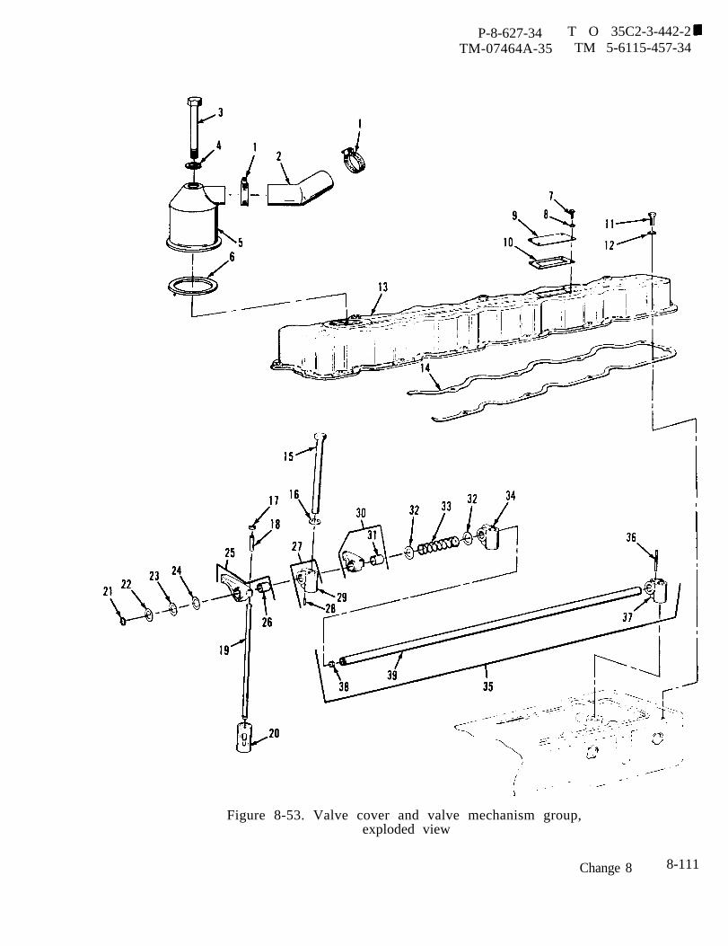
P-8-627-34 T O 35C2-3-442-2TM-07464A-35 TM 5-6115-457-34
Figure 8-53. Valve cover and valve mechanism group,exploded view
Change 8 8-111

P-8-627-34 T O 35C2-3-442-2TM-07464A-35 TM 5-6115-457-34
8-184. INSPECTION. 8-185. REPAIR.
a. Refer to table 1-1 and, using asuitable micrometer, check for excessivewear as follows:
1. Rocker arm bearing (26 and 31,figure 8-53) bore.
2. Shaft (39) diameter.
3. Clearance between bearings andshaft.
4. If allowable limits are not met,replace part.
b. Inspect ball end of adjusting screw(18) and valve contact surface of rockerarm assembly (25) for nicks, discoloration,and uneven wear.
c. Inspect rocker arm assembly (30)and shaft (35) to ensure that oil passagesare open.
d. Check clearance between lifter (20)and bore in block. Maximum allowableclearance is 0.012 inch. If clearance isexceeded, replace lifter.
e. Inspect push rod (19) for straight-ness. Rotate push rod on its ball center.Maximum allowable runout is 0.020 inchT.I.R. If limit is exceeded, replace pushrod. Do not attempt to straighten pushrod.
f. Inspect spring for cracks or distor-tion. If defective, replace spring.
g. Inspect rocker arm contact surfacesfor excessive wear. If defective, replacerocker arm.
h. Inspect components for cracks,breaks, and other damage.
i. Discard seal and gaskets.
CAUTION
Do not remove any more materialthan is required to remove dis-coloration and small nicks.
NOTEThe contact surfaces on adjustmentscrew (18) and lifter end of pushrod (19) may be noted to have a flatsurface on the ball end. This flatsurface is allowed by the manu-facturer during production and isnot to be considered a worn part.The adjusting screw ball end isallowed a 0.19 inch diameter flat,and the lifter end of the push rodis allowed a 0.125 inch diameterflat .
a. Clean up contact surfaces on adjust-ing screw (18, figure 8-53) and rocker armassembly (25), using a hone.
WARNING
Cleaning Solvents are flammable andmoderately toxic to skin, eyes andrespiratory tract. Eye and skinprotection required. Good generalventilation is normally adequate.
b, Clean out oil passages in rockerassembly and shaft using a thin wire.Flush with an approved cleaning solvent.
8-186. REASSEMBLY.
Refer to figure 8-53 and reassem-ble the valve cover and valve mechanismgroup in the reverse order of index num-bers assigned. Pay particular attention tothe following:
CAUTION
When installing bearing (26 and 31)into arm assembly bores (25 and 30),ensure that hole in bearing alignswith hole in bore arm.
8-112 Change 8
P-8-627-34 T O 35C2-3-442-2TM-07464A-35 TM 5-6115-457-34
a. Using a suitable driver, install accomplished during reassembly (para-bearings (26 and 31, figure 8-53) into arm graph 8-186).bores (25 and 30).
8-187. INSTALLATION. Refer to Operator and Organiza-Installation of valve cover tional Maintenance Manual and adjust
and valve mechanism group is valve lash.
Section XXV. CYLINDER HEAD GROUP
8-188. GENERAL.
The cylinder head group is mountedto the cylinder block. The cylinder headgroup consists of chamber assemblies,valve springs, valve guides, and liftingeyes. Cored passages in the cylinder headdirects the flow of coolant around the valveports and precombustionpassages allow lubricantto the valve mechanism.
8-189. REMOVAL.
a. Refer to Operator
chambers. Oilto be distributed
and Organiza-tional Maintenance Manual and remove thefollowing:
1. Lifting frame.
2. Air cleaner assembly.
3. Drain cooling system, loosenhose clamp, and remove top radiator hoseand water pump by-pass hose.
4. Ether start atomizer.
5. Water temperature sensing bulb.
6. High water temperature shutdownsensing bulb.
7. Lube oil filter assembly.
8. Remove turbocharger group.
b. Remove exhaust manifold group(paragraph 8-159).
c. Disconnect fuel injection pump linesand injectors (paragraph 8-142) and installplugs or caps to prevent dirt entering fuelinjection pump.
d. Remove fan mounting group(paragraph 8-31).
e. Remove valve cover and valve mech-anism group (paragraph 8-181).
f. Refer to figure 8-54 and removecylinder head by removing bolts (6 and 8)and lockwashers (7 and 9). Attach asuitable lifting device to lifting eyes (3)and remove cylinder head.
8-190. DISASSEMBLY.
Refer to figure 8-54 and disassem-ble cylinder head group in the order of indexnumbers assigned. Pay particular atten-tion to the following:
a. Using a suitable wrench, removeprecombustion chamber assemblies (21)from cylinder head (38).
b. Using a suitable spring compressor,remove springs (28) from exhaust andintake valves (30 and 32).
Change 8 8-113

P-8-627-34 T O 35C2-3-442-2TM-07464A-35 TM 5-6115-457-34
c. Tag each intake and exhaust valveand the cylinder number it was taken from.
d. Using suitable bushing driver,remove bushings (29, figure 8-54) fromcylinder head (38).
NOTEDo not remove inserts (31 and 33)unless replacement is required.
e. Using a suitable extracting tool,remove inserts (31 and 33) from cylinderhead (38).8-191. CLEANING.
WARNING
Cleaning Solvents are flammable andmoderately toxic to skin, eyes andrespiratory tract. Eye and skinprotect ion required. Good generalventilation is normally adequate.
CAUTION
Do not use a wire brush or a grind-ing wheel when cleaning components.
a. Place valves, valve bushings, andretainers in an approved cleaning solventand allow to soak for at least one hour.Using a stiff brush, remove all carbonlacquer, and residue from parts, and drythoroughly.
b. Remove scale from cylinder headusing an approved cleaning solvent and astiff brush, and dry thoroughly.
c. Clean metal components with anapproved cleaning solvent, and drythoroughly.8-192. INSPECTION.
a. Inspect cylinder headsdamaged threads, distortion,other defect.
b. Inspect precombustiondamaged threads, distortion,
for cracks,or any
chambers foror cracks.
Check tightness of plug (20) on the side ofprecombustion chamber.
c. Inspect valve springs for damagedcoils, cracks, and distortion. Check spring
force. Compress each spring to a lengthof 1.766 inches. Force required for com-pression should be 54.8 to 60.6 pounds.Refer to table 1-1 for spring free lengthand valve spring O.D. If limits are notmet, replace springs.
d. Inspect valve guides (29, figure 8-54)for cracks, distortion, and excessive wear.Check inside diameter of valve guides (29),using suitable pilot gauges. Refer totable 1-1 for acceptable diameter and maxi-mum allowable wear limits. If limits areexceeded, replace valve guides.
e. Inspect valve seat inserts for excessivewear, pitting, cracking or improper seatangle. The proper angle for seat and valveis 30 degrees. Refer to table 1-1, andusing a suitable micrometer, check diametersof inlet valve seat inserts and exhaust valveseat inserts. If allowable limits areexceeded, replace insert.
f. Inspect valves (30 and 32) for cracks,pitting, distortion, or excessive wear, Usea suitable micrometer and check valve stemdiameter. Refer to table 1-1 for maximumallowable wear limits. If limits are notmet, replace valve.
g. Coat each valve face with a thin filmof Prussian blue, then rotate each valve inassociated valve seat. Remove valves andexamine contact pattern on each valve andvalve seat, A line of contact near top andaround entire circumference of valve seatindicates line contact with valve. Thisamount of line contact would indicate thatthe valves and valve seats are acceptable.If, however, line contact is not noted toextend completely around the seat, or gapsin line contact appear around the seat, itwould indicate that the valves have to bereground.
h. Inspect valve seats (31 and 33). Ifvalve seat does not conform to the
8-114 Change 8
P-9-TM-457-35 T.O. 35C2-3-442-2TM-07464A-35 TM 5-6115-457-34
manufacturer’s minimum and maximumdimension, it can not be reground and mustbe replaced. Refer to figure 8-55.
i. Inspect valves (30 and 32) using asuitable micrometer, and check valve headdiameter, valve face angle, closed valveprojection, valve head diameter, and valvelip thickness. Refer to figure 8-55. Iflimits are exceeded, replace valve.
j. Inspect rotocoil assembly (27) forfreedom of rotation. Place rotocoil assem-bly in suitable test fixture with a 1 inch hole.Insert the rotocoil in the hole and load thetop of the rotocoil to 58 pounds. The de-flected height of the rotocoil under this loadshould be 0.295 ± 0. 010 inch when meas-ured from the fixture surface to the top ofthe rotocoil. If this deflection required isnot met, replace rotocoil assembly.
k. Discard all gaskets.
8-193. REPAIR.
a. When results of inspections in step g. ,paragraph 8-192 indicate that valves werenot properly seated, grind the valve seator seats using an approved valve seatgrinder, and grind the valve or valves,using a suitable valve face grindingmachine.
b. After valve seats and/or valve faceshave been ground until they are smooth andconcentric with valve guides, clean allparts with an approved cleaning solvent,and dry thoroughly.
c. If exhaust and intake valve faces(30 and 32, figure 8-54) and valve seatinserts (31 and 33) have been ground forproper seating, the dimensional specifica-tions outlined in figure 8-55 must be met.If dimensions are unacceptable, exhaustand intake valves (30 and 32) and valve
seat inserts (31 and 33) must be replaced.Use a suitable valve seat extractor toreplace valve seat inserts.
d. To install new valve seat insertsthat have been worn beyond acceptablegrinding tolerances, observe the following:(This does not include valve seat insertsthat are loose.)
1. Clean cylinder head with anapproved cleaning solvent, and drythoroughly.
2. Refer to table 1-1 to ensure thathead counterbores meet allowable limitsbefore installing inserts.
3. Immerse the cylinder head inwater heated to 180°F to 200°F for at least30 minutes.
4. Rest the cylinder head upsidedown on a bench, and lay a new insert incounterbore, valve seat up. This mustbe done quickly while the cylinder head ishot and the insert is cold (roomtemperature).
5. Using an approved valve seatinsert installation tool, drive insert downtight into counterbore.
6. Grind the new valve seat insertto the minimum allowable limit of the valveseat insert tolerances shown in table 1-1.
e. To replace a loose valve seat insert,the insert counterbore must be enlarged toaccept the next standard oversize insert.After enlarging counterbore, refer topreceding step d. for insert installationprocedure.
8-194. REASSEMBLY.
Refer to figure 8-54 and reassem-ble cylinder head group in the reverse
Change 1 8-115

P-9-TM-457-35 T.O. 35C2-3-442-2TM-07464A-35 TM 5-6115-457-34
Figure 8-54. Cylinder
8-116 Change 1
head group, exploded view
P-9-TM-457-35 T.O. 35C2-3-442-2TM-07464A-35 TM 5-6115-457-34
Legend to figure1. Bolt (2)2. Washer (2)
8-54:
3. Lifting eye (2)4. Nut5. Plate6. Bolt (18)7. Washer (18)8. Bolt (7)9. Washer (7)
10. Plug11. Bolt (4)12. Lock washer (4)13. Housing assembly14. Seal
15.16.17.18.
18A.18B.18C.18D.
19.20.21.
Temperature regulatorWasherGasketPlug (4)Screw (4)Lock washer (4)CoverGasketHead assemblyPlug (6)Chamber assembly (6)
22. Seal (6)23. Gasket (6)24. Gasket (6)
order of index numbers assigned, Payparticular attention to the following:
. Lubricate exhaust and intake valve(30 and 32), stems and valve guides (29)prior to installation. Exhaust and intakevalve (30 and 32) heads are marked on topfor identification; e.g. , EX for exhaustand IN for inlet,
b. If removed, install inserts (31 and33) into cylinder head (38) using a suitableinstalling tool.
c. Make preliminary valve clearanceadjustment. Adjust clearance for eachexhaust valve to 0.028 inch and each inletvalve to 0.015 inch. Refer to Operatorand Organizational Maintenance Manual forfinal valve adjustment.
d. Using a suitable valve guide driver,install valve guides (29) into cylinder head(39). Valve guide projection above cylin-der must not exceed 0.875 inch.
e. Using a suitable spring compressor,install springs (28) with painted end up.Tap rotocoil assembly (27) lightly as springcompressor is being removed to help seatlocks (26) properly.
25.26.27.28.29.30.31.32.33.34.35.
Gasket (6)Lock (24)Rotocoil assembly (12)Spring (12)Valve guide (12)Valve (6)Insert (6)Valve (6)Insert (6)Plug (7)Plug (6)
36. Director (18)37. Stud (12)
37A. Bushing (12)38. Head39. Gasket
f. Align opening in director (36) with“V” mark stamped on head.
g. Install new gaskets (25, 24, 23,18D and 14.
h. Coat seal (22) and mating surface inbore with liquid soap. Using a suitablewrench, install chamber assemblies (21)into cylinder head (38).
i. Torque plug (20) from 96 to144 inch-pounds.
j. Torque chamber assemblies (21)from 140 to 160 foot-pounds.
NOTE
Gasket (39) is to be clean and dryprior to installation.
k. Position a new cylinder head gasket(39) on the cylinder block. Rock headgentle until it seats flat on head gasket.
1. Install cylinder head (38) and torquecylinder head bolts (6 and 8) as shown infigure 8-56.
Change 1 8-117
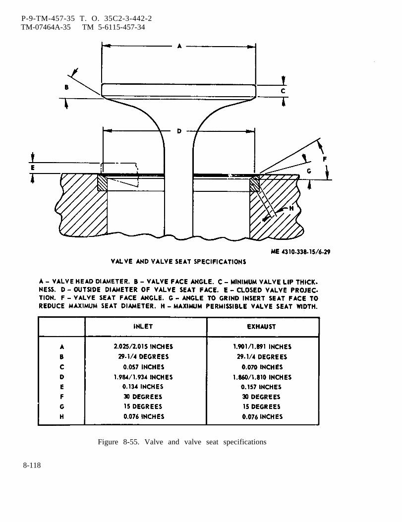
P-9-TM-457-35 T. O. 35C2-3-442-2TM-07464A-35 TM 5-6115-457-34
Figure 8-55. Valve and valve seat specifications
8-118

P-8-627-34 T O 35C2-3-442-2TM-07464A-35 TM 5-6115-457-34
Figure 8-56. Tightening sequence for cylinder head
8-195. INSTALLATION.
a. Attach a suitable lifting device tolifting eyes (3, figure 8-54) on cylinderhead. Install cylinder head and secure withbolts (6 and 8) and lock washers (7 and 8).Refer to figure 8-56 for torquing sequence.
b. Install valve cover and valve mech-anism group (paragraph 8-187).
c. Install fan mounting group (para-graph 8-37).
d. Install fuel injection pump lines andinjectors (paragraph 8-148).
e. Install exhaust manifold group(paragraph 8-163).
f. Refer to Operator and Organiza-tional Maintenance Manual and install thefoil owing:
1. Turbocharger group.
2. Lube oil filter assembly.
3. High water temperature shut-down sensing bulb.
4. Water temperature sensing bulb.
5. Ether start atomizer.
6. Connect water pump by-passhose and top radiator hose.
7.
8.
9.
Air cleaner assembly.
Lifting frame.
Service cooling system.
Change 8 8-119
P-8-627-34 T O 35C2-3-442-2TM-07464A-35 TM 5-6115-457-34
Section XXVI. FLYWHEEL AND FLYWHEEL HOUSING GROUP
8-196. GENERAL.
The flywheel and flywheel housinggroup is mounted on the rear of the cylinderblock, The flywheel and flywheel housinggroup consists of a cast housing flywheel,ring gear, and engine support brackets.The ring gear is shrink-fitted to the rim ofthe flywheel. The purpose of the flywheelis to provide a mass at the end of the crank-shaft to smooth out power impulses andreduce variation in rotative speed; and toprovide a mounting surface for the gener-rater coupling disc. The ring gear providesa place for starting motor engagement whencranking the engine. The flywheel housingalso provides a machined surface to mountthe generator adapter flange. Specialbrackets are bolted to the housing pads toprovide support for the engine when thegenerator is removed for repair. Theflywheel housing also provides a counter-bore for locating the rear main oilseal.8-197. REMOVAL.
a. Remove engine assembly (para-graph 2-8).
b. Refer to Operator and OrganizationalMaintenance Manual and remove air cleanerassembly, starter motor, and turbocharger.
c. Removal of flywheel and flywheelhousing group is accomplished during dis-assembly (paragraph 8-198).8-198. DISASSEMBLY.
Refer to figure 8-57 and disassembleflywheel and flywheel housing in the order ofindex numbers assigned. Pay particular atten-tion to the following:
a. Scribe a mark on flywheel and crank-shaft to show a relative position betweenthese two parts.
WARNING
Attach lifting device prior to re-moval of bolts (8) to prevent fly-wheel from falling off the crank-shaft end.
b. To lift flywheel assembly (10),thread eyebolt into tapped hole provided onflywheel face.
c. Attach lifting device, minimum capacity250 lb (113.4 kg), and remove bolts (8), lock-ring (9), and flywheel (10).
d. Using a suitable mallet, stroke frontface of flywheel housing (21) alternately oneach side of engine to loosen and work fly-wheel housing (21) off dowel pins.
NOTE
Do not remove ring gear (11) fromflywheel assembly (10) unlessdamage to ring gear (11) or hous-ing ( 12) is evident.
e. Discard crankshaft seal (22).8-199. CLEANING.
WARNING
Cleaning Solvents are flammable andmoderately toxic to skin, eyes andrespiratory tract. Eye and skinprotection required. Good generalventilation is normally adequate.
Compressed air used for cleaning anddrying purposes can create airborneparticles that may enter the eyes.Pressure shall not exceed 30 psig.Eye protection is required.
a. Clean parts with an approved clean-ing solvent and dry thoroughly.
b. Remove rust from ring gear, using astiff brush. Wash ring gear with solventand dry thoroughly.
8 - 1 2 0 C h a n g e 8

c. Flush outwith solvent andcompressed air.
turbo drain port in housingdry with low pressure
8-200. INSPECTION.
a. Inspect flywheel housing for cracks.Replace cracked flywheel housing.
b. Check machined gasket surface atring of flywheel housing for nicks and burrs.
c. Inspect threaded holes for damagedthreads.
d. Inspect ring gear teeth for nicks,burrs, cracks, and broken teeth. Nicksand burrs that extend below the hardenedsurface of the gear teeth are cause forrejection of the gear. Replace ring gear ifcracked or if teeth are broken.
e. Inspect ring gear for wear that mayhave destroyed the original tooth shape.If this condition is found, replace gear.
f. Inspect coupling disc counter boreon flywheel for burred edges or an indica-tion that coupling disc on generator doesnot seat properly.
g. Discard seal and gaskets.
8-201. REPAIR.
a. Remove minor nicks and burrs fromflywheel housing and ring gear teeth,using a suitable file or hone.
b. Repair minor thread damage usinga suitable thread chaser.
c. Replace a defective ring gear asfollows:
1. Cut or press off defective ringgear.
P-9-TM-457-35 T. O. 35C2-3-442-2TM-07464A-35 TM 5-6115-457-34
CAUTION
Under no circumstances should thering gear (11, figure 8-57) beheated over 600°F as excessiveheating may destroy the originalheat treatment. Do not heatring gear in one area.
2. Heat new ring gear to a maximumof 600°F. Use a torch and apply heatevenly around diameter of ring gear.
3. Install ring gear with chamferedportion of ring gear teeth facing towardstarter pinion or to backside of flywheel.Gear must be flush with flywheel shoulder.
CAUTION
Be careful to remove only theburred material on the edge of thecoupling disc counterbore.
d. Remove sharp edges and burrs fromcoupling disc counterbore in flywheel usinga suitable file,
8-202. REASSEMBLY.
Refer to figure 8-57 and reassem-ble flywheel and flywheel housing group inthe reverse order of index numbersassigned. Pay particular attention to thefollowing:
a. Bottom edges of housing gasket(22) that contacts oil pan plate must be cutsquare and flush with oil pan plate beforeflywheel housing is secured to crankcase.
b. Install two suitable pilot studs incylinder block to act as guide pins whileflywheel housing is hoisted into position andlocated on dowel pins.
c. Install crankshaft seal (13) asfollows :
8-121
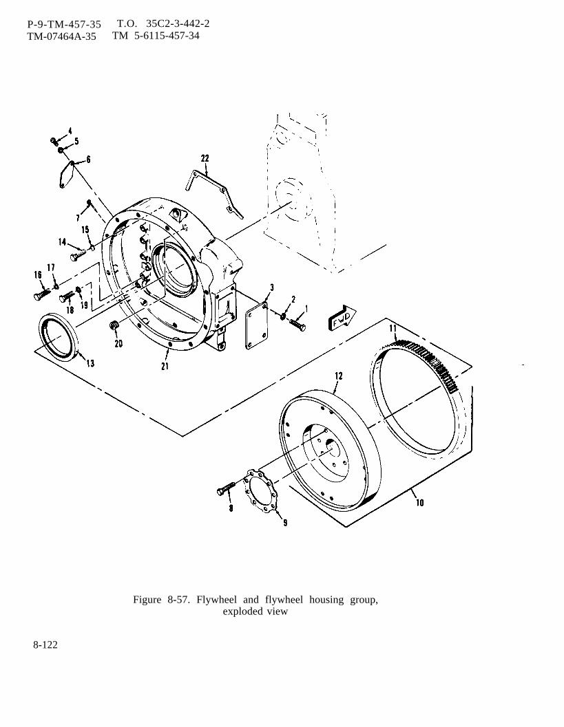
P-9-TM-457-35 T.O. 35C2-3-442-2TM-07464A-35 TM 5-6115-457-34
Figure 8-57. Flywheel and flywheel housing group,exploded view
8-122
P-8-627-34 T O 35C2-3-442-2TM-07464A-35 TM 5-6115-457-34
Legend to figure 8-57:
1. Bolt (4)2. Lock washer (4)3. Plate4. Bolt (2)5. Lock washer (2)6. Cover7. Pointer8. Bolt (9)
9. Lockring10. Flywheel assembly11. Ring gear12. Flywheel13. Seal14. Bolt (2)15. Lock washer (2)
1. Fabricate pilot and sleeve asshown in figure 2-1 (view F and G).
Lubricate sealing lip of seal(13, figure 8-57) lightly with crankcaseoil. Put MIL-S-22473 sealant on theouter metal shell of the seal. Boltpilot to the crankshaft flange and posi-tion seal on pilot with lip facing cyl-inder block as shown in figure 8-58(view B).
3. Place sleeve on stud and install3/4 inch washer 3/4-10 inch NC nut.
4. Tighten nut to press seal (13,figure 8-57) into flywheel housing (21).Remove installation tools.
d. Torque flywheel housing bolts to100 foot-pounds.
e. Before locating flywheel assembly(10, figure 8-57) on crankshaft, make surethat alignment scribe lines are lined up.
f. Torque flywheel bolts to 150 foot-pounds. If lock rings tabs do not matchwith flats on bolt heads, tighten boltsslightly to match.
CAUTION
Do not loosen bolts to line up lockring tabs with bolt head flats.
16. Bolt (9)17. Lock washer (9)18. Bolt (2)19. Lock washer (2)20. Plug21. Flywheel housing22. Gasket
g. Refer to figure 8-50 and installlockwashers (22) and bolts (21) to securebottom of flywheel housing.
h. Check flywheel and flywheel housingfor parallelism and concentricity, usingsuitable dial indicators as follows:
1. Remove fuel injectors, this willrelieve engine compression when rotatingcrankshaft.
2. When making checks, positiondial indicators straight and square asshown in figure 8-59 and 8-60 and makesure indicators have adequate travel in eachdirection.
3. Using a suitable board, applypressure to front end of crankshaft to makesure end play is in one direction only.
4. Perform concentricity check asshown in figure 8-59. Adjust dial indicatorto read zero at twelve o’clock position.Apply continuous pressure to front end ofcrankshaft and using tool, rotate crankshaftone full revolution, taking readings at45 degree intervals (8 readings each on
Change 8 8-123
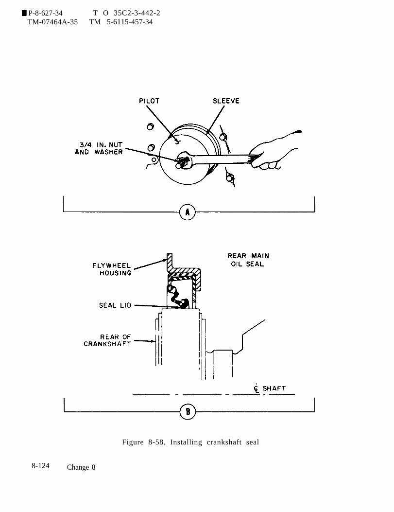
P-8-627-34 T O 35C2-3-442-2TM-07464A-35 TM 5-6115-457-34
Figure 8-58. Installing crankshaft seal
8-124 Change 8
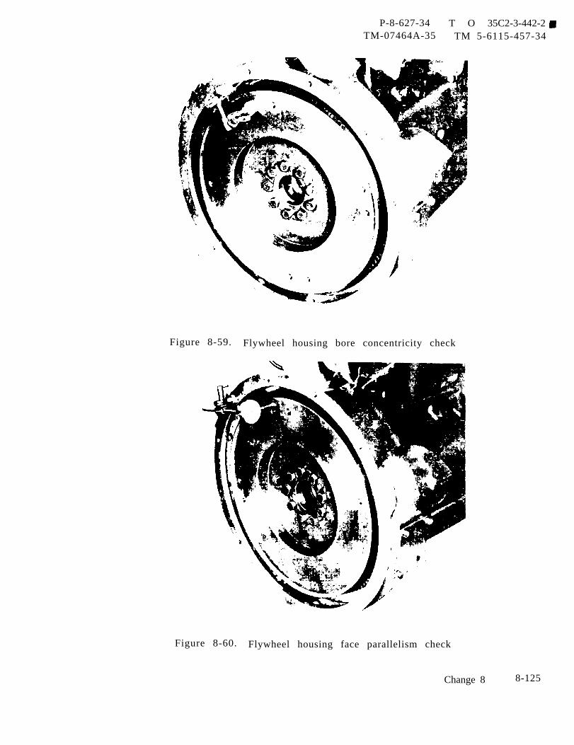
P-8-627-34 T O 35C2-3-442-2TM-07464A-35 TM 5-6115-457-34
Figure 8-59. Flywheel housing bore concentricity check
Figure 8-60. Flywheel housing face parallelism check
Change 8 8-125

P-8-627-34 T O 35C2-3-442-2TM-07464A-35 TM 5-6115-457-34
flywheel housing (21, figure 8-57) bore).Stop and remove tool before recording eachreading to ensure accuracy. The maximumtotal indicator reading must not exceed0.012 inch.
5. If the flywheel housing (21) borerun-out is excessive, remove flywheel (12)and loosen flywheel housing attaching bolts(14, 16, and 18) slightly and tap the flywheelhousing (21) with a soft hammer in therequired direction until the run-out is withinlimits. Re-tighten the attaching bolts (14,16, and 18), install flywheel (12) and re-check the run-out.
6. Perform parallelism check asshown in figure 8-60. Adjust dial indicatorto read zero at twelve o’clock position.Apply continuous pressure to front end ofcrankshaft and using tool, rotate crankshaftone full revolution, taking readings at45 degree intervals (8 readings each on fly-wheel face). Stop and remove tool before
recording each reading to ensure accuracy.The maximum total indicator reading mustnot exceed 0.006 inch.
7. If the flywheel housing (21 , fig-ure 8-57) face run-out is excessive, removeflywheel housing (21), and check for dirt orforeign material (such as old gasket mate-rial) between flywheel housing (21) andcylinder block. Install flywheel housing(21) and recheck the run-out. When run-outis correct, bend up lock ring tabs (9, Figure8-57).
8-203. INSTALLATION.
a. Installation of the flywheel and fly-wheel housing is accomplished duringreassembly (paragraph 8-202).
b. Refer to Operator and OrganizationalMaintenance Manual and install air cleanerassembly, starter motor, and turbocharger.
c. Install engine assembly (para-graph 2-8).
Section XXVII. CAMSHAFT GROUP
8-204. GENERAL.
The camshaft group is located onthe upper left side of the cylinder block andis driven by the crankshaft gear. The cam-shaft group consists of a camshaft gear,a thrust washer secured to the cylinderblock, and four sleeve type bearings. Thecams are forged integrally with the shaft.As the camshaft rotates, the cams movethe valve lifters and push rods which acti-vate inlet and exhaust valves.
8-205. REMOVAL.
a. Remove engine assembly(paragraph 2-8).
b. Remove valve cover and valve mech-anism group (paragraph 8-181).
c. Remove fan mounting group (para-graph 8-3 1).
d. Remove water pump group (para-graph 8-118).
e. Refer to Operator and OrganizationalMaintenance Manual and remove alternator.
f. Removegenerator sets
g. Removegraph 8-94).
hydraulic tank (preciseonly) (paragraph 8-86).
hydraulic pump (para-
8-126 Change 8
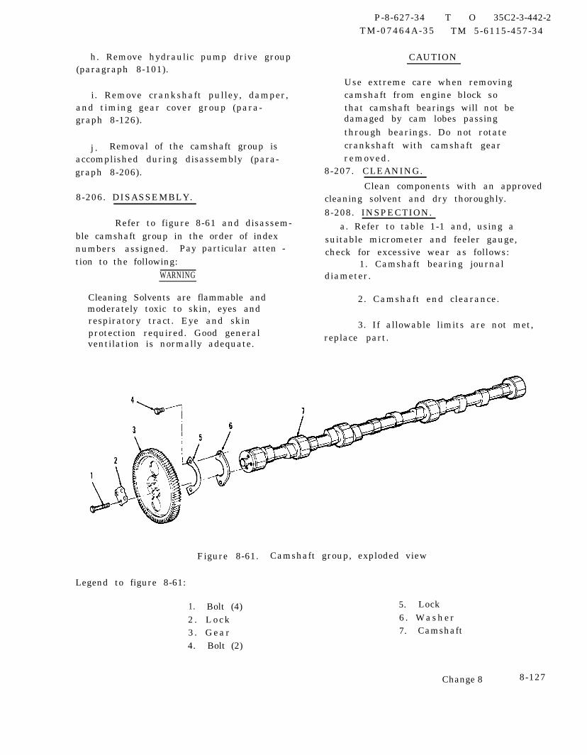
h. Remove hydraulic pump drive group(paragraph 8-101).
i. Remove crankshaft pulley, damper,and timing gear cover group (para-graph 8-126).
j . Removal of the camshaft group isaccomplished during disassembly (para-graph 8-206).
8-206. DISASSEMBLY.
Refer to figure 8-61 and disassem-ble camshaft group in the order of indexnumbers assigned. Pay particular atten -tion to the following:
WARNING
Cleaning Solvents are flammable andmoderately toxic to skin, eyes andrespiratory tract. Eye and skinprotection required. Good generalventilation is normally adequate.
P-8-627-34 T O 35C2-3-442-2TM-07464A-35 TM 5-6115-457-34
CAUTION
Use extreme care when removingcamshaft from engine block sothat camshaft bearings will not bedamaged by cam lobes passingthrough bearings. Do not rotatecrankshaft with camshaft gearremoved.
8-207. CLEANING.
Clean components with an approvedcleaning solvent and dry thoroughly.8-208. INSPECTION.
a. Refer to table 1-1 and, using asuitable micrometer and feeler gauge,check for excessive wear as follows:
1. Camshaft bearing journaldiameter.
2. Camshaft end clearance.
3. If allowable limits are not met,replace part.
Figure 8-61. Camshaft group, exploded view
Legend to figure 8-61:
1. Bolt (4) 5. Lock
2 . L o c k 6. Washer
3 . Gear 7. Camshaft
4. Bolt (2)
Change 8 8-127
P-8-627-34 T O 35C2-3-442-2TM-07464A-35 TM 5-6115-457-34
b. Measure bearing clearance betweenbearings and camshaft journals as follows:
NOTE
Camshaft bearing clearance can bedetermined only when camshaftbearings are pressed into the cyl-inder block.
1. If camshaft journal dimensionmeasured in step a. indicates that journalwear is within 0.002 inch of each other,clearances between camshaft journals andcamshaft bearings can be calculated.
2. Using a suitable inside microm-eter, measure the I.D. of the front cam-shaft bearing in the cylinder block. Sub-tract the measured diameter of the frontcamshaft journal from the I. D. of the frontcamshaft bearing in the cylinder block.The result is the running clearance. Maxi-mum allowable clearance is 0.008 inch.
3. If camshaft journal wear wasfound to be more than 0.002 inch differencebetween any two journals, the individualcamshaft bearings in the cylinder block willhave to be checked using the followingprocedure.
(a) Refer to Operator and Organi-zational Maintenance Manual and remove aircleaner assembly and turbocharger group.
(b) Remove flywheel and flywheelhousing (paragraph 8-197).
(c) Refer to figure 8-50 andremove bolts (6, 9, and 12), lock washers(7, 10, and 13), and washers (8, 11, and14). Remove oil pan (20) and gasket (15).Discard gasket.
(d) Remove oil pump group(paragraph 8-173).
8-128 Change 8
4.bottom of
5.
Rotate cylinder block so thatblock is facing up.
Using a suitable micrometer,measure I.D. of each camshaft bearing.Measure diameter of camshaft journal thatcorresponds to bearing just measured.Subtract measured diameter of camshaftjournal from measured I.D. of bearing.The result is the running clearance. Maxi-mum allowable clearance is 0.008 inch. Ifwithin limit, proceed to step 9. If limit isexc ceded, replace al 1 five camshaft bear-ings. Proceed to step 6.
6. Using a suitable puller, removeall five camshaft bearings.
7. Using a suitable tool, install newcamshaft bearings. Front bearing must berecessed 0.06 inch from front face of cam-shaft bore. Oil hole in bearing must alignwith oil hole in cylinder block, and joint inbearing must face cylinder block centerline.Intermediate bearings must be flush withfront face of bearing bore. Rear bearingmust be recessed 0.06 inch from rear faceof bore.
8. Recheck running clearance.Refer to step 5.
9. Rotate cylinder block so that topof block is facing up.
10. Install oil pump group (para-graph 8-179).
11. Refer to figure 8-50 and installnew gasket (15) and oil pan (20). Installwashers (8, 11, and 14), lockwashers (7,10, and 13), and bolts (6, 9, and 12).
12. Install flywheel and flywheelhousing (paragraph 8-203).
13. Refer totional Maintenance
Operator and Organiza-Manual and install turbo-
charger group and air cleaner assembly.
c . Inspect camshaft gear for nicked orcracked gear teeth. If cracked, replacegear.
d. Inspect camshaft for cracks anddistortion. If defective, replace camshaft.
8-209. REPAIR.
Repair minor nicks and burrs oncamshaft gear using a suitable file or hone.
8-210. REASSEMBLY.
Refer to figure 8-61 and reassem-ble camshaft group in the reverse order ofindex numbers assigned. Pay particularattention to the following:
a. Apply a graphite grease to camshaftlobes prior to installing camshaft (7).
b. Align letter C on camshaft gear (3)with letter C on crankshaft gear. Referto figure 8-30.
c . Measure gear end clearance. Endclearance should be 0.025 inch.
d. Camshaft front bearing must berecessed 0.06 inch from front face of bore.Oil hole in bearing must align with oil holein cylinder block, and joint in bearing must
P-8-627-34 T O 35C2-3-442-2 TM-07464A-35 TM 5-6115-457-34
face cylinder block centerline. Inter-mediate bearings must be flush with frontface of bearing bore. Rear bearing mustbe recessed 0.06 inch from rear face ofbore.
8-211. INSTALLATION.
a. Installation of the camshaft group isaccompli shed during reassembly (para-graph 8-210).
b. Install crankshaft pulley, damper,and timing gear cover pump (para-graph 8-132).
c. Install hydraulic pump (para-graph 8-99).
d. Install hydraulic tank (precise gen-erator sets only) (paragraph 8-92).
e. Refer to Operator and OrganizationalMaintenance Manual and install alternator.
f. Install water pump group (para-graph 8-124).
g. Install fan mounting group (para-graph 8-37).
h. Install valve cover and valve mech-anism group (paragraph 8-187).
i. Install engine assembly (para-graph 2-8).
Section XXVIII. CONNECTING RODS AND PISTONS GROUP
8-212. GENERAL. connecting rods and pistons group consistsof piston assemblies, connecting rodassemblies, bearings, pins, and retainers.
The connecting rods and pistons The piston assemblies are attached to thegroup is located in the cylinder block. The crankshaft by connecting rods.
Change 8 8-129
P-8-627-34 T O 35C2-3-442-2TM-07464A-35 TM 5-6115-457-34
8-213. REMOVAL.
a. Refer to Operator and Organiza-ti onal Maintenance Manual and remove thefollowing:
1. Air cleaner assembly.
2. Drain cooling system. Loosenhose clamps and remove top radiator hoseand water bypass hose.
3. Drain crankcase oil.
4. Remove ether start atomizer.
5. Remove sensing bulbs fromthermostat housing.
6. Remove oil filter assembly.
b. Remove lifting frame assembly(paragraph 3-8).
c . Remove fan mounting group (para-graph 8-31).
d. Refer to Operation and Organiza-tional Maintenance Manual and removeturbocharger.
e. Remove exhaust manifold group(paragraph 8-159).
f. Disconnect fuel lines from fuelinjection pump (paragraph 8-142).
g. Remove valve cover and valve mech-anism group (paragraph 8-181).
h. Remove cylinder head group (para-graph 8-189).
i. Remove oil pan group (para-graph 8-165).
j. Remove oil pump group (para-graph 8-173).
k. Removal of the connecting rods andpistons is accomplished during disassem-bly (paragraph 8-214).8-214. DISASSEMBLY .
Refer to figure 8-62 and disassem-ble connecting rods and pistons group inthe order of index numbers assigned. Payparticular attention to the following:
a. Prior to removing piston, note thecondition at the top of cylinder liner. If acarbon ridge is present, it must be removedusing a suitable ridge reamer.
b. Rotate crankshaft until the connectingrod and piston to be removed is at top deadcenter. Carefully remove each connectingrod and piston by pushing it out through topof cylinder.
c. Using a suitable retaining ringremover, remove two retaining rings (5).Using a suitable drift, drive out pistonpin (6).
d. Using suitable tools, drive outbushing (8) from connecting rod (7).
e. Tag each bearing halve (3), connect-ing rod assembly (9), and piston assem bly(14) indicating which cylinder they wereremoved from.
f. Use a suitable piston ring expanderto remove piston rings (10, 11, and 12)from the pistons (13).
8-215. CLEANING.
WARNING
Cleaning Solvents are f lammable andmoderately toxic to skin, eyes andrespiratory tract. Eye and skinprotection required. Good generalventilation is normally adequate.
a. Clean parts with an approved clean-ing solvent and dry thoroughly.
8-130 Change 8

P-9-TM-457-35 T. O. 35 C2-3-442-2TM-07464A-35 TM 5-6115-457-34
CAUTION
Do not use broken piston rings orcarbon scrapers on ring landssince this practice can result incutting sides of grooves. Be surebottom of each ring groove isclean and oil return holes in oilring groove are open.
b. If pistons have carbon on them, soakpistons in cold water overnight and then letthem dry (preferably in sunlight). Most ofthe carbon can then be removed with ahardwood stick.
8-216. INSPECTION.
a. Refer to table 1-1 and inspect partsfor dimensional tolerances. Replace defec-tive parts.
b. Inspect piston for burned condition,cracks, distortion, galling, or any otherdefects. Replace defective piston.
c. Inspect piston pins and rod bearingsfor scoring, galling, distortion, or cracks.Replace defective bearings.
d. Inspect connecting rod for cracks,breaks, or distortion. Replace defectiveconnecting rod.
NOTE
Bent rods should be discarded. D O
not attempt to align rods by bending.Abrasive materials may roll aroundbetween bearings (8) and crankshaftjournals causing scratches in thebearing without actually becomingembedded in the aluminum. Suchscratches are not necessarily harm-ful and do not indicate that bearings(8, figure 8-62) should be replaced.
e, To measure clearance and gap foreach piston ring (10, 11, and 12), insert apiston (13) in cylinder bore in the invertedposition. Insert each piston ring, one at atime, about two inches down in the cylinderbore and bring the bottom edge of the piston(13) up against the ring to square the ringin the cylinder bore. Check gap with afeeler gauge. If gap clearance for any ringis not as specified in table 1-1, the ringmust be filed or honed to specification, orreplaced.
8-217. REPAIR.
a. When installing a new bearing (8)into the connecting rod, the joint on thediameter of the bearing must be at rightangles (90 ± 10 degrees, either left or right)of the vertical centerline of the connectingrod. After pressing new bearing in placemachine accurately to dimensions in table1-1.
b. Connecting rod bearings (3) shouldalways be replaced as a set (two halvesmake a set). If inspection of one bearingshell indicates minimum thickness, thenreplace all six connecting rod bearingshells.
8-218. REASSEMBLY.
Refer to figure 8-62 and reassem-ble connecting rods and pistons group inthe reverse order of index numbersassigned. Pay particular attention to thefollowing:
a. Reassemble rod (7) on piston (13) sothat the etched cylinder number on rod (7)is on the same side as the "V" mark in thepiston (13).
b. Use a suitable piston ring expanderto install piston rings (10, 11, and 12) on
8-131
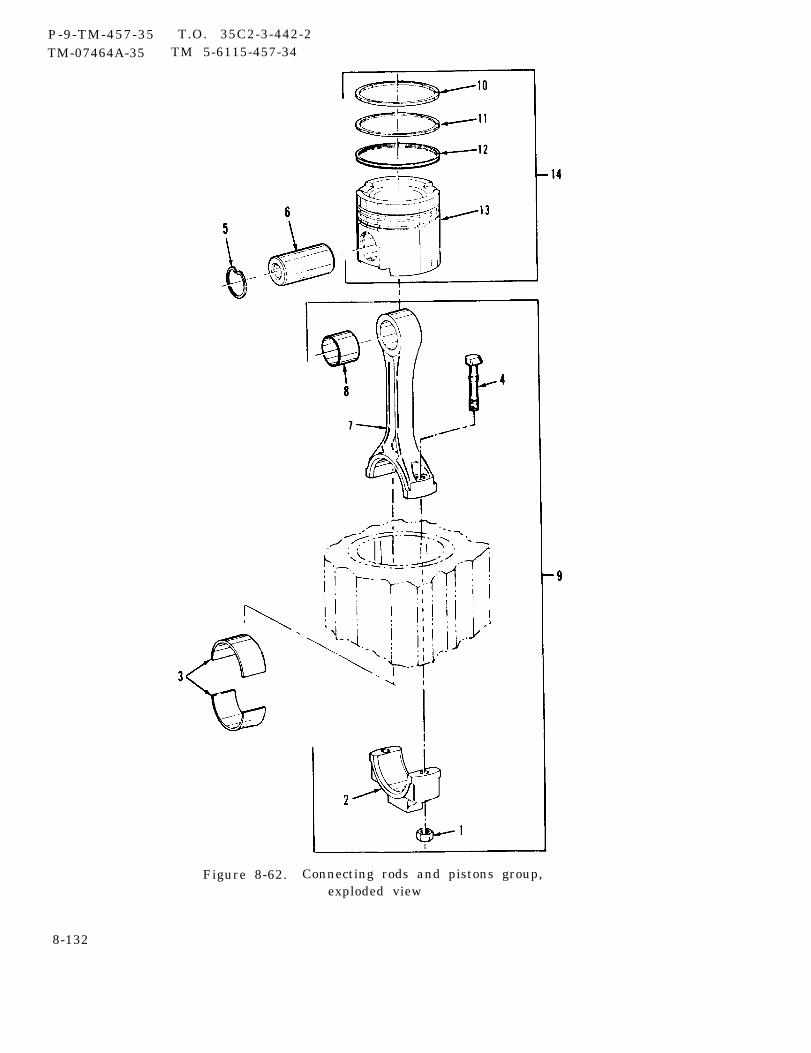
P-9-TM-457-35 T.O. 35C2-3-442-2TM-07464A-35 TM 5-6115-457-34
Figure 8-62. Connecting rods and pistons group,exploded view
8-132
P-9-TM-457-35 T.O. 35C2-3-442-2TM-07464A-35 TM 5-6115-457-34
Legend to figure 8-62:
1. Nut (2) 6 . Pin 11. Ring2. Bearing cap (6) 7. Rod 12. Ring3. Bearing (6) 8. Bearing 13. Piston4. Bolt (2) 9. Connecting rod assembly (6) 14. Piston assembly (6)5. Retaining ring (2) 10. Ring
pistons (13). On each ring, the word “UP”is stamped. Start with ring (12) andinstall ring with the word “UP” pointingtoward the top of the piston. Stagger ringgaps on piston so they are not in line witheach other.
c . Lubricate bearings (3 and 8), pistonrings (10, 11, and 12), and the liner wallswith clean engine oil.
d. Compress piston rings (10, 11, and12) with a suitable ring compressor tooland install piston (13) so that the “V” markon top of the piston lines up to the “V”mark on top of the block.
e. When assembling lower bearing cap(2) to connecting rod (7), make sure thatprotruding tab on back of each bearing half(3) lines up with corresponding recess inconnecting rod (7) and bearing cap (2).
f. Guide lower end of each connectingrod (7) over crankshaft journal so as not todamage crankshaft bearing surface.
g. Check connecting rod bearing clear-ance as follows:
1. Place an approved piece ofsoft plastic measuring strip betweencrankshaft journal and lower bearing half,on all six connecting rod assemblies.
2. Install lower bearing caps (2,figure 8-62) and tighten bolts, (4) and nuts(1) from 27 to 33 foot-pounds torque.
3. Remove caps (2) and bearingsone at a time and measure thickness ofplastic strips. The measurement repre-sents the bearing clearance. If the maxi-mum clearance exceeds 0.010 inch, re-place connecting rod bearings. It would beadvisable to replace all rod bearings (3) atthis time.
NOTE
Excessive bearing clearance canalso be an indication of crankshaftsurface being out-of-round.
g. Install caps (2) and bearings (3) andtorque bolts (4) as follows:
1. Lubricate threads of bolts withcrankcase oil, and tighten from 27 to33 foot-pounds torque.
2. Mark bolts and caps. Tighten anadditional 85 to 95 degrees from mark.
8-219. INSTALLATION.
a. Installation of the connecting rodsand pistons group is accomplished duringreassembly (paragraph 8-218),
b. Install oil8-179).
c. Install oil8-171).
pump group (paragraph
pan group (paragraph
d. Install cylinder head group (para-graph 8-195).
8-133

P-9-TM-457-34 T.O. 35C2-3-442-2TM-07464A-35 TM 5-6115-457-34
e. Refer to Operator and Organiza-tional Maintenance Manual and installturbocharger.
f. Install fan mounting group (para-graph 8-37).
g. Install exhaust manifold (para-graph 8-163).
h. Refer to Operator and Organiza-tional Maintenance Manual and install thefollowing:
1. Install oil filter assembly.
2. Install sensing bulbs to thermo-stat housing.
3. Install ether start atomizer.
4. Install air cleaner assembly.
5. Connect top radiator hose andwater by-pass hose. Tighten clamps.
6. Install lifting frame (para-graph 3-8).
7. Service cooling system.
8. Fill engine crankcase.
Section XXIX CRANKSHAFT GROUP AND MAIN BEARINGS
8-220. GENERAL.
The crankshaft group and mainbearings are located in the cylinder block.The crankshaft group and main bearingsconsist of a crankshaft assembly, mainbearings, plates, gear, and plugs. Theend thrust of the crankshaft is taken up byflanges on the lower half of the rear mainbearing, An oil seal pressed into thetiming gear housing cover prevents oilleakage at the front of the engine. An oilseal, pressed into the flywheel housing,bears against the crankshaft flange andprevents leakage at the rear of the engine.Counterweights are forged integrally withthe crankshaft and are drilled to obtainshaft balance. The crankshaft timing gearis pressed on the front of the crankshaft.The main bearings and caps support thecrankshaft in the cylinder block. Tabswhich are punched outward on each bearinghalf fit into recesses in the cylinder blockand bearing cap, securing the bearing andpreventing it from rotating.
8-221. REMOVAL.
a. Remove engine assembly (para-graph 2-8).
b. Remove fan mounting group (para-graph 8-3 1).
c. Remove water pump group (para-graph 8-118).
d. Remove hydraulic tank (precise setsonly) (paragraph 8-86).
e. Remove hydraulic pump (precisesets only) (paragraph 8-94).
f. Remove hydraulic pump drive group(paragraph 8-101).
g. Refer to Operator and Organization-al Maintenance Manual and Removealternator.
8-134
h. Remove crankshaft pulley, damper,and timing gear cover group (para-graph 8-126).
i. Remove oil pan group and relatedparts (paragraph 8-165).
j . Remove oil pump group (para-graph 8-173).
k. Refer to Operator and Organiza-tional Maintenance Manual and remove aircleaner assembly and turbocharger.
1. Remove flywheel and flywheel housinggroup (paragraph 8-197).
m. Removal of the crankshaft group andmain bearings is accomplished during dis-assembly (paragraph 8-222).
8-222. DISASSEMBLY.
Refer to figure 8-63 and disassem-ble crankshaft group and main bearings inthe order of index numbers assigned. Payparticular attention to the following:
NOTE
If only main bearing removal isrequired, perform steps a.through e.
a. Turn engine upside down and supportin a suitable fixture.
b. Remove bolts (1), washers (2), mainbearing caps (3), and lower bearinghalves (4).
c . Tag each bearing cap as to whichmain bearing it was removed from.
P-9-TM-457-35 T.0. 35C2-3-442-2TM-07464A-35 TM 5-6115-457-34
NOTECylinder block is upside down.The bearing half under the crank-shaft is still referred to as theupper bearing half.
d. Place a suitable tool in oil hole incrankshaft, and rotate crankshaft to rollout upper bearing half (4). Bearing halfmust be rolled out tab end first.
e . Place bearing half with its matingbearing half and bearing cap.
NOTEIf crankshaft removal is required,perform steps f. through i.
f. Refer to paragraph 8-214, andremove connecting rod bearing and bearingcaps. Tag each cap as to which connectingrod it was removed from.
NOTEDo not remove crankshaft gear (8,figure 8-63) and sleeves (7 and 10)unless excessive wear or damageis noted.
g. Lift crankshaft from block usingsuitable web sling around connecting rodjournals on crankshaft at cylinder No. 1and 6 or 2 and 4. Place crankshaft onsuitable bench support.
h. Attach each connecting rod bearingcap and insert to the connecting rod fromwhich they were removed.
i. Heat sleeves (7 and 10) and gear (8) to600°F maximum and remove from crank-shaft (11) .
CAUTION
With crankshaft removed fromblock, do not attempt to rotatecamshaft gear.
Change 1 8-135

P-9-TM-457-35 T.O. 35C2-3-442-2TM-07464A-35 TM 5-6115-457-34
Figure 8-63. Crankshaft group and main bearings,exploded view
8-136 Change 1
P-8-627-34 T O 35C2-3-442-2TM-07464A-35 TM 5-6115-457-34
Legend to figure 8-63: 1. Bolt (14) 6. Crankshaft assembly2. Washer (14) 7. Sleeve3. Cap (7) 8 . G e a r4. Bearing (half) (14) 9 . K e y5. Thrust washer (2) 10. Sleeve
8-223. CLEANING.
WARNING
Cleaning Solvents are f lammable andmoderately toxic to skin, eyes andrespiratory tract. Eye and skinprotection required. Good generalventilation is normally adequate.
a. Clean bearing caps and bearinghalves in an approved cleaning solvent, anddry thoroughly.
b. Clean crankshaft in an approvedcleaning solvent, and dry thoroughlyLubricate and wrap the bearing journalsafter cleaning.
c . Clean oil passages in the crankshaftwith a small soft brush.8-224. INSPECTION.
a. Inspect bearing surfaces for scoring,flaring, chipping, and cracks.
b. Inspect main bearing caps for highspots and burrs.
c. Inspect for damaged threads.
d. Refer to table 1-1 and check bearingclearances. If limits are exceeded, replacebearing.
e. Refer to table 1-1 and check bearingto crankshaft clearance as follows:
1. Place a small strip of approvedplastic between lower bearing half (4, fig-ure 8-63) and crankshaft. Light grease willhold the plastic strip in position.
2. Install main bearing cap (3) andtorque bolts from 165 to 185 foot-pounds.
11. Crankshaft
3. Rotate crankshaft one completerevolution. Remove main bearing cap (3,figure 8-63) and measure the thickness ofthe plastic strip. This measurement is themain bearing clearance. The maximumallowable clearance is 0.010 inch. Ifallowable limit is exceeded, replace mainbearing. Repeat inspection for each mainbearing.
f. Refer to table 1-1 and, using an out-side micrometer, check journal diametersfor excessive wear. If maximum allowablewear limits have been exceeded, replacecrankshaft.
g. Inspect crankshaft for scoring orgalling on crankpin and main journals.
h. Inspect crankshaft gear (7) forbroken or chipped teeth. If defective,replace gear.
i . Inspect keyway in crankshaft andtest woodruff key for a snug fit. Performthis inspection only if crankshaft gear(7) had been removed for repair orreplacement.
j . Inspect thrust washer contact areaat rear of crankshaft, on either side ofrear main crankshaft bearing journal forexcessive wear or roughness.
k. Inspect machined surface, at rearof crankshaft that comes into contact withrear oil seal, for a grooved condition.
Change 8 8-137
P-8-627-34 T O 35C2-3-442-2TM-07464A-35 TM 5-6115-457-34
1. Inspect thrust washers (5, fig-ure 8-63) for excessive wear, distortion,and discoloration. Minimum allowablethickness of washer is 0.175 inch. Iflimit is not met, replace thrust washer.
8-225. REPAIR.
a. Remove minor nicks and burrs frombearing caps using a smooth file.
b. Dress thrust washer contact area atrear of crankshaft on either side of rearmain crankshaft bearing journal with ahone to remove slight imperfections.
c . Polish machined surface, at rear ofcrankshaft that comes into contact withrear oil seal, to remove slight ridges lessthan 0.0002 inch in variation, using acrocus cloth wet with fuel oil. Rotatecrankshaft and polish the complete circum-ference of the surface.
8-226. REASSEMBLY.
Refer to figure 8-63 and reassem-ble crankshaft group and main bearings inthe reverse order of index numbersassigned. Pay particular attention to thefollowing:
If crankshaft gear (8) and sleeves(7 and 10) had been removed, install asfollows:
1. Heat sleeves (7 and 10) and gear(8) to 600°F maximum and install on crank-shaft.
NOTEPosition gear with timing marktoward front, Ensure key (9) ispositioned properly in keyway ofcrankshaft (11).
2. Install key (9) in keyway ofcrankshaft (11).
3. Heat gear to 600°F maximumand install on crankshaft with timing marktoward the front.
b. Clean main bearing surfaces incylinder block.
NOTE
If results of inspection in paragraph8-224 indicated excessively wornbearings, replace bearings at thistime. Ensure that bearing tab isaligned with the recess in cylinderblock. The upper bearing half hasan oil groove machined on the insideof bearing with two oil holes. Thisbearing half can be installed only asan upper main bearing. It is recom-mended that all bearings (4, figure8-63) halves be replaced even ifonly one bearing must be replaced.When new bearings are installed,proper clearance must be checkedas outlined in para. e, steps 1, 2,and 3, above.
c. Lubricate inside surface of bearingswith clean engine oil.
d. Install upper main bearing halves (4)in cylinder block.
e. Lift crankshaft using a suitable websling, and install crankshaft with crank-shaft gear timing mark aligned with timingmark on camshaft gear if camshaft has notbeen removed. Refer to figure 8-30.
f. install thrust washers (5, figure 8-63)on each side of rear main bearing in cylin-der block with the words “BLOCK SIDE”,that are stamped on each thrust plate, nextto the cylinder block half of the upper mainbearing.
g. Install lower bearing halves (4) andbearing caps (3) with lower bearing half tabmating with tab on upper bearing half.The bearing caps are numbered to ensureinstallation on the same journal fromwhich they were removed. Torque boltsas foil ows :
1. Lubricate thread of bolts (1) withcrankcase oil, and tighten from 27 to33 foot-pounds torque.
8-138 Change 8
2. Mark bolts (1, figure 8-63) andcaps (3).. Tighten an additional 85 to95 degrees from mark.
h. Measure crankshaft end clearanceby pushing crankshaft to one end of cylinderblock, and using a feeler gauge, measurethe clearance between the machined face ofthe crankshaft flange and the flange of thelower half of rear main bearing. Clearanceshould be 0.0025 to 0.0145 inch.
i. Refer to paragraph 8-218, andinstall connecting rod lower bearing andend caps.
8-227. INSTALLATION.
a. Installation of the crankshaft groupand main bearings is accomplished duringreassembly (paragraph 8-226).
b.group
c .tional
Install flywheel and flywheel housing(paragraph 8-203).
Refer to Operator and Organiza-Maintenance Manual and install
turbocharger group and air cleaner,
P-9-TM-457-35 T.O. 35C2-3-442-2TM-07464A-35 TM 5-6115-457-34
d. Install oil pump group (para-graph 8-179).
e. Install oil pan group (para-graph 8-171).
f. Install crankshaft pulley, damper,and timing gear cover group (para-graph 8-132).
g. Refer to Operator and Organiza-tional Maintenance Manual and installalternator.
h. Install hydraulic(paragraph 8-107).
i. Install hydrauliconly) (paragraph 8-99).
j . Install hydrauliconly) (paragraph 8-92).
pump drive group
pump (precise sets
tank (precise sets
k. Install water pump group (para-graph 8-124).
1. Install fan mounting group (para-graph 8-37).
m. Install engine assembly (para-graph 2-8).
8-228, GENERAL,
Section XXX, CYLINDER BLOCK AND COVERS GROUP
The cylinder block and coversgroup consists of replaceable cylinderliners, plugs, covers, pins, and end plates.The cylinder block assembly consists of acast cylinder block, which forms the mainstructural part of the engine. The cylinderblock has passages that carry coolant to
and around the cylinder liners and otherpassages that carry lubricating oil to allmoving parts. Seals on the liners preventleakage of coolant into the engine lubricat-ing system. The flywheel housing attachesto the rear of the cylinder block and thetiming gear cover and water pump to thefront end of the block. The oil pan andplate attach to the bottom of the cylinderblock. A compression gasket forms a
8-139
P-9-TM-457-35 T.O. 35 C2-3-442-2TM-07464A-35 TM 5-6115-457-34
tight seal between the cylinder blockassembly and the cylinder head assembly.
h. Remove hydraulic pump (precise setsonly) (paragraph 8-94).
8-229. REMOVAL.
a. Remove engine assembly (para-graph 2-8).
i. Remove hydraulic pump drive group(paragraph 8-101).
j. Remove governor actuator unit(paragraph 8-109).
b. Refer to Operator and Organiza-tional Maintenance Manual and remove thefollowing:
k. Remove crankshaft pulley, damper,and timing gear cover group (para-graph 8-126).
1. Engine wiring harness.1. Remove utility governor group
(paragraph 8-134).2. Air cleaner assembly,
3. Ether atomizer. m. Remove fuel injection group (para-graph 8-142).
4. Lube oil filter group.n. Remove accessory drive group
(paragraph 8-151).5. Manual throttle control.
6. Day tank assembly. o. Remove exhaust manifold group(paragraph 8-159).
7. Turbocharger group.p. Remove oil pan group and related
parts (paragraph 8-165).8. Starter motor assembly.
9. Alternator assembly. q. Remove oil pump group (para-graph 8-173).
10. Water pump group.r . Remove valve cover and mechanism
group (paragraph 8-181).c . Remove fan mounting group (para-graph 8-31).
s. Remove cylinder head group (para-graph 8-189).d. Remove tachometer drive group
(paragraph 8-54).t. Remove flywheel and flywheel hous-
ing group (paragraph 8-197).e. Remove fuel pump group (para-graph 8-62).
u. Remove camshaft group (para-graph 8-205).
v. Remove connecting rods and pistonsgroup (paragraph 8-213).
w. Remove crankshaft group and mainbearings (paragraph 8-221).
f. Remove oil cooler group (para-graph 8-78).
g. Remove hydraulic tank (precise setsonly) (paragraph 8-86).
8-140

8-230. DISASSEMBLY.
Refer to figure 8-64 and disassem-ble cylinder block and covers group in theorder of index numbers assigned. Payparticular attention to the following:
a. Use a suitable puller to removecylinder liners ( 12) from cylinder block (51).Mark liners in accordance with cylindersthey were removed from.
b. Use a suitable puller and removecamshaft bearings (40 and 45).8-231. CLEANING.
WARNING
Cleaning Solvents are f lammable andmoderately toxic to skin, eyes andrespiratory tract. Eye and skinprotection required. Good generalventilation is normally adequate.Compressed air used for cleaning anddrying purposes can create airborneparticles that may enter the eyes.Pressure shall not exceed 30 psig.Eye protection is required.
a. Clean parts with an approved clean-ing solvent, and dry thoroughly.
b. Clean all oil passages with a brushor rod, and use compressed air on passages.
c . Remove rust and scale from outsidesurface of cylinder liners using a stiffbrush.
d. . Remove rust and scale from waterjacket in cylinder Mock.8-232. INSPECTION.
a. Refer to table 1-1 and, using asuitable micrometer and feeler gauge,check for
1.
2.
3.
excessive wear as follows:Liner counterbore depth.
Camshaft bearing bore.
Camshaft bearing to blockclearance.
4. Cylinder line bore.
P-8-627-34 T 0 35C2-3-442-2TM-07464A-35 TM 5-6115-457-34
5. Cylinder liner flange thickness.
6. Install lower main bearing caps,and tighten bolts from 27 to 33 foot-poundstorque. Measure main bearing borediameter.
7. If allowable limits are exceeded,replace part.
b. Inspect cylinder liners for cracks,scoring, distortion, excessive wear, andother defects.
c . Inspect covers for cracks, breaks,distortion, and other defects.
d. Inspect cylinder bore for an out ofround c ondition.
e. Inspect top of cylinder block forgrooving or roughness.
f. Inspect camshaft bearings forgrooves or score marks on O. D. of bear-ings. If noted, this would indicate thatbearings have rotated in the block.
g. Inspect for damaged threads.
h. Discard all gaskets and seals.
8-233. REPAIR.
Repair tapped holes that are nickedor burred by retapping with a suitable tap.
8-234. REASSEMBLY.
Refer to figure 8-64 and reassem-ble cylinder block and covers group in thereverse order of index numbers assigned.Pay particular attention to the following:
a. Install new seals (13) on cylinderliner (12).
Change 8 8-141
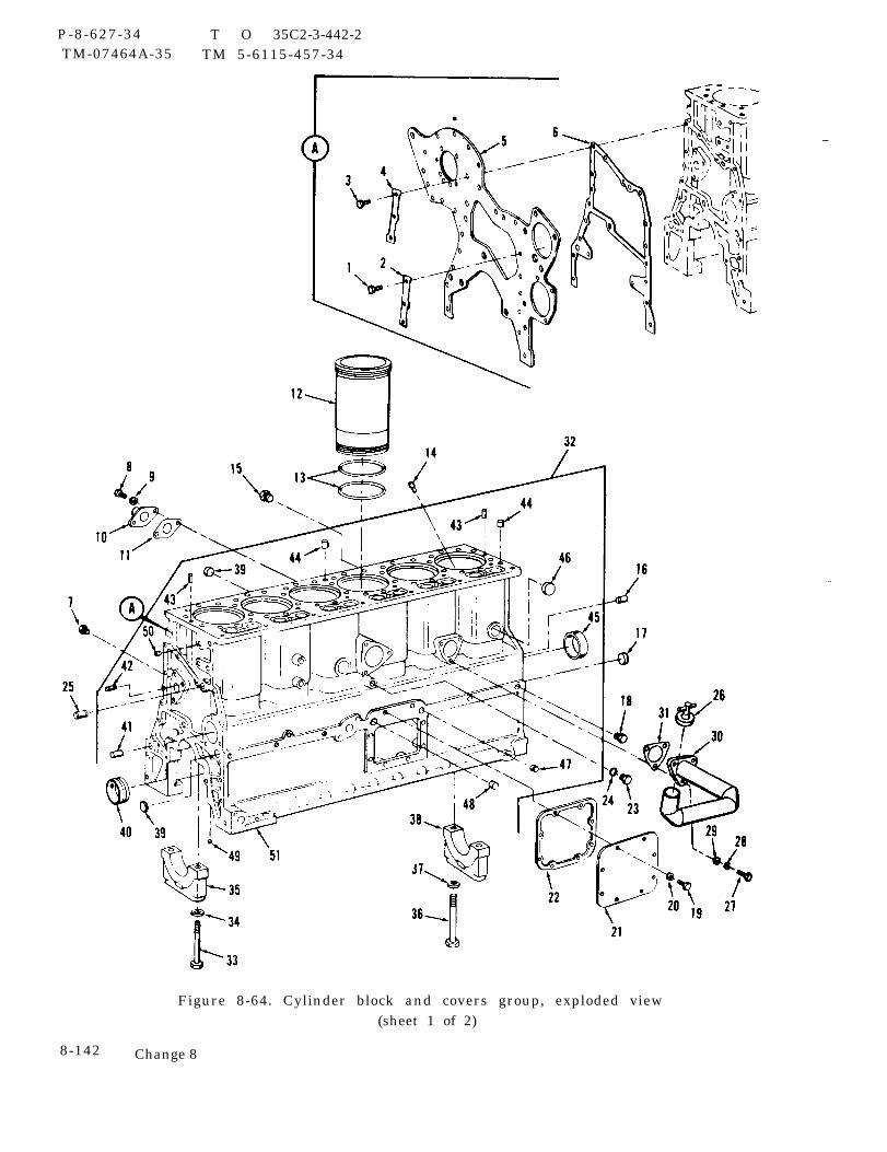
P-8-627-34 T O 35C2-3-442-2TM-07464A-35 TM 5-6115-457-34
Figure 8-64. Cylinder block and covers group, exploded view(sheet 1 of 2)
8-142 Change 8
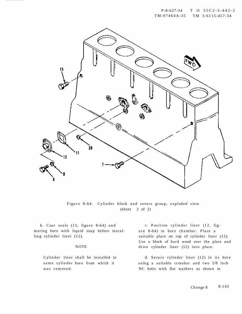
P-8-627-34 T O 3 5 C 2 - 3 - 4 4 2 - 2TM-07464A-35 TM 5-6115-457-34
Figure 8-64. Cylinder block and covers group, exploded view(sheet 2 of 2)
b. Coat seals (13, figure 8-64) and c. Position cylinder liner (12, fig-mating bore with liquid soap before instal- ure 8-64) in bore chamber. Place aling cylinder liner (12). suitable plate on top of cylinder liner (12).
Cylinder linersame cylinderwas removed.
Use a block of hard wood over the plate andNOTE drive cylinder liner (12) into place.
shall be installed in d. Secure cylinder liner (12) in its borebore from which it using a suitable crossbar and two 5/8 inch
NC bolts with flat washers as shown in
Change 8 8-143
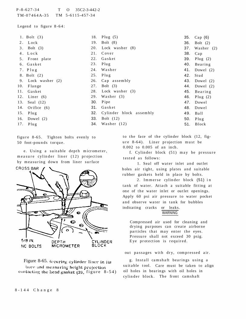
P-8-627-34TM-07464A-35
Legend to figure
1. Bolt (3)2 . Lock3. Bolt (3)4 . L o c k5. Front plate6. Gasket7 . P l u g8. Bolt (2)
T O 35C2-3-442-2TM 5-6115-457-34
8-64:
18.19.20.21.22.23.24.25.
9.10.11.12.13.14.15.16.17.
Lock washer (2)FlangeGasketLiner (6)Seal (12)Orifice (6)PlugDowel (2)Plug
26.27.28.29.30.31.32.33.34.
figure 8-65. Tighten bolts evenly to50 foot-pounds torque.
e. Using a suitable depth micrometer,measure cylinder liner (12) projectionby measuring down from liner surface
Plug (5)Bolt (8)Lock washer (8)CoverGasketPlugWasherPlugCap assemblyBolt (3)Lock washer (3)Washer (3)PipeGasketCylinder block assemblyBolt (12)Washer (12)
35.36.37.38.39.40.41.42.43.44.45.46.47.48.49.50.51.
Cap (6)Bolt (2)Washer (2)CapPlug (2)BearingDowel (2)StudDowel (2)Dowel (2)BearingPlug (2)DowelDowelBallPlugBlock
to the face of the cylinder block (12, fig-ure 8-64). Liner projection must be0.002 to 0.005 of an inch.
f. Cylinder block (51) may be pressuretested as follows:
1. Seal off water inlet and outletholes air tight, using plates and suitablerubber gaskets held in place by bolts.
2. Immerse cylinder block (51) i ntank of water. Attach a suitable fitting atone of the water inlet or outlet openings.Apply 60 psi air pressure to water pocketand observe water in tank for bubblesindicating cracks or leaks.
WARNING
Compressed air used for cleaning anddrying purposes can create airborneparticles that may enter the eyes.Pressure shall not exceed 30 psig.Eye protection is required.
out passages with dry, compressed air.
g. Install camshaft bearings using asuitable tool. Care must be taken to alignoil holes in bearings with oil holes incylinder block. The front camshaft
Figure 8-65.
f i g u r e 8 - 5 4 )
8 - 1 4 4 C h a n g e 8

P-9-TM-457-35 T. O. 35C2-3-442-2
bearing (40, figure 8-64) has two oil holesand are positioned in a vertical position.The remaining camshaft bearings (45) haveonly one hole and must be positioned withhole in a downward position.
h. Camshaft front bearing (40) must berecessed 0.06 of an inch from front face ofcamshaft bore, oil hole in bearing (40)must align with oil hole in cylinder block(51), and joint in bearing (40) must facecylinder block (51) centerline. Intermediatebearings (45) must be flush with front faceof bearing bore. Rear bearing (45) mustbe recessed 0.06 of an inch from rear faceof bore.
i. The maximum allowable clearancebetween camshaft journal and bearing thatis pressed into cylinder block is 0.008 inch.This clearance can be measured by using asuitable inside micrometer and check theI. D. of each camshaft bearing after it hasbeen pressed into the block. Use a suitable’outside micrometer and check the corre-sponding O. D. of each camshaft journal.Subtract the O. D. dimension of the cam-shaft journal from the I.D. of the camshaftbearing in the block. The result will bethe running clearance between the cam-shaft and the camshaft bearing. If theclearance exceeds O. 008 inch, replacecamshaft bearing.
j . Install cylinder block covers usingnew gaskets.
8-235. INSTALLATION.
a. Installation of cylinder block andcovers group is accomplished duringreassembly (paragraph 8-234).
b. Install crankshaft group and mainbearings (paragraph 8-227).
c .group
d.graph
e.group
f.graph
g.ani sm
h.graph
i.
TM-07464A-35 TM 5-6115-457-34
Install connecting rods and pistons(paragraph 8-219).
Install camshaft group (para-8-211).
Install flywheel and flywheel housing(paragraph 8-203).
Install cylinder head (para-8-195).
Install valve cover and valve mech-group (paragraph 8-187).
Install oil pump group (para-8-179).
Install oil pan group and relatedparts (paragraph 8-171).
j. Install exhaust manifold group(paragraph 8-163).
k. Install accessory drive group (para-graph 8-157).
1. Install fuel injection group (para-graph 8-148).
m. Install utility governor group(paragraph 8-140).
n. Install crankshaft pulley, damper,and timing gear cover group (para-graph 8-132).
o. Install governor actuator unit(paragraph 8-116).
p. Install hydraulic pump drive group(paragraph 8-107).
q. Install hydraulic pump (precise setsonly) (paragraph 8-99).
8-145
P-9-TM-457-35 T.O. 35C2-3-442-2TM-07464A-35 TM 5-6115-457-34
r. Install hydraulic tank (precise setsonly) (paragraph 8-92).
s. Install oil cooler group (para-graph 8-84).
t. Install fuel pump group (para-graph 8-68).
u. Install tachometer drive group(paragraph 8-60).
v. Install fan mounting group (para-graph 8-37).
w. Refer to Operator and Organiza-tional Maintenance Manual and install thefollowing:
1.
2.
3.
4.
5.
6.
7.
8.
9.
10.
Water pump group.
Alternator assembly.
Starter motor assembly.
Turbocharger group.
Day tank assembly.
Manual throttle control.
Lube oil filter group.
Ether atomizer.
Air cleaner assembly.
Engine wiring harness.
Section XXXI. ENGINE TEST AFTER OVERHAUL
8-236. GENERAL.
Following a complete overhaul orany major repair, involving the installationof piston rings, pistons, cylinder liners,or bearings, the engine should be run-inprior to release for service.
NOTE
Make sure all necessary adjust-ments have been performed andengine is fully serviced beforestarting test.
8-237. ENGINE ASSEMBLY RUN-IN ANDADJUSTMENTS.
Connect engine assembly to a suita-ble engine dynamometer equipped with acooling system and means of monitoringengine oil pressure, coolant temperature,and engine RPM.
8-146
a. PRE-RUN-IN CHECKS.
NOTE
Rotate engine in a clockwise direc-tion only, when viewing enginefrom front.
1. Manually rotate engine by apply-ing a 1-1/8 socket with extension handle tocrankshaft nut inside of damper.
2. Hold manual fuel shutdown leverin the closed rack or off position (fig-ure 8-66).
CAUTION
Do not crank starter motor for aperiod of more than 15 seconds.

Figure 8-66. Location of manual fuelshutdown lever
3. Turn engine over using starteruntil oil pressure builds up to 50 ± 10PSIG. Oil pressure should build upwithin 15 seconds.
4. Release manual fuel shutdownlever . Inspect all f luid systems forsigns of leakage.
b. OPERATIONAL TEST OF OVERSPEEDSHUTDOWN DEVICE.
1. Dead crank engine and deter-nine if solenoid plunger (2, Figure8-31A) pulls in (bottoms). I f the so le -noid plunger does not bottom or does nothave enough power to overcome the springtension, increase the measurementbetween the bushings (6 and 9, Figure3-31A) by adjusting bottom bushing.
2. Each time the engine isstarted, the solenoid plunger shouldpull in (bottom) and remain pulled in.This movement of the solenoid plungershould rotate the manual fuel rack levercounterclockwise to almost full onpos i t ion .
3.stopped or
Each time the engine isthe governor overspeed switch
P-9-TM-457-35 T.O. 35C2-3-442-2TM-07464A-35 TM 5-6115-457-34
is tripped, the solenoid plunger shouldrelease (move out of the solenoid) andremain released. This movement of thesolenoid plunger should rotate themanual fuel rack lever clockwise toa lmost fu l l o f f pos i t ion .
c . UTILITY GOVERNOR SPEED SETTINGADJUSTMENT. Adjust util ity governorlow and high speed stops as follows:
1. Loosen nut (5, figure 8-33)and turn low speed stop screw (4)counterclockwise until it is free ofspeeder spring (46).
CAUTIONDo not crank engine for morethan 15 seconds at a time.Permit starter to cool a mini-mum of three minutes betweencrankings.
2. Crank engine over withstarter and turn low speed stop screw(4) clockwise until governor outputshaft (13, f igure 8-33) rotates, openingfuel rack. Continue turning low speedstop screw until engine starts.
3. Permit engine to run a mini-mum of five minutes for warmup andadjust low speed stop screw (4) toobtain 800 RPM idle speed. Clockwiserotation will increase speed. Hold screwin position and tighten nut (5). RecheckRPM setting.
4. Rotate speed adjusting shaft(25) to maximum speed position and moni-tor engine RPM. Do not exceed 2300 RPM.
5. Engine high speed stopsetting should be 2250 RPM. To adjusthigh speed stop, loosen nut (20) androtate high speed stop screw (19) toobtain 2250 RPM when speed adjustingshaft (25) is in maximum speed position.Clockwise rotation will increase engineRPM setting. Tighten lock nut and re-check RPM setting.
6. If engine surges during
Change 2 8-147

P-9-TM-457-35 T.O. 35C2-3-442-2TM-07464A-35 TM 5-6115-457-34
warmup, remove governor cover (6) whileengine is running and move droop bracket(11) and pin (22) towards maximum posi-tion (away from governor ball headassembly (57).
7. When the engine is warmed up,adjust the droop bracket (11) and pin(22) as much towards minimun (toward ballhead assembly (57) as possible whilemaintaining steady speed. Manually movethe engine fuel linkage to cause atemporary engine speed increase. I f theengine returns to the original steadyspeed, the adjustment is satisfactory.If the engine speed does not settle out,increase droop slightly (approximately1/16 of an inch movement of bracket (11)and test again. Continue to increasethe droop until the operation is satis-factory .
d . RUN- IN. During run-in, monitoroil pressure and coolant temperature andcheck for unusual noise and vibrations.Discontinue run-in if oil pressure dropsbelow 20 psi, if coolant temperatureexceeds 217°F, or if unusual noise andvibrations occur.
1. Start engine and operate atidle speed (approximately 800 RPM), noload for 10 minutes.
NOTE
Three-quarter speeds are 1125RPM for 50 hertz operation,1350 RPM for 60 hertz operation,and 1500 RPM for 400 hertzoperation.
2. Operate engine at 3/4 ratedspeed and at 50 KW for fifteen minutes.
NOTE
Rated speeds are 1500 RPM for50 hertz operation, 1800 RPM for60 hertz operation, and 2000 RPMfor 400 hertz operation.
3. Operate engine at rated speedand at 100 KW for 30 minutes.
NOTE
Required tightness for cylinderhead bolts after test to be 150foot-pounds minimum.
4. Shut down engine and tightenall bolts and nuts. Tighten cylinderhead bolts, refer to f igure 8-56.
5. Inspect engine for leakage.
8-148 Change 2
P-8-627-34 T O 35C2-3-442-2TM-07464A-35 TM 5-6115-457-34
CHAPTER 9
BASE ASSEMBLY, STOWAGE TOOL BOX, AND FUEL TANK REPAIRINSTRUCTIONS
Section I. BASE ASSEMBLY
9-1. GENERAL.The base is a welded structure that
supports the generator set and the fuel tank.It consists of tubular cross members, fork-lift openings, and ground stud The engineand generator are mounted to the base, theengine front support and generator mount-ing provide a three point support systemfor the engine and generator. A batteryand rollout tray assembly is mounted inthe front end of the base and a stowage toolbox in the rear end. Each end of the baseis equipped with a tubular cross memberwhich permits connection of a towingdevice for skidding the generator set, forshort distance moving. Openings are pro-vided in the base to permit the generatorset to be lifted by a forklift, The base isequipped with a split-stud terminal to per-mit electrical grounding of the set.
9-2. R E M O V A L
Remove the following assembliesfrom the base assembly:
a. Refer to Operator and OrganizationalM aintenance Manual and perform thefollowing:
1. Drain coolant from the radiator.
2. Drain fuel from the day andfuel tank.
3. Drain lubricating oil from enginecrankcase.
WARNING
When disconnecting bat teries (lead-acid) disconnect negative terminalf i r s t .
4. Remove batteries and rollouttray,
b. Remove housing as specified inparagraph 3-2.
c . Remove generator as specified inparagraph 2-7.
ci. Remove engine as specified inparagraph 2-8.
9-3. DISASSEMBLY .
Refer to figure 9-1 and disassemblebase assembly in the order of index n u m -
bers assigned. Pay particular attentionto the following:
a. Tag hoses (1, 2, 3, and 4) withlocation prior to removal
b. Disassemble stowage tool box (19)as specified in paragraph 9-11.
c. Remove fuel tank (53) through stow-age tool box opening. Disassemble fueltank (53) as specified in paragraph 9-19.9-4. C LEANING.
WARNING
Cleaning Solvents are flammable andmoderately toxic to skin, eyes andrespiratory tract. Eye and skinprotection required. Good generalventilation is normally adequate.
a. Clean parts with an approved clean-ing solvent and dry thoroughly. If neces- -sary, remove hand deposits using a bristlebrush.
Change 8 9 -1
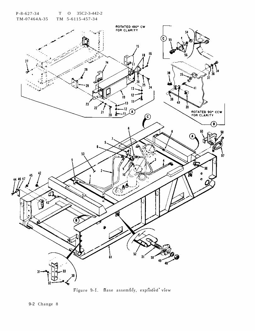
P-8-627-34 T O 35C2-3-442-2TM-07464A-35 TM 5-6115-457-34
Figure 9-1. Base assembly, exploded view
9-2 Change 8
P - 8 - 6 2 7 - 3 4 T OT M - 0 7 4 6 4 A - 3 5 T M
3 5 C 2 - 3 - 4 4 2 - 25-6115-457-34
Legend to figure 9-1:
1.
2 .3.4.5.6.7.8.9.
10.11.12.13.14.15.16.17.
HoseHoseHoseHoseElbow (5)Tee (2)CrossNutNippleWasherScrew (4)Lock washer (4)Washer (4)Upper filler panelUpper filler panelScrew (4)Nut (8)
22.23.24.25.26.27.28.29.30.31.32.33.34.35.36.37.38.
Washer (1)Filler panelScrew (2)Washer (2)BracketScrew (4)Nut (4)Rear tank stop (2)Screw (6)Nut (6)Washer (12)Bracket (2)Screw (2)Nut (2)WasherHeater exhaust plateElbow (2)
18. Washer (4) 39. Elbow19. Stowage tool box 4 0 . C r o s s20. Screw (2) 41. Nipple21. Lock washer (2)
b. Clean sealant from pipe threadsusing a wire brush.
9-5. INSPECTION.
a. Inspect parts for cracks, breaks,and defective welds.
CAUTION
If hose blockage is due to deteri-oration of internal portion of hose,hose shall be replaced.
b. Check hose for blockage, chafing,and condition of end fittings.
c. Inspect bevel washer for deteriora-tion, cracks, and permanent set in washercontact surface.
d. Inspect threads for damage.
42. Plug43. Elbow44. Screw (2)45. Nut (2)46. Washer (2)47. Ground rod plate48. Nut (4)49, Washer (4)50. Bevel washer (8)51. Tee bolt (4)52. Strap (2)53. Fuel tank assembly54. Nut55. Ground stud
*56. Lock washer (3)57. Auxiliary fuel hose58 . Screw59. Nut60. Auxiliary fuel hose mount61 . Base
* Applicable to serial numbers1 through 130
e. Inspect support brackets fordistortion.9-6. REPAIR.
WARNING
Welding operations produce heat,highly toxic fumes, injuriousradiation, metal slag and air-borne particles. Welding gog-gles, with proper tinted lenses,apron or jacket and welder 'sboots are required.
a. Weld cracks, breaks, and defectivewelds.
b. Repair damaged threads by chasingusing a suitable die or tap.
c. Straighten distorted support brackets.d. Remove damaged paint with a suitable
scraper . Blend in edges, prime, and paintdamaged areas.
9 -7 . REASSEMBLY.
Change 8 9-3
P-8-627-34 T O 35C2-3-442-2TM-07464A-35 TM 5-6115-457-34
Refer to figure 9-1 and reassemblebase assembly in the reverse order ofindex numbers assigned. Pay particularattention to the following:
a. Reassemble fuel tank as specified inparagraph 9-23.
b. Reassemble stowage tool box asspecified in paragraph 9-15.
c. Apply thread sealing compound con-forming to Military Specification MIL-S-45180, type III, to pipe threads prior toinstallation.
d. Install fuel tank (53) in base (61)through stowage tool box opening, makingsure that fuel tank needle valve is towardopening. Push tank against front stops,hold tank in position, and install rear tankstops so that stops hold tank in position.
e. Install bevel washers (50) with thickends on top.
f. Install and align stowage tool box (19)so that it is flush with base (61).
9 -8 . INSTALLATION.
Install the following assemblies onthe base assembly.
a. Install engine as specified in para-graph 2-8.
b. Install generator as specified inparagraph 2-7.
c. Install housing as specified in para-graph 3-6.
WARNING
When connecting lead-acid batteriesconnect positive terminal first.
d. Refer to Operator and OrganizationalMaintenance Manual and perform thefollowing:
1. Install batteries and rollout tray.2. Service engine crankcase, fuel
tank, and radiator.
Section II. STOWAGE TOOL BOX
9-9. GENERAL.
The stowage tool box is utilized forstorage of tools and miscellaneous equip-ment required for generator set operation.The box consists of a hinged cover, seal,and box. The cover covers the box openingand the seal prevents moisture and dirtentering the box.
9-10. REMOVAL.
Refer to figure 9-1 and remove stow-age tool box from base by removing screws(16), nuts (17), and washers (18).
9-11. DISASSEMBLY
Refer to figure 9-2 and disassemblethe stowage tool box in the order of indexnumbers assigned.
9 - 1 2
a.cloth.
CLEANING.
Clean seal with a clean lint-free
Cleaning Solvents are flammable andmoderately toxic to skin, eyes andrespiratory tract. Eye and skinprotection required. Good generalvent ilat ion is normally adequate.
b. Clean metal parts in an approvedcleaning solvent and dry thoroughly.
9 -4 Change 8

P-8-627-34 T O 35C2-3-442-2TM-07464A-35 TM 5-6115-457-34
Figure 9-2. Stowage tool box,exploded
Legend to figure 9-2:
1. Seal2. Nut (5)3. Washer (10)
9-13. INSPECTION.
view
4. Screw (5)5 . C o v e r6. Stowage box
a. Inspect sheet metal parts for cracks,dents, distortion, and worn hinges.
b. Inspect seal for cuts, cracks, anddeterioration.
c .
9-14.
a.using
Inspect paint for damage.
REPAIR.
Straighten dented and distorted partssuitable tools.
WARNING
Welding operations produce heat,highly toxic fumes, injuriousradiation, metal slag and air-borne particles. Welding gog-gles, with proper tinted lenses,apron or jacket and welder’sboots are required.
b. Weld cracks.
c. Remove damaged paint with asuitable scraper. Blend in edges, prime,and paint damaged areas.
9-15. REASSEMBLY.
Refer to figure 9-2 and reassemblethe stowage tool box in the reverse order ofthe numbers assigned. Pay particularattention to the following:
a. Align cover (5) so that seal (1) makesfull contact on stowage box (6) prior totightening nuts (2).
9-16. INSTALLATION.
Refer to figure 9-1 and installstowage-tool box assembly in base assem-bly. Pay particular attention to thefollowing:
a. Install stowage tool box and securewith screws (16), nuts (17), and washers(18), leaving nuts finger tight.
b. Align stowage tool box cover so thatit is flush with base assembly and tightennuts.
Change 8 9 -5
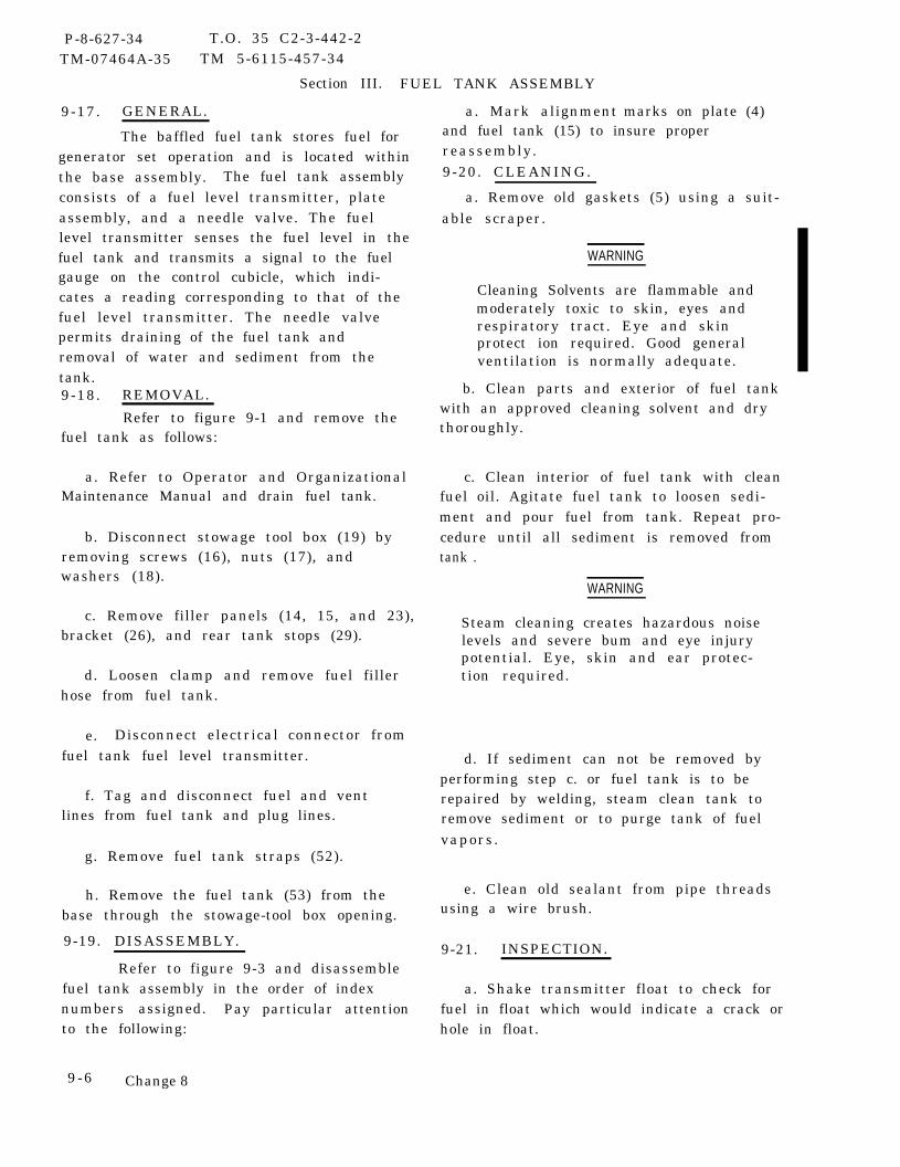
P-8-627-34 T.O. 35 C2-3-442-2TM-07464A-35 TM 5-6115-457-34
Section III. FUEL TANK ASSEMBLY
9-17. GENERAL.
The baffled fuel tank stores fuel forgenerator set operation and is located withinthe base assembly. The fuel tank assemblyconsists of a fuel level transmitter, plateassembly, and a needle valve. The fuellevel transmitter senses the fuel level in thefuel tank and transmits a signal to the fuelgauge on the control cubicle, which indi-cates a reading corresponding to that of thefuel level transmitter. The needle valvepermits draining of the fuel tank andremoval of water and sediment from thetank.9-18. REMOVAL.
Refer to figure 9-1 and remove thefuel tank as follows:
a. Refer to Operator and OrganizationalMaintenance Manual and drain fuel tank.
b. Disconnect stowage tool box (19) byremoving screws (16), nuts (17), andwashers (18).
c. Remove filler panels (14, 15, and 23),bracket (26), and rear tank stops (29).
d. Loosen clamp and remove fuel fillerhose from fuel tank.
e. Disconnect electrical connector fromfuel tank fuel level transmitter.
f. Tag and disconnect fuel and ventlines from fuel tank and plug lines.
g. Remove fuel tank straps (52).
h. Remove the fuel tank (53) from thebase through the stowage-tool box opening.
9-19. DISASSEMBLY.
Refer to figure 9-3 and disassemblefuel tank assembly in the order of indexnumbers assigned. Pay particular attentionto the following:
9 -6 Change 8
a. Mark alignment marks on plate (4)and fuel tank (15) to insure properreassembly.9-20. CLEANING.
a. Remove old gaskets (5) using a suit-able scraper.
WARNING
Cleaning Solvents are flammable andmoderately toxic to skin, eyes andrespiratory tract. Eye and skinprotect ion required. Good generalventilation is normally adequate.
b. Clean parts and exterior of fuel tankwith an approved cleaning solvent and drythoroughly.
c. Clean interior of fuel tank with cleanfuel oil. Agitate fuel tank to loosen sedi-ment and pour fuel from tank. Repeat pro-cedure until all sediment is removed fromtank .
WARNING
Steam cleaning creates hazardous noiselevels and severe bum and eye injurypotential. Eye, skin and ear protec-tion required.
d. If sediment can not be removed byperforming step c. or fuel tank is to berepaired by welding, steam clean tank toremove sediment or to purge tank of fuelvapors.
e. Clean old sealant from pipe threadsusing a wire brush.
9-21. INSPECTION.
a. Shake transmitter float to check forfuel in float which would indicate a crack orhole in float.
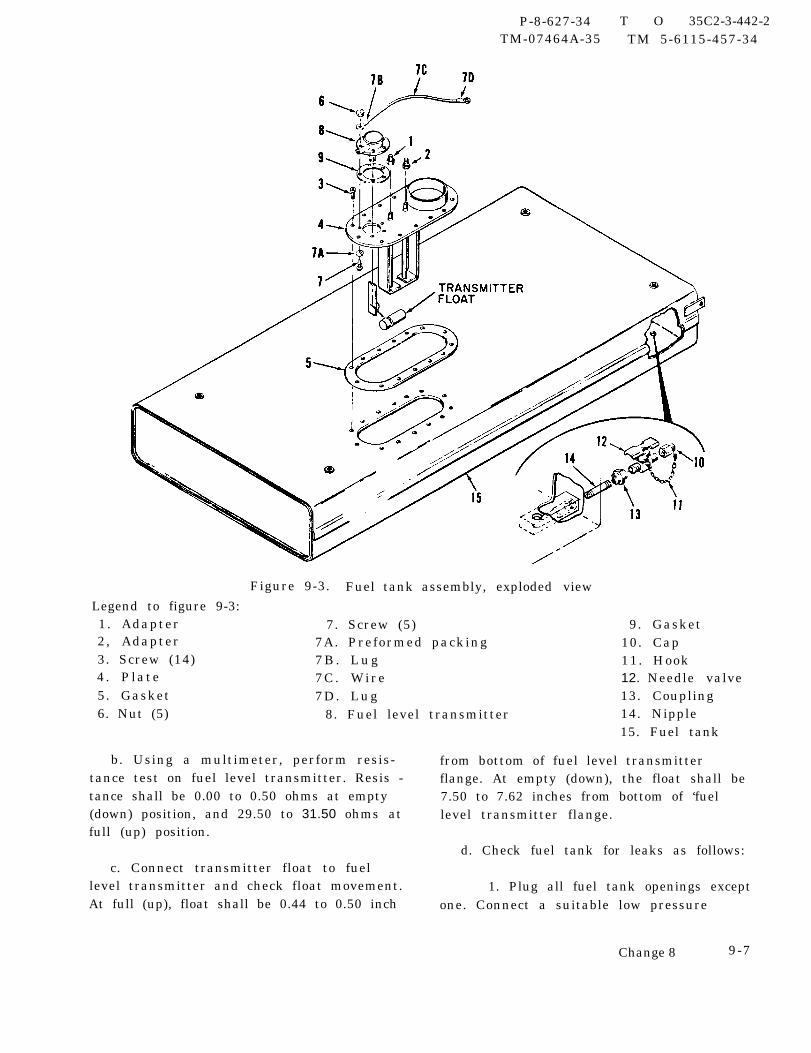
P-8-627-34 T O 35C2-3-442-2TM-07464A-35 TM 5-6115-457-34
Figure 9-3. Fuel tank assembly,Legend to figure 9-3:1. Adapter 7. Screw (5)2, Adapter 7A. Preformed packing3. Screw (14) 7 B . L u g4. Plate 7C. Wire5. Gasket 7D. Lug
exploded view
9. Gasket10. Cap11. Hook12. Needle valve13. Coupling
6. Nut (5) 8. Fuel level transmitter 14. Nipple15. Fuel tank
b. Using a multimeter, perform resis- from bottom of fuel level transmittertance test on fuel level transmitter. Resis - flange. At empty (down), the float shall betance shall be 0.00 to 0.50 ohms at empty 7.50 to 7.62 inches from bottom of ‘fuel(down) position, and 29.50 to 31.50 ohms at level transmitter flange.full (up) position.
d. Check fuel tank for leaks as follows:c. Connect transmitter float to fuel
level transmitter and check float movement. 1. Plug all fuel tank openings exceptAt full (up), float shall be 0.44 to 0.50 inch one. Connect a suitable low pressure
Change 8 9-7

P-8-627-34 T O 35C2-3-442-2TM-07464A-35 TM 5-6115-457-34
regulated air supply to remaining fueltank opening.
2. Slowly apply 0.5 PSI air pressureto fuel tank.
3. Apply a soapy water solution tofuel tank and check for bubbles that wouldindicate leaks. Mark leaks, if any.
4. Reduce air pressure to zero.Remove test equipment from tank. Removesoapy water solution from fuel tank.
e. Connect a suitable pressure supplyand gage to needle valve. Turn on pressuresupply and bleed test equipment by openingvalve. Close valve. Slowly apply 150 PSIand check for external and internal leakage.Reduce pressure to zero and remove testequipment from valve.
f. Check transmitter float linkage fordistortion.
g. Inspect for damaged threads.h. Inspect paint for damage.
9-22. REPAIR.
WARNING
Do not weld fuel tank unless tankhas been steam cleaned and it isfilled with water.
a. Repair cracks and holes in fuel tankas follows:
WARNING
Steam cleaning creates hazardous noiselevels and severe bum and eye injurypotential. Eye, skin and ear protec-tion required.
1. Steam clean tank to remove fuelvapors.
2. Fill tank with water.
9 -8
WARNING
Welding operations produce heat,highly toxic fumes, injuriousradiation, metal slag and air-borne particles. Welding gog-gles, with proper tinted lenses,apron or jacket and welder'sboots are required.
3. Weld crack or holes. Large
damaged area may be repaired by weldinga suitable patch over area.
4. Remove water from fuel tank anddry interior of tank thoroughly.
5. Check repaired areas for leakageas specified in paragraph 9-21, step d.
b. Straighten distorted transmitter floatlinkage using suitable tools.
c. Repair damaged fuel tank threadsusing a suitable tap. Fill tap grooves withgrease to catch cuttings. Remove allcuttings from fuel tank.
d. Remove damaged paint with a suitablescraper. Blend in edges, prime, and paintdamaged areas.
9-23. REASSEMBLY.
Refer to figure 9-3 and reassemblefuel tank assembly in the reverse order ofindex numbers assigned. Pay particularattention to the following:
—
a. Apply thread sealing compound con-forming to Military Specification MIL-S-45180, type III, to pipe threads prior toreassembly.
b. Make sure alignment marks on fueltank (15) and plate (4) are aligned when plateis installed.
9-24. INSTALLATION.
Refer to figure 9-1 and install thefuel tank as follows:
a. Install fuel tank (53) in base (61)through stowage tool box opening, makingsure needle valve is toward opening. Posi-tion and hold tank against forward stopsand install rear tank stops (29), bracket(26), and filler panels (14, 15, and 23).
Change 8
P-9-TM-457-35 T.O. 35C2-3-442-2TM-07464A-35 TM 5-6115-457-34
b. Install and secure fuel tank straps d. Connect fuel filler hose to fuel tank(52), making sure that thick end of bevel and secure with clamp.washers (50) are on top.
e. Install stowage tool box (19).c. Connect fuel and vent lines to fuel
tank. Connect electrical connector to f. Refer to Operator and Organizationalfuel level transmitter. Maintenance Manual and service fuel tank.
9-9/(9-10 blank)

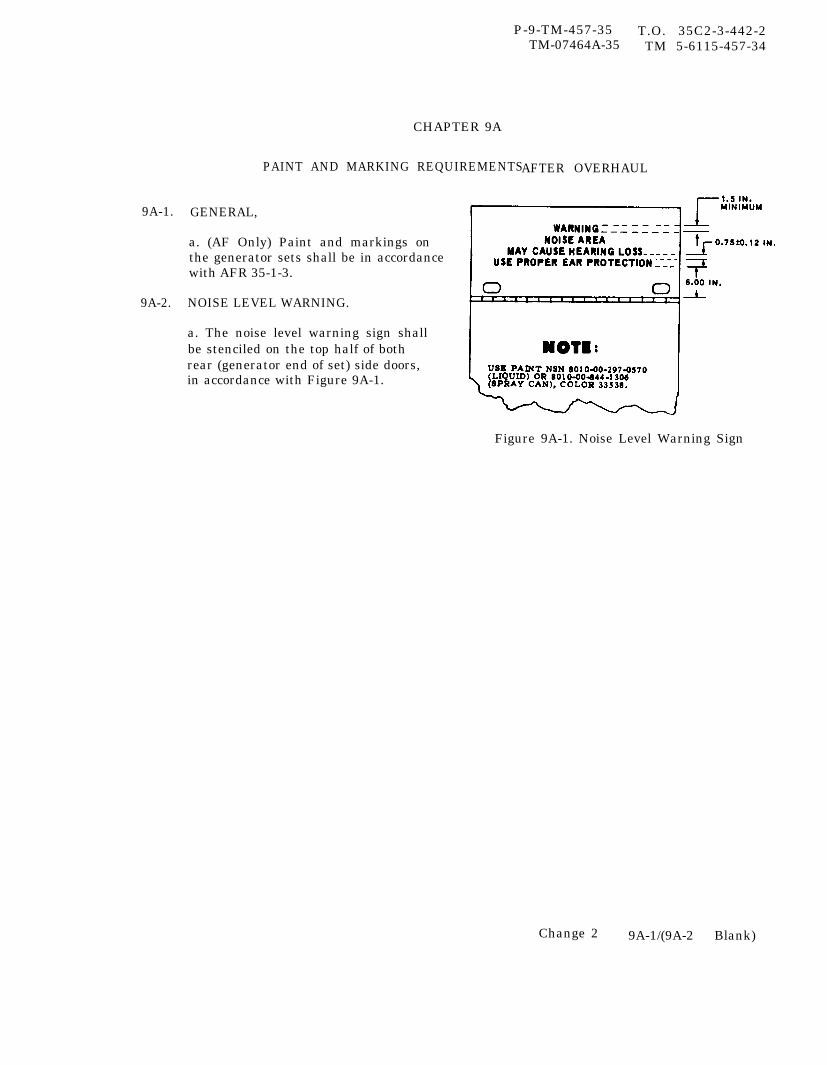
P-9-TM-457-35 T.O. 35C2-3-442-2
9A-1.
9A-2.
CHAPTER 9A
PAINT AND MARKING REQUIREMENTS
TM-07464A-35 TM 5-6115-457-34
AFTER OVERHAUL
GENERAL,
a. (AF Only) Paint and markings onthe generator sets shall be in accordancewith AFR 35-1-3.
NOISE LEVEL WARNING.
a. The noise level warning sign shallbe stenciled on the top half of bothrear (generator end of set) side doors,in accordance with Figure 9A-1.
Figure 9A-1. Noise Level Warning Sign
Change 2 9A-1/(9A-2 Blank)

P-8-627-34 T. O. 35C2-3-442-2TM-07464A-35 TM 5-6115-457-34
CHAPTER 10
TEST AFTER OVERHAUL
Section I. PRETEST CHECKS AND ADJUSTMENTS
10-1. GENERAL. 10-2. PRETEST CHECKS AND— — . .ADJUSTMENTS— .
Pretest checks and adjustmentsa. Perform engine assembly run-in and
shall be performed prior to test after over-adjustments paragraph 2-237.
haul cf the generator set. To perform the b. Perform alignment of electric gov-pretest checks and adjustments, proceed as ernor actuator unit (precise generator setsfollows : only), refer to paragraph 6-246.
Section II. TEST AFTER OVERHAUL
10-3. GENERAL.
All tests should be performed underthe following conditions:
a. All tests shall be made at ambienttemperatures.
b. AII test instrumentation will be inaccordance with Military StandardizationHandbook MIL-HDBK-705 and MilitaryStandard MIL-ST D-705, as applicable.
c . Temperatures will be measured bymeans of appropriately located thermo-couples and properly calibrated read-outdevices. Thermocouples will be insulatedfrom contact with other metals. Tempera-tures will be recorded in degrees Farenheitor Centigrade, depending on the instrumentscale, but will beheit in all cases.be measured by a
reduced in degrees Faren-Barometric pressure willmercurial barometer,
which will be corrected for the tempera-ture of the scale, the mercury for vaporpressure and for the location of the barom-eter with regard to altitude and latitude.Ameroid barometers will not be used.
d. Pretest adjustments shall be com-pleted prior to starting test procedures,refer to paragraph 10-2.
e . Operational procedures required insupport of the individual test specifiedherein shall be performed as outlined in theOperator and Organizational MaintenanceManual.
f. Record test results as required bylocal instructions.
10-4. START AND STOP TEST .
Test the generatorof abnormal start and stop
set for evidenceconditions by
Change 8 10-1

P -8 -627-34 T.O. 35C2-3-442-2TM-07464A-35 TM 5-6115-457-34
performing the start and shutdown proce-dures as outlined in the Operator andOrganizational Maintenance Manual. Thegenerator set should be capable of startingpromptly at any ambient temperatures inthe range of +125°F to -25°F withoutexternal heat.
a. Operate generator set at ratedspeed, voltage, and no-load for 15 minutes,then discontinue operation.
b. Operate generator set at ratedspeed, voltage, and no-load for 15 minutes.Discontinue operation by de-energizing theDC circuit breaker.
c. Repeat start-stop procedures twoadditional times. If any malfunction isnoted, make necessary repairs before sub-jecting the generator set to the remainingtests.
10-5. INSTRUMENT CHECK.
Test the generator set ammeter,voltmeter, and frequency meter for accu-racy by comparing them with masterinstruments.
NOTE
This test shall be done in conjunc-tion with other tests.
a. Adjust the meters to zero as outlinedin the Operator and Organizational M ainte -nance Manual.
NOTE
This test shall be repeated at allrated frequencies and at voltagesof 120/208 and 240/416.
b. Connect the generator set toa variable load. Operate the generator
set and vary the load as indicated instep c.
c. Record the master instrument read-ing and the readings of the meters at thefollowing percentages of rated load: 1/4,2 /4 , 3 /4 , 4 /4 , and 5 /4 percent .
d, The accuracy of the instrumentsshould be such that the maximum errorwill not exceed the following parameters:
1. Voltmeter - 2-1/2 percent of fullscale except not greater than 5 volts be-tween 115 and 125 volts, not greater than10 volts between 200 and 250 volts.
2. Ammeter -2 percent of fullscale.
3. Kilowatt meter -2 percent offull scale.
4. Frequency meter - 0.25 percentat any point on scale.
10-6. LOW OIL PRESSURE TRIP TEST .
Perform this test under an arti-ficially produced condition as follows:
a. Install a test adapter with a gage formeasuring pressure to the lubricating oilpressure switch, a valve for shutting offflow to pressure switch, and a valve forbleeding off pressure. Operate the gener-ator set at rated speed and no load.
b. Purge air from system through thebleed valve. Close valve and record oper-ating pressure.
CAUTION
If unit fails to shut down when oilpressure is below 15 ± 3 PSI, thetest should be discontinued andcorrective action taken.
10-2 Change 8
P-9-TM-457-35 T.O. 35C2-3-442-2TM-07464A-35 TM 5-6115-457-34
c. Close pressure shutoff valve andslowly bleed pressure from system until thegenerator set shuts down and LOW OILPRESSURE fault locator indicator illumi-nates. Record pressure. The generatorset shutdown and LOW OIL PRESSUREfault locator indicator shall occur simul-taneously at 15 ± 3 PSI.
d. Remove test components from gen-erator set.
10-7. HIGH COOLANT TEMPERATURETRIP TEST.
Perform the high coolant tempera-ture trip test as follows:
a. Remove coolant temperature trans-mitter from front of engine thermostathousing and install thermocouple in itsplace.
CAUTION
If the engine fails to shut down when222 °F is reached, drop the load andunblock the radiator to cool engine.
b. Operate unit at rated speed, blockair passing through the radiator and applysufficient load to raise the unit temperatureto the trip point of 217 ± 3°F. The highcoolant temperature switch shall actuate at214° to 220° F, causing the load contactor toopen, the engine to shut down, and theCOOLANT HIGH TEM P fault indicator toilluminate.
c . Remove the rmocouple and replacecoolant temperature transmitter.
10-8. LOW FUEL LEVEL TRIP TEST.
Perform the low level trip test asfollows :
a. Energize DC circuit breaker andposition start-run-stop switch to RUN tofill day tank. When day tank is full, theelectric fuel transfer pumps will changepitch indicating they are bypassing fuelinternally.
b. Disconnect electrical connector fromday tank fuel solenoid valve.
c. Operate the generator set at ratedvoltage, frequency and at full load untilday tank float valve switch actuates, causingthe load contactor to open, the engine toshut down and the NO FUEL fault indicatorto illuminate.
d. Start generator set and as soon asengine starts, lift red battle short switchguard and position switch to ON. Operategenerator set for one minute at rated volt-age, frequency and fuel load. Generatorset should operate for one minute withoutrunning out of fuel. Shut down generatorset, but do not de-energize DC circuitbreaker.
e. Connect electrical connector to daytank fuel solenoid valve. Position start-run-stop to RUN and fill day tank. Positionbattle short switch and guard to OFF posi-tion and de-energize DC circuit breaker.
10-9. SHORT CIRCUIT TRIP TEST.
Perform the short circuit trip testas follows:
a. Connect a load bank capable of sup-plying 450 percent of rated current to thegenerator set load terminals. Reactiveload may be used to obtain the requiredcurrent.
b. Adjust short circuit load to draw350 percent of rated current.
c. Operate the generator set at ratedvoltage, rated speed, and rated load.
d. Apply short circuit load of 350 percentrated current (total of 450 percent of ratedcurrent) to the generator set in one step.
10-3

P-9-TM-457-35 T.O. 35C2-3-442-2TM-07464A-35 TM 5-6115-457-34
CAUTION
If output contactor fails to open,instantaneously remove shortcircuit.
e. The output contactor shall actuateinstantaneously when current exceeds425 ± 25 percent of rated current, causingthe SHORT CIRCUIT fault indicator toilluminate.
10-10. OVER AND UNDER VOLTAGETRIP TEST .
Perform the over and under voltagetrip tests as follows:
a. Connect a voltmeter between T9 andT12 of the monitored 120 volt phase.
b. Operate the generator set at no load,rated frequency, and rated voltage with loadcontactor closed.
c. OVER VOLTAGE TRIP TEST.Raise voltage until the engine shuts down andOVER VOLT fault locator indicator illumi-nates. Record the voltage. The over volt-age relay shall actuate when the voltageexceeds 153 ± 3 volts for more than200 milliseconds causing the load contactorto open within 1 second, the engine to shut-down and the OVER VOLT fault indicator toilluminate.
d. UNDER VOLTAGE TRIP TEST(PRECISE GENERATOR SETS ONLY),
1. Repeat step b. , lower voltageuntil the UNDER VOLT fault locator indi-cator illuminates. Record voltage. Theload contactor shall open immediately whenvoltage drops below 48 volts, causing theUNDER VOLT fault locator indicator toilluminate.
2. Repeat step b. , reduce voltagebetween 65 to 103 volts. The load contactorshall open in 6 ± 2 seconds, causing theUNDER VOLT fault locator to illuminate.
3. Repeat steps b. , 4. 1., and 4.2.two additional times.
10-11.
test as
UNDER FREQUENCY TRIP TEST(PRECISE GENERATOR SETSONLY).
Perform the under frequency tripf ollows:
a. Operate the generator set at no load,rated frequency, and rated voltage with loadcontactor closed.
b. Lower frequency until the UNDERFREQ fault locator indicator illuminates.The load contactor should open, causing theUNDER FREQ fault locator indicator toilluminate when the frequency drops to thevalues indicated below:
50 hertz operation - 46 ± 1 hertz
60 hertz operation - 55 ± 1 hertz
400 hertz operation - 370 ± 5 hertz
10-12. PHASE SEQUENCE CHECK.
Perform the phase sequence checkas follows:
a. Connect a suitable phase sequenceindicator to generator set load terminals asfollowing rotation of set.
b. Operate generator set and determinephase sequence by observing the indicator.The AC output connections shall be of theproper rotation, compare test results withthe AC system simplified schematic, fig-ure 1-4 for 50/60 hertz generator sets orfigure 1-5 for 400 hertz generator sets.
10-4
P-9-TM-457-35 T.O. 35C2-3-442-2TM-07464A-35 TM 5-6115-457-34
c. If generator set is equipped with anAC output receptacle box, check phasesequence of each receptacle for properrotation.
10-13. PHASE BALANCE TEST.
Perform the phase balance test asfollows :
a. Operate generator set at 240/416volts, rated speed and no load. Adjustvoltage as necessary until average voltageis 240 volts line to neutral. Measure eachline to neutral voltage to the nearest0O.1 voltat load terminals and record.
NOTE
Load must be balanced. Record allthree line to neutral voltages andobtain the average value. Reduceor raise voltage as required, bythe amount that the previouslycomputed average differs fromrated voltage. The average of thethree phase voltages should beequal to rated voltage.
b. Measure and record each of the lineto neutral voltages.
c . The maximum difference in the threeline-to-neutral voltage under all balancedloads at rated voltage and speed shall notexceed one percent rated voltage and speedshall not exceed one percent rated line-to-neutral voltage. That is, no phase voltageshall differ from the average by more than1.2 volts.
d. Formula to compute percentage ofvoltage unbalance is as follows:
100 x maximum deviation
(T1-N) + 3 (T2-N)
from average
+ (T3-N)
10-14,
range
a.
FREQUENCY ADJUSTMENTRANGE TEST.
Perform the frequency adjustmenttest as follows:
PRECISE GENERATOR SETS.
1. Operate generator set at full load.
2. Slowly adjust frequency from 58 to62 hertz (for 50/60 hertz operation) and390 to 420 hertz (for 400 hertz operation).Clockwise rotation shall increase frequency.Voltage shall remain at rated value through-out the frequency range. The frequencyrheostat shall allow frequency adjust overthe following ranges at any load:
50 hertz operation -
60 hertz operation -
400 hertz operation -
Between 48 and 52hertz but not below45 hertz.
Between 58 and 62hertz but not above65 hertz.
Between 390 and 420hertz but not below370 hertz or above430 hertz,
b. UTILITY GENERATOR SETS.
1. Operate generator set at fullspeed by adjusting manual speed control.Record frequency.
2. Turn manual speed control knob90 degrees. Record frequency. A 90 degreeturn of the manual speed control knob shallnot cause a change in frequency greaterthan 1 percent.
3. Repeat step 2. a number oftimes, both raising and lowering frequency.
10-5

P-9-TM-457-35 T.O. 35C2-3-442-2TM-07464A-35 TM 5-6115-457-34
4. Rapidly decrease engine speed byturning the manual speed control knob to itslowest possible speed obtainable. Increaseengine speed by turning the manual speedcontrol knob to its maximum speed obtain-able, The manual speed control shall beadjustable from idle (approximately1400 RPM) to 2250 ± 25 RPM.
10-15. REGULATOR RANGE TEST.
Perform the regulator range test asfollows:
a. Operate generator set at 240/416 voltsat full load. Adjust voltage for 480 volts(for 50/60 hertz operation) and 458 volts (for400 hertz operation). Record voltage andspeed. Adjust voltage for 395 volts (for50/60 or 400 hertz operation. Record volt-age and speed.
b. Reduce load to zero. Adjust voltagefor maximum attainable voltage. Recordvoltage and speed. Adjust voltage for mini -mum voltage attainable. Record voltage andspeed.
c. The generator set shall operate atany load between no load and full load at thefollowing line-to-line voltages:
1. Between 380 and 426 volts for50 hertz operation.
2. Between 375 and 489 volts for60 hertz operation.
3. Between 395 and 458 volts for400 hertz operation.
10-16. EXCITER REGULATOR AND GOV-ERNOR STABILITY AND TRANSIENTRESPONSE TEST .
Perform the exciter regulator andgovernor stability and transient responsetest as follows:
a. Operate generator set at 240/416 voltsat full load until temperatures havestabilized.
b. Drop and apply the load a sufficientnumber of times to make sure that the volt-age and frequency are within the prescribedband .
c . The governor shall be set at isochron-ous regulation for precise generator setsand at 2.9 to 3 percent for uti Iity generatorsets. Adjust voltage to rated value. Nofurther adjustments shall be made duringthis test. The recorders in the test circuitare now started.
d. Perform the following load switchingsequence starting with full load, waitingapproximately 30 seconds between each loadchange:
Adjust load to full load and starting fromno load: full load - 0 - full load - 0 -full load -0
Adjust load to 3/4 load and starting fromn o l o a d : 3 / 4 - 0 - 3 / 4 - 0 - 3 / 4 - 0
Adjust load to 1/2 load and starting fromn o l o a d : 1 / 2 - 0 - 1 / 2 - 0 - 1 / 2 - 0
Adjust load to 1/4 load and starting fromno load: 1/4 - 0 - 1 / 4 - 0 - 1 / 4 - 0
10-6

P-9-TM-457-35 T.O. 35C2-3-442-2TM-07464A-35 TM 5-6115-457-34
e. The frequency and voltage requirements are indicated below:
Frequency Prec ise utility
Steady State Band (30 see) 0.5 percent 2 percent
Recovery Time 3 seconds 4 seconds
Overshoot and Undershoot (Apply Full Load) 6.0 percent 4 percent
Regulation 0.25 percent 2 to 3 percent
Voltage Prec ise Utility
Steady State Band (30 sec) 1.0 percent 2 percent
Regulation 1.0 percent 3 percent
10-17. LONG TERM STEADY STATESTABILITY TEST .
Perform the long term steady statestability test as follows:
a. Operate the generator set at ratedspeed, voltage, and full load for a period offour hours.
b. Record voltage and frequency at startand f ini ah of the four ham period. The longterm steady deviation at constant loadsfrom no load to full load shall be as follows:
1. The bandwidth shall remain within1 percent (for precise generator sets) and3 percent (for utility sets) of the ratedfrequency.
2. The bandwidth shall remain within2 percent (for precise generator sets) and4 percent (for utility generator sets) of therated voltage.
10-18. PARALLEL OPERATION ANDREVERSE POWER TEST.
a. PARALLEL OPERATION. Performthe parallel operation test as follows:
1. Operate two or more generatorsets in parallel at 240/416 volts at no load,refer to Operator and Organizational Main-tenance Manual.
2. If necessary, make fine adjust-ments to governors and exciter regulatorparalleling controls, with generator setsoperating in parallel and at no load.
3. Precise generator sets shalldivide load in accordance with the followingas system load at rated power factor isvaried between zero and 100 percent (andvice versa) of the combined rating of theconnected sets:
(a) Real power division. - A tno time shall the difference between theaverage individual kilowatt outputs of thethree sets, when supplying the system load,be greater than ten percent of the kilowattrating of one set.
(b) Power exchange. - At anyconstant system load up to the combinedrating of the sets in parallel, power ex-change between the sets shall not exceed10 percent of the KW rating of one set.Power exchange is the difference between
change 7 10-7

P-9-TM-457-35 T.O. 35 C2-3-442-2TM-07464A-35 TM 5-6115-457-34
the maximum and minimum power outputdelivered by one set, for constant systemload conditions.
(c) Reactive power division. -At no time shall the difference in averagereactive KVA supplied by any three setsdiffer by more than ten percent of thereactive KVA rating of one set. For theabove requirements, the initial system loadshall be equally divided between the sets,both as to active and reactive components;thereafter, there shall be no adjustmentsto governors, voltage regulators, or anyother component as system load is changed.When voltage regulators are not intercon-nected between sets, the above require-ments shall apply also, except that voltagedroop not exceeding three percent may beintroduced through the voltage regulatorreactive droop compensating circuits.
4. Utility generator sets shall divideload in accordance with the following systemload at rated power factor is varied between20 and 100 percent (and vice versa) of thecombined rating of the connected sets:
(a) Real power division. - Atno time shall the difference between theaverage individual kilowatt outputs of thethree sets, when supplying the system load,be greater than ten percent of the kilowattrating of one set.
(b) Power exchange. - At anyconstant system load up to the combinedrating of the sets in parallel, powerexchange between the sets shall not exceed10 percent of the KW rating of one set.Power exchange is the difference between thethe maximum and minimum power outputdelivered by one set, for constant systemload conditions.
(c) Reactive power division. -At no time shall the difference in averagereactive KVA supplied by any three setsdiffer by more than ten percent of thereactive KVA rating of one set. For theabove requirements, the initial system loadshall be equally divided between the sets,both as to active and reactive components;thereafter, there shall be no adjustmentsto governors, voltage regulators, or anyother components as system load ischanged.
b. REVERSE POWER TEST. Performthe reverse power test as follows:
1. Operate two generators sets inparallel at no load with load contractorsclosed, refer to Operator and organizationalMaintenance Manual,
2. Lower speed of generator setbeing tested until the REVERSE POWERfault locator indicator illuminates. Recordvalue of kilowatt load at which the loadcontactor opens. The load contactor shallopen when power flow into the generator setsexceeds 20 percent of rated value, causingthe REVERSE POWER fault locator indi-cator to illuminate.
10-19. ENGINE EFFICIENCY TEST.
Perform the engine efficiency testas follows:
a. Operate the generator set at fullrated load, speed, and voltage. Check theengine exhaust for excessive smoke anddensity of smoke.
b. The engine shall deliver 125 percentof rated load for five minutes. Engineexhaust smoke should be just visible at100 percent load.
10-8
P-8-627-34 T. O. 35C2-3-442-2TM-07464A-35 TM 5-6115-457-34
CHAPTER 11
FUEL BURNING WINTERIZATION KIT REPAIR INSTRUCTIONS
Section I. CONTROL BOX
11-1. GENERAL.
The control box is located to theright of the control cubicle and consists ofan ON-OFF switch, a circuit breaker,press-to-test indicator light, and tworeceptacles for interconnection. The ON-OFF switch permits starting of the heaterand a means of stopping the heater. Whenthe switch is positioned to OFF, the heatermotor will continue to operate for a periodof approximately 4-1/2 minutes, to purgeheated air and fuel from heater. The cir-cuit breaker is a manual reset type; itprotects the heater circuitry in case of anoverload. The press-to-test indicator lightilluminates to show that the heater is inoperation, it is also a means of checkingsystem electrical power.
11-2. REMOVAL.
Refer to Operator and Organiza-tional Maintenance Manual and removecontrol box.
11-3. DISASSEMBLY,
Refer to figure 11-1 and disassem-ble control box in the order of index num-bers assigned. Pay particular attention tothe following:
CAUTION
Prolonged use of soldering equip-ment could cause damage to compo-nents due to excessive heat.
NOTE
Disassemble controlthe extent necessaryrepair.
box only toto effect
a. Remove screws (1) and pull plate (2)aside. Tag and disconnect wiring fromplate components.
b. Remove connectors (5 and 8). Ifnecessary, remove wires from connectors.
c. Remove cover (10) from frame (26).
d. Remove lens (11), indicator light (15),circuit breaker (21), switch (25) and com-ponent board assembly (25 B).
11-4. CLEANING.
a. Clean electrical components with acloth moistened with an approved cleaningsolvent, and dry thoroughly.
WARNING
Cleaning Solvents are f lammable andmoderately toxic to skin, eyes andrespiratory tract. Eye and skinprotection required. Good generalventilation is normally adequate.
b. Clean metal components with anapproved cleaning solvent and drythoroughly.
11-5. INSPECTION.
a. Inspect connectors and each wire forcontinuity. Refer to table 11-1. Inspectconnectors for damaged threads; bent,loose, or missing pins; and for shorts tocase and surrounding pins.
Change 8 11-1
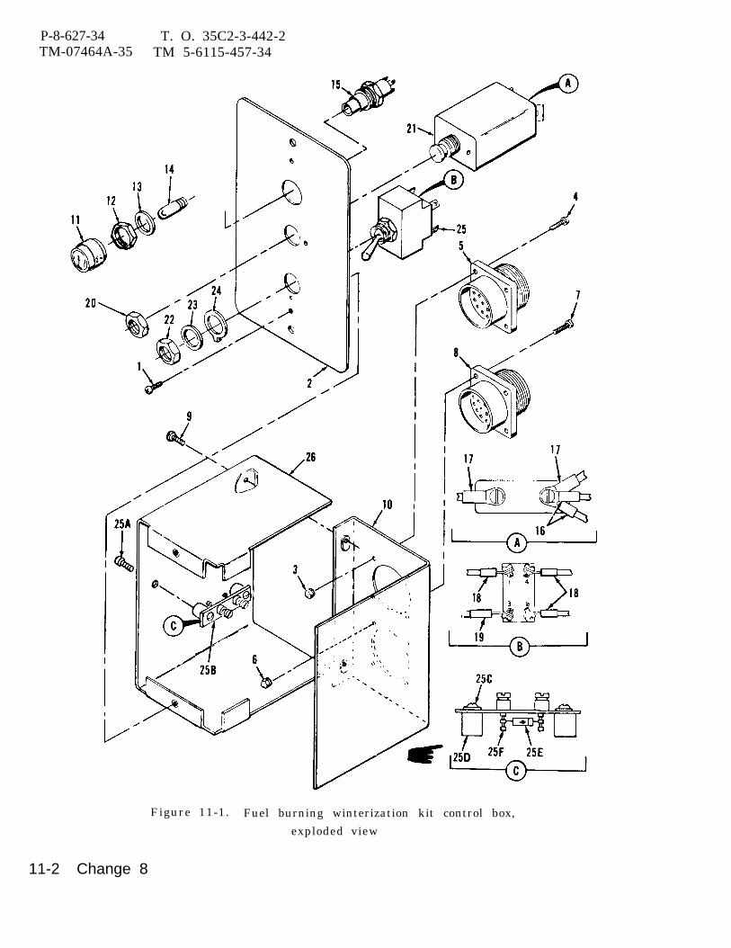
P-8-627-34 T. O. 35C2-3-442-2TM-07464A-35 TM 5-6115-457-34
Figure 11-1. Fuel burning winterization kit control box,
exploded view
11-2 Change 8
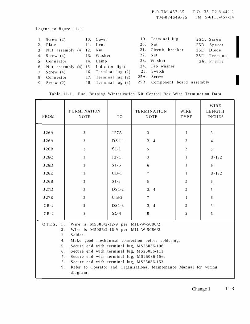
P-9-TM-457-35 T.O. 35 C2-3-442-2TM-07464A-35 TM 5-6115-457-34
Legend to figure 11-1:
1.2.3.4.5.6.7.8.9.
Screw (2) 10.Plate 11.Nut assembly (4) 12.Screw (4) 13.Connector 14.Nut assembly (4) 15.Screw (4) 16.Connector 17.Screw (2) 18.
CoverLensNutWasherLampIndicator lightTerminal lug (2)Terminal lug (2)Terminal lug (3)
19.20.21.22.23.24.25.
25A.25B.
Terminal lug 25C. ScrewNut 25D. SpacerCircuit breaker 25E. DiodeNut 25F. TerminalWasher 26. FrameTab washerSwitchScrewComponent board assembly
Table 11-1. Fuel Burning Winterization Kit Control Box Wire Termination Data
WIRET ERMI NATION TERMINATION WIRE LENGTH
FROM NOTE TO NOTE TYPE INCHES
J26A 3 J27A 3 1 3
J26A 3 DS1-1 3, 4 2 4
J26B 3 S1-1 5 2 5
J26C 3 J27C 3 1 3-1 /2
J26D 3 S1-6 6 1 6
J26E 3 CB-1 7 1 3-1 /2
J26B 3 S1-3 5 2 6
J27D 3 DS1-2 3, 4 2 5
J27E 3 C B-2 7 1 6
CB-2 8 DS1-3 3, 4 2 3
CB-2 8 S1-4 5 2 3
O T E S : 1 . Wire is M5086/2-12-9 per MIL-W-5086/2.2. Wire is M5086/2-16-9 per MIL-W-5086/2.3. Solder.4. Make good mechanical connection before soldering.5. Secure end with terminal lug, MS25036-106.6. Secure end with terminal lug, MS25036-111.7. Secure end with terminal lug, MS25036-156.8. Secure end with terminal lug, MS25036-153.9. Refer to Operator and Organizational Maintenance Manual for wiring
diagram.
Change 1 11-3
P-9-TM-457-35 T.O. 35 C2-3-442-2TM-07464A-35 TM 5-6115-457-34
b. Inspect switch, indicator light, andcircuit breaker for continuity. Refer tofigure 1-29.
c. Inspect terminal lugs for securityand c onditi on.
d. Inspect components for dents,cracks, and distortion.
11-6. REPAIR.
NOTE
Figure 1-29 is the fuel burningwinterization kit and wiring dia-gram contained in Operator andOrganizational MaintenanceManual.
a. Repair or replace defective controlbox wiring in accordance with table 11-1.
b. Repair dents and distortion usingproper tools.
11-7. REASSEMBLY.
Refer to figure 11-1 and reassem-ble control box in the reverse order ofindex numbers assigned. Pay particularattention to the following:
a. When installing switch (25), inserttab of tab washer (24) into hole of plate (2).
b. Install circuit breaker (21), indi-cator light (15), and lens (11).
c. Install connectors (5 and 8) with keylocated on the top.
d. Attach cover (10) to frame (26).
e. Connect wiring and check for properconnection, refer to table 11-1.
11-8. INSTALLATION.
Refer to Operatortional Maintenance Manualtrol box.
Section II. HEATER
11-9. GENERAL. resistance glow plug, isand ignite the fuel. The
The heater is a fuel burning typedesigned to pre-heat the engine for startingat low temperatures down to -65°F by cir-culating heated coolant through the engine.The heater consists of a blower motor,fuel regulator valve, limit switch, igniter,flame switch, and a coolant pump. Theblower motor and fan assembly providesair for combustion; it is also a means fordriving the coolant pump. The fuel regu-lator valve permits the fuel to be turned onand off; it also regulates the fuel flow tothe burner. The igniter, which is a high
and Organi za-and install con-
used to vaporizeflame switch con-
trols the electrical supply to the igniter,blower motor and indicator lamp; its opera-tion is determined by temperature. Recir-culation of heated coolant is provided bythe coolant pump at a rate of 80 to 100 GPH.Coolant is circulated around the heatercombustion chamber where it is heated andthen is circulated through the engine.
11-10. REMOVAL.
Refer to Operator and OrganizationalMaintenance Manual and remove heater.
11-4
11-11. DISASSEMBLY.
Refer to figure 11-2 and disassem-ble heater in the order of index numbersassigned. Pay particular attention to thefollowing:
a. Remove cover (1). Tagnect wires.
CAUTION
and di scon-
Use care when removing quartzrod (14) as it is easily broken ifdropped.
b. Remove receptacle assembly (3),terminal block (5), and flame switchassembly (8).
c. Remove igniter (18), gasket(19),
NOTE
Do not remove regulatorvalve assembly (21) untilafter casting (40) has beenremoved.
d. Remove burner assembly (48), andmotor and pump assembly (55) as acomplete assembly.
NOTE
Coolant pump (56) cannot be re-moved as a complete assembly.The unit must be disassembled dur-ing removal as the pump rotor (67)is secured to the motor shaft by aset screw (66).
e . Before disassembly of coolant pump,make an alignment mark across adapter(68), cam ring (63), and plate (58) for cor-rect alignment during reassembly.
P-8-627-34 T O 35 C2-3-442-2TM-07464A-35 TM 5-6115-457-34
11-12. CLEANING.
a. Clean electrical components with acloth moistened with an approved cleaningsolvent, and dry thor oughly.
b. Remove carbon desposits from burnerassembly using a suitable wire brush.
WARNING
Cleaning Solvents are flammable andmoderately toxic to skin, eyes andrespiratory tract. Eye and skinprotection required. Good generalventilation is normally adequate.
Compressed air used for cleaning anddrying purposes can create airborneparticles that may enter the eyes.Pressure shall not exceed 30 psig.Eye protection is required.
c. Clean orifice assembly by forcingfiltered compressed air through orifice inthe reverse flow direction.
d. Clean parts with an approved cle an -ing solvent, and dry thoroughly.11-13. INSPECTION.
a. Inspect components for cracks,dents, distortion, burrs, nicks, and dam-aged threads.
b. Inspect insulation for damage.c. Inspect springs for condition.
Inspect spring (60, figure 11-2). Using asuitable spring compressor, apply a loadof 1 ± 0.1 pounds and compress spring (60)to a working length of 0.750 inch. Springshould measure 1.164 inches free lengthafter test.
d. Inspect receptacle assembly forloose connections and bent or broken te r-minal pins. Check for short to case andsurrounding pins. Check for continuitybetween wires and terminal pins.
e. Inspect orifice assembly for properorifice opening. Opening should be0.012 inch diameter.
f. Inspect regulator valve assembly (21)as follows:
1. Check resistance of solenoid coil;resistance should be 150 ohms.
Change 8 11-5

P-8-627-34 T O 35 C2-3-442-2TM-07464A-35 TM 5-6115-457-34
Figure 11-2. Fuel burning winterization kit heater,exploded view
11-6 Change 8
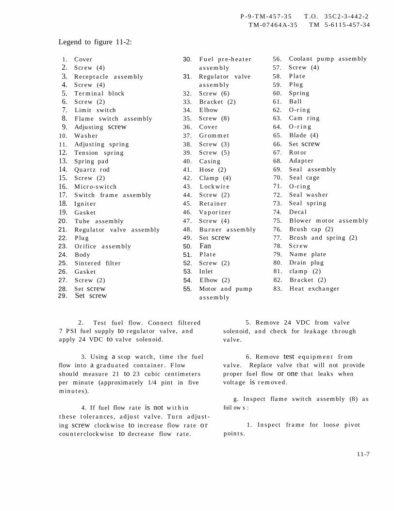
P-9-TM-457-35 T.O. 35C2-3-442-2TM-07464A-35 TM 5-6115-457-34
Legend to figure 11-2:
1.2.3.4.5.6.7.8.9.
10.11.12.13.14.15.16.17.18.19.20.21.22.23.24.25.26.27.28.29.
CoverScrew (4)Receptacle assemblyScrew (4)Terminal blockScrew (2)Limit switchFlame switch assemblyAdjusting screwWasherAdjusting springTension springSpring padQuartz rodScrew (2)Micro-switchSwitch frame assemblyIgniterGasketTube assemblyRegulator valve assemblyPlugOrifice assemblyBodySintered filterGasketScrew (2)Set screwSet screw
30.
31.
32.33.34.35.36.37.38.39.40.41.42.43.44.45.46.47.48.49.50.51.52.53.54.55.
Fuel pre-heaterassemblyRegulator valveassemblyScrew (6)Bracket (2)ElbowScrew (8)CoverGrommetScrew (3)Screw (5)CasingHose (2)Clamp (4)LockwireScrew (2)RetainerVaporizerScrew (4)Burner assemblySet screwFanPlateScrew (2)InletElbow (2)Motor and pumpassembly
2. Test fuel flow. Connect filtered7 PSI fuel supply to regulator valve, andapply 24 VDC to valve solenoid.
3. Using a stop watch, time the fuelflow into a graduated container. Flowshould measure 21 to 23 cubic centimetersper minute (approximately 1/4 pint in fiveminutes).
4. If fuel flow rate is not withinthese tolerances, adjust valve. Turn adjust-ing screw clockwise to increase flow rate o rcounterclockwise to decrease flow rate.
56.57.58.59.60.61.62.63.64.65.66.67.68.69.70.71.72.73.74.75.76.77.78.79.80.81.82.83.
Coolant pump assemblyScrew (4)PlatePlugSpringBallO-ringCam ringO-ringBlade (4)Set screwRotorAdapterSeal assemblySeal cageO-ringSeal washerSeal springDecalBlower motor assemblyBrush cap (2)Brush and spring (2)ScrewName plateDrain plugclamp (2)Bracket (2)Heat exchanger
5. Remove 24 VDC from valvesolenoid, and check for leakage throughvalve.
6. Remove test equipment fromvalve. Replace valve that will not provideproper fuel flow or one that leaks whenvoltage is removed.
g. Inspect flame switch assembly (8) asfoil ow s :
1. Inspect frame for loose pivotpoints.
11-7
P-9-TM-457-35 T.O. 35 C2-3-442-2TM-07464A-35 TM 5-6115-457-34
2. Check continuity of micro-switch(16) as follows:
(a) Depress the micro-switchbutton. This will be the ignition or startposition of the switch. Continuity should beindicated between the two NO terminals andalso between each of the NO terminals andthe common terminal. There should be anopen circuit between the two NC terminalsand also between the common terminal andthe two NC terminals.
(b) Release the micro-switchbutton. This will be the run position of themicro-switch. Continuity should be indi-cated between the two NC terminals and thecommon terminal. There should be an opencircuit between the NO ignition or start ter-minals and between the NO terminals andthe common terminal.
h. Inspect igniter as follows:
1. Inspect for broken coil or short.
2. Check igniter for proper resis-tance; resistance should be 1 ohm.
WARNING
To prevent burns, do not touchigniter during test, and allow enoughtime for it to return to ambienttemperature before removing testequipment.
3. Connect 24 VDC power source andan ammeter to igniter terminal. Groundigniter. Apply 24 VDC to igniter. Theigniter should draw 10.5 amperes and heatto a bright red color in a few seconds.
i. Inspect fan for loose or damagedblades.
j . Inspect heat exchanger and burnerassembly for warpage and burned area.
k. Inspect sintered filter for blockage.
1. Using a suitable dial indicator, checkend play on shaft of blower motor assembly.Grasp short shaft end and rotate in eitherdirection, at the same time moving in andout. The end play should not exceed 0.010to 0.025 inch.
m. Inspect adapter for damaged orscored face, warped condition, and dam -aged seal face. Inspect for motor shaftbore wear. Refer to figure 11-3 for limits.
n. Inspect seal cage for scored or dam-aged seal face.
o. Inspect rotor and blades for damageand wear. Refer to figure 11-3 for limits.
p. Inspect cam ring for damaged orscored bore. Inspect for warped condition.Both faces must be parallel within 0.001 inchT. I. R.
q. Inspect plate (58, figure 11-2) fordamaged or scored face.
11-14. REPAIR.
a. Seal face of adapter (68, figure 11-2)and seal face of seal cage (71) can bedressed to remove minor nicks, scratchesor scoring. Remove only material neces-sary to clean up seal face. Seal face mustbe parallel with rotor side of adapter within0.001 inch per inch. Replace either part ifimperfections cannot be dressed cut.
b. Straighten distorted parts usingsuitable tools.
c. Remove burrs or nicks using a stoneor file.
11-8
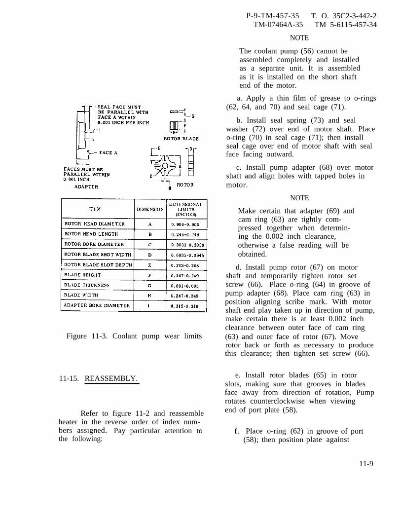
Figure 11-3. Coolant pump wear limits
11-15. REASSEMBLY.
Refer to figure 11-2 and reassembleheater in the reverse order of index num-bers assigned. Pay particular attention tothe following:
P-9-TM-457-35 T. O. 35C2-3-442-2TM-07464A-35 TM 5-6115-457-34
NOTE
The coolant pump (56) cannot beassembled completely and installedas a separate unit. It is assembledas it is installed on the short shaftend of the motor.
a. Apply a thin film of grease to o-rings(62, 64, and 70) and seal cage (71).
b. Install seal spring (73) and sealwasher (72) over end of motor shaft. Placeo-ring (70) in seal cage (71); then installseal cage over end of motor shaft with sealface facing outward.
c. Install pump adapter (68) over motorshaft and align holes with tapped holes inmotor.
NOTE
Make certain that adapter (69) andcam ring (63) are tightly com-pressed together when determin-ing the 0.002 inch clearance,otherwise a false reading will beobtained.
d. Install pump rotor (67) on motorshaft and temporarily tighten rotor setscrew (66). Place o-ring (64) in groove ofpump adapter (68). Place cam ring (63) inposition aligning scribe mark. With motorshaft end play taken up in direction of pump,make certain there is at least 0.002 inchclearance between outer face of cam ring(63) and outer face of rotor (67). Moverotor back or forth as necessary to producethis clearance; then tighten set screw (66).
e. Install rotor blades (65) in rotorslots, making sure that grooves in bladesface away from direction of rotation, Pumprotates counterclockwise when viewingend of port plate (58).
f. Place o-ring (62)(58); then position
in groove of portplate against
11-9
P-9-TM-457-35 T.O. 35C2-3-442-2TM-07464A-35 TM 5-6115-457-34
cam ring (63), Align scribe marks, andtighten screws (57) evenly.
g. Test coolant pump assembly (56).Refer to paragraph 11-16, step a.
h. After coolant pump has been reas-sembled and tested, flush with corrosivepreventive compound, Military SpecificationMIL-C-6529, and drain.
NOTE
Make certain that the lead wirefrom blower motor assembly (75)is on the side of the bloweropposite the name plate.
i. Assemble motor and pump assembly(55), inlet (53), plate (51), and fan (50)before installing into burner assembly (48).
j. Install burner assembly (48) andcasing (40).
k. Install cover (36).
1. Install regulator valve assembly (21),gasket (19), and igniter (18).
CAUTION
Use care when installing quartzrod (14) as it is easily broken ifdropped.
m. After installing quartz rod (14),gently raise the rod up and down to see if itmoves freely in the stainless tube. Alsomake sure at least 1/32 inch extends out oftube when rod is resting on bottom.
n. Install flame switch assembly (8) andterminal block (5).
o. Install receptacle assembly (3) withkey located on the top.
p. Adjust flame switch (8), refer toparagraph 11-16, step b.
q. Install cover (l).
11-16. COMPONENT TEST ANDADJUSTMENTS.
The following procedures covertesting and adjustments of individualcomponents.
a. Coolant Pump Assembly. Coolantpump assembly (56, figure 11-2) should betested before being reinstalled in the heater.Test coolant pump assembly as follows:
1. Connect motor and pump assem-bly to equipment as shown in figure 11-4.
2. Turn power switch to ON andrun-in unit for approximately 15 minutes.
3. Test relief valve by closingmanual shut-off valve. Discharge pressureshould not exceed 30 to 35 PSI when valveis closed. Open and close valve a fewtimes to check consistency of valve per-formance. Replace relief valve spring ifpressure exceeds 30 to 35 PSI.
4. To check pump for rated flow andpressure, adjust valve in discharge lineuntil a reading of 2 PSI is obtained on pres-sure gauge.
5. Using a suitable timer, check forrated flow of 80 GPH minimum at 2 PSI dis-charge pressure. Amperage draw shouldnot exceed 6 amperes during this test.
6. Check motor RPM using a strobelight. Motor shaft speed should be 8500 RPM.
7. Observe smoothness of operationof both pump and motor. Seal leakage of1 cubic centimeter per hour (seal may show
11-10
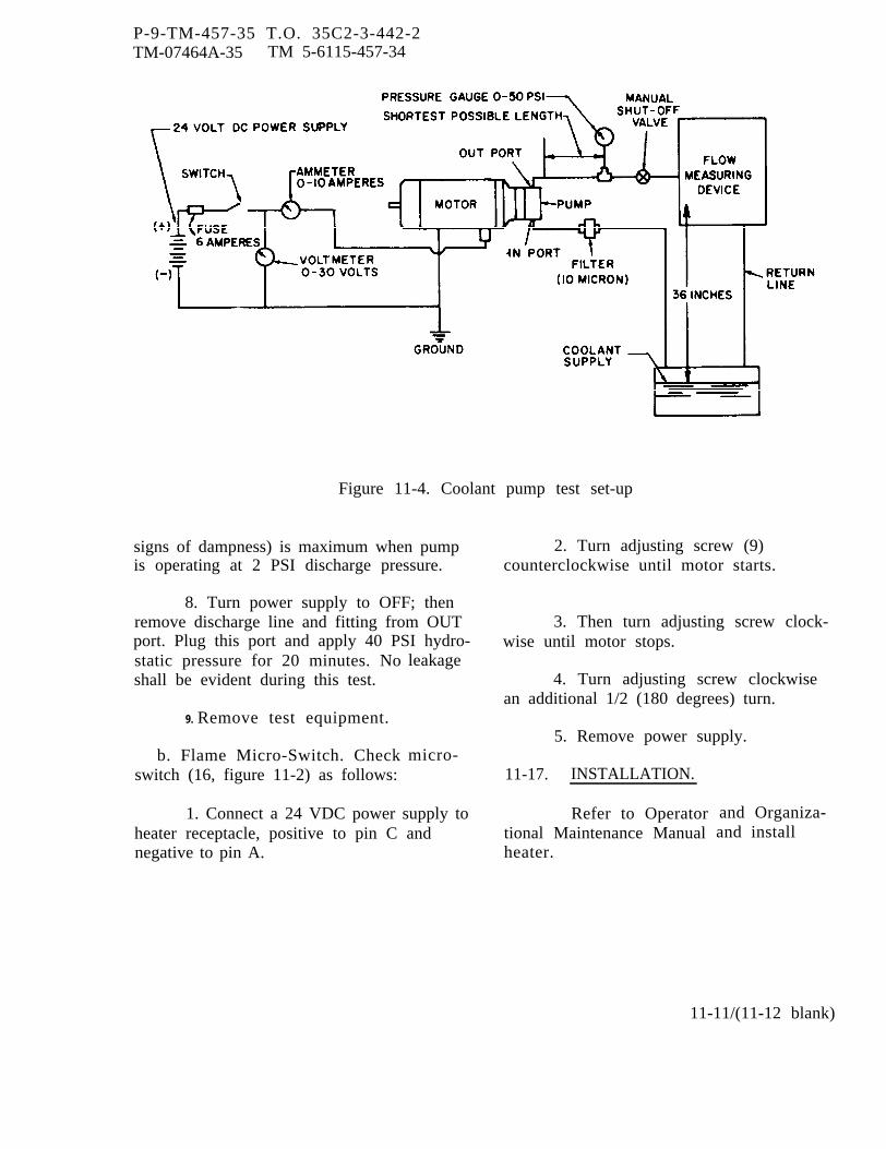
P-9-TM-457-35 T.O. 35C2-3-442-2TM-07464A-35 TM 5-6115-457-34
Figure 11-4. Coolant pump test set-up
signs of dampness) is maximum when pumpis operating at 2 PSI discharge pressure.
8. Turn power supply to OFF; thenremove discharge line and fitting from OUTport. Plug this port and apply 40 PSI hydro-static pressure for 20 minutes. Noshall be evident during this test.
9. Remove test equipment.
b. Flame Micro-Switch. Checkswitch (16, figure 11-2) as follows:
leakage
micro-
2. Turn adjusting screw (9)counterclockwise until motor starts.
3. Then turn adjusting screw clock-wise until motor stops.
4. Turn adjusting screw clockwisean additional 1/2 (180 degrees) turn.
5. Remove power supply.
11-17. INSTALLATION.
1. Connect a 24 VDC power supply toheater receptacle, positive to pin C andnegative to pin A.
Refer to Operatortional Maintenance Manualheater.
and Organiza-and install
11-11/(11-12 blank)


P-9-TM-457-35 T.O. 35C2-3-442-2TM-07464A-35 TM 5-6115-457-34
CHAPTER 12
ELECTRIC WINTERIZATION KIT REPAIR INSTRUCTIONS
Section I. CONTROL BOX
12-1. GENERAL.
The control box contains the oper-ating controls of the electric winterizati onkit. Incorporated in the box are the on-offswitch, fuse, step down transformer, fullwave diode rectifier, and heater indicator.The switch turns kit components on or offand the fuse protect kit components fromexcessive current. The step down trans-former converts input voltage from externalpower supply to 33 VAC which in turn isconverted to approximately 24 VDC by thefull wave diode rectifier for coolant pumpoperation. The indicator illuminateswhenever the kit is in operation.
12-2. REMOVAL.
Refer to Operator and Organiza-tional Maintenance Manual and remove thecontrol box.
1.2-3. TEST.
NOTE
Figure 1-30 is the electric win-terization kit schematic.
a. Connect control box to test equipmentas illustrated in figure 12-1.
b. Perform test procedures as specifiedin table 12-1.
Figure 12-1. Electric winterization kitcontrol box, test setup
12-4. DISASSEMBLY .
Refer to figure 12-2 and disassem-ble electric winterization kit control box inthe order of index numbers assigned. Payparticular attention to the following:
a. Prior to control box disassembly,test box as specified in paragraph 12-3 andthen disassemble control box only to theextent necessary to accomplish repair.
b. Remove cover (2). Tag and discon-nect harness wires from components andremove harnesses (3 and 9).
c. Tag diodes (11) with location andpolarity and remove diodes from terminalstrip by removing terminal strip screws.
12-1
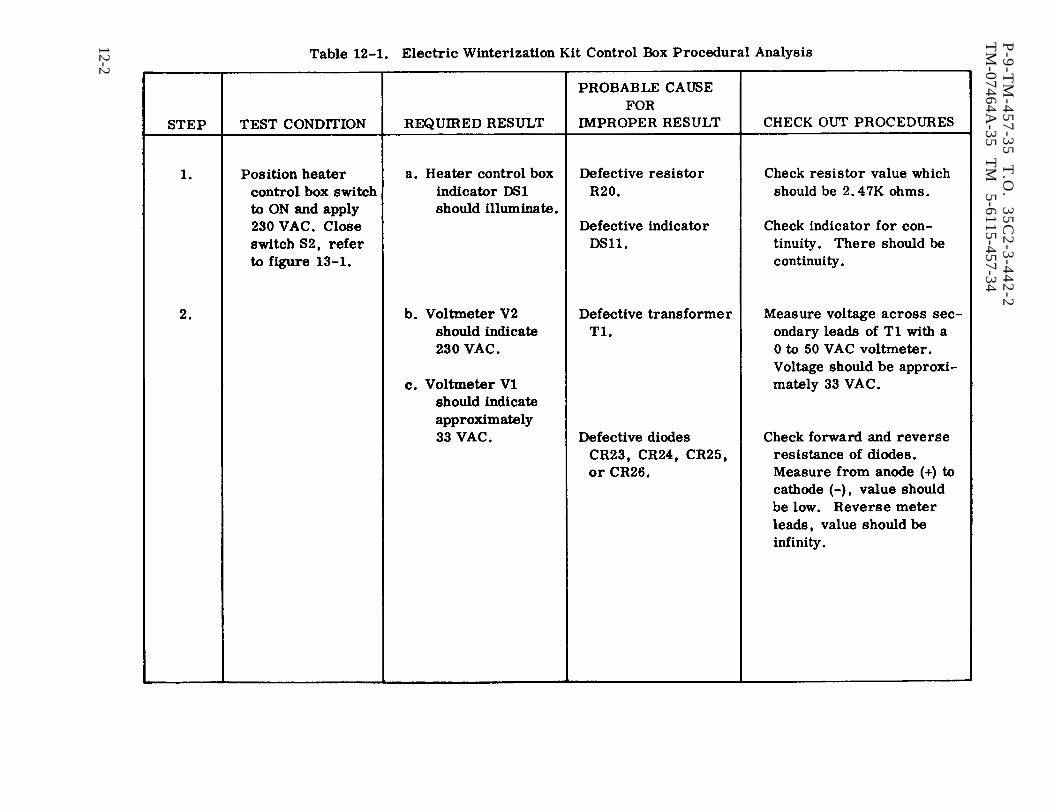
Table 12-1.
P-9
-TM
-45
7-3
5
T.O
. 3
5C
2-3
-44
2-2
TM
-07464A-35
TM
5-6115-457-34
12-2
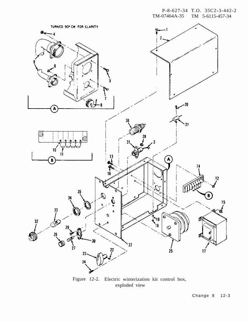
P-8-627-34 T.O. 35C2-3-442-2TM-07464A-35 TM 5-6115-457-34
Figure 12-2. Electric winterization kit control box,exploded view
Change 8 12 -3
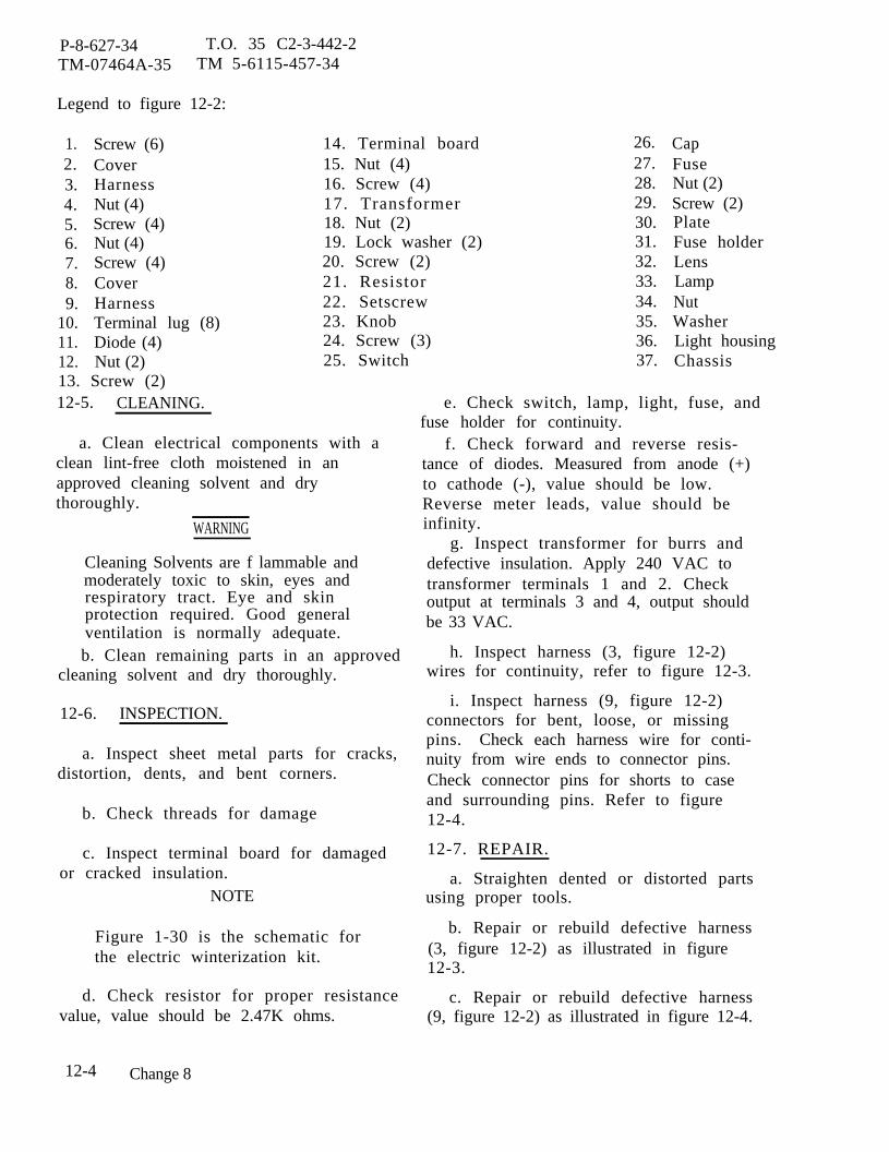
P-8-627-34 T.O. 35 C2-3-442-2TM-07464A-35 TM 5-6115-457-34
Legend to figure 12-2:
1.2.3.4.5.6.7.8.9.
10.11.12.
Screw (6)CoverHarnessNut (4)Screw (4)Nut (4)Screw (4)CoverHarnessTerminal lug (8)Diode (4)Nut (2)
13. Screw (2)12-5. CLEANING.
14. Terminal board15. Nut (4)16. Screw (4)17. Transformer18. Nut (2)19. Lock washer (2)20. Screw (2)21. Resistor22. Setscrew23. Knob24. Screw (3)25. Switch
a. Clean electrical components with aclean lint-free cloth moistened in anapproved cleaning solvent and drythoroughly.
WARNING
Cleaning Solvents are f lammable andmoderately toxic to skin, eyes andrespiratory tract. Eye and skinprotection required. Good generalventilation is normally adequate.b. Clean remaining parts in an approved
cleaning solvent and dry thoroughly.
12-6. INSPECTION.
a. Inspect sheet metal parts for cracks,distortion, dents, and bent corners.
b. Check threads for damage
c. Inspect terminal board for damagedor cracked insulation.
NOTE
Figure 1-30 is the schematic forthe electric winterization kit.
d. Check resistor for proper resistancevalue, value should be 2.47K ohms.
26.27.28.29.30.31.32.33.34.35.36.37.
CapFuseNut (2)Screw (2)PlateFuse holderLensLampNutWasherLight housingChassis
e. Check switch, lamp, light, fuse, andfuse holder for continuity.
f. Check forward and reverse resis-tance of diodes. Measured from anode (+)to cathode (-), value should be low.Reverse meter leads, value should beinfinity.
g. Inspect transformer for burrs anddefective insulation. Apply 240 VAC totransformer terminals 1 and 2. Checkoutput at terminals 3 and 4, output shouldbe 33 VAC.
h. Inspect harness (3, figure 12-2)wires for continuity, refer to figure 12-3.
i. Inspect harness (9, figure 12-2)connectors for bent, loose, or missingpins. Check each harness wire for conti-nuity from wire ends to connector pins.Check connector pins for shorts to caseand surrounding pins. Refer to figure12-4.
12-7. REPAIR.
a. Straighten dented or distorted partsusing proper tools.
b. Repair or rebuild defective harness(3, figure 12-2) as illustrated in figure12-3.
c. Repair or rebuild defective harness(9, figure 12-2) as illustrated in figure 12-4.
12-4 Change 8

P-9-TM-457-35 T. O. 35C2-3-442-2TM-07464A-35 TM 5-6115-457-34
Figure 12-3. Electric winterization kit control boxwiring harness
12-5
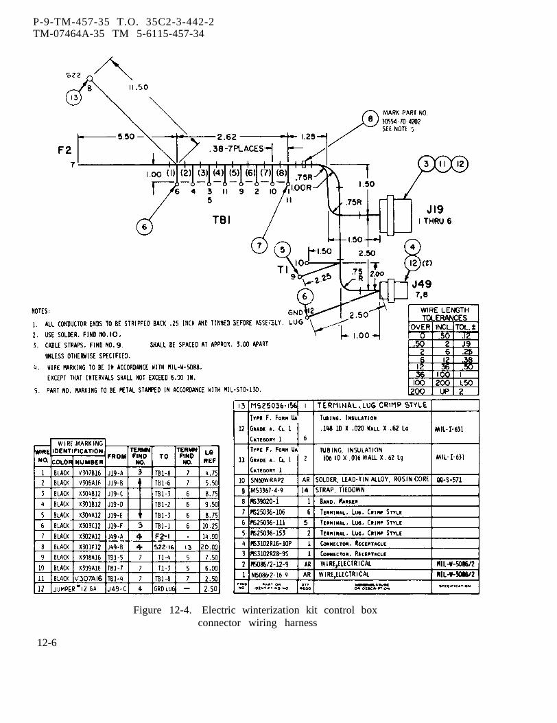
P-9-TM-457-35 T.O. 35C2-3-442-2TM-07464A-35 TM 5-6115-457-34
Figure 12-4. Electric winterization kit control boxconnector wiring harness
12-6

12-8. REASSEMBLY.
Refer to figure 12-2 and reassemblethe electric winterization kit control box inthe reverse order of index numbers assign-ed. Pay particular attention to the following:
a. Install connectors of harness (9) withkeyways on top.
NOTE
Refer to Operator and Organiza-tional Maintenance Manual forelectric winterization kit wiringdiagram.
P-8-627-34 T O 35C2-3-442-2TM-07464A-35 TM 5-6115-457-34
b. Prior to installing cover (2), referto figure 1-30 and check wiring for properconnection.
c. After reassembly, test control boxas specified in paragraph 12-3.
12-9. INSTALLATION .
Refer to Operator and Organiza-tional Maintenance Manual and install thecontrol box.
Section II. ELECTRIC HEATER
12-10. GENERAL.
The electric heater is utilized topreheat generator set engine coolant duringcold weather operation. The heater con-sists of a removable heating element,intake head with integral check valve andcoolant tank. The check valve insures thatthe coolant tank is always full and heatingelement is submerged in coolant. Theheating element heats the coolant in thetank which is in turn circulated through theengine coolant system.
12-11. REMOVAL.
Refer to Operator and Organiza-tional Maintenance Manual and remove theelectric heater.
12-12. DISASSEMBLY.
Refer to figure 12-5 and disassem-ble the electric heater in the order of indexnumbers assigned.
Figure 12-5. Electric winterization kitelectric heater, exploded view
Legend to figure 12-5:
1.2.3.4.5.6.
ScrewCoverEnd PlugHeating elementScrew (6)Washer (6)
7. Intake head andcheck valveassembly
8. Gasket9. Tank
10. Plug
Change 8 12-7
P-8-627-34 T O 35C2-3-442-2TM-07464A-35 TM 5-6115-457-34
12-13. C LEANING.
WARNING
Cleaning Solvents are flammable andmoderately toxic to skin, eyes andrespiratory tract. Eye and skinprotection required. Good generalventilation is normally adequate.
a. Remove hand coolant deposits fromcomponents by boiling components a mini-mum of 30 minutes in solution of one poundbaking soda to each gallon of water.
b. Clean old gasket from intake head
and check valve assembly and tank usingsuitable scraper. Exercise care not togouge surfaces.
a
c. Clean parts with an approved clean-ing solvent and dry thoroughly.
12-14. INSPECTION.
a. Inspect threads for damage.
b. Inspect parts for cracks and dam-aged gasket surfaces.
c. Check flap of check valve for free-dom of movement and for proper seating onintake head.
WARNING
Do not handle heating element dur-ing test and permit element to coolprior to removing test equipment.
d. Connect single phase 240 volts, 50,60, or 400 hertz power supply to heatingelement terminals. Connect suitable am-meter and wattmeter in series with heatingelement and power supply. Apply 240 VAC
and observe ammeter and wattmeter.Heating element should draw 10.8 amperesand 2500 watts. Remove test equipment,replace defective heating element.12-15. REASSEMBLY.
Refer to figure 12-5 and reassem-ble the electric heater in the reverse orderof index numbers assigned. Pay particularattention to the following:
a. Apply thread sealing compound con-forming to Military Specification MIL-S-45180, type III, to threads of end plug (3)and plug (9) prior to installation.
b. When installing intake head andcheck valve assembly (7), make sure thathole with arrow is on top.12-16. INSTALLATION .
Refer to Operator and Organiz a-tional Manual and install theelectric heater.
Section III. COOLANT PUMP
12-17. GENERAL.
The coolant pump consists of apump and motor assembly which operateson 24 VDC and provides a minimum of80 gallons per hour at 2 PSI. The motor isa continuous duty type and rotates in aclockwise direction as viewed from the pumpend. The motor is rated at 20 to 32 VDC,3.3 amperes with a maximum of 7500 RPM.
12-8 Change 8
The motor is equipped with an internalbypass and feed thru capacitor for radiosuppression and voltage and current pro-tection. The pump is a rotor type with abuilt in relief valve that is set at 30 to35 PSI. If coolant pressure reaches 30 to35 PSI, the relief valve ball is unseatedand coolant is permitted to bypass inter-nally within the pump until pressure isreduced to 30 PSI.
12-18. REMOVAL. �
P-8-627-34 T.O. 35 C2-3-442-2TM-07464A-35 TM 5-6115-457-34
Compressed air used for cleaning andRefer to Operator and Organiza-
ti onal Maintenance Manual and removecoolant pump.12-19. TEST .
a. Connect coolant pump to test equip-ment as illustrated in figure 11-4, excepttest equipment fuse rating should be4 amperes.
b. Perform test procedure specified inparagraph 11-16, step a. Test results dur-ing test should be the same as provided intest procedure except motor amperagedraw should not exceed 3.3 amperes instep a. 5. and motor RPM in step a. 6.should be 7500.12-20. DISASSEMBLY.
Refer to figure 12-6 and disassem-ble the coolant pump in the order of indexnumbers assigned. Pay particular atten-ti on to the following:
a. Mark alignment marks on port plate(6), cam ring (8), adapter (13), and motor(23) prior to disassembly to insure properreassembly.
WARNING
Avoid breathing fumes generated byunsoldering/soldering. Eye pro-tection is required.
b. Move shell (22) away from motorand unsolder wire (20) from pump.
c. Replace all packings.12-21. CLEANING.
a. Clean wire and motor with a cleanlint-free cloth moistened in an approvedcleaning solvent and dry thoroughly.
WARNING
Cleaning Solvents are flammable andmoderately toxic to skin, eyes andrespiratory tract. Eye and skinprotection required. Good generalventilation is normally adequate.
drying purposes can create airborneparticles that may enter the eyes.Pressure shall not exceed 30 psig.Eye protection is required.
b. Clean brush and spring assembly andbrush openings with filtered low pressurecompressed air.
c. Clean remaining parts in an ap-proved cleaning solvent and dry thoroughly.
1.2-22. INSPECTION.
a. Inspect springs for cracks, distor-tion, and broken ends.
b. Test relief valve spring for properspring rate using a suitable spring tester.Spring rate should be 1 pound ± 0.1 poundat 0.750 inch working length. After ratetest, check spring for proper free lengthof approximately 1.164 inches.
c. Test seal spring for proper springrate. Spring rate should be 2.5 pounds± 0.25 pound at 0.25 inch working length.After rate test, check spring for properfree length of approximately 0.470 inch.
d. Inspect relief valve ball and ballseat in port plate for grooves, scratches,and nicks .
e. Inspect parts for cracks, damagedcontact surfaces, signs of scuffing,and burrs.
f. Inspect threads for damages.
g. Inspect pump components forrefer to figure 11-3.
nicks,
wear,
h. Inspect brush and spring assemblybrushes for cracks, chips, and wear bycomparing brush with new brush. Replacebrush and spring assembly if brush isworn to half its original length.
Change 8 12-9

P-8-627-34 T.O. 35C2-3-442-2TM-07464A-35 TM 5-6115-457-34
Figure 12-6. Electric winterization kit coolant pump,exploded view
i. Rotate motor shaft and check forsmoothness of rotation, rough spots, andexcessive side play. Using a suitable dialindicator, check motor shaft end play.End play should be 0.010 to 0.025 inch.Check motor shaft for wear, shaftshould be 0.3125 ± 0.0005 inch diameterand 0.286 ± 0.005 inch from flat. Checkshaft for grooves on packing contact surface.
j . Check capacitor for open or short.
k. Connect 24 VDC and ammeter tomotor terminal and ground motor. Checkmotor RPM using a suitable strobe light.Motor should draw a maximum of 3.3 am-peres and RPM should be approximately7500.12-23. REPAIR.
a. Remove nicks and burrs using astone or file.
b. Repair loose nameplate using asuitable adhesive.
12-10 Change 8

P-8-627-34 T O 35C2-3-442-2TM-07464A-35 TM 5-6115-457-34
Legend to figure
1. Nameplate2. Plug
12-6:
3. Relief valve spring4. Relief valve ball5. Screw (4)6. Port plate7. Packing8. Cam ring9. Blade (4)
10. Setscrew11. Rotor12. Packing13. Adapter14. Seal cage15. Packing16. Washer17. Seal spring18. Brush cap (2)
12-24. REASSEMBLY.
Refer to figure 12-6 and reassem-ble the coolant pump in the reverse orderof index numbers assigned. Pay particularattention to the following:
WARNING
Avoid breathing fumes generated byunsoldering/soldering. Eye pro-tection is required.
a. Solder wire (20) to motor and posi-tion shell (22) on motor to ensure watertight seal.
b. Apply a thin film of grease to pack-ings (7, 12, and 15) and seal cage (14) sothat packing will move in groove to formproper seal at time of reassembly. Posi-ti on packings in grooves.
c. Install blades (9) in rotor (11).Align alignment marks.
19. Brush and spring assembly (2)20. Wire21. Shell22. Shell23. Motor24. Screw (4)25. Plate26. Gasket27. Capacitor
d. Position spring (17), washer (16),packing (15), seal cage (14), adapter (13),and assembled rotor (11) on motor shaft.Align motor setscrew opening with flat ofmotor shaft. Slide components towardmotor, compressing spring (17) and installsetscrew (10).
e. Install remaining components.Tighten screws (5) evenly to prevent sideloading components.
f. Test coolant pump as specified inparagraph 12-19.
12-25. INSTALLATION.
Refer to Operator and Organiza-tional Maintenance Manual and installcoolant pump.
12-11/(12-12 blank)

P-8-627-34 T O 35C2-3-442-2TM-07464A-35 TM 5-6115-457-34
CHAPTER 13
DUMMY LOAD KIT REPAIR INSTRUCTIONS
Section I. DUMMY LOAD KIT
13-1. GENERAL.
The dummy load kit is a balancedthree phase, four wire, resistive type loadbank. The kit is rated for approximately48 KW with increments loads of approximate-ly 12 KW. It is capable of operating witheither 50/60 hertz or 400 hertz generatorsets. The kit consists of a control box, re-sistive heater elements, and wiring enclosedin a ventilated housing. The kit is designedto operate at either 120/208 or 240/416 out-put voltages. The kit's load is created bythe heater elements, as selected by the loadswitch. The control box and its componentsare described in Section II of this chapter.
13-2. REMOVAL.
Refer to Operator and OrganizationalMaintenance Manual and remove dummyload kit.
13-3. DISASSEMBLY.
Refer to figure 13-1 and disassemblydummy load kit in the order of index num-bers assigned. Pay particular attention tothe following.
NOTE
Disassemble dummy load kit only tothe extent necessary to effect repair,
a. Remove cover assembly (6), sidepanels (17) channels (18 and 19) and endpanels (23, 24, and 25) from frame (70).
b. Tag, disconnect, and remove leads(28) from heater elements (33). Removeheater elements (33), resistor brackets(38, 43, and 48) from frame (70).
c. Remove control box cover (57), tagand disconnect wire harnesses (52 and 53)from control box components.
d. Separate control box (63), fire wall(61), panel (62), and end panels (67, 68, and69) from frame (70).
e. Refer to paragraph 13-22 for disas-sembly procedures for the control box.
13-4. CLEANING
a. Clean electrical components with aclean lint-free cloth moistened with an ap-proved cleaning solvent and dry thoroughly.
WARNING
Cleaning Solvents are flammable andmoderately toxic to skin, eyes andrespiratory tract. Eye and skinprotection required. Good generalventilation is normally adequate.
b. Clean metal parts in an approvedcleaning solvent and dry thoroughly.
13-5. INSPECTION AND TEST.
a. Inspect parts for cracks, dents, anddistortion.
b. Inspect threads for damage.
Change 8 13-1
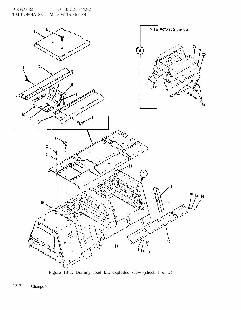
P-8-627-34 T O 35C2-3-442-2TM-07464A-35 TM 5-6115-457-34
Figure 13-1. Dummy load kit, exploded view (sheet 1 of 2)
13-2 Change 8
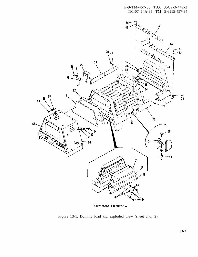
P-9-TM-457-35 T.O. 35C2-3-442-2TM-07464A-35 TM 5-6115-457-34
Figure 13-1. Dummy load kit, exploded view (sheet 2 of 2)
13-3
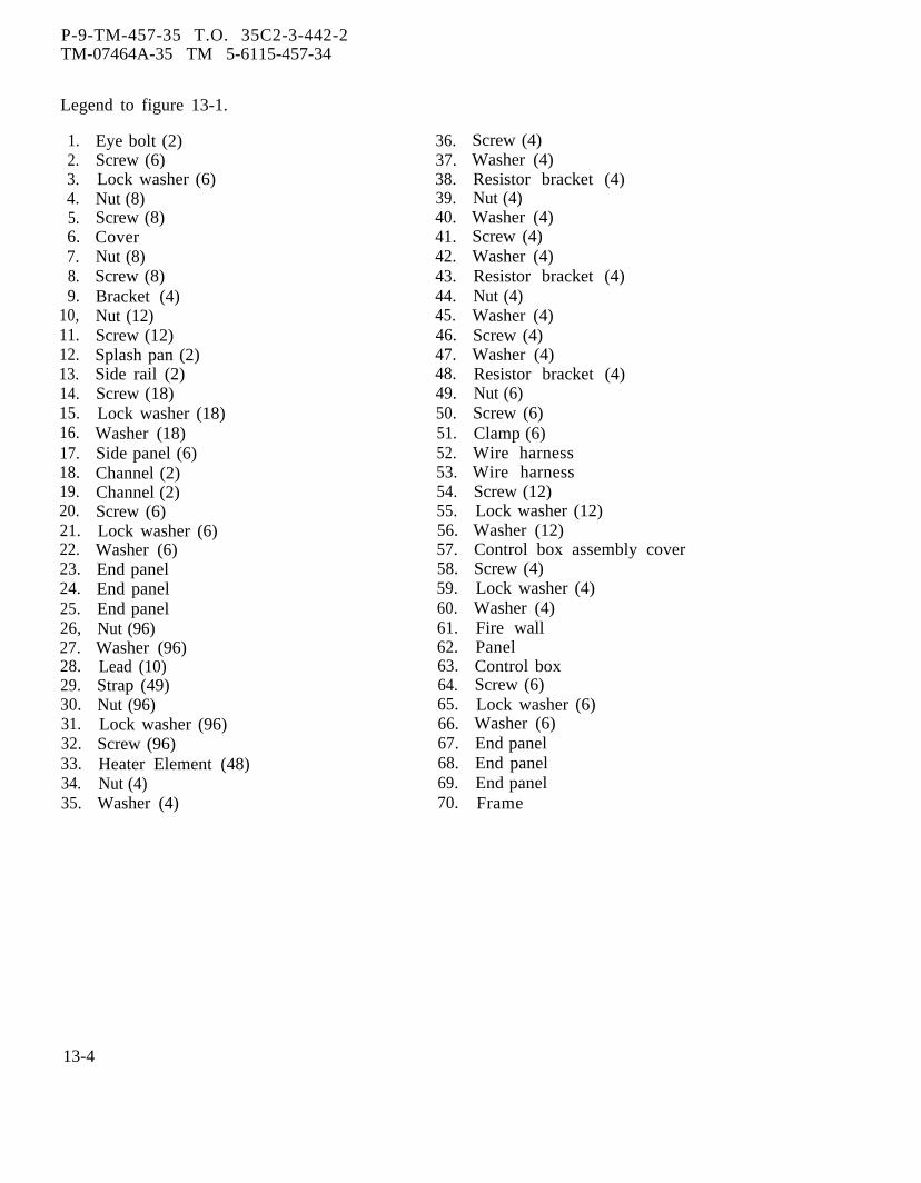
P-9-TM-457-35 T.O. 35C2-3-442-2TM-07464A-35 TM 5-6115-457-34
Legend to figure 13-1.
1.2.3.4.5.6.7.8.9.
10,11.12.13.14.15.16.17.18.19.20.21.22.23.24.25.26,27.28.29.30.31.32.33.34.35.
Eye bolt (2)Screw (6)Lock washer (6)Nut (8)Screw (8)CoverNut (8)Screw (8)Bracket (4)Nut (12)Screw (12)Splash pan (2)Side rail (2)Screw (18)Lock washer (18)Washer (18)Side panel (6)Channel (2)Channel (2)Screw (6)Lock washer (6)Washer (6)End panelEnd panelEnd panelNut (96)Washer (96)Lead (10)Strap (49)Nut (96)Lock washer (96)Screw (96)Heater Element (48)Nut (4)Washer (4)
36.37.38.39.40.41.42.43.44.45.46.47.48.49.50.51.52.53.54.55.56.57.58.59.60.61.62.63.64.65.66.67.68.69.70.
Screw (4)Washer (4)Resistor bracket (4)Nut (4)Washer (4)Screw (4)Washer (4)Resistor bracket (4)Nut (4)Washer (4)Screw (4)Washer (4)Resistor bracket (4)Nut (6)Screw (6)Clamp (6)Wire harnessWire harnessScrew (12)Lock washer (12)Washer (12)Control box assembly coverScrew (4)Lock washer (4)Washer (4)Fire wallPanelControl boxScrew (6)Lock washer (6)Washer (6)End panelEnd panelEnd panelFrame
13-4
NOTE
Dummy load kit wiring diagram iscontained in the Operator and Organi-zational Maintenance Manual.
c. Refer to figure 13-2 and 13-3 andcheck each harness wire for continuity.Check harness wires for loose terminallugs and defective installation.
d. A quick test of heater elements may beaccomplished without disassembly of dummyload bank. Measure resistance betweenterminal points 1, 7, 13, 19, 25, 31, 37,43, 49, 55, 61 and 67 to neutral lead LOon dummy load bank terminal board.Resistance valves should be approximately(1.75 ohms 120/208 voltage connection or(7 ohms 240/416 voltage connections). Re-fer to figure 1-31.
WARNING
Do not touch heater elements duringtest and permit elements to coolprior to removing test equipment.
e. Test resistance of each heater ele-ment, resistance should be 11 to 14 ohms.Test each heater element by connecting a120 VAC; 50, 60, or 400 hertz power supplya n d a 0 - 10 ampere AC ammeter to heaterelement terminals. Turn on power supply,heater element should draw 8.3 amperes.Remove test equipment.
f. Inspect fire wall for deterioration,cracks, and damaged ends.
g. Inspect paint for deterioration,cracks, and damaged ends.
13 -6. REPAIR.WARNING
Welding operations produce heat,highly toxic fumes, injuriousradiation, metal slag and air-bornegles,apronboots
particles. Welding gog-with proper tinted lenses,or jacket and welder’sare required.
P-8-627-34TM-07464A-35
a. Repair cracks byb. Straighten dented
using suitable tools.c. Remove damaged
T O 35C2-3-442-2TM 5-6115-457-34
welding.or distended parts
paint. Blend inedges, prime, and paint damaged areas.
d. Repair damaged harnesses as speci-fied in figure 13-2 or 13-3.13-7. WIRING HARNESS REBUILD.
a. Rebuild dummy load kit right sidewiring harness as specified in figure 13-2.
b. Rebuild dummy load kit left sidewiring harness as specified in figure 13-3.13-8. REASSEMBLY.
Refer to figure 13-1 and reassembledummy load kit in the reverse order of in-dex numbers assigned. Pay particularattention to the following:
a. Install end panels (67, 68, and 69)on frame (70).
b. Position wire harnesses (52 and 53)on frame (70) and secure with clamps (51)screws (50) and nuts (49).
c. Reassemble control box as specifiedin paragraph 13-28.
d. Install control box (63), fire wall (61),and panel (62) on frame (70). Connect wireharnesses (52 and 53) to control box com-ponents. Install control box cover (57) oncontrol box assembly (63).
NOTEDummy load kit wiring diagram iscontained in the Operator and Organi-zational Maintenance Manual.
e. Install heater elements (33) and leads(28). Leave screws (32) at center frameloose to permit expansion and travel ofheater elements (33). Check wiring forproper connection.
f. Install end panels (23, 24, and 25),channels (18 and 19), side panels (17), andcover assembly.
13-9. INSTALLATION.
Refer to Operator and OrganizationalMaintenance Manual and install dummy loadkit.
Change 8 13-5

Figure 13-2.
P-8-627-34
T
O
35C2-3-442-2
TM
-07464A-35
TM
5-6115-457-34
13-6C
hange 8

P-9-TM-457-35 T.O. 35C2-3-442-2TM-07464A-35 TM 5-6115-457-34
Figure 13-2. Dummy load kit right side wiring harness (sheet 2 of 2)
13-7
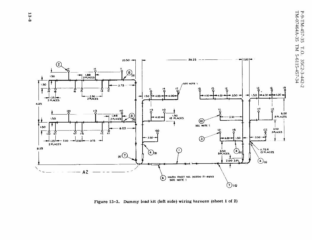
Figure 13-3.
P-9-T
M-457-35
T.O
. 35C
2-3-442-2T
M-07464A
-35 T
M
5-6115-457-34
13
-8
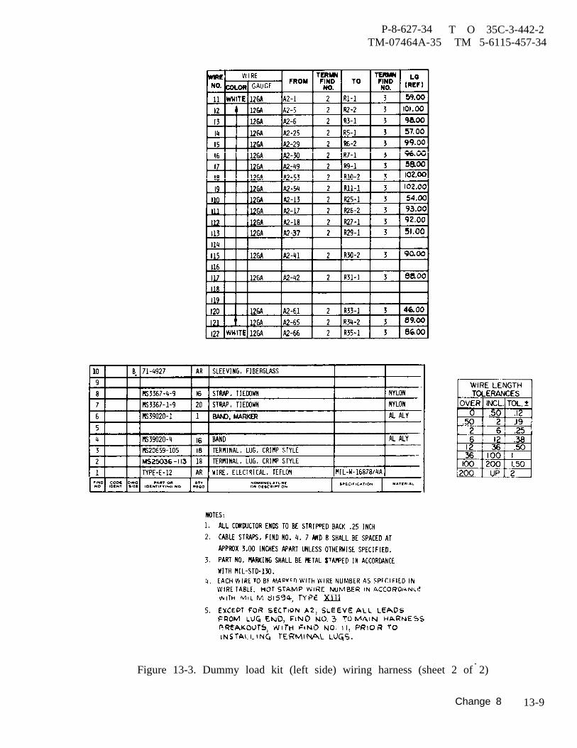
P-8-627-34TM-07464A-35
T O 35C-3-442-2 TM 5-6115-457-34
Figure 13-3. Dummy load kit (left side) wiring harness (sheet 2 of 2)
Change 8 13-9
P-8-627-34 T O 35C2-3-442-2TM-07464A-35 TM 5-6115-457-34
Section
13-10. GENERAL.
II. CONTROL BOX
b. Perform test specified in table 13-1.
a. Control Box. The control box con-tains the operating controls of the dummyload kit. The box incorporates a harness,load selector switch, load removalswitch, voltage change terminal board,load dumping relay, transformer, diodes,resistors, capacitors, relay, transistorsand contractors.
b. Load Dumping Relay (K5). Therelay contains controls necessary toautomatically remove dummy load kit fromoperation when the automatic load removalswitch is positioned to ON. With the switchin the ON position the dummy load kit isremoved from operation when the genera-tor set load exceeds 50 percent, Afterautomatic load removal the relay mustbe manually reset by positioning automaticload removal switch to BY-PASS RESET.
13-11. LOAD DUMPING RELAY (K5).
13-12. REMOVAL. Refer to figure 13-4and remove the load dumping relay asfollows :
a. Disconnect cover (11) from frame(91) by removing screws (9) and washers(10).
b. Tag and disconnect harness (51)wires from load dumping relay (45).
c. Disconnect load dumping relay (45)by removing screws (44).
13-13. TEST AND BENCH TEST.
a. Connect test equipment to the loaddumping relay as illustrated in figure 13-5.
13-14. DISASSEMBLY. Refer to figure13-6 and disassemble load dumping relayto the extent necessary to effect repair asfollows :
a. Remove relay, relay socket, andterminal strip by removing screws, wash-ers, and nuts.
WARNING
Avoid breathing fumes generated byunsoldering/soldering. Eye pro-tection is required.
b. Unsolder components from theirconnection points exercising care not toapply excessi ve heat to components.
13-15. CLEANING. Clean parts with aclean lint free cloth moistened in an approv-ed cleaning solvent and dry thoroughly.13-16. INSPECTION.
a. Inspect component side of circuitboard for damage, burns, di scolored areas,and signs of overheating. Check componentsfor security.
b. Inspect printed circuits of board forbreaks and damage.
13-17. REPAIR. Repair printed circuitsby soldering a jumper wire accross defec-tive area exercising care not to applyexcessive heat to components. Make suresolder joints do not project more than 0.094inch beyond surface of board.
13-18. REASSEMBLY. Refer to figure13-6. and reassembly load dumping relayas follows:
a. Solder components to their connec-tion points exercising care not to applyexcessive heat to components.
13-10 Change 8
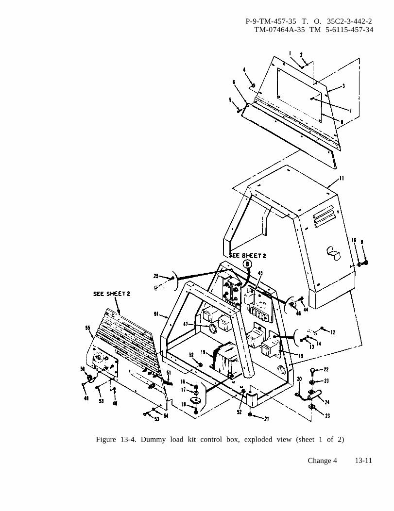
P-9-TM-457-35 T. O. 35C2-3-442-2TM-07464A-35 TM 5-6115-457-34
Figure 13-4. Dummy load kit control box, exploded view (sheet 1 of 2)
Change 4 13-11

P-9-TM-457-35 T.O. 35C2-3-442-2TM-07464A-35 TM 5-6115-457-34
Figure 13-4. Dummy load kit control box, exploded view (sheet 2 of 2)
13-12 Change 1
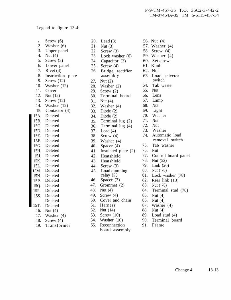
P-9-TM-457-35 T.O. 35C2-3-442-2TM-07464A-35 TM 5-6115-457-34
Legend to figure 13-4:
1 .
2.3.4.5.6.7.8.9.
10.11.12.13.14.15.
15A.15B.15C.15D.15E.15F.15G.15H.15J.15K.15L.15M.15N.15P.15Q.15R.15S.
15T.16.17.18.19.
Screw (6)Washer (6)Upper panelNut (4)Screw (3)Lower panelRivet (4)Instruction plateScrew (12)Washer (12)CoverNut (12)Screw (12)Washer (12)Contactor (4)DeletedDeletedDeletedDeletedDeletedDeletedDeletedDeletedDeletedDeletedDeletedDeletedDeletedDeletedDeletedDeletedDeletedDeletedDeletedNut (4)Washer (4)Screw (4)Transformer
20.21.22.23.24.25.26.
27.28.29.30.31.32.33.34.35.36.37.38.39.40.41.42.43.44.45.
46.47.48.49.50.51.52.53.54.55.
Lead (3)Nut (3)Screw (3)Lock washer (6)Capacitor (3)Screw (4)Bridge rectifierassemblyNut (2)Washer (2)Screw (2)Terminal boardNut (4)Washer (4)Diode (2)Diode (2)Terminal lug (2)Terminal lug (4)Lead (4)Screw (4)Washer (4)Spacer (4)Insulated plate (2)HeatshieldHeatshieldScrew (3)Load dumpingrelay K5Spacer (3)Grommet (2)Nut (4)Screw (4)Cover and chainHarnessNut (14)Screw (10)Washer (10)Reconnectionboard assembly
56. Nut (4)57. Washer (4)58. Screw (4)59. Washer (4)60. Setscrew61. Knob62. Nut63. Load selector
switch64.65.66.67.68.69.70.71.72.73.74.
75.76.77.78.79.80.81.82.83.84.85.86.87.88.89.90.91.
Tab wasteNutLensLampNutLightWasherNutNutWasherAutomatic loadremoval switch
Tab washerNutControl board panelNut (52)Link (26)Nut (’78)Lock washer (78)Rear link (13)Nut (’78)Terminal stud (78)Nut (4)Nut (4)Washer (4)Nut (4)Load stud (4)Terminal boardFrame
Change 4 13-13

Figure 13-5.
P-9-T
M-457-35
T.O
. 35C
2-3-442-2T
M-07464A
-35 T
M
5-6115-457-34
13-14
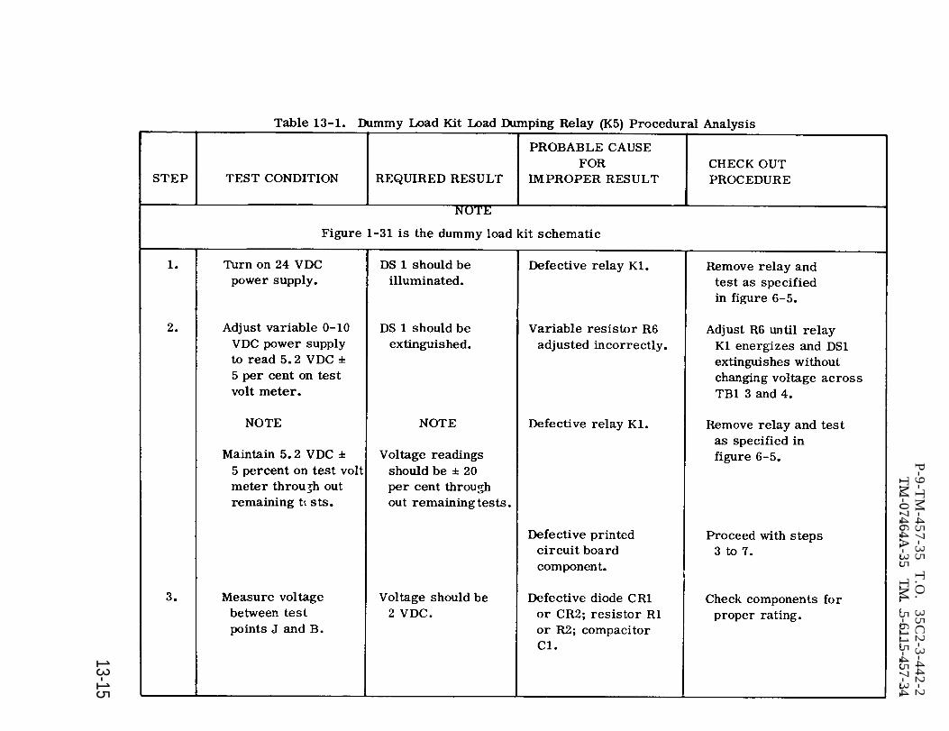
Table 13-1.
P-9-T
M-457-35
T.O
. 35C
2-3-442-2T
M-07464A
-35 T
M
5-6115-457-34
13-15

Table 13-1.
P-9-T
M-457-35
T.O
. 35C
2-3-442-2T
M-07464A
-35 T
M
5-6115-457-34
13-16
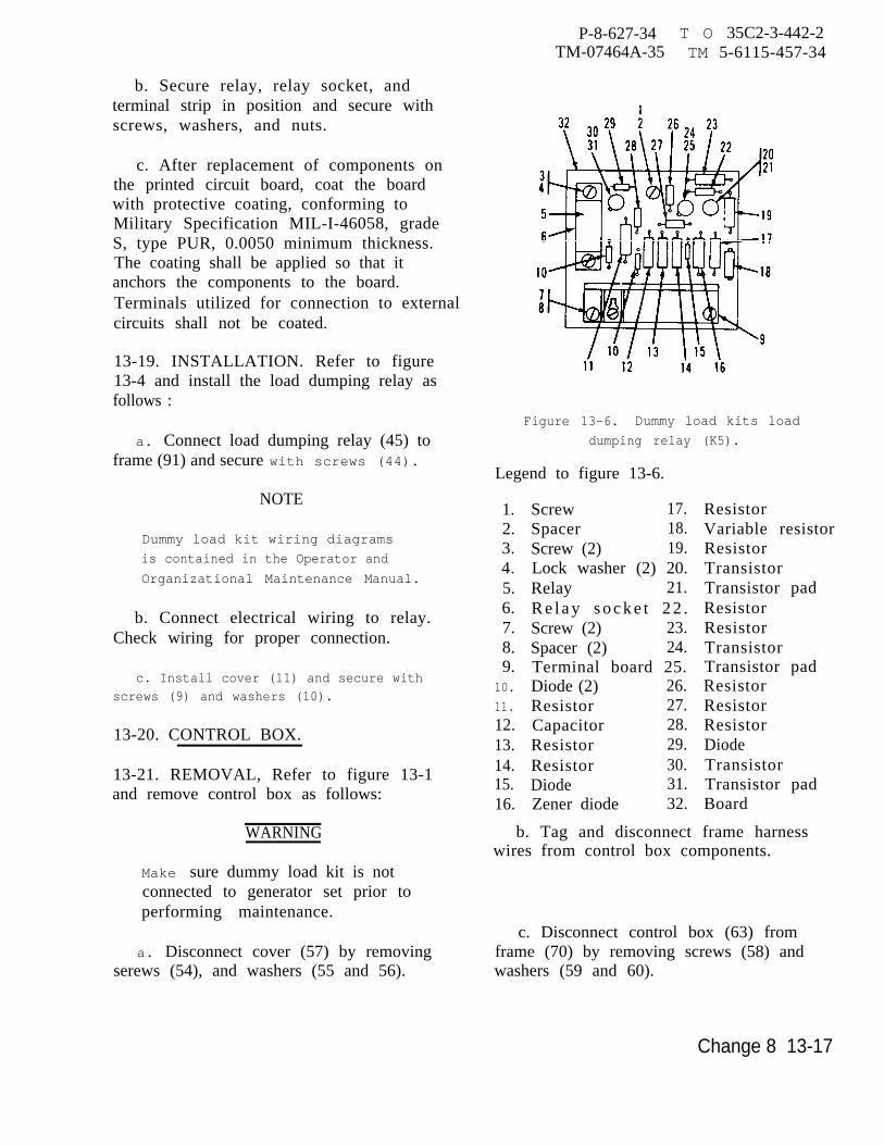
b. Secure relay, relay socket, andterminal strip in position and secure withscrews, washers, and nuts.
c. After replacement of components onthe printed circuit board, coat the boardwith protective coating, conforming toMilitary Specification MIL-I-46058, gradeS, type PUR, 0.0050 minimum thickness.The coating shall be applied so that itanchors the components to the board.Terminals utilized for connection to externalcircuits shall not be coated.
13-19. INSTALLATION. Refer to figure13-4 and install the load dumping relay asfollows :
a. Connect load dumping relay (45) toframe (91) and secure with screws (44).
NOTE
Dummy load kit wiring diagrams
is contained in the Operator and
Organizational Maintenance Manual.
b. Connect electrical wiring to relay.Check wiring for proper connection.
c. Install cover (11) and secure withscrews (9) and washers (10).
13-20. CONTROL BOX.
13-21. REMOVAL, Refer to figure 13-1and remove control box as follows:
WARNING
Make sure dummy load kit is notconnected to generator set prior toperforming maintenance.
a. Disconnect cover (57) by removingserews (54), and washers (55 and 56).
P-8-627-34TM-07464A-35
T O 35C2-3-442-2TM 5-6115-457-34
Figure 13-6. Dummy load kits load
dumping relay (K5).
Legend to figure 13-6.
1.2.3.4.5.6.7.8.9.
10.
11.
12.13.14.15.16.
Screw 17.Spacer 18.Screw (2) 19.Lock washer (2) 20.Relay 21.R e l a y s o c k e t 2 2 .Screw (2) 23.Spacer (2) 24.Terminal board 25.Diode (2) 26.Resistor 27.Capacitor 28.Resistor 29.Resistor 30.Diode 31.Zener diode 32.
ResistorVariable resistorResistorTransistorTransistor padResistorResistorTransistorTransistor padResistorResistorResistorDiodeTransistorTransistor padBoard
b. Tag and disconnect frame harnesswires from control box components.
c. Disconnect control box (63) fromframe (70) by removing screws (58) andwashers (59 and 60).
Change 8 13-17
P-8-627-34 T O 35C2-3-442-2TM-07464A-35 TM 5-6115-457-34
13-22. DISASSEMBLY. Refer to figure13-4 and disassemble control box in theorder of index number assigned. Payparticular attention to the following.
NOTE
Disassemble control box only to theextent necessary to effect repair.
a. Remove cover (11). Tag and dis-connect harness (51) wires from components.
b. Disassemble load dumping relay asspecified in paragraph 13-14, only afterperforming test specified in paragraph 13-13.
c. To remove leads (20) from capacitors.(24), remove screws and washers securingleads to capacitor terminal.
d. Tag lead (37) with location priorremoval to insure proper reassembly.
e. Remove nut (12), screw (13) andwasher (14). Remove contactor (15)from control box.
NOTE
Steps f. through h. deleted.
to
i. Note position of rear links (82) priorto removal to insure proper reassembly.
13-23. CLEANING.
a. Clean electrical components with aclean lint-free cloth moistened in an approv-ed cleaning solvent and dry thoroughly.
WARNING
Cleaning Solvents are f lammable andmoderately toxic to skin, eyes andrespiratory tract. Eye and skinprotection required. Good generalventilation is normally adequate.
b. Clean metal parts in an approvedcleaning solvent and dry thoroughly.
13-24. INSPECTION.
a. Inspect harness wires for defectiveor loose terminal lugs and defective insu-lation. Check each wire for continuity,refer to figure 13-7. Check connects forbent, loose, or missing pins and for shortsfrom case to pins and pins to surroundingpins.
N O T E
Figure 1-31 is the dummy load kit
schematic.
b. Check switches and light assemblyfor continuity.
13-25. TEST.
a . Test for continuity between contractorsK1, K2, K3, and K4 terminals L1 to T1, L2to T2, and L3 to T3; there should not becontinuity. Connect a 24 VDC ± 4 volt, 5ampere power supply and 0 - 5 ampereammeter to contactor terminals Cl and C3.Turn on power supply and observe ammeter.Ammeter should indicate 4.5 amperes pull-in current and 0.9 amperes holding current.Check for continuity between terminals L1to T1, L2 to T2, and L3 to T3; there shouldbe continuity. Turn off power supply.
b. Test resistance of transformerwindings. Check between terminals 1 and 2,3 and 4, and 5 and 6; resistance should be6.5, 7, and 0.06 ohms respectively. Check
13-18 Change 8
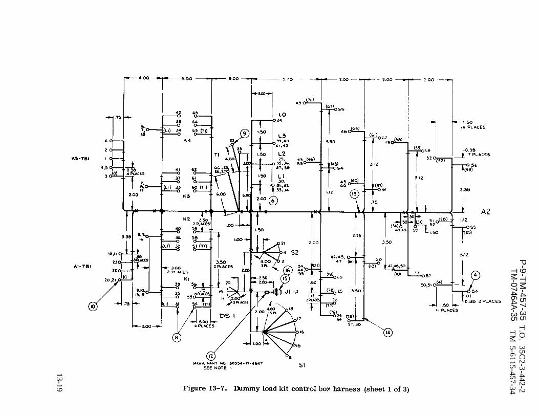
Figure 13-7.
P-9-T
M-457-35
TM-07464A
-35T
.O.
35C2-3-442-2
TM
5-6115-457-34
13-19

P-9-TM-457-35 T.O. 35C2-3-442-2TM-07464A-35 TM 5-6115-457-34
Figure 13-7. Dummy load kit control box harness (sheet 2 of 3)
insulation resistance using a 500 volt meg- voltmeter should indicate 35 volts. Connectger, resistance should be greater than 1 power supply and ammeter to terminals 3magohm. Connect a 50, 60, or 400 hertz and 4 with ammeter in series with terminal0.5 ampere power supply to terminals 1 3. Turn on power supply, ammeter shouldand 2 of transformer. Connect a 0-3 indicate less than 0.05 amperes and volt-ampere ammeter in series with power sup- meter should indicate 35 volts, Removeply and terminal 1. Connect a 0-50 VAC test equipment from transformer.voltmeter accross transformer terminals5 and 6. Turn on power supply, ammeter c. Test forward and reverse resist-should indicate less than 0.05 amperes and ante of diodes. Measured from anode (t)
13-20 Change 1
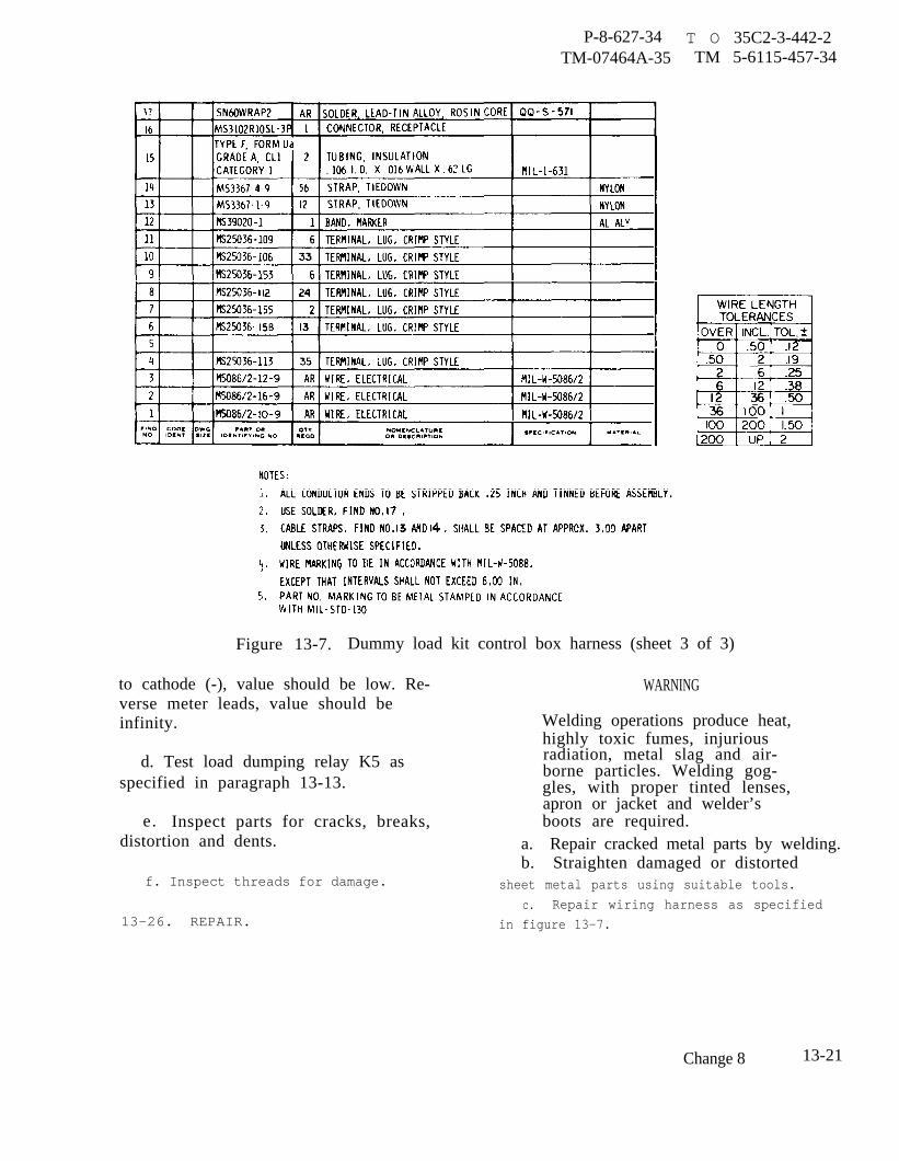
P-8-627-34TM-07464A-35
T O 35C2-3-442-2TM 5-6115-457-34
Figure 13-7. Dummy load kit control box harness (sheet 3 of 3)
to cathode (-), value should be low. Re- WARNINGverse meter leads, value should beinfinity. Welding operations produce heat,
highly toxic fumes, injuriousd. Test load dumping relay K5 as radiation, metal slag and air-
borne particles. Welding gog-specified in paragraph 13-13. gles, with proper tinted lenses,
apron or jacket and welder’se. Inspect parts for cracks, breaks, boots are required.
distortion and dents. a. Repair cracked metal parts by welding.b. Straighten damaged or distorted
f. Inspect threads for damage. sheet metal parts using suitable tools.
c. Repair wiring harness as specified13-26. REPAIR. in figure 13-7.
Change 8 13-21
P-8-627-34 T O 35C2-3-442-2TM-07464A-35 TM 5-6115-457 -34
13-27. WIRING HARNESS REBUILD. Re- h. Prior to installing cover (11) checkbuild dummy load kit control box harness as harness (51) wires and rear links (82) forspecified in figure 13-7. proper connection.
13-28. REASSEMBLY. Refer to figure i. Coat all solder connections with-13-4 and reassemble control box assembly fungus resistant varnish conforming toin the reverse order of index numbers
Pay particular attentiona s s i g n e d .to the following.
a. Reassemble load dumping relayas specified in paragraph 13-18.
b. When installing links (79), set linksfor desired voltage output, refer toOperator and Organizational MaintenanceManual.
NOTE
Military Specification MIL-U-173B priorto installing cover (n).
13-29. INSTALLATION. Refer to figure(45)
13-1 and install control box as follows.
NOTE
Control box cover must beremoved prior to installation.
a. Position panel (62), firewall (61),
Steps c. through g. deleted.and control box (63) on frame (70) andsecure with screws (58) and washers (59and 60).
NOTE
Dummy load bank wiring diagram iscontain in Operater and OrganizationalMaintenance Manual.
b. Connect frame harness wires tocontrol box components. Check wires forproper connection.
c. Install cover (57) and secure switchscrews (54) and washers (55 and 56).
NOTE
Dummy load kit wiring diagram iscontain in Operator and Organiza-tional Maintenance Manual.
All data on pages 14-1 through 14-8,including figures 14-1 and 14-2 deleted.
13-22 Change 8
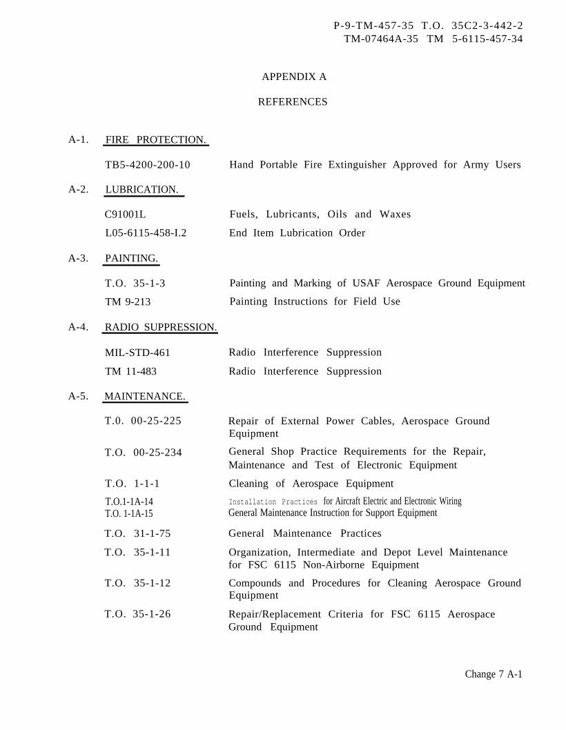
P-9-TM-457-35 T.O. 35C2-3-442-2TM-07464A-35 TM 5-6115-457-34
A-1. FIRE PROTECTION.
TB5-4200-200-10
A-2. LUBRICATION.
C91001L
L05-6115-458-I.2
A-3. PAINTING.
T.O. 35-1-3
TM 9-213
A-4. RADIO SUPPRESSION.
MIL-STD-461
TM 11-483
A-5. MAINTENANCE.
T.0. 00-25-225
T.O. 00-25-234
T.O. 1-1-1
T.O.1-1A-14T.O. 1-1A-15
T.O. 31-1-75
T.O. 35-1-11
T.O. 35-1-12
T.O. 35-1-26
APPENDIX A
REFERENCES
Hand Portable Fire Extinguisher Approved for Army Users
Fuels, Lubricants, Oils and Waxes
End Item Lubrication Order
Painting and Marking of USAF Aerospace Ground Equipment
Painting Instructions for Field Use
Radio Interference Suppression
Radio Interference Suppression
Repair of External Power Cables, Aerospace GroundEquipment
General Shop Practice Requirements for the Repair,Maintenance and Test of Electronic Equipment
Cleaning of Aerospace Equipment
Installation Practices for Aircraft Electric and Electronic WiringGeneral Maintenance Instruction for Support Equipment
General Maintenance Practices
Organization, Intermediate and Depot Level Maintenancefor FSC 6115 Non-Airborne Equipment
Compounds and Procedures for Cleaning Aerospace GroundEquipment
Repair/Replacement Criteria for FSC 6115 AerospaceGround Equipment
Change 7 A-1
P-9-TM-457-35 T.O. 35C2-3-442-2TM-07464A-35 TM 5-6115-457-34
T.O. 35-1-524
TM 9-1870-1
TB ORD 651
TM 38-750
TM 5-6115-458-12
TM 5-6115-458-35
TM 5-6115-458-25P
TM 9-2920-232-34
TM 9-6140-200-15
TM 5-764
MIL-HDBK-705
MIL-I-6868
MIL-I-25135
MIL-STD-120
MIL-STD-454
MIL-STD-705
MIL-STD-1261 (MR)
MIL-T-27730
MS 33540
USAF Equipment Registration Number System Applicable toFSC 6115 Equipment
Care and Maintenance of Pneumatic Tires
Use of Antifreeze Solutions and Cleaning Compounds inEngine Cooling Systems
The Army Maintenance Management System.
Operator and Organizational Maintenance Manual
Intermediate (Field) (Direct and General Support) and DepotMaintenance Manual
Organizational, Intermediate (Field) (Direct Support andGeneral Support) and Depot Maintenance Repair Parts andSpecial Tools Lists
Starter Motor Field Maintenance Manual
Operation and Organizational Field and Depot MaintenanceStorage Batteries, Lead Acid Type
Electric Motor and Generator Repair
Military Standardization Handbook, Generator Sets,Electrical Measurements and Instruments
Inspection Process, Magnetic Particle
Inspection Materials, Penetrant
Gauge Inspection
Standard General Requirements for Electronic Equipment
Generator Sets, Engine-Driven Methods of Test andInstructions
Welding Procedures for Construction Steels
Tape, Antiseize, Polytetrafluoroethy lene, with Dispenser
Safety Wiring and Cotter Pinning, General Practices for
A-6. SHIPMENT AND STORAGE.
T.O. 35-1-4 Processing and Inspection of Aerospace Ground Equipmentfor Storage and Shipment
T. O. 38-1-5 Processing and Inspection of Non-Mounted, Non-AircraftGasoline and Diesel Engines for Storage and Shipment
TB 740-90-1 Administrative Storage of Equipment
A-2
P-9-TM-457-35 T.O. 35C2-3-442-2TM-07464A-35 TM 5-6115-457-34
TB 740-93-2 Preservation of USAM EC Mechanical Equipment forShipment and Storage
TM 38-230 Preservation, Packaging and Packing of Military Suppliesand Equipment
MIL-S-207 Sulfuric Acid, Electrolyte: Packaging, Packing, andMarking for Shipment and Storage of
A-7. DESTRUCTION OF MATERIEL.
TM 750-244-3 Procedures for Destruction of Equipment to PreventEnemy Use
A-3/(A-4 blank)


P-9-TM-457-35 T.O. 35C2-3-442-2TM-07464A-35 TM 5-6115-457-34
ALPHABETICAL INDEX
A. C. Current Meter (M-8) . . . . . . . . . . . . . . . . . . . . . . . . . . . .Cleaning. . . . . . . . . . . . . . . . . . . . . . . . . . . . . . . . .Inspection . . . . . . . . . . . . . . . . . . . . . . . . . . . . . . . . . .Installation . . . . . . . . . . . . . . . . . . . . . . . . . . . . . . . . .Test . . . . . . . . . . . . . . . . . . . . . . . . . . . . . . . . . . . . .Test on Equipment . . . . . . . . . . . . . . . . . . . . . . . . . . . . .Removal . . . . . . . . . . . . . . . . . . . . . . . . . . . . . . . . . . .
A.C. Output Receptacle Box-DeletedAccessory Drive Group
Cleaning . . . . . . . . . . . . . . . . . . . . . . . . . . . . . . . . . . .Disassembly . . . . . . . . . . . . . . . . . . . . . . . . . . . . . . . .General . . . . . . . . . . . . . . . . . . . . . . . . . . . . . . . . . .Inspection . . . . . . . . . . . . . . . . . . . . . . . . . . . . . . . . . .Installation . . . . . . . . . . . . . . . . . . . . . . . . . . . . . . . . .Reassembly . . . . . . . . . . . . . . . . . . . . . . . . . . . . . . . . .Removal . . . . . . . . . . . . . . . . . . . . . . . . . . . . . . . . . . .Repair . . . . . . . . . . . . . . . . . . . . . . . . . . . . . . . . . . . .
AlternatorCleaning . . . . . . . . . . . . . . . . . . . . . . . . . . . . . . . . . .Disassembly . . . . . . . . . . . . . . . . . . . . . . . . . . . . . . . .General . . . . . . . . . . . . . . . . . . . . . . . . . . . . . . . . . .Inspection . . . . . . . . . . . . . . . . . . . . . . . . . . . . . . . . . .Installation . . . . . . . . . . . . . . . . . . . . . . . . . . . . . . . . .Reassembly . . . . . . . . . . . . . . . . . . . . . . . . . . . . . . . . .Removal . . . . . . . . . . . . . . . . . . . . . . . . . . . . . . . . . . .Repair . . . . . . . . . . . . . . . . . . . . . . . . . . . . . . . . . . . .Test and Adjustment . . . . . . . . . . . . . . . . . . . . . . . . . . . .
Base AssemblyCleaning . . . . . . . . . . . . . . . . . . . . . . . . . . . . . . . . . .Disassembly. . . . . . . . . . . . . . . . . . . . . . . . . . . . . . . . .General . . . . . . . . . . . . . . . . . . . . . . . . . . . . . . . . . . .Inspection . . . . . . . . . . . . . . . . . . . . . . . . . . . . . . . . . . . . . . . . . . . . . . . . . . . . . . . . .Installation . . . . . . . . . . . . . . . . . . . . . . . . . . . . . . . . .Reassembly . . . . . . . . . . . . . . . . . . . . . . . . . . . . . . . . .Removal . . . . . . . . . . . . . . . . . . . . . . . . . . . . . . . . . . .Repair . . . . . . . . . . . . . . . . . . . . . . . . . . . . . . . . . . . .
Camshaft GroupCleaning . . . . . . . . . . . . . . . . . . . . . . . . . . . . . . . . . .Disassembly . . . . . . . . . . . . . . . . . . . . . . . . . . . . . . . .General . . . . . . . . . . . . . . . . . . . . . . . . . . . . . . . . . . .Inspection . . . . . . . . . . . . . . . . . . . . . . . . . . . . . . . . . .Installation . . . . . . . . . . . . . . . . . . . . . . . . . . . . . . .Reassembly . . . . . . . . . . . . . . . . . . . . . . . . . . . . . . . . .Removal . . . . . . . . . . . . . . . . . . . . . . . . . . . . . . . . . . .Repair . . . . . . . . . . . . . . . . . . . . . . . . . . . . . . . . . . . .
Change 3
Paragraph
6-236-256-266-286-276-246-24b
8-1538-1528-1508-1548-1578-1568-1518-155
8-158-148-128-168-208-188-138-178-19
9-49-39-19-59-89-79-29-6
8-2078-2068-2048-2088-2118-2108-2058-209
I-1
P-9-TM-457-35 T.O. 35C2-3-442-2TM-07464A-35 TM 5-6115-457-34
ALPHABETICAL INDEX (Continued)
Circuit Breaker Assembly (CB2) . .Cleaning . . . . . . . . . . . .Disassembly . . . . . . . . . .Inspection . . . . . . . . . . .Installation . . . . . . . . . .Reasembly . . . . . . . . . .Repair . . . . . . . . . . . . .Test . . . . . . . . . . . . . .Test on Equipment . . . . . . .
Connecting Rods and Pistons GroupCleaning . . . . . . . . . . . .Disassembly . . . . . . . . . .General . . . . . . . . . . . .Inspection . . . . . . . . . . .Installation . . . . . . . . . .Reassembly . . . . . . . . . .Removal . . . . . . . . . . . .Repair . . . . . . . . . . . . .
Control Assembly . . . . . . . . .Cleaning . . . . . . . . . . . .Disassembly . . . . . . . . . .Inspection . . . . . . . . . . .Installation . . . . . . . . . .Reassembly . . . . . . . . . .Removal . . . . . . . . . . . .Repair . . . . . . . . . . . . .
Control Box Relay Assembly (A-4)Cleaning . . . . . . . . . . . .Disassembly . . . . . . . . . .Inspection . . . . . . . . . . . .Installation . . . . . . . . . .Reassembly . . . . . . . . . .Removal . . . . . . . . . . . .Repair . . . . . . . . . . . . .Test . . . . . . . . . . . . . .Test on Equipment . . . . . . .
Control Cubicle . . . . . . . . . . .Adjustment . . . . . . . . . . .
Paragraph
6-147A6-147E6-147D6-147F6-14716-147H6-147G6-147C6-147B
8-2158-2148-2128-2168-2198-2188-2138-2174-184-214-204-224-254-244-194-236-146-136-176-196-226-216-15b6-206-166-156-296-39
I - 2 C h a n g e 3

P-9-TM-457-35 T.O. 35 C2-3-442-2TM-07464A-35 TM 5-6115-457-34
ALPHABETICAL INDEX (Continued)
Cleaning . . . . . . . . . . . . . . . . . . . . . . . . . . . . . . . . . . . . . . . . . . . . .Disassembly . . . . . . . . . . . . . . . . . . . . . . . . . . . . . . . . . . . . ... . . .Inspection . . . . . . . . . . . . . . . . . . . . . . . . . . . . . . . . . . . . . . . . . . . .Installation . . . . . . . . . . . . . . . . . . . . . . . . . . . . . . . . . . . . . . . . . . . .Reassembly . . . . . . . . . . . . . . . . . . . . . .. . . . . . . . . . . . . . . . .Rebuild . . . . . . . . . . . . . . . . . . . .. . . . ..... . . . . . . . . . . .Repair . . . . . . . . . . . . . . ..... . . . . 0 . . . . . 0 . . . . . . . . * . . . . .
Test . . . . . . . . . . . . . . . . . . . . . . . . . . . . . . . . .... . . . . . .Test on Equipment . . . . . . . . . . . . . . . .... . . . . . . . . . . . . . . . . . .
Removal . . . . . . . . . . .. .. . ... . . . . . . . . . . . . . . . . . . . . . . . .Control Cubicle Assembly . . . . . . . . . . . . . . . . . . . . . . . . . . . . . . . . . . . .
Installation . . . . . . . . . . . . . . . . . . . ... . ... . . . . . . . . . . . . . . .Removal . . . . . . . . . . . . . . . . . . . . . . . . . . . . . . . . . . . . . . . . . . . . .
Convenience Receptacle Assembly50/60 Hertz Convenience Receptacle Assembly . . . . . . . . . . . . . . . . . . . .
Cleaning . .... . . . . . . . . . . . . . . .Disassembly . . . . . . . . . . . . . . . . . . . . . . . . . . . . . . . . . . . . . . . . .Inspection . . . . . . . . . . . . . . . . . . . . . . . . . . . . . . . . . . . . . . . . . .Installation . . . . . . . . . . . . . . . . . . . . . . . . .. . . . . . . . . . . . . . . .Reassembly . . . . . . . . . . . . . . . . . . . . . . . . . . . . . . . . . . . . . . . . . .Removal . . . . . . . . . . . . . . . . . .. . . . . . . . . .. . . . . . . .. . . . .Repair . . . . . . . . . . . . . . . . . . . . . . . . . . . . . . . . . . . . . . . . . . . .
400 Hertz Convenience Receptacle Assembly . . . . . . . . . . . . . . . . . . . . .Cleaning . . . . . . . . . . . . . . ... ... . ... . . ... . . . . . . . . .Disassembly . . . . . . . . . . . . . . . . . . . . . . . . . . . . . . . . . . . . . . . . .Inspection . . . . . . . . . . . . . . . . . . . . . . . . . . . . . . . . . . . . . . . ..O
Installation . . . . . . . . . . . . . . . . . . . . . . . . . . . . . . . . . . . . . . . . . .Reassembly . . . . . . . . . . . . . . . . . . . . . . . . . . . . . . . . . . . . . . . . . .Removal . . . . . . . . . . . . . . . . . . . . . . . . . . . . . . . . . . . . . . . . .Repair . . . . . . . . . . . . . . . . . * . * . . . . * . . . * . . . . . . . . . . . . .
General . . . . . . . . . . . . . . . . . . . . . . . . . . . . . . . . . . . . . . . . . . . . . .Crankshaft Group and Main Bearings
Cleaning . . . . . . . . . . . . . . . . . . . . . . . . . . . . . . . . . . . . . . . . . . . . .Disassembly . . . . . . . . . . . . . . . . . . . . . . . . . . . . . . . . . . . . . . . . . . .General . . . . . . . . . . . . . . . . . . . . . . . . . . . . . . . . . . . . . . . . . . . . . .Inspection . . . . . . . . . . . . . . . . . . . . . . . . . . . . . . ....Installation . . . . . . . . . . . . . .... . . . . . . . . . . . . . . . . . . . . . . . . .Reassembly . . . . . . . . . . . . . . . . . . . . . . . . . . . . . . . . . . . . .Removal . . . . . . . . . . . . . . . . . . . . . . . . . . . . . . . . . . . . . . .. . . . 0 . .
Repair . . . . . . . . . . ..... ● 0...... . .... . . . . . . . . ....
Paragraph
6-326-316-336-386-366-356-346-376-306-30b2-62-6b2-6a
6-586-616-606-626-656-646-596-636-666-696-686-706-736-726-676-716-57
8-2238-2228-2208-2248-2278-2268-2218-225
I-3
P-9-TM-457-35 T.O. 35C2-3-442-2TM-07464A-35 TM 5-6115-457-34
ALPHABETICAL INDEX (Continued)
Paragraph
Crankshaft Pulley, Damper and Timing GearCover Group
C l e a n i n g . . . . . . . . . . . . . . . . . . . . . . . . .Disassembly . . . . . . . . . . . . . . . . . . . . . . . . . . . . .
General . . . . . . . . . . . . . . . . . . . . . . . . . . . . . . . . . . . . . . . . Inspection . . . . . . . . . . . . . . . . . . . . . . . . . . . . . . . . . . . . . . . . . . .Installation . . . . . . . . . . . . . . . . . . . . . . . . . . . . . . . . . . . . . . . . . . .Reassembly . . . . . . . . . . . . . . . . . . . . . . . . . . . . . . . Removal . . . . . . . . . . . . . . . . . . . . . . .. . . . . . . . . . . . .
R e p a i r . . . . . . . . . . . . . . . . . . . . . . . . . . . . . . . . . . . . . . . . . . .
Cylinder Block and Covers GroupCleaning . . . . . . . . . . . . . . . . . . . . . . . . . . . . . . . . . . .
Disassembly . . . . . . . . . . . . . . . . . . . . . . . . . . . . . . . . . . . . . . . .
General . . . . . . . . . . . . . . . . . . . . . . . . . . . . . . . . . . . . . . . . . . . . .Inspection . . . . . . . . . . . . . . . . . . . . . . . . . . . . . . . . . . . . . . . . . . . . .Installation . . . . . . . . . . . . . . . . . . . . . . . . . . . . . . . . . . . . . .
Reassembly . . . . . . . . . . . . . . . . . . . . .. . . . Removal . . . . . . . . . . . . . . . . . . . . . . . . . . . . . . . . . . . . . . .
Repair . . . . . . . . . . . . . . . . . . . . . . . . . . . . . . . . . . . . . . . . Cylinder Head Group
C l e a n i n g . . . . . . . . . . . . . . . . . . . . . . . . . . . . . . . . . . . . . . . .
Disassembly . . . . . . . . . . . . . . . . . . . . . . . . . . . . . . . . . . . . . . . . . .
General . . . . . . . . . . . . . . . . . . . . . . . . . . . . . . . . . . . . . . . . . . . . .Inspection . . . . . . . . . . . . . . . . . . . . . . . . . . . . . . . . . . . . . . . . . . .Installation . . . . . . . . . . . . . . . . . . . . . . . . . . . . . . . . . . . . . . . . . . .Reassembly . . . . . . . . . . . . . . . . . . . . . . . . . . . . . . . . .
Removal . . . . . . . . . . . . . . . . . . . . . . . . . . . . . . . . . . . . . . . .
Repair . . . . . . . . . . . . . . . . . . . . . . . . . . . . . . . . . . . . . . . .
Day Tank AssemblyCleaning . . . . . . . . . . . . . . . . . . . . . . . . . . . . . . . . . . . . . .. .....Inspection . . . . . . . . . . . . . . . . . . . . . . . . . . . . . . . . . . . . . . . . . . .General . . . . . . . . . . . . . . . . . . . . . . . . . . . . . . . . . . . . . . . .
Reassembly and Installation . . . . . . . . . . . . . . . . . . . . . . . . . . . . . . . .Removal and Disassembly . . . . . . . . . . . . . . . . . . . . . . . . . . . . . . . . .Repair . . . , . 0 0 0 0 . . . . 0 . 0 . . . . . . 0 . . 0 . * . * * . * . * * * * * * . * *
D.C. Circuit Breaker BoxCleaning . . . . . . . . . . . . . . . . 0 . * . . . . * * * . . * * * * * * * * ● * * * *
Disassembly . . . . . . . . . . . . . . . . . . . . . . . . . . . . . . . . . . . . . . . . . .General . . . . . . . . . . . . . . . . . . . . . . . . . . . . . . . . . . . . . . . . . . . . .Inspection ● . . . . . . . . . . . . . . . . . . . . . .Installation . . . . . . . . . . . . . . . . . . . . . . . . . . . . . . . . . . . . . . . . . . .Reassembly . . . . . . . . . . . . . . . . . . . . . . . . . . . . . . . . . . . . . . . . . . . .
8-1288-1278-1258-1298-1328-1308-1268-130
8-2318-2308-2288-2328-2358-2348-2298-233
8-1918-1908-1888-1928-1958-1948-1898-193
8-408-418-388-438-398-42
6-436-426-406-446-476-46
I-4
P-9-TM-457-35 T.O. 35 C2-3-442-2TM-07464A-35 TM 5-6115 -457-34
ALPHABETICAL INDEX (Continued)
Paragraph
Removal ... ... . . . . . . . . . . . . . . ... Repair . . . . . . . . . . . . . . . . . . . . . . . . . . . . . . . . .. . . . . . . .
D.C. Relay Assembly (A-5) . . . . . . . . . . . . . . . . . . . . . . . . . . . . . . . . . . .
Cleaning . . . . . . . . . . . . . . . . . . . . . . . . . . . . . ... . . . . . . . . . . . . .Disassembly . . . . . . . . . . . . . . . . . . . . . . . . . . . . . . . . . . . . . . . . . . .Inspection . . . . . . . . . . . . .. . . . . . . . . . . . . . . . . . . . .
Installation . . . . . . . . . . . . . . . . . . . . . . . . . . . . . . . . . . . . . . . . . . . .Reassembly . . . . . . . . . . . . . . . . . . . . . . . . . . . . . . . . . . . . . . . . . . . .Repair . . . . . . . . . . . . . . . . . . . . . . . . . . . . . . . . . . . . . .. . . . . . . .
6-416-456-866-906-896-916-946-936-926-886-876-87b
13-413-313-113-513-913-813-213-7
13-2013-2313-2213-2413-2913-2813-2113-2613-2513-2713-1013-10a13-10b13-1113-1513-1413-1613-1913-1813-12
I - 5
P-9-TM-457-35 T.O. 35 C2-3-442-2TM-07464A-35 TM 5-6115-457-34
ALPHABETICAL INDEX (Continued)
13-1713-13
6-1226-1216-1206-1236-1266-1256-1246-1196-119b
5-35-15-45-65-55-2
12-512-412-112-612-912-812-212-712-3
12-2112-2012-1712-2212-2512-2412-1812-2312-19
I-6 Change 3

P-9-TM-457-35 T.O. 35C2-3-442-2TM-07464A-35 TM 5-6115-457-34
ALPHABETICAL INDEX (Continued)
Paragraph
Electric Winterization Kit, Electric HeaterCleaning . . . . . . . . . . . . . . . . . . . . . . . . . . . . . . . . . . . . . . . . . . . . . .Disassembly . . . . . . . . . . . . . . . . . . . . . . . . . . . . . . . . . . . . . . . . . . .General . . . . . . . . . . . . . . . . . . . . . . . . . . . . . . . . . . . . . . . . . . . . . .Inspection . . . . . . . . . . . . . . . . . . . . . . . . . . . . . . . . . . . . . . . . . . . .Installation . . . . . . . . . . . . . . . . . . . . . . . . . . . . . . . . . . . . . . . . . . . .Reassembly . . . . . . . . . . . . . . . . . . . . . . . . . . . . . . . . . . . . . . . . . . . .Removal . . . . . . . . . . . . . . . . . . . . . . . . . . . . . . . . . . . . . . . . . . . . . .
Engine . . . . . . . . . . . . . . . . . . . . . . . . . . . . . . . . . . . . . . . . . . . . . . . . .Installation . . . . . . . . . . . . . . . . . . . . . . . . . . . . . . . . . . . . . . . . . . . .Removal . . . . . . . . . . . . . . . . . . . . . . . . . . . . . . . . . . . . . . . . . . . . . .
Engine ComponentsDisassembly . . . . . . . . . . . . . . . . . . . . . . . . . . . . . . . . . . . . . . . . . . .General . . . . . . . . . . . . . . . . . . . . . . . . . . . . . . . . . . . . . . . . . . . . . .Installation . . . . . . . . . . . . . . . . . . . . . . . . . . . . . . . . . . . . . . . . . . . .Reassembly . . . . . . . . . . . . . . . . . . . . . . . . . . . . . . . . . . . . . . . . . . . .Removal . . . . . . . . . . . . . . . . . . . . . . . . . . . . . . . . . . . . . . . . . . . . . .
Engine Harness GroupCleaning . . . . . . . . . . . . . . . . . . . . . . . . . . . . . . . . . . . . . . . . . . . . . .General . . . . . . . . . . . . . . . . . . . . . . . . . . . . . . . . . . . . . . . . . . . . . . .Inspection . . . . . . . . . . . . . . . . . . . . . . . . . . . . . . . . . . . . . . . . . . . .Installation . . . . . . . . . . . . . . . . . . . . . . . . . . . . . . . . . . . . . . . . . . . .Rebuild . . . . . . . . . . . . . . . . . . . . . . . . . . . . . . . . . . . . . . . . . . . . . .Removal . . . . . . . . . . . . . . . . . . . . . . . . . . . . . . . . . . . . . . . . . . . . . .
Engine Test After OverhaulEngine Assembly Run-in and Adjustments . . . . . . . . . . . . . . . . . . . . . . . .
Pre-run-in Checks . . . . . . . . . . . . . . . . . . . . . . . . . . . . . . . . . . . . .Run-in . . . . . . . . . . . . . . . . . . . . . . . . ...... . . . . . . . . . . . . .Utility Governor Speed Setting Adjustment . . . . . . . . . . . . . . . . . . . . .
General . . . . . . . . . . . . . . . . . . . . . . . . . . . . . . . . . . . . . . . . . . . . . .Exciter-Regulator
Adjustment . . . . . . . . . . . . . . . . . . . . . . . . . . . . . . . . . . . . . . . . . . . .Cleaning . . . . . . . . . . . . . . . . . . . . . . . . . . . . . . . . . . . . . . . . . . . . .Disassembly . . . . . . . . . . . . . . . . . . . . . . . . . . . . . . . . . . . . . . . . . . .General . . . . . . . . . . . . . . . . . . . . . . . . . . . . . . . . . . . . . . . . . . . . . . .Inspection . . . . . . . . . . . . . . . . . . . . . . . . . . . . . . . . . . . . . . . . . . . .Installation . . . . . . . . . . . . . . . . . . . . . . . . . . . . . . . . . . . . . . . . . . . .Reassembly . . . . . . . . . . . . . . . . . . . . . . . . . . . . . . . . . . . . . . . . . . . .Rebuild . . . . . . . . . . . . . . . . . . . . . . . . . . . . . . . . . . . . . . . . . . . . . .Repair . . . . . . . . . . . . . . . . . . . . . . . . . . . . . . . . . . . . . . . . . . . . . . .Test . . . . . . . . . . . . . . . . . . . . . . . . . . . . . . . . . . . . . . . . .. ...
12-1312-1212-1012-1412-1612-1512-112-82-8b2-8a
8-38-18-58-48-2
8-88-68-98-118-108-7
8-2378-237a8-237c8-237b8-236
6-846-786-776-746-796-836-826-816-806-76
I-7
P-9-TM-457-35 T.O. 35C2-3-442-2TM-07464A-35 TM 5-6115-457-34
ALPHABETICAL INDEX (Continued )
6-756-75b
8-1608-1588-1618-1638-1598-162
8-338-328-308-348-378-368-318-35
6-526-516-486-536-566-556-546-506-496-49b
8-1998-1988-1968-2008-2038-2028-1978-2011-26-86-106-11
I-8
P-9-TM-457-35 T.O. 35C2-3-442-2TM-07464A-35 TM 5-6115-457-34
ALPHABETICAL INDEX (Continued)
Paragraph
Installation . . . . . . . . . . . . . . . . . . . . . . . . . . . . . . . . . . . . . . . . . . . .Test . . . . . . . . . . . . . . . . . . . . . . . . . . . . . . . . . . . . . . . . . . . . . . . .Test on Equipment . . . . . . . . . . . . . . . . . . . . . . . . . . . . . . . . . . . . . . .
Removal . . . . . . . . . . . . . . . . . . . . . . . . . . . . . . . . . . . . .Fuel Burning Winterization Kit Control Box
Cleaning . . . . . . . . . . . . . . . . . . . . . . . . . . . . . . . .Disassembly . . . . . . . . . . . . . . . . . . . . . . . . . . . . . . . . . . . . . . . . . . .General . . . . . . . . . . . . . . . . . . . . . . . . . . . . . . . . . . . . . . . . . . . . . .Inspection . . . . . . . . . . . . . . . . . . . . . . . . . . . . . . . . . . . . . . Installation . . . . . . . . . . . . . . . . . . . . . . . . . . . . . . . . . . . . . . . . . . .Reassembly . . . . . . . . . . . . . . . . . . . . . . . . . . . . . . . . . . . .
Removal . . . . . . . . . . . . . . . . . . . . . . . . . . . . . . . . . . . . . . . . ..Repair . . . . . . . . . . . . . . . . . . . . . . . . . . . . . . . . . . . . . . . . . . . . . . .
Fuel Burning Winterization Kit HeaterCleaning . . . . . . . . . . . . . . . . . . . . . . . . . . . . . . . . . . . . . . . . .Component Test and Adjustments . . . . . . . . . . . . . . . . . . . . . . . . . . . . .Disassembly . . . . . . . . . . . . . . . . . . . . . . . . . . . . . . .
General . . . . . . . . . . . . . . . . . . . . . . . . . . . . . . . . . . . . . . . . . . . . . . .Inspection . . . . . . . . . . . . . . . . . . . . . .
Installation . . . . . . . . . . . . . . . . . . . . . . . . . . . . . . . . . . . . . . . . . . .Reassembly . . . . . . . . . . . . . . . . . . . . . . . . . . . . . . . . .Removal . . . . . . . . . . . . . . . . . . . . . . . . . . . . . . . . . . . . . . . . . . . . . .Repair . . . . . . . . . . . . . . . . . . . . . . . . . .
Fuel Injection GroupCleaning . . . . . . . . . . . . . . . . . . . . . . . . . . . . . . . . . . . . . . . . . . . .Disassembly . . . . . . . . . . . . . . . . . . . . . . . . . General . . . . . . . . . . . . . . . . . . . . . . . . . . . . . . . . . . . . . . . . . . . . . .Inspection . . . . . . . . . . . . . . . . . . . . . . .Installation . . . . . . . . . . . . . . . . . . . . . . . . . . . . . . . . . . . . . . . . . .Reassembly . . . . . . . . . . . . . . . . . . . . . . . .Removal . . . . . . . . . . . . . . . . . . . . . . . . . . . . . . . . . . . . . . . . . .Repair . . . . . . . . . . . . . . . . . . . . . . . . . . . . . . .Testing . . . . . . . . . . . . . . . . . . . . . . . . . . . . . . . .
Fuel Pump GroupCleaning . . . . . . . . . . . . . . . . . . . . . . .Disassembly . . . . . . . . . . . . . . . . . . . . . . . . . . . . . . . . . . . . . . . . . . .General . . . . . . . . . . . . . . . . . . . . . . . . . . . . . . . . . . . . . . . . . . . . . .Inspection . . . . . . . . . . . . . . . . . . . . . Installation . . . . . . . . . . . . . . . . . . . . . . . . . . . . . . . . . . . . . .Reassembly . . . . . . . . . . . . . . . . . . . . . . . . . . . . . . . . . . . . . . . . . . . .Removal . . . . . . . . . . . . . . . . . . . . . . . . . . . . . . . . . .Repair . . . . . . . . . . . . . . . . . . . . . . . . . . . . . . . . . . . . . . . . . . . .
6-136-126-96-9b
11-411-311-111-511-811-711-211-6
11-1211-1611-1111-911-1311-1711-1511-1011-14
8-1448-1438-1418-1458-1488-1478-1428-1468-149
8-648-638-618-658-688-678-628-66
I-9

P-9-TM-457-35 T. O. 35C2-3-442-2TM-07464A-35 TM 5-6115-457-34
ALPHABETICAL INDEX (Continued)
Paragraph
Fuel Tank AssemblyCleaning . . . . . . . . . . . . . . . . . . . . . . . . . . . . . . . . . . . . . . . . . . . . . .Disassembly . . . . . . . . . . . . . . . . . . . . . . . . . . . . . . . . . . . . . . .General . . . . . . . . . . . . . . . . . . . . . . . . . . . . . . . . . . . . . . . . . . .Inspection . . . . . . . . . . . . . . . . . . . . . . . . . . . . . . . . . . . . .
Installation . . . . . . . . . . . . . . . . . . . . . . . . . . . . . . . . . . . . . . . . . Reassembly . . . . . . . . . . . . . . . . . . . . Removal . . . . . . . . . . . . . . . . . . . . . . . . . . . . . . . . . . . . . . . . . . . . . .Repair . . . . . . . . . . . . . . . . . . . . . . . . . . . . . . . . . . . . . . . . . . . . . . .
GeneralControl Cubicle . . . . . . . . . . . . . . . . . . . . . . . . . . . . . . . . . . . . . . . . .Description . . . . . . . . . . . . . . . . . . . . . . . . . . . . . . . . . . . . . . . . . . . .Radiator Assembly . . . . . . . . . . . . . . . . . . . . . . . . . . . . . . . . . . . . . .Reconnection Board Assembly, Load Contactor, LoadBoard Assembly, and Transformer Assembly . . . . . . . . . . . . . . . . . . . .
Removal and Installation of Major Componentsand Auxiliaries . . . . . . . . . . . . . . . . . . . . . . . . . . . . . . . . . . . . . . . . .
Shutter and Control Assembly . . . . . . . . . . . . . . . . . . . . . . . . . . . . . . .Troubleshooting . . . . . . . . . . . . . . . . . . . . . . . . . . . . . . . . . . . . . .
Generator . . . . . . . . . . . . . . . . . . . . . . . . . . . . . . . . . . . . . . . . . . . . .Installation . . . . . . . . . . . . . . . . . . . 0 . . , . . . . . * . * . . . . . * . . . * . .
Removal . . . . . . . . . . . . . . . . . . . . . . . . . . . . . . . . . . ........Generator Assembly Repair
Cleaning . . . . . . . . . . . . . . . . . . . . . . . . . . . . . . . . . . . . . . . . . .Disassembly . . . . . . . . . . . . . . . . . . . . . . . . . . . . . . . . . . . . . . . . .General . . . . . . . . . . . . . . . . . . . . . . . . . . . . . . . . . . . ...... .High Potential Test . . . . . . . . . . . . . . . . . . . . . . . . . . . . . . . . . . . . . .Inspection . . . . . . . . . . . . . . . . . . . . . . . . . . . . . . . . . . . . . . . . . . . . .Installation . . . . . . . . . . . . . . . . . . . . . . . . . . . . . . . . . . . . . .ON Equipment Test . . . . . . . . . . . . . . . . . . . . . . . . . . . . . . . . . . . . . .
Removal . . . . . . . . . . . . . . . . . . . . . . . . . . . . . . . . . . . . . . . . . .Reassembly . . . . . . . . . . . . . . . . . . . . . . . . . . . . . . . . . . . . . . . . .Repair or Rebuild . . . . . . . . . . . . . . . . . . . . . . . . . . . . . . . . . . . . . . .
Governor Actuator Unit (precise Sets Only)Cleaning . . . . . . . . . . . . . . . . . . . . . . . . . . . . . . . . . . . . . .Disassembly . . . . . . . . . . . . . . . . . . . . . . . . . . . . . . . . . . . . . . . . . . .General . . . . . . . . . . . . . . . . . . . . . . . . . . . . . . . . . . . . . . . . . . . .Inspection . . . . . . . . . . . . . . . . . . . . . . . . . . . . . . . . . . . . . . . . .Installation . . . . . . . . . . . . . . . . . . . . . . . . . . . . . . . . . . . . . . . . . . . .Reassembly . . . . . . . . . . . . . . . . . . . . . . . . . . . . . . . . . . . . . . . . . . . .Repair . . . . . . . . . . . . . . . . . . . . . . . . . . . . . . . . . . . . . . . . . . . . . . .Test and Adjustment . . . . . . . . . . . . . . . . . . . . . . . . . . . . . . . . . . . . . .Test and Removal . . . . . . . . . . . . . . . . . . . . . . . . . . . . . . . . . . . . . . .
Removal . . . . . . . . . . . . . . . . . . . . . . . . . . . . . . . . . . .
1-10 Change 3
9-209-199-179-219-249-239-189-22
6-11-34-1
6-136
2-54-172-42-72-7b2-7a
7-47-37-17-87-57-97-27-2b7-77-6
8-1118-1108-1088-1128-1168-1148-1138-1158-1098-109b
P-9-TM-457-35 T.O. 35C2-3-442-2TM-07464A-35 TM 5-6115 -457-34
ALPHABETICAL INDEX (Continued)
Paragraph
Housing FrameCleaning . . . . . . . . . . . . . . . . . . . . . . . . . . . . . . . . . . . . . . . . . . . . lGeneral . . . . . . . . . . . . . . . . . . . . . . . . . . . . . . . . . . . . . . .
Front Housing . . . . . . . . . . . . . . . . . . . . . . . . . . . . . . . . . ...Housing Frame . . . . . . . . . . . . . . . . . . . . . . . . . . . . . . . . . . .Rear Housing . . . . . . . . . . . . . . . . . . . . . . . . . . . . . . . . . . . . . . . .
Inspection . . . . . . . . . . . . . . . . . . . . . . . . . . . . . . . . . . . . . . . . . . . . .Reassembly and Installation . . . . . . . . . . . . . . . . . . . . . . . . . . . . . . . . .Removal and Disassembly . . . . . . . . . . . . . . . . . . . . . . . . . . . . . . . .Repair . . . . . . . . . . . . . . . . . . . . . . . . . . . . . . . . . . . . . . . . . . . . . . .
Hydraulic Pump (Precise Sets Only)Cleaning . . . . . . . . . . . . . . . . . . . . . . . . . . . . . . . . . . . . . . . . . . .General . . . . . . . . . . . . . . . . . . . . . . . . . . . . . . . . . . . . . . . . . . . .Inspection . . . . . . . . . . . . . . . . . . . . . . . . . . . . . . . . . . . . . . . . .Installation . . . . . . . . . . . . . . . . . . . . . . . . . . .. . . . . . . . .Removal . . . . . . . . . . . . . . . . . . . . . . . . . . . . . . . . . . . . . . . . . .Repair . . . . . . . . . . . . . . . . . . . . . . . . . . . . . . . . .Test . . . . . . . . . . . . . . . . . . . . . . . . . . . . . . . . . . . . . . . .
Hydraulic Pump Drive GroupCleaning . . . . . . . . . . . . . . . . . . . . . . . . . .... . . . . . . . . . . . . . .Disassembly . . . . . . . . . . . . . . . . . . . . . . . . . . . . . . . . . . . . . . . . . . .General . . . . . . . . . . . . . . . . . . . . . . . . . . . . . . . . . . . . . . . ..Inspection . . . . . . . ... . . . . . . . . . . . . . . . . . . .Installation . . . . . . . . . . . . . . . . . . . . . . . . . . . . . . . . . . . . . . .Reassembly . . . . ... . . . . . . . . . . . . . . . . . . . . . . . . . . . . . . .Removal . . . . . . . . . . . . . . . . . . . . . . . . . . . . . . . . . . . . . . . . .Repair . . . . . . . . . . . . . . . . . . . . . . . . . . . . . . . . . . . . . . . . . . . . . . .
Hydraulic Tank (Precise Sets Only)Cleaning . . . . . . . . . . . . . . . . . . . . . . .. . . . . . . . . . .Disassembly . . . . . . . . . . . . . . . . . . . . . . . . . . . . . . . .General . . . . . . . . . . . . . . . . . . . . . . . . . . . . . . . . . . . . . . . . .Inspection . . . . . . . . . . . . . . . . . . . . . . . . . . . . . . . . . . . . .Installation . . . . . . . . . . . . . . . . . . . . . . . . . . . . . ... . . . . . .Reassembly . . . . . . . . . . . . . . . . . . . . . . . . . . . . . . . . . . . . . . . . . . . .Removal . . . . . . . . . . . . . . . . . . . . . . . . . . . . . . . . . . . . . . . . .Repair . . . . . . . . . . . . . . . . . . . . . . . . . . . . . . . . . . . .
Lifting Frame AssemblyCleaning . . . . . . . . . . . . . . . . . . . . . . . . . . . . . . . . . . . . . . . .Disassembly . . . . . . . . . . . . . . . . . . . . . . . . . . . . . . . . . . . . .....General . . . . . . . . . . . . . . . . . . . . . . . . . . . . . . . . . . . . . . . . . . ..Inspection . . . . . . . . . . . . . . . . . . . . . . . . . . . . . . . . . . . . . .Installation . . . . . . . . . . . . . . . . . . . . . . . . . . . . . . . . . . . . .
3-33-13-lb3 - l a3-lc3-43-63-23-5
8-958-938-968-998-948-978-98
8-1038-1028-1008-1048-1078-1068-1018-105
8-888-878-858-898-928-918-868-90
3-103-93-73-113-14
I-11
P-9-TM-457-35 T.O. 35C2-3-442-2TM-07464A-35 TM 5-6115-457-34
ALPHABETICAL INDEX (Continued)
Paragraph
Reassembly . . . . . . . . . . . . . . . . . . . . . . . . . . . .Removal . . . . . . . . . . . . . . . . . . . . . . . . . . . . . . . Repair . . . . . . . . . . . . . . . . . . . . . . . . . . . . . . . . .... . .....
Load Board AssemblyCleaning . . . . . . . . . . . . . . . . . . . . . . . . . . . . . . . . . . .Inspection . . . . . . . . . . . . . . . . . . . . . . . . . . . . . . . . . . . . . . . . . . . . . . . . . . . . . . . . .Reassembly and Installation . . . . . . . . . . . . . . . . . . . . . . . . . . . . . . . . . . . . . . . . . . . . .Removal and Disassembly . . . . . . . . ....... . . . . . . . . . . . . . . . ...
Load ContactorInstallation . . . . . . . . . . . . . . . . . . . . . . . . . . . . . . . . . . .Test . . . . . . . . . . . . . . . . . .Test on Equipment . . . . . . . . . . . . . . . . . . . . . . . . . ... . ....
Removal . . . . . . . . . . . . . . . . . . . . . . . . . . .... . ..... ..Load Measurement Unit
Cleaning . . . . . . . . . . . . . . . . . . . . . . . . . . . . .Disassembly . . . . . . . . . . . . . . . . . . . . . . . . . . . . . . . . . . . . . . . . . . . . . . . . . . . . . . . . . . . .General . . . . . . . . . . . . . . . . . . . . . . . . . . . . . . . . . . . . . . . . . . . . . . . . . . . . . . . . . . .Inspection . . . . . . . . . . . . . . . . . . . . . . . . . . . . . . . .Installation . . . . . . . . . . . . . . . . . . . . . . . . . . . . . . . . . . . . . . . . . . . . . . . . . . . . . . . . . . . . .Reassembly . . . . . . . . . . . . . . . . . . . . . . . . . . . . . . . . . . . . . . . . . ...Repair . . . . . . . . . . . . . . . . . . . . . . . . . . . . . . . . . . . . . . . . . . . . . . . . . . . . . . . . . . . . . . . .Test and Adjustment . . . . . . . . . . . . . . . . . . . . . . . . . . . . . . . . . .Test on Equipment . . . . . . . . . . . . . . . . . . . . . . . . . . . . ...
Removal . . . . . . . . . . . . . . . . . . . . . . . . . . . . . . . .Mode I Relay Box Assembly
Bench Test . . . . . . . . . . . . . . . . . . . . . . . . . . . . . . . . . . . . . . . . . . . . . . . . .Cleaning . . . . . . . . . . . . . . . . . . . . . . . . . . . . . . . . . ..... . . . . ... . .Disassembly . . . . . . . . . . . . . . . . . . . . . . . . . . . . . . . . . . . . . . . . . . . . . . . . . . . . . . . . . . . .General . . . . . . . . . . . . . . . . . . . . . . . . . . . . . . . . . . . . . . . . . . . . . . . . . . . . . . . . . . . . . . . .Inspection and Bench Test . . . . . . . . . . . . . . . . . . . . . . . . . . . . ....Installation . . . . . . . . . . . . . . . . . . . . . . . . . . . . . . . . . . . . . . . . . . ..On Equipment Test . . . . . . . . . . . . . . . . . . . . . . . . . . . . . . . . . . ... . ......
Removal . . . . . . . . . . . . . . . . . . . . . . . . . . . . . . . . . . . . . . . .Reassembly . . . . . . . . . . . . . . . . . . . . . . . . . . . . . . . . . . . . . . . . . . . . . . . . . . . . . . . . . . . .Repair . . . . . . . . . . . . . . . . . . . . . . . . . . . . . . . . . . . . . . . . . . . . . . . . . . . . . . . ..
Mode H Relay Box AssemblyBench Test . . . . . . . . . . . . . . . . . . . . . . . . . . . . . . . . . . . . . . . . . . . . . . . . . . . . . . .Cleaning . . . . . . . . . . . . . . . . . . . . . . . . . . . . . . . . . . . ..... . ...Disassembly . . . . . . . . . . . . . . . . . . . . . . . . . . . . . . . . . . . . . . . . . . . . . . . . . . . . . . . General . . . . . . . . . . . . . . . . . . . . . . . . . . . . . ....... . ..Inspection . . . . . . . . . . . . . . . . . . . . . . . ... . . . . . . . . . . . ...... .. .Installation . . . . . . . . . . . . . . . . . . . . . . . . . . . . . . . . . . . . . . . . . . . . . . . . . . . . . . . .
3-133-83-12
6-1506-1516-1526-149
6-1476-1466-1456-145b
6-2166-2156-2126-2176-2206-2196-2186-2146-2136-213b
6-976-996-986-856-1006-1036-966-96b6-1026-101
6-1296-1316-1306-1046-1326-135
I-12 Change 3

P-9-TM-457-35 T.O. 35C2-3-442-2TM-07464A-35 TM 5-6115 -457-34
ALPHABETICAL INDEX (Continued)
Paragraph
Reassembly . . . . . . . . . . . . . . . . . . . . . . . . . . . . . . . . . . . . . . . . . . . .Repair . . . . . . . . . . . . . . . . . . . . . . . . . . . . . . . . . . . .Test on Equipment . . . . . . . . . . . . . . . . . . . . . . . . . . . . . . . .
Removal . . . . . . . . . . . . . . . . . . . . . . . . . . . . . . . . . . . . . . . . . . . .Oil Cooler Group
Cleaning . . . . . . . . . . . . . . . . . . . . . . . . . . . . . . . . . . . . . . . .Disassembly . . . . . . . . . . . . . . . . . . . . . . . . . . . . . .General . . . . . . . . . . . . . . . . . . . . . . . . . . . . . . . . . . . .Inspection . . . . . . . . . . . . . . . . . . . . . . . . . . . . . . . . . . . . .Installation . . . . . . . . . . . . . . . . . . . . . . . . . . . . . . . . . . . . . .Reassembly . . . . . . . . . . . . . . . . . . . . . . . . . . . . . . . . . . . . . . . . . . . .Removal . . . . . . . . . . . . . . . . . . . . . . . . . . . . . . . . . . . . . . . . . . . . .Repair . . . . . . . . . . . . . . . . . . . . . . . . . . . . . . . . . . . . . . . . . . . . . . .
Oil Pan Group and Related PartsCleaning . . . . . . . . . . . . . . . . . . . . . . . . . . . . . . . . . . . . ..Disassembly . . . . . . . . . . . . . . . . . . . . . . . . . . . . . . . . . . . . General . . . . . . . . . . . . . . . . . . . . . . . . . . . .Inspection . . . . . . . . . . . . . . . . . . . . . . . .Installation . . . . . . . . . . . . . . . . . . . . . . . . . . . . . . . . . . . . . . . . . . . .Reassembly . . . . . . . . . . . . . . . . . . . . . . . . . . . . . . . . .Removal . . . . . . . . . . . . . . . . . . . . . . . . . . . . . . . . . . . . . . .Repair . . . . . . . . . . . . . . . . . . . . . . . . . . . . . . . . . . .
Oil Pump GroupCleaning . . . . . . . . . . . . . . . . . . . . . . . . . . . . . . . . . .Disassembly . . . . . . . . . . . . . . . . . . . . . General . . . . . . . . . . . . . . . . . . . . . . . . . . . . . . . . . . . . .Inspection . . . . . . . . . . . . . . . . . . . . . . . . . . . . . . . . . .Installation . . . . . . . . . . . . . . . . . . . . . . . . . . . . . . . . . . . . .Reassembly . . . . . . . . . . . . . . . . . . . . . . . . . . . . . .Removal . . . . . . . . . . . . . . . . . . . . . . . . . . . . . . . . . . . . . . Repair . . . . . . . . . . . . . . . . . . . . . . . .
Organzational, Intermediate (Field) (Direct Support and GeneralSupport) and Depot Maintenance Repair Parts . . . . . . . . . . . . . . . . . . . . . .
Overload Relay (K-14)Installation . . . . . . . . . . . . . . . . . . . . . . . . . . . . . . . . . . . . . . . . . . . .Test . . . . . . . . . . . . . . . . . . . . . . . . . . . . . . . . . . . . . . . . . . . . . . . .Test on Equipment . . . . . . . . . . . . . . . . . . . . . . . . .
Removal . . . . . . . . . . . . . . . . . . . . . . . . . . . . . . . . . . . . . . . . . . .Overspeed Shutdown Device
Disassembly . . . . . . . . . . . . . . . . . . . . . . . . . . . . . . . . . . . . . . . . . . . . . . . . . . . . . . . . . . . . . .Inspection . . . . . . . . . . . . . . . . . . . . . . . . . . . . . . . . . . . . . . . . . . . . . . . . . . . . . . . . . . . . . . .Adjustment . . . . . . . . . . . . . . . . . . . . . . . . . . . . . . . . . . . . . . . . . . . . . . . . . . . . . . . . . . . . . .Reassembly . . . . . . . . . . . . . . . . . . . . . . . . . . . . . . . . . . . . . . . . . . . . . . . . . . . . . . . . . . . . . .Operational Test
Overspeed SwitchAdjustment . . . . . . . . . . . . . . . . . . . . . . . . . . . . . . . . . . . . . . . . . . . . . . . . . . . . . . . . . . . . . .
Major Speed Adjustment. . . . . . . . . . . . . . . . . . . . . . . . . . . . . . . . . . . . . . . . . . . . . . . .Minor Speed Adjustment . . . . . . . . . . . . . . . . . . . . . . . . . . . . . . . . . . . . . . . . . . . . . . . . . .
6-1346-1336-1286-128b
8-808-798-778-818-848-838-788-82
8-1678-1668-1648-1688-1718-1708-1658-169
8-1758-1748-1728-1768-1798-1788-1738-177
2-2
6-1776-1766-1756-175b
8-1108-1128-1148-1148-115
8-518-51a8-51b
Change 7 I-13

P-9-TM-457-35 T.O. 35C2-3-442-2TM-07464A-35 TM 5-6115-457-34
ALPHABETICAL INDEX (Continued)Paragraph
Cleaning . . . . . . . . . . . . . . . . . . . . . . . . . . . . . . . . . . . . . . . . . . . . . . . . . . . . . . .Disassembly . . . . . . . . . . . . . . . . . . . . . . . . . . . . . . . . . . . . . . . . . . . . . . . . . . . . . . ...General . . . . . . . . . . . . . . . . . . . . . . . . . . . . . . . . . . . . . . . . . . . . . . . . . . . . . . . . . . . . . . .Inspection . . . . . . . . . . . . . . . . . . . . . . . . . . . . . . . . . . . . . . . . . . . . . . . . . . . . . . . . . . .Installation . . . . . . . . . . . . . . . . . . . . . . . . . . . . . . . . . . . . . . . . . . . . . . . . . . . . . . . . . .Reassembly . . . . . . . . . . . . . . . . . . . . . . . . . . . . . . . . . . . . . . . . . . . . . . . . . .Removal . . . . . . . . . . . . . . . . . . . . . . . . . . . . . . . . . . . . . . . . . . . . . . . . . . . . . . . . . . . . .Repair . . . . . . . . . . . . . . . . . . . . . . . . . . . . . . . . . . . . . . . . . . . . . . . . . . . . . . . . . . . . . . .
Overvoltage Relay (K-3)Installation . . . . . . . . . . . . . . . . . . . . . . . . . . . . . . . . . . . . . . . . . . . . . . . . . . . . . . . . . .On Equipment Test . . . . . . . . . . . . . . . . . . . . . . . . . . . . . . . . . . . . . .
Removal . . . . . . . . . . . . . . . . . . . . . . . . . . . . . . . . . . . . . . . . . . . . .Test . . . . . . . . . . . . . . . . . . . . . . . . . . . . . . . . . . . . . . . . . . . . . . . . .
Permissive Paralleling Relay 400 Hertz (K16)Installation . . . . . . . . . . . . . . . . . . . . . . . . . . . . . . . . . . . . . . . . . . . . . . . . . . . . .On Equipment Test . . . . . . . . . . . . . . . . . . . . . . . . . . . . . . . . . . . . . .
Removal . . . . . . . . . . . . . . . . . . . . . . . . . . . . . . . Test . . . . . . . . . . . . . . . . . . . . . . . . . . . . . . . . . . . . . . . . . . . . . . .
Precise Governor Control Unit (A23)Alignment . . . . . . . . . . . . . . . . . . . . . . . . . . . . . . . . . . . . . . . . .Cleaning . . . . . . . . . . . . . . . . . . . . . . . . . . . . . . . . . . . . . . . . . . . . . . . .Disassembly . . . . . . . . . . . . . . . . . . . . . . . . . . . . . . . . . . . . . . . . . .General . . . . . . . . . . . . . . . . . . . . . . . . . . . . . . . . . . . . . . . . . . . . . . Inspection . . . . . . . . . . . . . . . . . . . . . . . . . . . . . . . . . .. . . . . . . . . .Installation . . . . . . . . . . . . . . . . . . . . . . . . . . . . . . . . .Reassembly . . . . . . . .. . . . . . . . . . . . . . . . . . . . . . .Rebuild . . . . . . . . . . . . . . . . . . . . . . .Repair . . . . . . . . . . . . . . . . . . . . . . . . . . . . . . . . . . . . . . . . . . . . . . . . . . . . ..Test . . . . . . . . . . . . . . . . . . . . . . . . . . . . . . . . . . . . . . . . . .. . . . . . . ... . ..Test and Removal . . . . . . . . . . . . . . ... . . . . . . . . . . . . . . . ...... . . . ...
Removal . . . . . . . . . . . . . . . . . . . . . . . . . . . . . . . . . . . . . . . . . . . .Precise Relay Box
Cleaning . . . . . . . . . . . . . . . . . .. . . . . . . . . . . . . . . .. ..... . . . . . . . . . . . . .. ....Disassembly . . . . . . . . . . . . . . . . . . . . . . . . . . . . . . . . . . . . . . General . . . . . . . . . . . . . ... . . . ........ . . . . ..... . ..Instillation . . . . . . . . . . . . . . . . . . . . . . . . . . . . . . . . . . . . . . . . . . . . . . . .Reassembly . . . . . .... . ....... . . . ...... . ....... . . . . . ... . . ....Repair . . . . . . . . . . . . . . . . . . . . . . . . . . . . . . . . . . . . . . . . . . . .Test ........ . . ...... . . . . . . ... . . . . . . . . . . . . . . . . . . . . . . . .......
Test and Removal . . . . . . . . . . . . . . . . . . . . . .Removal . . . ...... . ..... . . . ...... . ..... . . . . . . . . . . ..
General . . . . . . . . . . . . . . . . . . . . . . . . . . . . . . . . . . . . . .Pretest Checks and Adjustments . . . . . . . . . . . . . . . . . . . . . . . . . . . . .
Radiator . . . . . ..... . ....... . . . . . ..... . . . . . . . . . . . . . ..... . ...Cleaning . . . . ...... . . ..... . . . . . . . . . . . . ....... . . . ......Disassembly . . . . . . . . . . . . . . . . . . . . . . . . . . . . . . . . . . . . . . . . . .Inspection . . . . . . . . . . . . . . . . . . . . . . . . . . . . . . . . . . . .. . . . .. . . . . . . . . . . . . . . . .Installation . . . . . . . . . . . . . . . . . . . . . . . . . . . . . . . . . . . . . . . . . . . . . . . . . .Reassembly . . . . . . . . . . . . . . . . . . . . . . . . . . . . . . . . . . . . . . . . . . . . . . . . . . . . . . . . . . . .
1-14 Change 3
8-478-468-448-488-528-508-458-49
6-1656-1636-163b6-164
6-1176-1156-l15b6-116
6-2116-2056-2046-2016-2066-2106-2096-2086-2076-2036-2026-202b
6-1966-1956-1876-2006-1996-1986-194,6-1976-1936-193b10-110-24-84-124-114-134-164-15
P-9-TM-457-35 T.O. 35C2-3-442-2TM-07464A-35 TM 5-6115-457-34
ALPHABETICAL INDEX (Continued)
Paragraph
Removal . . . . . . . . . . . . . . . . . . . . . . . . . . . . . . . . . . . . . . . . . . . . . . . . . . . . . . . . . . . . . . .Repair . . . . . . . . . . . . . . . . . . . . . . . . . . . . . . . . . . . . . . . . . .Test . . ............. . . . . . . ... . ........ . . . . . . . . . . . . . . . . . . . . . . .
Radiator Upper and Lower Shroud and Shroud Plate . . . . . . . . . . . . . . . . Cleaning . . . . . . . . . . . ........ . . . . . . . . . . . . . . . . . . . . . ....... . . ...... ..Inspection . . . . . . . . . . . . . . . . . . . . . . . . . . . . . . . . . . . . . . . . . . . . . . . .Installation . . . . . . . . . . . . . . ....... . . . . ...... . . . . . . .... . ..... Removal. . . . . . . . . . . . . . . . . . . . . . . . . . . . . . . . ... . . . . . . . . . . . . . . . . . . . . . . . .Repair . . . . . . . . . . . . . . . . . . . . . . . . . . . . . . . . . . . . . . . . . . . . . . . . . .
Reconnection Board AssemblyCleaning . ........ . ........ . . . . ...... . . . ....... . . . . . . . . . . . . . ...Disassembly . . . . . . . . . . . . . . . . . . . . . . . . . . . . . . . . . . . . . . . . . . . . . . . . . . . . . . . . . . . .Inspection . . . . . . . . . . . . . . . . . . . . . . . . . . . . . . . . . . . . . . . . . . . . . . . . . . . . . . . . . . . . . .Installation . . . . . . . . . . . . . . . . ..... . ...... . . . . . . .... . ....... . ..Reassembly . . . . ..... ....... . . . . . . . . . . . . . . ..... . ...... . . . . . . ...Removal . . . . . . . . . . . . . . . . . . . . . . . . ....... . ...,... . . . . . . . . . . . . . ..
Reverse Power Relay (K15)Installation .... . . . . . . . . . . . . . . . . . . . . . . . . . . . . . . . . . . . . . . ..... .On Equipment Test . . . . . . . . . . . . . . ..... . . ........ . . ...... .....
Removal . ....... . . . . . . . . . . . . ....... . . . . . . . . . . . . . . . . . . . . . . . ..Scope . . . . . . . . . . . . . . . . . . . . . . . . . . . . . . . . . ..... . . . . . . ... . ......Short Circuit Relay (K-13)
Installation . . . . . . . . . . . . . . . . .... . . . . . . . . . . . . ....... . . . . . . .... . . . . . .Test on Equipment . . . . . . . . . . . . ....... . . . . . . . . . . . . . . . . . . . . . . ...... . . . .
Removal . ... . . . ...... . . . . . . . . . . . . . . . . . . . . . . . . . . . . . . . . . . . . .Shutter . . . . ..... . . . . . . . . . . . . . . . . . . . . . . . . . .... . . . . . . .... . . . . . . ..
Cleaning . . . . ...... . . . . . . . . . . . . . . . ...... . . ........ . . . . . . . . . . . . ......Disassembly . . . . . . . . . . . . . . . . . . . . . . . . . . . . . . . . . . . . . . . . . . . . . . . . . . . . . . . . . . .Inspection . . . . . . . . . . . . . . . . . . . .. . . . . . . . . . . . . . . . . . . . . . . . . . . . . . . . . . . . . . . .Installation . . . ....... . . ...... . . . . . . . . . . . . . ....... . . . . . . . . . . . . . . . .Reassembly . . . . . . . . . . . . . . . . . . . . . . . . . . . . . . . . . . . . . . . . . . . . . . . . . . . . . . . . . . . .Removal . ........ . . ....... . . . . . . . . . . . . . . . . . . . . . . . . . . . . . . . . . . .... .Repair . . . . . . . . . . . . . . . . . . . . . . . . . . . . . . . . . . . . . . . . . . . . . . . . . . . . . . . . . . . . .
Specially Designed (Fabricated) Tools and Equipment . . . . . . . . . . . . . . . . . . . . . . . . .Special Tools and Equipment . . . . . . . . . . . . . . . . . . . . . . . ..... . . ...... Starting Motor
Cleaning . . . . . . . . . . . . . . . . . .. .. . . . . . . . . . . .. . . . . . .. .. .....Disassembly . . . . . . . . . . . . . . . . . . . . . . . . . . . . . . . . . . . . . . . . . . . . . . . . . . . . . . . . . . . .Inspection . . . . . . ..... . . . . . . . . . .. . . . . . . . . ..... . . . . ....... . . ..Installation . ....... . . . . ..... . ...... . . . . . . . . . . . ...... . . . . . ...General . . . . . . . . . . . . . . . . . . . . . . . . . . . . . . . . . . . . . . . . . . . . . . . . . . . . . . . . . . . . . . .Reassembly . ...... . . . . . . . . . . . . . . . . . . . . . . . . . ....... . . . . . . . . . . . . . . . .Removal . . ....... . . . . . . . . . . . . . . . . . . . . . . . . ...... . . ....... . .....Repair . . . . . . . . . . . . . ..... . ........ . ....... . ........ . ....Testing . . . . . . . . . . . . . . . .... . . ....... ...,.... . . ....... . . ...
Armature End Play Adjustment . . . . . . . . . . . . . . . . . . . . . . . . . . . . . . . . . . . . . . .No Load Test . . . . ... . . . . . . . . . . . . . . . . . . . . . . . . . ..... . . . . . . . . . . . Pinion Position Adjustment . . . . . . . . . . . . . . . . . . . . . . . . . . . . . . . . . . . . . . . . . . .Solenoid Winding Test . . . . . . . . . . . . . . . . . . . . . . . . . . . . . . . . . . . . . . . . . . . . . . . .
Change 3
4-94-144-104-24-44-54-74-34-6
6-1406-1396-1416-1436-1426-138
6-1696-1676-167b1-1
6-1736-1716-171b4-264-294-284-304-334-324-274-312-32-1
8-248-238-258-298-218-278-228-268-288-28e8-28b8-28f8-28c
III
I-15
P-9-TM-457-35 T.O. 35C2-3-442-2TM-07464A-35 TM 5-6115-457-34
ALPHABETICAL INDEX (Continued)
Paragraph
Stall Torque Test . . . . . . . . . . . . . . . . . . . . . . . . . . . . , . . . . . . . . . . . . . . . . . . . . . . .8-28dStowage Tool Box
Cleaning . . . . . . . . . . . . . . . . . . . . . . . . . . . . . . . . . . . . . . . . . . . . . . . . . . . . . . . . . . . . ...9-12Disassembly . . . . . . . . . . . . ..... . . . . .... . .. . . 9-11General . . . . . . . . . . . . . . . . . . . . . . . . . . . . . . . . . . . . . . . . . . . . . . . . . . . . . . . . . . . . . ...9-9Inspection .. . . .. . . . .... . . . . . . . . . . . . . . . . . . . . . . . . . . . . . . . . . . . . . . . . . . . ...9-13Installation . . . . . . . . . . . . . . . . . . . . . . . . . . . . . . . . . . . 9-16Reassembly . . . . . . . . . . . . . . . . . . . . . . . . . . . . . . . . . . . . . . . . . . . . . . . . . . . . . . . . . . ...9-15Removal . . . . . . . . . . . . . . . . . . . . . . . . . . . . . . . . . . . . . . . . . . . . 9-10Repair . . . . . . . . . . . . . . . . . . . . . . . . . . . . . . . . . . . . . . . . . . . . . . . . . . . . . . . . . . . . . . ...9-14
Tabulated Data . . . . . . . . . . . . . . . . . . . . . . . . . . . . . . . . . . . . . . . . . . . . . . . . . . . 1-4Tachometer Drive Group
Cleaning . . . . . . . . . . . . . . . . . . . . . . . . . . . . . . . . . . . . . . . . . . . . . . . . . . . . . . . . . . . . ...8-56Disassembly . . . . . . . . . . . . . . . . . . . . . . . . . . . . . . . . . . . . . . . . . . . . . . . . . . . . 8-55General . . . . . . . . . . . . . . . . . . . . . . . . . . . . . . . . . . . . . . . . . . . . . . . . . . . . . . . . . . . . 8-53Inspection . . . . . . . . . . . . . . . . . . . . . . . . . . . . . . . . .. . . . . . . . . . 8-57Installation . . . . . . . . . . . . . . . . . . . . . . . . . . . . . . . . . . . . . . . . .. . .. . . 8-60Reassembly . . . . . . . . . . . . . . . . . . . . . . . . . . . .. . . . . . . . . . 8-59Removal . . . . . . . . . . . .. . . . . . . . . . . . . . . . .. .. . . . . . . . . . . . . . . . 8-54Repair . . . . . . . . . . . . . . . . . . . . . . . . . . . . . . . . . . . . . . . . . 8-58
Tactical Relay BoxCleaning . . . . . . . . . . . . . . . . . . . . . . . . . . . . . . . . . . . . . . . . . . . . . . 6-182Disassembly . . . . . . . . . . . . . . . . . . . . . . . . ..... . . . . . . . . . . . . . . ...... . 6-181General . . . . . . . . . . . . . . . . . . . . . . . . . . . . . . . . . . . . . . . . . . . . 6-161Inspection and Test . . . . . . . . . . . . . . ..... . . . . . . . . . . . . . ...... . . . . . . ... 6-183Installation . . . . . . .... . . . . . . . . . . . . . . . . . . ... . . ........ . . ........ . . . . . . 6-186Reassembly . . . . . . .... . ........ . . ..... . . . . ..... . . . . . . . . . . . . . . . . 6-185Repair . . . . . . . . . . . .... ....... . . . . . . . . . . . ...... . ...... .. 6-184Test . . . . . . . . . . . . ...... ...... . ...... . . . . . . . . . . . . . . . . . . . . . . . 6-180Test on Equipment . . . . . ..... . . . . . . . . . . . . . . . . . .... . . ...... . ...... 6-179
Removal . ....... . . . . . . . . . . . ..... . . ....... . . . . ...... ... 6-179bTest After Overhaul
Engine Efficiency Test . . . . . . . . . . . . . . . . . . . . . . . . . . . . . . . . . . . . . . . . . . . . . . . . ...10-19Exciter Regulator and Governor Stability and
Transient Response Test . . . . . . . . . . . . . . . . . . . . . . . . . . . . . . 10-16Frequency Adjustment Range Test . . . . . . . ... . . . . . . . . . . . . . ..... . . . . . . . . 10-14
Precise Generator Sets . . . . . . . . . . . . . ........ . . . . . ..... . . . . . . .... . . . . . 10-14aUtility Generator Sets . . ..... . . ...... . . . . . . . ... . . . . . . . . . . . . ... 10-14b
General . . ....... . . . . . . . . . . . ...... . ........ . . . . . . . . . . . . . . . . ... 10-3High Coolant Temperature Trip Test . . . . . . . . . . . . . . . . . . . . . . 10-7Instrument Check . . . . . . . . . . . . . . . . . . . . . . . . . . . . . . . . . . . . 10-5Long Term Steady State Stability Test . . . . . . . . . . . . . . . . . . . . . . . . . ...... . . 10-17Low Fuel Level Trip Test ........ ...... . . . . . . . . . . . . . . . . . . . . . . . . 10-8Low Oil Pressure Trip Test . . . . . . . . . . . . . . . . . . . . . . . . . . ...... . ...... 10-6Over and Under Voltage Trip Test . . . . . . . . . . . . . . . . . . . . . . . . . . . . . . . . . . . . . . ...10-10
Over Voltage Trip Test . . . . . . . . . . . . . . . . . . . . . . . . . . . . . . . . . . . . . . . . . . . . . . ..l0-l0cUnder Voltage Trip Test (Precise Sets Only) . . . . . . . . . . . . . . . . . . . . . . . . . . . . . 10-10d
Parallel Operation and Reverse Power Test . . . . . . . . . . . ..... . . ...... 10-18Parallel Operation . . . . . . . . . . . . . . . . . . . . . . . . . . . . . . . . . . . . . . . . . . . . . . . . . . . . 10-18a
I-16 Change 3

P-9-TM-457-35 T.O. 35C2-3-442-2TM-07464A-35 TM 5-6115-457-34
ALPHABETICAL INDEX (Continued)
Paragraph
Reverse Power Test . . ....... ........ . . . . . . . . . . . . . . . . . . . . . . . . . .Phase Balance Test . . . . . . .... . . ..... . . . . . . . . . . . . . . . . .... . . . ...Phase Sequence Check . . . . . . . . . . . . . . . . . . . . . . . . ...... . . . . . . ...Regulator Range Test . . . . .... . . ...... . . . . . . . . . . . . . ....... . . . . . . .Start and Stop Test . ....... . . . . .... . . . . . . . . . . . . . . . . . . . . . . . . . . . . . . . .Short Circuit Trip Test . . . . . . . . . . . . . . . . . . . . . . . . . . . . . . . . . . . . . ...... . . . .Under Frequency Trip Test (Precise Set Only) . . . . . . . . . . . . . . . .
Thermal Watt Converter . . ..... . . . . . . . ... . . . . . . .... . . . . . . . . . . Cleaning . . . . . . . . . . . . . ...... . . . . ..... . . ........ . ....... .. ...Inspection . . . ....... . . . . . . . . . . . . . . . . . . . . . . . .. . ... . . Installation . . . . ..... . . . . ...... . . . . . . . . . . . . . . . . . . . . . . . . . . . . . . . . . . ....Test . . . . . . . . . . . . . . . . . . . . . . . . . . . . . . . . . . . . . . . . .. .. . . . . . . . . . . . . . . ..Test on Equipment . . . . . . . . . . . . . . . . . . . . . . . . . . . . . . . . . . . . . . . . . . . . . . . . . . . . . .
Removal . . . . . . . . . . . . . . . . . . . . . . . ..... . . ...... . . . . . . . ... . ...Transformer Assembly
Cleaning . . . . . . . . . . . . . . . . . . . . . . . . . . . . . . . . . . . . . . . . . . . . . . . . .. . . . . . . . . . . .Disassembly . ....... . . ........ . . . . . . . . . . . . . ........ . . . . . . ....Inspection . . . . . . . . . . . . . . . . . . . . . . . . . . . . . . . . . . . .. . . . . .. . . .. . . . . . . . . . . .Installation . . ....... . . . ...... . ....... . ........ . . . . . . . . . . . . ...Reassembly . . ....... . ....... . . . . . . . . . . . ....... . . . . . . . . . . . . ..Removal . . . . . . . . . . . . . . . . . . . . . . . . . . . . . . . . . . . . . . .... . ....... . ......Repair . . . . .... . . . . . . . . . . . . . ..... . . . . . . . . . . . . . . . . . . . . . . . . . . . . . . . . . . .
Turbocharger GroupCleaning . . . . . . . . . . . . . . . . . . . . . . . . . . . . . . . . . . . . . . . . . . . . . . . . . . . . . . . . . . . . . .Disassembly . . . . . . . . . . . . . . . . . . . . . . . . . . . . . . . . . . . . . . .......General . . . . . . . . . . . . . ..... . . . . . . . . . . . . . . ...... . ....... . . . .Inspection .... . . . . . . . . . . . . . . . . . . . . . . . . . . . . . . . . . . . . . . . . . . . . . . . . . . .Installation . . . . . . . . . . . . . . . . . . . . . . . . . . . . . . . . . . . . . . . . . ,Reassembly . . . . . . . . . . . . . . . . . . . . . . . . . . . . . . . . . . . . . . . . . . . . . . . . . . . . . . . . . . .Removal . ...... . . . . . . . . . . . . . . ....... . . . . .... . ........ ... ....Repair . . . . . . . . . . . . . . . . . . . . . . . . . . . . . . . . . . . . . . . . . . . . . . . . . . . . . . . . . . . . . . . .
Under Frequency Relay 50/60 Hertz (K-12)Installation . . ....... . ....... . . . . . . .... . ....... . . . . ..... . . . . .Test . ..... . . . . ...... . . . . . . . . . . . . . ...... . . ........ . . ......Test on Equipment . . . . . . . . . . . . . . . . . . . . . . . . . . . . . . . . . . . . . . . . . . . . . . . . . . . . . .
Removal . . . . . . . . . . . . . . . . . . . . . . . . . . . . . . . . . . . . . . . . .Under Frequency Relay 400 Hertz (K12)
Bench Test . . . . . . .... . . . . . . . . . . . . . . . . . . . . . . . . . . . . . . . . . .. ... . . . ..Installation . . . . . . . . . . . . . . . . . . ... . . ...... . . . . . . . . . . . . . ........ . . . . . .On Equipment Test . . . . . ..... . . . . ..... . . . . . . . . . . . . . . ..... ......
Removal . . . ....... . . . . . . . . . . . . . . . . . . . . . . . . . .. . . .. .. . ..Undervoltage Relay 400 Hertz (K1l)
Installation ....... . . . . . . . . . . . . ...... . . . . . . .... . . ...... ..On Equipment Test . . . . . . . . . . . . ...... ....... . . ........ . . ......
Removal . . . . . . . . . . . . . ....... . . . . . . . . . . . . . . . . . . . . . . . . . ....... .Test . . ........ . . . . . . . . . . . . . ...... . . . . . . . . . . . . . . . . . . . . . . ...... .
Utility Governor GroupCleaning . . . . . . . . . . . . . . . . . . . . . . . . . . . . . . . . . . . . .. . ... .. . . . . . ..
Governor Drive Housing . . . . . . . . . . . . . . . . . . . . . . . . . . . . . . . . . . . . . . . . . . . . . .Utility Governor . . . . . . . . . . . . . . . . . . . . . . . . . . . . . . . . . . . . . . . . . . . . . . .. .
Change 3
10-18b10-1310-1210-1510-410-910-116-26-46-56-76-66-36-3b
6-1566-1556-1576-1606-1596-1546-158
8-728-718-698-738-768-758-708-74
6-1916-1906-1896-189b
6-1086-1096-1076-107b
6-1136-1116 - l l l b6-112
8-1368-136b8-136a
I-17
II

P-9-TM-457-35 T.O. 35C2-3-442-2TM-07464A-35 TM 5-6115-457-34
ALPHABETICAL INDEX (Continued)
Paragraph
Disassembly . . . . . . . . . . . . . . . . . . . . . . . . . . . . . . . . . . . . . . . . . . . . . . . . . . . . . . . . . . .Governor Drive Housing . . . . . . . . . . . . . . . . . . . . . . . . . .. . . . . .Utility Governor . . . . . . . . . . . . . . . . . . . . . . . . . . . . . . . . . . . . . . . . . . . . . . . . . . . . .
General . . . . . . . . . . . . . . . . . . . . . . . . . . . . . . . . . . . . . . . .Inspection . . . . . . . . . . . . . . . . . . . . . . . . . . . . . . . . . . . . . . . . . . . . . . . . . . . . . . . . . . . . .
Governor Drive Housing . . . . . . . . . . . . . . . . . . . . . . . . . . . . . . . . . . . . Utility Governor . . . . . . . . . . . . . . . . . . . . . . . . . . . . . . . . . . . . . . . . . . . . . . . . . . . . . .
Installation . . . . . . . . . . . . . . . . . . . . . . . . . . . . . . . . . . . . . . . . . . .Governor Drive Housing . . . . . . . . . . . . . . . . . . . . . . . . . . . . . . . . . .Governor Drive Housing Adjustment . . . . . . . . . . . . . . . . . . . . . . . . . . . . . . . . . . . .Utility Governor Adjustment . . . . . . . . . . . . . . . . . . . . . . . . . . . . . . Utility Governor and Linkage . . . . . . . . . . . . . . . . . . . . . . . . . . . . . . . . . . . . . . . . . .
Reassembly . . . . . . . . . . . . . . . . . . . . . . . . . . . . . . . . . . . . . . . . . . . . . . . . . . . . . . . . . . . .Governor Drive Housing . . . . . . . . . . . . . . . . . . . . . . . . . . . . . . . .Utility Governor . . . . . . . .... . . . . . . . . . . . . . . . . . . . . . . . . . . . . . . . . . . . . . . . . . .
Removal . . . . . . . . . . . . . . . . . . . . . . . . . .. . . . . . . . . . . . . . . . . . . . . . . . . . . . . . . . . . .Repair . . . . . . . . . . . . . . . . . . . . . . . . . . . . . . . . . . . . . . . . . . . . . . . . . . . . . . .
Governor Drive Housing . . . . . . . . . . . . . . . . . . . . . . . . . . . . . . . . . . . . . . . Utility Governor . . . . . . . . . . . . . . . . . . . . . . . . . . . . . . . . . . . . . . . . . . . . . .
Valve Cover and Valve Mechanism GroupCleaning . . . . . . . . . . . . . . . . . . . . . . . . . . . . . . . . . . . . . . . . . . . . .. ...Disassembly . . . . . . . . . . . . . . . . . . . . . . . . . . . . . . . . . . . . . . . . . . General . . . . . . . . . . . . . . . . . . . . . . . . . . . . . . . . . . . . . . . . . . . . Inspection . . . . . . . . . . . . . . . . . . . . . . . . . . . . . . . . . . . . . . . . .. . . . . . . . . . . . . . . . . . . .Installation . . . . . . . . . . . . . . . . . . . . . . . . . . . . . . . . . . . . . . . . . . . .Reassembly . . . . . . . . . . . . . . . . . . . . . . . . . . . . . . . . . . . . . . . . . . . . . . . . ..Removal . . . . . . . . . . . . . . . . . . . . . . . . . . . . . . . . . . . ... . . . . . . . . . .Repair . . . . . . . . . . . . . . ... . . . . . . . . . . . . . . . . . . . . . . . . . . . . . .. . . .
Water Pump GroupCleaning . . . . . . . . . . . . . . . .. . . . . . . . . . . .. .. . ... . . . . . . . . ..Disassembly . . . . . . . . . . . . . . . . . .. . . . . . . . . . .General . . . . . . . . . . . . . . . . . . . . . . . . . . . . ... . . . . . . . . . . .. . . . . . . . . .Inspection . . . . . . . . . . . . . .. . . . . . .... . . . . . . . . . . . . . . . . . . .. . . . . . . . . . . .Installation . . . . . . . . . . . . . . . . . . . . . . . . . . . . . . . . . . . . . . . . . . . . . . . . .Reassembly . . . . . . . . . . . . . . . . . . . . . . . . . . . . . . . . . . . . . . . . . . . . .Removal . . . . . . . . . . . . . . . . . . . . . . . . . . . . . . . . . . . . . . . . . . . . Repair . . . . . . . . . . . . . . . . . . . . . . . . . . . . . . . . . . . . . . . . . . . . . . . . . . . . . . . . . . . . . . . .
Wheel Mounting Kit . . . . . . . . . . . . . . . . . . . . . . . . . . . . . . . . . . . . . . . . . Installation . .. . . . . . . . . . . . . . . . . . . . . . . . . . . . . . . . . . . . . . . . . . . . . . ..Removal . . . . . . . . . . . . . . . . . . . . . . . . . . . . . . . . . . . . . . . . .. . . .
8-1358-135b8-135a8-1338-1378-137b8-137a8-1408-140a8-140b8-140c8-140d8-1398-139b8-139a8-1348-1388-138b8-138a
8-1838-1828-1808-1848-1878-1868-1818-185
8-1208-1198-1178-1218-1248-1238-1188-1222-92-9b2-9a
All data on pages I-19 through 1-20, deleted.
1-18 Change 3
P-9-TM-457-35 T.O. 35C2-3-442-2TM-07464A-35 TM 5-6115 -457-34
ALPHABETICAL INDEX (Continued)
Under Frequency Relay 400 Hertz (K12)Bench Test . . . . . . . . . . . . . . . . . . . . . . . . . . . . . . . . . . . . . . . . . . . .
Installation . . . . . . . . . . . . . . . . . . . . . . . . . . . . . . . . . . . . . . . . . . . .On Equipment Test . . . . . . . . . . . . . . . . . . . . . . . . . . . . . . . . . . . . . .
Removal . . . . . . . . . . . . . . . . . . . . . . . . . . . . . . . . . . . . . . . . . . .
Undervoltage Relay 400 Hertz (Kll)
Installation . . . . . . . . . . . . . . . . . . . . . . . . . . . . . . . . . . . . . . . . . . . .On Equipment Test . . . . . . . . . . . . . . . . . . . . . . . . . . . . . . . . . . . . . .
Removal . . . . . . . . . . . . . . . . . . . . . . . . . . . . . . . . . . . . . . . . . . . .
Test . . . . . . . . . . . . . . . . . . . . . . . . . . . . . . . . . . . . . .Utility Governor Group
Cleaning . . . . . . . . . . . . . . . . . . . . . . . . . . . . . . . . . . . ....Governor Drive Housing.. . . . . . . . . . . . . . . . . . . . . . . . . . . . . . . . .Utility Governor . . . . . . . . . . . . . . . . . . . . . . . . . . . . . . . . . . . . . . .
D i sas sembly . . . . . . . . . . . . . . . . . . . . . . . . . . . .Governor Drive Housing . . . . . . . . . . . . . . . . . . . Utility Governor . . . . . . . . . . . . . . . . . . . . . . . . . . . . . . . . . . . . . . . . . . . . . . .
General . . . . . . . . . . . . . . . . . . . . . . . . . . . . . . . . . . . . . . . . . . ...Inspection . . . . . . . . . . . . . . . . . . . . . . . . . . . . . . . . . . . . . . . . . . . . .
Governor Drive Housing.. . . . . . . . . . . . . . . . . . . . . . . . . . . . . . . . .Utility Governor . . . . . . . . . . . . . . . . . . . . . . . . . . . . . . . . . . . . . .
Installation . . . . . . . . . . . . . . . . . . . . . . . . . . . . . . . . . . . . . . . . . . . .Governor Drive Housing . . . . . . . . . . . . . . . . . . . . . . . . . . . . . . . . . .Governor Drive Housing Adjustment . . . . . . . . . . . . . . . . . . . . . . . . . .Utility Governor Adjustment. . . . . . . . . . . . . . . . . . . . .Utility Governor and Linkage . . . . . . . . . . . . . . . . . . . . . . . . . . . . . . . . .
Reassembly . . . . . . . .Governor Drive HousingUtility Governor . . . .
Removal . . . . . . . . . . . .Repair . . . . . . . . . . . .
Governor Drive HousingUtility Governor . . . .
. . . . . . . . . . . . . . . . . . . . . . . . . .
. . . . . . . . . . . . . . . . . . . . .
. . . . . . . . . . . . . . . .
. . . . . . . . . . . . . . . . . . . . . . .
. . . . . . . . . . . . . . . . . . . . . . . . . .
. . . . . . . . . . . . . . . . . . . . . .
. . . . . . . . . . . . . . . . . . . . . . . . .
Paragraph
6-108
6-1146-1076-107b
6-1136-1116-lllb
6-112
8-1368-136b8-136a8-1358-135b8-135a8-1338-1378-137b8-137a8-1408-140a8-140b8-140c8-140d8-1398-139b8-139a8-1348-1388-138b8-138a
Change 7 I-19/(1-20B1ank)


Official:VERNE L. BOWERSMajor General, United States ArmyThe Adjutant General
By Order of the Secretaries of the Army, the Navy, end the Air Force:
Official:DWIGHT W. COVELL, Colonel, USAFDirector of Administration
CREIGHTON W. ABRAMSGeneral, United States ArmyChief of Staff
A. R. MARSCHALLRear Admiral, CEC, USNcommander, Naval Facilities
Engineering Commend
JOHN D. RYAN, General, USAFChief of Staff
Distribution:Army:
To be distributed in accordence with DA Form 12-25D, direct end genera! support maintenancerequirements for Generator Sets: 60KW, 60 HZ Precise Power, 60 KW, 400 HZ Precise Power, 60 KW,60 HZ Utility.
MARCORPS CODE:AGC

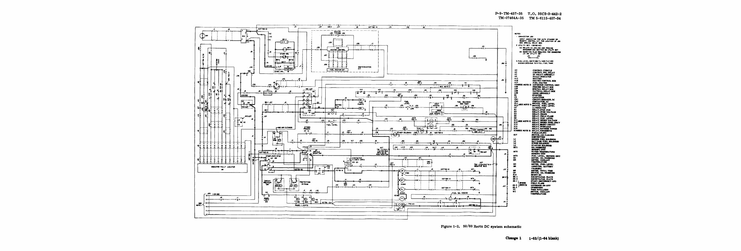
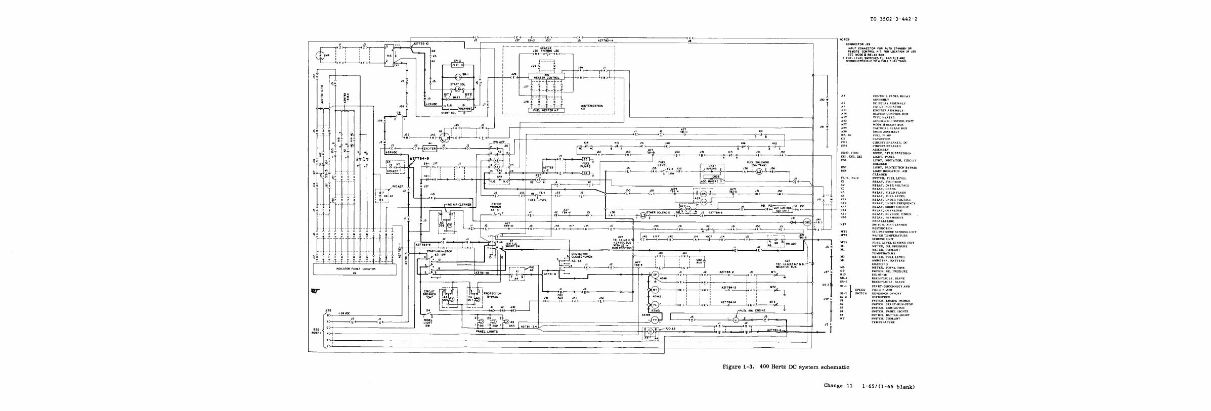

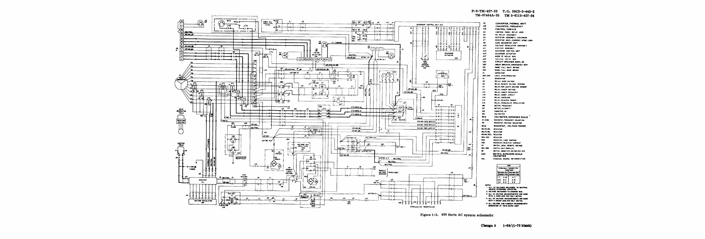

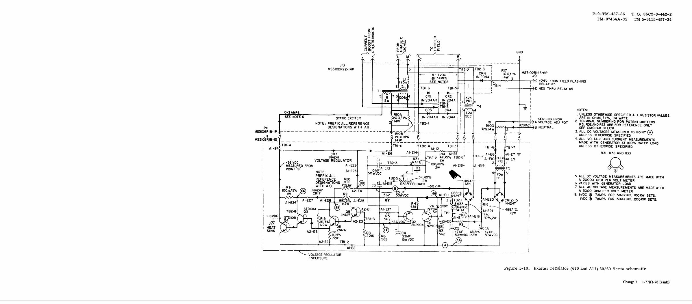
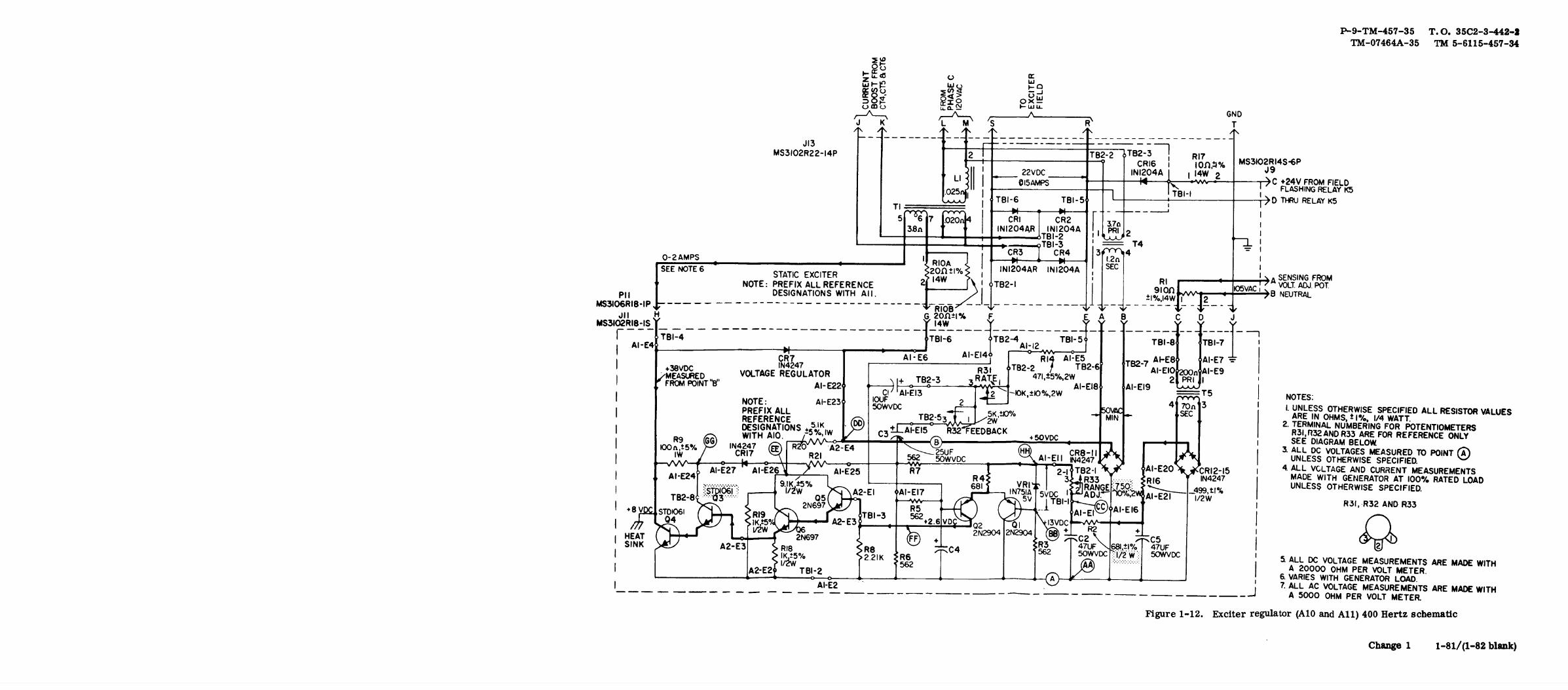

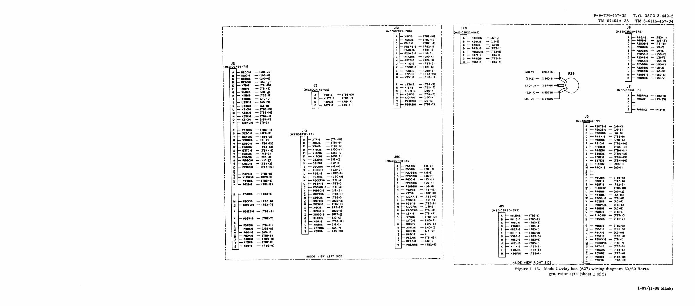

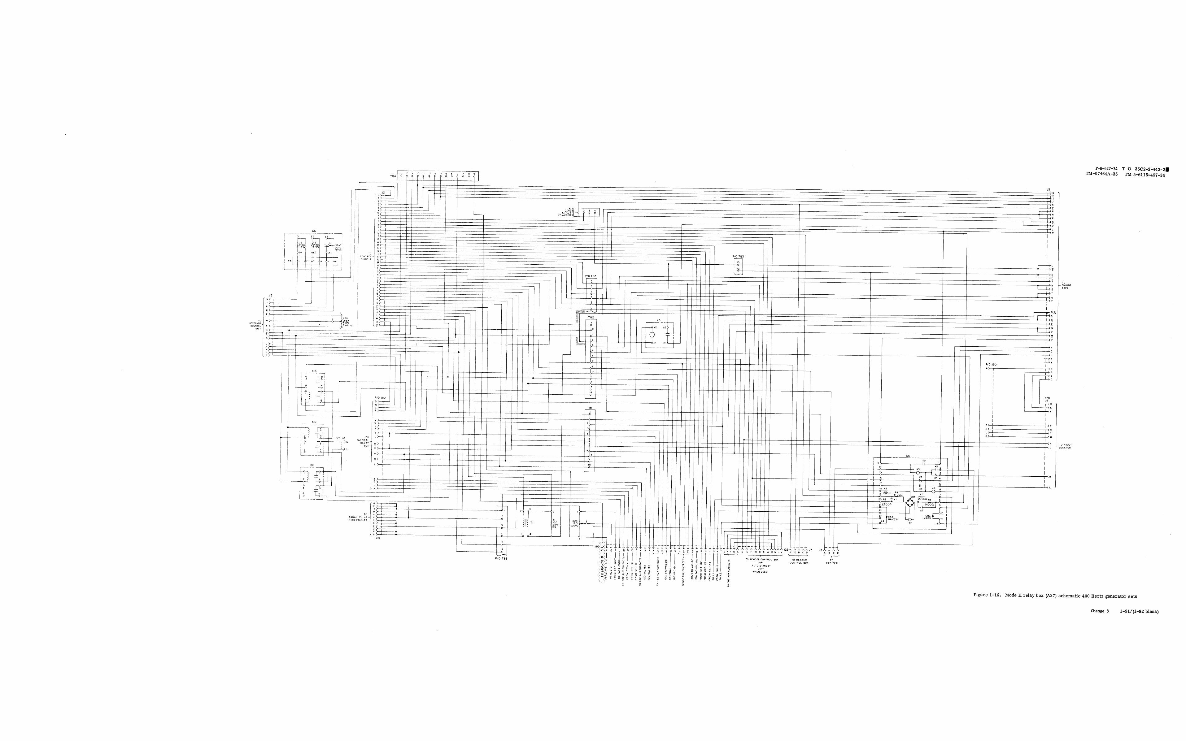
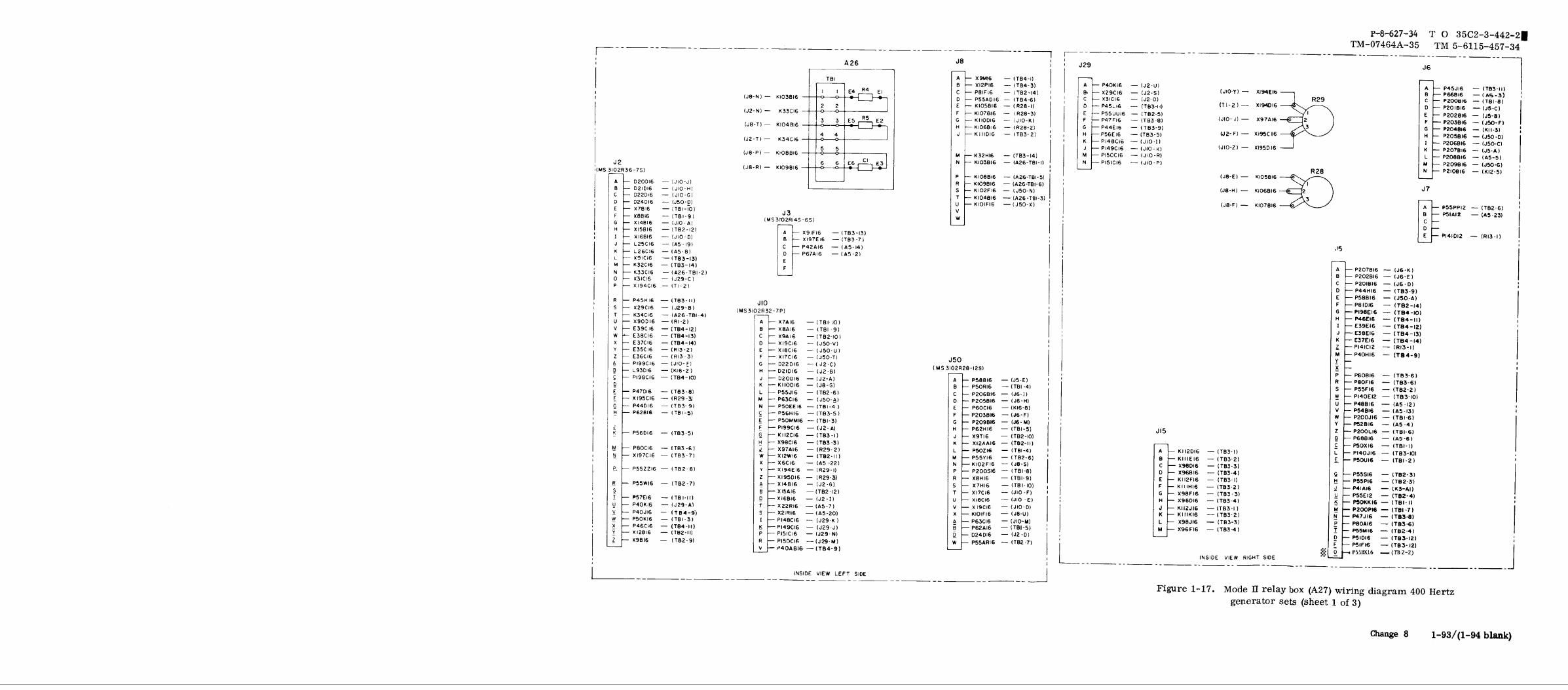
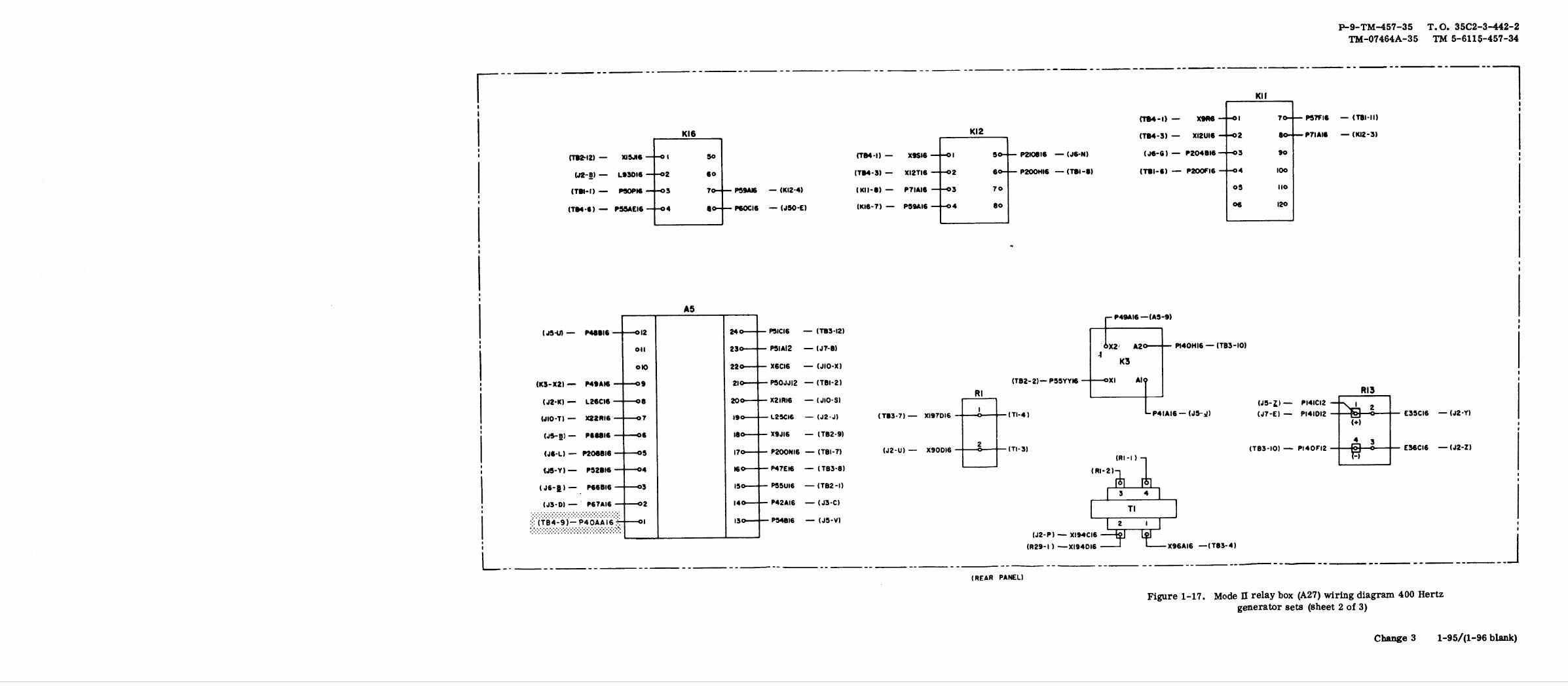
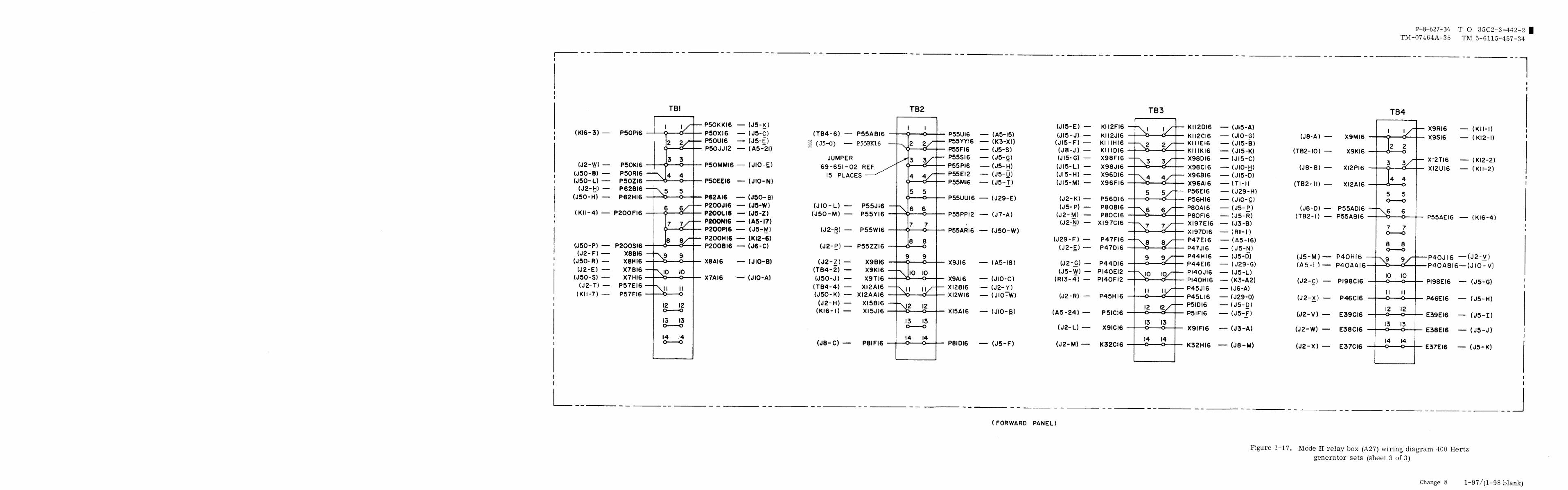

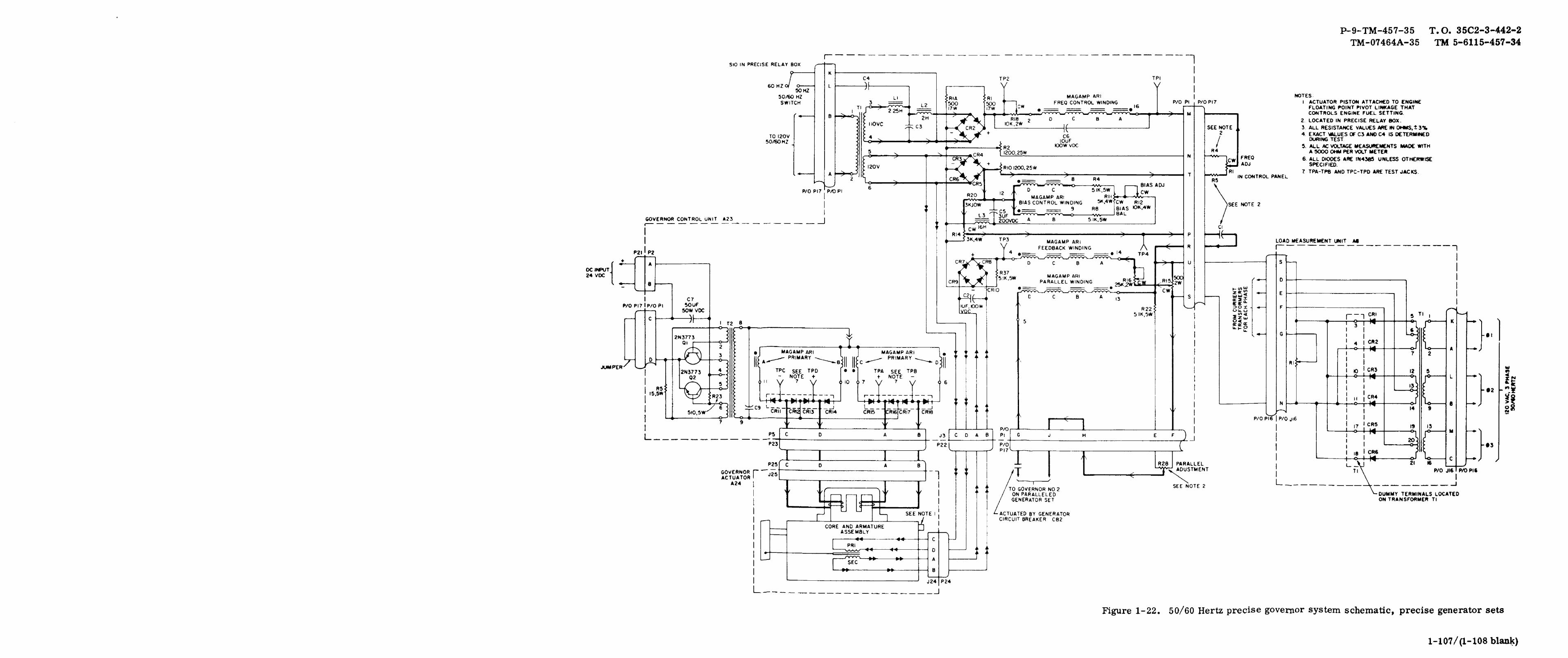
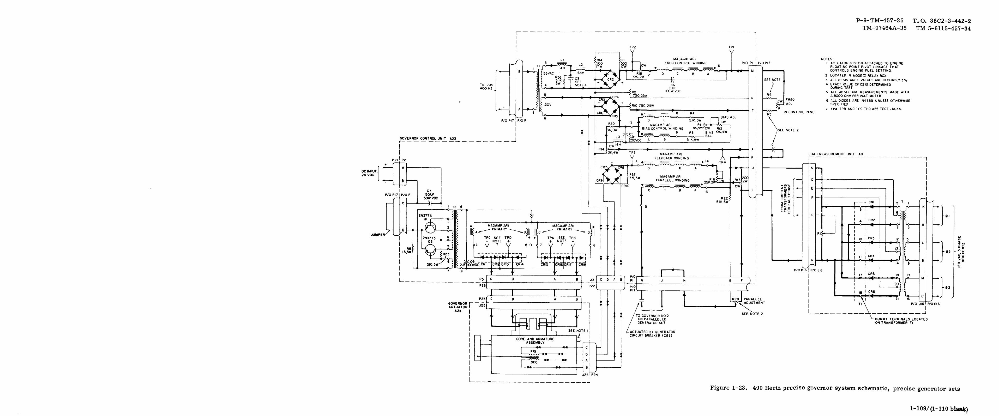
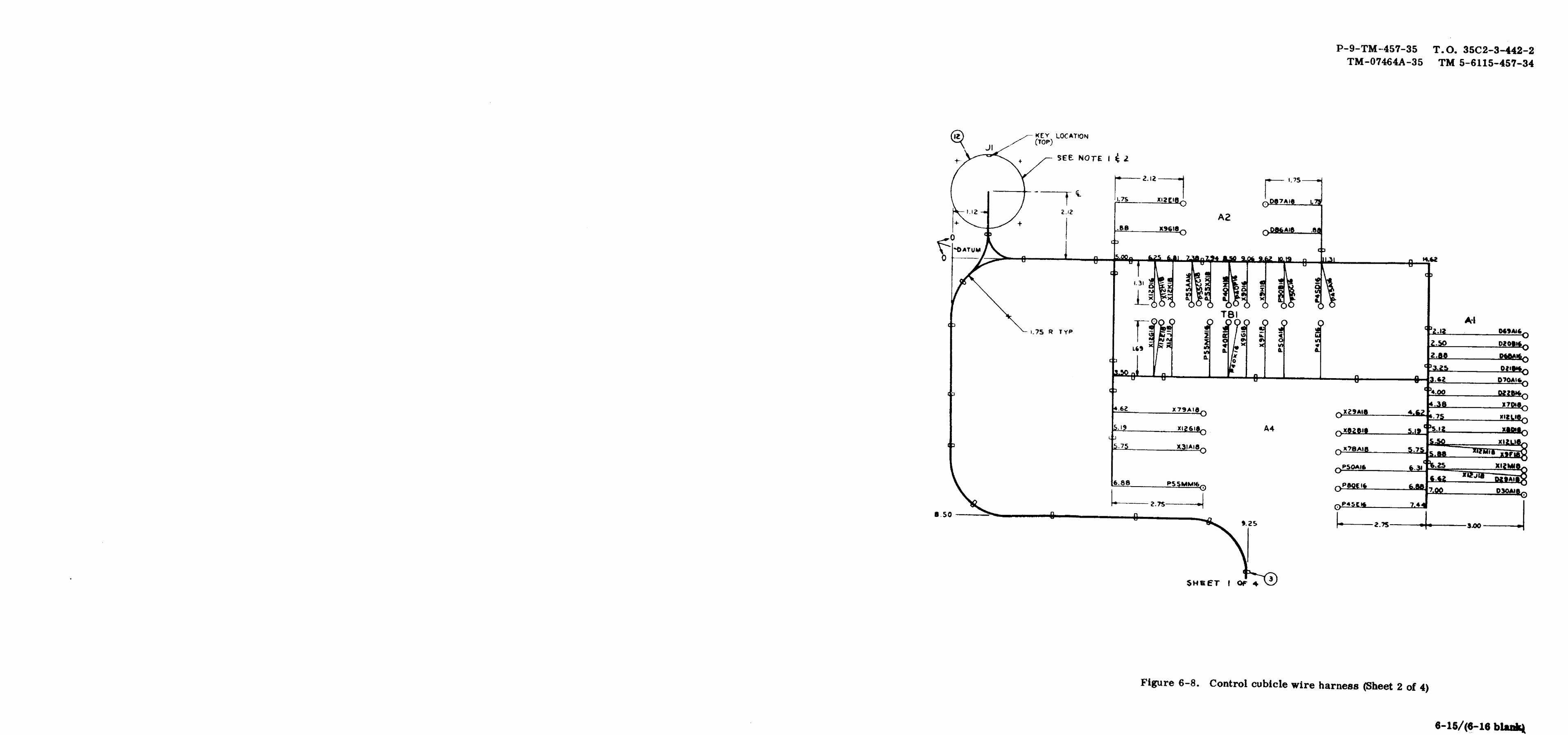
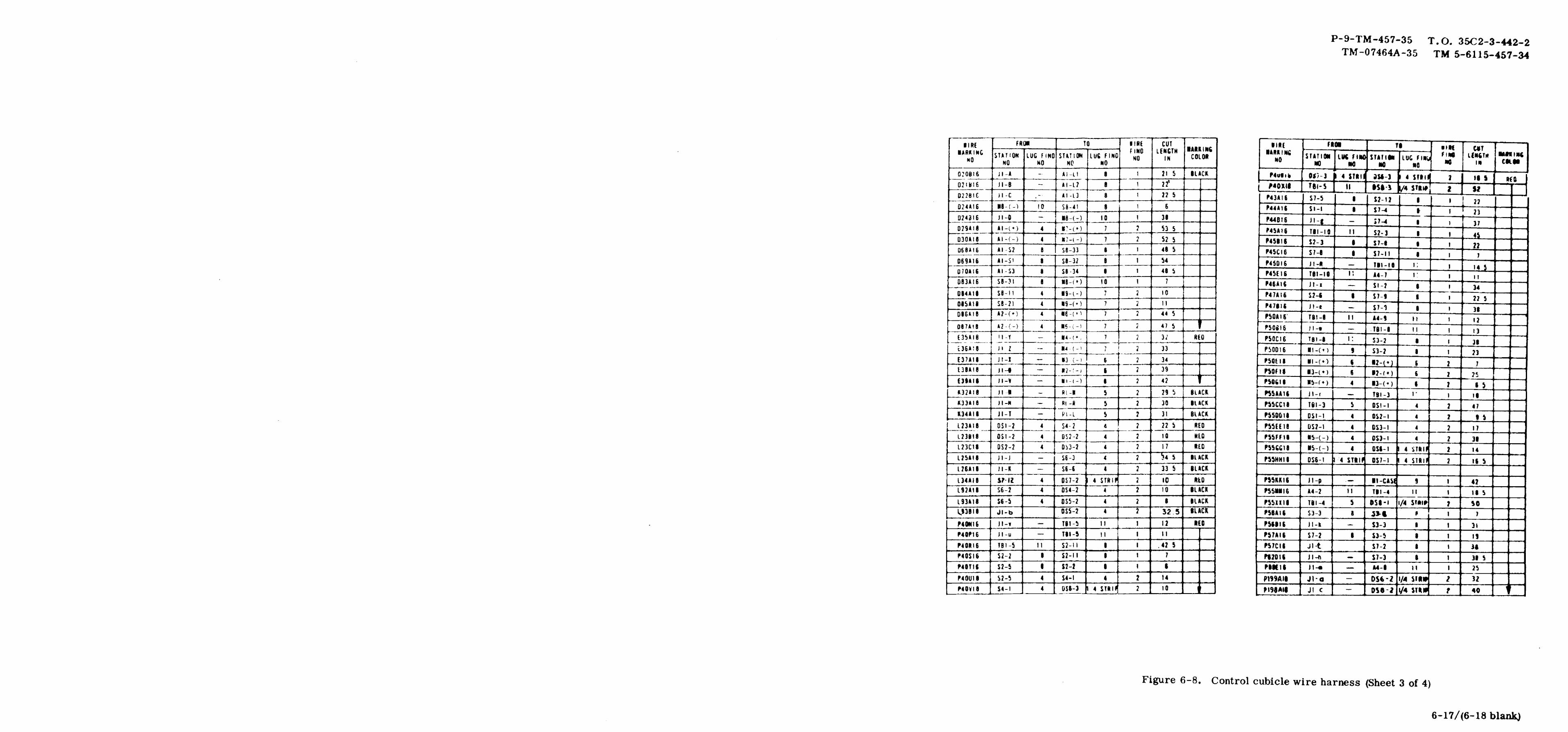
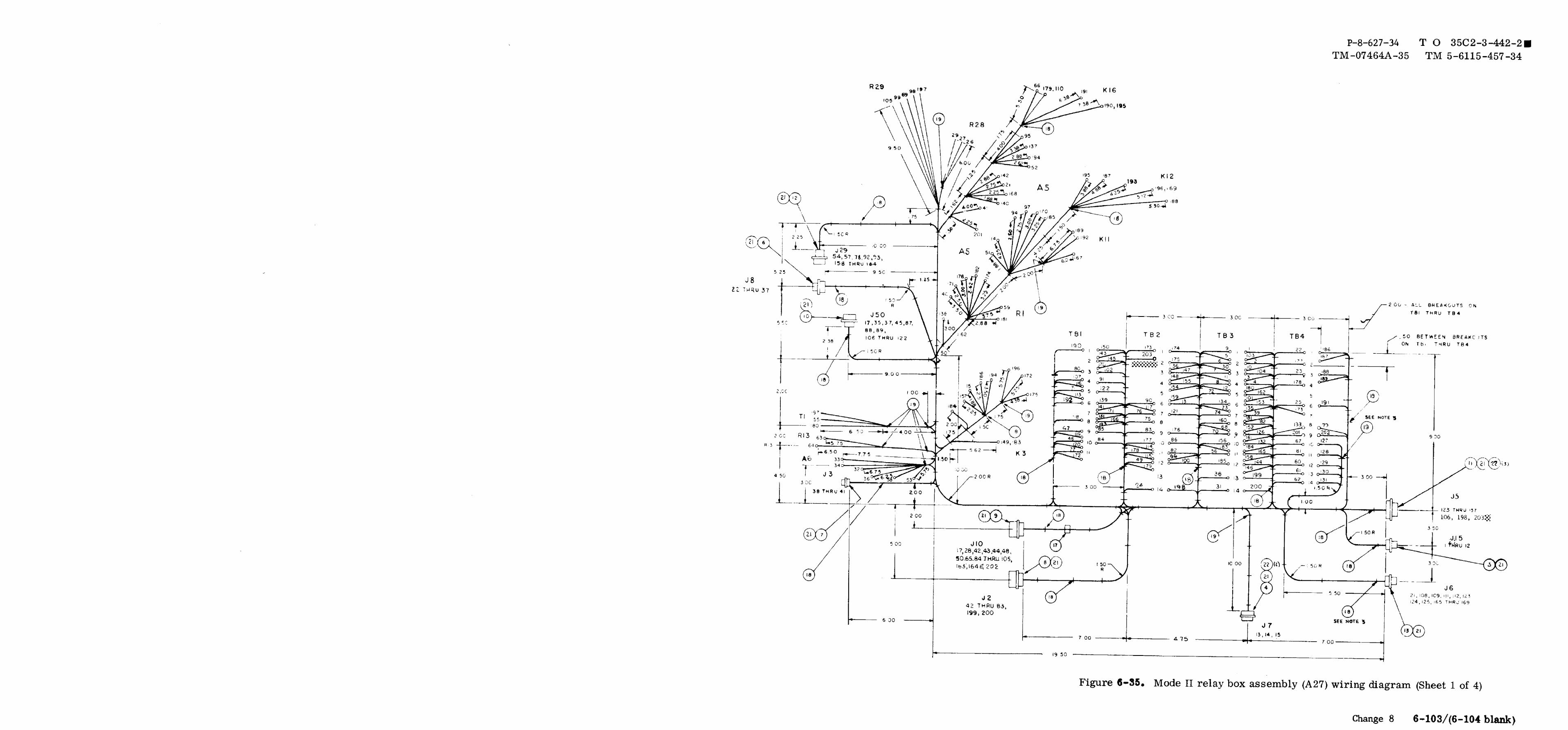
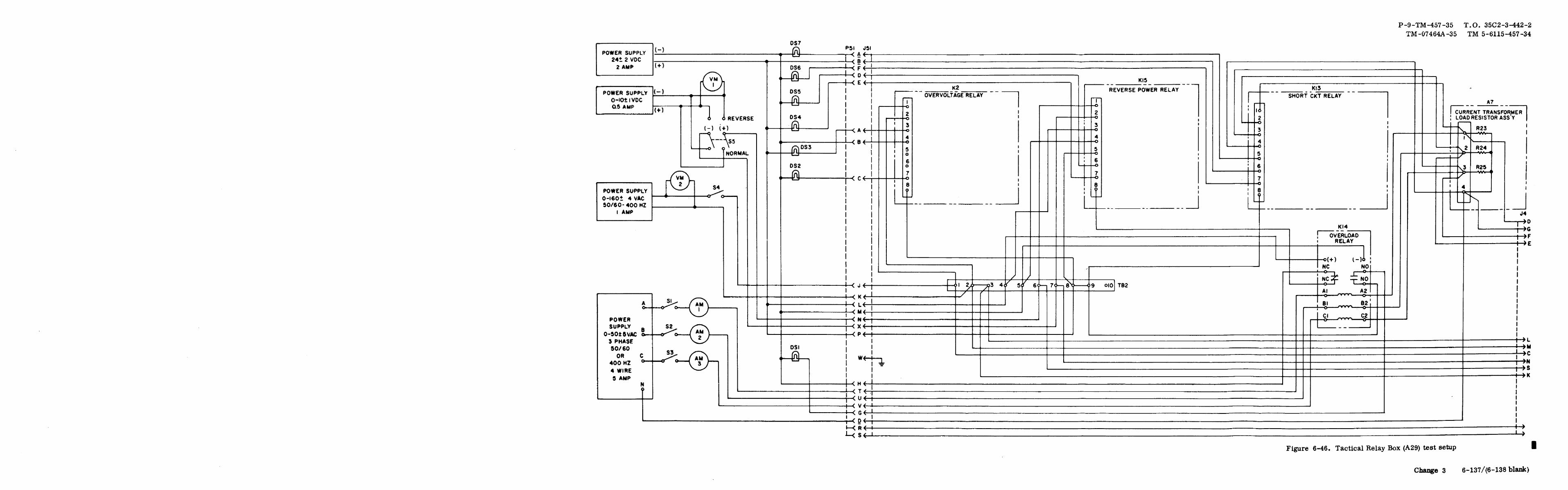
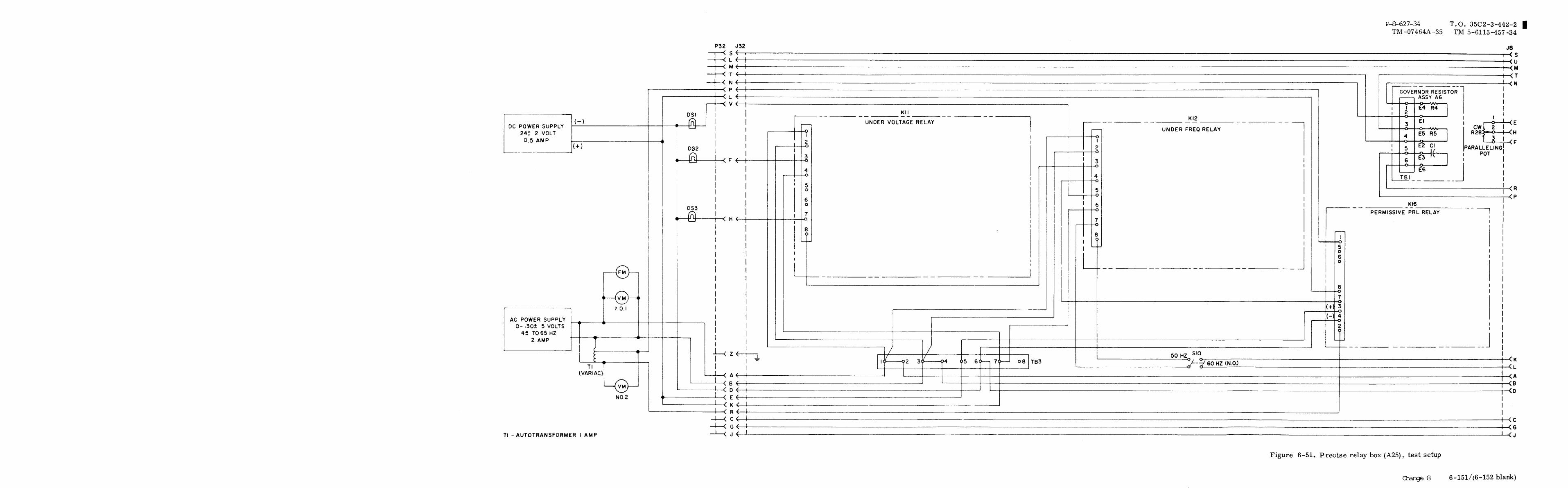


PIN : 013538-000