army tm 9-6115-642-10 air force to 35c2-3-455-11 marine corps tm 09247a/09248a-10/1 · tm...
TRANSCRIPT
ARMY TM 9-6115-642-10AIR FORCE TO 35C2-3-455-11
MARINE CORPS TM 09247A/09248A-10/1
TECHNICAL MANUAL
OPERATOR’S MANUAL
GENERATOR SETSKID MOUNTED, TACTICAL QUlET
10 KW, 60 AND 400 HZ
MEP-803A (60 HZ) 6115-01-275-5061MEP-813A (400 HZ) 6115-01-274-7392
DISTRIBUTION STATEMENT A: Approved for public release; distribution is unlimited.
HEADQUARTERS, DEPARTMENTS OF THE ARMY AND AIR FORCEAND HEADQUARTERS, U.S. MARINE CORPS
30 DECEMBER 1992
ARMY TM 9-6115-642-10AIR FORCE TO 35C2-3-455-11
MARINE CORPS TM 09247A/09248A-10/1
WARNING
H i g h v o l t a g e i s p r o d u c e d w h e n t h i s g e n e r a t o r s e t i s i n o p e r a t i o n .I m p r o p e r o p e r a t i o n c o u l d r e s u l t i n p e r s o n a l i n j u r y o r d e a t h .
WARNING
N e v e r a t t e m p t t o s t a r t t h e g e n e r a t o r s e t i f i t i s n o t p r o p e r l yg r o u n d e d F a i l u r e t o o b s e r v e t h i s w a r n i n g c o u l d r e s u l t i n s e r i o u sinjury or death by electrocution.
WARNING
N e v e r a t t e m p t t o c o n n e c t o r d i s c o n n e c t l o a d c a b l e s w h i l e t h e g e n e r a t o ri s r u n n i n g . F a i l u r e t o o b s e r v e t h i s w a r n i n g c o u l d r e s u l t i n s e v e r ep e r s o n a l i n j u r y o r d e a t h b y e l e c t r o c u t i o n .
WARNING
D C v o l t a g e s a r e p r e s e n t a t g e n e r a t o r s e t e l e c t r i c a l c o m p o n e n t s e v e nw i t h g e n e r a t o r s e t s h u t d o w n . A v o i d g r o u n d i n g s e l f w h e n t o u c h i n g a n y e l e c t r i c a l c o m p o n e n t s . F a i l u r e t o o b s e r v e t h i s w a r n i n g c a n r e s u l t i npersonal injury.
a
ARMY TM 9-6115-642-10AIR FORCE TO 35C2-3-455-11MARINE CORPS TM 09247A/09248A-10/1
WARNING
B a t t e r y a c i d w i l l c a u s e b u r n s t o u n p r o t e c t e d s k i n .
WARNING
T h e f u e l s i n t h i s g e n e r a t o r s e t a r e h i g h l y e x p l o s i v e . D o n o t s m o k e o ruse open f lame when per forming maintenance . F lames and explos ion c o u l d r e s u l t i n s e v e r e p e r s o n a l i n j u r y o r d e a t h .
WARNING
H o t f u e l i n g o f g e n e r a t o r s w h i l e t h e y a r e o p e r a t i n g p r e s e n t s a s a f e t yhazard and should not be at tempted . Hot engine sur faces and sparksp r o d u c e d f r o m t h e e n g i n e a n d g e n e r a t o r c i r c u i t r y a r e p o s s i b l e s o u r c e so f i g n i t i o n . F a i l u r e t o o b s e r v e t h i s w a r n i n g c o u l d c a u s e s e v e r ep e r s o n a l i n j u r y o r d e a t h m a y r e s u l t .
WARNING
Batteries give off f lammable gas. Do not smoke or use open flame when p e r f o r m i n g m a i n t e n a n c e . F l a m e s a n d e x p l o s i o n c o u l d r e s u l t i n p e r s o n a li n j u r y o r d e a t h .
b
WARNING
ARMY TM 9-6115-642-10AIR FORCE TO 35C2-3-455-11
MARINE CORPS TM 09247A/09248A-10/1
E x h a u s t d i s c h a r g e c o n t a i n s d e a d l y g a s e s . D o n o t o p e r a t e g e n e r a t o r s e ti n e n c l o s e d a r e a u n l e s s e x h a u s t d i s c h a r g e i s p r o p e r l y v e n t e d o u t s i d e .S e v e r e p e r s o n a l i n j u r y o r d e a t h d u e t o c a r b o n m o n o x i d e p o i s o n i n g c o u l dr e s u l t .
WARNING
L i q u i d s u n d e r p r e s s u r e a r e g e n e r a t e d a s a r e s u l t o f o p e r a t i o n o f t h eg e n e r a t o r s e t . H i g h p r e s s u r e l e a k s c o u l d c a u s e s e v e r e p e r s o n a l i n j u r yo r d e a t h .
WARNING
W i t h a n y a c c e s s d o o r o p e n , t h e n o i s e l e v e l o f t h i s g e n e r a t o r s e t w h e no p e r a t i n g c o u l d c a u s e h e a r i n g d a m a g e . H e a r i n g p r o t e c t i o n m u s t b e w o r nw h e n w o r k i n g n e a r t h e g e n e r a t o r s e t w h i l e r u n n i n g .
c
ARMY TM 9-6115-642-10AIR FORCE TO 35C2-3-455-11MARINE CORPS TM 09247A/09248A-10/1
WARNING
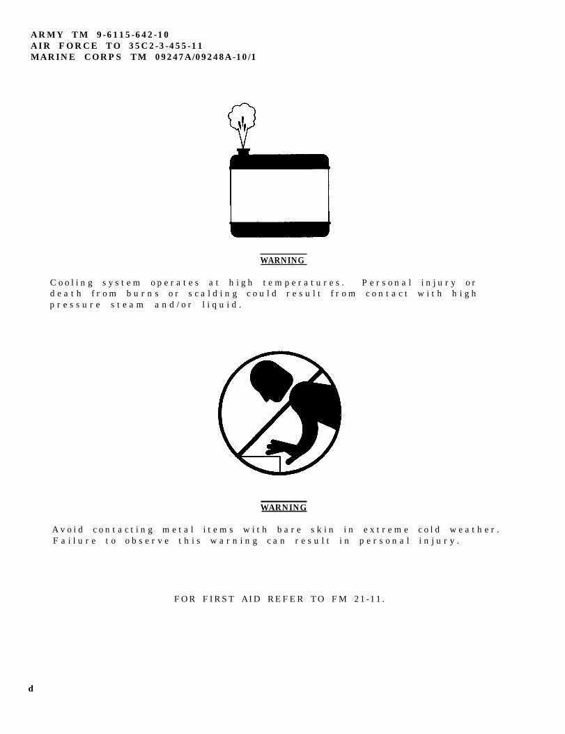
C o o l i n g s y s t e m o p e r a t e s a t h i g h t e m p e r a t u r e s . P e r s o n a l i n j u r y o rd e a t h f r o m b u r n s o r s c a l d i n g c o u l d r e s u l t f r o m c o n t a c t w i t h h i g hp r e s s u r e s t e a m a n d / o r l i q u i d .
WARNING
A v o i d c o n t a c t i n g m e t a l i t e m s w i t h b a r e s k i n i n e x t r e m e c o l d w e a t h e r .F a i l u r e t o o b s e r v e t h i s w a r n i n g c a n r e s u l t i n p e r s o n a l i n j u r y .
FOR FIRST AID REFER TO FM 21-11.
d
ARMY TM 96115642-10AIR FORCE TO 35C23-55-11
MARINE CORPS TM 09247A/09248A-10/1C2
CHANGE HEADQUARTERS, DEPARTMENTS OFTHE ARMY AND AIR FORCE, ANDHEADQUARTERS, U.S. MARINE CORPS
NO. 2 WASHINGTON, D.C., 30 October 1996
Operator’s Manual
GENERATOR SET, SKID MOUNTED, TACTICAL QUIET10 KW,60 AND 400 Hz
MEP-803A (60 Hz) 6115-01-275-5061MEP-813A (400 Hz) 6115-01-274-7392
DISTRIBUTION STATEMENT A: Approved for public release; distribution is unlimited
TM 9-6115-642-10TO 35C2-3-455-11/TM 09247A/09248A-10/1, 30 December 1992, is changed as follows:
1. Remove and insert pages as indicated below. New or changed text material is indicated by a vertical bar in themargin. An illustration change is indicated by a miniature pointing hand.
Remove pages Insert pagesi through iv i through iv1-7 through 1-10 1-7 through 1-102-5 and 2-6 2-5 and 2-62-15 and 2-16 2-15 and 2-162-25 through 2-30 2-25 through 2-30----- 2-30.1/(2-30.2 blank)2-35/(2-36 blank) 2-35 and 2-363-9 and 3-10 3-9 and 3-10
2. Retain this sheet in front of manual for reference purposes.
CHANGE
No. 1
ARMY TM 9-6115-642-10AIR FORCE TO 35C2-3-455-11
MARINE CORPS TM 09247A/09248A-10/1
HEADQUARTERS, DEPARTMENTS OFTHE ARMY AND THE AIR FORCE, ANDHEADQUARTERS, U.S. MARINE CORPSWASHINGTON, D.C., 30 AUGUST 1995
Operator’s Manual
GENERATOR SET, SKID MOUNTED, TACTICAL QUlET,10KW, 60 AND 400HZ
MEP-803A (60HZ) 6115-01-275-5061MEP-813A (400 HZ) 6115-01-274-7392
DISTRIBUTION STATEMENT A: Approved for public release; distribution is unlimited
TM 9-6115-642-10, 30 December 1992, is changed as follows:
1. Remove and insert pages as indicated below. New or changed text material is indicated by a vertical barin the margin. An illustration change is indicated by a miniature pointing hand.
Remove pages1-3 and 1-41-9 through 1-142-7 through 2-142-19 and 2-202-33 and 2-343-3 and 3-43-7 and 3-8
Insert pages1-3and1-41-9 through 1-142-7 through 2-142-19 and 2-202-33 and 2-343-3 and 3-43-7 and 3-8
2. Retain this sheet in front of manual for reference purposes.
ARMY TM 9-6115-642-10AIR FORCE TO 35C2-3-455-11MARINE CORPS TM 09247A/09248A-10/1
C2
By Order of the Secretaries of the Army, Air Force, and Navy (Including the Marine Corps):
DENNIS J. REIMEROfficial: General, United States Army
Chief of StaffJOEL B. HUDSON
Administrative Assistant to theSecretary of the Army
02B48
RONALD R. FOGELMANGeneral, USAFChief of Staff
Official:
HENRY VICCELLIO, JR.General, USAFCommander, Air Force Materiel Command
J. E. BUFFINGTONRear Admiral, CEC, US NavyCommanderNavy Facilities EngineeringCommand
D. R. BLOOMERColonel, USMCDirector, Program SupportMarine Corps Systems Command
DISTRIBUTION:To be distributed in accordance with DA Form 12-25-E, block no. 5243, requirements for TM 9-6115-642-10.
ARMY TM 9-6115-642-10AIR FORCE TO 35C2-3-455-11
MARINE CORPS TM 09247A/09248A-10/1
TECHNICAL MANUAL HEADQUARTERS, DEPARTMENTS OFTHE ARMY AND AIR FORCE, ANDHEADQUARTERS, U.S. MARINE CORPS
NO. 9-6115-642-10 WASHINGTON, D.C., 30 December 1992
TECHNICAL MANUALOperator’s Manual
GENERATOR SET, SKID MOUNTED, TACTICAL QUIET10 KW, 60 AND 400 Hz
MEP-803A (60 Hz) 6115-01-275-5061MEP-813A (400 Hz) 6115-01-274-7392
Distribution Statement A: Approved for public release; distribution is unlimited.
REPORTING OF ERRORS AND RECOMMENDING IMPROVEMENTS
You can help improve this manual. If you find any mistakes or if. you know of a way to improve theprocedures, please let us know.
(A): Army - Mail your letter or DA Form 2028 (Recommended Changes to Publications and Blank Forms),or DA Form 2028-2 located in the back of this manual directly to: Commander, US Army Aviation andTroop Command, ATTN: AMSAT-I-MP, 4300 Goodfellow Blvd., St. Louis, MO 63120-1798. You mayalso submit your recommended changes by E-mail directly to <mpmt%/[email protected]>. Instructions for sending an electronic 2028 may be found at the back of this publicationimmediately preceding the hard copy 2028.
(F): Air Force - AFTO Form 22 directly to: Commander, Sacramento Air Logistics Center, ATTN: TILBA,McClellan AFB, CA 95652-5990.
(M): Marine Corps - NVMC Form 10772 directly to: Commander, Marine Corps Logistics Bases (Code850), Albany, GA 31004-5000.
A reply will be furnished directly to you.
TABLE OF CONTENTSPage
HOW TO USE THIS MANUAL ................................................................... vCHAPTER 1 INTRODUCTION......................................................................................... 1-1Section 1. General Information .................................................................................... 1-1Section II. Equipment Description ................................................................................ 1-4Section III. Technical Principles of Operation ............................................................... 1-11
Change 2 i
ARMY TM 9-6115-642-10AIR FORCE TO 35C2-3-455-11MARINE CORPS TM 09247A/09248A-10-1
CHAPTER 2
Section I
Section II
Section III
Section IV
CHAPTER 3
Section I
Section II
Section III
APPENDIX AAPPENDIX B
APPENDIX C
APPENDIX D
Table Of Contents (Cont.)
Page
OPERATING INSTRUCTIONS . . . . . . . . . . . . . . . . . . . . . . . . . . . . . . . . . . . . 2-1
Description and Use of Operator’s Controls and Indicators . . . . . . . . . . . . . . . . 2-1
Preventive Maintenance Checks and Services (PMCS) . . . . . . . . . . . . . . . . . . 2-8
Operation Under Usual Conditions . . . . . . . . . . . . . . . . . . . . . . . . . . . . . . . . . . . . . 2-16
Operation Under Unusual Conditions . . . . . . . . . . . . . . . . . . . . . . . . . . . . . . . . . . 2-31
MAINTENANCE INSTRUCTIONS . . . . . . . . . . . . . . . . . . . . . . . . . . . . . . . . . . . 3-1
Lubrication Instructions . . . . . . . . . . . . . . . . . . . . . . . . . . . . . . . . . . . . . . . . . . . . 3-1
Troubleshooting . . . . . . . . . . . . . . . . . . . . . . . . . . . . . . . . . . . . . . . . . . . . . . . . . . 3-1
Symptom Index . . . . . . . . . . . . . . . . . . . . . . . . . . . . . . . . . . . . . . . . . . . . . . . . . . . . . . 3-2
Maintenance Procedures . . . . . . . . . . . . . . . . . . . . . . . . . . . . . . . . . . . . . . . . . . . 3-10
REFERENCES . . . . . . . . . . . . . . . . . . . . . . . . . . . . . . . . . . . . . . . . . . . . . . . . . . . . . A-1
COMPONENTS OF END ITEM (COEI)AND BASIC ISSUE ITEMS (BII) LIST . . . . . . . . . . . . . . . . . . . . . . . . . . . . . . B-1
ADDITIONAL AUTHORIZATION LIST (AAL) . . . . . . . . . . . . . . . . . . . . . . . . C-1
EXPENDABLE/DURABLE SUPPLIESAND MATERIALS LIST (EDSML) . . . . . . . . . . . . . . . . . . . . . . . . . . . . . . . . . D-1
INDEX.. . . . . . . . . . . . . . . . . . . . . . . . . . . . . . . . . . . . . . . . . . . . . . . . . . . . . . . . I-1
ii
ARMY TM 9-6115-642-10AIR FORCE TO 35C2-3-455-11
MARINE CORPS TM 09247A/09248A-10/1
LIST OF ILLUSTRATIONS
Number Title Page
1-1 Generator Set, 10kW, Tactical Quiet ......................................................................................... 1-21-2 Generator Set Components........................................................................................................ 1-51-3 . Engine Starting System.............................................................................................................. 1-111-4 Fuel System................................................................................................................................ 1-121-5 Engine Cooling System .............................................................................................................. 1-131-6 Engine Lubrication System ........................................................................................................ 1-141-7 Air Intake and Exhaust System ................................................................................................. 1-151-8 Output Supply System ............................................................................................................... 1-15
2-1 Operator’s Controls and Indicators............................................................................................. 2-22-2 Malfunction Indicator Panel ....................................................................................................... 2-52-3 Frequency Adjust Control .......................................................................................................... 2-72-4 Grounding Connections ............................................................................................................. 2-172-5 Installation of Load Cables ........................................................................................................ 2-192-6 Operating Instructions Plates
(Front and Right Side) ........................................................................................................... 2-242-7 Operating Instructions Plates
(Rear and Left Side) .............................................................................................................. 2-252-8 Operating Instructions Plate ...................................................................................................... 2-262-9 Generator Set Identification Plate .............................................................................................. 2-262-9A Generator Set Identification Plate .............................................................................................. 2-272-10 Set Rating Identification Plate .................................................................................................... 2-272-11 Voltage Connection Caution Plate ............................................................................................. 2-282-12 Grounding Stud Plate ................................................................................................................ 2-282-13 Slave Receptacle Plate .............................................................................................................. 2-282-14 Diagnostics Plate ....................................................................................................................... 2-282-15 Convenience Receptacle Plate ................................................................................................. 2-282-16 External Fuel Supply Plate ........................................................................................................ 2-282-17 Battery Connection Instruction Plate ......................................................................................... 2-292-18 Generator Identification Plate .................................................................................................... 2-292-19 Frequency Adjust Plate .............................................................................................................. 2-302-20 Lifting and Tiedown Diagram Plate ............................................................................................ 2-302-21 Fuel System Diagram Plate........................................................................................................ 2-30.1
3-1 Air Cleaner Element Replacement ............................................................................................ 3-113-2 Draining Fuel Filter/Water Separator ......................................................................................... 3-15
Change 2 iii
ARMY TM 9-6115-642-10AIR FORCE TO 35C2-3-455-11MARINE CORPS TM 09247A/09248A-10/1
Number
1 - 12 - 12 - 22 - 32 - 4
2 - 5
3 - 13 - 23 - 3
LIST OF TABLES
T i t l e
Leading Particulars . . . . . . . . . . . . .C o n t r o l P a n e l C o n t r o l s a n d I n d i c a t o r s . . . .Malfunction Indicator Panel . . . . . . . . .Frequency Adjust Control . . . . . . . . . . .O p e r a t o r P r e v e n t i v e M a i n t e n a n c e
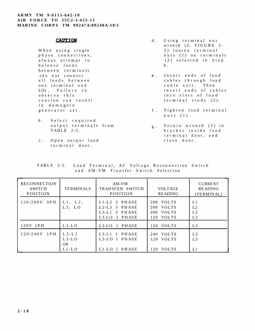
Checks and Services . . . . . . . . . . . .L o a d T e r m i n a l , A C V o l t a g e R e c o n n e c t i o n S w i t c h
a n d A M - V M T r a n s f e r S w i t c h S e l e c t i o n . . . .
Troubleshooting . . . . . . . . . . . . . . .Coolant . . . . . . . . . . . . . . . . . . .Diesel Fuel . . . . . . . . . . . . . . . . .
P a g e
1 - 72 - 32 - 62 - 7
2 - 1 0
2 - 1 8
3 - 33 - 1 33 - 1 4
i v
HOW TO USE THIS MANUAL
I n t h i s m a n u a l( T M 9 - 6 1 1 5 - 6 4 2 - 1 0 ) , p a r a g r a p h s
a r e u n d e r l i n e d a n d t h e s e c t i o n sa n d c h a p t e r s a p p e a r i n c a p i t a ll e t t e r s . T h e l o c a t i o n o fa d d i t i o n a l m a t e r i a l t h a t m u s t b er e f e r e n c e d i s c l e a r l y m a r k e d .D r a w i n g s i n t h i s t e x t a r el o c a t e d a s c l o s e a s p o s s i b l e t ot h e i r r e f e r e n c e s .
C h a p t e r 1 - I n t r o d u c t i o n .C h a p t e r 1 c o n t a i n s g e n e r a li n f o r m a t i o n , e q u i p m e n td e s c r i p t i o n a n d t e c h n i c a lp r i n c i p l e s o f o p e r a t i o n .
C h a p t e r 2 - O p e r a t i n gI n s t r u c t i o n s . C h a p t e r 2c o n t a i n s a d e s c r i p t i o n o fg e n e r a t o r s e t o p e r a t i o n c o n t r o l sa n d i n d i c a t o r s . T h e c o n t r o lp a n e l a s s e m b l y i s i l l u s t r a t e da n d e a c h c o n t r o l a n d i n d i c a t o ri s d e s c r i b e d i n a f o l l o w - o nt a b l e . O p e r a t i n g p r o c e d u r e sw h i c h i n c l u d e P r e v e n t i v eM a i n t e n a n c e C h e c k s a n d S e r v i c e s( P M C S ) a n d o p e r a t i o n u n d e r u s u a l
a n d u n u s u a l c o n d i t i o n s a r ed e t a i l e d .
C h a p t e r 3 - M a i n t e n a n c e .C h a p t e r 3 l i s t s m a i n t e n a n c ep r o c e d u r e s a u t h o r i z e d a t t h eo p e r a t o r l e v e l , a n dt r o u b l e s h o o t i n g p r o c e d u r e s u s e dt o r e c o g n i z e g e n e r a t o r s e tm a l f u n c t i o n s , t h e t e s t o ri n s p e c t i o n s , a n d t h e i rc o r r e c t i v e a c t i o n . A n i n d e x o fg e n e r a t o r s e t f a i l u r e s y m p t o m sw i l l h e l p g u i d e y o u t o t h ea p p r o p r i a t e t r o u b l e s h o o t i n gc h a r t .
ARMY TM 9-6115-642-10AIR FORCE TO 35C2-3-455-11
MARINE CORPS TM 09247A/09248A-10/1
A p p e n d i c e s .
A p p e n d i x A i s a l i s t o f t h eo t h e r p u b l i c a t i o n s r e f e r e n c e d b yt h i s m a n u a l . I n c l u d e d a r e o t h e rm a n u a l s w h i c h s h o u l d b e u s e dw i t h t h i s o p e r a t o r ’ s m a n u a l .
A p p e n d i x B i s t h e C o m p o n e n t s o fE n d I t e m ( C O E I ) a n d B a s i c I s s u eI t e m s ( B I I ) L i s t s .
A p p e n d i x C i s t h e A d d i t i o n a lA u t h o r i z a t i o n L i s t ( A A L ) .
A p p e n d i x D i s t h e E x p e n d a b l e /D u r a b l e S u p p l i e s a n d M a t e r i a l sL i s t ( E D S M L ) .
I n d e x . T h e i n d e x c o n t a i n s k e yt e c h n i c a l m a n u a l s u b j e c t sa r r a n g e d i n a l p h a b e t i c a l o r d e r .I f y o u r e q u i r e i n f o r m a t i o n o n as p e c i f i c s u b j e c t ( i . e . ,s t a r t i n g ) , b u t y o u a r e n o t s u r ew h e r e t o l o o k , u s e t h e i n d e x t ol o c a t e s p e c i f i c p a g e .
v/(vi blank)

ARMY TM 9-6115-642-10AIR FORCE TO 35C2-3-455-11
MARINE CORPS TM 09247A/09248A-10/1
CHAPTER 1
INTRODUCTION
SECTION I. GENERAL INFORMATION
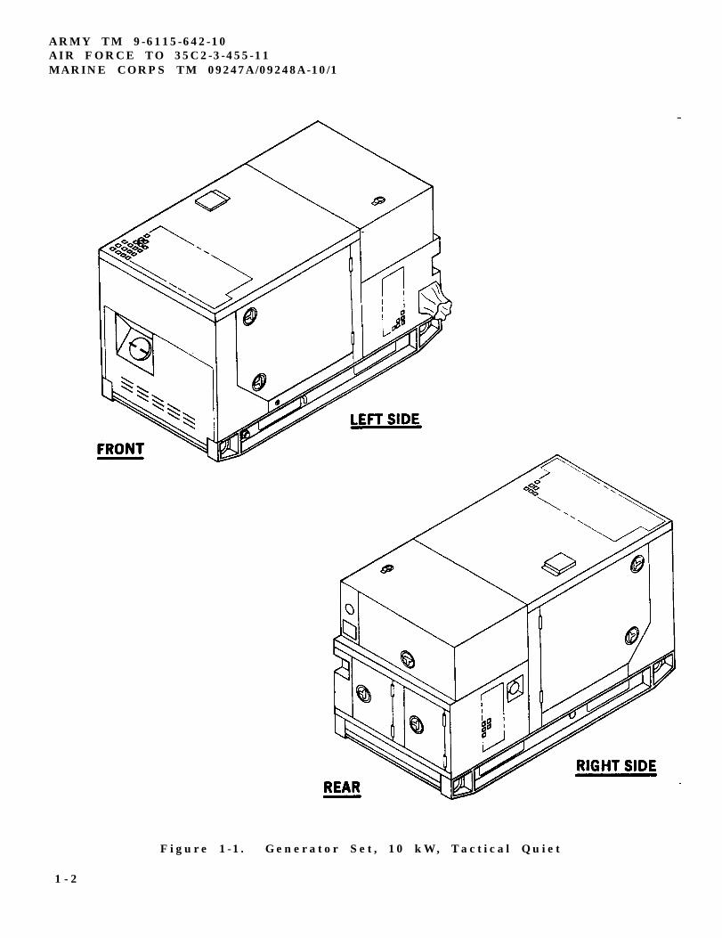
1 - 1 SCOPE.
1 - 1 . 1 T y p e o f M a n u a l . T h i sm a n u a l c o n t a i n s o p e r a t i o n a n do p e r a t o r m a i n t e n a n c e i n s t r u c -t i o n s f o r t h e T a c t i c a l Q u i e t(TQ) , 10 kW 60 and 400 Hz
G e n e r a t o r S e t s ( F I G U R E l - l ) ,h e r e i n r e f e r r e d t o a s g e n e r a t o rs e t . I n c l u d e d a r e d e s c r i p t i o n so f m a j o r c o m p o n e n t s a n d t h e i rf u n c t i o n s i n r e l a t i o n t o o t h e rc o m p o n e n t s .
1 - 1 . 2 M o d e l N u m b e r s a n dE q u i p m e n t N a m e s .
M o d e l N u m b e r E q u i p m e n t N a m e
MEP-803A G e n e r a t o r S e t ,S k i d M o u n t e d ,D i e s e l P o w e r e d ,T a c t i c a l Q u i e t 1 0kW 60 Hz.
G e n e r a t o r S e t ,S k i d M o u n t e d ,D i e s e l P o w e r e d ,T a c t i c a l Q u i e t10 kW 400 Hz.
1 - 1 . 3 P u r p o s e o f E q u i p m e n t .T h e g e n e r a t o r s e t p r o v i d e st a c t i c a l q u i e t A C p o w e r . T h eg e n e r a t o r s e t i s e a s i l yt r a n s p o r t e d , o p e r a t e d , a n dm a i n t a i n e d .
1-2 MAINTENANCE FORMS ANDRECORDS.
1 - 2 . 1 ( A ) D e p a r t m e n t o f t h eA r m y f o r m s a n d p r o c e d u r e s u s e df o r e q u i p m e n t m a i n t e n a n c e w i l l
MEP-813A
b e t h o s e p r e s c r i b e d b yDA PAM 738-750 , The ArmyM a i n t e n a n c e M a n a g e m e n t S y s t e m(TAMMS) .
1 - 2 . 2 ( F ) M a i n t e n a n c e F o r m s a n dR e c o r d s m a i n t a i n e d b y t h e A i rF o r c e a r e p r e s c r i b e d i n A F R 6 6 - 1a n d t h e a p p l i c a b l e T O 0 0 - 2 0S e r i e s T e c h n i c a l O r d e r s .
1 - 2 . 3 ( N ) N a v y u s e r s s h o u l dr e f e r t o t h e i r s e r v i c e p e c u l i a rd i r e c t i v e s t o d e t e r m i n e t h ea p p l i c a b l e m a i n t e n a n c e f o r m s a n dr e c o r d s t o b e u s e d .
1 - 2 . 4 ( M C ) M a i n t e n a n c e F o r m sa n d R e c o r d s u s e d b y M a r i n e C o r p sp e r s o n n e l a r e p r e s c r i b e d b y t h ec u r r e n t e d i t i o n o fT M 4 7 0 0 - 1 5 / 1 .
1 - 3 REPORTING EQUIPMENTIMPROVEMENT RECOMMENDATIONS( E I R ) .
1 - 3 . 1 I f y o u r g e n e r a t o r s e tn e e d s i m p r o v e m e n t , l e t u s k n o w .S e n d u s a n E I R . Y o u , t h e u s e r ,a r e t h e o n l y o n e w h o c a n t e l l u sw h a t y o u d o n ’ t l i k e a b o u t y o u re q u i p m e n t . L e t u s k n o w w h y y o ud o n ’ t l i k e t h e d e s i g n o rp e r f o r m a n c e . W e w i l l s e n d y o u ar e p l y .
1 - 1
ARMY TM 9-6115-642-10AIR FORCE TO 35C2-3-455-11MARINE CORPS TM 09247A/09248A-10/1
Figure 1-1 . Generator Set , 10 kW, Tactical Quiet
1 - 2
1-3.2 (A) Put it on an SF 368 (Quality Deficiency Report).EIRs should be mailed directly to
CommanderU.S. Army Aviation and Troop CommandAttn: AMSAT-I-MDC4300 Goodfellow Blvd.St. Louis. MO 63120-1798.
1 - 51-3.3 (N) Put it on applicable Navy form and mail itdirectly to:
Naval Construction Battalion CenterAttn: Code 157 Civil
EngineerSupport Office (CESO)Pat Hueneme,CA 93043-5000
1-3.4 (F) Quality Deficiency Reports (QDR)/MaterialDeficiency Reports (MDR) shall be sent electronic message toSMALC-CA//TILE//.
1-3.5 (MC) Quality Deficiency Reports (QDR) shall besubmitted on SF 368 in accordance with MCO 4855.10.Submit to:
CommanderMarine Corps Logistics Bases(Code 856)Albany, GA 31704-5000
1 - 4
The generator sets, models MEP-803A andMEP-813A, are warranted by Libby Corporation for a period
ARMY TM 9-6115-642-10AIR FORCE TO 35C2-3-455-11
MARINE CORPS TM 09247A/09248A-10/1
of 36 months or 1800 operating hours, whichever occurs first.Refer to Warranty Technical Bulletin TB 9-6115-642-24. Thewarranty starts on the date found in block 23, DA Form 2408-9.ink logbook. Report all defects in material or workmanshipto your supervisor, who will take appropriate action throughyour Unit Maintenance Shop.
The following list of abbreviations consists of thosespecial or unique abbreviations that are not contained inMIL-STD-12 and do not conflict with those in MIL-STD-12.
KPA
KVA
kW
CTA
MTOE
NATO
JTA
Kilopascal
Kilovolt-ampere
Kilowatt
Common Table ofAllowance
Modified Table ofOrganization andEquipment
North AtlanticTreatyOrganization
Joint Table ofAllowances
1-3
ARMY TM 9-6115-642-10AIR FORCE TO 35C2-3-455-11MARINE CORPS TM 09247A/09248A-10/1
Section II. EQUIPMENT DESCRIPTION
1-6
The generator sets, models MEP-803A andMEP-813A (FIGURE 1-2), are fully enclosed, self-contained.skid-mounted, portable units. They are equipped with controls.instruments and accessories necessary for operation. Thegenerator sets consist of a diesel engine, brushless generator.excitation system, speed governing system, fuel system, 24VDC starting system, control system and fault system.
NOTE
All locations (FIGURE 1-2) referenced inFIGURE 1-2 are given facing the control box side(rear) of the generator set.
1-7
1-7.1 The generator is powered by a fourcylinder, four cycle, fuel injected, naturally-aspirated.liquid-cooled diesel engine which occupies the front half of thegenerator set. The engine is also equipped with a fuelfilter/water separator, oil falter, and an air cleaner assembly.Protection devices automatically stop the engine during
conditions of high coolant temperature, low oil pressure, nofuel, over-voltage.
1-7.2 Radiator (9). The radiator is located at the front ofthe generator set. It acts as a heat exchanger for the enginecoolant.
1-7.3 Muffler (12). The muffler and exhaust tubing areconnected to the exhaust manifold on the engine. The exhaustexits from the top of the generator set housing. Gases areexhausted upward.
1-7.4 Starter (15). The starter is located on the right sideof the engine. The electric starter mechanically engages theengine flywheel in order to start the diesel engine.
1-7.5 The batterlycharging alternator is located on the right side of the engine. Itis capable of maintaining the batteries in a state of full chargein addition to providing the required 24 VDC control power.
1-7.6 Batteries (7). Two batteries are required, one oneach side of the generator set. The batteries are maintenancefree, lead acid, 12 volt type, connected in series. After starting,the generator set is capable of operating with batteriesremoved. A fuse and a diode, located behind the control panelassembly, protects the generator set if the batteries areincorrectly connected.
1-4 Change 1
ARMY TM 9-6115-642-10AIR FORCE TO 35C2-3-455-11
MARINE CORPS TM 09247A/09248A-10/1
FIGURE 1-2. Generator Set Components
1-5
ARMY TM 9-6115-642-10AIR FORCE TO 35C2-3-455-11MARINE CORPS TM 09247A/09248A-10/1
1 - 7 . 7 A i r C l e a n e r A s s e m b l y( 1 1 ) . T h e a i r c l e a n e r a s s e m b l yi s l o c a t e d o n t h e r i g h t s i d eb e h i n d t h e e n g i n e . I t c o n s i s t so f a d r y - t y p e , d i s p o s a b l e a i rf i l t e r e l e m e n t m a d e o f p a p e r a n dc a n i s t e r . T h e a i r c l e a n e ra s s e m b l y f e a t u r e s a d u s tc o l l e c t o r w h i c h t r a p s l a r g e d u s tp a r t i c l e s . T h e a i r c l e a n e ra s s e m b l y h a s a r e s t r i c t i o ni n d i c a t o r w h i c h w i l l i n d i c a t er e d w h e n t h e a i r f i l t e r e l e m e n tr e q u i r e s s e r v i c i n g .
1 - 7 . 8 F u e l T a n k ( 1 0 ) . T h e 9g a l l o n ( 3 4 l i t e r s ) f u e l t a n k i sl o c a t e d i n t h e f r o n t o f t h eg e n e r a t o r s e t b e l o w t h e e n g i n ea n d b e t w e e n t h e s k i d b a s e s i d em e m b e r s . T h e f u e l t a n k i s af u e l r e s e r v o i r a n d h a ss u f f i c i e n t c a p a c i t y t o e n a b l et h e g e n e r a t o r s e t t o o p e r a t e f o ra t l e a s t 8 h o u r s w i t h o u tr e f u e l i n g .
1 - 7 . 9 A C G e n e r a t o r ( 4 ) . The ACg e n e r a t o r i s a s i n g l e b e a r i n g ,d r i p - p r o o f , s y n c h r o n o u s ,b r u s h l e s s , t h r e e p h a s e , f a n -c o o l e d g e n e r a t o r . T h e g e n e r a t o ri s c o u p l e d d i r e c t l y t o t h e r e a ro f t h e d i e s e l e n g i n e .
1 - 7 . 1 0 L o a d O u t p u t T e r m i n a lB o a r d ( 1 8 ) . T h e l o a d o u t p u tt e r m i n a l b o a r d i s l o c a t e d o n t h er i g h t s i d e ( r e a r ) o f t h eg e n e r a t o r s e t . F o u r o u t p u tt e r m i n a l s l o c a t e d o n t h e b o a r d .T h e y a r e m a r k e d L 1 , L 2 , L 3 a n dLO. A f i f t h t e r m i n a l , m a r k e dG N D , i s l o c a t e d n e x t t o t h eo u t p u t t e r m i n a l s a n d s e r v e s a se q u i p m e n t g r o u n d f o r t h eg e n e r a t o r s e t . A r e m o v a b l e ,s o l i d c o p p e r b a r i s c o n n e c t e dbetween the LO and GNDt e r m i n a l s .
1 - 7 . 1 1 C o n t r o l P a n e l A s s e m b l y(19). T h e g e n e r a t o r s e t c o n t r o lp a n e l a s s e m b l y i s l o c a t e d a t t h er e a r o f t h e g e n e r a t o r s e t a n dc o n t a i n s c o n t r o l s a n di n s t r u m e n t s f o r o p e r a t i n g t h ee n g i n e a n d t h e g e n e r a t o r .
1 - 7 . 1 2 M a l f u n c t i o n I n d i c a t o rP a n e l ( 2 1 ) . T h e m a l f u n c t i o ni n d i c a t o r p a n e l i s l o c a t e d t ot h e l e f t o f t h e c o n t r o l p a n e la s s e m b l y . I t i n d i c a t e sm a l f u n c t i o n s o f t h e g e n e r a t o rs e t c o m p o n e n t s .
1 - 7 . 1 3 N A T O S l a v e R e c e p t a c l e(16). T h e N A T O s l a v e r e c e p t a c l ei s l o c a t e d o n t h e r i g h t s i d e( r e a r ) o f t h e g e n e r a t o r s e t . I ti s u s e d f o r s l a v e s t a r t i n g .
1 - 7 . 1 4 S k i d B a s e ( 1 7 ) . T h es k i d b a s e s u p p o r t s t h e g e n e r a t o rs e t . I t h a s f o r k l i f t a c c e s so p e n i n g s a n d c r o s s m e m b e r s f o rs h o r t d i s t a n c e m o v e m e n t . T h es k i d b a s e h a s p r o v i s i o n s i n t h eb o t t o m f o r i n s t a l l a t i o n o f t h eg e n e r a t o r s e t o n a t r a i l e r .
1 - 7 . 1 5 F u e l F i l t e r / W a t e rS e p a r a t o r ( 3 ) . T h e f u e lf i l t e r / w a t e r s e p a r a t o r i sl o c a t e d t o t h e r e a r o f t h ee n g i n e c o m p a r t m e n t o n t h e l e f ts i d e . T h e e l e m e n t r e m o v e si n p u r i t i e s a n d w a t e r f r o m t h ed i e s e l f u e l .
1 - 7 . 1 6 D i p s t i c k ( 2 ) . T h ed i p s t i c k i s l o c a t e d i n t h ee n g i n e c o m p a r t m e n t o n t h e l e f ts i d e . T h e d i p s t i c k s h o w s t h el u b r i c a t i n g o i l l e v e l i n t h ee n g i n e c r a n k c a s e .
1 - 6
ARMY TM 9-6115-642-10AIR FORCE TO 35C2-3-455-11
MARINE CORPS TM 09247A/09248A-10/1
1-7.17 Oil Filter (1). The oil filter is located in the enginecompartment on the left side. The filter removesimpurities from the engine lubricating oil.
1-7 18 Fan Belt (13). The fan belt is located inthe engine compartment on the front of theengine. The belt drives the fan, water pump andbattery charging alternator.
1-7.19 Water Pump (8). The water pump is located inthe engine compartment on the front of the engine. Thepump circulates the engine coolant through the engineblock and the radiator.
1-7.20 Dead Crank Switch (5). The Dead Crank switchis located in the engine compartment on the left
side For maintenance purposes the switch allows theengine to be cranked without starting.
1-7.21 Convenience Receptacle (22). Theconvenience receptacle is a 10 Amp, 120 VACreceptacle used to operate small plug in type equipment.It is protected by a Ground Fault Circuit Interrupterlocated below the malfunction indicator (1-7.12), anoverload circuit breaker located inside the control box,and an in-line fuse on generator sets, contract numberDAAK01-88- D-D080. The convenience receptaclepower is available at all times during operation of thegenerator set.
1-7.22 Frequency Adjust Control (20) The Frequencyadjust control is located at the rear left side of generatorset. It is used to adjust the generator frequency output.
1-8 DIFFERENCES BETWEEN MODELS Thedifferences between models of the generator setscovered in this manual are as follows:
Model MEP-803A is equipped with a 60 Hz generator.
Model MEP-813A is equipped with a 400 Hz generator.
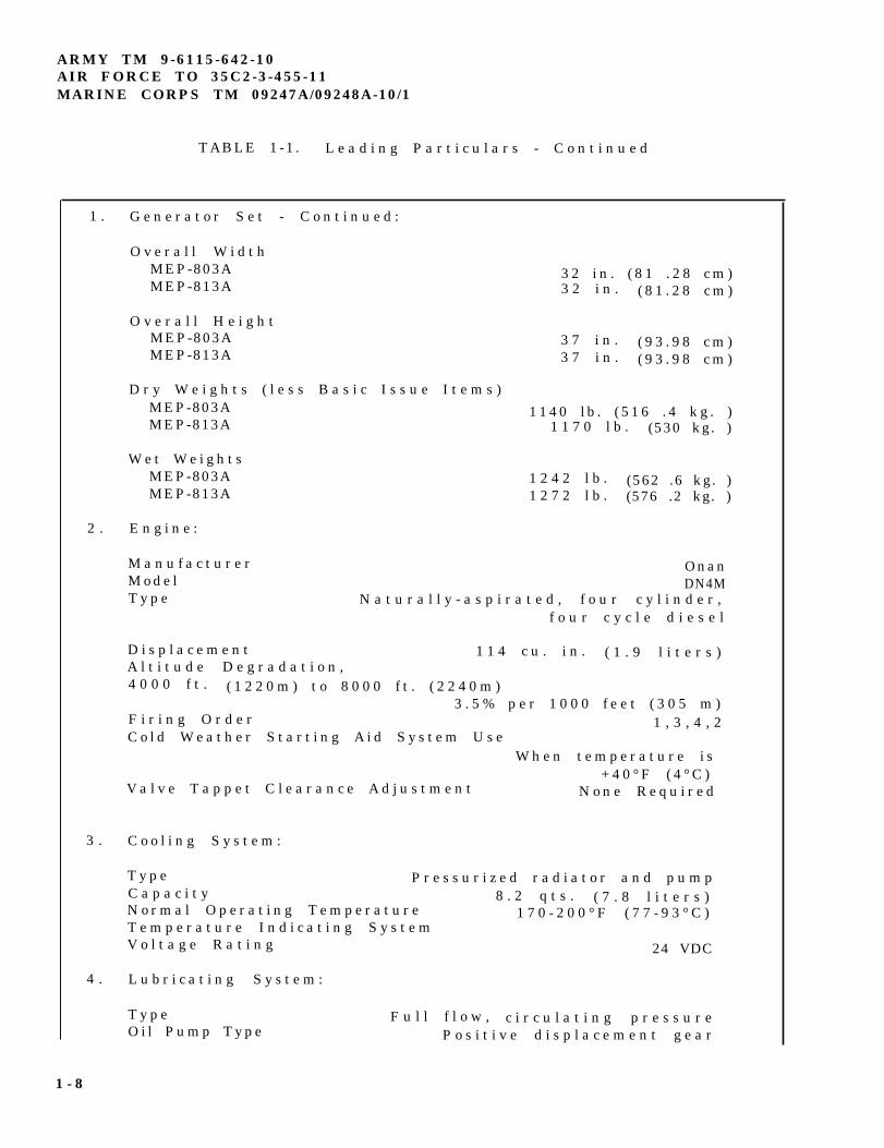
1-9 EQUIPMENT DATA. For a list of LeadingParticulars refer to TABLE 1-1
Table 1-1. Leading Particulars
1. Generator Set:
Model Numbers10 kW 60 Hz Tactical Quiet MEP-803A10 kW 400 Hz Tactical Quiet MEP-813A
National Stock Numbers10 kW 60 Hz Tactical Quiet NSN 6115-01-275-506110 kW 400 Hz Tactical Quiet NSN 6115-01-274-7392
Overall LengthMEP-803A 62 in (157 5 cm)MEP-813A 62 In. (157 5 cm)
Change 2 1-7
ARMY TM 9-6115-642-10AIR FORCE TO 35C2-3-455-11MARINE CORPS TM 09247A/09248A-10/1
TABLE 1-1 . L e a d i n g P a r t i c u l a r s - C o n t i n u e d
1 .
2 .
3 .
4 .
G e n e r a t o r S e t - C o n t i n u e d :
O v e r a l l W i d t hMEP-803AMEP-813A
O v e r a l l H e i g h tMEP-803AMEP-813A
D r y W e i g h t s ( l e s s B a s i c I s s u e I t e m s )MEP-803AMEP-813A
W e t W e i g h t sMEP-803AMEP-813A
3 2 i n . ( 8 1 . 2 8 c m )3 2 i n . ( 8 1 . 2 8 c m )
3 7 i n . ( 9 3 . 9 8 c m )3 7 i n . ( 9 3 . 9 8 c m )
1 1 4 0 l b . ( 5 1 6 . 4 k g . )1 1 7 0 l b . (530 kg. )
1 2 4 2 l b . (562 .6 kg. )1 2 7 2 l b . (576 .2 kg. )
E n g i n e :
M a n u f a c t u r e r OnanM o d e l DN4MT y p e N a t u r a l l y - a s p i r a t e d , f o u r c y l i n d e r ,
f o u r c y c l e d i e s e l
D i s p l a c e m e n t 1 1 4 c u . i n . ( 1 . 9 l i t e r s )A l t i t u d e D e g r a d a t i o n ,4 0 0 0 f t . ( 1 2 2 0 m ) t o 8 0 0 0 f t . ( 2 2 4 0 m )
3 . 5 % p e r 1 0 0 0 f e e t ( 3 0 5 m )F i r i n g O r d e r 1 , 3 , 4 , 2C o l d W e a t h e r S t a r t i n g A i d S y s t e m U s e
W h e n t e m p e r a t u r e i s+ 4 0 ° F ( 4 ° C )
V a l v e T a p p e t C l e a r a n c e A d j u s t m e n t N o n e R e q u i r e d
C o o l i n g S y s t e m :
T y p e P r e s s u r i z e d r a d i a t o r a n d p u m pC a p a c i t y 8 . 2 q t s . ( 7 . 8 l i t e r s )N o r m a l O p e r a t i n g T e m p e r a t u r e 1 7 0 - 2 0 0 ° F ( 7 7 - 9 3 ° C )T e m p e r a t u r e I n d i c a t i n g S y s t e mV o l t a g e R a t i n g 24 VDC
L u b r i c a t i n g S y s t e m :
T y p e F u l l f l o w , c i r c u l a t i n g p r e s s u r eO i l P u m p T y p e P o s i t i v e d i s p l a c e m e n t g e a r
1 - 8

ARMY TM 9-611 5-642-10AIR FORCE TO 35C2-3-455-11
MARINE CORPS TM 09247A/09248A-10/1
Table 1-1. Leading Particulars - continued
4. Lubricating System - Continued:Normal Operating Pressure 25-60 psi (172414 kPa)Oil Filter Type Full flow, spin-on, replaceable elementLubricating System Capacity 5.9 qts. (5 6 liters)Pressure Indicating SystemVoltage Rating 24 VDC
5. Fuel System:Type of Fuel DF-1, DF-2, DF-A, JP4, JP5, JP8Fuel Tank Capacity 9 gal. (34 liters)Fuel Consumption Rate: 60 Hz: .99 gal. (3.75 liters) per hour
400 Hz: 1.07 gal. (4.05 liters) per hourAuxiliary Fuel Pump:
Voltage Rating 24 VDCDelivery Pressure 5.0-6.5 psi (34.5-65.5 kPa) range
Fuel Level Switch:Type FloatCurrent 3.0 amp at 6 to 32 VDC
6. Engine Starting System:Batteries Two 12 volt, connected in seriesStarter:
Manufacturer OnanModel 191-1550Voltage Rating 24 VDCDrive Type Gear Reduction
Battery Charging Alternator:Manufacturer PrestoliteModels 8EM3005CA and 8MR3005CARating 18 amps at 24 VDCProtective Fuse 30 amps
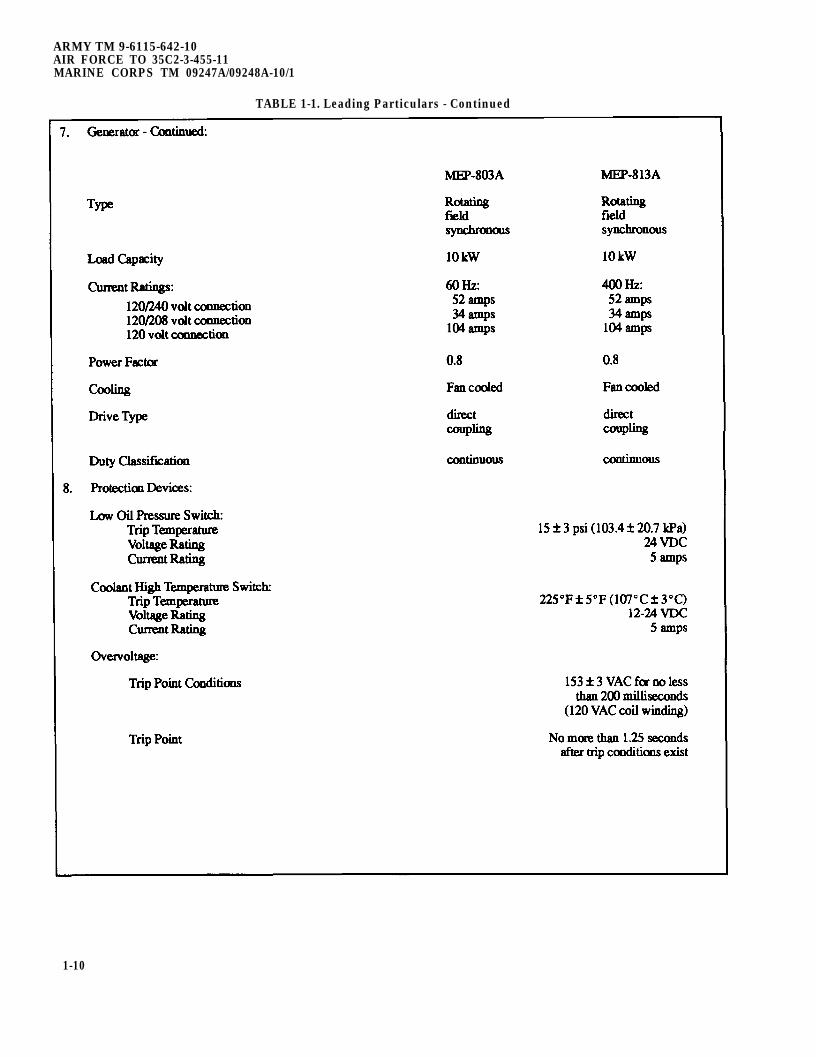
7. AC Generator.Manufacturer Onan
Change 2 1-9
ARMY TM 9-6115-642-10AIR FORCE TO 35C2-3-455-11MARINE CORPS TM 09247A/09248A-10/1
TABLE 1-1. Leading Particulars - Continued
1-10
ARMY TM 9-6115-642-10AIR FORCE TO 35C2-3-455-11
MARINE CORPS TM 09247A/09248A-10/1
Section III. TECHNICAL PRINCIPLES OF OPERATION
1-10
This section contains functional descriptions of thegenerator set and explains how the controls and indicatorsinteract with the system.
1-11.
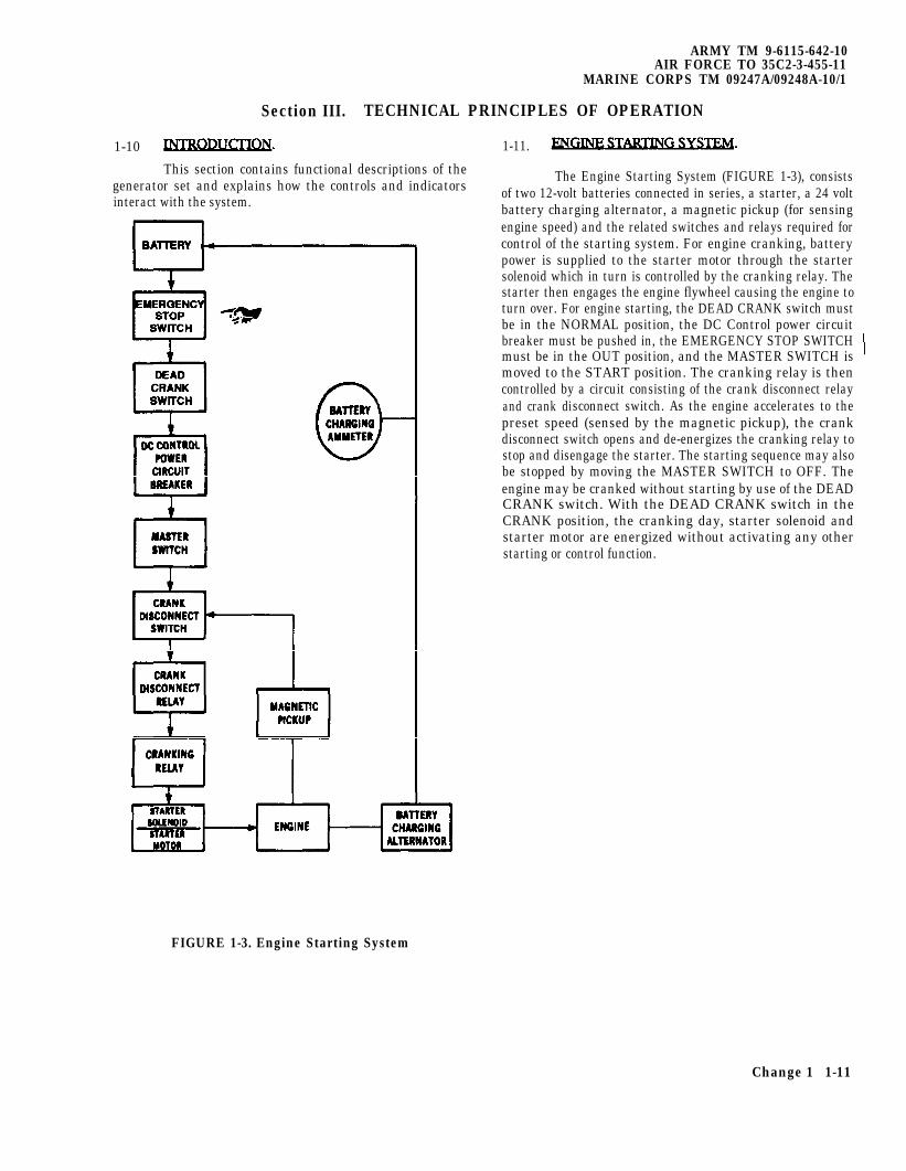
The Engine Starting System (FIGURE 1-3), consistsof two 12-volt batteries connected in series, a starter, a 24 voltbattery charging alternator, a magnetic pickup (for sensingengine speed) and the related switches and relays required forcontrol of the starting system. For engine cranking, batterypower is supplied to the starter motor through the startersolenoid which in turn is controlled by the cranking relay. Thestarter then engages the engine flywheel causing the engine toturn over. For engine starting, the DEAD CRANK switch mustbe in the NORMAL position, the DC Control power circuitbreaker must be pushed in, the EMERGENCY STOP SWITCHmust be in the OUT position, and the MASTER SWITCH ismoved to the START position. The cranking relay is thencontrolled by a circuit consisting of the crank disconnect relayand crank disconnect switch. As the engine accelerates to thepreset speed (sensed by the magnetic pickup), the crankdisconnect switch opens and de-energizes the cranking relay tostop and disengage the starter. The starting sequence may alsobe stopped by moving the MASTER SWITCH to OFF. Theengine may be cranked without starting by use of the DEADCRANK switch. With the DEAD CRANK switch in theCRANK position, the cranking day, starter solenoid andstarter motor are energized without activating any otherstarting or control function.
FIGURE 1-3. Engine Starting System
Change 1 1-11
ARMY TM 9-6115-642-10AIR FORCE TO 35C2-3-455-11MARINE CORPS TM 09247A/09248A-10/1
The batteries are charged by the battery chargingalternator that is belt driven by the engine. Generator setcontrol system power is also supplied by the battery chargingalternator. The BATTERY CHARGE ammeter indicates thecharge/discharge rate of the batteries, from -10 AMPS to +20AMPS, in 5 AMPS increments. Normal operating indicationdepends on the state of charge in the batteries. A low charge,such as exists immediately after engine starting. will cause ahigh reading (needle moves toward CHARGE area). When thecharge in the batteries has been restored, the indicator movesnear zero, 0.
1-12 FUEL SYSTEM.
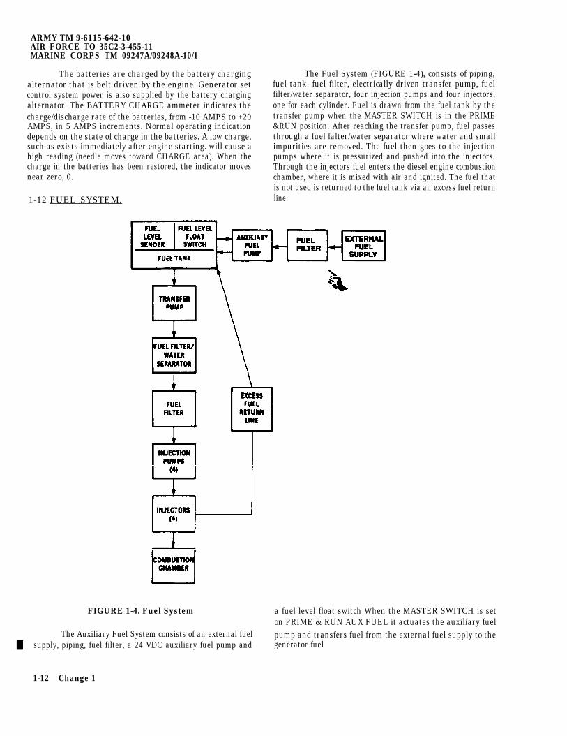
The Fuel System (FIGURE 1-4), consists of piping,fuel tank. fuel filter, electrically driven transfer pump, fuelfilter/water separator, four injection pumps and four injectors,one for each cylinder. Fuel is drawn from the fuel tank by thetransfer pump when the MASTER SWITCH is in the PRIME&RUN position. After reaching the transfer pump, fuel passesthrough a fuel falter/water separator where water and smallimpurities are removed. The fuel then goes to the injectionpumps where it is pressurized and pushed into the injectors.Through the injectors fuel enters the diesel engine combustionchamber, where it is mixed with air and ignited. The fuel thatis not used is returned to the fuel tank via an excess fuel returnline.
FIGURE 1-4. Fuel System a fuel level float switch When the MASTER SWITCH is seton PRIME & RUN AUX FUEL it actuates the auxiliary fuel
The Auxiliary Fuel System consists of an external fuel pump and transfers fuel from the external fuel supply to the supply, piping, fuel filter, a 24 VDC auxiliary fuel pump and generator fuel
1-12 Change 1
tank. The fuel level float switch shuts off the auxiliary fuelpump when the generator fuel tank is full and reactivates thepump as the level drops. The FUEL LEVEL indicator indicatesfuel level of generator fuel tank from (E) empty to (F) full inquarter tank increments.
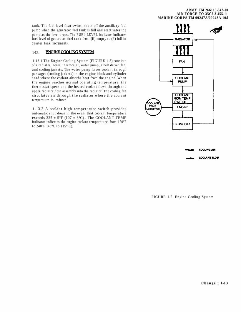
1-13.
1-13.1 The Engine Cooling System (FIGURE 1-5) consistsof a radiator, hoses, thermostat, water pump, a belt driven fan,and cooling jackets. The water pump forces coolant throughpassages (cooling jackets) in the engine block and cylinderhead where the coolant absorbs heat from the engine. Whenthe engine reaches normal operating temperature, thethermostat opens and the heated coolant flows through theupper radiator hose assembly into the radiator. The cooling fancirculates air through the radiator where the coolanttemperature is reduced.
1-13.2 A coolant high temperature switch providesautomatic shut down in the event that coolant temperatureexceeds 225 ± 5°F (107 ± 3°C) . The COOLANT TEMPindicator indicates the engine coolant temperature, from 120°Fto 240°F (48°C to 115° C).
ARMY TM 9-6115-642-10AIR FORCE TO 35C2-3-455-11
MARINE CORPS TM 09247A/09248A-10/l
FIGURE 1-5. Engine Cooling System
Change 1 1-13
ARMY TM 9-6115-642-10AIR FORCE TO 35C2-3-455-11MARINE CORPS TM 09247A/09248A-10/1
1-14.
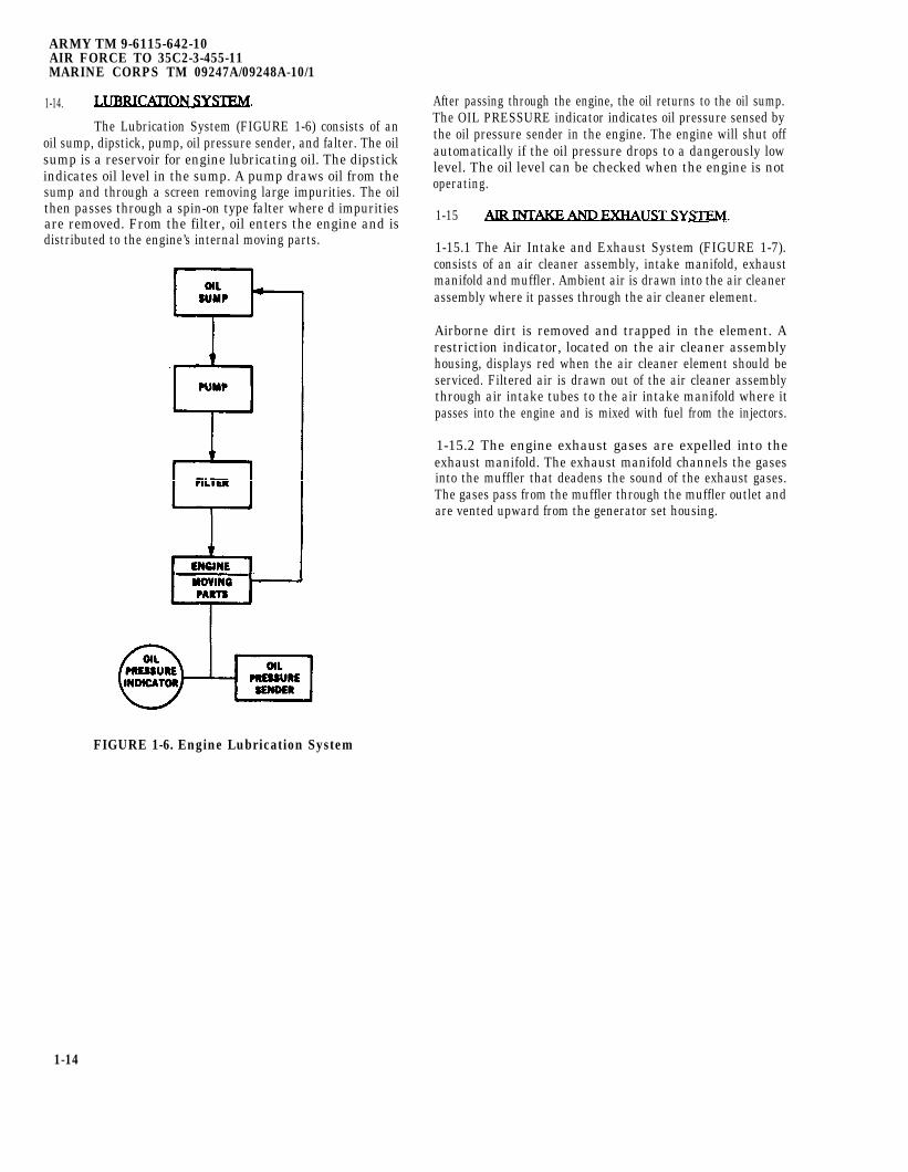
The Lubrication System (FIGURE 1-6) consists of anoil sump, dipstick, pump, oil pressure sender, and falter. The oilsump is a reservoir for engine lubricating oil. The dipstickindicates oil level in the sump. A pump draws oil from thesump and through a screen removing large impurities. The oilthen passes through a spin-on type falter where d impuritiesare removed. From the filter, oil enters the engine and isdistributed to the engine’s internal moving parts.
After passing through the engine, the oil returns to the oil sump.The OIL PRESSURE indicator indicates oil pressure sensed bythe oil pressure sender in the engine. The engine will shut offautomatically if the oil pressure drops to a dangerously lowlevel. The oil level can be checked when the engine is notoperating.
1-15
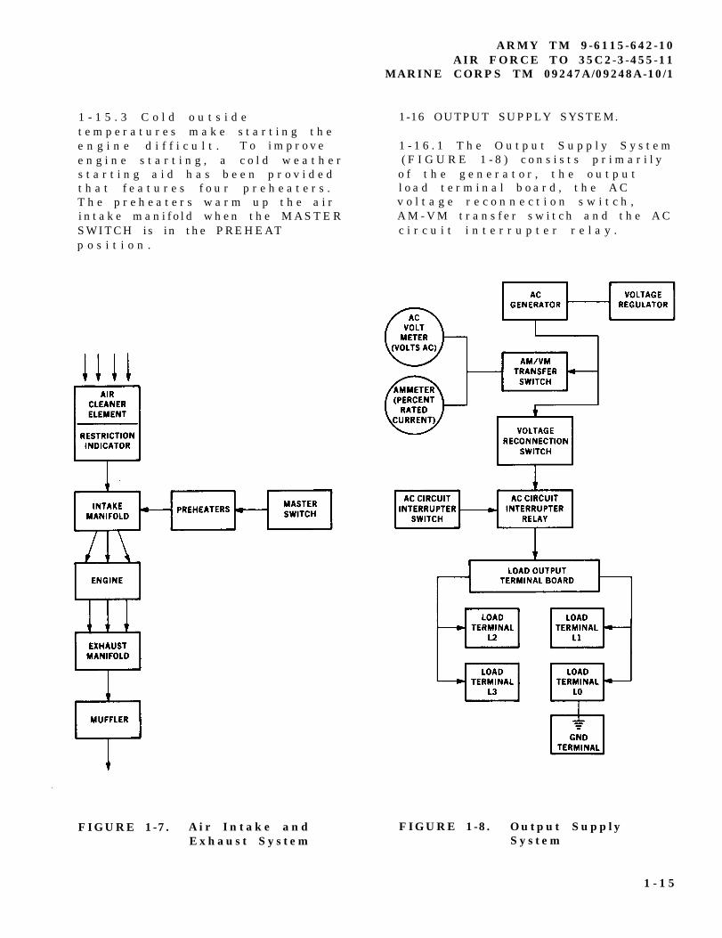
1-15.1 The Air Intake and Exhaust System (FIGURE 1-7).consists of an air cleaner assembly, intake manifold, exhaustmanifold and muffler. Ambient air is drawn into the air cleanerassembly where it passes through the air cleaner element.
Airborne dirt is removed and trapped in the element. Arestriction indicator, located on the air cleaner assemblyhousing, displays red when the air cleaner element should beserviced. Filtered air is drawn out of the air cleaner assemblythrough air intake tubes to the air intake manifold where itpasses into the engine and is mixed with fuel from the injectors.
1-15.2 The engine exhaust gases are expelled into theexhaust manifold. The exhaust manifold channels the gasesinto the muffler that deadens the sound of the exhaust gases.The gases pass from the muffler through the muffler outlet andare vented upward from the generator set housing.
FIGURE 1-6. Engine Lubrication System
1-14
1 - 1 5 . 3 C o l d o u t s i d et e m p e r a t u r e s m a k e s t a r t i n g t h ee n g i n e d i f f i c u l t . T o i m p r o v ee n g i n e s t a r t i n g , a c o l d w e a t h e rs t a r t i n g a i d h a s b e e n p r o v i d e dt h a t f e a t u r e s f o u r p r e h e a t e r s .T h e p r e h e a t e r s w a r m u p t h e a i ri n t a k e m a n i f o l d w h e n t h e M A S T E RSWITCH is in the PREHEATp o s i t i o n .
FIGURE 1-7. A ir Intake andExhaust System
ARMY TM 9-6115-642-10AIR FORCE TO 35C2-3-455-11
MARINE CORPS TM 09247A/09248A-10/1
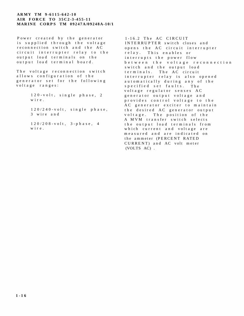
1-16 OUTPUT SUPPLY SYSTEM.
1 - 1 6 . 1 T h e O u t p u t S u p p l y S y s t e m( F I G U R E 1 - 8 ) c o n s i s t s p r i m a r i l y
o f t h e g e n e r a t o r , t h e o u t p u tl o a d t e r m i n a l b o a r d , t h e A Cv o l t a g e r e c o n n e c t i o n s w i t c h ,A M - V M t r a n s f e r s w i t c h a n d t h e A Cc i r c u i t i n t e r r u p t e r r e l a y .
FIGURE 1-8. Output SupplySystem
1 - 1 5
ARMY TM 9-6115-642-10AIR FORCE TO 35C2-3-455-11MARINE CORPS TM 09247A/09248A-10/1
P o w e r c r e a t e d b y t h e g e n e r a t o ri s s u p p l i e d t h r o u g h t h e v o l t a g er e c o n n e c t i o n s w i t c h a n d t h e A Cc i r c u i t i n t e r r u p t e r r e l a y t o t h eo u t p u t l o a d t e r m i n a l s o n t h eo u t p u t l o a d t e r m i n a l b o a r d .
T h e v o l t a g e r e c o n n e c t i o n s w i t c ha l l o w s c o n f i g u r a t i o n o f t h eg e n e r a t o r s e t f o r t h e f o l l o w i n gv o l t a g e r a n g e s :
1 2 0 - v o l t , s i n g l e p h a s e , 2w i r e .
1 2 0 / 2 4 0 - v o l t , s i n g l e p h a s e ,3 w i r e a n d
1 2 0 / 2 0 8 - v o l t , 3 - p h a s e , 4w i r e .
1 - 1 6 . 2 T h e A C C I R C U I TI N T E R R U P T E R s w i t c h c l o s e s a n do p e n s t h e A C c i r c u i t i n t e r r u p t e rr e l a y . T h i s e n a b l e s o ri n t e r r u p t s t h e p o w e r f l o wb e t w e e n t h e v o l t a g e r e c o n n e c t i o ns w i t c h a n d t h e o u t p u t l o a dt e r m i n a l s . T h e A C c i r c u i ti n t e r r u p t e r r e l a y i s a l s o o p e n e da u t o m a t i c a l l y d u r i n g a n y o f t h es p e c i f i e d s e t f a u l t s . T h ev o l t a g e r e g u l a t o r s e n s e s A Cg e n e r a t o r o u t p u t v o l t a g e a n dp r o v i d e s c o n t r o l v o l t a g e t o t h eA C g e n e r a t o r e x c i t e r t o m a i n t a i nt h e d e s i r e d A C g e n e r a t o r o u t p u tv o l t a g e . T h e p o s i t i o n o f t h eA M-V M t r a n s f e r s w i t c h s e l e c t st h e o u t p u t l o a d t e r m i n a l s f r o mw h i c h c u r r e n t a n d v o l t a g e a r em e a s u r e d a n d a r e i n d i c a t e d o nthe ammeter (PERCENT RATEDCURRENT) and AC vo l t meter(VOLTS AC) .
1 - 1 6
ARMY TM 9-6115-642-10AIR FORCE TO 35C2-3-455-11
MARINE CORPS TM 09247A/09248A-10/1
CHAPTER 2
OPERATING INSTRUCTIONS
SECTION I. DESCRIPTION AND USE OF OPERATOR’SCONTROLS AND INDICATORS
2 - 1 GENERAL. 2 - 2 CONTROL PANEL ASSEMBLY.
T h i s s e c t i o n d e s c r i b e s a n d T h e c o n t r o l p a n e l a s s e m b l yi l l u s t r a t e s t h e c o n t r o l s a n d c o n t a i n s m o s t o f t h e o p e r a t i n gi n d i c a t o r s t o e n s u r e p r o p e r c o n t r o l s a n d i n d i c a t o r s f o r t h eo p e r a t i o n o f t h e g e n e r a t o r s e t . g e n e r a t o r s e t . FIGURE 2-1 shows
t h e c o n t r o l p a n e l a s s e m b l yl a y o u t a n d T A B L E 2 - 1 d e s c r i b e se a c h c o n t r o l a n d i n d i c a t o r .
2 - 1
ARMY TM 9-6115-642-10AIR FORCE TO 35C2-3-455-11MARINE CORPS TM 09247A/09248A-10/1
FIGURE 2-1. Operator’s Controls and Indicators
2 - 2
K e y
1
2
3
4
5
6
7
8
9
10
11
ARMY TM 9-6115-642-10AIR FORCE TO 35C2-3-455-11
MARINE CORPS TM 09247A/09248A-10/1
TABLE 2-1 . C o n t r o l P a n e l C o n t r o l s a n d I n d i c a t o r s
C o n t r o l o r I n d i c a t o r
F U E L L E V E L i n d i c a t o r
P a n e l l i g h t s
COOLANT TEMP. indicator
O I L P R E S S U R E i n d i c a t o r
EMERGENCY STOPp u s h b u t t o n
FREQUENCY meter (HERTZ)
Ammeter (PERCENT RATEDCURRENT METER)
A M - V M t r a n s f e r s w i t c h
AC Vol tmeter (VOLTS AC)
VOLTAGE adjustP o t e n t i o m e t e r
BATTLE SHORT light
F u n c t i o n
I n d i c a t e s f u e l l e v e l .
I l l u m i n a t e s c o n t r o l p a n e l .
I n d i c a t e s e n g i n e c o o l a n tt e m p e r a t u r e .
I n d i c a t e s o i l p r e s s u r e .
S h u t s d o w n g e n e r a t o r s e t .
I n d i c a t e s g e n e r a t o r s e t o u t p u tf r e q u e n c y .
I n d i c a t e s g e n e r a t o r s e t l o a dc u r r e n t a s a p e r c e n t o f r a t e dc u r r e n t .
A l l o w s s e l e c t i o n o f c u r r e n t a n dv o l t a g e r e a d i n g s b e t w e e n o u t p u tl o a d t e r m i n a l s a s f o l l o w s :
S w i t c hP o s i t i o n V o l t a q e C u r r e n tL 1 - L 2 L 1 - L 2 L1
( 3 P h a s e )L2 - L3 L2 - L3 L2
( 3 P h a s e )L 3 - L 1 L 3 - L 1 L3
( 3 P h a s e )L3-LO L 3 - L O L3
( 3 P h a s e )L 3 - L 1 L 3 - L O L3
( 1 P h a s e )L3-LO L 3 - L O L3
( 1 P h a s e )
I n d i c a t e s o u t p u t v o l t a g e o fg e n e r a t o r s e t .
A d j u s t s g e n e r a t o r s e t v o l t a g e .
A m b e r l i g h t i n d i c a t e s b a t t l e s h o r ts w i t c h o n .
2 - 3
ARMY TM 9-6115-642-10AIR FORCE TO 35C2-3-455-11MARINE CORPS TM 09247A/09248A-10/1
TABLE 2-1 . C o n t r o l P a n e l C o n t r o l s a n d I n d i c a t o r s - C o n t i n u e d
K e y
12
13
14
15
16
17
18
19
2 0
2 1
C o n t r o l o r I n d i c a t o r
BATTLE SHORT switch
PANEL LIGHTS switch
AC CIRCUIT INTERRUPTERs w i t c h
AC CIRCUIT INTERRUPTERl i q h t
MASTER SWITCH
T i m e m e t e r ( T O T A LHOURS)
BATTERY CHARGE ammeter
DC CONTROL POWERc i r c u i t b r e a k e r ( C B 1 )( L o c a t e d B e h i n dC o n t r o l P a n e l )
A C V o l t a g eR e c o n n e c t i o n S w i t c h( L o c a t e d B e h i n dC o n t r o l P a n e l )
BATTERY CHARGER FUSE(FU1)( L o c a t e d B e h i n dC o n t r o l P a n e l )
F u n c t i o n
B y p a s s e s p r o t e c t i v e d e v i c e s .
O N - A c t i v a t e s o r d e a c t i v a t e sp a n e l l i q h t s .
O p e n s a n d c l o s e s A C c i r c u i ti n t e r r u p t e r r e l a y .
G r e e n l i g h t i n d i c a t e s A C c i r c u i ti n t e r r u p t e r r e l a y i s c l o s e d .
PREHEAT - E n e r g i z e s h e a t e r p l u g s .
OFF - D e e n e r g i z e s a l l c i r c u i t s ,e x c e p t p a n e l l i g h t s .
PRIME & RUN AUX FUEL - E n e r g i z e sg e n e r a t o r s e t r u n c i r c u i t s w i t hf u e l p u m p o p e r a t i n g a n d w i t ha u x i l i a r y f u e l p u m p s y s t e ma c t i v a t e d .
P R I M E & R U N - E n e r g i z e s g e n e r a t o rs e t r u n c i r c u i t s w i t h f u e l p u m po p e r a t i n g a n d a u x i l i a r y f u e ls y s t e m d e e n e r g i z e d .
START - E n e r g i z e s s t a r t e r .
I n d i c a t e s t o t a l e n g i n e o p e r a t i n gh o u r s .
I n d i c a t e s c h a r g e / d i s c h a r g e r a t e o fb a t t e r i e s .
E n e r g i z e s o r d e e n e r g i z e s D Cc i r c u i t s .
S e l e c t s 1 2 0 / 2 0 8 V A C , t h r e e - p h a s e ;1 2 0 V A C , s i n g l e p h a s e ; o r 1 2 0 / 2 4 0V A C , s i n g l e p h a s e o u t p u t a t l o a dt e r m i n a l b o a r d .
P r o t e c t s b a t t e r y c h a r g i n ga l t e r n a t o r .
2 - 4
ARMY TM 9-6115-642-10AIR FORCE TO 35C2-3-455-11
MARINE CORPS TM 09247A/09248A-10/1
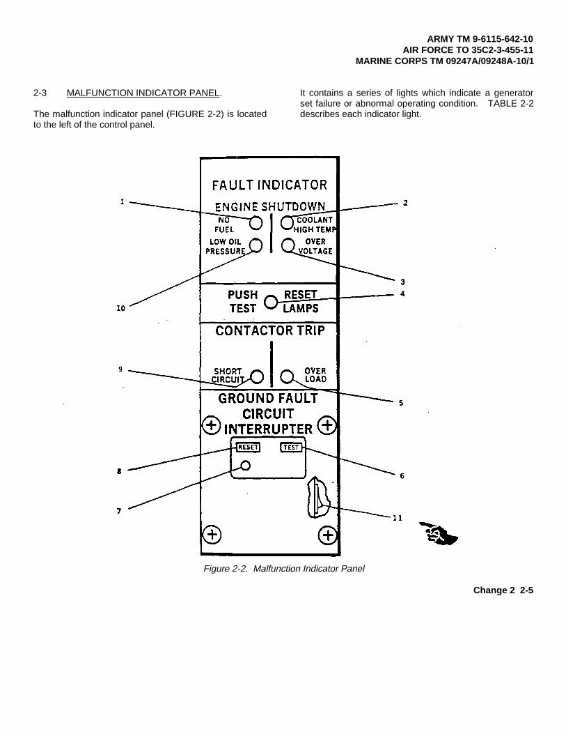
2-3 MALFUNCTION INDICATOR PANEL.
The malfunction indicator panel (FIGURE 2-2) is locatedto the left of the control panel.
It contains a series of lights which indicate a generatorset failure or abnormal operating condition. TABLE 2-2describes each indicator light.
Figure 2-2. Malfunction Indicator Panel
Change 2 2-5
ARMY TM 9-6115-642-10AIR FORCE TO 35C2-3-455-11MARINE CORPS TM 09247A/09248A-10/1
Table 2-2. Malfunction Indicator Panel
Key Control or Indicator Function1 NO FUEL indicator Lights when fuel level in fuel tank
is below preset level.2 COOLANT HIGH TEMP
indicatorLights when engine coolanttemperature exceeds 225° ± 5° F(107° ± 30 F).
3 OVERVOLTAGE indicator Lights when voltage in 120 voltgenerator coil exceeds 153 ± 3volts.
4 PUSH TEST RESET LAMPS Tests and resets fault indicatorlamps.
5 OVER LOAD indicator Lights when current in any phaseexceeds 110 percent of rated current.
6 GROUND FAULT CIRCUIT INTERRUPTERTESTpushbutton
Tests Ground Fault CircuitInterrupter.
7 Ground Fault CircuitInterrupter indicator
Mechanically trips red indicator, atground fault condition in circuit ofconvenience receptacle.
8 Ground Fault CircuitInterrupter PUSH TOTEST Pushbutton
Depress to reset Ground Fault CircuitInterrupter after test or groundfault has occurred.
9 SHORT CIRCUIT indicator Lights when generator set output inany phase exceeds 425 ± 25 percentof rated current.
10 LOW OIL PRESSUREindicator
Lights when engine lubricationsystems pressure is less than 15 + 3psi (103.4 ± 20.7 kPa) during engineoperation.
11 Convenience ReceptacleOverload CircuitBreaker (10-amp in-linefuse on generator sets,contract number DAAK01-88-D-D080)
Circuit breaker trips on when loadon convenience receptacle exceeds 10amps (fuse blows on generator sets,contract number DAAK01-88-D-D080).
2-6 Change 2
ARMY TM 9-6115-642-10AIR FORCE TO 35C2-3-455-11
MARINE CORPS TM 09247A/09248A-10/1
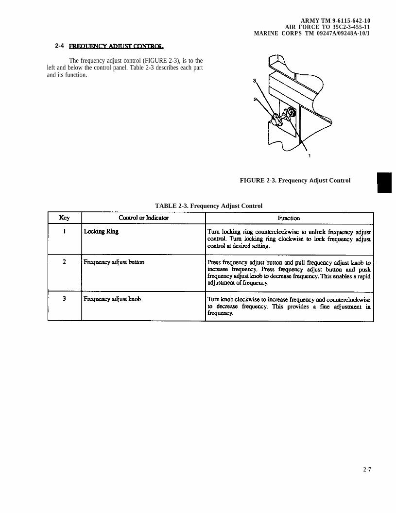
2-4
The frequency adjust control (FIGURE 2-3), is to theleft and below the control panel. Table 2-3 describes each partand its function.
FIGURE 2-3. Frequency Adjust Control
TABLE 2-3. Frequency Adjust Control
2-7
2-6.5
ARMY TM 9-6115-642-10AIR FORCE TO 35C2-3-455-11MARINE CORPS TM 09247A/09248A-10/1
Section II. PREVENTATIVE MAINTENANCE CHECKS AND SERVICES (PMCS)
2-5 General. To ensure that the generator set isready for operation at all times, it must be inspected so thatdefects can be discovered and corrected before they result inserials damage or failure.
2-5.1. CAUTIONS and WARNINGS. perform your before (B)PMCS.
2-5.2 While YOU Operate. Always keep in mind theCAUTIONS and WARNINGS. Perform your during (D)PMCS.
2-5.3 After You Operate. Be sure to perform your after
2-5.4 If yourequipment does not perform as required, refer to Chapter 3under Troubleshooting for possible problems. Report anymalfunctions or failures on the proper DA Form 2404, or referto DA PAM 738-750.
2-6 PMCS PROCEDURES.
NOTE
For general location of the items to be inspected inTABLE 2-4, refer to FIGURE 1-2 and FIGURE2-1.
2-6.1. Maintenance Checks and services (TABLE 2-4) list theinspections and care of you equipment required to keep it ingood operating condition.
2-6.2 The interval columnof your PMCS table tells you when to do a certain checkerservice.
2-6.3 The following guidelines havebeen provided to help you in” classifying leaks observed whileperforming PMCS.
Class I. Seepage of fluid (as indicated by wetness ordiscoloration) not great enough to form drops.
Class II. Leakage of fluid great enough to formdrops but not enough to cause drops to drip from item beingChecked/inspected.
Class III. Leakage of fluid great enough to formdrops that fall from the item being ckecked/inspected.
Equipment operation is allowable with minor oiland coolant leakage(Class I or II) and is able toperform its combat missions (refer to DA PAM738-750.
Of course, you must consider the fluid capacity inthe item/system being checked inspected. Whenin doubt, notify the next higher level ofmaintenance.
When operating with Class I or II leaks,continue to check fluid levels as required in yourPMCS.
All leaks should be reported to the next higherlevel of maintenance.
2-6.4 your PMCS table tells you how to do the required checks andservices. carefully follow these instructions. . If you do not havethe tools, or if the procedures indicate, complete a DA Form2404 and submit it to the next higher level of maintenance.
NOTE
The terms “ready/available” and “missioncapable”, refer to the same status: Generator set ison hand and is able to perform its combat missions,refer to DA PAM 738-750.
2-6.6generator set does not perform as required, refer to Chapter 3under Troubleshooting for possible problems. Report mymalfunctions or failures on DA Form 2404, refer to DA PAM738-750.
2-6.7PMCS. There is no requirement to remove assemblies/equipment prior to performing the PMCS.
2-8 Change 1
ARMY TM 9-6115-642-10AIR FORCE TO 35C2-3-455-11
MARINE CORPS TM 09247A/09248A-10/1
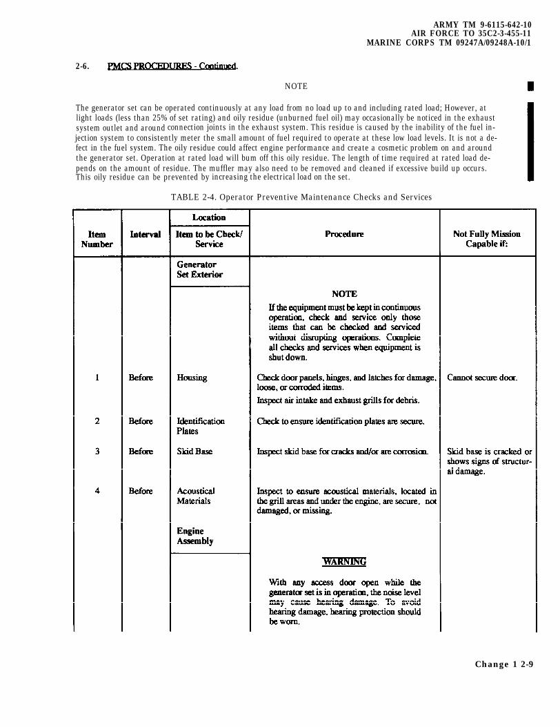
2-6.
NOTE
The generator set can be operated continuously at any load from no load up to and including rated load; However, atlight loads (less than 25% of set rating) and oily residue (unburned fuel oil) may occasionally be noticed in the exhaustsystem outlet and around connection joints in the exhaust system. This residue is caused by the inability of the fuel in-jection system to consistently meter the small amount of fuel required to operate at these low load levels. It is not a de-fect in the fuel system. The oily residue could affect engine performance and create a cosmetic problem on and aroundthe generator set. Operation at rated load will bum off this oily residue. The length of time required at rated load de-pends on the amount of residue. The muffler may also need to be removed and cleaned if excessive build up occurs.This oily residue can be prevented by increasing the electrical load on the set.
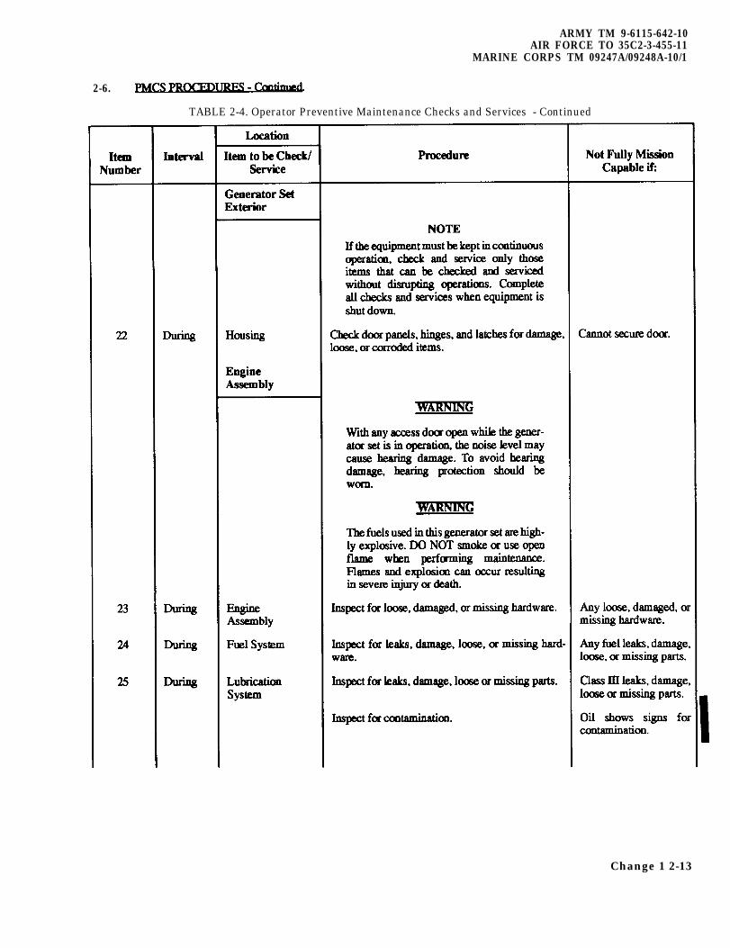
TABLE 2-4. Operator Preventive Maintenance Checks and Services
Change 1 2-9
ARMY TM 9-6115-442-10AIR FORCE TO 35C2-3-455-11MARINE CORPS TM 09247A/09248A-10/1
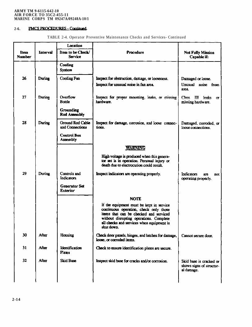
2-6.
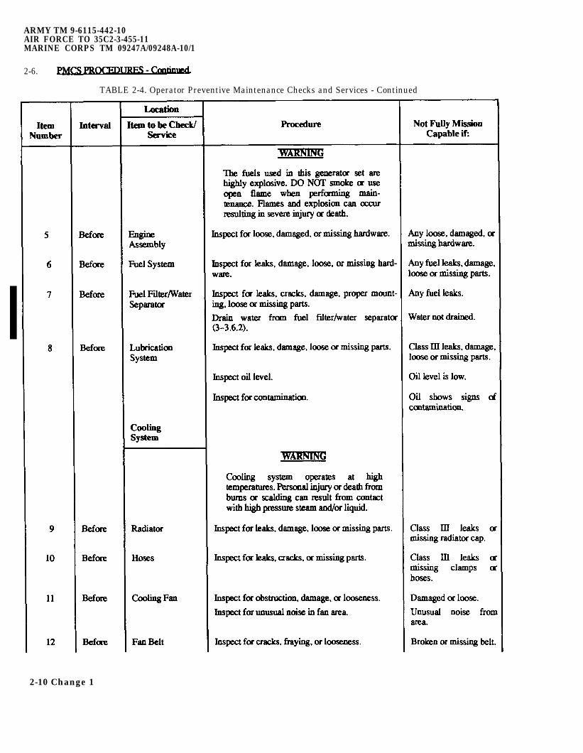
TABLE 2-4. Operator Preventive Maintenance Checks and Services - Continued
2-10 Change 1
ARMY TM 9-6115-642-10AIR FORCE TO 35C2-3-455-11
MARINE CORPS TM 09247A/09248A-10/1
2-6.1
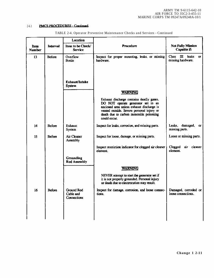
TABLE 2-4. Operator Preventive Maintenance Checks and Services - Continued
Change 1 2-11
ARMY TM 9-6115-642-10AIR FORCE TO 35C2-3-455-11MARINE CORPS TM 09247A/09248A-10/1
2-6.
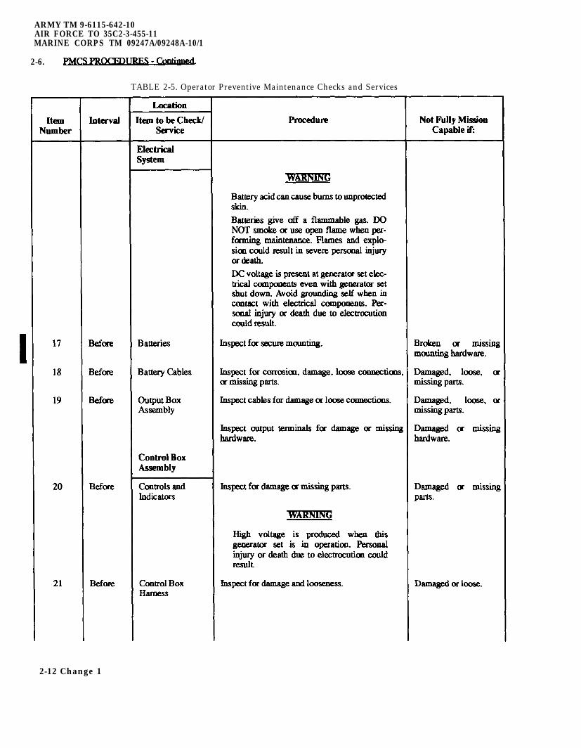
TABLE 2-5. Operator Preventive Maintenance Checks and Services
2-12 Change 1
ARMY TM 9-6115-642-10AIR FORCE TO 35C2-3-455-11
MARINE CORPS TM 09247A/09248A-10/1
2-6.
TABLE 2-4. Operator Preventive Maintenance Checks and Services - Continued
Change 1 2-13
ARMY TM 9-6115-642-10AIR FORCE TO 35C2-455-11MARINE CORPS TM 09247A/09248A-10/1
2-6.
TABLE 2-4. Operator Preventive Maintenance Checks and Services- Continued
2-14

ARMY TM 9-6115-642-10AIR FORCE TO 35C2-3-455-11
MARINE CORPS TM 09247A/09248A-10/1
2-6 PMCS PROCEDURES - Continued.
TABLE 2-4. Operator Preventive Maintenance Checks and Services - Continued
Location
Item Interval Item to be Procedure Not Fully MissionNumber Check/Service Capable if:
The fuels used in this generator setare highly explosive. DO NOTsmoke or use open flame when
performing maintenance. Flamesand explosion can occur resulting
in severe injury or death.
33 After Engine Inspect for loose, damaged, or missing Loose, damaged,Assembly hardware. or missing hard-
ware.
34 After Fuel System Inspect for leaks, damage, loose, or Any fuel leaks,missing hardware. damage, loose or
missing parts.
35 After Fuel Filter/ Inspect for leaks, cracks, damage, Any fuel leaks.Water proper mounting, loose or missing part s.Separator
Drain water. Water not drained.
36 After Lubrication Inspect for leaks, damage, loose or Class III leaks,System missing parts. damage, loose or
missing parts.
Inspect oil level. Oil level is low.
Inspect for contamination. Oil shows signs ofcontamination.
Cooling System
Cooling system operates at hightemperatures. Personal injury ordeath from burns or scalding can
result from contact with high pressuresteam and/or liquid.
37 After Radiator Inspect for leaks, damage, loose or Class III leaks ormissing parts. missing radiator
cap.38 After Hoses Inspect for leaks, cracks, or missing Class III leaks or
parts. missing clamps orhoses.
39 After Fan Belt Inspect for cracks, fraying, or Broken or missinglooseness. belt.
Control BoxAssembly
40 After Controls and Inspect for damaged or missing parts. Damaged or miss-Indicators ing parts.
2-15
ARMY TM 9-6115-642-10AIR FORCE TO 35C2-3-455-11MARINE CORPS TM 09247A/09248A-10/1
SECTION III. OPERATION UNDER USUAL CONDITIONS
2-7 GENERAL. This section provides informationand guidance for generator set operation under normalconditions, refer to FM 20-31.
2-8 ASSEMBLY AND PREPARATION FOR USE.
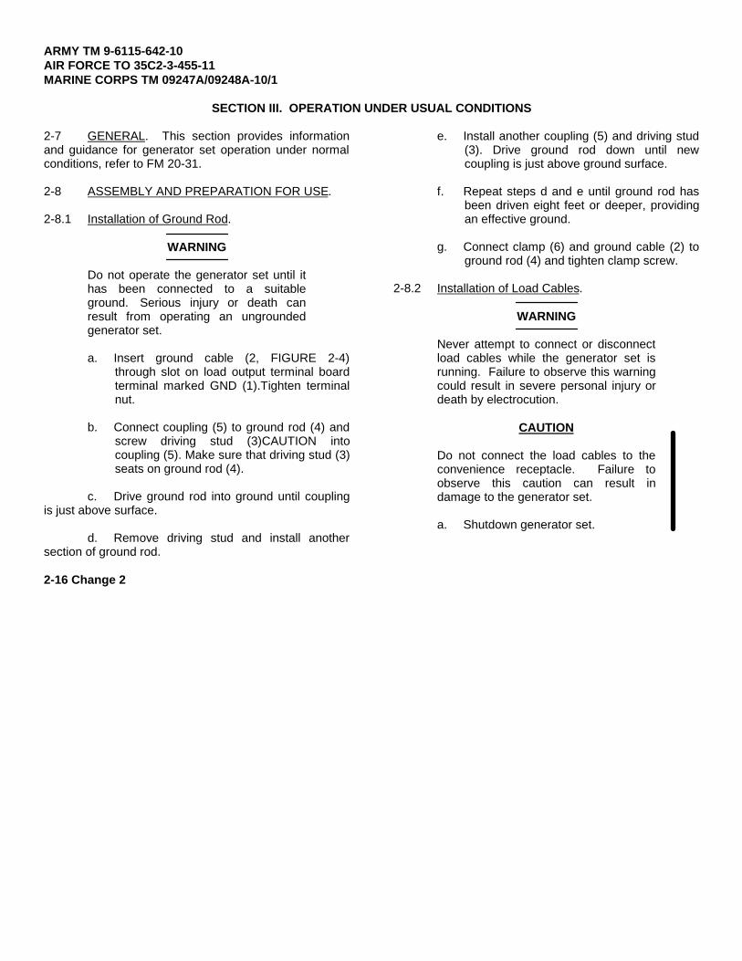
2-8.1 Installation of Ground Rod.
WARNING
Do not operate the generator set until ithas been connected to a suitableground. Serious injury or death canresult from operating an ungroundedgenerator set.
a. Insert ground cable (2, FIGURE 2-4)through slot on load output terminal boardterminal marked GND (1).Tighten terminalnut.
b. Connect coupling (5) to ground rod (4) andscrew driving stud (3)CAUTION intocoupling (5). Make sure that driving stud (3)seats on ground rod (4).
c. Drive ground rod into ground until couplingis just above surface.
d. Remove driving stud and install anothersection of ground rod.
e. Install another coupling (5) and driving stud(3). Drive ground rod down until newcoupling is just above ground surface.
f. Repeat steps d and e until ground rod hasbeen driven eight feet or deeper, providingan effective ground.
g. Connect clamp (6) and ground cable (2) toground rod (4) and tighten clamp screw.
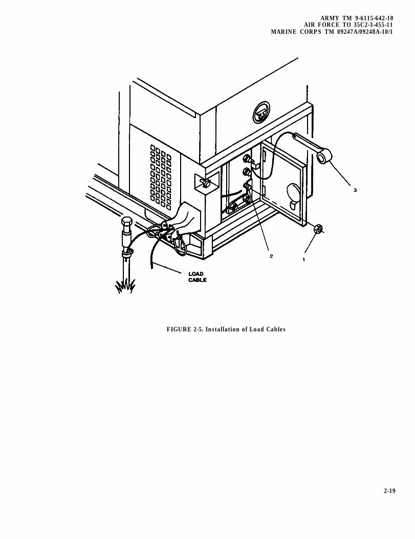
2-8.2 Installation of Load Cables.
WARNING
Never attempt to connect or disconnectload cables while the generator set isrunning. Failure to observe this warningcould result in severe personal injury ordeath by electrocution.
CAUTION
Do not connect the load cables to theconvenience receptacle. Failure toobserve this caution can result indamage to the generator set.
a. Shutdown generator set.
2-16 Change 2
ARMY TM 9-6115-642-10AIR FORCE TO 35C2-3-455-11
MARINE CORPS TM 09247A/09248A-10/1
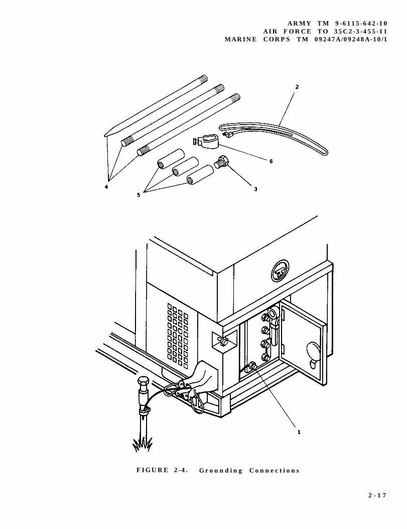
FIGURE 2-4. Grounding Connections
2 - 1 7
ARMY TM 9-6115-642-10AIR FORCE TO 35C2-3-455-11MARINE CORPS TM 09247A/09248A-10/1
W h e n u s i n g s i n g l ep h a s e c o n n e c t i o n s ,a l w a y s a t t e m p t t ob a l a n c e l o a d sb e t w e e n t e r m i n a l s( d o n o t c o n n e c t
a l l l o a d s b e t w e e no n e t e r m i n a l a n dLO) . F a i l u r e t oo b s e r v e t h i sc a u t i o n c a n r e s u l ti n d a m a g e t og e n e r a t o r s e t .
b . S e l e c t r e q u i r e do u t p u t t e r m i n a l s f r o mTABLE 2-5 .
c . O p e n o u t p u t l o a dt e r m i n a l d o o r .
d . U s i n g t e r m i n a l n u tw r e n c h ( 3 , F I G U R E 2 -5 ) l o o s e n t e r m i n a ln u t s ( 1 ) o n t e r m i n a l s( 2 ) s e l e c t e d i n S t e p
b .
e . I n s e r t e n d s o f l o a dc a b l e s t h r o u g h l o a dc a b l e e x i t . T h e ni n s e r t e n d s o f c a b l e si n t o s l o t s o f l o a dt e r m i n a l s t u d s ( 2 ) .
f . T i g h t e n l o a d t e r m i n a ln u t s ( 1 ) .
g . S e c u r e w r e n c h ( 3 ) i nb r a c k e t i n s i d e l o a dt e r m i n a l d o o r , a n dc l o s e d o o r .
TABLE 2-5 . L o a d T e r m i n a l , A C V o l t a g e R e c o n n e c t i o n S w i t c ha n d A M - V M T r a n s f e r S w i t c h S e l e c t i o n
RECONNECTION AM-VM CURRENTSWITCH TERMINALS TRANSFER SWITCH VOLTAGE READING
POSITION POSITION READING (TERMINAL)
1 2 0 / 2 0 8 V 3 P H L 1 , L 2 , L1-L2 3 PHASE 208 VOLTS L1L 3 , L O L2-L3 3 PHASE 208 VOLTS L2
L3-L1 3 PHASE 208 VOLTS L3L3-LO 3 PHASE 120 VOLTS L3
120V 1PH L 3 - L O L3-LO 1 PHASE 120 VOLTS L3
1 2 0 / 2 4 0 V 1 P H L 3 - L 1 L3-L1 1 PHASE 240 VOLTS L3L 3 - L O L3-LO 1 PHASE 120 VOLTS L3ORL 1 - L O L1-LO 1 PHASE 120 VOLTS L1
2 - 1 8
ARMY TM 9-6115-642-10AIR FORCE TO 35C2-3-455-11
MARINE CORPS TM 09247A/09248A-10/1
FIGURE 2-5. Installation of Load Cables
2-19
ARMY TM 9-6115-442-10AIR FORCE TO 35C2-3-455-11MARINE CORPS TM 09247A/09248A-10/1
2-9
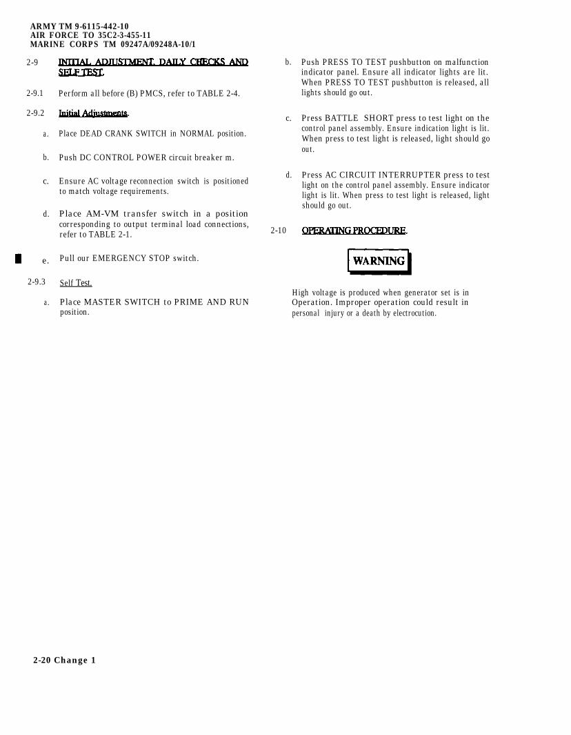
2-9.1
2-9.2
a.
b.
c.
d.
e.
2-9.3
a.
Perform all before (B) PMCS, refer to TABLE 2-4.
Place DEAD CRANK SWITCH in NORMAL position.
Push DC CONTROL POWER circuit breaker m.
Ensure AC voltage reconnection switch is positionedto match voltage requirements.
Place AM-VM transfer switch in a positioncorresponding to output terminal load connections,refer to TABLE 2-1.
Pull our EMERGENCY STOP switch.
Self Test.
Place MASTER SWITCH to PRIME AND RUNposition.
b.
c.
d.
2-10
Push PRESS TO TEST pushbutton on malfunctionindicator panel. Ensure all indicator lights are lit.When PRESS TO TEST pushbutton is released, alllights should go out.
Press BATTLE SHORT press to test light on thecontrol panel assembly. Ensure indication light is lit.When press to test light is released, light should goout.
Press AC CIRCUIT INTERRUPTER press to testlight on the control panel assembly. Ensure indicatorlight is lit. When press to test light is released, lightshould go out.
High voltage is produced when generator set is inOperation. Improper operation could result inpersonal injury or a death by electrocution.
2-20 Change 1
WARNING
E x h a u s t d i s c h a r g ec o n t a i n s d e a d l yg a s e s . D o n o to p e r a t e t h eg e n e r a t o r s e t i ne n c l o s e d a r e a su n l e s s e x h a u s td i s c h a r g e i sp r o p e r l y v e n t e do u t s i d e . S e v e r ep e r s o n a l i n j u r y o rd e a t h d u e t oc a r b o n m o n o x i d ep o i s o n i n g c o u l dr e s u l t .
2 - 1 0 . 1 S t a r t i n g P r o c e d u r e .
WARNING
N e v e r a t t e m p t t os t a r t t h eg e n e r a t o r s e t i fi t h a s n o t b e e np r o p e r l y g r o u n d e d .F a i l u r e t o o b s e r v et h i s w a r n i n g c o u l dr e s u l t i n s e r i o u si n j u r y o r d e a t h b ye l e c t r o c u t i o n .
CAUTION
D o n o t c r a n ke n g i n e i n e x c e s so f f i f t e e ns e c o n d s . A l l o ws t a r t e r t o c o o l a tl e a s t f i f t e e ns e c o n d s b e t w e e na t t e m p t e d s t a r t s .F a i l u r e t o o b s e r v et h i s c a u t i o n c o u l dr e s u l t i n d a m a g et o t h e s t a r t e r .
ARMY TM 9-6115-642-10AIR FORCE TO 35C2-3-455-11
MARINE CORPS TM 09247A/09248A-10/1
NOTE
A t t e m p e r a t u r e sb e l o w 4 0 ° F ( 4 ° C )i t m a y b en e c e s s a r y t o u s et h e C o l d W e a t h e rS t a r t i n g A i d .
NOTE
E n s u r e a l lg e n e r a t o r s e ta c c e s s d o o r s ,e x c e p t c o n t r o lp a n e l a c c e s s d o o r ,a r e c l o s e d .
a . I n c o l d w e a t h e rc o n d i t i o n s , p l a c eMASTER SWITCH toP R E H E A T p o s i t i o n f o ra p p r o x i m a t e l y 3 0s e c o n d s .
b . Rotate MASTER SWITCHt o S T A R T p o s i t i o n .
c . Hold MASTER SWITCH inS T A R T p o s i t i o n u n t i lo i l p r e s s u r e r e a c h e sa t l e a s t 2 5 p s i ( 1 7 2kPa) , v o l t a g e h a si n c r e a s e d t o i t sa p p r o x i m a t e r a t e dv a l u e , a n d e n g i n e h a sr e a c h e d s t a b l eo p e r a t i n g s p e e d .
d . Release MASTER SWITCHto PRIME AND RUNp o s i t i o n .
e . I f o p e r a t i n g w i t h a na u x i l i a r y f u e ls o u r c e , rotate MASTERSWITCH to PRIME ANDRUN AUX FUELp o s i t i o n .
2 - 2 1
ARMY TM 9-6115-642-10AIR FORCE TO 35C2-3-455-11MARINE CORPS TM 09247A/09248A-10/1
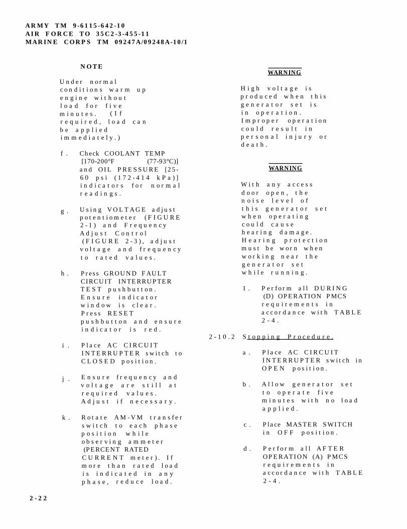
U n d e r n o r m a lc o n d i t i o n s w a r m u pe n g i n e w i t h o u tl o a d f o r f i v em i n u t e s . ( I fr e q u i r e d , l o a d c a nb e a p p l i e di m m e d i a t e l y . )
f . Check COOLANT TEMP[170-200°F (77-93°C)]
and OIL PRESSURE [25-6 0 p s i ( 1 7 2 - 4 1 4 k P a ) ]i n d i c a t o r s f o r n o r m a lr e a d i n g s .
g . U s i n g V O L T A G E a d j u s tp o t e n t i o m e t e r ( F I G U R E2 - 1 ) a n d F r e q u e n c yA d j u s t C o n t r o l( F I G U R E 2 - 3 ) , a d j u s t
v o l t a g e a n d f r e q u e n c yt o r a t e d v a l u e s .
h . Press GROUND FAULTCIRCUIT INTERRUPTERT E S T p u s h b u t t o n .E n s u r e i n d i c a t o rw i n d o w i s c l e a r .Press RESETp u s h b u t t o n a n d e n s u r ei n d i c a t o r i s r e d .
i . P lace AC CIRCUITINTERRUPTER switch toC L O S E D p o s i t i o n .
j . E n s u r e f r e q u e n c y a n dv o l t a g e a r e s t i l l a tr e q u i r e d v a l u e s .A d j u s t i f n e c e s s a r y .
k . R o t a t e A M - V M t r a n s f e rs w i t c h t o e a c h p h a s ep o s i t i o n w h i l eo b s e r v i n g a m m e t e r(PERCENT RATEDC U R R E N T m e t e r ) . I fm o r e t h a n r a t e d l o a di s i n d i c a t e d i n a n yp h a s e , r e d u c e l o a d .
WARNING
H i g h v o l t a g e i sp r o d u c e d w h e n t h i sg e n e r a t o r s e t i si n o p e r a t i o n .I m p r o p e r o p e r a t i o nc o u l d r e s u l t i np e r s o n a l i n j u r y o rd e a t h .
WARNING
W i t h a n y a c c e s sd o o r o p e n , t h en o i s e l e v e l o ft h i s g e n e r a t o r s e tw h e n o p e r a t i n gc o u l d c a u s eh e a r i n g d a m a g e .H e a r i n g p r o t e c t i o nm u s t b e w o r n w h e nw o r k i n g n e a r t h eg e n e r a t o r s e tw h i l e r u n n i n g .
1 . P e r f o r m a l l D U R I N G(D) OPERATION PMCSr e q u i r e m e n t s i na c c o r d a n c e w i t h T A B L E2 - 4 .
2 - 1 0 . 2 S t o p p i n g P r o c e d u r e .
a .
b .
c .
d .
P lace AC CIRCUITINTERRUPTER switch inO P E N p o s i t i o n .
A l l o w g e n e r a t o r s e tt o o p e r a t e f i v em i n u t e s w i t h n o l o a da p p l i e d .
Place MASTER SWITCHi n O F F p o s i t i o n .
P e r f o r m a l l A F T E ROPERATION (A) PMCSr e q u i r e m e n t s i na c c o r d a n c e w i t h T A B L E2 - 4 .
2 - 2 2
NOTE
e . Place DEAD CRANKs w i t c h t o O F Fp o s i t i o n .
2 - 1 1 PREPARATION FOR MOVEMENT.
a .
b .
c .
d .
S h u t d o w n g e n e r a t o rs e t . R e f e r t op a r a g r a p h 2 - 1 0 . 2 .
D i s c o n n e c t l o a dc a b l e s .
W h e n u s i n g a u x i l i a r yf u e l l i n e , d i s c o n n e c tl i n e , d r a i n e x c e s sf u e l f r o m l i n e a n ds t o r e l i n e i n s t o r a g eb o x .
D i s c o n n e c t g r o u n dc a b l e a n d r e m o v eg r o u n d r o d s . S t o r eg r o u n d r o d i n h o l d i n gc l i p o n r i g h t s i d e o fs k i d b a s e . S t o r ec a b l e a n d c o u p l i n g si n s t o r a g e b o x .
ARMY TM 9-6115-642-10AIR FORCE TO 35C2-3-455-11
MARINE CORPS TM 09247A/09248A-10/l
e .
f .
S e c u r e a l l g e n e r a t o rs e t a c c e s s d o o r s a n dp a n e l s .
F o r i n i t i a l s e t u pa f t e r m o v e m e n t , r e f e rt o p a r a g r a p h 2 - 8 f o ra s s e m b l y a n dp r e p a r a t i o n f o r u s e .
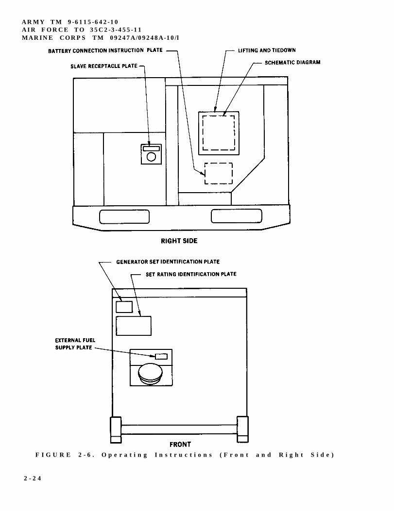
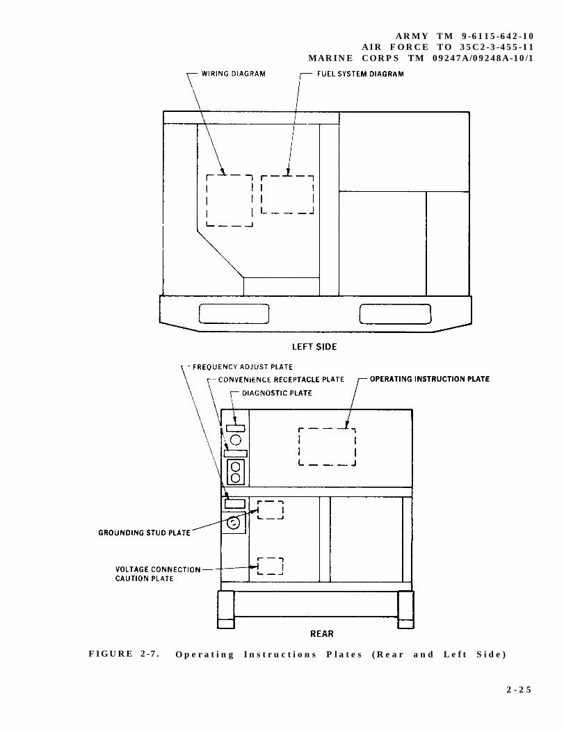
2 - 1 2 OPERATING INSTRUCTIONSAND DATA PLATES.
T h e r e a r e i d e n t i f i c a t i o na n d i n s t r u c t i o n p l a t e s o n t h eg e n e r a t o r s e t . FIGURE 2-6t h r o u g h 2 - 2 0 s h o w t h e l o c a t i o na n d c o n t e n t s o f e a c h p l a t e o nt h e g e n e r a t o r s e t .
2 - 2 3
ARMY TM 9-6115-642-10AIR FORCE TO 35C2-3-455-11MARINE CORPS TM 09247A/09248A-10/l
F I G U R E 2 - 6 . O p e r a t i n g I n s t r u c t i o n s ( F r o n t a n d R i g h t S i d e )
2 - 2 4
ARMY TM 9-6115-642-10AIR FORCE TO 35C2-3-455-11
MARINE CORPS TM 09247A/09248A-10/1
FIGURE 2-7. O p e r a t i n g I n s t r u c t i o n s P l a t e s ( R e a r a n d L e f t S i d e )
2 - 2 5
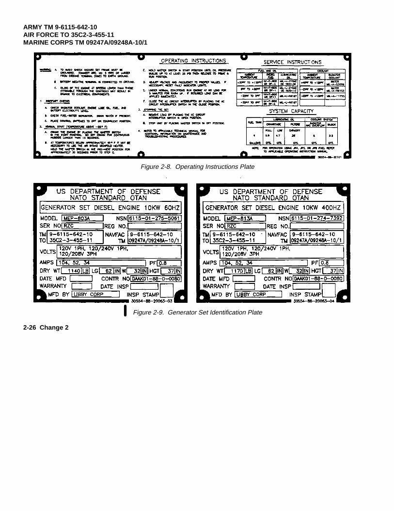
ARMY TM 9-6115-642-10AIR FORCE TO 35C2-3-455-11MARINE CORPS TM 09247A/09248A-10/1
Figure 2-8. Operating Instructions Plate
Figure 2-9. Generator Set Identification Plate
2-26 Change 2
ARMY TM 9-6115-642-10AIR FORCE TO 35C2-3-455-11
MARINE CORPS TM 09247A/09248A-10/1
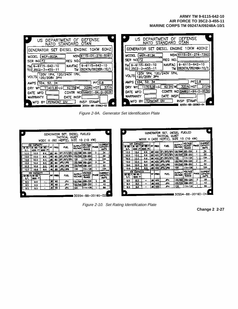
Figure 2-9A. Generator Set Identification Plate
Figure 2-10. Set Rating Identification PlateChange 2 2-27
ARMY TM 9-6115-642-10AIR FORCE TO 35C2-3-455-11MARINE CORPS TM 09247A/09248A-10/1
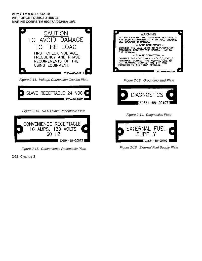
Figure 2-11. Voltage Connection Caution Plate
Figure 2-13. NATO slave Receptacle Plate
Figure 2-15. Convenience Receptacle Plate
Figure 2-12. Grounding stud Plate
Figure 2-14. Diagnostics Plate
Figure 2-16. External Fuel Supply Plate
2-28 Change 2
ARMY TM 9-6115-642-10AIR FORCE TO 35C2-3-455-11
MARINE CORPS TM 09247A/09248A-10/1
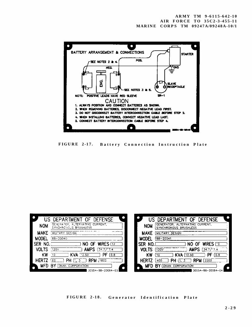
FIGURE 2-17. B a t t e r y C o n n e c t i o n I n s t r u c t i o n P l a t e
FIGURE 2-18. G e n e r a t o r I d e n t i f i c a t i o n P l a t e
2 - 2 9
ARMY TM 9-6115-642-10AIR FORCE TO 35C2-3-455-11MARINE CORPS TM 09247A/09248A-10/1
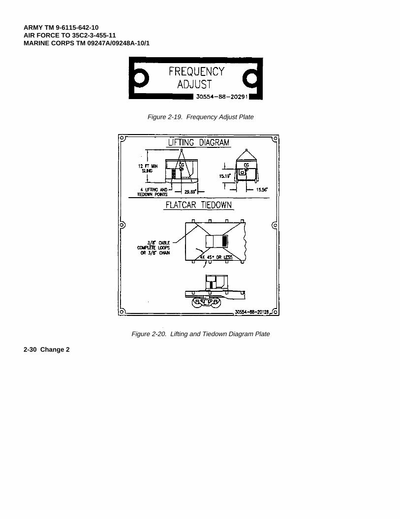
Figure 2-19. Frequency Adjust Plate
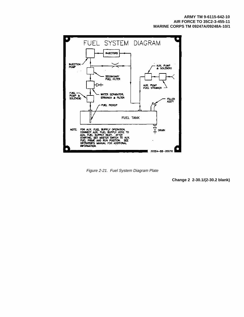
Figure 2-20. Lifting and Tiedown Diagram Plate
2-30 Change 2
ARMY TM 9-6115-642-10AIR FORCE TO 35C2-3-455-11
MARINE CORPS TM 09247A/09248A-10/1
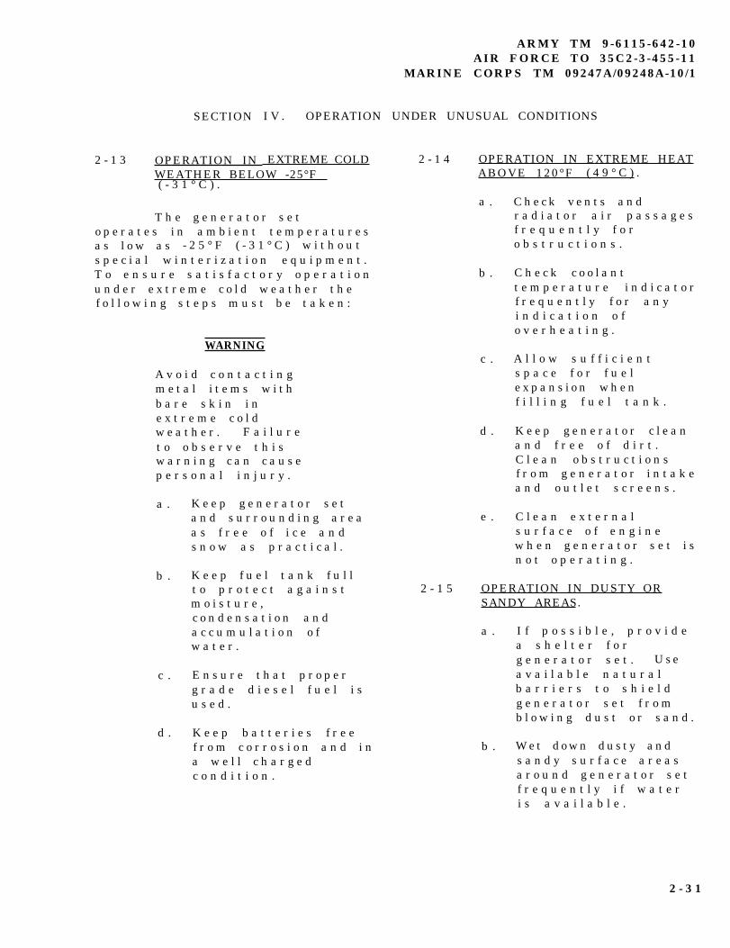
Figure 2-21. Fuel System Diagram Plate
Change 2 2-30.1/(2-30.2 blank)
SECTION
2 - 1 3 OPERATION IN
I V . OPERATION
EXTREME COLDWEATHER BELOW -25°F( - 3 1 ° C ) .
T h e g e n e r a t o r s e to p e r a t e s i n a m b i e n t t e m p e r a t u r e sa s l o w a s - 2 5 ° F ( - 3 1 ° C ) w i t h o u ts p e c i a l w i n t e r i z a t i o n e q u i p m e n t .T o e n s u r e s a t i s f a c t o r y o p e r a t i o nu n d e r e x t r e m e c o l d w e a t h e r t h ef o l l o w i n g s t e p s m u s t b e t a k e n :
WARNING
A v o i d c o n t a c t i n gm e t a l i t e m s w i t hb a r e s k i n i ne x t r e m e c o l dw e a t h e r . F a i l u r et o o b s e r v e t h i sw a r n i n g c a n c a u s ep e r s o n a l i n j u r y .
a .
b .
c .
d .
K e e p g e n e r a t o r s e ta n d s u r r o u n d i n g a r e aa s f r e e o f i c e a n ds n o w a s p r a c t i c a l .
K e e p f u e l t a n k f u l lt o p r o t e c t a g a i n s tm o i s t u r e ,c o n d e n s a t i o n a n da c c u m u l a t i o n o fw a t e r .
E n s u r e t h a t p r o p e rg r a d e d i e s e l f u e l i su s e d .
K e e p b a t t e r i e s f r e ef r o m c o r r o s i o n a n d i na w e l l c h a r g e dc o n d i t i o n .
ARMY TM 9-6115-642-10AIR FORCE TO 35C2-3-455-11
MARINE CORPS TM 09247A/09248A-10/1
UNDER UNUSUAL CONDITIONS
2 - 1 4
2 - 1 5
OPERATION IN EXTREME HEATABOVE 120°F ( 4 9 ° C ) .
a .
b .
c .
d .
e .
C h e c k v e n t s a n dr a d i a t o r a i r p a s s a g e sf r e q u e n t l y f o ro b s t r u c t i o n s .
C h e c k c o o l a n tt e m p e r a t u r e i n d i c a t o rf r e q u e n t l y f o r a n yi n d i c a t i o n o fo v e r h e a t i n g .
A l l o w s u f f i c i e n ts p a c e f o r f u e le x p a n s i o n w h e nf i l l i n g f u e l t a n k .
K e e p g e n e r a t o r c l e a na n d f r e e o f d i r t .C l e a n o b s t r u c t i o n sf r o m g e n e r a t o r i n t a k ea n d o u t l e t s c r e e n s .
C l e a n e x t e r n a ls u r f a c e o f e n g i n ew h e n g e n e r a t o r s e t i sn o t o p e r a t i n g .
OPERATION IN DUSTY ORSANDY AREAS.
a . I f p o s s i b l e , p r o v i d ea s h e l t e r f o rg e n e r a t o r s e t . U s ea v a i l a b l e n a t u r a lb a r r i e r s t o s h i e l dg e n e r a t o r s e t f r o mb l o w i n g d u s t o r s a n d .
b . W e t d o w n d u s t y a n ds a n d y s u r f a c e a r e a sa r o u n d g e n e r a t o r s e tf r e q u e n t l y i f w a t e ri s a v a i l a b l e .
2 - 3 1
ARMY TM 9-6115-642-10AIR FORCE TO 35C2-3-455-11MARINE CORPS TM 09247A/09248A-10/1
c .
d .
e .
f .
g .
h .
i .
K e e p a l l a c c e s s d o o r sc l o s e d , a s m u c h a sp o s s i b l e , t o p r e v e n te n t r y o f d u s t a n ds a n d i n t o h o u s i n ga s s e m b l y .
W i p e d u s t a n d s a n df r e q u e n t l y f r o m t h eg e n e r a t o r s e te x t e r n a l s u r f a c e a n dc o m p o n e n t s . Washe x t e r i o r s u r f a c e sf r e q u e n t l y w i t h c l e a nw a t e r w h e n g e n e r a t o rs e t i s n o t o p e r a t i n g .
S e r v i c e e n g i n e a i rc l e a n e r a s s e m b l yf r e q u e n t l y t oc o m p e n s a t e f o r i n t a k eo f a d d i t i o n a l d u s t o rs a n d . R e f e r t oP a r a g r a p h 3 - 3 . 3 . 2 .
D r a i n s e d i m e n tf r e q u e n t l y f r o m f u e lf i l t e r / w a t e rs e p a r a t o r . Whens e r v i c i n g f u e l t a n kb e c a r e f u l t o p r e v e n td u s t o r s a n d f r o me n t e r i n g f u e l t a n k .
C h a n g e e n g i n e o i l a n do i l f i l t e rf r e q u e n t l y .
S t o r e o i l a n d f u e l i nd u s t - f r e e c o n t a i n e r s .
E n s u r e t h a t g e n e r a t o rs e t g r o u n d c o n n e c -t i o n s a r e f r e e o fd u s t a n d s a n d a n dc o n n e c t i o n s a r e t i g h tb e f o r e s t a r t i n g t h eu n i t .
2 - 1 6 O P E R A T I O N U N D E R R A I N Y O R HUMID CONDITIONS.
CAUTION
F a i l u r e t o r e m o v ew a t e r p r o o fm a t e r i a l b e f o r eo p e r a t i n gg e n e r a t o r s e tc o u l d r e s u l t i ne q u i p m e n t d a m a g e .
a .
b .
c .
d .
I f p o s s i b l e , p r o v i d ea s h e l t e r f o rg e n e r a t o r s e t . C o v e rg e n e r a t o r s e t w i t hc a n v a s o r o t h e rw a t e r p r o o f m a t e r i a lw h e n i t i s n o t b e i n go p e r a t e d .
P r o v i d e a d e q u a t ed r a i n a g e t o p r e v e n tw a t e r f r o ma c c u m u l a t i n g o no p e r a t i o n s i t e .
K e e p a l l g e n e r a t o rs e t a c c e s s d o o r sc l o s e d , a s m u c h a sp o s s i b l e , t o p r e v e n te n t r y o f w a t e r i n t oh o u s i n g a s s e m b l y .
D r a i n w a t e rf r e q u e n t l y f r o m f u e lf i l t e r / w a t e rs e p a r a t o r .
2 - 3 2
DC voltages are present at generator set electricalcomponents even with generator set shutdown.Avoid grounding yourself when touching anyelectrical components. Failure to follow thiswarning can result in personal injury.
e. Remove moisture from generator set componentsbefore and after each operating period.
f. Keep fuel tank full to protect against moisture,condensation and accumulation of water.
2-17
Failure to remove waterproof material beforeoperating generator set could result in equipmentdamage.
a.
b.
c.
d.
2-18
ARMY TM 9-6115-642-10AIR FORCE TO 35C2-3-455-11
MARINE CORPS TM 09247A/09248A-10/1
If possible. provide a shelter for the generator set.Locate generator set so that radiator faces intoprevailing winds. Use natural barriers or, if possible,construct a barrier to protect generator set from saltwater. Cover generator set with canvas or otherwaterproof material when it is not being operated.
Keep all generator access doors closed, as much aspossible, to prevent entry of salt water into housingassembly.
Wash exterior surfaces frequently with clean waterwhen generator set is not operating.
Check wiring connections for corrosioninsulation for signs of deterioration.
and wire
The generator set will operate at elevations up to 4000feet (1219.1 meters) above - sea level without specialadjustment or reduction in load. At elevations greater than4000 feet (1219.1 meters) above sea level, the kilowatt ratingis reduced approximately 3.5 percent for each additional 1000feet (304.8 meters).
2-33
ARMY TM 9-6115-642-10AIR FORCE TO 35C2-3-455-11MARINE CORPS TM 09247A/09248A-10/1
2-19
2-19.1 General. The NATO slave receptacle can be used tostart the generator set when batteries are discharged.
2-19.2
a. Connect one end of NATO slave cable to fully charged24 VDC system and other end to discharged generatorset’s NATO slave receptacle. Start dischargedgenerator set.
b. Refer to Paragraph 2-10.
c. Remove NATO slave cable after generator set starts.
2-20
2-20.1 General. Depressing the EMERGENCY STOPpushbutton will stop the generator set.
NOTE
The generator set cannot be restarted withoutresetting the EMERGENCY STOP pushbuttonand turning MASTER SWITCH to OFF position.
2-21
Continued operation using the BATTLE SHORTswitch can result in damage to the generator set.
NOTE
If any emergency situation requires continuedoperation of the generator set, the BATTLESHORT switch is used to override all the safetydevices except the short circuit devices, andEMERGENCY STOP function.
NOTE
BATTLE SHORT switch must be OFF to startgenerator set.
a. Start generator set if set is not running. Refer toparagraph 2-10.
b. Lift cover on BATTLE SHORT switch and positionswitch to ON.
2-34 Change 1
ARMY TM 9-6115-642-10AIR FORCE TO 35C2-3-455-11
MARINE CORPS TM 09247A/09248A-10/1
2-22 OPERATION WHILE IN CON- TAMINATEDAREAS. The generator set is capable of being operatedby personnel wearing nuclear, biological, or chemical(NBC) protective clothing without special tools orsupporting equipment. Refer to FM 3-5, NBCDecontamination for information on decontaminationprocedures. Specific procedures for the generator setare the following:
a. Control panel indicators sealing gasket,rubber sleeves, and rope draw cords at output terminalaccess ports, control panel door gaskets, access doorgaskets, rubber tubing, and belts within the enginecompartment, coverings for electrical conduits, externalwater drain tubing, and retaining cords for slavereceptacle covers will absorb and retain chemicalagents. Replacement of these items is therecommended method of decontamination.
b. Lubricants, fuel, coolant, or battery fluidsmay be present on the external surfaces of the generatorset or components due to leaks or normal operation.These fluids will absorb NBC agents. The preferredmethod of decontamination is removal of these fluidsusing conventional decontamination methods inaccordance with FM 3-5.
c. Continued decontamination of externalgenerator set surfaces with supertropical bleach(STB)/decontamination solution number 2 (DS2) willdegrade clear plastic indicator coverings to a point wherereading indicators will become impossible. This problemwill become more evident for soldiers wearing protectivemasks. Therefore, the use of STB or DS2decontamination in these areas should be minimized.Indicators should be decontaminated with warm soapywater.
d. External surfaces of the control panelassembly that are marked with painted or stampedlettering will not withstand repeated decontamination withSTB or DS2 without degradation of this lettering.Therefore, the recommended method ofdecontamination for these areas is with warm soapywater.
e. Areas that will entrap contaminants, makingefficient decontamination extremely difficult, include thefollowing:
(1) Exposed heads of screws.
(2) Areas adjacent to and behind exposedwiring conduits.
(3) Hinged areas or access doors.
(4) Retaining chains for externalreceptacle covers.
(5) Areas around the tie-down/lilting rings,crevices around access doors, external screens coveringventilation areas, the external oil drain valve, and areasadjacent to the external fuel drain valve.
(6) Areas behind knobs and switches onthe control panel, externally mounted equipmentspecification data plates, external receptacle covers,access doors, access door locking mechanisms,recessed wells for access door handles, fuel cap, loadterminal board, slave receptacles, and frequencyadjustment controls.
Replacements of these items, if available, is thepreferred method of decontamination. Conventionalmethods of decontamination should be used on theseareas, while stressing the importance of thoroughnessand the probability of some degree of continuing contactand vapor hazard.
f. In an NBC contaminated environment, thegenerator set should be operated with all access doorsclosed to reduce the effects of contamination.
g. The use of overhead shelters or chemicalprotective covers is recommended as an additionalmeans of protection against contamination inaccordance with FM 3-5. However, if using covers, careshould be taken to provide adequate space for air flowand exhaust.
h. For additional NBC information, refer to FM3-3 and FM 34. Other services use applicablepublications for NBC.
Change 2 2-35
ARMY TM 9-6115-642-10AIR FORCE TO 35C2-3455-11MARINE CORPS TM 09247A/09248A-10/1
2-23 USE OF THF CONVENIENCERECEPTACLE.
WARNING
Power is available when the maincontactor is open. Avoid accidentalcontact. Failure to observe this warningcan result in severe personal injury ordeath by electrocution.
CAUTION
The maximum power rating for theconvenience receptacle is 10 Amps.Continuous operation above 10 Ampscan result in damage to the generatorset.
a. Start the generator set if it is not operating.Refer to para. 2-10.
b. Ensure the load does not exceed themaximum ’rating.
c. Reset the Ground Fault Circuit Interrupter.
d. Plug appropriate connector intoconvenience receptacle.
2-36 Change 2
MARINE
CHAPTER 3
ARMY TM 9-6115-642-10AIR FORCE TO 35C2-3-455-11
CORPS TM 09247A/09248A-10/1
MAINTENANCE INSTRUCTIONS
SECTION I. LUBRICATION INSTRUCTIONS
3-1 LUBRICATION ORDER.
R e f e r t o L O 9 - 6 1 1 5 - 6 4 2 - 1 2f o r l u b r i c a t i o n i n f o r m a t i o n .
SECTION II . TROUBLESHOOTING
3 - 2 G E N E R A L .
T h i s s e c t i o n l i s t s c o m m o nm a l f u n c t i o n s y o u m a y f i n d d u r i n go p e r a t i o n o f t h e g e n e r a t o r s e t .Y o u s h o u l d p e r f o r m t h et e s t s / i n s p e c t i o n s a n d c o r r e c t i v ea c t i o n s i n t h e o r d e r l i s t e d .
T h i s m a n u a l c a n n o t l i s t a l lm a l f u n c t i o n s t h a t m a y o c c u r , n o ra l l t e s t s o r i n s p e c t i o n s a n dc o r r e c t i v e a c t i o n s . I f am a l f u n c t i o n i s n o t l i s t e d o r i sn o t c o r r e c t e d b y l i s t e dc o r r e c t i v e a c t i o n s , n o t i f y y o u rs u p e r v i s o r .
NOTE
A i r F o r c e a n d M a r i n eC o r p s u s e r s m a yp e r f o r m m a i n t e n a n c eo n l y a s a u t h o r i z e d .
3 - 1
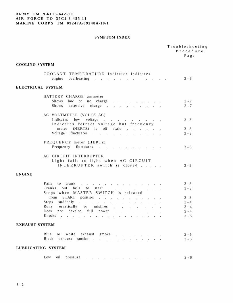
ARMY TM 9-6115-642-10AIR FORCE TO 35C2-3-455-11MARINE CORPS TM 09247A/09248A-10/1
SYMPTOM INDEX
T r o u b l e s h o o t i n gP r o c e d u r e -
P a g e
COOLING SYSTEM
COOLANT TEMPERATURE Indicator indicatesengine overheating . . . . . . . . . . . . 3 - 6
ELECTRICAL SYSTEM
ENGINE
BATTERY CHARGE ammeterShows low or no charge . . . . . . . . .Shows excessive charge . . . . . . . . .
AC VOLTMETER (VOLTS AC)Indicates low voltage . . . . . . . . .I n d i c a t e s c o r r e c t v o l t a g e b u t f r e q u e n c y
meter (HERTZ) is off scale . . . . . .Voltage fluctuates . . . . . . . . . . .
FREQUENCY meter (HERTZ)Frequency fluctuates . . . . . . . . . .
AC CIRCUIT INTERRUPTERL i g h t f a i l s t o l i g h t w h e n A C C I R C U I T
I N T E R R U P T E R s w i t c h i s c l o s e d . . . . .
Fails to crank . . . . . . . . . . . . . .Cranks but fails to start . . . . . . . . .Stops when MASTER SWITCH is re leased
from START position . . . . . . . . . . .Stops suddenly . . . . . . . . . . . . . .Runs erratically or misfires . . . . . . .Does not develop full power . . . . . . . .Knocks . . . . . . . . . . . . . . . . . .
EXHAUST SYSTEM
Blue or white exhaust smoke . . . . . . . .Black exhaust smoke . . . . . . . . . . . .
LUBRICATING SYSTEM
Low oil pressure . . . . . . . . . . . . .
3 - 73 - 7
3 - 8
3 - 83 - 8
3 - 8
3 - 9
3 - 33 - 3
3 - 33 - 43 - 43 - 43 - 5
3 - 53 - 5
3 - 6
3 - 2
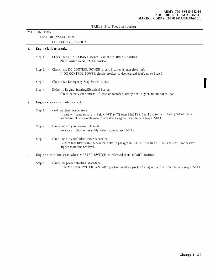
ARMY TM 9-6115-642-10AIR FORCE TO 35C2-3-455-11
MARINE CORPS TM 09247A/09248A-10/1
TABLE 3-1. Troubleshooting
MALFUNCTIONTEST OR INSPECTION
CORRECTIVE ACTION
1. Engine fails to crank.
Step 1. Check that DEAD CRANK switch is in the NORMAL position.Plain switch in NORMAL position.
Step 2. Check that DC CONTROL POWER circuit breaker is energized (in).If DC CONTROL POWER circuit breaker is deenergized (out), go to Step 3.
Step 3. Check that Emergency Stop Switch is out.
Step 4. Defect is Engine Starting/Electrical System.Check battery connections. If loose or corroded, notify next higher maintenance level.
2. Engine cranks but fails to start.
Step 1. Cold ambient temperature.If ambient temperature is below 40°F (4°C) turn MASTER SWITCH to PREHEAT position for amaximum of 30 seconds prior to cranking engine, refer to paragraph 2-10.1.
Step 2. Check for dirty air cleaner element.Service air cleaner assembly, refer to paragraph 3-3.3.2.
Step 3. Check for dirty fuel filter/water separator.Service fuel filter/water separator, refer to paragraph 3-3.6.2. If engine still fails to start, notify nexthigher maintenance level.
3. Engine starts but stops when MASTER SWITCH is released from START position.
Step 1. Check for proper starting procedure.Hold MASTER SWITCH in START position until 25 psi (172 kPa) is reached, refer to paragraph 2-10.1.
Change 1 3-3
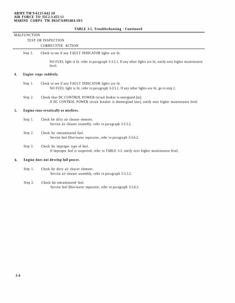
ARMY TM 9-6115-642-10AIR FORCE TO 35C2-3-455-11MARINE CORPS TM 09247A/09248A-10/1
TABLE 3-1. Troubleshooting - Continued
MALFUNCTIONTEST OR INSPECTION
CORRECTIVE ACTION
4.
5.
6.
Step 2. Check to see if any FAULT INDICATOR lights are lit.
NO FUEL light is lit. refer to paragraph 3-3.5.1. If any other lights are lit, notify next higher maintenancelevel.
Engine stops suddenly.
Step 1. Check to see if any FAULT INDICATOR lights are lit.NO FUEL light is lit, refer to paragraph 3-3.5.1. If any other lights are lit, go to step 2.
Step 2. Check that DC CONTROL POWER circuit broker is energized (in).If DC CONTROL POWER circuit breaker is deenergized (out), notify next higher maintenance level.
Engine runs erratically or misfires.
Step 1. Check for dirty air cleaner element.Service air cleaner assembly. refer to paragraph 3-3.3.2.
Step 2. Check far contaminated fuel.Service fuel filter/water separator, refer to paragraph 3-3.6.2.
Step 3. Check for improper type of fuel.If improper fuel is suspected, refer to TABLE 3-3, notify next higher maintenance level.
Engine does not develop full power.
Step 1. Check for dirty air clearer element.Service air cleaner assembly, refer to paragraph 3-3.3.2.
Step 2. Check for contaminated fuel.Service fuel filter/water separator, refer to paragraph 3-3.6.2.
3-4

ARMY TM 9-6115-642-10AIR FORCE TO 35C2-3--455-11
MARINE CORPS TM 09247A/09248A-10/1
TABLE 3-1 . T r o u b l e s h o o t i n g - C o n t i n u e d
MALFUNCTIONTEST OR INSPECTION
CORRECTIVE ACTION
S t e p 3 . C h e c k f o r r e s t r i c t e d e x h a u s t s y s t e m .M a k e s u r e e x h a u s t o p e n i n g i s f r e e f r o mo b s t r u c t i o n s . I f n o o b s t r u c t i o n s a r e f o u n d , n o t i f yn e x t h i g h e r m a i n t e n a n c e l e v e l .
S t e p 4 . C h e c k f o r i m p r o p e r t y p e o f f u e l .I f i m p r o p e r t y p e o f f u e l i s s u s p e c t e d , r e f e r t oTABLE 3-3 , n o t i f y n e x t h i g h e r m a i n t e n a n c e l e v e l .
7 . Engine knocks.
S t e p 1 . C h e c k f o r l o w l u b r i c a t i o n o i l l e v e l .I f n e c e s s a r y a d d o i l , r e f e r t o L O 9 - 6 1 1 5 - 6 4 2 - 1 2 .
S t e p 2 . C h e c k f o r l o o s e p a r t s o r f o r e i g n o b j e c t s i n e n g i n ec o m p a r t m e n t .
I f n o l o o s e p a r t s o r f o r e i g n o b j e c t s a r e f o u n d , g ot o S t e p 3 .
S t e p 3 . C h e c k f o r i m p r o p e r t y p e o f f u e l .I f i m p r o p e r t y p e o f f u e l i s s u s p e c t e d , r e f e r t oT A B L E 3 - 3 , n o t i f y n e x t h i g h e r m a i n t e n a n c e l e v e l .
8 . Blue or white exhaust smoke.
C h e c k f o r i m p r o p e r t y p e o f f u e l .I f i m p r o p e r t y p e o f f u e l i s s u s p e c t e d , r e f e r t oTABLE 3-3 , n o t i f y n e x t h i g h e r m a i n t e n a n c e l e v e l .
9 . Black exhaust smoke.
S t e p 1 . C h e c k f o r i m p r o p e r t y p e o f f u e l .I f i m p r o p e r t y p e o f f u e l i s s u s p e c t e d , r e f e r t oTABLE 3-3 , n o t i f y n e x t h i g h e r m a i n t e n a n c e l e v e l .
S t e p 2 . C h e c k f o r d i r t y a i r c l e a n e r e l e m e n t .S e r v i c e a i r c l e a n e r a s s e m b l y , r e f e r t o p a r a g r a p h3 - 3 . 3 . 2 .
3 - 5
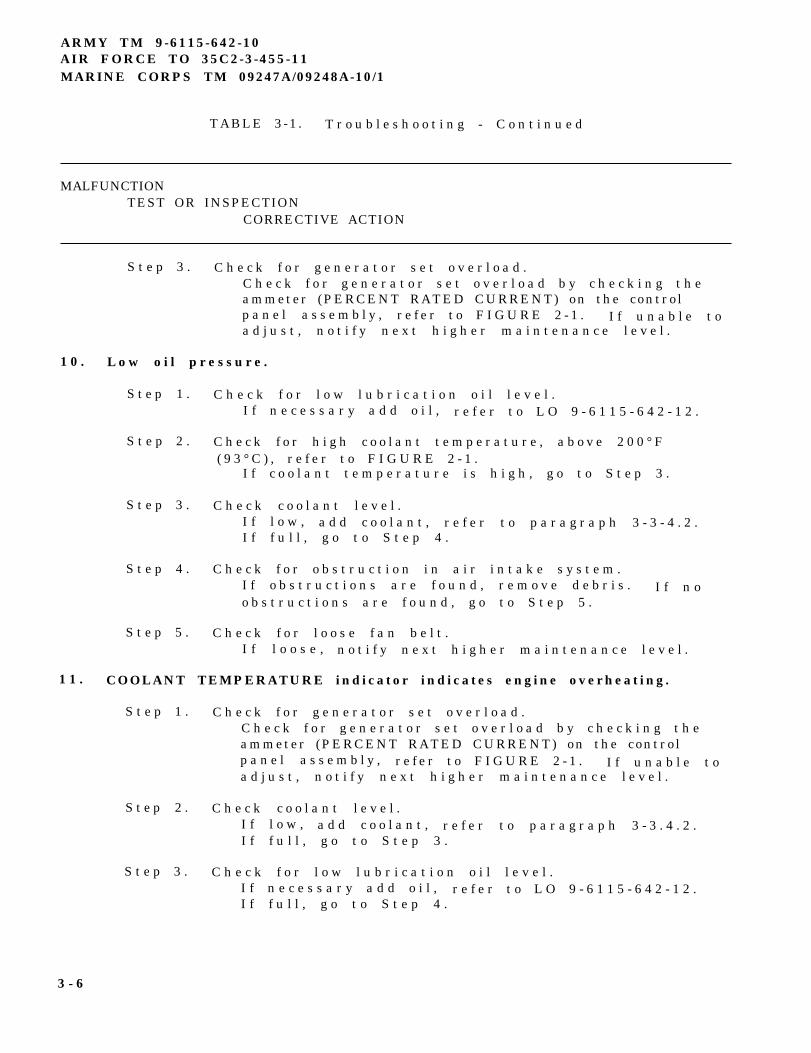
ARMY TM 9-6115-642-10AIR FORCE TO 35C2-3-455-11MARINE CORPS TM 09247A/09248A-10/1
TABLE 3-1 . T r o u b l e s h o o t i n g - C o n t i n u e d
MALFUNCTIONTEST OR INSPECTION
CORRECTIVE ACTION
S t e p 3 . C h e c k f o r g e n e r a t o r s e t o v e r l o a d .C h e c k f o r g e n e r a t o r s e t o v e r l o a d b y c h e c k i n g t h eammeter (PERCENT RATED CURRENT) on the contro lp a n e l a s s e m b l y , r e f e r t o F I G U R E 2 - 1 . I f u n a b l e t oa d j u s t , n o t i f y n e x t h i g h e r m a i n t e n a n c e l e v e l .
1 0 . L o w o i l p r e s s u r e .
S t e p 1 .
S t e p 2 .
S t e p 3 .
S t e p 4 .
S t e p 5 .
C h e c k f o r l o w l u b r i c a t i o n o i l l e v e l .I f n e c e s s a r y a d d o i l , r e f e r t o L O 9 - 6 1 1 5 - 6 4 2 - 1 2 .
C h e c k f o r h i g h c o o l a n t t e m p e r a t u r e , a b o v e 2 0 0 ° F( 9 3 ° C ) , r e f e r t o F I G U R E 2 - 1 .
I f c o o l a n t t e m p e r a t u r e i s h i g h , g o t o S t e p 3 .
C h e c k c o o l a n t l e v e l .I f l o w , a d d c o o l a n t , r e f e r t o p a r a g r a p h 3 - 3 - 4 . 2 .I f f u l l , g o t o S t e p 4 .
C h e c k f o r o b s t r u c t i o n i n a i r i n t a k e s y s t e m .I f o b s t r u c t i o n s a r e f o u n d , r e m o v e d e b r i s . I f n oo b s t r u c t i o n s a r e f o u n d , g o t o S t e p 5 .
C h e c k f o r l o o s e f a n b e l t .I f l o o s e , n o t i f y n e x t h i g h e r m a i n t e n a n c e l e v e l .
1 1 . COOLANT TEMPERATURE indicator indicates engine overheating.
S t e p 1 . C h e c k f o r g e n e r a t o r s e t o v e r l o a d .C h e c k f o r g e n e r a t o r s e t o v e r l o a d b y c h e c k i n g t h eammeter (PERCENT RATED CURRENT) on the contro lp a n e l a s s e m b l y , r e f e r t o F I G U R E 2 - 1 . I f u n a b l e t oa d j u s t , n o t i f y n e x t h i g h e r m a i n t e n a n c e l e v e l .
S t e p 2 . C h e c k c o o l a n t l e v e l .I f l o w , a d d c o o l a n t , r e f e r t o p a r a g r a p h 3 - 3 . 4 . 2 .I f f u l l , g o t o S t e p 3 .
S t e p 3 . C h e c k f o r l o w l u b r i c a t i o n o i l l e v e l .I f n e c e s s a r y a d d o i l , r e f e r t o L O 9 - 6 1 1 5 - 6 4 2 - 1 2 .I f f u l l , g o t o S t e p 4 .
3 - 6
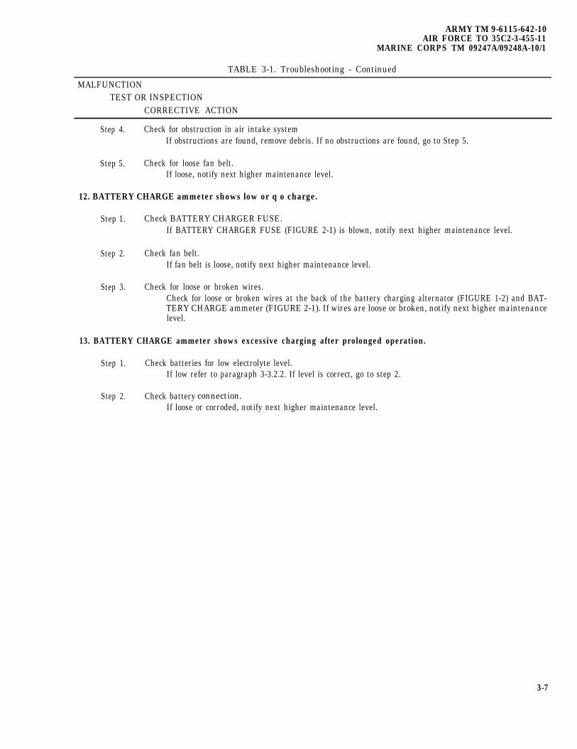
ARMY TM 9-6115-642-10AIR FORCE TO 35C2-3-455-11
MARINE CORPS TM 09247A/09248A-10/1
TABLE 3-1. Troubleshooting - Continued
MALFUNCTIONTEST OR INSPECTION
CORRECTIVE ACTION
Step 4. Check for obstruction in air intake systemIf obstructions are found, remove debris. If no obstructions are found, go to Step 5.
Step 5. Check for loose fan belt.If loose, notify next higher maintenance level.
12. BATTERY CHARGE ammeter shows low or q o charge.
Step 1. Check BATTERY CHARGER FUSE.If BATTERY CHARGER FUSE (FIGURE 2-1) is blown, notify next higher maintenance level.
Step 2. Check fan belt.If fan belt is loose, notify next higher maintenance level.
Step 3. Check for loose or broken wires.Check for loose or broken wires at the back of the battery charging alternator (FIGURE 1-2) and BAT-TERY CHARGE ammeter (FIGURE 2-1). If wires are loose or broken, notify next higher maintenancelevel.
13. BATTERY CHARGE ammeter shows excessive charging after prolonged operation.
Step 1. Check batteries for low electrolyte level.If low refer to paragraph 3-3.2.2. If level is correct, go to step 2.
Step 2. Check battery connection.If loose or corroded, notify next higher maintenance level.
3-7
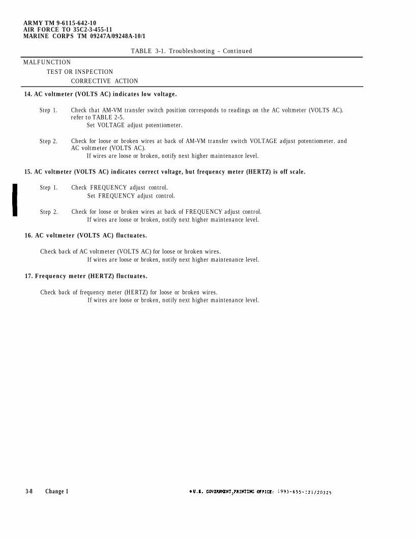
ARMY TM 9-6115-642-10AIR FORCE TO 35C2-3-455-11MARINE CORPS TM 09247A/09248A-10/1
TABLE 3-1. Troubleshooting - Continued
MALFUNCTIONTEST OR INSPECTION
CORRECTIVE ACTION
14. AC voltmeter (VOLTS AC) indicates low voltage.
Step 1. Check that AM-VM transfer switch position corresponds to readings on the AC voltmeter (VOLTS AC).refer to TABLE 2-5.
Set VOLTAGE adjust potentiometer.
Step 2. Check for loose or broken wires at back of AM-VM transfer switch VOLTAGE adjust potentiometer. andAC voltmeter (VOLTS AC).
If wires are loose or broken, notify next higher maintenance level.
15. AC voltmeter (VOLTS AC) indicates correct voltage, but frequency meter (HERTZ) is off scale.
Step 1. Check FREQUENCY adjust control.Set FREQUENCY adjust control.
Step 2. Check for loose or broken wires at back of FREQUENCY adjust control.If wires are loose or broken, notify next higher maintenance level.
16. AC voltmeter (VOLTS AC) fluctuates.
Check back of AC voltmeter (VOLTS AC) for loose or broken wires.If wires are loose or broken, notify next higher maintenance level.
17. Frequency meter (HERTZ) fluctuates.
Check back of frequency meter (HERTZ) for loose or broken wires.If wires are loose or broken, notify next higher maintenance level.
3-8 Change 1
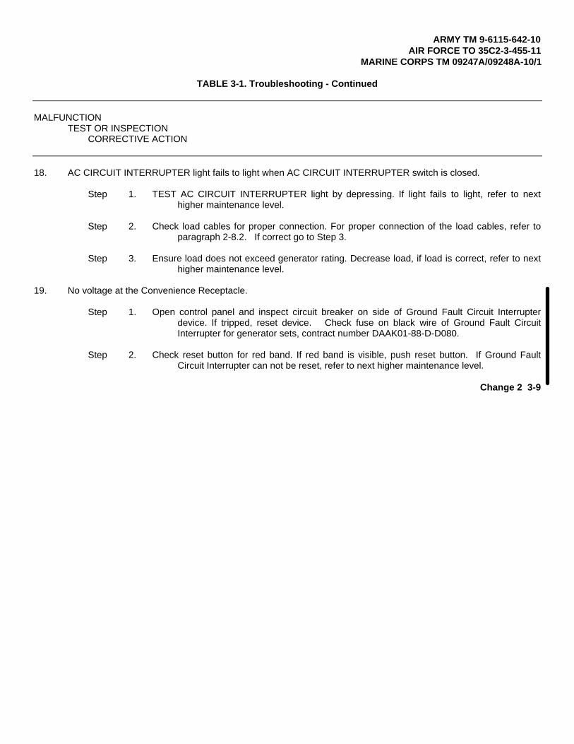
ARMY TM 9-6115-642-10AIR FORCE TO 35C2-3-455-11
MARINE CORPS TM 09247A/09248A-10/1
TABLE 3-1. Troubleshooting - Continued
MALFUNCTIONTEST OR INSPECTION
CORRECTIVE ACTION
18. AC CIRCUIT INTERRUPTER light fails to light when AC CIRCUIT INTERRUPTER switch is closed.
Step 1. TEST AC CIRCUIT INTERRUPTER light by depressing. If light fails to light, refer to nexthigher maintenance level.
Step 2. Check load cables for proper connection. For proper connection of the load cables, refer toparagraph 2-8.2. If correct go to Step 3.
Step 3. Ensure load does not exceed generator rating. Decrease load, if load is correct, refer to nexthigher maintenance level.
19. No voltage at the Convenience Receptacle.
Step 1. Open control panel and inspect circuit breaker on side of Ground Fault Circuit Interrupterdevice. If tripped, reset device. Check fuse on black wire of Ground Fault CircuitInterrupter for generator sets, contract number DAAK01-88-D-D080.
Step 2. Check reset button for red band. If red band is visible, push reset button. If Ground FaultCircuit Interrupter can not be reset, refer to next higher maintenance level.
Change 2 3-9
ARMY TM 9-6115-642-10AIR FORCE TO 35C2-3-455-11MARINE CORPS TM 09247A/09248A-10/1
S E C T I O N I I I . MAINTENANCE PROCEDURES
3-3 GENERATOR SET INSPECTIONAND SERVICE.
3 - 3 . 1 I n t r o d u c t i o n . T h i ss e c t i o n c o n t a i n s o p e r a t o rm a i n t e n a n c e p r o c e d u r e s .D e f i c i e n c i e s n o t e d d u r i n gi n s p e c t i o n w h i c h a r e b e y o n d t h em a i n t e n a n c e s c o p e o f t h eo p e r a t o r s h a l l b e r e p o r t e d t on e x t h i g h e r m a i n t e n a n c e l e v e l .
3 - 3 . 2 B a t t e r i e s .
B a t t e r y a c i d c a n c a u s eb u r n s t o u n p r o t e c t e ds k i n .
B a t t e r i e s g i v e o f ff l a m m a b l e g a s . D o n o ts m o k e o r u s e o p e nf l a m e w h e n p e r f o r m i n gm a i n t e n a n c e . F l a m e sa n d e x p l o s i o n c o u l dr e s u l t i n s e v e r ep e r s o n a l i n j u r y o rd e a t h .
3 - 3 . 2 . 1 I n s p e c t i o n .
a . S h u t d o w n g e n e r a t o rs e t , r e f e r t op a r a g r a p h 2 - 1 0 . 2 .
b . O p e n e n g i n e a c c e s sd o o r .
c . I n s p e c t f o r d a m a g e db a t t e r y c a s e ,c o r r o s i o n , o r d a m a g e da n d l o o s e c o n n e c t i o n so n t e r m i n a l c a b l e ,a n d d a m a g e d o rm i s s i n g b a t t e r y c a p s .
WARNING
B a t t e r i e s g i v e o f ff l a m m a b l e g a s . D o n o ts m o k e o r u s e o p e nf l a m e w h e n p e r f o r m i n gm a i n t e n a n c e . F l a m e sa n d e x p l o s i o n c o u l dr e s u l t i n s e v e r ep e r s o n a l i n j u r y o rd e a t h .
d . R e m o v e b a t t e r y c a p s .
CAUTION
E l e c t r o l y t e l e v e l m u s tc o v e r b a t t e r y p l a t e si n a l l c e l l s . F a i l u r et o o b s e r v e t h i sc a u t i o n c a n c a u s ed a m a g e t o t h e b a t t e r y .
NOTE
E l e c t r o l y t e l e v e ls h o u l d b e a t b o t t o m o fe a c h c a p c y l i n d e r .
e . I n s p e c t e l e c t r o l y t el e v e l .
f . P e r f o r m s e r v i c ep r o c e d u r e s i fr e q u i r e d .
9 “ I n s t a l l b a t t e r y c a p s .
h . C l o s e e n g i n e a c c e s sd o o r .
3 - 3 . 2 . 2 S e r v i c e .
a . S h u t d o w n g e n e r a t o rs e t , r e f e r t op a r a g r a p h 2 - 1 0 . 2 .
b . O p e n e n g i n e a c c e s sd o o r .
3 - 1 0
WARNING
B a t t e r i e s g i v e o f ff l a m m a b l e g a s . D o n o ts m o k e o r u s e o p e nf l a m e w h e n p e r f o r m i n gm a i n t e n a n c e . F l a m e sa n d e x p l o s i o n c o u l dr e s u l t i n s e v e r ep e r s o n a l i n j u r y o rd e a t h .
c . R e m o v e b a t t e r y c a p s .
NOTE
E l e c t r o l y t e l e v e ls h o u l d b e a t b o t t o m o fe a c h
d .
e .
f .
g .
c a p c y l i n d e r .
A d d d i s t i l l e d w a t e rt o e a c h b a t t e r y c e l la s r e q u i r e d .
Replace battery caps.
C l o s e e n g i n e a c c e s sd o o r .
I f n e c e s s a r y c o n t a c tn e x t h i g h e r m a i n t e -n a n c e l e v e l t o c l e a no r r e p l a c e b a t t e r i e so r b a t t e r y t e r m i n a l s .
3 - 3 . 3 A i r C l e a n e r A s s e m b l y(FIGURE 3-1).
3 - 3 . 3 . 1 I n s p e c t i o n .
a . S h u t d o w n g e n e r a t o rs e t , r e f e r t op a r a g r a p h 2 - 1 0 . 2 .
b . O p e n l e f t s i d e e n g i n ea c c e s s d o o r .
c . I n s p e c t a i r c l e a n e rh o u s i n g ( 5 , F I G U R E3 - 1 ) f o r d e n t s ,
ARMY TM 9-6115-642-10AIR FORCE TO 35C2-3-455-11
MARINE CORPS TM 09247A/09248A-10/1
c o r r o s i o n , m i s s i n gh a r d w a r e a n d o t h e rd a m a g e .
d . O p e n r i g h t s i d ee n g i n e a c c e s s d o o ra n d i n s p e c t a i rc l e a n e r r e s t r i c t i o ni n d i c a t o r f o ri n d i c a t i o n o f ac l o g g e d a i r c l e a n e re l e m e n t .
e . C l o s e e n g i n e a c c e s sd o o r .
FIGURE 3-1. A i r C l e a n e rReplacement
Element
3 - 1 1
ARMY TM 9-6115-642-10AIR FORCE TO 35C2-3-455-11MARINE CORPS TM 09247A/09248A-10/1
3 - 3 . 3 . 2 S e r v i c e .
a .
b .
c .
d .
e .
f .
g .
S h u t d o w n g e n e r a t o rs e t . R e f e r t op a r a g r a p h 2 - 1 0 . 2 .
O p e n l e f t s i d e e n g i n ea c c e s s d o o r .
L o o s e n w i n g n u t c l a m p(1, FIGURE 3-1) and
r e m o v e e n d c a p ( 2 ) o na i r c l e a n e r h o u s i n g( 5 ) .
R e m o v e w i n g n u t ( 3 )a n d a i r c l e a n e re l e m e n t ( 4 ) . I ff o u l e d , d i s c a r d a i rc l e a n e r e l e m e n t .
I n s p e c t i n s i d e o f a i rc l e a n e r h o u s i n g ( 5 )f o r d e b r i s . W i p e a i rc l e a n e r h o u s i n gi n t e r i o r w i t h c l e a nl i n t - f r e e c l o t h .
I n s t a l l a i r c l e a n e re l e m e n t ( 4 ) , w i n g n u t( 3 ) , e n d c a p ( 2 ) a n dt i g h t e n w i n g n u t ( 1 ) .
C l o s e e n g i n ec o m p a r t m e n t a c c e s sd o o r .
3 - 3 . 4 C o o l i n g S y s t e m .
3 - 3 . 4 . 1 I n s p e c t i o n .
a . S h u t d o w n g e n e r a t o rs e t . R e f e r t op a r a g r a p h 2 - 1 0 . 2 .
b . O p e n b o t h e n g i n ea c c e s s d o o r s .
C o o l i n g s y s t e mo p e r a t e s a t h i g ht e m p e r a t u r e s .P e r s o n a l i n j u r y o rd e a t h f r o m b u r n s o rs c a l d i n g c o u l d r e s u l tf r o m c o n t a c t w i t h h i g hp r e s s u r e s t e a m a n d / o rl i q u i d .
c .
d .
e .
f .
C h e c k r a d i a t o r f o rd i r t , l e a v e s ,i n s e c t s , e t c .b l o c k i n g a i r f l o w .
C h e c k r a d i a t o r a n dh o s e s f o r l e a k s ,l o o s e c o n n e c t i o n s ,l o o s e m o u n t i n g ,c o r r o s i o n , c h a f i n ga n d m i s s i n g p a r t s .
C h e c k c o o l a n t l e v e li n c o o l a n t r e c o v e r y( o v e r f l o w ) b o t t l e .
C l o s e e n g i n ec o m p a r t m e n t a c c e s sd o o r s .
3 - 3 . 4 . 2 S e r v i c e .
WARNING
C o o l i n g s y s t e mo p e r a t e s a t h i g ht e m p e r a t u r e s .P e r s o n a l i n j u r y o rd e a t h f r o m b u r n s o rs c a l d i n g c o u l d r e s u l tf r o m c o n t a c t w i t h h i g hp r e s s u r e s t e a m a n d / o rl i q u i d .
3 - 1 2
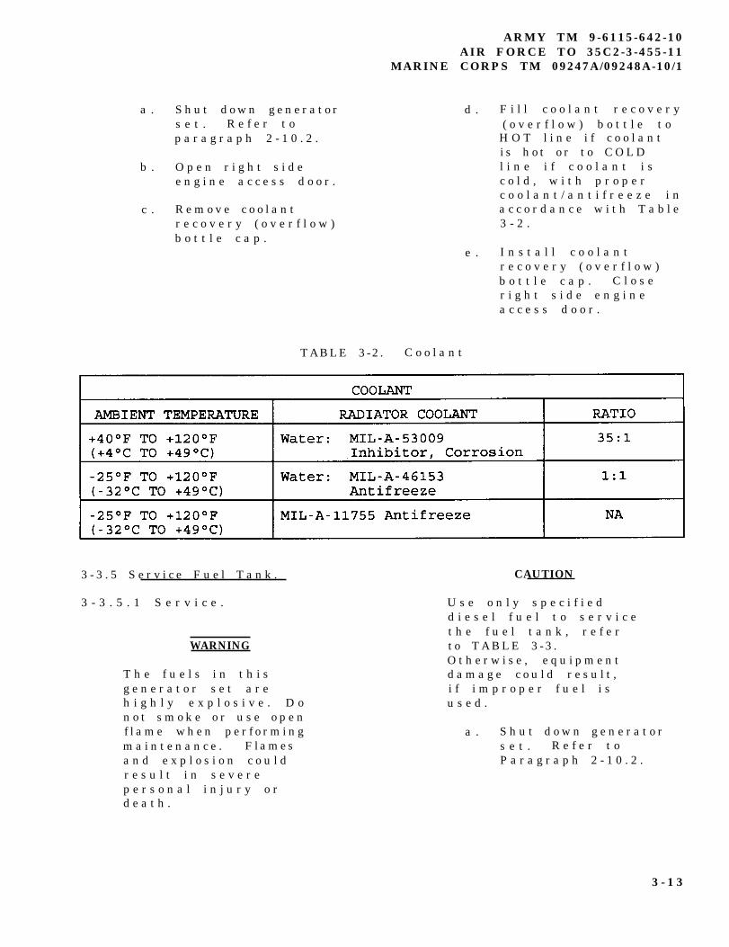
a . S h u t d o w n g e n e r a t o rs e t . R e f e r t op a r a g r a p h 2 - 1 0 . 2 .
b . O p e n r i g h t s i d ee n g i n e a c c e s s d o o r .
c . R e m o v e c o o l a n tr e c o v e r y ( o v e r f l o w )b o t t l e c a p .
ARMY TM 9-6115-642-10AIR FORCE TO 35C2-3-455-11
MARINE CORPS TM 09247A/09248A-10/1
d . F i l l c o o l a n t r e c o v e r y( o v e r f l o w ) b o t t l e t o
H O T l i n e i f c o o l a n ti s h o t o r t o C O L Dl i n e i f c o o l a n t i sc o l d , w i t h p r o p e rc o o l a n t / a n t i f r e e z e i na c c o r d a n c e w i t h T a b l e3 - 2 .
e . I n s t a l l c o o l a n tr e c o v e r y ( o v e r f l o w )b o t t l e c a p . C l o s er i g h t s i d e e n g i n ea c c e s s d o o r .
TABLE 3-2 . C o o l a n t
3 - 3 . 5 S e r v i c e F u e l T a n k . CAUTION
3 - 3 . 5 . 1 S e r v i c e .
WARNING
T h e f u e l s i n t h i sg e n e r a t o r s e t a r eh i g h l y e x p l o s i v e . D on o t s m o k e o r u s e o p e nf l a m e w h e n p e r f o r m i n gm a i n t e n a n c e . F l a m e sa n d e x p l o s i o n c o u l dr e s u l t i n s e v e r ep e r s o n a l i n j u r y o rd e a t h .
U s e o n l y s p e c i f i e dd i e s e l f u e l t o s e r v i c et h e f u e l t a n k , r e f e rt o T A B L E 3 - 3 .O t h e r w i s e , e q u i p m e n td a m a g e c o u l d r e s u l t ,i f i m p r o p e r f u e l i su s e d .
a . S h u t d o w n g e n e r a t o rs e t . R e f e r t oP a r a g r a p h 2 - 1 0 . 2 .
3 - 1 3
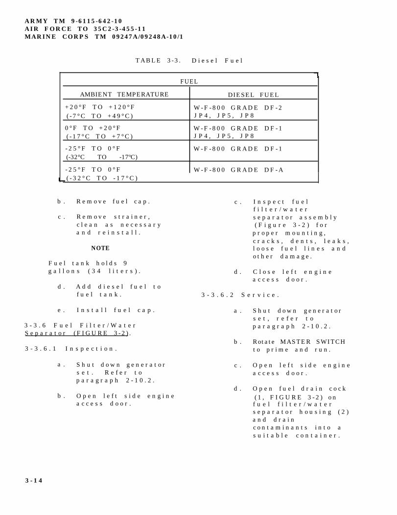
ARMY TM 9-6115-642-10AIR FORCE TO 35C2-3-455-11MARINE CORPS TM 09247A/09248A-10/1
TABLE 3-3 . D i e s e l F u e l
FUEL
AMBIENT TEMPERATURE DIESEL FUEL
+ 2 0 ° F T O + 1 2 0 ° F( - 7 ° C T O + 4 9 ° C )
W - F - 8 0 0 G R A D E D F - 2J P 4 , J P 5 , J P 8
0 ° F T O + 2 0 ° F( - 1 7 ° C T O + 7 ° C )
W - F - 8 0 0 G R A D E D F - 1J P 4 , J P 5 , J P 8
- 2 5 ° F T O 0 ° F(-32°C TO -17ºC)
W - F - 8 0 0 G R A D E D F - 1
- 2 5 ° F T O 0 ° F W - F - 8 0 0 G R A D E D F - A( - 3 2 ° C T O - 1 7 ° C )
b . R e m o v e f u e l c a p .
c . R e m o v e s t r a i n e r ,c l e a n a s n e c e s s a r ya n d r e i n s t a l l .
NOTE
F u e l t a n k h o l d s 9g a l l o n s ( 3 4 l i t e r s ) .
d . A d d d i e s e l f u e l t of u e l t a n k .
e . I n s t a l l f u e l c a p .
3 - 3 . 6 F u e l F i l t e r / W a t e rS e p a r a t o r ( F I G U R E 3 - 2 ) .
3 - 3 . 6 . 1 I n s p e c t i o n .
a . S h u t d o w n g e n e r a t o rs e t . R e f e r t op a r a g r a p h 2 - 1 0 . 2 .
b . O p e n l e f t s i d e e n g i n ea c c e s s d o o r .
c .
d .
I n s p e c t f u e lf i l t e r / w a t e rs e p a r a t o r a s s e m b l y( F i g u r e 3 - 2 ) f o r
p r o p e r m o u n t i n g ,c r a c k s , d e n t s , l e a k s ,l o o s e f u e l l i n e s a n do t h e r d a m a g e .
C l o s e l e f t e n g i n ea c c e s s d o o r .
3 - 3 . 6 . 2 S e r v i c e .
a .
b .
c .
d .
S h u t d o w n g e n e r a t o rs e t , r e f e r t op a r a g r a p h 2 - 1 0 . 2 .
Rotate MASTER SWITCHt o p r i m e a n d r u n .
O p e n l e f t s i d e e n g i n ea c c e s s d o o r .
O p e n f u e l d r a i n c o c k( 1 , F I G U R E 3 - 2 ) o nf u e l f i l t e r / w a t e rs e p a r a t o r h o u s i n g ( 2 )a n d d r a i nc o n t a m i n a n t s i n t o as u i t a b l e c o n t a i n e r .
3 - 1 4
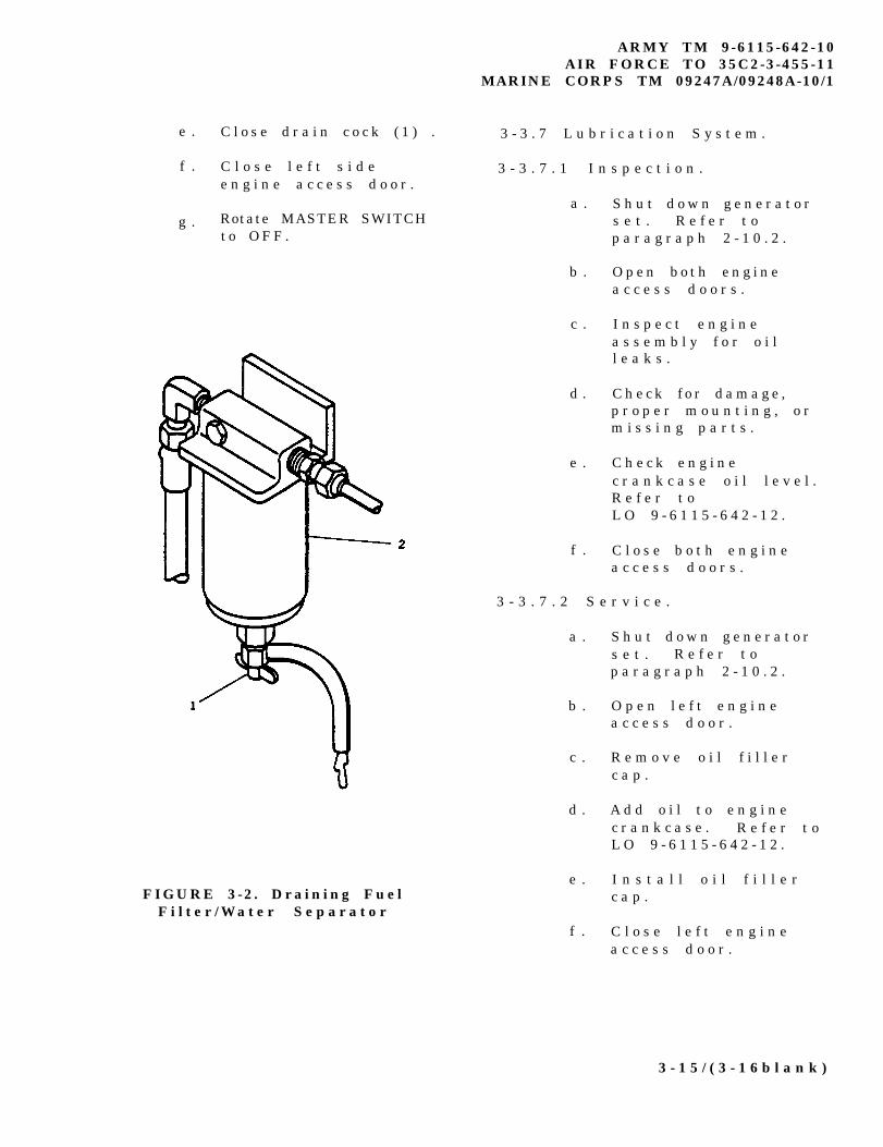
e . C l o s e d r a i n c o c k ( 1 ) .
f . C l o s e l e f t s i d ee n g i n e a c c e s s d o o r .
g . Rotate MASTER SWITCHt o O F F .
FIGURE 3-2 . Draining FuelF i l t e r / W a t e r S e p a r a t o r
ARMY TM 9-6115-642-10AIR FORCE TO 35C2-3-455-11
MARINE CORPS TM 09247A/09248A-10/1
3 - 3 . 7 L u b r i c a t i o n S y s t e m .
3 - 3 . 7 . 1 I n s p e c t i o n .
a .
b .
c .
d .
e .
f .
S h u t d o w n g e n e r a t o rs e t . R e f e r t op a r a g r a p h 2 - 1 0 . 2 .
O p e n b o t h e n g i n ea c c e s s d o o r s .
I n s p e c t e n g i n ea s s e m b l y f o r o i ll e a k s .
C h e c k f o r d a m a g e ,p r o p e r m o u n t i n g , o rm i s s i n g p a r t s .
C h e c k e n g i n ec r a n k c a s e o i l l e v e l .R e f e r t oL O 9 - 6 1 1 5 - 6 4 2 - 1 2 .
C l o s e b o t h e n g i n ea c c e s s d o o r s .
3 - 3 . 7 . 2 S e r v i c e .
a .
b .
c .
d .
e .
f .
S h u t d o w n g e n e r a t o rs e t . R e f e r t op a r a g r a p h 2 - 1 0 . 2 .
O p e n l e f t e n g i n ea c c e s s d o o r .
R e m o v e o i l f i l l e rc a p .
A d d o i l t o e n g i n ec r a n k c a s e . R e f e r t oL O 9 - 6 1 1 5 - 6 4 2 - 1 2 .
I n s t a l l o i l f i l l e rc a p .
C l o s e l e f t e n g i n ea c c e s s d o o r .
3 - 1 5 / ( 3 - 1 6 b l a n k )
These are the instructions for sending an electronic 2028
The following format must be used if submitting an electronic 2028. The subject line must be exactly the same and allfields must be included; however only the following fields are mandatory: 1, 3, 4, 5, 6, 7, 8, 9, 10, 13, 15, 16, 17, and 27.
From: ’Whomever’ <[email protected]>To: mpmt%[email protected]
Subject: DA Form 2028
1. From: Joe Smith2. Unit: home3. Address:4300 Park4. City: Hometown5. St: MO6. Zip: 777777. Date Sent: 19-OCT-938. Pub no: 55-2840-229-239. Pub Title: TM10. Publication Date: 04-JUL-8511. Change Number: 712. Submitter Rank: MSG13. Submitter FName: Joe14. Submitter MName: T15. Submitter LName: Smith16. Submitter Phone: 123-123-123417. Problem: 118. Page: 219. Paragraph: 320. Line: 421. NSN: 522. Reference: 623. Figure: 724. Table: 825. Item: 926. Total: 12327. Text:This is the text for the problem below line 27.
ARMY TM 9-6115-642-10AIR FORCE TO 35C2-3-455-11
MARINE CORPS TM 09247A/09248A-10/1
APPENDIX A
REFERENCES
A - 1 S C O P E .
T h i s a p p e n d i x l i s t s a l l f o r m s , f i e l d m a n u a l s , t e c h n i c a l m a n u a l sa n d m i s c e l l a n e o u s p u b l i c a t i o n s r e f e r e n c e d i n t h i s m a n u a l .
A-2 FORMS.
R e c o m m e n d i n g I m p r o v e m e n t s t o T e c h n i c a l P u b l i c a t i o n s . AFTO Form 22E q u i p m e n t I n s p e c t i o n a n d M a i n t e n a n c e W o r k s h e e t . . . DA Form 2404Equipment Control Log . . . . . . . . . . . . . . . DA Form 2408-9Quality Deficiency Report . . . . . . . . . . . . . . . . . SF 368R e c o m m e n d e d C h a n g e s t o E q u i p m e n t
Technical Publications . . . . . . . . . . . . . DA Form 2028-2R e c o m m e n d e d C h a n g e s t o P u b l i c a t i o n s
and Blank Forms . . . . . . . . . . . . . . . . . . DA Form 2028R e p o r t i n g E r r o r s a n d R e c o m m e n d i n g
I m p r o v e m e n t s t o T e c h n i c a l P u b l i c a t i o n s . . . . . . . N A V M C 1 0 7 7 2
A - 3 FIELD MANUALS.
Electric Power Generation in the Field . . . . . . . . . F M 2 0 - 3 1First Aid . . . . . . . . . . . . . . . . . . . . . . . . F M 2 1 - 1 1NBC Contamination Avoidance . . . . . . . . . . . . . . . F M 3 - 3NBC Decontamination . . . . . . . . . . . . . . . . . . . F M 3 - 5NBC Protection . . . . . . . . . . . . . . . . . . . . . . F M 3 - 4
A-4 TECHNICAL MANUALS.
Marine Corps Forms . . . . . . . . . . . . . . . . . T M 4 7 0 0 - 1 5 / 1
A-5 MISCELLANEOUS PUBLICATIONS.
Air Force Maintenance Forms and Records . . . . . . . . . A F R 6 6 - 1T h e A r m y M a i n t e n a n c e M a n a g e m e n t S y s t e m ( T A M M S ) . . DA PAM 738-750Lubrication Order . . . . . . . . . . . . . . . . L O 9 - 6 1 1 5 - 6 4 2 - 1 2Military Standard Abbreviations . . . . . . . . . . . . M I L - S T D - 1 2Quality and Deficiency Reporting . . . . . . . . . . . MCO 4855.10Warranty Technical Bulletin . . . . . . . . . . . T B 9 - 6 1 1 5 - 6 4 2 - 2 4
A - 1 / ( A - 2 b l a n k )
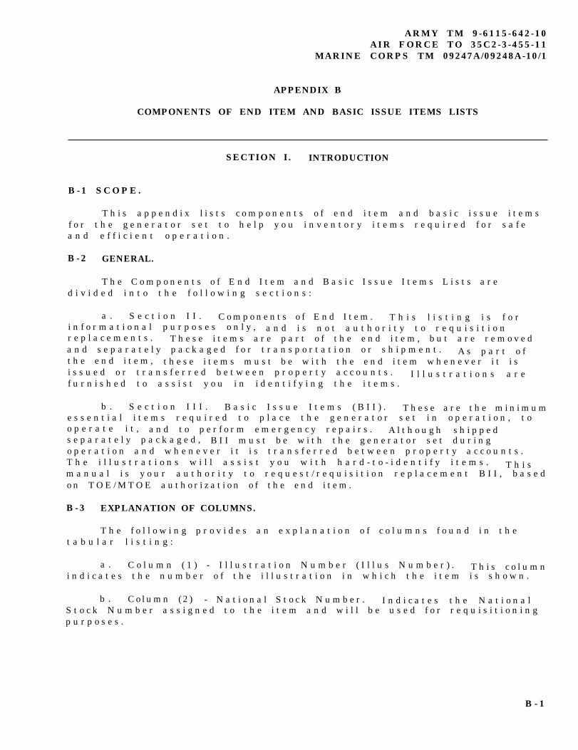
ARMY TM 9-6115-642-10AIR FORCE TO 35C2-3-455-11
MARINE CORPS TM 09247A/09248A-10/1
APPENDIX B
COMPONENTS OF END ITEM AND BASIC ISSUE ITEMS LISTS
SECTION I. INTRODUCTION
B - 1 S C O P E .
T h i s a p p e n d i x l i s t s c o m p o n e n t s o f e n d i t e m a n d b a s i c i s s u e i t e m sf o r t h e g e n e r a t o r s e t t o h e l p y o u i n v e n t o r y i t e m s r e q u i r e d f o r s a f ea n d e f f i c i e n t o p e r a t i o n .
B - 2 GENERAL.
T h e C o m p o n e n t s o f E n d I t e m a n d B a s i c I s s u e I t e m s L i s t s a r ed i v i d e d i n t o t h e f o l l o w i n g s e c t i o n s :
a . S e c t i o n I I . C o m p o n e n t s o f E n d I t e m . T h i s l i s t i n g i s f o ri n f o r m a t i o n a l p u r p o s e s o n l y , a n d i s n o t a u t h o r i t y t o r e q u i s i t i o nr e p l a c e m e n t s . T h e s e i t e m s a r e p a r t o f t h e e n d i t e m , b u t a r e r e m o v e da n d s e p a r a t e l y p a c k a g e d f o r t r a n s p o r t a t i o n o r s h i p m e n t . A s p a r t o ft h e e n d i t e m , t h e s e i t e m s m u s t b e w i t h t h e e n d i t e m w h e n e v e r i t i si s s u e d o r t r a n s f e r r e d b e t w e e n p r o p e r t y a c c o u n t s . I l l u s t r a t i o n s a r ef u r n i s h e d t o a s s i s t y o u i n i d e n t i f y i n g t h e i t e m s .
b . S e c t i o n I I I . B a s i c I s s u e I t e m s ( B I I ) . T h e s e a r e t h e m i n i m u me s s e n t i a l i t e m s r e q u i r e d t o p l a c e t h e g e n e r a t o r s e t i n o p e r a t i o n , t oo p e r a t e i t , a n d t o p e r f o r m e m e r g e n c y r e p a i r s . A l t h o u g h s h i p p e ds e p a r a t e l y p a c k a g e d , B I I m u s t b e w i t h t h e g e n e r a t o r s e t d u r i n go p e r a t i o n a n d w h e n e v e r i t i s t r a n s f e r r e d b e t w e e n p r o p e r t y a c c o u n t s .T h e i l l u s t r a t i o n s w i l l a s s i s t y o u w i t h h a r d - t o - i d e n t i f y i t e m s . T h i sm a n u a l i s y o u r a u t h o r i t y t o r e q u e s t / r e q u i s i t i o n r e p l a c e m e n t B I I , b a s e do n T O E / M T O E a u t h o r i z a t i o n o f t h e e n d i t e m .
B - 3 EXPLANATION OF COLUMNS.
T h e f o l l o w i n g p r o v i d e s a n e x p l a n a t i o n o f c o l u m n s f o u n d i n t h et a b u l a r l i s t i n g :
a . C o l u m n ( 1 ) - I l l u s t r a t i o n N u m b e r ( I l l u s N u m b e r ) . T h i s c o l u m ni n d i c a t e s t h e n u m b e r o f t h e i l l u s t r a t i o n i n w h i c h t h e i t e m i s s h o w n .
b . C o l u m n ( 2 ) - N a t i o n a l S t o c k N u m b e r . I n d i c a t e s t h e N a t i o n a lS t o c k N u m b e r a s s i g n e d t o t h e i t e m a n d w i l l b e u s e d f o r r e q u i s i t i o n i n gp u r p o s e s .
B - 1
ARMY TM 9-6115-642-10AIR FORCE TO 35C2-3-455-11MARINE CORPS TM 09247A/09248A-10/1
APPENDIX B
c . C o l u m n ( 3 ) - D e s c r i p t i o n . I n d i c a t e s t h e F e d e r a l i t e m n a m ea n d , i f r e q u i r e d , a m i n i m u m d e s c r i p t i o n t o i d e n t i f y a n d l o c a t e t h ei t e m . T h e l a s t l i n e f o r e a c h i t e m i n d i c a t e s t h e c o m m e r c i a l a n dG o v e r n m e n t E n t i t y ( C A G E ) c o d e ( i n p a r e n t h e s e s ) f o l l o w e d b y t h e p a r tn u m b e r . U s a b l e o n c o d e i d e n t i f i e s t h e s p e c i f i c t y p e o f g e n e r a t o r s e t( 6 0 o r 4 0 0 H z ) t o w h i c h t h e B I I a p p l i e s . H o w e v e r , t h e r e a r e n o B I I
w h i c h a r e s p e c i f i c t o e i t h e r t h e 6 0 o r 4 0 0 H z g e n e r a t o r s e t s .
d . C o l u m n ( 4 ) - U n i t o f M e a s u r e ( U / M ) . I n d i c a t e s t h e m e a s u r eu s e d i n p e r f o r m i n g t h e a c t u a l o p e r a t i o n a l / m a i n t e n a n c e f u n c t i o n . T h i sm e a s u r e i s e x p r e s s e d b y a t w o - c h a r a c t e r a l p h a b e t i c a l a b b r e v i a t i o n( e . g . , e a , i n , p r ) .
e . C o l u m n ( 5 ) - Q u a n t i t y r e q u i r e d ( Q t y r e q d ) . I n d i c a t e s t h eq u a n t i t y o f t h e i t e m a u t h o r i z e d t o b e u s e d w i t h / o n t h e e q u i p m e n t .
SECTION II. COMPONENTS OF END ITEM LIST
NONE
B - 2
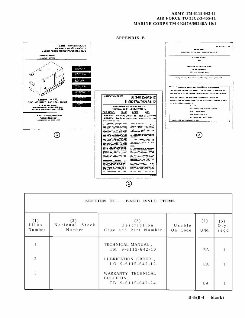
ARMY TM-6115-642-1)AIR FORCE TO 35C2-3-455-11
MARINE CORPS TM 09247A/09248A-10/1
APPENDIX B
(1 )I l l u sNumber
1
2
3
SECTION III . BASIC ISSUE ITEMS
( 2 )N a t i o n a l S t o c k
Number
( 3 )D e s c r i p t i o n
C a g e a n d P a r t N u m b e r
TECHNICAL MANUAL ,T M 9 - 6 1 1 5 - 6 4 2 - 1 0
LUBRICATION ORDER ,L O 9 - 6 1 1 5 - 6 4 2 - 1 2
WARRANTY TECHNICALBULLETIN
T B 9 - 6 1 1 5 - 6 4 2 - 2 4
U s a b l eOn Code
( 4 )
U/M
EA
EA
EA
(5)Q t yr e q d
1
1
1
B-3/(B-4 blank)

ARMY TM 9-6115-642-10AIR FORCE TO 35C2-3-455-11
MARINE CORPS TM 09247A/09248A-10/1
APPENDIX C
ADDITIONAL AUTHORIZATION LIST
SECTION I. INTRODUCTION
C - 1 S C O P E .
T h i s a p p e n d i x l i s t s a d d i t i o n a l i t e m s y o u a r e a u t h o r i z e d f o r t h es u p p o r t o f t h e g e n e r a t o r s e t .
C-2 GENERAL.
T h i s l i s t i d e n t i f i e s i t e m s t h a t d o n o t h a v e t o a c c o m p a n y t h eg e n e r a t o r s e t a n d t h a t d o n o t h a v e t o b e t u r n e d i n w i t h i t . T h e s ei t e m s a r e a l l a u t h o r i z e d t o y o u b y C T A , M T O E , T D A , o r J T A .
C-3 EXPLANATION OF LISTING.
N a t i o n a l s t o c k n u m b e r s , d e s c r i p t i o n s , a n d q u a n t i t i e s a r e p r o v i d e dt o h e l p y o u i d e n t i f y a n d r e q u e s t t h e a d d i t i o n a l i t e m s y o u r e q u i r e t os u p p o r t t h i s e q u i p m e n t . T h e i t e m s a r e l i s t e d i n a l p h a b e t i c a l s e q u e n c eb y i t e m n a m e u n d e r t h e t y p e d o c u m e n t ( i . e . , C T A , M T O E , T D A , o r J T A )w h i c h a u t h o r i z e s t h e i t e m ( s ) t o y o u .
SECTION II. ADDITIONAL AUTHORIZATION LIST
(1 )
NATIONALSTOCK
NUMBER
2 9 1 0 - 0 0 - 0 6 6 - 1 2 3 5
7 2 4 0 - 0 0 - 2 2 2 - 3 0 8 8
4 2 1 0 - 0 0 - 2 7 0 - 4 5 1 2
5 1 2 0 - 0 1 - 0 1 3 - 1 6 7 6
7 2 4 0 - 0 0 - 1 7 7 - 6 1 5 4
( 2 )
DESCRIPTION
CAGE & PART NUMBER USABLE ON CODE
ADAPTER, CONTAINER( 9 7 4 0 3 ) 1 3 2 1 1 E 7 5 4 1CAN, GASOLINE, MILITARY( 8 0 3 7 2 ) 4 2 - D - 1 2 8 0
EXTINGUISHER, FIRE, CARBON DIOXIDE( 8 1 3 4 8 ) O - E - 9 1 O
SLIDE HAMMER, GROUND(97403) 13226E7741
SPOUT, CAN, FLEXIBLE( 8 1 3 4 9 ) M I L - S - 1 2 8 5
(3 )
U/M
EA
EA
EA
EA
EA
(4)
QTYAUTH
1
1
1
1
1
C-1/(C-2 blank)

ARMY TM 9-6115-642-10AIR FORCE TO 35C2-3-455-11
MARINE CORPS TM 09247A/09248A-10/1
APPENDIX D
EXPENDABLE/DURABLE SUPPLIES AND MATERIALS LIST (EDSML)
SECTION I. INTRODUCTION
D - 1 SCOPE.
T h i s a p p e n d i x l i s t s e x p e n d a b l e / d u r a b l e s u p p l i e s a n d m a t e r i a l s y o uw i l l n e e d t o o p e r a t e a n d m a i n t a i n t h e g e n e r a t o r s e t . T h i s l i s t i n g i sf o r i n f o r m a t i o n a l p u r p o s e s o n l y a n d i s n o t a u t h o r i t y t o r e q u i s i t i o nt h e l i s t e d i t e m s . T h e s e i t e m s a r e a u t h o r i z e d t o y o u b y C T A 5 0 - 9 7 0 ,E x p e n d a b l e / D u r a b l e I t e m s ( e x c e p t M e d i c a l , C l a s s V , R e p a i r P a r t s , a n dH e r a l d i c I t e m s ) , o r C T A 8 - 1 0 0 , A r m y M e d i c a l D e p a r t m e n tE x p e n d a b l e / D u r a b l e I t e m s .
D - 2 EXPLANATION OF COLUMNS.
a . C o l u m n ( 1 ) - I t e m N u m b e r . T h i s n u m b e r i s a s s i g n e d t o t h ee n t r y i n t h e l i s t i n g a n d i s r e f e r e n c e d i n t h e n a r r a t i v e i n s t r u c t i o n st o i d e n t i f y t h e m a t e r i a l ( e . g . , " U s e c l e a n i n g c o m p o u n d , i t e m 5 . A p p x .D").
b . C o l u m n ( 2 ) - L e v e l . T h i s c o l u m n i d e n t i f i e s t h e l o w e s t l e v e lo f m a i n t e n a n c e t h a t r e q u i r e s t h e l i s t e d i t e m .
c . C o l u m n ( 3 ) - N a t i o n a l S t o c k N u m b e r . T h i s i s t h e N a t i o n a lS t o c k N u m b e r a s s i g n e d t o t h e i t e m ; u s e i t t o r e q u e s t o r r e q u i s i t i o nt h e i t e m .
d . C o l u m n ( 4 ) - D e s c r i p t i o n . I n d i c a t e s t h e F e d e r a l i t e m n a m ea n d , i f r e q u i r e d , a d e s c r i p t i o n t o i d e n t i f y t h e i t e m . T h e l a s t l i n ef o r e a c h i t e m i n d i c a t e s t h e C o m m e r c i a l a n d G o v e r n m e n t E n t i t y ( C A G E )code in parentheses ( ) followed by the part number.
e . C o l u m n ( 5 ) - U n i t o f M e a s u r e ( U / M ) . I n d i c a t e s t h e m e a s u r eu s e d i n p e r f o r m i n g t h e a c t u a l m a i n t e n a n c e f u n c t i o n . T h i s m e a s u r e i se x p r e s s e d b y a t w o - c h a r a c t e r a l p h a b e t i c a l a b b r e v i a t i o n ( e . g . , e a , i n ,p r ) . I f t h e u n i t o f m e a s u r e d i f f e r s f r o m t h e u n i t o f i s s u e ,r e q u i s i t i o n t h e l o w e s t u n i t o f i s s u e t h a t w i l l s a t i s f y y o u rr e q u i r e m e n t s .
D - 1
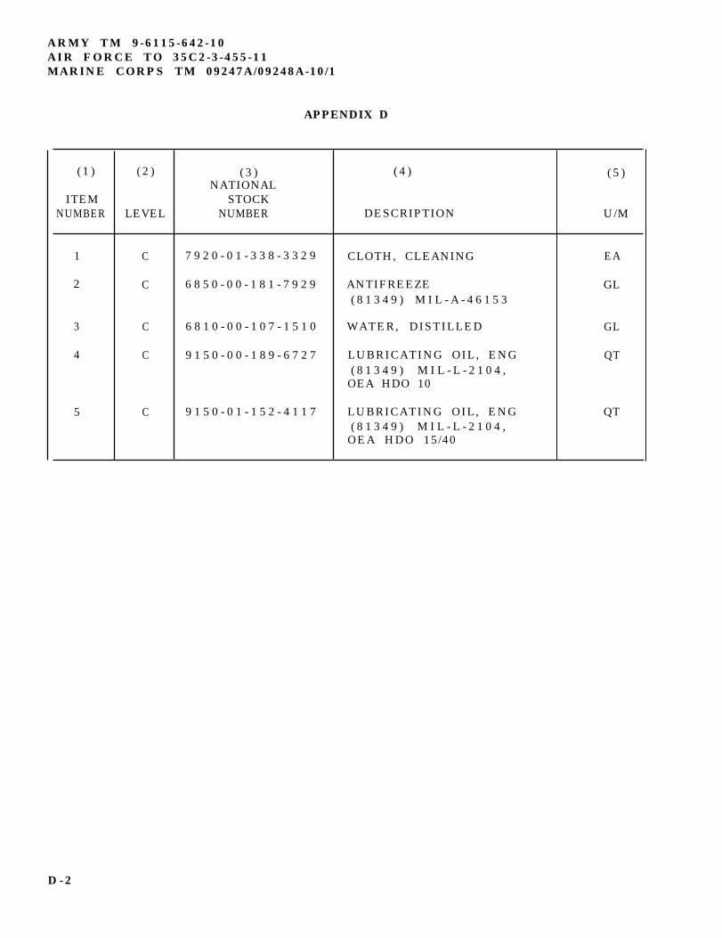
ARMY TM 9-6115-642-10AIR FORCE TO 35C2-3-455-11MARINE CORPS TM 09247A/09248A-10/1
APPENDIX D
( 1 ) ( 2 ) ( 3 ) ( 4 ) ( 5 )NATIONAL
ITEM STOCKNUMBER LEVEL NUMBER DESCRIPTION U/M
1 C 7 9 2 0 - 0 1 - 3 3 8 - 3 3 2 9 CLOTH, CLEANING EA
2 C 6 8 5 0 - 0 0 - 1 8 1 - 7 9 2 9 ANTIFREEZE GL( 8 1 3 4 9 ) M I L - A - 4 6 1 5 3
3 C 6 8 1 0 - 0 0 - 1 0 7 - 1 5 1 0 WATER, DISTILLED GL
4 C 9 1 5 0 - 0 0 - 1 8 9 - 6 7 2 7 LUBRICATING OIL, ENG QT( 8 1 3 4 9 ) M I L - L - 2 1 0 4 ,
OEA HDO 10
5 C 9 1 5 0 - 0 1 - 1 5 2 - 4 1 1 7 LUBRICATING OIL, ENG QT( 8 1 3 4 9 ) M I L - L - 2 1 0 4 ,
OEA HDO 15/40
D - 2
S u b j e c t
ARMY TM 9-6115-642-10AIR FORCE TO 35C2-3-455-11
MARINE CORPS TM 09247A/09248A-10/1
INDEX
A
Abbreviations, List of . . . . . . . . . . . . . . . . . . . . . . . .AC Generator, Location of . . . . . . . . . . . . . . . . . . . .Addit ional Author izat ion List . . . . . . . . . . . . . . . .After You Operate PMCS . . . . . . . . . . . . . . . . . . . . . .A i r C l e a n e r A s s e m b l y , I n s p e c t i o n a n d S e r v i c i n g o fA i r C l e a n e r A s s e m b l y , L o c a t i o n o f . . . . .A i r C l e a n e r E l e m e n t , R e p l a c e m e n t o f . . . . .A i r I n t a k e a n d E x h a u s t S y s t e m , D e s c r i p t i o n o fA l t e r n a t o r , Location of . . . . . . . . .A s s e m b l y a n d P r e p a r a t i o n f o r U s e . . .
B
B a t t e r i e s , I n s p e c t i o n a n d S e r v i c i n g o fB a t t e r i e s , Location of . . . . . . . . . . . . . . . . .Battle Short Switch, Use of . . . . . . . . . . . .Before You Operate PMCS . . . . . . . . . . . . . . .
C o m p o n e n t s o f E n d I t e m a n d B a s i c I s s u e I t e m sC o n t r o l P a n e l , D e s c r i p t i o n
C
.
.
.
.
.
.
.
.
.
.
.
.
.
.
.
.
.
.
of . . . . . . .C o n t r o l P a n e l A s s e m b l y , L o c a t i o n o f . . . .Controls and Indicators . . . . . . . . . .C o n v e n i e n c e R e c e p t a c l e , L o c a t i o n o f . . .Coolant Specifications . . . . . . . . . .C o o l i n g S y s t e m , I n s p e c t i o n a n d S e r v i c i n g o f
Daily Checks . . . . . . . . . . . . . . . . . . . . . . . D e a d C r a n k S w i t c h , L o c a t i o n o f .D i p s t i c k , Location of . . . . . .D e s c r i p t i o n a n d U s e o f O p e r a t o r ’ sD i e s e l F u e l S p e c i f i c a t i o n s . . .D i f f e r e n c e s B e t w e e n M o d e l s . . .
D
. . . . .
. . . . .
. . . . .
.
.
.
.
.
.
.
.
.
.
.
.
.
.
.
.
.
.
.
.
.
.
.
.
.
.
.
.
.
.
.
.
.
.
.
.
.
.
.
.
.
.
.
.
.
.
.
.
.
.
.
.
.
.
.
.
.
.
.
.
.
.
.
.
.
.
.
.
.
.
.
.
.
.
.
.
.
.
.
.
.
.
.
.
.
.
.
.
.
.
.
.
.
.
.
.
.
.
.
.
.
.
.
.
.
.
.
.
.
.
.
.
.
.
.
.
.
.
.
.
.
.
.
.
.
.
.
.
.
.
.
.
.
.
.
.
.
.
.
.
.
.
.C o n t r o l s a n d I n d i c a t o r s. . . . . . . . . . . .. . . . . . . . . . . .
E
Emergency Stopping . . . . . . . . . . . . . . . . . . . . . . . . . . . . . . . . . . .E n g i n e , Location of . . . . . . . . . . . . . . . . . . . . . . . . . . . . . . . . . . . . . . . . . .Engine, Servicing Lube Oil . . . . . . . . . . . . . . . . . . . . . . . . . . . . . . . . . . . . .
P a g e
1 - 31 - 6C - 12 - 83 - 1 11 - 63 - 1 21 - 1 41 - 42 - 1 6
3 - 1 01 - 42 - 3 42 - 8
B - 12 - 11 - 62 - 31 - 73 - 1 33 - 1 2
2 - 2 01 - 71 - 62 - 13 - 1 41 - 7
2 - 3 41 - 43 - 1 5
I - 1
ARMY TM 9-6115-642-10AIR FORCE TO 35C2-3-455-11MARINE CORPS TM 09247A/09248A-10/1
INDEX (CONTINUED)
S u b j e c t
E n g i n eE n g i n eE n g i n e
E (CONTINUED)
Cooling System, Description of . . . . . . . .L u b r i c a t i o n S y s t e m , D e s c r i p t i o n o f . . . . . .Starting System, Description of . . . . . . .
E q u i p m e n t C h a r a c t e r i s t i c s , C a p a b i l i t i e s a n d F e a t u r e sEquipment Data . . . . . . . . . . . . .Equipment Description . . . . . . . . . .E q u i p m e n t i s N o t R e a d y / A v a i l a b l e I f . . .E x p e n d a b l e / D u r a b l e
F a n B e l t , L o c a t i o n
S u p p l i e s
of . . .
a n d M a t e r i a l s
F
. . . . . . .F r e q u e n c y A d j u s t C o n t r o l , D e s c r i p t i o n o fF r e q u e n c y A d j u s t C o n t r o l , L o c a t i o n o f . .F u e lF u e lF u e lF u e lF u e lF u e l
F i l t e r / W a t e r S e p a r a t o r , L o c a t i o n o fF i l t e r / W a t e r S e p a r a t o r , S e r v i c i n g o fS p e c i f i c a t i o n s . . . . . . . . . .System, Description of . . . . . .T a n k , Location of . . . . . . . .Tank, Servicing . . . . . . . . .
G
General Information . . . . . . . . . . . . . . . . .. . . . . . .G e n e r a t o r S e t I n s p e c t i o n a n d S e r v i c e .G r o u n d i n g R o d , Installation of . . . . . . . . . . . . . . .
H, I, J
How to Use This Manual . . . . . . . . . . . . . . . . .I f Y o u r E q u i p m e n t F a i l s t o O p e r a t e . .Initial Adjustments . . . . . . . . . . . . . . . . . .I n s t a l l a t i o n o f G r o u n d i n g R o d . . . . .Installation of Load Cables . . . . . . . . . . . . .
K, L
L e a d i n gL e a k a g eL i s t o f
Particulars . . . . . . . . . .D e f i n i t i o n s f o r O p e r a t o r s P M C SAbbreviations . . . . . . . . .
L o a d C a b l e s , Installation of . . . . .Load Output Terminal Board . . . . . .
.
.
.
.
.
.
.
.
.
.
.
.
.
.
.
.
.
. . .
. . .
. . .L i s t
.
.
.
.
.
.
.
.
.
.
.
.
.
.
.
.
.
.
.
.
.
.
.
.
.
.
.
.
.
.
.
.
.
.
.
.
.
.
.
.
.
.
.
.L o c a t i o n - a n d D e s c r i p t i o n o f M a j o r C o m p o n e n t sLubrication Instructions . . . . . . . . . .
.
.
.
.
.
.
.
.
.
.
.
.
.
.
.
.
.
.
.
.
.
.
.
.
.
.
.
.
.
.
.
.
.
.
.
.
.
.
.
.
.
.
.
.
.
.
.
.
.
.
.
.
.
.
.
.
.
.
.
.
.
.
.
.
.
.
.
.
.
.
.
.
.
.
.
.
.
.
.
.
.
.
.
.
.
.
.
.
.
.
.
.
.
.
.
.
.
.
.
.
.
.
.
.
.
.
.
.
.
.
.
.
.
.
.
.
.
.
.
.
.
.
.
.
.
.
.
.
.
.
.
.
.
.
.
.
.
.
.
.
.
.
.
.
.
.
.
.
.
.
.
.
.
.
.
.
.
.
.
.
.
.
.
.
.
.
.
.
.
.
.
P a g e
1 - 1 31 - 1 41 - 1 11 - 41 - 71 - 42 - 9D - 1
1 - 72 - 71 - 71 - 63 - 1 43 - 1 41 - 1 21 - 63 - 1 3
1 - 13 - 1 02 - 1 6
v2 - 82 - 2 02 - 1 62 - 1 6
1 - 72 - 81 - 32 - 1 61 - 61 - 43 - 1
I - 2
ARMY TM 9-6115-642-10AIR FORCE TO 35C2-3-455-11
MARINE CORPS TM 09247A/09248A-10/1
INDEX (CONTINUED)
S u b j e c t
K,L (CONTINUED)
Lubrication System, Description of . . . . . . . . . . .L u b r i c a t i o n S y s t e m , I n s p e c t i o n a n d S e r v i c i n g o f . . . . .
M, N
Maintenance Forms and Records . . . . . . . . . . . . . .Maintenance Procedures . . . . . . . . . . . . . . . . .Mal funct ion Indicator Panel , Locat ion o fMalfunction Indicator Panel, Description . . . . . . . . . . . . . . . . . . .Model Numbers and Equipment Names . . . . . . . . . . . .M u f f l e r , Location of . . . . . . . . . . . . . . . . . .
O
Oil, Engine, Checking and Adding . . . . . . . . . . . .Oil Filter, Location of . . . . . . . . . . . . . . . . .Operating Instructions . . . . . . . . . . . . . . . . .Operating Instructions on Plates . . . . . . . . . . . .Operating Procedures . . . . . . . . . . . . . . . . . .Operation at High Altitudes . . . . . . . . . . . . . . .Operation in Dusty or Sandy Areas . . . . . . . . . . . .Operation in Extreme Cold Weather (-25°F [-31°C]) . . . . . . . . . . . . . . . . . . .Operation in Extreme Heat Above 120°F (48.8°C) . . . . . . . . . . . . . . . . . . . . .Operation in Salt Water Areas . . . . . . . . . . . . . .Operation Under Rainy or Humid Conditions . . . . . . . . . . . . . . . . . . . . . . . . . . .Operation Under Unusual Conditions . . . . . . . . . . .Operation Under Usual Conditions . . . . . . . . . . . .Operation Using Battle Short Switch . . . . . . . . . . .Operation While Contaminated . . . . . . . . . . . . . .Output Supply System, Description of . . . . . . . . . .
P, Q
PMCS Procedures . . . . . . . . . . . . . . . . . . . . .PMCS Table . . . . . . . . . . . . . . . . . . . . .Preparat ion for MovementPreventive Maintenance Checks and Services(PMCS) . . . . . . . . . .Purpose of Equipment . . . . . . . . . . . . . . . . . .
P a g e
1 - 1 43 - 1 5
1-13 - 1 01 - 62 - 51 - 11 - 4
3 - 1 51 - 72 - 12 - 2 32 - 2 02 - 3 32 - 3 12 - 3 12 - 3 12 - 3 32 - 3 22 - 3 12 - 1 62 - 3 42 - 3 51 - 1 5
2 - 82 - 1 02 - 2 32 - 81 - 1
I - 3
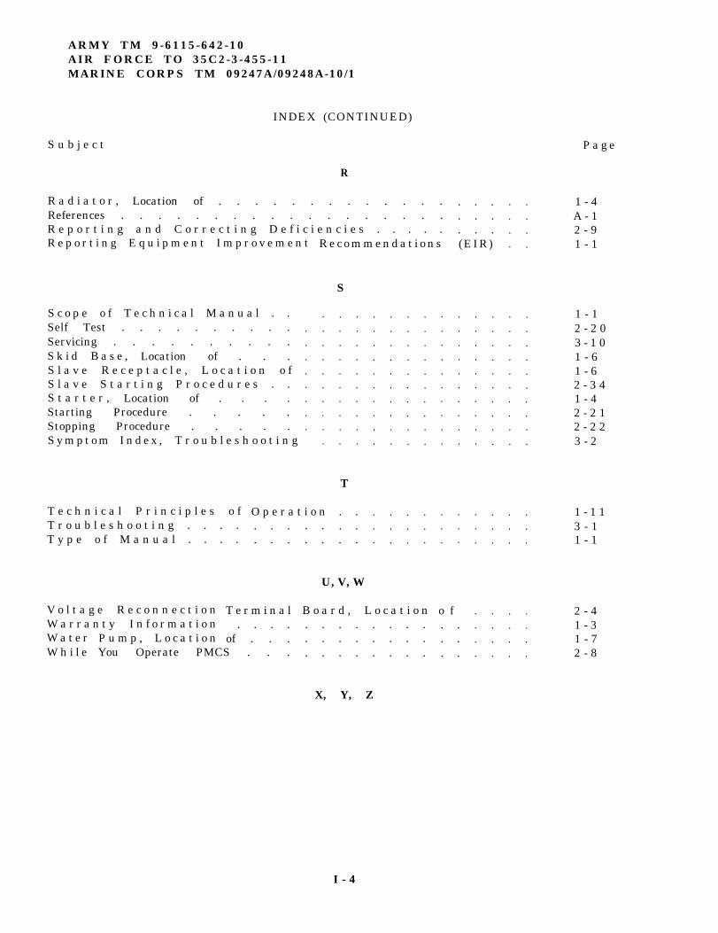
ARMY TM 9-6115-642-10AIR FORCE TO 35C2-3-455-11MARINE CORPS TM 09247A/09248A-10/1
INDEX (CONTINUED)
S u b j e c t P a g e
R
R a d i a t o r , Location of . . . . . . . . . . . . . 1 - 4A - 12 - 91 - 1
. . .
. . .
. . .
.
.
.
.
.
.
.
.
.
.
.
.
.
.
.
.
.
.
.
.
.
.
.
.
.
.
.
.
.
.
.
.
.
.
.
.
.
.
.
.
.
.
References . . . . . . . . . . . . . . . . . .R e p o r t i n g a n d C o r r e c t i n g D e f i c i e n c i e s . . . . .R e p o r t i n g E q u i p m e n t I m p r o v e m e n t (EIR)R e c o m m e n d a t i o n s
1 - 12 - 2 03 - 1 01 - 61 - 62 - 3 41 - 42 - 2 12 - 2 23 - 2
S c o p e o f T e c h n i c a l M a n u a l . .Self Test . . . . . . . . . .Servicing . . . . . . . . . .S k i d B a s e , Location of . . .S l a v e R e c e p t a c l e , L o c a t i o n o fS l a v e S t a r t i n g P r o c e d u r e s . .S t a r t e r , Location of . . . .Starting Procedure . . . . .Stopping Procedure . . . . .
.
.
.
.
.
.
.
.
.
.
.
.
.
.
.
.
.
.
.
.
.
.
.
.
.
.
.
.
.
.
.
.
.
.
.
.
.
.
.
.
.
.
.
.
.
.
.
.
.
.
.
.
.
.
.
.
.
.
.
.
.
.
.
.
.
.
.
.
.
.
.
.
.
.
.
.
.
.
.
.
.
.
.
.
.
.
.
.
.
.
.
.
.
.
.
.
.
.
.
.
.
.
.
.
.
.
.
.
.
.
.
.
.
.
.
.
.
.
.
.
.
.
.
.
.
.
.
.
.
.
.
.
.
.
.
.
.
.
.
.
.
.
.
.
.
.
.
.
.
.
S y m p t o m I n d e x , T r o u b l e s h o o t i n g
T
. .
. .
. .
T e c h n i c a l P r i n c i p l e s o fT r o u b l e s h o o t i n g . . . .T y p e o f M a n u a l . . . .
O p e r a t i o n 1 - 1 13 - 11 - 1
. . .
. . .. .. .
U, V, W
T e r m i n a l 2 - 41 - 31 - 72 - 8
V o l t a g e R e c o n n e c t i o nW a r r a n t y I n f o r m a t i o n
B o a r d , L o c a t i o n o f. .. .. .
. . . .of . . .
. . . . . . . .
. . . . . . . .
. . . . . . . .W a t e rW h i l e
P u m p , L o c a t i o nYou Operate PMCS . . .
X, Y, Z
I - 4
S
ARMY TM 9-6115-642-10AIR FORCE TO 35C2-3-455-11
MARINE CORPS TM 09247A/09248A-10/1
By Order of the Secretaries of the Army, Air Force, and Navy (including the Marine Corps):
Official:
MILTON H. HAMILTONAdministrative Assistant to the
Secretary of the Army03561
GORDON R. SULLIVANGeneral, United States Army
Chief of Staff
MERRILL A. McPEAKGeneral, USAFChief of Staff
Official:
RONALD W. YATESGeneral, USAFCommander, Air Force Materiel Command
DAVID E. BOTTORFFRear Admiral, CEC, US NavyCommanderNavy Facilities EngineeringCommand
H. E. REESEDeputy for SupportMarine Corps Research, Development andAcquisition Command
DISTRIBUTION:To be distributed in accordance with DA Form 12–25-E, block no, 5243, requirements for
TM 9-6115-642-10.
*U. S GOVERNMENT PRINTING OFFICE 1993 -755 -120/ 60128


PIN: 071026-000