army technical manual 5-6115-584-34 navfac navy...
TRANSCRIPT

ARMY TECHNICAL MANUALT M 5 - 6 1 1 5 - 5 8 4 - 3 4
NAVFAC P-8-622-34
NAVY PUBLICATION TO-35C2-3-456-2TM-0568C-34
AIR FORCE TECHNICAL ORDERMARINE CORPS TECHNICAL MANUAL
TECHNICAL MANUAL
INTERMEDIATE (FIELD) (DIRECT AND GENERAL SUPPORT)
AND DEPOT LEVEL MAINTENANCE MANUAL
GENERATOR SET, DIESEL ENGINE DRIVEN, TACTICAL SKID MTD 5KW, 1 PHASE-2 WIRE, 1 PHASE -3 WIRE, 3 PHASE -4 WIRE, 120, 120/240 AND 120/208 VOLTS
DOD MODEL CLASS HERTZ NSN
MEP-002A UTILITY 60 6115-00-465-1044
Published UNDER THE AUTHOR lTYOFTHEDEPARTMENTS 0F THE ARMY,AIR FORCE, NAVY, AND HEADQUARTERS U.S. MARINE CORPS
JULY 1977

TM 5-6115-584-34NAVFAC
WARNING
All specific cautions and warnings contained in this manual shall be strictlyadhered to. Otherwise, severe injury,death damage to the equipment mayresul t .
HIGH VOLTAGE
is produced when this Generator Set is in operation.
DEATH
or severe burns may result if personnel fail to observe safety precautions. notoperate this Generator Set until the ground terminal stud has been connected to asuitable ground. Disconnect the battery ground cable before removing and installingcomponents on the engine or in the electrical control panel system. Remove allrings, watches, and other jewelry when performing maintenance on this equipment.Loose fitting clothing should be secured to prevent it catching in moving parts. not attempt to service or otherwise make any adjustments, connections or nections of wires or cables until Generator Set is shut-down and completely energized.
DANGEROUS
Ba t te r ies genera teexplos ive gas dur ing charging: therefore, ut i l ize ext remecaution, do not smoke, or use open flame in the vicinity of the Generator Set whenservicing batteries.
Exhaust discharge contains noxious and deadly fumes. Do not operate GeneratorSets in enclosed areas unless exhaust discharge is properly vented to the outside.
To avoid sparking between filler nozzle and fuel tank, always maintain metal tometal contact between filler and fuel tank when filling fuel tank.
Do not smoke or use open flame the vicinity of the Generator Set while fueling.
LIQUIDS UNDER HIGH PRESSURE
are generated as result of operation of the Generator Set. Do not expose anypart of the body to high pressure leak in the fuel injection system.
WARNING
Clean parts in a well-ventilated area.Avoid inhalation of solvent fumes and pro-longed exposure of skin to cleaning solvent.Wash exposed skin thoroughly. Drycleaning solvent (Fed. Spec. used to clean parts is potentially dangerousto personnel and property. not use near open flame or excessive heat. Flashpoint of solvent is F. to 138° F. (38° C. to 59° C.).
WARNING
If conditions require fuel tank repairs by welding or other methods involving heator flame, take care to assure that all fumes are purged from the tank or fill tankwith water before commencing the repair. If possible, tank should be filled withwater prior to welding after being thoroughly purged of fumes. Applying heat orflame to a fuel tank containing residue, may result in a violent explosion, causingdeath or injury to maintenance personnel.
NOISE
Operating level of this generator can cause hearing damage. Ear protectors, asrecommended by the medical or safety officer,must be worn when working nearthis set.

TM 5-6115-584-34NAVFAC P-8-622-34
TO-35C2-3-456-2
CHANGE HEADQUARTERSDEPARTMENTS OF THE ARMY, NAVY,
AND AIR FORCENO. 8 WASHINGTON, D. C., 9 NOVEMBER 1992
C 8
Intermediate (Field) (Direct Support and General Support)and Depot Level Maintenance Manual
GENERATOR SET, DIESEL ENGINE DRIVEN, TACTICAL SKID MTD,5 kW, 1 PHASE -2 WIRE, 1 PHASE -3 WIRE, 3 PHASE -4 WIRE,
120, 120/240 AND 120/208 VOLTS
DOD MODEL CLASS HERTZ NSN
MEP-002A UTILITY 60 6115-00-465-1044
Approved for public release; Distribution is unlimited
TM 5-6115-584-34/NAVFAC P-8-622-34/TO-35C2-3-456-2, 22 July 1977 is changed as follows:
1. Remove and insert pages as indicated below. New or changed text material is indicated by a vertical bar inthe margin. An illustration change is indicated by a miniature pointing hand.
Remove pages Insert pages
6-11 and 6-12 6-11 and 6-12
2. Retain this sheet in front of manual for reference purposes.

TM 5-6115-584-34NAVFAC P-8-622-34TO-35C2-3-456-2
C8
By Order of the Secretaries of the Army, Navy and Air Force:
Official:
GORDON R. SULLIVANGeneral, United States Army
Chief of Staff
MILTON H. HAMILTONAdministrative Assistant to the
Secretary of the Army03009
MERRILL A. McPEAKGeneral, USAF
Chief of Staff
Official:RONALD W. YATES
General, United States Air ForceCommander, Air Force Materiel Command
DAVID E. BOTTORFFRear Admiral, CEC, US Navy
CommanderNavy Facilities Engineering Command
DISTRIBUTION:To be distributed in accordance with DA Form 12-25-E, block no. 0858, requirements for
TM 5-6115-584-34.

TM 5-6115-584-34NAVFAC P-8-622-34TO-35C2-3-456-2
C7
CHANGE
NO. 7
HEADQUARTERS ,DEPARTMENTS OF THE ARMY, NAVY AND AIR FORCE
AND HEADQUARTERS U.S. MARINE CORPSWASHINGTON, D.C., 25 July 1991
Intermediate (Field) (Direct and General Support)and Depot Level Maintenance Manual
GENERATOR SET, DIESEL ENGINE DRIVEN, TACTICAL SKID MTD 5 kW,1 PHASE -2 WIRE, 1 PHASE -3 WIRE, 3 PHASE -4 WIRE,
120, 120/240 AND 120/208 VOLTS
DOD MODEL CLASS HERTZ NSN
MEP-002A UTILITY 60 6115-00-465-1044
Approved for public release; distribution is unlimited
TM 5-61 15–584-34, NAVFAC P–8-622-34, TO-35 C2-3-45&2, 22 July 1977, is changed as follows:
1. The Marine Corps TM-05682C-34 is being deleted. All future change pages and revisions will reflect this.
2. Remove and insert pages as indicated below. New or changed text material is indicated by a vertical bar inthe margin. An illustration change is indicated by a miniature pointing hand.
Remove pages Insert pages
v and vi— ——
2-11 and 2-124-1/(4-2 blank)5–1 through 5–8—— —
6--7 and 6--8———
6-9 through 6-14———
6-15 and 6-166-19 and 6-206--20.17–29 through 7–327-41 and 7-42
v and vi1–9/(1–10 blank)2–11 and 2–124-1/(4-2 blank)5-1 through 5–85–9 though 5-126-7 and 6-86-8.1 /(6-8.2 blank)6-9 through 6-146-14. 1/(6-14.2 blank)6-15 and 6-166--19 and 6-206-20.1 and 6-20.27–29 through 7–327-41 and 7-42
2. Retain this sheet in front of manual for reference purposes.

TM 5-6115-584-34NAVFAC P-8-622-34TO-35C2-3A156-2
C7
By Order of the Secretaries of the Army , Air Force, and Navy:
GORDON R. SULLIVANGeneral, United States Army
Chief of Staff
Official:PATRICIA P. HICKERSON
Brigadier Genera/, United States ArmyThe Ac@tant General
MERRILL A. McPEAKGeneral USAFChief of Staff
Official:CHARLES C. McDONALD
General, USAFCommander, Air Force Logistics Command
DAVID E. BUTTORFFRear Admiral, CEC, US Navy
CommanderNavy Facilities Engineering Command
DISTRIBUTION:To be distributed in accordance with DA Form 12-25E, (qty rqr block no. 0858)

CHANGE
NO. 6
TM 5-6115-584-34
HEADQUARTERS,DEPARTMENTS OF THE ARMY, NAVY AND AIR FORCE
AND HEADQUARTERS U.S. MARINE CORPSWASHINGTON, D. C., 12 June
Intermediate (Field) (Direct and General Support)and Depot Level Maintenance Manual
GENERATOR SET, DIESEL ENGINE DRIVEN; TACTICALSKID MTD 5 KW, 1 WIRE, 1 WIRE,3 WIRE, 120, 120/140 AND 120/208 VOLTS
DOD MODEL CLASS HERTZ NSNUTILITY 60 6115-00-465-1044
Approved public release; distribution is unlimited
TM 5–61 0568 22 July 1977, ischanged as follows:
1. Remove and pages as indicated or changed text material is indicated by a verticalbar in the margin An illustration change is indicated by a miniature pointing hand.
Remove pages Insert pages
iii through v/vi1–1 through 1–4
2–11 and 2–122–15 and 2–16
through 3–3/ 3–44-1/4-26-7 and 6-87–1 and 7–27-5 and 7-67-25 and 7-267–29 and 7–307-41 through 7–448-1 and 8-29-1 and 9–2
Index through Index 4
iii through vi1–1 through 1–41–4.1/1-4,22–1 1 and 2–122–15 and 2–1 63–1 through 3–3/3-44–1 /4–26-7 and 6-87–1 and 7–27–5 and 7–67-25 and 7-267-29 and 7–307-41 through 7–448–1 and 8–29–1 and 9–210–1 through 10–14Index 1 through Index 4

TM 5-6115-584-34NAVFAC P-8-622-34TO-35C2-3-456-2TM-0568C-34
C6
2. Retain this sheet in front ofmanual for reference purposes.
By Order of the Secretaries of the Army , Air Force, and Navy (Including the Marine COtpS):
CARL E. VUONOGeneral, United States Army
Chief of Staff
Official:
THOMAS F. SIKORABrigadier General, United States Army
The Adjutant GeneralLARRY D. WELCH, General USAF
Chief of Staff
Official:ALFRED G. HANSEN
General, USAF, Commander, Air ForceLogistics Command
B.F. MONTOYARear Admiral, CEC, US Navy
CommanderNavy Facilities Engineering Command
H.E. REESEExecutive Director
Marine Corps Research, Development andAcquisition Command
DISTRIBUTION:
To be distributed in accordance with DA Form 12-25E, (qty rqr block no 0858).

Army Technical Manual TM 5-6115-584-34Navy Publication NAVFAC
Technical OrderMarine Corps Technical Manual
CHANGE HEADQUARTERS, DEPARTMENTS OF THE ARMY, NAVY ANDAIR FORCE AND HEADQUARTERS, U.S. MARINE CORPS
No. 5 Washington, D.C., 5 1989
Intermediate (Field) (Direct and General Support)and Depot Level Maintenance Manual
GENERATOR SET, DIESEL ENGINE DRIVEN; TACTICALSKID MTD 5 KW, 1 WIRE, 1 WIRE3 WIRE, 120, 120/140 AND 120/208 VOLTS
DOD MODEL CLASS HERTZ NSN
UTILITY 60 6115-00-465-1044
TM 22 changed as follows:
1. Remove and insert pages as indicated below. New or changed indicated by a vertical bar in the margin. An illustration change is indicateda miniature pointing hand.
Remove pages Insert pages
iii and iv1-9/1-102-5 and 2-62-11 and 2-126-1 and 6-26-7 and 6-86-13 through 6-16---6-19 and 6-206-20.1 and 6-20.27-13 and 7-147-25 and 7-26----7-37 and 7-38
8-3 and 8-4- - -
iii and iv1-9/1-102-5 and 2-62-11 and 2-126-1 and 6-26-7 and 6-86-13 through 6-166-16.1 and 6-16.26-19 and 6-206-20.17-13 and 7-147-25 and 7-267-26.1/7-26.27-37 and 7-388-3 and 8-4DA Form 2-28-2 (4)
2. Retain this sheet reference purposes.

TM 5-6115-584-34NAVFAC P-8-622-34TO-35C2-3-456-2TM-0568C-34
C5
By Orderofthe Secretaries of the Army, the3favy, and the Air Force:
CARLE. VUONO
of!lcial: General. United States ArmyChief of Stafl
R,L.DILWORTHBtigedier(kneml, UnitedState8.4rmg
~!teA@&tantCenera/
J.P.JONES,JR.Rear Admhd, CEC, US NauvCommanderiVaval Fw”litiea Engineen”ng Command
Official:LARRY D. WELSH, -era 1 USAF
Chief of Staff
ALFRED G. HANSEN(knend, CSAF, Commander, Air Force
Logintim Command
V. J. WALLSActing Deputy Chief of Stafffor Installations and Logistics
DISTRIBUTION:To be distributed in accordance with DA Form 12-25A, Direct and General Support
Maintenance requirements for Generator Set, Diesel Driven, Tactical, Skid Mounted,120V, 120/240V, 120/208V, 5KW, 60 HZ, lPH/2 Wire, lPH/3 Wire, 3PH/4 Wire (MEP-002A).

Army Technical Manual TM 5-6115-584-3aNavy Publication NAVFAC P-8-622-34Air Force Technical Order TO-35C2-3-456-2Marine Corps Technical Manual TII-0568C-34
C4
CHANGE1
DEPARTMENTS OF THE ARMY NAVY,
/AIR FORCE AND MARINE CORPS
No. 4 WASHINGTON, D.C., 1 April 1986
Intermediate (Field) (Direct and General Support)and Depot Level t4aintenance Manual
GENERATOR SET, DIESEL ENGINE DRIVEN; TACTICALSKID MTD 5 KW, 1 PHASE-2 WIRE, 1 PHASE-3 WIRE,3 PHASE-4 WIRE, 120, 120/140 AND 120/208 VOLTS
DOD MODEL CLASS HERTZ NSNMEP-002A UTILITY 60 6115-00-465-1044
TM 5-6115-584-34/NAVFAC P-8-622-34/TO 35C2-3-456-2/ TM 05682C-34, 22 ~UIY1977, is changed as follows:
1. Remove and insert pages as indicated below. New or changed text materialis indicated by a vertical bar in the margin. An illustration change is indicatedby a miniature pointing hand.
Remove pages Insert pages
iii and iv1-3 and 1-42-11 and 2-126-17 through 6-20---7-1 and 7-27-10.1 and 7-10.27-37 and 7-38
iii and iv1-3 and 1-42-11 and 2-126-17 through 6-206-20.1 and 6-20.27-1 and 7-27-10.1 and 7-10.27-37 and 7-38
2. Retain this sheet in front of manual for reference purposes.
— .

TM 5-6115-584-34NAVFAC P-8-622-34TO-35C2-3-456-2TN-0568C-34
C4
By Orderofthe Secretaries of the Army, the Navy, and theAirForce:
Official:
JOHN A. WICKHAM, JR.General, United States Army
Chief of Stat7
R. L. DILWORTHBrigadier General, United States Army
The Adjutant General
J. P. JONES, JR.Rear Admiral, CEC, US NavyCommanderNaval Facilities Engineering Command
Official:
EARL T. O’LOUGHLINGeneral, USAF, Commander, Air Force
Logistics Command
GEORGE B. CRISTLieutenant General, USMCDeputy Chief of Staff for Installations and Logistics
CHARLES A. GABRIEL, General USAFChief of Staff
DISTRIBUTION:To be distributed in accordance with DA Form 12-25A, Direct and General Support
Maintenance requirements for Generator Set, Diesel Driven, Tactical , Skid Mounted,120V, 120/240V, 120/208V, 5KW, 60 HZ, lPH/2 Wire, lPH/3 Wire, 3PH/4 Wire (MEP-002A).

DEPARTMENT OF THE ARMY TECHNICAL MANUAL TM 5-6115-584-34DEPARTMENT OF THE NAVY PUBLICATION NAVFAC P-8-622-34DEPARTMENT OF THE AIR FORCE TECHNICAL ORDER TO-35 C2-3-456-2MARINE CORPS TECHNICAL MANUAL TM-05682C-34
P?
CHANGE
}
DEPARTMENTS OF THE ARiVY, NAVY,AIR FORCE AND MARINE CORPS
NO. 3 ~TASHINGTON, D.C., 14 oct~be~ 1983
I~~termediate (Field) (Direct and General Support)and Depot Level Maintenance Manual
GENERATOR SET, DIESEL ENGINE DRIVEN; TACTICALSKID MTD 5 K W , 1 PHASE–2 WIRE, 1 PHASE–3 WIRE,3 PHASE–4 WIRE, 120, 120/140 AND 120/208 VOI.,TS
DOD MODEL CLASS HERTZ NSNMEP–002A UTILITY 60 6115–00–465–1044
TM 5-6115-584-34/NAVFAC P-8-622-34/TO 35C2-3-456-2/TM 05682C–34, 22 July 1977, is changed as follows:
1. Remove and insert pages as indicated below.
Remove pages Insert pa,qes
Table of Contents iii and iv iii thru v/viChapter 2 2–1 thru 2–4 2–1 thru 2–4
2–11 and 2–12 2–11 and 2-12Chapter 3 3–1 and 3–2 3–1 and 3-2Chapter 4 4–1/4–2 4-1/4-2Chapter 7 7–9 and 7–lo 7–9 thru 7–10.2Chapter 8 8–3 and 8–4 8–3 and 8–4
?U, New or changed text mater]a~ is indicated by a vertical bar
in the margin. An illustration change is indicated by a miniaturepointing hand.
3. Retain these sheets in front of manual for reference purposes.

TM 5-6115-584-34NAVFAC P-8-622-34TO-35 C2-3-456-2TM-0568C-34
r :3
By Order of the Secretaries of the Army, the Navy, and the Air Force:
Official:
ROBERT M. JOYCEMajor General, United States Army
The Adjutant General
Official:
JOHN A. WICKHAM, JR.General, United States Army
Chief of Staff
W. M. ZOBELRead Admiral, CEC, US NavyNavaiFaciiitiea Eqp”neen”ng Command
CHARLES A. GABRIEL, GeneraJ, WM.FChief of Staff
JAMES P. MULLINSGeneral, USAF, Commander, Air Fome
Logistics Command
V. J. WALLSAch”ngDeputy Chief of Staff for Installations and Logx”s&”cs
DISTRIBUTION:Active Army:
To be distributed in accordance with DA Form 12-24D, Direct and General Support Maintenance re-quirements for Generator Set, Engine Driven 5KW 60 HZ.
Marine Corps;MARCORPS: AGB

DEPARTMENT OF THE ARMY TECHNICAL MANUALDEPARTMENT OF THE NAVY PUBLICATIONDEPARTMENT OF THE AIR FORCE TECHNICAL ORDERMARINE CORPS TECHNICAL MANUAL
CHANGE
NO. 2I
TM 5-6115-584-34NAVFAC P-8-622-34
TO-35C2-3-456-2TM-05682C-34
C2
DEPARTMENTS OF THE ARMY, NAVY,AIR FORCE AND MARINE CORPS
Washington, DC, 30 March 1979
Intermediate (Field) (Direct and General Support)and Depot Level Maintenance Manual
GENERATOR SET, DIESEL ENGINE DRIVEN; TACTICALSKIP MTD 5 KW, 1 PHASE-2 WIRE, 1 PHASE-3 WIRE,3 PHASE-4 WIRE, 12Q, 120/240 AND 120/208 VOLTS
DOD MODELMEP-002A
CLASS HERTZ NSNUTILITY 60 6115-00-465-1044
TM 5-6115-584-34/NAVFAC P-8-622-34/TO 35C2-3-456-2/TM 05682C-34, 22 July 1977, ischanged as follows:
1. Remove old pages and insert new pages as indicated below.
2. New or changed material is indicated by a vertical bar in the margine of thepage.
Remove Pages Insert Pages
1-9/(1-10 blank) 1-9/(1-10 blank)6-1 and 6-2 6-1 and 6-26-3 and 6-4 6-3 and 6-46-5 and 6-6 6-5 and 6-66-7 and 6-8 6-7 and 6-86-13 and 6-14 6-13 and 6-14
3. File this change sheet in front of the publication for reference purposes.

TM 5-6115-564-34NAVFAC P-8-622-34
TO-35C2-3-456-2TM-05662C-34
C2
By Order of the Secretaries of the Army, the Navy, and the Air Force:
Official:
BERNARD W. ROGERSGeneral, United States Army
Chief of Staff
J, C. PENNINGTONMajor General, United States Army
The Adjutant General
D. G. ISELINRear Admiral, CEC, U. S. NavyCommander, Naval FacilitiesEngineering Command
Official:LEW ALLEN, JR., General, USAFChief of Staff
VAN L. CRAWFORD, JR., Colonel, USAFDirector of Administration
H. A. HATCHMajor General, U. S. Marine CorpsDeputy Chief of staff for Installations and Logi8tic8
Distribution:Active Army:
To be distributed in accordance with DA Form 12-25D, direct support and general support maintenancerequirements for generatxm sets, engine driven, 5 KW, 60 HZ.
Marine Corps:MARCORPS CODE: AGB

TM 5-6115-584-34NAVFAC P-8-622-34
TO 35C2-3-456-2TM 05682C-34
cl
DEPARTMENTS OF THE ARMY, NAVY,AIR FORCE AND MARINE CORPS
WASHINGTON , DC, 15 March 1978
Intermediate (Field) (Direct and General Support)and Depot Level Maintenance Manual
GENERATOR SET, DIESEL ENGINE DRIVEN; TACTICALSKIP MTD 5 KW, 1 PHASE-2 WIRE, 1 PHASE-3WIRE,3 PHASE-4 WIRE, 120, 120/240 AND 120/208 VOLTS
DOD MODEL CLASS HERTZ NSNMEP-O02A UTILITY 60 6115-00-465-1044
TM ~-6115-S84-34/NAvFL~C p.8-622_34~() 35G2-3..456-2~M 05682C+4, 22 July 1977, is changed as follows:
on front cover and throughout manual, Nal,y publication, NAVFAC P-8-262-11, should read: “NAVFACP-8-622-34”.
By Olcler of the Secretaries of the Army, the Navy, and the Air Force:
BERNARD W. ROGERS
Official:General, l~nited States Army
Chief of St%ff
J. C. PENNINGTONBrigadier Ge)(e)al, UH itecl States Ar))zy
The Aclj[ita)zt General
D. G. ISELIXRear Admiral, CEC, U. S. i%’avyCommander,Na[!al Facilities Engi7~eering C’om))la~(d
Official:
JAMES J. SHEPARD, Co/o)/e/, [’SAFDirecto) of’A{[>){ i)l ist)((tio)~
H. A. HATCH.Ilajo,’ Ge)~e)vl, [‘S .Ilu t.i)ie CorpsDept[tg 211 ief’ qt’ Stuff ’,fb), l){stallatio)~s a )/(1 Logist ics
DAVID C. JONES, General USAFChi<f of Staff
l)istli~ution:‘~o be distributed in accordance with DA Form 12-25D, DS & GS Maintenance requirements for
,t’l)erator Sets, Engine Driven: 5 KW, 60 HZ.


TM 5-6115-584-34
DEPARTMENT ARMY TECHNICAL MANUALNAVFAC
DEPARTMENT OF THE NAVY PUBLICATIONDEPARTMENT OF THE AIR FORCE TECHNICAL ORDERMARINE CORPS TECHNICAL
HEADQUARTERSDEPARTMENTS OF THE ARMY, NAVY, AIR USMC
WASHINGTON, 22 JULY 1977
INTERMEDIATE (FIELD) (DIRECT AND GENERAL SUPPORT)
AND DEPOT LEVEL MAINTENANCE MANUAL
GENERATOR SET, DIESEL ENGINE DRIVEN; TACTICAL SKI DMTD lPHASE-2 WIRE, 1 PHASE -3 WIRE, 3 PHASE -4 WIRE, 120, 120/240 AND 120/208 VOLTS
DOD MODEL LASS HERTZ NSN
UTILITY 60 6115-00-465-1044
C H A P T E R 1 .
Section I.
Section II.
C H A P T E R 2 .
Section I.
S e c t i o n
TABLE OF CONTENTS
EFFECTIVE PAGES.. . . . . . . . . . . . . . . . . . . .LIST OF ILLUSTRATIONS . . . . . . . . . . . . . . . . . . . . . .LIST OF TABLES . . . . . . . . . . . . . . . . . . . . . . . . . . .INTRODUCTION . . . . . . . . . . . . . . . . . . . . . . . . . . . .
GENERAL . . . . . . . . . . . . . . . . . . . . . . . . . . . . . . .
1-1. scope . . . . . . . . . . . . . . . . . . . . . . . . . . . . . .1-2. Limited Applicability . . . . . . . . . . . . . . . . . . . . .1-3. Maintenance Forms and Records . . . . . . . . . . . . . . .1-4. Reporting of Errors . . . . . . . . . . . . . . . . . . . . . .1-5. Levels of Maintenance Accomplishment . . . . . . . . . . .
DESCRIPTION AND TABULATED DATA . . . . . . . . . . . . . . .
1-6. Description . . . . . . . . . . . . . . . . . . . . . . . . . . .1-7. Tabulated Data . . . . . . . . . . . . . . . . . . . . . . . . .
GENERAL MAINTENANCE INSTRUCTIONS . . . . . . . . . . . . .
REPAIR PARTS, SPECIAL TOOLS, TEST, MEASUREMENT, AND EQUIPMENT (TMDE) , AND SUPPORT EQUIPMENT
2-1. Repair Parts . . . . . . . . . . . . . . . . . . . . 2-2. Tools and Equipment . . . . . . . . . . . . . . . . . . . . . .2-3. Fabricated Tools and Equipment . . . . . . . . . . . . . . .
TROUBLESHOOTING . . . . . . . . . . . . . . . . . . . . . . . . .
2-4. General . . . . . . . . . . . . . . . . . . . . . . . . . . . . .2-5. Malfunctions Not Corrected By Use of the Troubleshooting
Table . . . . . . . . . . . . . . . . . . . . . . . . . . . . .
Page
ivv
1-1
1-11-11-11-11-1
1-1
1-11-1
2-1
2-1
2-12-12-1
2-5
2-5
2-5
i

5-6115 -584 -34NAVFAC P-8-622-34
TO-35C2-3-456-2TM-0568C-34
TABLE OF CONTENTS (CONT)
Section III .
S e c t i o n IV.
CHAPTER 3.
Section I.
Section II.
CHAPTER 4.
Section L
Section II.
CHAPTER 5.
Section I.
Section II.
CHAPTER 6.
Section I.
S e c t i o n IL
GENERALMAINTENANCE. . . . . . . . . . . . . . . . . . . . . .
2-6. General Maintenance. . . . . . . . . . . . . . . . . . . . . .2-7. General Maintenance Procedures . . . . . . . . . . . . . . .
REMOVAL ANI INSTALLATION OF MAJOR COMPONENTS . . . .
2-8. Control Cubicle . . . . . . . . . . . . . . . . . . . . .- . .2-9. Engine Assembly. . . . . . . . . . . . . . . . . . . . . . . .2-10. Generator Assembly. . . . . . . . . . . . . . . . . . . . . .
MAINTENANCE OF COOLING SYSTEM . . . . . . . . . . . . . . .
DESCRIPTION AND FUNCTION.. . . . . . . . . . . . . . . . . . .
3-1. General . . . . . . . . . . . . . . . . . . . . . . . . . . . . .
MAINTENANCE . . . . . . . . . . . . . . . . . . . . . . . . . . . .
3-2. Engine Cooling System . . . . . . . . . . . . . . . . . . . .3-3. High Temperature Cut Out Switch . . . . . . . . . . . . . .
MAINTENANCE OF FUEL SYSTEM . . . . . . . . . . . . . . . . .
DESCRIPTION ANDF UNCTION.. . . . . . . . . . . . . . . . . . .
4-1. General . . . . . . . . . . . . . . . . . . . . . . . . . . . . .
MAINTENANCE OF FUEL TANK. . . . . . . . . . . . . . . . . . .
4-2. Fuel Tank . . . . . . . . . . . . . . . . . . . . . . . . . . .
MAINTENANCE OF STARTING SYSTEM . . . . . . . . . . . . . . .
DESCRIPTION AND FUNCTION.. . . . . . . . . . . . . . . . . . .
5-1. General . . . . . . . . . . . . . . . . . . . . . . . . . . . . .
MAINTENANCE . . . . . . . . . . . . . . . . . . . . . . . . . . . .
5-2. Starter Assembly . . . . . . . . . . . . . . . . . . . . . . . .
MAINTENANCE OF CONTROL SYSTEM . . . . . . . . . . . . . . .
DESCRIPTION AND FUNCTION.. . . . . . . . . . . . . . . . . . .
6-1. DC Control System . . . . . . . . . . . . . . . . . . . . . . .6-2. AC Instrumentation System . . . . . . . . . . . . . . . . . .6-3. Voltage Regulator . . . . . . . . . . . . . . . . . . . . . . .
MAINTENANCE . . . . . . . . . . . . . . . . . . . . . . . . . . . .
6-4. Coritrol Cubicle . . . . . . . . . . . . . . . . . . . . . . . .6-5. Generator Set Wiring Harness . . . . . . . . . . . . . . . .6-6. Voltage Regulator . . . . . . . . . . . . . . . . . . . . . . .6-7. AC Output Control Box Wiring Harness . . . . . . . . . . . .6-8. AC Output Control Box Assembly . . . . . . . . . . . . . . .6-9. AC Output Control Box (Internal Components) . . . . . . . .
Page
2-12
2-122-12
2-12
2-122-122-16
3-1
3-1
3-1
3-1
3-13-1
4-1
4-1
4-1
4-1
4-1
5-1
5-1
5-1
5-1
5-1
6-1
6-1
6-16-16-1
6-1
6-16-86-86-96-96-9
ii

TM 5-6115-584-34NAVFAC P-8-622-34
TO-35C2-3-456-2TM-0568C-34
TABLE OF CONTENTS (CONT)
CHAPTER 7.
Section I.
Section II.
Sec t ion I I I .
CHAPTER 8.
Section I.
Section II.
CHAPTER 9.
Section I.
S e c t i o n I I .
Sec t ion I I I .
MAINTENANCE OF ENGINE. . . . . . . . . . . . . . . . . . . . .
DESCRIPTION AND FUNCTION . . . . . . . . . . . . . . . . . . . .
7-1. General. . . . . . . . . . . . . . . . . . . . . . . . . . .
ENGINE EXTERNAL ASSEMBLY . . . . . . . . . . . . . . . . . . .
7-2. Fuel Lines . . . . . . . . . . . . . . . . . . . . . . . . . . . . . .7-3. External Governor Parts and Speed Control Assembly . . . .7-4. Flywheel and Ring Gear Assembly . . . . . . . . . . . . . .7-5. Flywheel Housing . . . . . . . . . . . . . . . . . . . . . . . . . . . . .7-6. Oil Cooler . . . . . . . . . . . . . . . . . . . . . . . . . . . . . . .7-7. Blower Wheel Assembly. . . . . . . . . . . . . . . . . . . . . . . .7-8. Battery Charge Alternator. . . . . . . . . . . . . . . . . . .
7-8.1.7-9.7-10.7-11.7-12.7-13.7-14.7-15.7-16.7-17.7-18.7-19.7-20.
ENGINE INTERNAL ASSEMBLIES . . . . . . . . . .. . . . . . . . . .Engine Compression Test . . . . . . . . . . . . . . . . . . . . . . . . . . . .Cylinder Head . . . . . . . . . . . . . . . . . . . . ...Piston and Connecting Rod. . . . . . . . . . . . . . . . . .Oil Pump . . . . . . . . . . . . . . . . . . . . . . .. . . . . . .Oil Filter Adapter Assembly . . . . . . . . . . . . . . . . .Oil By-Pass Valve . . . . . . . . . . . . . . . . . . . . . . . . . . . . .Gear Cover Assembly . . . . . . . . . . . . . . . . . . . . .Governor Cup . . . . . . . . . . . . . . . . . . . . . . . .Camshaft Assembly and Tappets . . . . . . . . . . . . . . .Crankshaft and Bearings . . . . . . . . . . . . . . . . . . . .Fuel Injection Pump. . . . . . . . . . . . . . . . . . . . . .Cylinder Block . . . . . . . . . . . . . . . . . . . . . . . . .Fuel Injector . . . . . . . . . . . . . . . . . . . . . . . . . .
MAINTENANCE OF GENERATOR ASSEMBLY . . . . . . . . . . . .
DESCRIPTION AND FUNCTION . . . . . . . . . . . . . . . . . .
8-1. General . . . . . . . . . . . . . . . . . . . . . . . . . . . . .
MAINTENANCE . . . . . . . . . . . . . . . . . . . . . . . . . . . .
8-2. Generator Maintenance . . . . . . . . . . . . . . . . . . . .
GENERATOR SET TEST AND INSPECTION AFTER REPAIR OROVERHAUL . . . . . . . . . . ........... . . . . . . . . . . .
GENERAL REQUIREMENTS. . . . . . . . . . . . . . . . .. .
9-1. General Information . . . . . . . . . . . . . . . . . . . . . .
INSPECTION . . . . . . . . . . . . . . . . . . . . . . . . . . . . . .
9-2. General . . . . . . . . . . . . . . . . . . . . . . . . . . . . .9-3. Engine Cooling System . . . . . . . . . . . . . . . . . . . . .9-4. Wiring Harnesses . . . . . . . . . . . . . . . . . . . . . . .
OPERATIONAL TESTS. . . . . . . . . . . . . . . . . . . . . . . .
9-5. Generator and Generator Control Circuitry. . . . . . . . . .9-6. Engine Control Circuitry. . . . . . . . . . . . . . . . . . . .
Page
7-1
7-1
7-1
7-1
7-17-17-57-67-67-67-8
7-97-10.17-10.27-137-197-197-197-217-257-257-277-307-417-41
8-1
8-1
8-1
8-1
8-1
9-1
9-1
9-1
9-1
9-19-19-1
9-1
9-19-1
iii

TM 5-6115-584-34NAVFAC P-8-622-34TO-35C2-3-456-2TM-0568C-34
TABLE OF CONTENTS CONTENTS (CONT)Page
C H A P T E R 1 0 . MATERIAL USED IN CONJUNCTION WITH DOD STANDARDGENERATOR SET, 5KW DIESEL ENGINE, MODELMEP-002A . . . . . . . . . . . . . . . . . . . . . . . . . . . . . . . . . . . . . . . . .
Section I. AUXILIARY EQUIPMENT . . . . . . . . . . . . . . . . . . . . . . . . . . . . . . . .
10-1. General . . . . . . . . . . . . . . . . . . . . . . . . . . . . . . . . . . . . . . . .
Section II. ACOUSTIC SUPPRESSION KIT INSTALLATION . . . . . . . . . . . . .
10-2. Acoustic Suppression Kit . . . . . . . . . . . . . . . . . . . . . . . . .10-3. Preliminary Procedures . . . . . . . . . . . . . . . . . . . . . . . . . . . . . .10-4. Acoustic Suppression Kit Installation . . . . . . . . . . . . . . .10-5. Post Installation Procedures . . . . . . . . . . . . . . . . . . . . . . . .
APPENDIX A. REFERENCE . . . . . . . . . . . . . . . . . . . . . . . . . . . . . . . . . . . . .
INDEX . . . . . . . . . . . . . . . . . . . . . . . . . . . . . . . . . . . . . . . . . . . . . .
10-1
10-1
10-1
10-2
10-210-410-4
10-14
A-1
INDEX 1
iv Change 6

TM 5-6115-584-34NAVFAC P-8-622-34
TO-35C2-3-456-2
Figurel–l.2-1.2-2.2-3.2-4.3-1.5-1.5-2.5-3.5-4.5-5.5-6.5-7.5-8.5-9.5-10.5-11.5-12.5-13.5-14.6-1.6-2.6-3.6-4.6-5.6-5.1.6-6.6-7.6-7.1.6-8.6-9.6-10.6-10.1.6-10.2.6-11.7-1.7-2.7-3.7-4.7-5.7-6.7-7.7-8.7-8.1.7-9.7-10.7-11.7-12.7-13.7-14.7-15.7-16.7-17.7-18.7-19.7-20.7-21.
LIST OF ILLUSTRATIONSTitle
Generator Set Electrical Schematic . . . . . . . . . . . . . . . . . . . . . . . . . . . . . . . . . . . . . . . . . . . .Speed Control Assembly . . . . . . . . . . . . . . . . . . . . . . . . . . . . . . . . . . . . . . . ...Disconnecting Engine from Generator . . . . . . . . . . . . . . . . . . . . . . . . . . . . . . . . . . . . . . . . . .Lifting Engine . . . . . . . . . . . . . . . . . . . . . . . . . . . . . . . . . . . . . . . . . . . . . . . . .Lifting Engine and Generator Assembly . . . . . . . . . . . . . . . . . . . . . . . . . . . . . . . . . . . . . . . .Engine Cooling System . . . . . . . . . . . . . . . . . . . . . . . . . . . . . . . . . . . . . . . . . . . . . . . . . .Electric Starter Assembly (STYLE I). . . . . . . . . . . . . . . . . . . . . . . . . . . . . . . . . . . . . . . . . . .Electric Starter Assembly (STYLE II) . . . . . . . . . . . . . . . . . . . . . . . . . . . . . . . . . . . . . . . . . .Pinion Gear Stopper Removal.. . . . . . . . . . . . . . . . . . . . . . . . . . . . . . . . . . . . . . . . . . . Testing Armature for Grounds . . . . . . . . . . . . . . . . . . . . . . . . . . . . . . . . . . . . . . . . . . .. Testing Armature for Shorted Coils . . . . . . . . . . . . . . . . . . . . . . . . . . . . . . . . . . . . . . . . .Testing Armature forOpenCoils . . . . . . . . . . . . . . . . . . . . . . . . . . . . . . . . . . . . . .Checking Commutator Runout . . . . . . . . . . . . . . . . . . . . . . . . . . . . . . . . . . . . . . . . . . . . . . . .Checking Armature Shaft Runout . . . . . . . . . . . . . . . . . . . . . . . . . . . . . . . . . . . . . . . . . .Testing Brush Spring Tension STYLE I Starter Only . . . . . . . . . . . . . . . . . . . . . . . . . . . . . .Testing Solenoid Switch . . . . . . . . . . . . . . . . . . . . . . . . . . . . . . . . . . . . . . . . . . . . . .Undercutting Mica . . . . . . . . . . . . . . . . . . . . . . . . . . . . . . . . . . . . . . . . . . . . .. . . .Brush Replacement STYLE I Starter Only . . . . . . . . . . . . . . . . . . . . . . . . . . . . . . . . . . . . . .Checking Pinion Clearance STYLE I Starter Only . . . . . . . . . . . . . . . . . . . . . . . . . . . . . . . .Checking Pinion Travel STYLE II Starter . . . . . . . . . . . . . . . . . . . . . . . . . . . . . . . . . . . . . . .Control Cubicle Wiring Harness . . . . . . . . . . . . . . . . . . . . . . . . . . . . . . . . . . . . . .Generator Set Wiring Harness . . . . . . . . . . . . . . . . . . . . . . . . . . . . . . . . . . . . . . . . . . . . . . . .Control Cubicle . . . . . . . . . . . . . . . . . . . . . . . . . . . . . . . . . . . . . . . . .. . . . .Testing Voltage Regulator . . . . . . . . . . . . . . . . . . . . . . . . . . . . . . . . . . . . . . . . . ..AC Voltage Regulator Schematic (P/N 72-5020) . . . . . . . . . . . . . . . . . . . . . . . . . . . . . . . . . .AC Voltage Regulator Schematic (P/N 72-5338) . . . . . . . . . . . . . . . . . . . . . . . . . . . . . . . . . .AC Output Control Box Wiring Harness . . . . . . . . . . . . . . . . . . . . . . . . . . . . . . . . . . . . . . . .AC Output Control Box Test Setup . . . . . . . . . . . . . . . . . . . . . . . . . . . . . . . . . . . . . .CVTand CT Wiring . . . . . . . . . . . . . . . . . . . . . . . . . . . . . . . . . . . . . . . . . . . . . ..AC Control Box Removal . . . . . . . . . . . . . . . . . . . . . . . . . . . . . . . . . . . . . . . . . . .....AC OutputControl Assembly . . . . . . . . . . . . . . . . . . . . . . . . . . . . . . . . . . . . . . . .AC Output Control Assembly (Switch, Receptacle and Circuit Breaker) . . . . . . . . . . . . . . .Rotary Assembly Switch . . . . . . . . . . . . . . . . . . . . . . . . . . . . . . . . . . . . . . . . . . . . . . . . . . .Rotary Assembly Switch . . . . . . . . . . . . . . . . . . . . . . . . . . . . . . . . . . . . . . . . . . . .Bridge Rectifier Assembly A-4 . . . . . . . . . . . . . . . . . . . . . . . . . . . . . . . . . . . . . . . .Injector Fuel Lines . . . . . . . . . . . . . . . . . . . . . . . . . . . . . . . . . . . . . . . . . . . . . .. Speed Control Assembly and Governor Control Assembly . . . . . . . . . . . . . . . . . . . . . . . . . .Engine Flywheel and Ring Gear Assembly . . . . . . . . . . . . . . . . . . . . . . . . . . . . . . . . . . . . . .Timing Port and Port Closing Mark . . . . . . . . . . . . . . . . . . . . . . . . . . . . . . . . . . . . . . . . . . . .Measuring Top Dead Center... . . . . . . . . . . . . . . . . . . . . . . . . . . . . . . . . . . . . . . . . . . . . .Testing Oil Cooler . . . . . . . . . . . . . . . . . . . . . . . . . . . . . . . . . . . . . . . . . . . . . . . . . . Battery Charge Alternator and Blower Wheel . . . . . . . . . . . . . . . . . . . . . . . . . . . . . . . . . . . .Resistively Loading the Batteries . . . . . . . . . . . . . . . . . . . . . . . . . . . . . . . . . . . . . . . . . . . . . .Testing Engine Compression . . . . . . . . . . . . . . . . . . . . . . . . . . . . . . . . . . . . . . . . . . . . . . . .Cylinder Head Removal . . . . . . . . . . . . . . . . . . . . . . . . . . . . . . . . . . . . . . . . . . . . . . .Valve Spring Removal . . . . . . . . . . . . . . . . . . . . . . . . . . . . . . . . . . . . . . . . . . . . . .Cylinder Head Assembly . . . . . . . . . . . . . . . . . . . . . . . . . . . . . . . . . . . . . . . . . . . . . . . . . . . .Valve Seat Replacement . . . . . . . . . . . . . . . . . . . . . . . . . . . . . . . . . . . . . . . . . . . . . . . . . .Cylinder Head Bolt Tightening Sequence . . . . . . . . . . . . . . . . . . . . . . . . . . . . . . . . . . . . . . .Piston and Connecting Rod . . . . . . . . . . . . . . . . . . . . . . . . . . . . . . . . . . . . . . . . . . . . . .Crankshaft Pistons and Connecting Rod . . . . . . . . . . . . . . . . . . . . . . . . . . . . . . . . . . . . . . . .Piston Ring Installation . . . . . . . . . . . . . . . . . . . . . . . . . . . . . . . . . . . . . . . . . . . . . . . . . . .Connecting Rod and Bushings . . . . . . . . . . . . . . . . . . . . . . . . . . . . . . . . . . . . . . . . . . . . . .Connecting Rod Installation . . . . . . . . . . . . . . . . . . . . . . . . . . . . . . . . . . . . . . . . . . . . . . .Oil Pump Removal . . . . . . . . . . . . . . . . . . . . . . . . . . . . . . . . . . . . . . . . . . . . . . . . . . . . . . . . .Oil Bypass Valve . . . . . . . . . . . . . . . . . . . . . . . . . . . . . . . . . . . . . . . . . . . . . . . . .Internal Engine Assembly . . . . . . . . . . . . . . . . . . . . . . . . . . . . . . . . . . . . . . . . . . . . . . . . . . . .
Page1-32-132-142-152-173-25-25-35-45-55-55-55-65-65-75-85-105-105-115-126-26-66-106-126-136-146-14.16-156-16.16-16.26-196-206-20.1DELETED6-217-27-37-47-57-67-67-77-87-10.17-10.27-117-127-137-147-157-167-177-187-197-207-217-22
Change 7 v

TM 5-6115-584-34NAVFAC P-8-622-34TO-35C2-3-456-2
Figure7-22.7-23.7-24.7-25.7-26.7-27.7-28.7-29.7-30.7-31.7-32.7-33.7-34.7-35.7-36.7-37.7–38.7-39.7-40.7-41.7-42.7-43.7-44.7-45.7-46.7-47.8-1.8-2.8-3.8-4.8-5.9-1.9-2.10-1.10-2.10-3.10-4.10-5.
Table1-1.1–2.2-1.2-2.2-3.6-1.6-2.6-3.6-4.6-5.6-6.7-1.9-1.10-1.
vi
LIST OF ILLUSTRATIONS (CONT)Title
Gear Cover Components . . . . . . . . . . . . . . . . . . . . . . . . . . . . . . . . . . . . . . . . . . . . . . . . . . .Gear Cover Inspection . . . . . . . . . . . . . . . . . . . . . . . . . . . . . . . . . . . . . . . . . . . . . . . . . . . . . .Governor Cup Assembly . . . . . . . . . . . . . . . . . . . . . . . . . . . . . . . . . . . . . . . . . . . . . . . . . . . .Camshaft Bearing Installation . . . . . . . . . . . . . . . . . . . . . . . . . . . . . . . . . . . . . . . . . . . . . . . .Crankshaft and Camshaft Gear Timing Marks . . . . . . . . . . . . . . . . . . . . . . . . . . . . . . . . . . . .Timing Gear Backlash . . . . . . . . . . . . . . . . . . . . . . . . . . . . . . . . . . . . . . . . . . . .Crankshaft Gear Removal . . . . . . . . . . . . . . . . . . . . . . . . . . . . . . . . . . . . . . . . . . . . . . . . . . . .Crankshaft Peening . . . . . . . . . . . . . . . . . . . . . . . . . . . . . . . . . . . . . . . . . . . . . . . . . . . . . . . . .Crankshaft Bearing Installation . . . . . . . . . . . . . . . . . . . . . . . . . . . . . . . . . . . . . . . . . . . . . . .Crankshaft End Play Measurement . . . . . . . . . . . . . . . . . . . . . . . . . . . . . . . . . . . . . . . . . . . .Injection Pump . . . . . . . . . . . . . . . . . . . . . . . . . . . . .. . . . . . . . . . . . . . . . . .Injection Pump Adjustment and Button Removal . . . . . . . . . . . . . . . . . . . . . . . . . . . . . . . . .Disassembly of Fuel Injection Pump . . . . . . . . . . . . . . . . . . . . . . . . . . . . . . . . . . . . . . . . . . .Removing Lower Spring Seat. . . . . . . . . . . . . . . . . . . . . . . . . . . . . . . . . . . . . . . . . . . . . . . . .Delivery Valve Test Assembly. . . . . . . . . . . . . . . . . . . . . . . . . . . . . . . . . . . . . . . . . . . . . . .Inspecting Tappet . . . . . . . . . . . . . . . . . . . . . . . . . . . . . . . . . . . . . . . . . . . . . . . . . . . . . . . . . .Assembling Hydraulic Head. . . . . . . . . . . . . . . . . . . . . . . . . . . . . . . . . . . . . . . . . . . . . . . . . .Control Unit Assembly . . . . . . . . . . . . . . . . . . . . . . . . . . . . . . . . . . . . . . . . . . . . . . . . . . . . . .Checking Plunger Sleeve Alignment . . . . . . . . . . . . . . . . . . . . . . . . . . . . . . . . . . . . . . . . . . .Pressure Testing Injection Pump . . . . . . . . . . . . . . . . . . . . . . . . . . . . . . . . . . . . . . . . . . . . . .Injection Pump Installation. . . . . . . . . . . . . . . . . . . . . . . . . . . . . . . . . . . . . . . . . . . . . . . . .Delivery Valve . . . . . . . . . . . . . . . . . . . . . . . . . . . . ... . . . . . . . . .Timing Port and Port Closing Mark . . . . . . . . . . . . . . . . . . . . . . . . . . . . . . . . . . . . . . . . . . . .Injector Nozzle Removal . . . . . . . . . . . . . . . . . . . . . . . . . . . . . . . . . . . . . . . . . . . . . . . . . . .Fuel Injector . . . . . . . . . . . . . . . . . . . . . . . . . . . . . . . . . . . . . . . . . . . . . . . . . . . .Centering Sleeve Installation . . . . . . . . . . . . . . . . . . . . . . . . . . . . . . . . . . . . . . . . . . . . . . . . .Generator Exploded View . . . . . . . . . . . . . . . . . . . . . . . . . . . . . . . . . . . . . . . . . . . . . . . . . . .Testing Exciter Rotor . . . . . . . . . . . . . . . . . . . . . . . . . . . . . . . . . . . . . . . . . . . . . . . . . . . . . . .Generator Frame Assembly Winding Data . . . . . . . . . . . . . . . . . . . . . . . . . . . . . . . . . . . .Exciter Rotor Assembly Winding Data . . . . . . . . . . . . . . . . . . . . . . . . . . . . . . . . . . . . . . . . .Generator Rotor Winding Data. . . . . . . . . . . . . . . . . . . . . . . . . . . . . . . . . . . . . . . . . . . . . . . .Adjusting R3 Resistor . . . . . . . . . . . . . . . . . . . . . . . . . . . . . . . . . . . . . . . . . . . . . . . .Testing Engine Control Circuitry . . . . . . . . . . . . . . . . . . . . . . . . . . . . . . . . . . . . . . . . . . . . . .Installation of Right Support, Rear Panel, and Rear Flap Assemblies . . . . . . . . . . . . . . . . . .Installation of Left Support Assembly . . . . . . . . . . . . . . . . . . . . . . . . . . . . . . . . . . . . . . . . . . .Installation of Rear and Side Closure and Exhaust Plenum Assemblies . . . . . . . . . . . . . .Installation of Right Panel Assembly . . . . . . . . . . . . . . . . . . . . . . . . . . . . . . . . . . . . . . . . . . .Installation of Left Panel, Front Panel and Top Panel Assemblies . . . . . . . . . . . . . . . . . . .
LIST OF TABLESTitle
Torque Values (Ft-Lb) . . . . . . . . . . . . . . . . . . . . . . . . . . . . . . . . . . . . . . . . . . . . . . . . . . . . . .Repair and Replacement Standards . . . . . . . . . . . . . . . . . . . . . . . . . . . . . . . . . . . . . . . . . . . .Special Tools, Test and Support Equipment . . . . . . . . . . . . . . . . . . . . . . . . . . . . . . . . . . . .Fabricated Tools and Equipment . . . . . . . . . . . . . . . . . . . . . . . . . . . . . . . . . . . . . . . . . . . . .T r o u b l e s h o o t i n g. . . . . . . . . . . . . . . . . . . . . . . . . . . . . . . . . . . . . . . . . . . . . . . . . . . . . . . . . . .Control Cubicle Wiring Harness . . . . . . . . . . . . . . . . . . . . . . . . . . . . . . . . . . . . . . . . . . . . . .5KW Generator Set Wiring Harness . . . . . . . . . . . . . . . . . . . . . . . . . . . . . . . . . . . . . . . . . . .AC Output Control Box Wiring Harness . . . . . . . . . . . . . . . . . . . . . . . . . . . . . . . . . . . . . . . .Terminal Voltages . . . . . . . . . . . . . . . . . . . . . . . . . . . . . . . . . . . . . . . . . . . . . . . . . . . . . . . . .Reconnection Switch Continuity . . . . . . . . . . . . . . . . . . . . . . . . . . . . . . . . . . . . . . . . . . . . . .Testing Bridge Assembly . . . . . . . . . . . . . . . . . . . . . . . . . . . . . . . . . . . . . . . . . . . . . . . . . . . . .Button Code Letter and Size. . . . . . . . . . . . . . . . . . . . . . . . . . . . . . . . . . . . . . . . . . . . . . . . . .Test Schedule . . . . . . . . . . . . . . . . . . . . . . . . . . . . . . . . . . . . . . . . . . . . . . . . . . . . . . . . . . . . . . . . . . .Acoustic Suppression Kit Parts and Required Hardware . . . . . . . . . . . . . . . . . . . . . . . . . . . .
Change 7
Page7-237-247-257-267-277-277-287-287-297-297-307-317-327-337-347-357-357-367-377-377-387-397-407-427-437-448-28-58-78-98-119-29-210-510-710-910-1110-13
Page1-31-42-12-22-66-36-56-76-96-156-177-409-210-2

TM 5-6115-584-34NAVI?AC P-8-622-34
TO-35C2-3-456-2TM-0568C-34
CHAPTER 1
INTRODUCTION
Sectionl.GENERAL
1-1. SCOPE.
This manual is for your use in maintaining the DODStandard Generator Set, 5KW Diessl Engine Driven,Model MEP-002A. It contains sections for generalmaintenance, including troubleshooting, and removaland installation of major components, and maintenanceof individual components of the unit. Thoroughly famil-iarize yourself with the unit before servicing or re-pairing unit.
1-2. LIMITED APPLICABILITY.
Some portions of this publication are not applicableto all services. These portions are prefixed to indicatethe services to which they pertain: (A) for Army,(F) for Air Force, (N) for Navy, and (MC) for MarineCorps. Portions not” prefixed” are applicable toservices.
1-3. MAINTENANCE FORMS AND RECORDS.
a. (A) Maintenance forms and records usedArmy persomel are prescribed in TM 38-750.
all
by
b. (F) Maintenance forms and records used by AirForce personnel are prescribed in AFM-66- 1 and theapplicable 00-20 Series Technical Orders.
C . (N) Navy users should refer to their servicepeculiar directives to determine applicable mainten-ance forms and records to be used.
d. (MC) Maintenance forms and records used byMarine Corps personnel are prescribed in TM 4700-15/ 1.
1-6. DESCRIPTION.
1-4. REPORTING OF ERRORS.
Report of errors, omissions, and recommendationsfor improvement of this publication by the individualuser is encouraged. Reports should be submitted asfollows:
a. (A) Army - DA Form 2026 directly to: Com-mander, US Army Troop Support Command, ATTN:DRSTS-MPP, 4300 Goodfellow Boulevard, St. Louis,MO 63120.
b. (F) Air Force - AFTO Form 22 directly to:Commander, Sacramento Air Logistics Center, ATTN:MMEDT, McClellan Air Force Base, CA 95652, inaccordance with TO-00-5- 1.
c. (N) Navy - by letter directly to: CommandingOfficer, US Navy, Ships Parts Control Center, AT TN:Code 783, Mechanicsburg, PA 17055.
d. (MC) Marine Corps - by NAVMC form 10772directly to: Commandant, US Marine Corps, ATTN:Code LMO- 1, WASH DC 20360.
1-5. LEVELS OF MAINTENANCE ACCOMPLISH-MENT-
a. (A, MC) Army and Marine Corps users shallrefer to the Maintenance Allocation Chart (MAC) fortasks and levels of maintenance to be performed.
b. (F) Air Force users shall accomplish mainte-nance at the user level consistent with their capabilityin accordance with policies established in AFM 66-1.
c. (N) Navy users shall determine their maintenancelevels in accordance with their service directives.
Section II. DESCRIPTION AND TABULATED DATA
1-7. TABULATED DATA.
A general description of the Diesel Engine GeneratorSets and information pertaining to the identification
a. General. This paragraph contains all maintenancedata pertinent to intermediate (field) (direct, general
p l a t e s a r e c o n t a i n e d i n t h e O p e r a t o r a n dOrganizational
support) and depot maintenance personnel.Maintenance Manual. Detailed
descriptions of the components of the Diesel EngineGenerator Sets are provided in the applicable b. Engine Generator Sets. Refer to Operator andmaintenance paragraphs of this manual. Organizational Maintenance Manual.
1-1
_— –.

T M 5 - 6 1 1 5 - 5 8 4 - 3 4NAVFAC P-8-622-34
T O - 3 5 C 2 - 3 - 4 5 6 - 2TM-0568C-34
C. Main Generator. Exciter field voltage and currentversus load, see the following:
ExciterPercent of Rated Load
1O-.8PF, 120 V Volts Amps0 17.8 0.96
25 21.7 0.5650 25.5 0.6675 29.8 0.77
100 34.0 0.87125 38.7 1.0
d. Generator Frame Assembly.
DOD Drawing No. . . . . . . . . . . . 72-5250Number of Slots. . . . . . . . . . . . . . . 60Pitch of Coil . . . . . . . . . . 1-11Coil Groups . . . . . . . . . . . . . . . . . 12Coils per Group. . . . . . . . . . . . . . . . 5Turns per Coil Group . . . . . . . 9-10-9-10-9Conductor . . . . . . . . . . . 3 strands of #18
AWG magnet wireResistance beween lead. . . 0.355± 0.036 ohms
pairs T1-T4, T2-T5, T3-T6T7-TI0, T8-T11 and T9-T12at 25°C (7T’F)
e. Generator Rotor.DOD Drawing No . . . . . . . . . . . . 72-5230Air Gap . . . . . . . . . . . . . . .090 to .106Number of Poles . . . . . . ... . ...4Turns per Pole .11...... . . . . . . 262Conductor . . . . . . . . . . . . 1 strand of #15
AWG magnet wireConnection . . . . . . . . . . . . . . . seriesResistance of Connected . . . 3,82 & ().38 ohms
Poles at 25° C (77° F)
f. Engine. Refer to Operator andMaintenance Manual.
g. Exciter Assembly.
Frequency Regulation . . . . . .Short Term Steady State . . . .
Stability (30 see)Long Term Steady State . . . .
Stability (4 hrs)Frequency Drift (8 Hr period) .
h. Exciter Stator.
i.
1-2
DOD Drawing No . . . . . . . . .Number of Poles ... ...,,Tmnsperc oil . . . . . . . . .Conductor . . . . . . . . . . . .
Organizational
. . . + 1.2 Hz
. . . ± 1.8 Hz
. . . + 1.2Hz
. . . 72-5240
. . . . . . . 8400
1 stand of #23AWG magnet wire
Comection seriesResistance at” 2&’”C” (~7; F) “ 1 1 “ ~6:0”*”3.6 ohms
Exciter Rotor.DOD Drawing No. . . . . . . . . . . . 72-5220Air Gap . . . . . . . . . . . . . .052 to .064Number of Slots . . . . . . . . . . . . ...36
Change b
Pitch of Coil . . . . . . . . . . . . . ...1-4Coil Groups . . . . . . . . . . . . . . ...24Coils per Group . . . . . . . . . . . . ...2-1Turns per Coil . . . . . . . . . . . . ...11Conductor . . . . . . . . . . . 1 strand of #17
AWG magnet wireResistance between . . . . . 0.677 + 0.068 ohms
T1-T2, T2-T3 and T1-T3at 25°C (77°F)
j. Circuit Breaker.DOD Drawing No. . . . . . . . . . . . 72-5173Construction
Handle Spacers . . . . . . . . . . . aluminumHandle Tie Bars . . . . . . . . . . aluminumMounting Insert . . . . . . . . . . . . . steelWasher . . . . . . . . . . . . external toothStuds . . . . . . . . . . brass with silver or
tin platedHandle Tie Pin . . . , . corrosion resistant
steelType . . . . . . . . . . . . . . . . .. relay tripVoltage . . . . . . . . . . . . . . . ..250vacFrequency . . . . . . . . . . . . . . . ..60Hz[ntermpting Capacity . . . . . . . . . . . 5000ARelay Coil . . . . . . . . . . . . . calibrated to
carry O. 82ATrip . . . . . . . . . . . . . 1.13A 6+ 3 minTrip . . . . , . . . . . 3.00A instantaneously
Maximum Contact Capacity . . , . . . . . 104ATemperature Range . . . . . . . 54” C thm 85° C
129° F thru 185° Fk. Engine Accessories.
(1) Fuel injection pump.
Manufacture r, . . . . . . . . . . . .. onanModel . . . . . . . . . . . . . . . .147 -0263Type . . . . . . . . . . PSU, single plunger
multi outletDrive Type . . . . . . . . . ..gear and camMounting . . . . . . . . . . . block mounted
(2) Fuel transfer pumps. Refer to operator andOrganizational Maintenance Manual.
(3) Electric starter. Refer to Operator andOrganizational Maintenance Manual.
(4) Battery charging alternator. Refer to Operatorand Organizational Maintenance Manual.
(5) Fuel solenoid valve.DOD Drawtng No . . . . . . . . . . ..72-5~9volts . . . . . . . . . . . . . . . . . 24 vdcWatts . . . . . . . . . . . . . . . . . . 12 wInput Pressure . . . . . . . . . . . ..20 Pai ,Orifice Size . . . . . . . . . . . . . 0.187 inch
(6) Oil pump.
1,Type . . . . . . . . . . . . . . . gear drivenAcoustic Suppression Kit.
Manufacturer . . . . . . . . . . . . . . . . . . IACModel . . . . . . .. ME P . . . . . . . .. MEP-OO2AASType . . . . . . . . . . . . . . . . sound absorptive
cover

TM 5-6115-584-34NAVFAC P-8-622-34
TO-35C2-3-456-2TM-0568C-34
Table 1-1. Torque Valuee (Ft-Lb Dry)1
;hlm
Comactlng rod bolt . . . . . . . . . . . . . .
Cover -rocker box....,. . . . . . . . .
Exhauat manUold nu t s . . . . . . . . . . . .
Fl~h881 mounting screw . . . , . , . . . . .
Gearcase cover . . . . . . . . . . . . . . . .
Rear beartng D1.ate . . . . . . . . . . . . . .
Rocker arm nut (prevailing toque locknut) .
Rocker ~mstti . . . . . . . . . . . . . . .
Ollpump mounttngscr~s . . . . . . . . . .
Oil baae mounting screws . . . . . . . . . .
Oil filter bate nmunttng screws . . . . . . .
Cylinder dead bolt . . . . . . . . . . . . . .
Oil cooler roounttng screws . . . . . . . . .
Blower wheel rnountlng screw . . . . . . . .
Intake mimifold mount ing screws . . . . . .
Injector nozzle mounting screws . . . . . . .
Glow plug . . . . . . . . . . . . . . . . . . .
Governor arm Iocklng screw . . . . . . . . .
Damper blower wheel assembly nut . . . . .
Backplate screw (hex-socket [lathed) . . . .
Center mah bolt . . . . . . . . . . . . . . .
High temperature cutout #witch . . . . . . .
Fuel supply line nut
F u e l r e t u r n line f~tting*****
● Anti S0120 Compound.
Torque Range (Cadmium Plated) (Ft-Lb Dry) _ll
Min.
27
7
11*
54
15
40*O
4*9*
35
13
42. *.*
18
44 ●
20
65
13
17
10.
32 (in. lb. )
28
75 (in. lb. )
97
50 (h: lb. )
16
Max . I
29
8
13”
58
17
45**
10...
40
17
47”*”*
20
46”
22
70
15
18
15*
36 (in. lb. )
30
85 (in. ~, )
102
60 (in. Lb. )
18
I
* * * * * Tig~ten to 1/6 turn beyond a h a n d t i g h t e n e d s n u g fit .
mange 6 I-S

Table 1-1. Torque Values Dry) (Cont'd)
Torque Range (Cadmium Plated)
Item Min. Max.
Acoustic Suppression KitRight Support Assembly Mounting Screws . . . . 24 28Left Support Assembly Mounting . . . . . 24 28Rear Panel Assembly Mounting Screws . . . . . . 18Rear Flap Assembly Mounting Screws . . . . . . . 18Rear Closure Assembly Mounting Screws . . . . . 14 18Side Closure Assembly Mounting Screws . . . . . 18Exhaust Plenum Assembly Mounting Screws . . 18Left Panel Assembly
Support Mounting Screws . . . . . . . . . . . . . . 16 (in. lb.) 20 (in, lb.)Side Closure Mounting Screws . . . . . . . . . . 18
Right Panel AssemblySupport Mounting Screws . . . . . . . . . . . . . . 16 (in. lb.) 20 (in. lb.)Rear Closure Mounting Screws . . . . . . . . . . 18Rear Panel Mounting Screws . . . . . . . . . . . 16 (in. lb.) 20 (in. lb.)
Front Panel Assembly Mounting Screws . . . . . 16 (in. lb.) 20 (in. lb.)Top Panel Assembly
Side Rear Closure Mounting Screws . . . . 14 18 Right Front Panel
Mounting Screws . . . . . . . . . . . . . . . . . . . 16 (in. lb.) 20 (in. lb.)—
Change 6

TM 5-6115-584-34NAVFAC
Table 1-2. Repair and Replacement (All values In unless otherwise specified.)
Manufacturer Dimensionand Tolerances
Maximum AllowableComponent Minimum Maximum Wear
CYLINDER BLOCK:
Cylinder diameter 3.4993 3.5005 0.005
Cylinder bore out of round 0.001 0.001
Cylinder bore taper 0.001 0.002
Main bearing bore - less bearings 2.4365 2.4375 2.4375
Camshaft bearing bore - lessbearings
Front 2.3745 2,3755 2.3755
Rear 1.3120 1.3130 1,3130
Valve tappet bore O. 8755 0.8765 0.8775
Main bearing journal diameter 2.242’7 2.2435 0.001
Main bearing journal clearance 0.0012 0.0037 0.0047
Main bearing journal out of round 0.0005 0.001
Main bearing journal taper 0.0004 0.0015
Connecting rod journal diameter 2.0597 2.0605 0.002
Connecting journal out of round 0.0005 0.001
Connecting journal taper 0.0004 0.0015
Fillet radii 0.1100 0.1200 0.1200
main bearing clearance O. 0024 0.0049 0.0054
Crankshaft thrust clearance 0.010 0.015 00 015**
Seal surface diameter - rear 1.8740 1.8750 0.0050
Seal surface diameter - front 1.6870 1.6875 0.0050
C O N NECTING RO D:
Length - c to c 5.9980 6.002
Bearing bore - less 2.1871 2.1876 2.1886
Bearing to crankshaft clearance 0.0010 0.0030 0.0040
Connecting rod side clearance 0.0020 0.0160 0.0160
● Replacement Bearing Only● * Shim Controlled
1-4.1/(1-4.2 blank)I


TM 5-6115-584-34NAVFAC P-8-622-34
TO-35C2-3-456-2TM-0568C-34
Table 1-2. Repair and Replacement standards (Cont)
and Tolerances
Component
CONNECTING ROD (Cont):
Connecting rod side clearance
Piston pin bushing bore - lessbushing
Piston pin bushing bore
CAMSHAFT:
Bearing journal diameterFrontRear
Lobe diameter - base to tip
Journal runout in vee blocks
Bearing clearance
End Thrust
Backlash camshaft to crank gear
PISTON:
Clearance in cylinder bore (pull on1/2 x 0.0050 ribbon)
Piston pin bore
Width of ring groove - top
Width of ring groove - 2nd & 3rdcompression
Width of ring groove - oil control
PISTON PIN:
Length
Diameter
Clearance in piston
Clearance in connecting rod
PISTON RING:
Clearance in groove - top
Clearance in groove - 2nd & 3rdcompression
Manufacturer Dimensions
Minimum
0.0020
1.043
0.9903
2.25001.1875
1.185
0.0012
0.0070
0.005
0.0062
0.99005
0.097
0.0965
0.1880
2.988
0.9899
0.0005
0.0002
0.0035
0.0030
Maximum
0.0160
1.045
0.9906
2.25051.1880
1.189
0.0037
0.0390
0.0100
0.0082
0.99025
0.098
0.0975
0.1895
3.003
0.9901
0.0025
0.0007
0.0075
0.0050
Maximum AllowableWear Limit
0.0160
1.0455
0.001
0.0020.002
0.005
0.004
0,0057
0.0450
0.0120
0.010
0.9903
0.005
0.005
0.005
N/A
0.001
0.0003
0.0008
0.0100
0.0080
1-5

TM 5-6115-584-34NAVFAC P-8-622-34
TO-35C2-3-456-2TM-0568C-34
Table 1-2. Repair and Replacement Standards (Cont)
Manufacturer Dimensionsand Tolerances
Maximum AllowableComponent Minimum Maximum Wear Limit
PISTON RING (Cont):
Clearance in groove - oil control 0.0020 0.0030 0.0050
Gap 0.0100 0.0200 0.0400
VALVE, INTAKE:
Head diameter 1.307 1.317 N/A
Stem diameter - tapered 0.3391/0.3381 0.3420/0.3410 0.002
Stem to guide clearance 0.0030/0.0050 0.0012/0.0032 0.0100
Stem to rocker arm clearance Cold 0.010 0.010 adjustable
Seat diameter in head 1.361 1.362 N/A
Seat width in heed 1/16 3/32 1/8
Top of valve recessed below 0.433 0.439 0.500cylinder head deck
Valve seat angle 45° N/A 45°Valve Face Angle 44° N/A 44°VALVE, EXHAUST:
Head diameter 1.307 1.317 N/A
Stem diameter 0.3405 0.3415 0.002
Stem to guide clearance 0.0030 0.0050 0.0100
Stem to rocker arm clearance Cold 0.007 0.007 adjustable
Seat diameter In head 1.361 1.362 N/A
Seat width in head 3/64 1/16 1/8
Top of valve recessed below 0.433 0.439 0.500cylinder head deck
Valve seat angle 45° N/A 45°Valve Face Angle 45° N/A 45°VALVE GUIDE:
Length Exhaust 2Intake 1-25/32
Outside dtameter 0.4690 0.4695 0.4695
Bore diameter - intake - ream 0.3425 0.3435 0.003
Bore diameter - exhaust - ream 0.3445 0.3455 0.003
Height above cylinder head deckIntake 11/32 N/AExhaust 5/8 N/A
1-6

TM 5-6115-584-34
Table (Cont). ,
Manufacturer Dimensionsand Tolerances
Maximum AllowableComponent Minimum Maximum Wear Limit
VALVE LIFTER:
BODY diameter 0.8725 0.8730 0.003
Overall length 1.510 1.550 1.500
Clearance in bore (block) 0.0025 0.0040 0.008
VALVE SPRINGS - &EXHAUST:
Free length 1-7/8
Total 5.75
Diameter wire 0.142
Outside diameter 0.901 0.920
Load closed 45 lb 49 lb 40 lb
Load open 87.2 lb 97.2 lb 80 lb
OIL PUMP BODY:
bore diameter - main 0.338 0.343 0.002
Shaft bore diameter - idler 0.308 0.309 0.002
Pump gear bore diameter 0.884 00.886 0.003
Pump gear bore depth 0.748 0.750 0.002
OIL PUMP SHAFTS:
Length - main 1.176 1.206 N/A
Length - idler 1-1/16 N/A
Diameter - main 0.3124 0.3126 0.002
Diameter - idler 0.3095 0.3110 0.002
Shaft clearance in body 0.0009 0.0016 0.003
OIL PUMP GEARS:
Outside diameter - both 0.878 0.880 0.005
- both 0.749 0.750
Clearance in body bore 0.004 008
End clearance to body Shimmed
Backlash, drive gear to camshaft 0.005 0.010 adjustable
1-7

TM 5-6115-584-34NAVFAC P-8-622-34
TO-35C2-3-456-2TM-0568C-34
Table 1-2. Repair and Replacement Standards (Cont)
and Tolerances
Component
FLYWHEEL:
Face runout, total
Pilot bore eccentricity
FLYWHEEL HOUSING:
Attaching face deviation
Housing bore eccentricity
ROCKER ARM MECHANISM:
Tappet adjusting screw torque
CYLINDER HEAD:
Warpage (longitudinally)
Warpage (laterally)
Manufacturer Dimensions
Minimum
4 ft-lbs
Maximum
0.0053
0.0020
0.0113
0.005
10 ft-lbs
0.001
0.001
Maximum AllowableWear Limit
0.0015
0.0015
( 7 ) O i l C o o l e r . Re fe r t o Opera tor and m. Engine Repair and Replacement Standards. TableOrganizational Maintenance Manual.
1. Safety Devices.
(1) High temperature switch. Refer to Operatorand Organizational Maintenance Manual.
(2) Low oil pressure switch. Refer to Operatorand Organizational Maintenance Manual.
(3) Fuel level switch (day tank). Refer toOperator and Organizational Maintenance Manual.
1-2 lists manufacturer’s sizes, tolerances, and maxi-mum allowable wear and clearances.
n. Schematic Wiring Diagrams. Figure 1-1 showsthe schematic wiring diagram of the power plant.
o. Torque Values.
(1) Table 1-1 lists specific torque values.
(2) All torque values are calculated for oil lubri-cated threads. Increase this value by 10 percent whenthreads are not lubricated.
1-8


TM 5-6115-584-34NAVFAC P-8-622-34
TO-35 C2-3-456-2TM-0568C-34
CHAPTER 2
GENERAL NMJNTENANCE INSTRUCTIONS
Section L REPAIR PARTS, SPECIAL TOOI.S, TEST, MEASUREMENT,E Q U IP M E N T (TMDE), AND SUPPORT E Q U I P M E N T
2-1. REPAIR PARTS.
Repair parts and equipment are listed and illustratedin the repair parts and special tools list manualcovering intermediate (field) ~~rect and General Sup-port) and depot maintenance for this Generator Set.
2-2. TOOLS AND EQUIPMENT.
Table 2-1 contains a list of all special tools, test andsupport equipment needed to maintain this unit.
2-3. FABRICATED TOOLS AND EQUIPMENT.
Table 2-2 contains fabrication instructions for alltools which must be fabricated by intermediate ordepot personnel for maintenance of this unit.
Table 2-1. Special Tools, Test and Support Equipment
AND DIAGNOSTIC
Item
Delivery valve test fixture
pump mounting fixture
Plunger spring compressiontool
Cente:ing sleeve
Compressor testergage
———NSN
ReferenceNo.
(01843)*TSE-76226or equivalent
TSE-76215
TSE-773
4910-i)o-870-6283
}Compression adapter : 4910 -00-870-
2 1 2 7-
Reference
Fig. No.
7-36
7-35
7-47
7-8.1
7-8.1
Para. No.
7-18
7-18
7-18
7-20
7-8.1
7-8.1
Use
Testing fuel injectionpump delivery valve
Mount fuel injectionpump in vise fordisassembly
Remove and installspring seat
Assembly of fuelinjector
Test enginecompressor
Test enginecompressor
* Federal supply code for the manufacturer.
Table No.
2-2
Change 3 2-1

TM 5-6115-584-34N A V F A C
Table 2-2. Fabricated Tools and Equipment
Nomenclature Reference No. orNSN Material Required
Pump mounting fixture O. 375” cold rolled steel
Fabrication Instructions:
Fabricate fixture as shown below. Drill “F” (0.255 in. -0.262 in. ) depth thru countersink 60° to0.332 in. diameter. Tap 0.3125-18 depth Two holes located within 0.005 in. of trueposition.
Sketch or Diagram:
4 1.250’
T COLD ROLLED STEEL
DRILL “F” (0.255” - 0.262”)DEPTH THRU
60” TO 0.332” DIA.TAP 0.3125’’-18 DEPTH THRU2 HOLES LOCATED WITHIN 0.005” OF TRUE POSITION
2-2

TM 5-6115-584-34NAVFAC P-8-622-34
TO-35 C2-3-456-2TM-0568C-34
Table 2-2. Fabricated Tools and Equipment (Cent)
Nomenclature Reference No. or NSN Material Required
Valve spring depressor 1/4” cold rolled steel
Fabrication Instructions:
Fabricate tool to dimensions shown below.
Sketch or Diagram:
l/4”R. l/2’’ DlA.
-+1/4 “ 9/16’?
-El ( ~[
‘“T- . I 1/8”
l=-==
2 1/4”
12.0” b
_.. —0
Nomenclature Reference No. or NSN Material Required$,;
—— —
___l
—
Compression adapter 5/16" cold rolled steelmoufiting studs
Fabrication Instructions:
Fabricate compression adapter mounting studs (2 required) to the dimensions shown below.
Sketch or Diagram:
4 - 5/1 6“ii
o 1‘—- 1.0” I
1.0’ — ,—
1’ 7.0’’––––
Change 3 2-3

T M 5 - 6 1 1 5 - 5 8 4 - 3 4NAVFAC P-8-622-34
TO-35C2-3-456-2TM-0568C-34
Table 2-2. Fabricated Tools and Equipment (Cent)
Nomenclature I Reference No. orNSN I Material Required ICrankshaft gear driver I I Steel pipe3/16J1wallthichess I
Fabrication Instructions:
Fabricate toolto dimensions shown below by sawing pipe to correct length.
Sketch or Diagram:
/“- 3A6’’THK.
e--~ ---- ____ ____ ____ ____ ____ -. -T●
+ 2 V4’’O.D
— _ _ _ _ _ _ _ _ _ _ _ _ _ _ _ _ _ _ _ _ _ _ _ . -1
~ ‘“”” D
2-4

TM 5-6115-584-34NAVFAC P-8-622-34-TO-35C2-3-456-2TM-0568C-34
Table 2-2. Fabricated Tools and Equipment (Cent)
Nomenclature Reference No. orNSN Material Required
Crankshaft gear puller ring Steel, round, CD
Fabrication 11’ArUCtiOIIS:
Make pulleraccording to dimensions shown below.
Sketch or Diagram:
‘<’’”-t-% //’_ 3 HOLES .19 DIA.2 HOLES.28 DiA.
3.00
\— 1 . 1 3 -—
I \BOLT CIRCLE
.50 1+
1
1- R A DIUS L3.CO
Section II. TROUBLESHOOTING
2-4. GENERAL. 2-5. MALFUNCTIONS NOT CORRECTED BY USE OFTHE TROUBLESH~T~G TABLE.
This section contains troubleshooting information forlocating and correcting operating troubles which maydevelop in the Generator Set. Each malfunction for anindividual component unit, or system is followed by a This manual cannot list all malfunctions that maylist of tests or inspections which will help you to occur, nor all tests or inspections and correctivedetermine probable causes and corrective actions to actions. If a malfunction is not listed or cannot betake. You should perform the test.+ inspections and corrected by listed corrective actions, notify yourcorrective actions in the order listed. supervisor.
Change 5 2-5
.- —

TM 5-6115-584-34
2-3. Troubleshooting—
MALFUNCTION INSPECTION
CORRECTIVE —
1. STARTER MOTOR TURN-HIGH CURRENT DRAW.
starter grounded terminals, or 5-2).
Replace component.
Check for frozen armature bushing (paragraph
bushing and. if necessary, armature.
STARTER DOES NOT TURN-NO D.RAW.
Step 1. Check for open armature windings (paragraph
Replace armature if necessary.
Step 2. Check for open starter windings (paragraph 5-2).
Replace field. windings if necessary.
Step 3. Check for or weak brush springs 5-2).
Replace brush springs necessary.
Step 4. Check worn (paragraph 5-2).
3. SLOW STARTER SPE ED.
Step 1. Check for dirty commutator (paragraph 5-2).
Clean or refinish commutator.
Step Check for worn armature shaft bushings (paragraph 5-2).
Replace bushings and, necessary, armature.
Step 3. Check for burned solenoid (paragraph 5-2).
Replace
4. Check for open shorted starter field windings (paragraph 5-2),
Replace windings necessary.
Step 5. Check for shorted generator (paragraph 8-2).
Replace stator windings.
Step 6. Check for worn generator end bearing (paragraph
Replace bearing if necessary.
Step Check for engine crankshaft,rod, and camshaft bearings (paragraph 7-17).
Replace bearings as necessary.Repair or replace worn componentsas necessary.
2-6 Change 5

TM 5-6115-584-34NAVFAC
Table 2-3. Troubleshooting (Cont)
MALFUNCTIONTEST OR INSPECTION
TION
4. STARTER WILL NOT ENGAGE FLYWHEEL.
Step 1. Check starter clutch (bendix) and pinion (paragraph 5-2).
Repair or replace as necessary.
Check for damaged ring gear (paragraph 7-4).
Replace ring gear if necessary.
5. ENGINE WILL NOT START WHEN CRANKED.
Step 1.
Step 2.
Step 3.
Check for faulty injection caused by dirty fuel.
Replace with clean fuel. Service fuel filters. Clean and necessary repair orreplace fuel injection nozzle (paragraph 7-20).
Check for poor compression.
See malfunction 14.
Incorrect timing.
Retime engine (paragraph 7-18).
6. ENGINE MISFIRES.
Step 1.
Step 2.
Step 3.
Step 4.
7. LOW ENGINE
Step 1.
Step 2.
Check for poor compression.
See malfunction 14.
Check for defective or dirty injection nozzles (paragraph 7-20).
Clean or replace nozzles.
Check for broken valve spring (paragraph 7-9).
Replace broken springs.
Check cylinder head assembly for build-up of carbon (paragraph 7-9).
Clean carbon from cylinder head assembly.
POWER.
Check for poor compression.
See malfunction 14.
Check for incorrect timing.
Adjust injection timing if necessary (paragraph 7-18).
8. LOW OIL PRESSURE.
Step 1. Check to see if oil by-pass is stuck open (paragraph 7- 13).
Clean or replace oil by-pass valve and spring.
2-7

TM 5-6115-584-34NAVFAC
Table 2-3. Troubleshooting (Cont)
MALFUNCTIONTESTORINSPECTION
CORRECTIVE ACTION. —
8 .
Check for worn oil pump (paragraph 7-11).
Replace pump.
Check (paragraph 7-17).
Replace worn bearings.
9. HIGH OIL PRESSURE
Step 1. Check to see if oil by-pass is stuck closed (paragraph 7-13).
Clean or replace oil by-pass valve and spring.
Step 2. Check for clogged passages.
Clean all oil lines and passages.
10. EXCESSIVE OIL CONSUMPTION.
Step 1. Check for worn valve guides (paragraph 7-9).
Replace guides, valves, and seals.
Step 2. Check for worn or sticking piston rings (paragraph 7-10).
Replace rings if necessary.
Step 3. Check for air leaks to crankcase.
Replace gaskets and seals as necessary.
BLACK EXHAUST EXCESSIVE FUEL CONSUMPTION
Step 1. Check for incorrect timing 7- 18).
Adjust injection timing if necessary.
Step 2. Check for faulty injection pump or nozzles (paragraphs 7-18 and 7-20).
Repair, overhaul, rebuild, or repiace pump and nozzles as necessary.
3. Check valve condition (paragraph
Replace worn valves.
12. TAPPING OR C LICKING SOUND FROM CYLINDER HEAD.
Step 1. Check for too great a valve clearance (paragraph 7-9).
Adjust clearance.
Step 2. Check for broken valve spring (paragraph 7-9).
Replace broken springs.
2-8

TM 5-6115-584-34NAVFAC P-8-622-34TO-35C2-3-456-2TM-0568C-34
Table 2-3. Troubleshooting (Cont)
MALFUNCTIONTEST OR INSPECTION
CORRECTIVE ACTION
13. METALLIC KNOCKING, CLICKING, OR POUNDING FROM CRANKCASE OR CYLINDER BLOCK.
Step 1. Check for worn or loose connecting rod bearings (paragraph 7-10).
Replace bearings if necessary.
Step 2. Check for loose piston and connecting rod assembly (paragraph 7-10).
Repair or replace assembly.
14. LOW ENGINE COMPRESSION.
Step 1.
Step 2.
Step 3.
Step 4.
Step 5.
Step 6.
Step 7.
NOTE
Normal cylinder pressure is between 350 and 450 psi depend-ing upon engine condition. Maintenance should be consideredif pressure is below 325 psi or if there is a 15 percent ormore difference between cylinders.
Check for loose cylinder head (paragraph 7-9).
Properly tighten head.
Check for leaky head gasket (paragraph 7-9).
Replace gasket.
Check for broken valve spring (paragraph 7-9).
Replace broken springs.
Check for sticking valves (paragraph 7-9).
See sticking valve section below.
Check for leaking valves (paragraph 7-9).
Clean and, if necessary, regrind valves and valve seats.
Check for worn or sticking piston rings (paragraph 7-10).
Replace rings if necessary. Check condition of cylinder walls.
Check for worn cylinder walls and pistons (paragraphs 7-10 and 7-19).
Refinish cylinder walls. Repair or replace pistons.
15. STICKING VALVES.
Step 1. Check for dirty, scored, or gummy valve stems or guides (paragraph 7-9).
Clean stems and guides. If necessary, replace guides.
Step 2. Check for weak or broken springs (paragraph 7-9).
Replace springs.
2-9

TM 5-6115-584-34NAVFAC P-8-622-34
TO-35C2-3-456-2TM-0568C-34
Table 2-3. Troubleshooting (Cont)
MALFUNCTIONTEST OR INSPECTION
CORRECTIVE ACTION
15. STICKING VALVES (CONT).
Step 3. Check clearance between valve stem and guide (paragraph 7-9).
Correct clearance.
16. ENGINE RUNS NORMALLY BUT GENERATOR HAS NO OUTPUT.
Step 1. Check voltage regulator (paragraph 6-6).
Repair or replace regulator.
Step 2. Check exciter field (stator) for open or shorted windings (paragraph 8-2).
Replace stator if necessary.
Step 3. Check diodes on exciter rotor (paragraph 8-2),
Replace diodes if necessary.
Step 4. Check generator field (rotor) for open or shorted windings
Replace rotor if necessary.
Step 5. Check generator rotor flashing circuit (paragraph 6-9).
Replace diode CR2 or bridge rectifier.
(paragraph 8-2).
Step 6. Check generator stator for open, shorted, or grounded windings (paragraph 8-2).
Replace stator if necessary.
Step 7. Check exciter rotor for open, shorted, or grounded windings (paragraph 8-2).
Replace exciter rotor if necessary.
Step 8. Check bridge assembly A4 for defective resistor or diodes (paragraph 6-9).
Replace defective resistor or diodes
17. ENGINE RUNS NORMALLY BUT GENERATOR HAS LOW OUTPUT.
Step 1. Check voltage regulator (paragraph 6-6).
Adjust, repair, or replace regulator.
Step 2. Check generator stator for open or shorted windings (paragraph 8-2),
Replace stator.
Step 3. Check exciter rotor for shorted windings (paragraph 8-2),
Replace rotor.
Step 4. Check diodes on exciter rotor (paragraph 8-2).
Replace diodes as necessary.
2-10

TM 5-6115-584-34NAVFAC P-8-622-34
TO-35C2-3-456-2
Table 2-3. Troubleshooting (Cont)
MALFUNCTIONTEST OR INSPECTION
CORRECTIVE ACTION
18. HIGH GENERATOR OUTPUT VOLTAGE (NO LOAD).
Step 1. Check for voltage regulator failure. Remove voltage regulator lead (wire 39C16) from terminal 17.If voltage goes even higher, the voltage regulator is good.
Test and repair defective regulator (paragraph 6-6),
Step 2. Check voltage adjust rheostat (R1).
Replace rheostat (R1) if necessary.
Step 3. Check current voltage transformer (CUTI) (paragraph 6-9b(7)).
Replace bad transformer.
Step 4. Check transformer T2 (paragraph 4-38( 15), TM 5-6115-584-12).
Replace bad transformer.
19. FREQUENCY METER (M3) FAILS TO REGISTER.
Step 1. Check transformers T1 and T2 (paragraph 4-38 (14 & 15), TM 5-6115-584-12).
Replace bad transformers.
Step 2. Check frequency meter and transducer (paragraph 6-4).
Replace bad meter or transducer.
20. BATTERIES DO NOT CHARGE.
Step 1. Check battery charging alternator stator (paragraph 8-2).
Replace bad stator.
Step 2. Check battery charging alternator rotor (paragraph 8-2).
Replace bad rotor.
Step 3. Check regulator-rectifier assembly.
Replace bad regulator-rectifier.
Step 4. Check DC control windings in the CVT (paragraph 6-9).
Replace if circuit is open.
Change 7 2-11

TM 5-6115-584-34NAVFAC P-8-622-34TO-35C2-3-456-2
Section III. GENERAL MAINTENANCE
2-6. GENERAL MAINTENANCE.
This section contains general maintenance instruc-tions which are the responsibility of direct supportand general support maintenance personnel. You tillfind that these instructions apply to several assem-blies or components. They would otherwise have tobe repeated throughout the chapter.
2-7. GENERAL MAINTENANCE PROCEDURES
a. Work Guidelines.
(1) Make sure the work area is clean before youdisassemble the pump or engine.
(2) Make sure that materials needed for themaintenance task are at hand. These may includecleaning solvents, lubricants, buckets, or other con-tainers for cleaning or keeping components separated,clean wiping cloths, and, of utmost importance, theproper tools.
DRY CLEANING SOLVENT, P-D-680 or P-S-861, used to clean parts is potentially danger-ous to personnel and property. Avoid repeatedand prolonged skin contact. DO NOT use nearopen flame or excessive heat. Flash point ofsolvent is 100° to 138° F (38 ° to 60 ° C).
(3) Clean the exterior of the engine and pumpbefore disassembly to keep foreign matter frombearings, gears, and other machine-surfaced partswhich are subject to scoring and other such damage.Use a cloth dampened with cleaning solvent (fed. spec.P-D-680).
Compressed air used for cleaning and dryingpurposes can create airborne particles that mayenter the eyes. Pressure shall not exceed 30 psiand use only with adequate chip guards andgoggles.
capped immediately after disassembly. If dirt doesaccidentally enter a component, it should be washedin clean fuel oil before reassembly.
Section IV. REMOVAL AND INSTALLATION OF MAJOR COMPONENTS
(4) If compressed air is used to clean parts, youshould make sure it is free of dirt and other con-taminants.
(5) Protect disassembled parts from dust, blowingsand, and moisture which can cause rapid wear anddeterioration of bearings, gears, and other machineparts.
b. Seals and Gaskets. Replace seals and gaskets ofall components disassembled. This wilI greatly reducethe possibility of leaking and will help prevent theentry of dust and dirt after reassembly.
c. Care of Bearings.
(1) Clean ball and roller bearings by placing themin a wire basket and immersing in a container offresh cleaning solvent. Agitate the bearings in thesolvent to remove all traces of old lubricant.
(2) After cleaning the bearings, dry them withclean compressed air. Take care to prevent spinningthe bearings when using a compressed air jet.
(3) Dip the cleaned bearings in clean engine oiland immediately wrap them in lint-free paper toprotect them from dust and other foreign matter.
d. Replacing Electronic Components.
(1) Tag wires before removal to facilitate properreconnection.
(2) When soldering use heat sink between solder-ing pencil and electronic component to prevent damageto the component.
(3) Do not use excessive heat when soldering onprinted circuit boards to prevent damage to board.
e. Fuel System Maintenance. The fuel injectors andfuel pump are manufactured to extremely tight toler-ances. Even small amounts of dust or water in thefuel system can damage these components. Conse-quently it is of great importance that dirt be kept outof the fuel lines and fittings during disassembly andassembly. All openings should be taped, plugged, or
2-8. CONTROL CUBICLE. 2-9. ENGINE ASSEMBLY.
a. Removal. Refer to Operator and Organizational a. Remove. On ASK equipped generators, refer to OperatorMaintenance Manual. and Organizational Maintenance Manual and remove cover
assembly to perform the following steps.b . I n s t a l l a t i o n . R e f e r t o O p e r a t o r a n d
Organizational Maintenance Manual. (1) Disconnect and remove batteries.
2 - 1 2 C h a n g e 6

TM 5-6115-584-34
(2) Tag and disconnect battery cables and groundcable from starter.
(3) Tag and disconnect wiring harness and elec-trical leads from engine.
(4) Disconnect air cleaner hoses from shutterassembly and intake manifold. Remove air cleanerand bracket assembly from top of generator.
(5) Disconnect fuel line from fuel filter at fuelcheck valve. Disconnect flexible fuel return line totop of fuel injection pump.
NAVFAC P-8-622-34TO-35C2-3-456-2TM-0568C-34
(7) Disconnect and remove fuel tank.
(8) Disconnect speed adjustment assembly (seefigure 2-l). Loosen nut (1) and lockwasher (2) andslide from bracket (5).
(9) Connect a suitable lifting device and supportengine.
(10) Disconnect engine from generator assembly.See figure 2-2.
(a) Remove generator screen-guard. Refer to(6) Disconnect oil drain hose from mounting on Operator and Organizational Maintenance Manual.
skid-base and drain oil.
Figure 2-1. Speed Control Assembly
2-13

TM 5-6115-584-34NAVFAC P-8-622-34
TO-35C2-3-456-2TM-0568C-34
Figure 2-2. Disconnecting Engine from Generator
(b) Remove center plug from grille on blowerhousing. Refer to Operator and OrganizationalMaintenance Manual.
(c) Using a 5/8” socket wrench on hex headcapscrew at center of blower wheel, rotate engineclockwise until one of the four sets of screws (1,figure 2-2) attaching generator fan (4) and couplingplate to engine flywheel is accessible thru opening ingenerator housing (8). Straighten locking tabs and re-move the two screws (1) and the locking plate (2)and pressure plate (3).
(d) Rotate engine an additional 90° and removesecond set of screws. Continue until all four sets ofscrews (1) are removed.
(e) Remove twelve nuts (5) and lockwashers(6) attaching generator housing (8) to engine (7).
(11) Remove four screws (3, figure 2-3), lock-washers (5), flatwashers (4) and nuts (6) attachingeach engine mount (2) to skid-base (7). Lift enginefree of Generator Set.
b. Installing Engine-Generator Assembly.
(1) Attach generator to engine.
(a) Install two 1/4- 20 x 2 in. pilot studs intothe engine flywheel (9, figure 2-2) in two holes thatare 180° apart.
(b) Align fan (4), adapter plate and flywheel (9)using pilot studs.
(c) Install four screws (l), locking plate (2),pressure plate (3) attaching fan and adapter to fly-wheel (9).
(d) Remove pilot studs and install remainingscrews (l), locking plates (2) and pressure plate (3).
(e) Bend locking plates (2) to lock all screws(l).
(f) Install twelve nuts (5) and lockwashers (6)to attach generator housing (8) to engine (7).
(2) Lift engine generator assembly into place onskid-base and install screws (3, figure 2-3), lock-washers (5), flatwashers (4) and nuts (6) to attachengine mounts to skid-base.
(3) Attach engine speed control (3, figure 2-1) tobracket (5) and tighten nut (l).
(4) Refer to Operator and organizat ionalMaintenance Manual and proceed as follows:
(a) Install generator screen-guard if previouslyremoved.
(b) Install fuel tank.
(c) Connect oil drain hose to mounting on skid-base.
(d) Connect fuel lines to fuel filter and fuelinjection pump.
(e) Install air filter assembly.
(f) Reconnect previously tagged wire harnessto engine (see schematic figure 1-1).-
(g) Connect cables to starter.
(h) Install batteries and reconnect.
2-14

TM 5-6115-584-34NAVFAC P-8-622-34
TO-35C2-3-456-2TM-0568C-34
Figure 2-3. Lifting Engine
2-15

TM 5-6115-584-34NAVFAC P-8-622-34
TO-35C2-3-456-2TM-0568C-34
c. Installing Engine.
(1) This installation procedure isif the engine has been removed and thebeen left mounted on the skid-base.
to be followedgenerator has
(2) Lift engine into place on skid-base usingengine lifting bracket (8, figure 2-3). Leave about a6 inch space between the generator and the engine.
(3) Loosen generator mounting screws (9, figure2-4).
(4) Mount generator to engine as follows:
(a) Install two 1/4-20 x 2 in. pilot studs intothe engine flywheel (9, figure 2-2) in two holes thatare 180° apart.
(b) Align fan (4), adapter plate and flywheel (9)using pilot studs.
(c) Install four screws (l), locking plate (2),pressure plate (3) attaching fan and adapter to fly-wheel (9).
(d) Remove pilot studs and install remainingscrews (l), locking plates (2) and pressure plate (3).
(e) Bend locking plates (2) to lock all screws(l).
(f) Install twelve nuts (5) and lockwashers (6)to attach generator housing (8) to engine (7).
(5) Tighten generator mounting screws (9, figure2-4).
(6) Attach engine supports (16, figure 2-4) toskid-base (19) with screws (12), flatwashers (13),lockwashers (14) and nuts (15).
(7) Perform step (4) of paragraph 2-9, b above.
(8) On ASK equipped generators, refer to Operator andOrganizational Maintenance Manual and replace cover assembly.
2-10. GENERATOR ASSEMBLY.
Engine lifting bracket is for lifting enginealone. If engine and generator assembly arelifted as one unit, use set lifting eye (18,figure 2-4).
a. Remove. On ASK equipped generators, refer to Operator andOrganizational Maintenance Manual and remove cover assembly.Generator assembly is removed by first removing engine andgenerator assembly as one unit then removing generator assemblyfrom engine.
(1) Disconnect three wiring assemblies fromconnectors (1, figure 2-4) at ac output cubicle (2).Disconnect generator ground at ground stud (3).
(2) Disconnect four screws (5), lockwashers (7),and flatwashers (8) attaching generator support (4) togenerator and lift engine and generator assembly (17)free of skid-base (19)
(3) Properly support engine and generator assem-bly and disconnect generator from engine assemblyas given in paragraph 2-9.
b. Install. Install engine and generator assembly as described inparagraph 2-9, b. Connect three wiring assemblies to connectors (1,figure 2-4) at ac output cubicle (2). Connect generator ground atground stud (3). On ASK equipped generators, refer to Operator andOrganizational Maintenance Manual and replace cover assembly.
2-16 Change 6

TM 5-6115-584-34NAVFAC P-8-622-34TO-35C2-3-456-2TM-0568C-34
Figure 2-4. Lifting Engine and Generator Assembly.
2-17/(2-18 blank)


TM 5-6115-584-34NAVFAC P-8-622-34
TO-35C2-3-456-2TM-0568C-34
CHAPTER 3
MAINTENANCE OF COOLING SYSTEM
Section I. DESCRIPTION AND FUNCTION
3-1. GENERAL. ator and forces it out openings near the engine. Theengine air outlet uses a shutter assembly to controlengine temperature. A thermostatic element controls
The engine has a pressure air cooling system. Fins shutter opening which limits air flow when the engineon the engtne blower draw air into the front of the is cold. When the engine air temperature reachesengine housing and force it past the cylinders and out approximately 120 °F, (49°C) the shutters begin tothe right side of the engine. A separate blower on the open. The shutters are completely open at 140°Fgenerator rotor draws air into the rear of the gener- (60° C) under full rated load.
Section II. MAINTENANCE
3-2. ENGINE COOLING SYSTEM.a. Inspect on Equipment (see figure 3-1). On ASK equipped
generators, refer to Operator and Organizational MaintenanceManual and remove cover assembly and exhaust plenum.
(1) Shutter Assembly. Inspect shutter assembly(1) for physical damage. Check for debris within as-sembly. Check for smooth operation of shutters whenmoved manually. Check for chipped paint or rusting.
(2) Bracket Assembly. Inspect that brackets (2)are securely mounted to shutters (3). Check thatbracket bearings are not excessively worn. Refer toOperator and Organizational MaintenanceManual.
(3) Shutters. Inspect shutters (3) for physicaldamage and secure mounting to brackets (2).
(4) Air Housing Panel and Door. Inspect air hous-ing panel and door (5) for physical damage.
(5) Grille. Inspect grille (6) for secure mountingto blower housing (7). Check for physical damage.(For units without ASK.)
(6) Blower Housing. Inspect blower housing (7)for physical damage. Check that blower housing issecurely mounted to engine.
b. Removal. Refer to Operator and Organizational MaintenanceManual.
c. Disassemble. Disassemble repairable com-ponents of the cooling system per Operator andOrganizational Maintenance Manual.
Solvent, Dry Cleaning P-D-680, Type II, is flam-mable and moderately toxic to skin, eyes andrespiratory tract. Eye and skin protection re-quired. Good general ventilation is normallyadequate.
d. Repair.
(1) Shuttsr Assembly Refer to Operator andOrganizational Maintenance Manual to remove andreplace defective components. Repair physical damageby removing the dents, welding breaks in shutter as-sembly box. Clean repaired area with dry cleaningsolvent Federal Specification P-D-680. Paint as re-quired with MIL-T-704, type A, semigloss, olive drab,color no. 24087.
(2) Bracket Assemblies. Replace bracket (2) orbearings if required.
(3) Shutters. Bump out dents and straighten shut-ters (3) if required. Clean with dry cleaning solventand repaint if necessary.
(4) Air Housing Panel and Door. Clean air hous-ing panel and door (5) with dry cleaning solvent andrepaint if necessary.
(5) Grille. Straighten any bent wires on grille(6) or weld if required to repair. (For units without ASK.)
(6) Blower Housing. Bump out dents in blowerhousing (7), repair cracks with welds if necessaryand clean with dry cleaning solvent. Paint as required.
e. Installation. Install engine cooling system and on ASKequipped generators, refer to Operator and OrganizationalMaintenance Manual and install cover assembly and exhaustplenum.
3-3. HIGH TEMPERATURE CUTOUT SWITCH.a. Remove (see figure 3-1). On ASK equipped generators, refer
to Operator and Organizational Maintenance Manual and remove toppanel assembly and exhaust plenum.
(1) Disconnect electrical leads (10).
(2) Straighten locking tab (12) and remove switch(11).
Change 6 3-1

TM 5-6115-584-34NAVFAC P-8-622-34
TO-35C2-3-456-2TM-0568C-34
Figure 3-1. Engine Cooling System
3-2

The high temperature cutout switch must beremoved and tested semiamually (500 hours),
b. Test .
(1) Using an oil pot tester and peanut oil, heatoil to 394° ± 10 ° F (201° ± 5 ° C).
(2) Immerse threads and bottom surface of switchin oil. After a minimum of 1 minute, use an ohm-meter and check continuity between terminals onswitch.
TM 5-6115-584-34NAVFAC P-8-622-34
TO-35C2-3-456-2TM--0568C-34
(3) If continuity exists, replace with a new switch.
(4) Keep threads and bottom surface of switch inoil and allow it to cool to 300° F (149° C ) minimum.Repeat continuity check in (2) above.
(5) If continuity does not exist, replace with anew switch.
c. Installation.
(1) Install switch (11) on engine and lock withlocking tab (12).
(2) Connect electrical leads (10) to switch ter-minals.
(3) On ASK equipped generators, refer to Operator andOrganizational Maintenance Manual and replace exhaustplenum and top panel assembly.
Change 6 3-3/(3-4 blank)


TM 5-6115-584-34NAVFAC P-8-622-34
TO-35C2-3-456-2
CHAPTER 4
MAINTENANCE OF FUEL SYSTEM
Section I. DESCRIPTION AND FUNCTION
4-1. GENERAL.
The engine fuel system consists of two pressure systems; thelow pressure system and the high pressure system. In the lowpressure system, a fuel pump may draw fuel from an externalsource to fill set tank or set tank maybe filled manually. If anexternal fuel source is selected, a float valve assembly in theset tank maintains the fuel level in the tank. Two other fuelpumps (in series) draw fuel from the set tank and force thefuel through a primary strainer, two secondary filters, and acheck valve assembly, to the injection pump. In the highpressure system, the fuel injection pump forces the fuel,under high pressure, to the fuel injection nozzles. The injec-
tion nozzles provide fuel to each combustion chamber of theengine. A small quantity of unused fuel is returned from theinjectors and injector pump to the fuel tank. A cam and gearon the camshaft drives the fuel injection pump. The geardrives the pump face gear, providing fuel distribution toeach cylinder in the proper order. The cam operates thepump plunger, pressurizing fuel to the nozzles. A controlsleeve meters fuel by controlling the length of time theplunger spill port is closed, maintaining pressure, and there-fore, the amount of fuel delivered in each stroke. The pintletype injection nozzles are conventional inward opening withadjustable opening pressure. They are factory adjusted toopen at 1900 to 1950 psi.
Section II. MAINTENANCE OF FUEL TANK
4-2. FUEL TANK,
a. Inspect. On ASK equipped generators, refer toOperator and Organizational Maintenance Manual andremove left panel and side closure assemblies. Inspect thefuel tank per Operator and Organizational MaintenanceManual.
b. Remove. Remove fuel tank and remove compo-nents per Operator and Organizational Maintenance Man-ual.
c. Test. Plug all but one opening in the fuel tank. Con-nect a regulated low pressure air supply to tank opening.Apply 3/4 to 1- 1/4 psi to tank and submerge tank into water.Check for leaks.
d. Repair.
Observe all safety precautions when solderingfuel tank. Avoid breathing fumes generated bylead soldering. Eye protection is required.
Hot refueling of generators while they are oper-ating poses a safety hazard and should not beattempted. Hot engine surfaces and sparks pro-duced from the engine and generator circuitryare possible sources of ignition. Severe injury ordeath to personnel and damage to the equip-ment may result.
( 1 ) Repair leaks in fuel tank by soldering.
(2) Clean repaired area with dry cleaning solventFederal Specification P-D- 680.
(3) Paint as required with MIL-T-704, type A,semigloss, olive drab, color no. 24087.
e. Install.
(1) On ASK equipped generators, refer to Opera-tor and Organizational Maintenance Manual and install leftpanel and side closure assemblies. Install the fuel tank andcomponents per Operator and Organizational MaintenanceManual.
(2) Fill tank with fuel oil.
Change 7 4-1/(4-2 blank)


TM5-6115-584-34NAVFAC P-8-622-34
TO-35C2-456-2
CHAPTER 5
MAINTENANCE OF STARTING SYSTEM
Section I. DESCRIPTION AND FUNCTION
5-1. GENERAL
The engine is cranked by a 24 volt electric starter.When the starter rotor solenoid is energized, thesolenoid core pulls in, shifting the pinion gearinto engagement with the engine flywheel ring gear.The starting motor is protected from overspeedingby an overrunning clutch. At the same time, con-tacts in the solenoid close to provide a circuitfor the starter. Two 12 volt batteries in seriesare used. The starting switch for this startingcircuit is located in the control cubicle.
Refer to the operator and Organizational Mainten-ance Manual for starting and operating the set. Ablower wheel alternator is utilized to rechargethe batteries.
a. A new (Style II) gear-reduction electricstarter will be installed on engines manufacturedduring 1990; and will be available as a replacementwhen the original starter, (Style I) is no longeravailable. The Style II starter are interchange-able with the Style I starter.
Section II. MAINTENANCE
5-2.
a.
STARTER ASSEMBLY
Test on Equipment. Refer to the Operator andOrganizational Maintenance Manual.
b. Removal. Refer to the Operator and Organiz-ational Maintenance Manual.
c. Disassembly; Style I (see figure 5-1)
(1) Remove nut (1) and lockwasher (2) fromsolenoid (13). Remove nut (3) and lockwasher (4)from brush assembly (21) terminal. Tag and removelead (5). Remove nut (6) and lockwasher (7) fromlower solenoid terminal, and loosen field coilconnector (8).
(2) Remove cotter pin (9) and pin (10) fromyoke (32). Remove screws (11), lockwashers (12)and remove solenoid switch (13).
(3) Remove through bolts (14), lockwasher(15) and remove back plate assembly (16) andthrust washer (27). Remove nut (17) and lockwasher(18) from brush assembly (21) terminal. Lift brushsprings (20) and remove brush assembly (21).Remove the insulating washer set (19) from brushassembly (21). With brush sprinq raised, removeother brushes (26) from brush holder (24). Removescrews (22), lockwashers (23) and remove brushholder (24).
(4) Remove retainer (29), boot (30), pin (31and separate pinion housing (28) and frame assem-bly (25). Do not lose thrust washer (27).
(5) Remove yoke (32) and remove armature (33)and drive assembly (35). Remove lock ring and stop(34) by forcing stop toward armature until lockring becomes accessible. See figure 5-3. Removelock ring and stop(34), and drive assembly (35)from armature (33). Do not disassemble driveassembly.
(6) Remove bearing (36) by pressing frompinion housing (28).
d.Disassembly; Style II (see figure 5-2)
(1) Remove nut (1) and lockwasher (2) fromSolenoid (5). Move lead terminal off solenoidand swing it aside. Install nut and lockwasheron solenoid threaded terminal for safe-keeping.
(2) Remove screws (3), spacer(s) (4) andremove solenoid (5) from front bracket.
NOTESolenoid mounting screw removal may requ-ire the use of a impact type driver.
(3) Remove nuts (6), flat washers (7) andremove ground terminal bracket assembly (8).
NOTEDisassembly of ground terminal bracketassembly not required unless the terminalthreads have been damaged. Refer to therepair parts manual for terminal components.
Change 7 5-1

Figure 5-1.
TM5-6115-584-34
NAVFAC P-8-622-34
TO-35C2-456-2
5-2C
hange 7

Figure 5-2.
TM5-6115-584-34
NAVFAC P-8-622-34
TO-35C2-456-2
Change 7
5-3

TM5-6115-584-34NAVFAC P-8-622-34TO-35C2-456-2
(4) Remove the through studs (9), removescrews (10) and rear cover (11).
(5) Raise the brush springs (12) lift thebrushes (13) and remove brush holder (14).
(6) Remove stator (frame assembly) (15), rearbearing (16), armature (17) and armature frontbearing (18).
(7) Remove screws (19), cover (20),retainingring (21), flat washer (22) and spacer (23).
(8) Remove screw (24) freeing the centerbracket (25).
NOTEThere is a spring force behind screw (24).
(9) Remove and count the flat washers (26),remove packing (27), outer spring (28), innerspring (29).
NOTENote the direction in which the lever isinstalled before removal.
(10) Remove lever (30) and gear (31).
(11) Push stopper (33) towards front bracketto release retaining ring (32). See figure 5-3.Remove retaining rinq (32), stopper (33), piniongear (34)
(12)the front
and spring(35).
Remove over running clutch (36) frombracket assembly (37).
e. Cleaning inspection
(1) Cleaning. Clean dust off parts withcompressed air or soft brush. Remove grease andoil with dry cleaning solvent.
Do not clean the armature or field coilswith solvent as wire insulation may bedamaged. Do not dip drive assembly oroverrunning clutch in solvent as theyare packed in grease and cannot be re-packed. May result in premature failure.
NOTEPinion shaft of the overrunning clutchmust turn freely in a clockwise directionand lock up when turned counter-clockwise.
(2) Remove discoloration or oxidation fromcommutaton with fine sand paper grade 00 or 000.Clean off sand with compressed air. Use only sand-paper!
(3) Bearings. Inspect all bearings for wearor damage. Replace if excessively worn or damage,or replace back plate assembly, pinion housing, orfront bracket assembly if individual bearing isnot available.
(4) Drive Assembly. Style I Starter only.Refer to Operator and Organizational MaintenanceManual .
(5) Brushes. Refer to Operator andOrganizational Maintenance Manual.
(6) Solenoid Switch. Refer to Operator andOrganizational Maintenance Manual.
(7) Armature. Inspect armature for wear.Inspect commutator for wear or runout. See testprocedure for runout. If commutator wear orrunout is not excessive, resurface according tothe repair procedures. Replace armature if itis excessively worn or damaged.
(8) Yoke/Lever. Inspect for damage or wear,replace if worn or damage.
(9) Frame Assembly. Inspect frame assemblyfor damage. Check wires of field coil for buringor worn insulation. Check pole shoes for tight-ness. Check field coils for signs of armaturecontact which may indicate bad bearings. Repairor replace if damage or defective.
f. Test Bench
(1) Testing Starter. Refer to Operator andOrganization Maintenance Manual.
Figure 5-3. Pinion Gear Stopper Removal
5-4 Change 7

TM5-6115-584-34NAVFAC P-8-622-34
TO-35C2-456-2
(2) Testing Armature.
(a) Testing Armature for grounds. Toucharmature shaft and the end of each commutator barwith a pair of ohmmeter leads. There should be nocontinuity. If continuity is indicatd betweenany commutator bar and armature shaft, it indica-tes a grounded armature. Replace grounded arma-ture. See figure 5-4.
(b) Testing Armature for shorted Coils.A growler is necessary to test for shorted coils.With the armature in the growler, turn thegrowler on and hold a thin steel strip parrallelover the armature surface. Turn qrowler on, andif the steel strip vibrates or is attracted to thearmature surface, the armature is shorted orgrounded. Turn off growler, rotate armature one-quarter turn and repeat test. Do this for onecomplete revolution of armature. See figure 5-5.If armature has a short or is grounded, replaceit.
(c) Testing Armature for Open Coils.Test coils for continuity with ohmmeter. Place onelead on commutator bar, other lead on the next bar.If there is discontinuity (infinite resistance),
Figure 5-4. Testing Armature for Grounds Figure 5-5. Testing Armature for Shorted Coils
Figure 5-6 Testing Armature for Open Coilsthe reading indicates open coil. See figureIf armature has an open coil, replace it.
5-6.
C h a n g e 77 5 - 5

TM5-6115-584-34NAVFAC P-8-622-34TO-35C2-456-2
(d) Testing Commutator Runout. Place the (e) Testing Armature Shaft Runout.armature in a test bench and check runout with a place armature in a test bench and check shaftdial indicator. See figure 5-7. When commutator runout with a dial indicator. Runout should notrunout exceeds 0.004 inch, commutator should be exceed 0.006 inch. See figure 5-8. If shaft isrefaced. After refacing commutator, check that it bent or worn, armature must be replaced.meets minimum specifications. Check and ifnecessary, undercut mica as given under repair.
Figure 5-7. Checking Cummutator Runout
i
Figure 5-8. Checking Armature Shaft Runout
5-6 Change 7

TM5-6115-584-34NAVFAC P-8-622-34
TO-35C2-456-2
(3) Testing Field Coils. See Operator andOrganizational Maintenance Manual.
(4) Testing Brushes. See Operator andOrganizational Maintenance Manual.
(5) Testing Brush Springs. Style I Starter.(see figure 5-9).Measure brush spring with tension meter. Push thebrush and take reading just as the brush projectsa little from the brush holder. On a new brush,the spring tension should be 32 to 40 ounces. Ifbrush spring tension is below 20 ounces, replaceit.
Figure 5-9. Testing Brush Spring TensionSTYLE I Starter Only.
(6) Testing Brush Springs. Style II Starter.Firmly hold brush holder and push the brushagainst the brush spring until completely insideof its guide. If little or no resistance (tension)is present, spring should be replaced. Badly wornor pitted brush surface may indicate weak spring.
(7) Testing Solenoid Switch. Style I Starter.
(b) Measure the hold-in current usingTest B, figure 5-10. Current should not exceed 6amps.
(c) Check total hold and pull currentdraw using Test C, figure 5-10. Total currentshould not exceed 25 amps. Replace defective sole-noid switch.
(8) Testing Solenoid Switch. Style II Starter.(see figure 5-10).
(a) With solenoid on starter, push thesolenoid plunger in and release it. The plungershould return to its original position. Plungershould slide in and out freely when push by hand.
(b) Check for continuity between terminal“B” and terminal “M” with an ohmmeter. Thereshould be no continuity.
(c) Push the plunger in and hold whilechecking continuity between terminal “B” and “M”.The ohmmeter should read zero ohm with completecontinuity. If no continuity reading, the solenoidis defective, replace it.
g. Repair
(1) Repairing Starter. Repair starter byreplacing defective components. Repair proceduresfor individual components are as follows:
(2) Repairing Armature. If the commutatorwear or runout is not excessive, (max 0.004), itmay & resurfaced as follows:
(a) Resurfacing Commutator. Place thearmature in a lathe. Style I starters my beturn down with a cutting tool. Style II startersmay not be turn down with a cutting tool! Only00 or 000 sandpaper may be used on Style II andif wear or runout cannot be corrected, the StyleII armture must be replaced! The Style Icommutator turn down may not reduce the diameterof commutator belcw 1-1/16 inches.
(b) Undercutting Mica. After commutatoris resurfaced, undercut mica to a depth of 0.025to 0.032 inch usina a power driven undercutting
(see figure 5-10).
(a) Check to be sure plunger movesfreely in coil. Measure pull-in coil current usinga ammeter. See Test A, figure 5-1O, current shouldnot exceed 16 amps.
tool. If no power driven tool is available, themica may be under cut by hand. See figure5–11.
NOTEUse care in undercutting. Do not widencommutator slots by removing metal frombars, and do not leave a thin edge of micanext to bars. Figure 5-11 illustrates goodand bad examples of undercutting. Aftermica has been undercut, polish commutatorin a lathe with number 00 to 000 sandpaperwhile the annature is rotating. Remove allcopper, sand and mica with compressed air.
Change 7 5-7

TM5-6115-584-34NAVFAC P-8-622-34TO-35C2-456-2
Figure 5-10. Testing Solenoid Switch
5-8 Change 7

TM5-6115-584-34NAVFAC P-8-622-34
TO-35C2-456-2
h. Reassembly Style I Starter (see figure 5-1)
(1) Soak sleeve bearing (36) in SAE 10 oilfor 15 minutes before assembly of starter.
(2) Press bearing (36) into pinion housing(28).
(3) Slide drive assembly (35) onto thearmature shaft. Slide stop and position lock ring(34) in its groove on the arm arure shaft. Pullstop over lock ring. A bearing puller tool maybe required.
(4) Install thrust washer (27) on the endof the armature shaft. Slip yoke (32) onto thedrive assembly (35) and install both in pinionhousing (28). Install pin (31) in pinion housingto hold yoke (32) in place.
(5) When brushes (26) are excessively worn,cut each brush lead 1 inch from the welded connec-tion (see figure 5-12). Install new brush asfollows:
(a) Using rosin core solder and a solder-ing iron, or heavy duty soldering gun, tin theremaining sections of the original brush lead.
(b) Position the new brush lead next tothe tinned section of the origiml brush lead.Install and crimp the brass strip connectors (thatare supplied with new brush) around both leads tohold the brush in place. See figure 5-12.
(c) Solder the new brushes in place.Position the brush leads so they do not contactthe frame or interfere with the thru boltinstallation.
(6) Install brush assembly (21) and brushwasher set (19) in frame assembly (25). Installthe previously removed nut (17) and washer (18)onto the stud of the brush assembly (21). Seefigure 5-1.
(7) Install brushes (21 and 26) in brushholder (24). Attach brush holder to frameassembly(23).
(8)(35) and(25).
(9)
(25) with screws (2
Assemble armaturepinion housing (28)
2) and lockwashers
(33), drive assemblywith frame assembly
Install brush springs (20).
(10) Install thrust washers (27) on the endof the armature shaft (33) and install back plateassembly (16) on frame assembly (25) with thethru bolts (14) and lock washers (15).
(11) Install solenoid (13) on frame assembly(25) with screws (11) and lockwashers (12) so thebottom terminal of solenoid goes thru the fieldcoil connector (8). Attach terminal to connectorwith nut (6) and lockwasher (7). Connect plungerof solenoid to yoke (32) with pin (10). Securepin (10) with cotter pin (9). Install boot (30)and boot retainer (29) over the yoke (32).
(12) Connect tagged lead (5) betweensolenoid switch (13) and brush assembly (21)threaded terminal using nut(l), nut (3) and lock-washers (2), lockwasher (4). Remove tags.
i. Reassembly Style II Starter(see figure 5-2).
(1) Apply a light coating of grease to thefollowing components before assembling starter.
Armature shaft splinesReduction Gear teethSail BearingsOver-running Clutch shaftsPinion Gear teethLever sliding padsStopper for pinion gearFront Bracket sleeve bearingSolenoid plunger
(2) Place Reduction gear (31) and flatwashers (26) onto rear shaft of over-runningclutch (36). Insert shaft with gear and washersthru Center bracket (25).
(3) Install spacer, flat washer (22) andretaining ring (21) on over-running clutch shaft.
(4) Push the over-running clutch (36) towardsthe center bracket and measure the end play bet-ween the center bracket (25) and the flat washer(22).
(5) Adjust end play to between 0.0039 to0.020 inch (0.1 to 0.5 mm) with adjustment washers(26).
(6) Install cover (20) with screws (19).
(7) Install lever (30) on to over-runningclutch, check for correct positioning as wasreferrred in disassembly. Add inner spring (29),outer spring (28) and packing (27). Slide clutchshaft thru front bracket assembly (37) and securecenter bracket to front bracket with screw (24).
Front and center brackets are under springtension, care must be used to keep packingand inner/outer spring in place while tight-ing the screw.
Change 7 5-9

TM5-6115-584-34NAVFAC P-8-622-34TO-35C2-456-2
Figure 5-11. Undercutting Mica
Figure 5-12. Brush Replacement STYLE I Starter only
5-10 Change 7

TM5-6115-584-34NAVFAC P-8-622-34
TO-35C2-456-2
(8) Slide spring (35), pinion gear (34) andStopper (33) onto shaft. Position retaining ring(32) in groove on shaft and pull stopper overring to secure it. A bearing puller tool maybe required.
(9) Place bearings (16) and (18) on thearmature shaft, and insert armature into thecenter bracket. Slide Stator (15) over armatureand into center bracket. Align stator to bracketby fitting tab on stator into notch on centerbracket.
(10) Place brush holder (14) with brushsprings (12) in place, over the communtator ofthe armature. Lift each brush spring (12) andinsert brush (13) into the guide on the brushholder (14).
(11) Place rear cover (11) over brush holderand against stator (15). Rotate slighly and alignthreaded holes in brush holder with holes incover. Secure brush holder to cover with screws(l0).
(12) Pass thru studs (9) through rear cover(11) into tapped holes in front bracket assembly(37) and secure.
(13) Place washers (7) on thru studs, placeterminal bracket assembly (8) on studs and addnuts (6).
(14) Place spacers (4) on solenoid switch (5)and align solenoid plunger slot over lever (30).Secure solenoid and spacers to front bracketassembly (37) with screws (3).
(15) Install field coil lead from stator (15)onto lower threaded terminal of the solenoid (5).Secure with nut (1) and washer (2).
J. Test after Repair/Overhaul. Style I Starter.
(1) After the starter is assembled, checkthe armature end play by inserting thicknessgauge between thrust washer (27) and pinionhousing (28). See figure 5-1. It should be bet-ween 0.005 and 0.035 inch. Adjust end play byadding or removinq thrust washers (27) on thecommuntator end of the Armature.
(2) Check pinion gear clearance. See figure5-13. Proper clearance is important to insurestarter engagment. To check, press on solenoidplunger to shift pinion gear into full mesh posi-tion. While holding plunger in, measure clearancewith feeler gauge (4) between pinion gear andstop. The proper clearance is 0.096 ±0.030/-0.020inch. Adjust clearance by turning solenoid plungerlink (1) in to decrease gap, or out to increasethe gap. See figure 5-13 cutaway view. Reinstallthe pin (2) and cotter pin (3) securing plungerlink (1) to yoke.
Figure 5-13 Checking Pinion Clearance. STYLE I Starter
K. Test after Repair/Overhaul. Style II Starter.
(1) After starter is assembled, check thepinion gear travel to ensure proper starter enga-gement. See figure 5-14.
(a) To measure, provide as 24 volt DC powersource, such as battery. connect the positive "+"battery to the solenoid terminal (S) with aelectrical lead that includes a momentary switch.
(b) Connect the negative “-” battery ter-minal to the ground terminal (G), with electricallead.
(c) Remove nut and lockwasher from terminal(M), than remove and secure lead (L) away fran thesolenoid.
(d) Close and hold the momentary switch toapply power to terminal (S) forcing the solenoidplunger to pull the lever and move the pinion gearforward. Measure the distance between mountingsurface of starter front bracket and outer edge ofpinion gear to determine the maximum travel (X).Release the power source and the internal springswill move lever to original position, returningthe pinion gear to its at rest position. Measurethis distance (Y). The difference between measur-emsnt (X) and (Y) should fall within the nominaltravel distance (Z) of l7mm + or - 1mm.
Change 7 5-11

TM5-6115-584-34NAVFAC P-8-622-34TO-35C2-456-2
Figure 5-14. Checking Pinion Travel STYLE II Starter
(e) If adjustment of pinion gear travel L. Installation. Refer to Operator andis required, remove screws (1) lift off solenoid Organization Maintenance Manual.(3). Adjust pinion travel by adding or removingmounting spacers (2). Increasing the number ofwashers will decrease maximum travel distance;and removing washers will increase maximum traveldistance.
NOTESolenoid mounting screw removal may requ-ire the use of a impact type driver.
(f) Reinstall the solenoid (3) make sureplunger engages the lever. Position the spacers(2) and install new screws (1) if necessary.
(g) Repeat steps (a) thru (e) until piniontravel is acceptable.
(h). Remove power source and install lead(L) on terminal (M). secure with nut and washer.
5-12 Change 7

TM 5-6115-584-34NAVFAC P-8-622-34TO-35C2-3-456-2TM-05682C-34
CHAPTER 6
MAINTENANCE OF CONTROL SYSTEM
Section I.
6-1. DC CONTROL SYSTEM.
DESCRIPTION AND FUNCTION
6-3. VOLTAGE REGULATOR.
Refer to the Operator and Organizational Maintenance Excitation current is controlled through the static type
Manual for the description and function of the dc control automatic voltage regulator. The voltage regulator contin-
system. uously compares the output voltage of the synchronousgenerator with a stable reference voltage. The differencebetween the two voltages constitutes an error signal which
6-2. AC INSTRUMENTATION SYSTEM. indicates an output voltage that is higher or lower thanthe generator set point. This error signal is amplified and
Refer to the Operator and Organizational Maintenance used to control the direct current output of the voltageManual for description and function of the ac instrumen- regulator which is applied to the control windings of thetation system. current-voltage transformers.
Section II. MAINTENANCE
6-4. CONTROL CUBICLE.
a. Wiring Harness.
(1) Remove. Disconnect wires of wiring harnessfrom all components. Remove clamp attaching harnessto control panel and remove harness.
(2) Repair. Table 6-1 lists the wire number, gauge,color, length and terminal lugs for each wire in the harness.Repair consists of replacing wires as required.
(3) Installation. Install harness by connecting wiresto components per figure 6-1. Attach harness to controlpanel with clamp.
b. Meters (on equipment test).
(1) Frequency Meter (M3) (16, figure 6-3). Con-nect a frequency meter of known accuracy to single phaseoutput terminals of load terminal board. Make certainreconnection switch is in proper position for single phaseoutput. Operate Generator Set and check readings of panelmeter (M3) against test frequency meter. If panel meterdoes not give the same reading as the test meter, testtransducer as given in (2) below.
(2) Frequency Transducer (A3) (56, figure 6-3).Test transducer using the same procedure as for testingfrequency meter. If transducer does not give proper meterreading, replace the transducer and/or the meter.
(3) Percent Current Meter (M4) (17, figure 6-3).Connect an ac test ammeter in series with the % ratedcurrent meter. Operate Generator Set with a single phaseload. Continue adding load to set until meter reads 0.75amps. Meter (M4) should read 100% ± 2% . Replace meterif necessary.
(4) AC Voltmeter (M5) (18, figure 6-3). Attachtest ac voltmeter in parallel (across terminals) with panelac voltmeter (M5). Operate Generator Set and comparereadings of the two meters. Panel voltmeter must be ac-curate to ± 2.5%, except between 115 and 125 volts,accuracy must be ± 3 volts and between 200 and 250 volts,accuracy must be ± 5 volts. If panel meter does not meetthese requirements, replace meter.
c. Meters (remove).
(1) Frequency Meter (M3) (16, figure 6-3). Tagand disconnect two leads from meter. Remove threescrews, lockwashers, and nuts attaching meter to paneland remove meter.
(2) Frequency Transducer (A3) (56, figure 6-3).Tag and disconnect four leads to frequency transducer.Remove four screws (54) and nuts (55) attaching trans-ducer to back of control cubicle and remove transducer.
(3) Percent Current Meter (M4) (17, figure 6-3).Tag and disconnect two leads from meter. Remove threescrews, lockwashers, and nuts attaching meter to controlpanel and remove meter.
6-1

TM 5-6115-584-34NAVFAC P-8-622-34TO-35C2-3-456-2TM-05682C-34
Figure 6-1. Control Cubicle Wiring Harness
6 - 2 Change 5

TM5-6115-584-34NAVFAC P-8-622-34
TO-35C2-3-456-2TM-05682C-34
Table 6-1. Control Cubicle Wiring Harness
NOTE
All wires are copper, 600V, per MIL-W-5086/2.
Marking Length Terminal Find No.Wire No. Gauge Color in Inches Terminal Lugs
D24A16 16 black 13 MS25036-154, MS25036-107D25A16 16 black 13 MS25036-154, MS25036-107D26A16 16 black 10 MS25036-154, MS25036-107D26B16 16 black 24 MS25036-107
D27A16 black 10.5 MS25036-154, MS25036-107D74A16 16 black 31.5 MS25036-154, MS25036-107D75A16 16 black 32 MS25036-154, MS25036-107H52A12 12 red 9.5 MS25036-112, 332-1819*
H52B12 12 red 18 332-1819*H52H12 12 red 18 332-1819*K51A12 12L56A16
red 21 MS25036-11216 red 39 MS25036-107, MS25036-107
L56B16 16 red 38.5 MS25036-107, MS25036-107L56C16 16 red 42 MS25036-107, MS25036-107P5OB1O 10 red 11.5 332-1819*P50C12 12 red 20 MS25036-112, 332-1819*
P50D12 12 red 9 MS25036-112, 332-1819*P50E16 16 red 41 MS25036-153, MS25036-107P50F16 16 red 15.5 MS25036-107P53A16 16 red 46.5 MS25036-153, MS25036-107
P53B16 16 red 37 MS25036-107, MS25036-107P53C16 16 red 46 MS25036-107, MS25036-107P53D16 16 red 44 MS25036-107, MS25036-107P54A16 16 red 42 MS25036-107, MS25036-107
P55C1O 10 red 15 332-1819*P55D16 16 red 18 MS25036-107P55G16 16 red 19 MS25036-107, MS25036-107P55H16 16 red 42 MS25036-107, MS25036-107
P55J16 16 red 44 MS25036-107, MS25036-107P55L16 16 red 16.5 MS25036-107P55N16 16 red 40 MS25036-107, MS25036-107P55P16 16 red 13 MS25036-107, MS25036-107
P55R16 16 red 16.5 MS25036-107P55U16 16 red 24 MS25036-107, MS25036-107P57A16 16 red 38.5 MS25036-107, MS25036-107P57B16 16 red 17 MS25036-107, MS25036-107
P57C16 16 red 17 MS25036-107, MS25036-107P58A16 16 red 27 MS25036-107P59C16 16 red 22 MS25036-107P60A16 16 red 11.5 MS25036-107, MS25036-107
P60B16 16 red 36 MS25036-107, MS25036-107P60C16 16 red 19.5 MS25036-107P61A16 16 red 39.5 MS25036-107, MS25036-107P61B16 16 red 10 MS25036-107, MS25036-107
* Onan Division of Onan Corporation (44940)
Change 2 6-3

TM5-6115-584-34NAVFAC P-8-622-34TO-35C2-3-456-2TM-05682C-34
Table 6-1. Control Cubicle Wiring Harness (Cont)
Marking Length Terminal Find No.Wire No. Gauge Color in Inches Terminal Lugs
P61C16 16 red 19.5 MS25036-107P61E16 16 red 19.5 MS25036-107P62A16 16 red 42 MS25036-107, MS25036-107P62B16 16 red 19.5 MS25036-107
P62D16 16 red 19.5 MS25036-107P64A16 16 red 9.5 MS25036-107, MS25036-107P64B16 16 red 41 MS25036-107, MS25036-107P64C16 16 red 21.5 MS25036-107
P64E16 16 red 21 MS25036-107, 323-0705*P66C16 16 red 43 MS25036-107
P66D16 16 red 12 MS25036-107, MS25036-107P66E16 16 red 21 MS25036-107, MS25036-107
P66F16 16 red 1 5 MS25036-107P67E16 16 red 30.5P67F16 16
MS25036-107red 12 MS25036-107, MS25036-107
P67G16 16 red 42 MS25036-153, MS25036-107
X9G16 16 black 23X9H16
MS25036-10716 black 19 MS25036-107, MS25036-107
X9J16 16 black 16 MS25036-153, MS25036-107X9K16 16 black 21 MS25036-153, MS25036-107
X12G16 16 black 23X12H16
MS25036-10716 black 19 MS25036-107, MS25036-107
X12J16 16 black 16 MS25036-153, MS25036-107X12K16 16 black 22 MS25036-153, MS25036-107
X14D16 16 black 24 MS25036-107X15D16 16 black 22.5X17D16
MS25036-10716 black 23
X17E16MS25036-107
16 black 42 MS25036-107, MS25036-107
X17F16 16 black 45 MS25036-107, MS25036-107X22C16 16 black 23X23C16
MS25036-10716 black 22 MS25036-107
X29C16 16 black 25 MS25036-107
X31D16 16 black 25.5X34C16
MS25036-10716 black 19 MS25036-107
X34D16 16 black 40.5 MS25036-107, MS25036-107X34E16 16 black 44.5 MS25036-107, MS25036-107
X35C16 16 black 25X39C16 16
MS25036-107black 27
X40C16MS25036-107
16 black 28.5X41A16 16
MS25036-107black 54.5 MS25036-153, MS25036-107
X42A16 16 black 54 MS25036-153, MS25036-107X43A16 16 black 37 MS25036-153, MS25036-107X44A16 16 black 35 MS25036-153, MS25036-107X45A16 16 black 25 MS25036-153, MS25036-107
X46A16 16 black 26.5 MS25036-153, MS25036-107
* Onan Division of Onan Corporation (44940)
6-4 Change 2

TM5-6115-584-34NAVFAC P-8-622-34
TO-35C2-3-456-2TM-05682C-34
Wire No.
D26C16H52C12H52J12K51B12
P50A10P50G16P55B10P59F16
P55M16P55S16P55E16P59B16
P60D16P61D16P61F16P62C16
P62E16P63A16P64D16P65A16
P66B16P66G16P67D16X9F16
X12F16X14C16X15C16X17C16
X22B16X23Bl6X29Bl6X31C16
X34Bl6X35B16X39Bl6X40B16
Table 6-2. 5KW Generator Set Wiring Harness
NOTE
All wires are copper, 600v, per MIL-W-5086/2.
Gauge
16121212
10161016
16161616
16161616
16161616
16161616
16161616
16161616
16161616
MarkingColor
blackredredred
redredredred
redredred
r e d
redredredred
redredredred
redredredblack
blackblackblackblack
blackblackblackblack
blackb l a c kblackblack
Lengthin Inches
31535335
39533631
35554747
31202 0 . 526
20494938
26.5533131
31313131
31313131
31313131
Terminal Lugs
---MS25036-112
MS25036-113-
MS25036-113-
----
----
--
MS25036-153MS25036-153
----
----
----
----
Change 2 6-5

TM5-6115-584-34NAVFAC P-8-622-34TO-35C2-3-456-2TM-05682C-34
Figure 6-2. Generator Set Wiring Harness
6-6

TM 5-6115-584-34NAVFAC P-8-622-34TO-35C2-3-456-2
Table 6-3. AC Output Control Box Wiring Harness
NOTE
All wires are copper, 600V, per MIL-W-5086/2.
Marking LengthWire No. Gauge Color in Inches Terminal Lugs
D26D16 16 black 21 MS26036-107D26E16 16 black 17 MS25036-107, MS25036-108D26F16 16 black 17 MS25036-107, MS26036-108D26G16 16 black 32 MS25036-107, MS25036-153
D26H16 16 black 15 MS25036-107, MS25036-108D26J16 16 black 3.5 MS25036-107D26K16 16 black 34 MS25035-107, MS25036-153P55F16 16 red 24 MS25036-107
P60E16 16 red 22 MS25036-107P60F16 16 red 19 MS25036-107, MS25036-107P60G16 16 red 20 MS25036-107P67A16 16 red 19 MS25036-107, MS25036-107
P67B16 16 white 20 MS25036-107P67C16 16 white 22 MS25036-107P67B16 16 red 20 MS25036-107P67C16 16 red 22 MS25036-107X1A8 8 black MS25036-115X2A8 8 black MS25036-115X3A8 8 black MS25036-115X3B12 12 black 30 MS25036-112, MS25036-156X7A8 8 black MS25036-115X8A8 8 black MS25036-115X9A8 8 black MS25036-115X4A8 8 black 16 MS25036-115X5A8 8 black 16.5 MS25036-115X4A8 8 white 16 MS25036-115X5A8 8 white 16.5 MS25036-115
X6A8 8 black 15 MS25036-115X6B12 12 black 32 MS25036-112, MS25036-156X7B8 8 black 12 MS25036-115, MS25036-115X7D16 16 black 13.5 MS25036-108, MS25036-153X8B8 8 black 18 MS25036-115, MS25036-115
X8D16 16 black 19 MS25036-108, MS25036-153X9B8 8 black 10 MS25036-115, MS25036-115X9D16 16 black 17.5 MS25036-108, MS25036-153X9E16 16 black 17 MS25036-108
X10A8 8 black 17.5 MS25036-115X10B8 8 black 21 MS25036-115, MS25036-115X10D16 16 black 39 MS25036-153, MS25036-108X11A8 8 black 19 MS25036-115X11B8 8 black 15 MS25036-115, MS25036-115X11D16 16 black 35 MS25036-153, MS25036-108X12A8 8 black 20 MS25036-115X12B8 8 black 19 MS25036-115, MS25036-115X12D16 16 black 35 MS25036-153, MS25036-108X12E16 16 black 21 MS25036-108X13B8 8 black 17 MS25036-115X14B16 16 black 22 MS25036-108X15B16 16 black 22.5 MS25036-108X17B16 16 black 20 MS25036-108
Change 5 6 -7

TM 5-6115-584-34NAVFAC P-8-622-34TO-35C2-3-456-2
Table 6-3. AC Output Control Box Wiring Harness (Cont)
Wire No.
X21A12X22A16X23A16X28A16X29A16X30A16X30B16X30C16
X31A16X31B16X32A16X33A
X34AX34AX36AX37A
X38AX39AX40AX47A
X48AX49A
16
16161616
16161616
1616
X76A16X77A16
X31F16
Gauge
1216161616161616
16161616
16161616
16161616
16161616
16
MarkingColor
blackblackblackblackblackblackblackblack
blackblackblackblack
blackblackblackblack
blackblackblackblack
blackblackblackblack
black
(4) AC Voltmeter (M5) (18, figure 6-3). Tag anddisconnect two leads from meter. Remove three screws,nuts, and lockwashers attaching meter to control panel andremove meter.
d. Meters (replace).
(1) Frequency Meter (M3) ( 16, figure 6-3). Positionmeter in control panel and attach with three screws, lock-washers, and nuts. Connect the two electrical leads andremove tags.
(2) Frequency Transducer (A3) (56, figure 6-3).Position transducer to back of control cubicle and attachwith four screws (54) and nuts (55). Connect the four electri-cal leads and remove tags.
(3) Percent Current Meter (M4) (17, figure 6-3).Position meter on control panel and attach with threescrews, lockwashers and nuts. Attach the two electrical leadsand remove tags.
(4) AC Voltmeter (M5) (18, figure 6-3). Positionmeter on control panel and attach with three screws, lock-washers, and nuts. Attach the two electrical leads andremove tags.
Lengthin Inches
102015.51419.5141532
7221614.5
17192828
25262122
20.5161634
35
Terminal Lugs
MS25036-156,MS25036-156MS25036-153MS25036-153MS25036-153, MS25036-153MS25036-153MS25036-153, MS25O36-107MS25036-107, MS25036-108MS25036-153, MS25036-107
MS25036-107, MS25036-153MS25036-107MS25036-153, MS25036-108MS25036-153, MS25036-153
MS25036-153MS25036-153MS25036-153, MS25036-153MS25036-153, MS25036-153
MS25036-153, MS25036-153MS25036-153MS25036-153MS25036-107, MS25036-153
MS25036-107,MS25036-153MS25036-107,MS25036-153MS25036-153, MS25036-108MS25036-153
MS25036-107, MS25036-153
6-5. GENERATOR SET WIRING HARNESS.
a. Remove (see figure 6-2). Refer to figure 6-2 andremove wiring harness at terminal boards and connectors.On ASK equipped generators, refer to Operator and Organi-zational Maintenance Manual and remove cover assembly.
b. Repair. Replace wires and terminals as needed. Seetable 6-2.
c. Install (see figure 6-2). Refer to figure 6-2 and installwiring harness at terminal boards and connectors. On ASKequipped generators, refer to the Operator and Organiza-tional Maintenance Manual and install cover assembly.
6-6. VOLTAGE REGULATOR.
a. Test, on Equipment.
(1) Operate set at rated load and adjust outputvoltage as follows:
(a) Refer to figure 6-5 (or 6-5.1) and turnadjustment screw on resistor R15 (or R16) counterclockwiseuntil voltage becomes unstable.
6-8 Change 7

TM 5-6115-584-34NAVFAC P-8-622-34
TO-35C2-3-456-2
NOTE
Voltage instability will be most evident immedi-ately following application or removal of theload.
(b) Turn screw on R15 (or R16) clockwise toreach stability.
(c) Turn screw on R15 (or R16) clockwise twoadditional turns.
(2) Operate Generator Set at 120 volts, single phaseload at 25%, 50%, 75% and 100% load.
(3) If L1 to L3 voltage deviates more than 5% overthe load range, voltage regulator is defective.
b. Inspect (see figure 6-3).
(1) Drop the control box panel (28) by looseningfasteners (9) to expose the voltage regulator (39).
(2) Visually inspect the voltage regulator for poorconnection or burned or open components or cracked circuitboard.
c. Remove.
(1) Tag and disconnect harness leads to voltage reg-ulator (39).
(2) Remove nuts (38) attaching voltage regulatorfrom control box (57) and remove voltage regulator.
d. Test, Bench (see figure 6-4).
(1) Connect ac voltage regulator to test circuit andtest as shown in figure 6-4. Transformers Tl and T2 arelocated in the control cubicle (see figure 6-3, items 34 and37) and may be disconnected and used for this test.
Change 7 6-8.1/(6-8.2 blank)


TM 5-6115-584-34NAVFAC P-8-622-34
TO-35C2-3-456-2
(2) Perform the test and calibration proceduresshown in figure 6-4.
(3) Failure of the voltage regulator to meet the testand calibration requirements indicates the voltage regulatorshould be replaced.
e. Repair. See voltage regulator schematic diagram,figure 6-5 or 6-5.1.
(1) Repair of the voltage regulator is limited toreplacing defective components. Refer to the schematic fig-ure 6-5 or 6-5.1 for proper values.
f. Installation (see figure 6-3).
NOTE
When replacing voltage regulator, removejumpers first from old voltage regulator. Installjumpers in the same location on the new regula-tor. Failure to do so will result in voltage regulatorfailure. If difficulty occurs in reconnectingjumpers, refer to Fig 1-1.
(1) Mount serviceable voltage regulator (39) intothe control box (57) using nuts (38).
(2) Reconnect previously tagged and removed har-ness to the voltage regulator terminal board.
6-7. AC OUTPUT CONTROL BOX WIRING HARNESS.
Install and repair wiring harness by replacing wires, connec-tors, and terminal lugs as necessary. See figure 6-6 and tables6-3,6-3.1 for all necessary wiring harness assembly.
6-8. AC OUTPUT CONTROL BOX ASSEMBLY.
a. Test, on Equipment.
(1) Resistor R3 (20, figure 6-10) must be adjustedas follows before performing any tests.
(2) Remove wire D26F16 from TB3-1 and con-nect 0 to 1 amp ac ammeter. Connect test ammeter as shownin figure 6-7.
(3) Place reconnection switch in 120 position.
(4) With the generator operating at rated fre-quency, apply rated load by closing circuit breaker (CB1) (9,figure 6-10).
(5) Adjust R3 until ammeter previously installedreads 0.6 amps, tighten locknut on R3. R3 is now adjustedproperly.
(6) Disconnect test equipment and proceed withtesting in accordance with test schedule.
NOTE
Because the proper connection of certain ac out-put control box circuits can only be determinedby its ability to function properly when operatedin conjunction with the control cubicle, it isimperative that the control cubicle supplied becomplete and is functioning properly for alltests.
(7) With the unit running normally, test controlbox assembly by measuring voltage at load terminals withthe reconnection switch in each of its three positions. Seetable 6-4.
b. Remove (see figure 6-8). Remove electrical connec-tor plugs from connectors (2) on side of control box (1).Remove two screws (3), lockwashers (4), bevel washers (5),lockwashers (6), and nuts (7). Remove four screws (8) andwashers (9) attaching box to skid-base (10) and remove con-trol box (1).
c. Install. Mount control box (1) to skid-base (10)using screws (8), washers (9), and screws (3), lockwashers (4),bevel washers (5), lockwashers (6), and nuts (7). Reconnectplugs to connectors (2).
6-9. AC OUTPUT CONTROL BOX (INTERNALCOMPONENTS).
Before working on the load terminal board orother devices associated with the ac control box,make certain that the Generator Set is not oper-ating, all switches are in the OFF or OPEN posi-tion, and there is no input to the load.
Table 6-4. Terminal Voltages
Measure CorrectSwitch Position Across Voltage
120 V, 1 Phase L1-L3 120 vac
120/240V, 1 Phase L0-L1 120 vacL0-L3 120 vacLI-L3 240 vac
120/208V, 3 Phase L0-L1 120 vacL0-L2 120 vacL0-L3 120 vacL1-L2 208 vacL2-L3 208 vacLI-L3 208 vac
Change 7 6-9

Figure 6-3.
TM 5-6115-584-34
NAVFAC P-8-622-34
TO-35C2-3-456-2
6-1
0

T M 5 - 6 1 1 5 - 5 8 4 - 3 4NAVFAC P-8-622-34
TO-35C2-3-456-2
1. Screw 20. Rheostat2. Nut
39. Regulator21. Switch 40. Link
3. Holder 22. Switch 41. Screw (2)4. Terminal (2) 23. Switch 42. Nut (2),5. Hook 24. Screw (2) 43. Relay6. Screw 25. Circuit breaker 44. Screw (2)7. Nut 26. Nut(4) 45. Nut (2)8. Clamp 27. Screw (4) 46. Panel assembly9. Fastener pin (3) 28. Panel 47. Screw (4)
10. Grommet(3) 29. Nut 48. Nut(4)11. Stud(3) 30. Screw 49. Screw(4)12. Battery indicator 31. Strap 50. Nut (4)13. Lampholder (2) 32. Screw (2)14. Lamp (2)
51. Screw (4)33. Nut (2) 52. Nut (4)
15. Hourmeter 34. Transformer 53. Wiring harness16. Frequency meter 35. Screw (4) 54. Screw (4)17. Percent rated current meter 36. Nut (4) 55. Nut (4)18. AC Voltmeter 37. Transformer 56. Frequency transducer19. Knob (3) 38. Nut (4) 57. Control box
TS 6115-584-34/6-3(2)
Figure 6-3. Control Cubicle (Sheet 2 of 2)
a. Inspect.
(1) Load Terminal Board (TB1). Inspect the loadterminal board (10, figure 6-9) for physical damage.Inspect the terminals for bad threads and security ofconnections.
(2) Reconnection Switch (S6) (see figure 6-10).Inspect reconnection switch (1) for physical damage.Check that switch is securely attached to control box(2) with four screws (3) and lockwashers (4) in frontand with two screws (5), spacers (6), lockwashers (7)and nuts (8) in back. Check that electrical connectionsto switch are clean and tight.
(3) AC Circuit Breaker (CB1) (see figure 6-10).Inspect main circuit breaker (9) for physical damage.Check that twelve electrical connections to breakerare clean and tight. Check that breaker is securelyfastened to output control box.
(4) Printed Circuit Board Bridge Assembly (seefigure 6-9). Remove four screws (11) and lockwashers(12) attaching side access panel (13) to output controlbox (24) and remove panel. Inspect printed circuitboard (23) and components for physical damage. Checkthat the assembly is clean and securely attached tooutput control box. Check that electrical connectionsto board are clean and tight.
(5) 15 Amp Circuit Breaker (CB3) (see figure6-10). Inspest 15 amp circuit breaker (11) for physi-cal damage. Check that two electrical connections tobreaker are clean and tight. Check that breaker issecurely attached to output control box (2).
ring or other physical damage. Check that two elec-trical connections to receptacle are clean and tight.Check that receptacle is securely fastened to frontpanel of output control box (2) with two screws (18)and nuts (19). Check that receptacle cover (16) andgasket (17) are securely attached to panel and thatcover operates properly.
(7) Linear Reactor (Ll) (see figure 6-9). Inspectlinear reactor (15) for physical damage. Check thatelectrical connections are clean and tight. Check thatreactor is securely attached to side panel of outputcontrol box.
(8) Connector Assemblies (see figure 6-9). In-spect each of the four connector assemblies (18 and21) mounted to side of output control box for corrosionor physical damage. Check that each connector assem-bly is securely mounted to side panel of output controlbox.
(9) Current Voltage Transformer (CVT1) (seefigure 6-9). Inspect transformer (6) for physicaldamage. Check that electrical connections to trans-former are clean and tight.
(10) Current Transformer (CT1) (see figure 6-9).Inspect transformer (7) for physical damage. Checkthat electrical connections to transformer are cleanand tight.
(11) Wiring Harness Assembly. Inspect wiring
(6) Convenience Receptacle (J14) (see figure6-10). Inspect convenience receptacle (13) for char-
harness for broken wires. Check for frayed or deter-iorated insulation. Check that all terminal points areclean, tight, and free of damage.
6-11

TM 5-6115-584-34NAVFAC P-8-622-34TO-35C2-3-456-2
Figure 6-4. Testing Voltage Regulator
*U.S. GOVERNMENT PRINTING OFFICE: 1993. 755.028/80002PIN: 032781-008
6-12 Change 8

Figure 6-5.
TM
5-6115-584-34N
AV
FAC
P-8-622-34T
O-35C
2-3-456-2
Change 7
6-13

TM
5-6115-584-34N
AV
FA
C P-8-622-34
TO-35C
2-3-456-2
Figure 6-5.1. AC
Voltage R
egulator Schem
atic (P/N 72-5338)
6-14C
hange 7

TM 5-6115-584-34NAVFAC P-8-622-34
TO-35C2-3-456-2
Figure 6-6. AC Output Control Box Wiring Harness
Change 7 6-14.1/(6-14.2 blank)


TM 5-6115-584-34NAVFAC P-8-622-34
TO-35C2-3-456-2
Figure 6-7. AC Output Control Box Test Setup
(12) Output Control Box Housing (24, figure6-9). Inspect output control box housing for physicaldamage. Check that all hinges, covers, and latchesoperate properly. Check that all nameplates are inplace. Check that side access cover is always in placewhen box is not being actively serviced.
b. Test.
(1) Reconnection Switch (S6) (1, figure 6-10). Tagand disconnect electrical connections except jumperwires from reconnection switch. Using an ohmmetercheck for continuity between terminals listed in table6-5 for each of the three switch positions. If continui-ty is not found for each pair of terminals listed, replacereconnection switch. If continuity is found betweenany other terminals switch should be replaced.
(2) AC Circuit Breaker (CB1). Test that breakerwill remain in both the ON and OFF positions.
(3) 15 Amp Circuit Breaker (CB3). Test thatbreaker will remain in both the set (pushed) and trip-ped (pulled) positions.
(4) Convenience Receptacle (J14). With 15 ampcircuit breaker in proper operating position, test con-venience receptacle using a 120 volt trouble light orvoltmeter. With the unit operating and the 15 amp cir-cuit breaker pushed in, 120 volts should be present atthe receptacle.
(5) Linear Reactor (L1). Disconnect electricalconnectors from control box. Use an ohmmeter tocheck resistance of each of the three windings in thereactor by checking resistance between terminals 1 and2,3 and 4,5 and 6. Resistance for each winding mustbe 13.5 ohms plus or minus 1.35, if not replace reactor.
(6) Connector Assemblies. Test for continuitybetween each pin and case for shorts to ground.
(7) Current Voltage Transformer (CVT1). Usingan ohmmeter check three primary windings oftransformer (figure 1-1, 6-7.1 and 6, figure 6-9) bymeasuring resistance from terminals H1 to H2, H3 toH4, H5 to H6, Resistance must be 2.27 ohms ± O.227ohms. Check resistance in three secondary windingsof transformer by checking from terminals X1 to X2,X1 to X3, X2 to X3. Resistance must be 1.68 ohms ±0.168 ohms. Check resistance in control windings bychecking from terminals C1 to C2. Resistance must be9.6 ohms ± 0.96 ohms. If any of the windings do notshow the proper resistance, replace transformer.
(8) Current Transformer (CT1). On the currenttransformer (figures 1-1, 6-7.1 and 7, figure 6-9) onlythe secondary windings can be checked. Using anohmmeter check resistance in secondary windings bychecking from terminals 1A to 2A, 1B to 2B, 1C to 2C.Resistance must be 0.5 ohms ±0.05 ohms. If any ofthe windings do not show the proper resistance,replace transformer.
(9) Bridge Rectifier Assembly (A4) (see figure6-11 ). Tag and remove leads to terminal board and toeach diode (3) separately by checking between ter-minals (6) shown in table 6-6. Resistance in one direc-tion should be very high in one direction and very lowin the other. Measure resistance of R1 (4). It shouldbe 56 ohms.
Change 5 6-15

Table 6-5.
TM 5-6115-584-34NAVFAC P-8-622-34TO-35C2-3-456-2
Mfg. No. 123919LB
This switch can be identified by the This switch can be identified by thefact that there are no extruded extruded threads on the terminalthreads. The terminal lugs are die lugs.punched. Nuts are used to hold the SWITCH POSITIONSterminal wires on. (REF ONLY)
Mfg. No. 123919LA
6 - 1 6 Change 7

TM 5-6115-584-34NAVFAC P-8-622-34TO-35C2-3-456-2T M - 0 5 6 8 2 C - 3 4
Figure 6-7.1 CVT and CT Wiring
Change 5 6-16.1

TM 5-6115-584-34NAVFAC P-8-622-34TO-35C2-3-456-2 T M - 0 5 6 8 2 C - 3 4
Figure 6-8. AC Control Box Removal
6 − 1 6 . 2 Change 5

TM 5-6115-584-34NAVFAC P-8-622-34
T0-35C2-3-456-2
Table 6-6. Testing Bridge Assembly
Check Resistance in BothTo Test Diode Directions Between Terminals
A4-CR1
A4-CR2
A4-CR3
A4-CR4
A4-CR5
A4-CR6
c. Removal.
2-5
1-5
3-5
2-4
1-4
3-4
(1) Reconnection Switch (S6) and Transformers (CT1 andCVT1). Due to the large number of wires connected to theseitems, they are removed from the control box with the wiringconnected. Remove screw (3, figure 6-10) and lockwashers (4).Remove screws (5), nuts (8), lockwashers (7) and spacers (6).Remove switch (1) and wiring. Remove transformers (6 and 7,figure 6-9) by removing screws(l), nuts(3) and lockwashers (2).Tag and remove wiring from transformers and switch.Disassemble transformers by removing screws(4) and nuts(5).
(2) Load Terminal Board (TB1) (see figure 6-9). Disconnectload from load terminal board. Remove six screws (8) andlockwashers (9), attaching board (10) to control box (24) andremove board. Tag and disconnect four wires to load terminals(25).
(3) AC Circuit Breaker (CB1). Remove side access panel(13, figure 6-9) by removing screws (11) and lockwashers (12).Tag and remove leads connected to circuit breaker (9, figure6-10). Remove six screws (10) attaching breaker (9) to frontpanel (2) and remove breaker.
(4) 15 Amp Circuit Breaker (CB3) (see figure 6-10). Removeside access panel (13, figure 6-9). Tag and disconnect two elec-trical leads to 15 amp circuit breaker (11, figure 6-10). Remove
TM-0568C-34
two screws (12) attaching breaker to front panel of output con-trol box (2) and remove breaker.
(5) Convenience Receptacle (J14). Remove four screws (11,figure 6-9) and lockwashers (12) attaching side access cover (13)to output control box and remove cover. Remove four screws(14, figure 6-10) and nuts (15) attaching receptacle cover to frontpanel and remove cover (16) and gasket (17). Tag and discon-nect two leads from receptacle. Remove two screws (18) andnuts (19) attaching receptacle to front panel and remove recep-tacle (13). Disconnect two leads from the receptacle and tapeeach lead end, separately (figure 1-7).
(6) Linear Reactor (L1) (see figure 6-9). Remove side ac-cess panel (13). Tag and disconnect six leads to linear reactor(15). Remove four screws (14) attaching reactor to side panelof output control box and remove reactor.
(7) Connector Assemblies (see figure 6-9). Remove screws(16 and 19) and nuts (17 and 20) attaching connectors (18 and21) to output control box and remove connector. Tag and discon-nect wires from wiring harness to connector. Reconnect taggedwires to new connector.
(8) Bridge Rectifier Assembly (see figure 6-9). Tag andremove leads to rectifier assembly (23). Remove nuts (22)holding bridge assembly to ac output control box and removebridge assembly. Replace bad diodes or resistors as necessary.
d. Install.
(1) Load Terminal Board (TB1). Attach four tagged wiresto load terminals per wiring diagram, figure 1-7. Attach loadterminal board (10, figure 6-9) to control box (24) with six screws(8) and lockwashers (9).
(2) AC Circuit Breaker (CB1) (see figure 6-10). Attach cir-cuit breaker (9) to front panel of output control box with sixscrews (10). Attach six tagged leads to terminals 3,4,7,8, 11,and 12 of breaker per wiring diagram, figure 1-1. Replace sideaccess panel.
(3) 15 Amp Circuit Breaker (CB3) (see figure 6-10). Attachnew breaker (11) to front panel of output control box (2) with two screws (12). Attach two tagged leads to 15 amp circuitbreaker per wiring diagram, figure 1-1.
Change 4 6-17

TM 5-6115-584-34NAVFAC P-8-622-34TO-35C2-3-456-2TM-0568C-34
Figure 6-9. AC Output Control Assembly (Sheet 1 of 2)
6-18

1. Screw (10) 14. Screws (4)2. Lockwasher(l0) 15. Linear reactor3. Nut(10) 16. Screw (12)4. Screw(2) 17. Nut(12)5. Nut(2) 18. Connector(3)6. Transformer 19. Screw(4)7. Transformer 20. Nut(4)8. Screw(6) 21. Connector9. Lockwasher (6) 22. Nut (4)
10. Load terminaI board 23. Bridge rectifier assembly11. Screw (4) 24. Output control box12. Lockwasher (4) 25. Load terminal (4)13. Access panel
Figure 6-9. AC Output Control Assembly (Sheet 2 of 2)
(4) Convenience Receptacle (J14) (MEP-003Aonly) (see figure 6-10). Attach new receptacle (13) to frontpanel with two screws (18) and nuts (19). Attach receptacle
TM 5-6115-584-34NAVFAC P-8-622-34
TO-35C2-3-456-2
cover (16) and gasket (17) to front panel with four screws(14) and nuts (15). Attach two tagged leads to receptacle perwiring diagram, figure 1-1.
(5) Linear Reactor (Ll) (see figure 6-9). Attachnew reactor (15) to side panel with four screws (14). Connectsix tagged leads to reactor per wiring diagram, figure 1-1.
(6) Connector Assemblies (see figure 6-9). Attachconnectors (18 and 21 ) to output control box with screws ( 16and 19) and nuts (17 and 20).
NOTE
If any difficulty is encountered in reconnecting the jumpers to the reconnection switch, refer to figure 6-10.1 and 6-10.2.
(7) Reconnection Switch (S6) and Transformers(CT1 and CVT1). Assemble transformers (6 and 7, figure6-9) with screws (4) and nuts (5). Attach tagged wires totransformers and reconnection switch (1, figure 6-10). Referto wiring diagram, figure 1-1. Install transformers (6 and 7,figure 6-9) with screws (1), nuts (3), and lockwashers (2).Install reconnection switch (1, figure 6-10) with screw (3),lockwasher (4), screw (5), spacer(6), lockwasher (7), and nut(8).
(8) Bridge Rectifier Assembly (see figure 6-9). Position bridge assembly (23) to ac output control boxand attach with nuts (22). Connect electrical leads andremove tags.
Change 7 6-19

Figure 6-10.
TM
5-6115-584-34
NA
VF
AC
P
-8-622-34T
O-35C
2-3-456-2
6-20

TM 5-6115-584-34NAVFAC P-8-623-34
TO-35C2-3-455-2
VIEW A-A VIEW B-B
NOTE
This switch can be identified by the factthat there are no extruded threads. Theterminal lugs are die punched. Nuts areused to hold the terminal wires on.
When installing this switch on 60 HZ sets,the harness leads will have to be reposi-tioned to reach some of the switch stacksthat have been moved.
Figure 6-10.1 Switch Assembly, Rotary (P/N 123919LB)
Change 7 6 - 2 0 . 1

TM 5-6115-584-34NAVFAC P-8-623-34TO-35C2-3-455-2
VIEW A–A VIEW B-B
NOTE
This switch can be identified bythe extruded threads on theterminal lugs.
Figure 6-10.2 Switch Assembly, Rotary (P/N 123919LA)
6 - 2 0 . 2 Change 7

TM 5-6115-584-34NAVFAC P-8-622-34TO-35C2-3-456-2TM-0568C-34
Figure 6-11. Bridge Rectifier Assembly A-4
6-21/(6-22 blank)


TM 5-6115-584-34NAVFAC P-8-622-34
TO-35C2-3-456-2TM-0568C-34
CHAPTER 7
MAINTENANCE OF ENGINE
Section I. DESCRIPTION AND FUNCTION
7-1. GENERAL. by using correct shim between rear bearing plate and cylin-der block. One piece, press fit oil seals are used to seal both endsof crankshaft. A mechanical governor is used to regulate engine
The engine is a two cylinder, air-cooled, overhead valve, fuel speed under varying generator load conditions. Since theinjected, diesel. End crankshaft and camshaft bearings are engine is direct coupled to the generator, 1800 RPM enginepress fit one piece bearings. Crankshaft end play is adjusted speed produces 60 Hz generator output.
Section II. ENGINE EXTERNAL ASSEMBLY
7-2. FUEL LINES.
Cap, plug, or tape all fuel lines and fittings as well asinjector and pump openings to keep dirt from enter-ing fuel system.
a. Removal. On ASK equipped generators, refer to Operator andOrganizational Maintenance Manual and remove right panel assem-bly. Tag and remove injector nozzle return lines (3, figure 7-1).Remove manifold (4) and return line (5). Tag and remove injectorlines (7).
b. Inspection. Inspect lines and fittings for thread damageand breaks which might cause leaks.
NOTE
For Torque information on fuel line fittingssee Table 1-1.
c. Installation. Remove plugs or tape from lines and ftitings.Contaminated lines and fittings should be rinsed with clean fuel oilbefore installation. Install injector lines (7, figure 7-1) between injectorpump (1) and injector nozzles (2). Remove tags. Install return line (5)and manifold (4). Install fittings (6) on injector nozzles (2) and installreturn lines (3) between fittings (6) and manifold (4). Remove tags,On ASK equipped generators, refer to Operator and OrganizationalMaintenance Manual and replace right panel assembly.
7-3. EXTERNAL GOVERNOR PARTS AND SPEEDCONTROL ASSEMBLY.
a. Inspect (see figure 7-2). On ASK equipped generators, referto Operator and Organizational Maintenance Manual and removeright panel assembly. Inspect governor linkage and springs forphysical damage, binding or excessive slack or wear. Check thatlinkage is clean and free of dirt, grease, or oil or other obstructions.Check that governor linkage moves freely. Check ball joints forsmooth but not loose fits.
b. Test. Operate engine until it reaches normal operating
temperature. Check frequency meter. Frequency meter shouldindicate 61.5 Hz at no load. Apply full rated load to unit. Gover-nor should adjust engine speed to equal 60 Hz output withouthunting (alternate increasing and decreasing of speed). Adjustengine sensitivity if necessary as given below.
c. Adjust.
(1) Low Speed Adjustment. Adjust low speed (1600 RPM)by repositioning the control nut (7, figure 7-2) at the attachingbracket located inaide the engine access door. The control knobshould be pushed fully in before making the low speed adjust-ment. This reduces tension on the spring (17) permitting gover-nor arm (3) to move the injector pump (2) to lower fuel positionreducing engine speed.
(2) High Speed Adjustment. Adjust high speed (2250RPM) by setting the maximum speed stop screw (18), locatedat the front of the engine (clockwise lowers speed,counterclockwise increases speed) with the control knob pulledfully out. The control knob can then be intermediately posi-tioned for 61.5 Hz (no load) operation.
(3) Sensitivity Adjustment. Adjust governor sensitivity(no load to full load speed droop) by turning the sensitivity ad-justing ratchet (16) counterclockwise (lower spring) for moresensitivity (less speed droop when full load is applied) orclockwise (raise spring) for less sensitivity (more speed droopwhen full load is applied). If the governor is too sensitive, arapid hunting condition occurs (alternate increasing anddecreasing of speed). Adjust for maximum sensitivity withouthunting.
d. Remove. Disconnect governor linkage (1) from injectorpump (2) and governor arm (3). Remove governor arm (3) andgovernor shaft (4). Remove cotter pin (5) and pin (6). Loosennuts (7) and (8). Remove clamp (10). Remove speed control cable(11). Remove control bracket (12) from engine back plate byremoving screw (13), lockwasher ( 14) and nut (15).
Change 6 7-1

TM 5-6115-584-34NAVFAC P-8-622-34TO-35C2-3-456-2TM-0568C-34
Figure 7-1. Injector Fuel Lines
7-2

Figure 7-2.
TM 5-6115-584-34
NAVFAC P-8-622-34TO-35C2-3-456-2
TM-0568C-34
7-3

Figure 7-3.
TM
5
-6
11
5-
58
4-
34
NA
VF
AC
P
-8-6
22
-34
TO
-3
5C
2-
3-
45
6-
2
TM
-0
56
8C
-3
4
7-4

e. Replace. Using screws (13, figure 7-2), lock-washers (14), and nuts (15), attach governor controlbracket (12) to engine back plate. Attach speed controlcable (11) to governor arm (3) with pin (6) and cotterpin (5). Attach governor arm (3) and governor linkage(1) between governor and fuel injection pump (2). Ifnew ball joints are used on linkage, position the newjoints to obtain the same length or 1/32 inch more (1turn = 1/32 inch) than the old linkage. If old linkagelength is not available, position new ball joints aboutmidway on each end linkage, then lengthen 1/8 inch.
Do not overspeed engine for more than amoment.
Start engine and adjust speed control for 61.5 Hz output at no load.It should then be possible to move the entire linkage down 1/2 inchwith a light finger pressure. If not, adjust linkage 1 turn at a time until1/2 inch downward travel is obtained. It should then be possible tomomentarily lift the linkage 1/2 inch with unit operating at rated load.Balance up and down travel by adjusting length of the linkage. OnASK equipped generators, refer to Operator and OrganizationalMaintenance Manual and replace right panel assembly.
7-4. FLYWHEEL AND RING GEAR ASSEMBLY.
a. Removal (see figure 7-3).
(1) Remove engine from set per paragraph 2-9.
(2) Remove timing pointer (10, figure 7-3) by re-moving screws (11).
(3) The flywheel (1) is a tapered fit on thecrankshaft (2). Remove flywheel mounting screw (3)and washer (4). Support and remove flywheel and ringgear assembly by using a two pronged wheel pullerinserted through the slots provided in the flywheel.
b. Clean and Inspect. Clean the flywheel and ringgear assembly (1) using solvent. Check the ring gearfor broken or worn teeth.
c. Install. Replacement flywheels are supplied withtiming marks already stamped in place. The enginemust still be timed properly to this timing mark. Theonly accurate method of determining the port closingpoint is to measure piston travel. This is a criticalmeasurement and should be done only with accurate,dependable equipment. Mount flywheel keyingproperly and tighten in place using screw (3) andwasher (4), (figure 7-3). With the flywheel mounted,rotate flywheel counterclockwise until Number 1cylinder is on its compression stroke, which followsthe closing of its intake valve. Remove the exhaustrocker arm (3, figure 7-9), exhaust valve rotator (1,figure 7-11), valve looks (2), spring retainer (3) andspring (5). using fabricated tool (see figure 7-10).Allow exhaust valve to drop down onto top of piston.Rotate flywheel counterclockwise until piston is at
TM 5-6115-584-34NAVFAC P-8-622-34
TO-35C2-3-456-2TM-0568C-34
NOTE
As the piston comes up to Top Dead Centerthere is very little change in the dial indicatorreading and extreme care should be used toestablish the exact Top Dead Center.
Zero the dial indicator. Rotate flywheel in oppositedirection (clockwise) to a point where the dial indica-tor will indicate approximately 0.200 inch. Rotate fly-wheel counterclockwise slowly until dial indicatorshows 0.128 inch before Top Dead Center. Care mustbe taken to insure that the valve is following the piston,and that reading is accurate. This procedure must befollowed to insure that all slack is taken out of thepiston and connecting rod fits. At 0.128 inch beforeTop Dead Center position, check timing pointer intiming port on side of flywheel housing (5, figure 7-3).The timing pointer (10) should be in exact alignmentwith P.C. mark on flywheel. If pointer is not in align-ment, move pointer, and remark generator adapteras shown in figure 7-4. Destroy old alignment mark.
Figure 7-4. Timing Port and Port Closing MarkTop Dead Center. This can be measured on top ofexhaust valve stem with a dial indicator (see figure 7-5).
Change 6 7 - 5

T M 5 - 6 1 1 5 - 5 8 4 - 3 4N A V F A C P - 8 - 6 2 2 - 3 4
T O - 3 5 C 2 - 3 - 4 5 6 - 2T M - 0 5 6 8 C - 3 4
Figure 7-5. Measuring Top Dead Center
7-5. FLYWHEEL HOUSING.
Figure 7-6. Testing Oil Cooler
c. Test (see figure 7-6).
(1) Plug the oil cooler outlet using suitable plug.
a. Remove flywheel per paragraph 7-4. Removeflywheel housing (see figure 7-3). Remove screws (6),
(2) Connect the oil cooler in suggested test set-
lockwashers (7) and washers (8) while supportingup (see figure 7-6).
housing (5). Remove flywheel housing.b. Clean and Inspect. Inspect flywheel housing for
cracks or dents. Wipe interior of housing with cleancloth. Check to see that pointer is not bent and se-curely mounted.
c. Install. Mount flywheel housing (5) to the engineusing screws (6), lockwashers (7) and washers (8).
7-6. OIL COOLER.
a. Remove. Refer to Operator/Crew and Organiza-tional Maintenance Manual and remove oil cooler.
b. Clean and Inspect. In a suitable area clean oilcooler using a brush and fuel oil. Inspect for leaks,bent fins and/or bad inlet and outlet threads.
(3) Apply 25 psi air pressure to the oil cooler.
(4) Close the valve and monitor the pressure. Adrop in air pressure indicates a leak in the oil cooler.
7-7. BLOWER WHEEL ASSEMBLY.
a. Inspect (see figure 7-7).
(1) Refer to Operator/Crew and OrganizationalMaintenance Manual and remove blower housing.
(2) Check blower wheel (4) for cracks or brokenfins. Check for free play between blower wheel andhub. Replace torsion damper assemblies (6) if freeplay is present.
7 - 6

TM 5-6115-584-34NAVFAC P-8-622-34
TO-35C2-3-456-2TM-0568C-34
Figure 7-7. Battery Charge Alternator and Blower Wheel
b. Removal. Remove screw (l), lockwasher (2) and c. Repair. Blower wheel and hub are a balancedwasher (3), attaching blower wheel to crankshaft. Usetwo 5/16-24 screws in blower hub and a suitablepuller to remove blower wheel (4) and key (5).
NOTE
Observe the arrangement of the conicalwashers in the torsion dampers before disas-sembly. These washers must be reassembledtn the same way or the function of the damperswill be impaired.
unit and should not be disassembled. To replace tor-sion damper assemblies (6), remove screws (8), nuts(7) and replace torsional dampers. Torque screws28-30 ft-lb.
d. Install.
(1) Mount blower wheel assembly to crankshaftusing screw (l), lockwasher (2) and washer (3). Torquescrew (1) to 65-70 ft-lb.
(2) Refer to Operator and OrganizationalMaintenance Manual and install blower housing.
7-7

TM 5-6115-584-34NAVFAC P-8-622-34TO-35C2-3-456-2TM-0568C-34
7-8.BATTERY CHARGE ALTERNATOR.
a. Inspect (eee figure 7-7).
(1) Refer to Operator and OrganizationalMaintenance Manual and remove blower housing.
(2) Check stator wiring and voltage regulatorwiring for loose connections or shorts. Check fuse F1(16).
b. Test on Equipment.
(1) Load the batteries with a 12 ohm, 200 wattresistor (see figure 7-8). Run the set at 60 Hz, 1800RPM. The charge rate should be between 6.5 and 10
(2) With generator running (60 Hz), disconnectbatteries leaving 12 ohm resistor load in circuit togenerator. The alternator should provide a dc voltagebetween 24 and 28.5 volts.
c. Removal.
( 1 ) R o t o r . R e f e r t o O p e r a t o r a n dOrganizational Maintenance Manual and remove theblower housing. Remove blower wheel assembly (4,figure 7-7) per paragraph 7-7. Remove rotor mountingscrews (9) and lockwashers (10) attaching rotor(11) toblower wheel (4) and remove rotor (11).
(2) Stator. Disconnect stator leads (14, figure7-7) from terminal block on engine back plate. Re-move wire clamp from oil filter casting. Removescrews (12) and lockwashers (13) attaching stator (15)
amperes. to engine and remove stator (15).
Figure 7-8. Resistively Loading the Batteries
7 - 8

d. Clean and Inspect. Clean blower wheel, stator f. Install.and rotor with clean dry cloth. Inspect stator and
TM 5-6115-584-34NAVFAC P-8-622-34
TO-35C2-3-456-2TM-0568C-34
rotor for signs of friction wear. Check stator wires (1) Stator. Attach stator (15) to engine usingfor breaks, looseness and good insulation. screws (12) and lockwashers (13). Replace wire clamp
to oil filter casting. Reconnect stator leads (14) ate. Test. terminal block.
(1) Rotor. The rotor is a permanent magnet as-sembly and should not deteriorate. (2) Rotor. Install rotor (11) into blower wheel (4)
using screws (9) and lockwashers (10). Install blower(2) Stator. Using an ohmmeter, check the stator wheel per paragraph 7-7. Install blower housing per
for open circuitry. High pot test the stator to ground Operator/Crew and Organizational Maintenancefor short circuits at 1070 volts. Manual.
Section III. ENGINE INTERNAL ASSEMBLIES
7-8.1. ENGINE COMPRESSION TEST.The engine cylinder compression tests of this
paragraph may be used to determine the condition ofengine valves, pistons, piston rings, and cylinders.Normal cylinder pressure should be between 350 to 450psi, depending upon engine condition. Correctivemaintenance should be considered if cylinder pressureis below 325 psi or if there is a pressure difference of15% or more between cylinders. These pressure ratingsapply to a warm engine at cranking speed (approx-imately 300 rpm).
a. Compression Test.
(1) Run the engine until normal operatingtemperature is reached.
(2) Stop engine and remove all injector nozzleassemblies in accordance with paragraph 7-20a.
(3) Disconnect and tag wires to governor fuel shutoff solenoid (K5).
(4) Obtain or fabricate two compression adaptermounting studs (see table 2-2).
(5) Install two compression adapter mountingstuds (3, figure 7-8.1) into cylinder head (13) in place ofscrews (1, figure 7-45).
(6) Assemble gasket (7, figure 7-8.1), adapter (8),gasket (9), heat shield (10) and gasket (11) on compres-sion adapter (6) (see table 2-l).
(7) Install compression adapter and assembledparts into cylinder head opening (12) of cylinder head(13).
(8) Install retainer flange (5) over compressionadapater studs (3) secure compression adapter (6) tocylinder head (13) with two MS51967-2 nuts (2) (frombench stock) and washers (4).
(9) Connect compression tester gage (1) (see table2-1) to compression adapter (6).
(10) Crank the engine. Read and record cylinderpressure as indicated by the compression tester gage.
(11) Remove nuts (2) from studs (3). Disassembleand remove items 4 through 11 from cylinder head (13).
Diesel engines have very closeclearances. Too much oil squirted intothe cylinder may cause a hydrostaticlock and damage the piston when theengine is cranked with compressionadapter and tester gage installed.
(12) Squirt a small amount of oil (approximately30 drops) into the cylinder through the cylinder injec-tor opening (12).
(13) Assemble and reinstall items removed in step(11)above.
(14) Crank the engine. Read and record cylinderpressure. If the cylinder pressure has increased con-siderably from the pressure recorded in step (10)above, the rings and cylinder bore should be checkedfor correct tolerances and wear limits.
(15) If the cylinder pressure has increased onlyslightly, the mating surfaces of the valves should bechecked for abnormal conditions.
(16) Repeat steps 5 through 15 for each cylinder.
(17) Install injector assemblies in accordance withparagraph 7-20i.
(18) Reconnect wires to governor fuel shut offsolenoid (K5).
Change 3 7 -9

TM 5-6115-584-34NAVFAC P-8-622-34TO-35C2-3-456-2TM-0568C-34
7-9.
a.
CYLINDER HEAD.
Removal (see figure 7-9).
(1) Remove. Refer to the Operator andOrganizational Maintenance Manual and remove airshutter assembly and intake and exhaust manifold,muffler and shroud assembly. Remove engine liftingbracket, rocker cover and gasket, fuel nozzles, andconnecting oil lines to cylinder head.
(2) Remove rocker arms by removing the self-locking rocker arm nuts (1, figure 7-9), rocker armballs (2) on each rocker arm (3). Lift rocker arm (3)off.
(3) Remove capscrews (4) and push rod guideplate (5), screws (6) and washers (7) holding eachcylinder head (8) to cylinder block (9).
(4) Remove push rod (15) and remove cylinderhead. If head sticks, rap sharply with a soft hammer.Do not use a pry, Do not strike the cooling fins.
(5) Remove push rod shield (17) and packings (16),spring (18) and washers (19).
(6) Remove cylinder head gasket (10).
b. Disassembly (see figure 7-11).
(1) Remove valve rotator (l). Using a valvespring compressor (see figure 7-10), disassemblevalve assemblies. Valve assemblies include springretainer lock (2), (see figure 7-11), retainer (3), valvespring (5) and valves (8) and 10).
(2) Remove intake valve seals (4).
c. Clean and Inspect. Thoroughly clean all compo-nents of cylinder head assembly. Remove all carbondeposits from intake and exhaust ports and clean all
gasket surfaces. Inspect all cylinder head componentsfor physical damage. Inspect cylinder head firing deckfor warpage by measuring the maximum gap betweenthe cylinder head and a steel straightedge placed inline and at a right angle to the cylinder head. If thegap exceeds the value in Table 1-2 in any direction,replace cylinder head.
d. Repair.
(1) Valves. Remove all carbon and check eachvalve (8 and 10, figure 7-11) for burning, pitting orwarped head. Valves that are slightly pitted or burned,refinish on a valve grinder. Refinish intake valves toa 44° angle and exhaust valves to a 45° angle. But, ifthey are badly pitted, or will have a thin edge whenrefacing, replace them. Check refinished valves for atight seat to the valve seat (7) with an air pressuretype testing tool or by applying Prussian Blue on thevalve face and rotating it against the seat.
(2) Valve Guides. Check valve guides (6 and 9,figure 7-11) to valve clearance. See table 1-2. If theproper clearance cannot be obtained by replacingvalve, replace valve guides. Drive the old valve guidesinto valve chambers. Drive new intake guides (6) inuntil they protrude 11/32 inch from the rocker coverside of the head. Ream new valve guide to obtain theproper clearance. Exhaust guides (9) should protrude5/8 inch from rocker cover side of the head.
(3) Valve Seats. If the valve seats (7, figure 7- 11)are pitted, refinish them. Using seat grinding equip-ment, reface each seat to a value given in table 1-2.Seat width should be 3/64 to 1/16 inch for exhaust and1/16 to 3/32 for intake. A seat can be refaced severaltimes before it becomes necessary to replace it. If,however, the valve seats are loose or cannot be re-faced, replace them. Adjust tool to cut 1/64 inch fromedge of seat. Oil the pilot to prevent it from seizing inthe valve guide. Cut each seat down to a narrow ridgeon edges and bottom and break it out with a sharp tool.
7-10 Change 3

TM 5-6115-584-34NAVFAC P-8-622-34
TO-35C2-3-456-2TM-0568C-34
Figure 7-8.1. Testing Engine Compression.
Change 3 7-10.1

T M 5 - 6 1 1 5 - 5 8 4 - 3 4NAVFAC P-8-622-34T O - 3 5 C 2 - 3 - 4 5 6 - 2TM-0568C-34
Figure 7-9. Cylinder Head Removal
7-10.2 Change 4

T M 5 - 6 1 1 5 - 5 8 4 - 3 4NAVFAC P-8-622-34
T O - 3 5 C 2 - 3 - 4 5 6 - 2TM-0568C-34
Figure 7-10. Valve Spring Removal
7-11

T M 5 - 6 1 1 5 - 5 8 4 - 3 4NAVFAC P-8-622-34
T O - 3 5 C 2 - 3 - 4 5 6 - 2TM-0568C-34
Figure 7-11. Cylinder Head Assembly
7-12

Be careful not to cut into counterbore bottom. Seefigure 7-12. Thoroughly clean valve seat counterboreand remove any burrs from the edges. Drive new valveseat inserts into place. Be certain that each seat restssolidly on bottom of counterbore at all points. Tomake installation easier, heat cylinder head in an ovenat 325 °F (163 ºC) for about l/2-hour. Face each newseat to the value given in table 1-2. The finished seatface should contact approximately center of the valveface. Use Prussian Blue on each valve face to checkthis. Make any corrections on the seat, not the valveface. When new seats are installed and faced, insertvalve into each seat and check clearance from valvehead to the face of cylinder head. If it is not the valuegiven in table 1-2, regrind the seat.
(4) Valve Springs. Check valve springs (5, figure7-11) on a compression scale. Valve spring data isgiven in the table 1-2. Replace any spring that is weak,cracked or pitted or has ends out of square.
(5) Push Rods. Check that push rod is absolute-ly straight. Replace bent or worn push rods.
e. Reassemble.
(1) Push a valve stem oil seal assembly (4) ontoeach intake valve guide (6, figure 7-11). Then oil insidesurface of each seal.
(2) Oil the stem of each valve (8 and 10, figure7-11) and insert each in its own guide (6 and 9). If in-take valve (8) is removed with seal in place on guide,wrap sharp edge of valve notch with cellophane tapeto protect seal bore.
(3) Check each valve for a tight seat.
(4) Using a valve spring compressor (see figure7-10), compress each valve spring and insert the valvespring retainer (3, figure 7-11) and retainer locks (2).Install valve rotator (l).
f. Install (see figure 7-9).
(1) Place head assembly (8) and gasket (10) oncylinder block (9). Install springs (18), washers (19)and packings (16) on push rod shields (17) and installassembled push rod shields in cylinder block. Liftback side of cylinder head and place push rod shieldsin place, lower cylinder head in place. Use an anti-seizecompound on head bolt threads and thread bolts (4and 6) and washer (7) into cylinder block (9).
Do not tighten head bolts at this time.
(2) Refer to Operator and OrganizationalMaintenance Manual and install intake manifold. Tor-que bolts 13-15 ft-lbs (see table l-l). Bend over locktabs. Now tighten head bolts 44 to 46 ft-lbs (see table1-1) following the sequence in figure 7-13.
TM 5-6115-584-34NAVFAC P-8-622-34
TO-35C2-3-456-2TM-05682C-34
Figure 7-12. Valve Seat Replacement
(3) Refer to Operator and Organizational--Maintenance Manual and install mufflers.
Install push rod with longer shoulderedend toward rocker arm. Improper installa-tion causes push rods to bend or break.
(4) Install push rods (15, figure 7-9), rocker arms(3), rocker arm balls (2) and rocker arm nuts (l).
(5) Set valve clearance per Operator andOrganizational Maintenance Manual.
(6) Refer to Operator and OrganizationalMaintenance Manual and install air shutter assemblyand shroud assembly.
NOTEAfter the first 50-hours of operation, read-just valve clearance.
7-10. PISTON AND CONNECTING ROD.
a. General (see figure 7-14). Each piston (7) is fit-ted with three compression rings and an oil controlring (4). Full floating piston pins connect the pistonto the connecting rod. The pins are held in place withretaining ring (5) at each end. The lower end of eachconnecting rod contains half shell precision bearings(11) and the upper end contains reamed bushings (13).
Change 5 7-13

TM 5-6115-584-34NAVFAC P-8-622-34TO-35C2-3-456-2
TM-05682C-34
Figure 7-13. Cylinder Head Bolt Tightening Sequence
7 - 1 4

T M 5 - 6 1 1 5 - 5 8 4 - 3 4NAVFAC P-8-622-34
T O - 3 5 C 2 - 3 - 4 5 6 - 2TM-0568C-34
Figure 7-14. Piston and Connecting Rod
7-15

Figure 7-15.
TM
5
-61
15
-58
4-3
4N
AV
FA
C
P-8
-62
2-3
4T
O-3
5C
2-3
-45
6-2
TM
-05
68
C-3
4
7-16

T M 5 - 6 1 1 5 - 5 8 4 - 3 4NAVFAC P-8-622-34
T O - 3 5 C 2 - 3 - 4 5 6 - 2TM-0568C-34
Figure 7-15. Crankshaft Pistons and Connecting Rod (Sheet 2 of 2)
NOTE
The connecting rod and cap are stamped forinstallation in the proper cylinder. When re-moving piston assemblies, check the markingso each piston can be installed in the propercylinder.
b. Removal (see figure 7-15).
(1) Drain crankcase oil and remove oil base (1)and gasket (2) by removing screw (3), lockwasher (4)and washer (5).
(2) Remove oil cup assembly (10, figure 7-19).
(3) Remove cylinder head (paragraph 7-9) andremove all carbon at the top of the cylinder bore. Re-move ridge from cylinder bore before removingpiston.
(4) Remove bolts (6, figure 7-15), cap (8) andbearings (7) from each connecting rod (9) and push thepiston assembly (10) upward through top of cylinderbore with a soft wooden tool to prevent rod bearingdamage. Loosely install cap (8) and bearings (7) onthe corresponding removed piston assembly to main-tain proper grouping.
c. Disassembly (see figure 7-14).
(1) Using a ring expander, remove piston rings(1, 2 and 4) and oil ring expander (3) from each piston.
(2) Remove two retaining rings (5) and push pistonpin (6) from each piston.
d. Inspect and Repair.
(1) Pistons. Thoroughly clean and inspect eachpiston. Clean carbon from ring grooves and be sureall oil holes are open. If any piston is badly scoredor burred, loose in cylinders, has badly worn ringgrooves or otherwise is not in good condition, replaceit. Check the piston clearance in cylinder 90° fromaxis of piston pin and below oil control ring (4, figure
7-14). Clearance should be 0.0062 to 0.0082 inch (seetable 1-2). If not, replace piston and check cylinderwall for possible reconditioning.
(2) Piston Pins. Each piston pin should be athumb push fit into its piston at room temperatures.
Figure 7-16. Piston Ring Installation
7-17

TM 5-6115-584-34NAVFAC P-8-622-34
TO-35C2-3-456-2TM-0568C-34
If pin is excessively loose, install a new piston andpin assembly.
NOTE
Piston and pins are matched sets and are notprocured separately.
(3) Rings. Place each piston ring into itscylinder bore and using a feeler gauge measure gapdimensions. Gap is shown in Table l-2. If gap is under0.010 inch, file as follows:
(a) Place file in vise.
(b) Grasp piston ring in both hands.
(c) Insert file into ring gap and move ring downthe entire length of file. Be sure to apply equal pres-sure on the ring.
(4) Connecting Rods (see figure 7-17). Cleanconnecting rods and check for each defects. Checkconnecting rod bushings for proper clearance withpiston pin. Clearance is given in Table 1-2. If bushings(13, figure 7-14) are excessively worn, press them outand install one new bushing from each side of bushingbore. Press new bushings only until flush with sidesof rod to leave 1/16 to 7/64 inch oil groove in center.Ream bushing I.D. to obtain the proper clearance.Check bore in connecting rod. Bore must be open.Check connecting rod alignment on a standard align-ment fixture.
Figure 7-17. Connecting Rod and Bushings
(5) Connecting Rod Bearings (see figure 7-17).Inspect connecting rod bearings for burrs, breaks,pits and wear. Measure clearance between bearingsand crankshaft journal. See Table 1-2 for clearance. Ifnecessary, repiace with new standard or undersizeprecision bearings.
e. Assembly (see figure 7-14).
NOTE
The piston witness mark (notch) must facefront of engine and rod witness marks (num-bers) must face toward camshaft side of en-gine.
(1) Install connecting rods (12, figure 7-14) oneach piston (7) with pins (6) and retaining rings (5).If new bushings (13) were installed, check to see thatends are flush with the connecting rod (12) to providefor oil recess in the center.
(2) Install rings and oil ring expander (1, 2, 3 and4) on each piston (7). Compression rings will bemarked TOP or identified in some other manner.Place this mark toward the closed end of piston.Space ring gaps 1/4 of the way around piston fromone another. No gap should be in line with piston pin.Oil the rings (1, 2 and 4) and pistons (7).
NOTE
When installing old bearings make sure theyare installed in the same position they wereremoved from.
(3) Position a bearing half (11) in connecting rod(12) and cap (10). Be sure there is no dirt under bear-ing. This could cause high spots and early bearingfailure.
f. Install.
(1) Hone cylinder walls. Clean and oil the cylin-der walls. Install each piston in proper cylinder usinga suitable installer. Each piston assembly should beinstalled with notch on piston toward front of engine.The notch on the circumference of the closed end ofthe piston should be located closest to front of engine.
(2) Position each connecting rod on crankshaftand oil the journal and install rod cap with bearinghalf. When installing rod cap, position so raised wit-ness mark on the forging matches the mark on con-necting rod. See figures 7-17 and 7-18. The pistonwitness mark should face front and rod witness markstoward camshaft side of engine.
(3) Tighten capscrews to specified torque. Seetable 1-1.
(4) Turn engine over by hand to see that allbearings are free.
7-18

(1) Refer to the Operator/Crew and Organiza-tional Maintenance Manual and remove the oil filter,
TM 5-6115-584-34NAVFAC P-8-622-34
TO-35C2-3-456-2TM-0568C-34
NOTE
After installation of new connecting rod ormain bearings, clearances should be checkedusing plastic gauge.
(5) Install oil base (1, figure 7-15) with a newgasket (2) using screws (3), lockwasher (4) andwasher (5).
(6) Install cylinder head using proper bolt tight-ening sequence (see figure 7-13).
7-11. OIL PUMP.
a. Remove.
(1) Refer to paragraph 7-14 and remove gearcover.
(2) Refer to paragraph 7-10 and remove oil baseassembly and oil cup assembly.
(3) Remove crankshaft gear lock ring (11, figure7-19), gear (13) and retaining washer (12). At thistime the crankshaft gear (13) should be inspected forsigns of wear.
(4) Hold the pump (16) while removing attachingscrews (14) and lockwashers (17). Remove pump.
b. Clean and Inspect.
(1) Inspect oil passages. Clean with stiff wireand wash out with fuel oil if necessary.
(2) Rotate pump drive gear and check that it ro-tates smoothly without binding.
c. Install (see figure 7-19).
(1) Install gear (16), retaining washer (15), andlockring (14).
(2) Fill pump intake and outlet with oil to be sure itis primed.
(3) Mount pump on engine using screws (14) andlockwashers (15). Allow pump drive gear to crank-shaft gear clearance. Failure to allow clearance candamage oil pump.
(4) Install oil cup assembly (10) into pump.
(5) Install oil base (refer to paragraph 7-10).
(6) Install gear cover (refer to paragraph
7-12. OIL FILTER ADAPTER ASSEMBLY.
a. Removal.
7-14).
Figure 7-18. Connecting Rod Installation
oil pressure switch and oil lines connected to the oilfilter adapter.
(2) Remove screws (20 and 21, figure 7-19) andIockwashers (22) and remove oil filter adapter (23)and gasket (24). Discard gasket.
b. Inspection. Clean and inspect oil filter adapterfor damaged threads. Check oil passages for obstruc-tion and clean if necessary.
c. Installation.
(1) Clean all gasket material from oil filteradapter (23, figure 7-19) and cylinder block. Attachoil filter adapter (23) and new gasket (24) to cylinderblock with screws (20 and 21) and lockwashers (22).
(2) Refer to the Operator/Crew and Organiza-tional Maintenance Manual and install the low oil pres-sure switch, oil filter and oil lines on the oil filtera d a p t e r .
7-13. OIL BY-PASS VALVE.
a. Test on Equipment (see figure 7-20). High oilpressure may be caused by the by-pass valve plungersticking closed. Low oil pressure may be caused bythe by-pass valve plunger sticking open. If these con-ditions exist, clean and inspect by-pass valve.
7-19

Figure 7-19.
TM 5-6115-584-34
NAVFAC P-8-622-34
TO-35C2-3-456-2
TM-0568C-34
7-20

T M 5 - 6 1 1 5 - 5 8 4 - 3 4NAVFAC P-8-622-34
T O - 3 5 C 2 - 3 - 4 5 6 - 2T M - 0 5 6 8 C - 3 4
Figure 7-19. Oil Pump Removal (Sheet 2 of 2)
b. Remove.
(1) Remove generator, engine flywheel, andadapter.
(2) Unscrew recessed plug (1, figure 7-20) inrear bearing plate (4).
(3) Lift out by-pass spring (2, figure 7-20) andvalve plunger (3).
Figure 7-20. Oil By-pass Valve
c. Cleaning and Inspection.
(1) Thoroughly clean spring (2, figure 7-20) andplunger (3). Replace defective or worn parts.
d. Test. Determine proper valve operation by check-ing spring and plunger against the following values.
(1) Plunger diameter should be 0.3365 inch to0.3380 inch.
(2) Spring free length should be 2-5/16 inches ±1/16 inch. Spring force should be 2.25 ± 0.11 poundswhen spring - is compressed to ainches.
e. Installation.
(1) Assemble spring (2, figure(3) and install in bearing plate (4).
(2) Install plug (l).
7-14. GEAR COVER ASSEMBLY.
a. Inspect (see figure 7-21).
length of 1-3/16
7-20) and plunger
(1) The governor shaft is supported by two setsof needle bearings and should not show signs of bind-ing when rotated through its free travel.
(2) The oil seal should be inspected for leaks anddamage.
b. Removal.
(1) Refer to Operator and organizat ion~Maintenance Manual and remove starter lockoutswitch. Remove governor arm (3, figure 7-2) byloosening screw (3, figure 7-22).
(2) Refer to Operator and Organizat ionalMaintenance Manual and remove blower housing.
(3) Refer to paragraphs 7-7 and 7-8 and removeblower wheel and stator.
(4) Remove screw from oil filter adapter. Re-move screws (1, figure 7-21), lockwasher (2), flat-washer (3), screw (4), lockwasher (5) holding gear
7 - 2 1

Figure 7-21.
TM
5
-61
15
-58
4-3
4N
AV
FA
C
P-8
-62
2-3
4T
O-3
5C
2-3
-45
6-2
TM
-05
68
C-3
4
7-
22
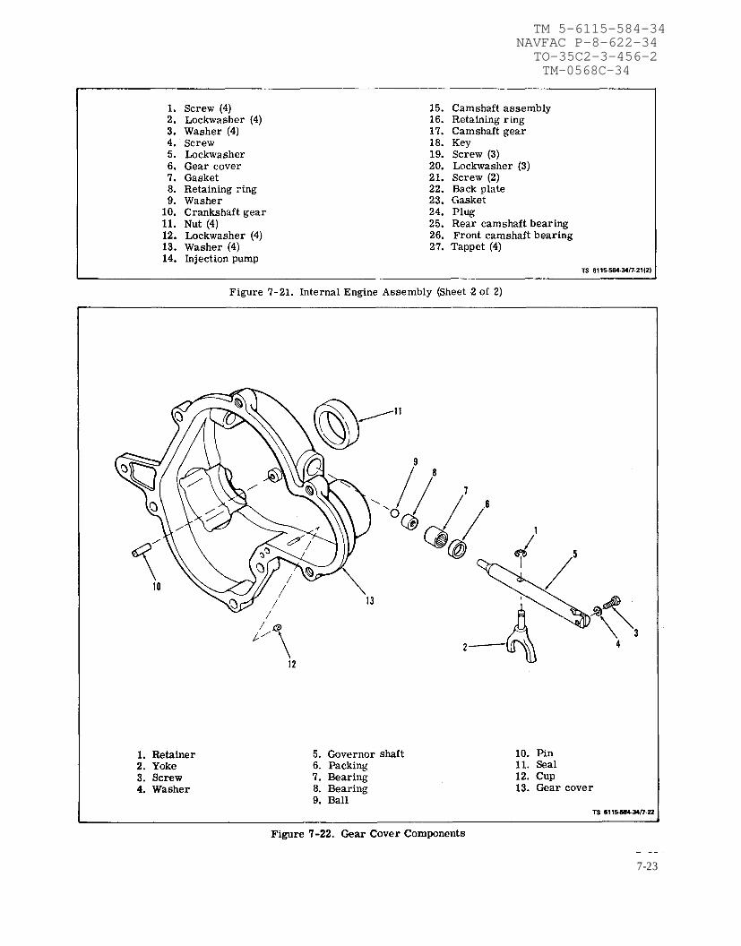
Figure 7-21.
Figure 7-22.
TM 5-6115-584-34NAVFAC P-8-622-34
TO-35C2-3-456-2TM-0568C-34
7-23

TM 5-6115-584-34NAVFAC P-8-622-34
TO-35C2-3-456-2TM-0568C-34
cover (6) to crankcase. Tape crankshaft keyway toprevent damage to seal. To loosen gear cover, tap itwith a soft hammer. Remove gasket (7).
c. Disassemble and Inspect.
(1) Governor Shaft (see figure 7-22). The gover-nor shaft (5) is supported by two sets of needle bear-ings (7). To remove shaft, remove retainer (1) andyoke (2) and pull shaft (5) from gear cover (13). Ifshaft is binding, clean bearings, if loose, replacebearings. To remove larger bearing (7) drive bearingoil seal (11) out from the outside of gear cover. Re-move smaller bearing (8) with bearing puller. Pressnew bearings and oil seal into place.
(2) Gear Cover Oil Seal (see figure 7-22). Re-place oil seal if damaged or worn. Drive old seal(11) out from inside gear cover (13). Lay cover on a
board so seal boss is supported. Insert new seal frominside with rubber lip and closed case toward outsideof gear cover and drive it flush with outside surface.
d. Reassemble.
(1) Work governor shaft to check for binding andsee that governor-shaft-end-thrust ball is in place(see figure 7-23).
(2) Turn governor yoke so smooth side (convexsurface) is toward governor cup (12, figure 7-22) oncamshaft.
(3) Turn governor cup so the stop pin (figure 7-23)in the gear cover will fit into one of the holes in cupsurface. Measure the distance from end of roll pin tomounting face of the cover. It should be 25/32 inch.If it is not, replace pin. Pin should be positioned withopen end facing crankshaft seal.
Figure 7-23. Gear Cover Inspection
7-24

e. Install (see figure 7-21).
(1) Pack the cavity between the two oil seal lipswith grease per MIL-G-23827.
(2) Tape keyway and sharp edges on crankshaftto protect the oil seal during installation.
(3) Mount gear cover (6) on engine using newgasket (7), screws (1 and 4), lockwashers (2and 5),and flatwasher (3). Tighten mounting screws to speci-fied torque. See table 1-1. Before tightening screws,be sure stop pin is in governor hole.
(4) Refer to Operator and OrganizationalMaintenance Manual and install starter lockoutswitch.
(5) Connect governor arm (3, figure 7-2) togovernor shaft (5, figure 7-22) and tighten screw (3).
(6) Refer to paragraphs 7-7 and 7-8 and installstator and blower wheel.
(7) Refer to Operator and OrganizationalMaintenance Manual and install blower housing.
7-15. GOVERNOR CUP.a. Remove (see figure 7-24). On ASK equipped generator refer
to Operation and Organizational Maintenance Manual and removeASK cover assembly. Remove retaining ring from camshaft centerpin and slide cup off. Be sure to catch the ten flyballs that will fall outwhen cup is removed.
b. Repair. Replace any flyballs that have flat spotsor grooves. Replace CUP if race surface is grooved orrough. The governor cup must be a free spinning fiton camshaft center pin, but should be replaced if ex-cessively loose or wobbly. Check distance the centerpin extends from the camshaft gear, this distancemust be 25/32 inch to give proper travel distance forthe cup (see figure 7-24). If it is less, the engine mayrace; if more, the cup will not hold the balls properly.If distance is too great, drive or press center pin in.If it is too small, replace pin; it cannot be removedwithout damaging the surface. If aluminum ball spaceropenings are badly worn, replace ball spacer. (Cam-shaft must be removed for this. )
c. Install. To install governor assembly, fill flyball recesses withgrease MIL-G-23827 and install flyballs. Position governor cup onshaft and install retaining ring. On ASK equipped generators, referto Operator and Organizational Maintenance Manual and replacecover assembly.
7-16. CAMSHAFT ASSEMBLY AND TAPPETS.
a. Removal.
(1) Refer to Operator and OrganizationalMaintenance Manual and remove blower housing.
TM 5-6115-584-34NAVFAC P-8-622-34
TO-35C2-3-456-2TM-0568C-34
NOTETo remove and replace only the camshaftgear, it is not necessary to remove theengine from the generator. Utilize thecamshaft/crankshaft gear puller ring on2-5, in conjunction with a push-pulltype puller to insure stabilization ofthe camshaft to remove the camshaft gear.Extreme care and diligence must be ex-ercised when driving the gear back ontothe camshaft to insure not driving thecamshaft through the back of the engine.
(2) Refer to paragraph 2-9 and remove engine.
(3) Refer to Operator and OrganizationalMaintenance Manual and remove rocker arm covers.
Figure 7-24. Governor Cup Assembly
(4) Refer to paragraph 7-14 and remove gearcover.
(5) Refer to paragraph 7-18 and remove fuel in-jection pump.
Change 6 7-25

TM 5-6115-584-34NAVFAC P-8-622-34
T O - 3 5 C 2 - 3 - 4 5 6 - 2TM-0568C-34
(6) Remove crankshaft gear retaining washer (9,figure 7-21) by removing lock ring (8) on the crank-shaft.
(7) Refer to paragraph 7-9 and remove rockerarms and push rods.
(8) Refer to paragraph 7-10 and remove oil base.
(9) Lay engine on side to avoid dropping tappets(27)and remove camshaft assembly (15) as a group.If necessary, pry it out with a screwdriver betweencamshaft gear and crankcase. Remove retaining ring(16) and press gear (17) off camshaft.
(10) Remove the valve tappets (27). These can beremoved only from bottom of crankcase.
(11) Refer to paragraph 7-17 and remove crank-shaft gear.
(12) Remove back plate (22) and gasket (23) byremoving screws (19), screws (21) and lockwashers(20).
(13) Camshaft Bearings. The camshaft bearings(25 and 26, figure 7-21) should be replaced if clear-ance to camshaft is greater than specified in table1-2, bearings show cracks, breaks, burrs, excessivewear, or other defects. The camshaft to bearing clear-ance should be 0.0012 to 0.0037 inch (see table 1-2].To check rear bearing (25) remove expansion plug(24) at rear of crankcase.
b. Cleaning and Inspection. If a cam lobe has be-come slightly scored, dress it smooth with a finestone. If camshaft is badly worn or scored, replace it.
c. Installation.
(1) Press new camshaft bearings into place. Seefigure 7-25 for proper placement. Press rear bear-ing flush with bottom of expansion plug recess. Pressfront bearing in flush with crankcase front surface
so oil passages are aligned. Do not attempt to reambearings, they are a precision type. After rear bear-ing is installed, insert a new expansion plug in re-cess, using sealing compound, and expand it into placewith sharp blows at its center.
NOTE
Expansion plug must not protrude from rearface of crankcase.
(2) Install new gasket (23, figure 7-21) and backplate (22) with screws (19 and 21) and lockwashers(20),
(3) Refer to paragraph 7-17 and install crank-shaft gear.
(4) With engine laid on its side, install tappets (27,figure 7-21).
(5) Install key (18, figure 7-21) on camshaft (15),press on gear (17) and install retaining ring (16).
(6) Install camshaft assembly (15) in enginemaking sure tappets (27) are in place on push rods.Align timing marks on camshaft gear and crankshaftgear (see figure 7-26). Check gear lash (see figure7-27).
(7) Install oil base per paragraph 7-10.
(8) Install crankshaft gear retaining washer (9,figure 7-21) and retaining ring (8) on the crankshaft.
(9) Refer to paragraph 7-9 and install rockerarms.
(10) Refer to paragraph 7-18 and install fuelinjection pump.
(11) Refer to paragraph 7-14 and install gearcover.
7-26 Change 5

TM 5-6115-584-34NAVFAC P-8-622-34
TO-35C2-3-456-2TM-05682C-34
Figure 7-25. Camshaft Bearing Installation
Change 5 7-26.1/(7-26.2 blank)


TM 5-6115-584-34NAVFAC P-8-622-34
TO-35C2-3-456-2
Figure 7-26. Crankshaft and CamshaftGear Timing Marks
(12) Refer to Operator and OrganizationalMaintenance Manual and install rocker arm covers.
(13) Refer to paragraph 2-9 and install engine.
(14) Refer to Operator and OrganizationalMaintenance Manual and install blower housing.
7-17. CRANKSHAFT AND BEARINGS=
a. Removal (see figure 7-15).
(1) Refer to Operator and OrganizationalMaintenance Manual and remove blower housing.
(2) Refer to paragraph 2-9 and remove engine.
(3) Refer to paragraph 7-7 and remove blowerwheel.
(4) Refer to paragraph 7-8 and remove alternatorstator.
(5) Refer to paragraph 7-14 and remove gearcover.
(6) Refer to paragraphheads.
(7) Refer to paragraphflywheel and housing.
7-9 and remove cylinder
7-4 and 7-5 and remove
TM-0568C-34
Figure 7-27. Timing Gear Backlash
(8) Refer to paragraph 7-10 and remove oil base.
(9) Refer to paragraph 7-11 and remove oil pumpcup assembly.
(10) Remove lock ring (14) and retaining washer(15) in front of crankshaft gear (16).
(11) Pull off crankshaft gear. It has 2-1/4-20 UNCtapped holes for attaching a gear pulling ring (seefigure 7-28). Use care not to damage teeth if gear isto be re-used. Remove woodruff keys (25, figure 7-15).
(12) Refer to paragraph 7-10 and remove connec-ting rod and piston assemblies.
(13) Remcve rear bearing plate (18, figure 7-15)from crankcase. Remove gasket (22) and shims (23).
7-27

TM 5-6115-584-34NAVFAC P-8-622-34
TO-35C2-3-456-2TM-0568C-34
Figure 7-28. Crankshaft Gear Removal
(14) Remove crankshaft (26) through rear openingin crankcase.
b. Clean and Inspect.
(1) Crankshaft. Clean crankshaft and blow out alloil passages. Check journals for out-of-round, taper,grooving or ridges. Pay particular attention to ridgesor grooves on either side of oil hole areas. Unusualconditions here often point to previous neglect of oilchanges. If journal dimensions are not within limitsor journals are scored, metallize and regrind crank-shaft to standards.
(2) Bearings. Replace bearings if clearances aregreater than limits (see table 1-2), or if bearings areworn, grooved or broken.
(3) Rear Oil Seal. Inspect seal for wear or dam-age which might cause it to leak.
c. Rebuild Crankshaft. If crankshaft requires re-grinding, metallize and regrind to standards. Specialprocedures must be observed when reworking dieselcrankshafts. In addition to regrinding, the crankshaftmust be shot-peened and super-finished. Failure toshot-peen the crankpin fillets is likely to cause earlyfailure. When the shaft is reground, follow this dataand figure 7-29 to shot-peen each crankpin fillet.
(1)
(2)
(3)
Almen gauge reading, 0.012-A.
Peen with 0.019 inch diameter cast steel shot.
Peen for 30-seconds on each crankpin fillet.
Figure 7-29. Crankshaft Peening
(4) Mask off connecting rod bearing areas.
d. Installation.
NOTE
After each installation step, check crankshaftto be sure it is not frozen in place.
(1) Heat cylinder block (27, figure 7-15) and bear-ing plate (18) at 325° F (163° C) in an oven 30 minutesand press front and rear main bearings (21) intoplace, aligning bearing housing oil holes (see figure7-30).
(2) Install thrust washers (24, figure 7-15) onlocking pins (see figure 7-30).
(3) Oil bearing surfaces and install crankshaft(26, figure 7-15) from rear of crankcase, throughrear bearing plate hole.
(4) Place gasket (22) on each side of shim (23).
(5) Before installing bearing plate, tape keywayand sharp edges on crankshaft to protect the oil sealduring installation. Mount and secure rear bearingplate (18).
(6) Check crankshaft end play (see figure 7-31).Use enough rear bearing plate shims to provide 0.010
7-28

TM 5-6115-584-34NAVFAC P-8-622-34
TO-35C2-3-456-2
Figure 7-30. Crankshaft Bearing Installation
to 0.015 inch end play. If more than 0.010 inch totalthickness is required, then use a steel shim ofproper thickness and an 0.005 inch thick gasket oneach side of shim. This avoids excessive gasketcompression and maintains bolt torque. Shims areavailable in 0.005, 0.010, 0.015, and 0.020 thick-ness.
(7) Install keys (25) on crankshaft (26), then drivegear (16) into place using fabricated tool (see table2-2). Install retaining washer (15) and lock ring (14).
(8) Refer to paragraph 7-10 and install rod andpiston assemblies.
(9) Refer to paragraph 7-5 and install flywheeland housing.
(10) Refer to paragraph 7-4 and 7-5 and installflywheel and housing.
(11) Refer to paragraph 7-11 and install oil base.
(12) Refer to paragraph 7-14 and install gearcover.
(13) Refer to paragraph 7-8 and install alternatorstator. Figure 7-31. Crankshaft End Play Measurement
7 - 2 9

TM 5-6115-584-34NAVFAC P-8-622-34TO-35C2-3-456-2
(14) Refer to paragraph 7-7 and install blower wheel.
(15) Refer to paragraph 7-9 and install cylinderheads.
(16) Refer to Operator and Organizational Mainte-nance Manual and install blower housing.
7-18. FUEL INJECTION PUMP.
a. Removal (see figure 7-32).
(1) Snap off governor linkage from injection pump(1), and governor control arm and remove linkage.
(2) Refer to paragraph 7-2 and disconnect inlet andfuel return lines from pump. Tag and disconnect high pres-sure lines at injector nozzle end at injector pump.
NOTE
All fuel connections must be plugged or cappedto prevent contamination.
Figure 7-32. Injection Pump
(3) Remove four hexagon nuts (2, figure 7-32). lock-washers (3), and flatwashers (4) holding pump (1) tocrankcase and lift pump off crankcase. Be careful to retainthe shims (5) between the crankcase and pump. The correctthickness of shims as stamped on the crankcase is importantto proper pump operation; it provides the proper gear lash.This thickness does not change when a new pump isinstalled. It changes only when a new cylinder block isinstalled. To calculate new shim thickness, measure betweencamshaft and engine block pump mounting surface. Sub-tract that measurement from 1.171 inches. This will be theshim thickness. Refer to fig. 7-33A. Use Gage, Depth,Micrometer NSN5210-00-542-4602 for this measurement.
(4) When removing a pump for replacement, recordthe button thickness and port closing dimensions as stampedon the side of the pump mounting flange (figure 7- 33). Thesevalues are important in timing a new pump to the engine.
b. Disassembly (see figure 7-34). All work on injectionequipment MUST be performed in the cleanest locationpossible. No filing, scraping or sawing should be dories onthe bench where repairs are made.
(1) Clean all external dirt and grease from thepump.
The Pump Housing Must NEVER Be Clampedin a Vise.
NOTE
A special mounting fixture (see table 2-2) mustbe made to adequately secure the pump housing.
(2) Clamp the mounting fixture in a suitable vise.
(3) Install the pump into the mounting fixture, withtwo 0.3125”-18 UNC-HEX head screws.
(4) Release lock tabs (2) and remove the two controlunit retaining plate screws (1) and tab washers (2, figure7-34) and the control unit retaining plate and stop assembly(3). Carefully pull the control unit assembly (4) with plungersleeve pin (5) out of the pump housing (6). Plunger sleeve pinoccasionally may have to be removed separately. Use needlenose pliers or magnetic pencil.
(5) Remove the delivery valve cap nut (7) and gas-ket (8).
(6) Remove the delivery valve holder (9) then liftout the delivery valve spring ( 10), delivery valve assembly(11) and delivery valve spacer ( 12).
7 - 3 0 Change 7

TM 5-6115-584-34NAVFAC P-8-622-34
TO-35C2-3-456-2
Figure 7-33. Injection Pump Adjustment and Button Removal
Figure 7-33A. Pump Installed
Change 7 7-31

T M 5 - 6 1 1 5 - 5 8 4 - 3 4
NAVFAC P-8-622-34
T O - 3 5 C 2 - 3 - 4 5 6 - 2
Figure 7-34. Disassembly of Fuel Injection Pump (Sheet 1 of 2)
7 - 3 2

T M 5 - 6 1 1 5 - 5 8 4 - 3 4NAVFAC P-8-622-34
T O - 3 5 C 2 - 3 - 4 5 6 - 2TM-0568C-34
1. Retaining plate screw (2) 14. Copper gasket 27. Spring ring2. Tabwasher (2) 15. Head retaining screws (4) 28. Face gear3. Control unit retaining plate 16. Head retaining clamps (4) 29. Thrust washer
and stop assembly 17. Head assembly 30. Plunger drive pin4. Control unit assembly 18. Head’’O’’ ring 31. Timing screw5. Plunger sleeve pin 19. Head’’O’’ ring 32. Gasket6. Pump housing 20. Tappet 33. “O” ring7. Cap nut 21. “O” ring 34. Plonger sleeve8. Gasket 22. Button spring ring 35. Plunger9. Delivery valve holder 23. Plunger button 36. Control unit bore
10. Valve spring 24. Lower spring seat washer 37. Pin11. Delivery valve assembly 25. Seat 38. Flatwasher12. Valve spacer 26. Plunger spring 39. Lockwasher13. Locating screw 40. Nut
TS6115-584-34/7-34(2)
Figure 7-34. Disassembly of Fuel Injection Pump (Sheet 2 of 2)
(7) Remove the hydraulic head locating screw (13)and copper gasket (14].
(8) Remove the four head retaining screws (15)and the four head retaining clamps (16). Carefullyrest tappet on clean surface and using shaft head,hammer pump body assembly until hydraulic headassembly separates from body assembly.
(9) Remove the “O” rings (18 and 19) from thehydraulic head and the pump housing.
(10) Remove the tappet (20) and related “O” ring(21) from the face gear bore.
(11) Remove the spring ring (22) and the plungerbutton (23) from the end of the plunger (the plunger ispart of hydraulic head assembly).
(12) Invert the hydraulic head assembly and placeit in a suitable arbor press (see figure 7-35).
(13) Position tool TSE 76215 over the lower springseat washer (24, figure 7-34) and depress the plungerspring, then remove the lower seat (25).
(14) Remove lower spring seat washer (24, figure7-34) and plunger spring (26).
(15) Place the hydraulic head assembly on abench. Using two screwdrivers to carefully pry offthe face gear (28), then remove the thrust washer (29).
(16) Do not remove the plunger (35) out of thehydraulic head.
NOTE
The Plunger, Plunger Sleeve and HydraulicHead are mated Parts and must ALWAYS bekept together.
(1) Place the delivery valve assembly in testfixture TSE 76226 and secure in a suitable vise (seefigure 7-36).
c. Inspect (see figure 7-34). Figure 7-35. Removing Lower Spring Seat
7 - 3 3

TM 5-6115-584-34NAVFAC P-8-622-34
TO-35C2-3-456-2TM-0568C-34
Figure 7-36. Delivery Valve Test Assembly
(a) Insert the delivery valve spring (1) and thedelivery valve holder (2). Tighten the delivery valveholder to a torque of 70-75 ft-lbs. Figure 7-36 illus-trates the components that are to be assembled totest fixture TSE 76226 (3).
(b) Attach test fixture TSE 76226 (3) to a manual-ly operated Nozzle Test Stand.
NOTE
Always check to make certain that all externalconnections are tight and that the Nozzle TestStand is in good order.
(c) Delivery valve opening pressure is 300-600psi. Delivery valve must hold 275 psi for 30 seconds.Remove delivery valve assembly from test fixture.The delivery valve spring (1) must be free of nicks orwear (flat spots). Always replace nicked or wornsprings.
LAPPING COMPOUND MUST NOT COME INCONTACT WITH THE RELIEF PISTON DUR-ING THE LAPPING OPERATION, AND ALLLAPPING COMPOUND MUST BE REMOVEDBEFORE INSTALLING THE DELIVERYVALVE ASSEMBLY INTO THE HYDRAULICHEAD.
(d) If the delivery valve assembly is leaky,the delivery valve seat may be lapped to its corres-ponding seat in the delivery valve body with a smallquantity of suitable Lapping Compbund.
(2) If the plunger button (23, figure 7-34) isgrooved, ridged, scored, or exhibits an uneven wearpattern, it must be replaced.
(3) Install a thrust washer (29). Redate thrustwasher if damaged.
(4) Replace the plunger drive gear (28) if theteeth are worn or damaged.
7-34

Figure 7-37. Inspecting Tappet
(5) Inspect the tappet (20) for possible wear atthe contact areas. The primary contact areas are thetappet contact area and the cam contact area (figure7-37). Replace the tappet if wear indentations exceed0.002". The tappet thickness measured between theplunger button contact surface and the cam contactarea must be 0.207" or larger.
(6) The pump housing (6, figure 7-34) should bewashed in a cleaning solvent. Check all the screwthreads in the housing, damaged threads can be re-paired using thread inserts.
(7) Examine the pump housing for cracks orother damage which will cause oil leakage. Replacecracked housings.
NOTE
The control unit assembly is serviceable as aunit only. Each control unit assembly is fur-nished with a factory fitted plunger sleeve pin.
(8) Holding sleeve of control unit assembly (4),rotate lever; shaft must turn freely. If a bindingcondition exists, wash assembly in a cleaning agent,and repeat procedure. If binding condition is stillpresent, control unit assembly must be replaced. Alsocheck to make certain that weld holding lever to shaftis intact.
(9) The flat end of plunger sleeve pin (5) must bechecked for clearance in the mating slot of theplunger sleeve. If the clearance is greater than 0.0015”,the entire control unit must be replaced.
TM 5-6115-584-34NAVFAC P-8-622-34
TO-35C2-3-456-2TM-0568C-34
(10) Plunger sleeve pin (5) must fit snug but mustbe free to rotate in control unit assembly.
NOTE
New part clearance is 0.0002-0.0008”. Ifclearance exceeds 0.0015”, replace controlunit assembly.
d. Reassembly (see figure 7-34).
NOTEReplace all copper and “O” ring gaskets.
(1) After all parts have been thoroughly cleanedand inspected and after all worn units have been re-placed, dip the individual parts in clean fuel oil.
(2) Invert the hydraulic head (17) and place it ona clean bench so that the head locating slot is forward.
(3) Refer to figure 7-38 and align the plungerdrive pin (1) into the plunger (2) so that the head ofthe plunger drive pin is in the line with the distribu-tor slot. Turn the plunger drive pin until its long sideis parallel to the length of the plunger with long endup.
Figure 7-38. Assembling Hydraulic Head
7-35

TM 5-6115-584-34NAVFAC P-8-622-34
TO-35C2-3-456-2TM-0568C-34
(4) Apply a thin coat of petroleum jelly to thethrust washer (29, figure 7-34) and assemble it to thehub on the face gear (28).
(5) Carefully center spring ring (27) on hydraulichead assembly.
(6) Position the face gear (28) and thrust washer(29) over the end of the plunger and align the head ofthe plunger sleeve pin with its mating slot located onthe inside of the face gear (28).
Do not use excessive pressure. If gear willnot snap into place easily, remove gear andcheck to see that spring ring (27) is centered,and that plunger drive pin (1, figure 7-38) isproperly aligned.
(7) Press the face gear (28, figure 7-34) onto thehydraulic head (17). Make certain that the spring ring(27) snaps into its mating groove in the face gear (28).Manually operate the plunger up and down. Freemovement of the plunger indicates that the face gearhas been correctly assembled to the hydraulic head.
(8) With head still in an inverted position, raiseplunger (35) to its highest position.
(9) Apply grease to exposed position of plungerto keep it in its highest position.
(10) Install spring (26) and spring retainingwasher (24), snap spring seat (25) into place on theplunger head (35).
(11) Install the plunger button (23) onto the end ofthe plunger and secure it by snapping the spring ring(22) into its mating groove in the lower spring seat(25).
(12) Check to make sure that the button springring (22) fits tightly into its groove in the lower springseat (25). Loose spring rings (22) must be replaced.
(13) Apply a thin coat of petroleum jelly to thetappet “O” ring (21) and install it into its groove onthe tappet (20). Apply thin coat of petroleum jelly toinside of tappet. Insert the tappet (20) into the facegear (28).
(14) Apply a thin coat of petroleum jelly to thehydraulic head “O” rings (18 and 19). Insert “O” ringinto the head bore of the pump housing (6). Install the"O" ring into its groove on the upper portion of thehydraulic head. Ensure “O” rings seat properly.
(15) Clamp pump mounting fixture in a vise, in-stall pump housing in fixture, then carefully insertthe hydraulic head into the pump housing so that thelocating slot in the hydraulic head is in line with thelocating screw hole in the pump housing (not seating).
(16) Install the head locating screw gasket (14)and the head locating screw (13) into the locatingscrew hole in the pump housing (6). Slight reposition-ing of the hydraulic head maybe necessary to properlyinstall the head locating screw. DO NOT USE FORCE.Tighten screw (13) to a torque of 90 to 100 inch-pound. Install head retaining clamps (16) and screws(15). Alternately tighten screws (15) at opposite cor-ners of housing (6) to properly seat the head assem-bly (17) in the housing. Tighten screws (15) to 13 to15 ft-lbs. Insert the timing screw (31) and its gasket(32) into the timing screw hole in the pump housing.Tighten the timing screw to a torque of 20 to 25 inch-pounds.
(17) Install the delivery valve spacer (12), de-livery valve assembly (11), delivery valve spring (10)and delivery valve holder (9), tighten delivery valveholder to a torque of 70-75 ft-lbs. Install deliveryvalve cap nut (7) and gasket (8). Torque nut to 55-60ft-lbs.
(18) Insert pin (37, figure 7-34) and flatwasher(38) into lower hole of lever on control unit assembly(4) and secure with lockwasher (39) and nut (40).Tighten to 20-25 inch-pounds.
(19) Apply a film of grease, LU 3003, to the con-trol unit “O” ring (33, figure 7-34), then install "O"ring in groove in control unit assembly. Ensure that"O" ring is seated. Apply oil to plunger sleeve pin (5)and insert the plunger sleeve pin (5) into the controlunit assembly (4).
Figure 7-39. Control Unit Assembly
7 - 3 6

TM 5-6115-584-34NAVFAC P-8-622-34
TO-35C2-3-456-2TM-05682C-34
(20) Place pump in horizontal position with controlunit bore (36) facing up.
(21) Center the plunger sleeve (34) in the controlunit bore (36). Position plunger sleeve pin (5) so that theflats align with the groove in the control sleeve (34) andthe electric pencil mark (dot) faces the top of the pump.
(22) Insert control unit assembly (4) into housing(6), pressing gently until control unit seats.
Do not use force. If flange is not seated on pumphousing, rotate arm both ways with finger pres-sure control unit in.
NOTE
Rotate the control unit lever through a 360° arcto make certain that the control unit assemblyis correctly installed. Failure to rotate 360°indicates that the plunger sleeve pin (5) is notengaging the plunger sleeve slot.
(23 ) Install control unit assembly retaining plate, asshown in figure 7-39 using two tab washers and twoscrews. Torque screws to 20-25 inch-pounds and bendlocking tabs over screws.
NOTE
If control unit will not seat, pull it out and re-peat steps (20 ) through (22).
Figure 7-40. Checking Plunger Sleeve Alignment
Figure 7-41. Pressure Testing Injection Pump
e. Test.
(1) Turn pump upside down and depress tappetwith thumb. Tappet should recede 1/16” into face gear(figure 7-40). If tappet cannot be depressed 1/16” intoface gear, plunger sleeve pin (5, figure 7 -34) is improperlyaligned. Disassemble pump and re-align pin.
(2) Remove the overflow valve assembly from thefuel outlet hole in the pump housing. Install a 1/4” pipeplug into the fuel outlet hole.
(3) Secure the pump close to a Nozzle Test Stand.
(4) Cap outlet ports (see figure 7-41).
(5) Install C-clamp on injection pumps as shown infigure 7-41 to retain face gear.
(6) Align holes in face gear and housing (see figure7-41).
(7) Connect the Nozzle Test Stand to the fuel inlethole in the pump housing.
7-37

TM 5-6115-584-34NAVFAC P-8-622-34TO-35C2-3-456-2TM-05862C-34
NOTE
A fuel inlet stud can be fabricated with a 1/4 “-18NPT pipe die. High pressure tubing must beused between the Nozzle Test Stand and thepump assembly.
NOTE
Always check to make sure that all external con-nections are tight and that the Nozzle Test Standis in good order.
(8) Slowly operate the Nozzle Test Stand until apressure of 400 psi is achieved. A rapid drop in pressureindicates that a leak is present. The pressure must remainabove 250 psi for at least 30 seconds.
DO NOT EXCEED A PRESSURE OF 400 PSI.
(9) Visual inspection should be as follows:
(a) Check for leakage by the head locating screw(13, figure 7-34).
(b) Slight leakage by control unit shaft is normaland is necessary to lubricate shaft. Fuel leakage betweenthe control unit body (4) and pump housing (6) indicatesthat either the “O” ring (33 ) is damaged or the matingsurfaces are damaged. Replace the “O” ring (33 ) and re-test the pump. If fuel leakage is excessive at control unitshaft or continues past “O” ring (33) replace defectiveparts.
(c) Check for leakage of fuel around the face gear(28 ). If leakage is evident, disassemble pump and inspect“O” ring (19).
(d) Check for fuel leakage between top of housingand head flange. To correct, disassemble and replaceupper hydraulic head “O” ring (18).
f. Install (Method 1).
(1) Turn engine flywheel to the port closing mark(PC) on the front cylinder (closest to blower wheel) com-pression stroke (see figure 7-44 ).
(2) Remove timing hole screw located on pumpmounting flange (figure 7-42). Insert a 1/8 inch diameterwire into the hole.
(3) Rotate pump face gear until wire slips into place,locking the gear in position.
(4) Mount pump on crankcase (see figure 7-32) (besure shims (5) are in place) and secure in position usingfour hexagon nuts (2), flatwashers (4) and Iockwashers(3). If “O” ring seal between pump and crankcase is worn,cracked or otherwise defective, replace it.
(5) Remove wire. Install timing hole screw andcopper gasket.
Figure 7-42. Injection Pump Installation
g. Install (Alternate Method 2).
(1) If pump was not timed by method 1, time nowusing alternate method 2 below.
(2) Connect flexible fuel inlet line to pump inlet.Connect fuel return line.
(3) Connect each fuel outlet line to the proper pumpoutlet (see paragraph 7-2).
(4) Connect governor linkage to governor arm.
(5) Start and run engine. Adjust governor linkage ifrequired (see paragraph 7-3).
A maximum trottle stop screw, located on theinjection pump control assembly, limits the max-imum amount of fuel which can be injected intothe engine. This screw should not be tamperedwith; it has been properly adjusted at the factoryto protect the engine from over-fueling (seefigure 7-33).
h. Adjust/Time on Equipment.
(1) Time the injection pump to the engine by usingthe proper thickness timing button between pump plungerand tappet (see figure 7-33). Use method 1 when replacingan old pump if the port closing dimensions and bottomnumber of the old pump were recorded. Use method 2 ifthe dimensions are lost, an old pump is being timed, orwhen replacing either the camshaft or crankshaft.
7 - 3 8 Change 5

(2) Timing Method 1. This is a means for calcu-lating the correct button thickness before the pump isinstalled. It requires the port closing dimensions andbutton thickness from the pump being replaced. Sub-stitute the dimensions for those in the formula belowand calculate the new button thickness. Determine thebutton code letter from table 7-1.
Example Formula:
Port closing dimension of old pump(removed from engine) . . . . . . . . . . 1.093
TM 5-6115-584-34NAVFAC P-8-622-34TO-35C2-3-456-2TM-0568C-34
NOTE
Always use button thickness closest to thisdimension.
Install the correct button in pump (figure 7-33) andinstall pump following the instructions under injec-tion pump installation above.
(3) Timing Method 2. Flowing the Pump.
(a) Install a Number 12 or M timing button ininjection pump and install pump on engine, followinginstructions under injection pump installation above.
Button thickness of old pump . . . . . . . +0.1191.212
Port closing dimension of new pump . . . . -1.089When removing tappets which contain timing
Button thickness of new pump . . . . . . . 0.123 buttons, do not allow the portion of the injec-tion pump which has the face gear to be lifted
Use button M from its position.
Figure 7-43. Delivery Valve
7-39

TM 5-6115-584-34NAVFAC P-8-622-34
TO-35C2-3-456-2 TM-0568C-34
Table 7-1. Button Code Letter and Size
Code
No. Or Letter
16
15
14
13
12
1
2
3
4
5
S
R
P
N
M
A
B
cD
E
Part No.
147A186
147A187
147A188
147A189
147A190
147A147
147A148
147A149
147A150
147A151
Size
0.134
0.131
0.128
0.125
0.122
0.119
0.116
0.113
0.110
0.107
(b) Remove delivery valve cap nut and deliveryvalve holder (figure 7-43). A 12 point socket or boxwrench must be used on delivery valve holder to keepfrom damaging this part. Lift out delivery valve springonly, and leave it out, replacing delivery valve holder,and delivery valve cap nut and gasket.
(c) Turn blower wheel clockwise until Numberl cylinder (closest to blower wheel)is on compressionstroke, which follows closing of intake valve.
(d) Set throttle lever on injection pump to wideopen or up position (compress stop solenoid plungerspring or remove stop solenoid assembly). ConnectNumber 1 cylinder fuel line to Number l pump outletso that fuel line projects from the engine, hangingdown. Position receptacle for fuel under the line. Con-nect lines from fuel supply to transfer pumps, trans-fer pumps to filter, and filter to injection pump,operate fuel transfer pumps to obtain fuel pressureat injection pump. This can be done on the unit byturning master switch to PRIME & RUN, or just byapplying 24 volts dc across the transfer pump. Ro-tate blower wheel about one inch counterclockwise sothat P.C. mark is below timing pointer hole.
(e) Rotate blower wheel clockwise until fuelflows from Number 1 cylinder fuel line. Continuerotating slowly clockwise until fuel stops flowing. Thepoint at which fuel stops flowing from Number 1 cyl-inder fuel delivery line is the injection pump portclosing point. Stop rotation of engine at exactly theport closing point (1- 2 drops in 5-10 seconds).
(f) Check timing pointer in the timing port onthe side of the generator adapter (figure 7-44). If
Figure 7-44. Timing Port and Port Closing Mark
timing pointer coincides with the P.C. mark stampedon flywheel, the injection pump button thickness iscorrect. If the P.C. mark-on flywheel is below thepointer, injection pump is closing early, and will re-quire a thinner button. If the P.C. mark on flywheelis above the pointer, injection pump is closing lateand will require a thicker button. Each mark on fly-wheel indicates a difference of 0.006 inch buttonthickness or 2 steps in button code number. (Example:The P.C. mark on flywheel is above pointer. Thepointer indicates 1-1/2 marks difference. A button0.009 inch thicker or 3 steps difference in buttonnumber code is indicated. Since a Number 12 or Mbutton is installed, a letter R button is needed. )
(g) Remove injection pump and insert propertiming button, taking the same precautions not to liftthe assembly containing face gear, when removingtiming button.
(h) Repeat injection pump installation.
(i) Check injection port closing point by re-peating steps three through six. The timing pointershould indicate the P.C. mark on flywheel. In no caseshould pointer be more than 1/2 mark away from theP.C. mark.
(j) Install delivery valve components. Be sureall parts are clean, and assembled carefully and
7-40

TM 5-6115-584-34NAVFAC P-8-622-34
TO-35C2-3-456-2
properly. The delivery valve holder must be assembled witha twelve point wrench, and retorqued to 0-80 ft-lbs. The capnut must be retorqued to 55-60 ft-lbs.
7-19. CYLINDER BLOCK.
a. Clean and Inspect.
(1) Steam clean cylinder block to remove depositsof oil and dirt. Immerse block in solvent tank to clean outinternal passages.
(2) Inspect top surface of cylinder block, the surfacethat mates with the cylinder head, for warping. Check bothacross cylinders and in line with cylinder.
(3) Use magnetic particle method to check thecylinder block for cracks. Replace block if cracked.
(4) Cylinder walls should be free of scratches, pit-ting and scuffing. Check each cylinder with an inside readingmicrometer for out-of round and wear. See Table 1-2 forbore measurements.
b. Overhaul and Rebuild. Always de-glaze cylinderwalls. If necessary, hone or rebore the cylinder to fit the nextavailable oversize piston. Pistons and rings are available in0.005, 0.010, 0.020, 0.030 and 0.040 inch oversize. If cylin-ders do not need refinishing, remove any existing ridgesfrom top of wall with a fine stone.
c. Install. If the cylinder block requires replacement anew set of injection pump shims must be used and theinjection pump must be re-timed. The shims are suppliedwith the replacement cylinder block. Refer to paragraph7-18 a. (3) for calculation of the shim thickness.
7-20. FUEL INJECTOR.
All injector openings and injector nozzles mustbe capped when the injector is removed from theengine.
a. Removal.
(1) Remove fuel lines (3 and 7, figure 7-1) at fuelinjectors.
(2) Remove screws (1, figure 7-45), washers (2) andretaining flanges (3).
(3) Remove fuel injector (4), gasket (5), aapter (6),gasket (7), heat shield (8) and gasket (9). Separate injectorfrom other components.
Do not attempt to disassemble nozzles or adjustnozzle pressure without the proper test equip-ment. A nozzle pressure tester is essential to do
Do not allow nozzle to spray against skin. Fuelunder nozzle pressure can penetrate flesh andcause a serious infection.
b. Test. Install nozzle to be tested on a static fuel nozzletesting fixture. Increase fuel pressure until nozzle opens.Opening pressure should be 1950 ± 25 psi for a new nozzleor 1750 ± 25 psi for a used nozzle (200 hours or more). Ifnozzle opening pressure is lower, adjust to 1950 psi for a newnozzle or 1750 psi for a used nozzle (see adjustment proce-dure).
c. Adjust.
(1) Remove pipe plug (1, figure 7-46).
(2) Loosen (do not remove) cover (2).
(3) Install injector nozzle on a static fuel nozzletesting fixture.
(4) Insert a 5/32 inch hex socket key through hole incover (2).
(5) Adjust opening pressure with hex key to correctpressure ( 1750 psi for a used injector, 1950 psi for a newinjector).
(6) Tighten cover (2), and recheck opening pressure.
d. Disassemble.
NOTE
When removing and disassembling fuel injec-tors, separate and label components of eachinjector. Never interchange components ofinjectors.
Never clamp injector in a vise without soft jaws.
(1) Secure injector in a holding fixture and removenozzle cap nut (12, figure 7-46) and nozzle (9).
NOTE
Do not remove nozzle unless replacement isrequired.
(2) Install nozzle cap nut (12) loosely to protectlapped surfaces of injector body.
e. Clean. Clean injectors in a clean room on aclean work bench. Provide a van of clean diesel fuel and
this work. a supply of lint-free wiping cloths. Never use hard or
Change 7 7 - 4 1

T M 5 - 6 1 1 5 - 5 8 4 - 3 4NAVPAC P-8-622-34
T O - 3 5 C 2 - 3 - 4 5 6 - 2
Figure 7-45. Injector Nozzle Removal
7-42 *U. S. GOVERNMENT PRINTING OFFICE: 1991 - 554-030/40082 PIN: 032781-007

sharp tools, emery paper, grinding powder, or abra-sives of any kind. If necessary clean outer surfacesof nozzle body (9) with a brass brush but, do not at-
tempt to scrape carbon from nozzle surfaces, becausesevere damage to spray hole can result. Use a soft,
oil soaked cloth to clean nozzle valve. Clean interiorof nozzle cap nut.
f. Inspect. Inspect tappet surfaces of injector bodyfor nicks or roughening. If damaged, replace injectorbody.
g. Repair. If cleaning will not eliminate a nozzledefect, replace nozzle. loosening adjusting screw (3).
TM 5-6115-584-34NAVFAC P-8-622-34
TO-35C2-3-456-2TM-0568C-34
h. Assemble.
(1) Rinse valve (7, figure 7-46) and nozzle (9)thoroughly in clean fuel oil before assembly. Valvemust be free in the nozzle. Lift valve (7) about one-third out of nozzle and release; valve should slideback to seat without aid when assembly is held at 45degree angle. If necessary, work valve into nozzlebody. Using dry compressed air, blow out fuel inlet(14).
(2) Remove all pressure on nozzle spring by
Figure 7-46. Fuel Injector
7-43

TM 5-6115-584-34NAVFAC P-8-622-34
TO-35C2-3-456-2TM-0568C-34
(3) Mount injector in a suitable holding fixture.
(4) Assemble valve (7) and nozzle (9) and installon body (15).
(5) Install nozzle cap nut (12) loosely.
When tightening nozzle cap nut & not contactnozzle valve (7).
(6) Place centering sleeve TSE 773 over nozzlefor initial tightening. Remove centering sleeve afterinitial tightening to prevent it from binding betweennozzle and cap nut and tighten nozzle cap nut to 50 to55 ft-lbs.
(7) Adjust opening pressure of nozzle (see para-graph 7-20c).
i. Installation.
(1) Make sure old gasket material has been re- moved from injector.
(2) Assemble new nozzle gasket (5, figure 7-45),adapter (6), gasket (7), heat shield (8) and gasket (9)on injector (4).
(3) Install injector and assembled parts into cyl-inder head (10).
(4) Install retaining flange (3) and tighten downwith screws (1) and washers (2).
(5) Reconnect fuel lines as described in para-graph 7-2.
(6) On ASK equipped generators, refer to Operator andOrganizational Maintenance Manual and replace right panelassembly.
Figure 7-47. Centering Sleeve Installation
7-44 Change 6

TM 5-6115-584-34NAVFAC P-8-622-34
TO-35C2-3-456-2TM-0568C-34
CHAPTER 8
MAINTENANCE OF GENERATOR ASSEMBLY
Section I. DESCRIPTION AND FUNCTION
8-1. GENERAL.
Refer to Operator and Organizational MaintenanceManual for description and function of the generator.
Section II. MAINTENANCE
8-2. GENERATOR MAINTENANCE.a. Test (On Equipment) (see fgure 8-1 ). On generators equipped
with the Acoustic Suppression Kit (ASK), the ASK cover assemblymust be removed for inspection and repair and replaced at comple-tion of task. Refer to Operator and Organizational MaintenanceManual for removal and installation of ASK cover assembly.
(1) Isolate the trouble to generator or regulator.Discomect the voltage regulator at the exciter (wiresP67C16 at TB3-5 and P60E16 at TB3-6). Connect a 12volt battery in place of the regulator with the (+)terminal to TB3-6 and (-) terminal to TB3-5. Run theengine with the battery in place of the voltage regula-tor. If there is output now, the voltage regulator isbad. If there is no output, the main alternator is bad.
(2) Check generator operation. Run the set withoutan external load, if the engine appears to be loaded(dark smoke apparent) the generator may have a wind-ing short to ground. If the engine does not seem to beloaded, there may be open windings.
(3) Testing Diodes (see figure 8-1). A shorted oropen diode in the rotating rectifier assembly cancause bad generator operation. This is evident byfailure of the generator terminal voltage to build upto rated value or a terminal voltage that is too low.When these symptoms are noticed, and the more ob-vious sources of trouble, (1) and (2) above have beeneliminated, check the individual diodes of the rotatingrectifier assembly as follows:
(a) Loosen four screws (5) and rotate bellcover (7) until it can be removed over screw heads.
(b) Disconnect each diode (42) by removingnuts and washers (40 and 41).
(c) Use an ohmmeter to measure the resis-tance between the terminal end and the threaded base(heat sink) end of the diode. Reverse ohmmeter leadsand repeat the resistance measurement. A diode ingood condition will have a very high resistance forone measurement and a resistance near zero when
ohmmeter probes are reversed, Failure to obtain these twoextremes in resistance measurement indicatas a defective diodethat should be removed and replaced.
NOTE
Be sure points of ohmmeter probes are suf-ficiently long and sharp to penetrate any in-sulating varnish on diode terminals.
(4) Replacing Diodes. Diodes of the rotating rec-tifier assembly which are found to be defective or inquestionable condition can be removed and replaced asfollows:
(a) Unsolder wires from diodes.
(b) Install new diode and attaching hardware.Tighten nut (40, figure 8-1) only finger tight.
(C) Using a 25 to 40 watt soldering iron, solderleadwires to terminal of replaced diode. To protectdiode from damage due to heat caused by soldering,hold diode terminal with needle nose pliers as a heatsink and use a low melting point solder.
(d) Allow each diode to cool after soldering.Tighten diode mounting nut (40) to torque of 30 inch-pounds.
(e) Install end bell cover (7).
(f) Tighten bolts (5).
(5) Resistance. Use resistance check to locateopen circuits.
b. Removal. Refer to paragraph 2-10 for generatorremoval.
Change 6 8-1

TM 5-6115-584-34NAVFAC P-8-622-34TO-35C2-3-456-2TM-0568C-34
Figure 8-1. Generator Exploded View (Sheet 1 of 2)
8 - 2

T M 5 - 6 1 1 5 - 5 8 4 - 3 4NAVFAC P-8-622-34
T O - 3 5 C 2 - 3 - 4 5 6 - 2TM-0568C-34
Figure 8-1. Generator Exploded View (Sheet 2 of 2)
c. Disassembly (see figure 8-l).
(1) Remove screws (l), nut (2), lockwasher (3),attaching screen (4) to generator and remove screen.
(2) Remove screws (5), lockwashers (8), attachingend bell cover (7) to end bell and remove cover.
(3) Remove screws (8) and lockwashers (9) hold-ing bearing retainer (33) to the end bell (16). Removescrews (10) and Iockwashers (11) attaching end bellassembly (16) to stator assembly and remove end bellassembly.
(4) Remove "O" ring (12) from bearing housing.Remove and tag wiring harness from terminal board(20). Remove screws (19) and nuts (18) attaching ter-mtnal board to exciter stator and remove terminalboard.
(5) Remove four screws (14) and lockwasher (15)attaching exciter stator (17) to end bell (16) and re-move exciter stator.
(6) Remove eight screws (24) attaching couplingdisk (37) to rotor shaft and remove coupling, lockplate (25) and retaining ring (26).
(7) Remove generator fan (28) which is now free.Do not remove balance screw from fan (28).
(8) Remove rotor assembly from stator assembly(53).
(9) Remove screw (29), lockwasher (30) and flat-washer (31) attaching bearing (32) to rotor shaft andremove bearing, bearing retainer (33) and shaft collar(34).
(10) If necessary, remove diodes from rotor asgiven in paragraph 8-2a above.
D o n o t r e m o v e e x c i t e r r o t o r f r o m r o t o rs h a f t u n l e s s t e s t r e s u l t s i n d i c a t en e e d f o r r e p l a c e m e n t .
d. Inspect. Visually inspect windings and lead con-nections. Check that diodes are securely mounted onheat sinks. Clean dust, dirt, and grease from diodes.Clean windings and drain holes. Check that end bear-ing is not damaged or worn. Inspect cooling fan andcoupling for damage.
e. Testing Exciter Stator (Field) (High PotentialT e s t ) .
-
Observe safety regulations. The voltages usedin this test are dangerous to human life. Con-tact with the leads or the windings under testmay cause severe, and possibly fatal, shock.Arrange the high voltage leads so that they arenot in a position to be accidentally touched.Keep clear of all energized parts. Always re-duce the test voltage to zero and ground thewinding under test before making any mechan-ical or electrical adjustments on the equip-ment. When grounding out windings which havebeen tested, always connect the connectionwire to ground first, and then to the winding.Never perform this test without at least oneother person assisting. Generator frame shallbe securely grounded.
(1) General. The high potential test is performedto determine whether or not the insulation of theequipment under test is defective. It is customary todetermine whether electrical equipment will withstandnormal voltage stresses by means of a test in whichhigher voltages than normal are applied for a definite
Change 5 8-3

TM 5-6115-584-34NAVFAC P-8-622-34TO-35C2-3-456-2TM-0568C-34
period of time. The applied voltage must not be sohigh as to injure the insulation unless the insulationwas initially defective.
(2) Apparatus. Use acceptable high potential testapparatus, following the operating instructions of themanufacturer.
(3) Procedure.
(a) Adequately ground high potential apparatusto a water pipe or similar electrical ground in ac-cordance with instructions accompanying the appara-tus.
b) Disconnect or remove rectifiers and semi-conductors from the circuit prior to conducting thetests.
(c) Isolate the rotor windings, the main statorwindings, and the exciter stator windings. This isaccomplished by disconnecting the various windingsfrom any associated control circuits or other con-nections.
(d) Connect the high-voltage lead from the testapparatus to the winding or circuit under test. Whentesting stator rotor, all windings and circuits must besecurely connected to ground. When testing rotor, allstator windings and circuits must be connected toground.
(4) Test.
(a) Turn on test apparatus in accordance withmanufacturer’s instructions, after making sure thatthe initially applied voltage will be not greater than600 volts.
(b) The test voltage then shall be raised uni-formly to the required maximum. This increase shallbe accomplished in not less than 10 seconds nor morethan 30 seconds. The maximum test voltage for rotorwindings shall be equal to 1,000 volts plus twice thehighest rated voltage of the generator. The test volt-age for stator wtndings shall be equal to 10 times forexciter ceiling voltage but in no case less than 1,500volts nor more than 3,500 volts.
(c) Apply the minimum voltage for 1 minute.
(d) After 1 minute of applied maximum voltage,the voltage then shall be reduced gradually to thevoltage initially applied. This reduction shall not beaccomplished in less than 5 seconds.
(e) Turn off test apparatus. Ground the high-voltage lead of the test apparatus to make sure that nocharge remains on the windings which have been undertest.
(f) Remove the high-voltage lead from thewinding and proceed with the tests of the remainingcircuits to be tested. Make sure that all circuits notunder test are securely grounded.
(5) Results. Any evidence of insulation break-down is cause for replacement of the equipmentunder test.
f. Winding Resistance Test. Perform winding re-sistance test using a Wheatstone bridge. Follow themanufacturer’s instructions given on the bridge. Re-sistance reading should be 36 ohms ± 3.6 ohms. Checkresistance between each lead and frame. A low re-sistance shows that the stator is shorted.
g. Testing Exciter Rotor. Perform winding resis-tance test and high potential test per MIL-STD-705A,methods 401.1 and 302.1. Test between T1-T2, T2-T3, T1T3. See figure 8-2 for location of test points.Resistance for each winding should be 0.677 ohms ±0.067 ohms. Also test for shorts between windingsand between each winding and rotor core.
h. Testing Generator Stator.
(1) High Potential Test. Test generator stator asgiven in paragraph 8-2e of this manual. Replacestator having faulty insulation.
(2) Winding Resistance Test. Perform winding re-sistance test using a Kelvin bridge. Follow the manu-facturer’s instructions given on the bridge. Resis-tance readings should be made on the pins of P9 andP10 (see figure 8-3). Resistance between lead pairsT 1- T4, T2- T5, T3- T6, T7- T1 0, T8- T11 and T9
-- T1 2
should be 0.355 ± 0.036 ohms at 77°F (25°C). Referto the table in figure 8-3 for location of the terminals.Also check resistance between each pin A through Fof P9 and P10 and the stator frame. Low resistanceindicates a shorted stator.
i. Testing Generator Rotor.
(1) High Potential Test. Test generator rotor asgiven in paragraph 8- 2e of this manual. Replace rotorhaving faulty insulation.
(2) Winding Resistance Test. Perform windingresistance test using a Wheatstone bridge. Follow themanufacturer’s instructions given on the bridge. Re-sistance reading should be 3.31 ohms ±0.33 ohms.Check resistance between each lead and frame. A lowresistance indicates that the rotor is shorted, a highresistance indicates open winding.
j. Reassembly.
(1) Install diodes (42 and 43, figure 8-1) on heatsink and secure with lockwashers (41) and nuts (40).
(2) Assemble shaft collar (34), bearing retainer(33), bearing (32) to the generator shaft using screw(29), lockwasher (30) and flatwasher (31).
(3) Place rotor assembly into stator (53).
(4) Position fan (28) in housing (53).
8 - 4 Change 3

TM 5-6115-584-34NAVFAC P-8-622-34
TO-35C2-3-456-2TM-0568C-34
Figure 8-2. Testing Exciter Rotor
8 - 5

TM 5-6115-584-34NAVFAC P-8-622-34TO-35C2-3-456-2TM-0568C-34
(5) Mount coupling disc and fan assembly to therotor assembly (52) using screw (24) lock plate (25)and retaining ring (26). Bend lock tabs flat againsthead of screw (24).
(6) Mount exciter stator (17) to end bell (16)using screws (14) and lockwashers (15).
(7) Place “O” ring (12) into end bell bearinghousing, attach terminal board (20) to the exciter
stator using screws (19) and nuts (18). Connect pre-viously tagged and removed harness wire terminals.
(8) Mount end bell assembly (13) to the statorassembly (53) using screw (10) and lockwashers (11).
(9) Install bearing retainer (33) and secure to endbell (16) with lockwasher (9) and screw (6).
(10) Mount end bell cover (7) using screws (5)and lockwashers (6).
(11) Mount screen (4) to generator, secure withscrew (l), nut (2) and lockwasher (3).
k. Test After Assembly. Rotate the generatorrotor shaft to be certain it rotates freely, that bear-ings are smooth and rotor does not rub against stator.
l. Installation. Refer to paragraph 2-10 for mountingof the generator.
m. Generator Winding Data.
(1) Generator frame assembly (see figure 8-3).
(2) Generator rotor (see figure 8-5).
(3) Exciter rotor assembly (see figure 8-4).
8 - 6

NOTES
TM 5-6115-584-34NAVFAC P-8-622-34
TO-35C2-3-456-2T M - 0 5 6 8 C - 3 4
Figure 8-3. Generator Frame Assembly Winding Data8-7/(8-8 blank)

TM 5-6115-584-34NAVFAC P-8-622-34
TO-35C2-3-456-2TM-0568C-34
CR1
v
CR4
TI
<
CONNECTION DIAGRAM
Wmdmg Oata:
\ II 920 2!
\ 1“1 .88 MAX.88 MAX ~
3
4
TORQUE TO15-20 2 5
INCH POUNDS 6
7
\SECTION A-A
:::::::.s / / 132’33\8 12-15
12 13 10 14
361-4
2421111 strand of ,mem 19
0.677 + 0.067 ohms at 25°C
.22
20 23
ti
7
SLOT DETAIL FORBALANCINGSCALE: 2/1SEE NOTE 6
I -, d u Y
BP H A S E A T ,
PHASE B T5
PHASEL T3
WINDING OIAGRAM
Legend
1. Laminatlorl assembly2. Nut and washer assembly3. Insulator4. Bushing5. Washer6. Screw7. Washer8. Nut9. Diode
10. Diode11. Heat sink12. Sleeving13. Heat sink
14. Grommet15. Wire16. Splices17. Insulation sleeving18. Insulation sleeving19. Wire (# 17 AWG magnet)20. Wedge21. Wedge22. Slot insulation23. Sheet24. Insulating varmsh25. Solder
NOTES
1, Winding extensions (item 19) shall be insulated with sleeving (Item 18) from slotsto splices.
2. Connect winding extensions T4, T5 and T6 together using splice (item 16). Spliceshall be insulated with sleeving (item 17).
3. Connect 2 leads (item 15) to each winding extension Tl, T2and T3usings!Jhce(,tem 16). Splices shall heinsulated with sleeving (item 17). Solder leads (item 15)to diodes (items 9 & 10) as shown in connection diagram.
4. All splices (item 16) shall be ,nstalled in accordance with MIL-STD-454, Re-quirement 19.
5. Leads and end turns shall be tied on both ends with sleeving (item 32) at approxi-mately every other slot.
6. Exciter rotor assembly shall be within .5 oz-inch of static balance. ff required,add balance we]ghts (item 23) in slots. See slot detail for balancing.
7, Varmsb and bake in accordance with flawing No. 72-5243-1 (item 24). Outsidediameter of laminations, shaft hole, and surfaces under insulators (item 3) shallbe free of varnish. Varnish on outside diameter of laminations shall be free ofprotruding mr bubbles and other surface irregularities which may.cause inter-ference with rotation.
Figure 8-4. Exciter Rotor Assembly Winding Data
8-9/(8-10 blank)

NOTES
TM 5-6115-584-34NAVFAC P-8-622-34
TO-35C2-3-456-2TM-0568C-34
Figure 8-5. Generator Rotor Winding Data
8-11/(8-12 blank

TM 5-6115-584-34NAVFAC P-8-622-34
TO-35C2-3-456-2TM-0568C-34
CHAPTER 9
GENERATOR SET TEST AND INSPECTION AFTER REPAIR OR OVERHAUL
Section I. GENERAL REQUIREMENTS
9-1. GENERAL INFORMATION. tests and inspections specified herein. Activities per-forming maintenance on any portion of the GeneratorSet must perform those tests and inspections required
The activity performing the repair or overhaul is by the applicable component or system repair in-responsible for the performance of all applicable struction.
Section II. INSPECTION
9-2. GENERAL.Inspect entire unit for loose, missing, or damaged parts. Check thateach part is properly painted and protected against corrosive climateconditions. Check that all parts are properly stowed on unit when notin use. On ASK equipped generators, cover must be removed forinspection and test and replaced at completion of task. Refer to Oper-ator and Organizational Maintenance Manual for removal and instal-lation of ASK cover assembly.
9-3. ENGINE COOLING SYSTEM.Check that all cooling system parts are in place.Check that there is sufficient clearance between engine
fan and blower housing and grille to prevent rubbingor binding. Check that shutter assembly operatesfreely, without binding.
9-4. WIRING HARNESSES.
Inspect to see that all wiring harnesses are properlyconnected and that all connectors are tight. Check thatall wires are secured away from moving parts whichmight damage wires.
Section III. OPERATIONAL TESTS
9-5. GENERATOR AND GENERATOR CONTROL CIR-CUITRY.
Test per table 9-1.
NOTE
Resistor R3 (20, figure 6-10) in the outputcontrol box, must be adjusted as follows be-fore performing any tests:
a. Remove wire D26F16 from TB3- 1 and connect 0to 1 amp ac test ammeter as shown in figure 9-1.
b. Place output control switch in 120 position.
c. With the generator operating at rated speed(1800 RPM) the generator field can be flashed byplacing the master switch on the control box in thestart position.
d. Close the circuit interrupter and apply ratedload.
e. Adjust R3 until ammeter previously installedreads 0.6 amps. Tighten locknut on R3. R3 is now ad-justed properly.
f. Disconnect test equipment and proceed with test-ing in accordance with test schedule table 9-1.
9-6. ENGINE CONTROL CIRCUITRY.
a. Test Equipment.
(1)
(2)
(3)
Batteries, 24 volts lead acid (BT1 and 2).
Switch, SPST S1, S2).
Lamps, 24V (Ll, L2, L3, L4, L5, L6, L7).
b. Test Setup. Connect control box and test equip-ment as shown in figure 9-2.
Change 6 9-1
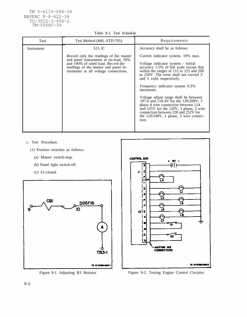
TM 5-6115-584-34NAVFAC P-8-622-34
TO-35C2-3-456-2TM-0568C-34
Table 9-1. Test Schedule
Test
Instrument
Test Method (MIL-STD-705)
513. lC
Record only the readings of the masterand panel instruments at no-load, 50%and 100% of rated load. Record thereadings of the master and panel in-struments at all voltage connections.
c. Test Procedure.
(1) Position switches as follows:
(a) Master switch-stop.
(b) Panel light switch-off.
(c) S1-closed.
Requ i r emen t s
Accuracy shall be as follows:
Current indicator system, 10% max.
Voltage indicator system - Initialaccuracy 2.5% of full scale except thatwithin the ranges of 115 to 125 and 200to 250V. The error shall not exceed 3and 5 volts respectively.
Frequency indicator system 0.5%maximum.
Voltage adjust range shall be between197.6 and 218.4V for the 120/208V, 3phase 4 wire connection between 114and 125V for the 120V, 1 phase, 2 wireconnection between 228 and 252V forthe 120/240V, 1 phase, 3 wire connec-tion.
Figure 9-1. Adjusting R3 Resistor Figure 9-2. Testing Engine Control Circuitry
9-2

d) S2-open.
(2) Place master switch in preheat position.Lamps L2 and L3 shall light indicating that the pre-heat circuitry is correct.
(3) Place master switch in start position. LampsLl, L2, L3, L4, L5 and L6 shall light indicating thatall circuits for starting are correct.
(4) With the master switch in the start position,open switch S1, lamp L1 shall extinguish indicatingthat the start disconnect circuitry is correct.
(5) With the master switch in the start position,close switch S2 and then place the master switch inthe prime and run position. Lamps L2 and L3 shallextinguish lamps L4, L5 and L6 shall remain lit in-dicating that the prime and run circuitry are correct.
(6) With the master switch in the prime and runposition and lamps L4, L5 and L6 lit, open switch S2.Lamp L4 shall extinguish indicating that the engineprotective devices circuit and the prime circuit iscorrect.
T M 5 - 6 1 1 5 - 5 8 4 - 3 4N A V F A C P - 8 - 6 2 2 - 3 4
T O - 3 5 C 2 - 3 - 4 5 6 - 2T M - 0 5 6 8 C - 3 4
(7) Repeat the procedure of step 5, except thatthe master switch shall be placed in the prime andrun aux. fuel position after closing switch S2. LampsL4, L5, L6, and L7 shall remain lit indicating thatthe prime and run aux. fuel circuitry is correct.
(8) With the master switch in the prime and runaux. fuel position and lamps L4, L5, L6 and L7 lit openswitch S2. Lamp L4 shall extinguish indicating thatthe engine protective devices circuit and the primecircuit is correct.
(9) Place master switch in the stop position, alllamps shall be out indicating that all stop circuits arecorrect.
(10) Place panel light switch in the on position,panel lights shall be on indicating that the panel lightcircuit is correct.
(11) Reposition all switches as in step 1 and dis-connect test setup.
9-3/ (9-4 blank)


TM5-6115-584-34NAVFAC P-8-622-34
TO 35C2–3-456-2TM 05682C-34
CHAPTER 10
MATERIEL USED IN CONJUNCTION WITH DOD STANDARD GENERATORSET, 5KW DIESEL ENGINE DRIVEN, MODEL MEP-002A
Section I. AUXILIARY EQUIPMENT
10-1. GENERAL.
This chapter describes all Direct Support procedures forauxiliary equipment (kits) which are used in conjunction with thegenerator set. Any effects of the auxiliary equipment on themaintenance procedures for the generator set are identified inthe maintenance procedures where they occur.
C h a n g e 6 1 0 - 1

TM5-6115-584-34NAVFAC P-8-622-34TO 35C2-3-456-2TM 05682C-34
SECTION II. ACOUSTIC SUPPRESSION KIT INSTALLATION
10-2. ACOUSTIC SUPPRESSION KIT.
The 5KW Acoustic Suppression Kit (ASK) is installed on generatorsets in either the skid or trailer configuration. Table 10-1lists ASK parts and related hardware. All required mountinghardware is supplied with the modification kit. Locate ASKassemblies, drill mounting holes and assemble as described infollowing paragraphs:
Table 10-1. Acoustic Suppression Kit Parts andRequired Hardware
the
Item Assembly Related Hardware Qty
1.
2.
3.
4.
5.
6.
10-2
Right Support(1, fig. 10-1)
Left Support(6, fig. 10-2)
Rear Panel(14, fig. 10-1)
Rear Flap(19, fig. 10-1)
Rear Closure(1, fig. 10-3)
Side Closure(9, fig. 10-3)
3/8"-l6xl/4LGHex Cap Screw3/8” Washer3/8” Nut3/8” Lockwasher3/8” Bevel WasherAdhesive Backed Teflon Tape
Use existing HardwareAdhesive Backed Teflon Tape
l/4"-2Ox3/4LGHex Cap Screw
1/4” Washer1/4” LocknutAdhesive Backed Teflon Tape
l/4-20x3/4LGHex Cap Screw
1/4” Washer1/4” Locknut
l/4"-20x3/4LGHex Cap Screw
1/4” Washer1/4” LocknutAdhesive Backed Teflon Tape
l/4"-2Ox3/4LGHex Cap Screw
1/4” Washer1/4” LocknutAdhesive Backed Teflon Tape
22222
50 in.
650 in.
484
11 3/4 in.
363
484
23 in.14 in.
242
20 1/2 in.29 1/4 in.
Change 6

TM5-6115-584-34NAVFAC P-8-622-34
TO 35C2-3-456-2TM 05682C-34
Table 10-1. Acoustic Suppression Kit Parts andRequired Hardware (Cont)
Item Assembly Related Hardware Qty
7.
8.
Exhaust Plenum(W/hose & hose clamp)(21, fig. 10-3)
Left Panel(Short Side)(2, fig. 10-5)
a. Attaches to LeftSupport Assembly
9.
10.
11.
b. Attaches To SideClosure Assembly
Right Panel(Long Side)(1, fig. 10-4)
a.
b.
c.
AttachesTo Right SupportAssembly
AttachesTo RearClosure Assembly
AttachesRear Panel
Front Panel(12, fig. 10-5)
Top Panel(16, fig. 10-5)
a.
b.
To Side andRear ClosureAssemblies
To Left, Right,and Front PanelAssemblies
45° elbow 1-1/4” 1l/4"-20x3/4LG Hex Cap Screw 41/4” Washer1/4” Locknut
Battery Terminal Covers
l/4"-2Ox3/4LGCap Hex Screw
1/4” Washer
5/16” Shoulder Screwwith 1/4 20 thread
5/16” Washer1/4” Washer1/4"-20 Locknut
l/4"-2Ox3/4LGHex Cap Screw
1/4” Washer
5/16” Shoulder Screwwith 1/4 20 thread
5/16” Washer1/4” Washer1/4"-20 Locknut
5/16” Shoulder Screwwith 1/4 20 thread
5/16” Washer
5/16” Shoulder Screwwith 1/4-20 thread5/16” Washer
5/16” Shoulder Screwwith 1/4 20 thread
5/16” Washer1/4” Washer1/4” Locknut
5/16” Shoulder Screwwith 1/4 20 thread
5/16” Washer
84
4
33
3333
5
5
2222
22
6
6
7777
1111
Change 6 10-3

TM5-6115-584-34NAVFAC P-8-622-34TO 35C2-3-456-2TM 05682C-34
10-3. PRELIMINARY PROCEDURES.
Prior to ASK installation, perform the following procedures:
a. When ASK installation is to be performed on trailermounted generator sets, ensure that generator set ground isconnected to trailer ground.
b. Refer to Operator and Organizational MaintenanceManual, paragraph 4-17, and remove the grille from the engineblower housing. Store grille and attaching hardware at owningunits facility.
10-4. ACOUSTIC SUPPRESSION KIT INSTALLATION.
a. Right Support Assembly.
(1) Refer to Operator and Organizational MaintenanceManual paragraph 4-17, and remove shroud and blower housing.
(2) Refer to figure 10–1 and locate right supportassembly (1) on skid (2). Align slots (3) in support assembly(1) with existing screw heads (4) and using support assembly (1)as template, mark the two additional mounting holes (5).
(3) Drill two 7/16 inch holes (5) into skid (2) forright support assembly (1).
(4) Cut a 50 in. length of adhesive backed teflontape (listed in Table 10-1, item 1). Apply adhesive backedteflon tape to a clean right support assembly top surface(surface that mounts against underside of skid frame). Use handpressure to remove air bubbles. Clear teflon tape away fromscrew slots.
(5) Loosen four existing screws (4) and slide rightsupport assembly (1) between skid (2) and bevel washers (6) asshown in figure 10-1, detail A.
(6) Install two each screws (7), washers (8), bevelwashers (9), lockwashers (10), and nuts (11) (as listed in Table10-1, item 1) in the two additional mounting holes (5).
(7) Torque four existing screws (4) and the two addedscrews (7) to 26 ±2 ft-lbs dry.
(8) Refer to Operator and Organizational MaintenanceManual, paragraph 4-17, and replace shroud and blower housing.
10-4 Change 6

TM5-6115-584-34NAVFAC P-8-622-34
TO 35C2-3-456-2TM 05682C-34
F i g u r e 1 0 - 1 . I n s t a l l a t i o n o f R i g h t S u p p o r t ,Rear Panel , and Rear F lap Assembl ies
Change 6 10-5

TM5-6115-584-34NAVFAC P-8-622-34TO 35C2-3-456-2TM 05682C-34
b. Left
(1)and lockwashers
Support Assembly.
Refer to figure 10-2 to remove four screws (1)(2) securing access plate (3) to AC output
control box assembly (4).
(2) Cut a 50 in. length of adhesive backed teflontape (listed in Table 10-1, item 2). Apply adhesive backedteflon tape to a clean left support assembly top surface (surfacethat mounts against underside of skid frame). Use hand pressureto remove air bubbles. Clear teflon tape away from screw slots.
(3) Loosen six existing screws (5) and slide leftsupport assembly (6) between skid (7) and bevel washers (8) asshown in figure 10-2, detail A.
(4) Torque six existing screws (5) to 26 ±2 ft-lbsdry.
(5) Refer to figure 10-2 to replace four screws (1)and lockwashers (2) which secure access plate (3) to AC outputcontrol box assembly (4).
c. Rear Panel Assembly.
CAUTI0NWhen drilling holes, careto damage fuel lines.
(1) Refer to figure 10-1
must be taken not
detail B and drill one 5/16inch guide hole (12) in generator set control cubicle supportframe (13) at location shown.
(2) Using rear panel assembly (14) as template, aligndrilled guide hole (12) with bottom left rear panel assembly holeand mark location of three remaining holes in support frame (13).Drill three 5/16 inch holes.
(3) Cut a 11 3/4 in. Length of adhesive backed teflontape (listed in Table 10-1, item 3). Apply adhesive backedteflon tape to clean right side surface of rear panel assembly(14) (surface with 2 captive nuts). Use hand pressure to removeair bubbles. Clear tape from captive nut openings.
(4) Refer to figure 10-1 to install rear panel assem-bly (14) to generator set control cubicle support frame (13) withfour screws (15), eight washers (16 and 17) and four locknuts(18) (as listed in Table 10-1, item 3).
(5) Torque screws (15) to 16 ±2 ft-lbs dry.
10-6 Change 6

TM5-6115-584-34NAVFAC P-8-622-34
TO 35C2-3-456-2TM 05682C-34
Figure 10-2. Installation of Left Support Assembly
Change 6 10-7

TM5-6115-584-34NAVFAC P-8-622-34TO 35C2-3-456-2TM 05682C-34
d. Rear Flap Assembly.
(1) Refer to figure 10-1 and using rear flap assembly(19) as template, center assembly on skid resting flap assemblyangle on top of skid (2). Mark mounting hole locations and drillthree 5/16 inch holes (20) into skid (2).
(2) Install rear flap assembly (19) to skid (2) withthree screws (21), six washers (22 and 23) and three locknuts(24) (as listed in table 10-1, item 4.)
(3) Torque screws (21) to 16 ±2 ft-lbs dry.
e. Rear Closure Assembly.
(1) Refer to Operator and Organizational MaintenanceManual paragraph 3-18 and remove air cleaner assembly.
CAUTION
When drilling holes care must be taken notto damage control cubicle.
(2) Refer to figure 10-3 and locate rear closureassembly (1) behind mounting brackets (3). Seat clips (3A) ofrear closure assembly (1) over mounting brackets (3) , so thatrear closure assembly (1) is positioned over vibration mount hard-ware. When positioned correctly, the rear closure assembly (1) is1/4 inch higher than top of control cubicle (2). Using rearclosure assembly (1) as template, mark and drill four 5/16 inchholes in mounting brackets (3).
(3) Cut a 23 in. length and a 14 in. length ofadhesive backed teflon tape (listed in Table 10-1, item 5) .Apply adhesive backed teflon tape to a clean top edge (edge withthree holes) and right edge (edge with two holes which willcontact right panel assembly) of rear closure assembly (1). Usehand pressure to remove air bubbles. Clear tape from holes.
(4) Install rear closure assembly (1) to controlcubicle support (3) with four screws (5), eight washers (6 and7), and four locknuts (8) (as listed in Table 10-1, item 5).
(5) Torque screws (5) to 16 ±2 ft-lbs dry.
(6) Refer to Operator and Organizational MaintenanceManual, paragraph 3-18, and replace air cleaner assembly removedin step e.(l).
f. Side Closure Assembly.
(1) Cut a 20 1/2 in. length and a 29 1/4 in. lengthof adhesive backed teflon tape
10-8 Change 6

TM5-6115-584-34NAVFAC P-8-622-34
TO 35C2-3-456-2TM 05682C-34
Figure 10-3. Installation of Rear and Side Closure and ExhaustPlenum Assemblies
Change 6 10-9

TM5-6115-584-34NAVFAC P-8-622-34TO 35C2-3-456-2TM 05682C-34
Apply adhesive backed teflon tape to a clean top edge (surfacewhich will mount against top panel assembly) and left edge (edgewith three holes) of side closure assembly (9). Use hand pres-sure to remove air bubbles. Clear teflon tape away from screwholes.
(2) Refer to figure 10-3 and locate side closureassembly (9) over fuel tank (10). Align side closure assemblymounting holes (11) with rear closure assembly mounting holes(12).
(3) Install side closure assembly (9) to rear closureassembly (1) with two screws (13), four washers (14 and 15) andtwo locknuts (16) (as listed in Table 10-1, item 6)
(4) Torque screws (13) to 16 ±2 ft-lbs dry.
g . Exhaust Plenum Assembly.
(1) Refer to figure 10-3 and install exhaust elbow(17) (as listed in Table 10-1, item 7) to generator exhaust (18) .Point elbow opening downward (exhaust down).
(2) Install hose (19) over sleeve (20) at bottom ofexhaust plenum (21). Install clamp (22) over hose (19) andsleeve (20).
(3) Install exhaust plenum assembly (21) over exhaustshutter assembly (23) until rear upper channel of plenum is flushwith exhaust shutter assembly (23). Screws (24) in exhaustshutter assembly (23) fit into plenum slots. (There is a 1-7/8”overlap.) Using exhaust plenum assembly (21) as template, markmounting holes (25) and drill four 5/16 inch holes in exhaustshutter assembly (23).
(4) Install exhaust plenum assembly (21) to exhaustshutter assembly (23) with four screws (26), eight washers (27and 28) and four locknuts (29) (listed in table 10-1, item 7.)
(5) Torque screws (26) to 16 ±2 ft-lbs dry.
(6) Route drain hose (19) between batteries andengine block.
h. Right Panel Assembly (Long Side).
(1) Refer to figure 10-4 and clear out acoustic fillfrom holes in right panel assembly (1) using 3/8 inch diameterpin.
(2) Locate right panel assembly (1) on right supportassembly (2) by aligning captive nuts (3) in right panel assembly(1) with holes in right support assembly (2). Align captive nuts(4) in rear panel assembly (5) with holes in right panel assembly(1). Align holes in rear closure assembly (6) with holes inright panel assembly (1).
10-10 Change 6

TM5-6115-584-34NAVFAC P-8-622-34
TO 35C2-3-456-2TM 05682C-34
Figure 10-4. Instal lat ion of Right Panel Assembly
Change 6 10-11

TM5-6115-584-34NAVFAC P-8-622-34TO 35C2-3-456-2TM 05682C-34
assembly (2) with five screws (7) and five washers (8). Installright panel assembly (1) to rear closure assembly (6) with twoscrews (9), four washers (10 and 11) and two locknuts (12).Install right panel assembly (1) to rear panel assembly (5) withtwo screws (13) and two washers (14) (listed in table 10-1,item 9.
(4) Torque screws (13) and screws (7) to 18 ±2 in.-lbs dry.
(5) Torque screws (9) to 16 ±2 ft-lbs dry.
i. Left Panel Assembly (Short Side).
(1) Refer to figure 10–5 and install battery terminalcovers (1) (listed in Table 10-1, item 8). Disconnect cableclamps from battery terminals. Place 4 each terminal covers (1)over battery terminals (2 red terminal covers for positive bat-tery terminals and 2 black terminal covers for negative batteryterminals). Reconnect cable clamps to battery terminals. Covercable clamps with terminal covers (1).
(2) Clear out acoustic fill from holes in left panelassembly (2) using 3/8 inch diameter pin.
(3) Locate left panel assembly (2) on left supportassembly (3) by aligning captive nuts (4) in panel with holes inleft support assembly (3).
(4) Install left panel assembly (2) to side closureassembly (5) with three screws (6), six washers (7 and 8) andthree locknuts (9) and to left support assembly (3) with threescrews (10) and three washers (11) (listed in table 10-1,item 8.)
(5) Torque screws (10) to 18 ±2 in.-lbs dry.
(6) Torque screws (6) to 16 ±2 ft-lbs dry.
j. Front Panel Assembly
(1) Refer to figure 10-5 and clear out acoustic fillfrom holes in front panel assembly (12) using 3/8 inch diameterpin.
(2) Install front panel assembly (12) to right panelassembly (13) and left panel assembly (2) with six screws (14)and six washers (15) (as listed in table 10-1, item 10). Startall screws by hand first.
(3) Torque screws (14) to 18 ±2 in.-lbs dry.
k. Top Panel Assembly.
(1) Refer to figure 10-5 and clear out acoustic fillfrom holes in top panel assembly (16) using 3/8 inch diameterpin.
10-12 Change 6

TM5-6115-584-34NAVFAC P-8-622-34
TO 35C2-3-456-2TM 05682C-34
Figure 10-5. Installation of Left Panel, Front Paneland Top Panel Assemblies
Change 6 10-13

TM5-6115-584-34NAVFAC P-8-622-34TO 35C2-3-456-2TM 05682C-34
(2) Locate top panel assembly (16) by aligning holesin top panel assembly (16) with captive nuts in left panelassembly (2), right panel assembly (13) and front panel assembly(12), and with holes in side closure assembly (5) and rearclosure assembly (17).
(3) Install top panel assembly (16) to left panelassembly (2), right panel assembly (13) and front panel assembly(12) with eleven screws (18) and eleven washers (19). Installtop panel assembly (16) to side closure assembly (5) and rearclosure assembly (17) with seven screws (20), 14 washers (21 and22) and seven locknuts (23) (as listed in Table 10-1, item 11).
(4) Torque screws (18) to
(5) Torque screws (20) to
1 0 - 5 . POST INSTALLATION PROCEDURES.
WARNING
18 ± 2 in.-lbs dry.
16 ±2 ft-lbs dry.
The local safety office and PreventativeMedicine Support Activity must be consultedprior to initial CARC painting.
Inspect ASK and generator set for any areas where touch-uppainting may be required. Perform necessary touch-up painting inaccordance with MIL-T-704 using paint colors green 383, brown383, and black as required by FED-STD-595.
10-14 Change 6

1.
2.
3.
4.
5.
A P P E N D I X A
REFERENCES
PAINTING:
T.O. 35-1-3
RADIO SUPPRESSION:
MIL-STD-461
MAINTENANCE:
T.O. 00-25-225T.O. 00-25-235
T.O. 1-1-1T.O. 1-1-2T.O. 31-1-75T.O. 35-1-11
T.O. 35-1-12T.O. 35-1-26
T.O. 35-1-524
T.O.34Y19-1-111AFM 66-1T.O.35C2-3-1-426
SHIPMENT AND STORAGE:
T.O. 35-1-4
T.O. 38-1-5
DESTRUCTION OF MATERIAL:
TM 750-244-3
TM 5-6115-584-34NAVFAC P-8-622-34
TO-35C2-3-456-2TM-0568C-34
Painting and marking of USAF Aerospace Ground Equipment.
Radio Interference Suppression.
Repair of External Power Cables, Aerospace Ground Equipment.General Shop Practice Requirements for the Repair, Maintenance andTest of Electric Equipment.Cleaning of Aerospace Equipment.Corrosion Control and Treatment for Aerospace Equipment.General Maintenance Practices.Organization, Intermediate and Depot Level Maintenance for FSC 6115Equipment.Components and Procedures for Cleaning Aerospace Ground Equipment.Repair/Replacement Criteria for FSC 6115 Aerospace Ground Equip-ment.USAF Equipment Registration Number System Applicable to FSC 6115Equipment.Electric Motor and Generator Repair.AF Maintenance Management.Inspection and Maintenance of FSC 6115 Electrical Generator Set.
Processing and Inspection of Aerospace Ground Equipment for Storageand Shipment.Processing and Inspection of Non-Mounted, Non-Aircraft Gasoline andDiesel Engines for Storage and Shipment.
Procedures for Destruction of Equipment to Prevent Enemy Use.
A-l/ (A-2 blank)


T M 5 - 6 1 1 5 - 5 8 4 - 3 4N A V F A C P - 8 - 6 2 2 - 3 4
T O - 3 5 C 2 - 3 - 4 5 6 - 2T M - 0 5 6 8 C - 3 4
ALPHABETICAL INDEX
Subject
AC Instrumentation System
A
. . . . . . . . . . . . . . . . . . . . . . . . . . . . . . . . . . . . . . . . . . .Acoustic Suppression Kit, Tabulated Data . . . . . . . . . . . . . . . . . . . . . . . . . . . . . . . . .Acoustic Suppression Kit. . . . . . . . . . . . . . . . . . . . . . . . . . . . . . . . . . . . . . . .
Installation . . . . . . . . . . . . . . . . . . . . . . . . . . . . . . . . . . . . . . . . . . . . . . . . . . . .
Parts and Hardware Required. . . . . . . . . . . . . . . . . . . . . . . . . . . . . . . . . . . . . .Preliminary Procedures . . . . . . . . . . . . . . . . . . . . . . . . . . . . . . . . . . . . . . . . . . .Post Installation Procedures. . . . . . . . . . . . . . . . . . . . . . . . . . . . . . . . . . . . . . . .
AC Output Control Box Assembly . . . . . . . . . . . . . . . . . . . . . . . . . . . . . . . . . . . . . . .
Internal Components . . .Removal . . . . . . . . . . .Test Set-UpWiring Harness . . . . . . .
Auxiliary Equipment . . . . .
Battery Charging AlternatorBlower Wheel . . . . . . . .Bridge Rectifier Assembly .
Testing . . . . . . . . .
Camshaft . . . . . . . .Camshaft Bearing InstallationCentering Sleeve InstallationConnecting Rod and BushingsConnecting Rod Installation .Control Cubicle
Removal. . . . . . . . . .Wiring Harness . . . . .
Control Unit Assembly . . ,Cooling System . . . . . . .
Description and FunctionInspection . . . . . . . .Maintenance . . . . . . .
Crankshaft and Bearings . Installation . . . . . . .
. . . . . . . . . . . . . . . . . . . . . . . . . . . . . . . . . . .
. . . . . . . . . . . . . . . . . . . . . . . . . ... .. . .
. . . . . . . . . . . . . . . . . . .. . . .. . . . . .
. . . . . . . . . . . . . . . . .... . . . . . . . . . . . . . . .
. . . . . . . . . . . . . . . . . . . . . . . . . . . . . . . . . ...
B
. . . . . . . . . . . . . . . . . . . . . . . . . . . . .
. . . . . . . . . . . . . . . . . . . . . . . . . . . . .
. . . . . . . . . . . . . . . . . . . . . . . . . . . . .
. . . . . . . . . . . . . . . . . . . . . . . . . . . . .
c. . . . . . . . . . . . . . . . . . . . . . . . . . . . .. . . . . . . . . . . . . . . . . . . . . . . . . . . .. . . . . . . . . . . . . . . . . . . . . . . . . . . . .. . . . . . . . . . . . . . . . . . . . . . . . . . . . .. . . . . . . . . . . . . . . . . . . . . . . . . . . . .. . . . . . . . . . . . . . . . . . . . . . . . . . . . .. . . . . . . . . . . . . . . . . . . . . . . . . . . . .. . . . . . . . . . . . . . . . . . . . . . . . . . . . .. . . . . . . . . . . . . . . . . . . . . . . . . . . . .. . . . . . . . . . . . . . . . . . . . . . . . . . . . .. . . . . . . . . . . . . . . . . . . . . . . . . . . . .. . . . . . . . . . . . . . . . . . . . . . . . . . . . .. . . . . . . . . . . . . . . . . . . . . . . . . . . . .. . . . . . . . . . . . . . . . . . . . . . . . . . . . .. . . . . . . . . . . . . . . . . . . . . . . . . . . . .
Crankshaft and Camshaft Timing Marks. . . . . . . . . . . . . . . . . . . . . . . . . . . . . .Crankshaft End Play Measurement . . . . . . . . . . . . . . . . . . . . . . . . . .Crankshaft Gear Removal . . . . . . . . . . . . . . . . . . . . . . . . . . . . . . .Crankshaft Peening . . . . . . . . . . . . . . . . . . . . . . . . . . . . . . . . . .Crankshaft, Pistons and Connecting Rod . . . . . . . . . . . . . . . . . . . . . . .Cylinder Block . . . . . . . . . . . . . . . . . . . . . . . . . . . . . . . . . . . . .Cylinder Head Assembly . . . . . . . . . . . . . . . . . . . . . . . . . . . . . . .
Bolt Tightening Sequence . . . . . . . . . . . . . . . . . . . . . . . . . . . . .Removal . . . . . . . . . . . . . . . . . . . . . . . . . . . . . . . . . . . . . .
Paragraph,Figure, Table,
Number
6-21-7
10-210-4,F10-1thru F10-5
T10-110-310-56-8
F6-9, F6-106-9
F6-8F6-7
6-7, F6-6T6-310-1
7-8, F7-77-7, F7-7
F6-11T6-6
7-16F7-25F7-47F7-l7F7-19
6-4, F6-32-8
F6-1, T6-1F7-39
F3-13-19-33-2
7-17F7-30F7-26F7-31F7-28F7-29F7-15
7-197-9, F7-11
F7-13F7-9
Change 6 INDEX 1

T M 5 - 6 1 1 5 - 5 8 4 - 3 4N A V F A C P - 8 - 6 2 2 - 3 4
T O - 3 5 C 2 - 3 - 4 5 6 - 2T M - 0 5 6 8 C - 3 4
ALPHABETICAL INDEX (CONT)
Subject
D
DC Control System . . . . . . . . .Delivery Valve Test . . . . . . . .Disconnecting Engine from Generator
Engine AssemblyDescription and Function . . , .Removal . . . . . . . . . . . .
Engine Control Circuitry Test . . .Exciter Rotor
Test . . . . . . . . . . . . . . .Winding Data . . . . . . . . . .
External Governor and Speed Control
Fabricated Tools . . . . . . . . . .Flywheel Housing . . . . . . . . . .Flywheel and Ring Gear Assembly .Fuel Injection Pump
Button Code Letter and Size . .Maintenance . . . . . . . . . .Tappet lnspection . . . . . . . .
Fuel Injector Assembly . . . . . , .Removal . . . . . . . . . . . .
Fuel Lines . . . . . . . . . . . . . .
. . . . . . . . . . . . . . . . . . . . . . . . .
. . . . . . . . . . . . . . . . . . . . . . . . .. . . . . . . . . . . . . . . . . . . . . . . .
E
. . . . . . . . . . . . . . . . . . . . . . . .. . . . . . . . . . . . . . . . . . . . . . . . .. . . . . . . . . . . . . . . . . . . . . . . . .
. . . . . . . . . . . . . . . . . . . . . . . . .
. . . . . . . . . . . . . . . . . . . . . . . . .. . . . . . . . . . . . . . . . . . . . . . . .
F
. . . . . . . . . . . . . . . . . . . . . . . . .
. . . . . . . . . . . . . . . . . . . . . . . . .
. . . . . . . . . . . . . . . . . . . . . . . . .
. . . . . . . . . . . . . . . . . . . . . . . . .
. . . . . . . . . . . . . . . . . . . . . . . . .
. . . . . . . . . . . . . . . . . . . . . . . . .
. . . . . . . . . . . . . . . . . . . . . . . . .
. . . . . . . . . . . . . . . . . . . . . . . . .
. . . . . . . . . . . . . . . . . . . . . . . . .Fuel System, Description and Function . . . . . . . . . . . . . . . . . . . . . . .Fuel Tank . . . . . . . . . . . . . . . . . . . . . . . . . . . . . . . . . . . . . . .
G
Gear Cover Assembly . . . . . . . . . . . . . . . . . . . . . . . . . . . . . . . . .Inspection . . . . . . . . . . . . . . . . . . . . . . . . . . . . . . . . . . . . .
General Maintenanc . . . . . . . . . . . . . . . . . . . . . . . . . . . .Generator Assembly. . . . . . . . . . . . . . . . . . . . . . .. . . . . . . . . . . . . . . . . . . . . . . . . . . . . .
General. . . . . . . . . . . . . . . . . . . . . . .. . . . . .. . . . . . . . . . . . . . . . . . . . . . . . . . . .Maintenance . . . . . . . . . . . . . . . . . . . . . . . . . . . . . . . . . . .Removal . . . . . . . . . . . . . . . . . . . . . . . . . . . . . . . . . . . . .
Generator and Control Circuitry Test. . . . . . . . . . . . . . . .. . . . . . .Generator Frame Assembly Winding Data. . . . . . . . . . . . . . . . . . .. .. ...
. .
Generator Rotor Winding Data . . . . . . . . . . . . . . . . . . . . . . . . . . . .Generator Set
Description . . . . . . . . . . . . . . . . . . . . . . . . . . . . . . . . . . . .Electrical Schematic . . . . . . . . . . . . . . . . . . . . . . . . . . .Test and Inspection after Overhaul . . . . . . . . . . . . . . . . . . . . . . . .Wiring Harness . . . . . . . . . . . . . . . . . . . . . . . . . . . . . . . . .
Governor Cup Assembly . . . . . . . . . . . . . . . . . . . . . . . . . . . . . . .
H
High Temperature Cutout Switch . . . . . . . . . . . . . . . . . . . . . . . . . . .Hydraulic Head Assembly . . . . . . . . . . . . . . . . . . . . . . . . . . . . . . .
Paragraph,Figure, Table,
Number
6-1F7-36
F2-2
7-12-9
9-6, F9-2
F8-2F8-4
7-3
2-3, T2-27-5
7-4, F7-3
T7-17-18
F7-377-20, F7-46
F7-457-24-14-2
7-14, F7-22F7-23
2-6F8-1
8-18-2
2-109-5
F8-3F8-5
1-6F1-1
9-16-5
F6-2, T6-27-15, F7-24
3-3F7-38
I n d e x 2 Change 6

TM 5-6115-584-34NAVFAC P-8-622-34
Subject
TO-35C2-3-456-2TM-0568C-34
ALPHABETICAL INDEX (CONT)
I
Injection Pump Adjustment and Button Removal . . . . . . . . . . . . . . . . . . .Injection Pump Assembly . . . . . . . . . . . . . . . . . . . . . . .
Del ivery Valve. . . . . . . . . . . . . . . . . . . . . . . . . . . . . . . D i s a s s e m b l y . . . . . . . . . . . . . . . . . . . . . . . . . . .Installation. . . . . . . . . . . . . . . . . . . . . . . . . . . . . . . . . .P r e s s u r e T e s t . . . . . . . . . . . . . . . . . . . . . . . . . . . . .
I n j e c t o r F u e l L i n e s . . . . . . . . . . . . . . . . . . . . . . . . . . . Internal Engine Assembly. . . . . . . . . . . . . . . . . . . . . . . . . . . . . . . . . . .. . . . . . . .
L
Levels of Maintenance Accomplishment . . . . . . . . . . . . . . . . . . . . . . .Lifting Engine . . . . . . . . . . . . . . . . . . . . . . . . . . . . . . . . . . . . .Lifting Engine Generator Assembly . . . . . . . . . . . . . . . . . . . . . . . .Load Terminal Voltages. . . . . . . . . . . . . . . . . . . . . . . . . . . . . . .Lower Spring Seat Removal. . . . . . . . . . . . . . . . . . . . . . . . . . . . . .
M
ManualLimited Applicability . . . . . . . . . . . . . . . . . . . . . . . . . . . . . . .Scope . . . . . . . . . . . . . . . . . . . . . . . . . . . . . . . . . . . . . . .
Maintenance Forms and Records . . . . . . . . . . . . . . . . . . . . . . . . . . .
0
Oil By-PassValve . . . . . . . . . . . . . . . . . . . . . . . . . . . . . . . . . .Oil Cooler . . . . . . . . . . . . . . . . . . . . . . . . . . . . . . . . . . . . . . .
Testing . . . . . . . . . . . . . . . . . . . . . . . . . . . . . . . . . . . . . .Oil Filter Adapter Assembly . . . . . . . . . . . . . . . . . . . . . . . . . . . . .Oil Pump . . . . . . . . . . . . . . . . . . . . . . . . . . . . . . . . . . . . . . .
Removal . . . . . . . . . . . . . . . . . . . . . . . . . . . . . . . . . . . . .
P
Piston and Connecting Rod . . . . . . . . . . . . . . . . . . . . . . . . . . . . . .Piston Ring Installation . . . . . . . . . . . . . . . . . . . . . . . . . . . . . . . .Piston Top Dead Center Measurement . . . . . . . . . . . . . . . . . . . . . . . .Plunger Sleeve Alignment Check . . . . . . . . . . . . . . . . . . . . . . . . . . .
R
Reconnection Switch Continuity . . . . . . . . . . . . . . . . . . . . . . . . . . . .Repair Parts . . . . . . . . . . . . . . . . . . . . . . . . . . . . . . . . . . . . .Repair Standards . . . . . . . . . . . . . . . . . . . . . . . . . . . . . . . . . . .Reporting of Errors . . . . . . . . . . . . . . . . . . . . . . . . . . . . . . . . . .Resistively Loading the Batteries . . . . . . . . . . . . . . . . . . . . . . . . . .Resistor R3 Adjustment . . . . . . . . . . . . . . . . . . . . . . . . . . . . . . . .
Paragraph,Figure, Table,
Number
F7-33F7-32F7-43F7-34F7-42F7-41F7-1
F7-21
1-52-3
F2-4T6-4
F7-35
1-21-11-3
7-13, F7-207-6
F7-67-127-11
F7-10
7-10, F7-14F7-16
F7-5F7-40
T6-52-1
T1-21-4
F7-8F9- 1
Change 6 INDEX 3

TM 5-6115-584-34NAVFAC P-8-622-34
TO-35C2-3-456-2TM-0568C-34
ALPHABETICAL INDEX (CONT)
Subject
s
Solenoid Switch, Testing . . . . . . . . . . . . . . . . . . . . . . . . . . . . . . .Special Tools. . . . . . . . . . . . . . . . . . . . . . . . . . . . . . . . . . . . . . .. . . . . . . . . . . . . . . . . . . . . Speed Control Assembly. . . . . . . . . . . . . . . . . . . . . . . . . . . . . . . . . . . . . . . . Starter Armature
Testing for Grounds . . . . . . . . . . . . . . . . . . . . . . . . . . . . . . .Testing for Shorts . . . . . . . . . . . . . . . . . . . . . . . . . . . . . . . .
Starter Assembly . . . . . . . . . . . . . . . . . . . . . . . . . . . . . . . . . . .Starter Brush Replacement.. . . . . . . . . . . . . . . . . . . . . . . . . . . . .Starter Brush Spring-Checking Tension . . . . . . . . . . . . . . . . . . . . . .Starter Commutator
Checking Runout . . . . . . . . . . . . . . . . . . . . . . . . . . . . . . . . .Undercutting Mica . . . . . . . . . . . . . . . . . . . . . . . . . . . . . . .
Starter Pinion, Checking Clearance . . . . . . . . . . . . . . . . . . . . . . . . .Starting system
Description and Function . . . . . . . . . . . . . . . . . . . . . . . .Maintenance.. . . . . . . . . . . . . . . . . . . . . . .
T
Tabulated Data . . . . . . . . . . . . . . . . . . . . . . . . . . . . . . . . . . . .Test Schedule . . . . . . . . . . . . . . . . . . . . . . . . . . . . . . . . . . . . .Timing Gear Backlash . . . . . . . . . . . . . . . . . . . . . . . . . . . .Timing Portand Port Closing Mark . . . . . . . . . . . . . . . . . . . . . . . . .Torque Values . . . . .Troubleshooting . . . .
Valve Seat ReplacementValve Spring Removal .Voltage Regulator . . .
Schematic . . . . .Testing . . . . . .
. . . . . . . . . . . . . . . . . . . . . . . . . . . . . . . .
. . . . . . . . . . . . . . . . . . . . . . . . . . . . . . . .
v
. . . . . . . . . . . . . . . . . . . . . . . . . . . . . . . .
. . . . . . . . . . . . . . . . . . . . . . . . . . . . . . . .
. . . . . . . . . . . . . . . . . . . . . . . . . . . . . . . .
. . . . . . . . . . . . . . . . . . . . . . . . . . . . . . . .
. . . . . . . . . . . . . . . . . . . . . . . . . . . . . . . .
w
Paragraph,Figure, Table,
Number
F5-22-2, T2-1
F2-1, F7-2
F5-3F5-4F5-1F5-9F5-7
F5-5F5-8
F5-10
5-15-2
1-7T9- 1
F7-27F7-4, F7-44
T1-12-4, T2-3
F7-12F7-l0
6-3, 6-6F6-5F6-4
Wiring Harnesses, Inspection. . . . . . . . . . . . . . . . . . . . . . . . . . . . 9-4
INDEX 4 Change 6

T M 5 - 6 1 1 5 - 5 8 4 - 3 4NAVFAC P-8 -622-34
T O - 3 5 C 2 - 3 - 4 5 6 - 2TM-0568C-34
By Order of the Secretaries of the Army, the Navy, and the Air Force:
BERNARD W. ROGERSGeneral, United States Army
Official: Chief of Staff
PAUL T. SMITHMajor General, United States Army
The Adjutant General
D. G. ISELINRear Admiral,CEC, U. S. NavyCommander,Naval Facilities Engineering Command
DAVID C. JONES, General, USAFOfficial: Chief of Staff
JAMES J. SHEPARD, Colonel, USAFDirector of Administration
W. R. JOHNSONBrigadier General, U. S. Marine CorpsActing Deputy Chief of Staff for Installations and Logistics
Distribution:To be distributed in accordance with DA Form 12-25D, Direct and General Support maintenance require-
ments for Generator Sets, Engine Driven: 5 KW, 60 HZ.
*U. S. GOVERNMENT PRINTING OFFICE: 1991 -281- 50447326


PIN: 032781