formatted chapter 29 alternating-current circuits ssm 071108.pdf173 chapter 29 alternating-current...
TRANSCRIPT

173
Chapter 29 Alternating-Current Circuits Conceptual Problems 3 • If the frequency in the circuit shown in Figure 29-27 is doubled, the inductance of the inductor will (a) double, (b) not change, (c) halve, (d) quadruple. Determine the Concept The inductance of an inductor is determined by the details of its construction and is independent of the frequency of the circuit. The inductive reactance, on the other hand, is frequency dependent. )(b is correct.
7 • (a) In a circuit consisting of a generator and a capacitor, are there any time intervals when the capacitor receives energy from the generator? If so, when? Explain your answer. (b) Are there any time intervals when the capacitor supplies power to the generator? If so, when? Explain your answer. Determine the Concept Yes to both questions. (a) While the magnitude of the charge is accumulating on either plate of the capacitor, the capacitor absorbs power from the generator. (b) When the magnitude of the charge is on either plate of the capacitor is decreasing, it supplies power to the generator. 9 • Suppose you increase the rotation rate of the coil in the generator shown in the simple ac circuit in Figure 29-29. Then the rms current (a) increases, (b) does not change, (c) may increase or decrease depending on the magnitude of the original frequency, (d) may increase or decrease depending on the magnitude of the resistance, (e) decreases. Determine the Concept Because the rms current through the resistor is given by
ωεε
22peakrms
rmsNBA
RI === , rmsI is directly proportional to ω. )(a is correct.
11 • Consider a circuit consisting solely of an ideal inductor and an ideal capacitor. How does the maximum energy stored in the capacitor compare to the maximum value stored in the inductor? (a) They are the same and each equal to the total energy stored in the circuit. (b) They are the same and each equal to half of the total energy stored in the circuit. (c) The maximum energy stored in the capacitor is larger than the maximum energy stored in the inductor. (d) The maximum energy stored in the inductor is larger than the maximum energy stored in the capacitor. (e) You cannot compare the maximum energies based on the data given because the ratio of the maximum energies depends on the actual capacitance and inductance values.
Deleted: 171
Formatted
Chapter 29
174
Determine the Concept The maximum energy stored in the electric field of the
capacitor is given byCQU
2
e 21
= and the maximum energy stored in the magnetic
field of the inductor is given by 2m 2
1 LIU = . Because energy is conserved in an
LC circuit and oscillates between the inductor and the capacitor, Ue = Um = Utotal. ( )a is correct.
17 • True or false: (a) A transformer is used to change frequency. (b) A transformer is used to change voltage. (c) If a transformer steps up the current, it must step down the voltage. (d) A step-up transformer, steps down the current. (e) The standard household wall-outlet voltage in Europe is 220 V, about twice
that used in the United States. If a European traveler wants her hair dryer to work properly in the United States, she should use a transformer that has more windings in its secondary coil than in its primary coil.
(f) The standard household wall-outlet voltage in Europe is 220 V, about twice that used in the United States. If an American traveler wants his electric razor to work properly in Europe, he should use a transformer that steps up the current.
(a) False. A transformer is a device used to raise or lower the voltage in a circuit. (b) True. A transformer is a device used to raise or lower the voltage in a circuit. (c) True. If energy is to be conserved, the product of the current and voltage must be constant. (d) True. Because the product of current and voltage in the primary and secondary circuits is the same, increasing the current in the secondary results in a lowering (or stepping down) of the voltage. (e) True. Because electrical energy is provided at a higher voltage in Europe, the visitor would want to step-up the voltage in order to make her hair dryer work properly. (f) True. Because electrical energy is provided at a higher voltage in Europe, the visitor would want to step-up the current (and decrease the voltage) in order to make his razor work properly.

Alternating-Current Circuits
175
Alternating Current in Resistors, Inductors, and Capacitors 19 • A 100-W light bulb is screwed into a standard 120-V-rms socket. Find (a) the rms current, (b) the peak current, and (c) the peak power. Picture the Problem We can use rmsrmsav IP ε= to find rmsI , rmspeak 2II = to find
peakI , and peakpeakpeak εIP = to find peakP .
(a) Relate the average power delivered by the source to the rms voltage across the bulb and the rms current through it:
rmsrmsav IP ε= ⇒rms
avrms ε
PI =
Substitute numerical values and evaluate rmsI :
A833.0A 8333.0V120W100
rms ===I
(b) Express peakI in terms of rmsI :
rmspeak 2II =
Substitute for rmsI and evaluate peakI : ( )A18.1
A 1785.1A8333.02peak
=
==I
(c) Express the maximum power in terms of the maximum voltage and maximum current:
peakpeakpeak εIP =
Substitute numerical values and evaluate peakP :
( ) ( ) W200V1202A1785.1peak ==P
21 • What is the reactance of a 1.00-μH inductor at (a) 60 Hz, (b) 600 Hz, and (c) 6.00 kHz? Picture the Problem We can use LX L ω= to find the reactance of the inductor at any frequency. Express the inductive reactance as a function of f:
fLLX L πω 2==
(a) At f = 60 Hz: ( )( ) mΩ38.0H00.1s602 1 == − μπLX
Deleted: (a) At f = 60 Hz:
Deleted: ( )( 00.1s602 1= −πLX

Chapter 29
176
(b) At f = 600 Hz: ( )( ) mΩ77.3H00.1s6002 1 == − μπLX
(c) At f = 6.00 kHz: ( )( ) mΩ7.37H00.1kHz 00.62 == μπLX
25 • A 20-Hz ac generator that produces a peak emf of 10 V is connected to a 20-μF capacitor. Find (a) the peak current and (b) the rms current. Picture the Problem We can use Ipeak = εpeak/XC and XC = 1/ωC to express Ipeak as a function of εpeak, f, and C. Once we’ve evaluate Ipeak, we can use Irms = Ipeak/ 2 to find rmsI . Express peakI in terms of εpeak
and XC: CXI peak
peak
ε=
Express the capacitive reactance: fCC
XC πω 211
==
Substitute for XC and simplify to obtain:
peakpeak 2 επfCI =
(a) Substitute numerical values and evaluate peakI :
( )( )( )mA25mA1.25
V10F20s202 1peak
==
= − μπI
(b) Express rmsI in terms of peakI :
mA182mA1.25
2peak
rms ===I
I
Undriven Circuits Containing Capacitors, Resistors and Inductors 29 • (a) What is the period of oscillation of an LC circuit consisting of an ideal 2.0-mH inductor and a 20-μF capacitor? (b) A circuit that oscillates consists solely of an 80-μF capacitor and a variable ideal inductor. What inductance is needed in order to tune this circuit to oscillate at 60 Hz? Picture the Problem We can use T = 2π/ω and LC1=ω to relate T (and hence f) to L and C.
Deleted: (b) At f = 600 Hz:
Deleted: ( )( 0.1s6002 1= −πLX
Deleted: (c) At f = 6.00 kHz:
Deleted: ( )(1kHz 00.62= πLX
Alternating-Current Circuits
177
(a) Express the period of oscillation of the LC circuit: ω
π2=T
For an LC circuit:
LC1
=ω
Substitute for ω to obtain:
LCT π2= (1)
Substitute numerical values and evaluate T:
( )( ) ms3.1F20mH0.22 == μπT
(b) Solve equation (1) for L to obtain: CfC
TL 222
2
41
4 ππ==
Substitute numerical values and evaluate L: ( ) ( )
mH88F80s604
1212
==− μπ
L
33 ••• An inductor and a capacitor are connected, as shown in Figure 29-30. Initially, the switch is open, the left plate of the capacitor has charge Q0. The switch is then closed. (a) Plot both Q versus t and I versus t on the same graph, and explain how it can be seen from these two plots that the current leads the charge by 90º. (b) The expressions for the charge and for the current are given by Equations 29-38 and 29-39, respectively. Use trigonometry and algebra to show that the current leads the charge by 90º. Picture the Problem Let Q represent the instantaneous charge on the capacitor and apply Kirchhoff’s loop rule to obtain the differential equation for the circuit. We can then solve this equation to obtain an expression for the charge on the capacitor as a function of time and, by differentiating this expression with respect to time, an expression for the current as a function of time. We’ll use a spreadsheet program to plot the graphs. Apply Kirchhoff’s loop rule to a clockwise loop just after the switch is closed:
0=+dtdIL
CQ
Because :dtdQI = 02
2
=+CQ
dtQdL or 01
2
2
=+ QLCdt
Qd
The solution to this equation is: ( )δω −= tQtQ cos)( 0
where LC1
=ω

Chapter 29
178
Because Q(0) = Q0, δ = 0 and:
tQtQ ωcos)( 0=
The current in the circuit is the derivative of Q with respect to t: [ ] tQtQ
dtd
dtdQI ωωω sincos 00 −===
(a) A spreadsheet program was used to plot the following graph showing both the charge on the capacitor and the current in the circuit as functions of time. L, C, and Q0 were all arbitrarily set equal to one to obtain these graphs. Note that the current leads the charge by one-fourth of a cycle or 90°.
-1.2
-0.6
0.0
0.6
1.2
0 2 4 6 8 10
t (s)
ChargeCurrent
Q (m
C)
I (m
A)
-1.2
-0.6
0.0
0.6
1.2
(b) The equation for the current is:
tQI ωω sin0−= (1)
The sine and cosine functions are related through the identity: ⎟
⎠⎞
⎜⎝⎛ +=−
2cossin πθθ
Use this identity to rewrite equation (1):
⎟⎠⎞
⎜⎝⎛ +=−=
2cossin 00
πωωωω tQtQI
Thus, the current leads the charge by 90°.
Driven RL Circuits 35 •• A coil that has a resistance of 80.0 Ω has an impedance of 200 Ω when driven at a frequency of 1.00 kHz. What is the inductance of the coil? Picture the Problem We can solve the expression for the impedance in an LR circuit for the inductive reactance and then use the definition of XL to find L.

Alternating-Current Circuits
179
Express the impedance of the coil in terms of its resistance and inductive reactance:
22LXRZ +=
Solve for XL to obtain: 22 RZX L −=
Express XL in terms of L: fLX L π2=
Equate these two expressions to obtain:
222 RZfL −=π ⇒f
RZLπ2
22 −=
Substitute numerical values and evaluate L:
( ) ( )( )
mH2.29
kHz00.12Ω0.80Ω200 22
=
−=
πL
39 •• A coil that has a resistance R and an inductance L has a power factor equal to 0.866 when driven at a frequency of 60 Hz. What is the coil’s power factor if it is driven at 240 Hz? Picture the Problem We can use the definition of the power factor to find the relationship between XL and R when the coil is driven at a frequency of 60 Hz and then use the definition of XL to relate the inductive reactance at 240 Hz to the inductive reactance at 60 Hz. We can then use the definition of the power factor to determine its value at 240 Hz. Using the definition of the power factor, relate R and XL: 22
cosLXR
RZR
+==δ (1)
Square both sides of the equation to obtain:
22
22cos
LXRR+
=δ
Solve for ( )Hz602LX : ( ) ⎟
⎠⎞
⎜⎝⎛ −= 1
cos1Hz60 2
22
δRX L
Substitute for cosδ and simplify to obtain:
( )( )
231
222 1
866.01Hz60 RRX L =⎟⎟
⎠
⎞⎜⎜⎝
⎛−=
Use the definition of XL to obtain: ( ) 222 4 LffX L π= and ( ) 222 4 Lf'f'X L π=
Chapter 29
180
Dividing the second of these equations by the first and simplifying yields:
( )( ) 2
2
22
22
2
2
44
ff'
LfLf'
fXf'X
L
L ==ππ
or
( ) ( )fXff'f'X LL
22
2⎟⎟⎠
⎞⎜⎜⎝
⎛=
Substitute numerical values to obtain: ( ) ( )
22
22
1
12
316
3116
Hz60s60s240Hz240
RR
XX LL
=⎟⎠⎞
⎜⎝⎛=
⎟⎟⎠
⎞⎜⎜⎝
⎛= −
−
Substitute in equation (1) to obtain: ( )
397.0
193
316
cos22
Hz240
=
=+
=RR
Rδ
41 •• Figure 29-33 shows a load resistor that has a resistance of RL = 20.0 Ω connected to a high-pass filter consisting of an inductor that has inductance L = 3.20-mH and a resistor that has resistance R = 4.00-Ω. The output of the ideal ac generator is given by ε = (100 V) cos(2πft). Find the rms currents in all three branches of the circuit if the driving frequency is (a) 500 Hz and (b) 2000 Hz. Find the fraction of the total average power supplied by the ac generator that is delivered to the load resistor if the frequency is (c) 500 Hz and (d) 2000 Hz. Picture the Problem 21 VV +=ε , where V1 is the voltage drop across R and V2, is the voltage drop across the parallel combination of L and RL. 21 VVε rrr
+= is the relation for the phasors. For the parallel combination, LRL
IIIrrr
+= . Also, V1 is in phase with I and V2 is in phase with
LRI . First draw the phasor diagram for the
currents in the parallel combination, then add the phasors for the voltages to the diagram.

Alternating-Current Circuits
181
The phasor diagram for the currents in the circuit is:
δ
LRI
r
LIr
Ir
Adding the voltage phasors to the diagram gives:
δ
LRI
r
LIr
Ir
tω
2Vr
1Vr
rε
δ
The maximum current in the inductor, I2, peak, is given by:
2
peak ,2peak ,2 Z
VI = (1)
where 2222
−−− += LL XRZ (2)
δtan is given by:
fLR
LR
XR
RVXV
II
LL
L
L
R
L
πω
δ
2
tanLpeak ,2
Lpeak ,2
peak ,
peak ,
===
==
Solve for δ to obtain:
⎟⎟⎠
⎞⎜⎜⎝
⎛= −
fLRπ
δ2
tan L1 (3)
Apply the law of cosines to the triangle formed by the voltage phasors to obtain:
δε cos2 peak ,2peak ,12
peak ,22peak ,1
2peak VVVV ++=
or δcos2 2peakpeak
22
2peak
22peak
22peak ZRIIZIRIZI ++=
Dividing out the current squared yields:
δcos2 222
22 RZZRZ ++=
Chapter 29
182
Solving for Z yields:
δcos2 222
2 RZZRZ ++= (4)
The maximum current peakI in the
circuit is given by:
ZI peak
peak
ε= (5)
Irms is related to peakI according
to: peakrms 2
1 II = (6)
(a) Substitute numerical values in equation (3) and evaluate δ :
( )( )
°=⎟⎟⎠
⎞⎜⎜⎝
⎛=
⎟⎟⎠
⎞⎜⎜⎝
⎛=
−
−
31.63Ω053.10Ω0.20tan
mH20.3Hz5002Ω0.20tan
1
1
πδ
Solving equation (2) for Z2 yields:
2221
−− +=
LL XRZ
Substitute numerical values and evaluate Z2:
( ) ( )Ω982.8
Ω053.10Ω0.20
1222
=
+=
−−Z
Substitute numerical values and evaluate Z:
( ) ( ) ( )( ) Ω36.1131.63cosΩ982.8Ω00.42Ω982.8Ω00.4 22 =°++=Z
Substitute numerical values in equation (5) and evaluate peakI :
A806.811.36
V100peak =
Ω=I
Substitute for peakI in equation (6) and evaluate rmsI :
( ) A23.6A806.82
1rms ==I
The maximum and rms values of V2 are given by:
( )( ) V095.79Ω982.8A806.82peakpeak 2,
==
= ZIV
and
( ) V929.55V095.792
12
1peak ,2rms,2
==
= VV

Alternating-Current Circuits
183
The rms values of rms,LRI and
rms,LI are: A80.2
Ω20.0V929.55rms,2
rms,L===
LR R
VI
and
A56.5Ω053.01V929.55rms,2
rms, ===L
L XV
I
(b) Proceed as in (a) with f = 2000 Hz to obtain:
Ω= 2.40LX , °= 4.26δ , Ω= 9.172Z , Ω= 6.21Z , A64.4peak =I , and
A28.3rms =I ,
V0.83max,2 =V , V7.58rms,2 =V ,
A94.2rms, =LRI , and A46.1rms, =LI
(c) The power delivered by the ac source equals the sum of the power dissipated in the two resistors. The fraction of the total power delivered by the source that is dissipated in load resistor is given by:
1
2rms,
2rms
1
11−−
⎟⎟⎠
⎞⎜⎜⎝
⎛+=⎟
⎟⎠
⎞⎜⎜⎝
⎛+=
+ LRR
R
RR
R
RIRI
PP
PPP
LLL
L
Substitute numerical values for f = 500 Hz to obtain:
( ) ( )( ) ( )
%2.50502.00.20A80.2
00.4A23.611
2
2
Hz500
==⎟⎟⎠
⎞⎜⎜⎝
⎛
ΩΩ
+=+
−
=fRR
R
PPP
L
L
(d) Substitute numerical values for f = 2000 Hz to obtain:
( ) ( )( ) ( )
%0.80800.00.20A94.2
00.4A28.311
2
2
Hz2000
==⎟⎟⎠
⎞⎜⎜⎝
⎛
ΩΩ
+=+
−
=fRR
R
PPP
L
L
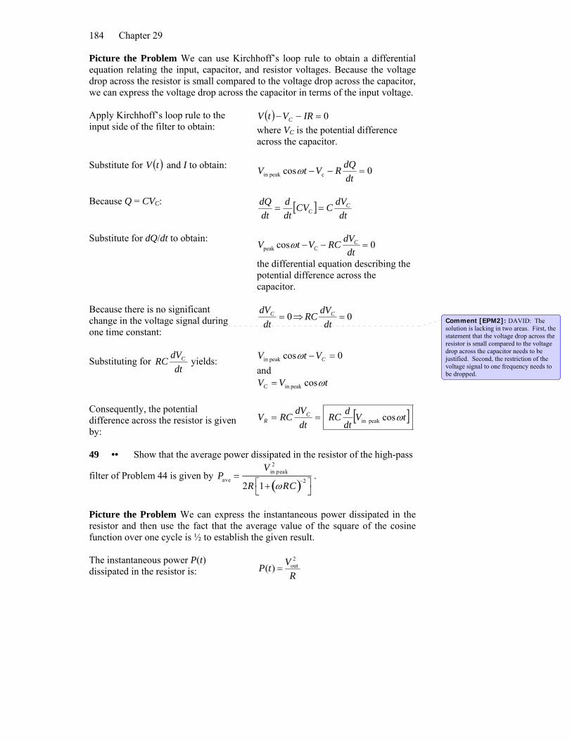
Filters and Rectifiers 47 •• A slowly varying voltage signal V(t) is applied to the input of the high-pass filter of Problem 44. Slowly varying means that during one time constant (equal to RC) there is no significant change in the voltage signal. Show that under these conditions the output voltage is proportional to the time derivative of V(t). This situation is known as a differentiation circuit.
Comment [EPM1]: DAVID: The solution is lacking in two areas. First, the statement that the voltage drop across the resistor is small compared to the voltage drop across the capacitor needs to be justified. Second, the restriction of the voltage signal to one frequency needs to be dropped.
Chapter 29
184
Picture the Problem We can use Kirchhoff’s loop rule to obtain a differential equation relating the input, capacitor, and resistor voltages. Because the voltage drop across the resistor is small compared to the voltage drop across the capacitor, we can express the voltage drop across the capacitor in terms of the input voltage. Apply Kirchhoff’s loop rule to the input side of the filter to obtain:
( ) 0=−− IRVtV C where VC is the potential difference across the capacitor.
Substitute for ( )tV and I to obtain: 0cos cpeakin =−−dtdQRVtV ω
Because Q = CVC: [ ]
dtdVCCV
dtd
dtdQ C
C ==
Substitute for dQ/dt to obtain: 0cospeak =−−
dtdVRCVtV C
Cω
the differential equation describing the potential difference across the capacitor.
Because there is no significant change in the voltage signal during one time constant:
0=dt
dVC ⇒ 0=dt
dVRC C
Substituting for dt
dVRC C yields:
0cospeakin =− CVtV ω and
tVVC ωcospeakin =
Consequently, the potential difference across the resistor is given by:
[ ]tVdtdRC
dtdV
RCV CR ωcospeakin ==
49 •• Show that the average power dissipated in the resistor of the high-pass
filter of Problem 44 is given by
Pave =V in peak
2
2R 1+ ωRC( )−2⎡⎣
⎤⎦
.
Picture the Problem We can express the instantaneous power dissipated in the resistor and then use the fact that the average value of the square of the cosine function over one cycle is ½ to establish the given result. The instantaneous power P(t) dissipated in the resistor is: R
VtP2
out)( =
Comment [EPM2]: DAVID: The solution is lacking in two areas. First, the statement that the voltage drop across the resistor is small compared to the voltage drop across the capacitor needs to be justified. Second, the restriction of the voltage signal to one frequency needs to be dropped.
Alternating-Current Circuits
185
The output voltage outV is: ( )δω −= tVV cosHout
From Problem 44:
( ) 2
peakin H
1 −+=
RC
VV
ω
Substitute in the expression for P(t) to obtain:
( )
( )[ ] ( )δωω
δω
−+
=
−=
− tRCR
V
tR
VtP
22
2peakin
22
H
cos1
cos)(
Because the average value of the square of the cosine function over one cycle is ½: ( )[ ]2
2peakin
ave 12 −+=
RCR
VP
ω
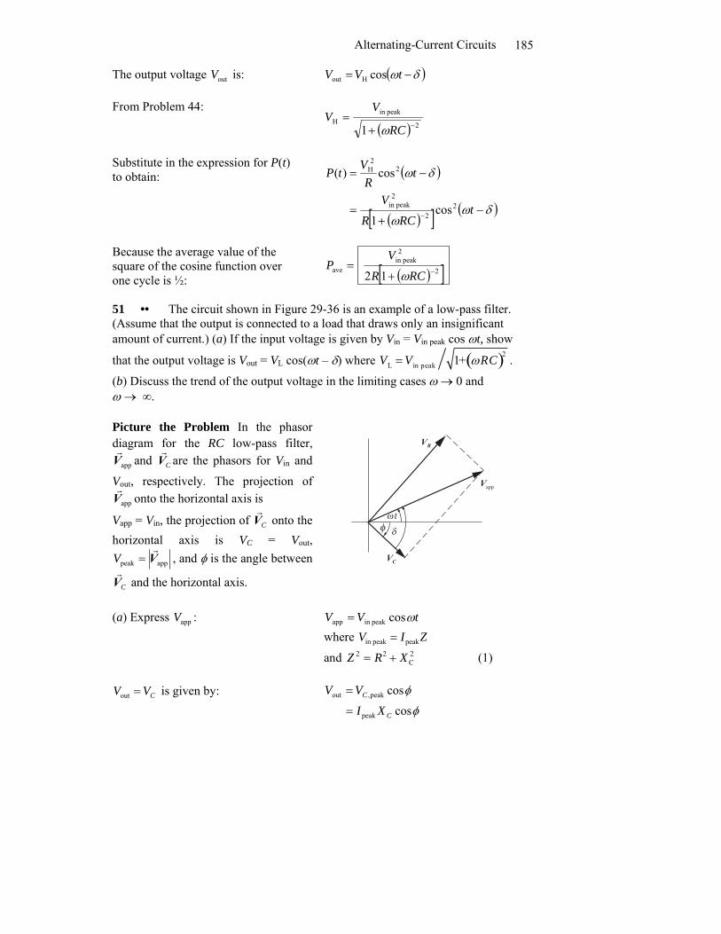
51 •• The circuit shown in Figure 29-36 is an example of a low-pass filter. (Assume that the output is connected to a load that draws only an insignificant amount of current.) (a) If the input voltage is given by Vin = Vin peak cos ωt, show
that the output voltage is Vout = VL cos(ωt – δ) where VL = V in peak 1+ ωRC( )2 .
(b) Discuss the trend of the output voltage in the limiting cases ω → 0 and ω → ∞. Picture the Problem In the phasor diagram for the RC low-pass filter,
appVr
and CVr
are the phasors for Vin and
Vout, respectively. The projection of appVr
onto the horizontal axis is
Vapp = Vin, the projection of CVr
onto the horizontal axis is VC = Vout,
apppeak Vr
=V , and φ is the angle between
CVr
and the horizontal axis.
δ
CVr
RVr
appVr
ωtφ
(a) Express appV :
tVV ωcospeakin app = where ZIV peakpeakin =
and 2C
22 XRZ += (1)
outV CV= is given by: φ
φ
cos
cos
peak
peak,out
C
C
XI
VV
=
=
Chapter 29
186
If we define δ as shown in the phasor diagram, then:
( )
( )δω
δω
−=
−=
tXZ
V
tXIV
C
C
cos
cos
peakin
peakout
Solving equation (1) for Z and substituting for XC yields:
22 1
⎟⎠⎞
⎜⎝⎛+=
CRZ
ω (2)
Using equation (2) to substitute for Z and substituting for XC yields:
( )δωω
ω
−
⎟⎠⎞
⎜⎝⎛+
= tC
CR
VV cos1
1 22
peakin out
Simplify further to obtain:
( )( )δω
ω−
+= t
RC
VV cos
1 2
peakin out
or ( )δω −= tVV cosLout
where
( )2
peakin
1 RC
VVL
ω+=
(b) Note that, as ω → 0, VL → peakV . This makes sense physically in that, for low frequencies, XC is large and, therefore, a larger peak input voltage will appear across it than appears across it for high frequencies.
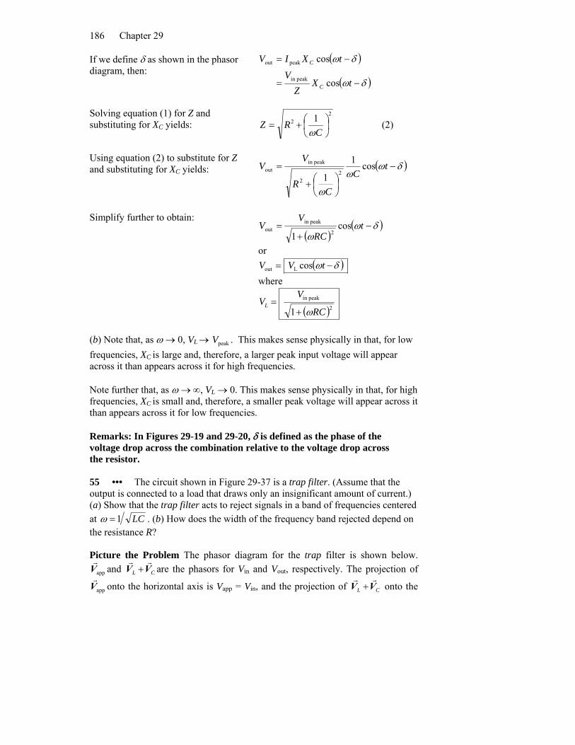
Note further that, as ω → ∞, VL → 0. This makes sense physically in that, for high frequencies, XC is small and, therefore, a smaller peak voltage will appear across it than appears across it for low frequencies. Remarks: In Figures 29-19 and 29-20, δ is defined as the phase of the voltage drop across the combination relative to the voltage drop across the resistor. 55 ••• The circuit shown in Figure 29-37 is a trap filter. (Assume that the output is connected to a load that draws only an insignificant amount of current.) (a) Show that the trap filter acts to reject signals in a band of frequencies centered at LC1=ω . (b) How does the width of the frequency band rejected depend on the resistance R? Picture the Problem The phasor diagram for the trap filter is shown below.
appVr
and CL VVrr
+ are the phasors for Vin and Vout, respectively. The projection of
appVr
onto the horizontal axis is Vapp = Vin, and the projection of CL VVrr
+ onto the
Alternating-Current Circuits
187
horizontal axis is VL + VC = Vout. Requiring that the impedance of the trap be zero will yield the frequency at which the circuit rejects signals. Defining the bandwidth as trapωωω −=Δ and requiring that RZ =trap will yield an expression for the bandwidth and reveal its dependence on R.
δ
LVr
CVr
RVr
appVr
CL VVrr
+
ω − δtωt
(a) Express appV :
tVV ωcospeak app,app = where ZIVV peakpeakpeak app, ==
and ( )222CL XXRZ −+= (1)
outV is given by: ( )δω −= tVV cospeak out,out
where trappeakpeak out, ZIV = and CL XXZ −=trap
Solving equation (1) for Z yields:
( )22CL XXRZ −+= (2)
Because :Lout CVVV += ( )
( )
( )δω
δω
δω
−=
−=
−=
tZZ
V
tZItVV
cos
coscos
trappeak
trappeak
peak out,out
Using equation (2) to substitute for Z yields:
( )δω −+
= tZZR
VV costrap2
trap2
peakout
Noting that outV = 0 provided
trapZ = 0, set trapZ = 0 to obtain:
0trap =−= CL XXZ
Substituting for XL and XC yields: 01
=−C
Lω
ω ⇒LC1
=ω
Chapter 29
188
(b) Let the bandwidth Δω be:
trapωωω −=Δ (3)
Let the frequency bandwidth be defined by the frequency at which
RZ =trap . Then:
RC
L =−ω
ω 1⇒ω2LC −1= ωRC
Because LC1
trap =ω : RCωω
ω=−⎟
⎟⎠
⎞⎜⎜⎝
⎛1
2
trap
For ω ≈ ωtrap:
RCtraptrap
2trap
2
ωω
ωω≈⎟
⎟⎠
⎞⎜⎜⎝
⎛ −
Solve for 2
trap2 ωω − : ( )( )traptrap
2trap
2 ωωωωωω +−=−
Because ω ≈ ωtrap, traptrap 2ωωω ≈+ :
( )traptrap2trap
2 2 ωωωωω −≈−
Substitute in equation (3) to obtain:
LRRC
22
2trap
trap ==−=Δω
ωωω
Driven RLC Circuits 63 •• Show that the expression 22
rmsav ZRP ε= gives the correct result for a circuit containing only an ideal ac generator and (a) a resistor, (b) a capacitor, and (c) an inductor. In the expression 22
rmsav ZRP ε= , avP is the average power
supplied by the generator, εrms is the root-mean-square of the emf of the generator, R is the resistance, C is the capacitance and L is the inductance. (In Part (a), C = L = 0, in Part (b), R = L = 0 and in Part (c), R = C = 0. Picture the Problem The impedance of an ac circuit is given by
( )22CL XXRZ −+= . We can evaluate the given expression for avP first for
XL = XC = 0 and then for R = 0. (a) For X = 0, Z = R and:
RRR
ZR
P2rms
2
2rms
2
2rms
avεεε
===
(b) and (c) If R = 0, then: ( )
( )00
2
2rms
2
2rms
av =−
==CL XXZ
RP εε

Alternating-Current Circuits
189
Remarks: Recall that there is no energy dissipation in an ideal inductor or capacitor. 65 •• Find (a) the Q factor and (b) the resonance width (in hertz) for the circuit in Problem 64. (c) What is the power factor when ω = 8000 rad/s? Picture the Problem The Q factor of the circuit is given by RLQ 0ω= , the resonance width by QQff πω 200 ==Δ , and the power factor by ZR=δcos . Because Z is frequency dependent, we’ll need to find XC and XL at ω = 8000 rad/s in order to evaluate cosδ. Using their definitions, express the Q factor and the resonance width of the circuit:
RLQ 0ω
= (1)
and
QQff
πω
200 ==Δ (2)
(a) Express the resonance frequency for the circuit: LC
10 =ω
Substituting for ω0 in equation (1) yields:
CL
RRLCLQ 1
==
Substitute numerical values and evaluate Q:
14 1.14F 2.0
mH 10Ω0.5
1===
μQ
(b) Substitute numerical values in equation (2) and evaluate Δf: ( ) Hz80
1.142rad/s1007.7Δ
3
=×
=π
f
(c) The power factor of the circuit is given by:
( ) 22
22 1cos
⎟⎠⎞
⎜⎝⎛ −+
=−+
==
CLR
R
XXR
RZR
CL
ωω
δ
Substitute numerical values and evaluate cosδ:
( ) ( )( ) ( )( )
27.0
F0.2s80001mH10s8000Ω 0.5
Ω 0.5cos2
112
=
⎟⎟⎠
⎞⎜⎜⎝
⎛−+
=
−−
μ
δ

Chapter 29
190
69 •• In the circuit shown in Figure 29-42 the ideal generator produces an rms voltage of 115 V when operated at 60 Hz. What is the rms voltage between points (a) A and B, (b) B and C, (c) C and D, (d) A and C, and (e) B and D? Picture the Problem We can find the rms current in the circuit and then use it to find the potential differences across each of the circuit elements. We can use phasor diagrams and our knowledge of the phase shifts between the voltages across the three circuit elements to find the voltage differences across their combinations. (a) Express the potential difference between points A and B in terms of
rmsI and XL:
LAB XIV rms= (1)
Express rmsI in terms of ε and Z: ( )22rms
CL XXRZI
−+==
εε
Evaluate XL and XC to obtain:
( )( )Ω=
== −
648.51mH137s6022 1ππfLX L
and
( )( )Ω=
== −
10.106F25s602
12
11 μππfC
X C
Substitute numerical values and evaluate rmsI :
( ) ( )A5556.1
10.106648.5150
V11522rms
=
Ω−Ω+Ω=I
Substitute numerical values in equation (1) and evaluate VAB:
( )( )V80
V 344.80Ω648.51A5556.1
=
==ABV
(b) Express the potential difference between points B and C in terms of
rmsI and R:
( )( )V78V 780.77
Ω50A5556.1rms
==
== RIVBC
(c) Express the potential difference between points C and D in terms of
rmsI and XC:
( )( )kV17.0V05.165
Ω10.106A5556.1rms
==
== CCD XIV
Alternating-Current Circuits
191
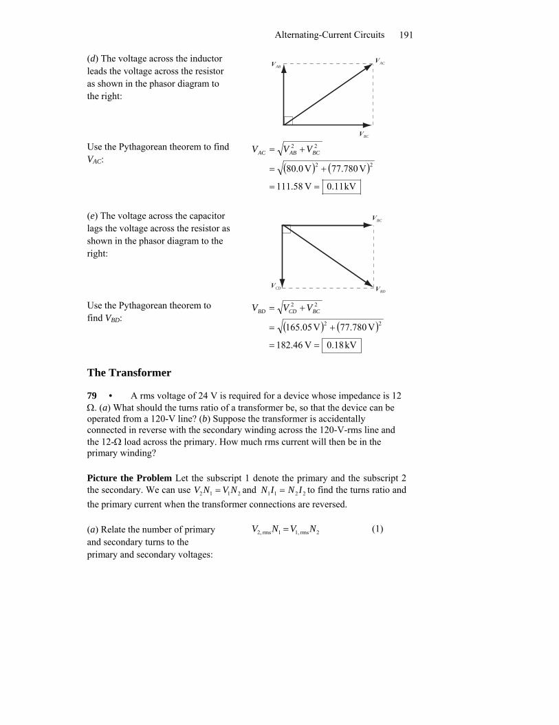
(d) The voltage across the inductor leads the voltage across the resistor as shown in the phasor diagram to the right:
ABVr
BCVr
ACVr
Use the Pythagorean theorem to find VAC:
( ) ( )kV11.0V 58.111
V780.77V0.80 22
22
==
+=
+= BCABAC VVV
(e) The voltage across the capacitor lags the voltage across the resistor as shown in the phasor diagram to the right:
BCVr
CDVr
BDVr
Use the Pythagorean theorem to find VBD:
( ) ( )kV18.0V 46.182
V780.77V05.165 22
22
==
+=
+= BCCDBD VVV
The Transformer 79 • A rms voltage of 24 V is required for a device whose impedance is 12 Ω. (a) What should the turns ratio of a transformer be, so that the device can be operated from a 120-V line? (b) Suppose the transformer is accidentally connected in reverse with the secondary winding across the 120-V-rms line and the 12-Ω load across the primary. How much rms current will then be in the primary winding? Picture the Problem Let the subscript 1 denote the primary and the subscript 2 the secondary. We can use 2112 NVNV = and 2211 ININ = to find the turns ratio and the primary current when the transformer connections are reversed. (a) Relate the number of primary and secondary turns to the primary and secondary voltages:
2rms 1,1rms 2, NVNV = (1)

Chapter 29
192
Solve for and evaluate the ratio N2/N1: 5
1V120V24
rms ,1
rms ,2
1
2 ===VV
NN
(b) Relate the current in the primary to the current in the secondary and to the turns ratio:
rms ,21
2rms ,1 I
NNI =
Express the current in the primary winding in terms of the voltage across it and its impedance:
2
rms ,2rms ,2 Z
VI =
Substitute for I2, rms to obtain:
2
rms ,2
1
2rms ,1
ZV
NNI =
Substitute numerical values and evaluate I1, rms: A50
Ω12V120
15
1 =⎟⎟⎠
⎞⎜⎜⎝
⎛⎟⎠⎞
⎜⎝⎛=I
General Problems 85 •• Figure 29-45 shows the voltage versus time for a square-wave voltage source. If V0 = 12 V, (a) what is the rms voltage of this source? (b) If this alternating waveform is rectified by eliminating the negative voltages, so that only the positive voltages remain, what is the new rms voltage? Picture the Problem The average of any quantity over a time interval ΔT is the integral of the quantity over the interval divided by ΔT. We can use this definition to find both the average of the voltage squared, ( )av
2V and then use the definition of the rms voltage. (a) From the definition of rmsV we have:
( )av2
0rms VV =
Noting that 20
20 VV =− , evaluate
rmsV :
V1202
0rms === VVV
Comment [DN3]: Needs checking … the 4e gets 10 A

Alternating-Current Circuits
193
(b) Noting that the voltage during the second half of each cycle is now zero, express the voltage during the first half cycle of the time interval
TΔ21 :
0VV =
Express the square of the voltage during this half cycle:
20
2 VV =
Calculate ( )av2V by integrating V2
from t = 0 to t = TΔ21 and dividing
by ΔT:
( ) [ ] 202
1Δ0
20
Δ
0
20
av2 2
121
ΔΔVt
TVdt
TVV T
T
=== ∫
Substitute to obtain: V5.82V12
202
021
rms ====VVV
89 ••• A circuit consists of an ac generator, a capacitor and an ideal inductor⎯all connected in series. The emf of the generator is given by
tωε cospeak . (a) Show that the charge on the capacitor obeys the equation
tCQ
dtQdL ωε cospeak2
2
=+ . (b) Show by direct substitution that this equation is
satisfied by tQQ ωcospeak= where ( )20
2peak
peak ωωε
−−=
LQ . (c) Show that the current
can be written as ( )δω −= tII cospeak , where CL XXL
I−
=−
= peak20
2peak
peak
εεωω
ω and
δ = –90º for ω < ω0 and δ = 90º for ω > ω0, where ω0 is the resonance frequency. Picture the Problem In Part (a) we can apply Kirchhoff’s loop rule to obtain the 2nd order differential equation relating the charge on the capacitor to the time. In Part (b) we’ll assume a solution of the form tQQ ωcospeak= , differentiate it twice,
and substitute for d2Q/dt2 and Q to show that the assumed solution satisfies the
differential equation provided ( )20
2peak
peak ωωε
−−=
LQ . In Part (c) we’ll use our
results from (a) and (b) to establish the result for Ipeak given in the problem statement. (a) Apply Kirchhoff’s loop rule to obtain:
0=−−dtdIL
CQε

Chapter 29
194
Substitute for ε and rearrange the differential equation to obtain:
tCQ
dtdIL ωε cosmax=+
Because dtdQI = :
tCQ
dtQdL ωε cosmax2
2
=+
(b) Assume that the solution is: tQQ ωcospeak=
Differentiate the assumed solution twice to obtain:
tQdtdQ ωω sinpeak−=
and
tQdt
Qd ωω cospeak2
2
2
−=
Substitute for dtdQ and 2
2
dtQd in the
differential equation to obtain:
t
tC
QtLQ
ω
ωωω
ε cos
coscos
peak
peakpeak
2
=
+−
Factor cosωt from the left-hand side of the equation: t
tC
QLQ
ω
ωω
ε cos
cos
peak
peakpeak
2
=
⎟⎟⎠
⎞⎜⎜⎝
⎛+−
If this equation is to hold for all values of t it must be true that: peak
peakpeak
2 εω =+−C
QLQ
Solving for peakQ yields:
CL
Q 12
peakpeak
+−=
ω
ε
Factor L from the denominator and substitute for 1/LC to obtain:
( )20
2peak
2
peakpeak 1
ωω
ω
ε
ε
−−=
⎟⎠⎞
⎜⎝⎛ +−
=
L
LCL
Q

Alternating-Current Circuits
195
(c) From (a) and (b) we have:
( )( )δω
ωωωω
ω
ωω
ε
−=
=−
=
−==
tI
tItL
tQdtdQI
cos
sinsin
sin
peak
peak20
2peak
peak
where
CL XXC
L
LLI
−=
−=
−=
−=
peakpeak
20
2
peak20
2peak
peak
1εε
εε
ωω
ωωω
ωω
ω
If ω > ω0, XL > XC and the current lags the voltage by 90° (δ = 90°).
If ω < ω0, XL < XC and the current leads the voltage by 90°(δ = −90°).

Chapter 29
196