alternating current (ac) circuits - via lab home...
TRANSCRIPT
Alternating Current (AC) Circuits
• We have been talking about DC circuits– Constant currents and voltages
– Resistors
– Linear equations
• Now we introduce AC circuits– Time-varying currents and voltages
– Resistors, capacitors, inductors (coils)– Linear differential equations
73
74
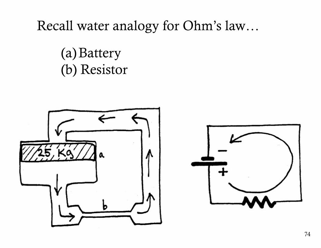
Recall water analogy for Ohm’s law…
(a) Battery(b) Resistor
75
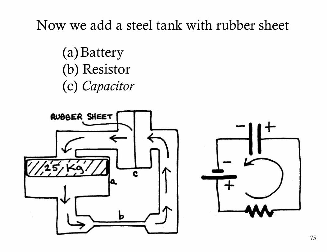
Now we add a steel tank with rubber sheet
(a) Battery(b) Resistor (c) Capacitor
76
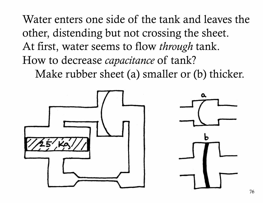
Water enters one side of the tank and leaves the other, distending but not crossing the sheet.At first, water seems to flow through tank.How to decrease capacitance of tank?
Make rubber sheet (a) smaller or (b) thicker.
77
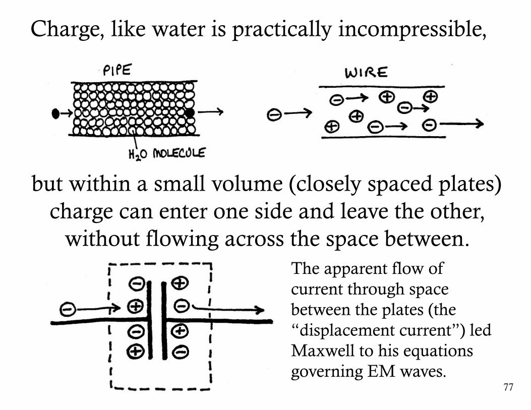
Charge, like water is practically incompressible,
but within a small volume (closely spaced plates)charge can enter one side and leave the other,
without flowing across the space between.The apparent flow of current through space between the plates (the “displacement current”) led Maxwell to his equations governing EM waves.
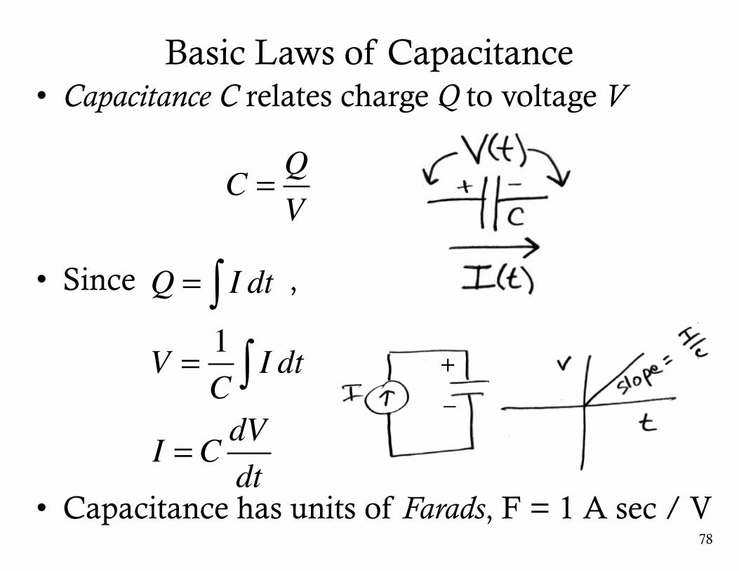
Basic Laws of Capacitance
78
• Capacitance C relates charge Q to voltage V
• Since ,
• Capacitance has units of Farads, F = 1 A sec / V
C = QV
Q = I dt∫V = 1
CI dt∫
I = C dVdt
+_
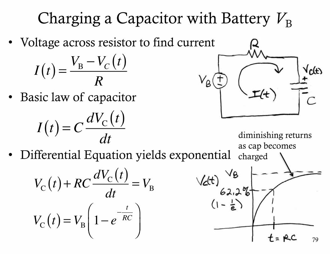
Charging a Capacitor with Battery VB
• Differential Equation yields exponential
79
I t( ) = VB −VC t( )R
• Voltage across resistor to find current
• Basic law of capacitor
VC t( )+ RC dVC t( )dt
=VB
I t( ) = C dVC t( )dt
VC t( ) =VB 1− e− tRC
⎛⎝⎜
⎞⎠⎟
diminishing returns as cap becomes charged
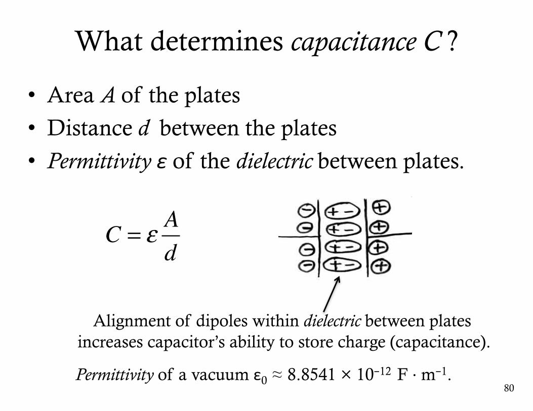
What determines capacitance C ?
• Area A of the plates
• Distance d between the plates
• Permittivity ε of the dielectric between plates.
80
C = ε Ad
Alignment of dipoles within dielectric between platesincreases capacitor’s ability to store charge (capacitance).
Permittivity of a vacuum ε0 ≈ 8.8541 × 10⁻¹² F · m−1.
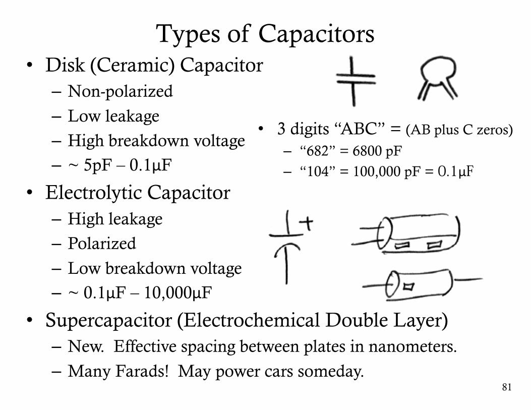
Types of Capacitors• Disk (Ceramic) Capacitor– Non-polarized
– Low leakage
– High breakdown voltage– ~ 5pF – 0.1μF
• Electrolytic Capacitor– High leakage
– Polarized
– Low breakdown voltage– ~ 0.1μF – 10,000μF
• Supercapacitor (Electrochemical Double Layer)– New. Effective spacing between plates in nanometers.
– Many Farads! May power cars someday.81
• 3 digits “ABC” = (AB plus C zeros)
– “682” = 6800 pF
– “104” = 100,000 pF = 0.1μF
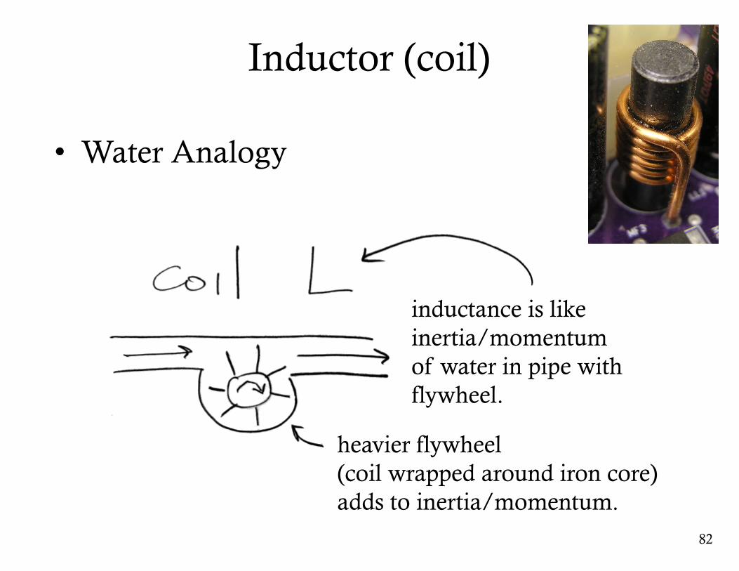
Inductor (coil)
• Water Analogy
82
inductance is like inertia/momentumof water in pipe withflywheel.
heavier flywheel (coil wrapped around iron core) adds to inertia/momentum.
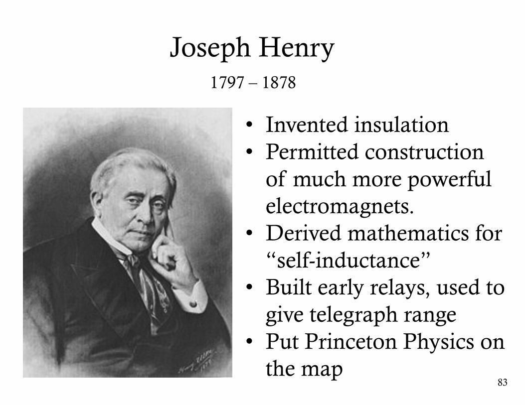
Joseph Henry
83
• Invented insulation• Permitted construction
of much more powerful electromagnets.
• Derived mathematics for “self-inductance”
• Built early relays, used to give telegraph range
• Put Princeton Physics on the map
1797 – 1878
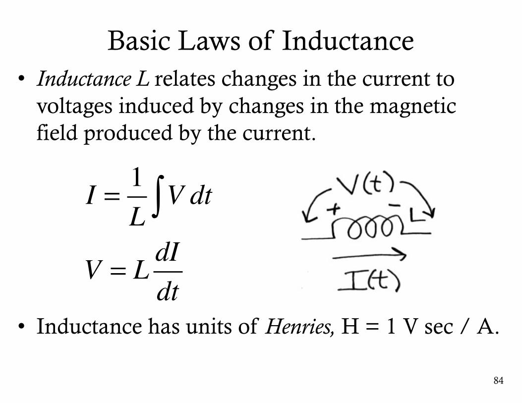
Basic Laws of Inductance• Inductance L relates changes in the current to
voltages induced by changes in the magnetic field produced by the current.
• Inductance has units of Henries, H = 1 V sec / A.
84
I = 1L
V dt∫V = L dI
dt
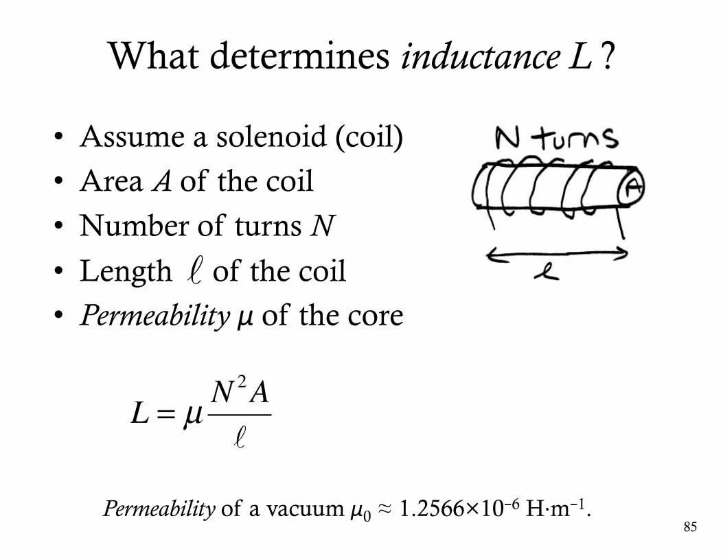
What determines inductance L ?
• Assume a solenoid (coil)
• Area A of the coil
• Number of turns N
• Length of the coil
• Permeability μ of the core
85
L = µ N2A
Permeability of a vacuum μ0 ≈ 1.2566×10⁻⁶ H·m−1.
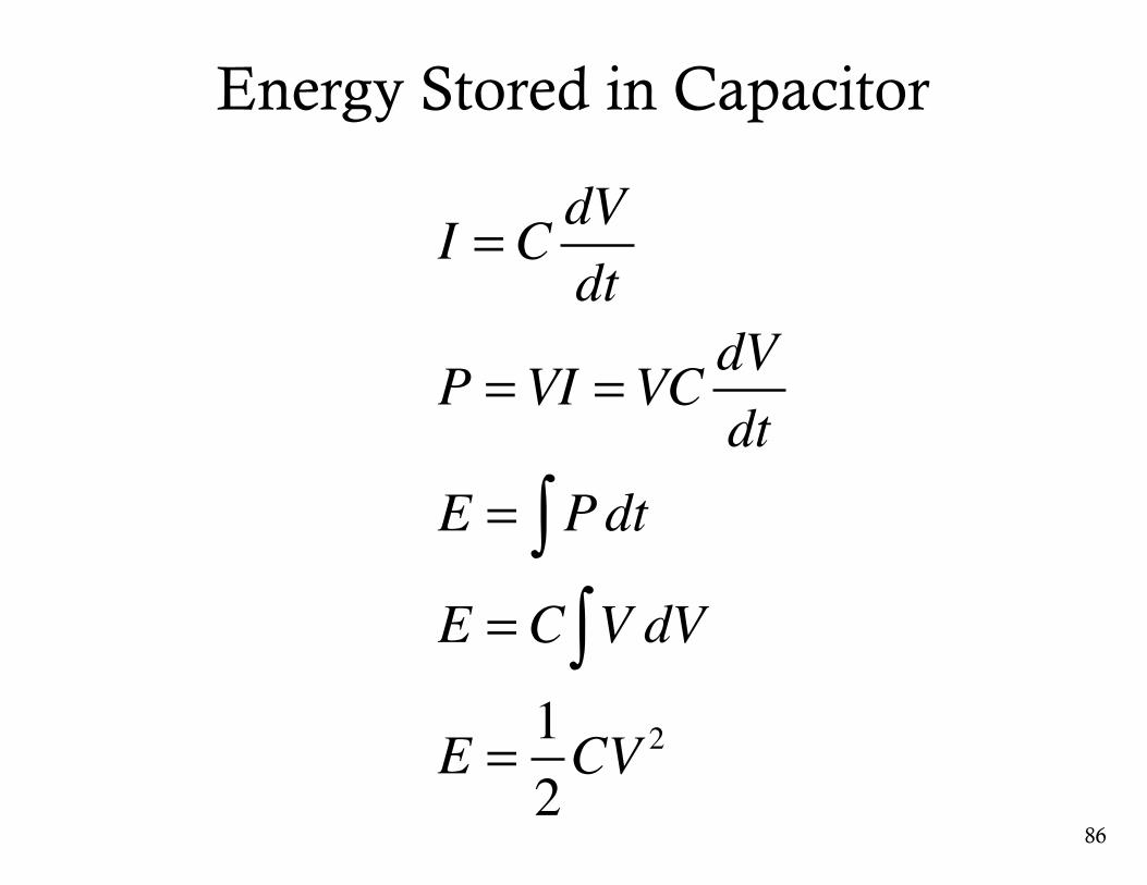
Energy Stored in Capacitor
86
I = C dVdt
P =VI =VC dVdt
E = Pdt∫E = C V dV∫E = 1
2CV 2
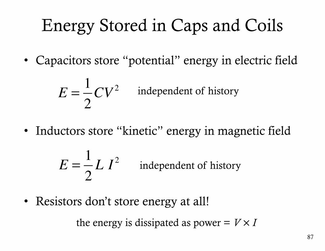
Energy Stored in Caps and Coils
• Capacitors store “potential” energy in electric field
• Inductors store “kinetic” energy in magnetic field
• Resistors don’t store energy at all!
87
E = 12CV 2 independent of history
E = 12L I 2
independent of history
the energy is dissipated as power = V ×I
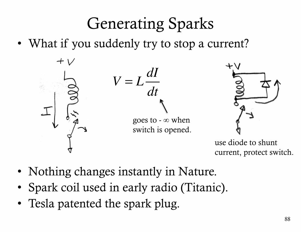
Generating Sparks• What if you suddenly try to stop a current?
• Nothing changes instantly in Nature. • Spark coil used in early radio (Titanic).• Tesla patented the spark plug.
88
V = L dIdt
goes to - ∞ when switch is opened.
use diode to shunt current, protect switch.
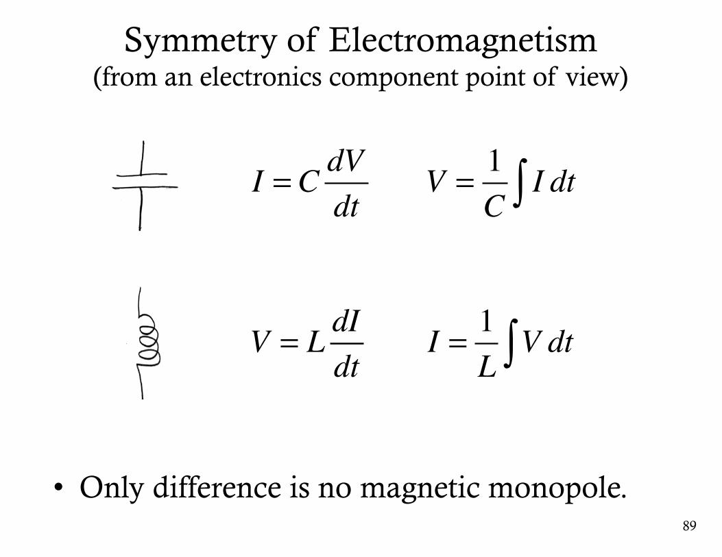
Symmetry of Electromagnetism(from an electronics component point of view)
• Only difference is no magnetic monopole.89
I = 1L
V dt∫V = L dIdt
I = C dVdt
V = 1C
I dt∫
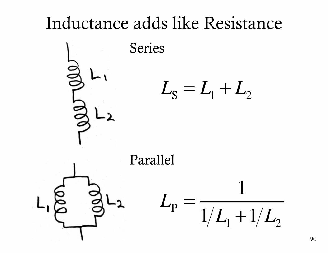
Inductance adds like Resistance
90
Series
Parallel
LS = L1 + L2
LP =1
1 L1 +1 L2
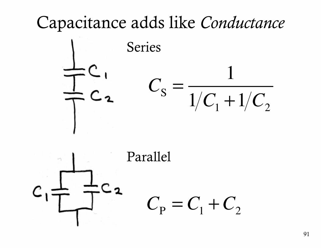
Capacitance adds like Conductance
91
Series
Parallel
CP = C1 +C2
CS =1
1 C1 +1 C2
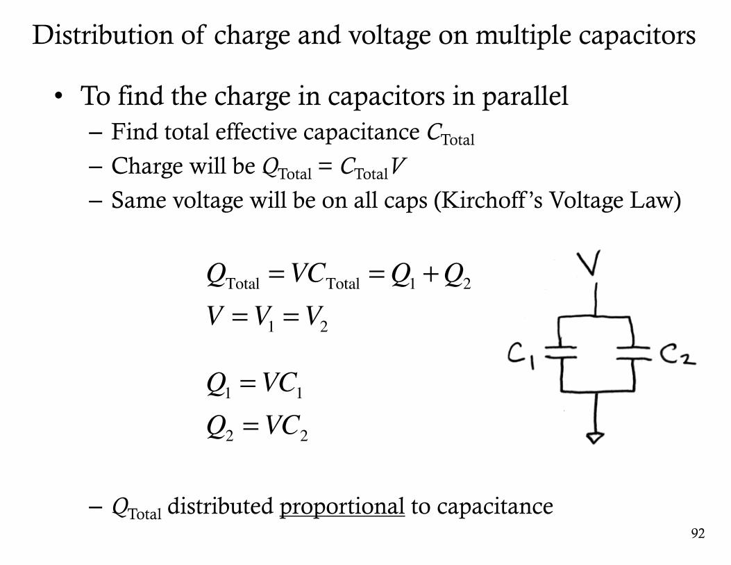
• To find the charge in capacitors in parallel– Find total effective capacitance CTotal
– Charge will be QTotal = CTotalV– Same voltage will be on all caps (Kirchoff ’s Voltage Law)
– QTotal distributed proportional to capacitance
Distribution of charge and voltage on multiple capacitors
92
Q1 =VC1Q2 =VC2
QTotal =VCTotal =Q1 +Q2
V =V1 =V2
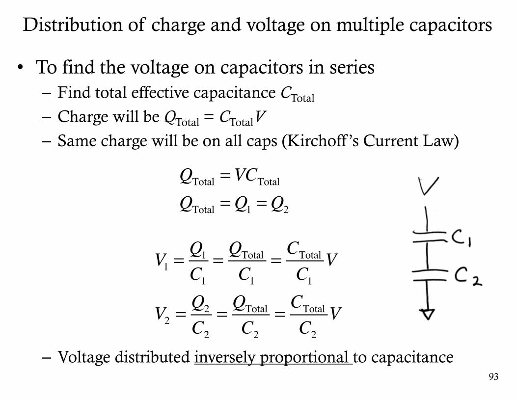
• To find the voltage on capacitors in series– Find total effective capacitance CTotal
– Charge will be QTotal = CTotalV– Same charge will be on all caps (Kirchoff ’s Current Law)
– Voltage distributed inversely proportional to capacitance
Distribution of charge and voltage on multiple capacitors
93
QTotal =VCTotalQTotal =Q1 =Q2
V1 =Q1C1
= QTotal
C1= CTotal
C1V
V2 =Q2
C2= QTotal
C2= CTotal
C2V
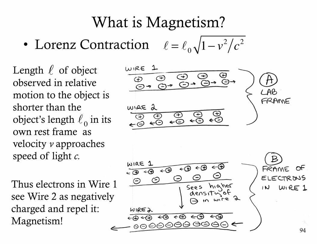
What is Magnetism?• Lorenz Contraction
94
= 0 1− v2 c2
Length of object observed in relative motion to the object is shorter than the object’s length in its own rest frame as velocity v approaches speed of light c.
0
Thus electrons in Wire 1 see Wire 2 as negatively charged and repel it: Magnetism!
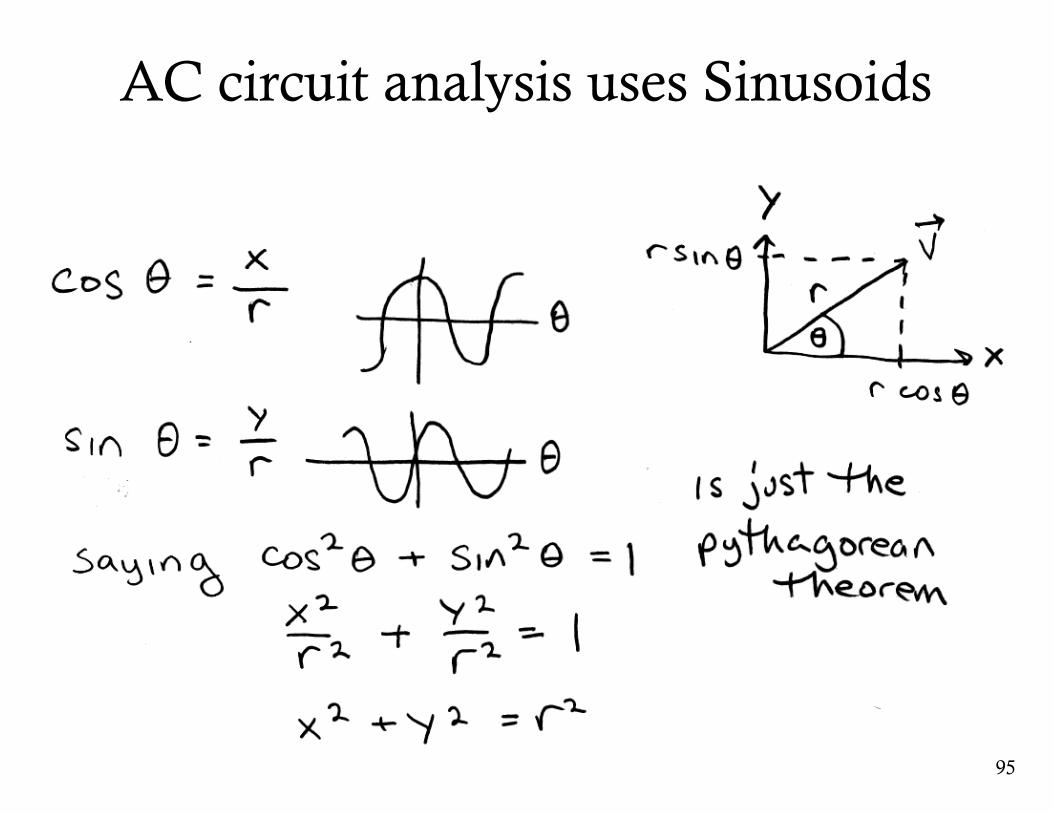
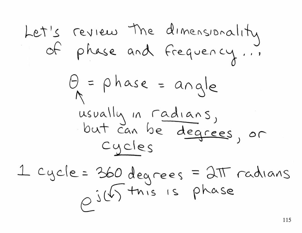
AC circuit analysis uses Sinusoids
95
96
Superposition of Sinusoids
• Adding two sinusoids of the same frequency, no matter what their amplitudes and phases, yields a sinusoid of the same frequency.
• Why? Trigonometry does not have an answer.
• Linear systems change only phase and amplitude
• New frequencies do not appear.
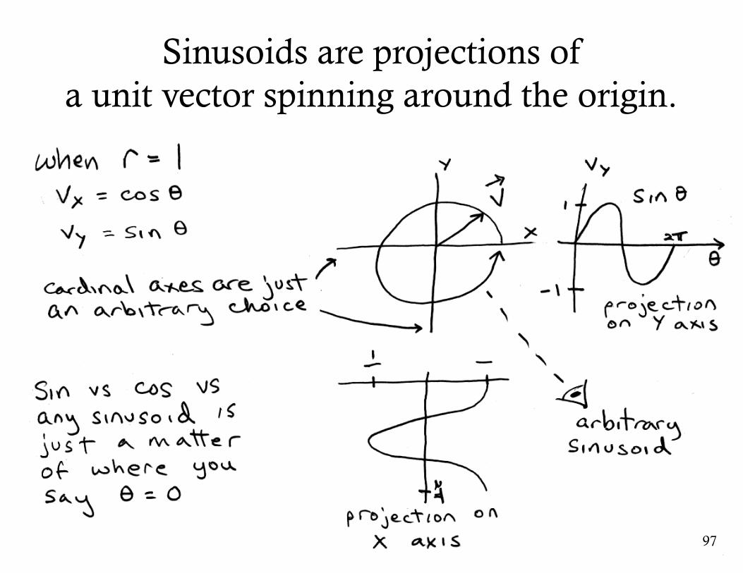
Sinusoids are projections ofa unit vector spinning around the origin.
97
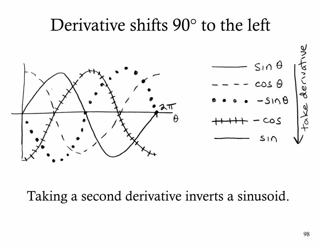
Derivative shifts 90° to the left
98
Taking a second derivative inverts a sinusoid.
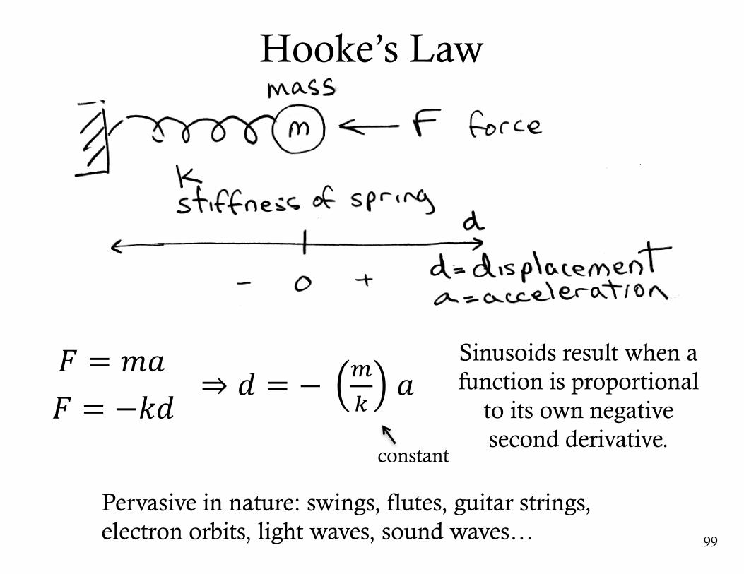
Hooke’s Law
99
Sinusoids result when a function is proportional
to its own negative second derivative.
constant
Pervasive in nature: swings, flutes, guitar strings, electron orbits, light waves, sound waves…
𝐹 = 𝑚𝑎𝐹 = −𝑘𝑑
⇒ 𝑑 = − +,
𝑎
100
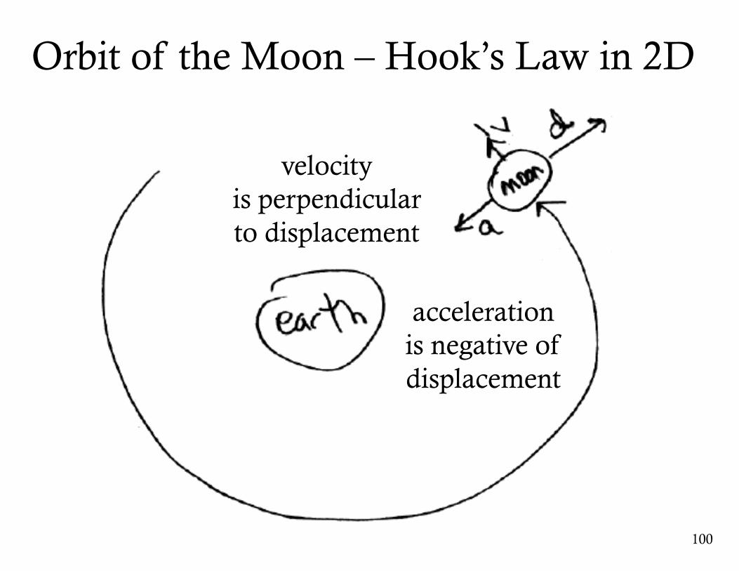
acceleration is negative of displacement
velocityis perpendicular to displacement
Orbit of the Moon – Hook’s Law in 2D
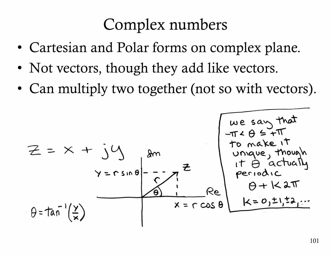
Complex numbers• Cartesian and Polar forms on complex plane.
• Not vectors, though they add like vectors.
• Can multiply two together (not so with vectors).
101
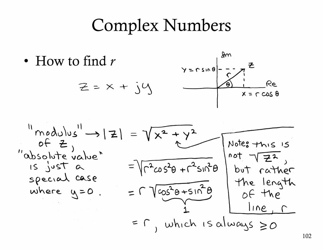
Complex Numbers
• How to find r
102
103
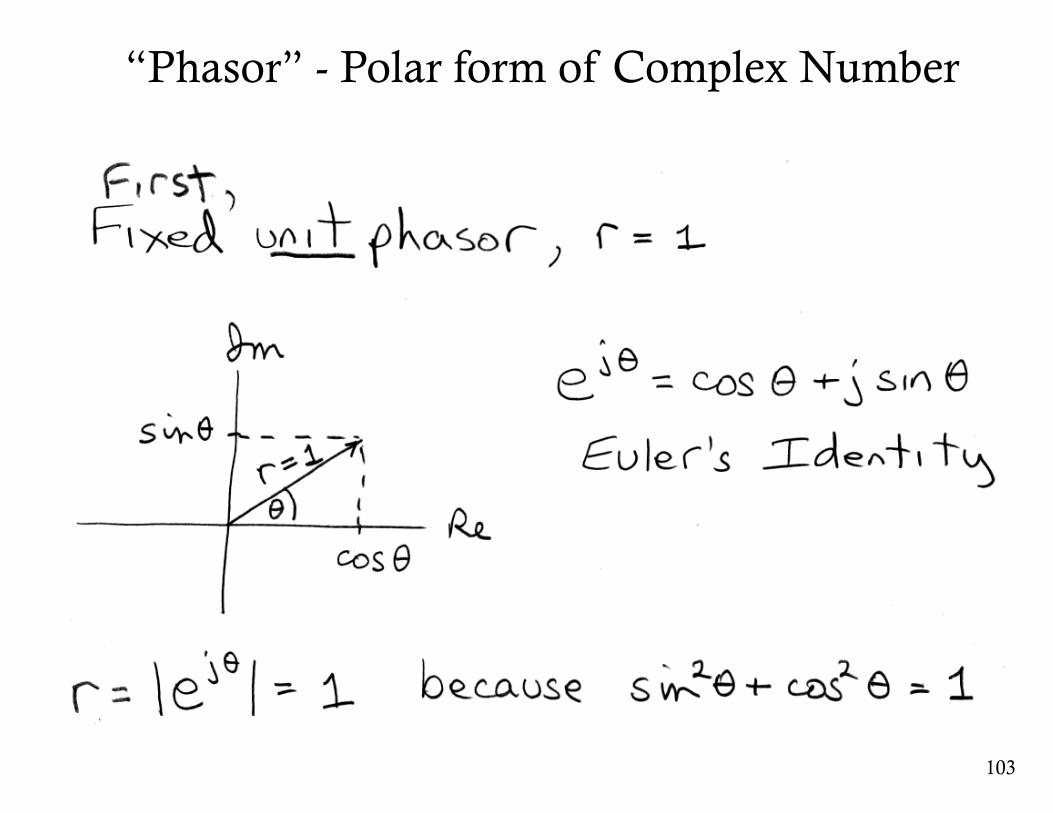
“Phasor” - Polar form of Complex Number

104
Cartesian and Polar forms (cont…)
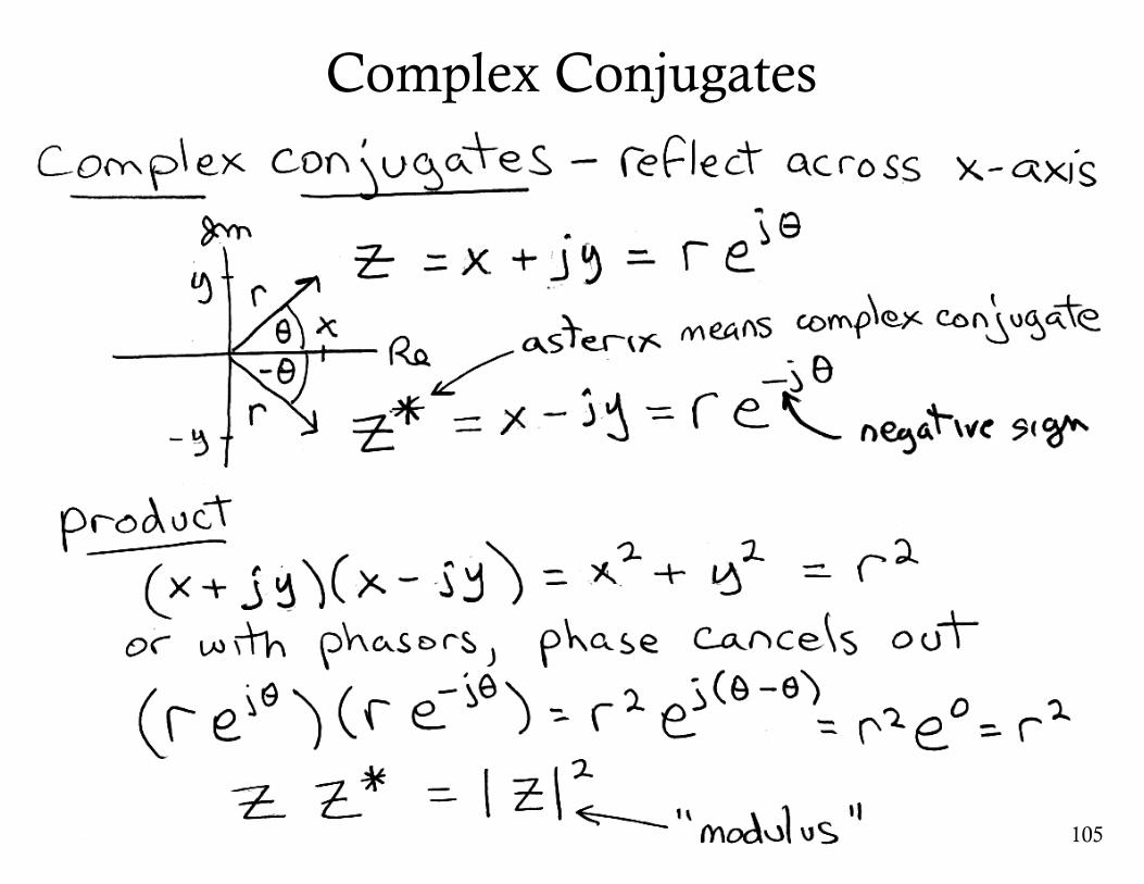
Complex Conjugates
105
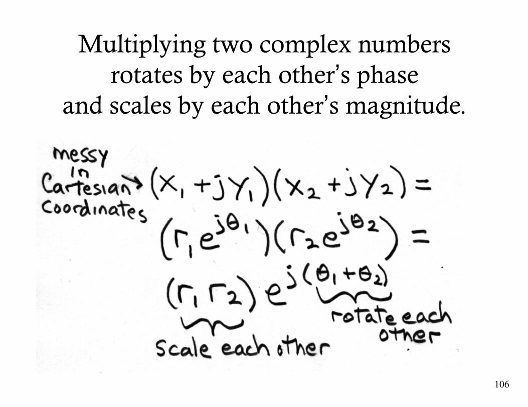
Multiplying two complex numbers rotates by each other’s phase
and scales by each other’s magnitude.
106
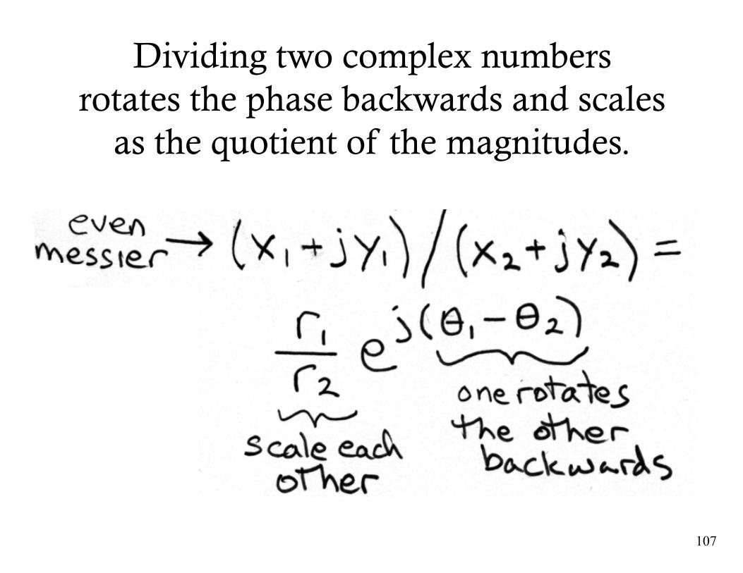
Dividing two complex numbersrotates the phase backwards and scales
as the quotient of the magnitudes.
107
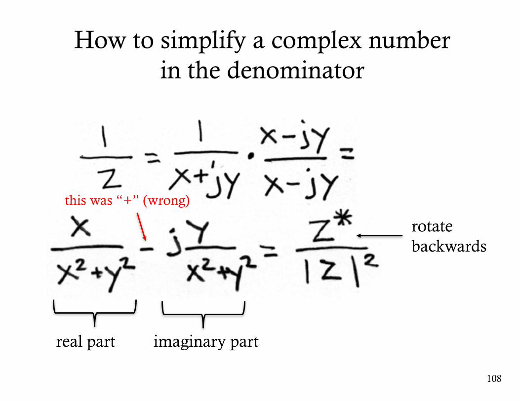
108
How to simplify a complex number in the denominator
real part imaginary part
rotate backwards
this was “+” (wrong)
109
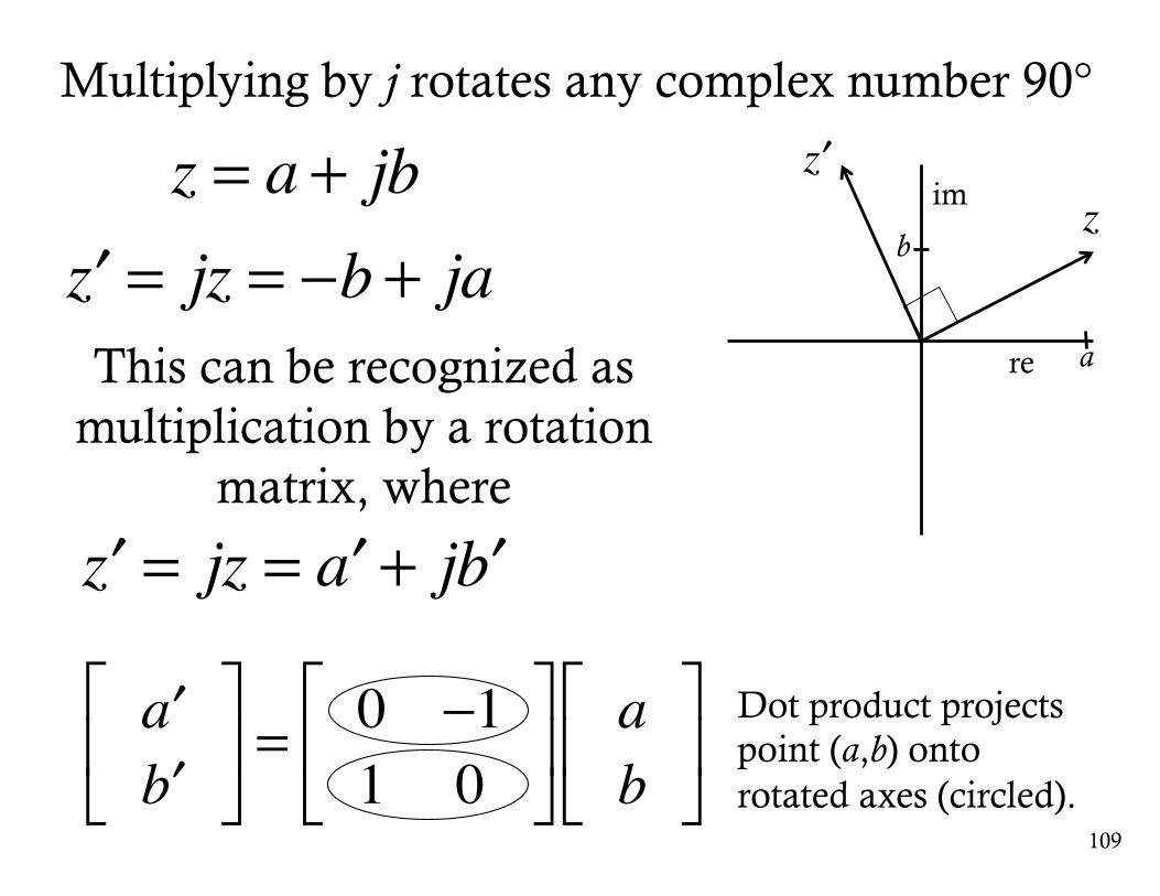
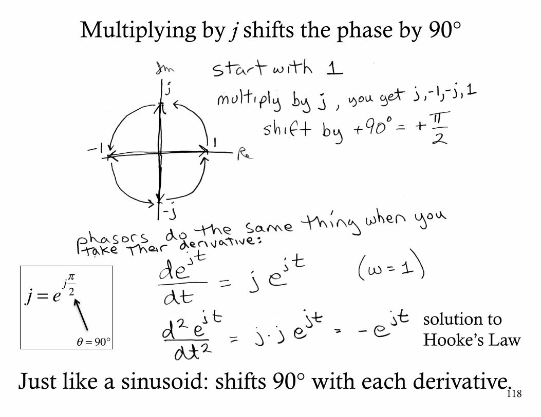
Multiplying by j rotates any complex number 90°
z = a + jb′z = jz = −b + jaThis can be recognized as
multiplication by a rotation matrix, where
′z = jz = ′a + j ′b
Dot product projects point (a,b) onto rotated axes (circled).
′a′b
⎡
⎣⎢
⎤
⎦⎥ =
0 −11 0
⎡
⎣⎢
⎤
⎦⎥
ab
⎡
⎣⎢
⎤
⎦⎥
re
im z′z
a
b
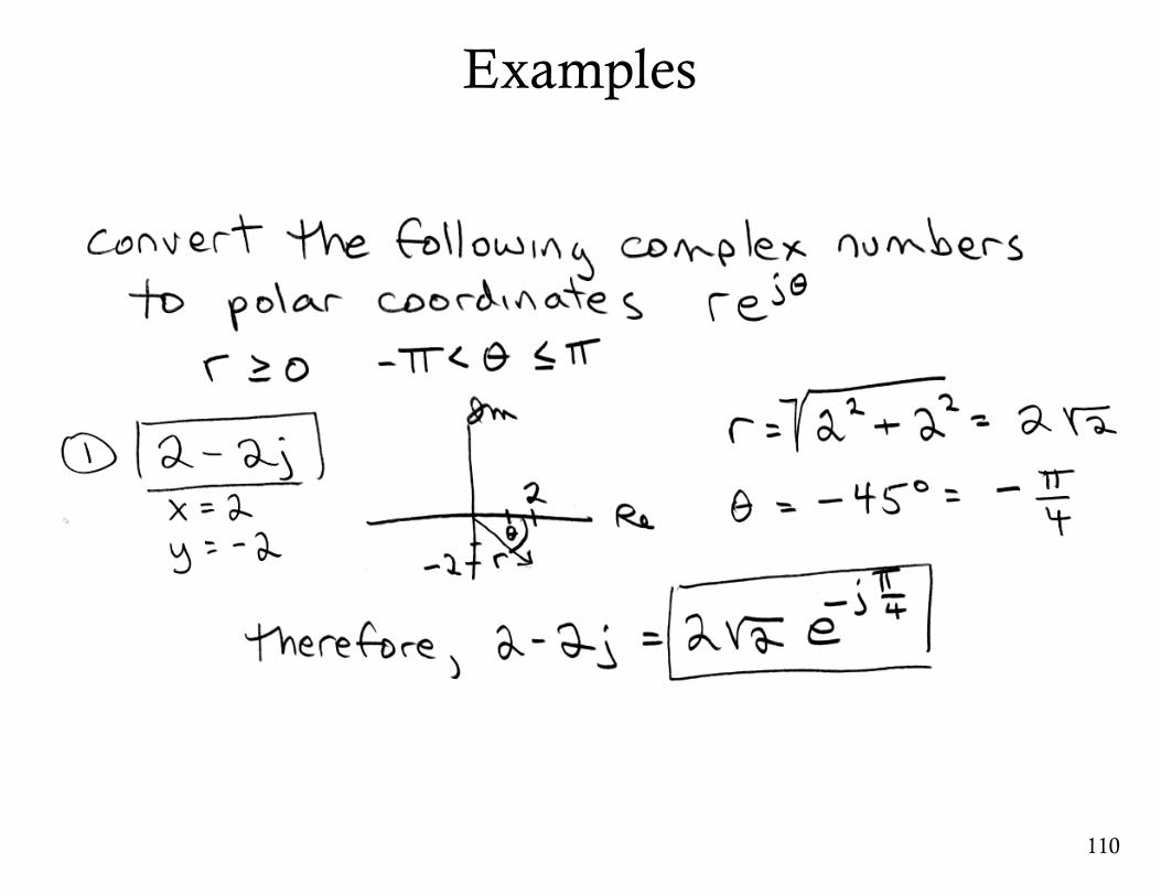
Examples
110
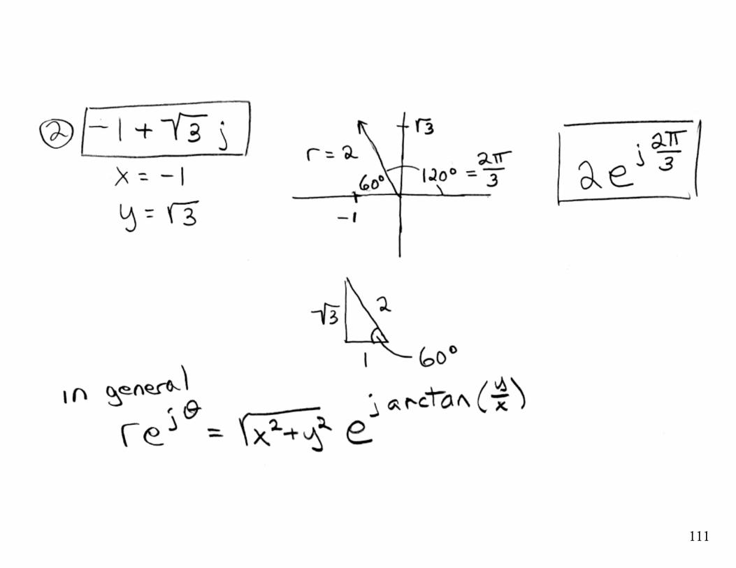
111
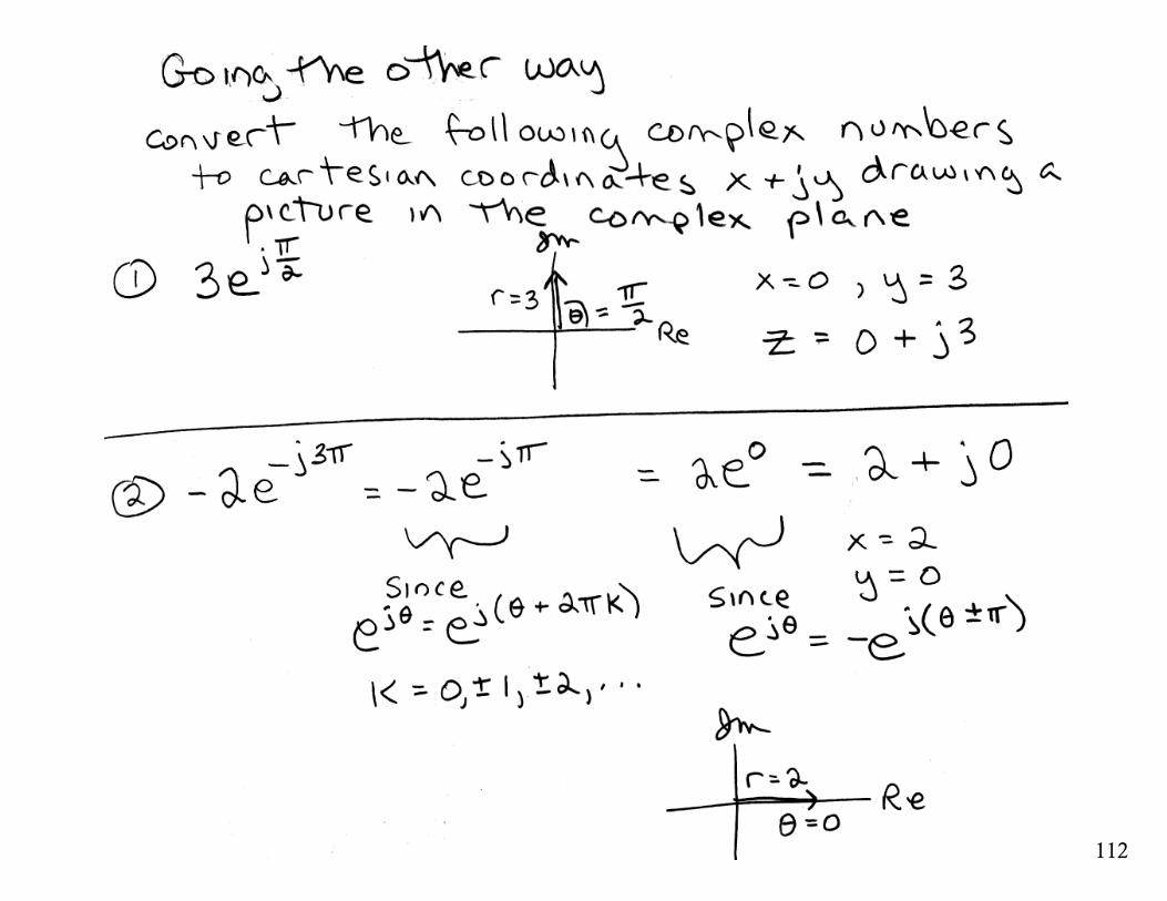
112
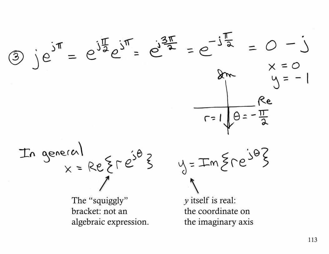
113
y itself is real:the coordinate on the imaginary axis
The “squiggly” bracket: not an algebraic expression.

Rotating by + or - 90°
114
115
116
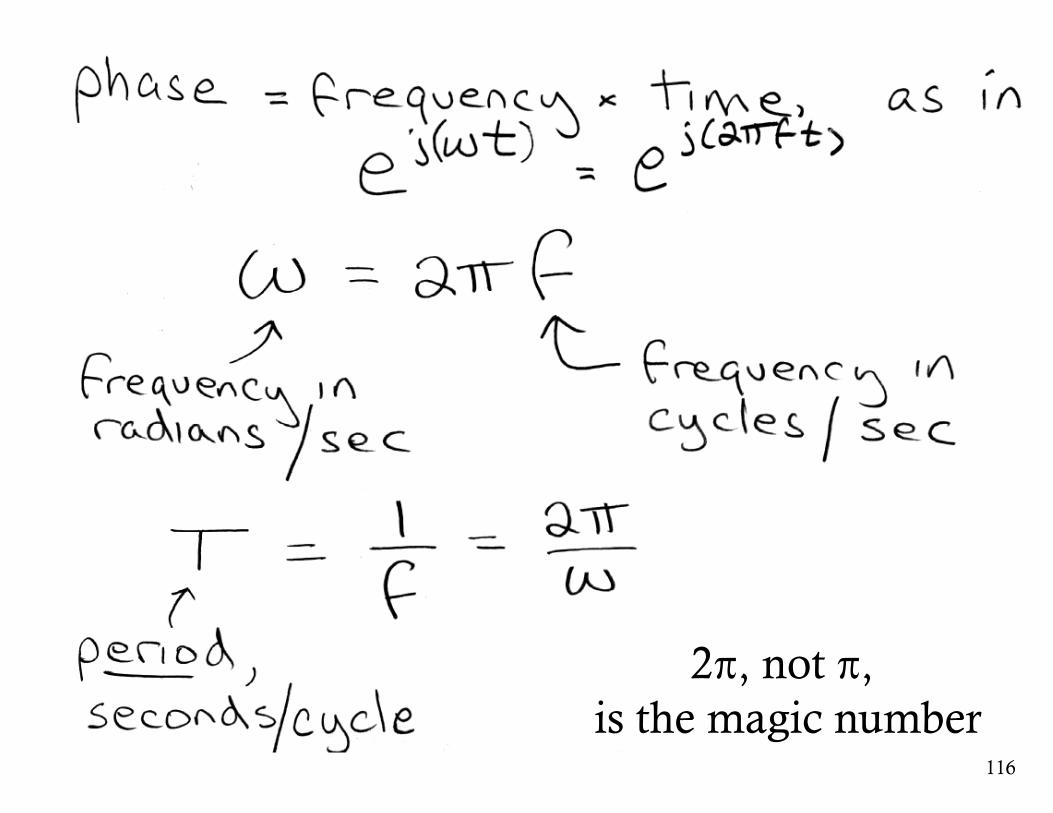
2π, not π, is the magic number
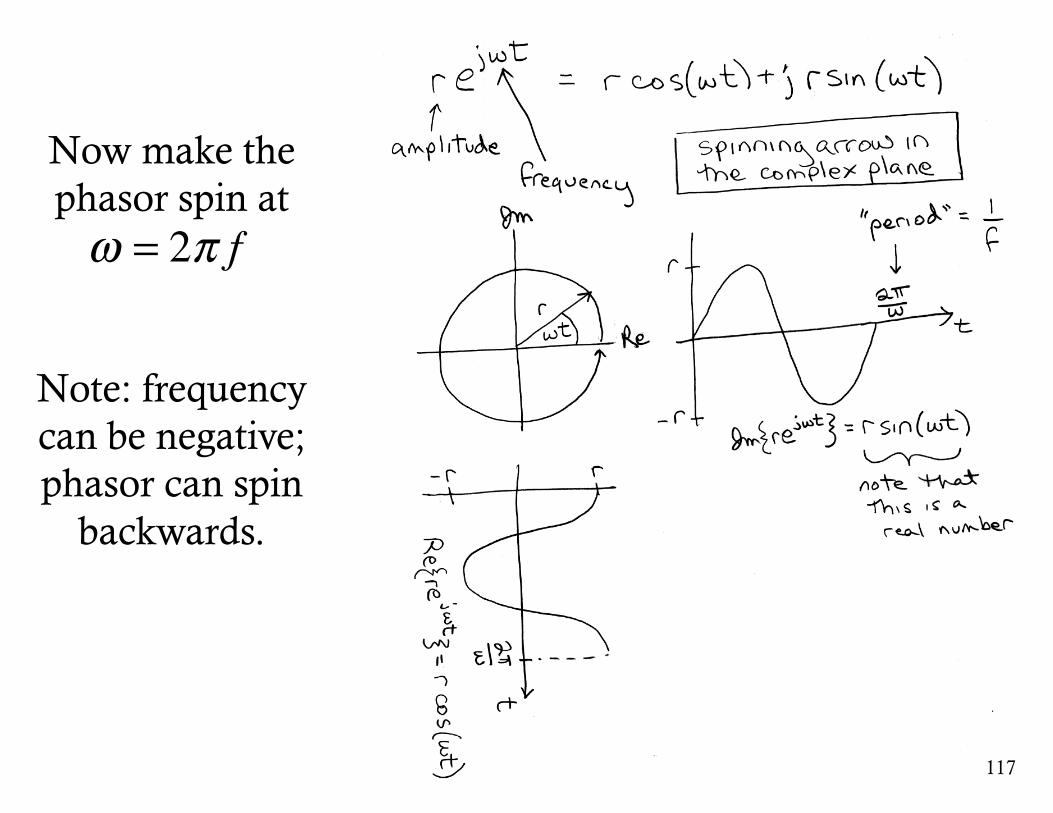
Now make the phasor spin at
Note: frequency can be negative; phasor can spin
backwards.
117
ω = 2π f
118
Multiplying by j shifts the phase by 90°
j = ejπ2
θ = 90°
Just like a sinusoid: shifts 90° with each derivative.
solution toHooke’s Law
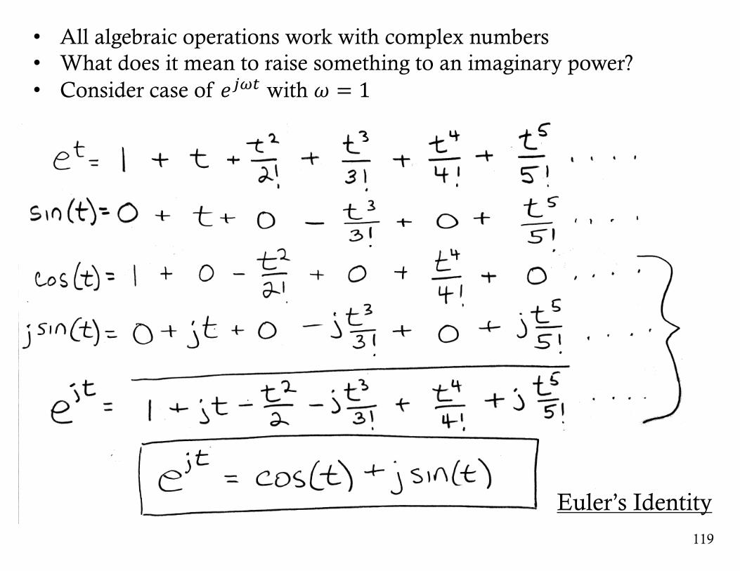
• All algebraic operations work with complex numbers• What does it mean to raise something to an imaginary power?• Consider case of 𝑒./0 with 𝜔 = 1
119
Euler’s Identity
120
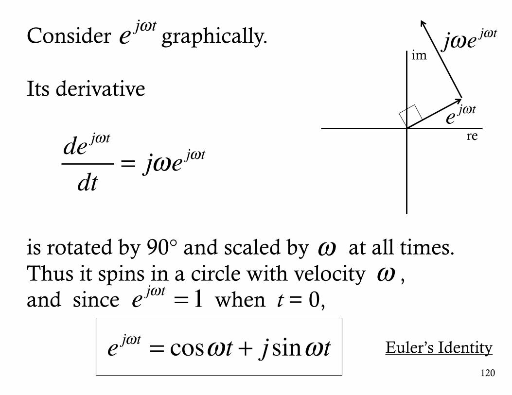
Consider graphically.
Its derivative
is rotated by 90° and scaled by at all times.Thus it spins in a circle with velocity , and since when t = 0,
e jωt
de jωt
dt= jωe jωt
re
im
e jωt
jωe jωt
ω
e jωt = cosωt + j sinωt
e jωt =1
Euler’s Identity
ω
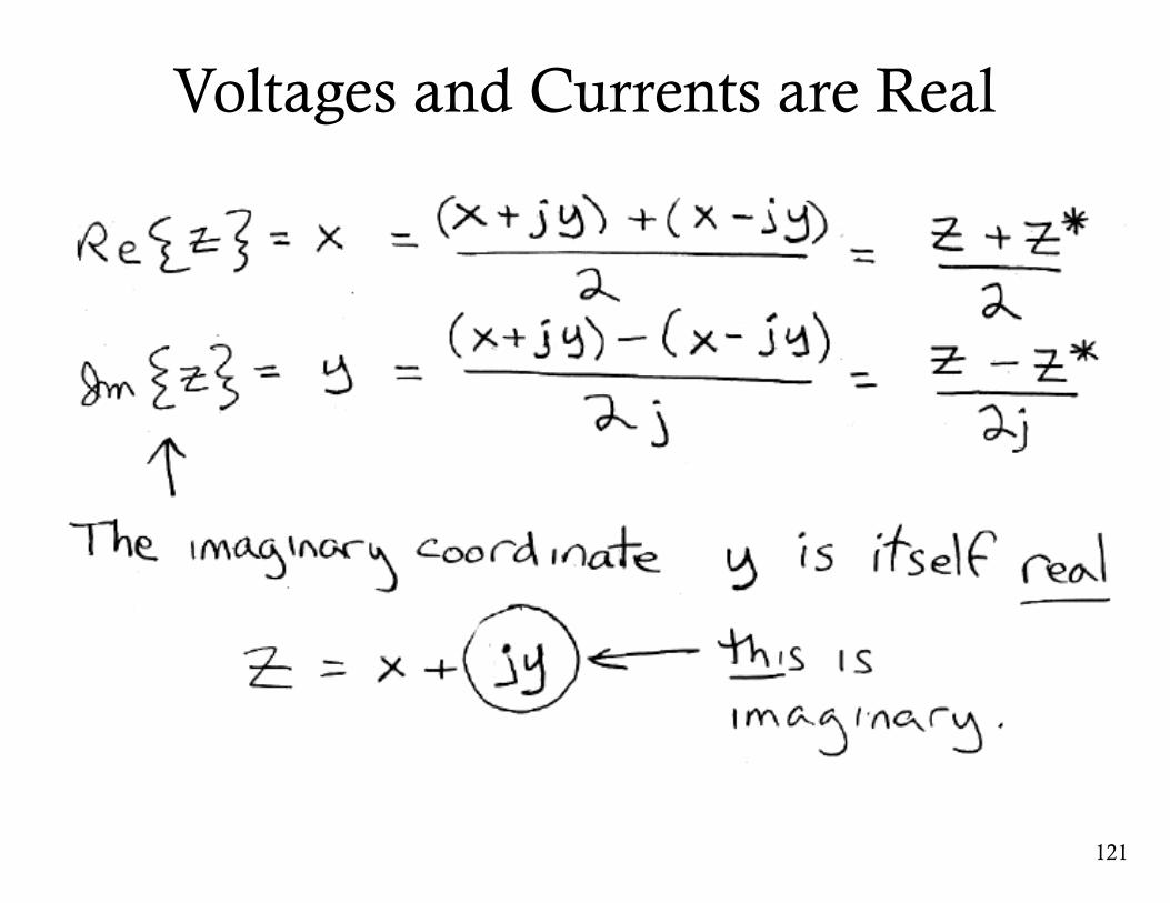
Voltages and Currents are Real
121
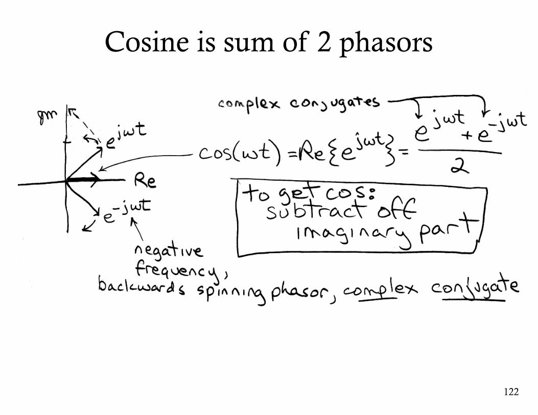
Cosine is sum of 2 phasors
122
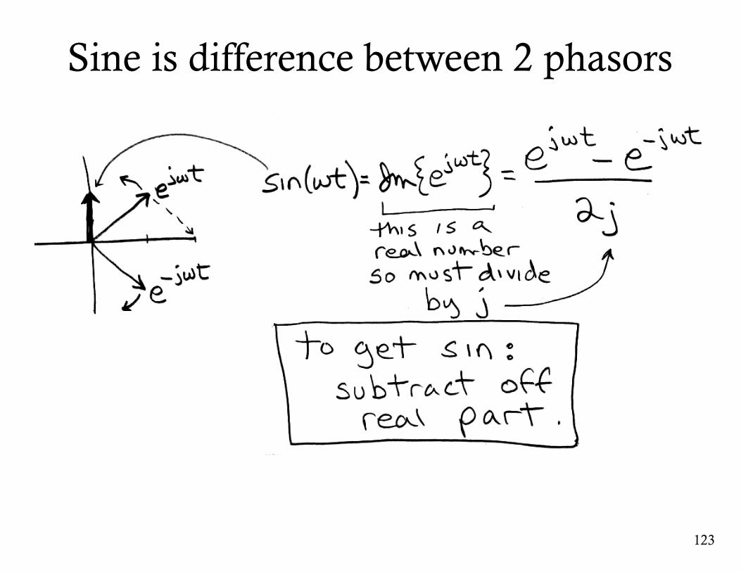
Sine is difference between 2 phasors
123
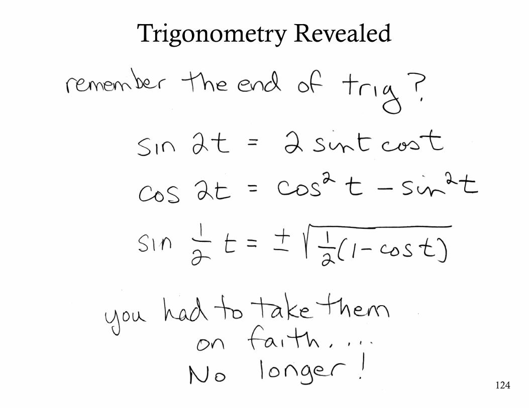
Trigonometry Revealed
124
125
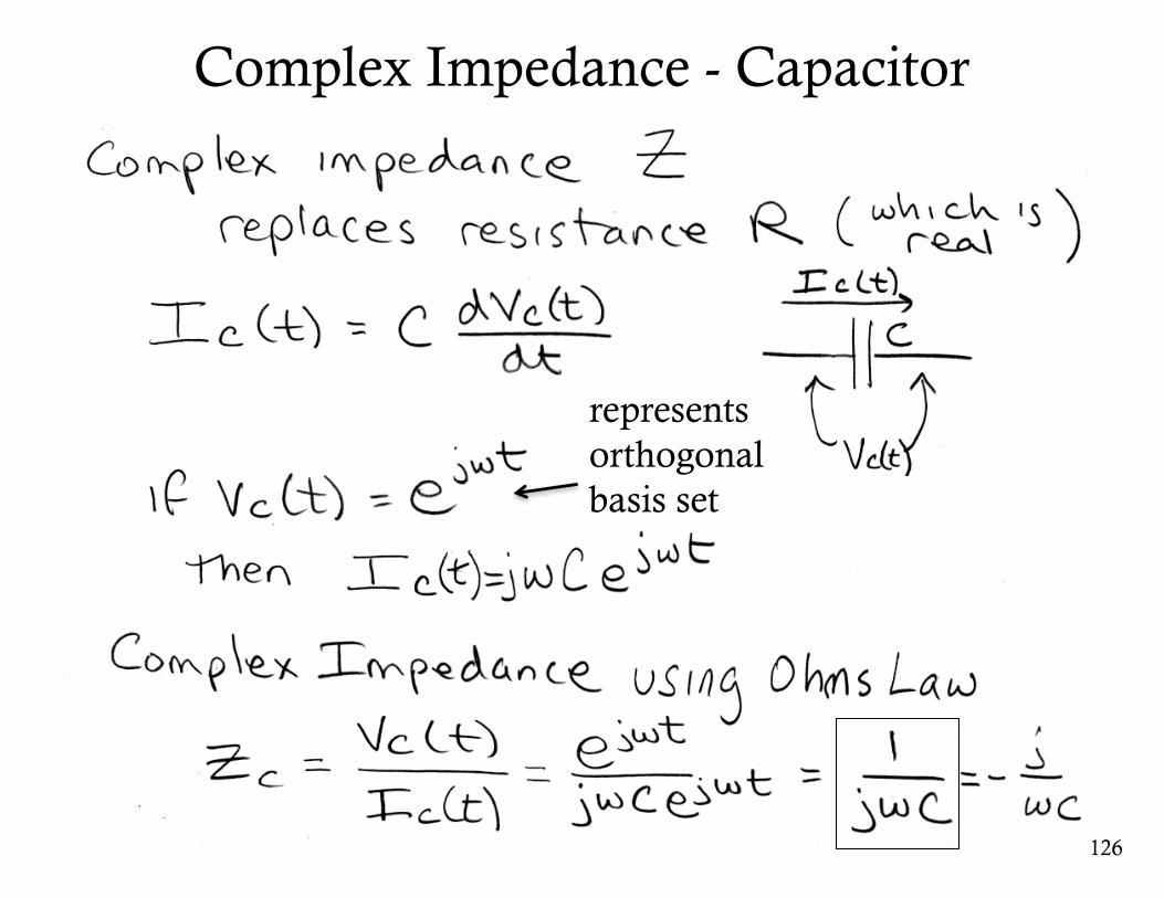
Complex Impedance - Capacitor
126
representsorthogonalbasis set
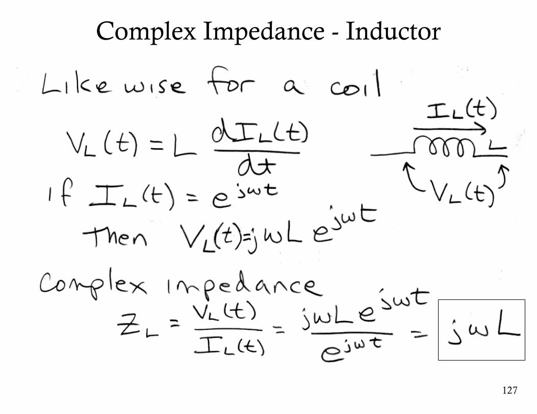
Complex Impedance - Inductor
127
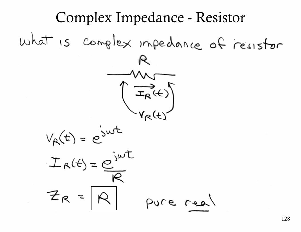
Complex Impedance - Resistor
128
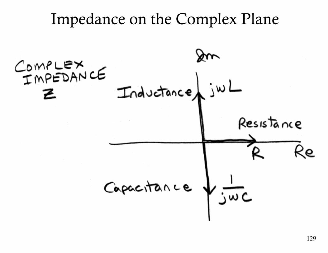
Impedance on the Complex Plane
129
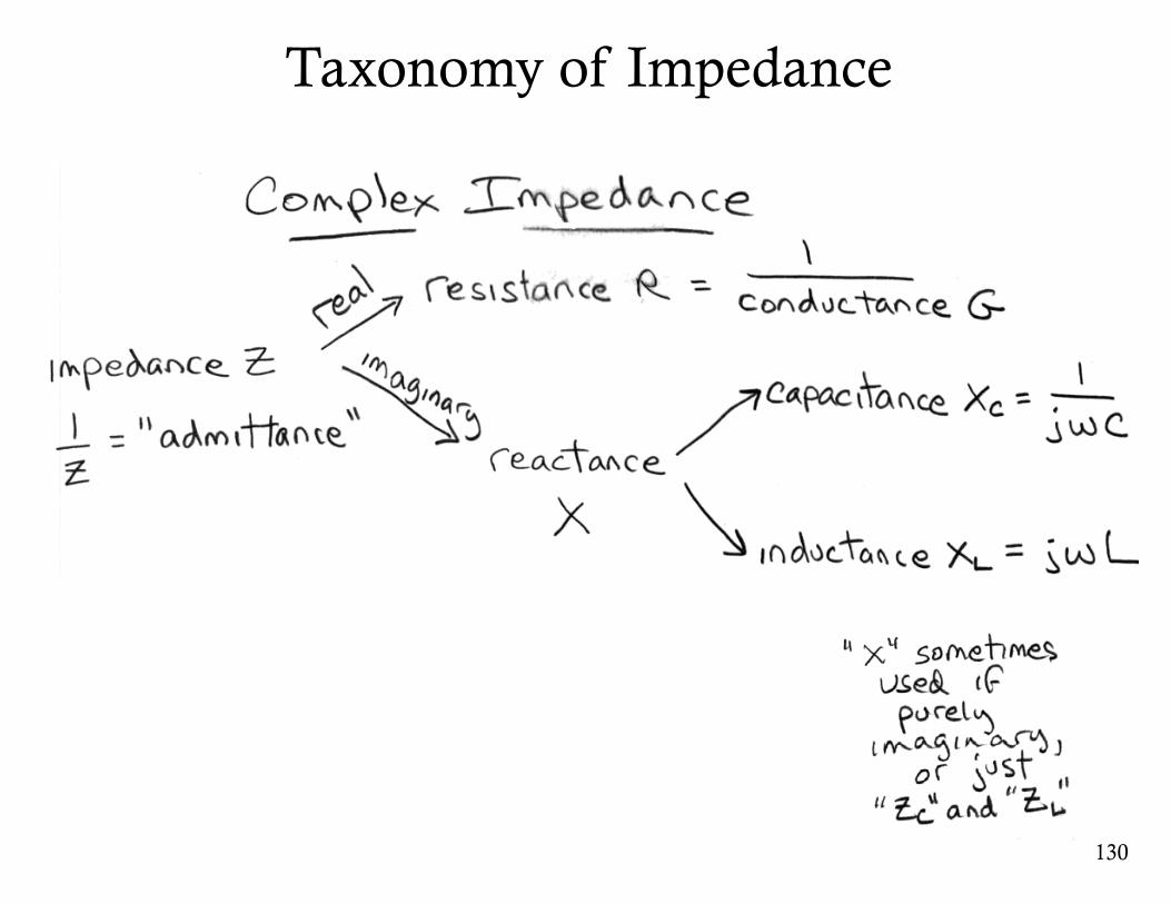
Taxonomy of Impedance
130
131
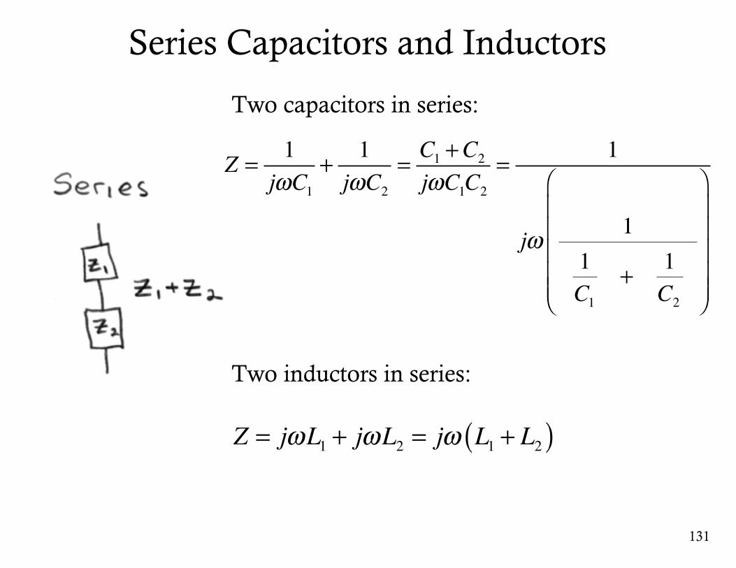
Z = 1jωC1
+ 1jωC2
= C1 +C2jωC1C2
= 1
jω 11C1
+ 1C2
⎛
⎝
⎜⎜⎜⎜⎜
⎞
⎠
⎟⎟⎟⎟⎟
Z = jωL1 + jωL2 = jω L1 + L2( )
Series Capacitors and Inductors
Two capacitors in series:
Two inductors in series:
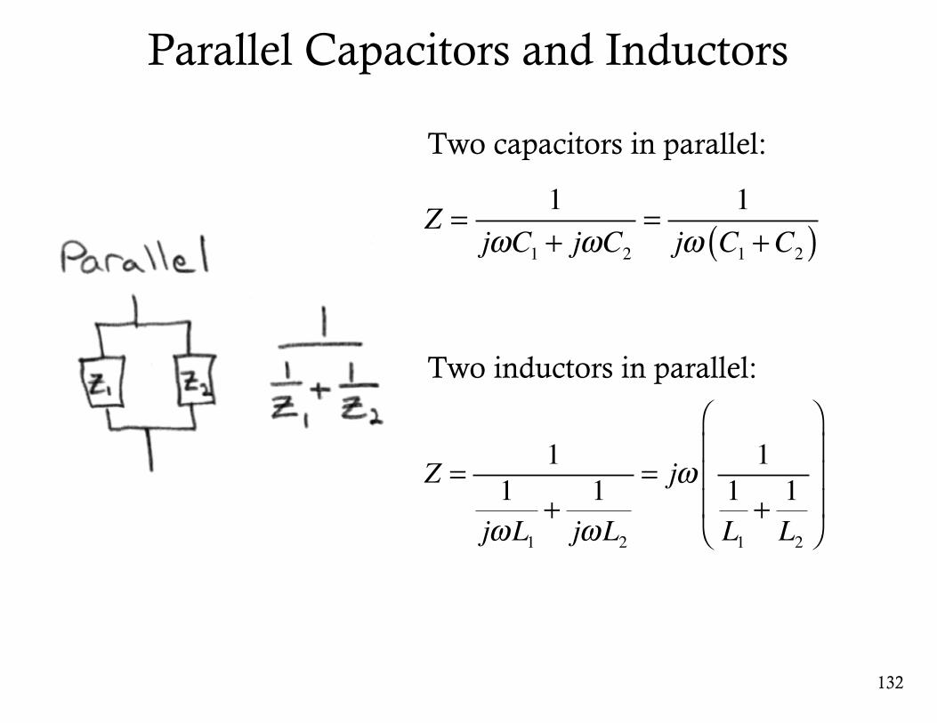
Parallel Capacitors and Inductors
132
Z = 1jωC1 + jωC2
= 1jω C1 +C2( )
Z = 11jωL1
+ 1jωL2
= jω 11L1
+ 1L2
⎛
⎝
⎜⎜⎜
⎞
⎠
⎟⎟⎟
Two capacitors in parallel:
Two inductors in parallel:
133
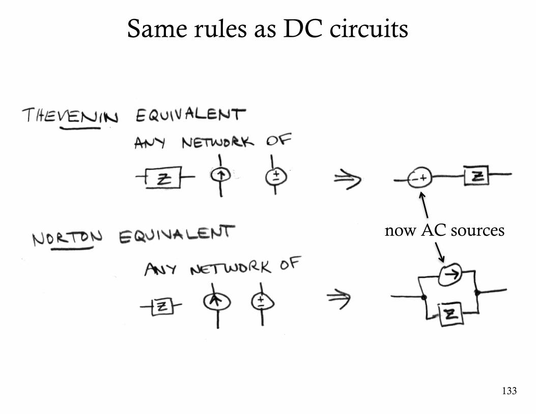
Same rules as DC circuits
now AC sources
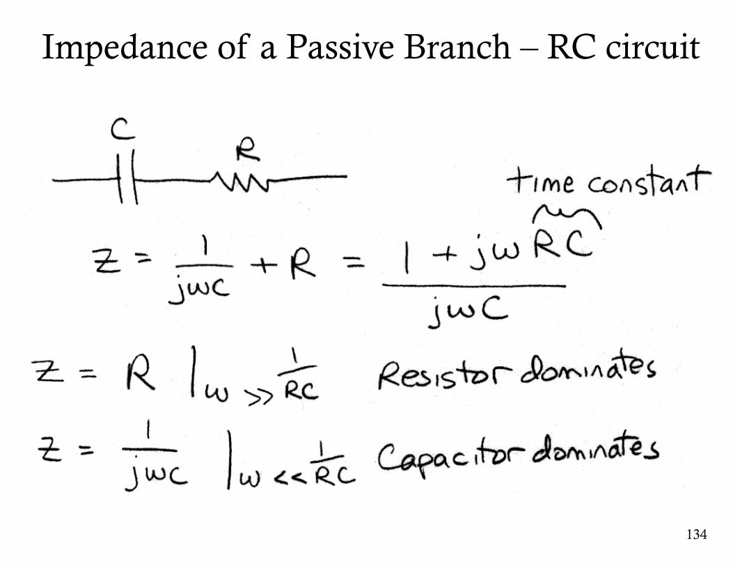
Impedance of a Passive Branch – RC circuit
134
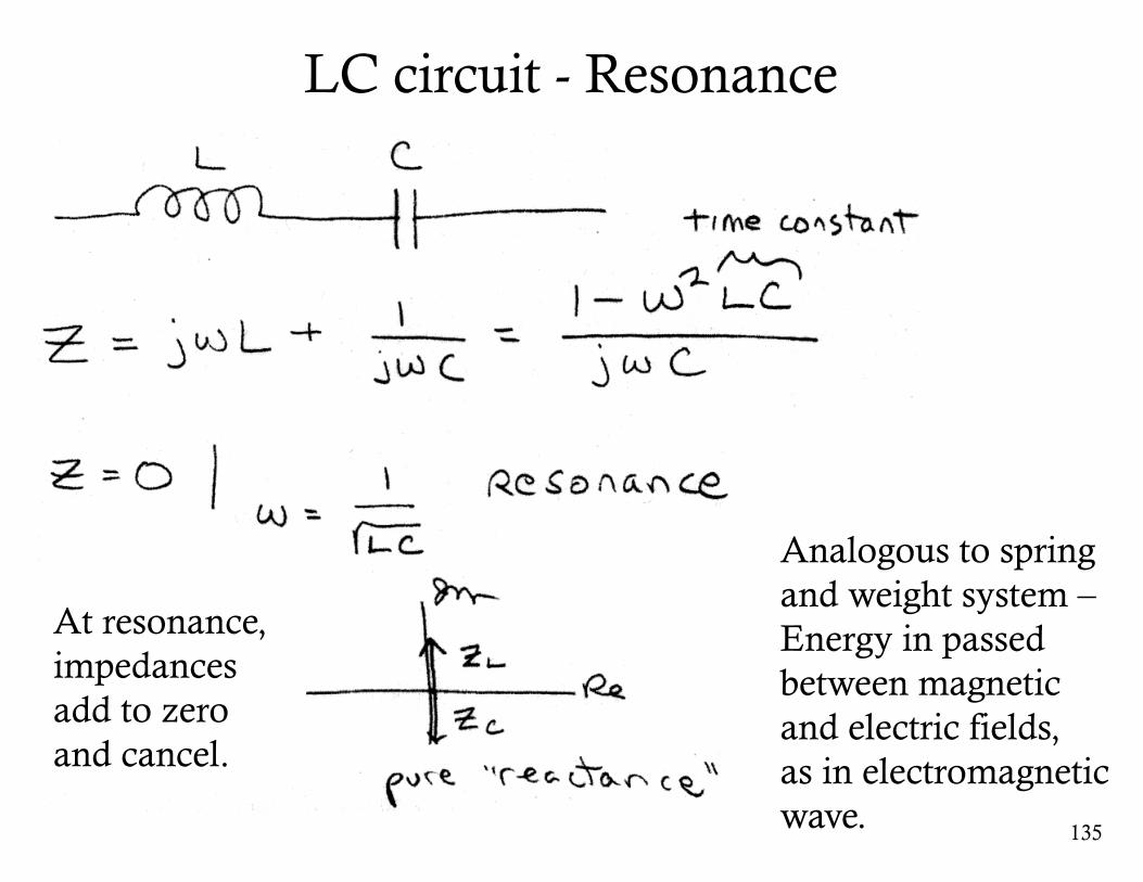
LC circuit - Resonance
135
Analogous to spring and weight system –Energy in passed between magnetic and electric fields,as in electromagnetic wave.
At resonance,impedances add to zero and cancel.
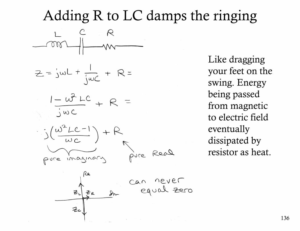
Adding R to LC damps the ringing
136
Like dragging your feet on the swing. Energy being passed from magnetic to electric field eventually dissipated by resistor as heat.
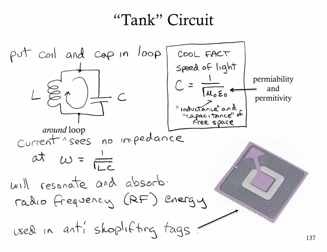
“Tank” Circuit
137
around loop^
permiabilityand
permitivity
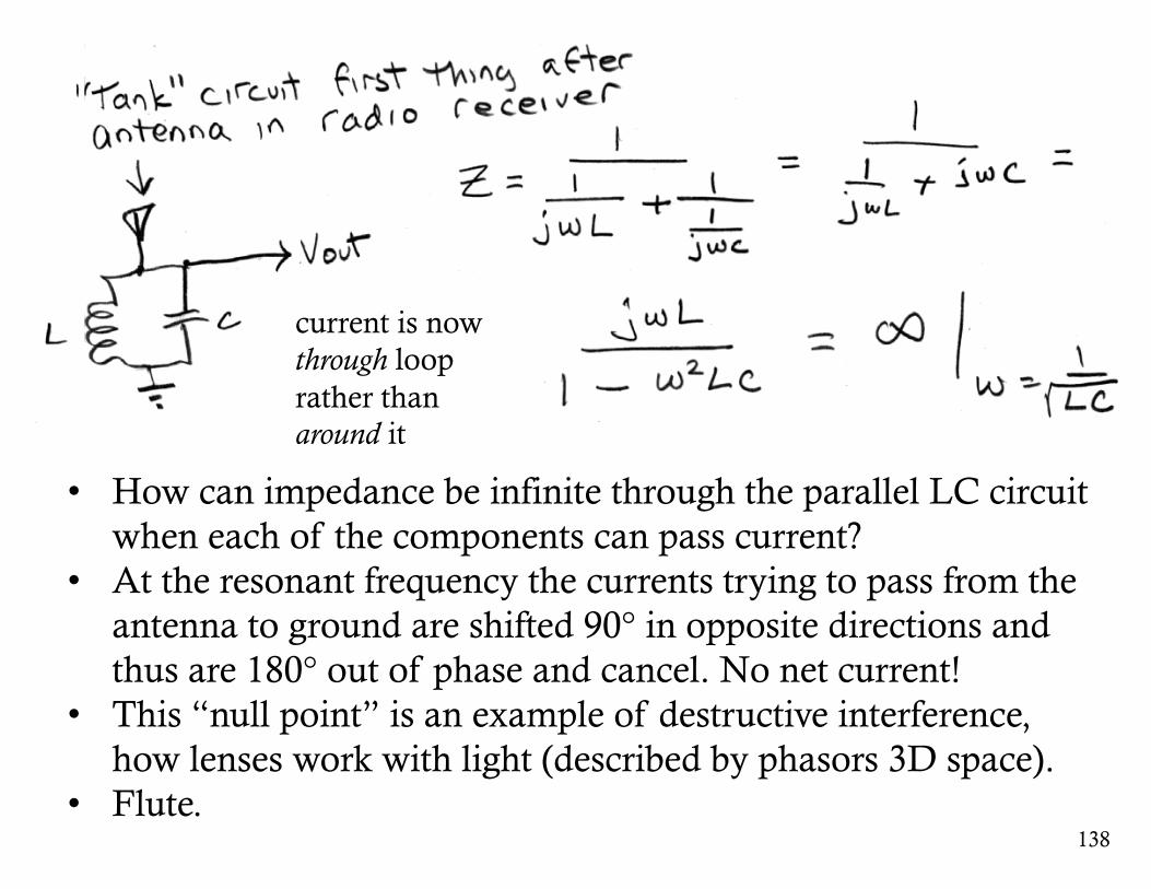
138
• How can impedance be infinite through the parallel LC circuit when each of the components can pass current?
• At the resonant frequency the currents trying to pass from the antenna to ground are shifted 90° in opposite directions and thus are 180° out of phase and cancel. No net current!
• This “null point” is an example of destructive interference, how lenses work with light (described by phasors 3D space).
• Flute.
current is nowthrough looprather than around it
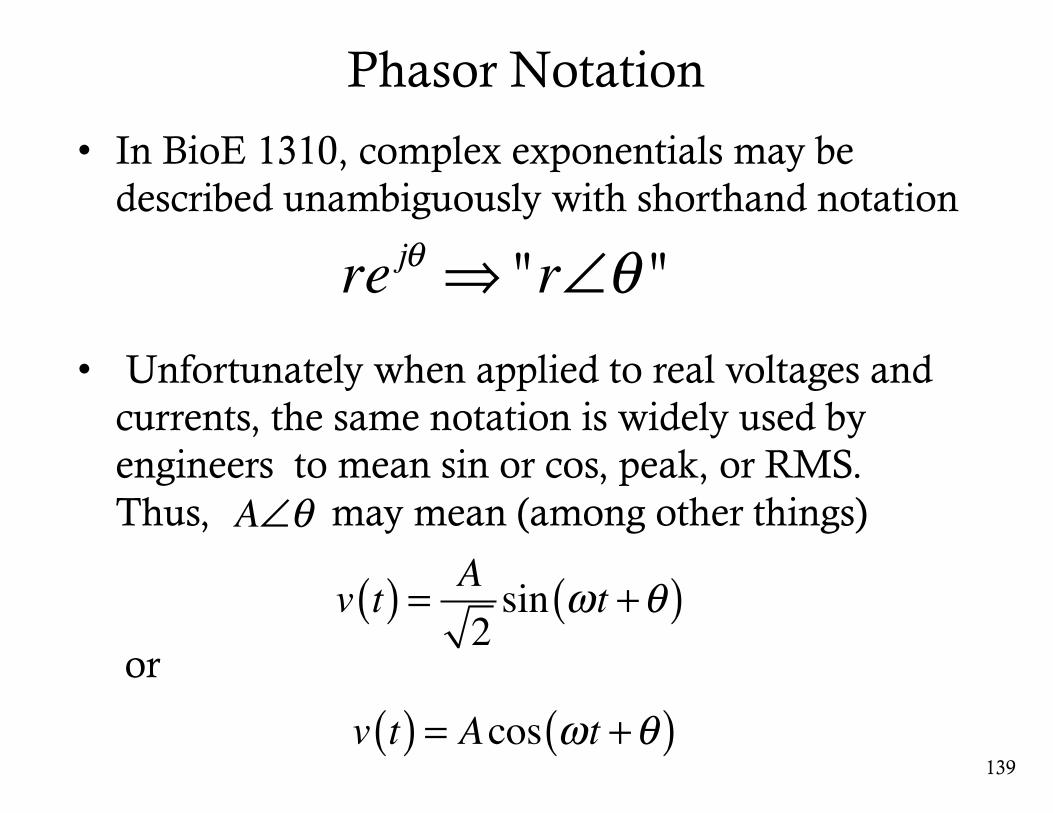
Phasor Notation
• In BioE 1310, complex exponentials may be described unambiguously with shorthand notation
• Unfortunately when applied to real voltages and currents, the same notation is widely used by engineers to mean sin or cos, peak, or RMS. Thus, may mean (among other things)
139
re jθ ⇒ "r∠θ "
A∠θ
v t( ) = A2sin ωt +θ( )
v t( ) = Acos ωt +θ( )or
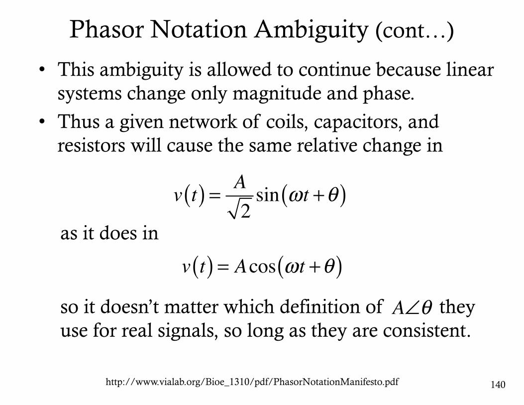
Phasor Notation Ambiguity (cont…)
• This ambiguity is allowed to continue because linear systems change only magnitude and phase.
• Thus a given network of coils, capacitors, and resistors will cause the same relative change in
140
A∠θ
v t( ) = A2sin ωt +θ( )
v t( ) = Acos ωt +θ( )as it does in
so it doesn’t matter which definition of they use for real signals, so long as they are consistent.
http://www.vialab.org/Bioe_1310/pdf/PhasorNotationManifesto.pdf
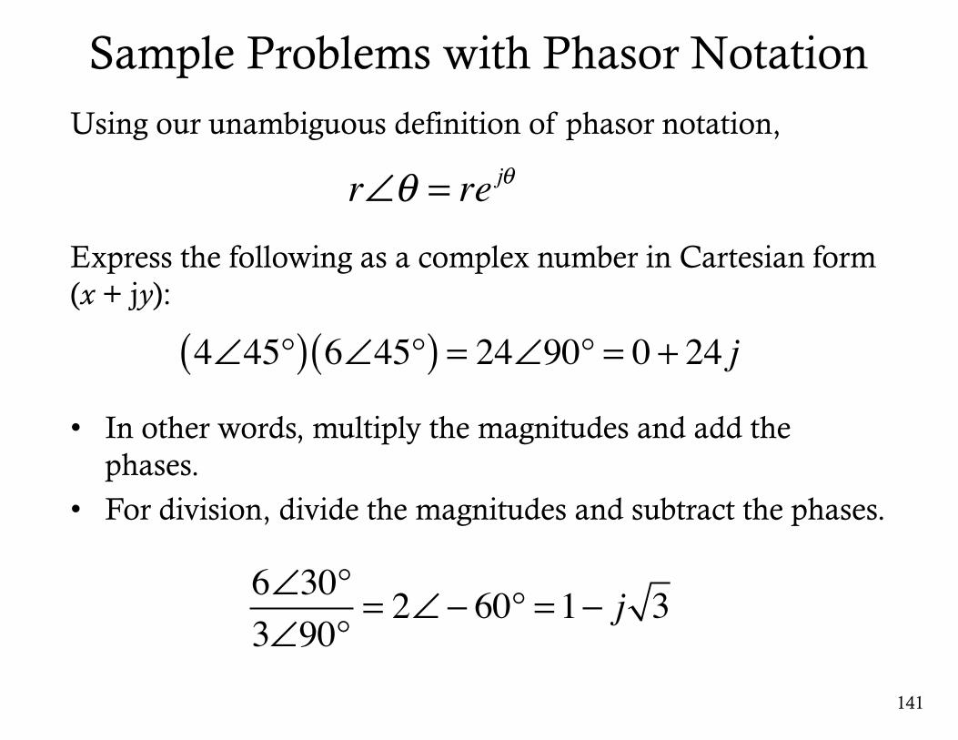
Sample Problems with Phasor NotationUsing our unambiguous definition of phasor notation,
Express the following as a complex number in Cartesian form (x + jy):
• In other words, multiply the magnitudes and add the phases.
• For division, divide the magnitudes and subtract the phases.
141
4∠45°( ) 6∠45°( ) = 24∠90° = 0 + 24 j
r∠θ = re jθ
6∠30°3∠90°
= 2∠− 60° =1− j 3
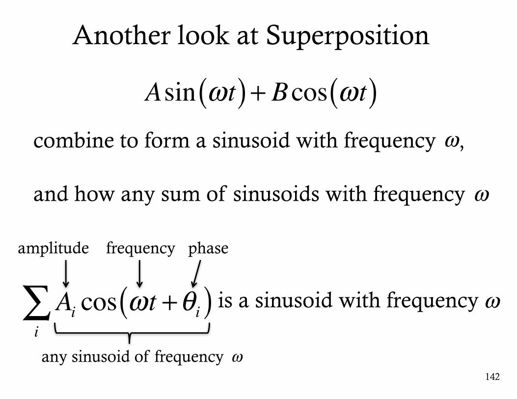
Another look at Superposition
142
Asin ωt( )+ Bcos ωt( )combine to form a sinusoid with frequency ,
and how any sum of sinusoids with frequency
ω
Ai cos ωt +θi( )i∑amplitude frequency phase
any sinusoid of frequency ω
is a sinusoid with frequency ω
ω
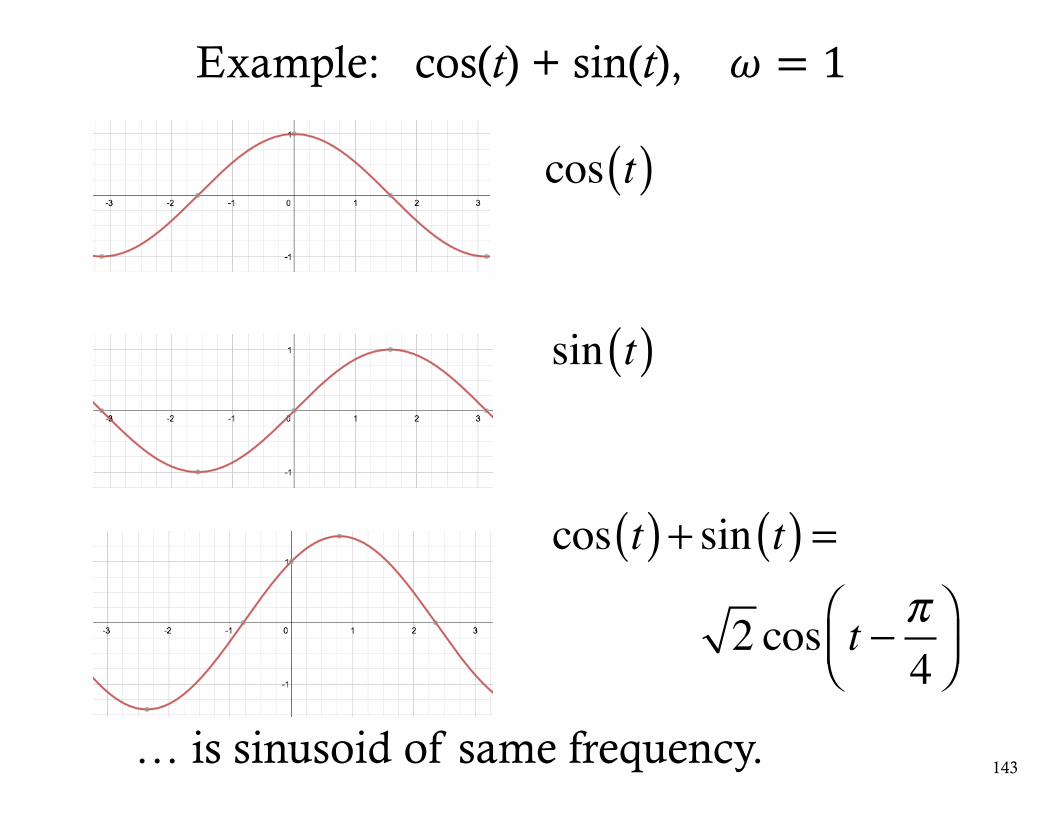
Example: cos(t) + sin(t), 𝜔 = 1
cos t( )
sin t( )
cos t( )+ sin t( ) =
2 cos t − π4
⎛⎝⎜
⎞⎠⎟
143… is sinusoid of same frequency.
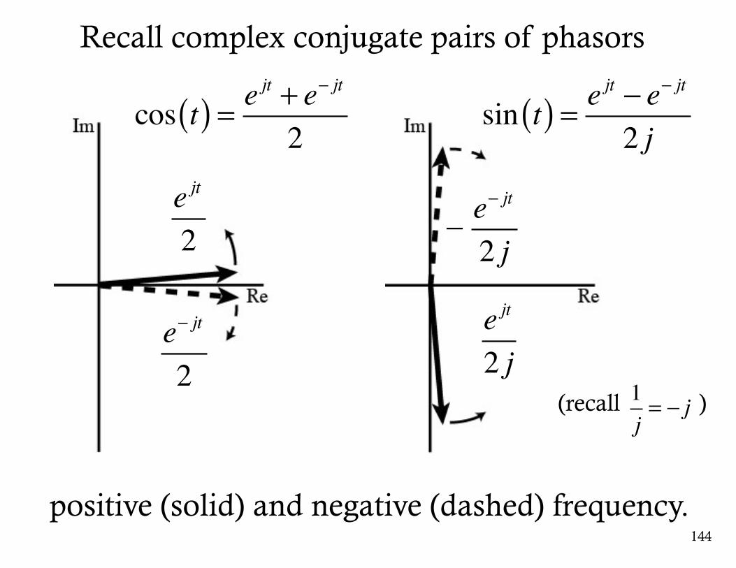
144
cos t( ) = ejt + e− jt
2
Recall complex conjugate pairs of phasors
e jt
2
e− jt
2
e jt
2 j
e− jt
2 j
positive (solid) and negative (dashed) frequency.
(recall )1j= − j
sin t( ) = ejt − e− jt
2 j
_
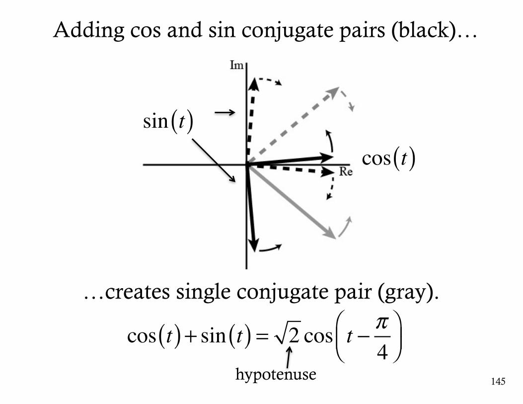
…creates single conjugate pair (gray).
sin t( )
cos t( )+ sin t( ) = 2 cos t − π4
⎛⎝⎜
⎞⎠⎟
145
cos t( )
Adding cos and sin conjugate pairs (black)…
hypotenuse
146
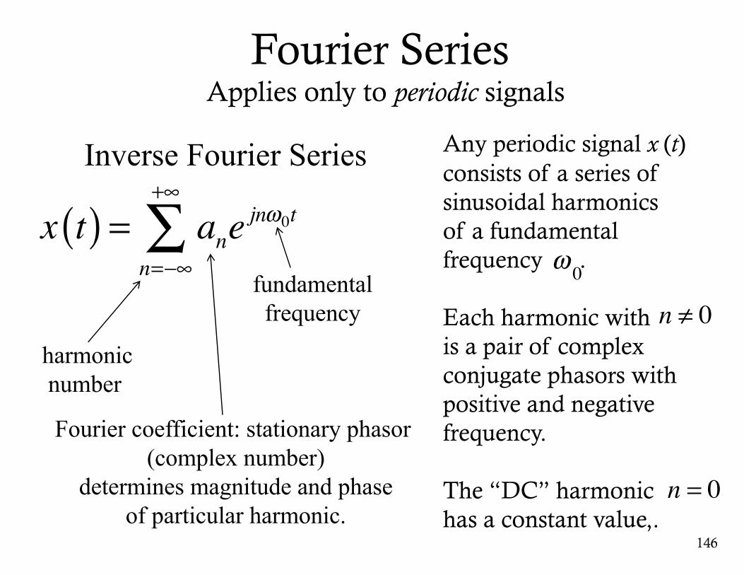
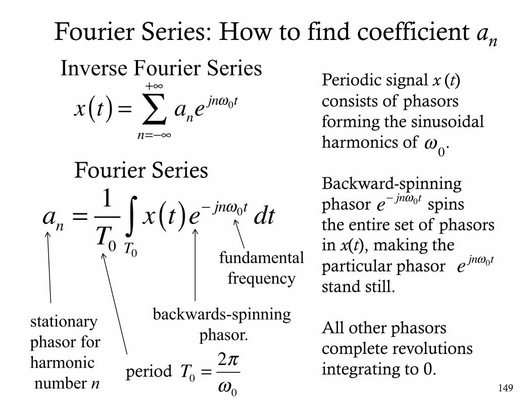
Inverse Fourier Series
Fourier coefficient: stationary phasor(complex number)
determines magnitude and phaseof particular harmonic.
x t( ) = anejnω0t
n=−∞
+∞
∑
harmonicnumber
fundamentalfrequency
Fourier Series Applies only to periodic signals
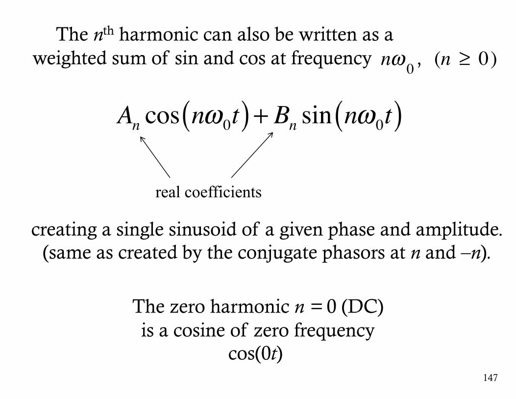
Any periodic signal x (t) consists of a series of sinusoidal harmonics of a fundamental frequency .
Each harmonic with is a pair of complex conjugate phasors with positive and negative frequency.
The “DC” harmonic has a constant value,.
ω 0
n ≠ 0
n = 0
147
An cos nω0t( )+ Bn sin nω0t( )
real coefficients
The nth harmonic can also be written as a weighted sum of sin and cos at frequency ,
The zero harmonic n = 0 (DC)is a cosine of zero frequency
cos(0t)
nω 0 (n ≥ 0)
creating a single sinusoid of a given phase and amplitude.(same as created by the conjugate phasors at n and –n).
148
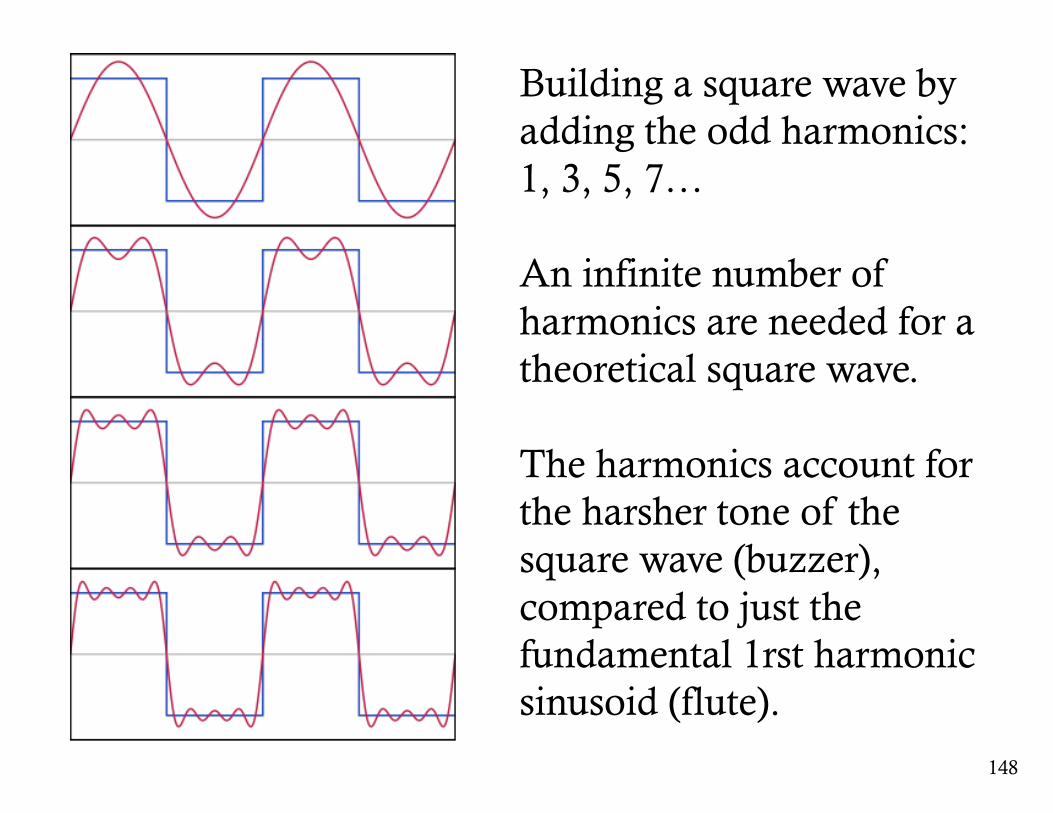
Building a square wave by adding the odd harmonics: 1, 3, 5, 7…
An infinite number of harmonics are needed for a theoretical square wave.
The harmonics account for the harsher tone of the square wave (buzzer), compared to just the fundamental 1rst harmonic sinusoid (flute).
149
backwards-spinning phasor.
an =1T0
x t( )e− jnω0t dtT0∫
stationaryphasor for harmonicnumber n
fundamentalfrequency
Fourier Series: How to find coefficient an
Periodic signal x (t) consists of phasorsforming the sinusoidal harmonics of .
Backward-spinning phasor spins the entire set of phasorsin x(t), making the particular phasorstand still.
All other phasorscomplete revolutions integrating to 0.
ω 0
e− jnω0t
e jnω0t
period T0 =2πω0
Fourier Series
Inverse Fourier Series
x t( ) = anejnω0t
n=−∞
+∞
∑
150
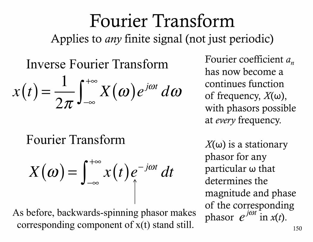
Inverse Fourier Transform
x t( ) = 12π
X ω( )e jωt dω−∞
+∞
∫
Fourier TransformApplies to any finite signal (not just periodic)
Fourier coefficient an
has now become a continues function of frequency, X(ω), with phasors possible at every frequency.
X(ω) is a stationary phasor for any particular ω that determines the magnitude and phase of the corresponding phasor in x(t).e jωt
Fourier Transform
X ω( ) = x t( )e− jωt dt−∞
+∞
∫As before, backwards-spinning phasor makes corresponding component of x(t) stand still.
151
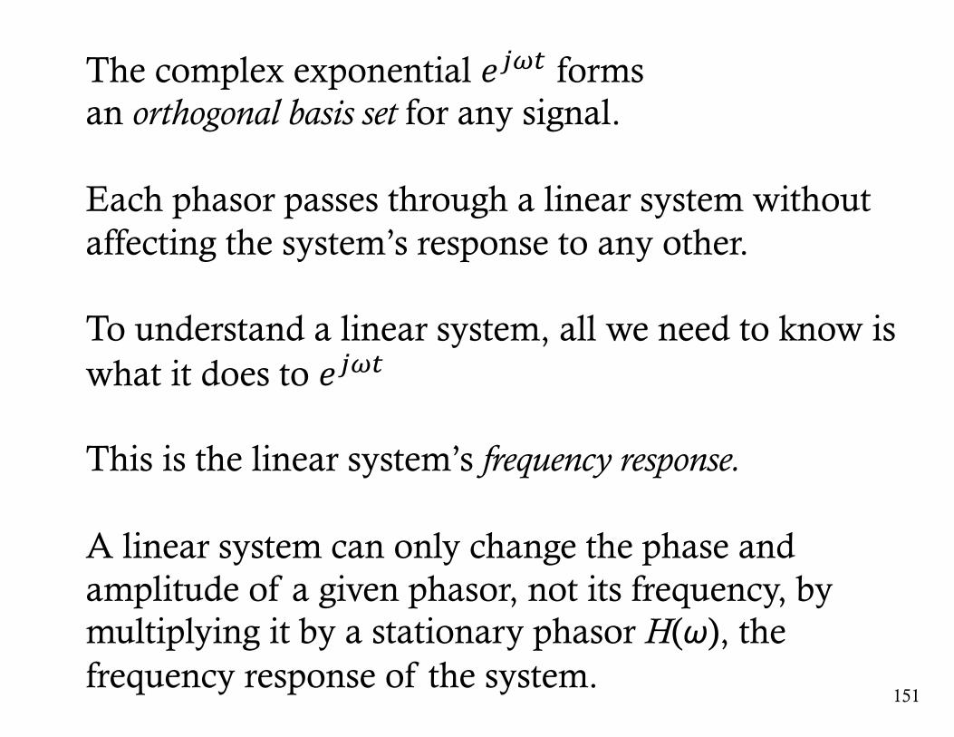
The complex exponential 𝑒./0 formsan orthogonal basis set for any signal.
Each phasor passes through a linear system without affecting the system’s response to any other.
To understand a linear system, all we need to know is what it does to 𝑒./0
This is the linear system’s frequency response.
A linear system can only change the phase and amplitude of a given phasor, not its frequency, by multiplying it by a stationary phasor H(ω), the frequency response of the system.
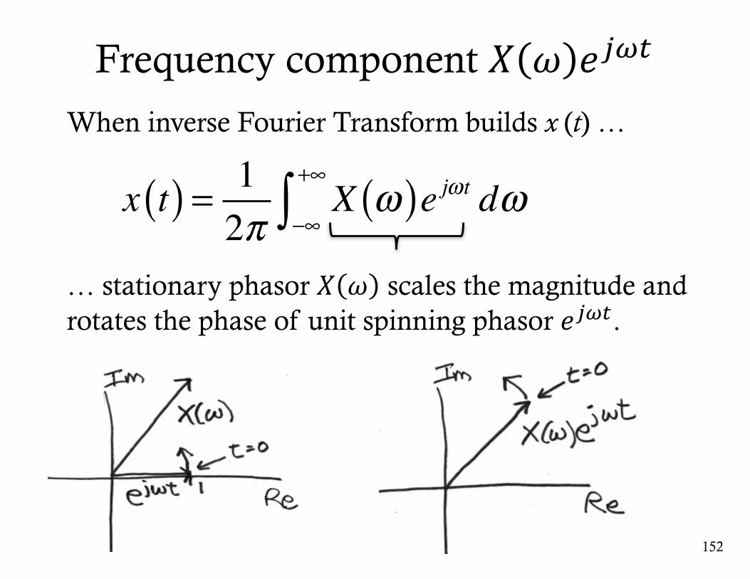
Frequency component 𝑋 𝜔 𝑒./0
When inverse Fourier Transform builds x (t) …
… stationary phasor 𝑋 𝜔 scales the magnitude and rotates the phase of unit spinning phasor 𝑒./0.
152
x t( ) = 12π
X ω( )e jωt dω−∞
+∞
∫
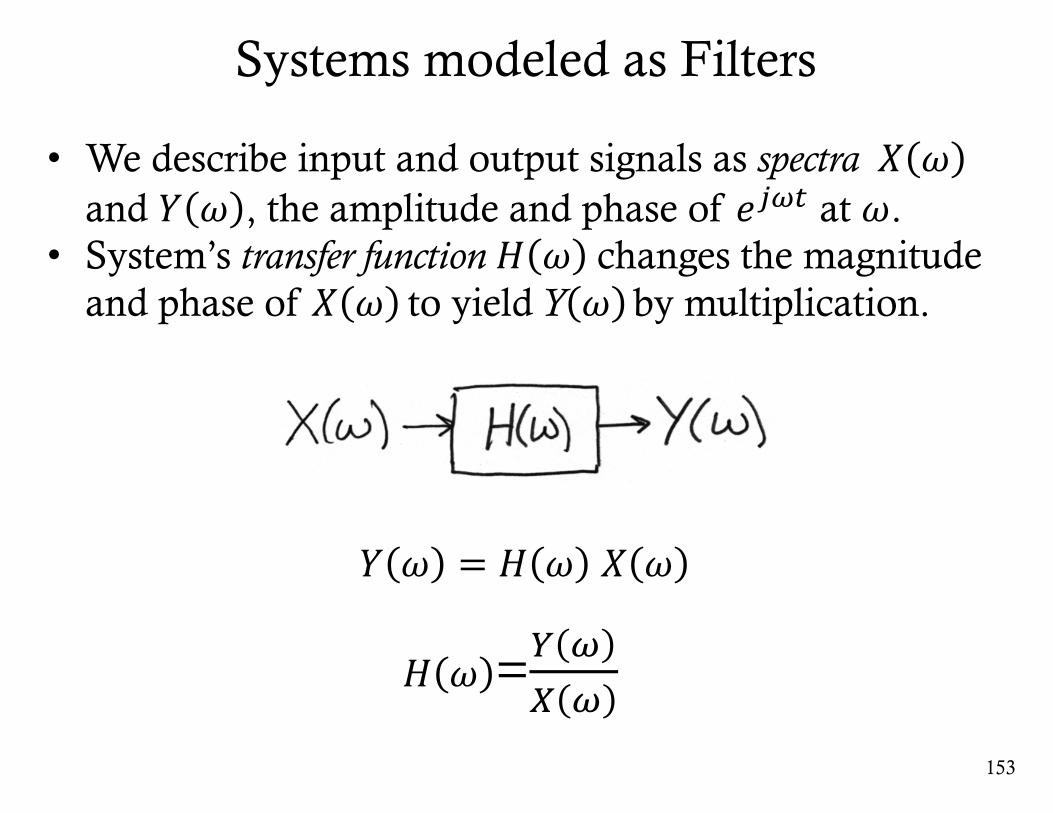
Systems modeled as Filters
153
• We describe input and output signals as spectra 𝑋 𝜔and 𝑌 𝜔 , the amplitude and phase of 𝑒./0 at 𝜔.
• System’s transfer function 𝐻 𝜔 changes the magnitude and phase of 𝑋 𝜔 to yield Y 𝜔 by multiplication.
𝐻 𝜔 =6 /7 /
𝑌 𝜔 = 𝐻 𝜔 𝑋 𝜔
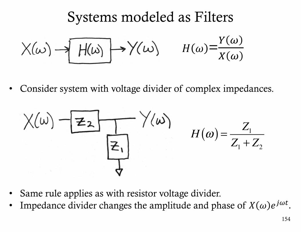
Systems modeled as Filters
154
• Consider system with voltage divider of complex impedances.
• Same rule applies as with resistor voltage divider.• Impedance divider changes the amplitude and phase of 𝑋 𝜔 𝑒./0.
H ω( ) = Z1Z1 + Z2
𝐻 𝜔 =6 /7 /
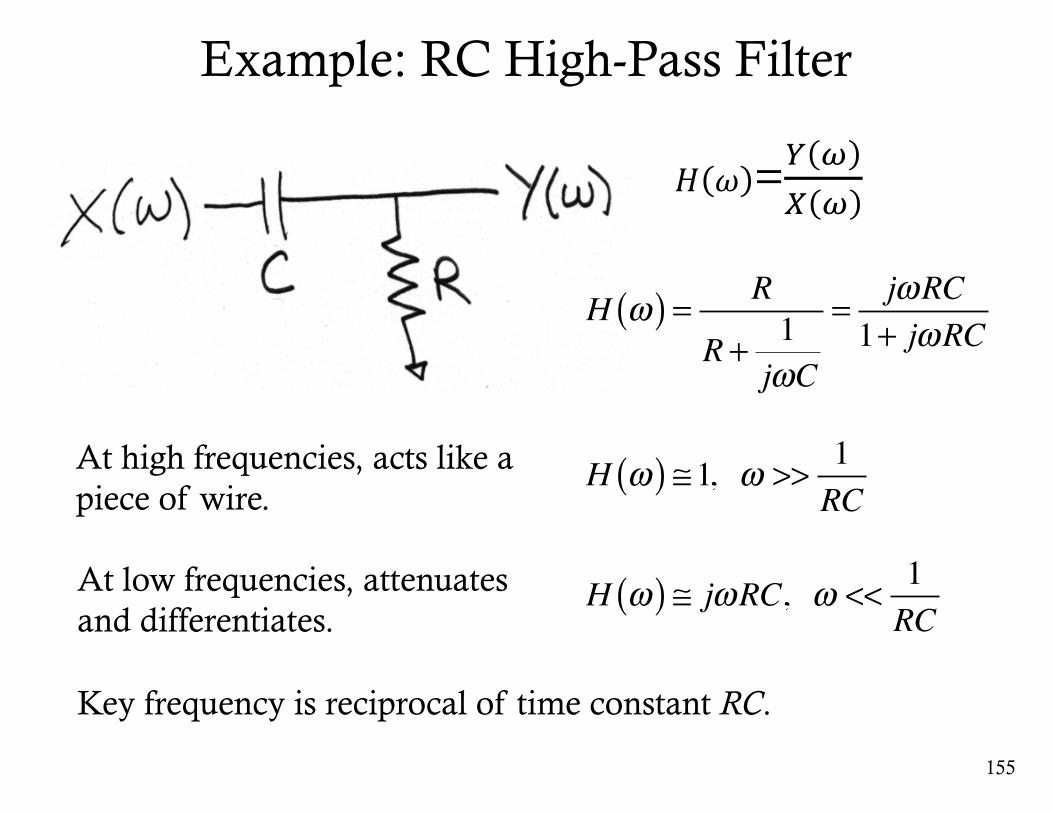
155
H ω( ) = R
R + 1jωC
= jωRC1+ jωRC
H ω( ) ≅1, ω >> 1RC
H ω( ) ≅ jωRC, ω << 1RC
At high frequencies, acts like a piece of wire.
At low frequencies, attenuates and differentiates.
Example: RC High-Pass Filter
Key frequency is reciprocal of time constant RC.
𝐻 𝜔 =6 /7 /
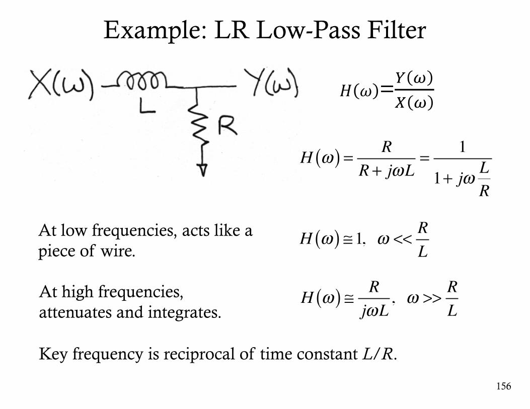
156
H ω( ) = RR + jωL
= 1
1+ jω LR
H ω( ) ≅1, ω << RL
H ω( ) ≅ RjωL
, ω >> RL
At low frequencies, acts like a piece of wire.
At high frequencies, attenuates and integrates.
Example: LR Low-Pass Filter
Key frequency is reciprocal of time constant L/R.
𝐻 𝜔 =6 /7 /

157
H ω( ) =1jωC
R + 1jωC
= 11+ jωRC
H ω( ) ≅1, ω << 1RC
H ω( ) ≅ 1jωRC
, ω >> 1RC
At low frequencies, acts like a piece of wire. (assuming no current at output)
At high frequencies, attenuates and integrates.
Example: RC Low-Pass Filter
Key frequency is reciprocal of time constant RC.
𝐻 𝜔 =6 /7 /
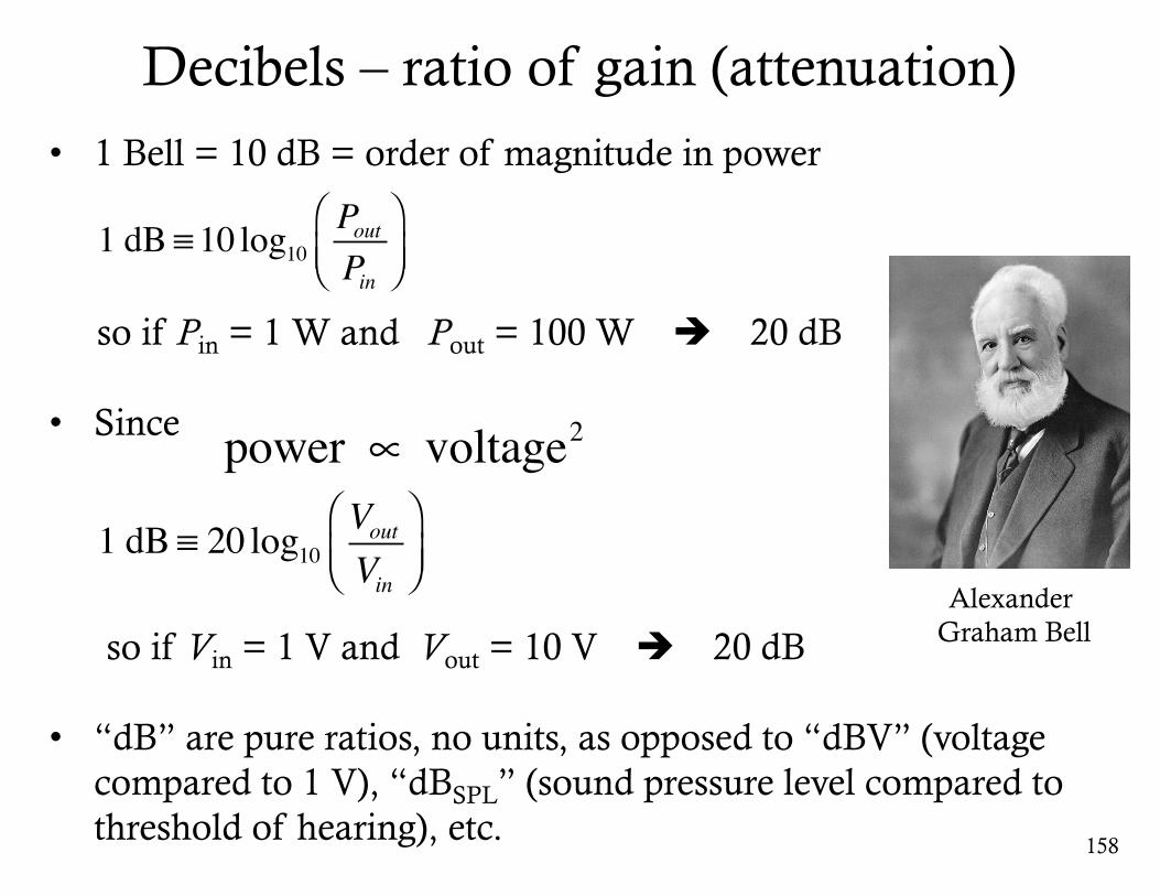
Decibels – ratio of gain (attenuation)
158
Alexander Graham Bell
• 1 Bell = 10 dB = order of magnitude in power
so if Pin = 1 W and Pout = 100 W è 20 dB
• Since
so if Vin = 1 V and Vout = 10 V è 20 dB
• “dB” are pure ratios, no units, as opposed to “dBV” (voltage compared to 1 V), “dBSPL” (sound pressure level compared to threshold of hearing), etc.
1 dB ≡10 log10PoutPin
⎛⎝⎜
⎞⎠⎟
1 dB ≡ 20 log10VoutVin
⎛⎝⎜
⎞⎠⎟
power ∝ voltage2

Magnitude and Phase of Low-Pass Filter
159
At corner (or “cut-off ”) frequency, ωC = 1/RC ,
H ω( ) = 1− j2
= 12
H ω( ) ≅ −3dB
Magnitude (Gain/Attenuation)
Recall low-pass filter:
Phase
∠H ω( ) = arctan− 1212
⎛
⎝⎜⎜
⎞
⎠⎟⎟
∠H ω( ) = −45°
H ω( ) = 11+ j
⋅1− j1− j
= 1− j2
𝐻 𝜔 =9
9:./;<
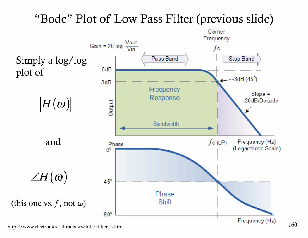
“Bode” Plot of Low Pass Filter (previous slide)
160http://www.electronics-tutorials.ws/filter/filter_2.html
H ω( )
Simply a log/log plot of
and
∠H ω( )(this one vs. f , not ω)
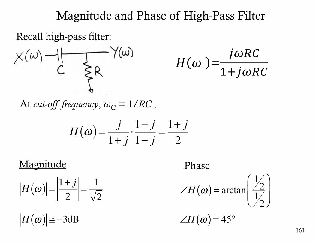
Magnitude and Phase of High-Pass Filter
161
At cut-off frequency, ωC = 1/RC ,
H ω( ) = 1+ j2
= 12
H ω( ) ≅ −3dB
Magnitude
Recall high-pass filter:
Phase
∠H ω( ) = arctan1212
⎛
⎝⎜⎜
⎞
⎠⎟⎟
∠H ω( ) = 45°
H ω( ) = j1+ j
⋅1− j1− j
= 1+ j2
𝐻 𝜔 =./;<9:./;<
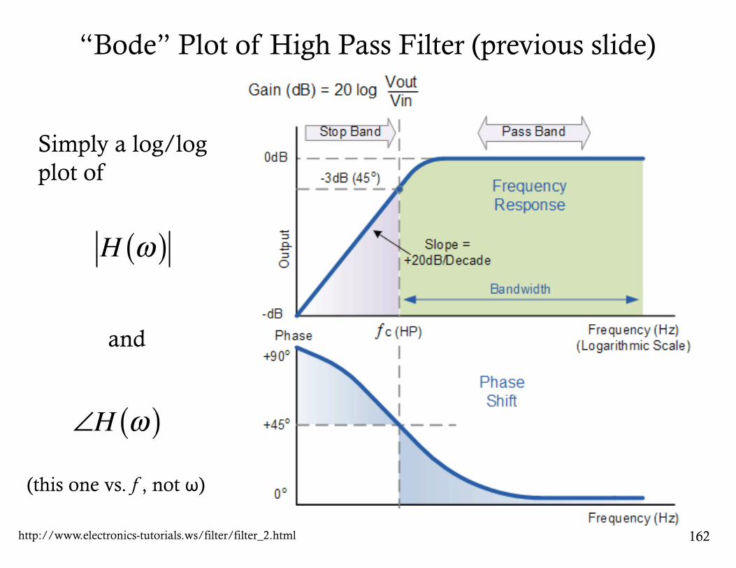
“Bode” Plot of High Pass Filter (previous slide)
162http://www.electronics-tutorials.ws/filter/filter_2.html
H ω( )
Simply a log/log plot of
and
∠H ω( )(this one vs. f , not ω)
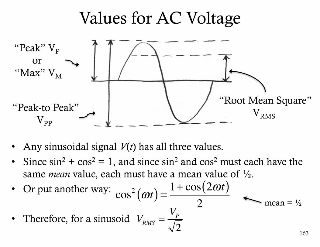
Values for AC Voltage
• Any sinusoidal signal V(t) has all three values.
• Since sin2 + cos2 = 1, and since sin2 and cos2 must each have the same mean value, each must have a mean value of ½.
• Or put another way:
• Therefore, for a sinusoid163
VRMS =VP2
“Peak” VP
or “Max” VM
“Peak-to Peak”VPP
“Root Mean Square”VRMS
cos2 ωt( ) = 1+ cos 2ωt( )2 mean = ½
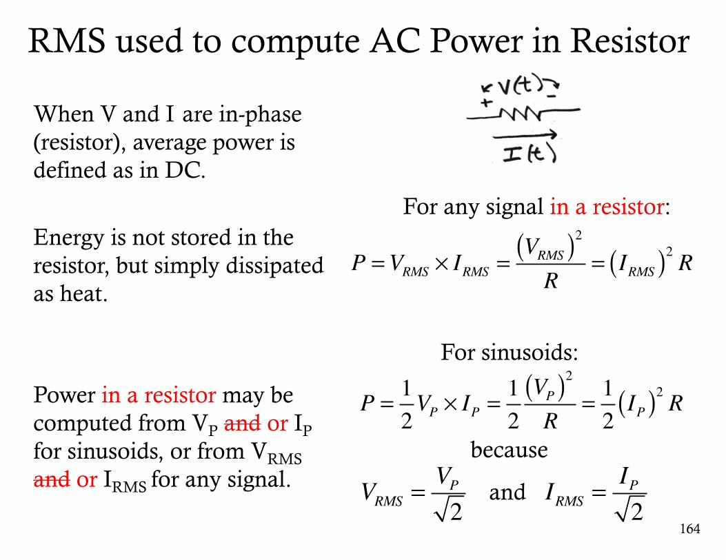
RMS used to compute AC Power in Resistor
When V and I are in-phase (resistor), average power is defined as in DC.
Energy is not stored in the resistor, but simply dissipated as heat.
Power in a resistor may be computed from VP and or IP
for sinusoids, or from VRMS
and or IRMS for any signal.
164
P =VRMS × IRMS =VRMS( )2R
= IRMS( )2 R
because
VRMS =VP2
P = 12VP × IP =
12VP( )2R
= 12IP( )2 R
For any signal in a resistor:
For sinusoids:
IRMS =IP2
and
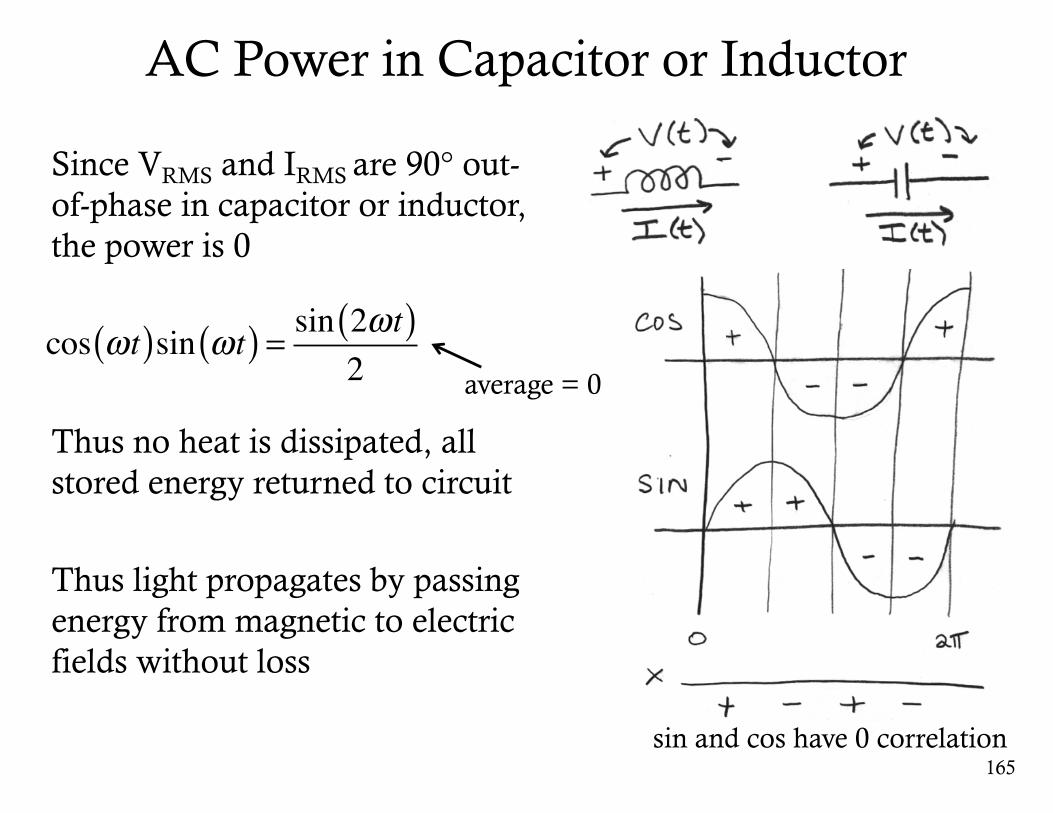
AC Power in Capacitor or Inductor
Since VRMS and IRMS are 90° out-of-phase in capacitor or inductor, the power is 0
Thus no heat is dissipated, all stored energy returned to circuit
Thus light propagates by passing energy from magnetic to electric fields without loss
165
cos ωt( )sin ωt( ) = sin 2ωt( )2
sin and cos have 0 correlation
average = 0
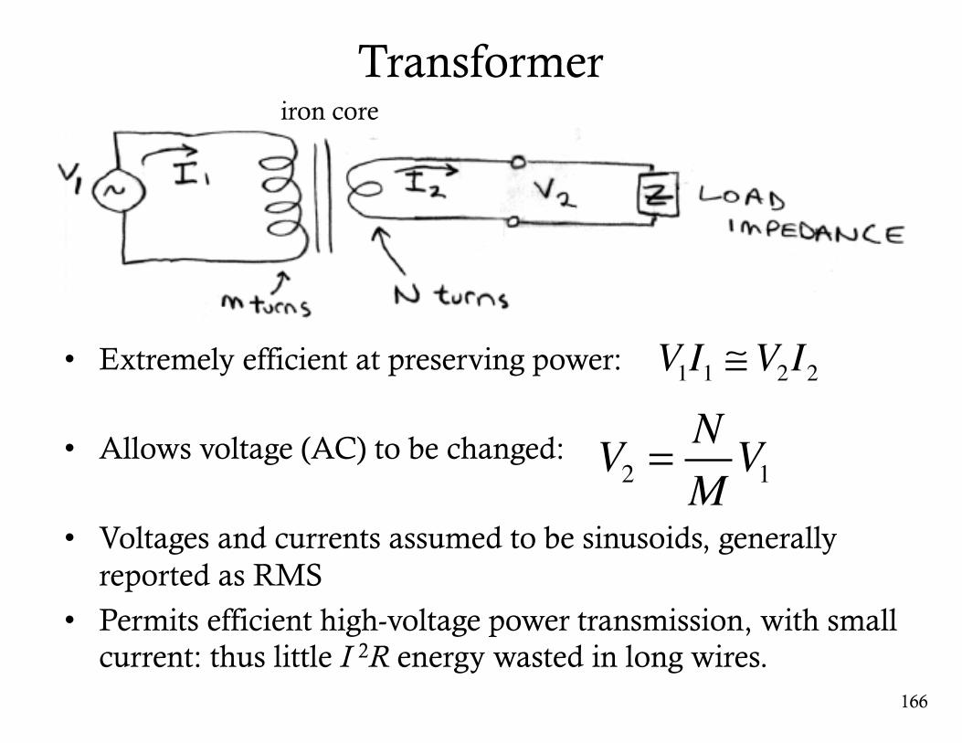
Transformer
• Extremely efficient at preserving power:
• Allows voltage (AC) to be changed:
• Voltages and currents assumed to be sinusoids, generally reported as RMS
• Permits efficient high-voltage power transmission, with small current: thus little I 2R energy wasted in long wires.
166
iron core
V1I1 ≅V2I2
V2 =NMV1
167
GeorgeWestinghouse
Nikola Tesla
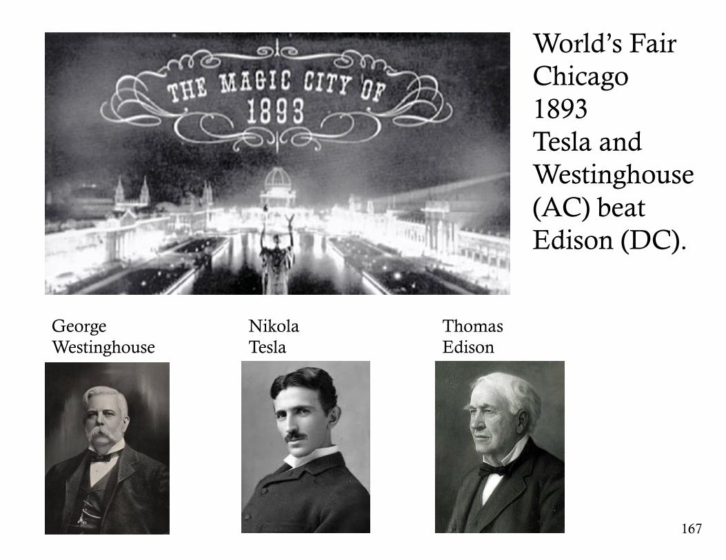
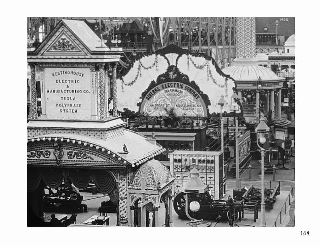
World’s FairChicago1893Tesla and Westinghouse (AC) beat Edison (DC).
ThomasEdison
168