alternating current circuits and electr oma gnetic w...
TRANSCRIPT

Chapter 21
Alternating Current Circuits and Electromagnetic Waves
Quick Quizzes
1. (a), (c). The average power is proportional to the rms current which is non-zero even though the average current is zero. (a) is only valid for an open circuit, for which . (b) and (d) can never be true because
R→∞av 0i = for AC currents.
2. (b). Choices (a) and (c) are incorrect because the unaligned sine curves in Figure 21.9 mean the voltages are out of phase, and so we cannot simply add the maximum (or rms) voltages across the elements. (In other words, R LV V V VC∆ ≠ ∆ + ∆ + ∆ even though
∆.) R Lv v v v∆ = ∆ + ∆ + ∆ C
3. (b). Note that this is a DC circuit. However, changing the amount of iron inside the solenoid changes the magnetic field strength in that region and results in a changing magnetic flux through the loops of the solenoid. This changing flux will generate a back emf that opposes the current in the circuit and decreases the brightness of the bulb. The effect will be present only while the rod is in motion. If the rod is held stationary at any position, the back emf will disappear, and the bulb will return to its original brightness.
4. (b), (c). The radiation pressure (a) does not change because pressure is force per unit area. In (b), the smaller disk absorbs less radiation, resulting in a smaller force. For the same reason, the momentum in (c) is reduced.
5. (b), (d). The frequency and wavelength of light waves are related by the equation f cλ =
or f c λ= , where c is the speed of light is a constant within a given medium. Thus, the frequency and wavelength are inversely proportional to each other, when one increases the other must decrease.
201

202 CHAPTER 21
Answers to Even Numbered Conceptual Questions
2. At resonance, X . This means that the impedance L X= C )( 22L CX X= + −Z R reduces to
Z = R.
4. The purpose of the iron core is to increase the flux and to provide a pathway in which nearly all the flux through one coil is led through the other.
6. The fundamental source of an electromagnetic wave is a moving charge. For example, in a transmitting antenna of a radio station, charges are caused to move up and down at the frequency of the radio station. These moving charges set up electric and magnetic fields, the electromagnetic wave, in the space around the antenna.
8. Energy moves. No matter moves. You could say that electric and magnetic fields move, but it is nicer to say that the fields stay at that point and oscillate. The fields vary in time, like sports fans in the grandstand when the crowd does the wave. The fields constitute the medium for the wave, and energy moves.
10. The average value of an alternating current is zero because its direction is positive as often as it is negative, and its time average is zero. The average value of the square of the current is not zero, however, since the square of positive and negative values are always positive and cannot cancel.
12. The brightest portion of your face shows where you radiate the most. Your nostrils and the openings of your ear canals are particularly bright. Brighter still are the pupils of your eyes.
14. No, the only element that dissipates energy in an AC circuit is a resistor. Inductors and capacitors store energy during one half of a cycle and release that energy during the other half of the cycle, so they dissipate no net energy.
16. The changing magnetic field of the solenoid induces eddy currents in the conducting core. This is accompanied by conversion of electrically-transmitted energy into internal energy in the conductor.
2I R
18. The voltages are not added in a scalar form, but in a vector form, as shown in the phasor diagrams throughout the chapter. Kirchhoff’s loop rule is true at any instant, but the voltages across different circuit elements are not simultaneously at their maximum values. Do not forget that an inductor can induce an emf in itself and that the voltage across it is 90° ahead of the current in the circuit in phase.
20. Insulation and safety limit the voltage of a transmission line. For an underground cable, the thickness and dielectric strength of the insulation between the conductors determines the maximum voltage that can be applied, just as with a capacitor. For an overhead line on towers, the designer must consider electrical breakdown of the surrounding air, possible accidents, sparking across the insulating supports, ozone production, and inducing voltages in cars, fences, and the roof gutters of nearby houses. Nuisance effects include noise, electrical noise, and a prankster lighting a hand-held fluorescent tube under the line.
Alternating Current Circuits and Electromagnetic Waves 203
Answers to Even Numbered Problems
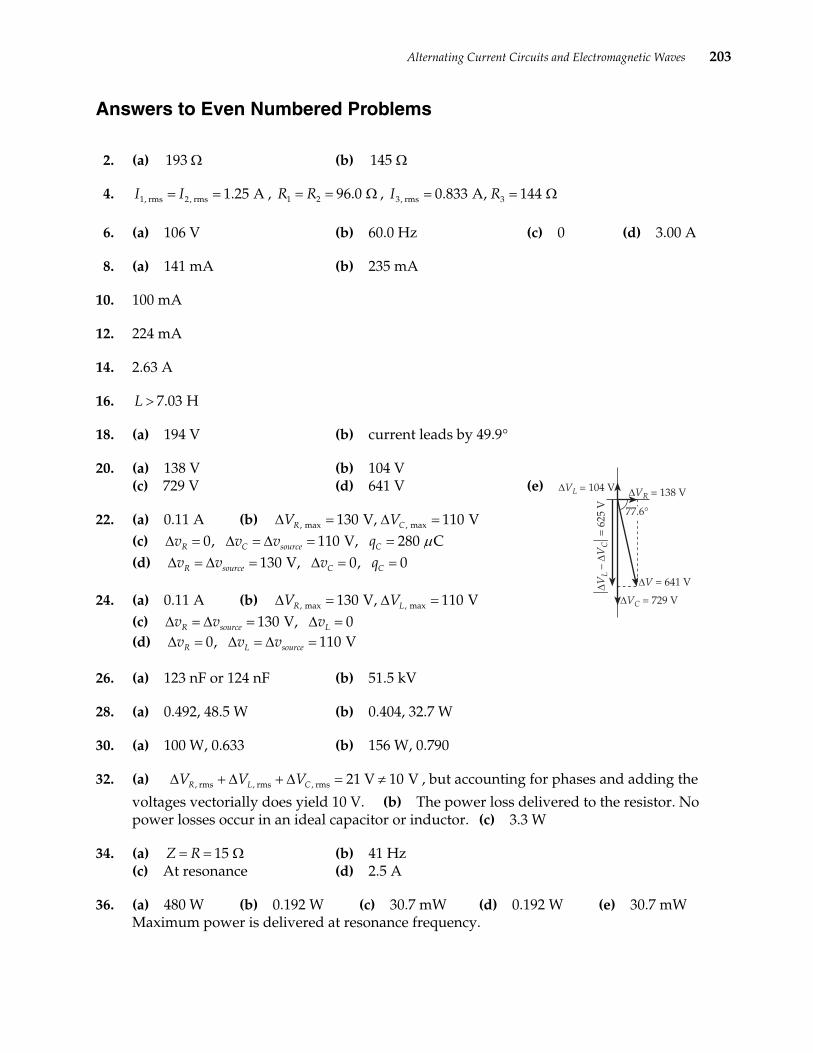
2. (a) (b) 193 Ω 145 Ω
4. , , 1, rms 2, rms 1.25 AI I= = 1 2 96.0 R R= = Ω 3, rms 30.833 A, 144 I R= = Ω
6. (a) 106 V (b) 60.0 Hz (c) 0 (d) 3.00 A
8. (a) 141 mA (b) 235 mA
10. 100 mA
12. 224 mA
14. 2.63 A
16. 7.03 HL >
18. (a) 194 V (b) current leads by 49.9°
20. (a) 138 V (b) 104 V (c) 729 V (d) 641 V (e)
22. (a) 0.11 A (b) (c)
, max , max130 V, 110 VR CV V∆ = ∆ =110 V, 280 Csource Cv q0, R Cv v µ∆ = ∆ =
R sourcev v∆ = ∆ =∆ = =
130 V, 0, 0C Cv q∆ = =
(d)
24. (a) 0.11 A (b) (c) (d)
, max , max130 V, 110 VR LV V∆ = ∆ =0 V, 0Lv∆ =
110 Vsourcev∆ =13R sourcev v∆ = ∆ =
0, R Lv v∆ = ∆ =
26. (a) 123 nF or 124 nF (b) 51.5 kV
28. (a) 0.492, 48.5 W (b) 0.404, 32.7 W
30. (a) 100 W, 0.633 (b) 156 W, 0.790
32. (a) , but accounting for phases and adding the
voltages vectorially does yield 10 V. (b) The power loss delivered to the resistor. No power losses occur in an ideal capacitor or inductor. (c) 3.3 W
, rms , rms , rms 21 V 10 VR L CV V V∆ + ∆ + ∆ = ≠
34. (a) (b) 41 Hz (c) At resonance (d) 2.5 A
15Z R= = Ω
36. (a) 480 W (b) 0.192 W (c) 30.7 mW (d) 0.192 W (e) 30.7 mW Maximum power is delivered at resonance frequency.

204 CHAPTER 21
38. (a) 18 turns (b) 3.6 W
40. (a) Fewer turns (b) 25 mA (c) 20 turns
42. (a) 29.0 kW (b) 0.580% (c) The maximum power that can be input to the line at 4.50 kV is far less than 5.00 MW, and it is all lost in the transmission line.
44. 82.998 10 m s×
46. 80%
48. 263.74 10 W×
50. 11.0 m
52. Radio listeners hear the news 8.4 ms before the studio audience because radio waves travel much faster than sound waves.
54. 14 116.003 6 10 Hz, the frequency increases by 3.6 10 Hz× ×
56. 71.1 10 m s×
58. 6~10 J
60. 2.5 mH, 26 Fµ
62. (a) 0.63 pF (b) 8.5 mm (c) 25 Ω
64. (a) (b) 12 mH 6.0 Ω
66. 32
68. 3cX R=
Alternating Current Circuits and Electromagnetic Waves 205
Problem Solutions
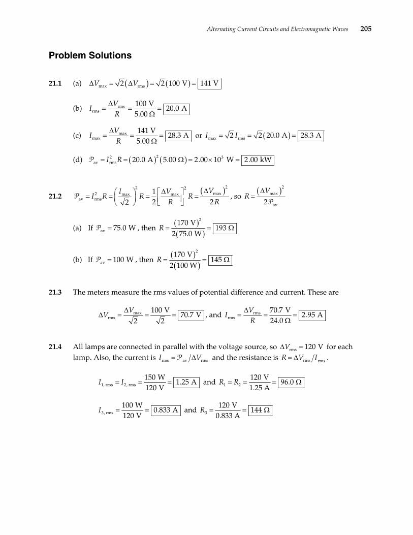
21.1 (a) ( ) ( )max rms2 2 100 V 141 VV V∆ = =∆ =
(b) rmsrms
100 V20.0 A
5.00 VR
∆=
ΩI = =
(c) maxmax
141 V28.3 A
5.00 VR
∆=
ΩI = = or ( )max rms2 2 20.0 A 28.3 AI I= = =
(d) ( ) ( )22 3av rms 20.0 A 5.00 2.00 10 W 2.00 kWI R Ω = × == =P
21.2 ( )22 2
max2 max maxav rms
12 22
VI VI R R R
R R
∆∆ = = = = P , so
( )2max
av2
VR
∆=
P
(a) If 75.0=P , then av W( )( )
2170 V193
2 75.0 WR = = Ω
(b) If 10=P , then av 0 W( )( )
2170 V145
2 100 WR = = Ω
21.3 The meters measure the rms values of potential difference and current. These are
maxrms
100 V70.7 V
2 2V
V∆
∆ = = = , and rmsrms
70.7 V2.95 A
24.0 V
IR
∆= = =
Ω
21.4 All lamps are connected in parallel with the voltage source, so rms 120 VV∆ = for each lamp. Also, the current is rms av rmsI V= ∆√ and the resistance is rms rmsR V I= ∆ .
1, rms 2, rms
150 W1.25 A
120 VI I= = = and 1 2
120 V1.25 A
R R 96.0 = = = Ω
3, rms
100 W0.833 A
120 VI = = and 3
120 V144
0.833 AR = = Ω
206 CHAPTER 21
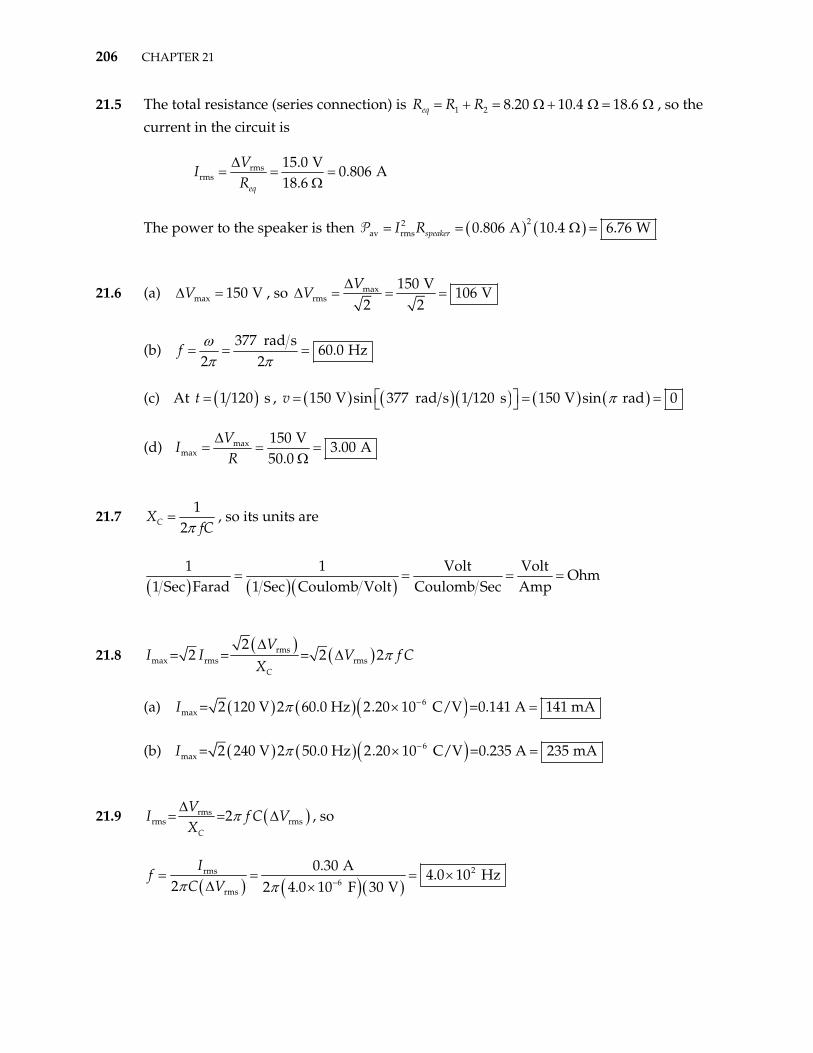
21.5 The total resistance (series connection) is 1 2 8.20 10.4 18.6 eqR R R= + = Ω + Ω = Ω , so the
current in the circuit is
rmsrms
15.0 V0.806 A
18.6 eq
VI
R∆
= = =Ω
The power to the speaker is then ( ) ( )2
s 0.806 A 10.4 6.76 WspeakerI R= = Ω =2av rmP
21.6 (a) ∆ = , so max 150 VV maxrms
150 V106 V
2 2V
V∆
∆ = = =
(b) 377 rad s
60.0 Hz2 2ωπ π
=f = =
(c) At ( )1 120 st = , ( ) ( )( ) ( ) ( )150 V sin 377 rad s 1 120 s 150 V sin rad 0v π = = =
(d) maxmax
150 V3.00 A
50.0 VR
∆=
ΩI = =
21.7 1
2CXfCπ
= , so its units are
( ) ( )( )1 1 Volt Volt
Ohm1 Sec Farad 1 Sec Coulomb Volt Coulomb Sec Amp
= = = =
21.8 ( ) ( )rms
max rms rms
2= 2 = = 2 2
C
VI I V
Xπ
∆∆ f C
(a) ( ) ( )( )6max 2 120 V 2 60.0 Hz 2.20 10 C/V =0.141 A 141 mAπ −× ==I
(b) ( ) ( )( )6max 2 240 V 2 50.0 Hz 2.20 10 C/V =0.235 A 235 mAπ −× ==I
21.9 ( )rmsrms rms= =2
C
VI f C
Xπ
∆∆
( )
V , so
( )( )2rms
6rms
0.30 A4.0 10 Hz
2 2 4.0 10 F 30 VI
fC Vπ π −
= = = ×∆ ×

Alternating Current Circuits and Electromagnetic Waves 207
21.10 ( )
( )( )( )
maxmax max
6
= =2
2 90.0 Hz 3.70 10 C/V 48.0 V =0.100 A= 100 mA
C
VI f C V
Xπ
π −
∆∆
= ×
21.11 ( )rms maxrms max= =2
2C
V VI f C f C V
Xπ π
∆ ∆ = ∆
( )
2
so ( )( )
5
max
0.75 A1.7 10 F 17 F
2 60 Hz 170 V 2I
Cf V
µπ π
−= = = × =∆
21.12 rms maxrms = =
2C
V VI C
Xω
∆ ∆
or ( )( )6rms
140 V= 120 rad s 6.00 10 F 0.224 A 224 mA
2I π − × = =
21.13 2LX f Lπ= , and from I
Lt
ε ∆= ∆
, we have ( )tI
Lε ∆
=∆
. The units of self inductance are
then [ ] [ ][ ][ ]
Volt secAmp
tI
Lε ∆ ⋅
= =∆
[ ][ ]
. The units of inductive reactance are given by
[ ] 1 Volt sec VoltOhm
sec Amp AmpX f L
⋅ = = = =
L
21.14 The maximum current in the purely inductive circuit is
( )( )
max maxmax
140 V3.71 A
120 rad s 0.100 HL
V VI
X Lω π∆ ∆
= = = =
so maxrms
3.71 A2.63 A
2 2I
I = = =
208 CHAPTER 21
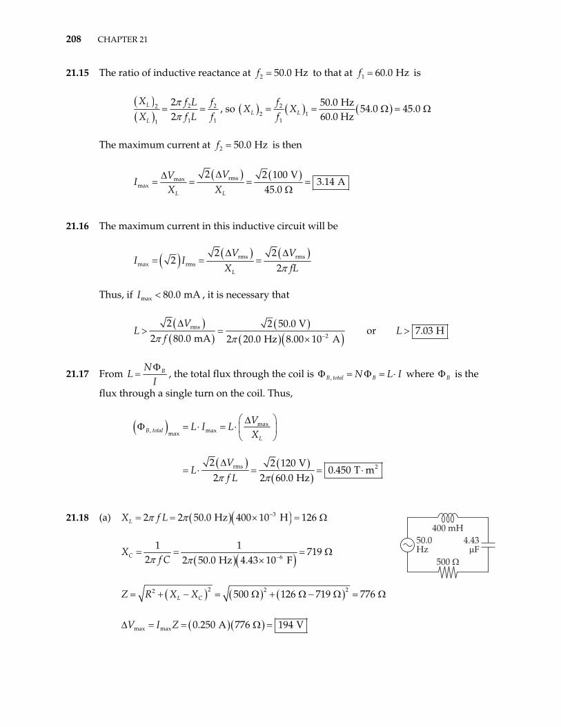
21.15 The ratio of inductive reactance at 2 50.0 Hzf = to that at 1 60.0 Hzf = is
( )( )
2 22
1 11
22
L
L
X f L fX f L
ππ
= =f
, so ( ) ( ) ( )54.0 45.022 1
1
50.0 Hz
60.0 HzL L
fX X
f= = Ω =
50.0 Hz
Ω
The maximum current at 2f = is then
( ) ( )rms
L L
V
X X
∆=max
max
2 2 100 V3.14 A
45.0 V
I∆
= = =Ω
21.16 The maximum current in this inductive circuit will be
( ) ( ) ( )rms rmsmax rms
2 22
2L
V VI I
X fπ∆ ∆
= = =
max 80.0 mAI <
L
Thus, if , it is necessary that
( )( )
( )( )( )
rms2
2 80.0 mA
V
fπ∆
2
2 50.0 V or 7.03 H
2 20.0 Hz 8.00 10 AL L
π −> = >
×
21.17 From BNIΦ
=L , the total flux through the coil is ,B total BN L IΦ = Φ = ⋅ where is the
flux through a single turn on the coil. Thus,
BΦ
( )
( ) ( )( )
max, maxmax
rms2 2 120 V2 2 60.0 Hz
B totalL
VL I L
X
VL
f Lπ π
∆Φ = ⋅ = ⋅
∆= ⋅ = 20.450 T m= ⋅
21.18 (a) ( )( )32 2 50.0 Hz 400 10 H 126 L Lπ π −= = × =X f
Ω
( )( )6
1 1719
2 2 50.0 Hz 4.43 10 FCXf Cπ π −
= = =×
( )
Ω
( ) ( )22 500 126 719L CZ R X X= + − = Ω + Ω −
( )( )
2 2 776 Ω = Ω
max max 0.250 A 776 194 VV I Z∆ = = Ω =

Alternating Current Circuits and Electromagnetic Waves 209
(b) 1 1 126 719 tan tan 49.9
500 L CX X
R− −− Ω − Ω
Ω φ = =
Thus,
= − °
the current leads the voltage by 49.9°
21.19 ( )( )6
1 166.3
2 2 60.0 Hz 40.0 10 FCXf Cπ π −
= = =×
( )
Ω
( ) ( )2 2 22 50.0 0 66.3 L CZ R X X= + − = Ω + − Ω 83.1= Ω
(a) rmsrms
30.0 V0.361 A
83.1 VZ
∆=
ΩI = =
(b) ( )( ), rms rms 0.361 A 50.0 18.1 VRV I R = Ω =∆ =
(c) ( )( ), rms rms 0.361 A 66.3 23.9 VC CV I X = Ω =∆ =
(d) 1 1 0 66.3 tan tan 53.0
50.0 L CX X
R− −− − Ω
Ω φ = =
so,
= − °
the voltage lags behind the current by 53.0°
21.20 ( )( )2 2 60.0 Hz 0.100 H 37.7 LX f Lπ π= = = Ω
( )( )6
1 126
2 2 60.0 Hz 10.0 10 FCXf Cπ π −
= =×
( )
5 = Ω
( ) ( )22 50.0 37.7 265L CZ R X X= + − = Ω + Ω −2 2 233Ω = Ω
(a) ( )( ), rms rms 2.75 A 50.0 138 VRV I R = Ω =∆ = (e)
(b) ( )( ), rms rms 2.75 A 37.7 104 VL LV I X = Ω =∆ =
(c) ( )( ), rms rms 2.75 A 265 729 VC CV I X = Ω =∆ =
(d) ( )( )rms rms 2.75 A 233 641 VV I Z = Ω =∆ =
210 CHAPTER 21
21.21 (a) ( )( ) 32 2 240 Hz 2.5 H 3.8 10 L Lπ π= = = ×X f
Ω
( )( )310 ×
6
1 12.7
2 2 240 Hz 0.25 10 FCXf Cπ π −
= = =×
( )
Ω
( ) ( ) 2 1.4 k Ω = Ω
2 22 3900 3.8 2.7 10L CZ R X X= + − = Ω + − ×
(b) maxmax 3
140 V0.10 A
1.4 10 VZ
∆=
× ΩI = =
(c) ( ) 3
1 1 3.8 2.7 10 tan tan 51
900 L CX X
R− − − × Ω−
Ω φ = = = °
(d) 0φ > , so the voltage leads the current
21.22 ( )( )
36
1 11.1 10
2 2 60 Hz 2.5 10 FCXfCπ π −
= = = ××
( )
Ω
( ) ( )2 222 3 31.2 10 0 1.1 10 1.6 10L CZ R X X= + − = × Ω + − × Ω = × 3 Ω
(a) maxmax 3
170 V0.11 A
1.6 10 VZ
∆=
× ΩI = =
(b) ( )( )3 2, max max 0.11 A 1.2 10 1.3 10 VRV I R = × Ω = ×
( )
∆ =
( )3 2, max max 0.11 A 1.1 10 1.1 10 VC CV I X∆ = = × Ω = ×
(c) When the instantaneous current i is zero, the instantaneous voltage across the resistor is 0Rv iR∆ = = . The instantaneous voltage across a capacitor is always 90°
or a quarter cycle out of phase with the instantaneous current. Thus, when 0i = ,
2, max 1.1 10 VC Cv V∆ = ×∆ =
and ( ) ( )( )6 2 -42.5 10 F 1.1 10 V 2.8 10 C 280 C C Cq C v µ−= ∆ = × × = × =
source R Cv v v
Kirchhoff’s loop rule always applies to the instantaneous voltages around a closed path. Thus, for this series circuit, ∆ = ∆ + ∆ and at this instant when i 0= ,
we have , max0 110 Vsource Cv V∆ = + ∆ =
Alternating Current Circuits and Electromagnetic Waves 211
(d) When the instantaneous current is a maximum ( )maxi I= , the instantaneous voltage
across the resistor is 21.3 10= ×max , max VR Rv iR I R V∆ = = = ∆
max=
. Again, the
instantaneous voltage across a capacitor is a quarter cycle out of phase with the current. Thus, when i I , we must have 0∆ =Cv and ( ) 0C Cq C v= ∆ = . Then,
applying Kirchhoff’s loop rule to the instantaneous voltages around the series circuit at the instant when maxi I= gives
21.3 10 V= ×, max 0source V∆ = ∆ +R Cv v∆ + Rv∆ =
21.23 ( )( )2 2 60.0 Hz 0.400 H 151 LX f Lπ π= = = Ω
( )( )6
1 188
2 2 60.0 Hz 3.00 10 FCXf Cπ π −
= =×
( )
4 = Ω
( ) ( )22 60.0 151 RLC L CZ R X X= + − = Ω + Ω −2 2884 736Ω = Ω
and rmsrms
RLC
VI
Z∆
=
(a) ( )20 7LC L C L CX X X= + − = − = 33 ΩZ X
( )rms, rms rms
90.0 V733 89.6 V
736 LC LC LCRLC
VV I Z Z
Z
∆ ∆ = ⋅ = = Ω = Ω
(b) ( ) ( ) ( )2 2 22 0 60.0 884 886RC CX= + − = Ω + Ω = ΩZ R
( )rms, rms rms
90.0 V886 108 V
736 RC RC RCRLC
VV I Z Z
Z
∆ ∆ = ⋅ = = Ω = Ω
21.24
( )( ) 32 2 60 Hz 2.8 H 1.1 10 LX fLπ π= = = ×
( )
Ω
( ) ( )2 222 3 31.2 10 1.1 10 0 1.6 10L CZ R X X= + − = × Ω + × Ω − = × 3 Ω
(a) maxmax 3
170 V0.11 A
1.6 10 VZ
∆=
× ΩI = =

212 CHAPTER 21
(b) ( )( )3 2, max max 0.11 A 1.2 10 1.3 10 VRV I R = × Ω = ×
( )
∆ =
( )3 2, max max 0.11 A 1.1 10 1.1 10 VL LV I X∆ = = × Ω = ×
(c) When the instantaneous current is a maximum ( )maxi I= , the instantaneous voltage
across the resistor is 2max , ma 0 VR Rv iR I R V∆ = = = ∆
maxi I
x 1.3 1= × . The instantaneous
voltage across an inductor is always 90° or a quarter cycle out of phase with the instantaneous current. Thus, when = , 0Lv∆ =
Lv v
.
Kirchhoff’s loop rule always applies to the instantaneous voltages around a closed path. Thus, for this series circuit, sourcev R∆ = ∆ + ∆ and at this instant when maxi I=
we have 2 V×max 0 1.3sourcev I R∆ = + = 10
(d) When the instantaneous current i is zero, the instantaneous voltage across the resistor is 0Rv iR∆ = = . Again, the instantaneous voltage across an inductor is a
quarter cycle out of phase with the current. Thus, when 0i = , we must have 2
, max 1.1 10 VL Lv V∆ = ∆ = × . Then, applying Kirchhoff’s loop rule to the
instantaneous voltages around the series circuit at the instant when gives 0i =2
, max0 1.1 10 Vsource R L Lv v v V∆ = ∆ + ∆ = + ∆ = ×
21.25 ( )( )
812
1 11.33 10
2 2 60.0 Hz 20.0 10 FCXf Cπ π −
= = = ××
Ω
( ) ( )2 22 2 3 850.0 10 1.33 10 1.33RC CZ R X= + = × Ω + × Ω =
(
810× Ω
and )sec 5rms
rms 8
5 000 V3.76 10 A
1.33 10 ondary
RC
VI
Z−
∆= = = ×
× Ω
Therefore, ( )( )5 3
, rms rms 3.76 10 A 50.0 10 1.88 Vb bV I R −∆ = = × × Ω =
Alternating Current Circuits and Electromagnetic Waves 213
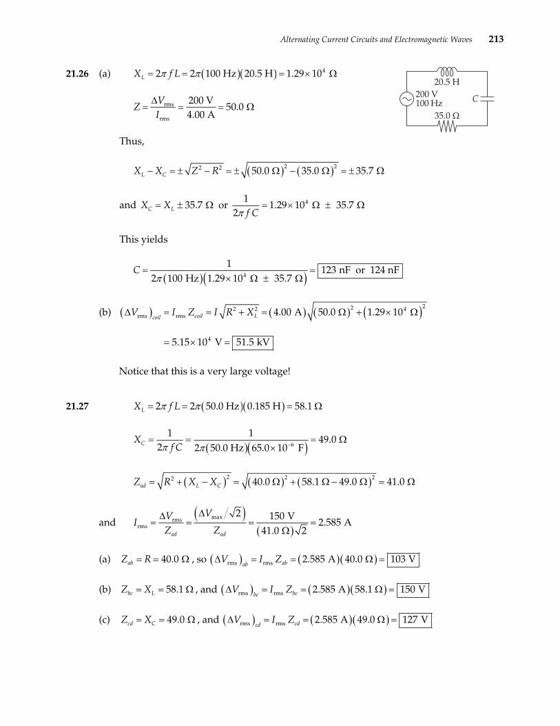
21.26 (a) ( )( ) 42 2 100 Hz 20.5 H 1.29 10 LX f Lπ π= = = × Ω
rms
rms
200 V50.0
4.00 AV
ZI∆
= = = Ω
Thus,
( ) ( )2 22 2 50.0 35.0 L CX X Z R− = ± − = ± Ω − Ω
35.7 C LX X= ± Ω
35.7= ± Ω
and or 411.29 10
2 f Cπ35.7 = × Ω ±
( )( )
Ω
This yields
4
12 100 Hz 1.29 10
Cπ × Ω
123 nF or 124 n 35.7
= =± Ω
F
(b) ( ) ( ) ( ) ( )222 2 4rms rms
4
4.00 A 50.0 1.29 10
5.15 10 V 51.5 kV
coil LcoilV I Z I R X∆ = = + = Ω + × Ω
= × =
Notice that this is a very large voltage!
21.27 ( )( )2 2 50.0 Hz 0.185 H 58.1 LX f Lπ π= = = Ω
( )( )6
1 12 2 50.0 Hz 65.0 10 FCX
f Cπ π −= =
×
( )
49.0 = Ω
( ) ( )22 40.0 58.1 49.0ad L CZ R X X= + − = Ω + Ω −2 2 41.0Ω = Ω
and ( )
( )maxrms
rms
2 150 V2.585 A
41.0 2ad ad
VVI
Z Z
∆∆= = = =
Ω
(a) Z R , so ( )40.0ab = = Ω ( )( )rms rms 2.585 A 40.0 103 VababV I Z∆ = = Ω =
(b) Z X , and ( )58.1bc L= = Ω ( )( )rms rms 2.585 A 58.1 150 VbcbcV I Z∆ = = Ω =
(c) Z X , and ( )49.0cd C= = Ω ( )( )rms rms 2.585 A 49.0 127 VcdcdV I Z∆ = = Ω =

214 CHAPTER 21
(d) 9.15 bd L CX= − =Z X , so Ω ( ) ( )( )rms rms 2.585 A 9.15 23.6 VbdbdV I Z∆ = = Ω =
21.28 (a) ( )( )6
1 188.4
2 2 60.0 Hz 30.0 10 FCXf Cπ π −
= = =×
Ω
( ) ( )2 22 2 50.0 88.4 102 CZ R X= + = Ω + Ω = Ω
rmsrms
100 V0.984 A
102 V
IZ
∆= = =
Ω
1 10 88.4 tan tan 60.5
50.0 CX
Rφ − −− − Ω = = = − Ω
( )
°
and cos cos 60.5 0.492power factor φ= = − ° =
( ) ( )( )(
)av rms rms cos 100 V 0.984 A 0.492V I φ= ∆ =P 48.5 W=
(b) ( )( )2 2 60.0 Hz 0.300 H 113 L LX fπ π= = = Ω
( ) ( )2 22 2 50.0 113 124LZ R X= + = Ω + Ω = Ω
rmsrms
100 V0.809 A
124 V
IZ
∆= = =
Ω
1 10 113 tan tan 66.1
50.0 CXR
φ − −− Ω = = = Ω °
and ( )cos cos 66.1power factor φ= =
( ) ( )( )(
0.404° =
)
av rms rms cos 100 V 0.809 A 0.404V I φ= ∆ =P 32.7 W=
21.29 (a) rms
rms
104 V208
0.500 AV
ZI∆
= = = Ω
(b) =P gives 2av rmsI R
( )av
22rms
10.0 W40.0
0.500 AR
I= = = ΩP
Alternating Current Circuits and Electromagnetic Waves 215
(c) 2LX= + 2Z R , so ( ) ( )2 22 2 208 40.0 204LX Z R = − = Ω − Ω = Ω
and ( )204
0.541 H2 2 60.0 Hz
LXL
fπ πΩ
= = =
21.30 (a) ( )( )2 2 60.0 Hz 0.100 H 37.7 L LX fπ π= = = Ω
( )( )-6
1 113
2 2 60.0 Hz 200 10 FCXfCπ π
= = =×
( )
.3 Ω
( ) ( )22 20.0 37.7 13.3L CZ R X X= + − = Ω + Ω −2 2 31.6Ω = Ω
( )2 2 2
2 max maxav rms
1 1 100 V20.0 100 W
2 2 31.6 2I V
I R R RZ
∆ = = = = Ω = Ω P
and2
av rms rms
rms rms rms rms rms
20.0 cos 0.633
31.6 I R I R
power factor RV I V I V Z
φ Ω
= = = = = = = ∆ ∆ ∆ Ω
P
(b) The same calculations as shown in Part (a) above, with 50.0 Hzf = , give
av31.4 , 15.9 , 25.3 , 156 W an 0.790L CX X Z= Ω = Ω = Ω = =P d power factor
21.31 (a) ( ) ( )2av rms rms rms rms , rmsRI R I I R I V= = = ∆√ , so av
rms, rms
14 W0.28 A
50 VR
IV
= = =∆√
Thus, , rms 2
rms
50 V1.8 10
0.28 ARV
RI
∆= = = × Ω
(b) 2LX= + 2Z R , which yields
( )2 2
22 2 2 2 2rms
rms
90 V1.8 10 2.7 10
0.28 AL
VX Z R R
I
∆ = − = − = − × Ω = ×
Ω
and ( )
22.7 10 0.71 H
2 2 60 HzLX
Lfπ π
× Ω= = =

216 CHAPTER 21
21.32 ( )( )32 2 600 Hz 6.0 10 H 23 LX fLπ π −= = × = Ω
( )( )-6
1 111
2 2 600 Hz 25 10 FCXfCπ π
= = =×
( )
Ω
( ) ( )22 25 23 11L CZ R X X= + − = Ω + Ω −2 2 28Ω = Ω
(a) ( )rms, rms rms
10 V25 9.0 V
28 R
VV I R R
Z∆ = = Ω = Ω
∆ =
( )rms, rms rms
10 V23 8.2
28 L L L
VV I X X
Z∆ ∆ = = = Ω = Ω
V
( )rms, rms rms
10 V11 3.8
28 C C C
VV I X X
Z∆ ∆ = = = Ω = Ω
V
, rms , rms , rms No , 9.0 V 8.2 V 3R L CV V V∆ + ∆ + ∆ = + +
( ) ( )
.8 V 21 V 10 V= ≠
However, observe that if we take phases into account and add these voltages vectorially, we find
( ) ( )2 2
, rms , rms , rms 9.0 V 8.2 VR L CV V V∆ + ∆ − ∆ = +2 23.8 V 10 V− = rms= ∆V
(b) The p is the greatest. No power losses occur in an
ideal capacitor or inductor.
ower delivered to the resistor
(c) ( )2 2
2 rmsrms
10 V25 3.3 W
28 V
I R RZ
∆ = = = Ω = Ω P
21.33 The resonance frequency of the circuit should match the broadcast frequency of the station.
0
12
fLCπ
= gives 2 20
14
Lf Cπ
=
( ) (
,
or )
622 6 12
12.29 10 H 2.29 H
4 88.9 10 Hz 1.40 10 FL µ
π−
−= = ×
× ×=

Alternating Current Circuits and Electromagnetic Waves 217
21.34 (a) At resonance, X so the impedance will be
L X=
( )
C
2L CX X−2 2 0 15 Z R R R= + = + = = Ω
(b) When X , we have L X= C
12
fL2fC
ππ
= which yields
( )( )6
1 141 Hz
2 2 0.20 H 75 10 Ff
LCπ π −= = =
×
(c) The current is a maximum at resonance where the impedance has its minimum
value of Z R= .
(d) At 60f = , Hz ( )( )2 60 Hz 0.20 H 75 LX π= = Ω( )( )
, 6
135
2 60 Hz 75 10 FCXπ −
= = Ω×
,
and ( ) ( )2 2 75 35 43 + Ω − Ω = Ω15Z = Ω
Thus, ( )
( )maxrms
2 150 V2.5 A
2 43
VVZ Z
∆= = = =
ΩrmsI∆
21.35 0
12
fLCπ
= , so 2 20
14
Cf Lπ
=
For ( ) 5z 5.00 10= ×
( )
0 0 min500 kH Hzf f= =
( )
8
65.1 10 F 51 nF
0 10 H−
−= × =
× ×max 22 5
1
4 5.00 10 Hz 2.C C
π= =
(
For ) 6
0 0 max1600 kHz 1.60 10 Hzf f= = = ×
( )
( )
9
64.9 10 F 4.9 nF
0 10 H−
−= × =min 22 6
1
4 1.60 10 Hz 2.C C
π= =
× ×
21.36 The resonance frequency is 0 0
12 f
LCω π= =
Also, LX Lω= and 1
C CX
ω=

218 CHAPTER 21
(a) At resonance, 0 -6
1 3.00 H1 000
3.00 10 FC L
LL L
CLCω = = = = = = ×
X X
Thus,
Ω
2 20Z R= + = R , rmsrms
120 V4.00 A
30.0 V
IZ
∆= = =
Ω
( ) ( )
and 24.00 A 30.0 480 WΩ =2
av rmsI R= =P
(b) At 021ω ω= ; ( )
0
1500
2L LX Xω
= = Ω , ( )0
2 2 00C CX Xω
0 = = Ω
( ) ( ) ( )22 22 30.0 500 2 000 1 500L CZ R X X= + − = Ω + Ω − Ω = Ω
and rms
120 V0.080 0 A
1 500 I = =
Ω
(
so ) ( )22av rms 0.080 0 A 30.0 0.192 WI R= = Ω =P
(c) At 0
14
ω ω= ; ( )0
1250
4L LX Xω
= = Ω , ( )0
4 4 00C CX Xω
0 = = Ω
, and 3 750Z = Ω rms
120 V0.032 0 A
3 750 I = =
Ω
so ( ) ( )22 20.032 0 A 30.0 3.07 10 W 30.7 mW−Ω = × =av rmsI R= =P
(d) At 2 0ω ω= ; ( )0
2 2 00L LX Xω
= = 0 Ω , ( )0
1500
2C CX Xω
= = Ω
, and 1 500Z = Ω rms
120 V0.080 0 A
1 500 I = =
Ω
so ( ) ( )20.080 0 A 30.0 0.192 WΩ =2
av rmsP I R= =
Alternating Current Circuits and Electromagnetic Waves 219
(e) At 4 0ω ω= ; ( )0
4 4 00L LX Xω
= = 0 Ω , ( )0
1250
4C CX Xω
= = Ω
, and 3 750Z = Ω rms
120 V0.032 0 A
3 750 I = =
Ω
so ( ) ( )22 20.032 0 A 30.0 3.07 10 W 30.7 mW−Ω = × =av rmsP I R= =
The power delivered to the circuit is a maximum when the rms current is a maximum. This occurs when the frequency of the source is equal to the resonance frequency of the circuit.
21.37 ( )( )0 0
3 6
1 12 1
10.0 10 H 100 10 Ff
LCω π
− −= = = =
× ×000 rad s
Thus, 02 2 000 rad sω ω= = ( )( )32 000 rad s 10.0 10 H 20.0 LX Lω −= = × = Ω
( )( )6
1 15.00
2 000 rad s 100 10 FCXCω −
= = = Ω×
( )
( ) ( )2 2 22 10.0 20.0 5.00 18.0L CZ R X X= + − = Ω + Ω − Ω = Ω
rmsrms
50.0 V2.77 A
18.0 V
IZ
∆= = =
Ω
( ) ( )22av rms 2.77 A 10.0 76.9 WI R= = Ω =P
The average power is and the energy converted in one period is
av av
2 J 276.9 0.242 J
s 2 000 rad sE T
π πω
= ⋅ = ⋅ = ⋅ =
P P
21.38 (a) ( )22, rms 1, rms
1
NV V
N∆ = ∆
so ( )2, rms2 1
1, rms
9.0 V240 turns 18 turns
120 V
VN N
V
∆ = = = ∆
220 CHAPTER 21
(b) For an ideal transformer, ( ) ( ) ( )av av 2, rms 2, rmsinput ouputV I= = ∆P P
( )( )
Thus, ( )av 9.0
inputP V 0.400 A 3.6 W= =
21.39 The power input to the transformer is
( ) ( )( ) 51, rms 1, rms 3 600 V 50 A 1.8 10 Winput V I= ∆ = = ×P
( )
For an ideal transformer, ( ) ( )av 2, rms 2, rms avouput inputV I= ∆ =P
( )( )
P so the current in the long-
distance power line is
5
av
2, rms
2, rms
1.8 10 W1.8 A
100 000 VinputI
V
×= = =
∆
P
( ) ( )22 22, rms 1.8 A 100 3.2 10 Wlost lineI R= = Ω = ×P
The power dissipated as heat in the line is then
The percentage of the power delivered by the generator that is lost in the line is
2
5
3.2 10 W0% 100% 0.18%
1.8 10 W ×
= × = × % Lost 10lost
input
= ×P
P
21.40 (a) Since the transformer is to step the voltage down from 120 volts to 6.0 volts, the secondary must have fewer turns than the primary.
(b) For an ideal transformer, ( ) ( )av avinput ouput=P P or ( ) ( )1, rms 1, rms 2, rms 2, rmsV I V I∆ = ∆ so the
current in the primary will be
( ) ( )( )2, rms 2, rms
1, rms1, rms
6.0 V 500 mA25
120 V
V II
V
∆= =
∆ mA=
(c) The ratio of the secondary to primary voltages is the same as the ratio of the number of turns on the secondary and primary coils, 2 1 2V V N N1∆ ∆ = . Thus, the number of turns needed on the secondary coil of this step down transformer is
( )22 1
1
6.0 V400 20 turns
120 VV
N NV
∆ = = = ∆

Alternating Current Circuits and Electromagnetic Waves 221
21.41 (a) At 90% efficiency, ( ) ( )av av0.90output input
=P P
1 000 kW=
Thus, if
the input power to the primary is ( )
( )av outputP
( )av 31 000 kW1.1 10 kW
0.90 0.90output= = = ×
Pav inputP
(b) ( ) 3 6
av 21, rms
1, rms 1, rms
1.1 10 kW 1.1 10 W3.1 10 A
3 600 Vinput
V V× ×
= = ×∆ ∆
PI = =
(c) ( ) 6
av 32, rms
2, rms 1, rms
1 000 kW 1.0 10 W8.3 10 A
120 Voutput
V V×
= = ×∆ ∆
PI = =
21.42 ( )( )4 54.50 10 m 6.44 10 m 290 lineR −= × Ω × = Ω
(a) The power transmitted is ( ) ( )av rms rmstransmittedV I= ∆P
so ( ) 6
3
0 10 W10.0 A
0 10 V×
=∆ ×
( ) ( )
avrms
rms
5.050
transmittedIV
= =P
Thus, ( ) 210.0 A 290 2.90 1Ω =2 4
av rms 0 W 29.0 kWlinelossI R= = × =P
(b) The power input to the line is ( ) ( ) ( ) 6 4
av av av 5.00 10 W+2.90 10 W=5.03 10 Winput transmitted loss
= + = × × ×P P P
( )( )
6
and the fraction of input power lost during transmission is
4
av
6av
2.90 10 W0.005 80 or 0.580%
5.03 10 Wloss
input
fraction×
= = =×
P
P

222 CHAPTER 21
(c) It is impossible to deliver the needed power with an input voltage of 4.50 kV. The maximum line current with an input voltage of 4.50 kV occurs when the line is shorted out at the customer’s end, and this current is
( ) rmsrms max
4 500 V15.5 A
290 line
VI
R∆
= = =Ω
( ) ( )( )
( )( )
rms rms maxmax
4.50 10 V 15.5 A
input V I= ∆
= ×
P
The maximum input power is then
This is far short of meeting the customer’s request, and all of this power is lost in the transmission line.
3 46.98 10 W 6.98 kW= × =
21.43 From v fλ= , the wavelength is
8
63.00 10 m s4.00 10 m 4 000 km
75 Hz×
= = = × =vf
λ
The required length of the antenna is then, 4 1 000 km= =L λ , or about 621 miles. Not very practical at all.
21.44 ( )( )7 2 2 12 2
0 0
1 1
4 10 N s C 8.854 10 C N mc
µ π − −= =
∈ × ⋅ × ⋅ 2
or 82.998 10 m sc = ×
21.45 (a) The frequency of an electromagnetic wave is f c λ= , where c is the speed of light, and λ is the wavelength of the wave. The frequencies of the two light sources are then
Red: 8
14-9
3.00 10 m s4.55 10 Hz
660 10 mredred
cf
λ×
= = = ××
and
Infrared: 8
14-9
3.00 10 m s3.19 10 Hz
940 10 mIRIR
cf
λ×
= = = ××
Alternating Current Circuits and Electromagnetic Waves 223
(b) The intensity of an electromagnetic wave is proportional to the square of its amplitude. If 67% of the incident intensity of the red light is absorbed, then the intensity of the emerging wave is ( )100% 67% 33%− = of the incident intensity, or
0.33f iI = I . Hence, we must have
max,
max,
0.33f f
i i
E I
E I= = 0.57=
21.46 If I is the incident intensity of a light beam, and I is the intensity of the beam after passing through length L of a fluid having concentration C of absorbing molecules, the Beer-Lambert law states that
0
( )10 0log I I CLε= − where ε is a constant.
For 660-nm light, the absorbing molecules are oxygenated hemoglobin. Thus, if 33% of this wavelength light is transmitted through blood, the concentration of oxygenated hemoglobin in the blood is
( )10
2
log 0.33HBOC
Lε−
=
(
[1]
The absorbing molecules for 940-nm light are deoxygenated hemoglobin, so if 76% of this light is transmitted through the blood, the concentration of these molecules in the blood is
)10log 0.76
HBCLε
−= [2]
Dividing equation [2] by equation [1] gives the ratio of deoxygenated hemoglobin to oxygenated hemoglobin in the blood as
( )( )
10
2 10
log 0.76log 0.33
HB20.25 or 0.25HB HC C=
=
BOHBO
CC
= =
2 1.00HB HBOC C+
Since all the hemoglobin in the blood is either oxygenated or deoxygenated, it is necessary that , and we now have 2 2 1.0HBO HBOC C0.25 + = . The fraction of hemoglobin that is oxygenated in this blood is then
2
1.01.0 0.25HBOC = =
+0.80 or 80%
Someone with only 80% oxygenated hemoglobin in the blood is probably in serious trouble needing supplemental oxygen immediately.

224 CHAPTER 21
21.47 The distance between adjacent antinodes in a standing wave is 2λ Thus, ( )2 6.00 cm 12.0 cm 0.120 mλ = = =
( )( )
, and
9 82.94 10 m s= ×0.120 m 2.45 10 Hzc fλ= = ×
21.48 At Earth’s location, the wave fronts of the solar radiation are spheres whose radius is the
Sun-Earth distance. Thus, from av av24
IntensityA rπ
= =√ √
, the total power is
( )( ) ( )22 11av 2
W4 1 340 4 1.49 10 m 3.74 10 W
mIntensity rπ π = = × = ×
P 26
21.49 From max max
02E B
tensityµ
=In and max
max
Ec
B= , we find
2max
02cB
Intensityµ
=
Thus,
( ) ( ) ( )7
2 60max 8
2 4 10 T m A21 340 W m 3.35 10 T
3.00 10 m sB Intensity
c
πµ −−
× ⋅= = = ×
×
( )
and ( )6 8 3max max 3.35 10 T 3.00 10 m s 1.01 10 V mE B c −= = × × = ×
21.50 8
6
3.00 10 m s11.0 m
27.33 10 Hzcf
λ×
= = =×
21.51 (a) For the AM band,
8
min 3max
3.00 10 m s188 m
1 600 10 Hzc
fλ
×= = =
×
8
max 3min
3.00 10 m s556 m
540 10 Hzc
fλ
×= = =
×
Alternating Current Circuits and Electromagnetic Waves 225
(b) For the FM band,
8
min 6max
3.00 10 m s2.78 m
108 10 Hzc
fλ
×= = =
×
8
max 6min
3.00 10 m s3.4 m
88 10 Hzc
fλ
×= = =
×
21.52 The transit time for the radio wave is
3
48
100 10 m3.33 10 s 0.333 ms
3.00 10 m sR
R
dt
c−×
= = = × =×
and that for the sound wave is
33.0 m8.7 10 s 8.7 ms
343 m ss
ssound
dt
v−= = = × =
Thus, the radio listeners hear the news 8.4 ms before the studio audience because
radio waves travel so much faster than sound waves.
21.53 If an object of mass m is attached to a spring of spring constant k, the natural frequency of vibration of that system is 2f k m π= . Thus, the resonance frequency of the
double bond will be
C=O
1326
2 800 N m1 15.2 10 Hz
2 2 2.66 10 kgoxygenatom
kf
mπ π −= = = ××
and the light with this frequency has wavelength
8
613
3.00 10 m s5.8 10 m 5.8 m
5.2 10 Hzcf
λ µ−×= = = × =
×
The infrared region of the electromagnetic spectrum ranges from max 1 mmλ ≈ down to
min 700 nm 0.7 mλ µ= = . Thus, the required wavelength falls with edin the infrar region .
226 CHAPTER 21
21.54 Since the space station and the ship are moving toward one another, the frequency after being Doppler shifted is ( )1O Sf f u c= + , so the change in frequency is
( )5
14 118
1.8 10 m s6.0 10 Hz 3.6 10 Hz
3.0 10 m sO S S
uf f f f
c
× ∆ = − = = × = × ×
and the frequency observed on the spaceship is
14 11 146.0 10 Hz 3.6 10 Hz 6.003 6 10 HzO Sf f f= + ∆ = × + × = ×
21.55 Since you and the car ahead of you are moving away from each other (getting farther apart) at a rate of 120 km h 80 km h 40 km h= − =u , the Doppler shifted frequency
you will detect is ( )1O Sf f u c= − , and the change in frequency is
( )14 78
40 km h 0.278 m s10 Hz 1.6 10 Hz
3.0 10 m s 1 km hO Sf f f
∆ = − = × = − × ×
4.3S
uf
c − = −
The frequency you will detect will be
144.3 10 Hz 1.= × − 7 146 10 Hz 4.299 999 84 10 HzO Sf f f= + ∆ × = ×
21.56 The driver was driving toward the warning lights, so the correct form of the Doppler shift equation is ( )1O Sf f u c= + . The frequency emitted by the yellow warning light is
8
149
3.00 10 m s5.17 10 Hz
580 10 mSS
cf
λ −
×= = = ×
×
and the frequency the driver claims that she observed is
8
149
3.00 10 m s5.36 10 Hz
560 10 mOO
cf
λ −
×= = = ×
×
The speed with which she would have to approach the light for the Doppler effect to yield this claimed shift is
( )14
8 714
Hz1 1.1 10 m s
Hz
− = ×
5.36 101 3.00 10 m s
5.17 10O
S
fu c
f
×= − = × ×
Alternating Current Circuits and Electromagnetic Waves 227
21.57 ( )DC
DC
12.0 V19.0
0.630 A
VR
I
∆= = =
( )
Ω
22 rms
rms
24.0 V2 42.1
0.570 AV
Z R f LI
π∆
= + = = = Ω
Thus, ( ) ( )
( )
2 22 2242.1 19.0
9.96 10 H 99.6 mH2 2 60.0 Hz
Z RL
fπ π−Ω − Ω−
= = = × =
21.58 Suppose you cover a 1.7 m-by-0.3 m section of beach blanket. Suppose the elevation angle of the Sun is 60°. Then the target area you fill in the Sun’s field of view is ( )( ) 21.7 m 0.3 m cos30 0.4 m° = . The intensity the radiation at Earth’s surface is surface incoming0.6I I= and only 50% of this is
absorbed. Since ( )av
E tI
A A
∆ ∆= =P
( ) ( )
, the absorbed energy is
( ) ( )
( )( )( )( )( )
surface incoming
2 2
0.5 0.5 0.6
0.5 0.6 1 340 W m 0.4 m 3 10 J
E I A t I ∆ = ∆ =
5600 s 6 10 J ~
A t∆
= = 6×
21.59 ( ) ( )
( ) ( )( )
222 2
22 6 2
2
200 2 60 Hz 5.0 10 F 5.7 10
CZ R X R f Cπ
π
−
−−
= + = +
= Ω + × = × Ω
Thus, ( )2 2
2 rmsav rms 2
120 V200 8.9 W
5.7 10 V
I R RZ
∆ = = = Ω = × Ω P
( )
38.9 10 kW−= ×
and ( )
( )( )( )
av
38.9 10 kW 24 h 8.0 cents kWh 1.7 cents
cost E rate t rate
−
= ∆ ⋅ = ⋅∆ ⋅
= × =
P
228 CHAPTER 21
21.60 LX Lω= , so LX Lω =
Then, ( )
1 1C
L
XC C X Lω
= =
( )
which gives
( )( ) 8.0 CΩ Ω 12L CL X X C= ⋅ = or ( )296 L = Ω C (1)
From 0 0
12 f
LCω π= = , we obtain
( )2
0
1
2LC
fπ=
Substituting from Equation (1), this becomes ( )( )
2 296 C 2
0
1
2 fπΩ =
or ( ) ( )
5
2 2
1 12.6 10 F 26 F
6 2 2 000 Hz 96 02 9C
fµ
π π π−= = = × =
Ω Ω
Then, from Equation (1), ( )( )2 5 310 F 2.5 10 H 2.5 mH− −× = × =96 2.6L = Ω
21.61 (a) The box cannot contain a capacitor since a steady DC current cannot flow in a series circuit containing a capacitor. Since the AC and DC currents are different, even when a 3.0 V potential difference is used in both cases, the box must contain a reactive element. The conclusion is that the box must contain a
resistor and inductor connected in series.
(b) DC
DC
3.00 V0.300 A
VI∆
R = = = 10 Ω
rms
rms
3.00 V0.200 A
VZ
I∆
= = = 15 Ω
Since ( )2f L2 2
LZ R X= + = 2 2R π+ , we find
( ) ( )
( )
2 22 2 15 30 mH
2 2 60 HzZ R
Lfπ π
Ω−= = =
10Ω −
Alternating Current Circuits and Electromagnetic Waves 229
21.62 (a) The required frequency is 8
102
3.00 10 m s1.0 10 Hz
3.00 10 mc
fλ −
×= = = ×
×. Therefore, the
resonance frequency of the circuit is 100
11.0 10 Hz
2f
LCπ= = × , giving
( ) ( ) ( )
13
126.3 10 F
400 10 H−
−= ×
× ×2 210
0
1 10.63 pF
2 2 10 HzC
f Lπ π= = =
(b) 2
00 Ad d
∈∈C = = , so
( )( )13 33
12 20
6.3 10 F 1.0 10 m8.5 10 m 8.5 mm
8.85 10 C N mC d
− −−
−
× ×⋅= = = × =
∈ × ⋅
(c) ( ) ( )( )10 1202 2 1.0 10 Hz 400 10 H 25 C L f Lπ π −= = = × × = ΩX X
21.63 (a) max
max
Ec
B= , so
6
16maxmax 8
0.20 10 V m6.7 10 T
3.00 10 m sE
Bc
−−×
= = = ××
(b)
( )( )( )
max max
0
6 1617 2
7
2
0.20 10 V m 6.7 10 T5.3 10 W m
2 4 10 T m A
E Btensity
µ
π
− −−
−
=
× ×= =
× ⋅
In
×
(c) ( ) ( )
( ) ( )
2
av
217 2 14
4
20.0 m5.3 10 W m 1.7 10 W
4
dIntensity A Intensity
π
π− −
=
= × = ×
= ⋅P
21.64 (a) rms
rms
12 V6.0
2.0 AVI∆
= = =Z Ω

230 CHAPTER 21
(b) DC
DC
12 V4.0
3.0 AVI∆
=R = =
From
Ω
( )22 2 2 2LZ R X R f Lπ= + = + , we find
( ) ( )
( )
2 22 226.0 4.0
1.2 10 H 12 mH2 2 60 Hz
Z RL
fπ π−Ω − Ω−
= = = × =
21.65 (a) The radiation pressure on the perfectly reflecting sail is
( ) ( )2
6 28
2 1 340 W m28.93 10 N m
3.00 10 m s
Intensityp
c−= = = ×
×
so the total force on the sail is ( )( )6 2 4 28.93 10 N m 6.00 10 m 0.536 NF p A −= ⋅ = × × =
(b) 5 20.536 N8.93 10 m s
6 000 kgFm
−= ×a = =
(c) From 20
12
x v t at+∆ = , with 0 0v = , the time is
( ) ( ) ( )
86
5 2 4
2 3.84 10 m2 1 d2.93 10 s 33.9 d
8.93 10 m s 8.64 10 sx
ta −
×∆ = = = × = × ×
21.66 We know that ( )( )
1, rms 11, rms 1, rms1 1
2 2, rms 2, rms2, rms 2
I ZV IN ZN V I ZI Z
∆= = = ∆
( ) ( )s 1, rms 2, rms 2, rmsV I V I∆ = ∆
2
Also, for an ideal transformer,
which gives 1, rm1, rms 2, rms
2, rms 1, rms
I V
I V
∆=∆
Therefore, 2, rms1 1
2 1, rms 2
VN ZN V Z
∆= ∆
, or 1, rms1 1
2 2, rms
VN ZN V Z
∆= ∆ 2
This gives 1 1 1
2 2 2
N N ZN N Z
=
, or 1 1
2 2
8 000 32
8.0 N ZN Z
Ω= = =
Ω

Alternating Current Circuits and Electromagnetic Waves 231
21.67 Consider a cylindrical volume with and cross-sectional area
3 31.00 Liter 1.00 10 mV −= = ×
1.00 2 mA = The length of this one liter cylinder is
3 3
2
1.00 10 m1.00
1.00 mV
d 310 mA
−×= = = −×
Imagine this cylinder placed at the top of Earth’s atmosphere, with its length perpendicular to the incident wave fronts. Then, all the energy in the one liter volume of sunlight will strike the atmosphere in the time required for sunlight to travel the length of the cylinder. This time is
3
8
1.00 10 m3.33
3.00 10 m sd
tc
−×∆ = = =
×
1.00
(
1210−×
2m
s
The energy passing through the area of the end of the cylinder in this time is )
( )( )( )
av
1 340 W m 1. 1
E t Intens∆ = ⋅∆ =P
2 200 m 3.33
ity A t ⋅ ⋅ ∆
= × 12 s 4.47 10 J− −= 9×0
21.68 The capacitance of a parallel-plate capacitor is 0 AC d= e , and its reactance in an AC
circuit is 1 2CX fCπ= . Observe that reducing the plate separation to one-half of its original value will double the capacitance and reduce the capacitive reactance to one-half the original value.
The impedance of an RLC series circuit in which LX R= is ( )22CZ R R X= + − . When
the applied voltage is , the current in the circuit is V∆ ( )22CI V Z V R R X= ∆ =∆ + − . If
now the plate separation, and hence the capacitive reactance, is cut to one-half the
original value, the new impedance is ( )22 2Z R′ = + CR X− and the new current will be
( )22 2CI V Z V R R X′ ′= ∆ = ∆ −
I
+
2I′ =
.
If it is observed that , then we must have
( ) ( )2 222
2
C
V V
R R XR R
∆ ∆
+ −+ − 2CX= or ( ) ( )222 24 2C CX R R XR R = + −+ −
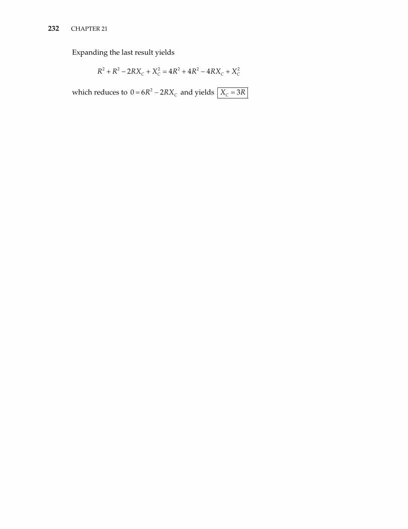
232 CHAPTER 21
2C
Expanding the last result yields which reduces to and yields
2 2 2 2 22 4 4 4C C CR R RX X R R RX X+ − + = + − +
20 6 2 CR RX= − 3CX R=