feps and scenarios for a spent nuclear fuel repository at olkiluoto
TRANSCRIPT

P O S I V A O Y
F I N - 2 7 1 6 0 E U R A J O K I , F I N L A N D
P h o n e ( 0 2 ) 8 3 7 2 3 1 ( n a t . ) , ( + 3 5 8 - 2 - ) 8 3 7 2 3 1 ( i n t . )
F a x ( 0 2 ) 8 3 7 2 3 7 0 9 ( n a t . ) , ( + 3 5 8 - 2 - ) 8 3 7 2 3 7 0 9 ( i n t . )
POSIVA 2007 -12
Process Report – FEPs and Scenariosfor a Spent Fuel Repository at Olkiluoto
December 2007
E d i t o r s :
B i l l M i l l e r
Nur i a Marcos
POSIVA 2007-12
December 2007
POSIVA OY
F I - 27160 EURAJOK I , F INLAND
Phone (02 ) 8372 31 (na t . ) , ( +358 -2 - ) 8372 31 ( i n t . )
Fax (02 ) 8372 3709 (na t . ) , ( +358 -2 - ) 8372 3709 ( i n t . )
E d i t o r s :
Bi l l M i l l e r
Sto l l e r UK L td .
Nur ia Marcos
Saan io & R i ekko l a Oy
Process Report – FEPs and Scenariosfor a Spent Fuel Repository at Olkiluoto
Base maps: ©National Land Survey, permission 41/MYY/07

ISBN 978-951 -652 -162 -9ISSN 1239-3096

Tekijä(t) – Author(s)
Editors:Bill Miller, Stoller UK Ltd. Nuria Marcos, Saanio & Riekkola Oy
Toimeksiantaja(t) – Commissioned by
Posiva Oy
Nimeke – Title
PROCESS REPORT – FEPs AND SCENARIOS FOR A SPENT NUCLEAR FUEL REPOSITORY AT OLKILUOTO Tiivistelmä – Abstract
This report discusses how features, events and processes (FEPs) are handled in Posiva’s Safety Case for the proposed spent fuel repository and the relationship with the FEPs in the NEA “International FEP List”.
The main processes potentially affecting the long-term safety of a KBS-3V repository system located at the Olkiluoto site are described for each relevant sub-system component or barrier (i.e. fuel, canister, etc.) and classified into two types: evolution-related processes and migration-related processes. The reason for this classification is that most of the processes are interdependent and coupled, and hard to classify uniquely as thermal, mechanical, chemical, hydrological, etc. This is the main difference with respect to previous process reports issued by POSIVA.
The significance of the processes in each of the sub-systems is estimated taking into account the scenarios set for the Safety Case regarding the expected evolution, the occurrence of defective canisters and deviations in the emplacement of e.g. bentonite barrier, and the consideration of unlikely events affecting any of the barriers (especially the canister).
Each process is described according to the current understanding of how it operates in the repository and how it affects performance at different times. Olkiluoto-specific issues are considered whenever relevant. The main uncertainties (conceptual and parameter/data) associated with each process are also documented.
The most significant evolution-related processes (e.g. radioactive decay and in-growth, deformation of cast iron insert, corrosion of copper overpack, swelling of bentonite, rock-water interaction, etc.) have already been taken into account in Posiva’s Evolution Report.
The most significant migration-related processes (e.g. radionuclide release from the fuel, water and gas transport, solute advection and diffusion, precipitation and co-precipitation, etc.) will be taken into account in the upcoming radionuclide transport analysis report (safety analysis) and complementary evaluations of safety report.
Avainsanat - Keywords
Features, events, processes, FEPs, scenarios, Olkiluoto, fuel, canister, buffer, backfill, plugs, seals, grout, geosphere ISBN
ISBN 978-951-652-162-9 ISSN
ISSN 1239-3096
Sivumäärä – Number of pages
274Kieli – Language
English
Posiva-raportti – Posiva Report
Posiva Oy FI-27160 EURAJOKI, FINLAND Puh. 02-8372 (31) – Int. Tel. +358 2 8372 (31)
Raportin tunnus – Report code
POSIVA 2007-12
Julkaisuaika – Date
December 2007
Tekijä(t) – Author(s)
Editors: Bill Miller, Stoller UK Ltd. Nuria Marcos, Saanio & Riekkola Oy
Toimeksiantaja(t) – Commissioned by Posiva Oy
Nimeke – Title
PROSESSIRAPORTTI – OLKILUODON KÄYTETYN YDINPOLTTOAINEEN LOPPUSIJOITUS-TILOJEN OMINAISPIIRTEET, TAPAHTUMAT JA ILMIÖT (FEPt) SEKÄ SKENAARIOT
Tiivistelmä – Abstract
Tässä raportissa esitellään, miten suunnitellun käytetyn ydinpolttoaineen loppusijoitustilojen ominaispiirteet, tapahtumat ja ilmiöt (FEPt) käsitellään Posivan turvallisuusperusteluissa. Lisäksi esitetään FEP-käsittelytavan suhde NEA:n ”International FEP List”-tietokantaan. Keskeiset pitkäaikaisturvallisuuteen mahdollisesti vaikuttavat ilmiöt KBS-3V-konseptiin perustuvissa loppusijoitustiloissa Olkiluodossa on kuvattu keskeisille päästöesteille ja jaoteltu kahteen luokkaan: tilojen käyttäytymiseen sekä kulkeutumiseen liittyviin. Tämä luokittelutapa on merkittävin ero Posivan aiempiin prosessiraportteihin nähden. Siihen päädyttiin, koska monet ilmiöt ovat toisistaan riippuvia ja siksi vaikeasti luokiteltavissa yksikäsitteisesti termisiksi, hydrologisiksi, mekaanisiksi, kemiallisiksi jne. Kunkin ilmiön suhteellinen tärkeys kussakin päästöesteessä on arvioitu. Tässä arviossa suhteel-lisesta tärkeydessä on huomioitu turvallisuusperusteissa käsiteltävät skenaariot odotettavissa olevasta käyttäytymisestä, viallisista kapseleista, mahdollisista poikkeamista esim. bentoniitti-puskurin asennuksessa sekä epätodennäköisistä päästöesteiden (erityisesti kapselin) toiminta-kykyyn vaikuttavista tapahtumista. Ilmiöiden ilmentyminen loppusijoitustiloissa ja vaikutukset toimintakykyyn eri ajanjaksoina on kuvattu nykytiedon mukaisesti. Olkiluotokohtaiset näkökulmat on otettu esille tarpeen vaatiessa. Jokaisesta ilmiöstä on esitetty myös merkittävimmät (konseptuaaliset ja parametriset) epä-varmuudet. Loppusijoitustilojen käyttäytymiseen liittyvät tärkeimmät ilmiöt, kuten radioaktiivinen hajoa-minen ja sisäänkasvu, valurautasisuksen muodonmuutokset, kuparikapselin korroosio, puskuri-bentoniitin paisuminen ja kallio-vesi-vuorovaikutus on huomioitu Posivan loppusijoitustilojen käyttäytymistä kuvaavassa raportissa. Tärkeimmät kulkeutumiseen liittyvät ilmiöt, kuten radionuklidien vapautuminen polttoaineesta, veden ja kaasun kuljettuminen, veteen liuenneiden aineiden advektiivinen ja diffusiivinen kulkeutuminen sekä saostuminen, tullaan käsittelemään seuraavasssa radionuklidien kulkeutu-mista analysoivassa raportissa (turvallisuusanalyysi) sekä ”täydentävät arviot”-raportissa. Avainsanat - Keywords
Ominaispiirteet, tapahtumat, ilmiöt, FEPt, skenaariot, Olkiluoto, polttoaine, kapseli, puskuri, täyttö, tulppa, sulkurakenne, injektiolaasti, geosfääri ISBN ISBN 978-951-652-162-9
ISSN ISSN 1239-3096
Sivumäärä – Number of pages 274
Kieli – Language Englanti
Posiva-raportti – Posiva Report Posiva Oy FI-27160 EURAJOKI, FINLAND Puh. 02-8372 (31) – Int. Tel. +358 2 8372 (31)
Raportin tunnus – Report code
POSIVA 2007-12 Julkaisuaika – Date
December 2007
1
TABLE OF CONTENTS
ABSTRACT
TIIVISTELMÄ
FOREWORD .................................................................................................................. 5
1 INTRODUCTION................................................................................................... 7 1.1 Background .................................................................................................. 7 1.2 Safety case portfolio..................................................................................... 9 1.3 Scope of this report .................................................................................... 10 1.4 Features, events and processes (FEPs).................................................... 11 1.5 Process descriptions .................................................................................. 11 1.6 The list of processes .................................................................................. 13
2 HANDLING OF SCENARIOS.............................................................................. 21 2.1 Definition/description of main scenario, defective canister scenario, additional scenarios, and variants ................ 21 2.2 Definition/description of the organization of calculation cases and variants for radionuclide transport analyses........................................ 23
3 FUEL/CAVITY IN CANISTER.............................................................................. 25 3.1 Description ................................................................................................. 25
3.1.1 Long-term safety and performance................................................... 27 3.1.2 Overview of processes...................................................................... 28
3.2 Processes related to the evolution of the fuel/cavity .................................. 29 3.2.1 Radioactive decay and in-growth...................................................... 30 3.2.2 Radiogenic heat generation and heat transfer.................................. 32 3.2.3 Structural alteration of the fuel pellets and cladding ......................... 35 3.2.4 Radiolytic acid production ................................................................. 37 3.2.5 Radiolysis of groundwater................................................................. 39 3.2.6 Corrosion of the fuel assembly ......................................................... 41 3.2.7 Dissolution of the fuel matrix............................................................. 44 3.2.8 Dissolution of the gap inventory........................................................ 48 3.2.9 Production of helium gas .................................................................. 51
3.3 Processes related to the migration of radionuclides and other substances................................................................................. 53
3.3.1 Diffusion in fuel pellets ...................................................................... 54 3.3.2 Radionuclide release from the fuel (radionuclide solubility).............. 56 3.3.3 Water and gas transport (in the canister cavity and fuel rods) ......... 59 3.3.4 Radionuclide transport (advection and diffusion).............................. 62 3.3.5 Colloidal transport ............................................................................. 64
4 COPPER CANISTER AND CAST IRON INSERT............................................... 67 4.1 Description ................................................................................................. 67
4.1.1 Long-term safety and performance ................................................... 69 4.1.2 Overview of processes...................................................................... 70
4.2 Processes related to the evolution of the canister components................. 70 4.2.1 Radiation attenuation by canister metal ............................................ 71 4.2.2 Heat transfer ..................................................................................... 73 4.2.3 Deformation of the cast iron insert .................................................... 75 4.2.4 Deformation of copper canister from external pressure .................... 78

2
4.2.5 Thermal expansion of the canister.................................................... 80 4.2.6 Deformation from internal corrosion products ................................... 82 4.2.7 Corrosion of cast iron insert .............................................................. 85 4.2.8 Corrosion of the copper overpack ..................................................... 90 4.2.9 Deposition of salts on canister surface ............................................. 93
4.3 Processes related to the migration of radionuclides and other substances................................................................................. 95
4.3.1 Radionuclide retardation by iron corrosion products......................... 96
5 BUFFER .............................................................................................................. 99 5.1 Description ................................................................................................. 99
5.1.1 Long-term safety and performance ................................................. 101 5.1.2 Overview of processes.................................................................... 102
5.2 Processes related to buffer evolution....................................................... 103 5.2.1 Heat transfer ................................................................................... 104 5.2.2 Water uptake................................................................................... 107 5.2.3 Piping and erosion, including chemical erosion .............................. 110 5.2.4 Swelling/mass redistribution............................................................ 114 5.2.5 Radiolysis of porewater................................................................... 118 5.2.6 Montmorillonite transformation ....................................................... 119 5.2.7 Alteration of accessory minerals and impurities.............................. 125 5.2.8 Microbial activity.............................................................................. 130
5.3 Processes related to the migration of radionuclides and other substances............................................................................... 135
5.3.1 Advection - Diffusion ...................................................................... 136 5.3.2 Gas transport .................................................................................. 138 5.3.3 Colloid formation and transport ....................................................... 141 5.3.4 Sorption (including ionic-exchange) ................................................ 143 5.3.5 Osmosis/Donnan equilibrium.......................................................... 147 5.3.6 Speciation of radionuclides ............................................................ 150 5.3.7 Precipitation and co-precipitation of radionuclides.......................... 152
6 BACKFILL IN DEPOSITION TUNNELS............................................................ 155 6.1 Description ............................................................................................... 155
6.1.1 Long-term safety and performance ................................................. 157 6.1.2 Overview of processes.................................................................... 157
6.2 Processes related to backfill evolution ..................................................... 158 6.2.1 Heat transfer ................................................................................... 159 6.2.2 Freezing .......................................................................................... 161 6.2.3 Water uptake................................................................................... 164 6.2.4 Piping and erosion, including chemical erosion ............................. 168 6.2.5 Swelling/mass redistribution............................................................ 171 6.2.6 Alteration of accessory minerals and impurities.............................. 175 6.2.7 Microbial activity.............................................................................. 176
6.3 Processes related to the migration of radionuclides and other substances............................................................................... 180
7 PLUGS, SEALS, GROUT.................................................................................. 181 7.1 Description ............................................................................................... 181
7.1.1 Long-term safety and performance ................................................. 183 7.1.2 Overview of processes.................................................................... 183
7.2 Processes related to the evolution of plugs, seals, and grout.................. 184 7.2.1 Heat transfer ................................................................................... 185

3
7.2.2 Freezing .......................................................................................... 189 7.2.3 Degradation of cementitious materials (radiation and thermal effects) ...................................................... 191 7.2.4 Degradation of grout (reactions with groundwater) - implications on bentonite performance............................................................... 195
7.3 Processes related to the migration of radionuclides and other substances .............................................................................. 200
7.3.1 Diffusion .......................................................................................... 201 7.3.2 Sorption........................................................................................... 203 7.3.3 Colloid formation ............................................................................. 204
8 GEOSPHERE.................................................................................................... 207 8.1 Description ............................................................................................... 207
8.1.1 Long-term safety and performance ................................................. 209 8.1.2 Overview of processes.................................................................... 210
8.2 Processes related to the evolution of the geosphere ............................... 210 8.2.1 Heat transfer ................................................................................... 211 8.2.2 Freezing (permafrost)...................................................................... 214 8.2.3 Stress redistribution due to excavation ........................................... 216 8.2.4 Reactivation-displacements along existing discontinuities.............. 218 8.2.5 Spalling of rock................................................................................ 221 8.2.6 Rock creep ...................................................................................... 223 8.2.7 Erosion and sedimentation in fractures........................................... 224 8.2.8 Rock-water interaction .................................................................... 226 8.2.9 Methane hydrate formation ............................................................. 229 8.2.10 Salt exclusion ................................................................................ 232 8.2.11 Microbial populations and processes ............................................ 235
8.3 Processes related to the migration of radionuclides and other substances............................................................................... 238
8.3.1 Radionuclide solubility, sorption, and precipitation ......................... 239 8.3.2 Groundwater flow (advection) ......................................................... 243 8.3.3 Dispersion ....................................................................................... 246 8.3.4 Matrix diffusion ................................................................................ 248 8.3.5 Two-phase flow ............................................................................... 250 8.3.6 Colloidal transport ........................................................................... 253
9 SUMMARY ........................................................................................................ 255
REFERENCES ........................................................................................................... 257

4
5
FOREWORD
This report is part of the Safety Case portfolio (see Section 1.2) and is the result of a joint effort of several individuals. Heikki Raiko (VTT), Kaija Ollila (VTT), and Ulla Vuorinen (VTT) contributed to Chapters 3 and 4. Arto Muurinen described buffer processes in Chapter 5. Paula Keto (Saanio & Riekkola Oy, SROY) was responsible for backfill issues (Chapter 6). Andrzej Cwirzen (Aaro Kohonen Oy, Finnmap) contributed to thermal issues in Chapter 7. Erik Johansson (SROY) was responsible of rock mechanics issues in Chapter 8. Petteri Pitkänen (VTT), Ari Luukkonen (VTT) Lasse Koskinen (VTT), contributed to hydrogeochemical issues and hydrogeology in Chapter 8. Lara Duro (Enviros Spain SL) was responsible for radionuclide transport issues in each of the chapters or the report. Timothy Schatz (SROY) contributed to colloidal transport.
The significance of each process with respect to long-term safety was rated by the experts overseeing this report: Bill Miller (Stoller UK Ltd.), Nuria Marcos (SROY), Aimo Hautojärvi (Posiva Oy) and Kari Koskinen (Posiva Oy).
We would like to thank Les Knight (private consultant, UK, formerly with NIREX), who provided invaluable comments on the entire report in draft form. The following experts reviewed parts of the report: Chapter 2, Ari Ikonen (Posiva Oy), Mikko Nykyri (Safram Oy), and Aimo Hautojärvi. Chapters 3 and 4 (first draft), Aimo Hautojärvi (Posiva Oy). Chapters 5 and 6 (first draft), David Arcos (Enviros Spain SL). Chapter 5 (up to the last version), Paul Wersin (Fachbereichsleiter Altlasten + Umweltgeologie). Chapter 7, Marja Vuorio (Posiva Oy) and Chapter 8, Johan Andersson.
Bill Miller & Nuria Marcos (editors)

6

7
1 INTRODUCTION
1.1 Background
Following an extensive programme of site selection, Posiva Oy (Posiva) identified Olkiluoto as the site for the Finnish spent nuclear fuel repository, and this decision was ratified by the Finnish Parliament in 2001.
The Olkiluoto site is located on a small island (approximately 10 km2 in area) on the southwestern coast of Finland and is separated from the mainland by a narrow strait. The western part of the island hosts the Olkiluoto nuclear power plant, with two reactors in operation and a third under construction, as well as a low and intermediate-level waste (VLJ) repository. The spent fuel repository is planned to be constructed near the centre of the island.
Site investigations have been underway at Olkiluoto for over 15 years and, in 2004, construction began of an underground rock characterisation facility called ONKALO which will be used further to characterize the bedrock properties, and to test and develop repository construction, operation, and closure technologies. Posiva plans to begin repository operations in 2020. The repository will be constructed in several stages and the total period of operation may extend to about 100 years (Andersson et al. 2007).
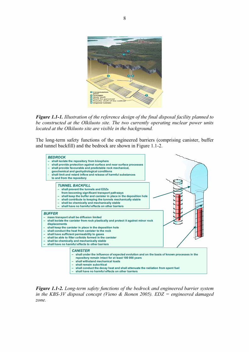
The reference design for the repository (KBS-3V) and the manner by which it is expected to evolve over time are described in detail in Pastina and Hellä (2006). The reference design consists of a one-storey underground facility with disposal tunnels at a depth of approximately 420 m, as shown in Figure 1.1-1. Alternative designs have considered a two-storey design with disposal tunnels located vertically above each other separated by some tens of metres of rock (Saanio et al. 2006).
Spent nuclear fuel, in the form of whole fuel assemblies, will be sealed inside a canister structure that consists of a massive cast iron insert (see Chapter 3) covered by a 50 mm thick copper overpack (see Chapter 4). For the sake of simplicity, the term ‘canister’ is used here to refer to the entire waste package comprised of the spent fuel, cast iron insert and copper overpack, unless otherwise indicated. Within the repository, canisters will be located individually inside deposition holes spaced at intervals along the floor of long horizontal deposition tunnels. The void spaces between the canister and the rock in the deposition hole will be filled with rings and blocks of dry compacted bentonite clay (see Chapter 5). Each deposition tunnel will be backfilled with a clay-rich material after all its deposition holes have been filled (see Chapter 6) and, at the end of the operational phase, all open regions in the repository as well as most direct access points to the surface (e.g. boreholes) will be backfilled and sealed to limit access of water to the repository area, although some boreholes may be kept open to allow for remote monitoring of the repository (see Chapter 7).
8
Figure 1.1-1. Illustration of the reference design of the final disposal facility planned to be constructed at the Olkiluoto site. The two currently operating nuclear power units located at the Olkiluoto site are visible in the background.
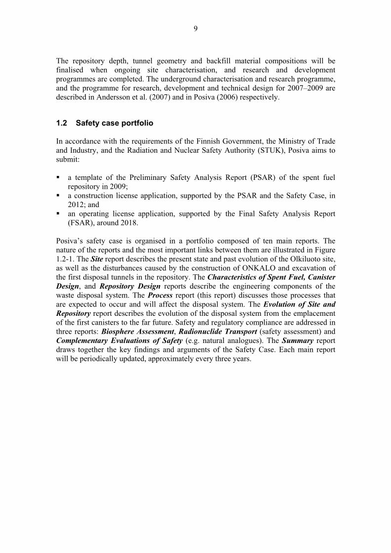
The long-term safety functions of the engineered barriers (comprising canister, buffer and tunnel backfill) and the bedrock are shown in Figure 1.1-2.
CANISTER
– shall under the influence of expected evolution and on the basis of known processes in the
repository remain intact for at least 100 000 years
– shall withstand mechanical loads
– shall remain subcritical
– shall conduct the decay heat and shall attenuate the radiation from spent fuel
– shall have no harmful effects on other barriers
BUFFER
– mass transport shall be diffusion limited
– shall isolate the canister from rock plastically and protect it against minor rock
displacements
- shall keep the canister in place in the deposition hole
– shall conduct the heat from canister to the rock
– shall have sufficient permeability to gases
– shall be able to filter colloids formed in the canister
– shall be chemically and mechanically stable
– shall have no harmful effects to other barriers
TUNNEL BACKFILL
– shall prevent the tunnels and EDZs
from becoming significant transport pathways
– shall keep the buffer and canister in place in the deposition hole
– shall contribute to keeping the tunnels mechanically stable
– shall be chemically and mechanically stable
– shall have no harmful effects on other barriers
BEDROCK
– shall isolate the repository from biosphere
- shall provide protection against surface and near surface processes
– shall provide favourable and predictable rock mechanical,
geochemical and geohydrological conditions
- shall limit and retard inflow and release of harmful substances
to and from the repository
CANISTER
– shall under the influence of expected evolution and on the basis of known processes in the
repository remain intact for at least 100 000 years
– shall withstand mechanical loads
– shall remain subcritical
– shall conduct the decay heat and shall attenuate the radiation from spent fuel
– shall have no harmful effects on other barriers
BUFFER
– mass transport shall be diffusion limited
– shall isolate the canister from rock plastically and protect it against minor rock
displacements
- shall keep the canister in place in the deposition hole
– shall conduct the heat from canister to the rock
– shall have sufficient permeability to gases
– shall be able to filter colloids formed in the canister
– shall be chemically and mechanically stable
– shall have no harmful effects to other barriers
TUNNEL BACKFILL
– shall prevent the tunnels and EDZs
from becoming significant transport pathways
– shall keep the buffer and canister in place in the deposition hole
– shall contribute to keeping the tunnels mechanically stable
– shall be chemically and mechanically stable
– shall have no harmful effects on other barriers
BEDROCK
– shall isolate the repository from biosphere
- shall provide protection against surface and near surface processes
– shall provide favourable and predictable rock mechanical,
geochemical and geohydrological conditions
- shall limit and retard inflow and release of harmful substances
to and from the repository
Figure 1.1-2. Long-term safety functions of the bedrock and engineered barrier system in the KBS-3V disposal concept (Vieno & Ikonen 2005). EDZ = engineered damaged zone.
9
The repository depth, tunnel geometry and backfill material compositions will be finalised when ongoing site characterisation, and research and development programmes are completed. The underground characterisation and research programme, and the programme for research, development and technical design for 2007–2009 are described in Andersson et al. (2007) and in Posiva (2006) respectively.
1.2 Safety case portfolio
In accordance with the requirements of the Finnish Government, the Ministry of Trade and Industry, and the Radiation and Nuclear Safety Authority (STUK), Posiva aims to submit:
a template of the Preliminary Safety Analysis Report (PSAR) of the spent fuel repository in 2009; a construction license application, supported by the PSAR and the Safety Case, in 2012; and an operating license application, supported by the Final Safety Analysis Report (FSAR), around 2018.
Posiva’s safety case is organised in a portfolio composed of ten main reports. The nature of the reports and the most important links between them are illustrated in Figure 1.2-1. The Site report describes the present state and past evolution of the Olkiluoto site, as well as the disturbances caused by the construction of ONKALO and excavation of the first disposal tunnels in the repository. The Characteristics of Spent Fuel, Canister
Design, and Repository Design reports describe the engineering components of the waste disposal system. The Process report (this report) discusses those processes that are expected to occur and will affect the disposal system. The Evolution of Site and
Repository report describes the evolution of the disposal system from the emplacement of the first canisters to the far future. Safety and regulatory compliance are addressed in three reports: Biosphere Assessment, Radionuclide Transport (safety assessment) and Complementary Evaluations of Safety (e.g. natural analogues). The Summary report draws together the key findings and arguments of the Safety Case. Each main report will be periodically updated, approximately every three years.

10
Figure 1.2-1. The main reports in the Safety Case portfolio. The colours of the boxes indicate the nature of the reports and the arrows show the most important transfers of knowledge and data (Vieno & Ikonen 2005).
This Safety Case portfolio is based on requirements from STUK as well as on the Nuclear Energy Agency (NEA) guidelines on the post-closure safety case for geological repositories (STUK 2001, NEA 2004). Recent examples of safety assessments for deep geological repositories, such as Sweden’s SR-Can (SKB 2006), the Canadian safety case on the disposal of used CANDU fuel in copper-steel containers in crystalline bedrock (Gierszewski et al. 2004), Switzerland’s Project Opalinus Clay (Nagra 2002), France’s Dossier 2005 (Andra 2005) also have provided guidance for Posiva’s Safety Case activities.
1.3 Scope of this report
This report discusses a range of processes potentially affecting the reference design disposal system. The scope of the report is limited to those processes that are expected to occur within the engineered barrier system and the geosphere. Biosphere processes (including human actions such as intrusion) are not included in this report but are covered in the Biosphere Assessment report. The effects of certain biosphere process when manifested in the engineered barriers and geosphere are, however, described here (e.g. permafrost is described as a geosphere processes but future climate change models are described in the evolution and biosphere reports).

11
1.4 Features, events and processes (FEPs)
As with most recent safety cases, the Posiva safety case is based on an analysis of features, events and processes (FEPs) considered relevant to a number of scenarios of the future post-closure evolution of the repository.
All processes considered relevant to the long-term evolution and performance of the engineered barriers and the geosphere, and which need to be included in the assessment, are identified. Processes that are not considered likely to occur are screened-out and are not discussed in this report but the reasoning for their exclusion is summarised in Table 1.4-1 (examples include volcanic and metamorphic activity which are considered improbable in Finland within the next one million years). Scenarios are discussed in Chapter 2.
Two key sources were used to identify the relevant FEPs for the engineered barriers and the geosphere:
1. the NEA international FEP database (NEA 2000), and 2. the previous Posiva Process report (Rasilainen 2004) that addressed the processes
listed in SKB’s SR97 Process report in the context of the Finnish repository design and the Olkiluoto site-specific context.
The NEA international FEP database is a generic list of FEPs considered to be applicable to most deep repository concepts. It is routinely used to audit FEP lists to ensure they are comprehensive but at a relatively high level because it does not address repository or site-specific technical details. The previous Posiva Process report does address the specific features and processes of the KBS-3V repository design but in a comparative manner to SR97.
An update to the previous Posiva Process report was considered necessary to account for the specific design features incorporated in the Finnish repository design (to address where it differs from the Swedish concept, for example in terms of the fabrication and welding of the canister) and also to account for the known specific geological and hydrogeological characteristics of the Olkiluoto site.
This report documents the scientific and technical knowledge relevant to each of these processes at a level suitable to enable its understanding and treatment in the assessment. It is not the purpose of this report to provide an exhaustive scientific description of each process since this can be found elsewhere in the literature.
1.5 Process descriptions
Each of the processes is described in later sections of this report using a common tabular format. The key components of this format are:
Category: indicates the relevant sub-system component (e.g. canister, buffer etc.) and type (e.g. evolution related or migration related etc).
12
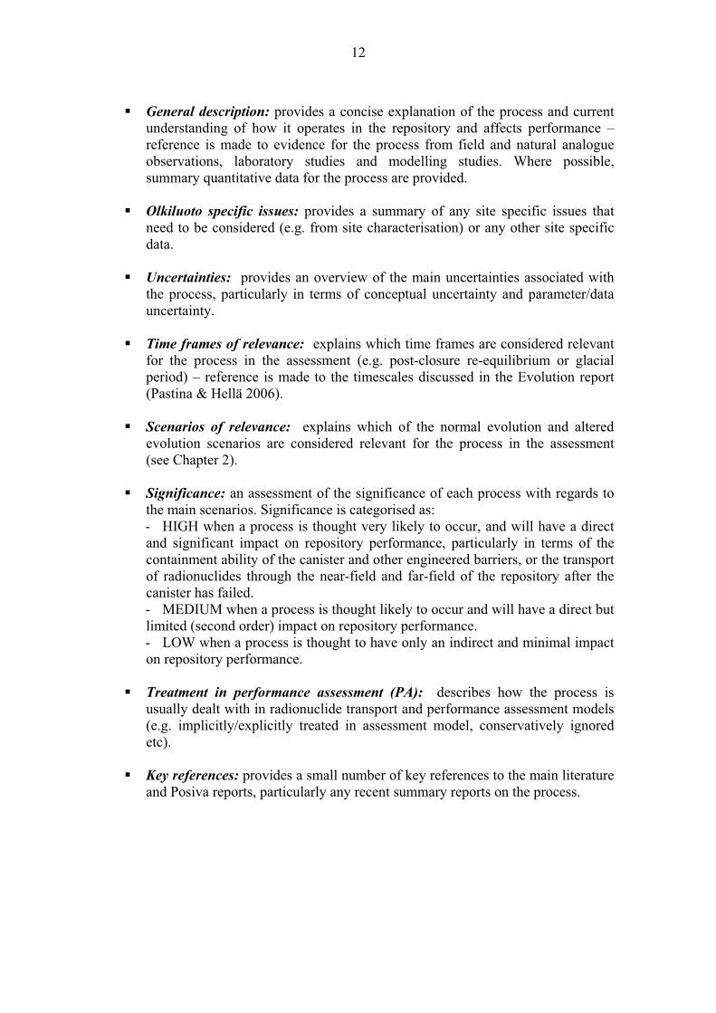
General description: provides a concise explanation of the process and current understanding of how it operates in the repository and affects performance – reference is made to evidence for the process from field and natural analogue observations, laboratory studies and modelling studies. Where possible, summary quantitative data for the process are provided.
Olkiluoto specific issues: provides a summary of any site specific issues that need to be considered (e.g. from site characterisation) or any other site specific data.
Uncertainties: provides an overview of the main uncertainties associated with the process, particularly in terms of conceptual uncertainty and parameter/data uncertainty.
Time frames of relevance: explains which time frames are considered relevant for the process in the assessment (e.g. post-closure re-equilibrium or glacial period) – reference is made to the timescales discussed in the Evolution report (Pastina & Hellä 2006).
Scenarios of relevance: explains which of the normal evolution and altered evolution scenarios are considered relevant for the process in the assessment (see Chapter 2).
Significance: an assessment of the significance of each process with regards to the main scenarios. Significance is categorised as: - HIGH when a process is thought very likely to occur, and will have a direct and significant impact on repository performance, particularly in terms of the containment ability of the canister and other engineered barriers, or the transport of radionuclides through the near-field and far-field of the repository after the canister has failed. - MEDIUM when a process is thought likely to occur and will have a direct but limited (second order) impact on repository performance. - LOW when a process is thought to have only an indirect and minimal impact on repository performance.
Treatment in performance assessment (PA): describes how the process is usually dealt with in radionuclide transport and performance assessment models (e.g. implicitly/explicitly treated in assessment model, conservatively ignored etc).
Key references: provides a small number of key references to the main literature and Posiva reports, particularly any recent summary reports on the process.
13
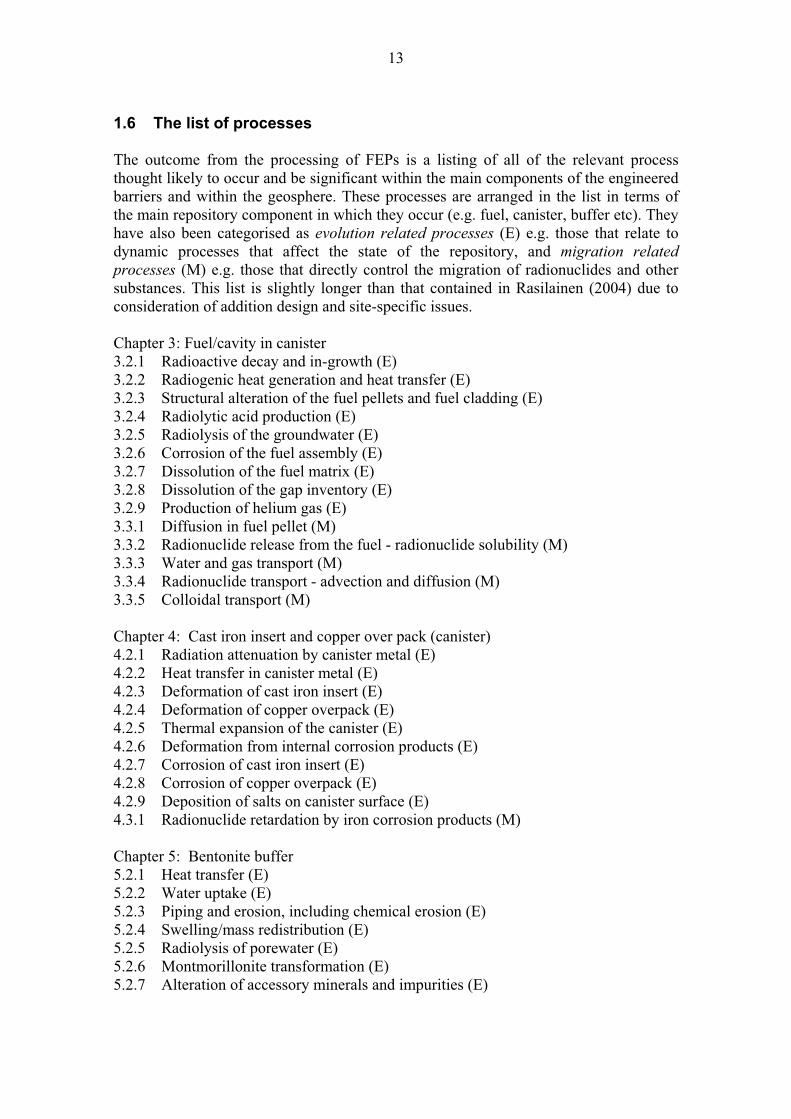
1.6 The list of processes
The outcome from the processing of FEPs is a listing of all of the relevant process thought likely to occur and be significant within the main components of the engineered barriers and within the geosphere. These processes are arranged in the list in terms of the main repository component in which they occur (e.g. fuel, canister, buffer etc). They have also been categorised as evolution related processes (E) e.g. those that relate to dynamic processes that affect the state of the repository, and migration related processes (M) e.g. those that directly control the migration of radionuclides and other substances. This list is slightly longer than that contained in Rasilainen (2004) due to consideration of addition design and site-specific issues.
Chapter 3: Fuel/cavity in canister 3.2.1 Radioactive decay and in-growth (E) 3.2.2 Radiogenic heat generation and heat transfer (E) 3.2.3 Structural alteration of the fuel pellets and fuel cladding (E) 3.2.4 Radiolytic acid production (E) 3.2.5 Radiolysis of the groundwater (E) 3.2.6 Corrosion of the fuel assembly (E) 3.2.7 Dissolution of the fuel matrix (E) 3.2.8 Dissolution of the gap inventory (E) 3.2.9 Production of helium gas (E) 3.3.1 Diffusion in fuel pellet (M) 3.3.2 Radionuclide release from the fuel - radionuclide solubility (M) 3.3.3 Water and gas transport (M) 3.3.4 Radionuclide transport - advection and diffusion (M) 3.3.5 Colloidal transport (M)
Chapter 4: Cast iron insert and copper over pack (canister) 4.2.1 Radiation attenuation by canister metal (E) 4.2.2 Heat transfer in canister metal (E) 4.2.3 Deformation of cast iron insert (E) 4.2.4 Deformation of copper overpack (E) 4.2.5 Thermal expansion of the canister (E) 4.2.6 Deformation from internal corrosion products (E) 4.2.7 Corrosion of cast iron insert (E) 4.2.8 Corrosion of copper overpack (E) 4.2.9 Deposition of salts on canister surface (E) 4.3.1 Radionuclide retardation by iron corrosion products (M)
Chapter 5: Bentonite buffer 5.2.1 Heat transfer (E) 5.2.2 Water uptake (E) 5.2.3 Piping and erosion, including chemical erosion (E) 5.2.4 Swelling/mass redistribution (E) 5.2.5 Radiolysis of porewater (E) 5.2.6 Montmorillonite transformation (E) 5.2.7 Alteration of accessory minerals and impurities (E)

14
5.2.8 Microbial activity (E) 5.3.1 Advection – Diffusion (M) 5.3.2 Gas transport (M) 5.3.3 Colloid formation and transport (M) 5.3.4 Sorption (including ionic-exchange) (M) 5.3.5 Osmosis/Donnan equilibrium (M) 5.3.6 Speciation of radionuclides (M) 5.3.7 Precipitation and co-precipitation (M)
Chapter 6: Backfill 6.2.1 Heat transfer (E) 6.2.2 Freezing (E) 6.2.3 Water uptake (E) 6.2.4 Piping and erosion, including chemical erosion (E) 6.2.5 Swelling/mass redistribution (E) 6.2.5 Radiolysis of porewater (E) 6.2.6 Alteration of accessory minerals and impurities (E) 6.2.7 Microbial activity (E)
Chapter 7: Plugs, seals, grout 7.2.1 Heat transfer (E) 7.2.2 Freezing (E) 7.2.3 Degradation of cementitious materials due to radiation and thermal effects (E) 7.2.4 Degradation of cementitious materials due to reactions with groundwater (E) 7.3.1 Diffusion (M) 7.3.2 Sorption (M) 7.3.3 Colloid formation (M)
Chapter 8: Geosphere 8.2.1 Heat transfer (E) 8.2.2 Freezing and permafrost (E) 8.2.3 Stress redistribution due to excavation (E) 8.2.4 Reactivation-displacements along existing fractures (E) 8.2.5 Spalling of rock (E) 8.2.6 Rock creep (E) 8.2.7 Erosion and sedimentation in fractures (E) 8.2.8 Rock-water interaction (E) 8.2.9 Methane hydrate formation (E) 8.2.10 Salt exclusion (E) 8.2.11 Microbial populations and processes (E) 8.3.1 Radionuclide solubility, sorption and precipitation (M) 8.3.2 Groundwater flow (advection) (M) 8.3.3 Dispersion (M) 8.3.4 Matrix diffusion (M) 8.3.5 Two-phase flow (M) 8.3.6 Colloidal transport (M)

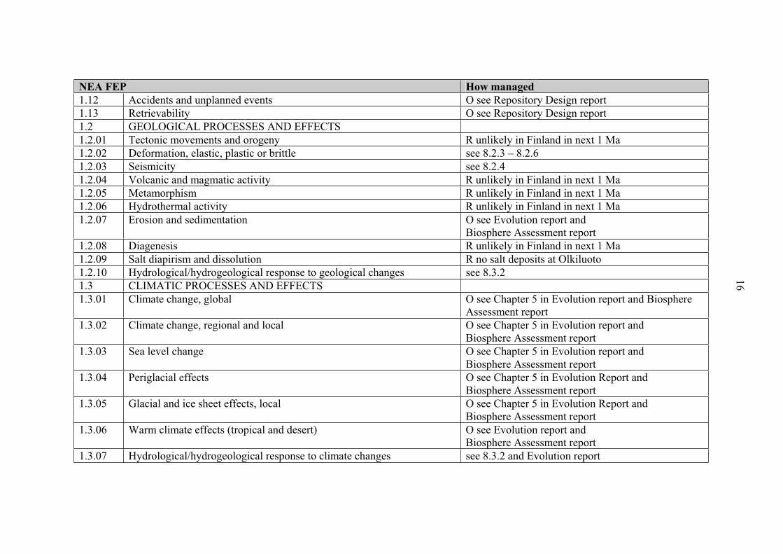
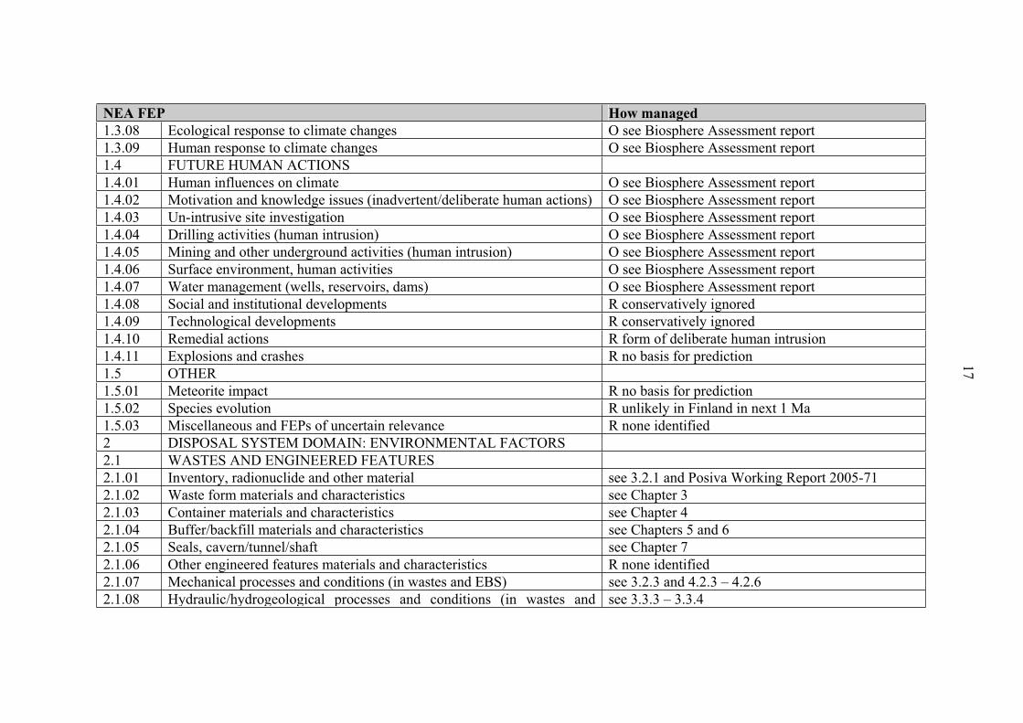
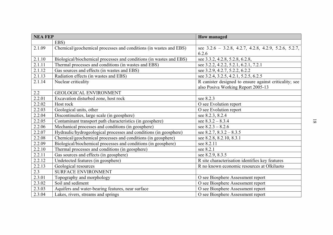
Table 1.6-1. Screening of FEPs from the NEA international list. R = rejected from consideration because not relevant to this assessment (with reasoning). O = out with the scope of this report. The reports mentioned relate to those listed in Figure 1.2-1.
NEA FEP How managed
0 ASSESSMENT BASIS 0.01 Impacts of concern O see Radionuclide Transport report 0.02 Timescales of concern O see Evolution report (POSIVA 2006-05) 0.03 Spatial domain of concern O see Radionuclide Transport report 0.04 Repository assumptions O see Radionuclide Transport report 0.05 Future human action assumptions O see Biosphere Assessment 0.06 Future human behaviour (target group) assumptions O see Biosphere Assessment 0.07 Dose response assumptions O see Biosphere Assessment and
Radionuclide Transport report 0.08 Aims of the assessment O see Radionuclide Transport report 0.09 Regulatory requirements and exclusions O see Radionuclide Transport report 0.10 Model and data issues O see Radionuclide Transport report 1 EXTERNAL FACTORS 1.1 REPOSITORY ISSUES 1.01 Site investigation O see Repository Design report 1.02 Excavation/construction O see Repository Design report 1.03 Emplacement of wastes and backfilling O see Repository Design report 1.04 Closure and repository sealing O see Repository Design report 1.05 Records and markers, repository O see Repository Design report 1.06 Waste allocation O see Repository Design report 1.07 Repository design O see Repository Design report 1.08 Quality control O see Repository Design report 1.09 Schedule and planning O see Repository Design report 1.10 Administrative control, repository site O see Repository Design report 1.11 Monitoring of repository O see Repository Design report
15
NEA FEP How managed
1.12 Accidents and unplanned events O see Repository Design report 1.13 Retrievability O see Repository Design report 1.2 GEOLOGICAL PROCESSES AND EFFECTS 1.2.01 Tectonic movements and orogeny R unlikely in Finland in next 1 Ma 1.2.02 Deformation, elastic, plastic or brittle see 8.2.3 – 8.2.6 1.2.03 Seismicity see 8.2.4 1.2.04 Volcanic and magmatic activity R unlikely in Finland in next 1 Ma 1.2.05 Metamorphism R unlikely in Finland in next 1 Ma 1.2.06 Hydrothermal activity R unlikely in Finland in next 1 Ma 1.2.07 Erosion and sedimentation O see Evolution report and
Biosphere Assessment report 1.2.08 Diagenesis R unlikely in Finland in next 1 Ma 1.2.09 Salt diapirism and dissolution R no salt deposits at Olkiluoto 1.2.10 Hydrological/hydrogeological response to geological changes see 8.3.2 1.3 CLIMATIC PROCESSES AND EFFECTS 1.3.01 Climate change, global O see Chapter 5 in Evolution report and Biosphere
Assessment report 1.3.02 Climate change, regional and local O see Chapter 5 in Evolution report and
Biosphere Assessment report 1.3.03 Sea level change O see Chapter 5 in Evolution report and
Biosphere Assessment report 1.3.04 Periglacial effects O see Chapter 5 in Evolution Report and
Biosphere Assessment report 1.3.05 Glacial and ice sheet effects, local O see Chapter 5 in Evolution Report and
Biosphere Assessment report 1.3.06 Warm climate effects (tropical and desert) O see Evolution report and
Biosphere Assessment report 1.3.07 Hydrological/hydrogeological response to climate changes see 8.3.2 and Evolution report
16
NEA FEP How managed
1.3.08 Ecological response to climate changes O see Biosphere Assessment report 1.3.09 Human response to climate changes O see Biosphere Assessment report 1.4 FUTURE HUMAN ACTIONS 1.4.01 Human influences on climate O see Biosphere Assessment report 1.4.02 Motivation and knowledge issues (inadvertent/deliberate human actions) O see Biosphere Assessment report 1.4.03 Un-intrusive site investigation O see Biosphere Assessment report 1.4.04 Drilling activities (human intrusion) O see Biosphere Assessment report 1.4.05 Mining and other underground activities (human intrusion) O see Biosphere Assessment report 1.4.06 Surface environment, human activities O see Biosphere Assessment report 1.4.07 Water management (wells, reservoirs, dams) O see Biosphere Assessment report 1.4.08 Social and institutional developments R conservatively ignored 1.4.09 Technological developments R conservatively ignored 1.4.10 Remedial actions R form of deliberate human intrusion 1.4.11 Explosions and crashes R no basis for prediction 1.5 OTHER 1.5.01 Meteorite impact R no basis for prediction 1.5.02 Species evolution R unlikely in Finland in next 1 Ma 1.5.03 Miscellaneous and FEPs of uncertain relevance R none identified 2 DISPOSAL SYSTEM DOMAIN: ENVIRONMENTAL FACTORS 2.1 WASTES AND ENGINEERED FEATURES 2.1.01 Inventory, radionuclide and other material see 3.2.1 and Posiva Working Report 2005-71 2.1.02 Waste form materials and characteristics see Chapter 3 2.1.03 Container materials and characteristics see Chapter 4 2.1.04 Buffer/backfill materials and characteristics see Chapters 5 and 6 2.1.05 Seals, cavern/tunnel/shaft see Chapter 7 2.1.06 Other engineered features materials and characteristics R none identified 2.1.07 Mechanical processes and conditions (in wastes and EBS) see 3.2.3 and 4.2.3 – 4.2.6 2.1.08 Hydraulic/hydrogeological processes and conditions (in wastes and see 3.3.3 – 3.3.4
17
NEA FEP How managed
EBS)2.1.09 Chemical/geochemical processes and conditions (in wastes and EBS) see 3.2.6 – 3.2.8, 4.2.7, 4.2.8, 4.2.9, 5.2.6, 5.2.7,
6.2.62.1.10 Biological/biochemical processes and conditions (in wastes and EBS) see 3.3.2, 4.2.8, 5.2.8, 6.2.8, 2.1.11 Thermal processes and conditions (in wastes and EBS) see 3.2.2, 4.2.2, 5.2.1, 6.2.1, 7.2.1 2.1.12 Gas sources and effects (in wastes and EBS) see 3.2.9, 4.2.7, 5.2.2, 6.2.2 2.1.13 Radiation effects (in wastes and EBS) see 3.2.4, 3.2.5, 4.2.1, 5.2.5, 6.2.5 2.1.14 Nuclear criticality R canister designed to ensure against criticality; see
also Posiva Working Report 2005-13 2.2 GEOLOGICAL ENVIRONMENT 2.2.01 Excavation disturbed zone, host rock see 8.2.3 2.2.02 Host rock O see Evolution report 2.2.03 Geological units, other O see Evolution report 2.2.04 Discontinuities, large scale (in geosphere) see 8.2.3, 8.2.4 2.2.05 Contaminant transport path characteristics (in geosphere) see 8.3.2 – 8.3.4 2.2.06 Mechanical processes and conditions (in geosphere) see 8.2.3 – 8.2.6 2.2.07 Hydraulic/hydrogeological processes and conditions (in geosphere) see 8.2.7, 8.3.2 – 8.3.5 2.2.08 Chemical/geochemical processes and conditions (in geosphere) see 8.2.8, 8.2.10, 8.3.1 2.2.09 Biological/biochemical processes and conditions (in geosphere) see 8.2.11 2.2.10 Thermal processes and conditions (in geosphere) see 8.2.1 2.2.11 Gas sources and effects (in geosphere) see 8.2.9, 8.3.5 2.2.12 Undetected features (in geosphere) R site characterisation identifies key features 2.2.13 Geological resources R no known economic resources at Olkiluoto 2.3 SURFACE ENVIRONMENT 2.3.01 Topography and morphology O see Biosphere Assessment report 2.3.02 Soil and sediment O see Biosphere Assessment report 2.3.03 Aquifers and water-bearing features, near surface O see Biosphere Assessment report 2.3.04 Lakes, rivers, streams and springs O see Biosphere Assessment report
18

NEA FEP How managed
2.3.05 Coastal features O see Biosphere Assessment report 2.3.06 Marine features O see Biosphere Assessment report 2.3.07 Atmosphere O see Biosphere Assessment report 2.3.08 Vegetation O see Biosphere Assessment report 2.3.09 Animal populations O see Biosphere Assessment report 2.3.10 Meteorology O see Biosphere Assessment report 2.3.11 Hydrological regime and water balance (near-surface) O see Biosphere Assessment report 2.3.12 Erosion and deposition O see Biosphere Assessment report 2.3.13 Ecological/biological/microbial systems O see Biosphere Assessment report 2.4 HUMAN BEHAVIOUR 2.4.01 Human characteristics (physiology, metabolism) O see Biosphere Assessment report 2.4.02 Adults, children, infants and other variations O see Biosphere Assessment report 2.4.03 Diet and fluid intake O see Biosphere Assessment report 2.4.04 Habits (non-diet-related behaviour) O see Biosphere Assessment report 2.4.05 Community characteristics O see Biosphere Assessment report 2.4.06 Food and water processing and preparation O see Biosphere Assessment report 2.4.07 Dwellings O see Biosphere Assessment report 2.4.08 Wild and natural land and water use O see Biosphere Assessment report 2.4.09 Rural and agricultural land and water use (incl. fisheries) O see Biosphere Assessment report 2.4.10 Urban and industrial land and water use O see Biosphere Assessment report 2.4.11 Leisure and other uses of environment O see Biosphere Assessment report 3 RADIONUCLIDE/CONTAMINANT FACTORS 3.1 CONTAMINANT CHARACTERISTICS 3.1.01 Radioactive decay and in-growth see 3.2.1 3.1.02 Chemical/organic toxin stability see 5.2.8, 6.2.8, 8.2.11 3.1.03 Inorganic solids/solutes see 3.3.55.3.4, 6.3.3, 3.1.04 Volatiles and potential for volatility see 7.2.4 3.1.05 Organics and potential for organic forms see 3.3.2, 5.3.7, 6.3.6, 7.3.2, 8.3.1
19

NEA FEP How managed
3.1.06 Noble gases see 3.3.3, 8.3.5 3.2 CONTAMINANT RELEASE/MIGRATION FACTORS 3.2.01 Dissolution, precipitation and crystallisation, contaminant see 3.3.2, 5.3.8, 6.3.7, 7.3.2, 8.3.1 3.2.02 Speciation and solubility, contaminant see 3.2.2, 5.3.7, 6.3.6, 7.3.2, 8.3.1 3.2.03 Sorption/desorption processes, contaminant see 3.3.2, 4.3.1, 5.3.5, 6.3.4, 7.3.2, 8.3.1 3.2.04 Colloids, contaminant interactions and transport with see 3.3.5, 5.3.4, 6.3.3, 7.3.1, 8.3.6 3.2.05 Chemical/complexing agents, effects on contaminant
speciation/transport see 3.3.2, 5.3.7, 6.3.6, 7.3.2, 8.3.1
3.2.06 Microbial/biological/plant-mediated processes, contaminant see 5.2.8, 6.2.8, 8.2.11 3.2.07 Water-mediated transport of contaminants see 3.3.3, 5.3.1, 5.3.2, 6.3.1, 8.3.2, 8.3.3 3.2.08 Solid-mediated transport of contaminants see 3.3.5, 5.3.4, 6.3.3, 7.3.1, 8.3.6 3.2.09 Gas-mediated transport of contaminants see 3.3.3, 5.3.3, 6.3.2, 8.3.5 3.2.10 Atmospheric transport of contaminants O see Biosphere Assessment report 3.2.11 Animal, plant and microbe mediated transport of contaminants O see Biosphere Assessment report 3.2.12 Human-action-mediated transport of contaminants O see Biosphere Assessment report 3.2.13 Foodchains, uptake of contaminants in O see Biosphere Assessment report 3.3 EXPOSURE FACTORS 3.3.01 Drinking water, foodstuffs and drugs, contaminant concentrations in O see Biosphere Assessment report 3.3.02 Environmental media, contaminant concentrations in O see Biosphere Assessment report 3.3.03 Non-food products, contaminant concentrations in O see Biosphere Assessment report 3.3.04 Exposure modes O see Biosphere Assessment report 3.3.05 Dosimetry O see Biosphere Assessment report 3.3.06 Radiological toxicity/effects O see Biosphere Assessment report 3.3.07 Non-radiological toxicity/effects O see Biosphere Assessment report 3.3.08 Radon and radon daughter exposure O see Biosphere Assessment report
20
21
2 HANDLING OF SCENARIOS
Posiva's safety case considers scenarios as relatively complete descriptions of future developments. According to the IAEA definition, scenario is defined as “a postulated or assumed set of condition and/or events. They are most commonly used in analyses of assessments to represent possible future conditions and/or events to be modelled, such as possible accidents at a nuclear facility, or the possible future evolution of a repository and its surroundings” (IAEA 2003). In this report the processes will be checked against the described set of scenarios.
In practice, the scenarios are quantitatively evaluated using calculation cases that – after conceptualisation of scenarios – handle them in various entireties (complete sets of assumptions and parameters). Thus calculation cases represent more restricted sets of assumptions than scenarios. In addition, calculation cases are used for handling uncertainties within the defined scenarios e.g. by varying the values of calculation parameters.
2.1 Definition/description of main scenario, defective canister scenario, additional scenarios, and variants
The method for developing scenarios follows a top down approach since most of the scenarios to have into consideration come from regulatory requirements. This means that we first select or define the scenarios to be analysed and then use FEP lists/databases, complemented with expert judgement, to check that nothing important has been left out of consideration. Moreover, the nearly complete set of calculation cases (note that calculation cases were called scenarios in earlier safety assessments) in earlier safety assessments (e.g. TILA-99; Vieno & Nordman 1999) could be grouped to fit in the scenarios selected for the current Posiva’s Safety Case.
The scenarios considered in the Posiva’s Safety Case portfolio have been partly defined in the Evolution Report (Pastina & Hellä 2006). In the main scenario of that report all system components are expected to behave as designed to keep their long-term safety functions over all time frames required by regulations in the YVL 8.4 (STUK 2001) and the time frames defined in the two climatic scenarios (Weichselian-R and Emissions-M) to be taken into account (see Chapter 5 in Pastina & Hellä 2006). No major disruptive events giving place to radionuclide releases are expected within the main scenario.
In the expected evolution of the repository no release of radionuclides occur within 100 000 to 1 000 000 years. Following STUK’s recommendations (STUK 2001), the defective canister scenario (DCS) has also been defined in the Evolution Report. Two variants are considered within this scenario, DCS-I and DCS-II. For the purpose of radionuclide transport calculations in the variant DCS-I it is assumed that the canister has no initial penetrating defects and that release of radionuclides does not occur within the first 10 000 years after closure of the repository. In the variant DCS-II it is assumed that the canister has an undetected penetrating defect and that release of radionuclides may start immediately at the time of repository closure.
22
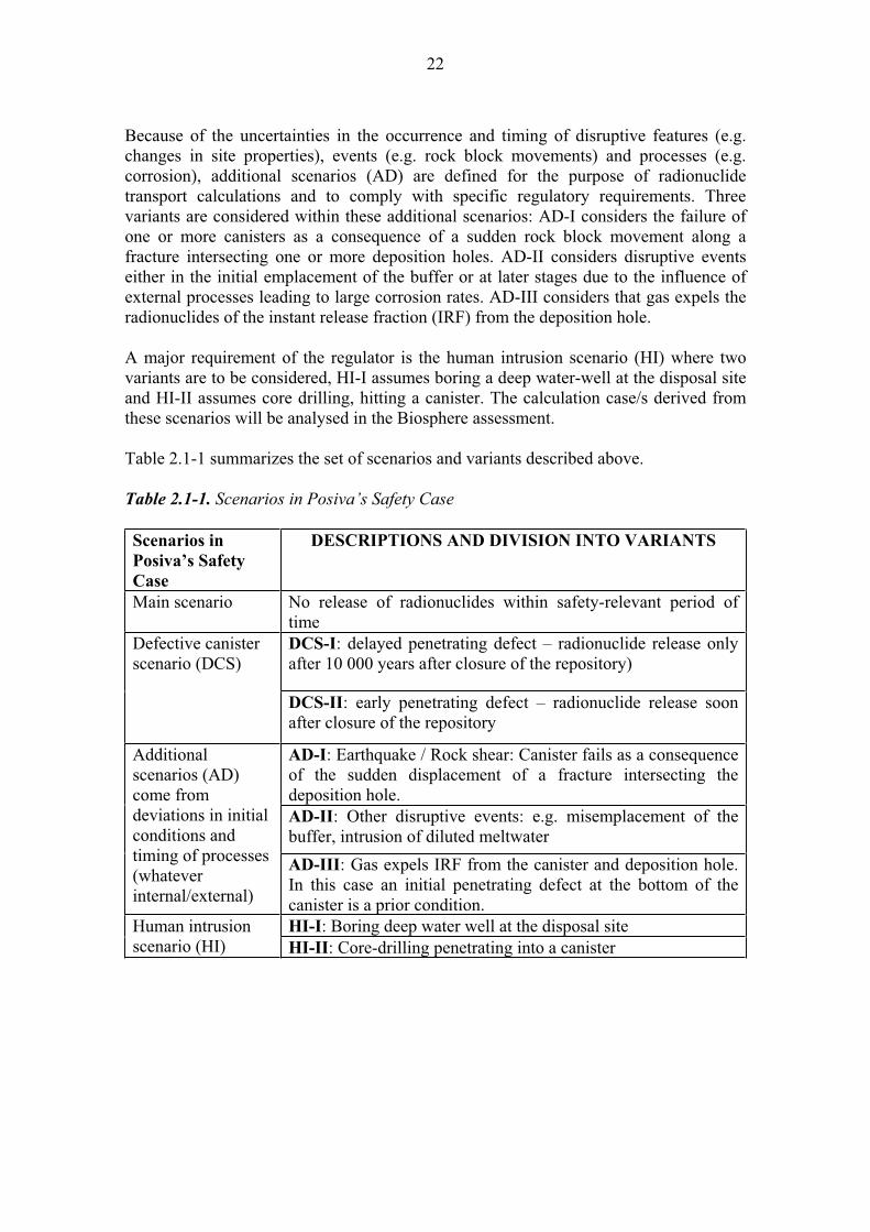
Because of the uncertainties in the occurrence and timing of disruptive features (e.g. changes in site properties), events (e.g. rock block movements) and processes (e.g. corrosion), additional scenarios (AD) are defined for the purpose of radionuclide transport calculations and to comply with specific regulatory requirements. Three variants are considered within these additional scenarios: AD-I considers the failure of one or more canisters as a consequence of a sudden rock block movement along a fracture intersecting one or more deposition holes. AD-II considers disruptive events either in the initial emplacement of the buffer or at later stages due to the influence of external processes leading to large corrosion rates. AD-III considers that gas expels the radionuclides of the instant release fraction (IRF) from the deposition hole.
A major requirement of the regulator is the human intrusion scenario (HI) where two variants are to be considered, HI-I assumes boring a deep water-well at the disposal site and HI-II assumes core drilling, hitting a canister. The calculation case/s derived from these scenarios will be analysed in the Biosphere assessment.
Table 2.1-1 summarizes the set of scenarios and variants described above.
Table 2.1-1. Scenarios in Posiva’s Safety Case
Scenarios in
Posiva’s Safety
Case
DESCRIPTIONS AND DIVISION INTO VARIANTS
Main scenario No release of radionuclides within safety-relevant period of time DCS-I: delayed penetrating defect – radionuclide release only after 10 000 years after closure of the repository)
Defective canister scenario (DCS)
DCS-II: early penetrating defect – radionuclide release soon after closure of the repository
AD-I: Earthquake / Rock shear: Canister fails as a consequence of the sudden displacement of a fracture intersecting the deposition hole. AD-II: Other disruptive events: e.g. misemplacement of the buffer, intrusion of diluted meltwater
Additionalscenarios (AD) come from deviations in initial conditions and timing of processes (whateverinternal/external)
AD-III: Gas expels IRF from the canister and deposition hole. In this case an initial penetrating defect at the bottom of the canister is a prior condition. HI-I: Boring deep water well at the disposal site Human intrusion
scenario (HI) HI-II: Core-drilling penetrating into a canister

23
2.2 Definition/description of the organization of calculation cases and variants for radionuclide transport analyses
Since the main scenario is tied in the expected evolution of the repository, where no releases of radionuclides will occur within safety-relevant period of time, no calculation cases are needed. On the other hand, the defective canister scenarios (DCS), additional scenarios (AD) and human intrusion scenarios (HI) in Table 2.1-1 are called assessment scenarios and are appraised by means of quantitative analyses (Figure 2.2-1).
Figure 2.2-1. The hierarchy of scenarios (1), conceptualization (2) and derivation of calculation cases (3).
Climatic scenarios envelope the expected evolution and assessment scenarios
Main scenario: Expected evolution: no release of radionuclides, no assessment needed, no definition of calculation cases; see Evolution Report
Assessment scenarios and variants
Defective canister scenario DCS
No penetrating defect DCS-I Penetrating defect DCS-II
Additional scenarios AD
Geosphere AD-I Buffer AD-II Gases AD-III
Human intrusion scenario HI
Deep water well HI-I Core-drilling hitting HI-II
Conceptualisation of each of the
assessment scenarios and variants
1
DCS-I
Definition of calculation cases (with variants to
include parameter variability due to
uncertainties)
DCS-II
AD-I
AD-II
AD-III
HI-I
HI-II
2
Case DCS-I.1, Case DCS-I.2, ...Case DCS-I.n
Case DCS-II.1, Case DCS-II.2, ...Case DCS-II.n
Case AD-I.1, Case -AD-I.2, ...Case AD-I.n
Case AD-II.1, Case AD-II.2, ...Case AD-II.n
Case AD-III.1, Case AD-III.2, ...Case AD-III.n
Case HI-I.1, Case HI-I.2, ...Case HI-I.n
Case HI-II.1, Case HI-II.2, ...Case HI-II.n
3

24
The scenario variants will be conceptualised and several calculation cases will be derived that do not aim to be realistic but rather explore the robustness of the system. The latter ones include what in TILA-99 (Vieno & Nordman 1999) were called “What if” cases and “sensitivity cases”. For example the calculation cases for DCS-I are defined based on the timing of corrosion process and the physico-chemical conditions at the time (e.g. the flow rate during ice sheet formation or melting is significantly different from periods without glaciation; Pastina & Hellä 2006). The calculation cases for DCS-II are defined by combining the size of the penetrating defect, the time of release of radionuclide, the buffer and backfill conditions, and the groundwater physico-chemical conditions at the time of release.
Figure 2.2-2 shows the derivation calculation cases for the defective canister scenario DCS-II as an example. A complete description of all the calculation cases derived from the scenarios will be given in the radionuclide transport report scheduled for spring 2008.
Figure 2.2-2. Derivation of calculation cases in the Defective Canister Scenario DCS-II.
CalculationCases in DCS-II
Groundwater Groundwater FlowComposition highe.g. saline
Release low/normalSmall time t
e.g. fresh high
low/normal
highe.g.saline
low/normal
Large Releasetime t'
e.g. fresh high
low/normal
Size of defect in DCS-II
DCS-II.4
DCS-II.3
DCS-II.2
DCS-II.1
DCS-II.5
DCS-II.6
DCS-II.7
DCS-II.8
DATA for the FAR FIELD
DATA for the NEAR FIELD:the release time defines the state of spent fuel and bentonite
25
3 FUEL/CAVITY IN CANISTER
3.1 Description
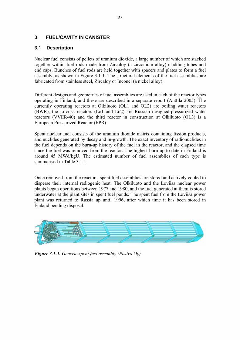
Nuclear fuel consists of pellets of uranium dioxide, a large number of which are stacked together within fuel rods made from Zircaloy (a zirconium alloy) cladding tubes and end caps. Bunches of fuel rods are held together with spacers and plates to form a fuel assembly, as shown in Figure 3.1-1. The structural elements of the fuel assemblies are fabricated from stainless steel, Zircaloy or Inconel (a nickel alloy).
Different designs and geometries of fuel assemblies are used in each of the reactor types operating in Finland, and these are described in a separate report (Anttila 2005). The currently operating reactors at Olkiluoto (OL1 and OL2) are boiling water reactors (BWR), the Loviisa reactors (Lo1 and Lo2) are Russian designed-pressurized water reactors (VVER-40) and the third reactor in construction at Olkiluoto (OL3) is a European Pressurized Reactor (EPR).
Spent nuclear fuel consists of the uranium dioxide matrix containing fission products, and nuclides generated by decay and in-growth. The exact inventory of radionuclides in the fuel depends on the burn-up history of the fuel in the reactor, and the elapsed time since the fuel was removed from the reactor. The highest burn-up to date in Finland is around 45 MWd/kgU. The estimated number of fuel assemblies of each type is summarised in Table 3.1-1.
Once removed from the reactors, spent fuel assemblies are stored and actively cooled to disperse their internal radiogenic heat. The Olkiluoto and the Loviisa nuclear power plants began operations between 1977 and 1980, and the fuel generated at them is stored underwater at the plant sites in spent fuel ponds. The spent fuel from the Loviisa power plant was returned to Russia up until 1996, after which time it has been stored in Finland pending disposal.
Figure 3.1-1. Generic spent fuel assembly (Posiva Oy).

26
Table 3.1-1. Life expectancy, spent fuel element accumulation, average burn-up, and uranium mass estimates for the nuclear power plants at Olkiluoto and Loviisa. Maximum burn-up estimates are based on estimates in 2007.
OL1 OL2 OL3 Lo1 Lo2 Anticipated operation life expectancy (years) 60 60 60 50 50 Number of accumulated spent fuel elements in kgU if the maximum burn-up is for Lo 55 and for OL 50 MWd/kgU
7250 7236 3729 3668 4009
Average burn-up of the spent fuel (MWd/kgU) 37.9 38.5 45.4 40.6 40.9 Uranium mass (tU) 1274 1270 1983 452 489
Once the initial decay heat has dissipated, it is planned to encapsulate the entire fuel assemblies in canisters prior to disposal in the repository. The design of the canisters and the encapsulation process is described in Chapter 4. The minimum cooling times for spent fuel assemblies to meet the heat load limit required for encapsulation is about 30 years for a burn-up of 40 MWd/kgU, as shown in Figure 3.1-2, although the average cooling time until encapsulation will be longer because no encapsulation has yet taken place.
AVERAGE COOLING TIME FOR ENCAPSULATION
0
10
20
30
40
50
60
70
20 25 30 35 40 45 50 55 60
BURN-UP (MWd/kgU)
TIM
E (
a)
EPR 863 W/tU
BWR 806 W/tU
VVER 950 W/tU
Figure 3.1-2. Average minimum cooling times of the Finnish fuel types, based on the allowable canister heat load limit required for encapsulation and as a function of discharge burn-up.
27
There is a low probability (less than one in ten thousand) that the fuel cladding is leaking and the fuel pellets will be in contact with cooling pond water. Typically, damaged fuel rods occur individually and so the probability is very low for several damaged rods to occur in a single fuel element or in a single canister. For modelling purposes, however, it is pessimistically assumed that one rod in each 12 elements in a single canister is leaking and initially water filled. The void inside a fuel rod is typically about 50 cm3 (BWR-rod), thus the maximum water content inside a canister is assumed to 600 cm3.
To minimise the amount of water from the fuel elements prior to encapsulation they will be are dried in a drying unit using a combination of elevated temperature and vacuum. The void spaces in the canister are then purged with argon to displace water and water vapour.
3.1.1 Long-term safety and performance
Any water or water vapour that remains within the fuel rods or in the void spaces within the canister at encapsulation is likely to undergo radioloytic decomposition processes, generating nitric acid. Both the initial water vapour and the nitric acid can cause dissolution and leaching of the spent fuel, although the extent of this process will be extremely limited because the majority of the cladding tubes are expected to remain intact and thus will not contain any water or air. Any small volume of water or nitric acid that does occur in the canister after encapsulation will be rapidly buffered by the large volume of metal and fuel.
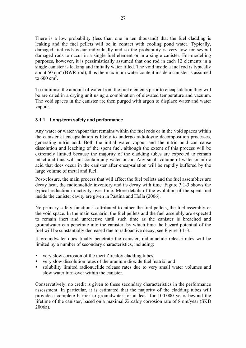
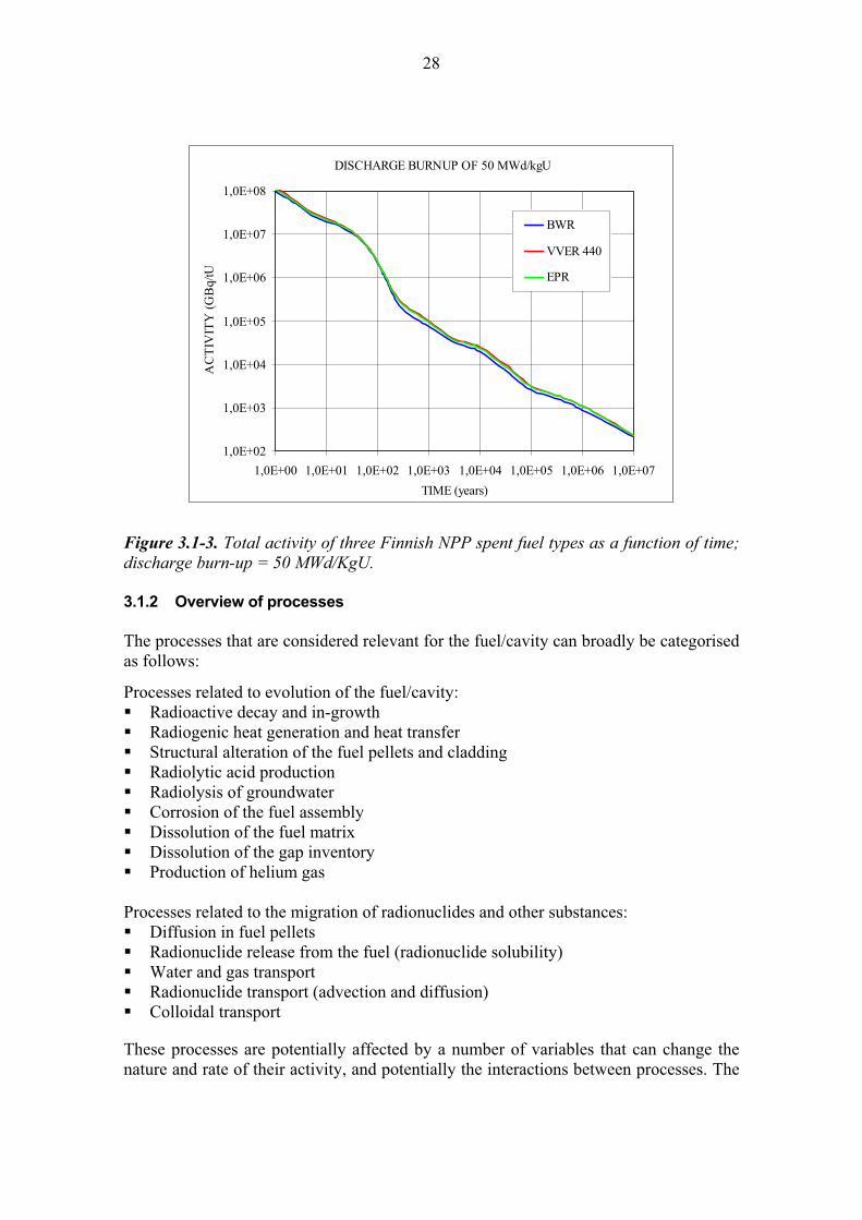
Post-closure, the main process that will affect the fuel pellets and the fuel assemblies are decay heat, the radionuclide inventory and its decay with time. Figure 3.1-3 shows the typical reduction in activity over time. More details of the evolution of the spent fuel inside the canister cavity are given in Pastina and Hellä (2006).
No primary safety function is attributed to either the fuel pellets, the fuel assembly or the void space. In the main scenario, the fuel pellets and the fuel assembly are expected to remain inert and unreactive until such time as the canister is breached and groundwater can penetrate into the canister, by which time the hazard potential of the fuel will be substantially decreased due to radioactive decay, see Figure 3.1-3.
If groundwater does finally penetrate the canister, radionuclide release rates will be limited by a number of secondary characteristics, including:
very slow corrosion of the inert Zircaloy cladding tubes, very slow dissolution rates of the uranium dioxide fuel matrix, and solubility limited radionuclide release rates due to very small water volumes and slow water turn-over within the canister.
Conservatively, no credit is given to these secondary characteristics in the performance assessment. In particular, it is estimated that the majority of the cladding tubes will provide a complete barrier to groundwater for at least for 100 000 years beyond the lifetime of the canister, based on a maximal Zircaloy corrosion rate of 8 nm/year (SKB 2006a).
28
DISCHARGE BURNUP OF 50 MWd/kgU
1,0E+02
1,0E+03
1,0E+04
1,0E+05
1,0E+06
1,0E+07
1,0E+08
1,0E+00 1,0E+01 1,0E+02 1,0E+03 1,0E+04 1,0E+05 1,0E+06 1,0E+07
TIME (years)
AC
TIV
ITY
(G
Bq/
tUBWR
VVER 440
EPR
Figure 3.1-3. Total activity of three Finnish NPP spent fuel types as a function of time; discharge burn-up = 50 MWd/KgU.
3.1.2 Overview of processes
The processes that are considered relevant for the fuel/cavity can broadly be categorised as follows:
Processes related to evolution of the fuel/cavity: Radioactive decay and in-growth Radiogenic heat generation and heat transfer Structural alteration of the fuel pellets and cladding Radiolytic acid production Radiolysis of groundwater Corrosion of the fuel assembly Dissolution of the fuel matrix Dissolution of the gap inventory Production of helium gas
Processes related to the migration of radionuclides and other substances: Diffusion in fuel pellets Radionuclide release from the fuel (radionuclide solubility) Water and gas transport Radionuclide transport (advection and diffusion) Colloidal transport
These processes are potentially affected by a number of variables that can change the nature and rate of their activity, and potentially the interactions between processes. The

29
potential impacts of the different variables on each of the processes are described in the subsequent sections.
3.2 Processes related to the evolution of the fuel/cavity
Various radiation, thermal, chemical and mechanical processes (and their couplings) will affect the evolution of the fuel pellets, the fuel assembly and the cavity within the canister.
In turn, these processes can affect the stability of the fuel and lead to release of radionuclides, and the migration of radionuclides and other substances through and from the fuel to the groundwater within the canister (Section 3.3).
These evolution processes are potentially affected by a number of variables that can change the nature and rate of their activity, and potentially the interactions between processes, as shown in Table 3.2-1.
The following sections describe each of these processes and the effects of the different variables on them.
30
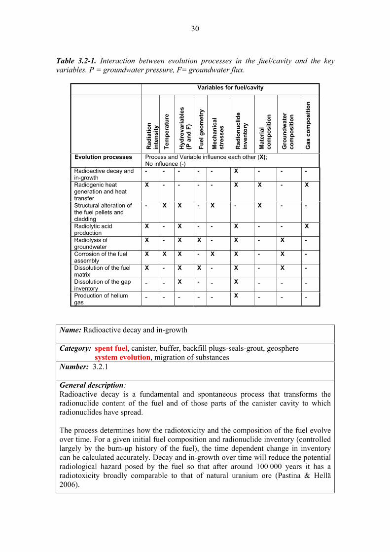
Table 3.2-1. Interaction between evolution processes in the fuel/cavity and the key variables. P = groundwater pressure, F= groundwater flux.
Variables for fuel/cavity
Ra
dia
tio
n
inte
ns
ity
Tem
pera
ture
Hyd
rovari
ab
les
(P a
nd
F)
Fu
el
ge
om
etr
y
Mech
an
ical
str
esse
s
Ra
dio
nu
clid
e
inv
en
tory
Mate
rial
co
mp
os
itio
n
Gro
un
dw
ate
r
co
mp
os
itio
n
Ga
s c
om
po
sit
ion
Evolution processes Process and Variable influence each other (X);No influence (-)
Radioactive decay and in-growth
- - - - - X - - -
Radiogenic heat generation and heat transfer
X - - - - X X - X
Structural alteration of the fuel pellets and cladding
- X X - X - X - -
Radiolytic acid production
X - X - - X - - X
Radiolysis of groundwater
X - X X - X - X -
Corrosion of the fuel assembly
X X X - X X - X -
Dissolution of the fuel matrix
X - X X - X - X -
Dissolution of the gap inventory
- - X - - X - - -
Production of helium gas
- - - - - X - - -
Name: Radioactive decay and in-growth
Category: spent fuel, canister, buffer, backfill plugs-seals-grout, geosphere system evolution, migration of substances
Number: 3.2.1
General description:Radioactive decay is a fundamental and spontaneous process that transforms the radionuclide content of the fuel and of those parts of the canister cavity to which radionuclides have spread.
The process determines how the radiotoxicity and the composition of the fuel evolve over time. For a given initial fuel composition and radionuclide inventory (controlled largely by the burn-up history of the fuel), the time dependent change in inventory can be calculated accurately. Decay and in-growth over time will reduce the potential radiological hazard posed by the fuel so that after around 100 000 years it has a radiotoxicity broadly comparable to that of natural uranium ore (Pastina & Hellä 2006).
31
Radioactive decay and in-growth will cause / , and neutron radiation, and will be accompanied by radiogenic heat production (see 3.2.2). The radiation field and the thermal output will reduce over time in a direct relationship to decay. The radiation from radioactive decay interacts with the materials in the fuel and the canister cavity. The - and - radiation has limited penetration and most of this radiation remains and is attenuated in the fuel itself. The - and neutron radiation has greater penetration and can reach and be attenuated by the canister and, to a lesser extent, the bentonite buffer.
The bulk rate of decay in the fuel (Bq/kg) and the resulting radiation fields are dependent on the fuel’s radionuclide content, which in turn depends on the fuel's burn-up history and the duration of the intermediate storage time before disposal. The decay power estimates were updated in 2005 taking into account the new values of maximum allowable burn-up and operational conditions at Finnish nuclear power plants (Anttila 2005).
Initially - and - decay from short-lived radionuclides dominate the radiation field and, over time, longer lived - becomes most significant. The dominating isotopes during the first few centuries are 137Cs and 90Sr, both with half-lives of around 30 years. Naturally occurring radioactive substances are common in nature (e.g. uranium ore) and have been studied as analogues of the behaviour of spent fuel, although no natural materials contain the short-lived fission products found in spent fuel.
Radioactive decay operates independently of any other physical or chemical conditions or variables, e.g. is not affected by temperature, pressure or the composition or geometry of the engineered barriers. The only controlling factor for the rate of decay and the strength of the radiation field in the repository is the inventory at the time of disposal.
Criticality events are precluded in the repository by the design of the canister and by ensuring sub-critical fuel loading. Olkiluoto specific issues:
There are no site-specific issues that need to be considered because radioactive decay processes are independent of the repository location. Uncertainties:
Radioactive decay as a function of time can be calculated with great accuracy when the initial radionuclide content is known. This is a consequence of the burn-up history of the fuel, which is recorded and known with only small uncertainties. Time frames of relevance:
The bulk rate of decay in the fuel (Bq/kg) is highest soon after disposal and reduces thereafter in a predictable manner. After around 100 000 years, the radioactivity content of the spent fuel is broadly similar to that or natural uranium ore.
Scenarios of relevance:
Radioactive decay will operate at the same rate in all scenarios. Significance:
Radioactive decay is considered to be of HIGH significance in all scenarios because

32
it is a fundamental control on the hazard potential of the waste. It is, however, of most importance to the early canister failure scenarios when there will remain a higher inventory of short-lived radionuclides that potentially could migrate out of the engineered barriers. Treatment in PA:
Radioactive decay codes are used to calculate the time dependent radionuclide inventory at the time of waste disposal and at all subsequent times. Radioactive decay and in-growth is usually explicitly modelled in transport codes and exposure calculations. Equivalent NEA international FEP:
2.1.01 “Inventory, radionuclide and other material” 2.1.13 “Radiation effects (in wastes and EBS)” 2.1.14 “Nuclear criticality” 3.1.01 “Radioactive decay and in-growth” Key references:
Anttila, M. 2005. Radioactive characteristics of the spent fuel of the Finnish nuclear power plants. Posiva Oy, Olkiluoto, Finland. Posiva Working Report 2005-71.
Pastina, B. & Hellä, P. (Eds.) 2006. Expected Evolution of the Spent Nuclear Fuel Repository at Olkiluoto. Posiva Oy, Olkiluoto, Finland. Report POSIVA 2006-05.
Name: Radiogenic heat generation and heat transfer
Category: spent fuel, canister, buffer, backfill, plugs-seals-grout, geosphere system evolution, migration of substances
Number: 3.2.2
General description:
Radiation generated in the fuel by radioactive decay (see 3.2.1) will be attenuated by the fuel itself and the other engineered barriers, particularly the canister. As a consequence of this attenuation, energy is transferred to the materials and most is converted into thermal energy (heat).
In the intact canister, heat will be transferred across the annulus between the fuel and the cladding largely by thermal radiation, and between and across metallic components of the fuel assembly and the cast iron insert of the canister by a combination of thermal radiation and conduction depending on the residual gas composition and pressure in the cavity and the radiation properties of the metal surfaces (emissivity).
The heat generation and transfer in fuel, canister cavity and in the canister have been calculated (Ikonen 2006). In the fuel pellets, radiant heat transfer is dominant, and will limit the maximum temperature in the fuel to between +200 C to +250 Cprovided that the outer surface temperature of the canister does not exceed +100 C.Radiogenic heat generation in the fuel is highest immediately after disposal, and reduces over time in direct relationship to radioactive decay.
33
If water is present in the void spaces in the cladding tubes and in the canister (either as pond water in perforated cladding tubes or as groundwater after canister failure) the overall thermal conductivity across the canister will be much increased, and the temperature of the fuel will be similar to the ambient temperature on the canister surface.
The absolute temperature in the fuel and the cavity will be affected by the entire chain of heat transfer between the different components in the repository. The peak temperature in the fuel will be reached shortly after deposition. After some 5 000 years the fuel and canister temperature will be close to +20 C presuming that the initial repository (ambient rock) temperature is about +10 C.
The temperature at any given time in the fuel is controlled by the heat balance. Heat is input by the natural geothermal gradient and by radiogenic heat generation within the fuel itself. Heat is output largely by conduction and dissipation through the canister to the buffer and bulk rock, and by advection/convection in water within the canister after it has been breached. The temperature in the repository is important because the rates of many processes affecting the spent fuel (e.g. dissolution) are temperature dependent.
Radiogenic heat generation and heat transfer is affected by a number of variables:
Radionuclide inventory is a direct influence on the radiation intensity, which in turn is a first order control on rate of radiogenic heat generation. Inventory, radiation intensity and radiogenic heat generation all reduce over time in direct relationship to radioactive decay. Material composition (of the fuel, cladding and other components of the fuel assembly) affects the rate at which the / , - and neutron radiation is attenuated and thus the amount of thermal energy (heat) that is generated in each component. The greater the attenuation, the greater the rate of heat generation. The material composition also affects the thermal conductivity of a component and thus the rate at which heat can be dispersed to other parts of the engineered barriers. Gas composition, the thermal conductivity of any gas present in the void spaces is strongly dependent on the type of gas.
In turn, the heat generation and transport affects other processes, such as the mechanical stresses on the fuel assembly (see 3.2.3) and other engineered barriers (see 4.2.3). Olkiluoto specific issues:
The natural geothermal gradient will have an influence on the near-field temperature but, in the immediate post-closure period, radiogenic heat generation will be the dominant control. Uncertainties: In general, the uncertainties associated with radiogenic heat generation and heat transfer in the fuel/cavity are low because the burn-up of the fuel is well known and the processes are readily modelled using thermal codes.
34
The actual heat output from each fuel assembly is planned to be measured and verified prior to encapsulation, which will further reduce parameter uncertainty.
Time frames of relevance:
The peak temperature of the fuel is reached shortly after disposal and the highest canister surface temperature is reached in 10-15 years after disposal. The maximum temperature in the rock at the edge of a single deposition hole is reached in 50-100 years and then it takes of the order of 5 000 years for the adjacent rock mass (near field) to reach ambient temperatures. After this time, the natural geothermal gradient will be the dominant process controlling the near-field temperature. Scenarios of relevance:
The high temperatures associated with the period shortly after disposal are of relevance to the fuel/cavity only for the defective canister scenarios (DCS) when groundwater could enter the canister, contact the fuel and dissolve/leach at higher rates. In this scenario, the high temperature could also drive faster recharge of water in the canister thus higher release rates than would occur when the fuel has cooled to ambient conditions. Significance:
Heat generation and heat transfer are of MEDIUM significance in the defective canister (DCS) and human intrusion scenarios (HI) because of the potential for early and accelerated release of radionuclides from the fuel.
In all other scenarios, these processes are of LOW significance because the fuel remains isolated from the groundwater and there is no radionuclide release from the fuel until after the canister is breached, by which time the near-field temperature is controlled by the natural geothermal gradient rather than by radiogenic heat generation. Furthermore, the fuel is design to withstand high temperatures and thermal gradients whilst in an operating reactor. Treatment in PA:
The temperature of the fuel and other engineered barriers is modelled using specific thermal codes. These codes are not, however, coupled to the radionuclide transport models, which do not account for temperature dependency on radionuclide solubility and speciation. This may be a non-conservative assumption for radionuclides whose solubility is increased at elevated temperatures, in the case of early canister failure.
Equivalent NEA international FEP:
“Thermal processes and conditions (in wastes and EBS)” Key references:
In the text: Ikonen, K. 2006. Fuel temperature in disposal canisters. Posiva Oy, Olkiluoto, Finland. Posiva Working Report 2006-19.
Others relevant: Pastina, B & Hellä, P. (Eds.) 2006. Expected Evolution of the Spent Nuclear Fuel Repository at Olkiluoto. Posiva Oy, Olkiluoto, Finland. Report POSIVA 2006-05.
Anttila, M. 2005. Radioactive Characteristics of the Spent Nuclear Fuel of the Finnish Nuclear Power Plants. Posiva Oy, Olkiluoto, Finland. Posiva Working Report 2005-71.
35
Name: Structural alteration of the fuel pellets and cladding
Category: spent fuel, canister, buffer, backfill, plugs-seals-grout, geosphere system evolution, migration of substances
Number: 3.2.3
General description:
Temperature changes and differential thermal fields in the fuel, and mechanical impacts associated with handling and transport, can affect the integrity of the fuel pellets and cladding.
Alpha decay of actinides in the spent fuel results in the formation of helium (He) atoms in closed pores in the fuel matrix (see 3.2.9). Helium is stable and unreactive, hence the total amount of helium gas in the fuel elements will increase over time as various radionuclides undergo alpha decay. Most of this helium will initially be trapped within the fuel matrix. The build-up of internal He gas pressure over time may, however, lead to micro-cracking and affect the physical integrity of the fuel matrix.
Helium gas will also accumulate in the gap between the fuel pellets and the inner walls of the cladding tubes. As the gas pressure increases, additional stress will be imposed on the spent fuel cladding, increasing the potential for cladding tube failure by DHC (delayed hydrogen cracking). In an intact cladding tube, the increase in helium gas pressure lies in the range 10 to 20 MPa in 100 000 years. If this pressure build-up leads to mechanical rupture of the cladding tube, the resulting pressure increase within the canister void would be of the order of 0.1 MPa, which is negligible in terms of structural durability of the canister (SKB 2006a).
Uptake of hydrogen during reactor operation can lead to hydride formation with embrittlement, which can enhance the likelihood of failure of the cladding tubes. Cracking of the fuel during reactor operations can also occur, weakening the fuel and making it susceptible to damage due to internal gas pressure. These processes can thus affect the subsequent release of radionuclides in the repository after the canister has failed and groundwater penetrates the canister void.
Structural alteration of the fuel pellets and cladding is affected by a number of variables:
The temperature is a control over the gas pressure. Temperature changes can also enhance mechanical failure of the fuel and cladding due to differential expansion/contraction (see 3.2.2). The differential gas pressure inside and outside of the cladding tubes is a contributory process in their failure, particularly when they have been weakened due to chemical reaction and corrosion. Mechanical stresses imposed by handling and transport during encapsulation and emplacement of the canister can also contribute to failure of the fuel pellets and cladding, although this can be minimised by careful handling. Material composition of the fuel and the cladding controls its mechanical strength, although the composition of both materials should be very well controlled during manufacture.
36
Olkiluoto specific issues:
There are no site-specific issues that will provide a significant control on the structural alteration of the fuel pellets and cladding when the canister is intact. The composition of the Olkiluoto groundwater will affect the rate of degradation of the fuel and cladding after canister failure. Uncertainties:
The effect of helium pressure build-up on the mechanical integrity of the fuel pellets and the cladding is uncertain, although this uncertainty is not considered to be significant for the long-term safety of the repository. Time frames of relevance:
The generation of helium is relevant at all timescales, with the gas pressure increasing overtime until the point at which the cladding fails. Scenarios of relevance:
The generation of helium and increase in gas pressure will occur in all scenarios. Significance: The structural alteration of the fuel pellets and cladding is of HIGH
significance in the defective canister (DCS) and human intrusion (HI) scenarios because the cladding, in these scenarios, will provide the main barrier to groundwater contact with the fuel after the canister has failed.
In the main scenario, this process is of LOW significance because the canister will isolate groundwater from the fuel and fuel cladding for extended periods of time and because the process is conservatively ignored in the safety assessment. From a realistic modelling perspective, however, the integrity of the cladding is of higher significance because it provides a secondary barrier to groundwater contact with the fuel after the canister has been breached.Treatment in PA:
The structural integrity of the cladding is not explicitly included in the main safety assessment calculations. It is conservatively assumed that as soon as the canister is breached, the entire fuel content becomes available for instantaneous water/fuel reactions. The secondary barrier provided by the cladding is therefore conservatively ignored.Equivalent NEA international FEP:
2.1.02 “Waste form materials and other characteristics” 2.1.07 “Mechanical processes and conditions (in wastes and EBS)” 2.1.11 “Thermal processes and conditions (in wastes and EBS)” Key references:
In the text: SKB 2006a. Fuel and canister process report for the safety assessment SR-Can. Swedish Nuclear Fuel and Waste Management Co (SKB), Stockholm, Sweden. SKB Technical Report TR-06-22.
Others relevant: Pastina, B. & Hellä, P. (Eds.) 2006. Expected Evolution of the Spent Nuclear Fuel Repository at Olkiluoto. Posiva Oy, Olkiluoto, Finland. Report POSIVA 2006-05.
Werme, L.O., Johnson, L.H., Oversby, V.M., King, F., Spahiu, K., Grambow, B. & Shoesmith, D.W. 2004. Spent fuel performance under repository conditions: A model for use in SR-Can. Swedish Nuclear Fuel and Waste Management Co (SKB), Stockholm, Sweden. SKB Technical Report TR-04-19.
37
Name: Radiolytic acid production
Category: spent fuel, canister, buffer, backfill, plugs-seals-grout, geosphere system evolution, migration of substances
Number: 3.2.4
General description:
Any residual cooling pond water or air contained in leaking fuel rods at the time of encapsulation will be decomposed by radiolysis to generate small quantities of nitrogen oxide species and even smaller quantities of hydrogen gas (H2), oxygen gas (O2), and hydrogen peroxide (H2O2). The products of radiolysis will then be converted to corrosive gases such as nitric acid or nitrous acid in the presence of any residual cooling pond water. Under dry conditions, aggressive corrosion agents such as nitric acid would not form.
Further reaction of these acids with the fuel assembly (see 3.2.6) and the cast iron canister insert (see 4.2.7) could lead to stress corrosion, and accelerated failure of the cladding and canister.
Radiolytic acid production is affected by a number of variables:
Gamma radiation intensity (and therefore waste inventory) is the primary control, due to the radioactive decay of 137Cs, which has a half-life of approximately 30 years. Therefore, gamma radiolysis declines to negligible levels in less than a thousand years. Radiolysis due to alpha, beta and neutron radiation continues for longer periods but the product yields are much smaller than with gamma radiolysis.The hydrovariables, particularly, presence and volume of water in the canister control how much acidic solution can be formed. The quantity of nitric acid formed is dependent on the amounts of water and air in the canister. Assuming 10% water, no more than 225 g of nitric acid can be formed. In an intact canister, this amount of nitric acid, residual oxygen and water will be consumed by corrosion reactions with the canister iron insert in around 100 years at the expected corrosion rates. The composition of any gas (air) in the canister controls the products of radiolysis and the composition of cooling pond water controls the composition of the acidic solution generated.
The canister void will be purged with argon gas during the encapsulation process to expel residual air and water, and thus minimise radiolytic and corrosion processes. It is conservatively assumed that the atmosphere in the canisters after loading will be composed of humid air (maximum 10%) and argon gas (minimum 90%) (SKB 2006a).Olkiluoto specific issues:
There are no site-specific issues that control radiolytic acid production. Uncertainties:
The quantity of residual water in the canister is uncertain but conservative modelling assumptions are that each canister may contain 600 g of cooling pond water in leaking fuel rods (SKB 2006a).
38
Time frames of relevance:
The acidic solutions formed by radiolysis will be consumed in corrosion reactions within 100 years.Scenarios of relevance:
The process will occur in all scenarios when residual air and cooling pond water is present in the canister. Significance:
The generation of acidic substances in an intact canister as a consequence of radiolysis of residual water vapour is considered to be of LOW significance because only a small amount of acid is expected to be produced that will be readily buffered by the very large mass of the cast iron insert. As such the resulting corrosion will have no significant impact on the performance of the canister.Treatment in PA:
The process is neglected from radionuclide release and transport models in all PA calculations. Equivalent NEA international FEPs:
2.1.13 “Radiation effects (in wastes and EBS)” Key references:
In the text: SKB 2006a. Fuel and canister process report for the safety assessment SR-Can. Swedish Nuclear Fuel and Waste Management Co (SKB), Stockholm, Sweden. SKB Technical Report TR-06-22.
Others relevant: McMurry, J., Dixon, D.A., Garroni, J.D., Ikeda, B.M., Stroes-Gascoyne, S., Baumgartner, P. & Melnyk, T.W. 2003. Evolution of a Canadian deep geologic repository: Base scenario. Report No: 06819-REP-01200-10092-R00.
Pastina, B. & Hellä, P. (Eds.) 2006. Expected Evolution of the Spent Nuclear Fuel Repository at Olkiluoto. Posiva Oy, Olkiluoto, Finland. Report POSIVA 2006-05.
Werme, L.O., Johnson, L.H., Oversby, V.M., King, F., Spahiu, K., Grambow, B. & Shoesmith, D.W. 2004. Spent fuel performance under repository conditions: A model for use in SR-Can. Swedish Nuclear Fuel and Waste Management Co (SKB), Stockholm, Sweden. SKB Technical Report TR-04-19.

39
Name: Radiolysis of groundwater
Category: spent fuel, canister, buffer, backfill, plugs-seals-grout, geosphere system evolution, migration of substances
Number: 3.2.5
General description:
After canister failure, the groundwater that enters the canister may be decomposed by radiolysis.
Only gamma radiation, that has a relatively long range, can affect the water in the canister cavity because alpha radiation is largely stopped by the fuel cladding. Alpha radiolysis can occur only if water comes into contact with fuel at the fuel/cladding gap in leaking fuel rods.
The radiolysis of groundwater produces primarily free electrons, OH-radicals and hydrogen atoms. Radicals are atoms, or atomic groups containing a free or unpaired electron, which makes them highly reactive. These react with dissolved components in the groundwater to produce a wide range of radicals and stable molecular species O2, H2O2 and H2. The formation of hydrogen gas from radiolysis will, however, be negligible compared to the H2 formation from the anaerobic corrosion reactions of the cast iron insert (see 4.2.7).
The highly mobile H2 potentially may migrate from the canister while the radiolytically generated oxidising species will react with the iron canister insert. In some models predicting high yields of oxidising species, the near field of the repository may become oxidising due to radiolysis. Recent studies on the gamma radiolysis of water containing small amounts of dissolved H2 suggest, however, that the production of oxidants has a threshold, i.e. above a certain concentration of dissolved H2 no further measurable oxidant production occurs (Pastina et al. 1999, Pastina & LaVerne 2001).
Radiolysis of groundwater is a process that has been observed and studied in a number of natural analogue studies of uranium orebodies, including Oklo and Cigar Lake. These studies suggest that, while relatively common, redox conditions are affected only very locally to the ore and, thus, that the effect has only a small-scale affect on radionuclide transport (Miller et al. 2000).
Radiolysis of groundwater is affected by a number of variables:
Gamma radiation intensity (and therefore waste inventory) is the primary control, due to the radioactive decay of 137Cs, which has a half-life of approximately 30 years. Therefore, gamma radiolysis declines to negligible levels in less than a thousand years.The hydrovariables, particularly, the presence and volume of water in the canister, because water intrusion in to the canister is needed for the radiolysis process to occur. The formation of radiolytic gases affects the pressure. This effect is considered to be minor in comparison to the production of hydrogen due to the corrosion of iron (see 4.2.7).
40
Fuel geometry, particularly the integrity of the fuel rods because alpha radiolysis can only occur only if water comes into contact with fuel at the fuel/cladding gap in leaking fuel rods. Groundwater composition affects the nature and the yields of the different radiolysis products.
Olkiluoto specific issues:
The composition of the local groundwater will influence the nature and the yields of different radiolysis products. Uncertainties:
The nature and yield of radiolytic products at high gamma radiation levels is uncertain but the mechanistic understanding of the process is sufficient for the needs of the safety assessment. Time frames of relevance:
Radiolysis by gamma radiation is relevant for a few hundred years, and by alpha radiation for thousands of years. Scenarios of relevance:
Radiolysis of groundwater is only relevant to the defective canister scenarios (DCS) and human intrusion scenario (HI) because, in the main scenario, radiation levels will have decayed to insignificance by the time groundwater can penetrate the canister. Significance:
Radiolysis is of MEDIUM significance in the defective canister (DCS) and human intrusion scenarios (HI) because of the potential for the redox conditions in the canister to be affected by the accumulation of radiolytically generated species.
Radiolysis is of LOW significance in the main scenario because radiation levels will have decayed to insignificance by the time groundwater can penetrate the canister.Treatment in PA:
The process is neglected from radionuclide release and transport models in all PA calculations. This may be a non-conservative approach in the defective canister and human intrusion scenarios when there is the potential for oxidising conditions to increase the solubility of redox sensitive radionuclides. Equivalent NEA international FEP:
2.1.13 “Radiation effects (in wastes and EBS)” Key references:
Pastina, B., Isabey, J. & Hickel, B. 1999. The influence of water chemistry on the radiolysis of the primary coolant water in pressurized water reactors. Journal of Nuclear Materials 264, 309-318.
Pastina, B. & LaVerne, J.A. 2001. Effect of molecular hydrogen on hydrogen peroxide in water radiolysis. J. Phys. Chem. A 2001, 105, 9316-9322.
Miller, W.M., Alexander, W.R., Chapman, N.A., McKinley, I.G. & Smellie, J.A.T. 2000. The geological disposal of radioactive wastes and natural analogues. Pergamon.

41
Name: Corrosion of the fuel assembly
Category: spent fuel, canister, buffer, backfill, plugs-seals-grout, geosphere system evolution, migration of substances
Number: 3.2.6
General description:
The fuel assembly is manufactured from high corrosion resistant metals such as stainless steel, Zircaloy, Inconel and Incoloy. The amount of Zircaloy is about tenfold compared to the other metals in the fuel bundles.
Prior to encapsulation, the fuel assembly will be stored underwater in cooling ponds for up to 50 years. During reactor operations and in the cooling ponds, there is the potential for failure for some cladding tubes, although the rate of failure is considered to be very low (less than one in ten thousand).
Corrosion of the fuel assembly in the repository needs to be considered under two circumstances: after encapsulation, and after intrusion by groundwater. In all cases, however, it anticipated that the kinetics of corrosion will be very slow.
When Zircaloy is exposed to air, uniform corrosion results in the rapid formation of a thin tightly bound passive zirconium oxide layer on its surface. During encapsulation, the canister is purged with argon but some air and water may be left inside producing minor amounts of gaseous hydrogen and oxygen and acidic solutions in the canister through radiolysis (see 3.2.4). It is assumed that oxygen will be consumed relatively rapidly by corrosion of the iron insert and cladding, and then in the absence of oxygen further uniform corrosion of the cladding is prevented. So almost all uniform corrosion of Zircaloy would occur prior to emplacement.
The Zircaloy may become embrittled as a result of hydrogen absorption but the rate of absorption would be kinetically inhibited by the passive zirconium oxide layer. When Zircaloy is cooling the absorbed hydrogen precipitates as zirconium hydrates resulting in a less ductile (more brittle) material that is more susceptible to fracturing. The formation of helium gas pressure caused by alpha decay in the fuel (see 3.2.9) will contribute to cladding tensile stresses, with the potential to cause creep rupture or delayed hydride cracking of the cladding (see 3.2.3).
After the canister is breached, the fuel assembly will be subject to corrosion by the penetrating groundwater. The rate and process of corrosion will then depend largely on the material composition, the chemical environment in the canister cavity and the temperature. Hydrogen will be generated by anaerobic corrosion of the iron insert and, to a lesser extent, through radiolysis of water. Pitting and crevice corrosion of cladding may be inhibited by the rapid consumption of oxidizing agents (e.g. radiolysis products) by the iron insert.
Stress corrosion cracking of Zircaloy would require oxidizing environments; strongly oxidizing neutral saline solutions (e.g. halide solutions), and the presence of some metals (e.g. caesium) and gases (e.g. iodine). However, inside an intact canister there
42
would not be enough strongly oxidizing agents (e.g. nitric acid, hydrogen peroxide) or iodine gas from fuel pellets to induce significant stress corrosion cracking.
Zircaloy corrosion rate in the presence of groundwater has not been studied extensively, but according to the few available data it is estimated to be approximately 2nm/y under expected conditions, which means that with a tube thickness of 0.8 mm penetration would require 400 000 years (Rothman 1984). Corrosion rates of the other metal components, stainless steel or nickel based alloys are higher; according to results of brief exposure in seawater, tens of microns per year for stainless steels and microns per year for nickel based alloys (Gdowski & Bullen 1988).
When the cladding is breached and groundwater gets in contact with the fuel, volume expansion of the fuel pellet through growth of secondary alteration products will induce further strain in the cladding. The strain may extend the size of the defect and lead to further cracking of the cladding and finally to “unzipping”.
There are no natural analogues of relevance to these man-made alloys but there are industrial analogues of stainless steel that provide bounding limits on the corrosion rate of this material under a variety of physico-chemical conditions.
The rate and process of corrosion of the fuel assembly will be affected by a number of variables:
Radiation intensity (and therefore waste inventory) because this controls radiolysis and the nature and generation rate of radiolysis products. Temperature because corrosion rates tend to increase with temperature. The hydrovariables, particularly, presence and volume of water in the canister because this is necessary before general corrosion in the presence of groundwater can take place. Composition of the fuel assembly materials, particularly the presence of impurities in the metallic components that could accelerate the corrosion rate of otherwise corrosion resistant materials. Mechanical stress on the cladding (e.g. from internal helium pressure) because this can exacerbate stress corrosion cracking. Groundwater composition, particularly strongly saline groundwaters, which can increase corrosion rates for some metals and induce stress corrosion cracking.
Olkiluoto specific issues:
At Olkiluoto the current groundwater close to the repository depth is strongly saline having dissolved solids (TDS) content around 10-20 g/L, containing mainly sodium, calcium and chloride. These saline waters may invoke stress corrosion cracking of the Zircaloy components.
Uncertainties:
The mechanistic understanding of the process is sufficient for conceptual modelling purposes. However, there is parameter uncertainty over the rates of corrosion and the validity of the corrosion rates observed in short term experiments.
43
Time frames of relevance:
There are two time frames of relevance. Early post-encapsulation when radiolysis is greatest due to the high gamma radiation field, and the long-term post-canister failure period when groundwater can penetrate the canister. Scenarios of relevance:
Corrosion of the fuel assembly is relevant to all scenarios but is most relevant to the defective canister scenarios when early contact with groundwater is possible, at high temperatures and in high radiation fields. Significance:
The significance of corrosion of the fuel assembly is LOW in the main scenario because long-term isolation of the fuel from groundwater is ensured by the integrity of the canister.
In the defective canister scenario (DCS), however, the integrity of the cladding is of HIGH significance because it provides a secondary barrier to groundwater contact with the fuel after the canister has been breached.Treatment in PA:
The corrosion of the fuel assembly is neglected from radionuclide release and transport models in all PA calculations. It is conservatively assumed that the cladding provides no barrier to groundwater contact with the fuel after the canister has been breached. In the case of the defective canister scenario, this may be an overly conservative assumption. Equivalent NEA international FEP:
2.1.09 “Chemical/geochemical processes and conditions (in wastes and EBS)” Key references:
In the text: Gdowski, G.E. & Bullen, D.B. 1988. Survey of degradation modes of candidate materials for high-level radioactive waste disposal containers. Oxidation and corrosion. Lawrence Livermore National Laboratory. Report UCID-21362. Vol. 2.
Rothman, A.J. 1984. Potential corrosion and degradation mechanisms of Zircaloy cladding on spent fuel in a tuff repository. Lawrence Livermore National Laboratory. Report UCID-20172.
Others relevant: McMurry, J., Dixon, D.A., Garroni, J.D., Ikeda, B.M., Stroess-Gascoyne, S. Baumgartner, P. & Melnyk, T.W. 2003. Evolution of a Canadian deep geological repository: Base Scenario. Ontario Power Generation, Toronto, Canada. Report 06819-REP-01200-10092-R00.
Pastina, B. & Hellä, P. (Eds.) 2006. Expected Evolution of a Spent Nuclear Fuel Repository at Olkiluoto. Posiva Oy, Olkiluoto. Posiva 2006-05.
Rasilainen, K. (Ed.) 2004. Localisation of the SR 97 Process Report for Posiva’s Spent Fuel Repository at Olkiluoto. Posiva Oy, Olkiluoto. Posiva 2004-05.
SKB 2006a. Fuel and canister process report for the safety assessment SR-Can. Svensk Kärnbränslehantering AB, Stockholm. SKB TR-06-22.
44
Name: Dissolution of the fuel matrix
Category: spent fuel, canister, buffer, backfill, plugs-seals-grout, geosphere system evolution, migration of substances
Number: 3.2.7
General description:
In the absence of any cooling pond water contained in leaking fuel rods, no dissolution of the spent fuel can occur until such time as both the canister and cladding are perforated by corrosion in the presence of groundwater.
When this occurs, the radionuclide inventory at the fuel grain boundaries will be rapidly released (see 3.2.8) and then subsequent radionuclide release will be dependent on the dissolution of the fuel matrix which is anticipated to occur at a very slow rate.
The majority of fission products and higher actinides in the fuel are present as solid solutions in the UO2 matrix. Upon contact with groundwater, the fuel matrix will dissolve or otherwise alter. This results in the release of uranium and other radionuclides contained in the fuel matrix. This process is controlled by the chemical environment in the fuel/clad gap, and the fuel composition and structure. The redox conditions at the fuel surface are the most important factor affecting the dissolution mechanism.
Under repository conditions at the expected time of canister failure, the near-field will be strongly reducing because all oxidising species will have been consumed by reaction with the iron insert and reducing minerals in the host rock and bentonite buffer. It can be assumed therefore that the groundwater coming into contact with fuel will be oxygen-free. Under these conditions, oxidative dissolution of UO2 could be caused only by radiolytic oxidants from the radiolysis of water (see 3.2.4). At the time of water intrusion under normal conditions, the radiation from the fuel will have decayed to low levels, and the dominant radiation will be -radiation. Alpha particles have a very short range. Hence they can cause radiolysis in only a thin layer of water (~ 35 µm) near the surface of the fuel. The main radiolysis products are molecular H2O2 and H2.
Some models predict that in the post-glacial phase, oxygenating meltwaters could penetrate down to repository depths. In this case oxic waters may potentially contact the fuel and cause accelerated dissolution and alteration. The duration of glacial meltwater penetration would, however, be very short and such waters are likely to be redox buffered by the bentonite buffer and the cast iron insert during diffusion through the engineered barriers.
The dissolution rate of spent fuel under the conditions caused by alpha radiolysis has been studied using UO2 doped with 233U (Ollila et al. 2003, 2004; Ollila & Oversby 2005). The doping levels were chosen to simulate the alpha activity levels expected at times of 3000 and 10 000 years after disposal. The tests were performed in synthetic

45
low-ionic- strength groundwater with and without bicarbonate. The tests in high-ionic strength solutions (0.1-1 M NaCl) simulating groundwater conditions in Olkiluoto are ongoing. The data show that the presence of anaerobically corroding iron in solution is very effective in controlling the redox conditions and limiting the solubility of UO2.H2 is more effective than Fe(II) in lowering the U concentration in solution. No results that could be attributed to the effects of alpha radiolysis in the leaching solutions could be observed.
The dissolution rate measurements with unirradiated UO2 in 0.01 M NaCl solution under anoxic and reducing conditions with isotope dilution method suggest the dependence of the U release on the ratio of UO2 surface area to water volume (SA/V) (Ollila 2006). This may be related to the dissolution of high-energy surface sites from the surface. The mechanism seems to include the dissolution and subsequent precipitation of U. The U concentration in solution remained at the same level. The effect of SA/V has not been tested with alpha doped UO2.
Most laboratory data on fuel dissolution is from systems with low ionic strength solutions and in oxidising conditions, in contrast to the high ionic strength, reducing groundwaters found at Olkiluoto. Werme et al. (2004) reviewed the available data under reducing conditions and proposed the fractional dissolution rates used in the SR-Can safety assessment. A linear dissolution rate in the range of 10-6 to 10-8 per year was proposed. The weight of the evidence was from experimental studies performed with unirradiated UO2 and alpha doped UO2 in dilute synthetic groundwater, and with spent fuel in 5 M NaCl. These studies were performed in the presence of hydrogen or in the presence of actively corroding iron. King and Shoesmith (2004) used an electrochemical model to predict the lifetime of spent fuel. They suggested the fractional dissolution rate of spent fuel in the presence of H2 is 10-
7 to 10-8 per year. This is in agreement with the dissolution rates based on other experimental studies.
There is a considerable body of information on UO2 dissolution processes and rates available from natural analogues, from a wide range of locations and geochemical environments, including in crystalline rocks from Finland (the Palmottu study: Ahonen et al. 2004). These studies have indicated that in chemically reducing environments, the rate of dissolution is extremely slow and in line with the laboratory data (Miller et al. 2000).
The dissolution of the spent fuel matrix will be affected by a number of variables:
The radiation intensity (and therefore inventory) is an important control because it determines the dose rate to water and the production of potential radiolytic oxidants. The level of alpha radiation in spent fuel at the time of water intrusion is not expected to cause oxidative dissolution of UO2. The effect of radiolysis is assumed to be suppressed by the presence of H2 and Fe(II). The hydrovariables, particularly, presence and volume of water in the canister because this is necessary before general corrosion in the presence of groundwater can take place. The fuel geometry is relevant because it affects both the radiation field and the

46
surface area of the fuel in contact with water affects the dissolution rate. Potential deposition of secondary phases on the fuel surface may retard dissolution. The dissolution of material from grain boundaries may increase surface area. These changes in fuel surface area due to precipitation/dissolution processes are considered to have minor influence. The structure and composition of the spent fuel, particularly of inclusions, may affect the bulk dissolution rate, but this is considered to be of less importance than the composition of the groundwater because of the quality control over the manufacture of fuel pellets. Groundwater temperature and composition, particularly high ionic strength groundwaters, which can affect the rate of UO2 dissolution. The ionic strength of groundwater is, however, expected to be less important than the redox conditions.
Olkiluoto specific issues:
The natural groundwater composition (ionic strength and redox conditions) is important for fuel dissolution, although these will be substantially altered by interaction with the engineered barrier system materials. Uncertainties:
The mechanisms and rate of spent fuel dissolution in the high ionic strength groundwaters at Olkiluoto are uncertain. Most data are available for dilute groundwater systems. The dissolution mechanisms of spent fuel in the presence of the anaerobic corrosion of iron are also uncertain. This is shown in the wide range of dissolution rates proposed by Werme et al. (2004). Time frames of relevance:
The dissolution of fuel is relevant for all time frames after groundwater penetrates the canister and the fuel cladding. In the main scenario, this will occur after 100 000 years or more. Scenarios of relevance:
The dissolution of fuel is most relevant to the defective canister scenarios (DCS) because under these conditions the temperature and radiation field is high (potentially accelerating the kinetics of dissolution) and the radionuclide inventory is also high.
The process is also of relevance to scenarios in which oxidising glacial waters may be in contact with the fuel (e.g. AD-I, AD-II) because of the higher dissolution rate of the fuel under these redox conditions.
In the main scenario, the dissolution of fuel is relevant but is not anticipated to occur until the far future by which time the radionuclide inventory of the waste has decayed substantially. Treatment in PA:
The fuel alteration/dissolution rate is modelled using the recommendations by Werme et al. (2004). The model for fuel dissolution in SR-Can is a constant fractional dissolution rate of 10-6 to 10-8 per year (SKB 2006a). These values are used in calculation cases and are considered to be conservative. Furthermore, the conceptual model takes no credit for the barrier provided by the fuel cladding, which will limit the contact between groundwater and the fuel. Significance: The fuel dissolution process is considered to be of HIGH significance because the modelled low solubility and reactivity of spent fuel under the reducing conditions expected in a repository is one of the key safety features for the geological

47
disposal concept. No interaction between the fuel and the groundwater can occur until such time as the canister has been breached. Equivalent NEA international FEPs:
2.1.01 “Inventory, radionuclide and other material” 2.1.09 “Chemical/geochemical processes and conditions (in wastes and EBS)” 3.2.01 “Dissolution, precipitation and crystallisation, contaminant” Key references:
Ahonen, L., Kaija, J., Paananen, M., Hakkarainen, V. & Ruskeeniemi, T. 2004. Palmottu natural analogue: A summary of the studies. Geological Survey of Finland, Nuclear Waste Disposal Research, Report YST-121, 39 p.
King, F. & Shoesmith, D. 2004. Electrochemical studies of the effect of H2 on UO2
dissolution. Swedish Nuclear Fuel and Waste Management Co (SKB), Stockholm, Sweden. SKB Technical Report TR-04-20.
Miller, W.M., Alexander, W.R., Chapman, N.A., McKinley, I.G. & Smellie, J.A.T. 2000. The geological disposal of radioactive wastes and natural analogues. Pergamon.
Ollila, K., Albinsson, Y., Oversby, V. & Cowper, M. 2003, 2004. Dissolution rates of unirradiated UO2, UO2 doped with 233U, and spent fuel under normal atmospheric conditions and under reducing conditions using an isotope dilution method. Posiva Oy, Olkiluoto, Finland. Posiva Report POSIVA 2004-03; Swedish Nuclear Fuel and Waste Management Co (SKB), Stockholm, Sweden. SKB Technical Report TR-03-13.
Ollila, K. & Oversby, V. 2005. Dissolution of unirradiated UO2 and UO2 doped with 233U under reducing conditions. Posiva Oy, Olkiluoto, Finland. Posiva Report POSIVA 2005-05, Swedish Nuclear Fuel and Waste Management Co (SKB), Stockholm, Sweden. SKB Technical Report TR-05-07.
Ollila, K. 2006. Dissolution of unirradiated UO2 and UO2 doped with 233U in 0.01 M NaCl under anoxic and reducing conditions. Posiva Oy, Olkiluoto, Finland. Posiva Report POSIVA 2006-08.
SKB 2006a. Fuel and canister process report for the safety assessment SR-Can. Swedish Nuclear Fuel and Waste Management Co (SKB), Stockholm, Sweden. SKB Technical Report TR-06-22.
Werme, L.O., Johnson, L.H., Oversby, V.M., King, F., Spahiu, K., Grambow, B. & Shoesmith, D.W. 2004. Spent fuel performance under repository conditions: A model for use in SR-Can. Swedish Nuclear Fuel and Waste Management Co (SKB), Stockholm, Sweden. SKB Technical Report TR-04-19.

48
Name: Dissolution of the gap inventory
Category: spent fuel, canister, buffer, backfill, plugs-seals-grout, geosphere system evolution, migration of substances
Number: 3.2.8
General description:
During irradiation of the fuel in the reactor, a certain fraction of the radionuclide inventory is enriched by a process of thermally-driven segregation into the gap between the fuel and the cladding, in cracks in the fuel pellets and at grain boundaries.
When groundwater contacts the fuel, after the canister and the cladding are breached, this enriched fraction becomes available for dissolution. These radionuclides usually have high solubilities and they are assumed to be released immediately in contact with the groundwater, on a timescale in the order of days, although the release from the grain boundaries may continue for an extended period of time. Of these radionuclides, the behaviour of fission gases is best known while the behaviour of other potentially segregated radionuclides is more uncertain (SKB 2006a). Some may form volatile products such as 14C in methane or carbon dioxide, while metals such as Tc, Ru, Rh, Pd and Mo may form metallic inclusions in the fuel pellets.
This fraction of radionuclides, that is rapidly released, is called the instant release fraction (IRF), and it is independent of the dissolution or alteration of the bulk UO2
matrix of the spent fuel. Because these radionuclides have high solubility and are generally non-sorbing, they can result in an early peak release from the near field.
The fraction of the radionuclides that is incompatible with the UO2 matrix and is present in the fuel/cladding gap is generally considered to be comparable to the fission gas release measured in gas release testing of fuel rods (Werme et al. 2004). The fission gas releases are typically < 1% at burn-ups below 40 MWd/kgU. At 40-50 MWd/kgU burn-ups, the fission gas release is below 1.5 % for PWR fuel, while for BWR fuel the release increases after 40 MWd/kgU is as high as 5%. The release of fission gas is more strongly correlated to the linear heat rating than to the burn-up of the fuel. The release is minimised by keeping the linear heat rating low under operating conditions.
Johnson et al. (2005a) have concluded that results from studies of fission product leaching from spent fuel permit reliable estimates for IRF to be made for several important long-lived radionuclides, e.g. 129I and 135Cs for moderate burn-up UO2
fuel ( 45 MWd/kgU). The immediate release of caesium and iodine from the fuel in contact with water has been experimentally verified (Johnson & Tait 1997). For high burn-up UO2 fuel (> 45 MWd/kgU), however, the leaching data are very limited.

49
Table 3.2-2. Instant release fractions for key radionuclides in % of total inventory (SKI 2007). The data in the second column by Werme et al. (2004) give the range corresponding to the lower and upper values in SR-Can (central value in brackets). The IRFs by Johnson et al. (2005a) give best estimates, and pessimistic values in brackets.
Werme et al. 2004 IRF (%) -
Johnson et al. 2005a IRF (%) at different burn-ups ( MWd/kgU) 37 41 48 60
14C 0.1 to 10 (5) 10 10 10 10
36Cl 1 to 10 (5) 5 5 10 16
79Se 0 to 0.1 (0.03) 1 (1) 1 (2) 3 (4) 6 (10)
99Tc 0 to 1 (0.2) 1 (1) 1 (2) 3 (4) 6 (10)
107Pd 0 to 1 (0.2) 1 (1) 1 (2) 3 (4) 6 (10)
126Sn 0 to 0.01 (0.003) 1 (1) 1 (2) 3 (4) 6 (10)
129I 0 to 5 (2) 3 (3) 3 (3) 4 (6) 10 (15)
135Cs 0 to 5 (2) 2 (2) 2 (2) 4 (6) 10 (15)
90Sr
not relevant for the long term 1 (1) 1 (2) 3 (4) 6 (10)
137Cs
not relevant for the long term 2 (2) 2 (2) 4 (6) 10 (15)
Werme et al. (2004) indicated the following radionuclides need to be considered in Sr-Can for canister failure after 1000 years: 14C, 36Cl, 79Se, 99Tc, 107Pd, 126Sn, 129Iand 135Cs. After 50 000 years the 14C inventory has decreased to insignificant levels due to radioactive decay.
Table 3.2-2 (see SKI 2007) gives the instant release fractions to be used in SR-Can, in comparison with the pessimistic values at different burn-ups reported by Johnson et al. (2005a). The latter values include all the fission products in the rim region, in addition to the gap and grain boundary inventories.
The dissolution of the gap inventory will be affected by a number of variables:
The hydrovariables, particularly, presence and volume of water in the canister because this is necessary before gap release in the presence of groundwater can take place.Radionuclide inventory in the gap and grain boundaries determines the contribution of the segregated nuclides to the source term.
The groundwater composition is not a control because the gap release will be highly soluble in the range of natural deep groundwaters.
50
Olkiluoto specific issues:
There are no site-specific issues that control dissolution of the gap inventory.Uncertainties: Any mechanistic/conceptual uncertainties are handled pessimistically, since immediate release after water contact is assumed. Time frames of relevance:
The release of segregated radionuclides will take place on a timescale in the order of days after groundwater comes into contact with the spent fuel. The time this occurs depends on the scenario. Scenarios of relevance:
The dissolution of the gap inventory is relevant to all assessment scenarios because these long-lived, highly mobile species will be released as soon as the canister and cladding are breached by whatever process.
Significance: The dissolution of the gap inventory is of HIGH significance because the long-lived, mobile nature of some of these radionuclides makes them dominant components of the radiological impacts to humans calculated in the PA (e.g. 129I, 14C).Treatment in PA:
Instant release is assumed for all of the segregated nuclides in the radionuclide release and transport models in all PA calculations in the SR-Can safety assessment (SKB 2006a). Equivalent NEA international FEPs:
2.1.01 “Inventory, radionuclide and other material” 2.1.09 “Chemical/geochemical processes and conditions (in wastes and EBS)” 3.2.01 “Dissolution, precipitation and crystallisation, contaminant”
Key references:
Johnson, L.H. & Tait, J.C. 1997. Release of segregated nuclides from spent fuel. Swedish Nuclear Fuel and Waste Management Co (SKB), Stockholm, Sweden. SKB Technical Report TR-97-18.
Johnson, L., Ferry, C., Poinssot, C. & Lovera, P. 2005a. Spent fuel radionuclide source-term model for assessing spent fuel performance in geologic disposal. Part 1: Assessment of the instant release fraction, Journal of Nuclear Materials, 346, 56-65.
SKB 2006a. Fuel and canister process report for the safety assessment SR-Can. Swedish Nuclear Fuel and Waste Management Co (SKB), Stockholm, Sweden. SKB Technical Report TR-06-22.
SKI 2007. Spent fuel dissolution and source term modelling in safety assessment. Synthesis and extended abstracts. Report from a workshop at Sigtunahöjden Hotel and Conference, Sigtuna, Sweden, May 17-19, 2006. SKI Report 2007:17.
Werme, L.O., Johnson, L.H., Oversby, V.M., King, F., Spahiu, K., Grambow, B. & Shoesmith, D.W. 2004. Spent fuel performance under repository conditions: A model for use in SR-Can. Swedish Nuclear Fuel and Waste Management Co (SKB), Stockholm, Sweden. SKB Technical Report TR-04-19.
51
Name: Production of helium gas
Category: spent fuel, canister, buffer, backfill, plugs-seals-grout, geosphere system evolution, migration of substances
Number: 3.2.9
General description:
Alpha decay of actinides in the spent fuel results in the formation of helium (He) atoms in closed pores in the fuel matrix. Alpha particles (helium nuclei) form gaseous helium after they have slowed down in the fuel matrix. Helium is stable and unreactive with other elements; hence the total amount of helium gas in the fuel elements will increase over time as various radionuclides undergo alpha decay.
In an intact cladding tube, this results in a pressure build-up, which could lead to mechanical rupture of the tube. Most of helium generated will, however, be trapped within the fuel matrix. The build-up of internal He gas pressure over time may lead to micro-cracking and affect the physical integrity of the UO2 matrix (see 3.2.3). When groundwater ultimately contacts the fuel, after canister failure, this could lead to the exposure of a larger surface area and affect the availability of fission products for dissolution (SKB 2006a, McMurry et al. 2003). However, this effect is considered to be short lived because the bulk dissolution rate for the fuel is expected to be solubility limited, and thus not controlled by the available surface area in the long term.
The rate of He production depends on the burn-up history of the fuel. Werme et al. (2004) calculated the He build-up after 1000 and 100 000 years for fuel with burn-up of 50 MWd/kgU to be about 8 x10¹⁸ and 3.1 x10¹⁹ atoms/g, respectively. On the basis of experimental studies using He ion implantation, they have concluded that the mechanical stability of spent fuel will not be detrimentally affected by the accumulation of He at burn-up < 50 MWd/kgU. In the Finnish reactors, the maximum burn-up has been limited to 45 MWd/kgU (since 2003) (Pastina & Hellä 2006). In the future, the maximum burn-up is estimated to be 50 MWd/kgU for OL1-2-3 (Pastina & Hellä 2006).
If all the accumulated He was released to the void inside the canister after the mechanical rupture of the cladding tube, the pressure increase (about 1 to 1.3 MPa after one million years) would be considerably lower than the external pressure to the canister and will have negligible effects on its stability (SKB 2006a).
The production of helium will be affected by one key variable:
Radionuclide inventory is a direct influence on the alpha radiation intensity, which determines the rate of the helium build-up.
Olkiluoto specific issues:
There are no site-specific issues that control helium production. Uncertainties:
The main uncertainty is the potential mechanical alterations of the fuel matrix at future high burn-up levels (SKB 2006a).
52
Time frames of relevance:
The production of helium proceeds for as long as there is uranium or other actinides left in the spent fuel. Scenarios of relevance:
The production of helium occurs in all scenarios but it is most relevant to the defective canister scenarios (DCS) because of the potential for split fuel cladding which could accelerate the contact between groundwater and the fuel pellets. Treatment in PA:
It is pessimistically assumed that all fuel rods are damaged as soon as water contacts the fuel. The helium build-up in the canister void is not explicitly taken into account in calculation cases, i.e. the process is neglected. Significance:
The generation of He and the development of gas pressure in the matrix of the fuel pellets and in the tubes is considered to be of LOW significance because it has no effect on the performance of the canister, and only a limited effect on the dissolution rate of the fuel after canister failure. Equivalent NEA international FEP:
3.1.06 “Noble gases” Key references:
McMurry, J., Dixon, D.A., Garroni, J.D., Ikeda, B.M., Stroes-Gascoyne, S., Baumgartner, P. & Melnyk, T.W. 2003. Evolution of a Canadian deep geologic repository: Base scenario, Report no: 06819-REP-01200-10092-R00.
Pastina, B. & Hellä, P. (Eds.) 2006. Expected Evolution of the Spent Nuclear Fuel Repository at Olkiluoto. Posiva Oy, Olkiluoto, Finland. Report POSIVA 2006-05.
SKB 2006a. Fuel and canister process report for the safety assessment SR-Can. Swedish Nuclear Fuel and Waste Management Co (SKB), Stockholm, Sweden. SKB Technical Report TR-06-22.
Werme, L.O., Johnson, L.H., Oversby, V.M., King, F., Spahiu, K., Grambow, B. & Shoesmith, D.W. 2004. Spent fuel performance under repository conditions: A model for use in SR-Can. Swedish Nuclear Fuel and Waste Management Co (SKB), Stockholm, Sweden. SKB Technical Report TR-04-19.
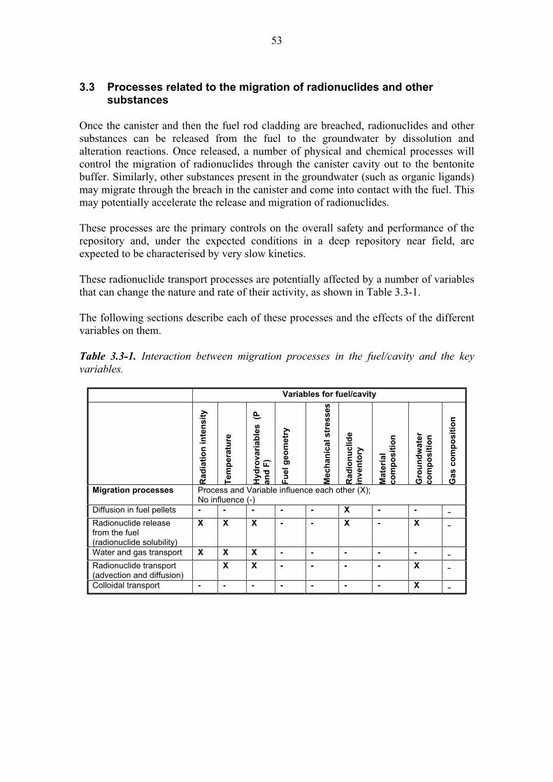
53
3.3 Processes related to the migration of radionuclides and other substances
Once the canister and then the fuel rod cladding are breached, radionuclides and other substances can be released from the fuel to the groundwater by dissolution and alteration reactions. Once released, a number of physical and chemical processes will control the migration of radionuclides through the canister cavity out to the bentonite buffer. Similarly, other substances present in the groundwater (such as organic ligands) may migrate through the breach in the canister and come into contact with the fuel. This may potentially accelerate the release and migration of radionuclides.
These processes are the primary controls on the overall safety and performance of the repository and, under the expected conditions in a deep repository near field, are expected to be characterised by very slow kinetics.
These radionuclide transport processes are potentially affected by a number of variables that can change the nature and rate of their activity, as shown in Table 3.3-1.
The following sections describe each of these processes and the effects of the different variables on them.
Table 3.3-1. Interaction between migration processes in the fuel/cavity and the key variables.
Variables for fuel/cavity
Ra
dia
tio
n in
ten
sit
y
Tem
pera
ture
Hy
dro
va
ria
ble
s
(P
an
d F
)
Fu
el
geo
metr
y
Mech
an
ical
str
es
ses
Ra
dio
nu
clid
e
inv
en
tory
Mate
rial
co
mp
os
itio
n
Gro
un
dw
ate
r
co
mp
os
itio
n
Ga
s c
om
po
sit
ion
Migration processes Process and Variable influence each other (X); No influence (-)
Diffusion in fuel pellets - - - - - X - - -Radionuclide release from the fuel (radionuclide solubility)
X X X - - X - X -
Water and gas transport X X X - - - - - -Radionuclide transport (advection and diffusion)
X X - - - - X -
Colloidal transport - - - - - - - X -
54
Name: Diffusion in fuel pellets
Category: spent fuel, canister, buffer, backfill, plugs and seals, geosphere system evolution, migration of substances
Number: 3.3.1
General description:
Fission products generated in the fuel will slowly migrate in the spent fuel matrix by two types of diffusion: thermally activated diffusion and athermal diffusion. Diffusion of radionuclides could in principle lead to enhanced fission product concentrations at grain boundaries and an increase in the rapid release inventories when water eventually comes into contact with the fuel after a canister failure (see 3.2.8).
A redistribution of fission products due to thermally activated diffusion can be considered insignificant for very long time periods (Werme et al. 2004, SKB 2006a). In contrast, athermal diffusion (which is induced by alpha self-irradiation) is expected to occur under disposal conditions.
Most of the theoretical approaches developed to date to estimate diffusion accelerated by alpha self-irradiation give low diffusion coefficients in the range 10-25 to 10-29 m2/safter 100 years of decay (SKI 2007, SKB 2006a). The most conservative approaches result in a diffusion coefficient of about 10-25 m2/s during the first decades, decreasing thereafter with time proportionally with the -activity of the spent fuel. Olander (2004) analysed the thermal spike produced in the UO2 lattice as a result of decay, typically producing an particle of 5 MeV and a recoil atom of ~ 100 keV. This spike would cause athermal diffusion. The diffusion coefficient calculated for Xe as a result of the thermal spike integrated over all alpha decays was 10-30 m2/s. Werme et al. (2004) discussed that the athermal diffusion mechanism does not have a significant influence on release if the diffusion constant is less than 10-26 m2/s. They concluded that for spent fuel with the burn-up range that is relevant in Swedish conditions, athermal diffusion is not expected to increase the instant release fractions even after a million years (SKB 2006a). The natural analogue observations from Oklo support low value for diffusion coefficient for alpha self-irradiation enhanced diffusion (SKB 2006a).
The process was estimated by Ferry et al. (2004) to increase the rapid release fraction by a few percent in the grain boundaries, in particular at high burn-up fuel (55 MWd/kgU), over 100 000 years. They concluded that uncertainties concerning the contribution of self-irradiation diffusion to the instant release fraction are large. In Finland, the maximum burn-up currently planned is estimated to be 50 MWd/kgU but higher burn-ups are possible.
The only variable of importance for this process is the total content of alpha emitters within the radionuclide inventory of the spent fuel (SKB 2006a).
Olkiluoto specific issues:
There are no site-specific issues that control diffusion in spent fuel.

55
Uncertainties:
The diffusion coefficient for athermal diffusion is not well quantified but is considered to be low from a combination of calculation, desk and natural analogue studies at the burn-up range that is relevant in Finnish conditions. Time frames of relevance:
The process will occur in the earliest time frame when the inventory of alpha emitters in the fuel is greatest. Scenarios of relevance:
The process will occur in all scenarios. Significance:
The process is considered to be of LOW significance in all scenarios with fuel burn-up < 50 MWd/kgU because this is below the threshold at which significant redistribution of fission products to the grain boundaries is expected to occur.
At higher burn-up, the process is considered to be of MEDIUM significance in all scenarios because of the potential for accelerated release of radionuclides from the fuel.
Treatment in PA:
The process is neglected from radionuclide release and transport models in all PA calculations. Equivalent NEA international FEPs:
2.1.01 “Inventory, radionuclide and other material” 2.1.09 “Chemical/geochemical processes and conditions (in wastes and EBS)” Key references:
Ferry, C., Lovera, P., Poissont, C. & Johnson, L. 2004. Quantitative assessment of the instant release fraction (IRF) for fission gases and volatile elements as a function of burn-up and time under geological disposal conditions. Mat. Res. Soc. Symp. Proc. Vol. 807 (Ed. V.M. Oversby and L.O. Werme), pp. 35-40.
Olander, D. 2004. Thermal spike theory of athermal diffusion of fission products due to alpha decay of actinides in spent fuel (UO2). Swedish Nuclear Fuel and Waste Management Co (SKB), Stockholm, Sweden. SKB Technical Report TR-04-17.
SKB 2006a. Fuel and canister process report for the safety assessment SR-Can. Swedish Nuclear Fuel and Waste Management Co (SKB), Stockholm, Sweden. SKB Technical Report TR-06-22.
SKI 2007. Spent fuel dissolution and source term modelling in safety assessment. Synthesis and extended abstracts. Report from a workshop at Sigtunahöjden Hotel and Conference, Sigtuna, Sweden, May 17-19, 2006. SKI Report 2007:17.
Werme, L.O., Johnson, L.H., Oversby, V.M., King, F., Spahiu, K., Grambow, B. & Shoesmith, D.W. 2004. Spent fuel performance under repository conditions: A model for use in SR-Can. Swedish Nuclear Fuel and Waste Management Co (SKB), Stockholm, Sweden. SKB Technical Report TR-04-19.
56
Name: Radionuclide release from the fuel (radionuclide solubility)
Category: spent fuel, canister, buffer, backfill, plugs and seals, geosphere system evolution, migration of substances
Number: 3.3.2
General description:
Radionuclides can be released from the fuel by a number of processes. Once in contact with groundwater, there will be rapid release of a certain fraction of the inventory enriched at grain boundaries (see 3.2.8) followed by a slower release of radionuclides from the fuel matrix by dissolution and alteration reactions (see 3.2.7).
Once released from the fuel, the transport behaviour of radionuclides is largely controlled by their solubility and speciation characteristics in the ambient hydrogeochemical environment.
The volume of water in the canister cavity and within the fuel rods is relatively small compared to the mass of spent fuel. This combined with the very slow rate of water turnover in the canister (due to the diffusive barrier provided by the bentonite buffer) means that the concentration of many radionuclides in the groundwater within the canister will be solubility limited.
Several assessments have been made of the radionuclide solubility limits expected within the repository near field (Duro et al. 2006, Grivé et al. 2007). Radionuclide solubilities are dependent on the chemical environment in the canister cavity. Generally, the most important groundwater parameters that affect solubility are the concentration of strong complexing ligands, e.g. carbonate content and pH. High salinity groundwaters affect the solubility equilibria through their ionic strength. Additionally, the redox conditions in the water are relevant for elements with several oxidation states. In the case of e.g. U, reducing conditions in the canister due to the presence of hydrogen gas and/or corroding iron are the most important factor in limiting U solubility. The temperature affects the kinetics of dissolution/precipitation processes as well as the solubilities and complexes formed. The temperature has a strong effect on pH and hence on the solubilities of hydrolysable elements.
Solubility refers to the total aqueous concentration of an element in all dissolved chemical forms, which are in equilibrium with each other and with a pure crystalline or amorphous phase. If equilibrium is reached, a maximum concentration of all soluble species can be estimated with the help of chemical thermodynamics. In the solubility calculations for safety assessments, a solubility-limiting phase is assumed for each radioelement. The most probable solid phases expected to form under chemical conditions are identified. The speciation calculations are important for both solubility, and the transport properties of radionuclides. The results of chemical thermodynamic modelling can be compared to the measured concentrations in natural and laboratory studies.
Radionuclides, which do not go into solution because of solubility constraints, can be directly incorporated into newly formed solid phases, which form by the alteration of

57
the spent fuel or the engineered barrier materials, or from direct precipitation from solution. Alternatively, radionuclides may be sorbed onto surfaces, such as the iron oxyhydroxides formed by corrosion of the iron insert of the canister (see 4.2.7). Colloids may affect the transport of poorly soluble radionuclides due to sorption onto their surfaces (see 3.3.5).
Radionuclide release from the fuel will be affected by a number of variables:
The radiation intensity (and therefore inventory) is an important control because radiolysis of water and radiolytically generated oxidants can cause oxidative conversion and dissolution of the UO2 spent fuel matrix. The hydrovariables, particularly the volume of water in the canister and the rate at which this volume turns over because this is a primary control over whether or not radionuclides released to the groundwater reach solubility limits or not, and thus is a control on the overall radionuclide release rate from the canister. Groundwater composition (particularly the redox conditions) and temperature are major controls over radionuclide solubility and speciation, and thus also strongly affect the bulk release rate from the fuel.
Olkiluoto specific issues:
Olkiluoto groundwater composition is characterised by a high ionic strength. This can affect the solubility and sorption behaviour of radionuclides in the near field. Although redox conditions are a major control, the natural redox conditions of the Olkiluoto groundwater will be substantially buffered by reaction with the engineered barriers.Uncertainties:
Radionuclide release processes are well understood from a conceptual model perspective. Similarly, the radionuclide solubilities are generally well characterised in thermodynamic databases. One of the most important numerical uncertainties in this regard is related to the impact of the temperature on the thermodynamics of radionuclide solubility, where the state of knowledge is currently less well understood due to the inherent difficulty in the quantification of reaction enthalpies. Time frames of relevance:
Radionuclide release processes are relevant for all time frames after groundwater penetrates the canister and the fuel cladding. In the main scenario, this will occur well after 100 000 years or more but in other scenarios potentially can occur much earlier. Scenarios of relevance:
Radionuclide release processes are most relevant to the defective canister scenarios (DCS-I and DCS-II) because under these conditions the temperature and radiation field is high (potentially accelerating the kinetics of dissolution) and the radionuclide inventory is also high.
The process is also of relevance to scenarios in which oxidising glacial waters may be in contact with the fuel (e.g. AD-I, AD-II) because of the higher solubility of radionuclides under oxidising conditions.
In the main scenario, the radionuclide release from the fuel is relevant but is not anticipated to occur until the far future by which time the radionuclide inventory of the waste has decayed substantially.
58
Significance:
The radionuclide release processes are considered to be of HIGH significance in all scenarios because they are a dominant control on the source term and, thus, the overall performance and safety of the repository. Treatment in PA:
Radionuclide solubility calculations are explicitly included in the radionuclide release and transport models in all PA calculations. It is conservatively assumed that the cladding provides no barrier to groundwater contact with the fuel after the canister has been breached and that after groundwater contacts the fuel the entire inventory is accessible for dissolution and that the transport will depend on the concentrations of the radionuclides, which will be dominated by their solubility. Equivalent NEA international FEPs:
2.1.09 “Chemical/geochemical processes and conditions (in wastes and EBS)” 3.2.01 “Dissolution, precipitation and crystallisation, contaminant” 3.2.02 “Speciation and solubility, contaminant” Key references:
In the text: Duro, L., Grivé, M., Cera, E., Gaona, X., Domènech, C. & Bruno, J. 2006. Determination and assessment of the concentration limits to be used in SR-Can. Swedish Nuclear Fuel and Waste Management Co. (SKB), Stockholm, Sweden. SKB TR 06-32.
Grivé, M., Montoya, V. & Duro, L. 2007. Assessment of the concentration limits for radionuclides for Posiva. Posiva Oy, Olkiluoto, Finland. Posiva Working Report 2007-103.
Others relevant: SKB 2004a. Interim Process Report for the Safety Assessment Sr-Can. Swedish Nuclear Fuel and Waste Management Co. (SKB), Stockholm, Sweden. SKB R-04-33.
SKB 2006a. Fuel and Canister Process Report for the Safety Assessment. Swedish Nuclear Fuel and Waste Management Co. (SKB), Stockholm, Sweden. SKB TR-06-22.
59
Name: Water and gas transport (in the canister cavity and fuel rods)
Category: spent fuel, canister, buffer, backfill, plugs-seals-grout, geosphere system evolution, migration of substances
Number: 3.3.3
General description:
Hydraulic processes control the movement of water and gas into and out of the canister cavity and through the fuel rods via pre-existing manufacturing defects or perforations caused by corrosion. Hydraulic processes are thus the main driver for radionuclides to be transported within the canister and out into the bentonite buffer, either in solution, gas phase or particulate/colloidal form.
It is likely that a two-phase (water-gas) system will develop within the canister void space and the fuel rods at some point in the post-closure evolution of the repository.
Water can be present either as (i) cooling pond water trapped in leaking fuel rods at the time of encapsulation, or (ii) groundwater that penetrates the canister after emplacement through pre-existing mechanical defects or perforations caused by metal corrosion.
Gas can be present either as (i) argon used to purge the canister at the time of encapsulation, (ii) vapour caused by boiling of water if the boiling point is exceeded, (iii) hydrogen generated by anaerobic corrosion of iron, or (iv) radiolysis of water or water vapour.
Of these, the anaerobic corrosion of iron is likely to be the greatest contributor. Water generation by boiling is only possible when the internal temperature exceeds the boiling point and thus is relevant only for cooling pond water trapped in leaking fuel rods and for groundwater in the early canister failure scenarios.
The presence of gas in the canister void space may have a significant impact on the release of radionuclides. Free gas formed in the canister will rise to the top of the canister and will accumulate as a bubble if it is contained. As more gas is produced, the gas pressure and bubble volume will increase, and water will be expelled from the canister through any perforations. The maximum possible size of the bubble will be controlled by the internal geometry of the canister and the location of the perforations in the canister metal.
Anaerobic corrosion of iron will lead to a continuous increase in the hydrogen pressure within the canister until the confining pressure from the bentonite is exceeded. The release rate of hydrogen from the canister will be controlled by the hydrogen pressure and the transport properties of the surrounding barriers. The case of hydrogen generation through anaerobic iron corrosion in a canister with different corrosion rates, hole sizes and available internal surface areas for corrosion has been modelled (Bond et al. 1997).
60
Any water expelled from the canister due to a build-up of gas will carry dissolved radionuclides and potentially radionuclides in colloidal form, some of which could adhere to the bubble surface. Thus, initially, gas generation may enhance the release of radionuclides from the canister. If, however, a large gas bubble forms in the canister, then further dissolution of the fuel and corrosion of the internal surfaces of the canister will be restricted as water is driven from contact with the fuel.
Water and gas transport in the canister cavity and fuel rods is affected by a number of variables:
Radiation intensity controls the rate of radiolytic gas generation, although this is a less important gas generation process than anaerobic corrosion of iron. Temperature controls the potential for water vapour to be produced by boiling, which can only occur in the period after emplacement when the internal canister temperature exceeds 100 °C. The rate of anaerobic iron corrosion is also temperature dependent. Hydrovariables, particularly the hydrostatic pressure, which controls the volume of any gas bubble that is formed.
In turn, water and gas transport in the canister cavity and fuel rods affects other processes, most notably water-fuel and water-canister interactions. Olkiluoto specific issues:
There are no site-specific issues that will provide a significant control on water and gas transport in the canister cavity and fuel rods. The physico-chemical conditions inside the canister will be very largely buffered by the engineered barriers rather than by the natural conditions of the groundwater. Uncertainties:
The greatest uncertainty in consideration of water-gas systems in the canister is the location and size of any perforations in the canister. If the perforations are at the top of a canister, then it is unlikely that a free gas phase (bubble) can accumulate in the canister and cause expulsion of the water. There are significant conceptual and numerical certainties related to the detailed description and modelling of the behaviour of the system including gas transport through the bentonite buffer. Time frames of relevance:
Cooling pond water (and vapour from boiling) is assumed to be present in the canister from the time of encapsulation. No additional water and gas transport can occur in the canister until after it has failed, and the time this occurs depends on the scenario. In the main scenario, this is anticipated to occur in excess of 100 000 years after emplacement. Scenarios of relevance:
Water and gas transport in the canister cavity and fuel rods is relevant to all scenarios when groundwater could enter the canister.Significance:
Water and gas transport in the canister cavity and fuel rods is considered to be of HIGH significance in all assessment scenarios because this is the dominant process by which radionuclides can be transported from the canister to the bentonite buffer. In the defect canister scenarios (DCS) and AD-III, however, the significance is greatest because of the potential for early and accelerated release when temperatures are high and the inventory presents the highest hazard.

61
Treatment in PA:
For an intact canister, the water and gas transport in the cavity will be negligible from the point of view of long-term safety. In the case of canister failure, the process is treated in the SR-Can main report (SKB 2006) as a part of an integral description of the evolution of the canister interior after damage. The descriptions are based on the modelling reported in Bond et al. (1997) and other sources. The process has been described also in Pastina and Hellä (2006). Equivalent NEA international FEPs:
2.1.08 “Hydraulic/hydrogeological processes and conditions (in wastes and EBS)” 2.1.12 “Gas sources and effects (in wastes and EBS)” 3.2.09 “Gas-mediated transport of contaminants” Key references:
In the text: Bond, A.E., Hoch, A.R., Jones, G.D., Tomczyk, A.J., Wiggin, R.M. & Worraker, W.J. 1997. Assessment of a spent fuel disposal canister – Assessment studies for a copper canister with cast steel inner component. Swedish Nuclear Fuel and Waste Management Co. (SKB), Stockholm, Sweden. SKB TR-97-19.
Pastina, B. & Hellä, P. (Eds.) 2006. Expected evolution of a spent nuclear fuel repository at Olkiluoto. Posiva Oy, Olkiluoto, Finland. Report POSIVA 2006-05.
SKB 2006. Long-term safety for KBS-3 repositories at Forsmark and Laxemar – a first evaluation. Main report of the SR-Can project. Swedish Nuclear Fuel and Waste Management Co. (SKB), Stockholm, Sweden. SKB TR-06-09
Others relevant: SKB 2006a. Fuel and canister process report for the safety assessment SR-Can. Swedish Nuclear Fuel and Waste Management Co. (SKB), Stockholm, Sweden. SKB Technical Report TR-06-22.
Suikki, M. & Warinowski, M. 2007. A drying system for spent fuel assemblies. Posiva Oy, Olkiluoto, Finland. Posiva Working Report 2007-28.
Wikramaratna, R.S., Goodfield, M., Rodwell, W.R., Nash, P.J. & Agg, P.J. 1993. A preliminary assessment of gas migration from the copper/steel canister. Swedish Nuclear Fuel and Waste Management Co, Stockholm, Sweden. SKB Technical Report 93-31.
62
Name: Radionuclide transport (advection and diffusion)
Category: spent fuel, canister, buffer, backfill, plugs-seals-grout, geosphere system evolution, migration of substances
Number: 3.3.4
General description:
Within the canister void space, diffusion, advection and convection may drive water movement and thus the transport of radionuclides in solution. Movement into and out of the canister will, however, be controlled by the hydraulic conductivity of the bentonite buffer which will provide a diffusive barrier. Thus the rate of radionuclide movement into and out of the canister will be very slow, and the dominant processes will be diffusion.
The transport of radionuclides in the aqueous phase is directly related to their solubility (see 3.3.2) given that, the higher the concentration limit, the higher the potential of radionuclide flux.
Any radionuclides that can partition into a free gas phase (bubble) may be transported within the canister as a gas (e.g. 14C). However, unless the gas pressure exceeds the confining pressure of the bentonite buffer, gas release from the canister will still be diffusion limited.
Radionuclide transport in the canister cavity will be affected by a number of variables:
Temperature and any thermal gradients within the canister, because these influence the rates of diffusion, advection and convection of water and solutes, as well as gas. The hydrovariables, particularly the presence of water, which is essential for advection or diffusion of solutes. Groundwater composition (particularly the redox conditions) is a major control over radionuclide solubility and thus strongly affects the bulk transport rate within and out of the canister.
Olkiluoto specific issues:
The composition of the groundwater affects the solubility of radionuclides and thus the potential for transport of solutes within the canister. Uncertainties:
Generally, advection and diffusion are well-known processes. The rate of water turnover and the transport of solutes within the canister void space are controlled by the hydraulic conductivity of the bentonite buffer, which is well known. Time frames of relevance:
Radionuclide transport within the canister is relevant for all time frames after groundwater penetrates the canister and the fuel cladding. In the main scenario, this will occur after 100 000 years or more but in other scenarios potentially can occur much earlier. Scenarios of relevance:
Radionuclide transport within the canister is most relevant to the additional scenarios in which the bentonite buffer is absent or poorly emplaced (AD-II) because, in this

63
situation, high water and radionuclide solute flows into and out of the canister can occur.
In the main scenario, radionuclide transport in the canister is relevant but is not anticipated to occur until the far future by which time the radionuclide inventory of the waste has decayed substantially. Significance:
Radionuclide transport in the canister is considered to be of HIGH significance in the poorly emplaced canister scenario (AD-II) because of the potential for enhanced rates of radionuclide release from the near field.
In the main scenario, radionuclide transport within the canister is considered to be of LOW significance because, under these conditions, the radionuclide release rate from the canister is controlled by solubility limits and dissolution rate of the fuel.Treatment in PA:
Radionuclide transport from the fuel through the fuel-cavity in the canister is not explicitly considered in PA exercises. It is conservatively assumed that once groundwater contacts the fuel the entire inventory is accessible for dissolution and that the transport will depend on the concentrations of the radionuclides, which will be dominated by their solubility. Equivalent NEA international FEPs:
3.2.07 “Water-mediated transport of contaminants” 3.2.09 “Gas-mediated transport of contaminants” Key references of relevance not mentioned in the text:
Duro, L., Grivé, M., Cera, E., Gaona, X., Domènech, C. & Bruno, J. 2006. Determination and assessment of the concentration limits to be used in SR-Can. Swedish Nuclear Fuel and Waste Management Co. (SKB), Stockholm, Sweden. SKB TR 06-32.
Grivé, M., Montoya, V. & Duro, L. 2007. Assessment of the concentration limits for radionuclides for Posiva. Posiva Oy, Olkiluoto, Finland. Posiva Working Report 2007-103.
SKB 2004a. Interim Process Report for the Safety Assessment Sr-Can. Swedish Nuclear Fuel and Waste Management Co. (SKB), Stockholm, Sweden. SKB R-04-33.
SKB 2006a. Fuel and Canister Process Report for the Safety Assessment. Swedish Nuclear Fuel and Waste Management Co. (SKB), Stockholm, Sweden. SKB TR-06-22.

64
Name: Colloidal transport
Category: spent fuel, canister, buffer, backfill, plugs-seals-grout, geosphere system evolution, migration of substances
Number: 3.3.5
General description:
Radionuclides may be released from the fuel in the form of colloidal or pseudocolloidal particles, which provides a potential transport mechanism for the poorly soluble radionuclide species. Furthermore, radionuclides may form as co-precipitates from solution in colloidal form.
Although such colloidal particles may move within the canister void space, they cannot migrate out of the canister and through the buffer because of its very high compaction. As such, the formation of colloidal or pseudocolloidal particles within the canister will not affect the overall release rate of radionuclides from the near field under normal conditions.
Colloidal radionuclide transport in the fuel cavity will be affected by a number of variables:
Composition of the spent fuel, fuel assembly and canister materials (and their secondary alteration products) because this is a primary control on the nature and rate of colloid production within the canister.Groundwater chemistry because it determines radionuclide solubility and speciation, and the stability of the colloids.
Olkiluoto specific issues:
The influence of high-salinity groundwater composition on colloid stability may be a site-specific issue because colloids are less stable under high salinity conditions compared to low ionic strength groundwaters. Uncertainties:
The population of colloids inside the canister will be uncertain. Time frames of relevance:
Colloidal transport within the canister is relevant for all time frames after groundwater penetrates the canister and the fuel cladding.Scenarios of relevance:
Colloidal transport within the canister is most relevant to the additional scenarios in which the bentonite buffer is absent or poorly emplaced (AD-II) because, in this situation, colloids may transport poorly soluble radionuclides through the buffer to the geosphere.
In the main scenario, colloidal transport in the canister is relevant but is not anticipated to occur until the far future by which time the radionuclide inventory of the waste has decayed substantially. Significance: Colloidal transport within the canister is of MEDIUM significance in the additional scenarios in which the bentonite buffer is absent or poorly emplaced (AD-II) because of the potential for increasing bulk radionuclide release rates.
65
In the main scenario, it is of LOW significance because it does not influence the release of radionuclide from the near field because the colloids will not be able to pass through the bentonite buffer.
Treatment in PA:
Colloidal transport within the canister is neglected from radionuclide release and transport models in all PA calculations. Equivalent NEA international FEPs:
2.1.09 “Chemical/geochemical processes and conditions (in wastes and EBS)” 3.2.02 “Speciation and solubility, contaminant” 3.2.04 “Colloids, contaminant interactions and transport with” Key references of relevance not mentioned in the text:
Grivé, M., Montoya, V. & Duro, L. 2007. Assessment of the concentration limits for radionuclides for Posiva. Posiva Oy, Olkiluoto, Finland. Posiva Working Report 2007-103.
SKB 2006a. Fuel and Canister Process Report for the Safety Assessment. Swedish Nuclear Fuel and Waste Management Co. (SKB), Stockholm, Sweden. SKB TR-06-22.

66
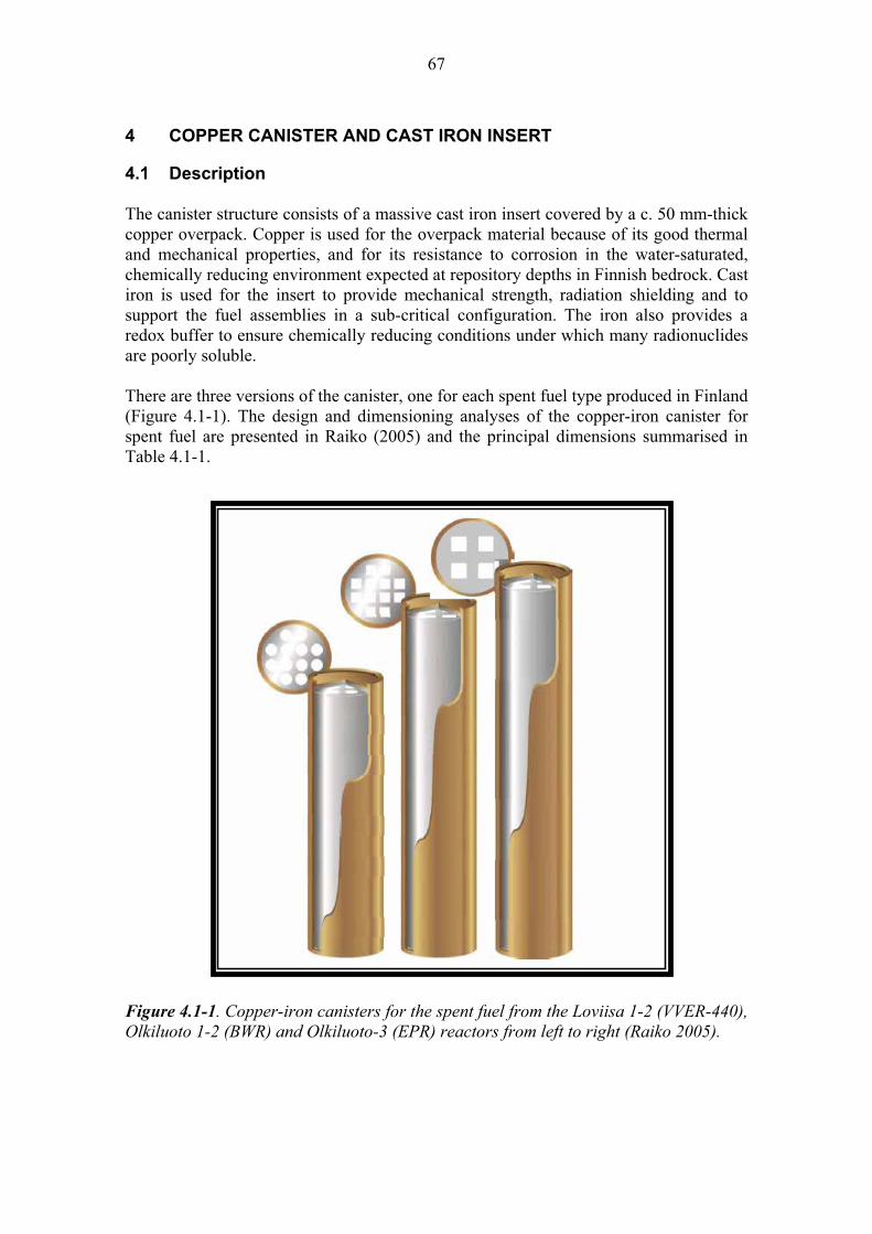
67
4 COPPER CANISTER AND CAST IRON INSERT
4.1 Description
The canister structure consists of a massive cast iron insert covered by a c. 50 mm-thick copper overpack. Copper is used for the overpack material because of its good thermal and mechanical properties, and for its resistance to corrosion in the water-saturated, chemically reducing environment expected at repository depths in Finnish bedrock. Cast iron is used for the insert to provide mechanical strength, radiation shielding and to support the fuel assemblies in a sub-critical configuration. The iron also provides a redox buffer to ensure chemically reducing conditions under which many radionuclides are poorly soluble.
There are three versions of the canister, one for each spent fuel type produced in Finland (Figure 4.1-1). The design and dimensioning analyses of the copper-iron canister for spent fuel are presented in Raiko (2005) and the principal dimensions summarised in Table 4.1-1.
Figure 4.1-1. Copper-iron canisters for the spent fuel from the Loviisa 1-2 (VVER-440), Olkiluoto 1-2 (BWR) and Olkiluoto-3 (EPR) reactors from left to right (Raiko 2005).
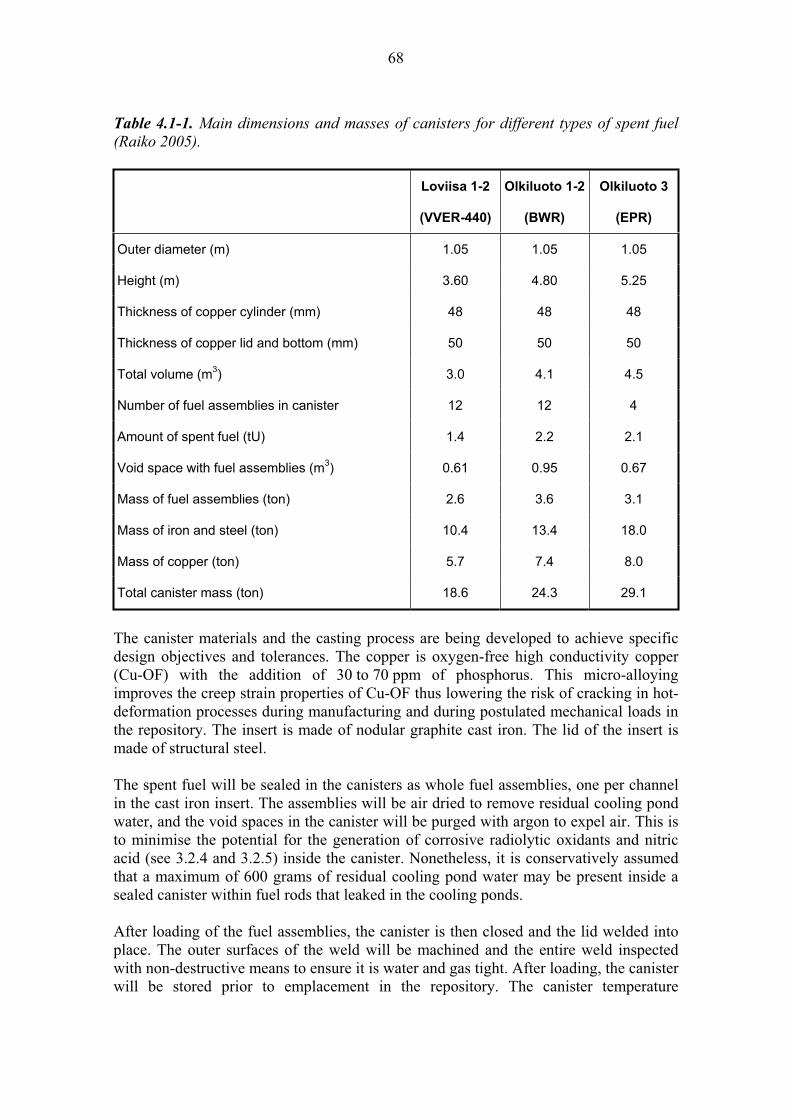
68
Table 4.1-1. Main dimensions and masses of canisters for different types of spent fuel (Raiko 2005).
Loviisa 1-2
(VVER-440)
Olkiluoto 1-2
(BWR)
Olkiluoto 3
(EPR)
Outer diameter (m) 1.05 1.05 1.05
Height (m) 3.60 4.80 5.25
Thickness of copper cylinder (mm) 48 48 48
Thickness of copper lid and bottom (mm) 50 50 50
Total volume (m3) 3.0 4.1 4.5
Number of fuel assemblies in canister 12 12 4
Amount of spent fuel (tU) 1.4 2.2 2.1
Void space with fuel assemblies (m3) 0.61 0.95 0.67
Mass of fuel assemblies (ton) 2.6 3.6 3.1
Mass of iron and steel (ton) 10.4 13.4 18.0
Mass of copper (ton) 5.7 7.4 8.0
Total canister mass (ton) 18.6 24.3 29.1
The canister materials and the casting process are being developed to achieve specific design objectives and tolerances. The copper is oxygen-free high conductivity copper (Cu-OF) with the addition of 30 to 70 ppm of phosphorus. This micro-alloying improves the creep strain properties of Cu-OF thus lowering the risk of cracking in hot-deformation processes during manufacturing and during postulated mechanical loads in the repository. The insert is made of nodular graphite cast iron. The lid of the insert is made of structural steel.
The spent fuel will be sealed in the canisters as whole fuel assemblies, one per channel in the cast iron insert. The assemblies will be air dried to remove residual cooling pond water, and the void spaces in the canister will be purged with argon to expel air. This is to minimise the potential for the generation of corrosive radiolytic oxidants and nitric acid (see 3.2.4 and 3.2.5) inside the canister. Nonetheless, it is conservatively assumed that a maximum of 600 grams of residual cooling pond water may be present inside a sealed canister within fuel rods that leaked in the cooling ponds.
After loading of the fuel assemblies, the canister is then closed and the lid welded into place. The outer surfaces of the weld will be machined and the entire weld inspected with non-destructive means to ensure it is water and gas tight. After loading, the canister will be stored prior to emplacement in the repository. The canister temperature

69
(measured on the external surfaces) increases within a few days up to +50 to +100 °C, depending on the internal radiogenic heat generation and the ventilation conditions in the canister storage area.
Posiva and SKB are carrying out a joint programme to develop methods to manufacture, seal and inspect copper-iron canisters for spent fuel. Canister manufacturing, fuel encapsulation, canister sealing, quality assurance and quality control are described in Posiva (2006) and Raiko (2005).
4.1.1 Long-term safety and performance
In the repository, a primary safety function of the canister is the corrosion resistance of the copper overpack, which provides for long-term isolation of the spent fuel from the geosphere and the accessible environment. The primary functions of the cast iron insert are to:
provide mechanical stability to the waste package under the hydrostatic and lithostatic pressures experienced at repository depth; maintain a sub-critical geometrical arrangement of the spent fuel; and provide radiation shielding during handling and transport of the package prior to and during emplacement.
Following the establishment of chemical and hydraulic re-equilibrium in the repository near field, the groundwater will be chemically reducing (anoxic) and saline. Uniform and localised (pitting and crevice) corrosion of the copper overpack may be accelerated in the presence of chloride in the deep saline groundwaters but, nonetheless, in the main scenario the overpack is expected to resist corrosion for in excess of 106 years. The cast iron inset will act as a redox buffer to maintain chemically reducing conditions in the near field after the copper overpack has been perforated.
It is likely that a small proportion of canisters will be characterised by some initial defect in the weld, and that these may be enhanced by corrosion leading to earlier canister failure, and different rates of failure are assessed.
Once the copper overpack is perforated by corrosion or due to an initial defect, groundwater can penetrate to the annulus between the overpack and the cast iron insert, and corrosion of the insert will commence.
The rates of uniform and localised corrosion of the insert, and thus the time until groundwater can access the internal void spaces of the canister, are controlled by the rate of groundwater ingress and the anaerobic corrosion rate of iron. Both of these processes will be slow, in part because the surrounding bentonite buffer provides a diffusive barrier to groundwater and solute transport to and from the canister.
70
4.1.2 Overview of processes
The processes that are considered relevant for the cast iron insert and copper overpack can broadly be categorised as follows:
Processes related to evolution of the canister components: Radiation attenuation by canister metal Heat transfer in the canister metal Deformation of the cast iron insert Deformation of the copper overpack Thermal expansion of the canister Deformation from internal corrosion products Corrosion of the cast iron insert Corrosion of the copper overpack Deposition of salts on canister surface
Processes related to the migration of radionuclides and other substances: Radionuclide retardation by iron corrosion products
These processes are potentially affected by a number of variables that can change the nature and rate of their activity, and potentially the interactions between processes. The potential impacts of the different variables on each of the processes are described in the subsequent sections.
4.2 Processes related to the evolution of the canister components
The key function of the canister is to isolate the spent fuel from the geological environment and the natural transport processes. This is achieved through the resistance of the copper canister to corrosion and the structural strength of the cast iron insert. Various radiation, thermal, chemical and mechanical processes (and their couplings) will affect the evolution of the cast iron insert and the copper overpack of the canister. The most important potential consequence is failure of the canister that would ultimately allow groundwater to penetrate the void space and come into contact with the fuel.
If failure of the canister occurs, this can lead to migration of radionuclides and other substances through the canister (Section 4.3).
These evolution processes are potentially affected by a number of variables that can change the nature and rate of their activity, and potentially the interactions between processes, as shown in Table 4.2-1.
The following sections describe each of these processes and the effects of the different variables on them.
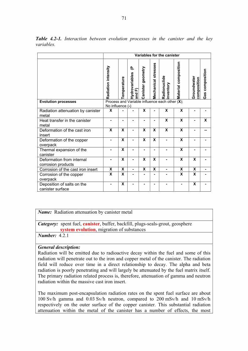
71
Table 4.2-1. Interaction between evolution processes in the canister and the key variables.
Variables for the canister
Ra
dia
tio
n in
ten
sit
y
Tem
pera
ture
Hy
dro
va
ria
ble
s
(P
an
d F
)
Can
iste
r g
eo
metr
y
Mech
an
ical
str
es
ses
Ra
dio
nu
clid
e
inv
en
tory
Ma
teri
al
co
mp
os
itio
n
Gro
un
dw
ate
r
co
mp
os
itio
n
Ga
s c
om
po
sit
ion
Evolution processes Process and Variable influence each other (X);No influence (-)
Radiation attenuation by canister metal
X - - X - X X - -
Heat transfer in the canister metal
- - - - - X X - X
Deformation of the cast iron insert
X X - X X X X - --
Deformation of the copper overpack
- X - X X - X - -
Thermal expansion of the canister
- X - - - - X - -
Deformation from internal corrosion products
- X - X X - X X -
Corrosion of the cast iron insert X X - X X - X X -
Corrosion of the copper overpack
X X - - - - X X -
Deposition of salts on the canister surface
- X - - - - - X -
Name: Radiation attenuation by canister metal
Category: spent fuel, canister, buffer, backfill, plugs-seals-grout, geosphere system evolution, migration of substances Number: 4.2.1
General description:
Radiation will be emitted due to radioactive decay within the fuel and some of this radiation will penetrate out to the iron and copper metal of the canister. The radiation field will reduce over time in a direct relationship to decay. The alpha and beta radiation is poorly penetrating and will largely be attenuated by the fuel matrix itself. The primary radiation related process is, therefore, attenuation of gamma and neutron radiation within the massive cast iron insert.
The maximum post-encapsulation radiation rates on the spent fuel surface are about 100 Sv/h gamma and 0.03 Sv/h neutron, compared to 200 mSv/h and 10 mSv/h respectively on the outer surface of the copper canister. This substantial radiation attenuation within the metal of the canister has a number of effects, the most

72
significant being the generation of thermal energy (heat) directly in the metal. The greatest influence on the near-field temperature will, however, be the decay heat generated directly by radioactive decay in the spent fuel pellets (see 3.2.2).
A secondary effect of gamma and neutron radiation attenuation is minor material change to the canister metal (e.g. yield stress, creep rates, enhanced solute segregation, dimensional changes and brittleness). Of these, embrittlement of steel and iron could be the most problematic in high radiation fields. Embrittlement can affect the mechanical strength of the cast iron insert and make it more prone to failure under loading. It is not, however, considered likely that the mechanical integrity of the canister will be significantly affected by this process (Guinan 2001).
There is relevant industrial analogue information from nuclear reactor operations on the performance of metals and alloys in high radiation fluxes that helps to support long-term assessments of canister metal performance.
Radiation attenuation by canister metal is affected by a number of variables:
Gamma and neutron radiation intensity (and therefore inventory) is the primary control. Gamma radiation is due largely to the radioactive decay of 137Cs, which has a half-life of approximately 30 years. Therefore, gamma radiolysis declines to negligible levels in less than a thousand years.Canister and fuel geometry which is significant in two respects; the thickness of the metal walls defines the rate of attenuation, every 20 to 25 mm thickness of the metal halves the gamma radiation rate and secondly, the canister body is the media through which the attenuated heat is conducted out of the canister. Material composition, particularly of the cast iron insert. The radiation sensitivity of steel materials is basically determined by its chemical composition. Phosphorous, copper and nickel contents influence the radiation embrittlement both separately and jointly. Empirical relationships between fast neutron fluence and chemical composition of steels and the degree of radiation embrittlement have been revealed from processing a large body of experimental data on reactor pressure vessel steels.
Olkiluoto specific issues:
There are no site-specific issues that control attenuation of radiation. Uncertainties:
The decay and radiation field is readily calculated, as is the amount of attenuation in the canister metal. There are no significant uncertainties. Time frames of relevance:
The peak radiation field and therefore attenuation is reached shortly after disposal and is directly related to the generation of gamma and neutron radiation, which has reduced substantially after 1000 years. Scenarios of relevance:
Attenuation of radiation by the canister metal will occur in all scenarios. Significance:
Radiation attenuation by the canister metal is considered to be of LOW significance in all post-closure scenarios because the greatest control on near-field heat generation is direct decay within the fuel and because embrittlement of the cast iron insert is not
73
considered likely to cause a substantial reduction in the mechanical integrity of the canister.
From an operational safety perspective, however, this process is of HIGH significance because of the radiation shielding provided to workers by the canister metal. Treatment in PA:
The attenuation of radiation by the canister metals is not explicitly included in the main post-closure safety assessment calculations. Equivalent NEA international FEP:
2.1.11 “Thermal processes and conditions (in wastes and EBS)” 2.1.13 “Radiation effects (in wastes and EBS)” Key references:
In the text: Guinan, M.W. 2001. Radiation effects in spent nuclear fuel canisters. Swedish Nuclear Fuel and Waste Management Co. (SKB), Stockholm, Sweden. SKB TR 01 32.
Others relevant: Anttila, M. 2005a. Gamma and neutron dose rates on the outer surface of three types of final disposal canisters. Posiva Oy, Olkiluoto, Finland. Posiva Working Report 2005-14.
Anttila, M. 2005b. Criticality safety calculations for three types of final disposal canisters. Posiva Oy, Olkiluoto, Finland. Posiva Working Report 2005-13.
Pastina B. & Hellä P. (Eds.) 2006. Expected Evolution of the Spent Nuclear Fuel Repository at Olkiluoto. Posiva Oy, Olkiluoto, Finland. Report POSIVA 2006-05.
SKB 2006a. Fuel and canister process report for the safety assessment SR-Can. Swedish Nuclear Fuel and Waste Management Co. (SKB), Stockholm, Sweden. SKB Technical Report TR-06-22.
Name: Heat transfer
Category: spent fuel, canister, buffer, backfill, plugs-seals-grout, geosphere system evolution, migration of substances Number: 4.2.2
General description:
Heat will be generated primarily by radioactive decay in the fuel (see 3.2.1) but also by radiation attenuation in the canister metal (see 4.2.1).
This heat will be transferred through the canister to the bentonite buffer by conduction directly through the metal and by radiation across the canister void spaces. Convection may also be an important means of heat transport after the canister has been breached and groundwater has flooded the void space. The fuel loading and period of surface storage are intended to ensure that the temperature on the outside of the canister never exceeds 100 °C in the repository.
74
The rate of heat transfer will be, in part, controlled by the thermal conductivity of the different canister materials and also by the natural geothermal gradient, which controls the ambient temperature in the near-field rock surrounding the bentonite buffer. Both iron and copper have very high thermal conductivities and, thus, there should be only very small temperature differentials between them. The heat transfer will cause the canister is expand and contract (see 4.2.5).
Heat transfer is affected by a number of variables:
Radionuclide inventory, which is a first order control on rate of radiogenic heat generation. Material composition (of the cast iron insert and copper overpack) affects the thermal conductivity of metals and also the rate at which radiation is attenuated (and heat generated). Gas composition, the thermal conductivity of any gas present in the canister void spaces is strongly dependent on the type of gas.
In turn, the heat transport affects other processes, such as resaturation of the bentonite buffer (see 5.2.2) and the thermal stress imposed on the near-field rock (see 8.2.3). Olkiluoto specific issues:
Heat transfer in the canister depends, in part, on the natural thermal condition of the site. At Olkiluoto, the initial ambient temperature at 400 m depth is about +10.5 Cand the temperature gradient in the rock is about +1.5 C per 100 m. Note that no significant heat rise is attributed to exothermic cement curing reactions because of the relatively small volume of cement used in the near field compared to the volume of the buffer, backfill and host rock. Uncertainties:
The hydraulic conductivities of the cast iron insert and copper overpack materials are very well known, and so the uncertainties associated with heat transfer within the canister are small. Time frames of relevance:
Heat transfer will occur in all time frames but the rate will be greatest shortly after emplacement when the maximum radiogenic heat output occurs and there is the greatest thermal gradient across the canister and the near field. The highest canister surface temperature in the repository is reached in 10-15 years. The maximum temperature in the rock at the edge of a single canister is reached in 50-100 years and then it takes of the order of 5 000 years for the near-field to return to ambient temperatures (Ikonen 2003a, 2005a). Scenarios of relevance:
Heat transfer occurs in all scenarios but is most important for the defective canister scenarios when groundwater fills the void space, thus altering the bulk thermal conductivity of the system, and allowing fuel dissolution reactions to occur at high rates (thermally controlled). Significance:
Heat transfer through the canister is considered to be of MEDIUM significance in all scenarios because of its impact on hydraulic resaturation of the bentonite buffer and the potential for causing uneven swelling or erosion of the bentonite (see 5.2.3).
75
Treatment in PA:
Heat transfer and the temperature of the canister is modelled using specific thermal codes. These codes are not, however, coupled to the radionuclide transport models which do not account for temperature dependency on radionuclide solubility and speciation.Equivalent NEA international FEPs:
2.1.11 “Thermal processes and conditions (in wastes and EBS)” Key references:
In the text: Ikonen, K. 2003a. Thermal analysis of spent nuclear fuel repository. Posiva Oy, Olkiluoto, Finland. Report POSIVA 2003-04.
Ikonen, K. 2005a. Thermal Analysis of Repository for Spent EPR-type Fuel. Posiva Oy, Olkiluoto, Finland. Report POSIVA 2005-06.
Others relevant: Pastina B. & Hellä P. (Eds.) 2006. Expected Evolution of the Spent Nuclear Fuel Repository at Olkiluoto. Posiva Oy, Olkiluoto, Finland. Report POSIVA 2006-05.
Hartikainen, J. 2006. Numerical simulation of permafrost depth at Olkiluoto. Posiva Oy, Olkiluoto, Finland. Posiva Working Report 2006-52.
SKB 2006a. Fuel and canister process report for the safety assessment SR-Can. Swedish Nuclear Fuel and Waste Management Co. (SKB), Stockholm, Sweden. SKB Technical Report TR-06-22.
Name: Deformation of the cast iron insert
Category: spent fuel, canister, buffer, backfill, plugs-seals-grout, geosphere system evolution, migration of substances Number: 4.2.3
General description:
Large external loads and pressures will be imposed on the canister, and these will be transmitted through the copper overpack to the cast iron insert. The two largest continuous components of these external pressures will be the hydrostatic pressure and the swelling pressure from the bentonite buffer, although lithostatic pressure can also be important in the case of mechanical failure of the near-field rock (e.g. due to differential heating see 8.2.1).
The hydrostatic pressure from groundwater is a symmetric and evenly distributed external load for the canister. The pressure depends on the groundwater column and, under normal conditions in Finland, the groundwater column approximates to the depth of the repository below ground. During glaciation, however, the hydrostatic pressure is increased by the thickness of the ice sheet under a warm based ice sheet in the absence of permafrost.

76
The swelling pressure of the bentonite buffer is caused by its expansion during absorption and saturation by groundwater (see 5.2.2). During resaturation after closure of the repository, swelling of the bentonite may be uneven, imposing differential pressures on a canister. After hydraulic re-equilibrium, the bentonite swelling pressure should also be symmetric and evenly distributed.
In addition to these continuous external pressures, intermittent and instantaneous external loads may occur as a consequence of rock movements that may be initiated by isostatic (glacial) or tectonic processes. Rock movements in the form of shear along a fracture plane may affect the canister via the buffer. Since such movement does not change the total volume of the bentonite buffer, the effect is essentially a shear deformation, whereby the shear strength of the buffer regulates the impact.
Lastly, internal loads and pressures will be imposed on the canister. These can occur due to the development of a gas phase or from the growth of secondary alteration products with a corresponding increase in volume. Initially the internal pressure will equate to atmospheric pressure but, as these processes occur over time, the internal pressure may increase (see 4.2.6).
The combination of these various internal and external pressures will result in time dependent loading on the cast iron insert. These loads may cause the insert to deform. Any deformation will cause strain in the structure, and strain results in mechanical stress.
The cast iron insert is designed so that the stresses and strains caused by external loads should be minimised and, under expected hydrostatic and bentonite swelling pressures, the cast iron insert should retain its structural integrity. This has been confirmed by pressure test demonstrations made on full-size canisters that indicated the collapse pressure of the canister is close to 14 MPa which is substantially greater than that expected in the repository (Andersson et al. 2005).
The integrity of the canister may, however, be compromised to shear type rock movements if the shear plane happens to intersect the deposition hole and the shear amplitude is sufficiently large. In Finland, which is an area of low seismic activity, such movements are considered unlikely except possibly locally during deglaciation. The consequence of large rock movements, which may occur during the deglaciation, is minimised by locating the disposal gallery outside major fracture zones in the bedrock (Hutri 2007). Such movements are more likely to occur on appropriately orientated existing fractures.
The mechanical behaviour of cast iron and steel is well observed from industrial analogues, and this knowledge and precedence can be applied to the mechanical understanding of the canister.
Deformation of the cast iron insert is affected by a number of variables:
Radiation affects the internal structure of iron and steel, causing embrittlement, which can affect deformation properties (see 4.2.1).
77
Temperature because many material properties are temperature dependent. Canister geometry, particularly the dimensions and shape of the canister has a significant control on its overall strength, stiffness, stress concentrations and stability against buckling. Mechanical stress is the dominant control on the deformation of the canister. Material composition is a direct control on the mechanical properties (strength, ductility, thermal expansion). Radionuclide inventory controls the generation of helium and, therefore, the build-up of gas pressure inside of the intact canister.
Olkiluoto specific issues:
The local geological conditions at the site will affect the final depth of the disposal tunnels, and thus the hydrostatic pressure. The anticipated thickness of future ice sheets, which will increase hydrostatic pressure under a warm-based ice sheet, is also site specific. Uncertainties:
Pressure loads (e.g. final swelling pressure from the bentonite buffer) are important, but they are well defined and understood, as is the strength of the canister. There is more uncertainty over the potential and consequence of shear-type mechanical loads, particularly in relation to deglaciation, and how deformation is transmitted from the rock, through the bentonite buffer to the canister. Time frames of relevance:
The groundwater pressure and the bentonite swelling pressure are built up within a few years or latest in a few decades. The first maximum glacial load can be expected after tens of thousands of years. Postulated rock shear deformations or major earthquakes may occur during or after each period of glaciation. Scenarios of relevance:
Deformation of the cast iron insert is relevant to all scenarios but is most significant in alternative scenarios that can lead to shear-type deformations such as earthquake/rock shear (AD-I). Significance:
Deformation of the cast iron insert is considered to be of HIGH significance in all scenarios because this component provides the mechanical integrity for the canister and, thus, is a primary factor in ensuring the long-term isolation capacity for the waste package.Treatment in PA:
Deformation of the cast iron insert is modelled using specific finite element tools. These are not, however, coupled to the radionuclide transport models. Future climate change and, thus, periods of increased stress during glaciation are modelled using specific climate scenarios. Equivalent NEA international FEP:
2.1.07 “Mechanical processes and conditions (in wastes and EBS)” Key references:
In the text: Andersson, C.-G., Andersson, M., Björkegren, L.-E., Dillström, P., Erixon, B., Minnebo, P., Nilsson, F. & Nilsson, K.-F. 2005. Probabilistic Analysis and Materials Characterisation of Canister Insert for Spent Nuclear Fuel – Summary Report. SKB Technical Report TR-05-17.
78
Hutri, K.-L. 2007. An approach to palaeoseismicity in the Olkiluoto (sea) area during the early Holocene. Radiation and Nuclear Safety Authority STUK, report STUK-A222.
Others relevant: Börgesson, L. 1986. Model shear tests of canisters with smectite clay envelopes in deposition holes. Swedish Nuclear Fuel and Waste Management Co. (SKB), Stockholm, Sweden. SKB Technical Report TR 86-26.
Börgesson, L. & Hernelind, J. 2006. Earthquake induced rock shear through deposition hole. Influence of shear plane inclination and location as well as buffer properties on the damage caused to the canister. Swedish Nuclear Fuel and Waste Management Co. (SKB), Stockholm, Sweden. SKB Technical Report TR-06-43.
Ikonen, K. 2005b. Mechanical analysis of cylindrical part of canisters for spent nuclear fuel. Posiva Oy, Olkiluoto, Finland. Posiva Working Report 2005-12.
Raiko, H. 2005. Disposal Canister for Spent Nuclear Fuel – Design Report. Posiva Oy, Olkiluoto, Finland. Report POSIVA 2005-02.
SKB 2006a. Fuel and canister process report for the safety assessment SR-Can. Swedish Nuclear Fuel and Waste Management Co. (SKB), Stockholm, Sweden. SKB Technical Report TR-06-22.
Name: Deformation of copper canister from external pressure
Category: spent fuel, canister, buffer, backfill, plugs-seals-grout, geosphere system evolution, migration of substances Number: 4.2.4
General description:
The copper overpack of the canister is arguably the most important engineering barrier in the repository system. The canister is designed so that the cast iron insert bears and resists all of the mechanical loading. The copper overpack is not attributed with any physical strength and its primary function is to provide resistance to corrosion.
Large external loads and pressures will be imposed on the canister, and these will be transmitted through the copper overpack to the cast iron insert. The two largest continuous components of these external pressures will be the hydrostatic pressure and the swelling pressure from the bentonite buffer. Intermittent and instantaneous external loads may also occur as a consequence of rock movements that may be initiated by isostatic (glacial) or tectonic processes.
The copper metal of the overpack is ductile and will deform, either plastically or by creep when the copper overpack is subjected to these loads and pressures. Initially this movement will cause closure of the small annulus between the overpack and the

79
insert. The copper overpack will deform until full contact is reached on all surfaces between the overpack and the iron insert due to the increasing external pressure load. The maximum local strain in the copper overpack weld will be about 3% when the annular gap between the overpack and the insert is forced to close (Knuutila 2001). At the end of this process, the copper will remain in a compressive stress state.
The copper overpack will similarly deform in response to deformations of the cast iron insert in response to external or internal pressures and loads. The canister is designed and dimensioned, however, such that the anticipated mechanical loads will not cause excessive deformations or creep, which would threaten the long-term isolation function.
Deformation of the copper overpack is affected by a number of variables:
Temperature because many material properties are temperature dependent. Canister geometry, particularly the dimensions and shape of the canister has a significant control on its overall strength, stiffness, stress concentrations and stability against buckling. Mechanical stress is the dominant control on the deformation of the canister. Material composition is a direct control on the mechanical properties (strength, ductility, thermal expansion).
Olkiluoto specific issues:
The local geological conditions at the site will affect the final depth of the disposal tunnels, and thus the hydrostatic pressure. The anticipated thickness of future ice sheets, which will increase hydrostatic pressure under a warm based ice sheet, is also site specific. Uncertainties:
Pressure loads (e.g. final swelling pressure from the bentonite buffer) are important, but they are well defined and understood, as is the behaviour of the copper overpack under those conditions.Time frames of relevance:
The groundwater pressure and the bentonite swelling pressure will increase within a few years or latest in a few decades. The first maximum glacial load can be expected after tens thousand years. Postulated rock shear deformations or major earthquakes may occur during or after each period of glaciation. Scenarios of relevance:
Deformation of the copper overpack is relevant to all scenarios but is most significant in alternative scenarios that can lead to shear-type deformations such as earthquake / rock shear in the near-field rock. Significance:
Deformation of the copper canister is considered to be of MEDIUM significance in all scenarios because, although this component provides the primary long-term isolation function for the waste package, it is the cast iron insert that provides mechanical integrity for the canister. The performance of the copper overpack is based on corrosion (chemical) resistance, rather than mechanical resistance. Treatment in PA:
Deformation of the copper overpack is modelled using specific finite element tools. These are not, however, coupled to the radionuclide transport models. The main
80
scenario assumes all canisters are initially intact but in the assessment scenarios the canister/s will fail over time in response to corrosion and mechanical impacts. Equivalent NEA international FEP:
2.1.07 “Mechanical processes and conditions (in wastes and EBS)” Key references:
In the text: Knuutila, A. 2001. Long-term creep of nuclear fuel disposal canister shroud. Posiva Oy, Helsinki, Finland. Posiva Working Report 2001-13.
Others relevant: Börgesson, L. & Hernelind, J. 2006. Earthquake induced rock shear through deposition hole. Influence of shear plane inclination and location as well as buffer properties on the damage caused to the canister. Swedish Nuclear Fuel and Waste Management Co. (SKB), Stockholm, Sweden. SKB Technical Report TR-06-43.
Ikonen, K. 2005b. Mechanical analysis of cylindrical part of canisters for spent nuclear fuel. Posiva Oy, Olkiluoto, Finland. Posiva Working Report 2005-12.
Raiko, H. 2005. Disposal Canister for Spent Nuclear Fuel – Design Report. Posiva Oy, Olkiluoto, Finland. Report POSIVA 2005-02.
SKB 2006a. Fuel and canister process report for the safety assessment SR-Can. Swedish Nuclear Fuel and Waste Management Co. (SKB), Stockholm, Sweden. SKB Technical Report TR-06-22.
Name: Thermal expansion of the canister
Category: spent fuel, canister, buffer, backfill, plugs-seals-grout, geosphere system evolution, migration of substances Number: 4.2.5
General description:
The temperature of the canister is controlled by the ambient geothermal gradient, the internal (radiogenic) heat generation and the hydraulic conductivity of the engineered barriers and the host rock.
The canisters will reach their maximum temperature in the repository within 10 to 15 years after the disposal. The maximum temperature on the outside surface of the canister should not exceed 100 C but the internal temperature at the surface of the fuel may be closer to 200 ºC (Ikonen 2003a).
The canister will react to this initial temperature increase by expansion of the metals but the copper overpack will expand more than the iron insert due to its higher thermal expansion coefficient. In the absence of external pressure, this would cause the annular gap between the insert and the overpack to widen from its nominal size of 1 mm but the external compressive loads will cause plastic creep of the copper and the annular gap will actually close under full hydraulic resaturation of the bentonite buffer and maximum swelling pressure.
81
The thermal conductivity of the metal body of the canister is two orders of magnitude higher than the conductivity of the surrounding bentonite and rock in the repository. Due to this, after thermal equilibrium has been reached, the metallic components of the canister will have a uniform temperature.
Over time, the canister will slowly cool and the canister metals contract. This temperature decrease will cause a tensile strain into the copper overpack due to the fact that the copper is shrinking more than iron when the temperature is decreasing,
As a result of these temperature changes, the canister will be affected by stresses, which will be greatest in those materials with the highest coefficient of thermal expansion (i.e. the copper overpack). Assessment of the thermal loading and associated deformation shows that the risk of failure of the canister metals can be neglected (Ikonen 2003a).
Thermal expansion of the canister is affected by a number of variables:
Temperature and more particularly the rate of change of temperature and the thermal gradient across the canister, because this affects the rate of expansion and any differential expansion that may occur. Material composition because the coefficient of thermal expansion is composition dependent. In the case of the canister it is higher for the copper than the cast iron.
Olkiluoto specific issues:
There are no site-specific issues that will provide a significant control on the thermal expansion of the canister. Uncertainties:
The maximum temperature inside the canister and the thermal expansion of the metal are well known and can be readily calculated. Time frames of relevance:
The maximum canister temperature will be developed within a few decades but the cooling to ambient temperature will take ten of thousands of years. Scenarios of relevance:
Thermal expansion of the canister will occur in all scenarios. Significance:
Thermal expansion of the canister metal is considered to be of LOW significance in all scenarios because the amount of expansion (and differential expansion) is considered to be below that necessary to cause failure of the canister and thus will not result in any loss of isolation capacity.
Treatment in PA:
Thermal expansion of the canister can be calculated but can be neglected from the radionuclide transport models. Equivalent NEA international FEPs:
2.1.07 “Mechanical processes and conditions (in wastes and EBS)” 2.1.11 “Thermal processes and conditions (in wastes and EBS)”
82
Key references:
In the text: Ikonen, K. 2003a. Thermal analysis of spent nuclear fuel repository. Posiva Oy, Olkiluoto, Finland. Report POSIVA 2003-04.
Others relevant: Raiko, H. 2005. Disposal Canister for Spent Nuclear Fuel – Design Report. Posiva Oy, Olkiluoto, Finland. Report POSIVA 2005-02.
SKB 2006a. Fuel and canister process report for the safety assessment SR-Can. Swedish Nuclear Fuel and Waste Management Co. (SKB), Stockholm, Sweden. SKB Technical Report TR-06-22.
Name: Deformation from internal corrosion products
Category: spent fuel, canister, buffer, backfill, plugs-seals-grout, geosphere system evolution, migration of substances Number: 4.2.6
General description:
Groundwater will potentially come into contact with the cast iron insert at some time after emplacement of the canister. This may happen in one of two ways:
through initial defects in the canister that allow for early and rapid contact between groundwater and the insert, while elevated near-field temperatures occur; due to slow corrosion and mechanical deformation of the copper overpack that will result in its failure after hundreds of thousands of years, when the near-field has cooled to ambient temperature.
Any cooling pond water contained in cladding tubes may cause early corrosion of the cast iron insert surfaces in the void space before the canister fails (see 3.2.4), but only a small volume of water is likely to be present and will be insufficient to cause any mechanical effects due to the growth of secondary alteration products.
When groundwater comes in contact with the cast iron insert, anaerobic corrosion of the iron will begin with the concomitant generation of secondary alteration products (see 4.3.1). Initially corrosion will be restricted to the exposed areas of the insert, which will be dependent, in part, on whether or not the annular gap between the insert and the copper overpack has closed due to plastic deformation of the copper (see 4.2.4). This is less likely to have occurred in the case of initial defects in the canister.
As corrosion and deformation progresses, increasingly large areas of the insert will become available for reaction with the groundwater. Localised corrosion of the insert or failure of the welds will eventually allow groundwater to enter the void spaces in the canister.
There are two main products generated by anaerobic corrosion of the cast iron insert: hydrogen and solid iron oxides or iron oxy-hydroxides (see 4.3.1) both of which are
83
associated with volume increase and thus an increase in loads and pressures internal to the canister.
Depending on the location of the breach in the canister, hydrogen gas may accumulate in the canister void spaces and its pressure will gradually increase and groundwater will be expelled. This gas pressure is, however, limited to the opening pressure of the bentonite buffer and will not be able to cause any deformation on the canister.
The rate of growth of solid iron oxide and oxy-hydroxide alteration products will be slow and constrained by the flux of groundwater to the cast iron insert, which in turn will be controlled, in the main scenario, by diffusion through the bentonite buffer and through perforations in the copper overpack. These solid alteration products occupy a larger volume than the equivalent quantity of iron and, over time, may lead to an increase in the internal pressure against the copper overpack. This may subsequently lead to local deformation and ultimately failure of the copper overpack, although there is considerable uncertainty over whether or not this is likely under repository conditions.
The process is described in SKB (2006); some experimental results are reported in Smart et al. (2006) and some natural analogues are referred to in Smart & Adams (2006).
Deformation from internal corrosion products is affected by a number of variables:
Temperature controls the rate of reaction and, in case of an initial defective canister, corrosion may begin at high near-field temperatures and be accelerated. Canister geometry, the dimensions and shape of the canister have an effect on the exposed surface area for corrosion and the void space into which solid corrosion products can expand.Mechanical stress on the canister is significant because compressive stress may make the corrosion process slower and affect the distribution of the corrosion products (Smart et al. 2006). Material composition, the composition of the iron (and other components in the near-field) is significant because the corrosion processes (especially the rate) and the nature of the secondary alteration products is depend on material composition. Groundwater composition, particularly redox conditions, will affect the rate of corrosion and the nature of the secondary alteration products, including their density/volume.
Olkiluoto specific issues:
There are no site-specific issues that will provide a significant control on deformation of the canister due to internal corrosion products, although the local groundwater chemistry may have an influence on the rate and nature of the corrosion reaction. Uncertainties:
There is significant uncertainty over the likely number, location and size of perforations in the copper overpack that may form and, thus, the exposed surface area of the cast iron insert available for reaction with the groundwater.

84
There is also uncertainty over the density and porosity of the resulting corrosion products and, therefore, the degree of expansion and whether or not these solid alteration products will be capable of causing expansion of confining metal surfaces under the compressive loads expected in a repository. The anaerobic corrosion product formed on iron-based materials is easily deformed and experimental studies seem to indicate that the corrosion products do not exert enough pressure to displace the copper shell (Smart et al. 2006). Time frames of relevance:
The process will start immediately after groundwater penetration through the copper overpack. In the defective canister scenarios, this may occur within a few years of emplacement, whereas in the main scenario this is not expected to occur until at least 100 000 years after emplacement. Scenarios of relevance: Deformation of the canister due to internal corrosion products may occur in all scenarios but is most relevant to the defective canister scenarios because the process will then occur earlier (when the inventory is greatest) and when the near-field temperature is greatest causing accelerated reaction. Significance:
The deformation of the canister due to corrosion is considered to be of LOW
significance in the main scenario because by the time it occurs the inventory will have decayed substantially and because the rate of radionuclide release is unlikely to be significantly affected by this process (the rate of release will be controlled by the rate of dissolution of the fuel).
The process is considered to be of MEDIUM significance in the defective canister (DCS) and human intrusion (HI) scenarios because it may increase the flow of groundwater to the fuel at a time when the temperature is high and so cause an increase in the bulk dissolution rate of the fuel.
The process is of LOW significance in the buffer misemplacement scenario (AD-II) because the integrity of the canister may still be maintained.Treatment in PA: The deformation of the canister due to corrosion is neglected from the PA. Conservative assumptions are made that all of the fuel becomes available to the groundwater at the time the canister fails. Equivalent NEA international FEP:
2.1.07 “Mechanical processes and conditions (in wastes and EBS)” Key references:
SKB 2006a. Fuel and canister process report for the safety assessment SR-Can. Swedish Nuclear Fuel and Waste Management Co. (SKB), Stockholm, Sweden. SKB Technical Report TR-06-22.
Smart, N.R., Rance, A.P. & Fennell, P.A.H. 2006. Expansion due to the anaerobic corrosion of iron. Swedish Nuclear Fuel and Waste Management Co. (SKB), Stockholm, Sweden. SKB Technical Report TR-06-41.
Smart, N.R. & Adams, R. 2006. Natural analogues for expansion due to the anaerobic corrosion of ferrous materials. Swedish Nuclear Fuel and Waste Management Co. (SKB), Stockholm, Sweden. SKB Technical Report TR-06-44.
85
Name: Corrosion of cast iron insert
Category: spent fuel, canister, buffer, backfill, plugs-seals-grout, geosphere system evolution, migration of substances Number: 4.2.7
General description:
Corrosion of the cast iron insert can happen in one of three ways: due to cooling pond water contained in failed cladding tubes may cause early corrosion of the cast iron insert surfaces in the void space, beginning immediately after encapsulation when temperatures are at their maximum; due to initial defects in the canister that allow for early and rapid contact between groundwater and the insert after emplacement while elevated near-field temperatures occur; and due to slow corrosion and mechanical deformation of the copper overpack that will result in its failure hundreds of thousands of years after emplacement allowing groundwater to contact the insert when the near-field has cooled to ambient temperature.
The maximum amount of cooling pond water that may be contained in a canister has been estimated to be 600 cm3. This will be liberated as vapour under the high internal temperatures and may interact with the cast iron insert either as water or as radiolytically generated nitric acid (see 3.2.4). The relatively small volume of water will rapidly be buffered by the large volume of iron and, thus, this process is not considered to be significant to the long-term stability of the canister.
Corrosion of the cast iron insert by groundwater cannot occur until such time as the copper overpack is perforated either by an initial defect or by corrosive failure of the copper. The corrosion of the iron in groundwater depends strongly on the chemical conditions, particularly pH and redox.
In the case of an initial canister defect, the groundwater in contact with the canister may be acidic and oxidising while the near-field establishes hydraulic and chemical equilibrium. Quickly, however, the groundwater conditions at repository depths will become mildly alkaline and anoxic, buffered by reaction with iron minerals present in the rock, backfill and buffer materials.
Under these chemical conditions, anaerobic corrosion of iron will generate hydrogen gas, small concentrations of dissolved iron(II) and magnetite (Fe3O4) as the most likely corrosion products. The formation of alternative solid secondary phases is possible, especially in the presence of higher contents of dissolved (reduced) sulphur species (CuFeS2 or FexS) or carbonate species (FeCO3 or Fe2(OH)2CO3). In the absence of buffering provided by carbonates, chloride-dominated solutions favour extremely slow corrosion accompanied by the formation of a thin magnetite film (Lee et al. 2006).
Results from literature surveys showed magnetite to be the most common corrosion product on archaeological iron objects under reducing conditions, or where the
86
artefacts were protected by the formation of an outer passivating layer (Miller et al. 2000).
The solid secondary alteration products may form a passivating layer on the surface of the iron, slowing further reaction, and reducing the likelihood of localised corrosion. A suggested ranking order of the protective ability is CuxS < CuFeS2 < FexS < CuFeO2 < Fe3O4.
These solid secondary alteration products occupy a larger volume than the equivalent quantity of iron and, over time, will fill the available void spaces. This will limit further access of groundwater to the insert and also generate a mechanical loading on the canister (see 4.2.3 and 5.5.4).
If the annular gap between the cast iron insert and the copper overpack has not closed due to plastic deformation of the copper, then the iron corrosion products will begin to fill this space. It has been estimated that between 10 000 and 20 000 years after failure of the copper overpack the annulus would become completely filled with corrosion products (SKB 2006a). Once groundwater can access the internal void spaces of the canister, growth of secondary alteration products will fill these spaces also. In the long-term, growth of the corrosion products will exert mechanical pressure on the canister causing weakening of the insert, which could lead to expansion of the original defect in the copper shell (see 4.2.4).
The solid secondary alteration products will provide abundant and very active sorption sites for radionuclides released from the spent fuel. Some radionuclides may be directly incorporated into the corrosion products through mineralisation and precipitation reactions, although this will be less important that sorption processes. The retention of radionuclides onto the surface of these solid phases will reduce their migration (see 4.3.1).
The rate of uniform corrosion has been estimated from laboratory and natural analogue studies to be below 1 m/y after a few 1000 years due to the passivation of the metal surfaces (e.g. Smart et al. 2001, Hermansson 2004). Once the passivating film has developed, the corrosion rate of the insert will depend on the availability of water (which will be constrained by the diffusive properties of the bentonite buffer in the main scenario) and the transport properties of ions through the passivating layer. Continued corrosion of the insert will consume the residual water inside the canister. When all of the void spaces are filled with alteration products, very little water can enter and corrosion will drop to a very low rate. Anaerobic corrosion of the iron insert will then continue, controlled by diffusion rates, until all of the iron is consumed.
Galvanic corrosion may occur at points of contact between the iron insert and the copper overpack, and lead to faster localised corrosion of the iron insert. Galvanic corrosion is affected by the same factors as other corrosion processes (e.g. pH, temperature and salinity) but in addition an unfavourable surface area ratio may lead to more pronounced galvanic attack. In the presence of oxygen in water, the rate of iron corrosion will be very high, but in anoxic conditions experimental results do not support increased iron corrosion rates when compared with the rates measured in the
87
absence of galvanic coupling, and the slow accumulation of a corrosion product layer reduces the corrosion rate of iron (Smart et al. 2004). Studies on archaeological items also demonstrate that in reducing conditions, galvanic coupling between iron and copper alloy does not cause highly accelerated corrosion rates of the iron (Smart and Adams 2006).
Stress corrosion cracking of the insert may occur due to static tensile stress on the cast iron insert in the presence of corrosive chemical species (e.g. radiolytically generated nitric acid). Under normal conditions in the repository, the canister will be under uniform external pressure due to bentonite swelling and tensile stresses will occur only on small, localised areas, and is not thought to be a significant contributor to corrosion.
Corrosion of the cast iron insert is affected by a number of variables:
Gamma radiation intensity may exert a marginal effect on the corrosion rate at high dose rates (~300 Gy/h), especially in less saline water at pH values somewhat higher than neutral (Smart & Rance 2005). Temperature controls the rate of corrosion reactions and, in the case of a canister with initial defect corrosion may begin at high near-field temperatures and be accelerated. Canister geometry, the dimensions and shape of the canister have an effect on the exposed surface area for corrosion and the void space into which solid corrosion products can expand. Material composition, the composition of the iron (and other components in the near-field) is significant because the corrosion processes (especially the rate) and the nature of the secondary alteration products is depend on material composition. Mechanical stress on the canister is significant because compressive stress may make the corrosion process slower and affect the distribution of the corrosion products. Stress also enhances the potential for stress corrosion cracking. Groundwater composition, particularly redox conditions, will affect the rate of corrosion and the nature of the secondary alteration products, including their density/volume.
Olkiluoto specific issues:
At Olkiluoto the current groundwater at repository depth is strongly saline having dissolved solids (TDS) content around 10-20 g/L, containing mainly sodium, calcium and chloride. The carbonate content in the deep groundwater is very low but high sulphide concentrations have been measured (around 12 mg/L). The TDS values tend to increase with depth and during the operational phase, pumping of the excavations may bring higher salinity groundwaters to the repository level. Uncertainties:
There are no significant uncertainties concerning the general understanding of iron corrosion processes in anaerobic conditions. Uncertainties in the uniform corrosion rate are also relatively small and the rate can be expected to be less than 1 m/y. There are also uncertainties associated with the occurrence and rate of any localised corrosion processes.
88
There is, however, considerable conceptual and numerical uncertainty about how coupled processes will operate in the specific conditions of the repository to control the long-term evolution of the canister, in terms of the availability of groundwater through the bentonite buffer, the growth of secondary alteration products in the available void spaces and the mechanical impact on the degrading canister. Time frames of relevance:
The process will start immediately after groundwater penetration in the copper overpack. In the defective canister scenarios (DCS-I and DCS-II), this may occur within a few years of emplacement, whereas in the main scenario this is not expected to occur until at least 100 000 years after emplacement. Scenarios of relevance:
Corrosion of the cast iron insert may occur in all scenarios but is most relevant to the defective canister scenarios because the process will then occur earlier (when the inventory is greatest) and when the near-field temperature is greatest causing accelerated reaction. Significance:
Corrosion of the cast iron insert is considered to be of LOW significance in the main scenario because by the time it occurs the inventory will have decayed substantially and because the rate of radionuclide release is unlikely to be significantly affected by this process (the rate of release will be controlled by the rate of dissolution of the fuel). Furthermore, the solid secondary alteration products will provide sorption sites for released radionuclides, which will reduce their transport.
The process is considered to be of MEDIUM significance in the defective canister (DCS) and human intrusion (HI) scenarios because it may increase the flow of groundwater to the fuel at a time when the temperature is high and so cause an increase in the bulk dissolution rate of the fuel.
The process is of LOW significance in AD-II, the buffer misemplacement scenario because the integrity of the canister may still be maintained.
Treatment in PA:
Corrosion of the cast iron insert and the role of the corrosion products are neglected from the PA. Conservative assumptions are made that all of the fuel becomes available to the groundwater at the time the canister fails.
Equivalent NEA international FEP:
2.1.09 “Chemical/geochemical processes and conditions (in wastes and EBS)” Key references:
In the text: Hermansson, H.P. 2004. The Stability of Magnetite and its Significance as a Passivating Film in the Repository Environment. Swedish Nuclear Power Inspectorate, Stockholm, Sweden. SKI Report 2004:07.
Lee, C.T., Qin, Z., Odziemkowski, M. & Shoesmith, D.W. 2006. The influence of groundwater anions on the impedance behaviour of carbon steel corroding under anoxic conditions. Electrochimica Acta, 51, 1558-1568.

89
Miller, W.M., Alexander, W.R., Chapman, N.A., McKinley, I.G. & Smellie J.A.T. 2000. The geological disposal of radioactive wastes and natural analogues. Pergamon.
SKB 2006a. Fuel and canister process report for the safety assessment SR-Can. Swedish Nuclear Fuel and Waste Management Co (SKB), Stockholm, Sweden. SKB TR-06-22.
Smart, N.R. & Rance, A.P. 2005. Effect of radiation on anaerobic corrosion of iron. Swedish Nuclear Fuel and Waste Management Co (SKB), Stockholm, Sweden. SKB TR-05-05.
Smart, N.R. & Adams, R. 2006. Natural analogue for expansion due to the anaerobic corrosion of ferrous materials. Swedish Nuclear Fuel and Waste Management Co (SKB), Stockholm, Sweden. SKB TR-06-44.
Smart, N.R., Blackwood, D.J. & Werme, L. 2001. The anaerobic corrosion of carbon steel and cast iron in artificial groundwaters. Swedish Nuclear Fuel and Waste Management Co (SKB), Stockholm, Sweden. SKB TR-01-22.
Smart, N.R., Fennell, P.A.H., Rance, A.P. & Werme, L. 2004. Galvanic corrosion of copper-cast iron couples in relation to the Swedish radioactive waste canister concept. In Prediction of Long term Corrosion Behaviour in Nuclear Waste Systems, Proceedings of the 2nd International Workshop, Nice September 2004, Eurocorr 2004, edited by ANDRA, France, 52-60.
Others relevant: Pastina, B. & Hellä, P. (Eds.) 2006. Expected Evolution of a Spent Nuclear Fuel Repository at Olkiluoto. Posiva Oy, Olkiluoto, Finland. Posiva 2006-05.
Rasilainen, K. (Ed.) 2004. Localisation of the SR 97 Process Report for Posiva’s Spent Fuel Repository at Olkiluoto. Posiva Oy, Olkiluoto, Finland. Posiva 2004-05.
Taniguchi, N., Kawasaki, M., Kawakami, S. & Kubota, M. 2004. Corrosion behaviour of carbon steel in contact with bentonite under anaerobic condition. In Prediction of Long term Corrosion Behaviour in Nuclear Waste Systems, Proceedings of the 2nd International Workshop, Nice September 2004, Eurocorr 2004, edited by ANDRA, France, 24-34.

90
Name: Corrosion of the copper overpack
Category: spent fuel, canister, buffer, backfill, plugs-seals-grout, geosphere system evolution, migration of substances Number: 4.2.8
General description:
The copper overpack of the canister is arguably the most important engineering barrier in the repository system. It is not attributed with any physical strength and its primary function is to provide resistance to corrosion for extended periods of time.
The metal will be of high purity, oxygen-free high conductivity copper (Cu-OF). In pure water, this metal is thermodynamically stable but in natural groundwaters, it will corrode by reactions and at rates controlled largely by the composition of the water, particularly the redox conditions and the nature of dissolved species.
Immediately after emplacement, the groundwater in contact with the canister may be oxidising while the near field establishes hydraulic and chemical equilibrium. Under these conditions, copper will be oxidised to form solid copper(II) oxide and any carbonate, sulphate and hydroxide present may also be incorporated into the oxide phases. These phases will coat the copper surface, forming a passivating layer which will inhibit further corrosion. The presence of chloride occurring naturally in the groundwater will, however, tend to maintain the canister in an ‘active’ corrosion state rather than in a ‘passive’ one. In the repository, the corrosion rate would be restricted by the supply of chloride through the bentonite buffer.
In the main scenario the duration of active, oxic corrosion would be limited and the groundwater conditions at repository depths will become mildly alkaline and anoxic, buffered by reaction with iron minerals present in the rock, and backfill and buffer materials.
In chemically reducing groundwaters, the only available corrosion agents are sulphide ions. Sulphide will promote uniform corrosion and localised (pitting and crevice) corrosion is considered unlikely in the absence of manufacturing defects (e.g. inclusions) in the copper.
Some sulphide will be present in the bentonite buffer material at the time of emplacement and this has been estimated to contribute to up to 35 µm or uniform corrosion on the copper overpack (Hedin 2004). Sulphide is also present naturally in concentrations of around 12 mg/L in the groundwaters at repository depth at Olkiluoto. This will contribute to corrosion of the copper but the corrosion rate will be limited by diffusion through the bentonite barrier to the canister surface. Due to the low rates of migration of sulphide to the canister surface, the rate of copper corrosion is expected to be very low, and even using conservative estimates are no more than around 200 µm during the 13 000 years until the onset of the next glaciation (Pastina & Hellä 2006). A higher rate of diffusion of sulphide to the canister would, however, be expected in case of a defective buffer layer around the canister.

91
Corrosion rates would increase during and after the next glaciation if oxygenated groundwaters reached repository depth, and oxic corrosion of the copper recommenced, but this is considered unlikely. More likely is that the change in the groundwater flow rate could increase the supply of sulphide to the near field but that conditions would remain anoxic (Pastina & Hellä 2006).
Overall, uniform corrosion rates are expected to be less than 1 mm in 100 000 years throughout the post-closure period (SKB 2006). With a copper thickness of 50 mm, the overpack is anticipated to remain intact for in excess of 1 million years in the main scenario.
Numerous natural analogue studies have corroborated the evidence that the sub-surface conditions will preserve copper well in Finland. Elemental copper has persisted for millions of years in several geological environments (e.g. Marcos 1989), including those found in Finland (Marcos & Ahonen 1999). Copper corrosion by oxidation and sulphidation occurs at very low rates even on natural copper ores.
Corrosion of the copper overpack is affected by a number of variables:
Gamma radiation intensity may exert a marginal effect on the corrosion rate at high dose rates but this is not considered significant. Temperature may affect the corrosion rate but is less important that the groundwater composition and the rate of supply of dissolved substances through the buffer. Material composition, the quality of the copper is significant, particularly the presence of inclusions, which may promote localised corrosion. Groundwater composition, particularly redox condition and concentration of chloride and sulphide, is the dominant control on copper corrosion rates. In the main scenario, however, the supply of water and dissolved substances is limited to the rate of their diffusion through the bentonite buffer.
Olkiluoto specific issues: The groundwater composition at Olkiluoto will be an important factor. The current groundwater at repository depth is strongly saline having dissolved solids (TDS) content around 10-20 g/L including sulphide at concentrations of around 12 mg/L. Uncertainties: There are no significant uncertainties concerning the general understanding of copper corrosion processes in anaerobic conditions. Uncertainties in the uniform corrosion rate are also relatively small and the rate can be expected to be less than 1 mm in 100 000 years (e.g. SKB 2006, Pastina & Hellä 2006).
The greatest uncertainties relate to possible disruption of the near-field system and geochemical conditions during the onset of a future glacial event. If oxic groundwaters were to reach to repository depths and the buffer was disrupted, then considerably faster corrosion rates could occur. This is, however, considered unlikely.
Time frames of relevance: Corrosion of the copper overpack will start immediately after emplacement. The period of oxic corrosion is anticipated to last for several decades until chemical re-equilibrium is established in the near field and anoxic conditions are attained. The next glacial event is anticipated to occur in 13 000 years time.
92
Scenarios of relevance: Corrosion of the copper overpack will occur in all scenarios but is most relevant to the additional scenario AD-II in which there is a defect in the emplacement of buffer ring around a defective canister. In this case, the flux of corrosive species through the barrier will be enhanced and the copper corrosion rate will be accelerated. Significance: Corrosion of the copper overpack is considered to be of HIGH
significance in all scenarios because this component of the engineered barriers provides the main isolation function through high corrosion resistance.Treatment in PA: Corrosion of the copper overpack is calculated and is used to set likely frequencies for canister failure. The process is not, however, directly coupled to the radionuclide transport models. Equivalent NEA international FEP:
2.1.09 “Chemical/geochemical processes and conditions (in wastes and EBS)” Key references:
Hedin, A. 2004. Integrated near-field evolution model for a KBS-3 repository. Swedish Nuclear Fuel and Waste Management Co. (SKB), Stockholm, Sweden. Report R-04-36.
Marcos, N. 1989. Native copper as a natural analogue for copper canister. Nuclear Waste Commission of Finnish Power Companies (YJT), Helsinki, Finland. Report YJT-89-18.
Marcos, N. & Ahonen, L. 1999. New data on the Hyrkkölä U-Cu mineralization: The behaviour of native copper in a natural environment. Posiva Oy, Helsinki, Finland. Report POSIVA 99-23.
Pastina, B. & Hellä, P. (Eds.) 2006. Expected Evolution of the Spent Nuclear Fuel Repository at Olkiluoto. Posiva Oy, Olkiluoto, Finland. Report POSIVA 2006-05.
SKB 2006. Long-term safety for KBS-3 repositories at Forsmark and Laxemar – a first evaluation. Main report of the SR-Can project. Swedish Nuclear Fuel and Waste Management Co. (SKB), Stockholm, Sweden. SKB Technical Report TR-06-09.

93
Name: Deposition of salts on canister surface
Category: spent fuel, canister, buffer, backfill, plugs-seals-grout, geosphere system evolution, migration of substances Number: 4.2.9
General description:
Deposition of solid phases (salts) on and adjacent to the outside surface of the canister can occur under two conditions:
during the initial post-emplacement period, but before complete hydraulic resaturation, when heat from the canister can cause the bentonite adjacent to the canister to dry and solid phases form by evaporation of residual water; and after resaturation when the high temperatures close to the canister cause solutes to exceed their solubility limits and solid phases form by precipitation from the groundwater.
Potentially, these solid phases could accelerate localised and uniform corrosion of the copper overpack.
In the deposition hole between the canister and the surrounding bentonite buffer there will be an annular gap of about 10 mm. When sealing the deposition hole, this gap may be left air filled or it may be filled with ‘technical water’ which will accelerate the hydraulic saturation process. The maximum surface temperature of the canister is 100ºC but, following hydraulic resaturation of the bentonite, the surface temperature of most canisters will be around 50 ºC after around 100 years (Pastina & Hellä 2006). Under these conditions, drying of the bentonite closest to the canister may occur in the first few years after emplacement, and before complete hydraulic resaturation.
Under these conditions, the wetting and resaturation of the bentonite will allow fast (reversible) chemical reactions to occur and cause dissolution of some solids from the external, cooler parts of the bentonite buffer. As they migrate towards the canister during the resaturation processes, those solutes that have lower solubility at higher temperatures (e.g. calcium sulphates and carbonate), may precipitate and accumulate on or near the canister surface. When temperature subsequently decreases, these solids may redissolve.
Salt deposition has been investigated in the long-term experiment (LOT) at Äspö where heaters are buried in bentonite (Karnland et al. 2000). Examination of the copper surfaces after approximately one year showed coverage by a thin layer of calcium sulphate/calcium carbonate, but no chloride enrichment even if the groundwater had high chloride content. It is not clear whether the precipitates were caused by evaporation or by the lower solubility of the calcium salts at elevated temperatures. Salt accumulations on steel heaters and in the surrounding clay were also discovered in hydrothermal experiments field tests in Stripa (Pusch et al. 1993).
Deposition of salts on the canister surface is affected by a number of variables: Temperature, because the solubility of a number of solutes is reduced under the
94
elevated temperatures that will occur close to the canister soon after emplacement (e.g. 50 – 100 ºC). Groundwater composition because this controls the amount and nature of solutes that may form solid phases by evaporation or precipitation.
Olkiluoto specific issues:
At Olkiluoto the current groundwater close to the repository depth is strongly saline having dissolved solids (TDS) content around 10-20 g/L. The composition of the porewater in the buffer soon after emplacement is, however, largely controlled by dissolution of solids from the bentonite material. Uncertainties:
The generic process of salt evaporation and precipitation is well understood, but uncertainties relate to the mechanism in the post-closure repository environment. Time frames of relevance:
Salt deposition on the canister surface is likely to occur in the first few decades after emplacement, before hydraulic, thermal and geochemical re-equilibrium has been re-established. Scenarios of relevance:
Salt deposition on the canister surface may occur in all scenarios. Significance:
Salt deposition on the canister surface is considered to be of LOW significance in all scenarios because the process is not considered to affect the mechanical or chemical integrity of the canister, or the transport of radionuclides. Treatment in PA:
Salt deposition on the canister surface does not have any safety implications and it is ignored in the PA. Equivalent NEA international FEPs:
2.1.09 “Chemical/geochemical processes and conditions (in wastes and EBS)” 3.2.01 “Dissolution, precipitation and crystallisation, contaminant” Key references:
Karnland, O., Sandén, T., Johannesson, L-E., Eriksen T.E., Jansson, M., Wold, S., Pedersen, K., Motamedi, M. & Rosborg, B. 2000. Long-term test of buffer material. Final report on the pilot parcels. Swedish Nuclear Fuel and Waste Management Co (SKB), Stockholm, Sweden. SKB TR-00-22, p. 131.
Pastina, B. & Hellä, P. (Eds.) 2006. Expected Evolution of the Spent Nuclear Fuel Repository at Olkiluoto. Posiva Oy, Olkiluoto, Finland. Report POSIVA 2006-05.
Pusch, R., Karnland, O., Lajudie, A., Lechelle, J. & Bouchet, A. 1993. Hydrothermal field test with french candidate clay embedding steel heater in the Stripa mine. Swedish Nuclear Fuel and Waste Management Co (SKB), Stockholm, Sweden. SKB TR-93-02.

95
4.3 Processes related to the migration of radionuclides and other substances
Once the canister fails, radionuclides can be released from the fuel to the groundwater by dissolution and alteration reactions. Once released, the radionuclides can be transported through the void spaces of the canister by a number of processes (see Section 3.3).
The main migration process associated with the canister is radionuclide retardation by secondary alteration products formed by the corrosion of the cast iron insert. This process is potentially affected by a number of variables, as shown in Table 4.3-1.
The following section describes this process and the effects of the different variables on it.
Table 4.3-1. Interaction between migration processes in the canister and the key variables.
Variables for the canister
Ra
dia
tio
n in
ten
sit
y
Tem
pera
ture
Hyd
rovari
ab
les
(P a
nd
F)
Can
iste
r g
eo
metr
y
Mech
an
ical
str
es
ses
Ra
dio
nu
clid
e
inv
en
tory
Ma
teri
al
co
mp
os
itio
n
Gro
un
dw
ate
r
co
mp
os
itio
n
Ga
s c
om
po
sit
ion
Migration processes Process and Variable influence each other (X);No influence (-)
Radionuclide retardation by iron corrosion products
- X X - - - X X -
96
Name: Radionuclide retardation by iron corrosion products
Category: spent fuel, canister, buffer, backfill, plugs-seals-grout, bedrock system evolution, migration of substances
Number: 4.3.1
General description:
Radionuclides can be released from the fuel by a number of processes. Their subsequent transport behaviour in the canister void space is largely controlled by their solubility and speciation characteristics in the ambient hydrogeochemical environment (see 3.3.2), and the effect of advection and diffusion processes (see 3.3.4).
The corrosion of the cast iron insert will have important implications for the speciation of radionuclides and, thus, for their solubility in within the canister. The generation of hydrogen due to anaerobic iron corrosion will impose a more reducing environment and this will decrease the solubility limit for most of the redox sensitive radionuclides, thus decreasing the potential mass fluxes out of the system. Solubility limits will play an important role in constraining the transport of many radionuclides within the canister, in contrast to the geosphere where radionuclide concentrations are likely to remain below solubility limits.
Physically, the migration of radionuclides, in solution, or in particulate/colloidal form, through the canister void spaces will be retarded by the growth of secondary alteration products formed by the corrosion of the cast iron insert. These solid secondary alteration products occupy a larger volume than the equivalent quantity of iron and, over time, will fill the available void spaces (see 4.2.7). As the void spaces are filled with corrosion products, groundwater will be expelled and migration pathways will become more tortuous and longer. Eventually, advection (and convection) processes may cease and radionuclide transport out of the canister can occur only by slow diffusion.
The migration of radionuclides released from the fuel will be further retarded by a number of chemical processes involving the cast iron insert. As the iron corrodes, and solid secondary alteration products are formed, there is the potential for radionuclides to be directly incorporated into these phases (mineralisation), similarly as radionuclides reach their solubility limits they may be incorporated in solid phases precipitated or co-precipitated from solution.
The Fe(II) solid phases formed due to the corrosion of the iron insert are active reducing agents and they will further reduce the mobility of redox sensitive radionuclides, such as actinides, Tc and Se given that their solubility decreases under reducing conditions.
More importantly, these solid corrosion products provide abundant and very active sorption sites for radionuclides. Sorption is element specific and depends both on radionuclide speciation, and the solid phase composition and surface characteristics. Under the ambient geochemical conditions, the primary iron corrosion product, magnetite, will be a strong scavenger of radionuclides from solution.
97
The combination of the generation of chemically reducing conditions under which many radionuclides are poorly soluble, mineralisation and precipitation reactions, and sorption onto iron corrosion products will significantly reduce the rate of radionuclide migration out of a canister.
A number of natural analogue studies have examined the sorption of radionuclides on iron corrosion products, particularly in geological environments where naturally occurring uranium is in contact with iron minerals such as at Poços de Caldas and Morro do Ferro. These studies support laboratory evidence for the high sorption capacity for these iron corrosion products (Miller et al. 2000).
Radionuclide retardation by iron corrosion products is affected by a number of variables:
Temperature is a significant control over the rate of iron corrosion and the efficiency of radionuclide sorption. The hydrovariables, particularly the volume of water in the canister and the rate at which this volume turns over because this is a primary control over the rate and process of iron corrosion. Material composition, particularly the addition of other metals in the iron alloy because these can affect the nature of the solid corrosion products that form by reaction with the groundwater. Groundwater composition (particularly redox and the concentration of dissolved species etc.) affects the nature of the first formed solid corrosion products and their subsequent alteration. For example, early formed magnetite may slowly react with the groundwaters to form a number of more stable solids such as goethite (FeOOH) and haematite (Fe2O3). This in turn affects the sorption properties of these alteration products.
Potentially the solid alteration products formed by the corrosion of the copper overpack may also retard radionuclides but this is considered to be less significant than for the iron corrosion products because of their smaller volume due to the much lower reactivity of copper. Olkiluoto specific issues: The local groundwater conditions will be a minor control on the rate and nature of the formation of iron corrosion products since, in the main scenario, the near-field groundwater composition will be largely buffered by reaction with the engineered barrier materials. Uncertainties:
Although the conceptual understanding of retardation processes involving the iron corrosion products is well established, the quantification of a bulk retardation rate for radionuclides due to the coupled processes of redox control, precipitation and sorption is not well defined.
Sorption is a reversible reaction, and the long-term retardation mechanism is not well established. Radionuclides initially sorbed to iron corrosion products may be subsequently released (e.g. if the redox or temperature changes) or if the solid dissolves or undergoes other mineralogical transformation. This may be more likely to occur in the case of early canister failure when chemical conditions in the near field

98
may be prone to more rapid change. The long-term sorption processes under these conditions are not well defined.Time frames of relevance:
Radionuclide retardation by iron corrosion products will begin as soon as groundwater causes dissolution of the fuel because corrosion of the iron insert will begin at the same time (e.g. when groundwater penetrates the canister void space). In the defective canister scenarios, this may occur within a few years of emplacement, whereas in the main scenario this is not expected to occur until at least 100 000 years after emplacement.
Scenarios of relevance:
Radionuclide retardation by iron corrosion products will occur in all scenarios but is most relevant to the defective canister scenarios (DCS-I and DCS-II) because the process will then occur earlier (when the inventory is greatest) and when the near-field temperature is greatest causing maximum disequilibrium in the near-field geochemical conditions. Significance:
Radionuclide retardation by iron corrosion products is considered to be of MEDIUM
significance in the main scenario because by the time it occurs the inventory will have decayed substantially and because the dominant control on the radionuclide release rate is considered to be the rate of dissolution of the fuel, with sorption onto iron corrosion products further limiting the release rate from the canister.
The process is considered to be of HIGH significance in the defective canister, human intrusion and defective buffer emplacement scenarios (DCS, HI, and AD-II) because, under these circumstances, radionuclide release may not be solubility limited due to high groundwater flux and, thus, sorption may become a dominant retardation process within the canister.Treatment in PA:
Radionuclide retardation by iron corrosion products is neglected from the PA. It is conservatively assumed that once groundwater contacts the fuel the entire inventory is accessible for dissolution and that the transport out of the canister will be controlled by their solubility. Equivalent NEA international FEPs:
3.2.02 “Speciation and solubility, contaminant” 3.2.05 “Chemical/complexing agents, effects on contaminant speciation/transport” 3.2.03 “Sorption/desorption processes, contaminant” 3.2.07 “Water-mediated transport of contaminants” Key references:
In the text: Miller, W.M., Alexander, W.R., Chapman, N.A., McKinley, I.G. & Smellie, J.A.T. 2000. The geological disposal of radioactive wastes and natural analogues. Pergamon.
Others relevant: Grivé, M., Montoya, V. & Duro, L. 2007. Assessment of the concentration limits for radionuclides for Posiva. Posiva Oy, Olkiluoto, Finland. Posiva Working Report 2007-103.
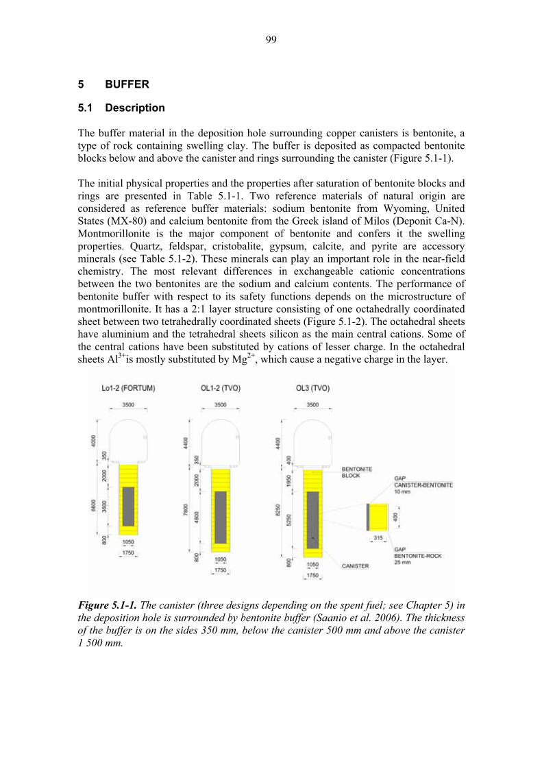
99
5 BUFFER
5.1 Description
The buffer material in the deposition hole surrounding copper canisters is bentonite, a type of rock containing swelling clay. The buffer is deposited as compacted bentonite blocks below and above the canister and rings surrounding the canister (Figure 5.1-1).
The initial physical properties and the properties after saturation of bentonite blocks and rings are presented in Table 5.1-1. Two reference materials of natural origin are considered as reference buffer materials: sodium bentonite from Wyoming, United States (MX-80) and calcium bentonite from the Greek island of Milos (Deponit Ca-N). Montmorillonite is the major component of bentonite and confers it the swelling properties. Quartz, feldspar, cristobalite, gypsum, calcite, and pyrite are accessory minerals (see Table 5.1-2). These minerals can play an important role in the near-field chemistry. The most relevant differences in exchangeable cationic concentrations between the two bentonites are the sodium and calcium contents. The performance of bentonite buffer with respect to its safety functions depends on the microstructure of montmorillonite. It has a 2:1 layer structure consisting of one octahedrally coordinated sheet between two tetrahedrally coordinated sheets (Figure 5.1-2). The octahedral sheets have aluminium and the tetrahedral sheets silicon as the main central cations. Some of the central cations have been substituted by cations of lesser charge. In the octahedral sheets Al3+is mostly substituted by Mg2+, which cause a negative charge in the layer.
Figure 5.1-1. The canister (three designs depending on the spent fuel; see Chapter 5) in the deposition hole is surrounded by bentonite buffer (Saanio et al. 2006). The thickness of the buffer is on the sides 350 mm, below the canister 500 mm and above the canister 1 500 mm.
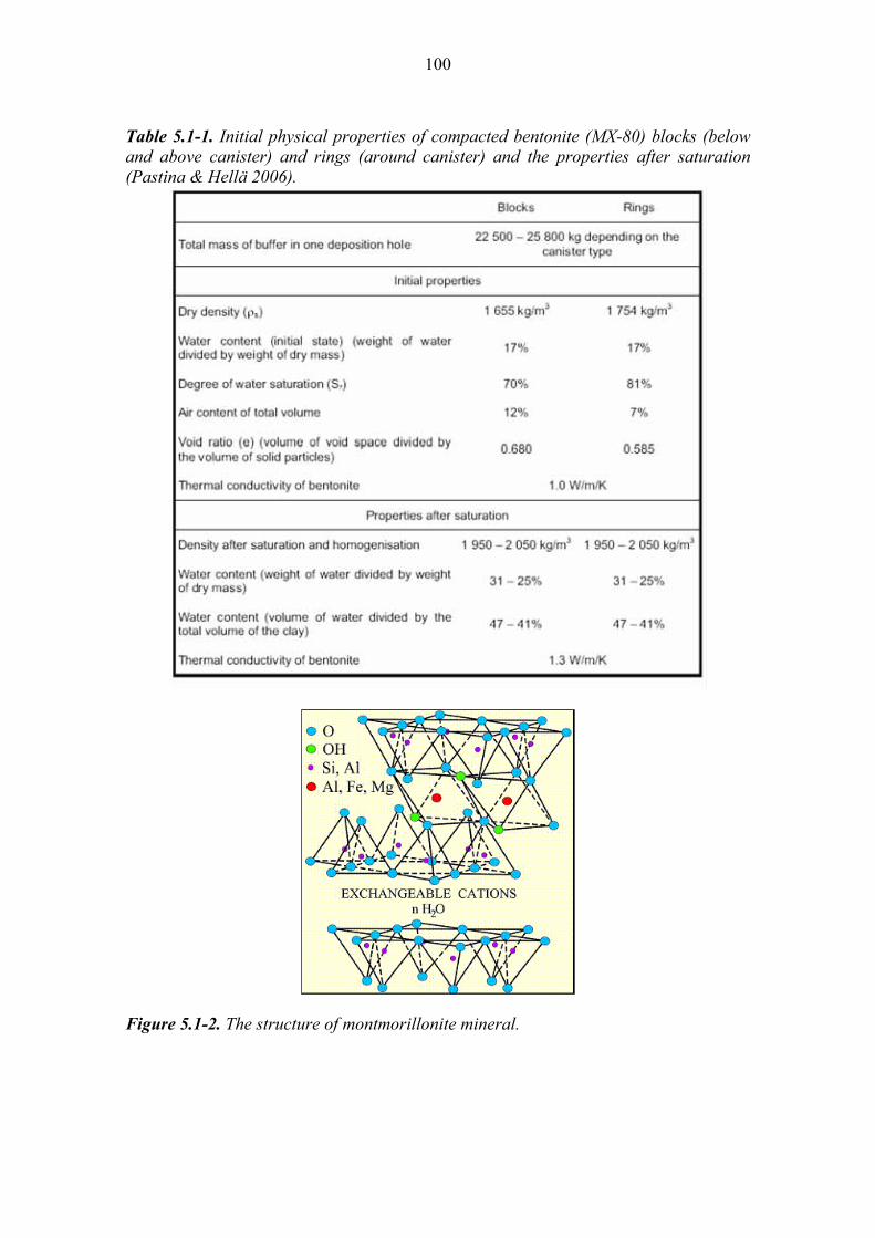
100
Table 5.1-1. Initial physical properties of compacted bentonite (MX-80) blocks (below and above canister) and rings (around canister) and the properties after saturation (Pastina & Hellä 2006).
Figure 5.1-2. The structure of montmorillonite mineral.
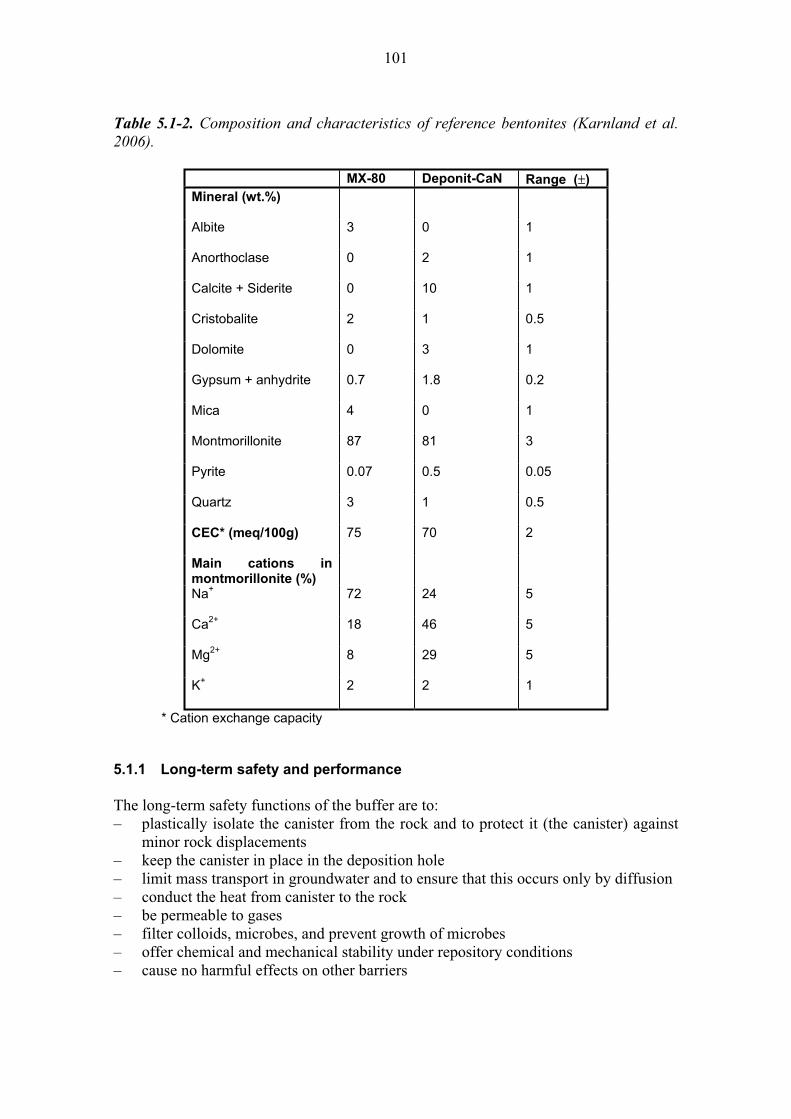
101
Table 5.1-2. Composition and characteristics of reference bentonites (Karnland et al. 2006).
MX-80 Deponit-CaN Range ( )
Mineral (wt.%)
Albite 3 0 1
Anorthoclase 0 2 1
Calcite + Siderite 0 10 1
Cristobalite 2 1 0.5
Dolomite 0 3 1
Gypsum + anhydrite 0.7 1.8 0.2
Mica 4 0 1
Montmorillonite 87 81 3
Pyrite 0.07 0.5 0.05
Quartz 3 1 0.5
CEC* (meq/100g) 75 70 2
Main cations in montmorillonite (%)
Na+ 72 24 5
Ca2+ 18 46 5
Mg2+ 8 29 5
K+ 2 2 1
* Cation exchange capacity
5.1.1 Long-term safety and performance
The long-term safety functions of the buffer are to: – plastically isolate the canister from the rock and to protect it (the canister) against
minor rock displacements – keep the canister in place in the deposition hole – limit mass transport in groundwater and to ensure that this occurs only by diffusion – conduct the heat from canister to the rock – be permeable to gases – filter colloids, microbes, and prevent growth of microbes – offer chemical and mechanical stability under repository conditions – cause no harmful effects on other barriers
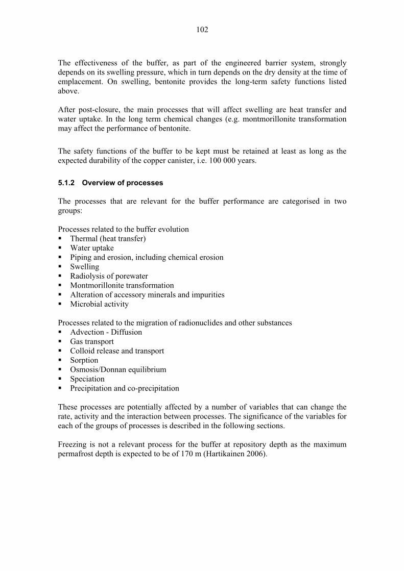
102
The effectiveness of the buffer, as part of the engineered barrier system, strongly depends on its swelling pressure, which in turn depends on the dry density at the time of emplacement. On swelling, bentonite provides the long-term safety functions listed above.
After post-closure, the main processes that will affect swelling are heat transfer and water uptake. In the long term chemical changes (e.g. montmorillonite transformation may affect the performance of bentonite.
The safety functions of the buffer to be kept must be retained at least as long as the expected durability of the copper canister, i.e. 100 000 years.
5.1.2 Overview of processes
The processes that are relevant for the buffer performance are categorised in two groups:
Processes related to the buffer evolution Thermal (heat transfer) Water uptake Piping and erosion, including chemical erosion SwellingRadiolysis of porewater Montmorillonite transformation Alteration of accessory minerals and impurities Microbial activity
Processes related to the migration of radionuclides and other substances Advection - Diffusion Gas transport Colloid release and transport SorptionOsmosis/Donnan equilibrium SpeciationPrecipitation and co-precipitation
These processes are potentially affected by a number of variables that can change the rate, activity and the interaction between processes. The significance of the variables for each of the groups of processes is described in the following sections.
Freezing is not a relevant process for the buffer at repository depth as the maximum permafrost depth is expected to be of 170 m (Hartikainen 2006).
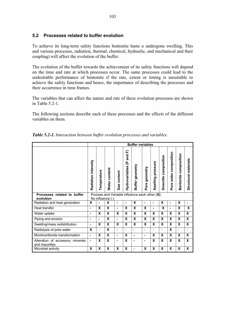
103
5.2 Processes related to buffer evolution
To achieve its long-term safety functions bentonite haste o undergone swelling. This and various processes, radiation, thermal, chemical, hydraulic, and mechanical and their coupling) will affect the evolution of the buffer.
The evolution of the buffer towards the achievement of its safety functions will depend on the time and rate at which processes occur. The same processes could lead to the undesirable performance of bentonite if the rate, extent or timing is unsuitable to achieve the safety functions and hence, the importance of describing the processes and their occurrence in time frames.
The variables that can affect the nature and rate of these evolution processes are shown in Table 5.2-1.
The following sections describe each of these processes and the effects of the different variables on them.
Table 5.2-1. Interaction between buffer evolution processes and variables.
Buffer variables
Ra
dia
tio
n in
ten
sit
y
Tem
pera
ture
Wate
r co
nte
nt
Gas c
on
ten
t
Hy
dro
va
ria
ble
s (
P a
nd
F)
Bu
ffer
geo
metr
y
Po
re g
eo
me
try
Sw
ellin
g p
res
su
re
Sm
ecti
te c
om
po
sit
ion
Po
re w
ate
r co
mp
osit
ion
Be
nto
nit
e c
om
po
sit
ion
Str
uctu
ral
mate
rials
Processes related to buffer evolution
Process and Variable influence each other (X);No influence (-)
Radiation and heat generation X - X - - X - - X - X -
Heat transfer - X X - X X X - X - X X
Water uptake - X X X X X X X X X X X
Piping and erosion - - X - X X X X X X X X
Swelling/mass redistribution - X X X X X X X X X X X
Radiolysis of pore water X - X - - - - - - X - -
Montmorillonite transformation - X X - X - - X X X X X
Alteration of accessory minerals and impurities
- X X - X - - X X X X X
Microbial activity X X X X X - X X X X X X

104
Radiation processes are of less importance for the buffer than for the canister (see detailed description in Chapter 4. The most important consequence is the heat generation and transfer. Heat transfer is treated in Section 5.2.1. Only a small fraction of the gamma and neutron radiation caused by the spent fuel can get throughout the canister wall. The gamma and neutron radiation that gets through the canister is attenuated in the buffer and in the near-field rock. The buffer geometry and the material composition influence the attenuation process. However, the radiation is of importance for chemical processes and gamma-radiolysis of porewater (Section 5.2.5).
Name: Heat transfer
Category: spent fuel, canister, buffer, backfill, plugs-seals-grout, bedrock system evolution, migration of substances
Number: 5.2.1
General description:
Heat transfer from the canister via the buffer (and backfill, see Chapter 6) to the near-field rock is ultimately dependent on the availability of the water from the rock that will cause the bentonite to swell and seal the gaps between and around the emplaced bentonite.
Water saturation of bentonite and the development of swelling pressure are important to dissipate the heat generated by the spent fuel. Wetting increases the thermal conductivity of the bentonite and the swelling of bentonite eliminates the gaps around the bentonite buffer.
Heat is generated by the radioactive decay of the spent fuel inside the canister at a time- dependent rate depending on the characteristics of spent fuel. The heat transfer outwards is governed by the thermal properties of the thermal transfer pathways. In solid materials, the heat is transferred by conduction, in liquid-filled gaps (such as those between the rock and the buffer) by conduction and to a lesser extent by convection, and in gas-filled gaps (such as those between the canister and the buffer) by radiation, conduction and, in case of wider gaps, by convection.
The most important parameter of the heat transport is the thermal conductivity, , of the different parts of the system. The thermal conductivity of bentonite is primarily dependent on its density and water saturation. The dependence of the thermal conductivity of compacted MX-80 bentonite on saturation and porosity measured by Börgesson et al. (1994) is seen in Figure 5.2-1. The thermal conductivity of water saturated MX-80 bentonite at a saturated density of 2000 kg/m3 is about 1.3 W/(m K) according to laboratory experiments. The thermal conductivity of gaps filled with water is 60 W/(m K), while that of gaps filled with gas is about 0.03 W/(m K). For the canister/bentonite gap the effective conductivity is 0.03 – 0.06 W/(m K), which takes into account also the contribution from the radiant heat transfer (Hökmark & Fälth 2003). The thermal parameters also depend slightly on the temperature as seen in Ikonen (2003a, 2005a).

105
Figure 5.2-1. Heat conductivity of laboratory–scale bentonite samples as function of water saturation (Sr) for a few values of the void ratio, e, (Börgesson et al. 1994).
The buffer geometry influences the heat transfer especially before full saturation because the heat transfer is dependent on the size of the gaps around the bentonite buffer, and they change during saturation.
Recent measurement results from the Prototype Repository Study at the Äspö Hard Rock Laboratory indicate that some of the deposition holes may be so dry that the bentonite buffer resaturates only very slowly (SKB 2006c). Differences could be seen in the temperatures between the wet and dry holes. In the dry hole a significant temperature drop was seen between the surface of the canister and the buffer while in the wet hole such a drop was not seen. Given the low rock permeability at Olkiluoto, it may be expected that many deposition holes will experience such ”dry” conditions. The heat transfer rate is thus sensitive to local conditions (e.g. water availability, gaps around the bentonite, water content of bentonite), which are not known exactly.
The temperature of the canister 5 000 years after disposal is between 11 and 6 Chigher than the natural ambient temperature at repository depth (Ikonen 2003a). As the buffer saturates (during the operational phase or in the early post-closure period, the gaps around the canister disappear causing a decrease of up 12 C in the canister temperature as the heat is transferred through the buffer to the rock. The typical temperature difference over the 350 mm-thick buffer is 15 C during the first decades if the bentonite is water saturated and some 5-7 C more, if the bentonite stays dry (SKB 2006b).
The variables (Table 5.2-1) that affect heat transfer are: Temperature – differences of temperature between the inner and outer surface of the buffer lead to heat transfer
106
Water content – modifies the heat transfer rate in bentonite Hydrovariables (P and F) – influence the heat transfer of bentonite in providing external water to the buffer Buffer geometry – the dimensions of the buffer is a variable to take into account in heat transfer calculations into and out of the buffer Pore geometry – influences the thermal properties of the buffer; voids do not conduct heat as effectively as solid particles Smectite composition – influences thermal conductivity, although the heat conductivity of different smectite types is likely to be insignificant Bentonite composition – influences thermal conductivity because of differences in the abundance of accessory mineral content Structural and stray materials – influences the rates of heat transfer from the buffer to the rock
Olkiluoto specific issues:
The heat transfer rate is sensitive to gaps between and around the bentonite and the water content of bentonite and thus dependent on the availability of the water from the rock and backfill in the tunnel. This relates in turn to the local rock permeability at Olkiluoto. The thermal properties of the rock of Olkiluoto should also be considered in the heat transfer calculations. Uncertainties:
Heat transfer from the canister via the buffer to the near field rock is in principle a simple process, which can be described with basic laws of physics. Reliable data of the thermal properties of all the materials of the near field of the repository is available (Ikonen 2003a, 2005a). Uncertainties are caused by the couplings parameters in coupled thermal-hydrological models used to describe evolution of the buffer.Time frames of relevance:
There are three important time frames. The first one and most critical time scale is the period during which the maximum temperature is reached, i.e. the first tens of years. The second one is the time it takes to achieve full water saturation. The process is estimated to take from tens of years to hundreds or even to thousands of years. After that the heat transport takes place by conduction under well-defined conditions. The third one is when after few thousand years the heat production, and thereby the heat transport through the buffer have been reduced to a few percent of their original values.Scenarios of relevance:
The heat transfer is relevant for all scenarios, but especially for the DCS. In the Main scenario the system performs as expected regardless of changes in temperature.Significance:
The heat transfer is considered to be of MEDIUM/HIGH significance especially before saturation. High significance in case the canister fails at an early stage, as temperature changes affects chemical reaction rates and transport processes.
Treatment in PA:
Heat transfer is not directly taken into account in radionuclide transport calculations.Equivalent NEA international FEP:
2.1.11 “Thermal processes and conditions (in wastes and EBS)” 2.1.13“Radiation effects (in wastes and EBS)”
107
Key references:
Börgesson, L., Fredrikson, A. & Johannesson, L.-E. 1994. Heat conductivity of buffer materials. Swedish Nuclear Fuel and Waste Management Co (SKB) Stockholm, Sweden. SKB Technical Report TR-94-29.
Hökmark. H. & Fälth, B. 2003. Thermal dimensioning of the deep repository. Influence of canister spacing, canister power, rock thermal properties, and near field design on the maximum canister surface temperature. Swedish Nuclear Fuel and Waste Management Co (SKB) Stockholm, Sweden. SKB Technical Report TR-03-09.
Ikonen, K. 2003a. Thermal analyses of spent nuclear fuel repository. Posiva Oy, Olkiluoto, Finland. Report POSIVA 2003-04.
Ikonen, K. 2005a. Thermal analyses of Repository for Spent EPR-type fuel. Posiva Oy, Olkiluoto, Finland. Report POSIVA 2005-06.
SKB 2006b. Buffer and backfill process report for the safety assessment SR-Can. Swedish Nuclear Fuel and Waste Management Co (SKB) Stockholm, Sweden. SKB Technical Report TR-06-18.
SKB 2006c. Äspö hard rock laboratory. Annual Report 2005. Swedish Nuclear Fuel and Waste Management Co (SKB), Stockholm, Sweden. SKB Technical Report TR-06-10.
Name: Water uptake
Category: spent fuel, canister, buffer, backfill, plugs-seals-grout, bedrock system evolution, migration of substances
Number: 5.2.2
General description:
To ensure the effectiveness of the buffer and diminish the consequences of thermal spalling in the deposition hole, an adequate swelling pressure should be maintained throughout all the evolution time frames. For bentonite to swell water uptake needs to be guaranteed after emplacement.
The wetting time of the buffer depends strongly on the hydraulic conductivity of the rock surrounding the deposition hole, i.e. on the availability of water (Pastina & Hellä 2006, SKB 2006b). The most important driving forces for bentonite saturation process will be the negative capillary pressure (suction) drawing water into the bentonite and the surrounding groundwater pressure.
Water transport in the buffer under unsaturated conditions is a complex process influenced by parameters of the buffer, backfill and the near-field rock.
108
Advection is of importance soon after the emplacement of the bentonite when the groundwater saturates the buffer and backfill from outside. The flowing groundwater entering the deposition hole may transport solutes into bentonite, redistribute solutes in the bentonite porewater, dissolve bentonite components, and release bentonite in colloidal form. These depend on the flow rate and chemistry of the groundwater entering the deposition hole (see Process 5.2.3).
The bentonite hydraulic conductivity is a function of the composition of the buffer, the void ratio and the degree of saturation (i.e. initial density), the ion concentration in the pore water and the temperature. Temperature increase decreases the viscosity of water, which means that the hydraulic conductivity increases with increasing temperature.
Many laboratory measurements on the hydraulic conductivity of different bentonites have been done and the effects of temperature, salinity and density have been taken into account (e.g. SKB 2004b). Laboratory and field measurements on the saturation and water movement under a temperature field have provided data for modelling the process (e.g. Hökmark et al. 2007).
High salinity of the saturating groundwater limits the swelling of the bentonite grains resulting in larger pores in the bentonite. The hydraulic conductivity increases with increasing pore size.
Hökmark (2004) and Börgesson et al. (2006) modelled water saturation of backfill and buffer using different assumptions for the saturation routes and material parameters. The calculations show that the time of buffer wetting depends strongly on the hydraulic conductivity of the rock surrounding the deposition hole. If the hydraulic conductivity is relatively high (exceeding 10–12 m/s) Börgesson & Hernelind (1999) and Börgesson et al. (2006) showed that the buffer will be saturated within a period of a few to some hundreds of years. Hökmark (2004) suggested that the bentonite behaviour will exert control on the hydration rate for deposition holes with a total inflow rate of 3 L/day or more and that the near-field hydrology will control for holes with inflow of less than 1 L/day. A rock with low hydraulic conductivity yielded very long times to saturation (up to 2 000 years) because the water will be supplied only through the backfill. Lempinen (2006a,b,c,d) has also modelled the buffer saturation process and found that, depending on the hydraulic boundary condition, the duration of the saturation period could extend from about 30 to 40 years up to hundreds of years.
The variables (Table 5.2-1) that are significant for water uptake are:
Temperature – the availability and behaviour of water in bentonite will depend on this variable. Water content –the initial water content in bentonite will control the wetting time. Gas content – free gas in the buffer may reduce the saturation rate Hydrovariables (P and F) – Pressure and flow conditions may control the availability of water thus controlling water uptake Buffer geometry – influences the hydraulic conductivity of the buffer Pore geometry – influences the hydraulic conductivity and gas permeability

109
Swelling pressure (stress state) – affects the pore geometry and distribution, hence affecting also hydraulic conductivity Smectite composition – affects pore geometry, swelling pressure and hydraulic conductivityPore water composition – the ionic concentration in pore water may affect the hydraulic conductivity of the buffer Bentonite composition – see above smectite and pore water Structural and stray materials – the effectiveness of these materials as providing dry or wet conditions in the near field may influence the water uptake of the buffer
Olkiluoto specific issues:
The wetting time of the buffer depends strongly on the hydraulic conductivity of the rock surrounding each deposition hole, i.e. on the availability of the water. The salinity of the groundwater also affects the hydraulic conductivity of the buffer and wetting time. Uncertainties:
Water transport in the buffer under unsaturated conditions and temperature gradient is a complex process that is determined by many coupled sub-processes and influenced by parameters of the buffer, backfill and the near-field rock. Much experimental data is available on MX-80, but less on the other bentonite types. There is large uncertainty and variability in the hydraulic parameters of the near field rock and its role may be decisive for the saturation of the buffer in each deposition hole.Time frames of relevance:
The process continues until the buffer has been saturated. The expected saturation time varies typically from a few years up to hundreds of years. It could last even thousands of years if the groundwater flow into the deposition hole is very low (e.g. Lempinen 2006a,b,c,d). Scenarios of relevance: The process is relevant for all scenarios, and especially for AD-II, where it is assumed the initial conditions of bentonite deviate from the expected.Significance:
The uptake of water in the buffer is of HIGH significance because it will affect the re-equilibrium of the near field and the state of the buffer. Disturbance to the buffer may provide potential fast flow-paths for substances able to damage the canister and for radionuclides once the canister has been breached. Treatment in PA:
The water uptake and transport under unsaturated conditions is not taken into account in radionuclide transport calculations. This process is treated is supplementary reports by THM modelling using different boundary conditions to determine the saturation time and the mechanical and chemical consequences of the saturation. Equivalent NEA international FEP:
2.1.08 “Hydraulic/hydrogeological processes and conditions (in wastes and EBS)” Key references:
Börgesson, L. & Hernelind, J. 1999. Coupled thermo-hydro-mechanical calculations of the water saturation phase of a KBS-3 deposition hole - Influence of hydraulic rock properties on the water saturation phase. Swedish Nuclear Fuel and Waste Management Co. (SKB), Stockholm, Sweden. SKB Technical Report TR-99-41.

110
Börgesson, L., Fälth, B. & Hernelind, J. 2006. Water saturation phase of the buffer and backfill in the KBS-3V concept. Special emphasis given to the influence of the backfill on the wetting of the buffer. Swedish Nuclear Fuel and Waste Management Co. (SKB), Stockholm, Sweden. SKB Technical Report TR-06-14.
Hökmark, H. 2004. Hydration of the bentonite buffer in a KBS-3 repository. Applied Clay Science, 26, 219–233.
Hökmark, H., Ledesma, A., Lassabatere, T., Fälth, B., Börgesson, L., Robinet, J.C., Sellali, N. & Sémété P. 2007. Modelling heat and moisture transport in the ANDRA/SKB temperature buffer test. Physics and Chemistry of the Earth 32, 753–766.
Lempinen, A. 2006a. Freefem++ in THM Analyses of KBS-3V Deposition Hole. Posiva Oy, Olkiluoto, Finland. Posiva Working Report 2006-76.
Lempinen, A. 2006b. Swelling of the Buffer of KBS-3V Deposition Hole. Posiva Oy, Olkiluoto, Finland. Posiva Working Report 2006-77.
Lempinen, A. 2006c. Simulations for EBS Task Force BMT 1. Posiva Oy, Olkiluoto, Finland. Posiva Working Report 2006-78.
Lempinen, A. 2006d. THM Model Parameters for Compacted Bentonite. Posiva Oy, Olkiluoto, Finland. Posiva Working Report 2006-79.
Pastina, B. & Hellä, P. (Eds.) 2006. Expected evolution of a spent nuclear fuel repository at Olkiluoto. Posiva Oy, Olkiluoto, Finland. Report POSIVA 2006-05.
SKB 2004b. Interim data report for the safety assessment SR-Can. Swedish Nuclear Fuel and Waste Management Co (SKB) Stockholm, Sweden. Report R-04-34.
SKB 2006b. Buffer and backfill process report for the safety assessment SR-Can. Swedish Nuclear Fuel and Waste Management Co (SKB) Stockholm, Sweden. SKB Technical Report TR-06-18.
Name: Piping and erosion, including chemical erosion
Category: spent fuel, canister, buffer, backfill, plugs-seals-grout, bedrock system evolution, migration of substances
Number: 5.2.3
General description:
Piping/erosion is the possible consequence of water uptake after the emplacement of bentonite if a threshold in advection is exceeded. Erosion may be due also to chemical effects (see below).
Bentonite can be eroded by flowing groundwater, through a process called piping
111
erosion. Mechanical erosion could take place during the operational phase due to high groundwater pressure gradients in the open excavations. Hydraulically conductive channels (“pipes”) are then formed in the bentonite due to flowing water and inadequate compaction. Mechanical erosion may result in a reduction in the density of the buffer, which decreases the swelling pressure, and increases the accessibility to the canister surface to sulphides in the groundwater, which in turn increases the copper corrosion rate and/or a release of clay colloids, which could potentially transport radionuclides in case of an accidental release (Pastina & Hellä 2006).
The risk for mechanical erosion is generally greatest before full saturation (see 5.2.2).
In laboratory experiments measuring the erosion of bentonite particles from unsaturated, compacted bentonite in contact with an artificial granite fracture, an erosion rate of ~0.0125 g/day was the largest determined. The bentonite (Gyeongju bentonite, 70% montmorillonite by weight) was compacted to 1.6 g/cm3. The solution flow velocity was 1.5 x 10⁻⁵ m/s and the solution composition was 0.01 M NaClO4 at pH=8.5. The eluted bentonite particles were ~0.5 micron in diameter on average. The observed erosion rates, as well as eluted particle sizes, were flow rate dependent suggesting mechanical erosion effects were predominant (Baik et al. 2007).
Börgesson & Sandén (2006) and SKB (2006) have summarized the present knowledge of the processes. Water inflow into the deposition hole and the deposition tunnel will take place mainly through fractures and will contribute to the wetting of the buffer and backfill. However, if the inflow is localized to fractures that carry more water than the swelling buffer or backfill can adsorb, there will be increased water pressure in the fracture acting on the filling material. The swelling bentonite forms a gel in the beginning of the wetting. This gel is usually too soft to stop the water inflow. The results may be piping in the bentonite, formation of a channel and a continuing water flow and erosion of bentonite slurry. The piping and the erosion are two different processes closely linked.
Piping may take place and the pipes remain open if 1) the water pressure pwf in the fracture is higher than the sum of the counteracting total pressure from the clay and the shear resistance of the clay, 2) the hydraulic conductivity of the clay is so low that water flow into the clay is sufficiently low to keep the water pressure at pwf and keep a high hydraulic gradient in the clay and 3) there is a downstream location available for the removal of eroded materials in order for the pipe to stay open.
Erosion will take place if the drag force on the clay particle from the water movement is higher than the sum of the friction and attraction forces between the particle and the clay structure.
Once the clay swells, it will reduce the size of the channel with time, but on the other hand the erosion will counteract and tear off bentonite particles and thus increase the size of the channel. There is thus a competition between swelling clay and eroding clay. If the inflow and the increase in water pressure are slow the pipe may seal before water pressure equilibrium has been reached.

112
Piping and erosion have been studied in conjunction with the KBS-3H concept and in the Baclo project (Börgesson et al. 2005). The piping tests done in laboratory experiments in three different scales show that the bentonite is very sensitive to piping and erosion and that it may take a considerable time until it heals if the inflow in one spot from a fracture is strong and the build-up of water pressure in the fracture is fast (Börgesson & Sandén 2006). The piping phenomena have been observed also in two field tests in Äspö HRL (LOT and the full scale test LASGIT). In LASGIT the flow rate was about 0.1 L/min, which yielded an erosion rate of about 1 g/L that remained for almost 2 months before the leakage was stopped in an artificial way (Börgesson & Sandén 2006).
Chemical erosion of bentonite relates to the spontaneous formation of colloids when dilute groundwater contacts bentonite. The concentration of sodium or calcium in groundwater has to be at least 0.1 M or 0.001 M respectively in order to neglect colloid formation (SKB 2006b). Chemical erosion of bentonite is only possible in the scenario where diluted glacial meltwater penetrates to repository depths.
The variables (Table 5.2-1) that are significant for the piping/erosion are:
Water content – the initial water content in the bentonite and that water, which bentonite is able to admit during swelling will control the occurrence of the process and rate of erosion Hydrovariables (P and F) – Pressure and flow conditions may define the importance of piping/erosion rates Buffer geometry – influences the hydraulic conductivity of the buffer Pore geometry – influences the hydraulic conductivity Swelling pressure (stress state) – affects the pore geometry and distribution, hence affecting also hydraulic conductivity and piping/erosion Smectite composition – affects pore geometry, swelling pressure and hydraulic conductivityPore water composition – the ionic concentration in pore water may affect the hydraulic conductivity of the buffer and later on chemical erosion Bentonite composition – see above smectite and pore water Structural and stray materials – the effectiveness of these materials as providing dry or wet conditions in the near field may influence the saturation of the buffer and hence the occurrence or not of piping/erosion
Olkiluoto specific issues:
The hydraulic properties of the rock, such as flow rate, water pressure and also water chemistry influence the process. Uncertainties:
Piping, erosion and subsequent sealing is a complicated process with many components, which are highly dependent on the hydraulic behaviour of the rock. Considerable uncertainties exist regarding both the influence of the rock hydrology and the ability of the buffer to resist these processes. The knowledge of when piping and erosion may occur and the consequences are currently not well known today.
113
However, it is highly uncertain whether dilute glacial meltwater will reach repository depths because of water-rock interaction reactions (e.g. Luukkonen 2006). Time frames of relevance:
The processes of piping and erosion in bentonite are most relevant in the initial period of the repository before full water saturation and pore water pressure equilibrium has been reached. The consequences may be relevant for longer periods if bentonite does not reseal the deposition holes.
Chemical erosion due to the penetration of dilute meltwater is only relevant after the end of the first ice-sheet at 70 000 years AP (see Chapter 5 in Pastina & Hellä 2006). Scenarios of relevance:
The process is relevant for all scenarios, but especially for AD-I (rock-shear, earthquake) and AD-II (disruptive initial or late events affecting bentonite).Treatment in PA: The occurrence of damaged bentonite due to the process is treated in selecting the parameters used for radionuclides transport (kd, diffusion) in the buffer. The process itself is not modelled in radionuclide transport calculations but in supplementary reports. Significance:
Piping/erosion are considered to be of MEDIUM significance as these processes are only likely to occur until the saturation of the buffer has been reached (late after 70 000 years in case of chemical erosion). The circumstances under which the process may occur would require a very low quality control in the selection of the deposition holes.Equivalent NEA international FEP:
2.1.04 “Buffer/backfill materials and characteristics” 2.1.08 “Hydraulic/hydrogeological process and conditions (in wastes and EBS)” Key references:
Baik, M.-H., Cho, W.-J. & Hahn, P.-S. 2007. Erosion of bentonite particles at the interface of a compacted bentonite and fractured granite. Eng. Geol. 91, 229-239.
Börgesson, L., Sandén, T., Fälth, B., Åkesson, M. & Lindgren, E. 2005. Studies of buffer behaviour in KBS-3H concept. Work during 2002–2004. Swedish Nuclear Fuel and Waste Management Co (SKB) Stockholm, Sweden. SKB R-05-50.
Börgesson, L. & Sandén, T. 2006. Piping and erosion in buffer and backfill materials. Current knowledge. Swedish Nuclear Fuel and Waste Management Co (SKB) Stockholm, Sweden. Report R-66-80.
Luukkonen, A. 2006. Estimations of durability of fracture minerals buffers in the Olkiluoto bedrock. Posiva Oy, Olkiluoto, Finland. Posiva Working Report 2006-107.
Pastina, B. & Hellä, P. (Eds.) 2006. Expected evolution of a spent nuclear fuel repository at Olkiluoto. Posiva Oy, Olkiluoto, Finland. Report POSIVA 2006-05.
SKB 2006b. Buffer and backfill process report for the safety assessment SR-Can. Swedish Nuclear Fuel and Waste Management Co (SKB) Stockholm, Sweden. SKB Technical Report TR-06-18.

114
Name: Swelling/mass redistribution
Category: spent fuel, canister, buffer, backfill, plugs-seals-grout, bedrock system evolution, migration of substances
Number: 5.2.4
General description:
To ensure the effectiveness of the buffer, an adequate swelling pressure should be maintained throughout all the evolution time frames.
Swelling pressure is the result of several components: the stored elastic energy of compressed particles, the osmotic pressure between electrical double layers at the external surfaces of the stacks of the montmorillonite flakes, and the hydration of the interlamellar cations and surfaces of smectite/montmorillonite. The former and latter components dominate at high bulk densities, while the second one controls swelling pressure at low densities (Pusch 2002).
Figure 5.2-1 shows the dependence of the swelling pressure on the clay density and salt concentration in solutions of NaCl (for MX-80) and CaCl2 (for Deponit CA-N) (SKB 2006b). The figure shows that the swelling pressure increases with increasing density and decreasing salt concentration. At high density, the effect of salt concentration is relatively small. The thickness of the electrical double layer on the external surfaces of the montmorillonite stacks, which determines the swelling pressure at low density, depends on the concentration of salt in the solution, while the hydration of the interlamellar cations, which controls the swelling pressure at high density, is not strongly affected by the salt concentration. As the buffer has a high density, salinity differences in groundwater expected during the evolution time periods will not affect significantly its swelling pressure.
Figure 5.2-1 also shows the difference in swelling pressure between sodium (MX-80) and calcium (Deponit Ca-N) bentonite. The main difference is that the former sorbs a larger amount of interlamellar water than the latter especially at low dry densities. However, at saturated densities over 1 800 kg/m3 (dry density > 1 250 kg/m3), the swelling pressures of sodium and calcium bentonites are approximately equal (SKB 2006b).
Karnland & Birgersson (2006) reviewed models predicting the swelling pressure of bentonite. The authors concluded that there was no general consensus concerning the detailed mechanisms of the forces responsible for swelling and the way they may be determined or calculated. Empirical models have, however, been useful for the evaluation of the effects of the density and salinity on the swelling pressure (Hedin 2004).
Current estimates indicate that it may take from a few years to a few thousand years for the bentonite to reach its swelling pressure, depending mainly on the hydraulic properties of the rock (see also Section 5.2.2; Börgesson & Hernelind 1999).
115
A change in the temperature of the buffer will cause water, particles and pore gas in the buffer to expand. However, the pressure increase is counteracted by drainage of the water through the rock and backfill (SKB 2006b).
At the interface between the buffer and backfill, the buffer exerts a swelling pressure against the backfill, and vice versa. In the Buffer Mass Test in Stripa, the buffer had expanded 5-7 cm into the backfill in the well-saturated holes (Pusch et al. 1985). Börgesson & Hernelind (1999) modelled the displacement of the interface between the buffer and backfill and the displacement of the canister during the wetting of the buffer for a rock with one fracture intersecting the centre of the deposition hole. The results show that the buffer/backfill interface heaves about 8 cm. The upwards swelling also affects the canister before full saturation of the buffer. The canister/buffer interface at first heaves 5–10 mm due to the uneven wetting of the buffer but settles at the completion of the wetting and ultimately reaches its initial position. The results also show that after full saturation and completed consolidation the density and swelling pressure are reduced above the canister but not along the sides of the canister.
Mass redistribution may take place if bentonite intrudes into fractures in the rock occur and/or if bentonite is eroded. The intrusion of bentonite into fractures is very limited due to the small aperture of the fractures and the shear resistance caused by the friction between the bentonite and the fracture surface. If there is no loss in bentonite due to erosion the effect is positive since it implies a sealing of the fracture. Problems arise if the gel that forms at the outer part of the penetrated bentonite is eroded and carried away by the groundwater. Since the penetration depth is proportional to the fracture width a rule of thumb may be used that states that the penetration is limited to 25 times the fracture width (SKB 2006b).
The issue of non-uniform wetting of the buffer is a realistic possibility in fractured rock wherein the fracture patterns will vary from one deposition hole to another. Consequently, uneven swelling pressure on the canister surface may cause localized mechanical stresses on the canister, resulting in movement, tilting or deformation of the canister. The time perspective associated with these phenomena can be up to hundreds of years. After full saturation the swelling pressure is rather homogeneous. The water pressure is added to the swelling pressure to give the total pressure. During glaciation the water pressure may be substantially higher at least in case of warm-based glaciers.
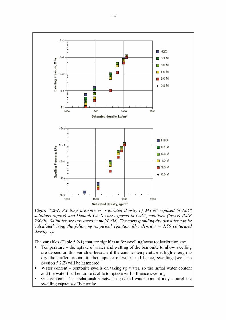
116
Figure 5.2-1. Swelling pressure vs. saturated density of MX-80 exposed to NaCl solutions (upper) and Deponit CA-N clay exposed to CaCl2 solutions (lower) (SKB 2006b). Salinities are expressed in mol/L (M). The corresponding dry densities can be calculated using the following empirical equation (dry density) = 1.56 (saturated density–1).
The variables (Table 5.2-1) that are significant for swelling/mass redistribution are: Temperature – the uptake of water and wetting of the bentonite to allow swelling are depend on this variable, because if the canister temperature is high enough to dry the buffer around it, then uptake of water and hence, swelling (see also Section 5.2.2) will be hampered Water content – bentonite swells on taking up water, so the initial water content and the water that bentonite is able to uptake will influence swelling Gas content – The relationship between gas and water content may control the swelling capacity of bentonite

117
Hydrovariables (P and F) – Pressure and flow conditions influence the availability of water and hence the swelling of bentonite Buffer geometry – influences the hydraulic conductivity and hence the swelling of the buffer Pore geometry – influences the hydraulic conductivity and hence the uptake of water and swelling capability Swelling pressure – influence swellingSmectite composition – swelling clays are all smectites, their composition determines the swelling capability Porewater composition – the ionic concentration in pore water may affect the hydraulic conductivity of the buffer and hence its swelling The effectiveness of structural materials to provide dry or wet conditions in the near field influences the availability of water, and hence the swelling of the buffer
Olkiluoto specific issues:
The saturation time of the buffer depends strongly on the hydraulic conductivity of the rock surrounding each deposition hole, i.e. on the availability of the water. Uncertainties:
The swelling pressure process and the swelling properties at water saturation are well known and can be modelled with sufficient accuracy. The unsaturated bentonite is complicated to model, and the models are incomplete.
There is great uncertainty and variability in the hydraulic parameters of the near field rock and its role is decisive for the saturation of the buffer.Time frames of relevance:
The process is relevant at all timescales. Scenarios of relevance:
Swelling/mass redistribution is relevant in all scenarios. Treatment in PA:
Swelling/mass redistribution is not taken into account in the calculations for performance assessment, but in supplementary calculations to estimate the behaviour of the system. Deviations from optimal conditions are taken into account by modifying the parameters (e.g. Kd) needed in radionuclide transport calculations. Significance: Swelling of the buffer is of HIGH significance because it is fundamental to achieve the designed safety functions. Equivalent NEA international FEP:
2.1.04 “Buffer/backfill materials and characteristics” 2.1.07 “Mechanical processes and conditions (in wastes and EBS)” 2.1.08 “Hydraulic/hydrogeological processes and conditions (in wastes and EBS)” Key references:
Börgesson, L. & Hernelind, J. 1999. Coupled thermo-hydro-mechanical calculations of the water saturation phase of a KBS-3 deposition hole - Influence of hydraulic rock properties on the water saturation phase. Swedish Nuclear Fuel and Waste Management Co. (SKB), Stockholm, Sweden. SKB TR-99-41.
Hedin, A. 2004. Integrated near-field evolution model for a KBS-3 repository. Swedish Nuclear Fuel and Waste Management Co. (SKB), Stockholm, Sweden. SKB Report R-04-36.
118
Karnland, O. & Birgersson, M. 2006. Montmorillonite stability. With special respect to KBS-3 conditions. Swedish Nuclear Fuel and Waste Management Co. (SKB), Stockholm, Sweden. SKB TR-06-11.
Pusch, R., Börgesson, L. & Ramqvist, G. 1985. Final Report of the Buffert Mass Test – Volume II: Test results. Swedish Nuclear Fuel and Waste Management Co. (SKB). Stripa Project TR 85-12.
Pusch, R. 2002. The Buffer and Backfill Handbook. Part 1: Definitions, basic relationships, and laboratory methods. Swedish Nuclear Fuel and Waste Management Co. (SKB). SKB Technical Report TR-02-20.
SKB 2006b. Buffer and backfill process report for the safety assessment SR-Can. Swedish Nuclear Fuel and Waste Management Co (SKB) Stockholm, Sweden. SKB Technical Report TR-06-18.
Name: Radiolysis of porewater
Category: spent fuel, canister, buffer, backfill, plugs-seals-grout, bedrock system evolution, migration of substances
Number: 5.2.5
General description:
As long as the canister is intact only gamma and neutron radiations penetrate the canister. The gamma radiation causes the excitation, or ionisation of water molecules followed by breaking of their chemical bonds (radiolysis) producing primarily free electrons, OH-radicals and hydrogen atoms. Beside these, the stable molecular species O2, H2O2 and H2 are also formed (SKB 2006a). Oxygen is consumed rapidly by oxidation with the copper canister and the accessory minerals of bentonite while hydrogen may be transported away. The canister wall thickness is, however, sufficient so that the effect of gamma-radiolysis on the outside is negligible.
In the case of a failed canister, radionuclides released and sorbed in the buffer could affect the porewater of the buffer by alpha, beta, and gamma radiation. Alpha particles have high LTE (Linear Transfer Energy) and a very short range. They can cause radiolysis of a thin layer of water (~35 µm) and produce mainly the molecular radiolysis products H2O2 and H2 (SKB 2006a). The oxygen is consumed rapidly by oxidation reactions with copper in the copper canister and the accessory minerals of bentonite. The amount of hydrogen is much less than that produced by the corrosion of the iron insert of the canister and it will be transported away (see Section 6.4.3).
The variables (Table 5.2-1) that are significant for the radiolysis of porewater are:
Radiation intensity – the rate of formation of radiolytic products is dependent on this variable Water content – the extent of radiolysis of porewater will depend on the total content of water
119
Porewater composition – significant for the formation of radiolytic products Olkiluoto specific issues:
No site-specific issues. Uncertainties:
No uncertainties regarding the understanding of the processes. Time frames of relevance:
The process is relevant for all time frames. Scenarios of relevance:
The process is relevant for all scenarios, and especially for the defective canister scenarios (DCS). Treatment in PA:
The process is not taken explicitly in PA, but in side reports. Significance:
This process is of LOW significance because it is unlikely to have any direct or important impact on either the performance of the near-field barriers or the transport of radionuclides through them.Equivalent NEA international FEP:
2.1.13 “Radiation effects (in wastes and EBS)” Key references:
SKB 2006a. Fuel and canister process report for the safety assessment SR-Can. Swedish Nuclear Fuel and Waste Management Co (SKB) Stockholm, Sweden. SKB Technical Report TR-06-22.
Name: Montmorillonite transformation
Category: spent fuel, canister, buffer, backfill, plugs-seals-grout, bedrock system evolution, migration of substances
Number: 5.2.6
General description:
Mineral transformations (e.g. montmorillonite) can affect the desired properties of bentonite, for example increasing hydraulic conductivity, increasing mechanical strength and reducing swelling pressure and capacity.
Karnland & Birgersson (2006) have presented an overview of montmorillonite stability with respect to KBS-3 conditions. The most important processes affecting montmorillonite stability are:
Illitisation:
Illitisation is a well-documented transformation of clay minerals in several different geological environments, and has been reproduced under laboratory conditions. Illite has a crystalline structure that is similar to that of montmorillonite but with a higher lattice charge due to partial replacement of tetrahedral silica by aluminium and with the interlamellar space collapsed through replacement of the hydrated cations by non-hydrated potassium:
120
Ca2+/Na+-montmorillonite + K+ + (Al3+) Illite + Silica + Ca2+/Na+
Illite material may be illustrated by the mineralogical composition of a natural illite from Montana, US, with less than 10% expandable layers (Hower & Mowatt 1966):
(Si6.81Al1.19) (Al3.25Fe0.14 Mg0.59) O20(OH) Ca0.1Na 0.02K1.53
tetrahedral octahedral tetrahedral exchangeable cations +octahedral
which can be compared with the composition of the montmorillonite in the MX-80 bentonite (SKB 2006b):
(Si7.86Al0.14) (Al3.11 Fe3+0.37 Mg0.50) O20(OH)4 Na0.47Ca0.05Mg 0.02K0.01
tetrahedral octahedral tetrahedral exchangeable cations +octahedral
The main difference is that illite has approximately one unit charge higher from tetrahedral layers, and potassium is the main charge compensating cation.
Illitization is kinetically controlled and dependent on temperature. Kinetic models have been developed for calculating the degree of smectite-to-illite transformation. The model by Huang et al. (1993) has been considered as the most generally applicable.
In order to calculate the illitisation using the Huang model, the temperature in the buffer and the potassium concentration in the pore water have to be known. Results from calculations are shown in Figure 5.2-2 (Karnland & Birgesson 2006). The maximum temperature in the repository is calculated to be below 50 °C after 1 000 years, below 25 °C after 10 000 years and about the initial temperature (i.e. 8-10 °C) after 100 000 years. The [K+] in the Äspö groundwater below 2 mM is comparable with the concentration in Olkiluoto below 1 mM (King et al. 2002). The calculated montmorillonite illitisation is insignificant for the expected repository conditions.
Chloritization:
Chlorites have the same basic structure as montmorillonite, but the layer charge is normally close to 2 unit charges per O20(OH)4. The layer charge is balanced by positively charged, octahedrally coordinated hydroxide sheets of Mg, Fe and Al. The kinetic rates for the transformation of montmorillonite to chlorite are very low, and only significant at high temperatures (>200 C) and high pH (e.g. Karnland & Birgersson 2006).
Silica dissolution due to high pH will treated in connection with the performance of cementitious components in plugs, seals, and grout (see Chapter 7). It is not generally an issue within the deposition hole.

121
Figure 5.2-2. Remaining montmorillonite part for different temperatures in a hydrothermal system with [K+] = 0.002 mole/liter (80 ppm) according to the Huang et al. (1993) kinetic model and laboratory determined constants (Ea = 28 kcal/mole and A = 8.1·104 s-1 mole–1) (Karnland & Birgersson 2006).
Transformation due to iron reactions:
Dissolved iron (as a corrosion product of the cast iron insert) could replace the aluminium in the octahedral layer of montmorillonite, transforming it into other clay minerals (odinite, cronstedtite, and/or berthierine), which are precursors of the final transformation into chlorite (Arcos et al. 2006). The status of current knowledge of iron/bentonite interaction and its potential impact on bentonite properties has been reported in Marcos (2003), Johnson et al. (2005b), Carlson et al. (2006) and Wersin et al. (2008). Stucki et al. (2000) found a minor reduction of the swelling pressure of iron-rich Na-montmorillonite when structural iron is reduced.
Wersin et al. (2008) studied the impact of iron/bentonite interaction on swelling pressure in case of an external source of Fe (II) as it is the Fe(II) derive from corrosion of a steel supercontainer in a KBS-3H repository. They showed that the adverse effects on the swelling buffer material are spatially limited to the outermost few cm near the buffer-supercontainer-rock interface for very long periods (Wersin et al. 2008).
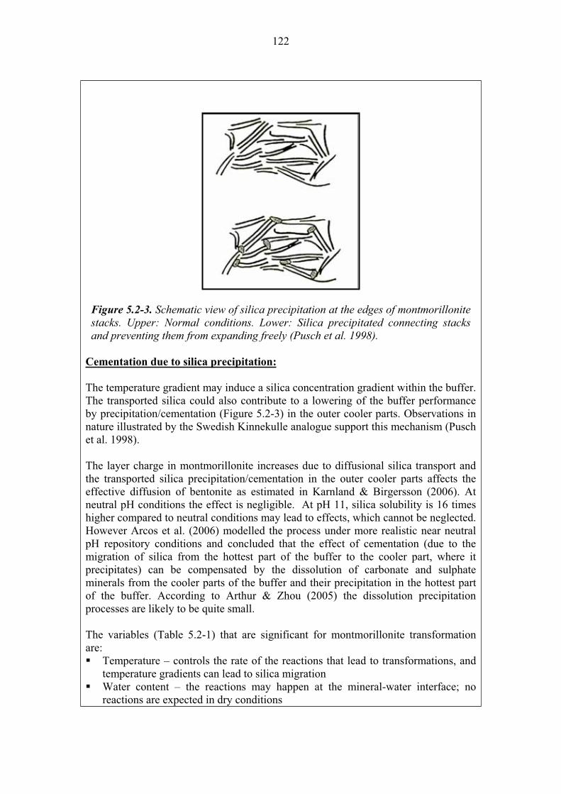
122
Cementation due to silica precipitation:
The temperature gradient may induce a silica concentration gradient within the buffer. The transported silica could also contribute to a lowering of the buffer performance by precipitation/cementation (Figure 5.2-3) in the outer cooler parts. Observations in nature illustrated by the Swedish Kinnekulle analogue support this mechanism (Pusch et al. 1998).
The layer charge in montmorillonite increases due to diffusional silica transport and the transported silica precipitation/cementation in the outer cooler parts affects the effective diffusion of bentonite as estimated in Karnland & Birgersson (2006). At neutral pH conditions the effect is negligible. At pH 11, silica solubility is 16 times higher compared to neutral conditions may lead to effects, which cannot be neglected. However Arcos et al. (2006) modelled the process under more realistic near neutral pH repository conditions and concluded that the effect of cementation (due to the migration of silica from the hottest part of the buffer to the cooler part, where it precipitates) can be compensated by the dissolution of carbonate and sulphate minerals from the cooler parts of the buffer and their precipitation in the hottest part of the buffer. According to Arthur & Zhou (2005) the dissolution precipitation processes are likely to be quite small.
The variables (Table 5.2-1) that are significant for montmorillonite transformation are:
Temperature – controls the rate of the reactions that lead to transformations, and temperature gradients can lead to silica migration Water content – the reactions may happen at the mineral-water interface; no reactions are expected in dry conditions
Figure 5.2-3. Schematic view of silica precipitation at the edges of montmorillonite stacks. Upper: Normal conditions. Lower: Silica precipitated connecting stacks and preventing them from expanding freely (Pusch et al. 1998).
123
Hydrovariables (P and F) – Pressure and flow conditions influence the availability of water and hence the occurrence of reactions Swelling pressure – influences the availability of chemical components affecting bentoniteSmectite composition – significant for all chemical reactions in the buffer Porewater composition – significant for all chemical reactions in the buffer Bentonite composition – significant for all chemical reactions The effectiveness of structural materials to provide dry or wet conditions in the near field may influence the availability and the composition of water reacting within the buffer
Olkiluoto specific issues: The chemical composition of the groundwater (pH, K+,dissolved Fe) may affect the montmorillonite transformation. Uncertainties:
The effect of iron from corrosion of the cast iron insert could result in changes in the bentonite. The extent and nature of such changes, as well as their effects on the bentonite properties are not well known currently. The extent of mineral redistribution due to cementation needs to be correlated with change in physical, mechanical and rheological properties of the buffer. Time frames of relevance: Montmorillonite transformation in the buffer due to thermal effects is most important during the operational phase and the early post-closure phase for approximately 1 000 years after the first canister emplacement, when the temperatures are highest. Other slow transformations (dissolved iron effects) are relevant for all time frames. Scenarios of relevance: All the assessment scenarios, and especially the defective canister scenario DCS. Treatment in PA:
Montmorillonite transformations are taken into account only in supplementary reports. The calculation cases in radionuclide transport take into account the possible changes in the properties of montmorillonite modifying the input parameters of the buffer.Significance: Montmorillonite transformation is considered to be of MEDIUM
significance because montmorillonite is the major component of bentonite controlling the performance of the buffer, ensuring that the buffer provides a suitable barrier to radionuclide migration once the canister is breached.Equivalent NEA international FEP:
2.1.09 “Chemical/geochemical processes and conditions (in wastes and EBS)” Key references:
Arcos, D., Grandia, F. & Domènech, C. 2006. Geochemical evolution of the near field of a KBS-3 repository. Swedish Nuclear Fuel and Waste Management Co. (SKB), Stockholm, Sweden. SKB Technical Report TR-06-16.
Arthur, R. & Zhou, W. 2005. Reactive-Transport Model of Buffer Cementation. Swedish Nuclear Power Inspectorate (SKI), Stockholm, Sweden. SKI Report 2005:59.
Carlson, L., Karnland O., Olsson S., Rance, A. & Smart, N. 2006. Experimental studies on the interactions between anaerobically corroding iron and bentonite. Posiva Oy, Olkiluoto, Finland. Posiva Working Report 2006-60.

124
Hower, J. & Mowatt, T.C. 1966. The mineralogy of illites and mixed-layer illite/montmorillonites. American Mineralogist 51, 825–854.
Huang, W.L., Longo, J.M. & Pevear, D.R. 1993. An experimentally derived kinetic model for smectite-to-illite conversion and its use as a geothermometer. Clays and Clay Minerals 41, 162–177.
Johnson, L., Marschall, P., Wersin, P. & Gribi, P. 2005b. HMCBG processes related to the steel components in the KBS-3H disposal concept. Posiva, Olkiluoto, Finland. Posiva Working Report 2005-09.
Karnland, O. & Birgersson, M. 2006. Montmorillonite stability. With special respect to KBS-3 conditions. Swedish Nuclear Fuel and Waste Management Co. (SKB), Stockholm, Sweden. SKB Technical Report TR-06-11.
King, F., Ahonen, L., Taxén, C., Vuorinen, U. & Werme, L. 2002. Copper corrosion under expected conditions in a deep geologic repository. Posiva Oy, Olkiluoto, Finland. Report POSIVA 2002-01.
Marcos, N. 2003. Bentonite-iron interactions in natural occurrences and in laboratory - the effects of the interaction on the properties of bentonite: a literature survey. Posiva, Olkiluoto, Finland. Posiva Working Report 2003-55.
Pusch, R., Takase, H. & Benbow, S. 1998. Chemical processes causing cementation in heat-affected smectite – the Kinnekulle bentonite. Swedish Nuclear Fuel and Waste Management Co. (SKB). SKB Technical Report TR-98-25.
SKB 2006b. Buffer and backfill process report for the safety assessment SR-Can. Swedish Nuclear Fuel and Waste Management Co. (SKB). SKB Technical Report TR-06-18.
Stucki, J.W., Wu, J., Gan, H., Komadel, P. & Banin, A. 2000. Effects of iron oxidation state and organic cations on dioctahedral smectite hydration. Clays and Clay Minerals 48, 290-298.
Wersin, P., Birgersson, M., Olsson, S. Karnland, O. & Snellman, M. 2008. Impact of corrosion-derived iron on the bentonite buffer within the KBS-3H disposal concept. The Olkiluoto site as case study. Posiva Oy, Olkiluoto, Finland. Posiva Working Report 2008-xx.
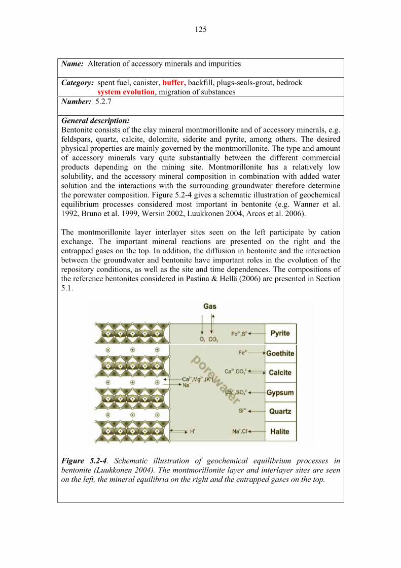
125
Name: Alteration of accessory minerals and impurities
Category: spent fuel, canister, buffer, backfill, plugs-seals-grout, bedrock system evolution, migration of substances
Number: 5.2.7
General description:
Bentonite consists of the clay mineral montmorillonite and of accessory minerals, e.g. feldspars, quartz, calcite, dolomite, siderite and pyrite, among others. The desired physical properties are mainly governed by the montmorillonite. The type and amount of accessory minerals vary quite substantially between the different commercial products depending on the mining site. Montmorillonite has a relatively low solubility, and the accessory mineral composition in combination with added water solution and the interactions with the surrounding groundwater therefore determine the porewater composition. Figure 5.2-4 gives a schematic illustration of geochemical equilibrium processes considered most important in bentonite (e.g. Wanner et al. 1992, Bruno et al. 1999, Wersin 2002, Luukkonen 2004, Arcos et al. 2006).
The montmorillonite layer interlayer sites seen on the left participate by cation exchange. The important mineral reactions are presented on the right and the entrapped gases on the top. In addition, the diffusion in bentonite and the interaction between the groundwater and bentonite have important roles in the evolution of the repository conditions, as well as the site and time dependences. The compositions of the reference bentonites considered in Pastina & Hellä (2006) are presented in Section 5.1.
Figure 5.2-4. Schematic illustration of geochemical equilibrium processes in bentonite (Luukkonen 2004). The montmorillonite layer and interlayer sites are seen on the left, the mineral equilibria on the right and the entrapped gases on the top.

126
The interaction reactions of the porewater with the accessory minerals as well as with montmorillonite surfaces are (Bruno et al. 1999, Arcos et al. 2006):
Dissolution-precipitation of carbonates. The minerals of importance are calcite, dolomite and siderite which can dissolve/precipitate according to the following reactions: CaCO3(s) + H+ Ca2+ + HCO3
-
CaMg(CO3)2(s) + 2H+ Ca2+ + Mg2+ + 2HCO3-
FeCO3(s) + H+ Fe2+ + HCO3-.
The reactions are important pH determinants and the last one has a clear effect on the redox conditions, too.
Protonation-deprotonation of the surfaces. This process contributes to the pH buffering according to the following reactions on the smectite edge surfaces:
SOH + H+ SOH2+
SOH SO- + H+.
Cation-exchange reactions. The main cation-exchange reactions are the following: NaX + K+ KX + Na+
2NaX + Ca2+ CaX2 + 2Na+
2NaX + Mg2+ MgX2 + 2Na+.
The control exerted by this process on the calcium and magnesium concentrations in the porewater also directly affects the dissolution-precipitation of the Mg and Ca minerals in the buffer.
Sulphate dissolution/precipitation. This reaction controls the calcium ion concentration in the porewater leading to indirect buffering of carbonate dissolution precipitation reaction: CaSO4 Ca2+ + SO4
2-.
The precipitation of gypsum and anhydrite is dependent on the temperature such that this process strongly depends on the thermal gradient during the non-isothermal period of the repository.
Equilibrium with CO2(g). Carbon dioxide can control the alkalinity according to the following reaction: CaCO3(s) + CO2(g) + H2O Ca2+ + 2HCO3
-.
This reaction is important especially in an open system.

127
Oxidation-reduction processes in bentonite1. The redox in bentonite will be
controlled by the redox active components in bentonite. If pyrite and O2 are present, oxidation can occur through the following reaction: FeS2(s) + 3.75O2(g) + 3.5H2O Fe(OH)3(s) + H+ + 2SO2
2- + 4H+
The reaction is irreversible in the repository conditions if reducing microbes are not present.
Siderite oxidation is another redox buffering reaction: FeCO3(s) + 2.5H2O + 0.25O2(g) Fe(OH)3(s) + H+ + HCO3
-.
Other processes. Other geochemical processes that can occur in the buffer are the dissolution/precipitation of silica phases (quartz, cristobalite and amorphous SiO2),especially in the presence of a thermal gradient: SiO2(s) SiO2
The dissolution of accessory aluminosilicate minerals in the bentonite, such as plagioclase or K-feldspar can be also considered.
CaAl2Si2O8 + 8H2O Ca2+ + 2Al(OH)4
– + 2Si(OH)4
KAlSi3O8 + 8H2O K+ + Al(OH)4– + 3Si(OH)4
The rate of aluminosilicate dissolution is very slow and dependent of pH and it will be an efficient chemical buffer only when the most readily occurring reactions are no longer active, due to the depletion of the minerals involved.
Coupling of the processes. The chemical conditions in the bentonite porewater are created by the coupling the reactions above and different transport processes within bentonite and between groundwater and bentonite. The direction of the diffusion is from the higher concentration to the lower one and can thus change when the groundwater concentrations vary as a function of time. The temperature gradient can affect the processes.
Some laboratory experiments have shown a redistribution of the easily dissolving accessory minerals (e.g., gypsum and calcite) during water saturation of bentonite under a thermal gradient (Karnland 1995). The precipitation of gypsum in the hottest parts of the buffer has been confirmed in the LOT field experiments at Äspö (Karnland et al. 2000, Muurinen 2006a).
Quartz is normally stable in the natural repository environment, but its solubility increases with increasing temperature. Silica may dissolve due to high temperature close the canister and be transported by diffusion outwards into the colder parts where
1 Oxidation-reduction processes are not limited to accessory minerals. See the effect of iron also in montmorillonite transformation (Section 5.2.6), iron as a product of the corrosion of the cast iron insert.

128
precipitation may take place. In the Buffer Mass Test in Stripa, the buffer was analyzed with respect to the distribution of silica, but no definite conclusion could be drawn regarding possible enrichment in the coldest part (Pusch 1985).
Wieland et al. (1994) modelled (mixing tank) the evolution of pH during the interaction of bentonite with simplified Allard and Äspö groundwaters. In the case of the Allard groundwater, the pH remained fixed at 8.4 while calcite was present in the system (up to about 90 exchange cycles), but after complete removal of calcite the pH gradually decreased to about 6.8.
According to the modelling of Bruno et al. (1999), the alkalinity buffering capacity is not largely affected by the replacement of porewater with granitic groundwater, whether from Äspö, Gideå or Finnsjön. The large input of Ca2+ with groundwater (e.g. Äspö and Olkiluoto) induces precipitation of calcite and buffers the alkalinity keeping the pH above 8.
The modelling results by Arcos et al. 2006 indicate that the interaction of present-day (Forsmark) groundwater with bentonite buffer has minor effects on the pH evolution of the system, despite the type of bentonite (MX-80 or Deponit CA-N) considered in the model. Carbonate minerals provide the pH buffering capacity if they are present. The intrusion of the high-salinity Laxemar water (close to the groundwater of Olkiluoto of today) in the system has no significant effect on the pH evolution, which is predicted to stay close to 7.0. The most significant changes are predicted when dilute and alkaline ice-melt derived water enters into the system. Then the dissolution of carbonate minerals is enhanced and increases the pH of the bentonite porewater to 8.3.
The simulations by Bruno et al. (1999) indicated that the reduction capacity of the bentonite system would only be exhausted after 300 000 years if a continuous flow of Äspö groundwater equilibrated with the atmosphere were reacting with bentonite with the lowest pyrite content (0.01 wt.%). According to Arcos et al. (2006), the redox state of the system seems to be controlled by the regional groundwater, assuming the reactions considered in the model calculations, as present-day groundwater in Forsmark at the repository depth lies on the equilibrium between pyrite and siderite.
The variables (Table 5.2-1) that are significant for the alteration of accessory minerals are the same as the ones for montmorillonite transformation (see Section 5.2.6). Olkiluoto specific issues:
The chemical conditions of the groundwater and the hydraulic parameters of the rock are site specific. Uncertainties
Key thermodynamic data for clays are still not well established. The main uncertainties remain in the kinetics of the processes.
Some critical uncertainties remain concerning the mechanistic understanding of the processes that control the redox state of the bentonite system. It is not clear yet to what extent pyrite and/or siderite are the main redox controlling phases.

129
The greatest uncertainty concerns the scope of cementation processes as a consequence of dissolution, transport and precipitation of silicon or aluminosilicate minerals during the thermal gradient. The scope and consequences of cementation cannot be predicted with reasonable certainty today.
It is assumed that pH is buffered by the equilibrium with calcite, and also proton buffer of clay (reaction at edge site). The amount (or even the presence) of calcite is somewhat uncertain in MX-80 bentonite but not in the Deponit CA-N bentonite.
In the determination of the pH value of a system, there are limitations, both in experiments and modelling exercises. Time frames of relevance:
The chemical precipitation/dissolution processes of accessory minerals are relevant for all time frames. Cementation, due to temperature and temperature gradients is most important during the thermal phase. Scenarios of relevance: The process need to be considered in all scenarios Treatment in PA:
The process is not explicitly included in PA exercises but is included in supplementary calculations of the modelling of the buffer chemical evolution for the thermal phase and the post-thermal long-term phase. The model handles advective flow, diffusive transport, and dissolution-precipitation of main bentonite accessory minerals, cation exchange and protonation-deprotonation. Significance:
The significance of the transformations of accessory minerals and impurities is considered to be LOW because it is not thought likely to occur to a large extent to a result in a significant reduction in the swelling pressure or increase in the permeability of the buffer. Thus it is not likely to affect the migration of radionuclides from the repository once the canister has been breached.Equivalent NEA international FEP:
2.1.09 “Chemical/geochemical processes and conditions (in wastes and EBS)” Key references:
Arcos, D., Grandia, F. & Domènech, C. 2006. Geochemical evolution of the near field of a KBS-3 repository. Swedish Nuclear Fuel and Waste Management Co, Stockholm. SKB TR-06-16.
Bruno, J., Arcos, D. & Duro, L. 1999. Processes and features affecting the near field hydrochemistry Groundwater-bentonite interaction. Swedish Nuclear Fuel and Waste Management Co, Stockholm. SKB TR-99-29.
Karnland, O. 1995. Salt redistribution and enrichment in compacted bentonite exposed to a thermal gradient – results from laboratory tests. Swedish Nuclear Fuel and Waste Management Co, Stockholm. SKB AR 95-31.
Karnland, O., Sandén, T., Johannesson, L.-E., Eriksen, T.E., Jansson, M., Wold, S., Pedersen, K., Motamedi, M. & Rosborg, B. 2000. Long-term test of buffer material. Final report on the pilot parcels. Nuclear Fuel and Waste Management Co, Stockholm. SKB TR-00-22.
130
Luukkonen, A. 2004. Modelling approach for geochemical changes in the prototype repository engineered barrier system. Posiva Oy, Olkiluoto, Finland. Posiva Working Report 2004-31.
Muurinen, A. 2006a. Chemical conditions in the A2 parcel of the long-term test of buffer material in Äspö (LOT). Posiva Oy, Olkiluoto, Finland. Posiva Working Report 2006-83.
Pastina, B. & Hellä, P. (Eds.) 2006. Expected evolution of a spent nuclear fuel repository at Olkiluoto. Posiva Oy, Olkiluoto, Finland. Report POSIVA 2006-05.
Pusch, R. 1985. Final Report of the Buffer Mass Test – Volume III: Chemical and physical stability of the buffer materials. Swedish Nuclear Fuel and Waste Management Co (SKB) Stockholm, Sweden. Stripa Project TR 85-14.
Wanner, H., Wersin, P. & Sierro, N. 1992. Thermodynamic modelling of bentonite-groundwater interaction and implications for near field chemistry in a repository for spent fuel. Swedish Nuclear Fuel and Waste Management Co., Stockholm. SKB TR-92-37.
Wersin, P. 2002. Geochemical modelling of bentonite porewater in high-level waste repositories. Journal of Contaminant Hydrology 61, 405-422.
Wersin, P., Spahiu, K. & Bruno, J. 1994. Kinetic modelling of bentonite-canister interaction. Long-term predictions of copper canister corrosion under oxic and anoxic conditions. Swedish Nuclear Fuel and Waste Management Co. Stockholm. SKB TR-94-25.
Wieland, E., Wanner, H., Albinsson, Y., Wersin, P. & Karnland, O. 1994. A surface chemical model of the bentonite water- interface and its implications for modelling the near field chemistry in a repository for spent fuel. Swedish Nuclear Fuel and Waste Management Co., Stockholm. SKB TR-94-26.
Name: Microbial activity
Category: spent fuel, canister, buffer, backfill, plugs-seals-grout, bedrocksystem evolution, migration of substances
Number: 5.2.8
General description: Bacterial activity can produce aqueous species, such as S(-II) species, that act as a corrosion agent for copper. Neither elevated temperatures nor radiation levels outside the canister are expected to hinder bacterial life in the buffer per se (Pedersen & Karlsson 1995, McMurry et al. 2003). The prerequisites for the viability of microbes are availability of sources of nutrients and energy and a swelling pressure of bentonite lower than the turgor pressure (or turgidity, i.e. the pressure of

131
the cell contents against the cell wall) of the bacterium, which is about 2 MPa (Masurat 2006).
All clay-based sealing materials in a deep geologic repository will contain initially a heterogeneous assemblage of indigenous microbes (McMurry et al. 2003). Additional microbes may be introduced with groundwater or technical water. Upon addition of water, sulphate-reducers indigenous bacteria to the buffer will be re-activated immediately to support production of hydrogen sulphide, which will control the redox level in the buffer pore fluid. However, the biological availability of water is diminished by adsorption in the bentonite causing the buffer to homogenize and to develop a high enough swelling pressure to transform active microbes to metabolically inactive spores incapable of producing corrosive agents, such as sulphide.
Microbially induced corrosion may play an important role in the chemical evolution of the canister before the bentonite reaches full saturation. If the near field is oxygen-free and the full swelling pressure has not yet developed, microbial activity in the wetter part of the buffer may be possible. The sulphide production rate is likely controlled by the low solubility of sulphide minerals in the bentonite porewater. It may be possible that sulphide does not reach the canister surface until most of the oxygen in the deposition hole has been consumed.
The conventional concept of the smectite-to-illite reaction (see Section 6.6.1) and of reaction kinetic models may be challenged by two recent studies describing the remarkable ability of cultures of the microbe Shewanella oneidensis to promote the smectite-to-illite phase transition (Dong et al. 2003, Kim et al. 2004). These studies showed that, contrary to the common belief that this reaction would require several months at elevated temperature and pressure, the microbe mediated the reaction in only 14 days at room temperature and 1 atmosphere through reduction of structural ferric iron. However, due to the low activity of water, low availability of K+, and the constrictive environment, this reaction is not likely to take place in the compacted bentonite buffer.
Pedersen (2000) presents the results from the last decade of the SKB microbiology research programme and gives current perspective of microbial processes in the disposal of the spent fuel as follows:
A full-scale experiment with buffer material consisting of a bentonite/sand ratio of 1 was performed at Atomic Energy of Canada Limited´s (AECL) underground laboratory in Canada. The results showed that microbes, with a few exceptions, could only be cultured from buffer samples with a water content of 15% or more, which is approximately equivalent to a bentonite with a saturated density of 2000 kg/m3
(Stroes-Gascoyne et al. 1996, 1997). The result of the Buffer Mass Container (BMC) experiment invoked questions about the survival of microbes, and especially sulphate reducing bacteria (SRB), in buffer materials in 100% bentonite and led to detailed laboratory experiments, as described below. Survival under laboratory conditions was studied in an experiment where two species of SRB were mixed with MX-80 bentonite at varying saturated densities, from 1 500 kg m-3 to 2000 kg m-3 (Motamedi

132
et al. 1996; Pedersen et al. 1995). The species were Desulfovibrio aespoeensis and Desulfomicrobium baculatum, both isolated from deep groundwater at the Äspö HRL. None of the species survived 60 days at densities above 1800 kg m-3.Desulfomicrobium baculatum survived the better of the two, remaining culturable for 60 days at 1 500 kg m-3.
In a field experiment suspensions of the SRB (anaerobic) and aerobic bacteria were mixed with bentonite clay to approximately 100 million bacteria per gram of dry weight clay. The clay with bacteria was subsequently formed into cylindrical plugs with a 20 mm length and diameter, and installed in bentonite blocks exposed to low (20–30 C) and high (50–70 C) temperatures. The blocks were installed in the LOT (long term test of buffer materials) boreholes immediately after the bacteria plugs were introduced. The experiment was terminated after 15 months. The major outcome was elimination of all bacteria except the spore-forming ones (Motamedi 1999, Pedersen et al. 2000).
Figure 5.2-5. A schematic model of microbial activity in the buffer as a function of time (adapted from Pedersen 2000).
133
The survival during the buffer swelling process was studied in a laboratory experiment. Swelling pressure odometers were installed with compacted bentonite with 10% water content, and a gap was left between the bentonite and the filter lid of the odometer, to mimic the gap in a deposition hole. Mixtures of bacteria were added to the gap and the odeometers were left for sampling at different times between 8 hours and 28 weeks. The part of the bentonite that came in contact with the microbes was sliced in layers perpendicular to the gap and the different microbes were analysed. The survival varied significantly from species to species and between different depths. The radiation and desiccation-resistant bacterium Deinococcusradiophilus and the sporeforming bacterium Bacillus subtilis showed the best survival rates. They also could be found in the deepest layer analysed, 3–6 mm, meaning that they mixed with the clay to a depth of at least 3 mm. The other bacteria tested also survived, but for shorter times and they did not survive at depth in the clay.
The results obtained on the survival and activity of microbes in compacted bentonite can be summarised in a conceptual model, as depicted in Figure 5.2-5. The model presented is based on current data, obtained with laboratory cultures.
The variables that are significant for microbial activity are:
Radiation intensity – controls the occurrence of microbes and microbial activity Temperature – temperature changes may enhance microbial activity Water content – microbes may need water to develop activity Gas content – significant for microbial processes as for the accessibility of methane and hydrogen as nutrients and products of microbial activity Hydrovariables (P and T) – especially significant for the transformation of montmorillonite and osmosis, as the availability of water may affect microbial activity Pore geometry – the size and shape of the pores is significant for microbial activity Swelling pressure – significant for the rate and extent of microbial activity Pore water composition – significant for the availability of nutrients for microbial activity Bentonite composition – see pore water composition; the content of organic carbon is of especial concern for microbial activity Structural materials – the composition of these materials and their degradation products may influence the rates of mineral transformation and microbial activity
Olkiluoto specific issues:
In situ populations of micro-organisms. Uncertainties:
The rate of microbially induced sulphide production (if any) at the final swelling pressure remains to be determined. The rate limiting factors such as diffusion of nutrients and sulphide, radiation, water content and heat stress must be clarified and defined.
Migration of micro-organisms through compacted bentonite is not well studied. The restrictions due to a low pore size may need to be experimentally defined.

134
The mechanisms for survival of microbes in bentonite and buffer materials are not fully understood.Time frames of relevance:
The process is relevant for all time frames. Scenarios of relevance:
The process is relevant for all scenariosTreatment in PA:
The process is not explicitly treated in PA but in supplementary reports in mass balance calculations to show how different kind of materials or groundwater will contribute either to microbial oxygen reduction or to microbial sulphide production from sulphate. Significance: The action of microbial populations in the buffer is considered to be of LOW significance. The process is however of no importance if the saturated clay density is above 1800 kg/m3 (SKB 2006b). Equivalent NEA international FEP:
2.1.10 “Biological/biochemical processes and conditions (in wastes and EBS)” Key references:
Dong, H., Kostka, J.E. & Kim, J. 2003. Microscopic evidence for microbial dissolution of smectite. Clays and Clay Minerals, 51, 502–512.
Kim, J., Dong, H., Seabaugh, J., Newell, S.W. & Eberl, D.D. 2004. Role of microbes in the smectite-to-illite reaction. Science, vol. 303, 830–832.
Masurat, P. 2006. Potential for corrosion in disposal systems for high-level radioactive waste by Meiothermus and Desulfovibrio. Doctoral thesis. Göteborg University.
McMurry, J., Dixon, D.A., Garroni, J.D., Ikeda, B.M., Stroes-Gascoyne, S., Baumgartner, P. & Melnyk, T.W. 2003. Evolution of a Canadian deep geologic repository. Base scenario. Atomic Energy of Canada Limited Report 06819-REP-01200-10092-R00.
Motamedi, M. 1999. The survival and activity of bacteria in compacted bentonite clay in conditions relevant to high level radioactive waste (HLW) repositories. Thesis. Göteborg: Göteborg University, pp. 1–45.
Motamedi, M., Karland, O. & Pedersen, K. 1996. Survival of sulphate reducing bacteria at different water activities in compacted bentonite. FEMS Microbiology Letters 141, 83–87.
Pedersen, K. 2000. Microbial processes in radioactive waste disposal. Swedish Nuclear Fuel and Waste Management Co. (SKB), Stockholm, Sweden. SKB Technical Report TR 00-04.
Pedersen, K. & Karlsson, F. 1995. Investigations of subterranean microorganisms – Their importance for performance assessment of radioactive waste disposal. Swedish Nuclear Fuel and Waste Management Co. (SKB), Stockholm, Sweden. SKB Technical Report TR-95-10.
135
Pedersen, K., Motamedi, M. & Karnland, O. 1995. Survival of bacteria in nuclear waste buffer materials – the influence of nutrients, temperature and water activity. Swedish Nuclear Fuel and Waste Management Co. (SKB), Stockholm, Sweden. SKB Technical Report 95-27.
Pedersen, K., Motamedi, M., Karnland, O. & Sandén, T. 2000. Cultivability of microorganisms introduced into a compacted bentonite clay buffer under high-level radioactive waste repository conditions. Engineering Geology 58, 149-161.
SKB 2006b. Buffer and backfill process report for the safety assessment SR-Can. Swedish Nuclear Fuel and Waste Management Co (SKB) Stockholm, Sweden. SKB Technical Report TR-06-18.
Stroes-Gascoyne, S., Pedersen, K., Daumas, S., Hamon, C.J., Haveman, T.L., Delaney, T.L., Ekendahl, S., Jahromi, N., Arlinger, J., Hallbeck, L. & Dekeyser, K. 1996. Microbial analysis of the buffer/container experiment at AECL’s underground research laboratory. Swedish Nuclear Fuel and Waste Management Co. (SKB), Stockholm, Sweden. SKB Technical Report TR 96-02.
Stroes-Gascoyne, S., Pedersen, K., Haveman, S. A., Dekeyser, K., Arlinger, J., Daumas, S., Ekendahl, S., Hallbeck, L., Hamon, C.J., Jahromi, N. & Delaney, T.L. 1997. Occurrence and identification of microorganisms in compacted clay-based buffer material designed for use in a nuclear fuel waste disposal vault. Canadian Journal of Microbiology 43, 1133–1146.
5.3 Processes related to the migration of radionuclides and other substances
The performance of the buffer may be endangered in interacting with, for example, cement leachates. The canister may fail due to initial defects or due to corrosion if damaging substances (e.g. sulphide, oxygen) in groundwater migrate through the bentonite to the canister. In all cases radionuclides, once release form the fuel and canister (see Chapter 3) will migrate through the buffer and/or through the buffer and backfill. The physical and chemical processes that control the migration of radionuclides and other substances through the buffer will be similar. The conditions of the groundwater entering the buffer will control the degradation of bentonite, corrosion rates of the canister, and the rate of migration of radionuclides.
The variables that can affect the nature and rate of these migration-related processes are shown in Table 5.3-1.
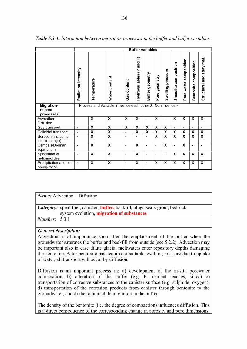
136
Table 5.3-1. Interaction between migration processes in the buffer and buffer variables.
Buffer variables
Ra
dia
tio
n in
ten
sit
y
Tem
pera
ture
Wate
r co
nte
nt
Gas c
on
ten
t
Hy
dro
va
ria
ble
s (
P a
nd
F)
Bu
ffer
geo
metr
y
Po
re g
eo
me
try
Sw
ellin
g p
ressu
re
Sm
ecti
te c
om
po
sit
ion
Po
re w
ate
r co
mp
osit
ion
Be
nto
nit
e c
om
po
sit
ion
Str
uctu
ral
an
d s
tray m
at.
Migration-relatedprocesses
Process and Variable influence each other X; No influence -
Advection – Diffusion
- X X X X - X - X X X X
Gas transport - X X X X X X X - - - -
Colloidal transport - X X - X X X X X X X X
Sorption (including ion exchange)
- X X - - - X X X X X X
Osmosis/Donnanequilibrium
- X X - X - - X - X - -
Speciation of radionuclides
- X X - X - - - X X X X
Precipitation and co-precipitation
- X X - X - X X X X X X
Name: Advection – Diffusion
Category: spent fuel, canister, buffer, backfill, plugs-seals-grout, bedrock system evolution, migration of substances
Number: 5.3.1
General description:
Advection is of importance soon after the emplacement of the buffer when the groundwater saturates the buffer and backfill from outside (see 5.2.2). Advection may be important also in case dilute glacial meltwaters enter repository depths damaging the bentonite. After bentonite has acquired a suitable swelling pressure due to uptake of water, all transport will occur by diffusion.
Diffusion is an important process in: a) development of the in-situ porewater composition, b) alteration of the buffer (e.g. K, cement leaches, silica) c) transportation of corrosive substances to the canister surface (e.g. sulphide, oxygen), d) transportation of the corrosion products from canister through bentonite to the groundwater, and d) the radionuclide migration in the buffer.
The density of the bentonite (i.e. the degree of compaction) influences diffusion. This is a direct consequence of the corresponding change in porosity and pore dimensions.

137
Buffer geometry determines the diffusion lengths. The influence of pore geometry is included in tortuosity and constrictivity and the effect is seen in the values of the diffusion coefficients. Smectite, bentonite, and porewater composition affect the diffusion coefficients, sorption and porosities during diffusion. Diffusion in bentonite has been thoroughly studied in conjunction with radionuclide transport. Diffusion equations for radionuclides are described in detail in Yu and Neretnieks (1997) and in SKB (2006). Yu and Neretnieks (1997) also give a detailed discussion of different experimental methods and how the results can be interpreted.
Diffusivity data for radionuclides through compacted bentonite have been compiled by different authors (see above). The selection by Ochs and Talerico (2004) used as reference groundwater for SKB should be reviewed in the light of the groundwater conditions at Olkiluoto.
The main variables (Table 5-3.1) that will affect the transport of radionuclides and other substances through bentonite in by advection or diffusion are:
Temperature – significant for all transport processes in water as it influences the viscosity of water Water content – the initial water content of bentonite along with water availability will control the occurrence of advection or diffusion, as well as, the amounts of solutes for transport Gas content – influences the rate of advection and diffusion Hydrovariables (P and F) – especially significant for the occurrence of one or another transport process as the availability of water may affect the composition of initial porewater and may provide damaging species Pore geometry – it influences the microstructure of bentonite and determines also the pore water content and hydraulic conductivity Smectite composition – significant for hydraulic conductivity Pore water composition – significant for hydraulic conductivity and the composition of solutes to be transported Bentonite composition – see pore water composition Structural and stray materials – the composition of these materials and their degradation products may influence the rates solute transport and the occurrence of advection over diffusion or vice versa.
Olkiluoto specific issues:
Specific issues for Olkiluoto are those related to the composition of the groundwater and the particularities of the buffer. Differences from conditions for the SKB repository are not expected to be very significant. Uncertainties:
Parameter/data uncertainty relates to the determination of diffusivities for compacted and saturated bentonite in the relevant Eh-pH conditions expected in the evolution of the repository. Conceptual model uncertainty in treating anion and cation diffusion: e.g. surface diffusion, treatment of electrostatic interactions, multicomponent effects. Time frames of relevance:
Advection is relevant soon after the emplacement of the buffer and/or later on after the melting of the first ice-sheet (i.e. after 70 000 years; Pastina & Hellä 2006).
138
Diffusion is relevant for all time frames after bentonite saturation. Scenarios of relevance:
The transport of radionuclides and other substances through the buffer is considered in all the assessment scenarios (see Chapter 2). Treatment in PA:
The transport of radionuclides is taken into account in radionuclide transport calculations through the selection and use of diffusion coefficients.Significance:
Advection through the buffer is of HIGH significance, because it will affect the performance of the bentonite buffer as a barrier for the migration of damaging substances to and from the repository. Diffusion through the saturated buffer is of HIGH significance because it delays and limits the migration of radionuclides through the bentonite after the canister has been breached. Diffusive transport processes allow radionuclides to contact a larger mineral surface area in the bentonite, with the possibility of increased sorption occurring, see 5.3.4. Equivalent NEA international FEP:
2.1.09 “Chemical/geochemical processes and conditions (in wastes and EBS)” 2.1.08 “Hydraulic/hydrogeological processes and conditions (in wastes and EBS)” 3.2.07 “Water-mediated transport of contaminants” 3.2.03 “Sorption/desorption processes, contaminants” Key references:
Ochs, M. & Talerico, C. 2004. SR-Can – Data and uncertainty assessment – Migration parameters for the bentonite buffer in the KBS-3 concept. Swedish Nuclear Fuel and Waste Management Co (SKB) Stockholm, Sweden. SKB Technical Report TR-04-18.
Pastina, B. & Hellä, P. (Eds.) 2006. Expected evolution of a spent nuclear fuel repository at Olkiluoto. Posiva Oy, Olkiluoto, Finland. Report POSIVA 2006-05.
SKB 2006b. Buffer and backfill process report for the safety assessment SR-Can. Swedish Nuclear Fuel and Waste Management Co (SKB) Stockholm, Sweden. SKB Technical Report TR-06-18.
Yu, J.-W. & Neretnieks, I. 1997. Diffusion and sorption properties of radionuclides in compacted bentonite. Swedish Nuclear Fuel and Waste Management Co (SKB) Stockholm, Sweden. SKB Technical Report TR-97-12.
Name: Gas transport
Category: spent fuel, canister, buffer, backfill, plugs-seals-grout, bedrock system evolution, migration of substances
Number: 5.3.2
General description:
The gas in the deposition hole can originate from air trapped in the buffer during saturation, radiolysis of water between the canister and buffer, radiolysis of water

139
inside a penetrated canister, microbial activity, from groundwater, and hydrogen resulting from the corrosion reaction of the cast iron insert with water. The last one is the most important. If the production rate is low or the gas quantity small, the gas can be dissolved and removed by diffusion. In the opposite case a separate gas phase will be formed and pressure will rise until a flow path is formed.
After breaking through the bentonite buffer, gas pressure will fall to a lower value (“shut-in pressure”), sufficient to support the pathways and prevent their closure due to swelling pressure. The formation of gas pathways is not expected to displace a significant amount of porewater or dissolved radionuclides (Harrington & Horseman 2003). The gas pathways will remain open until gas production ceases or is reduced enough to be dissipated solely by diffusion, at which time the pathways are expected to close and re-seal.
A number of gas migration experiments have been performed in compacted bentonite over the last 20 years. Gas flow through saturated bentonite is discussed in detail in Harrington & Horseman (2003), SKB (2006, 2006a), Rodwell (2005) and Pastina & Hellä (2006), and is only summarised here. There is strong evidence that gas flows in bentonite through a network of pressure-induced pathways.
When the gas generation ceases, or if the gas generation rates are low enough, the transport pathways are expected to close. This will occur when the pressure falls below the ‘shut-in pressure’. When the pathways close, gas migrates solely by diffusion.
The gas pressure depends on the temperature. This can be neglected if the gas transport occurs after the thermal phase. Gas permeability depends strongly on the water content of the clay since this determines the swelling pressure. After bentonite saturation this can be neglected. Gas content depends on the water content. Hydrovariables like gas and hydraulic pressure determine if the gas can be transported. The pore geometry, swelling pressure, smectite composition, porewater composition and bentonite composition are assumed to determine the break-through pressure.
Radionuclide transport in a gas phase may be due to two mechanisms: 1) radionuclides that escape and are themselves in gas phase (e.g. C-14, 3H, 129I, Rn) or 2) radionuclides in gas or water phase that are expelled through the buffer due the breakthrough of the gas pressure formed inside the canister (see above).
As the gas pressure depends on the temperature, gas expelling and formation of pathways in the buffer is most relevant during the initial thermal phase.
The variables (Table 5.3-1) that are significant for the gas transport are: Temperature – significant for the reaction rates leading to gas production and controls gas pressure and transport Water content – may control the amounts of gas in solution shifting from transport of gas as gas or in water Gas content – control gas pressure and transport
140
Hydrovariables (P and T) – may control the creation of gas transport paths through bentonite to the backfill and near-field rock Buffer geometry – influences the formation of paths for gas transport Pore geometry – control the content of gas and formation of transport paths Swelling pressure – significant for gas transport and formation of transport paths
Olkiluoto specific issues:
The hydraulic pressure and chemical conditions of the groundwater have to be considered in calculations involving a free gas phase.Uncertainties:
The hydro-mechanical behaviour of the water/vapour/gas system in a defective canister is governed by several coupled processes and parameters. Significant uncertainties related to the mechanistic understanding, system modelling and data remain. The observed gas transport through bentonite can be interpreted in different ways and experimental data to allow confirmation of a detailed modelling approach is currently lacking. The uncertainty concerns the number, size and spatial arrangement and lifespan of the gas-bearing fractures in bentonite. Time frames of relevance:
Gas expulsion and formation of pathways is relevant during the initial thermal phase when the bentonite is unsaturated and water may contact the cast iron insert in a defective canister scenario. After that radionuclide in gas form will migrate through diffusion.Scenarios of relevance:
Migration of radionuclides in a gas phase through the buffer is relevant to all scenarios. The case of expelling and formation of pathways in the buffer is considered only in the additional scenario AD-III (see Chapter 2).Treatment in PA:
Gas transport is not specifically treated in PA, but the gas transport within the buffer is evaluated for defective canisters in supplementary calculations. The migration of radionuclides in the gas phase through diffusion and expelled through pathways in the buffer is taken into account in radionuclide transport calculations.
Significance:
Most of the radionuclide transport in the buffer is thought to be mediated by water, thus the gas migration is considered of MEDIUM significance (disruption of the buffer in the scenario AD-II) significance. HIGH significance for tritium (3H) as hydrogen is the only gas likely to exceed partial pressure.
Equivalent NEA international FEP:
2.1.12 “Gas sources and effects (in wastes and EBS)” 3.2.09 “Gas mediated transport of contaminants" Key references:
Harrington, J.F. & Horseman, S.T. 2003. Gas migration in KBS-3 buffer bentonite. Sensitivity of test parameters to experimental boundary conditions. SKB Technical Report TR-03-02.
Pastina, B. & Hellä, P. (Eds.) 2006. Expected evolution of a spent nuclear fuel repository at Olkiluoto. Posiva Oy, Olkiluoto, Finland. Posiva 2006-05.

141
Rodwell, W.R. 2005. Summary of a GAMBIT Club workshop on gas migration in bentonite, Madrid 29–30 October, 2003. Swedish Nuclear Fuel and Waste Management Co (SKB); Stockholm, Sweden. SKB Technical Report TR-05-13.
SKB 2006. Long-term safety for KBS-3 repositories at Forsmark and Laxemar – a first evaluation. Main report of the SR-Can project. Swedish Nuclear Fuel and Waste Management Co (SKB); Stockholm, Sweden. SKB Technical Report TR-06-09.
SKB 2006a. Fuel and canister process report for the safety assessment SR-Can. Swedish Nuclear Fuel and Waste Management Co (SKB); Stockholm, Sweden. SKB Technical Report TR-06-22.
Name: Colloid formation and transport
Category: spent fuel, canister, buffer, backfill, plugs-seals-grout, bedrock system evolution, migration of substances
Number: 5.3.3
General description:
Colloids may generate during water uptake (see Section 5.2.2) and/or as the result of chemical erosion (see Section 5.2.3). Karnland (2005) and Wold and Eriksen (2005) have studied the colloidal behaviour of bentonite.
Natural groundwater colloids (inorganic, organic, or biological) and in situ generated colloids (e.g., bentonite) may serve as source material for colloid-mediated radionuclide transport depending on their relative stability and mobility in the repository environment.
Assuming the presence of radionuclides is a non-limiting factor, the magnitude of colloid-mediated radionuclide transport in the repository environment can be considered in terms of three main factors: colloid existence, radionuclide sorption, and radiocolloid (a colloid having a component that consist of radioactive atoms) mobility.
The fate and colloidally mediated transport of radionuclides will also depend to large degree on colloid stability and on their sorption behaviour with regard to the available colloids under repository environment conditions.
Radiocolloid mobility in the repository environment will most likely be a function of advection in conductive features; however, diffusion of radiocolloids through less permeable matrices may be significant as well.
Hydrogeochemical conditions in the repository will ultimately define the magnitude of colloid-mediated radionuclide transport through their influence on colloid existence (colloid stability, size distribution, deposition), radionuclide sorption (partitioning), and radiocolloid mobility (flow, filtration).
142
The variables (Table 5.3-1) that are significant for the colloid formation and transport are:
Temperature – significant for flow rates that would lead to the formation and release of colloids Water content – the initial water content along with water availability will control the formation of colloids and their transport Gas content – significant in the case of the accessibility of methane and hydrogen Hydrovariables (P and F) – significant for the formation and release of colloids in high flow conditions Buffer geometry – the position and shape of the buffer with respect to hydrological features in the bedrock is significant for water-bentonite interaction Pore geometry – the size and shape of the pores is significant for the transport/ filtration of colloids Swelling pressure – the higher the swelling pressure the less possibility of formation and transport of colloids Smectite compositon – significant for the formation and stability of colloids. Pore water composition – significant for the formation and stability of colloids Bentonite composition – significant for the formation of colloids and their size Structural and stray materials – the composition of these materials and their degradation products may influence the availability of water for the formation and transport of colloids
Olkiluoto specific issues:
Natural groundwater colloid populations; in situ generated colloid populations; groundwater evolution.
Uncertainties:
Uncertainties in measurement methodologies of colloids and their transport in saturated and undersaturated media.
Time frames of relevance:
In situ generated colloids due to penetration of dilute (melt) groundwater is relevant after tens of thousands of years.Scenarios of relevance:
Defective performance of the buffer (AD-II) Treatment in PA:
Radionuclide transport in colloids is not considered in PA, but the possibility is considered in selecting higher radionuclide solubility values than those recommended. Significance:
The process is significant for all assessment scenarios as follows: DCS-II, early failure-no swelling; HIGH
DCS-I, late failure-chemical erosion – relate to the release and transport of colloids late after the penetration of dilute groundwaters to repository depths; MEDIUM
This process is considered to be of MEDIUM significance because the transport of radionuclides in colloids would require of especial or unlikely circumstances like the penetration to repository depth of dilute waters.

143
Equivalent NEA international FEP:
2.1.09 “Chemical/geochemical processes and conditions (in wastes and EBS)” 3.2.02 “Speciation and solubility, contaminant” 3.2.04 “Colloids, contaminant interactions and transport with” Key references:
Karnland, O. 2005. Stability of bentonite colloid suspensions – A laboratory study. In: Laaksoharju, M., Wold, S. 2005. The colloid investigations conducted at the Äspö Hard Rock Laboratory during 2000 -2004. Swedish Nuclear Fuel and Waste Management Co. (SKB), Stockholm, Sweden. SKB Technical Report TR-05-20.
Wold, S. & Eriksen, T. 2005. Bentonite colloid stability – Effects of bentonite type, temperature, pH and ionic composition. In: Laaksoharju, M., Wold, S. 2005. The colloid investigations conducted at the Äspö Hard Rock Laboratory during 2000 -2004. Swedish Nuclear Fuel and Waste Management Co (SKB) Stockholm, Sweden. SKB Technical Report TR-05-20.
Name: Sorption (including ion-exchange)
Category: spent fuel, canister, buffer, backfill, plugs-seals-grout, bedrock system evolution, migration of substances
Number: 5.3.4
General description:
Sorption, a general term describing the attachment of dissolved species to mineral surfaces. It includes ion exchange, physical adsorption and surface complexation. Sorption can also be considered as the precursor to precipitation.
In bentonite the principal sorbing component is montmorillonite, which has two distinctly different types of surfaces, where two different types of sorption can take place (e.g. Sposito 1984, Stumm & Morgan 1996):
1. The surfaces of montmorillonite clay platelets carry a permanent negative charge arising from isomorphic substitution of lattice cations by cations of a lower valence. Charge neutrality is maintained by the presence of an excess of cations in solution held electrostatically in close proximity around the outside of the Al-Si-Al clay units. The electrostatically bound cations can undergo stochiometric exchange with the cations in solution. Sorption by this mechanism strongly depends on ionic strength/solution composition with weak dependency on pH. Cation exchange reactions are commonly described by selectivity coefficients defined over mass action equations (Gaines & Thomas 1953). The total permanent negative charge of a clay mineral is defined as the cation exchange capacity (CEC). Ion exchange is the typical sorption mechanism for alkali, and alkaline-earth elements, as well as transition metals at low pH values where positive solution species are predominant. Ion exchange with protons is important only at very low pHs. In MX-80 the major exchangeable cation is Na+ while in Deponit CA-N the major cations are Ca2+ and Mg2+. The cation exchange
144
capacities are about 700 meq/kg in both bentonites.
2. The surface hydroxyl groups ( S–OH) form the second type of reactive sites associated with montmorillonite. These groups are situated along the edges of the clay platelets. The CEC capacity of these sites in bentonite is about 80 meq/kg (Bradbury & Baeyens 2002). They can protonate or deprotonate so that the concentration of neutral, protonated and deprotonated edge sites ( S–OH, S–OH2+, S–O-) change as a function of pH. These sites can form complexes with cations and ligands in the solution. Many radionuclides can be taken up on the amphoteric hydroxyl surface groups and this process, modelled by surface complexation, is probably the most important sorption mechanism for heavy metals, transition metals, lanthanides and actinides in bentonite systems. The surface complexation of metals at S–OH-type sites is normally characterized by a strong dependency on pH, a weak dependency on ionic strength and a strong dependency on concentration (Bradbury & Baeyens 2003).
The supply of calcium from the deep groundwater into the bentonite and the dissolution of calcium-bearing accessory minerals (e.g. calcite, dolomite and gypsum) will convert the Na-clay to the calcium form through cation exchange. The exchange process depends strongly on the groundwater flow at the buffer-rock boundary. Despite the fact that this conversion is accelerated in the presence of a Ca-rich groundwater, the maximum conversion to Ca-form will occur on a million-year timescale due to the slow diffusion in compacted bentonite and the limited groundwater supply from the adjacent host rock. Even with the most realistic flow rate of the groundwater, in saline (Äspö-type) groundwater, only a few percent of the Na-bentonite is calculated to alter to Ca-bentonite over the first 10 000 years (Liu & Neretnieks 1997, Bruno et al. 1999). However, the updated model of Arcos et al. (2006) indicates that the amount of replacement could be larger than previously calculated assuming a hydraulic conductive feature intersecting the deposition hole. For MX-80 and Forsmark groundwater a 20% Na by Ca replacement has been calculated after 1 000 years (from initial NaX=70% and CaX2=20%) and a maximum of 47% Na by Ca after 60 000 years). This amount of replacement can be enlarged in the groundwater intersecting the hydraulic feature is highly saline. In this case after 60 000 years the values of NaX=29% and CaX2=71% were calculated.
Figure 5-3.1 presents the results of a laboratory experiment where the calcium occupation in bentonite increased in Olkiluoto-type saline groundwater from about 20 meq/g to 65 meq/g, when the bentonite was equilibrated with a water volume, which corresponded twenty times the volume of the bentonite porewater. In repository conditions at Olkiluoto the conversion of the Na by Ca is marginal (Muurinen & Lehikoinen 1999).
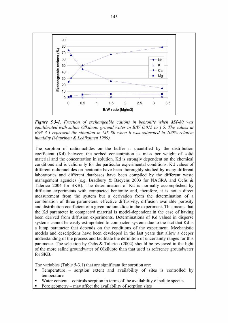
145
0
10
20
30
40
50
60
70
80
90
0 0.5 1 1.5 2 2.5 3 3.5
B/W ratio (Mg/m3)
Exch
an
geab
le c
ati
on
s (
%)
Na
K
Ca
Mg
Figure 5.3-1. Fraction of exchangeable cations in bentonite when MX-80 was equilibrated with saline Olkiluoto ground water in B/W 0.015 to 1.5. The values at B/W 3.3 represent the situation in MX-80 when it was saturated in 100% relative humidity (Muurinen & Lehikoinen 1999).
The sorption of radionuclides on the buffer is quantified by the distribution coefficient (Kd) between the sorbed concentration as mass per weight of solid material and the concentration in solution. Kd is strongly dependent on the chemical conditions and is valid only for the particular experimental conditions. Kd values of different radionuclides on bentonite have been thoroughly studied by many different laboratories and different databases have been compiled by the different waste management agencies (e.g. Bradbury & Baeyens 2003 for NAGRA and Ochs & Talerico 2004 for SKB). The determination of Kd is normally accomplished by diffusion experiments with compacted bentonite and, therefore, it is not a direct measurement from the system but a derivation from the determination of a combination of three parameters: effective diffusivity, diffusion available porosity and distribution coefficient of a given radionuclide in the experiment. This means that the Kd parameter in compacted material is model-dependent in the case of having been derived from diffusion experiments. Determinations of Kd values in disperse systems cannot be easily extrapolated to compacted systems due to the fact that Kd is a lump parameter that depends on the conditions of the experiment. Mechanistic models and descriptions have been developed in the last years that allow a deeper understanding of the process and facilitate the definition of uncertainty ranges for this parameter. The selection by Ochs & Talerico (2004) should be reviewed in the light of the more saline groundwater of Olkiluoto than that used as reference groundwater for SKB.
The variables (Table 5-3.1) that are significant for sorption are: Temperature – sorption extent and availability of sites is controlled by temperature Water content – controls sorption in terms of the availability of solute species Pore geometry – may affect the availability of sorption sites
146
Swelling pressure – see pore geometry; swelling pressure may control it Smectite composition – controls the nature of sorption sites and their availability Pore water composition – significant for all chemical processes Bentonite composition – see smectite composition Structural and stray materials – the composition of these materials and their degradation products influence the availability of sorption site sin bentonite
Olkiluoto specific issues: he composition of the groundwater affects the porewater chemistry, which is a major determinant of the cation exchange and sorption processes.Uncertainties:
Conceptual understanding and a large quantity of measurement data exist for cation exchange and sorption of many radionuclides under simplified systems. However, there is a clear lack of data for understanding and predicting the influence of some important variables, such as dissolved carbonate concentration or competition between major cations on radionuclide sorption, and this has to be taken into account in evaluating uncertainties of Kd values (Ochs & Talerico 2004). It is clear that Kd is a highly conditional parameter in terms of chemical conditions (pH, ionic strength, etc.) and has to be derived for each set of conditions. No sorption data are available for Deponit-Ca-N. Also the expected changes in groundwater composition during upconing and glacial cycles will be important sources of uncertainty. Time frames of relevance:
Sorption and ion exchange are important processes for the retention of most radionuclides and as such relevant for all time frames. Scenarios of relevance:
The process is relevant for all scenarios, main and assessment scenarios (see Chapter 2).Treatment in PA:
Sorption is included in the modelling of the radionuclide transport in all calculation cases derived from the assessment scenarios.
Significance:
The sorption of radionuclides in the buffer is of HIGH significance because the buffer has high sorption capacity and will delay the migration of radionuclides once the canister has failed. The long-term performance of the repository is strongly dependent on the transport/retardation characteristics of the buffer.
Equivalent NEA international FEP:
3.2.03 “Sorption/desorption processes, contaminant”
Key references:
Arcos, D., Grandia, F. & Domènech, C. 2006. Geochemical evolution of the near field of a KBS-3 repository. Swedish Nuclear Fuel and Waste Management Co, Stockholm. SKB TR-06-16.
Bradbury, M. & Baeyens, B. 2002. Porewater chemistry in compacted re-saturated MX-80 bentonite: Physico-chemical characterization and geochemical modelling. Nagra, Wettingen, Switzerland. Technical Report 01-08.
147
Bradbury, M. & Baeyens, B. 2003. Near-field sorption databases for compacted MX-80 bentonite for performance assessment of a high-level radioactive waste repository in Opalinus Clay host rock. Nagra, Wettingen, Switzerland. Technical Report 02-18.
Bruno, J., Arcos, D. & Duro, L. 1999. Processes and features affecting the near-field hydrochemistry. Groundwater-bentonite interaction. Swedish Nuclear Fuel and Waste Management Co. (SKB), Stockholm, Sweden. SKB Technical Report TR-99-29.
Gaines, G.L. & Thomas, H.C. 1953. Adsorption studies on clay minerals. A formulation of the thermodynamics of exchange adsorption. J. Chem. Phys., 21, 714-718.
Liu, J. & Neretnieks, I. 1997. Coupled transport/reaction modelling with ion-exchange: study of the long-term properties of bentonite buffer in a final repository. Swedish Nuclear Power Inspectorate (SKI), Stockholm, Sweden. SKI Report SKI 97:23.
Muurinen, A. & Lehikoinen, J. 1999. Porewater Chemistry in compacted bentonite. Posiva Oy, Helsinki, Finland. Posiva Report POSIVA 99-20.
Ochs, M. & Talerico, C. 2004. SR-Can – Data and uncertainty assessment – Migration parameters for the bentonite buffer in the KBS-3 concept. Swedish Nuclear Fuel and Waste Management Co (SKB) Stockholm, Sweden. SKB Technical Report TR-04-18.
Sposito, G. 1984. The surface chemistry of soils. Oxford University Press, New York.
Stumm, W. & Morgan, J.J. 1996. Aquatic chemistry, Wiley- Interscience, 3rd Ed.
Name: Osmosis/Donnan equilibrium
Category: spent fuel, canister, buffer, backfill, plugs-seals-grout, bedrock system evolution, migration of substances
Number: 5.3.5
General description: When the bentonite buffer is placed in a deposition hole a semipermeable boundary is formed on the buffer-rock interface. Two phenomena, Donnan equilibrium and Osmotic pressure, are developed on the boundary. These phenomena are strongly coupled with each other.
Donnan equilibrium refers to the distribution of ions between an ionic and colloidal solution (like montmorillonite) separated by a semipermeable membrane or boundary (Overbeek 1952, Karnland 1998, Ståhlberg 1999). The colloidal particles cannot pass the boundary while the other ions and the solvent can. The boundary maintains an unequal distribution of ionic solute concentration by acting as a selective barrier to

148
ionic diffusion. The condition for equilibrium is that the chemical potentials are equal on both sides of the membrane for all components that can permeate. Since the macro-sized mineral layers cannot pass the boundary, equilibrium will be established only for ions in the saturating solution and the montmorillonite charge compensating cations. For sodium montmorillonite and a sodium chloride solution these will only be Na+ and Cl–. In an ideal case it is possible to calculate the activity of sodium ions introduced into the clay-water system if the activity of the original cations in the clay and the activity of the ions in the external solution are known.
Osmosis is the net movement of a solvent across a semipermeable membrane from a region of high solvent potential to an area of low solvent potential when the membrane is permeable to the solvent but not the solute. The movement of the solute can be counteracted by increasing the pressure of the more-concentrated solution (low solvent potential) with respect to the less-concentrated one (high solvent potential). The osmotic pressure is defined to be the pressure required to maintain the equilibrium, with no net movement of solvent. Osmotic pressure depends on the concentration of the solute but not on its identity. The total osmotic pressure is the sum of the partial pressures caused by each solute type.
Osmotic pressure can be formed between the groundwater and the porewater of the bentonite. An external solution (groundwater) would reduce the pressure produced by the clay, to an extent equal to the osmotic pressure of the external solution, if no ions could pass into the clay. A sodium chloride concentration of around 1.7 M (10% by weight) would then result in a complete loss of swelling pressure in a KBS-3 buffer. On the other hand, if ions could pass freely into the clay, then the final conditions would be equal concentrations on both sides and no effect on swelling pressure would be found. This is not in accordance with experimental results (Karnland 1998).
Figure 5.3-2 shows how swelling pressure in bentonite depends on the concentration of the external solution. The ion equilibrium model for predicting swelling pressure is based on the assumption that the system is relatively homogenous with respect to pore geometry. The concentration caused by the external solution into the bentonite porewater can be explained also by assuming a dual porosity model with small interlamellar pores and larger external pores in bentonite (Muurinen 2006b). If this assumption is correct then the swelling pressure may decrease due to homogenization of the pore geometry with time.
The process may be relevant at very high solute concentrations in groundwater for highly compacted bentonite (saturated density 2 000 kg/m3. For low clay densities (saturated density below 2 000 kg/m3) the process is relevant for all concentrations (SKB 2006b).

149
The variables (Table 5.3-1) that are significant for osmosis/Donnan equilibria are: Temperature – significant for the transport of solutes Water content – the process do not occur in dry conditions Hydrovariables (P and F) – control the availability of water for the process to occurSwelling pressure – the process may not occur at high swelling pressure. Pore water composition – differences in porewater composition control the occurrence of the process
Figure 5.3-2. Measured (squares) and calculated (lines) swelling pressure versus clay density for different concentrations in a NaCl solution in equilibrium with the Na-montmorillonite. Legends show external solution concentration in mole/L (SKB 2006).
Olkiluoto specific issues:
The salinity of the groundwater may affect Donnan equilibrium and the osmotic pressure.Uncertainties:
The ion equilibrium model for predicting swelling pressure is based on the assumption that the system is relatively homogenous with respect to pore geometry. If this assumption is not correct then the swelling pressure may decrease due to homogenization of the pore geometry with time. Time frames of relevance:
The process is relevant for all timescales in the lifetime of the repository. Scenarios of relevance:
The process is relevant for all scenarios and especially in the defective buffer per se or due to mistakes in the emplacement (AD-II). Treatment in PA:
These processes are not treated specifically in PA calculations. Deviations are taken into account modifying the parameters for the buffer in the calculations.

150
Significance: Osmosis and Donnan equilibrium are of MEDIUM significance because under normal repository conditions they are not thought likely to affect the failure of the canister or substantially to affect radionuclide transport process. Equivalent NEA international FEP:
2.1.09 “Chemical/geochemical processes and conditions (in wastes and EBS)” Key references:
Karnland, O. 1998. Bentonite swelling pressure in strong NaCl solutions. Posiva Oy, Helsinki, Finland. Report POSIVA 98-01.
Muurinen, A. 2006b. Ion concentration caused by an external solution into the porewater of compacted bentonite. Posiva Oy, Olkiluoto, Finland. Posiva Working Report 2006-96.
Overbeek, J. 1952. Electrochemistry of double layer. In: Kruyt, H. 1952. Colloids Science. Amsterdam: Elsevier Publishing Company, 115– 93.
SKB 2006b. Buffer and backfill process report for the safety assessment SR-Can. Swedish Nuclear Fuel and Waste Management Co (SKB) Stockholm, Sweden. SKB Technical Report TR-06-18.
Ståhlberg, J. 1999. Retention model for ions in chromatography. Journal of Chromatography A, 855, 3–55.
Name: Speciation of radionuclides
Category: spent fuel, canister, buffer, backfill, plugs-seals-grout, bedrock system evolution, migration of substances
Number: 5.3.6
General description:
The aqueous speciation of radionuclides in the buffer has been recently assessed (Grivé et al. 2007) taking into account the composition of porewater in the bentonite (Wersin et al. 2008). From these calculations Cs, Sr, Ra and Ni will be mainly present as free cations in solution, Sm, Pu and Am as complexed cationic species, while Se, Th and U will mainly be present as anionic species (HSe- and Th(OH)3CO3
- and UO2(CO3)3
4- , respectively) in solution. The remaining radionuclides will be mainly in the form of uncharged species at the pH and conditions of interest. The lack of robust thermodynamic data for Nb, Mo and Pa hampers the proper speciation assessment. According to the results in Grivé et al. (2007), the sorption of Cs, Sr, Ra and Ni, will be most affected by the salinity of the groundwater due to the competition for interlayer exchange sites of the groundwater cations.
Olkiluoto specific issues:
Specific issues for Olkiluoto are those related with the composition of the groundwater and the exact nature of the buffer, but no very important differences with that of SKB due to these specificities are expected.

151
Uncertainties:
The speciation of radionuclides in the buffer depends on the bentonite porewater composition, which is representative for initial conditions. The evolution of the composition in time and its implication of the speciation of radionuclides may be difficult to assess.
Numerical uncertainties arise from the use of a specific thermodynamic database (another database will probably give different results) and activity corrections due to ionic strength (I), which varies from 10-5 to 1.2 M (Duro et al. 2006, Grivé et al. 2007).Time frames of relevance:
In principle, under the main base case scenario no radionuclide transport through the buffer is considered during the temperate and unsaturated periods. Even after bentonite water saturation it is not considered that the copper canister would be corroded.
In the case of a defective canister scenario with an initial penetrating defect, the process will start after the contact of water with the spent fuel and this may cause the gas transport of radionuclides due to the development of hydrogen gas pressure in the gap and also the formation of preferential advection paths for radionuclide transport.
The variables (Table 5.3-1) that are significant for the speciation of radionuclides are:
Temperature – controls the speciation of radionuclides and any other chemical component in the bentonite Water content – speciation does not occur in dry conditions Hydrovariables (P and F) – the availability of water is indispensable for speciation to occur Smectite composition – controls the porewater composition and hence the speciation of radionuclidesPore water composition – controls the speciation or radionuclides Bentonite composition – see smectite composition Structural and stray materials – the composition of these materials and their degradation products influences porewater composition and hence the speciation of radionuclides
Scenarios of relevance: All assessment scenariosTreatment in PA:
It is assumed that once groundwater contacts the spent fuel the entire inventory is accessible for dissolution and that the transport will occur by diffusion through the buffer. Mass transport models are based on diffusivities and Kds. Significance:
Speciation of radionuclides controls the way they are transported or retarded and influence the parameters used in radionuclide transport calculations. This process is of MEDIUM significance because of the different behaviour of anions, neutral species and cations in the bentonite. Equivalent NEA international FEP: Not equivalent, but relates to: 2.1.09 “Chemical/geochemical processes and conditions in wastes and EBS” 2.1.04 “ Buffer/backfill materials and characteristics”
152
Key references:
Duro, L., Grivé, M., Cera, E., Gaona, X., Domènech, C. & Bruno, J. 2006. Determination and assessment of the concentration limits to be used in SR-Can. Swedish Nuclear Fuel and Waste Management Co. (SKB), Stockholm, Sweden. SKB TR 06-32
Grivé, M., Montoya, V. & Duro, L. 2007. Assessment of the concentration limits for radionuclides for Posiva. Posiva Oy, Olkiluoto, Finland. Posiva Working Report 2007-103.
Wersin, P., Birgersson, M., Olsson, S. Karnland, O. & Snellman, M. 2008. Impact of corrosion-derived iron on the bentonite buffer within the KBS-3H disposal concept. The Olkiluoto site as case study. Posiva Oy, Olkiluoto, Finland. Posiva Working Report 2008-xx.
Name: Precipitation and co-precipitation of radionuclides
Category: spent fuel, canister, buffer, backfill, plugs-seals-grout, bedrock system evolution, migration of substances
Number: 5.3.7
General description:
Sorption and (co)precipitation are the two chemical mechanisms for radionuclide retention. Radionuclide concentrations are usually expected to be low in repository conditions and precipitation is usually neglected.
Co-precipitation of radionuclides requires the formation of new solid phases through major element reactions and this is generally difficult to quantify.
Radionuclides will initially precipitate as microcrystalline or amorphous solid phases, which may “grow” to form large crystals more resistant to dissolution. The new solid phase/s will be more stable as more similar in charge and radii are the major and the minor constituent (e.g. co-precipitation of Ra with Ba in barite or Sr with Ca in calcite).
Precipitation and (co)precipitation of radionuclides in bentonite/smectite and other mineral components has been reported in connection with many natural analogue studies and also at laboratory scale (e.g. Cramer & Smellie 1994).
The variables (Table 5.3-1) that are significant for the chemical processes are:
Temperature – temperature affects reaction rates for precipitation and (co)precipitationWater content – water is needed for the nucleation of newly-formed minerals containing radionuclides Hydrovariables (P and F) – control the availability of water needed for chemical reactions

153
Pore geometry – the size and shape of the pores is significant for the nucleation and formation of precipitates. It determines also the pore water content, which may especially affect the precipitation of radionuclides. Swelling pressure – at high swelling pressure only diffusion may be possible Smectite composition – significant for (co)precipitation of radionuclides Pore water composition – significant for all the kind and rate of precipitates Bentonite composition – significant especially for (co)precipitation of radionuclides with mineral components of the bentonite Structural materials – may influence the speciation of radionuclides to be incorporated in bentonite
Olkiluoto specific issues:
Specific issues for Olkiluoto are those related with the composition of the groundwater and the particularities of the buffer. Uncertainties:
Although the precipitation-dissolution of mineral phases including radionuclides can be calculated from thermodynamic data, the complexity of the chemical system and the very few data on precipitation kinetics makes modelling difficult. Time frames of relevance:
The process would potentially start after the migration of radionuclides to the buffer from the interior of a breached canister. Scenarios of relevance: The precipitation, co-precipitation of radionuclides is relevant for all the assessment scenarios (see Chapter 2). Treatment in PA:
Precipitation and co-precipitation of the buffer are not considered explicitly in Pa to be conservative, but the use of solubility limits for many radionuclides is taken into account in radionuclide transport calculations. The application of simple models to account for the complex co-precipitation process has been tested in several systems and currently the NEA is focusing attention on the study of these processes, as it is acknowledged by the publication of the last book of the NEA-TDB project (Bruno et al. 2007). Significance:
Precipitation and co-precipitation may control the long-term retention of radionuclides. However precipitates could became a source of radionuclides if the hydrological or geochemical conditions were to change in the future. Therefore this process is of HIGH significance in both the retention and release of radionuclides in the buffer and from it. Equivalent NEA international FEP:
3.2.01 “Dissolution, precipitation and crystallisation, contaminant” Key references:
Cramer, J.J. & Smellie, J.A.T. 1994. Final report of the AECL/SKB Cigar Lake analog study. AECL Technical Report, AECL-10851; SKB Technical Report, TR 94-04.
Bruno, J. Bosbach, D. Kulik, D. & Navrotsky, A. 2007. Chemical Thermodynamics of Solid Solutions of interest in Nuclear Waste Management. Chemical Thermodynamics Series Volume 10.

154
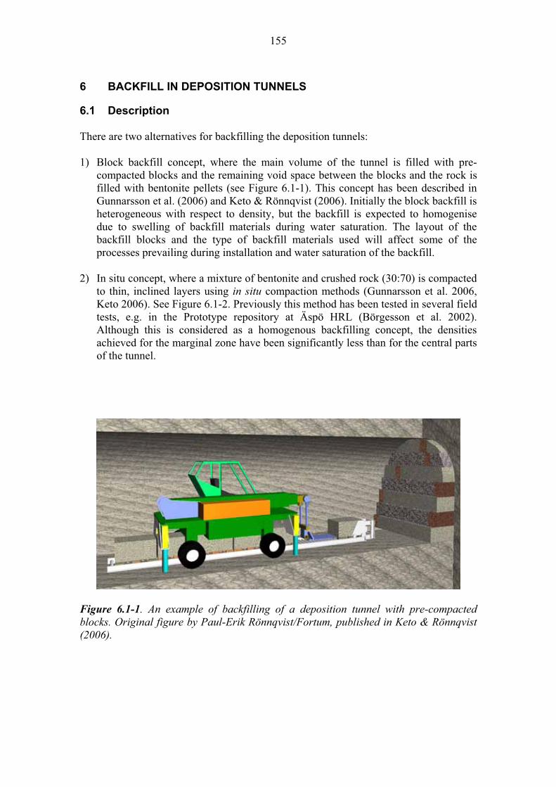
155
6 BACKFILL IN DEPOSITION TUNNELS
6.1 Description
There are two alternatives for backfilling the deposition tunnels:
1) Block backfill concept, where the main volume of the tunnel is filled with pre-compacted blocks and the remaining void space between the blocks and the rock is filled with bentonite pellets (see Figure 6.1-1). This concept has been described in Gunnarsson et al. (2006) and Keto & Rönnqvist (2006). Initially the block backfill is heterogeneous with respect to density, but the backfill is expected to homogenise due to swelling of backfill materials during water saturation. The layout of the backfill blocks and the type of backfill materials used will affect some of the processes prevailing during installation and water saturation of the backfill.
2) In situ concept, where a mixture of bentonite and crushed rock (30:70) is compacted to thin, inclined layers using in situ compaction methods (Gunnarsson et al. 2006, Keto 2006). See Figure 6.1-2. Previously this method has been tested in several field tests, e.g. in the Prototype repository at Äspö HRL (Börgesson et al. 2002). Although this is considered as a homogenous backfilling concept, the densities achieved for the marginal zone have been significantly less than for the central parts of the tunnel.
Figure 6.1-1. An example of backfilling of a deposition tunnel with pre-compacted blocks. Original figure by Paul-Erik Rönnqvist/Fortum, published in Keto & Rönnqvist (2006).

156
a)
b)
c)
d)
e)
f)
Figure 6.1-2. Compaction of inclined layers in the Prototype repository tunnel. The letters a-f indicate the different steps in backfilling: a) - b) moving the material into the tunnel and pushing it in place with the help of a bucket loader and a T-shaped leveller, c) compacting the material on the roof and d-f) compacting the rest of the layer with a slope compactor (Gunnarsson et al. 2006).
Currently the first alternative is being investigated further in the joint Posiva-SKB Baclo programme, as well as alternatives for backfilling and closure of central tunnels, auxiliary facilities and access routes. So far the assumption has been that the same materials that are used in deposition tunnels can also be used in the other parts of the repository other than the deposition holes themselves.
Various alternative backfill materials were studied by Johannesson & Nilsson (2006) to find out which dry density fulfils the requirements set for the backfill concerning swelling pressure, hydraulic conductivity and deformation due to upward swelling of the buffer bentonite in the deposition holes (Gunnarsson et al. 2006). The backfill materials currently considered are:
- Low-grade bentonite with ~ 60% of expandable minerals. An example of this material type is Indian non-commercial bentonite clay Asha 230. The dry density criteria set for Asha 230 is > 1 160 kg/m3 (Johannesson & Nilsson 2006, Gunnarsson et al. 2006).
- Mixed layer clay with ~45% of expandable minerals. Friedland clay produced in Germany is an example of this material. The dry density criteria set for Friedland clay is > 1 510 kg/m3 (Johannesson & Nilsson 2006, Gunnarsson et al. 2006).
- Mixture of bentonite and ballast, with <30% of expandable minerals (different bentonite types are being considered). The dry density criteria set for 30:70 mixtures studied by Johannesson & Nilsson (2006) is 1 740-1 890 kg/m3 (Gunnarsson et al. 2006).
157
Pure clays are considered only for the block concept because in situ compaction is considered feasible only for the 30:70 mixture. Depending on the backfill material and concept there can be variations in some of the repository evolution processes. The main differences are taken into account in the general process descriptions.
6.1.1 Long-term safety and performance
The backfill in the deposition tunnels is one of the multiple barriers that ensure the performance of the repository near field. The requirements concerning the safety functions of the backfill in deposition tunnels are (Posiva 2006):
- The backfill shall restrict the advection of groundwater along the deposition tunnels - The backfill in deposition tunnels shall restrict the upwards swelling/expansion of
the buffer in the deposition holes so that the function of the buffer is not impaired - The backfill must not in other ways significantly impair the safety functions of the
other barriers - The backfill shall be resistant to physical and chemical degradation in the long-term,
and its functions shall be preserved in the environment expected in the repository.
The main functions of the backfill and seals outside deposition tunnels are to prevent the formation of water conductive flow paths, contribute to keeping the tunnels mechanically stable and prevent inadvertent human intrusion to the repository (Posiva 2006).
The time frames relevant for the safety functions of the backfill to be kept are at least as long as that for the buffer, i.e. 100 000 years. The time frames relevant for the processes that may affect the backfill are dealt with in each of the process description.
6.1.2 Overview of processes
The processes that are relevant for the backfill performance are categorised in two groups:
Processes related to the backfill evolution Thermal (heat transfer and freezing) Water uptake Piping and erosion, including chemical erosion Swelling/mass redistribution Radiolysis of porewater Montmorillonite transformation Alteration of accessory minerals and impurities Microbial activity
Processes related to the migration of radionuclides and other substances Advection – Diffusion Gas transport
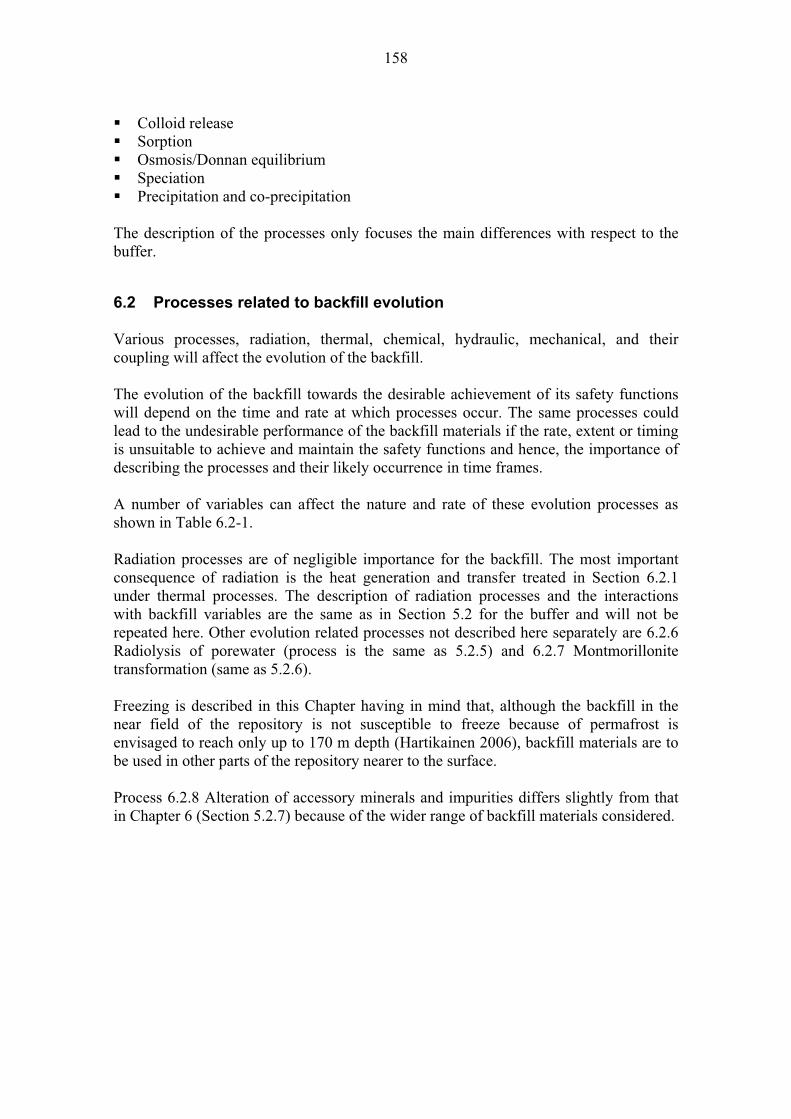
158
Colloid release SorptionOsmosis/Donnan equilibrium SpeciationPrecipitation and co-precipitation
The description of the processes only focuses the main differences with respect to the buffer.
6.2 Processes related to backfill evolution
Various processes, radiation, thermal, chemical, hydraulic, mechanical, and their coupling will affect the evolution of the backfill.
The evolution of the backfill towards the desirable achievement of its safety functions will depend on the time and rate at which processes occur. The same processes could lead to the undesirable performance of the backfill materials if the rate, extent or timing is unsuitable to achieve and maintain the safety functions and hence, the importance of describing the processes and their likely occurrence in time frames.
A number of variables can affect the nature and rate of these evolution processes as shown in Table 6.2-1.
Radiation processes are of negligible importance for the backfill. The most important consequence of radiation is the heat generation and transfer treated in Section 6.2.1 under thermal processes. The description of radiation processes and the interactions with backfill variables are the same as in Section 5.2 for the buffer and will not be repeated here. Other evolution related processes not described here separately are 6.2.6 Radiolysis of porewater (process is the same as 5.2.5) and 6.2.7 Montmorillonite transformation (same as 5.2.6).
Freezing is described in this Chapter having in mind that, although the backfill in the near field of the repository is not susceptible to freeze because of permafrost is envisaged to reach only up to 170 m depth (Hartikainen 2006), backfill materials are to be used in other parts of the repository nearer to the surface.
Process 6.2.8 Alteration of accessory minerals and impurities differs slightly from that in Chapter 6 (Section 5.2.7) because of the wider range of backfill materials considered.
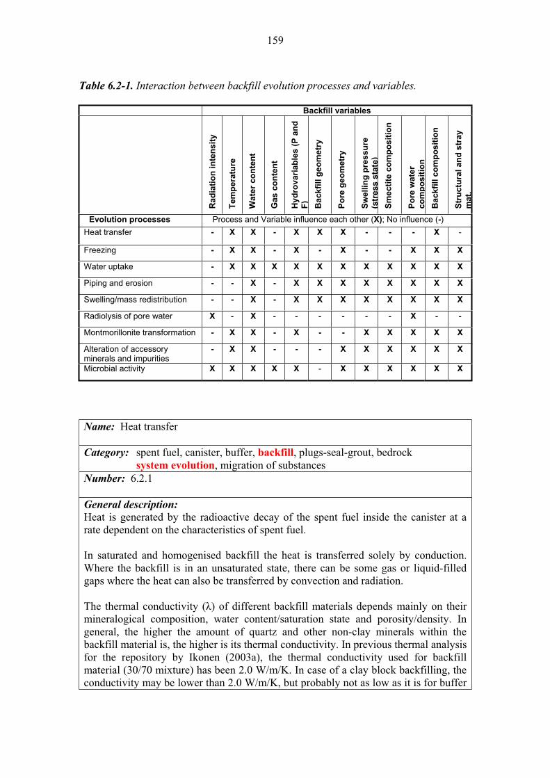
159
Table 6.2-1. Interaction between backfill evolution processes and variables.
Backfill variables
Ra
dia
tio
n in
ten
sit
y
Tem
pera
ture
Wate
r co
nte
nt
Gas c
on
ten
t
Hy
dro
va
ria
ble
s (
P a
nd
F)
Ba
ck
fill
ge
om
etr
y
Po
re g
eo
me
try
Sw
ellin
g p
ressu
re
(str
ess s
tate
)
Sm
ecti
te c
om
po
sit
ion
Po
re w
ate
r
co
mp
os
itio
n
Ba
ck
fill
co
mp
os
itio
n
Str
uctu
ral
an
d s
tray
mat.
Evolution processes Process and Variable influence each other (X); No influence (-)
Heat transfer - X X - X X X - - - X -
Freezing - X X - X - X - - X X X
Water uptake - X X X X X X X X X X X
Piping and erosion - - X - X X X X X X X X
Swelling/mass redistribution - - X - X X X X X X X X
Radiolysis of pore water X - X - - - - - - X - -
Montmorillonite transformation - X X - X - - X X X X X
Alteration of accessory minerals and impurities
- X X - - - X X X X X X
Microbial activity X X X X X - X X X X X X
Name: Heat transfer
Category: spent fuel, canister, buffer, backfill, plugs-seal-grout, bedrock system evolution, migration of substances
Number: 6.2.1
General description:
Heat is generated by the radioactive decay of the spent fuel inside the canister at a rate dependent on the characteristics of spent fuel.
In saturated and homogenised backfill the heat is transferred solely by conduction. Where the backfill is in an unsaturated state, there can be some gas or liquid-filled gaps where the heat can also be transferred by convection and radiation.
The thermal conductivity ( ) of different backfill materials depends mainly on their mineralogical composition, water content/saturation state and porosity/density. In general, the higher the amount of quartz and other non-clay minerals within the backfill material is, the higher is its thermal conductivity. In previous thermal analysis for the repository by Ikonen (2003a), the thermal conductivity used for backfill material (30/70 mixture) has been 2.0 W/m/K. In case of a clay block backfilling, the conductivity may be lower than 2.0 W/m/K, but probably not as low as it is for buffer
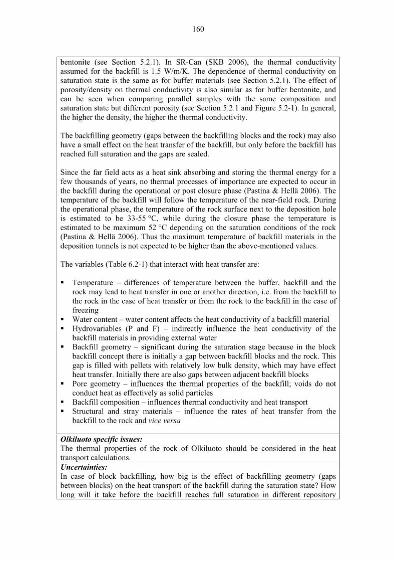
160
bentonite (see Section 5.2.1). In SR-Can (SKB 2006), the thermal conductivity assumed for the backfill is 1.5 W/m/K. The dependence of thermal conductivity on saturation state is the same as for buffer materials (see Section 5.2.1). The effect of porosity/density on thermal conductivity is also similar as for buffer bentonite, and can be seen when comparing parallel samples with the same composition and saturation state but different porosity (see Section 5.2.1 and Figure 5.2-1). In general, the higher the density, the higher the thermal conductivity.
The backfilling geometry (gaps between the backfilling blocks and the rock) may also have a small effect on the heat transfer of the backfill, but only before the backfill has reached full saturation and the gaps are sealed.
Since the far field acts as a heat sink absorbing and storing the thermal energy for a few thousands of years, no thermal processes of importance are expected to occur in the backfill during the operational or post closure phase (Pastina & Hellä 2006). The temperature of the backfill will follow the temperature of the near-field rock. During the operational phase, the temperature of the rock surface next to the deposition hole is estimated to be 33-55 °C, while during the closure phase the temperature is estimated to be maximum 52 °C depending on the saturation conditions of the rock (Pastina & Hellä 2006). Thus the maximum temperature of backfill materials in the deposition tunnels is not expected to be higher than the above-mentioned values.
The variables (Table 6.2-1) that interact with heat transfer are:
Temperature – differences of temperature between the buffer, backfill and the rock may lead to heat transfer in one or another direction, i.e. from the backfill to the rock in the case of heat transfer or from the rock to the backfill in the case of freezingWater content – water content affects the heat conductivity of a backfill material Hydrovariables (P and F) – indirectly influence the heat conductivity of the backfill materials in providing external water Backfill geometry – significant during the saturation stage because in the block backfill concept there is initially a gap between backfill blocks and the rock. This gap is filled with pellets with relatively low bulk density, which may have effect heat transfer. Initially there are also gaps between adjacent backfill blocks Pore geometry – influences the thermal properties of the backfill; voids do not conduct heat as effectively as solid particles Backfill composition – influences thermal conductivity and heat transport Structural and stray materials – influence the rates of heat transfer from the backfill to the rock and vice versa
Olkiluoto specific issues:
The thermal properties of the rock of Olkiluoto should be considered in the heat transport calculations. Uncertainties:
In case of block backfilling, how big is the effect of backfilling geometry (gaps between blocks) on the heat transport of the backfill during the saturation state? How long will it take before the backfill reaches full saturation in different repository

161
conditions? Thermal conductivity of different backfill material alternatives in varying density and saturation states. Time frames of relevance:
The maximum temperature in the near field rock and consequently also in the backfill is expected to be reached in about 50 years (Pastina & Hellä 2006). It is possible that the backfill has not reached full saturation during this time and this should be taken into account in the analysis. After the saturation of the backfill the heat transport takes place by conduction under well-defined conditions. The temperatures in the repository will remain elevated for approximately 1 000 years (Pastina & Hellä 2006).Scenarios of relevance:
The heat transport is relevant for all scenarios.Treatment in PA:
See Section 5.2.1 Significance: The significance of the process is LOW, since the effect of the heat transport in backfill is insignificant compared to buffer and the near-field/far-field bedrock.Equivalent NEA international FEP:
2.1.11 “Thermal processes and conditions (in wastes and EBS)” Key references:
Ikonen, K. 2003a. Thermal analyses of spent nuclear fuel repository. Posiva Oy, Olkiluoto, Finland. Posiva 2003-04.
Pastina, B. & Hellä, P. (Eds.) 2006. Expected evolution of a spent nuclear fuel repository at Olkiluoto. Posiva Oy, Olkiluoto, Finland. Report POSIVA 2006-05.
SKB 2006. Long-term safety for KBS-3 repositories at Forsmark and Laxemar – a first evaluation. Main report of the SR-Can project. Swedish Nuclear Fuel and Waste Management Co. (SKB), Stockholm, Sweden. SKB Technical Report TR-06-09.
Name: Freezing
Category: spent fuel, canister, buffer, backfill, plugs-seal-grout, bedrock system evolution, migration of substances
Number: 6.2.2
General description:
No freezing of the backfill is expected to occur during the operational and temperate post closure phase (Pastina & Hellä 2006). The likelihood of freezing is linked to the beginning of the next glaciation cycle and the formation of permafrost. According to the Weichselian-R scenario, the next glaciation cycle will start 13 000 years AP and will continue until 125 000 years AP (Pastina & Hellä 2006). Taking into account moderate amounts of greenhouse gases in the atmosphere (Emissions M-scenario) the subsequent glaciation will take place 170 000 years AP and will continue until 450 000 years AP (Pastina & Hellä 2006).
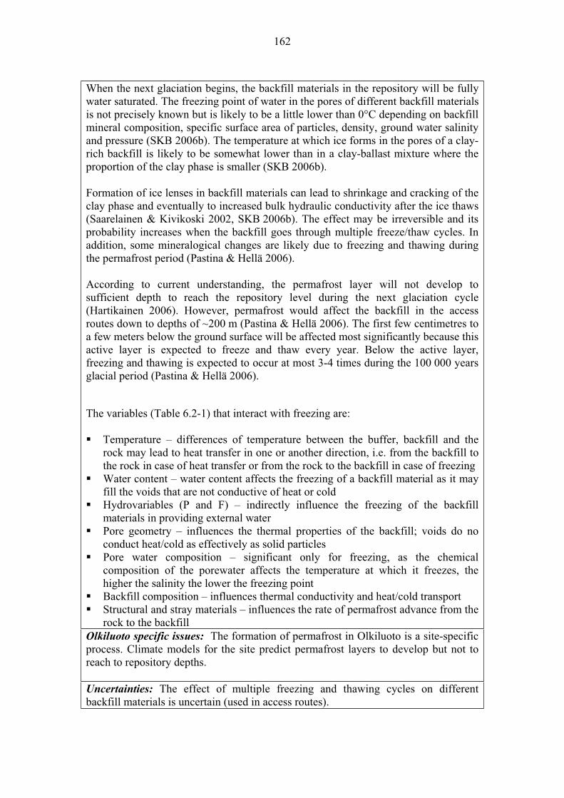
162
When the next glaciation begins, the backfill materials in the repository will be fully water saturated. The freezing point of water in the pores of different backfill materials is not precisely known but is likely to be a little lower than 0°C depending on backfill mineral composition, specific surface area of particles, density, ground water salinity and pressure (SKB 2006b). The temperature at which ice forms in the pores of a clay-rich backfill is likely to be somewhat lower than in a clay-ballast mixture where the proportion of the clay phase is smaller (SKB 2006b).
Formation of ice lenses in backfill materials can lead to shrinkage and cracking of the clay phase and eventually to increased bulk hydraulic conductivity after the ice thaws (Saarelainen & Kivikoski 2002, SKB 2006b). The effect may be irreversible and its probability increases when the backfill goes through multiple freeze/thaw cycles. In addition, some mineralogical changes are likely due to freezing and thawing during the permafrost period (Pastina & Hellä 2006).
According to current understanding, the permafrost layer will not develop to sufficient depth to reach the repository level during the next glaciation cycle (Hartikainen 2006). However, permafrost would affect the backfill in the access routes down to depths of ~200 m (Pastina & Hellä 2006). The first few centimetres to a few meters below the ground surface will be affected most significantly because this active layer is expected to freeze and thaw every year. Below the active layer, freezing and thawing is expected to occur at most 3-4 times during the 100 000 years glacial period (Pastina & Hellä 2006).
The variables (Table 6.2-1) that interact with freezing are:
Temperature – differences of temperature between the buffer, backfill and the rock may lead to heat transfer in one or another direction, i.e. from the backfill to the rock in case of heat transfer or from the rock to the backfill in case of freezing Water content – water content affects the freezing of a backfill material as it may fill the voids that are not conductive of heat or cold Hydrovariables (P and F) – indirectly influence the freezing of the backfill materials in providing external water Pore geometry – influences the thermal properties of the backfill; voids do no conduct heat/cold as effectively as solid particles Pore water composition – significant only for freezing, as the chemical composition of the porewater affects the temperature at which it freezes, the higher the salinity the lower the freezing point Backfill composition – influences thermal conductivity and heat/cold transport Structural and stray materials – influences the rate of permafrost advance from the rock to the backfill
Olkiluoto specific issues: The formation of permafrost in Olkiluoto is a site-specific process. Climate models for the site predict permafrost layers to develop but not to reach to repository depths.
Uncertainties: The effect of multiple freezing and thawing cycles on different backfill materials is uncertain (used in access routes).
163
Time frames of relevance: Freezing is a relevant process during the next glaciation period (from 13 000 years AP to several hundreds of thousands years). Scenarios of relevance: Freezing is relevant during and after permafrost periods for all scenarios.Treatment in PA: Freezing of the backfill will not be treated in the near field evolution model, since freezing is possible only in the near-surface parts of access routes of the repository. However, the issue is taken into account indirectly by modifying the parameters relevant to backfill permeability used in calculation cases derived from the assessment scenarios. Significance:
The freezing of the backfill is considered to be of LOW significance because the probability of permafrost occurrence at repository depth is very low. However, freezing needs to be taken into account in the design of backfill for access routes. Equivalent NEA international FEP:
2.1.11 “Thermal processes and conditions (in wastes and EBS)” Key references:
Hartikainen, J. 2006. Numerical simulation of permafrost depth at Olkiluoto. Posiva Oy, Olkiluoto, Finland. Posiva Working Report 2006-52.
Pastina, B. & Hellä, P. (Eds.) 2006. Expected evolution of a spent nuclear fuel repository at Olkiluoto. Posiva Oy, Olkiluoto, Finland. Report POSIVA 2006-05.
Saarelainen, S. & Kivikoski, H. 2002. Influence of freeze-thaw on the permeability of bentonite and bentonite mixtures – a literature study (in Finnish). Posiva Oy, Olkiluoto, Finland. Posiva Working Report 2002-31.
SKB 2006b. Buffer and backfill process report for the safety assessment SR-Can. Swedish Nuclear Fuel and Waste Management Co (SKB) Stockholm, Sweden. SKB Technical Report TR-06-18.
164
Name: Water uptake
Category: spent fuel, canister, buffer, backfill, plugs-seals-grout, bedrock system evolution, migration of substances Number: 6.2.3
General description:
Water uptake and transport in unsaturated backfill is a complex process affected by multiple variables. The main factors affecting the saturation of the backfill are the prevailing groundwater pressure in the surrounding rock and the negative capillary pressure (total suction) drawing water into the backfill material (Pastina & Hellä 2006). Water transport can take place either in the liquid or vapour phase. In the backfill, transport will mainly occur in the liquid phase, because the temperature due to radiogenic heat from the spent fuel will be lower than in the buffer due to the distance from the canister (see Section 6.4.1).
The backfill will have a certain initial water content depending on the material and the backfilling method. Groundwater will discharge from the rock matrix and water bearing fractures with varying inflow rate and pressure. The water transport depends on the water pressure gradient that is controlled by the hydraulic conductivity and the pore water pressure gradient in the backfill material (SKB 2006b). The requirement set for the final hydraulic conductivity of the backfill is 1x10⁻¹⁰ m/s, meaning that once enough saturation is reached that diffusion is the dominant transport process. This requirement is valid for the whole cross-section of the tunnel (Gunnarsson et al. 2006). The hydraulic conductivity of the backfill depends on the mineral composition of backfill material/materials, fraction and type of expandable clay minerals, density/void ratio, geometry of the backfill (density distribution), saturation state and salinity of the groundwater. In general, clay as a backfill material has a lower hydraulic conductivity than clay/ballast mixtures (Figures 6.2-1 and 6.2-2).
The suction potential of a backfill material depends on its saturation state (water retention curve), expandable clay mineral content and ionic concentration (SKB 2006b). The higher the saturation state of a material, the lower the suction potential. The suction potential of a bentonite/ballast mixture is low compared to pure clays, since the suction is determined by the clay fraction (clay dry density and clay water ratio) (SKB 2006b).
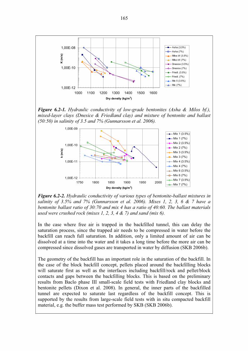
165
1,00E-12
1,00E-10
1,00E-08
1000 1100 1200 1300 1400 1500 1600
Dry density (kg/m3)
K (
m/s
)
Asha (3,5%)
Asha (7%)
Milos bf (3.5%)
Milso bf (7%)
Dnesice (3.5%)
Dnesice (7%)
Friedl. (3.5%)
Friedl. (7%)
Mix 5 (3.5%)
Mix (7%)
Figure 6.2-1. Hydraulic conductivity of low-grade bentonites (Asha & Milos bf.), mixed-layer clays (Dnesice & Friedland clay) and mixture of bentonite and ballast (50:50) in salinity of 3.5 and 7% (Gunnarsson et al. 2006).
1,00E-12
1,00E-11
1,00E-10
1,00E-09
1750 1800 1850 1900 1950 2000
Dry density (kg/m3)
k (
m/s
)
Mix 1 (3.5%)
Mix 1 (7%)
Mix 2 (3.5%)
Mix 2 (7%)
Mix 3 (3.5%)
Mix 3 (7%)
Mix 4 (3.5%)
Mix 4 (7%)
Mix 6 (3.5%)
Mix 6 (7%)
Mix 7 (3.5%)
Mix 7 (7%)
Figure 6.2-2. Hydraulic conductivity of various types of bentonite-ballast mixtures in salinity of 3.5% and 7% (Gunnarsson et al. 2006). Mixes 1, 2, 3, 6 & 7 have a bentonite ballast ratio of 30:70 and mix 4 has a ratio of 40:60. The ballast materials used were crushed rock (mixes 1, 2, 3, 4 & 7) and sand (mix 6).
In the case where free air is trapped in the backfilled tunnel, this can delay the saturation process, since the trapped air needs to be compressed in water before the backfill can reach full saturation. In addition, only a limited amount of air can be dissolved at a time into the water and it takes a long time before the more air can be compressed since dissolved gases are transported in water by diffusion (SKB 2006b).
The geometry of the backfill has an important role in the saturation of the backfill. In the case of the block backfill concept, pellets placed around the backfilling blocks will saturate first as well as the interfaces including backfill/rock and pellet/block contacts and gaps between the backfilling blocks. This is based on the preliminary results from Baclo phase III small-scale field tests with Friedland clay blocks and bentonite pellets (Dixon et al. 2008). In general, the inner parts of the backfilled tunnel are expected to saturate last regardless of the backfill concept. This is supported by the results from large-scale field tests with in situ compacted backfill material, e.g. the buffer mass test performed by SKB (SKB 2006b).
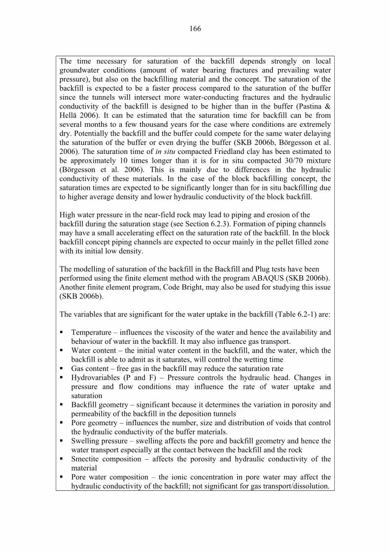
166
The time necessary for saturation of the backfill depends strongly on local groundwater conditions (amount of water bearing fractures and prevailing water pressure), but also on the backfilling material and the concept. The saturation of the backfill is expected to be a faster process compared to the saturation of the buffer since the tunnels will intersect more water-conducting fractures and the hydraulic conductivity of the backfill is designed to be higher than in the buffer (Pastina & Hellä 2006). It can be estimated that the saturation time for backfill can be from several months to a few thousand years for the case where conditions are extremely dry. Potentially the backfill and the buffer could compete for the same water delaying the saturation of the buffer or even drying the buffer (SKB 2006b, Börgesson et al. 2006). The saturation time of in situ compacted Friedland clay has been estimated to be approximately 10 times longer than it is for in situ compacted 30/70 mixture (Börgesson et al. 2006). This is mainly due to differences in the hydraulic conductivity of these materials. In the case of the block backfilling concept, the saturation times are expected to be significantly longer than for in situ backfilling due to higher average density and lower hydraulic conductivity of the block backfill.
High water pressure in the near-field rock may lead to piping and erosion of the backfill during the saturation stage (see Section 6.2.3). Formation of piping channels may have a small accelerating effect on the saturation rate of the backfill. In the block backfill concept piping channels are expected to occur mainly in the pellet filled zone with its initial low density.
The modelling of saturation of the backfill in the Backfill and Plug tests have been performed using the finite element method with the program ABAQUS (SKB 2006b). Another finite element program, Code Bright, may also be used for studying this issue (SKB 2006b).
The variables that are significant for the water uptake in the backfill (Table 6.2-1) are:
Temperature – influences the viscosity of the water and hence the availability and behaviour of water in the backfill. It may also influence gas transport. Water content – the initial water content in the backfill, and the water, which the backfill is able to admit as it saturates, will control the wetting time Gas content – free gas in the backfill may reduce the saturation rate Hydrovariables (P and F) – Pressure controls the hydraulic head. Changes in pressure and flow conditions may influence the rate of water uptake and saturation Backfill geometry – significant because it determines the variation in porosity and permeability of the backfill in the deposition tunnels Pore geometry – influences the number, size and distribution of voids that control the hydraulic conductivity of the buffer materials. Swelling pressure – swelling affects the pore and backfill geometry and hence the water transport especially at the contact between the backfill and the rock Smectite composition – affects the porosity and hydraulic conductivity of the material Pore water composition – the ionic concentration in pore water may affect the hydraulic conductivity of the backfill; not significant for gas transport/dissolution.
167
Backfill composition – the mineralogical composition affects the porosity and hydraulic conductivity of the material Structural and stay materials- the effectiveness of these materials as providing dry or wet conditions in the near field may influence the saturation of the backfill and also the occurrence of other hydraulic processes.
Olkiluoto specific issues:
Groundwater conditions (inflow, pressure, composition) are site specific and very localised (fracture networks) thus controlling the rate and heterogeneity of saturation. Uncertainties:
The saturation time of different backfill materials (in different backfilling concepts) need to be studied further with modelling, as well as the interaction between the buffer and backfill. This is important especially if the backfill consists of pre-compacted clay blocks. Time frames of relevance:
Depending of the backfill material and possibly also on the concept, water uptake may start at backfill deposition time and continue at least to the beginning of the post closure phase or even longer. Scenarios of relevance:
The water uptake and transport in unsaturated conditions is relevant for all scenarios. Treatment in PA:
The saturation of the backfill is treated in the near field evolution model and/or a separate study will be performed to explore the saturation of the buffer & backfill in detail.Significance:
The uptake of water in the backfill is of MEDIUM significance because it will affect the re-equilibrium of the near field and the state of the buffer. Disturbance to the backfill may provide potential fast flow-paths for radionuclides once the canister has been breached and they have migrated through the buffer. However, this is not expected to happen before the backfill has reached full saturation. The process is most important for the additional scenario AD-II.
Water transport along the floor of the deposition tunnel could potentially lead to erosion of buffer bentonite in the case the water would have free access to the deposition hole (see Process 6.2.4 Piping and erosion).
Equivalent NEA international FEP:
2.1.08 “Hydraulic/hydrogeological processes and conditions (in wastes and EBS)”
Key references:
Börgesson, L., Fälth, B. & Hernelind, J. 2006. Water saturation phase of the buffer & backfill in the KBS-3V concept – Special emphasis given to the influence of backfill on the wetting of the buffer. Swedish Nuclear Fuel and Waste Management Co (SKB) Stockholm, Sweden. SKB Technical Report TR-06-14.
Dixon, D., Anttila, S., Viitanen, M. & Keto, P. 2008. Tests to determine water uptake behaviour of tunnel backfill (Baclo tests at Äspö). SKB R-series report, R-08-xx. (To be published).
168
Gunnarsson, D., Morén, L., Sellin, P. & Keto, P. 2006. Deep Repository – engineered barrier systems. Assessment of backfill materials and methods for deposition tunnels. Posiva Oy, Olkiluoto. Posiva Working Report 2006-64.
Pastina, B. & Hellä, P. (Eds.) 2006. Expected evolution of a spent nuclear fuel repository at Olkiluoto. Posiva Oy, Olkiluoto, Finland. Report POSIVA 2006-05.
SKB 2006b. Buffer and backfill process report for the safety assessment SR-Can. Swedish Nuclear Fuel and Waste Management Co (SKB) Stockholm, Sweden. SKB Technical Report TR-06-18.
Name: Piping and erosion, including chemical erosion
Category: spent fuel, canister, buffer, backfill, plugs-seals-grout, bedrocksystem evolution, migration of substances
Number: 6.2.4
General description:
High water pressure in the near-field rock may lead to piping and erosion of the backfill during water uptake (see process 6.2.3). Formation of piping channels may have a small accelerating effect on the saturation rate of the backfill. In the block backfill concept piping channels are expected to occur mainly in the pellet filled zone with initial its low density.
The erosion of backfill materials takes place “when the drag force on a particle from the water movement is higher than the sum of friction and attraction forces between the particle and the clay structure” (SKB 2006b, see also Section 5.2.3 of this report). Erosion of backfill is expected to take place during the operational phase (first 0–100 years) but not during the post closure phase after the enhanced ground water flow due to construction of the repository have stabilized (Pastina & Hellä 2006). For chemical erosion see Section 5.2.3.
At the time of the installation of the backfill, erosion occurs at the exposed surface of the bulk backfill materials and as a consequence of the formation of flow channels (piping) through the backfill. Surface erosion takes place when the material cannot absorb all the water running on the exposed surface and the excess water and eroded particles start to flow gravitationally out of the tunnel. After installation of a concrete plug at the entrance of the disposal tunnel, erosion will be concentrated into piping channels. Formation of piping channels takes place when the water pressure exceeds the sum of swelling pressure and shear resistance of a backfill material (SKB 2006b). As a consequence of decreased hydraulic gradients in the repository (in time and due to installation of plugs), saturation and swelling of backfill materials, piping channels are expected eventually to self-heal. Based on preliminary results from the Baclo laboratory tests, the self-healing depends on the density and composition of backfill
169
materials. In general, bentonite-backfill mixtures seem to have a poorer self-healing capacity compared to other swelling clays.
Important controls on erosion are the degree to which tunnels and other underground spaces are filled with backfill material, the location and tightness of plugs cutting the flow paths, and the properties and location of rock fractures intersecting the tunnels. This is simply because free space needs to be available “downstream” for the erosion to occur, otherwise the flow paths are clogged by the particles and the erosion ceases (SKB 2006b).
In block backfill the erosion is expected to be concentrated in the pellet filled zone with its initial low density. In principle the situation is the same in the in situ concept, where low-density zones are located near the rock surfaces. The extent of erosion needs to be fairly large before it has a significant effect on the average bulk density of the backfill, especially in the case of the block backfilling concept. However, locally the drop in density may be more severe leading to reduction in swelling pressure, increased hydraulic conductivity and increased accessibility to buffer (Pastina & Hellä 2006). The dry density distribution of block backfill (homogenisation) after saturation is currently being studied in the Baclo programme. In addition, the effect of inflow rate, inflow time, pellet material, and water salinity on the erosion rate is currently being tested in laboratory and large-scale tests (Börgesson & Sandén 2006). It is not thought likely that erosion will substantially affect the characteristics of the backfill.
Erosion is a very common process observed in nature. Understanding concerning the erosion in nature can possibly be applied for studying the erosion of backfill materials, although the conditions are different. So far, such investigations applied for repository conditions have not been performed.
Chemical erosion due to diluted water during the glacial phase has been discussed in Section 5.2.3.
The variables that are significant for piping/erosion in the backfill (Table 6.2-1) are:
Water content – the initial water content in the backfill, and the water, which the backfill is able to admit as it saturates will control the process Hydrovariables (P and F) – Pressure controls the hydraulic head. Changes in pressure and flow conditions may shift the adequate wetting to piping/erosion Backfill geometry – significant because it determines the variation in porosity and permeability of the backfill in the deposition tunnels Pore geometry – influences the number, size and distribution of voids that control the hydraulic conductivity of the backfill materials Swelling pressure – swelling affects the pore and backfill geometry and hence the water transport especially at the contact between the backfill and the rock Smectite composition – affects the porosity and hydraulic conductivity of the material Pore water composition – the ionic concentration in pore water may affect the hydraulic conductivity of the backfill

170
Backfill composition – the mineralogical composition affects the porosity and hydraulic conductivity of the material Structural and stay materials- the effectiveness of these materials as providing dry or wet conditions in the near field may influence the occurrence or not of piping/erosion
Olkiluoto specific issues:
The extent of erosion of the backfill will be controlled in part by the site-specific nature of the fracture zones that will intersect the deposition tunnels and the rate of groundwater inflow prior to resaturation. Uncertainties:
The effect of variables (inflow, salinity, time, materials, design) on the erosion rate is not comprehensively understood. In addition, it is not certain if the results from laboratory tests can be scaled-up to the repository scale. The consequences of the erosion depend on how much material is lost during the operational phase, whether the piping channels will self-heal and what is the resulting dry density distribution after the backfill has reach full saturation.
Time frames of relevance:
Erosion will occur preferently during the operational phase and during the beginning of the post closure phase (until the enhanced groundwater flows have stabilized following hydraulic resaturation).
Chemical erosion due to the penetration of dilute meltwater is only relevant after the end of the first ice-sheet at 70 000 years AP (Pastina & Hellä 2006). Scenarios of relevance:
Erosion and piping needs to be considered in all scenarios, and it is especially relevant in AD-II, where the buffer is considered either to be misplaced or initially defective.Treatment in PA:
Erosion and piping in backfill is indirectly taken into account when selecting the transport parameters for backfill to be used in the calculation cases derived from the assessment scenarios. Significance:
The significance of erosion of the backfill is considered to be MEDIUM because it is not thought likely to occur to such an extent to result in any substantial reduction in the swelling pressure or increase in the permeability of the backfill, but in the long term it may to affect the migration of radionuclides from the repository once the canister has been breached. However if it is assumed that the backfill has sufficient self-healing capacity to seal piping channels after saturation, the process may be considered of LOW significance. Equivalent NEA international FEP:
2.1.04 “Buffer/backfill materials and characteristics” 2.1.08 “Hydraulic/hyrdrogeological processes and conditions (in wastes and EBS)” Key references:
Börgesson, L. & Sandén, T. 2006. Piping and erosion in buffer and backfill materials. Current knowledge. Swedish Nuclear Fuel and Waste Management Co (SKB) Stockholm, Sweden. SKB R-06-80.
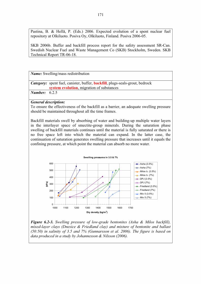
171
Pastina, B. & Hellä, P. (Eds.) 2006. Expected evolution of a spent nuclear fuel repository at Olkiluoto. Posiva Oy, Olkiluoto, Finland. Posiva 2006-05.
SKB 2006b. Buffer and backfill process report for the safety assessment SR-Can. Swedish Nuclear Fuel and Waste Management Co (SKB) Stockholm, Sweden. SKB Technical Report TR-06-18.
Name: Swelling/mass redistribution
Category: spent fuel, canister, buffer, backfill, plugs-seals-grout, bedrock system evolution, migration of substances
Number: 6.2.5
General description:
To ensure the effectiveness of the backfill as a barrier, an adequate swelling pressure should be maintained throughout all the time frames.
Backfill materials swell by absorbing of water and building-up multiple water layers in the interlayer space of smectite-group minerals. During the saturation phase swelling of backfill materials continues until the material is fully saturated or there is no free space left into which the material can expand. In the latter case, the continuation of saturation generates swelling pressure that increases until it equals the confining pressure, at which point the material can absorb no more water.
Swelling pressures in 3.5 & 7%
0
100
200
300
400
500
600
1000 1100 1200 1300 1400 1500 1600 1700
Dry density (kg/m3)
(kP
a)
Asha (3.5%)
Asha (7%)
Milos b. (3.5%)
Milos b. (7%)
DPJ (3.5%)
DPJ (7%)
Friedland (3.5%)
Friedland (7%)
Mix 5 (3.5%)
Mix 5 (7%)
Figure 6.2-3. Swelling pressure of low-grade bentonites (Asha & Milos backfill), mixed-layer clays (Dnesice & Friedland clay) and mixture of bentonite and ballast (50:50) in salinity of 3.5 and 7% (Gunnarsson et al. 2006). The figure is based on data produced in a study by Johannesson & Nilsson (2006).
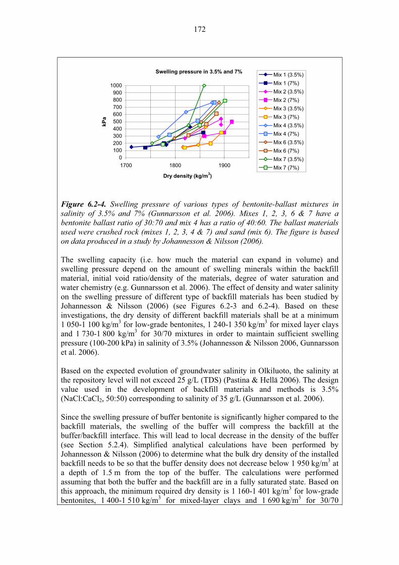
172
Swelling pressure in 3.5% and 7%
0
100200
300400
500
600700
800900
1000
1700 1800 1900
Dry density (kg/m3)
kP
a
Mix 1 (3.5%)
Mix 1 (7%)
Mix 2 (3.5%)
Mix 2 (7%)
Mix 3 (3.5%)
Mix 3 (7%)
Mix 4 (3.5%)
Mix 4 (7%)
Mix 6 (3.5%)
Mix 6 (7%)
Mix 7 (3.5%)
Mix 7 (7%)
Figure 6.2-4. Swelling pressure of various types of bentonite-ballast mixtures in salinity of 3.5% and 7% (Gunnarsson et al. 2006). Mixes 1, 2, 3, 6 & 7 have a bentonite ballast ratio of 30:70 and mix 4 has a ratio of 40:60. The ballast materials used were crushed rock (mixes 1, 2, 3, 4 & 7) and sand (mix 6). The figure is based on data produced in a study by Johannesson & Nilsson (2006).
The swelling capacity (i.e. how much the material can expand in volume) and swelling pressure depend on the amount of swelling minerals within the backfill material, initial void ratio/density of the materials, degree of water saturation and water chemistry (e.g. Gunnarsson et al. 2006). The effect of density and water salinity on the swelling pressure of different type of backfill materials has been studied by Johannesson & Nilsson (2006) (see Figures 6.2-3 and 6.2-4). Based on these investigations, the dry density of different backfill materials shall be at a minimum 1 050-1 100 kg/m3 for low-grade bentonites, 1 240-1 350 kg/m3 for mixed layer clays and 1 730-1 800 kg/m3 for 30/70 mixtures in order to maintain sufficient swelling pressure (100-200 kPa) in salinity of 3.5% (Johannesson & Nilsson 2006, Gunnarsson et al. 2006).
Based on the expected evolution of groundwater salinity in Olkiluoto, the salinity at the repository level will not exceed 25 g/L (TDS) (Pastina & Hellä 2006). The design value used in the development of backfill materials and methods is 3.5% (NaCl:CaCl2, 50:50) corresponding to salinity of 35 g/L (Gunnarsson et al. 2006).
Since the swelling pressure of buffer bentonite is significantly higher compared to the backfill materials, the swelling of the buffer will compress the backfill at the buffer/backfill interface. This will lead to local decrease in the density of the buffer (see Section 5.2.4). Simplified analytical calculations have been performed by Johannesson & Nilsson (2006) to determine what the bulk dry density of the installed backfill needs to be so that the buffer density does not decrease below 1 950 kg/m3 at a depth of 1.5 m from the top of the buffer. The calculations were performed assuming that both the buffer and the backfill are in a fully saturated state. Based on this approach, the minimum required dry density is 1 160-1 401 kg/m3 for low-grade bentonites, 1 400-1 510 kg/m3 for mixed-layer clays and 1 690 kg/m3 for 30/70
173
mixtures (Johannesson & Nilsson 2006, Gunnarsson et al. 2006). The mechanical interaction between the buffer and the backfill is currently studied further in the third phase of the Baclo programme.
Water uptake and swelling are the main processes causing homogenisation of the backfill (i.e. the bulk density distribution after saturation) and self-healing of piping channels that are important processes affecting water transport and erosion (Sections 6.2.3 and 6.2.4).
Whether the swelling of backfill materials is sufficient to fill the voids left after emplacement in the block backfill concept depends also on the backfill geometry, e.g. the block filling degree. In addition, deformation of partially saturated backfill due to swelling of the buffer bentonite depends on the backfill geometry. This is because there will be gaps between blocks and the loose pellet filled zone between the blocks and the rock. The effect of backfill design on homogenisation and mechanical behaviour of the block backfill will be further studied in the Baclo programme.
The backfill is expected to generate sufficient swelling pressure (100-200 kPa) in order to resist breakout and limit spalling of the near-field rock in the deposition tunnels (Pastina & Hellä 2006). Intrusion of backfill material into fractures by swelling is expected to be an insignificant process (SKB 2006b). Different plug structures shall be designed to withstand the pressure generated by the backfill material and full water pressure. If clay blocks with high swelling pressure are used in backfilling, this needs to be taken into account in the plug design. After closure of the repository the groundwater pressure gradients will gradually even out and will equalise on both sides of the plug (SKB 2006b).
Cation exchange from Na+ to Ca2+/Mg2+ (in the case of backfill materials with Na+ as the dominant exchangeable cation) is expected to have only a small effect on the swelling properties if the amount of swelling minerals and the density is sufficiently large (Karnland & Birgesson 2006).
The variables (Table 6.2-1) that are significant for swelling of the backfill are: Water content – the initial water content and the water that the backfill is able to uptake will influence swellingHydrovariables (P and F) – Pressure and flow conditions influence the availability of water and hence the swelling of the backfill Backfill geometry – the amount and distribution of swelling material influences the swelling and homogenisation of the backfill at tunnel scale Pore geometry – influences the hydraulic conductivity and hence the uptake of water and swelling capability Swelling pressure – influence swellingSmectite composition – swelling clays are all smectites, which composition determines the swelling capability. Porewater composition – the ionic concentration in pore water may affect the hydraulic conductivity of the backfill and hence its swelling Backfill composition – the amount and type of swelling minerals correlate with swelling

174
Structural and stray materials – the effectiveness of these materials to provide dry or wet conditions in the near field influences the availability of water, and hence the swelling of the buffer
Olkiluoto specific issues:
The expected maximum groundwater salinity is relatively high 25 g/L (TDS) and the performance of the backfill needs to address this. In addition, local groundwater conditions dictate the saturation process and the resulting swelling and compression properties of the backfill. Uncertainties:
Compression of the backfill due to swelling of the buffer in different saturation states. Effects of backfill design (e.g. the block filling degree) on the mechanical behaviour and homogenisation of the backfill will be studied further in the Baclo programme. Time frames of relevance:
Swelling and mass redistribution is a relevant process for all time frames. After saturation of both backfill and buffer (operational & post closure phase) the swelling of the buffer and compression of backfill will reach a steady state, where no more mass redistribution is expected. Scenarios of relevance:
Swelling and mass re-distribution is relevant for all scenarios.Treatment in PA:
The process is not explicitly taken into account in PA, but indirectly in selecting the backfill parameters (Da, Kd) to be used in the calculations cases derived from the
assessment scenarios.
A separate study is performed in the Baclo programme to model the mechanical interaction between the buffer and the backfill. Significance:
The swelling and mass distribution of the backfill is considered to be of HIGH
significance because it is a major control on the performance of the buffer, ensuring that the buffer provides a diffusion barrier to radionuclide migration once the canister is breached. Equivalent NEA international FEP:
2.1.04 “Buffer/backfill materials and characteristics” 2.1.07 “Mechanical processes and conditions (in wastes and EBS)” 2.1.08 “Hydraulic/hydrogeological processes and conditions (in wastes and EBS)” Key references:
Gunnarsson, D., Morén, L., Sellin, P. & Keto, P. 2006. Deep Repository – engineered barrier systems. Assessment of backfill materials and methods for deposition tunnels. Posiva Oy, Olkiluoto, Finland. Posiva Working Report 2006-64.
Johannesson, L-E. & Nilsson, U. 2006. Deep Repository – engineered barrier systems. Geotechnical behaviour of candidate backfill materials. Laboratory tests and calculations for determining performance of the backfill. Swedish Nuclear Fuel and Waste Management Co (SKB) Stockholm, Sweden. SKB R-06-73.
Karnland, O. & Birgesson, M. 2006. Montmorillonite stability. With special respect to KBS-3 conditions. Swedish Nuclear Fuel and Waste Management Co (SKB) Stockholm, Sweden. SKB Technical Report TR-06-11.
175
Pastina, B. & Hellä, P. (Eds.) 2006. Expected evolution of a spent nuclear fuel repository at Olkiluoto. Posiva Oy, Olkiluoto, Finland. Posiva 2006-05.
SKB 2006b. Buffer and backfill process report for the safety assessment SR-Can. Swedish Nuclear Fuel and Waste Management Co (SKB) Stockholm, Sweden. SKB Technical Report TR-06-18.
Name: Alteration of accessory minerals and impurities
Category: spent fuel, canister, buffer, backfill, plugs-seals-grout, bedrock system evolution, migration of substances
Number: 6.2.6
General description:
The content of accessory minerals in the 30/70 mixture in the backfill is different from the buffer (mainly bentonite). This includes both the amount and type of reactive minerals (different than framework silicates). Although the same chemical processes that occur in the buffer may also act in the backfill here are, however, some important differences between the two barrier materials. The temperature in the backfill is much lower than the buffer, and the thermal gradients are lower. Consequently dissolution/precipitation of minerals due to temperature effects is of less importance in the backfill. Friedland clay does contain minerals, which can affect the chemistry and thus mineral alteration processes (SKB 2006b).
No specific studies of chemical processes in the backfill have been done and the evaluation has to be based on the studies performed on bentonites and extrapolation from buffer studies. The differences in the composition, physical properties, temperature etc., have to be considered in the evaluation.
The variables (Table 6.2-1) that are significant for the alteration of accessory minerals are the same as the ones for montmorillonite transformation (see Section 5.2.6).
Olkiluoto specific issues:
The chemical conditions of the groundwater and the hydraulic parameters of the rock are considered. Uncertainties:
The main uncertainty from a design perspective is the composition of the backfill material, and the manner of its emplacement, which will control the final bulk permeability and porosity. Key thermodynamic data are well established and therefore reliable. The main uncertainties remain in the definition of the kinetically controlled processes.
Some critical uncertainties remain concerning the mechanistic understanding of the processes that control the redox state of the backfill system. It is not clear yet to what extent pyrite, siderite and/or iron in the smectite structure are the main redox
176
controlling phases. In backfill also microbially mediated processes are possible (see 6.2.9).
Some of the silicate transformations are kinetically controlled and their mechanistic understanding in compacted bentonite conditions is poorly known.
It is assumed that pH is buffered by the equilibrium with calcite. However, the amount (or even the presence) of this mineral phase is somewhat uncertain for some of the bentonite types under consideration (i.e. MX-80 bentonite). Time frames of relevance:
All time frames. Scenarios of relevance:
Alteration of the backfill will occur in all scenarios but may be more important in the buffer emplacement defects (AD-II) if the backfill is also poorly emplaced. Higher void space in the backfill will allow greater groundwater flow rates and higher water/rock ratios thus potentially accelerating the alteration rate.Treatment in PA:
The process is not explicitly included in the radionuclide transport calculation but in the modelling of the backfill chemical evolution. The model handles advective flow, diffusive transport, dissolution-precipitation of main bentonite accessory minerals, cation exchange and protonation-deprotonation.Significance:
The alteration of the backfill material by interaction with groundwater is of LOW
significance because the large bulk of the material will buffer the physical and chemical conditions for 105 years or so. It is considered unlikely that alteration of the backfill under expected conditions will ever substantially affect the canister or the transport of radionuclides in the near or far-fields after the canister is breached. Equivalent NEA international FEP:
2.1.09 “Chemical/geochemical processes and conditions (in wastes and EBS)” Key references:
SKB 2006b. Buffer and backfill process report for the safety assessment SR-Can. Swedish Nuclear Fuel and Waste Management Co (SKB) Stockholm, Sweden. SKB Technical Report TR-06-18.
Name: Microbial activity
Category: spent fuel, canister, buffer, backfill, plugs-seals-grout, bedrock system evolution, migration of substances
Number: 6.2.7
General description:
Characteristic to the backfill environment will be a) the presence of organic material in structural and stray material, b) a gas/water interface that will develop during the saturation process, and c) the presence of free oxygen until it has been consumed and reduced by microbes and/or by inorganic oxygen scavengers such as sulphides. Both of these factors are conducive to the presence of microbial populations.

177
The potential significance of microbes in the backfill is that, if they are present in viable populations, they could affect the chemistry and, if mobile, they could enhance radionuclide transport after the canister has been breached.
A schematic model of microbial activity in the backfill as a function of time is shown in Figure 6.2-5. If the density of the backfill bentonite is not high enough to make the environment hostile to microbes, the backfill may be a source of dissolved sulphide through the action of sulphate-reducing bacteria. Microbial activity is predicted to be greatest immediately after backfilling, when the groundwater reaches the backfill and mildly elevated temperatures promote microbiological oxygen reduction. Pedersen (2000) suggested that microbes could be extremely effective in removing oxygen from the backfill pore fluid mitigating corrosion of the copper canister. Microbial activity will decline as organic matter and oxygen in the backfill are consumed over time.
There have been few results from backfill research. A full-scale backfill and plug test has been started at the Äspö HRL (SKB 1999, Pedersen 2000). Laboratory cultures of various bacteria were introduced at specific positions in the middle of the backfill and the microbes in the backfill were analysed. The results showed a significant diversity of culturable bacteria in the backfill material at the outset.
The ongoing backfill experiment at Äspö hard rock laboratory includes microbial investigations. Large amounts of different micro-organisms were introduced locally to positions in the backfill. When the laboratory was decommissioned, the populations and activity of introduced as well as naturally occurring microbes in the backfill will be analysed. In addition, gases were analysed for the presence of microbially generated gas content. The results showed the presence of micro-organisms in the groundwater and demonstrated that the concentration of groundwater gases such as methane and hydrogen had increased significantly since closure (SKB 2006b).
Sulphide formation is considered in the mass balance calculations (Pastina & Hellä 2006). These calculations show that sulphides are precipitated as pyrite in the backfill. The build-up of gas pressure within the backfill is highly unlikely as any gas produced will be dissolved and transported away.
The radiation, desiccation and the swelling pressure effects on microbial activity in the backfill will be less pronounced than in the buffer and continuous microbial activity will be possible (Pedersen 2000).
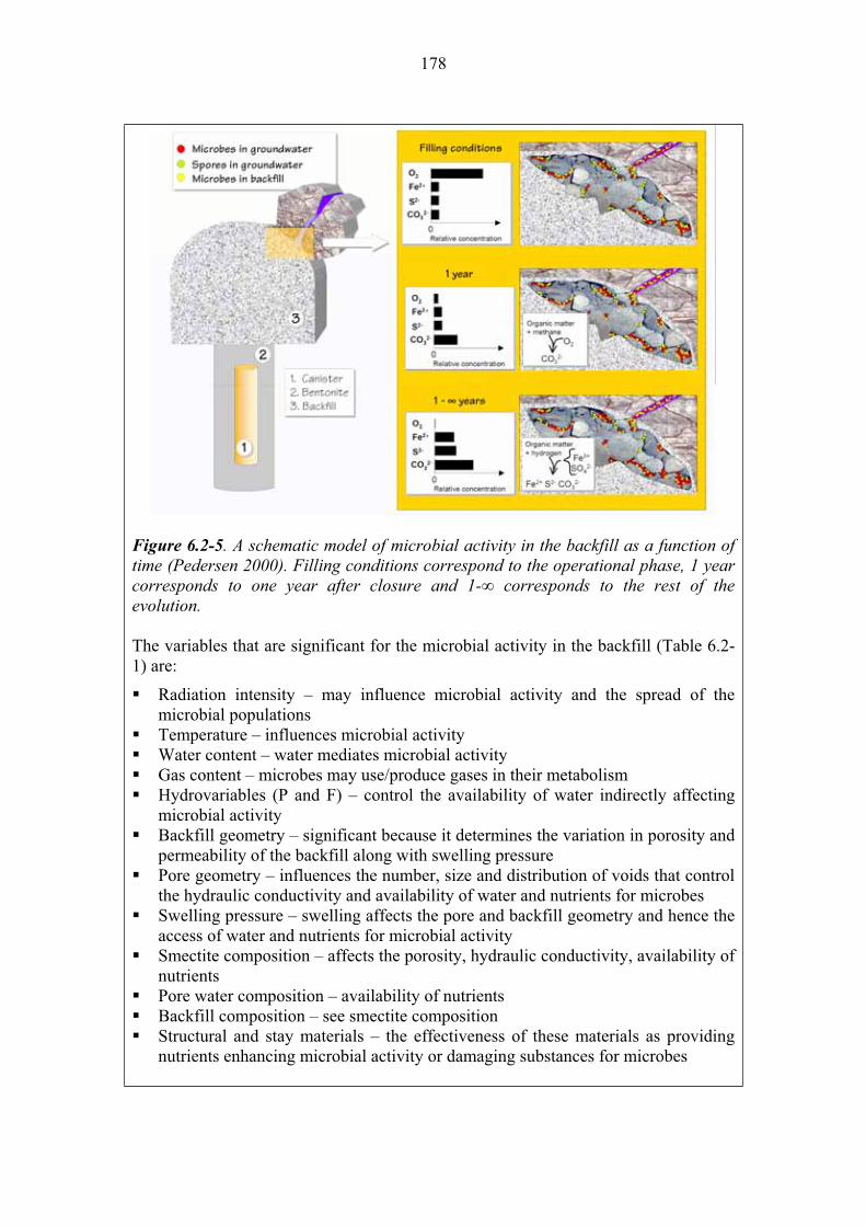
178
Figure 6.2-5. A schematic model of microbial activity in the backfill as a function of time (Pedersen 2000). Filling conditions correspond to the operational phase, 1 year corresponds to one year after closure and 1- corresponds to the rest of the evolution.
The variables that are significant for the microbial activity in the backfill (Table 6.2-1) are:
Radiation intensity – may influence microbial activity and the spread of the microbial populations Temperature – influences microbial activity Water content – water mediates microbial activity Gas content – microbes may use/produce gases in their metabolism Hydrovariables (P and F) – control the availability of water indirectly affecting microbial activity Backfill geometry – significant because it determines the variation in porosity and permeability of the backfill along with swelling pressure Pore geometry – influences the number, size and distribution of voids that control the hydraulic conductivity and availability of water and nutrients for microbes Swelling pressure – swelling affects the pore and backfill geometry and hence the access of water and nutrients for microbial activity Smectite composition – affects the porosity, hydraulic conductivity, availability of nutrientsPore water composition – availability of nutrients Backfill composition – see smectite composition Structural and stay materials – the effectiveness of these materials as providing nutrients enhancing microbial activity or damaging substances for microbes

179
Olkiluoto specific issues:
Groundwater chemistry and in situ microbial populations. Uncertainties:
The dominant uncertainty is the viable population of microbes in the backfill and their levels of activity. Time frames of relevance:
The process is relevant for all timeframes. Scenarios of relevance:
The process is relevant for all scenarios.Treatment in PA:
Microbial action is not explicitly included in the PA models. However, in supplementary calculations the mass balance will show how different kinds of residual materials remaining in the repository will contribute to microbial oxygen reduction. Furthermore, the availability of hydrogen will be decisive for microbial activity in the long term. Oxygen, ferric iron, sulphate and carbon dioxide will be reduced. The scope of these reactions is dependent on mass flows (SKB 2006b). Significance:
The action of microbial populations in the backfill is considered to be of LOW
significance: although viable populations are likely to be present their activity is unlikely to have any significant effect on the physical or chemical conditions. Thus these populations are unlikely to affect either the performance of the near-field barriers or the transport of radionuclides after the canister has been breached. Equivalent NEA international FEP:
2.1.10 “Biological/biochemical processes and conditions (in wastes and EBS)” Key references:
Pastina, B. & Hellä, P. (Eds.) 2006. Expected evolution of a spent nuclear fuel repository at Olkiluoto. Posiva Oy, Olkiluoto, Finland. Posiva 2006-05.
Pedersen, K. 2000. Microbial processes in radioactive waste disposal. Swedish Nuclear Fuel and Waste Management Co. (SKB), Stockholm, Sweden. SKB Technical Report TR 00-04.
SKB 1999. Äspö hard rock laboratory. Annual report 1998. Swedish Nuclear Fuel and Waste Management Co. (SKB), Stockholm, Sweden. SKB Technical Report TR-99-10.
SKB 2006b. Buffer and backfill process report for the safety assessment SR-Can. Swedish Nuclear Fuel and Waste Management Co (SKB) Stockholm, Sweden. SKB Technical Report TR-06-18.

180
6.3 Processes related to the migration of radionuclides and other substances
The physical and chemical processes that control the migration of radionuclides and other substances through the backfill are the same as to those of the buffer, and as such they are not treated separately in this chapter.

181
7 PLUGS, SEALS, GROUT
7.1 Description
Plugs, seals, and grout are structural components/materials used in the construction of the repository and access tunnel/s to improve their performance.
Plugs, made of concrete, are intended to be used at the top part of the access ramp to Onkalo, and at the entrance to the disposal tunnels at the repository level. The thickness of the plug will be 6 m according to preliminary dimensioning (Haaramo 1999). A concrete plate (5-10 cm thick; SKB 2004c) covered with a thin disk of metallic copper (Pastina & Hellä 2006) is also intended to be placed at the bottom of each deposition hole to level them and allow the canister to stay in a vertical position.
Borehole seals are of two types, tight seals and upper end seals. Tight seals are proposed to be constructed for the parts of boreholes where the rock has few fractures and a low hydraulic conductivity (Pusch & Ramqvist 2007a). For the upper end seals of deep boreholes two concepts (Figs. 7.1-1 and 7.1-2) have been developed and tested (Pusch & Ramqvist 2007a,b).
Between the tight seals the filling of those parts that intersect permeated fracture zones that does not need to be very low permeable but physically stable material that must be chemically compatible with the tight seals. These consist of smectite-rich clay in the form of highly compacted blocks or pellets, while the fillings separating them consists of silica concrete with a low content of low-pH cement plus ballast (aggregates) of quartz sand and quartzite. This type of concrete is largely inert with respect to chemical interaction with smectite clay. Should the cement component be leached its function as fill is not jeopardised because of the range of grain sizes in the ballast grains that prevents the large majority of them from migrating into the rock fractures.
The upper end seals represent “mechanical locks” that can be covered by other materials like moraine, silica concrete and trimmed rock columns. These covering materials can be allowed to degrade and be lost by (glacial) erosion while the “locks” need to remain largely intact for protecting the tight seals deeper in the boreholes. The chemical longevity of the materials selected, metallic copper and silica concrete, is claimed to be sufficient for the plugs to provide adequate sealing of the boreholes for at least 100 000 years. They have the necessary compressive and shear strengths to withstand the pressure from the tight seals in the holes as well as from possibly arising hydraulic gradients (see e.g. Section 8.3 in Pastina & Hellä 2006).
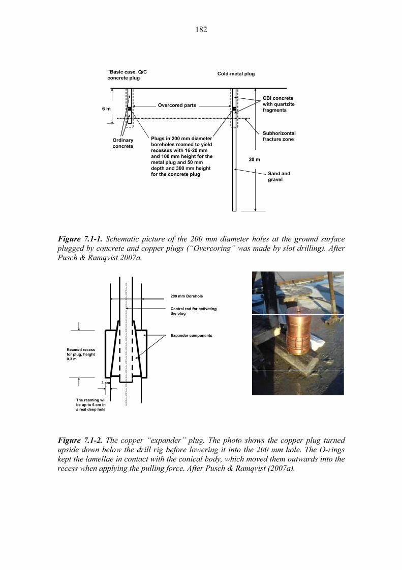
182
6 m
”Basic case, Q/C
concrete plugCold-metal plug
20 m
Plugs in 200 mm diameter
boreholes reamed to yield
recesses with 16-20 mm
and 100 mm height for the
metal plug and 50 mm
depth and 300 mm height
for the concrete plug
Overcored parts
Subhorizontal
fracture zoneOrdinary
concrete
Sand and
gravel
CBI concrete
with quartzite
fragments
Figure 7.1-1. Schematic picture of the 200 mm diameter holes at the ground surface plugged by concrete and copper plugs (“Overcoring” was made by slot drilling). After Pusch & Ramqvist 2007a.
200 mm Borehole
3 cm
Reamed recess
for plug, height
0.3 m
Central rod for activating
the plug
Expander components
The reaming will
be up to 5 cm in
a real deep hole
Figure 7.1-2. The copper “expander” plug. The photo shows the copper plug turned upside down below the drill rig before lowering it into the 200 mm hole. The O-rings kept the lamellae in contact with the conical body, which moved them outwards into the recess when applying the pulling force. After Pusch & Ramqvist (2007a).
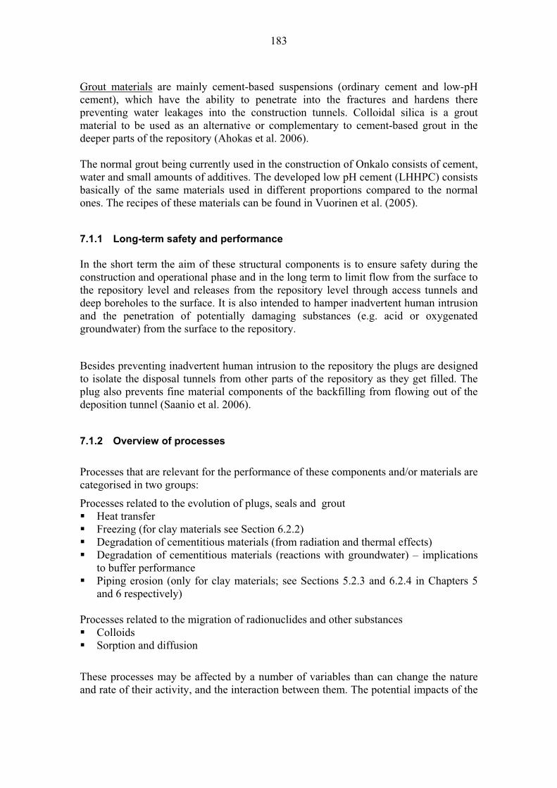
183
Grout materials are mainly cement-based suspensions (ordinary cement and low-pH cement), which have the ability to penetrate into the fractures and hardens there preventing water leakages into the construction tunnels. Colloidal silica is a grout material to be used as an alternative or complementary to cement-based grout in the deeper parts of the repository (Ahokas et al. 2006).
The normal grout being currently used in the construction of Onkalo consists of cement, water and small amounts of additives. The developed low pH cement (LHHPC) consists basically of the same materials used in different proportions compared to the normal ones. The recipes of these materials can be found in Vuorinen et al. (2005).
7.1.1 Long-term safety and performance
In the short term the aim of these structural components is to ensure safety during the construction and operational phase and in the long term to limit flow from the surface to the repository level and releases from the repository level through access tunnels and deep boreholes to the surface. It is also intended to hamper inadvertent human intrusion and the penetration of potentially damaging substances (e.g. acid or oxygenated groundwater) from the surface to the repository.
Besides preventing inadvertent human intrusion to the repository the plugs are designed to isolate the disposal tunnels from other parts of the repository as they get filled. The plug also prevents fine material components of the backfilling from flowing out of the deposition tunnel (Saanio et al. 2006).
7.1.2 Overview of processes
Processes that are relevant for the performance of these components and/or materials are categorised in two groups:
Processes related to the evolution of plugs, seals and grout Heat transfer Freezing (for clay materials see Section 6.2.2) Degradation of cementitious materials (from radiation and thermal effects) Degradation of cementitious materials (reactions with groundwater) – implications to buffer performance Piping erosion (only for clay materials; see Sections 5.2.3 and 6.2.4 in Chapters 5 and 6 respectively)
Processes related to the migration of radionuclides and other substances ColloidsSorption and diffusion
These processes may be affected by a number of variables than can change the nature and rate of their activity, and the interaction between them. The potential impacts of the
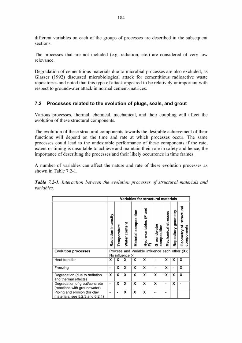
184
different variables on each of the groups of processes are described in the subsequent sections.
The processes that are not included (e.g. radiation, etc.) are considered of very low relevance.
Degradation of cementitious materials due to microbial processes are also excluded, as Glasser (1992) discussed microbiological attack for cementitious radioactive waste repositories and noted that this type of attack appeared to be relatively unimportant with respect to groundwater attack in normal cement-matrices.
7.2 Processes related to the evolution of plugs, seals, and grout
Various processes, thermal, chemical, mechanical, and their coupling will affect the evolution of these structural components.
The evolution of these structural components towards the desirable achievement of their functions will depend on the time and rate at which processes occur. The same processes could lead to the undesirable performance of these components if the rate, extent or timing is unsuitable to achieve and maintain their role in safety and hence, the importance of describing the processes and their likely occurrence in time frames.
A number of variables can affect the nature and rate of these evolution processes as shown in Table 7.2-1.
Table 7.2-1. Interaction between the evolution processes of structural materials and variables.
Variables for structural materials
Ra
dia
tio
n in
ten
sit
y
Tem
pera
ture
Wate
r c
on
ten
t
Ma
teri
al
co
mp
os
itio
n
Hy
dro
va
ria
ble
s (
P a
nd
F)
Gro
un
dw
ate
r
co
mp
os
itio
n
Mech
an
ical
str
es
ses
Rep
osit
ory
geo
metr
y
Ge
om
etr
y o
f s
tru
ctu
ral
co
mp
on
en
ts
Evolution processes Process and Variable influence each other (X);No influence (-)
Heat transfer X X X X X - X X X
Freezing - X X X X - X - X
Degradation (due to radiation and thermal effects)
X X X X X X X X X
Degradation of grout/concrete (reactions with groundwater)
- X X X X X - X -
Piping and erosion (for clay materials; see 5.2.3 and 6.2.4)
- - X X X - -

185
Name: Heat transfer
Category: spent fuel, canister, buffer, backfill, plugs-seals-grout, geosphere system evolution, migration of substances Number: 7.2.1
General description:
Heat is generated by the radioactive decay of the spent nuclear fuel placed inside the canister. The rate of heat emission depends on the characteristic of the type of fuel and type of the disposal canister (Ikonen 2003a). The highest modelled temperature of the fuel can be as high as 260 C and the external temperature of the copper canister 120 C (Ikonen 2006). However, the design maximum temperature of the exterior of the canister is limited to 100 C. The heat transfer through the plugs, seals and grout will be predominantly governed by conduction, when considering them as solids with liquid-filled gaps. Heat transfer is also possible by convection and radiation in the case of gas-filled gaps e.g. space between the canister and the buffer.
The heat generation is calculated from the radioactive decay of radionuclides. Secondly the -irradiation appeared to affect the microstructure and mechanical properties of the cementitious materials. For instance the results of the experimental studies of the properties of the cementitious material exposed to -irradiation of up to 6x10⁵ Gy by (Vodák et al. 2005) showed beside lower strength and more CaCO3 formed, also higher porosity, which could affect the thermal conductivity. However the canister is designed so that the maximum dose rate on the outer surface of the canister shall be less than 1 Gy/h to minimize the radiolysis of water or altering the bentonite buffer outside the canister (Raiko & Salo 1999). With the canister design proposed by SKB and Posiva, the surface dose rate immediately after encapsulation is less than 0.5 Gy/h. The estimated -irradiation dosage would reach the level of 1.3x10⁵ Gy after 30-40 years, about 4-5 times less than that applied by Vodák et al. (2005). More detailed description of the effects of gamma radiation on the microstructure and mechanical properties of the cementitious materials will be addressed in Section 7.2.3 of this report.
The heat generated in the canister (see Sections 3.2.2 in this report) is transferred from the canister surface to the buffer and through the buffer (Section 6.3.1) to the rock either directly or through the tunnel backfill and structural components (e.g. concrete plate at the bottom of the deposition hole). The structural component being most affected by heat will be the concrete plate at the bottom of the deposition holes. The grouting material, if present in the cracks adjacent to the deposition holes, might be affected as well. The highest predicted temperature, considering a 350 and 500 mm layer of bentonite which will fill the space between the rock and/or concrete bottom plate in the deposition holes and the canister, should not exceed ~40 C (Ikonen 2003a). This estimate was obtained by modelling and assuming the maximum external canister temperature to be below 100 C (Ikonen 2003a, 2006).
The distance between the concrete plugs installed at the entrances to the deposition tunnels and the nearest deposition hole is 6 meters (Haaramo 1999). In accordance with the modelling results obtained by Ikonen (2006) the highest temperature in the
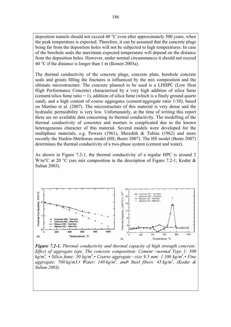
186
deposition tunnels should not exceed 40 C even after approximately 500 years, when the peak temperature is expected. Therefore, it can be assumed that the concrete plugs being far from the deposition holes will not be subjected to high temperatures. In case of the borehole seals the maximum expected temperature will depend on the distance from the deposition holes. However, under normal circumstances it should not exceed 40 C if the distance is longer than 1 m (Ikonen 2003a).
The thermal conductivity of the concrete plugs, concrete plate, borehole concrete seals and grouts filling the fractures is influenced by the mix composition and the ultimate microstructure. The concrete planned to be used is a LHHPC (Low Heat High Performance Concrete) characterised by a very high addition of silica fume (cement/silica fume ratio = 1), addition of silica fume (which is a finely ground quartz sand), and a high content of coarse aggregates (cement/aggregate ratio 1/10), based on Martino et al. (2007). The microstructure of this material is very dense and the hydraulic permeability is very low. Unfortunately, at the time of writing this report there are no available data concerning its thermal conductivity. The modelling of the thermal conductivity of concretes and mortars is complicated due to the known heterogeneous character of this material. Several models were developed for the multiphase materials, e.g. Powers (1961), Meredith & Tobias (1962) and more recently the Hashin-Shtrikman model (HS; Bentz 2007). The HS model (Bentz 2007) determines the thermal conductivity of a two-phase system (cement and water).
As shown in Figure 7.2-1, the thermal conductivity of a regular HPC is around 2 W/m C at 20 C (see mix composition in the description of Figure 7.2-1; Kodur & Sultan 2003).
Figure 7.2-1. Thermal conductivity and thermal capacity of high strength concrete: Effect of aggregate type. The concrete composition: Cement ~normal Type 1: 500 kg/m3, • Silica fume: 50 kg/m3,• Coarse aggregate ~size 9.5 mm: 1 100 kg/m3,• Fine aggregate: 700 kg/m3,• Water: 140 kg/m3, and• Steel fibers: 45 kg/m3, (Kodur & Sultan 2003).
187
However, an increase of the temperature causes a gradual decrease of the thermal conductivity. At higher temperatures the decrease became more apparent and additionally the effect of the aggregate type is more pronounced. The thermal conductivity of concrete strongly depends also on the moisture content. As shown by Flynn (1999), in an extreme case the increase of the moisture content by 10% can double the thermal conductivity. The significance of this effect will be lower at higher temperatures. In this case the hydro-variables of the environment are significant for the ultimate thermal conductivity. Similarly, the porosity of the binder matrix as well as of aggregates will affect the thermal conductivity. In this case an increase of porosity will lower the thermal conductivity.
The significant variables for heat transfer in the structural materials are: Radiation intensity – The radiation intensity is a significant variable, since radiation generates heat Temperature – Differences in temperature lead to heat transfer Water content – modifies the heat transfer rate in grout Material composition (concrete, grout, seals) – the physical and mechanical properties of the materials will affect heat transfer Hydrovariables – influence the availability of water and hence the thermal properties of the materials Repository geometry – significant Geometry of the structural components – significant
Olkiluoto specific issues:
The thermal conductivity and specific heat capacity of the cementitious materials will be affected by the availability of groundwater. Lower moisture content will result in lower values of the thermal conductivity. Uncertainties:
Due to the dry condition of some of the places and uncertainties in the hydraulic evolution of the buffer and backfill, the precise evaluation of the heat transfer may be difficult. Another uncertainty is associated with the effect of the gamma radiation on the microstructural changes of the cementitious materials (Vodák et al. 2005), and especially, the significance of this effect on the thermal conductivity, if any. Time frames of relevance: The highest temperature expected in the concrete bottom plate will be reached, as in the case of the canister in 10-15 years after the deposition. The maximum temperature in the rock at the edge of a single canister is reached in 50-100 years and then it takes of the order of 5 000 years to cool off to room temperature. After 100 000 years the temperature increase in all components of the repository will be less than 1 K. Changes of the thermal properties of the cementitious materials may occur at any time when the moisture conditions change.
Scenarios of relevance:
Heat transfer is relevant for all scenarios.Treatment in PA: Heat transfer is not directly taken into account in radionuclide transport calculations. Significance: Heat transfer processes are considered to be of MEDIUM significance because they have a significant influence on the near-field temperature which, itself, is an important control over the processes that will cause degradation of the materials
188
in the near field including the bentonite buffer, backfill and structural materials like the concrete plate at the bottom of deposition holes. The concrete plate at the bottom of the disposal hole is considered to have the greatest effect on the heat transfer from the container to the surrounding rock of all the elements in question. Equivalent NEA international FEP:
2.1.11 “Thermal processes and conditions (in wastes and EBS)” 2.1.13“Radiation effects (in wastes and EBS)” Key references:
Bentz, D.P. 2007. Transient Plane Source Measurements of the Thermal Properties of Hydrating Cement Pastes. Materials and Structures, 40, 1073-1080.
Flynn, D.R. 1999. Response of high performance concrete to fire conditions: review of thermal property data and measurement techniques, NIST National Institute of Standards and Technology, NIST GCR 99-767.
Haaramo, J. 1999. Sijoitustunneleiden sulkurakenteiden rakennussuunnittelu. Posiva Oy, Helsinki, Finland. Posiva Working Report 99-71. In Finnish, with abstract in English.
Ikonen, K. 2003a. Thermal Analyses of Spent Nuclear Fuel Repository. Posiva Oy, Olkiluoto, Finland. POSIVA 2003-04.
Ikonen, K. 2006. Fuel Temperature in Disposal Canisters. Posiva Oy, Olkiluoto, Finland. Posiva Working Report 2006-19.
Kodur, V.K.R. & Sultan, M.A. 2003. Effect of Temperature on Thermal Properties of High-Strength Concrete. Journal of Materials in Civil Engineering, 15, 101-107.
Martino, J.B., Chandler, N.A., Read, R.S. & Baker, C. 2007. Response of the tunnel sealing experiment concrete bulkhead to pressurization. Ontario Power Generation, Toronto, Canada. Report No: 06819-REP-01200-10085-R00.
Meredith, R.E. & Tobias, C.W. 1962. Conduction in heterogeneous systems. Advances in Electrochemistry and Electrochemical Engineering, 2, 15–47.
Powers, A.E. 1961. Conductivity in Aggregates. Knolls Atomic Power Laboratory. Schenectady, N.Y. Report KAPL-2145.
Raiko, H. & Salo, J.-P. 1999. Design report of the disposal canister for twelve assemblies. Posiva Oy, Helsinki, Finland. Posiva Working-Report 99-19.
Vodák, F., Trtík, K., Sopko, V., Kapi ková, O. & Demo, P. 2005. Effect of -irradiation on strength of concrete for nuclear-safety structures. Cement and Concrete Research, 35, 1447–1451.
189
Name: Freezing
Category: spent fuel, canister, buffer, backfill, plugs-seal-grout, geosphere system evolution, migration of substances
Number: 7.2.2
General description:
The likelihood of freezing is linked to the beginning of the next glaciation cycle and the formation of permafrost. According to current understanding, the permafrost layer will not develop to sufficient depth to reach the repository level during the next glaciation cycle (Hartikainen 2006), but it will affect the structural materials used in the upper part of the repository and the boreholes. For clay materials see Section 6.2.2.
Freezing itself may cause no major damage to cementitious materials, but multiple freeze/thaw cycles are known to alter the strength of most porous materials, such as concrete. The deterioration of concrete is associated with the freezing of water in wet concrete samples (Chaterji 1999), where more than 30 freeze-thaw cycles are needed to diminish the strength of wet samples. Frost damage in concrete has been shown to involve cement paste, aggregates, and the mineral and organic additives that comprise the structures (Pigeon & Pleau 1995). Cwirzen & Penttala (2003) recently studied the influence of the cement paste-aggregate interfacial transition zone on the frost durability of high-performance silica fume concrete. The concrete samples had water-to-binder ratios of 0.3, 0.35 and 0.42 and different additions of condensed silica fume. The results showed that the movement of the pore solution within the concrete during freezing and thawing cycles is enhanced in the transition zone initiating and accelerating damaging mechanisms. Moderate additions of silica fume seemed to strengthen the microstructure of the cement paste-aggregate interfacial transition zone and diminish damage effects.
It must be noted that most of the studies made on frozen concrete are related to the freezing of outdoor structures (e.g. Browne & Bamforth 1981, Chaterji 1999), where the temperature variability follows air temperatures and it is much higher than the variability of temperatures underground or in soils.
The variables (Table 7.2-1) that interact with freezing are:
Temperature – differences of temperature between the buffer, backfill, rock and structural components may lead to heat transfer in one or another direction, i.e. from the buffer and backfill to the structural materials and rock in case of heat transfer or from the rock to the structural materials in case of freezing Water content – water content affects the freezing of concrete and other cementitious materials as it may fill the voids that are not conductive of heat or coldMaterial composition – influences thermal conductivity and heat/cold transport Hydrovariables (P and F) – indirectly influences the freezing of the concrete and cementitious materials in providing external water Mechanical stresses – freezing affects the mechanical strength of the cementitious materials

190
Geometry of structural components – may influence the rate of frost advance from the rock to and through the components
Olkiluoto specific issues:
The formation of permafrost in Olkiluoto is a site-specific process. Uncertainties:
The effect of multiple freezing and thawing cycles on the structural materials has not been studied in the relevant conditions; most studies refer to outdoor freeze-thaw cycles.Time frames of relevance:
Freezing is a relevant process during the next glaciation period, not sooner than from 13 000 years AP (Pastina & Hellä 2006).Scenarios of relevance:
Freezing is relevant during and after permafrost periods for all scenarios.Treatment in PA:
Freezing of the structural materials is not treated in the near field evolution model. However, the issue is taken into account indirectly by modifying the parameters relevant to groundwater flow rates used in calculation cases derived from the assessment scenarios. Significance:
The freezing of the structural materials in access routes is considered to be of MEDIUM significance because the groundwater flow to repository depth may be enhanced in case of severe damage of these materials. Equivalent NEA international FEP:
2.1.11 “Thermal processes and conditions (in wastes and EBS)” Key references:
Browne, R.D. & Bamforth, P.B. 1981. The use of concrete for cryogenic storage: A summary of research, past and present. Proc. 1st Intern. Conf. Cryogenic Concrete, Newcastle upon Tyne, 135-162.
Chaterji, S. 1999. Aspects of the freezing process in a porous material–water system. Part I. Freezing and the properties of water and ice. Cement and concrete research 29, 627–630.
Cwirzen, A. & Penttala, V. 2003. Aggregate-cement paste transition zone properties affecting the salt-frost damage of high–performance concretes. Cement and Concrete Research, 35, 671–679.
Hartikainen, J. 2006. Numerical simulation of permafrost depth at Olkiluoto. Posiva Oy, Olkiluoto, Finland. Posiva Working Report 2006-52.
Pastina, B. & Hellä, P. (Eds.) 2006. Expected evolution of a spent nuclear fuel repository at Olkiluoto. Posiva Oy, Olkiluoto, Finland. Report POSIVA 2006-05.
Pigeon, M. & Pleau, R. 1995. Durability of Concrete in Cold Climates. E. & FN Spon, London, UK.
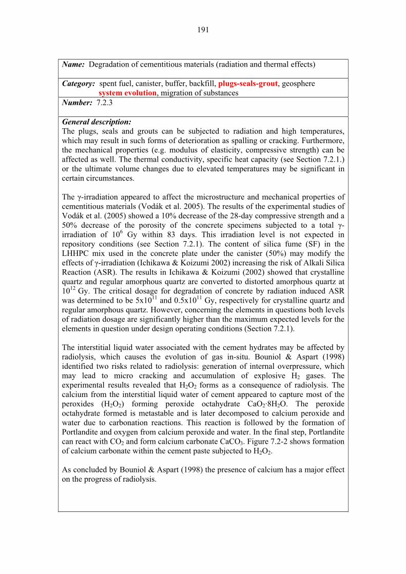
191
Name: Degradation of cementitious materials (radiation and thermal effects)
Category: spent fuel, canister, buffer, backfill, plugs-seals-grout, geosphere system evolution, migration of substances Number: 7.2.3
General description:
The plugs, seals and grouts can be subjected to radiation and high temperatures, which may result in such forms of deterioration as spalling or cracking. Furthermore, the mechanical properties (e.g. modulus of elasticity, compressive strength) can be affected as well. The thermal conductivity, specific heat capacity (see Section 7.2.1.) or the ultimate volume changes due to elevated temperatures may be significant in certain circumstances.
The -irradiation appeared to affect the microstructure and mechanical properties of cementitious materials (Vodák et al. 2005). The results of the experimental studies of Vodák et al. (2005) showed a 10% decrease of the 28-day compressive strength and a 50% decrease of the porosity of the concrete specimens subjected to a total -irradiation of 106 Gy within 83 days. This irradiation level is not expected in repository conditions (see Section 7.2.1). The content of silica fume (SF) in the LHHPC mix used in the concrete plate under the canister (50%) may modify the effects of -irradiation (Ichikawa & Koizumi 2002) increasing the risk of Alkali Silica Reaction (ASR). The results in Ichikawa & Koizumi (2002) showed that crystalline quartz and regular amorphous quartz are converted to distorted amorphous quartz at 1012 Gy. The critical dosage for degradation of concrete by radiation induced ASR was determined to be 5x10¹¹ and 0.5x10¹¹ Gy, respectively for crystalline quartz and regular amorphous quartz. However, concerning the elements in questions both levels of radiation dosage are significantly higher than the maximum expected levels for the elements in question under design operating conditions (Section 7.2.1).
The interstitial liquid water associated with the cement hydrates may be affected by radiolysis, which causes the evolution of gas in-situ. Bouniol & Aspart (1998) identified two risks related to radiolysis: generation of internal overpressure, which may lead to micro cracking and accumulation of explosive H2 gases. The experimental results revealed that H2O2 forms as a consequence of radiolysis. The calcium from the interstitial liquid water of cement appeared to capture most of the peroxides (H2O2) forming peroxide octahydrate CaO2·8H2O. The peroxide octahydrate formed is metastable and is later decomposed to calcium peroxide and water due to carbonation reactions. This reaction is followed by the formation of Portlandite and oxygen from calcium peroxide and water. In the final step, Portlandite can react with CO2 and form calcium carbonate CaCO3. Figure 7.2-2 shows formation of calcium carbonate within the cement paste subjected to H2O2.
As concluded by Bouniol & Aspart (1998) the presence of calcium has a major effect on the progress of radiolysis.
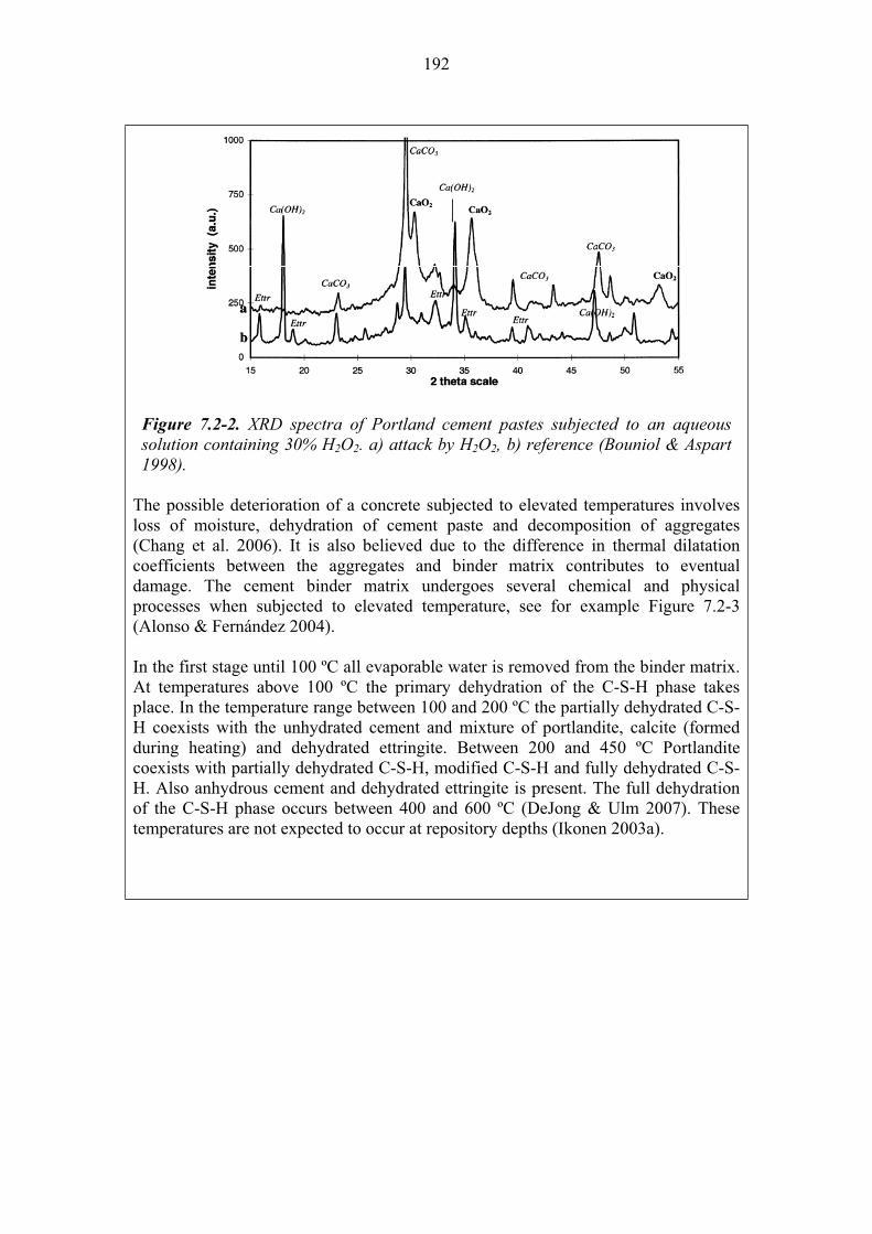
192
Figure 7.2-2. XRD spectra of Portland cement pastes subjected to an aqueous solution containing 30% H2O2. a) attack by H2O2, b) reference (Bouniol & Aspart 1998).
The possible deterioration of a concrete subjected to elevated temperatures involves loss of moisture, dehydration of cement paste and decomposition of aggregates (Chang et al. 2006). It is also believed due to the difference in thermal dilatation coefficients between the aggregates and binder matrix contributes to eventual damage. The cement binder matrix undergoes several chemical and physical processes when subjected to elevated temperature, see for example Figure 7.2-3 (Alonso & Fernández 2004).
In the first stage until 100 ºC all evaporable water is removed from the binder matrix. At temperatures above 100 ºC the primary dehydration of the C-S-H phase takes place. In the temperature range between 100 and 200 ºC the partially dehydrated C-S-H coexists with the unhydrated cement and mixture of portlandite, calcite (formed during heating) and dehydrated ettringite. Between 200 and 450 ºC Portlandite coexists with partially dehydrated C-S-H, modified C-S-H and fully dehydrated C-S-H. Also anhydrous cement and dehydrated ettringite is present. The full dehydration of the C-S-H phase occurs between 400 and 600 ºC (DeJong & Ulm 2007). These temperatures are not expected to occur at repository depths (Ikonen 2003a).
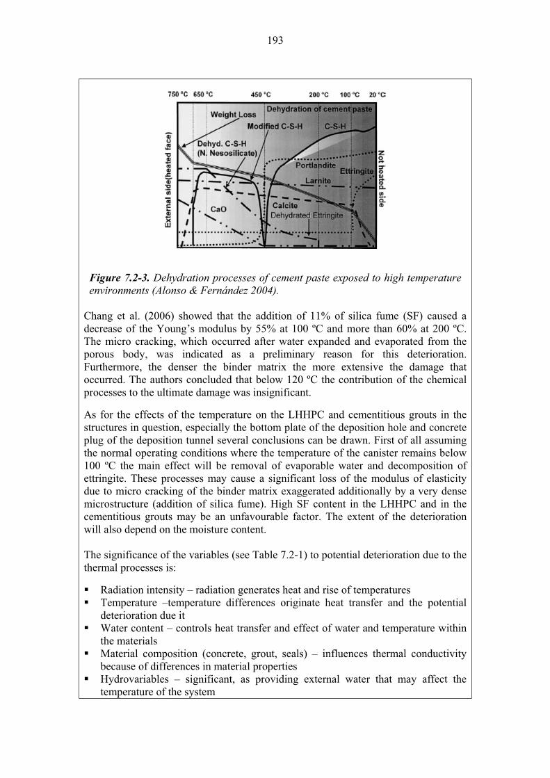
193
Figure 7.2-3. Dehydration processes of cement paste exposed to high temperature environments (Alonso & Fernández 2004).
Chang et al. (2006) showed that the addition of 11% of silica fume (SF) caused a decrease of the Young’s modulus by 55% at 100 ºC and more than 60% at 200 ºC. The micro cracking, which occurred after water expanded and evaporated from the porous body, was indicated as a preliminary reason for this deterioration. Furthermore, the denser the binder matrix the more extensive the damage that occurred. The authors concluded that below 120 ºC the contribution of the chemical processes to the ultimate damage was insignificant.
As for the effects of the temperature on the LHHPC and cementitious grouts in the structures in question, especially the bottom plate of the deposition hole and concrete plug of the deposition tunnel several conclusions can be drawn. First of all assuming the normal operating conditions where the temperature of the canister remains below 100 ºC the main effect will be removal of evaporable water and decomposition of ettringite. These processes may cause a significant loss of the modulus of elasticity due to micro cracking of the binder matrix exaggerated additionally by a very dense microstructure (addition of silica fume). High SF content in the LHHPC and in the cementitious grouts may be an unfavourable factor. The extent of the deterioration will also depend on the moisture content.
The significance of the variables (see Table 7.2-1) to potential deterioration due to the thermal processes is:
Radiation intensity – radiation generates heat and rise of temperatures Temperature –temperature differences originate heat transfer and the potential deterioration due it Water content – controls heat transfer and effect of water and temperature within the materials Material composition (concrete, grout, seals) – influences thermal conductivity because of differences in material properties Hydrovariables – significant, as providing external water that may affect the temperature of the system

194
Groundwater composition – added to heat may accelerate chemical interactions between cementitious materials and water Mechanical stresses – heating may affect the mechanical strength of the materials Repository geometry – the position of the materials with respect to the heat source influences the intensity of the effects Geometry of concrete plugs, seals and grout – the dimensions of the structures will influence in the extent of potential damage Mechanical stresses – heating may affect the mechanical strength of the materials
Olkiluoto specific issues:
The groundwater flow conditions in the bedrock may vary. It is expected that some areas will remain relatively dry. These varying conditions may affect the mechanical properties, (modulus of elasticity and compressive strength) of the LHHPC concrete and cementitious grouts, when subjected to high temperatures. Uncertainties:
The second uncertainty is the actual temperature on the surface of the canister. According to Ikonen (2006) it may theoretically exceed 200 C. If this would occur the thermal conductivity of bentonite, LHHPC concrete and cementitious grouts would decrease causing further increase of the actual temperature near the canister. At these temperatures further dehydration and modification of C-S-H will take place. The compressive strength and modulus of elasticity may decrease by more than 30% and 50%, respectively. The presence of silica fume will additionally enhance this effect. Extensive micro cracking of the binder matrix might occur as well. Time frames of relevance:
The highest temperature expected in the concrete bottom plate will be reached, as in the case of the canister in 10-15 years after deposition. The maximum temperature in the rock at the edge of a single canister is reached in 50-100 years and then it takes of the order of 5 000 years to cool off to ambient temperature. After 100 000 years the temperature increase in all components of the repository will be less than 1 K. Scenarios of relevance:
Degradation of cementitious materials due to thermal effects is relevant for all scenarios, but especially for DCS, and AD-II. Treatment in PA: The process can be conservatively ignored for the structural materials in the access tunnels. Significance:
Under designed operating condition the effect of radiation and thermal processes on the degradation of cementitious materials is considered LOW. Especially, taking into account that the behaviour of these structural components is not of the highest priority in the long-term performance of the repository. Any deviation from the design conditions (e.g. higher radiation and/or temperature) might increase the significance level to medium. Equivalent NEA international FEP:
2.1.11 “Thermal processes and conditions (in wastes and EBS)” 2.1.13 “Radiation effects (in wastes and EBS)” Key references:
Alonso, C. & Fernández, L. 2004. Dehydration and rehydration processes of cement paste exposed to high temperature environment. Journal of Materials Science, 34, 3015–3024.

195
Bouniol, P. & Aspart, A. 1998. Disappearance of oxygen in concrete under irradiation: the role of peroxides in radiolysis, Cement and Concrete Research, 28, 1669–1681.
Chang, T.-P., Lin, H.-C., Chang, W.-T. & Hsiao, J.-F. 2006. Engineering properties of lightweight aggregate concrete assessed by stress wave propagation. Cement and Concrete Composites, 28, 57–68.
Ichikawa T. & Koizumi, H. 2002. Possibility of Radiation-Induced Degradation of Concrete by Alkali-Silica Reaction of Aggregates. Journal on Nuclear Science and Technology 39, 880–884.
Ikonen, K. 2003a. Thermal Analyses of Spent Nuclear Fuel Repository. Posiva Oy, Olkiluoto, Finland. POSIVA 2003-04.
Ikonen, K. 2006. Fuel Temperature in Disposal Canisters. Posiva Oy, Olkiluoto, Finland. Posiva Working Report 2006-19.
Vodák, F., Trtík, K., Sopko, V., Kapi ková, O. & Demo, P. 2005. Effect of -irradiation on strength of concrete for nuclear-safety structures. Cement and Concrete Research, 35, 1447–1451.
Name: Degradation of grout (reactions with groundwater) – implications on bentonite performance Category: spent fuel, canister, buffer, backfill, plugs-seals-grout, bedrock
system evolution, migration of substancesNumber: 7.2.4
General description:
The major concern of the chemical degradations of grout and other cementitious materials due to reactions with groundwater is the generation of hyperalkaline leachates that could potentially interact with bentonite and diminish its swelling pressure (e.g. Karnland 2004), thus endangering the long-term safety functions of the buffer (see Section 5.1.1).
There are few data on the degradation mechanisms of low-pH cement (Vuorinen et al. 2005) but the data on the degradation of Ordinary Portland Cement (OPC) can be discussed and applied taking into account that the degradation products and evolution of the pH may differ in the case of low-pH cement. A consensus seems to have been achieved on the evolution of Ordinary Portland Cement porewater with time producing hyperalkaline leachates with an initial pH of 13.4 (KOH/NaOH buffered), later decreasing to pH 12.5 (CaOH2 buffered) as shown in Figure 7.2-4 (Miller et al. 2000). As the figure shows, the high alkalinity plume can last for several hundred thousands years and up to a few million years.
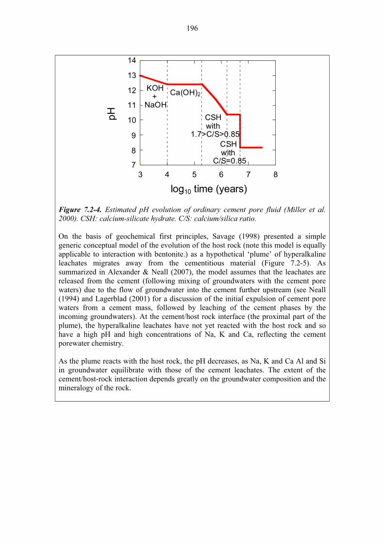
196
log10 time (years)
7
8
9
10
11
12
13
14
3 4 5 6 7 8
C/S=0.85with
KOH+
NaOH
Ca(OH)2
CSH
CSHwith
1.7>C/S>0.85
Figure 7.2-4. Estimated pH evolution of ordinary cement pore fluid (Miller et al. 2000). CSH: calcium-silicate hydrate. C/S: calcium/silica ratio.
On the basis of geochemical first principles, Savage (1998) presented a simple generic conceptual model of the evolution of the host rock (note this model is equally applicable to interaction with bentonite.) as a hypothetical ‘plume’ of hyperalkaline leachates migrates away from the cementitious material (Figure 7.2-5). As summarized in Alexander & Neall (2007), the model assumes that the leachates are released from the cement (following mixing of groundwaters with the cement pore waters) due to the flow of groundwater into the cement further upstream (see Neall (1994) and Lagerblad (2001) for a discussion of the initial expulsion of cement pore waters from a cement mass, followed by leaching of the cement phases by the incoming groundwaters). At the cement/host rock interface (the proximal part of the plume), the hyperalkaline leachates have not yet reacted with the host rock and so have a high pH and high concentrations of Na, K and Ca, reflecting the cement porewater chemistry.
As the plume reacts with the host rock, the pH decreases, as Na, K and Ca Al and Si in groundwater equilibrate with those of the cement leachates. The extent of the cement/host-rock interaction depends greatly on the groundwater composition and the mineralogy of the rock.
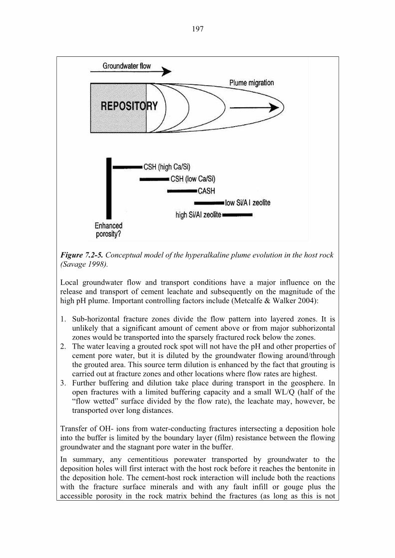
197
Figure 7.2-5. Conceptual model of the hyperalkaline plume evolution in the host rock (Savage 1998).
Local groundwater flow and transport conditions have a major influence on the release and transport of cement leachate and subsequently on the magnitude of the high pH plume. Important controlling factors include (Metcalfe & Walker 2004):
1. Sub-horizontal fracture zones divide the flow pattern into layered zones. It is unlikely that a significant amount of cement above or from major subhorizontal zones would be transported into the sparsely fractured rock below the zones.
2. The water leaving a grouted rock spot will not have the pH and other properties of cement pore water, but it is diluted by the groundwater flowing around/through the grouted area. This source term dilution is enhanced by the fact that grouting is carried out at fracture zones and other locations where flow rates are highest.
3. Further buffering and dilution take place during transport in the geosphere. In open fractures with a limited buffering capacity and a small WL/Q (half of the “flow wetted” surface divided by the flow rate), the leachate may, however, be transported over long distances.
Transfer of OH- ions from water-conducting fractures intersecting a deposition hole into the buffer is limited by the boundary layer (film) resistance between the flowing groundwater and the stagnant pore water in the buffer.
In summary, any cementitious porewater transported by groundwater to the deposition holes will first interact with the host rock before it reaches the bentonite in the deposition hole. The cement-host rock interaction will include both the reactions with the fracture surface minerals and with any fault infill or gouge plus the accessible porosity in the rock matrix behind the fractures (as long as this is not

198
sealed by reaction). This includes any porewaters held in the matrix, which can have a significant effect on preliminary mineral reactions (e.g. at Maqarin, the matrix porewater is HCO3
- -rich and so induces precipitation of calcite in/around the fracture face; Smellie 1998).
During this interaction with the host rock, the pH will be considerably lowered although no quantitative data on the host rock buffering capacity are available. The use of ordinary Portland cement is envisaged to constitute a risk to bentonite buffer stability in a KBS-3 repository. The cement has aggressive nature and it will chemically disturb the clay minerals. The cementitious water diffuses into the bentonite and causes mineralogical alteration in the bentonite. The main effect of cement on bentonite is dissolution of montmorillonite through its alkaline porewater.
The interaction between the alkaline plume with the host rock (in particular the buffering capacity of fracture fillings), the groundwater dilution factor, and the precipitation/dissolution of secondary minerals in bentonite will decrease the adverse effects of pH plume on bentonite and other clayed materials used in the backfill and borehole seals.
The significant variables for the degradation of grout due to reactions with groundwater are:
Temperature – temperature affects the rate of chemical reactions Water content – chemical reactions take place in presence of water Repository geometry – the position of the materials with respect to the availability of groundwater and the paths for groundwater flow Material composition (concrete, grout, seals) – the nature of degradation products and pH of fluids after reactions will depend on the material composition Groundwater composition – added to heat may accelerate chemical interactions between cementitious materials and water Hydrovariables – influences the availability of external water that may interact with grout and other cementitious materials
Olkiluoto specific issues:
Groundwaters flow and transport paths. Uncertainties:
There are uncertainties in the buffering capacity of high pH of the fracture minerals; the transport paths in the fracture network are difficult to estimate. Time frames of relevance:
The degradation of grout and cementitious materials may last as long as they are available to groundwater. During permafrost, chemical reactions may be inhibited due to lack of free water to interact. Scenarios of relevance:
Degradation of grout is relevant for all scenarios, but specially in AD-II. Treatment in PA:
This process is not directly taken into account in radionuclide transport calculations but in complementary reports to estimate the performance of the repository system and the site (e.g. Vieno et al. 2003, Alexander & Neall 2007). Significance:
The process is considered of MEDIUM significance in case the alkaline plume
199
reaches and damages the bentonite buffer of several holes to a large extent and especially if the damage occur at the same time. Equivalent NEA international FEP:
3.2.07 “Water-mediated transport of contaminants” Key references:
Alexander, W.R. & Neall, F.B. 2007. Assessment of potential perturbations to Posiva's SF repository at Olkiluoto from the ONKALO facility. Posiva Oy, Olkiluoto, Finland. Posiva Working Report 2007-35.
Karnland, O. 2004. Proceedings of a the International Workshop on Bentonite-Cement Interaction in Repository Environments (Eds.Metcalfe, R &Walker C.), 14-16 April 2004, Tokyo, Japan, Posiva Working Report 2004-25 (NUMO-TR-04-05).
Lagerblad, B. 2001. Leaching performance of concrete based on studies of samples from old concrete constructions. SKB Swedish Nuclear Fuel and Waste Management Co, Stockholm, Sweden. SKB Technical Report TR 01-27.
Metcalfe, R. & Walker, C. (Eds.) 2004. Proceedings of a the International Workshop on Bentonite-Cement Interaction in Repository Environments, 14-16 April 2004, Tokyo, Japan, Posiva Working Report 2004-25 (NUMO-TR-04-05).
Miller, W.M., Alexander, W.R., Chapman, N.A., McKinley, I.G. & Smellie, J.A.T. 2000. Geological disposal of radioactive wastes. Pergamon, Amsterdam, The Netherlands.
Neall, F. 1994. Modelling of the near-fiel chemistry of the SMA repository at the Wellenberg site: application of the extended cement degradation model. Nagra, Wettingen, Switzerland. Nagra Technical Report NTB 94-03.
Savage, D. 1998. Zeolite occurrence, stability and behaviour. Ch.8 in J.A.T.Smellie (editor). Maqarin Natural Analogue Study: Phase III. SKB Swedish Nuclear Fuel and Waste Management Co, Stockholm, Sweden. SKB Technical Report TR 98-04.(Vols. I and II)
Smellie, J.A.T. (Ed.) 1998. Maqarin natural analogue project: Phase III. Swedish Nuclear Fuel and Waste Management Co, Stockholm, Sweden. SKB Technical Report TR 98-04. (Vols. I and II)
Vieno, T., Lehikoinen, J., Löfman, J. & Nordman, H. 2003. Assessment of disturbances caused by construction and operation of ONKALO. Posiva Oy, Olkiluoto, Finland. Report POSIVA 2003-06.
Vuorinen, U., Lehikoinen, J., Imoto, H., Yamamoto, T. & Cruz Alonso, M. 2005. Injection grout for deep repositories, Subproject 1: low-pH cementitious grout for larger fractures, leach testing of grout mixes and evaluation of the long-term safety. Posiva Oy, Olkiluoto, Finland. Posiva Working Report 2004-46.

200
7.3 Processes related to the migration of radionuclides and other substances
Although no credit is given to the structural components as a barrier for the potential release of radionuclides, there is a number of processes that may control the migration of radionuclides and other substances along transport paths possibly filled with structural materials or their degradation products.
The variables that can affect the nature and rate of these migration-related processes are shown in Table 7.3-1.
Table 7.3-1. Interaction between migration processes in the structural materials and their variables.
Structural components variables
Ra
dia
tio
n in
ten
sit
y
Tem
pera
ture
Wate
r co
nte
nt
Ma
teri
al
co
mp
os
itio
n
Hy
dro
va
ria
ble
s (
P a
nd
F)
Gro
un
dw
ate
r c
om
po
sit
ion
Mech
an
ical
str
es
ses
Rep
osit
ory
geo
metr
y
Ge
om
etr
y o
f s
tru
ctu
ral
co
mp
on
en
ts
Migration-related processes
Process and Variable influence each other X; No influence -
Diffusion - X X X X X - - -
Sorption - X X X - X - - -
Colloidal transport - X X X X X - - -

201
Name: Diffusion
Category: spent fuel, canister, buffer, backfill, plugs-seals-grout, bedrock system evolution, migration of substances
Number: 7.3.1
General description:
Diffusion is an important process in: a) transport of substances that influences the degradation of cementitious materials (e.g. chloride, sulphate) and b) the radionuclide migration through these materials.
In the context of cementitious materials diffusion has been mostly studied and modelled to estimate concrete durability (e.g. Bentz et al. 1997, Marchand et al. 2002). Concrete is a three-phase composite, consisting of aggregates, bulk cement paste, and interfacial transition zone (ITZ) cement paste. The ITZ surrounding each aggregate is characterized by a high porosity. In a study by Bentz el al. (1998) it was found that concrete diffusivity depended on the water-to-cement (W/C) ratio, degree of hydration and aggregate volume fraction. This study was only for Portland cement concrete and did not consider the addition of silica fume. The results for chloride diffusivity ranged over two orders of magnitude, from 2.1·10-13 to 8.2·10-11 m2/s.
Bentz et al. (2000) found that the addition of a 10% of silica fume for a W/C of 0.3 reduced diffusivity by a factor of 15 or more, thus increasing the durability of concrete.
Diffusivity data for radionuclides through cementitious materials (mostly concrete) have been obtained in the field of cementitious repositories for low- and intermediate-level nuclear waste disposal. Recently, Wellman et al. (2006) obtained diffusivities of the order of 10-11 – 10-15 m2/s for iodine and of 10-12 – 10-14 m2/s for rhenium in concrete. The concrete contained about 4% of fly ash.
Albinsson et al (1996) studied the diffusion of Cs, Am and Pu. No movement could be measured for Am and Pu, but the diffusivity measured for Cs was in the range of 10-12 to 10-13 m2/s according with other data reported in the literature (e.g. Johnston & Wilmot 1992).
The main variables (Table 7.3-1) that will affect the transport of radionuclides and other substances through cementitious materials by diffusion are
Temperature – significant for all transport processes in water as it influences the viscosity of water Water content – the water content of cementitious materials along with water availability will control the occurrence of advection or diffusion, as well as, the amounts of solutes for transport.
Material composition – the composition of these materials and their degradation products influence diffusivity
Hydrovariables (P and F) – especially significant for the availability of water that

202
carries the solutes to the cementitious materials Groundwater composition – significant for hydraulic conductivity and the composition of solutes to be transported
Olkiluoto specific issues:
Specific issues for Olkiluoto are those related to the composition of the groundwater that may vary during the evolution of the repository. Uncertainties:
Parameter/data uncertainty relates to the determination of diffusivities for low-pH cement as most of the existing data has been obtained for ordinary Portland cement. Time frames of relevance:
Diffusion is relevant for all time frames. Scenarios of relevance: The transport of radionuclides and other substances through cementitious materials is conservatively ignored in all the assessment scenarios (see Chapter 2). Treatment in PA:
In radionuclide transport calculations no data related to diffusion in cementitious materials is taken into account. Significance:
Diffusion through cementitious materials is of LOW significance, because these materials do not make up the bulk of the repository. Equivalent NEA international FEP:
3.2.07 “Water-mediated transport of contaminants” 3.2.03 “Sorption/desorption processes, contaminants” Key references:
Albinsson, Y., Andersson, S., Börjesson, S. & Allard, B. 1996. Diffusion of radionuclides and concrete-bentonite systems. Journal of Contaminant Hydrology 21, 189–200.
Bentz, D.P., Detwiler, R.J., Garboczi, E.J., Halamickova, P. & Schwartz, L.M. 1997. Multi-scale modelling of the diffusivity of mortar and concrete, in “Chloride penetration in concrete”, L.O. Nilsson & Ollivier, J.P. (Eds.) RILEM, 85-94.
Bentz, D.P., Garboczi, E.J. & Lagergren, E.S. 1998. Multi-scale microstructural modelling of concrete diffusivity: Identification of significant variables. Journal of Cement, Concrete, and Aggregates 20, 129–139.
Bentz, D.P., Jensen, O.M., Coats, A.M. & Glasser, F.P. 2000. Influence of silica fume on diffusivity in cement-based materials I. Experimental and computer modelling studies on cement pastes. Cement and Concrete Research 30, 953-962.
Johnston, H.M. & Wilmot, D.J. 1992. Sorption and diffusion studies in cementitious grouts. Waste Management 12, 289–297.
Marchand, J., Samson, E., Maltais, Y., Lee, R.J. & Sahu, S. 2002. Predicting the performance of concrete structures exposed to chemically aggressive environments – field validation. Materials and Structures 35, 623-631.
Wellman, D.M., Mattigod, S.V., Whyatt, G.A., Powers, L., Parker, K.E., Clayton,
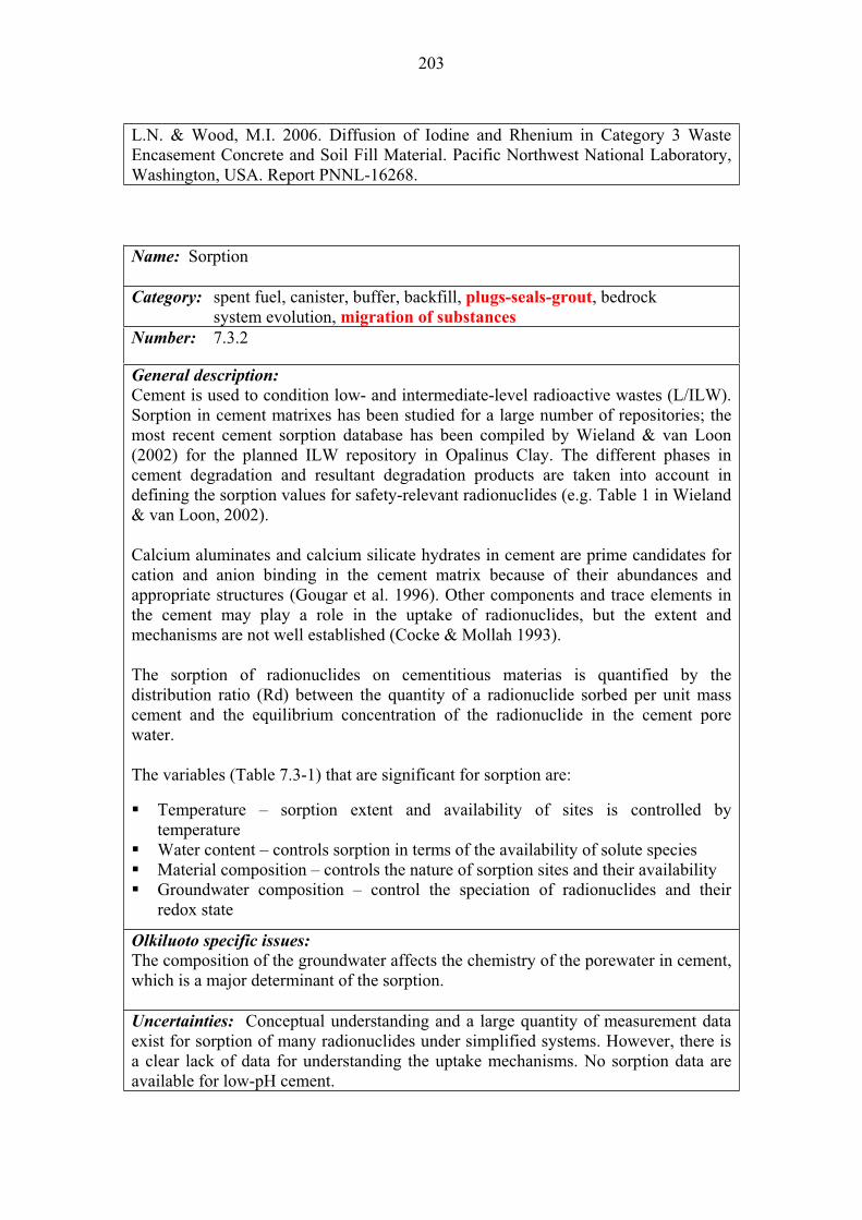
203
L.N. & Wood, M.I. 2006. Diffusion of Iodine and Rhenium in Category 3 Waste Encasement Concrete and Soil Fill Material. Pacific Northwest National Laboratory, Washington, USA. Report PNNL-16268.
Name: Sorption
Category: spent fuel, canister, buffer, backfill, plugs-seals-grout, bedrock system evolution, migration of substances
Number: 7.3.2
General description:
Cement is used to condition low- and intermediate-level radioactive wastes (L/ILW). Sorption in cement matrixes has been studied for a large number of repositories; the most recent cement sorption database has been compiled by Wieland & van Loon (2002) for the planned ILW repository in Opalinus Clay. The different phases in cement degradation and resultant degradation products are taken into account in defining the sorption values for safety-relevant radionuclides (e.g. Table 1 in Wieland & van Loon, 2002).
Calcium aluminates and calcium silicate hydrates in cement are prime candidates for cation and anion binding in the cement matrix because of their abundances and appropriate structures (Gougar et al. 1996). Other components and trace elements in the cement may play a role in the uptake of radionuclides, but the extent and mechanisms are not well established (Cocke & Mollah 1993).
The sorption of radionuclides on cementitious materias is quantified by the distribution ratio (Rd) between the quantity of a radionuclide sorbed per unit mass cement and the equilibrium concentration of the radionuclide in the cement pore water.
The variables (Table 7.3-1) that are significant for sorption are:
Temperature – sorption extent and availability of sites is controlled by temperature Water content – controls sorption in terms of the availability of solute species Material composition – controls the nature of sorption sites and their availability Groundwater composition – control the speciation of radionuclides and their redox state
Olkiluoto specific issues:
The composition of the groundwater affects the chemistry of the porewater in cement, which is a major determinant of the sorption.
Uncertainties: Conceptual understanding and a large quantity of measurement data exist for sorption of many radionuclides under simplified systems. However, there is a clear lack of data for understanding the uptake mechanisms. No sorption data are available for low-pH cement.
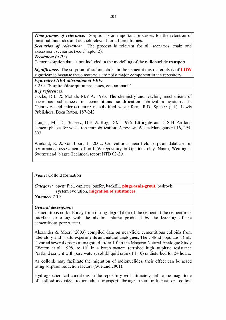
204
Time frames of relevance: Sorption is an important processes for the retention of most radionuclides and as such relevant for all time frames. Scenarios of relevance: The process is relevant for all scenarios, main and assessment scenarios (see Chapter 2).Treatment in PA:
Cement sorption data is not included in the modelling of the radionuclide transport.
Significance: The sorption of radionuclides in the cementitious materials is of LOW
significance because these materials are not a major component in the repository.Equivalent NEA international FEP:
3.2.03 “Sorption/desorption processes, contaminant” Key references:
Cocke, D.L. & Mollah, M.Y.A. 1993. The chemistry and leaching mechanisms of hazardous substances in cementitious solidification-stabilization systems. In Chemistry and microstructure of solidified waste form. R.D. Spence (ed.). Lewis Publishers, Boca Raton, 187-242.
Gougar, M.L.D., Scheetz, D.E. & Roy, D.M. 1996. Ettringite and C-S-H Portland cement phases for waste ion immobilization: A review. Waste Management 16, 295-303.
Wieland, E. & van Loon, L. 2002. Cementitious near-field sorption database for performance assessment of an ILW repository in Opalinus clay. Nagra, Wettingen, Switzerland. Nagra Technical report NTB 02-20.
Name: Colloid formation
Category: spent fuel, canister, buffer, backfill, plugs-seals-grout, bedrock system evolution, migration of substances
Number: 7.3.3
General description:
Cementitious colloids may form during degradation of the cement at the cement/rock interface or along with the alkaline plume produced by the leaching of the cementitious pore waters.
Alexander & Moeri (2003) compiled data on near-field cementitious colloids from laboratory and in situ experiments and natural analogues. The colloid population (mL-
1) varied several orders of magnitud, from 107 in the Maqarin Natural Analogue Study (Wetton et al. 1998) to 103 in a batch system (crushed high sulphate resistance Portland cement with pore waters, solid:liquid ratio of 1:10) undisturbed for 24 hours.
As colloids may facilitate the migration of radionuclides, their effect can be assed using sorption reduction factors (Wieland 2001).
Hydrogeochemical conditions in the repository will ultimately define the magnitude of colloid-mediated radionuclide transport through their influence on colloid

205
existence (colloid stability, size distribution, deposition), radionuclide sorption (partitioning), and mobility (flow, filtration).
The variables (Table 7.3-1) that are significant for the colloid formation and transport are:
Temperature – significant for flow rates that would lead to the formation and transport of colloids, and the stability of colloids Water content – the water content in cementitious materials may control the formation of colloids and their transport Material composition – significant for the formation and stability of colloids Hydrovariables (P and F) –significant for the formation and release of colloids in high flow conditions Groundwater composition – significant for the formation of colloids, their size and stability
Olkiluoto specific issues:
Groundwater composition and its evolution in time Uncertainties:
Uncertainties in the extent of formation and transport mechanisms. Time frames of relevance:
Cementitious colloids may form soon after the use and emplacement of cementitious materials, and be at the site for very long periods. Scenarios of relevance:
The process is relevant in all scenarios. Treatment in PA: Radionuclide transport in cementitious or other colloids is not considered in PA, but the possibility is considered in selecting higher radionuclide solubility values than those recommended and or modifying sorption values. Significance: This process is considered to be of MEDIUM significance because the transport of radionuclides in cementitious colloids would require of the failure of the EBS.Equivalent NEA international FEP:
3.2.02 “Speciation and solubility, contaminant” 3.2.04 “Colloids, contaminant interactions and transport with” Key references:
Alexander, W.R. & Moeri, A. 2003. Cementitious colloids: Integration of laboratory, natural analogue and in situ field data. Goldsmidt Conference Abstracts, Geochimica et Cosmochimica Acta, 18(S1): A11, 159-160.
Wetton, P.D., Pearce, J.M., Alexander, W.R., Milodowski, A.E., Reeder, S., Wragg, J. & Salameth, E. 1998. Production of colloids at the cement/host rock interface. Ch 19 in J.A.T. Smellie (ed.). Maqarin Natural Analogue Study: Phase III. Swedish Nuclear Fuel and Waste Management Co, Stockholm, Sweden. SKB TR 98-04.
Wieland, E. 2001. Experimental studies on the inventory of cement-derived colloids in the porewater of a cementitious backfill material. PSI Berich 01-01, Paul Scherrer Institut, Villigen, and Nagra Technical Report NTB 01-02.

206
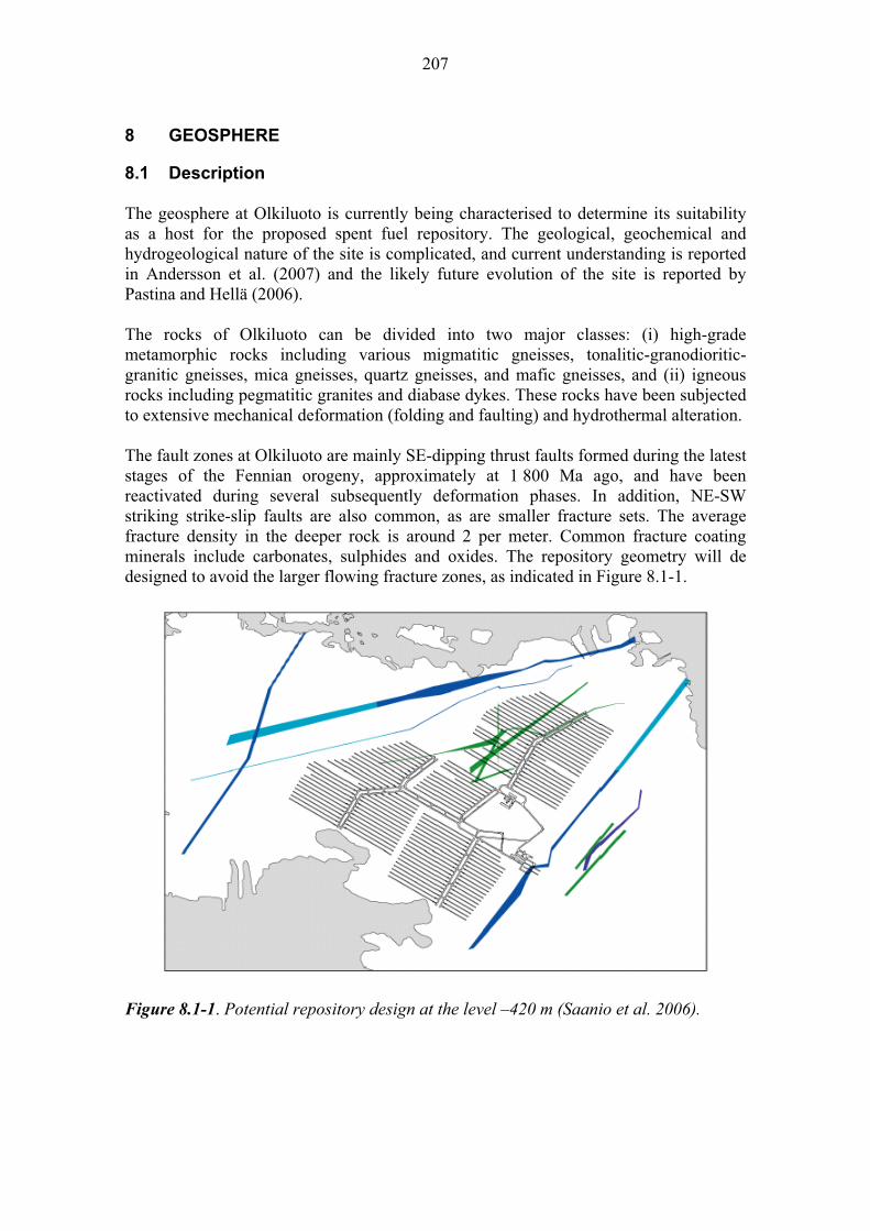
207
8 GEOSPHERE
8.1 Description
The geosphere at Olkiluoto is currently being characterised to determine its suitability as a host for the proposed spent fuel repository. The geological, geochemical and hydrogeological nature of the site is complicated, and current understanding is reported in Andersson et al. (2007) and the likely future evolution of the site is reported by Pastina and Hellä (2006).
The rocks of Olkiluoto can be divided into two major classes: (i) high-grade metamorphic rocks including various migmatitic gneisses, tonalitic-granodioritic-granitic gneisses, mica gneisses, quartz gneisses, and mafic gneisses, and (ii) igneous rocks including pegmatitic granites and diabase dykes. These rocks have been subjected to extensive mechanical deformation (folding and faulting) and hydrothermal alteration.
The fault zones at Olkiluoto are mainly SE-dipping thrust faults formed during the latest stages of the Fennian orogeny, approximately at 1 800 Ma ago, and have been reactivated during several subsequently deformation phases. In addition, NE-SW striking strike-slip faults are also common, as are smaller fracture sets. The average fracture density in the deeper rock is around 2 per meter. Common fracture coating minerals include carbonates, sulphides and oxides. The repository geometry will de designed to avoid the larger flowing fracture zones, as indicated in Figure 8.1-1.
Figure 8.1-1. Potential repository design at the level –420 m (Saanio et al. 2006).

208
Groundwater flow at depth in the rock is predominantly through the fracture network. The transmissivity of the fracture zones can vary by several orders of magnitude (105 – 109 m2/s), and there is a general decrease in transmissivity with depth.
The hydrogeochemical system at Olkiluoto is particularly complex and reflects both long periods of rock-water interaction, and flushing by meteoric, seawater and glacial melt waters at different times in the last several thousand years due to glacial events and the associated isostatic and eustatic processes. In broad terms, groundwaters become more saline and reducing with depth, and the trend indicates one of mixing between glacial melt waters and older groundwaters down to proposed repository depths. The deep layers of the Olkiluoto groundwater also contains dissolved methane and hydrogen of abiogenic origin. This is indicated in Figure 8.1-2.
Figure 8.1-2. Illustrative hydrogeochemical site conceptual model of baseline groundwater conditions (Pitkänen et al. 2004) with the main water-rock interaction processes at Olkiluoto. Enhanced chemical reactions dominate in the infiltration zone at shallow depths, and at the interface between Na-Cl-SO4 and Na-Cl groundwater types. The hydrogeologically dominant zones are also presented. The illustration depicts the hydrogeochemical conditions in the water-conductive fracture systems, not in diffusion-dominated pore space inside rock blocks.
209
Water-rock interactions (i.e. the interaction between water and materials present on or within the rock, such as fracture filling materials, fracture surface minerals, microbes, matrix water) stabilise the groundwater chemistry at Olkiluoto by buffering the pH and controlling the redox conditions. Examples of such interactions are calcite and silicate dissolution and precipitation as well as carbon and sulphur cycling.
The present (baseline) hydrogeochemical conditions in the Olkiluoto bedrock are stable. According to observations, deep saline groundwater does not appear to be chemically disturbed by later groundwaters. Hydrogeochemical reactions and transport processes are generally slow (Pitkänen et al. 2004). However, where solutes in different chemical states are mixed or where other materials in contact with water are in significant disequilibrium with groundwater, chemical processes occur faster. These processes are able to drive the chemical system away from the baseline stability and they can be kinetically controlled by the mass of the less abundant chemical agents involved in chemical disequilibrium. Microbes are typical catalysers for these reactions.
8.1.1 Long-term safety and performance
The geosphere is intended to provide a stable environment for the engineered barriers. Under normal evolution conditions, only a very small proportion of the total radionuclide inventory is estimated to migrate from the near field into the geosphere, and typically it is only the long-lived, poorly sorbing and highly soluble radionuclides that will do so (e.g. 129I, 14C).
These radionuclides will migrate through the geosphere mostly dissolved in the groundwater and at the speed of the advecting groundwater flow. A small proportion of the radionuclides may be associated with gaseous phase transport (e.g. 14C in CO2) or with colloids. The migration of radionuclides may be retarded by a combination of chemical processes (sorption, co-precipitation) and hydro-mechanical processes (matrix diffusion).
The geosphere will undergo significant perturbations from expected future climate change. The timing and duration of the next glacial event is uncertain, but is not likely to occur before 13 000 years AP. Permafrost development followed by ice sheet formation will cause major changes to the groundwater flow system, changing recharge and discharge points and the groundwater flow path length to the surface. Melting and retreat of the glacier will cause oxic, low ionic strength waters to flush through the upper few hundred metres of the rock. This will affect the hydrogeochemical conditions and the stability of fracture coating minerals. Under expected conditions, the canister will remain intact through the next few cycles of glaciation, but if early failure of the canister occurred, the transport of any radionuclides released to the geosphere would be significantly affected by these climate change events.

210
8.1.2 Overview of processes
The processes that are considered relevant for the geosphere can broadly be categorised as follows:
Process related to the evolution of the geosphere: Heat transfer Freezing (permafrost) Stress redistribution due to excavation Reactivation-displacements along existing fractures Spalling of rock Rock creep Erosion and sedimentation in fractures Rock-water interaction Methane hydrate formation Salt exclusion Microbial populations and processes
Processes related to the migration of radionuclides and other substances: Radionuclide speciation, solubility and sorption Groundwater flow (advection) DispersionMatrix diffusion Two phase flow Colloidal transport
These processes are potentially affected by a number of variables that can change the nature and rate of their activity, and potentially the interactions between processes. The potential impacts of the different variables on each of the processes are described in the subsequent sections.
8.2 Processes related to the evolution of the geosphere
Various thermal, chemical, hydraulic and mechanical processes (and their couplings) will affect the evolution of the geosphere. The nature and significance of some of these processes will vary with depth, with some being restricted only to shallow depths, and with time.
In turn, these processes can affect the migration behaviour of radionuclides and other substances in the far-field rock (Section 8.3) and thus the release of radionuclides across the geosphere-biosphere interface to the accessible environment.
These processes are potentially affected by a number of variables that can change the nature and rate of their activity, and potentially the interactions between processes, as shown in Table 8.2-1. The following sections describe each of these processes and the effects of the different variables on them.
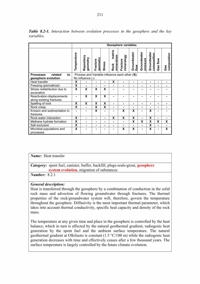
211
Table 8.2-1. Interaction between evolution processes in the geosphere and the key variables.
Geosphere variables
Tem
pera
ture
Rep
osit
ory
geo
metr
y
Fra
ctu
re
geo
metr
y
Str
ess
Ro
ck
matr
ix
min
era
log
y
Fra
ctu
re
min
era
log
y
Gro
un
dw
ate
r
flo
w
Gro
un
dw
ate
r
pre
ssu
re
Gro
un
dw
ate
r
co
mp
os
itio
n
Ga
s f
low
Gas
co
mp
os
itio
n
Processes related to geosphere evolution
Process and Variable influence each other (X);No influence (-)
Heat transfer X - - - X - - - - - -
Freezing (permafrost) X - - - - - - - - - -
Stress redistribution due to excavation
X X X X - - - - - - -
Reactivation-displacements along existing fractures
- X X X - - - - - - -
Spalling of rock X X X X - - - - - - -
Rock creep X - X X - - - - - - -
Erosion and sedimentation in fractures
- - X - - X X - X - -
Rock-water interaction X - - - X X X - X - -
Methane hydrate formation X - - - - - X X X X X
Salt exclusion X - - - - - - - X - -
Microbial populations and processes
X - - - - X X - X - X
Name: Heat transfer
Category: spent fuel, canister, buffer, backfill, plugs-seals-grout, geosphere
system evolution, migration of substancesNumber: 8.2.1
General description:
Heat is transferred through the geosphere by a combination of conduction in the solid rock mass and advection of flowing groundwater through fractures. The thermal properties of the rock/groundwater system will, therefore, govern the temperature throughout the geosphere. Diffusivity is the most important thermal parameter, which takes into account thermal conductivity, specific heat capacity and density of the rock mass.
The temperature at any given time and place in the geosphere is controlled by the heat balance, which in turn is affected by the natural geothermal gradient, radiogenic heat generation by the spent fuel and the ambient surface temperature. The natural geothermal gradient at Olkiluoto is constant (1.5 °C/100 m) while the radiogenic heat generation decreases with time and effectively ceases after a few thousand years. The surface temperature is largely controlled by the future climate evolution.

212
The highest temperatures will be reached soon after backfilling of the repository in the near-field rock adjacent to the bentonite buffer. This will cause the rock to expand and may result in thermal spalling (see 8.2.5). Temperatures in the geosphere will always be lower than in the engineered barriers, largely because of the large volume of rock into which thermal energy is dissipated and the poor thermal conductivity of the bentonite buffer.
The lowest temperatures will be reached in the upper parts of the geosphere in response to the development of permafrost and surface ice-sheets during future glacial cycles (see 8.2.2).
Heat transfer is affected by a number of variables:
The radiogenic heat output and heat transfer from the canister through the buffer to the near-field rock. This reduces over time in direct relationship to radioactive decay.Climate, which controls the average ground temperature at any point in time. Rock composition and structure (porosity and water content) affects the bulk thermal properties of the geosphere and affects the local geothermal gradient, although this is a second order control.
Thermal analyses and dimensioning of KBS-3V and KBS-3H type repositories have been reported (Ikonen 2003a, 2003b, and 2005a).
Olkiluoto specific issues: The site-specific rock properties at Olkiluoto have been investigated in many core samples from various depth of the proposed repository site. Typically, the Olkiluoto mica gneiss is thermally anisotropic and heterogeneous due to its natural variation in texture, mineral composition, and orientation of migmatitic banding and schistosity. In Kukkonen (2000) the thermal diffusivity was calculated from measured data and all results were corrected for the temperature dependencies of thermal parameters using literature data (Table 8.2-2). Thermal conductivity decreases with increasing temperature.
Anisotropy was investigated by correlating schistosity/banding with thermal conductivity. Although compositional variation and texture of the present samples also influence this relationship, the result suggests that the average factor of anisotropy of the mica gneiss is of the order of 1.2 to 1.3. Thermal conductivity and diffusivity show their lowest values in the direction perpendicular to schistosity and banding.
Table 8.2-2. Thermal conductivity and specific heat capacity at different temperatures.
Average thermal conductivity (W m
-1 K
-1)
Specific heat capacity (J kg -1
K-1
)
22 C 2.70 ± 0.42 737
60 C 2.61 784
100 C 2.49 832 Average rock bulk density 2 749 ± 29 kg m-3

213
The effect of anisotropic bedrock on the temperature rise of the repository was studied in Löfman (2001, 2005). This analysis showed that if the anisotropy factor is in the range 1.2 to 1.3 and the typical dip of the foliation is about 40 then thermal dimensioning calculations can be made with adequate accuracy using homogenous material models and average thermal properties of the rock. Uncertainties:
There is some uncertainty regarding how the deposition sequence in time and space influences the near-surface rock temperatures in the first decades after deposition, but this is not likely to affect long-term performance.
The thermal properties of the Olkiluoto rock are variable but the range of uncertainty is small as determined from direct measurement of core drilled rock samples. In the last few years Posiva has been developing a thermal diffusivity measuring instrument TERO that can be used for in-situ thermal investigations in drilled investigation holes. Time frames of relevance:
The maximum temperature in the near-field rock adjacent to the bentonite buffer is reached in 50-100 years and then it takes of the order of 5 000 years for the near-field to reach ambient temperatures. After this time, the natural geothermal gradient will be the dominant process controlling the near-field temperature. Scenarios of relevance:
Heat transfer will occur in all scenarios but may be more important in the defective emplacement of the buffer scenarios because this may affect the thermal boundary between the bentonite and the buffer, leading to higher than anticipated near-field temperatures. Significance:
Heat transfer is of MEDIUM significance in a combined defective buffer and defective canister scenario (AD-II and DSC) because of the potential for early and accelerated migration of radionuclides released to the geosphere in elevated near-field temperatures (by conduction and advection).
In all other scenarios, this process is of LOW significance because there is no release of radionuclides during the period of elevated temperature in the geosphere. Treatment in PA:
The temperature of the near-field rock is modelled using specific thermal codes. These codes are not, however, coupled to the radionuclide transport models, which do not account for temperature dependency on radionuclide solubility and speciation. Thermal driven groundwater flow is not included in the transport models.
Equivalent NEA international FEP:
2.2.10 “Thermal processes and conditions (in geosphere)” Key references:
Ikonen, K. 2003a. Thermal analysis of spent nuclear fuel repository. Posiva Oy, Olkiluoto, Finland. Report POSIVA 2003-04.
Ikonen, K. 2003b. Thermal analysis of KBS-3H type repository. Posiva Oy, Olkiluoto, Finland. Report POSIVA 2003-11.

214
Ikonen, K. 2005a. Thermal Analysis of Repository for Spent EPR-type Fuel. Posiva Oy, Olkiluoto, Finland. Report POSIVA 2005-06.
Kukkonen, I. 2000. Thermal properties of the Olkiluoto mica gneiss: Results of laboratory measurements. Posiva Oy, Olkiluoto, Finland. Posiva Working Report 2000-40.
Löfman, J. 2001. The effect of anisotropic bedrock on the temperature rise of the repository – preliminary study. Posiva Oy, Helsinki, Finland. Posiva Working Report 2001-17.
Löfman, J. 2005. Simulation of hydraulic disturbances caused by the decay heat of the repository in Olkiluoto. Posiva Oy, Olkiluoto, Finland. Report POSIVA 2005-07.
Name: Freezing (permafrost)
Category: spent fuel, canister, buffer, backfill, plugs-seals-grout, geosphere
system evolution, migration of substances Number: 8.2.2
General description:
Glacial conditions are expected to occur several times at Olkiluoto in the future, although the timing and duration is uncertain and dependent on a number of assumptions.
At the earliest, glacial conditions may occur in around 13 000 years AP. At this time, all residual heat from the canisters will have dissipated into the rock. Therefore, the only thermal evolution of the geosphere remaining is due to the natural geothermal gradient and climate effects (see 8.2.1).
The onset of glacial conditions will be accompanied by permafrost, and the ground is expected to freeze down to around 180 m depth (Hartikainen 2006). Permafrost is not expected to penetrate down to repository depths under any likely conditions. The depth of permafrost is controlled by the balance between the natural geothermal gradient (warming) and the average surface temperature and the duration of sub-zero climatic conditions (cooling).
The development of permafrost will have a number of impacts on the evolution of the geosphere. Expanding groundwater in pores and fractures will exert mechanical stress on the rock, and may enhance the fracture network. This may be exacerbated by the weight of any overlying ice sheet.
More significantly, permafrost with extensive lateral development will fundamentally change the groundwater flow paths, potentially shutting off existing recharge and discharge zones, modifying head gradients, and thus altering regional and local flowpaths. If groundwater recharge is restricted, then the flux of water through the

215
repository may be reduced for the duration of permafrost (and ice sheet) development, and groundwater may ‘stagnate’ in the long term. As permafrost develops and subsequently melts, a dynamic groundwater flow system will evolve, until a new recharge-discharge equilibrium is established.
Freezing may also have consequences for rock-water interactions (see 8.2.8) and more saline groundwaters may result from longer reaction times, although the significance of this is thought to be limited (Smellie & Frape 1997). In addition, the formation and melting of methane hydrates in response to permafrost conditions is also a consideration (see 8.2.9).
Freezing (permafrost development) is not affected by any internal features or processes in the repository, and is only controlled by external climatic conditions.
Olkiluoto specific issues:
The development of permafrost and ice sheets at Olkiluoto has been extensively studied (Pastina & Hellä 2006 and references therein). Repeated glaciation-deglaciation events related to climate changes are expected. The magnitude of these climatic events will vary and the Olkiluoto site will experience periods of permafrost, ice, submersion and dry temperate climate. Permafrost is not, however, expected to penetrate down to repository depths under any likely conditions.
Uncertainties:
The main uncertainty relates to the timing and duration of permafrost development. In all cases, however, permafrost is expected to occur after radiogenic heat from the spent fuel has dissipated, and so this is not a factor. The actual depth of permafrost development is also uncertain but there is confidence that it will not extend down to repository depths.Time frames of relevance:
The timing of permafrost development is directly controlled by future climate change events (natural and anthropogenically modified). The timing of climatic events is very different depending on the climatic scenario considered. The first permafrost layer appears approximately 13 000 years AP in the Weichselian-R climate scenario and 170 000 years AP in the Emissions-M scenario (Chapter 5 in Pastina & Hellä 2006).
Scenarios of relevance:
Permafrost will develop in all scenarios but it is most significant for the defective canister scenarios (DCS) because, in this case, the first cycle of permafrost development may be coincident with early release of radionuclides from the canister.
Significance:
Freezing is of MEDIUM significance in the defective canister scenario because of the potential for early radionuclide transport through the geosphere to be significantly affected by the lateral and temporal extent of permafrost.
In all other scenarios, freezing is considered to be of LOW significance because permafrost will not extend down to repository depths and will not affect the containment properties of the near-field.
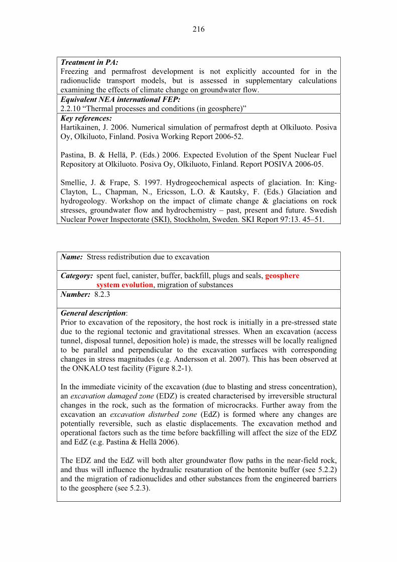
216
Treatment in PA:
Freezing and permafrost development is not explicitly accounted for in the radionuclide transport models, but is assessed in supplementary calculations examining the effects of climate change on groundwater flow. Equivalent NEA international FEP:
2.2.10 “Thermal processes and conditions (in geosphere)” Key references:
Hartikainen, J. 2006. Numerical simulation of permafrost depth at Olkiluoto. Posiva Oy, Olkiluoto, Finland. Posiva Working Report 2006-52.
Pastina, B. & Hellä, P. (Eds.) 2006. Expected Evolution of the Spent Nuclear Fuel Repository at Olkiluoto. Posiva Oy, Olkiluoto, Finland. Report POSIVA 2006-05.
Smellie, J. & Frape, S. 1997. Hydrogeochemical aspects of glaciation. In: King-Clayton, L., Chapman, N., Ericsson, L.O. & Kautsky, F. (Eds.) Glaciation and hydrogeology. Workshop on the impact of climate change & glaciations on rock stresses, groundwater flow and hydrochemistry – past, present and future. Swedish Nuclear Power Inspectorate (SKI), Stockholm, Sweden. SKI Report 97:13. 45–51.
Name: Stress redistribution due to excavation
Category: spent fuel, canister, buffer, backfill, plugs and seals, geosphere
system evolution, migration of substances Number: 8.2.3
General description:Prior to excavation of the repository, the host rock is initially in a pre-stressed state due to the regional tectonic and gravitational stresses. When an excavation (access tunnel, disposal tunnel, deposition hole) is made, the stresses will be locally realigned to be parallel and perpendicular to the excavation surfaces with corresponding changes in stress magnitudes (e.g. Andersson et al. 2007). This has been observed at the ONKALO test facility (Figure 8.2-1).
In the immediate vicinity of the excavation (due to blasting and stress concentration), an excavation damaged zone (EDZ) is created characterised by irreversible structural changes in the rock, such as the formation of microcracks. Further away from the excavation an excavation disturbed zone (EdZ) is formed where any changes are potentially reversible, such as elastic displacements. The excavation method and operational factors such as the time before backfilling will affect the size of the EDZ and EdZ (e.g. Pastina & Hellä 2006).
The EDZ and the EdZ will both alter groundwater flow paths in the near-field rock, and thus will influence the hydraulic resaturation of the bentonite buffer (see 5.2.2) and the migration of radionuclides and other substances from the engineered barriers to the geosphere (see 5.2.3).
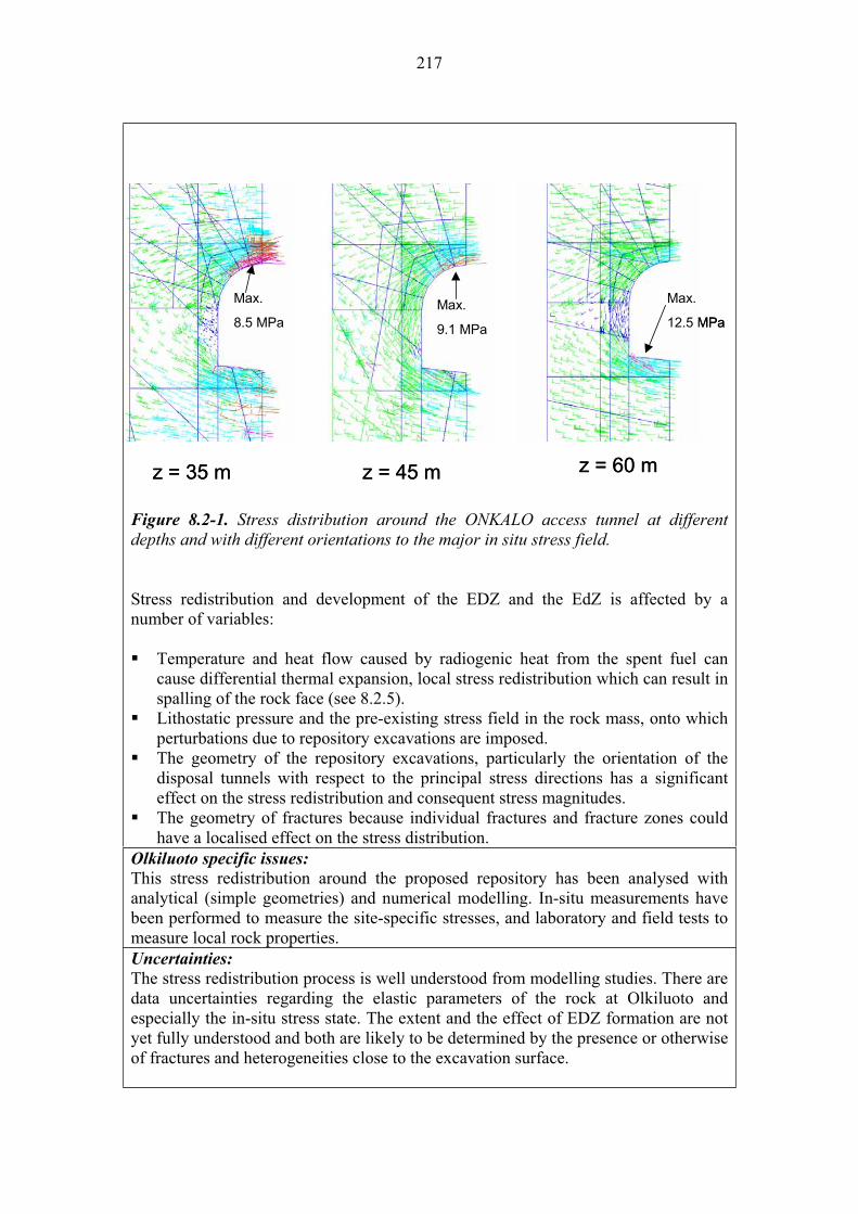
217
Max.
8.5 MPa
z = 35 m
Max.
9.1 MPa
z = 45 m z = 60 m
Max.
12.5 MPa
Max.
8.5 MPa
z = 35 m
Max.
9.1 MPa
z = 45 m z = 60 m
Max.
12.5 MPa
Figure 8.2-1. Stress distribution around the ONKALO access tunnel at different depths and with different orientations to the major in situ stress field.
Stress redistribution and development of the EDZ and the EdZ is affected by a number of variables:
Temperature and heat flow caused by radiogenic heat from the spent fuel can cause differential thermal expansion, local stress redistribution which can result in spalling of the rock face (see 8.2.5).Lithostatic pressure and the pre-existing stress field in the rock mass, onto which perturbations due to repository excavations are imposed. The geometry of the repository excavations, particularly the orientation of the disposal tunnels with respect to the principal stress directions has a significant effect on the stress redistribution and consequent stress magnitudes. The geometry of fractures because individual fractures and fracture zones could have a localised effect on the stress distribution.
Olkiluoto specific issues:
This stress redistribution around the proposed repository has been analysed with analytical (simple geometries) and numerical modelling. In-situ measurements have been performed to measure the site-specific stresses, and laboratory and field tests to measure local rock properties. Uncertainties:
The stress redistribution process is well understood from modelling studies. There are data uncertainties regarding the elastic parameters of the rock at Olkiluoto and especially the in-situ stress state. The extent and the effect of EDZ formation are not yet fully understood and both are likely to be determined by the presence or otherwise of fractures and heterogeneities close to the excavation surface.
218
Time frames of relevance:
Stress redistribution will occur within the first few decades after excavation, and will continue throughout the thermal peak and process of hydraulic resaturation. Scenarios of relevance:
Stress redistribution will occur in all scenarios but may be most relevant to the defective buffer emplacement scenario (AD-II) because a reduced bentonite swelling pressure will allow larger rock displacements and spalling to occur in the near-field rock.Significance:
The redistribution of stress in the far-field rock is of MEDIUM significance because this is one element of the post-closure re-equilibrium of the repository that potentially can affect the degradation of the near-field barriers and the transport of radionuclides in the geosphere. Treatment in PA:
Stress redistribution is not explicitly included in the safety assessment models, but is examined as part of supplementary calculations to determine the mechanical stability of the excavation. Equivalent NEA international FEP:
2.2.04 “Discontinuities, large scale (in geosphere)” 2.2.06 “Mechanical processes and conditions (in geosphere)” Key references
Andersson, J., Ahokas, H., Hudson, J., Koskinen, L., Luukkonen, A., Löfman, J., Keto, V., Pitkänen, P., Mattila, J., Ikonen, A. & Ylä-Mella, M. 2007. Olkiluoto site description 2006. Posiva Oy, Olkiluoto, Finland. Report POSIVA 2007-03.
Pastina, B. & Hellä, P. (Eds.) 2006. Expected Evolution of the Spent Nuclear Fuel Repository at Olkiluoto. Posiva Oy, Olkiluoto, Finland. Report POSIVA 2006-05.
Name: Reactivation-displacements along existing discontinuities
Category: spent fuel, canister, buffer, backfill, plugs and seals, geosphere
system evolution, migration of substances Number: 8.2.4
General description:
All deep rock, including the basement rock at Olkiluoto, contains various physical discontinuities in the form of joints, faults, and fractures etc. These may take different geometries and spatial scales. Some of these discontinuities may be ‘open’ particularly in the near-surface zones and present a route for groundwater flow, while others may be ‘closed’ due to the compressive stresses or ‘sealed’ by the precipitation of secondary, fracture filling minerals.
When stresses and strains build in the rock mass, it is more likely that any displacement will occur along these pre-existing discontinuities than for new fractures to form in intact rock. Three, quite different types of process can be anticipated to

219
occur in the rock in the far field that might cause displacement along pre-existing fractures in the rock.
1. Tectonic: these result from stresses accumulated from ridge push (plate tectonics) processes. Due to the distance of Finland from active plate margins, this type of activity is of low importance over the timescales relevant to repository safety.
2. Excavation induced: there could potentially be displacement along existing features due to the stress redistribution caused by the excavation of the repository (Andersson et al. 2007). The design and layout of the repository is, however, based on the site characterisation data and is intended to avoid this happening to any large extent (see 8.2.3).
3. Glaciation induced: whereby glacial cycles will substantially change the stress state in and around the repository due to ice-loading and this could cause reactivation of pre-existing features. Glaciation will cause additional vertical loads in the rock mass and thereby induced differential horizontal loads. Deglaciation and the resulting differential stresses can cause dynamic effects in rock and is the most likely cause of fault reactivation (e.g. Ojala et al. 2004).
Reactivation-displacements along existing discontinuities can have a number of consequences. Most likely it will result in a localised change to groundwater flow paths as new preferential pathways are established. In some cases this could reduce the path length and time for radionuclides to be transported through the geosphere. Displacement would also cause the groundwater in the fracture to be displaced. There is evidence for very large-scale groundwater expulsion after some large magnitude earthquakes.
In the worst case, displacement could cause direct disruption to a disposal hole leading to early mechanical failure of the canister, although the siting of tunnels and disposal holes is intended to avoid this situation. La Pointe & Hermanson (2002) have analysed the displacements due to the post-glacial earthquakes and concluded that a conservative canister failure probability in Olkiluoto is 0.0014% assuming that a slip of 0.1 m or more on a fracture would result in canister failure.
Reactivation-displacements along existing discontinuities is affected by a number of variables:
Repository geometry, and particularly how and where the repository excavations intersect the existing discontinuities. The initial stress state of the rock and the geometry of existing discontinuities because individual fractures and fracture zones could have a localised effect on the stress distribution. Climate change and the development of ice sheets that cause an increase in the loading on the far-field rock.
Olkiluoto specific issues:Detailed site characterisation work is underway to map the 3D network of existing discontinuities in the rock, and the detailed repository design will ensure canisters are located a safe distance away from them.
220
Uncertainties:The reactivation-displacement process is fairly well understood from modelling studies but uncertainties exist concerning the exact mechanical loads and stresses that will result from future glaciations, and how this will impact on existing discontinuities. In addition, there is considerable uncertainty regarding the effect on groundwater flow systems and the possibility for large-scale groundwater expulsion due to displacement. The timing of future glacial cycles is also subject to considerable uncertainty. Time frames of relevance:
Given that glacial loading and unloading is the most likely cause of reactivation-displacement process, the time frames of relevance are the same as those predicted for future glaciations. The timing of climatic events is very different depending on the climatic scenario considered, with the earliest predicted glacial event being 13 000 years AP. Scenarios of relevance:
The reactivation-displacement process can occur in all scenarios but is most relevant to the defective buffer emplacement scenario (AD-II) because, in this situation, there is the greatest likelihood of early canister failure occurring due to increased mechanical loads and stress on the canister due to a displacement intersecting a deposition hole.Significance:
This process is of LOW significance because the repository design and layout is intended to ensure that no disposal holes (thus canisters) are located close to existing faults or fractures. As a consequence, fault reactivation should not affect the near-field barriers or cause failure of the canister, but it might potentially enhance radionuclide transport in the geosphere by creating fast return paths.Treatment in PA:
The reactivation-displacement of discontinuities is not explicitly included in the safety assessment models, but is examined as part of supplementary calculations to determine the probability of a deposition hole being compromised. In safety assessment the consequences of such event are analysed in the calculation cases derived from the scenario AD-I (see Chapter 2 in this report). Equivalent NEA international FEPs:
2.2.04 “Discontinuities, large scale (in geosphere)” 2.2.06 “Mechanical processes and conditions (in geosphere)” Key references:
Andersson, J., Ahokas, H., Hudson, J., Koskinen, L., Luukkonen, A., Löfman, J., Keto, V., Pitkänen, P., Mattila, J., Ikonen, A. & Ylä-Mella, M. 2007. Olkiluoto site description 2006. Posiva Oy, Olkiluoto, Finland. Report POSIVA 2007-03.
La Pointe, P. & Hermanson, J. 2002. Estimation of rock movements due to future earthquakes at four Finnish candidate repository sites. Posiva Oy, Helsinki, Finland. Report POSIVA 2002-02.
Ojala, V.J., Kuivamäki, A. & Vuorela, P. 2004. Postglacial deformation of bedrock in Finland. Geological Survey of Finland, Nuclear Waste Disposal Research. Report YST-120
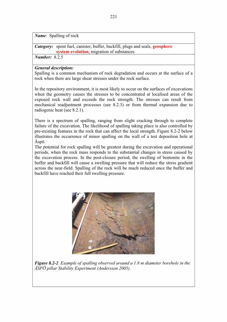
221
Name: Spalling of rock
Category: spent fuel, canister, buffer, backfill, plugs and seals, geosphere
system evolution, migration of substances Number: 8.2.5
General description:
Spalling is a common mechanism of rock degradation and occurs at the surface of a rock when there are large shear stresses under the rock surface.
In the repository environment, it is most likely to occur on the surfaces of excavations when the geometry causes the stresses to be concentrated at localised areas of the exposed rock wall and exceeds the rock strength. The stresses can result from mechanical readjustment processes (see 8.2.3) or from thermal expansion due to radiogenic heat (see 8.2.1).
There is a spectrum of spalling, ranging from slight cracking through to complete failure of the excavation. The likelihood of spalling taking place is also controlled by pre-existing features in the rock that can affect the local strength. Figure 8.2-2 below illustrates the occurrence of minor spalling on the wall of a test deposition hole at Äspö.The potential for rock spalling will be greatest during the excavation and operational periods, when the rock mass responds to the substantial changes in stress caused by the excavation process. In the post-closure period, the swelling of bentonite in the buffer and backfill will cause a swelling pressure that will reduce the stress gradient across the near-field. Spalling of the rock will be much reduced once the buffer and backfill have reached their full swelling pressure.
Figure 8.2-2. Example of spalling observed around a 1.8 m diameter borehole in the ÄSPÖ pillar Stability Experiment (Andersson 2005).
222
Spalling is affected by a number of variables:
Temperature and temperature gradients from radiogenic heat causing differential thermal expansion and stress in the rock adjacent to the excavations. Repository geometry because the orientation of the disposal tunnels has a significant effect on the stress magnitudes around the excavations and hence on the extent of spalling. The initial stress state of the rock and the geometry of existing discontinuities because individual fractures and fracture zones could have a localised effect on spalling.
Olkiluoto specific issues:
Detailed site characterisation work is underway to measure local stress conditions in the rock and the rock strength, and other factors such as foliation that can affect the potential for spalling. The final depth and geometry of the repository will take into account these factors. Uncertainties:
The likelihood and consequence of spalling are well understood from modelling studies and from experience in deep rock excavations. The exact location of spalling cannot be predicted but the overall nature and extent of spalling in the repository is understood. The probability of spalling in an individual deposition hole will depend in part on the rate of bentonite resaturation which itself depends on local rock permeability which is both heterogeneous and uncertain.
Time frames of relevance:
Spalling will be most important during the construction and operational phases of the repository. Heat generation from the first emplaced canisters will cause additional thermal stresses and possibly heat induced spalling. Additional loads from the glaciations can contribute the spalling. Time-dependent changes may change stress distribution and rock properties around the excavations. Scenarios of relevance:
Spalling of the rock will occur in all scenarios but is most relevant to the defective buffer scenario (AD-II) in which reduced swelling pressures allow large stress gradients to remain across the near field, thus increasing the longer-term likelihood and consequence of spalling.Significance:
The spalling of the near-field rock is of LOW significance in the main scenario because it will have limited effect on the retention properties of the engineered barriers or the near-field rock.
It is also of LOW significance in the defective buffer scenario (DCS-II) because, although there is greater potential for spalling and rock collapse, the lack of a diffusive barrier due to the absence of a confining bentonite buffer swelling pressure is the dominant concern. Treatment in PA:
The spalling of rock is not explicitly included in the post-closure safety case models, but mechanical effects are dealt with in supplementary calculations when designing the repository excavations (Hudson et al. 2008).

223
Equivalent NEA international FEP:
2.2.06 “Mechanical processes and conditions (in geosphere)” Key references:
Andersson, C. 2005. Äspö Pillar Stability Experiment. Final experiment design, monitoring results and observations. Swedish Nuclear Fuel and Waste Management Co, Stockholm, Sweden, SKB. SKB Report R-05-02.
Hudson, J.A., Harrison, J.P., Hakala, M. & Johansson, E. 2008. Assessment of the Potential for Excavation-Induced Rock Spalling at the Olkiluoto Site: Generic and Specific Estimates. Posiva Oy, Olkiluoto, Finland. Posiva Working Report 2008-xx (in print).
Name: Rock creep
Category: spent fuel, canister, buffer, backfill, plugs and seals, geosphere
system evolution, migration of substances Number: 8.2.6
General description:
Creep of the rock mass is a slow, quasi-continuous (time-dependent) deformation process that generally occurs along pre-existing discontinuities in the rock. Creeping at a very slow rate can, however, also take place in the rock matrix due to differential stress fields.
Creep may occur in the geosphere as a result of the imposition of stresses resulting from tectonic, climatic (e.g. ice loading / unloading) and repository excavation processes, but is unlikely to be as significant as the more rapid stress readjustment and displacement processes that will occur in response to excavation of the repository (see 8.2.3 and 8.2.4).
Creep occurs in intact rock and along pre-existing discontinuities, and is likely to change the hydraulic and transport properties of discontinuities (e.g. Eloranta et al. 1992). In particular the fracture connectivity and channelling properties could change, such that the preferential flow paths through the rock mass could alter with time. Creep of the rock around repository excavations may deform the bentonite buffer. In an extreme case it could affect the waste package, although considerable creep deformation would be required for any damage to occur and this is considered very unlikely.
Creep is affected by a number of variables: Temperature and temperature gradients can affect rock creep but at the range of temperatures likely to occur over the long-term in the geosphere, this will be a minor control. The initial stress state of the rock and the geometry of existing discontinuities because creep occurs along pre-existing discontinuities.

224
Climate change and the development of ice sheets that cause an increase in the loading on the far-field rock that may result in slow time-dependent creep processes.
Olkiluoto specific issues:The potential and extent of rock creep is dependent on the composition and nature of the bulk rock, and the 3D network of discontinuities. These features are being investigated as part of the site characterisation programme. Uncertainties:
The very long-term creep processes are not well understood but this uncertainty is not considered to be significant. Time frames of relevance:
Rock creep will occur continuously at a slow rate throughout the lifetime of the repository.Scenarios of relevance:
Rock creep will occur in all scenarios but may be most relevant in the defective buffer scenarios in which reduced swelling pressures allow large stress gradients to remain across the near field.Significance:
Rock creep is considered to be of LOW significance in all scenarios because displacement along existing discontinuities will be the dominant stress readjustment processes.Treatment in PA:
Rock creep is not explicitly included in the post-closure safety case models, and only investigated as part of side calculations. Equivalent NEA international FEP:
2.2.06 “Mechanical processes and conditions (in geosphere)” Key reference:Eloranta, P., Simonen, A. & Johansson, E. 1992. Creep in crystalline rock with application to high-level nuclear waste repository. Helsinki, Finland: Nuclear Waste Commission of Finnish Power Companies. YJT-92-10.
Name: Erosion and sedimentation in fractures
Category: spent fuel, canister, buffer, backfill, plugs and seals, geosphere
system evolution, migration of substances Number: 8.2.7
General description:
Groundwater flow in the geosphere will predominantly take place through fractures.
During and after the operational phase, the groundwater inflows in the near-field rock may be increased significantly and the water chemistry may become more acidic and oxidising. As a consequence, there is the potential for fracture filling materials to be dissolved and eroded, and for the transmissivity of the factures to increase (Pitkänen et al. 2004).

225
In contrast, there is the possibility for bentonite particles eroded from the buffer (see 5.2.3) to be carried into water-bearing fractures where they can accumulate and cause sedimentation. This process can potentially restrict the flow of groundwater through the fractures and reduce their transmissivity. Bentonite particles released from the buffer may act as colloids and influence the transport of radionuclides in the geosphere (see 8.3.6).
Erosion and sedimentation in fractures is not expected to lead to significant changes in the bulk hydraulic properties of the geosphere. This is because highly conductive fractures will be grouted and the residual transmissivity will not be sufficient to cause significant erosion and sedimentation.
Erosion and sedimentation in fractures is affected by a number of variables:
Fracture geometry, and in particular the width of channels in fractures through which groundwater flows. Composition of fracture filling materials, which controls their susceptibility to dissolution and erosion. Groundwater flow rate, which can affect the transport capacity for bentonite particles eroded from the buffer and backfill. Groundwater composition, which can affect the rate of dissolution and erosion of the fracture filling materials.
Olkiluoto specific issues:The characteristics of the fracture network and the groundwater composition and site-specific but it is not anticipated that these factors will substantially affect the process. Uncertainties:
The rate and extent of erosion and sedimentation has not been quantified but is not considered to be sufficiently great to affect repository performance. Time frames of relevance:
The process is most likely to occur in the early period of hydraulic resaturation and establishment of chemical equilibrium, although glacial meltwaters if they reached repository depths might also affect erosion and sedimentation in fractures.
Scenarios of relevance:
Erosion and sedimentation may occur in all scenarios but may be most relevant to the defective buffer emplacement scenario when the flow of groundwater into and out of fractures connected to the excavations can greater in the absence of bentonite buffer.Significance:
Erosion and sedimentation is considered to be of LOW significance in all scenarios because it will not substantially affect the transport of radionuclides or other substances in the geosphere.Treatment in PA:
Erosion and sedimentation is not explicitly included in the post-closure safety case models, and only investigated as part of supplementary calculations. Equivalent NEA international FEP:
2.2.05 “Contaminant transport path characteristics (in geosphere)”
226
Key reference:Pitkänen, P., Partamies, S. & Luukonen, A. 2004. Hydrogeochemical interpretation of baseline groundwater conditions at the Olkiluoto site. Posiva Oy, Olkiluoto, Finland. Report POSIVA 2003-07.
Name: Rock-water interaction
Category: spent fuel, canister, buffer, backfill, plugs and seals, geosphere
system evolution, migration of substances Number: 8.2.8
General description:
Groundwater contained in the geosphere will interact with the mineral surfaces it is in contact with. The majority of the water in a fractured crystalline rock will be held in the fractures and, therefore, the dominant reacting solid will be the minerals coating the fracture walls. In pre-existing fractures, these fracture coating minerals may not be representative of the bulk mineralogy of the rock because they are likely themselves to be the solid products of previous rock-water interactions.
Typically the fracture coating minerals at Olkiluoto are carbonates, sulphides and oxides, compared to the bulk rock matrix which is composed of silicate minerals (e.g. Pitkänen et al. 1999).
Practically the only carbonate mineral in the Olkiluoto fractures is calcite. Compared to most other common mineral-water interactions, calcite is quickly equilibrated and in most cases the reaction is described adequately with equilibrium thermodynamics. Calcite is a significant pH buffer especially against low pH. Calcite equilibrium is strongly coupled to the consumption and production of CO2 by biological processes.
The most common sulphide mineral in the Olkiluoto fractures is pyrite, though also pyrrhotite, sphalerite and chalcopyrite are found less frequently. All sulphides as well as dissolved SO4 are redox sensitive since sulphur is both a potential electron donor and acceptor in redox processes. However, pyrite and pyrrhotite are among the sulphide phases most effectively dissolved in oxic conditions because both ferrous iron and sulphur can be oxidised in redox processes. The reaction rates for sulphide oxidation are several orders of magnitude higher than for silicates. Various rock-water interaction processes may be mediated by microbial action (see 8.2.11).
Most silicate minerals in the fractures and the rock matrix are prone to mineral alterations under typical geosphere conditions. Partial or incongruent decomposition of silicates is often energetically more favourable than direct breakdown by complete dissolution, for example K-feldspar typically alters to form illite and kaolinite. At ambient temperatures, all usual silicate reactions are surface area, specific rate (function of e.g. pH and various inhibition factors) and mineral saturation controlled (Lasaga 1984). An additional factor that affects silicate dissolution reactions is the presence of redox sensitive elements (such as Fe). At Olkiluoto, biotite, chlorite,

227
hornblende, and cordierite minerals all exhibit redox sensitive behaviour because of their Fe-content. Often silicate reactions take place in conditions far from thermodynamic equilibrium, but the specific reaction rates of silicates are usually several orders of magnitude slower than for the carbonates and sulphide minerals.
Typically, the most active part of the geosphere for water-rock interactions is the upper oxidising, acidic zone. Baseline studies at Olkiluoto (Pitkänen et al. 1999) indicate that dissolution of calcite, plagioclase and mafic minerals, and precipitation of quartz and kaolinite occur in the overburden and upper bedrock. The driving force of dissolution reactions lies in the low ionic strength and acidity of meteoric water. Future climate change will affect recharge, notably the flux and composition of recharge water. In post-glacial melt conditions, low ionic strength glacial meltwaters may intrude down into the geosphere to considerable depth, and this can have a long-term, significant impact on rock-water interaction.
In the near-field rock, alkaline groundwaters may be created due to degradation of concrete (e.g. Baker et al. 2002) and this alkaline groundwater will cause degradation of silicates around the repository and precipitation further along fractures when more neutral pH conditions prevail. Thus cement leachate-rock interactions are an important potential factor for altering flow in the near-field rock. Similarly, during the period of radiogenic heating, calcite may be precipitated in the near-field rock because it has lower solubility at higher temperatures.
Rock-water interactions will also be important if the repository is left open for extended periods of time (e.g. post-emplacement monitoring). Under these open conditions the most important reactions is likely to be the oxidation of pyrite. This process is known to occur very rapidly and can lead to very low pH groundwaters (pH < 3). It is the cause of ‘acid mine drainage’ and is well observed in many deep mines and excavations. The significance of the reaction depends entirely on the amount of pyrite present.
Rock-water interaction is important for radionuclide transport in the geosphere for a number of reasons: 1) they control the overall hydrochemical system, notably the redox state, and
therefore are a major influence on the solubility and speciation of radionuclides released from the near-field (see 8.3.1);
2) radionuclides may be sorbed or incorporated into secondary alteration products formed by rock-water interaction (see 8.3.1); and
3) dissolution and precipitation of fracture coating minerals can alter the groundwater flow system, and flow rate, thus affecting the radionuclide transport time through the geosphere (8.3.2).
Water-rock interactions are affected by a number of variables:
Temperature is an important control and as a simple rule, in typical geosphere temperatures, a 10 C increase in temperature causes a 2–3 fold increase in reaction rate. Groundwater flow has an indirect effect in that it can introduce new chemical

228
species to depth and transport dissolved substances throughout the geosphere. Rock matrix and fracture mineral composition are key controls, particularly of fracture coating minerals, because these represent the solid phases directly in contact with the groundwater for reaction. Groundwater composition is fundamental, particular pH, redox and ionic strength. Over time the groundwater composition in the geosphere will be subject to change in response to excavation of the repository and its closure; leachates from the repository engineered barrier materials; climate change causing cycling between meteoric, seawater and glacial meltwater recharge systems.
Olkiluoto specific issues:
The most common fracture minerals in Olkiluoto are calcite, pyrite, quartz, kaolinite and feldspars. Notably, the fractures lack ferric oxyhydroxide precipitations. The fractures are by far the most important pathway for groundwater within the geosphere and, thus, interactions between the groundwater and these minerals will dominate the hydrogeochemical system.
The rock matrix at Olkiluoto consists of high-grade metamorphic rocks. Consequently, many metamorphic mineral assemblages found are originally stabilised at high temperatures and pressures (e.g. cordierite, garnet, and sillimanite). These high-grade metamorphic minerals are potentially more prone to rock-water processes than minerals more frequently found in crystalline granitic bedrock. Olkiluoto rock contains smectites in the rock matrix and in the fracture zones partially due to retrograde metamorphism that are not associated with later rock-water interactions. However, detailed properties of the smectites (e.g. cation exchange capacities, chemical compositions, grain size distributions are) are not well known. Uncertainties:
Conceptually, rock-water interactions are well understood but there are a number of parameter uncertainties that occur in terms of modelling future rock-water systems. These include both rate constants and thermodynamic data. With regards the evolution of the Olkiluoto groundwater system, there is uncertainty about the timing and effect of future climate change and the impact this will have on recharge water chemistry and flow (depth) conditions. Time frames of relevance:
Rock-water interactions will occur at all times, although different reactions may dominate at different times in response to dynamic climate and groundwater systems.
Scenarios of relevance:
Rock-water interactions are relevant to all scenarios, although they may be more important in the defective canister and buffer emplacement scenarios because, in these cases, larger releases of radionuclides from the near-field to the geosphere may occur.Significance:
Rock-water interactions in the geosphere are of HIGH significance because they are important for controlling the groundwater chemistry and thus the solubility and retardation processes that will affect radionuclides released from a breached canister. Treatment in PA:
Rock-water interactions in the geosphere are not explicitly included in the post-closure safety case models, although thermodynamic models are used to estimate the
229
likely geochemical conditions in the far field and thus to set solubilities for radionuclides released from the near field. Equivalent NEA international FEPs:
2.2.08 “Chemical/geochemical processes and conditions (in geosphere)” 3.2.01 “Dissolution, precipitation and crystallisation, contaminant” 3.2.03 “Sorption/desorption processes, contaminant” Key references:
Baker, A.J., Bateman, K., Hyslop, E.K., Ilett, D.J., Linklater, C.M., Milodowski, A.E., Noy, D.J., Rochelle, C.A. & Tweed, C.J. 2002. Research on the alkaline disturbed zone resulting from cement-water-rock reactions around a cementitious repository. United Kingdom Nirex Limited, Nirex Report N/054.
Lasaga, A.C. 1984. Chemical kinetics of water-rock interactions. Journal of Geophysical Research 89(B6), 4009-4025.
Pitkänen, P., Luukkonen, A., Ruotsalainen, P., Leino-Forsman, H. & Vuorinen, U. 1999. Geochemical modelling of groundwater evolution and residence time at the Olkiluoto site. Posiva Oy, Helsinki, Finland. Report POSIVA 98-10.
Name: Methane hydrate formation
Category: spent fuel, canister, buffer, backfill, plugs and seals, geosphere
system evolution, migration of substances Number: 8.2.9
General description:
Methane hydrates or methane ice, also called clathrates, are solid crystalline compounds of methane and water, having an approximate formula of CH4 nH2O, where n 5 – 7. They are found abundantly on the sea floor and in the Arctic permafrost areas associated with oil and gas (methane) occurrences (Ahonen 2001).
Methane is trapped within hydrogen bonded water molecules and contributes to the structural stability by its small molecular size. Methane ice looks like normal water ice and has similar density, but methane is significantly concentrated in it and therefore its formation requires both water and a separate gas phase (methane supersaturation). The hydrate lattice is stabilised by weak van der Waals forces thus methane hydrates are stable in specific pressure and temperature conditions as shown below (Sloan 2004).
As indicated in Figure 8.2-3, methane hydrates can only form when the pressure is in excess of 20 bars (corresponds to 200 m equivalent depth) and temperature less than 15 C. Another precondition for methane hydrate formation is that CH4 gas phase separates from groundwater (i.e. supersaturated conditions).

230
Figure 8.2-3. Phase diagram for a methane-water mixture as a function of depth (equivalent to hydrostatic pressure assuming 10 bar/100 m) and temperature. Gray area limits methane hydrate stability in temperature-pressure field. Tm represents the melting temperature of ice (Buffet 2000). TC corresponds to the current temperature profile at Olkiluoto and TP represents potential gradient under long term permafrost conditions with the thickness about 100 m.
The current temperature profile in the bedrock at Olkiluoto is clearly too high to allow the formation of methane hydrates at any depths but they could form under deep permafrost conditions. Such conditions may be expected in the future, and possibly several periods during the next tens of thousands of years depending on climate scenarios (Pastina & Hellä 2006).
Similarly, current CH4 contents are well below the solubility limit at repository depths, but near saturation in the deepest samples (800-900 m depth) and suggest that a gas phase may exist at those depths or deeper (Gascoyne 2005). Consequently, a free methane gas phase is unlikely to develop at repository depths unless deep saline groundwater moves upwards, or migration and microbial production of CH4 clearly increase for some reason.
The main issue of methane hydrate is their melting, which releases significant amounts of CH4 gas and forms a gas phase in a short time period. This may have a significant effect on the hydrogeological conditions, may induce cracks or activate flow conditions in the bedrock. Gas phase formation and its influence on hydrogeology is a significant issue at Olkiluoto although conditions for CH4 hydrate stabilisation will not form. It is also unlikely that methane gas phase will exist in the near field at the time of next glaciation and thus methane ice issue mainly concerns far-field conditions.
231
Methane hydrate formation and gas phase is affected by a number of key variables:
Temperature, specifically the onset of cold temperatures in a next glacial cycle, because methane hydrates form at low temperatures. Groundwater flow and gas flow because melting of methane hydrate leads to two-phase flow system with free gas (see 8.3.5). Hydrostatic pressure is important because methane hydrates form at pressures in excess of those equivalent to 200 m depth. Groundwater composition is a dominant control because hydrates can form only in methanic conditions where the methane content exceeds its solubility.
Olkiluoto specific issues:
High concentrations of dissolved CH4 deep in the bedrock at Olkiluoto create potential conditions for CH4 hydrate formation. The accumulation rate for CH4 is currently unknown albeit is estimated to be very slow. The time frame of a potential glacial period is, however, very long, which may make gas phase formation, significant accumulation and finally CH4 hydrate formation possible if enough porosity is available. Uncertainties:
Methane formation and accumulation processes are relatively well understood in the case of Olkiluoto, but the kinetics of microbial formation and the rate of accumulation of either microbial or abiogenic methane are not well known (Pitkänen & Partamies 2007).Time frames of relevance:
Methane hydrates can only form during glacial cycles when deep permafrost develops. The significance of CH4 hydrate is confined to the melting stage of permafrost either during the end of glacial period or to the formation of warm based ice sheet. The timing of climatic events is very different depending on the climatic scenario considered, with the earliest predicted event being 13 000 years AP.
Scenarios of relevance:
Methane hydrates are relevant to all scenarios because glacial conditions will occur in all scenarios considered. Significance:
The formation of methane hydrates is considered to be of LOW significance in all scenarios because the volume of ice that can form is considered to be small. Treatment in PA:
Methane hydrate formation is not explicitly considered in the main safety assessment calculations but some supplementary calculations have been undertaken to assess the potential for occurrence. Equivalent NEA international FEP:
2.2.11 “Gas sources and effects (in geosphere)” Key references:
Ahonen, L. 2001. Permafrost: occurrence and physicochemical processes. Posiva Oy, Helsinki, Finland. Report POSIVA 2001-05.
Buffet, B.A. 2000. Clathrate hydrates. Annual Review of Earth and Planetary Sciences, 28, 477-507.

232
Gascoyne, M. 2005. Dissolved gases in groundwaters at Olkiluoto. Posiva Oy, Eurajoki, Finland. Posiva Working Report 2005-56.
Pastina, B. & Hellä, P. (Eds.) 2006. Expected evolution of a spent nuclear fuel repository at Olkiluoto. Posiva Oy, Olkiluoto, Finland. Report POSIVA 2006-05.
Pitkänen, P. & Partamies, S. 2007. Origin and implications of dissolved gases in groundwater at Olkiluoto. Posiva Oy, Olkiluoto, Finland. Report POSIVA 2007-04.
Sloan, E.D. 2004. Introductory overview: Hydrate knowledge development. Am. Min., 89, 1155-1161.
Name: Salt exclusion
Category: spent fuel, canister, buffer, backfill, plugs and seals, geosphere
system evolution, migration of substances Number: 8.2.10
General description:
In permafrost conditions ground-temperature remains perennially below zero and, as a consequence, groundwater freezes (see 8.2.2). Dissolved components in groundwater do not, however, incorporate in the ice lattice, but segregate into a separate phase. This may lead to the formation of a saline water body moving ahead of an advancing freezing front; isolation of brine pockets within the ice phase; accumulation of salts on the grain-boundaries or crystallisation of cryogenic minerals. Cold saline waters and brines associated with permafrost are known as called cryopegs.
The freezing point of saline waters/brines may be much below zero, depending on salinity, as shown in Figure 8.2-4. With decreasing temperature a brine-phase with increasing salinity segregates.
Segregation of a saline front ahead of propagating permafrost requires that downward movement of a brine body is as fast, or faster, than the cooling front. Scoping calculations indicate that the rate of permafrost advancement in low-porosity crystalline rock may be of the order of 5 cm/y (Ahonen 2001). In those conditions, the downward transport of salinity must mainly take place via diffusion, and so the formation of segregated intra-permafrost cryopegs, cryogenic mineralisation or sorbed grain-boundary salts is possible. The high density of the saline water may cause it to sink downwards to repository levels where it could interact with the bentonite buffer, causing it to loose some of its swelling capacity.
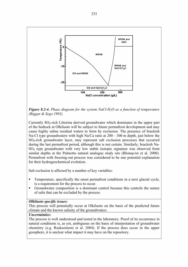
233
Figure 8.2-4. Phase diagram for the system NaCl-H2O as a function of temperature (Biggar & Sego 1993).
Currently SO4-rich Littorina derived groundwater which dominates in the upper part of the bedrock at Olkiluoto will be subject to future permafrost development and may cause highly saline residual waters to form by exclusion. The presence of brackish Na-Cl type groundwaters with high Na/Ca ratio at 200 – 300 m depth, just below the SO4-rich groundwater layer, may represent salt exclusion processes that occurred during the last permafrost period, although this is not certain. Similarly, brackish Na-SO4 type groundwater with very low stable isotopic signature was observed from similar depths at the Palmottu natural analogue study site (Blomqvist et al. 2000). Permafrost with freezing-out process was considered to be one potential explanation for their hydrogeochemical evolution.
Salt exclusion is affected by a number of key variables:
Temperature, specifically the onset permafrost conditions in a next glacial cycle, is a requirement for the process to occur. Groundwater composition is a dominant control because this controls the nature of salts that can be excluded by the process.
Olkiluoto specific issues:
This process will potentially occur at Olkiluoto on the basis of the predicted future climate and the known salinity of the groundwaters. Uncertainties:
The process is well understood and tested in the laboratory. Proof of its occurrence in natural conditions is, as yet, ambiguous on the basis of interpretation of groundwater chemistry (e.g. Ruskeeniemi et al. 2004). If the process does occur in the upper geosphere, it is unclear what impact it may have on the repository.
234
Time frames of relevance:
Salt exclusion can occur only during permafrost periods. The timing of climatic events is very different depending on the climatic scenario considered, with the earliest predicted event being 13 000 years AP. Scenarios of relevance:
Salt exclusion is relevant to all scenarios because glacial conditions will occur at some time in all scenarios considered. Significance:
The exclusion of salt from freezing groundwater during permafrost is considered to be of LOW significance. This is because although the process may occur, it will not result in any increase in the rate of degradation of the near-field barriers or in the rate of radionuclide transport through the far field. Other processes associated with permafrost, such as the substantial change in regional groundwater flow-fields, are considered to be more significant.Treatment in PA:
Salt exclusion is not explicitly included in the main calculations of the safety assessment, but has been investigated in supporting studies. Equivalent NEA international FEP:
2.2.08 “Chemical/geochemical processes and conditions (in geosphere)” Key references:
Ahonen, L. 2001. Permafrost: occurrence and physicochemical processes. Posiva Oy, Helsinki, Finland. Report POSIVA 2001-05.
Biggar, K.W. & Sego, D.C. 1993. The strength and deformation behaviour of model adfreeze and grouted piles in saline frozen soils. Can. Geotechnical J. 30, 319 – 337.
Blomqvist, R., Ruskeeniemi, T., Kaija, J., Ahonen, L., Paananen, M., Smellie, J., Grundfelt, B., Bruno, J., Pérez del Villar, L., Rasilainen, K., Pitkänen, P., Suksi, J., Casanova, J., Read, D. & Frape, S. 2000. The Palmottu natural analogue project. Phase II: Transport of radionuclides in a natural flow system at Palmottu. European Commission, Nuclear Science and Technology Series. EUR 19611 EN.
Ruskeeniemi, T., Ahonen, L., Paananen, M., Frape, S.H., Stotler, R., Hobbs, M., Kaija, J., Degnan, P., Blomqvist, R., Jensen, M., Lehto, K., Moren, L., Puigdomenech, I. & Snellman, M. 2004. Permafrost at Lupin (Phase II). Geol. Surv. Finland, Espoo. Report YST-119.
235
Name: Microbial populations and processes
Category: spent fuel, canister, buffer, backfill, plugs and seals, geosphere
system evolution, migration of substances Number: 8.2.11
General description:
Microbes are ubiquitous forms of life and different species of microbes are adapted to different physicochemical conditions. It is also known that active microbial populations and processes extend deep into the bedrock to repository depths, and that deep subsurface microbes may differ substantially from those in the near-surface environment (Pedersen 2008). These microbes are most likely to be located on the surfaces of fracture coating minerals, and may influence certain rock-water interactions. Figure 8.2-5 indicates the main microbial metabolic processes that occur at different depths in the geosphere.
In near-surface oxidising conditions, oxygen is consumed by microbes through aerobic respiration, aerobic methane oxidation, and oxidisation of iron and sulphur compounds. In deeper reducing conditions, microbes take advantage of a broad range of reactions such as denitrification, fermentation, and reduction of manganese and sulphate, using methane, carbon dioxide and carbon dioxide of crustal origin.
Microbes in Olkiluoto groundwater have been studied and data shows that aerobic bacterial activity is restricted to the upper few metres and anaerobic microbes dominate at all greater depths. Increased activities of several species are recorded at a depth of around 300 metres (Havemann et al. 1998, 2000; Pedersen 2008). This depth is significant at Olkiluoto because it denotes the deepest groundwater where sulphate containing ancient seawater has infiltrated. Methane and higher hydrocarbon concentrations are also distinctly reduced at this depth compared to deeper groundwaters, and it is postulated that microbes are influencing the mass-transfers and reactions related to the methane and sulphate.
Microbial populations in the geosphere may be important for controlling aspects of the geochemical system (e.g. maintenance of reducing conditions), and thus the solubility and speciation of radionuclides released from the near field (see 8.3.1). In general, however, microbial populations and processes are less significant than in the near field where they can potentially become involved in bio-corrosion of the barrier materials.

236
Figure 8.2-5. A biogeochemical process sequence for different bacterial metabolic groups. Vertical dimension is a figurative (and approximative) depth- and redox-scale (oxic on top and anoxic at depth).
Microbial populations and processes are affected by a number of variables:
Temperature, the activity of microbial species found in the geosphere is temperature dependent. The most significant control on temperature in the far field is the natural geothermal gradient. Fracture mineralogy is important because the fracture coating minerals act as the main substrate onto which microbial populations form, and from which they derive some nutrients. Groundwater flow has an indirect effect in that it can introduce new microbial species to depth and transport populations throughout the geosphere. Groundwater and gas composition provides nutrients to microbes in the form of dissolved species derived from rock-water interactions. In particular, the composition of dissolved redox sensitive species is important for maintaining Eh conditions and supporting different forms of microbial species.
237
Olkiluoto specific issues:
The viability of microbial species throughout the geosphere is important to understand because of the potential for microbes to catalyse certain reactions, and influencing the overall hydrochemical system which controls the transport behaviour of radionuclides released from the near-field.
Present day microbial processes are useful for understanding these mass-transfers and reactions, particularly those related to methane and sulphate. At the moment it is not clear, how much of the microbial activity detected at depth is caused by man-made disturbances.Uncertainties:
It is evident that viable microbial populations will occur in the repository geosphere and that they may influence certain aspects of the hydrogeochemical system. It is uncertain, however, how important this influence may be and what will be the overall consequence for radionuclide transport in the geosphere. There is considerable uncertainty about the nature and populations of microbes that would be viable in the long-term in the geosphere. Current sampling and culturing methods indicate several microbial groups to be alive across a broad depth ranges within the bedrock, but do not show what processes are active. Several processes may be active simultaneously (several of the microbial groups are active) or none of the processes are active (all microbial groups are dormant). Time frames of relevance:
Microbiological processes in Olkiluoto will remain potentially active for the complete lifetime of the repository. Microbial populations will tend to respond to all nutrients available or intruding with time into the geosphere either from ground surface, from deeper depths or from the engineered barrier system. Scenarios of relevance:
Microbial populations and processes will occur in all scenarios.Significance:
Microbial populations and processes in the geosphere are considered to be of LOW
significance because only a very small proportion of the radionuclide inventory is expected to reach the geosphere where microbial processes may potentially influence their migration. Those radionuclides that do reach the geosphere are poorly sorbing, mobile species (e.g. 129I) and are less likely to be influenced by microbial populations than other radionuclides that will tend to remain in the near field.Treatment in PA:
Microbial populations and processes are not explicitly included in the post-closure safety case models but considerable effort through focussed research and supplementary calculation has been placed on estimating the potential consequences of microbial activity on radionuclide transport in the geosphere. Equivalent NEA international FEPs:
2.2.08 “Chemical/geochemical processes and conditions (in geosphere)” 2.2.09 “Biological/biogeochemical processes and conditions (in geosphere)”Key references:
Havemann, S., Pedersen, K. & Ruotsalainen, P. 1998. Geomicrobial investigations of groundwaters from Olkiluoto, Hästholmen, Kivetty and Romuvaara. Posiva Oy, Helsinki, Finland. Report POSIVA 98-09.
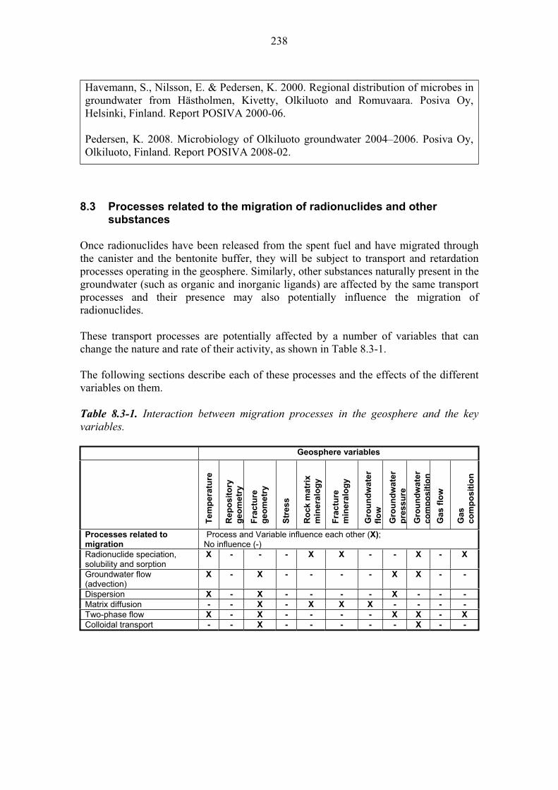
238
Havemann, S., Nilsson, E. & Pedersen, K. 2000. Regional distribution of microbes in groundwater from Hästholmen, Kivetty, Olkiluoto and Romuvaara. Posiva Oy, Helsinki, Finland. Report POSIVA 2000-06.
Pedersen, K. 2008. Microbiology of Olkiluoto groundwater 2004–2006. Posiva Oy, Olkiluoto, Finland. Report POSIVA 2008-02.
8.3 Processes related to the migration of radionuclides and other substances
Once radionuclides have been released from the spent fuel and have migrated through the canister and the bentonite buffer, they will be subject to transport and retardation processes operating in the geosphere. Similarly, other substances naturally present in the groundwater (such as organic and inorganic ligands) are affected by the same transport processes and their presence may also potentially influence the migration of radionuclides.
These transport processes are potentially affected by a number of variables that can change the nature and rate of their activity, as shown in Table 8.3-1.
The following sections describe each of these processes and the effects of the different variables on them.
Table 8.3-1. Interaction between migration processes in the geosphere and the key variables.
Geosphere variables
Tem
pera
ture
Re
po
sit
ory
geo
metr
y
Fra
ctu
re
geo
metr
y
Str
ess
Ro
ck m
atr
ix
min
era
log
y
Fra
ctu
re
min
era
log
y
Gro
un
dw
ate
r
flo
w
Gro
un
dw
ate
r
pre
ssu
re
Gro
un
dw
ate
r
co
mp
os
itio
n
Ga
s f
low
Gas
co
mp
os
itio
n
Processes related to migration
Process and Variable influence each other (X);No influence (-)
Radionuclide speciation, solubility and sorption
X - - - X X - - X - X
Groundwater flow (advection)
X - X - - - - X X - -
Dispersion X - X - - - - X - - -
Matrix diffusion - - X - X X X - - - -
Two-phase flow X - X - - - - X X - X
Colloidal transport - - X - - - - - X - -

239
Name: Radionuclide solubility, sorption, and precipitation
Category: spent fuel, canister, buffer, backfill, plugs and seals, geosphere
system evolution, migration of substances
Number: 8.3.1
General description:
Waste derived radionuclides may only occur in the geosphere after the canister has been breached, radionuclides have been released from the fuel, and have migrated through the canister and the bentonite buffer. Under normal evolution conditions, only a very small proportion of the total radionuclide inventory is estimated to migrate from the near field to the geosphere, and typically it is only the long-lived, poorly sorbing and highly soluble radionuclides that will do so (e.g. 129I, 14C).
The majority of these radionuclides that reach the geosphere will be dissolved in the groundwater and will be transported by the advecting groundwater (see 8.3.2), some radionuclides may however be associated with a gaseous phase (see 8.3.5) or colloids (see 8.3.6).
The speciation of dissolved radionuclides is very important for radionuclide transport in the geosphere because it is a major control on their solubility and reactivity. Different aqueous species form as a function of the composition of the groundwater. In the presence of very strong complexants, the formation of stable aqueous species will decrease the sorption extent of radionuclides. This is exemplified by the behaviour of naturally occurring uranium where the presence of high concentration of carbonate in solution produces the formation of the stable uranium(VI)-carbonate species and measurably reduces the extent of sorption. The redox state of the system also significantly affects the aqueous speciation of radionuclides for those redox sensitive elements, such as Se, Tc and the actinides. A very thorough study of the radionuclide speciation in the Olkiluoto reference groundwater has been recently conducted and taking account of likely future groundwater compositions due to climate change (Grivé et al. 2007).
Due to the anticipated very small release from the near field, it is unlikely that the concentrations of radionuclides dissolved in the groundwater in the geosphere will be solubility controlled (i.e. radionuclide concentrations will be at trace levels and are unlikely ever to reach solubility limits). As such, precipitation of pure solid phases is not expected to be a significant process in the geosphere. Nevertheless, the retention of radionuclides by co-precipitation with other naturally occurring major species (e.g. carbonates) may occur at locations in the geosphere where their solubility limits are reached. This might occur in the far-field at the interface between groundwaters with different compositions (e.g. oxic/anoxic water boundaries). Co-precipitation of naturally occurring radionuclides is commonly observed in geological systems, and has been studied as part of several natural analogue studies (e.g. Palmottu in Blomqvist et al. 2000).
The transport of dissolved radionuclides may also be retarded by sorption onto mineral surfaces. Typically this will be onto fracture coating minerals (carbonates,

240
sulphides and oxides) rather than the silicate minerals of the rock matrix. Sorption is element specific and depends both on radionuclide speciation (valency state, hydrolysis, complexation and groundwater composition) and the solid phase composition and surface characteristics. Radionuclides may sorb via two mechanisms:
1) Surface complexation by means of a bond between the surface of the solid, which is normally hydrated, and the radionuclide. This mechanism is most efficient for hydrolysable radionuclides, such as actinides and hard metal-type radionuclides.
2) Ionic exchange by means of substitution of a given ion of the mineral structure by the radionuclide. This occurs strongly on clay minerals due to the interlayer cations existing in their structure. This mechanism is normally more efficient for those less hydrolysable radionuclides, such as soft acid-type radionuclides.
Sorption capacity is defined by the distribution coefficient (Kd) which is the ratio between the concentration of the radionuclide in the solid phase and in solution. Most of the radionuclides in the geosphere are not, however, strongly sorbing (e.g. Altmann et al. 2001) and in the absence of co-precipitation reactions their retardation in the geosphere will be via hydraulic and mechanical process such as dispersion (see 8.3.3) and matrix diffusion (see 8.3.4).
The far-field groundwater composition will be subject to change in response to climate, and overtime the upper geosphere may recharged with meteoric, seawater and glacial meltwaters, each with different redox, pH and ionic strengths. Changes to the groundwater mean that the fracture filling minerals to which radionuclides are associated (via co-precipitation or sorption) may be formed or dissolved.
Radionuclide solubility and sorption will be affected by a number of variables:
Groundwater and gas composition (particularly the redox conditions, and dissolved gases) and temperature are major controls over radionuclide speciation, and control the solubilities of major species that may form solid phases into which radionuclides can co-precipitate. Composition of the rock matrix and particularly the fracture minerals control the potential for sorption of radionuclides onto solid phases.
Olkiluoto specific issues:
Present-day Olkiluoto groundwater composition is characterised by a high ionic strength. This can affect the solubility and sorption behaviour of radionuclides in the near field. The fractures in the rock are typically coated with carbonates and sulphides, which may provide sites for sorption or new mineral co-precipitation. Uncertainties:
A graphical illustration showing the level of uncertainty associated with radionuclide transport and retardation processes in the geosphere (Figure 8.3-1) was produced in the Retrock project (EUR 2005), see below. This shows that in general the most significant processes are well understood from a conceptual and modelling perspective.
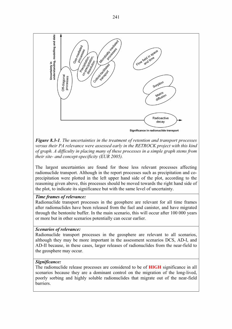
241
Figure 8.3-1. The uncertainties in the treatment of retention and transport processes versus their PA relevance were assessed early in the RETROCK project with this kind of graph. A difficulty in placing many of these processes in a simple graph stems from their site- and concept-specificity (EUR 2005).
The largest uncertainties are found for those less relevant processes affecting radionuclide transport. Although in the report processes such as precipitation and co-precipitation were plotted in the left upper hand side of the plot, according to the reasoning given above, this processes should be moved towards the right hand side of the plot, to indicate its significance but with the same level of uncertainty.
Time frames of relevance:
Radionuclide transport processes in the geosphere are relevant for all time frames after radionuclides have been released from the fuel and canister, and have migrated through the bentonite buffer. In the main scenario, this will occur after 100 000 years or more but in other scenarios potentially can occur earlier.
Scenarios of relevance:
Radionuclide transport processes in the geosphere are relevant to all scenarios, although they may be more important in the assessment scenarios DCS, AD-I, and AD-II because, in these cases, larger releases of radionuclides from the near-field to the geosphere may occur.
Significance:
The radionuclide release processes are considered to be of HIGH significance in all scenarios because they are a dominant control on the migration of the long-lived, poorly sorbing and highly soluble radionuclides that migrate out of the near-field barriers.
242
Treatment in PA:
The transport of radionuclides in the water phase is explicitly included in all the assessment scenarios and calculation cases which account for radionuclide solubility. The only retention process considered explicitly is sorption, which is parameterised by the ‘lump’ Kd coefficient and incorporated in the retardation factor in the transport equation.
Precipitation and co-precipitation in the geosphere are currently omitted processes in all assessments to-date for conservatism of the calculations. Nevertheless, this is not a true conservative approach because the accumulation of radionuclides in a given area due to precipitation may constitute a secondary source of radionuclides in the future, if conditions change towards being more favourable for their mobilisation. Equivalent NEA international FEPs:
2.2.08 “Chemical/geochemical processes and conditions (in geosphere)” 3.2.01 “Dissolution, precipitation and crystallisation, contaminant” 3.2.03 “Sorption/desorption processes, contaminant” Key references:
Altmann, S. Bruno, J. & Tweed, C.J. 2001. Using Thermodynamic Sorption Models for Guiding Radioelement Distribution Coefficient (Kd) Investigations. A Status Report. OECD 2001.
Blomqvist, R., Ruskeeniemi, T., Kaija, J., Ahonen, L., Paananen, M., Smellie, J., Grundfelt, B., Pedersen, K., Bruno, J., Pérez del Villar, L., Cera, E., Rasilainen, K., Pitkänen, P., Suksi, J., Casanova, J., Read, D. & Frape, S. 2000. The Palmottu natural analogue project. Phase II: Transport of radionuclides in a natural flow system at Palmottu. EUR 19611 EN. Contract No FI4W-CT95-0010.
EUR 2005. Treatment of Radionuclide Transport in Geosphere within Safety Assessments. (Retrock). Final report June 2005. Contract No. FIKW-CT-2001-20201. EUR 21230 EN.
Grivé, M., Montoya, V. & Duro, L. 2007. Assessment of the concentration limits for radionuclides for Posiva. Posiva Oy, Olkiluoto, Finland. Posiva Working Report 2007-103.
243
Name: Groundwater flow (advection)
Category: spent fuel, canister, buffer, backfill, plugs and seals, geosphere
system evolution, migration of substances
Number: 8.3.2
General description:
In crystalline hard rocks (such as those at Olkiluoto) groundwater flow takes place predominantly in a fracture network, and is driven by differentials in hydrostatic pressure (the hydraulic gradient).
The regional hydraulic gradient may change with time due to the effects of climate change. In particular, the development of an ice sheet will increase the hydrostatic pressure by the height of the ice, and hydraulic gradients will similarly increase across the margin of an ice sheet. Similarly, relative sea-level rise and fall (due to isostatic uplift of the land) will affect local hydrostatic pressures and hydraulic gradients. As such, groundwater flow patterns observed today will not persist throughout the lifetime of the repository.
Below the water table in the saturated zone, all of the fractures in the rock are full of groundwater. In areas of high rainfall, such as Finland, the water table can be at or very close to the ground surface. An important characteristic of saturated groundwater flow in fractured rock is that the flow rate is strongly heterogeneous on all scales. At a large scale (tens of metres or more), flow is concentrated in a small number of flowing features, typically formed by fracture zones or along intersecting fractures. On a smaller scale (centimetre scale), flow within a fracture is often channelled through interconnected void spaces in between any fracture filling minerals. In addition, there are many water filled void spaces that are not interconnected, in which water is effectively stagnant and diffusion becomes the dominant transport mechanism (see 8.3.4).
Radionuclides and other substances dissolved in the groundwater will be transported at the same rate as the advecting groundwater, although the concentration of radionuclides in the groundwater can be reduced through dispersion and dilution processes (see 8.3.3), through sorption onto the exposed mineral surfaces (see 8.3.1) and diffusion (see 8.3.4).
Due to the heterogeneity of the fracture network and of groundwater flow within it, modelling radionuclide transport is difficult. According to Darcy’s Law, the groundwater flow rate through rock is controlled by the hydraulic gradient and the hydraulic conductivity, which in turn is a function of porosity and permeability, and the properties of the (density, viscosity etc). The heterogeneity in the system means that the actual hydraulic conductivity of the rock and, hence, the velocity and direction of flow (and thus radionuclide transport) can vary widely throughout the rock mass. Complex groundwater flow models are thus developed to account for this heterogeneity, and these are often based around discrete fracture network (DFN) models.
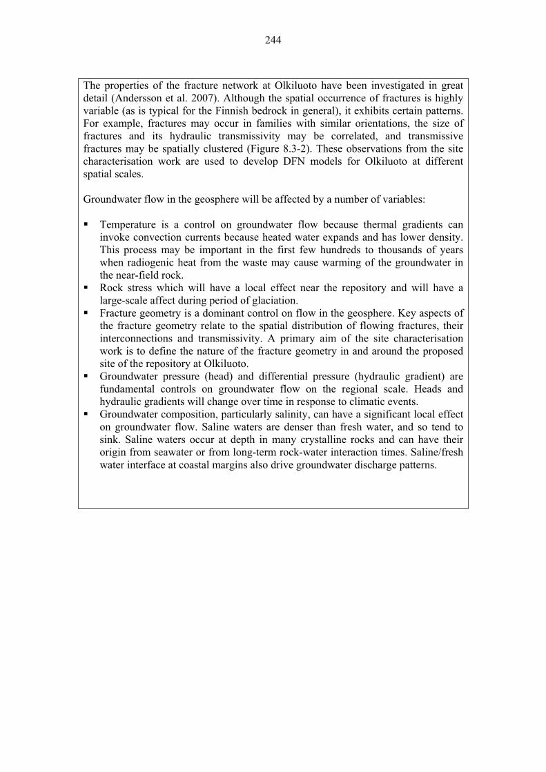
244
The properties of the fracture network at Olkiluoto have been investigated in great detail (Andersson et al. 2007). Although the spatial occurrence of fractures is highly variable (as is typical for the Finnish bedrock in general), it exhibits certain patterns. For example, fractures may occur in families with similar orientations, the size of fractures and its hydraulic transmissivity may be correlated, and transmissive fractures may be spatially clustered (Figure 8.3-2). These observations from the site characterisation work are used to develop DFN models for Olkiluoto at different spatial scales.
Groundwater flow in the geosphere will be affected by a number of variables:
Temperature is a control on groundwater flow because thermal gradients can invoke convection currents because heated water expands and has lower density. This process may be important in the first few hundreds to thousands of years when radiogenic heat from the waste may cause warming of the groundwater in the near-field rock. Rock stress which will have a local effect near the repository and will have a large-scale affect during period of glaciation. Fracture geometry is a dominant control on flow in the geosphere. Key aspects of the fracture geometry relate to the spatial distribution of flowing fractures, their interconnections and transmissivity. A primary aim of the site characterisation work is to define the nature of the fracture geometry in and around the proposed site of the repository at Olkiluoto. Groundwater pressure (head) and differential pressure (hydraulic gradient) are fundamental controls on groundwater flow on the regional scale. Heads and hydraulic gradients will change over time in response to climatic events. Groundwater composition, particularly salinity, can have a significant local effect on groundwater flow. Saline waters are denser than fresh water, and so tend to sink. Saline waters occur at depth in many crystalline rocks and can have their origin from seawater or from long-term rock-water interaction times. Saline/fresh water interface at coastal margins also drive groundwater discharge patterns.
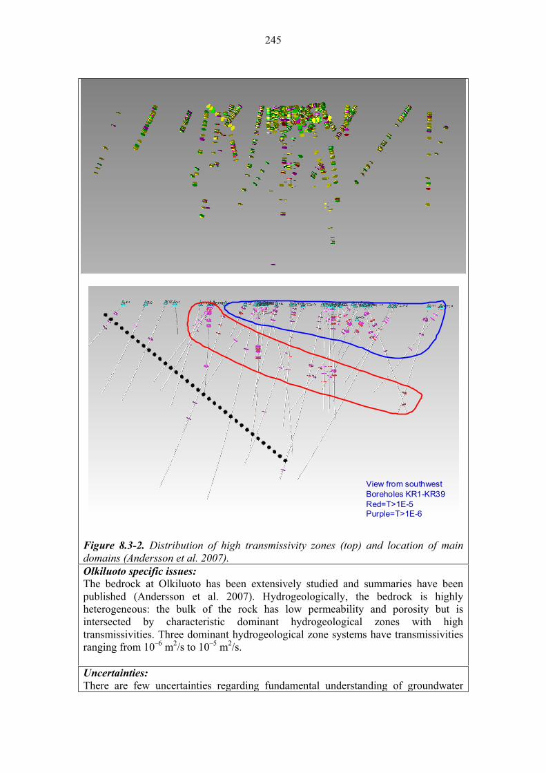
245
View from southwestBoreholes KR1-KR39Red=T>1E-5Purple=T>1E-6
View from southwestBoreholes KR1-KR39Red=T>1E-5Purple=T>1E-6
Figure 8.3-2. Distribution of high transmissivity zones (top) and location of main domains (Andersson et al. 2007). Olkiluoto specific issues:
The bedrock at Olkiluoto has been extensively studied and summaries have been published (Andersson et al. 2007). Hydrogeologically, the bedrock is highly heterogeneous: the bulk of the rock has low permeability and porosity but is intersected by characteristic dominant hydrogeological zones with high transmissivities. Three dominant hydrogeological zone systems have transmissivities ranging from 10–6 m2/s to 10–5 m2/s.
Uncertainties:
There are few uncertainties regarding fundamental understanding of groundwater
246
flow. There are, however, considerable uncertainties associated with being able to simulate and model the complex heterogeneity of groundwater flow in a fractured crystalline rock mass. Ongoing site characterisation work is reducing the uncertainty about the location and characteristics of the fracture network that carried groundwater at Olkiluoto. Time frames of relevance:
Groundwater flow operates at all times, although the rate of flow and the flux of water through the host rock will change over time in response to a number of factors but particularly climate. Scenarios of relevance:
Groundwater flow is relevant to all scenarios. Significance:
Groundwater flow is considered to be of HIGH significance in all scenarios because it is the primary process responsible for the return of radionuclides from the repository to the accessible environment.Treatment in PA:
Groundwater flow rates are explicitly included in the radionuclide release and transport models in all PA calculations. Various conceptual and mathematical models may be used to describe advective flow in fractured crystalline rock. Equivalent NEA international FEPs:
2.1.07 “Hydraulic/hydrogeological processes and conditions (in geosphere)” 2.2.05 “Contaminant transport path characteristics (in geosphere)” 3.2.07 “Water-mediated transport of contaminants” Key references:
Andersson, J., Ahokas, H., Hudson, J., Koskinen, L., Luukkonen, A., Löfman, J., Keto, V., Pitkänen, P., Mattila, J., Ikonen, A. & Ylä-Mella, M. 2007. Olkiluoto site description 2006. Posiva Oy, Olkiluoto, Finland. Report POSIVA 2007-03.
Name: Dispersion
Category: spent fuel, canister, buffer, backfill, plugs and seals, geosphere
system evolution, migration of substances
Number: 8.3.3
General description:
The process by which solutes are transported by the bulk motion of a flowing groundwater is advection (see 8.3.2). At the small scale (centimetres and less), however, variations in the flow field coupled with mechanical mixing and molecular diffusion can result in local water flows and velocities that are different to the larger-scale average, resulting in the spreading of the solute plume (Figure 8.3-3).
Spreading of the solute plume can occur in the direction of advection (longitudinal dispersion) and perpendicular to the direction of advection (transverse dispersion) and result in both spatial and temporal spreading of solutes. Mixing of groundwaters of different composition, may also affect the chemical and physical retardation of migrating radionuclides.

247
Location of fluid particles:at t
at t+ t
Main direction of flow
Contribution of different
factors in hydronynamic
dispersion
Location of fluid particles:at t
at t+ t
Main direction of flow
Contribution of different
factors in hydronynamic
dispersion
Figure 8.3-3. Hydrodynamic dispersion on a microscopic scale. An additional sub-process (not shown in the figure) also contributing to the spreading of the tracer is matrix diffusion, which has been identified as a key retardation process in the geosphere (see 8.3.4).
Dispersion is an important process affecting radionuclide transport in the geosphere. The effect is both to delay and reduce the peak breakthrough concentration of radionuclides returning to the accessible environment. Radionuclides become spread through a larger volume of rock and water, and thus become available for sorption on a large surface area (see 8.3.1) and to matrix diffusion in a larger volume of rock (see 8.3.4).
Dispersion in the geosphere will be affected by a number of variables:
Hydraulic gradient (groundwater pressure) and temperature are driving forces for groundwater flow, and thus are controls on dispersion. The faster the groundwater and the greater the flux of water moving, the greater the potential for dispersion to occur if the flow is turbulent. Fracture geometry is a dominant control because it affects the potential for mixing between different groundwater flow pathways. In addition, the tortuosity of the flow path introduces local perturbations in flow and thus increases the potential for dispersion occurring.
Olkiluoto specific issues:
Dispersion will undoubtedly occur in Olkiluoto groundwaters but it is a difficult process to measure in the field. As groundwater flow conditions change with time (in response to climate change) then the extent of dispersion will also vary.
248
Uncertainties:
There are few uncertainties regarding the fundamental understanding of dispersion. There are, however, considerable uncertainties associated with being able to simulate and model dispersion within the complex heterogeneity of groundwater flow in a fractured crystalline rock mass. Time frames of relevance:
Dispersion of radionuclides in groundwater will occur at all times after the canister has breached and radionuclides have migrated to the geosphere. Scenarios of relevance:
Dispersion of radionuclides is relevant to all scenarios but is most relevant to the early canister failure scenarios because, in this case, there is the potential for greater total activity to be released to the geosphere. Significance:
Dispersion of radionuclides is considered to be of MEDIUM significance in all scenarios because it provides a means of reducing the peak breakthrough concentration of radionuclides returning to the accessible environment.Treatment in PA:
Dispersion of radionuclides is explicitly included in radionuclide transport models based on advection/dispersion models. Equivalent NEA international FEPs:
2.1.07 “Hydraulic/hydrogeological processes and conditions (in geosphere)” 2.2.05 “Contaminant transport path characteristics (in geosphere)” 3.2.07 “Water-mediated transport of contaminants” Key references of interest not mentioned in the text:
Andersson, J., Ahokas, H., Hudson, J., Koskinen, L., Luukkonen, A., Löfman, J., Keto, V., Pitkänen, P., Mattila, J., Ikonen, A. & Ylä-Mella, M. 2007. Olkiluoto site description 2006. Posiva Oy, Olkiluoto, Finland. Report POSIVA 2007-03.
Name: Matrix diffusion
Category: spent fuel, canister, buffer, backfill, plugs and seals, geosphere
system evolution, migration of substances
Number: 8.3.4
General description:
In fractured crystalline rocks groundwater movement generally takes place by flow (advection) along the fracture network (see 8.3.2). Matrix diffusion is the process by which radionuclides and other species in the flowing groundwater migrate into the stagnant pores and microfractures of the surrounding rock mass (Neretnieks 1980).
When radionuclides enter these pores and microfractures, they are isolated from the main advective flow and may sorb onto the surfaces of the minerals in the pore. This is an important retardation process for radionuclides in fractured crystalline rocks where there is a large depth of interconnected porosity in the rock adjacent to the flowing fractures, into which matrix diffusion can take place. Even for non-sorbing

249
species, matrix diffusion may provide an efficient temporal retardation process simply by removing them from the flowing groundwater.
The actual significance of matrix diffusion on radionuclide transport in the geosphere is controlled by the volume of rock available for the process. In turn, this volume is restricted by the depth of interconnected microporosity in the rock mass and the flow wetted surface in the advecting fractures. The flow-wetted surface is partly controlled by the nature of the fracture coating minerals, which could effectively ‘seal’ the rock matrix from the groundwater and would limit matrix diffusion.
Matrix diffusion in the geosphere will be affected by a number of key variables:
Fracture geometry, and in particular the width of channels in fractures through which groundwater flows and the flow wetted surface, that both control the potential for migration into adjacent stagnant pore spaces. Composition and extent of fracture filling materials which can coat and seal the surfaces of fractures and thus limit the potential for matrix diffusion occurring. Rock matrix mineralogy controls the nature of the interconnected porosity and the sorption potential for the exposed pore (mineral) surfaces. Groundwater flow, because the rate of flow (and the turbulence of flow). affects the chance of dissolved substances moving sideways within the flow field and entering the adjacent porosity.
Olkiluoto specific issues:
The characteristics of the fracture network, the flow wetted surface area and the depth of interconnected porosity are all site-specific parameters that can be assessed as part of the site characterisation programme. Uncertainties:
While matrix diffusion theory is well established, it is not evident how effective it may be for retarding radionuclide migration. The depth of interconnected porosity can be measured and the penetration depth for radionuclides has been measured but it has not been possible to define a reliable ‘retardation parameter’ for matrix diffusion to use in performance assessments. Time frames of relevance:
Matrix diffusion is relevant for all time frames after radionuclides have been released from the fuel and canister, and have migrated through the bentonite buffer. In the main scenario, this will occur after 100 000 years or more but in the assessment scenarios potentially can occur earlier.
Scenarios of relevance:
Matrix diffusion is relevant to all scenarios, although it may be more important in the assessment scenarios DCS, AD-I and AD-II because, in these cases, larger releases of radionuclides from the near field to the geosphere may occur.
Significance:
Matrix diffusion within the geosphere is of MEDIUM significance in all scenarios because of the potential for retarding even poorly sorbing radionuclides that have migrated out of the near field.

250
Treatment in PA:
Matrix diffusion within the geosphere is usually conservatively neglected from radionuclide release and transport models in all PA calculations, although supplementary calculations may assess the potential retardation effect for differing volumes of accessible microporosity. Equivalent NEA international FEPs:
3.2.03 “Sorption/desorption processes, contaminant” 3.2.07 “Water-mediated transport of contaminants” Key references:
Neretnieks, I. 1980. Diffusion in the rock matrix: an important factor in radionuclide migration? Journal of Geophysical Research, 85, 4379-4397.
Name: Two-phase flow
Category: spent fuel, canister, buffer, backfill, plugs and seals, geosphere
system evolution, migration of substances
Number: 8.3.5
General description:
Dissolved gases are an important factor in deep groundwater systems and also constitute a notable mass of dissolved species at Olkiluoto. The major sources of naturally occurring dissolved gases in groundwaters are
– air dissolved in groundwater during recharge (predominantly N2, O2, Ar); – dissolved gases produced in the bedrock by radioactive decay (He, Ar, Rn); – crustal degassing and diffusion (He, N2, CH4, H2); and – thermogenic and biogenic processes (CH4 and heavier hydrocarbons, H2S, CO2,
N2).
In the repository, gas may also be formed by anaerobic degradation of the iron insert of the canister (see 4.2.7), through microbial reactions (see 8.2.11) or from radiolysis of the groundwater (see 3.2.5). Of these processes, anaerobic degradation of iron is considered to be most significant.
In addition, rapid evolution of gas is possible if methane hydrates were to melt, causing the release of significant amounts of CH4 (see 8.2.9).
The solubility of gases in groundwater depends mostly on pressure: solubility increases and is directly proportional as a function of depth when hydrostatic pressure increases. The solubility of gases is also reduced by increasing temperature and salinity. A free gas phase may form if an aggregate partial pressure of the dissolved gases exceeds the hydrostatic pressure. This typically occurs when groundwater flows from depth towards the surface and the hydrostatic pressure drops. Degassing of the groundwater results in a depletion of the lighter (less soluble) gases because they tend to diffuse faster into the forming bubbles, i.e. degassing fractionates gas composition.
251
Once a free gas has formed in the groundwater, a two-phase flow situation is created. Free gas will migrate mainly through fractures and fault zones upwards and may form a mechanism for transporting radionuclides released from the canister. Radionuclides may either be directly incorporated into gases (e.g. tritium in methane) and the gas bubbles will provide a rapid transport mechanism for these nuclides because the buoyancy of the bubbles will allow them to travel faster than the mean groundwater flow rate. In addition, other nuclides may be carried with the bubbles if they occur in colloidal form because colloids are sometimes preferentially attached to the gas-water interface (i.e. the bubble surface).
A free gas phase may also affect the transport of radionuclides dissolved in the groundwater by altering the groundwater flow patterns. This could occur by a number of mechanisms. If a large volume of gas is formed, bubbles may push groundwater in front of them or may seal certain pathways (an air-lock) depending on the geometry of the fracture. The significance of gas bubbles for radionuclide transport and for changing groundwater flow patterns is, however, very largely dependent on the volume of gas present.
At Olkiluoto, the most abundant dissolved gases are CO2, H2, N2, O2, and He. In particular deep brines contain methane near its saturation point (Gascoyne 2005, Pitkänen et al. 2004, Pitkänen & Partamies 2007). However, the impact of the dissolved gases on groundwater flow is weak as long as gas remains dissolved.
Two-phase flow is affected by a number of variables:
Hydrostatic pressure and temperature, which controls the solubility of gases in groundwater and thus the likelihood of a free gas phase forming. Rock stress, which will have a local effect near the repository and will have a large-scale affect during period of glaciation. Fracture geometry, which controls the transport characteristics of any free gas once it forms and, in particular, whether it can move upwards due to buoyancy or form an air-lock. Groundwater composition is fundamental because the concentration of dissolved gases in the groundwater is a primary control (with pressure) over the formation of a free gas phase.Gas composition because different gases and compositions will present different solubilities in the geosphere conditions.
Two-phase flow may also occur in the period shortly after closure of the repository, when air trapped in the excavations and in fractures in the near-surface rock is displaced or dissolved by groundwater resaturating the near field. This will be a transient process and unlikely to affect the geosphere.
Olkiluoto specific issues:
The formation and high CH4 concentration in deep saline groundwater is an essential question at Olkiluoto. Continuous accumulation of CH4 may lead to formation of a free gas phase particularly if gas solubility decreases for instance due to upconing of saline groundwater (pressure decrease) or increasing temperature, which has
252
substantial importance for safety. It would have a strong influence on groundwater flow and gas phase migration.
Uncertainties:
The fundamental understanding of the gas formation and two-phase flow processes is sufficient for the needs of the safety assessment. It is uncertain, however, whether two-phase flow will occur in the geosphere and, if it does, whether it will be significant in controlling radionuclide transport processes. Time frames of relevance:
Two-phase flow involving radionuclides cannot occur until after the canister has been breached and radionuclides have been transported through the near field to the geosphere. Two-phase flow involving naturally occurring gases (particularly CH4)may take place at any time if conditions allow. Scenarios of relevance:
Two-phase flow is potentially relevant to all scenarios.Treatment in PA:
Two-phase flow is not usually incorporated into radionuclide release and transport models, but is dealt with through side calculations. Significance:
Two-phase flow in the repository is of LOW significance in all scenarios. Naturally occurring gases are unlikely to have any important effect on the long-term safety and performance of the repository. The generation of gases from the repository itself (e.g. through anaerobic degradation of iron) may enhance the transport of radionuclides out of the near field if a large volume of free gas phase develops but this is not likely to occur at the gas generation rates predicted. Equivalent NEA international FEP:
2.2.11 “Gas sources and effects (in geosphere)” Key references:
Gascoyne, M. 2005. Dissolved gases in groundwaters at Olkiluoto. Posiva Oy, Eurajoki, Finland. Posiva Working Report 2005-56.
Pitkänen, P. & Partamies, S. 2007. Origin and implications of dissolved gases in groundwater at Olkiluoto. Posiva Oy, Olkiluoto, Finland. Report POSIVA 2007-04.
Pitkänen, P., Partamies, S. & Luukkonen, A. 2004. Hydrogeochemical interpretation of baseline groundwater conditions at the Olkiluoto site. Posiva Oy, Olkiluoto, Finland. Report POSIVA 2003-07.

253
Name: Colloidal transport
Category: spent fuel, canister, buffer, backfill, plugs and seals, geosphere
system evolution, migration of substances
Number: 8.3.6
General description:
Radionuclides in the geosphere may be associated with naturally occurring colloids found in the groundwater or colloids formed from the erosion of the bentonite buffer (see 5.3.3).
Under the normal behaviour colloids cannot migrate through the bentonite buffer and, consequently, radionuclides would have to transfer to colloids in the near-field or far-field rock after diffusing through the buffer. However, the radionuclides that reach the geosphere under normal conditions will be poorly sorbing and highly soluble and, therefore, less likely to be associated with colloids than other nuclides.
Naturally-occurring colloids are not expected to be stable under the high ionic strength groundwaters found at depth at Olkiluoto. Nevertheless, in the case of the scenario of infiltrating glacial melt water, with lower ionic strength, the colloidal stability will be enhanced and colloid-mediated transport can have some influence on the migration of radionuclides.
Colloidal particles formed from the erosion of the bentonite buffer may be stable in the deep groundwaters, and these could influence radionuclide transport in the geosphere. It is not evident, however, whether transport would be enhanced because colloids may readily be filtered and blocked in the small fracture apertures, thus retarding the transport of any radionuclides sorbed onto them.
Colloidal radionuclide transport in the geosphere will be affected by a number of key variables:
Fracture geometry because the aperture and tortuosity of the fractures will control the likelihood of the colloids becoming trapped and filtered from the advecting groundwater flow. Groundwater chemistry because it determines radionuclide solubility and speciation, and the stability of the colloids.
Olkiluoto specific issues: The influence of high-salinity groundwater composition on colloid stability. Uncertainties:
The population of colloids in the geosphere, and their mobility and stability, under different groundwater conditions is not well characterised. Time frames of relevance:
Colloidal transport in the geosphere is relevant for all time frames after radionuclides have been released from the fuel and canister, and have migrated through the bentonite buffer. In the main scenario, this will occur after 100 000 years or more but in other scenarios potentially can occur earlier.

254
Scenarios of relevance:
Colloidal transport in the geosphere is relevant to all scenarios, although it may be more important in the defective canister and buffer emplacement scenarios (DCS and AD-II) because, in these cases, larger releases of radionuclides from the near-field to the geosphere may occur and the absence of a buffer may allow colloids to migrate directly from the canister to the geosphere. Significance:
Colloidal transport within the geosphere is of MEDIUM significance in the additional scenarios in which the bentonite buffer is absent or poorly emplaced because of the potential for increasing bulk radionuclide release rates.
In the main scenario, it is of LOW significance because only a small inventory is likely to be presence in the geosphere and largely of poorly sorbing radionuclides.Treatment in PA:
Colloidal transport within the geosphere is neglected from radionuclide release and transport models in all PA calculations. Equivalent NEA international FEPs:
2.2.08 “Chemical/geochemical processes and conditions (in geosphere)” 3.2.04 “Colloids, contaminant interactions and transport with” Key references of interest not mentioned in the text:
EUR 2005. Treatment of Radionuclide Transport in Geosphere within Safety Assessments. (Retrock). Final report June 2005. Contract No. FIKW-CT-2001-20201. EUR 21230 EN.
Grivé, M., Montoya, V. & Duro, L. 2007. Assessment of the concentration limits for radionuclides for Posiva. Posiva Oy, Olkiluoto, Finland. Posiva Working Report 2007-103.
255
9 SUMMARY
This report discusses a range of processes potentially affecting a KBS-3V repository system for spent fuel designed for construction at the Olkiluoto island in south-western Finland. The selection of the processes is based on a screening of the NEA international feature, events and processes (FEP) database (NEA 2000), the previous Posiva Process report (Rasilainen 2004) and the FEPs used in the recent Swedish safety assessment SR-Can (SKB 2006).
Scenarios (Chapter 2) are outlined that comprise FEPs which are potentially significant to long-term safety. However the detailed analysis of scenarios is not within the scope of this report.
The main processes potentially affecting the long-term safety of the repository system are described for each relevant sub-system component or barrier (i.e. fuel, canister, etc.) and classified into two types: evolution-related processes and migration-related processes. This classification was used because it better represents the complex interactions and coupling of processes, and reflects the fact that many processes cannot uniquely be defined as thermal, hydrological, mechanical or chemical.
Each process description provides the current understanding of how it operates in the repository and how it affects performance at different times. Olkiluoto-specific issues are considered whenever relevant. The main uncertainties (conceptual and parameter/data) associated with each process are also documented.
The significance of the processes in each of the sub-systems or barriers is estimated taking into account firstly the desired properties to ensure the performance of the barrier in order to achieve long-term safety secondly the scenarios identified for Posiva’s Safety Case regarding the expected evolution, the occurrence of defective canisters and deviations in the emplacement of e.g. bentonite barrier, and the consideration of unlikely events affecting any of the barriers (especially the canister). The rationale for the assigned significance is explicitly given in each process description. The time frames in which the processes are expected to occur are also taken into account.
The most significant evolution-related processes are the following:
– In the fuel/cavity in canister (Chapter 3): radioactive decay and in-growth, structural alteration of the fuel pellets and fuel cladding, corrosion of the fuel assembly, dissolution of the fuel matrix and dissolution of the gap inventory.
– In the canister (Chapter 4): radiation attenuation, deformation of cast iron insert and corrosion of copper overpack.
– In the bentonite buffer (Chapter 5): heat transfer, water uptake and swelling.
– In the backfill (Chapter 6): swelling.
– In the geosphere (Chapter 8): rock-water interactions.
256
The most significant migration related processes are the following:
– In the fuel/cavity in canister (Chapter 3): radionuclide release from the fuel – radionuclide solubility, water and gas transport, and radionuclide transport (advection and diffusion).
– In the canister (Chapter 4): radionuclide retardation by iron corrosion products
– In the bentonite buffer (Chapter 5): gas (hydrogen) transport, colloid formation and transport, sorption, precipitation and co-precipitation.
– In the backfill (Chapter 6): see bentonite buffer.
– In the geosphere (Chapter 8): radionuclide solubility, sorption and precipitation, groundwater flow (advection).
Climate change is not directly dealt with in this report but the consequences of climate change on the near-field and far-field processes listed in this report are discussed. The processes related to climate changes and the evolution-related processes in this report have been taken into account in Posiva’s Evolution Report (Pastina and Hellä 2006). Migration-related processes (e.g. radionuclide release from the fuel, water and gas transport, advection and diffusion, precipitation and co-precipitation, etc.) are taken into account in the upcoming radionuclide transport analysis report (safety analysis) and in the complementary evaluations of safety report, both scheduled to be published in 2008.
257
REFERENCES
Ahokas, H., Hellä, P., Ahokas, T., Hansen, J., Koskinen, K., Lehtinen, A., Koskinen, L., Löfman, J., Mészáros, F., Partamies, S., Pitkänen, P., Sievänen, U., Marcos, N., Snellman, M. & Vieno, T. 2006. Control of water inflow and use of cement in ONKALO after penetration of fracture zone R19. Posiva Oy, Olkiluoto, Finland. Posiva Working Report 2006-45.
Ahonen, L. 2001. Permafrost: occurrence and physicochemical processes. Posiva Oy, Helsinki, Finland. Report POSIVA 2001-05.
Ahonen, L., Kaija, J., Paananen, M., Hakkarainen, V. & Ruskeeniemi, T. 2004. Palmottu natural analogue: A summary of the studies. Geological Survey of Finland, Nuclear Waste Disposal Research, Report YST-121, 39 p.
Albinsson, Y., Andersson, S., Börjesson, S. & Allard, B. 1996. Diffusion of radionuclides and concrete-bentonite systems. Journal of Contaminant Hydrology 21, 189–200.
Alexander, W.R. & Moeri, A. 2003. Cementitious colloids: Integration of laboratory, natural analogue and in situ field data. Goldsmidt Conference Abstracts, Geochimica et Cosmochimica Acta, 18(S1): A11, 159-160.
Alexander, W.R. & Neall, F.B. 2007. Assessment of potential perturbations to Posiva's SF repository at Olkiluoto from the ONKALO facility. Posiva Oy, Olkiluoto, Finland. Posiva Working Report 2007-35.
Alonso, C. & Fernández, L. 2004. Dehydration and rehydration processes of cement paste exposed to high temperature environment. Journal of Materials Science, 34, 3015–3024.
Altmann, S. Bruno, J. & Tweed, C.J. 2001. Using Thermodynamic Sorption Models for Guiding Radioelement Distribution Coefficient (Kd) Investigations. A Status Report. OECD 2001.
Andersson, C. 2005. Äspö Pillar Stability Experiment. Final experiment design, monitoring results and observations. Swedish Nuclear Fuel and Waste Management Co. (SKB), Stockholm, Sweden, SKB. SKB Report R-05-02.
Andersson, C.-G., Andersson, M., Björkegren, L.-E., Dillström, P., Erixon, B., Minnebo, P., Nilsson, F. & Nilsson, K.-F. 2005. Probabilistic Analysis and Materials Characterisation of Canister Insert for Spent Nuclear Fuel – Summary Report. SKB Technical Report TR-05-17.
Andersson, J., Ahokas, H., Hudson, J., Koskinen, L., Luukkonen, A., Löfman, J., Keto, V., Pitkänen, P., Mattila, J., Ikonen, A. & Ylä-Mella, M. 2007. Olkiluoto site description 2006. Posiva Oy, Olkiluoto, Finland. Report POSIVA 2007-03.
258
Andra (Agence National pour la Gestion des Déchets Radioactifs) 2005. Dossier Argyle 2005 and Dossier Granite 2005. Available at <http://www.andra.fr>.
Anttila, M. 2005a. Gamma and neutron dose rates on the outer surface of three types of final disposal canisters. Posiva Oy, Olkiluoto, Finland. Posiva Working Report 2005-14.
Anttila, M. 2005b. Criticality safety calculations for three types of final disposal canisters. Posiva Oy, Olkiluoto, Finland. Posiva Working Report 2005-13.
Anttila, M. 2005. Radioactive Characteristics of the Spent Nuclear Fuel of the Finnish Nuclear Power Plants. Posiva Oy, Olkiluoto, Finland. Posiva Working Report 2005-71.
Arcos, D., Grandia, F. & Domènech, C. 2006. Geochemical evolution of the near field of a KBS-3 repository. Swedish Nuclear Fuel and Waste Management Co. (SKB), Stockholm, Sweden. SKB Technical Report TR-06-16.
Arthur, R. & Zhou, W. 2005. Reactive-Transport Model of Buffer Cementation. Swedish Nuclear Power Inspectorate (SKI), Stockholm, Sweden. SKI Report 2005:59.
Baik, M.-H., Cho, W.-J. & Hahn, P.-S. 2007. Erosion of bentonite particles at the interface of a compacted bentonite and fractured granite. Eng. Geol. 91, 229-239.
Baker, A.J., Bateman, K., Hyslop, E.K., Ilett, D.J., Linklater, C.M., Milodowski, A.E., Noy, D.J., Rochelle, C.A. & Tweed, C.J. 2002. Research on the alkaline disturbed zone resulting from cement-water-rock reactions around a cementitious repository. United Kingdom Nirex Limited, Nirex Report N/054.
Bentz, D.P. 2007. Transient Plane Source Measurements of the Thermal Properties of Hydrating Cement Pastes. Materials and Structures, 40, 1073-1080.
Bentz, D.P., Detwiler, R.J., Garboczi, E.J., Halamickova, P. & Schwartz, L.M. 1997. Multi-scale modelling of the diffusivity of mortar and concrete, in “Chloride penetration in concrete”, L.O. Nilsson & Ollivier, J.P. (Eds.) RILEM, 85-94.
Bentz, D.P., Garboczi, E.J. & Lagergren, E.S. 1998. Multi-scale microstructural modelling of concrete diffusivity: Identification of significant variables. Journal of Cement, Concrete, and Aggregates 20, 129–139.
Bentz, D.P., Jensen, O.M., Coats, A.M. & Glasser, F.P. 2000. Influence of silica fume on diffusivity in cement-based materials I. Experimental and computer modelling studies on cement pastes. Cement and Concrete Research 30, 953-962.
Biggar, K.W. & Sego, D.C. 1993. The strength and deformation behaviour of model adfreeze and grouted piles in saline frozen soils. Can. Geotechnical J. 30, 319 – 337.
Blomqvist, R., Ruskeeniemi, T., Kaija, J., Ahonen, L., Paananen, M., Smellie, J., Grundfelt, B., Bruno, J., Pérez del Villar, L., Rasilainen, K., Pitkänen, P., Suksi, J., Casanova, J., Read, D. & Frape, S. 2000. The Palmottu natural analogue project. Phase

259
II: Transport of radionuclides in a natural flow system at Palmottu. European Commission, Nuclear Science and Technology Series. EUR 19611 EN.
Bond, A.E., Hoch, A.R., Jones, G.D., Tomczyk, A.J., Wiggin, R.M. & Worraker, W.J. 1997. Assessment of a spent fuel disposal canister – Assessment studies for a copper canister with cast steel inner component. Swedish Nuclear Fuel and Waste Management Co. (SKB), Stockholm, Sweden. SKB TR-97-19.
Börgesson, L. 1986. Model shear tests of canisters with smectite clay envelopes in deposition holes. Swedish Nuclear Fuel and Waste Management Co. (SKB), Stockholm, Sweden. SKB Technical Report TR 86-26.
Börgesson, L. & Hernelind, J. 1999. Coupled thermo-hydro-mechanical calculations of the water saturation phase of a KBS-3 deposition hole - Influence of hydraulic rock properties on the water saturation phase. Swedish Nuclear Fuel and Waste Management Co. (SKB), Stockholm, Sweden. SKB Technical Report TR-99-41.
Börgesson, L. & Hernelind, J. 2006. Earthquake induced rock shear through deposition hole. Influence of shear plane inclination and location as well as buffer properties on the damage caused to the canister. Swedish Nuclear Fuel and Waste Management Co. (SKB), Stockholm, Sweden. SKB Technical Report TR-06-43.
Börgesson, L. & Sandén, T. 2006. Piping and erosion in buffer and backfill materials. Current knowledge. Swedish Nuclear Fuel and Waste Management Co. (SKB), Stockholm, Sweden. Report R-66-80.
Börgesson, L., Fredrikson, A. & Johannesson, L.-E. 1994. Heat conductivity of buffer materials. Swedish Nuclear Fuel and Waste Management Co. (SKB), Stockholm, Sweden. SKB Technical Report TR-94-29.
Börgesson, L., Gunnarsson, D., Johannesson, L-E. & Sanden, T. 2002. Prototype repository. Swedish Nuclear Fuel and Waste Management Co. (SKB), Stockholm, Sweden. Installation of buffer, canisters, backfill and instruments in Section 1. SKB IPR-02-23.
Börgesson, L., Sandén, T., Fälth, B., Åkesson, M. & Lindgren, E. 2005. Studies of buffer behaviour in KBS-3H concept. Work during 2002–2004. Swedish Nuclear Fuel and Waste Management Co. (SKB), Stockholm, Sweden. SKB R-05-50.
Börgesson, L., Fälth, B. & Hernelind, J. 2006. Water saturation phase of the buffer and backfill in the KBS-3V concept. Special emphasis given to the influence of the backfill on the wetting of the buffer. Swedish Nuclear Fuel and Waste Management Co. (SKB), Stockholm, Sweden. SKB Technical Report TR-06-14.
Bouniol, P. & Aspart, A. 1998. Disappearance of oxygen in concrete under irradiation: the role of peroxides in radiolysis, Cement and Concrete Research, 28, 1669–1681.

260
Bradbury, M. & Baeyens, B. 2003. Near-field sorption databases for compacted MX-80 bentonite for performance assessment of a high-level radioactive waste repository in Opalinus Clay host rock. Nagra, Wettingen, Switzerland. Technical Report 02-18.
Browne, R.D. & Bamforth, P.B. 1981. The use of concrete for cryogenic storage: A summary of research, past and present. Proc. 1st Intern. Conf. Cryogenic Concrete, Newcastle upon Tyne, 135-162.
Bruno, J., Arcos, D. & Duro, L. 1999. Processes and features affecting the near field hydrochemistry Groundwater-bentonite interaction. Swedish Nuclear Fuel and Waste Management Co. (SKB), Stockholm. SKB TR-99-29.
Bruno, J. Bosbach, D. Kulik, D. & Navrotsky, A. 2007. Chemical Thermodynamics of Solid Solutions of interest in Nuclear Waste Management. Chemical Thermodynamics Series Volume 10.
Buffet, B.A. 2000. Clathrate hydrates. Annual Review of Earth and Planetary Sciences, 28, 477-507.
Carlson, L., Karnland O., Olsson S., Rance A. & Smart N. 2006. Experimental studies on the interactions between anaerobically corroding iron and bentonite. Posiva Oy, Olkiluoto, Finland. Posiva Working Report 2006-60.
Chang, T.-P., Lin, H.-C., Chang, W.-T. & Hsiao, J.-F. 2006. Engineering properties of lightweight aggregate concrete assessed by stress wave propagation. Cement and Concrete Composites, 28, 57–68.
Chaterji, S. 1999. Aspects of the freezing process in a porous material–water system. Part I. Freezing and the properties of water and ice. Cement and concrete research 29, 627–630.
Cocke, D.L. & Mollah, M.Y.A. 1993. The chemistry and leaching mechanisms of hazardous substances in cementitious solidification-stabilization systems. In Chemistry and microstructure of solidified waste form. R.D. Spence (ed.). Lewis Publishers, Boca Raton, 187-242.
Cramer, J.J. & Smellie, J.A.T. 1994. Final report of the AECL/SKB Cigar Lake analog study. AECL Technical Report, AECL-10851; SKB Technical Report, TR 94-04.
Cwirzen, A. & Penttala, V. 2003. Aggregate-cement paste transition zone properties affecting the salt-frost damage of high–performance concretes. Cement and Concrete Research, 35, 671–679.
Dixon, D., Anttila, S., Viitanen, M. & Keto, P. 2008. Tests to determine water uptake behaviour of tunnel backfill (Baclo tests at Äspö). SKB R-series report, R-08-xx. (To be published).
261
Dong, H., Kostka, J.E. & Kim, J. 2003. Microscopic evidence for microbial dissolution of smectite. Clays and Clay Minerals, 51, 502–512.
Duro, L., Grivé, M., Cera, E., Gaona, X., Domènech, C. & Bruno, J. 2006. Determination and assessment of the concentration limits to be used in SR-Can. Swedish Nuclear Fuel and Waste Management Co. (SKB), Stockholm, Sweden. SKB TR 06-32.
EUR 2005. Treatment of Radionuclide Transport in Geosphere within Safety Assessments. (Retrock). Final report June 2005. Contract No. FIKW-CT-2001-20201. EUR 21230 EN.
Flynn, D.R. 1999. Response of high performance concrete to fire conditions: review of thermal property data and measurement techniques, NIST National Institute of Standards and Technology, NIST GCR 99-767.
Gaines, G.L. & Thomas, H.C. 1953. Adsorption studies on clay minerals. A formulation of the thermodynamics of exchange adsorption. J. Chem. Phys., 21, 714-718.
Gascoyne, M. 2005. Dissolved gases in groundwaters at Olkiluoto. Posiva Oy, Eurajoki, Finland. Posiva Working Report 2005-56.
Gdowski, G.E. & Bullen, D.B. 1988. Survey of degradation modes of candidate materials for high-level radioactive waste disposal containers. Oxidation and corrosion. Lawrence Livermore National Laboratory. Report UCID-21362. Vol. 2.
Gierszewski, P., Avis, J., Calder, N., D’Andrea, A., Garisto, F., Kitson, C., Melnyk, T., Wei, K. & Wojciechowski, L. 2004. Third case study – Post closure safety assessment. Ontario Power Generation Report 06819-REP-01200-10109-R00.
Glasser, F.P. 1992. Progress in the immobilization of radioactive wastes in cement. Cement and Concrete Research 22, 201–216.
Gougar, M.L.D., Scheetz, D.E. & Roy, D.M. 1996. Ettringite and C-S-H Portland cement phases for waste ion immobilization: A review. Waste Management 16, 295-303.
Grivé, M., Montoya, V. & Duro, L. 2007. Assessment of the concentration limits for radionuclides for Posiva. Posiva Oy, Olkiluoto, Finland. Posiva Working Report 2007-103.
Guinan, M.W. 2001. Radiation effects in spent nuclear fuel canisters. Swedish Nuclear Fuel and Waste Management Co. (SKB), Stockholm, Sweden. SKB TR 01 32.
Gunnarsson, D., Morén, L., Sellin, P. & Keto, P. 2006. Deep Repository – engineered barrier systems. Assessment of backfill materials and methods for deposition tunnels. Posiva Oy, Olkiluoto, Finland. Posiva Working Report 2006-64.
262
Haaramo, J. 1999. Sijoitustunneleiden sulkurakenteiden rakennussuunnittelu. Posiva Oy, Helsinki, Finland. Posiva Working Report 99-71. In Finnish, with abstract in English.
Harrington, J.F. & Horseman, S.T. 2003. Gas migration in KBS-3 buffer bentonite. Sensitivity of test parameters to experimental boundary conditions. SKB Technical Report TR-03-02.
Hartikainen, J. 2006. Numerical simulation of permafrost depth at Olkiluoto. Posiva Oy, Olkiluoto, Finland. Posiva Working Report 2006-52.
Havemann, S., Pedersen, K. & Ruotsalainen, P. 1998. Geomicrobial investigations of groundwaters from Olkiluoto, Hästholmen, Kivetty and Romuvaara. Posiva Oy, Helsinki, Finland. Report POSIVA 98-09.
Havemann, S., Nilsson, E. & Pedersen, K. 2000. Regional distribution of microbes in groundwater from Hästholmen, Kivetty, Olkiluoto and Romuvaara. Posiva Oy, Helsinki, Finland. Report POSIVA 2000-06.
Hedin, A. 2004. Integrated near-field evolution model for a KBS-3 repository. Swedish Nuclear Fuel and Waste Management Co. (SKB), Stockholm, Sweden. Report R-04-36.
Hermansson, H.P. 2004. The Stability of Magnetite and its Significance as a Passivating Film in the Repository Environment. Swedish Nuclear Power Inspectorate, Stockholm, Sweden. SKI Report 2004:07.
Hökmark, H. 2004. Hydration of the bentonite buffer in a KBS-3 repository. Applied Clay Science, 26, 219–233.
Hökmark. H. & Fälth, B. 2003. Thermal dimensioning of the deep repository. Influence of canister spacing, canister power, rock thermal properties, and near field design on the maximum canister surface temperature. Swedish Nuclear Fuel and Waste Management Co. (SKB), Stockholm, Sweden. SKB Technical Report TR-03-09.
Hökmark, H., Ledesma, A., Lassabatere, T., Fälth, B., Börgesson, L., Robinet, J.C., Sellali, N. & Sémété P. 2007. Modelling heat and moisture transport in the ANDRA/SKB temperature buffer test. Physics and Chemistry of the Earth 32, 753–766.
Hower, J. & Mowatt, T.C. 1966. The mineralogy of illites and mixed-layer illite/montmorillonites. American Mineralogist 51, 825–854.
Huang, W.L., Longo, J.M. & Pevear, D.R. 1993. An experimentally derived kinetic model for smectite-to-illite conversion and its use as a geothermometer. Clays and Clay Minerals 41, 162–177.
Hudson, J.A., Harrison, J.P., Hakala, M. & Johansson, E. 2008. Assessment of the Potential for Excavation-Induced Rock Spalling at the Olkiluoto Site: Generic and Specific Estimates. Posiva Oy, Olkiluoto, Finland. Posiva Working Report 2008-xx (in print).

263
Hutri, K.-L. 2007. An approach to palaeoseismicity in the Olkiluoto (sea) area during the early Holocene. Radiation and Nuclear Safety Authority STUK, report STUK-A222.
IAEA [International Atomic Energy Agency] 2003. IAEA Radioactive Waste Management Glossary, 2003 Edition. IAEA, Vienna. Available at <http://www-pub.iaea.org/MTCD/publications/PDF/Pub1155_web.pdf>.
Ichikawa, T. & Koizumi, H. 2002. Possibility of Radiation-Induced Degradation of Concrete by Alkali-Silica Reaction of Aggregates. Journal on Nuclear Science and Technology 39, 880–884.
Ikonen, K. 2003a. Thermal analysis of spent nuclear fuel repository. Posiva Oy, Olkiluoto, Finland. Report POSIVA 2003-04.
Ikonen, K. 2003b. Thermal analysis of KBS-3H type repository. Posiva Oy, Olkiluoto, Finland. Report POSIVA 2003-11.
Ikonen, K. 2005a. Thermal Analysis of Repository for Spent EPR-type Fuel. Posiva Oy, Olkiluoto, Finland. Report POSIVA 2005-06.
Ikonen, K. 2005b. Mechanical analysis of cylindrical part of canisters for spent nuclear fuel. Posiva Oy, Olkiluoto, Finland. Posiva Working Report 2005-12.
Ikonen, K. 2006. Fuel temperature in disposal canisters. Posiva Oy, Olkiluoto, Finland. Posiva Working Report 2006-19.
Johannesson, L-E. & Nilsson, U. 2006. Deep Repository – engineered barrier systems. Geotechnical behaviour of candidate backfill materials. Laboratory tests and calculations for determining performance of the backfill. Swedish Nuclear Fuel and Waste Management Co. (SKB), Stockholm, Sweden. SKB R-06-73.
Johnson, L.H. & Tait, J.C. 1997. Release of segregated nuclides from spent fuel. Swedish Nuclear Fuel and Waste Management Co. (SKB), Stockholm, Sweden. SKB Technical Report TR-97-18.
Johnson, L., Ferry, C., Poinssot, C. & Lovera, P. 2005a. Spent fuel radionuclide source-term model for assessing spent fuel performance in geologic disposal. Part 1: Assessment of the instant release fraction, Journal of Nuclear Materials, 346, 56-65.
Johnson, L., Marschall, P., Wersin, P. & Gribi, P. 2005b. HMCBG processes related to the steel components in the KBS-3H disposal concept. Posiva, Olkiluoto, Finland. Posiva Working Report 2005-09.
Johnston, H.M. & Wilmot, D.J. 1992. Sorption and diffusion studies in cementitious grouts. Waste Management 12, 289–297.

264
Karnland, O. 1995. Salt redistribution and enrichment in compacted bentonite exposed to a thermal gradient – results from laboratory tests. Swedish Nuclear Fuel and Waste Management Co. (SKB), Stockholm. SKB AR 95-31.
Karnland, O. 1998. Bentonite swelling pressure in strong NaCl solutions. Posiva Oy, Helsinki, Finland. Report POSIVA 98-01.
Karnland. O. 2004. Proceedings of a the International Workshop on Bentonite-Cement Interaction in Repository Environments (Eds.Metcalfe, R &Walker C.), 14-16 April 2004, Tokyo, Japan, Posiva Working Report 2004-25 (NUMO-TR-04-05).
Karnland, O. 2005. Stability of bentonite colloid suspensions – A laboratory study. In: Laaksoharju, M., Wold, S. 2005. The colloid investigations conducted at the Äspö Hard Rock Laboratory during 2000 -2004. Swedish Nuclear Fuel and Waste Management Co. (SKB), Stockholm, Sweden. SKB Technical Report TR-05-20.
Karnland, O. & Birgersson, M. 2006. Montmorillonite stability. With special respect to KBS-3 conditions. Swedish Nuclear Fuel and Waste Management Co. (SKB), Stockholm, Sweden. SKB TR-06-11.
Karnland, O., Sandén, T., Johannesson, L.-E., Eriksen, T.E., Jansson, M., Wold, S., Pedersen, K., Motamedi, M. & Rosborg, B. 2000. Long-term test of buffer material. Final report on the pilot parcels. Nuclear Fuel and Waste Management Co. (SKB), Stockholm. SKB TR-00-22.
Karnland, O., Olsson, D., Nilsson, U. & Sellin, P. 2006. Mineralogy and sealing properties of various bentonites and smectite-rich clay materials. Swedish Nuclear Fuel and Waste Management Co. (SKB), Stockholm, Sweden. SKB TR-06-30.
Keto, P. 2006. Backfilling of deposition tunnels, in situ alternative. Posiva Oy, Olkiluoto, Finland. Posiva Working Report 2006-90.
Keto, P. & Rönnqvist, P.-E. 2006. Backfilling of Deposition Tunnels, Block Alternative. Posiva Oy, Olkiluoto, Finland. Posiva Working Report 2006-89.
Kim, J., Dong, H., Seabaugh, J., Newell, S.W. & Eberl, D.D. 2004. Role of microbes in the smectite-to-illite reaction. Science, vol. 303, 830–832.
King, F. & Shoesmith, D. 2004. Electrochemical studies of the effect of H2 on UO2
dissolution. Swedish Nuclear Fuel and Waste Management Co. (SKB), Stockholm, Sweden. SKB Technical Report TR-04-20.
King, F., Ahonen, L., Taxén, C., Vuorinen, U. & Werme, L. 2002. Copper corrosion under expected conditions in a deep geologic repository. Posiva Oy, Olkiluoto, Finland. Report POSIVA 2002-01.
Knuutila, A. 2001. Long-term creep of nuclear fuel disposal canister shroud. Posiva Oy, Helsinki, Finland. Posiva Working Report 2001-13.

265
Kodur, V.K.R. & Sultan, M.A. 2003. Effect of Temperature on Thermal Properties of High-Strength Concrete. Journal of Materials in Civil Engineering, 15, 101-107.
Kukkonen, I. 2000. Thermal properties of the Olkiluoto mica gneiss: Results of labora-tory measurements. Posiva Oy, Olkiluoto, Finland. Posiva Working Report 2000-40.
Lagerblad, B. 2001. Leaching performance of concrete based on studies of samples from old concrete constructions. SKB Swedish Nuclear Fuel and Waste Management Co. (SKB), Stockholm, Sweden. SKB Technical Report TR 01-27.
La Pointe, P. & Hermanson, J. 2002. Estimation of rock movements due to future earthquakes at four Finnish candidate repository sites. Posiva Oy, Helsinki, Finland. Report POSIVA 2002-02.
Lasaga, A.C. 1984. Chemical kinetics of water-rock interactions. Journal of Geophysical Research 89(B6), 4009-4025.
Lee, C.T., Qin, Z., Odziemkowski, M. & Shoesmith, D.W. 2006. The influence of groundwater anions on the impedance behaviour of carbon steel corroding under anoxic conditions. Electrochimica Acta, 51, 1558-1568.
Lempinen, A. 2006a. Freefem++ in THM Analyses of KBS-3V Deposition Hole. Posiva Oy, Olkiluoto, Finland. Posiva Working Report 2006-76.
Lempinen, A. 2006b. Swelling of the Buffer of KBS-3V Deposition Hole. Posiva Oy, Olkiluoto, Finland. Posiva Working Report 2006-77.
Lempinen, A. 2006c. Simulations for EBS Task Force BMT 1. Posiva Oy, Olkiluoto, Finland. Posiva Working Report 2006-78.
Lempinen, A. 2006d. THM Model Parameters for Compacted Bentonite. Posiva Oy, Olkiluoto, Finland. Posiva Working Report 2006-79.
Liu, J. & Neretnieks, I. 1997. Coupled transport/reaction modelling with ion-exchange: study of the long-term properties of bentonite buffer in a final repository. Swedish Nuclear Power Inspectorate (SKI), Stockholm, Sweden. SKI Report SKI 97:23.
Löfman, J. 2001. The effect of anisotropic bedrock on the temperature rise of the repository – preliminary study. Posiva Oy, Helsinki, Finland. Posiva Working Report 2001-17.
Löfman, J. 2005. Simulation of hydraulic disturbances caused by the decay heat of the repository in Olkiluoto. Posiva Oy, Olkiluoto, Finland. Report POSIVA 2005-07.
Luukkonen, A. 2004. Modelling approach for geochemical changes in the prototype repository engineered barrier system. Posiva Oy, Olkiluoto, Finland. Posiva Working Report 2004-31.

266
Luukkonen, A. 2006. Estimations of durability of fracture minerals buffers in the Olkiluoto bedrock. Posiva Oy, Olkiluoto, Finland. Posiva Working Report 2006-107.
Marchand, J., Samson, E., Maltais, Y., Lee, R.J. & Sahu, S. 2002. Predicting the performance of concrete structures exposed to chemically aggressive environments – field validation. Materials and Structures 35, 623-631.
Marcos, N. 1989. Native copper as a natural analogue for copper canister. Nuclear Waste Commission of Finnish Power Companies (YJT), Helsinki, Finland. Report YJT-89-18.
Marcos, N. 2003. Bentonite-iron interactions in natural occurrences and in laboratory - the effects of the interaction on the properties of bentonite: a literature survey. Posiva, Olkiluoto, Finland. Posiva Working Report 2003-55.
Marcos, N. & Ahonen, L. 1999. New data on the Hyrkkölä U-Cu mineralization: The behaviour of native copper in a natural environment. Posiva Oy, Helsinki, Finland. Report POSIVA 99-23.
Martino, J.B., Chandler, N.A., Read, R.S. & Baker, C. 2007. Response of the tunnel sealing experiment concrete bulkhead to pressurization. Ontario Power Generation, Toronto, Canada. Report No: 06819-REP-01200-10085-R00.
Masurat, P. 2006. Potential for corrosion in disposal systems for high-level radioactive waste by Meiothermus and Desulfovibrio. Doctoral thesis. Göteborg University.
McMurry, J., Dixon, D.A., Garroni, J.D., Ikeda, B.M., Stroes-Gascoyne, S., Baumgartner, P. & Melnyk, T.W. 2003. Evolution of a Canadian deep geologic repository: Base scenario. Report No: 06819-REP-01200-10092-R00.
Meredith, R.E. & Tobias, C.W. 1962. Conduction in heterogeneous systems. Advances in Electrochemistry and Electrochemical Engineering, 2, 15–47.
Metcalfe, R. & Walker, C. (Eds.) 2004. Proceedings of a the International Workshop on Bentonite-Cement Interaction in Repository Environments, 14-16 April 2004, Tokyo, Japan, Posiva Working Report 2004-25 (NUMO-TR-04-05).
Miller, W.M., Alexander, W.R., Chapman, N.A., McKinley, I.G. & Smellie, J.A.T. 2000. The geological disposal of radioactive wastes and natural analogues. Pergamon.
Motamedi, M. 1999. The survival and activity of bacteria in compacted bentonite clay in conditions relevant to high level radioactive waste (HLW) repositories. Thesis. Göteborg: Göteborg University, pp. 1–45.
Motamedi, M., Karland, O. & Pedersen, K. 1996. Survival of sulphate reducing bacteria at different water activities in compacted bentonite. FEMS Microbiology Letters 141, 83–87.

267
Muurinen, A. 2006a. Chemical conditions in the A2 parcel of the long-term test of buffer material in Äspö (LOT). Posiva Oy, Olkiluoto, Finland. Posiva Working Report 2006-83.
Muurinen, A. 2006b. Ion concentration caused by an external solution into the porewater of compacted bentonite. Posiva Oy, Olkiluoto, Finland. Posiva Working Report 2006-96.
Muurinen, A. & Lehikoinen, J. 1999. Porewater Chemistry in compacted bentonite. Posiva Oy, Helsinki, Finland. Posiva Report POSIVA 99-20.
Nagra 2002. Project Opalinus Clay – Safety Report – Demonstration of disposal feasibility for spent fuel, vitrified high-level waste and long-lived intermediate-level waste (Entsorgungsnachweis). Nagra, Wettingen, Switzerland. Nagra Technical Report 02-05.
NEA (Nuclear Energy Agency) 2000. Features, Events and Processes (FEPs) for Geologic Disposal of Radioactive Waste. An International Database. Organisation for Economic Cooperation and Development, Paris. France.
NEA (Nuclear Energy Agency) 2004. Post-closure Safety Case for Geological Repositories. Nature and Purpose. NEA No. 3679. Organisation for Economic Cooperation and Development, Paris. France.
Neall, F. 1994. Modelling of the near-fiel chemistry of the SMA repository at the Wellenberg site: application of the extended cement degradation model. Nagra, Wettingen, Switzerland. Nagra Technical Report NTB 94-03.
Neretnieks, I. 1980. Diffusion in the rock matrix: an important factor in radionuclide migration? Journal of Geophysical Research, 85, 4379-4397.
Ochs, M. & Talerico, C. 2004. SR-Can – Data and uncertainty assessment – Migration parameters for the bentonite buffer in the KBS-3 concept. Swedish Nuclear Fuel and Waste Management Co. (SKB), Stockholm, Sweden. SKB Technical Report TR-04-18
Ojala, V.J., Kuivamäki, A. & Vuorela, P. 2004. Postglacial deformation of bedrock in Finland. Geological Survey of Finland, Nuclear Waste Disposal Research. Report YST-120
Ollila, K. 2006. Dissolution of unirradiated UO2 and UO2 doped with 233U in 0.01 M NaCl under anoxic and reducing conditions. Posiva Oy, Olkiluoto, Finland. Posiva Report POSIVA 2006-08.
Ollila, K. & Oversby, V. 2005. Dissolution of unirradiated UO2 and UO2 doped with 233U under reducing conditions. Posiva Oy, Olkiluoto, Finland. Posiva Report POSIVA 2005-05, Swedish Nuclear Fuel and Waste Management Co. (SKB), Stockholm, Sweden. SKB Technical Report TR-05-07.

268
Ollila, K., Albinsson, Y., Oversby, V. & Cowper, M. 2003, 2004. Dissolution rates of unirradiated UO2, UO2 doped with 233U, and spent fuel under normal atmospheric conditions and under reducing conditions using an isotope dilution method. Posiva Oy, Olkiluoto, Finland. Posiva Report POSIVA 2004-03; Swedish Nuclear Fuel and Waste Management Co. (SKB), Stockholm, Sweden. SKB Technical Report TR-03-13.
Overbeek, J. 1952. Electrochemistry of double layer. In: Kruyt, H. 1952. Colloids Science. Amsterdam: Elsevier Publishing Company, 115– 93.
Pastina, B. & LaVerne, J.A. 2001. Effect of molecular hydrogen on hydrogen peroxide in water radiolysis. J. Phys. Chem. A 2001, 105, 9316-9322.
Pastina, B. & Hellä, P. (Eds.) 2006. Expected evolution of a spent nuclear fuel repository at Olkiluoto. Posiva Oy, Olkiluoto, Finland. Report POSIVA 2006-05.
Pastina, B., Isabey, J. & Hickel, B. 1999. The influence of water chemistry on the radiolysis of the primary coolant water in pressurized water reactors. Journal of Nuclear Materials 264, 309-318.
Pedersen, K. 2000. Microbial processes in radioactive waste disposal. Swedish Nuclear Fuel and Waste Management Co. (SKB), Stockholm, Sweden. SKB Technical Report TR 00-04.
Pedersen, K. 2008. Microbiology of Olkiluoto groundwater 2004–2006. Posiva Oy, Olkiluoto, Finland. Report POSIVA 2008-02.
Pedersen, K. & Karlsson, F. 1995. Investigations of subterranean microorganisms – Their importance for performance assessment of radioactive waste disposal. Swedish Nuclear Fuel and Waste Management Co. (SKB), Stockholm, Sweden. SKB Technical Report TR-95-10.
Pedersen, K., Motamedi, M. & Karnland, O. 1995. Survival of bacteria in nuclear waste buffer materials – the influence of nutrients, temperature and water activity. Swedish Nuclear Fuel and Waste Management Co. (SKB), Stockholm, Sweden. SKB Technical Report 95-27.
Pedersen, K., Motamedi, M., Karnland, O. & Sandén, T. 2000. Cultivability of microorganisms introduced into a compacted bentonite clay buffer under high-level radioactive waste repository conditions. Engineering Geology 58, 149-161.
Pigeon, M. & Pleau, R. 1995. Durability of Concrete in Cold Climates. E. & FN Spon, London, UK.
Pitkänen, P. & Partamies, S. 2007. Origin and implications of dissolved gases in groundwater at Olkiluoto. Posiva Oy, Olkiluoto, Finland. Report POSIVA 2007-04.
269
Pitkänen, P., Luukkonen, A., Ruotsalainen, P., Leino-Forsman, H. & Vuorinen, U. 1999. Geochemical modelling of groundwater evolution and residence time at the Olkiluoto site. Posiva Oy, Helsinki, Finland. Report POSIVA 98-10.
Pitkänen, P., Partamies, S. & Luukkonen, A. 2004. Hydrogeochemical interpretation of baseline groundwater conditions at the Olkiluoto site. Posiva Oy, Olkiluoto, Finland. Report POSIVA 2003-07.
Posiva 2006. Nuclear waste management of the Olkiluoto and Loviisa power plants: Programme for research, development and technical design for 2007-2009. Posiva Oy, Olkiluoto, Finland. POSIVA TKS-2006.
Powers, A.E. 1961. Conductivity in Aggregates. Knolls Atomic Power Laboratory. Schenectady, N.Y. Report KAPL-2145.
Pusch, R. 1985. Final Report of the Buffer Mass Test – Volume III: Chemical and physical stability of the buffer materials. Swedish Nuclear Fuel and Waste Management Co. (SKB), Stockholm, Sweden. Stripa Project TR 85-14.
Pusch, R. 2002. The Buffer and Backfill Handbook. Part 1: Definitions, basic relationships, and laboratory methods. Swedish Nuclear Fuel and Waste Management Co. (SKB), Stockholm, Sweden. SKB Technical Report TR-02-20.
Pusch, R. & Ramqvist, G. 2007a. Borehole sealing. Final report on Sub-project 2. SKB Swedish Nuclear Fuel and Waste Management Co. (SKB), Stockholm, Sweden. SKB Technical Report TR-07-xx. (To be published).
Pusch, R. & Ramqvist, G. 2007b. Borehole sealing. Final report on Sub-project 3. SKB Swedish Nuclear Fuel and Waste Management Co. (SKB), Stockholm, Sweden. SKB Technical Report TR-07-xx. (To be published)
Pusch, R., Börgesson, L. & Ramqvist, G. 1985. Final Report of the Buffer Mass Test – Volume II: Test results. Swedish Nuclear Fuel and Waste Management Co. (SKB), Stockholm, Sweden. Stripa Project TR 85-12.
Pusch, R., Takase, H. & Benbow, S. 1998. Chemical processes causing cementation in heat-affected smectite – the Kinnekulle bentonite. Swedish Nuclear Fuel and Waste Management Co. (SKB), Stockholm, Sweden. SKB Technical Report TR-98-25.
Raiko, H. 2005. Disposal Canister for Spent Nuclear Fuel – Design Report. Posiva Oy, Olkiluoto, Finland. Report POSIVA 2005-02.
Raiko, H. & Salo, J.-P. 1999. Design report of the disposal canister for twelve assemblies. Posiva Oy, Helsinki, Finland. Posiva Working-Report 99-19.
Rasilainen, K. (Ed.) 2004. Localisation of the SR97 Process report for Posiva’s spent fuel repository at Olkiluoto. Posiva Oy, Olkiluoto, Finland. Report POSIVA 2004-05.

270
Rodwell, W.R. 2005. Summary of a GAMBIT Club workshop on gas migration in bentonite, Madrid 29–30 October, 2003. Swedish Nuclear Fuel and Waste Management Co. (SKB), Stockholm, Sweden. SKB Technical Report TR-05-13.
Rothman, A.J. 1984. Potential corrosion and degradation mechanisms of Zircaloy cladding on spent fuel in a tuff repository. Lawrence Livermore National Laboratory. Report UCID-20172.
Ruskeeniemi, T., Ahonen. L., Paananen, M., Frape, S.H., Stotler, R., Hobbs, M., Kaija, J., Degnan, P., Blomqvist, R., Jensen, M., Lehto, K., Moren, L., Puigdomenech, I. & Snellman, M. 2004. Permafrost at Lupin (Phase II). Geol. Surv. Finland, Espoo. Report YST-119.
Saanio, T., Kirkkomäki, T., Keto, P., Kukkola, T. & Raiko, H. 2006. Preliminary design of the Repository. Stage 2. Posiva Oy, Olkiluoto, Finland. Posiva Working Report 2006-94.
Saarelainen, S. & Kivikoski, H. 2002. Influence of freeze-thaw on the permeability of bentonite and bentonite mixtures – a literature study (in Finnish). Posiva Oy, Olkiluoto, Finland. Posiva Working Report 2002-31.
Savage, D. 1998. Zeolite occurrence, stability and behaviour. Ch.8 in J.A.T.Smellie (editor). Maqarin Natural Analogue Study: Phase III. SKB Swedish Nuclear Fuel and Waste Management Co. (SKB), Stockholm, Sweden. SKB Technical Report TR 98-04.(Vols. I and II)
SKB 1999. Äspö hard rock laboratory. Annual report 1998. Swedish Nuclear Fuel and Waste Management Co. (SKB), Stockholm, Sweden. SKB Technical Report TR-99-10.
SKB 2004a. Interim Process Report for the Safety Assessment Sr-Can. Swedish Nuclear Fuel and Waste Management Co. (SKB), Stockholm, Sweden. SKB R-04-33.
SKB 2004b. Interim data report for the safety assessment SR-Can. Swedish Nuclear Fuel and Waste Management Co. (SKB) Stockholm, Sweden. Report R-04-34.
SKB 2004c. Interim main report of the safety assessment SR-Can. Swedish Nuclear Fuel and Waste Management Co. (SKB), Stockholm, Sweden. SKB Technical Report TR-04-11.
SKB 2006. Long-term safety for KBS-3 repositories at Forsmark and Laxemar – a first evaluation. Main report of the SR-Can project. Swedish Nuclear Fuel and Waste Management Co. (SKB), Stockholm, Sweden. SKB Technical Report TR-06-09.
SKB 2006a. Fuel and canister process report for the safety assessment SR-Can. Swedish Nuclear Fuel and Waste Management Co. (SKB), Stockholm, Sweden. SKB Technical Report TR-06-22.

271
SKB 2006b. Buffer and backfill process report for the safety assessment SR-Can. Swedish Nuclear Fuel and Waste Management Co. (SKB) Stockholm, Sweden. SKB Technical Report TR-06-18.
SKB 2006c. Äspö hard rock laboratory. Annual Report 2005. Swedish Nuclear Fuel and Waste Management Co. (SKB), Stockholm, Sweden. SKB Technical Report TR-06-10.
SKI 2007. Spent fuel dissolution and source term modelling in safety assessment. Synthesis and extended abstracts. Report from a workshop at Sigtunahöjden Hotel and Conference, Sigtuna, Sweden, May 17-19, 2006. SKI Report 2007:17.
Sloan, E.D. 2004. Introductory overview: Hydrate knowledge development. Am. Min., 89, 1155-1161.
Smart, N.R. & Rance, A.P. 2005. Effect of radiation on anaerobic corrosion of iron. Swedish Nuclear Fuel and Waste Management Co. (SKB), Stockholm, Sweden. SKB TR-05-05.
Smart, N.R. & Adams, R. 2006. Natural analogues for expansion due to the anaerobic corrosion of ferrous materials. Swedish Nuclear Fuel and Waste Management Co. (SKB), Stockholm, Sweden. SKB Technical Report TR-06-44.
Smart, N.R., Blackwood, D.J. & Werme, L. 2001. The anaerobic corrosion of carbon steel and cast iron in artificial groundwaters. Swedish Nuclear Fuel and Waste Management Co. (SKB), Stockholm, Sweden. SKB TR-01-22.
Smart, N.R., Fennell, P.A.H., Rance, A.P. & Werme, L. 2004. Galvanic corrosion of copper-cast iron couples in relation to the Swedish radioactive waste canister concept. In Prediction of Long term Corrosion Behaviour in Nuclear Waste Systems, Proceedings of the 2nd International Workshop, Nice September 2004, Eurocorr 2004, edited by ANDRA, France, 52-60.
Smart, N.R., Rance, A.P. & Fennell, P.A.H. 2006. Expansion due to the anaerobic corrosion of iron. Swedish Nuclear Fuel and Waste Management Co. (SKB), Stockholm, Sweden. SKB Technical Report TR-06-41.
Smellie, J.A.T. (Ed.) 1998. Maqarin natural analogue project: Phase III. SKB Swedish Nuclear Fuel and Waste Management Co. (SKB), Stockholm, Sweden. SKB Technical Report TR 98-04. (Vols. I and II)
Smellie, J. & Frape, S. 1997. Hydrogeochemical aspects of glaciation. In: King-Clayton, L., Chapman, N., Ericsson, L.O. & Kautsky, F. (Eds.) Glaciation and hydrogeology. Workshop on the impact of climate change & glaciations on rock stresses, groundwater flow and hydrochemistry – past, present and future. Swedish Nuclear Power Inspectorate (SKI), Stockholm, Sweden. SKI Report 97:13. 45–51.
Sposito, G. 1984. The surface chemistry of soils. Oxford University Press, New York.

272
Ståhlberg, J. 1999. Retention model for ions in chromatography. Journal of Chromatography A, 855, 3–55.
Stroes-Gascoyne, S., Pedersen, K., Daumas, S., Hamon, C.J., Haveman, T.L., Delaney, T.L., Ekendahl, S., Jahromi, N., Arlinger, J., Hallbeck, L. & Dekeyser, K. 1996. Microbial analysis of the buffer/container experiment at AECL’s underground research laboratory. Swedish Nuclear Fuel and Waste Management Co. (SKB), Stockholm, Sweden. SKB Technical Report TR 96-02.
Stroes-Gascoyne, S., Pedersen, K., Haveman, S. A., Dekeyser, K., Arlinger, J., Daumas, S., Ekendahl, S., Hallbeck, L., Hamon, C.J., Jahromi, N. & Delaney, T.L. 1997. Occurrence and identification of microorganisms in compacted clay-based buffer material designed for use in a nuclear fuel waste disposal vault. Canadian Journal of Microbiology 43, 1133–1146.
STUK 2001. Long-term safety of disposal of spent nuclear fuel. Radiation and Nuclear Safety Authority (STUK). Guide YVL 8.4.
Stucki, J.W., Wu, J., Gan, H., Komadel, P. & Banin, A. 2000. Effects of iron oxidation state and organic cations on dioctahedral smectite hydration. Clays and Clay Minerals 48, 290-298.
Stumm, W. & Morgan, J.J. 1996. Aquatic chemistry, Wiley- Interscience, 3rd Ed.
Suikki, M. & Warinowski, M. 2007. A drying system for spent fuel assemblies. Posiva Oy, Olkiluoto, Finland. Posiva Working Report 2007-28.
Taniguchi, N., Kawasaki, M., Kawakami, S. & Kubota, M. 2004. Corrosion behaviour of carbon steel in contact with bentonite under anaerobic condition. In Prediction of Long term Corrosion Behaviour in Nuclear Waste Systems, Proceedings of the 2nd International Workshop, Nice September 2004, Eurocorr 2004, edited by ANDRA, France, 24-34.
Vieno, T. & Nordman, H. 1999. Safety assessment of spent fuel disposal in Hästholmen, Kivetty, Olkiluoto and Romuvaara, TILA-99. Posiva Oy, Helsinki, Finland. Report POSIVA 99-07.
Vieno, T. & Ikonen, A.T.K. 2005. Plan for Safety Case of spent fuel repository at Olkiluoto. Posiva Oy, Olkiluoto, Finland. Report POSIVA 2005-01.
Vieno, T., Lehikoinen, J., Löfman, J. & Nordman, H. 2003. Assessment of disturbances caused by construction and operation of ONKALO. Report POSIVA 2003-06.
Vodák, F., Trtík, K., Sopko, V., Kapi ková, O. & Demo, P. 2005. Effect of -irradiation on strength of concrete for nuclear-safety structures. Cement and Concrete Research, 35, 1447–1451.
273
Vuorinen, U., Lehikoinen, J., Imoto, H., Yamamoto, T. & Cruz Alonso, M. 2005. Injection grout for deep repositories, Subproject 1: low-pH cementitious grout for larger fractures, leach testing of grout mixes and evaluation of the long-term safety. Posiva Oy, Olkiluoto, Finland. Posiva Working Report 2004-46.
Wanner, H., Wersin, P. & Sierro, N. 1992. Thermodynamic modelling of bentonite-groundwater interaction and implications for near field chemistry in a repository for spent fuel. Swedish Nuclear Fuel and Waste Management Co. (SKB), Stockholm. SKB TR-92-37.
Wellman, D.M., Mattigod, S.V., Whyatt, G.A., Powers, L., Parker, K.E., Clayton, L.N. & Wood, M.I. 2006. Diffusion of Iodine and Rhenium in Category 3 Waste Encasement Concrete and Soil Fill Material. Pacific Northwest National Laboratory, Washington, USA. Report PNNL-16268.
Werme, L.O., Johnson, L.H., Oversby, V.M., King, F., Spahiu, K., Grambow, B. & Shoesmith, D.W. 2004. Spent fuel performance under repository conditions: A model for use in SR-Can. Swedish Nuclear Fuel and Waste Management Co. (SKB), Stockholm, Sweden. SKB Technical Report TR-04-19.
Wersin, P. 2002. Geochemical modelling of bentonite porewater in high-level waste repositories. Journal of Contaminant Hydrology 61, 405-422.
Wersin, P., Spahiu, K. & Bruno, J. 1994. Kinetic modelling of bentonite-canister interaction. Long-term predictions of copper canister corrosion under oxic and anoxic conditions. Swedish Nuclear Fuel and Waste Management Co. (SKB), Stockholm. SKB TR-94-25.
Wersin, P., Birgersson, M., Olsson, S. Karnland, O. & Snellman, M. 2008. Impact of corrosion-derived iron on the bentonite buffer within the KBS-3H disposal concept. The Olkiluoto site as case study. Posiva Oy, Olkiluoto, Finland. Posiva Working Report 2008-xx.
Wetton, P.D., Pearce, J.M., Alexander, W.R., Milodowski, A.E., Reeder, S., Wragg, J. & Salameth, E. 1998. Production of colloids at the cement/host rock interface. Ch 19 in J.A.T. Smellie (ed.). Maqarin Natural Analogue Study: Phase III. Swedish Nuclear Fuel and Waste Management Co. (SKB), Stockholm, Sweden. SKB TR 98-04.
Wieland, E. 2001. Experimental studies on the inventory of cement-derived colloids in the porewater of a cementitious backfill material. PSI Berich 01-01, Paul Scherrer Institut, Villigen, and Nagra Technical Report NTB 01-02.
Wieland, E. & van Loon, L. 2002. Cementitious near-field sorption database for performance assessment of an ILW repository in Opalinus clay. Nagra, Wettingen, Switzerland. Nagra Technical report NTB 02-20.
Wieland, E., Wanner, H., Albinsson, Y., Wersin, P. & Karnland, O. 1994. A surface chemical model of the bentonite water- interface and its implications for modelling the
274
near field chemistry in a repository for spent fuel. Swedish Nuclear Fuel and Waste Management Co. (SKB), Stockholm. SKB TR-94-26.
Wikramaratna, R.S., Goodfield, M., Rodwell, W.R., Nash, P.J. & Agg, P.J. 1993. A preliminary assessment of gas migration from the copper/steel canister. Swedish Nuclear Fuel and Waste Management Co. (SKB), Stockholm, Sweden. SKB TR-93-31.
Wold, S. & Eriksen, T. 2005. Bentonite colloid stability – Effects of bentonite type, temperature, pH and ionic composition. In: Laaksoharju, M. & Wold, S. 2005. The colloid investigations conducted at the Äspö Hard Rock Laboratory during 2000-2004. Swedish Nuclear Fuel and Waste Management Co. (SKB), Stockholm, Sweden. SKB TR-05-20
Yu, J.-W. & Neretnieks, I. 1997. Diffusion and sorption properties of radionuclides in compacted bentonite. Swedish Nuclear Fuel and Waste Management Co. (SKB), Stockholm, Sweden. SKB Technical Report TR-97-12.
1 (3)
LIST OF REPORTS POSIVA-REPORTS 2007 POSIVA 2007-01 Drill Hole Logging Device TERO76 for Determination of Rock Thermal Properties Ilmo Kukkonen, Ilkka Suppala, Arto Korpisalo, Geological Survey of Finland Teemu Koskinen, Stips Oy February 2007 ISBN 978-951-652-149-0 POSIVA 2007-02 Olkiluoto Biosphere Description 2006 Reija Haapanen, Haapanen Forest Consulting Lasse Aro, Hannu Ilvesniemi, Timo Kareinen, Finnish Forest Research Institute Teija Kirkkala, Lounais-Suomen vesi- ja ympäristötutkimus Oy Anne-Maj Lahdenperä, Pöyry Environment Oy Sakari Mykrä, Hanna Turkki, Lounais-Suomen vesi- ja ympäristötutkimus Oy Ari T. K. Ikonen, Posiva Oy February 2007 ISBN 978-951-652-150-6 POSIVA 2007-03 Olkiluoto Site Description 2006 Johan Andersson, JA Streamflow AB Henry Ahokas, Pöyry, Environment Oy John A. Hudson, Rock Engineering Consultants, UK Lasse Koskinen, Ari Luukkonen, Jari Löfman, Vesa Keto, Petteri Pitkänen, VTT Jussi Mattila, Ari T. K. Ikonen, Mia Ylä-Mella, Posiva Oy March 2007 ISBN 978-951-652-151-3 POSIVA 2007-04 Origin and Implications of Dissolved Gases in Groundwater at Olkiluoto Petteri Pitkänen, Sami Partamies VTT March 2007 ISBN 978-951-652-152-0

2 (3)
POSIVA 2007-05 Quality Review of Hydrochemical Baseline Data from the Olkiluoto Site Petteri Pitkänen, Technical Research Centre of Finland (VTT) Henry Ahokas, Pöyry Environment Oy Mia Ylä-Mella, Posiva Oy Sami Partamies, Technical Research Centre of Finland (VTT) Margit Snellman, Saanio & Riekkola Oy Pirjo Hellä, (ed.) Pöyry Environment Oy June 2007 ISBN 978-951-652-153-7 POSIVA 2007-06 Safety assessment for a KBS-3H spent nuclear fuel repository at Olkiluoto - Summary report Paul Smith, Fiona Neall, Margit Snellman, Barbara Pastina, Henrik Nordman, Lawrence Johnson & Thomas Hjerpe 2008 ISBN 978-951-652-154-4 POSIVA 2007-07 Safety assessment for a KBS-3H spent nuclear fuel repository at Olkiluoto - Radionuclide transport report Paul Smith, Henrik Nordman, Barbara Pastina, Margit Snellman, Thomas Hjerpe & Lawrence Johnson 2008 ISBN 978-951-652-155-1 POSIVA 2007-08 Safety assessment for a KBS-3H spent nuclear fuel repository at Olkiluoto - Evolution report Paul Smith, Lawrence Johnson, Margit Snellman, Barbara Pastina & Peter Gribi 2008 ISBN 978-951-652-156-8 POSIVA 2007-09 Safety assessment for a KBS-3H spent nuclear fuel repository at Olkiluoto - Process report Peter Gribi, Lawrence Johnson, Daniel Suter, Paul Smith, Barbara Pastina & Margit Snellman 2008 ISBN 978-951-652-157-5 POSIVA 2007-10 Safety assessment for a KBS-3H spent nuclear fuel repository at Olkiluoto - Complementary evaluations of safety report Fiona Neall, Barbara Pastina, Paul Smith, Peter Gribi, Margit Snellman & Lawrence Johnson 2008 ISBN 978-951-652-158-2

3 (3)
POSIVA 2007-11 Impact of corrosion-derived iron on the bentonite buffer within the KBS-3H disposal concept - the Olkiluoto site as a case study Paul Wersin, Martin Birgersson, Siv Olsson, Ola Karnland & Margit Snellman 2008 ISBN 978-951-652-159-9 POSIVA 2007-12 Process Report – FEPs and Scenarios for a Spent Fuel Repository at Olkiluoto Editors: Bill Miller, Stoller UK Ltd. Nuria Marcos, Saanio & Riekkola Oy December 2007 ISBN 978-951-652-162-9