february - portland, oregon
TRANSCRIPT

Global Fire Protection Group 225 Wilmington West Chester Pike, Suite 246
Chadds Ford, PA 19317 855‐456‐2250 www.globalfpg.com
15 February 2021 John Beebe Fireproofing Department Estimator/Project Manager WPI 26055 SW Canyon Creek Road Wilsonville, OR 97070 O: 503‐624‐5373/M: 503‐519‐1816 Email: [email protected] RE: Project: Block 216 Location: 970 Washington Street, Portland, OR Contractor: WPI Global Engineering Judgment: GFPG_BLOCK 216_STEEL ANGLE_PORTLAND OR_001b Rating: 2‐hours Dear Mr. Beebe: We have received and reviewed the documentation provided via email regarding the protection of steel angles on the above referenced project. Received were a copy of the Life Safey Checklist as prepared by the City of Portland – Bureau of Development Services, Recheck dated 2 February 2021, and a corresponding letter from GCP Applied Technologies dated 24 November 2020, prepared by John Dalton, GCP Applied Technologies. It is desired that the required 2‐hour fire‐resistive rating be achieved, in accordance with ASTM E119/UL 263, “Standard Test Methods for Fire Tests of Building Construction and Materials,” as well as the 2014 Oregon Structural Specialty Code. Briefly, per comment #3 of the Portand BDS Recheck, Sheet 007 of the project documents indicates the installation of L4 x 3 x ¼” steel angles that are to be protected utilizing Monokote‐1000 HB Spray‐Applied Fire Resistive Material (SFRM) as manufactured by GCP Applied Technologies, at a thickness as determined by UL Designs D779 and N852. These thicknesses are based off the designs tested in UL Designs D779 and N852. UL has not tested for this application. As a result, an Alternative Method per Section 703.3 of the 2014 Oregon Structural Specialty Code is required in the form of an Engineering Judgment to address the firestopping of this condition. Section 703.3 states, “The application of any of the alternative methods listed in this section shall be based on the fire exposure and acceptance criteria specified in ASTM E119 or UL 263. The required fire resistance of a building element, component or assembly shall be permitted to be established by any of the following methods or procedures: 1. Fire‐resistance designs documented in sources; 2. Prescriptive designs of fire‐resistance‐rated building elements, components or assemblies as prescribed in Section 721; 3. Calculations in accordance with Section 722; 4. Engineering analysis based on a comparison of building element, component or assemblies designs having fire‐resistance ratings as determined by the test procedures set forth in ASTM E119 or UL 263; 5. Alternative protection methods as allowed by Section 104.11.”

Global Fire Protection Group 225 Wilmington West Chester Pike, Suite 246
Chadds Ford, PA 19317 855‐456‐2250 www.globalfpg.com
Per UL Best Practice Guide, “For non‐traditional shapes such as steel angle, … it is typical industry practice to utilize a thickness based on a UL design of similar orientation and use. The thickness would be derived from the W/D or HpA of the non‐traditional shape provided it is subjected to the same exposure limitations listed in the Wide Flange or HSS design.” As mentioned, it is standard industry practice to determine SFRM thicknesses based on calculated A/P and W/D rations. These ratios are determined by dividing the weight, W, of the steel section in lbs./ft. (or the cross‐sectional area, A, of the steel member) by the heated perimeter, D (or P), of protection at the interface of the protection material through which heat is be transferred to the steel, in inches. A/P ratio equation for steel members is provided in the Underwriters Laboratories, Inc. (UL) Directory. UL has also not tested for miscellaneous shapes such as L‐angles. The thickness are derived from the W/D ratio of the miscellaneous shape. Thicknesses provided were determined based on the derived W/D ratio of the angled steel member and the corresponding design thickness from the indicated UL Design. Pursuant to our review of the evaluation presented, and utilizing the thickness required as outlined in the UL Design for the appropriate condition, Global believes that substantial justification exists to support the conclusion that the required fire‐resistance rating in accordance with ASTM E119 would be obtained for the beam, utilizing the design thicknesses detailed in D779/N852, provided that the Monokote MK‐1000 HB product is installed in accordance with manufacturer’s written application installation instructions and methods. This review is limited to those specific assemblies depicted and only for use as part of the above referenced project and cannot be extended to other assemblies or projects. The rating of the fireproofing system is dependent on the performance of the surrounding structure under fire exposure with a maximum possible rating of 2‐hours based on the thicknesses provided. The contractor is responsible for the compliant installation of the referenced engineering judgment. Prepared by: John D. Campbell, P.E.

2/15/2021 BXUV.D779 - Fire-resistance Ratings - ANSI/UL 263 | UL Product iQ
https://iq.ulprospector.com/en/profile?e=13800 1/6
BXUV.D779 - Fire-resistance Ratings - ANSI/UL 263
Design/System/Construction/Assembly Usage Disclaimer
Authorities Having Jurisdiction should be consulted in all cases as to the particular requirements covering the installation anduse of UL Certified products, equipment, system, devices, and materials.Authorities Having Jurisdiction should be consulted before construction.Fire resistance assemblies and products are developed by the design submitter and have been investigated by UL forcompliance with applicable requirements. The published information cannot always address every construction nuanceencountered in the field.When field issues arise, it is recommended the first contact for assistance be the technical service staff provided by the productmanufacturer noted for the design. Users of fire resistance assemblies are advised to consult the general Guide Information foreach product category and each group of assemblies. The Guide Information includes specifics concerning alternate materialsand alternate methods of construction.Only products which bear UL's Mark are considered Certified.
BXUV - Fire Resistance Ratings - ANSI/UL 263 Certified for UnitedStates
BXUV7 - Fire Resistance Ratings - CAN/ULC-S101 Certified for CanadaSee General Information for Fire-resistance Ratings - ANSI/UL 263 Certified for United States Design Criteria and Allowable Variances
See General Information for Fire Resistance Ratings - CAN/ULC-S101 Certified for Canada Design Criteria and Allowable Variances
Design No. D779December 01, 2020
Restrained Assembly Ratings — 1, 1-1/2, 2, 3 & 4 HUnrestrained Assembly Ratings — 1, 1-1/2, 2, 3 & 4 H
Unrestrained Beam Ratings — 1, 1-1/2, 2, 3 & 4 HRestricted Load Condition — See Items 1 and 6
This design was evaluated using a load design method other than the Limit StatesDesign Method (e.g., Working Stress Design Method). For jurisdictions employingthe Limit States Design Method, such as Canada, a load restriction factor shall be
used — See Guide BXUV or BXUV7
* Indicates such products shall bear the UL or cUL Certification Mark forjurisdictions employing the UL or cUL Certification (such as Canada), respectively.
1. Supports — W8 x 28 or alternate (per Section IV.6 in the front of the Fire Resistance Directory) steel beam or min 8K1 steeljoists when joist substitution applied.

2/15/2021 BXUV.D779 - Fire-resistance Ratings - ANSI/UL 263 | UL Product iQ
https://iq.ulprospector.com/en/profile?e=13800 2/6
Note: Joists from the N series designs may be substituted for the listed beam (Item 1). When joists are substituted, the restrainedrating of the joist must be equal to or greater that the restrained rating of the assembly. Additional joist substitutionrequirements are contained in the front of the Fire Resistance Directory.
2. Normal Weight or Lightweight Concrete — Normal weight concrete, carbonate or siliceous aggregate, 145 pcf plus orminus 3 pcf unit weight, 3000 psi compressive strength, vibrated. Lightweight concrete, expanded shale, clay, or slateaggregate by rotary-kiln method 102-120 pcf unit weight, 3000 psi compressive strength, vibrated, 4 to 7 percent air. Minthickness as measured to crests of steel floor and form units, 2-1/2 in.
3. Welded Wire Fabric — 6 x 6 - W1.4 x W1.4.
3A. Fiber Reinforcement — As an alternate to Item 3, engineered synthetic fibers added to concrete mix to control shrinkagecracks in concrete. See Fiber Reinforcement (CBXQ) category in the Fire Resistance Directory for names of manufacturers andrates of application.
4. Steel Floor and Form Units — Composite 1-1/2, 2, or 3 in. deep galv units. Min gauge is 22 MSG.ASC STEEL DECK, DIV OF ASC PROFILES L L C — 32 in. wide Types NH-32, NHN-32; 36 in. wide Types BH-36, BHN-36, BHN-35-1/4,2WH-36, 2WHS-36, 3WxH-36, 3WH-36, 3W-36, DG3W-36. All units may be galvanized or Prime Shield. Non-cellular decks may be venteddesignated with a "V" suffix to the product name.
CANAM GROUP INC — 24 in. wide Type P-2432 composite or 36 in. wide Types P-3623, P-3606 and P-3615; 24 or 36 in. wide Type LF3.Type LF3 may be welded or fastened together with min 1 in. long No. 10 self-drilling, self-tapping steel screws 36 in. OC. Types LF3 may bephos/ptd
CANAM STEEL CORP — 24 in. wide Type P-2432 composite or 36 in. wide Types P-3623, P-3606 and P-3615
CANAM STEEL CORP — 24, 30 or 36 in. wide Type BL; 24 or 36 in. wide Types LF1.5, LF2, LF3; 24, 36 in. wide Types LF2, -3 may be weldedor fastened together with min 1 in. long No. 10 self-drilling, self-tapping steel screws 36 in. OC. Types BL, LF2, -3, N-Lok may be phos/ptd
KAM INDUSTRIES LTD, DBA CORDECK — 24 in. wide, QL-3, 24 or 36 in. wide, 2 or 3 in. deep QL-99. Units may be welded or fastenedtogether with No. 10 self-drilling, self-tapping screws 60 in. OC. The length of the screws shall be sufficient to fully penetrate adjacentfloor units
DECK WEST INC — 36 in. Types 2-DW, 3-DW, B-DW or BA-DW. Units may be welded or fastened together with No. 10 self-drilling, self-tapping screws 60 in. OC. The length of the screws shall be sufficient to fully penetrate adjacent floor units
DESIGN ASSISTANCE CONSTRUCTION SYSTEMS INC — 36 in. wide Type DACS1.5CD, or 24 in. wide Types DACS2.0CD or DACS3.0CD
EPIC METALS CORP — 24 in. wide Types EC150, EC366, 36 in. wide Type EC266
NEW MILLENNIUM BUILDING SYSTEMS L L C — 24 or 36 in. wide Types 2.0CD, 3.0CD, 2.0CFD, 3.0CFD, 3.0CFDES; 24, 30, or 36 in. wideTypes 1.5CD, 1.5CDI, 1.5CDR, 1.5CFD. Units may be phos/painted or galvanized.
OEG BUILDING MATERIALS — Types 1-1/2", 2" and 3" deep Composite Decks
STEEL MASTERS INTERNATIONAL DEPENDABLE STEEL — 36 in. wide Types 2WH-36, 3WH-36. Units may be phos/painted orgalvanized.
VERCO DECKING INC - A NUCOR CO — FORMLOK™ deck types PLB, B, BR, PLN3, N3, PLN, N, PLW2, W2, PLW3, W3. Units are min 24 in.wide and may be galvanized or phos./ptd. Deck may be vented or non-vented.

2/15/2021 BXUV.D779 - Fire-resistance Ratings - ANSI/UL 263 | UL Product iQ
https://iq.ulprospector.com/en/profile?e=13800 3/6
VULCRAFT, DIV OF NUCOR CORP — 24, 30 or 36 in. wide Types 1.5VL1, 1.5PLVLI; 24 or 36 in. wide Types 2VL1, 2.0PLVLI, 3VL1, 3.0PLVLI.Units may be phos/ptd. 36 in. wide Types 1.5 SB, 1.5 SBR; 24 or 36 in wide Types 2.0 SB, 3.0 SB, 36 in. wide Type High Strength 1.5 SBI, 36in. wide Type High Strength 1.5 SBN; Units may be phos/ptd
5. Shear Connectors — (Optional) — Studs, 3/4 in. diam by 4-1/2 in. long, headed type or equivalent per AISC specification.Welded to top flange of the beam, or top chord of the joist, through the deck.
6. Spray-Applied Fire Resistive Materials — Applied by mixing with water and spraying to steel surfaces which must be cleanand free of dirt, loose scale and oil. When steel deck is used, the area between the steel deck and the beams top flange shallbe filled. Min avg and min ind density of 15/14 pcf respectively. Min avg and min ind density of 22/19 pcf respectively forTypes Z-106, Z-106/G, Z-106/HY. Min avg and min ind density of 40/36 pcf respectively for Types Z-146, Z-146PC and Z-146Tcementitious mixture. Min avg and min ind density of 50/45 pcf respectively for Types Z-156, Z-156T and Z-156PC. Applicationto steel deck requires the installation of expanded metal lath with Type Z-146, Z-146T, Z146PC, Z-156, Z-156T and Z-156PConly. See Item 7. For method of density determination, refer to Design Information Section.
Restrained Assembly Rating Hr
Unrestrained Assembly Rating Hr
Unrestrained Beam
Rating Hr
Spray Applied Fire Resistive Mtl Thkns In. on Steel Deck Concrete
TypeCrests Valley
1 0 1 0 0 LW
1 1 1 5/16 5/16 NW or LW
1-1/2 1 1 5/16(a) 5/16(a) NW or LW
1-1/2 1-1/2 1-1/2 5/16(a) 5/16(a) NW or LW
2 1 1 3/8(b) 3/8 NW or LW
2 2 2 3/8(b) 3/8 NW or LW
3 1-1/2 1-1/2 11/16 1/2 NW or LW
3 3 3 11/16 1/2 NW or LW
4 2 2 1-1/2 1-1/8 LW
4 4 4 1-1/2 1-1/8 LW
4 2 2 1-7/16 13/16 NW
4 4 4 1-7/16 13/16 NW
(a) Min thickness of 3/8 in. required when 1-1/2 in. deep fluted units are used.
(b) Min thickness of 1/2 in. is required in crests of 1-1/2 in. deep fluted units for the 2 h Restrained Assembly Rating.
Restrained Assembly Rating Hr
Unrestrained Assembly Rating Hr
Unrestrained Beam
Rating Hr
Beam Thickness
Light Weight Concrete Normal Weight Concrete
full flange 1/2 flange## full flange 1/2 flange##
W8x28 W8x28 W8x28 W8x28
Beam Beam Beam Beam
1 0 1 5/16 7/16 5/16 7/16
1 1 1 5/16 7/16 5/16 7/16

2/15/2021 BXUV.D779 - Fire-resistance Ratings - ANSI/UL 263 | UL Product iQ
https://iq.ulprospector.com/en/profile?e=13800 4/6
1 1/2 1 1 5/16 7/16 5/16 7/16
1 1/2 1 1/2 1 1/2 11/16 3/4 5/8 3/4
2 1 1 5/16 7/16 5/16 7/16
2 2 2 1 1 7/8 1-1/16
3 1 1/2 1 1/2 11/16 3/4 5/8 3/4
3 3 3 1-5/16 1-7/16 1-7/16 1-11/16
4 2 2 1 1 7/8 1-1/16
4 4 4 1-5/8 1-15/16 2 2-5/16
## Applicable when the thickness applied to the beams' lower flange edges is reduced to one-half. Thickness applied to beams' lowerflange edges shall be a min of 1/4 in.
ARABIAN VERMICULITE INDUSTRIES — Types MK-6/HY, MK-6/HY Extended Set, MK-6/HB, MK-10 HB, MK-10 HB Extended Set, MK-6s,MK-6 GF, MK-6 GF Extended Set, MK-1000/HB, MK-1000/HB Extended Set, Z-106, Z-106/G, Z-106/HY, Z-146 investigated for exterior use
GCP KOREA INC — Types MK-6/HY, MK-6/HY Extended Set, MK-6/HB, MK-10 HB, MK-10 HB Extended Set, MK-6s, MK-6 GF, MK-6 GFExtended Set, MK-1000/HB, MK-1000/HB Extended Set, Z-106, Z-106/G, Z-106/HY, Z-146 investigated for exterior use
GCP APPLIED TECHNOLOGIES INC — Types MK-6/HY, MK-6/HY Extended Set, MK-6/HB, MK-10 HB, MK-10 HB Extended Set, MK-6s,MK-6 GF, MK-6 GF Extended Set, MK-1000/HB, MK-1000/HB Extended Set, RG, Z-106, Z-106/G, Z-106/HY, Z-146, Z-146T, Z146PC, Z-156,Z-156T and Z-156PC investigated for exterior use
6A. Sprayed Fiber* — (Optional, Not Shown) Sprayed Fiber, Classified for Surface Burning Characteristics (BNST), having amaximum applied density of 3.5 pcf applied over Spray-Applied Fire Resistive Material (Item 6) on both Steel Floor and FormUnits (Item 4) and Supports (Item 1) in accordance with the following tables:
Allowable Sprayed Fiber Thickness over SFRM applied to Steel Deck (Item 4)Installed
SFRM Thickness
(in.) on Deck
SFRM Density (lb/ft )
15 22 40 50
Sprayed Fiber Thickness (in.)
0 6-11/16 8 8 8
5/16 5-3/8 7-7/8 8 8
3/8 5-1/16 7-7/16 8 8
11/16 3-3/4 5-1/2 8 8
1-7/16 9/16 13/16 8 8
1-1/2 1/4 3/8 8 8
Note: Installed SFRM thickness on deck refers to thickness applied to crests of steel deck.
Allowable Sprayed Fiber Thickness over SFRM applied to Beams (Item 1)
3

2/15/2021 BXUV.D779 - Fire-resistance Ratings - ANSI/UL 263 | UL Product iQ
https://iq.ulprospector.com/en/profile?e=13800 5/6
Installed SFRM
Thickness (in.) on Beam
SFRM Density (lb/ft )
15 22 40 50
Sprayed Fiber Thickness (in.)
5/16 8 8 8 8
7/16 8 8 8 8
5/8 8 8 8 8
11/16 8 8 8 8
3/4 8 8 8 8
7/8 8 8 8 8
1 8 8 8 8
1-1/16 8 8 8 8
1-5/16 7-3/4 8 8 8
1-7/16 7-1/4 8 8 8
1-5/8 6-7/16 8 7-7/8 8
1-11/16 6-3/16 8 7-1/8 8
1-15/16 5-1/16 7-7/16 4-5/16 5-3/8
2 4-13/16 7-1/16 3-9/16 4-7/16
2-5/16 3-1/2 5-1/8 0 0
INTERNATIONAL CELLULOSE CORP — Type K13, URE-K, or SonaSpray FC
7. Metal Lath — (Not Shown) — (Required with Z-146, Z-146T, Z146PC, Z-156, Z-156T and Z-156PC, otherwise optional)—Metal lath shall be 3/8 in. expanded diamond mesh, weighing 2.5 lb per sq yd. Secured to underside of steel deck with No. 12by 3/8 in. pan head self-drilling, self-tapping screws and steel washers with an outside diam of 1/2 in. screws spaced 12 in. OCin both directions with lath edges overlapped approx 3 in.
* Indicates such products shall bear the UL or cUL Certification Mark forjurisdictions employing the UL or cUL Certification (such as Canada),
respectively.Last Updated on 2020-12-01
The appearance of a company's name or product in this database does not in itself assure that products so identified have been manufacturedunder UL's Follow-Up Service. Only those products bearing the UL Mark should be considered to be Certified and covered under UL's Follow-UpService. Always look for the Mark on the product.
UL permits the reproduction of the material contained in the Online Certification Directory subject to the following conditions: 1. The GuideInformation, Assemblies, Constructions, Designs, Systems, and/or Certifications (files) must be presented in their entirety and in a non-misleadingmanner, without any manipulation of the data (or drawings). 2. The statement "Reprinted from the Online Certifications Directory with permission
3

2/15/2021 BXUV.D779 - Fire-resistance Ratings - ANSI/UL 263 | UL Product iQ
https://iq.ulprospector.com/en/profile?e=13800 6/6
from UL" must appear adjacent to the extracted material. In addition, the reprinted material must include a copyright notice in the followingformat: "© 2021 UL LLC"

2/15/2021 BXUV.N852 - Fire-resistance Ratings - ANSI/UL 263 | UL Product iQ
https://iq.ulprospector.com/en/profile?e=14526 1/5
BXUV.N852 - Fire-resistance Ratings - ANSI/UL 263
Design/System/Construction/Assembly Usage Disclaimer
Authorities Having Jurisdiction should be consulted in all cases as to the particular requirements covering the installation anduse of UL Certified products, equipment, system, devices, and materials.Authorities Having Jurisdiction should be consulted before construction.Fire resistance assemblies and products are developed by the design submitter and have been investigated by UL forcompliance with applicable requirements. The published information cannot always address every construction nuanceencountered in the field.When field issues arise, it is recommended the first contact for assistance be the technical service staff provided by the productmanufacturer noted for the design. Users of fire resistance assemblies are advised to consult the general Guide Information foreach product category and each group of assemblies. The Guide Information includes specifics concerning alternate materialsand alternate methods of construction.Only products which bear UL's Mark are considered Certified.
BXUV - Fire Resistance Ratings - ANSI/UL 263 Certified for UnitedStates
BXUV7 - Fire Resistance Ratings - CAN/ULC-S101 Certified for CanadaSee General Information for Fire-resistance Ratings - ANSI/UL 263 Certified for United States Design Criteria and Allowable Variances
See General Information for Fire Resistance Ratings - CAN/ULC-S101 Certified for Canada Design Criteria and Allowable Variances
Design No. N852July 13, 2017
Restrained Beam Ratings — 1, 1-1/2, 2, 3 and 4 HrUnrestrained Beam Ratings — 1, 1-1/2, 2, 3 and 4 Hr
Loading Determined by Allowable Stress Design Method or Load and ResistanceFactor Design Method published by the American Institute of Steel Construction, or
in accordance with the relevant Limit State Design provisions of Part 4 of theNational Building Code of Canada
* Indicates such products shall bear the UL or cUL Certification Mark forjurisdictions employing the UL or cUL Certification (such as Canada), respectively.
1. Steel Beam — W8x28 min size.
2. Normal Weight Concrete — Compressive strength, 4000 psi. Either carbonate or siliceous aggregate may be used. Unitweight, 145 +/- 3 pcf.

2/15/2021 BXUV.N852 - Fire-resistance Ratings - ANSI/UL 263 | UL Product iQ
https://iq.ulprospector.com/en/profile?e=14526 2/5
2A. Light Weight Concrete — Compressive strength, 3000 psi. Either expanded shale, clay or slate aggregate by rotary-kilnmethod. Unit weight, 110 +/- 3 pcf.
3. Shear Connector — (Optional) — Studs, 3/4 in. diam headed type or equivalent per AISC specifications. Welded to the topflange of beam through the steel floor units.
4. Welded Wire Fabric — (Optional) — 6x6-10/10 SWG.
5. Steel Floor and Form Units* — 1-5/16 in. deep corrugated units; or 1-1/2 to 3 in. deep fluted or cellular units welded tobeam.
6. Spray-Applied Fire Resistive Materials* — Applied by mixing with water and spraying in more than one coat to the beamto the final thicknesses shown below. Crest areas shall be filled with Spray-Applied Fire Resistive Materials above the beam.Beam surfaces must be clean and free of dirt, loose scale and oil. Min average and min ind. density of 15/14 pcf respectively.Min avg and min ind density of 22/19 pcf respectively for Types Z-106, Z-106/HY , Z-106/G. Min avg and min ind density of40/36 pcf respectively for Types AV650, Z-146, Z-146PC and Z-146T cementitious mixture. Min avg and min ind density of50/45 pcf respectively for Types AV800, Z-156, Z-156T and Z-156PC. For method of density determination, see DesignInformation Section.The thickness of Spray-Applied Fire Resistive Materials shown in the table below are only applicable when the beams are supporting floorassemblies containing only fluted floor and form units, topped with normal weight concrete (Item 2).
Rating Hr
Min Thkns In.
Restrained Beam Unrestrained Beam
1 5/16 5/16
1-1/2 7/16 9/16
2 11/16 13/16
2(+) 9/16 3/4
3 1-3/16 1-5/16
3(#) 1-1/16 1-1/4
4 1-11/16 1-7/8
(+) Rating applicable only when a minimum of 4-1/2 in. of normal weight concrete provided over deck crests.
(#) Rating applicable only when a minimum of 5-1/4 in. of normal weight concrete provide over deck crests.
The thickness of Spray-Applied Fire Resistive Materials shown in the table below are only applicable when the beams are supporting floorassemblies containing corrugated or cellular floor and form units, topped with normal weight concrete (Item 2).
Rating Hr
Min Thkns In.
Restrained Beam Unrestrained Beam
1 3/8 3/8
1-1/2 9/16 11/16
2 7/8 1-1/16
2(+) 3/4 15/16
3 1-9/16 1-11/16
3(#) 1-7/16 1-9/16

2/15/2021 BXUV.N852 - Fire-resistance Ratings - ANSI/UL 263 | UL Product iQ
https://iq.ulprospector.com/en/profile?e=14526 3/5
4 2-1/4 2-7/16
(+) Rating applicable only when a minimum of 4-1/2 in. of normal weight concrete provided over deck crests.
(#) Rating applicable only when a minimum of 5-1/4 in. of normal weight concrete provide over deck crests.
The thickness of Spray-Applied Fire Resistive Materials shown in the table below are applicable when the thickness applied to the beams'lower flange edges is reduced by one-half and the beams are supporting solid concrete slabs or floor assemblies containing only flutedfloor or form units with normal weight concrete (Item 2).
Rating Hr
Min Thkns In.
Restrained Beam Unrestrained Beam
1 3/8 3/8
1-1/2 7/16 5/8
2 11/16 7/8
2(+) 9/16 13/16
3 1-3/16 1-7/16
3(#) 1-1/16 1-3/8
4 1-11/16 1-15/16
(+) Rating applicable only when a minimum of 4-1/2 in. of normal weight concrete provided over deck crests.
(#) Rating applicable only when a minimum of 5-1/4 in. of normal weight concrete provide over deck crests.
The thickness of Spray-Applied Fire Resistive Materials shown in the table below are applicable when the thickness applied to the beams'lower flange edges is reduced by one-half and the beams are supporting solid concrete slabs or floor assemblies containing corrugated orcellular floor or form units with normal weight concrete (Item 2).
Rating Hr
Min Thkns In.
Restrained Beam Unrestrained Beam
1 1/2 1/2
1-1/2 9/16 13/16
2 7/8 1-1/8
2(+) 3/4 1-1/16
3 1-9/16 1-7/8
3(#) 1-7/16 1-13/16
4 2-1/4 2-9/16
(+) Rating applicable only when a minimum of 4-1/2 in. of normal weight concrete provided over deck crests.
(#) Rating applicable only when a minimum of 5-1/4 in. of normal weight concrete provide over deck crests.
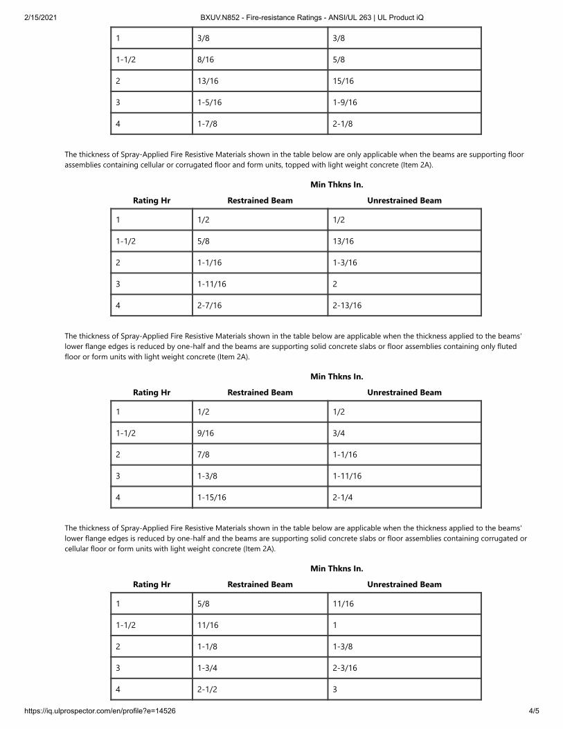
The thickness of Spray-Applied Fire Resistive Materials shown in the table below are only applicable when the beams are supporting floorassemblies containing only fluted floor and form units, topped with light weight concrete (Item 2A).
Rating Hr
Min Thkns In.
Restrained Beam Unrestrained Beam
2/15/2021 BXUV.N852 - Fire-resistance Ratings - ANSI/UL 263 | UL Product iQ
https://iq.ulprospector.com/en/profile?e=14526 4/5
1 3/8 3/8
1-1/2 8/16 5/8
2 13/16 15/16
3 1-5/16 1-9/16
4 1-7/8 2-1/8
The thickness of Spray-Applied Fire Resistive Materials shown in the table below are only applicable when the beams are supporting floorassemblies containing cellular or corrugated floor and form units, topped with light weight concrete (Item 2A).
Rating Hr
Min Thkns In.
Restrained Beam Unrestrained Beam
1 1/2 1/2
1-1/2 5/8 13/16
2 1-1/16 1-3/16
3 1-11/16 2
4 2-7/16 2-13/16
The thickness of Spray-Applied Fire Resistive Materials shown in the table below are applicable when the thickness applied to the beams'lower flange edges is reduced by one-half and the beams are supporting solid concrete slabs or floor assemblies containing only flutedfloor or form units with light weight concrete (Item 2A).
Rating Hr
Min Thkns In.
Restrained Beam Unrestrained Beam
1 1/2 1/2
1-1/2 9/16 3/4
2 7/8 1-1/16
3 1-3/8 1-11/16
4 1-15/16 2-1/4
The thickness of Spray-Applied Fire Resistive Materials shown in the table below are applicable when the thickness applied to the beams'lower flange edges is reduced by one-half and the beams are supporting solid concrete slabs or floor assemblies containing corrugated orcellular floor or form units with light weight concrete (Item 2A).
Rating Hr
Min Thkns In.
Restrained Beam Unrestrained Beam
1 5/8 11/16
1-1/2 11/16 1
2 1-1/8 1-3/8
3 1-3/4 2-3/16
4 2-1/2 3

2/15/2021 BXUV.N852 - Fire-resistance Ratings - ANSI/UL 263 | UL Product iQ
https://iq.ulprospector.com/en/profile?e=14526 5/5
ARABIAN VERMICULITE INDUSTRIES — Types MK-6/HY, MK-6/HY Extended Set, MK-10 HB, MK-10 HB Extended Set, MK-6/HB, MK-6s,MK-6 GF, MK-6 GF Extended Set, MK-1000/HB, MK-1000/HB Extended Set, Z-106, Z-106/G, Z-146 investigated for exterior use. TypesAV650 and AV800 investigated for external use.
GCP KOREA INC — Types MK-6/HY, MK-6/HY Extended Set, MK-10 HB, MK-10 HB Extended Set, MK-6/HB, MK-6s, MK-6 GF, MK-6 GFExtended Set, MK-1000/HB, MK-1000/HB Extended Set, Z-106, Z-106/G, Z-106/HY, Z-146 investigated for exterior use.
GCP APPLIED TECHNOLOGIES INC — Types MK-6/HY, MK-6/HY Extended Set, MK-10 HB, MK-10 HB Extended Set, MK-6/HB, MK-6s,MK-6 GF, MK-6 GF Extended Set, MK-1000/HB, MK-1000/HB Extended Set, RG, Z-106, Z-106/G, Z-106/HY, Z-146, Z-146T, Z146PC, Z-156,Z-156T and Z-156PC investigated for exterior use.
7. Metal Lath — (Optional for contour applications, required for boxed applications) — 3.4 lb/sq yd expanded steel. May betied to lath hangers with No. 18 SWG steel wire spaced 6 in. OC max. or fastened directly to the steel with welds, screws, orpowder actuated fasteners.
* Indicates such products shall bear the UL or cUL Certification Mark forjurisdictions employing the UL or cUL Certification (such as Canada),
respectively.Last Updated on 2017-07-13
The appearance of a company's name or product in this database does not in itself assure that products so identified have been manufacturedunder UL's Follow-Up Service. Only those products bearing the UL Mark should be considered to be Certified and covered under UL's Follow-UpService. Always look for the Mark on the product.
UL permits the reproduction of the material contained in the Online Certification Directory subject to the following conditions: 1. The GuideInformation, Assemblies, Constructions, Designs, Systems, and/or Certifications (files) must be presented in their entirety and in a non-misleadingmanner, without any manipulation of the data (or drawings). 2. The statement "Reprinted from the Online Certifications Directory with permissionfrom UL" must appear adjacent to the extracted material. In addition, the reprinted material must include a copyright notice in the followingformat: "© 2021 UL LLC"

MONOKOTE MK-1000 HBProduct data and application instructions
Product Description
MONOKOTE MK-1000 HB is a single component, spray applied, mill-mixed fire resistive plaster. It has approval for
use on structural steel members and fluted decking to provide up to four hours of fire protection, and on flat plate
cellular decking for up to three hours with SPATTERKOTE SK-3.
The product has been designed to obtain bond strengths in excess of 1,000 psf making it an attractive material for
meeting the 2009 IBC building requirements for bond strength for buildings in excess of 420 feet tall. The capability of
meeting the bond strength requirements with a high yielding spray applied fire resistant material makes MONOKOTE
MK- 1000 HB fire resistive plasters a cost effective option.
Features & Benefits
MONOKOTE cementitious fireproofing offers many significant advantages to the architect, owner, applicator and
building occupant. These include:
Delivery & Storage
Steel & Concrete Surfaces
®
®
®
®
®
Proven in-place performance
Low in-place cost
Fast, efficient application
UL fire tested and factory inspected
Building Code compliant
All material to be used for fireproofing shall be delivered in original unopened packages bearing the name of the
manufacturer, the brand and proper UL labels for fire hazard and fire resistance classifications.
The material shall be kept dry until ready for use. Packages of material shall be kept off of the ground, under cover
and away from sweating walls and other damp surfaces. All bags that have been exposed to water before use shall
be discarded. Stock of material is to be rotated and used before its expiration date.
Product Data Sheets
Page 1 of 4

Performance Characteristics
PHYSICAL PROPERTIESPHYSICAL PROPERTIES RECOMMENDED SPECIFICATIONRECOMMENDED SPECIFICATION TYPICAL VALUESTYPICAL VALUES TEST METHODTEST METHOD
Dry density, minimum average 18 pcf (288 kg/m ) 18 pcf (288 kg/m ) ASTM E605
Bond strength 1,000 psf (28.7 KPa) 1,528 psf (46.3 KPa) ASTM E736
Compression, 10% deformation 50 psi (344 KPa) 53 psi (385.0 KPa) ASTM E761
Air erosion Max 0.000 g/ft (0.00 g/m ) 0.000 g/ft (0.00 g/m ) ASTM E859
Corrosion Does not contribute to corrosion Does not contribute to corrosion ASTM E937
Bond impact No cracking, spalling or delamination No cracking, spalling or delamination ASTM E760
Deflection No cracking, spalling or delamination No cracking, spalling or delamination ASTM E759
Resistance to mold growth No growth after 28 days No growth after 28 days ASTM G21
Surface burning characteristics Flame spread = 0 Smoke developed =
0
Flame spread = 0 Smoke developed =
0
ASTM E84
Combustibility Less than 5 MJ/m total, 20 kw/m
peak heat release
Less than 5 MJ/m total, 20 kw/m
peak heat release
ASTM E1354
Prior to the application of MONOKOTE MK-1000 HB fire resistive plasters, an inspection shall be made to
determine that all steel surfaces are acceptable to receive fireproofing. The steel shall be free of oil, grease, rolling
compounds or lubricants, loose mill scale, excess rust, noncompatible primer, lock down agent or any other
substance that will impair proper adhesion. Where necessary, the cleaning of steel surfaces to receive fireproofing
shall be the responsibility of the general contractor.
®
The project architect shall determine if the painted/primed structural steel to receive fireproofing has been tested in
accordance with ASTM E119, to provide the required fire resistance rating.
Many Fire Resistance Designs allow the use of painted metal floor or roof-deck in place of galvanized decking.
Painted decking must be UL listed in the specific fire resistance designs and must carry the UL classification marking.
Consult your local GCP sales representative for details.
Prior to application of MONOKOTE MK-1000 HB fire resistive plasters, a bonding agent, approved by the
fireproofing manufacturer, shall be applied to all concrete substrates to receive MONOKOTE MK-1000 HB.
®
®
Fireproofing to the underside of roof deck assemblies shall be done only after roofing application is complete and
roof traffic has ceased.
No fireproofing shall be applied prior to completion of concrete work on steel decking.
Other trades shall not install ducts, piping, equipment, or other suspended items until the fireproofing is completed
and inspected.
Other trades shall install clips, hangers, support sleeves, and other attachments that penetrate the fireproofing, prior
to application of the fireproofing.
3 3
2 2 2 2
2 2 2 2
*Actual laboratory tested values meet or exceed GCP’s recommended value. Test reports are available on request from your GCP sales representative.
Product Data Sheets
Page 2 of 4

Mixing
Application
Temperature & Ventilation
MONOKOTE fireproofing shall be mixed by machine in a conventional, plaster-type mixer or a continuous mixer
specifically modified for cementitious fireproofing. The mixer shall be kept clean and free of all previously mixed
material. The mixer speed in a conventional mixer shall be adjusted to the lowest speed which gives adequate
blending of the material and a mixer density of 43–53 pcf (690–850 kg/m ) of material.
®
3
Using a suitable metering device and a conventional mixer, all water shall be first added to the mixer as the blades
turn. Mixing shall continue until the mix is lump-free, with a creamy texture. All material is to be thoroughly wet.
Target density of 48 ± 1 pcf (770 ± 16 kg/m ) is most desirable. Overmixing MONOKOTE will reduce pumping
rate.
3 ®
Application of MONOKOTE Fireproofing can be made in the following sequence:®
For thicknesses of approximately 1⁄2 in. (13 mm) or less, apply in one pass.1.For thicknesses of 5⁄8 in. (16 mm) or greater, apply subsequent passes after the first coat has set.2.
SPATTERKOTE SK-3 shall be applied to all cellular steel floor units with flat plate on the bottom and to roof decking
where required prior to application of MONOKOTE . SPATTERKOTE shall be applied in accordance with
manufacturer’s application instructions.
®
® ®
MONOKOTE Fireproofing material shall not be used if it contains partially set, frozen or caked material.®
The minimum average density shall be that required by the manufacturer, listed in the UL Fire Resistance Directory
for each rating indicated, ICBO Evaluation Report, as required by the authority having jurisdiction, or minimum
average 18 lbs/ft3 (288 kg/m3), whichever is greater.
MONOKOTE shall be mixed with water at the job site.®
MONOKOTE Accelerator is to be used with MONOKOTE Fireproofing to enhance set characteristics and product
yield. The MONOKOTE Accelerator is injected into the MONOKOTE Fireproofing at the spray gun. MONOKOTE
Accelerator shall be mixed and used according to manufacturers recommendations.
® ®
® ® ®
MONOKOTE is applied directly to the steel, at various rates of application which will be job dependent, using
standard plastering type equipment or continuous mixer/pump units. A spray gun, with a properly sized orifice and
spray shield and air pressure at the nozzle of approximately 20 psi (38 KPa), will provide the correct hangability,
density and appearance. NOTE: If freshly sprayed MONOKOTE does not adhere properly, it is probably due to a too
wet mix, poor thickness control, or an improperly cleaned substrate.
®
®
The substrate temperature shall be a minimum of 40°F (4.5°C) for at least 1-hour prior to the application of the
MONOKOTE . Additionally, the air and substrate temperature during application and for a minimum or 24 hours
after application shall be no less than 40°F (4.5°C).
®
Provisions shall be made for ventilation to properly dry the fireproofing after application. In enclosed areas lacking
natural ventilation, air circulation and ventilation must be provided to achieve a minimum total fresh air exchange
rate of 4 times per hour until the material is substantially dry.
Product Data Sheets
Page 3 of 4

Field Tests
Safety
The architect will select an independent testing laboratory (for which the owner will pay) to sample and verify the
thickness and density of the fireproofing in accordance with the the applicable building code.
The architect will select an independent testing laboratory (for which the owner will pay) to randomly sample and
verify the bond strength of the fireproofing in accordance with the provisions of ASTM E736.
Results of the above tests will be made available to all parties at the completion of pre-designated areas which shall
have been determined at a pre-job conference.
MONOKOTE is slippery when wet. The general contractor and applicator shall be responsible for posting
appropriate cautionary “SLIPPERY WHEN WET” signs. Signs should be posted in all areas in contact with wet
fireproofing material. Anti-slip surfaces should be used on all working surfaces.
®
Safety Data Sheets (SDS) for MONOKOTE MK-1000 HB fire resistive plasters are available on our web site or by
calling 866-333-3SBM.
®
gcpat.com | North America customer service: 1-866-333-3726gcpat.com | North America customer service: 1-866-333-3726
We hope the information here will be helpful. It is based on data and knowledge considered to be true and accurate, and is offered for consideration, investigation and verification by the user, but we do not warrant the results to be obtained. Please read all statements,
recommendations, and suggestions in conjunction with our conditions of sale, which apply to all goods supplied by us. No statement, recommendation, or suggestion is intended for any use that would infringe any patent, copyright, or other third party right.
MONOKOTE and SPATTERKOTE are registered trademarks, which may be registered in the United States and/or other countries, of GCP Applied Technologies Inc. This trademark list has been compiled using available published information as of the publication date and
may not accurately reflect current trademark ownership or status.
© Copyright 2018 GCP Applied Technologies Inc. All rights reserved.
GCP Applied Technologies Inc., 62 Whittemore Avenue, Cambridge, MA 02140 USA.
In Canada, GCP Canada, Inc., 294 Clements Road, West, Ajax, Ontario, Canada L1S 3C6.
This document is only current as of the last updated date stated below and is valid only for use in the United States. It is important that you always refer to the currently available information at the URL below to provide the most current product information at the time
of use. Additional literature such as Contractor Manuals, Technical Bulletins, Detail Drawings and detailing recommendations and other relevant documents are also available on www.gcpat.com. Information found on other websites must not be relied upon, as they may
not be up-to-date or applicable to the conditions in your location and we do not accept any responsibility for their content. If there are any conflicts or if you need more information, please contact GCP Customer Service.
Last Updated: 2021-02-05
gcpat.com/solutions/products/monokote-fireproofing/monokote-mk-1000-hbgcpat.com/solutions/products/monokote-fireproofing/monokote-mk-1000-hb
Product Data Sheets
Page 4 of 4