fan ductwork upgrade generating unit 1 forced draft … · induced vibrations and fan pressure...
TRANSCRIPT

A REPORT TO
THE BOARD OF COMMISSIONERS OF PUBLIC UTILITIES
Electrical
Mechanical
EPEGS ;y Civiler ,
T A Df.
Cn LLINS Protection & Control
Transmission & Distributionur.nnruu ►:
.j
^am 2^^V
i0
Ca^^ -
ei,A NI)Telecontrol
System Planning
UPGRADE GENERATING UNIT 1 FORCED DRAFT
FAN DUCTWORK
Holyrood Thermal Generating Station
February 2010
newfoundland labrador
h droa nalcor energy company

Holyrood: Upgrade Unit 1 Forced Draft Fan Ductwork
Table of Contents
1
INTRODUCTION 1
2
PROJECT DESCRIPTION 3
3
EXISTING SYSTEM 43.1
Age of Equipment or System 53.2
Major Work and/or Upgrades 53.3
Anticipated Useful life 53.4
Maintenance History 53.5
Outage Statistics 63.6
Industry Experience 73.7
Maintenance or Support Arrangements 73.8
Vendor Recommendations 73.9
Availability of Replacement Parts 83.10 Safety Performance 83.11 Environmental Performance 83.12 Operating Regime 8
4
JUSTIFICATION 94.1
Net Present Value 94.2
Levelized Cost of Energy 104.3
Cost Benefit Analysis 104.4
Legislative or Regulatory Requirements 124.5
Historical Information 124.6
Forecast Customer Growth 124.7
Energy Efficiency Benefits 124.8
Losses during Construction 124.9
Status Quo 12............................................................................4.10 Alternatives 13
5
CONCLUSION 145.1
Budget Estimate 145.2
Project Schedule 15
APPENDIX A A1
APPENDIX B B1
Newfoundland and Labrador Hydro
i

Holyrood: Upgrade Unit 1 Forced Draft Fan Ductwork
1
INTRODUCTION
The Holyrood Thermal Generating Station (Holyrood) is an essential part of the Island
Interconnected System, with three units providing a total capacity of 490 MW. The
generating station was constructed in two stages. In 1971, Stage I was completed bringing
on line two generating units, Units 1 and 2, capable of producing 150 MW each. In 1979,
Stage II was completed bringing on line one additional generating unit, Unit 3, capable of
producing 150 MW. In 1988 and 1989, Units 1 and 2 were up-rated to 170 MW. Holyrood
(illustrated in Figure 1) represents approximately one third of Newfoundland and Labrador
Hydro's (Hydro) total Island Interconnected generating capacity.
Figure 1: Holyrood Thermal Generating Station
The three main components of each generating unit are the boiler, turbine, and generator.
The boiler servicing Unit 1 is equipped with two forced draft (ED) fans which are commonly
referred to as the east and west FD fans. A FD fan is a system that provides combustion air
to the boiler during operation. The fan consist of a rotating assembly, commonly referred
to as an impellor, that is positioned inside a steel casing which contains both air intake and
Newfoundland and Labrador Hydro
Page 1
Holyrood: Upgrade Unit 1 Forced Draft Fan Ductwork
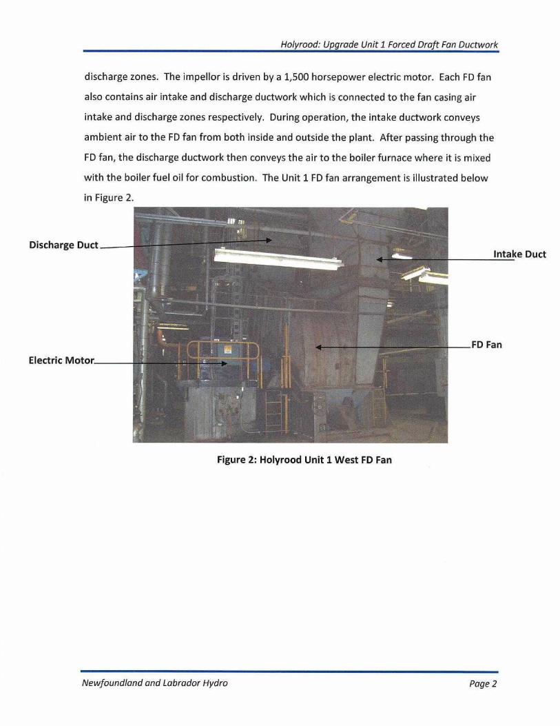
discharge zones. The impellor is driven by a 1,500 horsepower electric motor. Each FD fan
also contains air intake and discharge ductwork which is connected to the fan casing air
intake and discharge zones respectively. During operation, the intake ductwork conveys
ambient air to the FD fan from both inside and outside the plant. After passing through the
FD fan, the discharge ductwork then conveys the air to the boiler furnace where it is mixed
with the boiler fuel oil for combustion. The Unit 1 FD fan arrangement is illustrated below
in Figure 2.
Discharge Duct
Electric Motor
Intake Duct
FD Fan
Figure 2: Holyrood Unit 1 West FD Fan
Newfoundland and Labrador Hydro
Page 2

Holyrood: Upgrade Unit 1 Forced Draft Fan Ductwork
2
PROJECT DESCRIPTION
This project is required to perform modifications to the ductwork on the east and west FD
fans servicing generating Unit 1 to reduce fan vibration levels and eliminate ductwork
cracking. A Computational Fluid Dynamics (CFD) analysis will be completed on the fans
while they are in operation in order to model the air flow characteristics inside the intake
and discharge ductwork. CFD analysis is a computer modeling technique commonly used in
industry to model fluid flows and analyze problems in mechanical systems by simulating the
interaction of fluid flows with equipment surfaces. Based on the results of the CFD analysis,
custom fabricated equipment will be installed inside the FD fan intake and discharge
ductwork. These modifications will reduce flow induced vibrations and ductwork cracking.
It is also anticipated that the modifications will reduce the overall pressure drop across the
air handling system thereby reducing the fan power consumption. Due to safety concerns
associated with performing modifications to the FD fan ductwork during the regular annual
boiler outage maintenance work in the same congested work area, this project will be sole
sourced to Alstom Power, the boiler service contractor because of their overall experience
and familiarity with Holyrood.
Newfoundland and Labrador Hydro
Page 3
Holyrood: Upgrade Unit 1 Forced Draft Fan Ductwork
3
EXISTING SYSTEM
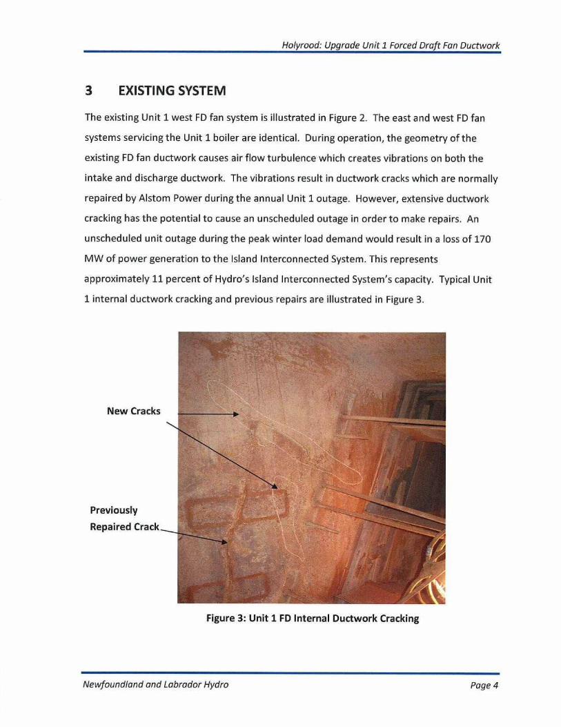
The existing Unit 1 west FD fan system is illustrated in Figure 2. The east and west FD fan
systems servicing the Unit 1 boiler are identical. During operation, the geometry of the
existing FD fan ductwork causes air flow turbulence which creates vibrations on both the
intake and discharge ductwork. The vibrations result in ductwork cracks which are normally
repaired by Alstom Power during the annual Unit 1 outage. However, extensive ductwork
cracking has the potential to cause an unscheduled outage in order to make repairs. An
unscheduled unit outage during the peak winter load demand would result in a loss of 170
MW of power generation to the Island Interconnected System. This represents
approximately 11 percent of Hydro's Island Interconnected System's capacity. Typical Unit
1 internal ductwork cracking and previous repairs are illustrated in Figure 3.
Figure 3: Unit 1 FD Internal Ductwork Cracking
Newfoundland and Labrador Hydro
Page 4

Holyrood: Upgrade Unit 1 Forced Draft Fan Ductwork
3.1 Age of Equipment or System
The existing oil fired boiler and FD fans are 39 years old.
3.2 Major Work and/or Upgrades
Unit 1 was originally commissioned in 1971 to produce 150 MW and was up-rated to
produce 170 MW in 1988. During the upgrade it was necessary to increase the capacity of
the FD fans in order to increase the volumetric flow rate of combustion air to the boiler. A
higher volume of combustion air was necessary to increase the boiler maximum steam flow
rate required to produce the additional 20 MW. The capacity of the FD fans was increased
by adding tips to the existing fan impellor blades.
3.3 Anticipated Useful life
The anticipated useful life of Unit 1 has been forecasted to extend to the year 2020, absent
an infeed from Lower Churchill.
3.4 Maintenance History
FD fan maintenance is a component of the annual maintenance strategy for Unit 1. During
the annual shutdown Hydro uses a boiler service contractor, Alstom Power, to perform
preventative maintenance inspections and corrective maintenance repairs on the FD fans
and ductwork system. The cost of maintenance for the FD fans is a component of the total
maintenance cost for the whole unit. The five-year maintenance history for the Unit 1 FD
fans is shown below in Table 1.
Newfoundland and Labrador Hydro
Page 5
Holyrood: Upgrade Unit 1 Forced Draft Fan Ductwork
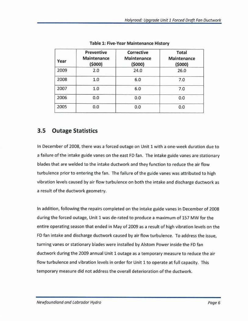
Table 1: Five-Year Maintenance History
Year
PreventiveMaintenance
($000)
CorrectiveMaintenance
($000)
TotalMaintenance
($000)2009 2.0 24.0 26.0
2008 1.0 6.0 7.0
2007 1.0 6.0 7.0
2006 0.0 0.0 0.0
2005 0.0 0.0 0.0
3.5 Outage Statistics
In December of 2008, there was a forced outage on Unit 1 with a one-week duration due to
a failure of the intake guide vanes on the east FD fan. The intake guide vanes are stationary
blades that are welded to the intake ductwork and they function to reduce the air flow
turbulence prior to entering the fan. The failure of the guide vanes was attributed to high
vibration levels caused by air flow turbulence on both the intake and discharge ductwork as
a result of the ductwork geometry.
In addition, following the repairs completed on the intake guide vanes in December of 2008
during the forced outage, Unit 1 was de-rated to produce a maximum of 157 MW for the
entire operating season that ended in May of 2009 as a result of high vibration levels on the
FD fan intake and discharge ductwork caused by air flow turbulence. To address the issue,
turning vanes or stationary blades were installed by Alstom Power inside the FD fan
ductwork during the 2009 annual Unit 1 outage as a temporary measure to reduce the air
flow turbulence and vibration levels in order for Unit 1 to operate at full capacity. This
temporary measure did not address the overall deterioration of the ductwork.
Newfoundland and Labrador Hydro
Page 6
Holyrood: Upgrade Unit 1 Forced Draft Fan Ductwork
3.6 Industry Experience
Flow induced vibration caused by air flow turbulence due to ductwork geometry is common
in FD fan systems. The industry trend is to utilize CFD analysis techniques and perform duct
work modifications to reduce air flow turbulence as opposed to replacing the existing
ductwork to correct geometry design problems. Many companies now specialize in
providing solutions to reduce flow induced vibrations in fan duct work systems and overall
fan pressure loss through the use of CFD analysis techniques.
The application of CFD techniques and modifications to FD fan ductwork was completed in
February of 2004 at New Brunswick Power 's 1,050 MW coal fired power plant located at
Colson Cove. M&l Power Technology (M&I), a company that specializes in the application of
CFD techniques to modify ductwork in order to reduce flow induced turbulence and overall
fan pressure loss, was contracted by New Brunswick Power to perform modifications to the
FD fan ductwork servicing one of the 350 MW coal fired units at the Colson Cove generating
facility. Appendix A provides the background for the project.
3.7 Maintenance or Support Arrangements
Hydro currently has a service contract with Alstom Power to perform boiler maintenance
during the annual scheduled outage. The FD fan maintenance is completed under the boiler
service contract.
3.8 Vendor Recommendations
In December of 2009, Hydro had a preliminary CFD analysis completed on the Unit 1 FD fans
intake and discharge ductwork systems by M&l to reduce pressure loss and flow induced
vibrations in plant air flow systems. The analysis indicated that the air inside the ductwork
Newfoundland and Labrador Hydro
Page 7
Holyrood: Upgrade Unit 1 Forced Draft Fan Ductwork
does not flow through at a uniform velocity. This results in high fan entry loss and poor fan
blade loading. In addition, the analysis also indicated that the fans are operating at a high
flow rate (165 Kg/s per fan) resulting in very high velocity magnitude in the range of 84.5 to
96.6 m/s which creates flow induced vibration. The report from M&l recommends that
Hydro perform a more comprehensive CFD analysis on the FD fan systems and install
aerodynamic diffusers and long turning vanes inside the ductwork to reduce both flow
induced vibrations and fan pressure loss. The report outlining the findings of the analysis is
included in Appendix B.
3.9 Availability of Replacement Parts
Spare parts are available for the existing Unit 1 FD fan system.
3.10 Safety Performance
There are no safety code violations with the current operation of the Unit 1 FD fans.
3.11 Environmental Performance
There are no environmental code violations with the operation of the existing Unit 1 FD
fans.
3.12 Operating Regime
Holyrood operates in a seasonal regime. The full plant capacity is needed to meet the
winter electrical requirements on the Island Interconnected System. The FD fan systems
are an integral component of Unit 1.
Newfoundland and Labrador Hydro
Page 8
Holyrood: Upgrade Unit 1 Forced Draft Fan Ductwork
4
JUSTIFICATION
The FD fans servicing Unit 1 at Holyrood have an ongoing problem with flow induced
vibration on the fan intake and discharge ductwork systems. During operation, the
geometry of the existing FD fan ductwork causes air flow turbulence which creates
vibrations on both the intake and discharge ductwork. The vibrations cause cracks to
develop in the ductwork. The cracks are normally repaired during the annual Unit 1 outage.
However, the development of cracks on an on-going basis threatens the integrity of the
ductwork infrastructure and reduces the reliability of Unit 1.
In December of 2008, there was a forced outage on Unit 1 due to a failure of the intake
guide vanes on the East FD fan. Failure of the intake guide vanes was due to high vibration
levels caused by air flow turbulence on both the intake and discharge ductwork. In addition,
high vibrations levels resulted in a de-rating of Unit 1 during the 2009 operating season. To
address the issue, turning vanes were installed inside the fan ductwork during the 2009
annual Unit 1 outage as a temporary measure to reduce air flow turbulence and vibration
levels.
Failure of the FD fan ductwork can result in an unplanned Unit 1 outage of three to four
weeks duration. An unscheduled unit outage during the peak winter load demand would
result in a loss of 170 MW of power generation to the Island Interconnected System which
represents approximately 11 percent of the Island Interconnected System's capacity.
This project is required to maintain the reliability of generating Unit 1 at Holyrood.
4.1 Net Present Value
A Net Present Value (NPV) calculation was not done, however, a cost benefit analysis was
completed on two alternatives over a study period of ten years. See Cost Benefit Analysis
Section 4.3 for details.
Newfoundland and Labrador Hydro
Page 9

Holyrood: Upgrade Unit 1 Forced Draft Fan Ductwork
4.2 Levelized Cost of Energy
The levelized cost of energy is a high level means to compare costs of developing two or
more alternative generating sources. Therefore, the levelized cost of energy is not
applicable to this project.
4.3 Cost Benefit Analysis
A cost benefit analysis was completed on two alternatives. The study period for the cost
benefit analysis was 10 years.
Alternative 1 - Upgrade Unit 1 FD Fan Ductwork based on Fuel Cost Savings:
This alternative is to complete the proposed modifications to Unit 1 FD fans in order to
reduce ductwork vibrations caused by flow induced turbulence and air handling system
overall pressure loss. Upon completion of Alternative 1, the annual operating and
maintenance (O&M) cost was estimated at $1,000 per year which would cover FD fan
preventative maintenance inspections. It is anticipated that there would not be any
unscheduled FD fan failures or corrective maintenance to repair ductwork cracks after
completing the proposed modifications to the FD fan ductwork. The preliminary CFD
analysis report completed by M&l Technology (Appendix B) indicated that the energy
savings associated with each FD fan will be 16 percent after completing the proposed
modifications to the ductwork. The savings for Alternative 1 were calculated using the
January 2010 Nalcor Energy/NLH Thermal Fuel Oil Price Forecast for No.6, 0.7 percent
sulphur fuel with a PUB approved conversion factor of 630 kWh/bbl. Using an average Unit
1 load of 80 MW and 4,520 operating hours as in 2009, the Cumulative Present Worth
(CPW) for Alternative 1 is a benefit of $489,706 with a payback of six years.
A sensitivity analysis was performed on Alternative 1 using a Levelized Unit Energy Cost
(LUEC). The PUB approved LUEC rate at $0.09 per kilowatt hour was used to calculate the
Newfoundland and Labrador Hydro
Page 10

Holyrood: Upgrade Unit 1 Forced Draft Fan Ductwork
project saving. Using an average Unit 1 load of 80 MW and 4,520 operating hours, the CPW
cost is $182,008.
Alternative 2 - Status Quo:
This alternative is to operate the FD fans under the current operating conditions without
performing any modification to the ductwork. Using the maintenance history available for
the Unit 1 FD fans, the annual O&M cost for this alternative is expected to be $7,000 per
year to perform preventative maintenance inspections and corrective maintenance repairs.
Also, based on the history of forced outages with an occurrence in 2008 and repair cost at
approximately $330,000, it was assumed that an identical forced outage would occur again
in 2018. Using the O&M cost indicated above, the CPW cost for Alternative 2 is $242,526.
The analysis indicates that Alternative 1 is the lower cost option. Table 2 shows the results
of the cost benefit analysis.
Table 2: Cost Benefit Analysis
HRD Unit 1 FD Fan Ductwork ModificationsAlternative Comparison
Cumulative Net Present Value
To The Year
2020
AlternativesCumulativeNet Present
CPW Difference betweenAlternative and the
Value (CPW) Least Cost Alternative
HRD Unit 1 FD fan Ductwork Modifications @Fuel Cost (489,706) 0
Status Quo 242,526 732,232
Newfoundland and Labrador Hydro
Page 11
Holyrood: Upgrade Unit 1 Forced Draft Fan Ductwork
4.4 Legislative or Regulatory Requirements
There are no legislative or regulatory requirements to complete the proposed modification
to the FD fan ductwork to reduce vibration levels and fan pressure loss.
4.5 Historical Information
There is no applicable historical information.
4.6 Forecast Customer Growth
Customer load growth is not affected by this project.
4.7 Energy Efficiency Benefits
It is anticipated that completion of the proposed project will reduce the energy consumed
by the Unit 1 FD fans by 16 percent.
4.8 Losses during Construction
There are no associated losses during the construction of this project as it will be scheduled
during the annual planned unit outage.
4.9 Status Quo
Status quo is not an acceptable alternative. A cost benefit analysis has shown that
upgrading the FD fan ductwork will present a savings to Hydro. Also, an unscheduled failure
during the peak winter load demand could result in a loss of 170 MW of power which
represents approximately 11 percent of the Island Interconnected System's capacity.
Newfoundland and Labrador Hydro
Page 12

Holyrood: Upgrade Unit 1 Forced Draft Fan Ductwork
4.10 Alternatives
Two alternatives were considered as discussed in the Cost Benefit Analysis Section 4.3.
Newfoundland and Labrador Hydro
Page 13

Holyrood: Upgrade Unit 1 Forced Draft Fan Ductwork
5
CONCLUSION
Modifications to the Unit 1 existing FD fan ductwork systems is required to reduce flow
induced vibrations caused by air flow turbulence due to the existing ductwork geometry.
The modifications will also reduce the overall fan pressure drop, thereby reducing the fan
power consumption by 16 percent. Using an average Unit 1 load of 80 MW and 4,250
operating hours as in 2009, a cost benefit analysis indicates that completing the proposed
project is the preferred option as compared to the status quo alternative.
Failure to perform the modifications to the Unit 1 FD fan ductwork systems increases the
likelihood of unscheduled downtime on the turbine and increases the risk of being unable
to meet customer demands during the peak winter load requirement.
5.1 Budget Estimate
The budget estimate for this project is shown in Table 3.
Table 3: Budget Estimate
Project Cost:($x1,000) 2011 2012 Beyond Total
Material supply 20.0 0.0 0.0 20.0
Labour 68.3 0.0 0.0 68.3
Consultant 0.0 0.0 0.0 0.0
Contract Work 619.1 0.0 0.0 619.1
Other Direct Costs 2.0 0.0 0.0 2.0
O/H, AFUDC & Escln. 62.8 0.0 0.0 62.8
Contingency 70.9 0.0 0.0 70.9
TOTAL 843.0 0.0 0.0 843.0
Newfoundland and Labrador Hydro
Page 14
Holyrood: Upgrade Unit 1 Forced Draft Fan Ductwork
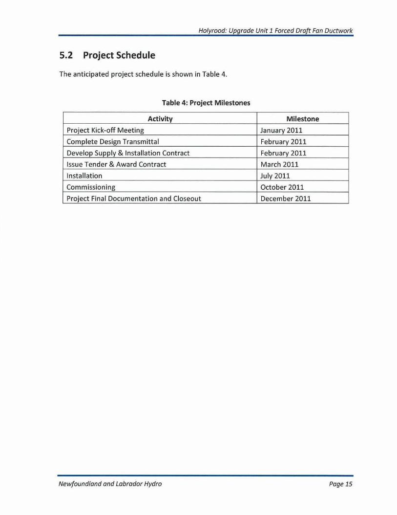
5.2 Project Schedule
The anticipated project schedule is shown in Table 4.
Table 4: Project Milestones
Activity Milestone
Project Kick-off Meeting January 2011
Complete Design Transmittal February 2011
Develop Supply & Installation Contract February 2011
Issue Tender & Award Contract March 2011
Installation July 2011
Commissioning October 2011
Project Final Documentation and Closeout December 2011
Newfoundland and Labrador Hydro
Page 15

Holyrood: Upgrade Unit 1 FD Fan DuctworkAppendix A
APPENDIX A
Project Background:
M&l Technology's Solution for FD fan Inlet Duct Silencing SystemFor
New Brunswick Power's Colson Cove 1,050 MW Power Plant
Newfoundland and Labrador Hydro
Al

Holyrood: Upgrade Unit 1 FD Fan DuctworkAppendix A
M&I Power Tech.
PROJECT BACKGROUND
M&I's Solution for F.D. Fan Inlet Duct Silencing SystemFor
New Brunswick Power's Colson Cove 1,050 MW Power Plant, Canada
N.B Power sought a solution that would reduce noise emanating from the I.D Fan. Theconventional splitter type silencer solution occupies lot of space and it was not possibleto accommodate it in the available space. Additionally, the pressure drop of theconventional silencer was very high to the tune of 36 mm WC and this pressure dropwas resulting in overloading of the F.D Fans. Even an increase of 12 mm W.C wouldhave adversely affected Fan performance, which in turn would have affected qenerationcapacity.
Babcock & Wilcox, Canada which was contracted for this part of the project,approached M&l to employ its "Aero-Acoustic" technology and develop a solution thatwould solve this apparently conflicting requirement.
M&I's approach integrates flow streamlining with noise attenuation. The flow across theducting system and fan was analyzed and the effect of turbulence, flow separation,vortices, etc was determined. M&l then developed a diffusion system that streamlinedflow across the inlet ducting and ensured that the flow into the Fan is uniform. This 3-dimensional diffusion system that M&l designed also acts as a silencer and absorbsnoise. Additionally, the duct is lined with acoustic insulation, which contributes to noiseattenuation A streamlined flow across the duct without turbulence would reduce theflow induced vibration and this also brings down noise generation.
You would note M&l have not employed the conventional splitter type silencer and thisbrings down the pressure drop. Also, by streamlining the flow across the duct, it ispossible to convert unproductive velocity pressure to useful static pressure. In this caseM&I was able to reduce pressure drop by 26 mm W.C. as compared to conventionalsplitter silencer. The noise level that was guaranteed was 84 dBA at 1 m. 1 dB lowerthan conventional silencer.
Please refer enclosed CFD analysis and Drawing carried out at bid stage for thecustomer. We are glad to inform you that M&l met contractual performance guaranteesas demonstrated in our CFD results. Please also refer enclosed reference letter fromB&W, Canada confirming superiority of M&l's aero-acoustic technology overconventional design.
Page 4
Newfoundland and Labrador Hydro
A2
Holyrood: Upgrade Unit 1 FD Fan DuctworkAppendix A
Babcock & IAlulcox Canada Ltd.
5E1 Coronation BoulevardCambridge, OntarioCanada N1R 5V3Tel: (519x621-2130Fs: (519) 622-3664
a McDermott company
February 13, 2004
To Whomsoever it Mav Concern
This is to advise that Babcock & Wilcox Canada contracted with M&1 Air Systems Engineering,Mississauga, Canada for the design, engineering and supply of an Aerodynamic inlet silencerducting system. The system will be installed on fi nos. Forced Draft (F.D.) Fans at the 3 x 350MW Coleson Cove Power Station (Owned and Operated by New Brunswick Power, Canada).B&W opted for the M&I design as it offered a noise attenuation solution at a very low pressuredrop across the ducting system, compared to a conventional splitter type silencer solution.Performance guarantees were provided by M&l,
B&W has recently installed two systems for one of the 350 MW units (Unit # 3). B&W issatisfied with design, engineering and workmanship of the silencer units. Moreover, M&1'smodular construction enabled B&W to easily retrofit the FD inlet ducting in spite of the spaceconstraints of the existing station. Unit #}3 is operating at full capacity load of 350 MW, and hasmet the contractual performance criteria.
R.J. JohnstonProject Manager
Page 4A
Newfoundland and Labrador Hydra
A3
Holyrood: Upgrade Unit 1 FD Fan DuctworkAppendix A
M&l Power Tech.
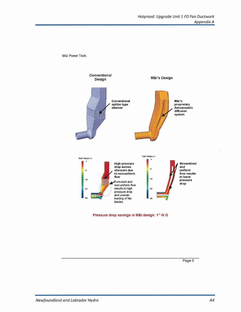
ConventionalDesign M&l's Design
Conventional
M&I'ssplittertype
proprietarysilencer
Aeroacousticdiffusionsystem
High pressuredrop acrosssilencers dueto non-uniformflow
urbulent andnon-uniform flowresults in highpressure dropand unevenloading of fanblades
Tot Relive t,,nI
Streamlinedanduniformflow resultsin lowerpressuredrop
Pressure drop savings in M&I design: 1" W.G
Page 5
Newfoundland and Labrador Hydro
A4

Holyrood: Upgrade Unit 1 FD Fan DuctworkAppendix A
M&I Power Tech.
Babcock & Wilcox A/c New Brunswick PowerColson Cove Project (1,050 MW)
FD Fan Aerodynamic Inlet Silencer Duct
Page 6
Newfoundland and Labrador Hydra
A5

Holyrood: Upgrade Unit 1 FD Fan DuctworkAppendix A
M&I Power Tech.
M&I
Client: Heyden Power Station, E-ON, Germany
Responsibility:Design, CFD Analysis, Engineering, Manufacturing, Supply andSupervision of Installation.
Project Background:
Heyden Power Station (An E-ON Company) awarded contract to M&1 for CFDAnalysis, Design, Engineering ; Manufacturing, Supply and Supervision of 2 nos 950MW units. Objective of working with M&I was to reduce draft loss of 3.5 mbar beforeESP and total Draft loss reduction of 10 mbar from Economizer outlet to FD Fandischarge. Above draft saving was very important, since Heyden PS is envisaging useof different grades of Coal in place of Brown Coal. This has resulted in to 10-12%higher volumetric flow in the draft system. Heyden PS had two fold problems to tackleabove situation.
1) Suitability of Existing ESP Duct and Structure2) Static Pressure Margins of ID fan
Bigger ID fan could have solved second problem but first problem was still unresolved.Except M&I solution there were no other feasible alternatives to address first issue.
M&I is offering Aero-acoustic solution for following areas of power plant:
I) SCR Inlet System (Between Ammonia Injection and SCR Catalyst)2) Air Pre Heater Inlet System3) ESP Inlet System4) ESP Inlet Transition5) Fan Suction Box6) ID Fan Discharge Duct7) FGD Inlet System
By leveraging Aero-acoustic technology, M&I is proposing pressure drop reduction inthe plant draft system to Heyden PS. Savings are in the tune of 10 mbar to 12 mbar.
Page 7
Newfoundland and Labrador Hydro
A6
Holyrood: Upgrade Unit 1 FD Fan DuctworkAppendix A
M&I Power Tech.
M&I
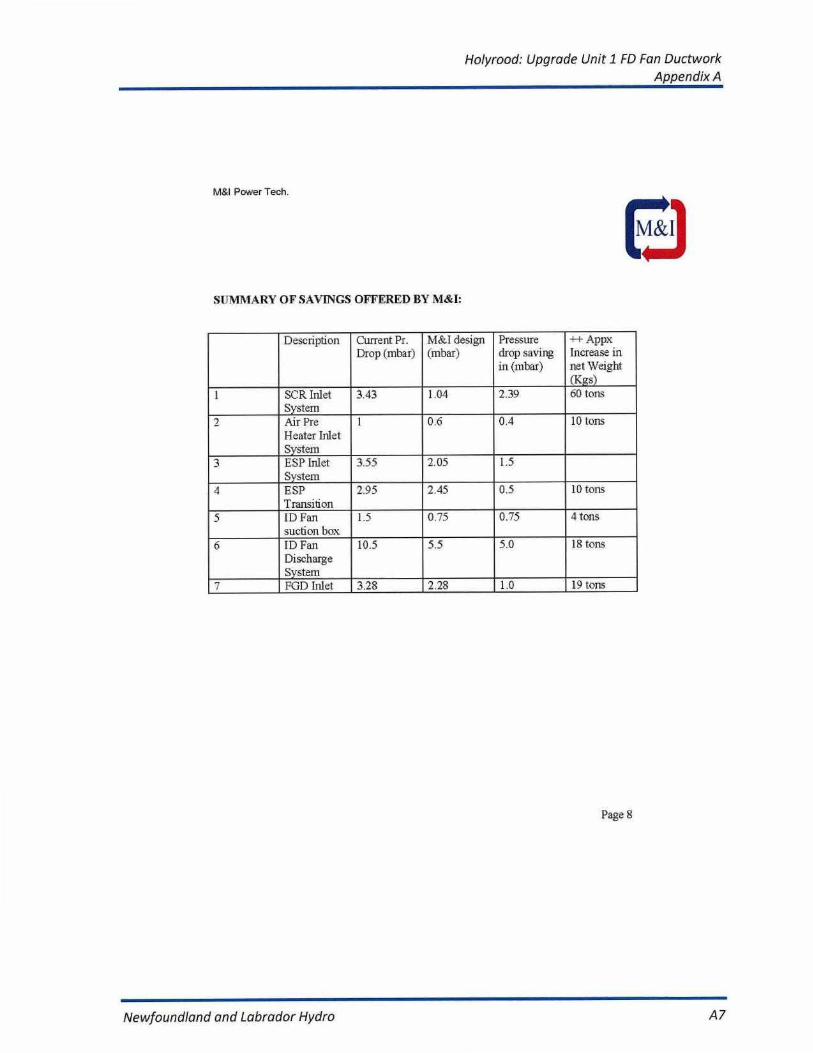
SUMMARY OF SAVINGS OFFERED BY M&I:
Description Current Pr.Drop (mbar)
Iv1&.I design(mbar)
Pressuredrop savingin (mbar)
++ AppxIncrease innet Weight(Kgs)
1 SCR InletSystem
3.43 1.04 2.39 60 tons
2 Air PreHeater InletSystem
1 0.6 0.4 10 tons
3 ESP InletSystem
3.55 2.05 1.5
4 ESPTransition
2.95 2.45 0.5 10 tons
5 ID Fansuction box
1.5 0.75 0.75 4 tons
6 ID FanDischargeSystem
10.5 5.5 5.0 18 tons
7 FGD Inlet 3.28 2.28 1.0 19 tons
Page 8
Newfoundland and Labrador Hydro
A7

Halyrood: Upgrade Unit 1 FD Fan DuctworkAppendix A
7.h]aR.20C8 14 : 38
EKW KGM KW-LEI T UNG
NR.094
5.1
e•or^ Kraftwerke
E.ON 1(rahwarke Grrbrl. Po$tfach 11 a0. C•3u59 Peterseagi n
M & I AIR SYSTEMS ENGINEERINGM & I POWER TECHNOLOGY, INC.Mr. Dipti Kr. Dana2140 Meadowpine Blvd.Mississauga, ONCanada L5N 6H6
Petershagen, 2006-03-07
Optimization of Flue Gas Ducts and Fans, including AuxiliaryEnvironmental Equipment
This is to advise that EON hraftwerke GmbH, Tresckowstrafle 5, 30457Hannover, Germany contracted with M&1 Power Technolog/, Inc.,Mississauga, Canada for Design, Engineering, Manufacture and SLpply ofaerodynamic diffusers for our 915 MW Hayden Power Station atPetershagen to reduce the plant draft loss across the following system s:
1) SCR Inlet system2) ESP Inlet duct and transition3) ID fan suction box4) ID fan discharge system5) FGD Inlet system
Above plant draft loss reduction was necessary to accommodate burning ofcoal with less caloric value. This means more flue gas transportation toproduce the same MW. Further it was also necessary to keep same or lowsuction pressure upstream of ESP. to avoid reconstruction of tie ESPcasing.
We are pleased to mention here that M&I fulfilled all our expectaticontractual guarantees through an efficient diffusion system Furthsolution avoided installation of new ID fans. The following tangible
ns andM&I
benefits
Chairman of theSupervisory Board:Bernhard Fischer
were achieved through M&I technology: Managing Directors:Dr. logo Loge(Chairman)Manfred Peters1) Reduction of 2.2 MW ID fan Power Consumption
2) 11 mbar saving in the pressure drop Or. Erich Schmitz
1/2
Gerhard SeibelCarmel St:blelrl
Registered Office HanoverHanover District CourtMRS 58691
Page as
E.ON Kraftwerke GmbhKraftwerksgruppeMittalwose rPlant managerKraftwerkssiedlungD-32469 Petershagenwww. o o n -k raf rw e r ke.c o m
Matthias Eldon7 49-OS702-29 .32 21F 49-05702, 29.30 61m atth ias.e lden®eon-energle.com
our reference T/Eid . Fr
Newfoundland and Labrador Hydro
A8
Holyrood: Upgrade Unit 1 FD Fan DuctworkAppendix A
7.M42.200E _4:33
EKW KGM KW-Lel7EJNG
H .094
S.2
e•on Kraftwerke
M&sl executed this job in time without any delay even in a Harr w steelmarket through efficient project management and offered very god co-operation during installation of the above system.
Due to this excellent result, E-ON would recommend this technology beingapplied not only to other existing operating plants, but also in case o addingFGI) or SCR and forthcoming new plants of their own whe^.e mostadvanced technology will be part of the design group to consider in order toreduce costs and raise performance. As such, M&1 technology would beplaced on our list of priority,
The technology itself has other salient benefits such as noise and vibrationsolution without utilizing large conventional silencers, since the technologyaddresses noise at the source.
Eor additional information please feel free to contact the undersigrwish M&I many more years of success in the future business.
Yours sincerely,
E.ON Kraftwerke GruhH
iN.
ed. We
212
Page BB
Newfoundland and Labrador Hydro
A9
Holyrood: Upgrade Unit 1 FD Fan DuctworkAppendix A
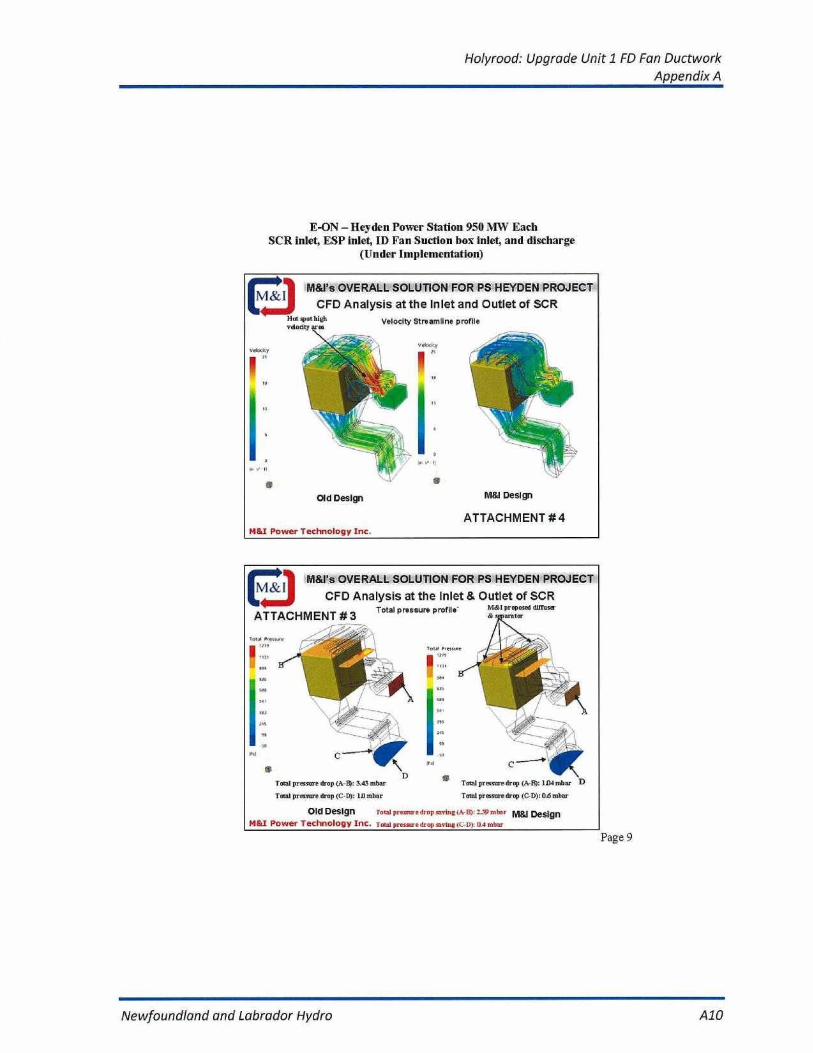
E-ON - Hey den Power Station 950 MW EachSCR inlet, ESP inlet, ID Fan Suction box inlet, and discharge
(Under Implementation)
M&I0 M&I's OVERALL SOLUTION FOR PS HEYDEN PROJECT
vaociit
•
Old Design
ATTACHMENT #4Mel Power Technology Inc.
M&l Design
Page 9
M&I's OVERALL SOLUTION FOR PS HEYDEN PROJECT
CFD Analysis at the Inlet & Outlet of SCRTotal pressure profile'
Mitt proposed dllllssaAss muter
Total pressuredrop (A B): lllamhar
Total prossuredrop IC-D): 04 miter
Old Design
Tom] pressure dl op tuvtig(-e:'- mhnr M&I DesignM&I Power Technology Inc. Tonal pressure drop raring(r-D): Da mbar
D
513
FJ
Newfoundland and Labrador Hydro
A10

Holyrood: Upgrade Unit 1 FD Fan DuctworkAppendix A
Page 10
M&10 M&I's OVERALL SOLUTION FOR PS HEYDEN PROJECT
CFD Analysis at Air Heater Outlet to ESP Inlet
Velocity Str'eamiining Profile
Old Design
M&I Design
ATTACHMENT # 11H&J Power Technology Inc.
M&I0 M&I's OVERALL SOLUTION FOR PS HEYDEN PROJECT
CFD Analysis at Air Heater Outlet to ESP InletTotal pressure profile'
Bra. w.
ee
Total pressure drop (A-B): 3.55 mbar
Total pressure drop (A-B): 2-05 mbar
Total pr es sure drop saving (A-13i: L.50 mbar
Old Design
M&l Design
ATTACHMENT #10H&I Power Technology Inc.
Newfoundland and Labrador Hydro
All
Holyrood: Upgrade Unit 1 FD Fan DuctworkAppendix A
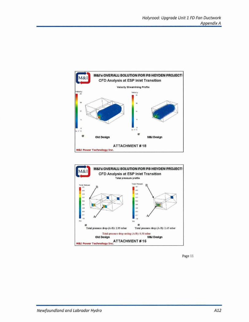
Fj M&I's OVERALL SOLUTION FOR PS HEYDEN PROJECT
CFD Analysis at ESP Inlet Transition
Velocity Streamlining Profile
▪ Old Design
ATTACHMENT # 18M&l Power Technology Inc.
• M&I Design
,.
Page 11
M&Ys OVERALL SOLUTION FOR PS HEYDEN PROJECT ICFD Analysis at ESP Inlet Transition
Total pressure profile
To▪
tal pressure drop (A-B): 2.95 mbar
Total pressure drop (A-13): 2.45 mbar
Total pressuie drop roving (A-By 0.50 inbat
Old Design
I= Design
M&l Power Technology IncATTACHMENT.
# 16
Pdl
Newfoundland and Labrador Hydro
A12

Holyrood: Upgrade Unit 1 FD Fan DuctworkAppendix A
Toni Pressure Drop : 3.9$ mbar
M&I DesignM&Y Power Technology Enc.
Total Pressure Drop : 4ASnbar
Existing Design
CFD Analysis for PS Heyden projectID Fan Intake SystemPressure SI reran Wre
0 1
Ms OVERALL SOLUTION FOR PS HEYDEN PROJECT
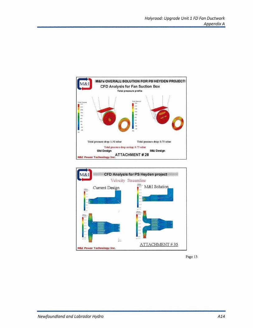
CFD Analysis for Fan Suction Box
Velocity Profile
Old Design
M&l Design
ATTACHMENT # 27M&I Power Technology Inc.
I
Page 12
Newfoundland and Labrador Hydro
A13
Holyrood: Upgrade Unit 1 FD Fan DuctworkAppendix A
00 M8d`s OVERALL SOLUTION FOR PS HEYDEN PROJECT
CFD Analysis for Fan Suction BoxTotal pressure profile
Total pressrre drop: 1.50 mbar
Total pressure drop: 0.75 mbar
Tote l i essnre drop saving: 0.75 mbar
Old Design
M&I DesignATTACHMENT # 28
M&I Power Technology Inc.
M&I Power Technology Inc.
M&10 CFD Analysis for PS Heyden project
Velocity Streamline
Current Design
M&I Solution
ATTACHMENT # 35
Page 13
Newfoundland and Labrador Hydro
A14

Holyrood: Upgrade Unit 1 FD Fan DuctworkAppendix A
Page 14
M&i0 CFD Analysis for PS Heyden project
Total Pressure Streamline
Current Design
M&I Solution
Toilel Pressure Drop Reaches to
6.0 I1ec6 WGI1ecffiding 3.2" Wt.;Silencer Section Lois
M&I Power Technology Inc.
Told Pressure Drop Readies toOnly 4.1 Inch NG Including 1.8"WG Silencer Section Loss
E-ON Heyden Power Stn. 950 MW EachFGD Inlet duct c 100% Flow of Full Load
Total pressure drop profile
M&I
Tone 35essu<
sin
Iv9
Total pressure drop (A-Et) : 3.28 mbar Tota l pressure drop (A43) : 228 mbar
Pressure drop saving (A-B) :1.00 mbar
Current Design
M&I Power Technology Inc.
M&I Solution
Newfoundland and Labrador Hydro
A15

Holyrood: Upgrade Unit 1 FD Fan DuctworkAppendix A
E-ON - Heyden Power Station 950 MW EachSCR Inlet Modification Different Option offered by M&i
Page 14A
CFD Analysis for PS Hoyden project forFGD Inlet duct @ 100% Flow of Full Load
A
Mil Ppw.n TCUHIIEILOQY INn
00 CFD Analysis for PS Heyden project forFGD Inlet duct @ 100% Flow of Full Load
A
Solid ModelM1AI POW la TiCHNOLO•IY IND
Newfoundland and Labrador Hydro
A16
Holyrood: Upgrade Unit 1 FD Fan DuctworkAppendix A
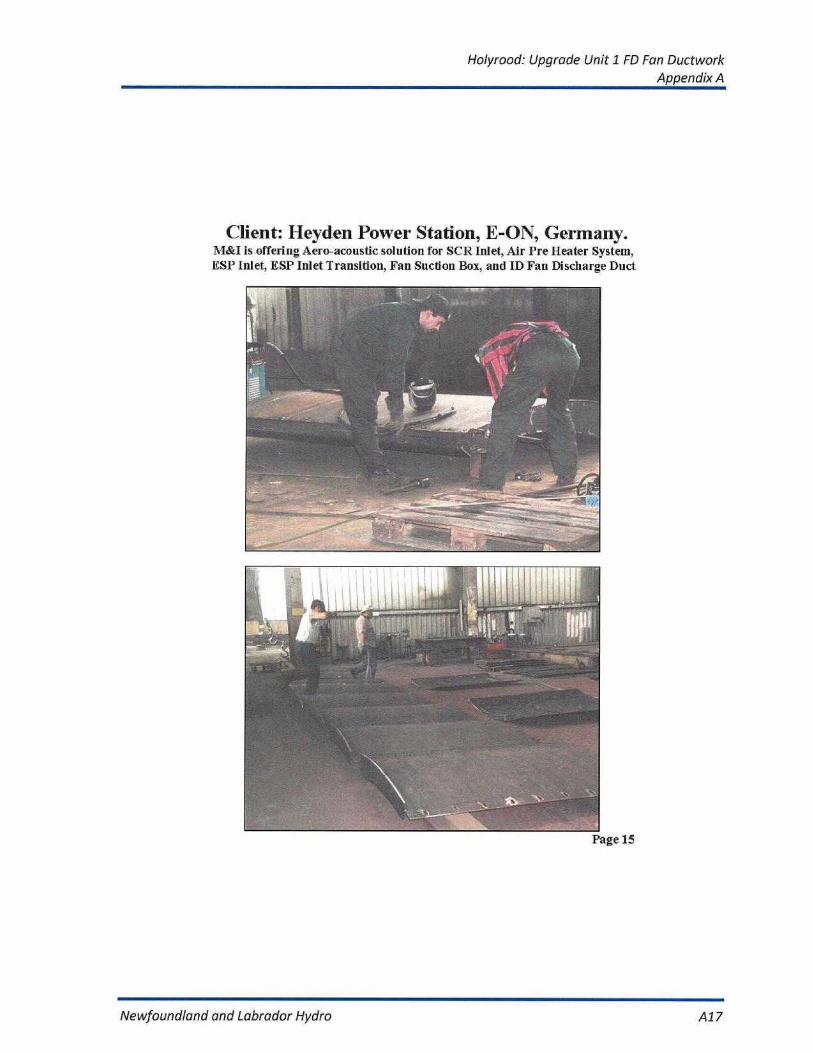
Client: Heyden Power Station, E-ON, Germany.M&I is offering Aero-acoustic solution for SCR Inlet, Air Pre Heater System,
ESP Inlet, ESP Inlet Transition. Fan Suction Box, and ID Fan Discharge Duct
Page 15
Newfoundland and Labrador Hydro
A17

Holyrood: Upgrade Unit 1 FD Fan DuctworkAppendix A
Page 16
Newfoundland and Labrador Hydro
A18

Holyrood: Upgrade Unit 1 FD Fan DuctworkAppendix A
Page 17
Newfoundland and Labrador Hydro
A19

Holyrood: Upgrade Unit 1 FD Fan DuctworkAppendix B
APPENDIX B
Commercial Proposal For:
FD Fan Inlet & Discharge Ductwork Modifications To Eliminate FlowInduced Vibration And Capacity Bottleneck
At theHolyrood Thermal Generating Station
Newfoundland and Labrador Hydro
B1

Holyrood: Upgrade Unit 1 FD Fan DuctworkAppendix B
Quotation #: P09-001
Techno-Commercial Proposal
For
FD Fan Inlet & Discharge Modifications to eliminate flowinduced vibrations and capacity bottleneck
At
Holyrood Generating Station
Submitted to:
NEWFOUNDLAND AND LABRADOR HYDROST. JOHN'S, NEWFOUNDLAND
M&l Power Technology, Inc.2145 Meadowplne Blvd. Mississauga,
Ontario, Canada, L5N 6R8
02/12/2009
Newfoundland and Labrador Hydro
B2

Holyrood: Upgrade Unit 1 FD Fan DuctworkAppendix B
:Inn
f]n onn_I nr_,:Ildl_n7h{nr
m& t
February 12,2009
Newfoundland and Labrador HydroHolyrood Generating StationDuff's Road, HoiyroodNL AOA 2RD
SUB: Quotation for CFD analysis & Modification to FD fan Inlet & Discharge Duct.
Dear Sirs,
At the outset I would like to thank you for the courtesy extended to our engineer VladimirElise. We also appreciate the opportunity to provide you with the proposal for themodifications of FD fan inlet and discharge duct to eliminate flow induced vibrationproblem and debofilenecking of fan capacity limitation. In view of long business relationswith your esteemed organization, we had no hesitation in carrying out preliminary CFDanalysis worth $ 10,000 free of cost to evaluate flow condition inside the FD fan inlet anddischarge duct responsible for vibration and turbulence. Refer "Synopsis" segment of theproposal showing CFD results of the existing duct.
Attached is our techno-commercial proposal & general arrangement drawing showingproposed modification areas. We have diligently worked on the proposal based on theinformation collected by our engineer. Most of our modifications are at the strategiclocations where maximum benefits exist in the above draft system. We propose modulesto be retrofitted at those locations only. We are also envisaging some outside ductmodifications, which can be easily carried out at site..
M&l 's aerodynamic diffusers offer reduction in the vibration and FD fan performanceimprovement by virtue of reduction in pressure drop in inlet and discharge duct.Estimated savings are enumerated below for review:
• Expected Pressure drop Reduction! Savings inFD fan Inlet Duct: 1.5" W.G.
• Expected Pressure drop Reduction! Savings inFD fan Outlet Duct: 2.0" W.G
• Minimal flow induced vibrations in the ducts.
21 4' Pneai i_ veil ie t
7. :_!Id l.^rl r'FR _ 311-N:in
•'f r',aro_eeb aro7 briar,, ooll pe,9 Ili: dacvmerrr remin the Drperrv or,'.g„ Fewer iech,':rc;v and ;ienilbe _e'iJ norr. . , r _ . , e . : :”',r 1 h . - „ r :.,:rI.,cd.rme acr .: licr..:=r1n-,e:.-n^c',v':'c._l^r,r;-_3, t:.r Ir,e a]d:v:-e'r r:r;e.'1
Newfoundland and Labrador Hydro
B3

Holyrood: Upgrade Unit 1 FD Fan DuctworkAppendix B
Proposal- Holyrood Generating slalion fD for c4uc1 modificationsClient: HewIonndland ?t Labrador Hyde NI.
At this time we are open to help us to work to gather with you on this project
We now look forward to hear from you to proceed further in the matter. In case you needfurther clarification, please feel free to contact me.
Thanking you and assuring you of our best services at all times,
Best regards,
Pradeep Gaur, P.Eng.PresidentM&I Power Technology Inc.
fvi^.l Pu•arE i is ortn:;Iocy Inc.2145 Meadowine Blvd Missirs;;uca i)l4 I.cN 61;8 Canada
Ph +1 (4161 63/-i,lti±p;i/) 6{)J Fax 1 I4 I of 623-$4°0
III Concept; ono Deno,: obtl,r, 4,o this doc^rrEni remain 4he proper? oF: a.I Fo.^ei ieG-noio_y anti fno:I nor' be xed forOr,
cpnl:nno°n of 'no c.s-nCs,,, :,:c n-r.c.", '; c >~,e^-r e o,ceci
M&I
Newfoundland and Labrador Hydro
B4
Holyrood: Upgrade Unit 1 FD Fan DuctworkAppendix B
FD 1' i:In C n . n :f
-t;
I
L
i
1.1
CONTENTS
Section 1
Introduction to M&I !Company profile
Section 2
Synopsis
Section 3
Scope of Work
Section 4
Limit of Supply & Exclusion
Section 5
Design Basis
Section 6
Performance Parameters & Guarantees
Section 7
Price Schedule
Section 8
Drawing
1--
DIccry
2i
E
:.D.
L5N ii-.FS
.
1. 11
i
iii ii
Al Corepl.; arid Da:iv,Ili:
ptuperly
M&IFoweii
Lie.3,,
fu,
M&1
Newfoundland and Labrador Hydro
85

Holyrood: Upgrade Unit 1 FD Fan DuctworkAppendix B
'Cr
Section 1
NMI
COMPANY PROFILE
:I
M=714.7.,thr:...E..
C:,L . l L5N .P.1-:1.1M711",•74.71177
•
"'oh.1,011
d
:h IL* 49 GU
rE. rLILIr,lho properly oLM.F.IPc.N.1'ec 11r,,17j,r n,LL,d ;IV!,
lox1 1-,-.: , I : e, Dlhol.: !he applcolk, n
.1' h,r n'---Lh,':
=
Newfoundland and Labrador Hydro
B6
Holyrood: Upgrade Unit 1 FD Fan DuctworkAppendix B
M&'I
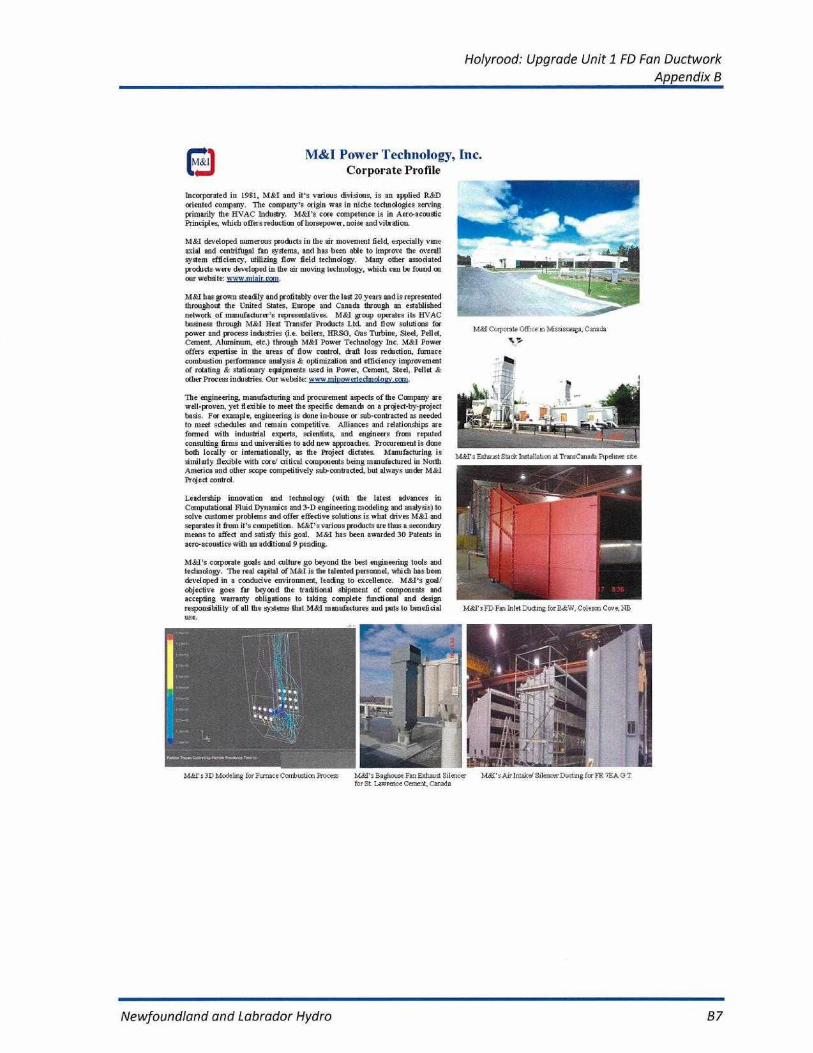
M&I Power Technology, Inc.Corporate Profile
Incorporated in 1981, M&I and its various divisions, is an applied R&Doriented company. The company's origin wag in niche technologies servingprimarily the IIVAC Industry. M&I's core competence is In Aero.acoudicPrinciples, which offers reduction of horsepower, noise and vibration
M&i developed numerous predicts in the air movement field, especially vaneaxial and centrifugal fan systems, and has been able to improve the overall.system efficiency, utilizing flow field technology. Many other assodatedproducts were developed in the air moving technology, which can be found onour websitc www miair.cont.
M&I has grown steadily and profitably over the last 20 years and is representedthroughout the United States, Europe and Canada though an establishednetwork of manufacturer's representatives. M&1 group operates its IHVACbusiness through M&t Pleat Transfer Products Ltd. and flow solutions forpower and process industries (i.e. boilers, I{RSO, Cos Turbine, Steel, Pellet,Cement, Aluminum, etc.) through M&I Power Technology Inc, M&I Poweroffers expertise in the areas of flow control, draft loss redaction, furnacecombustion performance analysis & optimization and efficiency improvementof rotating & stationary equipments used in Power. Cement. Steel, Pellet &other Process industries. Our website: www an sowertechnoloav, call.
The engineering, manufacturing and procurement aspects of the Company arewet-proven, yet flexible to meet the specific demands en a project-by-projectbads. For example, engineering is done in-house or sub-contracted as neededto meet schedules and remain competitive. Alliances and relationships areformed with industrial experts. scientists, and engineers from reputedconsulting firms and universities to add new approaches. Procuremenl is doneboth locally or internationally, as the Project dictates. Manufacturing issimilarly flexible with corer critical components being manufactured in NorthAmerica and other scope competitively sula-cecaliacted, but always under M&IProject control.
Leadership innovation and technology (with the latest advances inComputational Fluid Dynamics and 3-D engineering modeling and analysi a) tosolve customer problems and offer effective solutions is what dives M&I andseparates it from it's competition. M&I's various products are thus a secondarymeans to affect and satisfy this goal. M&i has been awarded 30 Patents inaero-acoustics with an addtional It pending.
M&I's corporate goals and culture go beyond the best engineering tools andtechnology. The real capital of M&I is the talented personnel, which has beendeveloped in a conducive enviromncan, lending to excellence. M&I's goal!objective goes far beyond the traditional shipment of components andaccepting warranty obligations to taking complete functional and designresponsibility of all the systems that M&I manufactures and puts to beneficialuse.
Mat's 3D Modeling for Furnace Conk usti an Process
M&Cs Bagttoose Fan Exhaust Silencerfor St Lawrence Cement, Canada
Newfoundland and Labrador Hydro
B7

Holyrood: Upgrade Unit 1 FD Fan DuctworkAppendix B
H..
rEi
_1-;r_
NIX[
Section 2
SYNOPSIS
?l
E
: -:a, = s td LtiI I F3 CanodoPh +1
i
i
.1 Coriilepli,
wHiiied I, II
prirzierly
NiS.I Pi,..er
and riKI ii,-:.,l
:v7,d
Newfoundland and Labrador Hydro
B8

Holyrood: Upgrade Unit 1 FD Fan DuctworkAppendix B
^, _.p•^^c^: ^^^_ayr^_,r-^^ =ma=r i _-1,_Inr.^i 5h7h.; r rD t De (1 . ...i rn: 117c-:Jh _n_
SYNOPSIS
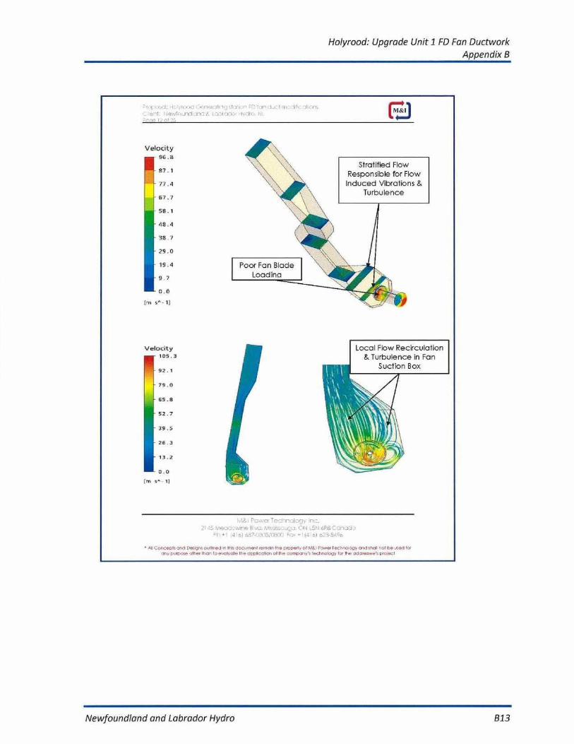
M&l has carefully analyzed FD fan inlet duct and discharge duct between fanoutlet and Steam coil air heater (SCAR) to identify potential reasons for flowinduced vibration and fan capacity curtailment. Based on site visit by M&lEngineer and the information collected 1 received from plant ; M&l carried out apreliminary CFD analysis to map flow behavior inside the upstream anddownstream duct of the FD fan. Based on the results of CFD findings, M&l issubmitting a proposal for modification of the above segment using their state ofthe art aerodynamic diffusers to achieve lower pressure loss and elimination offlow stratification and turbulence. To develop an efficient manufactured solution,M&l needs to carryout an advanced CFD analysis. This activity will only becarried out after placement of the order. However preliminary analysis gave usgood indication of problems in the system.
It is quite evident from the CFD pictures attached below that there are very highvelocity hot spots in the certain portion of the duct combined with local flowseparation in the certain areas of the duct causing flow recirculation. Drasticchange in velocity distribution across duct cross section resulting in high fanentry loss and poor fan blade loading. Moreover fan is operating at very high flowrate (165 kg/sec/fan) resulting in very high velocity magnitude creating flowinduced vibrations. It is very important to eradicate those high velocity hotspotsthrough aerodynamic diffusions by bring dynamic pressure values close to areaaverage velocities from mass average velocities. Further pressure regains needsto be achieved at fan discharge to minimize unproductive velocity pressureresponsible for high backpressure and loss across steam coil air heater.
Mal 's proposal comprisesof internalmodificationsand someexternalmodifications to the one side of inlet and discharge duct.:
M&l would propose state of the art aerodynamics diffusion system and longturning vanes to eliminate flow abnormalities like local flow separation,turbulence and eddy's. Utmost care is given to understand flow behavior andinsertion of suitable shape diffusers to achieve proper flow diffusion.
Please refer attached schematic drawing #P09-001-OOt showingindicative areas (final modifications to be confirmed by detailed CFDanalysis) of modifications proposed by M&l( suitable diffusers will bedesigned & developed to retrofit at those locations) to achieve lowerdraft loss and pressure drop savings. indicative pressure drop savings tobe achieved by M&l modifications are given below:
3 .,j. I
<i - Ir. ?I=DIY ^.-
^'1 ^ , eryJ:,v.^n = r -
1 a'^_ >> :,t ^d l 1.51J dP^i. arn-o--la
ph
-
-.. Ii -',;
^II =o^._2P15 CUCI D iii r^ 0,,111r.5.^ in Ili' JO:.:nini1 r• Heal. Ih2 ,^CPCti^ of Mi i Fnv^et le[I•-w Ia v and .1x711 nel be _;^a'•x
Newfoundland and Labrador Hydro
B9
Holyrood: Upgrade Unit 1 FD Fan DuctworkAppendix B
r •I. ^_;c: H:,
:a
^cl 7'i i'^:; sfatl.:I F['f-n-_
71'i.-711^;s_..I Ilk
-
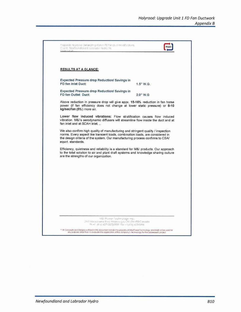
RESULTS AT A GLANCE:
Expected Pressure drop Reduction! Savings inFD fan Inlet Duct:
1.5" W.G.
Expected Pressure drop Reduction! Savings inFD fan Outlet Duct:
2.0" W.G
Above reduction in pressure drop will give appx. 15-16% reduction in fan horsepower (if fan efficiency does not change at lower static pressure) or 8-10kg/sec/fan (5%) more air.
Lower flow induced vibrations: Flow stratification causes flow inducedvibration. M&l s aerodynamic diffusers will streamline flow inside the duct and atfan inlet and at SCAR inlet...
We also confirm high quality of manufacturing and stringent quality / inspectionnorms. Every aspect like transient loads, combination loads, are considered inthe design criteria of the system. Our manufacturing process confirms to CSA/equvt, standards.
Efficiency, quietness and reliability is a standard for Mal products Our approachto the total solution to air and plant draft systems and knowledge sharing cultureare the strengths of our organization.
r-=i_A 4! 1a^aacrunnc E ...c:, PA
C AA `N
C7n:"ACI,S.:+'
`... - liidl^i
nil Ocn enln ClrnntL'e;inrr,:JVllirKd!ii Ira_dor:Nnlenl[^nral: the cr•operrv of M$IPnvcrl=.-_h.n:Ijy' And;furlit,r:.
I
14 hc_
M&I
Newfoundland and Labrador Hydro
B10

Holyrood: Upgrade Unit 1 FD Fan DuctworkAppendix B
I.
;1CA,^ -^fl [l Y.-In X7.,.1 r1 n 1.:111 :. n .I I_
CFD RESULTS OF EXISTING DUCT:
FD FanDischarge Duct
Very High VelocityStratificationCausing Flow
Induced Vibrations
214; TAW7J'_anne. bk•_.,VI,
ViolI , _'I . ! LSVI CPC)
7r1^ IrV^F.-. _
41 ror.cepls an:1 De_
a-lLn, d in lIc doccinen!^sci c the crcperlY of r,^ Fnwr.r 1nch:l(hi y cad shall nil hn ^..^.d ionu L¢.eo h_. rl
ID E.,clIal h_a-ni^ I ' c,n cl N'i anCOn^: LJ wlc ., ix c. ndclir-
Newfoundland and Labrador Hydro
B11

Holyrood: Upgrade Unit 1 FD Fan DuctworkAppendix B
-
17._
.1,4 : 0
i:, I
c, =1 , n .-
::itic n E
NIS.c[
Velocity77.4
69.6
61.9
54.1
46.4
38.7
30,9
23.2
15.5
7 7
0.0
1
n .Dh.l 1_11
:11 - vDJ0+
-
'
.-.271, 17-:4 c,
and De,grE ovWroed In 11* d.7wnenl ,er nnnx N,e prcr ea, .1' Mt r Powerhr,
d
I be sea rc,r
r
1o 4wksOllt,e. L
,, 1H-- ..
e-:1'
'Or
1]_,:•
Newfoundland and Labrador Hydro
B12
Holyrood: Upgrade Unit 1 FD Fan DuctworkAppendix B
r
H
I 11
[ rl =1,,I n
r .rI I ,
1
rn I t
1 . k I
-lr
I I
Velocity96.a
\\\\s\
\
87.1
77.4
67.7
58.1
48.4
38 7
29.0
19.4
9..7
0.0[rn
- 1]
2115
B
OM L51 . 1 6F:6 C,-ginaa,
+1 14 ("I ,5.'.7.
=,, - 1 [I !,:,)
41I Con.-.6t, or,•1 0,11 3: ou!l1r.d ,n dr,cv,.,,I
the
o! M?.l P Owes 1
!Toll r-51 b.= .r.ndr^mar
Newfoundland and Labrador Hydro
813
Stratified FlowResponsible for FlowInduced Vibrations &
Turbulence
Velocity
[rn
1]
Local Flow Recirculation& Turbulence in Pan
Suction Box

Holyrood: Upgrade Unit 1 FD Fan DuctworkAppendix B
el.l: 1-lolvr,:
rel
1 111
' D "Dl -, Cl
:11 n ,: MS: r
Section 3
SCOPE OF WORK
F
T :,.c
rp:
1'14.5
Pvd.
,DN L I I
,: Dn.7dO=1'.
iAlcl x. ..T./Cell)-i
- I
Concepts Irv.] Er,ozi-4-n.c.Allnd ,n Pis document rar.,jb lhe properly or Nlt.lFa ,.,ar h;ch,"ala.n,
be
Icnny b..,rix.-e
P-..7, raw,l,ole the
at [ha
Newfoundland and Labrador Hydro
B14
Holyrood: Upgrade Unit 1 FD Fan DuctworkAppendix 8
ma, f
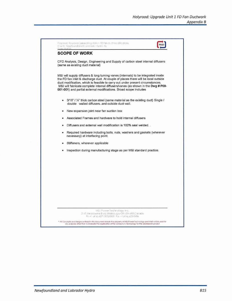
SCOPE OF WORK
CFD Analysis, Design, Engineering and Supply of carbon steel internal diffusers(same as existing duct material)
M&I will supply diffusers & tong turning vanes (internals) to be integrated insidethe FD fan inlet & discharge duct. At couple of places there will be local outsideduct modification, which is feasible to carry out under present circumstances.M&l will fabricate complete internal diffusers/vanes (as shown in the Dwg # P09-
001-001) and partial external modifications. Broad scope includes
• 3116' / W thick carbon steel (same material as the existing duct) Singledouble walled diffusers..and outside duct wall.
• New expansion joint near fan suction box
• Associated Frames and hardware to hold internal diffusers
• Diffusers and external wall modification is 100% seal welded.
▪ Required hardware including bolts, nuts, washers and gaskets (wherevernecessary) at interfacing point.
• Stiffeners, wherever applicable
• Inspection during manufacturing stage as per M&l standard practice.
212,F
-,h.1 - `.I I rF3 I, ire Jdq
F'I-Iy - L7 ' rl'[S
:JI Cor,,tcC.b c3rdY
,,nrltrEJl,, lIt doc..,l,eni roar bin 1-3r,coe.re c,IM I FCWrcr Tc,'.hr3.%[?]r 3 d 51•Yll ltl be ne- 33
, C'.v4+r,.. ' l i -r I I ' !
I " , .
1 . ' , e .[FriC :;l;: ^ . . . f II'.' .,:,nl^ c r . . - • : I ' . . ' . . . '.^„ f.:. ry..-:^d,y„r, _ _ , _ . .a: I`
Newfoundland and Labrador Hydro
B15
Holyrood: Upgrade Unit 1 FD Fan DuctworkAppendix B
1 .:dr •1S .J: Ftyl7.1
Irlic.1-E.
:
n .
I F.
:DI
I. .t
,
-
Section4
LIMIT OF SUPPLY AND EXCLUSION
r./I
10, , _J'I
r FL.1 il
.=
1,1 --,,,
5/dY-11
- E4 h^ r: ,.-
4.1Cd-drteepfs and ftettior e.d,11irct
Ili dopt.mt,etrl ,et-rtt,d 11-,e pc:petty otM&I Fe,,er Tsyp '-d-etagy' and sh.ll ', p i be ,eeJ
Newfoundland and Labrador Hydro
B16

Holyrood: Upgrade Unit 1 FD Fan DuctworkAppendix B
an a._,Ci ', . ' 1I cahor,_M&I
LIMIT OF SUPPLY:
• Internal & some external modifications to existing duct an extent tomeet pressure drop saving values as mentioned in the above scopeof work.
EXCLUSION:
o Foundation, anchor bolts, nuts, washers and leveling hardware.
o Unloading, forwarding, and storage of equipment at job site.
o Dismantling, Installation, start-up, testing, commissioning, utilities andconsumables.
o Insulation if any
a Structural support, ladder, grating.
o Plant and equipment lighting.
o Lighting arrestors and grounding system, Fire protection and detectionsystem.
o Site leveling and grading.
o Control and Power cables, Supply of AC or DC power.
o Dampers.
o Third party inspection.
o Emission probes.
o Any statutory clearance.
o Any item not specifically mentioned in our scope
AI' C'er^cenk'Fro7 bai;'a'outlined In His d.: _ .tocnl rem;iri the eropeee or v&I F _wef iechrrJ.t4v;x'id glgil 'SCI uc used to!Ih.r
I_?'-oI . nl
I _
p4•, I
:l th:._r:.^tl-
v
!i . 1V f: 11
7d
. .r,
I
Newfoundland and Labrador Hydro
817

Holyrood: Upgrade Unit 1 FD Fan DuctworkAppendix B
d41r i ..,r I
:1- . FE' 1'r:In C . ..
-O r:M&I
Section 5
DESIGN BASIS
E'k-ri,
LEI
.':ar-locio
gip,,--r= ./CeO - l
- i.3'.-5) ri.7.7:r.,;.I.G6
All Cor,OOpl,
DE,ig,oulLIr.od
114, Op pr-me I renroir,lhe properly pr
Fewer or:1,r, logy ant !-r'.ill
tre r-oorr-:1 1t.,
rf fr.
II
77 ,'r,r-LO,r': ,wr,o,l
Newfoundland and Labrador Hydro
B18

Holyrood: Upgrade Unit 1 FD Fan DuctworkAppendix B
_e for, d, :11'r: t7i': jt
i..
DESIGN BASIS:
Design pressure:
• FD fan Downstream duct
• Design air temperature
Operational Condition at Rated load:
• Air Temperature at FD inlet:
:
30 deg C
• T Air Flow from one FD fan
:
165 kg/sec
▪ Duct/diffuser Corrosion allowance 1116"
• Maximum Velocity inside the duct 4000 FPM
SITE DATA:
Site location
: Holyrood Generating Station, NLSite ElevationAmbient tempMaximum
: Not AvailableMinimum
: Not AvailableDesign Relative Humidity
: Not AvailableDesign Ambient Pressure
: 14.03 AsiaMax. Rainfall Intensity
: Not AvailableMax. Wind Velocity
: Not AvailableSeismic Zone Factor
: Low intensity - assumedGround Snow Load/Exp. Coeff.
: Not Available
t' f.^^ryt:ovAnS E, : ^ ,. Of l i- ^ Id ,if81_ ^n•.-a=6-:
.1I r'orrrepls urrd
oe^rl'ired.1', Ili: dac.Jnl olr mesa Ir,e PrcE .erly otf ti Power fechreiE.-gv mnd shell'I I be w_^rc?
-101+30"WG
40 deg C
Newfoundland and Labrador Hydro
B19
Holyrood: Upgrade Unit 1 FD Fan DuctworkAppendix B
t
d: H ly
7tir _^ [4]r. F[^ f ii i J.
Design Philosophy:
While designing internal diffusers, long turning vanes and fan discharge diffuserduct , following design considerations were considered
Loads are considered as force applied to support structure'+ For primary load calculations, all loads are considered separately
• Duct internals are designed for transient air heater upset condition
Internal diffusers, turning vanes provided at various locations inside the FD fanduct will be thoroughly checked for structural integrity as well as retainedadequately with duct walls.
6 u7, Ff ississa.r:», 0I'd L`5I'1iF,7 . - '- i.r
07.
l
A:I ^=o;,rcrk and DFwig,.x II r.cd vl IM= dco.mrni r?=nivn the G^^^ °-+w ofM&l Prwc ^c-throt2jy and shall nnl bs,s5tl i:+
Newfoundland and Labrador Hydro
620
Holyrood: Upgrade Unit 1 FD Fan DuctworkAppendix B
4:fly
1[ r
cl.,-
qv:
D1h:1"c
Section 6
PERFORMA NCE PARAMETERS
•-:
1,
1 , 51 . ] 6E8 r_ 7ro-aJr
Ph
- '1.1.1161
,TvI n cepl:
it IN', dn.
reman II,: p ,c p erl), ol PM'
1.1,11 ncl b,. ed
Newfoundland and Labrador Hydra
821
Holyrood: Upgrade Unit 1 FD Fan DuctworkAppendix B
FD
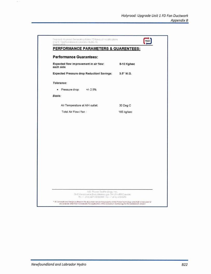
PERFORMANCE PARAMETERS&GUARENTEES:
Performance Guarantees:
Expected flow improvement in air flow:
8-10 Kg/seceach side
Expected Pressure drop Reduction! Savings:
3.5" W.G.
Tolerance:
a Pressure drop:
+1- 2.5%
Basis:
Air Temperature at AM outlet:
30 Deg C
Total Air Flow/ fan :
965 kg/sec
I
:,I.:g,
1 - 1 n:.
'Ii+F rl:i-. .)
A!I n =' n),:epl, or .,J
oollir.d
rer,sir.1he prop-e0y.
]P .:wo
r_.1 II.,
Jr^111 .^,
4,•,7KTl
c.,phoo?ion of IL=
z, 11
Newfoundland and Labrador Hydro
B22

Holyrood: Upgrade Unit 1 FD Fan DuctworkAppendix B
Dif,ef . 7t
Section 7
PRICE SCHEDULE
f.f/fLff
f i 45 Mef3.7fC.r.Incl- Bl if CIC5f.:. f4ff '-5116F'. :7.711%0:L71
A 1 f,f
55-5f ,,fr.e0i
-
t.f
Ail Cor,ool .,, s,Lffigns
fr: Irt docowoof ref,
Use properly of W.-I Fower ..,O og, crud
6e .:-!*9 fcr
Newfoundland and Labrador Hydro
B23
Holyrood: Upgrade Unit 1 FD Fan DuctworkAppendix B
I^
,lo!yr_ :•J
r^^r^rlrnasiarl-^ r_, F7l7r,:. : _7 1'I: y l`i•CO7irre
M&I
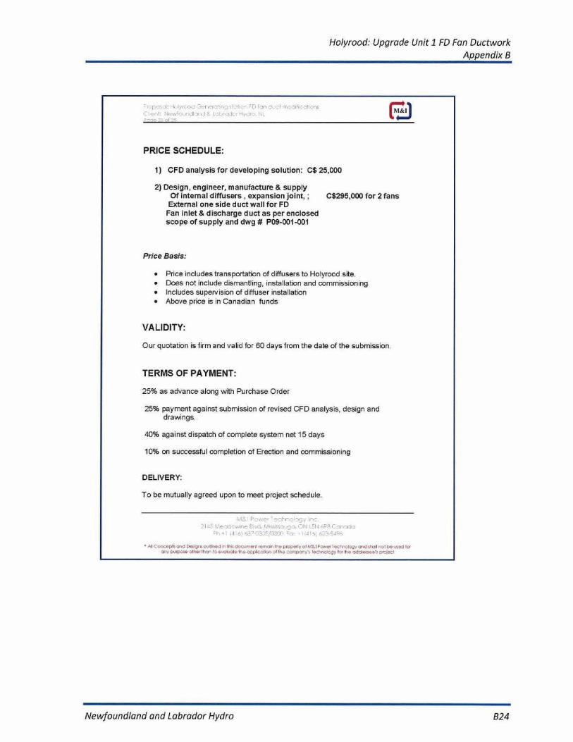
PRICE SCHEDULE:
1) CFD analysis for developing solution: C$ 25,000
2) Design, engineer, manufacture & supplyOf internal diffusers , expansion joint, ;
C$295,000 for 2 fansExternal one side duct wall for FDFan inlet & discharge duct as per enclosedscope of supply and dwg # P09-001-001
Price Basis:
• Price includes transportation of diffusers to Holyrood site.• Does not include dismantling, installation and commissioning• includes supervision of diffuser installation• Above price is in Canadian funds
VALIDITY:
Our quotation is firm and valid for 60 days from the date of the submission
TERMS OF PAYMENT:
25% as advance along with Purchase Order
25% payment against submission of revised CFD analysis, design anddrawings.
40% against dispatch of complete system net 15 days
10% on successful completion of Erection and commissioning
DELIVERY:
To be mutually agreed upon to meet project schedule.
2145 fa•.--1, vnl
F +^. !-Ai.Si=sr...,-±^• •T,1.1 I _`13 r`-F8 r-.:71-^:-19r7_.+: 141x., h_'- ` ^."/fl=.rr, = . -'idl•.n ^,---
- r-.
Fll!,t,^..:eD!E.rr,7 rrs=ig,coulfr pd in Iltis d,=O,n r!^•-nrr^i lne CCrlpoly O;;i"Z.1 F'.?n 4ec Yi: ele r,., end sIr^llr :•I be
Newfoundland and Labrador Hydro B24

Holyrood: Upgrade Unit 1 FD Fan DuctworkAppendix B
, 'DPO-Lal:
]
.71 DT
D f , :r=
F:1
Section 8
Drawings
21 .1'
. ;1:)
'EN
.=
- Al
urvi Dc., igrr: o n,:Iirre..J in I It d.E . Anenr rer-ndr,11-e
o, N.°..1 P:,,q e.r.hr,1w, al id sr.!! ,ol b,,ed rtn,
ri,
f.y
Newfoundland and Labrador Hydro
625

Holyrood: Upgrade Unit 1 FD Fan DuctworkAppendix 8
4-
1. AU. DIMENSION FILE IN INKIi^.2.FORAIOPURPOSE ONLY
• 1-. -1
PIS-CC 03:
.gin.
NJA iI. ^.^..:..,
s. 1,
1
1
Newfoundland and Labrador Hydro
826