experiment fresnel coefficients - harvey mudd college 8 - fresnel... · fresnel coefficients...
TRANSCRIPT

Experiment 8
Fresnel Coefficients
References
• Optics by Eugene Hecht, Chapter 4
• Introduction to Modern Optics by Grant Fowles, Chapter 2
• Principles of Optics by Max Born and Emil Wolf, Chapter 1
• Optical Physics, 4th edition by Lipson, Lipson and Lipson, Chapter 5
8.1 Introduction
The ancients understood the law of reflection—that the angle of incidence was equal to the angleof reflection—but had a law of refraction that only worked near normal incidence. WillebrordSnel van Royen (1580–1626) was the first to figure out that sinθ1 ∝ sinθ2, where the angles aremeasured with respect to the normal. Snel worked this out in 1621,1 although he did not publishthis result. René Descartes (1596–1650) gave the first published account in La Dioptrique (1637).In English-speaking countries, the relation
n1 sinθ1 = n2 sinθ2 (8.1)
is called Snel’s law; in the French-speaking world, it is known as Descartes’ law. You will explorea number of routes to deriving Snel’s law, including Fermat’s principle and Maxwell’s equations.
But Snel’s law is only part of the story: it doesn’t determine how the incident beam should divideits energy between the reflected and refracted beams. Figuring out that mystery was long delayedby Newton’s incomparable stature as the scientist of his age. His corpuscular theory of light did
1M. Born and E. Wolf, Principles of Optics, 7th edition (Cambridge, 1999) xxvi.
revised: 7 December 2017 93 Physics 134

8.2. Theoretical Background Fresnel Coefficients
not lend itself easily to this purpose. The way forward came from Etienne Louis Malus (1775–1812), who discovered in 1808 that light reflected from a glass plate at a certain angle is polarized.Shortly thereafter in 1815, David Brewster (1781–1868) worked out that when the angle betweenthe reflected and refracted beams is 90◦, the reflected beam is polarized with its electric vectorperpendicular to the plane of incidence. The angle of incidence that achieves this conditionis called Brewster’s angle. Jean-Augustin Fresnel’s (1788–1827) wave theory was able not onlyto account for diffraction—leading to the outrageous, but confirmed, prediction of the Poissonbright spot—but also how the reflected intensity depends on polarization.
In this experiment, you will use optical rails, a semicircular prism, a linear polarizer, two wave-plates, and two photodiode detectors to investigate the laws of Snel, Malus, and Fresnel. Themain goals are:
1. To determine the index of refraction of a material using Snel’s law.
2. To investigate polarization of light and the effects of half- and quarter-wave plates.
3. To investigate the polarization dependence of reflection and transmission coefficients fora dielectric-air boundary.
The procedure that follows is vague by design, to encourage you to develop skill in aligning opticsand in designing your own approaches to confirming these theoretical relationships.
8.2 Theoretical Background
8.2.1 Snel’s Law
Snel’s law describes the refraction of light at an interface between two dielectrics with indices ofrefraction n1 and n2. If the angle the incident beam makes with the normal to the local tangent
n1
n2
θ1 θ1
θ2
ki krefl
krefr
Figure 8.1: Geometry of refraction.
Physics 134 94 revised: 7 December 2017

Fresnel Coefficients 8.2. Theoretical Background
plane is θ1 and the angle the transmitted beam makes with that normal is θ2, as illustrated inFig. 8.1, then the angles are related by Eq. (8.1).
Snel’s law and the fact that the angle of incidence equals the angle of reflection are often intro-duced as facts of nature. To gain a deeper understanding of them, it is useful to examine fourdifferent approaches: the motion of wavefronts following Huygens’ principle, a calculation us-ing Fermat’s principle of least time, the principles of quantum optics covered in Physics 51, and aderivation grounded in electromagnetic fields that applies boundary conditions at the interfacebetween media that arise from Maxwell’s equations. These approaches are all discussed in thereference in Hecht. The great advantage of the latter approach is that it incorporates the effect ofpolarization in a natural way.
You should understand the derivation of Snel’s law from these different approaches.
8.2.2 Law of Malus
The law of Malus describes how the intensity of a linearly polarized beam of light traverses aperfect linear polarizer. The polarizer only transmits one component of the light wave’s electricfield, but since the intensity of the beam is proportional to the square of the electric field, thetransmitted intensity is given by
Itrans = I0 cos2φ (8.2)
where φ is the angle between the pass axis of the polarizer and the electric vector of the incidentbeam.
8.2.3 Fresnel Coefficients
The Fresnel coefficients describe the amplitudes of reflected and transmitted electromagneticwaves at the interface between two dielectrics. The geometry is shown in Fig. 8.2. Recall that foran electromagnetic plane wave with angular frequency ω= 2π f ,
E(x, y, z, t ) = E0 cos(k · r−ωt )
E0 ⊥ k
ω= c
n|k| =⇒ f λ= c
n=⇒ f λ0 = c
where λ0 is the wavelength in a vacuum. Because electromagnetic waves are transverse, theelectric and magnetic fields are perpendicular to the direction of propagation. Any arbitrary E0
can be resolved into two components with directions shown in Fig. 8.2. The key feature is rec-ognizing that the direction of propagation and the normal to the surface between the materialsdetermine a plane called the “plane of incidence”. In the figure, one material is below the planeof the interface and one is above.
revised: 7 December 2017 95 Physics 134

8.2. Theoretical Background Fresnel Coefficients
The reflection and transmission coefficients are determined by applying the electromagneticboundary conditions at the interface. Since the boundary conditions for the electric field de-pend on the direction of the electric field, the reflection and transmission coefficients for E||,inc
and E⊥,inc are different. You should go through the derivation of the reflection and transmis-sion coefficients for the two polarizations. For the special case in which the materials are non-magnetic, so that µ1 =µ2 = 1, the results are
r⊥ =(
E⊥,refl
E⊥,inc
)= ni cosθi −nt cosθt
ni cosθi +nt cosθt=−sin(θi −θt)
sin(θi +θt)(8.3)
t⊥ =(
E⊥,trans
E⊥,inc
)= 2ni cosθi
ni cosθi +nt cosθt= 2sinθt cosθi
sin(θi +θt)(8.4)
r|| =(
E||,refl
E||,inc
)= nt cosθi −ni cosθt
nt cosθi +ni cosθt= tan(θi −θt)
tan(θi +θt)(8.5)
t|| =(
E||,trans
E||,inc
)= 2ni cosθi
ni cosθt +nt cosθi= 2sinθt cosθi
sin(θi +θt)cos(θi −θt)(8.6)
where we can use Snel’s law to relate θi and θt.
Note that these equations describe the electric field amplitudes, which are not the same as theintensities of the reflected or transmitted beams.
N
Plane of incidence
Plane of interface nt
niθi
θt
kinc
E||,inc
E⊥,inc
krefl
E||,refl
E⊥,refl
ktrans
E||,trans
E⊥,trans
Figure 8.2: The geometry for the Fresnel coefficients. The incident electromagnetic wave can havepolarization anywhere in the plane perpendicular to the direction of propagation. The incident fieldis thus a superposition of E||,inc and E⊥,inc. In this figure, if the plane of incidence is the plane of thepaper, then E⊥,inc is out of the plane. Note: magnetic fields are not shown, but are orthogonal to bothk and E. Boundary conditions derived from Maxwell’s equations require that components of E and Bthat are parallel to the interface must be continuous, as must be the parallel component of k.
Physics 134 96 revised: 7 December 2017

Fresnel Coefficients 8.3. Experimental Setup
8.2.4 Brewster’s Angle
Notice that the value for r|| given in Eq. (8.5) goes to zero when θi +θt = π/2, which means thatthere is a particular angle of incidence where there will be no reflected light of the parallel polar-ization when that condition is met. This angle is called Brewster’s angle.
8.2.5 Total Internal Reflection
If we examine Snel’s law for the case that n1 > n2 then we see that there is a critical angle ofincidence for which θt = θ2 =π/2. At this condition, the transmission coefficients go to zero andall the light is reflected. What happens at larger angles of incidence?
8.2.6 Waveplates and Circular Polarization
In the discussion of Fresnel coefficients we resolved the incident electromagnetic wave into a su-perposition of linearly polarized components. Sometimes a more useful basis is that of left-handand right-hand circularly polarized light. The action of a waveplate is to control the polarizationof light and a waveplate can be used to change from linearly polarized to circularly polarizedlight or to change the orientation of linearly polarized light. The experimental setup includes aquarter and a half waveplate. Read about what these are and how they change the polarizationof light.
8.3 Experimental Setup
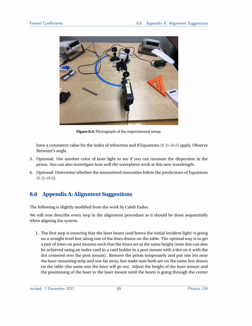
The experimental setup is shown schematically in Fig. 8.3. It consists of a semicircular plasticprism on a rotation stage, a laser, two waveplates, a linear polarizer in a rotation mount and twophotodiode detectors. These are mounted on a large board ruled with radial lines. The alignmentprocedure will be to ensure that the incident light hits the prism on the rotation axis. The prism ismounted on an X-Y-R stage so that it can be translated to make the alignment work. See Fig. 8.4.
Notice that the path of the light is most easily analyzed if the laser hits the flat face of the prismon the rotation axis and the center of the semicircle. Then the light refracted into the prismreaches the semicircular interface at normal incidence so does not refract on leaving the prism.The alignment procedure is designed to reach this position. One suggested process is detailed inAppendix A.
revised: 7 December 2017 97 Physics 134

8.4. Qualitative Measurements Fresnel Coefficients
Figure 8.3: Schematic of the setup. The waveplates can be substituted for the polarizer or put inseries with it. [Figure from Caleb Eades]
8.4 Qualitative Measurements
(to be answered with a combination of reading the specification sheets and using the equipment)
1. What type of detectors are supplied? How do they measure the intensity of the light? Whatdo the scales on the top do to the signal?
2. What is the polarization state of the light from the laser?
3. Align the prism with the laser so the geometry for the rest of the experiment is convenient.Document the process you use and what you consider the figures of merit for a good align-ment.
8.5 Quantitative Measurements
1. Determine if Snel’s law applies to this system. If it does, then find the index of refraction ofthe prism. Observe total internal reflection and notice that a quick estimate of n can be foundby making this one measurement.
2. Confirm that the detector and linear polarizer work as expected by taking measurements toconfirm the Law of Malus.
3. Determine whether the quarter- and half-wave plates work as expected. At the end of thesemeasurements you should be able to control the polarization of the laser beam.
4. Measure the reflected light from the prism as a function of incident angle for a couple oflinear polarization directions. Analyze your data using the reflection coefficients to see if you
Physics 134 98 revised: 7 December 2017
Fresnel Coefficients 8.6. Appendix A: Alignment Suggestions
Figure 8.4: Photograph of the experimental setup.
have a consistent value for the index of refraction and if Equations (8.3)–(8.6) apply. ObserveBrewster’s angle.
5. Optional: Use another color of laser light to see if you can measure the dispersion in theprism. You can also investigate how well the waveplates work at this new wavelength.
6. Optional: Determine whether the transmitted intensities follow the predictions of Equations(8.3)–(8.6).
8.6 Appendix A: Alignment Suggestions
The following is slightly modified from the work by Caleb Eades.
We will now describe every step in the alignment procedure as it should be done sequentiallywhen aligning the system.
1. The first step is ensuring that the laser beam (and hence the initial incident light) is goingon a straight level line along one of the lines drawn on the table. The optimal way is to geta pair of irises on post mounts such that the irises are at the same height (note this can alsobe achieved using an index card in a card holder in a post mount with a dot on it with thedot centered over the post mount). Remove the prism temporarily and put one iris nearthe laser mounting strip and one far away, but make sure both are on the same line drawnon the table (the same one the laser will go on). Adjust the height of the laser mount andthe positioning of the laser in the laser mount until the beam is going through the center
revised: 7 December 2017 99 Physics 134

8.6. Appendix A: Alignment Suggestions Fresnel Coefficients
of both irises (or is hitting the dot on the index card in both the near and far field if usingthe index card). Use the set screw in the laser mount to adjust the positioning of the laserin the mount. Make sure that the laser is still at a height where it will hit the prism. If it isnot, adjust the heights of the irises as appropriate and redo this step.
2. Put the polarizing optic in its mount on the same track as the laser diode and set it at aheight such that the laser diode is roughly hitting the center of the optic (it should alreadybe hitting the center horizontally based on step (i)). Twist the optic until the back reflectionis into the laser diode as well as this can be arranged.
3. Place a stiff metal rectangular object of some width flat against the side of the square baseof the prism-rotating stage. Barely unscrew the stage and then rotate holding the metalpiece flat until the metal piece aligns exactly with the table line that is perpendicular to thetable line the laser path is on (or the laser path line as it is a square). Screw the base backin. This ensures that the incident angle value read on the rotation stage has no offset (thatis, the value you read is the actual incident angle value).
4. Put the prism in its mount and press it such that the flat face is against the flat part of theinset. Ensure that the rotation stage is set to 0◦ (that is, the flat face of the prism is per-pendicular to the laser path). Now, use the micrometer perpendicular to the laser path totranslate the rotation stage in the direction perpendicular to the path of the laser propa-gation until the beam is centered on the flat face of the prism. It is helpful here to use aneutral density filter to make the beam weaker and get a more precise centering. It is alsohelpful to look down the flat face of the prism and use the set screw hole to see where thelaser should go (it should be centered on this hole as well).
5. (90◦-90◦ test) One way to test whether the perpendicular position has been set correctly isto set the rotation stage to 90◦ and then look to make sure the beam is split in half, so ifyou hold an index card against the flat face of the prism, you should see half of the beamon the index card and half going onto the semicircular face of the prism. This should alsobe true when the rotation stage is set to 270◦. If this is not the case, then try step 4 again.
6. (45◦-45◦ test) Before this step, close the irises in front of the photodiode detectors all theway such that they have just a little hole. (Note you should adjust the height of the detec-tors such that the reflected beam is centered height-wise on the hole before continuing).Place the detectors on either side of the prism stage on the drawn line perpendicular to thelaser path. Set the rotation stage (which should be at zero) to 45◦. If the reflected light isnot hitting one of the detectors exactly (to where the reflected beam is centered on the littlehole), use the micrometer that is along the laser path to adjust the “z”-position of the stageuntil the beam is centered on the hole. Now set the rotation stage to 315◦. If everything hasbeen done properly, then the beam should be centered on the hole of the other detector.If the beam is not centered on the hole of the other detector, then something is off in thealignment. The potential issues are that the laser is not following the table line that it ismounted on, the square base of the rotation stage is not rotationally oriented properly, or
Physics 134 100 revised: 7 December 2017
Fresnel Coefficients 8.7. Appendix B: Sample Data for Fresnel Coefficients
the beam is not hitting the center of the flat prism face. Repeat all the steps as necessaryuntil the culprit is found.
If all these steps are done properly, then the data collected should be reasonably reliable (at leastat the appropriate angles and with the center of the beam hitting the correct location on thecenter of the front flat face of the prism).
8.7 Appendix B: Sample Data for Fresnel Coefficients
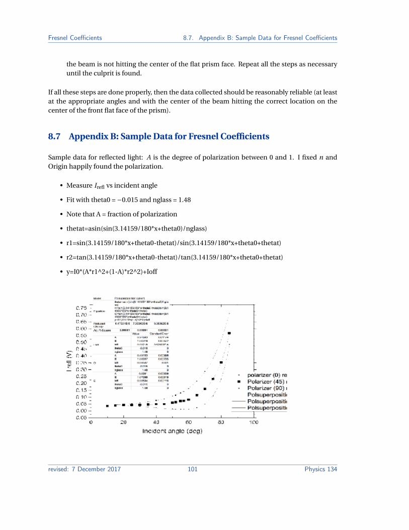
Sample data for reflected light: A is the degree of polarization between 0 and 1. I fixed n andOrigin happily found the polarization.
• Measure Irefl vs incident angle
• Fit with theta0 = −0.015 and nglass = 1.48
• Note that A = fraction of polarization
• thetat=asin(sin(3.14159/180*x+theta0)/nglass)
• r1=sin(3.14159/180*x+theta0-thetat)/sin(3.14159/180*x+theta0+thetat)
• r2=tan(3.14159/180*x+theta0-thetat)/tan(3.14159/180*x+theta0+thetat)
• y=I0*(A*r1^2+(1-A)*r2^2)+Ioff
revised: 7 December 2017 101 Physics 134

8.7. Appendix B: Sample Data for Fresnel Coefficients Fresnel Coefficients
If we examine the fitting coefficients we see good agreement for the values.
Value Standard Error
I refl A 0.97893 0.01174I refl I0 1.04319 0.00677I refl Ioff 0.00218 9.62023E-4I refl theta0 -0.015 0I refl nglass 1.48 0
D A 0.49153 0.00996D I0 1.00007 0.00705D Ioff 0.00507 0.001D theta0 -0.015 0D nglass 1.48 0E A 0.0261 0.00839E I0 1.07088 0.00815E Ioff 0.00594 0.00116E theta0 -0.015 0E nglass 1.48 0
Physics 134 102 revised: 7 December 2017