erection of steel beams and · pdf file2-1 chapter two erection of steel beams and girders...
TRANSCRIPT

2-1
CHAPTER TWO
ERECTION OF STEEL BEAMS AND GIRDERS
CONTENTS
GENERAL ................................................................................................................................................. 2-2 Inspecting for Defects Before Erection ................................................................................................ 2-3 Handling and Storage .......................................................................................................................... 2-3
BOLTING .................................................................................................................................................. 2-4 General Requirements ......................................................................................................................... 2-4
Fastener Assemble Materials ............................................................................................................... 2-5 Installation ............................................................................................................................................ 2-6 Bolt Tightening ..................................................................................................................................... 2-11
Allowable Bolting Adjustments ............................................................................................................. 2-19
WELDING.................................................................................................................................................. 2-20 Welder Qualification ............................................................................................................................. 2-20 Types and Positions of Welds .............................................................................................................. 2-23 Weld Defects ........................................................................................................................................ 2-27
ANSWERS TO QUESTIONS .................................................................................................................... 2-30
2-2
GENERAL
As you know from chapter one, the erection of beams and girders is pretty much the same whether the material is steel or concrete. However, there are some aspects of steel girder or beam erection that are unique and these will be discussed in detail in this lesson. Steel girders require bolting and welding both of which are very critical with regard to the quality of the final product. Bolting requires rigorous procedures to ensure that critical joints and connections are assembled and joined correctly. Welding is so important that welders must be qualified and this requires them to be tested to confirm that their skills and abilities are acceptable. You must pay close attention to the girder framing configuration that is covered in detail in the plans and shop drawings. The framing plans will show all the information needed to ensure that the right girder goes in the right location and in the proper direction. These plans will also show where the bracing is located. Certain simple clues will give you the girder’s proper orientation into a frame. Attached tags, paint, or approved low stress die stamped match marks on frame members indicate which components go together. Also, with experience, you can look at copings on sloped beams and determine which end goes where (e.g. sloped transverse members used to achieve cross-slope, and sloped longitudinal members used to achieve vertical profiles). Once the girders are in their proper location, the cross bracing is installed in order to ensure the lateral stability of the superstructure prior to deck placement and to ensure that vehicular traffic loads are shared by multiple girders once the bridge is in service. Steel girders also have shear connectors that are vertical steel studs welded to the top flange in specific locations. The shear connectors ensure that the deck and girders act together to carry the loads by preventing the deck from slipping on top of the girders when the girders deflect. You must make sure that the shear connectors are fastened to the top flange properly and they are in the proper locations and are proper sizes according the shop drawings and plans. Standard Specification 502, covers the inspection requirements for shear connectors and you must be thoroughly familiar with this specification in order to perform a proper shear connector inspection.
2-3
INSPECTING FOR DEFECTS BEFORE ERECTION
When they arrive at the project site, examine the beams/girders carefully for the following defects and report significant ones to the Project Administrator: KINKS: Sharp bends in flange or web plates that do not reveal warps. Kinks are occasionally required by
the design so check the plans before you report a kink as a defect. WARPS: Wavy sections in flange or web plates that are an indication of buckling or excessive
temperature effects caused by welding. BENDS: Gradual curves in plates that are not indicated as being part of the design. CRACKS: These are very serious defects when in a steel beam because they can grow and eventually
cause sudden failure of a plate, which can cause collapse of the beam or even the entire superstructure. PLUMBNESS: Using a Plumb Bob or square, check to see that flange plates are perpendicular to the
web plate and that stiffener plates are perpendicular to top and bottom flange plates. WELDED AND BOLTED CONNECTIONS: Examine all welds that join plates together, such as flange to
web connections, for obvious welding defects and make sure that any bolted connections are properly assembled and that bolts appear to be snug. A loose bolt can be revealed by the sound it makes when lightly taped with a hammer.
HANDLING AND STORAGE When the beams/girders arrive at the project site very often they are lifted from a truck or barge and are placed directly in their permanent position. You must make sure that the proper lifting devices are used and placed at the proper locations so that lifting stresses will not cause damage to the girder. These devices are usually special clamps that attach to the top flange. If they are used improperly, there can be damage structurally or to the beam’s protective coating. Pay particular attention to box girders and curved girders since they can be larger, heavier, or far more unstable then single straight beams and are; therefore, more difficult to handle property.
2-4
If the beams/girders are placed in a temporary storage site prior to permanent placement, they must be supported at least at the points of bearing shown in the plans and they must be high enough off the ground to avoid being submerged in, or being splashed by, water. The beams should also be kept free of dirt, oil, or any other detrimental contaminant.
BOLTING [SS 460]
GENERAL REQUIREMENTS As an Inspector, you will be responsible for inspecting field bolting. Bolting is done with high-strength bolts, nuts and hardened-steel washers. Here are some general requirements for bolting: The combination of fastener elements, which include a bolt, nut, DTI (Direct Tensioning Indicator) and
washer/s, is referred to as a fastener assembly. Torque tests - which will be explained later - are performed on a representative fastener assembly that is made up of elements from specific production lots. Once a production lot for each element of an assembly is established, it must not be changed unless a new set of torque tests are conducted on the assembly.
Bolted connections must be used only as indicated on the plans or in the Special Provisions. For bolted girder splices, all bolts required by the plans must be installed and fully tightened prior to the
removal of falsework or any other temporary support. Failure to have a fully completed splice could result in severe damage to the joint and girder or even collapse.
The materials quality of the fastener assembly and the accuracy of the bolt tightening process are
extremely critical to the integrity of a bolted connection or joint. It is your job to verify that accurate tracking and documentation of the assemble materials are being done by the Contractor and that correct torquing procedures are being consistently followed.
2-5
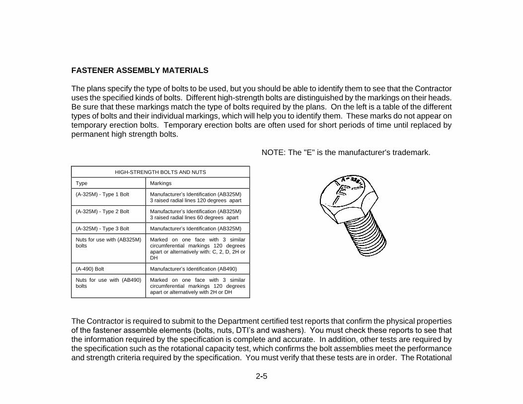
FASTENER ASSEMBLY MATERIALS The plans specify the type of bolts to be used, but you should be able to identify them to see that the Contractor uses the specified kinds of bolts. Different high-strength bolts are distinguished by the markings on their heads. Be sure that these markings match the type of bolts required by the plans. On the left is a table of the different types of bolts and their individual markings, which will help you to identify them. These marks do not appear on temporary erection bolts. Temporary erection bolts are often used for short periods of time until replaced by permanent high strength bolts. NOTE: The "E" is the manufacturer's trademark.
HIGH-STRENGTH BOLTS AND NUTS Type
Markings
(A-325M) - Type 1 Bolt
Manufacturer’s Identification (AB325M) 3 raised radial lines 120 degrees apart
(A-325M) - Type 2 Bolt
Manufacturer’s Identification (AB325M) 3 raised radial lines 60 degrees apart
(A-325M) - Type 3 Bolt
Manufacturer’s Identification (AB325M)
Nuts for use with (AB325M) bolts
Marked on one face with 3 similar circumferential markings 120 degrees apart or alternatively with: C, 2, D, 2H or DH
(A-490) Bolt
Manufacturer’s Identification (AB490)
Nuts for use with (AB490) bolts
Marked on one face with 3 similar circumferential markings 120 degrees apart or alternatively with 2H or DH
The Contractor is required to submit to the Department certified test reports that confirm the physical properties of the fastener assemble elements (bolts, nuts, DTI’s and washers). You must check these reports to see that the information required by the specification is complete and accurate. In addition, other tests are required by the specification such as the rotational capacity test, which confirms the bolt assemblies meet the performance and strength criteria required by the specification. You must verify that these tests are in order. The Rotational
2-6
Capacity Test must also be performed in the field and you will need to consult the Project Administrator for the detailed procedure covering this test. Fastener elements are manufactured hundreds or thousands at a time from a single source of steel. All the elements from a single source are said to come from the same LOT. The physical properties of elements from different LOTs can differ a great deal so it is very critical that once the LOTs of a fastener assembly are established, that they not be changed. Torque tests performed on a small sample of assemblies each day at the project site, are based on using the same LOTs for all the assemblies installed that day. If LOTs are mixed the torque tests will not be valid and the assemblies will not perform as expected. The Contractor is required to establish a procedure for making sure that LOTs are identified properly and that elements of different LOTs are not mixed together. You must make sure the Contractor follows the procedure for maintaining integrity of the LOTs. Other materials related issues you will need to monitor include type and quality of bolt lubricants, packaging of the fastener elements during shipping, and storage and protection of the elements prior to installation. All these issues are governed by comprehensive specifications that you must be thoroughly familiar with.
INSTALLATION There are two types of bolted connections: Friction and Shear (also called “Bearing”). For the Friction type, the bolts are tightened to a degree that friction between the steel plates that the bolts are holding together, will prevent slippage of the plates when they are loaded. For Shear type connections, the plates may slip which can allow them to come to bear on the bolt shafts. For structural steel connections of bridges, shear type connections are not permitted. For friction connections, you need to be sure that contact surfaces of joint or connection plates referred to as the “Faying Surfaces” are free of the following: dirt and loose scale (except tight mill scale), burrs, pits, oil, paint and lacquer, galvanizing, and any other thing that would prevent a completely tight joint. The faying surfaces of bolted connections must be in full contact when assembled and must not be separated by gaskets or any other compressible material. You must check that bolt holes are at least 1/16 inch larger than the diameter of the bolt shaft, but not greater than 2/16 inch. Greater then 2/16 inch requires the use of a special washer or can even require the use of a larger bolt. Where one side of a connection is protected from the weather, the threaded ends of bolts should be placed on the protected side if possible.
2-7
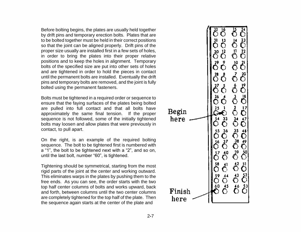
Before bolting begins, the plates are usually held together by drift pins and temporary erection bolts. Plates that are to be bolted together must be held in their correct positions so that the joint can be aligned properly. Drift pins of the proper size usually are installed first in a few sets of holes, in order to bring the plates into their proper relative positions and to keep the holes in alignment. Temporary bolts of the specified size are put into other sets of holes and are tightened in order to hold the pieces in contact until the permanent bolts are installed. Eventually the drift pins and temporary bolts are removed, and the joint is fully bolted using the permanent fasteners. Bolts must be tightened in a required order or sequence to ensure that the faying surfaces of the plates being bolted are pulled into full contact and that all bolts have approximately the same final tension. If the proper sequence is not followed, some of the initially tightened bolts may loosen and allow plates that were previously in contact, to pull apart. On the right, is an example of the required bolting sequence. The bolt to be tightened first is numbered with a “1”, the bolt to be tightened next with a “2”, and so on, until the last bolt, number “60”, is tightened. Tightening should be symmetrical, starting from the most rigid parts of the joint at the center and working outward. This eliminates warps in the plates by pushing them to the free ends. As you can see, the order starts with the two top half center columns of bolts and works upward, back and forth, between columns until the two center columns are completely tightened for the top half of the plate. Then the sequence again starts at the center of the plate and

2-8
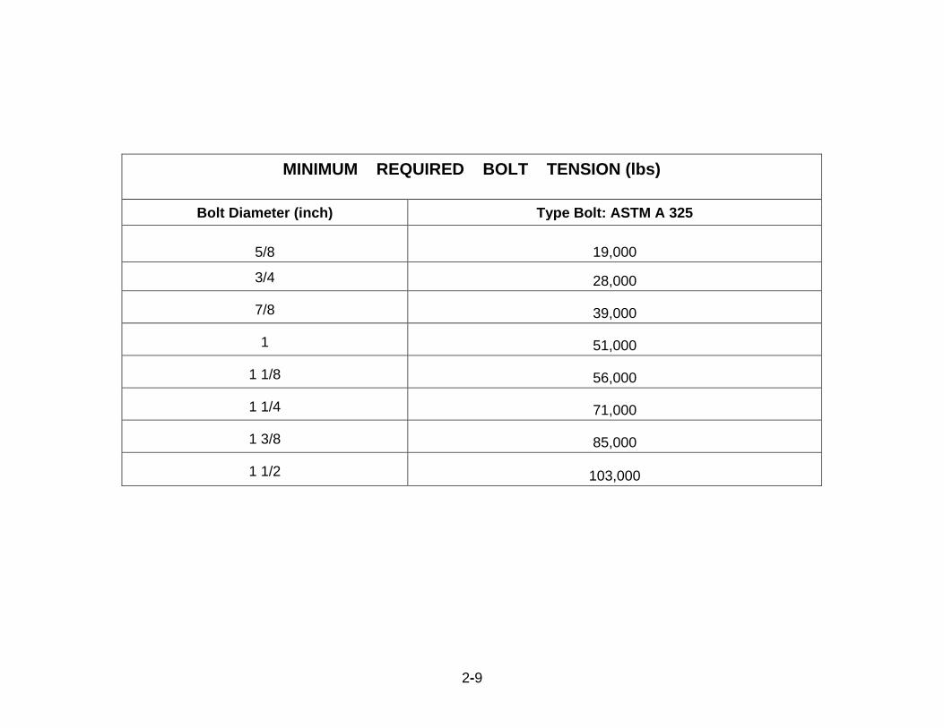
goes up the outside top half column until it is complete, followed by the opposite outside top half column. The order is the same for the bottom half of the plate. Regardless of the shape of the plate or the number of bolts, this general order must be followed. Be sure the Contractor has replaced all temporary drift pins or temporary erections bolts with permanent bolts. You can tell the difference by the identification markings on the permanent bolt heads. Usually, bolting is done with impact wrenches. When this is the case, impact wrenches should have adequate capacities and be sufficiently supplied with air to perform the required tightening in approximately 10 seconds. If limited clearance will prevent the nut from being turned, then tightening may be done by turning the bolt while the nut is prevented from rotating. In this case a washer must be used under the bolt head and lubricant must be used on the bolt face. When bolts are not perpendicular to the plate, a beveled washer may be required. The plans will specify the minimum bolt tension to be obtained for each bolt. The Department's required bolt tensions are shown in the table on the next page. Try the quiz beginning on the next page, and then we will discuss how bolts are tightened.
2-9
MINIMUM REQUIRED BOLT TENSION (lbs)
Bolt Diameter (inch) Type Bolt: ASTM A 325
5/8 19,000
3/4
28,000
7/8
39,000
1
51,000
1 1/8
56,000
1 1/4
71,000
1 3/8
85,000
1 1/2
103,000
2-10
Q U I Z
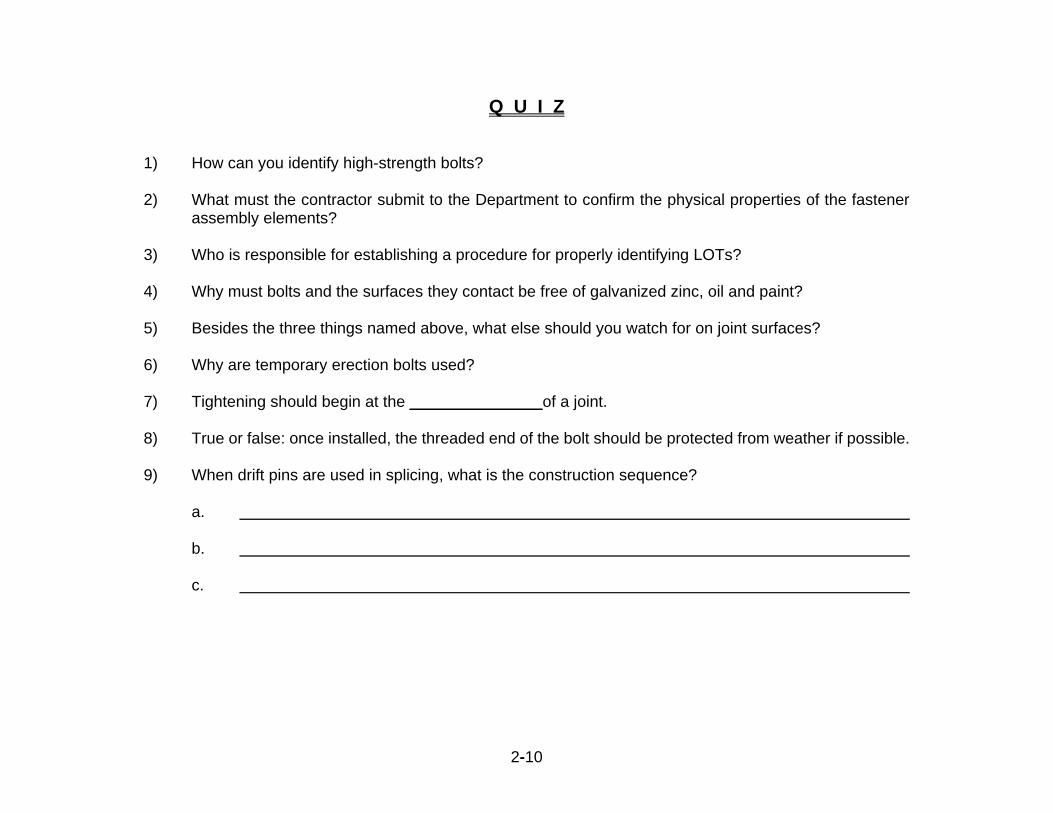
1) How can you identify high-strength bolts? 2) What must the contractor submit to the Department to confirm the physical properties of the fastener
assembly elements? 3) Who is responsible for establishing a procedure for properly identifying LOTs? 4) Why must bolts and the surfaces they contact be free of galvanized zinc, oil and paint?
5) Besides the three things named above, what else should you watch for on joint surfaces?
6) Why are temporary erection bolts used? 7) Tightening should begin at the _______________of a joint. 8) True or false: once installed, the threaded end of the bolt should be protected from weather if possible. 9) When drift pins are used in splicing, what is the construction sequence?
a.
b.
c.

2-11
BOLT TIGHTENING Bolts are tightened until the tension force (measured in pounds) in the bolt reaches a minimum level, which applies the required clamping or compression force to the plates being joined. There are two methods for ensuring that the bolt is tightened to at least the minimum tension. One method uses a Direct Tension Indicator (DTI) and the other method, referred to as the Turn-Of-Nut (TON) method, establishes how much torque or nut rotation will produce the minimum tension. Refer to the contract documents to determine which method must be used. Both may be permitted, so find out from the Contractor which method he intends to use. Inspecting the TON method requires the use of an inspecting wrench, which may be either a calibrated torque wrench or a calibrated power wrench. Inspecting the DTI method requires the use of a feeler gauge. A calibrated torque wrench is equipped with a dial gage that measures and displays the torque while tightening a bolt. A construction worker supplies the tightening force. Power wrenches are calibrated to stall or cutout at the desired level of tension. Wrenches are referred to as calibrated when their measuring device or gage is certified to be accurate by an independent laboratory or vendor who adjusts the mechanism so that it performs to the required level of accuracy.
A Typical Calibrated Torque Wrench

2-12
0.005”
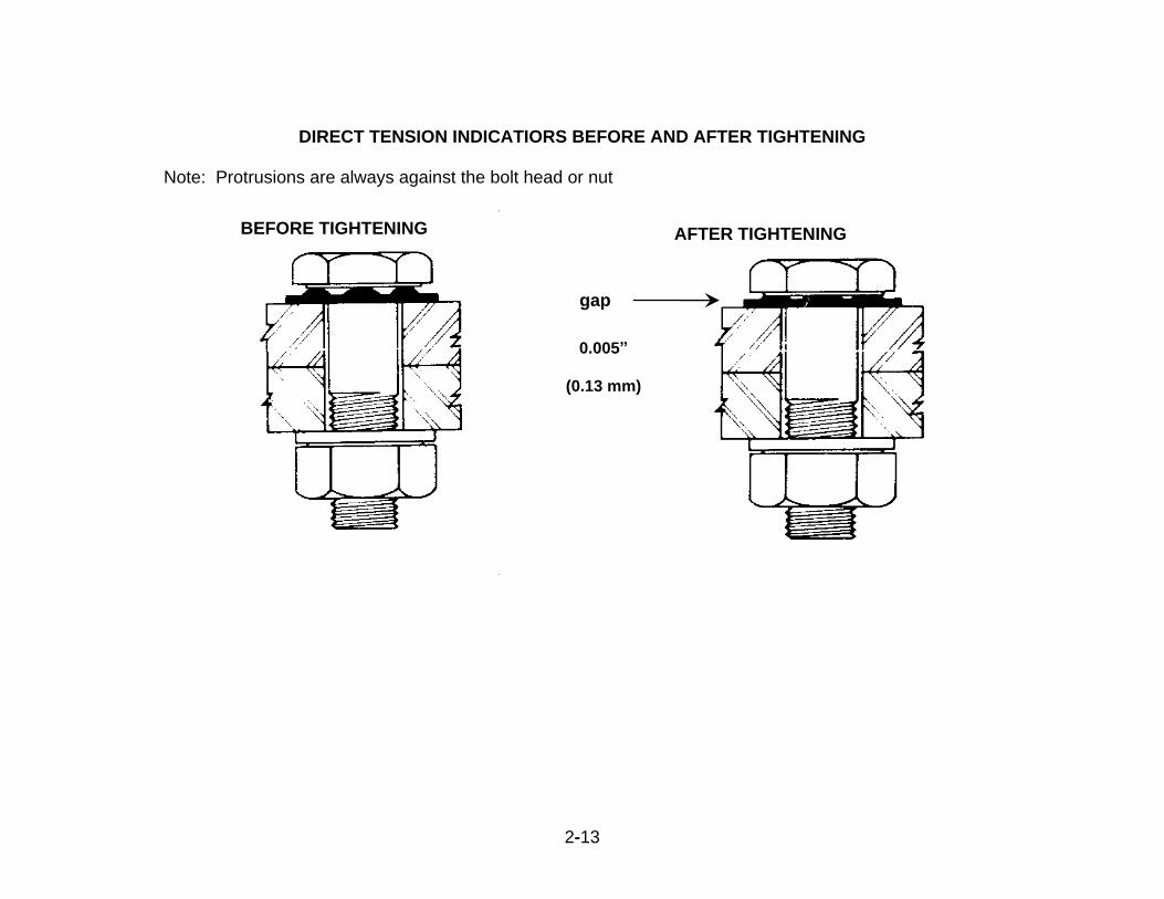
Direct Tension Indicator Method For the DTI method, a device that looks like a washer with bumps or protrusions on it (see illustration) is placed between the bolt head (when the nut is turned) and the plate before tightening begins. When the bolt head has to be turned, the DTI is placed under the nut. As the protrusions are flattened during tightening, the tension in the bolt increases. When the protrusions are flattened to a gap, less then a specified amount, between the washer surface of the DTI and the bolt head - typically 0.005” - the bolt will have the minimum required tension. As can be seen in the illustration, a feeler gage is used to determine when the proper gap has been achieved and the gage must be placed at a number of locations, called refusal points, on the DTI. Not all the gaps between protrusions must be less than 0.005” to approve the bolt as fully tensioned. For example, if the DTI has five gaps between protrusions, 3 gaps must be refused by the gage for the bolt tension to be approved. The specification will have a table that will indicate the number of gap refusals required for a given size DTI and you will need to be familiar with this table. The gap can also vary if the DTI is galvanized. The illustration below shows a DTI before and after it is flattened to the required minimum gap. During the tightening process, the construction worker should go through a first round of tightening in which every DTI in the joint is flattened to more than the minimum gap. This should produce a snug tight condition for the joint. What is meant by snug tight will be explained later in this lesson. Then, during the second round, the worker should flatten every DTI to the final required minimum gap. If only one round of tightening is used, there is a high probability that bolts tightened during the start of the round will loosen because steel plate warps in those locations are eliminated as more bolts are tightened. The bolting sequence explained in the installation section above, must be used.
2-13
DIRECT TENSION INDICATIORS BEFORE AND AFTER TIGHTENING Note: Protrusions are always against the bolt head or nut
BEFORE TIGHTENING AFTER TIGHTENING
gap
0.005”
(0.13 mm)

2-14
Q U I Z
1) What are the two methods for ensuring that bolts are tightened to the required tension?
a. b.
2) Inspection of the turn-of-nut method requires the use of a calibrated wrench or a
calibrated wrench. 3) True or false: a DTI must be placed under the bolt head if the bolt head is turned. 4) What device is used to measure the gap between the DTI and the bolt head or nut? 5) Should every DTI be flattened to the minimum required gap during the first round of tightening?
Turn-Of-Nut Method (TON) For the TON method, each bolt is tightened to a “snug tight” condition by turning the nut while holding the bolt head stationary. After the snug tight condition is achieved, the nut is turned another 1/3 to 3/3 of a turn depending on the length of the bolt and the bolted parts orientation to the bolt axis - thus the name Turn-Of-Nut. The longer the bolt is, the greater the required turn. The snug tight torque plus the torque that is produced by the “turn” - the additional 1/3 to 3/3 turn - must result in a bolt that has 1.05 times the minimum required tension shown in the table of the Installation Lesson above. In addition, once all bolts are snug tight, which must happen before any nuts are turned, all faying surfaces of the joint plates must be in full contact and have no gaps showing. If this cannot be achieved, excessive plate warping may exist and you should notify the Project Administrator immediately for a special tightening procedure or other remedial action. The Contractor must establish a snug tight torque value for bolts at the start of each day that bolts are installed and this torque is referred to as the “job inspection torque”. The job inspection torque must be determined each day because the torque will vary from day to day depending on the temperature, humidity, degree of lubrication,

2-15
and finish of the assembly elements. The snug tight torque is determined by tightening the bolt to a trial torque, that is the Contractor’s best guess, then turning the nut the required amount and measuring the bolt tension. The bolt is placed in a special device called a Skidmore-Wilhelm calibrator, or just Skidmore, that measures and displays the amount of bolt tension. If the tension is equal to or greater than 1.05 times the required minimum, then the trial torque is acceptable. Care should be taken not to exceed the required minimum tension by more than 15% as damage to the bolt could occur, reducing the friction in the connection. This procedure is performed five times for each combination of fastener assembly and three of the five values are averaged since the high and low values are not used. This average torque value is the snug tight torque that is used for that day or the job inspection torque. The job inspection torque plus the torque produced by the turn will produce 1.05 times the minimum required tension and; therefore, the torque versus tension relationship is established. Note: this relationship does not need to be established when DTIs are used because the DTI confirms the required bolt tension directly when the gap closes to the specified opening. You should watch the bolting procedure to be sure a proper bolting sequence is followed. Normally a bolt is tightened by turning the nut, but sometimes it is not possible to get a wrench onto the nut because of an obstruction. Then it is necessary to turn the bolt head while holding the nut to prevent its turning. The hardened washer must be placed under the bolt head when tightening and the surface between the washer and bolt head should be lubricated. You must observe the installation and tightening of bolts to determine if the selected tightening procedure is properly used. You must also determine that all bolts are tightened. The following procedure must be followed when you inspect the bolt installation and tightening of a joint or any connection. After the Contractor has installed all the permanent bolts, he will start the snugging process. Using the
job inspection torque, the Contractor will install all the bolts of the connection. If this process is done correctly you must confirm that the faying surfaces will be in full contact and there will be no gaps between plates.
You must also confirm that the snugging is acceptable by checking to see that the job inspection torque
has been developed. This is done with a torque wrench by checking a representative sample of not less than 3 bolts or ten percent of all the bolts in the joint, whichever is larger. If all the sample bolts have the full job inspection torque, then the snugging is considered to be acceptable and the turn-of -nut process can begin. If you find that even one sample bolt fails to develop the required torque, then it must be tightened to the full torque and all the bolts in the joint must then be torque tested by the Contractor while

2-16
you observe. Any other loose bolts must be tightened. Once you accept the joint as being in snug tight condition, the Contractor can begin the turn-of-nut
process. To do this he must place a mark (vertical straight line) on the flat end of the bolt shaft and on the nut so that the line on the bolt end and on the nut are visually aligned, which is referred to as matchmarking. This will allow you to confirm that the required turn, say 1/3 rotation or 120 degrees, is fully completed since you will be able to observe the mark on the nut relative to the mark on the bolt thread. The plate must also be matchmarked because you will be able to tell if the bolt moved during the turn, which is not permitted. If the bolt rotates during the turning process, then the nut must be completely loosened and snugged again before the turn can be reapplied.
Splice Plate Connection – Note the markings where the “Turn of Nut” rotation was recorded
2-17
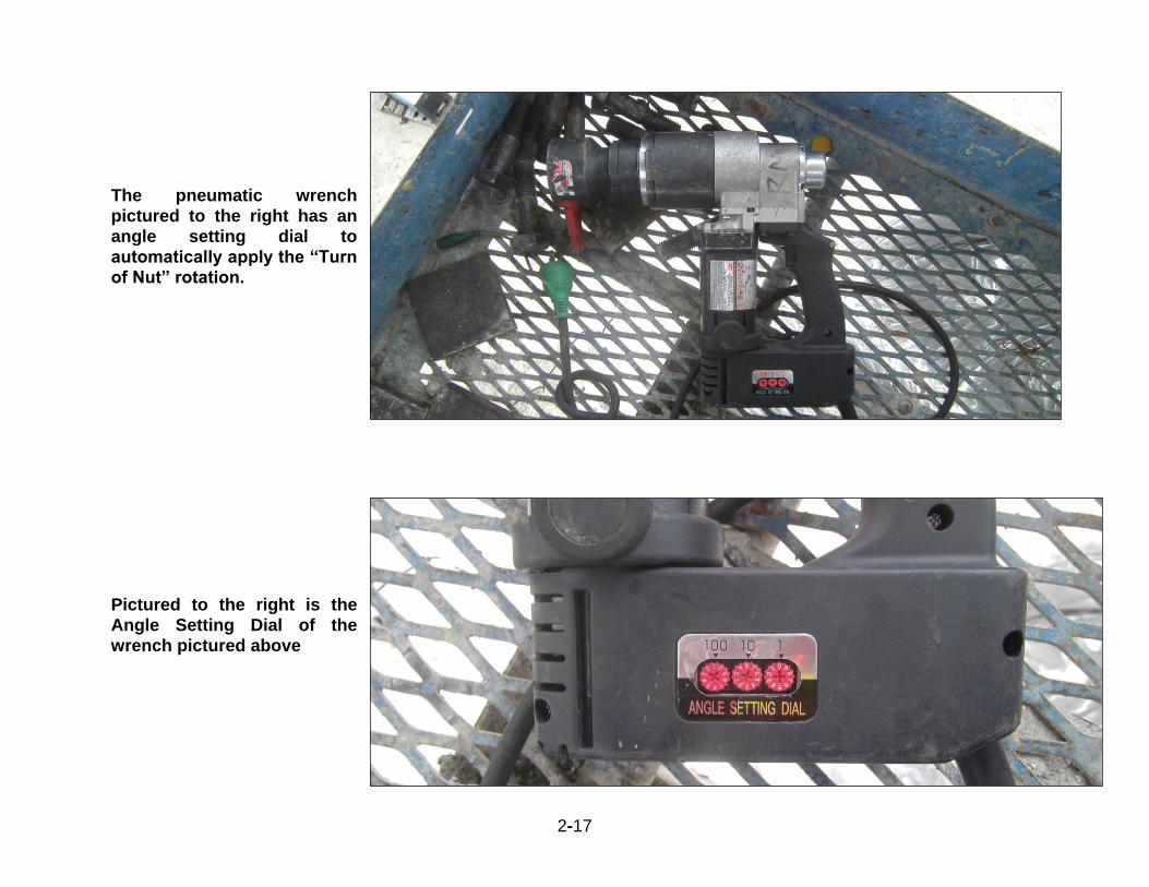
The pneumatic wrench
pictured to the right has an
angle setting dial to
automatically apply the “Turn
of Nut” rotation.
Pictured to the right is the
Angle Setting Dial of the
wrench pictured above
2-18
Q U I Z
1) The ______ ______ ______ plus the torque that is produced by the “turn” must result in a bolt that has
1.05 times the minimum required tension. 2) True or false: a joint is considered to be snug tight if the faying surfaces have gaps of not more than
1/100 inch. 3) The job inspection torque must be determined each day because the torque will vary from day to day
depending on the ___________, ________, _________, and _________. 4) As measured by the Skidmore, a bolt must develop a capacity ______ times the minimum required to be
acceptable. 5) How many fastener assemblies of each combination per lot per day are required to be Skidmore tested in
order to establish the job inspection torque? 6) How many bolts make up a representative torque checking sample for snug tight acceptance? 7) List the three locations where matchmarks must appear.
2-19
ALLOWABLE BOLTING ADJUSTMENTS One more point can be made about bolting. Steel plates should fit together with little distortion or strain. The need for slight adjustments using drift pins is to be expected. However, if the holes are too far out of place, do not allow workmen to force the parts into position with drift pins. The improper use of drift pins may damage the material around the holes and will overstress the plates. Also, do not allow a member to be struck with a heavy sledgehammer. In most structures, a reasonable amount of reaming and drilling to match up holes is allowable. However, no reaming should be allowed in a connection in a main tension member of a truss, unless specific permission is obtained from the Project Administrator. Any error which cannot be corrected by light drifting, a moderate amount of reaming and drilling, or slight chipping and cutting, should be reported to the Project Administrator. Approval of the proposed method of correcting the fault must be obtained before the method is used. Checks and any necessary corrections should be made as the work progresses. Also, before the parts are connected permanently, you should check the work once more to be sure that all members are aligned properly and are set so as to give the required camber. This final checking is necessary to prevent poor alignment from being built into the final structure.
Q U I Z
1) Why must you not allow workmen to force steel parts into position during construction?
2) Where can reaming be done? 3) If light drifting or moderate amount of reaming or drilling does not correct errors, what should you do? 4) Before final connecting is done, you must make a final check of the steel parts for and .
2-20
WELDING [SS 460]
Welding is done in two places -- in the shop and in the field. With the exception of attaching shear studs to the top flange of steel girders, shop welding is done on structural steel components such as girders and beams. Almost all other field welding is done in order to splice steel piles. As an Inspector, you will be concerned with field welds and you should be able to recognize incorrect or poor quality welds on any steel member that shows up on your project. Any questionable weld must be reported to the Project Administrator. You should have a basic understanding of the standard welding symbols shown on the plans. The Standard Symbols can be reviewed by studying the American Institute of Steel Construction chart on the next page. You are not responsible for knowing how to weld, but you should be able to distinguish between good and bad welds. You also will be responsible for checking to see that the welder's qualification documents are in order before welding begins. Only qualified welders are permitted to make steel pile splices. In the remainder of this section we will discuss welder qualification, types and positions of welds and weld defects.
WELDER QUALIFICATION
Only welders who are qualified can be allowed to weld structural members and it is your responsibility to verify this is the case. Qualification is based on tests and inspections given by private testers. The qualification requirements that apply will be determined by the latest welding code governing the work and the code most commonly used by the Department is the American Association of State Highway and Transportation Officials Bridge Welding Code. Consult with your Project Administrator about the details of verifying welder qualifications and to obtain a copy of the latest welding code.

2-21
2-22
Q U I Z 1) Most field welding is done in order to _______________________________________________. 2) Briefly list your responsibilities in regard to welding.
_________________________________________________________________________________ _________________________________________________________________________________ _________________________________________________________________________________
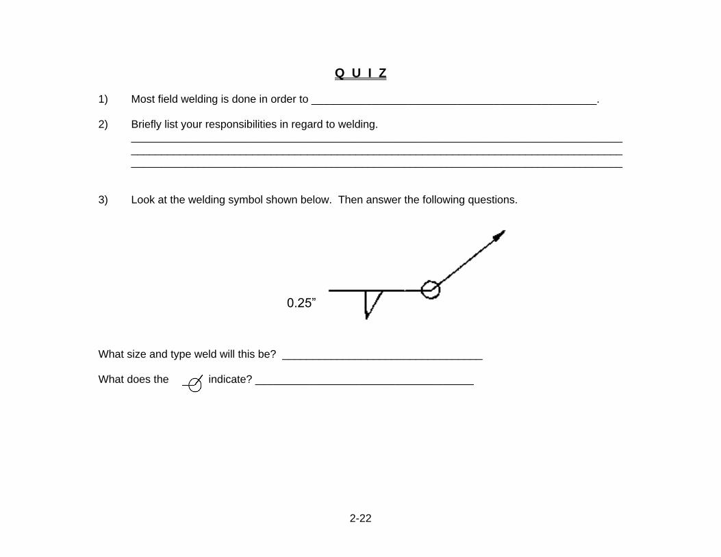
3) Look at the welding symbol shown below. Then answer the following questions.
What size and type weld will this be? _________________________________ What does the indicate? ____________________________________
0.25”
2-23
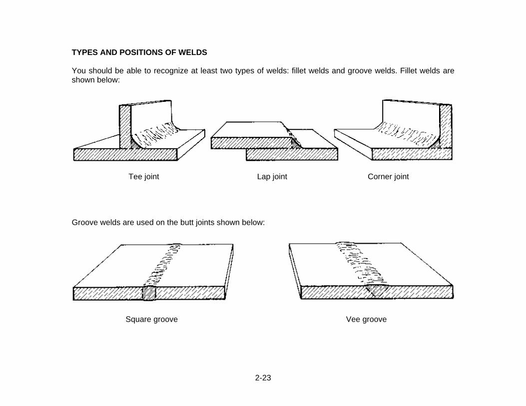
TYPES AND POSITIONS OF WELDS You should be able to recognize at least two types of welds: fillet welds and groove welds. Fillet welds are shown below:
Tee joint Lap joint Corner joint Groove welds are used on the butt joints shown below:
Square groove Vee groove
2-24
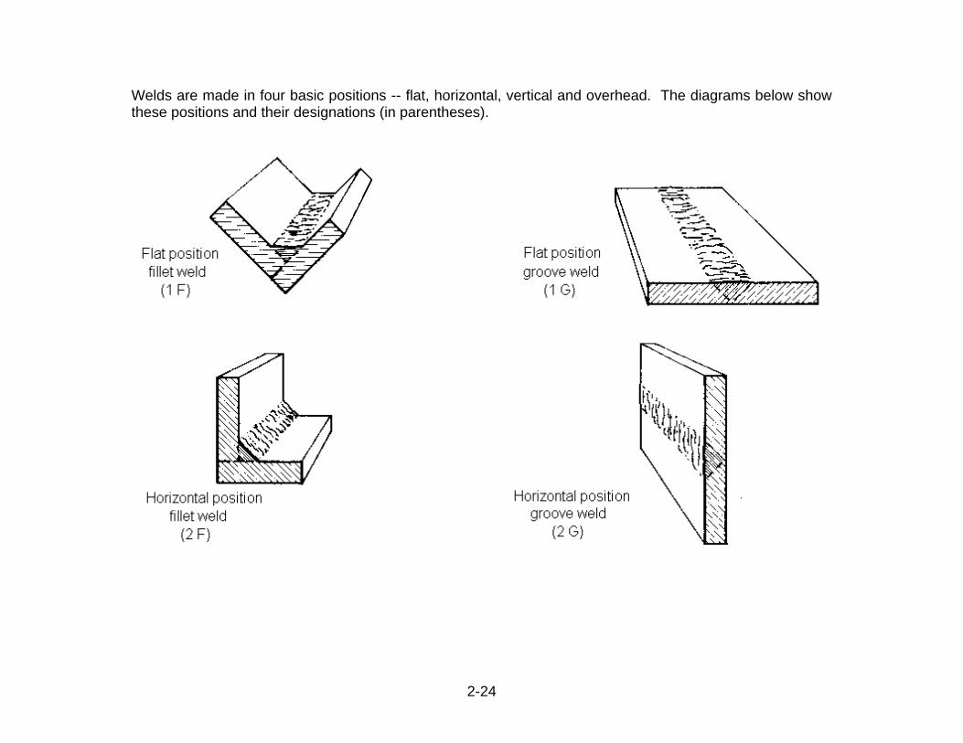
Welds are made in four basic positions -- flat, horizontal, vertical and overhead. The diagrams below show these positions and their designations (in parentheses).
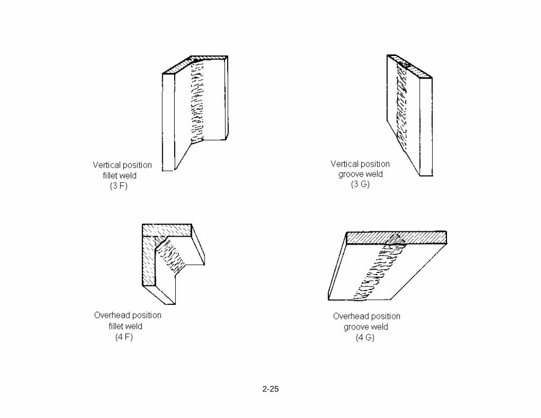
2-25
2-26
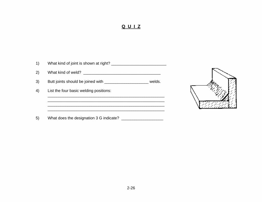
Q U I Z
1) What kind of joint is shown at right? _________________________ 2) What kind of weld? ___________________________________ 3) Butt joints should be joined with ____________________ welds. 4) List the four basic welding positions:
_____________________________________________________ _____________________________________________________
_____________________________________________________ _____________________________________________________
5) What does the designation 3 G indicate? ___________________
2-27
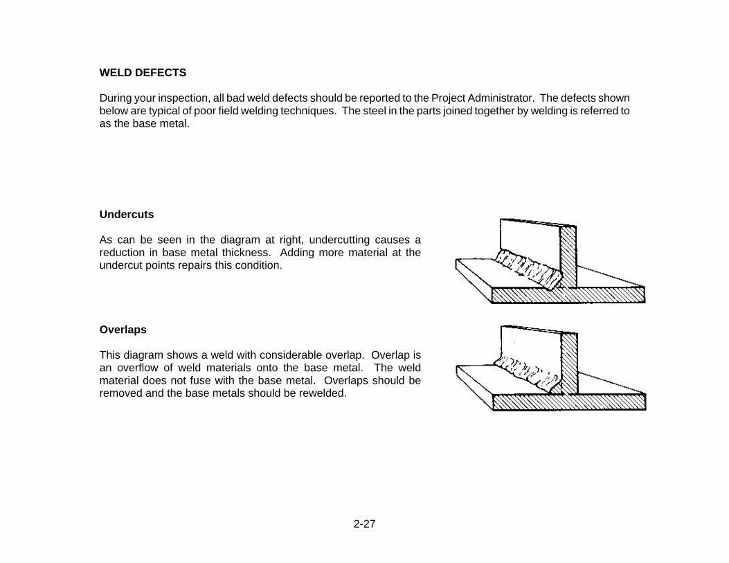
WELD DEFECTS During your inspection, all bad weld defects should be reported to the Project Administrator. The defects shown below are typical of poor field welding techniques. The steel in the parts joined together by welding is referred to as the base metal.
Undercuts As can be seen in the diagram at right, undercutting causes a reduction in base metal thickness. Adding more material at the undercut points repairs this condition.
Overlaps This diagram shows a weld with considerable overlap. Overlap is an overflow of weld materials onto the base metal. The weld material does not fuse with the base metal. Overlaps should be removed and the base metals should be rewelded.
2-28
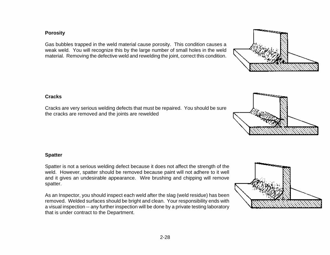
Porosity Gas bubbles trapped in the weld material cause porosity. This condition causes a weak weld. You will recognize this by the large number of small holes in the weld material. Removing the defective weld and rewelding the joint, correct this condition.
Cracks Cracks are very serious welding defects that must be repaired. You should be sure the cracks are removed and the joints are rewelded
Spatter Spatter is not a serious welding defect because it does not affect the strength of the weld. However, spatter should be removed because paint will not adhere to it well and it gives an undesirable appearance. Wire brushing and chipping will remove spatter. As an Inspector, you should inspect each weld after the slag (weld residue) has been removed. Welded surfaces should be bright and clean. Your responsibility ends with a visual inspection -- any further inspection will be done by a private testing laboratory that is under contract to the Department.
2-29
Q U I Z
1) Does undercutting cause a reduction or an overflow of base metal thickness? 2) What causes porosity? 3) How should overlaps be corrected? 4) Must cracks in welds be corrected?
2-30
ANSWERS TO QUESTIONS Page 2-10,Fastener Assembly Mtrls. and Installation 1) By markings on their heads. 2) certified test reports 3) Contractor 4) They would prevent a tight joint. 5) dirt, loose scale, burrs, pits, lacquer 6) To hold connections together until permanent
bolts are installed. 7) most rigid part 8) true 9) a. Drift pins placed in the first few sets of holes.
b. Temporary bolts are put into other sets of
holes and tightened c. Permanent bolts placed in other holes and
tightened d. Drift pins removed and connection
completed with remaining permanent bolts
Page 2-14, Bolt Tightening and DTI method 1) DTI, Turn-Of-Nut 2) torque, power 3) false 4) feeler gage 5) no Page 2-18, Turn-Of-Nut Method 1) snug tight torque 2) false, surfaces must be in full contact 3) temperature, humidity, lubrication, finish of
the assembly elements. 4) 1.05 5) 5 6) larger of 3 bolts or 10% of the total bolts 7) bolt threads, nut, plate

2-31
Page 2-19, Allowable Bolting Adjustments 1) Strain will damage parts and over stress the
steel. 2) Any parts other than main tension members. 3) Contact the Project Administrator. 4) alignment, camber Page 2-22, Welding Symbols 1) splice piles 2) Understand standard welding symbols.
Distinguish between good and bad welds. Check welder’s qualifications.
3) weld size: 0.25 inch (6.35 mm), type weld: fillet 4) weld all around Page 2-26, Types and Positions of Welds 1) corner 2) fillet 3) groove
4) flat, horizontal, vertical, overhead 5) vertical position groove weld Page 2-29, Weld Defects 1) reduction 2) Gas bubbles trapped in the weld material 3) Remove them and reweld base metals 4) yes