dynamic simulation of a cfb boiler system -...
TRANSCRIPT

Thermal Engineering Laboratory
Dynamic Simulation of a CFB
Boiler System
2015. 11. 05, Seoul, Korea
Sang Min CHOI
Thermal Engineering Lab
KAIST
71th IEA-FBC Technical Meeting

Introduction

Dynamic Simulation of a CFB Boiler System
Dynamic Performance Prediction of a CFB Boiler System
3
ü Dynamically changes mass,
energy flow and properties
ü Control system running
ü Dynamically changes mass,
energy flow and properties
ü Control system running
<External environment changes>
Load variation and a change of operating
conditions
<External environment changes>
Load variation and a change of operating
conditions
Dynamic performance
prediction is required
Dynamic performance
prediction is required
▪ Necessity of a Dynamic Model
▪ Modeling Considerations in CFB boiler with drum
ü Operation and Performance of a CFB
Boiler are determined by SG loop and
GS loop
ü These loops has to be considered for
exact performance prediction
ü This model considers gas flow, solid
flow and water-steam flow
SG loopWS loop

Dynamic Simulation of a CFB Boiler System
Model description

Dynamic Simulation of a CFB Boiler System
Modeling description (1)
5
▪ Dynamic sub-models of a 340MWe CFB Boiler
Solid-gas circulation loop model<Furnace: ①, ②>
<Return part: ③,④,⑤>
Water-steam circulation loop model(drum-downcoomer-riser tube)
<2’, 2’’>
Heat exchanger model(Convective heat exchanger)
<⑥,⑦,⑧,⑨,⑩>
Dynamic sub-modelsDynamic sub-models
§ The entire CFB boiler is divided into a finite number of dynamic model
(Solid-gas circulation loop model, water-steam circulation loop model, heat exchanger model)
§ Relevant theories, Numerical approach and physical conservation rules are applied in each
dynamic sub-model.

Dynamic Simulation of a CFB Boiler System
Modeling description (2)
6
▪ Basic concept of heat and mass flow in a discretized heat exchanger
▪ Governing equation
( )uS
t xr frf ¶¶
+ =¶ ¶
1-D unsteady and no diffusion term
Ø Mass balance:
+ ∆ = + Ø Energy balance: + ∆ = + : in-out mass flow, mass transfer, generated mass by reaction
: in-out heat flow, heat transfer, reaction heat
ü Each side is connected in terms of heat
and mass flow
ü Mass-heat flow, heat transfer and heat
reaction are dynamically calculated
+ ∆ = +

Dynamic Simulation of a CFB Boiler System
Modeling description (3)
7
▪ Transport Phenomena Modules<Solid-gas circulation loop>
Hydrodynamics of
fluidized bed
Bubbling fluidized Bed (Bubble vs. Emulsion)
Core-Annuls model (Core vs. Annulus)
Solid side behavior
Fragmentation, Attrition
Solid volume fraction
Solid-gas mass transfer
Solid circulation rate
Coal combustion
reaction
Devolatilization, Volatile combustion
Char combustion, CO combustion
<Water-steam circulation loop>
Drum loop model
(Astrom, 1999)
Mass and heat balance of drum and
downcommer-riser
Drum level
Discharged steam flow rate
<Heat transfer coefficient>Furnace Cluster renewal model
Cyclone, Loopseal Fitting data from operation data
Heat exchanger tube bank Tube bank heat transfer
▪ Numerical approachü Convergence condition: Mass and Temperature < 10 ü Calculation domain: Furnace (150 × 2), Heat
exchanger (80 × 1), Downcommer-riser
(20 × 1), Drum and Return part (0-D)
ü Time step : 0.5 sec
Dynamic Simulation of a CFB Boiler System
Model Develop and Dynamic Simulation Process
8
Develop sub-models(Each component)
Develop sub-models(Each component)
Open loop model(CFB Boiler System)Open loop model
(CFB Boiler System)Closed loop model(CFB Boiler System)Closed loop model(CFB Boiler System)
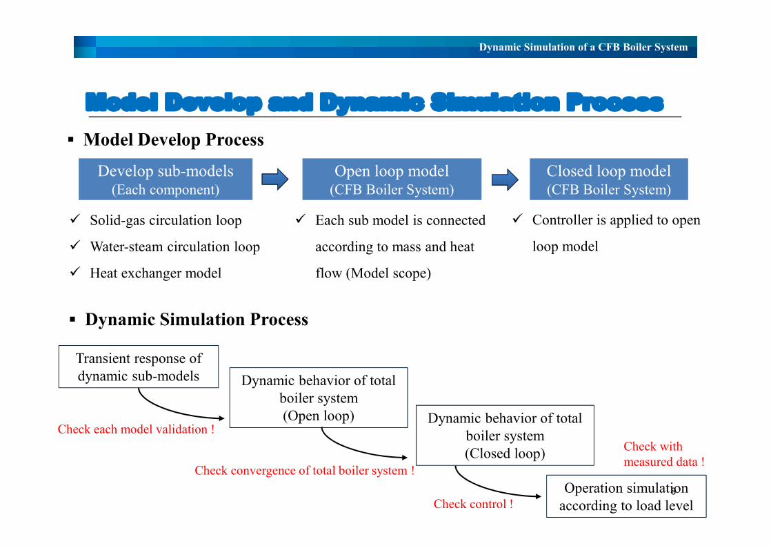
ü Solid-gas circulation loop
ü Water-steam circulation loop
ü Heat exchanger model
ü Each sub model is connected
according to mass and heat
flow (Model scope)
ü Controller is applied to open
loop model
▪ Model Develop Process
▪ Dynamic Simulation Process
Transient response of dynamic sub-models Dynamic behavior of total
boiler system(Open loop) Dynamic behavior of total
boiler system(Closed loop)
Operation simulation according to load level
Check each model validation !
Check control !
Check convergence of total boiler system !
Check with measured data !

Dynamic results

Dynamic Simulation of a CFB Boiler System
Transient response of sub-models (1)
10
-200 0 200 400 600 800 1000 1200 1400
840
880
920
960
1000
Furnace temperature Cyclone temperature+5 %
+45 °C
+40 °C
305 sec
Solid
-gas
tem
pera
ure [
°C]
Time [sec]
30
35
40
45
50
55 Fuel supply (Input condition)
Fuel
supp
ly [k
g/s]
-200 -100 0 100 200 300 400262
264
266
268
270
+10 %
+2 °C
160 sec
Temperature
Wat
er te
mpe
ratu
re [d
eg C
]
Time [sec]
22
24
26
28
30
32
34
36 Heat duty (Input condition)
Hea
t dut
y [M
W]
-200 -100 0 100 200 300 400384
386
388
390
392
+10 %
Temperature
Stea
m T
erm
pera
ture
[°C]
Time [sec]
35 sec+1.1 °C
14
16
18
20
22
24 Heat duty (Input condition)
Hea
t dut
y [M
W]
=
▪ Solid-gas circulation loop ▪ Economizer
▪ Superheater
=
=
ü Dynamic behavior of each sub-model is
validated time constant which is obtained from
globally simplified lumped system.
ü Difference of response time is showed due to
thermal inertia of each-sub model.

Dynamic Simulation of a CFB Boiler System
Transient response of sub-models (1)
11
▪ Water-steam circulation loopü Validation of water-steam circulation loop
model was performed by Astrom model.
(small scale 50MWe)
ü Astrom model can be applied to a large
scale boiler.
ü This results show the dynamic behavior of
target boiler in this study.
ü Dynamic behavior of this boiler is similar
to that of the boiler in Astrom.
310
320
330
340
350 Heat duty
Heat
inpu
t [MW
]
250
260
270
280
290
300
Steam flow rate
Steam
flow
rate [
kg/s]
18.0
18.2
18.4
18.6
18.8
19.0 Drum pressure
Drum
press
ure [
MPa]
1200
1220
1240
1260
1280
Circulation rate
Circ
ulatio
n rate
[kg/s
]
-50 0 50 100 150
0.32
0.36
0.40
0.44 Quality
Time [sec]
Qua
lity at
the r
iser e
xit [-]
-0.10
-0.05
0.00
0.05
0.10
Water level
Wate
r leve
l [m]

Dynamic Simulation of a CFB Boiler System
Open loop model (2)
12
ü Dynamic sub-models are integrated according to the mass flow and the heat transfer as
described in the CFB boiler system of the power plant.

Dynamic Simulation of a CFB Boiler System
Open loop model (2)
13
-200 0 200 400 600
46
48
50
52
54
Fuel SupplyFuel S
upply
[kg/s
]
Time [sec]
300310320330340350360
Air Flow
Air F
low [k
g/s]
+5 %
-200 0 200 400 600825
850
875
900
925
950
Furnace CycloneSo
lid-G
as Te
mpera
ture [°
C]
Time [sec]
-200 0 200 400 6000.00.51.01.52.02.53.03.54.0
O2 co
ncentr
ation
[%]
Time [sec]
-200 0 200 400 60017
18
19
20
21
22
23
Drum pressure
Drum
Press
ure [M
Pa]
Time [sec]
-0.6
-0.4
-0.2
0.0
0.2
0.4
Water Level Wate
r Leve
l [m]
-200 0 200 400 600
270
300
330
360
Mass F
low ra
te [kg
/s]
Time [sec]
Steam Feed water
-200 0 200 400 600250
300
350
400
450
Water
- Stea
m Te
mpera
ture [°
C]
Time [sec]
P. SH Drum S. ECO
ü Disturbance: Fuel supply
ü Solid-gas temp.
ü Oxygen concentration
ü Water steam temp.
ü Controller is required in drum
pressure, water level and
steam mass flow rate.
ü Require controller

Dynamic Simulation of a CFB Boiler System
Closed loop model (1)
14
ü In order to simulate real operation situation, controller is applied to the open loop model
ü Several crucially important parameters are chosen in this model.

Dynamic Simulation of a CFB Boiler System
Closed loop model (2)
15
-1 0 1 2 3 4 5 6
60
40
20
20
19
18
17
-6.3kg/s
795 sec
-0.8MPa
950 sec
Drum pressure Set point
Drum
press
ure [
MPa]
Time [1,000 sec]
Fuel
supply
[kg/s
] Fuel supply
-1 0 1 2 3 4 5 6
Oxygen con. Set point
Oxyg
en co
ncen
tratio
n [%
]
Time [1,000 sec]
Air flow
Air f
low ra
te [kg
/s]-45 sec
400
300200
100
5
2
4
3
2
796 sec
-1 0 1 2 3 4 5 6
0.08
-0.00
-0.08
300
350
250
200
Steam Feed Water Set Steam
-40 kg/s
285 sec
Mass
flow
rate
[kg/s]
Time [1,000 sec]
Water Level Set Level
Wate
r Lev
el [m
]
-1 0 1 2 3 4 5 6200
250
300
350
400
Load
[MW
e]
Time [1,000 sec]
-15 %
ü It is checked that all control variables is controlled to set values
ü Response time of drum pressure is larger than other parameters, so this parameter dominates the
dynamic behavior of the total CFB boiler system

Dynamic Simulation of a CFB Boiler System
Operation simulation (1)
16
ü Input Condition: Load data (Set value of drum pressure, steam flow rate)
0 2 4 6 8 10 12
150
200
250
300
350Lo
ad [M
W]
Time [hr]
① ② ④③ ⑤
▪ Operation case (trial operation 2011. 9. 18 for 12hr)
( ) = +
Dynamic Simulation of a CFB Boiler System
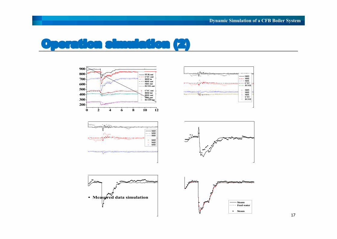
Operation simulation (2)
17
0 2 4 6 8 10 12200300400500600700800900
time [hr]
FUR out CYC out RH2 in RH1 out SH1 out ECO1 out
CYC out RH2 int RH1 out SH1 out ECO1 out
Gas T
empe
ratur
e [° C
]
(a) Gas temperature0 2 4 6 8 10 12
250
300
350
400
450
500
550
600
time [hr]
SH3 SH2 SH1 CYC ECO2
SH3 SH2 SH1 CYC ECO2
Wate
r-stea
m tem
pera
ture [
° C]
(b) Water-steam temperautre
0 2 4 6 8 10 1215
16
17
18
19
20
time [hr]
Drum
press
ure [
Mpa
](d) Drum pressure
0 2 4 6 8 10 12300
350
400
450
500
550
600
SH3 SH2 SH1
SH3 SH2 SH1
time [hr]
Tube
wall
temp
eratur
e [° C
]
(c) Tube wall temperature
0 2 4 6 8 10 12400
500
600
700
800
900
1000
1100
time [hr]
Steam Feed water
SteamM
ass flo
w [to
n/hr]
(f) Mass flow rate0 2 4 6 8 10 12
40
80
120
160
200
time [hr]
Fuel
supp
ly [to
n/hr]
(e) Fuel supply
▪ Measured data simulation

Dynamic Simulation of a CFB Boiler System
Operation simulation (3)
18
0 2 4 6 8 10 120
500
1000
1500
2000
2500
time [hr]
Solid
circu
lation
rate
[kg/s]
(a) Solid circulation rate0 2 4 6 8 10 12
-0.01
0.00
0.01
0.02
time [hr]Time [hr]
Wate
r lev
el [m
]
(b) Water level
0 2 4 6 8 10 12
Boile
r circ
ulatio
n rate
[kg/s
] Boiler circulation rate
time [hr]
4030
01020
20
1050
15
(d) boiler circulation rate and spary water flow
Spar
y wate
r flow
[kg/s
] Spary water flow
0 2 4 6 8 10 12
200
300
400
500
600
time [hr]
Temp
eratur
e [° C
]
(c) Temperature
RH2 (Gas) ECO2 (Gas) ECO1 (Water-steam)
▪ Unmeasured data simulation
Dynamic Simulation of a CFB Boiler System
Conclusion

Dynamic Simulation of a CFB Boiler System
Conclusion
20
ü Through this study, the CFB boiler dynamic model, which is composed of discretized dynamic sub-models
considering the water-steam flow, the gas-solid flow and the tube wall, is developed.
ü This model is based on physical phenomena, heat and mass balance and numerical approach. Especially, the
interaction between the solid-gas circulation loop and the water-steam circulation loop is carefully modeled due to
this circulation loops significantly determine the performance of the CFB boiler with the drum loop.
ü Model was validated as following process; 1) Each dynamic sub-model (Time constant and reference), 2) Open
loop model (Convergence of total boiler system), 3) Closed loop model (Controlled variables), 4) Operation
simulation (Measured data in real plant) → This model can simulate a real situation relatively well even with its
limitations
ü Although current model is developed to a particular CFB boiler, the modeling approach and the simulation strategy
can be extended to the other CFB boiler system with the drum loop.

Dynamic Simulation of a CFB Boiler System
CFB Boiler Dynamic Simulator
Thermal Engineering Lab

Dynamic Simulation of a CFB Boiler System
22
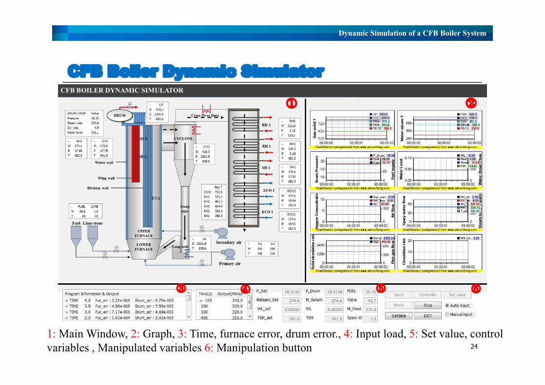
CFB Boiler Dynamic Simulator
Ø The dynamic model is developed to a simulator
Ø The dynamic simulator is developed by MFC programing in
C++

Dynamic Simulation of a CFB Boiler System
CFB Boiler Dynamic Simulator
23
Ø This program can simulate the dynamic behavior of a CFB boiler system according
to its load data or operating conditions.
Ø These conditions can be defined as the disturbance according to time by user.
Ø This program is available to Run/Freeze
Ø This program can show visualization :Graph, Result window and Save files
Ø This simulation calculates results for a certain time frame, and then it resumes the
calculations on a preferred day.
Ø Simulation can start from any steady-state, and apply any disturbance.
Dynamic Simulation of a CFB Boiler System
CFB Boiler Dynamic Simulator
24
① ②
③ ④ ⑥⑤
1: Main Window, 2: Graph, 3: Time, furnace error, drum error., 4: Input load, 5: Set value, control variables , Manipulated variables 6: Manipulation button

Dynamic Simulation of a CFB Boiler System
Input window
25
Furnace and back pass geometry Drum loop geometry Convective HE. geometry
Wall type HE. geometry Coal, Limestone, Sand, Air condition Heat transfer condition and Node
① ② ③
④ ⑤ ⑥
Furnace and back pass geometry Drum loop geometry Convective HE. geometry
Wall type HE. geometry Coal, Limestone, Sand, Air condition Heat transfer condition and Node

Dynamic Simulation of a CFB Boiler System
Controller window
26
①
②
①
②
Ø 1. Controller On: Apply controller, PID value have to input
Ø 2. Controller Off: Not apply controller, Input manual have to input

Dynamic Simulation of a CFB Boiler System
Simulation Method
27
Ø Simulation method: 1) Auto input, 2) Manual input
Ø Auto input can be defined by load data according to time in
the text window by user
Ø Manual input can be defined by set value and boundary
conditions in the set value window
Auto inputManual input
Dynamic Simulation of a CFB Boiler System
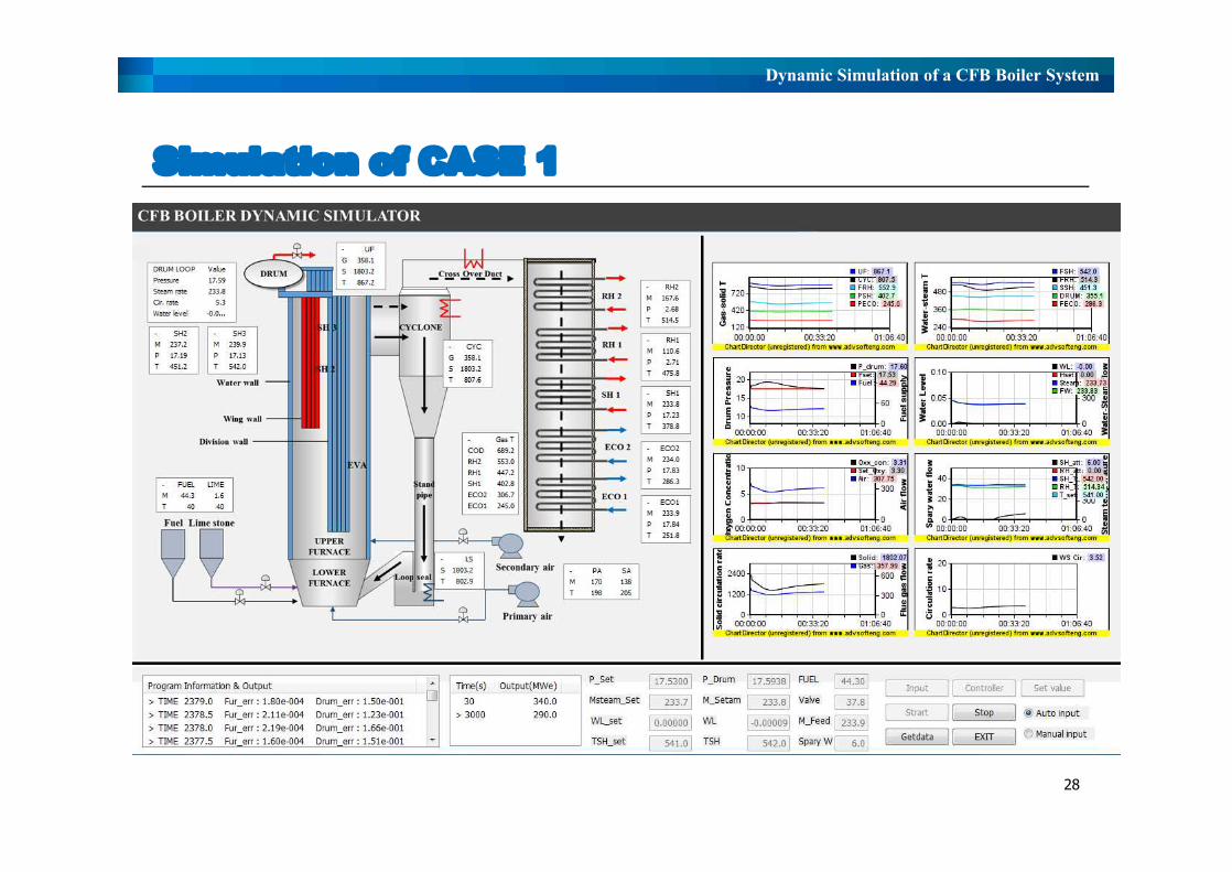
Simulation of CASE 1
28

Dynamic Simulation of a CFB Boiler System
Simulation Results
29
Water-Steam temperature Solid-gas temperature Wall temperature
Material Flow Water-Steam Circulation
Gas velocity Water-steam velocity Heat duty
Water-Steam pressure
Water-Steam temperature Solid-gas temperature Wall temperature
Material Flow Drum loop
Gas velocity Water-steam velocity Heat duty
Water-Steam pressure