ciuden spain’s city of iea report on legal and co2...
TRANSCRIPT

July / August 2011 Issue 22
Alstom Power study concludes CCS is cost effectiveReport - six in ten Europeans want CCS in new coal power plants
UK Government electricity market reform
Carbon Management Canada funds 18 projects
New trials at Australian Otway project
CIUDEN Spain’s city ofenergy
IEA report on legal andregulatory progress
CO2 capture from air
CO2 pipeline structuralsafety

A lot of companies are making structured packings for carbon capture, but none has ever beaten the performance and reliability of Sulzer Chemtech equipment. Sulzer’s MellapakPlus offers up to 40% more capacity than a conven-
tional structured packing, depend-ing on pressure, among many other advantages. Our products and extensive application know-how will help you put a chill on global warming. Contact us today.
MellapakPlus:
The highest capacity metal sheet packing
for CO2 capture
Conventional structured packing
MellapakPlus
For more information, visit www.sulzerchemtech.com
Sulzer Chemtech Canada, Inc.
5218-68 AvenueEdmonton, AlbertaT6B 2X7, CanadaPhone: +1 780-577-7999Fax: +1 780-577-7980E-mail: [email protected]: www.sulzerchemtech.com

Contents
Six in ten Europeans wants CCS in new coal power plantsThe European Commission has published a special Eurobarometer report about publicawareness of CCS in 12 EU member states. Public knowledge is still generally low, but ahigher proportion thought that CCS is effective to combat climate change, than thosewho did not. Also, 60 % said that CCS should be compulsory in new coal power plant. ByNiklas Kalvø Tessem, Bellona
UK Government electricity market reformThe UK Secretary of State for Energy and Climate Change Chris Huhne has outlined plansfor reform of the UK electricity market, including feed-in tariffs and an emissionsperformance standard
Carbon Management Canada funds projectsCarbon Management Canada is funding 18 new projects for a total of $10 million,including a way to convert CO2 into methanol and water
Alstom Power study “CCS is cost effective”Unveiling the results of a detailed study, based on Alstom’s 13 pilot and demonstrationprojects and validated by independent experts, Alstom Power President, PhilippeJoubert, said at a PowerGen Europe conference in Milan that, “We can now be confidentthat carbon capture technology works and is cost effective”.
Carbon Capture Journal2nd Floor, 8 Baltic Street East, London EC1Y 0UPwww.carboncapturejournal.comTel +44 (0)207 017 3405Fax +44 (0)207 251 9179
EditorKeith [email protected]
PublisherKarl [email protected]
Advertising and SponsorshipJohn FinderTel +44 (0)207 017 [email protected]
Capturing CO2 from the airIn the search for potential approaches to tackle climate change policy makers have to-datelargely ignored the contribution that could be made from the implementation of methodsthat directly extract greenhouse gases (GHGs), particularly carbon dioxide from theatmosphere. Dr Tim Fox, Institution of Mechanical Engineers, explains how this could work
CO2CRC tests new CO2 capture technologyAn innovative system for capturing carbon dioxide from power stations will be developedfor field-scale testing by the Cooperative Research Centre for Greenhouse GasTechnologies
22
15
2
CIUDEN - city of energy in SpainCIUDEN is leading Spain's carbon capture and storage research efforts, with programmescovering the whole CCS chain, as well as founding a National Museum of Energy andcollaborating with universities on post-graduate training
IEA reports progress on CCS regulationThere has been visible progress in setting legal and regulatory frameworks for CCSaccording to a new report from the International Energy Agency. By Justine Garrett andSean McCoy, IEA Secretariat
Projects and policy
Capture
Leaders
Carbon capture journal (Print) ISSN 1757-1995
Carbon capture journal (Online) ISSN 1757-2509July - August 2011 - carbon capture journal
Carbon Capture Journal is your one stopinformation source for new technicaldevelopments, opinion, regulatory andresearch activity with carbon capture,transport and storage.
Carbon Capture Journal is delivered on printand pdf version to a total of 6000 people, allof whom have requested to receive it,including employees of power companies,oil and gas companies, government,engineering companies, consultants,educators, students, and suppliers.
Subscriptions: £250 a year for 6 issues. Tosubscribe, please contact Karl Jeffery [email protected] you can subscribe online at www.d-e-j.com/store
Front cover: CIUDEN’s TechnologyDevelopment Centre for CO2 Capture inCubillos de Sil, Leon, Spain. The centre will beopen for use by any company or institutionwishing to conduct oxyfuel CO2 captureresearch there.
24
6
Transport and storageStructural safety in CO2 transport pipelinesAlthough CO2 pipelines will be the primary means for transporting CO2 for storage, it isoften considered as an ‘available technology’ and so discussed less. There is a need forstructural integrity-based model for the assessment of pipeline safety, says Dr AmirChahardehi, Offshore Renewable Energy Group, Cranfield University
New trials begin at Australian Otway ProjectA series of research trials into geological storage of carbon dioxide have begun at theCO2CRC Otway Project in Victoria, Australia
20
July/August 2011 Issue 22
10
Legal ColumnCalum Hughes, principal consultant in CCS regulation and policy at Yellow Wood Energy,discusses how CO2 EOR projects fit with current UK and EU regulatory frameworks andwhether they might benefit from state funding 8
9
12
11
Status of CCS project databaseThe status of 78 large-scale integrated projects data courtesy of the Global CCS Institute
1
17

CIUDEN - city of energy in SpainCIUDEN is leading Spain's carbon capture and storage research efforts, with programmes covering thewhole CCS chain, as well as founding a National Museum of Energy and collaborating with universities onpost-graduate training.
CIUDEN, standing for city of energy, ciudad
de la energia in Spanish, was founded five
years ago to promote economic development
through activities related to energy and the
environment in the relatively poor region of
El Beirzo in North West Spain. It is leading
Spain's carbon capture and storage research
efforts, with programmes covering the whole
CCS chain, as well as founding a National
Museum of Energy and collaborating with
universities on post-graduate training.
The El Bierzo region has long been as-
sociated with industries including coal min-
ing and power production. The site of the
CO2 capture technology development plant
(TDP) in Cubillos del Sil is next to the old-
est operating power station in Spain, Ende-
sa's Compostilla II plant.
The TDP will be available for any in-
stitution to use. “Companies can come here
and do their own R&D work,” explained Pe-
dro Otero, CO2 Capture Programme Techni-
cal Director. “We are non-profit and we are
not charging for the investment costs of the
facility. Companies just pay for the running
costs, the coal and other expenses. We will
be very happy to host any company here,
from Australia or wherever not just from
within the EU.”
As a public institution, it also benefits
from a closer relationship to the general pop-
ulation, and its efforts at public outreach
seem to have met with far greater success
than in some other countries, where large
multinationals have received a relatively
hostile reception.
Fernando Torrecilla, CIUDEN's Direc-
tor of International Communication, boasts
that the research facility, located only a few
kilometres from the city of Ponferrada, is
widely supported because of their outreach
programmes. Only a few weeks before, they
invited anyone from the area to come and
take a look, and over one thousand people
came and walked around the site.
The CO2 Capture TechnologyDevelopment PlantCIUDEN's installation is unique in that it is
designed to be extremely flexible in the
range of experiments that can be conducted.
It is an oxyfuel combustion test bed, but it
incorporates two separate boilers, one pul-
verized coal (PC) and the other circulating
fluidized bed (CFB). It is also designed to
use a range of different coals, with two hop-
pers that can take different
types and be mixed to produce
more variety. There is also a
3MW biomass gasifier.The
aim is to test the flexibility of
the boilers for oxy-combustion
and CO2 capture with a range
of different fuel types.
The PC boiler will oper-
ate up to 20MW while the CFB
boiler will be up to 30MW in
oxy-combustion mode.
The Technology Devel-
opment Plant will allow re-
search, development and inno-
vation activities to be carried
out in a number of relevant
fields, namely:
1. Testing of the individ-
ual stages and the complete
technological chain.
2. Evaluation and opti-
mization of the design and op-
eration of boilers.
3. Validation of tools for
boiler design, dynamic simula-
tion and performance predic-
tion.
Leaders
2
The Technology Development Centre for CO2 Capture in Cubillos de Sil, Leon. The centre will beopen for use by any company or institution wishing to conduct oxyfuel CO2 capture research
The experimental setup includes a 3MW biomass gasifier
carbon capture journal - July - August 2011

In 2010, companies benefitted from Oxand’s ability to: � Implement Risk management frameworks � Optimize CO2 – EOR solutions � Perform Well integrity risk assessments (P&RTM) � Share our knowledge through training sessions on demand
Oxand : Over 100 leading risk management consultants and experts in geology, geophysics, material durability, and long term structural integrity, working from 7 locations worldwide and applying the same rigor as for their nuclear projects.
What about your projects ? Take advantage of our unique experience and know-how.
www.oxand.com [email protected]
Your solution for secure gas storage

4
Leaders
4. Identification of the best combina-
tion of technologies for CO2 flow depura-
tion for transport and storage.
5. Testing of start-up, shut-down and
load follow-up routines, with special atten-
tion to the oxygen-related safety issues.
The aim is to first validate the full chain
of processes from fuel preparation to CO2
purification, producing an stream ready for
transport and storage, then produce data for
scaling-up the PC, CFB, FGD (flue gas de-
sulphurization) and CPU (compression and
purification unit) technologies.
When I visited, Mr Otero and the rest
of the staff had only just moved into the new
purpose built centre, comprising control
room, labs and offices, where engineers and
technicians can all work together on the ex-
perimental programme.
Mr Otero is excited about the potential
of the plant to conduct a broad range of ex-
periments in a relatively short space of time.
“We have designed this plant for more
than 20 years' life and we expect to be con-
ducting many tests during the whole of this
time,” he said. “In the power plant next door
we did experiments in an industrial installa-
tion with all the difficulties that entails. I
worked there for over 30 years and in that
time we conducted just a few experiments.”
As a publicly funded project, the pilot
had to go through a difficult procurement
process for the different elements of the
plant. Coordinating the over 30 suppliers has
been one of the major challenges until now.
Although the principal providers are large
multi-nationals, many were small Spanish
companies that were not always used to
working with others on a large project.
Also the large technology providers
were not always so keen to make time for
what they saw as a small-scale project.
“This is a big project for experimenta-
tion but for a technology provider it is really
a small project. Take for example the FGD
do some technology development and find
new ways of purifying CO2 and we are here
for that.”
The plant will also be available to any
company wishing to use it, not just those
who have supplied the technology. “We ex-
pect to be the host of many companies will-
ing to do R&D work here with our help.”
Bringing together many people from
different backgrounds and with different lev-
els of experience makes the centre an ideal
place for knowledge transfer.
“We have prepared the site with lost of
infrastructure ready to be used, and we are
assembling a very skilled team of operators.
We have designed the training of those peo-
ple in a very sensible way, mixing young
people with more senior people, so we will
be able to transfer knowledge to the younger
people in a very short space of time.”
“It is one of the aims of CIUDEN that
the centre here will act as a training acade-
my to prepare the next generation of engi-
unit. For this project it has a budget of say
€4 million. For a full size power station such
as Compostilla the cost would be €120 or
€150 million. The engineering work to be
done is the same for the small as the big
one.”
“We have been fortunate that our boiler
technology provider Foster Wheeler is very
committed to this project. They come here
very often and we are developing a very
good relationship with the Finnish people
who are developing the basic and conceptu-
al engineering and who will be in charge of
the experimental programme for the CFB
boiler.”
“We are also developing a good rela-
tionship with Air Liquide, the CPU has been
awarded by Esolux, a Spanish company,
with Air Liquide as the technology
provider.”
“I hope that both companies will be
here for many days and many years, because
our interests are the same, they also have to
imS
process ediffeplliim
agramdiiaprocess
LCOAROMFNOIIOTRAAREPP
SSABIOMROMFNIOTRAAPREP
N
th
O2 GEORATSNDA
TAORISPAV
WM02PCOILERB
GE
NIOT
N
IIESHAP
IOTORPBSANIOCTES
CO 2
SSABIOM
15- 03BCFB
INRAT
CO2
RIEIFSGA
NGINEE
ORCHT
NIO
TA
UL
RC
CI
RE
GR2
F
Pulverized Coal Boiler
Size (m) 24 x 7,6 x 4,5
Burners 4 horizontal burners2 vertical burners
MWth PCS maxoxycombustion
mode20
O2 (kg/h) 6600Recirculation
gas flow (kg/h) 17900
Flue gas flow (kg/h) 26400Coal flow rate
(kg/h) 3350
Steam (t/h) 25P(bar) / T ( C) 30 / 420
Dimensions (m) 21x2,7x2,4MWth SCP maxoxy-combustion 30
O2 (kg/h) 8775Flue gas recycle
(kg/h) 25532
Flue gas (kg/h) 28800
Coal feed (kg/h) 5469
Limestone feed (kg/h) 720
Steam (t/h) 44,6P(bar) / T ( C) 30 / 250
Circulating Fluidized Bed Boiler
Simplified process diagram of the technology development plant
carbon capture journal - July - August 2011

July - August 2011 - carbon capture journal 5
Leaders
neers in Spain with specific knowledge in
the CCS field. We are working on a collabo-
ration agreement with Leon University not
just in CO2 capture but over the whole CCS
field.”
“We intend to use this centre as a train-
ing centre for people coming from Spanish
universities, from overseas universities and
for professional development for working
engineers and technicians so they can gain
specific skills related with CCS and electri-
cal generation in general.”
“We will have some equipment here
which will not yet be in operating power sta-
tions, such as the CO2 capture and compres-
sion unit and it is only in places such as this
that it will be possible to gain experience
with operating it.”
Knowledge gained from the pilot ex-
periments will be shared with the CCS com-
munity, although CIUDEN has some specif-
ic agreements with technology providers that
some developments will remain proprietary.
“We should be able to manage the two
scenarios, knowledge-sharing as a require-
ment of the EU funding, and that some part
of the developments made here will be the
property of the technology providers. But at
the end, all that knowledge goes to the mar-
ket, and will be shared with the world.”
“We will try to manage an equilibrium
between programmes which are funded by
CIUDEN with different research institutions
and projects which are shared with different
parties for which CIUDEN receives fund-
ing.”
The Compostilla demonstrationprojectThe current pilot installation will conduct
Phase I experiments as part of the Compos-
tilla OXYCFB300 project, which is one of
the seven demonstrations funded through the
EU Energy Programme for Recovery. As
well as the capture TDP, transport and stor-
age pilots are under way to test the full chain
before progressing to a full scale demonstra-
tion in Phase II.
Phase 2 of the project is to build a full
scale 300MW CFB demonstration plant on
the same site. The final investment decision
for the project will be made mid 2012, based
on the knowledge and results obtained in the
Phase 1 technology demonstrations.
National Museum of EnergyCIUDEN also manages a public education
project which will become a National Muse-
um of Energy (NME). It will be housed in
three buildings including the former Com-
postilla I and MSP power stations. The Com-
postilla building will house the main visitor's
area focused on universal energy concepts.
The MSP complex will explain the extrac-
tion and use of coal for power generation.
The Foundation has an ambitious goal of
attracting 250,000 visitors to the site each
year.
The first site, Ene.térmica, opened in
July 2011 and will offer over 350 hours of
activities free over the summer including
guided tours, visits and workshops for chil-
dren explaining the role of coal in energy-
generation and energy in everyday life.
The NME is part of CIUDEN's public
outreach agenda to educate and inform and
thereby gain more support for its activities.
PISCO2 storage demonstrationLocated near Burgos in the centre of North-
ern Spain, PISCO2 is a project to develop
biomonitoring strategies of potential CO2
leakages through testing biogeochemical ef-
fects of CO2 injection in soils.
The test site for CO2 injection in soils
(known as PISCO2, by its Spanish acronym)
consists of 18 cells of concrete excavated in
the ground; each of them, with an area of 16
square meters and a depth of 2.5 meters.
These cells will be filled with soils from dif-
ferent areas of Spain with potential capabili-
ty for CO2 storage including Hontomín
(Burgos), where CIUDEN’s CO2 Storage
Technological Development Plant is under
development.
Micro-perforated tubes buried at 1 and
2 meters under the surface, will allow the in-
jection of small quantities of diffuse CO2 at
different given flow rates. The facility will
serve to test how small CO2 diffuse leakages
can influence the vegetation, microorgan-
isms, lichens and soils and aims to find use-
ful, cheap and ecological bio-indicators of
any CO2 concentration variation in wide ar-
eas.
It will also serve as a laboratory for
agricultural tests of the beneficial effects of
low CO2 emissions. In addition, the installa-
tion will be a tool to test and calibrate meas-
urement instruments such as accumulation
chambers, sensors, etc.
Construction started in April 2011 and
it is planned to be fully operational in Octo-
ber 2011. Its configuration makes it unique
and CIUDEN is open for cooperative re-
search projects with institutions all over the
World.
The research team is comprised of a
multidisciplinary group of researchers such
as biologists, chemists, geologists and sev-
eral collaborators. The work at the plant will
consist of periodical sampling, continuous
monitoring and modeling of CO2 transport
across various interfaces.
The EU has funded this project, of
which costs of construction and first research
phase are estimated at 1M€.
The results obtained will be applied to
CIUDEN’s CO2 Storage site in Hontomín,
Burgos (Spain) which is planned to be com-
pletely operational in early 2013.
More information
www.ciuden.es
The site of the National Museum of Energy in the Compostilla I power station next to CIUDEN’soffice can be seen at the bottom of the picture, with the city of Ponferrada in the background

carbon capture journal - July - August 20116
Leaders
The International Energy Agency (IEA) re-
leased the second edition of the IEA Carbon
Capture and Storage Legal and Regulatory
Review on 27 May 2011.
Produced bi-annually, the review pro-
vides an up-to-date snapshot of global CCS
regulatory developments by gathering con-
tributions by national and regional govern-
ments, as well as leading organisations en-
gaged in CCS regulatory activities. The sec-
ond edition of the review reflects ongoing
progress at national and regional levels to-
wards comprehensive CCS legal and regula-
tory frameworks.
Particular progress has been made in
Europe, given the 25 June 2011 deadline for
transposition of the EU CCS Directive.1
Spain, France and the United Kingdom are
among 11 of 27 EU member states to have
formally communicated transposition meas-
ures to the Commission by this deadline.
Work is ongoing in Germany, Poland, the
Czech Republic, Ireland and Greece,
amongst other countries. The European
Commission has a number of enforcement
powers that may be relevant where member
states fail to communicate transposition
measures in time.
In addition to these national transposi-
tion developments, the European Commis-
sion released four guidance documents on 31
March 2011, after an extended period of con-
sultation. The documents, which are intend-
ed to assist national transposition measures,
deal with risk management across the CCS
chain, site characterisation, composition of
the CO2 stream, monitoring and corrective
measures, transfer of liability, financial se-
curity and financial contributions from oper-
ators.
The provisions on financial security
and contributions have generated particular
interest from industry and other CCS stake-
holders. The Commission will also be veri-
fying conformity of national measures with
the directive as transposition measures are
officially communicated to the European
Commission.
Across the Atlantic, progress is also be-
ing made towards comprehensive legal and
regulatory frameworks for CCS. In the Unit-
ed States, the Environmental Protection
Agency (EPA) has finalised two federal rules
related to geological storage, under the Safe
Drinking Water Act2 and the Clean Air Act.3
Developments also continue at a state level:
approximately a dozen states already have
elements of frameworks in place to address
geological storage.
In Canada, the provinces are leading
the way, with Alberta being the first Canadi-
an jurisdiction to finalise its regulatory
framework. The province is embarking on a
comprehensive review process to ensure that
its regulations are fit for purpose as CCS
demonstration efforts ramp up in the juris-
diction.
The Australian federal government has
built on its significant work to date. In June,
the government finalised secondary legisla-
tion to support dedicated legislation for off-
shore geological CO2 storage that it enacted
in 2008. In addition, legislation is in place to
regulate onshore geological storage in three
Australian states, with developments in a
further state progressing well.
Beyond the regions that have been at
the forefront of CCS regulatory develop-
ments for some time, many other countries
are implementing or considering CCS regu-
lation, including Malaysia, South Africa,
Vietnam, Mexico and Indonesia. Preparato-
ry steps are being undertaken in these juris-
dictions to set the stage for framework de-
velopment over the coming years.
In addition to providing an update on
national-level progress, the second edition
of the CCS review addresses long-term lia-
bility for stored CO2, one of the key chal-
lenges facing countries in developing regu-
latory approaches to CCS, as its theme.
It also looks at: developments made by
the international CCS community in advanc-
ing CCS deployment through amendments
to international marine treaties and in the
context of the UNFCCC framework, and the
process behind developing CCS regulatory
frameworks.
Long‐term liability for stored CO2Long‐term liability for stored CO2 is one of
the most challenging and complex aspects of
regulating CO2 storage activities. In a CCS
context, liability tends to be used as a gener-
ic term to refer to three specific responsibili-
ties: general or civil law liabilities for dam-
age to the environment, human health or
third party property; responsibility for un-
dertaking and bearing the cost of any correc-
tive or remediation measures associated with
a storage site; and responsibility for leakage
of CO2 to the atmosphere, where CCS oper-
ations are undertaken as part of a CO2 emis-
sions reduction scheme.
Discussion of long‐term liability has
generally focused on whether liabilities as-
sociated with a storage site should be trans-
ferred to government or retained by opera-
tors indefinitely. The second edition of the
CCS review shows a trend towards transfer-
ring liability, with Australia, the European
Union and some Australian, Canadian and
US states and provinces taking this ap-
proach.
However, there is no clear consensus
on whether liability should be transferred:
some CCS regulation is silent on certain
elements of long‐term liability, which may
mean that the operator or related entities are
liable for a storage site and the injected CO2
in perpetuity.
Generally, where provision is made for
transfer of liability from the operator three
requirements are imposed before liability is
transferred: evidence that there is no signifi-
cant risk of stored CO2 leaking to the atmos-
phere or impacting other subsurface re-
sources (e.g. groundwater or oil and gas re-
sources); a minimum time period having
elapsed from cessation of injection; and a fi-
nancial contribution to fund long‐term stew-
ardship of the site, reducing the financial ex-
posure of the entity designated to take on
long‐term liability.
The CCS review shows that there are
marked differences between jurisdictions,
however, on how these requirements are in-
terpreted in legislation and the processes by
which an operator can demonstrate that they
have been met. The extent of the liability
transfer and its timing also differs, with some
jurisdictions transferring responsibility for
certain types of liability, such as corrective
or remediation measures, before liabilities
arising under civil law, for example.
Some jurisdictions have also discussed
IEA reports progress on CCS regulationThere has been visible progress in setting legal and regulatory frameworks for CCS according to a newreport from the International Energy Agency.By Justine Garrett and Sean McCoy, IEA Secretariat
1 Directive 2009/31/EC of the European Parliament and ofthe Council of 23 April 2009 on the geological storage ofcarbon dioxide.2 42 U.S.C. §300f et seq. (1974). Federal Requirements underthe Underground Injection Control (UIC) Program forCarbon Dioxide (CO2) Geologic Sequestration Wells, FinalRule, 75 Fed. Reg. 77230 (Dec. 10, 2010).3 Environmental Protection Agency, Mandatory Reportingof Greenhouse Gases: Injection and Geologic Sequestrationof Carbon Dioxide, Final Rule, 75 Fed. Reg. 75060 (Dec. 1,2010).

Leaders
a transfer of responsibility for certain liabili-
ties only up to a specified threshold. In prac-
tice, there is much to consider beyond the
preliminary question of whether liability
should be transferred. The second edition of
the CCS review expands upon these issues
with country-specific examples.
Talking process: how do you develop aCCS regulatory framework?The contributions to the second edition of
the CCS review not only demonstrate the
significant progress that is being made to-
wards developing national CCS legal and
regulatory frameworks worldwide: they also
provide interesting insights into the process
involved in getting appropriate regulation in
place. Jurisdictions implement CCS regula-
tion in the context of different legal and reg-
ulatory environments and traditions, as well
as existing resource extraction or environ-
mental impact frameworks.
This means that it is difficult to come
up with universal rules on how best to de-
velop enabling frameworks for CCS. The
second edition demonstrates, however, that
there are common elements in the way juris-
dictions are approaching the task. These
trends may guide and inform national or re-
gional governments that are setting out to de-
velop regulation.
Steps in the regulatory development
progress addressed in the second edition in-
clude: whether comprehensive CCS regula-
tory framework development should pre-
cede, run parallel with or come after pilot
and demonstration projects; establishing in-
teragency working groups to progress CCS
framework development; undertaking “gap
and barrier” analyses to determine how ex-
isting frameworks compare with the aims of
future CCS regulation; and ensuring regula-
tion is fit for purpose.
Developments on the internationalCCS scene: London, OSPAR and CancunThe second edition also reports on a number
of CCS developments in the context of in-
ternational marine laws and climate change
negotiations since the launch of CCS review.
The London Protocol was amended in
2009 to allow for cross-border transportation
of CO2 for the purposes of storage. The
amendment requires ratification by
Netherlands, which has introduced legisla-
tion for ratification of the OSPAR amend-
ments into the senate, and it is therefore like-
ly that the 2007 amendments will enter into
force this year.
At the “COP 16” climate change nego-
tiations in Cancun, Mexico, in November
and December 2010, it was determined that
CCS should be included as an eligible clean
development mechanism (CDM) project ac-
tivity, subject to specified issues being ad-
dressed and resolved in a satisfactory man-
ner.
This is the most significant progress to-
wards an international incentive mechanism
for supporting CCS operations in develop-
ing countries over the past five years. The
Cancun decision requests the Subsidiary
Body for Scientific and Technological Ad-
vice (SBSTA) to elaborate modalities and
procedures for the inclusion of CCS as a
project activity under the CDM, with a view
to recommending a decision at “COP 17” in
Durban, South Africa, in November and De-
cember 2011.
The modalities and procedures are to
address specified technical issues, including
site selection criteria, monitoring, project
boundaries, transboundary projects, account-
ing for project emissions, liability and risk
and safety assessments. A dedicated work
programme has been developed for 2011 to
facilitate this process and although signifi-
cant progress has been made, a substantial
amount of work remains before CCS proj-
ects can realise funding through the CDM.
two‐thirds of the contracting parties – effec-
tively, 27 of the 40 countries that have rati-
fied the London Protocol to date – to enter
into force.
To date, only Norway has ratified the
amendment to Article 6 and only one contri-
bution to second edition of the CCS review
– from the Netherlands – refers to plans to
ratify the Article 6 amendment. Of the 40
contracting parties, only about 16 are cur-
rently pursuing CCS development and active
in international CCS forums such as the Car-
bon Sequestration Leadership Forum, IEA
Greenhouse Gas R&D Programme, Global
CCS Institute and IEA.
Even within those contracting parties
that are actively looking at CCS and engaged
in international CCS dialogue, not all are in-
terested in offshore CO2 storage or trans-
boundary movement of CO2 for offshore
storage, making ratification of the Article 6
amendment a low priority. Thus, achieving a
further 25 of ratifications will be a signifi-
cant challenge and is likely to require a con-
certed, international effort.
While the 2009 amendment is not in
force, contracting parties will be constrained
in their ability to co‐operate on offshore stor-
age. The second edition reports that further
work is needed to understand the emissions
profile and potential interest in CCS of the
contracting parties to the London Protocol;
likely applicability of transboundary CO2
transport for the purposes of offshore stor-
age to each contracting party, either as an im-
porter or exporter of CO2 emissions, and in-
dividual CCS projects globally; and poten-
tial impact on global CCS deployment if off-
shore storage continues to be restricted by
Article 6.
In terms of the OSPAR Convention,
Annexes II and III were amended in 2007 to
enable CO2 injection into the sub‐seabed un-
der the Convention. The amendments must
be ratified by at least seven parties before
they will enter into force. Six have now rati-
fied the amendments: Norway, the United
Kingdom, the European Union, Germany,
Luxemburg and Spain.
The meeting of OSPAR contracting
parties in June 2011 will consider an update
from those parties yet to ratify. The majority
of these countries are well advanced with
their ratification processes, including the
More information
The IEA Carbon Capture and Storage Le-
gal and Regulatory Review is available on
the IEA website at:
www.iea.org/ccs/legal/review.asp
Justine Garrett, IEA Secretariat
Tel. +33 (0)1 40 57 67 97
Sean McCoy, IEA Secretariat
Tel. +33 (0)1 40 57 67 07
Subscribe to Carbon
Capture Journal
Six issues only £250
Sign up to our free e-mail newsletter atwww.carboncapturejournal.com

carbon capture journal - July - August 20118
CCS legal and policy – July / August 2011Calum Hughes, principal consultant in CCS regulation and policy at Yellow Wood Energy, discusses howCO2 EOR projects fit with current UK and EU regulatory frameworks and whether they might benefit fromstate funding. [email protected]
Until recently the matter of whether the eco-
nomics of enhanced oil recovery (EOR) in the
North Sea was sufficiently robust to provide a
bankable revenue stream that could reliably be
included in the business case of a CCS project
seemed a largely academic, if much debated,
one as EOR was not a feature of any of the
CCS projects slated for the UK. Recent devel-
opments have, however, altered this situation
and the question of how EOR projects might
fit within CCS policy and regulatory frame-
works, as well as how they might benefit from
state funding, have become extremely relevant
for the developers of both EOR and non-EOR
CCS projects.
Whilst the Energy Act 2008 was wend-
ing its way through the legislative process
there was much concern and, I believe, behind
the scenes lobbying, on the issue of whether
the prohibition on the storage of CO2 beneath
UK waters included in the Act, and the con-
comitant requirement that a storage site must
be licensed, should apply where the storage
was ‘ancillary to the getting of petroleum’ (i.e.
should apply to EOR). A procrastinatory com-
promise was achieved via the inclusion of a
carve-out provision in the Act to the effect that
CO2 injection for EOR shall only be consid-
ered as storage, for the purposes of the Act, in
the circumstances as may be specified by Or-
der of the Secretary of State.
Such Orders will presumably be used to
address EOR projects on a case by case basis
and it is uncertain what criteria will be applied
in ascertaining which EOR projects will, and
which will not, require a CO2 storage licence
and therefore which will be required to com-
ply with the extensive monitoring, verifica-
tion, post-closure and financial security condi-
tions of such a licence. This places EOR CCS
projects in a peculiar position and the current
state, and application, of legislation raises
some interesting issues.
Interaction with the CCS DirectiveThe CCS Directive is clear that Member States
are obliged to ensure that no CO2 storage site
within their territory is operated without a stor-
age permit and, under the UK’s recent licens-
ing regulations, a storage permit for a storage
site in UK waters is obtained via a storage li-
cence. It would therefore appear that the oper-
ation of an EOR site would breach the provi-
sions of the CCS Directive if, and only if, the
holder of a petroleum production licence who
is injecting CO2 for the purposes of EOR is
doing so also with the intention of ‘storing’
the CO2 and does not have a permit to do so.
Adopting the purposive approach typically ap-
plied in EU law, this interpretation would ap-
pear to agree with the aims of the Directive as
evidenced in the preamble, which states
“where [EOR] is combined with geological
storage of CO2, the provisions of this Direc-
tive … should apply”.
It would seem an obvious presumption,
therefore, that in cases where an EOR project
was also a CO2 storage project (for the pur-
poses of the CCS Directive), the Secretary of
State would issue an Order providing that the
activities at the site included storage (for the
purposes of the Energy Act 2008), thereby re-
quiring that site to be the subject of a storage
licence. This is however only a presumption
as there is no explicit requirement in the Act
for the Secretary of State to behave in this way.
Furthermore, there is a question as to the
definition of ‘storage’ for the purposes of the
Directive? The Directive states that it estab-
lishes a legal framework for the environmen-
tally safe geological storage of CO2 and that
the purpose of such storage is the “permanent
containment of CO2” but, the Directive in-
cludes no explicit definition of ‘storage’ or, for
that matter ‘permanent’.
ETS ExemptionIt may be argued that the obvious pragmatic
solution to the difficulty of ascertaining when
an EOR project should be considered to be
storing CO2 might be to let the injection site
operator elect whether the relevant site is a
storage site or not and apply for the necessary
licences accordingly. The making of this deci-
sion would be commercially driven as it would
affect the EOR project’s revenue streams.
A fundamental part of the value of CCS
projects to CO2 emitters is the saving realised
by storing CO2 and thereby avoiding the re-
quirement to purchase and surrender al-
lowances (EUAs) under the EU Emissions
Trading Scheme (ETS). If an EOR project de-
veloper wishes to offer the emitter from whom
it takes CO2 the benefit of not having to sur-
render EUAs then it can acquire a CO2 stor-
age permit and accept the associated costs and
obligations. Alternatively, the EOR developer
can avoid the costs and obligations if it choos-
es not to offer
the emitter the
EUA savings.
There are
a number of
counter-points
to the case for
letting devel-
opers decide
how their proj-
ect should be
categorised but
even putting
these aside the
above argu-
ment only
holds if it is
certain that emitters sending their CO2 to a
non-permitted EOR site would still be obliged
to surrender EUAs for that CO2. The ETS Di-
rective was amended in 2009 to make it ex-
plicit that where CO2 is stored in a storage site
permitted in accordance with the CCS Direc-
tive then the liability to surrender EUAs, with
respect to that CO2, would not accrue.
There are however no explicit provisions
clarifying the position with respect to
EOR/CCS projects using non-permitted injec-
tion sites. It is clear that in the latter case an
emitter would not benefit from the explicit ex-
emption provisions but it is less clear whether
that emitter could tenably claim that as the
CO2 it had sent for EOR injection had not, in
fact, been ‘released into the atmosphere’, as is
required under the ETS Directive for the lia-
bility to surrender EUAs to accrue, that it had
no such liability.
So, the purposive intent of EU law with
regard to permitted EOR sites is reasonably
clear but in the case of non-permitted sites the
situation is more vague.
Requirement for a Crown Lease?Property rights respecting the sea bed and sub-
soil beneath waters extending beyond a States’
territorial boundaries are secured under inter-
national maritime law. In the UK, those rights
have been claimed for the Crown by Act of
Parliament. The rights with respect to the get-
ting of hydrocarbons are licensable by the Sec-
retary of State and, whilst those appertaining
to the storage of gases are also licensable by
the Secretary of State, the ‘land’ itself is placed
within the auspices of The Crown Estate. The
Calum Hughes, YellowWood Energy
CCS legal column - Calum Hughes

July - August 2011 - carbon capture journal 9
Projects and Policy
6 in 10 Europeans wants CCS for new coal
proportion thought that it is effective (39%)
than those who did not (25%).
Nearly four in ten people felt that CCS
could be effective in the fight against climate
change. A third (33%) felt CCS technology
could be ‘fairly effective’, while a further
one out of every sixteen (6%) believed it
could be ‘very effective’.
A quarter of respondents thought that it
would not be effective in fighting climate
change, around one in fourteen (7%) thought
that CCS was ‘not at all effective’ in fight-
ing climate change, while just under a fifth
(18%) thought it was ‘not very effective’.
However, well over a third (36%) said that
they ‘did not know’ whether CCS technolo-
gy could be effective or not to fight climate
change.
Benefits from CCS technologyPeople were unclear about the benefits of
CCS technology. Overall a higher proportion
thought that they would not benefit from
CCS technology (38%) than thought they
would benefit from it (23%).
The main reason why people thought
they would benefit from CCS technology
was ‘an improvement of air quality’. The
main reason people thought they would not
benefit was that it would ‘not have a posi-
tive effect on the environment’
Opinions about the safety of CO2storageRespondents in each country were asked
how concerned they would be if a deep un-
derground storage site for CO2 were to be
located within 5km of their home. Overall
around six in ten people (61%) expressed
some concern about the safety of CO2 stor-
age. Just under a quarter were ‘very con-
The European Commission has published a special Eurobarometer report about public awareness of CCSin 12 EU member states. Public knowledge is still generally low, but a higher proportion thought that CCSis effective to combat climate change, than those who did not. Also, 60 % said that CCS should becompulsory in new coal power plant. By Niklas Kalvø Tessem, Bellona
cerned’ about it. The two main concerns peo-
ple had about CO2 storage were ‘effects on
the environment and health’ and the ‘risk of
leaks while the site was in operation’
Best options for storing CO2Public opinion was almost evenly divided
about the best ways to store captured CO2
emissions: under the seabed, in areas of low
population density and near the facility that
produced the emissions.
Sources of information about CCSOverall, universities and research institu-
tions emerged as the organisations that the
highest proportion of respondents trusted in
terms of providing them with information
about CCS (45%). Just under a third (31%)
indicated that they trusted NGOs whilst just
under a quarter trusted journalists (24%) and
a similar proportion (23%) trusted regional
and local authorities. One in five (20%) in-
dicated that they trusted their national gov-
ernment. Just over one in eight trusted The
European Union (14%), energy companies
(13%) or friends and family (13%).
Future developments in the energysector and the role of CCSSix in ten people (60%) agreed that CCS
should be compulsory for the building of
new coal-fired power plants. Over half
(55%) agreed that CO2 represents a safety
risk for the future.
Download the report at:
ec.europa.eu/energy/coal/sustainable_coal/ccs_eurobarometer_en.htm
The International Energy Agency estimates
that the cost of achieving desired climate
change stabilisation by 2050 will be at least
70 % higher if CCS is not available and
widely deployed after 2020. Still, public
knowledge of CCS is limited.
The fact that CCS is a complicated is-
sue makes it less known than energy effi-
ciency and renewable energy measures.
13,091 respondents in twelve EU member
states were interviewed between February
9th and March 5th 2011 about their aware-
ness and acceptance of CCS.
Here are some of the most interesting
findings:
Awareness of CCS technologyWhilst over a quarter of respondents indicat-
ed that they had heard of CCS, only one in
ten (10%) said they also knew what it was.
One in five (18%) indicated that they had
heard of it but did not really know what it
was. The majority, over two thirds (67%),
had not heard of CCS.
Awareness of the specific CCS projectsWithin individual countries there were some
small variances to the overall figures, the ex-
ception being in the Netherlands, where
more than a third (35%) had heard of the EU
co-financed CCS project in Rotterdam. in
comparison, fewer than one in ten had heard
about a specific CCS project in Germany
(9%), Italy (9%), Poland (8%) and the UK
(5%). Only 2% of Spanish people had heard
of such a project.
Opinions about the CCS technologyA high proportion of people ‘do not know’
whether CCS technology is effective in the
fight against climate change, but a higher
point of interest this raises is, if the activity in
question is both the getting of hydrocarbon
and the storage of gases, what property rights
are required to inject CO2 beneath the sea-bed
and store it there indefinitely and who may
grant them.
Many precedents exist with respect to the
re-injection of natural gas into hydrocarbon
reservoirs for the purpose of maximising ex-
traction of reserves and, I understand, a num-
ber of existing petroleum production licences
authorise the injection of CO2 for this pur-
pose. Nevertheless the question remains as to
whether the storage of CO2 in the sub-soil be-
low UK waters under a petroleum production
licence is permissible without a lease granted
by The Crown Estate and if so, under what
powers is the right to store granted and who
has ownership of, and liability for, the inject-
ed CO2 going forward?
There are several other interesting legal
issues surrounding EOR CCS projects which
there is not space to consider here, not least if
such projects will benefit from the various
state financial support schemes available to
CCS projects if a CO2 storage licence and
Crown Lease is not obtained; most of these is-
sues, including the three discussed above,
hinge partly or entirely upon what ‘storage’
means within the context of EOR under EU
and UK law. Pinning down the definition of
the term within this context would be a chal-
lenging task but the lack of such a definition
introduces further regulatory uncertainty into
an industry which already has more than its
fair share.

carbon capture journal - July - August 201110
Projects and Policy
UK Government electricity market reformThe UK Secretary of State for Energy and Climate Change Chris Huhne has outlined plans for reform ofthe UK electricity market, including feed-in tariffs and an emissions performance standard.
Building on the Carbon Price Floor an-
nounced in the Budget, he talked about a
number of steps aimed at supporting low car-
bon electricity generation.
Key elements of the reform package in-
clude:
- a Carbon Price Floor (announced in
Budget 2011) aimed at reducing investor un-
certainty, putting a fair price on carbon and
providing a stronger incentive to invest in
low-carbon generation now;
- the introduction of new long-term
contracts (Feed-in Tariff with Contracts for
Difference) to provide stable financial incen-
tives to invest in all forms of low-carbon
electricity generation. A contract for differ-
ence approach has been chosen over a less
cost-effective premium feed-in tariff;
- an Emissions Performance Standard
(EPS) set at 450g CO2/kWh to reinforce the
requirement that no new coal-fired power
stations are built without CCS, but also to
ensure necessary short-term investment in
gas can take place; and
- a Capacity Mechanism, including de-
mand response as well as generation, which
is needed to ensure future security of elec-
tricity supply. The government is seeking
further views on the type of mechanism re-
quired and will report on this around the turn
of the year.
"We will send a clearer message that
low-carbon electricity is a key part of our fu-
ture energy mix," said Mr Huhne.
"We will introduce a new system of
long-term contracts, to remove uncertainty
for both investors and consumers, and make
low-carbon energy more attractive."
"Contracts for Difference will be intro-
duced for all forms of low-carbon genera-
tion. Lowering the cost of capital, and allow-
ing clean technologies with high-up front
and low long-run costs to compete fairly
against traditional unabated fossil fuels."
"This will build on the Carbon Price
Floor, providing the additional clarity and
certainty that investors need."
"We will introduce an Emissions Per-
formance Standard, to send a clear regulato-
ry signal on the amount of carbon new fos-
sil-fuel power stations can emit."
"This will reinforce the requirement
that no new coal-fired power stations are
built without carbon capture and storage,
while ensuring that vital investment in gas
can take place."
"CCS is a key part of our plan to decar-
bonise electricity generation. It is the only
technology that can potentially reduce emis-
sions from fossil fuel-fired power stations by
as much as 90%."
The Carbon Capture and Storage Asso-
ciation (CCSA) has welcomed the publica-
tion of the Electricity Market Reform (EMR)
White Paper.
Jeff Chapman, Chief Executive of the
CCSA commented:
“A Contract for Difference Feed in Tar-
iff, index-linked to fuel price, is the right
mechanism to support CCS now and into the
future, and we would welcome this mecha-
nism as part of the EMR package.
“The CCSA estimates that at least 20-
30GW of fossil-fuel power generation ca-
pacity fitted with CO2 capture and storage
will need to be installed to meet the UK’s
aim of largely decarbonising its power sec-
tor by 2030.
“Delivering that amount of CCS capac-
ity by 2030 is challenging but achievable and
industry will rely on this mechanism to de-
liver a bankable incentive. The White Paper
establishes the world’s first support mecha-
nism for all low carbon technologies that en-
ables CCS to be deployed on a par with oth-
er options.
“This represents a tremendous step for-
ward, sends the right signal to industry that
this Government is serious about CCS and
could give the UK a technological leadership
in what will be a massive future global CCS
market.
”We recognise that the Government’s
objective to achieve a decarbonised power
sector by 2030 will put additional cost on
hard pressed consumers but including CCS
in the EMR will be the most cost-effective
way to address climate change and so will
effectively save on electricity bills.
“We need to get UK CCS projects un-
der way as quickly as possible and so we are
pleased to see that the arrangements detailed
in the White Paper may be applied to the
coming four CCS Demonstration Projects,
to ensure a smooth transition into deploy-
ment of CCS under the EMR.
“The CCSA also believes that the
White Paper provides the framework neces-
sary for the implementation of CCS beyond
the four Demonstration Projects which will
be required if we are to meet UK and inter-
national targets on climate change.
“We welcome the statement in the
White Paper that Government will support
cost-effective and flexible low carbon power
generation, including CCS - recognising the
need for the introduction of a market based
capacity payment.”
White Paper
Legislation
InstitutionalFramework
Policyfinalised
PrimaryLegislation
2011 2012 2013
Feed-in Tariff with Contract for Difference
(FiT CfD)
CapacityMechanism
(CM)
Carbon PriceFloor (CPF)
EmissionsPerformance
Standard (EPS)
Transition toEMR
Renewables Obligation (RO) open to new generation Choice between RO and FiT CfD
RO closed tonew generationEarly low-carbon investment – enabling
discussions
Report onDecarbonisation and CCS
ProgressEPS applied to all new build
EPS in force
CPF in force
Add
ition
al in
form
atio
n pu
blis
hed
Initial workto establishorganisation
Organisation up and running,delivers first contracts
Organisation receives legalpowers
SecondaryLegislation
Statutory Instruments in force
Royal Assent
First FiT CfD contracts signed
Capacityprocured as
required
CM in place
CPF rising incrementally along published trajectory
2014 2015 2016 2017 2018 2019 2020
Renewable energy target
Bill introduced
Possible first payments made
Capacity in place (could be earlier)Lead in time for capacity (could be compressed if necessary)
Annual assessments of need for additional capacity
Report onDecarbonisation and CCS
Progress
RO vintaged
An indicative timetable for implementation and transition
Download the white paper at:
www.decc.gov.uk

July - August 2011 - carbon capture journal 11
Projects and Policy
For more information and a full list of the
projects go to:
www.cmc-nce.ca
Carbon Management Canada funds projectsCarbon Management Canada (CMC-NCE) is funding 18 new projects for a total of $10 million.
CMC-NCE is a Canadian Network of Cen-
tres of Excellence that supports game-chang-
ing research to eliminate carbon emissions
from the upstream fossil energy industry.
The network comprises over 140 researchers
across 25 universities and colleges in Cana-
da.
Projects funded in Round 2 range from
work toward developing what could become
the world’s first zero-emission solid oxide
fuel cell, to research seeking a way to con-
vert CO2 into water and methanol (see be-
low), to an investigation into public attitudes
toward greenhouse gas mitigation strategies.
The largest award, $1.92 million, was
given to a project to coax communities of
microorganisms to convert coal into natural
gas, or methane, while still in the ground.
The methane produced from bioconversion
would then be collected for use as a clean-
burning fuel.
This project, led by Dr. Sushanta Mitra
at the University of Alberta, exemplifies
CMC-NCE’s emphasis on funding interdis-
ciplinary, multi-institution projects. The 15
principal investigators on the project are
from four universities, plus government and
industry. Researchers represent disciplines
ranging from biology to hydrology to geo-
sciences, and both mechanical and chemical
engineering.
Dr. Steve Larter, CMC-NCE scientific
director and a researcher on the project,
notes the interdisciplinary approach is criti-
cal to the project’s success.
“The problems can’t be solved by a re-
ally good geochemist, or just a really good
microbiologist, or just a very good engineer.
We’re trying to build an orchestra.”
This round of funding increases the
number of CMC-NCE supported research
projects from 18 to 36. Last year, $8.7 mil-
lion was awarded to 17 projects.
Turning CO2 into liquid fuelU of T chemists Douglas Stephan and Euge-
nia Kumacheva are laying the foundation for
an efficient and cost-effective method to
transform CO2 and hydrogen into water and
methanol, a liquid fuel. The ultimate goal is
an energy-generation system that would be
carbon neutral, with every CO2 molecule re-
leased from fuel consumption being convert-
ed back into methanol.
The research project is fueled by a $268
thousand grant from Carbon Management
Canada through its Round 2 funding.
“The CMC funding is giving us an op-
portunity to explore chemistry that relates to
one of the biggest problems facing hu-
mankind,” said Stephan.
Methanol, or methyl hydrate, is the
same clean-burning fuel that’s used to heat a
fondue pot. A liquid, methanol is relatively
easy to store and transport, even with exist-
ing delivery systems—gas station pumps, for
example.
“The big problem with new possible fu-
els is the infrastructure for transportation,”
commented Stephan.
The unprecedented approach to CO2
capture and reuse builds on his group’s
breakthrough discovery of a new way to cap-
ture and use CO2, research that has been
supported in part by NSERC and the green
chemistry commercialization body, Green-
Centre Canada.
“It’s really incredibly simple chemistry
that we’ve discovered,” said Stephan. “We
generate this new reactivity that we’ve been
able to observe with CO2 and a variety of
other small molecules.”
To carry out the process, chemical
reagents dubbed “frustrated Lewis pairs” are
used to effect these new chemical reactions.
Extremely effective and versatile, the frus-
trated Lewis pairs are also nontoxic—unlike
conventional catalysts employed to convert
CO2 to methanol.
“Now the question is,” said Stephan,
“can we tweak the system? Optimize the sys-
tem?”
“If we could do this catalytically,” he
explained, “…so that you could use a very
small amount of our catalyst…to grab CO2,
transform it to methanol, release it, and then
go back and do it again…you really bring
down the cost of the process.”
Another challenge is that the reactions
happen so quickly, it is difficult to study
them. However, a new technique developed
in the Kumacheva lab is making it easier to
obtain the needed data.
Along with a clean source of hydro-
gen—a technology that Stephan noted is im-
minent—the team hopes that the CO2 to
methanol system will one day revolutionize
the fuel sector.
“New chemistry is going to be part of
the solution to environmental issues,” said
Stephan, adding “it’s not widely recognized
just how much chemistry goes into just about
every solution to any problem.”
Viola Birss, Canada Research Chair in Electrochemistry of Materials at the University of Calgary,is part of a team working to develop what could become the world's first zero-emissions solidoxide fuel cell. The research project is funded by Carbon Management CanadaPhoto: Riley Brandt, University of Calgary

carbon capture journal - July - August 201112
Projects and Policy
Alstom Power study “CCS is costeffective”www.alstom.com/powerUnveiling the results of a detailed study,
based on Alstom’s 13 pilot and demonstra-
tion projects and validated by independent
experts, Alstom Power President, Philippe
Joubert, said at a PowerGen Europe con-
ference in Milan that, “We can now be con-
fident that carbon capture technology
works and is cost effective”.
The cost of electricity generated in a
coal-burning power plant with CCS equip-
ment, which will be available at a commer-
cial scale in 2015 and will allow to capture
90% of the emitted CO2, will be between 6.5
and 8.5 eurocents/kWh depending on the fu-
el and location, says an Alstom study.
This cost is already competitive against
power coming from renewable energy
sources, while it will improve over the years
as the CCS technology matures. The same
conclusion applies for a gas-burning power
plant using CCS.
After 10 years of development, CCS
technology is on the point of large-scale de-
ployment, Mr joubert said. A new global
market is opening up, from which Europe is
well positioned to benefit given its techno-
logical lead, the steps taken to put in place a
regulatory framework and the decisions
made to incentivize CCS deployment
through the financing of large demonstration
plants.
Philippe Joubert added, “This is a deci-
sive moment for players in the European en-
ergy field, in industry or in policy-making,
if they want to actively position themselves
as leaders on the world stage for this field of
decarbonised fossil fuels, where there is con-
siderable potential.”
Alstom has long maintained that all so-
lutions to reduce emissions, while generat-
ing the power needed for economic develop-
ment and social welfare, will be necessary
to tackle climate change: increasing the use
of all renewable forms of energy, improving
the efficiency of fossil power generation on
both new and existing plants, and develop-
ing carbon capture and storage (CCS).
Over half of the world’s electricity will
still be produced from fossil fuels in 2035,
and CCS is currently the only valid solution
for drastically reducing emissions from fos-
sil fuel generation. The application of CCS
to both coal-fired and gas-fired power sta-
tions and to industry is essential, as this tech-
nology could account for up to 20 percent of
the required emissions reduction by the year
2050, according to the International Energy
Agency (IEA), said Mr Joubert.
Cansolv Boundary Dam project beginsconstructionwww.cansolv.comCansolv Technologies Inc., a subsidiary of
Shell, has received approval for construc-
tion of its integrated carbon and sulphur
capture system at Boundary Dam power
station in Saskatchewan, Canada.
The approval for construction was
granted by the Saskatchewan provincial gov-
ernment. Saskatchewan Power Corporation
(SaskPower) is leading the development of
the Boundary Dam Integrated Carbon Cap-
ture and Storage Demonstration Project in
Estevan, Saskatchewan.
The project will fully integrate and re-
build an aging lignite coal-fired unit to reach
a capacity of 150 megawatts (MW), with the
captured CO2 being used for enhanced oil
recovery (EOR) to increase production in
nearby fields and the SO2 being used as a
key feedstock for the local fertilizer indus-
try.
“As the first commercial scale project
to get this type of investment, this is a high-
ly significant vote of confidence by the
Saskatchewan government and SaskPower
that our technology offering is solid and
competitive,” said Steve Bryce, President of
Cansolv. “This Cansolv first is expected to
capture about one million tonnes of CO2 an-
nually, and we are delighted to be part of
Saskatchewan’s journey to a lower CO2 en-
ergy system. We look forward to participat-
ing in more programmes of this type around
the world.”
“We’re pleased to be working with pri-
vate sector partners like Cansolv on an inno-
vative project that will lead to a more secure
energy future and a cleaner environment,”
added Robert Watson, SaskPower President
and Chief Executive Officer. “This project
will help determine whether we can contin-
ue to operate our three coal-fired power sta-
tions in a cost effective and environmentally
sustainable manner.”
The Cansolv-patented technology is a
flexible system that uses regenerable amines
to capture CO2 and SO2. It is applicable to
a broad range of industrial applications in
addition to power plant flue gases. SNC-
Lavalin Inc. will be in charge of the con-
struction of the system at Boundary Dam.
Construction was started immediately
following government approvals, and opera-
tions are planned to commence in 2014.
Funding agreed for Shell Quest Projectwww.shell.caShell has signed agreements with the Gov-
ernments of Alberta and Canada to secure
$865 million in funding for its Quest Carbon
Capture and Storage Project in Canada.
The Quest Project will capture and per-
manently store underground more than one
million tonnes of CO2 per year from Shell’s
Scotford Upgrader near Edmonton, Alberta,
which processes heavy oil from the Athabas-
Policy, company and regulation news
SaskPower’s Boundary Dam power plant (Image: Wtshymanski at en.wikipedia)

July - August 2011 - carbon capture journal 13
Projects and Policy
ca oil sands.
"Quest would be the first application of
CCS technology for an oil sands upgrading
operation," said John Abbott, Shell’s Execu-
tive Vice President of Heavy Oil. "Not only
would it allow us to significantly reduce the
carbon footprint of our oil sands operation
here in Alberta, but it will contribute to the
global knowledge that will help to get other
CCS projects up and running more quickly."
Shell says it aims to be a leader in con-
tinuously improving its oil sands environ-
mental performance, through CO2 reduction,
improved water management and minimiz-
ing the impacts of tailings ponds.
A number of innovative technological
solutions, including CCS, will be required to
achieve that goal.
“By continuing to move CCS technolo-
gy forward, Alberta is demonstrating its on-
going leadership in realizing the commer-
cial-scale deployment of this technology and
greening our energy production,” said Alber-
ta Premier Ed Stelmach.
The signing of the funding agreement
was announced today as part of an event
marking the earlier start-up of Shell’s
100,000-barrel-per-day expansion of its
Athabasca Oil Sands Project (AOSP), bring-
ing total capacity to 255,000 barrels per day.
The AOSP includes the Muskeg River Mine,
Jackpine Mine and Scotford Upgrader.
Regulatory applications for the Quest
Project were submitted in November 2010.
The signing of the funding agreements rep-
resents another important milestone prior to
Shell taking a financial investment decision
in 2012, subject to the outcome of the regu-
latory process and economic feasibility.
With CO2 injection planned for 2015,
the Quest Project would join a handful of
CCS projects around the world that are in-
jecting CO2 at a commercial scale. Shell is
working with governments and other experts
globally on both political and technical lev-
els to facilitate the development and wide-
scale deployment of CCS and is involved in
progressing a number of projects around the
world, across a wide range of sectors.
The Quest Project is being advanced on
behalf of the AOSP, a joint venture among
Shell Canada (60 per cent) Chevron Canada
Limited (20 per cent) and Marathon Oil
Canada Corporation (20 per cent).
Three European research institutesform CCS alliancewww.sintef.noThe research institutes SINTEF in Nor-
way, TNO in the Netherlands and IFP En-
ergies nouvelles (IFPEN) in France are
joining forces in the newly established
“Tri4CCS Alliance”.
Tri4CCS aims to make the capture,
transport and storage of CO2 (CCS) safer
and more cost-effective.
The three institutes are supporting the
efforts of energy utilities, equipment suppli-
ers and authorities via their research and in-
novation efforts related to CCS - i.e. the fu-
ture capture, transport and underground stor-
age of CO2 from fossil-fuelled power sta-
tions and process industry.
The three institutes employ a total of
450 scientists in these fields, with a R&D
portfolio in CCS of some €60 million a year.
“As a group, we are large enough to
tackle the scientific challenges that will
emerge when in the course of a few years
Europe commissions its planned demonstra-
tion and full-scale CCS plants,” says alliance
spokesman Dr. Nils A. Røkke, Vice Presi-
dent Climate Technologies, SINTEF.
Røkke points to the International Ener-
gy Agency's estimate that energy conserva-
tion and renewable energy alone will not be
enough to prevent a global temperature rise
of more than two degrees Celsius.
“The IEA makes it perfectly clear that
CCS will be an important weapon in the ar-
moury we need to win the climate fight. But
there are still many challenges ahead of us
before CCS will be a feasible technology,
and it is in this perspective that the establish-
ment of the ”Tri4CCS Alliance” will make a
difference,” says Dr. Røkke.
According to Dr. Røkke, the expertise
of the alliance will be of particular impor-
tance as a means of ensuring that carbon cap-
ture plants will be environmentally friendly
and as cost-effective as possible, and just as
important when it comes to monitoring the
stored CO2.
“Research results will play a decisive
role in gaining the public's acceptance for
underground storage of CO2, and there too,
the work of the alliance will be important,”
says Dr. Røkke.
Each of the three partners in the al-
liance operates important laboratory and test
facilities.
“All in all, these facilities are a major
asset as we integrate our R&D efforts in
CCS,” says Dr. Røkke.
The facilities cover all main elements
in the CCS chain.
The alliance members are participating
in follow-up projects on full-scale CO2 stor-
age from the Sleipner and Snøhvit gas fields
off the coast of Norway, and the onshore
CO2 storage projects of In Salah in Algeria
and Lacq in France.
“The alliance as a group knows a great
deal about the “storage geology” of several
geographical regions. With this knowledge,
we can offer our services in many parts of
the world,” says Røkke.
“The TRI4CCS Alliance is based on a
shared vision of the development of carbon
capture and storage technology. IFPEN,
SINTEF and TNO have joined forces to de-
liver more rapidly the technologies needed
for worldwide deployment of CCS. I really
appreciate the trustful and constructive rela-
tionship among the three of us and I am con-
fident in the strength of our alliance," says
Pascal Barthélemy, IFPEN Executive Vice-
President.
Global CCS Institute Appoints CEOwww.globalccsinstitute.comBrad Page has been appointed Chief Ex-
ecutive Officer of the Global CCS Insti-
tute. He will take up the position during
August 2011.
Page comes to the Institute from the
Energy Supply Association of Australia
(ESAA) where he has been CEO for the past
7 years. During this time he has become an
authoritative spokesperson for the electricity
and downstream natural gas industries. He
has also been an active member of the Aus-
tralian Government Business Roundtable on
Climate Change; the CSIRO Energy Trans-
formed Flagship Advisory Committee; the
Australian Government Energy White Paper
High-Level Consultative Committee; and
has Chaired the CSIRO Energy and Trans-
port Sector Advisory Council.
Before joining the ESAA, Page has led
a successful career in the public service
where he has filled senior appointments
since 1997. These positions include, General
Manager of Innovation Programs at AusIn-
dustry; Head of Secretariat at the Council of
Australian Government (COAG) Energy
Market Review; Director of Industry Policy
Brad Page, CEO of the Global CCS Institute

carbon capture journal - July - August 201114
Projects and Policy
and Regulation in the Australian Capital Ter-
ritory (ACT) Government Department of Ur-
ban Services; and Manager of Electricity Re-
form in the Australian Department of Indus-
try, Science and Resources.
During his career Page has worked ex-
tensively with governments and industry in
the United States, Japan, the United King-
dom and Europe in relation to energy and cli-
mate change.
In 2009, Page was awarded the British
Council, Chevening Fellowship to study the
economics of climate change at Cambridge
University.
AEP cancels CCS demo plans atMountaineer plantwww.aep.comAmerican Electric Power is terminating
its cooperative agreement with the U.S.
Department of Energy and placing its
CCS plans on hold, citing the current un-
certain status of U.S. climate policy and
the continued weak economy as contribu-
tors to the decision.
“We are placing the project on hold un-
til economic and policy conditions create a
viable path forward,” said Michael G. Mor-
ris, AEP chairman and chief executive offi-
cer. “With the help of Alstom, the Depart-
ment of Energy and other partners, we have
advanced CCS technology more than any
other power generator with our successful
two-year project to validate the technology.
But at this time it doesn’t make economic
sense to continue work on the commercial-
scale CCS project beyond the current engi-
neering phase.
“We are clearly in a classic ‘which
comes first?’ situation,” Morris said. “The
commercialization of this technology is vital
if owners of coal-fueled generation are to
comply with potential future climate regula-
tions without prematurely retiring efficient,
cost-effective generating capacity. But as a
regulated utility, it is impossible to gain reg-
ulatory approval to recover our share of the
costs for validating and deploying the tech-
nology without federal requirements to re-
duce greenhouse gas emissions already in
place. The uncertainty also makes it difficult
to attract partners to help fund the industry’s
share.”
In 2009, AEP was selected by the De-
partment of Energy (DOE) to receive fund-
ing of up to $334 million through the Clean
Coal Power Initiative to pay part of the costs
for installation of a commercial-scale CCS
system at AEP’s Mountaineer coal-fueled
power plant in New Haven, W.Va. The sys-
tem would capture at least 90 percent of the
carbon dioxide (CO2) from 235 megawatts
of the plant’s 1,300 megawatts of capacity.
The captured CO2, approximately 1.5 mil-
lion metric tons per year, would be treated
and compressed, then injected into suitable
geologic formations for permanent storage
approximately 1.5 miles below the surface.
Plans were for the project to be com-
pleted in four phases, with the system to be-
gin commercial operation in 2015. AEP has
informed the DOE that it will complete the
first phase of the project (front-end engineer-
ing and design, development of an environ-
mental impact statement and development of
a detailed Phase II and Phase III schedule)
but will not move to the second phase.
US NATCARB CCS website updatedwww.natcarbviewer.comAn updated and redesigned National Car-
bon Sequestration Database and Geo-
graphic Information System (NATCARB)
website offers key CCS information.
NATCARB is an interactive virtual en-
cyclopedia of CCS information, including
locations and information on field projects,
a map of all publically announced worldwide
CCS projects and their status; and the com-
plete latest edition of NETL’s assessment of
carbon storage resource potential in the Unit-
ed States and portions of Canada.
The updated site integrates new fea-
tures and was specifically designed to make
it easily accessible for public viewing and
use. Among the highlights presented in a
tabbed format:
- Location and links to CCS projects
undertaken by the Energy Department’s sev-
en Regional Carbon Sequestration Partner-
ships (RCSPs). The partnerships form a na-
tionwide network that is determining the
most suitable technologies, regulations, and
infrastructure for CCS deployment in differ-
ent areas of the United States and portions
of Canada.
- An interactive version of data con-
tained in the 2010 Carbon Sequestration of
the United States and Canada – Third Edi-
tion. Released in November 2010, this edi-
tion among other things documents up to
5,700 years of carbon storage resource po-
tential in the United States and portions of
Canada. The layers in the NATCARB view-
er show the unmineable coal areas, oil and
gas reservoirs, saline formations, and sedi-
mentary basins that provide this storage po-
tential, as well as the locations of CO2 sta-
tionary sources.
- The locations of small- and large-
scale CCS field projects with links for more
information, including the 10 site characteri-
zation projects funded by the Department of
Energy as part of the Recovery Act. CCS
field projects are designed to demonstrate
that geologic formations in the United States
and Canada have the capability to store thou-
sands of years of CO2 emissions and con-
firm that CO2 capture, transportation, and
injection can be achieved safely, permanent-
ly, and economically.
- A user-friendly world map with pin-
points for all publically announced CCS
projects and their status. Clicking on a point
in the Worldwide Carbon Capture and Stor-
age (WCCS) database provides a link for
more information about a project. This data-
base is also available as a Google Earth lay-
er on NETL's website.
NATCARB was created by NETL with
input from the seven RCSPs in the Carbon
Sequestration Program. The information
contained in NATCARB is current as of
March 31, 2011, and will be updated quar-
terly as changes occur.
The updated US National Carbon Sequestration Database and Geographic Information System(NATCARB) website offers key CCS information in a graphical format

15July - August 2011 - carbon capture journal
Capture and Conversion
At the core of international climate change
mitigation policy is the notion that a global
legally binding emissions reduction agree-
ment can be reached, which in the case of
CO2 would drive worldwide carbon pricing
to incentivise investment in low-carbon tech-
nologies and behaviours.
Through this approach it is hoped that
global mean temperature rise will be kept be-
low the 2°C threshold that many in the sci-
ence community tell us is necessary to avoid
dangerous climate change.
There is however growing recognition
that this approach is not producing the nec-
essary action on the required timescale and
in the meantime global emissions continue
to rise. It is therefore important that policy
makers seek ways of accelerating emissions
reduction while simultaneously utilizing the
full range of mitigation approaches available
to them.
Climate change mitigation policy
worldwide in relation to CO2 is based on
three commonly accepted methods for re-
ducing the accumulation of emissions in the
atmosphere. These are:
1. Reduce demand for CO2 emitting
energy and processes through energy conser-
vation, increased energy efficiency and be-
havioural change;
2. Substitute technologies characterised
by lower CO2 emission levels in place of
carbon-intensive industrial processes and en-
ergy sources;
3. Capture the CO2 emitted from pow-
er generation and other industrial processes
utilising fossil fuels and sequestrate the gas
by storing it in suitable underground geolo-
gies; carbon capture and storage (CCS).
These approaches are however missing
a mitigation opportunity, as they do not al-
low for the contribution that could be made
by the removal of CO2 directly from the at-
mosphere.
This method, known as air capture, can
be achieved through a number of technolo-
gies (McGlashan, Shah & Workman 2010)
including air capture machines.
Air capture for mitigationAir capture offers two mitigation possibili-
ties:
1. ‘negative emissions’ through capture
and sequestration;
2. ‘carbon recycling’ through the cap-
ture and processing of CO2 for onward use
in industrial or energy applications that re-
sult in ‘closed loop’ carbon cycles.
Both approaches take advantage of the
fact that direct capture of CO2 from the at-
mosphere can take place at any geographical
location regardless of the point at which the
gas is emitted. This would enable difficult to
tackle CO2 sources to be accounted for in
the mitigation process, including non-sta-
tionary and dispersed sources such as air-
craft, ships and industrial processes that are
not amenable to CCS.
It could also facilitate the participation
of countries with low GHG emissions in the
carbon economy and global mitigation ef-
fort. This would be achieved for example
through the development of a direct CO2
capture and sequestration activity trading in
the world’s carbon markets, or a carbon re-
cycling industry driving localized fuel man-
ufacture for energy security. These develop-
ment routes could be particularly attractive
for those countries with low industrial devel-
opment costs and abundant ‘stranded’ or ‘ex-
cess’ sources of renewable energy, which can
be used to drive the machines cost-effective-
ly.
From an international policy perspec-
tive, it is the fact that a negative emissions
approach can be used to establish a rational
‘ceiling’ (or cap) price on CO2 emissions
globally that is potentially of most signifi-
cant benefit. In this regard, if all CO2 emit-
ters were subject to a mandatory internation-
al requirement to apply an alternative abate-
ment method or pay for the negative emis-
sions necessary to balance their CO2 emis-
sions account, the cost of air capture with
onward sequestration would represent the ul-
timate limit on the price to the polluter for
putting the CO2 in the atmosphere.
This simple approach would drive
worldwide carbon pricing to encourage cost
reduction in competing low-carbon tech-
nologies and incentivize both deployment
Capturing CO2 from the airIn the search for potential approaches to tackle climate change policy makers have to-date largelyignored the contribution that could be made from the implementation of methods that directly extractgreenhouse gases (GHGs), particularly carbon dioxide (CO2), from the atmosphere. This article examinesthe role that such an approach, known as air capture, can play in tackling the challenge of global warmingand makes recommendations for climate change policy developments in this area. Dr Tim Fox, Institution of Mechanical Engineers
Carbon Engineering Ltd’s Air-Contactor device which could be used to remove CO2 passingthrough the machine
CCJ22_Layout 1 16/08/2011 17:40 Page 15

16 carbon capture journal - July - August 2011
Capture and Conversion
gardless of any difference between the two,
both CCS and air capture machines with on-
ward sequestration represent technologies at
the most expensive end of the abatement cost
curve (McKinsey 2009). It is therefore clear
that the development and deployment of air
capture machines alongside CCS will define
the ‘ceiling’ carbon price.
Application of approachTo apply a negative emissions approach it
will be necessary to engineer CO2 trans-
portation and sequestration infrastructure in
a similar way to that required for CCS. On
the other hand, the application of carbon re-
cycling would use the directly captured CO2
in industrial processes to avoid the ‘new’
CO2 emissions that would otherwise result
from those processes. In this regard the ap-
proach provides mitigation through stabiliza-
tion with the potential added benefit of buy-
ing us time while we transition to a low car-
bon economy.
CO2 already has a number of industrial
uses in which the gas is supplied as a chem-
ical feedstock to the product manufacturing
process and ultimately released to the atmos-
phere; examples include Urea, Inorganic
Carbonates, Polyurethanes and food and
drink applications. Currently these uses are
largely supplied by the well established com-
mercial gas handlers from sources in which
the CO2 is a by-product, or waste stream.
Taken overall, they are cumulatively small
in comparison with annual global CO2 emis-
sions (100-200Mt versus 28,000Mt), but
nevertheless the substitution of the one-way
waste streams by ‘recycled’ CO2 obtained
using air capture would prevent further ac-
cumulation in the atmosphere of CO2 from
these products.
Ideally, in such cases the air capture
plant would be located adjacent to the CO2
demand, thereby potentially saving pipeline
or surface transport costs and GHG emis-
sions. The displaced CO2 by-product or
waste stream previously utilized as feedstock
by the product manufacturer would need to
be abated by the source owner in-line with
the principle of polluter pays. However, in a
future carbon constrained world the manu-
facturer would no longer need to be liable
for the carbon cost of the CO2 emitted by
their product when it later enters the atmos-
phere, as a closed loop carbon cycle will
have been established.
In addition to existing processes, major
new industrial uses for CO2 are emerging
through R&D which have the potential to
provide wider sustainability benefits, as well
as consume large volumes of the gas. One
such innovation is the use of CO2 to manu-
facture synthetic fuels. The basic process;
and large-scale behavioral change, thereby
removing the need for a complex global
legally binding emissions reduction agree-
ment.
If ultimately required, legacy emissions
can be removed from the atmosphere using
a negative emissions approach, thereby en-
abling CO2 concentrations to be returned to
acceptable levels (as defined by the climate
science community).
Air capture machinesMachines that will enable air capture are at
an advanced stage of engineering design,
reaching pilot demonstration potential, and
represent a promising technology for early
deployment of this approach. The two prin-
cipal proponents of these machines are Prof
Klaus Lackner (Lackner 2009) and Prof
David Keith (Keith, Ha-Dong & Stolaroff
2006) both of whom have active air capture
R&D programmes with designs based on the
use of some form of chemical scrubbing to
extract CO2 from air passing through the de-
vice.
However, though broad descriptions of
the technologies are available, the early
stage proprietary nature of the work means
that many details are not in the public do-
main. It must therefore be noted that al-
though the technique appears feasible from
an engineering perspective (IMechE 2009)
there is considerable uncertainty as to future
cost levels.
For artificial trees Lackner (Lackner
2009) states that in the process of moving
beyond prototypes to mass production and
operation, the price of air capture could drop
from around US$200/tCO2 to as low as
US$30/tCO2 for machines delivering 1-
3tCO2 /day.
It should however be acknowledged
that although these ‘target’ air capture costs
have been shown to be plausible (Mc-
Glashan, Shah & Workman 2010) they are
considered by some to be overly optimistic
and that, based on current technology in the
public domain, a starting point might be
nearer US$430/tCO2 (APS 2011).
Though it would not be sensible to use
air capture to account for emissions from
large stationary sources that are amenable to
CCS, these figures compare with recent esti-
mates for CCS costs in the range US$30-
90/tCO2 (Florin & Fennell 2010), including
the transportation and storage component of
around US$1-12/tCO2.
In the context of the uncertainty of fu-
ture technical developments and localized
prices for equipment, finance, maintenance
and energy, the cost of air capture and CCS
emissions capture appear to be potentially of
broadly similar magnitude. However, re-
obtaining hydrogen from water via electrol-
ysis and combining this hydrogen with CO2
to create methanol or other hydrocarbons, is
well known and has been shown to be
amenable to a closed loop carbon recycling
approach based on the use of air capture
technology (Pearson & Turner 2011). De-
spite concerns raised regarding the efficien-
cy of the process, which will require careful
engineering to address, synthetic fuels have
many benefits, including:
• provide high energy densities compa-
rable with conventional hydrocarbons;
• do not require a change in the current
liquid fuel infrastructure or consumer behav-
iour;
• can buy time in the low-carbon tran-
sition of ground transportation;
• are not subject to the land-use issues
affecting biofuels (they can be used in com-
bination with biofuels where appropriate);
• help tackle the difficult challenges of
mitigating air and ship transport emissions
and have the potential to enhance fuel secu-
rity.
SummaryGiven the slow progress to-date on climate
change mitigation using current policy ap-
proaches, it is critical that we avoid wasting
time and urgently assess alternatives that
Poly tree designs are another approach

17July - August 2011 - carbon capture journal
Capture and Conversion
may help in meeting the challenge of decar-
bonisation. Air capture technology is one
such alternative in an early stage of devel-
opment and, as with CCS, needs interven-
tion to drive pilot testing, demonstration at
scale and detailed cost assessment. Govern-
ments should therefore provide development
and assessment support through research
budgets and the addition of air capture to ex-
isting CCS strategy and policy.
In common with many generally ac-
cepted technology based methods for miti-
gating GHG emissions, negative emissions
and carbon recycling will result in an addi-
tional cost to society and are unlikely to
make economic sense without market inter-
vention. Appropriate changes in policies and
mechanisms will therefore be needed to
drive their adoption, deployment and utiliza-
tion. In this regard Governments should
recognise the important contribution that
these approaches can make to climate
change mitigation and engage in developing
national and international policy framework
models for their adoption.
References
McGlashan, N., Shah, N. and Workman, M.
The Potential for the Deployment of Nega-
tive Emissions Technologies in the
UK. AVOID / Workstream 2 / Deliverable 1
/ Report 18 [ AV/WS2/D1/18 ] (Imperial
College, London, 2010).
Lackner, K. Capture of carbon dioxide from
ambient air. Eur. Phys. J. Special Topics 176
(2009).
Keith, D., Ha-Dong, M. and Stolaroff, J.K.
Climate strategy with CO2 capture from the
air. Climate Change, 74 (2006).
IMechE. Geo-engineering: Giving us the
time to act? (Institution of Mechanical Engi-
neers, London, 2009).
APS. Socolow, R. (ed) Direct Air Capture of
CO2 with Chemicals. (American Physical
Society, Washington D.C., 2011).
Florin, N. and Fennell, P. Carbon Capture
Technology: future fossil fuel use and miti-
gating climate change. Grantham Institute
Briefing Paper #3. (Imperial College, Lon-
don, 2010).
McKinsey & Co. Pathways to a low carbon
economy; version 2 of the global greenhouse
gas abatement cost curve. (McKinsey and
Company, 2009).
Pearson R.J. and Turner J.W.G. Renewable
fuels – an automotive perspective, in Roddy,
D. (ed) Comprehensive Renewable Energy,
Vol 5: Biomass and Biofuels. (Elsevier, Am-
sterdam, to be published 2011).
Capture news
International Power's Hazelwood power station in Victoria, Australia will be the site of a newCO2 capture test by CO2CRC
Author and links
Dr Tim Fox is Head of Energy and Envi-
ronment at the Institution of Mechanical
Engineers, London, UK.
www.imeche.org
The Institution’s Policy Statement on Air
Capture can be downloaded from:
www.imeche.org/knowledge/policy/environment/policy/Geo-engineeringpolicystatement1101
CO2CRC tests new CO2 capturetechnologywww.co2crc.com.auAn innovative system for capturing car-
bon dioxide from power stations will be
developed for field-scale testing by the Co-
operative Research Centre for Green-
house Gas Technologies (CO2CRC), fol-
lowing a grant from Brown Coal Innova-
tion Australia (BCIA).
The three year $4.2 million project will
allow CO2CRC to further develop the sys-
tem, UNO Mk 3, by modifying and relocat-
ing an existing capture plant to International
Power's Hazelwood power station in Victo-
ria. In a separate project, a CO2CRC small
to medium enterprise partner, Process
Group, will use the new plant for testing a
new state-of-the-art WES Absorber™ Tech-
nology absorption column.
The CO2CRC project will develop a
computer model of the process to facilitate
scale-up, along with large-scale designs and
costs for equipment items, with the aim of
making the system "power station ready'.
“The capture process is generally the
most expensive part of a carbon capture and
storage (CCS) system,” said Professor Di-
anne Wiley, CO2CRC Capture Program
Manager.
“CO2CRC's UNO process has been
shown to potentially reduce capture costs by
15 to 20 per cent, thereby saving millions of
dollars a year and substantially lowering the
costs of the whole CCS system.”
The UNO Mk 3 system, developed by
the CO2CRC solvent team at The Universi-
ty of Melbourne, uses potassium carbonate,
an environmentally benign compound simi-
lar to baking soda, to capture CO2 from large
industrial sources for storage. The solvent
used is non-volatile (will not evaporate) and
oxygen-tolerant (will not break down over
time).
The new system not only promises sig-
nificant energy efficiencies and environmen-
tal benefits but also features removal of SOx
and NOx impurities, producing a by-product
that can potentially be used in fertiliser man-
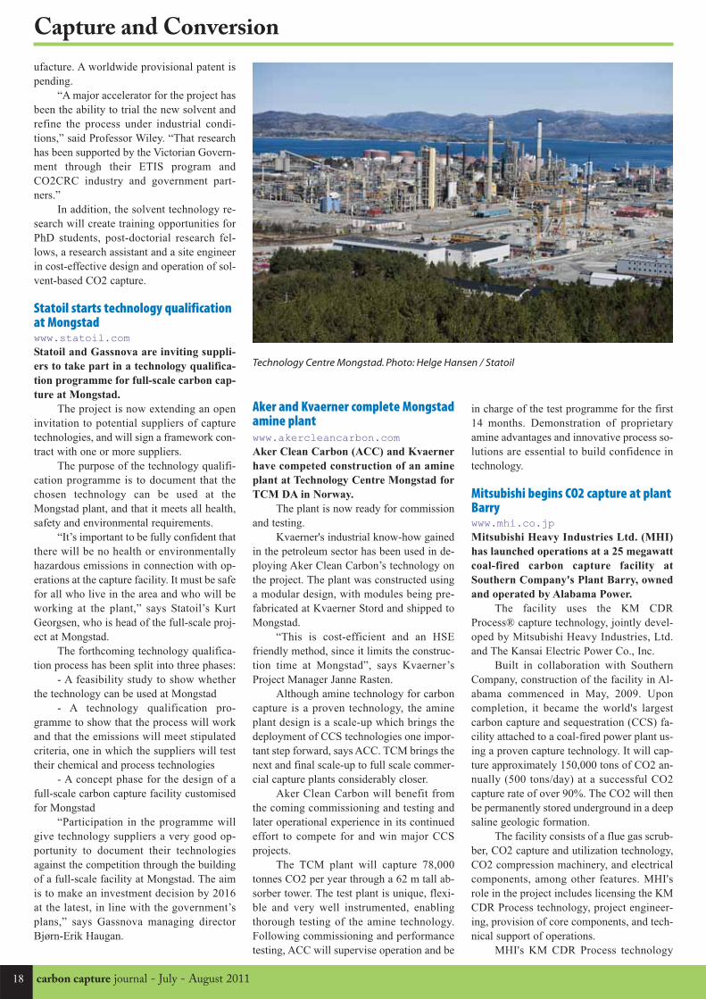
18 carbon capture journal - July - August 2011
Capture and Conversion
ufacture. A worldwide provisional patent is
pending.
“A major accelerator for the project has
been the ability to trial the new solvent and
refine the process under industrial condi-
tions,” said Professor Wiley. “That research
has been supported by the Victorian Govern-
ment through their ETIS program and
CO2CRC industry and government part-
ners.”
In addition, the solvent technology re-
search will create training opportunities for
PhD students, post-doctorial research fel-
lows, a research assistant and a site engineer
in cost-effective design and operation of sol-
vent-based CO2 capture.
Statoil starts technology qualificationat Mongstadwww.statoil.comStatoil and Gassnova are inviting suppli-
ers to take part in a technology qualifica-
tion programme for full-scale carbon cap-
ture at Mongstad.
The project is now extending an open
invitation to potential suppliers of capture
technologies, and will sign a framework con-
tract with one or more suppliers.
The purpose of the technology qualifi-
cation programme is to document that the
chosen technology can be used at the
Mongstad plant, and that it meets all health,
safety and environmental requirements.
“It’s important to be fully confident that
there will be no health or environmentally
hazardous emissions in connection with op-
erations at the capture facility. It must be safe
for all who live in the area and who will be
working at the plant,” says Statoil’s Kurt
Georgsen, who is head of the full-scale proj-
ect at Mongstad.
The forthcoming technology qualifica-
tion process has been split into three phases:
- A feasibility study to show whether
the technology can be used at Mongstad
- A technology qualification pro-
gramme to show that the process will work
and that the emissions will meet stipulated
criteria, one in which the suppliers will test
their chemical and process technologies
- A concept phase for the design of a
full-scale carbon capture facility customised
for Mongstad
“Participation in the programme will
give technology suppliers a very good op-
portunity to document their technologies
against the competition through the building
of a full-scale facility at Mongstad. The aim
is to make an investment decision by 2016
at the latest, in line with the government’s
plans,” says Gassnova managing director
Bjørn-Erik Haugan.
Aker and Kvaerner complete Mongstadamine plantwww.akercleancarbon.comAker Clean Carbon (ACC) and Kvaerner
have competed construction of an amine
plant at Technology Centre Mongstad for
TCM DA in Norway.
The plant is now ready for commission
and testing.
Kvaerner's industrial know-how gained
in the petroleum sector has been used in de-
ploying Aker Clean Carbon’s technology on
the project. The plant was constructed using
a modular design, with modules being pre-
fabricated at Kvaerner Stord and shipped to
Mongstad.
“This is cost-efficient and an HSE
friendly method, since it limits the construc-
tion time at Mongstad”, says Kvaerner’s
Project Manager Janne Rasten.
Although amine technology for carbon
capture is a proven technology, the amine
plant design is a scale-up which brings the
deployment of CCS technologies one impor-
tant step forward, says ACC. TCM brings the
next and final scale-up to full scale commer-
cial capture plants considerably closer.
Aker Clean Carbon will benefit from
the coming commissioning and testing and
later operational experience in its continued
effort to compete for and win major CCS
projects.
The TCM plant will capture 78,000
tonnes CO2 per year through a 62 m tall ab-
sorber tower. The test plant is unique, flexi-
ble and very well instrumented, enabling
thorough testing of the amine technology.
Following commissioning and performance
testing, ACC will supervise operation and be
in charge of the test programme for the first
14 months. Demonstration of proprietary
amine advantages and innovative process so-
lutions are essential to build confidence in
technology.
Mitsubishi begins CO2 capture at plantBarrywww.mhi.co.jpMitsubishi Heavy Industries Ltd. (MHI)
has launched operations at a 25 megawatt
coal-fired carbon capture facility at
Southern Company's Plant Barry, owned
and operated by Alabama Power.
The facility uses the KM CDR
Process® capture technology, jointly devel-
oped by Mitsubishi Heavy Industries, Ltd.
and The Kansai Electric Power Co., Inc.
Built in collaboration with Southern
Company, construction of the facility in Al-
abama commenced in May, 2009. Upon
completion, it became the world's largest
carbon capture and sequestration (CCS) fa-
cility attached to a coal-fired power plant us-
ing a proven capture technology. It will cap-
ture approximately 150,000 tons of CO2 an-
nually (500 tons/day) at a successful CO2
capture rate of over 90%. The CO2 will then
be permanently stored underground in a deep
saline geologic formation.
The facility consists of a flue gas scrub-
ber, CO2 capture and utilization technology,
CO2 compression machinery, and electrical
components, among other features. MHI's
role in the project includes licensing the KM
CDR Process technology, project engineer-
ing, provision of core components, and tech-
nical support of operations.
MHI's KM CDR Process technology
Technology Centre Mongstad. Photo: Helge Hansen / Statoil

19July - August 2011 - carbon capture journal
Capture and Conversion
uses an advanced solvent called KS-1 to cap-
ture the CO2 from a flue gas stack. The flue
gas is directed to the KM CDR Process
where the KS-1 solvent reacts with and cap-
tures the CO2. CO2 can then be separated
from the KS-1 and compressed for pipeline
transport. Compared with other CO2 capture
technologies, the KM CDR Process uses sig-
nificantly less energy, claims MHI.
The project is an initiative associated
with the U.S. Department of Energy's Re-
gional Carbon Sequestration Partnership
Phase III program. Captured CO2 will be
supplied to the Southeast Regional Carbon
Sequestration Partnership for injection un-
derground. The CO2 will remain under-
ground, permanently trapped in the geologic
formation.
MHI has received orders for ten natu-
ral gas-fired CO2 capture facilities, with
eight of the facilities currently in operation,
representing a world-class CO2 capture line-
up. In contrast, while coal-fired CO2 capture
facilities are currently at the commercial fea-
sibility testing stage, since 2006 MHI has
partnered with Japan's Research Institute of
Innovative Technology for the Earth (RITE)
in demonstrating a 10 ton/day scale coal-
fired CO2 capture facility.
With the experience gained from stable,
continuous operations of a CO2 capture fa-
cility in Japan, along with the know-how
gained from the CO2 capture project in the
United States, MHI intends to verify the eco-
nomic feasibility and reliability of coal-fired
CO2 capture.
US National Carbon Capture Centeropens post-combustion test centerwww.nationalcarboncapturecenter.comThe recent successful commissioning of an
Alabama-based test facility is another step
forward in research that will speed de-
ployment of innovative post-combustion
CO2 capture technologies for coal-based
power plants, according to the U.S. De-
partment of Energy (DOE).
Technologies tested at are an important
component of Carbon Capture and Storage,
whose commercial deployment is considered
by many experts as essential for helping to
reduce human-generated CO2 emissions that
contribute to potential climate change.
The Post-Combustion Carbon Capture
Center (or PC4) facility is part of the larger
NCCC, a testing and evaluation center estab-
lished by the U.S. Department of Energy in
2009 and operated and managed by South-
ern Company.
The NCCC works collaboratively with
technology developers worldwide to test and
evaluate both pre- and post-combustion car-
bon capture technologies under realistic con-
ditions, accelerating development of cost-ef-
fective CO2 capture technologies and ensur-
ing continued use of coal for power genera-
tion.
The PC4 is located at the Alabama
Power Gaston power plant Unit 5, an 880
MW supercritical pulverized coal unit. Ini-
tial testing at the PC4 began recently when
researchers used a solvent called mo-
noethanolamine (MEA) to capture CO2 from
a slipstream of flue gas from the plant. To
date, the MEA solvent has exceeded the ex-
pected 90 percent CO2 capture, and the unit
is now in steady operation capturing about
10 tons of CO2 per day. Data from
these initial tests will be used as a baseline
to evaluate the performance of emerging
CO2 capture technologies.
The NCCC has entered into testing
agreements with Aker Clean Carbon AS and
Babcock & Wilcox Power Generation Group
Inc. for evaluation of their advanced CO2
capture processes at PC4. Both companies
plan to conduct testing of their respective
technologies at the NCCC later this year.
In addition to DOE and Southern Com-
pany, participants in the NCCC include
American Electric Power, Arch Coal, EPRI,
Luminant, NRG Energy, Peabody Energy,
and RioTinto.
Aker Clean Carbon cooperates withNorcemNorcem and Aker Clean Carbon (ACC)
have announced a cooperation agreement
for capture of CO2 in the cement industry.
The cement industry is a major emitter
of CO2 and as part of an ongoing sustain-
able strategy on climate protection, Norcem
and its parent company HeidelbergCement
Group, in cooperation with the European Ce-
ment Research Academy (ECRA) have de-
cided to enter into a partnership agreement
with ACC.
Under the agreement ACC will perform
studies to enable Norcem, through ECRA, to
assist the European cement industry in un-
derstanding the use of technology for future
CO2 capture.
Norcem will execute a Concept study
and a pre-engineering study for later trials
with ACC post-combustion capture technol-
ogy at Norcem’s plant in Brevik, Norway.
Any ensuing trials will be given industrial
environment testing by using ACC’s Mobile
Test Unit (MTU).
ACC has run its MTU now with more
than 14,000 hours industrial operation, pro-
viding unique support for Norcem.
“The Cement Industry is a major emit-
ter of CO2 and we are delighted to be able
to work with Norcem, HeidelbergCement
and ECRA in this important forward-look-
ing project” says Liv Monica B Stubholt,
Chief Executive Officer of Aker Clean Car-
bon.
“HeidelbergCement and Norcem have
already taken major steps in reducing the
emissions of CO2 from the production of ce-
ment. The next important step is CO2-cap-
ture. We assume that a cement plant is a fa-
vorable location for capturing of CO2. We
look forward to test the technology together
with Aker Clean Carbon”, says Per Brevik,
Director Alternative fuels of HeidelbergCe-
ment Northern Europe.
The cement industry develops strate-
gies, conducts practical testing and gains
project experience through ECRA, whose
mission is to advance innovation in the ce-
ment industry within the context of sustain-
able development and to communicate the
latest knowledge and research findings in ce-
ment and concrete technology.
ECRA members have chosen Norcem
Brevik as the site for ECRA operational CO2
capture test projects.
Subscribe to Carbon
Capture Journal
Six issues only £250
Sign up to our free e-mail newsletter atwww.carboncapturejournal.com

20 carbon capture journal - July - August 2011
Transport and Storage
The demand for carbon capture and storage
(CCS) in recent years as a viable solution to
the problem of CO2 emissions from power
plants has led to an increase in interest in re-
search in certain associated areas of technolo-
gies. Among these, the transport process has
usually been taken for granted as ‘available
technology’, and is therefore discussed less.
While there is considerable experience
in the transport of natural gas by pipelines,
experience in the transport of CO2 through
pipelines is relatively limited and far less than
that required for a thorough understanding of
the pertinent details for the design and analy-
sis of pipelines for CO2. This article discuss-
es the current issues in the field of CO2-trans-
porting pipelines and highlights the need for
a structural integrity-based model for the as-
sessment of safety and for the design of CO2
pipelines.
CO2 Emissions and Global WarmingThe need to reduce the emission of CO2 and
other greenhouse gases into the atmosphere
as a result of industrial development has been
the driving force behind the development of
CCS technologies. There is overwhelming
scientific evidence, as shown in the Fourth
Assessment Report of the Intergovernmental
Panel on Climate Change (IPCC), that climate
change will threaten economic growth and
long-term prosperity [1, 2]. The IPCC sug-
gests that to avoid the most catastrophic im-
pacts of climate change, greenhouse gas emis-
sions need to peak in the next 10 to 15 years
and be reduced by the order of 50–80% be-
low 1990 levels by 2050.
CCS is considered a key solution to the
problem of anthropogenic CO2 emissions.
However, as the Congressional Research
Service Report on CO2 pipelines indicates [3]
the general focus of CCS and related legisla-
tion is on the capture and storage of CO2 and
not its transportation. As the report suggests:
“this reflects the perception that transporting
CO2 via pipelines does not present a signifi-
cant barrier to implementing large-scale
CCS” [3]. Nevertheless, the truth and the per-
ception are different.
CO2 PipelinesThe current generation of CO2 pipelines has
been operational for over 30 years, mainly in
the US, transporting high-pressure CO2 for
onshore enhanced oil recovery across sparse-
ly populated terrain. However, the next gen-
eration of CO2 pipelines will be directed at
climate change mitigation.
Initiatives such as the EU Emissions
Trading Scheme, usually requiring companies
to limit or reduce greenhouse gas emissions,
mean that there will be a serious economic
driver for power generation companies to
consider CCS technology. Moreover, for the
CCS process to be cost-effective and safe, all
three main aspects of capture, transport and
storage technologies should be developed and
possibly standardised.
Carbon Capture and Storage PipelinesPipelines seem to be the primary mode of
transport of CO2 in the context of CCS [4, 5].
The expansion of CO2 pipelines in recent
years and safety requirements for pipelines in
densely populated areas mean that new leg-
islative and safety considerations should be
taken into account for the emerging CCS
pipelines.
Compared with hydrocarbon transport
pipelines, there is very little experience in the
design and maintenance of CO2 pipelines. Al-
so, since some or most of the storage loca-
tions are offshore, the requirements for
pipelines in the offshore environment need to
be considered. Design and construction of
new dedicated pipelines for CO2 transport,
or, in some cases, the conversion of existing
infrastructure, both require a thorough under-
standing of the safety issues associated with
the transport of CO2.
CO2 as a Hazardous SubstanceA significant amount of information has been
published outlining the hazards associated
with relatively small releases of CO2 [6]. In
water, CO2 forms an acidic solution, leading
to corrosion issues, and is a known asphyxi-
ant [7]. For more information about the haz-
ards and legal status of CO2 the reader is re-
ferred to Harper [8].
Pipeline FailureMakino et al. highlight the existing issues with
the prediction of crack propagation in ultra-
high-pressure natural gas pipelines [9].
Whereas the catastrophic failure mode in pres-
surised pipelines is clearly demonstrated in
burst tests as being ductile, crack initiation at
low temperatures is more likely to be due to
the metal lacking sufficient toughness, i.e. brit-
tle failure mode [10]. Cravero et al. recom-
mend a constraint-modified failure assessment
diagram which takes into account both ductile
and cleavage (brittle) mode failures [11].
Safety Considerations – LeakageScenarioPipeline transmission of CO2 over longer dis-
tances is considered most efficient when the
CO2 is in the supercritical or dense phase
[12]. Safety analysis of the pipeline should in-
clude the important ‘what-if’ scenario, where
a defect is assumed to be created in the
pipeline. The existence of a defect in the
pipeline would lead to rapid escape of fluid
CO2 from the hole.
Mahgerefteh et al. have proposed an out-
flow model which predicts the decompression
behaviour of the CO2 flow through the pipe
defect [13]. Starting from liquid or supercriti-
cal phases, the saturation pressure – at which
liquid and gas phases are in equilibrium – is
determined by the initial pressure of the fluid
in the pipe; the higher the initial pressure the
higher the saturation pressure.
For a pure component, the temperature
is a function of pressure and therefore the
temperature of the escaping gases is wholly
dependent on the depressurisation trajectory.
Eldevik et al. [14] argue that, as a result of
pipeline failure, rapid depressurisation may
cause the CO2 to cool to the triple point and
the low temperatures could cause associated
operational and structural problems.
A detailed discussion on the decompres-
sion behaviour of CO2 from a pipeline defect
can be found in [13]. In a review article, El-
devik emphasises that the likelihood of solid
CO2 deposition on the pipe as a result of de-
compression may bring the local temperature
as low as - 78˚C [15]. This can have a severe
impact on the pipeline material’s toughness
or resistance to fracture.
Metal Embrittlement – Toughnessversus TemperaturePipeline steels show a ductile-to-brittle tran-
sition at low temperatures and the toughness
value of the material, i.e. the resistance to brit-
tle fracture, is reduced at lower temperatures.
Knowledge of the exact behaviour of the ma-
terial is key in the development of a structur-
al integrity model for the pipeline. As part of
the development of the model, a database con-
taining toughness characteristics of the mate-
Although CO2 pipelines will be the primary means for transporting CO2 for storage, it is often consideredas an ‘available technology’ and so discussed less. There is a need for structural integrity-based model forthe assessment of pipeline safety, says Dr Amir Chahardehi, Offshore Renewable Energy Group, CranfieldUniversity
Structural safety in CO2 transport pipelines

July - August 2011 - carbon capture journal 21
Transport and Storage
rial as a function of temperature should be
compiled.
Current Testing Methods, FutureOutlook and RequirementsCurrent test standards relevant to the evalua-
tion of pipeline toughness include testing
methods such as the Drop Weight Tear Test
(DWTT) [16–18] and Notched Bar Impact
Test [19]. Some authors have recommended
the use of pre-cracked test specimens in the
impact test and report a closer correlation with
the plane-strain fracture toughness (KIC)
[20].
However, there is a considerable amount
of uncertainty as to the correlations between
the actual fracture toughness value pertinent
in the design and analysis of CO2 pipelines
and the results from the Charpy impact test or
DWTT [21]. The conclusion of the Health and
Safety Executive report on the subject is that
whereas individual correlations have been in-
troduced and summarised, “no single correla-
tion describes completely the KIC tempera-
ture transition although some attempt to do
so” [21].
The Det Norske Veritas Recommended
Practice [4] rather vaguely suggests that the
pipeline should be designed such that any rup-
ture is arrested within a small number of pipe
joints. Notwithstanding the fact that the pre-
dictive requirements of any structural integri-
ty model demand accurate knowledge of ma-
terial characteristics at different temperatures,
a more rigorous standard practice should be
devised for CO2 pipelines considering their
growing importance and the potential hazards
of pipeline failure and CO2 leakage.
There are currently a relatively large
number of test programmes dedicated to de-
veloping systematic understanding of the
structural integrity issues and requirements of
these pipelines. It is the author’s belief that a
rigorous, robust structural integrity model for
CO2 pipelines can only be obtained after ma-
terial characteristics tests, such as DWTT,
Charpy and fundamental fracture mechanics
tests involving the direct determination of
KIC, are used in conjunction with component
testing, full-scale or otherwise.
Large-scale component testing gives in-
valuable information about the transferability
of the results obtained from specimen tests to
the real world. Fundamental tests should in-
clude crack initiation and measurements of
the onset of unstable crack growth in regions
of temperature gradient, where the crack is
likely to grow from a region of low tempera-
ture in the vicinity of the defect to a region
where the temperature is effectively in equi-
librium with the environment.
The low toughness value of the metal in
the neighbourhood of the defect would mean
that crack initiation is likely even though the
normal ‘working temperature’ toughness of
the metal is sufficient to ensure lack of crack
growth [13, 23]. Robertson devised a test to
characterise this temperature gradient effect
on the propagation of cleavage fracture in
steels [24].
This type of test, modified to account for
the requirements of CO2 pipelines in terms of
steel type, thickness and geometry constraint,
can be used as a tool in the generation of the
material property database. Validation tests
for pipeline weldments [25] allowing for in-
corporation of residual stresses through the
use of weight functions [26] are required in
order to construct a robust, predictive struc-
tural integrity model for CO2 pipelines.
References1. Intergovernmental Panel on Climate
Change, Climate change 2007: Synthesis Re-
port, Contribution of Working Groups I, II and
III to the Fourth Assessment Report of the In-
tergovernmental Panel on Climate Change,
Geneva, Switzerland: IPCC, 2007.
2. Caraballo AC, Rabindran P, Winning
G, et al., Fracture Control Strategy for the Con-
version of Oil and Gas Pipelines to Transport
CO2. Presented at: 5th Pipeline Technology
Conference, 19–20 April 2010, Hannover,
Germany.
3. Parfomak PW, Folger P, Carbon Diox-
ide (CO2) Pipelines for Carbon Sequestration,
Emerging Policy Issues, Congressional Re-
search Service Report for Congress, 19 April
2007. Order Code RL33971.
4. Det Norske Veritas, Recommended
Practice DNV-RP-J202, Design and Operation
of CO2 Pipelines, April 2010.
5. Holloway S, Carbon dioxide capture
and geological storage, Philos Transact A
Math Phys Eng Sci, 2007;365:1095–1107.
6. Gale J, Davison J, Transmission of
CO2 – safety and economic considerations,
Proceedings of the 6th International Confer-
ence on Greenhouse Gas Control Technolo-
gies, Kyoto, Japan, 1–4 October 2002;517–22.
7. Connolly S, Hazards from high pres-
sure carbon dioxide releases during carbon
dioxide sequestration processes (precis),
Health and Safety Executive, Offshore Safety
Division.
8. Harper P, The Inclusion of CO2 as a
Hazardous Substance in the Seveso Directive,
Health and Safety Executive.
9. Makino H, Kubo T, Shiwaku T, et al.,
Prediction for Crack Propagation and Arrest
of Shear Fracture in Ultra-high Pressure Natu-
ral Gas Pipelines, ISIJ Int, 2001;41(4):381–8.
10. Burdekin FM, Knott JF, Sumpter
JDG, Shery AH, TAGSI views on aspects of
crack arrest philosophies for pressure vessels
with thicknesses up to 100mm, Int J Pressure
Vessels Piping, 1999;76:879–83.
11. Cravero S, Ruggieri C, Structural in-
tegrity of axially cracked pipeline using con-
ventional and constrain-modified failure as-
sessment diagrams, Int J Pressure Vessels Pip-
ing, 2006;83:607–17.
12. Leitner W, Green Chemistry, Design
to dissolve, Nature, 2000;405:129–30.
13. Mahgerefteh H, Atti O, Modeling
Low-Temperature-Induced Failure of Pressur-
ized Pipelines, AIChE J, 2006;52(3):1248– 56.
14. Eldevik F, Graver B, Torbergsen LE,
Saugerud OT, Development of a Guideline for
Safe, Reliable and Cost Effective Transmis-
sion of CO2 in Pipelines, Energy Procedia,
2009;1:1579–85.
15. Eldevik F, Safe Pipeline Transmis-
sion of CO2, Pipeline Gas J,
2008;235(11):76–7.
16. Recommended Practice for Conduct-
ing Drop-Weight Tear Test on Line Pipe, API
RP 5L3, American Petroleum Institute Stan-
dard.
17. Metallic materials – Drop weight tear
test, BS EN 10274:1999, British Standard.
18. Standard Test Method for Drop-
Weight Tear Test of Ferritic Steels, ASTM
E436-91, ASTM International Standard.
19. Standard Test Methods for Notched
Bar Impact Testing of Metallic Materials,
ASTM E23-07a, ASTM International Stan-
dard.
20. Radon JC, Turner CE, Fracture
Toughness Measurement by Instrumented Im-
pact Test, Eng Fract Mech, 1969;1:411–28.
21. Critical Examination of Correlations
between Fracture Toughness and Charpy Im-
pact Energy, Offshore Technology Report –
OTO 96 710, Health and Safety Executive.
22. Caraballo A, Imai Y, Aihara S, Yapp
D, J R-Curve Estimation by Drop Weight Tear
Test, Proceedings of the 18th European Con-
ference on Fracture, Dresden, Germany, 30
August–3 September 2010.
23. MATTRAN Project, Funded by
E.ON/EPSRC. Available at:
http://research.ncl.ac.uk/mattran/ (accessed
Jan 2011).
24. Robertson TS, Propagation of Brittle
Fracture in Steel, J Iron Steel Inst,
1953;175:361–74.
25. Yuan WG, Wu YY, Tronskar J P, De-
velopment of Fracture Toughness using SENT
specimens and Validation Test on Large
Strained Pipeline Weldment.
26. Chahardehi A, Brennan FP, The Ef-
fect of Residual Stresses Arising from Laser
Shock Peening on Fatigue Crack Growth, Eng
Fract Mech, 2010;77(11):2033–9.
Contact the [email protected]

22 carbon capture journal - July - August 2011
Transport and Storage
New trials begin at Australian OtwayProject
The experiments, led by the Cooperative Re-
search Centre for Greenhouse Gas Technolo-
gies (CO2CRC), are part of the $10 million
second stage of the project, which is focused
on saline formations, geological structures
with the potential to permanently store hun-
dreds of years' worth of carbon dioxide emis-
sions.
An international research team has
been assembled by the Centre, with re-
searchers from leading Australian research
organisations, Lawrence Berkeley National
Laboratory (USA), Korea Institute of Geo-
science and Mineral Resources (KIGAM),
Canada's Simon Fraser University and New
Zealand's GNS Science.
The team will use a new 1565 metre
well at the site to undertake a complex se-
ries of extractions and injections of carbon
dioxide and water over the next two months,
evaluating storage capacity and security.
A sophisticated and highly innovative
28 metre instrument array, installed 1400
metres underground in the same well into
which the carbon dioxide is injected, will
measure pressure, temperature and tracer gas
concentrations, while a „U-tube' system al-
lows the team to chemically analyse samples
of water and dissolved gas direct from the
reservoir, at pressures equivalent to 1400
metres underground.
“The Otway Project has been demon-
strating safe storage of carbon dioxide in a
depleted gas reservoir since 2008,” says
CO2CRC Chief Executive Dr Peter Cook,
“and the successful first stage provided a
great deal of highly useful information on
monitoring, verification and regulation of
CCS.
“This second stage involves research
aimed at tackling some of the key outstand-
ing research questions regarding storage ca-
pacity and security in types of rocks found
many parts of the world. It will enable
CO2CRC to produce practical tools for com-
mercial CCS projects that will make it easi-
er to evaluate a potential reservoir.”
The CO2CRC Otway Project involves
researchers from Australian universities and
research organisations as well as from the
United States, Korea, Canada and New
Zealand. The project has been financially
supported by the Australian Federal Govern-
ment, the Victorian State Government and
the US Department of Energy, as well as
CO2CRC members.
A series of research trials into geological storage of carbon dioxide have begun at the CO2CRC OtwayProject in Victoria, Australia.
www.co2crc.com.au
The 30 metre instrument assembly before installation in the well (Image ©CO2CRC)
Final preparations before the instruments are installed downhole (Image ©CO2CRC)

July - August 2011 - carbon capture journal 23
Transport and Storage
Transport and storage news
DOE funds projects aimed at CCSsecurity and environmental safety
www.fossil.energy.govThe U.S. Department of Energy’s (DOE)
portfolio of field projects aimed at con-
firming that long-term geologic CO2 stor-
age is safe and environmentally secure has
been expanded by three projects selected
to collectively receive $34.5 million over
four years.
Researchers will conduct small-scale
injection testing of CO2 into promising geo-
logic formations. Project data will be incor-
porated in the National Carbon Sequestra-
tion Database and Geographical Information
System (NATCARB), an interactive online
tool that integrates a wealth of information
on worldwide efforts to deploy carbon cap-
ture and storage (CCS) technology.
The total award value of the new proj-
ects is more than $45 million, with approxi-
mately $10.5 million provided by
the recipients. The work will be managed by
the Office of Fossil Energy’s National Ener-
gy Technology Laboratory (NETL).
Members of the public and industry can
use NATCARB to assess future opportuni-
ties for developing commercial carbon stor-
age projects throughout the United States.
The projects are:
- Blackhorse Energy, LLC (Houston,
Texas) — Blackhorse Energy plans to inject
approximately 53,000 tons of CO2 into a ge-
ologic formation located in Livingston
Parish, Louisiana. The project will assess the
suitability of strandplain geologic formations
for future large-scale geologic storage of
CO2 in association with enhanced oil recov-
ery. Additionally, they will test the efficacy
of increased storage using short-radius hori-
zontal well technology to inject supercritical
CO2 and CO2 foam into the reservoir.
- University of Kansas Center for Re-
search, Inc. (Lawrence, Kansas) — The Uni-
versity of Kansas will inject at least 70,000
metric tons of CO2 into multiple formations.
The project will demonstrate the application
of state-of-the-art monitoring, verification,
and accounting (MVA) tools and techniques
to monitor and visualize the injected CO2
plume and establish best practice method-
ologies for MVA and closure in "shelf clas-
tic" and "shelf carbonate" geologic forma-
tions.
- Virginia Polytechnic Institute and
State University (Blacksburg, Virginia) —
The Virginia Polytechnic Institute and State
University will attempt to reduce uncertain-
ty, test the properties of coal seams, and
evaluate the potential for enhanced coalbed
methane recovery by injecting approximate-
ly 20,000 tons of CO2 into unmineable
coalbeds.
DNV CCS well integrity guidelineDNV has released a new guideline for Carbon Capture and Storage projects. The CO2WELLS guideline isthe result of a major joint industry project which brought together upstream operators and power utilitycompanies.
Aimed at project developers and authorities,
it describes a generic framework process for
managing the risks associated with existing
wells at carbon dioxide (CO2) storage loca-
tions, both onshore and offshore.
DNV has previously published indus-
try guidelines across the full CCS value
chain of capture, transport and storage.
These guidelines have been implemented by
a number of companies for their current and
planned CO2 operations, as well as being
adopted by authorities as a component in
their own regulations.
The CO2WELLS guideline represents
the latest addition to this series. Within the
field of CO2 geological storage, it supple-
ments DNV’s CO2QUALSTORE guideline
which was published in 2010 following a
similar joint industry initiative.
Together, these two guidelines provide
a generic capital value process for CCS proj-
ects that is designed to qualify geological
storage sites through iterative cycles of risk
and uncertainty reducing measures. The in-
tegrity of existing wells at CO2 storage sites
has been highlighted as a potential concern,
and the new CO2WELLS guideline address-
es this issue head on.
The guideline describes a risk manage-
ment framework for existing wells at poten-
tial CO2 storage sites, both onshore and off-
shore. It is aimed at project developers and
authorities and includes guidance on:
- Risk assessment of active and aban-
doned wells during the initial screening of
candidate storage sites;
- The qualification of these wells for
continued or modified use in a CCS project.
The guideline is consistent with the
ISO31000 international standard for risk
management and with current and emerging
regulations for CO2 geological storage in the
US, Canada, Europe and Australia.
Participants of the CO2WELLS joint
industry project are DNV, E.On Engineering,
GASSCO, GASSNOVA, Global CCS Insti-
tute, Health & Safety Executive UK, Nation-
al Grid, Petrobras, RWE, Shell Canada, Vat-
tenfall
Unified guidelines to speed up CCSimplementationDNV believes that CCS is a strategically im-
portant technology for maintaining sustain-
able growth whilst reducing CO2 emissions.
By permanently storing CO2 produced by
industrial processes in deep geological for-
mations, it has been highlighted as one of the
key technologies that can facilitate a transi-
tion to a more carbon neutral world.
For CCS to play a significant role in
combating climate change, however, a sig-
nificant number of commercial scale proj-
ects must be initiated around the world with-
in the coming years. To boost the deploy-
ment of CCS in a safe and sustainable way,
there is a need for unified, recognized and
publicly available guidelines that provide the
standards that can help speed up innovation.
Mike Carpenter, project manager at
DNV, said, “DNV’s core philosophy is that
technology development and knowledge
sharing foster innovation and improvements
in safety. So when industry is facing chal-
lenges like CCS, the best way of solving
them is for the key players to join forces
through joint industry projects. In this way
we, as an industry, can develop global best
practices and standards.”
All of DNV’s guidelines and recommend-
ed practices for CCS have been developed
through joint industry projects and are
freely available from
www.dnv.com/ccs

carbon capture journal - July - August 201124
Status of CCS project database
The status of 78 large-scale integrated projects data courtesy of the Global CCS InstituteFor the full list, with the latest data as it becomes available, please see the pdf version online at www.carboncapturejournal.com or
download a spreadsheet at www.globalccsinstitute.com/resources/data
Project Name Description
Asset
Lifecycle
Stage
CountryVolume
CO2
Operation
Date
ADM Company Illinois
ICCS
The project will capture around 1 million tonnes per annum of carbon dioxide from
ethanol production. The carbon dioxide will be stored approximately 2.1 km
underground in the Mount Simon Sandstone, a deep saline formation.
Define UNITED STATES 1 Mtpa 2012
AEP Mountaineer
235MWe CO2 Capture
AEP's Mountaineer coal-fired power station was retrofitted with Alstom's patented
chilled ammonia carbon capture technology. This project has been operational at
pilot scale since September 2009 and full-scale operation is expected by 2015.
Define UNITED STATES 1.5 Mtpa 2015
Air LiquideAir Liquide is building a new hydrogen plant in Rotterdam. The installation of a
cryogenic purification unit (CPU) at the plant, capturing up to 550,000 tonnes per
annum of carbon dioxide, is under evaluation.
Define NETHERLANDS 0.55 Mtpa 2012
Air Products Project
This project proposes to capture more than 1 million tonnes per year of carbon
dioxide from two steam methane reformers. The CO2 will be transported via
Denbury's Midwest pipeline to the Hastings and Oyster Bayou oil fields for enhanced
oil recovery.
Define UNITED STATES 1 Mtpa 2015
BelchatowAlstom and PGE EBSA are partnering to build an 858 MW lignite-fired power plant
with CCS. Around 1.8 million tonnes per annum of carbon dioxide will be captured
and stored in deep saline formations.
Define POLAND 1.8 Mtpa 2015
Bow CityThe Bow City Power Project is a proposed super critical 1,000 MW coal-fired power
plant incorporating post combustion carbon capture and storage. Around 1 million
tonnes per annum of carbon dioxide will be captured at the plant.
Evaluate CANADA 1 Mtpa 2016
Browse LNGUp to 3 million tonnes per annum of carbon dioxide will be captured at this proposed
liquid natural gas development located in the government precinct near James Price
Point on the Dampier peninsula.
Evaluate AUSTRALIA 3 Mtpa 2017
C.Gen KillingholmeC.Gen is proposing this new IGCC plant in north Lincolnshire that would capture
around 2 million tonnes per annum of carbon dioxide feeding into the National Grid
transport and storage network. The project is part of the Yorkshire Forward initiative.
DefineUNITED
KINGDOM2.5 Mtpa 2015-2016
Cash Creek
The ERORA Group proposes to build a Hybrid IGCC project in Henderson County,
Kentucky. It will produce about 565 MW as well as synthetic natural gas. The plant
will capture about 2.5 million tonnes per annum of carbon dioxide for enhanced oil
recovery.
Evaluate UNITED STATES 2.5 Mtpa 2015
Coffeyville
Gasification Plant
Coffeyville Resources is proposing to build a carbon capture unit at an existing
gasification plant in Kansas. The project would capture around 770,000 tonnes per
annum of carbon dioxide for urea production and enhanced oil recovery.
Define UNITED STATES0.585
Mtpa2013
Compostilla ProjectThis project uses oxyfuel and fluidised bed technology on a 30 MW pilot plant which
will scale up to 300 MW. It has received funding from the European Energy
Programme for Recovery (EEPR).
Define SPAIN 1.1 Mtpa 2015
CoolimbaAviva Corporation Ltd proposes the construction of a 400-450MW coal-fired base-
load power station using circulating fluidized bed technology and capturing up to 2
million tonnes per annum of carbon dioxide. Suitable storage sites are being sought.
Identify AUSTRALIA 2 Mtpa 2015
Don Valley2Co Energy is developing this project to capture nearly 5 million tonnes per annum
of carbon dioxide from a new build natural gas-fired power station. The project is part
of the Yorkshire Forward initiative.
EvaluateUNITED
KINGDOM4.75 Mtpa 2015
DongguanDongguan Taiyangzhou Power Corporation intends to construct an 800 MW IGCC
plant capturing up to 1 million tonnes per annum of carbon dioxide, which would be
stored in depleted oil and gas reservoirs.
Define CHINA 1 Mtpa 2015
DraxAlstom UK Ltd, Drax Power Limited and National Grid plc are jointly developing a
new 426 MW oxy-fired plant in North Yorkshire which would capture around 2 million
tonnes per annum of carbon dioxide. The project is part of the Humber CCS Cluster.
EvaluateUNITED
KINGDOM2 Mtpa 2015
Emirates Steel
Industries
This project proposes to capture around 800,000 tonnes per annum of carbon
dioxide from a steel plant in the Industrial City of Abu Dhabi (ICAD) by 2014. The
project is being developed as part of the Abu Dhabi CCS Network (Masdar).
EvaluateUNITED ARAB
EMIRATES0.8 Mtpa 2014
Enhance Energy EOR
Project
Enhance Energy and Fairborne Energy Trust are jointly developing an enhanced oil
recovery project at their Clive D2A and D3A fields, using carbon dioxide captured
from a refinery and a fertiliser plant, and transported via the Alberta Carbon Trunk
Line.
Execute CANADA 1.8 Mtpa 2012

July - August 2011 - carbon capture journal 25
Status of CCS project database
Facility DetailsCapture
Type
Transport
Type
Transport
Length
Storage
TypeProject URL
Ethanol plantIndustrial
SeparationPipeline 1.6 km
Deep Saline
Formations#http://www.adm.com/#
235 MWe slipstream
from 1300 MW net
coal-fired power plant
Post-
Combustion
capture
Pipeline 30 kmDeep Saline
Formationshttp://www.aep.com/environmental/climatechange/carboncapture/
130,000 Nm3/h
hydrogen plant
Pre-
Combustion
capture
Combination Not specifiedEnhanced Oil
Recovery#http://www.airliquide.com/#
Hydrogen production
at oil refinery
Pre-
Combustion
capture
Pipeline Not specifiedEnhanced Oil
Recoveryhttp://www.airproducts.com/index.asp
260 MW equivalent on
858 MW lignite-fired
power plant
Post-
Combustion
capture
Pipeline 60-140 kmDeep Saline
Formations#http://www.bot.pl/#
1000 MW coal-fired
power plant
Post-
Combustion
capture
Pipeline 6-30 kmEnhanced Oil
Recoverywww.bowcitypower.ca
Liquefied natural gas
(LNG) plant
Gas
ProcessingPipeline Not specified Not Specified #http://www.woodside.com.au/#
430-520 MW net IGCC
Pre-
Combustion
capture
Pipeline UnspecifiedTo Be
Determined#http://www.cgenpower.com/en/projects_killingholme.html#
565 MW IGCC and
130 MSCF/day SNG
gasifier
Pre-
Combustion
capture
Pipeline Not specifiedEnhanced Oil
Recovery#http://www.erora.com/#
Fertiliser plant
Pre-
Combustion
capture
Pipeline 112 kmEnhanced Oil
Recoveryhttp://www.cvrenergy.com/NitrogenFertilizerOperations/index.html
300 Mwe (Phase 2)
coal-fired oxyfuel
combustion power
plant
Oxyfuel
Combustion
capture
Pipeline 120 kmDeep Saline
Formations#http://www.compostillaproject.es/#
2x200 MW or 3x150
MW coal-fired CFB
power plant
Post-
Combustion
capture
Pipeline 20-80km
Depleted Oil
and Gas
Reservoirs
www.coolimbapower.com.au
Natural gas-fired
power plant
Oxyfuel
Combustion
capture
Pipeline 175 kmTo Be
Determined#http://www.2coenergy.com/#
800 MW net coal-fired
IGCC power plant
Pre-
Combustion
capture
Pipeline 100 km
Depleted Oil
and Gas
Reservoirs
#http://www.dgpowerfuel.com/english/profile.asp#
426 MW gross coal-
fired power plant
Oxyfuel
Combustion
capture
Pipeline Not specified
Depleted Oil
and Gas
Reservoirs
#http://www.draxpower.com/#
Steel plantIndustrial
SeparationPipeline 50 km
Enhanced Oil
Recoveryhttp://www.esi-steel.com/#http://www.esi-steel.com/#
Fertiliser production
and hydrogen
production at the oil
refinery
Pre-
Combustion
capture
Pipeline 240 kmEnhanced Oil
Recoveryhttp://www.enhanceenergy.com/projects/clive.html

www.airliquide.com
www.airliquide.com
Innovating to benefit our lives and our planet.
Innovating to benefit our li
Innovating to benefit our li
Innovating to benefit our li
Innovating to benefit our li
Innovating to benefit our li
Innovating to benefit our li
Innovating to benefit our li
Innovating to benefit our li
Innovating to benefit our li
aInnovating to benefit our li
and ouInnovating to benefit our li
ur plansevInnovating to benefit our li
net.
e tivavinnoin sence eprfsesagniidednuoF
teluoR-titePeppilihP:.rr.tsullI
©
tttcommity deepland with s countrie0 8in
tlaeh,yrtsudnirof,2091niecnarFn
ainable susta o ted teeyemplo00 3,64with
norivneehtdnahehtsiediuqiLriA
use e we, futurainable y eltssionaaPs. eea htiw,tnemnr edaeldlrowe
ect the entoprthast bethe
.airlwwww.
-
onment.virect the eno toffer can air t tha
.airliquide.com
enable life, e servepr
and ss eogrprenable