wind-tunnel techniques
TRANSCRIPT
Wind-tunnel techniques
By
Sangram Samal
What is a wind tunnels?
A wind tunnel is a tube or tunnel that has man-made wind blown through it
at a certain speed. Scientists and engineers put a model of an airplane in the
tunnel and then study the way the air moves around the model.
What is the purpose of a wind tunnel? A wind tunnel is used to simulate air flow over a model of an airplane or a
wing section so it can be studied.
The model can be instrumented to measure the lift and drag and other
parameters for study.
• The wind tunnel can produce air flow at the desired speed and condition.
•Engineers may use a wind tunnel to study and design a wing shape.
Wind tunnels can be used to study interference between parts of the aircraft
or between an airplane and a bomb as it drops away.
What are types of wind tunnels Wind tunnel can be classified by size, test section velocity and working principle.
• The wind tunnels come in a lot of sizes. Some are only a few inches square, and some are large enough to test a full-size airplane.
• Identification of W/T may be made through the cross sectional from the test section. It may square, rectangle, octagonal, circular, elliptic
• Also classified with velocity as: low speed wind tunnels, supersonic wind tunnels and hyper-sonic wind tunnels.
• Blower (Fan is ahead of test section) and suction type (Fan is after the test section)
• There are two basic types of wind tunnels
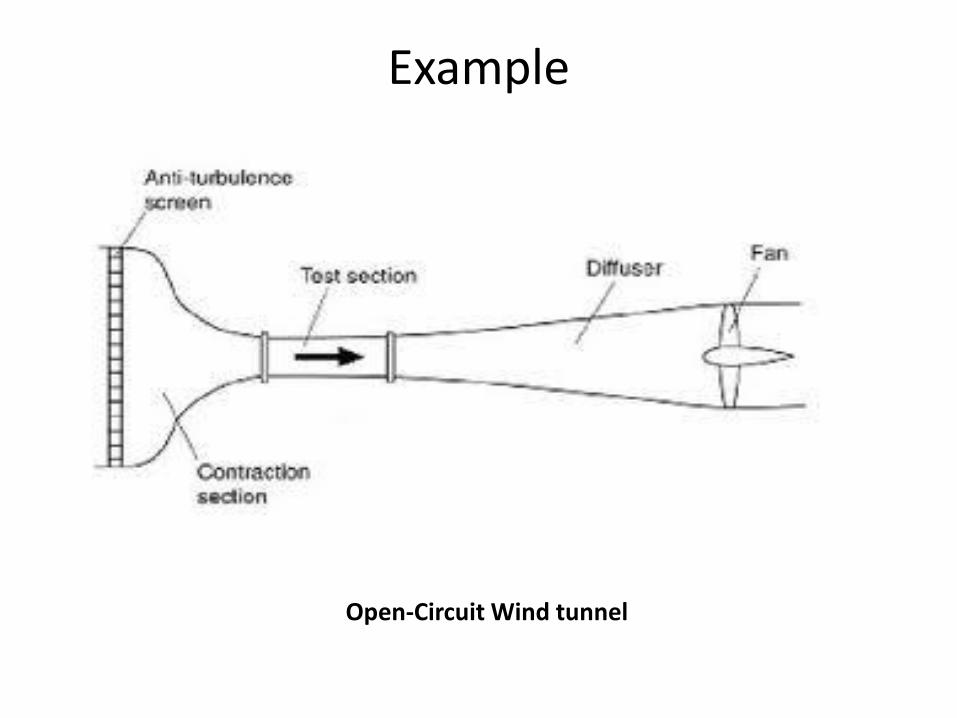
Open-Circuit (or ‘Eiffel’ or ‘NPL’) wind tunnel
Closed Test Section / Open Test section
Closed-Circuit wind tunnel
Closed Test Section
Example
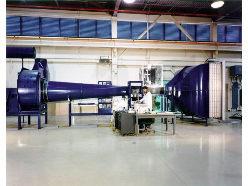
Open-Circuit Wind tunnel
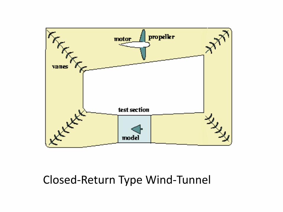
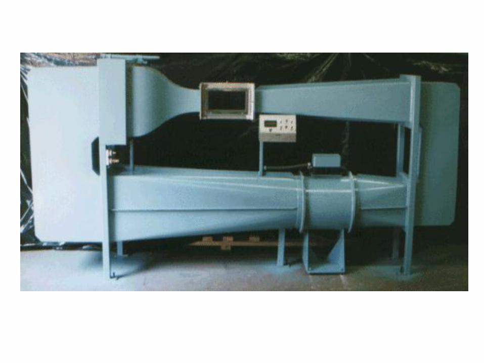
Closed-Return Type Wind-Tunnel
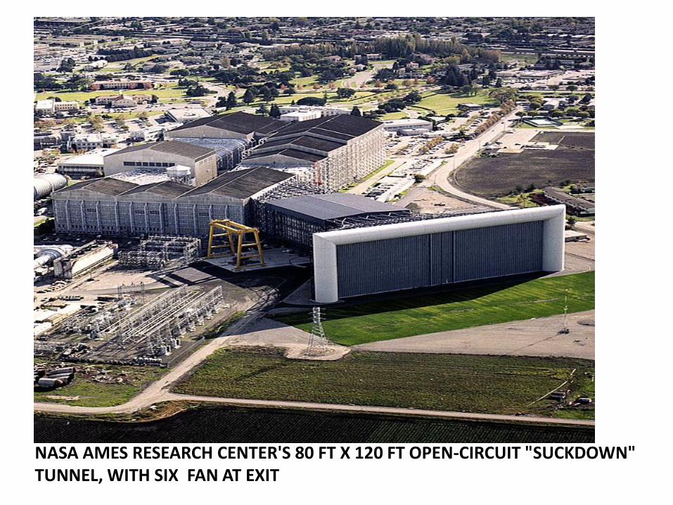
NASA AMES RESEARCH CENTER'S 80 FT X 120 FT OPEN-CIRCUIT "SUCKDOWN" TUNNEL, WITH SIX FAN AT EXIT
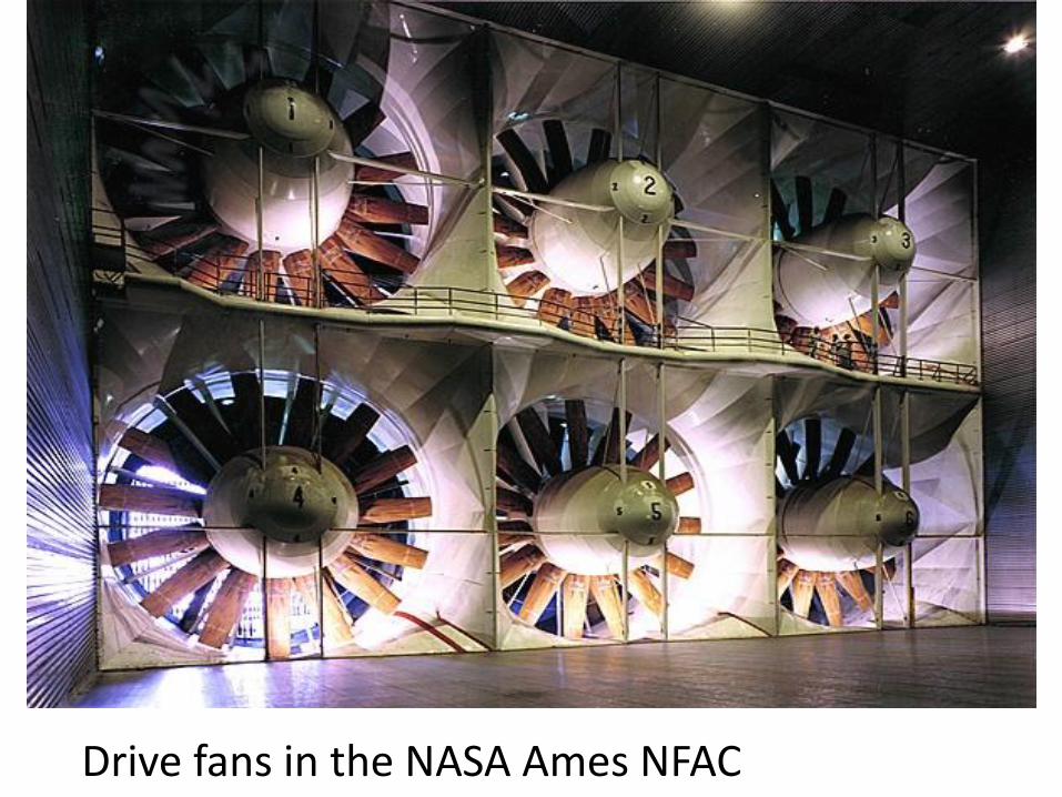
Drive fans in the NASA Ames NFAC
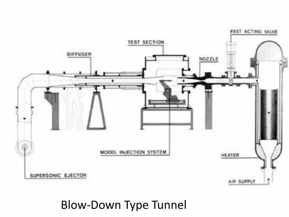
Blow-Down Type Tunnel
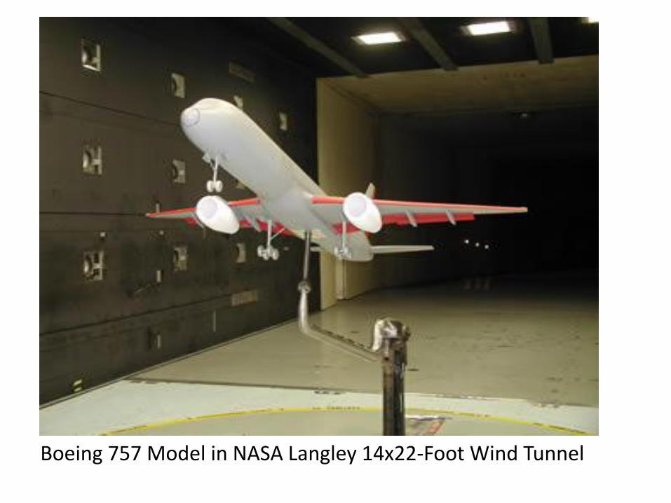
Boeing 757 Model in NASA Langley 14x22-Foot Wind Tunnel
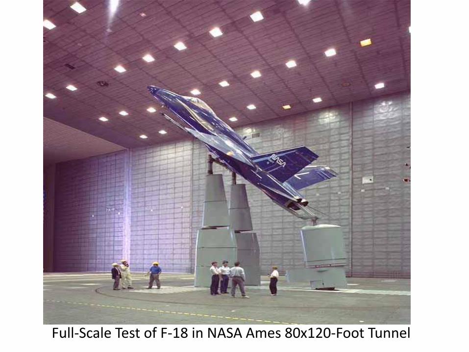
Full-Scale Test of F-18 in NASA Ames 80x120-Foot Tunnel
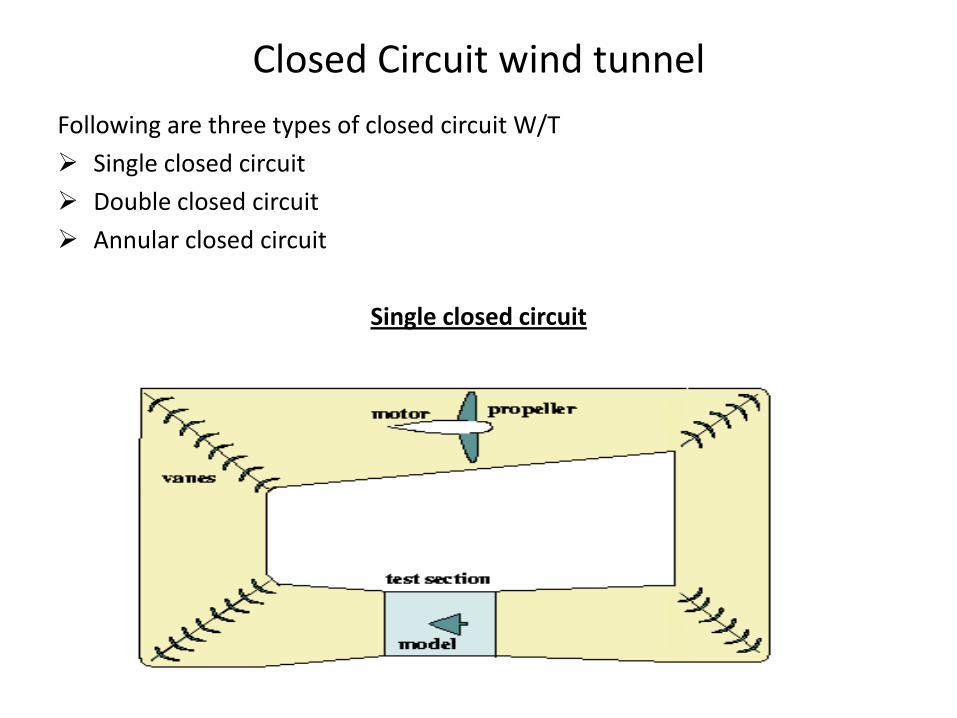
Closed Circuit wind tunnel
Following are three types of closed circuit W/T
Single closed circuit
Double closed circuit
Annular closed circuit
Single closed circuit
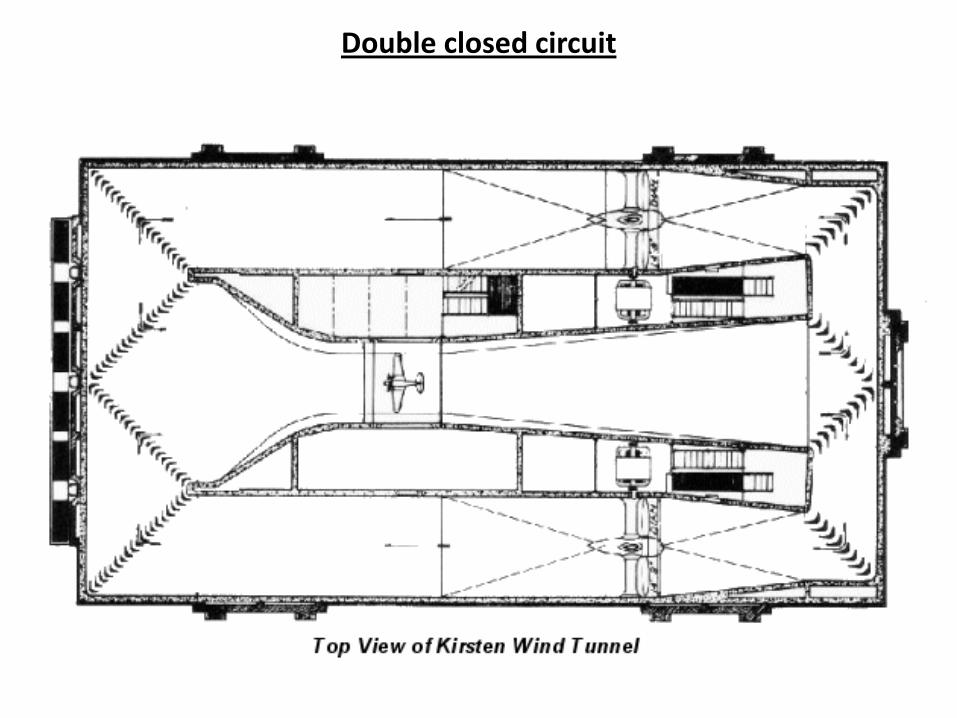
Double closed circuit
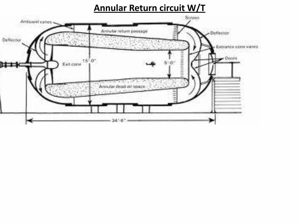
Annular Return circuit W/T
Difference between open and closed circuit type W/T
• Open circuit wind tunnel uses fresh air from atmosphere
• Test section temperature, density and pressure depend on the atmospheric condition In case of open tunnel.
• In case of close circuit above can be controlled.
• The atmospheric gust can cause variation in test section dynamic pressure in case of open type W/T
• The test section can be kept open in case of Open circuit W/T (called ‘Eiffel’ tunnel)
• Open circuit W/T is noisy, depend on out side weather condition.
• There may be chance of coming the dust, Insects and birds inside to tunnel in case of open circuit W/T
• The fans can damage due to model failure in case of open circuit W/T
Difference between single and double, annular type W/T
• Only the single type W/T is in general acceptance at present
• The Double and annular type the air is extremely turbulent. So difficulty to find out test data.
• Disadvantage of the double return type is that a variation in velocity may cause to yaw the model inside test section.
• In double return type flow deflection may not symmetrical , which can cause the yaw or roll to model
Other different type of W/T
Variable Pressure Tunnel (Return)
• This type of W/T , pressure can be maintained higher or lower than atmospheric pressure
• It required some time to build the required pressure before start the W/T
• Mach no and Reynolds number can be changes using different pressure.
Variable Density Tunnel (Return)
• This tunnel can attend high Reynolds number without either very high speed or large model
• This tunnel is no longer used because of high turbulence. Reynolds number can increase by blowing the air from pressure reservoir for a small W/T
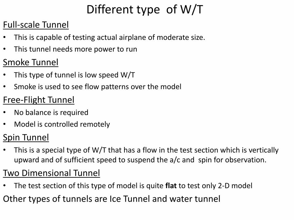
Different type of W/T Full-scale Tunnel • This is capable of testing actual airplane of moderate size.
• This tunnel needs more power to run
Smoke Tunnel • This type of tunnel is low speed W/T
• Smoke is used to see flow patterns over the model
Free-Flight Tunnel • No balance is required
• Model is controlled remotely
Spin Tunnel • This is a special type of W/T that has a flow in the test section which is vertically
upward and of sufficient speed to suspend the a/c and spin for observation.
Two Dimensional Tunnel • The test section of this type of model is quite flat to test only 2-D model
Other types of tunnels are Ice Tunnel and water tunnel
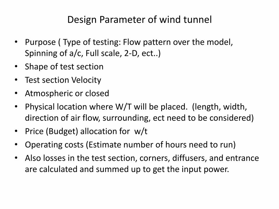
Design Parameter of wind tunnel
• Purpose ( Type of testing: Flow pattern over the model, Spinning of a/c, Full scale, 2-D, ect..)
• Shape of test section
• Test section Velocity
• Atmospheric or closed
• Physical location where W/T will be placed. (length, width, direction of air flow, surrounding, ect need to be considered)
• Price (Budget) allocation for w/t
• Operating costs (Estimate number of hours need to run)
• Also losses in the test section, corners, diffusers, and entrance are calculated and summed up to get the input power.
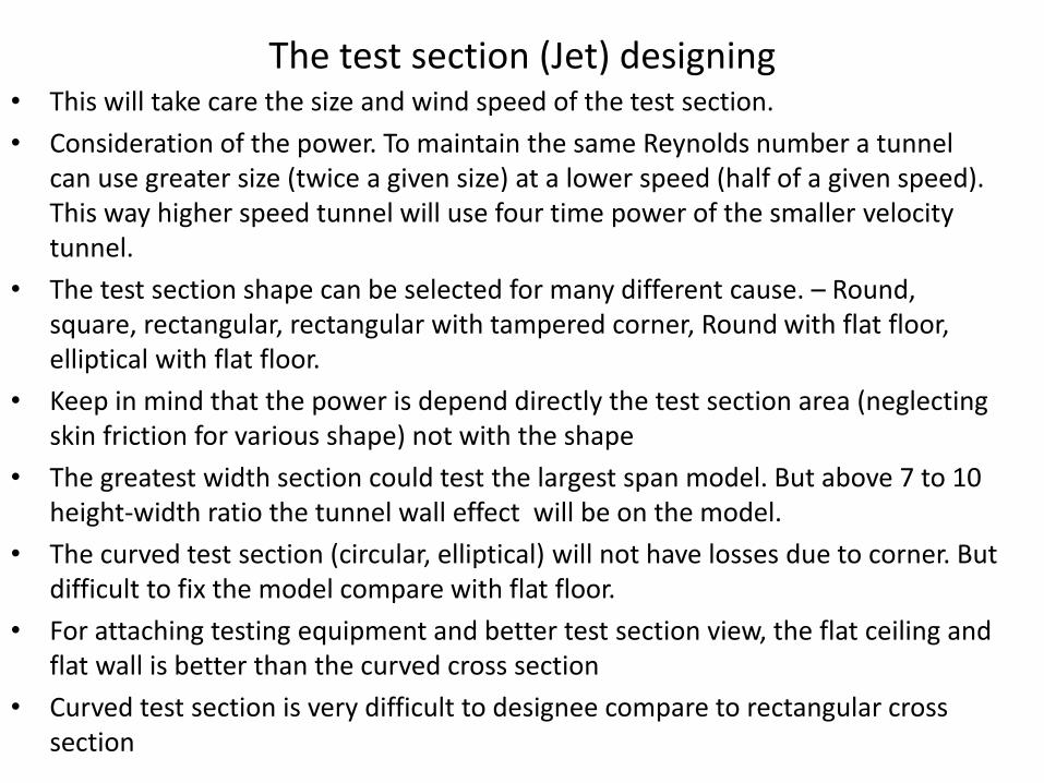
The test section (Jet) designing • This will take care the size and wind speed of the test section.
• Consideration of the power. To maintain the same Reynolds number a tunnel can use greater size (twice a given size) at a lower speed (half of a given speed). This way higher speed tunnel will use four time power of the smaller velocity tunnel.
• The test section shape can be selected for many different cause. – Round, square, rectangular, rectangular with tampered corner, Round with flat floor, elliptical with flat floor.
• Keep in mind that the power is depend directly the test section area (neglecting skin friction for various shape) not with the shape
• The greatest width section could test the largest span model. But above 7 to 10 height-width ratio the tunnel wall effect will be on the model.
• The curved test section (circular, elliptical) will not have losses due to corner. But difficult to fix the model compare with flat floor.
• For attaching testing equipment and better test section view, the flat ceiling and flat wall is better than the curved cross section
• Curved test section is very difficult to designee compare to rectangular cross section
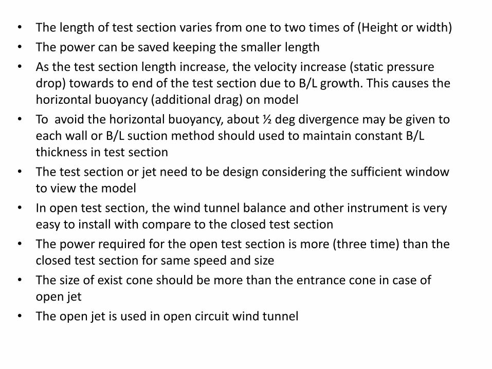
• The length of test section varies from one to two times of (Height or width)
• The power can be saved keeping the smaller length
• As the test section length increase, the velocity increase (static pressure drop) towards to end of the test section due to B/L growth. This causes the horizontal buoyancy (additional drag) on model
• To avoid the horizontal buoyancy, about ½ deg divergence may be given to each wall or B/L suction method should used to maintain constant B/L thickness in test section
• The test section or jet need to be design considering the sufficient window to view the model
• In open test section, the wind tunnel balance and other instrument is very easy to install with compare to the closed test section
• The power required for the open test section is more (three time) than the closed test section for same speed and size
• The size of exist cone should be more than the entrance cone in case of open jet
• The open jet is used in open circuit wind tunnel
The Return Passage
• The return passage or diffuser plays a major role on power saving
• Power losses in a wind tunnel vary with cube of the air speed at fan
• It is desirable to increase the cross sectional area of return passage as rapidly as possible to reduce the velocity and hence the power losses
• The rate of this area increase is limited otherwise flow will separated from walls will cause large losses
• The divergence angle of diffuser should be 5 to maximum 7 degree.
• Smaller diffuser angle make larger diffuser length cause more cost
• Wider diffuser angle less length of W/T but flow (B/L) is separated which causes losses.
• To prevent B/L separation the screen, vortex generators, splitter plate and boundary layer control technique can be used
•
The Breather
• This used to reduce the vibration inside the test section
• This is keeping a slot (about 0.05 diam wide) into the diffuser which connected it to the atmosphere. Such arrangement is called ‘Breather’
• Special effort should be made to keep vibration out the test section and balance supports
The Fan Flow and Straightener System
• The fan should be located downstream of the second corner of the closed-circuit W/T
• The argument for positioning after the second turn is that the flow has by then been in constant area for considerable time and therefore should be relatively smooth when it meets the fan
• Three basic fan-straightener systems are used. A Fan with straightener vanes behind of the fan
A fan with pre-rotating vanes ahead of it with above system
Counter rotating fans in which the second fan removes the rotation created by the first
• The counter rotating fan can remove all the twist in all the speed. Two fan need to be designed to develop more thrust and equal thrust should be applied to both fans
• Fans with pre-rotating vanes can develop more thrust for a given blade area because initial rotation increase the total velocity of the airstream
• Disadvantage of pre-rotating vanes is that can not pre rotate at proper rpm at different power of main fan
• The variable pitch fan will have good efficiency at variable speed.
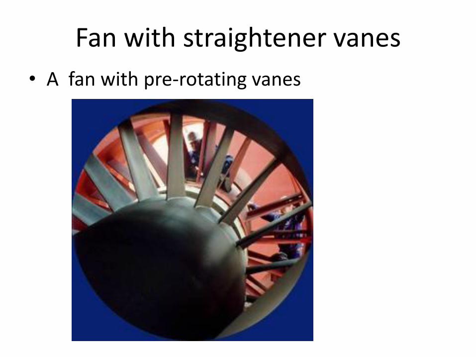
Fan with straightener vanes
• A fan with pre-rotating vanes
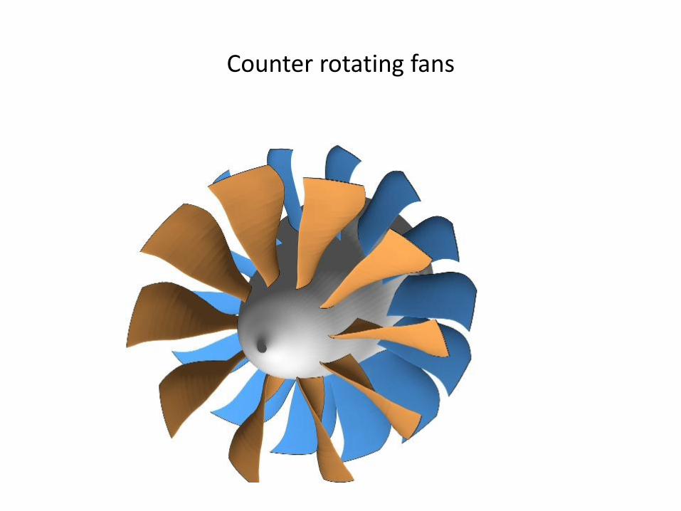
Counter rotating fans
The Drive motor and Fan
• The thrust of the fan and drag components vary with the square of the fan rpm
• Velocity in test section can be adjustedusing varying fan rpm or changing the pitch angle of the fan
• Most of the W/T speed is controlled using the fan RPM
• Different type of motor is used to rotate the fan (d-c motor, variable frequency, Magnetic coupling, induction motor, Internal combustion drive motor, ect…)
• The nacelle must be from o,3 to o,7diam in order to give the best flow condition for the fan
The corners
• Practically it is not possible to design the corners without losses.
• Using proper turning vanes the losses can reduce
• Drag due to separation ƞ= ∆p/q ƞ = corner losses coefficient
∆p = static pressure drop due to losses
q = dynamic pressure
• The abrupt corner gives 100 % (ƞ = 1. 00)
• With good designing this can be reduce to 0.15
The Honeycombs and Screen • Honeycombs and screen are used in the settling chamber to improve the flow
and reduce the turbulence of the air
• Disadvantage of honeycomb is reduce the area (surge)
• Different type of honeycombs are square, rectangle, octagonal
• Disadvantage of honeycombs, add the blockage to air flow at entrance
• Screens are far more useful than honeycombs for adjusting the flow
• Low turbulence tunnel might have six or more screens inside the settling chamber
Entrance Cone • Use between settling chamber to the test section to increase velocity
• Bad designing of entrance cone can cause the flow separation before the test section
• Boundary layer growth of cone can be avoided at test section keeping very small gap ( of 0.05 diam) just before test section
• Contraction ratio and length of cone need to be design properly to get required velocity at test section without boundary layer separation from cone
Power Losses
• A logical approach to the losses in wind tunnel- Break down the tunnel into following parts
– Cylindrical section
– Corners
– Expanding Section
– Contracting section
• Calculate the losses for each section
• This excluded the losses from fan and motor efficiency
Cooling
• Due to motor (propeller driven) there is increase in temperature in the flow
• For low power tunnel with open jet this effect is very low
• For tunnel with high power input and high jet velocity this effect can be more
• For this type of tunnel the cooling may be done by any of the four methods: – Increase of surface cooling by running of water over the tunnel exterior
– Interior cooling by the addition of water cooled turning vanes
– Water cooled radiator in the largest tunnel section
– By Continuous replacement of heated tunnel air with cool air using air exchanger
Jet Inserts • Tunnel can have auxiliary test section which can be fitted inside the
normal test section to reduce the test section size to save the model cost or increase the velocity
• This test section are usually either end plate or contraction types.
Calibration of the test section
• Speed
• Boundary layer growth
• Yaw of air
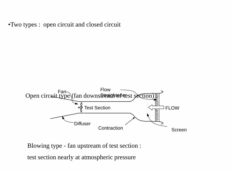
•Two types : open circuit and closed circuit
Open circuit type (fan downstream of test section) :
Blowing type - fan upstream of test section :
test section nearly at atmospheric pressure
Fan
Test Section
Diffuser Contraction
FLOW
Flow Straightener
Screen
Wind-tunnel techniques
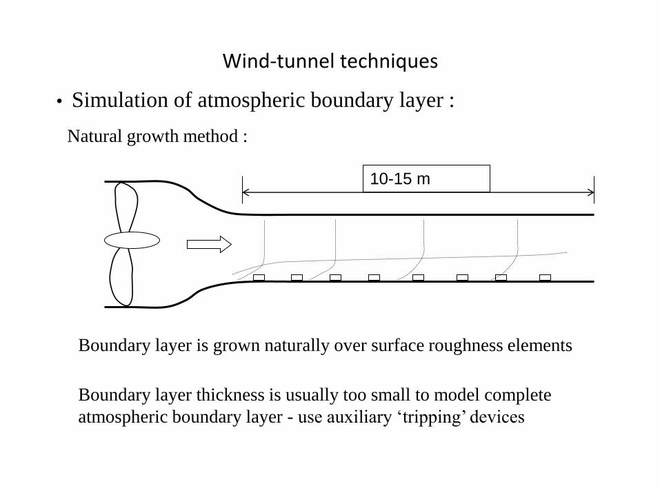
• Simulation of atmospheric boundary layer :
Natural growth method :
Boundary layer is grown naturally over surface roughness elements
Boundary layer thickness is usually too small to model complete
atmospheric boundary layer - use auxiliary ‘tripping’ devices
10-15 m
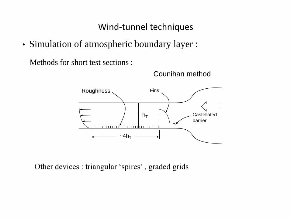
Wind-tunnel techniques
• Simulation of atmospheric boundary layer :
Methods for short test sections :
Other devices : triangular ‘spires’ , graded grids
Counihan method
Fins
Castellated
barrier hT
Roughness
~4hT
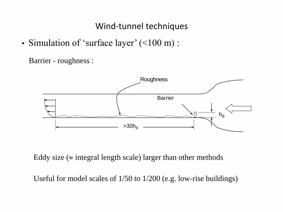
Wind-tunnel techniques
• Simulation of ‘surface layer’ (<100 m) :
Barrier - roughness :
Eddy size ( integral length scale) larger than other methods
hB
>30hB
Barrier
Roughness
Useful for model scales of 1/50 to 1/200 (e.g. low-rise buildings)
Wind-tunnel techniques
• Simulation of hurricane boundary layers :
Near eye wall : steep profile up to about 100 metres - then nearly constant
Can use non-hurricane boundary layer for rougher terrain in wind tunnel
simulations
Turbulence is higher in hurricanes (but ‘patchy’)
Wind-tunnel techniques
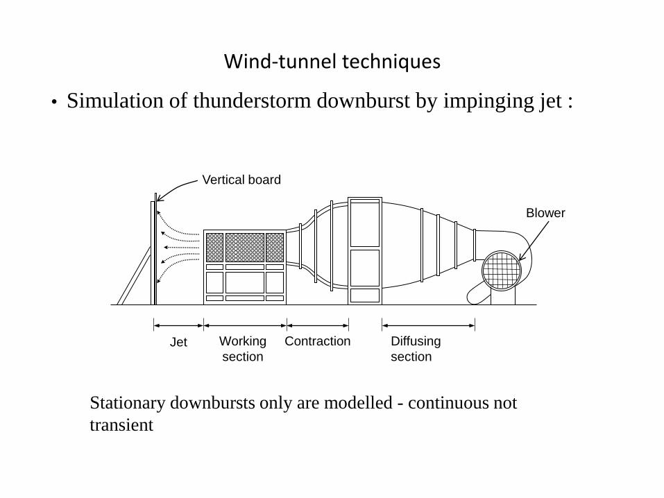
• Simulation of thunderstorm downburst by impinging jet :
Jet Working
section
Contraction Diffusing
section
Vertical board
Blower
Stationary downbursts only are modelled - continuous not
transient
Wind-tunnel techniques
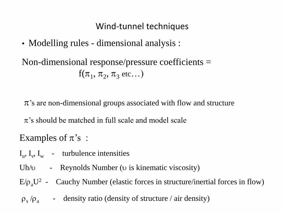
• Modelling rules - dimensional analysis :
’s are non-dimensional groups associated with flow and structure
Non-dimensional response/pressure coefficients =
f(1, 2, 3 etc…)
’s should be matched in full scale and model scale
Examples of ’s :
Iu, Iv, Iw - turbulence intensities
Uh/ - Reynolds Number ( is kinematic viscosity)
E/aU2 - Cauchy Number (elastic forces in structure/inertial forces in flow)
s /a - density ratio (density of structure / air density)
Wind-tunnel techniques
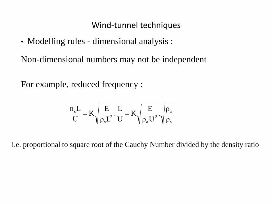
• Modelling rules - dimensional analysis :
For example, reduced frequency :
Non-dimensional numbers may not be independent
i.e. proportional to square root of the Cauchy Number divided by the density ratio
s
a
2
a
2
s
s
ρ
ρ.
Uρ
EK
U
L.
Lρ
EK
U
Ln
Wind-tunnel techniques
• Modelling rules - dimensional analysis :
Scaling requirements might be relaxed
Not possible to obtain equality of all non-dimensional groups
Judgement based on experience and understanding of mechanics of the
phenomena
Quality assurance manuals and standards for wind-tunnel testing are
now available - e.g. A.W.E.S. , A.S.C.E.
Wind-tunnel techniques
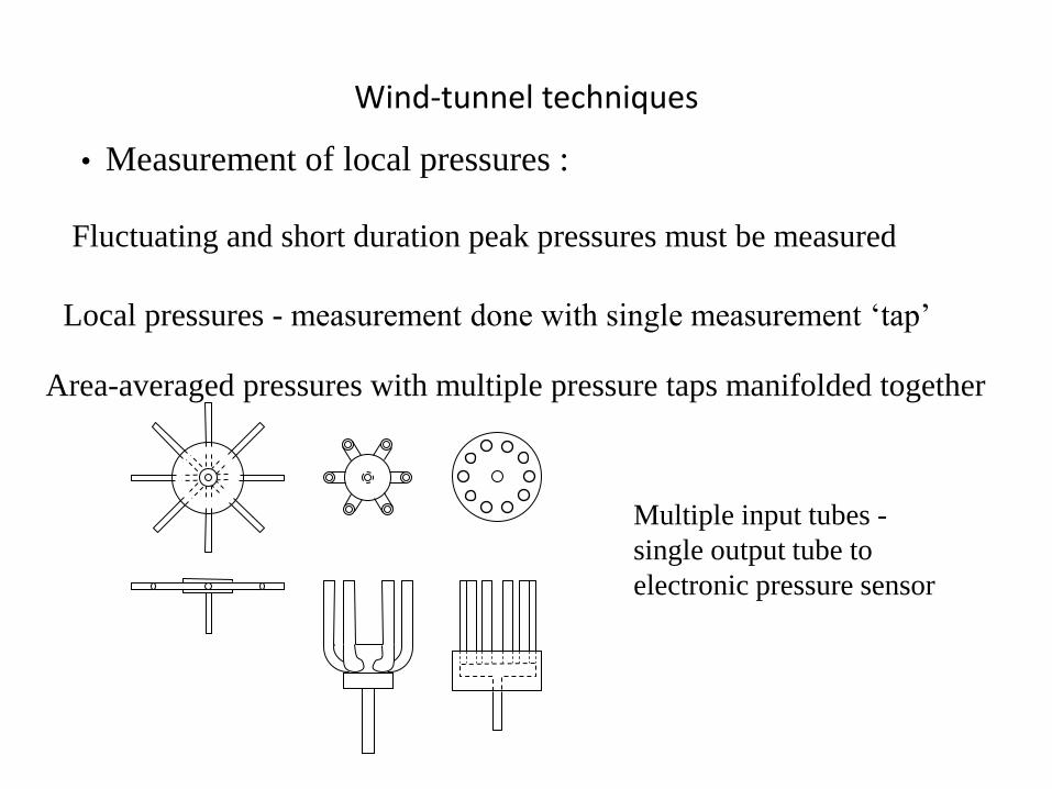
• Measurement of local pressures :
Local pressures - measurement done with single measurement ‘tap’
Fluctuating and short duration peak pressures must be measured
Area-averaged pressures with multiple pressure taps manifolded together
Multiple input tubes -
single output tube to
electronic pressure sensor
Wind-tunnel techniques
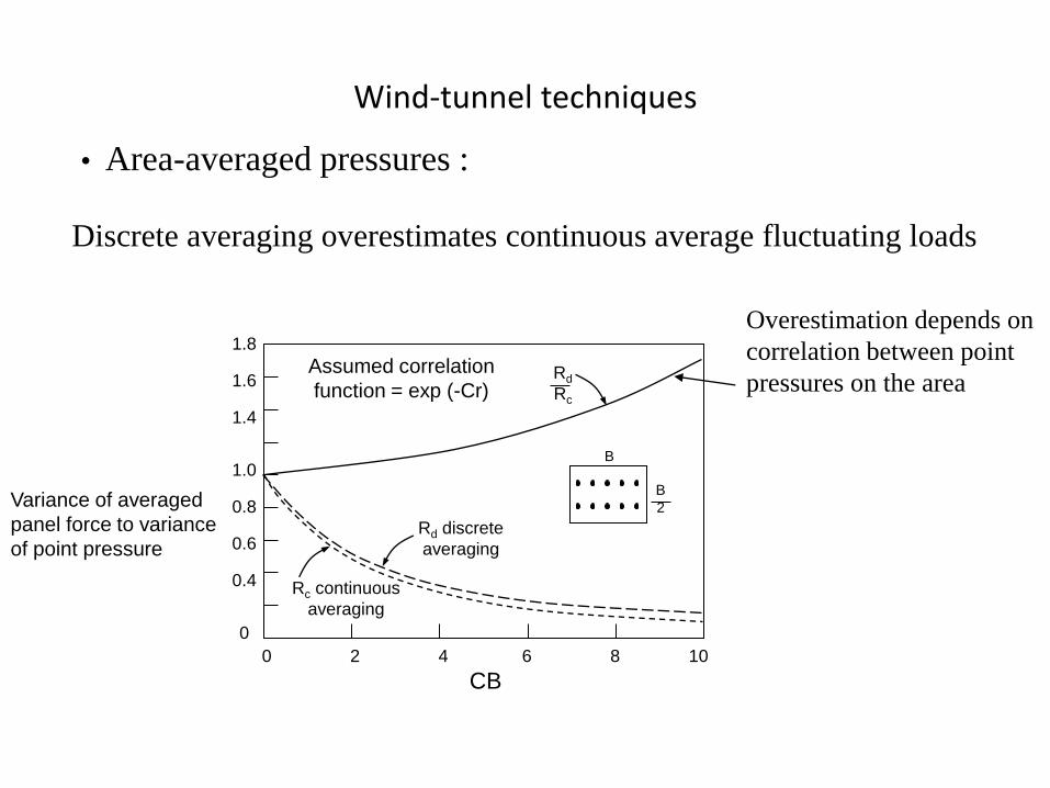
• Area-averaged pressures :
Discrete averaging overestimates continuous average fluctuating loads
Rd discrete
averaging
Rc continuous
averaging
Rd
Rc
Assumed correlation
function = exp (-Cr)
B
B
2
1.8
1.6
1.4
1.0
0.8
0.6
0.4
0
0 2 4 6 8 10
CB
Variance of averaged
panel force to variance
of point pressure
Overestimation depends on
correlation between point
pressures on the area
Wind-tunnel techniques
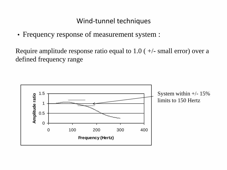
• Frequency response of measurement system :
Require amplitude response ratio equal to 1.0 ( +/- small error) over a
defined frequency range
0
0.5
1
1.5
0 100 200 300 400
Frequency (Hertz)
Am
plitu
de
ra
tio System within +/- 15%
limits to 150 Hertz
Wind-tunnel techniques
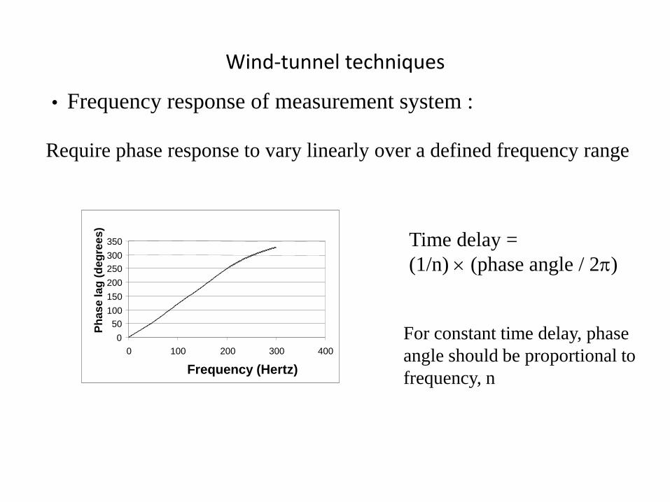
• Frequency response of measurement system :
Require phase response to vary linearly over a defined frequency range
0
50
100
150
200
250
300
350
0 100 200 300 400
Frequency (Hertz)
Ph
as
e la
g (
deg
ree
s)
Time delay =
(1/n) (phase angle / 2)
For constant time delay, phase
angle should be proportional to
frequency, n
Wind-tunnel techniques
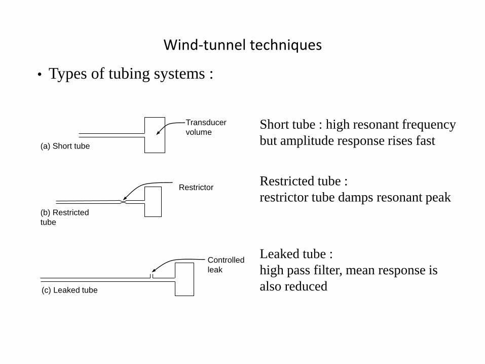
• Types of tubing systems :
Short tube : high resonant frequency
but amplitude response rises fast
Restricted tube :
restrictor tube damps resonant peak
Leaked tube :
high pass filter, mean response is
also reduced
Transducer
volume
(a) Short tube
Restrictor
(b) Restricted
tube
Controlled
leak
(c) Leaked tube
Wind-tunnel techniques
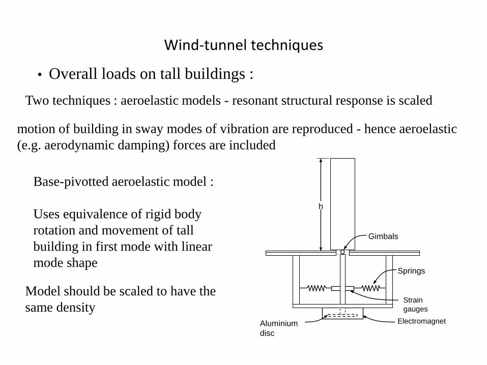
• Overall loads on tall buildings :
Two techniques : aeroelastic models - resonant structural response is scaled
Base-pivotted aeroelastic model :
Gimbals
Springs
Strain
gauges
Electromagnet Aluminium
disc
h
motion of building in sway modes of vibration are reproduced - hence aeroelastic
(e.g. aerodynamic damping) forces are included
Uses equivalence of rigid body
rotation and movement of tall
building in first mode with linear
mode shape
Model should be scaled to have the
same density
Wind-tunnel techniques
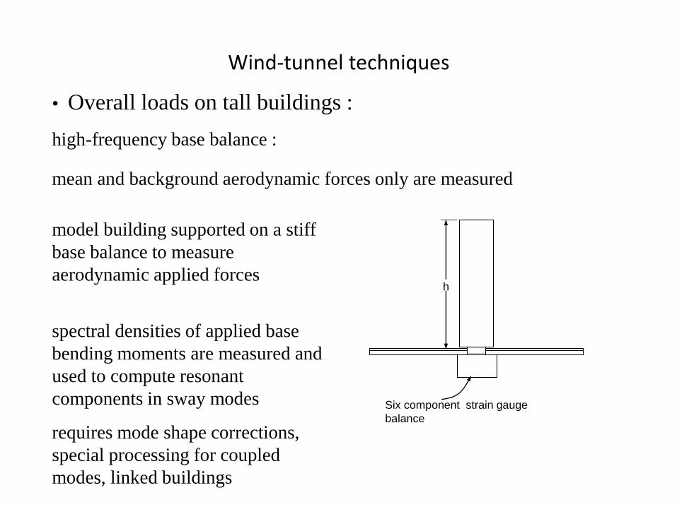
• Overall loads on tall buildings :
model building supported on a stiff
base balance to measure
aerodynamic applied forces
high-frequency base balance :
spectral densities of applied base
bending moments are measured and
used to compute resonant
components in sway modes
mean and background aerodynamic forces only are measured
h
Six component strain gauge
balance
requires mode shape corrections,
special processing for coupled
modes, linked buildings
Wind-tunnel techniques
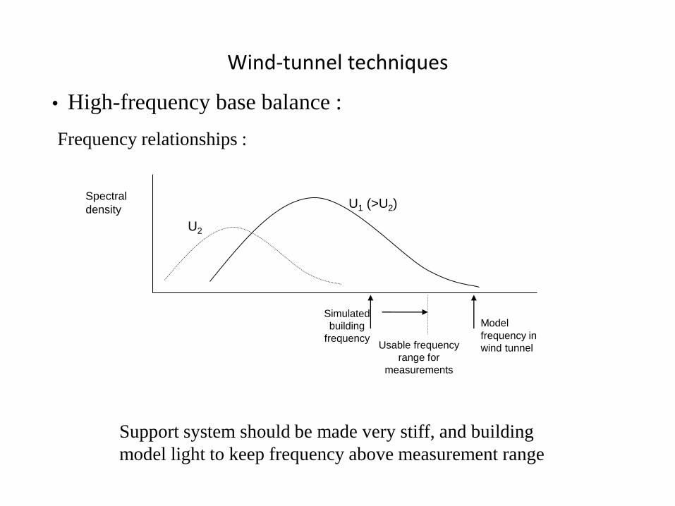
• High-frequency base balance :
Support system should be made very stiff, and building
model light to keep frequency above measurement range
Frequency relationships :
U1 (>U2)
U2
Simulated
building
frequency
Model frequency in
wind tunnel
Spectral
density
Usable frequency
range for
measurements
Wind-tunnel techniques
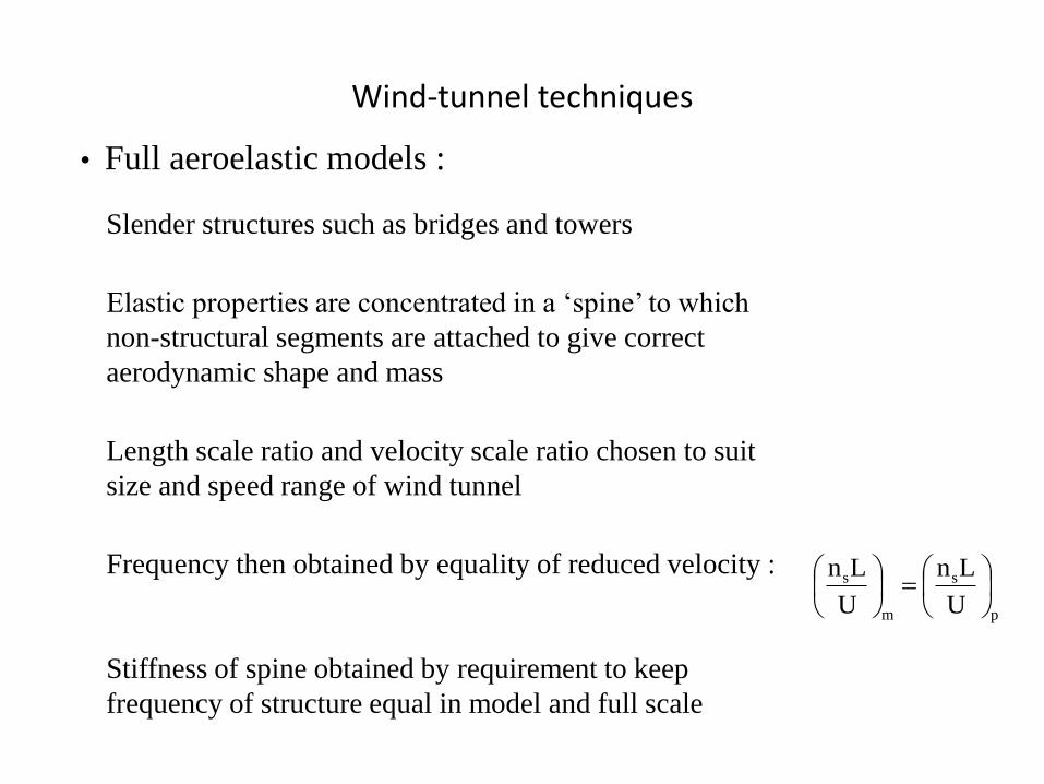
• Full aeroelastic models :
Elastic properties are concentrated in a ‘spine’ to which
non-structural segments are attached to give correct
aerodynamic shape and mass
Slender structures such as bridges and towers
Length scale ratio and velocity scale ratio chosen to suit
size and speed range of wind tunnel
Frequency then obtained by equality of reduced velocity :
p
s
m
s
U
Ln
U
Ln
Stiffness of spine obtained by requirement to keep
frequency of structure equal in model and full scale
Wind-tunnel techniques
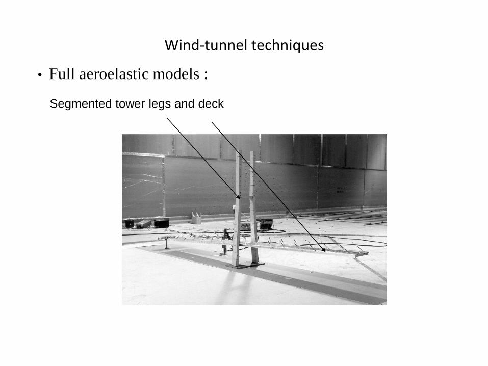
• Full aeroelastic models :
Segmented tower legs and deck