mars and venus entry simulation capabilities of irs plasma wind tunnel pwk3
TRANSCRIPT

www.ccsenet.org/apr Applied Physics Research Vol. 4, No. 1; February 2012
ISSN 1916-9639 E-ISSN 1916-9647 146
Mars and Venus Entry Simulation Capabilities of IRS Plasma Wind Tunnel PWK3
Georg Herdrich (Corresponding author) & Thomas Marynowski
Michael Dropmann & Stefanos Fasoulas
Institut für Raumfahrtsysteme, Universität Stuttgart
Pfaffenwaldring 31, 70569 Stuttgart, Germany
Tel: 49-711-685-624-12 E-mail: [email protected]
Received: July 17, 2011 Accepted: August 1, 2011 Published: February 1, 2012
doi:10.5539/apr.v4n1p146 URL: http://dx.doi.org/10.5539/apr.v4n1p146
The research was partially financed by the European Space Agency, Noordwijk, The Netherlands
Abstract
An assessment is made for the inductively driven plasma wind tunnel PWK3 with the goal to derive relevant mass specific enthalpies for typical Mars and Venus atmospheric entry missions. For this purpose an integral method has been used which links the plasma power to the radial distribution of total pressure and fully catalytic heat flux in the plasma jet on basis of a relation from Marvin and Pope. Rebuilding the enthalpies with this relation allows for the derivation of a gas specific proportionality factor. This factor enables the derivation of the mass specific enthalpies at the centre line and the radial profiles for the respective condition are not necessarily required any more. Correspondingly a review of reference CO2 plasma conditions obtained in past investigations at IRS leads to the identification of an operational envelope in terms of the mass specific enthalpies which are from an energy consideration the prerequisite for the creation of similarities with respect to the real atmospheric entry maneuvers. The analysis shows that PWK3 is capable to cover the full range of mass specific enthalpies that are required for typical Mars and Venus atmospheric entry scenarios.
Keywords: Atmospheric entry simulation, Non-equilibrium plasma, Simulation facilities
1. Introduction
Electrodeless inductively heated plasma generators enable basic thermal protection system material tests (e.g. catalysis- see Herdrich, Fertig, Lein, Steinbeck, Pidan (2010) and Herdrich, Fertig, Petkow, Steinbeck, (2010)) and the simulation of atmospheres that contain chemically reactive components such as of Mars or Venus with a high amount of CO2 in the atmosphere. The inductively driven generators at IRS have an optimized design where the induction coil is closer to the plasma than it is with other designs, see Herdrich, Petkow (2008) and Nawaz, Herdrich (2009). Therefore, the electromagnetic field loss is reduced. The water cooling system surrounds both the coil and the plasma tube.
In the future, several planetary probe missions, soft landing missions and sample return missions such as "Venus Sample Return Mission", "Mars Mini-Probes", Mars Society Balloon Mission or "Mars Sample Return Mission" (MSR) will be accomplished, see Herdrich, Auweter-Kurtz, Endlich (2003). The current reference mission of ESA, ExoMars, has the final goal of a sample return. The sample, however, has to be brought from the Martian surface such that the overall mission has to cope with both an atmospheric entry at Mars and a hyperbolic re-entry for Earth as e.g. outlined by Bouilly, Bonnefond, Boulier, Balemboy, Boquet, Plaindoux, Mignot, (2009).
For such missions both TPS and environment (plasma) during the entry have to be investigated by means of computational and ground facility based simulations. Such ground facilities are the IRS plasma wind tunnels PWK 1-4 reproducing the thermal, aerodynamic and chemical load on the surface of a space vehicle entering an atmosphere. They are operated with different plasma generators; see Herdrich, Auweter-Kurtz, Endlich, (2003) and Auweter-Kurtz, Herdrich, Laure, Wagner (2004).
In addition, plasma wind tunnels can be applied for the development of in-flight instruments e.g. aiming for the
www.ccsenet.org/apr Applied Physics Research Vol. 4, No. 1; February 2012
Published by Canadian Center of Science and Education 147
assessment of the conditions at the hot structures and the plasma conditions experienced by the vehicle during entry as e.g. described by Auweter-Kurtz, Fertig, Herdrich, Laux, Schöttle, Wegmann, Winter (2003), Lein, Reimer, Stubicar, Deuble, Auweter-Kurtz, Herdrich, Winter (2009) and Herdrich, Fertig, Lein, Löhle, Preci, Steinbeck, Wernitz, Auweter-Kurtz, Roeser (2010). Furthermore, they can be also used to support development activities for instruments to be used for airborne observation campaigns, see Herdrich, Fertig, Lein, Löhle, Preci, Steinbeck, Wernitz, Auweter-Kurtz, Roeser (2010). Reference conditions can be used for validation of numerical tools as well; see Fertig, Herdrich (2009).
Non-intrusive measurement techniques like emission spectroscopy, Fabry-Perot interferometry and laser-induced fluorescence are used to investigate the plasma flows. Relevant techniques as such are e.g. described and applied by Löhle, Eichhorn, Steinbeck, Lein, Herdrich, Röser, Auweter-Kurtz (2008) and by Matsui, Takayanagi, Komurasaki, Arakawa, Knapp, Herdrich, Auweter-Kurtz (2008). They are applied to determine atomic and molecular density and the velocity distribution. The laser absorption spectroscopy technique of the Department of Aeronautics and Astronautics (Tokyo University) was used for IRS-PWK3 to determine densities and translational temperatures e.g. of atomic oxygen, see also Matsui, Komurasaki, Herdrich, Auweter-Kurtz (2005).
Besides the non-intrusive measurement techniques, mass spectrometry, electrostatic and radiation probes belong to the group of intrusive measurement techniques. Mechanical probes are among the most important instruments for plasma-diagnostic measurements and are often used. Besides the standard sample support system which carries the TPS material sample to be tested, probes for Pitot pressure, Mach number, heat flux, enthalpy and oxygen partial pressure determination are used. Electrostatic probes are used to ascertain the plasma potential, electron density and temperature, energy distribution of the electrons, ion temperature and flow velocity. Radiometric probes are unavoidable when the radiation heat flux cannot be neglected compared to the convective part. This is the case when during sample return missions the entry speed into the Earth’s atmosphere is especially high or when the atmosphere of another celestial body (that is to be entered) contains strong radiating species, as for example the atmosphere of Titan.
2. Experimental Set-up
2.1 Facility PWK3
An extensive description of the facility has been developed by Herdrich (2004).
The PWK3 set-up shown in Fig. 1 consists of the IPG plasma source and the vacuum chamber. The chamber is about 2 m in length and 1.6 m in diameter. Optical accesses enable the investigation of the plasma. A heat exchanger between the chamber and the vacuum system cools down the hot plasma to protect the vacuum system from being damaged. The flat lid of PWK3 (left side chamber) is equipped with the IPG and the external resonant circuit consisting of the capacitors with the connection to the IPG coil. The right side flange of the vacuum chamber is connected to the IRS vacuum pump system simulating pressures at altitudes up to 90 km (Earth entry). Total suction power of the pumps amounts to 6103 m3/h at atmospheric pressure and reaches about 2.5105 m3/h at 10 Pa measured at the intake pipe of the system, which has a diameter of 1 m. The base pressure is about 0.5 Pa. The desired tank pressure can be adjusted between the best achievable vacuum and 100 kPa by removing one or more pumps from the circuit and/or mixing additional air into the system close to the pumps.
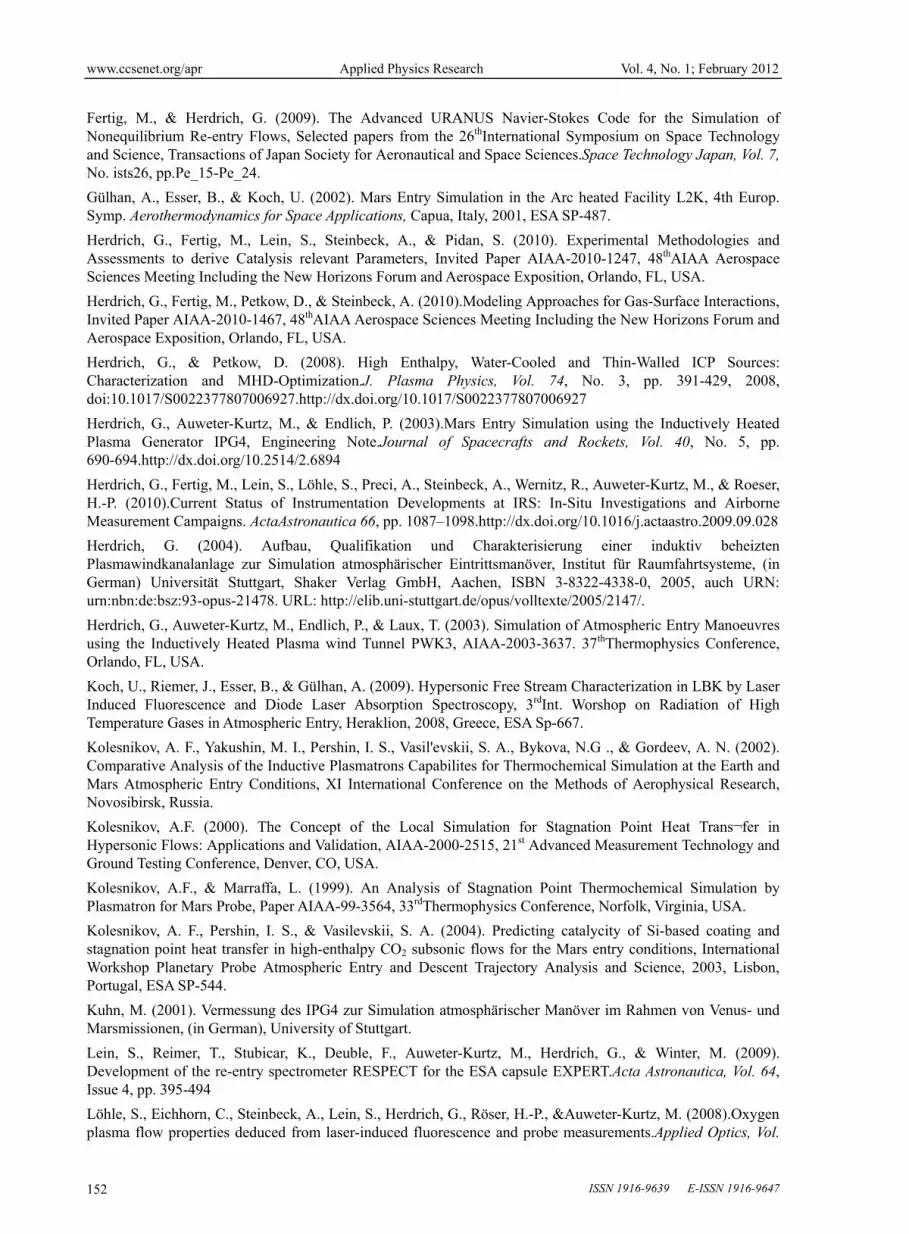
The external resonant circuit is water cooled. With this, the capacitors, which have a capacity of 6 nF ± 20 % each, and the coil are cooled. The resonant circuit depicted in Fig. 2 is built in Meissner type switching using a metal-ceramic triode with an oscillator efficiency of about 75%. Its nominal frequency can be changed by switching the number of capacitors k as well as by the use of coils with different inductivities, i.e. variation of coil turns, n.
For the present investigations, a water cooled 2.5-turn (n = 2.5) and 5.5-turn (n = 5.5) coil, each having a length l of 120 mm, were used. These configurations lead to inductivities L of 0.45 and 1.8 H, respectively. The whole circuit is connected to a 375 kW power supply. The incoming anode power can be adjusted by the control of the anode (plate) voltage. Correspondingly, the frequency can be approximated by
LCf
12
(1)
Here, is the angular frequency while f is the frequency. The coil inductivity is calculated by
272 ,10 nldgnl
ddLcoil
(2)

www.ccsenet.org/apr Applied Physics Research Vol. 4, No. 1; February 2012
ISSN 1916-9639 E-ISSN 1916-9647 148
as the well-known relationship for long coils is not applicable anymore, see also reference Herdrich, Auweter-Kurtz, Endlich (2003). The coil’s diameter d has to be inserted in cm leading to the dimension Henry for L. The parameter , a correction factor, has a magnitude of 6, as e.g. derived by Herdrich, Petkow (2008). Introducing the parameter k for the number of capacitors used during operation, the frequency can be determined by
knknfknff kn
11),( 1;1;
.(3)
Usually, there are peripheral inductivities due to the coil’s input leads which are not negligible. Therefore, it is useful to use Eq. (3) in empirical form depending on k i.e. for coils with specific n.
With the coils used in this investigation (n = 2.5, n = 5.5), Eqs. (1) and (2) deliver frequencies that are higher than the measured ones. This can be explained by the presence of peripheral inductivities which can be of the same order of magnitude as the coil inductivities:
Pericoiltot LLL .(4)
Eqs. (2-4) in combination with the measured frequencies for n = 2.5 and n = 5.5 lead to the frequency range shown in Fig. 3 for PWK3 using the inductively heated plasma generators IPG3, IPG4 and IPG5.
Figure 3 shows the measured frequencies of the facility PWK3 together with the calculated frequencies using Eq. (1) for different plasmas. Here, Eq. (4) was applied and LPeri was calculated for all measured values. These values depend on the number of capacitors k and on the number of coil turns n. According to Fig. 3, this leads to a frequency range between 0.5 and 1.4 MHz. The usage of just one capacitor together with a 2.5-turn coil (Lcoil 0,4 H) makes a frequency of 1.9 MHz achievable. This value cannot be operated permanently due to limitations of the energy supply system and current limiting effects that are ongoing with the capacity reduction. The second coil’s (n = 5.5) inductivity is Lcoil 1,8 H. The frequencies shown with filled symbols were measured using a looped conductor connected to an oscilloscope. The open square symbol represents frequencies measured with a modified Pearson current monitor described by Herdrich (2004).
Here, the coil currents for k = 4 were measured with high time resolution for oxygen and nitrogen while varying the mass flow rate and anode power such that frequency spectra could be obtained by Fourrier analysis. For k = 7 a Rogowski coil was used to determine the frequencies for argon and air while varying the plate power. Regression analysis was performed for the data by Herdrich (2004). With Lperi ≈ 0.75 µH Eqs. (1-4) correspond well to the measured frequencies.
Inductively heated plasma generators basically consist of a coil surrounding a plasma container (tube) and capacitors. The alternating current in the coil induces a mostly azimuthal electric field inside the tube. This electric field initiates an electric discharge in the gas that is injected on one side into the tube (Fig. 4). The produced plasma is expanded into the vacuum chamber. The plasma current amplitude - and thus the Ohmic heating - strongly depends on the electric conductivity of the plasma and the resonant frequency.
The principal parts of the plasma generators IPG3 and IPG4 are described here. An axial optical access through the inner injection head enables investigations of the plasma inside the generator. The tube cooling system is transparent. Hence, the position of the "plasma flame" within the tube can be observed with regard to different operating parameters such as chamber pressure, working gas, mass flow and anode power. Additionally, this feature is supported by the axial optical window. The total length of IPG3 is about 0.35 m, its diameter is about 0.1 m. The quartz tube contains the generated plasma which leaves the generator through the chamber adapter. The induction coil is connected to the external resonant circuit delivering power and cooling water for the IPGs. Furthermore, both the tube and the coil are surrounded by the tube cooling, which protects the quartz tube from overheating. The water and an additional cage around the generator serve as an rf-radiation protection shield. The length of IPG4 is about 0.4 m (with nozzle). IPG5 is an advanced design where reducing the distance between plasma and coil in turn further reduces the coupling losses as realized by Nawaz, Herdrich (2009).
2.2 Measurement Techniques
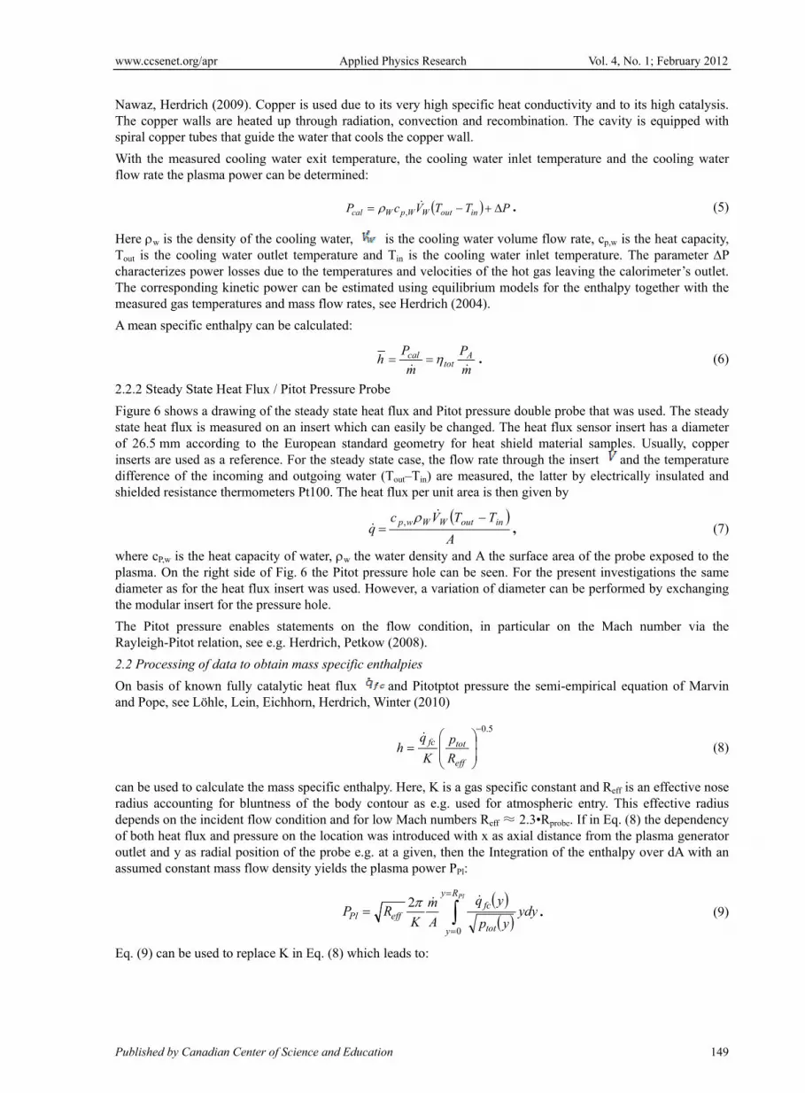
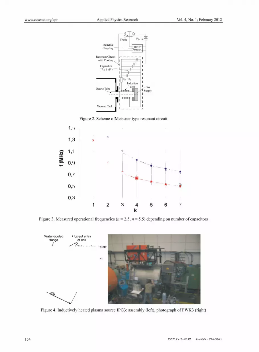
2.2.1 Cavity Calorimeter
A cavity calorimeter has been developed in order to determine the thermal plasma power in the PWK3 vacuum chamber (Fig. 5). The working principle is easy. The plasma enters the copper cavity, which is shaped like a cone, through a hole. The diameter of the hole is 120 mm, which is roughly 25 % bigger than the usual plasma beams. The distance between the calorimeter and the plasma outlet of the IPG is about 100 mm. This is necessary because smaller distances can result in retroactions that manipulate the discharge behaviour of the IPG; see
www.cc
Publish
NawazThe cospiral c
With thflow ra
Here Tout is charactThe comeasur
A mean
2.2.2 S
Figure state heof 26.5inserts differenshielde
where plasmadiametthe mo
The PiRayleig
2.2 Pro
On basand Po
can be radius dependof bothoutlet aassume
Eq. (9)
csenet.org/apr
hed by Canadian
z, Herdrich (20opper walls arecopper tubes th
he measured cate the plasma
w is the densitthe cooling w
terizes power orresponding kred gas temper
n specific enth
Steady State He
6 shows a draeat flux is mea5 mm accordinare used as a
nce of the inced resistance th
cP,w is the heata. On the rightter as for the hodular insert fo
itot pressure gh-Pitot relatio
ocessing of dat
sis of known fope, see Löhle,
used to calculaccounting fo
ds on the incidh heat flux andand y as radiaed constant ma
) can be used to
n Center of Scien
009). Copper ie heated up thhat guide the w
cooling water power can be
ty of the coolinwater outlet temlosses due to t
kinetic power cratures and ma
halpy can be ca
eat Flux / Pitot
awing of the stasured on an ing to the Eurreference. For
coming and ouhermometers P
t capacity of wt side of Fig. 6
heat flux insertor the pressure
enables statemon, see e.g. He
ta to obtain ma
fully catalytic Lein, Eichhor
late the mass spor bluntness oent flow condi
d pressure on tal position of thass flow densit
o replace K in
Applied
nce and Educati
s used due to hrough radiatiowater that cools
exit temperatdetermined:
Pcal
ng water, mperature andthe temperaturcan be estimat
ass flow rates,
alculated:
h
t Pressure Prob
teady state heainsert which caropean standarr the steady stautgoing water Pt100. The hea
q
water, w the w6 the Pitot pret was used. Hohole.
ments on the erdrich, Petkow
ass specific en
heat flux rn, Herdrich, W
pecific enthalpf the body coition and for lohe location wahe probe e.g. aty yields the pl
PlP
Eq. (8) which
Physics Resear
ion
its very high son, convections the copper w
ture, the coolin
TVc outWWpW
,
is the coolingd Tin is the cores and velocitted using equisee Herdrich (
m
Ph tot
cal
be
at flux and Pitoan easily be chrd geometry fate case, the fl(Tout–Tin) are
at flux per unit
A
TVc WWwp,
water density aessure hole canowever, a varia
flow conditiw (2008).
thalpies
and PitotptoWinter (2010)
fc
R
p
K
qh
py. Here, K is ontour as e.g. ow Mach numbas introduced wat a given, thelasma power P
Ry
y
eff A
m
KR
2
h leads to:
rch
specific heat cn and recombi
wall.
ng water inlet
PTin .
g water volumooling water inties of the hot ilibrium model(2004).
m
PA
.
ot pressure douhanged. The hfor heat shieldflow rate throu
measured, thearea is then gi
TT inout ,
and A the surfan be seen. Foration of diame
ion, in particu
t pressure the
5.0
eff
tot
R
p
a gas specific used for atmobers Reff ≈ 2.3with x as axialen the IntegratPPl:
PlR
tot
fc ydyyp
yq
0
Vol.
onductivity anination. The ca
t temperature
me flow rate, cp
nlet temperatugas leaving th
ls for the enth
uble probe thatheat flux sensod material samugh the insert e latter by eleciven by
face area of ther the present ineter can be per
ular on the M
semi-empiric
constant and Rospheric entry.3•Rprobe. If in El distance fromtion of the enth
dy .
. 4, No. 1; Febru
nd to its high cavity is equipp
and the coolin
p,w is the heat cure. The paramhe calorimeterhalpy together
t was used. Thr insert has a d
mples. Usuallyand the tem
ctrically insula
e probe exposenvestigations tformed by exc
Mach number
al equation of
Reff is an effect. This effectivEq. (8) the depm the plasma ghalpy over dA
uary 2012
149
catalysis. ped with
ng water
(5)
capacity, meter P ’s outlet. with the
(6)
he steady diameter
y, copper mperature
ated and
(7)
ed to the the same changing
via the
f Marvin
(8)
tive nose ve radius pendency generator A with an
(9)
www.ccsenet.org/apr Applied Physics Research Vol. 4, No. 1; February 2012
ISSN 1916-9639 E-ISSN 1916-9647 150
PlRy
y tot
fc
tot
fc
Pl
effydy
yp
yq
yxp
yxq
R
h
yxh
0
2 ,
,
2
,
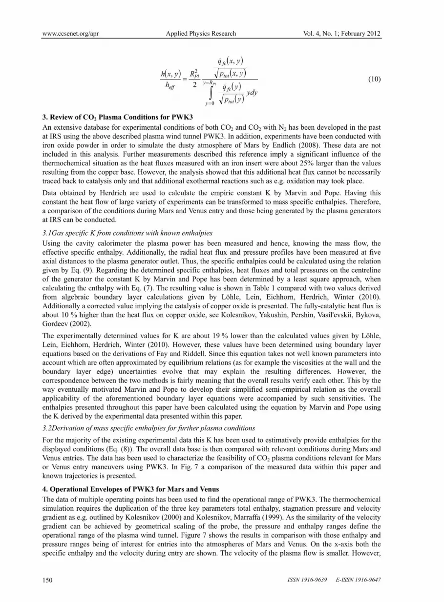
(10)
3. Review of CO2 Plasma Conditions for PWK3 An extensive database for experimental conditions of both CO2 and CO2 with N2 has been developed in the past at IRS using the above described plasma wind tunnel PWK3. In addition, experiments have been conducted with iron oxide powder in order to simulate the dusty atmosphere of Mars by Endlich (2008). These data are not included in this analysis. Further measurements described this reference imply a significant influence of the thermochemical situation as the heat fluxes measured with an iron insert were about 25% larger than the values resulting from the copper base. However, the analysis showed that this additional heat flux cannot be necessarily traced back to catalysis only and that additional exothermal reactions such as e.g. oxidation may took place.
Data obtained by Herdrich are used to calculate the empiric constant K by Marvin and Pope. Having this constant the heat flow of large variety of experiments can be transformed to mass specific enthalpies. Therefore, a comparison of the conditions during Mars and Venus entry and those being generated by the plasma generators at IRS can be conducted.
3.1Gas specific K from conditions with known enthalpies Using the cavity calorimeter the plasma power has been measured and hence, knowing the mass flow, the effective specific enthalpy. Additionally, the radial heat flux and pressure profiles have been measured at five axial distances to the plasma generator outlet. Thus, the specific enthalpies could be calculated using the relation given by Eq. (9). Regarding the determined specific enthalpies, heat fluxes and total pressures on the centreline of the generator the constant K by Marvin and Pope has been determined by a least square approach, when calculating the enthalpy with Eq. (7). The resulting value is shown in Table 1 compared with two values derived from algebraic boundary layer calculations given by Löhle, Lein, Eichhorn, Herdrich, Winter (2010). Additionally a corrected value implying the catalysis of copper oxide is presented. The fully-catalytic heat flux is about 10 % higher than the heat flux on copper oxide, see Kolesnikov, Yakushin, Pershin, Vasil'evskii, Bykova, Gordeev (2002).
The experimentally determined values for K are about 19 % lower than the calculated values given by Löhle, Lein, Eichhorn, Herdrich, Winter (2010). However, these values have been determined using boundary layer equations based on the derivations of Fay and Riddell. Since this equation takes not well known parameters into account which are often approximated by equilibrium relations (as for example the viscosities at the wall and the boundary layer edge) uncertainties evolve that may explain the resulting differences. However, the correspondence between the two methods is fairly meaning that the overall results verify each other. This by the way eventually motivated Marvin and Pope to develop their simplified semi-empirical relation as the overall applicability of the aforementioned boundary layer equations were accompanied by such sensitivities. The enthalpies presented throughout this paper have been calculated using the equation by Marvin and Pope using the K derived by the experimental data presented within this paper.
3.2Derivation of mass specific enthalpies for further plasma conditions
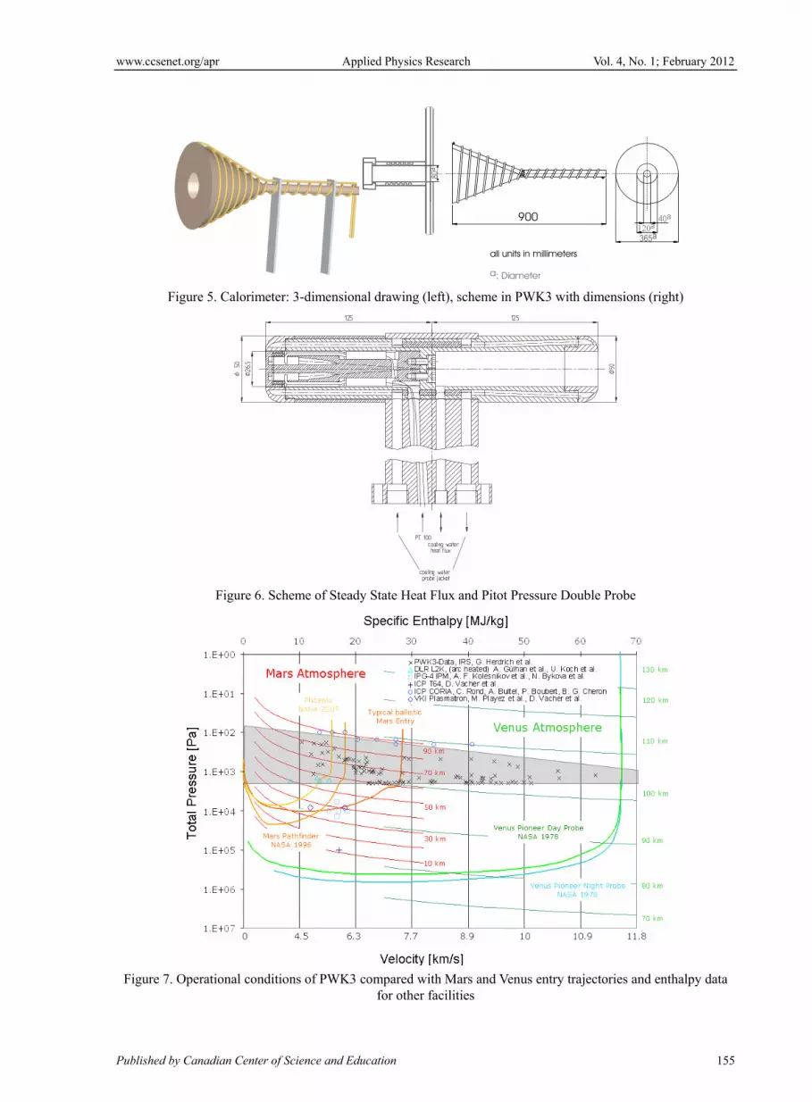
For the majority of the existing experimental data this K has been used to estimatively provide enthalpies for the displayed conditions (Eq. (8)). The overall data base is then compared with relevant conditions during Mars and Venus entries. The data has been used to characterize the feasibility of CO2 plasma conditions relevant for Mars or Venus entry maneuvers using PWK3. In Fig. 7 a comparison of the measured data within this paper and known trajectories is presented.
4. Operational Envelopes of PWK3 for Mars and Venus The data of multiple operating points has been used to find the operational range of PWK3. The thermochemical simulation requires the duplication of the three key parameters total enthalpy, stagnation pressure and velocity gradient as e.g. outlined by Kolesnikov (2000) and Kolesnikov, Marraffa (1999). As the similarity of the velocity gradient can be achieved by geometrical scaling of the probe, the pressure and enthalpy ranges define the operational range of the plasma wind tunnel. Figure 7 shows the results in comparison with those enthalpy and pressure ranges being of interest for entries into the atmospheres of Mars and Venus. On the x-axis both the specific enthalpy and the velocity during entry are shown. The velocity of the plasma flow is smaller. However,
www.ccsenet.org/apr Applied Physics Research Vol. 4, No. 1; February 2012
Published by Canadian Center of Science and Education 151
the mass specific enthalpies are duplicated.
For Mars, the trajectories of the Phoenix and Pathfinder Lander and a typical ballistic trajectory are shown. For Venus the trajectories of the Pioneer Venus Day and Night Probes are shown, see Seiff, Kirk (1982). Additionally, lines of equal altitude of the Mars and Venus atmosphere are plotted. For Mars, the atmosphere is modeled isothermal using density and pressure data obtained by Spirit during descend at an altitude of 20 km. For Venus the obtained atmospheric entry data of the Pioneer Venus Day Probe has been used (see Seiff, Kirk (1982)). In terms of pressure the currently performed operational regime of PWK3 is between 1.3 hPa and 20 hPa. The maximum achieved mass specific enthalpy is about 63 MJ/kg. By decreasing the mass flow rates for the plasma generator even higher specific enthalpies would be possible. The minimum pressure is limited on the one hand by the vacuum pump performance and on the other hand by the plasma generator.
The operational range allows simulating the conditions during early Mars entry, including peak deceleration, matching both enthalpy and pressure conditions. In addition, the enthalpy conditions can be reproduced for both Mars and Venus entries at the whole. However, it is evident that the facility should be extended to a higher pressure regime in future as both filling the gap to the higher pressure regimes and the development of equilibrium and near equilibrium test cases e.g. for plasma radiation research can be performed.
All experimental data were taken from the following references: Endlich, P. (2008), Kuhn (2001), Herdrich, Auweter-Kurtz, Endlich, Laux, (2003) and Endlich, Auweter-Kurtz, Herdrich, Löhle, Winter, (2003). In addition, enthalpy conditions from other facilities, all of them inductively driven except the arc-driven L2K, are shown. The values used for this are reported in the following references: Koch, Riemer, Esser, Gülhan, (2009), Gülhan, Esser, Koch, (2002), Bykova, Vasilevkii, Gordeev, Kolesnikov, Pershin, Yakushin (1997), Kolesnikov, Pershin, Vasilevskii (2004), Vacher, Andre, Dudeck (2008) and Rond, Bultel, Boubert, Cheron (2008). With the L2K data an attempt to create a data base with maximum completeness is made although these facilities typically suffer from electrode problems that accompany the use of CO2 as working gas.
5. Conclusions Based on measurements of radial total pressure and heat flux profiles of CO2 plasma in PWK3 the constant K introduced by Marvin and Pope could be determined experimentally. Comparison with values being derived on basis of the Fay-Riddell equation showed deviations of up to 38 %. The respective reasons for these deviations have been discussed. The obtained value for K has been used to determine the specific enthalpies of previously measured CO2 plasma conditions. Those enthalpies have been compared with conditions during Mars and Venus entry. The comparison revealed that PWK3 is able to provide the enthalpy conditions of the whole Mars and Venus entry. The rather lower pressures for the atmospheric Mars entries allow simulating both pressures und specific enthalpies fairly well for this scenario. Venus entries are out of the pressure range. Consequently the extension of the pressure regime of PWK3 will be subject to further research.
References
Auweter-Kurtz, M., Herdrich, G., Laure, S., & Wagner, H.P. (2004). Plasma Source Development for Technical Applications at IRS, The 4th International Symposium on Applied Plasma Science-ISAPS ’03, Kyoto/Japan 01.-05.09.2003. Advances in Applied Plasma Science, Vol. 4, 2003, S. 157-162, Vacuum, Vol. 73/3-4 (2004) pp 309-316. http://dx.doi.org/10.1016/j.vacuum.2003.12.077
Auweter-Kurtz, M. Fertig, M., Herdrich, G., Laux, T., Schöttle, U., Wegmann, Th., & Winter, M. (2003). Entry Experiments at IRS – In-flight Measurement during Atmospheric Entries.Space Technology Journal (ST), Vol. 23, Issue 4, pp. 217-234, July 2003, ISSN 0892-9270, R. Monti, UniversitätNeapel.
Bouilly, J. M., Bonnefond, F, Boulier, E, Balemboy, C, Boquet, M, Plaindoux, C, & Mignot, Y. (2009). Thermal Protection System of the ExoMars Entry Probe, 6thEuropean Workshop on Thermal Protection Systems and Hot Structures.
Bykova, N., Vasilevkii, S. A., Gordeev, A. N., Kolesnikov, A. F., Pershin, I. S., & Yakushin, M. I. (1997). An Induction Plasmatron Application for Simulation of Entry into Mars Atmosphere, 3rdInt. Symp. at ESTEC, Noordwijk, ESA SP-408.
Endlich, P. (2008). Untersuchungen zur experimentellen Simulation des Eintritts von Raumflugkörpern in die Marsatmosphäre, (in German) Dissertation, University of Stuttgart, 2008.
Endlich, P., Auweter-Kurtz, M., Herdrich, G., Löhle, L., & Winter, M. (2003).The inductively heated Plasma Wind Tunnel PWK3 as a Means for Emission Experiments to rebuilt radiation Test Cases. ESTEC Plasma Radiation Workshop, Portugal, Lisbon.
www.ccsenet.org/apr Applied Physics Research Vol. 4, No. 1; February 2012
ISSN 1916-9639 E-ISSN 1916-9647 152
Fertig, M., & Herdrich, G. (2009). The Advanced URANUS Navier-Stokes Code for the Simulation of Nonequilibrium Re-entry Flows, Selected papers from the 26thInternational Symposium on Space Technology and Science, Transactions of Japan Society for Aeronautical and Space Sciences.Space Technology Japan, Vol. 7, No. ists26, pp.Pe_15-Pe_24.
Gülhan, A., Esser, B., & Koch, U. (2002). Mars Entry Simulation in the Arc heated Facility L2K, 4th Europ. Symp. Aerothermodynamics for Space Applications, Capua, Italy, 2001, ESA SP-487.
Herdrich, G., Fertig, M., Lein, S., Steinbeck, A., & Pidan, S. (2010). Experimental Methodologies and Assessments to derive Catalysis relevant Parameters, Invited Paper AIAA-2010-1247, 48thAIAA Aerospace Sciences Meeting Including the New Horizons Forum and Aerospace Exposition, Orlando, FL, USA.
Herdrich, G., Fertig, M., Petkow, D., & Steinbeck, A. (2010).Modeling Approaches for Gas-Surface Interactions, Invited Paper AIAA-2010-1467, 48thAIAA Aerospace Sciences Meeting Including the New Horizons Forum and Aerospace Exposition, Orlando, FL, USA.
Herdrich, G., & Petkow, D. (2008). High Enthalpy, Water-Cooled and Thin-Walled ICP Sources: Characterization and MHD-Optimization.J. Plasma Physics, Vol. 74, No. 3, pp. 391-429, 2008, doi:10.1017/S0022377807006927.http://dx.doi.org/10.1017/S0022377807006927
Herdrich, G., Auweter-Kurtz, M., & Endlich, P. (2003).Mars Entry Simulation using the Inductively Heated Plasma Generator IPG4, Engineering Note.Journal of Spacecrafts and Rockets, Vol. 40, No. 5, pp. 690-694.http://dx.doi.org/10.2514/2.6894
Herdrich, G., Fertig, M., Lein, S., Löhle, S., Preci, A., Steinbeck, A., Wernitz, R., Auweter-Kurtz, M., & Roeser, H.-P. (2010).Current Status of Instrumentation Developments at IRS: In-Situ Investigations and Airborne Measurement Campaigns. ActaAstronautica 66, pp. 1087–1098.http://dx.doi.org/10.1016/j.actaastro.2009.09.028
Herdrich, G. (2004). Aufbau, Qualifikation und Charakterisierung einer induktiv beheizten Plasmawindkanalanlage zur Simulation atmosphärischer Eintrittsmanöver, Institut für Raumfahrtsysteme, (in German) Universität Stuttgart, Shaker Verlag GmbH, Aachen, ISBN 3-8322-4338-0, 2005, auch URN: urn:nbn:de:bsz:93-opus-21478. URL: http://elib.uni-stuttgart.de/opus/volltexte/2005/2147/.
Herdrich, G., Auweter-Kurtz, M., Endlich, P., & Laux, T. (2003). Simulation of Atmospheric Entry Manoeuvres using the Inductively Heated Plasma wind Tunnel PWK3, AIAA-2003-3637. 37thThermophysics Conference, Orlando, FL, USA.
Koch, U., Riemer, J., Esser, B., & Gülhan, A. (2009). Hypersonic Free Stream Characterization in LBK by Laser Induced Fluorescence and Diode Laser Absorption Spectroscopy, 3rdInt. Worshop on Radiation of High Temperature Gases in Atmospheric Entry, Heraklion, 2008, Greece, ESA Sp-667.
Kolesnikov, A. F., Yakushin, M. I., Pershin, I. S., Vasil'evskii, S. A., Bykova, N.G ., & Gordeev, A. N. (2002). Comparative Analysis of the Inductive Plasmatrons Capabilites for Thermochemical Simulation at the Earth and Mars Atmospheric Entry Conditions, XI International Conference on the Methods of Aerophysical Research, Novosibirsk, Russia.
Kolesnikov, A.F. (2000). The Concept of the Local Simulation for Stagnation Point Heat Trans¬fer in Hypersonic Flows: Applications and Validation, AIAA-2000-2515, 21st Advanced Measurement Technology and Ground Testing Conference, Denver, CO, USA.
Kolesnikov, A.F., & Marraffa, L. (1999). An Analysis of Stagnation Point Thermochemical Simulation by Plasmatron for Mars Probe, Paper AIAA-99-3564, 33rdThermophysics Conference, Norfolk, Virginia, USA.
Kolesnikov, A. F., Pershin, I. S., & Vasilevskii, S. A. (2004). Predicting catalycity of Si-based coating and stagnation point heat transfer in high-enthalpy CO2 subsonic flows for the Mars entry conditions, International Workshop Planetary Probe Atmospheric Entry and Descent Trajectory Analysis and Science, 2003, Lisbon, Portugal, ESA SP-544.
Kuhn, M. (2001). Vermessung des IPG4 zur Simulation atmosphärischer Manöver im Rahmen von Venus- und Marsmissionen, (in German), University of Stuttgart.
Lein, S., Reimer, T., Stubicar, K., Deuble, F., Auweter-Kurtz, M., Herdrich, G., & Winter, M. (2009). Development of the re-entry spectrometer RESPECT for the ESA capsule EXPERT.Acta Astronautica, Vol. 64, Issue 4, pp. 395-494
Löhle, S., Eichhorn, C., Steinbeck, A., Lein, S., Herdrich, G., Röser, H.-P., &Auweter-Kurtz, M. (2008).Oxygen plasma flow properties deduced from laser-induced fluorescence and probe measurements.Applied Optics, Vol.

www.ccsenet.org/apr Applied Physics Research Vol. 4, No. 1; February 2012
Published by Canadian Center of Science and Education 153
47, No.13, pp.1837-1845.
Löhle, S., Lein, S., Eichhorn, Ch., Herdrich, G., & Winter, M. (2010). Spectroscopic Investigation of an Inductively Heated CO2 Plasma for Mars entry simulation.Journal of Technical Physics, Quarterly, Vol. L, No.3, pp 233-246, 2009.
Matsui, M., Takayanagi, H., Komurasaki, K., Arakawa, Y., Knapp, A., Herdrich, G., & Auweter-Kurtz, M. (2008). Enthalpy Measurement of Inductively Heated Air Flow. Journal of Spacecraft and Rockets, Vol. 45, No. 1, pp. 155-157. http://dx.doi.org/10.2514/1.34369
Matsui, M., Komurasaki, K., Herdrich, G., & Auweter-Kurtz, M. (2005). Enthalpy Measurement in Inductive Plasma Generator Flow by Laser Absorption Spectroscopy. AIAA Journal, Vol. 43, No. 9, pp. 2060-2064.
Nawaz, A., & Herdrich, G. (2009). Impact of plasma tube wall thickness on power coupling in ICP.Plasma Sources Sci. Technol.,18045018. http://dx.doi.org/10.1088/0963-0252/18/4/045018
Rond, C., Bultel, A., Boubert, P., & Cheron, & B. G. (2008). Spectroscopic measurements of nonequilibrium CO2 plasma in RF torch. Chemichal Physicy 354, 16-26. http://dx.doi.org/10.1016/j.chemphys.2008.09.006
Seiff, A., & Kirk, D. B. (1982). Structure of the Venus Mesosphere and Lower Thermosphere from Measurements during Entry of the Pioneer Venus Probes, ICARUS 49, 49-70.http://dx.doi.org/10.1016/0019-1035(82)90056-2
Vacher. D., Andre, P., & Dudeck, M. (2008). Overview on Studies of Martian like CO2-N2 Mixture by inductively coupled Plasma Torch, 3rd Workshop RHTGAE, Heraklion, Greece.
Table 1. Comparison of different values for K
KCO2 [kW/(m3/2Pa1/2MJ)] Comments
0.28 copper based heat flux
0.31 factor of 1.1 used to obtain fully-catalytic
heat flux, see text
0.37 Ref. [16] based on Fay-Riddell
0.43 Ref. [19] based on Fay-Riddell
Figure 1. PWK3 facility set-up
www.ccsenet.or
154
Figure
Figur
rg/apr
e 3. Measured
re 4. Inductive
A
Figure 2. S
operational fr
ely heated plas
Applied Physics
Scheme ofMei
requencies (n =
sma source IPG
s Research
ssner type reso
= 2.5, n = 5.5)
G3: assembly (
ISS
onant circuit
depending on
(left), photogra
Vol. 4, No.
SSN 1916-9639
number of cap
aph of PWK3
1; February 201
E-ISSN 1916-964
pacitors
(right)
2
47
www.ccsenet.org/apr Applied Physics Research Vol. 4, No. 1; February 2012
Published by Canadian Center of Science and Education 155
Figure 5. Calorimeter: 3-dimensional drawing (left), scheme in PWK3 with dimensions (right)
Figure 6. Scheme of Steady State Heat Flux and Pitot Pressure Double Probe
Figure 7. Operational conditions of PWK3 compared with Mars and Venus entry trajectories and enthalpy data
for other facilities