development of pulsed arc heater for small hypersonic high-enthalpy wind tunnel
TRANSCRIPT
1
DEVELOPMENT OF A PULSED ARC HEATER
FOR A SMALL HYPERSONIC HIGH ENTHALPY WIND TUNNEL
Leonardo Biagioni*, Fabrizio Scortecci†
Centrospazio - CPR
Fabrizio Paganucci‡
Dept. of Aerospace Engineering, University of Pisa
A pulsed arc heater was designed, manufactured and installed in Centrospazio laboratory to equip a newly
developed hypersonic, high-enthalpy, small-scale blow-down wind tunnel. The facility operates with air in the
low to medium Reynolds number range (104∼106) and is capable of producing Mach 6 air flows, with a specific
total enthalpy up to 3 MJ/kg, on an 60 mm effective diameter test section. The heater is run in a pulsed, quasi-
steady mode, with test time ranging between 10 and 50 ms. The flow is directly heated by the electric arc
established between two coaxial electrodes, powered by a large capacitor bank. A suitable plenum chamber
placed just downstream of the discharge chamber allows the flow to reach thermochemical equilibrium before
the expansion in the wind tunnel nozzle and enhances mixing therefore reducing radial gradients. A numerical
model was developed to simulate the unsteady gasdynamic behavior of the arc heater: the model was used during
the design phase to optimize the geometric and temporal parameters of the heater and to assess the hypersonic
tunnel useful test time. Experimental results compare favorably with numerical predictions. More than 600 runs
have been so far performed, demonstrating the heater reliability and capabilities.
The material herein included was first presented as paper AIAA 97-3016 at the 33rd AIAA/ASME/SAE/ASEE Joint Propulsion Conference
and Exhibit in Seattle WA, July 1997.
* Graduate Student. Centrospazio, Via Gherardesca 5, I-56014 Ospedaletto (PI), Italy.
Student Member AIAA.† Senior Research Engineer. Centrospazio, Via Gherardesca 5, I-56014 Ospedaletto (PI), Italy..
Member AIAA.‡ Assistant Professor. Dept. of Aerospace Engineering, University of Pisa, Via Diotisalvi 2, I-56100 Pisa,
Italy. Member AIAA.

2
List of Symbols
A restricted section area
C0 arc characteristic constant
Cp gas constant pressure specific heat
Cv gas constant volume specific heat
I arc current
k arc characteristic coefficient
m arc characteristic coefficient
&m mass flow rate
M restricted section Mach number
p static pressure
R gas constant (288 J kg-1 K-1 for air)
t time
T static temperature
v flow velocity
V chamber volume
Wth thermal input power
∆h enthalpy variation
∆V voltage difference
∆x electrodes distance
ε arc efficiency
γ gas specific heat ratio
Γ internal energy function
η restricted section discharge coefficient
Subscripts
0 initial conditions
tot stagnation conditions
in incoming flow
out outgoing flow
restr restricted section
electrodes electrodes conditions
sheaths electrodes sheaths conditions
Introduction
A small hypersonic high-enthalpy, arc-heated, blow-down wind tunnel (High Enthalpy Arc-heated Tunnel,
HEAT) was recently developed and installed in Centrospazio laboratory 1, with the aim of performing
3
experiments in the framework of the European Space Agency FESTIP program 2. The tunnel is capable of
delivering Mach 6 air flows (Mach 8.5 runs in Helium have been performed too) with a specific total enthalpy up
to 3 MJ/kg, on an effective test section with a 60 mm diameter, in the low to medium Reynolds number range
(104∼106). It operates in a pulsed, quasi-steady mode, with running time ranging between 10 and 50 ms,
therefore allowing for a simple, uncooled design to be feasible and effective 3.
The HEAT facility mainly consists of an arc-driven gas heater and a contoured expansion nozzle 4,
exhausting in a dump tank with a 4.1 m3 volume. Auxiliary systems are fitted to the arc heater to provide it with
working fluid and energy, as below described. The tank is evacuated by four rotary pumps until a pressure of 10
Pa is reached before each run: this pressure level allows an under-expanded hypersonic jet to be maintained at
the nozzle exit for a running time in excess of 200 ms. However, the presently available power system limits the
steady state hot pulse to less than 50 ms.
The present work deals with the arc heater design and the experimental characterization carried out so far,
using air as the working fluid. Measurements of arc input power, stagnation temperature and pressure in the
plenum chamber during the power pulse are illustrated.
Arc Heater Description
The arc heater consists of two electrodes positioned in a discharge chamber and of a suitable plenum/mixing
chamber. The cathode is machined out of a 2%-thoriated tungsten rod, measuring 10 mm in diameter; a boron
nitride constricted channel (constrictor) separates the cathode from the annular coaxial copper anode. The test
fluid (air in the present case) is injected into the discharge chamber through two fast acting solenoid valves and
is heated by the electric arc sparking between the electrodes: the constrictor provides arc stability and improves
thermal energy exchange between the arc column and the surrounding flow. A coaxial magnetic field (with
intensity of a few tenths of gauss) is applied in the discharge region to spin the arc and therefore avoid its
concentration on a single anode spot 5. Two boron nitride perforated screens are placed just downstream of the
anode, both to collect particles sputtered from the electrodes and to enhance turbulence in the plenum chamber:
turbulent mixing promotes a more uniform radial distribution of enthalpy across the stream.
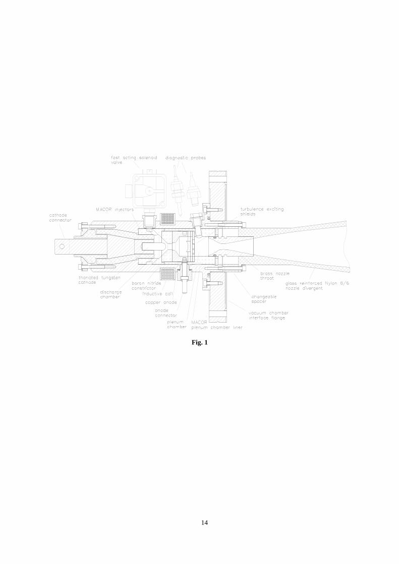
The arc heater was designed in a highly modular and operationally flexible way, to be easily modified for
different test campaigns: different electrode arrangements and constrictor configurations can be easily installed,
insulating spacers of different length can be mounted to increase when necessary the plenum chamber volume. A
view of the heater is shown in Fig.1.
4
The plenum chamber is designed to give the flow a sufficiently long residence time in the high pressure
region, in order to reach chemical and vibrational equilibrium before the expansion in the wind tunnel nozzle. A
computer program was developed to study the non-equilibrium evolution of air flowing through the plenum
chamber. A six-reactions chemical model was used, while the Landau-Teller model was assumed for vibrational
relaxation, with constants obtained from the available literature 6 7 8. The results obtained show that complete
relaxation from the arc column conditions (i.e. fully dissociated, partly ionized) is achieved over a distance of a
few millimeters, for plenum conditions of a few bars in pressure and less than 3000 K in temperature. Clearly,
these results represent only an order of magnitude estimate: nevertheless, they seem appropriate for a
conservative design of the plenum chamber, provided its length is much longer than the evaluated relaxation
length.
The gas feeding system was designed to supply smooth and repeatable cold flow pulses with duration of
about 100 ms. The air pulse is produced by opening two fast acting solenoid valves. Each valve is activated by a
rectangular electric signal generated by a programmable electronic board. A 0.005 m3 reservoir is placed just
upstream of each valve in order to maintain a quasi-constant back pressure during the pulse. In this way, a
steady-state flow is reached a few milliseconds after the valve activation. Both the mass flow rate and the gas
pulse duration can be easily adjusted by setting respectively the reservoir pressure (up to 50 bar) and the electric
pulse duration.
The electrical power system consists of a 12.5 mF main capacitor bank (MCB), which can be charged up to
2400 V, storing a total energy of 36 kJ (Fig. 2). A RL matching network is wired between the capacitor bank and
the arc heater, in order to obtain a discharge current time evolution with a roughly constant plateau of duration
not shorter than 15 ms, during which a power up to 200 kW is supplied to the electrodes. A high-voltage ignitron
device is used to command the arc ignition at the desired moment (programmable with a resolution of 0.5 ms), in
order to maximize the useful run time. The initial MCB voltage is not sufficient to obtain a direct electric
breakdown through air at the nominal pressure level. Therefore, an additional network consisting of a 600µF
igniting capacitor bank (ICB) and a 20 mH inductance is permanently connected in parallel with the main power
unit. This network is used to self-ignite the discharge as soon as air begins to flow across the electrodes and the
pressure reaches a critical value in accordance with Paschen law 9 (typically in the order of a few hundreds Pa).
The discharge self-ignition takes place a few milliseconds after the valve opening: the ICB is rated to sustain
30÷40 A of discharge current for a few milliseconds, i.e. until the discharge chamber pressure reaches the
desired value (of about 2 bar) and the ignitron is switched on, allowing the MCB to supply energy to the arc.
5
Summarizing, this arrangement allows for energizing the gas when a significant ionization (produced by the ICB
discharge) is already present, thus facilitating the high pressure breakdown and the establishing of a stable MCB-
driven arc, with duration and characteristic determined by the overall network scheme.
Arc Heater Numerical Simulations
To optimize the arc heater geometry on the basis of the gasdynamic system behavior, a numerical model
based on a lumped-parameter/control-volume approach was developed and implemented in a suitable code. The
facility is schematized as composed by a series of "volumes" (capacitive elements) connected through "restricted
sections" (resistive elements).
The volume elements are modeled assuming space-independent gasdynamic parameters (equal to an
equivalent average value), the working fluid is considered to be a thermally perfect gas, conduction and radiation
effects are neglected. Finally, kinetic energy contribution to the total enthalpy is neglected (which is equivalent
to assume subsonic flow). Accordingly, the Eulerian unsteady conservation equations for the flow are integrated
over the volume. For each volume element, a set of two coupled time-dependent integral equations is obtained,
one for the pressure derivative and the other for the temperature derivative. The equations are written below, in
general form and with clear notation:
T
dttppT
V
RTmmp
t
jout
iin ji
+
+
−=
∫∑∑ 0
0 ')'(&&
&&&
Γ+
Γ
−
−Γ
+
−Γ
+
=∑∑∑∑
th
vj
outi
inj
out
pout
i
ininpin
WTCmm
vTCm
vTCm
Tji
j
j
i
ii&&&&
&22
22
where:
∫ ∑∑
−+=Γ
t
jout
iinvv dttmtmC
RTVp
Cji0
0
0 ')'()'( &&
The interface conditions between volume elements (i.e. the restricted section elements) are modeled using
quasi-1D steady gasdynamic relations, obtaining a set of three algebraic equations as follows:
γγ
γγη−+
−
+⋅⋅=1
1
2
2
11 restrrestr
tot
restri MR
MT
Apm
i
&
6
−
⋅
−=
−
11
2,1min
1
γγ
γ out
inrestr p
pM
p
thintotouttot Cm
WTT
⋅+=
&
For the sake of simplicity, the possible development of standing shocks inside the arc heater is neglected: this
assumption is not verified during the very first moments following the valves opening. Nevertheless, it seems
reasonable to believe that such initial phenomena do not affect the further behavior of the system.
Schematizing the heater as composed by 4 volumes connected by 3 sections (as shown in Fig. 3), the
resulting dynamic system is described by a set of 17 coupled equations. The forcing actions on the system are the
solenoid valves opening (described by a trapezoidal law) and the power input from the arc column to the gas.
Two different power input laws were examined for the present work: a simplified trapezoidal input and a real
input signal as directly measured at the electrodes. The former case was considered during the preliminary
design phase, during which the detailed arc behavior was still unknown, the latter was considered for model
validation, by comparing numerical and experimental results.
The optimal arc heater configuration was investigated by varying the geometrical parameters, some of which
are constrained by dimensional and/or operational limits, more specifically: the reservoir volume and pressure
cannot exceed respectively 0.01 m3 and 50 bar, for assembly and safety reasons; the injector effective area must
be a multiple of 12.5 mm2 to allow the adoption of available, commercial valves; the plenum chamber volume
cannot be less than 25 cm3 to permit installation of ceramic screens, the length cannot be less than 15 mm to
allow for full chemical and vibrational relaxation of the flow (3 times the relaxation lenght as computed by the
previously described model); the nozzle throat area is dictated by the Mach 6 condition in the 60 mm diameter
test section.
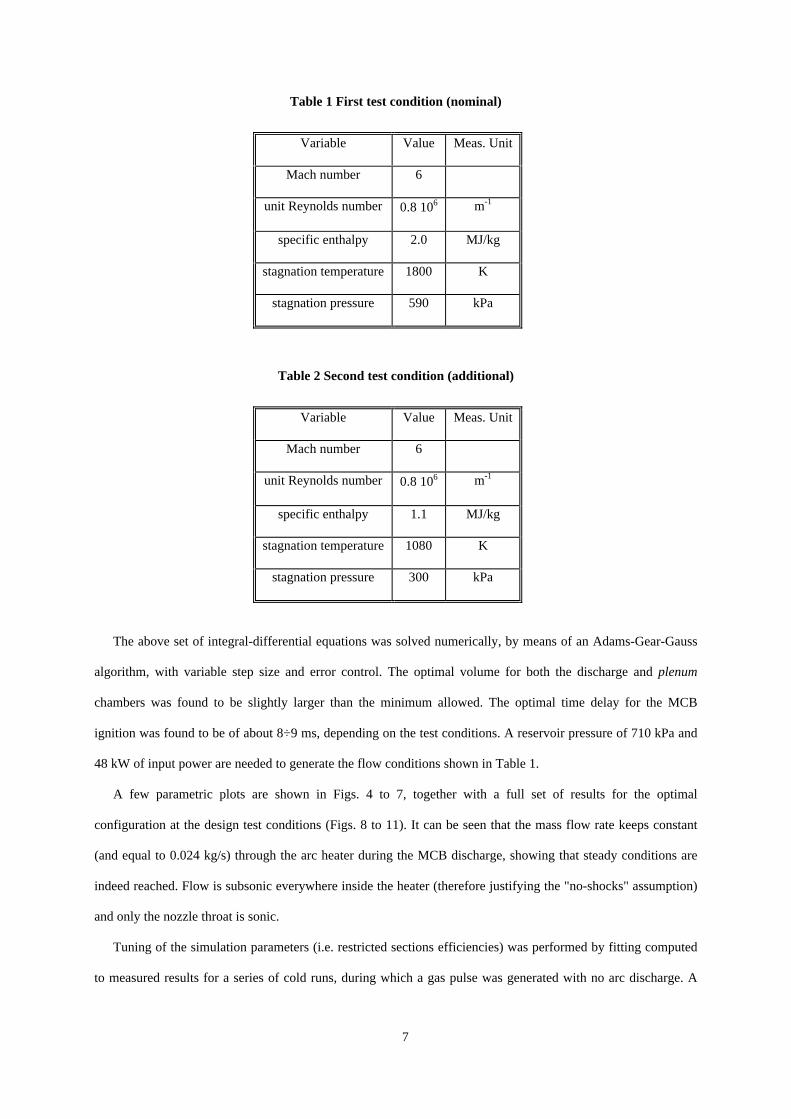
The optimization objective was to maximize the time length of the quasi-steady hot gas pulse, for a given
discharge time: steadiness conditions were evaluated in terms of stagnation pressure and temperature inside the
plenum chamber which, in good approximation, also represent the stagnation conditions in the hypersonic test
section. Optimization was performed referring to a nominal test condition, shown in Table 1. A second condition
was subsequently verified (Table 2) to assess operational flexibility of the facility.
7
Table 1 First test condition (nominal)
Variable Value Meas. Unit
Mach number 6
unit Reynolds number 0.8⋅106 m-1
specific enthalpy 2.0 MJ/kg
stagnation temperature 1800 K
stagnation pressure 590 kPa
Table 2 Second test condition (additional)
Variable Value Meas. Unit
Mach number 6
unit Reynolds number 0.8⋅106 m-1
specific enthalpy 1.1 MJ/kg
stagnation temperature 1080 K
stagnation pressure 300 kPa
The above set of integral-differential equations was solved numerically, by means of an Adams-Gear-Gauss
algorithm, with variable step size and error control. The optimal volume for both the discharge and plenum
chambers was found to be slightly larger than the minimum allowed. The optimal time delay for the MCB
ignition was found to be of about 8÷9 ms, depending on the test conditions. A reservoir pressure of 710 kPa and
48 kW of input power are needed to generate the flow conditions shown in Table 1.
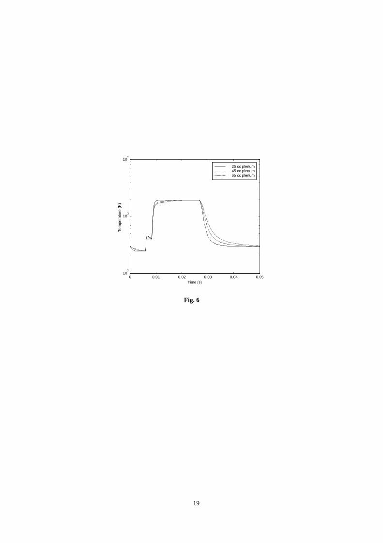
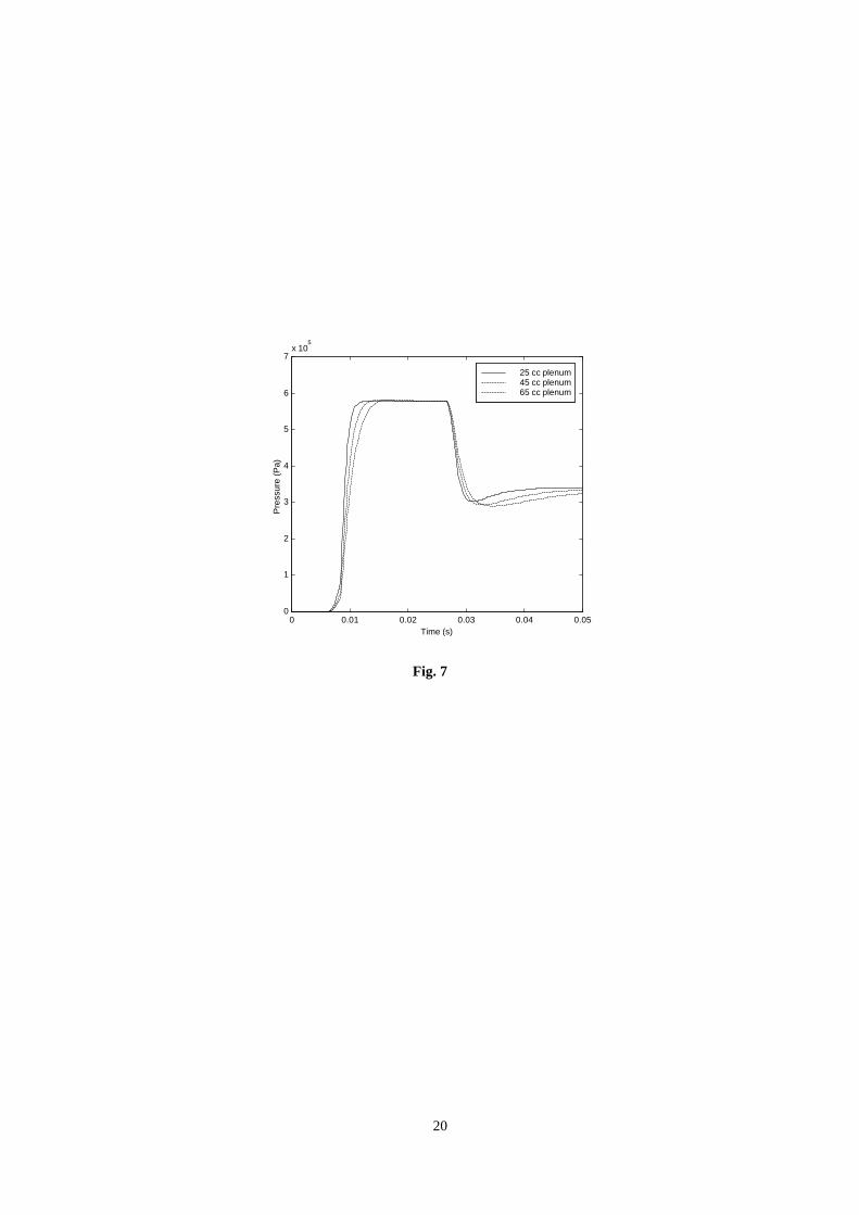
A few parametric plots are shown in Figs. 4 to 7, together with a full set of results for the optimal
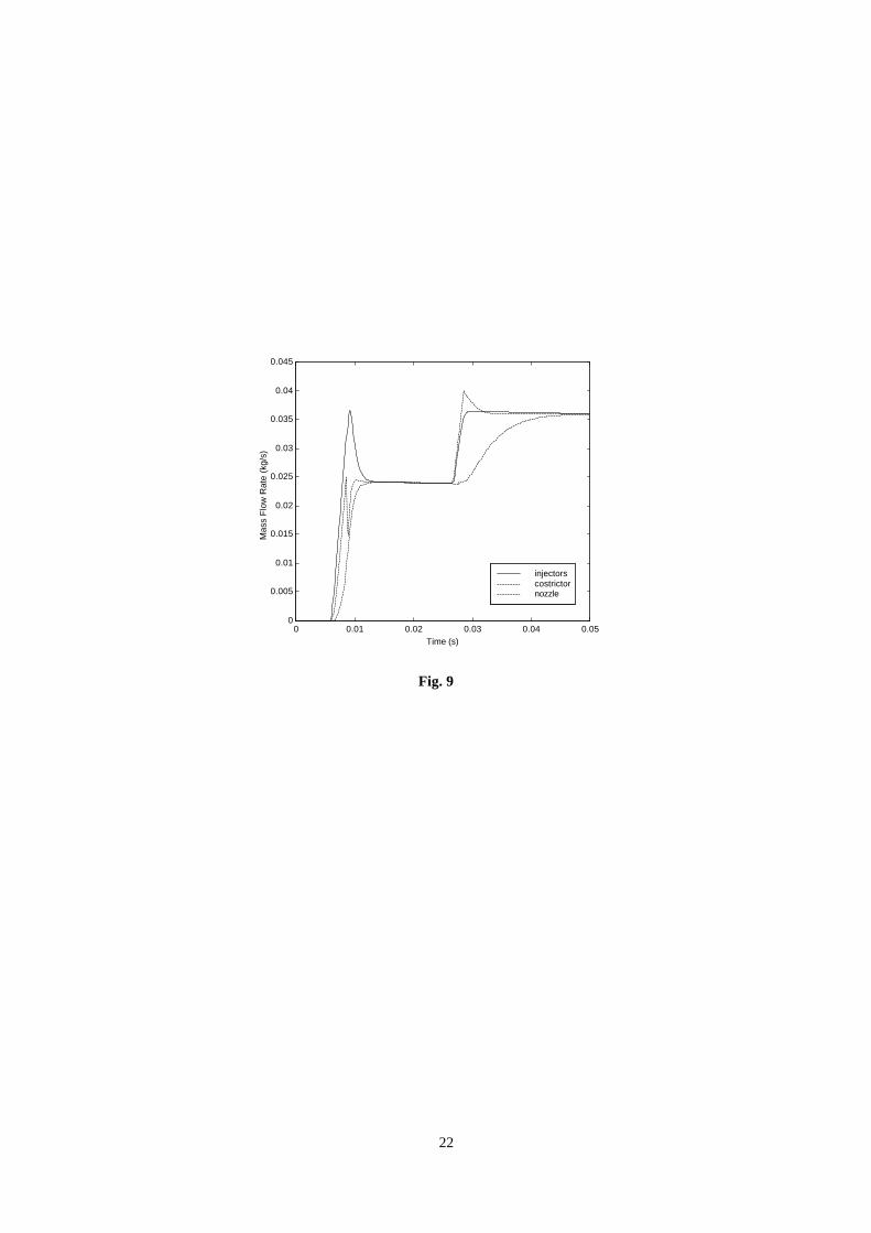
configuration at the design test conditions (Figs. 8 to 11). It can be seen that the mass flow rate keeps constant
(and equal to 0.024 kg/s) through the arc heater during the MCB discharge, showing that steady conditions are
indeed reached. Flow is subsonic everywhere inside the heater (therefore justifying the "no-shocks" assumption)
and only the nozzle throat is sonic.
Tuning of the simulation parameters (i.e. restricted sections efficiencies) was performed by fitting computed
to measured results for a series of cold runs, during which a gas pulse was generated with no arc discharge. A
8
good agreement was obtained, showing that the numerical model can correctly describe at least the cold flow
case. In Fig. 12 a comparison between the stagnation pressure numerically calculated and experimentally
measured in the plenum chamber is shown, for a cold run with a reservoir pressure of 690 kPa.
Experimental Characterization
An experimental campaign was performed to assess the capabilities of the arc heater: measurements of
stagnation pressure and temperature in the plenum chamber, voltage and current (and therefore power) at the
electrodes were carried out using synthetic air as the working fluid. The plenum pressure was measured using a
fast response, temperature compensated, ruggedized piezo-resistive transducer (Kulite HKM 375), the
temperature using unshielded Omega platinum/platinum-rhodium thermocouples, 1/1000” in diameter. The
current flowing through the electrodes was measured by means of a Contec Hall effect probe, while the arc
voltage drop by two Tektronik P6015 high voltage probes, the electrodes being floating with respect to the
ground. A Hewlett Packard HP 5185 transient recorder, controlled by a Macintosh IIvx personal computer,
and a National Instruments AT-MIO-16-E2 DAQ board, installed in a PC Pentium workstation, were used for
data acquisition, storage and analysis. Since the thermocouples response time is not sufficient to properly resolve
the arc running time, a numerical correction method 10,11 was employed to calculate instantaneous temperatures
from thermocouple measurements.
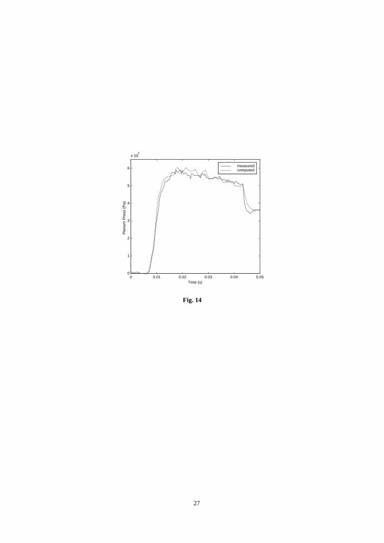
Figs. 13 and 14 show the time history of the main electric and gasdynamic arc heater parameters during a
typical run, the time axis origin corresponding to the valve opening moment. In Fig. 13 the arc current measured
at the electrodes is shown: the self-ignited current produced by the ICB additional network can be seen, together
with the steep current increase (produced by the MCB network) occurring when the ignitron is activated, 9 ms
after the valve opening. Fig. 14 shows the pressure measured in the plenum chamber. The pressure rise induced
by the electric discharge heat input is clearly visible.
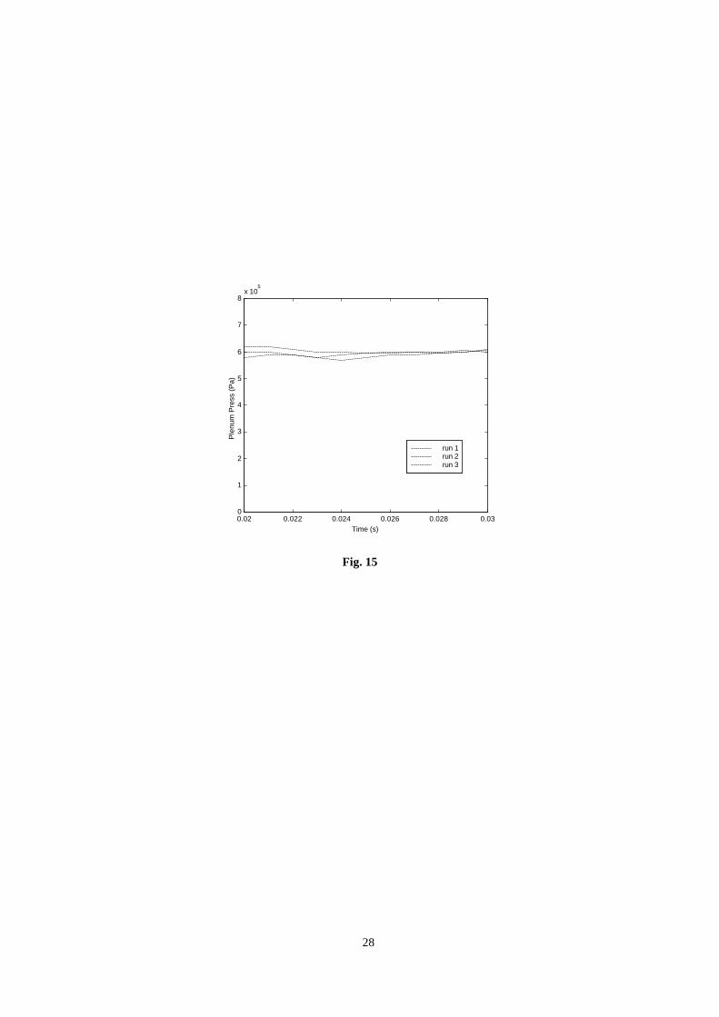
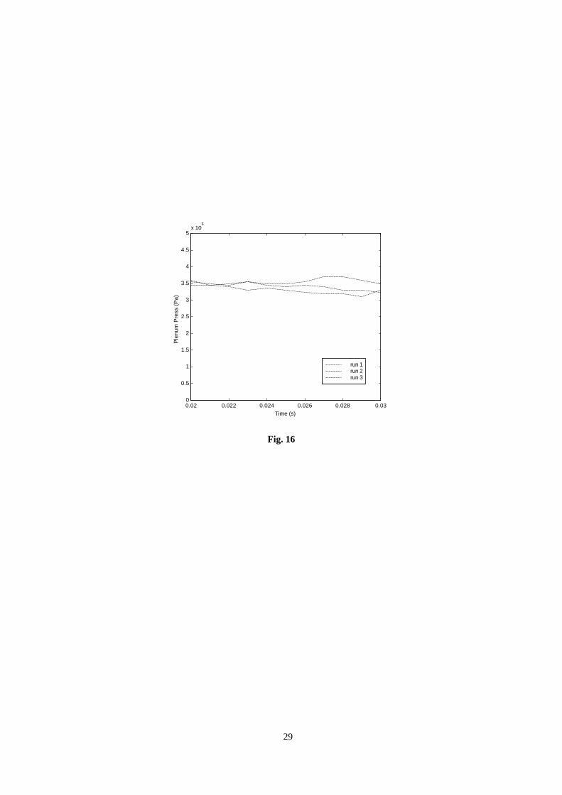
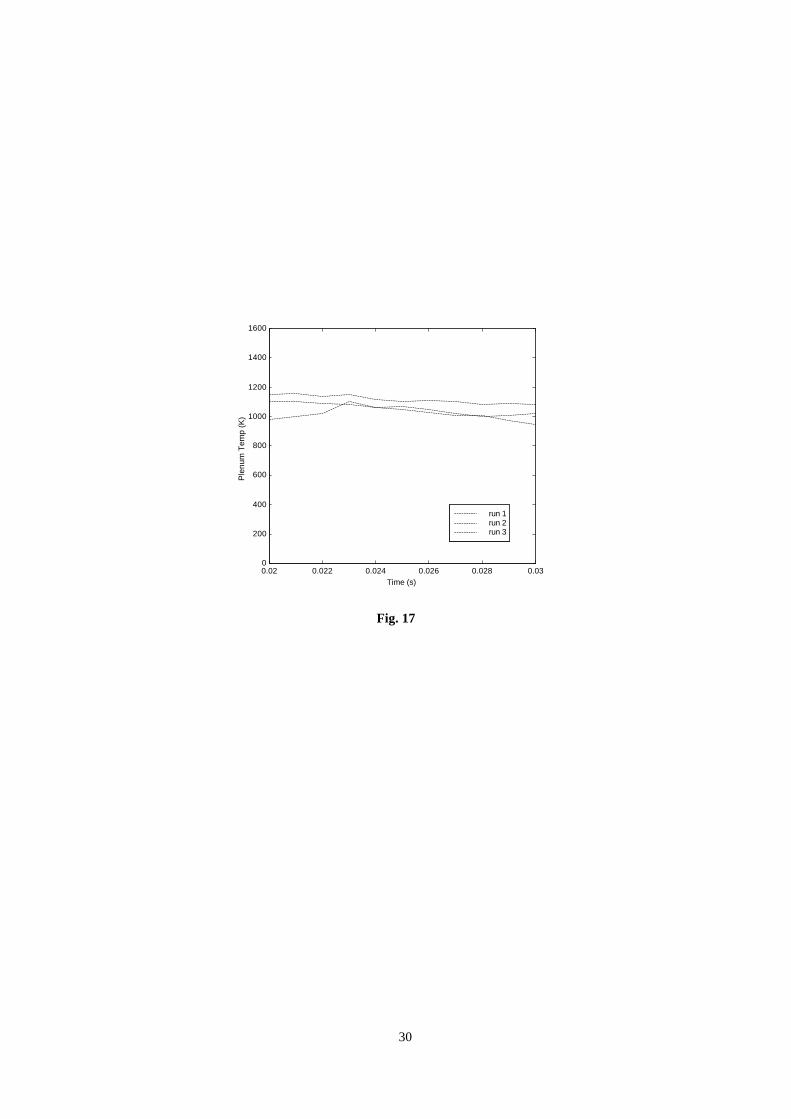
A series of runs was performed to assess the steadiness and repeatability of the arc heater performance, for
the two operation conditions considered: during these runs the main heater controlling parameters (i.e. reservoir
pressure and MCB voltage charge) were kept constant. Higher enthalpy runs (Table 1) were performed with a
reservoir pressure of 900 kPa and a MCB voltage of 1220 V, while lower enthalpy ones (Table 2) were
performed with a reservoir pressure of 500 kPa and a MCB voltage of 735 V. Sample results for a 10 ms time
interval during the quasi-steady phase are shown in Figs. 15 to 17. The measured data indicate that fair
repeatability exists both for pressure and temperature in the plenum chamber.
9
A few tests were also performed at higher energy levels, to assess the heater reliability for conditions closer
to the operating limit: though a proper characterization could not be performed, stagnation temperatures and
pressures up to respectively 2800 K and 1 MPa were obtained by charging the MCB up to 1800 V.
The simulation code was validated against experimental data by using actually measured power signals as
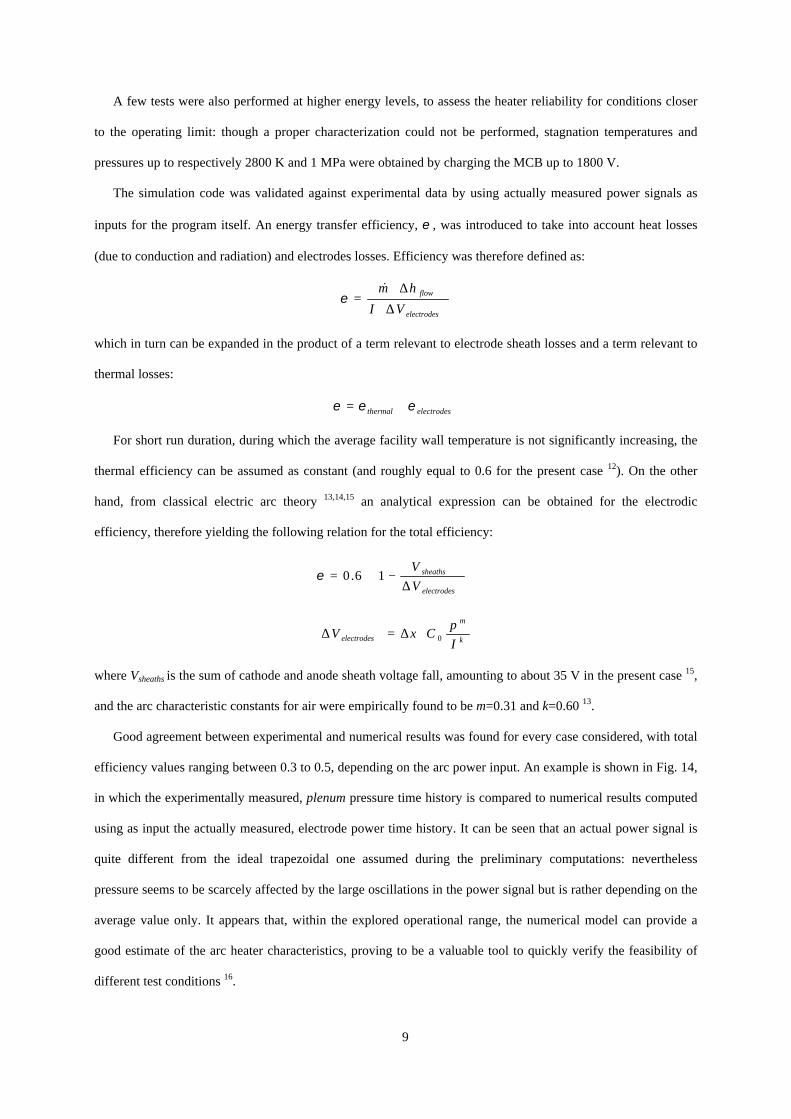
inputs for the program itself. An energy transfer efficiency, ε , was introduced to take into account heat losses
(due to conduction and radiation) and electrodes losses. Efficiency was therefore defined as:
electrodes
flow
VI
hm
∆⋅
∆⋅=
&ε
which in turn can be expanded in the product of a term relevant to electrode sheath losses and a term relevant to
thermal losses:
electrodesthermal εεε ⋅=
For short run duration, during which the average facility wall temperature is not significantly increasing, the
thermal efficiency can be assumed as constant (and roughly equal to 0.6 for the present case 12). On the other
hand, from classical electric arc theory 13,14,15 an analytical expression can be obtained for the electrodic
efficiency, therefore yielding the following relation for the total efficiency:
∆
−⋅=electrodes
sheaths
V
V16.0ε
k
m
electrodes I
pCxV 0⋅∆=∆
where Vsheaths is the sum of cathode and anode sheath voltage fall, amounting to about 35 V in the present case 15,
and the arc characteristic constants for air were empirically found to be m=0.31 and k=0.60 13.
Good agreement between experimental and numerical results was found for every case considered, with total
efficiency values ranging between 0.3 to 0.5, depending on the arc power input. An example is shown in Fig. 14,
in which the experimentally measured, plenum pressure time history is compared to numerical results computed
using as input the actually measured, electrode power time history. It can be seen that an actual power signal is
quite different from the ideal trapezoidal one assumed during the preliminary computations: nevertheless
pressure seems to be scarcely affected by the large oscillations in the power signal but is rather depending on the
average value only. It appears that, within the explored operational range, the numerical model can provide a
good estimate of the arc heater characteristics, proving to be a valuable tool to quickly verify the feasibility of
different test conditions 16.

10
The main problem evidenced during the heater operation was the occasional occurrence of anomalous
discharge modes characterized by extremely high current intensities, which were the major source of component
deterioration 3. In the final design, anomalous discharges have been effectively controlled, though not completely
eliminated, using a constricted discharge chamber and spinning the arc by means of a coaxial magnetic field 5.
Even for proper operation, some level of electrode degradation cannot be avoided. As usually occurring with
pulsed arc devices, repeated starts cause significant electrode erosion which in the case of HEAT arc-heater is
enhanced by the relatively high discharge pressure and the low electrode wall temperature. On cold electrodes,
sheat phenomena are responsible of a significant fraction of the total power dissipated by Joule effect, which has
detrimental consequences on the electrodes (the cathode in particular), enhancing erosion and reducing the useful
lifetime. In particular, a cathode mass loss of 7-23 mg/C is estimated for the ignition procedure used 17, which
gives a tungsten flow contamination of 65-260 ppm at design flow conditions. Flow contamination caused by
copper is estimated to be less than 2 ppm. In addition to electrodes erosion, some damage to the turbulence
enhancing shields was observed. After the initial tests the shields had to be redesigned to avoid sharp corners,
which proved unable to withstand the induced thermal stresses. In any case, no damage was ever observed on the
tested models caused by impacting particles: for instance, during the SWBLI test campaign 2 thin-film gauges
were used to measure the local heat flux to the model wall without experiencing any damage to the exposed test
elements.
Conclusions
Taking advantage of the existing know-how on arcjets and plasma sources for space applications, a pulsed
arc heated wind tunnel for hypersonic activities has been successfully developed at Centrospazio. Tests carried
out so far have shown both the reliability of the arc heater and, more in general, the effectiveness of the
numerical tools developed for the heater design, in spite of their relative simplicity.
More than 600 runs using synthetic air as the working fluid have been performed since the second half of
1996, with no part replacements and without any significant component damage. As expected, the cathode and
the ceramic mixing shields proved to be the most stressed and critical components, though operating the facility
in a pulsed mode greatly alleviated the problems: it appears unlikely that such good results in term of flow
steadiness and homogeneity could be attained in continuous arc-heated tunnels based on the same concepts 3.
A good repeatability of plenum chamber flow parameters (stagnation pressure and temperature) has been
obtained for all the operation condition investigated. Furthermore stagnation temperatures in excess of 2500 K
11
have been observed, demonstrating the possibility to extend the arc heater capability beyond the maximum
design temperature foreseen at the beginning of the activity.
Acknowledgments
The work herein described was partially financed by European Space Agency under contract No.
11.534/95/NL/FG in the framework of the Future European Space Transportation Investigation Programme.
The authors wish to acknowledge the help of Mr. Alessandro Alcamo and Mr. Giovanni Pala in setting up the
facility. Finally, the tunnel would not have been realized without the friendly support of Prof. Mariano
Andrenucci and Prof. Luca d'Agostino.
References
1 Scortecci, F., Paganucci, F., d'Agostino, L. and Andrenucci, M., "A New Hypersonic High Enthalpy Wind
Tunnel", AIAA 97-3017, 33rd AIAA/ASME/SAE/ASEE Joint Propulsion Conference and Exhibit, Seattle WA,
USA, July 1997.
2 Scortecci, F., Paganucci, F. and d'Agostino, L., "Experimental Investigation of Shock-Wave/Boundary-Layer
Interactions Over an Artificially Heated Model in Hypersonic Flow", AIAA 98-1571, 8th AIAA International
Space Planes and Hypersonic Systems and Technologies Conference, Norfolk VA, USA, April 1998.
3 Biagioni, L., Scortecci, F., Paganucci, F., Banetta, S., and d'Agostino, L., "Two Years of Arc-Tunnel
Experience at Centrospazio", 3rd European Symposium on Aerothermodynamics for Space Vehicles,
Noordwijk, The Netherlands, November 1998.
4 Scortecci, F., Paganucci, F., Biagioni, L., Borrelli, S. and Marini, M., "Disegno dell'ugello per una galleria
ipersonica ad alta entalpia", XIV Congresso Nazionale AIDAA, Napoli, Italy, October 1997.
5 Horn, D.D., Felderman, E.J. and MacDermott, W.N., "Impacts of External Magnetic Fields Applied to High-
Pressure Electric Arc Heaters", Journal of Propulsion and Power, vol.12,num.6, November-December 1996.
6 Landau, L. and Teller, E., "Theory of Sound Dispersion", Physicaliske Zeitschrift der Sowjetunion, vol.10,
1936
7 Wray, K.L., “Chemical Kinetics of High Temperature Air”, in Hypersonic Flow Research edited by F.R.
Riddell, Progress in Astronautics and Rocketry Series, Academic Press, New York, 1962
8 Vincenti, W.G. and Kruger, C.H., "Introduction to Physical Gas Dynamics", John Wiley & Sons, New York,
1965
12
9 Jahn, R.G., “Physics of Electric Propulsion”, McGraw-Hill, New York, 1968
10 Albertson, C.W. and Bausermann, W.A., “Total Temperature Probes for High-Temperature Hypersonic
Boundary-Layer Measurements”, NASA TM-4407, 1993
11 Glawe, G.E., Holanda, R. and Krause, L.N., “Recovery and Radiation Corrections and Time Constants of
Several Sizes of Screened and Unshielded Thermocouple Probes for Measuring Gas Temperature”, NASA TP-
1099, 1978
12 Cann, G.L., Buhler, R.D., Harder, R.L. and Moore, R.A., “Basic Research on Gas Flows Through Electric
Arcs, Hot Gas Containment Limits”, ARL 64-49, Washington, 1964
13 Roth, J.R., "Industrial Plasma Engineering – Volume 1", IOP Publishing, 1995.
14 Stine, H.A. and Watson, V.R., “The Theoretical Enthalpy Distribution of Air in Steady Flow Along the Axis
of a Direct-Current Electric Arc”, NASA TN D-1331, 1962
15 Shih, K.T. and Pfender, E., “Electrode Energy Transfer Mechanism in a MPD Arc”, AIAA Journal,
vol.8,num.2 February 1970
16 Biagioni, L., Scortecci, F., Paganucci, F., d'Agostino, L. and Andrenucci, M., "Performance of Centrospazio
Hypersonic High Enthalpy Wind Tunnel", AIAA 98-1508, 8th AIAA International Space Planes and
Hypersonic Systems and Technologies Conference, Norfolk VA, USA, April 1998.
17 Auweter-Kurtz, M., Glocker, B., Kurtz, L., Loesener, O., Schrade, H.O., Tubanos, N., Wegmann, T., Willer,
D. and Polk, J.E., “Cathode Phenomena in Plasma Thrusters”, Journal of Propulsion and Power, vol.9,num.6
November-December 1993
13
Figure Captions
Fig. 1 Arc heater view.
Fig. 2 Electric feeding system schematic.
Fig. 3 Arc heater lumped parameter model.
Fig. 4 Plenum temperature time history computed for different ignition delays.
Fig. 5 Plenum pressure time history computed for different ignition delays.
Fig. 6 Plenum temperature time history computed for different plenum chamber volumes.
Fig. 7 Plenum pressure time history computed for different plenum chamber volumes.
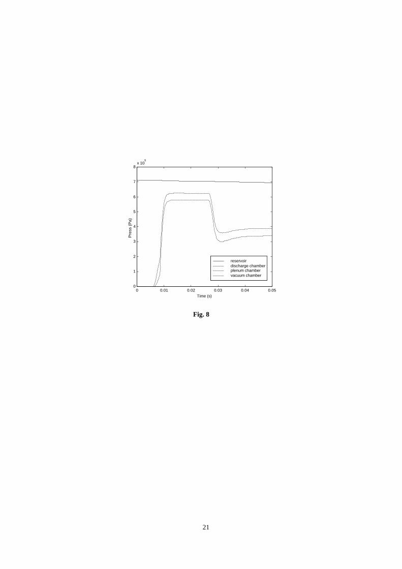
Fig. 8 Pressure time histories computed at different locations in the facility. Optimal configuration.
Fig. 9 Mass flow rate time histories computed at different locations in the facility. Optimal configuration.
Fig. 10 Temperature time histories computed at different locations in the facility. Optimal configuration.
Fig. 11 Mach number time histories computed at different locations in the facility. Optimal configuration.
Fig. 12 Measured and computed plenum pressure time histories during a cold run.
Fig. 13 Measured eletrodes power input history during run d3008-4.
Fig. 14 Measured and computed plenum pressure time histories during run d3008-4.
Fig. 15 Higher enthalpy runs: plenum pressure repeatability.
Fig. 16 Lower enthalpy runs: plenum pressure repeatability.
Fig. 17 Lower enthalpy runs: plenum temperature repeatability.
14
Fig. 1
15
+ -
Ignitron
0.6 mF
12.5 mF
20 mH
3.8 Ω26 mH
Arc Heater
Main
Igniter
Fig. 2
16
Fig. 3
17
0 0.01 0.02 0.03 0.04 0.0510
2
103
104
Time (s)
Tem
pera
ture
(K
)
7 ms delay 8 ms delay 9 ms delay 10 ms delay
Fig. 4
18
0 0.01 0.02 0.03 0.04 0.050
1
2
3
4
5
6
7x 10
5
Time (s)
Pre
ssur
e (P
a)
7 ms delay 8 ms delay 9 ms delay 10 ms delay
Fig. 5
19
0 0.01 0.02 0.03 0.04 0.0510
2
103
104
Time (s)
Tem
pera
ture
(K
)
25 cc plenum45 cc plenum65 cc plenum
Fig. 6
20
0 0.01 0.02 0.03 0.04 0.050
1
2
3
4
5
6
7x 10
5
Time (s)
Pre
ssur
e (P
a)
25 cc plenum45 cc plenum65 cc plenum
Fig. 7
21
0 0.01 0.02 0.03 0.04 0.050
1
2
3
4
5
6
7
8x 10
5
Time (s)
Pre
ss (
Pa)
reservoir discharge chamberplenum chamber vacuum chamber
Fig. 8
22
0 0.01 0.02 0.03 0.04 0.050
0.005
0.01
0.015
0.02
0.025
0.03
0.035
0.04
0.045
Time (s)
Mas
s F
low
Rat
e (k
g/s)
injectors costrictornozzle
Fig. 9
23
0 0.01 0.02 0.03 0.04 0.05
250
500
750
1000
1250
1500
1750
2000
Time (s)
Tem
p (K
)
reservoir discharge chamberplenum chamber vacuum chamber
Fig. 10
24
0 0.01 0.02 0.03 0.04 0.050
0.2
0.4
0.6
0.8
1
Time (s)
Mac
h N
umbe
r
injectors costrictornozzle
Fig. 11
25
0 0.01 0.02 0.03 0.04 0.050
0.5
1
1.5
2
2.5
3
3.5x 10
5
Time (s)
Ple
num
Pre
ss (
Pa)
measuredcomputed
Fig. 12
26
0 0.01 0.02 0.03 0.04 0.050
2
4
6
8
10
12
14x 10
4
Time (s)
Ele
ctro
de P
ower
(W
)
Fig. 13
27
0 0.01 0.02 0.03 0.04 0.050
1
2
3
4
5
6
x 105
Time (s)
Ple
num
Pre
ss (
Pa)
measuredcomputed
Fig. 14
28
0.02 0.022 0.024 0.026 0.028 0.030
1
2
3
4
5
6
7
8x 10
5
Time (s)
Ple
num
Pre
ss (
Pa)
run 1run 2run 3
Fig. 15
29
0.02 0.022 0.024 0.026 0.028 0.030
0.5
1
1.5
2
2.5
3
3.5
4
4.5
5x 10
5
Time (s)
Ple
num
Pre
ss (
Pa)
run 1run 2run 3
Fig. 16
30
0.02 0.022 0.024 0.026 0.028 0.030
200
400
600
800
1000
1200
1400
1600
Time (s)
Ple
num
Tem
p (K
)
run 1run 2run 3
Fig. 17