wind energy design and fundamentals - cedengineering.com
TRANSCRIPT

Wind Energy Design and Fundamentals
Course No: R06-004
Credit: 6 PDH
Anuj Bhatia
Continuing Education and Development, Inc. 22 Stonewall Court
Woodcliff Lake, NJ 07677
P: (877) 322-5800
1
WIND ENERGY DESIGN AND FUNDAMENTALS
The rising concerns over climate change, environmental pollution, and energy security have seen
increased interest in developing renewable energy with wind energy being at the forefront. Wind
energy refers to the technology that converts the air’s motion into mechanical energy, usually for
electricity production.
Wind energy captures the natural air in our environment and converts the air’s motion into
mechanical energy. The wind is caused by differences in atmospheric pressure. Wind speeds
vary based on geography, topography, and season. As a result, there are some locations that are
better suited for wind energy generation than others. In general, wind speeds are higher near the
coast and offshore since there are fewer objects like vegetation, mountains, and buildings to slow
them down.
The mechanism used to convert air motion into electricity is referred to as a turbine. A turbine is
a large structure with several spinning blades. These blades are connected to a rotor and an
electromagnetic generator generates electricity when the wind causes the blades to spin.
Traditionally, this energy was used for milling grain and pumping water, but today it is used to
create electricity.
A major advantage of wind is that it is a clean and a renewable form of energy. Its production of
electricity has no direct carbon emissions or air pollutants and does not consume water. Wind
also has relatively low operations and maintenance costs after the initial construction. However,
wind energy faces several challenges. Wind speeds can vary throughout the day and year,
causing intermittency issues for power grids. The price tag of wind power has traditionally been
higher than conventional electricity generation sources, though the wind cost curve has declined
significantly in recent years. Other concerns such as land use, noise, and bird disruption have
also been raised in certain areas.
In terms of technology, turbine design focuses on optimizing power output by focusing on two key
parameters: blade length and average wind speed. The latter is affected by surface terrain and
varies spatially, directionally, and seasonally. The effectiveness of a particular installation is
quantified by “capacity factor” - the ratio of actual annual energy output to the theoretical maximum
output. Several basic designs are in use, but most commercial installations use a horizontal axis,
upwind-facing design. Wind energy is expanding both onshore and offshore with bigger turbines
– both in physical size and generating capacity to capture more stable winds and to maximize the
return on installation costs.
2
The purpose of this 6-hour course is to introduce the general aspects of wind energy and wind
turbines. The course discusses the wind turbine’s operating principles, the key components,
technology & performance features, cost economics, and various environmental and social
aspects.
3
TABLE OF CONTENTS
1 CHAPTER -1: FUNDAMENTALS OF WIND ENERGY ................................................................................ 6
1.1 Wind .............................................................................................................................................. 6
1.2 How Does Wind Energy Work? ..................................................................................................... 7
1.3 Wind Turbines ............................................................................................................................... 8
1.4 Wind Farms ................................................................................................................................... 9
1.5 Factors Influencing Wind Energy .................................................................................................. 9
1.6 Main Advantages of Wind Energy ............................................................................................... 11
1.7 Main Disadvantages of Wind Energy .......................................................................................... 12
1.8 Basic Facts about Wind Turbines ................................................................................................ 12
2 CHAPTER -2: TYPES OF WIND TURBINES ............................................................................................ 18
2.1 Horizontal Axis Wind Turbines (HAWT) ...................................................................................... 18
2.2 Design Configurations of HAWT .................................................................................................. 19
2.3 Vertical Axis Wind Turbines (VAWT) ........................................................................................... 21
2.4 Design Configurations of VAWT .................................................................................................. 23
2.5 Comparison between HAWTs and VAWTs .................................................................................. 24
3 CHAPTER -3: WIND TURBINE COMPONENTS ..................................................................................... 26
3.1 Key Components ......................................................................................................................... 26
3.2 Blades .......................................................................................................................................... 26
3.3 Hub and Rotor ............................................................................................................................. 28
3.4 Nacelle ......................................................................................................................................... 29
3.5 Drivetrain .................................................................................................................................... 31
3.6 Main Shaft and Couplings ........................................................................................................... 33
3.7 Generator .................................................................................................................................... 33
3.8 Cooling Unit ................................................................................................................................. 34
3.9 Braking ........................................................................................................................................ 34
3.10 Yaw Mechanism .......................................................................................................................... 35
3.11 Power System Interconnection ................................................................................................... 36
3.12 Tower .......................................................................................................................................... 38
3.13 Foundations ................................................................................................................................ 42
3.14 Cost Contributions ...................................................................................................................... 43
4 CHAPTER - 4: PHYSICS OF WIND POWER ........................................................................................... 44
4.1 Power v/s Energy ........................................................................................................................ 44
4
4.2 Power Contained in Wind ........................................................................................................... 45
4.3 Effective Useable Energy from Wind Turbine ............................................................................. 46
4.4 Practical Limits of Energy Output................................................................................................ 50
4.5 Net Power Output from the Turbine .......................................................................................... 52
4.6 Important Rules for Wind Turbines ............................................................................................ 54
4.7 Power Curve ................................................................................................................................ 56
5 CHAPTER – 5: WIND TURBINE DESIGN PARAMETERS ........................................................................ 58
5.1 Tip Speed Ratio (TSR) .................................................................................................................. 58
5.2 Choice of the Number of Blades ................................................................................................. 60
5.3 Relationship of TSR and Coefficient of Performance (Cp) .......................................................... 61
5.4 How to arrive at TSR in Field Conditions? ................................................................................... 62
6 CHAPTER – 6: WIND FARMS ............................................................................................................... 66
6.1 Onshore Wind Energy ................................................................................................................. 66
6.2 Disadvantages of Onshore Wind Energy ..................................................................................... 67
6.3 Offshore Wind Energy ................................................................................................................. 67
6.4 Onshore vs Offshore Wind Turbines ........................................................................................... 69
6.5 Design of Wind Farms ................................................................................................................. 70
6.6 Site Analysis and Selection .......................................................................................................... 70
6.7 Weibull Curve .............................................................................................................................. 72
6.8 Power Grid Access ....................................................................................................................... 73
6.9 The Placement and Spacing of Wind Turbines ........................................................................... 74
6.10 Wind Farm Area .......................................................................................................................... 74
6.11 Cost of Installation ...................................................................................................................... 75
7 CHAPTER - 7: WIND ENERGY ECONOMICS ......................................................................................... 77
7.1 Typical Onshore and Offshore Wind Costs ................................................................................. 77
7.2 Investment Costs of Wind Power Plants (USD/kW) .................................................................... 78
7.3 Revenue from Wind Turbine Power ........................................................................................... 79
7.4 Availability Factor and Capacity Factor ....................................................................................... 79
7.5 Annual Energy Generation .......................................................................................................... 80
7.6 Is Wind Energy Cost-Effective? ................................................................................................... 84
8 CHAPTER - 8: WIND TURBINE CONTROL SYSTEMS ............................................................................. 86
8.1 Pitch Angle Control ..................................................................................................................... 86
8.2 Stall Control ................................................................................................................................. 87

5
8.3 Yaw Control ................................................................................................................................. 88
8.4 Speed Control Strategy ............................................................................................................... 88
9 CHAPTER -9: WIND ENERGY CHALLENGES ......................................................................................... 91
9.1 Environmental Impact of Wind Energy ....................................................................................... 91
9.2 Environmental/Social Challenges ............................................................................................... 91
9.3 Mitigation .................................................................................................................................... 93
9.4 Technical Issues ........................................................................................................................... 94
9.5 Safety Considerations ................................................................................................................. 94

6
1 CHAPTER -1: FUNDAMENTALS OF WIND ENERGY
The wind is one of the most important sources of green and renewable energy.
Both the terms "wind energy" and "wind power" refer to the process of using the wind to generate
mechanical or electrical power. This mechanical power can be used for specialized tasks like
grinding grain or pumping water, or it can be converted to electricity using a generator.
1.1 Wind
Wind is the movement of air caused by pressure variations in the atmosphere. Meteorologists call
this wind-causing force the “pressure gradient force”. The bigger the pressure gradient force (also
known as the pressure differential), the faster and more powerful the wind generation. The
pressure differential is the result of three concurrent events:
a. The sun unevenly heating the atmosphere
b. The rotation of the earth
c. Geographical features
1.1.1 Sun’s Energy
The sun's energy heats the atmosphere and the Earth in an unequal manner. The sun’s energy
creates temperature differences in the atmosphere. The warm air rises, lowering atmospheric
pressure locally. The surrounding air rushes to fill the low-pressure area, causing wind to blow.
1.1.2 Rotation of Earth
The wind is influenced by the movement of the earth. As it turns on its axis, the air does not travel
directly from higher pressure areas to lower pressure areas. Instead, it is deflected by the Coriolis
force; the direction of deflection depends on latitude. The air is pushed to the west in the northern
hemisphere and the east in the southern hemisphere. Because of the Coriolis force, different
regions of Earth have different prevailing wind directions.
1.1.3 Geographical Features
Geographical elements in the immediate vicinity might have a distinct impact. Trees, buildings,
lakes, the sea, hills, and valleys all influence the direction and speed of the wind on the Earth's
surface. For example, in coastal areas, where warm land and cool sea meet, the temperature
difference creates thermal effects, which causes local sea breezes. During the day, the air above
the land heats up more quickly than the air over water. The warm air over the land expands and
rises, and the heavier, cooler air rushes in to take its place, creating winds. During the night, the
7
water is warm relative to the land, so air is warmed over the water and rises; the resulting low
pressure draws cool air from land out to sea.
The wind speeds are higher near the coast and offshore since fewer objects like vegetation,
mountains, and buildings slow them down.
1.2 How Does Wind Energy Work?
Wind energy is the energy obtained from the force of the wind.
Windmills convert the kinetic energy of the air currents into mechanical power. This mechanical
power can be used for specific tasks such as grinding grain or pumping water.
Wind turbines transform the kinetic energy of the wind into mechanical energy, and then a
generator converts this mechanical energy into electricity. Stronger winds provide most energy
conversion as they rotate the blades faster.
A wind turbine works as follows:
When the wind travels over the blades, it creates LIFT (like an aircraft wing), causing the blades
to turn.
The turbine blades are attached to the rotor, and as the turbine blades rotate, the rotor rotates as
well.
The rotor is connected to a low-speed shaft inside the nacelle. This shaft revolves at a low speed,
around 15–20 revolutions per minute (RPM), matching the speed of the rotor. This low speed is
insufficient for power generation.
A constant speed gearbox is used to increase the speed of the turbine rotor to a speed that can
be used by the generator. Because the generator must rotate at a speed that matches the
frequency of the electric network (50 or 60 Hz in most countries), it must be turned at 1500 RPM
for 50 Hz and 1800 RPM for 60 Hz. A modern wind turbine may have a gear ratio of 100:1 or
more. So, every time the blades make one revolution, the generator shaft spins 100 times!
The generator's high-speed rotation produces an electric potential difference, commonly known
as voltage (electricity).
Electricity from the generator goes to a transformer which converts it to the right voltage for the
electricity grid. The electricity is then transmitted via the electricity network.
The gearbox, generator and control system are contained within a housing unit called a nacelle
located at the top of the tower. The nacelle is automatically aligned to the direction of wind via a

8
yaw mechanism to take maximum advantage of the wind, regardless of which direction it is
blowing.
1.3 Wind Turbines
The three main components of the wind turbine are:
a. The rotor: composed of three blades and the bushing that joins them together, its function
is to capture the force of the wind and convert it into mechanical rotational energy.
b. The gearbox: connected to the engine by means of a shaft, its function is to increase the
rotational speed from 15 to 30 RPM to 1500 – 1800 RPM.
c. The generator: this element is responsible for converting the mechanical energy of
rotation into electrical energy.
A turbine's average height varies from 50 to 120 meters, depending on the strength of the wind.
Because there is more wind at higher heights, the wind turbine becomes more efficient as it grows
taller.
The blades of commercial wind turbines are typically over 50 meters long. The bigger diameter
blades are designed to have just the right curvature so they can capture as much wind as possible.

9
When wind moves both over and under the blade, the aerofoil shapes create LIFT which causes
the rotor connecting the blades to turn.
1.4 Wind Farms
The wind farms pool in many wind turbines that make it possible to obtain energy in large
quantities. These must be set up in places where windy conditions are predominant.
Each of the wind turbines that make up a wind farm are linked together by underground cables
that carry the electricity to a transformer substation. From there it is transported to homes,
factories, or other end users, through the distribution networks of the various electric distribution
companies.
Wind farms may be very large, covering areas of hundreds of square miles. They can also be
offshore, located in a body of water.
1.5 Factors Influencing Wind Energy
The wind blows all throughout the world, and there are numerous locations where it can be used
to generate power, ranging from small scales for houses to industrial proportions, as well as
supplying town and city power networks.
The potential wind resource in each location is influenced by a number of factors. The three key
factors that determine power output are:
a. Wind speed
b. Air density
c. Turbine swept diameter (blade length)

10
Wind turbines require a lot of wind on a regular basis, which is more vital than having occasional
high winds.
1.5.1 Wind Speed
The wind speed largely determines the amount of electricity generated by a turbine.
Wind energy increases with the cube power of the wind speed. If you double the wind speed, the
energy potential increases by a factor of 8.
Location of the installation is therefore very important and should have average wind speeds,
wind maps are used to determine if the location is suitable. Because different regions have
different wind speeds, any suggested site must be thoroughly researched to assure a decent
return on investment. Before making a decision, wind speeds are often observed for a year at the
site.
Caution
Although it may appear that placing wind turbines in areas with the highest wind speeds is the
most viable option, this is not always the case. Turbines produce the most energy when they are
in regions where there is a consistent stream of wind rather than sporadic strong winds.
1.5.2 Height of Tower and Installation
The wind blows faster at higher altitudes due to the reduced influence of surface roughness and
lower air viscosity. At ground level, there are many obstacles in the form of buildings, houses,
hills, trees, etc. which impede the flow of wind and hence decrease its speed. Usually, doubling
the height of the wind tower increases the expected wind speeds by 10% and the expected power
by 34%. In absolute terms, the average wind speed increases by 0.5 m/s for every 6 meters
height.
1.5.3 Density of Air
Wind power is directly proportional to air density, which has a direct relationship with altitude,
pressure, and temperature. Dense air exerts more pressure on the rotors and therefore, results
in higher power output.
Air density is maximum at sea level. That is the reason why we have so many wind farms near or
in seas or oceans. At higher altitude, air density decreases significantly, so wind farms cannot be
made in the mountains.

11
1.5.4 Rotor Diameter
Larger blades have a greater area swept by the rotor enabling them to capture more of the wind's
kinetic energy. Wind power output has a direct relationship with the area swept by the rotor, and
the area is proportional to the square power of the diameter. This means that doubling the rotor
diameter will increase the energy output by a factor of 4.
1.5.5 Direction of Wind
The direction of the wind changes regularly. The wind turbines must face the direction of wind for
optimum performance and effective distribution of force on the rotors. Large commercial turbines
generally use a wind sensor (weathervane) coupled with a servo motor and yawing mechanism
to turn the turbine into the wind.
Additionally, if the velocity of the wind changes, the blades will also adjust so that they are aligned
to an optimum angle of attack with the relevant wind flow.
1.6 Main Advantages of Wind Energy
Wind energy has numerous advantages, both for businesses who invest in it and for society by
helping to minimize the effects of climate change:
1.6.1 Clean
As it does not require any combustion process, it is an energy with zero greenhouse gas (GEI)
emissions, the main culprits of global warming.
A wind farm produces very little waste: nothing needs to be hauled away and disposed of, no
water is required to cool machines, and no effluent needs to be scrubbed or cleaned.
1.6.2 Renewable
The wind is called a renewable energy source because the wind is an unlimited resource and will
blow as long as the sun shines. Wind power, as an alternative to burning fossil fuels, is plentiful,
widely distributed, clean, produces no greenhouse gas emissions during operation and consumes
no water.
1.6.3 Cheap
Once installed, wind turbines have a low operating cost, as wind is free. It costs about 1-2 cents
per kilowatt-hour of power usage after the tax credits. Another reason is the electricity generated
12
from the wind farms is at fixed prices and doesn’t depend on other factors like on fossil fuels in
the case of other power generation plants.
1.6.4 Low Impact
Wind farms are constructed following an extensive analysis and planning procedure. Depopulated
locations are also explored to avoid detrimental effects on residents.
1.6.5 Availability in Remote Areas
a. The one-time investment can be useful for the remote areas to provide the electricity.
b. The areas, where the normal power distribution is poor the wind power can act as a savior
in remote areas.
c. The wind energy is free and can be used efficiently with modern technology.
1.6.6 It Generates Green Jobs
According to the International Renewable Energy Agency (IRENA), wind energy already employs
more than 1.2 million people today and the number of green jobs will not stop growing.
1.7 Main Disadvantages of Wind Energy
An inherent weakness of all wind machines is their strong dependency on wind speed. The main
disadvantages of wind energy are as follows:
a. The variability of wind strength. The wind speed is not constant and can go from zero to
high at any time.
b. The capacity factor (availability or utilization) is low since electricity production is
fluctuating. Both weak or strong winds will shut down a turbine and electricity won't be
produced at all.
c. Turbines can be noisy depending on where they are placed.
d. Wind turbines have been found to harm wildlife, especially birds and bats.
e. They have a high initial cost, though they pay for themselves relatively quickly.
f. Large space is needed for installation of wind turbines.
1.8 Basic Facts about Wind Turbines
1.8.1 Characteristics of Wind Energy
There are few characteristics of wind energy:
13
a. Power is proportional to the cube of wind speed, i.e. P α v3. Hence, if speed is increased,
wind power will increase drastically.
b. Power is proportional to the density of air, i.e. P α ρ. Hence, if the density is increased,
wind energy will increase. At lower elevations, air density is more. Typically, the ratings
for wind turbines are based on standard conditions of 15°C at sea level. A density
correction should be made for higher elevations. A correction for temperature is typically
not needed for predicting the long-term performance of a wind turbine.
c. Power is proportional to the rotor swept area, i.e. P α A (or P α r2, square of blade length,
i.e., radius). Hence, if the rotor area is more, wind energy will be more.
1.8.2 Classification of Wind Turbines
Wind turbines are classified based on three criteria:
1.8.2.1 According to Design
a. Vertical axis design – These are designed like an eggbeater. It is named after French
inventor Darrius.
b. Horizontal axis design - Most modern wind turbines are horizontal turbines. They are
widely used for electricity generation.
1.8.2.2 According to Site Location
a. Onshore: Onshore wind energy is harnessed from a turbine or wind farms (cluster of
turbines) located on land. Onshore wind turbines range in size from 10 kilowatts to as
large as 8 MW. Larger wind turbines are more cost-effective and are grouped together
into wind farms, which provide bulk power to the electrical grid.
b. Offshore - Offshore wind energy is the energy obtained by harnessing powerful ocean
winds. They can generate tremendous power in the waters off coastal areas because the
wind blows more consistently and strongly in offshore areas than inland due to the
absence of barriers. Offshore sitting allows the use of larger turbines in range of 3.6 to 12
MW for offshore turbines. 15 MW turbines are planned, and 20 MW turbines are
theoretically possible.
1.8.2.3 According to Size
a. Small turbines – These have the capacity of 100 kilowatts (kW) mostly used in homes.
b. Utility-scale turbines – Starting from 100 kW to few megawatts (MW).

14
1.8.3 Wind Generation Capacity
Asia leads electricity generation by means of wind, with China alone having an installed capacity
of 188400 MW as of 2017. China makes up over 80% of the installed capacity of Asia and contains
some of the world's largest wind farms, the largest being the Gansu Wind Farm. The United States
is the second leading country in wind power capacity, with a capacity of approximately 90000
MW, which is only about half of China's.
1.8.4 Availability Factor
The availability factor is defined as the fraction of time during a given period that the turbine is
actually online.
1.8.5 Capacity Factor
The capacity factor describes the net yield from the wind farms and is defined as the ratio of the
total energy generated during a given period to the total rated generation capacity during the
same period.
Over the course of a year, a wind turbine will typically generate about 25% of the theoretical
maximum output (onshore farms). This means that only 25% of the installed capacity is used on
average, due to the intermittency of wind. For offshore turbines, it is around 40%.
The capacity factor of conventional gas power stations is on average 80%-90%. Because of
stoppages for maintenance or breakdowns, no power plant generates power 100% of the time.
1.8.6 Site Location
Wind farms require a consistent wind flow, traveling at just the right speed (not too slow, yet not
too fast). Therefore, it is important to analyze the prevailing winds in each region, to determine
the ideal spots to place a wind farm. Once a location is selected, the placing of wind turbines is
important to maximize the amount of power received from the wind.
1.8.7 Turbine Spacing
Turbines are usually spaced about 5 to 9 rotor diameters apart. If the turbines are put too close,
the front turbines will block the wind to the turbines behind them, causing them to spin too slowly.
This is referred to as "shadowing".

15
1.8.8 Turbine Costs
a. Upfront investment costs for onshore turbine typically ranges from 1300 to 2500 USD/kW
globally. A 2 MW (2000 kW) onshore turbine will cost anyway between USD 2.6 and 4.4
million, inclusive of all installation fees.
b. Offshore wind is significantly more expensive than onshore (around 2.5 times more
expensive). Costs range between 3300 and 6000 USD/kW, depending on turbine size and
floating design.
1.8.9 Wind Speed
a. Cut-in wind speed: This is the wind speed at which the wind turbine will start generating
power— typical cut-in wind speeds are 3 to 5 m/s.
b. Nominal wind speed: This is the lowest speed at which the wind turbine reaches its
nominal power output. Above this speed, higher power outputs are possible, but the rotor
is controlled to maintain a constant power to limit loads and stresses on the blades. Wind
speed of 13 m/s to 15 m/s is normally specified to achieve rated capacity and optimum
efficiency.
c. Cut-out wind speed: This is the highest wind speed at which the turbine will operate. Above
this speed, the turbine is stopped to prevent damage to the blades. The cut-out speed is
normally 25 m/s.
The range of wind speeds between cut-in and cut-out is called the operating range of the turbine.
Typically, maximum power generation occurs at nominal wind speeds of 13 to 15 m/s.
1.8.10 The Size of Wind Turbines
1.8.10.1 Rotor Size
a. The blade length (rotor radius) usually ranges between 20 m to 80 m.
b. The longest rotor designs belong to:
• GE, Model Haliade-X: 107 m
• Siemens Gamesa, Model 14-222 DD: 108 m
1.8.10.2 Tower Height
a. The tower height (turbine masts) would usually range between 60 to 120 m.
b. The tallest mast belonging again to:
• GE, Model Haliade-X: 150 m

16
• Siemens Gamesa, Model 14-222 DD: 150 m.
1.8.11 How fast do the blades turn?
Horizontal axis wind turbines turn at anything between 15 to 20 revolutions per minute (RPM) at
a constant speed. However, an increasing number of machines operate at variable speeds, where
the rotor speed increases and decreases according to the wind speed.
The vertical wind turbines have higher RPMs of 100 and higher.
1.8.12 Number of Blades
The optimum number of blades for a wind turbine depends on the job the turbine has to do.
Turbines for generating electricity need to operate at high speeds but do not need much turning
force. These machines generally have three or two blades. On the other hand, wind pumps need
turning force but not much speed and therefore have many blades.
Most modern commercial wind turbines have three blades, as they produce the optimum amount
of power. Two bladed machines are cheaper and lighter, with higher running speeds which
reduces the cost of the gearbox, and they are easier to install. They perform almost as well as
three-blade turbines. However, they can be noisier and are not as visually attractive, appearing
'jerky' when they turn.
1.8.13 What is a wind turbine made of?
The towers are mostly tubular and made of steel or concrete, generally painted light grey. The
blades are made of fiberglass, reinforced polyester, or carbon fiber composite materials. They are
off white or light grey because it is inconspicuous under most lighting conditions. The finish is
matt, to reduce reflected light.
1.8.14 Lifespan
Wind turbines are usually designed to operate around 120,000 hours (20 – 25 years), but the
gearbox lifespan is about 1.5 years and needs to be replaced.
1.8.15 Is wind power competitive?
Yes, wind power is competitive once all the costs that affect traditional energy sources - like fuel
and CO2 costs, and the effects on environment and health – are factored in.
One MWh of electricity produced by coal emits about a tonne of CO2, one MWh of electricity
produced by gas emits about half a tonne of CO2, whereas wind-powered electricity emits no CO2.

17
If gas and coal producers have to pay for their CO2 emissions, wind power becomes
comparatively cheaper since its CO2 costs are zero.
Electricity from wind turbines or other renewable energy sources is supported by many countries
by way of green electricity quotas and carbon trading mechanisms.
1.8.16 Windy Locations in the USA
Most farms are between the Midwest and the West Coast region of the USA along the gusty Great
Plains. There are almost no wind farms on the East Coast.
We will learn more about the wind turbine operating principles, the key components, technology,
and the performance features in the subsequent chapters.

18
2 CHAPTER -2: TYPES OF WIND TURBINES
Wind turbines are classified into two types:
a. Horizontal Axis Turbines
b. Vertical Axis Turbines
A horizontal axis machine has its blades rotating on a horizontal axis. These are the most common
onshore and offshore wind turbines.
A vertical axis machine has its blades rotating on a vertical axis perpendicular to the ground. An
advantage of the vertical axis is that blades do not have to be mechanically reoriented when the
wind direction changes. These are less commonly used in small capacity ranges.
2.1 Horizontal Axis Wind Turbines (HAWT)
A horizontal axis wind turbine (HAWT) has its rotating shaft parallel to the ground.
Horizontal axis wind turbines have the main rotor shaft, gearbox, electrical generator, and other
components housed in a nacelle and located at the top of a tower. The turbine's rotor blades must
point in the direction of the wind. The reason for the necessity of facing the wind is both a more
effective distribution of force on the rotors, and prevention of structural damage to the turbine due
to improper loading on the turbine structure. Small turbines are pointed by a simple weathervane
19
placed square with the rotor (blades), while large turbines generally use a wind sensor coupled
with a servo motor and yawing mechanism to turn the turbine into the wind.
The turbine supports all its components at the top of the tower and therefore, the structure needs
a strong foundation to support the weight of the rotor blades, gearbox, generator, and other
components of the turbine.
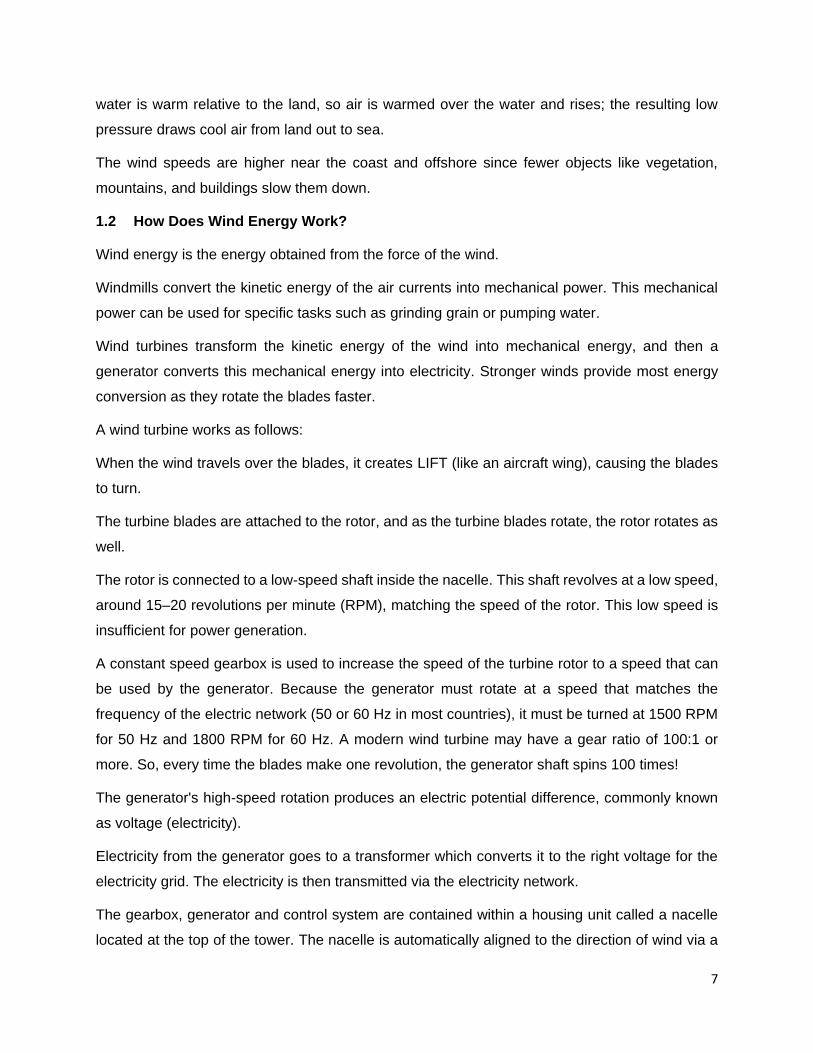
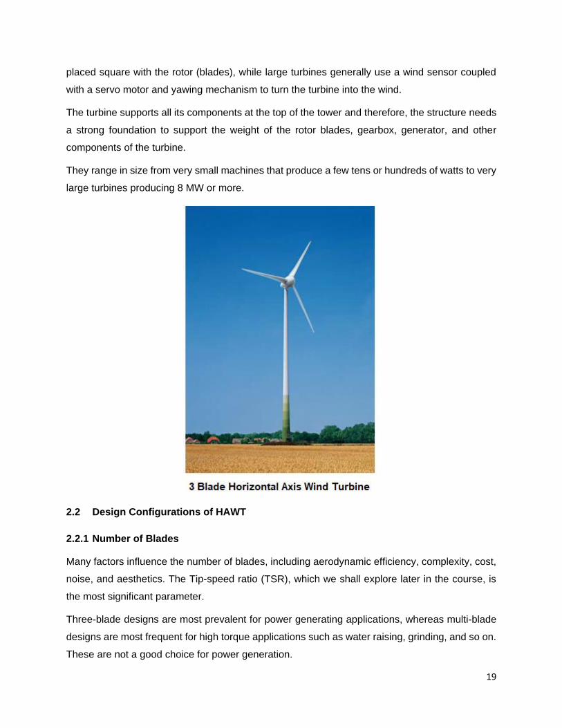
They range in size from very small machines that produce a few tens or hundreds of watts to very
large turbines producing 8 MW or more.
2.2 Design Configurations of HAWT
2.2.1 Number of Blades
Many factors influence the number of blades, including aerodynamic efficiency, complexity, cost,
noise, and aesthetics. The Tip-speed ratio (TSR), which we shall explore later in the course, is
the most significant parameter.
Three-blade designs are most prevalent for power generating applications, whereas multi-blade
designs are most frequent for high torque applications such as water raising, grinding, and so on.
These are not a good choice for power generation.

20
2.2.2 Upwind and Downwind Types
HAWT come in two general designs – upward or downward turbines according to the direction in
which wind turbines accept the wind.
2.2.2.1 Upwind HAWT
In an upwind design, the blades face into the wind, which means the wind reaches the rotors
before the mast. Therefore, rotors do not suffer from the wind shade behind the tower, which
means a more efficient operation as well as less susceptibility to wear and tear of the rotors.
Usually, upwind turbines need direction adjustment devices such as yawing mechanism to keep
the blades in the face of wind.
2.2.2.2 Downwind HAWT
In a downwind design, the blades face away from the incoming wind, which means the rotor is
downstream of the tower. The wind strikes the mast before it reaches the blades. This
configuration exempts the direction device because it can follow the wind automatically. Thus, the
downwind turbine does not require a yaw mechanism to place the turbine in line with the wind
direction and could weigh less due to having variable-pitch blades.
Downwind variants suffer from fatigue and structural failure caused by turbulence when a blade
passes through the tower’s wind shadow (for this reason, the majority of HAWTs use an upwind
design, with the rotor facing the wind in front of the tower).

21
2.2.3 Advantages of HAWT
a. Can handle higher wind speeds than the other wind turbine design.
b. High efficiency, since the blades always move perpendicularly to the wind, receiving power
through the whole rotation.
2.2.4 Disadvantages of HAWT
a. Components of a horizontal axis wind turbine (gearbox, rotor shaft, and brake assembly)
are heavy and positioned at the top of the tower. Transportation, repairs, and maintenance
is costly.
b. Upwind type HAWTs require an additional yaw control mechanism to turn the blades
toward the wind.
c. Require large land area for installation because a minimum of 7 rotor diameter spacing is
recommended between two turbines.
d. They require tall masts, which makes them obtrusively visible across large areas,
disrupting the appearance of the landscape.
2.3 Vertical Axis Wind Turbines (VAWT)
Vertical axis wind turbines, as shortened to VAWTs, have the rotation axis perpendicular to the
wind direction and the ground. They can harness winds from any direction without the need to
reposition the rotor when the wind direction changes. The design also allows for lesser structure
heights, which makes them suitable options for being installed on the rooftops for small-scale
power generation.
The design also allows for an easier service and repair due to the fact that the gearbox and
generator are placed near the ground. In anyways, due to the nature of this design, there is no
need for any wind sensors or yawing mechanism to align the rotors with the wind directions.
Despite these advantages, VAWTs have found little commercial success to date, in part due to
issues with power quality, cyclic loads on the tower systems, and the lower efficiency of some
VAWT designs.
22
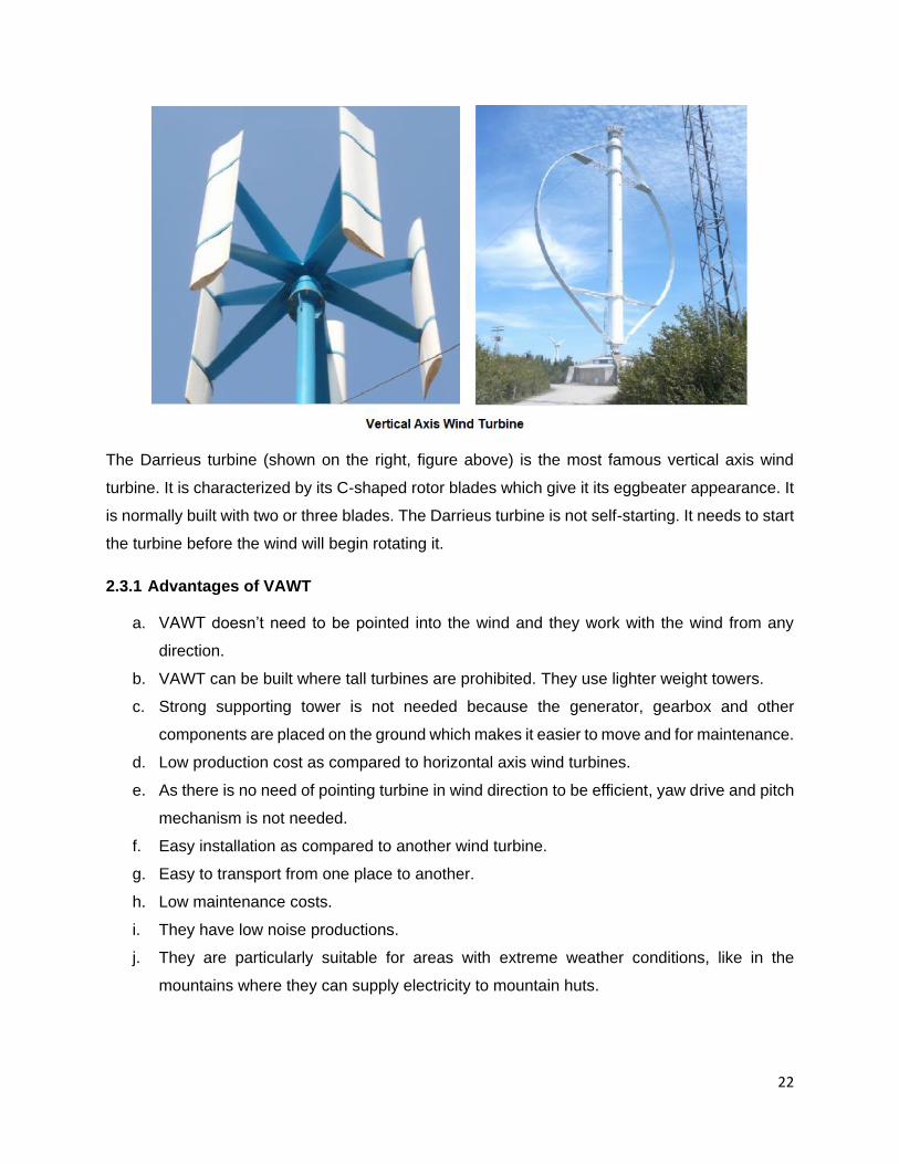
The Darrieus turbine (shown on the right, figure above) is the most famous vertical axis wind
turbine. It is characterized by its C-shaped rotor blades which give it its eggbeater appearance. It
is normally built with two or three blades. The Darrieus turbine is not self-starting. It needs to start
the turbine before the wind will begin rotating it.
2.3.1 Advantages of VAWT
a. VAWT doesn’t need to be pointed into the wind and they work with the wind from any
direction.
b. VAWT can be built where tall turbines are prohibited. They use lighter weight towers.
c. Strong supporting tower is not needed because the generator, gearbox and other
components are placed on the ground which makes it easier to move and for maintenance.
d. Low production cost as compared to horizontal axis wind turbines.
e. As there is no need of pointing turbine in wind direction to be efficient, yaw drive and pitch
mechanism is not needed.
f. Easy installation as compared to another wind turbine.
g. Easy to transport from one place to another.
h. Low maintenance costs.
i. They have low noise productions.
j. They are particularly suitable for areas with extreme weather conditions, like in the
mountains where they can supply electricity to mountain huts.
23
k. Their design allows for less space required between each two VAWT, which means
possibly a more power generation per unit of area. In some creative installations, VAWTs
are installed below the existing HAWTs as supplementary power generation units.
2.3.2 Disadvantages of VAWT
a. They do not get the advantage of the higher wind speeds at higher elevations.
b. They have low tip speed ratio.
c. They need an initial push to start by a small motor.
d. They are less efficient compared to horizontal axis wind turbines because of the additional
drag created when their blades rotate.
e. Controlling rotor speed is difficult.
f. They have relative high vibration because the airflow near the ground creates turbulent
flow.
2.4 Design Configurations of VAWT
VAWT come in several varieties:
2.4.1 Darrieus Wind Turbine
Darrieus type rotors are lift devices characterized by curved blades with aerofoil cross-sections.
They are also known as egg-beater designs. They have relatively low solidity and low starting
torques, but a high tip to wind speeds and therefore relatively high-power outputs per given rotor
weight and cost.
However, because of the large torque ripple and cyclic stresses on the tower, it results in poor
reliability. These wind turbines require external power support to start turning.
2.4.2 Giromill Turbine
The Giromill is typically powered by two or three vertical aerofoils attached to the central mast by
horizontal supports. It has the feature of variable pitch for reducing the torque pulsation and it is
self-starting.
Giromill turbines work well in turbulent wind conditions and are an affordable option where a
standard horizontal axis windmill type turbine is unsuitable.

24
2.4.3 Savonius Wind Turbine
The Savonius is a drag type device with two half-cylinders facing in opposite directions, forming
an S-shaped cross-section. They require relatively low-velocity winds, turn relatively slowly but
yield a high torque.
It is useful for grinding grain, pumping water, and many other tasks but its slow rotational speeds
make it unsuitable for generating electricity on a large scale.
The modified version of Savonius wind turbine has long helical scoops and provides smooth
torque.
2.5 Comparison between HAWTs and VAWTs
Items HAWTs VAWTs
Output power Wide range Narrow range
Starting Self-starting Need starting means
Efficiency Higher Lower
Cost Lower Higher
Wind direction Need redirected when the
Wind change its direction
Does not needs redirected
into the wind direction
Generator and gear box At the top of the tower At the ground level
Maintenance Difficult Easy

25
Conclusion
The HAWT has emerged as the dominant design configuration in modern wind turbine installation.
The HAWT's popularity stems from its high power and enhanced rotor control via pitch and yaw
control. All of today's main large-scale turbine manufacturers have capitalized on this concept,
which has been proven on a megawatt scale.
VAWT has the advantages of reduced tower loads because the heavy generator equipment can
be mounted on the ground and also, it doesn’t require any additional mechanism to face the wind.
Still the VAWT is not considered a competitive mainstream technology due to the following
drawbacks:
a. Low tip speed ratio and difficulty in controlling rotor speed.
b. Difficulties in the self-starting of vertical turbines.
26
3 CHAPTER -3: WIND TURBINE COMPONENTS
The wind turbines whether they’re large or small, or connected to the grid, are similar in design.
3.1 Key Components
A wind turbine consists of three main parts:
a. Rotor: The rotor is made of the blades and the hub, which holds them in position as they
turn.
b. Nacelle: The nacelle contains large primary components such as the main shafts,
gearbox, generator, and control system at the top of the tower.
c. Tower: The tower holds up the rotor and a nacelle (or box).
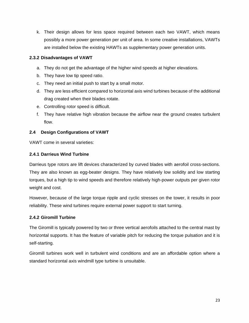
Here’s an illustration and a simple breakdown of all the components of a Horizontal axis wind
turbine (HAWT).
3.2 Blades
The rotor blades capture the wind and transfer its power to the rotor hub.

27
Blades are not solid; they are hollow and are made of composite fiberglass-reinforced polyester
or epoxy resin. The trend is to make them larger (for more power), lighter, and stronger. New
materials like fiberglass with carbon fibers are now being widely used to provide the high strength-
to-weight ratio required for the ever-larger wind turbine blades.
3.2.1 Blades Profile
The profile of blades is very important in noise reduction, high wind speed survival, and high-
performance energy output. The main operating principle is as follows:
There are two types of aerodynamic forces created by airflow over any surface: DRAG forces in
the direction of the airflow and LIFT forces perpendicular to the wind. Either or both can be used
to generate the forces needed to rotate the blades of a wind turbine. But more energy can be
extracted from wind using lift rather than drag, but this requires specially curved aerofoil surfaces,
like those used on aircraft wings. The aerofoil shape means that one side of the blade is curved
while the other is flat.
The wind blows faster along the curved edge, causing a pressure difference between the upper
and lower surfaces, resulting in a net force in the direction perpendicular to the wind. The air
“pushes” the blades to equalize the pressure differential, which causes them to turn.
28
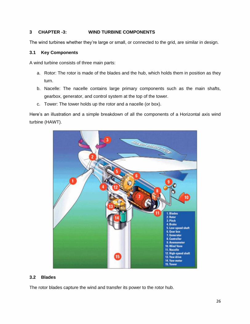
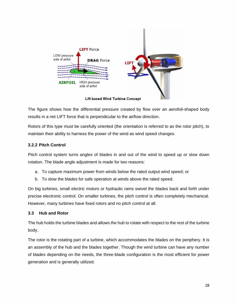
The figure shows how the differential pressure created by flow over an aerofoil-shaped body
results in a net LIFT force that is perpendicular to the airflow direction.
Rotors of this type must be carefully oriented (the orientation is referred to as the rotor pitch), to
maintain their ability to harness the power of the wind as wind speed changes.
3.2.2 Pitch Control
Pitch control system turns angles of blades in and out of the wind to speed up or slow down
rotation. The blade angle adjustment is made for two reasons:
a. To capture maximum power from winds below the rated output wind speed; or
b. To slow the blades for safe operation at winds above the rated speed.
On big turbines, small electric motors or hydraulic rams swivel the blades back and forth under
precise electronic control. On smaller turbines, the pitch control is often completely mechanical.
However, many turbines have fixed rotors and no pitch control at all.
3.3 Hub and Rotor
The hub holds the turbine blades and allows the hub to rotate with respect to the rest of the turbine
body.
The rotor is the rotating part of a turbine, which accommodates the blades on the periphery. It is
an assembly of the hub and the blades together. Though the wind turbine can have any number
of blades depending on the needs, the three-blade configuration is the most efficient for power
generation and is generally utilized.

29
The turbine rotor and hub assembly rotate at a rate of 15 to 20 revolutions per minute (RPM)
depending on the turbine size and design. The hub is normally attached to a low-speed shaft
connected to the turbine gearbox. Modern turbines use a pitch mechanism to adjust the angle of
the blades to the best of their ability, which is accomplished by the rotating at the base of each
blade. This allows rotor RPM to be controlled and more time spent in the design range. It also
enables the blades to be adorned in high wind conditions to prevent damage.
The average rotor diameter of a larger wind turbine is about 100 meters.
3.4 Nacelle
The nacelle is a strong, hollow shell that houses the electrical and mechanical components of the
turbine. Usually made of fiberglass, the nacelle contains the main drive shaft, gearbox, and
generator. It also contains the blade pitch control, a hydraulic system that controls the angle of
the blades, and the yaw drive, which controls the position of the turbine relative to the wind.
To the left of the nacelle, we have the wind turbine rotor, i.e. the rotor blades and the hub and at
the back of the nacelle there is an anemometer and wind vane to monitor wind conditions (speed
and direction).
Service personnel may enter the nacelle from the tower of the turbine.
The arrangement inside the generator housing is shown schematically in the figure below.

30
3.4.1 Subcomponents of Nacelle
The major sub-components of nacelle include:
System Function
Drivetrain (gearbox, low and high-
speed shaft)
Shift torque and speed characteristic
Generator Convert from mechanical to electrical energy
Anemometer Measures the wind speed
Vane Tracks the incoming wind direction
Yaw mechanism Adjusts the position of nacelle with respect to wind
speed and direction
Cooling system Cools the generator and gearbox lubrication system
Power system interconnection Interface generator with load or power grid
SCADA Monitor performance, control set-points, human interface
Each system has a dependency on the others. Therefore, it is necessary for the turbine to have
a system-wide controller to communicate with and coordinate control of various turbine
components. Based on information from various sensors, the main controller can set operating
31
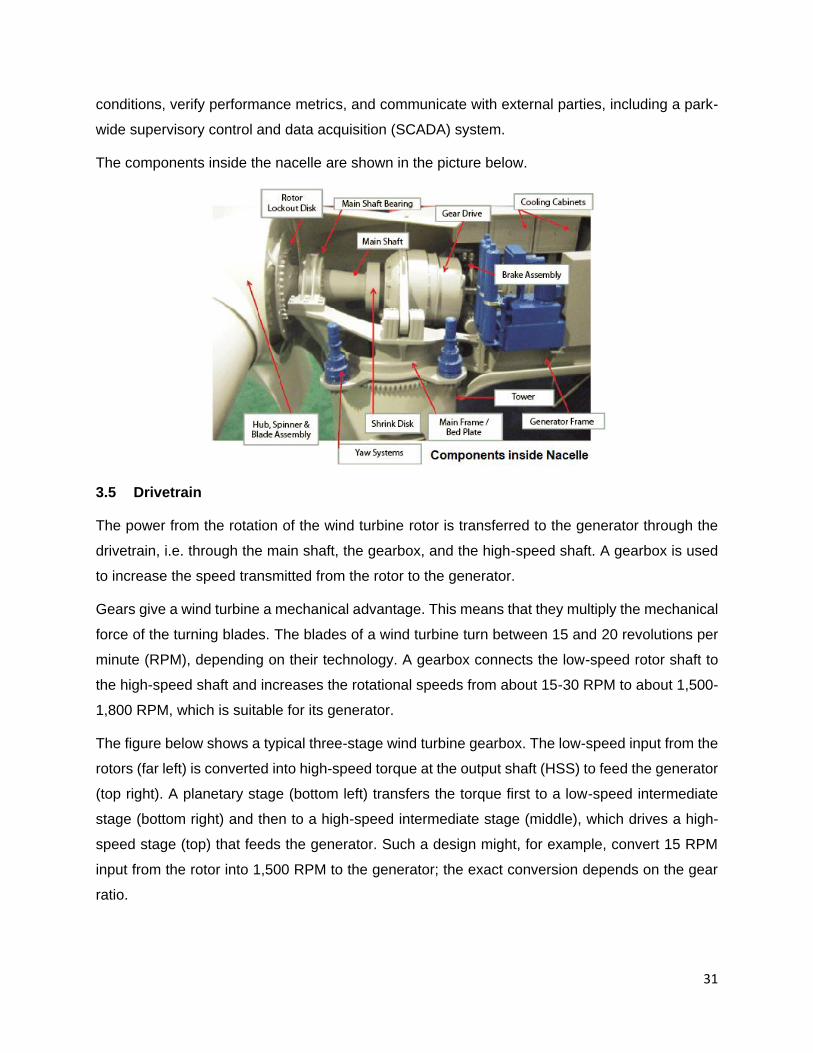
conditions, verify performance metrics, and communicate with external parties, including a park-
wide supervisory control and data acquisition (SCADA) system.
The components inside the nacelle are shown in the picture below.
3.5 Drivetrain
The power from the rotation of the wind turbine rotor is transferred to the generator through the
drivetrain, i.e. through the main shaft, the gearbox, and the high-speed shaft. A gearbox is used
to increase the speed transmitted from the rotor to the generator.
Gears give a wind turbine a mechanical advantage. This means that they multiply the mechanical
force of the turning blades. The blades of a wind turbine turn between 15 and 20 revolutions per
minute (RPM), depending on their technology. A gearbox connects the low-speed rotor shaft to
the high-speed shaft and increases the rotational speeds from about 15-30 RPM to about 1,500-
1,800 RPM, which is suitable for its generator.
The figure below shows a typical three-stage wind turbine gearbox. The low-speed input from the
rotors (far left) is converted into high-speed torque at the output shaft (HSS) to feed the generator
(top right). A planetary stage (bottom left) transfers the torque first to a low-speed intermediate
stage (bottom right) and then to a high-speed intermediate stage (middle), which drives a high-
speed stage (top) that feeds the generator. Such a design might, for example, convert 15 RPM
input from the rotor into 1,500 RPM to the generator; the exact conversion depends on the gear
ratio.

32
The gearbox in a wind turbine does not "change gears". It normally has a single gear ratio between
the rotation of the rotor and the generator. A modern wind turbine may have a gear ratio of 100:1
or more. So, every time the blades make one revolution, the generator shaft spins 100 times!
The gearbox is a costly (and heavy) part of the wind turbine. Experience has shown that the
gearbox has a limited life of 2 to 3 years. This is because the energy in the wind does not remain
constant for a relatively acceptable length of time. It continuously fluctuates, because of the nature
of wind. This causes the gear teeth to undergo overload and hammering stress that leads to
fatigue and failure. In addition, the gearbox is a heavy item in the nacelle on the top of a turbine.
But why utilize a gearbox in the first place? Isn't it possible to run the generator straight from the
main shaft's power?
Engineers are looking on direct-drive design options, in which the generator's speed is transmitted
directly to it. However, because the generator must rotate at the same speed as the turbine
blades, the generator will be significantly larger. For example, if we use an ordinary generator,
directly connected to a 50 Hz AC (alternating current) three-phase grid with two, four, or six poles,
we would have to have an extremely high-speed turbine with between 1000 and 3000 revolutions
per minute (rpm). Another possibility is to build a slow-moving AC generator with many poles. But
if you want to connect the generator directly to the grid, you will end up with a 200-pole generator
(i.e. 300 magnets) to arrive at a reasonable rotational speed of 30 RPM.
Another issue is that the mass of the generator's rotor must be roughly proportional to the amount
of torque it must handle (moment or turning force). In any case, a directly powered generator will
be extremely heavy (and expensive).

33
3.6 Main Shaft and Couplings
The main shaft is a drive shaft connected to the rotor and the gearbox or to the generator.
Shaft couplings usually include at least one joint which offers flexibility. Without a flexible shaft
coupling, vibrations caused by misalignment are transferred through the rigid coupling and into
the connected equipment. The result is increased stress on bearing races and rollers. Increased
harmonic content is also noticed when operating without a flexible coupling. For these reasons, it
is important to take care in ensuring shaft alignment, component integrity, and ample damping.
3.7 Generator
The generator is the component that turns the rotor's mechanical energy into an electric potential
difference, commonly known as voltage. It has a construction like that of an electric motor.
Generators may be either constant or variable speed types. Variable speed units are expensive
and/or unproven. Constant speed generators in use are synchronous induction and permanent
magnet types. Doubly fed induction generators are typically the standard configuration. It is very
versatile and has an extensive database.
The four types of wind turbine generators in use are as follows:
a. Type 1) Fixed speed squirrel-cage induction machine.
b. Type 2) Wound-rotor induction machine with variable resistance (wider speed/torque
range).
c. Type 3) Doubly fed wound-rotor induction machine with power electronics (widest range).
d. Type 4) Permanent magnet generators (PMG) or other synchronous constructions.
Several new technologies offer the best mix of gearbox and generator. The main trade-off is
between the use and complexity of the gearbox and the size of the generator and its associated
costs. The typical combination of the drivetrain is as follows:
a. High Speed geared system is mainly coupled with Doubly-Fed Induction Generator, which
only requires a small converter.
b. Low & Medium Speed geared system is mainly coupled with PMG. This system minimizes
rare earth material requirements, especially in medium-speed designs (greater gearbox
complexity allows the use of smaller & cheaper generators).
c. Direct drive system with classic synchronous generators.
Because a generator must be rotated at a speed corresponding to the frequency of the electric
network (50 or 60 Hz in most countries), it must be rotated faster than the turbine rotor. Most

34
generators need to be turned at 1500 RPM (for 50 Hz) and 1800 RPM (for 60 Hz). In no way, it is
feasible for a turbine rotor to move that fast. A gearbox, therefore, must increase the speed of the
turbine rotor to a speed that can be used by the generator.
3.8 Cooling Unit
The cooling unit contains an electric fan to cool the electrical generator. In addition, it contains an
oil cooling unit that is used to cool the oil in the gearbox.
3.9 Braking
The amount of electricity generated increases as the wind speed increases. In the event of load
tripping or accidental disconnection of the electrical load, the rotor speed may increase
dangerously. This may lead to mechanical damage to the rotor as well as the generator. The
automatic braking system is triggered to prevent undue stress on the rotor and damage to the
turbine components.
When wind speed exceeds a rating based on the individual design (between 25 -30 m/s), an
automatic shutdown is triggered. There are three methods employed:
3.9.1 Aerodynamic/Pitch Braking
Aerodynamic or Pitch braking is the most practical braking design and usually the first port of call
for turbine controllers.
Once the anemometer registers exceptionally strong winds, the pitch control function begins to
rotate the blades in the opposite direction to the current wind flow.
The wind catches a different area of the blades, resulting in less lift and momentum.
As the rotors slow, the gap between them increases and more wind slips between them. The
turbine and motor resume control of the slowing down process.
Once the blades are completely free of the wind's path, they slow to a natural standstill.
This is by far the safest method and guarantees a longer usable life for the turbine and its
components.
3.9.2 Mechanical Braking
Mechanical braking is mostly used as a backup for the aerodynamic braking system and as a
parking brake once the blades have stopped. However, if the aerodynamic braking system should
fail or the winds are too strong for it to work effectively, mechanical braking is the next option.
35
The brake disc is a circular piece of metal with holes around its perimeter. Once activated, a
stopper peg plugs one hole to bring the system to an emergency stop.
Although a fast way to stop the rotors, this system causes undue grinding of the metal
components, which can cause damage to components, and greatly reduce the service life of a
wind turbine.
The system is sometimes relied upon during maintenance work and repairs.
3.9.3 Electrical Braking
Electrical braking works in a similar way to aerodynamic braking, whereby some of the generated
electricity is used to turn the rotating blades in the opposite direction of the wind.
It isn't available in all turbines as it is a more expensive system to operate. However, electrical
braking slows rotors down until they stop faster, usually before any friction damage is done to
internal components.
3.10 Yaw Mechanism
A yaw mechanism guarantees that the turbine always faces the wind.
Since the direction of wind keeps on changing with respect to time and the rotor must follow the
wind and adjust its orientation to the wind direction to get the maxim power output. The yaw
mechanism helps in changing the direction of the nacelle with respect to the direction of the wind.
In small turbines, yaw action is controlled by a tail vane while in larger machines a
servomechanism operated by a wind-direction sensor controls the yaw motor, keeping the turbine
properly oriented.

36
The yaw mechanism uses electrical motors to turn the nacelle. However, many turbine designs
are restricted in their yaw movement. This is because the cables that carry power and/or control
signals from down-tower to up-tower are generally bundled together and allowed to twist a
specified amount as the nacelle rotates. If those cables are twisted too much, they can be pulled
off their anchors resulting in extreme damage. A limit switch is used to notify the controller when
the twist limit has been reached.
3.11 Power System Interconnection
Wind turbine’s power distribution system requires the use of controllers, transformers, filters,
relays, and other sensors and protective devices. The wind turbine must be able to limit its power
production and also to resist various fault conditions.
When connecting a wind turbine to an existing power distribution network, the terminal voltage
and frequency should match the power systems, and harmonic currents must be kept to a
minimum. Harmonic mitigation is possible with filters, and automated synchronization is possible
with controllers.
3.11.1 Controller
A wind turbine is a complex system to control because the source of power (wind) is not in our
control. Wind speed can fluctuate rapidly, even from second to second. As a result, a turbine's
power output must always be modified to account for wind variations.

37
Adaptable and dependable controllers are therefore, required for modern wind turbine generators.
The controller senses wind speed, wind direction, shaft speeds and torques, output power and
generator temperature. Control signals are generated with the electrical output corresponding to
the wind energy input.
In general, a control system is used for the following purposes:
a. Cut-in and cut-out of the equipment
b. Changing the orientation of the rotor into the wind
c. Power control of the rotor by varying the pitch of the blades.
d. Safety functions
The anemometer measures the speed and the intensity of the wind. It may be a simple instrument,
or it may be a complex, computer-aided machine that measures and records wind patterns over
time. The electronic signals from the anemometer are used by the wind turbine's electronic
controller to start the wind turbine when the wind speed reaches approximately 5 m/s (10 knots).
The controller stops the wind turbine automatically if the wind speed exceeds 25 m/s (50 knots)
to protect the turbine and its surroundings from damaging winds. Brakes (which can be
mechanical, electrical, or hydraulic) can be used to stop the rotor in emergencies.
A weathervane, wind vane, or weathercock is an instrument used for showing the direction of the
wind. It measures the wind direction and communicates with the yaw drive to orient the turbine
properly with respect to the wind. A yaw drive, powered by a yaw motor, orients upwind turbines
to keep them facing the wind when the direction changes. A yaw drive is not needed in downwind
turbines as the wind automatically blows the rotor away from it.
A pitch system turns blades out of the wind to control rotor speed and to keep the rotor from
turning in winds that are too low or too high to produce electricity.
The electronic controller performs the safety functions. In case of any malfunction, (e.g.
overheating of the gearbox or the generator), it automatically stops the wind turbine and calls the
turbine operator's computer via a telephone modem link.
3.11.2 Supervisory Control and Data Acquisition (SCADA)
All the critical functions of the wind turbine are monitored and supervised from the substation and
the control center to detect and resolve any incidents.
Supervisory control and data acquisition (SCADA) systems collect information from wind turbines,
substations, loads, and system operators, and can control turbine set points to maintain reliable

38
operation. When a system operator sends power generation signals, the SCADA system receives
them and adjusts the set-points of individual turbines. It can also shut down turbines in case of
excess energy production and emergency operations.
The SCADA system monitors and records a wide range of characteristics, including rotational
speeds and hydraulic temperature, blade pitch and nacelle yaw angles, and wind speed. As a
result, the wind farm operator can have complete information and control over the turbines from
a remote location. SCADA systems also show the operator visual information about the status of
the turbine and its components. In most cases, interfaces are provided to visualize system details
and allow remote control of the wind turbine.
3.12 Tower
The tower supports the structure of the turbine (rotor and nacelle) at its top. Wind turbine tower
height is significant because wind speed rises with height, and taller towers allow turbines to catch
more energy and generate more electricity. The tower also elevates the turbine above air
turbulence that can occur near the ground due to impediments such as hills, buildings, and trees.
The average height of the tower is roughly 50 m and the tallest reaching over 200 m. The height
of the tower is usually determined by the location, rotor diameter, and wind speed conditions. In
general, the tower height is slightly more than the Rotor diameter for medium and large turbines.
Small turbines should have taller towers than their rotor diameters; otherwise, the turbine will be
too close to the ground surface, resulting in poor wind speeds. A tower of 50 to 80 meters is
typical for a modern 1000 kW turbine. Increased tower height can give very high rates of return in
terms of power output for relatively minor investments.
The average weight of a wind turbine tower is more than 40 tonnes, and the tower might account
for more than 10% of the entire cost.
3.12.1 Main Tower Design Considerations
a. Minimization of the tower’s mass
b. Maximization of the tower’s stiffness
c. Maximization of the tower’s stiffness to mass ratio
d. Minimization of vibrations
e. Minimization of a performance index that measures the separation between the structure’s
natural frequency and the turbine’s exciting frequency
f. Maximization of the system natural frequency

39
The key focus points to address are cross-sectional dimension, buckling, tower top deflection,
and rotation restrictions. Limits on the towers, when paired with the natural frequency of the
foundation system, are another essential issue that must be addressed to provide a suitable tower
design.
3.12.2 Types of Tower
There are several designs for the towers:
a. Lattice towers
b. Guyed pole towers
c. Tubular steel or concrete towers
d. Hybrid - combination of these
Each type of tower has its own advantages depending on size of the turbine, type of terrain,
average wind velocity, turbulence level of wind in that wind farm, etc.
3.12.2.1 Lattice Towers
Lattice towers are manufactured using welded steel profiles. It can be constructed with perfectly
shaped steel rods that are connected to form a lattice. It has the same appearance as a traditional
communications tower.
40
The primary benefit of lattice towers is that they are less expensive because they require half the
amount of material as a free-standing tubular tower of comparable stiffness. These towers are
also very easy to transport in sections and install in pieces.
The most significant downside of lattice towers is their appearance. The lattice towers have nearly
disappeared from use for large, contemporary wind turbines due to aesthetic concerns.
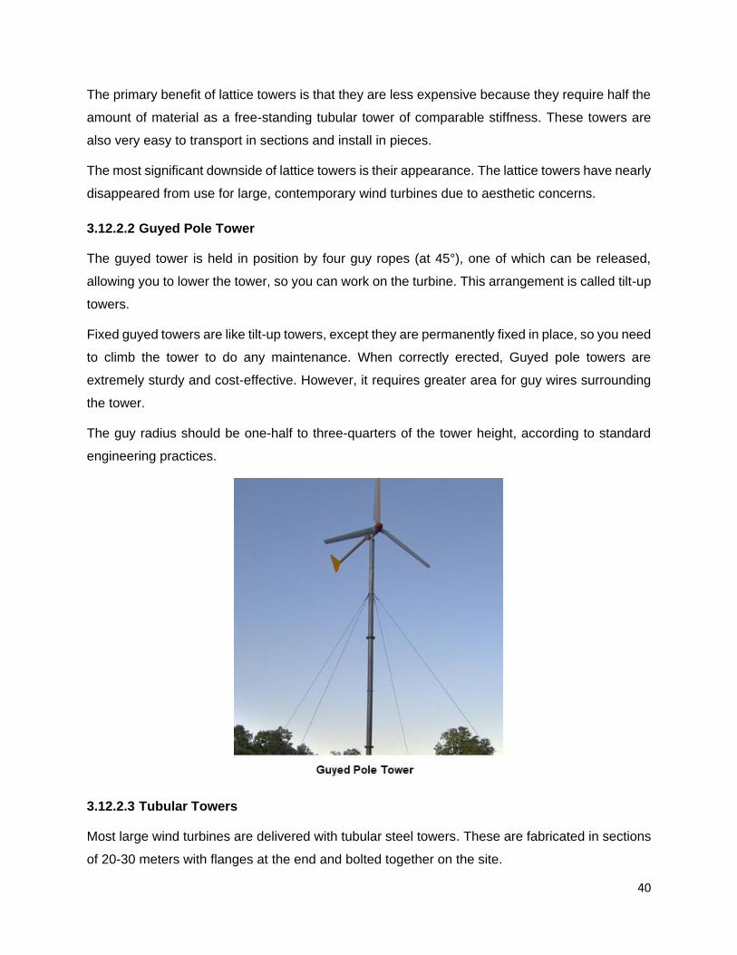
3.12.2.2 Guyed Pole Tower
The guyed tower is held in position by four guy ropes (at 45°), one of which can be released,
allowing you to lower the tower, so you can work on the turbine. This arrangement is called tilt-up
towers.
Fixed guyed towers are like tilt-up towers, except they are permanently fixed in place, so you need
to climb the tower to do any maintenance. When correctly erected, Guyed pole towers are
extremely sturdy and cost-effective. However, it requires greater area for guy wires surrounding
the tower.
The guy radius should be one-half to three-quarters of the tower height, according to standard
engineering practices.
3.12.2.3 Tubular Towers
Most large wind turbines are delivered with tubular steel towers. These are fabricated in sections
of 20-30 meters with flanges at the end and bolted together on the site.

41
The towers are made of rolled steel plate or concrete in conical shape (i.e. with their diameter
increasing towards the base) for greater stability and to save materials at the same time. The
towers are normally coated with a zinc-based finish and epoxy and urethane layers to provide
corrosion resistance.
Most modern turbines have a tower made of circular tubular steel with a diameter of 3 to 5 meters
and a height of 75 to 110 meters, depending on the size of the turbine and its location. A general
rule of thumb is to install a wind turbine on a tower with the bottom of the rotor blades at least 9
meters above any obstacle that is within 90 meters of the tower.
Towers have doors at the top and bottom that allow access to the vertical ladders, power lines,
yaw mechanism, and nacelle for any type of maintenance or inspection. The nacelle is also
accessible through a set of vertical ladders on the outside of the tower for maintenance and other
inspections. Modern turbines even include elevators that run from the basement to the top of the
tower.
Conical tubular steel towers are commonly used in large, contemporary wind turbines. The
principal advantage of this tower over a lattice tower is that it allows service employees to access
the wind turbine for repair and maintenance in a safe manner. The higher cost is a drawback.

42
3.12.3 Towers Cost Comparisons
Lattice towers are the cheapest to build since they use about half the amount of steel that is used
for a tubular steel tower.
The cost of a wind turbine tower is typically around 20% of the total cost of the turbine. The cost
of adding another 10 meters to a 50-meter tower is approximately $15,000. As a result, it is critical
for the final cost of the turbine.
3.13 Foundations
Wind turbines are huge structures that must withstand high wind speeds. They need to be pinned
to the ground in deep, excavated holes.
Wind turbine foundations are made of concrete with steel reinforcements. The foundation's design
will be dictated by the soil's condition and the strength of the wind.
The foundation must handle both the vertical load from the turbine and the horizontal load from
the wind force. The tower loading consists of loads from the turbine, wind, self-weight, and internal
fixtures. Loads on the foundation, which result from the various loads on the tower, are obtained
from the structural load calculations.
In offshore turbines that are well into the sea, the base can be floating, but it is of sufficient mass
to support the turbine weight and all the forces exerted on it and to hold it upright.

43
3.14 Cost Contributions
In terms of costs, the percentage on the total cost of the different components is divided as shown
in Figure below:

44
4 CHAPTER - 4: PHYSICS OF WIND POWER
Wind power is the conversion of wind energy into a useful form of energy, such as using wind
turbines to make electrical power, windmills for mechanical power, and wind pumps for water
pumping.
4.1 Power v/s Energy
Energy and power are closely related but not the same.
Energy is defined as the capacity to do some work. The most used unit to measure power is
kilowatt-hour (kWh).
Power is defined as the rate at which energy is transferred.
Electrical power is measured in Watts (W). It’s a relatively small unit so those more frequently
encountered are the kilowatt (kW) or 1,000 W, and the megawatt (MW) or 1,000,000 W.
Utility-scale wind turbines are usually identified by the maximum amount of power they can
produce, also called their rating. Commercial wind turbines are 1 to 6 MW rated capacity.
Electricity production and consumption is measured in kilowatt-hours (kWh). A kilowatt-hour is
one kilowatt (1,000 Watts) of electricity produced or consumed for one hour.
Example: If a wind turbine operates at a constant power of 10 kW for 2 hours, it will produce 20
kWh of energy.
Example:
One 25-W light bulb left on for 10 hours consumes 250 Wh of electricity.
One 100-W light bulb left on for 10 hours consumes one kilowatt-hour of electricity.

45
Electric bills usually identify the cost of power for their service area in $/kWh. In the Midwest,
power cost about $0.12/kWh, a figure that includes generation and transmission costs. Some
eastern utilities charge more, about $0.20/kWh, and some western states where hydropower is
available and coal is inexpensive, about $0.10/kWh.
4.2 Power Contained in Wind
The power contained in wind is the kinetic energy of the flowing air mass per unit time. The kinetic
energy in the wind of a mass m with the velocity v is:
E = ½ m v2
The air mass m can be determined from the air density ρ and the air volume V according to:
m = ρ V
Then,
E = ½ ρ V v2
Then the power contained in the wind is the rate of change of energy and is given as:
Pwind =E
Δt=
ρ ΔV v2
2 Δt
The rate of airflow or the volume (V) across the wind turbine in a given time is given as:
𝛥V = A v 𝛥t
𝑃𝑤𝑖𝑛𝑑 = 1
2 𝜌 𝐴 𝑣3
Pwind = Input power of wind (Watts)
ρ = Air density (kg/m3)
A = Swept area (m2)
v = Air velocity (m/s)
Divide the expression by 1000 to obtain power in kilowatts (KW).
The cross-sectional area (swept area) of the wind turbine can be calculated in terms of the
blade radius, r, using the equation for the area of a circle:
A = π r² = ¼ π D²
where the radius is equal to the blade length as shown in the figure below:

46
The rotor swept area, A, is important because the rotor is the part of the turbine that captures the
wind energy. So, the larger the rotor, the more energy it can capture.
Substituting A = ¼ π D² in the power equation:
𝑃𝑤𝑖𝑛𝑑 = (1
8𝜋) 𝜌 𝐷2𝑣3
The equation shows the three variables that determine the wind power blowing into a wind turbine.
a. Air density
b. Blade diameter (resulting in a certain swept area)
c. Wind velocity
4.3 Effective Useable Energy from Wind Turbine
The above power equation looks impressive, but wind turbines are not 100% efficient.
Wind turbines extract energy by slowing down the wind. For a wind turbine to be 100% efficient it
would need to stop 100% of the wind but then the rotor would have to be a solid disk and it would
not turn and no kinetic energy would be converted. Some energy must remain in the air leaving
the turbine. On the other extreme, if you had a wind turbine with just one rotor blade, most of the
wind passing through the area swept by the turbine blade would miss the blade completely and
so the kinetic energy would be kept by the wind.
In 1919, German physicist, Albert Betz calculated that the theoretical maximum power that can
be extracted from the wind is 59.3%. This is called the “Betz” limit. The actual efficiency with which
the blades convert available wind power to rotating shaft energy is less than the Betz limit.
Therefore, the effective useful energy that can be extracted from wind is:

47
Pu = Pwind x 0.593
Where,
Pu = Effective useable energy that can be extracted from
wind
Pwind = Input power of the wind
0.593 = Betz limit
Note that the Betz theory only indicates that the theoretical maximum power extraction from the
wind is 59.3%. It doesn’t mean that 59.3% of the energy will be available as final output from the
turbine.
In practice, the power captured by the wind turbine rotor, Pu, is below the theoretical Betz limit
due to the inefficiencies and losses attributed to different configurations, rotor blades profiles,
finite wings, friction, and turbine designs. Actual effective useable power that can be extracted by
the wind turbine relative to the energy available in the wind stream is some fraction of the available
power and is defined by the coefficient of performance, Cp.
𝐶𝑝 =𝑃𝑢
𝑃𝑤𝑖𝑛𝑑
Pu = Cp x Pwind
Cp = Coefficient of power
Pu = Effective useable power that can be extracted from wind
Pwind= Input power of the wind
Cp value is unique for a given turbine system and is normally defined by the turbine
designers/manufacturer at various wind speeds but it is important to understand the relationship

48
between all these factors and to calculate the useable power at wind speeds other than the rated
wind speed.
The Cp value is unique to each turbine system and is typically established by the turbine
designer/manufacturer at various wind speeds. However, it is critical to understand the
relationship between the usable power and the rated power.
We can calculate the effective useable power (Pu) by multiplying the Cp at a given wind speed
by the input power in the wind (Pwind). For a given turbine design, Cp is a function of tip speed
ratio (TSR).
a. Cp = 0.59 ----- The maximum theoretically achievable power coefficient (Betz limit)
b. Cp = 0.35 to 0.40 ---------The actual achievable power conversion for a good design given
by the manufacturer
So, when the manufacturer specifies the Cp of 0.4, the useable power that can be extracted from
wind is:
Pu = Pwind x 0.4
Pu = 1
2 𝜌 𝐴 𝑣3 x 0.4
4.3.1 Sample Calculation #1
Consider a wind turbine with a blade length of 20 m, operating at an average wind velocity of 10
m/s at sea level density of 1.225 kg/m3. What is the effective useable power that can be extracted
from the wind using Betz limit of 0.593 and manufacturer Cp rating of 0.4?
Solution:
We know the input wind power is governed by equation:
𝑃𝑤𝑖𝑛𝑑 = (1
8𝜋) 𝜌 𝐷2𝑣3-------- (Watts)
Blade length = 20 m
Rotor diameter = 20 x 2 = 40 m
v = 10 m/s
ρ = 1.225 kg/m3
𝑃𝑤𝑖𝑛𝑑 = (1
8 𝑥 3.14) 1.225𝑥 (40)2(10)3 ------ (Watts)

49
𝑃𝑤𝑖𝑛𝑑 = 770 KW -------------------- (Divide the expression by 1000 to get power in KW)
The theoretical effective useable power that can be extracted from wind using Betz limit:
Pu = Pwind x 0.593
Pu = 770 KW x 0.593
Pu = 456 KW
The effective useable power that can be extracted from wind using manufacturers data:
Pu = Pwind x 0.4
Pu = 770 KW x 0.4
Pu = 308 KW
4.3.2 Sample Calculation #2
We are given the following data:
a. Blade length, l = 52 m
b. Wind speed, v = 12 m/sec
c. Air density, ρ = 1.23 kg/m3
d. Power Coefficient, Cp = 0.4
How much power can be extracted from the wind?
Solution:
Inserting the value for blade length as the radius of the swept area into power equation we have:
L = r = 52 m

50
A = π r² = 3.14 x 52 x 52 = 8495 m2
We can then calculate the power converted from the wind into the useful rotation energy in the
turbine using equation:
Pu = 1
2 ρ A v3Cp
Pu = 1
2x 1.23 x 8495 x 123x 0.4 = 3.6 MW
4.4 Practical Limits of Energy Output
We have learned that, at best, a wind turbine can harvest a little more than 59 percent of the
incoming wind power, according to the Betz limit. But this is a theoretical limit. The real conversion
of wind power into the mechanical shaft power considers the aerodynamic losses, which are
defined by the turbine designers by the term coefficient of power (Cp).
The Betz Limit is a design goal that designers attempt to achieve in a real-world turbine. A Cp
value of 0.35–0.40 is a reasonable design goal for a functional wind turbine. This is further
reduced by a capacity factor accounting for the periods of poor wind flow as well, due to inherent
inefficiencies in the mechanical gearbox, electric generator, and other components.
When all these inefficiencies are accounted for, you might be able to get 30 to 35 percent of the
wind's rated energy as actually delivered in the very best conditions. Let's look at the losses in
the system at the sub-component level.
4.4.1 Inefficiencies and Losses in Wind Turbine System
The energy conversion process that turns wind power into electric power goes through three (3)
major conversion efficiencies namely, aerodynamic, mechanical, and electrical efficiencies. Some
energy is lost in every stage and the final electric power is less than the total wind power we
started with.

51
4.4.1.1 Aerodynamic Efficiency
The blade design and operating conditions have an impact on the performance and losses
experienced by wind turbines (referred to as aerodynamic efficiencies). The following are some
of the factors that influence aerodynamic efficiency:
a. Blade shape, profile, and number
b. Rotor end and whirlpool losses
c. Turbine and wind speed
d. Turbulence caused by drag or vortex shedding (tip losses)
e. Wake effects
The aerodynamic turbine efficiency is factored into the Coefficient of Power (Cp) value given by
the turbine manufacturer. The manufacturers generally enhance the aerodynamic efficiency by:
a. Avoiding low tip speed ratios which increase wake rotation
b. Selecting aerofoils which have a high lift to drag ratio
c. Specialized tip geometries
In-depth explanation and analysis can be found in the literature.
4.4.1.2 Mechanical Efficiency
The drivetrain, mainly the gearbox, shaft support bearings and couplings contribute to friction
losses. No machine is 100% efficient and the drivetrain normally contributes to 4 to 8% friction
and heat losses. The output is therefore adjusted for the mechanical efficiency (ȠM).

52
4.4.1.3 Electrical Efficiency
The gearbox shaft drives a generator, which transforms mechanical energy to electrical energy.
Some complicated power electronics is needed to convert the much less-than-perfect electricity
into the clean and precise 60 Hz power (or 50 Hz in some countries) needed for the grid. Both the
generator and power electronics have losses in the range of 15 to 20%. The output is therefore
adjusted for the electrical efficiency (ȠE).
4.5 Net Power Output from the Turbine
To calculate wind turbine power
output, you need to estimate two
values: the useful wind power and the
efficiency of the wind turbine.
Where,
• Pout = Net output power watts (746
watts = 1 hp) (1,000 watts = 1
kilowatt)

53
Multiplying these two values produces
an estimate of the output power of the
wind turbine. The equations are listed
below:
Pout = Pu x ȠM x ȠE
Pu = Cp x Pwind
Pwind =1
2ρ A v3
Therefore, the output power from the
combined wind turbine system is:
Pout = Cp x ½ ρ A v3 x ȠM x ȠE
• Pu = Effective useable power of the
wind in watts
• Pwind = Input power of the wind in
watts
• ρ = air density (about 1.225 kg/m3 at
sea level, less high up)
• A = rotor swept area, exposed to the
wind in m2
• Cp = Coefficient of performance
(0.593 is the maximum theoretically
possible and 0.35 for a good design)
• v = wind speed in meters/sec (20 mph
= 9 m/s)
• ȠM = gearbox/bearings efficiency
(depends, could be as high as 95% if
good)
• ȠE = generator efficiency (80% or
possibly more for a permanent
magnet generator or grid-connected
induction generator)
Let's do an example.
4.5.1 Sample Calculation #3
Consider a large wind turbine with a rotor diameter of 101 meters, operating at an average wind
velocity of 12 m/s at sea-level density of 1.225 kg/m3. What will be the net power output from the
turbine, If the manufacturer’s coefficient of power is 38%, mechanical efficiency is 96% and
electrical efficiency is 84%?
Solution:
Input power of the wind:
Pwind =1
2ρ A v3
ρ = 1.225 kg/m3

54
v = 12 m/s
𝐴𝑟𝑒𝑎 𝑜𝑓 𝑡ℎ𝑒 𝑟𝑜𝑡𝑜𝑟 (𝐴) = 𝜋𝑑2
4
𝐴 = 3.14 𝑥 (101)2
4= 8008 𝑚2
Pwind =1
2x 1.225 x 8008 x (12)3 = 8475667 𝑊𝑎𝑡𝑡𝑠
Pwind = 8475 𝐾𝑊
Effective useable power of the wind:
Pu = Pwind x Cp
Pu = 8475 x 0.38
Net Power Output from the Turbine:
Pout = Pu x ȠM x ȠE
Pu = 3220 KW
ȠM = 96%
ȠE = 84%
Then,
Pout = 3220 x 0.96 x 0.84
Pout = 2586 KW
4.6 Important Rules for Wind Turbines
Let’s go back to the equation that shows the maximum power that can be available from a wind
turbine.
𝑃𝑜𝑤𝑒𝑟 𝑂𝑢𝑡𝑝𝑢𝑡 (𝑃𝑜) = 1
2 𝜌 𝐴 𝑣3𝐶𝑝 Ƞm Ƞe
Or
𝑃𝑜 = (1
8𝜋) 𝜌 𝐷2𝑣3𝐶𝑝 Ƞm Ƞe
Notice that the available power (or net power output) is dependent on the cube of velocity. Whoa!
This means that even a small increase in wind speed results in a large increase in power.
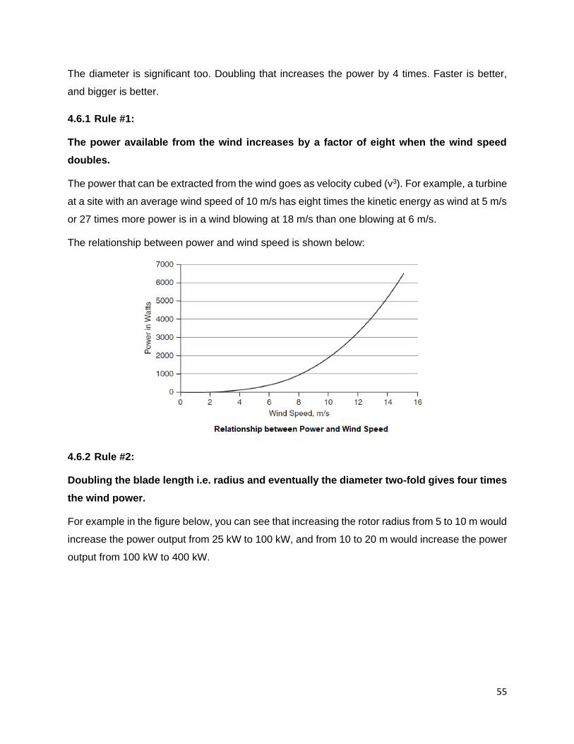
55
The diameter is significant too. Doubling that increases the power by 4 times. Faster is better,
and bigger is better.
4.6.1 Rule #1:
The power available from the wind increases by a factor of eight when the wind speed
doubles.
The power that can be extracted from the wind goes as velocity cubed (v3). For example, a turbine
at a site with an average wind speed of 10 m/s has eight times the kinetic energy as wind at 5 m/s
or 27 times more power is in a wind blowing at 18 m/s than one blowing at 6 m/s.
The relationship between power and wind speed is shown below:
4.6.2 Rule #2:
Doubling the blade length i.e. radius and eventually the diameter two-fold gives four times
the wind power.
For example in the figure below, you can see that increasing the rotor radius from 5 to 10 m would
increase the power output from 25 kW to 100 kW, and from 10 to 20 m would increase the power
output from 100 kW to 400 kW.

56
These two fundamental physical relationships are behind the drive to scale up the physical size
of turbines. A larger rotor diameter allows a single turbine to generate more electricity, providing
a better return on installation cost. Both the selection of a "windy" location and increasing the
height produce more power. Note that the taller turbines produce a higher and more consistent
supply of electricity.
4.7 Power Curve
The power output of a wind turbine varies with wind speed. Every turbine has a characteristic
wind speed–power curve, often simply called the power curve, shown in the figure below.

57
The wind turbine power curve features three key wind speeds:
a. Cut in wind speed: The cut-in wind speed is the wind speed below which the turbine does
not rotate and generate power. Above the cut-in wind speed, the torque generated by
airflow overcomes the frictional torques inherent in the mounting assembly of the turbine
blades. Typical cut-in wind speeds are 3 to 5 m/s.
b. Nominal wind speed: This is the lowest speed at which the wind turbine reaches its
nominal power output. Above this speed, higher power outputs are possible, but the rotor
is controlled to maintain a constant power to limit loads and stresses on the blades.
c. Cut-out wind speed: The cut-out wind speed is the wind speed at which the turbine must
be shut down to avoid damage due to excessive centrifugal forces and other mechanical
stresses. The turbine has two methods of reducing torque in high winds.
• Automatic cut-off: When the wind speed registers the Survival Speed, the auto-
shutdown of the motor is triggered, causing the rotors to cease.
• Feather blades: Fitted to the outer edge of a blade during construction, the feathers
help to reduce unwanted rotational torque. When the wind speed reduces, they
'unfeather' and resume normal operation.
The figure shows that the turbine starts producing power at about 4 m/s, reaches its rated speed
at about 14 m/s, and its maximum rotational speed at about 25 m/s. The range of wind speed
between cut-in speed (4 m/s) and cut-out speed (25 m/s) is called the operating range of the
turbine.
The power output will increase cubically with wind speed, for example, if wind speed doubles, the
power output will increase 8 times. The cubic dependence ends at higher speeds above 14 m/s
and the curve becomes relatively flat i.e. the wind turbine operates at nearly constant power
between the nominal rated wind speed and cut-out velocities.
Typically, the best-rated performance is achieved in the speed range between 13 and 15 m/s.

58
5 CHAPTER – 5: WIND TURBINE DESIGN PARAMETERS
We have learned in the previous chapter that the Coefficient of Power (Cp) value is unique for a
given turbine system. Cp is dependent on the “Tip Speed Ratio” (TSR).
What is TSR???
5.1 Tip Speed Ratio (TSR)
The Tip Speed Ratio (TSR) is an extremely important factor in wind turbine design. It is defined
as the ratio between the tangential speed of the tip of a blade and the actual speed of the wind.
TSR = Speed of rotor tip
Wind speed
𝑇𝑆𝑅 (𝜆) =𝑉
𝑣=
𝜔𝑟
𝑣=
2𝜋𝑓𝑟
𝑣
where:
• V = ω r = rotor tip speed (m/s)
• v = wind speed (m/s)
• r = rotor radius (m)
• ω = 2 π f = angular velocity (radian/sec.)
• f = rotational frequency (rotation/sec)
The tip speed ratio is related to efficiency, with the optimum varying with the number of blades
and the blade design.
5.1.1 Example – 1
Wind turbine blades traveling at 50 m/s with a wind speed of 10 m/s results in a TSR of 5.
𝑇𝑆𝑅 (𝜆) =𝑉
𝑣=
50
10= 5
Therefore, the tip of the blade is traveling 5 times faster than the wind.
5.1.2 Example – 2
Find the TSR of the wind turbine operating at a wind speed of 15 m/sec, for a rotor blade radius
of 10 m, rotating at 1 rotation per second?
Solution:
f = 1 rotation/sec

59
v = 15 m/s
r = 10 m
ω = 2 π f = angular velocity (radian/sec)
𝑇𝑆𝑅 (𝜆) =𝑉
𝑣=
𝜔𝑟
𝑣=
2𝜋𝑓𝑟
𝑣
𝑇𝑆𝑅 (𝜆) =2𝜋𝑓𝑟
𝑣
𝑇𝑆𝑅 (𝜆) =2 𝑥 3.14 𝑥 1 𝑥 10
15= 4.18
The TSR depends on the design of blade profile, the number of blades, and the type of wind
turbine. In general, a high TSR is desirable since it results in a high shaft rotational speed that
allows for the efficient operation of an electrical generator.
5.1.3 Why TSR is Important?
A wind turbine's TSR is particularly crucial for determining its efficiency and maximizing wind
collection. There are two scenarios in operation:
a. When the rotor spins too slowly or the blades are so far apart, a lot of wind will pass
through the gaps between the blades rather than giving energy to your turbine.
b. When the rotor spins too quickly or the blades are too close together, too much turbulent
air is formed, and each blade moves into the turbulent air created by the blade before it.
It lessens the wind speed for the blades that follow. This is known as the "wind shadow"
effect, and it gets worse as the number of blades or rotation speed increases.
The TSR should be selected so that the rotor blades do not pass through turbulent air. It is obvious
that the efficiency of power transfer from wind depends on the proper choice of the number of
blades and the speed.
But that raises the question: how will you know the ideal TSR??
5.1.4 How do you know the perfect Tip Speed Ratio???
The optimal TSR depends on the number of rotor blades “n”.
If you want the optimum TSR for maximum power output, this formula has been empirically
proven:
TSR (max. power) =4 π
n

60
Where n is the number of blades. For n = 2, the optimal TSR is calculated to be 6.28, for n = 3, it
is 4.19 and it reduces to 3.14 for n = 4.
The table below depicts the optimal TSR in relation to the number of blades. The smaller number
of blades has high TSR and it reduces with a higher number of blades.
No. of Blades (n) Optimum TSR
2 Around 6
3 Around 4 -5
4 Around 3
6 Around 2
The aerofoil design profile of the blade increases the rotational speed of the blade, and thus
generate more power. The optimal TSR values may be approximately 25 – 30 percent above the
values shown in the table.
A too low TSR would cause the wind turbine to exhibit a tendency to slow and stall. On the other
hand, if the TSR is too high, the turbine will rotate very rapidly, and will experience larger stresses.
It may lead to catastrophic failure, if uncontrolled.
5.2 Choice of the Number of Blades
Wind turbines with different number of blades will produce different output power and torque. In
general, a high TSR is preferred, which means fewer blades for maximum power production.
In light winds, multi-blade turbines can turn at a low speed and produce a lot of torque (turning
force). These turbines are often used to pump water, crush grains, or do other mechanical tasks
requiring a high starting torque. For windmills, the ideal TSR is around 1.
A small number of blades, on the other hand, implies low torque and high speed. The demand for
a high TSR in power generating wind turbines leads to a smaller number of blades, usually only
two or three. Their selection is influenced by various pros and cons.
a. Three-bladed rotors can achieve a Cp value of 48% and come closer to the ideal value of
59%.
b. For wind turbines with two blades or weight-balanced one-bladed rotor configurations, the
yield is smaller (5 – 10% lower than 3-blade) despite a higher TSR, because of the smaller
torque Ƭ.

61
c. Three-blade turbines are 33 percent heavier and more expensive than two-blade designs.
But the three-blade design, provides a smoother power output and a more balanced
gyroscopic force, resulting in less blade fatigue and a lower risk of failure.
Therefore, today's wind turbines have three blades.
Caution
A high TSR is desirable, but it should not come at the expense of the rotor. It will grow noisy and
possibly fail if it is over-stressed.
The following are some of the drawbacks of a high TSR:
a. Blade tips operating at 80 m/s of greater are subject to leading edge erosion from dust
and sand particles, and would require special leading-edge treatments like helicopter
blades to mitigate such damage
b. Noise, both audible and inaudible is generated
c. Vibration, especially in 2 or 1 blade rotors
d. Reduced rotor efficiency due to drag and tip losses
e. Higher speed rotors require much larger braking systems to prevent the rotor from
reaching a runaway condition that can cause disintegration of the turbine rotor blades.
5.3 Relationship of TSR and Coefficient of Performance (Cp)
For a given turbine design, the Coefficient of performance (Cp) is a function of tip speed ratio
(TSR).
The greatest attainable power coefficient, known as the Betz Limit, is 59.3 %, as we learnt in the
previous chapter. In practice, however, the power coefficient (Cp) center in the range of 35 to
40%. The inefficiencies and losses ascribed to varied configurations, rotor blade profiles, finite
wings, friction, and turbine detonation results in a value below the theoretical limit.
The figure below shows the actual wind turbine power coefficient as a function of the TSR.
The figure shows that the maximum power extraction occurs at the optimal TSR, where the
difference between the actual TSR (blue curve) and the line defined by a constant TSR is the
lowest. This difference represents the power in the wind that is not captured by the wind turbine.
Frictional losses, finite wing size, and turbine design losses account for part of the uncaptured
wind power and are supplemented by the fact that a wind turbine does not operate at the optimal
TSR across its operating range of wind speeds.

62
5.4 How to arrive at TSR in Field Conditions?
Before we can calculate the tip speed ratio, we need to know how long it takes the rotor to make
one full revolution.
5.4.1 How to Find the Tip Speed?
From a distance, it is easy to be fooled into thinking that wind turbines spin in a slow and
cumbersome manner. It is not until you get up close to them that you appreciate the speed at
which they rotate.
When you know the formula, it is possible to calculate the speed of a turbine, with the help of a
calculator.
To calculate the speed of a turbine, you will need to know the rotor radius, which is the length of
the blade.
Speed is defined as distance divided by time.
For a rotor, the distance traveled in one rotation is the circumference (2πr).
So, if the blade travels one circumference (2 π r) in a rotation time of T (seconds), the blade travel
speed (V) is given by:
V = 2πr/T
5.4.2 Example
For a blade measuring 40 m., obtain the circumference of the turning circle by:

63
2 π r
2 x 3.14 x 40 = 251.2 m
If it takes 4 seconds for the blade tip to travel that distance, the speed is:
251.2
4 = 62.8 𝑚/𝑠𝑒𝑐
Or in other words, this wind turbine turns at 62.8 meters per second.
In the above example, notice that the circumference is measured at the periphery i.e. the tip of
the blade.
Now when you see the figure below, the speed of a rotating blade varies from the center to the
tip. The speed is fastest at the tip than at the center or near the hub. Wind turbine experiences
variations in velocity along the length of the blade and therefore the blades are twisted to avoid
breaking or bending due to the turning moment of the wind. Twisting adds stiffness to the blades.
The design must include other features such as variable pitch operation (rotating the entire blade
along its axis as the wind speed varies) or variable rotation speeds.
5.4.3 How to Find the Wind Speed?
The device used for wind speed measurement is called an anemometer. There are three different
techniques for wind speed measurement. In general, any measurable phenomenon that has a
strong dependence on wind velocity can be used for wind speed measurement. Experience has
shown that thrust, pressure, and the cooling effect, are the three most convenient parameters by
which wind speed can be directly measured.

64
5.4.3.1 Robinson Cup Anemometer
Wind turbines employ a vane anemometer, a piece of equipment essential to their safe and
controlled operation. The device is situated atop the tower, easily recognized by the set of
spinning blades or cups. The number of revolutions over an allotted period is measured and
displayed as kilometers per hour (km/h).
The vane denotes the other important factor, wind direction.
The Robinson cup anemometer consists of a vertical shaft carrying three or four horizontal arms,
at the ends of which there are hemispherical cups of thin sheet metal. The circular rims of the
cups are in vertical planes passing through the common axis of rotation. The thrust of wind is
greater on the concave sides than on the convex ones, thereby leading to the rotation of the
vertical shaft (Refer to figure below).
As this is a vertical-axis device, there is no problem with the orientation along the wind direction.
The wind velocity has a linear relationship with the speed of rotation, which is measured by a
photocell-operated digital counter. The display can be pre-calibrated to give the wind speed
directly. Modern devices have facilities for continuous data logging and storage, from which data
can be retrieved later for analysis.
At very low wind speeds, the readings of the cup anemometer can be erroneous due to the friction
of the bearings. During fast variations of wind speed, the inertia effect may be significant, e.g.,
when the wind speed drops quickly, the anemometer tends to rotate faster and takes time to slow
down. Despite these minor drawbacks, the Robinson cup anemometer is the most extensively
used instrument for wind speed measurement.
The other devices used for wind speed measurement are the pressure tube anemometer and the
hot wire anemometer.

65
5.4.4 TSR Calculations
Now that you’ve made all your measurements, you should be able to figure out your TSR.
You already calculated the tip speed (distance traveled divided by the time taken for one
revolution) using the equation:
V = 2πr/T
Also, you have found out the wind speed using anemometer.
You can find out the TSR by dividing the tip speed (V) by the wind speed (v).
𝑇𝑆𝑅 =2𝜋𝑟
𝑇𝑣

66
6 CHAPTER – 6: WIND FARMS
A wind farm is a collection of wind turbines designed to generate utility-scale electric power from
wind in large quantities. These are set up in areas where there is a lot of wind and it is consistent.
Large wind farms contain a few or hundreds of wind turbines in the same area and require large
tracks of land space for installation.
There are currently two types of wind farms:
a. Onshore - Land based
b. Offshore - Sea based
6.1 Onshore Wind Energy
Onshore wind energy is responsible for generating electricity by harnessing wind from land-based
wind turbines. To do this, we erect wind turbines that can convert kinetic energy from the wind
into usable power and transfer it to the distribution network.
Onshore wind can be classified into two types “small wind” or “distributed wind”, and “utility-scale”
wind:
6.1.1 Small Wind Farm
Small wind sometimes called “distributed wind energy” refers to wind turbines that are 10 kW to
100 kW range. These turbines may be installed as off-grid or on-grid setup.

67
In off-grid setup, the wind turbine is not connected to the power grid, and its generated power is
directly consumed by the end-user or stored in the battery for future use. Applications include
homes, agricultural and livestock farms, ranches, watering facilities and other businesses that are
deployed in remote settings.
On-grid setup requires connecting to the distribution lines and is often supported by financial
incentives, which reduce up-front capital costs to the consumer.
6.1.2 Utility Scale Wind Farms
Utility-scale wind farms refer to a cluster of wind turbines with sizes ranging from as low as 100
kW to several megawatts. The number can range from a few to dozens, to hundreds of energy-
producing turbines. The generated power of utility-scale wind turbines is injected into the power
grid.
6.1.3 Advantages of Onshore Wind Energy
a. Cheaper foundations compared to offshore work
b. Easily integrated with the electrical- grid network
c. Cheaper installation and access during the construction phase
d. It can be operated and maintained easily and cheaply
6.2 Disadvantages of Onshore Wind Energy
a. Negative visual impact and noise
b. Limited availability of lands
c. Restrictions associated with obstructions like buildings, mountains, etc.
d. Birds getting trapped in blades
e. Affected to more turbulence
6.3 Offshore Wind Energy
Offshore wind energy is the energy obtained by harnessing powerful ocean winds. Because the
wind blows more continuously and fiercely offshore than inland, they can generate enormous
power in the waters off coastal areas. To make the most of this resource, mega-structures are
installed that are seated on the seabed and equipped with the latest technical innovations.

68
The offshore turbines can be built in very high capacities and sizes because designers are not
worried about the terrain-induced turbulence or the noise. GE has built an offshore design rated
at 12 MW, with the rotor diameter matching the towers of the Golden Gate Bridge, and the surface
area of the blade sweep equivalent to seven American football fields.
6.3.1 Advantages of Offshore Energy
a. The biggest benefit of offshore wind is that it’s dependable and steady. Even in shallow
water, the wind tends to be stronger and steadier than onshore. Steady trade winds
contribute to strong electricity production numbers at offshore sites.
b. The roughness of the water surface is very low and obstacles to the wind are less. So,
large turbines can be installed
c. Noise pollution is also not a factor because these are too far from the shores.
6.3.2 Disadvantages of Offshore Energy
a. Installing offshore wind turbines has challenges in constructing towers and foundations
that will be underwater. It’s expensive.
b. A lot of marine equipment will be needed to ferry large structures to offshore locations and
then secure them to the ocean floor.
c. Connection to the utility grid is also much more complex and expensive.

69
d. Performing maintenance on offshore towers is difficult and much more expensive than
onshore. At times the turbines will be inaccessible.
e. Sea water environment is corrosive, so offshore turbines will need more durable seals and
more reliable equipment. The turbine’s materials must be marine-grade and corrosion-
resistant.
6.4 Onshore vs Offshore Wind Turbines
The design and working of offshore and onshore wind turbines is largely identical. The two major
differences and considerations are in installation and the use of versatile blade pitch systems that
are adaptable to larger turbines and minimize risky maintenance.
6.4.1 Depth of Water and Foundations
Setting up an onshore wind turbine is usually much simpler than an offshore one. Onshore wind
turbines typically use concrete foundations. Offshore construction presents different challenges,
the most obvious being how the structure is anchored. Depending on the depth of the water, the
strategy changes.
a. For shallow water (< 30 m in depth) – conventional tower structure is typically used with
monopile construction.
b. For transitional waters (30-60 m) - cross-braced “jacket” foundation is used.
c. For deeper waters (> 60 m), wind turbines are anchored semisubmersibles. Prototype
floating platforms are being tested.
The transformer design is also different for different water depths, and in general, offshore
installations are moving from the gearbox to direct-drive designs.
A lot of the semisubmersible technologies, as well as the anchors used for offshore turbine
structures and foundations are borrowed from the oil and gas industry– which has been
maintaining offshore structures for decades.
6.4.2 Distance from Shore
The rotor size in the turbine goes up as you go further out from the coast.
You have to factor in the distance from shore for laying cables to bring the electricity to market.
6.4.3 Tower Size & the Pitch Actuator
All offshore wind turbines are pitch-controlled because there is more power per tower with blade
pitch control. Offshore turbines are typically larger because in addition to being well-suited for

70
constant offshore breezes, an offshore foundation is a much larger percentage of the turbine’s
overall cost (compared to land) and it is important to squeeze every possible megawatt out of the
structure before building the next one.
6.5 Design of Wind Farms
A site appropriate for the installation of wind turbines should, by definition, be "windy," with regular
and constant winds. Geographic location, season, height above the surface, and time of day all
influence the direction and speed of the wind. There is very little power generated if the wind is
too weak.
Winds are rarely constant, in addition to day-to-day variations. They are nearly always gusting
instead. This turbulence causes two issues:
a. The generator's electrical power output will fluctuate continually, necessitating suitable
conditioning.
b. The continually changing forces on the blades results in fatigue loading and eventual
failure.
It is, therefore, essential to understand this wind variability and as well as how often specific
speeds of wind occur and how the surrounding terrain impacts airflow stability.
6.6 Site Analysis and Selection
The process of constructing a wind farm is extremely complex due to the numerous elements that
must be considered to determine where and when it should be built. The following are a few
important considerations:
a. Examining wind patterns and speeds
b. Examining the direction of the wind
c. Examining the soil properties in preparation for the foundation
d. Calculating the demand for electricity and the distance to the transmission line from the
wind site.
6.6.1 Other Factors
There are many other factors at play when designing a wind farm.
a. The area should be as wide and open as possible in the prevailing wind direction, with few
obstacles. Its visual influence needs to be considered – few, larger turbines are usually
better than many smaller ones.

71
b. The location should have inexpensive access to power grids.
c. The turbines should be easily accessible for maintenance and repair work when needed.
d. Noise levels should be calculated beforehand and must comply with the levels of sound
stipulated in national legislation.
e. Turbine spacing considering the effect one turbine can have on others nearby – the 'wake
effect'.
f. The risk of extreme events such as earthquakes.
g. The logistics to transport the turbines and the local availability of cranes.
6.6.2 Wind Speeds
The site area should be investigated for mean wind speeds and direction before a wind turbine
project is set up.
The windiness of a location must be expressed in numerical terms. To accomplish this, the wind
is normally measured by its speed and direction at a certain area. Wind atlases provide a graphical
depiction of mean wind speed by displaying the distribution of wind speeds on a large scale (for
a specified height).
Wind speed is traditionally measured with anemometers, usually, three cups capture the wind
rotating around a vertical axis.
Weathervanes are used to determine the direction of the wind. After measuring wind data for at
least one year, the mean annual wind speed can be calculated. Wind speed and wind direction
statistics are visualized in a wind rose, showing the statistical repartition of wind speed per
direction.
Wind statistics show the best sites to locate wind farms according to the best wind resources.
They also include details on how the turbines should be placed in respect to one another and
what the spacing between them should be.
Wind speeds are classified into seven different classes — with class one being the lowest and
class seven being the highest. Wind speeds in class 3, which is 6.7 – 7.2 m/s and above are
typically needed to economically generate power.
Wind patterns are often analyzed using a wind spectrum. A high value of the wind spectrum
represents a large change in the wind speed at the given time interval. The peaks, when plotted
on a graph, reflect turbulences that occur over time.

72
6.6.3 Wind speed distribution
When selecting a location, it's critical to understand the wind speed distribution, fluctuations, and
spread.
a. Diurnal − Caused by the difference between temperatures during the day and at night.
b. Depressions − Occur with four-day intervals along the coastal region.
c. Annual − The annual distribution is influenced by latitude.
6.7 Weibull Curve
Because wind speed and direction change over time, calculating the power generation potential
necessitates some statistical analysis. A Weibull curve is frequently used to statistically model
fluctuations in wind speed (see the chart below). In essence, the Weibull curve estimates the
number of hours the wind blows at different speeds during a year for a particular yearly average
wind speed.
This chart depicts the predicted number of hours per year when the wind speed is at a given level.
The amount of energy a wind turbine produces is determined by the wind speed–power curve
covered in earlier chapters as well as the wind speed frequency distribution at the location, as
illustrated in the image above.
6.7.1 Wind Resource Maps
Wind energy forecasting is a crucial tool for determining the best location for a wind turbine. Wind
speed charts and statistics are available from the National Oceanic and Atmospheric

73
Administration (NOAA) and the National Renewable Energy Laboratory (NREL) in the United
States.
These are maps of estimated wind resources provided by government agencies (National 'wind
atlases'), which are used to inform policymaking and stimulate wind power development. The
wind map for US sites released by NREL is shown below.
6.8 Power Grid Access
It is important to note that wind isn't the only factor for siting turbines.
Wind farm developers must consider the farm's proximity to transmission lines as well as the
equipment required to connect to the power grid. Transmission line construction incurs additional
expenditures that frequently outweigh the overall benefit.
Developers must also consider the terrain, potential obstacles, and interference with underlying
rock and faults, as well as local airports and plane traffic, bird and bat flight patterns, and
community impact (noise and other possible effects).

74
Gansu in China is the world's largest wind farm that produces 6,800 megawatts of electricity, but
it is underutilized, since it's located 1,000 miles from the cities that could most use the power,
pointing to the importance of siting when choosing a wind farm location.
6.9 The Placement and Spacing of Wind Turbines
Each wind farm responds to its defining factors, which include wind speed ratios and direction,
size and type of the turbine, and land costs.
To function properly, wind turbines require a constant and unbroken flow of air. Because each
wind turbine causes turbulence in the area behind and around it, the turbines must be spaced far
enough to maximize power output and minimize turbulence.
According to several studies, turbine spacing should be between 6 and 10 times the diameter of
the rotor, with most developers opting for roughly 7 rotor diameters apart. This arrangement
ensures that developers get the most out of their energy and landowners get the most out of their
space. It's worth noting that more spacing means more costs.
So, an 80-meter rotor would need to be 560 meters -- more than a third of a mile -- from adjacent
turbines.
6.10 Wind Farm Area
6.10.1 Direct Land Use
The area of wind farms per MW capacity is referred to as direct land use. The concrete tower pad,
power substations, and new access roads are also part of the land-use area. In the United States,
the average direct land use for wind turbines per megawatt of rated capacity is 0.75 acres. A 2-
megawatt wind turbine, for example, would require 1.5 acres* of land.
(*1 acre of land = 4046 sq-m)
6.10.2 Total Wind Farm Average Area
There is a lot of space between turbines in any wind farm. Space is needed so that one wind
turbine does not obstruct the passage of air to the next, allowing each to gather as much energy
as possible from the wind.
Some more space is required to follow ridgelines or avoid other obstacles and road networks.
Often the regulations impose the following:
a. The blades of a wind turbine should be at least 9 m above any obstacle.
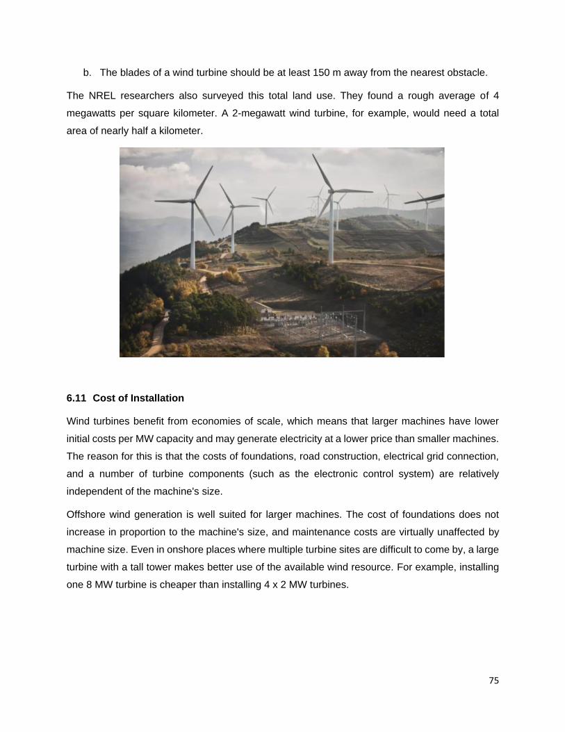
75
b. The blades of a wind turbine should be at least 150 m away from the nearest obstacle.
The NREL researchers also surveyed this total land use. They found a rough average of 4
megawatts per square kilometer. A 2-megawatt wind turbine, for example, would need a total
area of nearly half a kilometer.
6.11 Cost of Installation
Wind turbines benefit from economies of scale, which means that larger machines have lower
initial costs per MW capacity and may generate electricity at a lower price than smaller machines.
The reason for this is that the costs of foundations, road construction, electrical grid connection,
and a number of turbine components (such as the electronic control system) are relatively
independent of the machine's size.
Offshore wind generation is well suited for larger machines. The cost of foundations does not
increase in proportion to the machine's size, and maintenance costs are virtually unaffected by
machine size. Even in onshore places where multiple turbine sites are difficult to come by, a large
turbine with a tall tower makes better use of the available wind resource. For example, installing
one 8 MW turbine is cheaper than installing 4 x 2 MW turbines.

76
Onshore wind is currently more cost-effective than offshore wind development. However, as
offshore turbines are mass-produced on a bigger scale in the coming years, final costs per MW
will fall, making offshore wind energy increasingly competitive.
6.11.1 Construction Schedule
Construction time is usually very short.
A 10 MW onshore wind farm can easily be built-in two months.
A larger 50 MW onshore wind farm can be built-in six months.
Offshore wind farms take longer to develop, as the sea is inherently a more hostile environment.
The average time is about 12 months.
6.11.2 Turbine Lifespan
Most larger wind farms are expected to survive at least 20 years. They will run constantly for up
to 120,000 hours during their lifetime. In comparison, an automobile engine's design lifetime is
between 4,000 and 6,000 hours.

77
7 CHAPTER - 7: WIND ENERGY ECONOMICS
Financing expenses are critical to a wind project's economic success.
Turbine expenses make up the most capital costs, particularly onshore, where they can account
for up to 84 percent of total installed costs. The rotor blades, tower, and gearbox are the key
components of turbines, accounting for around half of the total cost.
Offshore costs are much higher than onshore, owing to the harsh marine environment, which
necessitates corrosion control, deeper foundations, more expensive installations, and more
robust grid connections.
The cost of operation and maintenance often accounts for 20% to 25% of the total electricity bill
(as low as 11 percent for onshore and up to 35 percent for some offshore projects).
7.1 Typical Onshore and Offshore Wind Costs
Capital cost breakdown (top) & share of capital in levelized cost of electricity (bottom)
Notes:
a. Grid connection costs include cables, substation, and installations.
b. Construction costs include foundations and road improvements.
c. Planning and miscellaneous related to engineering, permitting, and licensing.

78
d. Fixed and variable operation and maintenance (O&M) costs include insurance,
administration, taxes, leases, and maintenance contracts, as well as repair, maintenance,
and replacement parts.
Source: IPCC (2011), “Special report on renewable energy”; IRENA (2012), “Renewable Energy
Technologies: Cost Analysis series - Wind Power”
7.2 Investment Costs of Wind Power Plants (USD/kW)
7.2.1 Capital Costs
The cost of a wind project varies based on turbine pricing, wind farm size, and local market
conditions (e.g., local industry competitiveness, labor costs...etc.).
Upfront investment costs for onshore turbine typically ranges from 1300 to 2500 USD/kW globally.
In China and India, they are as low as 1300 USD/kW, but in the United States, they average over
2200 USD/kW. This suggests that a 2 MW (2000 kW) onshore turbine will cost between USD 2.6
and 4.4 million regardless of installation costs. Small turbines with a capacity of less than 100 kW
will cost between $3000 and $8000 per kW.
Offshore wind is much more expensive than onshore wind (around 2.5 times more expensive).
Costs range between 3300 and 6000 USD/kW, depending on turbine size and floating design.
The average for shallow water and semi-near shore conditions is around 4,500 USD/kW in
Europe. The high installation costs of offshore turbines are mitigated by their unequalled energy
producing capabilities.
The turbine costs are influenced by:
a. Increases in the prices of commodities, mainly steel, copper, and cement.
b. Supply-chain bottlenecks caused by rapid market growth.
c. Increases in turbine size and system, sophistication to achieve higher load factors and
meet system requirements.
Plateau and decrease in wind turbine prices are due to:
a. Economies of scale production – large sizes
b. More stable and even declining commodity prices.
c. Supply chain catch-up with demand.
d. Increased competition, following the emergence of manufacturers with local content in
low-cost manufacturing bases.

79
7.2.2 Operation & Maintenance Costs
Operation & Maintenance (O&M) costs are a significant component of wind power costs. They
include:
a. Fixed O&M such as insurance, administration, grid access fees.
b. Variable O&M, mainly scheduled and unscheduled maintenance.
Average onshore O&M costs are typically around 10 USD/MWh in the US and 20 USD/MWh in
Europe.
Offshore O&M costs are expected to be significantly higher, ranging from 27 to 54 USD/MWh.
Source: US DOE LBNL (2012), “2011 Wind Technologies Market Report”
7.3 Revenue from Wind Turbine Power
You now want to know how much money your wind turbine will bring in. It is mostly determined
by the energy tariff, or how much you will be paid per kWh generated by the turbine. The
calculation is simple once you have that number:
Revenue = Tariff * POUTPUT
Depending largely on capacity factors, current wind electricity revenues range from:
a. 0.05 to 0.15 USD per kWh for onshore
b. 0.10 to 0.3 USD per kWh for offshore
7.3.1 Revenue Predictions
Predictions of how much energy a turbine will produce are crucial in the energy market since
energy is sold before it is produced. This means that correct energy calculations are critical for
balancing energy in the market and forecasting a company's earnings.
Understanding how a turbine performs at various wind speeds is essential for calculating the
revenue lost due to any turbine outage. It's also helpful to know how much power a turbine should
be producing so that if there's an issue with it, it can be detected by lower-than-expected energy
levels.
7.4 Availability Factor and Capacity Factor
The availability factor is the percentage of time that the turbine is really operational within a certain
period.

80
The capacity factor compares the plant’s actual production over a given period, with the amount
of power the plant would have produced had it been running run at full capacity for the same
amount of time, that is:
𝐹𝑐𝑎𝑝 = 𝑃𝑎𝑐𝑡
𝑃𝑚𝑎𝑥
Where,
• Fcap = capacity factor
• Pact = actual power produced
• Pmax = power at maximum operating capacity, often at wind speeds 14 m/s mph and
greater.
For example, a 1.5-MW turbine operating at full capacity around the clock for a year would
produce:
Pmax = 1.5 MW × 24 hr./day × 365 day/year × 1 year = 13,140 MWh
However, from normally variable winds, its records might show it generated only 5,214 MWh.
Hence, its capacity factor would be:
𝐹𝑐𝑎𝑝 = 𝑃𝑎𝑐𝑡
𝑃𝑚𝑎𝑥
𝐹𝑐𝑎𝑝 = 5,214 𝑀𝑊ℎ
13,140 𝑀𝑊ℎ = 0.39 𝑜𝑟 39%
Throughout the year, typically a workload of 23% can be reached inland. This increases to 28%
on the coast and 43% offshore.
7.5 Annual Energy Generation
We learned in the previous chapters the relevance of annual wind speed distribution curve and
the power curve.
The power curve, when combined with the annual wind speed distribution, can be used to
determine how much energy a wind turbine could produce over the course of a year.
The power at each wind speed (as determined by the power curve) is then multiplied by the
number of hours per year that the wind blows at that speed.
Hours x Turbine power = Energy produced
Example:

81
Consider the Vestas V82 (1.65 MW turbine) is to be installed in Jodhpur location, India. The
characteristics of Vestas V82 turbine is as below:
Turbine Model Vestas V82
Rated power 1,650 kW
Diameter 82 m
Swept area 5281 m²
Hub height 78 m (50 Hz)
Cut-in wind speed 3.5 m/s
Nominal rated wind speed 13.0 m/s
Cut-out wind speed 20 m/s
Air density 1.225 kg/m3
The power curve for the Vestas V82 1.65 MW turbine is shown below:
The annual wind speed distribution for Jodhpur location is shown below.

82
Now, theoretically this turbine can generate 14,454 MWh of energy each year, if the wind
conditions remain consistent throughout the year.
Turbine capacity = 1.65 MW
Number of hours of operation per year = 24 x 365 = 8760 hours
Therefore, theoretical energy yield = 1.65 x 8760 = 14,454 MWh
In practice, the wind speed is never constant and is variable throughout.
So, when you correlate the probable hours shown in the annual distribution with the yield from
the power curve, you can estimate the probable gross energy yield from the turbine every year.
Let's take a look at how this works!
The turbine will cut-in at 3.5 m/s but the power yield would be very low.
At 5 m/s wind speed, the probable hours per year is 1000 hours in a year and the corresponding
power yield at this point is 180 kW. So, the energy yield at 5 m/s wind speed would be 1000 x 180
= 180000 kWh or 180 MWh
Similarly, the energy yield at all other speeds can be estimated (refer to table below):
Wind Speed (m/s) Hours per year Power kW Energy Yield, MWh
4 900 10 9
5 1000 180 180
6 1000 370 370
7 900 500 450
8 800 800 640
9 630 1000 630
10 560 1250 700
11 400 1580 632
12 300 1620 486
13 200 1650 330
14 160 1650 264

83
15 80 1650 132
16 40 1650 66
17 40 1650 66
18 20 1650 33
19 20 1650 33
Net Energy Yield per annum 5021
The total net energy yield per annum would be 5021 MWh.
The capacity factor may now be calculated.
A wind turbine's capacity factor is the total annual energy generated divided by the amount of
energy that might be generated if it ran continuously at rated capacity 24 hours a day, 365 days
a year. The capacity factor in this case is:
5021 MWh
1.65 MW ∗ 8760 hr= 34.73%.
This value is reasonable falling in a typical range of 35 to 40%.
Or in other words, the Jodhpur location is considered windy enough to justify the installation of
this wind turbine.

84
7.6 Is Wind Energy Cost-Effective?
When buying a wind turbine, the payback period analysis is the simplest approach to check your
investments. The payback period is the length of time required for an investment to recover its
initial outlay in terms of profits or savings.
Using the same example as before, the simple payback period for the Vestas V82 model (1.65
MW capacity) would be roughly 6.16 years if the capital costs are $ 475,000 and the average
revenue from energy output is $ 401,680 (5021,000 kWh @ $0.08 per kWh). See the calculations
below:
a. Purchase and installation cost of Vestas V82 model = $ 1500 per kW
b. Rated capacity of Vestas V82 model = 1.65 MW or 1650 kW
c. Capital cost of Vestas turbine = 1650 x 1500 = 2,475,000
d. Average sale price of energy = $ 0.08 per kWh
e. Total energy generation per annum = 5021 MWh or 5021000 kWh
f. Total revenue from sale of electricity = 5021000 x 0.08 = $ 401680
Payback period

85
2475000 USD
401680 (USD/year)= 6.16 years
The calculation is a simple payback period.
The most significant aspect of calculating the payback period is to calculate realistic income
estimates, administrative expenses, operation, maintenance, and repair costs, land lease prices,
tax advantages, regulatory and green compliance fees, and depreciation benefits. You must
additionally account for efficiency losses as well as transmission and distribution (T&D) losses
when calculating the total cost of ownership.
You can determine how long it will take for your new wind turbine to pay for itself once you have
all this information. As a rule, anything longer than ten years is usually not worth the investment.
A thorough Life Cycle Analysis should be conducted for large projects. The cost of wind-generated
electricity is mostly determined by:
a. The annual energy production from the wind turbine installation
b. The capital cost of the installation
c. The discount rate is applied to the capital cost of the project
d. The length of the contract with the purchaser of the electricity being produced
e. The number of years over which the investment in the project is to be recovered (or any
loan repaid)
f. The operation and maintenance costs, including maintenance of the wind turbines,
insurance, land leasing, offshore leasing, etc.

86
8 CHAPTER - 8: WIND TURBINE CONTROL SYSTEMS
Wind turbines require certain control for productivity and safety.
In high winds, it is desirable to lessen the drive train loads and secure the generator from
overloading, by restricting the turbine power to the rated value up to the furling speed. At blast
speeds, the machine must be slowed down or stopped. At low and moderate speeds, the objective
is to catch wind as productively as possible.
Alongside many working attributes, the datasheet of a turbine specifies its output at a particular
wind speed, generally known as the rated wind speed. This is the base wind speed at which the
wind turbine delivers its maximum efficiency and output. For most turbines, this speed is normally
between 13 and 15 m/s. The generator rating is chosen to best utilize the mechanical output of
the turbine at the rated wind speed.
User has a no control over the wind speeds. But the control system can adapt the wind turbine to
the prevailing wind characteristics. Wind turbines can have the following key control mechanisms:
a. Pitch angle control
b. Stall control
c. Yaw control
d. Speed control
8.1 Pitch Angle Control
Pitch control is the technology used to operate and control the angle of the blades in a wind
turbine. The system is in general either made up by electric motors and gears, or hydraulic
cylinders and a power supply system.
The pitch system is a closed loop drive system. The turbine main controller calculates the required
pitch angle from a set of conditions, such as wind speed, generator speed and power production.
The Pitch angle control principle is explained in the figure below. The input variable to the pitch
controller is the error signal arising from the difference between the output electrical power and
the reference power.
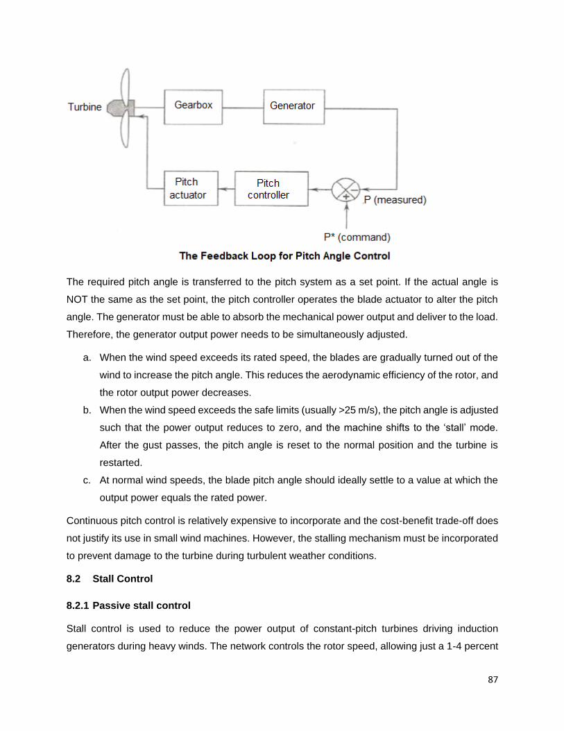
87
The required pitch angle is transferred to the pitch system as a set point. If the actual angle is
NOT the same as the set point, the pitch controller operates the blade actuator to alter the pitch
angle. The generator must be able to absorb the mechanical power output and deliver to the load.
Therefore, the generator output power needs to be simultaneously adjusted.
a. When the wind speed exceeds its rated speed, the blades are gradually turned out of the
wind to increase the pitch angle. This reduces the aerodynamic efficiency of the rotor, and
the rotor output power decreases.
b. When the wind speed exceeds the safe limits (usually >25 m/s), the pitch angle is adjusted
such that the power output reduces to zero, and the machine shifts to the ‘stall’ mode.
After the gust passes, the pitch angle is reset to the normal position and the turbine is
restarted.
c. At normal wind speeds, the blade pitch angle should ideally settle to a value at which the
output power equals the rated power.
Continuous pitch control is relatively expensive to incorporate and the cost-benefit trade-off does
not justify its use in small wind machines. However, the stalling mechanism must be incorporated
to prevent damage to the turbine during turbulent weather conditions.
8.2 Stall Control
8.2.1 Passive stall control
Stall control is used to reduce the power output of constant-pitch turbines driving induction
generators during heavy winds. The network controls the rotor speed, allowing just a 1-4 percent

88
variance. For a blade operating at a near constant speed, the angle of attack increases as the
wind speed increases. The lift force drops beyond a certain angle of attack, causing the rotor
efficiency to decline. This is a built-in feature that eliminates the need for a complicated control
system and moving parts. By carefully designing the rotor blade profile to induce turbulence on
the rotor blade side not facing the wind, the lift force can be further lowered, limiting the power
production in high winds.
8.2.2 Active Stall Control
At high wind speeds, the blade is turned a few degrees in the opposite direction to that in a pitch-
controlled machine. This increases the angle of attack, which can be adjusted to maintain the
rated output power at all high wind speeds below the furling speed. In heavy winds, the power of
a passively controlled machine drops. A deep stall is a term used to describe the action of active
stall control. Active pitch control is typically only utilized with high-capacity machines for economic
reasons.
8.3 Yaw Control
This control keeps the turbine oriented in the direction of the wind. A tail-vane is used in small
turbines to do this. This can be accomplished in large machines with motorized control systems
operated by a fan-tail (a small turbine installed perpendicular to the main turbine) or, in the case
of wind farms, a centralized sensor for wind direction identification. Yaw control can also be
achieved without the need of any additional mechanisms by putting the turbine downwind so that
the thrust force pushes the turbine in the direction of the wind.
The yaw control mechanism can also be employed for speed control: at high wind speeds, the
rotor is turned away from the wind direction, lowering mechanical power. However, due to the
stresses it causes on the rotor blades, this technology is rarely used if pitch control is available.
Yawing often generates a lot of noise, so it's a good idea to keep the yawing rate low in big
machines.
8.4 Speed Control Strategy
There are five different wind speed bands for each wind turbine, requiring different speed control
strategies.

89
1. The machine does not produce power below a cut-in speed. If the rotor has enough
beginning torque, it may be able to rotate at a lower speed. The rotor, however, does not
extract any power and rotates freely. The aerodynamic torque produced at standstill in
many modern designs is rather modest, and the rotor must be started (by operating the
generator in motor mode) at the cut-in speed.
2. Maximum power is extracted from the wind at normal rated wind speeds. The maximum
power point is reached at a given (constant) value of the TSR. As a result, the rotating
speed must be altered regularly in relation to the wind speed to track the highest power
point.
3. At high winds, the rotor speed is limited to a maximum value based on the mechanical
component’s design limits. In this region, the Cp is lower than the maximum, and the power
output is not proportional to the cube of the wind speed.
4. At even higher wind speeds, the power output is kept constant at the maximum value
allowed by the electrical components.
5. To protect the system components, the power production is turned off and the rotation is
stopped at a predetermined cut-out or furling wind speed.
Yaw control, pitch angle control (if available), and eddy-current or mechanical brakes can all be
used to achieve the latter three control regimes.
The control technique in the intermediate-speed range is dependent on the type of electrical
power generating system utilized and can be split into two categories:
a. The constant-speed generation scheme
b. The variable-speed generation scheme

90
If the electrical system includes a grid-connected synchronous generator, the constant-speed
generating method is required. The permitted range of speed fluctuation in grid-connected squirrel
cage induction generators is relatively small, necessitating a nearly constant rotational speed.
However, constant-speed generation systems are unable to extract the maximum amount of
energy from wind. The power coefficient for each type of wind turbine reaches a maximum at a
given value of TSR, as shown in the graph above. To get the most power out of the wind, the
turbine should run at a constant TSR, which implies the rotational speed should be proportional
to the wind speed. Therefore, the maximum power extraction necessitates a variable-speed
generation system with speed control aimed at maintaining a constant TSR. These systems can
generate 20-30% more power than constant-speed generators. Variable-speed generation
systems are becoming more popular as induction generators and power electronic converters
become more advanced.
Variable wind power creates electrical energy with variable frequencies based on the rotor's
rotational speed. It is then converted by electronic devices to the frequency of the grid by the
transmission system. This entails a number of complicated procedures that are beyond the scope
of this beginning course. Please refer to the textbooks or seek vendor guidance for the same.

91
9 CHAPTER -9: WIND ENERGY CHALLENGES
9.1 Environmental Impact of Wind Energy
The growth of wind energy has both beneficial and negative environmental consequences. On
the plus side, wind turbines do not emit:
a. Carbon dioxide or other greenhouse gases during the generation of power.
b. Pollutants that cause acid rain or smog, resulting in a variety of ailments
c. Radioactivity
d. Land, sea, or watercourse contamination
e. The consumption of water – unlike many conventional (and some renewable) energy
sources. This could be important if water shortages occur with increasing frequency in the
future.
9.2 Environmental/Social Challenges
Wind energy is a renewable resource that produces no pollutants or greenhouse gases during
operation and requires no fuel, thus no mining or drilling is required, unlike coal, oil, or natural gas
power plants.
However, many of the social challenges to mainstream wind power adoption are environmental,
with some inhabitants near proposed wind farms expressing strong emotional objections.
9.2.1 Visual Impacts
Medium and big wind turbines have rotors that can be 100 meters in diameter and are mounted
on towers as tall as 50 meters. Residents near residential areas have been vocal in their
opposition to wind farms, claiming that big clusters of large wind turbines are a blight on the
landscape and, lower the property values. Nobody wants them to live in their yard. It could have
a negative impact on recreational and leisure activities.
The visual perception of a wind turbine or the wind farm is determined by a variety of factors
including:
a. Turbine size
b. Turbine design
c. Number of blades
d. Color
e. Number of turbines in a wind farm
f. The layout of the wind farm

92
g. The extent to which moving rotor blades attract attention.
9.2.2 Noise
Wind turbines are often considered noisy, but they are not especially noisy compared to other
equipment with equal power ratings.
Wind turbine noise comes from two main sources:
a. Mechanical noise from gearboxes and generators, which can be reduced significantly by
utilizing quieter gears, placing equipment on resilient mounts, and using acoustic
enclosures.
b. Aerodynamic noise, which is best described as a "swishing" sound caused by the
interaction of the airflow with the rotor. The trailing edge of the blades, as well as the
interaction of the airflow with the blades and the tower, have an impact. Because it tends
to grow with rotational speed, some turbines are intended to run at lower rotational speeds
during periods of low wind.
The noise levels measured on most commercial wind turbines provide data that allows the
turbines to be sited at a sufficient distance from habitations to reduce (or avoid) noise nuisance.
Noise levels from large, modern wind turbines are generally low, consisting mostly of a low-
pitched cyclic "whooshing" sound. At 300 meters, noise is normally limited to 35 to 45 dB(A)
decibels, and noise is not a concern for humans at 800 meters.
9.2.3 Electromagnetic Interference
When a wind turbine is placed between a radio, television, or microwave transmitter, it can
sometimes reflect some of the electromagnetic radiation, interfering with the original signal as it
reaches the receiver. The received signal may be significantly distorted because of this.

93
The amount of electromagnetic interference created by a wind turbine is mostly determined by
the materials used to construct the blades and the tower's surface form.
9.2.4 Wildlife
The large, rotating blades of a rotor pose a hazard for birds, as evidenced by the increased
mortality rates of large birds of prey near the Altamont Pass wind farm in California. Concerns
have been raised concerning the impact of offshore wind on fish, crustaceans, marine animals,
marine birds, and migratory birds.
In comparison to other man-made risks, studies show that wind turbines kill a very small
percentage of birds. Wind turbines cause 100 000–440 000 bird crashes every year, according to
the American Bird Conservancy (ABC), compared to 4–50 million with towers, 10–154 million with
power lines, 10.7–380 million with roads/vehicles, over 31 million with urban lights, and 100
million–1 billion with glass on buildings.
9.2.5 Land Use
Because wind power is not a concentrated form of energy (like oil or coal), it requires large
amounts of land, typically 10 to 30 acres per turbine. For example, DOE estimated that 142,000
1.5 MW turbines would be required to generate 20% of the nation’s electricity needs; at 20 acres
per turbine, almost 3 billion acres of land are needed. However, most of the land associated with
wind farms is “empty space,” and could be available for other uses, such as agriculture.
9.3 Mitigation
Technology advances and siting wind farms offshore should largely avoid these impacts:
a. Technology advances: wind turbine manufacturers have worked on designs and
aerodynamics that limit noise and the impact on wildlife.
b. Offshore: wind farms are being located further and further from shores, which should
negate many of the public concerns relating to the visual and noise impact of turbines on
coastal areas.
c. Social impact studies indicate that public concern about wind energy is greatest directly
after the announcement of a wind farm, while acceptance increases after construction,
when the actual impacts can be assessed. People living closest to existing wind plants
tend to be more accepting than those who live further away and are less familiar with the
technology.
94
9.4 Technical Issues
Despite the maturity of modern wind technologies, two key technical issues must be addressed
before it can find widespread use:
9.4.1 Variability
Wind turbines, unlike coal or oil power facilities, do not operate continuously due to wind
variability. The turbines may sit inactive during periods of low wind, leading to the continuing
debate over whether wind power can truly reduce the demand for conventional power plants.
Furthermore, the wind is rarely steady, resulting in short-term variability and "noisy" power output.
9.4.2 Grid Connectivity
The best wind resources are usually located far away from the transmission lines that connect
wind turbines to the grid. The variability of the power from wind also presents challenges for the
current electrical grid system, which was designed for the relatively uniform and predictable power
generated from conventional oil and coal power plants.
9.5 Safety Considerations
Because wind turbines are such tall structures, the possibility of falls is always a concern on these
locations. The height above ground during installation and maintenance operations is the most
dangerous aspect of working with wind turbines.
Workers may be needed to climb ladders hundreds of feet in the air as part of their construction
and maintenance operations. While most construction ladder falls occur at a height of 10 feet or
less, permanent ladders within wind turbine towers extend much beyond the height of a typical
ladder. When a worker falls, he or she is more likely to sustain a major injury or die.
Fall prevention and protection should be a major priority for contractors working on wind turbine
projects, and workers must be protected in all aspects of a fall.
Fall protection equipment is mandated by some countries on new turbines, which means the
person ascending the turbine must wear a parachutist-style set of straps. The straps are
connected to an anchoring mechanism by a steel wire that follows the person as they ascend or
descend the turbine. A shock absorber must be included in the wire system so that people are
reasonably safe in the event of a fall.
95
Wind turbines, particularly those with large diameters and tall towers, may penetrate low-flying
zones of aircraft and interfere with radar communication signals if they are positioned in certain
restricted areas.
A number of national and international standards control machinery protection, fire protection,
and electrical insulation protection. It is critical that the machinery shall be entirely stopped
completely during servicing. In addition to a mechanical brake, the rotor can be locked in place
with a pin, to prevent any movement of the mechanical parts whatsoever.

96
Summary Annexure
Technology Developments
The key objectives for efficient utilization of wind energy are:
a. Maximizing Energy Capture
b. Minimizing Costs per unit of Capacity
c. Meeting Grid Network Requirements
Objectives Maximizing Energy
Capture
Minimizing Costs
per unit of Capacity
Meeting Grid
Network
Requirements
Key Drivers a. Access to better
wind resources
b. Exploit lower-
quality wind
resource sites
c. Increase load
factor
a. Reduce
investment cost
b. Reduce operation
& maintenance
c. Maximize land-
use value
a. Contribute to
system stability
b. Contribute to
voltage control
c. Enhance
predictability
Technology a. Larger rotor
diameter / turbine
size
b. Variable speed
turbine
c. Extreme
conditions
resistance
a. Lighter rotor and
nacelle, drive train
layout
b. Pitch system,
control system to
avoid fatigue
c. Second-hand
market
a. Pitch control, power
converter, drive
train
b. Variable speed, fast
response &
communication,
converters
c. Computational tools
& new projection
methodology.

97
References
a. Global wind energy outlook scenarios- GWEC (Global Wind Energy Council)
b. “International Energy Outlook 2019 with Projections to 2050.” U.S. Energy Information
Agency.
c. “Global Wind Report 2019.” Global Wind Energy Council.
d. “Wind Explained History of Wind Power.” U.S. Energy Information Agency.
e. “Offshore Wind Research and Development.” U.S. Department of Energy Office of Energy
Efficiency & Renewable Energy.
f. Guided Tour on Wind Energy by the Danish Wind Industry Association.
g. American Wind Energy Association. A very extensive site from the industry group that
promotes wind energy.
h. Alternative Energy News. Basic concepts, as well as the latest developments.
i. Vestas, GE, Suzlon and Iberdrola Wind Turbines Manuals and Whitepapers.