weldability of high strength steels in wet welding conditions
TRANSCRIPT
67POLISH MARITIME RESEARCH, No 2/2013
INTRODUCTION
According to the most general classification, the underwater welding processes can be divided into dry and wet ones [1-5]. The dry methods consist in local isolation of welding area from surrounding water by means of special chambers in which atmospheric pressure (isobaric welding) or an elevated pressure resulting from welding depth (hyperbaric welding) is present. A characteristic feature of the wet welding is direct underwater contact of diver-welder, electrode and base material. An intermediate variant between wet and dry welding is application of a local dry chamber (dry spot welding) [1-3]. Applicability of particular processes in underwater welding conditions is characterized in Tab. 1.
Weldability of high strength steels in wet welding conditions
Dariusz Fydrych, Ph.D.,Jerzy Łabanowski, Assoc. Prof.,Grzegorz Rogalski, Ph.D.,Gdansk University of Technology, Poland
ABSTRACT
In this paper are characterized problems of high strength steel weldability in underwater wet welding conditions. Water as a welding environment intensifies action of unfavourable factors which influence susceptibility to cold cracking of welded steel joints. The susceptibility to cold cracking of S355J2G3 steel and S500M steel in wet conditions was experimentally estimated (by using Tekken test). It was concluded that the steels in question are characterized by a high susceptibility to formation of cracks in welds. Usefulness of the proposed Temper Bead Welding technique (TBW) was experimentally verified as a method
for improving weldability of the steels in the analyzed conditions.
Key words: underwater welding; steel weldability, cold cracking; wet welding; cracks in welds; improving weldability
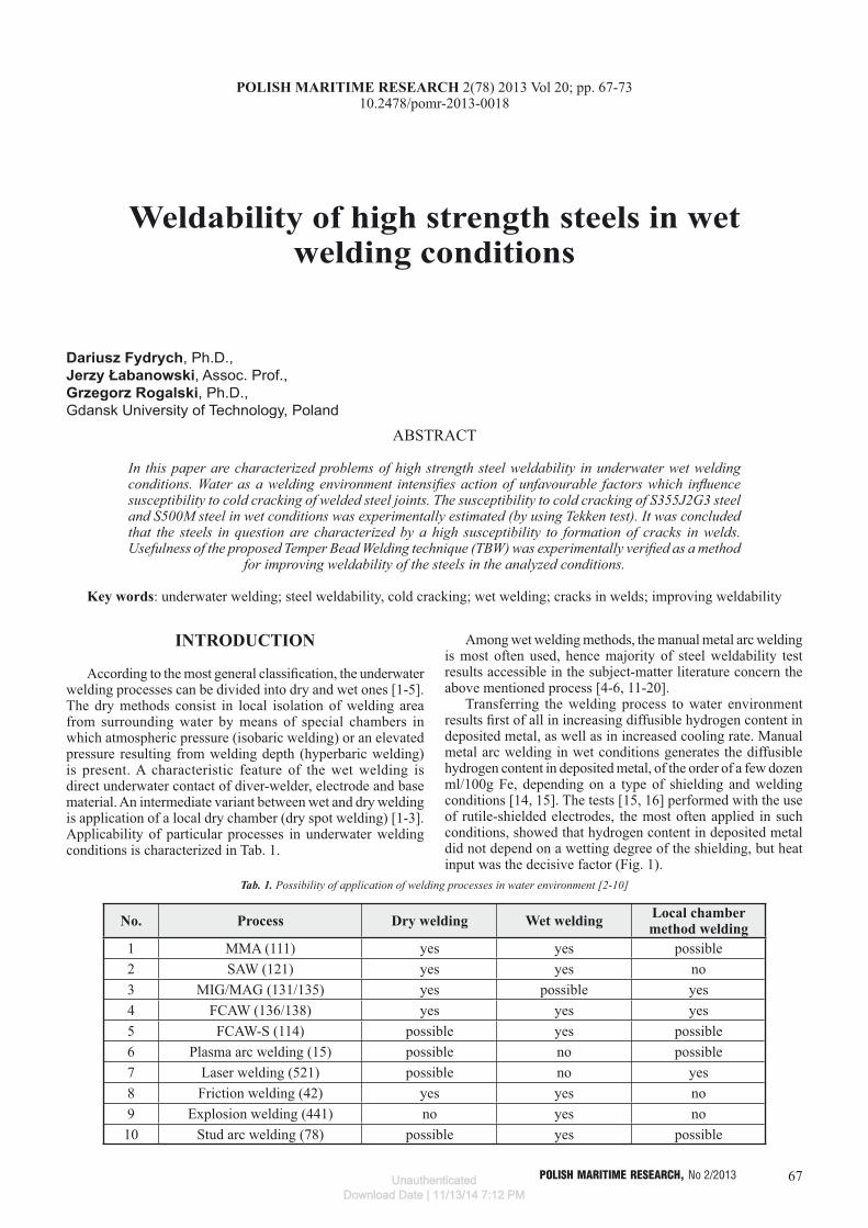
Tab. 1. Possibility of application of welding processes in water environment [2-10]
No. Process Dry welding Wet welding Local chamber method welding
1 MMA (111) yes yes possible2 SAW (121) yes yes no3 MIG/MAG (131/135) yes possible yes4 FCAW (136/138) yes yes yes5 FCAW-S (114) possible yes possible6 Plasma arc welding (15) possible no possible7 Laser welding (521) possible no yes8 Friction welding (42) yes yes no9 Explosion welding (441) no yes no10 Stud arc welding (78) possible yes possible
Among wet welding methods, the manual metal arc welding is most often used, hence majority of steel weldability test results accessible in the subject-matter literature concern the above mentioned process [4-6, 11-20].
Transferring the welding process to water environment results first of all in increasing diffusible hydrogen content in deposited metal, as well as in increased cooling rate. Manual metal arc welding in wet conditions generates the diffusible hydrogen content in deposited metal, of the order of a few dozen ml/100g Fe, depending on a type of shielding and welding conditions [14, 15]. The tests [15, 16] performed with the use of rutile-shielded electrodes, the most often applied in such conditions, showed that hydrogen content in deposited metal did not depend on a wetting degree of the shielding, but heat input was the decisive factor (Fig. 1).
POLISH MARITIME RESEARCH 2(78) 2013 Vol 20; pp. 67-7310.2478/pomr-2013-0018
UnauthenticatedDownload Date | 11/13/14 7:12 PM

68 POLISH MARITIME RESEARCH, No 2/2013
Fig. 1. Effect of heat input of MMA wet welding on diffusible hydrogen content in deposited metal [16]
Cooling rates of joints made underwater are much shorter compared with those for in - air welding conditions. The increase of cooling rate contributes to forming brittle structures in heat affected zone (HAZ) and to increasing values of residual stresses. Such conditions result in that welded structural steel joints made directly in water are characterized by a high susceptibility to forming cold cracks. The cracks appear even in joints made of steel of a low carbon equivalent Ce ≤ 0.3 %. In the HAZ of such steel joints the increase of hardness up to the level of 350 ÷ 400 HV, as well as many hydrogen micro-cracks were observed [13, 14]. In Fig. 2 are presented the results of Tekken tests performed underwater, which were used for development of an equation for determining the minimum heat input value which protects against cold cracks forming [4].
Fig. 2. Results of Tekken tests, underwater wet MMA welding: ○ – no cracks, × – internal cracks, ● – internal and external cracks [4]
The equation is of the following form:
q = 200 × (P – T/600) – 67
where: q – heat input, [kJ/cm],
P = Ce + HD/60 + R/200000,T – initial temperature, [⁰C],Ce – carbon equivalent acc. International Institute of Welding,
[%],HD – diffusible hydrogen content in deposited metal, [ml/100g
Fe],R – restraint intensity, [MPa].
The tests [17] on Implant specimens, performed in the conditions similar to those for Tekken test, showed that critical stresses were higher than yield point of the tested steel. It goes to show that the steel was crack-resistant, which is not consistent with the results given in [4].
A great number of variable factors which act during underwater welding makes it difficult to formulate safe welding conditions, i.e. those possible to protect joints against cracking. However on the basis of many tests the following approximate criteria for safe wet welding of non-alloy steels, were determined [18]:- base material carbon equivalent: Ce < 0.30 %,- heat input: greater than 1.5 kJ/mm.
In the case of application of austenitic electrodes value of welded steel carbon equivalent may be even greater – up to 0.40 %. In this case hot cracks should be expected to occur in welds [4, 19]. Increase of toughness of weld metal at wet welding conditions can be also achieved by applying low-alloy electrodes containing nickel. The optimal Ni content in weld is considered as 2% [19].
Another limitation method of susceptibility to forming cold cracks is application of temper bead welding technique (TBW) [20, 21]. In the TBW a reduction of post-welding residual stresses as well as a decrease of hardness in HAZ is achieved. The technique is applied to thick sections, i.e. where it is not possible to perform heat treatment operation after welding. It consists in overlaying successive beads onto weld, that introduces local heat treatment in the area of prior made weld layer. In HAZ of the layer structural transformations may occur in the temperature range higher than AC1 temperature. ASME rules require to make six layers, and for three first layers increased value of heat input is often used [21]. In the case of implementation of TBW technique for preventing against cold cracking it is important to determine a time interval between instants of overlaying a tempered bead and tempering one. Depending on a type of applied electrode the time up to crack forming at wet welding may reach from 3 min to 2 hours. Successive parameters important from the point of view of effectiveness of the process are: value of heat input in every bead as well as distance between bead axes (pitch) [21].
EXPERIMENTAL
The tests were aimed at determination of susceptibility to forming cold cracks in joints of high strength steels, made by using covered electrodes in wet welding process. The tests were performed in accordance with the following scheme: - preparation of welding stands in air and underwater
environment- preparation of Tekken tests- welding of test joints- visual testing and penetrant testing- macroscopic and microscopic meta l lographic
examinations- Vickers hardness measurements.
Additionally, to assess usefulness of application of TBW technique for improving steel weldability in water environment,
UnauthenticatedDownload Date | 11/13/14 7:12 PM

69POLISH MARITIME RESEARCH, No 2/2013
test padding welds were made and subjected to macroscopic metallographic examinations and hardness measurements.
For the tests 15 mm plates of S355J2G3 and S500M steel were used. Their chemical compositions and mechanical properties are given in Tab. 2 and 3.
Tab. 3. Mechanical properties of S355J2G3 and S500M steel
Yield pointRe [MPa]
Tensile strengthRm [MPa]
ElongationA5 [%]
S355J2G3 464 577 22.1
S500M 525 619 20.5
The test welds were made by using Lincoln Electric OMNIA (E 42 0RC 11) electrodes of 4 mm diameter. They are general application rutile electrodes for welding in all positions, of the chemical composition: C – 0.07%, Mn – 0.5%, Si – 0.5%, and the mechanical properties: Re – min. 420 MPa, Rm – 500 ÷ 640 MPa, A5 – min 20%.
The Tekken test joints of S500M steel were made in water and air environment at various heat input values. The Tekken test joints of S355J2G3 steel were made only at underwater conditions. The test joints were prepared in compliance with the standard guidelines [22], on the underwater welding stand at low water depth [3]. In Tab. 4 are presented the conditions for performing Tekken tests on selected joints.
Penetrant testing The visual and penetrant testing [23-25] of the test
joints were performed after 72 h from finishing the welding. Occurrence of cracks in welds of all the specimens made in water environment was observed, but in S355J2G3 steel joints the cracks were placed close to fusion line, whereas in the specimens made of S500M steel – in weld axis. In the Tekken specimens welded in air environment no cracks were revealed.
Macroscopic metallographic examinations The macroscopic metallographic examinations were
performed in accordance with the standard guidelines [26]. Example photos of the cross-sections are presented in Fig. 3÷5. In the specimens made underwater extensive cracks and
Tab. 2. Chemical composition of S355J2G3 and S500M steel, wt %
S355J2G3C Si Mn P S Cr Ni Cu Al Ce
0.17 0.35 1.44 0.014 0.014 0.04 0.077 0.30 0.02 0.44
S500MC Si Mn P S Nb V Ti Al Ce
0.067 0.018 1.380 0.009 0.002 0.056 0.054 0.001 0.039 0.30
Tab. 4. Conditions of Tekken tests
No. of specimen Steel
Environment
Welding parameters
Welding time t [s]
Heat input value q [kJ/mm]
U [V] I [A]W1 S500M water 30.0 228 16.4 1.40W2 S500M water 34.3 232 18.5 1.85W3 S500M water 32.5 244 16.9 1.68P6 S500M air 22.0 168 30.0 1.39P12 S500M air 24.3 160 31.0 1.511A S355J2G3 water 30.8 228 33.0 2.902A S355J2G3 water 29.2 232 29.0 2.44
a porosity were sometimes found. Tekken specimens of S500M steel welded in air environment were characterized by a much lower susceptibility to cracking, however in one of them some cracks were observed. The results obtained from the Tekken tests are presented in Tab. 5.
Fig. 3. Cross-section of the W1 (S500M) test joint with the visible crack initiated in weld root
Fig. 4. Cross section of the 1A (S355J2G3) test joint with the visible crack initiated in fusion line
Fig. 5. Cross-section of the P12 (S500M) test joint with the visible crack initiated in weld root
UnauthenticatedDownload Date | 11/13/14 7:12 PM
70 POLISH MARITIME RESEARCH, No 2/2013
Tab. 5. Results of Tekken tests
No. of specimen Environment
Penetrant testing
Macroscopic metallographic examinations
Hardness measurements Percentage of cracks
HV10 max Cf [%] Cs [%]
W1.1water
crack crack 25840.0
61.0W1.2 crack crack 294 79.3W2.1
watercrack crack 283
27.544.4
W2.2 crack crack 287 81.4W3.1
watercrack crack 262
43.873.3
W3.2 crack crack 298 62.5P6.1
airno crack no crack 248
0.00.0
P6.2 no crack no crack 242 0.0P12.1 air crack crack 251
18.530.0
P12.2 air crack crack 240 27.01A.1 water crack crack 417
100.083.0
1A.2 water crack crack 413 100.02A.1 water crack crack 430
100.078.0
2A.2 water crack crack 421 90.0
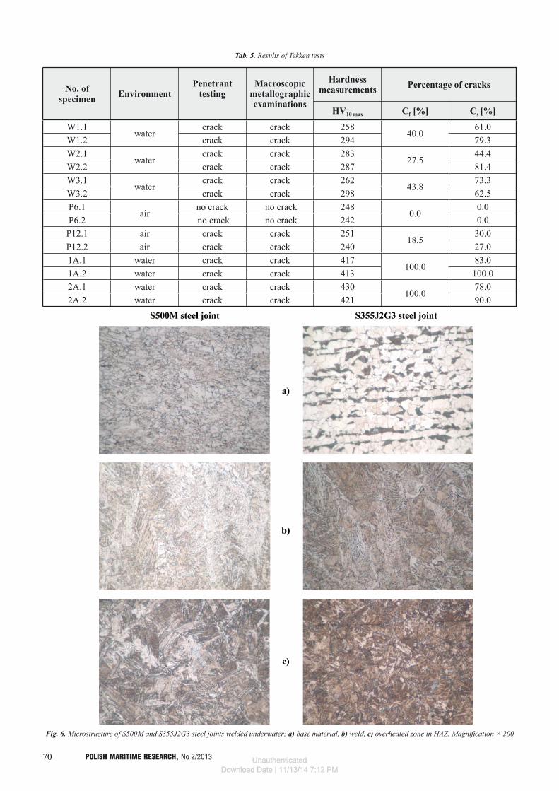
Fig. 6. Microstructure of S500M and S355J2G3 steel joints welded underwater; a) base material, b) weld, c) overheated zone in HAZ. Magnification × 200
UnauthenticatedDownload Date | 11/13/14 7:12 PM

71POLISH MARITIME RESEARCH, No 2/2013
Microscopic metallographic examinations In Fig. 6 are presented typical structures of base material,
weld and HAZ at fusion line for the tested joints made underwater. The S500M steel structure consists of ferrite grains of very different sizes with a trace of pearlite content whereas S355J2G3 steel shows a ferritic-pearlitic structure of distinct banding. The weld structure of both the steels is similar and consists of ferrite of column arrangement with an outline of Widmanstätten structure. In the HAZ of S500M steel, quasi-pearlite structures with acicular ferrite bands reaching down the grains, are observed, whereas in the HAZ of S355J2G3 steel acicular quench structures are visible.
Hardness measurements of welded jointsThe hardness measurements were performed according to
the standard [27] under 98 N load (HV10). Example results are shown in Fig. 7 through 9. In the S500M steel joints made both in the air and underwater, hardness values for weld and base material were close to each other and equal to about 200 HV10. In HAZ only a slight increase in hardness up to 240 HV10 was observed for air environment welding conditions, whereas the transferring of the welding process to water environment resulted in further increase of maximum hardness of HAZ up to about 280 HV10.
However the maximum hardness values in HAZ of the S355J2G3 steel joints were significantly greater. A higher carbon content in this steel in association with an increased cooling rate of the joints resulted in the quenching of HAZ material and increase of its hardness up to over 400 HV10.
Fig. 7. Hardness distribution across P6.2 test joint of S500M steel welded in the air, HVmax = 242
Fig. 8. Hardness distribution across W2.1 test joint of S500M steel welded underwater, HVmax = 283
Fig. 9. Hardness distribution across 1A.1 test joint of S355J2G3 steel welded underwater, HVmax = 425
Application of temper bead welding (TBW)A preliminary assessment of usefulness of application of
the tempering bead technique to improve weldability in water environment was performed by using S355J2G3 steel plates. On the testing plate of 12 × 100 × 200 mm dimensions padding welds were made with the use of Omnia electrodes at 10 min interval and 40% pitch. Cross-sections of the padding welds were subjected to the macroscopic metallographic examinations and hardness measurements. Parameters of the padding welding are given in Tab. 6. A photo of polished macroscopic cross-section of test beads with indication of padding weld laying sequence is shown in Fig. 10.
Tab. 6. Welding parameters for S355J2G3 steel
Padding weld
Welding current
I [A]
Arc voltage U [V]
Welding speed v
[mm/min]Heat input q
[kJ/mm]
1 206 34.5 255 1.672 226 41.0 213 2.60
Fig. 10. Cross section of the test weld beads; S355J2G3steel; 40% pitch
In Fig. 11. is shown location and designation of areas in which hardness measurements were made, and in Tab. 7 and Fig. 12 are presented results of hardness measurements performed at 2 mm distance measured from specimen surface.
The presented results of hardness measurements for padding welds make it possible to conclude that the temper bead welding in underwater welding allows to lower maximum hardness in HAZ to a safe level as regards cold crack forming. In Fig. 12 two characteristic points of increased hardness (swcap and swcbp) can be observed. They appear at fusion line and simultaneously very close to edges of the padded elements. In this place intensive heat sinking occurs, a.o. due to bubble boiling, that leads to forming high hardness structures. In
UnauthenticatedDownload Date | 11/13/14 7:12 PM

72 POLISH MARITIME RESEARCH, No 2/2013
making multilayer joints such phenomenon can be minimized by providing heat again during laying successive tempering beads – in the case in question – it means making the last bead between two padding welds.
DISCUSSION
In all the test joints made underwater, cracks in welds were observed. The phenomenon is in compliance with information contained in the literature sources concerning weldability of the tested steels [28]. Specimens made in the air were characterized by a much lower susceptibility to crack forming. Crack occurrence in the joints made in the air resulted from using rutile electrodes. Application of such electrodes was conditioned in association with real underwater welding conditions with the use of the MMA process as well as convergence with requirements of the PN-EN ISO 15618-1 standard concerning certification of divers-welders for wet welding [29]. In the above mention standard, one of the recommended welding electrodes is that with rutile coating. Welding with rutile electrodes both in the air and underwater is a process of a high hydrogen content. Presence of hydrogen in steel weldments leads to degradation of their structure and mechanical properties [30]. On the basis of the previous tests the diffusible hydrogen
content in deposited material obtained in air environment can be estimated to be about 35 ml/100g Fe, whereas in the case of underwater welding – 50 ml/100 g Fe [15, 31].
In the wet welding conditions for S500M steel the increase of HAZ hardness from 240 ÷ 250 HV10 (characteristic for welding in the air) up to 260 ÷ 300 HV10, took place. Maximum hardness values in HAZ of S500M steel are lower than 350 HV10 value is considered as critical from the point of view of susceptibility to cold cracking. However the test joints of S355J2G3 steel were characterized by the much greater maximum hardness in HAZ of values over 400 HV10. It results from their welding conditions (a. o. greater cooling rates - consequently - shorter cooling times t8/5), which, at the carbon equivalent Ce = 0.44% for S355J2G3 steel, led to forming quenched structures. For Tekken specimens of S355J2G3 steel the initiating of cracks in fusion line is characteristic (Fig. 4), which is confirmed by presence of brittle structures in this area. Hardness distribution over cross-section of Tekken joints made of S500M steel complies with acceptance criteria used for approving welding technologies in the air. Limitation of maximum hardness in HAZ down below 350 HV10 value results from low carbon content in the steel as well as carbon equivalent Ce = 0.30%. The presented results indicate that low-carbon steels after thermo-mechanical processing is applicable for marine and off-shore engineering structures when underwater welding is required.
The application of the TBW technique to S355J2G3 steel allowed to reach satisfactory results, that is manifested by the hardness measurement results in trouble areas of padding welds (Tab. 7). The technique in question is greatly useful in welding elements made of a steel which requires a heat treatment after welding. In wet welding conditions or dry hyperbaric ones such treatment would be very expensive and in most cases impossible to perform. TBW technique makes it possible to obtain, by applying relatively simple technological operations, welded joints which satisfy criteria of subject-matter standards or requirements of classification societies. It may find application e.g. to repair work of underwater piping lines. It should be added that effectiveness of application of tempering beads depends on many factors e.g. welding position, welding parameters (heat input), arc length, torch setting angle, interval between padding weld laying and weld pitch. However further investigations are required to develop TBW technology for wet welded joints. The successive tests should take into account factors, that would make it possible to determine optimum conditions for application of temper bead technique to underwater welding process.
CONCLUSIONS
1. The joints of S355J2G3 and S500M steel, made underwater in the restraint conditions showed high susceptibility to forming cold cracks in welds.
2. In all the Tekken test joints of S500M steel, made with the use of wet welding method cold cracks were revealed, and in the joints made in the air such cracks were found in only one of the two test joints.
Tab. 7. Results of hardness measurements of S355J2G3 steel test plates
mr swcan swcap mna wswcb mnb swcbp swcbn mrHV10 191 256 448 213 198 250 446 245 191
swca2n swca2p wswcan wswcapHV10 251 325 223 260
Fig. 12. Hardness distribution along A-A line (see Fig. 11) on S355J2G3 steel test plate. The HVmax of the tempered zone in HAZ of 1st weld bead
(swca2p) is marked by red horizontal line.
Fig. 11. Location and designation of tested areas on testing plate: mr – base material, mna – 1st padding weld, mnb – 2nd padding weld,
swca – HAZ of 1st padding weld, swcb –HAZ of 2nd padding weld, wswca – area of overlapping swca and swcb, wswcb – area of swcb
overlapping mna, n – normalization area, p – overheated area, A-A – hardness measurement line
UnauthenticatedDownload Date | 11/13/14 7:12 PM

73POLISH MARITIME RESEARCH, No 2/2013
3. Maximum hardness in HAZ of the S500M steel joints did not exceed 300 HV, whereas that in HAZ of the S355J2G3 steel joints was over 400 HV10 in value.
4. It was proved that the TBW technique was effective for the joints of high strength steel welded underwater. The application of the TBW resulted in the decreasing of maximum hardness in HAZ of S355J2G3 steel joints down to the value below 350 HV10.
BIBLIOGRAPHY
1. The Standard AWS D3.6M:2010 Underwater Welding Code.2. Łabanowski J.: Development of underwater welding techniques.
Przegląd Spawalnictwa (Welding Technology Review), 10/2008 (in Polish).
3. Łabanowski J., Fydrych D., Rogalski G.: Underwater Welding – a review. Advances in Materials Science, 3/2008.
4. Christensen N.: The metallurgy of underwater welding. Proceedings of the International Conference „Underwater Welding”, Trondheim, Norway 1983.
5. Cotton H. C.: Welding under water and in the splash zone – a review. Proceedings of the International Conference „Underwater Welding”, Trondheim, Norway 1983.
6. Ibarra S., Grubbs C. E., Liu S.: State of the art and practice of underwater wet welding of steel. International workshop on underwater welding of marine structures. New Orleans, USA, 1994.
7. Zhang X., Ashida E., Shono S., Matsuda F.: Effect of shielding conditions of local dry cavity on weld quality in underwater Nd:YAG laser welding. Journal of Materials Processing and Technology. Vol. 174, Issues 1-3, May 2006.
8. Fydrych D., Rogalski G.: Effect of underwater local cavity welding method conditions on diffusible hydrogen content in deposited metal. Welding International Vol. 27, Issue 3, March 2013, pages 196-202.
9. Ambroziak A., Gul B.: Underwater friction bonding of overlap joints by means of a plasticized steel pin (FHPP). Przegląd Spawalnictwa (Welding Technology Review), 9-10/2006 (in Polish).
10. Ambroziak A., Gul B.: Investigations of underwater FHPP for welding steel overlap joints. Archives of Civil and Mechanical Engineering 2/2007.
11. Rodriguez-Sanchez J. E., Rodriguez-Castellanos A., Perez-Guerrero F., Carbajal-Romero M. F., Liu S.: Offshore fatigue crack repair by grinding and wet welding. Fatigue and Fracture of Engineering Materials and Structures, 34/2010.
12. Pessoa E., Bracarense A., Zica E., Liu S., Perez-Guerrero F.: Porosity variation along multi-pass underwater wet welds and its influence on mechanical properties. Journal of Materials Processing Technology. Vol. 179, Issues 1–3, 20 October 2006, pp. 239–243.
13. Bohme D., Eisenbeis C.: Investigation into the credibility of the implant test when used to assess the cold cracking sensitivity of underwater wet welds. Proceedings of the International Conference „Welding Under Extreme Conditions”, Helsinki, Finland 1989.
14. Hoffmeister H., Kuster K.: Process variables and properties of underwater wet shielded metal arc laboratory welds. Proceedings of the International Conference „Underwater Welding”, Trondheim, Norway 1983.
15. Fydrych D., Rogalski G.: Effect of shielded-electrode wet welding conditions on diffussion hydrogen content in deposited metal. Welding International Vol. 25, Iss. 3, March 2011, p. 166-171.
16. Suga Y.: Effect of diffusible hydrogen on mechanical properties of underwater welded joints – study on improving the mechanical properties of underwater welded joints (the 1st report). Transactions of the Japan Welding Society 10/1985.
17. Brink S. H., Boltje G. W.: Cold cracking susceptibility of welds obtained by wet underwater welding. Proceedings of the International Conference „Underwater Welding”, Trondheim, Norway 1983.
18. Fydrych D.: Cold cracking of steel welded in water environment. Przegląd Spawalnictwa (Welding Technology Review), 10/2012 (in Polish).
19. Liu S.: Fundamentos de saldatura humeda. Seminario de saldatura humeda. Campeche, Mexico 1999.
20. Global Divers & Contractors : Joint industry underwater welding development program. Phase I - final report. Colorado School of Mines, 1995.
21. Łomozik M.: Morphology and toughness of heat affected zone regions of steel welded joints in the aspect of temper beads application. Uczelniane Wydawnictwa Naukowo-Dydaktyczne AGH (Scientific and Didactic Publishing House, Cracow Mining and Metallurgy Academy), Kraków 2007 (in Polish).
22. The Standard PN-EN ISO 17642-2:2005. Destructive tests on welds in metallic materials. Cold cracking tests for weldments. Arc welding processes. Part 2: Self-restraint tests. (in Polish).
23. The Standard PN-EN ISO 17637:2011. Non-destructive testing of welds. Visual testing of fusion-welded joints (in Polish).
24. The Standard PN-EN 571-1:1999. Non-destructive testing. Penetrant testing. Part 1: General principles (in Polish).
25. The Standard PN-EN ISO 23277:2010. Non-destructive testing of welds. Penetrant testing of welds. Acceptance levels (in Polish).
26. The Standard PN-EN 1321:2000. Destructive test on welds in metallic materials. Macroscopic and microscopic examination of welds (in Polish).
27. The Standard PN EN ISO 9015-1:2011 Destructive tests on welds in metallic materials. Hardness testing. Hardness test on arc welded joints (in Polish).
28. Tasak E.: Weldability of steel (in Polish ). Wydawnictwo Fotobit (Fotobit Publishers), Cracow 2002.
29. Rogalski G., Łabanowski J.: Certification of divers-welders for underwater wet welding in hyperbaric conditions. Biuletyn Instytutu Spawalnictwa (Bulletin of Polish Welding Institute), 1/2011 (in Polish).
30. Ćwiek J.: Hydrogen assisted cracking of high-strength weldable steels in sea-water. Journal of Materials Processing Technology, Vol. 164-165 (2005), p. 1007-1013.
31. Fydrych D., Łabanowski J.: Determining diffusible hydrogen amounts using the mercury method. Welding International Vol. 26, Iss. 9, September 2012, p. 697-702.
CONTACT WITH THE AUTHORS
Dariusz Fydrych, Ph.D.,Jerzy Łabanowski, Assoc. Prof.,
Grzegorz Rogalski, Ph.D.,Faculty of Mechanical EngineeringGdansk University of Technology
Narutowicza 11/1280-233 Gdansk, POLAND
e-mail: [email protected]
UnauthenticatedDownload Date | 11/13/14 7:12 PM