georgetown wet weather treatment station
TRANSCRIPT
Department of Natural Resources and Parks Wastewater Treatment Division
Executed Counterparts Counterpart No. _______ of _______
Including Addenda Nos. _______ through _______
CPA No. ______________
Georgetown Wet Weather Treatment Station - Treatment Station
Contract No. C01025C17
Funded in part by the
Washington State Department of Ecology
Volume 4 of 23
Technical Specifications (Division 11 – Division 14)
May 2017

This page intentionally left blank.
May 2017 C01025C17 Georgetown Wet Weather Treatment Station 1 TABLE OF CONTENTS
Table of Contents Georgetown Wet Weather Treatment Station
Contract C01025C17
VOLUME 1 OF 23
DIVISION 0 – BIDDING REQUIREMENTS, FORMS GENERAL TERMS AND CONDITIONS 00020 INVITATION TO BID 00100 INSTRUCTIONS TO BIDDERS 00120 NON-DISCRIMINATION, EQUAL EMPLOYMENT OPPORTUNITY, MINORITY AND
WOMEN BUSINESS ENTERPRISES UTILIZATION, AND APPRENTICESHIP REQUIREMENTS
00130 WAGE RATES 00300 FORM OF BID 00310 BID GUARANTY BOND 00410 FORMS AND DOCUMENTS DUE PRIOR TO CONTRACT EXECUTION 00420 PERFORMANCE AND PAYMENT BOND 00430 INSURANCE REQUIREMENTS 00440 QUALIFICATIONS INFORMATION 00500 AGREEMENT 00600 ADDENDA 00700 GENERAL TERMS AND CONDITIONS 00800 SUPPLEMENTAL TERMS & CONDITIONS 00900 ESCROW BID DOCUMENTATION
VOLUME 2 OF 23
DIVISION 1 - GENERAL REQUIREMENTS
01010 SUMMARY OF WORK 01012 REFERENCE MATERIAL 01014 MILESTONES AND CONSTRAINTS 01015 USE OF COUNTY FACILITIES AND EQUIPMENT 01021 COUNTY-SELECTED EQUIPMENT 01025 MEASUREMENT AND PAYMENT 01031 ANCHORAGE AND BRACING 01035 ASBESTOS AND LEAD INFORMATION 01036 GEOTECHNICAL INFORMATION 01038 CONSTRUCTION PLANNING WORK 01050 SURVEY INFORMATION 01062 PERMITS AND EASEMENTS 01063 HEALTH AND SAFETY 01065 SEWER ACCESS 01195 PROTECTION AND MAINTENANCE OF PROPERTY AND WORK 01200 CONTRACT MEETINGS 01300 SUBMITTALS PROCEDURE 01310 PROJECT SCHEDULES AND REPORTS 01350 SUSTAINABILITY REQUIREMENTS 01380 PHOTOGRAPHS AND VIDEOS 01405 AIR BARRIER SYSTEM QUALITY CONTROL 01410 CONSTRUCTION TESTING 01420 SPECIAL INSPECTION, OBSERVATION, AND TESTING 01425 EQUIPMENT SEISMIC CERTIFICATION 01430 QUALITY CONTROL PROGRAM 01450 AREA EXPOSURE DESIGNATIONS

May 2017 C01025C17 Georgetown Wet Weather Treatment Station 2 TABLE OF CONTENTS
01500 CONTRACTOR'S CONSTRUCTION FACILITIES 01560 ENVIRONMENTAL MANAGEMENT 01570 TRAFFIC REGULATION 01660 EQUIPMENT TESTING, TRAINING, AND COMMISSIONING 01710 FINAL CLEANING 01715 CONSTRUCTION WASTE MANAGEMENT 01720 RECORD DRAWINGS 01725 ASSET DATA 01730 OPERATION AND MAINTENANCE INFORMATION AND MANUALS 01740 GUARANTY AND WARRANTY 01750 SPARE PARTS 01999 STANDARD FORMS
DIVISION 2 - SITE CONSTRUCTION 02045 CUTTING AND PATCHING 02060 CONTAMINATED SOIL HANDLING AND DISPOSAL 02105 SEWER BYPASSING 02121 SETTLEMENT AND VIBRATION MONITORING 02122 GEOTECHNICAL MONITORING AND DATA COLLECTION 02123 PROCESS FACILITY WATER PRE-LOADING 02140 DEWATERING 02160 EXCAVATION SUPPORT SYSTEMS 02200 EARTHWORK 02221 TRENCHING, BACKFILLING AND COMPACTING 02270 EROSION AND SEDIMENT CONTROL 02271 SITE WATER DISCHARGE 02365 SECANT PILE EXCAVATION SUPPORT SYSTEM 02370 GABIONS 02380 DEEP GROUND IMPROVEMENT 02462 STEEL PIN PILES 02463 STEEL PIN PILE LOAD TESTING 02480 CONCRETE BLOCK WALL 02513 HOT MIX ASPHALT (HMA) PAVEMENT 02580 PAVEMENT MARKING 02605 UTILITY STRUCTURES 02720 STORM DRAINAGE SYSTEM 02725 BIORETENTION 02761 VIDEO INSPECTION OF SEWERS AND STORM DRAINS 02770 PERVIOUS CONCRETE PAVEMENT 02771 CONCRETE CURB AND SIDEWALKS 02780 MORTAR SET PRECAST CONCRETE PAVERS 02810 IRRIGATION 02820 EXPANDED METAL FENCES AND GATES 02830 CHAIN LINK FENCE AND GATES 02870 SITE FURNISHING 02900 LANDSCAPING 02920 LANDSCAPE SOIL MATERIALS 02930 LAWNS AND GRASSES 02970 PRE-VEGETATED MATS
May 2017 C01025C17 Georgetown Wet Weather Treatment Station 3 TABLE OF CONTENTS
VOLUME 3 OF 23
DIVISION 3 - CONCRETE 03100 CONCRETE FORMS AND ACCESSORIES 03200 CONCRETE REINFORCEMENT 03251 CONCRETE JOINTS 03300 CAST IN PLACE CONCRETE 03302 UNDERWATER CONCRETE 03350 POLISHED CONCRETE FLOOR FINISH 03370 CONCRETE CURING 03600 GROUT 03720 VERTICAL AND OVERHEAD CONCRETE SURFACE REPAIR SYSTEMS 03722 HORIZONTAL CONCRETE SURFACE REPAIR SYSTEMS 03740 CONCRETE REPAIR CRACK INJECTION
DIVISION 5 - METALS 05050 WELDING 05120 STRUCTURAL STEEL 05310 STEEL DECK 05400 COLD-FORMED STEEL FRAMING 05500 METAL FABRICATIONS 05501 ANCHORAGE TO CONCRETE 05520 METAL RAILING 05530 GRATINGS, FLOOR PLATES, AND STAIR TREADS
DIVISION 6 – WOOD AND PLASTICS
06101 ROUGH CARPENTRY 06220 FINISH CARPENTRY AND MILLWORK 06510 FIBERGLASS REINFORCED PLASTIC (FRP) 06630 FIBERGLASS REINFORCED PLASTIC (FRP) GRATING
DIVISION 7 – THERMAL AND MOISTURE PROTECTION 07130 BELOW GRADE WATERPROOFING 07132 HOT RUBBERIZED ASPHALT WATERPROOFING 07190 UNDER-SLAB VAPOR BARRIERS 07191 WATER REPELLENT AND ANTI-GRAFITTI COATING 07210 BUILDING INSULATION 07221 ROOF INSULATION 07272 FLUID APPLIED AIR BARRIER SYSTEM 07410 SHEET METAL SIDING 07420 PLASTIC WALL PANELS 07513 MODIFIED BITUMEN ROOFING SYSTEM 07550 VEGETATED ROOF ASSEMBLY 07555 MEMBRANE INTEGRITY TEST SYSTEM 07610 SHEET METAL ROOFING 07620 SHEET METAL FLASHING AND TRIM 07720 ROOF HATCHES 07800 UNIT SKYLIGHTS 07810 APPLIED FIREPROOFING 07840 PENETRATION FIRESTOPPING 07850 FIRE RATED JOINTS 07900 JOINT SEALERS
May 2017 C01025C17 Georgetown Wet Weather Treatment Station 4 TABLE OF CONTENTS
DIVISION 8 – DOORS AND WINDOWS
08110 STEEL DOORS AND FRAMES 08310 ACCESS HATCHES 08330 OVERHEAD COILING DOORS 08400 ALUMINUM FRAMED GLAZING SYSTEMS 08710 FINISH HARDWARE 08800 GLAZING
DIVISION 9 - FINISHES 09260 GYPSUM BOARD SYSTEMS 09300 TILE WORK 09500 ACOUSTICAL TREATMENT 09510 ACOUSTICAL CEILING 09520 METAL ACCOUSTICAL WALL AND CEILING PANELS 09530 SOUND ABSORPTIVE INTERIOR PANELS 09650 RESILIENT BASE AND ACCESSORIES 09671 CONCRETE FLOOR SEALER 09720 STRETCHED FABRIC PANELS 09900 COATING SYSTEMS 09901 FINISH SCHEDULE
DIVISION 10 - SPECIALTIES
10001 FALL PROTECTION EQUIPMENT 10101 VISUAL DISPLAY SURFACES 10200 LOUVERS AND VENTS 10263 STAINLESS STEEL CORNER GUARDS 10405 SIGNS 10500 LOCKERS 10520 PORTABLE FIRE EXTINGUISHERS AND CABINETS 10810 TOILET AND BATH ACCESSORIES
VOLUME 4 OF 23
DIVISION 11 - EQUIPMENT
11000 GENERAL REQUIREMENTS FOR EQUIPMENT 11002 EQUIPMENT SUPPORTS, GROUTING AND INSTALLATION 11009 EQUIPMENT LIST 11020 VIBRATION AND CRITICAL SPEED LIMITATIONS 11021 VIBRATION ISOLATION SYSTEMS 11030 NOISE REQUIREMENTS AND CONTROL 11040 MACHINE ALIGNMENT 11045 LARGE PUMP AND RECIPROCATING EQUIPMENT MOUNTING 11050 GENERAL EQUIPMENT MOUNTING 11060 ELECTRIC MOTORS 11074 ROTARY LOBE SOLIDS PUMPS 11083 LOW EMISSION DIESEL ENGINE STANDBY GENERATOR SET 150 KW AND
LARGER 11101 CORROSION-RESISTANT SLIDE GATES 11111 CORROSION RESISTANT HEAVY DUTY STOP LOGS 11259 SCREENINGS COMPACTOR EQUIPMENT 11260 MULTI-RAKE BAR SCREENS 11301 ULTRAVIOLET (UV) DISINFECTION SYSTEM EQUIPMENT INSTALLATION 11340 VARIABLE SPEED NON-CLOG CENTRIFUGAL PUMPS
May 2017 C01025C17 Georgetown Wet Weather Treatment Station 5 TABLE OF CONTENTS
11344 VERTICAL TURBINE SOLIDS HANDLING PUMPS 11347 SUBMERSIBLE PUMPS 11351 PACKAGE LOW PRESSURE EFFLUENT PUMP STATION 11366 INSTRUMENT AIR COMPRESSOR SYSTEM AND APPURTENANCES 11367 SERVICE AIR COMPRESSOR SYSTEM 11451 APPLIANCES 11590 AUTOMATIC COMPOSITE SAMPLERS, VACUUM AND PRESSURE TYPE AND
PRIORITY POLLUTANT SAMPLERS 11710 C2 SERVICE WATER SUPPLY 11801 BALLASTED SEDIMENTATION SYSTEM INSTALLATION
DIVISION 12 - FURNISHINGS 12241 ROLLER WINDOW SHADES 12350 METAL CASEWORK
DIVISION 13 - SPECIAL CONSTRUCTION
13100 ARTIST COORDINATION 13101 COMMUNITY EVENT SUPPORT 13110 CATHODIC PROTECTION SYSTEM 13202 COMPRESSED AIR RECEIVER TANKS 13205 POLYETHYLENE STORAGE TANKS 13210 WATER STORAGE TANKS 13230 FIBERGLASS REINFORCED PLASTIC (FRP) FABRICATIONS 13231 VANE BAFFLES 13234 FIBERGLASS REINFORCED PLASTIC (FRP) DUCTWORK 13250 LARGE 4000 CFM AND ABOVE ACTIVATED CARBON ODOR CONTROL UNITS 13411 ABOVE GROUND STEEL FUEL STORAGE TANKS 13525 ACTIVATED CARBON 13701 SECURITY CAMERA SYSTEM
DIVISION 14- CONVEYING SYSTEMS 14310 MONORAIL HOISTS 14630 BRIDGE CRANE AND HOISTS
VOLUME 5 OF 23
DIVISION 15 - MECHANICAL
15050 PIPING SYSTEMS 15061 STEEL PIPE 15062 DUCTILE IRON PIPE 15064 PLASTIC PIPING 15065 HIGH-DENSITY POLYETHYLENE PIPE 15066 COPPER PIPING 15067 STAINLESS STEEL PIPING 15069 FIBERGLASS REINFORCED POLYMER PIPE 15073 ACID-RESISTANT CAST IRON SOIL PIPE 15075 JOINT GASKETS 15085 PIPING CONNECTIONS 15090 EXPANSION JOINTS AND FLEXIBLE METAL HOSE 15092 WALL PENETRATION SEALS 15095 PIPING APPURTENANCES 15096 PIPE HANGERS AND SUPPORTS 15097 SEISMIC RESTRAINTS FOR PIPING
May 2017 C01025C17 Georgetown Wet Weather Treatment Station 6 TABLE OF CONTENTS
15101 GATE VALVES 15103 BUTTERFLY VALVES 15104 BALL VALVES 15107 ECCENTRIC PLUG VALVES 15110 SPRING-LOADED SWING CHECK VALVES 15111 CUSHIONED SWING CHECK VALVES 15112 DUCKBILL CHECK VALVES 15120 REDUCED PRESSURE PRINCIPLE BACKFLOW PREVENTERS 15121 PRESSURE REGULATING VALVES 15123 PRESSURE RELIEF VALVES 15124 SOLENOID VALVES 15130 SEAL WATER CONTROL UNIT SCHEDULE 15135 CONTROL VALVE SCHEDULES 15140 VALVE AND GATE OPERATORS AND OPERATOR APPURTENANCES 15150 SPECIALTY VALVES 15200 HOSES AND NOZZLES FOR UTILITY STATIONS 15260 INSULATION FOR EXPOSED PIPING AND EQUIPMENT 15265 ELECTRIC HEAT TRACE PERFORMANCE 15330 AUTOMATIC SPRINKLER SYSTEMS 15400 PLUMBING 15440 PLUMBING FIXTURES 15442 EMERGENCY EYEWASH AND SHOWER 15509 FIRE HYDRANTS 15632 ELECTRIC UNIT SPACE HEATERS 15633 NATURAL GAS UNIT SPACE HEATERS 15700 DUCTLESS CEILING CASSETTE SPLIT SYSTEM HEAT PUMP UNITS 15820 CEILING FANS 15828 CENTRIFUGAL FIBERGLASS REINFORCED PLASTIC (FRP) FANS AND
BLOWERS 15835 AIR HANDLING UNITS 15846 DUCTWORK THERMAL INSULATION 15859 IN-LINE CENTRIFUGAL FANS 15880 VENTILATION AIR FILTERS 15887 INLINE SPIRAL SILENCERS 15889 MIST AND GREASE ELIMINATOR FILTERS 15891 SHEET METAL DUCTWORK 15892 ACOUSTICAL LINING FOR DUCTS 15901 AUTOMATIC HEATING, VENTILATING, AND AIR CONDITIONING 15903 DIFFUSERS, GRILLES, AND REGISTERS 15911 DAMPERS AND DAMPER MOTORS 15912 FIRE DAMPERS 15990 HVAC SYSTEM TESTING, ADJUSTING AND BALANCING
VOLUME 6 OF 23
DIVISION 16 - ELECTRICAL
16000 GENERAL REQUIREMENTS FOR ELECTRICAL WORK 16030 ELECTRICAL TESTING 16110 RACEWAYS, BOXES, AND SUPPORTS 16120 600 VOLT CONDUCTORS AND CABLES 16122 LOW VOLTAGE BUSWAY 16140 WIRING DEVICES 16158 480 VAC VARIABLE FREQUENCY DRIVES 5 - 500 HP 16175 MISCELLANEOUS ELECTRICAL DEVICES 16176 LOCAL CONTROL PANELS

May 2017 C01025C17 Georgetown Wet Weather Treatment Station 7 TABLE OF CONTENTS
16250 AUTOMATIC TRANSFER SWITCH 16400 SERVICE AND METERING 16421 TRANSIENT VOLTAGE SURGE SUPPRESSION SYSTEM 16431 SHORT CIRCUIT AND COORDINATION STUDY 16432 ARC FLASH STUDY 16440 INSTRUMENT TRANSFORMERS, METERS, SWITCHES, AND ACCESSORIES 16445 AUTOMATIC THROW-OVER SYSTEM 16450 GROUNDING SYSTEM 16460 DRY-TYPE TRANSFORMERS (600 VOLTS AND LESS) 16470 LIGHTING AND POWER DISTRIBUTION PANELBOARDS 16500 LIGHTING FIXTURES 16510 LOW VOLTAGE LIGHTING CONTROL SYSTEMS 16512 ARCHITECTURAL LIGHTING 16621 DIESEL FUEL LEAK DETECTION AND INVENTORY SYSTEM 16660 FIRE ALARM SYSTEM PERFORMANCE 16710 PAGING/INTERCOMMUNICATION SYSTEM 16720 GENERAL COMMUNICATIONS 16740 TELEPHONE AND COMPUTER DATA PROVISIONS 16800 PHOTOVOLTAIC POWER SYSTEM GRID CONNECTED 16890 FIBER OPTIC NETWORK EQUIPMENT 16905 LOW VOLTAGE METAL-ENCLOSED DRAWOUT SWITCHGEAR 16906 LOW VOLTAGE SWITCHBOARDS 16920 LOW VOLTAGE MOTOR CONTROL CENTERS 16926 THREE-PHASE UNINTERRUPTIBLE POWER SUPPLY EQUIPMENT
VOLUME 7 OF 23
DIVISION 17 - INSTRUMENTATION AND CONTROL
17000 PROCESS INSTRUMENTATION AND CONTROL 17110 PANELS 17120 ANNUNCIATOR SYSTEMS 17130 POWER SUPPLY AND CONDITIONING EQUIPMENT 17132 SINGLE PHASE UNINTERRUPTIBLE POWER SUPPLY EQUIPMENT 17211 PROCESS TAPS AND PRIMARY ELEMENTS 17212 TRANSMITTERS 17216 PROCESS SWITCHES 17271 SIGNAL CONDITIONING MODULES 17272 MISCELLANEOUS PANEL INSTRUMENTS 17274 MINIATURE CASE ELECTRONIC PANEL INSTRUMENTS 17275 MISCELLANEOUS INSTRUMENTS 17320 MACHINE MONITORING EQUIPMENT 17500 COMMON CONTROL FUNCTIONS 17510 SECURITY AND SAFETY SYSTEMS CONTROL STRATEGY 17511 FACILITY OPERATING SEQUENCE CONTROL STRATEGY 17512 POWER FAILURE AND RECOVERY CONTROL STRATEGY 17513 ARCHITECTURAL LIGHTING CONTROL STRATEGY 17514 GWWTS RAIN GAUGE CONTROL STRATEGY 17520 GEORGETOWN REGULATOR CONTROL STRATEGY 17522 GEORGETOWN REGULATOR HAZARDOUS GAS DETECTION CONTROL
STRATEGY 17524 GEORGETOWN REGULATOR ELECTRICAL SYSTEM CONTROL STRATEGY 17526 REGULATOR FACILITY MECHANICAL SYSTEMS CONTROL STRATEGY 17527 EBI LEVEL AT BRANDON REGULATOR CONTROL STRATEGY 17528 SOUTH MICHIGAN TRUNK AND EBI LEVEL CONTROL STRATEGY 17530 EQUALIZATION BASIN CONTROL STRATEGY
May 2017 C01025C17 Georgetown Wet Weather Treatment Station 8 TABLE OF CONTENTS
17531 INFLUENT PUMP STATION CONTROL STRAGEGY 17533 PRELIMINARY TREATMENT CONTROL STRATEGY 17534 PRELIMINARY TREATMENT HAZARDOUS GAS DETECTION CONTROL
STRATEGY 17536 PRETREATMENT FACILITY MECHANICAL SYSTEMS CONTROL STRATEGY 17540 BALLASTED SEDIMENTATION SYSTEM CONTROL STRATEGY 17544 COAGULANT STORAGE CONTROL STRATEGY 17545 CAUSTIC STORAGE AND FEED SYSTEM CONTROL STRATEGY 17546 BALLASTED SEDIMENTATION FACILITY MECHANICAL SYSTEMS CONTROL
STRATEGY 17550 UV DISINFECTION CONTROL STRATEGY 17551 C3 STORAGE AND EFFLUENT DROP BOX CONTROL STRATEGY 17553 C3 PUMPING CONTROL STRATEGY 17555 DE-FOAMER CONTROL STRATEGY 17556 UV DISINFECTION FACILITY MECHANICAL SYSTEMS CONTROL STRATEGY 17557 EFFLUENT SUMP 1 PUMP CONTROL STRATEGY 17560 SOLIDS HOLDING TANK CONTROL STRATEGY 17570 ODOR CONTROL SYSTEMS CONTROL STRATEGY 17572 ODOR CONTROL HAZARDOUS GAS DETECTION CONTROL STRATEGY 17580 PROCESS AREA ELECTRICAL SPACE SYSTEMS CONTROL STRATEGY 17590 STANDBY GENERATOR SYSTEM CONTROL STRATEGY 17599 OPERATIONS BUILDING ELECTRICAL SYSTEMS CONTROL STRATEGY 17600 VENDOR-SUPPLIED PACKAGE CONTROL SYSTEMS 17800 PROGRAMMABLE LOGIC CONTROLLERS 17801 GRAPHICAL OPERATOR INTERFACE 17802 PROGRAMMING 17803 COMMUNICATIONS INTERFACES 17804 PLC TESTING 17805 OPTICAL FIBER CABLES 17810 OIT INTEGRATION 17900 SCHEDULES 17901 INSTRUMENT SCHEDULE 17902 ALARM SCHEDULE 17903 PLC I/O SCHEDULE 17904 METROTEL SCHEDULE 17905 OFF-SITE SCADA SIGNAL SCHEDULE
VOLUME 8 OF 23 – CONTRACT DRAWINGS GENERAL
VOLUME 9 OF 23 – CONTRACT DRAWINGS GENERAL SITE CIVIL DEVELOPMENT
VOLUME 10 OF 23 – CONTRACT DRAWINGS ARCHITECTURAL
VOLUME 11 OF 23 – CONTRACT DRAWINGS STRUCTURAL
VOLUME 12 OF 23 – CONTRACT DRAWINGS PROCESS MECHANICAL

May 2017 C01025C17 Georgetown Wet Weather Treatment Station 9 TABLE OF CONTENTS
VOLUME 13 OF 23 – CONTRACT DRAWINGS PLUMBING AND HVAC
VOLUME 14 OF 23 – CONTRACT DRAWINGS ELECTRICAL
VOLUME 15 OF 23 – CONTRACT DRAWINGS INSTRUMENTATION AND CONTROL
VOLUME 16 OF 23 – ARCHAEOLOGICAL RESOURCES MONITORING/INADVERTENT DISCOVERY PLAN
VOLUME 17 OF 23 – UV SYSTEM SUPPLIER PACKAGE (1 OF 2)
VOLUME 18 OF 23 – UV SYSTEM SUPPLIER PACKAGE (2 OF 2)
VOLUME 19 OF 23 – BALLASTED SEDIMENTATION PACKAGE (1 OF 2)
VOLUME 20 OF 23 – BALLASTED SEDIMENTATION PACKAGE (2 OF 2)
VOLUME 21 OF 23 – EXAMPLE SYSTEM TEST PLAN
VOLUME 22 OF 23 - GEOTECHNICAL DATA REPORT
VOLUME 23 OF 23 – PERMITS AND EASEMENTS

May 2017 C01025C17 Georgetown Wet Weather Treatment Station 10 TABLE OF CONTENTS
This page intentionally left blank.
DIVISION 11 EQUIPMENT

This page intentionally left blank.

May 2017 C01025C17 Georgetown Wet Weather Treatment Station 11000 - 1 GENERAL REQUIREMENTS FOR EQUIPMENT
SECTION 11000
GENERAL REQUIREMENTS FOR EQUIPMENT
PART 1 GENERAL
1.01 SUMMARY
A. This Section specifies general requirements which are applicable to all mechanical equipment and the electrical equipment driving the mechanical equipment. 1. Additional specific requirements are listed in other Sections of the Specifications and Drawings. 2. Equipment under this Division includes providing and testing the equipment described in the
Sections listed in Division 11, Division 13, Division 14, Division 15, Division 16 and Division 17.
1.02 QUALITY ASSURANCE
A. Referenced Standards: This Section incorporates by reference the latest revision of the following documents. These references are a part of this Section as specified and modified. In case of conflict between the requirements of this Section and those of the listed documents, the requirements of this Section shall prevail. Reference Title ABMA 9 Load Ratings and Fatigue Life for Ball Bearings ABMA 11 Load Ratings and Fatigue Life for Roll Bearings ASME B1.1 Unified Inch Screw Threads ASME B1.20.1 Pipe Threads, General Purpose ASME B16.1 Cast Iron Pipe Flanges and Flanged Fittings, Class 25, 125, 250 and 800 ASME B18.2.1 Square and Hex Bolts and Screws ASME B18.2.2 Square and Hex Nuts ISO 1940 Mechanical Vibration- Balance Quality Requirements of Rigid Rotors NFPA 70 National Electrical Code UL 508 Industrial Control Equipment WISHA Washington Industrial Safety and Health Act
B. Arrangement: The arrangement of equipment indicated in the Drawings is based upon information available at the time of design and is not intended to show exact dimensions for a specific manufacturer. The Drawings are, in part, diagrammatic and some features of the illustrated equipment installation may require revision to meet actual equipment installation requirements. Structural supports, foundations, connected piping and valves, electrical and instrument equipment connections shown may have to be altered to accommodate the equipment provided. No additional payment will be made for such revisions and alterations. Substantiating calculations and Drawings shall be submitted prior to beginning the Work.
C. Balance: 1. Unless specified otherwise, all rotating elements in motors, pumps, blowers and centrifugal
compressors: fully assembled, including coupling hubs, before being statically and dynamically balanced. All rotating elements: balanced to G 2.5 as specified in ISO 1940, Parts 1 and 2.
2. Where specified, balancing reports, demonstrating compliance with this requirement: submitted as product data.

May 2017 C01025C17 Georgetown Wet Weather Treatment Station 11000 - 2 GENERAL REQUIREMENTS FOR EQUIPMENT
1.03 SUBMITTALS
A. Procedures: Section 01300.
B. Submittals: made as specified for each equipment item or group of related equipment items. Identify the equipment by the number listed in this Section, by manufacturer and by type designation.
C. Operation and maintenance information: Section 01730.
D. Spare Parts: Section 01750.
E. Forms: Section 01999.
F. Manufacturer’s installation instructions..
1.04 PROTECTION DURING SHIPMENT AND STORAGE
A. General: Unless otherwise specified in the specific Section for the equipment, this paragraph applies.
B. Shipping: 1. Equipment: shipped in sealed, weather-tight, enclosed conveyances and protected against
damaging stresses during transport. 2. Bearing housings: wrapped or otherwise sealed to prevent contamination by grit and dirt, and
ventilation and other types of openings: taped closed. 3. Damage: corrected to conform to the Contract requirements before the assembly is incorporated
into the Work.
C. Factory applied coatings: Each item of equipment: shipped to the site of the work with the manufacturer's shop applied prime coating. See Section 09900 for requirements.
D. Special monitoring: For the equipment listed below, a recording accelerometer, designed to record the magnitude of sudden impacts in 3 directions (X, Y, Z) on continuous strip charts with both time and "g" force scales,: shipped with, and fixed to each separately packed assembly or its packing crate. Upon arrival of each shipment, immediately notify the Project Representative; the accelerometer: removed in the presence of representatives of the Project Representative and the Contractor. If the magnitude of the maximum acceleration exceeds 3.0 g, the assembly and any subassembly: dismantled and inspected for damage.
Equipment Section Standby Diesel Generator 11083
E. Storage: Store and protect products in accordance with the manufacturer's instructions, with seals and labels intact and legible. Storage instruction: studied by the Contractor and reviewed with the Project Representative. Instructions: carefully followed and a written record of this kept by the Contractor. Arrange storage to permit access for inspection. 1. All mechanical and electrical equipment and instruments subject to corrosive damage by the
atmosphere if stored outdoors (even if covered with canvas): stored in a weather-tight building that has adequate ventilation to prevent condensation. The building may be a temporary structure on the site or elsewhere, but shall be approved by the Project Representative. Maintain temperature and humidity in the building within the range required by manufacturer.
2. All equipment: stored fully lubricated with oil, grease and other lubricants unless otherwise instructed by the manufacturer.
May 2017 C01025C17 Georgetown Wet Weather Treatment Station 11000 - 3 GENERAL REQUIREMENTS FOR EQUIPMENT
3. Moving parts: rotated a minimum of once weekly to ensure proper lubrication and to avoid metal-to-metal galling or “welding”. Upon installation of the equipment, start the equipment, at least one half of operating load once weekly for an adequate period of time to ensure that it does not deteriorate from lack of use. Keep written records of maintenance and rotation which is performed prior to start up.
4. Lubricants: changed upon completion of installation and as frequently as required thereafter during the period between installation and acceptance. New lubricants: put into the equipment at the time of acceptance, unless allowed otherwise by the Project Representative.
5. Prior to acceptance, have the manufacturer inspect the equipment and certify that its condition has not been detrimentally affected by the storage period. Such certifications by the manufacturer: deemed to mean that the equipment is judged to be in a condition equal to that of equipment that has been shipped, installed, tested and accepted in a minimum time period. As such, the manufacturer will guaranty the equipment equally in both instances. If such a certification is not given, the equipment shall be judged to be defective and shall be removed and replaced at the Contractor's expense.
6. Equipment space heaters: wired and activated to maintain temperatures for control of condensation, as soon as possible during storage in a warehouse and after equipment is installed in its final location.
1.05 SEISMIC REQUIREMENTS
A. Anchor and brace equipment in accordance with Section 01031.
1.06 ELECTRICAL REQUIREMENTS
A. Starters: Except for starters specifically included in Division 16, furnish all starters for motors in this Division.
B. Disconnects: Except for factory-supplied disconnects mounted on mechanical equipment or in combination with starters, motor disconnects: in accordance with Division 16.
C. Power and control wiring: Except for factory wiring on mechanical equipment, power and control wiring under this Section: in accordance with Division 16.
D. Provide controls, controllers, transformers, and switches required by the Work of this Section.
E. Factory-wired assemblies and panels: prewired to numbered terminal strips for connection to field wiring.
F. Provide disconnect switch for each control circuit connection to prewired assemblies and control panels.
G. Provide approved wiring diagrams for work furnished under this Section.
H. Provide weatherproof devices and installations for outdoor applications or as specified in Division 16.
I. Install wiring as specified in Division 16.
J. Equipment devices and wiring shall comply with NEC.
K. See Section 16000 for listing and labeling requirements.
May 2017 C01025C17 Georgetown Wet Weather Treatment Station 11000 - 4 GENERAL REQUIREMENTS FOR EQUIPMENT
PART 2 PRODUCTS
2.01 FLANGES AND PIPE THREADS
A. Unless otherwise noted, all flanges on equipment and appurtenances: flat faced and shall conform in dimensions and drilling to ASME B16.1, Class 125.
B. Flange assembly bolts: heavy pattern, hexagonal head, carbon steel machine bolts with heavy pattern, hot pressed, hexagonal nuts conforming to ASME B18.2.1 and B18.2.2. Threads: Unified Screw Threads, Standard Coarse Thread Series, Class 2A and 2B, ASME B1.1.
C. Unless otherwise specified, for general purpose locations use carbon steel machine bolts and nuts. Use Type 316 SS bolts and nuts for corrosive environment, such as wet wells, odor control rooms, or in contact with corrosive liquids.
D. All pipe threads shall conform in dimension and limits of size to ASME B1.20.1, Class 2 NPT, Taper Pipe Thread.
2.02 BEARINGS
A. Unless otherwise specified, equipment bearings: oil or grease lubricated, ball or roller type, designed to withstand the stresses of the service specified. Each bearing: rated in accordance with the latest revisions of ABMA 9 and ABMA 11. Unless otherwise specified, equipment bearings shall have a minimum L-10 rating life of 50,000 hours. The rating life: determined using the maximum equipment operating speed.
B. Grease lubricated bearings, except those specified to be factory sealed and lubricated: fitted with easily accessible grease supply, flush, drain and relief fittings. Extension tubes: used when necessary. Grease supply fittings: standard hydraulic alemite type.
C. Oil lubricated bearings: equipped with either a pressure lubricating system or a separate oil reservoir type system. Each oil lubrication system: of sufficient size to safely absorb the heat energy normally generated in the bearing under a maximum ambient temperature of 60 degrees C and equipped with a filler pipe and an external level indicator gage. Provide extension pipes, plugs, and valves for oil drain to allow drainage of oil into a container.
2.03 V-BELT ASSEMBLIES
A. V-belt assemblies: 1. Dodge Dyna-V belts with matching Dyna-V sheaves and Dodge Taper-lock bushings. 2. Wood's Super V-belts with matching Sure-Grip sheaves and Wood's Sure-Grip bushings. 3. Approved Equal.
B. Where stationary control variable pitch sheaves are specified, they shall be dry lubricated, and have locking collars to clamp all movable parts securely in place to eliminate relative motion between sheave parts. The sheaves: adjustable only when the unit is stopped and the sheaves are unloaded.
C. Sheaves and bushings: statically balanced. Additionally, sheaves and bushings which operate at a peripheral speed of more than 5,500 feet per minute: dynamically balanced. Sheaves: separately mounted on their bushings by means of 3 pull-up grab or cap tightening screws. Bushings: key seated to the drive shaft.
D. Belts: selected for not less than 150 percent of rated driver horsepower and, where two sheaves sized are specified: capable of operating with either set of sheaves. Belts: of the anti-static type where explosion-proof equipment is specified. Multiple belts: in matched sets.

May 2017 C01025C17 Georgetown Wet Weather Treatment Station 11000 - 5 GENERAL REQUIREMENTS FOR EQUIPMENT
2.04 SHAFT SEALS
A. General: Seals for water and wastewater pump shafts: either mechanical seals or packing. Unless specified otherwise, mechanical seals and packing shall conform to the requirements set forth in this Section.
B. Mechanical Seals: 1. Mechanical seals: provided for rotating shafts where specified. Seal: factory installed, and
external, single seal, split-type for removal without disassembly of the pump. Balanced seals: provided when operating pressure, shaft size and operating speed dictate this requirement.
2. Factory furnished seals: installed solid but be built to split. All replacement seal components: split in half including the elastomer, gland, rotary and stationary seal faces and rotary holder. The non-shaft elastomer shall incorporate a ball and socket to ease installation.
3. The seal shall provide positive sealing under system surge pressure (1.5 times operating head) and momentary vacuum up to 25 inches of mercury.
4. The stationary seal face: multiple springs to maintain the sealing function. The spring system: isolated from the pumpage to eliminate corrosion and clogging.
5. The seal: install over a stainless steel shaft sleeve. The shaft sleeve: alloyed per the pump section specification without heat treatment so set screws can properly anchor. The seal gland: a universal adjustable gland drilled with two standard NPT flushing connections.
6. The bottom of the stuffing box shall contain a split throttle bushing, running with close clearances to the shaft sleeve to reduce seal water flow and contamination in the stuffing box from pumpage.
7. Materials of construction components: a. Gland and rotary holder: 316 Stainless Steel. b. Springs: Elgiloy or Hastelloy C. c. Rotary Seal Face: Tungsten Carbide or Silicon Carbide. d. Stationary Seal Face: Solid Silicon Carbide. e. Elastomer: Viton.
8. Acceptable Manufacturers unless otherwise specified: a. Chesterton 442: provided with Spiral Track. b. Approved Equal.
C. Packing: 1. Unless otherwise specified, rotating shafts: provided with stuffing boxes and shaft packing.
Stuffing boxes: tapped to permit introduction of seal liquid and shall hold a minimum of 5 rows of packing and a bronze lantern ring.
2. Packing: die-molded packing rings of material suitable for the intended service and as recommended by the manufacturer. Lantern rings: of 2-piece construction and provided with tapped holes to facilitate removal.
3. Acceptable Manufacturers: a. Pack-Ryt system: provided with Spiral Track. b. Approved Equal.
2.05 COUPLINGS
A. Unless otherwise specified in the particular equipment sections, equipment with a driver greater than 1/2-HP, and where the input shaft of a driven unit is directly connected to the output shaft of the driver, shall have its two shafts connected by a flexible coupling which can accommodate angular misalignment, parallel misalignment and end float, and which cushions shock loads and dampens torsional vibrations. The flexible member shall consist of a tire with synthetic tension members bonded together in rubber. The flexible member: attached to flanges by means of clamping rings and cap screws, and the flanges: attached to the stub shaft by means of taperlock bushings which shall give the equivalent of a shrunk-on fit. There: no metal-to-metal contact between the driver and the driven unit. Each coupling: sized and provided as recommended by the coupling manufacturer for the specific application, considering horsepower, speed of rotation, and type of service.

May 2017 C01025C17 Georgetown Wet Weather Treatment Station 11000 - 6 GENERAL REQUIREMENTS FOR EQUIPMENT
B. Where torque or horsepower capacities of couplings of the foregoing type is exceeded, provide couplings sized in accordance with the equipment manufacturer's recommendations and sizing data are submitted. Install in conformance to the coupling manufacturer's instructions.
C. Acceptable manufacturers: 1. Thomas-Rex. 2. Falk Steel Flex. 3. Approved Equal.
2.06 GUARDS
A. Exposed moving parts: provided with guards which meet the requirements of WISHA.
B. Fabricated of flattened expanded metal screen to provide visual inspection of moving parts without removal of the guard.
C. Designed to be readily removable to facilitate maintenance of moving parts.
D. Reinforced holes provided.
E. Provisions made to extend lube fittings through guards.
F. Unless otherwise specified, guard materials: 1. Class 1, Div 1 or 2 areas: Aluminum, 5005-H34, 3/4-.125. 2. Corrosive atmosphere areas: Stainless steel, Type 304, 3/4-13. 3. All other areas: To match the material of the equipment.
2.07 CAUTION SIGNS
A. Equipment with guarded moving parts which operate automatically or by remote control: identified by signs reading "CAUTION - AUTOMATIC EQUIPMENT MAY START AT ANY TIME". Signs: constructed of fiberglass material, minimum 1/8 inch thick, rigid, suitable for post or wall mounting, in accordance with Section 10405. Letters: white on a red background. The sign size and pattern: as indicated in the Drawings. Signs: installed near guarded moving parts.
2.08 GAGE TAPS, TEST PLUGS, DRAINS, AND GAGES
A. Unless otherwise specified, 1/2-inch threaded pressure taps with full port ball valve isolation cocks: provided on the suction and discharge sides of all pumps, blowers and compressors.
B. Permanent pressure devices (gages, sensors, switches, etc.): provided only where shown or specified, and: installed in accordance with the standard details indicated in the Drawings.
C. Gage taps, test plugs, and gages: as specified in Divisions 15 and 17.
D. Air release taps on pump discharge and suction lines: 1-inch minimum or as indicated in the Drawings.
2.09 NAMEPLATES
A. Nameplates: provided on each item of equipment and shall contain the specified equipment name and equipment number. Equipment nameplates: laser etched on 1/16-inch thick Type 316 stainless steel with 3/16-inch letters. The normal size of nameplates: 3/4-inch high by 2-inch long.

May 2017 C01025C17 Georgetown Wet Weather Treatment Station 11000 - 7 GENERAL REQUIREMENTS FOR EQUIPMENT
B. Equipment titles: spelled out on the nameplates. If abbreviations are required because of space limitations, abbreviations: submitted to the Project Representative and approved prior to manufacturer.
C. Nameplates: fastened to the equipment in an accessible location with No. 4 or larger oval head self-tapping stainless steel screws or drive pins. The use of adhesives will not be permitted.
2.10 LUBRICANTS
A. Provide for each item of mechanical equipment a supply of the lubricant required for the commissioning period. Lubricants: of the type recommended by the equipment manufacturer.
B. Limit the various types of lubricants by consolidating them, with the equipment manufacturer's approval, into the least number of different types, consistent with the County's current supplier.
C. Not less than 90 days before the date shown in construction schedule for starting, testing and adjusting equipment, provide the Project Representative with three copies of a list showing the required lubricants, after consolidation, for each item of mechanical equipment. The list shall show estimated quantity of lubricant needed for a full year's operation, assuming the equipment will be operating continuously.
2.11 ANCHOR BOLTS
A. Anchor bolts: designed for lateral forces for both pullout and shear in accordance with the provisions of Section 05501 and 01031.
B. Drilled-in epoxy or expansion anchor bolts will not be permitted for permanent application where subject to pull-out forces.
C. Unless otherwise stated in the specifications, anchor bolt materials shall conform to the provisions of Section 05501.
2.12 ELECTRICAL DEVICES
A. All motors, starters, controls, instruments, and other electrical components and devices furnished with mechanical systems: listed and labeled for the purpose for which it is used by Underwriters Laboratories (UL) or equivalent nationally recognized testing laboratory acceptable to the Washington State Department of Labor and Industry and to the local administrative authority. Where one of these listings is required but not available, obtain written permission for a variance from the Authorities Having Jurisdiction. In addition, electrical components and devices shall comply with Division 16 of these Specifications.
2.13 CONTROL PANELS
A. All control panels, factory, shop or field assembled, shall be labeled as a unit in accordance with UL 508. The UL 508 label shall be affixed to the inside of the door or cover, adjacent to the data pocket.
2.14 MOTORS AND CONTROLLERS
A. Provide under Division 11 all motors for all equipment specified herein and all controllers other than those specifically indicated as being furnished under other Sections; all equipment and wiring shall conform to applicable Sections of Division 16.

May 2017 C01025C17 Georgetown Wet Weather Treatment Station 11000 - 8 GENERAL REQUIREMENTS FOR EQUIPMENT
B. Power wiring for all motors and associated controllers other than wiring for automatic controls will be furnished under Division 16. Unless otherwise noted, power supply will be 480 volts, 3-phase, 60 hertz for motors. Control voltages: 120 volts or lower, single phase, 60 hertz, or direct current, 30 volts or lower. Disconnect switches for roof exhaust fans or other equipment installed remote from its controller: furnished as an integral part of the equipment.
C. The horsepower ratings of electrical motors indicated in the Drawings and Specifications are based on engineering design calculations and the selection of specific manufacturer's catalog items of mechanical equipment. If the actual equipment to be furnished requires a different motor horsepower, any resulting changes in motor branch circuits and associated circuiting shall be included in the original Contract bid.
D. Alignment of all motors to equipment: in accordance with the requirements of Section 11040.
E. All equipment: designed and built for industrial service and be capable of delivering rated horsepower under the following applicable conditions: 1. 100 degrees F maximum ambient temperature. 2. Voltage variations to +/-10 percent of nameplate rating. 3. Frequency variations to+/-5 percent of nameplate rating. 4. Combined voltage and frequency variations to +/-10 percent total, as long as frequency does not
exceed+/-5 percent.
F. Unless otherwise specified, motors: TEFC.
2.15 SPARE PARTS
A. Procedures: Section 01750.
B. Wherever required by detailed specification sections: stored in accordance with the provisions of this paragraph.
C. Tagged by project equipment number and identified as to part number, equipment manufacturer, and subassembly component (if appropriate).
D. Subject to deterioration such as ferrous metal items and electrical components: properly protected by lubricants or desiccants and encapsulated in hermetically sealed plastic wrapping.
E. Individual weights less than 50 pounds and dimensions less than 2 feet wide, or 18 inches high, or 3 feet in length: stored in a wooden box with a hinged wooden cover and locking hasp.
F. Hinges: strap type.
G. The box: painted and identified with stenciled lettering stating the name of the equipment, equipment numbers, and the words "spare parts." A neatly typed inventory of spare parts: taped to the underside of the cover.
PART 3 EXECUTION
3.01 EQUIPMENT INSTALLATION
A. Locate and install sleeves, inserts, and supports as required at proper stage of construction.
B. Install equipment so nameplates are readily visible.
C. Install in accordance with manufacturer’s instructions.

May 2017 C01025C17 Georgetown Wet Weather Treatment Station 11000 - 9 GENERAL REQUIREMENTS FOR EQUIPMENT
D. Basis for equipment and material installation is the published recommendations of manufacturer. Submit recommendations for review.
E. Balance: 1. Unless specified otherwise, rotating elements in motors, pumps, blowers and centrifugal
compressors: fully assembled, including coupling hubs, before being statically and dynamically balanced. Rotating elements: balanced to G 2.5 as specified in ISO 1940, Parts 1 and 2.
2. Where specified, balancing reports, demonstrating compliance with this requirement. 3. For screw centrifugal pumps, rotating parts such as motor rotor, flywheel and shaft assembly, and
impeller and shaft assembly shall be balanced to G1.0.
3.02 FIELD QUALITY CONTROL
A. Equipment: provided and tested within the tolerances recommended by the equipment manufacturer where indicated in the individual mechanical Sections. Certain Sections may also require that equipment additionally be installed and tested under the direction of installers who have been factory trained by the equipment manufacturer. This requirement, however, shall not be construed as relieving the Contractor of the overall responsibility for this portion of the Work.
B. Forms specified in Section 01999: completed and submitted.
C. System-wide, station-wide and plant-wide process testing: in accordance with Section 01660.
END OF SECTION

May 2017 C01025C17 Georgetown Wet Weather Treatment Station 11000 - 10 GENERAL REQUIREMENTS FOR EQUIPMENT
This page intentionally left blank.
May 2017 C01025C17 EQUIPMENT SUPPORTS, GROUTING Georgetown Wet Weather Treatment Station 11002 - 1 AND INSTALLATION
SECTION 11002
EQUIPMENT SUPPORTS, GROUTING AND INSTALLATION
PART 1 GENERAL
1.01 DESCRIPTION
A. This Section specifies minimum requirements for equipment supports, including concrete equipment pads, equipment bases, supports, anchorage, and accessories with weights greater than 200 pounds. If conflict exists between Sections and recommendations of individual equipment manufacturers, the more restrictive shall prevail.
1.02 QUALITY CONTROL
A. Referenced Standards: This Section incorporates by reference the latest revision of the following documents. These references are a part of this Section as specified and modified. In case of conflict between the requirements of this Section and those of the listed documents, the requirements of this Section shall prevail. Reference Title ANSI/HI Baseplate Design ANSI/HI 1.4 Centrifugal Pumps Installation, Operation and Maintenance ANSI/HI2.4 Vertical Pumps Installation, Operation and Maintenance API 610, 1995 Centrifugal Pumps for Petroleum, Heavy Duty Chemical and Gas
Industry Services API RECOMMENDED PRACTICE 686
Recommended Practices for Machinery Installation and Installation Design
ASTM C531 Linear Shrinkage and Coefficient of Thermal Expansion of Chemical Resistant Mortars, Grouts, and Monolithic Surfacings
ASTM C579 Compressive Strength of (Method/B) Chemical Resistant Mortars and Monolithic Surfacings
ASTM C307 Tensile Strength of chemical Resistant Mortar, Grouts and Monolithic Surfacings
ASTM C882 Bond Strength of Epoxy-Resin Systems Used with Concrete ASTM C884 Thermal Compatibility Between Concrete and an Epoxy-Resin Overlay ASTM C1181 Creep of Concrete in Compression ASTM D2471 Gel Time and Peak Exothermic Temperature of Reacting
Thermosetting Resins SSPC Society for Protective Coatings Specifications, Vol. 2.
1.03 SUBMITTALS
A. Procedures: Section 01300.
B. The following information shall be submitted: 1. Shop drawings for all equipment bases and anchorage details. 2. Certification of anchor bolt calculations. 3. Machine and equipment base installation schedule with manufacturers' anchor bolt torque
requirements. 4. Results of grout strength tests.
1.04 SEISMIC ANCHORAGE
A. Comply with Section 01031.

May 2017 C01025C17 EQUIPMENT SUPPORTS, GROUTING Georgetown Wet Weather Treatment Station 11002 - 2 AND INSTALLATION
PART 2 PRODUCTS
2.01 GENERAL
A. Provide all supports, anchorage, and mounting of all equipment, unless otherwise specified in accordance with the manufacturer's recommendations, and industry standards requirements. Each piece of equipment shall be anchored to resist the greater of the maximum lateral and vertical forces required by the local governing code or by the manufacturer of the equipment, whichever is greater. This force shall be considered acting at the center of gravity of the piece under consideration. No equipment shall be anchored to vertical structural elements without written approval of the Project Representative. Provide all elements required to resist the calculated forces described herein or required by the equipment manufacturer. Provide certification that for equipment, 20 horsepower and larger, anchor bolt calculations showing adequacy of bolt sizing and anchor embedment have been performed and signed by a registered engineer in the state of Washington.
B. All equipment shall be mounted on concrete equipment pads. Unless otherwise specified, equipment and drivers shall be rigidly mounted on a common cast iron or fabricated steel baseplate or soleplate grouted into place on the equipment pads. Under no circumstances shall equipment supports be grouted directly to concrete slabs or floors. Bases for equipment shall be hot-dip galvanized after fabrication unless otherwise specified. Machined surfaces shall not be galvanized.
C. Installation practices shall follow the guidance presented in Chapters 4 and 5 of API Recommended Practice 686, unless superseded by more restrictive requirements of these Specifications or manufacturer requirements.
2.02 CONCRETE EQUIPMENT PADS
A. Concrete equipment pads for equipment and floor penetrations shall be at least 2 inches larger in plan on all sides than the steel or cast base and not less than 6 inches above the finished floor elevation, and shall be shaped to drain liquids away from the base. Equipment pad details shall follow the requirements set forth in Figure A-4 of API 686 unless superseded by more restrictive requirements of these specifications or the requirements of the equipment manufacturer.
B. All conduits, piping connections, drains, etc. serving the equipment, shall be enclosed by the concrete equipment pad. Unless otherwise specified, no conduits, piping connections, drains, etc., will be accepted which rise directly from the floor.
2.03 EQUIPMENT BASES
A. General: 1. Unless otherwise specified, mounting bases for equipment 20 horsepower and larger shall be a
minimum of 1 inch thick. Bases shall have edges bearing on the grout surface rounded to a radius of not less than 2-inches to avoid producing stress risers on the grouted foundation. Grout pouring holes (minimum 4 inches in diameter) shall be provided in bases and bases shall have grout release holes. Except where vibration isolation systems are specified, bases shall be grouted as specified in this Section. Internal stiffeners shall be provided and shall be designed to allow free flow of grout from one section of the base to another. The minimum acceptable opening in cross-bracing and stiffeners shall be 2-inches high by 6-inches in length. Welds shall be continuous and free from skips, blow holes, laps and pockets.
2. Equipment bases for horizontal pumps shall conform to the requirements of this Section, ANSI/HI 1.3.4, API 610 (paragraph 3.3), and shall provide common support for the pump and motor (and flywheel, if one is specified). In the event of conflict, the requirements of this Section shall govern. Eight positioning jackscrews shall be provided for drivers and flywheels (if specified) for horizontal pump baseplates. Bases for horizontal pumps shall be equipped with jackscrews for positioning and leveling the base prior to grouting.

May 2017 C01025C17 EQUIPMENT SUPPORTS, GROUTING Georgetown Wet Weather Treatment Station 11002 - 3 AND INSTALLATION
3. Mounting holes for anchor bolts in the bases, mounting blocks, or sole plates shall be drilled and not burned out and they shall not be open slots. Mounting studs shall be Type 316 stainless steel. Anchor bolts shall be Type 316 stainless steel as specified in this Section. A non-seize or non-galling compound shall be used on threads.
4. Mounting pads for equipment shall be machined after welding and stress relieving and shall be coplanar to 0.002 in. in all directions. Mounting pads shall extend not less than 1-inch on all sides beyond the position for the equipment.
5. Equipment bases for vertical volute-type pumps weighing more than 2000 pounds shall be soleplates or leveling boxes under individual feet or support brackets integral with the volute casting. Direct mounting on the equipment pads will not be permitted.
B. Type I Bases: Type I bases shall be structural steel bases with thickened steel pads for doweling. The bases shall be rectangular in shape for equipment other than centrifugal refrigeration machines and pump bases, which may be "T" or "L" shaped to accommodate the equipment drive and accessories. Pump bases for split case pumps shall include supports for suction and discharge base ells, if required by the specified configuration. Perimeter members shall be beams with a minimum depth equal to 1/10th of the longest dimension of the base. Beam depth need not exceed 14 inches provided that the deflection and misalignment is kept within acceptable limits as determined by the manufacturer. Terminations requiring connections to the base shall be nuts welded to the bottom side of the base and plugged with cork, plastic plugs or grease, or acorn nuts. Grout holes shall be provided for the bases of equipment where vibration isolation is not specified. Sole plates, mounting blocks and baseplates weighing more than 1000 pounds shall be leveled with jackscrews incorporated into the fabrication. Jackscrews shall be located in thickened pads or otherwise in sufficient metal to provide ease in adjusting level.
C. Type II/III Bases: Type II and Type Ill bases, which are applicable for vibration isolation mounting, are specified in Section 11021. Bases installed in a seismic active zone, isolators shall be provided with seismic restraint.
D. Type IV Bases: Type IV bases shall be cast iron. Cast iron bases located within buildings, do not require galvanizing but shall be sealed in accordance with the requirements for bleeding surfaces specified in Section 09900 prior to grouting. Terminations requiring connections to the base shall be nuts welded to the bottom side of the base and plugged with cork, plastic plugs or grease, or acorn nuts. In no case shall the fastener terminate only into the metal base.
E. Soleplates: Where soleplates are provided, the underside shall be scribed with the words "THIS SIDE DOWN" using welding rod material prior to milling the equipment mating surface flat to a tolerance of not less than 0.002 in./ft in all directions.
F. Mounting Blocks: Where equipment is fabricated or cast with individual support pads or feet and provision of a common base, as in bottom suction pump, the equipment may be supported on individual piers in lieu of a common equipment pad. In such instances, the equipment may be supported at the pads or feet on individual sole plates or mounting blocks, which shall be leveled and grouted into place as specified in this Section.

May 2017 C01025C17 EQUIPMENT SUPPORTS, GROUTING Georgetown Wet Weather Treatment Station 11002 - 4 AND INSTALLATION
2.04 GROUT FOR EQUIPMENT BASES
A. Epoxy Grout: 1. Unless otherwise specified, grout for equipment bases shall be non-shrinking epoxy grout
conform to the following requirements: TEST RESULT
ASTM C531 Shrinkage shall be less than 0.080% and thermal expansion less than 17 x 10-6 in/in/oF
ASTM C579 Strength shall be a minimum of 12,000 psi in 7 days when tested by method B, modified.
ASTM C882 Bond strength to portland concrete shall be greater than 2000 PSI.
ASTM C884 Epoxy grout shall pass the thermal compatibility test when overlayed on portland cement concrete.
ASTM C637 Tensile strength shall not be less than 1700 PSI. Modulus of elasticity shall not be less than 1.8 x 10⁶ psi.
ASTM C1181 Creep of the epoxy grout shall be less than 0.005 in/in with the test at 70 degrees F and 140 degrees F with a load of 400 psi.
ASTM D2471 Peak exothermic temperature shall not exceed 110oF when a specimen 6 IN diameter x 12 IN high is used. Gel time shall be a least 150 minutes.
2. The vehicle shall be a two-component (liquid and hardener) system designed to yield the above
characteristics when combined with the manufacturer's recommended aggregate system. The grout shall be suitable for supporting precision machinery subject to high impact and shock loading in industrial environments while exposed to elevated temperature as high as 150 degrees F, with a load of 1200 PSI. Aggregate for equipment base grout shall be as furnished by the manufacturer of the epoxy grout mix.
B. Cementious Grout: Cementious grout for use with equipment supports for equipment rated 5 horsepower and smaller or weighing less than 1000 pounds, whichever is less, may be as specified in Section 03600. Procedures for leveling and clamping equipment shall be as specified in this Section.
2.05 EPOXY PRIMER
A. The epoxy primer shall be a lead free, chrome free, rust inhibitive, two-component epoxy primer specifically designed for use on metal substrates and in conjunction with epoxy grout. The epoxy primer shall be a product of the epoxy grout manufacturer.
2.06 ANCHOR BOLTS
A. Anchor bolts shall be stainless steel, set in PVC sleeves. Sleeves shall allow a free length projection of not less than fifteen bolt diameters above the concrete required to develop the strength of the bolt. Projection above the nut on the baseplate or soleplate shall be no more than 3/4 -inch.
May 2017 C01025C17 EQUIPMENT SUPPORTS, GROUTING Georgetown Wet Weather Treatment Station 11002 - 5 AND INSTALLATION
PART 3 EXECUTION
3.01 GENERAL
A. Pumps shall be installed in accordance with this Section and ANSI/HI 1.4 and ANSI/HI 2.4. Grouting of equipment bases shall take place prior to connecting any field piping or electrical and instrumentation systems. Unless the Project Representative accepts an alternate installation procedure in writing, baseplates shall be grouted with the equipment removed.
B. Equipment that is not mounted on vibration isolators shall be anchored directly to the supporting floor system. In addition to the anchorage, such equipment shall be internally designed so that static and moving parts are anchored to the supporting framework to resist imposed forces. Forces shall be transmitted to the base in order to be anchored as required.
C. Connecting piping with flexible connections and/or expansion joints shall be anchored such that the intended uses of these joints are maintained in the piping system without imposing strain on the equipment connections. Where the equipment manufacturer requires a rigid connection between the machine and connecting piping systems (generally, this will be higher discharge head pumps), the flexible coupling shown may be deleted and the equipment installed in the following manner: 1. The equipment pad shall be prepared as specified per this Section. 2. The baseplate, soleplate or leveling blocks supporting the equipment shall be installed, leveled,
and grouted in place as specified. 3. The equipment shall be installed, aligned and dowelled in place as specified. 4. The piping shall be installed and aligned to the equipment connections and the field piping
connections without welding one of the joints for one section of pipe between the equipment connection and the field piping and valving. Flanged joints shall be bolted up and pressure tested.
5. All piping shall be fully supported by supports designed to accept their full weight. 6. The final sections of piping shall be aligned with the equipment and field connections without the
use of jacks, chain falls or other devices to force it into alignment. 7. The final piping joints shall be welded only after the previous steps have been completed and
accepted by the Project Representative.
D. Conduit and piping for future equipment shall be capped flush with the floor or concrete pad in such a manner to allow future connection.
E. Coordinate location of electrical conduit and piping penetrations within the concrete pad and equipment base. Penetrations shall stub-up on the same side of the equipment as required for connection to the equipment. Equipment drains shall be located as required for drainage from equipment.
F. Prior to commencing equipment installation work, have the manufacturer of the epoxy grout to be used for equipment installation conduct training for the workmen installing the product. The training shall be not less than 4 hours in length and shall cover all aspects of using the products, from mixing to application.

May 2017 C01025C17 EQUIPMENT SUPPORTS, GROUTING Georgetown Wet Weather Treatment Station 11002 - 6 AND INSTALLATION
3.02 INSTALLATION
A. Anchor Bolts: 1. Prior to concrete placement, anchor bolts shall be accurately set according to the manufacturer's
foundation drawings and firmly secured to prevent shifting during concrete placement. The bolts shall be embedded in the structural concrete to develop the full strength of the bolt. Concrete in equipment pads cannot be used for this purpose. All anchor bolts shall be dimensionally checked against the foundation drawings for proper length, diameter, thread length, thread projection, etc., by a representative of the equipment manufacturer prior to placing concrete. Prior to placing concrete for the equipment pad, plastic sleeves shall be placed around each bolt to provide for minor adjustment of bolt position prior to grouting. Sleeves shall be filled with a pliable, non-bonding material such as silicon rubber or wax to prevent contact between the concrete or grout and the anchor bolt. Bolt threads and projections in the sleeves above the structural slab shall be protected in the sleeve by heavily greasing or waxing the threads and shank with paste wax and wrapping with plastic sheeting. The protective wrapping shall be firmly secured with tie wires. The protective wrapping shall be removed prior to placing the grout.
2. The equipment manufacturer shall recommend the size of the anchor bolts for the equipment and shall also furnish the recommended tightening torque for the nuts; however, the minimum size bolt shall be 3/4 inch for equipment rated 20 to 100 horsepower, 1 inch for equipment rated over 100 to 300 horsepower and 1-1/4 inches for 300 to 500 horsepower. Anchor bolts for equipment rated over 500 horsepower shall be as recommended by the manufacturer of the equipment and as approved by the Project Representative.
B. Concrete Equipment Pad Preparation: 1. After the concrete is fully cured (sample cylinders, as specified in Section 03300, shall be taken
and tested for equipment pads supporting equipment weighing more than 1000 pounds), the equipment pad shall be chipped approximately 3/4 inch – 1 inch, to remove all laitance and defective or weak concrete. A light duty, hand held pneumatic chipper with a chisel type toot shall be used for chipping the foundation. Abrasive blast, bush-hammer, jack hammers with sharp chisels or needle gun preparation of concrete surfaces to be grouted are not acceptable. The amount of concrete removed shall be such that the final baseplate or soleplate elevation results in not less than 3 inches of grout between the surface of the equipment pad and lower baseplate flange or the underside of the soleplate.
2. All edges shall be chamfered 2 inch to 4 inch at a 45-degree angle. Dust, dirt, chips, oil, water, and any other contaminants shall be removed and the surface protected with plastic sheeting until grouting. The grout contact surface on the equipment pad shall be coated with one coat (not more than 5 mils) of catalyzed epoxy resin.
C. Equipment Bases and Soleplates: 1. All surfaces of equipment bases and soleplates to be in contact with epoxy grout shall be cleaned
to SSPC SP-6 and shall be primed with epoxy primer within 8 hours of cleaning.
May 2017 C01025C17 EQUIPMENT SUPPORTS, GROUTING Georgetown Wet Weather Treatment Station 11002 - 7 AND INSTALLATION
D. Leveling and Shimming: 1. All machinery shall be mounted and leveled by millwrights. Equipment bases and equipment
shall be leveled against steel surfaces. Use of other materials for leveling purposes is prohibited. Unless otherwise specified, baseplates, mounting blocks and soleplates weighing less than 1000 pounds shall be leveled on stainless steel blocks 4 inches square and 1-1/2 inches thick with a hole drilled in the center for the anchor bolt, placed under the base at every anchor bolt. Jackscrews acting on flat steel plates shall be used for heavier components. Leveling shall be by use of leveling blocks machined flat on all horizontal surfaces and measuring not less than 4 inches wide horizontally and shims that shall extend not less than three inches beyond the base of the equipment. Leveling blocks shall be coated with a light oil just prior to beginning the leveling and grouting work. Using precut stainless steel shims coated with a light oil between the base and the steel blocks at the anchor bolts, level the equipment baseplates, soleplates or mounting blocks against the anchor bolt nuts to a maximum tolerance of 0.005 in./ft or as otherwise required by the equipment manufacturer, if more stringent. Mounting surfaces for equipment shall be coplanar within 0.002 in. in any direction. The shims shall be placed so the tabs on the shims are easily accessible. A minimum of four shims per anchor bolt shall be used. The total shim thickness at each anchor bolt shall be at least 0.015 inch. Leveling shall be against anchor bolts prior to final grouting.
2. Leveling equipment shall be precision surveying equipment. Machinists' spirit levels will not be permitted for leveling purposes for any base plate or equipment foundation with a plan dimension greater than 4 feet.
3. Leveling nuts may be used for mounting equipment less than 500 pounds. Level the equipment against the anchor bolt nuts to a maximum tolerance of 0.005 in./ft or as otherwise required by the equipment manufacturer, if more stringent. Wedges will not be allowed.
E. Grouting: 1. Grout forms shall be built of minimum of 3/4 inch thick waterproof plywood and shall be securely
braced (minimum brace size shall be 2 inch x 4 inch). Forms shall provide a minimum of 2 inch hydrostatic head above the final elevation of the grout, to assist in flow during installation.
2. Forms shall be coated with three coats of paste wax on all areas that will come in contact with the grout to prevent the grout from bonding to the forms. Forms shall be waxed before assembly to prevent accidental application of wax to surfaces where the grout is to bond. Before any forms are installed, concrete surfaces that will contact epoxy grout shall be free from any foreign material, such as oil, sand, water, grease, etc. Forms shall be liquid-tight. Any open spaces or cracks in forms, or at the joint between forms and the foundation, shall be sealed off, using sealant. Outside vertical and horizontal edges of the grout shall have 45-degree chamfers. Blackouts shall be provided at shimming and leveling nut positions to allow removal of shimming equipment after the grout has cured. Jackscrews shall be coated with a light oil or other acceptable bond breaking compound.
3. The 45-degree chamfer strip shall be located at the final elevation of the grout. The final elevation of the grout on baseplates with exposed 1-beam or C-channel supports shall be at the top of the lower support flange. The top of the grout, on baseplates with solid sides and soleplates, shall be 1 inch above the bottom of the baseplate or the underside of the soleplate. The grout's final elevation shall not be so high as to bond the anchor bolt nut and washer.

May 2017 C01025C17 EQUIPMENT SUPPORTS, GROUTING Georgetown Wet Weather Treatment Station 11002 - 8 AND INSTALLATION
4. The epoxy resin and hardener shall be mixed in accordance with the grout manufacturer's recommendations. Aggregate shall be slowly added to the mixer one bag at a time. The grout shall be mixed only long enough to wet out the aggregate. Grout shall be placed at the center of one end of the baseplate or soleplate and worked toward the ends in such a manner as to force the air out from beneath the baseplate or soleplate and out the vent holes, to eliminate voids. The grout shall be placed in a manner that avoids air entrapment using a head box to pour grout into the grout holes. When the head box is moved to the next grout hole, a 6-inch high standpipe shall be placed over the grout hole and filled with grout. Exercise care to never allow the grout to fall below the baseplate level once the grout has made contact with the baseplate. Grout placement shall be continuous until all portions of the space beneath the baseplate or soleplate have been filled. Subsequent batches of grout shall be prepared so as to be ready when the preceding batch has been placed. Under no circumstances shall the grouting operation be halted because of lack of grout mix. After the entire baseplate is full, 6-inch high standpipes shall be maintained over each grout hole, to continue purging of air. When the grout has started to take an initial set (determined by a noticeable increase in temperature and no flow of grout at the vent holes) the standpipes shall be removed and excess grout cleaned from surfaces.
5. A grout sample shall be taken for each piece of equipment to be grouted. The sample shall be placed in a cylinder of sufficient size to yield three 2 inch x 2 inch x 2 inch test samples. The samples shall be tagged with the equipment number, and ambient temperature at the time of placement. The samples shall be tested in accordance with the manufacturer's recommendations. Once the epoxy grout cylinder has been completely filled, it shall be placed next to the foundation of the equipment being grouted and allowed to cure for 48 hours. After 48 hours, the test cylinder shall be tested in accordance with the grout manufacturer's recommendations by an independent testing laboratory. The results shall be reported directly to the Project Representative. Forms shall be removed only after the grout has cured sufficiently and upon specific permission from the Project Representative.
F. Completion: 1. Upon acceptance by the Project Representative and the equipment manufacturer's
representative and after the grout has reached sufficient strength, the shims shall be removed, or leveling nuts or jack screws backed off to allow the grout to fully support the equipment base, leveling block or soleplate. Removal of extended shimming material (direct mounted baseplates weighing 1000 pounds or less) shall be by sledge hammer, taking care not to damage the grout. The anchor bolts shall be torqued, using calibrated indicating torque wrenches, to develop the full clamping force required by the equipment manufacturer. Anchor bolts shall be torqued in increments of not more than 25 percent of final value in an alternating pattern to avoid stress concentration on the grout surface. Pockets for access to shims, mounting blocks, or leveling nuts shall be filled with grout mix and pointed after the anchor bolts have been torqued to final values.
END OF SECTION

May 2017 C01025C17 Georgetown Wet Weather Treatment Station 11009 - 1 EQUIPMENT LIST
SECTION 11009
EQUIPMENT LIST
PART 1 GENERAL
1.01 SUMMARY
A. This Section provides a list of the new equipment to be incorporated in the work. Additional information including instrumentation device lists are provided in Division 17. Identification requirements for this section apply to equipment items in Division 17.
B. Each ID number is prefixed with a standard abbreviation to indicate the function of the particular device. Prefixes for mechanical and electrical equipment shall be from the King County standard abbreviations Drawing or Specifications.
1.02 QUALITY ASSURANCE (NOT USED)
1.03 SUBMITTALS (NOT USED)
1.04 COMPLETENESS
A. Equipment lists presented in these Specifications and indicated in the drawings are included for the convenience of the Project Representative and are not warranted to represent rigorous and precise listings of all equipment, devices, and material to be provided under this Contract. The Contractor shall rely upon its own material and equipment takeoff lists for this purpose.
B. The equipment list herein includes equipment that is to be removed, modified, new or future. Existing plant equipment that requires new tag numbers is included in this Section and is identified as existing equipment.
C. Additional listings and/or schedules of instrumentation devices, other equipment, annunciators, PLC I/O points, Metrotel I/O, SCADA signals and relays with their identification numbers and other information are included in Division 17.
1.05 NUMBERING SYSTEM
A. The following example describes how the equipment identification system is developed. 1. FT 854101A Where FT = Equipment function; 854 = Facility Number; 101 = Equipment or Loop
Number; A, B, etc. = parallel or sequential elements.
B. Each ID number is prefixed with a standard abbreviation to indicate the function of the particular device. Prefixes for mechanical and electrical equipment shall be from the County’s standard abbreviations Drawing included in this Contract.
C. Equipment Status: The following are used to represent equipment status: 1. E = Existing. 2. M = Modify. 3. F = Future. 4. D = Demolish or remove, do not replace. 5. N = New. 6. R = Remove, Replace with new.

May 2017 C01025C17 Georgetown Wet Weather Treatment Station 11009 - 2 EQUIPMENT LIST
PART 2 PRODUCTS
2.01 NAMEPLATES
A. See Section 11000 for fabrication details and requirements.
2.02 EQUIPMENT SCHEDULE
May 2017 C01025C17 Georgetown Wet Weather Treatment Station 11009 - 3 EQUIPMENT LIST
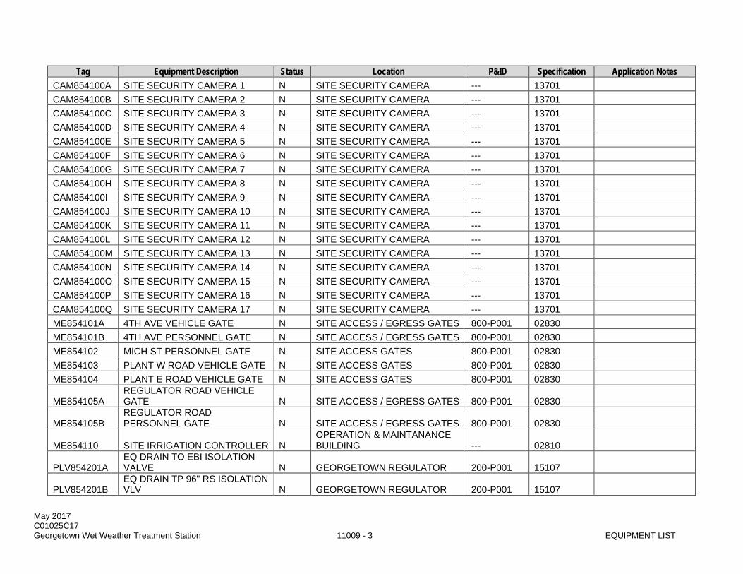
Tag Equipment Description Status Location P&ID Specification Application Notes CAM854100A SITE SECURITY CAMERA 1 N SITE SECURITY CAMERA --- 13701 CAM854100B SITE SECURITY CAMERA 2 N SITE SECURITY CAMERA --- 13701 CAM854100C SITE SECURITY CAMERA 3 N SITE SECURITY CAMERA --- 13701 CAM854100D SITE SECURITY CAMERA 4 N SITE SECURITY CAMERA --- 13701 CAM854100E SITE SECURITY CAMERA 5 N SITE SECURITY CAMERA --- 13701 CAM854100F SITE SECURITY CAMERA 6 N SITE SECURITY CAMERA --- 13701 CAM854100G SITE SECURITY CAMERA 7 N SITE SECURITY CAMERA --- 13701 CAM854100H SITE SECURITY CAMERA 8 N SITE SECURITY CAMERA --- 13701 CAM854100I SITE SECURITY CAMERA 9 N SITE SECURITY CAMERA --- 13701 CAM854100J SITE SECURITY CAMERA 10 N SITE SECURITY CAMERA --- 13701 CAM854100K SITE SECURITY CAMERA 11 N SITE SECURITY CAMERA --- 13701 CAM854100L SITE SECURITY CAMERA 12 N SITE SECURITY CAMERA --- 13701 CAM854100M SITE SECURITY CAMERA 13 N SITE SECURITY CAMERA --- 13701 CAM854100N SITE SECURITY CAMERA 14 N SITE SECURITY CAMERA --- 13701 CAM854100O SITE SECURITY CAMERA 15 N SITE SECURITY CAMERA --- 13701 CAM854100P SITE SECURITY CAMERA 16 N SITE SECURITY CAMERA --- 13701 CAM854100Q SITE SECURITY CAMERA 17 N SITE SECURITY CAMERA --- 13701 ME854101A 4TH AVE VEHICLE GATE N SITE ACCESS / EGRESS GATES 800-P001 02830 ME854101B 4TH AVE PERSONNEL GATE N SITE ACCESS / EGRESS GATES 800-P001 02830 ME854102 MICH ST PERSONNEL GATE N SITE ACCESS GATES 800-P001 02830 ME854103 PLANT W ROAD VEHICLE GATE N SITE ACCESS GATES 800-P001 02830 ME854104 PLANT E ROAD VEHICLE GATE N SITE ACCESS GATES 800-P001 02830
ME854105A REGULATOR ROAD VEHICLE GATE N SITE ACCESS / EGRESS GATES 800-P001 02830
ME854105B REGULATOR ROAD PERSONNEL GATE N SITE ACCESS / EGRESS GATES 800-P001 02830
ME854110 SITE IRRIGATION CONTROLLER N OPERATION & MAINTANANCE BUILDING --- 02810
PLV854201A EQ DRAIN TO EBI ISOLATION VALVE N GEORGETOWN REGULATOR 200-P001 15107
PLV854201B EQ DRAIN TP 96" RS ISOLATION VLV N GEORGETOWN REGULATOR 200-P001 15107
May 2017 C01025C17 Georgetown Wet Weather Treatment Station 11009 - 4 EQUIPMENT LIST
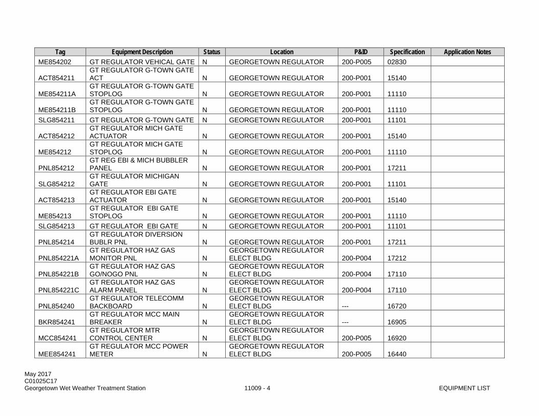
Tag Equipment Description Status Location P&ID Specification Application Notes ME854202 GT REGULATOR VEHICAL GATE N GEORGETOWN REGULATOR 200-P005 02830
ACT854211 GT REGULATOR G-TOWN GATE ACT N GEORGETOWN REGULATOR 200-P001 15140
ME854211A GT REGULATOR G-TOWN GATE STOPLOG N GEORGETOWN REGULATOR 200-P001 11110
ME854211B GT REGULATOR G-TOWN GATE STOPLOG N GEORGETOWN REGULATOR 200-P001 11110
SLG854211 GT REGULATOR G-TOWN GATE N GEORGETOWN REGULATOR 200-P001 11101
ACT854212 GT REGULATOR MICH GATE ACTUATOR N GEORGETOWN REGULATOR 200-P001 15140
ME854212 GT REGULATOR MICH GATE STOPLOG N GEORGETOWN REGULATOR 200-P001 11110
PNL854212 GT REG EBI & MICH BUBBLER PANEL N GEORGETOWN REGULATOR 200-P001 17211
SLG854212 GT REGULATOR MICHIGAN GATE N GEORGETOWN REGULATOR 200-P001 11101
ACT854213 GT REGULATOR EBI GATE ACTUATOR N GEORGETOWN REGULATOR 200-P001 15140
ME854213 GT REGULATOR EBI GATE STOPLOG N GEORGETOWN REGULATOR 200-P001 11110
SLG854213 GT REGULATOR EBI GATE N GEORGETOWN REGULATOR 200-P001 11101
PNL854214 GT REGULATOR DIVERSION BUBLR PNL N GEORGETOWN REGULATOR 200-P001 17211
PNL854221A GT REGULATOR HAZ GAS MONITOR PNL N
GEORGETOWN REGULATOR ELECT BLDG 200-P004 17212
PNL854221B GT REGULATOR HAZ GAS GO/NOGO PNL N
GEORGETOWN REGULATOR ELECT BLDG 200-P004 17110
PNL854221C GT REGULATOR HAZ GAS ALARM PANEL N
GEORGETOWN REGULATOR ELECT BLDG 200-P004 17110
PNL854240 GT REGULATOR TELECOMM BACKBOARD N
GEORGETOWN REGULATOR ELECT BLDG --- 16720
BKR854241 GT REGULATOR MCC MAIN BREAKER N
GEORGETOWN REGULATOR ELECT BLDG --- 16905
MCC854241 GT REGULATOR MTR CONTROL CENTER N
GEORGETOWN REGULATOR ELECT BLDG 200-P005 16920
MEE854241 GT REGULATOR MCC POWER METER N
GEORGETOWN REGULATOR ELECT BLDG 200-P005 16440

May 2017 C01025C17 Georgetown Wet Weather Treatment Station 11009 - 5 EQUIPMENT LIST
Tag Equipment Description Status Location P&ID Specification Application Notes
TVSS854241 GT REGULATOR MCC SURGE PROTECTOR N
GEORGETOWN REGULATOR ELECT BLDG 200-P005 16421
ACT809251A BRANDON REGULATOR GATE 1 ACT N BRANDON REGULATOR 250-P001 15140
ACT809251B BRANDON REGULATOR GATE 2 ACT N BRANDON REGULATOR 250-P001 15140
PNL854251 GT REGULATOR 208V PANELBOARD N BRANDON REGULATOR --- 16470
SLG809251A BRANDON REGULATOR GATE 1 N BRANDON REGULATOR 250-P001 11101 SLG809251B BRANDON REGULATOR GATE 2 N BRANDON REGULATOR 250-P001 11101 TFR854251 GT REG 480V - 208/120V XFMR N BRANDON REGULATOR --- 16460
MBS854252 GT REGULATOR UPS MAINT BYPASS SW N
GEORGETOWN REGULATOR ELECT BLDG --- 16926
UPS854252 GT REGULATOR UPS N GEORGETOWN REGULATOR ELECT BLDG 200-P005 16926
DT854261 GT REG INST AIR RECVR DRAIN TRAP N
GEORGETOWN REGULATOR ELECT BLDG 200-P002 13202
PRV854261 GT REGULATOR INST AIR RECVR PRV N
GEORGETOWN REGULATOR ELECT BLDG 200-P002 13202
PRESS VESSEL SUPPLIER
PVL854261 GT REGULATOR INST AIR RECEIVER N
GEORGETOWN REGULATOR ELECT BLDG 200-P002 13202
RV854261 GT REG INST AIR PRESS REGLTR N
GEORGETOWN REGULATOR ELECT BLDG 200-P002 15121
DT854262 GT REG SERV AIR RECVR DRAIN TRAP N
GEORGETOWN REGULATOR ELECT BLDG 200-P003 13202
PRV854262 GT REGULATOR SERV AIR RECVR PRV N
GEORGETOWN REGULATOR ELECT BLDG 200-P003 13202
PRESS VESSEL SUPPLIER
PVL854262 GT REGULATOR SERV AIR RECIEVER N
GEORGETOWN REGULATOR ELECT BLDG 200-P003 13202
HP854274 GT REGULATOR HEAT PUMP UNIT N
GEORGETOWN REGULATOR ELECT BLDG 200-P007 15700
ME854274 GT REGULATOR HEAT PUMP FAN COIL N
GEORGETOWN REGULATOR ELECT BLDG 200-P007 15700
TST854274 GT REGULATOR THERMOSTAT N GEORGETOWN REGULATOR ELECT BLDG 200-P007 15901 HVAC SUPPLIER
PNL854281 GT REGULATOR CONTROL PNL N GEORGETOWN REGULATOR ELECT BLDG MULTIPLE 17110

May 2017 C01025C17 Georgetown Wet Weather Treatment Station 11009 - 6 EQUIPMENT LIST
Tag Equipment Description Status Location P&ID Specification Application Notes
PNL854282 GT REGULATOR METROTEL PNL N
GEORGETOWN REGULATOR ELECT BLDG MULTIPLE 17275
LP854292 GT REGULATOR ART LTG CONTROL PNL N
GEORGETOWN REGULATOR ELECT BLDG 200-P005 16510
FCP854294 GT REGULATOR FIRE ALARM PANEL N
GEORGETOWN REGULATOR ELECT BLDG 200-P005 16660
PNL854300 EQUALIZATION BASIN BUBBLER PANEL N SCREENINGS / EQ BASIN / IPS 300-P008 17211
V854300A EQ BASIN DRAIN FLAP GATE 1 N SCREENINGS / EQ BASIN / IPS 300-P008 15150 V854300B EQ BASIN DRAIN FLAP GATE 2 N SCREENINGS / EQ BASIN / IPS 300-P008 15150
ARV854301 EQ BSN DRAIN PMPS AIR REL VALVE N SCREENINGS / EQ BASIN / IPS 300-P017 15123
AVV854301 EQ BSN DRAIN PMP 1 AIR VAC VALVE N SCREENINGS / EQ BASIN / IPS 300-P017 15123
CHV854301 EQ BASIN DRAIN PUMP 1 CHK VLV N SCREENINGS / EQ BASIN / IPS 300-P017 15110
DS854301 EQ BASIN DRAIN PUMP 1 DISCONNECT N SCREENINGS / EQ BASIN / IPS --- 16175
LCS854301 EQ BASIN DRAIN PUMP 1 LCS N SCREENINGS / EQ BASIN / IPS 300-P017 16176 MY854301 EQ BASIN DRAIN PUMP 1 MS N SCREENINGS / EQ BASIN / IPS 300-P017 16920 P854301 EQ BASIN DRAIN PUMP 1 N SCREENINGS / EQ BASIN / IPS 300-P017 11347
PLV854301 EQ BASIN DRAIN PUMP 1 ISO VALVE N SCREENINGS / EQ BASIN / IPS 300-P017 15107
AVV854302 EQ BSN DRAIN PMP 2 AIR VAC VALVE N SCREENINGS / EQ BASIN / IPS 300-P017 15123
CHV854302 EQ BASIN DRAIN PUMP 2 CHECK VLV N SCREENINGS / EQ BASIN / IPS 300-P017 15110
DS854302 EQ BASIN DRAIN PUMP 1 DISCONNECT N SCREENINGS / EQ BASIN / IPS --- 16175
LCS854302 EQ BASIN DRAIN PUMP 2 LCS N SCREENINGS / EQ BASIN / IPS 300-P017 16176
MY854302 EQ BASIN DRAIN PUMP 2 MTR STRTR N SCREENINGS / EQ BASIN / IPS 300-P017 16920
P854302 EQ BASIN DRAIN PUMP 2 N SCREENINGS / EQ BASIN / IPS 300-P017 11347
PLV854302 EQ BASIN DRAIN PUMP 2 ISO VALVE N SCREENINGS / EQ BASIN / IPS 300-P017 15107
PNL854303A HAZARDOUS GAS MONITORING PANEL N SCREENINGS / EQ BASIN / IPS 300-P018 17212
May 2017 C01025C17 Georgetown Wet Weather Treatment Station 11009 - 7 EQUIPMENT LIST
Tag Equipment Description Status Location P&ID Specification Application Notes
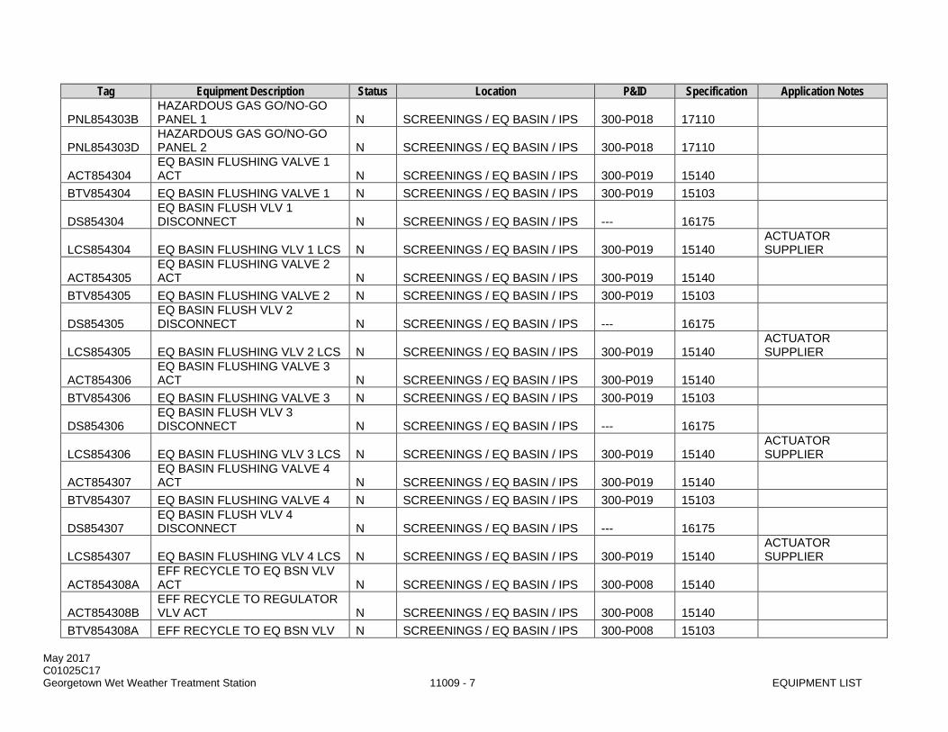
PNL854303B HAZARDOUS GAS GO/NO-GO PANEL 1 N SCREENINGS / EQ BASIN / IPS 300-P018 17110
PNL854303D HAZARDOUS GAS GO/NO-GO PANEL 2 N SCREENINGS / EQ BASIN / IPS 300-P018 17110
ACT854304 EQ BASIN FLUSHING VALVE 1 ACT N SCREENINGS / EQ BASIN / IPS 300-P019 15140
BTV854304 EQ BASIN FLUSHING VALVE 1 N SCREENINGS / EQ BASIN / IPS 300-P019 15103
DS854304 EQ BASIN FLUSH VLV 1 DISCONNECT N SCREENINGS / EQ BASIN / IPS --- 16175
LCS854304 EQ BASIN FLUSHING VLV 1 LCS N SCREENINGS / EQ BASIN / IPS 300-P019 15140 ACTUATOR SUPPLIER
ACT854305 EQ BASIN FLUSHING VALVE 2 ACT N SCREENINGS / EQ BASIN / IPS 300-P019 15140
BTV854305 EQ BASIN FLUSHING VALVE 2 N SCREENINGS / EQ BASIN / IPS 300-P019 15103
DS854305 EQ BASIN FLUSH VLV 2 DISCONNECT N SCREENINGS / EQ BASIN / IPS --- 16175
LCS854305 EQ BASIN FLUSHING VLV 2 LCS N SCREENINGS / EQ BASIN / IPS 300-P019 15140 ACTUATOR SUPPLIER
ACT854306 EQ BASIN FLUSHING VALVE 3 ACT N SCREENINGS / EQ BASIN / IPS 300-P019 15140
BTV854306 EQ BASIN FLUSHING VALVE 3 N SCREENINGS / EQ BASIN / IPS 300-P019 15103
DS854306 EQ BASIN FLUSH VLV 3 DISCONNECT N SCREENINGS / EQ BASIN / IPS --- 16175
LCS854306 EQ BASIN FLUSHING VLV 3 LCS N SCREENINGS / EQ BASIN / IPS 300-P019 15140 ACTUATOR SUPPLIER
ACT854307 EQ BASIN FLUSHING VALVE 4 ACT N SCREENINGS / EQ BASIN / IPS 300-P019 15140
BTV854307 EQ BASIN FLUSHING VALVE 4 N SCREENINGS / EQ BASIN / IPS 300-P019 15103
DS854307 EQ BASIN FLUSH VLV 4 DISCONNECT N SCREENINGS / EQ BASIN / IPS --- 16175
LCS854307 EQ BASIN FLUSHING VLV 4 LCS N SCREENINGS / EQ BASIN / IPS 300-P019 15140 ACTUATOR SUPPLIER
ACT854308A EFF RECYCLE TO EQ BSN VLV ACT N SCREENINGS / EQ BASIN / IPS 300-P008 15140
ACT854308B EFF RECYCLE TO REGULATOR VLV ACT N SCREENINGS / EQ BASIN / IPS 300-P008 15140
BTV854308A EFF RECYCLE TO EQ BSN VLV N SCREENINGS / EQ BASIN / IPS 300-P008 15103

May 2017 C01025C17 Georgetown Wet Weather Treatment Station 11009 - 8 EQUIPMENT LIST
Tag Equipment Description Status Location P&ID Specification Application Notes
BTV854308B EFF RECYCLE TO REGULATOR VLV N SCREENINGS / EQ BASIN / IPS 300-P008 15103
DS854308A EFF RECYCLE TO EQ BSN VLV DISC N SCREENINGS / EQ BASIN / IPS --- 16175
DS854308B EFF RECYCLE TO REG VLV DISC N SCREENINGS / EQ BASIN / IPS --- 16175
LCS854308A EFF RECYCLE TO EQ BSN VLV LCS N SCREENINGS / EQ BASIN / IPS 300-P008 15140
ACTUATOR SUPPLIER
LCS854308B EFF RECYCLE TO REGULATOR VLV LCS N SCREENINGS / EQ BASIN / IPS 300-P008 15140
ACTUATOR SUPPLIER
MTR854311 T1 - INFLUENT PUMP 1 MOTOR N TRAIN 1 IPS PUMPS 300-P011 11344 P854311 T1 - INFLUENT PUMP 1 N TRAIN 1 IPS PUMPS 300-P011 11344 VFD854311 T1 - INFLUENT PUMP 1 VFD N TRAIN 1 IPS PUMPS 300-P011 16158 MTR854312 T1 - INFLUENT PUMP 2 MOTOR N TRAIN 1 IPS PUMPS 300-P012 11344 P854312 T1 - INFLUENT PUMP 2 N TRAIN 1 IPS PUMPS 300-P012 11344 VFD854312 T1 - INFLUENT PUMP 2 VFD N TRAIN 1 IPS PUMPS 300-P012 16158 MTR854313 T1 - INFLUENT PUMP 3 MOTOR N TRAIN 1 IPS PUMPS 300-P013 11344 P854313 T1 - INFLUENT PUMP 3 N TRAIN 1 IPS PUMPS 300-P013 11344 VFD854313 T1 - INFLUENT PUMP 3 VFD N TRAIN 1 IPS PUMPS 300-P013 16158
ACT854314 EQ BASIN FLUSHING VALVE 5 ACT N SCREENINGS / EQ BASIN / IPS 300-P019A 15140
BTV854314 EQ BASIN FLUSHING VALVE 5 ACT N SCREENINGS / EQ BASIN / IPS 300-P019A 15103
DS854314 EQ BASIN FLUSH VLV 5 DISCONNECT N SCREENINGS / EQ BASIN / IPS --- 16175
LCS854314 EQ BASIN FLUSHING VLV 5 LCS N SCREENINGS / EQ BASIN / IPS 300-P019A 15140 ACTUATOR SUPPLIER
ACT854315 EQ BASIN FLUSHING VALVE 6 ACT N SCREENINGS / EQ BASIN / IPS 300-P019A 15140
BTV854315 EQ BASIN FLUSHING VALVE 6 ACT N SCREENINGS / EQ BASIN / IPS 300-P019A 15103
DS854315 EQ BASIN FLUSH VLV 6 DISCONNECT N SCREENINGS / EQ BASIN / IPS --- 16175
LCS854315 EQ BASIN FLUSHING VLV 6 LCS N SCREENINGS / EQ BASIN / IPS 300-P019A 15140 ACTUATOR SUPPLIER
ACT854316 EQ BASIN FLUSHING VALVE 7 N SCREENINGS / EQ BASIN / IPS 300-P019A 15140

May 2017 C01025C17 Georgetown Wet Weather Treatment Station 11009 - 9 EQUIPMENT LIST
Tag Equipment Description Status Location P&ID Specification Application Notes ACT
BTV854316 EQ BASIN FLUSHING VALVE 7 ACT N SCREENINGS / EQ BASIN / IPS 300-P019A 15103
DS854316 EQ BASIN FLUSH VLV 7 DISCONNECT N SCREENINGS / EQ BASIN / IPS --- 16175
LCS854316 EQ BASIN FLUSHING VLV 7 LCS N SCREENINGS / EQ BASIN / IPS 300-P019A 15140 ACTUATOR SUPPLIER
ACT854317 EQ BASIN FLUSHING VALVE 8 ACT N SCREENINGS / EQ BASIN / IPS 300-P019A 15140
BTV854317 EQ BASIN FLUSHING VALVE 8 ACT N SCREENINGS / EQ BASIN / IPS 300-P019A 15103
DS854317 EQ BASIN FLUSH VLV 8 DISCONNECT N SCREENINGS / EQ BASIN / IPS --- 16175
LCS854317 EQ BASIN FLUSHING VLV 8 LCS N SCREENINGS / EQ BASIN / IPS 300-P019A 15140 ACTUATOR SUPPLIER
MTR854321 T2 - INFLUENT PUMP 1 MOTOR N TRAIN 2 IPS PUMPS 300-P014 11344 P854321 T2 - INFLUENT PUMP 1 N TRAIN 2 IPS PUMPS 300-P014 11344 VFD854321 T2 - INFLUENT PUMP 1 VFD N TRAIN 2 IPS PUMPS 300-P014 16158 MTR854322 T2 - INFLUENT PUMP 2 MOTOR N TRAIN 2 IPS PUMPS 300-P015 11344 P854322 T2 - INFLUENT PUMP 2 N TRAIN 2 IPS PUMPS 300-P015 11344 VFD854322 T2 - INFLUENT PUMP 2 VFD N TRAIN 2 IPS PUMPS 300-P015 16158 MTR854323 T2 - INFLUENT PUMP 3 MOTOR N TRAIN 2 IPS PUMPS 300-P016 11344 P854323 T2 - INFLUENT PUMP 3 N TRAIN 2 IPS PUMPS 300-P016 11344 VFD854323 T2 - INFLUENT PUMP 3 VFD N TRAIN 2 IPS PUMPS 300-P016 16158
ME854330A INFLUENT CHANNEL STOPLOG 1 N SCREENING BUILDING 300-P001 11110
ME854330B INFLUENT CHANNEL STOPLOG 2 N SCREENING BUILDING 300-P001 11110
ME854330C INFLUENT CHANNEL STOPLOG 3 N SCREENING BUILDING 300-P001 11110
PNL854330 INFLUENT CHANNEL BUBBLER PANEL N SCREENING BUILDING 300-P001 17211
BV854331A INF SAMP PMP 1 DISCH ISO VLV N SCREENING BUILDING 300-P005 15104
BV854331B INF SAMP PMP 1 FLUSH ISO VLV N SCREENING BUILDING 300-P005 15104

May 2017 C01025C17 Georgetown Wet Weather Treatment Station 11009 - 10 EQUIPMENT LIST
Tag Equipment Description Status Location P&ID Specification Application Notes
CHV854331A INF SAMP PMP 1 DISCH CHK VLV N SCREENING BUILDING 300-P005 15110
CHV854331B INF SAMP PMP 1 FLUSH CHK VLV N SCREENING BUILDING 300-P005 15110
H854331 INFLUENT SAMPLE PUMP 1 HOIST N SCREENING BUILDING 300-P005 14310
LCS854331 INFLUENT SAMPLE PUMP 1 LCS N SCREENING BUILDING 300-P005 16176 MY854331 INFLUENT SAMPLE PUMP 1 MS N SCREENING BUILDING 300-P005 16920 P854331 INFLUENT SAMPLE PUMP 1 N SCREENING BUILDING 300-P005 11347
BV854332A INF SAMP PMP 2 DISCH ISO VLV N SCREENING BUILDING 300-P005 15104
BV854332B INF SAMP PMP 2 FLUSH ISO VLV N SCREENING BUILDING 300-P005 15104
CHV854332A INF SAMP PMP 2 DISCH CHK VLV N SCREENING BUILDING 300-P005 15110
CHV854332B INF SAMP PMP 2 FLUSH CHK VLV N SCREENING BUILDING 300-P005 15110
H854332 INFLUENT SAMPLE PUMP 2 HOIST N SCREENING BUILDING 300-P005 14310
LCS854332 INFLUENT SAMPLE PUMP 2 LCS N SCREENING BUILDING 300-P005 16176 MY854332 INFLUENT SAMPLE PUMP 2 MS N SCREENING BUILDING 300-P005 16920 P854332 INFLUENT SAMPLE PUMP 2 N SCREENING BUILDING 300-P005 11347
PNL854333A INF SAM ROOM HAZ GAS MONITOR PNL N SCREENING BUILDING 300-P018 17212
PNL854333B INF SMP ROOM HAZ GAS GO/NOGO PNL N SCREENING BUILDING 300-P018 17110
PNL854333C INF SMP ROOM HAZ GAS ALARM PANEL N SCREENING BUILDING 300-P018 17110
BV854334 INFLUENT SAMPLE DRAIN VALVE N INFLUENT SAMPLE ROOM 300-P005 15104
ME854334 INFLUENT SAMPLE BOX N INFLUENT SAMPLE ROOM 300-P005 ---
SMP854335 INFLUENT COMPOSITE SAMPLER N INFLUENT SAMPLE ROOM 300-P005 11590
SMP854337 INFLUENT PRI POLLUTANT SAMPLER N INFLUENT SAMPLE ROOM 300-P005 11590
PNL854340 SCREENINGS NETWORK PANEL N
SCREENING BLDG PANEL ROOM MULTIPLE 17110
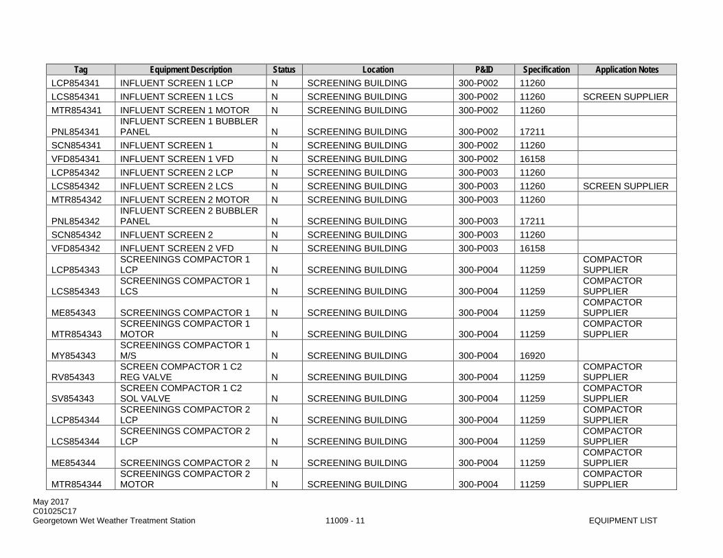
May 2017 C01025C17 Georgetown Wet Weather Treatment Station 11009 - 11 EQUIPMENT LIST
Tag Equipment Description Status Location P&ID Specification Application Notes LCP854341 INFLUENT SCREEN 1 LCP N SCREENING BUILDING 300-P002 11260 LCS854341 INFLUENT SCREEN 1 LCS N SCREENING BUILDING 300-P002 11260 SCREEN SUPPLIER MTR854341 INFLUENT SCREEN 1 MOTOR N SCREENING BUILDING 300-P002 11260
PNL854341 INFLUENT SCREEN 1 BUBBLER PANEL N SCREENING BUILDING 300-P002 17211
SCN854341 INFLUENT SCREEN 1 N SCREENING BUILDING 300-P002 11260 VFD854341 INFLUENT SCREEN 1 VFD N SCREENING BUILDING 300-P002 16158 LCP854342 INFLUENT SCREEN 2 LCP N SCREENING BUILDING 300-P003 11260 LCS854342 INFLUENT SCREEN 2 LCS N SCREENING BUILDING 300-P003 11260 SCREEN SUPPLIER MTR854342 INFLUENT SCREEN 2 MOTOR N SCREENING BUILDING 300-P003 11260
PNL854342 INFLUENT SCREEN 2 BUBBLER PANEL N SCREENING BUILDING 300-P003 17211
SCN854342 INFLUENT SCREEN 2 N SCREENING BUILDING 300-P003 11260 VFD854342 INFLUENT SCREEN 2 VFD N SCREENING BUILDING 300-P003 16158
LCP854343 SCREENINGS COMPACTOR 1 LCP N SCREENING BUILDING 300-P004 11259
COMPACTOR SUPPLIER
LCS854343 SCREENINGS COMPACTOR 1 LCS N SCREENING BUILDING 300-P004 11259
COMPACTOR SUPPLIER
ME854343 SCREENINGS COMPACTOR 1 N SCREENING BUILDING 300-P004 11259 COMPACTOR SUPPLIER
MTR854343 SCREENINGS COMPACTOR 1 MOTOR N SCREENING BUILDING 300-P004 11259
COMPACTOR SUPPLIER
MY854343 SCREENINGS COMPACTOR 1 M/S N SCREENING BUILDING 300-P004 16920
RV854343 SCREEN COMPACTOR 1 C2 REG VALVE N SCREENING BUILDING 300-P004 11259
COMPACTOR SUPPLIER
SV854343 SCREEN COMPACTOR 1 C2 SOL VALVE N SCREENING BUILDING 300-P004 11259
COMPACTOR SUPPLIER
LCP854344 SCREENINGS COMPACTOR 2 LCP N SCREENING BUILDING 300-P004 11259
COMPACTOR SUPPLIER
LCS854344 SCREENINGS COMPACTOR 2 LCP N SCREENING BUILDING 300-P004 11259
COMPACTOR SUPPLIER
ME854344 SCREENINGS COMPACTOR 2 N SCREENING BUILDING 300-P004 11259 COMPACTOR SUPPLIER
MTR854344 SCREENINGS COMPACTOR 2 MOTOR N SCREENING BUILDING 300-P004 11259
COMPACTOR SUPPLIER
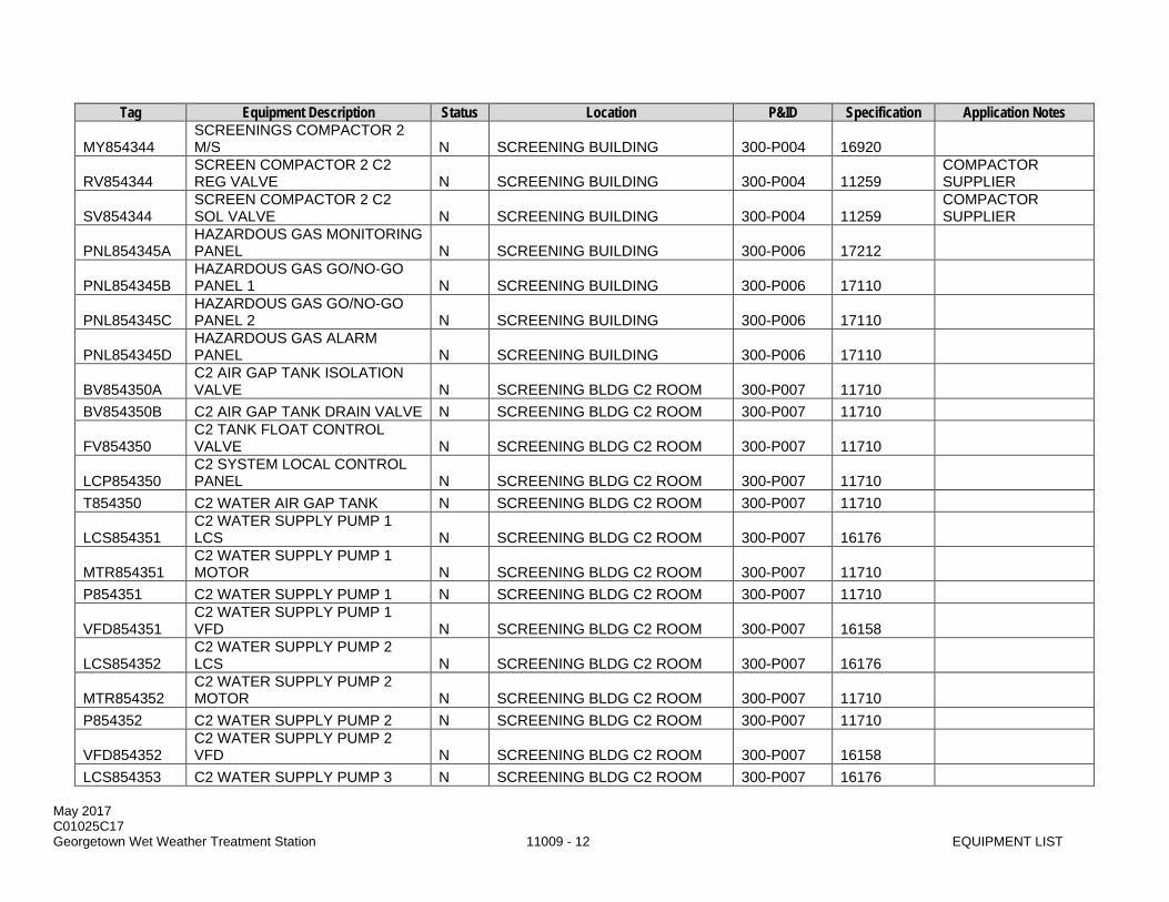
May 2017 C01025C17 Georgetown Wet Weather Treatment Station 11009 - 12 EQUIPMENT LIST
Tag Equipment Description Status Location P&ID Specification Application Notes
MY854344 SCREENINGS COMPACTOR 2 M/S N SCREENING BUILDING 300-P004 16920
RV854344 SCREEN COMPACTOR 2 C2 REG VALVE N SCREENING BUILDING 300-P004 11259
COMPACTOR SUPPLIER
SV854344 SCREEN COMPACTOR 2 C2 SOL VALVE N SCREENING BUILDING 300-P004 11259
COMPACTOR SUPPLIER
PNL854345A HAZARDOUS GAS MONITORING PANEL N SCREENING BUILDING 300-P006 17212
PNL854345B HAZARDOUS GAS GO/NO-GO PANEL 1 N SCREENING BUILDING 300-P006 17110
PNL854345C HAZARDOUS GAS GO/NO-GO PANEL 2 N SCREENING BUILDING 300-P006 17110
PNL854345D HAZARDOUS GAS ALARM PANEL N SCREENING BUILDING 300-P006 17110
BV854350A C2 AIR GAP TANK ISOLATION VALVE N SCREENING BLDG C2 ROOM 300-P007 11710
BV854350B C2 AIR GAP TANK DRAIN VALVE N SCREENING BLDG C2 ROOM 300-P007 11710
FV854350 C2 TANK FLOAT CONTROL VALVE N SCREENING BLDG C2 ROOM 300-P007 11710
LCP854350 C2 SYSTEM LOCAL CONTROL PANEL N SCREENING BLDG C2 ROOM 300-P007 11710
T854350 C2 WATER AIR GAP TANK N SCREENING BLDG C2 ROOM 300-P007 11710
LCS854351 C2 WATER SUPPLY PUMP 1 LCS N SCREENING BLDG C2 ROOM 300-P007 16176
MTR854351 C2 WATER SUPPLY PUMP 1 MOTOR N SCREENING BLDG C2 ROOM 300-P007 11710
P854351 C2 WATER SUPPLY PUMP 1 N SCREENING BLDG C2 ROOM 300-P007 11710
VFD854351 C2 WATER SUPPLY PUMP 1 VFD N SCREENING BLDG C2 ROOM 300-P007 16158
LCS854352 C2 WATER SUPPLY PUMP 2 LCS N SCREENING BLDG C2 ROOM 300-P007 16176
MTR854352 C2 WATER SUPPLY PUMP 2 MOTOR N SCREENING BLDG C2 ROOM 300-P007 11710
P854352 C2 WATER SUPPLY PUMP 2 N SCREENING BLDG C2 ROOM 300-P007 11710
VFD854352 C2 WATER SUPPLY PUMP 2 VFD N SCREENING BLDG C2 ROOM 300-P007 16158
LCS854353 C2 WATER SUPPLY PUMP 3 N SCREENING BLDG C2 ROOM 300-P007 16176

May 2017 C01025C17 Georgetown Wet Weather Treatment Station 11009 - 13 EQUIPMENT LIST
Tag Equipment Description Status Location P&ID Specification Application Notes LCS
MTR854353 C2 WATER SUPPLY PUMP 3 MOTOR N SCREENING BLDG C2 ROOM 300-P007 11710
P854353 C2 WATER SUPPLY PUMP 3 N SCREENING BLDG C2 ROOM 300-P007 11710
VFD854353 C2 WATER SUPPLY PUMP 3 VFD N SCREENING BLDG C2 ROOM 300-P007 16158
LCS854354 C2 WATER SUPPLY PUMP 4 LCS N SCREENING BLDG C2 ROOM 300-P007 16176
MTR854354 C2 WATER SUPPLY PUMP 4 MOTOR N SCREENING BLDG C2 ROOM 300-P007 11710
P854354 C2 WATER SUPPLY PUMP 4 N SCREENING BLDG C2 ROOM 300-P007 11710
VFD854354 C2 WATER SUPPLY PUMP 4 VFD N SCREENING BLDG C2 ROOM 300-P007 16158
BV854355A C2 SUPPLY REGULATOR INLET VLV N SCREENING BLDG C2 ROOM 300-P007 11710
BV854355B C2 SUPPLY REGULATOR OUTLET VLV N SCREENING BLDG C2 ROOM 300-P007 11710
BV854355C C2 SUPPLY REGULATOR BYPASS VLV N SCREENING BLDG C2 ROOM 300-P007 11710
BV854355D C2 SUPPLY HYDRO-P TANK ISO VLV N SCREENING BLDG C2 ROOM 300-P007 11710
PRV854355 C2 HYDRO TANK PRESS RELIEF VALVE N SCREENING BLDG C2 ROOM 300-P007 11710 C2 SUPPLIER
PVL854355 C2 WATER HYDRO-PNEUMATIC TANK N SCREENING BLDG C2 ROOM 300-P007 11710
RV854355A C2 REGULATING VALVE N SCREENING BLDG C2 ROOM 300-P007 11710 ME854356C C2 ROOM ROLL-UP DOOR N SCREENING BLDG C2 ROOM 800-P001 08330
DT854361 PRELIM TREAT I/A RECVR DR TRAP N
SCREENING BLDG PANEL ROOM 300-P021 13202
PRV854361 PRELIM TREAT INST AIR RECVR PRV N
SCREENING BLDG PANEL ROOM 300-P021 13202
PRESS VESSEL SUPPLIER
PVL854361 PRELIM TREAT INST AIR RECEIVER N
SCREENING BLDG PANEL ROOM 300-P021 13202
RV854362 PRELIM TREAT INST AIR PRESS REG N
SCREENING BLDG PANEL ROOM 300-P021 15121
RV854363 PRELIM TREAT INST AIR PRESS REG N
SCREENING BLDG PANEL ROOM 300-P021 15121

May 2017 C01025C17 Georgetown Wet Weather Treatment Station 11009 - 14 EQUIPMENT LIST
Tag Equipment Description Status Location P&ID Specification Application Notes
RV854364 PRELIM TREAT INST AIR PRESS REG N
SCREENING BLDG PANEL ROOM 300-P021 15121
RV854365 PRELIM TREAT INST AIR PRESS REG N
SCREENING BLDG PANEL ROOM 300-P021 15121
RV854366 PRELIM TREAT INST AIR PRESS REG N
SCREENING BLDG PANEL ROOM 300-P021 15121
DT854367 PRELIM TREAT SERV AIR DRAIN TRAP N
SCREENING BLDG PANEL ROOM 300-P022 13202
PRV854367 PRELIM TREAT SERV AIR RECVR PRV N
SCREENING BLDG PANEL ROOM 300-P022 13202
PRESS VESSEL SUPPLIER
PVL854367 PRELIM TREAT SERV AIR RECEIVER N
SCREENING BLDG PANEL ROOM 300-P022 13202
AHU854374 SCREENINGS ROOM AHU N SCREENINGS / EQ BASIN / IPS 300-P024 15835
ME854374B SCREENINGS ROOM ROLL-UP DOOR N SCREENINGS / EQ BASIN / IPS 800-P001 08330
PNL854374 PRETREATMENT HVAC PANEL N SCREENINGS / EQ BASIN / IPS MULTIPLE 15901 HVAC SUPPLIER
RV854374 SCRN ROOM AHU REGULATING VALVE N SCREENINGS / EQ BASIN / IPS 300-P024 15121
VFD854374 SCREENINGS ROOM AHU VFD N SCREENINGS / EQ BASIN / IPS 300-P024 16158 DPR854375A C2 ROOM SUPPLY DAMPER N SCREENINGS / EQ BASIN / IPS 300-P025 15911 DPR854375B C2 ROOM EXHAUST DAMPER N SCREENINGS / EQ BASIN / IPS 300-P025 15911 FLT854375 C2 ROOM SUPPLY FILTER N SCREENINGS / EQ BASIN / IPS 300-P025 15880 LVR854375A C2 ROOM SUPPLY LOUVER N SCREENINGS / EQ BASIN / IPS 300-P025 10200 LVR854375B C2 ROOM EXHAUST LOUVER N SCREENINGS / EQ BASIN / IPS 300-P025 10200 MY854375 C2 ROOOM SUPPLY FAN M/S N SCREENINGS / EQ BASIN / IPS 300-P025 16920 RV854375 C2 ROOM NAT GAS PRESS REG N SCREENINGS / EQ BASIN / IPS 300-P025 15121 SF854375 C2 ROOOM SUPPLY FAN N SCREENINGS / EQ BASIN / IPS 300-P025 15859 TST854375 C2 ROOM THERMOSTAT N SCREENINGS / EQ BASIN / IPS 300-P025 15901 HVAC SUPPLIER UH854375 C2 ROOM UNIT HEATER N SCREENINGS / EQ BASIN / IPS 300-P025 15633 EF854376 SAMPLE ROOM EXHAUST FAN N SCREENINGS / EQ BASIN / IPS 300-P026 15859 FLT854376 SAMPLE ROOM SUPPLY FILTER N SCREENINGS / EQ BASIN / IPS 300-P026 15880
LVR854376A SAMPLE ROOM SUPPLY LOUVER N SCREENINGS / EQ BASIN / IPS 300-P026 10200

May 2017 C01025C17 Georgetown Wet Weather Treatment Station 11009 - 15 EQUIPMENT LIST
Tag Equipment Description Status Location P&ID Specification Application Notes
LVR854376B SAMPLE ROOM EXHAUST LOUVER N SCREENINGS / EQ BASIN / IPS 300-P026 10200
MY854376 SCREENINGS BLDG EXHAUST FAN M/S N SCREENINGS / EQ BASIN / IPS 300-P026 16920
TST854376 SAMPLE RM THERMOSTAT N SCREENINGS / EQ BASIN / IPS 300-P026 15901 HVAC SUPPLIER UH854376 SAMPLE ROOM UNIT HEATER N SCREENINGS / EQ BASIN / IPS 300-P026 15632 DPR854377A PNL ROOM SUPPLY DAMPER N SCREENINGS / EQ BASIN / IPS 300-P027 15911 DPR854377B PNL ROOM EXHAUST DAMPER N SCREENINGS / EQ BASIN / IPS 300-P027 15911 FLT854377 PNL ROOM SUPPLY FILTER N SCREENINGS / EQ BASIN / IPS 300-P027 15880 LVR854377A PNL ROOM SUPPLY LOUVER N SCREENINGS / EQ BASIN / IPS 300-P027 10200 LVR854377B PNL ROOM EXHAUST LOUVER N SCREENINGS / EQ BASIN / IPS 300-P027 10200 MY854377 PNL ROOOM SUPPLY FAN M/S N SCREENINGS / EQ BASIN / IPS 300-P027 16920
RV854377 PNL ROOM NAT GAS PRESS REG N SCREENINGS / EQ BASIN / IPS 300-P027 15121
SF854377 PNL ROOOM SUPPLY FAN N SCREENINGS / EQ BASIN / IPS 300-P027 15859 TST854377 PNL ROOM THERMOSTAT N SCREENINGS / EQ BASIN / IPS 300-P027 15901 HVAC SUPPLIER UH854377 PNL ROOM UNIT HEATER N SCREENINGS / EQ BASIN / IPS 300-P027 15633
C854378 SCREENINGS BUILDING BRIDGE CRANE N SCREENINGS / EQ BASIN / IPS --- 14360
DPR854379A SCREENINGS BALANCING DAMPER 1 N SCREENINGS / EQ BASIN / IPS 300-P020 15911
DPR854379B SCREENINGS BALANCING DAMPER 2 N SCREENINGS / EQ BASIN / IPS 300-P020 15911
DPR854379C SCREENINGS BALANCING DAMPER 3 N SCREENINGS / EQ BASIN / IPS 300-P020 15911
DPR854379D SCREENINGS BALANCING DAMPER 4 N SCREENINGS / EQ BASIN / IPS 300-P020 15911
PNL854391 SCREENINGS 208V PANELBOARD N SCREENINGS / EQ BASIN / IPS --- 16470
TFR854391 SCREENINGS 480 - 208/120V XFMR N SCREENINGS / EQ BASIN / IPS --- 16460
FCP854394 SCREENING BLDG FIRE ALARM PANEL N SCREENINGS / EQ BASIN / IPS 800-P002 16660
SFT854401 POLYMER ROOM EYE WASH N BALLASTED SEDIMENTATION 400-P008 15442 V854407A MH 3 DRAIN FLAP GATE 1 N BALLASTED SEDIMENTATION 300-P008 15150

May 2017 C01025C17 Georgetown Wet Weather Treatment Station 11009 - 16 EQUIPMENT LIST
Tag Equipment Description Status Location P&ID Specification Application Notes V854407B MH 3 DRAIN FLAP GATE 2 N BALLASTED SEDIMENTATION 300-P008 15150 V854407C MH 3 DRAIN FLAP GATE 3 N BALLASTED SEDIMENTATION 300-P008 15150 V854407D MH 3 DRAIN FLAP GATE 4 N BALLASTED SEDIMENTATION 300-P008 15150 V854408A MH 4 DRAIN FLAP GATE 1 N BALLASTED SEDIMENTATION 300-P008 15150 V854408B MH 4 DRAIN FLAP GATE 2 N BALLASTED SEDIMENTATION 300-P008 15150 V854408C MH 4 DRAIN FLAP GATE 3 N BALLASTED SEDIMENTATION 300-P008 15150 V854408D MH 4 DRAIN FLAP GATE 4 N BALLASTED SEDIMENTATION 300-P008 15150 V854408E MH 4 DRAIN FLAP GATE 5 N BALLASTED SEDIMENTATION 300-P008 15150
PNL854410 T1 - BALLASTED SED PLC PANEL N BALLASTED SEDIMENTATION 1 MULTIPLE 17800 BY KRUGER
PNL854411 BALL SED DIST BUBBLER PNL N BALLASTED SEDIMENTATION 1 400-P001 17211
MTR854412 T1 - RAPID MIX TANK MIXER MOTOR N BALLASTED SEDIMENTATION 1 400-P002 11800 BY KRUGER
MX854412 T1 - RAPID MIX TANK MIXER N BALLASTED SEDIMENTATION 1 400-P002 11800 BY KRUGER
MY854412 T1 - RAPID MIX TANK MIXER M/S N BALLASTED SEDIMENTATION 1 400-P002 16920
MTR854413 T1 - COAGULATION TANK MXR MOTOR N BALLASTED SEDIMENTATION 1 400-P002 11800 BY KRUGER
MX854413 T1 - COAGULATION TANK MIXER N BALLASTED SEDIMENTATION 1 400-P002 11800 BY KRUGER
MY854413 T1 - COAGULATION TANK MIXER M/S N BALLASTED SEDIMENTATION 1 400-P002 16920
PLV854413 T1 - MIX / COAG TANK DRAIN VLV N BALLASTED SEDIMENTATION 1 400-P002 15107
MTR854414 T1 - MATURATION TANK MXR MOTOR N BALLASTED SEDIMENTATION 1 400-P002 11800 BY KRUGER
MX854414 T1 - MATURATION TANK MIXER N BALLASTED SEDIMENTATION 1 400-P002 11800 BY KRUGER
VFD854414 T1 - MATURATION TANK MIXER VFD N BALLASTED SEDIMENTATION 1 400-P002 16158
ME854415 T1 - SETTLING TNK RAKE MECHANISM N BALLASTED SEDIMENTATION 1 400-P002 11800 BY KRUGER
MTR854415 T1 - SETTLING TANK MOTOR N BALLASTED SEDIMENTATION 1 400-P002 11800 BY KRUGER
PLV854415 T1 - MAT / SETLNG TANK DRAIN VLV N BALLASTED SEDIMENTATION 1 400-P002 15107
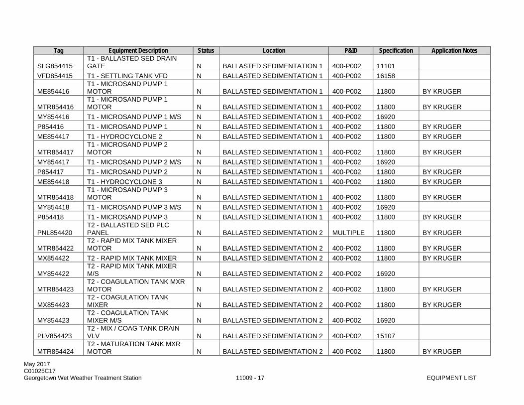
May 2017 C01025C17 Georgetown Wet Weather Treatment Station 11009 - 17 EQUIPMENT LIST
Tag Equipment Description Status Location P&ID Specification Application Notes
SLG854415 T1 - BALLASTED SED DRAIN GATE N BALLASTED SEDIMENTATION 1 400-P002 11101
VFD854415 T1 - SETTLING TANK VFD N BALLASTED SEDIMENTATION 1 400-P002 16158
ME854416 T1 - MICROSAND PUMP 1 MOTOR N BALLASTED SEDIMENTATION 1 400-P002 11800 BY KRUGER
MTR854416 T1 - MICROSAND PUMP 1 MOTOR N BALLASTED SEDIMENTATION 1 400-P002 11800 BY KRUGER
MY854416 T1 - MICROSAND PUMP 1 M/S N BALLASTED SEDIMENTATION 1 400-P002 16920 P854416 T1 - MICROSAND PUMP 1 N BALLASTED SEDIMENTATION 1 400-P002 11800 BY KRUGER ME854417 T1 - HYDROCYCLONE 2 N BALLASTED SEDIMENTATION 1 400-P002 11800 BY KRUGER
MTR854417 T1 - MICROSAND PUMP 2 MOTOR N BALLASTED SEDIMENTATION 1 400-P002 11800 BY KRUGER
MY854417 T1 - MICROSAND PUMP 2 M/S N BALLASTED SEDIMENTATION 1 400-P002 16920 P854417 T1 - MICROSAND PUMP 2 N BALLASTED SEDIMENTATION 1 400-P002 11800 BY KRUGER ME854418 T1 - HYDROCYCLONE 3 N BALLASTED SEDIMENTATION 1 400-P002 11800 BY KRUGER
MTR854418 T1 - MICROSAND PUMP 3 MOTOR N BALLASTED SEDIMENTATION 1 400-P002 11800 BY KRUGER
MY854418 T1 - MICROSAND PUMP 3 M/S N BALLASTED SEDIMENTATION 1 400-P002 16920 P854418 T1 - MICROSAND PUMP 3 N BALLASTED SEDIMENTATION 1 400-P002 11800 BY KRUGER
PNL854420 T2 - BALLASTED SED PLC PANEL N BALLASTED SEDIMENTATION 2 MULTIPLE 11800 BY KRUGER
MTR854422 T2 - RAPID MIX TANK MIXER MOTOR N BALLASTED SEDIMENTATION 2 400-P002 11800 BY KRUGER
MX854422 T2 - RAPID MIX TANK MIXER N BALLASTED SEDIMENTATION 2 400-P002 11800 BY KRUGER
MY854422 T2 - RAPID MIX TANK MIXER M/S N BALLASTED SEDIMENTATION 2 400-P002 16920
MTR854423 T2 - COAGULATION TANK MXR MOTOR N BALLASTED SEDIMENTATION 2 400-P002 11800 BY KRUGER
MX854423 T2 - COAGULATION TANK MIXER N BALLASTED SEDIMENTATION 2 400-P002 11800 BY KRUGER
MY854423 T2 - COAGULATION TANK MIXER M/S N BALLASTED SEDIMENTATION 2 400-P002 16920
PLV854423 T2 - MIX / COAG TANK DRAIN VLV N BALLASTED SEDIMENTATION 2 400-P002 15107
MTR854424 T2 - MATURATION TANK MXR MOTOR N BALLASTED SEDIMENTATION 2 400-P002 11800 BY KRUGER

May 2017 C01025C17 Georgetown Wet Weather Treatment Station 11009 - 18 EQUIPMENT LIST
Tag Equipment Description Status Location P&ID Specification Application Notes MX854424 T2 - MATURATION TANK MIXER N BALLASTED SEDIMENTATION 2 400-P002 11800 BY KRUGER
VFD854424 T2 - MATURATION TANK MIXER VFD N BALLASTED SEDIMENTATION 2 400-P002 16158
ME854425 T2 - SETTLING TANK RAKE N BALLASTED SEDIMENTATION 2 400-P002 11800 BY KRUGER MTR854425 T2 - SETTLING TANK MOTOR N BALLASTED SEDIMENTATION 2 400-P002 11800 BY KRUGER
PLV854425 T2 - MAT / SETLNG TANK DRAIN VLV N BALLASTED SEDIMENTATION 2 400-P002 15107
SLG854425 T2 - BALLASTED SED DRAIN GATE N BALLASTED SEDIMENTATION 2 400-P002 11101
VFD854425 T2 - SETTLING TANK VFD N BALLASTED SEDIMENTATION 2 400-P002 16158 ME854426 T2 - HYDROCYCLONE 1 N BALLASTED SEDIMENTATION 2 400-P002 11800 BY KRUGER
MTR854426 T2 - MICROSAND PUMP 1 MOTOR N BALLASTED SEDIMENTATION 2 400-P002 11800 BY KRUGER
MY854426 T2 - MICROSAND PUMP 1 M/S N BALLASTED SEDIMENTATION 2 400-P002 16920 P854426 T2 - MICROSAND PUMP 1 N BALLASTED SEDIMENTATION 2 400-P002 11800 BY KRUGER ME854427 T2 - HYDROCYCLONE 2 N BALLASTED SEDIMENTATION 2 400-P002 11800 BY KRUGER
MTR854427 T2 - MICROSAND PUMP 2 MOTOR N BALLASTED SEDIMENTATION 2 400-P002 11800 BY KRUGER
MY854427 T2 - MICROSAND PUMP 2 M/S N BALLASTED SEDIMENTATION 2 400-P002 16920 P854427 T2 - MICROSAND PUMP 2 N BALLASTED SEDIMENTATION 2 400-P002 11800 BY KRUGER ME854428 T2 - HYDROCYCLONE 3 N BALLASTED SEDIMENTATION 2 400-P002 11800 BY KRUGER
MTR854428 T2 - MICROSAND PUMP 3 MOTOR N BALLASTED SEDIMENTATION 2 400-P002 11800 BY KRUGER
MY854428 T2 - MICROSAND PUMP 3 M/S N BALLASTED SEDIMENTATION 2 400-P002 16920 P854428 T2 - MICROSAND PUMP 3 N BALLASTED SEDIMENTATION 2 400-P002 11800 BY KRUGER
RV854430 POLYMER FEED C2 PRESS REG N POLYMER FEED 400-P011 15121
ME854431A T1 - POLY FEED PUMP 1 CAL COLUMN N POLYMER FEED 400-P002 11801 BY KRUGER
ME854431B T1 - POLY FEED PUMP 1 MIXER N POLYMER FEED 400-P002 11801 BY KRUGER
MEE854431 T1 – POLYMER TOTE WEIGH SCALE N POLYMER FEED 400-P003 17212
MTR854431 T1 - POLYMER FEED PUMP 1 MOTOR N POLYMER FEED 400-P002 11801 BY KRUGER

May 2017 C01025C17 Georgetown Wet Weather Treatment Station 11009 - 19 EQUIPMENT LIST
Tag Equipment Description Status Location P&ID Specification Application Notes P854431 T1 - POLYMER FEED PUMP 1 N POLYMER FEED 400-P002 11801 BY KRUGER
RV854431 POLYMER FEED C2 WATER PRESS REG N POLYMER FEED 400-P002 15121
SV854431 T1 - POLYMER CARRIER WTR VALVE N POLYMER FEED 400-P002 11801 BY KRUGER
VFD854431 T1 - POLYMER FEED PUMP 1 VFD N POLYMER FEED 400-P002 16158
ME854432A T2 - POLY FEED PUMP 2 CAL COLUMN N POLYMER FEED 400-P002 11801 BY KRUGER
ME854432B T2 - POLYMER FEED PUMP 2 MIXER N POLYMER FEED 400-P002 11801 BY KRUGER
MEE854432 T2 – POLYMER TOTE WEIGH SCALE N POLYMER FEED 400-P003 17212
MTR854432 T2 - POLYMER FEED PUMP 2 MOTOR N POLYMER FEED 400-P002 11801 BY KRUGER
P854432 T2 - POLYMER FEED PUMP 2 N POLYMER FEED 400-P002 11801 BY KRUGER
SV854432 T2 - POLYMER CARRIER WTR VALVE N POLYMER FEED 400-P002 11801 BY KRUGER
VFD854432 T2 - POLYMER FEED PUMP 2 VFD N POLYMER FEED 400-P002 16158
MEE854431 T1 – POLYMER TOTE WEIGH SCALE N POLYMER FEED 400-P003 17212
MEE854432 T2 – POLYMER TOTE WEIGH SCALE N POLYMER FEED 400-P003 17212
ME854433 POLYMER ROOM ROLL-UP DOOR N POLYMER FEED 800-P001 08330
RV854434 BALL SED DECK EAST C2 PRESS REG N BALLASTED SEDIMENTATION 400-P011 15121
RV854435A BALLASTED SED DECK C2 PRESS REG N BALLASTED SEDIMENTATION 400-P011 15121
RV854435B BALLASTED SED DECK C2 PRESS REG N BALLASTED SEDIMENTATION 400-P011 15121
RV854435C BALLASTED SED DECK C2 PRESS REG N BALLASTED SEDIMENTATION 400-P011 15121
RV854435D BALLASTED SED DECK C2 PRESS REG N BALLASTED SEDIMENTATION 400-P011 15121
RV854435E BALLASTED SED DECK C2 PRESS REG N BALLASTED SEDIMENTATION 400-P011 15121
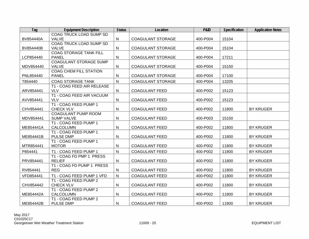
May 2017 C01025C17 Georgetown Wet Weather Treatment Station 11009 - 20 EQUIPMENT LIST
Tag Equipment Description Status Location P&ID Specification Application Notes
BV854440A COAG TRUCK LOAD SUMP SD VALVE N COAGULANT STORAGE 400-P004 15104
BV854440B COAG TRUCK LOAD SUMP SD VALVE N COAGULANT STORAGE 400-P004 15104
LCP854440 COAG STORAGE TANK FILL PANEL N COAGULANT STORAGE 400-P004 17211
MDV854440 COAGULANT STORAGE SUMP VALVE N COAGULANT STORAGE 400-P004 15150
PNL854440 COAG CHEM FILL STATION PANEL N COAGULANT STORAGE 400-P004 17100
T854440 COAG STORAGE TANK N COAGULANT STORAGE 400-P004 13205
ARV854441 T1 - COAG FEED AIR RELEASE VLV N COAGULANT FEED 400-P002 15123
AVV854441 T1 - COAG FEED AIR VACUUM VLV N COAGULANT FEED 400-P002 15123
CHV854441 T1 - COAG FEED PUMP 1 CHECK VLV N COAGULANT FEED 400-P002 11800 BY KRUGER
MDV854441 COAGULANT PUMP ROOM SUMP VALVE N COAGULANT FEED 400-P003 15150
ME854441A T1 - COAG FEED PUMP 1 CALCOLUMN N COAGULANT FEED 400-P002 11800 BY KRUGER
ME854441B T1 - COAG FEED PUMP 1 PULSE DMP N COAGULANT FEED 400-P002 11800 BY KRUGER
MTR854441 T1 - COAG FEED PUMP 1 MOTOR N COAGULANT FEED 400-P002 11800 BY KRUGER
P854441 T1 - COAG FEED PUMP 1 N COAGULANT FEED 400-P002 11800 BY KRUGER
PRV854441 T1 - COAG FD PMP 1 PRESS RELIEF N COAGULANT FEED 400-P002 11800 BY KRUGER
RV854441 T1 - COAG FD PUMP 1 PRESS REG N COAGULANT FEED 400-P002 11800 BY KRUGER
VFD854441 T1 - COAG FEED PUMP 1 VFD N COAGULANT FEED 400-P002 11800 BY KRUGER
CHV854442 T1 - COAG FEED PUMP 2 CHECK VLV N COAGULANT FEED 400-P002 11800 BY KRUGER
ME854442A T1 - COAG FEED PUMP 2 CALCOLUMN N COAGULANT FEED 400-P002 11800 BY KRUGER
ME854442B T1 - COAG FEED PUMP 2 PULSE DMP N COAGULANT FEED 400-P002 11800 BY KRUGER
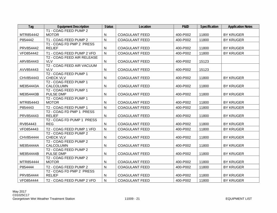
May 2017 C01025C17 Georgetown Wet Weather Treatment Station 11009 - 21 EQUIPMENT LIST
Tag Equipment Description Status Location P&ID Specification Application Notes
MTR854442 T1 - COAG FEED PUMP 2 MOTOR N COAGULANT FEED 400-P002 11800 BY KRUGER
P854442 T1 - COAG FEED PUMP 2 N COAGULANT FEED 400-P002 11800 BY KRUGER
PRV854442 T1 - COAG FD PMP 2 PRESS RELIEF N COAGULANT FEED 400-P002 11800 BY KRUGER
VFD854442 T1 - COAG FEED PUMP 2 VFD N COAGULANT FEED 400-P002 11800 BY KRUGER
ARV854443 T2 - COAG FEED AIR RELEASE VLV N COAGULANT FEED 400-P002 15123
AVV854443 T2 - COAG FEED AIR VACUUM VLV N COAGULANT FEED 400-P002 15123
CHV854443 T2 - COAG FEED PUMP 1 CHECK VLV N COAGULANT FEED 400-P002 11800 BY KRUGER
ME854443A T2 - COAG FEED PUMP 1 CALCOLUMN N COAGULANT FEED 400-P002 11800 BY KRUGER
ME854443B T2 - COAG FEED PUMP 1 PULSE DMP N COAGULANT FEED 400-P002 11800 BY KRUGER
MTR854443 T2 - COAG FEED PUMP 1 MOTOR N COAGULANT FEED 400-P002 11800 BY KRUGER
P854443 T2 - COAG FEED PUMP 1 N COAGULANT FEED 400-P002 11800 BY KRUGER
PRV854443 T2 - COAG FD PMP 1 PRESS RELIEF N COAGULANT FEED 400-P002 11800 BY KRUGER
RV854443 T2 - COAG FD PUMP 1 PRESS REG N COAGULANT FEED 400-P002 11800 BY KRUGER
VFD854443 T2 - COAG FEED PUMP 1 VFD N COAGULANT FEED 400-P002 11800 BY KRUGER
CHV854444 T2 - COAG FEED PUMP 2 CHECK VLV N COAGULANT FEED 400-P002 11800 BY KRUGER
ME854444A T2 - COAG FEED PUMP 2 CALCOLUMN N COAGULANT FEED 400-P002 11800 BY KRUGER
ME854444B T2 - COAG FEED PUMP 2 PULSE DMP N COAGULANT FEED 400-P002 11800 BY KRUGER
MTR854444 T2 - COAG FEED PUMP 2 MOTOR N COAGULANT FEED 400-P002 11800 BY KRUGER
P854444 T2 - COAG FEED PUMP 2 N COAGULANT FEED 400-P002 11800 BY KRUGER
PRV854444 T2 - COAG FD PMP 2 PRESS RELIEF N COAGULANT FEED 400-P002 11800 BY KRUGER
VFD854444 T2 - COAG FEED PUMP 2 VFD N COAGULANT FEED 400-P002 11800 BY KRUGER

May 2017 C01025C17 Georgetown Wet Weather Treatment Station 11009 - 22 EQUIPMENT LIST
Tag Equipment Description Status Location P&ID Specification Application Notes
SFT854445 COAG FEED ROOM SAFETY SHOWER N COAGULANT FEED 400-P008 15442
SFT854446 COAG FILL STATION SAFETY SHOWER N COAGULANT FEED 400-P008 15442
SFT854447 COAG STORAGE SAFETY SHOWER N COAGULANT FEED 400-P008 15442
BV854450A CAUST TRUCK LOAD SUMP SD VALVE N CAUSTIC STORAGE 400-P005 15104
BV854450B CAUST TRUCK LOAD SUMP SD VALVE N CAUSTIC STORAGE 400-P005 15104
LCP854450 CAUSTIC STORAGE TANK FILL PANEL N CAUSTIC STORAGE 400-P005 17111
MDV854450 CAUSTIC STORAGE SUMP VALVE N CAUSTIC STORAGE 400-P005 15150
PNL854450 CAUSTIC CHEM FILL STATION PANEL N CAUSTIC STORAGE 400-P005 17100
T854450 CAUSTIC STORAGE TANK N CAUSTIC STORAGE 400-P005 13205
ARV854451 T1 - CAUST FEED AIR RELEASE VLV N CAUSTIC FEED 400-P001 15123
AVV854451 T1 - CAUST FEED AIR VACUUM VLV N CAUSTIC FEED 400-P001 15123
LCS854451 T1- CAUS FEED PUMP 1 LCS N CAUSTIC FEED 400-P006 11800 BY KRUGER
MDV854451 CAUSTIC PUMP ROOM SUMP VALVE N CAUSTIC FEED 400-P003 15150
ME854451A T1 - CAUSTIC FEED PMPS CAL COL N CAUSTIC FEED 400-P006 11801 BY KRUGER
ME854451B T1 - CAUS FEED PMP 1 PULSE DAMP N CAUSTIC FEED 400-P006 11801 BY KRUGER
ME854451C T1 - CAUST FEED PMP STRAINER N CAUSTIC FEED 400-P006 11801
MTR854451 T1 - CAUSTIC FEED PMP 1 MOTOR N CAUSTIC FEED 400-P006 11801 BY KRUGER
P854451 T1 - CAUSTIC FEED PMP 1 N CAUSTIC FEED 400-P006 11801 BY KRUGER
PRV854451 T1 - CAUS FD PMP 1 PRESS RELIEF N CAUSTIC FEED 400-P006 11800 BY KRUGER
RV854451A T1 - CAUS FD PMPS PRESS REGLTR N CAUSTIC FEED 400-P006 11800 BY KRUGER
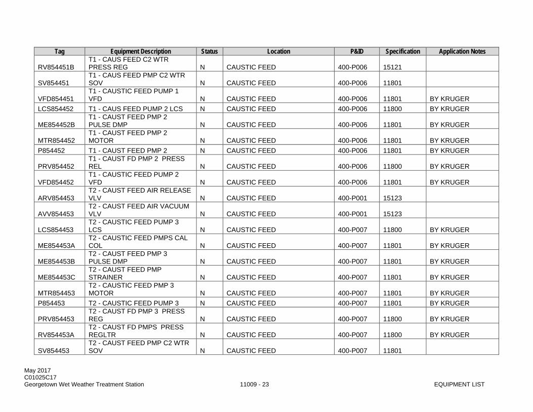
May 2017 C01025C17 Georgetown Wet Weather Treatment Station 11009 - 23 EQUIPMENT LIST
Tag Equipment Description Status Location P&ID Specification Application Notes
RV854451B T1 - CAUS FEED C2 WTR PRESS REG N CAUSTIC FEED 400-P006 15121
SV854451 T1 - CAUS FEED PMP C2 WTR SOV N CAUSTIC FEED 400-P006 11801
VFD854451 T1 - CAUSTIC FEED PUMP 1 VFD N CAUSTIC FEED 400-P006 11801 BY KRUGER
LCS854452 T1 - CAUS FEED PUMP 2 LCS N CAUSTIC FEED 400-P006 11800 BY KRUGER
ME854452B T1 - CAUST FEED PMP 2 PULSE DMP N CAUSTIC FEED 400-P006 11801 BY KRUGER
MTR854452 T1 - CAUST FEED PMP 2 MOTOR N CAUSTIC FEED 400-P006 11801 BY KRUGER
P854452 T1 - CAUST FEED PMP 2 N CAUSTIC FEED 400-P006 11801 BY KRUGER
PRV854452 T1 - CAUST FD PMP 2 PRESS REL N CAUSTIC FEED 400-P006 11800 BY KRUGER
VFD854452 T1 - CAUSTIC FEED PUMP 2 VFD N CAUSTIC FEED 400-P006 11801 BY KRUGER
ARV854453 T2 - CAUST FEED AIR RELEASE VLV N CAUSTIC FEED 400-P001 15123
AVV854453 T2 - CAUST FEED AIR VACUUM VLV N CAUSTIC FEED 400-P001 15123
LCS854453 T2 - CAUSTIC FEED PUMP 3 LCS N CAUSTIC FEED 400-P007 11800 BY KRUGER
ME854453A T2 - CAUSTIC FEED PMPS CAL COL N CAUSTIC FEED 400-P007 11801 BY KRUGER
ME854453B T2 - CAUST FEED PMP 3 PULSE DMP N CAUSTIC FEED 400-P007 11801 BY KRUGER
ME854453C T2 - CAUST FEED PMP STRAINER N CAUSTIC FEED 400-P007 11801 BY KRUGER
MTR854453 T2 - CAUSTIC FEED PMP 3 MOTOR N CAUSTIC FEED 400-P007 11801 BY KRUGER
P854453 T2 - CAUSTIC FEED PUMP 3 N CAUSTIC FEED 400-P007 11801 BY KRUGER
PRV854453 T2 - CAUST FD PMP 3 PRESS REG N CAUSTIC FEED 400-P007 11800 BY KRUGER
RV854453A T2 - CAUST FD PMPS PRESS REGLTR N CAUSTIC FEED 400-P007 11800 BY KRUGER
SV854453 T2 - CAUST FEED PMP C2 WTR SOV N CAUSTIC FEED 400-P007 11801

May 2017 C01025C17 Georgetown Wet Weather Treatment Station 11009 - 24 EQUIPMENT LIST
Tag Equipment Description Status Location P&ID Specification Application Notes
VFD854453 T2 - CAUSTIC FEED PUMP 3 VFD N CAUSTIC FEED 400-P007 11801 BY KRUGER
LCS854454 T2 - CAUSTIC FEED PUMP 4 LCS N CAUSTIC FEED 400-P007 11800 BY KRUGER
ME854454B T2 - CAUST FEED PMP 4 PULSE DMP N CAUSTIC FEED 400-P007 11801 BY KRUGER
MTR854454 T2 - CAUSTIC FEED PMP 4 MOTOR N CAUSTIC FEED 400-P007 11801 BY KRUGER
P854454 T2 - CAUSTIC FEED PMP 4 N CAUSTIC FEED 400-P007 11801 BY KRUGER
PRV854454 T2 - CAUSTIC FD PMP 4 PRESS REG N CAUSTIC FEED 400-P007 11800 BY KRUGER
VFD854454 T2 - CAUSTIC FEED PUMP 4 VFD N CAUSTIC FEED 400-P007 11801 BY KRUGER
SFT854455 CAUST FEED ROOM SAFETY SHOWER N CAUSTIC FEED 400-P008 15442
SFT854456 CAUST FILL STA SAFETY SHOWER N CAUSTIC FEED 400-P008 15442
SFT854457 CAUST STORAGE SAFETY SHOWER N CAUSTIC FEED 400-P008 15442
C854471 BALL SED / UV BRIDGE CRANE N BALLASTED SEDIMENTATION --- 14360
FLT854474 EAST POLY ROOM SUPPLY FILTER N BALLASTED SEDIMENTATION 400-P009 15880
LVR854474 EAST POLY ROOM SUPPLY LOUVER N BALLASTED SEDIMENTATION 400-P009 10200
MY854474 EAST POLY ROOM SUPPLY FAN M/S N BALLASTED SEDIMENTATION 400-P009 16920
SF854474 EAST POLY ROOM SUPPLY FAN N BALLASTED SEDIMENTATION 400-P009 15859 TST854474 POLY ROOM THERMOSTAT N BALLASTED SEDIMENTATION 400-P009 15901 HVAC SUPPLIER UH854474A POLY ROOM UNIT HEATER N BALLASTED SEDIMENTATION 400-P009 15632 UH854474B POLY ROOM UNIT HEATER N BALLASTED SEDIMENTATION 400-P009 15632
EF854475 WEST POLY ROOM EXHAUST FAN N BALLASTED SEDIMENTATION 400-P009 15859
LVR854475 WEST POLY ROOM EXHAUST LOUVER N BALLASTED SEDIMENTATION 400-P009 10200
MY854475 WEST POLY ROOM EXHAUST FAN M/S N BALLASTED SEDIMENTATION 400-P009 16920
FLT854476 CAUST ROOM SUPPLY FILTER N BALLASTED SEDIMENTATION 400-P010 15880

May 2017 C01025C17 Georgetown Wet Weather Treatment Station 11009 - 25 EQUIPMENT LIST
Tag Equipment Description Status Location P&ID Specification Application Notes LVR854476 CAUST ROOM SUPPLY LOUVER N BALLASTED SEDIMENTATION 400-P010 10200
MY854476 CAUSTIC ROOM SUPPLY FAN M/S N BALLASTED SEDIMENTATION 400-P010 16920
SF854476 CAUST ROOM SUPPLY FAN N BALLASTED SEDIMENTATION 400-P010 15859 TST854476 CAUST ROOM THERMOSTAT N BALLASTED SEDIMENTATION 400-P010 15901 HVAC SUPPLIER UH854476 CAUST ROOM UNIT HEATER N BALLASTED SEDIMENTATION 400-P010 15632 EF854477 CAUST ROOM EXHAUST FAN N BALLASTED SEDIMENTATION 400-P010 15859
LVR854477 CAUST ROOM EXHAUST LOUVER N BALLASTED SEDIMENTATION 400-P010 10200
MY854477 CAUSTIC ROOM EXHAUST FAN M/S N BALLASTED SEDIMENTATION 400-P010 16920
SFT854501 UV PUMP ROOM SAFETY SHOWER N UV PUMP ROOM 500-P015 15442
SFT854502 UV DECK SAFETY SHOWER N UV DISINFECTION 500-P015 15442
BV854504 UV CHEM CLEANING TNK DRAIN VALVE N UV DISINFECTION 500-P003 15104
PNL854504 UV CHEMICAL CLEANING TANK PANEL N UV DISINFECTION 500-P003 11301 BY OZONIA
RV854504 UV CLEANING TANK AIR PRESS REG N UV DISINFECTION 500-P019 15121
T854504 UV CHEMICAL CLEANING TANK N UV DISINFECTION 500-P003 11301 BY OZONIA
CHV854505 EFFLUENT SUMP PUMP 1 CHECK VLV N UV DISINFECTION 500-P010 15110
LCS854505 EFFLUENT SUMP 1 LOCAL CTRL STA N UV DISINFECTION 500-P010 16176
MY854505 EFFLUENT SUMP PUMP 1 MTR STARTER N UV DISINFECTION 500-P010 16920
P854505 EFFLUENT SUMP PUMP 1 N UV DISINFECTION 500-P010 11347
PLV854505 EFFLUENT SUMP PUMP 1 OUTLET VLV N UV DISINFECTION 500-P010 15107
PNL854505 EFFLUENT SUMP 1 BUBBLER PANEL N UV DISINFECTION 500-P010 17211
PNL854510 T1 - UV DISINFECTION CONTROL PNL N UV DISINFECTION 500-P002 11301 BY OZONIA
PWR854511 T1 - UV POWER SUPPLY UNIT 1 N UV DISINFECTION 500-P002 11301 BY OZONIA

May 2017 C01025C17 Georgetown Wet Weather Treatment Station 11009 - 26 EQUIPMENT LIST
Tag Equipment Description Status Location P&ID Specification Application Notes
TFR854511 T1 - UV PWR SUPPLY UNIT 1 XFMR N UV DISINFECTION --- 16460
UV854511A T1 - UV LAMP BANK 1 N UV DISINFECTION 500-P002 11301 BY OZONIA UV854511B T1 - UV LAMP BANK 2 N UV DISINFECTION 500-P002 11301 BY OZONIA PWR854512 T1 - UV POWER SUPPLY UNIT 2 N UV DISINFECTION 500-P002 11301 BY OZONIA
TFR854512 T1 - UV PWR SUPPLY UNIT 2 XFMR N UV DISINFECTION --- 16460
UV854512A T1 - UV LAMP BANK 3 N UV DISINFECTION 500-P002 11301 BY OZONIA UV854512B T1 - UV LAMP BANK 4 N UV DISINFECTION 500-P002 11301 BY OZONIA PWR854513 T1 - UV POWER SUPPLY UNIT 3 F UV DISINFECTION 500-P002 11301 BY OZONIA
TFR854513 T1 - UV PWR SUPPLY UNIT 3 XFMR F UV DISINFECTION --- 16460
UV854513A T1 - UV LAMP BANK 5 F UV DISINFECTION 500-P002 11301 BY OZONIA BV854515 T1 - UV DRAIN VALVE N UV DISINFECTION 500-P002 15104 ME854515 T1 - UV EFFLUENT LAUNDER N UV DISINFECTION 500-P002 11301 BY OZONIA
PNL854517 C3 STORAGE TANK BUBBLER PANEL N UV DISINFECTION 500-P006 17211
SLG854517 C3 STORAGE TANK DRAIN GATE N UV DISINFECTION 500-P006 11101
ACT854518 T1 - EFFLUENT GATE ACT N UV PUMP ROOM 500-P009 15140
BV854518A UV PUMP ROOM EFF PIPE DRAIN VLV N UV PUMP ROOM 500-P009 15104
BV854518B UV PUMP ROOM EFF PIPE DRAIN VLV N UV PUMP ROOM 500-P009 15104
PNL854518 T1 - EFFLUENT GATE PANEL N UV PUMP ROOM 500-P009 15140
SLG854518 T1 - EFFLUENT ISOLATION GATE N UV PUMP ROOM 500-P009 11101
ACT854519 T1 - C3 RECIRCULATION VALVE ACT N UV PUMP ROOM 500-P008 15140
BTV854519 T1 - C3 RECIRCULATION VALVE N UV PUMP ROOM 500-P008 15103
DS854519 T1 - C3 RECIRCULATION VALVE DISC N UV PUMP ROOM --- 16175
PNL854520 T2 - UV DISINFECTION CONTROL PNL N UV DISINFECTION 500-P003 11301 BY OZONIA
PWR854521 T2 - UV POWER SUPPLY UNIT 1 N UV DISINFECTION 500-P003 11301 BY OZONIA
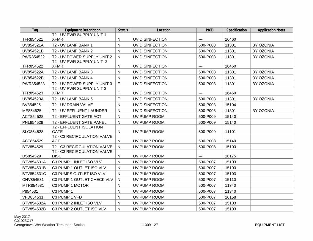
May 2017 C01025C17 Georgetown Wet Weather Treatment Station 11009 - 27 EQUIPMENT LIST
Tag Equipment Description Status Location P&ID Specification Application Notes
TFR854521 T2 - UV PWR SUPPLY UNIT 1 XFMR N UV DISINFECTION --- 16460
UV854521A T2 - UV LAMP BANK 1 N UV DISINFECTION 500-P003 11301 BY OZONIA UV854521B T2 - UV LAMP BANK 2 N UV DISINFECTION 500-P003 11301 BY OZONIA PWR854522 T2 - UV POWER SUPPLY UNIT 2 N UV DISINFECTION 500-P003 11301 BY OZONIA
TFR854522 T2 - UV PWR SUPPLY UNIT 2 XFMR N UV DISINFECTION --- 16460
UV854522A T2 - UV LAMP BANK 3 N UV DISINFECTION 500-P003 11301 BY OZONIA UV854522B T2 - UV LAMP BANK 4 N UV DISINFECTION 500-P003 11301 BY OZONIA PWR854523 T2 - UV POWER SUPPLY UNIT 3 F UV DISINFECTION 500-P003 11301 BY OZONIA
TFR854523 T2 - UV PWR SUPPLY UNIT 3 XFMR F UV DISINFECTION --- 16460
UV854523A T2 - UV LAMP BANK 5 F UV DISINFECTION 500-P003 11301 BY OZONIA BV854525 T2 - UV DRAIN VALVE N UV DISINFECTION 500-P003 15104 ME854525 T2 - UV EFFLUENT LAUNDER N UV DISINFECTION 500-P003 11301 BY OZONIA ACT854528 T2 - EFFLUENT GATE ACT N UV PUMP ROOM 500-P009 15140 PNL854528 T2 - EFFLUENT GATE PANEL N UV PUMP ROOM 500-P009 15140
SLG854528 T2 - EFFLUENT ISOLATION GATE N UV PUMP ROOM 500-P009 11101
ACT854529 T2 - C3 RECIRCULATION VALVE ACT N UV PUMP ROOM 500-P008 15140
BTV854529 T2 - C3 RECIRCULATION VALVE N UV PUMP ROOM 500-P008 15103
DS854529 T2 - C3 RECIRCULATION VALVE DISC N UV PUMP ROOM --- 16175
BTV854531A C3 PUMP 1 INLET ISO VLV N UV PUMP ROOM 500-P007 15103 BTV854531B C3 PUMP 1 OUTLET ISO VLV N UV PUMP ROOM 500-P007 15103 BTV854531C C3 PUMPS OUTLET ISO VLV N UV PUMP ROOM 500-P007 15103 CHV854531 C3 PUMP 1 OUTLET CHECK VLV N UV PUMP ROOM 500-P007 15110 MTR854531 C3 PUMP 1 MOTOR N UV PUMP ROOM 500-P007 11340 P854531 C3 PUMP 1 N UV PUMP ROOM 500-P007 11340 VFD854531 C3 PUMP 1 VFD N UV PUMP ROOM 500-P007 16158 BTV854532A C3 PUMP 2 INLET ISO VLV N UV PUMP ROOM 500-P007 15103 BTV854532B C3 PUMP 2 OUTLET ISO VLV N UV PUMP ROOM 500-P007 15103
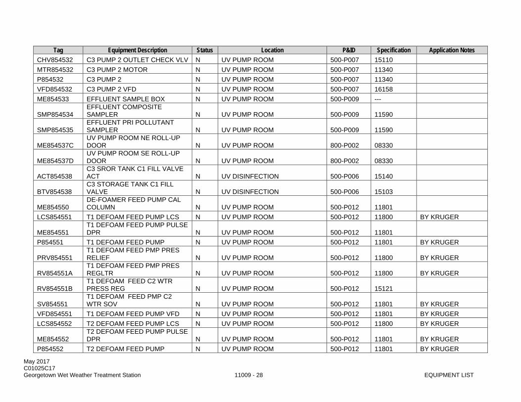
May 2017 C01025C17 Georgetown Wet Weather Treatment Station 11009 - 28 EQUIPMENT LIST
Tag Equipment Description Status Location P&ID Specification Application Notes CHV854532 C3 PUMP 2 OUTLET CHECK VLV N UV PUMP ROOM 500-P007 15110 MTR854532 C3 PUMP 2 MOTOR N UV PUMP ROOM 500-P007 11340 P854532 C3 PUMP 2 N UV PUMP ROOM 500-P007 11340 VFD854532 C3 PUMP 2 VFD N UV PUMP ROOM 500-P007 16158 ME854533 EFFLUENT SAMPLE BOX N UV PUMP ROOM 500-P009 ---
SMP854534 EFFLUENT COMPOSITE SAMPLER N UV PUMP ROOM 500-P009 11590
SMP854535 EFFLUENT PRI POLLUTANT SAMPLER N UV PUMP ROOM 500-P009 11590
ME854537C UV PUMP ROOM NE ROLL-UP DOOR N UV PUMP ROOM 800-P002 08330
ME854537D UV PUMP ROOM SE ROLL-UP DOOR N UV PUMP ROOM 800-P002 08330
ACT854538 C3 SROR TANK C1 FILL VALVE ACT N UV DISINFECTION 500-P006 15140
BTV854538 C3 STORAGE TANK C1 FILL VALVE N UV DISINFECTION 500-P006 15103
ME854550 DE-FOAMER FEED PUMP CAL COLUMN N UV PUMP ROOM 500-P012 11801
LCS854551 T1 DEFOAM FEED PUMP LCS N UV PUMP ROOM 500-P012 11800 BY KRUGER
ME854551 T1 DEFOAM FEED PUMP PULSE DPR N UV PUMP ROOM 500-P012 11801
P854551 T1 DEFOAM FEED PUMP N UV PUMP ROOM 500-P012 11801 BY KRUGER
PRV854551 T1 DEFOAM FEED PMP PRES RELIEF N UV PUMP ROOM 500-P012 11800 BY KRUGER
RV854551A T1 DEFOAM FEED PMP PRES REGLTR N UV PUMP ROOM 500-P012 11800 BY KRUGER
RV854551B T1 DEFOAM FEED C2 WTR PRESS REG N UV PUMP ROOM 500-P012 15121
SV854551 T1 DEFOAM FEED PMP C2 WTR SOV N UV PUMP ROOM 500-P012 11801 BY KRUGER
VFD854551 T1 DEFOAM FEED PUMP VFD N UV PUMP ROOM 500-P012 11801 BY KRUGER LCS854552 T2 DEFOAM FEED PUMP LCS N UV PUMP ROOM 500-P012 11800 BY KRUGER
ME854552 T2 DEFOAM FEED PUMP PULSE DPR N UV PUMP ROOM 500-P012 11801 BY KRUGER
P854552 T2 DEFOAM FEED PUMP N UV PUMP ROOM 500-P012 11801 BY KRUGER

May 2017 C01025C17 Georgetown Wet Weather Treatment Station 11009 - 29 EQUIPMENT LIST
Tag Equipment Description Status Location P&ID Specification Application Notes
PRV854552 T2 DEFOAM FEED PMP PRES RELIEF N UV PUMP ROOM 500-P012 11800 BY KRUGER
RV854552 T2 DEFOAM FEED PMP PRES REGLTR N UV PUMP ROOM 500-P012 11800 BY KRUGER
SV854552 T2 DEFOAM FEED PMP C2 WTR SOV N UV PUMP ROOM 500-P012 11801 BY KRUGER
VFD854552 T2 DEFOAM FEED PUMP VFD N UV PUMP ROOM 500-P012 11801 BY KRUGER
RV854560 UV CLEANING STATION PRESS REG N UV DISINFECTION 500-P018 15121
AD854561 INST AIR DRYER N UV PUMP ROOM 500-P013 11366 CPR854561 INST AIR COMPRESSOR 1 N UV PUMP ROOM 500-P013 11366 DT854561A INST AIR DRAIN TRAP 1 N UV PUMP ROOM 500-P013 11366 DT854561B INST AIR DRAIN TRAP 2 N UV PUMP ROOM 500-P013 11366 DT854561C INST AIR DRAIN TRAP 3 N UV PUMP ROOM 500-P013 11366 FLT854561A INST AIR FILTER N UV PUMP ROOM 500-P013 11366 FLT854561B INSTRUMENT AIR FILTER N UV PUMP ROOM 500-P013 11366
LCS854561 INSTRUMENT AIR COMPRESSOR 1 LCS N UV PUMP ROOM 500-P013 16176
MY854561 INST AIR CPR 1 MOTOR STARTER N UV PUMP ROOM 500-P013 16920
PNL854561 INSTRUMENT AIR CONTROL PANEL N UV PUMP ROOM 500-P013 11366
PVL854561 INSTRUMENT AIR RECEIVER N UV PUMP ROOM 500-P013 11376 CPR854562 INST AIR COMPRESSOR 2 N UV PUMP ROOM 500-P013 11366
LCS854562 INSTRUMENT AIR COMPRESSOR 2 LCS N UV PUMP ROOM 500-P013 16176
MY854562 INST AIR CPR 2 MOTOR STARTER N UV PUMP ROOM 500-P013 16920
RV854562 INSTRUMENT AIR PRESS REGLTR N UV PUMP ROOM 500-P013 15121
RV854563 INSTRUMENT AIR PRESS REGLTR N UV PUMP ROOM 500-P013 15121
RV854564 INSTRUMENT AIR PRESS REGLTR N UV PUMP ROOM 500-P013 15121
RV854565 INSTRUMENT AIR PRESS REGLTR N UV PUMP ROOM 500-P013 15121

May 2017 C01025C17 Georgetown Wet Weather Treatment Station 11009 - 30 EQUIPMENT LIST
Tag Equipment Description Status Location P&ID Specification Application Notes CPR854566 SERVICE AIR COMPRESSOR 1 N UV PUMP ROOM 500-P014 11367
DT854566 SERV AIR RECVR 1 DRAIN TRAP N UV PUMP ROOM 500-P014 11367
LCS854566 SERVICE AIR COMPRESSOR 1 LCS N UV PUMP ROOM 500-P014 16176
MY854566 SERVICE AIR COMPRESSOR 1 M/S N UV PUMP ROOM 500-P014 16920
PRV854566 SERV AIR RECIEVER 1 PRV N UV PUMP ROOM 500-P014 11367 PVL854566 SERV AIR RECEIVER 1 N UV PUMP ROOM 500-P014 11367
RV854566 SERV AIR SYS C2 WTR PRESS REG N UV PUMP ROOM 500-P014 15121
CPR854567 SERV AIR COMPRESSOR 2 N UV PUMP ROOM 500-P014 11367
DT854567 SERV AIR RECVR 2 DRAIN TRAP N UV PUMP ROOM 500-P014 11367
LCS854567 SERVICE AIR COMPRESSOR 2 LCS N UV PUMP ROOM 500-P014 16176
MY854567 SERVICE AIR COMPRESSOR 2 M/S N UV PUMP ROOM 500-P014 16920
PRV854567 SERV AIR RECVR 2 PRV N UV PUMP ROOM 500-P014 11367 PVL854567 SERV AIR RECIEVER 2 N UV PUMP ROOM 500-P014 11367 AD854568 SERVICE AIR DRYER N UV PUMP ROOM 500-P019 11367 DT854568A SERVICE AIR DRAIN TRAP 1 N UV PUMP ROOM 500-P019 11367 DT854568B SERVICE AIR DRAIN TRAP 2 N UV PUMP ROOM 500-P019 11367 FLT854568 SERVICE AIR FILTER N UV PUMP ROOM 500-P019 15880
RV854568 SERVICE AIR TO I/A PRESS REG N UV PUMP ROOM 500-P019 15121
MY854569 HOT WTR SYSTEM CIRC PUMP M/S N UV DISINFECTION 500-P015 16920
P854569 HOT WTR SYSTEM CIRC PUMP N UV DISINFECTION 500-P015 15440 HOT WATER SUPPLIER
PRV854569 HOT WTR SYS PRESS RELIEF VLV N UV DISINFECTION 500-P015 15123
HOT WATER SUPPLIER
T854569 HOT WTR SYSTEM EXPANSION TANK N UV DISINFECTION 500-P015 15440
HOT WATER SUPPLIER
TMV854569 HOT WTR SYSTEM MIXING VALVE N UV DISINFECTION 500-P015 15440
HOT WATER SUPPLIER
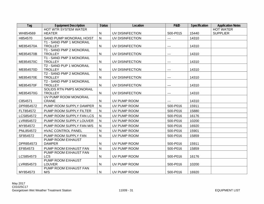
May 2017 C01025C17 Georgetown Wet Weather Treatment Station 11009 - 31 EQUIPMENT LIST
Tag Equipment Description Status Location P&ID Specification Application Notes
WH854569 HOT WTR SYSTEM WATER HEATER N UV DISINFECTION 500-P015 15440
HOT WATER SUPPLIER
H854570 SAND PUMP MONORAIL HOIST N UV DISINFECTION --- 14310
ME854570A T1 - SAND PMP 1 MONORAIL TROLLEY N UV DISINFECTION --- 14310
ME854570B T1 - SAND PMP 2 MONORAIL TROLLEY N UV DISINFECTION --- 14310
ME854570C T1 - SAND PMP 3 MONORAIL TROLLEY N UV DISINFECTION --- 14310
ME854570D T2 - SAND PUP 1 MONORAIL TROLLEY N UV DISINFECTION --- 14310
ME854570E T2 - SAND PMP 2 MONORAIL TROLLEY N UV DISINFECTION --- 14310
ME854570F T2 - SAND PMP 3 MONORAIL TROLLEY N UV DISINFECTION --- 14310
ME854570G SOLIDS RTN PMPS MONORAIL TROLLEY N UV DISINFECTION --- 14310
C854571 UV PUMP ROOM MONORAIL CRANE N UV PUMP ROOM --- 14310
DPR854572 PUMP ROOM SUPPLY DAMPER N UV PUMP ROOM 500-P016 15911 FLT854572 PUMP ROOM SUPPLY FILTER N UV PUMP ROOM 500-P016 15880 LCS854572 PUMP ROOM SUPPLY FAN LCS N UV PUMP ROOM 500-P016 16176 LVR854572 PUMP ROOM SUPPLY LOUVER N UV PUMP ROOM 500-P016 10200 MY854572 PUMP ROOM SUPPLY FAN M/S N UV PUMP ROOM 500-P016 16920 PNL854572 HVAC CONTROL PANEL N UV PUMP ROOM 500-P016 15901 SF854572 PUMP ROOM SUPPLY FAN N UV PUMP ROOM 500-P016 15859
DPR854573 PUMP ROOM EXHAUST DAMPER N UV PUMP ROOM 500-P016 15911
EF854573 PUMP ROOM EXHAUST FAN N UV PUMP ROOM 500-P016 15859
LCS854573 PUMP ROOM EXHAUST FAN LCS N UV PUMP ROOM 500-P016 16176
LVR854573 PUMP ROOM EXHAUST LOUVER N UV PUMP ROOM 500-P016 10200
MY854573 PUMP ROOM EXHAUST FAN M/S N UV PUMP ROOM 500-P016 16920

May 2017 C01025C17 Georgetown Wet Weather Treatment Station 11009 - 32 EQUIPMENT LIST
Tag Equipment Description Status Location P&ID Specification Application Notes
RV854574 PUMP ROOM NAT GAS PRESS REG N UV PUMP ROOM 500-P017 15121
TST854574 UV PUMP ROOM THERMOSTAT 1 N UV PUMP ROOM 500-P017 15901 HVAC SUPPLIER
UH854574 UV PUMP ROOM UNIT HEATER 1 N UV PUMP ROOM 500-P017 15633
UH854575 UV PUMP ROOM UNIT HEATER 2 N UV PUMP ROOM 500-P017 15633
PNL854601 SOLIDS HOLDING TANK BUBBLER PNL N SOLIDS HOLDING TANK 600-P001 17211
CHV854611 SOLIDS RETURN PMP 1 CHECK VLV N UV PUMP ROOM 600-P003 15110
LCS854611A SOLIDS RETURN PMP 1 LCS N UV PUMP ROOM 600-P003 16176 LCS854611B SOLIDS RETURN PMPS LCS N UV PUMP ROOM 600-P003 16176 MTR854611 SOLIDS RETURN PMP 1 MOTOR N UV PUMP ROOM 600-P003 11074 MY854611 SOLIDS RETURN PMP 1 MS N UV PUMP ROOM 600-P003 16920 P854611 SOLIDS RETURN PUMP 1 N UV PUMP ROOM 600-P003 11074
PLV854611A SOLIDS RTN PMP 1 INLET ISO VLV N UV PUMP ROOM 600-P003 15107
PLV854611B SOLIDS RTN PMP 1 OUTLET ISO VLV N UV PUMP ROOM 600-P003 15107
CHV854612 SOLIDS RTN PMP 2 CHECK VLV N UV PUMP ROOM 600-P003 15110 LCS854612 SOLIDS RETURN PMP 2 LCS N UV PUMP ROOM 600-P003 16176 MTR854612 SOLIDS RETURN PMP 2 MOTOR N UV PUMP ROOM 600-P003 11074 MY854612 SOLIDS RETURN PMP 2 MS N UV PUMP ROOM 600-P003 16920 P854612 SOLIDS RETURN PUMP 2 N UV PUMP ROOM 600-P003 11074
PLV854612A SOLIDS RTN PMP 2 INLET ISO VLV N UV PUMP ROOM 600-P003 15107
PLV854612B SOLIDS RTN PMP 2 OUTLET ISO VLV N UV PUMP ROOM 600-P003 15107
PLV854613A SOLIDS RETURN TO EBI VALVE N UV PUMP ROOM 600-P003 15107
PLV854613B SOLIDS RETURN TO TRUCK VALVE N UV PUMP ROOM 600-P003 15107
PLV854613C SOLIDS RTN PUMPS BYPASS VLV N UV PUMP ROOM 600-P003 15107
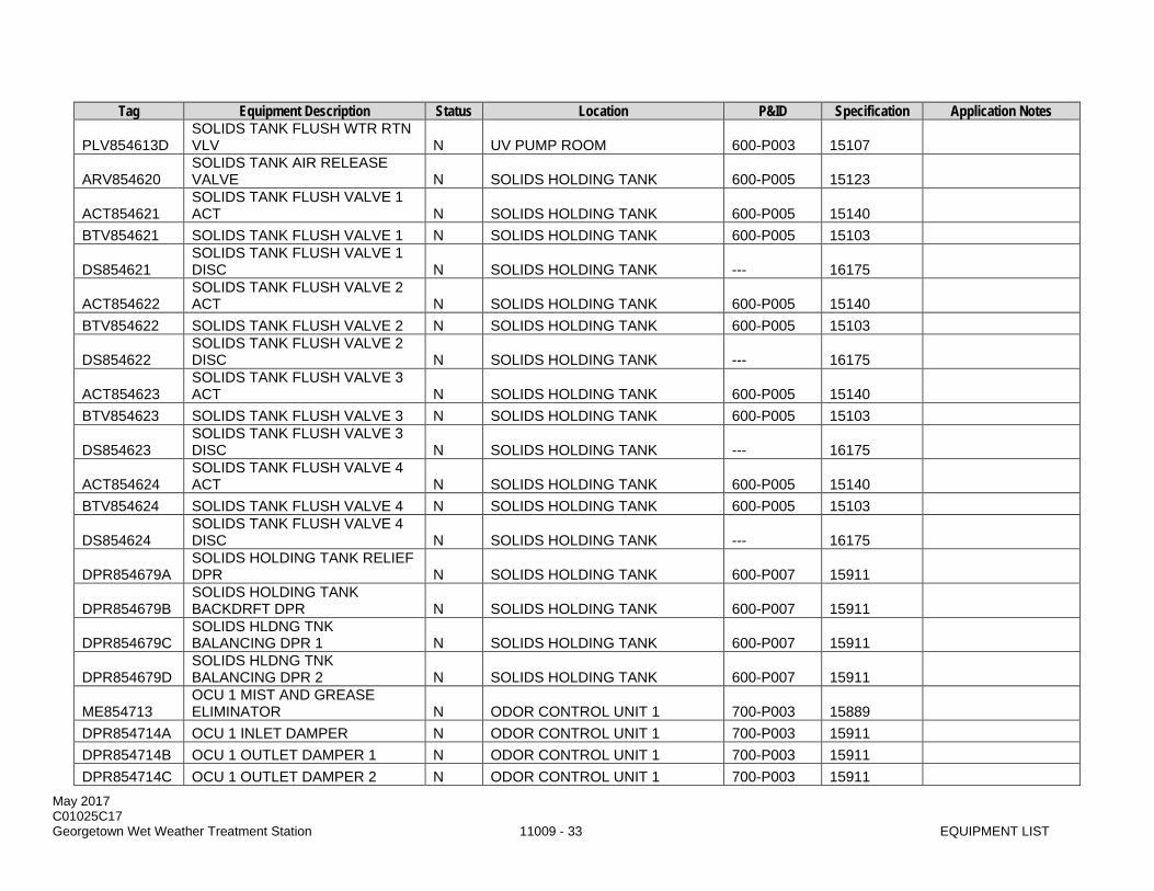
May 2017 C01025C17 Georgetown Wet Weather Treatment Station 11009 - 33 EQUIPMENT LIST
Tag Equipment Description Status Location P&ID Specification Application Notes
PLV854613D SOLIDS TANK FLUSH WTR RTN VLV N UV PUMP ROOM 600-P003 15107
ARV854620 SOLIDS TANK AIR RELEASE VALVE N SOLIDS HOLDING TANK 600-P005 15123
ACT854621 SOLIDS TANK FLUSH VALVE 1 ACT N SOLIDS HOLDING TANK 600-P005 15140
BTV854621 SOLIDS TANK FLUSH VALVE 1 N SOLIDS HOLDING TANK 600-P005 15103
DS854621 SOLIDS TANK FLUSH VALVE 1 DISC N SOLIDS HOLDING TANK --- 16175
ACT854622 SOLIDS TANK FLUSH VALVE 2 ACT N SOLIDS HOLDING TANK 600-P005 15140
BTV854622 SOLIDS TANK FLUSH VALVE 2 N SOLIDS HOLDING TANK 600-P005 15103
DS854622 SOLIDS TANK FLUSH VALVE 2 DISC N SOLIDS HOLDING TANK --- 16175
ACT854623 SOLIDS TANK FLUSH VALVE 3 ACT N SOLIDS HOLDING TANK 600-P005 15140
BTV854623 SOLIDS TANK FLUSH VALVE 3 N SOLIDS HOLDING TANK 600-P005 15103
DS854623 SOLIDS TANK FLUSH VALVE 3 DISC N SOLIDS HOLDING TANK --- 16175
ACT854624 SOLIDS TANK FLUSH VALVE 4 ACT N SOLIDS HOLDING TANK 600-P005 15140
BTV854624 SOLIDS TANK FLUSH VALVE 4 N SOLIDS HOLDING TANK 600-P005 15103
DS854624 SOLIDS TANK FLUSH VALVE 4 DISC N SOLIDS HOLDING TANK --- 16175
DPR854679A SOLIDS HOLDING TANK RELIEF DPR N SOLIDS HOLDING TANK 600-P007 15911
DPR854679B SOLIDS HOLDING TANK BACKDRFT DPR N SOLIDS HOLDING TANK 600-P007 15911
DPR854679C SOLIDS HLDNG TNK BALANCING DPR 1 N SOLIDS HOLDING TANK 600-P007 15911
DPR854679D SOLIDS HLDNG TNK BALANCING DPR 2 N SOLIDS HOLDING TANK 600-P007 15911
ME854713 OCU 1 MIST AND GREASE ELIMINATOR N ODOR CONTROL UNIT 1 700-P003 15889
DPR854714A OCU 1 INLET DAMPER N ODOR CONTROL UNIT 1 700-P003 15911 DPR854714B OCU 1 OUTLET DAMPER 1 N ODOR CONTROL UNIT 1 700-P003 15911 DPR854714C OCU 1 OUTLET DAMPER 2 N ODOR CONTROL UNIT 1 700-P003 15911
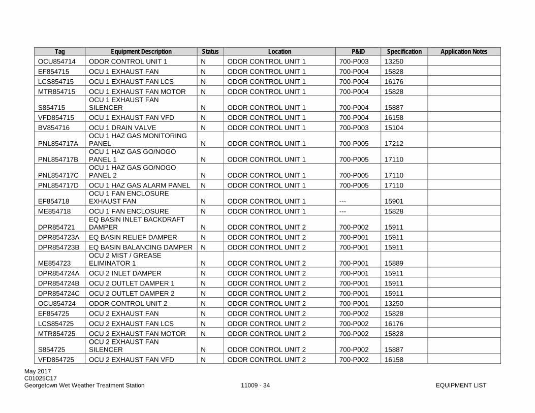
May 2017 C01025C17 Georgetown Wet Weather Treatment Station 11009 - 34 EQUIPMENT LIST
Tag Equipment Description Status Location P&ID Specification Application Notes OCU854714 ODOR CONTROL UNIT 1 N ODOR CONTROL UNIT 1 700-P003 13250 EF854715 OCU 1 EXHAUST FAN N ODOR CONTROL UNIT 1 700-P004 15828 LCS854715 OCU 1 EXHAUST FAN LCS N ODOR CONTROL UNIT 1 700-P004 16176 MTR854715 OCU 1 EXHAUST FAN MOTOR N ODOR CONTROL UNIT 1 700-P004 15828
S854715 OCU 1 EXHAUST FAN SILENCER N ODOR CONTROL UNIT 1 700-P004 15887
VFD854715 OCU 1 EXHAUST FAN VFD N ODOR CONTROL UNIT 1 700-P004 16158 BV854716 OCU 1 DRAIN VALVE N ODOR CONTROL UNIT 1 700-P003 15104
PNL854717A OCU 1 HAZ GAS MONITORING PANEL N ODOR CONTROL UNIT 1 700-P005 17212
PNL854717B OCU 1 HAZ GAS GO/NOGO PANEL 1 N ODOR CONTROL UNIT 1 700-P005 17110
PNL854717C OCU 1 HAZ GAS GO/NOGO PANEL 2 N ODOR CONTROL UNIT 1 700-P005 17110
PNL854717D OCU 1 HAZ GAS ALARM PANEL N ODOR CONTROL UNIT 1 700-P005 17110
EF854718 OCU 1 FAN ENCLOSURE EXHAUST FAN N ODOR CONTROL UNIT 1 --- 15901
ME854718 OCU 1 FAN ENCLOSURE N ODOR CONTROL UNIT 1 --- 15828
DPR854721 EQ BASIN INLET BACKDRAFT DAMPER N ODOR CONTROL UNIT 2 700-P002 15911
DPR854723A EQ BASIN RELIEF DAMPER N ODOR CONTROL UNIT 2 700-P001 15911 DPR854723B EQ BASIN BALANCING DAMPER N ODOR CONTROL UNIT 2 700-P001 15911
ME854723 OCU 2 MIST / GREASE ELIMINATOR 1 N ODOR CONTROL UNIT 2 700-P001 15889
DPR854724A OCU 2 INLET DAMPER N ODOR CONTROL UNIT 2 700-P001 15911 DPR854724B OCU 2 OUTLET DAMPER 1 N ODOR CONTROL UNIT 2 700-P001 15911 DPR854724C OCU 2 OUTLET DAMPER 2 N ODOR CONTROL UNIT 2 700-P001 15911 OCU854724 ODOR CONTROL UNIT 2 N ODOR CONTROL UNIT 2 700-P001 13250 EF854725 OCU 2 EXHAUST FAN N ODOR CONTROL UNIT 2 700-P002 15828 LCS854725 OCU 2 EXHAUST FAN LCS N ODOR CONTROL UNIT 2 700-P002 16176 MTR854725 OCU 2 EXHAUST FAN MOTOR N ODOR CONTROL UNIT 2 700-P002 15828
S854725 OCU 2 EXHAUST FAN SILENCER N ODOR CONTROL UNIT 2 700-P002 15887
VFD854725 OCU 2 EXHAUST FAN VFD N ODOR CONTROL UNIT 2 700-P002 16158

May 2017 C01025C17 Georgetown Wet Weather Treatment Station 11009 - 35 EQUIPMENT LIST
Tag Equipment Description Status Location P&ID Specification Application Notes BV854726 OCU 2 DRAIN VALVE N ODOR CONTROL UNIT 2 700-P001 15104
ME854726 OCU 2 MIST / GREASE ELIMINATOR 2 N ODOR CONTROL UNIT 2 700-P001 15889
PNL854727A OCU 2 HAZ GAS MONITORING PANEL N ODOR CONTROL UNIT 2 700-P006 17212
PNL854727B OCU 2 HAZ GAS GO/NOGO PANEL 1 N ODOR CONTROL UNIT 2 700-P006 17110
PNL854727C OCU 2 HAZ GAS GO/NOGO PANEL 2 N ODOR CONTROL UNIT 2 700-P006 17110
PNL854727D OCU 2 HAZ GAS ALARM PANEL N ODOR CONTROL UNIT 2 700-P006 17110
EF854728 OCU 2 FAN ENCLOSURE EXHAUST FAN N ODOR CONTROL UNIT 2 --- 15901
ME854728 OCU 2 FAN ENCLOSURE N ODOR CONTROL UNIT 2 --- 15828
V854733 OCU 1 DRAIN MANHOLE FLAP GATE 1 N ODOR CONTROL SYSTEM 700-P001 15150
V854734 OCU 1 DRAIN MANHOLE FLAP GATE 2 N ODOR CONTROL SYSTEM 700-P001 15150
V854735 OCU 2 DRAIN MANHOLE FLAP GATE 3 N ODOR CONTROL SYSTEM 700-P001 15150
APC854831 BALL SED SWBD 1 HARMNIC FLTR N
PROCESS ELECTRICAL BUILDING --- 16906
MEE854831 BALLASTED SED SWBRD 1 PWR MTR N
PROCESS ELECTRICAL BUILDING 800-P001 16440
SWBD854831 BALLASTED SED SWITCHBOARD 1 N
PROCESS ELECTRICAL BUILDING 800-P001 16906
TVSS854831 BALLASTED SED SWBRD 1 TVSS N
PROCESS ELECTRICAL BUILDING 800-P001 16421
APC854832 BALL SED SWBD 2 HARMNIC FLTR N
PROCESS ELECTRICAL BUILDING --- 16906
MEE854832 BALLASTED SED SWBRD 2 PWR MTR N
PROCESS ELECTRICAL BUILDING 800-P001 16440
SWBD854832 BALLASTED SED SWITCHBOARD 2 N
PROCESS ELECTRICAL BUILDING 800-P001 16906
TVSS854832 BALLASTED SED SWBRD 2 TVSS N
PROCESS ELECTRICAL BUILDING 800-P001 16421
MCC854841 BALLASTED SED MCC 1 N PROCESS ELECTRICAL BUILDING 800-P001 16920
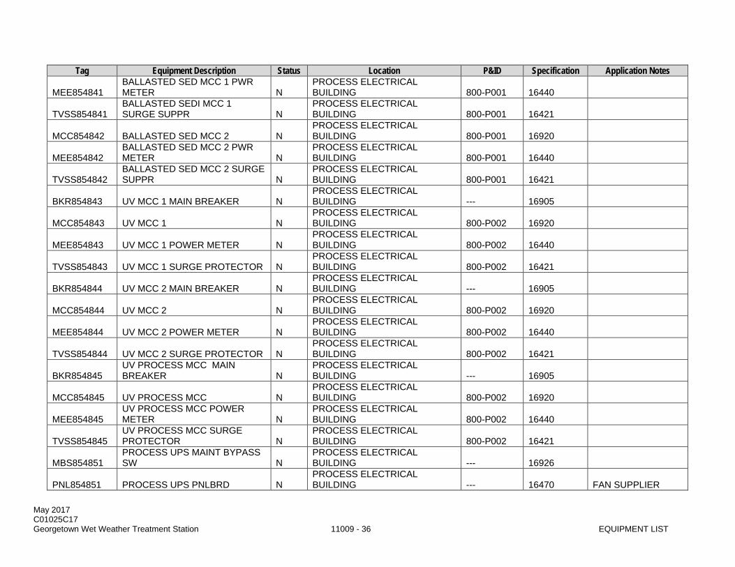
May 2017 C01025C17 Georgetown Wet Weather Treatment Station 11009 - 36 EQUIPMENT LIST
Tag Equipment Description Status Location P&ID Specification Application Notes
MEE854841 BALLASTED SED MCC 1 PWR METER N
PROCESS ELECTRICAL BUILDING 800-P001 16440
TVSS854841 BALLASTED SEDI MCC 1 SURGE SUPPR N
PROCESS ELECTRICAL BUILDING 800-P001 16421
MCC854842 BALLASTED SED MCC 2 N PROCESS ELECTRICAL BUILDING 800-P001 16920
MEE854842 BALLASTED SED MCC 2 PWR METER N
PROCESS ELECTRICAL BUILDING 800-P001 16440
TVSS854842 BALLASTED SED MCC 2 SURGE SUPPR N
PROCESS ELECTRICAL BUILDING 800-P001 16421
BKR854843 UV MCC 1 MAIN BREAKER N PROCESS ELECTRICAL BUILDING --- 16905
MCC854843 UV MCC 1 N PROCESS ELECTRICAL BUILDING 800-P002 16920
MEE854843 UV MCC 1 POWER METER N PROCESS ELECTRICAL BUILDING 800-P002 16440
TVSS854843 UV MCC 1 SURGE PROTECTOR N PROCESS ELECTRICAL BUILDING 800-P002 16421
BKR854844 UV MCC 2 MAIN BREAKER N PROCESS ELECTRICAL BUILDING --- 16905
MCC854844 UV MCC 2 N PROCESS ELECTRICAL BUILDING 800-P002 16920
MEE854844 UV MCC 2 POWER METER N PROCESS ELECTRICAL BUILDING 800-P002 16440
TVSS854844 UV MCC 2 SURGE PROTECTOR N PROCESS ELECTRICAL BUILDING 800-P002 16421
BKR854845 UV PROCESS MCC MAIN BREAKER N
PROCESS ELECTRICAL BUILDING --- 16905
MCC854845 UV PROCESS MCC N PROCESS ELECTRICAL BUILDING 800-P002 16920
MEE854845 UV PROCESS MCC POWER METER N
PROCESS ELECTRICAL BUILDING 800-P002 16440
TVSS854845 UV PROCESS MCC SURGE PROTECTOR N
PROCESS ELECTRICAL BUILDING 800-P002 16421
MBS854851 PROCESS UPS MAINT BYPASS SW N
PROCESS ELECTRICAL BUILDING --- 16926
PNL854851 PROCESS UPS PNLBRD N PROCESS ELECTRICAL BUILDING --- 16470 FAN SUPPLIER

May 2017 C01025C17 Georgetown Wet Weather Treatment Station 11009 - 37 EQUIPMENT LIST
Tag Equipment Description Status Location P&ID Specification Application Notes
UPS854851 PROCESS UPS N PROCESS ELECTRICAL BUILDING 800-P002 16926
PNL854852 UV 208V PANELBOARD N PROCESS ELECTRICAL BUILDING --- 16470
TFR854852 UV 480 - 208/120V XFMR N PROCESS ELECTRICAL BUILDING --- 16460
PNL854853 UV 208V PANELBOARD N PROCESS ELECTRICAL BUILDING --- 16470
TFR854853 UV 480V - 208/120V XFMR N PROCESS ELECTRICAL BUILDING --- 16460
PNL854854 BALLASTED SED 208V PANELBOARD N
PROCESS ELECTRICAL BUILDING --- 16470
TFR854854 BALLSTED SED 480 - 208/120V XFMR N
PROCESS ELECTRICAL BUILDING --- 16460
PNL854856 BALLASTED SED 208V PANELBOARD N
PROCESS ELECTRICAL BUILDING --- 16470
TFR854856 BALLASTED SED 480 - 208/120 XFMR N
PROCESS ELECTRICAL BUILDING --- 16460
PNL854857 HEAT TRACE 208 PANELBOARD 1 N
PROCESS ELECTRICAL BUILDING --- 16470
TFR854857 HEAT TRACE 480V - 208/120V XFMR N
PROCESS ELECTRICAL BUILDING --- 16460
PNL854858 HEAT TRACE 208 PANELBOARD N PROCESS ELECTRICAL BUILDING --- 16470
TFR854858 HEAT TRACE 480V - 208/120V XFMR N
PROCESS ELECTRICAL BUILDING --- 16460
DPR854872A PROCESS ELECT SUPPLY DAMPER N
PROCESS ELECTRICAL BUILDING 800-P003 15911
DPR854872B PROCESS ELECT RETURN DAMPER N
PROCESS ELECTRICAL BUILDING 800-P003 15911
LVR854872 PROCESS ELECT SUPPLY LOUVER N
PROCESS ELECTRICAL BUILDING 800-P003 10200
AHU854873 PROCESS ELECT AIR HANDLING UNIT N
PROCESS ELECTRICAL BUILDING 800-P003 15835
HP854873 PROCESS ELECT HEAT PUMP N PROCESS ELECTRICAL BUILDING 800-P003 15835
DPR854874 PROCESS ELECT RELIEF DAMPER N
PROCESS ELECTRICAL BUILDING 800-P003 15911

May 2017 C01025C17 Georgetown Wet Weather Treatment Station 11009 - 38 EQUIPMENT LIST
Tag Equipment Description Status Location P&ID Specification Application Notes
LVR854874 PROCESS ELECT RELIEF LOUVER N
PROCESS ELECTRICAL BUILDING 800-P003 10200
PNL854874 PROCESS ELECTRICAL HVAC PANEL N
PROCESS ELECTRICAL BUILDING MULTIPLE 15901 HVAC SUPPLIER
PNL854881 MAIN CONTROL PANEL N PROCESS ELECTRICAL BUILDING MULTIPLE 17110
PNL854882 GWWTS METROTEL PANEL N PROCESS ELECTRICAL BUILDING MULTIPLE 17275
PNL854883 MULTI-CHANNEL GAS MONITOR PANEL N
PROCESS ELECTRICAL BUILDING MULTIPLE 17212
PNL854884 MULTI-CHANNEL GAS MONITOR PANEL N
PROCESS ELECTRICAL BUILDING MULTIPLE 17212
LC854891 PROCESS LIGHTING CONTROL PANEL N
PROCESS ELECTRICAL BUILDING --- 16470
FCP854894 PROCESS ELECT BLDG FIRE PANEL N
PROCESS ELECTRICAL BUILDING 800-P002 16660
BAT854901A ENGINE GENERATOR BATTERY RACK 1 N GENERATOR BUILDING 900-P003 11083
BAT854901B ENGINE GENERATOR BATTERY RACK 2 N GENERATOR BUILDING 900-P003 11083
BKR854901A GENERATOR BREAKER N GENERATOR BUILDING --- 16905
BKR854901B GENERATOR FEEDER BREAKER N GENERATOR BUILDING --- 16905
BKR854901C GENERATOR LOAD BANK BREAKER N GENERATOR BUILDING --- 16905
E854901 GENERATOR ENGINE N GENERATOR BUILDING 900-P003 11083 G854901 ENGINE GENERATOR N GENERATOR BUILDING 900-P003 11083
LCP854901 ENGINE GENERATOR CONTROL PANEL N GENERATOR BUILDING 900-P003 11083
LCS854901 GENERRATOR DISABLE CONTROL STA N GENERATOR BUILDING 900-P003 11083 BY GEN SUPPLIER
MEE854901A GENERATOR LOAD BANK RCPT CABINET N GENERATOR BUILDING --- 11083 FAN SUPPLIER
MEE854901B GENERATOR POWER MONITOR N GENERATOR BUILDING 900-P003 16440
S854901 ENGINE GENERATOR EXHST SILENCER N GENERATOR BUILDING 900-P003 15887

May 2017 C01025C17 Georgetown Wet Weather Treatment Station 11009 - 39 EQUIPMENT LIST
Tag Equipment Description Status Location P&ID Specification Application Notes
DPR854902 ENGINE GENERATOR INLET DAMPER N GENERATOR BUILDING 900-P005 15911
LVR854902 ENGINE GENERATOR INLET LOUVER N GENERATOR BUILDING 900-P005 10200
MTR854902A ENGINE GENERATOR INLET DAMPER 1 N GENERATOR BUILDING 900-P005 15911
MTR854902B ENGINE GENERATOR INLET DAMPER 2 N GENERATOR BUILDING 900-P005 15911
MTR854902C ENGINE GENERATOR INLET DAMPER 3 N GENERATOR BUILDING 900-P005 15911
MTR854902D ENGINE GENERATOR INLET DAMPER 4 N GENERATOR BUILDING 900-P005 15911
NA854902 ENGINE GEN INLET NOISE ATTENUAT N GENERATOR BUILDING 900-P005 15911
DPR854903A ENGINE GENERATOR OUTLET DAMPER N GENERATOR BUILDING 900-P005 15911
DPR854903B GENERATOR ROOM BYPASS DAMPER N GENERATOR BUILDING 900-P005 15911
LVR854903 ENGINE GENERATOR OUTLET LOUVER N GENERATOR BUILDING 900-P005 10200
MTR854903A ENGINE GENERATOR OUTLET DAMPER 1 N GENERATOR BUILDING 900-P005 15911
MTR854903B ENGINE GENERATOR OUTLET DAMPER 2 N GENERATOR BUILDING 900-P005 15911
MTR854903C ENGINE GENERATOR OUTLET DAMPER 3 N GENERATOR BUILDING 900-P005 15911
MTR854903D ENGINE GENERATOR OUTLET DAMPER 4 N GENERATOR BUILDING 900-P005 15911
NA854903 ENGINE GEN OUTLET NOISE ATTENUAT N GENERATOR BUILDING 900-P005 15911
FLT854904A ENGINE GENERATOR 1 FUEL FILTER N GENERATOR BUILDING 900-P004 11083
DIESEL FUEL SYS SUPPLIER
FLT854904B ENGINE GENERATOR 2 FUEL FILTER N GENERATOR BUILDING 900-P004 11083
DIESEL FUEL SYS SUPPLIER
LCP854904A LEAK DETECTION / INVENTORY PNL N GENERATOR BUILDING 900-P004 16221
DIESEL FUEL SYS SUPPLIER
LCP854904B D/A CONVERTER / ISOLATOR PNL N GENERATOR BUILDING 900-P004 16221
DIESEL FUEL SYS SUPPLIER
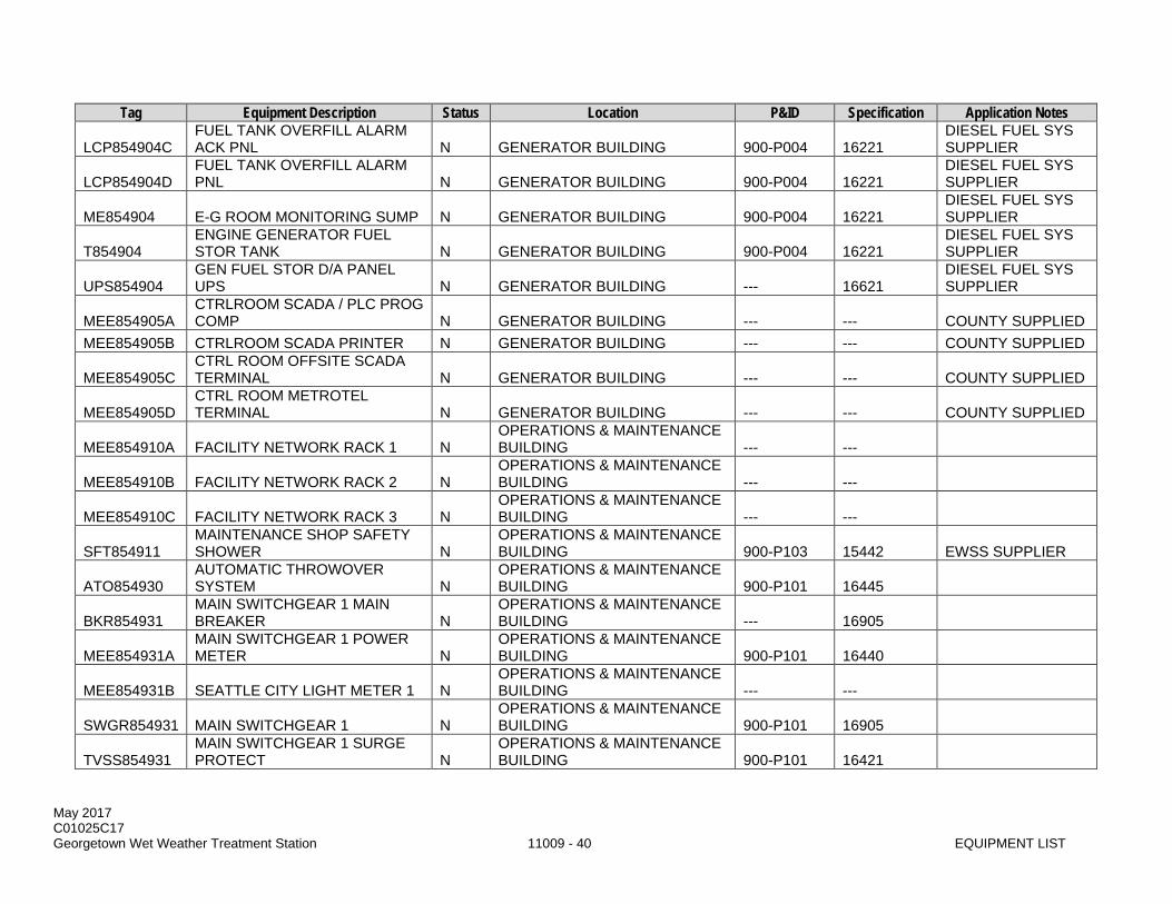
May 2017 C01025C17 Georgetown Wet Weather Treatment Station 11009 - 40 EQUIPMENT LIST
Tag Equipment Description Status Location P&ID Specification Application Notes
LCP854904C FUEL TANK OVERFILL ALARM ACK PNL N GENERATOR BUILDING 900-P004 16221
DIESEL FUEL SYS SUPPLIER
LCP854904D FUEL TANK OVERFILL ALARM PNL N GENERATOR BUILDING 900-P004 16221
DIESEL FUEL SYS SUPPLIER
ME854904 E-G ROOM MONITORING SUMP N GENERATOR BUILDING 900-P004 16221 DIESEL FUEL SYS SUPPLIER
T854904 ENGINE GENERATOR FUEL STOR TANK N GENERATOR BUILDING 900-P004 16221
DIESEL FUEL SYS SUPPLIER
UPS854904 GEN FUEL STOR D/A PANEL UPS N GENERATOR BUILDING --- 16621
DIESEL FUEL SYS SUPPLIER
MEE854905A CTRLROOM SCADA / PLC PROG COMP N GENERATOR BUILDING --- --- COUNTY SUPPLIED
MEE854905B CTRLROOM SCADA PRINTER N GENERATOR BUILDING --- --- COUNTY SUPPLIED
MEE854905C CTRL ROOM OFFSITE SCADA TERMINAL N GENERATOR BUILDING --- --- COUNTY SUPPLIED
MEE854905D CTRL ROOM METROTEL TERMINAL N GENERATOR BUILDING --- --- COUNTY SUPPLIED
MEE854910A FACILITY NETWORK RACK 1 N OPERATIONS & MAINTENANCE BUILDING --- ---
MEE854910B FACILITY NETWORK RACK 2 N OPERATIONS & MAINTENANCE BUILDING --- ---
MEE854910C FACILITY NETWORK RACK 3 N OPERATIONS & MAINTENANCE BUILDING --- ---
SFT854911 MAINTENANCE SHOP SAFETY SHOWER N
OPERATIONS & MAINTENANCE BUILDING 900-P103 15442 EWSS SUPPLIER
ATO854930 AUTOMATIC THROWOVER SYSTEM N
OPERATIONS & MAINTENANCE BUILDING 900-P101 16445
BKR854931 MAIN SWITCHGEAR 1 MAIN BREAKER N
OPERATIONS & MAINTENANCE BUILDING --- 16905
MEE854931A MAIN SWITCHGEAR 1 POWER METER N
OPERATIONS & MAINTENANCE BUILDING 900-P101 16440
MEE854931B SEATTLE CITY LIGHT METER 1 N OPERATIONS & MAINTENANCE BUILDING --- ---
SWGR854931 MAIN SWITCHGEAR 1 N OPERATIONS & MAINTENANCE BUILDING 900-P101 16905
TVSS854931 MAIN SWITCHGEAR 1 SURGE PROTECT N
OPERATIONS & MAINTENANCE BUILDING 900-P101 16421

May 2017 C01025C17 Georgetown Wet Weather Treatment Station 11009 - 41 EQUIPMENT LIST
Tag Equipment Description Status Location P&ID Specification Application Notes
BKR854932 MAIN SWITCHGEAR 2 MAIN BREAKER N
OPERATIONS & MAINTENANCE BUILDING --- 16905
MEE854932A MAIN SWITCHGEAR 2 POWER METER N
OPERATIONS & MAINTENANCE BUILDING 900-P101 16440
MEE854932B SEATTLE CITY LIGHT METER 2 N OPERATIONS & MAINTENANCE BUILDING --- ---
SWGR854932 MAIN SWITCHGEAR 2 N OPERATIONS & MAINTENANCE BUILDING 900-P101 16905
TVSS854932 MAIN SWITCHGEAR 2 SURGE PROTECT N
OPERATIONS & MAINTENANCE BUILDING 900-P101 16421
BKR854933 MAIN SWITCHGEAR TIE BREAKER N
OPERATIONS & MAINTENANCE BUILDING --- 16905
ATS854934 STANDBY POWER ATS N OPERATIONS & MAINTENANCE BUILDING 900-P102 16520
MEE854934 STANDBY SWBD POWER MONITOR N
OPERATIONS & MAINTENANCE BUILDING 900-P102 16440
SWBD854934 STANDBY POWER SWITCHBOARD N
OPERATIONS & MAINTENANCE BUILDING 900-P102 16906
MEE854935 PHOTOVOLTAIC INVERTER N OPERATIONS & MAINTENANCE BUILDING --- 16800
PNL854940 O&M TELECOMM BACKBOARD N OPERATIONS & MAINTENANCE BUILDING --- 16720
BKR854941 GENERATOR MCC MAIN BREAKER N
OPERATIONS & MAINTENANCE BUILDING --- 16905
MCC854941 GENERATOR MOTOR CONTROL CENTER N
OPERATIONS & MAINTENANCE BUILDING 900-P103 16920
MEE854941 GENERATOR MCC POWER METER N
OPERATIONS & MAINTENANCE BUILDING 900-P103 16440
TVSS854941 GENERATOR MCC SURGE PROTECTOR N
OPERATIONS & MAINTENANCE BUILDING 900-P103 16421
BKR854942 OPERATIONS MCC MAIN BREAKER N
OPERATIONS & MAINTENANCE BUILDING --- 16905
MCC854942 OPERATIONS MOTOR CONTROL CENTER N
OPERATIONS & MAINTENANCE BUILDING 900-P102 16920
MEE854942 OPERATIONS MCC POWER METER N
OPERATIONS & MAINTENANCE BUILDING 900-P102 16440
TVSS854942 OPERATIONS MCC SURGE PROTECTOR N
OPERATIONS & MAINTENANCE BUILDING 900-P102 16421

May 2017 C01025C17 Georgetown Wet Weather Treatment Station 11009 - 42 EQUIPMENT LIST
Tag Equipment Description Status Location P&ID Specification Application Notes
MBS854951 OPERATIONS UPS MAINT BYPASS SW N
OPERATIONS & MAINTENANCE BUILDING --- 16926
PNL854951 OPERATIONS UPS PANELBOARD N
OPERATIONS & MAINTENANCE BUILDING --- 16470
PNL854951 GENERATOR 208V PANELBOARD N
OPERATIONS & MAINTENANCE BUILDING --- 16470
TFR854951 GENERATOR 480V - 208/120V XFMR 1 N
OPERATIONS & MAINTENANCE BUILDING --- 16460
UPS854951 OPERATIONS UPS N OPERATIONS & MAINTENANCE BUILDING 900-P102 16926
PNL854952 OPERATIONS 480V PANELBOARD N
OPERATIONS & MAINTENANCE BUILDING --- 16470
LC854955 GENERATOR BLDG LTG CONTROL PANEL N
OPERATIONS & MAINTENANCE BUILDING --- 16510
PNL854956 OPERATIONS 208V PANELBOARD 1 N
OPERATIONS & MAINTENANCE BUILDING --- 16470
TFR854956 OPERATIONS 480 - 208/120V XFMR 1 N
OPERATIONS & MAINTENANCE BUILDING --- 16460
PNL854957 OPERATIONS 208V PANELBOARD 2 N
OPERATIONS & MAINTENANCE BUILDING --- 16470
TFR854957 OPERATIONS 480 - 208/120V XFMR 2 N
OPERATIONS & MAINTENANCE BUILDING --- 16460
RV854961 MAINT SHOP SERV AIR PRESS REG N
OPERATIONS & MAINTENANCE BUILDING 900-P001 15121
DT854962 SHOP SERV AIR RECVR DRAIN TRAP N
OPERATIONS & MAINTENANCE BUILDING 900-P001 11367
PRV854962 MAINT SHOP SERV AIR RECVR PRV N
OPERATIONS & MAINTENANCE BUILDING 900-P001 13202
PRESS VESSEL SUPPLIER
PVL854962 MAINT SHOP SERV AIR RECIEVER N
OPERATIONS & MAINTENANCE BUILDING 900-P001 11367
GV854964A C1 SUPPLY ISOLATION VALVE N RPBP ENCLOSURE 900-P002 15101 GV854964B C1 SUPPLY ISOLATION VALVE N RPBP ENCLOSURE 900-P002 15101 GV854964C C1 SUPPLY ISOLATION VALVE N RPBP ENCLOSURE 900-P002 15101 RPBP854964 CITY WATER RPBP N RPBP ENCLOSURE 900-P002 15120
RV854964 CITY WATER PRESS REGULATOR N RPBP ENCLOSURE 900-P002 15121
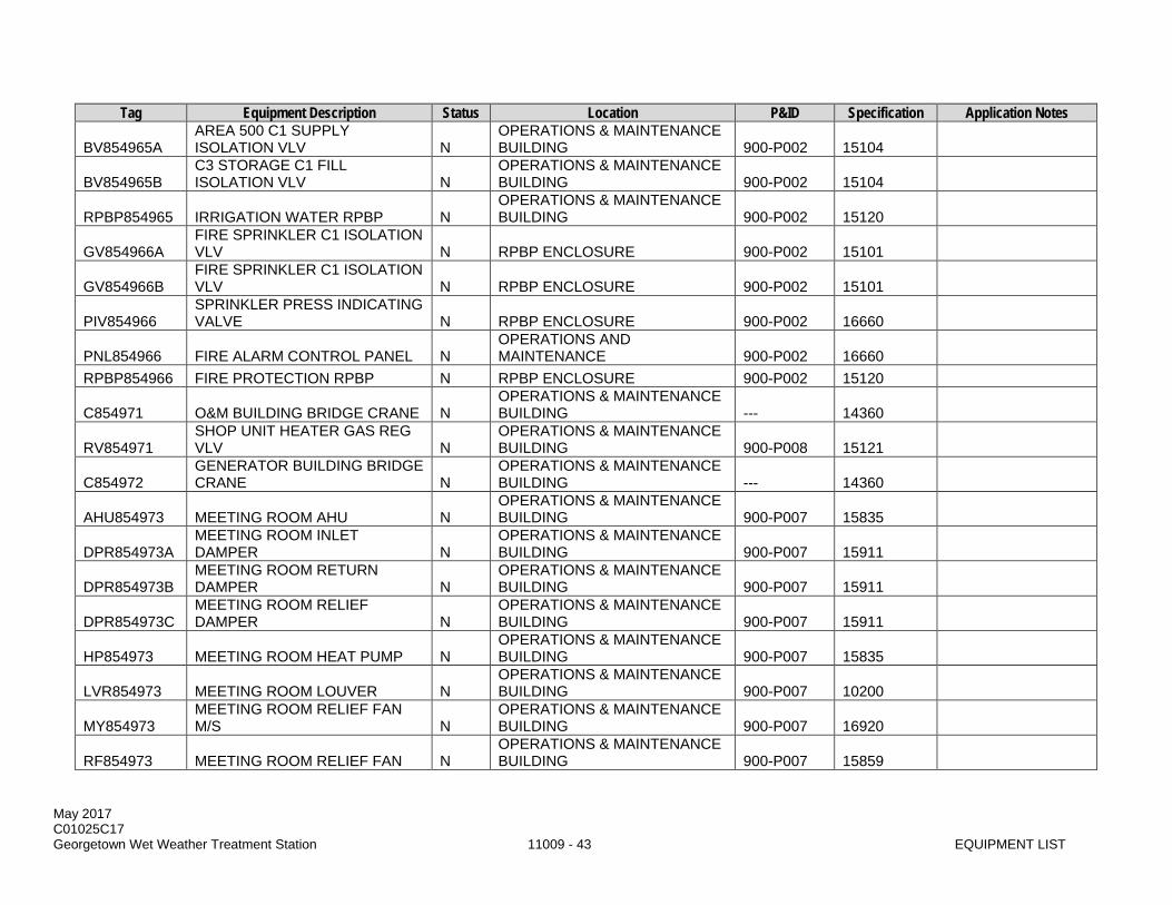
May 2017 C01025C17 Georgetown Wet Weather Treatment Station 11009 - 43 EQUIPMENT LIST
Tag Equipment Description Status Location P&ID Specification Application Notes
BV854965A AREA 500 C1 SUPPLY ISOLATION VLV N
OPERATIONS & MAINTENANCE BUILDING 900-P002 15104
BV854965B C3 STORAGE C1 FILL ISOLATION VLV N
OPERATIONS & MAINTENANCE BUILDING 900-P002 15104
RPBP854965 IRRIGATION WATER RPBP N OPERATIONS & MAINTENANCE BUILDING 900-P002 15120
GV854966A FIRE SPRINKLER C1 ISOLATION VLV N RPBP ENCLOSURE 900-P002 15101
GV854966B FIRE SPRINKLER C1 ISOLATION VLV N RPBP ENCLOSURE 900-P002 15101
PIV854966 SPRINKLER PRESS INDICATING VALVE N RPBP ENCLOSURE 900-P002 16660
PNL854966 FIRE ALARM CONTROL PANEL N OPERATIONS AND MAINTENANCE 900-P002 16660
RPBP854966 FIRE PROTECTION RPBP N RPBP ENCLOSURE 900-P002 15120
C854971 O&M BUILDING BRIDGE CRANE N OPERATIONS & MAINTENANCE BUILDING --- 14360
RV854971 SHOP UNIT HEATER GAS REG VLV N
OPERATIONS & MAINTENANCE BUILDING 900-P008 15121
C854972 GENERATOR BUILDING BRIDGE CRANE N
OPERATIONS & MAINTENANCE BUILDING --- 14360
AHU854973 MEETING ROOM AHU N OPERATIONS & MAINTENANCE BUILDING 900-P007 15835
DPR854973A MEETING ROOM INLET DAMPER N
OPERATIONS & MAINTENANCE BUILDING 900-P007 15911
DPR854973B MEETING ROOM RETURN DAMPER N
OPERATIONS & MAINTENANCE BUILDING 900-P007 15911
DPR854973C MEETING ROOM RELIEF DAMPER N
OPERATIONS & MAINTENANCE BUILDING 900-P007 15911
HP854973 MEETING ROOM HEAT PUMP N OPERATIONS & MAINTENANCE BUILDING 900-P007 15835
LVR854973 MEETING ROOM LOUVER N OPERATIONS & MAINTENANCE BUILDING 900-P007 10200
MY854973 MEETING ROOM RELIEF FAN M/S N
OPERATIONS & MAINTENANCE BUILDING 900-P007 16920
RF854973 MEETING ROOM RELIEF FAN N OPERATIONS & MAINTENANCE BUILDING 900-P007 15859
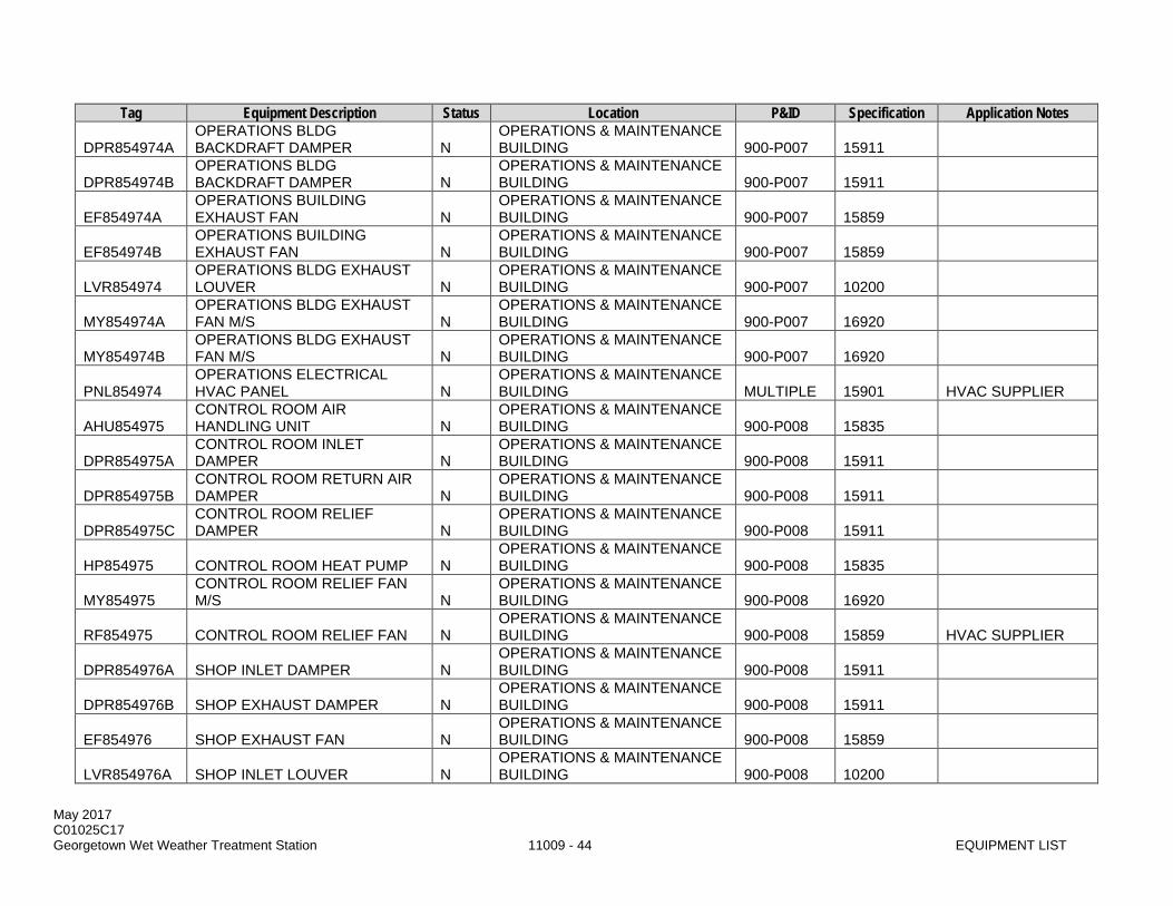
May 2017 C01025C17 Georgetown Wet Weather Treatment Station 11009 - 44 EQUIPMENT LIST
Tag Equipment Description Status Location P&ID Specification Application Notes
DPR854974A OPERATIONS BLDG BACKDRAFT DAMPER N
OPERATIONS & MAINTENANCE BUILDING 900-P007 15911
DPR854974B OPERATIONS BLDG BACKDRAFT DAMPER N
OPERATIONS & MAINTENANCE BUILDING 900-P007 15911
EF854974A OPERATIONS BUILDING EXHAUST FAN N
OPERATIONS & MAINTENANCE BUILDING 900-P007 15859
EF854974B OPERATIONS BUILDING EXHAUST FAN N
OPERATIONS & MAINTENANCE BUILDING 900-P007 15859
LVR854974 OPERATIONS BLDG EXHAUST LOUVER N
OPERATIONS & MAINTENANCE BUILDING 900-P007 10200
MY854974A OPERATIONS BLDG EXHAUST FAN M/S N
OPERATIONS & MAINTENANCE BUILDING 900-P007 16920
MY854974B OPERATIONS BLDG EXHAUST FAN M/S N
OPERATIONS & MAINTENANCE BUILDING 900-P007 16920
PNL854974 OPERATIONS ELECTRICAL HVAC PANEL N
OPERATIONS & MAINTENANCE BUILDING MULTIPLE 15901 HVAC SUPPLIER
AHU854975 CONTROL ROOM AIR HANDLING UNIT N
OPERATIONS & MAINTENANCE BUILDING 900-P008 15835
DPR854975A CONTROL ROOM INLET DAMPER N
OPERATIONS & MAINTENANCE BUILDING 900-P008 15911
DPR854975B CONTROL ROOM RETURN AIR DAMPER N
OPERATIONS & MAINTENANCE BUILDING 900-P008 15911
DPR854975C CONTROL ROOM RELIEF DAMPER N
OPERATIONS & MAINTENANCE BUILDING 900-P008 15911
HP854975 CONTROL ROOM HEAT PUMP N OPERATIONS & MAINTENANCE BUILDING 900-P008 15835
MY854975 CONTROL ROOM RELIEF FAN M/S N
OPERATIONS & MAINTENANCE BUILDING 900-P008 16920
RF854975 CONTROL ROOM RELIEF FAN N OPERATIONS & MAINTENANCE BUILDING 900-P008 15859 HVAC SUPPLIER
DPR854976A SHOP INLET DAMPER N OPERATIONS & MAINTENANCE BUILDING 900-P008 15911
DPR854976B SHOP EXHAUST DAMPER N OPERATIONS & MAINTENANCE BUILDING 900-P008 15911
EF854976 SHOP EXHAUST FAN N OPERATIONS & MAINTENANCE BUILDING 900-P008 15859
LVR854976A SHOP INLET LOUVER N OPERATIONS & MAINTENANCE BUILDING 900-P008 10200
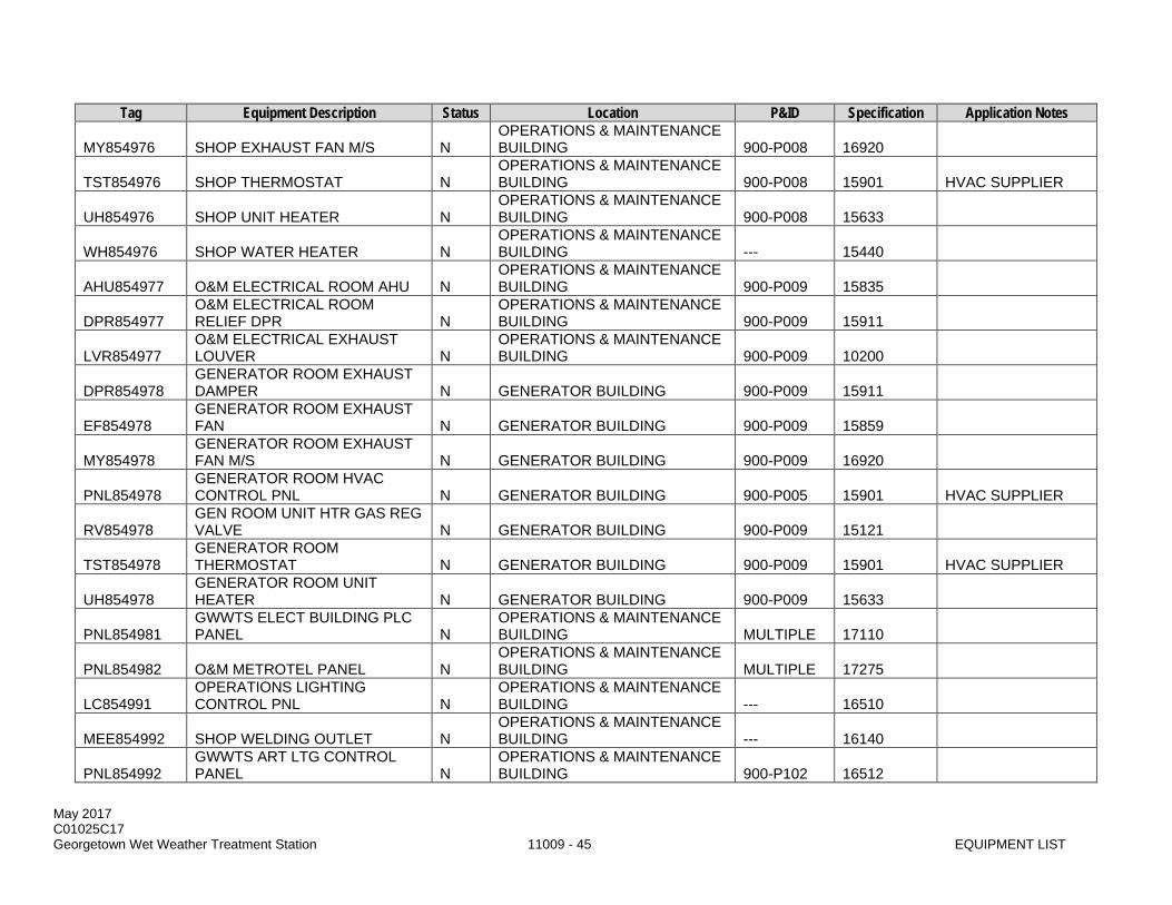
May 2017 C01025C17 Georgetown Wet Weather Treatment Station 11009 - 45 EQUIPMENT LIST
Tag Equipment Description Status Location P&ID Specification Application Notes
MY854976 SHOP EXHAUST FAN M/S N OPERATIONS & MAINTENANCE BUILDING 900-P008 16920
TST854976 SHOP THERMOSTAT N OPERATIONS & MAINTENANCE BUILDING 900-P008 15901 HVAC SUPPLIER
UH854976 SHOP UNIT HEATER N OPERATIONS & MAINTENANCE BUILDING 900-P008 15633
WH854976 SHOP WATER HEATER N OPERATIONS & MAINTENANCE BUILDING --- 15440
AHU854977 O&M ELECTRICAL ROOM AHU N OPERATIONS & MAINTENANCE BUILDING 900-P009 15835
DPR854977 O&M ELECTRICAL ROOM RELIEF DPR N
OPERATIONS & MAINTENANCE BUILDING 900-P009 15911
LVR854977 O&M ELECTRICAL EXHAUST LOUVER N
OPERATIONS & MAINTENANCE BUILDING 900-P009 10200
DPR854978 GENERATOR ROOM EXHAUST DAMPER N GENERATOR BUILDING 900-P009 15911
EF854978 GENERATOR ROOM EXHAUST FAN N GENERATOR BUILDING 900-P009 15859
MY854978 GENERATOR ROOM EXHAUST FAN M/S N GENERATOR BUILDING 900-P009 16920
PNL854978 GENERATOR ROOM HVAC CONTROL PNL N GENERATOR BUILDING 900-P005 15901 HVAC SUPPLIER
RV854978 GEN ROOM UNIT HTR GAS REG VALVE N GENERATOR BUILDING 900-P009 15121
TST854978 GENERATOR ROOM THERMOSTAT N GENERATOR BUILDING 900-P009 15901 HVAC SUPPLIER
UH854978 GENERATOR ROOM UNIT HEATER N GENERATOR BUILDING 900-P009 15633
PNL854981 GWWTS ELECT BUILDING PLC PANEL N
OPERATIONS & MAINTENANCE BUILDING MULTIPLE 17110
PNL854982 O&M METROTEL PANEL N OPERATIONS & MAINTENANCE BUILDING MULTIPLE 17275
LC854991 OPERATIONS LIGHTING CONTROL PNL N
OPERATIONS & MAINTENANCE BUILDING --- 16510
MEE854992 SHOP WELDING OUTLET N OPERATIONS & MAINTENANCE BUILDING --- 16140
PNL854992 GWWTS ART LTG CONTROL PANEL N
OPERATIONS & MAINTENANCE BUILDING 900-P102 16512
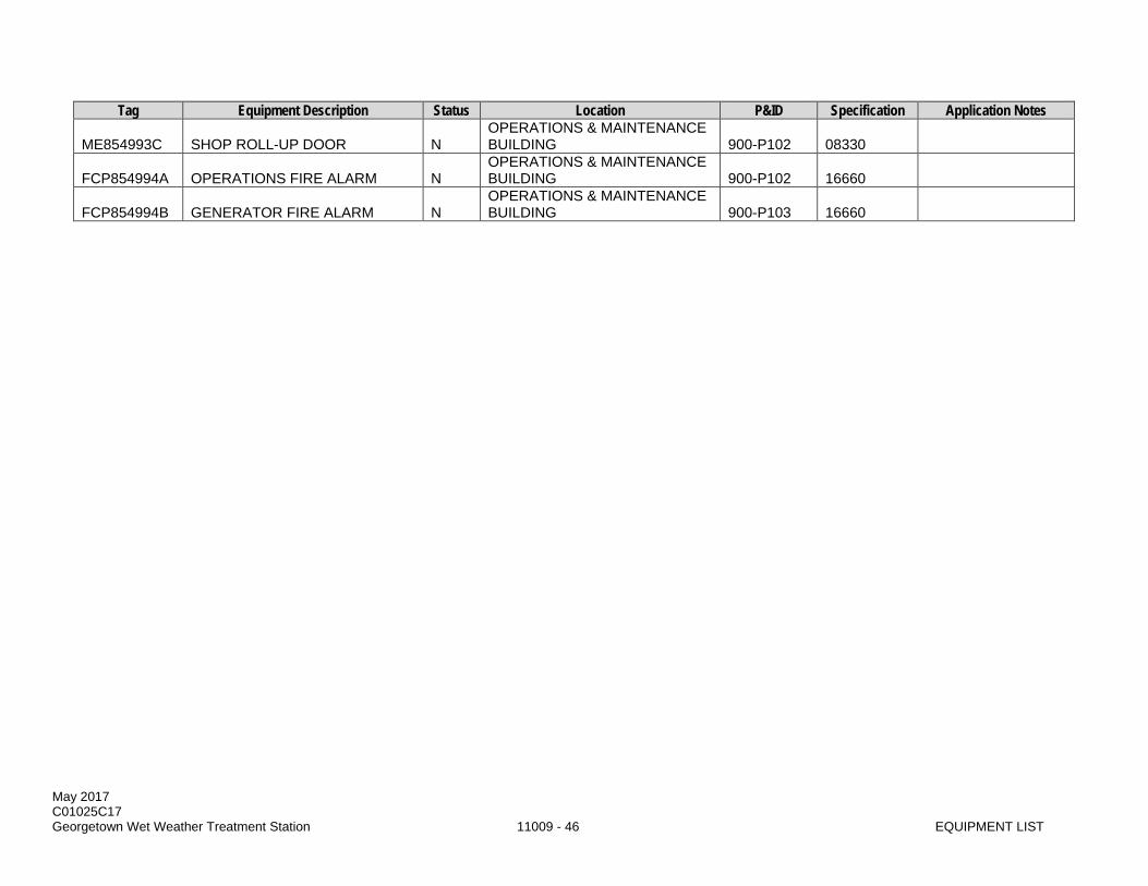
May 2017 C01025C17 Georgetown Wet Weather Treatment Station 11009 - 46 EQUIPMENT LIST
Tag Equipment Description Status Location P&ID Specification Application Notes
ME854993C SHOP ROLL-UP DOOR N OPERATIONS & MAINTENANCE BUILDING 900-P102 08330
FCP854994A OPERATIONS FIRE ALARM N OPERATIONS & MAINTENANCE BUILDING 900-P102 16660
FCP854994B GENERATOR FIRE ALARM N OPERATIONS & MAINTENANCE BUILDING 900-P103 16660

May 2017 C01025C17 Georgetown Wet Weather Treatment Station 11009 - 47 EQUIPMENT LIST
PART 3 EXECUTION (NOT USED)
END OF SECTION

May 2017 C01025C17 Georgetown Wet Weather Treatment Station 11009 - 48 EQUIPMENT LIST
This page intentionally left blank.
May 2017 C01025C17 Georgetown Wet Weather Treatment Station 11020 - 1 VIBRATION AND CRITICAL SPEED LIMITATIONS
SECTION 11020
VIBRATION AND CRITICAL SPEED LIMITATIONS
PART 1 GENERAL
1.01 SUMMARY
A. This Section specifies vibration and critical speed limitations for rotating equipment. Individual equipment Sections may specify more stringent requirements which shall then govern over this Section.
B. This Section outlines the basic standards for acceptance of equipment. Any equipment demonstrating levels above these limits shall be repaired, modified or replaced at the Contractor's expense as determined by the Project Representative. 1. General Equipment:
a. No narrow band spectral vibration amplitude components, whether sub-rotational, higher harmonic, or synchronous multiple of running speed, are to exceed 40% of synchronous vibration amplitude.
b. The presence of discernible vibration amplitude peaks or vibration spectra at a bearing inner or outer race frequencies shall be cause for rejection.
2. Electric Motors: a. Stator eccentricity evidenced by a spectral peak at 2 times electrical line frequency that is
more than 40% of the peak at rotational frequency. b. Rotor eccentricity evidenced by a spectral peak at 2 times electrical line frequency with
spectra side bands at the pole pass frequency around the 2 times line frequency peak.
C. This Section covers requirements for calculating expected vibration resonances.
D. This Section covers requirements for on-site field testing of vibration of the installed equipment and reporting the test results. Submittals for field-testing are only required when specified in the individual equipment Sections.
1.02 QUALITY ASSURANCE
A. Referenced Standards: This Section incorporates by reference the latest revision of the following documents. These references are a part of this Section as specified and modified. In case of conflict between the requirements of this Section and those of the listed documents, the requirements of this Section shall prevail. Reference Title AGMA 6000-B96 Measurement of Linear Vibration of Gear Units ANSI/HI 9.6.4 American National Standard for Centrifugal and Vertical Pumps for
Vibration Measurements and Allowable Values
B. Hydraulic Institute standards.
C. Testing Qualifications: Tests shall be performed by an experienced vibration analysis expert who shall interpret the results against this Section and provide recommended acceptance or modification requirements to the Project Representative.
D. Instrumentation: Provide necessary test instrumentation which has been calibrated within one year from date of test to recognized test standards traceable to the National Institute of Standards and Technology, Washington DC, or approved source.
May 2017 C01025C17 Georgetown Wet Weather Treatment Station 11020 - 2 VIBRATION AND CRITICAL SPEED LIMITATIONS
1.03 SUBMITTALS
A. Procedures: Section 01300.
B. Qualifications: 1. Vibration analysis firm qualifications and experience documentation.
C. The following information shall be provided when specified in the individual equipment Sections: 1. Test plan as outlined in Section 01660. 2. Test data report sheets for each piece of equipment showing mounting location of test
instruments. 3. Manufacturer's certified calculations and data showing location of critical speeds in relation to the
operating speeds. 4. Any deviation from the vibration or critical speed standards shall be noted on the submittal cover
sheet and approved prior to release for manufacture. 5. Test equipment calibration certificates.
D. Vibration analysis expert’s findings and recommendations.
1.04 FIELD VIBRATION TESTING:
A. General: Equipment testing for vibration and natural frequencies shall be conducted with equipment, installed, grouted and operational. Test instrumentation shall be portable, temporarily mounted or permanently installed components if suitably calibrated for the test measuring and recording instruments.
B. Definitions: 1. Peak to Peak Displacement: Root Mean Square (RMS) average of the peak to peak
displacement multiplied by the square root of 2. 2. Peak Velocity: RMS average of the peak velocity multiplied by the square root of 2. 3. Peak Acceleration: RMS average of the peak acceleration multiplied by the square root of 2. 4. High Frequency Enveloping: A process to extract very low amplitude time domain signals
associated with impact or impulse events such as bearing or gear tooth defects and display them in a frequency spectra of acceleration versus frequency. Typical manufacturers' notation is “Spike Energy” by Rockwell Automation, (Entek/IRD) or “PeakVue” by CSI.
5. Low Speed Equipment: Equipment or components rotating at less than 600 rpm. 6. Convert velocity to displacement:
D = 19,100 * V / F D is the peak-to-peak displacement in mils. V is the peak velocity in inches per second. F is the frequency in cycles per minute.
C. Test Requirements: 1. Measure filtered vibration spectra for peak velocity, peak to peak displacement versus frequency
and measure vibration phase in three perpendicular planes at each normally accessible bearing housing on the driven equipment, gear or clutch assembly and the driver. One plane of measurement shall be parallel to the axis of rotation of the component. Measure rotational speeds using a photometric or other tachometer with input directly to the vibration data collector.
2. Fixed speed equipment shall be operated at the design operating condition during the test recording. Variable speed equipment shall be tested to establish performance over the entire speed range.
3. Field test for natural frequency: Excite the installed equipment and support system in three perpendicular planes. Use the same locations as used for vibration tests above. Determine the natural resonant frequency of the driver, clutch or gear, driven equipment and supports.

May 2017 C01025C17 Georgetown Wet Weather Treatment Station 11020 - 3 VIBRATION AND CRITICAL SPEED LIMITATIONS
1.05 VIBRATION ACCEPTANCE CRITERIA
A. Vibration Displacement Limits - Pumps: Unless otherwise specified, pumping equipment shall not exceed the following Unfiltered Overall Peak-to-Peak Amplitudes (mils).
Operating Speed [RPM] Non-Clog Pumps Clean Fluid 0 - 300 6.0 6.0 301 - 600 5.0 5.0 601 - 900 4.0 3.0 901 - 1200 3.5 2.0 1200 - 1500 3.0 1.8 1501 - 1800 2.5 1.5 Note: Axial shaft placement is not to exceed 50% of the maximum radial shaft displacement relative to the casing.
B. Vibration Velocity Limits: Unless otherwise specified, equipment shall not exceed the following peak velocities (inches/second).
Equipment Unfiltered Overall Limit Any Filtered Peak Limit Non-Clog or Mixed Flow Pumps 0.35 0.25 Clean Fluid Multi- Vane Pumps 0.25 0.20 Motors 0.25 0.20 Steady Bearings 0.25 0.20 Gear Reducers < AGMA 6000-B96 limits Other Equipment, Radial 0.16 0.10 Other Equipment, Axial 0.10 0.10
1.06 CRITICAL SPEED REQUIREMENTS
A. General Requirement: 1. No narrow band spectral vibration amplitude components, whether sub-rotational, higher
harmonic, or synchronous multiple of running speed, are to exceed 40% of synchronous vibration amplitude.
2. The presence of discernible vibration amplitude peaks or vibration spectra at a bearing inner or outer race frequencies shall be cause for rejection.
B. Electric Motors: 1. Stator eccentricity evidenced by a spectral peak at 2 times electrical line frequency that is more
than 40% of the peak at rotational frequency. 2. Rotor eccentricity evidenced by a spectral peak at 2 times electrical line frequency with spectra
side bands at the pole pass frequency around the times line frequency peak.
C. Unless otherwise specified, rotating mechanical equipment shall satisfy the following: 1. First critical speed of the constant, variable, and 2-speed driven equipment is to be at least 25%
above the maximum operating speed or 25% below the minimum operating speed. 2. Second critical speed of any 2-speed or variable speed equipment is to be at least 25% above or
below the maximum operating speed or 25% below the minimum operating speed.
D. Critical speeds for equipment with flexible shaft-rotor systems shall be at least 15% below the minimum operating speed and 20% above maximum operating speed.
May 2017 C01025C17 Georgetown Wet Weather Treatment Station 11020 - 4 VIBRATION AND CRITICAL SPEED LIMITATIONS
PART 2 PRODUCTS
2.01 TEST VIBRATION INSTRUMENT REQUIREMENTS
A. Analyzers: Use digital type analyzers or data collectors with anti-aliasing filter, 12 bit A/D converter, fast fourier transform circuitry, phase measurement capability, time wave form data storage, high frequency enveloping capabilities, 35 frequency ranges from 21 to 1,500,000 cycles per minute, adjustable fast fourier transform resolution from 400 to 6400 lines, storage for up to 100 - 3200 line frequency spectra, RS232C data output port, circuitry for integration of acceleration data to velocity or double integration to displacement. 1. Manufacturers:
a. Entek-IRD, Division of Rockwell Automation, Enpac1200 with applicable data analysis software or Entek Model 838 analyzer with built in printer.
b. Computational Systems Inc., (CSI) Division of Emerson Electric, Model 2120A, Data Collector/Analyzer with applicable analysis software.
B. Analyzer Settings: 1. Units: English, inches/second, mils and g's. 2. Fast Fourier Transform Lines: Most equipment 1600 minimum. Motors require enough lines to
distinguish motor current frequencies from rotational frequencies. Use 3200 lines for motors with a nominal speed of 3600 rpm, 3200 lines minimum for High Frequency Enveloping and 1600 lines minimum for low speed equipment.
3. Sample Averages: 4 minimum. 4. Maximum Frequency (Fmax): 3600 rpm. 5. 40 times rotational frequency for rolling element bearings. 6. 10 times rotational frequency for sleeve bearings. 7. Amplitude Range: Auto Select. Full scale shall not be more than twice the acceptance criteria or
the highest peak, whichever is lower. 8. Fast Fourier Transform Windowing: Hanning Window. 9. High Pass Filter: Minus 3 dB at 120 cycles per minute for high-speed equipment. Minus 3 dB at
21 cycles per minute for low speed equipment.
C. Accelerometers: 1. Low Speed Equipment: Low frequency, shear mode accelerometer, 500 millivolts per g
sensitivity, 10 g range, +/- 5% frequency response from 0.5 hertz to 850 hertz, magnetic mount. a. Manufacturers:
1) Wilcoxon Research, model 797L. 2) PCB, Model 393C.
2. High Speed Equipment: General purpose accelerometer, 100 millivolts per g sensitivity, 50g range, +/- 2 dB. Frequency response range from 2 hertz to 12,000 hertz when stud mounted or magnetic mount. a. Manufacturers:
1) Wilcoxon Research, Model 793. 2) IRD Model 943.
PART 3 EXECUTION (NOT USED)
END OF SECTION
May 2017 C01025C17 Georgetown Wet Weather Treatment Station 11021 - 1 VIBRATION ISOLATION SYSTEMS
SECTION 11021
VIBRATION ISOLATION SYSTEMS
PART 1 GENERAL
1.01 SUMMARY
A. This Section specifies vibration isolation system requirements for mechanical equipment. Additional vibration isolation system requirements are provided in individual mechanical equipment Sections.
B. This Section requires Supervision by the vibration isolation manufacturer's qualified representative as is necessary to assure and certify correct installation and adjustment of the vibration isolators and seismic restraints.
1.02 QUALITY ASSURANCE
A. Reference Standards: This Section incorporates by reference the latest revision of the following documents. These references are a part of this Section as specified and modified. In case of conflict between the requirements of this Section and those of the listed documents, the requirements of this Section shall prevail. Reference Title ASHRAE CH 52 Handbook, HVAC Systems and Applications, Sound and Vibration
Control
B. Qualifications: The vibration isolation manufacturer's qualified representative shall provide supervision as is necessary to assure correct installation and adjustment of the vibration isolators and seismic restraints.
1.03 SUBMITTALS
A. Procedures: Section 01300.
B. Product and Technical Data: 1. Manufacturer and manufacturer's type designation. 2. Manufacturer's catalog data. 3. Seismic system design calculations. 4. Seismic restraint test reports. 5. Installation reports. 6. Static and dynamic deflections, weights, isolator locations, and flexible connector designs. 7. Spring deflections and diameters, compressed spring heights, and solid spring heights. 8. Scale drawing of Type D mounting hanger showing the 30-degree arc capability. 9. Curb mounted base seal and wind resistance details. 10. Seismic restraint load deflection curves up to 1/2-inch deflection along the three principal
orthogonal axes.
C. Forms: 11000-A per Section 01999.

May 2017 C01025C17 Georgetown Wet Weather Treatment Station 11021 - 2 VIBRATION ISOLATION SYSTEMS
1.04 DESIGN REQUIREMENTS
A. All vibration isolation systems, including the isolators, seismic restraints, and flexible connectors between the isolated equipment and associated piping, ducting, and/or electrical work, shall be prepared, signed, stamped, and dated by a registered Professional Engineer licensed in the state of Washington and qualified in vibration isolation systems. This provision shall not be construed as relieving the Contractor of its overall responsibility for the Work.
B. Flexible connectors shall be provided by the manufacturer of the mechanical equipment item in accordance with the recommendations of the vibration isolation system engineer.
1.05 SEISMIC RESTRAINTS
A. General: 1. Restraint devices shall resist the forces specified and be designed in accordance with the
Section 01031. 2. Design lateral forces shall be distributed in proportion to the mass distribution of the equipment.
B. Floor Mounted Equipment: 1. Provide equipment and appurtenances resiliently floor mounted on spring or pad type vibration
isolators, except for curb mounted equipment, with seismic snubbers. 2. Four all-directional restraint/snubbers. 3. Capacity of snubbers, at 3/8-inch deflection, shall be 3 to 4 times the load at the adjacent
equipment mount. 4. Restraint assembly shall consist of welded steel interlocking assemblies welded or bolted
securely to the equipment or the equipment bases and the supporting structure. 5. Line restraint assembly surfaces, which engage under seismic motion with a resilient elastomer
3/4 inches thick. 6. Restraints shall be field adjustable and be positioned for 1/4-inch clearance both vertically and
horizontally or clearance as required preventing interference during normal operation, stopping, or starting.
7. Restraint assembly shall have a minimum rating of 1.0 g based on independent test data.
C. Curb Mounted Equipment: slack stainless steel cables designed to provide 1.0 g restraint in the four primary horizontal directions based on independent test data.
D. Suspended Equipment: 1. Restraint assembly for suspended equipment, piping, or ductwork shall consist of plow steel
cable attached to steel thimbles with neoprene sleeve all specifically designed for cable service and securely fastened to the equipment, or the equipment base and the building structure.
2. Size cables for a force of 1.0 g with a minimum safety factor of 2.0 based upon independent test data.
3. Install cables to prevent excessive seismic motion and arranged so as not to engage during normal operation, starting, or stopping.
PART 2 PRODUCTS
2.01 GENERAL
A. Acceptable Manufacturer: 1. Mason Industries, Inc. 2. Korfund Dynamics Corporation. 3. Kinetics Noise Control. 4. Approved Equal.
May 2017 C01025C17 Georgetown Wet Weather Treatment Station 11021 - 3 VIBRATION ISOLATION SYSTEMS
B. Flexible connectors: provided by the manufacturer of the mechanical equipment item in accordance with the recommendations of the vibration isolation system engineer.
2.02 BASES
A. See Section 11050 and Section 11045.
2.03 VIBRATION ISOLATION MOUNTINGS
A. Type A: 1. Double deflection neoprene mountings having a minimum static deflection of 0.35 inches. 2. All metal surfaces shall be neoprene covered to avoid corrosion and shall have friction pads both
top and bottom so that they need not be bolted to the floor. 3. Bolt holes and anchor bolts where required to resist lateral migration. 4. Resilient washers and bushings to prevent contact between the bolts and the equipment support
bases. 5. On equipment such as small vent sets, use steel rails above the mountings to compensate for the
overhang.
B. Type B: 1. Freestanding spring type isolators laterally stable without any housing and complete with 1/4-inch
neoprene acoustical friction pads between the base and the support. 2. Leveling bolts shall be rigidly bolted to the equipment. 3. Hot-dip galvanized steel. 4. Springs:
a. Diameters shall be no less than 0.8 times the compressed height of the spring at rated load. b. Minimum additional travel to solid: equal to 50 percent of the rated deflection.
C. Type C: 1. Type B mountings with a housing having vertical limit stops to prevent spring extension when
weight is removed. 2. Provide for equipment with operating weight different from the installed weight, such as chillers,
boilers, etc., and equipment exposed to the wind, such as cooling towers. 3. Housing shall serve as blocking during erection and shall be located between the supporting steel
and roof or the grillage and dunnage as indicated in the Drawings. 4. Installed and operating heights shall be the same. A minimum clearance of 1/2 inch shall be
maintained around restraining bolts and between the housing and the spring to prevent interference with the spring action.
5. Limit stops shall be out of contact during normal operations. 6. Hot-dip galvanized steel.
D. Type D: 1. Steel hangers which contain a steel spring and a 0.3-inch deflection neoprene element in series. 2. Neoprene element shall be molded with a rod isolation bushing which passes through the hanger
box. 3. Spring diameters and hanger box lower hole sizes shall be of sufficient size to permit the hanger
rod to swing through a 30-degree arc before contacting the hole. 4. Springs: minimum additional travel to solid equal to 50 percent of the rated deflection.
E. Type E: 1. Double deflection, cork and rubber sandwich pads consisting of a high-density cork layer
permanently bonded to top and bottom layers of corrugated oil-resistant synthetic rubber. 2. The corrugated design shall allow deflection to increase with load and shall form a nonskid
surface to resist lateral migration of the equipment. 3. Bolt holes and anchor bolts where required to resist migration.
May 2017 C01025C17 Georgetown Wet Weather Treatment Station 11021 - 4 VIBRATION ISOLATION SYSTEMS
4. Resilient washers and bushings to prevent contact between the bolts and the equipment support bases.
PART 3 EXECUTION
3.01 GENERAL
A. Securely anchor or fasten seismic restraints to the equipment and supporting structure in accordance with approved submittal.
B. Adjust operating clearances so that restraints do not interfere with normal operation of the equipment.
3.02 MOUNTING REQUIREMENTS
A. Unless the equipment incorporates unit construction using an integral rigid frame or is specified otherwise, mount each item of mechanical equipment along with its drive unit on rigid steel or steel and concrete base.
B. Cast iron bases: not permitted when equipment is furnished with a vibration isolation system.
C. Vibration: 1. Where specified, mount the equipment, including the base, on or suspended from vibration
isolators to prevent the transmission of vibration and mechanically transmitted sound to the supporting structure.
2. Vibration isolation available internally in the equipment shall not be considered equivalent and shall not be provided when vibration isolation as specified herein is required.
3. Normally provided internal vibration isolators shall be replaced with rigid supports in such cases. 4. Vibration isolators shall be selected in accordance with unit weight distribution to produce
reasonably uniform deflections at each support.
D. Unless otherwise indicated, bases, isolators, and deflections shall be as specified in Table 27, ASHRAE CH 52.
3.03 FIELD QUALITY CONTROL
A. Seismic restraint tests shall be conducted in an independent laboratory or under the supervision of an independent registered Project Manager.
B. Bolt the snubber assemblies to the test machine as the snubber is normally installed.
C. Test reports shall certify that neither the elastomeric nor the snubber body sustained any obvious deformation after release of load.
D. Upon completion of the installation and after the system is placed into operation, the manufacturer's representative shall make a final inspection and submit its installation report in writing certifying the correctness of installation and compliance with approved submittal. The inspection shall include removal of the flange bolts to insure proper alignment of the piping without bolts. Correct any relative movement or separation of the flange faces without using bolts to distort the make-up.
END OF SECTION

May 2017 C01025C17 Georgetown Wet Weather Treatment Station 11030 - 1 NOISE REQUIREMENTS AND CONTROL
SECTION 11030
NOISE REQUIREMENTS AND CONTROL
PART 1 GENERAL
1.01 SUMMARY
A. This Section specifies allowable equipment noise levels and ambient measurement of those levels.
1.02 QUALITY ASSURANCE
A. Referenced Standards: This Section incorporates by reference the latest revision of the following documents. These references are a part of this Section as specified and modified. In case of conflict between the requirements of this Section and those of a listed document, the requirements of this Section shall prevail. Reference Title ANSI S1.4 Sound Level Meters ASME PTC 36 Measurement of Industrial Sound
1.03 SUBMITTALS
A. Procedures: Section 01300.
B. Field Test Plan.
C. Field Monitoring Results.
D. Field Noise Mitigation Methods (if applicable).
1.04 ALLOWABLE NOISE LEVELS
A. Unless otherwise indicated, the maximum permissible noise levels for a complete piece of mechanical equipment located within or outside a structure shall not exceed 85 dBA at 3 feet. A complete piece of equipment includes the driver and driven equipment plus any intermediate couplings, gears, and auxiliaries.
B. Comply with applicable sound limit consistent with City approvals and maximum permissible environment noise level of 70 dBA for the surrounding industrial district.
1.05 NOISE LEVEL MEASUREMENTS
A. Unless otherwise indicated, maximum permissible noise (sound pressure) levels are in decibels as read on a standard sound level meter.
B. Make all measurements in relation to a reference pressure of 0.0002 microbar.
C. Sound level meter shall be equipped with manufacturers windscreen, set on the "A" scale and to slow response.
D. Make measurements of emitted noise levels on a sound level meter meeting at least the Type II requirements as set forth in the latest revision of ANSI S1.4.

May 2017 C01025C17 Georgetown Wet Weather Treatment Station 11030 - 2 NOISE REQUIREMENTS AND CONTROL
E. Unless otherwise indicated, in the individual equipment Sections, make multiple measurements of sound level at the specified distance from any major surface along the entire perimeter and at mid-height of the piece of equipment or at the specified distance from an outer major surface encompassing the sound source including inlets or outlets. Measurements shall also be collected with the sound level meter mounted on a tripod, 4 to 5 ft. above grade or platform.
PART 2 PRODUCTS (NOT USED)
PART 3 EXECUTION
3.01 FACTORY TESTS
A. Certified Tests: 1. Where indicated in the individual equipment Section, provide for each piece of equipment prior to
shipment to the job site, a certified factory noise test report on the actual equipment to be provided or an unconditional guarantee that the equipment, when operating under design conditions, will not produce noise exceeding the permissible levels specified.
2. Noise levels in excess of that specified shall be cause for rejection of the equipment. 3. Standard noise data is not acceptable.
B. Conditions: 1. Perform noise measurements, preferably, at the factory. 2. In any event, make these measurements prior to shipment of any equipment to the job site. 3. Unless otherwise indicated, perform the measurements in a reverberant or semi-reverberant
condition, with equipment sitting on a hard reflective surface. Alternatively permitted conditions are those that duplicate the circumstances under which the equipment will operate at this project.
4. Make tests at 1/2, 3/4, and full load where applicable.
C. Manufacturer certification: 1. Manufacturer shall certify the maximum noise levels emanating from the equipment, its operating
conditions, the environment in which tested, a list of the acoustical instruments used, and the points at which the measurements were made.
2. The description shall be sufficiently detailed to permit the test to be repeated, and it shall include a sketch of the item being measured which shows the points of measurement and the point of maximum encountered noise level on the measurement line.
3. Submit three copies of certified test results to the Project Representative prior to shipment.
D. Meeting the specification for any equipment is dependent upon satisfactory noise level performance after installation.
3.02 FIELD QUALITY CONTROL
A. Employ a Professional Engineer registered in the state of Washington experienced in acoustical measurement to perform a field noise survey to measure the noise level of each piece of equipment or assembly that has specified noise generation or attenuation characteristics. Develop a test plan for Project Representative approval. Sound measurement tolerances and uncertainty shall not be subtracted from the measured value prior to comparing to applicable limit.
B. Purpose: 1. To confirm compliance with noise and sound requirements specified for the subject equipment
item or assembly as well as overall project limits. 2. Make measurements and tests to determine the noisiest operating point within the specified
operating range. Conduct detailed measurements and tests at the noisiest operating point to confirm compliance with Section requirements.

May 2017 C01025C17 Georgetown Wet Weather Treatment Station 11030 - 3 NOISE REQUIREMENTS AND CONTROL
C. Equipment: 1. Make all measurements with only the equipment item or assembly in question operating, or
adjusted for the contribution from background noise. 2. Noise generated by the subject equipment item or assembly shall exceed the background noise
level by at least 5 dB in the frequency range of interest during testing.
D. Sound power levels: 1. Where sound power levels are specified it shall be acceptable to measure sound power directly,
such as by the acoustical intensity technique or substitution technique, or measure sound pressure levels and adjust the measurements for distance or local reverberant conditions.
2. Document adjustments applied to sound pressure levels to derive sound.
E. Results: 1. Organize the test results in the same format as the Section requirements. 2. The report shall identify the subject equipment item and compare the specification requirements,
the manufacturer's certified submittal data, the levels acquired from the field test program, and any adjustments to the data.
3.03 FIELD NOISE MITIGATION: 1. In the event that the noise tests show levels in excess of the allowable limits, replace equipment
or take appropriate field noise reduction measures to reduce the noise levels at the measurement location(s) to the allowable limits.
2. All field noise reduction measures shall be approved by the Project Representative prior to execution.
3. Mitigation methods may include the following, but not limited to: a. Sound reduction enclosures. b. Acoustical equipment mountings. c. Acoustical wall or ceiling panels. d. Acoustical insulation on the equipment.
4. Acoustical materials must be washable/cleanable by hosing down with water. 5. Do not allow rated capacities, operation, and normal maintenance procedures of the equipment to
be affected by the noise reduction measures.
3.04 REQUIRED BEST PRACTICES
A. Establish a telephone number for use by the public to report any significant undesirable noise conditions associated with the construction and operation of the Project. If the telephone is not staffed 24 hours per day, it will include an automatic answering feature, with date and time stamp recording, to answer calls when the phone is unattended. This telephone number will be posted in a manner such that it is visible to public.
B. Throughout construction and during equipment testing, document, investigate, evaluate and resolve noise complaints associated to this project. Resolution includes the following: 1. Document and respond to each noise complaint. 2. Attempt to contact the person(s) making the noise complaint within 24 hours. 3. Conduct an investigation to attempt to determine the source of noise related to the complaint; and 4. If the noise complaint is legitimate, take all feasible measures to reduce the noise at its source.
C. Noisy construction or demolition work that causes offsite annoyance, as evidenced by the filing of a legitimate noise complaint, will be restricted to the period from 7 a.m. to 7 p.m. Monday through Friday except as allowed by the Project Representative.
D. Equipment shall implement self-adjusting backup alarms or broad-band backup alarms provided such alarms comply with all applicable safety regulations.

May 2017 C01025C17 Georgetown Wet Weather Treatment Station 11030 - 4 NOISE REQUIREMENTS AND CONTROL
E. Haul trucks and other engine-powered equipment will be equipped with adequate mufflers. Haul trucks will be operated in accordance with posted speed limits. Truck engine exhaust brake use will be limited to emergencies.
F. Semi-permanent stationary equipment (e.g., generators and lights) may be available in “quiet” packages and will be stationed as far from sensitive areas as possible.
G. Interior equipment rooms that are periodically accessed by personnel shall include absorptive surface treatments compatible with the room environment to minimize reverberant sound. See Section 09530 for requirements.
H. Overall operational sound levels shall be in compliance with the applicable sound limit. In the event sound levels are found to exceed the applicable limit, a plan to install additional mitigation measures necessary to achieve compliance with the limits, and a schedule, subject to Project Representative approval, for implementing these measures shall be provided by the contractor. When these measures are implemented and in place, repeat the noise survey.
I. Rooms and work areas accessible to personnel shall be marked “Hearing Protection Required” in accordance with applicable regulations.
END OF SECTION

May 2017 C01025C17 Georgetown Wet Weather Treatment Station 11040 - 1 MACHINE ALIGNMENT
SECTION 11040
MACHINE ALIGNMENT
PART 1 GENERAL
1.01 SUMMARY
A. This Section specifies requirements for alignment of mechanical and HVAC equipment weighing 400 pounds or more. Equipment with drivers 5 horsepower and less are specifically exempted from the requirements of this Section. This Section also includes requirements for alignment software and equipment to be provided to the County on commissioning.
1.02 QUALITY ASSURANCE
A. Referenced Standards: This Section incorporates by reference the latest revision of the following documents. These references are a part of this Section as specified and modified. In case of conflict between the requirements of this Section and those of the listed documents, the requirements of this Section shall prevail. Reference Title Shaft Alignment Handbook
Shaft Alignment Handbook, current edition, John Piotrowski, Marcel Decker Inc.
1.03 SUBMITTALS
A. Procedures: Section 01300.
B. All alignment records.
PART 2 PRODUCTS
2.01 EQUIPMENT
A. Laser alignment equipment: As required
2.02 ALIGNMENT REQUIREMENTS
A. General: 1. All equipment shall be aligned using laser alignment equipment to the tolerances specified by the
subject equipment manufacturer or the criteria specified in this Section, whichever is more stringent.
2. Alignment Criteria: unless otherwise indicated by more stringent manufacturers’ requirements, all mechanical equipment shall be aligned to the following criteria:
Maximum Tolerable Misalignment Speed Couplings Spacer Shaft
rpm, maximum Offset (mils) Angularity (mils/inch)
offset (mils/inch of shaft length)
600 and less 5.0 1.0 1.8 900 4.0 0.7 1.2 1200 2.5 0.5 0.9 1800 2.0 0.3 0.6 3600 1.0 0.2 0.3 7200 0.5 0.1 0.15

May 2017 C01025C17 Georgetown Wet Weather Treatment Station 11040 - 2 MACHINE ALIGNMENT
a. Soft foot shall be not more than 2.0 mils for any speed. b. Separately mounted equipment connected by offset universal joints are exempted from the
offset and angularity requirements. c. All units shall be installed and leveled as specified in this Section.
B. Equipment Alignment: 1. Alignment equipment used to perform the work required shall:
a. Employ laser alignment techniques to achieve the required tolerances. b. Be computer based and compatible with 2010 or newer MS Excel based spreadsheets and
databases. c. Employ a hand-held field computer using a graphic interface to determine actual alignment
and necessary corrective action to bring equipment into required tolerance. d. Have a computer powered by rechargeable NiCad batteries and capable of storing up to
1000 machine measurement sets, complete with labels, graphics and comments. 2. The link between field measurement instruments and the computer shall be through infrared. 3. External interface between the field computer and other processors shall be by RS-232C serial
cable ports. 4. Laser emitter:
a. Class 2 type, FDA 21 CFR 1000 and 1040 compliant. b. Powered by lithium ion batteries. c. Operate on a 670 nm wavelength and have a beam divergence of less than 0.3 microradians
at a power of not more than 1 microwatt.
C. Laser receiver: 5 axis capability with a resolution of 0.04 mil offset and 10 micro radians angularity.
PART 3 EXECUTION
3.01 GENERAL
A. Shims for level and alignment between motor base plate and the mounting base per Section 11050.
B. Grout after leveling and aligning. Machines supported on integral feet or support pads shall be leveled, grouted and aligned in the following order: driven machine; intermediate bearings or machines; and driver.
C. Align all machines prior to any connections to piping, electrical and instrumentation systems. Upon completion of all field connections, recheck alignment to demonstrate no change. If change has occurred, eliminate any external forces affecting machine alignment and repeat the alignment process.
D. Recheck all machine alignment parameters after the equipment has been brought to operating temperature by operation at specified conditions. Where required by other Sections, factory authorized installation technicians representing the equipment manufacturer shall witness final alignment Work.
E. Independently check all alignment work using the shaft and coupling spool method described in the Shaft Alignment Handbook. After completion of all alignment Work and acceptance in writing by factory installation technician, all machines shall be dowelled in place using tapered stainless steel dowels.
F. Perform alignment work with millwrights skilled in this type of work under the supervision of a technician trained in the use of the laser alignment by the manufacturer of the alignment equipment. All final results of the alignment Work shall be subject to inspection and verification by the Project Representative.
May 2017 C01025C17 Georgetown Wet Weather Treatment Station 11040 - 3 MACHINE ALIGNMENT
G. Submit all alignment records. Copies to be signed and dated by the technician performing the alignment Work.
END OF SECTION

May 2017 C01025C17 Georgetown Wet Weather Treatment Station 11040 - 4 MACHINE ALIGNMENT
This page intentionally left blank.
May 2017 C01025C17 LARGE PUMP AND Georgetown Wet Weather Treatment Station 11045 - 1 RECIPROCATING EQUIPMENT MOUNTING
SECTION 11045
LARGE PUMP AND RECIPROCATING EQUIPMENT MOUNTING
PART 1 GENERAL
1.01 SUMMARY
A. This Section specifies minimum requirements for mounting large pump and reciprocating equipment and their installation on equipment pads. Completed equipment supports shall consist of equipment pads, equipment anchors, and rigid equipment mounts (baseplates and soleplates, or mounting blocks) set in grout.
B. Unless alternate requirements for equipment mounts are specified in the applicable equipment specification, the requirements of this Section shall be applied to rigid mounts for all rotating or reciprocating equipment that is used to mix, convey, or pressurize fluids (gases and liquids). The requirements of this Section shall also apply whenever referenced in specifications for other types of equipment. If conflict exists between this Section and requirements of individual equipment manufacturers, the more restrictive requirements shall prevail.
C. Mounting for pumps under 25 HP or equipment with vibration isolation systems: Section 11050.
1.02 QUALITY ASSURANCE
A. Referenced Standards: This Section incorporates by reference the latest revision of the following documents. These references are a part of this Section as specified and modified. In case of conflict between the requirements of this Section and those of the listed documents, the requirements of this Section shall prevail.
Reference Title ANSI/HI 1.4 Centrifugal Pumps - Installation, Operation and Maintenance ANSI/HI 2.4 Vertical Pumps - Installation, Operation and Maintenance API RECOMMENDED PRACTICE 686
Recommended Practices for Machinery Installation and Installation Design
ASTM E329 Inspection and Testing Agencies for Concrete, Steel, and Bituminous Materials as Used in Construction
MIL-PRF-907E Anti-Seize Thread Compound, High Temperature SSPC Society for Protective Coatings Specifications, Vol. 2 SBC Seattle Building Code ASTM C531 Linear Shrinkage and Coefficient of Thermal Expansion of Chemical
Resistant Mortars, Grouts, and Monolithic Surfacings ASTM C579 Compressive Strength of (Method/B) Chemical Resistant Mortars and
Monolithic Surfacings ASTM C307 Tensile Strength of chemical Resistant Mortar, Grouts and Monolithic
Surfacings ASTM C882 Bond Strength of Epoxy-Resin Systems Used with Concrete ASTM C884 Thermal Compatibility Between Concrete and an Epoxy-Resin Overlay ASTM C1181 Creep of Concrete in Compression ASTM D2471 Gel Time and Peak Exothermic Temperature of Reacting
Thermosetting Resins
1.03 SUBMITTALS
A. Procedures: Section 01300.

May 2017 C01025C17 LARGE PUMP AND Georgetown Wet Weather Treatment Station 11045 - 2 RECIPROCATING EQUIPMENT MOUNTING
B. Schedule of rigid equipment mount installations.
C. Qualifications: 1. Name, employer and certificates or other information documenting compliance with the
journeyman qualifications requirements for millwrights who will install rigid equipment mounts. 2. Certificates or other documentation issued by the shrink grout manufacturer that demonstrates
that the grout manufacturer's technical representative has been factory trained on installation of grout for equipment mounts.
D. Shop drawings for all equipment pads, equipment anchors, and baseplate, soleplate or mounting block details. Shop drawings shall depict size and location of equipment pads and reinforcement; equipment drains; equipment anchor, size, location, and projection; expansion joint locations; elevation of top of grout and grout thickness; elevation of top of baseplate; soleplate; or mounting block; size and location of electrical conduits; and any other equipment mounting features embedded in equipment pads. Shop drawings for equipment pads, equipment anchors, and baseplate, soleplate, or mounting blocks shall be numbered and marked (specification number and equipment number) for inclusion (filing) with the associated equipment submittal requirements.
E. Equipment anchorage calculations.
1.04 DEFINITIONS
A. Base or Baseplate: Rigid Fabricated welded steel elements, cast iron, or plate steel baseplate providing a common mounting element on which the soleplate, feet, or mounting surfaces of equipment are mounted by means of bolted connections.
B. Soleplate: A machined plate providing a common mounting element on which the feet or mounting surfaces of equipment are mounted by means of bolted connections.
C. Mounting Blocks: Multiple smaller baseplates on which individual feet or equipment supports are mounted when the mounting surfaces of equipment or a driver are not fastened to a common baseplate or soleplate.
D. Equipment Pads: Structural Concrete pad to raise the equipment or equipment foundation above the grade level of the supporting floor.
E. Equipment Pedestal: Concrete foundation for supporting and elevating equipment baseplate or mounts above the supporting structural floor slab or local grade. Pedestals to have minimum weight of ten times the weight of the pump or equipment it supports.
F. Mounting Pads: Thickened or raised areas of baseplates and soleplates where the feet or mounting surfaces of mounted equipment and drivers are bolted and/or doweled to the baseplate or soleplate.
G. Leveling Blocks: Temporary steel blocks placed under baseplates, soleplates, or a mounting block at leveling positions (at equipment anchors) for the purpose of leveling baseplates, soleplates, or mounting blocks prior to grouting.
H. Shims: Thin stainless steel plates of a uniform thickness installed on top of Leveling Blocks for fine adjustment of level. Shims may also be used between equipment or drivers and baseplates, soleplates, or mounting blocks for equipment alignment purposes.
I. Wedges: Pairs of uniformly tapered metal blocks that are stacked with the tapered surfaces reversed (relative to the other wedge) so that the top and bottom surfaces of the wedges are parallel. Wedges are used between equipment pads and baseplates, soleplates, or mounting blocks for the purpose of leveling baseplates, soleplates, or mounting blocks.
May 2017 C01025C17 LARGE PUMP AND Georgetown Wet Weather Treatment Station 11045 - 3 RECIPROCATING EQUIPMENT MOUNTING
J. Mounting Stud: Threaded rod or bolts anchored to baseplates, soleplates, or mounting blocks for the purpose of mounting equipment or ancillary devices onto baseplates, soleplates, or mounting blocks.
K. Reinforcement Dowels: Steel reinforcement rods embedded in concrete, across a cold joint, for the purpose of transferring loads or force across the joint.
L. Machine Alignment Dowels: Tapered diameter rods inserted in tapered diameter holes for the purpose of aligning machinery. The practice of drilling tapered diameter holes through machinery and baseplates so that Machine Alignment Dowels may be inserted to facilitate alignment of machinery is known as Doweling.
M. Leveling Position: A location on the top of a concrete equipment pad or pedestal where leveling tools and equipment will be temporarily installed or used for the purpose of leveling baseplates, soleplates, and mounting blocks prior to grouting.
PART 2 PRODUCTS
2.01 CONCRETE EQUIPMENT PADS AND PEDESTALS
A. Concrete equipment pads: as indicated in the structural details for equipment pads and equipment anchors for rigid mounted equipment. Unless otherwise shown, the minimum size is six inches above the floor and two inches on all sides of the baseplate.
B. Concrete pump/equipment pedestals: as indicated in the structural details to obtain the proper elevation of the equipment for mounting. Note metal pedestal are not allowed for equipment mounted per this Section.
C. Equipment Baseplates or Soleplates shall be mounted to the equipment pad or pedestal as shown in the Drawings.
D. Submit equipment anchor calculations for all equipment with drivers 25 horsepower and greater. Equipment anchor calculations shall demonstrate that equipment anchor size, embedment, and edge distance comply with the SBC and are sufficient to resist the maximum lateral and vertical forces (pull-out and shear) encountered during operation of the equipment. Maximum lateral and vertical forces shall include: the combined forces resulting from seismic loads specified in the Seattle Building Code, loads resulting from pipe connections and pipe anchorage, and vibration plus other loads resulting from operation of the equipment. Equipment anchor size (diameter) shall be as required by the equipment manufacturer to resist the maximum lateral and vertical forces specified in this paragraph. Equipment anchor calculations shall be prepared by a Professional Engineer licensed in the state of Washington.
2.02 BASEPLATES, SOLEPLATES, AND MOUNTING BLOCKS
A. General: 1. Baseplates shall be of the type and size shown in the Drawings. Soleplates, and mounting blocks
shall be a minimum of 1 inch thick for equipment with drivers 25 horsepower and larger. Grout pouring holes (minimum 4 inches in diameter for cementitious non-shrink grout, minimum 2 ½ inches in diameter for cementitious nonshrink grout) shall be provided in all baseplates and soleplates and all baseplates and soleplates shall have grout release holes. Mounting blocks may be grouted without grout pouring holes provided that no dimension of the mounting block (width or length) exceeds 18 inches. Grout relief or vent holes (minimum 1 inch in diameter) shall be provided in all baseplates, soleplates, and mounting blocks
May 2017 C01025C17 LARGE PUMP AND Georgetown Wet Weather Treatment Station 11045 - 4 RECIPROCATING EQUIPMENT MOUNTING
2. Mounting holes for equipment anchors shall be drilled through baseplates, soleplates, and mounting blocks. Mounting holes for equipment anchors shall not be burned out and they shall not be open slots. All mounting studs shall be Type 316 stainless steel. An anti-seize or anti-galling compound shall be applied to all mounting stud threads prior to installing nuts on mounting studs. Terminations requiring connections to baseplates, soleplates, or mounting blocks shall be acorn nuts welded to the under side of the baseplate or nuts welded to the underside of the baseplate and plugged with cork, plastic plugs or grease. In no case shall the fastener terminate only into the metal baseplate. Where baseplates, soleplates, or mounting blocks are leveled using jackscrews, jackscrew threads shall be tapped in thickened pads or otherwise in sufficient metal to provide ease in adjusting level.
3. Baseplates, soleplates, and mounting blocks shall be annealed to relieve stresses associated with welding after fabrication is complete. Final machining of baseplates, soleplates, or mounting blocks (mounting pads on baseplates or soleplate surfaces used for an indexed fit) shall be performed after annealing of the baseplate, soleplate, or mounting block.
4. Mounting pads for equipment shall be machined after all welding and stress relieving and shall be coplanar within 0.002 inch per foot in all directions. Mounting pads shall extend not less than 0.5 inch beyond the perimeter of the foot or mounting surface of the mounted equipment, in all directions.
5. Equipment baseplates shall provide common support for the equipment and driver (and flywheel, if one is specified). Baseplates for equipment with drivers 20 horsepower and greater shall be furnished with eight transverse alignment (horizontal) positioning jackscrews for alignment of equipment drivers on horizontal surfaces of baseplates. Two of the eight transverse alignment/positioning jackscrews shall be installed in perpendicular directions in a horizontal plane at the mounting position for each corner or foot of the equipment driver. (Eight additional jackscrews shall be provided for transverse alignment of the flywheel, if flywheels are specified.)
B. Type I Baseplates: 1. Plate or fabricated rigid structural steel baseplates with thickened steel mounting pads for
doweling and bolting equipment to the baseplate. The baseplates shall be rectangular in shape for equipment other than centrifugal refrigeration machines and pump baseplates, which may be "T" or "L" shaped to accommodate the equipment drive and accessories. Baseplates for split case pumps shall include supports for suction and discharge elbows, if required by the specified configuration. Perimeter members shall be beams with a minimum depth equal to 1/10th of the longest dimension of the baseplate. Beam depth need not exceed 14 inches provided that the deflection and misalignment is kept within acceptable limits as determined by the manufacturer. All Type I baseplates, soleplates, and mounting blocks shall have edges of surfaces bearing on grout rounded to a radius of not less than 0.25 inch. Horizontal corners of Type I baseplates, soleplates, or mounting blocks shall be rounded to a radius of not less than two inches to avoid producing stress risers on the grouted foundation. . Internal stiffeners shall be provided on all cast and fabricated baseplates and shall be designed to allow free flow of grout from one section of the baseplate to another. The minimum acceptable opening in cross bracing and stiffeners shall be 2-inches high by 6-inches in width. All welds shall be continuous and free from skips, blowholes, laps and pockets. Type I baseplates are not acceptable for equipment or drivers over 50 horsepower; Type V baseplates are required for equipment and drivers over 50 HP.
C. Type II/III Baseplates: 1. Not applicable to this Section. They are applicable for vibration isolation mounting as specified in
Section 11021.
D. Type IV Baseplates: 1. Cast iron with thickened mounting pads for doweling and bolting equipment to the baseplate.
Cast iron baseplates shall be sealed in accordance with the requirements for bleeding surfaces specified in Section 09900 prior to grouting.

May 2017 C01025C17 LARGE PUMP AND Georgetown Wet Weather Treatment Station 11045 - 5 RECIPROCATING EQUIPMENT MOUNTING
E. Soleplates: 1. Where soleplates are provided, the underside shall be scribed with the words “THIS SIDE
DOWN” using welding rod material prior to milling the mounting pad for each equipment foot or mounting surface. Mounting surfaces and mounting pads on soleplates shall be milled flat to a tolerance of not less than 0.002 inch per foot in all directions. Soleplates shall be machined for an indexed fit to the mounted equipment or driver.
F. Mounting Blocks: 1. Where equipment is fabricated or cast with feet or mounting surfaces that are not fastened to a
common baseplate or soleplate, as in dry-pit bottom suction pumps, the equipment may be supported on individual concrete piers or equipment pads in lieu of a common baseplate or soleplate and equipment pad. In such instances, the equipment shall be supported at the feet or mounting surfaces on individual mounting blocks, which shall be leveled and grouted into place on the individual piers or equipment pads as specified in this Section. Vertical volute-type pumps weighing more than 2000 pounds shall be mounted on mounting blocks under each foot or mounting surface for the pump. All mounting blocks shall be furnished with jackscrew threads (three locations, minimum) tapped in the mounting block for the purpose of leveling mounting blocks with jackscrews.
2.03 GROUT FOR EQUIPMENT PADS
A. Epoxy Grout: 1. Unless otherwise specified, grout for setting bearing surfaces of baseplate, soleplates, and
mounting blocks on equipment pads shall be Epoxy Grout for Equipment Mounting. The epoxy grout for equipment pads shall conform to the following requirements: a. ASTM C531: Shrinkage shall be less than 0.080% and thermal expansion less than 17 x 10-
6 in/in/oF. b. ASTM C579: Strength shall be a minimum of 12,000 psi in 7 days when tested by method B,
modified. c. ASTM C882: Bond strength to Portland concrete shall be greater than 2000 PSI. d. ASTM C884: Epoxy grout shall pass the thermal compatibility test when overlayed on
Portland cement concrete. e. ASTM C307: Tensile strength shall not be less than 1700 PSI. Modulus of elasticity shall not
be less than 1.8 x 10⁶ psi. f. ASTM C1181: Creep of the epoxy grout shall be less than 0.005 in/in with the test at 70 F
and 140 F with a load of 400 psi. g. ASTM D2471: Peak exothermic temperature shall not exceed 110oF when a specimen 6 IN
diameter x 12 IN high is used. Gel time shall be at least 150 minutes. 2. The grout shall be a two-component (liquid and hardener) system designed to yield the above
characteristics when combined with the manufacturer's recommended aggregate system. The grout shall be suitable for supporting precision machinery subject to high impact and shock loading in industrial environments while exposed to elevated temperature as high as 150 degreeF, with a load of 1200 PSI. Aggregate for equipment baseplate grout shall be as furnished by the manufacturer of the epoxy grout mix.
B. Cementitious Nonshrink Grout: 1. Cementitious Nonshrink Grout used for setting bearing surfaces of baseplates, soleplates, or
mounting blocks on equipment pads shall be: a. Masterflow 928 by Master Builders Technologies. b. High Performance Precisions Grout by Five Star Grout. c. Approved Equal.
2. Where the term nonshrink grout or cementitious grout is used in the ontext of details and specifications for equipment mounting, it shall mean Cementitious Nonshrink Grout. Training and quality control by the grout manufacturer's technical representative is not required for rigid equipment mounts installed with cementitious non-shrink grout.

May 2017 C01025C17 LARGE PUMP AND Georgetown Wet Weather Treatment Station 11045 - 6 RECIPROCATING EQUIPMENT MOUNTING
2.04 PRIMERS
A. Epoxy: 1. Lead free, chrome free, rust inhibitive, two-component epoxy primer specifically designed for use
on metal substrates and in conjunction with epoxy grout. The epoxy primer shall be a product of the epoxy grout manufacturer.
B. Cementitious Nonshrink: 1. Lead-free, chrome free, rust inhibitive, two-component cementitious non-shrink primer specifically
designed for use on metal substrates and in conjunction with cementitious non-shrink grout. The cementitious non-shrink primer shall be a product of the cementitious non-shrink grout manufacturer.
2.05 ANTI-SEIZE/ANTI-GALLING COMPOUND
A. Anti-seize or anti-galling compound shall be a molybdenum disulfide and graphite combination in an aluminum complex baseplate grease conforming to MIL-PRF-907E.
B. Acceptable Manufacturers include: 1. Jet Lube, CWS Industrials Co. 2. LA-CO Industries, Inc. 3. Approved Equal.
2.06 HIGH COMPRESSIVE STRENGTH CEMENTITIOUS NON-SHRINK PUTTY
A. Acceptable Manufacturers: 1. IWT Philadelphia Resins. 2. IWT Polymer Technologies. 3. Approved Equal.
PART 3 EXECUTION
3.01 GENERAL
A. Grouting for installation of equipment on equipment pads shall take place prior to connecting any field piping or electrical and instrumentation systems. Unless the Project Representative accepts an alternate installation procedure in writing, baseplates, soleplates, and mounting blocks shall be leveled and grouted with the equipment removed. Mounting blocks for dry pit bottom suction pumps may be leveled and grouted in position with the equipment on the mounting blocks. Pumps shall be installed in accordance with this Section and ANSI/HI 1.4 or ANSI/HI 2.4, as appropriate for the type of pumping equipment installed. 1. Sewage lift pumps using concrete support baseplates and sole plates shall use flowable
cementitious non-shrink grout as referenced in Section 11002. 2. Other baseplate mounted equipment shall use cementitious non-shrink grout as outlined in
Section 11002. 3. Connecting piping with flexible connections and/or expansion joints shall be anchored such that
the intended uses of these joints are maintained in the piping system without imposing strain on the equipment connections.
4. Where an equipment manufacturer's installation requirements include a rigid connection between the machine and connecting piping systems, the Contractor shall delete any flexible coupling (including equipment connection fittings) indicated in the Drawings and install the equipment in the following manner, in lieu of installing the flexible coupling: a. The equipment pad shall be prepared as shown on the details for rigid equipment mounts b. The baseplate, soleplate, or mounting blocks supporting the equipment shall be installed,
leveled, and grouted in place as specified in this Section.
May 2017 C01025C17 LARGE PUMP AND Georgetown Wet Weather Treatment Station 11045 - 7 RECIPROCATING EQUIPMENT MOUNTING
c. The equipment shall be installed, aligned and doweled in place as specified in Sections 11000 and 11040.
d. The piping shall be installed and aligned to the equipment connections and the field piping connections without welding one of the joints for one section of pipe between the equipment connection and the field piping and all valving. All flanged joints shall be bolted up and pressure tested.
e. All piping shall be fully supported by supports designed to accept their full weight and thrust forces.
f. The final sections of piping shall be aligned with the equipment and field connections without the use of jacks, chain falls or other devices to force it into alignment.
g. The final piping joints shall be welded only after the previous steps have been completed and accepted by the Project Representative.
3.02 EQUIPMENT MOUNTING REQUIREMENTS:
A. Unless otherwise specified, equipment and drivers shall be located on a equipment pad supporting a common cast-in-place concrete pedestal and cast iron or fabricated steel baseplate or soleplate; the equipment and drivers shall be rigidly mounted to the baseplate or soleplate and grouted into place. Under no circumstances shall baseplates, soleplates, or mounting blocks be grouted directly to concrete slabs or floors.
3.03 INSTALLATION
A. Anchor Bolts: 1. Provide type 316 stainless steel anchor bolts. Anchor bolts shall be designed for static,dynamic
and seismic loads. 2. Prior to concrete placement, anchor bolts shall be accurately set according to the manufacturer's
foundation drawings and firmly secured to prevent shifting during concrete placement. The bolts shall be embedded in the structural concrete to develop the full strength of the bolt. Concrete in equipment pads cannot be used for this purpose. All anchor bolts shall be dimensionally checked against the foundation drawings for proper length, diameter, thread length, thread projection, etc., by a representative of the equipment manufacturer prior to placing concrete. Prior to placing concrete for the equipment pad, plastic sleeves shall be placed around each bolt to provide for minor adjustment of bolt position prior to grouting. Sleeves shall be filled with a pliable, non-bonding material such as silicon rubber or wax to prevent contact between the concrete or grout and the anchor bolt. Bolt threads and projections in the sleeves (refer to paragraph 11002-2.06) above the structural slab shall be protected in the sleeve by heavily greasing or waxing the threads and shank with paste wax and wrapping with plastic sheeting. The protective wrapping shall be firmly secured with tie wires. The protective wrapping shall be removed prior to placing the grout.
3. The equipment manufacturer shall recommend the size of the anchor bolts for the equipment and shall also furnish the recommended tightening torque for the nuts; however, the minimum size bolt shall be 3/4 inch for equipment rated 20 to 100 horsepower, 1 inch for equipment rated over 100 to 300 horsepower and 1-1/4 inches for 300 to 500 horsepower. Anchor bolts for equipment rated over 500 horsepower shall be as recommended by the manufacturer of the equipment and as approved by the Project Representative.

May 2017 C01025C17 LARGE PUMP AND Georgetown Wet Weather Treatment Station 11045 - 8 RECIPROCATING EQUIPMENT MOUNTING
B. Concrete Equipment Pad Preparation: 1. After the concrete is fully cured, the top of the equipment pad shall be roughened by chipping the
surface. Chipping shall remove all laitance and defective or weak concrete and result in a rough surface profile with a 0.25 inch minimum amplitude. Chipping shall expose broken aggregate without dislodging unbroken aggregate from the cement matrix and shall not cause fractures below the concrete surface. Leveling surfaces of the concrete that have been finished smooth and level for baseplate, soleplate, or mounting block leveling at equipment anchors shall be protected from damage during chipping. A light duty, hand held pneumatic chipper with a chisel type tool shall be used for chipping the equipment pad concrete surface. Abrasive blast, bush-hammer, jack hammers with sharp chisels, heavy chipping tools, or needle gun preparation of concrete surfaces to be grouted is not acceptable.
2. Prior to leveling activities, satisfactory removal of defective or weak concrete shall be demonstrated in the presence of the Project Representative by operating the chipper on the chipped concrete surface at locations identified by the Project Representative. The chipped surface of the concrete shall be such that the final baseplate, soleplate, or mounting block elevation results in the grout manufacturer's recommended grout thickness between the surface of the equipment pad and the lower baseplate flange, underside of the soleplate or underside of mounting block.
3. All dust, dirt, chips, oil, water, and any other contaminants shall be removed and the surface protected with plastic sheeting until grout is installed.
4. Concrete equipment pad surfaces that have been finished smooth and level for use as leveling positions shall be protected from damage during chipping activities. Alternatively, leveling positions may be restored on chipped surfaces. Leveling positions shall be restored by installing leveling blocks or leveling plates for jackscrews on a high compressive strength cementitious non-shrink putty. Leveling blocks and leveling plates shall be installed level on the cementitious non-shrink putty.
C. Baseplates, Soleplates, and Mounting Blocks: 1. All surfaces of baseplates, soleplates, and mounting blocks to be in contact with cementitious
non-shrink grout shall be cleaned to SSPC SP-6 and shall be primed with cementitious non-shrink primer within 8 hours of cleaning. Primer coatings shall conform to the supplier's recommendations for thickness and solvents.
D. Leveling: 1. All machinery shall be mounted and leveled by journeyman millwrights. Precision surveying
equipment shall be used for leveling. Machinists' spirit levels will not be permitted for leveling purposes for any baseplate, soleplate, or mounting block with a plan dimension greater than 4 feet. Baseplates and mounting blocks shall be leveled to a maximum tolerance of 0.002 inch per foot or as otherwise required by the equipment manufacturer, if more stringent. Soleplates shall be leveled to 0.0005 inch per foot or as otherwise required by the equipment manufacturer, if more stringent. An anti-seize or anti-galling compound shall be applied to all equipment anchor threads prior to beginning baseplate, soleplate, or mounting block leveling.
2. All baseplates, soleplates, and mounting blocks shall be leveled against steel surfaces (jackscrew plates, leveling blocks, leveling nuts, support plates, or other steel surfaces). Use of other materials for leveling purposes is strictly and specifically prohibited. Unless otherwise specified, baseplates, mounting blocks, and soleplates shall be leveled as indicated in the leveling details. Leveling equipment and tools shall be stainless steel leveling blocks and shims, steel wedges, or jackscrews bearing on leveling plates. Leveling nuts may be used for leveling baseplates and soleplates weighing less than 200 pounds. The use of leveling nuts for leveling mounting blocks is not permitted.
3. After baseplates, soleplates, or mounting blocks have been leveled on the leveling equipment, the Contractor shall clamp the baseplates, soleplates, or mounting blocks in position by installing the equipment anchor nuts and washers. Clamping torque shall be less than the final clamping torque specified by the manufacturer, but sufficient to hold the baseplate, soleplate, or mounting block in position. The Contractor shall verify that the correct level and position of the baseplate, soleplate, or mounting block has been maintained after clamping on the leveling equipment.
May 2017 C01025C17 LARGE PUMP AND Georgetown Wet Weather Treatment Station 11045 - 9 RECIPROCATING EQUIPMENT MOUNTING
4. Leveling blocks shall be stainless steel, four inches square and 1-1/2 inches thick with an open-ended slot terminating in the center for the equipment anchor. Leveling blocks shall be machined flat on all horizontal surfaces and placed under the baseplate or soleplate at each equipment anchor. Shims shall be pre-cut stainless steel, slotted for removal after grouting, and shall extend not less than three inches beyond the baseplate, soleplate or mounting block. Leveling blocks and shims shall be coated with a light oil just prior to beginning the leveling and grouting work. Shims shall be placed so the tabs on the shims are easily accessible.
E. Grouting: 1. Grout forms shall be built of minimum of 3/4 inches thick waterproof plywood and shall be
securely braced (minimum brace size shall be 2 inches x 4 inches). Forms shall provide a minimum of 2 inches hydrostatic head above the final elevation of the grout, to assist in flow during installation.
2. Forms shall be coated with three coats of paste wax on all areas that will come in contact with the grout to prevent the grout from bonding to the forms. Forms shall be waxed before assembly to prevent accidental application of wax to surfaces where the grout is to bond. Before any forms are installed, all concrete surfaces that will contact epoxy grout shall be free from any foreign material, such as oil, sand, water, grease, etc. Forms shall be liquid-tight. Any open spaces or cracks in forms, or at the joint between forms and the foundation, shall be sealed off, using sealant. All outside vertical and horizontal edges of the grout shall have 45-degree chamfers. Blockouts shall be provided at all shimming and leveling nut positions to allow removal of shimming equipment after the grout has cured. Jackscrews shall be coated with a light oil or other acceptable bondbreaking compound.
3. The 45-degree chamfer strip shall be located at the final elevation of the grout. The final elevation of the grout on baseplateplates with exposed I-beam or C-channel supports shall be at the top of the lower support flange. The top of the grout, on baseplateplates with solid sides and soleplates, shall be 1.0 inch above the bottom of the baseplateplate or the underside of the soleplate. The grout's final elevation shall not be so high as to bond the anchor bolt nut and washer.
4. The epoxy resin and hardener shall be mixed in accordance with the grout manufacturer's recommendations. Aggregate shall be slowly added to the mixer one bag at a time. The grout should be mixed only long enough to wet out all the aggregate. Grout shall be placed at the center of one end of the baseplateplate or soleplate and worked toward the ends in such a manner as to force the air out from beneath the baseplateplate or soleplate and out the vent holes, to eliminate voids. The grout shall be placed in a manner that avoids air entrapment using a head box to pour grout into the grout holes. When the head box is moved to the next grout hole, a 6-inch high standpipe shall be placed over the grout hole and filled with grout. The Contractor shall exercise care to never allow the grout to fall below the baseplateplate level once the grout has made contact with the baseplateplate. Grout placement shall be continuous until the all portions of the space beneath the baseplateplate or soleplate have been filled. Subsequent batches of grout shall be prepared so as to be ready when the preceding batch has been placed. Under no circumstances shall the grouting operation be halted because of lack of grout mix. After the entire baseplateplate is full, 6-inch high standpipes shall be maintained over each grout hole, to continue purging of air. When the grout has started to take an initial set (determined by a noticeable increase in temperature and no flow of grout at the vent holes) the standpipes shall be removed and excess grout cleaned from all surfaces. a. A grout sample shall be taken for each piece of equipment to be grouted. The sample shall
be placed in a cylinder of sufficient size to yield three 2 inches x 2 inches x 2 inches test samples. The samples shall be tagged with the equipment number, ambient temperature at the time of placement. The samples shall be tested in accordance with the manufacturer's recommendations. Once the epoxy grout cylinder has been completely filled, it shall be placed next to the foundation of the equipment being grouted and allowed to cure for 48 hours. After 48 hours, the test cylinder shall be tested in accordance with the grout manufacturer's recommendations by an independent testing laboratory. The results shall be reported directly to the Project Representative. Forms shall be removed only after the grout has cured sufficiently and upon specific permission from the Project Representative.

May 2017 C01025C17 LARGE PUMP AND Georgetown Wet Weather Treatment Station 11045 - 10 RECIPROCATING EQUIPMENT MOUNTING
F. Completion: 1. Upon acceptance by the Project Representative and the equipment manufacturer's
representative and after the grout has reached sufficient strength, grout forms and block outs at leveling positions shall be removed. Leveling blocks and shims or wedges and support plates shall be removed, leveling nuts and jack screws shall be backed off to allow the grout to fully support the baseplate, mounting block, or soleplate. Take care not to damage the grout during removal of extended shimming material or leveling equipment and tools.
2. The equipment anchor nuts shall be tightened, using calibrated indicating torque wrenches, to develop the full clamping force required by the equipment manufacturer.
3. Equipment anchor nuts shall be tightened in increments of not more than 25 percent of the final torque value in an alternating pattern to avoid stress concentration on the grout surface. After tightening equipment anchor nuts to final values, apply additional wax, grease, or mastic to all exposed portions of the equipment anchor beneath the baseplate, soleplate, or mounting block.
4. After applying additional wax or mastic to exposed portions of equipment anchors, block outs (pockets) for access to leveling nuts, leveling blocks and shims, or wedges shall be filled with the grout material installed under baseplates, soleplates, or mounting blocks and pointed after the equipment anchor nuts have been tightened to final values. Jackscrews shall be removed and holes in the baseplate, soleplate, or mounting blocks filled with a flexible sealant (silicone rubber) or a short cap screw.
5. Check for baseplate, soleplate, or mounting block movement (soft foot) by individually loosening and re-tightening each equipment anchor. Vertical movement at each equipment anchor shall be measured and recorded during loosening and retightening and shall not exceed 20 micrometers (0.001 inch). Vertical movement shall be measured using a magnetic-baseplated dial indicator on the baseplate, soleplate, or mounting block referenced to the cementitious non-shrink grout surface of the equipment pad or other approved method. Soft foot conditions shall be sufficient cause for removal and reinstallation of grout and baseplates, soleplates, or mounting blocks.
6. Check for grout voids by tapping along the upper surfaces of the baseplate, soleplate, or mounting block. Grout voids shall be sufficient cause for removal and reinstallation of grout and baseplates, soleplates, or mounting blocks. Grout voids shall be marked. At the discretion of the Project Representative, grout voids may be repaired by drilling 1/8-inch NPT holes in opposite corners of each void area. One hole shall be fitted with a grease fitting and the other for a vent. Grout is then pumped into each void with a grout gun until the grout emerges from the vent holes. Exercise caution from high pressure as the grout gun can lift or distort the baseplate. Remove grease fitting and clean up with approved solvent. Recheck for voids after grout repair has cured. Repeat as necessary.
3.04 FIELD QUALITY CONTROL
A. To demonstrate conformance with the specified requirements for rigid equipment mounts, the Contractor shall provide the services of an independent testing laboratory that complies with the requirements of ASTM E329. The testing laboratory shall sample and test equipment mounting related materials as indicated in this Section. Costs of testing laboratory services shall be borne by the Contractor.
B. For equipment with drivers 25 horsepower and greater, furnish the services of a grout manufacturer's technical representative that has been factory trained by the grout manufacturer. The grout manufacturer's technical representative shall perform training and quality control of grout installation for rigid equipment mounts as indicated in this Section.
3.05 FINAL INSPECTION
A. The Project Representative will conduct a final inspection with the Contractor for conformance to requirements of the Contract Documents.
END OF SECTION

May 2017 C01025C17 Georgetown Wet Weather Treatment Station 11050 - 1 GENERAL EQUIPMENT MOUNTING
SECTION 11050
GENERAL EQUIPMENT MOUNTING
PART 1 GENERAL
1.01 SUMMARY
A. This Section specifies equipment mounting for all equipment except pumps and reciprocating equipment over 25 Horsepower. It specifies equipment bases, supports, anchorage, and accessories.
B. Vibration isolation systems are specified in Section 11021.
1.02 QUALITY ASSURANCE
A. Referenced Standards: This Section incorporates by reference the latest revision of the following documents. These references are a part of this Section as specified and modified. In case of conflict between the requirements of this Section and those of a listed document, the requirements of this Section shall prevail. Reference Title SBC Seattle Building Code
1.03 SUBMITTALS
A. Procedures: Section 01300.
B. Shop drawings for all equipment bases and anchorage details.
C. No less than 4 weeks in advance of equipment installation, submit anchorage and bracing drawings and calculations bearing the stamp of a Professional Engineer registered in the state of Washington. Drawings and calculations shall include and clearly show the criteria used to determine seismic coefficients and forces applied to the equipment, including: 1. Equipment sizes. 2. Operating weights. 3. Vibration forces. 4. Support locations. 5. Floor openings, notches and recesses. 6. Criteria used to determine seismic forces:
a. Seismic design category. b. Soil type. c. Importance factors. d. Component seismic factors.
1.04 MOUNTING REQUIREMENTS
A. All anchorage of equipment is to be made of poured-in-place concrete elements; it is imperative that anchorage be coordinated with the concrete work so that anchorage may be installed at time of pouring. If submittal of calculations and anchorage details are not approved prior to pouring of concrete, be responsible for any strengthening of concrete elements.
B. For belt driven equipment shown as in-line and piggyback, the base shall be rectangular and the motor shall always be behind and above the driven equipment and never over the driven equipment unless approved by the Project Representative. Motor mounting hardware for any belt driven configuration shall allow for belt tension adjustment.
May 2017 C01025C17 Georgetown Wet Weather Treatment Station 11050 - 2 GENERAL EQUIPMENT MOUNTING
C. Provide supports, anchorage, and mounting of equipment in accordance with the manufacturer's recommendations, the SBC, and industry standards requirements.
D. Provide elements required to resist the calculated forces described herein or required by the equipment manufacturer.
E. Design anchorage for equipment bases, supports, and foundations in accordance with SBC and Section 01031.
F. For equipment 15 horsepower and larger, anchor bolt calculations showing adequacy of bolt sizing and anchor embedment shall be prepared, stamped, dated, and signed by a Professional Engineer registered in the state of Washington.
PART 2 PRODUCTS
2.01 GENERAL
A. Unless otherwise specified, rigidly mount equipment and driver on a common cast iron or fabricated steel baseplate.
B. All equipment located on floor slabs shall be mounted on concrete pads.
C. Unless otherwise indicated, hot-dip galvanize the bases after fabrication, except cast Iron bases.
2.02 CONCRETE PADS
A. Provide concrete pads, for equipment and associated floor penetrations that are at least 2 inches larger than the steel or cast base and not less than 6 inches above the finished floor elevation.
B. Shape to drain away from the base.
C. Enclose conduits, piping connections, or drains. Unless otherwise indicated, no fixtures that rise directly from the floor, including conduits, piping connections, or drains, will be accepted.
2.03 EQUIPMENT BASES
A. Curb Mounted Bases: 1. Curb mounted equipment where vibration isolation is required, principally roof top heating,
ventilating and air conditioning equipment, shall be mounted on vibration isolation bases that fit over the curb and under the isolated equipment. The extruded aluminum top and bottom members shall contain cadmium-plated springs having a 1-inch minimum deflection with 50 percent additional travel to solid. Spring diameters shall be no less than 0.8 times the spring height at rated load. Wind resistance shall be provided by means of resilient snubbers in the corners with a minimum clearance of 1/4 inch so as not to interfere with spring action except in high winds. The weather seal shall consist of continuous closed cell sponge materials both above and below the base and a waterproof flexible neoprene connection duct joining the outside perimeter of the aluminum members. Foam or other contact seals are unacceptable at the spring cavity closure. Caulking shall be kept to a minimum.

May 2017 C01025C17 Georgetown Wet Weather Treatment Station 11050 - 3 GENERAL EQUIPMENT MOUNTING
B. Type I Bases: 1. Type I bases shall be structural steel bases with thickened pads for doweling. The bases shall be
rectangular in shape for equipment other than centrifugal refrigeration machines and pump bases, which may be "T" or "L" shaped. Pump bases for split case pumps shall include supports for suction and discharge base elbows. Perimeter members shall be beams with a minimum depth equal to 1/10 of the longest dimension of the base. Beam depth need not exceed 14 inches provided that the deflection and misalignment is kept within acceptable limits as determined by the manufacturer. Height saving brackets shall be employed in mounting locations to provide a base clearance of 1 inch.
C. Type II Bases: 1. Type II bases shall be steel members used to cradle machines having legs or bases that do not
require a complete supplementary base. Members shall be sufficiently rigid to prevent strains in the equipment. Height saving brackets shall be employed in mounting locations to provide a clearance of 1 inch below the base.
D. Type III Bases: 1. Type III bases shall be rectangular foundations consisting of concrete filled structural steel beam
or channel forms. Bases for split case pumps shall be of sufficient size to provide support for suction and discharge base elbows. The base depth need not exceed 12 inches unless specifically recommended by the base manufacturer or required for mass or rigidity. In general, base depth shall be a minimum of 1/12 of the longest dimension of the base but not less than 6 inches. Forms shall include, as a minimum, concrete reinforcement consisting of 1/2-inch bars or angles welded in place on 6-inch centers each way in a layer 1-1/2 inches above the bottom or additional steel as required by structural conditions. Forms shall be provided with drilled steel members with sleeves welded below the holes to receive equipment anchor bolts where the anchor bolts fall in concrete locations. Height saving brackets shall be employed in mounting locations to maintain a 1-inch clearance below the base.
E. Type IV Bases: 1. Type IV bases shall be cast iron. Cast iron bases located within a building, vault, tunnels, or
galleries do not require galvanizing but shall be sealed in accordance with the requirements for bleeding surfaces specified in Section 09900 prior to grouting. Fasteners requiring connections to the base shall be terminated by nuts welded to the bottom side of the base and plugged with cork, plastic plugs or grease, or acorn nuts. In no case shall the fastener terminate only into the metal base. Bases for pumps shall be provided with perimeter drip rims plumbed to the equipment drain.
2.04 ANCHOR BOLTS
A. Anchor bolts shall be stainless steel set in PVC sleeves. Sleeves shall allow a free length projection of not less than 15 bolt diameters above the concrete required to develop the strength of the bolt. Projection above the nut on the baseplate or soleplate shall be no more than 3/4-inch.
B. Provide type 316 stainless steel anchor bolts for process equipment and motors. Anchor bolts shall be designed for static, dynamic and seismic loads.
PART 3 EXECUTION
3.01 GENERAL
A. Anchor each piece of equipment to resist the minimum lateral force required by code, the SBC or by the manufacturer of the equipment, whichever is greater. Consider this force acting at the center of gravity of the piece under consideration.
May 2017 C01025C17 Georgetown Wet Weather Treatment Station 11050 - 4 GENERAL EQUIPMENT MOUNTING
B. Anchor no equipment to vertical structural elements.
C. Equipment which is not vibration isolated shall be anchored directly to the supporting floor system. In addition to the anchorage, such equipment shall be internally designed so that static and moving parts are anchored to the supporting framework to resist the imposed seismic forces. Forces shall be transmitted to the base in order to be anchored as required. Vibration isolated equipment shall be specially designed to meet these same requirements.
D. Piping and Conduit: 1. Anchor piping with flexible connections and/or expansion joints such that the intended uses of
these joints are maintained in the piping system. 2. Cap flush conduit and piping for future equipment with the floor or concrete pad in such a manner
to allow future connection. 3. Coordinate location of electrical conduit and piping penetrations within the concrete pad and
equipment base. 4. Stub up all penetrations on the same side of the equipment as required for connection to the
equipment. 5. Locate equipment drains as required for drainage from equipment.
3.02 CONCRETE PADS
A. Provide concrete pads for equipment and associated floor penetrations that are at least 2-inches larger than the steel or cast base and not less than 6-inches above the finished floor elevation.
B. Shape to drain away from the base.
C. Enclose conduits, piping connections, or drains. Unless otherwise indicated, no fixtures that rise directly from the floor, including conduits, piping connections, or drains, will be accepted.
3.03 INSTALLATION
A. Unless otherwise indicated, place steel blocks 4 inches square and 1-1/2 inches thick with a hole drilled in the center for the stud under the base at every mounting stud.
B. Leveling: 1. Level equipment by using precut stainless steel shims between the base and the steel blocks at
the mounting studs. 2. Place the shims so the tabs on the shims are easily accessible. 3. Use a minimum of 4 shims per stud. 4. The total shim thickness at each stud shall be at least 0.015 inches. 5. Leveling nuts may be used for mounting equipment less than 10 horsepower. 6. Wedges: not allowed.
C. Mounting: 1. Unless otherwise indicated, mounting bases for equipment 20 horsepower and larger shall be a
minimum of 1 inch thick. 2. Drill and do not burn out mounting holes in the bases. The holes shall not be open slots. 3. Use mounting studs that are 316 stainless steel. Use a non-seize or non-galling compound on the
threads. 4. Use mounting studs that are the "L" shaped type and go through any concrete pad into the floor.
D. Manufacturer specifications for mounting: 1. The equipment manufacturer shall recommend the size of the mounting studs for the motor and
equipment and shall also furnish the recommended tightening torque for the nuts.
May 2017 C01025C17 Georgetown Wet Weather Treatment Station 11050 - 5 GENERAL EQUIPMENT MOUNTING
2. Regardless, the minimum size stud shall be: a. 3/4-inch for 20 to 100 horsepower. b. 1 inch for over 100 to 300 horsepower. c. 1-1/4 inch for 300 to 500 horsepower. d. Over 500 horsepower shall be as recommended by the manufacturer of the equipment.
E. Grout: 1. Equipment per Section 03600. 2. Use non-shrink cementitious and non-ferrous grout. 3. No less than 7/8-inch thick and no more than 1-5/8 inches thick. 4. In accordance with Section 11002.
END OF SECTION

May 2017 C01025C17 Georgetown Wet Weather Treatment Station 11050 - 6 GENERAL EQUIPMENT MOUNTING
This page intentionally left blank.

May 2017 C01025C17 Georgetown Wet Weather Treatment Station 11060 - 1 ELECTRIC MOTORS
SECTION 11060
ELECTRIC MOTORS
PART 1 GENERAL
1.01 SUMMARY
A. This Section specifies low-voltage alternating current induction motors, 500 horsepower or less.
1.02 QUALITY ASSURANCE
A. Referenced Standards: This Section incorporates by reference the latest revision of the following documents. These references are a part of this Section as specified and modified. In case of conflict between the requirements of this Section and those of the listed documents, the requirements of this Section shall prevail. Reference Title IEEE 43 Recommended Practice for Testing Insulation Resistance of Electric
Machinery IEEE 112 Method B Standard Test Procedure for Polyphase Induction Motors and Generators IEEE 841 Standard for Petroleum and Chemical Industry – Premium-Efficiency,
Severe-Duty, Totally Enclosed Fan-Cooled (TEFC) Squirrel Cage Induction Motors – Up to and including 370 kW (500 hp)
NEMA MG 1 Motors and Generators UL 674 Motors and Generators, Electric, for Use in Hazardous Locations, Class I,
Groups C and D, Class II, Groups E, F and G UL 1004 Motors, Electric Chapter WAC 51-11 Washington State Energy Code
1.03 SUBMITTALS
A. Procedures: Section 01300.
B. The submittals for Section 11060 and the submittal for the driven unit: combined into one submittal. Failure to provide and combine both submittals shall result in rejection of the submittals without further review.
C. "Motor Data" Form No. 11060A in Section 01999. Separate the motor data for each motor of 1/2-horsepower and greater.
D. Motor data shall be submitted with the driven machinery Shop Drawings: Motor data shall include: 1. Name and specification number of driven machine. 2. Motor manufacturer. 3. Motor type or model and dimension drawing. Include motor weight. 4. Nominal horsepower. 5. NEMA design. 6. Enclosure type. 7. Frame size. 8. Winding insulation class and temperature rise class. 9. Voltage, phase, and frequency ratings. 10. Service factor. 11. Full load current at rated horsepower for application voltage. 12. Full load speed. 13. Guaranteed minimum full load efficiency. Also nominal efficiencies at ½ and ¾ load.

May 2017 C01025C17 Georgetown Wet Weather Treatment Station 11060 - 2 ELECTRIC MOTORS
14. Type of thermal protection or overtemperature protection, if needed. 15. Wiring diagram for devices such as motor leak detection, temperature, vibration, or speed
switches, as applicable. 16. Bearing data. Include recommendation for lubricants of relubricatable type bearings. 17. If utilized with a variable frequency controller, verify motor is inverter duty type. Include minimum
speed at which motor may be operated for the driven machinery. Provide shaft grounding details and information.
18. Power factor at ½, ¾ and full load.
E. Manufacturer's general descriptive information relative to motor features.
F. Operation and maintenance information: Section 01730.
G. Certification letter by the manufacturer for the following: 1. Inverter duty motors shall be specifically certified by the motor manufacturer to be compatible with
the adjustable frequency controller to be used with the motor.
PART 2 PRODUCTS
2.01 GENERAL
A. Build motors in accordance with NEMA MG 1, UL 674, UL 1004, and to the requirements specified.
B. All motors: listed and labeled for the purpose for which they are used by Underwriters Laboratories (UL) or equivalent nationally recognized testing laboratory acceptable to the Washington State Department of Labor and Industry and to the local administrative authority. Where one of these listings is required but not available, obtain written permission for a variance from King County. This requirement supersedes the listing and labeling requirements of Division 16.
C. All equipment: designed and built for industrial service and be capable of delivering rated horsepower under the following applicable conditions: 1. 100ºF maximum ambient temperature. 2. 100 percent relative humidity. 3. Voltage variations to ±10 percent of nameplate rating. 4. Frequency variations to ±5 percent of nameplate rating. 5. Combined voltage and frequency variations to ±10 percent total, as long as frequency does not
exceed ±5 percent.
D. Unless otherwise indicated, motors: factory-mounted to the equipment as practicable.
E. Motors shall, as a minimum, comply with the requirements of this Section and the manufacturer's standard industrial product. Additional or better features which are not specifically prohibited by the specifications, but which are a part of the manufacturer's standard industrial product to be included in the motor being furnished. A standard industrial product is a product that has been or will be sold on the market through advertisement or manufacturer's catalogs, or brochures, and represents the latest production model(s).
F. Motor enclosures will be identified as follows: 1. ODP: Open Drip-Proof; NEMA MG1.25.1. 2. WP: Weather Protected, Type I and II; NEMA MG1.25.8.1. 3. TENV: Totally Enclosed, Nonventilated; NEMA MG1.26.1. 4. TEFC: Totally Enclosed, Fan Cooled; NEMA MG1.26.2. 5. EP: Explosion-Proof; NEMA MG1.26.3.
May 2017 C01025C17 Georgetown Wet Weather Treatment Station 11060 - 3 ELECTRIC MOTORS
G. Unless otherwise indicated, electrical requirements: as follows: 1. Service factor:
a. Single-phase motors: 1.0. b. Three-phase motors: 1.15.
2. Time rating: Motors shall have continuous time ratings in conformance with NEMA MG 1-10.35. 3. Torques: Motors shall meet, or exceed, the locked rotor and breakdown torques specified for
NEMA Design B. 4. Currents: Locked rotor currents shall not exceed the values for NEMA Design B. 5. Protection: Current density and heating characteristics to be such that the motors will not burn
out if subjected to a maximum of 20-second stall at six times full-load current. 6. Rating: Motors shall not be submitted or provided that are required to operate at greater than
their nameplate horsepower. Use of the service factor will not be allowed under conditions of rated voltage and frequency.
7. Insulation: Unless otherwise specified, all motors shall have non-hydroscopic insulation systems conforming to the requirements for NEMA Class B or higher.
8. Conduit box: One size larger than standard. 9. Motor efficiencies for motors to comply with Chapter 51-11 WAC, Chapters 14 and 15.
Determine efficiency by the dynamometer test method, IEEE 112, Method B.
H. Unless otherwise indicated, mechanical requirements: as follows: 1. Frame sizes: Conforming to latest NEMA Standard MG1-11.31 for "T" frames, and all
dimensions meeting NEMA Standards insofar as they apply. 2. Shafts:
a. In accordance with NEMA "T" or "TS" dimensions. b. Long shafts: Suitable for belt, chain, or gear drive, within limits established by good industrial
practice and documented by NEMA Standards MG1-14.42 and MG1-14.07. c. Short shafts: Used for direct connection.
3. Connection diagrams: Permanently attached to the motor, either inside the conduit box or on the motor frame, in a location readable from the conduit box side.
4. External finish: Corrosion resistant for outdoor operation. 5. All bolts, screws, and other external hardware: treated for resistance to corrosion.
I. Nameplates: 1. Of corrosion resistant metal such as stainless steel or brass. 2. Engraved or stamped and shall be permanently fastened to the motor frame with screws or drive
pins of the same material. 3. Nameplates shall indicate clearly the items of information enumerated in NEMA MG1. 4. Coordinate the motor nameplate location so it is readily visible for inspection in the completed
machine.
J. Construction: Motors provided under this specification shall have the following features of construction: 1. Frames:
a. Cast iron frames for motors ½ horsepower and larger. b. Steel frames for motors smaller than ½ horsepower. c. Aluminum frame motors will not be permitted.
2. Cast metal fan blades and shrouds. 3. Stainless steel hardware. 4. Nonhygroscopic leads. 5. Class B temperature rise above 40 degrees C ambient. 6. NEMA design B unless otherwise specified.
K. Protective Coating: Before shipment, coat the shaft extension and any other external bare exposed metal parts of each motor with an easily removable rust preventive.

May 2017 C01025C17 Georgetown Wet Weather Treatment Station 11060 - 4 ELECTRIC MOTORS
L. Packaging: All loose motors: packed in Styrofoam or securely fastened to a hardwood skid or pallet for fork-truck handling and shall be covered for protection against dirt and moisture during transit and for short-time outdoor storage.
2.02 MOTORS LESS THAN 1/2 HORSEPOWER
A. General: 1. Unless otherwise indicated, motors less than 1/2 horsepower shall be single-phase, squirrel cage,
capacitor start induction run type designed for 115 volt, 60 Hz operation. 2. Dual voltage (115/230) rated motors are acceptable if all leads are brought out to the conduit box.
B. Enclosures: 1. Unless otherwise indicated, motors shall have open drip-proof enclosures. 2. Explosion-proof motors:
a. Where specified. b. UL label for Class I, Division 1, Group D hazardous locations. c. Automatic reset with normally closed contact rated two amperes at 115V AC.
3. An over-temperature device in the enclosure shall be provided to detect and automatically de-energize the motor if the enclosure surface temperature exceeds 280 degrees C.
4. The nameplate shall be marked with the UL frame temperature code T2A.
2.03 MOTORS 1/2-HORSEPOWER THROUGH 300 HORSEPOWER
A. General: 1. Motors 1/2-horsepower through 300 horsepower shall be 3-phase, squirrel cage, induction motors
designed for 460-volt, 60-Hz operation. 2. Dual voltage (230/460) rated motors are acceptable if all leads are brought out to the conduit box. 3. Motor enclosure, rpm, horsepower, and modifications (if any) are specified in the specific
equipment Section. 4. Two speed motors shall be single winding.
B. Acceptable Manufacturers: 1. WEG. 2. Approved Equal.
C. Drip-Proof Motors: Unless otherwise indicated, drip-proof motors shall have Class B insulation with a service factor of 1.15.
D. Totally Enclosed Fan Cooled Motors (TEFC): 1. General:
a. Frame sizes 182 and larger shall have cast-iron frames and end shields. b. Smaller frames:
1) Constructed of rolled steel with cast-metal end shields. 2) Provided with condensation drain holes. 3) Frame sizes 286 and larger shall have an automatic breather/drain device provided in the
drain hole. 2. General duty motors shall have Class B insulation with a service factor of 1.15. 3. Severe duty motor:
a. Acceptable manufacturer: 1) Reliance Electric SXT-XT. 2) Westinghouse Mill and Chemical. 3) WEG. 4) Approved Equal.
b. Shall have Class F insulation with a service factor of 1.15. c. Internal surfaces coated with a corrosion-resistant epoxy paint.

May 2017 C01025C17 Georgetown Wet Weather Treatment Station 11060 - 5 ELECTRIC MOTORS
4. Premium Efficiency, Severe Duty TEFC Motor: a. Acceptable Manufacturers:
1) Reliance Electric Duty-Master XE. 2) Baldor Super-E. 3) WEG. 4) Approved Equal.
b. Identical to the severe duty motor except that it will be designed to comply with the minimum nameplate efficiency in Table A. The preferred motor is 4-pole 1800 RPM.
Table A, Minimum Nameplate Efficiency NEMA MG-1 Table 12-12 and 20-B
Speed, RPM 1200 1800 3600
Horsepower 6-Pole 4-Pole 2-Pole 1/2 3/4 1 80.0 82.5 74.0
1.5 85.5 84.0 81.5 2 86.5 84.0 82.5 3 87.5 87.5 84.0 5 87.5 87.5 86.5
7.5 89.5 90.2 87.5 10 89.5 90.2 88.5 15 90.2 91.0 89.5 20 90.2 91.7 89.5 25 91.7 92.4 90.2 30 91.7 92.4 90.2 40 93.0 93.0 91.0 50 93.0 93.6 91.7 60 93.6 94.1 92.4 75 93.6 94.5 92.4
100 94.1 94.5 93.0 125 94.1 94.5 94.1 150 95.0 95.0 95.1 200 95.0 96.4 94.5 250 95.0 96.4 95.0 300 - 96.4 95.0 350 - 96.4 95.8 400 95.0 96.4 95.0 450 95.0 95.4 95.0 500 95.0 96.4 95.0
c. The efficiency: as determined by the dynamometer test method, IEEE 112, Method B.
E. Explosion-Proof Motor: 1. Acceptable manufacturer:
a. Marathon Electric. b. Reliance Electric. c. WEG. d. Approved Equal.
2. UL-listed for Class I, Division 1, Group D hazardous atmospheres. 3. Having a Class B insulation with a service factor of 1.15. 4. UL-approved breather/drain device provided in the motor drain hole. 5. Frame temperature thermostat which:
a. Meets UL frame temperature limit code T2A (280 degrees C).

May 2017 C01025C17 Georgetown Wet Weather Treatment Station 11060 - 6 ELECTRIC MOTORS
b. Automatically reset, normally closed contact rated 2 amperes at 115V AC. c. Nameplate marked with the UL temperature limit code T2A.
F. Submersible Motors: Submersible pump motors shall meet the following requirements unless otherwise specified in the individual equipment Section. 1. UL-approved for explosion-proof atmospheres in accordance with this Section. 2. Mechanical seals:
a. Two mechanical seals. b. The lower seal is outside the motor and protecting the upper seal. c. Upper seal is in an oil-filled chamber.
3. Moisture detector probes in the oil-filled seal chamber shall be provided to indicate the presence of moisture in the seal chamber.
4. A normally closed NEMA Class B150 contact from the moisture detector shall open to deactivate the motor control circuit in the event of moisture detection.
5. Relays or solid state controls which are required: provided in an enclosure on or near the motor. 6. Provide winding temperature detectors per this Section. 7. Energy efficient, explosion-proof motor: Identical to the explosion-proof motor except that the
efficiency shall comply with Table A this Section.
G. Inverter Duty Motors: 1. Acceptable manufacturer:
a. General Electric. b. Reliance. c. US Motors. d. Approved Equal.
2. The motors controlled by variable frequency drives (VFD) shall be rated for inverter duty and shall include a stainless steel nameplate showing "Inverter Duty Motor."
3. Nameplate shall also show that motor is suitable for variable torque operation on VFD power from 6 to 60 Hz, and show rated torque in lb-ft on inverter power in addition to the standard nameplate data specified in NEMA standards.
4. Supply certification with submittals that the motors meet all requirements of NEMA MG1, Part 31. a. Inverter duty motors shall be specifically certified by the motor manufacturer to be compatible
with the adjustable frequency controller to be used with the motor. Motor to be designed to operate over the speed or frequency range specified. Equip inverter duty motors (75HP and above) with two RTDs – 100 ohm platinum temperature detectors mounted on the DE and ODE bearings of the motor in a manner that is suitable for detecting bearing temperature and provides ready access for maintenance purposes.
5. Motors shall include an 'inverter grade' insulation system using not less than triple insulation layer wire and other features necessary to meet the voltage spike specifications of NEMA MG1, Paragraph 31.4.4.2. Complete insulation of the slot, cell, and phase groups is required. The system shall be rated for Class F temperature rise or better at a service factor of 1.0.
6. Inverter duty motors shall include a normally closed winding over-temperature thermostat suitable to be wired to the VFD panel for drive shutdown.
7. Equip inverter duty motors with bearing protection rings to eliminate harmful shaft currents by channeling harmful shaft voltages away from bearings to ground. Provide mounting brackets or kits suited to each motor.
8. The maximum permissible noise level for inverter duty motors not to exceed 85 dBA at 3 feet. 9. Field test inverter duty motors for sound output when running with their designated VFD. 10. Provide inverter duty motors with a thrust bearing housing that includes a suitable mounting boss
for the vibration sensor if indicated in the Drawings.
H. Vertical Motor: 1. Solid-shaft specifically designed for vertical installation. 2. Unless otherwise indicated, full voltage with a Type P base. 3. The type of enclosure, service factor, type of shaft and thrust bearing as specified in the specific
equipment Section.

May 2017 C01025C17 Georgetown Wet Weather Treatment Station 11060 - 7 ELECTRIC MOTORS
I. Conduit Boxes: 1. Provide with threaded hubs. 2. Provide motors with neoprene gaskets at the base of the conduit box and between the halves of
the conduit box. 3. Provide motors with a grounding lug located within the box for the raceway ground connection.
J. Temperature Sensing and Protection: 1. All submersible motors:
a. Containing a bi-metal disc thermostat to sense winding over-temperature. b. Thermostat: Automatic reset, normally closed contact, rated at two amperes at 115V AC. c. Motor nameplate: Marked "OVER TEMP PROT 2" in accordance with NEMA MG 1-12.53.
2. Motors ten horsepower through but not including 100 horsepower: a. Containing a bi-metal disc thermostat to sense winding over-temperature. b. Thermostat: Automatic reset, normally closed contact, rated at two amperes at 115V AC. c. Motor nameplate: Marked "OVER TEMP PROT 2" in accordance with NEMA MG 1-12.53.
3. Motors 100 horsepower and above: a. Having a temperature sensing device embedded in the motor winding which is sensitive to
both over-temperature and rate of temperature rise. b. Sensor shall be wired to a NEMA 4 temperature monitor box located near or on the motor. c. Temperature sensing system: Automatic reset, normally closed contact, rated two amperes
at 115V AC. d. Motor nameplate: Marked "OVER TEMP PROT 1" in accordance with NEMA MG 1-12.53.
K. Rotors: 1. Die cast aluminum or brazed copper construction. 2. Epoxy protected corrosion on external surfaces. 3. Free from inherent axial thrust and be balanced to within NEMA Standard MG 1-12.05 vibration
limits. If balancing weights are required, they shall be permanently secure by welding or other approved method.
L. Space heaters: 1. Provide for all motors over 10 horsepower. 2. Heaters for 480 VAC motors: 120 VAC, single phase and 200 watts or less.
M. Constant Torque Motors: 1. Certain motors shall provide constant torque over their speed range when used with variable
frequency type variable speed controllers. 2. Most common application is variable speed pumping of positive displacement pumps. 3. Motors shall be suitable for these applications; specifically, the submittal data for each such motor
shall include a letter of certification from the variable frequency supplier that the motor is suitable for the application and compatible with the variable frequency controller.
PART 3 EXECUTION
3.01 FIELD QUALITY CONTROL
A. Motors shall be installed in accordance with the motor manufacturers written instructions.
B. Perform the following tests: 1. Inspect each motor installation for any deviation from rated voltage, phase, frequency and
improper installation. 2. Visually check for proper phase and ground connections. Verify that shaft grounding devices are
properly grounded. 3. Check winding and bearing temperature detectors and space heaters for functional operation. 4. Test for proper rotation prior to connection of driven equipment.
May 2017 C01025C17 Georgetown Wet Weather Treatment Station 11060 - 8 ELECTRIC MOTORS
5. Visually check that motor overload heaters are properly sized and that MCP breaker settings are correct for the motor installed.
6. Test insulation (i.e., megger test) of motors in accordance with NEMA MG-1. Test voltage shall be 1000V AC plus twice the rated voltage of the motor.
C. Insulation Check: 1. The County may test the insulation resistance of the motor at any time after delivery of the motor
to the Site or at any time during the warranty period. 2. Tests for acceptability shall be made using a 1,000-volt megohm meter (megger). 3. Interpretations of test results for minimum acceptable values of insulation resistance shall be
made in accordance with IEEE 43. 4. Correct deficiencies.
D. Load Testing: 1. The County may test a motor at any time after delivery of the motor to the Site or at any time
during the warranty period to determine its ability to operate at nameplate current or less and meet the load test requirements.
2. Correct deficiencies.
E. Complete Form 16000-B in Section 01999.
END OF SECTION

May 2017 C01025C17 Georgetown Wet Weather Treatment Station 11074 - 1 ROTARY LOBE SOLID PUMPS
SECTION 11074
ROTARY LOBE SOLID PUMPS
PART 1 GENERAL
1.01 SUMMARY
A. This Section specifies rotary lobe, solids handling, positive displacement pumps for pumping thickened municipal primary sludge. All pumps specified in this Section shall be provided by one manufacturer.
B. The general requirements applicable to all mechanical equipment, as specified in Section 11000 are applicable to the equipment specified in this Section.
1.02 QUALITY ASSURANCE
A. Referenced Standards: This Section incorporates by reference the latest revision of the following documents. These references are a part of this Section as specified and modified. In case of conflict between the requirements of this Section and those of the listed documents, the requirements of this Section shall prevail.
Reference Title ABMA American Bearing Manufacturers’ Association AGMA American Gear Manufacturers’ Association AISI American Iron and Steel Institute ANSI American National Standards Institute HIS Hydraulic Institute Standards: 9.6.4, Rotodynamic Pumps for Vibration
Analysis and Allowable Values ASTM A36 Specification for Carbon Structural Steel ASTM A48 Specification for Gray Iron Castings ASTM A108 Specification for Steel Bars, Carbon, Cold-Finished, Standard Quality ASTM A276 Specification for Stainless Steel Bars and Shapes ASTM A743 Specification for Castings, Iron-Chromium, Iron-Chromium-Nickel, Corrosion
Resistant, for General Application ASTM A576 Specification for Steel Bars, Carbon, Hot-Wrought, Special Quality ASTM D2240 Standard Test Method for Rubber Property—Durometer Hardness NEC National Electrical Code (NFPA 70) National Electrical Manufacturers’ Association (NEMA): MG 1 Motors and Generators IBC/ICBO International Building Code
B. Unit Responsibility: 1. The system shall be the end product of one responsible system manufacturer. The Contractor
shall assign unit responsibility to the manufacturer of the pumps provided under this section. This manufacturer is the Unit Responsibility manufacturer and has unit responsibility for the equipment assembly specified in this section and the motors specified in Section 11060. Agents, representatives, or other entities who are not a direct component of the manufacturing corporation will not be acceptable as a substitute for the manufacturer's corporation in meeting the requirement for Unit Responsibility.
2. The Unit Responsible manufacturer shall ensure coordination of design and selection of all system components such that all equipment provided as part of the Unit Responsibility is compatible and operates reliably and properly to achieve the performance requirements specified. Unit responsibility for related components in an assembly does not require or obligate the Unit Responsibility manufacturer to warranty the workmanship or quality of component products not manufactured by them.
May 2017 C01025C17 Georgetown Wet Weather Treatment Station 11074 - 2 ROTARY LOBE SOLID PUMPS
3. Coordinate equipment selection with the Unit Responsible manufacturer and shall be responsible for providing the equipment as specified herein. Contractor shall assure that all equipment systems provided as part of the system are the products for which Unit Responsibility has been coordinated by the Unit Responsible manufacturer in this Section.
4. The requirement for Unit Responsibility shall in no way relieve the Contractor of responsibility for performance as specified in the Contract Provisions.
1.03 SUBMITTALS
A. Procedures: Section 01300.
B. Forms: 11000-A, 11000-B, 11000-C, and 11060-A: Section 01999.
C. Information required under Section 11060.
D. Performance curves developed for the specific application. Performance curves shall show speed, capacity, pressure and power for specified conditions.
E. Drawings showing general dimensions and confirming the size of pumps, motors and drives; piping connections; and construction details of equipment, wiring diagrams and weight of equipment.
F. Operation and maintenance information specified in Section 01730, except Items 2 and 10.
G. Calculations summarizing the critical speed analysis. Calculations shall be prepared, stamped, dated and signed by a Professional Civil or Structural Engineer registered in the state of Washington.
H. Complete field test report required by Section 01660.
1.04 OPERATING CONDITIONS
A. General: 1. Coordinate pump requirements with drive manufacturer and be responsible for pump and drive
requirements. 2. Where adjustable speed drives are required, furnish a coordinated operating system complete
with pump, drive, and speed controller. 3. Pumping units required under this Section shall be complete. 4. Operating conditions as specified describe the range of operating requirements for each pumping
system. 5. Capacity:
a. The rated operating capacity and head is the condition upon which the pumping system has been designed.
b. Other specified operating points are estimates defined by the expected operating characteristics of the pumping system.
c. These estimates describe conditions at which the pumping system may operate, such as maximum capacity, maximum head and minimum capacity.
6. The total dynamic head is the summation of static head, friction losses, dynamic losses and turbulence losses, and does not include pump inlet, pump discharge or internal pump losses.
7. Pump efficiency is the ratio of the energy output of the pump to the energy input applied to the pump shaft.
8. Maximum nameplate motor horsepower applies to the entire range of specified pump operating conditions.
9. Critical speeds: a. Each pumping system, comprising pump, driver and all appurtenances, shall have no
dangerous critical or resonant frequencies at multiples of the speed range required by the pump to meet the specified operating conditions.
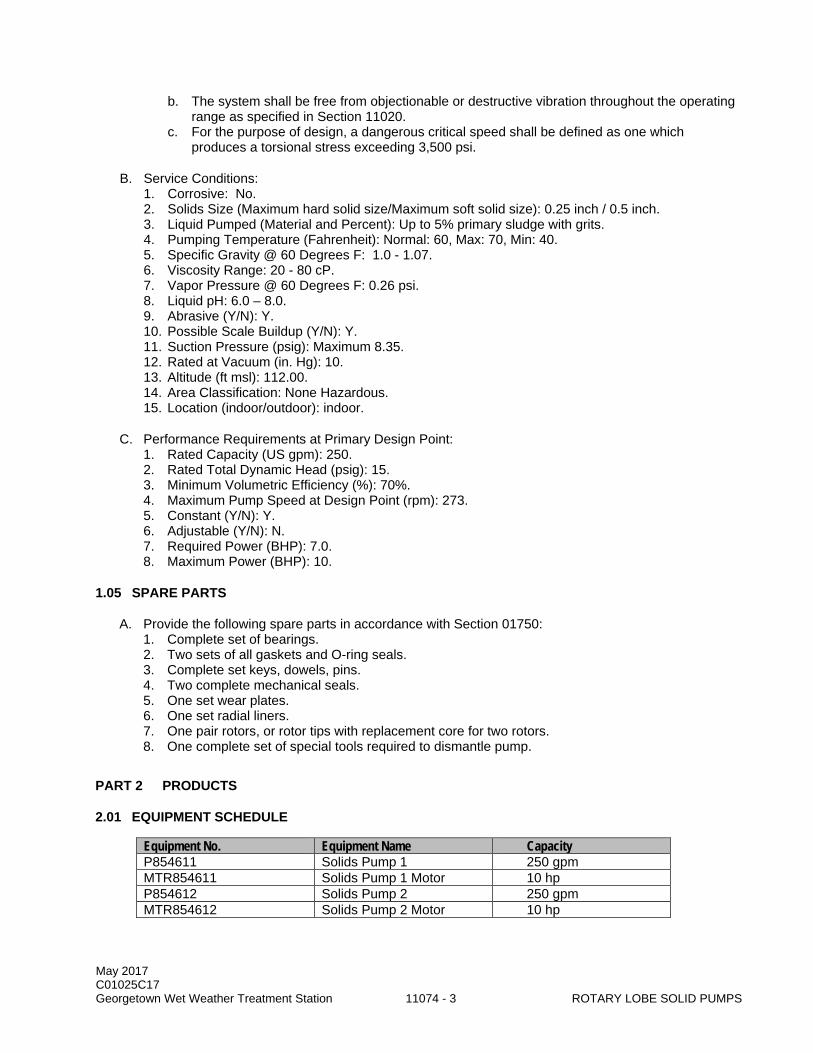
May 2017 C01025C17 Georgetown Wet Weather Treatment Station 11074 - 3 ROTARY LOBE SOLID PUMPS
b. The system shall be free from objectionable or destructive vibration throughout the operating range as specified in Section 11020.
c. For the purpose of design, a dangerous critical speed shall be defined as one which produces a torsional stress exceeding 3,500 psi.
B. Service Conditions: 1. Corrosive: No. 2. Solids Size (Maximum hard solid size/Maximum soft solid size): 0.25 inch / 0.5 inch. 3. Liquid Pumped (Material and Percent): Up to 5% primary sludge with grits. 4. Pumping Temperature (Fahrenheit): Normal: 60, Max: 70, Min: 40. 5. Specific Gravity @ 60 Degrees F: 1.0 - 1.07. 6. Viscosity Range: 20 - 80 cP. 7. Vapor Pressure @ 60 Degrees F: 0.26 psi. 8. Liquid pH: 6.0 – 8.0. 9. Abrasive (Y/N): Y. 10. Possible Scale Buildup (Y/N): Y. 11. Suction Pressure (psig): Maximum 8.35. 12. Rated at Vacuum (in. Hg): 10. 13. Altitude (ft msl): 112.00. 14. Area Classification: None Hazardous. 15. Location (indoor/outdoor): indoor.
C. Performance Requirements at Primary Design Point: 1. Rated Capacity (US gpm): 250. 2. Rated Total Dynamic Head (psig): 15. 3. Minimum Volumetric Efficiency (%): 70%. 4. Maximum Pump Speed at Design Point (rpm): 273. 5. Constant (Y/N): Y. 6. Adjustable (Y/N): N. 7. Required Power (BHP): 7.0. 8. Maximum Power (BHP): 10.
1.05 SPARE PARTS
A. Provide the following spare parts in accordance with Section 01750: 1. Complete set of bearings. 2. Two sets of all gaskets and O-ring seals. 3. Complete set keys, dowels, pins. 4. Two complete mechanical seals. 5. One set wear plates. 6. One set radial liners. 7. One pair rotors, or rotor tips with replacement core for two rotors. 8. One complete set of special tools required to dismantle pump.
PART 2 PRODUCTS
2.01 EQUIPMENT SCHEDULE
Equipment No. Equipment Name Capacity P854611 Solids Pump 1 250 gpm MTR854611 Solids Pump 1 Motor 10 hp P854612 Solids Pump 2 250 gpm MTR854612 Solids Pump 2 Motor 10 hp
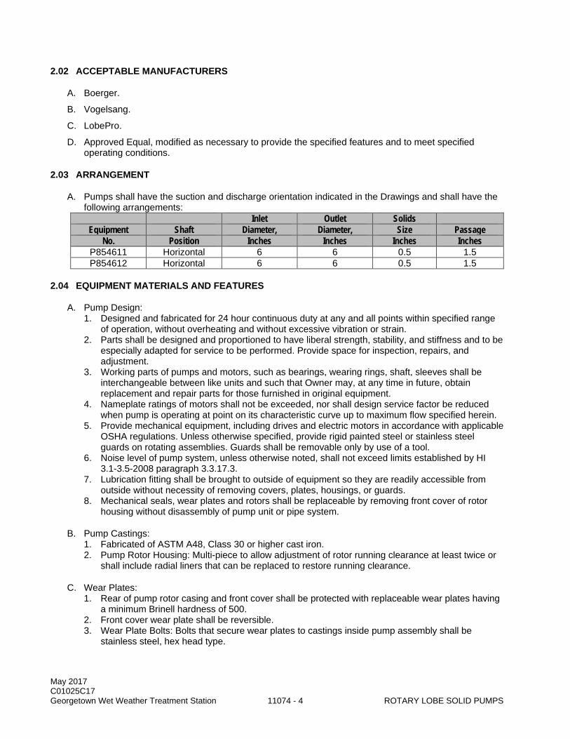
May 2017 C01025C17 Georgetown Wet Weather Treatment Station 11074 - 4 ROTARY LOBE SOLID PUMPS
2.02 ACCEPTABLE MANUFACTURERS
A. Boerger.
B. Vogelsang.
C. LobePro.
D. Approved Equal, modified as necessary to provide the specified features and to meet specified operating conditions.
2.03 ARRANGEMENT
A. Pumps shall have the suction and discharge orientation indicated in the Drawings and shall have the following arrangements:
Inlet Outlet Solids Equipment Shaft Diameter, Diameter, Size Passage
No. Position Inches Inches Inches Inches P854611 Horizontal 6 6 0.5 1.5 P854612 Horizontal 6 6 0.5 1.5
2.04 EQUIPMENT MATERIALS AND FEATURES
A. Pump Design: 1. Designed and fabricated for 24 hour continuous duty at any and all points within specified range
of operation, without overheating and without excessive vibration or strain. 2. Parts shall be designed and proportioned to have liberal strength, stability, and stiffness and to be
especially adapted for service to be performed. Provide space for inspection, repairs, and adjustment.
3. Working parts of pumps and motors, such as bearings, wearing rings, shaft, sleeves shall be interchangeable between like units and such that Owner may, at any time in future, obtain replacement and repair parts for those furnished in original equipment.
4. Nameplate ratings of motors shall not be exceeded, nor shall design service factor be reduced when pump is operating at point on its characteristic curve up to maximum flow specified herein.
5. Provide mechanical equipment, including drives and electric motors in accordance with applicable OSHA regulations. Unless otherwise specified, provide rigid painted steel or stainless steel guards on rotating assemblies. Guards shall be removable only by use of a tool.
6. Noise level of pump system, unless otherwise noted, shall not exceed limits established by HI 3.1-3.5-2008 paragraph 3.3.17.3.
7. Lubrication fitting shall be brought to outside of equipment so they are readily accessible from outside without necessity of removing covers, plates, housings, or guards.
8. Mechanical seals, wear plates and rotors shall be replaceable by removing front cover of rotor housing without disassembly of pump unit or pipe system.
B. Pump Castings: 1. Fabricated of ASTM A48, Class 30 or higher cast iron. 2. Pump Rotor Housing: Multi-piece to allow adjustment of rotor running clearance at least twice or
shall include radial liners that can be replaced to restore running clearance.
C. Wear Plates: 1. Rear of pump rotor casing and front cover shall be protected with replaceable wear plates having
a minimum Brinell hardness of 500. 2. Front cover wear plate shall be reversible. 3. Wear Plate Bolts: Bolts that secure wear plates to castings inside pump assembly shall be
stainless steel, hex head type.

May 2017 C01025C17 Georgetown Wet Weather Treatment Station 11074 - 5 ROTARY LOBE SOLID PUMPS
D. Rotors: 1. Driven through positive timing gears running in oil. 2. Solid cast-iron rotor cores shall be covered with a layer of Buna-N at an average durometer
hardness of 70 as per ASTM D2240. 3. Geometry:
a. Rotor core shall be same as that of finished rotor. b. Linear with three or four lobes to provide a near pulseless flow.
4. Designed for pumping thickened waste, primary and secondary sludge, and anaerobically digested sludge containing organic solids, small inorganic particles, and grit.
E. Shafts: 1. Fabricated of alloy steel AISI A4140. 2. Protected from wetting by fluid being pumped or fabricated of carbon steel with ceramic coated
stainless steel sleeves through seal area. 3. Maximum shaft deflection shall be 0.0018 inches.
F. Mechanical Seals: 1. Mechanical style with tungsten carbide seal faces. Cartridge style mechanical seals that use
bushings to permanently place seals are acceptable. 2. All mechanical seals shall have a shaft sleeve installed to protect the pump during seal failure. 3. Seal Holders: Fabricated of Type 304 stainless steel materials that are suitable for prolonged
corrosion and chemical resistance. 4. Pumps that utilize packing glands or require external flushing for lubrication and cooling are not
acceptable.
G. Quench/Blocking Chamber: 1. Oil-filled quench/blocking chamber located behind mechanical seal, and in front of bearing
housing lip seal shall be molded into casting of pump, or mounted into the cartridge seal of the pump.
2. Chamber shall be suitable for fill, from top of pump, through fill ports and have an external sight glass or oil bottle for visual inspection of status of mechanical seal operation.
3. Oil shall provide lubrication and cooling of seals.
H. Flanges: 1. Port Connection: ANSI 125 pound or 150 pound rated or greater. 2. Inlet and outlet ports shall be constructed of grey iron, or mild steel fittings and flanges bolted to
rectangular ports on pump casting. 3. Ports shall be oriented horizontally without offset unless otherwise indicated in the Drawings. 4. Inlet and outlet ports shall be fabricated to fit the dimensions indicated in the Drawings, but not to
exceed 2 feet-6 inches between flange faces of pump inlet and outlet ports, unless otherwise approved by the Project Representative.
I. Pump Front Cover: 1. Provide access to pump chamber without disconnecting pipe work or bearings. 2. When opened shall provide unhindered access to rotors, wear plate, and mechanical seals.
J. Bearings: 1. Sized to withstand maximum radial or axial load carried by shafts for continuous duty. 2. Minimum ABMA L10 Bearing Life:
a. Running at Steady or Constant Speed, Load, Pressure and Temperature: 100,000 hours. b. Operated with Variable Frequency Drive: 50,000 hours.

May 2017 C01025C17 Georgetown Wet Weather Treatment Station 11074 - 6 ROTARY LOBE SOLID PUMPS
K. Timing Gears and Gear Housing: 1. Meet AGMA Class 8 quality minimum. 2. Keyed and timed to prevent contact between rotors and provide smooth and quiet transmission of
load. 3. Located in separate oil-filled, cast-iron gear box fitted with a sight glass to monitor oil level.
L. Gear Reducer: 1. In-line gear reducer designated for continuous duty at moderate shock load. 2. Meet AGMA Class II, with service factor of 1.4 minimum for pump applications with moderate
shock, continuous duty and AGMA Class III, with service factor of 2.0 minimum for heavy shock, continuous duty operation.
3. C face, mounted with C face drive motor to form integral gearmotor combination.
M. Structural Base: Rotary lobe pump, gear reducer, motor or gearmotor shall be mounted on a structural steel baseplate, with structural channel supports as necessary, complete with couplings, guards, and mounting hardware.
N. Drive Motor: 1. Horsepower: 10. 2. Voltage: 460. 3. Phase: 3. 4. Synchronous Speed (rpm): 1800. 5. Service Factor: 1.15. 6. Inverter Duty: No. 7. Enclosure: TEFC.
2.05 ACCESSORIES
A. Equipment Identification Plate: 1. 16-gauge stainless steel with 1/4-inch die-stamped equipment tag number securely mounted in a
readily visible location giving name of manufacturer, rated capacity, head, speed and other pertinent data. Attach to each pump, motor, and gear reducer.
2. Additionally, pump serial number, model, gear reduction and motor horsepower shall be cut or stamped into steel plate and welded to skid for permanent identification.
B. Lifting Lugs: Equipment weighing over 100 pounds.
C. Anchor Bolts: Type 316 stainless steel, sized by equipment manufacturer, 1/2-inch minimum diameter, and as specified in Section 05501.
2.06 FACTORY FINISHING
A. Prepare, prime and finish in accordance with Section 09900. System B-1.
PART 3 EXECUTION
3.01 FACTORY TESTS
A. General: Factory test pumps for performance and hydrostatic pressure as specified in the Hydraulic Institute Test Code. Actual performance at the maximum rated speed may be predicted from test data in accordance with the affinity relationships subject to the following restrictions: 1. Conduct the test at no greater than the next highest synchronous motor speed above the rated
speed.

May 2017 C01025C17 Georgetown Wet Weather Treatment Station 11074 - 7 ROTARY LOBE SOLID PUMPS
2. Measure at least 10 data points to predict the pump's operating characteristics (capacity, head, efficiency, power) for the rated speed and other speeds required to satisfy the specified operating conditions. a. The data shall extend at least 15 percent beyond the pump's rated capacity at rated speed.
B. The Engineer reserves the right to witness the factory testing. Inform the Project Representative and the Engineer at least 30 days prior to the factory tests.
3.02 INSTALLATION
A. Align, connect and install each pump in accordance with the manufacturer's instruction.
3.03 FIELD TESTING
A. After installation, field-test the equipment over the entire range of operation with all flows and suction and discharge pressures recorded in a test log.
B. Field testing shall be in accordance with Section 01660.
3.04 FIELD FINISHING
A. Touch up on the field in accordance with Section 09900. System B-1.
3.05 TRAINING
A. Procedures: Section 01660.
B. A manufacturer’s representative shall provide a minimum of four 2-hour sessions of classroom training. Two sessions will be specific to operations while two sessions will be specific to maintenance. Conduct one training session per week on consecutive weeks to accommodate the shift schedules of operations and maintenance staff.
C. Total of eight hours.
D. Certify completion of training on Form 11000-B, see Section 01999.
END OF SECTION

May 2017 C01025C17 Georgetown Wet Weather Treatment Station 11074 - 8 ROTARY LOBE SOLID PUMPS
This page intentionally left blank.
May 2017 C01025C17 LOW EMISSION DIESEL ENGINE STANDBY Georgetown Wet Weather Treatment Station 11083 - 1 GENERATOR SET 150 KW AND LARGER
SECTION 11083
LOW EMISSION DIESEL ENGINE STANDBY GENERATOR SET 150 KW AND LARGER
PART 1 GENERAL
1.01 SUMMARY
A. This Section specifies a diesel engine-generator set that will be operated to provide standby power. The engine generator supplier will also supply design and coordinate the above around diesel storage tank specified in Section 13411.
1.02 QUALITY ASSURANCE
A. Referenced Standards: This Section incorporates by reference the latest revision of the following documents. These references are a part of this Section as specified and modified. In case of conflict between the requirements of this Section and those of the listed documents, the requirements of the Section shall prevail. Reference Title 40 CFR Part 1039, Subpart G 1039.625
Code of Federal Regulations Part 1039 - Control of Emissions for New and In- Use Nonroad-Compression Ignition Engines Subpart G – Special Compliance Provisions
Puget Sound Clean Air Agency Regs, Art. 9 and Art. 15
Article 9: Emission Standards and Section 9.03 Emission of Air Contaminants: Visual Standard and Article 15: Nonroad Engines
IFC 79 International Fire Code – Vent Sizing ISO 8528 Reciprocating Internal Combustion Engine Driven Alternating Current Generating
Sets NEMA MG1 National Electrical Manufacturers Association Standards Publication MG-1 NEMA 250 Enclosures for Electrical Equipment (1000 Volts Maximum) NETA-ATS International Electrical Testing Association - Acceptance Test Specifications NFPA 37 National Fire Protection Association Standard 37, Standard for the Installation and
Use of Stationary Combustion Engines and Gas Turbines NFPA 30 Flammable and Combustible Liquids Code NFPA 70 National Electrical Code (NEC) and local amendments NFPA 110 Emergency and Standby Power Systems SAE J 1349 Society of Automotive Engineers Engine Power Test Code – Spark Ignition and
Compression Ignition – As Installed Net Power Rating UL 142 Steel Aboveground Tanks for Flammable and Combustible Liquids UL 508 Standard for Industrial Control Equipment UL 508A Standard for Industrial Control Panels UL 2200 Standard for Stationary Engine Generator Assemblies SFC Chapter 57 Seattle Fire Code Flammable and Combustible Liquids 7-32 FM Global Property Loss Prevention Data Sheets, Ignitable Liquid Operation 7-88 FM Global Property Loss Preventative Data Sheets, Flammable Liquids Storage Tanks
B. Qualifications: 1. The equipment supplier shall have available 24 hour-per-day service by factory-trained
technicians and shall have a manufacturer’s authorized dealers parts and service facility located within 50 miles of the Site.
May 2017 C01025C17 LOW EMISSION DIESEL ENGINE STANDBY Georgetown Wet Weather Treatment Station 11083 - 2 GENERATOR SET 150 KW AND LARGER
2. Torsional Analysis Engineer: a. Professional Engineer registered in the state of Washington routinely engaged in the
preparation of Torsional Vibration Analysis and Critical Speeds analysis. 3. Electrical Engineer:
a. An electrical engineer with a minimum of five years of experience working for the Manufacturer.
b. Shall have either a 4-year undergraduate degree from a university having an electrical engineering program accredited by Engineering Accreditation Commission (EAC) of Accreditation Board for Engineering and Technology, Inc. (ABET), or a professional license.
4. Testing Agency: An electrical testing agency accredited by NETA.
1.03 SUBMITTALS
A. Procedures: Section 01300.
B. Qualifications.
C. General: 1. Drawings include:
a. Installation drawings (plans and sections) for the complete engine generator set. b. Exhaust system drawings. c. Generator control panel fabrication drawings showing the location, size and other details for
mounting and installation. d. Electrical and controls interface, and interconnection drawings showing all internal and
external wiring and terminations. e. Electrical one-line diagrams. f. Project specific configuration/parameters by electrical switchboard vendor: time delay
settings, trip settings, ATS settings (from/to utility and standby power configuration), etc. g. Copy of all configuration parameters or switch settings.
2. Equipment color. 3. Wet weight of each complete unit and of heaviest single component. 4. Factory prepared torsional vibration analysis report. 5. Foundation, mounting and isolation requirements and vibration isolation system transmissibility
calculations. Include seismic design calculations and data as required by Section 01031. 6. Calculations of vent sizes per IFC 79 signed and approved by the local fire marshal. 7. Manufacturer template locations for stub-up of conduits at the engine generator equipment pad
and engine generator control panel. 8. Field test procedures submitted 14 days prior to testing. 9. Commissioning plan submitted 30 days prior to commissioning. 10. Register programming and configuration software to the County. 11. Manufacturer engine control software. 12. Seismic design calculations and data: as required by Section 01031.
D. Engine: 1. Torque, brake horsepower, and fuel consumption curves for the specified conditions. 2. Complete fuel piping schematics for engine-mounted auxiliaries showing the relative position of
all piping, filters, valves, and appurtenances and including fuel regulatory data. 3. Catalog information and operating description of fuel storage and transfer system. 4. Interface schematics. 5. Details of governing system. 6. Cooling system design data, including heat rejection to jacket water, intercooler, lube oil, ambient
air, and exhaust. 7. Complete lube oil piping schematics showing the relative positions of all valving, pumps, filters,
temperature and pressure detectors.
May 2017 C01025C17 LOW EMISSION DIESEL ENGINE STANDBY Georgetown Wet Weather Treatment Station 11083 - 3 GENERATOR SET 150 KW AND LARGER
8. Complete cooling water piping schematics, showing the relative position of all pumps, temperature and level sensing components, remote radiator, heat exchangers and safety devices, and the rate of flow in all cooling water circuits.
9. Complete details of all safety devices and system instrumentation for sensing: pressure, temperature, level etc.
10. Manufacturer's model number and descriptive information. 11. Sound level information, by octave band, on engine with fan and silencer attenuation. 12. Engine starting:
a. Engine cranking voltage. b. Number of batteries. c. Battery rating of completed bank, amp-hour. d. Battery dimensions. e. Recommended size of battery cables, AWG. f. Battery voltage - 24 VDC.
13. Radiator airflow and static pressure (external to radiator). 14. Exhaust gas flow rate, in acfm, and temperature at rated condition. 15. Circuit information for engine jacket water heater.
E. Generator: 1. Weight. 2. Stator and field ratings, including: temperature rise at full load and overload conditions. 3. Complete description of insulation system. 4. Generator impedances: Xd, Xq, Xd', Xd", X2, Xo. 5. Catalog data showing kVA, full load amperes, etc. 6. Generator decrement curve. 7. Available fault current.
F. Generator impedances and fault current information for the electrical system analyses reports specified in Section 16431.
G. Fault current information verifying compliance with the arc flash requirements specified in Section 16432.
H. Engine Generator Controls and Power Distribution: 1. Project- specific wiring, detailed panel fabrication drawings, elementary and
process/instrumentation diagrams for the generator engine control system and interfaces to the facility control system, power distribution, voltage regulation and excitation circuitry showing identified terminals and identified conductors.
2. Catalog information for all panel face instruments, meters, gauges, switches, devices, control system components (including any optional accessories), any skid mounted termination boxes, terminal strips, the control panel lighting configuration and method.
3. Conduit stub-out locations. 4. Operating temperature setpoints.
I. Exhaust Silencer: 1. Sound level information for engine, exhaust outlet data throughout the entire frequency range and
attenuation provided by the silencer throughout its entire frequency range.
J. Factory Test Report. 1. Copies of all generator test documentation.
K. Source Quality Control documentation.
L. Operation and maintenance information: Section 01730.
M. Special Warranty per this Section.

May 2017 C01025C17 LOW EMISSION DIESEL ENGINE STANDBY Georgetown Wet Weather Treatment Station 11083 - 4 GENERATOR SET 150 KW AND LARGER
N. Finalized, complete as-constructed, electrical wiring, panel, elementary and process/instrument diagrams showing connection and interconnection of identified terminals and identified conductors to components of the complete electrical system.
O. Field Testing Agency procedures and test results, including forms 11000-A, 11000-B, and 11060-A per Section 01999.
P. Engine shall have a label affixed certifying EPA Emergency Stationary conformance.
Q. Exhaust system design calculations including piping system expansion and contraction and system flexibility at flexible connections to accommodate system thermal conditions. Provide calculations for all exhaust system supports to document support vertical and horizontal load capacity.
R. Spare Parts: Section 01750.
1.04 ENGINEER RESPONSIBILITY
A. Provide technical design and support the following: 1. Preparation of submittals. 2. Addressing any comments or questions and preparing any re-submittals as necessary. 3. Coordinating factory acceptance test. 4. Other activities required to ensure that the generator provided complies with the Contract
Documents.
B. Provide trouble-shooting of standby power generation system installation, testing, commissioning, operation and warranty.
1.05 SITE CONDITIONS
A. Equipment shall be installed in location(s) as indicated in the Drawings. The equipment will be installed indoors within the Georgetown CSO Treatment Facility generator room in Seattle, Washington, at an approximate elevation of 13 feet above mean sea level (MSL). The ambient conditions are expected to be in the following ranges: 1. Temperature, degrees F: 30 to 100. 2. Relative humidity, percent: 10 to 100.
1.06 DELIVERY, STORAGE, AND HANDLING
A. See Section 11000.
B. The equipment to be furnished under this Section shall be shipped to the site with weathertight covers on all piping and electrical connections.
C. Shaft housing penetrations shall be sealed in a manner that shall protect against damage from the elements and deterioration of the equipment due to moisture, corrosive gases, dirt and debris.
D. Each individual shipment shall be packaged in a manner designed to protect the equipment against damage caused by sudden acceleration or deceleration, and shall have an accelerometer affixed to the unit prior to shipment.
E. Storage of the equipment before, during and after shipment to the site shall include watertight temporary enclosure covers, heaters, and all other environmental controls to ensure dry conditions and adequate protection. Winding and block heaters shall be temporarily powered and checked daily until permanent power is applied.

May 2017 C01025C17 LOW EMISSION DIESEL ENGINE STANDBY Georgetown Wet Weather Treatment Station 11083 - 5 GENERATOR SET 150 KW AND LARGER
F. Provide any necessary inspections to ensure the equipment is stored in accordance with this Specification.
1.07 SPECIAL WARRANTY
A. Reference Section 01740.
B. The warranty shall in no event be for a period of less than five years from date of Substantial Completion of the System or 2,500 operating hours, whichever comes first. Warranty starts at equipment startup, which may be several months before substantial completion.
C. Warranty shall include a local cylinder head exchange program, repair parts, labor, reasonable travel expense necessary for repairs at the Site, and expendables (lubricating oil, filters, antifreeze, and other service items made unusable by the defect) used during the course of repair. Applicable deductible costs shall be specified in the manufacturer's warranty.
D. A warranty nameplate of not less than 6 inches x 8 inches shall be affixed to the generator set with the following data: 1. Warranty Period. 2. Start-up Date. 3. Termination Date. 4. Supplier Name. 5. Supplier Address. 6. 24-Hour Emergency Number. 7. Name of organization to perform maintenance.
PART 2 PRODUCTS
2.01 EQUIPMENT SCHEDULE
Equipment Number Description BAT854901A Engine Generator Battery Rack 1 BAT854901B Engine Generator Battery Rack 2 E854901 Generator Engine G854901 Engine Generator LCP854901 Engine Generator Control Panel S854901 Engine Generator Exhaust Silencer
2.02 GENERAL
A. Type: 1. The generation unit shall be driven by a heavy-duty, four-stroke, 1800 rpm, turbocharged, diesel-
powered, internal combustion engine suitable for standby operation at constant speed under the specified conditions.
2. Shall be specifically designed to meet EPA Emergency Stationary Regulations for air pollution emissions.
3. The unit may run continuously for several days. 4. Engine generator shall be compliant with UL 2200.
B. The generator shall be a three-phase, four-wire, six lead, wye-connected solidly grounded, revolving field, brushless, permanent magnet excited, synchronous type.
C. General Requirements: 1. Generator rating, kW: 500. 2. Fuel tank, gallons/location: 1000/Above Grade, Outdoors.
May 2017 C01025C17 LOW EMISSION DIESEL ENGINE STANDBY Georgetown Wet Weather Treatment Station 11083 - 6 GENERATOR SET 150 KW AND LARGER
3. Fuel suction lift required, feet: 8 ft. static + friction. To be confirmed by supplier. 4. Radiator mounting: Skid.
D. Equipment shall be in current production as a standard series. Material and parts in this unit shall be new and unused, of current manufacture, of the highest grade, and free from all defects affecting performance.
E. The engine, flywheel, generator, intermediate couplings and accessories attached to the power train, shall be designed to be free from dangerous torsional vibratory criticals and critical speeds from 25 percent below to the unit's operating synchronous speed.
2.03 ACCEPTABLE MANUFACTURERS
A. Caterpillar.
B. Cummins.
C. MTU Onsite Energy Corporation.
D. No Substitutions.
2.04 ACCEPTABLE PRODUCTS
A. Engine: The engine shall be one of the engine-generator series that is prequalified for this size engine-generator and for this project, modified as needed to meet the requirements of these Specifications.
B. Generator: The generator shall be one of the engine-generator series that is prequalified for this size engine-generator and for this project, modified as needed to meet the requirements of these Specifications.
C. Engine-Generator Control Panel: The generator set shall be provided with a generator mounted control panel that is designed and manufactured by the prequalified engine-generator manufacturer modified as needed to meet the requirements of these Specifications.
2.05 SYSTEM DESCRIPTION
A. General: 1. Shall include the capability of automatically controlling generator set operation. 2. After starting, the unit will attain rated speed and voltage, and accept rated load. 3. Speed shall be controlled by the engine governor, while generator output voltage regulation shall
be a function of the generator automatic voltage regulator. 4. Manual adjustment of generator speed and voltage at the generator control panel shall be
provided. 5. Start, stop, and cool-down sequences shall be initiated manually or automatically by the closing
or opening of a contact. 6. The control system shall automatically engage the cranking motor, sense engine starting speed,
disengage the motor, and arm the engine protection circuit.
B. Automatic Mode: 1. Shall operate as follows in automatic AUTO mode. 2. Upon receipt of a start/run signal (closed dry contact) from the automatic transfer scheme
specified in Section 16250, the engine shall immediately start. 3. The engine controls shall bring the engine up to operating speed and stabilize it at a generator
frequency of 60 Hz.
May 2017 C01025C17 LOW EMISSION DIESEL ENGINE STANDBY Georgetown Wet Weather Treatment Station 11083 - 7 GENERATOR SET 150 KW AND LARGER
4. Controls shall excite the generator field and stabilize the output at 480V.
C. Run Mode: 1. Operation of the engine-generator in the run (MANUAL) mode shall be the same as in the
automatic mode except that the engine start/stop signals shall be manually initiated from the engine control panel.
2. When MANUAL engine-generator operations are no longer desired, the control panel selector switch shall be placed in AUTO mode and aligned for engine starting by automatic means from the auto transfer scheme upon loss of normal power.
D. Test Mode: 1. County provided load bank is to be interconnected with load bank receptacle enclosure
MEE854901 for exercising the engine generator. 2. The Test Mode for the engine generator shall be the same as the MANUAL run mode. 3. Once the engine-generator tests are complete, the load bank will be manually disconnected from
the service switchboard. 4. Generator shall continue to run in MANUAL until its cool down period is complete. 5. Generator shall then be manually stopped and placed in AUTO to enable engine starting by
automatic means from the transfer controls upon loss of Normal power. 6. Generator shall start and run in response to a “Test Run” command. Test runs shall be
conducted with only the load bank.
2.06 PERFORMANCE AND DESIGN REQUIREMENTS
A. General: The engine shall be rated as follows: 1. Maximum piston speed: 2,500 feet per minute. 2. Rotational speed: 1,800 rpm, maximum. 3. Fuel: Diesel No. 2. 4. Minimum external fan backpressure: 0.5 in w.c. capability (after radiator).
B. Generator suppliers shall provide the following for the generator submittal: 1. Rated brake horsepower, minimum with fan. 2. Break mean effective pressure at rated output, psi. 3. Fuel consumption, maximum gallons per hour.
C. Exhaust Silencing: 1. Provide an Extreme Application Series exhaust silencer. 2. Exhaust silencer supported above the engine as shown and shall be of the horizontal, multi-
chamber, tuned port type. 3. Combination of exhaust piping design and silencers: Provide a minimum sound level attenuation
of 45 to 52 dBA for all frequencies. 4. Silencer and exhaust system to be designed to accommodate a future Diesel Particulate Filter.
D. Exhaust Emissions: The engine shall be specifically designed to minimize the discharge of gaseous pollutants to the atmosphere. Emission levels shall comply with U.S. EPA emission standards under 40 CFR Part 1039, Subpart G 1039.625 for non-road emergency stationary diesel engine emission levels and Puget Sound Clean Air Agency Article 9.03 Emission of Air Contaminants: Visual Standard and Article 15 Nonroad Engines.
E. Fuel Control Systems: 1. Capable of continuously monitoring engine operating performance and adjusting the operating
parameters to obtain optimum emissions and fuel consumption levels without loss or dip in power.
2. Adjustments shall be accomplished in a manner that will not reduce engine efficiency or result in greater pollutant emissions.

May 2017 C01025C17 LOW EMISSION DIESEL ENGINE STANDBY Georgetown Wet Weather Treatment Station 11083 - 8 GENERATOR SET 150 KW AND LARGER
3. Engine shall operate efficiently from 50 to 100 percent of the specified rated output; exhaust emission characteristics must be maintained at all engine loading conditions without manual engine adjustments.
F. Service Piping: 1. The engine supplier shall be responsible for properly sizing the service piping within the engine
and cooling water systems and fuel supply/return system. 2. The engine supplier shall also be responsible for all flexible connections between the engine-
driven pump set and field piping. 3. Service piping to and from the engines shall be routed along and anchored to the engine sub
base. 4. The connection to field piping shall be made with flexible metal hoses at the backs or sides of the
engines. 5. No valves or pressure regulators shall be installed on the engine side of the flexible connections.
G. Skid-Mounted Radiator Engine Cooling: 1. Engine cooling system specified with a skid-mounted radiator in this Section shall be a closed-
loop, engine powered, air-cooled, front-mounted radiator type. 2. Engine jacket water and auxiliary water from the closed-loop cooling system shall be circulated
through the engine jacket, and all auxiliary circuits, through a generator-set-mounted radiator by an engine-driven pump.
3. Engine cooling water system shall include an electric heater for the engine jacket coolant, which shall keep the engine block warm to facilitate quick starts and immediate application of full load.
H. Circuit Breakers: Provide the following circuit breakers mounted on the generator set: 1. 800AF breaker for the generator. 2. 800AF breaker for portable loadbank connection to loadbank receptacle enclosure MEE854901. 3. 800AF breaker for interconnection to 800A, 4-pole auto-transfer switch.
2.07 GENERATOR DESIGN REQUIREMENTS
A. General: The generator shall be rated as follows: 1. Rated kW (Standby): 500 kW at 1,800 rpm with 0.8 power factor. 2. Output voltage: 480/277V, three-phase, 60Hz, four-wire, six lead, wye connected, fully rated
neutral. 3. Insulation: Class H, with Class F temperature rise. 4. Lugs: The generator shall have bus bars for connection of all load cables and shall have space
for terminating five sets of 500 kCM cables.
B. Voltage: The following voltage requirement shall be provided: 1. Steady-state nominal voltage at rated kW: as indicated above. 2. Manual adjustment: ±5 percent of nominal. 3. Regulation: Not to exceed 1 percent. 4. Steady-load bandwidth: Not to exceed ±0.5 percent. 5. Transient response: The transient voltage response shall not exceed 20 percent and the
recovery shall not exceed 3 seconds, upon a single step block load. If generator set does not meet this requirement the genset will need to be upsized to the next larger size.
6. Voltage waveform distortion from no load to full linear load shall not exceed 5 percent total harmonic distortion. No single harmonic shall exceed 3 percent.
C. Frequency: The following frequency requirements shall be provided: 1. Steady-state nominal frequency at rated kW: 60 Hz. 2. Synchronous operating speed at nominal frequency: 1,800 rpm. 3. Regulation, no load to full load: Isochronous: ±0.25 percent. 4. Steady-load bandwidth: Not to exceed ±0.5 percent.

May 2017 C01025C17 LOW EMISSION DIESEL ENGINE STANDBY Georgetown Wet Weather Treatment Station 11083 - 9 GENERATOR SET 150 KW AND LARGER
5. Transient response: a. Based upon 25 percent load steps. b. Dip, with step application of loads as indicated above, shall not exceed 4 percent. c. Recovery time: Not to exceed 5 seconds.
2.08 ENGINE-GENERATOR CONTROL PANEL DESIGN REQUIREMENTS
A. Electrical Diagrams: 1. Provide complete wiring, panel, elementary and process/instrumentation diagrams shown in
point-to-point fashion for the engine-generator engine control, paralleling switchgear, power distribution, voltage regulation, and excitation circuitry.
2. Provide breaker status via a red LED type light for breaker closed and a green LED type light for breaker open.
3. Supplier shall be responsible for determining conduit and conductor sizes for all devices and controls furnished under this Section.
4. Elementary diagrams, schematics, and one-lines, shall show the scheme or sequence in which the devices of the generator engine control system, generator coordination panel, power distribution, voltage regulation, breaker control, and excitation circuitry are connected in relation to each other.
5. Panel diagrams shall show the physical location of the parts of an electrical system. In each case, every conductor and terminal shall be labeled and identified.
B. Electrical Energy Source: 1. Normal electric power for control shall be 24 VDC from the engine starting batteries. 2. Engine supplier shall be responsible for providing any voltage transformation equipment required.
C. Engine Controls and Instrumentation: 1. Engine control and instrumentation systems shall be integrated into an engine-mounted engine
generator control panel which shall be bottom fed. 2. Conductors and cables that interface with devices mounted on the generator skid to devices
mounted off the skid shall leave the generator skid from grouped termination boxes. 3. Provide three terminal boxes:
a. 480 volt or 240 volt power, whichever is applicable. b. 120, 208, 240 or 480 volt power and control. c. 24-volt control and millivolt signals.
4. Isolate the 24-volt and millivolt voltage inside of the control panel from the 120 or 480-volt terminations.
5. Provide labeled terminal strips and conductors at the engine-generator control panel and at the termination boxes for these circuits.
6. Conductors entering the control panel shall land on labeled terminal strips prior to final connections on the discrete components.
7. Operator control devices, gauges, meters, machine monitoring, etc., associated with engine shall be face-mounted in the control panel.
8. Terminal boxes shall be provided on the engine generator set for interfacing power, control, and monitoring circuits between the control panel and the engine generator set.
9. Terminal boxes shall utilize labeled terminal strips and conductors. 10. Provide 24V auxiliary relays as required to signal the motorized dampers for the generator intake
and exhaust louvers. 11. Dry contacts from the auxiliary relays shall signal the motor starters to deenergize the motorized
dampers when the engine receives a run signal.
D. All indication, gauges, meters shall be 24 VDC back lighted devices or the control panel shall be provided with 24 VDC control panel face lighting that shall be mounted at the top of the panel and provide suitable lighting for clear and easy viewing of the panel face mounted devices.
May 2017 C01025C17 LOW EMISSION DIESEL ENGINE STANDBY Georgetown Wet Weather Treatment Station 11083 - 10 GENERATOR SET 150 KW AND LARGER
2.09 ENGINE COMPONENTS
A. General: 1. Diesel engine-generator set shall consist of a diesel engine, skid-mounted engine radiator
system, engine-mounted accessories, and direct-connected generator, all mounted on a rigid base and frame. a. Engine accessories shall be installed by the engine supplier. b. The frame shall be supported by steel spring isolators. c. Anchor bolts shall be provided by Contractor and designed as specified in Section 01031.
2. Flexible couplings for jacket water, lube oil, fuel, and exhaust piping shall be provided. 3. Water connectors braided, fiber jacketed rubber hoses. 4. Oil and fuel connectors shall be braided stainless steel jacketed rubber hoses with synthetic
liners, meeting Factory Mutual requirements. 5. All hoses shall be, at a minimum, 150 psig working pressure. Fuel connectors shall bear the
Underwriters Laboratories label. 6. The exhaust connector shall be unbraided, stainless steel, suitable for temperatures up to 1,300
degrees F. 7. Engine couplings shall be as follows:
a. Exhaust flex will be stainless steel bellows with carbon steel turbo and muffler connections. b. Fuel flex connections will be rubber lined with stainless braiding on the outside. c. Radiator hoses will be rubber with fiber braiding.
B. Engine: 1. General: The engine shall be a four-stroke cycle, turbocharged, water-cooled, diesel fuel unit
capable of meeting the design and performance requirements operating on No. 2 diesel fuel. 2. Base and Frame:
a. The engine base shall be of rigid construction with heavy transverse girders formed to support the crankshaft main bearings.
b. The engine frame shall be a suitable box shape to provide longitudinal and transverse rigidity. 3. Cylinders:
a. Cylinders shall be cast with the engine block. b. Engine block shall be cast iron with replaceable wear liners. c. Cylinder liners shall be finished to give a straight bore and shall be machined and honed.
4. Cylinder Heads: a. Shall be of the individual valve-in-head type constructed of cast iron with valve guides and
plug sockets fully jacketed for efficient cooling. b. Renewable hardened steel inserts shall be provided for all valve stem guides. c. Valve seats shall be made of hardened steel selected specifically for high temperature
service. 5. Crankshaft:
a. The crankshaft shall be made from a single forged steel billet and heat treated. b. Shall be sized to provide a liberal margin of safety against abnormal strains. c. Journals shall be hardened and micropolished. d. The shaft shall be finished all over, drilled and ported for pressure lubrication of all bearings
and statically and dynamically balanced after fabrication. e. If of two-piece design, the crankshaft shall be machined and balanced as a single unit.
6. Main Crankshaft Bearings: a. The main crankshaft bearings shall be amply sized and shall be arranged for replacement
without removing the crankshaft. b. The bearing at the flywheel end of the engine shall be of greater area than the intermediate
crankshaft bearings. c. Bearing caps shall be fitted into place and bolted to the frame.

May 2017 C01025C17 LOW EMISSION DIESEL ENGINE STANDBY Georgetown Wet Weather Treatment Station 11083 - 11 GENERATOR SET 150 KW AND LARGER
7. Connecting Rods and Crank Pin Bearings: a. The connecting rods shall be made of heat-treated steel forgings. b. The crank end of the rod shall be of tee foot design for use with two-piece babbitted or
sleeved crank pin boxes. c. Provision shall be made for the use of large through bolts to securely fasten the crank pin
boxes to the foot of the rod. d. The design shall permit removal of the piston and connecting rod through the cylinder liner. e. Oil jets shall supply piston cooling and lubricating oil; drilled connecting rod passages will not
be permitted. 8. Flywheel:
a. The flywheel shall be of heavy-duty design and one-piece construction and shall be made of high-grade close-grained cast iron.
b. Torsional dampers, if required, shall be of the viscous type. 9. Pistons:
a. Oil-cooled made of close-grained cast iron or aluminum alloy accurately machined to size. b. Long in proportion to the diameter and shall be fitted with not less than two compression and
one oil control rings. c. The oil control rings may be located in the piston skirt or above the wrist pin.
10. Piston Pins: a. Made of high-grade steel, hardened and ground to ensure a fine running fit. b. Either of the type that are fitted into the pistons so as to prevent rotation in the pistons but
permitting free expansion of both pistons and pins, or of the full floating type held longitudinally by retaining rings fitted into the wrist pin bore of the piston.
11. Valves and Valve Gear: a. Inlet and exhaust valves shall be precision machined and shall be made of the highest grade
heat-resisting material. b. Valve seats shall be replaceable, of heat resistant high alloy steel. c. Valves shall be the largest possible diameter so as to produce the greatest volumetric
efficiency and adequate scavenging of the cylinders in order to keep valve maintenance to a minimum.
d. Valve mechanisms shall be constructed so as to provide positive action with utmost rigidity. e. Two intake and exhaust valves shall be provided in each cylinder head.
12. Camshaft: a. Alloy steel forgings with integral cams, machined, heat-treated and ground with polished
bearing and contact surfaces. b. Chain driven or driven through gears front or back.
13. Gear Train: Gears shall be lapped and shaved for uniform loading and quiet operation. 14. Exhaust Manifold:
a. Single-outlet and, if in pairs, joined to provide a single exhaust outlet for the engine. b. A flexible stainless steel expansion bellows shall be provided at the outlet whose style shall
be coordinated with the location of the silencer mounting as shown. c. Shielded or insulated to reduce surface temperature to a level that would prevent injury.
15. Engine/Crankcase Breather: a. Engine breather(s) shall be equipped with crankcase ventilation filter(s) to remove oil mist
coming from the crankcase breather vent. b. Neither oil fumes nor condensed liquid oil shall be discharged to the room. c. Return connection point from the filter shall be as directed by the engine manufacturer. d. Connections of liquid or gas lines to the engine’s exhaust air plenum, if any, shall be
separated by flexible connectors. 16. Turbocharger and Aftercooler:
a. The engine combustion air shall be pressurized using exhaust gas driven centrifugal compressor(s).
b. An aftercooler, selected specifically for use with the closed loop engine cooling system, shall be provided for cooling the combustion air.

May 2017 C01025C17 LOW EMISSION DIESEL ENGINE STANDBY Georgetown Wet Weather Treatment Station 11083 - 12 GENERATOR SET 150 KW AND LARGER
17. Air Filters: a. Engine shall obtain the necessary volume of combustion air through inlet air filters of the dry
panel type with replaceable filter cartridges and service indicator. b. Separate filters shall be provided for each cylinder bank. c. Mounted on the engine or engine skid so that they are easily maintained yet do not block
maintenance of other engine parts.
C. Fuel Oil System: 1. General:
a. Engine manufacturer shall be responsible for supply of the Fuel Oil Storage Tank per Section 13411 and both design, provision and coordination of a fuel oil delivery system meeting the functional requirements of this Section 13411.
b. System shall contain the features specified, and additional components as necessary to provide a complete and operable system.
c. Provide for transfer of fuel from bulk storage tank to engine and fuel return to the bulk fuel storage tank from the engine.
d. Major components include a double-walled Fuel Tank per Section 13411, engine driven injector pump, and fuel filtration.
e. Fuel oil piping is specified in Section 15050. Flexible connections shall be provided at fuel piping connections to the engine. Flexible connections shall meet Factory Mutual requirements.
f. Components and Piping to conform with SFC Chapter 57. 2. Bulk Storage Tank: The bulk fuel storage tank shall have a capacity of 1000 gallon and tank and
fuel monitoring system as specified in Sections 13411 and 16621. 3. Fuel Oil Cooler:
a. Provide a radiator-mounted integral, fuel oil cooler to provide cooling of fuel returned to storage tank from engine.
b. Radiator shall be sized adequately to maintain fuel temperatures at or below engine manufacturer’s recommended fuel temperatures, when operating under conditions of maximum heat rejection to fuel and minimum fuel consumption rates.
c. All interconnection or logic wiring shall be integral to the unit. 4. Fuel System:
a. The fuel metering system shall be integral with the engine. b. Include fuel filter, transfer pump, injection pumps, lines, and nozzles. c. The pumps shall be of a variable displacement type to alter the volume of fuel delivered to
the spray nozzles according to load demand. d. Fuel filters shall be of the replaceable microglass element type designed for long service life. e. The oil filters shall be provided with telltale differential pressure indicators and shall be
mounted on the sub base. f. Fuel oil separator primary and secondary shall be supplied.
D. Lubrication System: 1. Engine shall be of the wet sump type, provided with a full pressure lubricating oil system arranged
to distribute oil to all moving parts of the engine. 2. Lubrication oil pump shall be a positive displacement type that is integral with the engine and
gear driven from the engine gear train. 3. System shall incorporate full flow filtration with bypass valve to continue lubrication in the event of
filter clogging. 4. Bypass valve shall be integral with the engine filter base or receptacle. 5. Systems where bypass valves are located in the replaceable oil filter are not acceptable. 6. Filter shall be provided with inlet and discharge pressure taps. 7. Pressure gauges shall be provided, oil-filled, and suitable for engine service. 8. Engine shall be equipped with a lubricating oil cooler, sized to cool the oil as recommended by
the manufacturer. 9. Jacket water shall be circulated through the water side of the oil cooler.
May 2017 C01025C17 LOW EMISSION DIESEL ENGINE STANDBY Georgetown Wet Weather Treatment Station 11083 - 13 GENERATOR SET 150 KW AND LARGER
E. Speed Governing System: 1. Engine governor shall control engine speed and transient load response within commercial and
ISO 8528 tolerances. 2. It shall be selected, installed, and tested by the generator set manufacturer. 3. Engine governor shall be a microprocessor based speed control fuel control governor. 4. In the event of a dc power loss, the forward acting actuator shall move to the minimum fuel
position. 5. Engine governing shall maintain steady-state speed regulation of 0.25 percent. 6. Speed drop shall be adjustable from 0 (isochronous) to 10 percent from no load to full rated load. 7. Ramping to rated speed during start-up shall be delayed until engine oil pressure is assured, with
rate of acceleration controlled. 8. Rate of acceleration during start-up shall be adjustable.
F. Electric Starting System: 1. General:
a. Engine starting system shall include dual 24 VDC starting motor(s) and starter relay. b. Batteries shall be lead acid type mounted near the starting motor. c. Required cables will be furnished and sized to satisfy circuit requirements. d. System shall be capable of starting a properly equipped engine within 10 seconds at ambient
temperatures greater than 30 degrees F. 2. Starting system and control system:
a. Utilize a best battery selector with two sets of batteries and two chargers as a redundant source.
b. During normal operation, current to the dual loads shall flow from both chargers and both batteries thought the best battery selector.
c. Should one battery fail (e.g. shorted cell or open circuit) the other battery shall continue to power both loads automatically and without interruption.
3. Batteries: a. Starting batteries shall be selected and supplied by the generator set manufacturer. b. Batteries shall be a heavy duty SLI lead acid type with thru-partition connectors, and housed
in a hard rubber or polypropylene case with provision for venting. c. Starting batteries shall be rated 24 VDC with an ampere-hour and CCA rating as specified by
the manufacturer. d. Sizing shall consider specific application requirements of engine oil viscosity, ambient starting
temperature, overcharging, and vibration. e. Starting batteries shall be mounted as indicated in the Drawings. f. Starting batteries shall be enclosed within battery boxes that shall be provided with separate
covers. g. Battery box covers shall withstand a standing weight of 300 pounds. h. Battery boxes shall have adequate volume to act as a secondary containment for the battery
acid. i. Battery boxes shall be vented and shall be made of nonconductive and acid-resistant
materials. j. Batteries and battery boxes shall be provided in accordance with the seismic design
requirements of Section 01031. k. Battery cable and conduit size shall be selected by the engine-generator manufacturer and
shall be installed by the Contractor. l. Battery warranty shall be the responsibility of the generator set manufacturer. m. Batteries shall be maintenance free.
4. Battery Charging: Starting 24 VDC battery charger shall be selected and supplied by the engine-generator set manufacturer. Battery chargers to be provided as follows: a. Fully automatic with manually adjustable voltage and equalize timer. b. Phase: Single. c. Hz: 50/60. d. 120//240 VAC, 13AAC. e. 24 VDC, 25 ADC.

May 2017 C01025C17 LOW EMISSION DIESEL ENGINE STANDBY Georgetown Wet Weather Treatment Station 11083 - 14 GENERATOR SET 150 KW AND LARGER
f. NFPA alarm outputs. 5. Battery Disconnect Switch:
a. Provide a battery disconnect switch that disconnects the cranking and control batteries from the engine-generator.
b. Padlockable in the open position. c. Rated for 125 percent of peak cranking current. d. The switch and associated wiring shall be factory installed on the skid.
G. Cooling System, Skid-Mounted Radiator: 1. For locations requiring a skid-mounted radiator as specified within this Section, the engine jacket
water cooling system shall be a closed-circuit design with provision for filling, expansion, and deaeration and employing a close coupled radiator with a pusher type fan.
2. Radiator shall be sized to cool the engine continuously while operating at full rated load, and test overload if applicable, and at site conditions.
3. Fan shall be belt driven from pulley or direct coupled on engine crankshaft. Poly-V-belt or a minimum of two individual V-belts, each of which shall be capable of driving the fan if one belt fails.
4. A flexible connection shall be provided for connection to the fixed air discharge plenum. The flexible connection shall be provided with the necessary angle, straps, bolts, clips, or other fasteners to secure the flexible material to the equipment and ductwork plenum.
5. Coolant shall be supplied and shall be fresh water with 50 percent ethylene glycol antifreeze with corrosion inhibitors.
6. Three-piece radiator with a top tank, bottom tank and center core assembly for ease of assembly.
H. Jacket Water Heater: 1. Engines shall be fitted with thermostatically controlled jacket water heater(s) designed to maintain
proper conditions for quick starting regardless of ambient temperature. 2. Jacket water heater(s) shall be provided to maintain a coolant temperature of 32 degrees C
(90 degrees F) while the engine is not operating. 3. Heaters:
a. Include thermostatic controls and isolation valves. b. Heaters shall be 6000W and shall be powered with 208 VAC, single-phase or three-phase.
I. Exhaust System: 1. Exhaust piping
a. Shall be provided in accordance with Section 15050. b. Flexible stainless steel expansion joint(s) shall be provided as shown between the engine
exhaust manifold(s) and the silencer. c. A combination "Y"/elbow shall be provided at the exhaust manifold(s) to accommodate the
low head exhaust silencer mounting if required. d. Engine manufacturer shall size expansion joints to allow for thermal growth of connected
equipment and piping. e. Piping shall be sized to accommodate a future diesel Particulate Filter.
2. Exhaust silencer: a. Shall be an extreme application series type exhaust silencer meeting the performance
requirements specified within this Section. b. Silencer shall have a 1-inch condensate drain connection. c. The silencer shall be supported by pre-engineered spring hangers unless otherwise indicated
in the Drawings. d. Seismic restraints and hangers shall be designed as specified in Section 01031. e. The silencer shall be fabricated of heavy-gauge steel in all-welded construction with
inspection ports and drain fittings in each chamber. f. Exhaust system painting shall be in accordance with Section 09900 and components shall be
painted regardless of whether insulation is specified in Section 15260.
May 2017 C01025C17 LOW EMISSION DIESEL ENGINE STANDBY Georgetown Wet Weather Treatment Station 11083 - 15 GENERATOR SET 150 KW AND LARGER
g. Acceptable Manufacturer: 1) Maxim M62. 2) Nelson. 3) Beaird. 4) Approved Equal.
h. Exhaust silencer shall be sized to accommodate a future diesel Particulate Filter.
J. Finish: 1. Generator set, including base, shall be completely painted at the factory with two-part
polyurethane paint mixed prior to application in accordance with Section 09900. 2. Provide one quart of touch-up paint shall be provided with generator set.
K. Protective Devices: 1. Engine shall be provided with the following devices, factory installed and adjusted. Each device
shall be suitable for use with the engine's control circuit and shall be complete with all necessary conduit and wiring.
2. Leads shall be brought to a common engine-mounted terminal box located on the sub base. 3. Protective devices shall include the following:
a. Overspeed switch that shall be separate from the governor and shall close at 10 percent above synchronous speed to actuate an alarm contact.
b. An engine running relay designed to open whenever the engine is rotating, including cranking. The relay shall be employed for authentication of no engine rotation in the engine starting controls. Less than 2 rpm shall be acceptable as zero speed.
c. Underspeed-normal speed, snap-action, single pole, double-throw electronic switch. The underspeed switch shall be adjustable from 50 to 100 percent of normal operating speed.
d. Low oil pressure switch that closes when the pressure in the lube oil system is below permissible operating levels.
e. Temperature switch, mounted in the lubricating oil system, designed to close when the oil temperature downstream from the oil cooler reaches unacceptable levels.
f. Mushroom head Emergency Stop button to be located on the generator skid to allow for immediate shutdown of the engine generator.
g. Second mushroom head Emergency Stop button supplied and shipped loose to be located remotely for the Fire Department access.
h. Pushbutton shall be labeled “Generator Shutdown – Fire Department Only” and be mounted behind plastic protective cover.
i. Protective device with dual RTDs shall be included to monitor generator winding temperature. j. Devices shall be specifically designed for engine service of a type suitable for reliable
operation in the presence of continuous vibration. k. All contacts shall be electrically isolated and rated as required by NEC. l. Conduits shall be routed to provide maximum access to all maintenance points.
L. Monitoring and Measuring Connections: The engine shall be provided with suitable taps or connections available for the measurement of the following: 1. Lubricating oil inlet pressure. 2. Lubricating oil inlet temperature. 3. Engine speed. 4. Intake manifold vacuum. 5. Jacket water inlet temperature. 6. Jacket water outlet temperature.
M. Exterior Wall Penetration Thimble: 1. The exhaust system wall penetration thimble shall be an insulated thimble meeting the
requirements of NFPA 37 for installation in combustible construction. 2. Thimble to be a triple wall, type 304 stainless steel with an inner annular ring of high-temperature
insulation, and an outer annular air gap with vent holes top and bottom. 3. Rate thimble for use up to 1400 degrees F.

May 2017 C01025C17 LOW EMISSION DIESEL ENGINE STANDBY Georgetown Wet Weather Treatment Station 11083 - 16 GENERATOR SET 150 KW AND LARGER
4. Thimble assembly to include interior (bottom) and exterior (top) mounting plates, a rain guard cap, and all attachment hardware.
5. All metal components to be stainless steel. Install as shown and in accordance with the manufacturer’s direction.
6. Installation to not restrict air movement through the air gap. 7. Acceptable Manufacturer:
a. GT Systems Inc. b. Harco. c. Approved Equal.
2.10 GENERATOR COMPONENTS
A. General: 1. Synchronous alternator directly connected to engine through flexible coupling. 2. Dripproof, guarded. 3. Self-ventilated, air-cooled. 4. Self-lubricated bearing. 5. Generator rotor capable of operating at 15 percent over-speed. Balanced to 25 percent over-
speed. 6. Engine and generator torsionally compatible. 7. Class H insulation with a Class F rise conforming to NEMA standard MG1 Section 1.65. 8. Equipment grounding shall exist:
a. Between generator and engine. b. Between generator frame and transfer scheme through cable connections. c. Between battery charger, control cabinet(s), conduits, generator enclosure, wire tray(s), fuel
tank, light fixtures, and any other metal conductive parts in accordance with NEC. 9. Generator power connections shall be located in an enclosure that is readily accessible for
inspection. 10. Full static-type three-phase sensing voltage regulator. Microprocessor controlled, temperature
compensated with under-frequency output reduction in response to frequency reduction below 58 to 59 Hz.
11. Voltage and engine speed adjusting rheostats. 12. Two-thirds pitch stator winding. 13. Permanent magnet generator pilot exciter capable of sustaining 300 percent of rated alternator
current output for approximately 10 seconds. 14. Maximum subtransient reactance: 17.2 percent. 15. All termination boxes shall be readily accessible and shall be located to access conduits stubbing
up from below. 16. Generator wiring shall permit the installation of differential protection. Six leads shall be available
for installation of CTs. 17. Generator protection shall be as indicated on the one-line diagram. 18. Provide compression lugs suitable for terminating all cables at the generator connection box.
B. Voltage Regulator: 1. The automatic voltage regulator shall incorporate PMG technology and shall maintain generator
output voltage by controlling the current applied to the exciter field of the generator. 2. The regulator shall be microprocessor controlled and shall be provided with three-phase RMS
sensing circuits and temperature compensation. 3. The regulator shall include electronic voltage buildup and overcurrent protection. It shall
incorporate 1:1 volts per Hz characteristics with the regulated voltage a linear function proportional to frequency over a 30 to 70 Hz range.
4. The regulator shall be suitable for mounting within or external to the generator assembly, and have provision for remote voltage level control, using 16 gauge shielded wire.

May 2017 C01025C17 LOW EMISSION DIESEL ENGINE STANDBY Georgetown Wet Weather Treatment Station 11083 - 17 GENERATOR SET 150 KW AND LARGER
5. As installed, the voltage regulator shall meet the applicable Sections of the following standards: a. Underwriters Laboratory (UL). b. National Electrical Code (NEC). c. Institute of Electrical and Electronic Engineers (IEEE). d. National Electrical Manufacturers Association (NEMA).
C. Rated Generator Circuit Breaker: 1. Generator output breaker, loadbank breaker and feeder breaker to auto-transfer switch are
housed on the generator set as indicated in the Drawings. 2. Generator output circuit leaving the skid shall be designed and installed stubbed through floor. 3. See Division 16 Sections for breaker requirements.
2.11 ENGINE-GENERATOR CONTROL PANEL
A. Panel: 1. The generator mounted engine-generator control panel shall include a voltmeter, ammeter,
wattmeter, frequency meter and a microprocessor-based controller for local starting, monitoring, metering, and protective controls.
2. Include a communications interface module/modem for remote monitoring capabilities. 3. Location for mounting the engine-generator control panel is as indicated in the Drawings. 4. Engine mount control panel:
a. Provide in a NEMA 12 enclosure with a front hinged door. b. Installed to be free of vibration from the running engine-generator, and meet the specification
requirements of Section 17110. c. UL listed in accordance with UL508A. d. Comply with requirements of NFPA 110.
5. Powered by a 24 VDC battery charger and engine starting battery system. 6. Readily accessible interfacing terminal strips for all wires and cables leaving the panel shall be
provided. 7. Instruments, gauges, meters shall be back lit or 24 VDC lighting shall be mounted to the control
panel to provide operational lighting. 8. Control panel shall include the minimum following features:
a. Controls: 1) Manual-Off-Auto switch. 2) Mushroom head Emergency Stop pushbutton. 3) Alarms acknowledge/reset switch. 4) Lockout/Failure Fault reset switch. (The control design shall be such that the fault
indication shall remain until reset. The fault reset switch shall operate only when the Run-Off-Auto switch is in the OFF position).
5) Remote Run Command. 6) Voltage regulator adjustment. 7) Generator breaker control switch. 8) Fuel Storage Tank critical low level shut off.
b. Displays: 1) Oil pressure. 2) Coolant temperature. 3) Generator voltage. 4) Generator amperage. 5) Frequency. 6) Battery charging voltage. 7) Engine run time. 8) Generator kilowatts.
c. Status Output Dry Contacts: 1) Rated 120 VAC. 2) Where output contacts are provided from solid-state components rated less than 120
VAC, provide interposing relays in their cabinet to derive the 120 VAC dry contacts.
May 2017 C01025C17 LOW EMISSION DIESEL ENGINE STANDBY Georgetown Wet Weather Treatment Station 11083 - 18 GENERATOR SET 150 KW AND LARGER
d. Accept the following inputs: 1) Run Command. 2) Generator Override Shutdown.
e. Power monitoring: 1) Provide power output to plant control system via Modbus. 2) Provide communication devices and configuration required to communicate with plant
control system via Modbus. f. The following status output contacts shall be provided:
a) Generator Running (4 sets normally open, 1 set normally closed). b) Generator Common Failure (1 set normally open); contact transfers state when any
specified “Failure” alarm event occurs. c) Generator Common Trouble (1 set normally open); contact transfers state when any
specified “Trouble” alarm event occurs. d) Generator READY: Generator in AUTO and no alarms present and no E-STOP(s)
depressed; (1 set normally open). e) Generator NOT IN AUTO (1 set normally open, 1 set normally closed).
g. Terminal Strips for Interconnecting Wiring: 1) Engine-generator associated status, alarm and control points shall be collected on
terminal strips within each of three generator terminal boxes before the signals leave the generator skid and land at the generator control panel.
2) Refer to the Drawings for identification of the necessary terminals. 3) Provide terminal strips at the SCADA interface panel and shall terminate and label wires
in accordance with this Section 16000. 4) Wires shall also be tagged with the noun name of the status or alarm point the signal
wires are associated with.
B. Microprocessor Engine Controller: 1. A microprocessor-based engine controller specifically designed for advanced diesel engine
management, monitoring, and emissions control shall monitor all significant engine parameters, and adjust engine performance according to speed, altitude, temperature, aftercooler temperature, and engine condition.
2. Incorporate revisable control software capable of reconfiguring engine operation to desired performance levels.
3. Controller shall display a minimum of the following: volts, amps, watts, power factor, generator running, generator READY (as defined herein), oil pressure and temperature, coolant temperature, fuel level, hours, time and date of alarms, rpm, main fuel tank level.
4. Microprocessor based controller will annunciate the following trouble and failure alarms: a. Overcrank (failure). b. Overspeed (failure). c. Engine Temperature High (trouble and failure). d. Oil Pressure Low (trouble and failure). e. Generator Overcurrent (trouble and failure). f. Engine Oil Bearing Temperature High (failure). g. Generator Bearing Temperature High (failure). h. Generator Winding Temperature High (trouble and failure). i. Underspeed (trouble). j. Fuel Tank Leak into Containment Area (trouble). k. Fuel Tank Low Level (two trouble levels and failure). l. Fuel Tank High Level (trouble). m. Engine Fuel Pump Failure (failure). n. High DC (trouble). o. Low DC (trouble). p. Low Coolant Temperature (trouble). q. Not in Automatic (trouble).
5. Engine-mounted field switches and instruments shall have NEMA 4 enclosures which meet the of Section 17110.

May 2017 C01025C17 LOW EMISSION DIESEL ENGINE STANDBY Georgetown Wet Weather Treatment Station 11083 - 19 GENERATOR SET 150 KW AND LARGER
6. The engine controller: a. Configured to avoid interruption of power whenever possible. b. In the event of system faults that do not require immediate failure, the engine shall be
programmed to continue operation at power levels sufficient to remain within performance limits.
c. Display real time and historical data to allow user to optimize operation and provide accurate service information in the event of a malfunction. Information shall be accessible through a data link for remote monitoring, or through an Ethernet, USB, or RS-232 port (or other communications port acceptable to the Project Representative).
d. Data link failure shall not cause an interruption of engine operation. 7. The microprocessor-based engine controller shall be able to comply with the following:
a. If controller can perform additional functions specified within this Section, it is acceptable that those functions be performed by the controller and it is not required to duplicate the function with separate hardware as specified within this Section.
b. Manufacturer shall identify and demonstrate in the submittal process which of the controls and alarms are proposed to be implemented through the controller instead of separate control and alarm hardware.
c. Total controls shall provide all of the functionality specified within this Section. 8. Where required to configure and program the generator system controller, components or
operator interface, provide one copy of all applicable configuration and programming software, licensed to King County. Cabling and interfacing hardware shall also be provided.
9. Provide administrator login rights for all configuration and programming software to the County.
2.12 SPARE PARTS
A. Procedures: Section 01750.
B. The following spare parts shall be provided: 1. One complete replacement engine lubricating oil and fuel oil filter elements. 2. One complete set of hoses (fuel, oil and coolant). 3. One complete replacement engine air filter elements. 4. One set of any software programs applicable to the generator and all other components that
require software for troubleshooting, maintenance, and adjustment. 5. One set of manufacturer's recommended specialized tools or instruments to monitor/ troubleshoot
engine or generator components. 6. One complete set of control fuses and replacement lamps.
2.13 SOURCE QUALITY CONTROL
A. General: 1. Engine-generator set shall be subject to both static and operating testing. 2. Notify Project Representative and Engineer in writing no fewer than 45 days prior to any Factory
Test so that arrangements can be made for inspection by the Engineer. 3. Factory Tests shall not begin until Factory Test procedures are submitted and accepted by the
Project Representative. 4. The Engineer reserves the right to witness the factory tests. 5. Provide for repetitive visits, if required, if additional witnessed testing is required due to failure of
the generators to meet specified conditions. 6. Prepare a Factory Test Report documenting the procedure and results of tests. 7. Shipment of the generator set from the factory shall not occur until factory test results are
submitted and accepted by the Project Representative. 8. Results of the Factory Tests shall be certified by the manufacturer’s quality control department as
overseen by factory engineering group of the manufacturer.
May 2017 C01025C17 LOW EMISSION DIESEL ENGINE STANDBY Georgetown Wet Weather Treatment Station 11083 - 20 GENERATOR SET 150 KW AND LARGER
B. Static Testing: 1. Entire unit, including control panels and accessories, shall be fully tested on a major components
basis, using static methods to ensure that all safety devices and control circuits are properly installed, aligned and connected.
2. Trim piping shall be pressure tested, and all regulators, solenoid valves, etc., tested for proper function.
C. Operating Tests: 1. Engine-generator unit shall be set up in a test cell and operated to determine its operating
characteristics under various loads. The tests shall be conducted in accordance with SAE J 1349 and NEMA MG-1.
2. Engine and generator monitoring systems shall be verified to be operating accurately. Control panel instrumentation, gauges, back lighting, switches, etc., shall be confirmed to be operating correctly.
3. Engine generator test shall include full load steady-state and transient response testing including engine and generator voltage dip and load data via step loading (using a supplemental load bank, as required to complete the specified testing).
4. Engine generator shall be factory tested under the following cumulative step loading conditions: a. Step Load 1: Resistive load equivalent to 25 percent of engine kW rating. b. Step Load 2: Resistive load equivalent to 50 percent of engine kW rating. c. Step Load 3: Resistive load equivalent to 75 percent of engine kW rating. d. Step Load 4: Resistive load equivalent to 100 percent of engine kW rating. e. The maximum allowable voltage dip shall be 20 percent for each loading step. The voltage
dip shall recover within 3 seconds. 5. Complete unit shall be subjected to a continuous operating test of at least eight hours with
two hours at half load, two hours at three quarters load, and four hours at full load. 6. Records, in addition to the information required by SAE J 1349, shall be provided for all specified
tests. In addition to the tests required by SAE J 1349 and NEMA MG-1, testing shall minimally include the following tests: a. Average starting time for not less than five cold starts. Records shall include test cell
temperature and number of cranking cycles before successful start. b. Fuel consumption at 50, 75, and 100 percent rated load. c. Voltage and frequency transients upon application and removal of rated load. Values shall
be recorded on high speed charts to provide accurate definition of response. d. Voltage and frequency transients upon application and removal of rated load. Valves shall be
recorded on high speed charts to provide accurate definition of response. e. Voltage regulation. f. Rated power. g. Maximum power. h. Winding resistance. i. Winding insulation resistance. j. Current balance on windings. k. Voltage balance on windings. l. Regulator range test. m. Phase sequence. n. Emissions conformance. Engine will not be individually emissions tested but will have a label
affixed certifying EPA emissions conformance. o. All alarms, indicators, and protective functions specified in this Section.
7. In addition to the specified testing, a torsional analysis shall be performed to verify that the engine-generator set, as configured, is free from harmful torsional stress.
8. Verify that engine and generator monitoring systems are operating accurately. Confirm that control panel instrumentation, gauges, back lighting, switches, etc., are operating correctly.
May 2017 C01025C17 LOW EMISSION DIESEL ENGINE STANDBY Georgetown Wet Weather Treatment Station 11083 - 21 GENERATOR SET 150 KW AND LARGER
PART 3 EXECUTION
3.01 INSTALLATION
A. Manufacturer's representative shall consult with Contractor during installation to ensure proper installation and conformance with manufacturer's instructions.
B. The installation shall be certified on Form 11000-A included in Section 01999.
3.02 FIELD QUALITY CONTROL
A. Start-Up: 1. Start-up shall be performed by a manufacturer's service representative in the presence of the
Project Representative. 2. In addition to the manufacturer’s standard start-up check-out, it shall consist of a complete
system check-out developed by an electrical Testing Agency accredited by NETA to perform the tests.
3. Every control function including all failures, alarms, indicating lights, switches, horns, metering, gauges and protective devices shall be demonstrated to work properly.
4. Each function will then be signed off individually by the Project Representative on a check list developed by the Testing Agency.
5. Perform tests in accordance with Section 01660 and 16030. 6. Any ground-fault circuitry shall be performance tested in accordance with NEC Article 230, and a
copy of the test to be made available for the County and the Authority Having Jurisdiction. 7. Prior to acceptance, equipment shall be tested in accordance with Section 01660 to show it will
start and operate properly under all modes of operation. 8. Allow a minimum of eight hours of manufacturer’s service representative time for operational
testing. 9. Testing will include a 2-hour full load test at 1.0 power factor. The generator supplier shall
provide resistive load banks. 10. Manufacturer shall provide a certified technician on site for testing and adjusting the generators
over a three day period at the site.
B. System Performance Test: 1. Submit the test procedure 30 days prior to the test. The test shall be developed by the Testing
Agency to demonstrate the correct function of the standby power generation system. 2. Removal of “Normal” power shall be simulated to prove proper operation of control features,
alarms, status, and the capability to cause the standby power generation system to start, transfer power, and operate continuously without operator assistance.
3. Comply with testing procedures in NFPA 110, 5-13 to ensure that engine generator system is capable of 10-second starting per NFPA 110 level 1.
4. Field test shall be conducted and the manufacturer's representative in the presence of the Project Representative.
5. Costs of testing, including fuel shall be borne by the Contractor. 6. County's load sequencing controls shall be implemented for operation in conjunction with the
generator operation. As part of the system performance test, assist the County in the implementation and testing of the load sequencing controls.
7. As part of the system performance test, assist King County in the implementation and testing of the load sequencing controls.
8. Allow for up to 14 days’ time in this phase of performance testing as contingency in the overall project scheduling for County to modify and/or correct load sequencing controls to optimize performance as required.
9. Refer to Section 01660 for additional details regarding these testing requirements. 10. At the completion of testing, the bulk fuel storage tank shall be provided with a full level of fuel.
May 2017 C01025C17 LOW EMISSION DIESEL ENGINE STANDBY Georgetown Wet Weather Treatment Station 11083 - 22 GENERATOR SET 150 KW AND LARGER
3.03 TRAINING
A. Procedures: 01660.
B. The manufacturer's representative shall provide one 8-hour day onsite training for King County operations staff and an additional one 8-hour day on site training to King County maintenance staff. The training shall include the following: 1. Operation of the generator sets including manual start-up and automatic operation with the
automatic transfer scheme. 2. Routine maintenance. 3. Troubleshooting. 4. Instruction on generator control and monitoring equipment, specialized tools, or instruments shall
be provided. 5. Technical review of the control logic using elementary diagrams. 6. Generator control system configuration, setup and control program software modifications. 7. Generator control system operator interface configuration, setup and configuration program
software modifications. 8. Procedure for loading generator set with load bank.
C. Certify completion of training on Form 11000-B included in Section 01999.
END OF SECTION
May 2017 C01025C17 Georgetown Wet Weather Treatment Station 11101 - 1 CORROSION-RESISTANT SLIDE GATES
SECTION 11101
CORROSION-RESISTANT SLIDE GATES
PART 1 GENERAL
1.01 SUMMARY
A. This Section specifies fabricated corrosion resistance slide gates.
B. Corrosion-resistant slide gates shall be impermeable rigid composite plastic with reinforced steel core or all stainless steel construction as indicated in the Drawings or at the Contractor’s option.
C. The general requirements applicable to all mechanical equipment, as summarized in Section 11000 are applicable to the equipment specified in this Section.
1.02 QUALITY ASSURANCE
A. Referenced Standards: This Section incorporates by reference the latest revision of the following documents. These references are a part of this Section as specified and modified. In case of conflict between the requirements of this Section and those in the listed documents, the requirements of this Section shall prevail. Reference Title AWWA C561 Fabricated Stainless Steel Slide Gates AWWA C563 Fabricated Composite Slide Gates ASTM A193 Alloy-Steel and Stainless Steel Bolting for High Temperature or High Pressure
Service and Other Special Purpose Applications ASTM A240 Chromium and Chromium-Nickel Stainless Steel Plate, Sheet, and Strip for
Pressure Vessels and for General Applications. ASTM A276 Stainless Steel Bars and Shapes ASTM A380 Standard Practice for Cleaning, Descaling, and Passivation of Stainless Steel
Parts, Equipment, and Systems ASTM D635 Test Method for Rate of Burning and/or Extent and Time of Burning of Self-
Supporting Plastics in a Horizontal Position ASTM D648 Test Method for Deflection Temperature of Plastics under Flexural Load ASTM D2000 Standard Classification System for Rubber Products in Automotive
Applications ASTM D4020 Ultra-High-Molecular-Weight Polyethylene Molding and Extrusion Materials NASA CR-1457 ASME B1.5
Manual for Structural Stability Analysis of Sandwiched Plates and Shells ACME Screw Threads
B. Qualifications: The slide gate manufacturer shall be regularly engaged in the production of slide gates. Manufacturer shall have furnished similar installations of slide gates which are in successful and continuous operation for stormwater and wastewater facilities for a minimum of ten years. Project Manager assigned to this project by the gate manufacturer shall a minimum of ten years experience with water control gates.
C. Factory Tests: Shop performance test and leakage test per AWWA C563, Section 5.2 or AWWA C561 as applicable to the gates provided. Feeler gauge testing is not considered an acceptable leakage test.

May 2017 C01025C17 Georgetown Wet Weather Treatment Station 11101 - 2 CORROSION-RESISTANT SLIDE GATES
D. Unit Responsibility: 1. The system shall be the end product of one responsible system manufacturer. The Contractor
shall assign unit responsibility to the manufacturer of the valve/gate, actuator, or representative of either corporation. This manufacturer is the Unit Responsibility manufacturer and has unit responsibility for the actuators in Section 15140 and the gates as specified in this Section. Agents, representatives, or other entities who are not a direct component of the manufacturing corporation can provide the Unit Responsibility.
2. The Unit Responsible manufacturer shall ensure coordination of design and selection of all system components such that all valves/gates and actuators provided as part of the Unit Responsibility is compatible and operates reliably and properly to achieve the performance requirements specified. Unit responsibility for related components in an assembly does not require or obligate the Unit Responsibility manufacturer to warranty the workmanship or quality of component products not manufactured by them.
3. The Contractor shall coordinate valve/gate and actuator selection with the Unit Responsible manufacturer and shall be responsible for providing the equipment as specified herein. Contractor shall assure that all valve/gate and actuator components provided as part of the system are the products for which Unit Responsibility has been coordinated by the Unit Responsible manufacturer in this Section.
4. The requirement for Unit Responsibility shall in no way relieve the Contractor of responsibility for performance as specified in the Contract Provisions.
1.03 SUBMITTALS
A. Procedures: Section 01300.
B. Qualifications: 1. Manufacturer’s Statement of Qualifications.
C. Manufacturer’s product literature.
D. Layout drawings including, plan, cross section, dimensions, type of operators, and details showing proposed mounting for each size and typical application of gate. 1. Include minimum concrete block-out requirements for embedded frames and confirm compliance
with details in the Drawings.
E. Manufacturer’s data including materials of construction, construction details of equipment, and weight and reaction loads for all equipment.
F. Gate Operator data: See Section 15140.
G. Calculations: 1. Verify compliance with design requirements specified in this Section. 2. Comprehensive safety factor calculations shall include bending moments, buckling stress and
bending stress with thermal expansion factors referenced in NASA CR-1457.Safety factors shall be calculated for the side under maximum head and shear at the side/seal interface.
H. Operation and maintenance information: Section 01730.
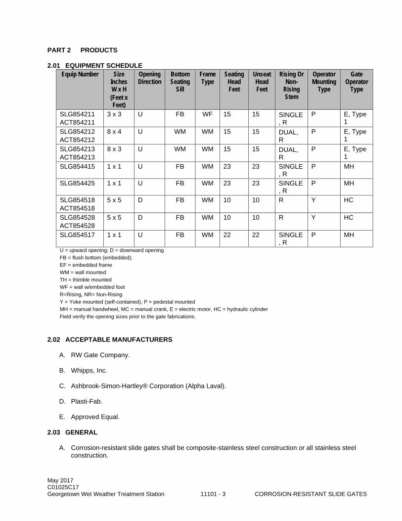
May 2017 C01025C17 Georgetown Wet Weather Treatment Station 11101 - 3 CORROSION-RESISTANT SLIDE GATES
PART 2 PRODUCTS
2.01 EQUIPMENT SCHEDULE Equip Number Size
Inches W x H (Feet x Feet)
Opening Direction
Bottom Seating
Sill
Frame Type
Seating Head Feet
Unseat Head Feet
Rising Or Non-
Rising Stem
Operator Mounting
Type
Gate Operator
Type
SLG854211 ACT854211
3 x 3 U FB WF 15 15 SINGLE, R
P E, Type 1
SLG854212 ACT854212
8 x 4 U WM WM 15 15 DUAL, R
P E, Type 1
SLG854213 ACT854213
8 x 3 U WM WM 15 15 DUAL, R
P E, Type 1
SLG854415 1 x 1 U FB WM 23 23 SINGLE, R
P MH
SLG854425 1 x 1 U FB WM 23 23 SINGLE, R
P MH
SLG854518 ACT854518
5 x 5 D FB WM 10 10 R Y HC
SLG854528 ACT854528
5 x 5 D FB WM 10 10 R Y HC
SLG854517 1 x 1 U FB WM 22 22 SINGLE, R
P MH
U = upward opening; D = downward opening FB = flush bottom (embedded); EF = embedded frame WM = wall mounted TH = thimble mounted WF = wall w/embedded foot R=Rising, NR= Non-Rising Y = Yoke mounted (self-contained), P = pedestal mounted MH = manual handwheel, MC = manual crank, E = electric motor, HC = hydraulic cylinder Field verify the opening sizes prior to the gate fabrications.
2.02 ACCEPTABLE MANUFACTURERS
A. RW Gate Company.
B. Whipps, Inc.
C. Ashbrook-Simon-Hartley® Corporation (Alpha Laval).
D. Plasti-Fab.
E. Approved Equal.
2.03 GENERAL
A. Corrosion-resistant slide gates shall be composite-stainless steel construction or all stainless steel construction.

May 2017 C01025C17 Georgetown Wet Weather Treatment Station 11101 - 4 CORROSION-RESISTANT SLIDE GATES
B. All slide gates shall be fully factory assembled with frame, slide, stem, shaft, and operator. Where shipping constraints are required, and unless otherwise prohibited by this Section, the frame may be partially assembled such that the top may be easily mounted to the bottom containing the slide.
C. Where square-to-circular or bell-lip conversion is required, provide a bell-end pipe insert of suitable diameter and water stop.
D. Self-adjusting UV stabilized UHMWPE seals with nitrile compression cord not to be replaced in less than 10 years.
2.04 DESIGN REQUIREMENTS
A. Performance Requirements: 1. Service Conditions: Gates shall be suitable for service with untreated wastewater and resistant to
hydrogen sulfide corrosion. 2. Slide gates shall be designed for the specified seating and unseating heads. 3. Design slides and frames with a safety factor of 5 with regard to tensile, compressive and shear
strength, and with the requirement that all gates will comply with field leakage tests specified in AWWA C563, Section 5.2.3.1 or AWWA C561 as applicable to the gates provided. Calculations shall be submitted to show conformance. a. Gates shall be designed for a guaranteed leakage rate not to exceed 0.05 gpm per lineal foot
of seating perimeter. 4. Maximum deflection for slide shall not exceed 1/1000 of the span or 1/16-IN, whichever is less,
under design head conditions based upon horizontal support members only.
2.05 COMPONENT SIZING
A. Operating forces used for determining the strength of gate components (yokes, frames, slides, stems, slide nut pockets, and other load-bearing members) shall be based on the sum of the guide friction force (computed using an opening breakaway friction factor of no greater than 0.4) and the weight of slide and stem.
B. When the gate is in motion, the operating forces shall be based on the sum of the frictional force (using a guide friction factor of no greater than 0.2) and the weight of slide and stem.
2.06 MATERIALS
A. Materials of construction shall be as follows: 1. Slide (disc):
a. Engineered composite FRP completely encapsulating an internal matrix of welded stainless steel reinforcement structure.
b. ASTM A240 Type 316L stainless steel. 2. Frame: ASTM A240 Type 316L stainless steel with a flush bottom. 3. Slide Seats: ASTM D4020 UHMW Polyethylene. 4. Seating faces or seals: Self-adjusting ASTM D4020 UV stabilized UHMW polyethylene. 5. Flush bottom seal: ASTM D2000, EPDM, or neoprene. 6. Stem: ASTM A276 Type 316L stainless steel. 7. Stem cover: Polycarbonate. 8. Fasteners and adjusting hardware: ASTM A193 or ASTM A276 Type 316L stainless steel. 9. Yoke: ASTM A240 Type 316L stainless steel. 10. Wall thimbles: ASTM A240 Type 316L stainless steel.
B. All welded stainless steel components shall be cleaned, descaled, and passivated per ASTM A380.
May 2017 C01025C17 Georgetown Wet Weather Treatment Station 11101 - 5 CORROSION-RESISTANT SLIDE GATES
2.07 FEATURES
A. Slides constructed of composite material: 1. Slide shall be constructed from a reinforced impermeable rigid composite plastic material:
a. Outer surface skin minimum thickness: 1/4-inch. b. Internal matrix of welded steel of suitable strength for the specified service. c. Rigid polyurethane foam shall be used as filler between the internal reinforcing system and
shall be a minimum density of 7 pounds per cubic foot. d. Outer surface skins shall be a homogeneous plastic material, be nontoxic and shall be
stabilized against ultraviolet light. e. The plastic material shall have the minimum properties shown in the Properties Table
appearing below: f. Properties Table for thermoform skin material:
1) Tensile strength: 12,500 psi. 2) Young's Modulus: 1,200,000 psi. 3) Flexural strength: 18,000 psi. 4) Flexural modulus: 1,400,000 psi. 5) Compressive strength: 11,000 psi. 6) Impact strength: 40,300,000 erg. 7) Water absorption: 0.38 percent. 8) Specific gravity: 1.72. 9) Coefficient of thermal expansion: 1.6 x 10⁻⁵ per degree C. 10) Heat distortion point: 80 degrees C ASTM D648. 11) Low temperature impact strength: 93% at -20 degrees C. 12) Notch sensitivity: Not notch sensitive. 13) Fire resistance: Class 1 Spread of Flame, Rating BS476: Part 1: 1953 self-extinguishing
ASTM D635 - 56R. 14) Chemical resistance: alkalines, ozone (2 to 3 ppm).
g. Properties Table for thermoset skin material: 1) Tensile strength: 15,000 psi. 2) Flexural modulus: 1,000,000 psi. 3) Flexural strength: 20,000 psi. 4) Compressive strength: 22,000 psi. 5) Impact strength: 9.0 ft-lb/in. 6) Water absorption: 0.13% (in 24hr).
B. Slides constructed of SST: a. Plate minimum thickness: 1/4-inch. b. Reinforcing members fabricated from Type 316L SST structural shapes. Horizontal members
welded to side vertical stiffeners. c. Slides shall engage the frame a minimum of 1-IN on each side. d. The portion of the slide that engages the frame shall have a minimum thickness of ½-IN.
C. Frame: 1. Frames shall be flange back, unless otherwise indicated. 2. Guide frames shall be flush with operating floors or slabs and be self-contained and sufficiently
strong so that no further support or reinforcement is required. 3. Frames for self-contained gates shall be designed for maximum loads from gate actuators in a
stalled condition. 4. Wall-mounted frames (Type WM) shall be the flanged type. Wall mounted guides and invert
members shall have a minimum weigh of 13 lbs/ft. The portion of the frame where the anchor penetrates shall have a minimum thickness of ½-inch.
5. Embedded frame (Type EF) gates shall be installed in block-out recesses formed in the channel walls and floor providing no protrusions. Embedded guides and invert members shall have a minimum weight of 6 lbs/ft.

May 2017 C01025C17 Georgetown Wet Weather Treatment Station 11101 - 6 CORROSION-RESISTANT SLIDE GATES
6. Thimble-mounted gates (Type TH) shall be drilled to match the wall thimble. Wall thimbles shall conform to AWWA C561, Section 4.4.10. Thimble-mounted guides and invert members shall have a minimum weigh of 13 lbs/ft. The portion of the frame where the wall thimble stud penetrates shall have a minimum thickness of ½-inch.
7. Frame shall be designed to allow flange mounting on sides and top. Bottom flange to remain free of attachment to mounting face. Grout fill to grade invert as indicated in the Drawings.
8. Guide frames for shall be a one-piece design. Bolted construction is not permitted. Gussets shall be provided on wall mounted frames and thimble-mounted frames to transfer the load from unseating head conditions from the outermost surface of the frame to the anchors or wall thimble studs.
D. Seals: 1. The sealing arrangement for the reinforced plastic slide gates shall consist of sealing faces and
side guides constructed of ultra high molecular weight polyolefin having a coefficient of friction as defined herein and backing constructed of highly resilient expanded neoprene.
2. The sealing system for all stainless steel gates shall be as follows: a. Self-adjusting UV stabilized UHMWPE with a nitrile compression cord. The flush bottom
invert seal on upward opening gates shall be resilient synthetic rubber securely bolted inside the invert member. Invert seals that are secured solely with adhesive are not acceptable. With the slide open, the invert of the gate shall be flush with the channel or opening bottom, with no pockets or cavities for the accumulation of solids.
b. Top and side seals shall be able to be replaced without removing the gate frame from the wall or wall thimble. All seats and seals shall be mechanically fastened and replaceable.
c. Guides and seating of the gate shall be self-adjusting for the life of the gate.
E. All moving contact surfaces shall be incompatible to each other thereby minimizing sticking or jamming.Stems: 1. Gates having a width to height ratio of less than 2 shall have single rising stems. Gates having a
width to height ratio of greater than or equal to 2 shall have dual rising stems mechanically linked through a stainless steel interconnecting shaft to a common actuator unless otherwise indicated.
2. Gate stems shall be minimum 1-1/2-inch major diameter. 3. Stems shall have full depth Acme type cold rolled threads with a maximum surface roughness of
16 micro inches. 4. Stem couplings, where required, shall match the stem material. Stem guides shall be 316L
stainless steel and of the split, UHMWPE, adjustable type with UHMWPE contact surfaces. 5. Provide stems and stem guides in accordance with AWWA C563, Sections 4.4.6 and 4.4.7 or
AWWA C561 as applicable to the gates provided as modified herein. 6. Stem guides shall be provided at sufficient intervals to prevent the L/R ratio of the unsupported
stem length (L) from exceeding 200, where R is the radius of gyration of the stem. 7. For gates with electric actuators, stems shall be designed to withstand a compressive thrust force
equal to at least 1.25 times the rated output of the hoisting mechanism with the motor in the stalled condition.
8. For gates with manual actuators, stems shall be designed to withstand a compressive thrust force equal to at least 2.5 times the rated output of the hoisting mechanism with a 40-pound force applied to the auxiliary hand wheel or crank.
9. Stem guides for self-contained gates shall be part of the self-contained frame.
2.08 GATE ACTUATORS
A. See Section 15140.

May 2017 C01025C17 Georgetown Wet Weather Treatment Station 11101 - 7 CORROSION-RESISTANT SLIDE GATES
PART 3 EXECUTION
3.01 INSTALLATION
A. Install in accordance with manufacturer’s instruction and as indicated in the Drawings.
3.02 FIELD QUALITY CONTROL
A. Leakage tests: AWWA C563, Section 5.2.3 or AWWA C561 as appropriate. 1. Field leakage rates shall be less than 0.05 gpm per lineal foot of seating perimeter.
3.03 FIELD SERVICE
A. A factory trained representative shall provide the following field services: 1. Gates installation supervision. One trip of a minimum of two days at the project site prior to
grouting the gates. 2. Gates startup, testing, and training. One trip of a minimum of two days at the Project Site.
END OF SECTION

May 2017 C01025C17 Georgetown Wet Weather Treatment Station 11101 - 8 CORROSION-RESISTANT SLIDE GATES
This page intentionally left blank.

May 2017 C01025C17 Georgetown Wet Weather Treatment Station 11111 - 1 CORROSION RESISTANT HEAVY DUTY STOP LOGS
SECTION 11111
CORROSION RESISTANT HEAVY DUTY STOP LOGS
PART 1 GENERAL
1.01 SUMMARY
A. This Section specifies corrosion resistant heavy duty composite stop log panels and lifting devices.
B. The general requirements applicable to all mechanical equipment, as summarized in Section 11000 are applicable to the equipment specified in this Section.
1.02 QUALITY ASSURANCE
A. Referenced Standards: This Section incorporates by reference the latest revision of the following documents. These references are a part of this Section as specified and modified. In case of conflict between the requirements of this Section and those of the listed documents, the requirements of this Section shall prevail. Reference Title ASTM A276 Stainless Steel Bars and Shapes ASTM D256 Test Method for Determining the Izod Pendulum Impact Resistance of Plastics ASTM D570 Test Method for Water Absorption of Plastics ASTM D638 Test Method for Tensile Properties of Plastics ASTM D695 Test Method for Compressive Properties of Rigid Plastic ASTM D696 Test Method for Coefficient of Linear Thermal Expansion of Plastics Between
−30°C and 30°C with a Vitreous Silica Dilatometer ASTM D790 Test Methods for Flexural Properties of Unreinforced and Reinforced Plastics
and Electrical Insulating Materials ASTM D792 Test Methods for Density and Specific Gravity (Relative Density) of Plastics by
Displacement ASTM D1056 Flexible Cellular Materials—Sponge or Expanded Rubber ASTM D2000 Classification System for Rubber Products in Automotive Applications ASTM D2583 Test Method for Indentation Hardness of Rigid Plastics by Means of a Barcol
Impressor ASTM D2563 Standard Practice for Classifying Visual Defects in Glass-Reinforced Plastic
Laminate Parts ASTM D2584 Test Method for Ignition Loss of Cured Reinforced Resins
B. Composition of the stop log laminate shall be in accordance with the recommendations shown in the Quality Assurance Report for Reinforced Thermoset Plastic (RTP) Corrosion Resistant Equipment prepared under the sponsorship of the Society of the Plastics Industry, Inc. (SPI), and the Material Technology Institute (MTI) of the Chemical Process Industry for “Hand Lay-UP Laminates,” and shall meet the specifications for Type I, Grade 10 laminates shown in Appendix M-1 of said report: 1. Visual inspection for defects shall be made without the aid of magnification and defects shall be
classified as to type and level as shown in Table 1 of ANSI/ASTM D2563-0, approved 1977, (or any subsequent revision). Allowable surface tolerances are as follows:
DEFECTS ALLOWABLE TOLERANCE Cracks Crazing Blisters Chips Pits Dry Spots Fish Eyes Burned Areas Entrapped Air
None
Wrinkles and solid blisters, not to exceed 1/8”
Maximum Deviation: 10% of thickness, but not to exceed 1/8 inch (0.3mm)
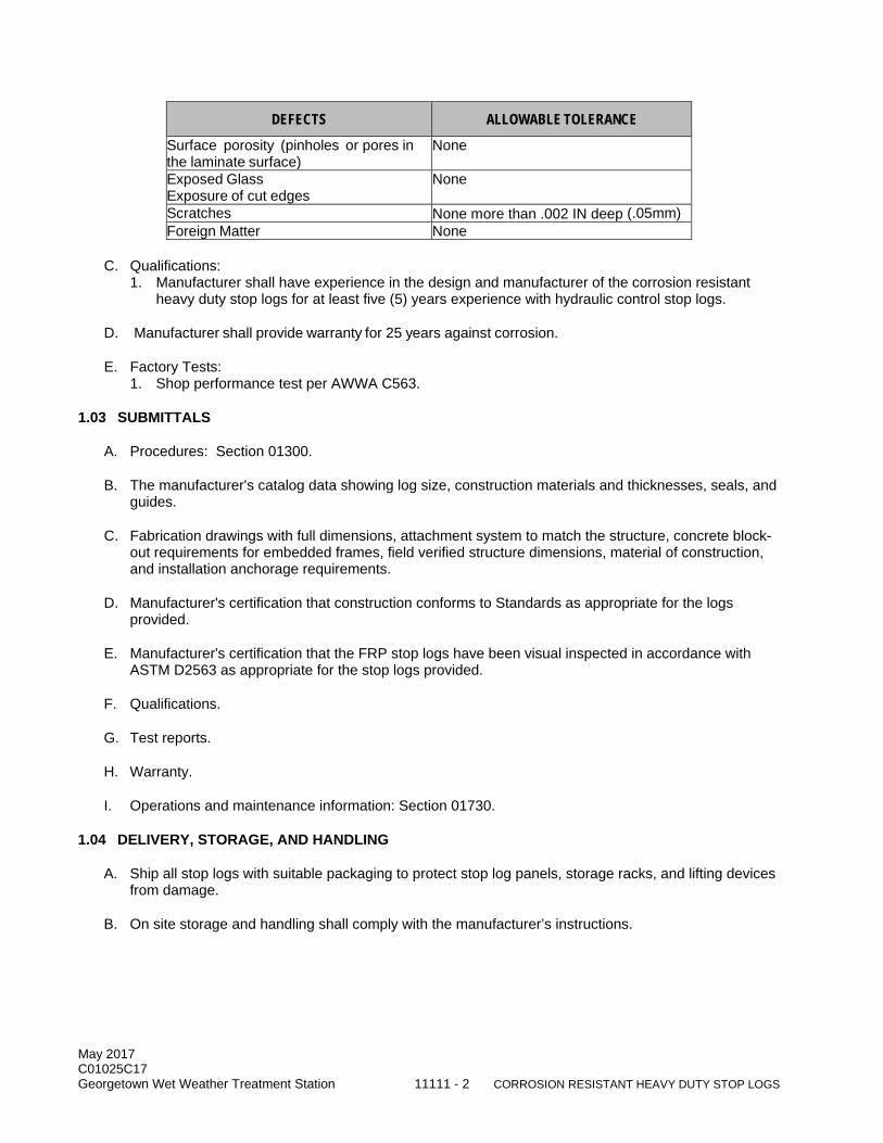
May 2017 C01025C17 Georgetown Wet Weather Treatment Station 11111 - 2 CORROSION RESISTANT HEAVY DUTY STOP LOGS
DEFECTS ALLOWABLE TOLERANCE Surface porosity (pinholes or pores in the laminate surface)
None
Exposed Glass Exposure of cut edges
None
Scratches None more than .002 IN deep (.05mm) Foreign Matter None
C. Qualifications: 1. Manufacturer shall have experience in the design and manufacturer of the corrosion resistant
heavy duty stop logs for at least five (5) years experience with hydraulic control stop logs.
D. Manufacturer shall provide warranty for 25 years against corrosion.
E. Factory Tests: 1. Shop performance test per AWWA C563.
1.03 SUBMITTALS
A. Procedures: Section 01300.
B. The manufacturer's catalog data showing log size, construction materials and thicknesses, seals, and guides.
C. Fabrication drawings with full dimensions, attachment system to match the structure, concrete block-out requirements for embedded frames, field verified structure dimensions, material of construction, and installation anchorage requirements.
D. Manufacturer's certification that construction conforms to Standards as appropriate for the logs provided.
E. Manufacturer's certification that the FRP stop logs have been visual inspected in accordance with ASTM D2563 as appropriate for the stop logs provided.
F. Qualifications.
G. Test reports.
H. Warranty.
I. Operations and maintenance information: Section 01730.
1.04 DELIVERY, STORAGE, AND HANDLING
A. Ship all stop logs with suitable packaging to protect stop log panels, storage racks, and lifting devices from damage.
B. On site storage and handling shall comply with the manufacturer’s instructions.
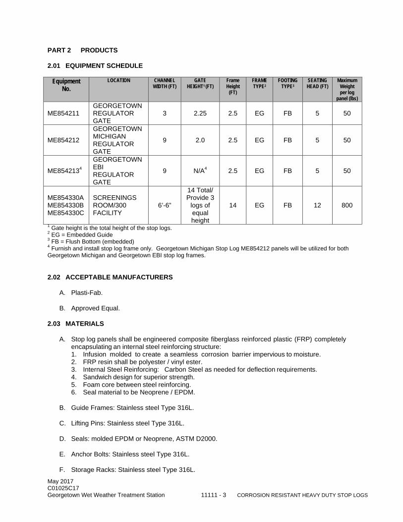
May 2017 C01025C17 Georgetown Wet Weather Treatment Station 11111 - 3 CORROSION RESISTANT HEAVY DUTY STOP LOGS
PART 2 PRODUCTS
2.01 EQUIPMENT SCHEDULE
Equipment No.
LOCATION CHANNEL WIDTH (FT)
GATE HEIGHT1 (FT)
Frame Height
(FT)
FRAME TYPE2
FOOTING TYPE3
SEATING HEAD (FT)
Maximum Weight per log
panel (lbs)
ME854211 GEORGETOWN REGULATOR GATE
3 2.25 2.5 EG FB 5 50
ME854212
GEORGETOWN MICHIGAN REGULATOR GATE
9 2.0 2.5 EG FB 5 50
ME8542134
GEORGETOWN EBI REGULATOR GATE
9 N/A4 2.5 EG FB 5 50
ME854330A ME854330B ME854330C
SCREENINGS ROOM/300 FACILITY
6’-6”
14 Total/ Provide 3
logs of equal height
14 EG FB 12 800
1 Gate height is the total height of the stop logs. 2 EG = Embedded Guide 3 FB = Flush Bottom (embedded) 4 Furnish and install stop log frame only. Georgetown Michigan Stop Log ME854212 panels will be utilized for both Georgetown Michigan and Georgetown EBI stop log frames.
2.02 ACCEPTABLE MANUFACTURERS
A. Plasti-Fab.
B. Approved Equal.
2.03 MATERIALS
A. Stop log panels shall be engineered composite fiberglass reinforced plastic (FRP) completely encapsulating an internal steel reinforcing structure: 1. Infusion molded to create a seamless corrosion barrier impervious to moisture. 2. FRP resin shall be polyester / vinyl ester. 3. Internal Steel Reinforcing: Carbon Steel as needed for deflection requirements. 4. Sandwich design for superior strength. 5. Foam core between steel reinforcing. 6. Seal material to be Neoprene / EPDM.
B. Guide Frames: Stainless steel Type 316L.
C. Lifting Pins: Stainless steel Type 316L.
D. Seals: molded EPDM or Neoprene, ASTM D2000.
E. Anchor Bolts: Stainless steel Type 316L.
F. Storage Racks: Stainless steel Type 316L.

May 2017 C01025C17 Georgetown Wet Weather Treatment Station 11111 - 4 CORROSION RESISTANT HEAVY DUTY STOP LOGS
2.04 PHYSICAL PROPERTIES
A. Structural characteristics for a 1/8 inch glass mat laminate shall meet the following minimum physical properties:
Tensile strength 15,000 psi Flexural Modulus 1,000,000 psi Flexural Strength 20,000 psi Compressive Strength 22,000 psi Impact Strength 9.0 ft-lbs/in. Water absorption 0.13%
B. Seals: Extruded Neoprene / EPDM Seals shall have the following physical characteristics: Specific Gravity 1.25 Hardness 55 – 65 Shore A Durometer Tensile Strength 1500 psi min. Elongation 300% Low temperature brittleness - 40°C
2.05 DESIGN CRITERIA
A. Stop log system shall be designed for a maximum head pressure as per the equipment schedule specified herein.
B. Stop logs shall meet AWWA C563 leakage requirements: 1. Maximum allowable leakage of stop logs with seating head specified herein shall not exceed 0.10
gpm per foot of wetted linear seal area under full design head when installed in manufacturer’s guide frames.
C. Stop logs shall be designed so that the maximum fiber stress (ultimate or yield, whichever applies) does not exceed 2.5 times the working stress.
D. Stop logs shall be suitably reinforced to withstand the seating head per the equipment schedule specified herein with a deflection less than 1/360 of the stop log width or 1/4 inch, whichever is less.
2.06 CONSTRUCTION
A. Stop Log Panels: 1. The dimensions of each stop log panel shall be design to be suitable to install at the locations as
indicated in the Drawings. 2. The stop log shall be fabricated by means of vacuum infusion so as to totally encapsulate the
internal structural matrix and protect it against corrosion from moisture or chemical deterioration with a minimum thickness of 1/4 inch FRP on the front and back facings, and 3/4 inch FRP on the remaining perimeter.
3. Surface Conditions: a. The surface shall be resin rich to a depth of .010 inches to .020 inches and reinforced with C-
glass or polymeric fiber surfacing material. b. The surface shall be free of exposed reinforcing fibers. c. All stop log panels shall be flat and level. d. Warpage throughout the entire stop log pane shall not produce a crown of more than 1/16
inch in any direction. 4. The copolymer composite shall be ultraviolet stabilized and seamless to protect inner structural
members from corrosion.
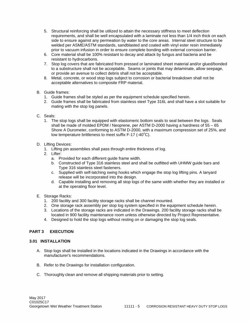
May 2017 C01025C17 Georgetown Wet Weather Treatment Station 11111 - 5 CORROSION RESISTANT HEAVY DUTY STOP LOGS
5. Structural reinforcing shall be utilized to attain the necessary stiffness to meet deflection requirements, and shall be well encapsulated with a laminate not less than 1/4 inch thick on each side to ensure against any permeation by water to the core areas. Internal steel structure to be welded per ASME/ASTM standards, sandblasted and coated with vinyl ester resin immediately prior to vacuum infusion in order to ensure complete bonding with external corrosion barrier.
6. Core material shall be 100% resistant to decay and attack by fungus and bacteria and be resistant to hydrocarbons.
7. Stop log covers that are fabricated from pressed or laminated sheet material and/or glued/bonded to a substructure shall not be acceptable. Seams or joints that may delaminate, allow seepage, or provide an avenue to collect debris shall not be acceptable.
8. Metal, concrete, or wood stop logs subject to corrosion or bacterial breakdown shall not be acceptable alternatives to composite FRP material.
B. Guide frames: 1. Guide frames shall be styled as per the equipment schedule specified herein. 2. Guide frames shall be fabricated from stainless steel Type 316L and shall have a slot suitable for
mating with the stop log panels.
C. Seals: 1. The stop logs shall be equipped with elastomeric bottom seals to seal between the logs. Seals
shall be made of molded EPDM / Neoprene, per ASTM D-2000 having a hardness of 55 – 65 Shore A Durometer, conforming to ASTM D-2000, with a maximum compression set of 25%, and low temperature brittleness to meet suffix F-17 (-40oC).
D. Lifting Devices: 1. Lifting pin assemblies shall pass through entire thickness of log. 2. Lifter:
a. Provided for each different guide frame width. b. Constructed of Type 316 stainless steel and shall be outfitted with UHMW guide bars and
Type 316 stainless steel fasteners. c. Supplied with self-latching swing hooks which engage the stop log lifting pins. A lanyard
release will be incorporated into the design. d. Capable installing and removing all stop logs of the same width whether they are installed or
at the operating floor level.
E. Storage Racks: 1. 200 facility and 300 facility storage racks shall be channel mounted. 2. One storage rack assembly per stop log system specified in the equipment schedule herein. 3. Locations of the storage racks are indicated in the Drawings. 200 facility storage racks shall be
located in 900 facility maintenance room unless otherwise directed by Project Representative. 4. Designed to hold the stop logs without resting on or damaging the stop log seals.
PART 3 EXECUTION
3.01 INSTALLATION
A. Stop logs shall be installed in the locations indicated in the Drawings in accordance with the manufacturer's recommendations.
B. Refer to the Drawings for installation configuration.
C. Thoroughly clean and remove all shipping materials prior to setting.
May 2017 C01025C17 Georgetown Wet Weather Treatment Station 11111 - 6 CORROSION RESISTANT HEAVY DUTY STOP LOGS
3.02 FIELD QUALITY CONTROL
A. Field testing shall be in accordance with Section 01660.
B. Each gate shall be tested for leakage. 1. Leakage rate shall conform to performance requirements specified in this Section. 2. Perform test with seating head at the maximum operating head on each log.
END OF SECTION

May 2017 C01025C17 Georgetown Wet Weather Treatment Station 11259 - 1 SCREENINGS COMPACTOR EQUIPMENT
SECTION 11259
SCREENINGS COMPACTOR EQUIPMENT
PART 1 GENERAL
1.01 SUMMARY
A. This Section includes providing two screenings compactor systems.
B. Performance Requirements: Screenings will be removed from the wastewater by 6-mm front-cleaned multi-rake bar screens and discharged to the screenings compactors through a discharge chute. The equipment is located in a Class 1 Division 2 area. The screenings compactors shall receive the raw screenings, and dewater and press the screenings to produce a product with minimum 35 percent dry solids. The dewatered screenings shall be capable of passing the EPA Paint Filter Test as described in method 9095 of EPA Publication SW-486.
1.02 QUALITY ASSURANACE
A. Referenced Standards: This Section incorporates by reference the latest revision of the following documents. These references are a part of this Section as specified and modified. In case of conflict between the requirements of this Section and those of the listed documents, the requirements of this Section shall prevail.
Reference Title ASTM A36 Structural Steel ASTM A53 Pipe, Steel, Black and Hot-Dipped, Zinc-coated, Welded and Seamless AGMA 6013 Standard for Industrial Enclosed Gear Drives
B. The Contract Documents represent the minimum acceptable standards for the compacting equipment for this project. All equipment shall conform fully in every respect to the requirements of the respective parts and sections of the Drawings and Specifications. The entire unit shall be Manufacturer’s standard product, but shall be modified, redesigned, furnished with special features or accessories, made of materials or provided with finishes as may be necessary to conform to the quality mandated by the technical and performance requirements of the Specification.
C. The entire screenings compaction unit shall be manufactured from AISI 316L stainless steel shapes. All components made of stainless steel shall be cleaned, descaled and passivated in accordance with ASTM A380.
D. All welding is performed in accordance with American Welding Society (AWS) D1.1 Structural Welding Code, or equivalent.
E. Factory Tests: 1. Perform manufacturer’s standard function test on final assembly to ensure that equipment
shipped will function as intended. 2. The Engineer reserves the right to be present during the factory testing. 3. The Project Representative and Engineer shall be notified at least 42 days prior to the estimated
test date.

May 2017 C01025C17 Georgetown Wet Weather Treatment Station 11259 - 2 SCREENINGS COMPACTOR EQUIPMENT
4. The manufacturer shall furnish certified copies of all test results.
F. Unit Responsibility: 1. The system shall be the end product of one responsible system manufacturer. Assign unit
responsibility to the manufacturer of the screenings compactors provided under this section. This manufacturer is the Unit Responsibility manufacturer and has unit responsibility for the equipment assembly specified in this section, the motors specified in Section 11060, the Local Control Panel specified in this section and in Section 17600, and the solenoid valves specified in section 15124. Agents, representatives, or other entities who are not a direct component of the manufacturing corporation will not be acceptable as a substitute for the manufacturer's corporation in meeting the requirement for Unit Responsibility.
2. The Unit Responsible manufacturer shall ensure coordination of design and selection of all system components such that all equipment provided as part of the Unit Responsibility is compatible and operates reliably and properly to achieve the performance requirements specified. Unit responsibility for related components in an assembly does not require or obligate the Unit Responsibility manufacturer to warranty the workmanship or quality of component products not manufactured by them.
3. The Contractor shall coordinate equipment selection with the Unit Responsible manufacturer and shall be responsible for providing the equipment as specified herein. Contractor shall assure that all equipment systems provided as part of the system are the products for which Unit Responsibility has been coordinated by the Unit Responsible manufacturer in this Section.
4. The requirement for Unit Responsibility shall in no way relieve the Contractor of responsibility for performance as specified in the Contract Provisions.
1.03 SUBMITTALS
A. Procedures: Section 01300.
B. Forms 11000-A, 11000-B, and 11060-A: Section 01999.
C. Shop drawings: 1. Manufacturer’s catalog information, descriptive literature, specifications, and identification of
materials for construction. 2. Detailed structural, mechanical, and electrical drawings showing equipment fabrications and
interface with other items. Include dimensions, size, and locations of connections to other work. 3. Motor product data as specified in Section 11060. 4. Power and control wiring diagrams, including terminals and numbers. 4. Measures used to prevent contamination of stainless steel with ferric oxide dust as applicable. 5. Equipment weights and lifting points. 6. Recommendations for short and long term storage. 7. A copy of the manufacturer’s special warranty. 5. Shop painting systems, including manufacturer’s descriptive technical catalog literature and
specifications. 6. External utility requirements for water, power, drain, etc., for each component 7. Anchor bolt and mounting design calculations and details. 8. Operation and Maintenance Manual: Provide Operation and Maintenance Manual per Section
01730. 9. Intermittent operation and maintenance protocol:
a. Manufacturer shall provide recommended protocol for the exercising of the screening compaction equipment for intermittent usage. At a minimum this should include procedures, duration and frequency.
10. The protocol shall be outlined for: a. Protocol during the wet weather season. b. Protocol during the dry weather season (up to 5 months of nonusage).
11. Spare Parts: Section 01750.

May 2017 C01025C17 Georgetown Wet Weather Treatment Station 11259 - 3 SCREENINGS COMPACTOR EQUIPMENT
D. Factory testing results and certification (Preinstallation Testing).
E. Component, System and Operational Test Phases testing procedures.
F. Summary report of Component, System and Operational Tests.
G. PLC tag list.
1.04 SERVICE REQUIREMENTS
A. Service Conditions: Each screenings compactor shall be capable of dewatering and compacting screenings removed from raw wastewater.
Description Equipment Nos. ME854343, ME 854344 Location Indoors, grade-level floor of IPS and Equalization Basin. The Screenings
Room has a hazardous classification of Class I, Division 2, Group D. The room is heated between temperature 55 degrees F and 85 degrees F, and ventilated with 12 air changes per hour.
Fluid Type Screenings from a 6 mm bar screen including water, rags, stringy material, pieces of wood, metal objects, paper, glass, grit, rocks, organic waste solids, and other coarse material.
Fluid Temperature 40-70 degrees F Control Operation of the screenings compactor shall be controlled manually by a
start pushbutton, or automatically by remote start signal from the Plant Control System.
Utilities C2 Water used for wash water. Wash water supply is available at approximately 60 psi, 25 gpm per screenings compactor system.
B. Design Requirements: Item Equipment Nos.
ME854343, ME 854344 Screenings Compactor
Solids Handling Capacity, cubic feet per hour 140 Dry weight of compacted solids, minimum, percent 35 Screenings volume reduction, minimum, percent 50
Drive Motor Motor type Constant Speed Motor horsepower, maximum 5 Motor speed, rpm 1800 Motor enclosure, type TEFC Motor space heaters No
1.05 SPECIAL WARRANTY
A. For components of this Section, provide a special warranty with duration of two years, with any and/or all conditions listed below and as specified in Section 01740: 1. A warranty for the integrity of the screenings compaction equipment, including appurtenances
and supports, shall be provided by the equipment manufacturer starting at the beginning of the commissioning period. The warranty shall be against all defects in workmanship and materials.
2. Due to the critical nature of this equipment, necessary repairs within the warranty period shall be started within three days from the date the manufacturer is notified of a defect. Within 48 hours after being notified of the defect by the County, the manufacturer shall provide a repair plan acceptable to the County.

May 2017 C01025C17 Georgetown Wet Weather Treatment Station 11259 - 4 SCREENINGS COMPACTOR EQUIPMENT
PART 2 PRODUCTS
2.01 EQUIPMENT SCHEDULE
Equipment No. Equipment Name Capacity or Size LCP854343 Screenings Compactor 1 LCP -- LCP854344 Screenings Compactor 2 LCP -- LCS854343 Screenings Compactor 1 LCS -- LCS854344 Screenings Compactor 2 LCS -- ME854343 Screenings Compactor 1 -- ME854344 Screenings Compactor 2 -- MTR854343 Screenings Compactor 1 Motor -- MTR854344 Screenings Compactor 2 Motor -- RV854343 S/C 1 C2 Water Regulating Valve -- RV854344 S/C 2 C2 Water Regulating Valve -- SV854343 S/C 1 C2 Water Solenoid Valve -- SV854344 S/C 2 C2 Water Solenoid Valve --
2.02 GENERAL
A. The screenings compactor shall be manufacturer’s standard product and only modified as necessary to comply with the Drawings, Specifications, and specified service conditions.
B. Manufacturer shall provide screening compactor, motors, gear reducers, control panels and local control stations, and lifting attachments as a complete integrated package to ensure proper coordination, compatibility, and operation of the system. Motor starters to be provided by others. Manufacturer shall coordinate as needed to ensure compatibility.
C. All structural members of the equipment shall be designed for shock and vibratory loads.
D. Each screenings compactor shall have the manufacturer’s name, address and product identification on a nameplate securely affixed to the equipment at a location and height visible from the operating deck.
E. The screenings compactor shall be manufacturer in a stainless steel only factor to prevent contamination of the stainless steel with ferric oxide dust, or in a factory that has measures in place to prevent contamination of stainless steel with ferric oxide dust. Submit measures utilized to prevent contamination.
2.03 ACCEPTABLE MANUFACTURERS
A. SSWP as manufacturered by Kusters Water.
B. Rotamat Compactor as manufactured by Huber Technology, Inc.
C. Hycor Helixpress as manufactured by Parkson Corporation.
D. Approved Equal.
2.04 MATERIALS
A. Transition Chute: 1. Type 304 Stainless steel with Teflon coating to provide a smooth surface that does not allow
material to build up between the screen and screenings compactor. 2. Provide access door in end to promote access, cleaning and inspection.

May 2017 C01025C17 Georgetown Wet Weather Treatment Station 11259 - 5 SCREENINGS COMPACTOR EQUIPMENT
B. Screenings Compactor: The screenings compactor shall have a compaction screw, screenings conveyor, and dewatering press for dewatering, compacting, and transporting the screenings. 1. To minimize odors and nuisance, the conveyance, dewatering and compaction zones shall be
completely enclosed. 2. The compactor shall be provided with a support stand which shall be fabricated from stainless
steel Double-C-Channels, each having a minimum thickness of 1/8-in. 3. A compaction zone shall be provided as an integral part of the screw conveyor and tube. The
compaction zone shall be designed to form a plug of screenings material and to return water released from the screened material via the Drainage zone
4. Drainage zone shall be constructed of Type 304 stainless steel with ¼-inch diameter perforations. 5. The screw shall be constructed of two concentric flights formed continuously from bar stock and
welded together. Design torque shall exceed that which overloads the motor by a safety factor of at least 3. Motors will be protected by over-current protection in the plant control system.
6. The screw shall have a 360-degree reverse-pitch spiral in the discharge zone to prevent the dewatered plug from advancing to the drive. The reverse-pitch spiral shall have a serrated cutter to break the dewatered plug off and allow it to fall into the discharge chute.
7. The screw shall be fitted with a water resistant brush to clean the drain openings and the brushes shall be secured to the screen with stainless steel fasteners.
8. The drive shaft of the gear motor shall be directly coupled to the screw. 9. The transport tube shall have a minimum 11 gauge thickness and shall have an
inspection/cleanout door. 10. The transport tube shall be fitted with three Type 304 stainless steel wear bars to prevent the
screw from wearing on the surface of the transport tube. The wear bars will be tapped and fastened to the conical and straight sections of the tube using cap screws.
11. A dewatering press zone shall consist of a jacket, dewatering cylinder, and plug restrictor to increase liquid removal from solids.
12. Bolts, nuts and washers shall be selected from AISI 304L or 316L stainless steel such that they are anti-seizing.
C. Discharge Assembly: The discharge assembly shall consist of a discharge pipe, chute adapter and discharge chute. The discharge pipe shall be constructed of stainless steel and be of tubular construction. A Type 304L stainless steel adapter shall be bolted to the discharge pipe for installation of a flexible chute. A flexible neoprene discharge chute shall be attached to the discharge pipe to direct screenings into the bagger and dumpster. 1. Bagging system: A continuous bagging system shall be provided to abate odors and to seal
dewatered screenings to prevent any direct contact. The discharge bagging system shall provide a clean, odor-free means of collecting and containing the material discharged from the screenings equipment. The bagging system shall be attached to the screenings discharge. An accordion-folded plastic cassette bag shall be fitted to the end of the bagging system and will collect any discharged material. The end of the bag will be tied in a knot. The bag shall be cut and the exposed ends tied in a knot once it is determined that the bag is full. A stainless steel adapter flange and plastic cassette bag holder shall be utilized to mount for the screenings discharge. The adapter flange shall be fitted to the discharge chute such that it is positioned as close to the horizontal as possible. The plastic holder shall be attached to the stainless steel adapter and shall hold the continuous cassette bag. The plastic cassette bag holder shall consist of two parts, a tube and brim, which shall be held together by a stainless steel ring. The cassette bag shall be 260 to 295 feet long, non-porous, three-ply, co-extruded polyethylene with a thickness not to exceed 1.5 mils and a dart drop of not less than 1.65 pounds.
D. Wash Water Spray System: 1. An intermittently operated wash water spray system shall be provided to clean the screening of
organic material, clean the equipment, and prevent plugging of the drainage holes. 2. The spray wash system shall be enclosed such that spray water, aerosols or leakage do not
contaminate the operating floor. A brass body Y-strainer shall be provided. The strainer shall include a removable and washable stainless steel 20-mesh (800 micron) filter element.

May 2017 C01025C17 Georgetown Wet Weather Treatment Station 11259 - 6 SCREENINGS COMPACTOR EQUIPMENT
3. A single feed connection for the wash water system shall be provided. The manufacturer shall include a manifold to distribute wash water to all washing points as recommended.
4. The wash water spray system shall discharge into the compaction chamber. 5. The flow of water to spray system shall be controlled by solenoid valve(s) and automatically
controlled in conjunction with the compactor operation. See Section 15124.
E. Screw Drive Unit: The equipment shall be provided with a motor in accordance with the requirements of Section 11060. The equipment shall be driven by a shaft-mounted, helical bevel gear reducer.
F. Bearings: Designs featuring a bearing anywhere in the path of the dewatered screenings are unacceptable. 1. The lower stub shall be supported by a bearing that is lubricated for life. The bearing shall
include a bronze slide bushing that is provided with a low friction Teflon® coating and a pair of lip-seals. The entire lower bearing assembly shall be held in place using stainless steel bolted plates; designs that use c-clips or non-metallic cover method are not acceptable. The lower bearing shall not take any thrust from the screw. Bearings with insufficient sealing that require a positive internal water pressure to remain clear of debris or for lubrication (with water, oil or grease) shall not be acceptable for this Project.
G. Anchor Bolts: Equipment manufacturer shall furnish all anchor bolts of ample size and strength required to securely anchor each item of equipment. Anchor bolts, hex nuts, and washers shall be stainless steel. Anchor bolts shall be epoxy type.
2.05 ELECTRICAL COMPONENTS AND ACCESSORIES
A. The electrical requirements for each screenings compactor include those indicated in the Drawings, Section 17600, Division 16, and all other applicable Sections.
B. Provide all necessary electrical components and wiring for a complete, functional system. Electrical components and wiring shall be provided and installed in accordance with the National Electric Code (NEC) and additional Washington State requirements as necessary.
C. This Section includes equipment which will be installed in a Class 1, Division 1, Group D, hazardous, corrosive, and wet area. The motor shall meet IEEE standard 841.
D. Motor starters are to be provided by others.
E. A solenoid valve shall be provided to control the spray wash system. Valve shall be fail close and shall be in accordance with Section 15124.
2.06 EQUIPMENT CONTROL SYSTEM REQUIREMENTS
A. Each screenings compactor shall be provided with a Vendor-Supplied Package Control System (Package Control System). The Package Control System shall include everything required for a complete, fully functional, and integrated control system.
B. In addition to the requirements identified in this Section, the requirements for each Package Control System shall include those indicated in the Drawings, Section 17600 and all other referenced Sections.
C. Package Control System – Summary: 1. The following is a summary of Package Control System features, functionality, and services to be
provided as part of each screenings compactor Package Control System: a. Local Control Panels and Local Control Stations. b. Programmable Logic Controllers shall be per Division 17.

May 2017 C01025C17 Georgetown Wet Weather Treatment Station 11259 - 7 SCREENINGS COMPACTOR EQUIPMENT
c. Panel mounted operator interface terminals (OIT) shall be per Division 17. d. PLC/OIT Software and Programming shall be per Division 17. e. PLC Hard-Wire I/O interface to Package Equipment Instruments and Field Devices. f. PLC Hard-Wire IO interface with Local Control Stations (LCSs). g. PLC Hard-Wire I/O interface to the facility process control system (PCS). h. PLC hard wired interface between Package Controls and VFDs provided by others. i. Ethernet Interface between PLCs and the PCS. j. Control Strategy Implementation. k. Integration of Package Control System with the PCS. l. Factory, Component, System, and Operational Testing.
D. Control Panels: 1. The control panels to be provided for the Multi-rake Bar Screen Package Control Systems shall
be as follows: a. Screenings Compactor 1 Control Panel LCP854343. b. Screenings Compactor 2 Control Panel LCP854344.
2. Each screenings compactor package control panel shall be provided with the following pilot devices at a minimum: a. Control Power. b. Compactor Running Forward. c. Compactor Running Reverse. d. Compactor Jam. e. Compactor Fault.
3. Each screenings compactor package control panel shall be provided with the following control switches and pushbuttons at a minimum: a. HAND-OFF-AUTO switch. b. FORWARD-REVERSE switch. c. Alarm RESET pushbutton. d. E-STOP pushbutton.
4. Each screenings compactor package control panel shall provide the following hard wired control signals to the PCS. a. Dry contact signals rated 5A at 120 VAC.
1) Compactor in AUTO. 2) Compactor Running Forward. 3) Compactor Running Reverse. 4) Compactor FAULT. 5) Compactor E-STOP.
5. Each screenings compactor package control panel shall receive the following hard wired control signals provided by others. a. Dry contact signals rated 5A at 120 VAC.
1) Screenings compactor RUN.
E. Programmable Logic Controller Data Exchange: 1. All PLC configured control, status and alarm data points shall be accessible by the facility PCS.
a. Communications: Ethernet. b. Format: PLC program tags formatted to meet County tag naming standard.
2. Supplier shall submit a complete PLC tag list.
F. Operator Interface Terminal shall be configured and coordinated with the configuration of facility OIT system, provided by others, in compliance with Section 17810. 1. At a minimum, the OIT shall provide:
a. Display Features: 1) Compactor Running Forward. 2) Compactor Running Reverse. 3) Compactor run time. 4) Compactor Current Demand.

May 2017 C01025C17 Georgetown Wet Weather Treatment Station 11259 - 8 SCREENINGS COMPACTOR EQUIPMENT
5) Compactor fail, service reminder and operational messages. b. Local alarm annunciation. c. User Adjustment of Operating Setpoints.
G. Local Control Stations: 1. The Local Control Stations to be provided with the Screenings Compactor Package Control
Systems shall be as follows: a. Screenings Compactor 1 Local Control Station LCS854343. b. Screenings Compactor 2 Local Control Station LCS854344.
2. Each Screenings Compactor Package Local Control Station shall be cast aluminum, rated NEMA 7. a. Size enclosures to accommodate listed control devices.
3. Each Screenings Compactor Package Local Control Station shall be provided with the following control devices: a. Compactor HAND-OFF-AUTO selector switch, rated NEMA 7. b. FORWARD-REVERSE selector switch, rated NEMA 7. c. The E-STOP Pushbutton, rated NEMA 7, provided with adequate contacts and wired into the
compactor local control panel control circuitry to achieve the following: 1) Positive hard-wire shutdown and maintained start inhibit of screenings compactor motor
by interrupting all 120VAC control power immediately after the fuse on the load side of ungrounded terminal of the control power transformer within the Package Equipment control panel.
2) E-STOP switch activation notification though a dedicated supplementary E-Stop switch contact, which is hard-wired from the dedicated E-Stop switch contact through the Package Equipment control panel to the PCS discrete input.
2.07 SPARE PARTS
A. Procedures: Section 01750.
B. Furnish the following spare parts: 1. 1 complete bottom bearing assembly. 2. 1 set of hopper cleaning brushes. 3. 1 spare solenoid valve. 4. 5 boxes with 260-295 feet endless bags each.
C. Spare parts shall be tagged and stored as specified in Section 11000.
PART 3 EXECUTION
3.01 INSTALLATION
A. The equipment shall be installed in accordance with the manufacturer’s recommendations, and tested under the direction of factory-trained personnel. The installation and trial operation shall be certified on Form 11000-A as specified in Section 01999.
B. All coating and stainless steel damage that occurred during shipping shall be repaired as soon as the equipment arrives on site.
C. All stainless steel bolts and nut threads shall be coated with non-seizing compound prior to final assembly.
May 2017 C01025C17 Georgetown Wet Weather Treatment Station 11259 - 9 SCREENINGS COMPACTOR EQUIPMENT
3.02 FIELD TESTS
A. In addition to any testing herein, perform all testing for this product or system consistent with the requirements of Section 01660, the applicable codes, and the manufacturer’s current quality assurance program.
B. Pre-operational and component test: 1. In accordance with Section 01660. 2. The Screenings Compactor shall be tested to operate for a continuous 2 to 4-hour period without
material to verify that the unit operates in a FORWARD mode.
C. Performance Testing: 1. Manufacturer shall test equipment as a complete unit to verify discharge can meet the EPA Paint
Filter Test as described in method 9095 of EPA Publication SW-486. The manufacturer or manufacturer’s representative shall complete the test and provide the results for review.
2. Manufacturer shall also operate screenings washer with bagger attached to verify that bagger is secured and unfolds and extends as required to discharge to the dumpster.
3.03 MANUFACTURER’S SERVICES
A. Provide a factory-trained representative at the site for the specified quantity and duration of the following activities. Specified durations do not include travel time to or from the Site. 1. Installation Inspection: Assist, supervise, and inspect the Contractor’s activities during installation
of screenings compactors. Provide a minimum of 8 hours of installation inspection during installation of the screenings compactors.
2. Test Phase Assistance: Assist, supervise, and inspect the Contractor’s activities during the testing specified in Section 01660. Provide a minimum of 12 hours for testing. Complete Form 11000-A, Section 01999.
3. Training Session: Procedures Section 01660. Provide a minimum of four 2-hour sessions (each) of classroom training on screenings compactors. Two sessions will be specific to operations while two sessions will be specific to maintenance. Conduct one training session per week on consecutive weeks to accommodate the shift schedules of operations and maintenance staff.
4. Total of eight hours. 5. Certify completion of training on Form 11000-B, Section 01999.
END OF SECTION

May 2017 C01025C17 Georgetown Wet Weather Treatment Station 11259 - 10 SCREENINGS COMPACTOR EQUIPMENT
This page intentionally left blank.

May 2017 C01025C17 Georgetown Wet Weather Treatment Station 11260 - 1 MULTI-RAKE BAR SCREENS
SECTION 11260
MULTI-RAKE BAR SCREENS
PART 1 GENERAL
1.01 SUMMARY
A. This Section specifies multi-rake screens for collection and removal of solid and fibrous material from combined sewer wastewater. Each multi-rake bar screen shall include a frame, housing, bars, rakes, drive element, seals, cleaning mechanisms, gear reducer, motors, mounting fixtures, associated instruments, interfaces with the facility Process Control System (PCS), and all necessary appurtenances to provide a complete and operable unit.
1.02 QUALITY ASSURANCE
A. Referenced Standards: This Section incorporates by reference the latest revision of the following documents. These references are a part of this Section as specified and modified. In case of conflict between the requirements of this Section and those of the listed documents, the requirements of this Section shall prevail. Reference Title ASTM A276 Stainless Steel Bars and Shapes ASME American Society of Mechanical Engineers
ASTM A380 Standard Practice for Cleaning, Descaling and Passivation of Stainless Steel Equipment and Systems
AISI American Iron and Steel Institute AWS D1.1 American Welding Society Structural Welding Code-Steel AWS D1.6 American welding Society Structural welding Code-Stainless Steel AGMA American Gear Manufacturers Association NEC National Electrical Code IEEE Institute of Electrical and Electronics Engineers
B. Qualifications: 1. Manufacturer:
a. Shall be successful in the experience of manufacture, operation, and servicing of equipment of type, size, quality, performance, and reliability equal to that specified. The manufacturer shall submit evidence of experience having supplied at least ten screens with the same bar spacing and opening and equal size or larger as that specified, in the USA or abroad that has been in successful operation for at least two years.
b. Shall have designed and manufactured multiple rake type bar screens for a minimum of five years.
C. Unit Responsibility: 1. The system shall be the end product of one responsible system manufacturer. The Contractor
shall assign unit responsibility to the manufacturer of the multi-rake bar screens provided under this section. This manufacturer is the Unit Responsibility manufacturer and has unit responsibility for the equipment assembly specified in this section, the motors specified in Section 11060, and the Local Control Panel specified in this section and in Section 17600, Agents, representatives, or other entities who are not a direct component of the manufacturing corporation will not be acceptable as a substitute for the manufacturer's corporation in meeting the requirement for Unit Responsibility.
May 2017 C01025C17 Georgetown Wet Weather Treatment Station 11260 - 2 MULTI-RAKE BAR SCREENS
2. The Unit Responsible manufacturer shall ensure coordination of design and selection of all system components such that all equipment provided as part of the Unit Responsibility is compatible and operates reliably and properly to achieve the performance requirements specified. Unit responsibility for related components in an assembly does not require or obligate the Unit Responsibility manufacturer to warranty the workmanship or quality of component products not manufactured by them.
3. The Contractor shall coordinate equipment selection with the Unit Responsible manufacturer and shall be responsible for providing the equipment as specified herein. Contractor shall assure that all equipment systems provided as part of the system are the products for which Unit Responsibility has been coordinated by the Unit Responsible manufacturer in this Section.
4. The requirement for Unit Responsibility shall in no way relieve the Contractor of responsibility for performance as specified in the Contract Provisions.
1.03 SUBMITTALS
A. Procedures: Section 01300.
B. Qualifications: 1. An experience statement with a list of the comparable screen installations including the correct
name and telephone number of a contact person at each installation.
C. Forms 11000-A, 11000-B, and 11060-A: Section 01999.
D. Manufacturer, model and type.
E. A copy of the Contract Document control diagrams and process and instrumentation diagrams relating to the submitted equipment, with addendum updates that apply to the equipment in this Section, marked to show specific changes necessary for the equipment proposed in the submittal. If no changes are required, the drawing or drawings shall be marked "no changes required". Failure to include copies of the relevant Drawings with the submittal will be cause for rejection of the entire submittal with no further review.
F. Drawings showing general dimensions and confirming the size of equipment including side seal height, motors and drives, anchor bolt locations, and piping connections.
G. Manufacturer's data including materials of construction, construction details of equipment, wiring diagrams, weight of equipment, and lifting points.
H. Certificate of compliance or complete list of all deviations from the Drawings and Specifications.
I. Factory testing results and certification (Preinstallation Testing).
J. Component, System and Operational Test Phases testing procedures.
K. Summary report of Component, System and Operational Tests.
L. Catalog data on all ancillary electrical components.
M. PLC tag list per this Section.
N. Electrical requirements, schematic diagrams, and details of components included.
O. Anchorage: Section 05501.
P. Range and setting of indicators, instruments, timers, and other related devices, as applicable.
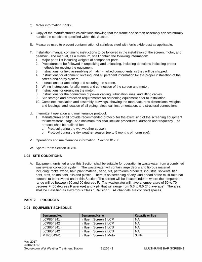
May 2017 C01025C17 Georgetown Wet Weather Treatment Station 11260 - 3 MULTI-RAKE BAR SCREENS
Q. Motor information: 11060.
R. Copy of the manufacturer's calculations showing that the frame and screen assembly can structurally handle the conditions specified within this Section.
S. Measures used to prevent contamination of stainless steel with ferric oxide dust as applicable.
T. Installation manual containing instructions to be followed in the installation of the screen, motor, and gearbox. The manual, as a minimum, shall contain the following information: 1. Major parts list including weights of component parts. 2. Procedures to be followed in unpacking and unloading, including directions indicating proper
methods for moving the equipment. 3. Instructions for field assembling of match-marked components as they will be shipped. 4. Instructions for alignment, leveling, and all pertinent information for the proper installation of the
screen and spray system. 5. Instructions for anchoring and securing the screen. 6. Wiring instructions for alignment and connection of the screen and motor. 7. Instructions for grounding the motor. 8. Instructions for the connection of power cabling, lubrication lines, and lifting cables. 9. Site storage and protection requirements for screening equipment prior to installation. 10. Complete installation and assembly drawings, showing the manufacturer's dimensions, weights,
and loadings; and location of all piping, electrical, instrumentation, and structural connections.
U. Intermittent operation and maintenance protocol: 1. Manufacturer shall provide recommended protocol for the exercising of the screening equipment
for intermittent usage. At a minimum this shall include procedures, duration and frequency. The protocol shall be outlined for: a. Protocol during the wet weather season. b. Protocol during the dry weather season (up to 5 months of nonusage).
V. Operations and maintenance information: Section 01730.
W. Spare Parts: Section 01750.
1.04 SITE CONDITIONS
A. Equipment furnished under this Section shall be suitable for operation in wastewater from a combined wastewater collection system. The wastewater will contain large debris and fibrous material including: rocks, wood, hair, plant material, sand, silt, petroleum products, industrial solvents, fish nets, tires, animal fats, oils and plastic. There is no screening of any kind ahead of the multi-rake bar screens to be provided under this Section. The screen will be located indoors where the temperature range will be between 50 and 90 degrees F. The wastewater will have a temperature of 50 to 70 degrees F (55 degrees F average) and a pH that will range from 5.6 to 8.5 (7.0 average). The area shall be classified as Hazardous Class 1 Division 1. All channels are confined spaces.
PART 2 PRODUCTS
2.01 EQUIPMENT SCHEDULE
Equipment No. Equipment Name Capacity or Size LCP854341 Influent Screen 1 LCP NA LCP854342 Influent Screen 2 LCP NA LCS854341 Influent Screen 1 LCS NA LCS854342 Influent Screen 2 LCS NA MTR854341 Influent Screen 1 Motor 3 HP

May 2017 C01025C17 Georgetown Wet Weather Treatment Station 11260 - 4 MULTI-RAKE BAR SCREENS
Equipment No. Equipment Name Capacity or Size MTR854342 Influent Screen 2 Motor 3 HP SCN854341 Influent Screen 1 70 MGD SCN854342 Influent Screen 2 70 MGD
2.02 GENERAL
A. Multi-rake bar screens shall be manufacturer’s standard product and only modified as necessary to comply with the Drawings, Specifications, and specified service conditions.
B. Manufacturer shall provide multi-rake bar screens, motors, gear reducers, controls, control panels and local control stations, and lifting attachments as a complete integrated package to ensure proper coordination, compatibility, and operation of the system.
C. All structural members of the equipment shall be designed for shock and vibratory loads.
D. Motor shall be inverter duty rated and compatible with a VFD.
E. Each multi-rake bar screen shall have the manufacturer’s name, address and product identification on a nameplate securely affixed to the equipment at a location and height visible from the operating deck.
2.03 ACCEPTABLE MANUFACTURERS
A. ProTechtor Multi-rake Screen as manufactured by Kusters Water.
B. RakeMax Multi-rake Bar Screen as manufacturer by Huber Technology, Inc.
C. MS Series Bar Screen as manufactured by Headworks, Inc.
D. Approved Equal.
E. The multi-rake screen manufacturer's standard models or products may require modification to conform to the specified requirements.
2.04 MATERIALS
A. Materials specified are considered the minimum acceptable for the purposes of durability, strength, and resistance to erosion and corrosion.
B. The mechanically cleaned screen shall be designed for passively resisting corrosion from free and combined chlorine residuals, chlorides, hydrogen sulfide, condensation containing sulfuric acid residual, and sulfates.
C. Screen shall be manufactured from ASTM 316L stainless steel.
2.05 SERVICE CONDITIONS
A. The mechanically cleaned screen shall be a multi-rake bar type screen contained within a self-supporting frame. The water will pass through the screen bars on the upstream side and, as the screening rake rotates, the debris collected on the bars will be lifted above the deck level where it will be removed and discharged through a chute to the screenings compactor inlet.

May 2017 C01025C17 Georgetown Wet Weather Treatment Station 11260 - 5 MULTI-RAKE BAR SCREENS
2.06 DESIGN REQUIREMENTS
A. Each screen shall be designed for continuous duty and shall be suitable for installation under the following conditions:
Number of Units: 2 Type: Multi-Rake Type of Screen Installation: Protrude into channel Bar Screen Opening: 6 mm Bar Shape: Teardrop or trapezoidal Peak Flow per screen 70 MGD Minimum Flow per screen 5 MGD Maximum Screenings Removal Capacity per Screen, Wet Screenings: 200 cubic feet/hour
Channel Width, Feet: 6.5 Discharge Height, EL.: Per manufacturer Operating Deck, EL.: 114.0 Channel Top, EL.: 114.0 Channel Invert, EL.: 90.0 Maximum Top of Screen, EL: 125.5 Water Surface Upstream of Screen at Peak Flow, EL.: 99.2 - 99.4
Water Surface Downstream of Screen at Peak Flow, EL.: 98.0 - 98.33
Angle of Inclination of Screen From Horizontal, degrees 75
Rake Engagement Frequency at Normal Speed, Seconds: 30
Rake Engagement Frequency at High Speed, Seconds: 5
Screen Drive Hp: 3 Nominal Motor Speed (rpm): 1800 Voltage 460V, 3-phase
B. The screen shall be capable of processing the peak flow without exceeding the maximum upstream water level based on a 35% reduction of the screen’s free open-area.
2.07 FEATURES
A. General: 1. Screen shall be manufactured from ASTM 316L stainless steel shapes (rods, angles, and
channels), pipes, and sheets. In particular, side frames and guides, bar rack, rake assembly, scraper assembly, shafting, fasteners (bolts & nuts, etc.) and anchor bolts shall be made of this material.
2. Screen shall be manufactured either in a stainless steel only factory to prevent contamination of the stainless steel with ferric oxide dust, or in a factory that has measures in place to prevent contamination of stainless steel with ferric oxide dust. Submit measures utilized to prevent contamination.
3. All stainless steel components and structures shall be cleaned, descaled, and passivated in accordance with ASTM A380.
4. The bar screen shall be provided with a dead plate extending from the bar rack to the discharge chute. The dead plate shall be securely fastened to the side frames.
5. Screenings transported to the top of the screen shall be discharged positively by means of a rake mechanism to the discharge chute. The rake mechanism shall be fitted with a compression spring that allows the rake to return to its resting position smoothly without any shock. Rakes shall be made of stainless steel.

May 2017 C01025C17 Georgetown Wet Weather Treatment Station 11260 - 6 MULTI-RAKE BAR SCREENS
6. A discharge chute shall be mounted to direct screening into the screenings compactor inlet. The chute shall be provided by the screenings compactor manufacturer. The screening manufacturer shall coordinate with the screenings compactor manufacturer as needed so that the full enclosed chute can discharge the screens to the inlet.
7. A frame shall be provided supporting all required loads. The side frames shall be connected to support frames. The support frames shall be securely anchored onto the operating floor.
8. The screen shall be provided with easily removable, sufficiently stiffened covers. The covers shall be provided with handles and shall be fastened in such a manner to allow for installation and removal without utilizing hand tools. The covers will extend the full width of the screen for a minimum of 5.0 ft in height.
9. Each side frame shall include separate roller tracks to guide the rakes. The roller tracks shall be bolted to the frame so that they can easily be replaced.
10. Drive chains for the rakes shall be roller type chains and be made of stainless steel. Drive chains, chain guides, sprockets and their bearings shall be replaceable without the need for removing the screen from the channel.
11. Each screen shall be provided with four sprockets. The sprockets shall be made of stainless steel plates.
12. The rake mechanism shall be capable of 2 cleaning speeds: Low and High, in addition to varying speed by means of variable frequency drive. Screens which do not meet these performance criteria shall not be acceptable.
13. All the mechanical bar screening equipment shall be assembled in the manufacturer's shop to ensure proper fitting of parts, the control panel shall be pre-wired, tested and then match-marked for erection, and disassembled for shipment.
14. Neoprene strips shall be fastened to the side frames to seal the lateral gaps between the side frames and the channel walls.
15. All equipment shall be designed, fabricated, and assembled in accordance with recognized and acceptable engineering and shop practice. Individual parts shall be manufactured to standard sizes and thicknesses so that repair parts can be installed in the field. Like parts of duplicate units shall be interchangeable. Equipment shall not have been in service prior to delivery, except as required by testing.
B. Bar Rack: 1. The bar rack shall consist of tapered, trapezoidal or teardrop shaped stainless steel bars with a
minimum upstream dimension of 8 mm, a minimum downstream dimension of 4 mm, and a minimum depth of 40 mm with required clear spacing between the bars. Round bars shall not be used. The lower ends of the bars shall be provided with a minimum 4 mm thick curved base plate such that the rakes positively remove all screenings from the bottom of the bar rack.
2. The bar rack shall consist of equally spaced, straight bars that are inclined from the horizontal with the inclination angle specified above and shall span the full width of the channel. The bar rack shall be securely fastened to and supported by the frame of the screen, and be readily removable. Bars that are welded to the framework or welded into sub-assemblies shall not be allowed. Replacement screen bars shall be available from the screen manufacturer. Replacement bars shall be supplied in accordance with this Section.
3. Bars shall be fastened to a dead plate that extends to the point of discharge. Bars shall extend a minimum of 300 mm above the maximum water level.
C. Welding: 1. All welding shall conform to AWS D1.6 or AWS D1.1, as applicable. Weld spatter shall be
prevented by the use of spatter-prevention paste at welded joints. Weld slag shall be removed. 2. After welding operations, stainless steel components shall be cleaned of organic contamination
using a solvent that is free of chlorides. 3. Welded ferrous or steel components shall be provided with continuous seal welds between full
penetration skip welds or sealed with a paintable silicone caulk. 4. Field welding of stainless steel will not be permitted.
May 2017 C01025C17 Georgetown Wet Weather Treatment Station 11260 - 7 MULTI-RAKE BAR SCREENS
D. Frame Assembly: 1. The framework of the screen shall have a cross-section with a minimum thickness of 4 mm. The
side frames shall be have a minimum thickness of 4 mm formed to a channel profile. The minimum thickness of bottom frame shall be 4 mm. The frame shall have support beams with a U-profile minimum thickness of 4 mm on the front above the maximum water line. Wrap around stiffeners with a thickness of 4 mm formed to a channel profile shall be placed along the screen frame above the maximum water line for rigidity. No braces, gussets or stiffeners shall be inside the screen frame below the maximum water line.
2. The side frames shall be connected to support frames. The support frames shall be securely anchored to the operating floor.
3. The supporting framework for the bar screens shall be stainless steel, designed in conformance with the requirements of the latest revision of the AISC Standards for the Design, Fabrication and Erection of Structural Steel for Buildings, and support loads based on a completely loaded screen plus dead weight of the equipment. Shop connections may be welded, riveted, or bolted.
4. The supporting framework shall be self-supporting and designed to a minimum of twice the natural frequency of the bar screen unit under all loading conditions.
5. All structural members and connections shall be designed so that the unit stresses will not exceed AISC allowable stresses by more than 1/3 when subject to loading of twice the running torque of the drive motor.
6. The support framework shall be designed and constructed such that the screen is independently supported, to allow the bar screen to be installed and disassembled without disturbing existing equipment.
7. Supports shall be installed using welded constructions with bolted connections to bar screen casings, feet and support points. Field connections shall be bolted using reamed, subpunched holes and finished bolts as follows: a. Supporting members attached to concrete shall be by stainless steel anchor bolts. A
minimum of two bolts shall be used per supporting member. Supporting members attached to structural steel elements shall be by stainless steel hex bolts with one flat washer and one lock washer. A minimum of two bolts shall be used at each connection point.
8. The screen will be of a design utilizing structural side frames to which are bolted the bar rack and dead plate resulting in a structurally self-supporting unit. Designs in which side frames or chain guides are supported from the channel walls shall not be acceptable.
9. The side frames will include shrouds around the footshaft sprockets to prevent debris from interfering with the proper meshing of the chains and sprockets. The shrouds will also be designed to prevent grit accumulation at the chain and sprocket location.
10. Side wall seal plates with minimum 4 mm thick neoprene strips will be furnished with the screen to close off the area between the side frames and channel walls. The seal plates will extend from the channel invert to at least 6-inches above maximum sewage depth.
11. Lifting lugs will be provided on the side frames as recommended by the screen manufacturer. 12. Each side frame shall include chain guides attached to the frame to align the rake teeth into the
screen bars and maintain engagement in the bar rack. The chain guides shall assist in deflecting flow and solids away from the chain and lower sprockets to minimize materials catching on the sprockets and chain. The chain guides shall be manufactured of stainless steel.
13. The screen shall be provided with easily removable without tools, sufficiently stiffened covers. Covers shall either be constructed of clear impact-resistant Polycarbonate material (thickness of 6 mm), or of stainless steel (thickness of 1.5 mm) with edges on all sides. The covers shall be provided with handles and shall be provided with quarter turn clamp fasteners turn in such a manner to allow for easy installation and removal.
E. Rakes: 1. The rakes will be mounted between two strands of chain running over two sets of sprocket
wheels.

May 2017 C01025C17 Georgetown Wet Weather Treatment Station 11260 - 8 MULTI-RAKE BAR SCREENS
2. The rakes will be stainless steel, with raking tines of suitable shape to effectively clean the front and sides of the bars. The rakes shall meet one of the following criteria: a. Rakes shall include rake bars made of 6 mm thick channel profile having a cross section of
105 mm x 60 mm. Rake blades with a thickness of 8 mm and a depth of 170 mm shall be bolted to the rake bars. The rake blades shall have raking tines matching and engaging the bars of the bar rack. The rake blades shall consist of a minimum of six pieces with raking tines such that only one portion of the rake blades needs to be replaced in case that a tine should be damaged.
b. Raking tines shall have tooth profile precision cut from a single continuous bar of sufficient thickness and depth to insure adequate stiffness and strength. The rakes shall run in guides on both sides to ensure engagement. The rake material shall be as follows: 1) Minimum thickness of rake bar and plate shall be 12 mm total. 2) Minimum reinforcement profile shall be 4mm. 3) Minimum side sheet thickness shall be 10 mm.
F. Rake Wiper: 1. A pivoting wiper mechanism will be positioned at the point of discharge and shall have a
replaceable ultra high molecular weight polyethylene (UHMW) wiper blade, with a minimum thickness of 10 mm.
2. During each cycle, the wiper blade shall contact the rake heads at its inner surface during upward travel and shall scrape the debris off the end of the rake head and through the discharge chute. The entire wiper mechanism including the wiper arms shall be fully contained inside the framework of the bar screen.
3. The wiper mechanism, excluding the wiper blade, shall be manufactured of stainless steel. No moving parts shall extend beyond the framework or the discharge chute.
4. The design shall be such that the rake repositions the wiper mechanism. The wiper mechanism design shall allow the rake assembly to be operated in reverse, through the wiper mechanism, without the need to manually lift the wiper assembly.
5. The grease fittings for the wiper arms shall be extended and secured to the side frames in an area where they can be easily accessed by plant personnel or the wiper bearings shall be self lubricating plastic.
6. Shock absorbers shall be provided to cushion the release of the wiper.
G. Rake and Chain Assembly, and Sprockets: 1. The rake and chain assembly shall consist of multiple rakes attached to the roller links of the
roller chain. The roller chain shall engage onto adjustable upper sprockets and fixed lower sprockets on each side of the screen.
2. The upper and lower sprockets shall be made of solid stainless steel with a minimum thickness of 27 mm. The sprockets shall be of the pitch and width to match the roller chain and shall have a stainless steel hub and sprocket teeth. The tooth width on the sprockets shall be a minimum of 27 mm.
3. The upper sprockets shall be key mounted onto a drive shaft. 4. Chains shall be roller type chains and made of stainless steel of high tensile strength and
resistance to corrosion. The average ultimate strength of the chain shall be minimum 25,000 pound-force. Chain pins shall be a stainless steel and hardened. Chain rollers shall be stainless steel.
5. A chain guide shall be securely fixed to the screen side frames for the full height of travel, shall not protrude into the flow, and will be of stainless steel. The guides assure proper meshing between the rake tines and the bar rack, and proper clearance between the rake tines and the dead plate. Replaceable wear strips on chain guides located below the water level shall not be allowed. The chain guides shall be bolted to the side frame so they can be easily replaced.

May 2017 C01025C17 Georgetown Wet Weather Treatment Station 11260 - 9 MULTI-RAKE BAR SCREENS
H. Shafting and Bearings: 1. The drive shaft shall be made of solid stainless steel, fitted with a shear pin device with bronze
bushing, or auto reverse feature, to provide full protection of the drive unit. Keyways with fitted keys will be provided where necessary. The drive shaft will be equipped with an adjustable screw type take-up providing for a 100 mm adjustment of the screen chains. The take up screw shall be made of 18-8 stainless steel. The lower sprockets shall rotate on a stainless steel stub shaft attached to the frame. Lower sprockets and bearing shall be replaceable without removing the screen from the channel.
2. Upper bearings shall be flange bearings, and shall be provided with grease nipples for easy lubrication. The bearings shall be designed for use with biodegradable grease. Sealed self-lubricating upper bearings may be utilized. Self-lubricating bearings shall meet the same criteria as that for lower bearings, described below.
3. Lower bearings shall consist of a life sealed bushing system. The system shall consist of a stainless steel stub shaft supporting a ceramic collar. The ceramic collar will interface with a high lubricity, low friction composite bushing surface to ensure zero metal to metal contact. This composite bushing shall be designed for extreme wear life in highly abrasive, high impact environments. Lower bushings that require any maintenance, or have metal to metal wear shall not be accepted.
I. Dead Plate: 1. The dead plate will be fastened to the side frames of the screen, and will extend from the top of
the bar rack to the point of discharge. A steel lip will be provided at the discharge point of the dead plate.
2. The plate shall be flat without undulation so that the rake tines will ride no closer than 1 mm from the dead plate and no further than 3.5 mm from the dead plate. It shall be securely fastened to the side frames.
3. The dead plate shall be made of stainless steel having a minimum thickness of 4 mm.
J. Discharge Chute: 1. A discharge chute will be provided to guide the debris to the inlet hopper of the screenings
compactor. This chute will be provided by the screenings compactor manufacturer. Screening manufacturer shall coordinate with screenings compactor manufacturer as required.
K. Drive Unit: 1. The drive assembly shall be complete with an adjustable mounting frame, motor, and gear
reducer. 2. The drive units are not all mounted on the same side – see Drawings for drive orientation. 3. The motor shall be explosion proof and shall be as specified in Section 11060. Motor shall be
inverter duty rated and compatible with a VFD. 4. The drive unit will be of the motorized type mounted on an adjustable drive chain take-up base at
the top of the screen. The drive unit gear reducer will be fully housed, running in oil, with anti-friction bearings throughout.
5. The motor will be totally enclosed, ball bearing, variable speed, and of ample power for starting and continuously operating the mechanism under normal operating conditions without overloading. Motor will conform to NEMA standards.
6. The drive unit will be assembled by the manufacturer and shipped as a complete assembly to ensure proper assembly of all components.
7. The drive shaft shall include an integral rocker arm or torque arm assembly on the drive end that flexes if the screen rakes get jammed and triggers the jamming protection features. Electronic jam protection can be provided as an alternate. Jamming protection being triggered will send an alarm to the VFD/control system.
8. The drive unit shall be designed for continuous service and intermittent spray water contact.

May 2017 C01025C17 Georgetown Wet Weather Treatment Station 11260 - 10 MULTI-RAKE BAR SCREENS
9. The bevel gear reducer shall be a totally enclosed unit. Gear reducer shall have ball or roller bearings throughout with all moving parts immersed in oil. Gear reducers which require periodic disassembly of the unit and manual re-greasing of bearings are not acceptable. The nominal input power rating of the gear reducer shall be at least equal to the nominal horsepower of the drive motor. Gear reducer shall be designed and manufactured in compliance with applicable AGMA or equivalent standards. During continuous operation the oil temperature shall not exceed 200 degrees F (95 degrees C).
L. Anchorage: Anchor bolts shall be minimum 5/8-inch diameter. Anchor bolts shall be ASTM 316L stainless steel unless otherwise indicated in this specification and approved by the manufacturer. Anchor bolts shall be ample size and strength for the purpose intended and as indicated in the Drawings. Anchor bolt and mounting bolt design calculations shall be performed and provided in the submittal.
M. Motor: The configuration shall be as scheduled in the Design Requirements paragraph within this Section and provided in accordance with Section 11060. Motors shall be furnished with motor winding over temperature protection thermostats as specified in Section 11060.
N. Instruments: The instruments shall be as stated in Division 17.
2.08 EQUIPMENT ELECTRICAL REQUIREMENTS
A. The electrical requirements for each Multi-rake Bar Screen include those indicated in the Drawings, Section 17600, Division 16, and all other applicable Sections.
B. Provide all necessary electrical components and wiring for a complete and functional system. Electrical components and wring shall be provided and installed in accordance with the National Electrical Code (NEC) and additional State and local requirements as applicable.
C. This Section includes equipment which will be installed in a Class 1, Division 1, Group D, hazardous, corrosive, and wet area. The motor shall meet IEEE standard 841.
D. Motor starters and variable frequency drive equipment is provided by others.
2.09 EQUIPMENT CONTROL SYSTEM REQUIREMENTS
A. Each Multi-rake Bar Screen shall be provided with a Vendor-Supplied Package Control System (Package Control System). The Package Control System shall include everything required for a complete, fully functional, and integrated control system.
B. In addition to the requirements identified in this Section, the requirements for each Package Control System include those indicated in the Drawings, Section 17600 and all other referenced Sections.
C. Package Control System – Summary: 1. The following is a summary of Package Control System features, functionality, and services to be
provided as part of each Multi-rake Bar Screen Package Control System: a. Local Control Panels and Local Control Stations. b. Programmable Logic Controllers shall be per Division 17. c. Panel mounted operator interface terminals (OIT) shall be per Division 17. d. PLC/OIT Software and Programming shall be per Division 17. e. PLC hardwired I/O interface to Package Equipment Instruments and Field Devices. f. PLC hardwired IO interface with Local Control Stations (LCSs). g. PLC hardwired I/O interface to the facility process control system (PCS). h. PLC hardwired interface between Package Controls and VFDs provided by others. i. Ethernet Interface between PLCs and the PCS.

May 2017 C01025C17 Georgetown Wet Weather Treatment Station 11260 - 11 MULTI-RAKE BAR SCREENS
j. Control Strategy Implementation. k. Integration of Package Control System with the PCS. l. Factory, Component, System, and Operational Testing.
D. Control Panels: 1. The control panels to be provided for the Multi-rake Bar Screen Package Control Systems shall
be as follows: a. Multi-rake Bar Screen 1 Control Panel LCP854341. b. Multi-rake Bar Screen 2 Control Panel LCP854342.
2. Each Raw Sewage Bar Screen Package Control Panel shall be provided with the following pilot devices at a minimum: a. Control Power. b. Screen Running Forward. c. Screen Running Reverse. d. Screen Jam. e. Screen Fault.
3. Each Raw Sewage Bar Screen Package Control Panel shall be provided with the following control switches and pushbuttons at a minimum: a. Alarm Reset pushbutton. b. Estop pushbutton.
4. Each Raw Sewage Bar Screen Package Control Panel shall provide the following hardwired control signals to the PCS. a. Dry contact signals rated 5A at 120 VAC.
1) Screen in AUTO. 2) Screen RUNNING Forward. 3) Screen RUNNING Reverse. 4) Screen FAULT. 5) Screen E-STOP.
b. 4-20 mA signals. 1) Screen channel differential level.
5. Each Raw Sewage Bar Screen Package Control Panel shall receive the following hardwired control signals from the PCS. a. Dry contact signals rated 5A at 120 VAC.
1) Screen RUN. b. 4-20 mA signals.
1) Screen differential level.
E. Programmable Logic Controller Data Exchange: 1. All PLC configured control, status and alarm data points shall be accessible by the facility PCS.
a. Communications: Ethernet. b. Format: PLC program tags formatted to meet County tag naming standard.
2. Supplier shall submit a complete PLC tag list.
F. Operator Interface Terminal shall be configured and coordinated with the configuration of facility OIT system, provided by others, in compliance with Section 17810. 1. At a minimum, the OIT shall provide:
a. Display Features: 1) Screen Running Forward. 2) Screen Running Reverse. 3) Screen Operating Speed. 4) Screen run time. 5) Current Demand. 6) Fail, service reminder and operational messages.
b. Local alarm annunciation. c. User Adjustment of Operating Setpoints.

May 2017 C01025C17 Georgetown Wet Weather Treatment Station 11260 - 12 MULTI-RAKE BAR SCREENS
G. Local Control Stations: 1. The Local Control Stations to be provided with the Multi-rake Bar Screen Package Control
Systems shall be as follows: a. Raw Sewage Bar Screen 1 Local Control Station LCS854341. b. Raw Sewage Bar Screen 2 Local Control Station LCS854342.
2. Each Raw Sewage Bar Screen Package Local Control Station shall be cast aluminum, rated NEMA 7. a. Size enclosures to accommodate listed control devices.
3. Each Raw Sewage Bar Screen Package Local Control Station shall be provided with the following control devices: a. Screen HAND-OFF-AUTO selector switch, rated NEMA 7. b. Forward/Reverse selector switch, rated NEMA 7. c. E-Stop Pushbutton, rated NEMA 7, provided with adequate contacts and wired into the
screen local control panel control circuitry to achieve the following: 1) Positive hardwire shutdown and maintained start inhibit of Multi-rake Bar Screen motor
by interrupting all 120VAC control power immediately after the fuse on the load side of ungrounded terminal of the control power transformer within the Package Equipment control panel.
2) E-Stop switch activation notification though a dedicated supplementary E-Stop switch contact, which is hardwired from the dedicated E-Stop switch contact through the Package Equipment control panel to the PCS discrete input.
2.10 COATINGS
A. Procedures: Section 09900.
2.11 SOURCE QUALITY CONTROL
A. Factory Tests (Pre-installation Testing): The screen shall be factory assembled and factory tested before being shipped. As a minimum factory testing shall include a test to demonstrate that the frame assembly and bar rake can resist the loads imposed by the motion of a fully loaded moving screen assembly and the possible situation where the screen encounters a blocked flow condition with an upstream water depth of up to 12 feet and no downstream water depth. The screen shall also be tested to verify that it can meet the Design Requirements specified within this Section. The Engineer reserves the right to be present during the factory testing. The Project Representative and Engineer shall be notified at least 42 days prior to the estimated test date.
2.12 SPARE PARTS
A. Procedures: Section 01750.
B. The screen manufacturer shall furnish the recommended spare parts that will be needed during the first 5 years of operation.
C. Pack all spare parts for long-term storage in an unheated, unventilated, damp area in containers which are clearly identified on all sides with indelible markings as to contents.
D. Spare parts shall be tagged and stored in accordance with Section 11000.
May 2017 C01025C17 Georgetown Wet Weather Treatment Station 11260 - 13 MULTI-RAKE BAR SCREENS
PART 3 EXECUTION
3.01 INSTALLATION
A. Equipment Mounting: 1. Procedures: Section 11050. 2. Mount equipment in accordance with manufacturer's mounting details.
B. Alignment Procedures: Section 11040.
3.02 FIELD QUALITY CONTROL
A. Field Testing: 1. In addition to any testing herein, perform all testing for this product or system consistent with the
requirements of Section 01660, the applicable codes, and the manufacturers' current quality assurance program.
2. Performance Testing: Following completion of Pre-installation and Component Test Phases in accordance with Section 01660, system and operational testing shall be performed for the multi-rake screen installation to determine system operating conditions and verify that the unit meets the requirements specified within the Design Requirements.
3. If required, take corrective action and have the units retested to ensure full compliance with the specified requirements.
B. Manufacturer's Services: 1. Provide a factory-trained representative, specifically trained on the type of equipment specified, at
the site for the specified quantity and duration of the following activities. Specified durations do not include travel time to or from the project site. Service representative requirements include the following: a. Two Installation Inspections: Assist, supervise, and inspect the Contractor's activities during
installation of multi-rake screens. Provide a minimum of 16 hours of installation inspection during installation of the first multi-rake screen. Provide a minimum of 32 hours of installation inspection of additional installations of multi-screens and post startup assessment of previously installed screens.
b. The service representative shall inspect and verify location of anchor bolts, placement, leveling, alignment and field erection of equipment, as well as control panel operation and electrical connections. In addition, the service representative shall be present during initial energizing of equipment to determine directional testing as described herein. Minimum one site visit and one, eight-hour day on site.
c. Test Phase Assistance: Assist, supervise, and inspect the Contractor's activities during testing. Provide a minimum of 16 hours during testing. Complete Form 11000-A, Section 01999.
3.03 TRAINING
A. Procedures: Section 01660.
B. A manufacturer’s representative shall provide a minimum of four 2-hour sessions (each) of classroom training on screens. Two sessions shall be specific to operations while two sessions will be specific to maintenance. Conduct one training session per week on consecutive weeks to accommodate the shift schedules of operation and maintenance staff.
C. Total of eight hours.
May 2017 C01025C17 Georgetown Wet Weather Treatment Station 11260 - 14 MULTI-RAKE BAR SCREENS
D. Certify completion of training on Form 11000-B, Section 01999.
END OF SECTION

May 2017 C01025C17 ULTRAVIOLET (UV) DISINFECTION Georgetown Wet Weather Treatment Station 11301 - 1 SYSTEM EQUIPMENT INSTALLATION
SECTION 11301
ULTRAVIOLET (UV) DISINFECTION SYSTEM EQUIPMENT INSTALLATION
PART 1 GENERAL
1.01 SUMMARY
A. This Section specifies the installation, startup, and testing requirements of the UV Disinfection System (UV System), provided by the UV System Supplier (UVSS), for the Georgetown Wet Weather Treatment Station (GWWTS) Project.
B. The UVSS has been pre-selected and the equipment will be provided by the Contractor per the requirements of Section 01021. Be responsible for purchasing, storing, installing, and testing the equipment as well as additional services required to provide a complete system.
C. Shop drawings of the UVSS equipment and the executed procurement contract documents for the UVSS pre-selection scope of services are provided as reference in Volume 17 and Volume 18.
1.02 QUALITY ASSURANCE
A. Referenced Standards: This Section incorporates by reference the latest revision of the following documents. These references are a part of this Section as specified and modified. In case of conflict between the requirements of this Section and those of the listed documents, the requirements of this Section shall prevail. Reference Title APHA/ AWWA/ WEF Standard Methods for the Examination of Water and Wastewater, 22nd
Edition NWRI/ WRF Ultraviolet Disinfection Guidelines for Drinking Water and Water Reuse,
August 2012
1.03 SUBMITTALS
A. Procedures: Section 01300.
B. UV System manufacturer shall note any modifications to the material provided in Volume 18 relative to the final fabricated product: 1. If a modification is noted, submit an updated version of any affected documentation in Volume 18,
including cutsheets, diagrams, shop drawings, or design information prior to shipment of the UV System.
C. Operation and maintenance information: 1. Section 01730.
D. Manufacturer’s instructions covering storage, handling, installation, lubrication, and maintenance for the UV System.
E. Original licenses/agreements of all computer software used in the UV System.
F. Testing and Installation Submittals: 1. All required forms per Section 01660. 2. Process Control Narrative:
a. Summarize the step-by-step operation of the system in coordination with Section 17550 and the manufacturer’s O&M.

May 2017 C01025C17 ULTRAVIOLET (UV) DISINFECTION Georgetown Wet Weather Treatment Station 11301 - 2 SYSTEM EQUIPMENT INSTALLATION
b. Provide descriptions for each input/output from the UV Disinfection Main Control Panel as well as the interaction of the UV System with the GWWTS master SCADA system.
3. System Warranty. 4. Performance Guarantee. 5. Warranties of UV System components.
a. Submit a copy of the extended two (2) year warranty for all UV System components. 6. Manufacturer’s instructions covering storage, handling, installation, lubrication, and maintenance
for the UV System. 7. Sample Repair and Replacement contract including: term, fee, products covered, guaranteed
timeframe for replacement, procedure for repair or replacement including information for disposing of burned-out or broken UV lamps, transportation charges, ownership of failed/defective equipment, and warranty on replacement equipment.
8. Replacement cost to the County and recommended replacement intervals for the following: a. General:
1) Electronic ballast. 2) UV lamp intensity sensor. 3) UV lamps. 4) UV lamp quartz sleeve. 5) Sleeve wiper.
9. Contact information for UV lamp and ballast suppliers other than UVSS. 10. Certification of installation. 11. Certification of factory testing and equipment assembly prior to shipment. 12. Training Plan documentation in accordance with Section 01660. 13. Testing phase documentation in accordance with Section 01660:
a. Testing Phase Plan. b. Testing Report. c. Field Service Report.
1.04 DEFINITIONS (NOT USED)
1.05 SYSTEM DESIGN CRITERIA (NOT USED)
1.06 PERFORMANCE GUARANTEE
A. The UV System provided shall produce an effluent conforming to the effluent standards indicated in the Drawings and in Volume 17 and Volume 18. Fecal coliform shall not exceed 400 cfu/100 mL for any sample taken. The performance shall be guaranteed by the UVSS.
B. UVSS shall guarantee compliance with the following disinfection requirement for the life of the equipment: 1. Peak value for fecal coliform in the disinfected HRC effluent does not exceed the design criteria.
C. UVSS shall guarantee compliance with the disinfection requirement provided that: 1. The constructed facilities do not deviate substantially from the UVSS design recommendations. 2. The actual flow rates do not exceed the peak flow given in the design criteria table. 3. Wastewater characteristics are no worse than the values given in the design criteria table. 4. County operation and maintenance procedures do not deviate from UVSS’s recommendations.

May 2017 C01025C17 ULTRAVIOLET (UV) DISINFECTION Georgetown Wet Weather Treatment Station 11301 - 3 SYSTEM EQUIPMENT INSTALLATION
D. If the UV System should fail to meet effluent disinfection requirements, except for non-warranted causes as noted, UVSS shall provide services of an experienced factory-trained authorized representative to inspect and correct all UV System deficiencies within two (2) weeks of written notification of non-compliance with effluent disinfection requirements. If the cause of failure is determined to be non-warranted, the County will reimburse UVSS for all reasonable costs of the investigation, otherwise, UVSS shall be solely responsible for costs to modify and retest the UV System to demonstrate compliance with effluent disinfection requirements. If correction of the failure requires provision of additional equipment, installation of additional equipment shall be only as accepted by the County. If the UV System fails to meet effluent disinfection requirements following correction(s), the County may require the UV System to be removed within thirty (30) days after rejection or replaced with a UV System able to meet effluent disinfection requirements at no cost to the County.
1.07 DELIVERY, STORAGE, AND HANDLING
A. Delivery and Storage: 1. UVSS shall ship the entire UV System (including all components) as a unit. 2. Equipment to be unloaded by Contractor. 3. Provide written notice to the County a minimum three (3) days prior to anticipated date of delivery
to afford an opportunity for the County to be present and inspect unloading of UV System equipment.
4. Authorized representative of UVSS shall be present during unloading. 5. Manufacturer’s instructions covering storage, handling, installation, lubrication, and maintenance
for the UV System shall be furnished to the County a minimum of 30 days prior to the date the equipment is shipped.
6. Grease and lubricating oil shall be applied to all bearings and similar items. 7. All equipment shall be delivered by the UVSS to the site ready for installation. UVSS shall be
responsible to coordinate with the Contractor to provide proper storage of the equipment. 8. Deliver materials dry and undamaged.
B. Painted and coated surfaces shall be protected against impact, abrasion, discoloration, and other damage. Painted and coated surfaces which are damaged prior to acceptance of equipment shall be repainted to the satisfaction of the Project Representative.
C. Each item of equipment shall be tagged or marked as identified in the delivery schedule or on the shop drawings prior to shipping. Complete packing lists and bills of material shall be included with each shipment.
D. Damaged and missing UV System equipment shall be replaced with new equipment at no additional cost to the County: 1. Replenish any spare parts used to specified quantity.
PART 2 PRODUCTS
2.01 GENERAL
A. Summary of UV System Components: 1. See Volume 17 and Volume 18 for scope of supply for the UVSS. The following table is a
summary of the major system components supplied by the UVSS as outlined in the submittal information included in Volume 18.
2. Location and space for a future fifth UV bank in each channel, as well as an associated power supply unit, is indicated in the Drawings. a. Future banks and power supply units are designated as follows:
1) T1-UV Lamp Bank 5 (UV854513). 2) T1-UV Power Supply Unit 5 (PWR854513).
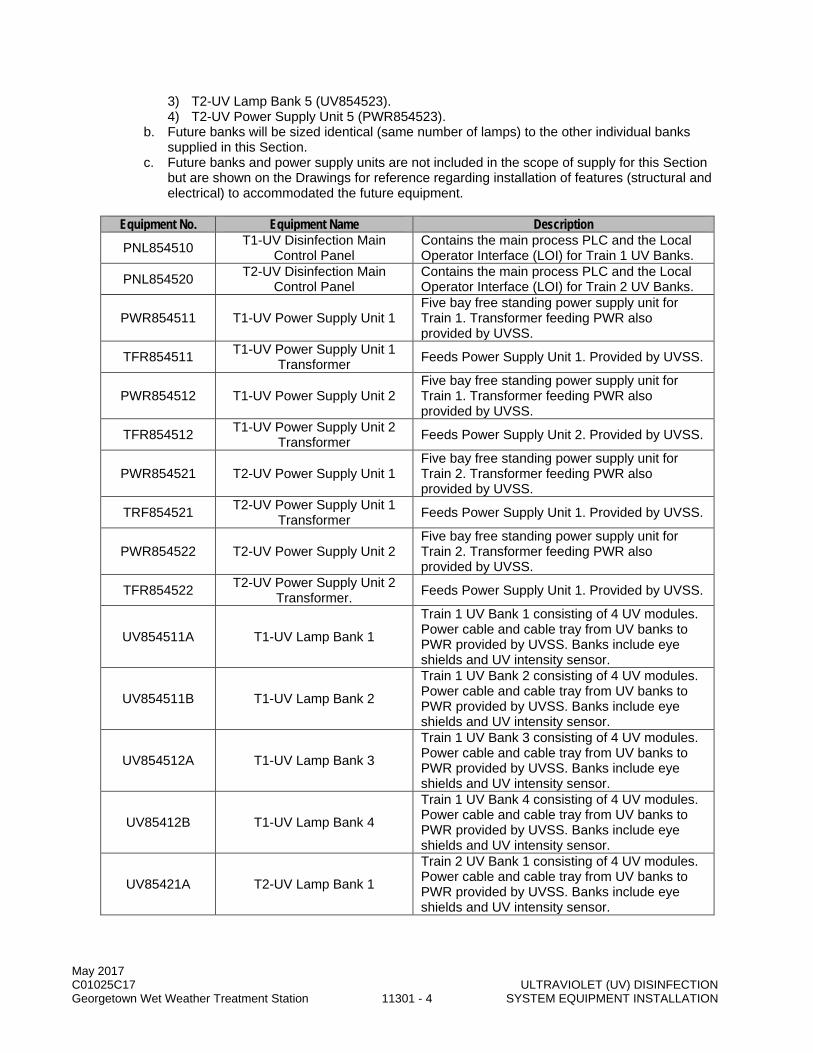
May 2017 C01025C17 ULTRAVIOLET (UV) DISINFECTION Georgetown Wet Weather Treatment Station 11301 - 4 SYSTEM EQUIPMENT INSTALLATION
3) T2-UV Lamp Bank 5 (UV854523). 4) T2-UV Power Supply Unit 5 (PWR854523).
b. Future banks will be sized identical (same number of lamps) to the other individual banks supplied in this Section.
c. Future banks and power supply units are not included in the scope of supply for this Section but are shown on the Drawings for reference regarding installation of features (structural and electrical) to accommodated the future equipment.
Equipment No. Equipment Name Description PNL854510 T1-UV Disinfection Main
Control Panel Contains the main process PLC and the Local Operator Interface (LOI) for Train 1 UV Banks.
PNL854520 T2-UV Disinfection Main Control Panel
Contains the main process PLC and the Local Operator Interface (LOI) for Train 2 UV Banks.
PWR854511 T1-UV Power Supply Unit 1 Five bay free standing power supply unit for Train 1. Transformer feeding PWR also provided by UVSS.
TFR854511 T1-UV Power Supply Unit 1 Transformer Feeds Power Supply Unit 1. Provided by UVSS.
PWR854512 T1-UV Power Supply Unit 2 Five bay free standing power supply unit for Train 1. Transformer feeding PWR also provided by UVSS.
TFR854512 T1-UV Power Supply Unit 2 Transformer Feeds Power Supply Unit 2. Provided by UVSS.
PWR854521 T2-UV Power Supply Unit 1 Five bay free standing power supply unit for Train 2. Transformer feeding PWR also provided by UVSS.
TRF854521 T2-UV Power Supply Unit 1 Transformer Feeds Power Supply Unit 1. Provided by UVSS.
PWR854522 T2-UV Power Supply Unit 2 Five bay free standing power supply unit for Train 2. Transformer feeding PWR also provided by UVSS.
TFR854522 T2-UV Power Supply Unit 2 Transformer. Feeds Power Supply Unit 1. Provided by UVSS.
UV854511A T1-UV Lamp Bank 1
Train 1 UV Bank 1 consisting of 4 UV modules. Power cable and cable tray from UV banks to PWR provided by UVSS. Banks include eye shields and UV intensity sensor.
UV854511B T1-UV Lamp Bank 2
Train 1 UV Bank 2 consisting of 4 UV modules. Power cable and cable tray from UV banks to PWR provided by UVSS. Banks include eye shields and UV intensity sensor.
UV854512A T1-UV Lamp Bank 3
Train 1 UV Bank 3 consisting of 4 UV modules. Power cable and cable tray from UV banks to PWR provided by UVSS. Banks include eye shields and UV intensity sensor.
UV85412B T1-UV Lamp Bank 4
Train 1 UV Bank 4 consisting of 4 UV modules. Power cable and cable tray from UV banks to PWR provided by UVSS. Banks include eye shields and UV intensity sensor.
UV85421A T2-UV Lamp Bank 1
Train 2 UV Bank 1 consisting of 4 UV modules. Power cable and cable tray from UV banks to PWR provided by UVSS. Banks include eye shields and UV intensity sensor.
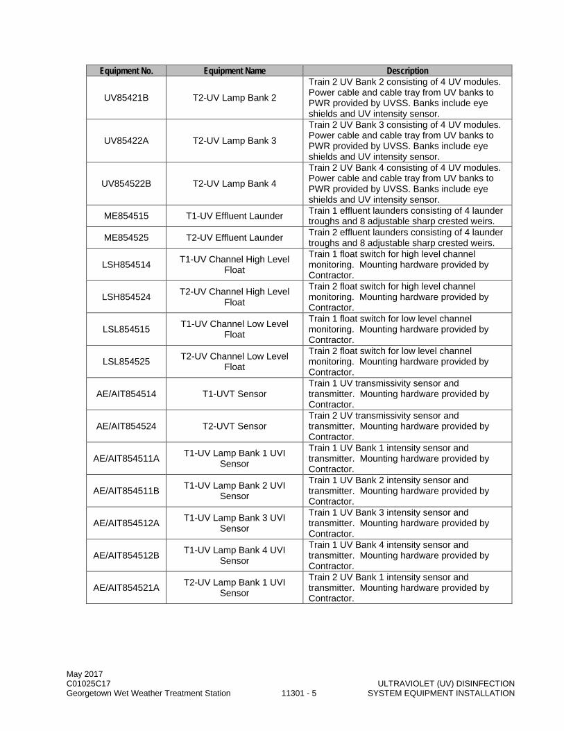
May 2017 C01025C17 ULTRAVIOLET (UV) DISINFECTION Georgetown Wet Weather Treatment Station 11301 - 5 SYSTEM EQUIPMENT INSTALLATION
Equipment No. Equipment Name Description
UV85421B T2-UV Lamp Bank 2
Train 2 UV Bank 2 consisting of 4 UV modules. Power cable and cable tray from UV banks to PWR provided by UVSS. Banks include eye shields and UV intensity sensor.
UV85422A T2-UV Lamp Bank 3
Train 2 UV Bank 3 consisting of 4 UV modules. Power cable and cable tray from UV banks to PWR provided by UVSS. Banks include eye shields and UV intensity sensor.
UV854522B T2-UV Lamp Bank 4
Train 2 UV Bank 4 consisting of 4 UV modules. Power cable and cable tray from UV banks to PWR provided by UVSS. Banks include eye shields and UV intensity sensor.
ME854515 T1-UV Effluent Launder Train 1 effluent launders consisting of 4 launder troughs and 8 adjustable sharp crested weirs.
ME854525 T2-UV Effluent Launder Train 2 effluent launders consisting of 4 launder troughs and 8 adjustable sharp crested weirs.
LSH854514 T1-UV Channel High Level Float
Train 1 float switch for high level channel monitoring. Mounting hardware provided by Contractor.
LSH854524 T2-UV Channel High Level Float
Train 2 float switch for high level channel monitoring. Mounting hardware provided by Contractor.
LSL854515 T1-UV Channel Low Level Float
Train 1 float switch for low level channel monitoring. Mounting hardware provided by Contractor.
LSL854525 T2-UV Channel Low Level Float
Train 2 float switch for low level channel monitoring. Mounting hardware provided by Contractor.
AE/AIT854514 T1-UVT Sensor Train 1 UV transmissivity sensor and transmitter. Mounting hardware provided by Contractor.
AE/AIT854524 T2-UVT Sensor Train 2 UV transmissivity sensor and transmitter. Mounting hardware provided by Contractor.
AE/AIT854511A T1-UV Lamp Bank 1 UVI Sensor
Train 1 UV Bank 1 intensity sensor and transmitter. Mounting hardware provided by Contractor.
AE/AIT854511B T1-UV Lamp Bank 2 UVI Sensor
Train 1 UV Bank 2 intensity sensor and transmitter. Mounting hardware provided by Contractor.
AE/AIT854512A T1-UV Lamp Bank 3 UVI Sensor
Train 1 UV Bank 3 intensity sensor and transmitter. Mounting hardware provided by Contractor.
AE/AIT854512B T1-UV Lamp Bank 4 UVI Sensor
Train 1 UV Bank 4 intensity sensor and transmitter. Mounting hardware provided by Contractor.
AE/AIT854521A T2-UV Lamp Bank 1 UVI Sensor
Train 2 UV Bank 1 intensity sensor and transmitter. Mounting hardware provided by Contractor.
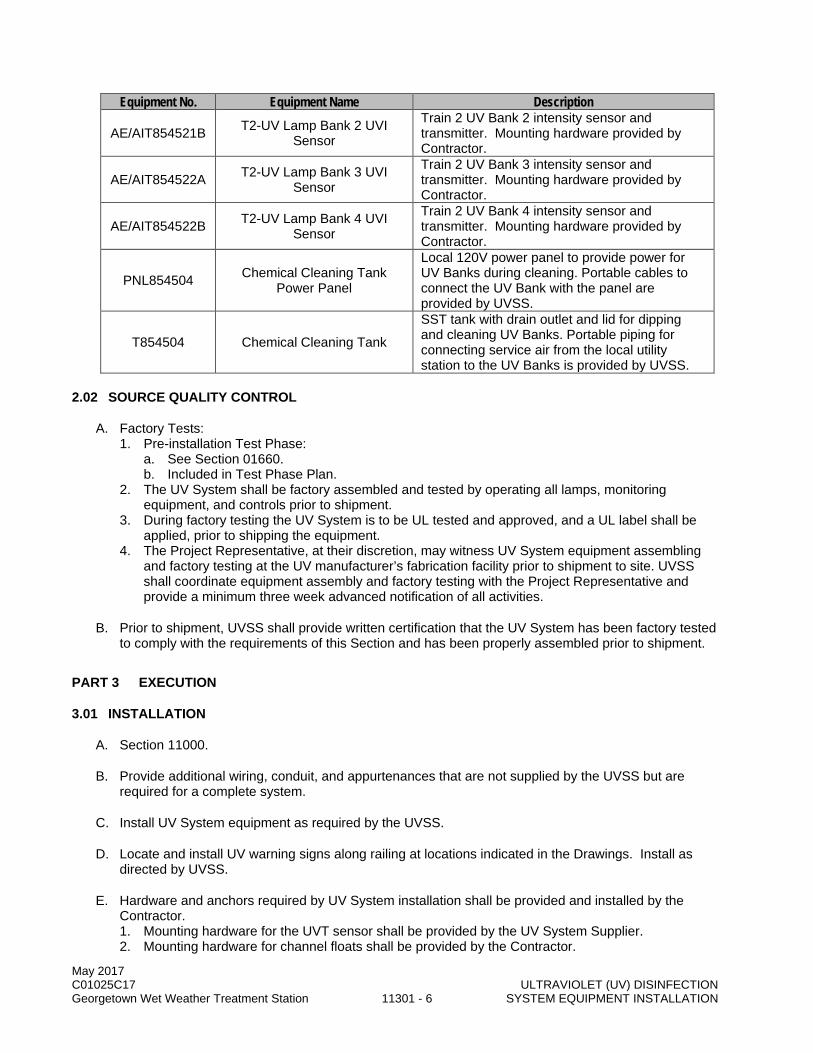
May 2017 C01025C17 ULTRAVIOLET (UV) DISINFECTION Georgetown Wet Weather Treatment Station 11301 - 6 SYSTEM EQUIPMENT INSTALLATION
Equipment No. Equipment Name Description
AE/AIT854521B T2-UV Lamp Bank 2 UVI Sensor
Train 2 UV Bank 2 intensity sensor and transmitter. Mounting hardware provided by Contractor.
AE/AIT854522A T2-UV Lamp Bank 3 UVI Sensor
Train 2 UV Bank 3 intensity sensor and transmitter. Mounting hardware provided by Contractor.
AE/AIT854522B T2-UV Lamp Bank 4 UVI Sensor
Train 2 UV Bank 4 intensity sensor and transmitter. Mounting hardware provided by Contractor.
PNL854504 Chemical Cleaning Tank Power Panel
Local 120V power panel to provide power for UV Banks during cleaning. Portable cables to connect the UV Bank with the panel are provided by UVSS.
T854504 Chemical Cleaning Tank
SST tank with drain outlet and lid for dipping and cleaning UV Banks. Portable piping for connecting service air from the local utility station to the UV Banks is provided by UVSS.
2.02 SOURCE QUALITY CONTROL
A. Factory Tests: 1. Pre-installation Test Phase:
a. See Section 01660. b. Included in Test Phase Plan.
2. The UV System shall be factory assembled and tested by operating all lamps, monitoring equipment, and controls prior to shipment.
3. During factory testing the UV System is to be UL tested and approved, and a UL label shall be applied, prior to shipping the equipment.
4. The Project Representative, at their discretion, may witness UV System equipment assembling and factory testing at the UV manufacturer’s fabrication facility prior to shipment to site. UVSS shall coordinate equipment assembly and factory testing with the Project Representative and provide a minimum three week advanced notification of all activities.
B. Prior to shipment, UVSS shall provide written certification that the UV System has been factory tested to comply with the requirements of this Section and has been properly assembled prior to shipment.
PART 3 EXECUTION
3.01 INSTALLATION
A. Section 11000.
B. Provide additional wiring, conduit, and appurtenances that are not supplied by the UVSS but are required for a complete system.
C. Install UV System equipment as required by the UVSS.
D. Locate and install UV warning signs along railing at locations indicated in the Drawings. Install as directed by UVSS.
E. Hardware and anchors required by UV System installation shall be provided and installed by the Contractor. 1. Mounting hardware for the UVT sensor shall be provided by the UV System Supplier. 2. Mounting hardware for channel floats shall be provided by the Contractor.

May 2017 C01025C17 ULTRAVIOLET (UV) DISINFECTION Georgetown Wet Weather Treatment Station 11301 - 7 SYSTEM EQUIPMENT INSTALLATION
F. Chemical Cleaning Tank provided by the UV System manufacturer is a SST liner that shall be encased in concrete as indicated in the Drawings to provide a complete system. See Volume 18 for detail of the liner system with associated welded anchors.
G. The UVSS shall provide technical support to the Contractor during the installation. UVSS shall assign competent and experienced factory trained authorized representative(s) to provide technical direction during installation, adjusting, and testing of the UV System and ancillary equipment.
H. The UVSS’s representative shall be responsible for adjustments and checking satisfactory function of all components of the installed UV System for the following items as minimum: 1. Proper lamp installation. 2. Proper alignment. 3. Intended operation of all components. 4. Proper connection of control panels. 5. Proper operation of all instrumentation, including channel floats, UVT sensors, and UV intensity
sensors. 6. Proper operation of transformers and ballasts.
I. The UVSS shall be present full time for a minimum of three (3) eight (8)-hour days to inspect and certify that the UV System has been installed in accordance with the manufacturer’s recommendations. 1. The time allowance for installation inspection is separate from the requirements for training and
testing.
J. Install “Warning Signs” at the periphery of UV System process area at locations indicated in the Drawings. See Volume 18.
K. The UVSS representative shall approve the installation and provide a Field Service Report stating UV System and ancillary equipment is: 1. Properly installed and tested. 2. Free from any induced stress imposed by attached Work. 3. Operational under full load conditions. 4. Operational under all control modes.
3.02 FIELD QUALITY CONTROL
A. Testing: 1. See Section 01660. 2. Test Phase Plan submittals:
a. See Section 01660. b. Prepared by UVSS.
3. The following test phases shall be completed on UV System: a. Component Test Phase. b. System Test Phase. c. Operational Test Phase. d. Commissioning Test Phase.
4. General: a. Furnish labor, material, equipment, and services required to conduct and satisfactorily
complete testing, exclusive of the supplies provided by the UVSS. b. Coordinate all testing services provided by the UVSS. c. The UVSS field representative shall be responsible to direct the Contractor’s staff during
operation of all support systems provided by or required by the UVSS for testing and operation of the UV System.
d. The UVSS field representative shall be present full time during testing periods of the UV System.

May 2017 C01025C17 ULTRAVIOLET (UV) DISINFECTION Georgetown Wet Weather Treatment Station 11301 - 8 SYSTEM EQUIPMENT INSTALLATION
e. The UVSS shall furnish all necessary supplies (excluding power) needed for the testing of the UV System equipment, unless otherwise noted in this Section.
f. Sampling and testing procedure shall comply with NWRI Guidelines. g. The County may conduct additional sampling and testing at any time at the County’s expense
without providing advance notification to the UVSS. h. Contractor shall provide power meters, as directed by the UVSS, for use in testing. i. Any temporary recirculation pumps or mixing system utilized during testing shall be provided
by the Contractor and approved by the UVSS. j. Testing shall be conducted at a time selected by the Contractor and mutually agreed to by
the UVSS and the County. k. Provide all personal protective equipment (PPE) required by the manufacturer to conduct the
testing: 1) Safety instructions shall be included as part of the Test Phase Plan submittals. 2) Temporary signage to indicate testing in progress and warn of UV light hazards. 3) Face shields, gloves, and other equipment to fully protect testing personnel from UV light
as recommended by the manufacturer. 5. Component Test Phase:
a. See Section 01660. b. Installed component tests and inspection. c. Conducted after installation, but prior to the System Test Phase. d. With assistance from the UVSS’s representative, conduct the Component Test Phase. e. Component Test Phase shall be conducted on each individual component of the UV System
until it has achieved one (1) continuous hour of satisfactory operation. f. Component Test Phase shall include, but not be limited to:
1) Wiring continuity test. 2) Control system loop test. 3) UV intensity sensor test to determine sensor-to-sensor variability, impact of sensor
position and sensor accuracy. All on-line sensors shall be tested. 4) Wiping system test. 5) UV transmissivity sensor test. 6) Water level control functional test. 7) Monitoring instrument calibration. 8) Control and alarm test. 9) Harmonics test.
g. Component Test Phase shall be witnessed by the County. 6. System Test Phase:
a. Complete UV System test and evaluation to demonstrate the components of the UV System interact and operate as specified.
b. System Test Phase procedures as specified in Section 01660. c. System Test Phase shall include confirming the operability of the serial interface between the
UV control panels, PLC, and the GWWTS control system. Both the UVSS and Contractor shall be present during the interface test.
7. Operational Test Phase A: a. All testing listed in this section shall be completed during the portion of the Operational Test
Phase that utilizes wastewater (Operational Test Phase Part 2, as defined in Section 01660). b. Operational Test Phase A is to demonstrate that the UV System is capable of achieving
specified disinfection requirements and meeting the head loss requirements without exceeding the maximum power usage as stated in the UVSS’s proposal.
c. Operational Test Phase A shall be conducted based on conditions for flow, UV transmittance, and dose as specified, and adjusted for degradation such as equipment aging and wear, fouling and cleaning efficiency.
d. Operational Test Phase A shall be conducted during the period outlined in Section 01660.

May 2017 C01025C17 ULTRAVIOLET (UV) DISINFECTION Georgetown Wet Weather Treatment Station 11301 - 9 SYSTEM EQUIPMENT INSTALLATION
e. Flow Testing: 1) The UVSS shall provide detailed testing protocol for the County’s review and approval
prior to the testing. The testing protocol shall follow the NWRI guidelines, including the following: a) Testing flow conditions: peak flow (35 MGD per channel), average flow (10 MGD per
channel) and minimum flow (4 MGD per channel) based on a flow rate per lamp basis. (1) Flow rate per lamp shall be based on the number of banks that would be required
to be online in a channel under the given flow conditions and water quality. b) Testing shall be conducted on each individual bank. c) Testing shall be conducted on each train/channel with the control system in
automatic settings. (1) Each test shall take place over a minimum 2-hour period with samples collected
during the period at approximately one hour increments following the start of each test (minimum three samples per test).
d) Samples for fecal coliform shall be collected on the influent and effluent for each test. e) Sample analysis shall be in accordance with the procedures described in the latest
edition of “Standard Methods for the Examination of Water and Wastewater”. 2) The Contractor and the County will operate the facility such that specified flow conditions
are approximately simulated to each UV channel. All reasonable efforts will be made to approximate steady-state flow conditions for the duration required to allow samples to be taken.
3) Testing shall be conducted after the lamps have completed a 100-hour burn-in period. 4) The lamps shall be automatically cleaned at the rate of 48 cycles per day per lamp
(maximum) for the duration of the test. Manual cleaning of any kind by the UVSS will not be allowed during the testing period.
5) Sample collection will be done by the Contractor and the County’s laboratory personnel. The sample collection shall be directed by the UVSS representative. a) The County shall collect additional samples during testing for use in bioassay
validation tests. These tests will be conducted at the County’s expense by a third party.
6) Sample analysis will be conducted at the County’s laboratory and at the County’s expense.
7) Coordinate with laboratory personnel to collect, preserve, and transport the samples to the laboratory; conduct the required analyses, and report the results. Chain of custody procedures shall be followed using a custody form typically used by the County.
8) All testing results shall meet the disinfection requirements described in this Section. 9) The data to be determined from each test shall include the following:
a) Flow rate and flows split between channels. b) Detention time based on volume of water flowing by the UV lamps. c) Number of lamps in operation. d) UV dose. e) Fecal coliform counts in influent and effluent. f) Total suspended solids (TSS). g) 5-day Biochemical Oxygen Demand (BOD). h) Iron (mg/L). i) Temperature. j) pH. k) Hardness. l) Alkalinity. m) Manganese. n) Color. o) Conductivity. p) Total organic carbon (TOC). q) UV transmittance. r) UV intensity reading from the online instrumentation.
May 2017 C01025C17 ULTRAVIOLET (UV) DISINFECTION Georgetown Wet Weather Treatment Station 11301 - 10 SYSTEM EQUIPMENT INSTALLATION
s) Water level(s) under various flow conditions. t) Wiping frequency.
10) Power consumption: amps, kW demand, and kWh operating of the UV System and ancillary equipment.
11) During the testing period, the County will be sampling and performing independent bioassay tests to characterize the wastewater. Coordinate the timing of this sampling within the Test Phase Plan submittals and allow access for the County to take the samples.
12) Document testing per Section 01660. a) UVSS shall certify testing and sign Form 01660-A as prepared by the Contractor.
f. Dosed Wastewater Testing: 1) In addition to the flow testing noted above, the UVSS shall conduct a peak flow test,
based on a flow per lamp basis, on the first bank in each of the two channels (Bank 4 in both Train 1 and Train 2).
2) The UVSS shall provide detailed testing protocol for the County’s review and approval prior to the testing. The testing protocol shall follow the NWRI guidelines. a) The testing protocol shall outline any temporary mixing or pumping systems
necessary for the testing, as determined by the UVSS. b) All temporary equipment, if used, shall be provided, installed, and operated by the
Contractor. 3) Testing shall utilize enhanced wastewater with the following characteristics:
a) Augmented wastewater (as defined in Operational Test Phase Part 2, Section 01660) shall be dosed with fecal coliform, as necessary, to reach a minimum six log concentration. (1) Fecal coliform for dosing shall be obtained and dosed by the Contractor, as
directed by the UVSS. The UVSS shall approve all dosing protocol and fecal coliform source of supply.
b) Augmented wastewater (as defined in Operational Test Phase Part 2, Section 01660) shall be dosed with humic acid (SuperHume®,or Approved Equal), as necessary, to achieve a UVT of 50-55%. (1) Humic acid shall be obtained and dosed by the Contractor, as directed by the
UVSS. The UVSS shall approve all dosing protocol and humic acid source of supply.
4) Enhanced wastewater shall be applied to Bank 4 over a minimum 2-hour period with samples collected during the period at approximately one hour increments following the start of each test (minimum three samples per test). a) Testing data and protocol shall match the requirements of the flow testing as outlined
above. b) Power consumption: amps, kW demand, and kWh operating of the UV System and
ancillary equipment. c) During the testing period, the County will be sampling and performing independent
bioassay tests to characterize the wastewater. Coordinate the timing of this sampling within the Test Phase Plan submittals and allow access for the County to take the samples.
d) Document testing per Section 01660. (1) UVSS shall certify testing and sign Form 01660-A as prepared by the Contractor.
8. Commissioning Phase: a. As outlined in Section 01660.
9. Operational Test Phase B: a. All testing listed in this section shall be completed after the Commissioning Phase, but before
the end of the two year extended warranty period. b. The UVSS shall provide detailed testing protocol for the County’s review and approval prior to
Operational Test Phase A. The testing protocol shall follow the NWRI guidelines.
May 2017 C01025C17 ULTRAVIOLET (UV) DISINFECTION Georgetown Wet Weather Treatment Station 11301 - 11 SYSTEM EQUIPMENT INSTALLATION
c. Operational Test Phase B is to demonstrate that the UV System, when operating under actual CSO influent conditions, is capable of achieving specified disinfection requirements and meeting the head loss requirements without exceeding the maximum power usage as stated in the UVSS’s proposal. 1) Testing shall be conducted during actual CSO events, with County staff operating the
facility under the guidance of the UVSS. d. Operational Test Phase B shall be conducted based on conditions for flow, UV transmittance,
and dose as specified, and adjusted for degradation such as equipment aging and wear, fouling and cleaning efficiency. 1) A minimum of three full-scale tests shall be conducted on each channel. Test flows
indicated are total channel flows and shall not be applied on a flow per lamp basis: a) Peak flow of 35 MGD, applied as total channel flow. b) Average flow of 20 MGD, applied as total channel flow. c) Minimum flow of 4 MGD, applied as total channel flow.
2) Sample collection will be done by the Contractor and the County’s laboratory personnel. The sample collection shall be directed by the UVSS representative. a) The County shall collect additional samples during testing for use in bioassay
validation tests. These tests will be conducted at the County’s expense by a third party.
3) Sample analysis will be conducted at the County’s laboratory and at the County’s expense.
4) Coordinate with laboratory personnel to collect, preserve, and transport the samples to the laboratory; conduct the required analyses, and report the results. Chain of custody procedures shall be followed using a custody form typically used by the County.
5) All testing results shall meet the disinfection requirements described in this Section. 6) The data to be determined from each test shall include the following:
a) Flow rate and flows split between channels. b) Detention time based on volume of water flowing by the UV lamps. c) Number of lamps in operation. d) UV dose. e) Fecal coliform counts in influent and effluent. f) Total suspended solids (TSS). g) 5-day Biochemical Oxygen Demand (BOD). h) Iron (mg/L). i) Temperature. j) pH. k) Hardness. l) UV transmittance. m) UV intensity reading from the online instrumentation. n) Water level(s) under various flow conditions. o) Wiping frequency.
7) Power consumption: amps, kW demand, and kWh operating of the UV System and ancillary equipment.
8) During the testing period, the County will be sampling and performing independent bioassay tests to characterize the wastewater. Coordinate the timing of this sampling within the Test Phase Plan submittals and allow access for the County to take the samples.
9) Document testing per Section 01660. a) UVSS shall certify testing and sign Form 01660-A as prepared by the Contractor.
e. UVSS Testing Labor Coordination: 1) The UVSS, during the duration of the two year warranty period, shall be available to
conduct Operational Test Phase B under the following requirements: a) The County shall select the time period for testing based on wet weather conditions
available. b) Once notified, the UVSS shall be onsite within 72 hours and prepared to conduct the
testing.
May 2017 C01025C17 ULTRAVIOLET (UV) DISINFECTION Georgetown Wet Weather Treatment Station 11301 - 12 SYSTEM EQUIPMENT INSTALLATION
c) The UVSS shall be available for up to 14 continuous days from the time of arrival onsite. (1) If testing is completed in less than the maximum allotted time, the UVSS shall be
compensated at the contracted daily rate for the time spent onsite. d) The UVSS shall conduct the secondary refresher training, as specified in this
Section.
B. Test Reports: 1. The UVSS representative shall prepare the Testing Report based on the test results.
a. Two separate Test Reports shall be prepared: one for all testing conducted prior to the Commissioning Phase and a second for Operational Test Phase B.
2. For each report, one (1) electronic copy shall be submitted to the County. 3. The County shall provide sampling data paperwork to the UVSS, for inclusion in the report, from
any portion of the analysis conducted by the County. 4. Report shall include the following information:
a. Date and time of inspection, sampling, or testing. b. Flow condition during testing. c. Record of conditions at the GWWTS noting any unusual circumstances. d. Plans and description of locations of samples taken and testing performed. e. Lamp status. f. Ballast status. g. Laboratory reports including:
1) Signature of the person performing tests. 2) Standard method and analytical method for conducting the test. 3) Chain of custody sheets. 4) Testing results.
h. Interpretation of results. i. Recommended corrective actions to bring equipment into compliance, if required.
5. Submit Testing Report to the County within two (2) weeks of test completion for review and acceptance.
C. If the UV System and ancillary equipment fail to meet testing requirements specified in this Section, modifications to equipment or operational changes shall be made to produce an installation which will satisfy the requirements: 1. The County will notify UVSS, and UVSS shall investigate the problem and develop a corrective
plan within two (2) weeks of notification. 2. After modifications, the equipment shall be completely re-tested as specified in this Section.
Additional testing shall have the same requirements and duration as initial testing specified. 3. UVSS shall be solely responsible for costs for modifications to the UV System. This includes
payments of all structural or electrical modifications necessary to accommodate the modified equipment.
4. UVSS shall be solely responsible for costs for re-testing required to demonstrate compliance. This includes all engineering fees and expenses associated with County’s witness of the re-tests.
D. Additional testing periods beyond the initial periods will not be a basis for extension of contract time or claims for additional compensation from the County.
E. If the UV System and ancillary equipment fail to meet testing requirements specified in this Section, and after several attempts of implementing the correcting measures by the UVSS, it will be the County’s option to require any or all of the following: 1. Complete removal of the UV System and allow associated equipment within thirty (30) days after
rejection.
May 2017 C01025C17 ULTRAVIOLET (UV) DISINFECTION Georgetown Wet Weather Treatment Station 11301 - 13 SYSTEM EQUIPMENT INSTALLATION
2. Replacement with equipment able to meet testing requirements specified in this Section at no additional cost to the County: a. In the interim between removal of the UV System and installation and testing of the
replacement UV System, provide continuous disinfection at all times at the expense of the original UVSS.
3. All payments made by the County associated with UV System equipment shall be returned to the County if the UV System cannot perform in accordance with this Section.
3.03 TRAINING
A. See Section 01660.
B. Coordinate all training and associated submittal requirements.
C. The UVSS shall be present full time for a minimum of three (3) full days to provide complete training of the County’s personnel in operating, maintaining, and repairing the equipment specified in this Section. 1. The time allowance for training is separate from the requirements for field inspection and testing.
D. The UVSS shall submit a Training Lesson Plan to the County prior to conducting the training. Training aids and hands-on demonstrations should be described in the Training Lesson Plan.
E. The UVSS shall maintain records of the individuals that have completed training and provide information required for the documentation of training hours required for the County’s personnel.
F. Instructions shall be specific to the models of equipment provided and shall include both classroom and hands-on instruction.
G. A minimum of two sessions for each training topic shall be conducted to allow for multiple shifts of the County’s personnel to receive the same training.
H. Training shall include as minimum: 1. UV disinfection theory. 2. The UV System overview. 3. Processes training including start up, shut down, flow pacing or dose pacing. 4. Routine and non-routine maintenance training including lamp replacement, ballast replacement,
intensity meter replacement and wiper replacement. 5. Safety training including safety procedures for operation and maintenance. 6. Mechanical equipment training. 7. Instrumentation and control equipment training including switches, meters and transmitters, and
analyzers. 8. Electrical control training. 9. Process logic control equipment training. 10. OIT system training. 11. All training shall be conducted at the County’s location.
I. Training sessions may be video taped by the County at the County’s expense.
J. The UVSS shall be responsible for all costs associated with training and shall provide required materials, texts and supplies.
K. All training materials shall be provided by UVSS in written and electronic format. All training materials shall be based on the O&M Manual.
L. Initial training shall be completed prior to commencement of System Test Phase.
May 2017 C01025C17 ULTRAVIOLET (UV) DISINFECTION Georgetown Wet Weather Treatment Station 11301 - 14 SYSTEM EQUIPMENT INSTALLATION
M. Secondary Training: 1. The UVSS shall repeat, in full, the training requirements listed in this Section for a second time,
as a refresher course for the County. 2. Training shall take place during the same period when the UVSS is onsite conducting Operational
Test Phase B, at specific times as determined by the County.
END OF SECTION

May 2017 C01025C17 VARIABLE SPEED NON-CLOG Georgetown Wet Weather Treatment Station 11340 - 1 CENTRIFUGAL PUMPS
SECTION 11340
VARIABLE SPEED NON-CLOG CENTRIFUGAL PUMPS
PART 1 GENERAL
1.01 SUMMARY
A. This Section specifies dry pit, variable speed and vertical solids handling centrifugal pumps for pumping primary effluent.
1.02 QUALITY ASSURANCE
A. Referenced Standards: This Section incorporates by reference the latest revision of the following documents. These references are a part of this Section as specified and modified. In case of conflict between the requirements of this Section and those of the listed documents, the requirements of this Section shall prevail.
Reference Title ABMA 9 Load Ratings and Fatigue Life for Ball Bearings ABMA 11 Load Ratings and Fatigue Life for Roller Bearings ASTM A48 Gray Iron Castings ASTM A108 Steel Bars, Carbon, Cold Finished, Standard Quality ASTM A276 Stainless and Heat-Resisting Steel Bars and Shapes ASTM A278 Gray Iron Castings for Pressure Containing Parts for Temperatures of up to
650 degrees F. ASTM A322 Steel Bars, Alloy, Standard Grades ASTM A395 Ferritic Ductile Iron Pressure Retaining Castings for Use at Elevated
Temperatures ASTM A571 Austenitic Ductile Iron Castings for Pressure-Containing Parts Suitable for
Low-Temperature Service ASTM A576 Steel Bars, Carbon, Hot Wrought, Special Quality ASTM A743 Castings, Iron-Chromium, Iron-Chromium-Nickel, Corrosion Resistance for
General Application HI 9.6.4 Rotodynamic Pumps for Vibration Measurements and Allowable Values. HI 14.6 Rotodynamic Pumps for Hydraulic Performance Acceptance Tests HI 9.1-9.8 Centrifugal/Vertical General Pump Guidelines IEEE 112 Test Procedure for Polyphase Induction Motors and Generators
B. Unit Responsibility: 1. The system shall be the end product of one responsible system manufacturer. The Contractor
shall assign unit responsibility to the manufacturer of the pumps provided under this section. This manufacturer is the Unit Responsibility manufacturer and has unit responsibility for the equipment assembly specified in this section, the motors specified in Section 11060 and the variable frequency drives specified in Section 16158. Agents, representatives, or other entities who are not a direct component of the manufacturing corporation will not be acceptable as a substitute for the manufacturer's corporation in meeting the requirement for Unit Responsibility.
2. The Unit Responsible manufacturer shall ensure coordination of design and selection of all system components such that all equipment provided as part of the Unit Responsibility is compatible and operates reliably and properly to achieve the performance requirements specified. Unit responsibility for related components in an assembly does not require or obligate the Unit Responsibility manufacturer to warranty the workmanship or quality of component products not manufactured by them.

May 2017 C01025C17 VARIABLE SPEED NON-CLOG Georgetown Wet Weather Treatment Station 11340 - 2 CENTRIFUGAL PUMPS
3. The Contractor shall coordinate equipment selection with the Unit Responsible manufacturer and shall be responsible for providing the equipment as specified herein. Contractor shall assure that all equipment systems provided as part of the system are the products for which Unit Responsibility has been coordinated by the Unit Responsible manufacturer in this Section.
4. The requirement for Unit Responsibility shall in no way relieve the Contractor of responsibility for performance as specified in the Contract Provisions.
1.03 SUBMITTALS
A. Procedures: Section 01300.
B. Forms: 11000-A, 11000-B, 11000-C, and 11060-A: Section 01999.
C. Performance data curves showing head, capacity, horsepower demand, net positive suction head required (NPSH3), and pump efficiency over entire operating range of pump, from shutoff to maximum capacity. 1. Include the pump’s preferred operating range (POR) and the manufacturer’s defined maximum
allowable operating range (AOR) for continuous steady state service on performance curves. 2. Indicate separately head, capacity, horsepower demand, NPSH3, and overall efficiency required
at the AOR’s minimum and maximum continuous stable flow conditions and at the Rated Conditions and at Secondary Conditions (if applicable).
D. Drawings showing general dimensions and confirming the size of pumps, motors, and drives; piping connections; and construction details of equipment; wiring diagrams; and weight of equipment.
E. For variable speed motors, provide performance data curves for 50, 60, 70, 80, and 90 percent of nominal speed.
F. Noise Data.
G. Anchorage and bracing calculations to demonstrate anchorage system is adequate per Section 01031.
H. A copy of the Contract Document control diagrams and process and instrumentation diagrams relating to the submitted equipment, with addendum updates that apply to the equipment in this Section, marked to show specific changes necessary for the equipment proposed in the submittal. If no changes are required, the Drawing or Drawings shall be marked "no changes required". Failure to include copies of the relevant Drawings with the submittal shall be cause for rejection of the entire submittal with no further review.
I. Motor submittal information as specified in Section 11060.
J. Variable frequency drive information as required under Section 16158.
K. Certification of satisfactory testing of each unit with copies of test logs and resulting performance curves.
L. Operations and maintenance information per Section 01730.
M. Installation certification Form 11000-A.
N. Test reports.
O. Training certification Form 11000-B.
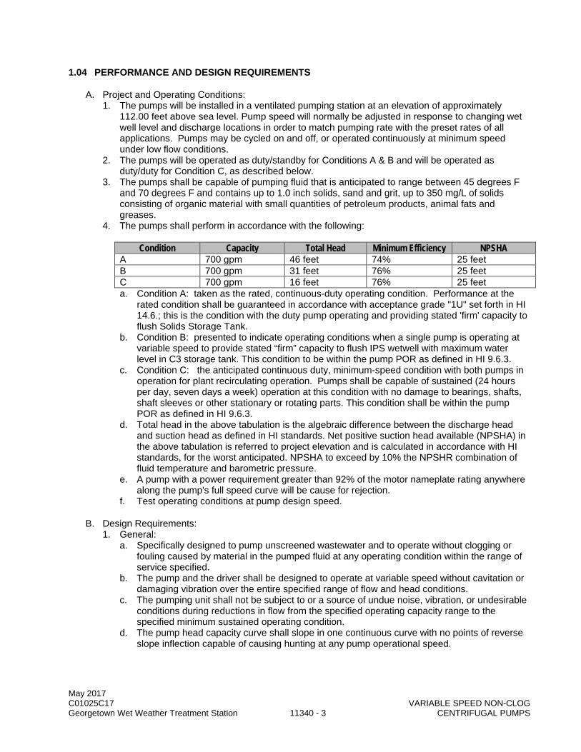
May 2017 C01025C17 VARIABLE SPEED NON-CLOG Georgetown Wet Weather Treatment Station 11340 - 3 CENTRIFUGAL PUMPS
1.04 PERFORMANCE AND DESIGN REQUIREMENTS
A. Project and Operating Conditions: 1. The pumps will be installed in a ventilated pumping station at an elevation of approximately
112.00 feet above sea level. Pump speed will normally be adjusted in response to changing wet well level and discharge locations in order to match pumping rate with the preset rates of all applications. Pumps may be cycled on and off, or operated continuously at minimum speed under low flow conditions.
2. The pumps will be operated as duty/standby for Conditions A & B and will be operated as duty/duty for Condition C, as described below.
3. The pumps shall be capable of pumping fluid that is anticipated to range between 45 degrees F and 70 degrees F and contains up to 1.0 inch solids, sand and grit, up to 350 mg/L of solids consisting of organic material with small quantities of petroleum products, animal fats and greases.
4. The pumps shall perform in accordance with the following:
Condition Capacity Total Head Minimum Efficiency NPSHA A 700 gpm 46 feet 74% 25 feet B 700 gpm 31 feet 76% 25 feet C 700 gpm 16 feet 76% 25 feet a. Condition A: taken as the rated, continuous-duty operating condition. Performance at the
rated condition shall be guaranteed in accordance with acceptance grade "1U" set forth in HI 14.6.; this is the condition with the duty pump operating and providing stated 'firm' capacity to flush Solids Storage Tank.
b. Condition B: presented to indicate operating conditions when a single pump is operating at variable speed to provide stated “firm” capacity to flush IPS wetwell with maximum water level in C3 storage tank. This condition to be within the pump POR as defined in HI 9.6.3.
c. Condition C: the anticipated continuous duty, minimum-speed condition with both pumps in operation for plant recirculating operation. Pumps shall be capable of sustained (24 hours per day, seven days a week) operation at this condition with no damage to bearings, shafts, shaft sleeves or other stationary or rotating parts. This condition shall be within the pump POR as defined in HI 9.6.3.
d. Total head in the above tabulation is the algebraic difference between the discharge head and suction head as defined in HI standards. Net positive suction head available (NPSHA) in the above tabulation is referred to project elevation and is calculated in accordance with HI standards, for the worst anticipated. NPSHA to exceed by 10% the NPSHR combination of fluid temperature and barometric pressure.
e. A pump with a power requirement greater than 92% of the motor nameplate rating anywhere along the pump's full speed curve will be cause for rejection.
f. Test operating conditions at pump design speed.
B. Design Requirements: 1. General:
a. Specifically designed to pump unscreened wastewater and to operate without clogging or fouling caused by material in the pumped fluid at any operating condition within the range of service specified.
b. The pump and the driver shall be designed to operate at variable speed without cavitation or damaging vibration over the entire specified range of flow and head conditions.
c. The pumping unit shall not be subject to or a source of undue noise, vibration, or undesirable conditions during reductions in flow from the specified operating capacity range to the specified minimum sustained operating condition.
d. The pump head capacity curve shall slope in one continuous curve with no points of reverse slope inflection capable of causing hunting at any pump operational speed.
May 2017 C01025C17 VARIABLE SPEED NON-CLOG Georgetown Wet Weather Treatment Station 11340 - 4 CENTRIFUGAL PUMPS
e. All components shall be designed to safely withstand forces resulting from flow reversals up to 125 percent of maximum speed within the pump during shutdowns caused by power failure. The complete pumping unit shall be designed to operate without overload on any component at any point along the pump's entire full-speed operating curve. The full-speed operating curve is the pump performance curve which extends through the Condition A operating point.
2. In addition to the requirements above, equipment provided under this Section shall conform to the following: a. Pump:
1) Minimum sphere capable of passing through: 1.0 inch from inlet to discharge. 2) Minimum efficiency at Condition A: 74 percent. 3) Minimum inlet size: 8 inches. 4) Minimum discharge size: 5 inches. 5) Maximum Speed: 1200 RPM.
b. Motor: 1) Type: Inverter duty. 2) Nominal speed: 1200 RPM. 3) Horsepower, nameplate: 15 hp. 4) Voltage/cycle/phase: 460/60/3. 5) Service factor: 1.0. 6) Minimum efficiency: Premium Efficiency.
3. Net Positive Suction Head Required Limitations: The pumping equipment furnished under this Section shall have Net Positive Suction Head Required (NPSHR) characteristics, defined and determined in accordance with Hydraulic Institute Standards.
C. Mass Elastic Systems and Critical Speeds: 1. Each complete system, including pump, motor, and all appurtenances shall have no dangerous
critical or resonant frequencies or multiples of resonant frequencies within 20 percent above and 20 percent below the speed range required by the pump to meet the specified operating conditions.
2. Installed pumping units shall meet the vibration and critical speed limitations specified in Section 11020.
1.05 FACTORY TESTS:
A. Pump and Pumping Unit Tests: Each pump shall be factory tested for performance and hydrostatic pressure as specified in ANSI/HI 14.6, including NPSHR characteristics as specified in that standard. However, if impeller diameter reduction is required to adjust pump performance to the tolerances specified in ANSI/HI 14.6, the pump shall be retested.
B. Motor and Variable Frequency Drive Tests: Selected test speeds shall include Condition A, Condition B and Condition C as specified in paragraph 11340-1.04A. Motor temperature rise at each test speed shall be determined in accordance with IEEE 112.
C. Test results shall be signed and certified by an officer of the manufacturing corporation.
1.06 SHIPPING
A. Ship pumping units to the site in enclosed containers in a manner designed to protect the pumping units against damaging stress caused by sudden acceleration or deceleration.
B. Fit each pump with an impact indicator prior to shipment. The impact indicator to consist of two sets of spring loaded steel balls nested within a clear plastic housing. Set the indicator to release at a force of 10 g's in any direction.
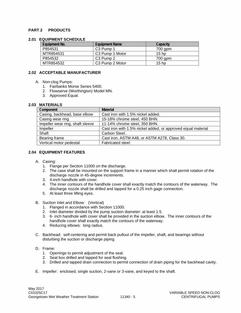
May 2017 C01025C17 VARIABLE SPEED NON-CLOG Georgetown Wet Weather Treatment Station 11340 - 5 CENTRIFUGAL PUMPS
PART 2 PRODUCTS
2.01 EQUIPMENT SCHEDULE Equipment No. Equipment Name Capacity P854531 C3 Pump 1 700 gpm MTR854531 C3 Pump 1 Motor 15 hp P854532 C3 Pump 2 700 gpm MTR854532 C3 Pump 2 Motor 15 hp
2.02 ACCEPTABLE MANUFACTURER
A. Non-clog Pumps: 1. Fairbanks Morse Series 5400. 2. Flowserve (Worthington) Model MN. 3. Approved Equal.
2.03 MATERIALS Component Material Casing, backhead, base elbow Cast iron with 1.5% nickel added. Casing wear ring 15-18% chrome steel, 450 BHN. Impeller wear ring, shaft sleeve 11-14% chrome steel, 350 BHN. Impeller Cast iron with 1.5% nickel added, or approved equal material Shaft Carbon Steel.. Bearing frame Cast iron, ASTM A48, or ASTM A278, Class 30. Vertical motor pedestal Fabricated steel.
2.04 EQUIPMENT FEATURES
A. Casing: 1. Flange per Section 11000 on the discharge. 2. The case shall be mounted on the support frame in a manner which shall permit rotation of the
discharge nozzle in 45-degree increments. 3. 4-inch handhole with cover. 4. The inner contours of the handhole cover shall exactly match the contours of the waterway. The
discharge nozzle shall be drilled and tapped for a 0.25 inch gage connection. 5. At least three lifting eyes.
B. Suction Inlet and Elbow: (Vertical) 1. Flanged in accordance with Section 11000. 2. Inlet diameter divided by the pump suction diameter: at least 1.5. 3. 6- inch handhole with cover shall be provided in the suction elbow. The inner contours of the
handhole cover shall exactly match the contours of the waterway. 4. Reducing elbows: long radius.
C. Backhead: self-centering and permit back pullout of the impeller, shaft, and bearings without disturbing the suction or discharge piping.
D. Frame: 1. Openings to permit adjustment of the seal. 2. Seal box drilled and tapped for seal flushing. 3. Drilled and tapped drain connection to permit connection of drain piping for the backhead cavity.
E. Impeller: enclosed, single suction, 2-vane or 3-vane, and keyed to the shaft.

May 2017 C01025C17 VARIABLE SPEED NON-CLOG Georgetown Wet Weather Treatment Station 11340 - 6 CENTRIFUGAL PUMPS
F. Shaft: 1. Ample strength and stiffness to operate without distortion or damaging vibration throughout the
range of service specified. 2. Turned, ground and polished, of proportions suitable for use in variable speed pumping
applications. 3. The section of shaft fitting between radial and thrust bearings shall be suitably thickened to
withstand bending loads at all speeds of operation and at all conditions of flow and head. 4. Sufficient section to limit deflection at the impeller discharge centerline to not more than five mils
when the pump is operating at any continuous-duty point defined by the envelope of Operating Conditions specified.
G. Shaft Sleeve (with mechanical seal): The section of each shaft which extends in to the stuffing box: 1. Fitted with replaceable sleeve fabricated of 316L Stainless Steel. 2. The sleeve shall be held to the shaft to prevent rotation. 3. Gasketed to prevent leakage between the shaft and the sleeve. 4. Minimum shaft sleeve thickness shall be 3/8 inch.
H. Wear Rings: 1. For the impeller and the casing and attached by screwed fasteners. 2. Casing ring hardness shall exceed impeller ring hardness by not less than 100 points on the
Brinell scale. 3. Impeller ring hardness: 350 Brinell, minimum.
I. Mechanical Seal: 1. Rotating shafts shall be provided with single mechanical seals with no seal water required. Seals
shall be factory installed. Seals shall be internal, single seal, split for removal without requiring disassembly of the pump. Balanced seals shall be provided when operating pressure, shaft size and operating speed dictate this requirement.
2. All components of the seal shall be split in half including the elastomers, gland, rotary and stationary seal faces and rotary holder. The non-shaft elastomers shall incorporate a ball and socket to ease installation.
3. Hydraulically balanced, O-ring design with positive sealing under system surge pressure and momentary vacuum up to 25 inches Hg.
4. Stationary seal shall be multiple spring loaded to maintain the sealing function. Isolate the spring system from the pumpage to eliminate corrosion and clogging.
5. Install over the pump manufacturer’s shaft sleeve. The seal gland shall be a universal adjustable gland drilled with two standard NPT flushing connections.
6. Materials of fabrication: Item Material
Gland and Rotary Holder 316 Stainless Steel Springs Elgiloy or Hastelloy C Rotary Seal Face Tungsten Carbide Stationary Seal Face Tungsten Carbide Elastomers Viton
7. Acceptable manufacturer:
a. Chesterton. b. Flowserve Corp. Durametallic type PSS Split Seal (Flowserve Corp, Fluid Sealing Div). c. Approved Equal.
J. Bearings: 1. The radial and thrust bearings shall be designed for the worst combination of loading developed
for Operating Conditions A, B, or C for a bearing life (L-10) of 100,000 hours in accordance with ABMA 9 or 11.

May 2017 C01025C17 VARIABLE SPEED NON-CLOG Georgetown Wet Weather Treatment Station 11340 - 7 CENTRIFUGAL PUMPS
K. Drive Coupling. See Section 11000.
L. Pump Base: 1. Provide a rugged heavy-duty fabricated steel pump support base designed to permit access to
the suction inlet and cleanout, bolted directly to the volute. Mount the base on a concrete pad. 2. Designed to support the assembled weight of the pump and motor. 3. Anchor bolting shall be Type 316 stainless steel and sized by the manufacturer in accordance
with Section 01031. Minimum anchor size shall be ½-inch.
M. Motor: The motor shall be vertical, inverter duty, TEFC enclosure conforming to the requirements of Section 11060 and this Section.
N. Variable Frequency Drive: see Section 16158.
2.05 SPARE PARTS
A. Per Section 01750.
B. The following spare parts shall be provided for each size and type of pump: 1. 3 sets of all gaskets. 2. 1 set of pump bearings. 3. 1 set of impeller and casing wearing rings. 4. 1 set of mechanical seals. 5. 3 sets of lip seals (if applicable).
2.06 SHOP/FACTORY FINISHING
A. Prepare, prime and finish in accordance with Section 09900. System B-1.
PART 3 EXECUTION
3.01 INSTALLATION
A. Each pumping unit shall be aligned, connected, and installed in accordance with the Drawings and the manufacturer's printed instructions.
B. Level base by means of steel wedges (steel plates and steel shims). Wedge taper not greater than 1/4 inch per foot. Use double wedges to provide level bearing surface for pump and driver base. Accomplish wedging so there is no change of level or springing of baseplate when anchor bolts are tightened..
C. Adjust pump assemblies such that driving units are properly aligned, plumb, and level with driven units and all interconnecting shafts and couplings. Do not compensate for misalignment by use of flexible couplings.
D. Connect suction and discharge piping without imposing strain to pump flanges.
E. Certified on Form 11000-A per Section 01999.
3.02 FIELD FINISHING
A. Contractor provide field touchup in accordance with Section 09900. System B-1.
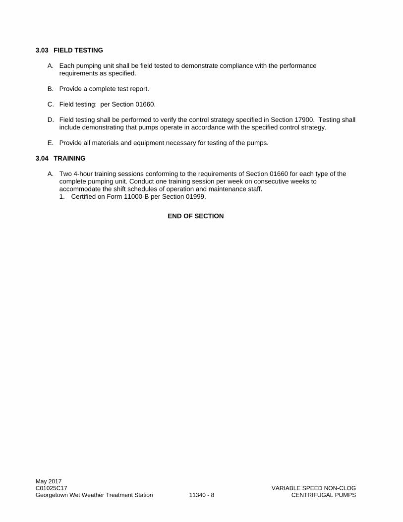
May 2017 C01025C17 VARIABLE SPEED NON-CLOG Georgetown Wet Weather Treatment Station 11340 - 8 CENTRIFUGAL PUMPS
3.03 FIELD TESTING
A. Each pumping unit shall be field tested to demonstrate compliance with the performance requirements as specified.
B. Provide a complete test report.
C. Field testing: per Section 01660.
D. Field testing shall be performed to verify the control strategy specified in Section 17900. Testing shall include demonstrating that pumps operate in accordance with the specified control strategy.
E. Provide all materials and equipment necessary for testing of the pumps.
3.04 TRAINING
A. Two 4-hour training sessions conforming to the requirements of Section 01660 for each type of the complete pumping unit. Conduct one training session per week on consecutive weeks to accommodate the shift schedules of operation and maintenance staff. 1. Certified on Form 11000-B per Section 01999.
END OF SECTION

May 2017 C01025C17 Georgetown Wet Weather Treatment Station 11344 - 1 VERTICAL TURBINE SOLIDS HANDLING PUMPS
SECTION 11344
VERTICAL TURBINE SOLIDS HANDLING PUMPS
PART 1 GENERAL
1.01 SUMMARY
A. This Section specifies vertical turbine solids handling pumps for raw sewage.
1.02 QUALITY ASSURANCE
A. Referenced Standards: This Section incorporates by reference the latest revision of the following documents. These references are a part of this Section as specified and modified. In case of conflict between the requirements of this Section and those of the listed documents the requirements of this Section shall prevail. Reference Title AWWA E101 Vertical Turbine Pumps-Line Shaft and Submersible Types ASTM A48 Standard Specification for Gray Iron Castings ASTM A53 Standard Specification for Pipe, Steel, Black and Hot-Dipped, Zinc-Coated,
Welded and Seamless ASTM A276 Standard Specification for Stainless and Heat-Resisting Steel Bars and Shapes ANSI/HI 9.6.3 Hydraulics Institute, Rotodynamic Centrifugal and Vertical Pumps-Guideline for
Allowable Operating Region. ANSI/HI 1.3 Hydraulics Institute Rotodynamic Centrifugal Pump Applications.
B. Unit Responsibility: 1. The system shall be the end product of one responsible system manufacturer. The Contractor
shall assign unit responsibility to the manufacturer of the pumps provided under this section. This manufacturer is the Unit Responsibility manufacturer and has unit responsibility for the equipment assembly specified in this section, the motors specified in Section 11060 and the variable frequency drives specified in Section 16158. Agents, representatives, or other entities who are not a direct component of the manufacturing corporation will not be acceptable as a substitute for the manufacturer's corporation in meeting the requirement for Unit Responsibility.
2. The Unit Responsible manufacturer shall ensure coordination of design and selection of all system components such that all equipment provided as part of the Unit Responsibility is compatible and operates reliably and properly to achieve the performance requirements specified. Unit responsibility for related components in an assembly does not require or obligate the Unit Responsibility manufacturer to warranty the workmanship or quality of component products not manufactured by them.
3. The Contractor shall coordinate equipment selection with the Unit Responsible manufacturer and shall be responsible for providing the equipment as specified herein. Contractor shall assure that all equipment systems provided as part of the system are the products for which Unit Responsibility has been coordinated by the Unit Responsible manufacturer in this Section.
4. The requirement for Unit Responsibility shall in no way relieve the Contractor of responsibility for performance as specified in the Contract Provisions.
1.03 SUBMITTALS
A. Procedures: Section 01300.
B. Forms: 11000-A, 11000-B, 11000-C, and 11060-A: Section 01999.
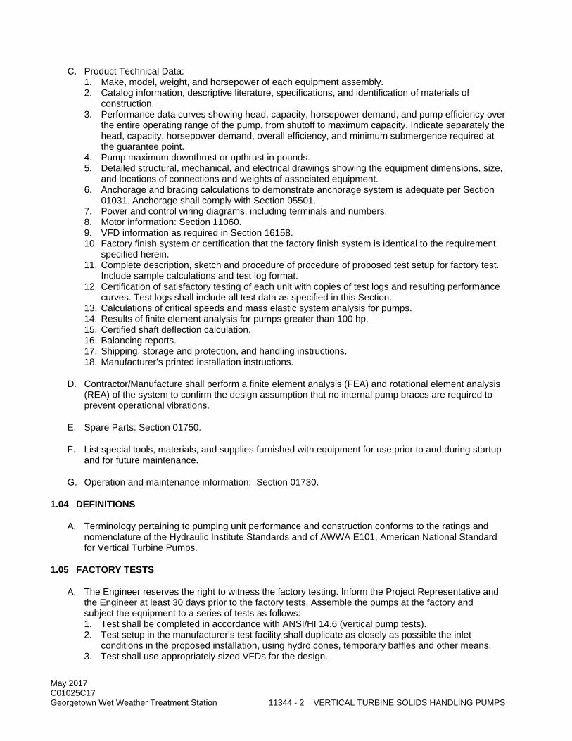
May 2017 C01025C17 Georgetown Wet Weather Treatment Station 11344 - 2 VERTICAL TURBINE SOLIDS HANDLING PUMPS
C. Product Technical Data: 1. Make, model, weight, and horsepower of each equipment assembly. 2. Catalog information, descriptive literature, specifications, and identification of materials of
construction. 3. Performance data curves showing head, capacity, horsepower demand, and pump efficiency over
the entire operating range of the pump, from shutoff to maximum capacity. Indicate separately the head, capacity, horsepower demand, overall efficiency, and minimum submergence required at the guarantee point.
4. Pump maximum downthrust or upthrust in pounds. 5. Detailed structural, mechanical, and electrical drawings showing the equipment dimensions, size,
and locations of connections and weights of associated equipment. 6. Anchorage and bracing calculations to demonstrate anchorage system is adequate per Section
01031. Anchorage shall comply with Section 05501. 7. Power and control wiring diagrams, including terminals and numbers. 8. Motor information: Section 11060. 9. VFD information as required in Section 16158. 10. Factory finish system or certification that the factory finish system is identical to the requirement
specified herein. 11. Complete description, sketch and procedure of procedure of proposed test setup for factory test.
Include sample calculations and test log format. 12. Certification of satisfactory testing of each unit with copies of test logs and resulting performance
curves. Test logs shall include all test data as specified in this Section. 13. Calculations of critical speeds and mass elastic system analysis for pumps. 14. Results of finite element analysis for pumps greater than 100 hp. 15. Certified shaft deflection calculation. 16. Balancing reports. 17. Shipping, storage and protection, and handling instructions. 18. Manufacturer’s printed installation instructions.
D. Contractor/Manufacture shall perform a finite element analysis (FEA) and rotational element analysis (REA) of the system to confirm the design assumption that no internal pump braces are required to prevent operational vibrations.
E. Spare Parts: Section 01750.
F. List special tools, materials, and supplies furnished with equipment for use prior to and during startup and for future maintenance.
G. Operation and maintenance information: Section 01730.
1.04 DEFINITIONS
A. Terminology pertaining to pumping unit performance and construction conforms to the ratings and nomenclature of the Hydraulic Institute Standards and of AWWA E101, American National Standard for Vertical Turbine Pumps.
1.05 FACTORY TESTS
A. The Engineer reserves the right to witness the factory testing. Inform the Project Representative and the Engineer at least 30 days prior to the factory tests. Assemble the pumps at the factory and subject the equipment to a series of tests as follows: 1. Test shall be completed in accordance with ANSI/HI 14.6 (vertical pump tests). 2. Test setup in the manufacturer’s test facility shall duplicate as closely as possible the inlet
conditions in the proposed installation, using hydro cones, temporary baffles and other means. 3. Test shall use appropriately sized VFDs for the design.

May 2017 C01025C17 Georgetown Wet Weather Treatment Station 11344 - 3 VERTICAL TURBINE SOLIDS HANDLING PUMPS
4. Test shall include test data for each Condition Point (A, B, C, and D) and any other points stipulated for this test procedure.
5. Test data at the full speed operating conditions shall include shaft vibration and case noise. 6. NPSH3 tests shall also be performed to confirm the data used to establish NPSHA margin for
each specified operating condition as specified within this Section. NPSH3 tests shall be on one of the 16 MGD pumps and two of the 10 MGD pumps. For the County’s factory test witness will select the three pumps for testing. All NPSH3 test shall extend from 30 percent to 140 percent of the Best Efficiency Flow at full speed, or to not less than 10 percent (in terms of flow) past the flow at Operating Condition A, whichever is greater. Failure to achieve guaranteed performance or performance proposed in accepted submittal documents, whichever is the more restrictive (capacity and head, efficiency or NPSH3) shall be cause for rejection.
B. Test data shall include separate readings of inlet and discharge head for each data point. Not less than 10 test points shall be taken, including not less than 4 within +/- 8 percent (on the basis of rated flow) of the rated condition (Condition Point A) and not less than 2 test points within +/- 4 percent of the pump best efficiency point at the test speed. In addition, one test point shall be sufficient to define head and power requirements at shutoff head.
PART 2 PRODUCTS
2.01 EQUIPMENT SCHEDULE
Equipment No. Equipment Name Capacity or Size P854311 Train 1 – Influent Pump 1 10 MGD P854312 Train 1 – Influent Pump 2 10 MGD P854313 Train 1 – Influent Pump 3 16 MGD P854321 Train 2 – Influent Pump 1 10 MGD P854322 Train 2 – Influent Pump 2 10 MGD P854323 Train 2 – Influent Pump 3 16 MGD MTR854311 Train 1 – Influent Pump Motor 1 200 Hp MTR854312 Train 1 – Influent Pump Motor 2 200 Hp MTR854313 Train 1 – Influent Pump Motor 3 300 Hp MTR854321 Train 2 – Influent Pump Motor 1 200 Hp MTR854322 Train 2 – Influent Pump Motor 2 200 Hp MTR854323 Train 2 – Influent Pump Motor 3 300 Hp
2.02 ACCEPTABLE MANUFACTURERS
A. The manufacturer’s standard models or products may require modifications to conform to specified requirements.
B. Fairbanks Morse.
C. Flowserve.
D. Approved Equal.
2.03 MATERIALS
A. Materials of construction shall be as follows: Component Material
Discharge Head, Column, and Baseplate Steel, ASTM A53 Bowl, Suction bell, and Bowl Wear Liner Cast Iron, ASTM A48 Pump Shaft, Lineshafts and Drive Shaft, and Shaft Couplings Stainless Steel ASTM A276
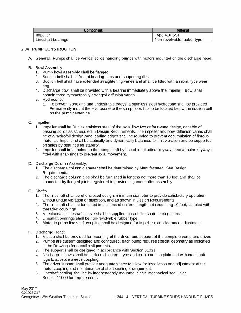
May 2017 C01025C17 Georgetown Wet Weather Treatment Station 11344 - 4 VERTICAL TURBINE SOLIDS HANDLING PUMPS
Component Material Impeller Lineshaft bearings
Type 416 SST Non-revolvable rubber type
2.04 PUMP CONSTRUCTION
A. General: Pumps shall be vertical solids handling pumps with motors mounted on the discharge head.
B. Bowl Assembly: 1. Pump bowl assembly shall be flanged. 2. Suction bell shall be free of bearing hubs and supporting ribs. 3. Suction bell shall have extended straightening vanes and shall be fitted with an axial type wear
ring. 4. Discharge bowl shall be provided with a bearing immediately above the impeller. Bowl shall
contain three symmetrically arranged diffusion vanes. 5. Hydrocone:
a. To prevent vortexing and undesirable eddys, a stainless steel hydrocone shall be provided. Permanently mount the Hydrocone to the sump floor. It is to be located below the suction bell on the pump centerline.
C. Impeller: 1. Impeller shall be Duplex stainless steel of the axial flow two or four-vane design, capable of
passing solids as scheduled in Design Requirements. The impeller and bowl diffusion vanes shall be of a hydrofoil designVane leading edges shall be rounded to prevent accumulation of fibrous material. Impeller shall be statically and dynamically balanced to limit vibration and be supported on sides by bearings for stability.
2. Impeller shall be attached to the pump shaft by use of longitudinal keyways and annular keyways fitted with snap rings to prevent axial movement.
D. Discharge Column Assembly: 1. The discharge column diameter shall be determined by Manufacturer. See Design
Requirements. 2. The discharge column pipe shall be furnished in lengths not more than 10 feet and shall be
connected by flanged joints registered to provide alignment after assembly.
E. Shafts: 1. The lineshaft shall be of enclosed design, minimum diameter to provide satisfactory operation
without undue vibration or distortion, and as shown in Design Requirements. 2. The lineshaft shall be furnished in sections of uniform length not exceeding 10 feet, coupled with
threaded couplings. 3. A replaceable lineshaft sleeve shall be supplied at each lineshaft bearing journal. 4. Lineshaft bearings shall be non-revolvable rubber type. 5. Motor to pump line shaft coupling shall be designed for impeller axial clearance adjustment.
F. Discharge Head: 1. A base shall be provided for mounting of the driver and support of the complete pump and driver. 2. Pumps are custom designed and configured, each pump requires special geometry as indicated
in the Drawings for specific alignments. 3. The support shall be designed in accordance with Section 01031. 4. Discharge elbows shall be surface discharge type and terminate in a plain end with cross bolt
lugs to accept a sleeve coupling. 5. The driver support shall provide adequate space to allow for installation and adjustment of the
motor coupling and maintenance of shaft sealing arrangement. 6. Lineshaft sealing shall be by independently-mounted, single-mechanical seal. See
Section 11000 for requirements.
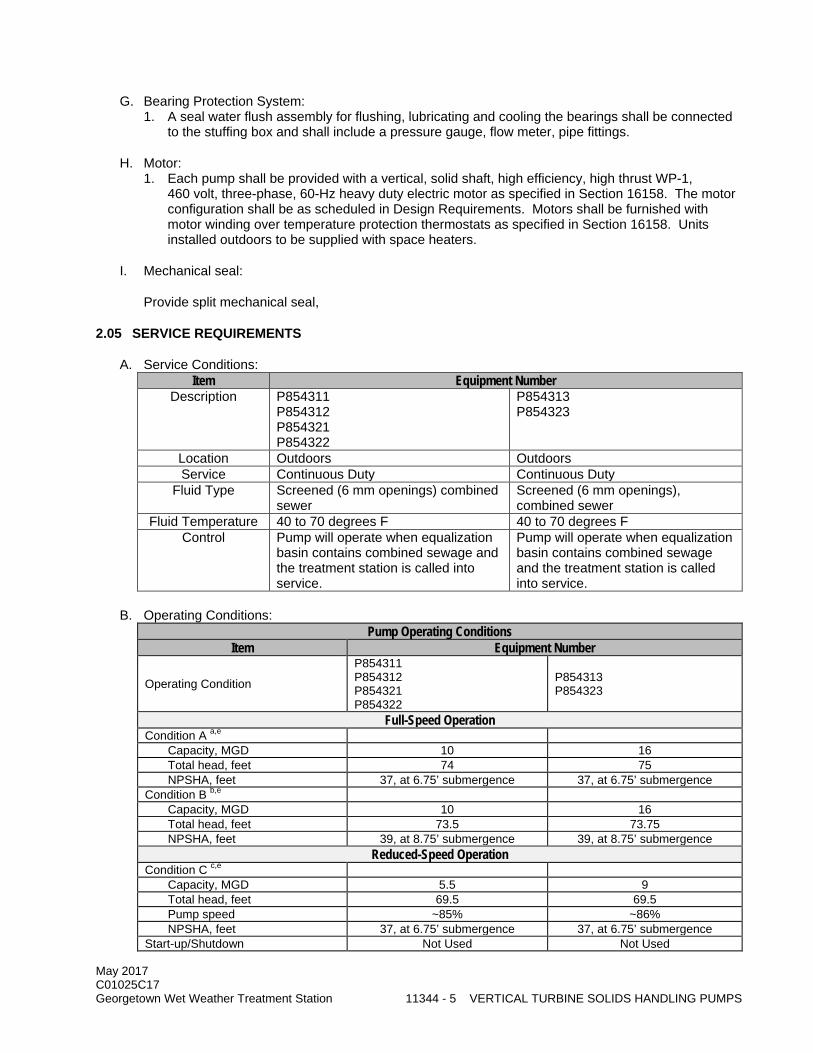
May 2017 C01025C17 Georgetown Wet Weather Treatment Station 11344 - 5 VERTICAL TURBINE SOLIDS HANDLING PUMPS
G. Bearing Protection System: 1. A seal water flush assembly for flushing, lubricating and cooling the bearings shall be connected
to the stuffing box and shall include a pressure gauge, flow meter, pipe fittings.
H. Motor: 1. Each pump shall be provided with a vertical, solid shaft, high efficiency, high thrust WP-1,
460 volt, three-phase, 60-Hz heavy duty electric motor as specified in Section 16158. The motor configuration shall be as scheduled in Design Requirements. Motors shall be furnished with motor winding over temperature protection thermostats as specified in Section 16158. Units installed outdoors to be supplied with space heaters.
I. Mechanical seal:
Provide split mechanical seal,
2.05 SERVICE REQUIREMENTS
A. Service Conditions: Item Equipment Number
Description P854311 P854312 P854321 P854322
P854313 P854323
Location Outdoors Outdoors Service Continuous Duty Continuous Duty
Fluid Type Screened (6 mm openings) combined sewer
Screened (6 mm openings), combined sewer
Fluid Temperature 40 to 70 degrees F 40 to 70 degrees F Control Pump will operate when equalization
basin contains combined sewage and the treatment station is called into service.
Pump will operate when equalization basin contains combined sewage and the treatment station is called into service.
B. Operating Conditions: Pump Operating Conditions
Item Equipment Number
Operating Condition
P854311 P854312 P854321 P854322
P854313 P854323
Full-Speed Operation Condition A a,e Capacity, MGD 10 16 Total head, feet 74 75 NPSHA, feet 37, at 6.75’ submergence 37, at 6.75’ submergence Condition B b,e Capacity, MGD 10 16 Total head, feet 73.5 73.75 NPSHA, feet 39, at 8.75’ submergence 39, at 8.75’ submergence
Reduced-Speed Operation Condition C c,e Capacity, MGD 5.5 9 Total head, feet 69.5 69.5 Pump speed ~85% ~86% NPSHA, feet 37, at 6.75’ submergence 37, at 6.75’ submergence Start-up/Shutdown Not Used Not Used

May 2017 C01025C17 Georgetown Wet Weather Treatment Station 11344 - 6 VERTICAL TURBINE SOLIDS HANDLING PUMPS
Pump Operating Conditions Item Equipment Number
Condition D d,e Capacity, MGD 5.5 9 Total head, feet 69 69 Pump speed 84% 85% NPSHA, feet Varies (39’ start, 37’ shutoff) Varies (39’ start, 37’ shutoff) Notes: a. Condition A is taken as the rated operating condition. Performance at the rated condition is guaranteed. Pumps
furnished are selected to achieve Condition A performance, but also operate continuously without objectionable vibration or cavitation at the head specified under Condition B. Condition A is located in the preferred operating region or allowable operating region as established by the pump manufacturer in accordance with ANSI/HI 9.6.3 for the specific model proposed for the application.
b Condition B is used for pump selection. Condition B is located within the preferred operating region as established by the pump manufacturer in accordance with ANSI/HI 9.6.3. NPSHA, as listed for Condition B, is calculated based on an estimated flow rate at Condition B.
c Condition C is the anticipated continuous duty minimum speed condition. Pumps are capable of sustained (24 hours per day) operation at this condition within the specified vibration limit requirements. Condition C is located within the preferred operating region as established by the pump manufacturer in accordance with ANSI/HI 9.6.3 for the specific model proposed for this application.
d Condition D represents the expected momentary (start-up/shutdown) condition. Pumps operate for not more than 30 seconds at this condition when initiating or terminating a service cycle. The maximum anticipated number of service cycles is once per event.
e Total head in the above table is the algebraic difference between the discharge head and suction head as defined in ANSI/HI 1.1 through 1.6. Net positive suction head available (NPSHA) is calculated in accordance with ANSI/HI 1.3 for average barometric pressure and maximum temperature conditions. NPSHA at the pump impeller eye can be determined by adjusting the given value by proposed pump dimensions and the indicated requirements for pump installation details. NPSHA is calculated for the configuration selected during design. NPSHA may change from the indicated value if the contractor proposes an alternate pump selection. It is the Contractor’s responsibility to make this adjustment and produce calculations justifying the proposed selection.
2.06 PERFORMANCE REQUIREMENTS
A. Pumps will be located inside the equalization basin and the motors will be mounted outdoors, on a depressed concrete slab on top of the equalization basin.
B. Discharge head will be above the concrete slab.
C. The pumps shall operate without clogging or fouling caused by material in the pumped fluid at any operating condition within the range of service indicated.
2.07 DESIGN REQUIREMENTS Item Equipment Number
Pump P854311 P854312 P854321 P854322
P854313 P854323
Rigid sphere, inches diameter (min.), capable of passing through the pump from inlet to discharge
4 inch 5 inch
Maximum efficiency at full speed, minimum, percent
Discharge piping connection size, inches, minimum
16 inches 20 inches
Operating speed 1200 rpm 900 rpm Mounting Elevation, feet 107.5 107.5 Minimum Water Surface Elevation, feet 75.0 75.0 Channel Bottom Elevation, feet 68.25 68.25 Minimum Lineshaft Diameter, Inches Motor
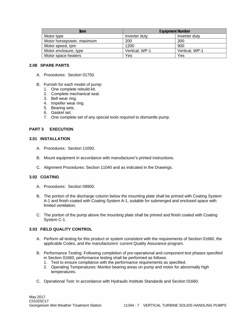
May 2017 C01025C17 Georgetown Wet Weather Treatment Station 11344 - 7 VERTICAL TURBINE SOLIDS HANDLING PUMPS
Item Equipment Number Motor type Inverter duty Inverter duty Motor horsepower, maximum 200 300 Motor speed, rpm 1200 900 Motor enclosure, type Vertical, WP-1 Vertical, WP-1 Motor space heaters Yes Yes
2.08 SPARE PARTS
A. Procedures: Section 01750.
B. Furnish for each model of pump: 1. One complete rebuild kit. 2. Complete mechanical seal. 3. Bell wear ring. 4. Impeller wear ring. 5. Bearing sets. 6. Gasket set. 7. One complete set of any special tools required to dismantle pump.
PART 3 EXECUTION
3.01 INSTALLATION
A. Procedures: Section 11050.
B. Mount equipment in accordance with manufacturer’s printed instructions.
C. Alignment Procedures: Section 11040 and as indicated in the Drawings.
3.02 COATING
A. Procedures: Section 09900.
B. The portion of the discharge column below the mounting plate shall be primed with Coating System A-1 and finish coated with Coating System A-1, suitable for submerged and enclosed space with limited ventilation.
C. The portion of the pump above the mounting plate shall be primed and finish coated with Coating System C-1.
3.03 FIELD QUALITY CONTROL
A. Perform all testing for this product or system consistent with the requirements of Section 01660, the applicable Codes, and the manufacturers’ current Quality Assurance program.
B. Performance Testing: Following completion of pre-operational and component test phases specified in Section 01660, performance testing shall be performed as follows: 1. Test to ensure compliance with the performance requirements as specified. 2. Operating Temperatures: Monitor bearing areas on pump and motor for abnormally high
temperatures.
C. Operational Test: In accordance with Hydraulic Institute Standards and Section 01660.

May 2017 C01025C17 Georgetown Wet Weather Treatment Station 11344 - 8 VERTICAL TURBINE SOLIDS HANDLING PUMPS
D. Pumps P854311, P854312, P854313, P854321, P854322, and P854323 shall be field tested for operating vibration and natural frequencies as specified in Section 11020.
3.04 MANUFACTURER’S SERVICES
A. Provide a factory-trained representative at the site for the specified quantity and duration of the following activities. Specified durations do not include travel time to or from the Project Site. 1. Installation Inspections: Assist, supervise, and inspect the Contractor’s activities during
installation of Vertical Turbine pumps. Provide a minimum of 8 hours of installation inspection during installation of the first vertical turbine pump of each pump model.
2. Test Phase Assistance: Assist, supervise, and inspect the Contractor’s activities during testing. Provide a minimum of 10 hours for testing of each Vertical Turbine pump installation.
3. Complete Form 11000-A, Section 01999.
3.05 TRAINING
A. Procedures: Section 01660.
B. Manufacturer’s representative shall conduct two 4-hour training session per pump model supplied. Coordinate training session with Project Representative. Conduct one training session per week on consecutive weeks to accommodate the shift schedules of operation and maintenance staff.
C. Certify completion of training on Form 11000-B, Section 01999.
END OF SECTION

May 2017 C01025C17 Georgetown Wet Weather Treatment Station 11347 - 1 SUBMERSIBLE PUMPS
SECTION 11347
SUBMERSIBLE PUMPS
PART 1 GENERAL
1.01 SUMMARY
A. This Section specifies submersible pumps complete with motor, discharge elbow, guide rail brackets, access covers, and accessories.
1.02 QUALITY ASSURANCE
A. Referenced Standards: This Section incorporates by reference the latest revision of the following documents. These references are a part of this Section as specified and modified. In case of conflict between the requirements of this Section and those of the listed documents, the requirements of this Section shall prevail. Reference Title ASTM A48 Gray Iron Castings ASTM A276 Stainless and Heat-Resisting Steel Bars and Shapes Hydraulic Institute Standards Standards of the Hydraulic Institute UL 674 Motors and Generators, Electric, for Use in Hazardous Locations,
Class I, Groups C and D, Class II, Groups E, F, and G.
B. Unit Responsibility: 1. The system shall be the end product of one responsible system manufacturer. The Contractor
shall assign unit responsibility to the manufacturer of the pumps provided under this section. This manufacturer is the Unit Responsibility manufacturer and has unit responsibility for the equipment assembly specified in this section and the motors specified in Section 11060. Agents, representatives, or other entities who are not a direct component of the manufacturing corporation will not be acceptable as a substitute for the manufacturer's corporation in meeting the requirement for Unit Responsibility.
2. The Unit Responsible manufacturer shall ensure coordination of design and selection of all system components such that all equipment provided as part of the Unit Responsibility is compatible and operates reliably and properly to achieve the performance requirements specified. Unit responsibility for related components in an assembly does not require or obligate the Unit Responsibility manufacturer to warranty the workmanship or quality of component products not manufactured by them.
3. The Contractor shall coordinate equipment selection with the Unit Responsible manufacturer and shall be responsible for providing the equipment as specified herein. Contractor shall assure that all equipment systems provided as part of the system are the products for which Unit Responsibility has been coordinated by the Unit Responsible manufacturer in this Section.
4. The requirement for Unit Responsibility shall in no way relieve the Contractor of responsibility for performance as specified in the Contract Provisions.
1.03 SUBMITTALS
A. Procedures: Section 01300.
B. Forms 11000-A, 11000-B, and 11060-A: Section 01999.
C. Product Technical Data: 1. Motor information: Section 11060.

May 2017 C01025C17 Georgetown Wet Weather Treatment Station 11347 - 2 SUBMERSIBLE PUMPS
2. Motor data showing rated hp, service factor, voltage, full load amperage and enclosure rating. Power cable rating and listing (UL approved, or ETL, CSA) for this service.
3. Manufacturer’s data including materials of construction, installation instructions, and equipment weight.
4. Predicted performance curves developed for the specific application. Performance curves shall plot pump speed, capacity, head, horsepower requirements, and efficiency over the manufacturer's proposed range of operation. Also include data on sphere size for solids capacity, suction, and discharge size, flange or compression gland connection.
5. Shop drawings including dimensions and section views of all equipment showing details of construction and installation dimensions and minimum sump dimensions.
6. Drawings and certification for shaft overhang as specified. 7. Information for watertight and submersible cable entry seal and cable connections to the motor. 8. Electrical shop drawings showing details of power and control cables installation, cable support
system, cable termination details, and wiring diagrams.
D. Spare parts: Section 01750.
E. Factory and field test reports.
F. Bearing service life calculations.
G. Operating and maintenance information: Section 01730.
PART 2 PRODUCTS
2.01 EQUIPMENT SCHEDULE
Equipment No. Equipment Name Capacity or Size P854301 Drain Pump 1 770 gpm P854302 Drain Pump 2 770 gpm P854331 Influent Sample Pump 1 200 gpm P854332 Influent Sample Pump 2 200 gpm P854505 Effluent Sump 1 Pump 250 gpm MTR854301 Drain Pump No. 1 Motor 20 hp MTR854302 Drain Pump No. 2 Motor 20 hp MTR854331 Influent Sampling Pump 1 Motor 5 hp MTR854332 Influent Sampling Pump 2 Motor 5 hp MTR 854505 Effluent Sump 1 Pump Motor 10 hp
2.02 ACCEPTABLE MANUFACTURER
A. Flygt.
B. Ebara.
C. Fairbanks-Morse.
D. Vaughan.
E. Approved Equal.
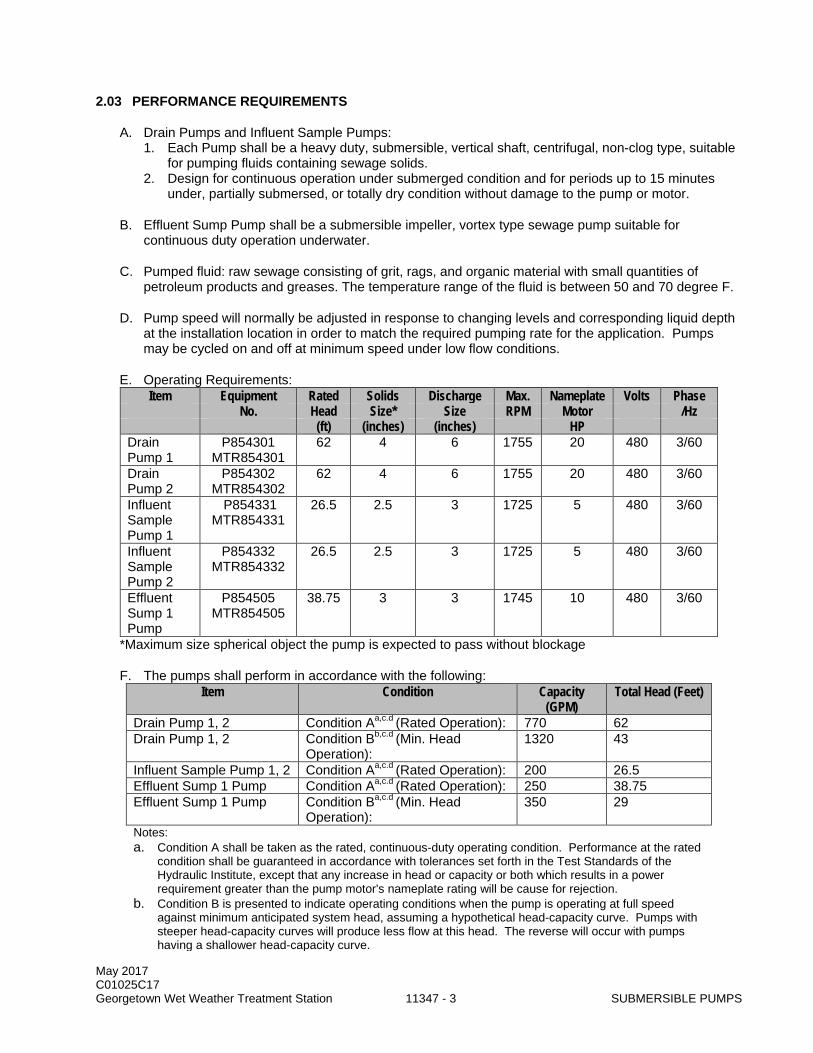
May 2017 C01025C17 Georgetown Wet Weather Treatment Station 11347 - 3 SUBMERSIBLE PUMPS
2.03 PERFORMANCE REQUIREMENTS
A. Drain Pumps and Influent Sample Pumps: 1. Each Pump shall be a heavy duty, submersible, vertical shaft, centrifugal, non-clog type, suitable
for pumping fluids containing sewage solids. 2. Design for continuous operation under submerged condition and for periods up to 15 minutes
under, partially submersed, or totally dry condition without damage to the pump or motor.
B. Effluent Sump Pump shall be a submersible impeller, vortex type sewage pump suitable for continuous duty operation underwater.
C. Pumped fluid: raw sewage consisting of grit, rags, and organic material with small quantities of petroleum products and greases. The temperature range of the fluid is between 50 and 70 degree F.
D. Pump speed will normally be adjusted in response to changing levels and corresponding liquid depth at the installation location in order to match the required pumping rate for the application. Pumps may be cycled on and off at minimum speed under low flow conditions.
E. Operating Requirements: Item Equipment Rated Solids Discharge Max. Nameplate Volts Phase
No. Head Size* Size RPM Motor /Hz (ft) (inches) (inches) HP
Drain Pump 1
P854301 MTR854301
62 4 6 1755 20 480 3/60
Drain Pump 2
P854302 MTR854302
62 4 6 1755 20 480 3/60
Influent Sample Pump 1
P854331 MTR854331
26.5 2.5 3 1725 5 480 3/60
Influent Sample Pump 2
P854332 MTR854332
26.5 2.5 3 1725 5 480 3/60
Effluent Sump 1 Pump
P854505 MTR854505
38.75 3 3 1745 10 480 3/60
*Maximum size spherical object the pump is expected to pass without blockage
F. The pumps shall perform in accordance with the following: Item Condition Capacity
(GPM) Total Head (Feet)
Drain Pump 1, 2 Condition Aa,c.d (Rated Operation): 770 62 Drain Pump 1, 2 Condition Bb,c.d (Min. Head
Operation): 1320 43
Influent Sample Pump 1, 2 Condition Aa,c.d (Rated Operation): 200 26.5 Effluent Sump 1 Pump Condition Aa,c.d (Rated Operation): 250 38.75 Effluent Sump 1 Pump Condition Ba,c.d (Min. Head
Operation): 350 29
Notes: a. Condition A shall be taken as the rated, continuous-duty operating condition. Performance at the rated
condition shall be guaranteed in accordance with tolerances set forth in the Test Standards of the Hydraulic Institute, except that any increase in head or capacity or both which results in a power requirement greater than the pump motor's nameplate rating will be cause for rejection.
b. Condition B is presented to indicate operating conditions when the pump is operating at full speed against minimum anticipated system head, assuming a hypothetical head-capacity curve. Pumps with steeper head-capacity curves will produce less flow at this head. The reverse will occur with pumps having a shallower head-capacity curve.
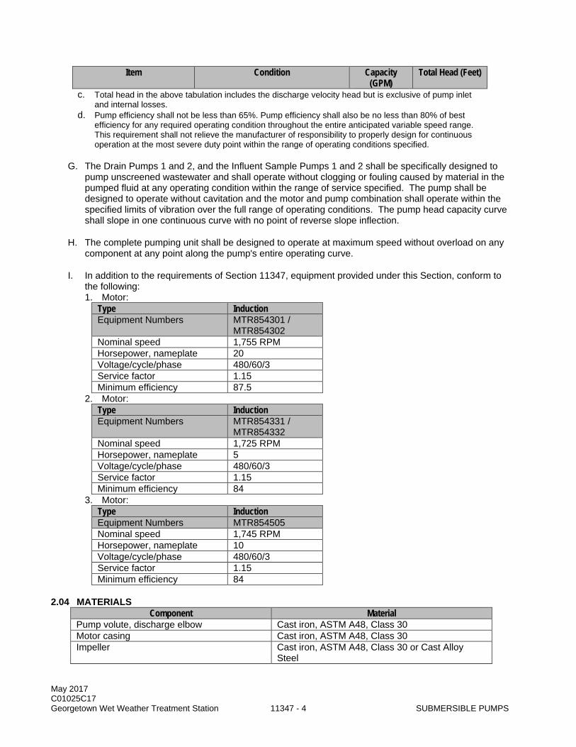
May 2017 C01025C17 Georgetown Wet Weather Treatment Station 11347 - 4 SUBMERSIBLE PUMPS
Item Condition Capacity (GPM)
Total Head (Feet)
c. Total head in the above tabulation includes the discharge velocity head but is exclusive of pump inlet and internal losses.
d. Pump efficiency shall not be less than 65%. Pump efficiency shall also be no less than 80% of best efficiency for any required operating condition throughout the entire anticipated variable speed range. This requirement shall not relieve the manufacturer of responsibility to properly design for continuous operation at the most severe duty point within the range of operating conditions specified.
G. The Drain Pumps 1 and 2, and the Influent Sample Pumps 1 and 2 shall be specifically designed to pump unscreened wastewater and shall operate without clogging or fouling caused by material in the pumped fluid at any operating condition within the range of service specified. The pump shall be designed to operate without cavitation and the motor and pump combination shall operate within the specified limits of vibration over the full range of operating conditions. The pump head capacity curve shall slope in one continuous curve with no point of reverse slope inflection.
H. The complete pumping unit shall be designed to operate at maximum speed without overload on any component at any point along the pump's entire operating curve.
I. In addition to the requirements of Section 11347, equipment provided under this Section, conform to the following: 1. Motor:
Type Induction Equipment Numbers MTR854301 /
MTR854302 Nominal speed 1,755 RPM Horsepower, nameplate 20 Voltage/cycle/phase 480/60/3 Service factor 1.15 Minimum efficiency 87.5
2. Motor: Type Induction Equipment Numbers MTR854331 /
MTR854332 Nominal speed 1,725 RPM Horsepower, nameplate 5 Voltage/cycle/phase 480/60/3 Service factor 1.15 Minimum efficiency 84
3. Motor: Type Induction Equipment Numbers MTR854505 Nominal speed 1,745 RPM Horsepower, nameplate 10 Voltage/cycle/phase 480/60/3 Service factor 1.15 Minimum efficiency 84
2.04 MATERIALS Component Material
Pump volute, discharge elbow Cast iron, ASTM A48, Class 30 Motor casing Cast iron, ASTM A48, Class 30 Impeller Cast iron, ASTM A48, Class 30 or Cast Alloy
Steel
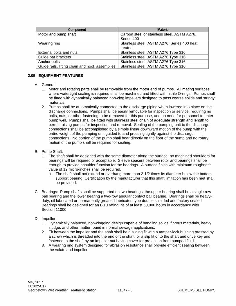
May 2017 C01025C17 Georgetown Wet Weather Treatment Station 11347 - 5 SUBMERSIBLE PUMPS
Component Material Motor and pump shaft Carbon steel or stainless steel, ASTM A276,
Series 400 Wearing ring Stainless steel, ASTM A276, Series 400 heat
treated. External bolts and nuts Stainless steel, ASTM A276 Type 316 Guide bar brackets Stainless steel, ASTM A276 Type 316 Anchor bolts Stainless steel, ASTM A276 Type 316 Guide rails, lifting chain and hook assemblies Stainless steel, ASTM A276 Type 316
2.05 EQUIPMENT FEATURES
A. General: 1. Motor and rotating parts shall be removable from the motor end of pumps. All mating surfaces
where watertight sealing is required shall be machined and fitted with nitrile O-rings. Pumps shall be fitted with dynamically balanced non-clog impellers designed to pass coarse solids and stringy materials.
2. Pumps shall be automatically connected to the discharge piping when lowered into place on the discharge connections. Pumps shall be easily removable for inspection or service, requiring no bolts, nuts, or other fastening to be removed for this purpose, and no need for personnel to enter pump well. Pumps shall be fitted with stainless steel chain of adequate strength and length to permit raising pumps for inspection and removal. Sealing of the pumping unit to the discharge connections shall be accomplished by a simple linear downward motion of the pump with the entire weight of the pumping unit guided to and pressing tightly against the discharge connections. No portion of the pump shall bear directly on the floor of the sump and no rotary motion of the pump shall be required for sealing.
B. Pump Shaft: 1. The shaft shall be designed with the same diameter along the surface; no machined shoulders for
bearings will be required or acceptable. Sleeve spacers between rotor and bearings shall be enough to provide shoulder function for the bearings. A surface finish with minimum roughness value of 12 micro-inches shall be required. a. The shaft shall not extend or overhang more than 2-1/2 times its diameter below the bottom
support bearing. Certification by the manufacturer that this shaft limitation has been met shall be provided.
C. Bearings: Pump shafts shall be supported on two bearings; the upper bearing shall be a single row ball bearing and the lower bearing a two-row angular contact ball bearing. Bearings shall be heavy-duty, oil lubricated or permanently greased lubricated type double shielded and factory sealed. Bearings shall be designed for an L-10 rating life of at least 50,000 hours in accordance with Section 11000.
D. Impeller: 1. Dynamically balanced, non-clogging design capable of handling solids, fibrous materials, heavy
sludge, and other matter found in normal sewage applications. 2. Fit between the impeller and the shaft shall be a sliding fit with a tamper-lock bushing pressed by
a screw which is threaded into the end of the shaft, or a slip fit onto the shaft and drive key and fastened to the shaft by an impeller nut having cover for protection from pumped fluid.
3. A wearing ring system designed for abrasion resistance shall provide efficient sealing between the volute and impeller.

May 2017 C01025C17 Georgetown Wet Weather Treatment Station 11347 - 6 SUBMERSIBLE PUMPS
E. Mechanical Seals: 1. Pumps shall be provided with tandem double mechanical seals running in an oil reservoir,
composed of two separate lapped face seals. The lower seal unit, between the pump and oil chamber, shall consist of one stationary and one positively driven, rotating tungsten-carbide or silicon-carbide ring, with each pair of rings held in contact by a separate spring. The upper seal unit, between the oil sump and the motor housing, shall consist of one stationary tungsten-carbide or silicon-carbide ring and one positively driven silicon-carbide or rotating carbon ring. Ceramic seals will not be acceptable. The seals shall require neither maintenance nor adjustment and shall be easily replaceable. Conventional double mechanical seals with a single or a double spring between the rotating faces, or that require constant differential pressure to effect sealing and are subject to opening and penetration by pumping forces, will not be acceptable. The submersible pumps shall be capable of continuous submergence without loss of watertight integrity to a depth of 65 feet.
2. Each pump shall be provided with an oil chamber for the shaft sealing system. The oil chamber shall be designed to assure that air is left in the oil chamber to absorb the expansion of the oil due to temperature variations. The drain and inspection plug with positive anti-leak seal shall be easily accessible from the outside.
F. Cable Seal: The cable entry water seal design shall preclude specific torque requirements to insure a watertight and submersible seal. The power and control cable entry shall be double sealed employing rubber grommets or other suitable material having a close tolerance fit against the cable outside diameter and the entry inside diameter and compressed by the entry body containing a strain relief function separate from the function of sealing the cable. The cable entry junction chamber and motor shall be separated by a stator lead sealing gland or terminal board, which shall isolate the motor interior from foreign material gaining access through the pump top.
G. Motor: The pump motor shall be of the special purpose design specified in Section 11060. The motor shall be designed for continuous duty, capable of sustaining a minimum of 10 starts per hour. The motor shall be rated Explosion-Proof and shall be UL listed in accordance with UL 674 for Class I, Group D hazardous atmospheres. The junction chamber, containing the terminal board, shall be hermetically sealed from the motor. Connection between the cable conductors and stator leads shall be made with threaded compressed type binding post permanently affixed to a terminal board. The submersible electrical cable shall be of sufficient length to reach the junction box located outside the sump where shown.
H. Cooling System: 1. Each unit shall be provided with a cooling system and thermal sensors shall be provided to
monitor stator temperatures. The stator shall be equipped with three thermal switches, embedded in the end coils of the stator winding (one switch in each stator phase). These shall be used in conjunction with external motor overload protection and wired to the control panel. a. Oil-filled motors shall be positively cooled by circulating oil through the windings to passages
within the pump designed as a heat exchanger to transfer heat to the pumped fluid.
I. Guide System: 1. Guide bars, which shall steer the pump into proper contact with the discharge elbow shall be non-
adjustable and shall not bear the weight of the pump. The system shall consist of single pipe guide rails supported top and bottom. The discharge connection elbow shall be bolted to the floor and shall serve as the lower attachment point for the guide rails. The pull-up system shall be as designed by the pump manufacturer.

May 2017 C01025C17 Georgetown Wet Weather Treatment Station 11347 - 7 SUBMERSIBLE PUMPS
a. Unless otherwise indicated, each pump shall be provided with a hinged access cover with frame cast into the top slab. Cover shall be aluminum, skid proof design, with flush locking mechanism and shall be designed to support a uniform live load of 100 pounds per square foot with a safety factor of three. The doors shall be provided with stainless steel hinges and lifting handle shall open to 90 degrees and lock automatically in that position. All hardware shall be stainless steel. Frame shall include upper attachment for guide rails and attachments for lifting chain and power cable. Access frames and covers shall be sized as specified.
2. An upper guide rail bracket of Type 316L stainless steel shall be provided. Intermediate guide rail brackets shall be used if the length of guide rail is over 20FT. The material of the Intermediate guide shall be the same as the upper guide rail bracket.
J. Pump and Motor Protection: 1. Sensors or switches shall be provided to monitor various operating conditions including high
temperature in motor windings, moisture accumulation in the stator cavity, and high temperature of the bearings.
2. Sensors shall be embedded in the motor windings (each phase) to monitor for high temperature. 3. Bearing temperature shall monitored by direct sensor contact with the bearing outer race or
housing. 4. Sensors shall be as specified in Section 17320. 5. Sensors shall be installed as indicated in the Drawings. 6. Sensors shall be wired into control systems specified in Division 17.
2.06 SOURCE QUALITY CONTROL
A. Each pump shall be tested for performance at the factory to determine head versus capacity, efficiencies, and kilowatt draw required for the operating points that are specified. All tests shall be run in accordance with the Hydraulic Institute Standards. Testing shall also include the following: 1. Impeller, motor rating and electrical connections shall first be checked for compliance to the
Specifications. 2. A motor and cable insulation test for moisture content or insulation defects shall be made. 3. Prior to submergence, the pump shall be run dry to establish correct rotation and mechanical
integrity. 4. The pump shall be run for 30 minutes submerged, a minimum of 6 feet under water.
B. The Engineer reserves the right to witness the factory testing. Inform the Project Representative and the Engineer at least 30 days prior to the factory tests.
C. Prepare a written report stating the factory tests have successfully been completed. Include the results of the test for each pump.
2.07 ACCESSORIES
A. The pump manufacturer shall provide all submersible pumps with pump lifting chains, guide rails, guide rail brackets, cable holder assemblies, safety chain hook assemblies, discharge elbow connections, anchor bolts, and all other accessories necessary to complete the installation as specified.
2.08 SPARE PARTS
A. Procedures: Section 01750.
B. One spare pump of each size.
May 2017 C01025C17 Georgetown Wet Weather Treatment Station 11347 - 8 SUBMERSIBLE PUMPS
PART 3 EXECUTION
3.01 INSTALLATION
A. Pumps shall be installed in strict accordance with the manufacturer's recommendations.
3.02 FIELD QUALITY CONTROL
A. After completion of installation, field test pumps in accordance with Section 01660 to demonstrate compliance with the performance requirements as specified.
B. Provide a minimum of eight hours of on-site field service by a qualified service engineer to inspect installation and testing on the completed installations for lubrication, alignment, free operation, etc.
C. Complete Form 11000-A: Section 01999.
3.03 TRAINING
A. Procedures: Section 01660.
B. Provide a minimum of two two-hour sessions of classroom training on submersible pumps. Conduct one training session per week on consecutive weeks to accommodate the shift schedules of operation and maintenance staff.
C. Certify completion of training on Form 11000-B: Section 01999.
END OF SECTION

May 2017 C01025C17 Georgetown Wet Weather Treatment Station 11351 - 1 PACKAGE LOW PRESSURE EFFLUENT PUMP STATION
SECTION 11351
PACKAGE LOW PRESSURE EFFLUENT PUMP STATION
PART 1 GENERAL
1.01 SUMMARY
A. Section includes requirements for the design, fabrication and installation of a low pressure effluent pump station.
1.02 QUALITY ASSURANCE
A. Referenced Standards: This Section incorporates by reference the latest revision of the following documents. These references are a part of this Section as specified and modified. In case of conflict between the requirements of this Section and those of the listed documents, the requirements of this Section shall prevail.
Reference Title NEMA National Electrical Manufacturer's Association 250,
Enclosures for Electrical Equipment (1000 Volts Maximum). UL Underwriters Laboratories, Inc.
B. Qualifications: 1. Manufacturer shall be regularly engaged in the manufacture of packaged pumping stations for not
less than five (5) years. 2. System description.
C. Low Pressure Effluent Pump Station includes but is not necessarily limited to the following major components: 1. Underground basin. 2. Process equipment: submersible effluent pump. 3. Interior piping, valving and pipe supports. 4. Electrical and control systems:
a. Single point exterior power connection for pump station. b. Pilot Type: Pump Control.
D. Single Source Responsibility: 1. Provide single source responsibility for all station components and systems through supplier of
low pressure effluent pump station.
1.03 SUBMITTALS
A. Procedures: Section 01300.
B. Shop Drawings: 1. Product technical data including:
a. Acknowledgement that products submitted meet requirements of standards referenced. b. Manufacturer’s delivery, storage, handling and installation instructions. c. Data sheets that include manufacturer’s name and complete product model number.
1) Clearly identify all optional accessories that are included. d. Shipping and operating weight. e. Equipment physical characteristics:
1) Dimensions (both horizontal and vertical). 2) Materials of construction and construction details.

May 2017 C01025C17 Georgetown Wet Weather Treatment Station 11351 - 2 PACKAGE LOW PRESSURE EFFLUENT PUMP STATION
f. Equipment factory primer and paint data. g. Manufacturer's recommended spare parts list. h. Equipment lining and coatings. i. Equipment utility requirements.
2. Contract Closeout Information: 3. Operation and Maintenance Data per Section 01730.
a. warranty
C. The pump manufacturer shall provide a part(s) and labor warranty on the complete station and accessories, including, but not limited to pump, basin, float controls, and piping, for a period of twenty-four (24) months after notice of Owner’s acceptance. 1. Any defects found during the warranty period will be reported to the manufacturer by the Owner.
PART 2 PRODUCTS
2.01 ACCEPTABLE MANUFACTURERS
A. Subject to compliance with the Contract Documents, the following manufacturers are acceptable: 1. Low pressure effluent pump station:
a. Barnes (Crane Pump Systems). b. Little Giant. c. Keen Pumps. d. Pentair (Hydromatic). e. Triple D Pump Co. f. Approved Equal.
2.02 EQUIPMENT
A. Low Pressure effluent Pumps: 1. Design condition: 30 gpm at 20 FT TDH. 2. Service Fluid: Floor drain waste, 60○F. 3. Minimum driver horsepower: 1/3 HP. 4. Centrifugal effluent pump with vortex impeller. 5. Single mechanical seal. 6. Pump castings shall be cast iron, fully epoxy coated 8-10 mils nominal dry thickness. 7. Shaft: Stainless Steel. 8. 60 Hz. 9. 120 V Single Phase. 10. Speed (nominal): 1,750 rpm. 11. Maximum pump weight: 50 lbs. 12. Power Supply cord length: 20 ft.
2.03 PIPING AND CHECK VALVES
A. Equip the pump discharge with a factory installed, PVC Ball Check Valve and pull port true-xxx ball valve built into the sch 80 PVC discharge piping. 1. Wetwell.
B. Construct the wetwell of fiberglass with ballast support flange wet well size 24 IN Dia x 48 IN Deep.
C. House simplex effluent pumps.
D. Quick disconnects on discharge piping between pump and connection to force main to allow ease of pump removal.

May 2017 C01025C17 Georgetown Wet Weather Treatment Station 11351 - 3 PACKAGE LOW PRESSURE EFFLUENT PUMP STATION
E. Provide the following: 1. A 4 IN PVC inlet connect for Schedule 40 sanitary line.
a. Locate inlet connection 24 IN below the wetwell top flange. 2. Pump discharge with 1-1/2 IN socket for PVC solvent weld connection, easily adaptable to 1-1/4
IN PVC or HDPE pipe materials. 3. A lockable, aluminum, non-slip lid hung with lifting handle.
a. Hinges and hardware to be stainless steel. b. Lid must have a service rating of 150 LBS per square foot.
4. Concrete ballast for wetwell as necessary. 5. All hardware of 300 series stainless steel. 6. Electrical Connection: 1IN Conduit Connection to side of wetwell.
2.04 ACCESSORIES
A. Provide Polypropylene rope stainless lifting mechanism for each pump.
B. Controls: 1. Use control float(s) as level controls for controlling pump operation.
PART 3 EXECUTION
3.01 SEQUENCE OF CONSTRUCTION
A. Procedures for the installation of the low pressure sewage pump station and are as follows: 1. Install the low pressure sewage pump station at the location designated in the Drawings. 2. Connect the discharge line from the effluent pump to the force main. 3. Install a conduit from the 120V Power Supply plug-in to the low pressure sewage grinder pump
station. a. Locate the low pressure sewage pump station and the 120V Power Supply in close proximity
to each other. 4. Install the cable, provided by the grinder pump manufacturer, into the conduit from the the low
pressure sewage pump station and connect the cable wiring to the 120V Power Supply. 5. Install the effluent pump per manufacturer’s recommendations.
a. Provide a written statement from manufacturer’s qualified representative that the installation was performed properly and is ready for operation.
6. Test the effluent pump unit. a. Contractor to obtain potable water for testing. b. Project Representative to witness the testing of the unit. c. Install the low pressure sewage effluent pump station cover and leave secured.
END OF SECTION

May 2017 C01025C17 Georgetown Wet Weather Treatment Station 11351 - 4 PACKAGE LOW PRESSURE EFFLUENT PUMP STATION
This page intentionally left blank.
May 2017 C01025C17 INSTRUMENTATION AIR COMPRESSOR Georgetown Wet Weather Treatment Station 11366 - 1 SYSTEM AND APPURTENANCES
SECTION 11366
INSTRUMENTATION AIR COMPRESSOR SYSTEM AND APPURTENANCES
PART 1 GENERAL
1.01 SUMMARY
A. This Section specifies instrument air compression system and associated appurtenances.
1.02 QUALITY ASSURANCE
A. Referenced Standards: This Section incorporates by reference the latest revision of the following documents. These references are part of this Section as specified and modified. In case of conflict between the requirements of this Section and those of the listed documents, the requirements of this Section shall prevail. Reference Title 49 CFR 173.34 Qualification, Maintenance, and Use of Cylinders ASME American Society of Mechanical Engineers-Boiler and Pressure Vessel Code NEMA 1 National Electrical Manufacturers Association, Enclosure Rating 1 NEMA 4 National Electrical Manufacturers Association, Enclosure Rating 4 NEMA 12 National Electrical Manufacturers Association, Enclosure Rating 12 UL Underwriters Laboratories
B. See electrical process and instrumentation drawings for electrical controls requirements.
C. Unit Responsibility: 1. The system shall be the end product of one responsible system manufacturer. The Contractor
shall assign unit responsibility to the manufacturer of the instrumentation air compressors provided under this section. This manufacturer is the Unit Responsibility manufacturer and has unit responsibility for the equipment assembly specified in this section, the motors specified in Section 11060, and for the Local Control Panel specified in this section and in Section 17600. Agents, representatives, or other entities who are not a direct component of the manufacturing corporation will not be acceptable as a substitute for the manufacturer's corporation in meeting the requirement for Unit Responsibility.
2. The Unit Responsible manufacturer shall ensure coordination of design and selection of all system components such that all equipment provided as part of the Unit Responsibility is compatible and operates reliably and properly to achieve the performance requirements specified. Unit responsibility for related components in an assembly does not require or obligate the Unit Responsibility manufacturer to warranty the workmanship or quality of component products not manufactured by them.
3. The Contractor shall coordinate equipment selection with the Unit Responsible manufacturer and shall be responsible for providing the equipment as specified herein. Contractor shall assure that all equipment systems provided as part of the system are the products for which Unit Responsibility has been coordinated by the Unit Responsible manufacturer in this Section.
4. The requirement for Unit Responsibility shall in no way relieve the Contractor of responsibility for performance as specified in the Contract Provisions.
1.03 SUBMITTALS
A. Procedures: Section 01300.

May 2017 C01025C17 INSTRUMENTATION AIR COMPRESSOR Georgetown Wet Weather Treatment Station 11366 - 2 SYSTEM AND APPURTENANCES
B. Shop drawings of instrument air system, showing assembled compressors on the receiver tank, compressors support system, receiver tank anchorage to the floor, air dryer installation, pressure gauges support and installation, piping connections between the compressors, receiver tank, air dryer, location of pressure switches and attachment to the receiver tank. Provide dimensions confirming to the design dimensions as indicated in the Drawings. Show connections to the instrument air piping system.
C. Power and control wiring diagrams.
D. Compressed air receiver tank capacity, dimensions, material of construction, working pressure, test pressure, safety relief valve data, and certificate as required by ASME BPVC, Section VIII, Division 1 or Division 2.
E. Instrument air compressors material of construction, performance data, rated capacity and working pressure.
F. Pressure switches, pressure gauges, and safety pressure relief valves.
G. Performance and technical data and material of construction of air filters, air dryer and pressure regulator.
H. Piping and isolation valves information and piping connection between compressed air system components as indicated in the Drawings.
I. Boiler/Pressure Vessel Installation Permit issued by the State of Washington Dept. of Labor and Industries. (Information available at www.LNI.wa.gov/scs/boilers).
J. Equipment wiring and control diagrams.
K. Anchor bolt details and calculations.
L. Manufacturer's certification that air dryer will dry air to 35 to 39 degrees F dew point (NFPA Class H) at rated capacity.
M. Layout drawings of all piping, foundations and supports with sizes and dimensions indicated in the Drawings.
N. Operations and maintenance information: Section 01730.
O. Motor data: Section 11060.
P. Forms: 11000-A, 11000-B and 11060-A: Section 01999.
Q. Spare Parts: Section 01750.
1.04 ENVIRONMENTAL CONDITIONS
A. The instrument air system will be installed indoors in a heated Wastewater Treatment Facility. Indoor air conditions vary from near dry to 100% humidity.

May 2017 C01025C17 INSTRUMENTATION AIR COMPRESSOR Georgetown Wet Weather Treatment Station 11366 - 3 SYSTEM AND APPURTENANCES
PART 2 PRODUCTS
2.01 EQUIPMENT SCHEDULE
Equipment Number Description CPR854561 Instrument Air Compressor 1 CPR854562 Instrument Air Compressor 2 PVL854561 Instrument Air Receiver PI854561A Pressure Indicator A PI854561B Pressure Indicator B PS854561 Pressure Switch Lead PS854561 Pressure Switch Follow PSH854561 Pressure Switch High PSL854561 Pressure Switch Low FLT854561A Instrument Air Filter (coalescing) FLT854561B Instrument Air Filter (particulate) AD854561 Air Dryer DT854561A Instrument Air Drain Trap 1 DT854561B Instrument Air Drain Trap 2 DT854561C Instrument Air Drain Trap 3 MTR854561 Instrument Air Compressor 1 Motor MTR854562 Instrument Air Compressor 2 Motor LCS854561/LCS854562 Local Control Stations
2.02 ACCEPTABLE MANUFACTURERS
A. The County standards for instrument air systems are as follows. Duplex Air Compressor Assembly: 1. Champion. 2. Quincy. 3. Ingersoll Rand. 4. Approved Equal.
B. Air Cooled Aftercooler: 1. Champion. 2. Quincy Northwest. 3. Ingersoll Rand 4. Approved Equal.
C. Refrigerated Air Dryer: 1. Pneumatech Inc. 2. Zeks. 3. Approved Equal.
D. Filter: 1. Particulate:
a. Finite Division of Parker-Hannifin. b. Approved Equal.
2. General Purpose: a. IMI Norgren Excelon. b. Approved Equal.

May 2017 C01025C17 INSTRUMENTATION AIR COMPRESSOR Georgetown Wet Weather Treatment Station 11366 - 4 SYSTEM AND APPURTENANCES
3. Coalescing: a. IMI Norgren Excelon. b. Approved Equal.
E. Automatic Drain Valves: 1. Air Systems Products Dehydra 52. 2. Armstrong ADP-1. 3. Approved Equal.
F. High Pressure Selector Relay: 1. Fairchild Industrial Products Co. 2. Approved Equal.
2.03 INSTRUMENT AIR SYSTEM ASSOCIATED EQUIPMENT
A. Duplex Air Compressors Assembly: 1. General: Duplex air compressors assembly consists of two compressors mounted on the air
receiver tank with all necessary check valves, isolation valves, interconnecting piping, pressure switches, pressure gauges, pressure relief valves, and remote wall mounted control panel complete with all control and power wiring as indicated in the Drawings. The compressors shall be selected for continuous duty operation and shall deliver clean, oil-free air. Each compressor shall be equipped with medium efficiency inlet air filter.
2. Compressors: Single stage, heavy duty, air-cooled, oil-less air compressors. The air compressors shall be direct driven with 1,725 rpm, 460 volt, 3 phase, 5 hp motor to provide 30 acfm at 100 psi pressure. Motor shall be TEFC high efficient severe duty type in accordance with Section 11060.
3. Air Receiver Tank: Horizontal, 240 gallon minimum capacity to meet the requirements of ASME Boiler and Pressure Vessel Code, Section VIII, Division 1 or Division 2 for 200 psig. The receiver tank shall be equipped with an automatic drain valve, as indicated in the Drawings. The receiver tank working pressure shall be at 100 psig. The receiver tank shall be equipped with check valve, pressure gage, an ASME relief valve set at 185 psig, and manual ball valves as indicated in the Drawings. The air receiver shall be rigidly mounted to the equipment pad. Configuration shall be horizontal and tank shall be sufficiently high above the concrete equipment pad so there is ample vertical height for the receiver’s automatic drain valve to be installed and function properly.
4. Compressors shall be equipped with unloader valves. 5. Pressure Gages and Pressure Switches: conform to the requirements of Division 17.
B. Air Cooled Aftercooler: 1. A combination of water/dirt/oil removal type of refrigerated air cooled aftercooler shall be
provided. 2. The unit shall be capable of drying the air flow of one instrument air compressor to a pressure
dew point not to exceed 39 degrees F with a pressure drop not to exceed 5 psig. 3. The dryer also shall be of the constant-running type. 4. The unit shall be a single prepiped, prewired package ready for single-point installation in the
compressed air system. 5. Suitable for 120 volt, one phase electrical service.
C. Refrigerated Air Dryer: 1. The refrigerated air dryer shall be a liquid refrigerant-to-air chiller unit capable of continuously
drying 31.2 scfm at 100 psig and at 100F ambient and 35F to 39F dew point temperature. 2. Air dryer shall be NEMA 1 and shall be floor mounted, as indicated in the Drawings. 3. The air dryer shall be 550w suitable for 120 volt, 60 Hz, one phase electrical service. 4. The air dryer shall be equipped with an automatic drain valve and inlet air oil and particulate filter.

May 2017 C01025C17 INSTRUMENTATION AIR COMPRESSOR Georgetown Wet Weather Treatment Station 11366 - 5 SYSTEM AND APPURTENANCES
D. Air Filters: The air filters assembly shall be a combination of general purpose and coalescing Type filters. 1. General purpose filters shall be die cast aluminum housing head, aluminum bowel with indicator
lens, sintered polypropylene element, and auto drain. The filters shall be 1/2 inch port size for pipe connection complete with all mounting brackets, and gaskets.
2. The coalescing filter shall be die cast aluminum housing head, aluminum bowel with indicator lens, synthetic fiber and polyurethane element and auto drain. The filters shall be 1/2 inch port size for pipe connection complete with all mounting brackets, and gaskets. The element shall be microglass coalescing media and shall have a minimum DOP efficiency of 99.97% with 0.3-0.6 micron particles.
3. Air flow pressure drop through each filter shall not exceed 2.5 psi with an air flow rate of 31.2 cfm at 100 psig.
4. All coalescing filters shall be equipped with automatic condensate drain valves.
E. Particulate Filter: 1. Filter housing shall have die cast aluminum heads and drawn aluminum bowls. 2. The filter element shall be microglass coalescing media and shall have a minimum DOP
efficiency of 99.97% with 0.3-0.6 micron particles. 3. Pressure drop shall not exceed 2.5 psig with an air flow rate 31.2 scfm at 100 psig. 4. A differential pressure gage shall be provided.
F. Air Pressure Regulator/Filter: 1. In line combined pressure regulator/filter with quick release bayout bowl. 2. Push to lock adjusting knob with tamper resistant accessory. 3. Aluminum body, 1/2 inch NPT inlet and outlet ports, maximum bowl pressure 250 psig at 125
degrees F with a general purpose filter element.
G. Automatic Condensate Drain Valves: 1. Valve shall be demand activated, zero-loss, fully pneumatically operated. Once the drain cycle is
initiated, the condensate shall be expelled positively using full system pressure. There shall be no discharge of compressed air associated with the drain cycle.
2. The drain valves shall be rated for not less than 150 psig maximum operating pressure at maximum operating temperature of 150 degrees F in nonchemically hostile environment.
H. Pressure Gauges and Pressure Switches: 1. Install pressure gauges and pressure switches as indicated in the Drawings and as described in
the control strategy of the instrument air system. 2. Pressure Gauges: As specified in Section 15095. 3. Pressure Switches: Pressure switches shall be two independently adjustable set point types, as
specified in Section 17216.
I. Control: Controls shall be indicated in the electrical, process and instrumentation drawings and as described in Divisions 16 and 17.
2.04 DESIGN REQUIREMENTS
A. Meet the requirements of ASME Boiler and Pressure Vessel Code, Section VIII, [Division1 or 2].
B. Performance Requirements: 1. Instrument air compressors and accessories shall be designed and selected for continuous duty
operation and shall deliver clean, oil-free air. 2. Air cooled compressors shall at all times deliver air which meets the operating requirements listed
in this Section. 3. Inlet air shall be filtered with a medium efficiency filter. 4. Discharged air shall be dried before distribution to the instrument air system. 5. The system shall be equipped with automatic tank drain.
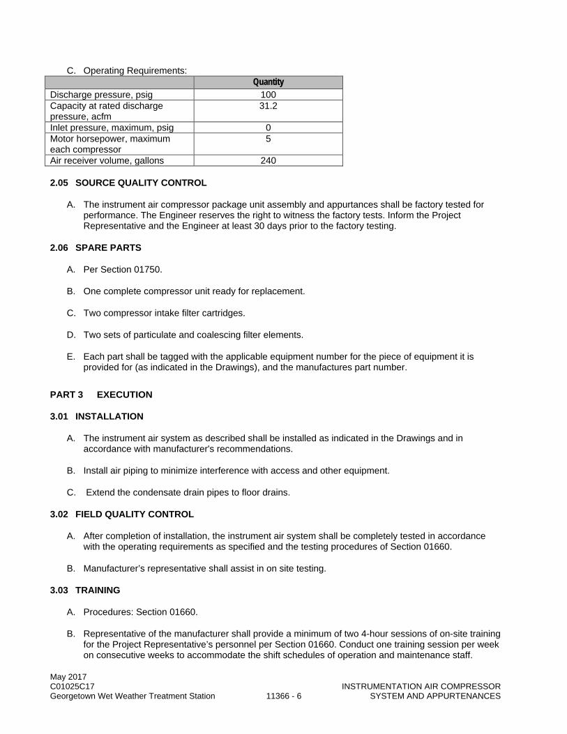
May 2017 C01025C17 INSTRUMENTATION AIR COMPRESSOR Georgetown Wet Weather Treatment Station 11366 - 6 SYSTEM AND APPURTENANCES
C. Operating Requirements: Quantity
Discharge pressure, psig 100 Capacity at rated discharge pressure, acfm
31.2
Inlet pressure, maximum, psig 0 Motor horsepower, maximum each compressor
5
Air receiver volume, gallons 240
2.05 SOURCE QUALITY CONTROL
A. The instrument air compressor package unit assembly and appurtances shall be factory tested for performance. The Engineer reserves the right to witness the factory tests. Inform the Project Representative and the Engineer at least 30 days prior to the factory testing.
2.06 SPARE PARTS
A. Per Section 01750.
B. One complete compressor unit ready for replacement.
C. Two compressor intake filter cartridges.
D. Two sets of particulate and coalescing filter elements.
E. Each part shall be tagged with the applicable equipment number for the piece of equipment it is provided for (as indicated in the Drawings), and the manufactures part number.
PART 3 EXECUTION
3.01 INSTALLATION
A. The instrument air system as described shall be installed as indicated in the Drawings and in accordance with manufacturer's recommendations.
B. Install air piping to minimize interference with access and other equipment.
C. Extend the condensate drain pipes to floor drains.
3.02 FIELD QUALITY CONTROL
A. After completion of installation, the instrument air system shall be completely tested in accordance with the operating requirements as specified and the testing procedures of Section 01660.
B. Manufacturer’s representative shall assist in on site testing.
3.03 TRAINING
A. Procedures: Section 01660.
B. Representative of the manufacturer shall provide a minimum of two 4-hour sessions of on-site training for the Project Representative’s personnel per Section 01660. Conduct one training session per week on consecutive weeks to accommodate the shift schedules of operation and maintenance staff.
May 2017 C01025C17 INSTRUMENTATION AIR COMPRESSOR Georgetown Wet Weather Treatment Station 11366 - 7 SYSTEM AND APPURTENANCES
C. Training shall be certified on Form 11000-B per Section 01999.
END OF SECTION

May 2017 C01025C17 INSTRUMENTATION AIR COMPRESSOR Georgetown Wet Weather Treatment Station 11366 - 8 SYSTEM AND APPURTENANCES
This page intentionally left blank.

May 2017 C01025C17 Georgetown Wet Weather Treatment Station 11367 - 1 SERVICE AIR COMPRESSOR SYSTEM
SECTION 11367
SERVICE AIR COMPRESSOR SYSTEM
PART 1 GENERAL
1.01 SUMMARY
A. This Section specifies service air compressors as a complete system that includes rotary screw compressors, coalescing filters, air dryers, motors, controls, and associated accessories and appurtenances.
1.02 QUALITY ASSURANCE
A. Referenced Standards: This Section incorporates by reference the latest revision of the following documents. These references are part of this Section as specified and modified. In case of conflict between the requirements of this Section and those of the listed documents, the requirements of this Section shall prevail.
Reference Title ASME PTC 10 Compressors and Exhausters. ASME Boiler and Pressure Vessel Code 49 CFR 173.34 Qualification, Maintenance and Use of Cylinders
B. Factory Tests: 1. Test complete assemblies for correct rotation, proper alignment and connection, and quiet
operation. 2. Inspect control panels for required construction, electrical connection, and intended function. 3. The Engineer reserves the right to witness the factory testing. Inform the Project Representative
and the Engineer at least 30 days prior to the factory tests.
C. Unit Responsibility: 1. The system shall be the end product of one responsible system manufacturer. The Contractor
shall assign unit responsibility to the manufacturer of the service air compressors provided under this section. This manufacturer is the Unit Responsibility manufacturer and has unit responsibility for the equipment assembly specified in this section, the motors specified in Section 11060, and for the Local Control Panel specified in this section and in Section 17600. Agents, representatives, or other entities who are not a direct component of the manufacturing corporation will not be acceptable as a substitute for the manufacturer's corporation in meeting the requirement for Unit Responsibility.
2. The Unit Responsible manufacturer shall ensure coordination of design and selection of all system components such that all equipment provided as part of the Unit Responsibility is compatible and operates reliably and properly to achieve the performance requirements specified. Unit responsibility for related components in an assembly does not require or obligate the Unit Responsibility manufacturer to warranty the workmanship or quality of component products not manufactured by them.
3. The Contractor shall coordinate equipment selection with the Unit Responsible manufacturer and shall be responsible for providing the equipment as specified herein. Contractor shall assure that all equipment systems provided as part of the system are the products for which Unit Responsibility has been coordinated by the Unit Responsible manufacturer in this Section.
4. The requirement for Unit Responsibility shall in no way relieve the Contractor of responsibility for performance as specified in the Contract Provisions.

May 2017 C01025C17 Georgetown Wet Weather Treatment Station 11367 - 2 SERVICE AIR COMPRESSOR SYSTEM
1.03 SUBMITTALS
A. Procedures: Section 01300.
B. Items to be submitted for this Section: 1. Make, model, weight, and horsepower of each equipment assembly. 2. Manufacturer’s catalog information, descriptive literature, and specifications including materials of
construction. 3. Detailed mechanical and electrical drawings showing equipment fabrications. Include
dimensions, size, and locations of connections to other equipment. 4. External utility requirements such as air, water, power, and drain for each component. 5. Shop and field painting systems. Include manufacturer’s descriptive technical catalog literature
and specifications. 6. Calculations by a registered engineer to demonstrate that support design complies with
requirements of this Section. 7. Functional description of internal and external instrumentation and controls including list of
parameters monitored, controlled, and alarmed. 8. Control panel elevation drawings showing construction and placement of operator interface
devices and other elements. 9. Motor submittal data per Section 11060. 10. Power and control wiring diagrams, including terminals and numbers. 11. Operation and maintenance information: Section 01730. 12. Manufacturer’s certification for the performance of certain features of the specified equipment that
cannot be readily inspected. 13. Manufacturer’s recommended vibration limits of the instrument air compressors. 14. Field performance test procedures. 15. Manufacturer’s instructions for installation of the equipment. 16. Factory test reports of each test and inspection. 17. Field test reports for each functional and performance test of equipment. 18. Forms: 11000-A, 11000-B and 11060-A; Section 01999. 19. Spare Parts: Section 01750.
1.04 ENVIRONMENTAL CONDITIONS
A. All system components specified herein shall be designed for continuous operation in an indoor environment with conditions as follows: 1. Temperature Range: 45 to 95 degrees F. 2. Relative Humidity Range: 30 to 95 percent. 3. Inlet Elevation: Approximately 13 feet above mean sea level.
1.05 DEFINITIONS
A. Terminology used in this specification conforms to the following definitions: 1. Standard Cubic Foot per Minute (scfm): Volume flow rate of air at standard conditions of
60 degrees F, 14.7 psia, and 36 percent relative humidity.
PART 2 PRODUCTS
2.01 EQUIPMENT SCHEDULE
Equipment No. Item CPR854566 Service Air Compressor 1 ICP854566 Service Air Compressor 1 Control Panel CPR854567 Service Air Compressor 2 ICP854567 Service Air Compressor 2 Control Panel

May 2017 C01025C17 Georgetown Wet Weather Treatment Station 11367 - 3 SERVICE AIR COMPRESSOR SYSTEM
Equipment No. Item PVL854566 Service Air Receiver 1 PRV854866 Service Air Receiver 1 PRV DT854566 Service Air Receiver 1 Drain Trap PVL854567 Service Air Receiver 2 PRV854567 Service Air Receiver 2 PRV DT854567 Service Air Receiver 2 Drain Trap AD854568 Service Air Dryer 1 FLT854568 Service Air Filter DT854568A Service Air Filter Drain Trap DT854568B Service Air Filter Dryer Drain Trap MTR854566 Service Air Compressor 1 Motor MTR854567 Service Air Compressor 2 Motor
2.02 ACCEPTABLE MANUFACTURERS
A. The listed manufacturers are believed to have the capability of producing equipment and/or materials meeting the requirements specified in this Section. The manufacturer’s standard models or products may require modifications to conform to specified requirements. Service air compressor systems shall be as manufactured by: 1. Atlas Copco. 2. Quincy Northwest. 3. Approved Equal.
2.03 AIR COMPRESSOR SYSTEM EQUIPMENT
A. Service Air Compressors: 1. Each air compressors shall be a factory assembled packaged unit, including inlet filter, air
compressor, drive motor, aftercooler, moisture separator, lubrication system, starter, regulation and control system, and all accessories mounted on a common rigid steel base on a horizontal receiver and enclosed with removable steel sound-dampening panels and doors.
2. Compressor shall be a direct-drive, water-cooled, single stage, oil-flooded rotary screw type to meet the requirements and conditions specified in this Section.
3. Compressor shall be equipped with heavy-duty, multistage, dry-type inlet air filter silencers with replaceable elements.
4. The oil filters shall be the full flow type with a bypass valve. The filters shall have drop-in cartridge elements capable of at least 1,000-hour operation between changes.
5. Oil Cooling: Incorporate a water-cooled oil heat exchanger sized to limit the cooling water required to 12 gpm (maximum) when operating with 70 degrees F cooling water and at full load. The cooling water shall be controlled by a temperature regulating valve to maintain a constant oil temperature throughout the load range and shall automatically shut off the cooling water supply when the compressor is shut down.
6. Compressed Air Cooling: Provide a water-cooled compressed air aftercooler and moisture separator with automatic drain trap, mounted to the compressor frame and plumbed in series with the oil cooler. Size aftercooler to limit the discharge air temperature to 100 degrees F with a supply water (to the combination oil cooler and aftercooler) temperature of 70 degrees F.
7. Oil Separator: Provide a combination air receiver-oil separator assembly. The tank shall be fitted with an ASME safety valve set to 165 psig, a dual oil separation system designed to reduce oil carryover to a level of 2 ppm, and a solenoid-operated blowdown valve with muffler.
8. Motor: a. In accordance with NEMA MG 1. b. Type: Squirrel cage. c. Enclosure: TEFC. d. Duty Cycle: Continuous. e. Temperate Rating: 40 degrees C ambient.
May 2017 C01025C17 Georgetown Wet Weather Treatment Station 11367 - 4 SERVICE AIR COMPRESSOR SYSTEM
f. Horsepower, Maximum: 25. g. Speed, Maximum, rpm: 1800. h. Volts: 480. i. Phase: Three. j. Frequency: 60 Hz. k. Service Factor: 1.15 (minimum). l. Minimum Full Load Efficiency: 92.5 percent. m. Connected Load: Not to exceed motor nameplate horsepower rating under any anticipated
operating conditions. n. Motors shall be furnished with motor winding over temperature protection thermostats as
specified in Section 11060. 9. Accessories:
a. All automatic drain valves shall be powered from the compressor control panel. 10. Sound Enclosure:
a. Provide sectionalized steel sound-insulating enclosure with doors to provide access to compressor unit, motor, and accessories for normal maintenance.
b. Doors shall be removable. c. Provide sound insulating material on inside of enclosure to achieve noise levels specified.
11. Receiver: a. Horizontal design, 120 gallon capacity, 150 psig design pressure. b. Automatic tank drain valve. c. Pressure relieve valve as required by ASME pressure vessel code.
B. Heavy Duty Coalescing Filter: 1. Provide heavy duty, self-cleaning coalescing type oil filter to be located between air compressors
and air dryer. 2. Designed to remove sub-micron aerosol particles.
a. 99.98 percent efficiency for 3 micron particles and smaller. b. 99.999 percent efficiency for particles greater than 3 microns.
3. Housing: a. Constructed of carbon steel to ASME Boiler and Pressure Vessel Code rated and code
stamped for 150 psi working pressure. b. Rated flow for each filter shall be minimum 125 scfm. c. Inlet and outlet connections: 1-inch NPT. d. Drain Connection: 1/2-inch NPT. e. The housing shall be equipped with a fully flanged opening in the top for access and
replacement of the filter element. 4. Filter Element:
a. Special chemical glass fibers packed between two carbon steel support screens. Mist particles shall collect on the glass fibers and coalesce into a liquid film to be pulled by gravity to the bottom of the filter housing.
b. Replaceable element with 10-year life under conditions specified. c. Filter element.
5. Appurtenances: a. Provide each coalescing filter with a 0-5 psi differential pressure gauge with 0.25-psi
increments. b. Provide coalescing filter with an automatic condensate drain valve.
C. Instrument Air Dryer: 1. The instrument air dryers shall be air-cooled refrigerated type that removes moisture from
compressed air. The air dryer shall be a factory-assembled packaged unit, including air and refrigerant circuits, regulating system, controls, and all accessories mounted on a common rigid steel base.
2. Components: a. Hermetically sealed refrigeration unit with air-cooled refrigeration condenser. b. Air-to-refrigerant chiller tube-in-tube, nonfouling heat exchanger(s).

May 2017 C01025C17 Georgetown Wet Weather Treatment Station 11367 - 5 SERVICE AIR COMPRESSOR SYSTEM
c. Separator: Stainless steel. d. Equip dryer with an automatic drain trap for removing collected condensate. e. Provide power on light and high temperature air warning light. f. Utilize hot gas bypass system to maintain constant dew point from no-load to full-load
conditions. g. Provide fan cutout switch to stop fans during low ambient temperature conditions.
3. The entire dryer assembly shall be mounted on a base frame with a sound attenuated enclosure. 4. Electrical System: Thermal and overload protection with automatic reset. 5. Dryer Capacity: 35 degrees F pressure dew point at 100 psig with a flow of 125 scfm at a dryer
inlet temperature of 100 degrees F saturated. 6. Dryer Pressure Drop: Maximum 5 psig. 7. Refrigerant Compressor Drive:
a. 2 horsepower motor (maximum). b. 115/230 volts. c. One-phase. d. 60 Hz.
8. Air dryer shall be: a. Pneumatech model AC. b. Zeks model HSG. c. Approved Equal.
D. Automatic Condensate Drain Valves: 1. Valve shall be demand activated, zero-loss, fully pneumatically operated. Once the drain cycle is
initiated, the condensate shall be expelled positively using full system pressure. There shall be no discharge of compressed air associated with the drain cycle.
2. The drain trap shall be capable to discharge minimum of 60 gph of up to 80 percent oil in water mixture at the nominal system operating pressure of 100 psig. It shall be rated for not less than 150 psig maximum operating pressure at maximum operating temperature of 170 degrees F in nonchemically hostile environment.
3. Drain trap shall be: a. Air System Products Dehydra 52. b. Armstrong ADP-1. c. Approved Equal.
2.04 DESIGN REQUIREMENTS
A. Performance Requirements: 1. Compressors and accessories shall be designed and selected for continuous duty operation at
the rated capacity and pressures and shall deliver clean, dry air. 2. Compressors shall be capable of operating continuously at the specified maximum ambient room
temperature at the rated capacity without overheating or overload. 3. Compressors shall be designed as a complete system that includes compressor, motor, controls,
accessories, and sound enclosure.
B. Operating Requirements: Service Air Compressors
Equipment Numbers Operating Condition CPR854566 and CPR854567
Discharge pressure, psig 100 Capacity at rated discharge pressure, scfm 105 Inlet pressure, maximum, psig 0 Motor horsepower, maximum 25 Discharge temperature, maximum, degrees F 100 Cooling water inlet temp., maximum, degrees F 70

May 2017 C01025C17 Georgetown Wet Weather Treatment Station 11367 - 6 SERVICE AIR COMPRESSOR SYSTEM
Service Air Compressors Equipment Numbers Cooling water flowrate required, maximum, gpm 12
Noise level, dB(A), free field at 1-meter, maximum 67
Service Air Dryer Equipment Numbers
Operating Condition AD854568 Discharge pressure dewpoint, degrees F 38 Pressure for rated capacity, psig 100 Inlet temperature, maximum, degrees F 100 Rated capacity, scfm 250
2.05 SPARE PARTS
A. Procedures: Section 01750.
B. Furnish the following spare parts: 1. Compressor Intake Filter Cartridges: Two. 2. Compressor Oil Filter: Two.
2.06 INSTRUMENTATION AND CONTROLS
A. Instrumentation and control components provided shall be in accordance with the requirements and component qualities specified in Section 17000 and Section 17600.
B. The process instrumentation and control diagram for the instrument air system does not show all controls and instrumentation specified in this Section. The service air compressor system and air dryer system shall be provided with a complete instrumentation and control system to meet the function requirements specified in this Section.
C. Air Compressor System Operation: 1. General:
a. Each compressor shall be supplied with a NEMA 4 rated Local Control Panel, identified as the ICP, which shall be a skid-mounted panel. Each ICP shall house a microprocessor to control the unit.
b. Each ICP shall be provided with a 100 Mb Ethernet network connection. Each ICP will connect to an Ethernet switch. Communications between the ICP and the plant control system shall be via the Ethernet switch.
c. The compressor manufacturer shall provide all programming and system configuration necessary to make communication between the ICP and plant control system fully functional as described herein.
2. Each compressor shall have OFF and AUTO functions. a. When in the AUTO mode, and given a RUN command from the Plant Control System (PCS),
the compressor shall automatically perform the following: 1) Start from standstill when the discharge pressure drops below a preset and adjustable
set point. 2) Operate with load/unload control when air demand is less than compressor capacity.
Load/unload pressure set points shall be preset and adjustable. 3) Shutdown the compressor if the unit runs unloaded for a preset time interval (adjustable
from 1/2 to 4 hours, minimum). b. When in the OFF mode, the compressor shall be OFF.

May 2017 C01025C17 Georgetown Wet Weather Treatment Station 11367 - 7 SERVICE AIR COMPRESSOR SYSTEM
3. Provide safety devices to shutdown the compressor system and require manual reset in the event of: a. High air temperature. b. Cooling water. c. High oil temperature. d. Low oil pressure. e. Low oil level. f. High discharge pressure. g. Motor overload.
4. Equipment shall automatically restart following a power failure if the equipment was operating in the AUTO mode, and a RUN command signal is present.
D. Air Compressor Local Control Panels: 1. Special Requirements:
a. All compressor system skid control panel, instrumentation, and power wiring shall be factory installed. Provide clearly marked terminal strip at the local control panel.
b. Provide a factory preset fail-safe high temperature shutdown switch with manual reset. c. Provide combination solid state, reduced voltage motor starter with bypass contactor and
overload protection. Provide with adjustable times for acceleration to full speed and for deceleration to stop.
d. Provide main disconnect with lockable external operating handle. 2. Control Panel Operator Interfaces: At a minimum, provide the following functions on the face of
each panel. System control and operator interface functions shall be accomplished through the use of a microprocessor or PLC with membrane-type touch pad control and graphical or numeric electronic display. a. Controls:
1) OFF/AUTO selector function. 2) START/STOP function. 3) E-STOP function. 4) Alarm RESET pushbutton.
b. Status Indications: 1) Power ON. 2) OFF/AUTO mode.
c. Continuous Indications: 1) Loaded runtime hour meter. 2) Unloaded runtime hour meter. 3) Oil pressure. 4) Discharge air temperature. 5) Discharge air pressure.
d. Alarms: Common alarm. 3. Control Panel External Interfaces:
a. Provide status of all controls, indications and alarms to the PCS. b. Receive the following inputs from the PCS.
1) Compressor RUN signal. 2) Load/unload settings. 3) Pressure band.
4. Control Panel Electrical: a. Service voltage shall be 480-volt, three-phase, 60-Hz, single point connection. Provide
control power transformed in the panel for 120-volt controls and a 120V ac duplex receptacle on the face of the panel for external devices.
b. Panel shall be designed for 65,000 amps symmetrical short-circuit withstand current. 5. Control panel shall provide 120-volt power to skid mounted automatic drain valves.
E. Air Dryer System Operation: 1. Each compressor shall have two control modes, ON and OFF.
a. When in the ON mode, the dryer operates.
May 2017 C01025C17 Georgetown Wet Weather Treatment Station 11367 - 8 SERVICE AIR COMPRESSOR SYSTEM
b. When in the OFF mode, the dryer shall be OFF. 2. Equipment shall automatically restart following a power failure if the equipment was operating in
the ON mode.
F. Air Dryer Local Control Panels: 1. Special Requirements:
a. All dryer system skid control panel, instrumentation, and power wiring shall be factory installed. Provide clearly marked terminal strip at the local control panel.
b. Provide main disconnect with lockable external operating handle. c. Provide combination motor starter with overload protection.
2. Control Panel Operator Interfaces: At a minimum, provide the following functions on the face of each panel. System control and operator interface functions may be accomplished with the specified discrete components, or they may be accomplished through the use of a microprocessor or PLC with membrane-type touch pad control and graphical or numeric electronic display. a. Controls:
1) ON/OFF selector switch. 2) Alarm RESET pushbutton.
b. Status Indications: Power ON. c. Continuous Indications: Discharge dewpoint. d. Alarms: Fail.
3. Control Panel External Interfaces: a. Outputs shall be maintained contact relays, suitable for 5 amps at 120V ac. b. Provide the following output to the PCS:
1) Common Alarm: Indicates dryer shutdown or impending shutdown due to any alarm condition which jeopardizes the performance of the equipment. The common alarm contact shall close when any alarms are activated and shall remain closed until all of these alarm conditions are cleared at the local control panel via the alarm RESET pushbutton.
4. Control Panel Electrical: Service voltage shall be 480-volt, three-phase, 60-Hz, single point connection. Provide control power transformed in the panel for 120-volt controls and a 120-volt ac duplex receptacle on the face of the panel for external devices.
5. Control panel shall provide 120-volt power to skid mounted automatic drain valves.
2.07 FACTORY COATINGS
A. Procedures: Section 09900.
B. Furnish manufacturer’s standard baked enamel finish.
PART 3 EXECUTION
3.01 INSTALLATION
A. The service air compressor and dryer packages shall be installed as shown and in accordance with manufacturer's written installation instructions.
B. Install piping in accordance with manufacturer’s piping diagrams.
C. Pipe moisture separator and auto drain valve outlets to nearest hub drain or floor drain.
May 2017 C01025C17 Georgetown Wet Weather Treatment Station 11367 - 9 SERVICE AIR COMPRESSOR SYSTEM
3.02 FIELD QUALITY CONTROL
A. In addition to any testing herein, perform all testing for this product or system consistent with the requirements of Section 01660, the applicable Codes, and the manufacturers’ current Quality Assurance program.
B. Component Tests: Conduct on each air compressor. 1. Vibration Test:
a. System shall not develop amplitudes of vibration in excess of manufacturer’s recommendations.
b. Test with units installed and in normal operation. c. If units exhibit vibration in excess of the limits specified, adjust, or modify as necessary. Units
which cannot be adjusted or modified to conform as specified shall be replaced.
C. Performance Test: 1. Conduct on each air compressor and air dryer, assisted by manufacturer’s representative. 2. Perform under actual or approved simulated operating conditions. 3. One air compressor and one air dryer shall be tested at a time. 4. Test for a continuous 3-hour period without malfunction. 5. Perform with Project Representative present. 6. If units do not meet the specified design and operating requirements, adjust or modify as
necessary and retest.
3.03 MANUFACTURER’S SERVICES
A. Provide a factory-trained representative at the site for the specified quantity and duration of the following activities. Specified durations do not include travel time to or from the project site. 1. One Installation Inspection: Assist, supervise, and inspect the Contractor’s activities during
installation of the service air compressor systems. Provide a minimum of 4 hours of installation inspection during installation of the service air compressor systems.
2. Test Phase Assistance: Assist, supervise, and inspect the Contractor’s activities during testing. Provide a minimum of 16 hours for testing of the service air compressor systems installation. Complete Form 11000-A, Section 01999.
3. Two Training Sessions: Procedures Section 01660. Provide a minimum of 4 hours of classroom training on the service air compressor systems installations for each training session. Conduct one training session per week on consecutive weeks to accommodate the shift schedules of operation and maintenance staff. Certify completion of training on Form 11000-B, Section 01999.
END OF SECTION

May 2017 C01025C17 Georgetown Wet Weather Treatment Station 11367 - 10 SERVICE AIR COMPRESSOR SYSTEM
This page intentionally left blank.

May 2017 C01025C17 Georgetown Wet Weather Treatment Station 11451 - 1 RESIDENTIAL APPLIANCES
SECTION 11451
APPLIANCES
PART 1 GENERAL
1.01 SUMMARY
A. This Section specifies appliances.
1.02 QUALITY ASSURANCE (NOT USED)
1.03 SUBMITTALS
A. Procedures: Section 01300.
B. Product Data: Submit complete product data for each appliance.
C. Contract Closeout Submittals: 1. Operation and Maintenance Data: Submit installation, maintenance, and warranty documents
with Operation and Maintenance Manuals.
PART 2 PRODUCTS
2.01 ACCEPTABLE MANUFACTURERS
A. Refrigerator: 1. LG LFC21776ST; 21 cu ft.; bottom freezer; counter depth, 3 door (French door refrigerator,
bottom freezer), stainless steel; Energy Star. 2. Approved Equal.
B. Range: 1. GE JD630SFSS, 30 inch, electric drop-in range. Stainless steel, ceramic glass cooktop or
Approved Equal.
C. Dishwasher: 1. GE GLDT696JSS, 24 inch wide built-in dishwasher (to fit under 34"h countertops) Hidden
controls, Energy Star or Approved Equal.
D. Microwave Oven: 1. GE PEB7226SFSS; 2.2 cu. Ft.; stainless steel. 2. Approved Equal.
E. Range Hood: 1. GE JVE40STSS; 30 inch, install as unvented recirculating unit, stainless steel, Energy Star. 2. Approved Equal.

May 2017 C01025C17 Georgetown Wet Weather Treatment Station 11451 - 2 RESIDENTIAL APPLIANCES
PART 3 EXECUTION
3.01 EXAMINATION
A. Prior to starting work, carefully inspect installed work of other trades and verify that such work is complete to the point where work of this Section may properly commence. Notify the Project Representative in writing of conditions detrimental to the proper and timely completion of the Work.
B. Do not begin installation until unsatisfactory conditions are resolved. Beginning work constitutes acceptance of site conditions and responsibility for defective installation caused by prior observable conditions.
3.02 INSTALLATION
A. Install appliances in accordance with the manufacturer's recommendations in the locations indicated.
END OF SECTION
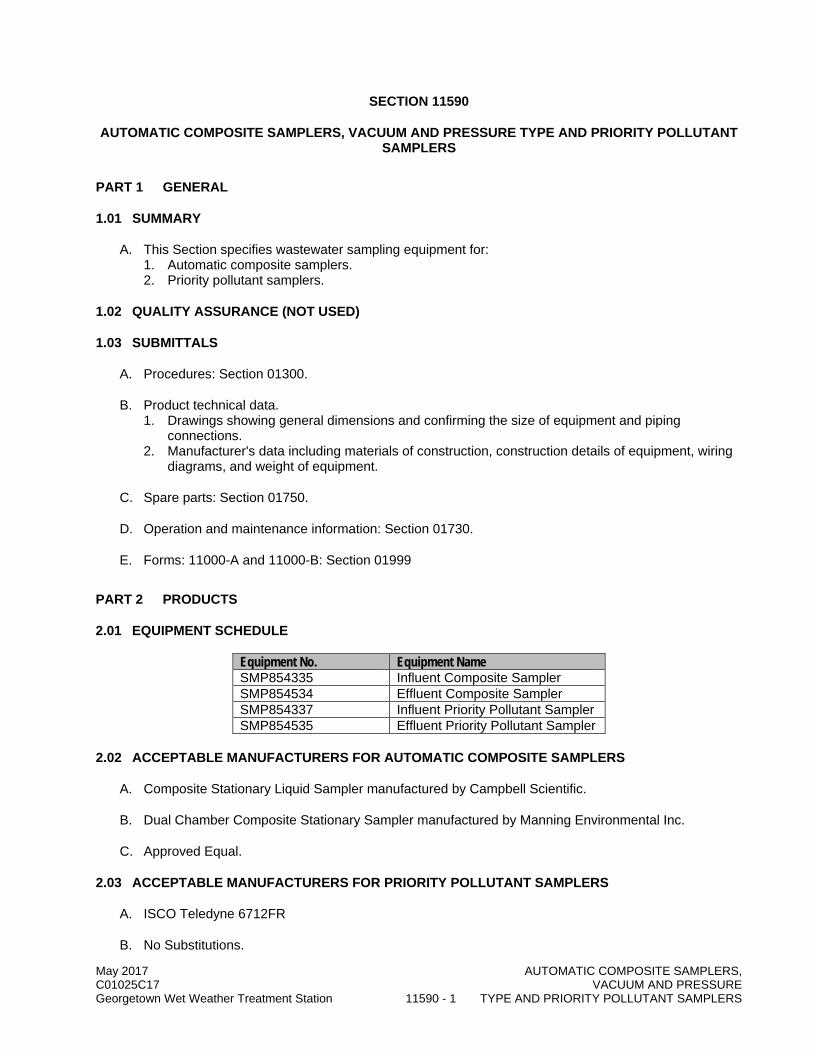
May 2017 AUTOMATIC COMPOSITE SAMPLERS, C01025C17 VACUUM AND PRESSURE Georgetown Wet Weather Treatment Station 11590 - 1 TYPE AND PRIORITY POLLUTANT SAMPLERS
SECTION 11590
AUTOMATIC COMPOSITE SAMPLERS, VACUUM AND PRESSURE TYPE AND PRIORITY POLLUTANT SAMPLERS
PART 1 GENERAL
1.01 SUMMARY
A. This Section specifies wastewater sampling equipment for: 1. Automatic composite samplers. 2. Priority pollutant samplers.
1.02 QUALITY ASSURANCE (NOT USED)
1.03 SUBMITTALS
A. Procedures: Section 01300.
B. Product technical data. 1. Drawings showing general dimensions and confirming the size of equipment and piping
connections. 2. Manufacturer's data including materials of construction, construction details of equipment, wiring
diagrams, and weight of equipment.
C. Spare parts: Section 01750.
D. Operation and maintenance information: Section 01730.
E. Forms: 11000-A and 11000-B: Section 01999
PART 2 PRODUCTS
2.01 EQUIPMENT SCHEDULE
Equipment No. Equipment Name SMP854335 Influent Composite Sampler SMP854534 Effluent Composite Sampler SMP854337 Influent Priority Pollutant Sampler SMP854535 Effluent Priority Pollutant Sampler
2.02 ACCEPTABLE MANUFACTURERS FOR AUTOMATIC COMPOSITE SAMPLERS
A. Composite Stationary Liquid Sampler manufactured by Campbell Scientific.
B. Dual Chamber Composite Stationary Sampler manufactured by Manning Environmental Inc.
C. Approved Equal.
2.03 ACCEPTABLE MANUFACTURERS FOR PRIORITY POLLUTANT SAMPLERS
A. ISCO Teledyne 6712FR
B. No Substitutions.

May 2017 AUTOMATIC COMPOSITE SAMPLERS, C01025C17 VACUUM AND PRESSURE Georgetown Wet Weather Treatment Station 11590 - 2 TYPE AND PRIORITY POLLUTANT SAMPLERS
2.04 MATERIALS AND COMPONENTS FOR AUTOMATIC COMPOSITE SAMPLERS
A. Sampler Operation: The automatic sampling system shall be comprised of a diaphragm operated vacuum/compressor pump, compound pressure/vacuum gauge, volumetric metering chamber assembly, micro-processor based electronic controller and all associated valves, tubing and electrical components necessary to provide a complete automatic composite sampling system. The system shall be capable of gathering fluid from a variety of sources including containers, open channels, pipes and any open source of water.
B. Sampler Enclosure: NEMA 3R rated, polyester-based powder coated steel, with a key-lockable door.
C. Suction Hose: 25 feet of 3/8-inch-diameter nylon reinforced PVC intake hose. End to include stainless steel sinker/strainer. Quick connect terminals shall be included.
D. Sample Container: Nine liter HDPE with “container full” shutoff cap, 2 containers per unit.
E. Refrigeration insulation: Polyurethane foam.
F. Metering chamber: acrylic or ABS with a barrier valve.
G. O-rings: Buna-N or Viton.
H. Sample Storage: Sample refrigeration temperature shall be maintained at 39 degrees F in 120 degrees F ambient conditions, and controlled by a hermetically sealed air sensing thermostat. The refrigerator shall be equipped with a compressor, fan cooled condenser, front ventilation, and silver brazed connections. All refrigeration components and copper plumbing shall be protected with a phenolic resin coating.
I. Sampling Sequence: 1. The sampling cycle shall begin with a high pressure air purge of the intake assembly to remove
residual liquid and obstructions. Upon completion of the pre-purge cycle, the system shall convert to a vacuum state, drawing the sample through the intake hose into the metering chamber until contact is made with a liquid sensing rod and the volume control tube. The system shall then pressurize, ejecting excess fluid back through the intake line until the predetermined sample volume is obtained. The sample shall then be deposited under pressure to the sample container. The post sample purge clears the intake assembly of any residual liquid after the sample is collected.
2. The sampling system shall be designed such that the fluid does not pass through any pump or distribution plate nor does it pass through any orifice less than 3/8-inch diameter. Should the sampler, for any reason, not be able to draw a sufficient volume of fluid to obtain a sample, the operator may program the unit to automatically initiate a second attempt. Should a sample not be delivered after the second attempt, the sampler shall abort the sequence and await the next sample initiation signal.
3. Upon two consecutive failures the sampler will suspend the sampling program until manually reset and provide a fault alarm output signal.
J. Sampler Controls: 1. All controls and the refrigerator unit shall operate from a 115 VAC, single phase, 60 Hz, 15A
electric service. All electronic and mechanical components shall be contained within the sampler enclosure, panel mounted at a convenient height.
2. Start delay shall be based on time/day; pulse input; 4-20 mA input; external contact; level control; disabled.
3. Sample initiation shall be based on interval time; pulse input; 4-20 mA input; external contact. 4. Sample programs shall include composite, multi-composite, consecutive, daily cycle, time step
(override).

May 2017 AUTOMATIC COMPOSITE SAMPLERS, C01025C17 VACUUM AND PRESSURE Georgetown Wet Weather Treatment Station 11590 - 3 TYPE AND PRIORITY POLLUTANT SAMPLERS
5. An overflow protection system shall prevent the sampler from overfilling the sample container. 6. The controller shall allow manual sampling, manual purge, manual bottle advance and restart. 7. Common fault and sample success relays to be included. 8. Controller shall include:
a. 2x16 character backlit LCD display. b. 6 key with multi-level menu touchpad. c. Real time and operating system clock. d. Sample taken (pulse output) status output. e. Available displays: real time clock; process timing; process controls; pulse counting; event
response; multi-level description; flashing prompts; diagnostic. f. Switches: run/off (spst toggle), on/off (5A lighted breaker); heater on/off; refrigerator on/off.
K. Alarms: 1. Sample in progress alarm. 2. Missed sample alarm. 3. Composite sample bottle full alarm.
2.05 EQUIPMENT PERFORMANCE REQUIREMENTS FOR AUTOMATIC COMPOSITE SAMPLERS
A. The composite wastewater sampler shall be a sampler suited for composite sampling applications.
B. The sampler shall be suited to collect flow proportioned wastewater samples in a single bottle.
C. The sampler shall be a dual station and the two chambers shall be able to operate independently of each other.
D. The influent and effluent composite sampling shall be flow paced to accomplish a flow weighted composite sample per event.
E. The sampler shall route samples from the point of sample collection to the storage container of the sampler.
F. Service Conditions: Samplers shall be capable of collecting samples from wastewater with the following constituents and characteristics: 1. Description: Influent Sampler. 2. Location: As shown on Plans. 3. Fluid type: combined sewer. 4. Description: Effluent Sampler. 5. Location: Effluent after the UV Disinfection Equipment. 6. Fluid type: Treated effluent.
2.06 SPARE PARTS FOR AUTOMATIC COMPOSITE AND PRIORITY POLLUTANT SAMPLERS
A. Procedures: Section 01750.
B. Furnish the following spare parts for each sampler: 1. One suction tubing assembly with strainer and fittings. 2. One discharge tubing assembly with fittings. 3. One set of fuses.
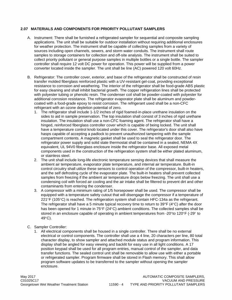
May 2017 AUTOMATIC COMPOSITE SAMPLERS, C01025C17 VACUUM AND PRESSURE Georgetown Wet Weather Treatment Station 11590 - 4 TYPE AND PRIORITY POLLUTANT SAMPLERS
2.07 MATERIALS AND COMPONENTS FOR PRIORITY POLLUTANT SAMPLERS
A. Instrument: There shall be furnished a refrigerated sampler for sequential and composite sampling applications. The unit shall be suitable for outdoor installation without requiring additional enclosures for weather protection. The instrument shall be capable of collecting samples from a variety of sources including open channels, sewers, and storm water conduits. The instrument shall route samples to storage containers for collection and off-site analysis. The instrument shall be suited to collect priority pollutant or general purpose samples in multiple bottles or a single bottle. The sampler controller shall require 12 volt DC power for operation. This power will be supplied from a power converter located inside the sampler. The unit shall be line (AC) powered 120 volt 60Hz.
B. Refrigerator: The controller cover, exterior, and base of the refrigerator shall be constructed of resin transfer molded fiberglass reinforced plastic with a UV-resistant gel-coat, providing exceptional resistance to corrosion and weathering. The interior of the refrigerator shall be food-grade ABS plastic for easy cleaning and shall inhibit bacterial growth. The copper refrigeration lines shall be protected with polyester tubing or phenolic resin. The condenser coil shall be powder-coated with polyester for additional corrosion resistance. The refrigerator evaporator plate shall be aluminum and powder-coated with a food-grade epoxy to resist corrosion. The refrigerant used shall be a non-CFC refrigerant with an ozone depletion potential of zero. 1. The refrigerator shall include 1-1/2 inches of rigid foamed-in-place urethane insulation on the
sides to aid in sample preservation. The top insulation shall consist of 3 inches of rigid urethane insulation. The insulation shall use a non-CFC foaming agent. The refrigerator shall have a hinged, reinforced fiberglass controller cover which is capable of being locked. The unit shall have a temperature control knob located under this cover. The refrigerator's door shall also have hasps capable of accepting a padlock to prevent unauthorized tampering with the sample compartment contents. A magnetic gasket shall be used to seal the refrigerator door. The refrigerator power supply and solid state thermostat shall be contained in a sealed, NEMA 4X equivalent, UL 94V0 fiberglass enclosure inside the refrigerator base. All exposed metal components used in the construction of the refrigeration system shall be either plated aluminum, or stainless steel.
2. The unit shall include long-life electronic temperature sensing devices that shall measure the ambient air temperature, evaporator plate temperature, and internal air temperature. Built-in control circuitry shall utilize these sensors to control operation of the compressor, built-in heaters, and the self defrosting cycle of the evaporator plate. The built-in heaters shall prevent collected samples from freezing if the ambient air temperature drops below freezing. The unit shall use a condensing coil with forced air cooling and the air intake shall be filtered to prevent dirt and other contaminants from entering the condenser.
3. A compressor with a minimum rating of 1/5 horsepower shall be used. The compressor shall be equipped with a temperature safety cutout that will disengage the compressor if a temperature of 221°F (105°C) is reached. The refrigeration system shall contain HFC-134a as the refrigerant. The refrigerator shall have a 5 minute typical recovery time to return to 39°F (4°C) after the door has been opened for 1 minute in 75°F (24°C) ambient conditions. The collected samples shall be stored in an enclosure capable of operating in ambient temperatures from -20°to 120°F (-29° to 49°C).
C. Sampler Controller: 1. All electrical components shall be housed in a single controller. There shall be no external
electrical or control components. The controller shall use a 4 line, 20 characters per line, 80 total character display, to show sampler and attached module status and program information. This display shall be angled for easy viewing and backlit for easy use in all light conditions. A 17 position keypad shall be used for all program entries, manual control of the sampler, and data transfer functions. The sealed control unit shall be removable to allow use with either a portable or refrigerated sampler. Program firmware shall be stored in Flash memory. This shall allow program software updates to be transferred to the sampler without opening the sampler enclosure.

May 2017 AUTOMATIC COMPOSITE SAMPLERS, C01025C17 VACUUM AND PRESSURE Georgetown Wet Weather Treatment Station 11590 - 5 TYPE AND PRIORITY POLLUTANT SAMPLERS
2. The control box shall be constructed of 1/4" thick Noryl® plastic and the enclosure shall conform to NEMA 4X, 6 (IP 67 control box, IP 17 pump) standards for water tight, dust tight, and corrosion resistance and submersion. A desiccator shall be located inside the control box to prevent moisture damage to electrical components.
3. The controller shall have an operating temperature of 32 to 120 °F (0 to 49 °C), and a storage temperature of 0 to 140 °F (-18 to 60 °C).
4. The sampler controller shall have two programming modes: standard and extended. Additionally, two styles of programming shall be available: quick view and sequential programming styles. There shall be a sequence available to select either standard or extended programming. On-line help shall be available to direct the user through the programming sequence or refer to specific sections in the instruction manual. The sampler shall provide 512 kilobytes of battery-backed RAM memory with a minimum life of five years. This memory shall maintain the sampler's program settings, stored programs, and the results of the last sampling sequence when the sampler is turned off or an external power interruption occurred. A user-initiated diagnostics routine shall determine the operational status of the sampler. Any error conditions detected by the diagnostic routines shall be displayed to the user.
5. Standard programming shall allow the user to define specific program operational parameters. Additionally, the sampler shall be able to be programmed to operate on specific days of the week. An option shall be available to automatically re-run the active program. No user re-activation shall be required if this option is selected. The user can program the sampler to collect sequential or composite samples at user-definable intervals. A delay to first sample collection shall be programmable in minutes from 0 to 9,999, or by the real-time clock or eliminated. The user shall be able to enter a 10 character alpha numeric description as a sampling site name. a. Time Pacing, Standard Programming: The sampler shall use an internal real-time clock to
provide time and date information. Uniform time-paced samples shall be collected at regular time intervals from 1 minute to 99 hours and 59 minutes.
b. Flow Pacing, Standard Programming: The sampler shall accept a 12V DC flow proportional pulse or isolated dry contact closure from an external flow meter for flow pacing. The pulse or contact closure shall be at least 25 ms in duration. The user shall select the number of flow pulses as the flow interval for each sample collection. If connected to a 700 series flow module, flow pacing shall be stated in interval flow volume between each sample.
6. Extended programming shall allow the user to enter intricate programs for sample collection. All options available in standard programming mode are available with extended programming. The sampler shall have the ability to be programmed for up to 2 real-time pause/resume sampling times. The pause/resume routines and delay to the first sample are independent of the sample pacing interval. The sampler shall be capable of storing up to 5 sampling routines. The duration and frequency of purges can be controlled by the user in this mode. Sample retries and line rinses shall be selectable from 0 to 3. The user shall be able to enter a 10 character alpha numeric description as a sampling site name. The user shall also be able to enter 10 character alphanumeric names for each stored sampling program. a. Two-part programming shall provide multiple sample pacing for collecting independent
samples in distinct bottle sets. This shall be used for storm water runoff monitoring or other applications. Sample volumes and intervals for the independent samples shall be separately programmed. All programming options shall be available for the independent programs. These two distinct programs shall be capable of being initiated separately by external conditions.
b. Time Pacing of Samples, Enhanced Programming: The sampler shall use an internal real-time clock to provide time and date information. Uniform time-paced samples shall be collected at regular time intervals from 1 minute to 99 hours and 59 minutes. Additionally, non-uniform time interval sampling shall be available. These non-uniform time intervals shall be capable of being paced by clock time, or in specific minute intervals for each sample collected. An additional non-uniform timed sampling mode shall allow the user to enter the number and volume of samples to collect and a time period to complete the sampling routine. The sampler shall then randomly select and record each sample collection.

May 2017 AUTOMATIC COMPOSITE SAMPLERS, C01025C17 VACUUM AND PRESSURE Georgetown Wet Weather Treatment Station 11590 - 6 TYPE AND PRIORITY POLLUTANT SAMPLERS
c. Flow Pacing of Samples, Enhanced Programming: The sampler shall accept a 12V DC flow-proportional pulse or isolated dry contact closure from an external flow meter for flow pacing. The pulse or contact closure must be at least 50 ms in duration. The user shall select the number of flow pulses as the flow interval for each sample collection. If connected to a 700 series flow module, flow pacing can also be stated in interval flow volume between each sample.
d. Flow Dependent Sample Volumes: For extended programs that are uniform time paced, a flow-dependent-sample-volume option shall be offered. If a flow module is attached, the input signal shall be the module's flow volume. Otherwise, it shall be the flow pulse count at the external flow meter connector. The user shall enter the amount of flow required for each 10 ml of sample. At sample time, the sample volume shall be calculated based on the flow that occurred since the last sample. This sample volume will be at least 20 ml, but not more than the bottle volume (or 9990 ml, whichever is smaller). No sample shall be taken at the start time.
e. Event-Paced Sampling: This mode of sampling shall allow the user to select specific external events to pace a sampling routine. A sample shall be collected when specific external events occur. Sampling shall take place with each occurrence of the external event.
7. Sampler Controller Outputs a. Three optional internal isolated analog outputs shall be available. These outputs shall be
configurable to either 4-20 mA or 0-20 mA. These outputs shall be programmable for any parameter measured by the sampler with the exception of rainfall.
b. A serial data output shall be available. ASCII data shall be transmitted at user selectable intervals of 15 seconds, 1 minute, 5 minutes, or 15 minutes. Additionally, the data output can be accessed by sending a specific command to the sampler. Baud rates shall be selectable from: 1200, 2400, 4800, or 9600. At all baud rates, the data shall be sent with no parity, 8 data bits, and one stop bit. Data shall be is in a comma-separated-value format.
c. There shall be available a programmable input/output (I/O) port that shall initiate a signal, based on monitored events, capable of activating an optional single, dual, or triple contact closure for controlling external devices or signaling other equipment. The signal is a 5 volt CMOS digital signal programmable to activate high or low, based on a programmed TRUE or FALSE condition(s). These outputs shall be programmable through the front panel and can be re-configured by the user.
d. For those programs that have delayed or scheduled start times, parameter readings shall be displayed while waiting for the start time. At the start time for the sampling program, the totalizer shall be reset to display total flow information for the sampling program. Parameter and flow readings shall also be displayed after the program is complete. Additionally, the 6712 sampler shall be capable of operating as a display and logging unit only.
8. Command-Driven Mode: There shall be provided an operational mode where the sampler shall be fully controlled through an external device. The external controller shall be responsible for determining when to take a sample, how much volume to pump, and where to put the sample. The external controller shall directly interface to the sampler via an RS-232 communications port at 2400 baud, 8 data bits, 1 stop bit, and no parity. A comma-separated-value protocol is used by the external controller to make requests, and by the sampler to report results. At the appropriate time as determined by the external controller, a command is sent to the sampler. The sampler shall move the distribution arm to the appropriate location and collect the volume of sample directed by the controller. After sample collection, the sampler shall signal back to the controller that the sample was successfully captured, or any operational faults that can be detected by the sampler.
D. Sample Delivery: 1. Samples shall be collected using a peristaltic pump. This pump shall produce typical line
velocities of 3.0 feet per second in a 3/8 inch (0.95 cm) ID suction line at 3 feet (1 m) of head. At 25 feet (7.6 m) of head, the pump shall typically produce a line velocity of 2.2 feet (0.67 m) per second. The pump shall be capable of lifting a sample 28 feet (8 m). The body of the peristaltic pump shall be an integral part of the sampler controller. The pump shall be constructed of high strength Noryl plastic and designed for corrosion resistance and long tubing life. Before and after

May 2017 AUTOMATIC COMPOSITE SAMPLERS, C01025C17 VACUUM AND PRESSURE Georgetown Wet Weather Treatment Station 11590 - 7 TYPE AND PRIORITY POLLUTANT SAMPLERS
each sample is collected, the pump shall air-purge the suction line. Pre-purges and post-purges shall be automatically controlled, and no pre-calibration adjustments are required. User-selectable purge lengths shall also be available. The sample stream shall be a direct path from sample source to sample bottle. Samples shall not pass through metering chambers or other diversions. The pump shall include a latched cover and thumbscrew opening for the replacement of pump tubing. The pump shall include a built-in safety interlock. With the opening of the pump's latch and band, all power shall be removed from the sampler's pump motor, to eliminate the possibility of a pump activation injuring personnel.
2. The sampler shall typically deliver sample volumes with an accuracy of ±10 ml or ±10%, whichever is greater, of the programmed value. The sample volume repeatability shall be ±5 ml or ±5%, whichever is greater, of the average of the maximum and minimum sample volume in the sample set. The user can select sample volumes from 10 to 9,990 ml in 1 ml increments. The liquid detector also monitors for anomalies in the sample collection process. If no liquid is detected, the sampler shall be capable of retrying the sampling sequence up to three times. Additionally, the sampler shall be capable of being programmed to rinse the suction line with the source liquid up to three times.
3. Liquid Detector: The sampler shall utilize a non-wetted, non-conductive detector to sense the presence of the liquid. The sensor shall not be dependent on, or affected by, any chemical or physical property of the liquid or its contents. The sensor shall not require routine maintenance or cleaning. The liquid detection system shall minimize the effects of changing head, intermittent flow in the suction line, or variable battery conditions on sample volume. After initial detection of liquid, the sensor shall monitor for the presence of liquid during the sample collection sequence. Additionally, the liquid detector shall be used to detect bottle full conditions when the sampler is operated in the single bottle sampling mode.
4. Pump Revolution Counter: After liquid detection, the pump revolution counter shall count actual pump revolutions to determine sample volume delivery to the storage containers. If liquid flow is interrupted during the sample collection sequence, the detector shall inhibit the pump revolution counter from incrementing until liquid flow is restored. Automatic compensations for air slugs in the sample shall be made by the delivery system. Additionally, the pump revolution counter shall monitor the total number of pump revolutions and alert the user when a pre-selected number of counts has been reached. This tubing life indicator shall alert the user to the need for pump tubing replacement. This indicator shall be on the sampler's display screen. The pump tubing used shall be specially treated to minimize water extractable pollutants. Specially designed bands shall indicate the correct placement of the tubing inside the pump. The tubing shall typically last for a minimum of 1,000,000 pump counts. One pump revolution is equivalent to 12 pump counts.
5. Sample distribution shall be through the use of a worm gear drive mechanism. This system shall lock the corrosion-resistant distribution arm above the appropriate sample container. A dual optical sensor shall be used for positive location of the distributor arm. A single adjustable distributor arm shall be used for all bottle configurations and sampler mounting possibilities.
6. The sampler program shall allow the user to select from 3 types of sample distribution: samples per bottle, bottles per sample, and multiple bottle compositing. In the samples per bottle mode, a minimum of 15 samples shall be capable of being deposited in each sample container. In the bottles per sample mode all sample bottles shall be capable of being filled with a single initiation. Multiple bottle compositing shall allow the user to place multiple samples in a single bottle while simultaneously creating a duplicate bottle or set of bottles. The sampler shall switch bottles after a period of time has elapsed, or a predetermined number of samples have been collected.
E. Suction Lines and Strainers: The sampler shall require a suction line and strainer. The suction line shall be made of 3/8 inch (.95 cm) ID Teflon with a length of 25 feet. The suction line shall have a factory-installed standard all stainless steel strainer for 3/8" (0.95cm) line.
F. Sample Collection Containers: Nine liter HDPE with “container full” shutoff cap, 2 containers per unit

May 2017 AUTOMATIC COMPOSITE SAMPLERS, C01025C17 VACUUM AND PRESSURE Georgetown Wet Weather Treatment Station 11590 - 8 TYPE AND PRIORITY POLLUTANT SAMPLERS
G. Options: 1. 581 Rapid Transfer Device (RTD): There shall be provided a hand-held device for transferring
data from the 6712 sampler. This information shall be in the form of daily summaries of the sampling data and other external sensing devices accompanying the 6712 sampler. The 581 shall typically store reports from up to 25 samplers. The unit shall be housed in a totally encapsulated polyurethane housing. The 581 shall meet standards for NEMA 4X, 6 (IP 68) standards for water-tightness. The communications protocol shall use a RS-232 serial communications, transmitting at 9600 baud. The total data storage capability shall be 967 Kbytes.
2. 2102 Wireless Module: There shall be provided a wireless communications module to communicate with a personal computer. This device will communicate similar to that of a direct connection to the sampler without the communications cable. The user can download all stored information from the 6712 for later manipulation.
3. Personal Computer Software (Samplink): There shall be provided software that shall allow two separate reports to be transferred to an IBM-compatible computer: a sampling results report and a program settings report. The program shall include failsafe loading with site ID codes to prevent field errors due to multiple files.
4. YSI SDI-12 Sonde: The sampler controller will include an SDI-12 input interface. The controller will function as a SDI-12 logger. A maximum of 10 input devices can be attached to the sampler controller. A maximum of 8 parameters from the sensors which may include multi-parameter sondes can be stored in the controller’s memory, and an additional 8 parameters can be used for program initiation or event paced sampling. The controller will accept Teledyne Isco-compatible sondes with a minimum of additional programming. Compatible, non-Teledyne Isco SDI-12 sensors must be programmed for the type of parameter and units selected for measurement.
H. Communication Options: 1. Internal Phone Modem:
a. The 6712FR shall be compatible with an internal phone modem. This landline analog modem shall operate at a transfer speed of 2400 Baud. The modem shall be capable of enabling the transfer of stored data from the 6712 sampler to a PC, and alarm information via telephone. In addition, software shall be available to enable the sampler to accept remote commands via the modem. These shall include: Sample program initiation, taking a sample, selection of stored program to operate, or the end of a sampling routine.
2. CDMA Modem: a. The 6712 FR shall be compatible with an external digital cellular CDMA modem for issuing
alarm information in the form of digital text messages via dialup server to cellular phones. Remote operation shall be possible through a computer command program such as Hyper Terminal. An external digital modem is available from Teledyne Isco.
3. TDMA Modem a. The 6712 FR shall be compatible with an external digital cellular GSM modem for issuing
alarm information in the form of digital text messages using SMS to cellular phones. Remote operation shall be possible through a computer command program such as Hyper Terminal. An external digital modem is available from Teledyne Isco.
PART 3 EXECUTION
3.01 INSTALLATION
A. Equipment Mounting: The equipment shall be installed at the location specified and in accordance with the manufacturer's recommendations.

May 2017 AUTOMATIC COMPOSITE SAMPLERS, C01025C17 VACUUM AND PRESSURE Georgetown Wet Weather Treatment Station 11590 - 9 TYPE AND PRIORITY POLLUTANT SAMPLERS
3.02 FIELD QUALITY CONTROL
A. In addition to any testing herein, perform all testing for this product or system consistent with the requirements of Section 01660, the applicable codes, and the manufacturers' current quality assurance program.
B. Component Test Phase: Following the preoperational test phase specified in Section 01660, perform the following field tests during the component test phase. 1. Sampling Program Test:
a. Test each sampler. b. Simulate a variable 4-20 mA input for demonstration of flow proportional sampling. c. Verify the correct sampling interval is achieved for operation at five different simulated flow
conditions. d. Create each alarm condition and confirm that the appropriate alarm signal is received by the
plant control system.
3.03 TRAINING
A. Procedures: Section 01660.
B. The sampler suppliers shall provide two 2-hour instruction session. Coordinate training sessions with the Project Representative. Conduct one training session per week on consecutive weeks to accommodate the shift schedules of operation and maintenance staff. The training session shall include preventive maintenance requirements, overhaul and troubleshooting instructions, and sampler programming procedures.
END OF SECTION

May 2017 AUTOMATIC COMPOSITE SAMPLERS, C01025C17 VACUUM AND PRESSURE Georgetown Wet Weather Treatment Station 11590 - 10 TYPE AND PRIORITY POLLUTANT SAMPLERS
This page intentionally left blank.
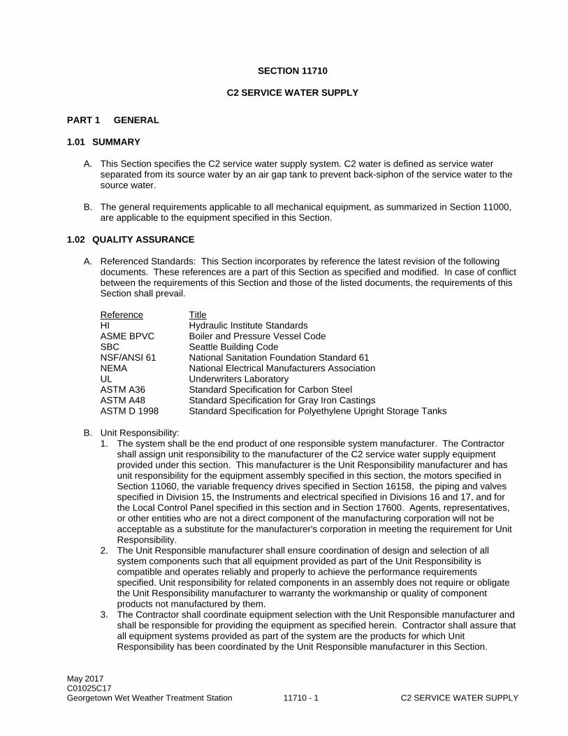
May 2017 C01025C17 Georgetown Wet Weather Treatment Station 11710 - 1 C2 SERVICE WATER SUPPLY
SECTION 11710
C2 SERVICE WATER SUPPLY
PART 1 GENERAL
1.01 SUMMARY
A. This Section specifies the C2 service water supply system. C2 water is defined as service water separated from its source water by an air gap tank to prevent back-siphon of the service water to the source water.
B. The general requirements applicable to all mechanical equipment, as summarized in Section 11000, are applicable to the equipment specified in this Section.
1.02 QUALITY ASSURANCE
A. Referenced Standards: This Section incorporates by reference the latest revision of the following documents. These references are a part of this Section as specified and modified. In case of conflict between the requirements of this Section and those of the listed documents, the requirements of this Section shall prevail. Reference Title HI Hydraulic Institute Standards ASME BPVC Boiler and Pressure Vessel Code SBC Seattle Building Code NSF/ANSI 61 National Sanitation Foundation Standard 61 NEMA National Electrical Manufacturers Association UL Underwriters Laboratory ASTM A36 Standard Specification for Carbon Steel ASTM A48 Standard Specification for Gray Iron Castings ASTM D 1998 Standard Specification for Polyethylene Upright Storage Tanks
B. Unit Responsibility: 1. The system shall be the end product of one responsible system manufacturer. The Contractor
shall assign unit responsibility to the manufacturer of the C2 service water supply equipment provided under this section. This manufacturer is the Unit Responsibility manufacturer and has unit responsibility for the equipment assembly specified in this section, the motors specified in Section 11060, the variable frequency drives specified in Section 16158, the piping and valves specified in Division 15, the Instruments and electrical specified in Divisions 16 and 17, and for the Local Control Panel specified in this section and in Section 17600. Agents, representatives, or other entities who are not a direct component of the manufacturing corporation will not be acceptable as a substitute for the manufacturer's corporation in meeting the requirement for Unit Responsibility.
2. The Unit Responsible manufacturer shall ensure coordination of design and selection of all system components such that all equipment provided as part of the Unit Responsibility is compatible and operates reliably and properly to achieve the performance requirements specified. Unit responsibility for related components in an assembly does not require or obligate the Unit Responsibility manufacturer to warranty the workmanship or quality of component products not manufactured by them.
3. The Contractor shall coordinate equipment selection with the Unit Responsible manufacturer and shall be responsible for providing the equipment as specified herein. Contractor shall assure that all equipment systems provided as part of the system are the products for which Unit Responsibility has been coordinated by the Unit Responsible manufacturer in this Section.

May 2017 C01025C17 Georgetown Wet Weather Treatment Station 11710 - 2 C2 SERVICE WATER SUPPLY
4. The requirement for Unit Responsibility shall in no way relieve the Contractor of responsibility for performance as specified in the Contract Provisions.
1.03 SUBMITTALS
A. Procedures: Section 01300.
B. Manufacturer's specifications, data, and drawings of pumps, valves, tanks, instruments, and control panel of the C2 service water supply system: 1. Pump performance data, type, model, rpm, type of bearing, type of coupling, weight, material of
construction, and shop paint information. Provide pumps' net positive suction head (NPSH) requirements, efficiency, brake horse power and motor information.
2. Hydropneumatic tank manufacturer's catalog information including dimensions, capacity, construction materials, piping connections locations and sizes. Provide submittals required by Section VIII, Division 1 or 2 of the ASME Boiler and Pressure Vessel Code. Provide hydropneumatic tank's charged pressure.
3. Air-gap tank fabrication drawings with capacity, dimensions, construction materials. 4. Air-gap tank fill control valve data. 5. Catalog information for C2 service water supply system pressure control switches and air gap
tank level control switches, as required for the automatic operation of the C2 service water system.
6. Control panel wiring diagram drawings, including control, monitoring, alarming, and control system description.
7. Pump motor data: Section 16128.
C. Documentation of Factory Testing.
D. Approved final field test results of the C2 service water supply system.
E. Operation and maintenance information: Section 01730. 1. Including pumps, level control switches, pressure switches, hydropneumatic tank, air gap tank,
and air gap tank fill control valve.
F. Spare Parts: Section 01730.
G. Forms: 11000-A, 11000-B and 11060-A: Section 01999.
1.04 SITE CONDITIONS
A. The water supplied to the air gap tank will be at a temperature of 45 to 85 degrees F.
PART 2 PRODUCTS
2.01 EQUIPMENT SCHEDULE
Equipment No. Description CV854350 Float Control Valve T854350 C2 Air Gap Tank PVL854355 C2 Water Supply Hydropneumatic Tank P854351 C2 Water Supply Pump 1 MTR854351 C2 Water Supply Pump 1 Motor P854352 C2 Water Supply Pump 2 MTR854352 C2 Water Supply Pump 2 Motor P854353 C2 Water Supply Pump 3
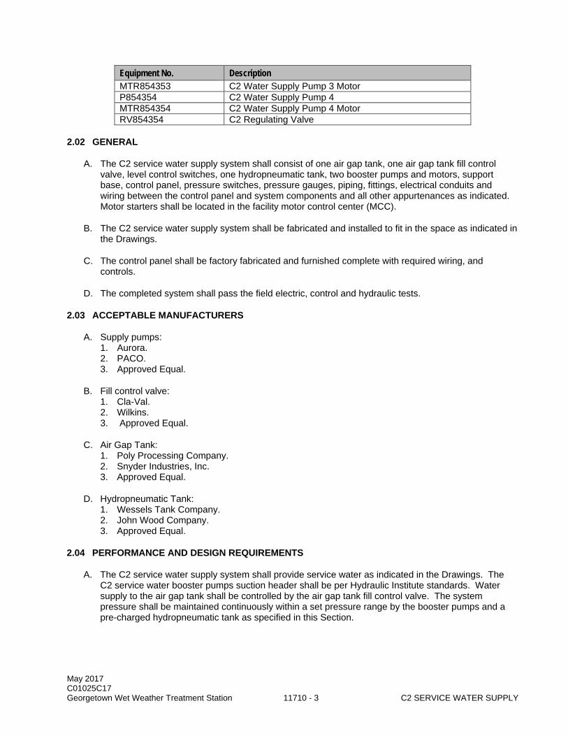
May 2017 C01025C17 Georgetown Wet Weather Treatment Station 11710 - 3 C2 SERVICE WATER SUPPLY
Equipment No. Description MTR854353 C2 Water Supply Pump 3 Motor P854354 C2 Water Supply Pump 4 MTR854354 C2 Water Supply Pump 4 Motor RV854354 C2 Regulating Valve
2.02 GENERAL
A. The C2 service water supply system shall consist of one air gap tank, one air gap tank fill control valve, level control switches, one hydropneumatic tank, two booster pumps and motors, support base, control panel, pressure switches, pressure gauges, piping, fittings, electrical conduits and wiring between the control panel and system components and all other appurtenances as indicated. Motor starters shall be located in the facility motor control center (MCC).
B. The C2 service water supply system shall be fabricated and installed to fit in the space as indicated in the Drawings.
C. The control panel shall be factory fabricated and furnished complete with required wiring, and controls.
D. The completed system shall pass the field electric, control and hydraulic tests.
2.03 ACCEPTABLE MANUFACTURERS
A. Supply pumps: 1. Aurora. 2. PACO. 3. Approved Equal.
B. Fill control valve: 1. Cla-Val. 2. Wilkins. 3. Approved Equal.
C. Air Gap Tank: 1. Poly Processing Company. 2. Snyder Industries, Inc. 3. Approved Equal.
D. Hydropneumatic Tank: 1. Wessels Tank Company. 2. John Wood Company. 3. Approved Equal.
2.04 PERFORMANCE AND DESIGN REQUIREMENTS
A. The C2 service water supply system shall provide service water as indicated in the Drawings. The C2 service water booster pumps suction header shall be per Hydraulic Institute standards. Water supply to the air gap tank shall be controlled by the air gap tank fill control valve. The system pressure shall be maintained continuously within a set pressure range by the booster pumps and a pre-charged hydropneumatic tank as specified in this Section.

May 2017 C01025C17 Georgetown Wet Weather Treatment Station 11710 - 4 C2 SERVICE WATER SUPPLY
B. Operating conditions and requirements: System Components Equipment
No. Design Requirements
C2 Water Supply Pumps and Motors Supply Pump No. 1 P854351 Capacity at rated head, gpm 100 Supply Pump No. 2 P854352 Rated head, psig 100 Supply Pump No. 3 Supply Pump No. 4
P854353 P854354
Operating pressure range, psig 90-100
Pump maximum inlet pressure, FT 10 Shutoff head, FT 235 Pump suction and discharge size, inches 1½/1¼ Motor rated speed, RPM 3520-3540 Power supply 460v/60Hz/3PH Motor nameplate HP 15
Hydropneumatic Tank Hydropneumatic Tank PVL85435
5 Capacity, gallons 792
Tank diameter, inches 48 Pre-charge pressure, psig 95
Air Gap Tank Air Gap Tank T854350 Capacity, Gallons 3000 Tank Diameter, Inches 85 Tank height, inches 140 Tank Material HDPE
2.05 BOOSTER PUMPS
A. The booster pumps shall be close-coupled, horizontal end suction centrifugal type fitted with a mechanical seal to prevent leakage. The mechanical seal shall be suitable for water temperatures from 32 degrees F to 212 degrees F. The pump shall be suitable for a maximum operating pressure of 150 psig. The pump motors shall be totally enclosed, fan cooled, energy efficient, inverter duty and suitable for 480 volt, 60 Hz, 3 phase power supply as specified in Section 16158. The pumps performance shall be stable and free from cavitation and noise throughout the full operating range.
B. Seals: Corrosion-resistant mechanical seals. Seal cooling and lubricating water shall be internally supplied.
C. Materials: Item Material
Pump Casing Cast iron, ASTM A48 or Ductile Iron, ASTM A 395 Impeller Cast iron, ASTM A48 Wear Ring Stainless steel, Type 316 Motor Shaft Stainless steel, Type 316 Shaft Sheave Stainless steel, Type 316 Base plate ASTM A36 steel or cast iron Class 40
2.06 HYDROPNEUMATIC TANK
A. Designed for a pressure booster system with cyclic pump operation. The tank shall be an ASME rated pressure vessel designed for a working pressure of 200 PSI. The tank shall be of welded steel construction with a field replaceable heavy-duty butyl rubber bladder diaphragm certified to NSF/ANSI standard 61. The tank liner shall be corrosion resistant polypropylene with a copper-lined acceptance fitting. The air chamber shall be pre-pressurized at the factory as required for the system. The tank shall be designed for vertical mounting and connected to the system as indicated in the Drawings.
May 2017 C01025C17 Georgetown Wet Weather Treatment Station 11710 - 5 C2 SERVICE WATER SUPPLY
The tank shall be provided with corrosion-resistant factory finish coating, interior and exterior, in accordance with Section 09900 requirements.
B. Design and manufacture in compliance with the ASME Boiler and Pressure Vessel Code. Meet the requirements of Section VIII, Division 1 of the ASME Boiler and Pressure Vessel Code. Each tank shall bear an ASME inspector's stamp, complete with design working pressure and date and place of manufacture.
C. The tank seismic anchorage and bracing shall be per SBC compliant and per Section 01031. For purposes of this requirement the weight of the tank shall be the weight when completely filled with water.
D. The tank shall be provided with rubber bladder replacement access cap, a 4-inch flanged water supply system connection, lifting lugs, air charge valve, and 1-inch drain. The tank's pressure switches shall be provided on the piping connections, as indicated in the Drawings.
E. Provide 200 psi pressure safety relief valve mounted on discharge pipe as indicated in the Drawings and as per Section 15123 for connection to facility drain piping system.
2.07 AIR GAP TANK
A. The air gap tank shall be fabricated as indicated in the Drawings. The size and location of the tank connections shall be field verify by the Contractor as required for proper piping system. The tank shall be self-supporting, impact resistant, and shall be suitable for operating temperatures from 32 to 140 degrees Fahrenheit. The tank shall be provided with inlet, vent, level switch, outlet, overflow, and drain connections.
B. The air gap tank shall be provided with an air gap for the water supply, level switch, and fill control valve float switch. The water supply pipe to the air gap tank shall be terminated a distance three pipe diameters above the tank.
C. The tank seismic anchorage and bracing shall be per Section 01031. For purposes of this requirement the weight of the tank shall be the weight when completely filled with water.
2.08 FILL CONTROL VALVE
A. Automatic non-modulating float valve that controls the liquid level in the air gap tank.
B. The valve shall fully open when liquid level reaches the pre-set low level and close drip-tight when the liquid level reaches to the preset high point.
C. Pilot controlled, diaphragm actuated, composition disc, single seated, hydraulically operated valve with float mechanism mounted on top of the air gap tank.
D. The float positions the pilot control to close the valve when the float contacts the upper stop. The high and low liquid levels are adjusted by positioning the stop collars on the float rod. The difference between high and low levels can be adjusted to as little as one inch, or to as much as eighteen inches.
E. The seat ring shall be renewable, and the diaphragm and disc shall be easily replaceable.

May 2017 C01025C17 Georgetown Wet Weather Treatment Station 11710 - 6 C2 SERVICE WATER SUPPLY
F. The valve shall be suitable for use with potable water, and shall have threaded connections. The main valve body and valve trim shall be bronze. The pilot control system shall be bronze with stainless steel trim. The opening and closing levels shall be adjustable and shall be set for proper system operation. The opening and closing rates shall be adjustable to prevent water hammer in the supply water system. The float rod shall be of sufficient length to provide adequate adjustment. The working pressure range is 50 to 80 psig. The valve shall be factory equipped with opening and closing speed controls.
G. The high and low level control floats shall be mercury free, floating ball type, with a nominal 5 inch diameter, Teflon coated stainless steel float ball which contains a sealed snap action assembly. The float shall be provided with a support mechanism and an adjustable mounting bracket suitable for fastening to the air gap tank. All mounting accessories and float rod shall be stainless steel.
2.09 AIR GAP TANK LEVEL SENSORS
A. See Section 17216.
B. The level control sensors shall be provided with a support mechanism and to fit in the level control stilling well in the air gap tank. All mounting accessories shall be stainless steel.
2.10 PRESSURE SWITCHES AND GAUGES
A. Provide pressure switches for the C2 service water supply system pumps automatic operation. The pressure switches shall operate the LEAD and LAG pumps to maintain the set point pressures and to provide high and low water pressure signals to the C2 service water control panel. The pressure switches shall have two independently adjustable set points, and as specified in Section 17216.
B. The low pressure alarm set point shall be 5 psi higher than the LAG pump on pressure set point.
2.11 C2 SERVICE WATER CONTROL PANEL
A. The C2 service water supply system shall be provided with remote mounted factory wired NEMA 4X control panel containing operating switches, indicating lights, safety controls, fused control circuit with knife switch type LED blown fuse indictor, terminal strips, LEAD and LAG pumps manual selector switch, and all other accessories required for proper system operation. The panels shall be factory wired for single point120 volt, single phase control power connection via terminal blocks.
B. Power and control system conduits and wiring installation between the motors, control panel and other components of the C2 service water supply system including level and pressure switches, and pumps shall be provided by the Contractor according to the manufacturer's installation electrical drawings and as indicated in the Drawings.
C. Panel fabrication and labeling to conform to the requirements of Division 16 and 17 of this specification and as indicated in the Drawings.
D. Provide dry contact closure signals rated 5A at 120V ac for connection to the facility Process Control System. 1. Air gap tank level HIGH. 2. Air gap tank level LOW. 3. C2 water pressure HIGH. 4. C2 water pressure LOW. 5. C2 water system FAULT.

May 2017 C01025C17 Georgetown Wet Weather Treatment Station 11710 - 7 C2 SERVICE WATER SUPPLY
2.12 PIPING AND VALVES
A. Piping: Section 15050.
B. Ball valves: Section 15104.
C. Ball check valves: Section 15150.
D. C2 Water Pressure Regulator valve: Section 15121.
2.13 ELECTRICAL
A. Comply with Division 16.
B. Electrical motors: Section 16158.
2.14 SEQUENCE OF OPERATION
A. Each pump shall be controlled by a "HAND-OFF-AUTO" switch. The C2 System Local Control Panel shall have a LEAD/FOLLOW selector switch to determine LEAD, FOLLOW 1, FOLLOW 2, and FOLLOW 3 pump positions. In the “AUTO” mode the pumps shall control remotely mounted VFDs to operate the variable speed pumps to maintain a constant discharge pressure. The system control panel shall receive an analog signal, 4-20 mA, from the system pressure transmitter indicating actual system pressure. Additional pumps shall be started and ramped up to meet demand and pumps shall ramp down and shut off as demand reduces. In "HAND" mode the selected LEAD pump shall be turned on and off manually by ON-OFF switch located on the control panel. Indicating lights shall be provided on the control panel for ON and OFF running status for each pump. In the event of high or low water level in the air gap tank, an alarm light shall be illuminated on the control panel. In the event of low water level in the air gap tank, in AUTO and HAND mode, the pumps shall shut down until manually reset via an alarm RESET pushbutton mounted on the control panel face. Time delay relays shall be provided in the control panel to eliminate the systems pressure fluctuations and false signals. The pumps shall also shut down for motors shell high temperature and the panel shall provide pumps motors HIGH TEMP alarm lights and manual RESET button.
B. The air gap tank water supply is controlled by the air gap tank fill control float valve. The valve opens and closes based on the valve open and close tank level set points.
C. The C2 service water supply system equipment, each shall be provided with a 16-gage stainless steel identification tag. Identification tags shall bear the complete equipment name and number, as specified. Characters shall be 1/4-inch, die-stamped or laser etched. Identification tags shall be securely attached to the equipment in a readily visible location using stainless steel screws (except for components on control panel doors which shall meet the requirements of Division 17 without violating the panels UL listing).
2.15 SPARE PARTS
A. Procedures: Section 01750.
B. Provide one spare pump.

May 2017 C01025C17 Georgetown Wet Weather Treatment Station 11710 - 8 C2 SERVICE WATER SUPPLY
PART 3 EXECUTION
3.01 INSTALLATION
A. Install as recommended by the manufacturer of the components. The installation and initial operation shall be certified on Form 11000-A included in Section 01999.
B. Install the hydropneumatic tank and accessories precharged, filled and pressurized in accordance with the manufacturer's written instructions and the latest edition of the Seattle Building Code Seismic requirements.
C. Precharge the hydropneumatic tank precharge in the presence of the Project Representative in accordance with the manufacturer's recommendation. Other pressure and level control setting shall be adjusted by the Contractor and tested for the Project Representative’s acceptance.
3.02 FIELD QUALITY CONTROL
A. After installation, test the equipment to verify control system, shutdown, interlocks and alarms.
B. Verify the instrument settings and control strategies specified.
3.03 TRAINING
A. Procedures: Section 01660.
B. Manufacturer’s representative shall conduct two 1-hour training sessions for operations staff and two 1-hour training sessions for maintenance staff. Coordinate training session with Project Representative. Conduct one operations and one maintenance training session per week on consecutive weeks to accommodate the shift schedules of operations and maintenance staff.
C. Training shall be certified on Form 11000-B included in Section 01999.
END OF SECTION

May 2017 C01025C17 BALLASTED SEDIMENTATION Georgetown Wet Weather Treatment Station 11801 - 1 SYSTEM INSTALLATION
SECTION 11801
BALLASTED SEDIMENTATION SYSTEM INSTALLATION
PART 1 GENERAL
1.01 SUMMARY
A. This Section specifies all work and materials that the Contractor (Installing Contractor) is responsible for to provide a complete ACTIFLO ballasted sedimentation system (ACTIFLO System).
B. The ACTIFLO System has been pre-selected by the Owner. Coordinate with the requirements of Section 01021.
C. The Section 11800 documenting the scope of ACTIFLO manufacturer as well as ACTIFLO System initial submittals are available as reference in Volumes 19 and 20 of the Contract Documents. Obtain a set of conforming submittals including any updates, additions, or exceptions from the initial submittals, prior to installation of the system.
D. Responsible for procuring the ACTIFLO system during the construction at the price pre-negotiated between the County and the ACTIFLO Manufacturer. Also, responsible for managing and coordinating with the ACTIFLO Manufacturer on all the submittals, equipment delivery, installation, testing and services after construction.
E. The ACTIFLO System includes the following: 1. Mixers:
a. Rapid Mix Tank Mixers. b. Coagulation Tank Mixers. c. Maturation Tank Mixers.
2. Setting Tank Equipment: a. Sludge Scrapers (drive and assembly). b. Scraper Support Bridge. c. Lamella Tube Modules and Lamella Tube Support System. d. Collection Troughs and Collection Trough Supports.
3. Microsand Recirculation System Equipment: a. Microsand/Sludge Recirculation Pumps. b. Valves. c. Flow transmitters. d. Pressure indicating transmitters. e. Hydrocyclones. f. Hydrocyclone support stand.
4. Ancillary Items: a. Baffles. b. Maturation tank draft tubes. c. Sand concentration sampling device. d. Influent and effluent turbidity and pH transmitters
5. Microsand. 6. Chemical Feed Systems:
a. Liquid polymer makeup units including progressive cavity metering pumps. One complete unit as shelf spare is included.
b. Coagulant metering pumps on skid. 1) Flow transmitters for each treatment train.
c. Caustic metering pumps on skid. 1) Flow transmitters for each treatment train.
May 2017 C01025C17 BALLASTED SEDIMENTATION Georgetown Wet Weather Treatment Station 11801 - 2 SYSTEM INSTALLATION
d. Defoamer metering pumps on skid. 1) Flow transmitters for each treatment train.
7. ACTIFLO Control System Equipment and Programming. 8. Manufacturer services as specified in Section 11800 of Appendix B.
1.02 QUALITY ASSURANCE
A. Referenced Standards: This Section incorporates by reference the latest revision of the following documents. These references are a part of this Section as specified and modified. In case of conflict between the requirements of this Section and those of the listed documents, the requirements of this Section shall prevail.
Reference Title AGMA American Gear Manufacturers Association AFBMA Anti Friction Bearing Manufacturers Association NEMA National Electrical Manufacturers Association
1.03 SUBMITTALS
A. Procedure: 01300.
B. Forms 11000-A, 11000-B, 11060-A: Section 01999.
C. Shop drawings from Contractor for Contractor-Furnished Items: 1. Catalog information and cuts for all system components provided by the Contractor and to be
used in the installation of the system. 2. Detailed shop drawings of all system installation components and all interconnections and
interface requirement (piping, power, control, instrumentation, data) in conformance with the ACTIFLO Manufacturer’s recommendations.
3. Special unloading, storage and protection, and handling plans. 4. Anchorage: Section 05501.
D. Quality Control Submittals: 1. Manufacturer’s Certificate of Proper Installation.
E. Contract Closeout Submittal: 1. Service records for maintenance performed during construction.
F. Component, system and operational test reports.
G. Performance Test Plan and Test Report.
1.04 DEFINITIONS
A. ACTIFLO: A staged microsand enhanced flocculation system combined with lamella settling creating a high rate clarification process.
B. ACTIFLO Manufacturer or supplier: Veolia Water Technologies, Inc. dba Kruger; 4001 Weston Parkway; Cary, North Carolina 27513; (919) 677-8310.
C. ACTIFLO System: The entire mechanical, electrical, instrumentation and control system furnished by the ACTIFLO Manufacturer as specified in Section 11800 and included in Kruger’s submittals (see Volumes 19 and 20).

May 2017 C01025C17 BALLASTED SEDIMENTATION Georgetown Wet Weather Treatment Station 11801 - 3 SYSTEM INSTALLATION
1.05 SYSTEM DESIGN CRITERIA (NOT USED)
1.06 PERFORMANCE GUARANTEE (NOT USED)
1.07 DELIVERY, STORAGE AND HANDLING
A. Delivery and Storage: 1. Provide written notice to the County a minimum three (3) calendar days prior to anticipated date
of delivery to afford an opportunity for the County to be present and inspect unloading of equipment.
2. Equipment to be unloaded by Contractor. 3. Authorized representative of Vendor shall be present during unloading. 4. Manufacturer’s instructions covering storage, handling, installation, lubrication, and maintenance
for the equipment shall be furnished to the County a minimum of 30 days prior to the date the equipment is shipped.
5. Grease and lubricating oil shall be applied to all bearings and similar items. 6. All equipment shall be delivered by the Vendor to the site ready for installation. Vendor shall be
responsible to coordinate with the Contractor to provide proper storage of the equipment. 7. Deliver materials dry and undamaged.
B. Painted and coated surfaces shall be protected against impact, abrasion, discoloration, and other damage. Painted and coated surfaces which are damaged prior to acceptance of equipment shall be repainted to the satisfaction of the Project Representative.
C. Each item of equipment shall be tagged or marked as identified in the delivery schedule or on the submittals prior to shipping. Complete packing lists and bills of material shall be included with each shipment.
D. Damaged and missing equipment shall be replaced with new equipment at no additional cost to the County: 1. Replenish any spare parts used to specified quantity.
1.08 SITE CONDITIONS
A. The ACTIFLO system provided under this Section shall be suitable for operation in wastewater from a combined sewer overflow (CSO) collection system. The wastewater will be screened by 6-mm (1/4 inch) multi-rake bar screens before entering ACTIFLO® system. The mixers, setting tank equipment, hydro cyclones and control panels will be located outdoors where the temperature range will be between 30 and 90 degrees F. The microsand pumps, and chemical feed systems will be located indoors where the temperature range will be between 45 and 80 degrees F. The wastewater will have a temperature of 0 to 25 degrees C and a pH that will range from 6.5 to 7.8 after chemical addition for pH adjustment. The interior of the ballasted sedimentation basins from the minimum operating water surface to the top of the tank wall, the envelop 18 inches above the top of the tank and extending 18 inches beyond the exterior wall, the envelop 18 inches above grade extending 10 feet horizontally from the exterior tank walls shall be classified as Hazardous Class 1 Division 2. The indoor space shall be non-classified space.
PART 2 PRODUCTS
2.01 ACTIFLO® SYSTEM SCOPE OF SUPPLY
A. Mixers: Rapid Mix Tank Mixers Coagulation Tank Mixer Maturation Tank Mixers
No. of units 2 2 2

May 2017 C01025C17 BALLASTED SEDIMENTATION Georgetown Wet Weather Treatment Station 11801 - 4 SYSTEM INSTALLATION
Rapid Mix Tank Mixers Coagulation Tank Mixer Maturation Tank Mixers Equipment No. MX854412
MX854422 MX854413 MX854423
MX854414 MX854424
Tank Dimensions, each 6’ x 6’ x 6’ side water depth (SWD)
16’-9” x 16’-9” x 23’ SWD
23’-9” x 26’-3” x 23’ SWD
Mixing Cycle Continuous Continuous Continuous Horsepower, each 5 25 20 Drive type Constant speed drive Constant speed drive Variable frequency
drive
B. Settling Tank Equipment: Settling Tank Sludge
Scraper Bridge Support
No. of units 2 2
Equipment No. MX854415 MX854425
N/A
Tank Dimensions, each 26’-3” x 26’-3” x 23’ SWD
Horsepower, each 5 N/A Materials 304 SST Epoxy coated carbon
steel
2.02 LAMELLA SETTLERS, TROUGHS AND SUPPORTS
A. Lamella Tube Modules: 1. Type: Hexagonal inclined at 60 degrees from the horizontal. 2. Material: Black polystyrene.
B. Lamella Settler Support Set and Tie-down Assembly: 1. Number: 2 Sets. 2. Material: Type 304 stainless steel.
C. Collection Troughs and Supports: 1. Number: 2 Sets. 2. Type: Rectangular troughs with square-notch weirs. 3. Size: Per Manufacturer. 4. Material: Type 304 stainless steel, 1/8 inch thick.
2.03 MICROSAND RECIRCULATION SYSTEM EQUIPMENT Microsand Recirculation Pump Hydrocyclone
No. of units 6 6 Equipment No. P854416
P854417 P854418 P854426 P854427 P854428
ME854416 ME854417 ME854418 ME854426 ME854427 ME854428
Drive Type Constant Speed N/A Liquid Microsand (sand and solids
slurry) Microsand (sand and solids slurry)
Capacity, each gpm 730 730 Total dynamic head, ft as determined by ACTIFLO
manufacturer
Efficiency, % 58% minimum

May 2017 C01025C17 BALLASTED SEDIMENTATION Georgetown Wet Weather Treatment Station 11801 - 5 SYSTEM INSTALLATION
Microsand Recirculation Pump Hydrocyclone Rated power, each, hp 40 Motor type Squirrel cage induction meeting
requirement of NEMA MG 1
Motor horsepower 40 Service Factor 1.15 Enclosure Type TEFC Synchronous Speed 1,800
2.04 VALVES
A. Discharge Side Pump Isolation Valve: 1. Number: 6. 2. Valve Type: 8-inch diameter, eccentric plug type; cast iron body with ANSI class 125/150 raised
face through bolding flanges; provided with square braided high temperature flax packing, acrylonitrile-butadiene resilient seat material, and hand wheel actuators.
3. Manufacturer: a. Dezurik Company, Inc.
B. Suction Side Pump Isolation Valve: 1. Number: 6. 2. Valve Type: 8-inch diameter, eccentric plug type; cast iron body with ANSI class 125/150 raised
face through bolding flanges; provided with square braided high temperature flax packing, acrylonitrile-butadiene resilient seat material, and hand wheel actuators.
3. Manufacturer: a. DeZurik Company, Inc.
C. Flush Connection Valve: 1. Number: 6. 2. Valve Type: 2-inch diameter ball valve; 304 SS, end entry type, RTFE seats, Teflon packing,
hand lever operator, rated 150-pound SWP, 600-pound WOG. 3. Manufacturer:
a. Velan.
D. Sand Sampling Valve: 1. Number: 6. 2. Valve Type: 0.5-inch diameter ball valve; 304 SS, end entry type, RTFE seats, Teflon packing,
hand lever operator, rated 150-pound SWP, 600-pound WOG. 3. Manufacturer:
a. Velan.
E. Pressure Transmitter Isolation Valve: 1. Number: 6. 2. Valve Type: 0.5-inch diameter ball valve; 304 SS, end entry type, RTFE seats, Teflon packing,
hand lever operator, rated 150-pound SWP, 600-pound WOG. 3. Manufacturer:
a. Velan.
2.05 HYDROCYCLONES
A. Manufacturer: 1. Krebs Engineers.
B. Material: Urethane.

May 2017 C01025C17 BALLASTED SEDIMENTATION Georgetown Wet Weather Treatment Station 11801 - 6 SYSTEM INSTALLATION
2.06 ANCILLARY ITEMS
A. Baffles: 1. Material: Type 304 stainless steel. 2. Locations: Coagulation tanks. 3. Quantity: 2 sets.
B. Maturation Tank Draft Tubes: 1. Material: Type 304 stainless steel. 2. Locations: maturation tanks. 3. Quantity and size: one(1) per tank, size as recommended by ACTIFLO Manufacturer.
C. Sand Concentration Sampling Device: 1. Type: Imhoff cone, plastic. 2. Quantity: 2.
D. Pressure Indicating Transmitter on the microsand recirculation pump discharge: 1. Number: 6.
E. Flow Indicating Transmitter on microsand recirculation pump discharge: 1. Number: 6. 2. Per the County’s standard.
2.07 MICROSAND
A. Type: 1. Material: Pure silica. 2. Effective Size: 80 to 130 micron. 3. Coefficient of Uniformity: Less than 1.7. 4. Specific Gravity: 2.6 to 2.7.
B. Amount: 40 tons for initial startup, provided in cubes, loaded on pallets suitable for use with a forklift.
2.08 CHEMICAL FEED SYSTEMS Polymer Feed Pump Coagulant Metering
Pump Caustic Metering
Pump Defoamer Metering
Pump No. of units 2 (two skids) 4 (two skids) 4 (two skids) 2 (One skid) Equipment No. P854431
P854432 P854441 P854442 P854443 P854444
P854451 P854452 P854453 P854454
P854551 P854552
Pump Type Progressive cavity
Diaphragm Diaphragm Diaphragm
Drive Type VFD Integral VFD Integral VFD Integral VFD Liquid Neat polymer 42% ACH solution 25% Sodium
hydroxide solution Defoamer solution
Capacity, each, gph 0.3 - 11 6 - 180 2 - 70 0.2 - 2.0 Maximum Pressure, psi
100 30 30 30
Rated power, each 1 hp 1x120 V, 2.4 A 1x120 V, 2.4 A 1x120 V, 2.4 A
May 2017 C01025C17 BALLASTED SEDIMENTATION Georgetown Wet Weather Treatment Station 11801 - 7 SYSTEM INSTALLATION
A. Instrumentation and controls: 1. The ACTIFLO Manufacturer shall be responsible for the proper sizing, programming and
operation of the associated control equipment to adequately protect and control the equipment specified in this Section.
2. Control System Architecture: a. Each ACTIFLO treatment train shall be controlled by a control system dedicated to the
operation of the treatment train. b. Control Systems Required: 2. c. Each ACTIFLO treatment train control system shall consist of:
1) Process sensors. 2) Control panel. 3) PLC system. 4) OIT system.
d. Each ACTIFLO treatment train control system shall be networked to their associated treatment station and UV system train control systems via a treatment train Ethernet network. 1) Network Media: Multi-mode Fiber-Optic and Cat 6 copper. 2) Network Topology: Device level ring.
B. Field Instruments: 1. Influent turbidity sensor:
a. Number: 2. b. Type: immersion type.
2. Influent pH sensor: a. Number: 2. b. Type: immersion type.
3. Effluent turbidity sensor: a. Number: 2. b. Type: immersion type.
4. Effluent pH sensor: a. Number: 2. b. Type: immersion type.
C. Control Panels PNL854410 and PNL854420: 1. Provide a single control panel to control each treatment train.
a. The control panels shall contain all electrical components and control devices for control of each ACTIFLO train.
b. Panel shall be NEMA 4X SS and shall be freestanding. c. Panel shall be located in the 3-sided hydrocyclone enclosure on the ACTIFLO® basin deck.
Prior to fabricating control panels, confirm panel dimensions so that the control panels fit in available space.
d. Power supply to panel shall be one 120V ac, 50-/60-Hz, single-phase circuit.
D. Panel Mounted Controls and Indications: 1. For each treatment train, provide ON/OFF/AUTO hand switches, and “IN AUTO OPEARATION”
indicating lights. See Paragraph Functional Requirements above. 2. Provide an Operator Interface Terminal (OIT) mounted on panel face.
a. OIT shall allow operator to adjust all parameters related to automatic operation, including speed of adjustable speed drives.
b. OIT shall display all equipment status and alarm conditions related to automatic operation. As a minimum, the OIT shall display the following: 1) Rapid mix tank mixer under AUTO control, each mixer. 2) Rapid mix tank mixer ON status, each mixer. 3) Rapid mix tank mixer FAIL alarm, each mixer. 4) Coagulation mixer under AUTO control, each mixer. 5) Coagulation mixer ON status, each mixer. 6) Coagulation mixer FAIL alarm, each mixer.

May 2017 C01025C17 BALLASTED SEDIMENTATION Georgetown Wet Weather Treatment Station 11801 - 8 SYSTEM INSTALLATION
7) Maturation mixer under AUTO control, each mixer. 8) Maturation mixer ON status, each mixer. 9) Maturation mixer FAIL alarm, each mixer. 10) Maturation mixer DRIVE FAIL alarm, each mixer. 11) Maturation mixer actual drive speed, each mixer. 12) Sludge scraper under AUTO control, each scraper. 13) Sludge scraper ON status, each scraper. 14) Sludge scraper FAIL alarm, each scraper. 15) Sludge scraper DRIVE FAIL alarm, each scraper. 16) Sludge scraper actual drive speed, each scraper. 17) Microsand pump under AUTO control, each pump. 18) Microsand pump ON status, each pump. 19) Microsand pump HIGH DISCHARGE pressure alarm, each pump. 20) Microsand pump LOW DISCHARGE pressure alarm, each pump. 21) Coagulant metering pump under AUTO control, each pump. 22) Coagulant metering pump ON status, each pump. 23) Coagulant metering pump FAIL alarm, each pump. 24) Coagulant metering pump actual speed, each pump. 25) Coagulant metering pump skid flowrate, each flow meter 26) Polymer feed pump under AUTO control, each unit. 27) Polymer feed pump ON status, each pump. 28) Polymer feed pump FAIL alarm, each pump. 29) Polymer feed pump DRIVE FAIL alarm, each pump. 30) Polymer feed pump actual speed, each pump. 31) PLC FAIL alarm. 32) PLC RUN mode status.
E. Programmable Logic Controller and Applications Software: 1. Provide all PLC and OIU applications software to meet the functional requirements described
above and also to support a safely operating system. 2. Configure each treatment train PLC to communicate all treatment train operations status, alarms
and control setpoints with the plant OIT and SCADA systems via an Ethernet network.
2.09 SCOPE OF SUPPLY FOR INSTALLING CONTRACTOR
A. Responsible for procuring and installing the County-selected ACTIFLO system and supplying all the necessary materials, equipment and appurtenances not supplied by the ACTILFO System Manufacturer as part of the scope of supply for the ACTIFLO system, but required for a complete, functional and operational ACTIFLO system. Including:
1. Supports required to install the ACTIFLO system supplied by the ACTIFLO Manufacturer. 2. All the hardware, fasteners, anchor bolts, nuts, plates and angles necessary for the installation of
the ACTIFLO system. All hardware, fasteners, anchor bolts, nuts, plates and angles, etc shall be Type 316 stainless steel.
3. All the interconnection piping between ACTIFLO equipment, drain pipe, vent pipe and associated fittings required for a complete functional system. Grooved couplings (Victaulic or equal) are required at the microsand pump suction and discharge side, per requirement of the ACTIFLO Manufacturer.
4. All air relief valves, drain valves, drain gates and ancillary necessary for proper operation of the system.
5. All mating flanges, insulating flanges, couplings, gaskets, bolts, nuts and all necessary piping specialties to install the ACTIFLO system, and analyzers supplied by the ACTIFLO Manufacturer. Mating flanges shall be as required in Section 15050. All bolts, nuts shall be Type 316 stainless steel.
6. All conduit, fittings, supports, hubs and wiring including wire terminations and terminators necessary for the complete installation of the ACTIFLO equipment, LCPs, instruments, analyzers, devices and OUI supplied as part of the ACTIFLO system.

May 2017 C01025C17 BALLASTED SEDIMENTATION Georgetown Wet Weather Treatment Station 11801 - 9 SYSTEM INSTALLATION
7. All the equipment supports, u-bolts and all necessary hardware to install all the equipment supplied by ACTIFLO manufacturer.
8. Installation of all the analyzers, instruments, including electrical and mechanical connections.
B. Refer to the P&IDs and installation drawings from the ACTIFLO System submittal, which is included in Volumes 19 and 20 of the Contract Documents.
2.10 MEETINGS
A. Per Section 01200.
2.11 ACCESSORIES PROVIDED BY INSTALLING CONTRACTOR
A. Equipment Identification Plates: Section 11000.
B. Anchor Bolts: Type 316 stainless steel, sized by ACTIFLO manufacturer, and as specified in Section 05501.
PART 3 EXECUTION
3.01 INSTALLATION
A. Per Section 01038.
B. Take delivery of the ACTIFLO System according to the schedule prepared by the Contractor. Be responsible for storage of the entire ACTIFLO System in a heated storage space until the system is ready for installation. Coordinate the requested week of delivery with the County and ACTIFLO Manufacturer at least 18 weeks prior to required shipment date. Coordinate the specific delivery day and the time with ACTIFLO Manufacturer and shipper 3 weeks prior to arrival.
C. Install products in conformance with ACTIFLO Manufacturer’s final shop drawings and installation instructions.
D. Coordinate with ACTIFLO Manufacturer regarding interconnecting wiring between ACTIFLO System and LCPs. Wiring to be provided by ACTIFLO Manufacturer. Commonly available connectors shall be provided by the Installing Contractor.
E. Provide all interconnecting structures, equipment, piping, electrical and instrumentation work, finish painting, and appurtenances that are not provided by the ACTIFLO Manufacturer as indicated in the Drawings and ACTIFLO Manufacturer’s shop drawings, to achieve a complete and functional system.
F. Terminate all field wiring associated with the ACTIFLO equipment and LCPs.
G. Provide foundation pads for all equipment (mixers, pumps, panels, etc.) as shown. Verify exact dimensions and configuration of all pads, including penetrations, with ACTIFLO Manufacturer’s furnished shop drawings.
H. Properly align, plumb and level, with no stresses on connecting piping or conduit all mechanical and electrical equipment.
I. Verify that the electrical system is safe and will operate as intended and meet all requirements of the ACTIFLO Manufacturer. Check electrical, instrumentation, control, and communication systems for continuity, phasing, grounding, and proper functions.
May 2017 C01025C17 BALLASTED SEDIMENTATION Georgetown Wet Weather Treatment Station 11801 - 10 SYSTEM INSTALLATION
3.02 FIELD FINISHING
A. Field touch up with paint supplied by equipment manufacturer.
3.03 FIELD QUALITY CONTROL
A. Settling Tank Equipment: 1. Prior to placement of settling tank equipment into service, check effluent weir setting by filling
settling tank with water to elevation indicated in the Drawings. Weirs: Level to within plus or minus 1/8 inch of the design elevation shown.
B. Mixers and Pumps: 1. Make necessary adjustment on the equipment pad, grout or pump inlet and outlet piping
connection when the tank settlement causes unleveled equipment or mis-aligned piping.
C. Component, System and Operational Tests: 1. See Sections 01660, 17000 and 17804.
D. Performance Test: 1. Perform in accordance with the Performance Test Protocol attached to this Section as a
supplement. One part of the performance test will be completed during Operational Test Phase Part 2. The other part of the performance test will be completed during the two-year warranty period after commissioning.
2. Perform with the Project Representative present. 3. Meet the performance requirements specified earlier in this Section. 4. Adjust, align, or modify units and retest if necessary. 5. Demonstrate required interface with the plant computer control system. 6. See Sections 01660, 17000 and 17804.
3.04 ACTIFLO® MANUFACTURERS’ SERVICES
A. Provide process engineering and design support to facilitate completion of the ACTIFLO® system design.
B. Provide chemical jar testing and optimization testing to assist the coagulant and polymer selection.
C. Present at Site or classroom designated by the County, for minimum person-days listed below, travel time excluded:
1. 6 person-days in 2 trips for programming coordination and validation. 2. 10 person-days in 3 trips for inspecting the equipment delivery, training the Installation
Contractor, installation assistance and inspection. 3. 4 person-days in 2 trips for component, system and operational testing. 4. 8 person-days in 2 trips for performance testing. 5. 4 person-days in 2 trips for facility commissioning. 6. 4 person-days in 2 trips for classroom or Site training of the County’s personnel. 7. 8 person-days in 2 trips for operation consultation and optimization services during the two-year
warranty period.
D. Certify completion of training on Form 11000-B: Section 01999.
3.05 TRAINING
A. Notify the County at least 60 days prior to completion of the ACTIFLO System installation of the date when the system will be ready for operation for training purposes. The County will coordinate with the ACTIFLO Manufacturer to arrange onsite and classroom training.

May 2017 C01025C17 BALLASTED SEDIMENTATION Georgetown Wet Weather Treatment Station 11801 - 11 SYSTEM INSTALLATION
B. Make facility available for the County and ACTIFLO Manufacturer for training, up to 4 days onsite.
C. Procedure: Section 01660.
3.06 SUPPLEMENTS
A. The supplements listed below, following “End of Section”, are part of this Specification. 1. King County GWWTS Ballasted Sedimentation Process Performance Test Protocol

May 2017 C01025C17 BALLASTED SEDIMENTATION Georgetown Wet Weather Treatment Station 11801 - 12 SYSTEM INSTALLATION
This page intentionally left blank.
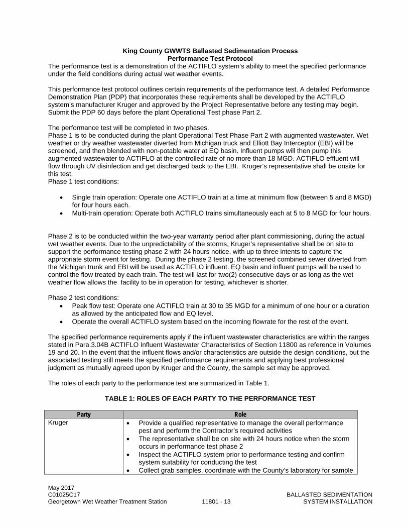
May 2017 C01025C17 BALLASTED SEDIMENTATION Georgetown Wet Weather Treatment Station 11801 - 13 SYSTEM INSTALLATION
King County GWWTS Ballasted Sedimentation Process Performance Test Protocol
The performance test is a demonstration of the ACTIFLO system’s ability to meet the specified performance under the field conditions during actual wet weather events. This performance test protocol outlines certain requirements of the performance test. A detailed Performance Demonstration Plan (PDP) that incorporates these requirements shall be developed by the ACTIFLO system’s manufacturer Kruger and approved by the Project Representative before any testing may begin. Submit the PDP 60 days before the plant Operational Test phase Part 2. The performance test will be completed in two phases. Phase 1 is to be conducted during the plant Operational Test Phase Part 2 with augmented wastewater. Wet weather or dry weather wastewater diverted from Michigan truck and Elliott Bay Interceptor (EBI) will be screened, and then blended with non-potable water at EQ basin. Influent pumps will then pump this augmented wastewater to ACTIFLO at the controlled rate of no more than 18 MGD. ACTIFLO effluent will flow through UV disinfection and get discharged back to the EBI. Kruger’s representative shall be onsite for this test. Phase 1 test conditions:
• Single train operation: Operate one ACTIFLO train at a time at minimum flow (between 5 and 8 MGD) for four hours each.
• Multi-train operation: Operate both ACTIFLO trains simultaneously each at 5 to 8 MGD for four hours. Phase 2 is to be conducted within the two-year warranty period after plant commissioning, during the actual wet weather events. Due to the unpredictability of the storms, Kruger’s representative shall be on site to support the performance testing phase 2 with 24 hours notice, with up to three intents to capture the appropriate storm event for testing. During the phase 2 testing, the screened combined sewer diverted from the Michigan trunk and EBI will be used as ACTIFLO influent. EQ basin and influent pumps will be used to control the flow treated by each train. The test will last for two(2) consecutive days or as long as the wet weather flow allows the facility to be in operation for testing, whichever is shorter. Phase 2 test conditions:
• Peak flow test: Operate one ACTIFLO train at 30 to 35 MGD for a minimum of one hour or a duration as allowed by the anticipated flow and EQ level.
• Operate the overall ACTIFLO system based on the incoming flowrate for the rest of the event. The specified performance requirements apply if the influent wastewater characteristics are within the ranges stated in Para.3.04B ACTIFLO Influent Wastewater Characteristics of Section 11800 as reference in Volumes 19 and 20. In the event that the influent flows and/or characteristics are outside the design conditions, but the associated testing still meets the specified performance requirements and applying best professional judgment as mutually agreed upon by Kruger and the County, the sample set may be approved. The roles of each party to the performance test are summarized in Table 1.
TABLE 1: ROLES OF EACH PARTY TO THE PERFORMANCE TEST
Party Role Kruger • Provide a qualified representative to manage the overall performance
pest and perform the Contractor’s required activities • The representative shall be on site with 24 hours notice when the storm
occurs in performance test phase 2 • Inspect the ACTIFLO system prior to performance testing and confirm
system suitability for conducting the test • Collect grab samples, coordinate with the County’s laboratory for sample
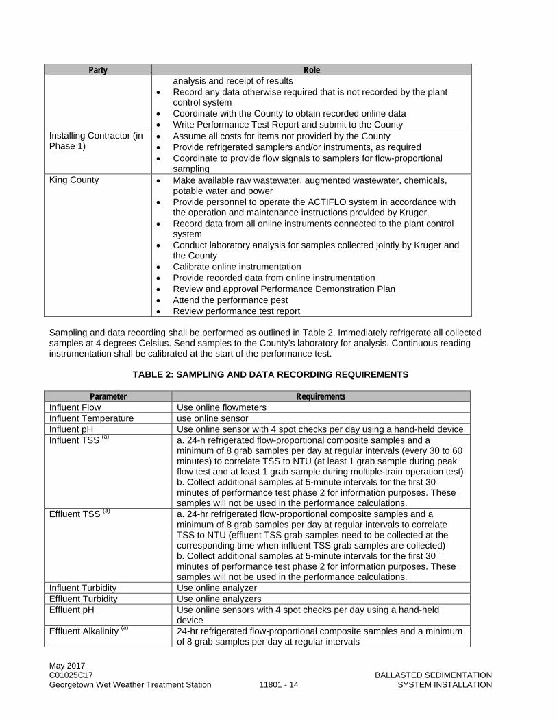
May 2017 C01025C17 BALLASTED SEDIMENTATION Georgetown Wet Weather Treatment Station 11801 - 14 SYSTEM INSTALLATION
Party Role analysis and receipt of results
• Record any data otherwise required that is not recorded by the plant control system
• Coordinate with the County to obtain recorded online data • Write Performance Test Report and submit to the County
Installing Contractor (in Phase 1)
• Assume all costs for items not provided by the County • Provide refrigerated samplers and/or instruments, as required • Coordinate to provide flow signals to samplers for flow-proportional
sampling King County • Make available raw wastewater, augmented wastewater, chemicals,
potable water and power • Provide personnel to operate the ACTIFLO system in accordance with
the operation and maintenance instructions provided by Kruger. • Record data from all online instruments connected to the plant control
system • Conduct laboratory analysis for samples collected jointly by Kruger and
the County • Calibrate online instrumentation • Provide recorded data from online instrumentation • Review and approval Performance Demonstration Plan • Attend the performance pest • Review performance test report
Sampling and data recording shall be performed as outlined in Table 2. Immediately refrigerate all collected samples at 4 degrees Celsius. Send samples to the County’s laboratory for analysis. Continuous reading instrumentation shall be calibrated at the start of the performance test.
TABLE 2: SAMPLING AND DATA RECORDING REQUIREMENTS
Parameter Requirements Influent Flow Use online flowmeters Influent Temperature use online sensor Influent pH Use online sensor with 4 spot checks per day using a hand-held device Influent TSS (a) a. 24-h refrigerated flow-proportional composite samples and a
minimum of 8 grab samples per day at regular intervals (every 30 to 60 minutes) to correlate TSS to NTU (at least 1 grab sample during peak flow test and at least 1 grab sample during multiple-train operation test) b. Collect additional samples at 5-minute intervals for the first 30 minutes of performance test phase 2 for information purposes. These samples will not be used in the performance calculations.
Effluent TSS (a) a. 24-hr refrigerated flow-proportional composite samples and a minimum of 8 grab samples per day at regular intervals to correlate TSS to NTU (effluent TSS grab samples need to be collected at the corresponding time when influent TSS grab samples are collected) b. Collect additional samples at 5-minute intervals for the first 30 minutes of performance test phase 2 for information purposes. These samples will not be used in the performance calculations.
Influent Turbidity Use online analyzer Effluent Turbidity Use online analyzers Effluent pH Use online sensors with 4 spot checks per day using a hand-held
device Effluent Alkalinity (a) 24-hr refrigerated flow-proportional composite samples and a minimum
of 8 grab samples per day at regular intervals

May 2017 C01025C17 BALLASTED SEDIMENTATION Georgetown Wet Weather Treatment Station 11801 - 15 SYSTEM INSTALLATION
Parameter Requirements Ballast Loss methodology to be provided by Kruger for determining quantity of
ballast lost to waste solids and ACTIFLO effluent Coagulant Usage Totalization of online coagulant flowmeter and coagulant concentration Polymer Usage Totalization of polymer flow (based on pump speed and calibration
curve) and active polymer concentration Caustic Usage Totalization of online caustic flowmeter and caustic concentration (a) Analyses to be performed according to latest edition of Standard Methods in triplicate. Results Analysis: TSS removal: Tabulate the influent and effluent grab and composite sample TSS concentrations, along with the sampling time and test condition. See example in Table 3. Use standard deviation statistical data analysis to appropriately disregard any erroneous results (outliers). The rejection of any data as outliers will be through mutual agreement between Kruger and the County. For each performance test phase, calculate the average influent and average effluent TSS concentrations based on all the grab and composite sample results over the duration of the test phase. Then calculate the average TSS removal efficiency based on the average influent and effluent TSS concentrations, using the follow formula.
(Average Influent TSS Concentration) – (Average Effluent TSS Concentration) (Average Influent TSS Concentration)
TABLE 3: TSS TEST SUMMARY TABLE
Sample No. Sampling Time Test Condition Influent TSS (mg/L)
Effluent TSS (mg/L)
TSS Removal Efficiency (%)
1 2 3 4 5 6 7 8 Composite 1 Composite 2
Compliance with the specified TSS removal performance will be based upon:
Influent TSS Effluent TSS < 150 mg/L < 20 mg/L
150 – 200 mg/L < 25 mg/L 200 – 300 mg/L < 30 mg/L
> 300 mg/L 85% removal After completion of the performance test, obtain any required online recorded data from the Project Representative. Analyze and consolidate the test data and results in a written report including the following information as a minimum:
• Project Name • Dates of testing • Names, affiliations and roles of all personnel involved • Summary of Performance Test procedures and test conditions • Summarized test data and analytical results • Discussion of results calculations, and comparison to specified performance and guarantee values

May 2017 C01025C17 BALLASTED SEDIMENTATION Georgetown Wet Weather Treatment Station 11801 - 16 SYSTEM INSTALLATION
• Appendix of the Performance Demonstration Plan • Appendix of detailed data and supporting calculations • Electronic copy of data in Microsoft Excel format • Signature page for Contractor and Project Representative
END OF SECTION

DIVISION 12 FURNISHINGS

This page intentionally left blank.
May 2017 C01025C17 Georgetown Wet Weather Treatment Station 12241 - 1 ROLLER WINDOW SHADES
SECTION 12241
ROLLER WINDOW SHADES
PART 1 GENERAL
1.01 SUMMARY
A. This Section specifies manually operated sunscreen roller shades.
1.02 QUALITY ASSURANCE
A. Installer Qualifications: Installer trained and certified by the manufacturer with a minimum of 5 years’ experience in installing products comparable to those specified in this Section.
B. Mock-Up: 1. Provide mock-ups in accordance with this Section. 2. Provide a mock-up (manual shades only) of one roller shade assembly for evaluation of
mounting, appearance and accessories. 3. Approved mock-up may be used in the Work.
1.03 SUBMITTALS
A. Procedures: Section 01300.
B. Product literature.
C. Shop Drawings: 1. Indicate roller shade sizes and mounting details. Indicate relationship to adjacent construction. 2. Show wiring diagrams including integration of motor controllers with building management
system, audiovisual and lighting control systems as applicable.
D. Window Treatment Schedule: For roller shades. Use same room designations as indicated on the Drawings and include opening sizes and key to typical mounting details.
E. Samples: Submit fabric samples for selection.
1.04 SYSTEM DESCRIPTION
A. Manual control roller shades.
PART 2 PRODUCTS
2.01 ROLLER WINDOW SHADES (RS-51)
A. Acceptable Manufacturers: 1. MechoShade Systems, Inc. 2. Lutron. 3. Hunter Douglas Contract. 4. Approved Equal.
B. Shading Fabric: Printable shade fabric as selected by the Project Representative from the manufacturer's complete line; PVC free.
May 2017 C01025C17 Georgetown Wet Weather Treatment Station 12241 - 2 ROLLER WINDOW SHADES
C. Fascia Panel: Extruded aluminum panel with enamel finish, color as selected by the Project Representative from the manufacturer's standard line; snap-on mounting to roller-shade mounting brackets.
D. Controls: Manufacturer’s manual chain controls.
2.02 FABRICATION
A. Fabricate units to fit the openings indicated, from head to sill, and from jamb to jamb.
B. Fabricate elements to integrate with adjacent construction.
PART 3 EXECUTION
3.01 EXAMINATION
A. Prior to starting Work, carefully inspect installed work of other trades and verify that such work is complete to the point where work of this Section may properly commence. Notify the Project Representative, in writing of conditions detrimental to the proper and timely completion of the Work.
B. Do not begin installation until unsatisfactory conditions are resolved. Beginning Work constitutes acceptance of conditions as satisfactory.
3.02 INSTALLATION
A. Install in accordance with manufacturer's instructions.
B. Install shades level, square, true, and with uniform and equal perimeter spacing, free of folds. Install for smooth operation.
C. Provide support framing and brackets as necessary to support roller shades.
END OF SECTION
May 2017 C01025C17 Georgetown Wet Weather Treatment Station 12350 - 1 METAL CASEWORK
SECTION 12350
METAL CASEWORK
PART 1 GENERAL
1.01 SUMMARY
A. This Section specifies manufactured painted steel panel base, wall cabinets, and casework hardware.
1.02 QUALITY ASSURANCE
A. Reference Standards: This Section incorporates by reference the latest revision of the following documents. These references are a part of this Section as specified and modified. In case of conflict between the requirements of this Section and those of the listed documents, the requirements of this Section shall prevail. Reference Title ASTM A653 Specification for Steel Sheet, Zinc-coated (Galvanized) or Zinc-Iron Alloy-Coated
(Galvannealed) by Hot-Dip Process ASTM A666 Standard Specification for Annealed or Cold-Worked Austenitic Stainless Steel
Sheet, Strip, Plate, and Flat Bar ASTM A1008 Standard Specification for Steel, Sheet, Cold-Rolled, Carbon, Structural, High-
Strength Low-Alloy, High-Strength Low-Alloy with Improved Formability, Solution Hardened, and Bake-Hardenable
B. Qualifications: 1. Casework Manufacturer: Regularly engaged in the manufacture of metal casework of the type
specified.
1.03 SUBMITTALS
A. Procedures: Section 01300.
B. Submittals: 1. Product Data: Submit complete product data for metal casework system proposed. Include
proposed door and drawer pulls, hinges, and lock systems 2. Shop drawings:
a. Show component dimensions and configurations, construction details, joint details, and attachments, utility and service requirements and locations, and shape and type of materials used. Indicate proposed finishes.
b. Indicate casework locations, large scale plans, elevations, cross sections, rough-in and anchor placement dimensions and tolerances, clearances required, and relationship to adjoining surfaces including countertops.
c. Manufacturer’s installation instructions: indicate special installation requirements. 3. Samples:
a. Color Samples: 1) Submit samples of manufacturer’s available range of metal paint colors for selection. 2) Submit sample of casework concealed interior finish options.
b. Casework Sample: Submit a complete custom metal base cabinet sample at reduced size. Cabinet shall be approximately 12 inches wide and 24 inches high by minimum 16 inches deep. Include one drawer assembly and one cabinet door. Include one adjustable shelf. Show base construction and leveling provisions. Show a finished end panel.

May 2017 C01025C17 Georgetown Wet Weather Treatment Station 12350 - 2 METAL CASEWORK
C. Informational Submittals: 1. Manufacturer’s Certificate: Certify that Products meet or exceed specified requirements. 2. List of no less than twenty installations done with product constructed in accordance with the
specified requirements. 3. Test reports showing performance of powder coat finish over steel.
1.04 CASEWORK DESIGN REQUIREMENTS
A. Design Requirements: 1. Flush Overlay Design: Faces of doors and drawers shall overlay the cabinet ends, top or bottom
rails. Horizontal and vertical case shell members (panels, top rails and bottoms) shall be concealed behind drawer and door fronts. Reveals shall be uniform 1/8 inch between drawer and door fronts.
2. Interior of case units: Flush interior. 3. Self-Supporting Units: Completely welded shell assembly without applied panels at ends, backs
or bottoms, so that cases can be used interchangeably or as a single, stand-alone unit. 4. Construction shall allow all cabinet parts to be replaced and allow inter-case reconfiguration of
doors and drawers using hand tools.
B. Structural Performance Requirements: Casework components shall withstand the following maximum static loads, without permanent deformation to the component or to the casework operation, when properly leveled, supported and the load evenly distributed: 1. Steel base units: 500 lbs. per lineal ft. 2. Suspended units: 300 lbs. 3. Drawers in a Cabinet:
a. 12 inch wide or less: Minimum 65lb load rating. b. 32 inch wide or less: Minimum 100lb load rating. c. 42 inch wide or less: Minimum 200lb load rating.
4. Hanging wall cases: 300 lbs. 5. Shelves (base, wall, tall units 40lbs/sq.ft., up to 200 lbs per shelf.
1.05 DELIVERY, STORAGE, AND HANDLING
A. Deliver casework assemblies in manufacturer's unopened packages or bundles with labels intact.
B. Store materials in a dry, well-ventilated, weathertight place. Comply with manufacturer's written instructions for storage, handling, and protection to meet warranty requirements.
1.06 WARRANTY
A. Include approved manufacturer’s standard warranty.
PART 2 PRODUCTS
2.01 CUSTOM METAL CASEWORK
A. Basis of Design: Metal laboratory grade casework systems and components specified are based on the products of Mott/Advanced Lab Concepts Corporation. Similar and equal systems by the following other manufacturers may be used subject to the specified requirements. 1. Jamestown Metal Products. 2. Kewaunee Scientific Corporation. 3. Peterson Corporation. 4. Bedcolab. 5. Goelst USA, LLC. 6. Approved Equal.
May 2017 C01025C17 Georgetown Wet Weather Treatment Station 12350 - 3 METAL CASEWORK
2.02 MATERIALS
A. Stainless Steel: Type 304 or 316 stainless steel, #4 finish one side, ASTM A 666.
B. Cold-Rolled Steel Sheet: ASTM A1008, Commercial Steel (CS), Type B; suitable for exposed applications.
C. Metallic-Coated Steel Sheet: ASTM A653, Commercial Steel (CS), Type B; with minimum A60 (ZF180) metallic coating.
2.03 COMPONENTS
A. Hardware: 1. Drawer and Door Pulls: 5/16 inch stainless steel wire style; 4 inch wide; brushed finish. Provide
two pulls on all drawers over 24 inch wide. 2. Hinges: Brushed stainless steel type; 5-knuckle; frictionless; not less than 3 inch long with fast
pin and rounded ends. Concealed European style hinges are not be acceptable. 3. Locks:
a. Removable core 5-disc tumbler, heavy-duty cylinder type. b. Exposed lock surfaces shall have brushed chrome finish and stamped with identifying
numbers. c. Key and master key in accordance with the Project Representative’s direction. d. Lab spaces: Each cabinet with a lock shall be uniquely keyed and master keyed by
laboratory unit. (Multiple locking drawers and doors within a single cabinet shall be keyed alike.)
4. Door Catches: Adjustable nylon roller type, with strike. 5. Cabinet Shelf Clips: Die formed steel, zinc plated, designed to provide shelf support and
adjustment in ½ inch increments. 6. Drawer Slides:
a. Removable full extension, self-closing Accuride (or equivalent) slide; hold open detent. b. Load capacities as follows:
1) 12 inch wide or less: Minimum 65 lb/pair load rating. 2) 32 inch wide or less: Minimum 100 lb/pair load rating and progressive movement. 3) 42 inch wide or less: Minimum 200 lb/pair load rating.
c. Metal Finish: Clear zinc finish. d. Permanently lubricated nylon rollers. e. Parallel self-closing action within 2-5/8 inch. f. Built-in stops protecting the drawer head from impact on closing. g. Double-stop to prevent the drawer from falling when extended and allowing the drawer to be
locked in the open position. 7. Shelf Clips: Die formed steel, zinc plated, designed to provide shelf support and adjustment in ½
inch increments. 8. Wall Cabinet Mounting Bracket and Attachment Rails:
a. Provide concealed galvanized steel wall mounting bracket and rail allowing vertical and front-to-back adjustment of the wall mounted unit.
b. Provide access to adjustment screws through holes in back panel. Cover hole with black plastic cover cap.
c. Filler Strip: Compressible Filler Strip used to obscure wall hanging brackets and rail from side view. Strips up to 3050 mm long with adhesive backer.
9. Adjustable Leveler: Adjustable leveler with free spinning base with minimum load capacity of 330 pounds per leveler. Provide minimum of four levelers per cabinet. Leveler shall adjust using an allen wrench. Levelers accessible through hole in bottom of cabinet. Provide black plastic caps for each leveler hole.
10. Fasteners and Anchors: Types, sizes, material and finish as recommended by the approved manufacturer for the application.
May 2017 C01025C17 Georgetown Wet Weather Treatment Station 12350 - 4 METAL CASEWORK
11. Provide miscellaneous other hardware in manufacturer’s standard finish as selected by the Project Representative.
2.04 FABRICATION
A. Metal casework shall be fabricated from 18 gauge cold rolled steel sheet, except as follows: 1. 12 GA – Bottom corner gussets. 2. 14 GA – Hinge reinforcements, suspension channels. 3. 20 GA – Inner door panels, filler stiles, fixed back panels, drawer bodies. 4. 22 GA – Removable back panels.
B. Provide rigid, self-adhesive sound deadening foam in all door and drawer fronts, end panels, and optional finished back panels.
C. Base and Tall Cabinets (standard 22-7/8 inch nominal depth): 1. Minimum height, including base and corner gussets; leveler fully retracted:
a. Base Standing: 35.500 inches. b. Base Sitting: 27.892 inches. c. Base ADA: 31.696 inches. d. Tall: 83.750 inches.
2. One-piece formed end panels and back with internal reinforcing front posts and hinge reinforcement.
3. Front posts shall be fully closed with full height reinforcing upright. Base cabinets, 30" and wider, with double swinging doors shall have full access to complete interior without center vertical post.
4. Shelf adjustment holes in front and rear posts shall be perfectly aligned for level setting, adjustable to 1/2 inch increments.
5. Base cabinet drawer units may be provided without backs or bottoms. 6. Sink units shall be provided with removable backs for service access. 7. Tall cabinet units shall be provided with full formed backs, recessed 1/8 inch for mounting
purposes. 8. One-piece bottom with formed front edge spot welded to front rail. 9. Provide top rail which is interlocked and welded to end panels; flush with front of unit.
D. Wall Cabinet Construction: 1. One piece formed end panels and back with internal reinforcing front posts and hinge
reinforcement. 2. Front post fully closed with full height reinforcing upright. 3. Shelf adjustment holes in front and rear posts shall be perfectly aligned for level setting,
adjustable to ½ inch increments. 4. One-piece formed back, recessed ¾ inch for mounting purposes. 5. One-piece top with front edge formed into front rail. 6. One-piece bottom with front edge formed into front rail. 7. All exposed seams on joints will be welded, ground and polished to an equivalent mill finish.
E. Support Bases: 1. Formed sheet steel base to provide minimum 3.750 inches high by 3.875 inches deep toe-kick
space. 2. Provide reinforcing gussets at each corner to support adjustable levelers which are adjustable
from the interior of the cabinet. 3. Form bases from channel shaped rails. Notch and pierce side rails to interconnect with the
front/rear rails to provide a stable cabinet base.
F. Adjustable Shelves: 1. Adjustable shelves shall be fabricated from minimum 18 gauge steel sheet. 2. Shelves shall be die formed with front and back edges formed down and back 1 inch; ends
formed down 3/4 inch.

May 2017 C01025C17 Georgetown Wet Weather Treatment Station 12350 - 5 METAL CASEWORK
3. Shelves over 36 inches long and 16 inches deep include hat channel reinforcement, full length of the shelf.
4. Pull out shelves: Same suspension as specified for drawers. 5. Shelves to be adjustable on 32mm centers.
G. Provide intermediate rails between doors and drawers. Intermediate rails shall be flush with the face of the carcass and designed to allow the use of drawer security panels as required.
H. Drawer Assemblies: 1. Steel Drawer Fronts: 3/4 inch thick, double wall construction; painted before assembly and sound
deadened; top front corners fitted smooth. 2. Modularly sized for interchangeability. Designed to be easily removable in the field without use of
special tools. 3. Drawer bodies:
a. 20 GA mild steel, 1-pc construction, bottom and sides coved and top edges formed. No sharp edges. Painted manufacturer’s standard neutral grey color.
b. Configured to receive drawer slides. 4. Provide drawer with rubber bumpers. Friction centering devices are not acceptable. 5. Provide security panels for drawers with keyed different locks (as required).
I. Door Assemblies: 1. 3/4 inch thick interlocking double steel pan construction with sound deadened interior. Pans shall
be screw fastened together. Reinforce interior of front panel with welded steel hat channels. 2. Provide internal 14 gauge reinforcement in case and door to receive hinges. Hinges shall be
removable with screw fasteners; welding of hinges not acceptable. 3. Doors shall close against rubber bumpers. 4. All door assemblies shall have smooth corners and edges.
J. Backsplash at Kitchen: Fabricate from 16 GA stainless steel. Secure with adhesive and oval head stainless steel screws with stainless steel cup washers.
K. Fabricate casework to ensure durable and rigid units and to permit plumb and level site installation with tight joints between sections.
L. Fabricate units to receive countertops specified in other Sections.
2.05 STAINLESS STEEL FINISHES
A. Provide #4 brushed finish to exposed stainless steel surfaces.
2.06 FINISHING OF FABRICATED STEEL ELEMENTS WITH BAKED-ON POWDER COATED FINISH
A. Powder Coat Finish: 1. Hybrid epoxy-polyester; approximate gloss of 60 degrees; VOC free compounds. 2. Mil Thickness:
a. Exterior and interior surfaces exposed to view: 1.8 – 3 mils. b. Backs of cabinets and other surfaces not exposed to view: 1.8 mils minimum.
3. Color: Grey color as selected from manufacturer’s complete line.
B. Shop apply powder coat paint system after metal components and parts have been completely formed. All components shall be individually painted to ensure that no area is vulnerable to corrosion due to lack of paint coverage.
May 2017 C01025C17 Georgetown Wet Weather Treatment Station 12350 - 6 METAL CASEWORK
C. Powder Coat Application: 1. Pre-treatment: Wash surfaces with an alkaline cleaner followed by a spray applied phosphate
solution to form a uniform phosphate surface to promote paint adhesion and prevent corrosion. 2. Dry pretreated surfaces, and coat with a chemical and corrosion resistant, electrostatically
applied powder coat finish. 3. Cure powder coat by baking at elevated temperatures to provide maximum properties of
corrosion and wear resistance.
D. Metal Finish Performance Requirements: Powder coat finish on metal casework components shall have been tested in accordance with the full requirements of SEFA 8 M-2007 Recommended Practice and shall have met minimum performance requirements. 1. Chemical Spot Test – Section 10.1; Zero level 3 conditions exist, and sum of all ratings is ten or
less. 2. Hot Water Test – Section 10.2; Finish shall show no visible effect due to the hot water. 3. Finish Impact Test – Section 10.3; no visual evidence of any cracks or checks due to impact. 4. Paint Adhesion on Steel – Section 10.4; A 4B rating or better; Ninety-five percent or more of the
grid area shall show finish intact. 5. Paint Hardness on Steel – Section 10.5; The paint finish shall withstand the abrasion of a 4H
pencil without penetrating through to the substrate and completing a continuous circuit.
PART 3 EXECUTION
3.01 EXAMINATION
A. Prior to starting Work, carefully inspect installed work of other trades and verify that such work is complete to the point where work of this Section may properly commence. Notify the Project Representative in writing of conditions detrimental to the proper and timely completion of the Work.
B. Verify that required utilities are available. In proper locations, and ready for use.
C. Do not begin installation until all unsatisfactory conditions are resolved. Beginning Work constitutes acceptance of conditions as satisfactory.
3.02 PREPARATION
A. Coordinate the installation of blocking and other supports required for the installation of custom metal casework elements.
3.03 INSTALLATION
A. Install casework, components and accessories as indicated and in accordance with manufacturer’s instructions.
B. Fasteners securing casework shall be in concealed or semi-concealed locations, unless approved otherwise.
C. Set casework items plumb and square, securely anchored to building structure.
D. Bolt continuous cabinets together with joints flush, tight and uniform, and with alignment of adjacent units within 1/16 inch tolerance.
E. Install casework attachment rails on wall along entire length of wall to facilitate installation of wall cabinets. Hang wall mounted casework on attachment rails. Level and adjust wall casework using adjustment capabilities of wall unit mounting brackets.
May 2017 C01025C17 Georgetown Wet Weather Treatment Station 12350 - 7 METAL CASEWORK
F. Scribe to abutting surfaces and align adjoining components. Apply matching filler pieces where casework abuts dissimilar construction.
G. Repair small scratches and surface blemishes on units using manufacturers supplied touch up materials or replace parts or unit as required.
H. Install casework to accommodate countertops specified elsewhere.
3.04 ADJUSTING
A. Adjust doors, drawers, hardware, fixtures, and other moving or operating parts to function smoothly.
3.05 CLEANING
A. Remove dirt with damp cloth, soap and water. Remove stubborn dirt with zero VOC cleaner as recommended by the manufacturer for the application. Do not use harsh abrasive or toxic cleaners.
3.06 PROTECTION OF FINISHED WORK
A. Do not permit finished casework to be exposed to continued construction activity.
B. Protect finished casework from damage by water, heat and other causes until final acceptance.
C. Replace casework exhibiting surface discoloration, and damage at no additional cost to the County.
END OF SECTION

May 2017 C01025C17 Georgetown Wet Weather Treatment Station 12350 - 8 METAL CASEWORK
This page intentionally left blank.

DIVISION 13 SPECIAL CONSTRUCTION

This page intentionally left blank.

May 2017 C01025C17 Georgetown Wet Weather Treatment Station 13100 - 1 ARTIST COORDINATION
SECTION 13100
ARTIST COORDINATION
PART 1 GENERAL
1.01 SUMMARY
A. This Section specifies requirements for coordinating the installation of artwork within the Building 900 stairwell and south east corner of site. The installed locations of the artwork are indicated in the Drawings.
B. 4Culture has hired an Artist in compliance with its 1% for Art legislation. Artwork is being integrated into this project and consists of a public art piece as indicated in the Drawings. Artist design of the above ground piping, conduit, equipment, and panels is in progress but not complete. Drawings show the current state of design. Contractor shall coordinate final location of below ground piping and conduit with Artist prior to installation.
C. 4Culture has a separate contract with the Artist to fabricate, transport and install the artwork.
1.02 QUALITY ASSURANCE (NOT USED)
1.03 SUBMITTALS
A. Procedures: Section 01300.
B. Schedule for installation and coordination points for all on-site work activities related to the artwork tied to the Contractor’s accepted current schedule.
1.04 DEFINITIONS
A. Artist: Charles Blanc and Tristan Surtees, Sans Facon, and Artist Subcontractors. The Artist is under contract with 4Culture and, through coordination with the Project Representative, will be responsible to provide information and carry out the design, supervise Artist subcontractors, and to inspect the fabrication and installation of the artwork.
B. Artwork: Rain Monument, including the paver support assembly, as shown on Drawings.
C. 4Culture: Entity in charge for Owner on managing the Artist’s work to comply with King County’s Art Legislation.
1.05 SHIPMENT, DELIVERY, AND STORAGE
A. Shipment of the artwork will be provided by Artist.
B. Artwork delivery is predicated upon immediate installation after delivery with no interim storage. Should approved schedule not be met by the Contractor, Contractor shall provide additional storage and delivery activities for Artist’s materials and equipment at no additional cost.
C. When the artwork or any subcomponent thereof is stored onsite, such storage shall be in accordance with Project Representative’s recommendations.

May 2017 C01025C17 Georgetown Wet Weather Treatment Station 13100 - 2 ARTIST COORDINATION
1.06 SCHEDULE
A. Contractor will be responsible for: 1. Indicating artwork foundation installation in Draft Project Schedule. 2. Establishing required date for final Artist artwork piping and electrical design for coordination with
below ground piping and conduit locations prior to installation. Date shall not be more than 120 days prior to artwork foundation installation.
3. Establishing 30 day artwork installation time period for installation of artwork and associated equipment in construction schedule.
1.07 COUNTY RESPONSIBILITY
A. Scheduling and coordination with the Artist and 4Culture.
B. Provide the Contractor a minimum of 14 days-notice prior to installation of all artwork elements.
C. Facilitate two (2) coordination meetings with Artist and Contractor prior to installation of artwork. The first meeting shall occur after final Artist artwork piping and electrical design has been completed. The second meeting shall occur prior to installation of the acrylic tube. Agenda shall include artwork schedule, staging and foundation cure time required prior to installation.
1.08 ARTIST RESPONSIBILITY
A. Furnish and install the artwork as shown on the Drawings.
B. Identify 1 day within the 30 day artwork installation time period for cell-cast acrylic (PMMA) tube (“acrylic tube”) installation. Date shall not be less than 14 days after artwork foundation has been installed. Provide notification of this date a minimum of 120 days prior to artwork foundation installation.
C. The Project Representative and Artist shall jointly inspect the condition of each piece of artwork and equipment prior to acceptance upon delivery.
D. Inspect embedded items prior to contractor pouring concrete for foundation.
E. Witness and observe testing of utility services at the artwork.
F. Provide necessary equipment for installation of the artwork including but not limited to crane and rigging.
PART 2 PRODUCTS (NOT USED)
PART 3 EXECUTION
3.01 GENERAL
A. Contractor communication with the Artist shall be through the Project Representative.
B. Allow Artist use of Contractor’s sanitary facilities.
C. Provide access, laydown/storage and staging areas at the Building 900 stairwell and south east corner of site for the Artist to install the artwork including but not limited to on-site crane staging area during acrylic tube installation.

May 2017 C01025C17 Georgetown Wet Weather Treatment Station 13100 - 3 ARTIST COORDINATION
D. Provide advance written notice to the Project Representative, 30 days before acrylic tube foundation is poured.
E. Contractor shall coordinate final location, alignment, and elevation of the paver support assembly inside the water monument with Artist prior to embedding the support assembly in concrete.
F. Provide surveyed locations of all utility connections for the acrylic tube, the art equipment in the Building 900 stairwell, and pipe penetration sleeve for water supply to artwork.
G. Provide pigtail in the Building 900 stairwell for power connection for the artwork.
H. Install grouting around base of acrylic tube.
I. Install the Artist supplied paver support assembly within the acrylic tube.
J. Provide 16 hours of general support during artwork installation and commissioning.
K. Protect artwork from damage from construction activities after installation is complete.
END OF SECTION

May 2017 C01025C17 Georgetown Wet Weather Treatment Station 13100 - 4 ARTIST COORDINATION
This page intentionally left blank.
May 2017 C01025C17 Georgetown Wet Weather Treatment Station 13101 - 1 COMMUNITY EVENT SUPPORT
SECTION 13101
COMMUNITY EVENT SUPPORT
PART 1 GENERAL
1.01 SUMMARY
A. This Section specifies requirements for coordinating the community events that will be run by the County.
B. The County will schedule up to four (4) separate community events that will occur over a single two day weekend to allow community members to view the project site, specifically the equalization basin, prior to completion of construction.
C. Contractor will be responsible for providing access to the site, and facilities to host the venue with protection of the public in mind.
1.02 QUALITY ASSURANCE (NOT USED)
1.03 SUBMITTALS
A. Procedures: Section 01300.
B. Schedule that identifies the installation of the equalization basin tremie slab with a 2 week window for the community events called out for the County to select dates.
C. Site plan drawing showing public access corridors and temporary guardrail plan around the top edge of the equalization basin.
D. Health and Safety Plan to accommodate general access on-site for the general public during the community event.
1.04 COUNTY RESPONSIBILITY
A. Final selection of community event date(s).
B. Coordination of public viewing space location and walkways.
C. Coordination on the final power requirements for lighting, sound amplification, temporary power, and filming.
D. Provide the staff required for support and security for the event in coordination with the Contractor.
E. Obtain temporary noise variance for the community event.
F. Deliveries of event materials will be coordinated with the Contractor and will to the greatest extent possible be limited to non-construction hours.
May 2017 C01025C17 Georgetown Wet Weather Treatment Station 13101 - 2 COMMUNITY EVENT SUPPORT
PART 2 PRODUCTS (NOT USED)
PART 3 EXECUTION
3.01 GENERAL
A. Coordinate with Project Representative.
B. Provide temporary guardrail.
C. Provide public viewing surface and walkway.
D. Provide scaffolding staircase from ground surface to bottom of equalization basin.
E. General support shall be paid on a time and materials basis and may include the following: 1. Lighting, sound amplification, temporary power, and filming. 2. Provide bulk movement of materials and equipment including but not limited to hoisting, rigging
and lifting of community event supplies into and out of the equalization basin.
3.02 COMMUNITY RELATIONS EVENT
A. Coordinate with Project Representative to accommodate community relations event during non-work hours. Preparation time prior to event will be required during work hours. Coordinate with Project Representative.
B. The event, at each performance, will be accessible to limited members of the public (not more than 200) who will observe from the top edge of the equalization basin and remain behind protective guardrail while viewing a performance that will occur at the bottom of the basin.
C. Event Minimum Safety Requirements: 1. Install temporary guardrail around the top edge of the equalization basin that is 42 inches high
and will provide a secure barrier from which the public can view the event in the basin. This fencing must be approved by the Project Representative not less than 12 hours prior to the event.
2. Provide scaffolding staircase from ground surface to bottom of equalization basin. 3. Provide ¾ inch Minus Crushed Gravel, Mineral Aggregate Type 1G (Top Course) over erosion
sediment control materials as a walking surface for the general public. Walking surface to be 3 inches in depth over 10,000 square feet in an area designated by the Project Representative.
4. Delineate the walkway from a defined site entrance to the basin viewing area to assure that the public does not access other areas of the construction site outside of the basin viewing area.
D. Event Parking: 1. No onsite parking required for general public during community events.
END OF SECTION

May 2017 C01025C17 Georgetown Wet Weather Treatment Station 13110 - 1 CATHODIC PROTECTION SYSTEM
SECTION 13110
CATHODIC PROTECTION SYSTEM
PART 1 GENERAL
1.01 SUMMARY
A. This Section specifies a galvanic anode cathodic protection and corrosion monitoring system for buried metal pipe. The system consists of magnesium anodes, test stations, reference cells, joint bonds, electrical insulators, and all associated wiring and hardware as required for a complete and operable system.
B. The Drawings are diagrammatic and do not necessarily show all fittings, wiring or wiring devices required by code. Include in its bid these and related items and the work associated with their installation.
1.02 QUALITY ASSURANCE
A. Referenced Standards: This Section incorporates by reference the latest revision of the following documents. These references are a part of this Section as specified and modified. In case of conflict between the requirements of this Section and those of the listed documents, the requirements of this Section shall prevail. Reference Title ASTM B843 Magnesium Alloy Anodes for Cathodic Protection ASTM G97 Test Method for Laboratory Evaluation of Magnesium Sacrificial Anode Test
Specimens for Underground Applications NEMA WC 70 Nonshielded Power Cables Rated 2000 volts or less for Distribution of
Electrical Energy UL 44 Rubber Insulated Wires and Cables UL 467 Grounding and Bonding Equipment UL 486 Wire Connectors and Soldering Lugs UL 510 Insulating Tape
B. Qualifications: 1. Performed work of this Section with a firm regularly engaged in the design, repair, and
maintenance of cathodic protection systems. Have a traceable, verifiable record of continuous, relevant work and performance for a minimum of three years.
2. All work shall be accomplished by qualified and experienced personnel working under continuous competent supervision.
1.03 SUBMITTALS
A. Procedures: Section 01300.
B. Manufacturer's product data showing conformance to the specifications for anodes, test station, splice materials, wire, wire connectors and coating materials of: 1. Anodes. 2. Reference cells. 3. Stations. 4. Wires. 5. Thermite weld materials. 6. Coating.
May 2017 C01025C17 Georgetown Wet Weather Treatment Station 13110 - 2 CATHODIC PROTECTION SYSTEM
C. Functional testing letter that includes tabulation of joint bond resistance values and structure-to-soil potential measurements.
D. Field test measurements.
PART 2 PRODUCTS
2.01 GENERAL
A. Materials shall be a standard product of a manufacturer regularly engaged in their production.
B. All components of the following materials shall be products of the same manufacturer to ensure compatibility and continuity.
C. No splices shall be permitted in wires other than at locations indicated in the Drawings.
2.02 MATERIALS
A. Prepackaged Anodes.
B. Wire.
C. Insulating Splice Materials.
D. Test Stations.
E. Cable Warning Tape.
F. Reference Cell.
G. Conduit and Fittings.
H. Thermite Welds.
I. Thermite Weld Coating.
2.03 PREPACKAGED ANODES
A. Prepackaged Anodes: 1. Weight: 20 lbs. (19.5 lbs. min.). 2. Cross section: 2 inches by 2 inches, nominal. 3. Minimum length: 60 inches. 4. Steel wire core. 5. 50 percent efficient based on their dielectric consumption rate. 6. Classified as high potential magnesium, Grade MIC, anode alloy per ASTM B843. 7. Alloy: Open circuit potential of 1.70 -1.75 volts with respect to a saturated calomel electrode
based on the test procedure established in ASTM G97. 8. Chemical composition as follows:
a. Aluminum: 0.010 percent maximum. b. Manganese: 0. 5 to 1.3 percent. c. Zinc: 0.004 percent maximum. d. Silicon: 0.05 percent maximum. e. Copper: 0.02 percent maximum. f. Nickel: 0.001 percent maximum. g. Iron: 0.03 percent maximum.
May 2017 C01025C17 Georgetown Wet Weather Treatment Station 13110 - 3 CATHODIC PROTECTION SYSTEM
h. Other Impurities, each: 0.05 percent maximum. i. Other Impurities, total: 0.30 percent maximum. j. Magnesium: Balance Dow Magnesium Galvomag or Approved Equal.
9. Lead wire: Each anode shall have a minimum 15-foot long lead wire of black, Type RHW, No. 12 AWG, solid copper wire connected to one end of the steel wire core by means of silver soldering. The connection shall be insulated by filling the anode's recess area with an electrical potting compound.
10. Bag and Backfill: a. Packaged in a permeable cloth bag containing a backfill mixture composed of:
1) Hydrated Gypsum: 75 percent. 2) Bentonite Clay: 20 percent. 3) Sodium Sulfate: 5 percent.
b. The backfill mixture shall be firmly packaged around the magnesium anode within the cloth bag by means of adequate vibration, with at least two full inches of backfill mixture covering the entire surface of the anode.
c. Each anode shall have a packaged weight of not less than 70 lbs.
2.04 WIRE
A. Test Wires: 1. Type RHW, No. 10 AWG, single conductor, stranded copper. 2. Lead wire colors: as indicated in the Drawings. 3. UL 44. Rome Cable, Spec 2150, or Approved Equal.
B. Joint Bond Wires: 1. Type HMWPE, single conductor, stranded copper. Supply joint bonds complete with formed
copper sleeves on each end of the wire. 2. Push—On, Mechanical, or Flanged Joints: No. 2 AWG wires 18-inches long. 3. Flexible Coupling Joints: No. 2 AWG wires, 24-inches long, with two 12-inch long THHN
insulated No. 12 AWG pigtails, as manufactured by Erico Products (Cleveland, OH), or Approved Equal.
4. Insulated Flexible Coupling Joints: No. 8 AWG wire, 18-inches long, with one 12-inch long THHN insulated No. 12 AWG pigtail wire.
2.05 INSULATING SPLICE MATERIALS
A. Wire-to-Wire Connectors: 1. Copper alloy split bolt connectors of the proper size to accommodate the wires being connected
together. 2. UL 467. Thomas & Betts Co., Type 9H, or Approved Equal.
B. Insulated Splice Materials: 1. Mastic:
a. Soft, tacky, moldable, un-backed elastomeric tape. b. The mastic shall not have a backing tape. c. Royston Laboratories, "Tac-Tape", or Approved Equal.
2. Rubber Tape: a. Self-fusing 25 mil minimum thickness, water resistant, highly conformable rubber tape. b. 3M, "Scotch 23 Tape", or Approved Equal.
3. Vinyl Tape: a. 7 mil vinyl electrical tape that is conformable and adhesive-backed. b. UL 510. 3M, "Scotch 33+ Tape", or Approved Equal.
4. Electrical Coating: a. Moisture proof coating designed for electrical splices. b. 3M, "Scotchkote" (Part No. 14853).

May 2017 C01025C17 Georgetown Wet Weather Treatment Station 13110 - 4 CATHODIC PROTECTION SYSTEM
2.06 TEST STATIONS
A. Test Station Boxes: 1. Concrete box with a cast iron lid labeled either "CP TEST" or "ANODE". 2. Having an internal depth no less than 12 inches and an internal diameter no less than 8 inches. 3. Brooks Products, Series I-RT, or Approved Equal.
B. Test Boards: 1/4-inch thick phenolic panel, NEMA Grade LE for electrical use under wet conditions.
C. Hardware: 1/4-20 UNC brass.
2.07 CABLE WARNING TAPE
A. Polyethylene tape, minimum 6 inches wide, red or yellow in color, and labeled "CAUTION - CATHODIC PROTECTION".
B. Reef Industries, "Terra Tape", or Approved Equal.
2.08 REFERENCE CELL
A. Material: Permanent type, copper-copper sulfate reference electrode suitable for direct burial with a minimum design life of 15 years.
B. Dimensions: 1-1/2-inch diameter by 6 inches long, minimum.
C. Wire: 14 AWG stranded copper wire with yellow, 600-volt RHH-RWH insulation of sufficient length to reach the test station without splicing. Attach wire to electrode and insulate in accordance with manufacturer’s standard connection detail. Connection shall be stronger than the wire.
D. Manufacturers and Products: 1. Borin Manufacturing; Model SRE-007-CUY. 2. Electrochemical Devices, Inc.; Model UR-CUG-CW. 3. GMC Electrical, Inc.; Model CU-1-UGPC. 4. Approved Equal.
2.09 CONDUIT AND FITTINGS
A. 1-1/4-inch schedule 40 PVC.
2.10 THERMITE WELD MATERIALS
A. Thermite welds: Thermite weld materials consist of wire sleeves, welders, and weld cartridges according to weld manufacturer’s recommendations for each wire size and pipe or fitting size and material. Welding materials and equipment shall be product of a single manufacturer. Interchanging materials of different manufacturer’s not acceptable.
B. Molds: Graphite. Ceramic “One-Shot” molds not acceptable.
C. Adapter Sleeves: 1. For No. 12 AWG and No. 2 AWG wires. 2. Prefabricated factory sleeve joint bonds or bond wires with formed sleeves made in the field are
acceptable. Attach field-formed joint bond sleeves with appropriate size and type of hammer die furnished by thermite weld manufacturer.
3. Extend wire conductor ¼-inch beyond end of sleeve.

May 2017 C01025C17 Georgetown Wet Weather Treatment Station 13110 - 5 CATHODIC PROTECTION SYSTEM
D. Use cast iron thermite weld cartridges for cast and ductile iron pipe and fittings.
E. Maximum Cartridge Size: 25 grams for steel and 32 grams for cast and ductile iron pipe materials.
F. Welders and Cartridges: For attaching copper wire to pipe material: Pipe Material Weld Type Cartridge Size, Max.
4 AWG Wire and Smaller Steel HA, VS, HC 25 gm Ductile Iron HB, VH, HE 32 gm Cast Iron HB, VH, HE 32 gm
2 AWG Joint Bonds Steel FS 25 gm Ductile or Cast Iron FC 32 gm
G. Welding Materials Manufacturers: 1. Erico Products Inc (Cadweld), Cleveland, OH. 2. Continental Industries, Inc. (Thermoweld), Tulsa, OK. 3. Approved Equal.
2.11 COATING
A. Thermite Weld Coating: 1. Thermite Weld Caps: Prefabricated weld cap with coating and suitable primer, such as Handy
Cap II with Royston Primer 747, as manufactured by Royston Laboratories, Inc., or Approved Equal.
2. Insulating Resin: 100 percent solids epoxy that can cure in submerged or buried conditions. At Contractor’s option, bitumastic coating (Carboline Bitumastic 50 or Approved Equal) may be used if it is allowed to dry completely before covering.
3. Use products recommended by pipe or fitting coating manufacturer to repair spot damage at thermite weld connections not covered by standard pipeline coating repair procedure or thermite weld cap.
PART 3 EXECUTION
3.01 GENERAL
A. The Drawings are diagrammatic. The exact locations and routing of cables and conduits shall be governed by structural conditions and physical interference. The final placement of the test stations shall be at the locations approved by the Project Representative.
B. All materials, workmanship and installation shall conform with all requirements of the legally constituted authority having jurisdiction. These authorities include: the National Electric Code, General Construction Safety Orders of the Industrial Accident Commission, and all other applicable State, County, or City codes and regulations.
C. Unless otherwise indicated, install all materials in accordance with the manufacturer's recommendations, safety procedures and as shown.
D. Where requirements of this Section conflict with the manufacturer's recommendations, the manufacturer's recommendations shall take precedence.
E. Store all materials and equipment to be used in construction in such a manner as to be protected from detrimental effects from the elements. If actual storage is not available, stack materials and equipment well above ground level and protect from the elements as appropriate.
May 2017 C01025C17 Georgetown Wet Weather Treatment Station 13110 - 6 CATHODIC PROTECTION SYSTEM
3.02 ANODE INSTALLATION
A. Inspection: 1. Inspect the anodes and materials to ensure that damage has not been incurred through shipping
or through mishandling. 2. Handle anodes carefully at all times and do not drop or drag. 3. Do not handle, lift or lower anodes by means of the anode's lead wires. 4. Replace anodes that have been damaged to the extent that the permeable cloth bag has been
torn and backfill material has been lost.
B. Prepackaged Anodes: 1. Remove all wrapping (not the cloth bag) and be place in the hole. 2. Take care to protect the anode lead wires. 3. Install the anodes in a10-foot deep, 7-inch minimum diameter augured hole. Lower the anodes
into the hole with a rope. DO NOT USE THE LEAD WIRE. 4. Maintain the anodes free of oils, chemicals, paint, petroleum products and other foreign
chemicals or coatings. Remove all coatings, wrapping and protective shipping material from the anode prior to installation.
5. Install the magnesium anodes as indicated in the Drawings. Place soil that is free from rocks and debris around the anode. Continue backfilling with native soil to ground surface.
6. Each anode wire shall terminate in the corresponding test station and shall be connected to the appropriate terminal as indicated in the Drawings.
7. Damage to the canvas bag enclosing the anode and backfill material, anode to wire connection, copper wire, or wire insulation will require replacement of the entire assembly.
3.03 PIPE JOINT BONDS
A. Electrically bond joints of buried steel and ductile iron pipe, including vault and manhole piping and fittings, and including restrained joints, except joints specified to be threaded, welded, or insulated.
B. Install two joint bond wire assemblies at each joint that requires bonding for pipe 16-inch diameter and larger. Install one joint bond wire assembly at each joint that requires bonding for pipe less than 16-inch diameter.
C. Use thermite weld process for electrical connection of wires to pipe and fittings.
D. Test each joint bond for continuity as specified herein.
E. Joint bonds are not required for cast iron soil pipe.
3.04 COPPER-COPPER SULFATE REFERENCE CELLS
A. Maintain free of oils, chemicals, paint, petroleum products and other foreign chemicals or coatings. Remove all coatings, wrapping and protective shipping material from the reference cell prior to installation.
B. Install as indicated in the Drawings. Place each cell approximately 4 inches from the pipe.
C. Do not handle or lower by the lead wire. Place soil that is free from rocks and debris around the reference cell. When soil has been placed to the top of the cell, pour water into the hole to saturate the cell and adjacent soil as necessary. Continue backfilling with native soil to ground surface.
D. Each reference cell wire shall terminate in the corresponding test station and shall be connected to the appropriate terminal as indicated in the Drawings.
May 2017 C01025C17 Georgetown Wet Weather Treatment Station 13110 - 7 CATHODIC PROTECTION SYSTEM
E. Damage to the cell, cell to wire connection, copper wire, or wire insulation will require replacement of the entire assembly.
3.05 THERMITE WELDS
A. Thermite Weld: 1. Use thermite weld method for electrical connection of copper wire to steel, ductile, and cast-iron
surfaces. Observe proper safety precautions, welding procedures, thermite weld material selection, and surface preparation recommended by welder manufacturer. Ensure that pipe or fitting wall thickness is of sufficient thickness that thermite weld process will not damage integrity of pipe or fitting wall or protective lining.
2. After weld connection has cooled, remove slag, visually inspect, and physically test wire connection by tapping with a hammer; remove and replace defective connections.
3. On pipe and fittings with dielectric linings, make weld connection on shop tab provided or on a thick metal section to minimize damage to lining and coating. After weld is made, coat weld with coating repair material.
4. For ductile and cast iron pipe and fittings: install prefabricated thermite weld cap over each completed connection. Repair exposed metal surfaces not covered by thermite weld cap in accordance with coating manufacturer’s recommendations. Repair damage to pipe lining in accordance with lining applicator’s recommendations.
5. For steel pipe: apply insulating resin, then specified joint coating at each completed connection. Repair exposed metal surfaces not covered by resin or pipe coating in accordance with coating manufacturer’s recommendations.
3.06 TEST STATION INSTALLATION
A. General location of test stations are indicated in the Drawings. Field determine location of test stations based on actual site conditions and as approved by the Project Representative.
B. Locate test stations as follows: 1. Type FT where shown and wherever a buried pipe enters a structure underground. 2. Install Type FF test stations where any ferrous metal pipe crosses a foreign-owned pipeline under
cathodic protection. 3. Install Type FC test station at both ends of cased crossings. 4. Install Type FI test station at buried insulated joints.
C. Attach test wires to pipe.
D. Install reference electrode as specified herein.
E. Wires to foreign-owned pipelines will be attached by pipeline owner, unless permission is granted to Contractor in writing by owner of foreign pipeline. Coordinate this Work with owner of foreign pipeline before pipe is excavated.
F. Locate flush mounted test stations directly over pipeline, except in areas of heavy traffic conditions. Where heavy traffic conditions exist, locate test stations to side of roadway.
G. Set flush to grade.
H. Provide 18-inches of extra wire in the test station to allow removal of the terminal block for testing purposes.
I. Install all test wires in conduit.
J. Bury test and reference electrode wires a minimum of 36 inches below finished grade.
May 2017 C01025C17 Georgetown Wet Weather Treatment Station 13110 - 8 CATHODIC PROTECTION SYSTEM
K. Make wire connections to test station terminals with crimp-on spade lug terminals, except where solid wire is specified or terminal strips with tubular clamps are used.
L. Wire Labels: 1. Install on conductors in boxes. 2. Position markers in boxes so they do not interfere with operation and maintenance. 3. Plastic, paper or cloth markers will not be permitted. 4. Each pipe test wire shall include pipe diameter and pipe type, reference electrode, foreign pipe,
or casing, as applicable.
3.07 INSULATED JOINTS
A. Install insulated joints to electrically isolate pipelines from other structures as specified in Section 15050.
3.08 TESTS AND INSPECTIONS
A. Electrical Continuity Testing: 1. Provide necessary equipment and materials, and make electrical connections to pipe as required
to test continuity of bonded joints. 2. Conduct continuity test on buried joints that are required to be bonded. Test electrical continuity
of joint bonds after bonds are installed but before backfilling of pipe. 3. Have Cathodic Protection Specialist monitor tests of bonded joints. 4. Test electrical continuity of completed joint bonds using either a digital low resistance ohmmeter
or by Calculated Resistance Method, at Contractor’s option. a. Digital Low Resistance Ohmmeter Method:
1) Provide the following equipment and materials: a) One Biddle Model 247001 digital low resistance ohmmeter. b) One set of duplex helical current and potential hand spikes, Biddle Model
No. 241001, cable length as required. c) One calibration shunt rated at 0.001 ohm, 100 amperes, Biddle Model No. 249004.
2) Test Procedure: a) Measure resistance of joint bonds with low resistance ohmmeter in accordance with
manufacturer’s written instructions. b) Use helical hand spikes to contact pipe on each side of joint, without touching
thermite weld or bond. c) Clean contact area to bright metal by filing or grinding and without surface rusting or
oxidation. d) Record measured joint bond resistance on test form described herein. e) Repair damaged pipe coating.
b. Calculated Resistance Method: 1) An example joint bond test schematic is included in Division 13 of the standard details. 2) Provide the following equipment and materials:
a) One dc ammeter (meter or clamp-on) with full scale reading of 100 amperes and a minimum resolution of 1 ampere or a 100-ampere shunt with a voltmeter as specified herein.
b) One high resistance electronic voltmeter with a dc low range of 200 millivolts full scale to a dc high range of 20 volts full scale and capable of a minimum resolution of 1 millivolt (two voltmeters are required if a shunt is used).
c) One knife switch, safety switch, or time controlled relay suitable for test current. d) Two electrical probes for the voltmeter. e) Insulated wire suitable for carrying the test current, length as required. f) One dc power supply with a steady capacity of 50 amperes minimum; storage
batteries are not an acceptable power supply. g) Test Procedure: Either tightly clamp or thermite weld current wire connections to the
pipe. Determine wire size for the test current, and do not exceed 1,000 feet in length.
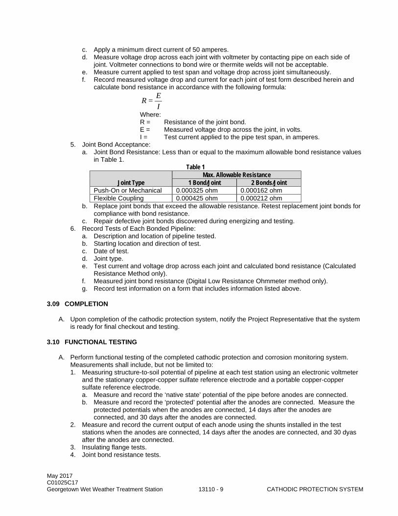
May 2017 C01025C17 Georgetown Wet Weather Treatment Station 13110 - 9 CATHODIC PROTECTION SYSTEM
c. Apply a minimum direct current of 50 amperes. d. Measure voltage drop across each joint with voltmeter by contacting pipe on each side of
joint. Voltmeter connections to bond wire or thermite welds will not be acceptable. e. Measure current applied to test span and voltage drop across joint simultaneously. f. Record measured voltage drop and current for each joint of test form described herein and
calculate bond resistance in accordance with the following formula:
R = EI
Where: R = Resistance of the joint bond. E = Measured voltage drop across the joint, in volts. I = Test current applied to the pipe test span, in amperes.
5. Joint Bond Acceptance: a. Joint Bond Resistance: Less than or equal to the maximum allowable bond resistance values
in Table 1. Table 1
Joint Type Max. Allowable Resistance
1 Bond/Joint 2 Bonds/Joint Push-On or Mechanical 0.000325 ohm 0.000162 ohm Flexible Coupling 0.000425 ohm 0.000212 ohm
b. Replace joint bonds that exceed the allowable resistance. Retest replacement joint bonds for compliance with bond resistance.
c. Repair defective joint bonds discovered during energizing and testing. 6. Record Tests of Each Bonded Pipeline:
a. Description and location of pipeline tested. b. Starting location and direction of test. c. Date of test. d. Joint type. e. Test current and voltage drop across each joint and calculated bond resistance (Calculated
Resistance Method only). f. Measured joint bond resistance (Digital Low Resistance Ohmmeter method only). g. Record test information on a form that includes information listed above.
3.09 COMPLETION
A. Upon completion of the cathodic protection system, notify the Project Representative that the system is ready for final checkout and testing.
3.10 FUNCTIONAL TESTING
A. Perform functional testing of the completed cathodic protection and corrosion monitoring system. Measurements shall include, but not be limited to: 1. Measuring structure-to-soil potential of pipeline at each test station using an electronic voltmeter
and the stationary copper-copper sulfate reference electrode and a portable copper-copper sulfate reference electrode. a. Measure and record the ‘native state’ potential of the pipe before anodes are connected. b. Measure and record the ‘protected’ potential after the anodes are connected. Measure the
protected potentials when the anodes are connected, 14 days after the anodes are connected, and 30 days after the anodes are connected.
2. Measure and record the current output of each anode using the shunts installed in the test stations when the anodes are connected, 14 days after the anodes are connected, and 30 dyas after the anodes are connected.
3. Insulating flange tests. 4. Joint bond resistance tests.
May 2017 C01025C17 Georgetown Wet Weather Treatment Station 13110 - 10 CATHODIC PROTECTION SYSTEM
B. Tabulate all cathodic protection field test measurements, with date and test location. Prepare and submit a written report that describes test equipment and procedures, includes the tabulated test data, and lists deficiencies found and repairs made.
END OF SECTION
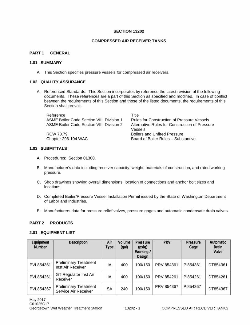
May 2017 C01025C17 Georgetown Wet Weather Treatment Station 13202 - 1 COMPRESSED AIR RECEIVER TANKS
SECTION 13202
COMPRESSED AIR RECEIVER TANKS
PART 1 GENERAL
1.01 SUMMARY
A. This Section specifies pressure vessels for compressed air receivers.
1.02 QUALITY ASSURANCE
A. Referenced Standards: This Section incorporates by reference the latest revision of the following documents. These references are a part of this Section as specified and modified. In case of conflict between the requirements of this Section and those of the listed documents, the requirements of this Section shall prevail.
Reference Title ASME Boiler Code Section VIII, Division 1 Rules for Construction of Pressure Vessels ASME Boiler Code Section VIII, Division 2 Alternative Rules for Construction of Pressure
Vessels RCW 70.79 Boilers and Unfired Pressure Chapter 296-104 WAC Board of Boiler Rules – Substantive
1.03 SUBMITTALS
A. Procedures: Section 01300.
B. Manufacturer's data including receiver capacity, weight, materials of construction, and rated working pressure.
C. Shop drawings showing overall dimensions, location of connections and anchor bolt sizes and locations.
D. Completed Boiler/Pressure Vessel Installation Permit issued by the State of Washington Department of Labor and Industries.
E. Manufacturers data for pressure relief valves, pressure gages and automatic condensate drain valves
PART 2 PRODUCTS
2.01 EQUIPMENT LIST
Equipment Number
Description Air Type
Volume (gal)
Pressure (psig)
Working / Design
PRV Pressure Gage
Automatic Drain Valve
PVL854361 Preliminary Treatment Inst Air Receiver IA 400 100/150 PRV 854361 PI854361 DT854361
PVL854261 GT Regulator Inst Air Receiver IA 400 100/150 PRV 854261 PI854261 DT854261
PVL854367 Preliminary Treatment Service Air Receiver SA 240 100/150 PRV 854367 PI854367 DT854367

May 2017 C01025C17 Georgetown Wet Weather Treatment Station 13202 - 2 COMPRESSED AIR RECEIVER TANKS
Equipment Number
Description Air Type
Volume (gal)
Pressure (psig)
Working / Design
PRV Pressure Gage
Automatic Drain Valve
PVL854262 GT Regulator Service Air Receiver SA 240 100/150 PRV 854262 PI854262 DT854262
PVL854962 Maint. Shop Service Air Receiver SA 240 100/150 PRV 854962 PI854962 DT854962
2.02 GENERAL
A. Performance and Design Requirements: the air receivers shall store compressed air from air compressors inside ventilated buildings at a wastewater plant. It is expected that air in the receivers may have some moisture plus small traces of oil and fine particulate matter.
B. Equipment shall be of the welded steel vertical type, cylindrical in shape, with semi-elliptical heads.
2.03 ACCEPTABLE MANUFACTURERS
A. Compressed Air Receiver Tanks: 1. Manchester Tank. 2. Hanson Tank. 3. Approved Equal.
B. Pressure Relief Valves: 1. Kunkle. 2. Conbraco. 3. Approved Equal.
C. Pressure Gages: 1. Wika. 2. Ashcroft. 3. Amtek. 4. Approved Equal.
D. Automatic Condensate Drain Valves: 1. Air System Products Dehydra 52. 2. Armstrong ADP-1. 3. Approved Equal.
2.04 EQUIPMENT
A. Air Receivers: 1. Equipment shall be of the welded steel vertical type, cylindrical in shape, with semi-elliptical
heads. 2. Air receivers shall be fitted with pressure-type manholes and semi-elliptical pressure heads. 3. All tanks shall contain threaded or flanged bosses for inlet, outlet, pressure relief and gage
connections as indicated in the Drawings and shall have a 1-inch minimum drain connection. 4. The interior of all tanks shall be protected with a baked marine epoxy coating factory-applied after
fabrication. The coating shall be applied in two coats and shall be completely free of pinholes and thin spots.
5. The exterior of all tanks shall be painted with a 2-part epoxy paint system suitable for an industrial environment.
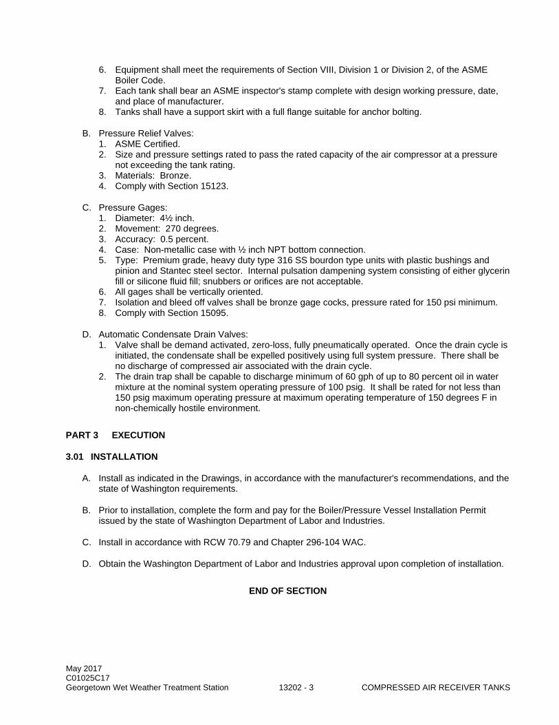
May 2017 C01025C17 Georgetown Wet Weather Treatment Station 13202 - 3 COMPRESSED AIR RECEIVER TANKS
6. Equipment shall meet the requirements of Section VIII, Division 1 or Division 2, of the ASME Boiler Code.
7. Each tank shall bear an ASME inspector's stamp complete with design working pressure, date, and place of manufacturer.
8. Tanks shall have a support skirt with a full flange suitable for anchor bolting.
B. Pressure Relief Valves: 1. ASME Certified. 2. Size and pressure settings rated to pass the rated capacity of the air compressor at a pressure
not exceeding the tank rating. 3. Materials: Bronze. 4. Comply with Section 15123.
C. Pressure Gages: 1. Diameter: 4½ inch. 2. Movement: 270 degrees. 3. Accuracy: 0.5 percent. 4. Case: Non-metallic case with ½ inch NPT bottom connection. 5. Type: Premium grade, heavy duty type 316 SS bourdon type units with plastic bushings and
pinion and Stantec steel sector. Internal pulsation dampening system consisting of either glycerin fill or silicone fluid fill; snubbers or orifices are not acceptable.
6. All gages shall be vertically oriented. 7. Isolation and bleed off valves shall be bronze gage cocks, pressure rated for 150 psi minimum. 8. Comply with Section 15095.
D. Automatic Condensate Drain Valves: 1. Valve shall be demand activated, zero-loss, fully pneumatically operated. Once the drain cycle is
initiated, the condensate shall be expelled positively using full system pressure. There shall be no discharge of compressed air associated with the drain cycle.
2. The drain trap shall be capable to discharge minimum of 60 gph of up to 80 percent oil in water mixture at the nominal system operating pressure of 100 psig. It shall be rated for not less than 150 psig maximum operating pressure at maximum operating temperature of 150 degrees F in non-chemically hostile environment.
PART 3 EXECUTION
3.01 INSTALLATION
A. Install as indicated in the Drawings, in accordance with the manufacturer's recommendations, and the state of Washington requirements.
B. Prior to installation, complete the form and pay for the Boiler/Pressure Vessel Installation Permit issued by the state of Washington Department of Labor and Industries.
C. Install in accordance with RCW 70.79 and Chapter 296-104 WAC.
D. Obtain the Washington Department of Labor and Industries approval upon completion of installation.
END OF SECTION

May 2017 C01025C17 Georgetown Wet Weather Treatment Station 13202 - 4 COMPRESSED AIR RECEIVER TANKS
This page intentionally left blank.
May 2017 C01025C17 Georgetown Wet Weather Treatment Station 13205 - 1 POLYETHYLENE STORAGE TANKS
SECTION 13205
POLYETHYLENE STORAGE TANKS
PART 1 GENERAL
1.01 SUMMARY
A. This Section specifies the work necessary to furnish and install chemical storage tanks for caustic (sodium hydroxide) and coagulant.
1.02 QUALITY ASSURANCE
A. Referenced Standards: This Section incorporates by reference the latest revision of the following documents. These references are a part of this Section as specified and modified. In case of conflict between the requirements of this Section and those of the listed documents, the requirements of this Section shall prevail. Reference Title ASME B16.1 Cast Iron Pipe Flanges and Flanged Fittings Test Method for Steady-State Heat Flux Measurements and Thermal
Transmission Properties by Means of the Guarded-Hot-Plate Apparatus ASTM D635 Standard Test Method for Rate of Burning and/or Extent and Time of Burning
of Plastics in a Horizontal Position ASTM D638 Test Method for Tensile Properties of Plastics ASTM D648 Test Method for Deflection Temperature of Plastics Under Flexural Load ASTM D746 Test Method for Brittleness Temperature of Plastics and Elastomers by
Impact ASTM D790 Test Methods for Flexural Properties of Unreinforced and Reinforced Plastics
and Electrical Insulating Materials Standard Definitions of Terms Relating to Plastics ASTM D1505 Test Method for Density of Plastics by the Density-Gradient Technique ASTM D1525 Test Method for Vicat Softening Temperature of Plastics Test Method for Compressive Properties of Rigid Cellular Plastics Test Method for Apparent Density of Rigid Cellular Plastics Test Method for Tensile and Tensile Adhesion Properties of Rigid Cellular
Plastics ASTM D1693 Test Method for Environmental Stress-Cracking of Ethylene Plastics Method of Test for Porosity of Rigid Cellular Plastics ASTM D1998 Specification for Polyethylene Upright Storage Tanks ASTM E84 Test Method for Surface Burning Characteristics of Building Materials ASTM F1473 Test Method for Notch Tensile Test to Measure the Resistance to slow Crack
Growth of Polyethylene Pipes and Resins SBC Seattle Building Code
B. Factory Tests: The tank fabricators shall have a quality control procedure adequate to ensure that all fabrication complies with these Specifications: 1. Impact Tests: A representative sample from each tank shall undergo a factory impact test. Impact
test shall meet the requirements of ASTM D1998. 2. Gel Tests: A representative sample from each tank provided shall undergo a factory gel test, as
prescribed by ASTM D1998. 3. Hydrostatic Leak Tests:
a. Perform on each tank. b. Fill to overflow nozzle; allow to stand for 24 hours with no visible leakage.
May 2017 C01025C17 Georgetown Wet Weather Treatment Station 13205 - 2 POLYETHYLENE STORAGE TANKS
4. Wall Thickness: Each tank shall have an actual wall thickness measurement taken at every 90 degrees, at each 1 foot elevation, up to 3 feet from the bottom of the tank.
5. The Engineer reserves the right to witness the factory tests. Inform the Project Representative and the Engineer at least 30 days prior to the factory testing.
6. Reports: Certify, by signature, the results of the factory testing.
1.03 SUBMITTALS
A. Procedures: Section 01300.
B. Items to be submitted for this Section: 1. Fabricator's catalog information, descriptive literature, specifications, and identification of
materials of construction. Provide catalog cuts for all off-the-shelf items. 2. Detailed fabrication drawings shall be scale drawings showing the relative size, configuration,
location, materials of construction, and details of all equipment and materials to be furnished including the tanks, fittings, supports, and tank holddown and support systems. Both plan and elevation views shall be provided. All piping terminal points shall be clearly shown and fully dimensioned.
3. Resin used for each tank and all supporting specifications for resins. 4. Foundation and Anchor Bolt Drawings: drawings shall be provided that show all data and details
required for design of the tank foundations including locations and dimensions for knockouts and embedded items, and the size, type, location, embedment and projection of anchor bolts.
5. Complete design calculations for tanks, supports, ladder and platform and appropriate accessories stamped by a professional engineer registered in the State of Washington. Diagrams and calculations shall be provided that indicate all static and dynamic loads. Reactions (uplift, shear, gravity loads, etc.) shall be indicated for each of the applicable loading combinations found in the SBC. Calculations for anchor bolt type, size, and location shall be indicated for the controlling load condition and SBC.
6. Quality assurance submittals in accordance with Section 01410. 7. Tank data indicating pressure rating, diameter, straight shell lengths, overall lengths, wall
thickness, and details of nozzle designs. 8. Tank capacity chart indicating gallons for each inch of depth and cumulative total from bottom. 9. Certified test data on representative samples of standard materials which demonstrate
compliance with the physical properties specified herein. 10. Certified copy of all factory test results including gel tests, impact tests, and hydrostatic tests.
Provide a listing of procedures used in testing. 11. Installation Instructions: Installation instructions shall be completed, detailed, and sequenced
instructions for original installation. Recommended methods for assembly and adjustment including all bolt torques shall be provided along with special precautions and the sequence of work. Rigging and lifting details shall also be included for all factory-fabricated assemblies and individual components weighing over 100 pounds.
12. Electrical heat tracing and foam insulation data sheets as required in Sections 15260 and 15265. 13. All exceptions and any proposed revisions to the requirements of the Specifications shall be
included with the Submittals. 14. Fabricator's Certificate of Compliance with fabrication requirements. 15. Quality Assurance Inspection:
a. Initial QA Inspection Report. b. Certification of Factory Testing.
16. Special shipping, storage and protection, and handling instructions. 17. Fabricator's written/printed installation and tank support instructions. 18. Manufacturer's Certificate of Proper Installation. 19. Operation and Maintenance Data: Section 01730.
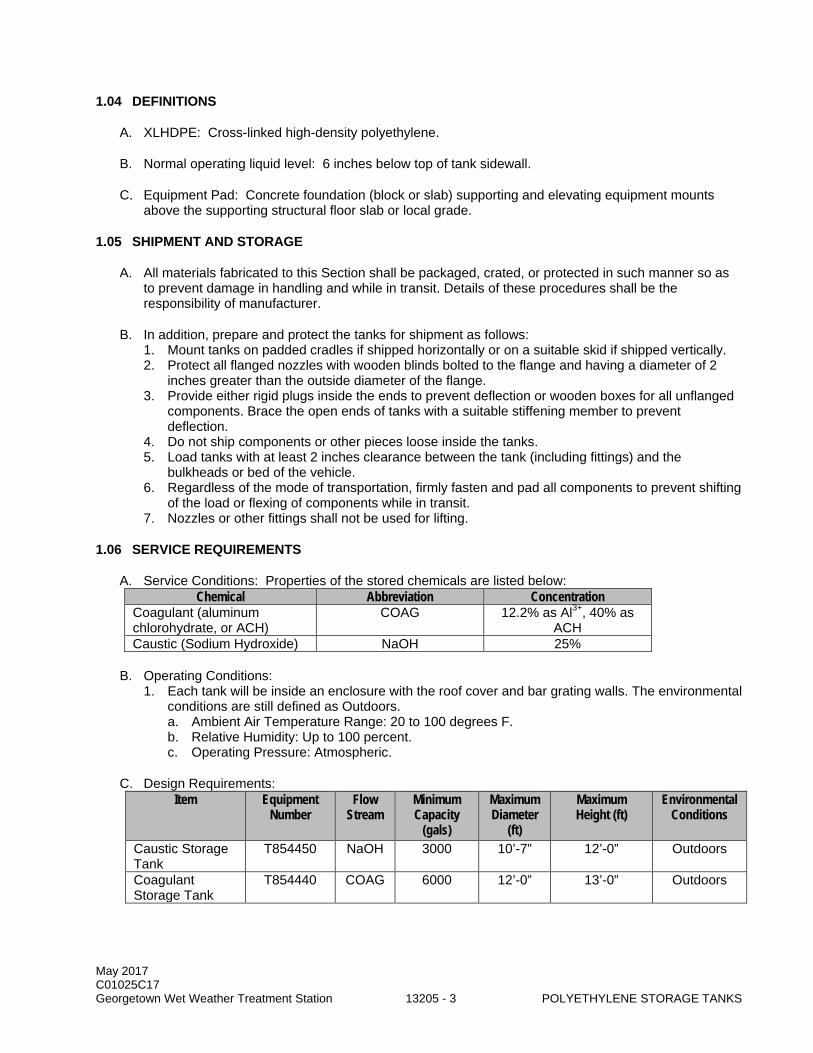
May 2017 C01025C17 Georgetown Wet Weather Treatment Station 13205 - 3 POLYETHYLENE STORAGE TANKS
1.04 DEFINITIONS
A. XLHDPE: Cross-linked high-density polyethylene.
B. Normal operating liquid level: 6 inches below top of tank sidewall.
C. Equipment Pad: Concrete foundation (block or slab) supporting and elevating equipment mounts above the supporting structural floor slab or local grade.
1.05 SHIPMENT AND STORAGE
A. All materials fabricated to this Section shall be packaged, crated, or protected in such manner so as to prevent damage in handling and while in transit. Details of these procedures shall be the responsibility of manufacturer.
B. In addition, prepare and protect the tanks for shipment as follows: 1. Mount tanks on padded cradles if shipped horizontally or on a suitable skid if shipped vertically. 2. Protect all flanged nozzles with wooden blinds bolted to the flange and having a diameter of 2
inches greater than the outside diameter of the flange. 3. Provide either rigid plugs inside the ends to prevent deflection or wooden boxes for all unflanged
components. Brace the open ends of tanks with a suitable stiffening member to prevent deflection.
4. Do not ship components or other pieces loose inside the tanks. 5. Load tanks with at least 2 inches clearance between the tank (including fittings) and the
bulkheads or bed of the vehicle. 6. Regardless of the mode of transportation, firmly fasten and pad all components to prevent shifting
of the load or flexing of components while in transit. 7. Nozzles or other fittings shall not be used for lifting.
1.06 SERVICE REQUIREMENTS
A. Service Conditions: Properties of the stored chemicals are listed below: Chemical Abbreviation Concentration
Coagulant (aluminum chlorohydrate, or ACH)
COAG 12.2% as Al3+, 40% as ACH
Caustic (Sodium Hydroxide) NaOH 25%
B. Operating Conditions: 1. Each tank will be inside an enclosure with the roof cover and bar grating walls. The environmental
conditions are still defined as Outdoors. a. Ambient Air Temperature Range: 20 to 100 degrees F. b. Relative Humidity: Up to 100 percent. c. Operating Pressure: Atmospheric.
C. Design Requirements: Item Equipment
Number Flow
Stream Minimum Capacity
(gals)
Maximum Diameter
(ft)
Maximum Height (ft)
Environmental Conditions
Caustic Storage Tank
T854450 NaOH 3000 10’-7” 12’-0” Outdoors
Coagulant Storage Tank
T854440 COAG 6000 12’-0” 13’-0” Outdoors
May 2017 C01025C17 Georgetown Wet Weather Treatment Station 13205 - 4 POLYETHYLENE STORAGE TANKS
1.07 GENERAL MANUFACTURING REQUIREMENTS
A. Fabricator's Quality Assurance Supervisor: Minimum of 5 years' experience in the fabrication of polyethylene storage tanks of similar size and usage.
B. Tanks shall be manufactured by a firm with a nationally accepted quality standard (i.e., ISO9001).
C. Determination of Cross-Linking: Tank manufacturer shall be capable of issuing gel tests according to ASTM 1998 to determine the ortho-xylene insoluble fraction of cross linked polyethylene. Results with 1/8-inch inner wall reading shall be no less than 65 percent gel.
D. Like items of materials and equipment shall be the end products of one manufacturer in order to provide standardization for appearance operation, maintenance spare parts, and manufacturer's service.
1.08 WARRANTY
A. For the Work of this Section, provide all warranties as described in the General Conditions 00700, Subsection 7.9B, and provide all normal commercial warranties available, as described in the General Conditions.
B. In addition, tanks shall have a minimum 5-year guaranty from the tank manufacturer, covering the complete cost of repair and replacement of the tanks (not including any costs associated with altering, removing, or demolishing the existing facility structure for such removal which shall be borne by Contractor) during the first 5 years of service, should leakage occur through the tank or the tank fittings, or should the tank or tank fittings show signs of fatigue or failure as determined by Project Representative.
PART 2 PRODUCTS
2.01 EQUIPMENT SCHEDULE
Equipment No. Equipment Name T854440 Coagulant Storage Tank T854450 Caustic Storage Tank
2.02 GENERAL
A. Design Requirements: 1. Manufacturer shall design chemical storage tanks, including wall thickness and methods and
locations of support and anchorage. Design shall be prepared and sealed by a professional engineer meeting requirements as specified in this Section.
2. Seismic Load: In accordance with Section 01031. In addition, design tanks to withstand a seismic event resulting in a 12-degree tilt of the tank base for a time period of 60 days without structural failure of the tank or anchorage. Perform non-linear finite element analysis to simulate seismic event.
3. Wind Load: 85 mph, Exposure C, Wind Importance Factor 1.15 in accordance with SBC. 4. Live Load: 50 pounds per square foot. 5. Concentrated Load: 250 pounds. 6. Load Combination: Calculate according to requirements of applicable code. 7. Special Loads: Design tanks for dead loads from all attached piping, valves and valve actuators. 8. Hydrostatic Load: Specific gravities of 1.7. Tanks shall be designed to withstand the hydrostatic
pressure resulting from a full tank. 9. The tanks shall be designed to withstand temperatures of 130 to 140 degrees F during tank filling
events.
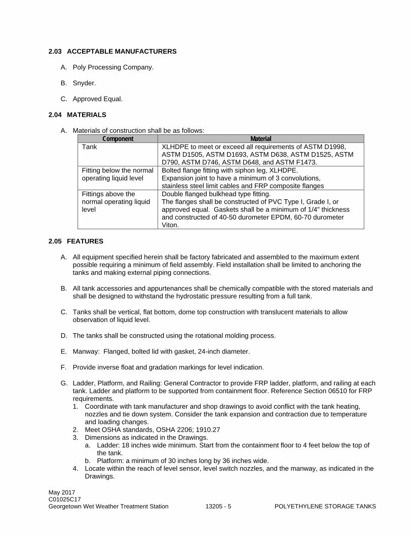
May 2017 C01025C17 Georgetown Wet Weather Treatment Station 13205 - 5 POLYETHYLENE STORAGE TANKS
2.03 ACCEPTABLE MANUFACTURERS
A. Poly Processing Company.
B. Snyder.
C. Approved Equal.
2.04 MATERIALS
A. Materials of construction shall be as follows: Component Material
Tank XLHDPE to meet or exceed all requirements of ASTM D1998, ASTM D1505, ASTM D1693, ASTM D638, ASTM D1525, ASTM D790, ASTM D746, ASTM D648, and ASTM F1473.
Fitting below the normal operating liquid level
Bolted flange fitting with siphon leg, XLHDPE. Expansion joint to have a minimum of 3 convolutions, stainless steel limit cables and FRP composite flanges
Fittings above the normal operating liquid level
Double flanged bulkhead type fitting. The flanges shall be constructed of PVC Type I, Grade I, or approved equal. Gaskets shall be a minimum of 1/4" thickness and constructed of 40-50 durometer EPDM, 60-70 durometer Viton.
2.05 FEATURES
A. All equipment specified herein shall be factory fabricated and assembled to the maximum extent possible requiring a minimum of field assembly. Field installation shall be limited to anchoring the tanks and making external piping connections.
B. All tank accessories and appurtenances shall be chemically compatible with the stored materials and shall be designed to withstand the hydrostatic pressure resulting from a full tank.
C. Tanks shall be vertical, flat bottom, dome top construction with translucent materials to allow observation of liquid level.
D. The tanks shall be constructed using the rotational molding process.
E. Manway: Flanged, bolted lid with gasket, 24-inch diameter.
F. Provide inverse float and gradation markings for level indication.
G. Ladder, Platform, and Railing: General Contractor to provide FRP ladder, platform, and railing at each tank. Ladder and platform to be supported from containment floor. Reference Section 06510 for FRP requirements. 1. Coordinate with tank manufacturer and shop drawings to avoid conflict with the tank heating,
nozzles and tie down system. Consider the tank expansion and contraction due to temperature and loading changes.
2. Meet OSHA standards, OSHA 2206; 1910.27 3. Dimensions as indicated in the Drawings.
a. Ladder: 18 inches wide minimum. Start from the containment floor to 4 feet below the top of the tank.
b. Platform: a minimum of 30 inches long by 36 inches wide. 4. Locate within the reach of level sensor, level switch nozzles, and the manway, as indicated in the
Drawings.
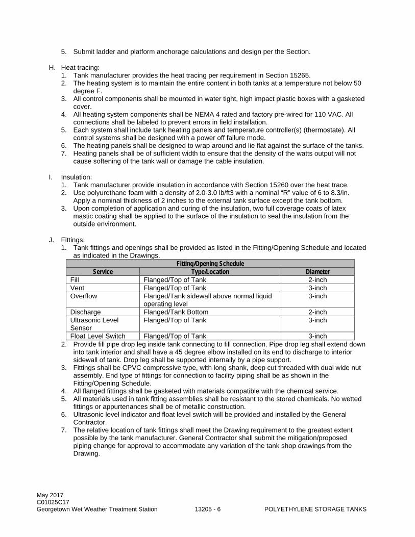
May 2017 C01025C17 Georgetown Wet Weather Treatment Station 13205 - 6 POLYETHYLENE STORAGE TANKS
5. Submit ladder and platform anchorage calculations and design per the Section.
H. Heat tracing: 1. Tank manufacturer provides the heat tracing per requirement in Section 15265. 2. The heating system is to maintain the entire content in both tanks at a temperature not below 50
degree F. 3. All control components shall be mounted in water tight, high impact plastic boxes with a gasketed
cover. 4. All heating system components shall be NEMA 4 rated and factory pre-wired for 110 VAC. All
connections shall be labeled to prevent errors in field installation. 5. Each system shall include tank heating panels and temperature controller(s) (thermostate). All
control systems shall be designed with a power off failure mode. 6. The heating panels shall be designed to wrap around and lie flat against the surface of the tanks. 7. Heating panels shall be of sufficient width to ensure that the density of the watts output will not
cause softening of the tank wall or damage the cable insulation.
I. Insulation: 1. Tank manufacturer provide insulation in accordance with Section 15260 over the heat trace. 2. Use polyurethane foam with a density of 2.0-3.0 lb/ft3 with a nominal “R” value of 6 to 8.3/in.
Apply a nominal thickness of 2 inches to the external tank surface except the tank bottom. 3. Upon completion of application and curing of the insulation, two full coverage coats of latex
mastic coating shall be applied to the surface of the insulation to seal the insulation from the outside environment.
J. Fittings: 1. Tank fittings and openings shall be provided as listed in the Fitting/Opening Schedule and located
as indicated in the Drawings. Fitting/Opening Schedule
Service Type/Location Diameter Fill Flanged/Top of Tank 2-inch Vent Flanged/Top of Tank 3-inch Overflow Flanged/Tank sidewall above normal liquid
operating level 3-inch
Discharge Flanged/Tank Bottom 2-inch Ultrasonic Level Sensor
Flanged/Top of Tank 3-inch
Float Level Switch Flanged/Top of Tank 3-inch 2. Provide fill pipe drop leg inside tank connecting to fill connection. Pipe drop leg shall extend down
into tank interior and shall have a 45 degree elbow installed on its end to discharge to interior sidewall of tank. Drop leg shall be supported internally by a pipe support.
3. Fittings shall be CPVC compressive type, with long shank, deep cut threaded with dual wide nut assembly. End type of fittings for connection to facility piping shall be as shown in the Fitting/Opening Schedule.
4. All flanged fittings shall be gasketed with materials compatible with the chemical service. 5. All materials used in tank fitting assemblies shall be resistant to the stored chemicals. No wetted
fittings or appurtenances shall be of metallic construction. 6. Ultrasonic level indicator and float level switch will be provided and installed by the General
Contractor. 7. The relative location of tank fittings shall meet the Drawing requirement to the greatest extent
possible by the tank manufacturer. General Contractor shall submit the mitigation/proposed piping change for approval to accommodate any variation of the tank shop drawings from the Drawing.
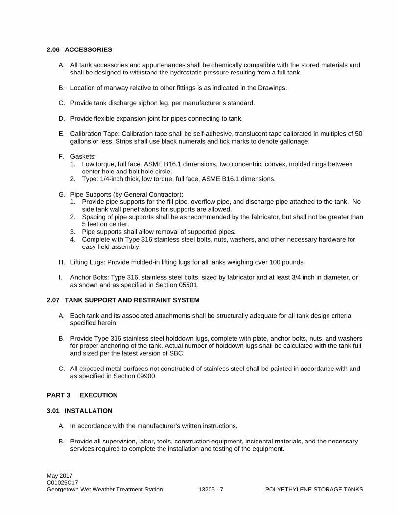
May 2017 C01025C17 Georgetown Wet Weather Treatment Station 13205 - 7 POLYETHYLENE STORAGE TANKS
2.06 ACCESSORIES
A. All tank accessories and appurtenances shall be chemically compatible with the stored materials and shall be designed to withstand the hydrostatic pressure resulting from a full tank.
B. Location of manway relative to other fittings is as indicated in the Drawings.
C. Provide tank discharge siphon leg, per manufacturer’s standard.
D. Provide flexible expansion joint for pipes connecting to tank.
E. Calibration Tape: Calibration tape shall be self-adhesive, translucent tape calibrated in multiples of 50 gallons or less. Strips shall use black numerals and tick marks to denote gallonage.
F. Gaskets: 1. Low torque, full face, ASME B16.1 dimensions, two concentric, convex, molded rings between
center hole and bolt hole circle. 2. Type: 1/4-inch thick, low torque, full face, ASME B16.1 dimensions.
G. Pipe Supports (by General Contractor): 1. Provide pipe supports for the fill pipe, overflow pipe, and discharge pipe attached to the tank. No
side tank wall penetrations for supports are allowed. 2. Spacing of pipe supports shall be as recommended by the fabricator, but shall not be greater than
5 feet on center. 3. Pipe supports shall allow removal of supported pipes. 4. Complete with Type 316 stainless steel bolts, nuts, washers, and other necessary hardware for
easy field assembly.
H. Lifting Lugs: Provide molded-in lifting lugs for all tanks weighing over 100 pounds.
I. Anchor Bolts: Type 316, stainless steel bolts, sized by fabricator and at least 3/4 inch in diameter, or as shown and as specified in Section 05501.
2.07 TANK SUPPORT AND RESTRAINT SYSTEM
A. Each tank and its associated attachments shall be structurally adequate for all tank design criteria specified herein.
B. Provide Type 316 stainless steel holddown lugs, complete with plate, anchor bolts, nuts, and washers for proper anchoring of the tank. Actual number of holddown lugs shall be calculated with the tank full and sized per the latest version of SBC.
C. All exposed metal surfaces not constructed of stainless steel shall be painted in accordance with and as specified in Section 09900.
PART 3 EXECUTION
3.01 INSTALLATION
A. In accordance with the manufacturer's written instructions.
B. Provide all supervision, labor, tools, construction equipment, incidental materials, and the necessary services required to complete the installation and testing of the equipment.
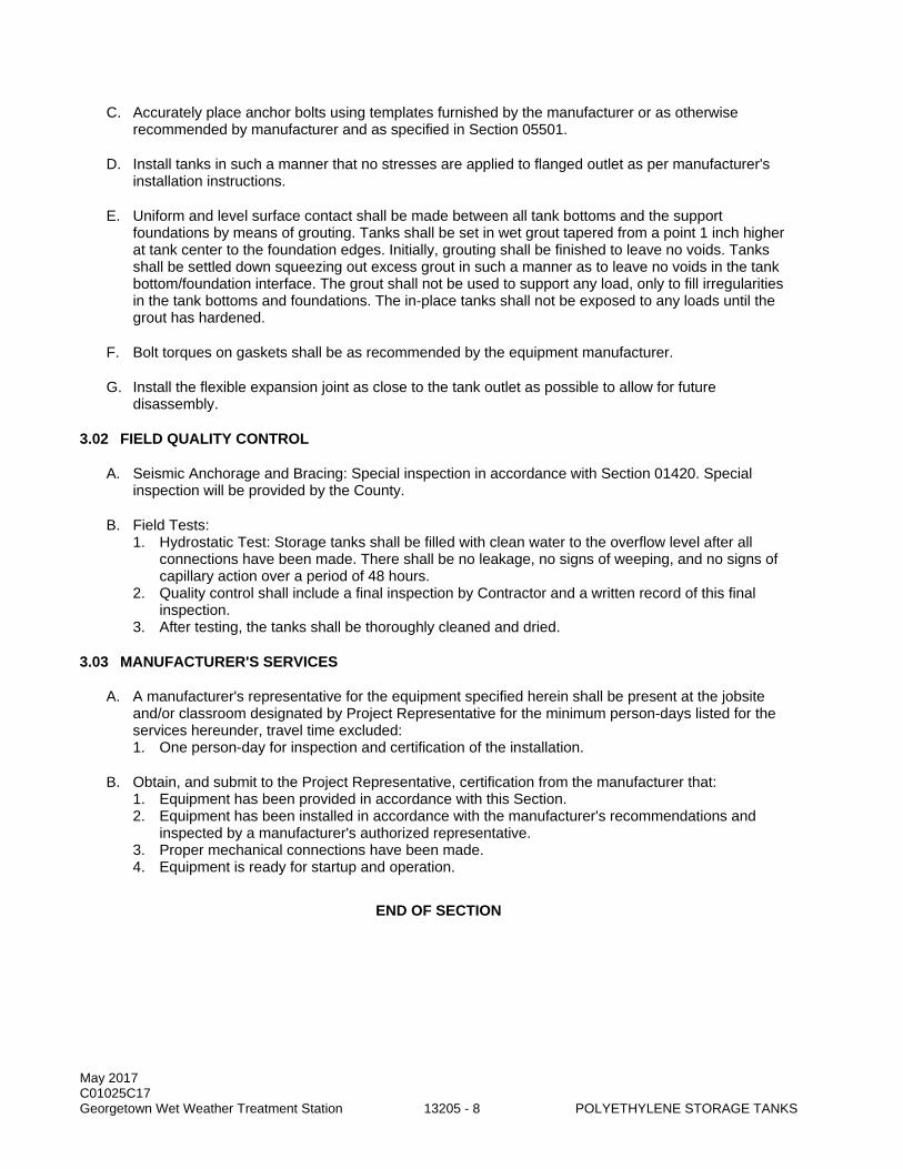
May 2017 C01025C17 Georgetown Wet Weather Treatment Station 13205 - 8 POLYETHYLENE STORAGE TANKS
C. Accurately place anchor bolts using templates furnished by the manufacturer or as otherwise recommended by manufacturer and as specified in Section 05501.
D. Install tanks in such a manner that no stresses are applied to flanged outlet as per manufacturer's installation instructions.
E. Uniform and level surface contact shall be made between all tank bottoms and the support foundations by means of grouting. Tanks shall be set in wet grout tapered from a point 1 inch higher at tank center to the foundation edges. Initially, grouting shall be finished to leave no voids. Tanks shall be settled down squeezing out excess grout in such a manner as to leave no voids in the tank bottom/foundation interface. The grout shall not be used to support any load, only to fill irregularities in the tank bottoms and foundations. The in-place tanks shall not be exposed to any loads until the grout has hardened.
F. Bolt torques on gaskets shall be as recommended by the equipment manufacturer.
G. Install the flexible expansion joint as close to the tank outlet as possible to allow for future disassembly.
3.02 FIELD QUALITY CONTROL
A. Seismic Anchorage and Bracing: Special inspection in accordance with Section 01420. Special inspection will be provided by the County.
B. Field Tests: 1. Hydrostatic Test: Storage tanks shall be filled with clean water to the overflow level after all
connections have been made. There shall be no leakage, no signs of weeping, and no signs of capillary action over a period of 48 hours.
2. Quality control shall include a final inspection by Contractor and a written record of this final inspection.
3. After testing, the tanks shall be thoroughly cleaned and dried.
3.03 MANUFACTURER'S SERVICES
A. A manufacturer's representative for the equipment specified herein shall be present at the jobsite and/or classroom designated by Project Representative for the minimum person-days listed for the services hereunder, travel time excluded: 1. One person-day for inspection and certification of the installation.
B. Obtain, and submit to the Project Representative, certification from the manufacturer that: 1. Equipment has been provided in accordance with this Section. 2. Equipment has been installed in accordance with the manufacturer's recommendations and
inspected by a manufacturer's authorized representative. 3. Proper mechanical connections have been made. 4. Equipment is ready for startup and operation.
END OF SECTION
May 2017 C01025C17 Georgetown Wet Weather Treatment Station 13210 - 1 WATER STORAGE TANKS
SECTION 13210
WATER STORAGE TANKS
PART 1 GENERAL
1.01 SUMMARY
A. This Section specifies exterior free standing metal cisterns to be used for rainwater harvesting.
1.02 QUALITY ASSURANCE
A. Referenced Standards: This Section incorporates by reference the latest revision of the following documents. These references are a part of this Section as specified and modified. In case of conflict between the requirements of this Section and those of the listed documents, the requirements of this Section shall prevail. Reference Title ASTM A653 Standard Specification for Steel Sheet, Zinc-Coated (Galvanized) or Zinc-Iron
Alloy-Coated (Galvannealed) by the Hot-Dip Process. ASTM A283 Standard Specification for Low and Intermediate Tensile Strength Carbon Steel
Plates. ASTM A572 Standard Specification for High-Strength Low-Alloy Columbium-Vanadium
Structural Steel. ASTM A1011 Standard Specification for Steel, Sheet and Strip, Hot-Rolled, Carbon,
Structural, High-Strength Low-Alloy, High-Strength Low-Alloy with Improved Formability, and Ultra-High Strength.
AWWA D103 Factory-Coated Bolted Carbon Steel Tanks for Water Storage. IBC International Building Code. SBC Seattle Building Code.
B. Manufacturer: Tank fabricator shall be experienced in manufacturing corrugated galvanized steel bolted tanks for water storage. 1. The materials, design, fabrication and erection of the bolt together tank shall conform to AWWA
D103, latest edition as modified herein. 2. Revise AWWA D103 Section 1.1.2 to remove the sentence that reads “This standard is not
applicable to tanks of corrugated construction”. 3. The tanks shall be designed as anchored tanks. 4. Revise AWWA D103 Section 5.9.1.2.1 to read “All tanks shall have the minimum number and
size of anchor bolts, equally spaced, as indicated in the Drawings.” 5. A corrosion allowance of 1/8” shall be provided for all steel plates, anchor straps, anchor chairs,
and tank walls. 6. The minimum thickness of the tank plates shall be as described in AWWA D103 Section 3.10 and
Table 16. All components shall be assumed to be in contact with water. 7. AWWA D103 Section 5.9.2, shall be revised to indicate that a corrosion allowance of 1/4 in. 8. Shall be applied to the root thread diameter of anchor bolts. 9. AWWA D103 Section 5.9.4, 8 shall be revised to read “Cast-in place anchor bolts are required.”
Post installed anchors will not be permitted. 10. Compliance with NSF/ANSI 61 is not required.
May 2017 C01025C17 Georgetown Wet Weather Treatment Station 13210 - 2 WATER STORAGE TANKS
C. In addition to the design requirements contained in AWWA D103 the following analyses shall be provided: 1. The stresses and fastener loads shall be based on a finite element analysis that accurately
models the cross section and overall dimensions of the corrugated tank wall and the discrete fasteners connecting the tank shell elements.
2. A minimum factor of safety of 1.2 shall be demonstrated through finite element analyses that accurately models the cross section and overall dimensions of the corrugated tank wall for localized and “elephant foot” buckling of the tank wall.
3. For all finite element analyses the maximum element size shall not exceed ½ inch on a side. The depth and pitch of the corrugations shall be accurately modeled.
D. Installer: Experienced in the installation of tanks exceeding 20,000 gallons and working on commercial construction job sites. Tank installer shall be trained in confined space protocols (OSHA) and be able to prove a minimum of five (5) years of tank building experience.
1.03 SUBMITTALS
A. Procedures: Section 01300.
B. Items to be submitted for this Section: 1. Fabricator's catalog information, descriptive literature, specifications, and identification of
materials of construction. Provide catalog cuts for all off-the-shelf items. 2. Detailed fabrication drawings specific to these tanks and this project shall be scale drawings
showing the relative size, configuration, location, materials of construction, and details of all equipment and materials to be furnished including the tanks, fittings, access openings, supports, and tank hold down and support systems. Both plan and elevation views shall be provided. All piping terminal points shall be clearly shown and fully dimensioned.
3. Complete design calculations specific to these tanks and this project, supports and appropriate accessories prepared, stamped, dated, and signed by a Professional Engineer registered in the state of Washington. Diagrams and calculations shall be provided that indicate all static and dynamic loads. Reactions (uplift, shear, gravity loads, etc.) shall be indicated for each of the applicable loading combinations found in the SBC. Calculations for anchor bolt type, size, and location shall be indicated for the controlling load condition and SBC.
4. All drawings and calculations shall be prepared, stamped, dated, and signed by a Professional Structural Engineer registered in the state of Washington.
5. Seismic loads shall be based on the Site Seismic Criteria provided in Section 01031, 1.05. a. Design shall include the effects of impulsive loads, convective loads and sloshing as provided
in AWWA D103. 6. Quality assurance submittals in accordance with Section 01410. 7. Installation Instructions: Installation instructions shall be completed, detailed, and sequenced
instructions for original installation. Recommended methods for assembly and adjustment including all bolt torques shall be provided along with special precautions and the sequence of work. Rigging and lifting details shall also be included for all factory-fabricated assemblies and individual components weighing over 100 pounds.
8. All exceptions and any proposed revisions to the requirements of the Specifications shall be included with the Submittals.
9. Fabricator's Certificate of Compliance with fabrication requirements. 10. Special shipping, storage and protection, and handling instructions. 11. Fabricator's written/printed installation and tank support instructions. 12. Manufacturer's Certificate of Proper Installation. 13. Operation and Maintenance Data: As specified in Section 01730.
C. Permitting: Refer to Section 01062.
May 2017 C01025C17 Georgetown Wet Weather Treatment Station 13210 - 3 WATER STORAGE TANKS
1.04 PRODUCT DELIVERY, STORAGE, AND HANDLING
A. All materials fabricated to this Specification must be packaged, crated, or protected in such manner so as to prevent damage in handling and while in transit. Details of these procedures shall be the responsibility of manufacturer.
1.05 WARRANTY
A. For the Work of this Section, provide all warranties as described in the General Conditions 00700, Subsection 7.9B, and provide all normal commercial warranties available, as described in the General Conditions.
B. In addition, the manufacturer shall warrant the tank structure against defects in workmanship and materials for a period of thirty (30) years from the date of shipment of the materials from the factory. Warranty shall cover the complete cost of repair and replacement of the tanks (not including any costs associated with altering, removing, or demolishing the existing facility structure for such removal which shall be borne by Contractor) during the first 5 years of service, should leakage occur through the tank or the tank fittings, or should the tank or tank fittings show signs of fatigue or failure as determined by Project Representative.
C. The manufacturer shall warrant the main liner against defects in workmanship and materials for a minimum of (10) ten years from the date of shipment of the materials from the factory on a pro-rata basis.
PART 2 PRODUCTS
2.01 CISTERN DESIGN CHARACTERISTICS
A. The water storage tanks shall be standard factory engineered galvanized steel tanks with liquid tight liners. The water storage tanks shall be assembled and erected on site. The tank structure shall consist of corrugated, galvanized steel wall sheets, roof panels, one roof panel with access hatch, standard peak cap, roof ladder angles, anchor clips and necessary hardware for tank assembly.
B. Acceptable manufacturers: 1. Water Storage Tanks, Inc. 2. Specified Water Systems. 3. SCAFCO. 4. Approved Equal.
C. Bolted tank structure - Galvanized steel tank wall and roof panels shall be pre-punched at the factory for field assembly.
D. Pre-liner - A 6 oz. black geotextile pre-liner shall be installed inside of the tank structure. The pre-liner shall cover the tank floor and the walls on all surfaces at which the main liner could contact the tank structure.
E. Main Liner - The tank shall be lined with a flexible membrane 40 oz. PVC coated polyester fabric liner, model number WST-NSFX-40R, such as those provided by Water Storage Tanks, Inc. (phone 512-301-1817), Braley-Gray & Associates (phone 206-405-4370), Specified Water Systems (phone 800-301-5632). The liner shall be prefabricated to fit the tank dimensions. The liner shall meet the following minimum requirements: 1. Material Weight: 40 oz./yd2 +/- .5oz. 2. Fiber: Polyester. 3. Thickness: 0.040 IN. 4. Yarn (Denier): 2600*2600.
May 2017 C01025C17 Georgetown Wet Weather Treatment Station 13210 - 4 WATER STORAGE TANKS
5. Fabric Count (threads): 15/15 (fd/inch). 6. Type of Coating: E-PVC. 7. NSF-61: No. 8. Tensile Strength:
a. Warp: 950 lbs./2 in². b. Fill: 900 lbs./2 in².
9. Tear Strength: a. Warp: 150 lbs. b. Fill: 150 lbs.
10. Elongation: a. Warp: 29%. b. Fill: 38%.
11. Adhesion Strength: 22 lbs./2 in². 12. Hydrostatic Resistance: 1113 psi. 13. Temperature Resistance: -22 ~ +160F. 14. Abrasion: 0.0021 oz. 15. Welds: 2 IN overlap; RF weld. 16. Hanging Method: Grommets with rope hem. 17. If applied to metal tank, affixed to heat-treated SAE grade 8.2 (DIN 10.9) bolts through tank wall
with nuts.
F. Roof and Installation access: 1. A 22 inch round access hole with cover shall be at the top center of the roof (36 inches for tanks
27 feet in diameter or larger). 2. For tanks 12 feet in diameter or greater, a 24 inches X 16 inches X 19 inches trapezoidal access
hole with hinged cover shall be located on the lower end of one roof sheet. 3. For 6 foot, 8 foot, and 9 foot diameter tanks a round inspection hatch will be an appropriate
replacement. 4. A 20 inch X 40 inch bolted side access panel shall be located 22 inches above the floor on a side
panel. The side access shall be bolted closed before final installation of the main liner.
G. Side access through liner: 1. Access hatch shall meet the requirements of AWWA D103, Section 7.1. 2. The hatch shall be round with a 24 inch inner diameter and with a perimeter plate that is custom
rolled to match the diameter of the tank. The weight of the hatch shall be borne by a support saddle, if required. The cover plate shall have a 30 inch minimum seal surface and shall affix in accordance to a 150# flange bolt pattern.
3. Provide two lifting lugs on the hatch to facilitate lifting the plate by hand.
H. Tank foundation shall be a concrete pad that will extend at least 9 inches outside of the tank wall in all directions.
I. Water level indicator: 1. Provide two (2) water level indicators for the project; one for tank #3 and one for tank #4. 2. Gauge shall consist of a stainless steel frame and stainless steel hardware with nylon sheave
pulleys. Cable shall be nylon coated stainless steel with a minimum breaking strength of 270lbs. The float shall be a non-corrosive stainless steel weighted float. The gauge body shall be clear polycarbonate that is UV resistant.
J. Hardware - All bolts and nuts shall be electro-galvanized with JS-1000 clear coat protective coating. Roof bolts shall have factory-installed steel-backed vinyl washers. Wall sheet bolts shall have slotted button heads for insertion from inside toward outside. All bolts shall be heat treated and meet SAE Grade 8.2 or stronger Specifications.

May 2017 C01025C17 Georgetown Wet Weather Treatment Station 13210 - 5 WATER STORAGE TANKS
K. Anchor clips: 1. The anchor clips and anchor bolts shall conform to the structural design calculation package and
shall meet site-specific requirements to properly anchor the tank in accordance with seismic, wind load, and other environmental conditions. Anchor clips shall be placed no less than every 39 inches around the perimeter of the tank.
2. A heavy duty anchor “chair” shall be utilized with the anchor bolt extending through the base plate and through a 1” hole in the top plate of the chair. A minimum of 9-15/16 inches shall separate the two plates to allow for stretch of the anchor bolt during a seismic event. The anchor chair shall be secured to the wall of the tank with no fewer than six 3/8 inch bolts.
L. North stormwater tank #3; (9 foot diameter): 1. 20 feet-9 inches tall (to top), 17 feet-11 inches to rim x 9 foot diameter tank. 2. Capacity = 8,400 Gallons. 3. Max Cistern Water Surface Level = 131.15 4. Bottom Cistern Level = 114.00 5. Type of Roof shall be steel. 6. Type of bottom shall be manufacturer’s standard bottom. 7. Vertical distance from concrete pad level to the top of the inlet pipe = 114.50. 8. Vertical distance from concrete pad level to the top of the outlet pipes = 114.58. 9. Locations of manholes, ladders and accessories shall be as indicated in the Drawings. 10. The size, number and location of pipe and fittings shall be as indicated in the Drawings. 11. A removable silt top is not required. 12. The overflow type shall be as indicated in the Drawings. 13. Ladder safety cages are not required. 14. Tank vent to be a 4” diameter pipe installed vertically on the roof to a height of 8” above that point
in the roof. Location to be determined by the manufacturer. 15. Shop inspection per AWWA D103 Section 11.1 is not required. 16. Certified mill-test reports per AWWA D103 Section 11.1 are required. 17. Snow load shall be as required by the City of Seattle Building Code. 18. Wind load shall be as required by the City of Seattle Building Code. 19. Seismic load shall be as required by AWWA D103 Section 14:
a. Importance Factor = 1.25. b. Site Class F. c. SD1 = 0.96. d. SDS = 0.73.
M. South stormwater tank #4; (8 foot diameter): 1. 16 feet-10 inches tall (to top), 14 feet-4 inches to rim x 8 foot diameter tank. 2. Capacity = 5,300 Gallons. 3. Max Cistern Water Surface Level = 127.90. 4. Max Rainwater Harvest Cistern Level = 125.25. 5. Bottom Cistern Level = 114.33. 6. Type of Roof shall be steel. 7. Type of bottom shall be manufacturer’s standard bottom. 8. Vertical distance from concrete pad level to the top of the inlet pipe = 129.21. 9. Vertical distance from concrete pad level to the top of the outlet pipes = 115.83. 10. Locations of manholes, ladders and accessories shall be as indicated in the Drawings. 11. The size, number and location of pipe and fittings shall be as indicated in the Drawings. 12. A removable silt top is not required. 13. The overflow type shall be as indicated in the Drawings. 14. Ladder safety cages are not required. 15. Tank vent to be a 4” diameter pipe installed vertically on the roof to a height of 8” above that point
in the roof. Location to be determined by the manufacturer. 16. Shop inspection per AWWA D103 Section 11.1 is not required. 17. Certified mill-test reports per AWWA D103 Section 11.1 are required. 18. Snow load shall be as required by the City of Seattle Building Code.
May 2017 C01025C17 Georgetown Wet Weather Treatment Station 13210 - 6 WATER STORAGE TANKS
19. Wind load shall be as required by the City of Seattle Building Code. 20. Seismic load shall be as required by AWWA D103 Section 14:
a. Importance Factor = 1.25. b. Site Class F. c. SD1 = 0.96. d. SDS = 0.73.
N. South stormwater tank #5 & 6; (8 foot diameter): 1. 16 feet-10 inches tall (to top), 14 feet-4 inches to rim x 8 foot diameter tank. 2. Capacity = 5,300 Gallons. 3. Max Cistern Water Surface Level = 127.90. 4. Max Rainwater Harvest Cistern Level = 125.25. 5. Bottom Cistern Level = 114.33. 6. Type of Roof shall be steel. 7. Type of bottom shall be manufacturer’s standard bottom. 8. Vertical distance from concrete pad level to the top of the outlet/inlet pipe = 114.83 9. Locations of manholes, ladders and accessories shall be as indicated in the Drawings. 10. The size, number and location of pipe and fittings shall be as indicated in the Drawings. 11. A removable silt top is not required. 12. The overflow type shall be as indicated in the Drawings. 13. Ladder safety cages are not required. 14. Tank vent to be a 4” diameter pipe installed vertically on the roof to a height of 8” above that point
in the roof. Location to be determined by the manufacturer. 15. Shop inspection per AWWA D103 Section 11.1 is not required. 16. Certified mill-test reports per AWWA D103 Section 11.1 are required. 17. Snow load shall be as required by the City of Seattle Building Code. 18. Wind load shall be as required by the City of Seattle Building Code. 19. Seismic load shall be as required by AWWA D103 Section 14:
a. Importance Factor = 1.25. b. Site Class F. c. SD1 = 0.96. d. SDS = 0.73.
O. South stormwater tank #7; (12 foot diameter): 1. 17 feet-11 inches tall (to top), 14 feet-4 inches to rim x 12 foot diameter. 2. Capacity = 12,000 Gallons. 3. Max Cistern Water Surface Level = 127.90 4. Max Rainwater Harvest Cistern Level = 125.25. 5. Bottom Cistern Level = 114.33. 6. Type of Roof shall be steel. 7. Type of bottom shall be manufacturer’s standard bottom. 8. Vertical distance from concrete pad level to the crown of the inlet pipe = 114.83. 9. Vertical distance from concrete pad level to the crown of the outlet pipes = 114.92. 10. Vertical distance from top of concrete pad level to the invert of the flow control outlet pipe =
125.25. 11. Vertical distance from top of concrete pad level to the invert of the overflow outlet pipe =127.90. 12. Locations of manholes, ladders and accessories shall be as indicated in the Drawings. 13. The size, number and location of pipe and fittings shall be as indicated in the Drawings. 14. A removable silt top is not required. 15. The overflow type shall be as indicated in the Drawings. 16. Ladder safety cages are not required. 17. Tank vent to be a 4” diameter pipe installed vertically on the roof to a height of 8” above that point
in the roof. Location to be determined by the manufacturer. 18. Shop inspection per AWWA D103 Section 11.1 is not required. 19. Certified mill-test reports per AWWA D103 Section 11.1 are required. 20. Snow load shall be as required by the City of Seattle Building Code.

May 2017 C01025C17 Georgetown Wet Weather Treatment Station 13210 - 7 WATER STORAGE TANKS
21. Wind load shall be as required by the City of Seattle Building Code. 22. Seismic load shall be as required by AWWA D103 Section 14:
a. Importance Factor = 1.25. b. Site Class F. c. SD1 = 0.96. d. SDS = 0.73.
2.02 MECHANICAL CONNECTIONS
A. All accessories and connections shall be in accordance with the requirements of AWWA D103, Section 7.
B. Tank penetrations through the floor of the tank or the tank wall within the water storage level shall be completed utilizing modified schedule 80 PVC flange sets as supplied by the tank manufacturer. Flanges shall be bolted together with stainless steel or brass hex head cap screws with bonded sealing washers at all liquid side holes. Liquid seam sealant may be used to ensure effective sealing. 1. It is NOT acceptable to utilize flanges which use a single set of through-bolts which essentially
“sandwich” the liner and flange faces to the steel wall. This method may cause additional leak points and may compromise the structural integrity of the tank wall.
C. Fittings: 1. Tank fittings and openings shall be provided as listed in the Fitting/Opening Schedule and located
as indicated in the Drawings. Fitting/Opening Schedule
Service Type/Location Diameter Fill Flanged/Top or bottom of Tank 6-inch Vent Flanged/Top of Tank 4-inch Primary & Secondary Overflow
Flanged/Top of Tank 6-inch
Discharge Flanged at tank bottom 2-inch
PART 3 EXECUTION
3.01 EXAMINATION
A. Verify conditions as satisfactory to receive work of this Section prior to beginning Work.
3.02 PROTECTION
A. Protect all existing utilities, and adjacent completed construction. No Work shall be permitted outside Work limits.
3.03 INSTALLATION
A. Install all products in accordance with manufacturer's instructions, approved shop drawings and provisions of Contract Documents.
B. Tanks shall be and assembled by personnel trained and experienced in the erection of bolted steel tanks and the installation of flexible membrane liners so as to not void any manufacturer warranties. Installation personnel entering the tank must be trained on confined space OSHA protocols.
3.04 FIELD QUALITY CONTROL
A. Pre-Construction Meeting: Prior to start of work a pre-construction meeting is required. Notify the Project Representative a minimum of (14) days prior to meeting date.
May 2017 C01025C17 Georgetown Wet Weather Treatment Station 13210 - 8 WATER STORAGE TANKS
B. Seismic Anchorage and Bracing: Special inspection in accordance with Section 01410. Special inspection will be provided by the County.
C. A representative of the tank materials supplier shall inspect the tank structure before installation of the pre-liner and main liner. Tank assembly shall comply with tank supplier recommendations for the proper assembly techniques.
D. Liner shall be installed by an authorized installer familiar with proper liner hanging techniques that do not void the manufacturer warranty.
3.05 ADJUSTMENT & CLEANING
A. Water tanks are classified as confined spaces and qualified personnel should be employed for any tank entry. The preferred method for cleaning the tanks is to open the bottom drain valve and drain the tank. Then open the roof side cover and use a hand-held water hose to wash down the tank walls and floor toward the tank drain. After cleaning is complete, close and secure the roof access cover and close the bottom drain valve.
3.06 TESTING
A. As required in Section 01660.
B. Leak testing shall be performed in accordance with the requirements of AWWA D103 Section 11.2. 1. Repair any leaks in accordance with the requirements of AWWA D103 Section 11.2.3 and retest
the tank until all leaks have been repaired.
3.07 OPERATION AND MAINTENANCE
A. As required in Section 01730.
END OF SECTION
May 2017 C01025C17 FIBERGLASS REINFORCED Georgetown Wet Weather Treatment Station 13230 - 1 PLASTIC (FRP) FABRICATIONS
SECTION 13230
FIBERGLASS REINFORCED PLASTIC (FRP) FABRICATIONS
PART 1 GENERAL
1.01 SUMMARY
A. This Section specifies requirements for fiberglass reinforced plastic (FRP) fabrications.
1.02 QUALITY ASSURANCE
A. Referenced Standards: This Section incorporates by reference the latest revision of the following documents. These references are a part of this Section as specified and modified. In case of conflict between the requirements of this Section and those of the listed documents, the requirements of this Section shall prevail. Reference Title ASTM D883 Standard Terminology Relating to Plastics ASTM D2471 Standard Test Method for Gel Time and Peak Exothermic Temperature of
Reacting Thermosetting Resins ASTM D2583 Standard Test Method for Indentation Hardness of Rigid Plastics by Means of a
Barcol Impressor ASTM D2584 Standard Test Method for Ignition Loss of Cured Reinforced Resins ASTM E84 Standard Test Method for Surface Burning Characteristics of Building Materials ASME RTP-1 Reinforced Thermoset Plastic Corrosion Resistant Equipment NBS Voluntary Product Standard PS 15-69, Custom Contact-Molded Reinforced-
Polyester Chemical-Resistant Process Equipment
1.03 SUBMITTALS
A. Procedures: Section 01300.
B. Product technical data and shop drawings: 1. Submittals for FRP fabrications that are specified within other individual Sections shall be
submitted per the requirements of the individual Section. Submittals for FRP fabrications that are not specified in other Sections shall be submitted per the requirements of this Section.
2. All information developed by the Manufacturer which describes specifically how the equipment is to be manufactured. Provide shop drawings, standards, specifications, procedures or other shop instructions, and catalog data sheets as needed to fully describe the fabrication. This shall include but not be limited to: a. Resin type. b. Type and amount of fillers or additives. c. Corrosion liner laminate sequence and thickness. d. Reinforcement types and layer sequences for hand lay-up laminates. e. For filament wound components provide:
1) Helix angle. 2) Glass content range. 3) Strand yield. 4) Layer or cycle thickness. 5) Amount of chopped strand or unidirectional roving interspersed with winding and location
within laminate.
May 2017 C01025C17 FIBERGLASS REINFORCED Georgetown Wet Weather Treatment Station 13230 - 2 PLASTIC (FRP) FABRICATIONS
f. For other components provide: 1) Construction type. 2) Laminate thicknesses. 3) Layer sequences. 4) Glass content range.
g. For secondary overlays, both interior and exterior, provide: 1) Laminate thicknesses. 2) Layer sequences and widths.
h. Construction details showing components and assembly overlays. 3. Details indicating the design basis of the equipment. 4. Standard colors for selection by the Project Representative. 5. FRP manufacturer assembly and erection plans. The plans shall provide details on handling,
field connections, and final installation. 6. Repair procedures.
1.04 DEFINITIONS
A. The terminology of this Section is consistent with ASTM D883.
B. Equipment: the FRP equipment, as listed in the applicable equipment Section, including ancillary equipment, work, and materials as described in this Section and Drawings.
C. Fabricator (Manufacturer): the primary party responsible for fabrication of the equipment. Terms are used interchangeably.
D. Mat: a fibrous material consisting of randomly oriented chopped or swirled glass filaments loosely held together with a binder.
E. Chopped Glass: a fibrous material consisting of randomly oriented chopped filaments applied directly to a mold surface or laminate under construction by a chopper gun.
F. Fiber Prominence (Jackstraw): the distinct visibility of individual glass strands causing a loss of translucency of the laminate.
1.05 SHIPPING
A. Fabricator is responsible for proper packaging and protection of materials to prevent damage during shipping, handling and storage.
B. Vessels and Baffles: 1. Package, load, and protect materials to prevent transit and handling damage. 2. All equipment that is shipped in a horizontal position shall be mounted on padded cradles
contacting at least 120 degrees of the vessel circumference. 3. All end blocking used to prevent shifting of equipment shall be padded. 4. Equipment shall be loaded with a minimum clearance of two inches between pieces (including
external fittings, nozzles, or other projections) and the bed of the car or truck. When two or more units are shipped together, sufficient clearance shall be provided between units to prevent contact in transit.
5. Coverings of suitable plywood or hardboard, securely fastened shall protect flange and baffle faces.
6. Loose parts such as fasteners, gaskets, and accessory fittings shall be packaged securely to allow storage under field conditions.
7. All dry FRP field-joining materials shall be precut in the shop and layered in order of laminate sequence, then labeled and packaged in sealed, moisture-proof containers for shipment.

May 2017 C01025C17 FIBERGLASS REINFORCED Georgetown Wet Weather Treatment Station 13230 - 3 PLASTIC (FRP) FABRICATIONS
8. When a number of loose items or field joining materials are packed in larger shipping crates, each crate will be individually marked or tagged as to its contents, clearly listing number and type of each item contained therein.
C. Ducting: 1. Package, load, and protect materials to prevent transit and handling damage. 2. All ducts shall be supported for shipment on cradles spaced no greater than 20 feet. 3. Duct lengths shall also be supported by cradles within two feet of the duct end. 4. Cradles used to support duct or other equipment shall contact at least 120 degrees of the
circumference, be padded, and match the outside diameter within + 1/8 inch, - 0 inch. 5. If duct is stacked in layers, cradles shall be used which support each piece of duct independently
from the overlying and underlying material, such that no duct in a cradle carries more than its own weight.
6. Duct ends and flange faces shall be protected by covering with suitable material that is securely fastened.
7. Ducting shall be loaded with a minimum clearance of two inches between pieces (including external fittings, nozzles, or other projections) and the bed of the car or truck.
8. Loose parts such as fasteners, gaskets, and accessory fittings shall be packaged securely to allow storage under field conditions.
9. When a number of loose items are packed in larger shipping containers, each container shall be individually marked or tagged as to its contents, clearly listing number and type of each item contained therein.
PART 2 PRODUCTS
2.01 GENERAL
A. Unless otherwise indicated, metal hardware attached to FRP equipment with overlays (including anchor bolts, anchor lugs, lifting lugs, hangers, etc.) shall be Type 316 stainless steel.
B. Unless otherwise indicated, gaskets shall be neoprene. Gaskets for use with FRP flanges shall be flat, full-faced, and drilled to match the drilling of the mating flange(s).
C. The Project Representative will review the Fabricator’s choice of resin/catalyst before fabrication begins to verify compliance to the resin manufacturers recommended procedures.
D. Color: Items of a similar nature or subassemblies of a single unit shall be similar in color: 1. Color shall be selected by the Project Representative from the coating Manufacturer’s standard
colors.
2.02 ACCEPTABLE MANUFACTURERS (NOT USED)
2.03 MATERIALS
A. Resin: 1. The equipment shall be fabricated using the corrosion-resistant resin(s) specified in the
applicable equipment Section or Drawings. 2. When not otherwise specified, resins used for FRP specialties shall be premium grade vinyl ester
resins, selected based on the required chemical resistance, operating temperature, and need for Class I fire retardancy in accordance with ASTM E84. Selection is to be verified by the resin manufacturer for suitability in the specified service.
3. Unless otherwise indicated, the same resin shall be used throughout laminates. 4. The resin manufacturer shall recommend the type and amount of catalysts and promoters for the
required service. 5. Maintain positive measurement and control of catalysts, promoters, and resins.
May 2017 C01025C17 FIBERGLASS REINFORCED Georgetown Wet Weather Treatment Station 13230 - 4 PLASTIC (FRP) FABRICATIONS
6. Use no fillers, additives, or pigments in the resin except as specified below, and in the applicable equipment Section.
7. A thixotropic agent for viscosity control may be used in the proportion and type recommended by the resin manufacturer.
8. No thixotropic agent shall be used in the corrosion liner or on surfaces to be in contact with the corrosive environment.
9. Resin putty: a. Made using the same resin as used in the original fabrication of the parts to be joined. b. Contain a minimum 15 percent by weight of milled glass fibers. c. A fumed-silica additive such as Aerosil 200 or Cab-O-Sil TS-720 shall be added to increase
the viscosity of the putty. d. Use of silica flour, grinding dust, or other fillers is not allowed.
10. When permitted in the applicable equipment Section, antimony trioxide or antimony pentoxide may be added to the resin in the amount necessary to achieve a Class I flame spread rating of 25 or less based on ASTM E84, in the structural wall only. Resin manufacturer’s recommendations shall be followed.
11. Unless otherwise indicated, the corrosion liner shall not contain fire retardant additive.
B. Reinforcement: 1. Type and sequence of reinforcement to be used shall be as designated in the applicable
equipment Section or Drawings. 2. Unless otherwise indicated, glass fiber reinforcement used shall be a commercial grade
corrosion-resistant borosilicate glass. 3. Glass fiber reinforcing shall have an epoxy compatible silane type surface finish and binder that is
specifically recommended by the glass manufacturer for the particular resin system to be used. This surface finish shall allow the maximum possible chemical bonding between the resin and glass.
4. Unless otherwise indicated, surfacing veils shall be Type C (chemical grade) glass, 20-mil thickness. Polyester surfacing veil, such as Nexus or Approved Equal shall be used only when indicated in the applicable equipment Section or Drawings, or when specifically recommended by the resin manufacturer as necessary for the chemical service.
5. Mat shall be Type E (electrical grade) glass, 1-1/2 oz. or 3/4 oz. per sq. ft., as specified in the applicable equipment section, with nominal fiber length of 1.25 ± 0.75 inches.
6. Continuous glass roving used in chopper guns for spray-up shall be Type E chopper roving. 7. Woven roving shall be 24 oz. per sq. yd. Type E glass and have a 5 x 4 plain weave. 8. Continuous roving used in filament wound construction shall be Type E glass winder roving with a
yield of 200 yards or more per pound. 9. Unidirectional reinforcement shall be weft unidirectional fabric, Type E glass, with a glass strand
yield equal to or greater than, (more yds/lb) that of the adjacent filament winding strand, stitched in a manner that provides uniform strand density without bunching or gapping.
2.04 FABRICATION
A. Molds: 1. Molds constructed of Masonite, wood, or other porous material shall be completely covered with
Mylar or other similar material to produce a smooth and glossy inner surface on the FRP equipment.
2. Molds and mandrels shall be hard-surfaced such that working the wet laminate will not cause local displacement of the material or air entrapment. Covering of mandrels with cardboard is not allowed.
3. Certain components indicated in the Drawings assume the availability of specific tooling and/or molds.
B. Vessel Assembly: 1. Cutouts from the equipment are to be marked, indicating their original location, and given to the
Project Representative.
May 2017 C01025C17 FIBERGLASS REINFORCED Georgetown Wet Weather Treatment Station 13230 - 5 PLASTIC (FRP) FABRICATIONS
2. Flanged nozzles shall be installed with bolt holes straddling principal centerlines of the vessel. For tank tops, nozzle bolt holes straddle radial centerlines. Other layouts take precedence when indicated in the Drawings.
3. Provide template when requested that locates anchor bolt holes within +1/8 inch for each vessel. 4. When specified in the applicable equipment Section or Drawings, a non-skid surface shall be
provided on the exterior surface of domed covers. Silica grit may be applied in conjunction with the final resin coat, or other methods employed if approved by the Project Representative.
5. Apply and overlay on the outside of the equipment a plastic nameplate showing the following information: a. Name of manufacturer. b. Date of manufacture. c. Contract number. d. Equipment name/number. e. Resin number and manufacturer. f. Design pressure and temperature. g. Vessel diameter, height, and weight.
6. Butt joints or shell joints are to be in the number and location(s) as indicated in the applicable Section or Drawings. Additional joints are not. Joints made directly on the filament winding machine, known as "slip joints" or "mod joints", are not allowed. If joint locations are not indicated in the Drawings, propose number and location for review by Project Representative.
7. Allowable tolerances shall be as listed in ASME RTP-1, Fig. 4-1 and NM7-1, except as modified herein or in the applicable equipment Section or Drawings.
8. When joining components, gaps at mating edges shall be limited to 1/4 inch maximum, and misalignment of inside surfaces shall not exceed 1/3 of the lesser wall thickness.
9. The outside surface of vessel flat bottoms after assembly shall be flat within ± 1/2 inch. In addition, localized indentations or protrusions shall not exceed ± 1/4 inch within two feet.
10. Nozzle cutout reinforcement shall be applied as specified in the applicable equipment Section or Drawings.
11. When reinforcing materials are cut to facilitate placement around an installed nozzle or opening, joints in successive reinforcing layers shall be staggered to avoid overlapping and shall not be placed so that the joints are parallel to the axis of the tank. The principal fiber direction of the woven roving reinforcement shall be parallel to the tank axis.
C. Duct Assembly: 1. Apply and overlay an identification tag on each duct spool, straight duct length, or other
equipment, showing the following information: a. Name of manufacturer. b. Date of manufacture. c. Contract number. d. Resin identification. e. Duct diameter. f. Laminate thickness. g. Unique spool identification number.
2. Unless otherwise indicated, tolerances on spool assembly shall be as follows: a. Dimensional tolerances shall be per NBS PS 15-69. Other standards specified for the
equipment in the appropriate Section take precedence when applicable. b. Minimum thickness: Laminate thicknesses designated in the applicable equipment Section or
Drawings are construction minimums. c. Diameter, including out of roundness, shall be ±1/8 inch or ±1 percent, whichever is greater. d. Tolerance on overall length and location of tees and laterals shall be ±1/4 inch. e. Plain ends shall be cut square with the duct axis ±1/8 inch. f. Flanges shall be perpendicular to the axis of the duct ±1/2 degree, and shall be flat to ±1/32
inch up to and including 16 inches diameter and ±1/16 inch for larger diameters. g. Tolerance on the specified angle for tees, laterals, and miters shall be ±1/2 degree.
3. Cutouts from the equipment are to be marked, indicating their original location, and given to the Project Representative.
May 2017 C01025C17 FIBERGLASS REINFORCED Georgetown Wet Weather Treatment Station 13230 - 6 PLASTIC (FRP) FABRICATIONS
4. Cut Lengths: Provide straight lengths with a minimum of shop butt joining of shorter lengths. In order to minimize waste or in order that mandrels may be limited to 20-foot, shop butt joints will be allowed with the review of the Project Representative. Shop butt joints shall be shown on the Fabricator's shop drawings.
5. Duct Marking: a. All lengths of duct shall be identified as required above. b. If required by the Project Representative, return a marked-up copy of the layout drawings
with mark numbers referenced.
D. All laminates: 1. Refer to the applicable equipment Section or Drawings for reinforcement sequences. No
deviations in number or sequence of plies shall be allowed without approval of the Project Representative.
2. Positive methods shall be used to assure uniform total thickness of the laminate and uniform glass-to-resin ratio without surplus resin or unsaturated glass.
3. All laminate thickness shown in the applicable Section or Drawings are construction minimums. Be responsibility to verify that minimum thicknesses are obtained using the laminate sequences specified.
4. The minimum allowable structural laminate thickness shall be the total laminate thickness less the specified corrosion liner thickness.
5. Delays in hand lay-up laminating sequences for purposes of exotherm shall follow application of a mat ply. When lamination is resumed, it shall begin with a mat ply. Additional mat layers applied due to exotherm stops shall not be considered as part of the required wall thickness.
6. Laminating: a. Sequence interruptions shall not exceed 24 hours, and the in-process surface shall retain
acetone sensitivity until laminating is resumed. b. Lack of compliance with the procedures, or any indication that contamination of the surface
has occurred, shall require that surface preparation be redone before resuming. c. Before resuming lamination, any rough areas or projections shall be touch-ground to allow full
contact of the succeeding wet laminate. 7. An exotherm interruption is specifically prohibited within the corrosion liner. An exotherm
interruption between the corrosion liner and the structural layers is limited to a maximum of twelve hours.
8. Chopped strand glass applied by chopper gun is allowed in lieu of mat layers if the application is mechanically controlled in a manner that ensures uniform thickness and glass-to-resin ratio.
9. All non-mold surfaces shall be coated with resin containing wax additive in the amount necessary to allow full cure of the surface.
10. In the case of interior primary corrosion surfaces such as interior overlays, this wax coat shall be applied within 24 hours of original lamination.
11. In the case of exterior surfaces, this wax coat shall also contain a UV stabilizer in the type and amount recommended by the resin manufacturer.
12. The exterior surface of equipment shall be resin rich and reinforced with two layers of C-glass surfacing veil, unless otherwise indicated.
13. When specified in the applicable equipment section, the exterior coat shall be an opaque pigmented surface coat, UV inhibiting for exposed applications, applied only after Project Representative's inspection. Color to be selected by the Project Representative from the Manufacturer’s standard colors: a. Minimum thickness: 20 mils (unless otherwise noted in applicable equipment section).
14. Saturation of reinforcement prior to application to equipment shall not be performed on waxed paper or other contaminated material. Saturation of reinforcement on clean paper or cardboard is allowed.
15. All cut edges shall be thoroughly coated with resin so that no glass fibers are exposed. 16. Cut edges exposed to the corrosive service shall be sealed with a corrosion liner laminate, (inner
surface and interior layers). 17. All voids shall be filled with resin putty.
May 2017 C01025C17 FIBERGLASS REINFORCED Georgetown Wet Weather Treatment Station 13230 - 7 PLASTIC (FRP) FABRICATIONS
E. Corrosion Liner Laminates (Inner Surface and Interior Layers): 1. A corrosion liner laminate shall be provided for internal surfaces of the equipment that will be
exposed to the service environment. Internal supports, pipes or other components shall also be completely encapsulated with a corrosion liner laminate.
2. As a minimum, corrosion liner shall consist of one (1) layer of surfacing veil followed by two (2) layers of 1 ½ oz/sq ft mat.
3. Minimum thickness of the corrosion liner laminate shall be 100 mils, or as otherwise required in the applicable equipment Section or Drawings.
4. Other service environments may require additional layers of surfacing veil or mat, as required in the applicable equipment Section or Drawings, or as recommended for suitability in the specified service by the resin manufacturer.
5. All plies of the inner surface and interior layer are to gel completely before proceeding with the structural laminates, but in no case shall the interruption exceed twelve hours. The surface shall retain acetone sensitivity until the structural laminate is applied. Lack of compliance to either of these aspects shall be cause for rejection of the corrosion liner.
6. Completed corrosion liner as described above shall contain not less than 20 percent or more than 30 percent glass (by weight).
7. No thixotropic material shall be used in the resin for the liner or in the fabrication of any FRP components intended for internal service.
8. All edges of surfacing veils in wet lay-up shall be lapped a minimum of one inch. 9. A separately cured unreinforced gel coat shall not be used. 10. Corrosion liner shall be followed by a hand lay-up or filament wound structural laminate as
specified below.
F. Hand-Layup Structural Laminates: 1. For hand lay-up structural laminates, reinforcement shall consist of mat and woven roving in the
sequence specified in the applicable equipment Section or Drawings. 2. All woven roving shall have a ply of mat on each side. Two adjacent plies of woven roving are
not permitted. 3. All edges of woven roving material in wet lay-up shall be lapped a minimum of two inches.
Lapped edges of adjacent layers shall be staggered to obtain the maximum possible strength. 4. Laminates containing primarily 1-1/2 oz. per sq. ft. mat layers in conjunction with woven roving
shall contain not less than 35 percent or more than 45 percent glass (by weight). 5. Laminates containing primarily 3/4 oz. per sq. ft. mat layers in conjunction with woven roving are
considered to be high strength laminates and shall contain not less than 45 percent or more than 55 percent glass (by weight).
G. Filament Wound Structural Laminates: 1. For filament wound structural laminates, reinforcement shall consist of continuous strand
fiberglass roving applied with a minimum of interruptions until the specified minimum thickness is attained. This laminate shall contain the percentage of glass (by weight) specified in the applicable equipment Section or Drawings.
2. Each complete cycle of filament winding shall form a closed pattern of winding bands, which completely covers the surface with two bi-directional layers. Each layer shall be a maximum of one roving in thickness. Singular cycles shall not exceed a thickness of 0.06 inches. In laminates with helix angles greater than 75°, a minimum of 10% of the structural wall reinforcement shall be oriented at 0°, (longitudinal direction), ± 5°. This reinforcement shall be applied in a minimum of two layers of weft unidirectional fabric and equally spaced through the thickness.
3. Spacing of filaments within the winding band shall be sufficiently close that bridging is avoided and glass content is maintained within the specified limits. Spacing of the filaments shall be uniform across the winding band without bunching or gapping.
4. The helix angle of winding shall be as specified in the applicable equipment Section or Drawings, as measured from the centerline of revolution of the equipment shell.
5. Unless otherwise indicated in the applicable equipment Section or Drawings, tolerance on helix angle is ± 2 degrees.
May 2017 C01025C17 FIBERGLASS REINFORCED Georgetown Wet Weather Treatment Station 13230 - 8 PLASTIC (FRP) FABRICATIONS
6. If layers of mat or chopped glass are needed to insure proper bonding between the corrosion liner and filament winding, or within the filament winding to accommodate the Fabricator’s manufacturing methods or to provide for laminates of acceptable quality, they may be added at the Fabricator’s option. These layers are considered to be extra material and will result in a thickness greater than specified. The amount of filament winding and unidirectional roving specified shall still be applied.
7. If for any reason, winding is interrupted to the point where the outer surface is gelled or exothermal temperatures are excessive, production shall stop and the laminate shall be allowed to cure. Any prominent ridges left on the cured surface shall be ground to smooth the projections and prevent bridging.
8. Following the grinding, a bedding layer of 3/4 oz. per sq. ft. mat or chopped glass shall be applied and thoroughly rolled to remove air. Winding with continuous strand shall be resumed before this layer gels. The additional mat layer is extra material and will result in a wall thickness greater than that specified.
H. Secondary Overlays: 1. Surface Abrasion:
a. Prior to starting secondary overlays, adequate surface abrasion with no surface contamination is required. Every precaution shall be taken to assure adequate surface preparation and a good bond of the secondary overlays.
b. Prior to making overlays, the cured or wax-coated surfaces of the area to be overlaid shall be roughened thoroughly by grinding. The roughened area shall extend 1inch minimum beyond the proposed overlay edge. The roughened area shall be completely coated with wax coat at the completion of the joint.
c. Grinding shall be sufficiently deep that traces of glossy resin coat are removed and glass fiber is exposed over the entire abraded surface.
d. The edges of the abraded surface shall be "feathered" out such that no sharp discontinuities exist.
e. For surface abrasion by grinding, grinding disks shall be new and not contaminated, with a grit size of 16 to 24.
f. FRP joint application shall begin within four hours of surface abrasion. Repeat surface abrasion if greater than four hours.
2. Final Surface Preparation: a. Within 15 minutes prior to beginning FRP joint application, dust shall be removed from the
abraded area by vacuuming or brushing with clean non-metallic brushes, or wiping with clean dry rags.
b. Solvent wiping the abraded area is not allowed. c. Air blowing the abraded area is not allowed. d. If any indication of contamination is present after this final surface preparation, the abraded
area shall be scrubbed with solvent and allowed to evaporate to verify removal of the contaminant. Repeat this solvent wash if necessary. Surface abrasion shall be repeated after solvent washing.
I. Joining Laminates: 1. FRP joining laminates are subject to applicable requirements specified in other Sections for
laminates. 2. FRP joints shall be reinforced with an overlay of glass reinforcement and resin which extends
equally within ± 1/2 inch on each side of the joint. A smooth contour is required. 3. Minimum thickness, ply sequence, and ply widths of FRP joints shall be as specified in the
applicable equipment Sections. 4. Tolerance on width of joint reinforcement plies is + 1 inch, - 0 inch. Woven roving plies shall not
exceed the width of the mat ply below them. 5. Parts to be joined shall be restrained to prevent movement until completion and cure of the joint
overlay. 6. Parts shall be fit-up; verify that tolerances and assembly requirements of Sections are met.

May 2017 C01025C17 FIBERGLASS REINFORCED Georgetown Wet Weather Treatment Station 13230 - 9 PLASTIC (FRP) FABRICATIONS
7. All cut edges shall be resin coated. The void between component parts shall be completely filled with resin putty, taking care not to extrude an excessive amount of putty into the interior.
8. The puttied area shall be ground to a smooth contour and final surface preparation repeated. 9. The abraded area to be overlaid shall be resin coated immediately prior to applying glass
reinforcement, using a stiff brush to work resin into the rough surface. 10. The resin coat shall be applied only to an area as wide (+ l inch, - 0 inch) as the next exothermal
stage of the joint sequence and shall be repeated prior to each exothermal stage. 11. No thixotropic material shall be used in this resin.
J. Environment: 1. Maintain conditions in the FRP laminate work area when the final surface preparation and FRP
laminate application are in process, in order to not jeopardize the reliability of the laminate or secondary bond. As a minimum, controls shall include the following: a. All surfaces to be overlaid and materials are to be maintained within a range of 60° F to 95°
F, and be at least 5° F greater than dewpoint temperature. b. During the exotherm stage(s) of each laminate sequence, the temperature of the curing
laminate will likely exceed 95° F. No further lamination may proceed until the exotherm has completed and the laminate has cooled to 95° F or less. No attempt shall be made to artificially cool the curing laminate prematurely.
c. Prepared surfaces and materials shall be protected from blowing dust, moisture and other contaminants.
d. If any of the above conditions are violated while the final surface preparation or FRP laminate application are in-process, work shall stop immediately and the process shall begin again with surface abrasion.
2. Materials shall be stored in a dry area and within the temperature and humidity limits recommended by the manufacturers.
K. Flanges: 1. Unless otherwise indicated, flanges shall be made by hand lay-up construction with nozzle neck
and flange made integrally in one piece and fabricated in accordance with the dimensions shown in the applicable equipment Section or Drawings. Layers of reinforcement in the nozzle neck and hub shall extend uninterrupted into the flange.
2. Unless otherwise indicated, additional hub thickness shall be built-up using alternating layers of 1-1/2 oz. per sq. ft. mat and 24 oz. per sq. yd. woven roving.
3. Additional thickness in the flange shall be built-up using "ring" cutouts of mat, evenly distributed throughout the flange thickness.
4. Press molded or filament wound flanges are not allowed. Filament winding of the nozzle neck is not allowed, and the “flange on pipe” method of nozzle fabrication (Ref. RTP-1, Fig. 4-11) is not allowed.
5. To obtain proper seating, bolt holes shall be spot-faced for SAE size washers. Overall machining of the back of the flange is allowed if the fillet radius is maintained and the hub is not undercut. Bolt holes and other cut surfaces shall be resin coated. Spot-facing or back-facing shall not produce a flange thickness less than indicated in the Drawings.
6. Resin coat flange bolt holes so that no fibers are exposed.
2.05 SOURCE QUALITY CONTROL
A. Allowable Visual Defects: 1. Minimize the amount of defects in laminates. Visual defects in any area of the equipment shall
not exceed the maximum allowable levels of visual defects set forth in RTP-1 Table 6-1, Level 2. Allowable defects apply to small localized areas and shall not be averaged over larger areas.
2. Air entrapment limits, (gaseous bubbles or blisters), that are required to supplement RTP-1 Table 6-1, shall be as follows. Dimensions refer to the largest measured dimension for any specific defect. Defects at the interfaces between layers are subject to the most stringent requirement: a. Inner Surface: 2 per sq. in. up to max. size of 1/16 inch, except < 1/64 inch is unlimited. b. Interior Layer: 2 per sq. in. up to max. size of 1/8 inch, except < 1/32 inch is unlimited.
May 2017 C01025C17 FIBERGLASS REINFORCED Georgetown Wet Weather Treatment Station 13230 - 10 PLASTIC (FRP) FABRICATIONS
c. Structural Layer: 2 per sq. in. up to max. size of 1/4 inch, except < 1/8 inch is unlimited. 3. Presence of visual defects in excess of the allowable levels shall be grounds for rejection of the
equipment.
B. FRP Fabrication: 1. Implement a comprehensive quality assurance procedure. The following subparagraphs describe
the minimum requirements. 2. Inspect equipment while in-process and after completion to assure compliance to all aspects of
the specification Sections, Drawings, and Submittal. Inspection shall include, as a minimum: a. Checks for allowable visual defects. b. Laminate thickness and sequence. c. Glass content of laminates. d. Barcol hardness. e. Lack of acetone sensitivity. f. Dimensional tolerances. g. Adherence to Drawing requirements and Fabricator shop drawings. h. Surface preparation prior to secondary overlays. i. Environmental conditions during fabrication.
3. Inspector shall complete a report of the findings including method of measurement for each separate assembly.
4. Prior to use, test resin to establish cure characteristics and verify that it meets the resin manufacturer's acceptance standards.
5. Resin testing shall be performed in accordance with ASTM D2471. Gel time, gel time to peak exotherm, and peak exothermic temperature shall be recorded.
6. If the Fabricator in any way alters the resin after receipt, such as through the addition of styrene, promoters, or other additives, perform one test for each drum or portion thereof mixed with additives.
7. Provide documentation for each test including resin type, manufacturer, batch and lot number, drum number, complete listing of additives with amounts added, and description and manufacturer of each additive.
8. Inspect glass reinforcement prior to use in fabrication and do not use any glass that does not meet the manufacturer’s acceptance standards. Glass material that is wet or has been wet shall not be used. For each type of glass and lot number used, record the manufacturer, product description, binder type, product code, production date, and lot number. For mat, woven roving, unidirectional roving, and cloth, records shall also include actual measured weight per square yard of material.
9. Retain nozzle cutouts and other excess laminate, clearly marking each piece to identify its original location. Give the laminate samples to the Project Representative. For areas where valid laminate samples are not available, sample plugs shall be taken at the Project Representative’s request. Repair subsequent holes.
10. Verify glass content of corrosion liner and structural laminate on samples from at least two representative areas of each major component in accordance with ASTM D2584. This test shall be completed and the results reported as follows: a. Measure and record total thickness, corrosion liner thickness, and structural laminate
thickness. b. Separate the corrosion liner from the structural laminate and determine glass content for
each ASTM D2584. c. Record the sequence of individual reinforcement plies from the remains of the ignition test.
11. Glass content of corrosion liner portion of laminates shall be within the range specified herein. Minimum glass content of structural layers shall satisfy the glass content used as a basis for the physical properties of the fabrication.
12. Prior to final shipment of the equipment, provide the Project Representative with a complete quality control report, consisting of copies of records maintained for compliance with this Section.
May 2017 C01025C17 FIBERGLASS REINFORCED Georgetown Wet Weather Treatment Station 13230 - 11 PLASTIC (FRP) FABRICATIONS
C. Inspection: 1. The Project Representative shall be permitted access to the equipment during fabrication and
upon completion for the purpose of verifying compliance with the Contract Documents. The inspection is not intended to replace the Fabricator’s own quality control procedures.
2. Final inspection shall be performed only after the Contractor certifies in writing that the terms and requirements of the Contract Documents have been met.
3. Provide a minimum of seven days’ notice prior to availability of the equipment for final inspection. 4. Notify the Project Representative at the completion of particular milestones during fabrication.
Provide at least 48 hours’ notice prior to occurrence of these milestones. The milestones are as follows: a. View tooling prior to fabrication. b. Beginning application of corrosion liner for each major component. c. Extraction of each major component prior to beginning assembly. d. Upon completion of each separate assembly.
5. The Project Representative may include additional milestones. 6. When the equipment is not to the stage of completion designated for a milestone inspection, be
responsible for the cost of the inspector’s time and expenses which will be deducted from the next Application for Payment.
7. Allow photographing of the equipment while in-process and/or upon completion. 8. Magnification or other special viewing or measurement devices may be used. 9. Clean equipment of foreign material and workings that might block the view for inspection. 10. The equipment shall be in a position that allows for easy access and viewing and shall be moved
to allow viewing of parts of the equipment. 11. Evidence of poor workmanship or lack of compliance with any aspect of the Contract Documents
will be result in rejection of the equipment. 12. Subsequent repair of rejected equipment may be undertaken in an attempt to bring the equipment
to an acceptable state. 13. The Project Representative may employ destructive testing, such as ultimate tensile or flexural
strength tests or glass content ignition tests, on available samples or use other non-destructive test methods, such as acoustic emission, ultrasonic or magnetic thickness measurement, on the completed equipment for verification of compliance to the Contract Documents.
14. Testing performed by the Project Representative will be accomplished through use of applicable ASTM test methods when appropriate.
15. Provide hardness tests for acceptance by the Project Representative on the liner surface using the Barcol impressor, Model GYZJ 934-1, calibrated at two points in accordance with ASTM D2583. Ten readings will be taken in a localized area, deleting the two highest and two lowest, and averaging the remaining six. Unless otherwise indicated in the applicable equipment Section, minimum acceptable Barcol hardness shall be at least 90 percent of the resin manufacturer's minimum specified hardness for the cured resin.
16. The Project Representative may also perform an acetone sensitivity test. Evidence of a sticky or tacky surface following rubbing with an acetone-saturated cloth shall be reason for rejection of the equipment.
PART 3 EXECUTION
3.01 GENERAL
A. FRP specialties shall be shipped, installed, joined, and erected under the direction of the FRP manufacturer’s representative.
B. Where jointing is required, workers trained in jointing requirements shall be used at the direction of the FRP manufacturer’s representative.
C. Fabricated equipment shall have the warning, "Plastic Equipment - Handle with Care" stenciled on two sides in letters a minimum of two inches high.

May 2017 C01025C17 FIBERGLASS REINFORCED Georgetown Wet Weather Treatment Station 13230 - 12 PLASTIC (FRP) FABRICATIONS
3.02 HANDLING FRP EQUIPMENT
A. The equipment shall not be rolled, slid, dropped, allowed to swing into other objects, or forced out of shape. Resulting impact and excessive distortions may cause cracking or crazing.
B. When working in or around FRP equipment, care shall be exercised to prevent tools, scaffolding, or other objects from striking or being dropped on or inside the equipment. Workmen entering the equipment shall wear soft-soled shoes.
C. Observe proper rigging and hoisting practices.
D. The use of a crane is recommended both in lifting and positioning the equipment. The slings or cables attached to the equipment shall lift as nearly vertical as possible. Under no circumstances shall slings or cables lift more than 45 degrees from vertical. A spreader bar (lifting fixture) may be necessary to keep the lifting angle within this range.
E. Lifting lugs in most cases are not designed to accommodate lifting vessels in or from the horizontal position. Nylon slings encircling the tank shall be used for this purpose and for righting the vessel to the vertical position.
F. Unless otherwise indicated, use lifting lugs, loaded uniformly for lifting vessels in the vertical position. The use of spreader bars is recommended to keep loads on lugs as nearly vertical and uniform as possible.
G. When lifting lugs are not provided and it is necessary to use lifting slings in direct contact with the FRP equipment, the slings shall be woven nylon or canvas at least three inches wide. Care shall be taken to assure that shackles, eyes, hooks, or other objects do not come into contact with the FRP equipment.
H. Do not attach lifting slings or cables to, nor allow them to come in contact with, any nozzles, flanges, gussets, or fittings other than lifting and/or anchor lugs.
3.03 ASSEMBLY AND ERECTION PLANS
A. Assemble and erect in accordance with the manufacturer's recommended procedures.
END OF SECTION
May 2017 C001025C17 Georgetown Wet Weather Treatment Station 13231 - 1 VANE BAFFLES
SECTION 13231
VANE BAFFLES
PART 1 GENERAL
1.01 SUMMARY
A. Section Includes: 1. Fiberglass reinforced plastic (FRP) vane baffles located in the UV system channels designed to
direct the channel flow to the UV effluent launders and weirs.
1.02 QUALITY ASSURANCE
A. Referenced Standards: This Section incorporates by reference the latest revision of the following documents. These references are a part of this Section as specified and modified. In case of conflict between the requirements of this Section and those of the listed documents, the requirements of this Section shall prevail. Reference Title ASTM D-256 Standard Test Methods for Determining the Izod Pendulum Impact Resistance of
Plastics ASTM D-570 Standard Test Method for Water Absorption of Plastics ASTM D-638 Standard Test Method for Tensile Properties of Plastics ASTM D-790 Standard Test Method for Flexural Properties of Unreinforced and Reinforced
Plastics and Electrical Insulating Materials ASTM D-3039 Standard Test Method for Tensile Properties of Polymer Matrix Composite Materials
1.03 SUBMITTALS
A. Produce technical data and shop drawings: 1. Detailed drawings showing equipment fabrication, dimensions, and support framework as
required by the Drawings. 2. Produce technical data per Section 13230. 3. Acknowledgement that products submitted meet the requirement of standards referenced. 4. Structural calculations and fabrication drawings prepared, stamped, dated and signed by a
Professional Engineer registered in the state of Washington. a. Details of baffle design including reinforcement for structural layers and corrosion liner. b. Details of attachment method and hardware, including anchor bolt sizing and embedment
depth. c. Confirmation that pick points are structurally designed for lifting the baffle from the channel. d. Confirmation that all listed design conditions have been achieved.
5. Cutout examples (a minimum of 6 inch x 6 inch size) from FRP baffles shall be shipped with the baffles and provided to the Project Representative. a. Provide two cutouts total, one from each baffle.
B. Written verification from the manufacturer that the selected resin and catalyst systems are appropriate for the Service Requirements of this Section.
C. Quality Control Submittals: 1. Manufacturer’s Certificate of Compliance. 2. Shipping, storage, protection, and handling instructions. 3. Manufacturer’s written/printed installation instructions.

May 2017 C001025C17 Georgetown Wet Weather Treatment Station 13231 - 2 VANE BAFFLES
4. Certified test reports of the physical and mechanical properties of the product including: a. Sample ASTM D3039 testing for proposed materials. b. Additional tests as follows:
Test Method
Tensile Strength ASTM D-638 Flexural Strength ASTM D-790 Flexural Modulus ASTM D-790 Notched Izod ASTM D-256 Water Absorption ASTM D-570
1.04 WARRANTY
A. Manufacturer shall provide a 5-year product warranty for the baffles to be free of defects in materials and workmanship.
B. Warranty will begin at the date of substantial completion.
PART 2 PRODUCTS
2.01 GENERAL
A. Service Requirements: 1. Submerged in municipal wastewater at temperatures between 35 and 80°F.
a. When facility is not online and effluent channels are drained, baffle may be exposed to atmospheric air between 10 and 90°F.
2. Exposed to UV light from the effluent disinfection system.
B. Each baffle shall consist of a single angled plate molded of corrosion-resistant, UV-treated FRP.
C. Baffles to be installed at the location indicated in the Drawings.
D. Design Conditions: 1. Panel thickness indicated in the Drawings is a minimum. 2. Utilize support/attachment method as indicated in the Drawings. 3. Provide bolt hole/support tolerances as necessary to accommodate thermal
expansion/contraction. 4. Maximum deflection of L/300 span under any load condition. 5. Design loads for panel and for anchorage and bracing per Section 01031. 6. Convective (channel flow) lateral force: designed for up to 1.5 fps wastewater velocities (as
measured in direction of flow) with baffle angled as indicated in the Drawings. 7. Anchorage and attachment methods indicated in the Drawing are representative examples and
shall be considered minimum requirements. a. Baffle design submittal shall include details for all anchorage and supports to confirm
compliance with this specification and the minimum standards indicated in the Drawings.
E. Laminate Design Standards: 1. Structural layer meeting the requirements of Section 13230 (hand-layup structural laminates).
a. Mat and woven roving sequence as determined by the baffle manufacturer. 2. Corrosion liner meeting the requirements of Section 13230.
F. Coating: 1. UV inhibiting paint. 2. Minimum thickness: 20 mil.

May 2017 C001025C17 Georgetown Wet Weather Treatment Station 13231 - 3 VANE BAFFLES
G. Panel edges shall be rounded to avoid hard angles or sharp surfaces that would collect debris from the wastewater flow. Flow along the baffle shall normally scour the surface of debris and keep the surface clear.
H. Baffle dimensions and clearances as indicated in the Drawings.
2.02 ACCEPTABLE MANUFACTURERS (NOT USED)
2.03 MATERIALS
A. Baffles: 1. Each baffle panel shall be molded of FRP. 2. Baffle panel material shall have the following properties:
TEST METHOD MINIMUM VALUE
Tensile Strength ASTM D-638 20,000 psi Flexural Strength ASTM D-790 30,000 psi Flexural Modulus ASTM D-790 1.4 x 10⁶ psi Notched Izod ASTM D-256 24 ft-lbs/in Water Absorption ASTM D-570 0.6 percent
3. Resin: a. Premium quality vinyl ester meeting the requirements of Section 13230. b. Suitable for use in submerged wastewater applications.
4. Glass Reinforcement: a. Per Section 13230.
5. UV Inhibiting Paint: a. Opaque pigmented surface coat. b. Suitable for submerged and exposed applications. c. Color: white.
B. Baffle Anchorage and Support System: 1. Installation hardware and fasteners shall be 316 SST with PTFE washers/gaskets as indicated in
the Drawings. 2. Support plates shall be grouted in place with non-shrink grout. 3. Supports shall be anchored to the channel floor with epoxy anchors per Section 05500 and
Section 05501.
2.04 FABRICATION
A. Per Section 13230.
2.05 SOURCE QUALITY CONTROL
A. Per Section 13230.
PART 3 EXECUTION
3.01 INSTALLATION
A. See Section 13230.
B. Install the baffle in accordance with the Drawings and manufacturer’s recommendations.
May 2017 C001025C17 Georgetown Wet Weather Treatment Station 13231 - 4 VANE BAFFLES
C. Mounting (anchor bolt) holes in the FRP baffle shall be factory drilled. Field cutting of baffle panels will not be permitted without express permission from the Project Representative. 1. Field cut or drilled edges shall be coated per the manufacturer’s recommendations to prevent
fiber blooming or fraying.
D. Support hardware required for installation shall be supplied by the baffle manufacturer.
END OF SECTION

May 2017 C01025C17 FIBERGLASS REINFORCED Georgetown Wet Weather Treatment Station 13234 - 1 PLASTIC (FRP) DUCTWORK
SECTION 13234
FIBERGLASS REINFORCED PLASTIC (FRP) DUCTWORK
PART 1 GENERAL
1.01 SUMMARY
A. This Section specifies FRP ductwork, supports, dampers, silencers, and accessories for foul air ventilating systems.
B. Unless otherwise indicated, the requirements of Section 13230 shall apply to this Section.
1.02 QUALITY ASSURANCE
A. Reference Standards: This Section incorporates by reference the latest revision of the following documents. These references are a part of this Section as specified and modified. In case of conflict between the requirements of this Section and those of the listed documents, the requirements of this Section shall prevail.
Reference Title AMCA 500 Air Movement and Control Association, Laboratory Methods for Testing
Louvers for Rating ASME RTP-1 American Society of Mechanical Engineers, Reinforced Thermoset Plastic
Corrosion-Resistant Equipment ASTM C582 Standard Specification for Contact-Molded Reinforced Thermosetting Plastic
(RTP) Laminates for Corrosion-Resistant Equipment ASTM E84 Standard Test Method for Surface Burning Characteristics of Building
Materials ASTM E477 Standard Test Method for Measuring Acoustical and Airflow Performance of
Duct Liner Materials and Prefabricated Silencers FM 4910 Factory Mutual, American National Standard for Cleanroom Materials
Flammability Test Protocol FM 4922 Factory Mutual, Approval Standard for Fume Exhaust Ducts or Fume and
Smoke Exhaust Ducts SMACNA Sheet Metal and Air Conditioning Contractors National Association: - Thermoset FRP Duct Construction Manual - Seismic Restraint Manual: Guidelines for Mechanical Systems UL 181 Underwriters Laboratory, Standard for Factory-Made Air Ducts and Air
Connectors
1.03 SUBMITTALS
A. Procedures: Section 01300.
B. Product technical data and shop drawings: 1. Complete damper shop drawings illustrating component configuration, dimensions, and materials
list. 2. Certified damper leakage test results in accordance with AMCA 500 standards, pressure drop
characteristics, and operator torque requirements: a. Data shall result from prototype testing conducted in accordance with AMCA 500 test
standards, in an AMCA certified test facility. 3. Product technical data per Section 13230.
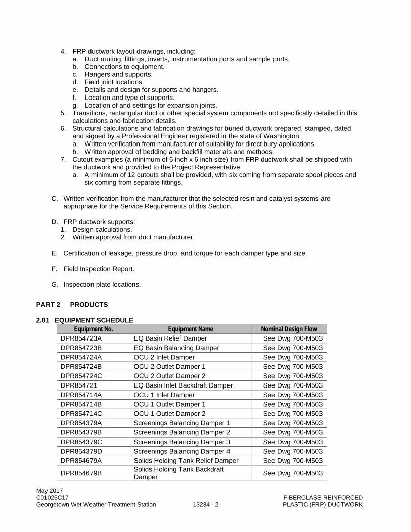
May 2017 C01025C17 FIBERGLASS REINFORCED Georgetown Wet Weather Treatment Station 13234 - 2 PLASTIC (FRP) DUCTWORK
4. FRP ductwork layout drawings, including: a. Duct routing, fittings, inverts, instrumentation ports and sample ports. b. Connections to equipment. c. Hangers and supports. d. Field joint locations. e. Details and design for supports and hangers. f. Location and type of supports. g. Location of and settings for expansion joints.
5. Transitions, rectangular duct or other special system components not specifically detailed in this calculations and fabrication details.
6. Structural calculations and fabrication drawings for buried ductwork prepared, stamped, dated and signed by a Professional Engineer registered in the state of Washington. a. Written verification from manufacturer of suitability for direct bury applications. b. Written approval of bedding and backfill materials and methods.
7. Cutout examples (a minimum of 6 inch x 6 inch size) from FRP ductwork shall be shipped with the ductwork and provided to the Project Representative. a. A minimum of 12 cutouts shall be provided, with six coming from separate spool pieces and
six coming from separate fittings.
C. Written verification from the manufacturer that the selected resin and catalyst systems are appropriate for the Service Requirements of this Section.
D. FRP ductwork supports: 1. Design calculations. 2. Written approval from duct manufacturer.
E. Certification of leakage, pressure drop, and torque for each damper type and size.
F. Field Inspection Report.
G. Inspection plate locations.
PART 2 PRODUCTS
2.01 EQUIPMENT SCHEDULE Equipment No. Equipment Name Nominal Design Flow
DPR854723A EQ Basin Relief Damper See Dwg 700-M503 DPR854723B EQ Basin Balancing Damper See Dwg 700-M503 DPR854724A OCU 2 Inlet Damper See Dwg 700-M503 DPR854724B OCU 2 Outlet Damper 1 See Dwg 700-M503 DPR854724C OCU 2 Outlet Damper 2 See Dwg 700-M503 DPR854721 EQ Basin Inlet Backdraft Damper See Dwg 700-M503 DPR854714A OCU 1 Inlet Damper See Dwg 700-M503 DPR854714B OCU 1 Outlet Damper 1 See Dwg 700-M503 DPR854714C OCU 1 Outlet Damper 2 See Dwg 700-M503 DPR854379A Screenings Balancing Damper 1 See Dwg 700-M503 DPR854379B Screenings Balancing Damper 2 See Dwg 700-M503 DPR854379C Screenings Balancing Damper 3 See Dwg 700-M503 DPR854379D Screenings Balancing Damper 4 See Dwg 700-M503 DPR854679A Solids Holding Tank Relief Damper See Dwg 700-M503
DPR854679B Solids Holding Tank Backdraft Damper See Dwg 700-M503

May 2017 C01025C17 FIBERGLASS REINFORCED Georgetown Wet Weather Treatment Station 13234 - 3 PLASTIC (FRP) DUCTWORK
Equipment No. Equipment Name Nominal Design Flow
DPR854679C Solids Holding Tank Balancing Damper 1 See Dwg 700-M503
DPR854679D Solids Holding Tank Balancing Damper 2 See Dwg 700-M503
2.02 GENERAL
A. Service Requirements: 1. Air Stream Contents: Saturated air streams containing hydrogen sulfide in concentrations up to
50 ppm at between 20 and 115°F. 2. Pressure and Vacuum (gauge): Minimum operating conditions are 30 inches water column (w.c.)
positive pressure and 30 inches w.c. vacuum (negative pressure).
2.03 ACCEPTABLE MANUFACTURERS
A. FRP Ducting Resin (Exterior/Buried): 1. Ashland: Derakane 510C-350. 2. Ashland: Hetron 992. 3. Reichhold: Dion VER9300FR. 4. Approved Equal.
B. FRP Silencers: 1. Fibersonic by DP Wilson. 2. ECS Environmental Solutions. 3. Approved Equal.
C. FRP Ductwork (Interior): 1. Composites USA (Dual Guard 2000). 2. The Engineer knows no equal.
D. FRP Ductwork (Exterior/Buried): 1. Spunstrand. 2. ECS Environmental Solutions. 3. Daniel Company. 4. Approved Equal.
E. FRP Round Dampers: 1. Swartwout: CBDR914. 2. Daniel Company: DanElast. 3. Approved Equal.
F. Backdraft and Pressure Relief Dampers: 1. Swartwout: CBDR914. 2. Daniel Company: DanElast. 3. Approved Equal
G. Expansion Joints: 1. Proco. 2. Daniel Company. 3. Spunstrand. 4. Approved Equal.
May 2017 C01025C17 FIBERGLASS REINFORCED Georgetown Wet Weather Treatment Station 13234 - 4 PLASTIC (FRP) DUCTWORK
H. Zero-Loss Stackheads: 1. Spunstrand. 2. ECS Environmental Solutions. 3. Approved Equal.
I. Acoustical Jacketing: 1. Advance Thermal Corp (Acoustirap). 2. North Atlantic Associates (Quiet Cover). 3. Approved Equal.
2.04 MATERIALS
A. FRP Ducting: 1. Interior (Screenings Room):
a. Factory Mutual approved (FM 4922 and FM 4910) with unlimited height restrictions. b. UL 181 listed Class 1 duct:
1) Flame spread of 5 (interior and exterior of duct). 2) Smoke development of 10 (interior and exterior of duct).
c. Fluoropolymer, corrosion resistant construction, suitable for the Service Requirements outlined in this Section for both the interior and exterior of the ductwork. 1) Corrosion Liner (resin rich) Thickness, minimum: 100 mils.
a) Surfacing Veil (Inner Surface): Halar surfacing veil (25 mils). b) Interior Layer: 20-30 percent C-glass, resin rich.
2) Filament Wound Structural Wall Glass Content: 55 percent to 65 percent. 3) Natural color, no pigments allowed. 4) External Layer: woven fiberglass cloth.
d. For portions of the interior ductwork that extend outside the building to connect with exterior ductwork, the exterior of the duct shall include a UV inhibiting gelcoat that meets a flame spread of 25 or less per ASTM E84. 1) Minimum coating thickness: 20 mil. 2) Color: match color sample provided by the Project Representative.
2. Exterior/Buried: a. Resin: Premium grade vinyl ester resin, suitable for the Service Requirements outlined in this
Section. 1) Natural color, no pigments allowed.
b. Laminates shall achieve a Class I flame spread in accordance with ASTM E84. 1) Antimony pentoxide may be used, if necessary, to achieve the required flame spread
rating. 2) Duct located exterior (above grade) shall include a UV inhibiting gelcoat that meets a
flame spread of 25 or less ASTM E84. a) Minimum coating thickness: 20 mil. b) Color: match color sample provided by the Project Representative.
c. Special Catalyst: In accordance with the recommendations of the resin manufacturer for the intended service.
d. Minimum Barcol Hardness: 36. e. Corrosion Liner (resin rich) Thickness, minimum: 100 mils.
1) Surfacing Veil (Inner Surface): Two (2) plies of 10 mil C-glass surfacing veil. 2) Interior Layer: Two (2) layers of 1-1/2 oz./sq. ft. mat.
f. Filament Winding Helix Angle: 55 percent; Tolerance: 2. g. Filament Winding Cycle Thickness, Maximum: 0.06 inches. h. Filament Wound Structural Wall Glass Content: 55 percent to 65 percent. i. Buried Ductwork:
1) Structurally designed to include soil and HS-25 traffic loads based on the depth, grading and soil conditions indicated in the Drawings and Specifications.
2) Designed for full range of pressure and vacuum conditions.
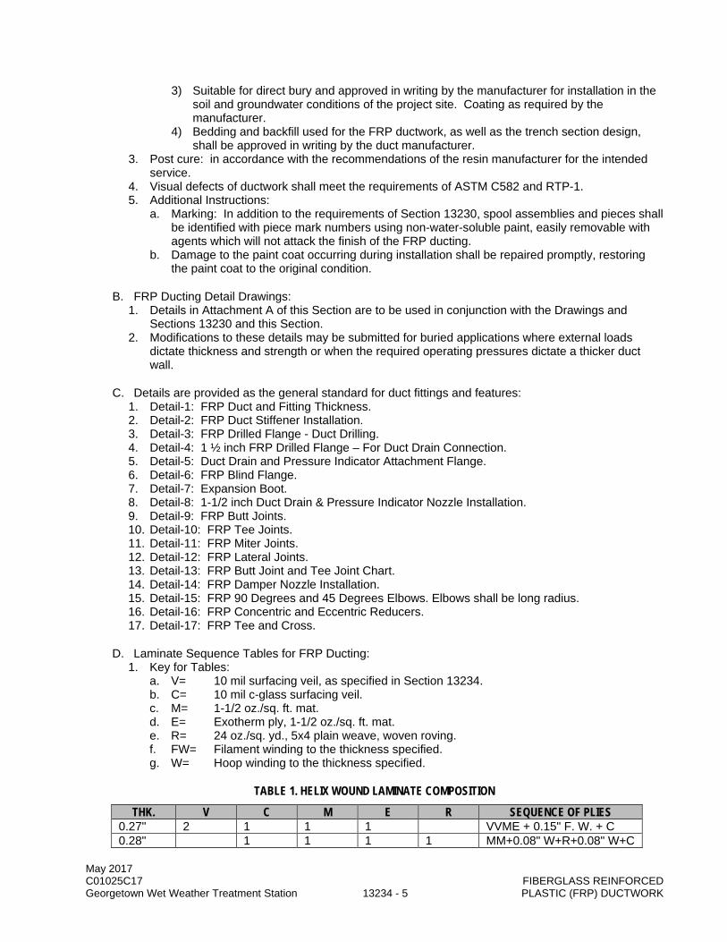
May 2017 C01025C17 FIBERGLASS REINFORCED Georgetown Wet Weather Treatment Station 13234 - 5 PLASTIC (FRP) DUCTWORK
3) Suitable for direct bury and approved in writing by the manufacturer for installation in the soil and groundwater conditions of the project site. Coating as required by the manufacturer.
4) Bedding and backfill used for the FRP ductwork, as well as the trench section design, shall be approved in writing by the duct manufacturer.
3. Post cure: in accordance with the recommendations of the resin manufacturer for the intended service.
4. Visual defects of ductwork shall meet the requirements of ASTM C582 and RTP-1. 5. Additional Instructions:
a. Marking: In addition to the requirements of Section 13230, spool assemblies and pieces shall be identified with piece mark numbers using non-water-soluble paint, easily removable with agents which will not attack the finish of the FRP ducting.
b. Damage to the paint coat occurring during installation shall be repaired promptly, restoring the paint coat to the original condition.
B. FRP Ducting Detail Drawings: 1. Details in Attachment A of this Section are to be used in conjunction with the Drawings and
Sections 13230 and this Section. 2. Modifications to these details may be submitted for buried applications where external loads
dictate thickness and strength or when the required operating pressures dictate a thicker duct wall.
C. Details are provided as the general standard for duct fittings and features: 1. Detail-1: FRP Duct and Fitting Thickness. 2. Detail-2: FRP Duct Stiffener Installation. 3. Detail-3: FRP Drilled Flange - Duct Drilling. 4. Detail-4: 1 ½ inch FRP Drilled Flange – For Duct Drain Connection. 5. Detail-5: Duct Drain and Pressure Indicator Attachment Flange. 6. Detail-6: FRP Blind Flange. 7. Detail-7: Expansion Boot. 8. Detail-8: 1-1/2 inch Duct Drain & Pressure Indicator Nozzle Installation. 9. Detail-9: FRP Butt Joints. 10. Detail-10: FRP Tee Joints. 11. Detail-11: FRP Miter Joints. 12. Detail-12: FRP Lateral Joints. 13. Detail-13: FRP Butt Joint and Tee Joint Chart. 14. Detail-14: FRP Damper Nozzle Installation. 15. Detail-15: FRP 90 Degrees and 45 Degrees Elbows. Elbows shall be long radius. 16. Detail-16: FRP Concentric and Eccentric Reducers. 17. Detail-17: FRP Tee and Cross.
D. Laminate Sequence Tables for FRP Ducting: 1. Key for Tables:
a. V= 10 mil surfacing veil, as specified in Section 13234. b. C= 10 mil c-glass surfacing veil. c. M= 1-1/2 oz./sq. ft. mat. d. E= Exotherm ply, 1-1/2 oz./sq. ft. mat. e. R= 24 oz./sq. yd., 5x4 plain weave, woven roving. f. FW= Filament winding to the thickness specified. g. W= Hoop winding to the thickness specified.
TABLE 1. HELIX WOUND LAMINATE COMPOSITION
THK. V C M E R SEQUENCE OF PLIES 0.27" 2 1 1 1 VVME + 0.15" F. W. + C 0.28" 1 1 1 1 MM+0.08" W+R+0.08" W+C
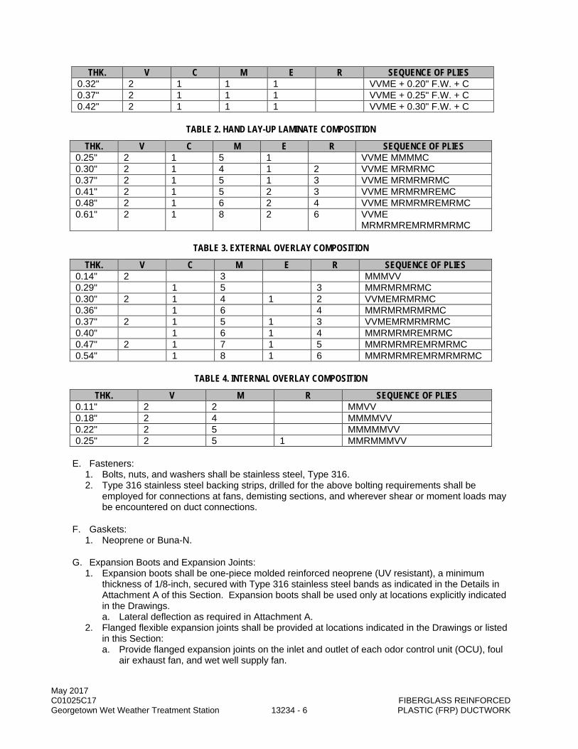
May 2017 C01025C17 FIBERGLASS REINFORCED Georgetown Wet Weather Treatment Station 13234 - 6 PLASTIC (FRP) DUCTWORK
THK. V C M E R SEQUENCE OF PLIES 0.32" 2 1 1 1 VVME + 0.20" F.W. + C 0.37" 2 1 1 1 VVME + 0.25" F.W. + C 0.42" 2 1 1 1 VVME + 0.30" F.W. + C
TABLE 2. HAND LAY-UP LAMINATE COMPOSITION
THK. V C M E R SEQUENCE OF PLIES 0.25" 2 1 5 1 VVME MMMMC 0.30" 2 1 4 1 2 VVME MRMRMC 0.37" 2 1 5 1 3 VVME MRMRMRMC 0.41" 2 1 5 2 3 VVME MRMRMREMC 0.48" 2 1 6 2 4 VVME MRMRMREMRMC 0.61" 2 1 8 2 6 VVME
MRMRMREMRMRMRMC
TABLE 3. EXTERNAL OVERLAY COMPOSITION
THK. V C M E R SEQUENCE OF PLIES 0.14" 2 3 MMMVV 0.29" 1 5 3 MMRMRMRMC 0.30" 2 1 4 1 2 VVMEMRMRMC 0.36" 1 6 4 MMRMRMRMRMC 0.37" 2 1 5 1 3 VVMEMRMRMRMC 0.40" 1 6 1 4 MMRMRMREMRMC 0.47" 2 1 7 1 5 MMRMRMREMRMRMC 0.54" 1 8 1 6 MMRMRMREMRMRMRMC
TABLE 4. INTERNAL OVERLAY COMPOSITION
THK. V M R SEQUENCE OF PLIES 0.11" 2 2 MMVV 0.18" 2 4 MMMMVV 0.22" 2 5 MMMMMVV 0.25" 2 5 1 MMRMMMVV
E. Fasteners: 1. Bolts, nuts, and washers shall be stainless steel, Type 316. 2. Type 316 stainless steel backing strips, drilled for the above bolting requirements shall be
employed for connections at fans, demisting sections, and wherever shear or moment loads may be encountered on duct connections.
F. Gaskets: 1. Neoprene or Buna-N.
G. Expansion Boots and Expansion Joints: 1. Expansion boots shall be one-piece molded reinforced neoprene (UV resistant), a minimum
thickness of 1/8-inch, secured with Type 316 stainless steel bands as indicated in the Details in Attachment A of this Section. Expansion boots shall be used only at locations explicitly indicated in the Drawings. a. Lateral deflection as required in Attachment A.
2. Flanged flexible expansion joints shall be provided at locations indicated in the Drawings or listed in this Section: a. Provide flanged expansion joints on the inlet and outlet of each odor control unit (OCU), foul
air exhaust fan, and wet well supply fan.

May 2017 C01025C17 FIBERGLASS REINFORCED Georgetown Wet Weather Treatment Station 13234 - 7 PLASTIC (FRP) DUCTWORK
b. Material: reinforced neoprene, with integral flange suitable for exterior (UV resistant) service with FRP duct.
c. Unless otherwise indicated in the Drawings, shall be circular (cylindrical) construction: 1) Rectangular joints shall be used for flexible connectors on fan discharge outlets and on
inlet box connections. d. Backing Rings: 3/8-inch thick, 2-inch wide, Type 316 stainless steel.
1) Integral FRP of 316 SST flange may be used in place of backing rings. e. Minimum total expansion/contraction: 4-inches:
1) Joint shall be field set based on ambient temperature at the time of installation to provide for the complete range of thermal expansion and contraction required for the Service Requirements.
2) Manufacturer shall submit recommended setting for review by the Project Representative: a) Design temperature range: 10°F to 100°F.
f. Minimum allowable lateral deflection: Five degrees. g. Thickness: 1/4-inch, minimum.
3. Durometer value: 70 or less.
H. Supports and Hangers: 1. See Section 15050, 15096 and 15097. 2. Not all supports are shown in the Drawings. 3. Provide supports as indicated in the Drawings and any additional supports necessary for
compliance with the requirements of this Section. 4. FRP ductwork shall be supported at intervals no greater than those indicated in the table below. 5. Supports and hangers shall transmit ductwork loads into the building structural frame through a
system of intermediate beams and struts as necessary to accommodate requirements of these Specifications.
6. Support Types: a. Guide Supports: provide for support for all applicable loads, but allow for axial movement of
the duct and expansion and contraction of the duct radially. b. Fixed (Anchor) Supports: provide rigid connections to the duct, within the constraints of this
Section for thermal expansion, to support applicable loads and prevent axial movement of the duct. 1) FRP Collars:
a) An FRP collar shall be composed of a laminate build-up on either side of a support strap or saddle to provide a rigid hold on the saddle strap and limit duct axial movement.
2) Alternative methods to provide fixed supports shall meet the requirements of this Section. 7. Prepare construction details for supports and hangers and layout drawings for location and type
of supports, including location of any required expansion joints.
FRP DUCTING ALLOWABLE SPANS INSIDE DIAMETER - INCHES MAXIMUM SPAN, FOOT
12 12 14 12 16 12 18 12 20 12 24 12 32 12 36 12
May 2017 C01025C17 FIBERGLASS REINFORCED Georgetown Wet Weather Treatment Station 13234 - 8 PLASTIC (FRP) DUCTWORK
8. Hangers and supports shall be lined with 1/8-inch thick neoprene, bonded to the metal hanger or support, to provide cushion for the duct (minimum durometer of 60). If the support is intended to allow the duct to slide due to thermal expansion (Guide Support), a piece of polymer sheet or roof membrane shall be used over the neoprene to provide a lower friction surface, as recommended by the duct manufacturer.
9. Vertical and horizontal support pedestals shall be anchored to concrete walls and floors using a baseplate and grout underlayment similar to Standard Detail 151314. a. When vertical pedestals are positioned over in areas without a concrete finished floor, a base
equipment pad shall be included in the support design. 1) The equipment pad base shall meet the requirements of Standard Detail 030032 or
030033. Selection of the equipment pad base shall be by the support designer and the basis of selection included as part of the submitted support design shop drawings.
2) Equipment pad design shall be coordinated with the site geotechnical report and the following criteria: a) Allowable bearing pressure (static) = 800 psf. b) Allowable bearing pressure (transient loading: i.e. wind/seismic) = 1200 psf.
10. Attach supports (guide and fixed) to the full circumference of the duct and allow for radial and axial thermal expansion.
11. Duct support system shall be designed to accommodate the full range of thermal movement within the duct system for temperatures ranging from 10°F to 100°F.
12. Base of every horizontal duct shall be support by a saddle extending a minimum of 120 degrees along the invert of the duct.
13. Support attachment radius shall be designed for the warmest condition of the duct and avoid imparting excessive hoop stress on the duct.
14. Support saddles shall avoid imparting excessive point loads on the ductwork. The minimum saddle width shall be as follows: a. Duct diameter 12-inches or less: 4-inches. b. Duct diameter greater than 12-inches and less than or equal to 18-inches: 6-inches. c. Duct diameter greater than 18-inches and less than or equal to 24-inches: 8-inches. d. Duct diameter greater than 24-inches: 12-inches. e. Edges of saddles and straps toward the FRP duct shall be softened to 1/16-inch or larger
radius. 15. Hangers and supports (including hardware) shall be constructed of materials meeting the
requirements of Section 15096. 16. Structural attachments and anchor bolts shall conform to Section 15096 and Section 05501. 17. Supports shall be designed with a 5:1 safety factor and account for all applicable seismic and
operating loads. a. Seismic loadings: Section 01031. b. All FRP duct support systems, regardless of duct diameter, shall be designed for seismic
loading and be required to operate after a seismic event. c. Seismic supports shall brace against horizontal, vertical, axial and longitudinal sway. d. For the purpose of support design, the material transported in FRP duct shall be considered
hazardous. 18. Hangers and supports shall be provided at dampers, mist/grease eliminators, both sides of bends
and elbows, both sides of expansion boots and expansion joints, and other valves and fittings to accommodate the full load of the equipment. a. Inlet and discharge flanges of process equipment and dampers shall not be used for the
support of ductwork. b. Duct wall/floor penetrations shall not be used for support of ductwork or otherwise assumed
to provide any form of vertical or lateral restraint. c. Duct penetrations through acoustical enclosures shall not be used for support of ductwork.
19. Unless otherwise indicated in this Section, support systems for FRP ductwork shall be designed in compliance with the SMACNA Thermoset FRP Duct Construction Manual and the SMACNA Seismic Restraint Manual: a. Supports shall be approved in writing by the FRP duct manufacturer.

May 2017 C01025C17 FIBERGLASS REINFORCED Georgetown Wet Weather Treatment Station 13234 - 9 PLASTIC (FRP) DUCTWORK
b. Support design for the ductwork shall be prepared, stamped, dated and signed by a Professional Engineer registered in the state of Washington.
I. Dampers:
EQUIPMENT NO. DESCRIPTION SERVICE STYLE DIAMETER (IN) DPR854723A EQ Basin Relief
Damper FA Backdraft
Round 24
DPR854723B EQ Basin Balancing Damper
FA Round 24
DPR854724A OCU 2 Inlet Damper FA Round 28
DPR854724B OCU 2 Outlet Damper 1
TA Round 20
DPR854724C OCU 2 Outlet Damper 2
TA Round 20
DPR854721 EQ Basin Inlet Backdraft Damper
SPA Backdraft Round
24
DPR854714A OCU 1 Inlet Damper FA Round 36
DPR854714B OCU 1 Outlet Damper 1
TA Round 26
DPR854714C OCU 1Outlet Damper 2
TA Round 26
DPR854379A Screenings Balancing Damper 1
FA Round 24
DPR854379B Screenings Balancing Damper 2
FA Round 24
DPR854379C Screenings Balancing Damper 3
FA Round 24
DPR854379D Screenings Balancing Damper 4
FA Round 24
DPR854679A Solids Holding Tank Relief Damper
SPA Backdraft Round
16
DPR854679B Solids Holding Tank Backdraft Damper
SPA Backdraft Round
16
DPR854679C Solids Holding Tank Balancing Damper 1
FA Round 12
DPR854679D Solids Holding Tank Balancing Damper 2
FA Round 12
1. General:
a. Dampers shall have FRP blades, Type 316 stainless steel shafts and hardware, and permanently lubricated bearings of material impervious to attack by acids and caustics.
b. Damper frames shall be fabricated from channels with widths to match connecting ductworks, a minimum height of 2-inches and a minimum thickness of 10-gauge for rectangular dampers.
c. Frame deflection produced by a differential pressure of 30-inches w.c. across the closed damper shall not exceed 1/360th of the span in any direction.
d. Dampers shall be flanged. Flanges shall be pre-punched and shall match duct flanges and bolt patterns as specified in this Section.
e. Stuffing boxes: 1) Provide for gas-tight seals to prevent leakage at shaft penetrations. 2) Adjustable and contain a minimum of two sets of packing glands.

May 2017 C01025C17 FIBERGLASS REINFORCED Georgetown Wet Weather Treatment Station 13234 - 10 PLASTIC (FRP) DUCTWORK
3) Bearings shall be flange mounted, located outside the air stream unless otherwise noted. Bearings may be molded PTFE, oil impregnated sintered bronze or relubricable rolling element.
f. Rectangular damper linkage: 1) Capable of transmitting twice the maximum torque required by the damper at the
maximum rated differential pressure. 2) Linkage lever arms shall be a minimum of 3-inches and the lever arms shall be tack
welded to the axles. 3) Linkage connections shall be supplied with oil impregnated bronze bearings.
g. Operators: 1) Torque requirements of 500 inch-pounds or less shall have heavy duty manual locking
quadrants. 2) Torque requirements in excess of 500 inch-pounds shall have manual worm gear
actuators with hand wheels. 3) Constructed of corrosion resistant and epoxy coated materials. 4) When not readily accessible (above 6-feet from finished floor), provide with non-sparking
chain wheel operators. h. Leakage through the closed FRP dampers at 70°F and 10-inches w.c. differential pressure
shall not exceed one cfm per square foot of conduit cross-sectional area for dampers, unless noted otherwise in this Section. 1) Damper supplier shall provide certified leakage, pressure drop, and torque for each
damper type and size. Data shall result from prototype testing conducted in accordance with AMCA 500 test standards in an AMCA certified test facility.
2. Round Dampers: a. Vinyl ester FRP with a flame spread rating matching the FRP exterior ductwork in this
Section. 1) Dampers located interior shall include a UV inhibiting gel coat matching the exterior
ductwork in this Section. 2) Dampers located interior (inside any room, structure, or building) shall include an
intumescent gelcoat that meets both a flame spread of 25 or less and a smoke development rating of 50 or less ASTM E84. a) Two (2) coats of PPG Speedhide Flat Latex paint No. 42-7 or an Approved Equal
product, in accordance with the manufacturer’s recommendations, for exterior fire retardancy.
b. Butterfly dampers suitable for balancing and for positive shut-off. c. Shut-off sealing shall be achieved by a TFE fluorocarbon O-ring seal and be designated as
“zero leakage” or meeting the maximum leakage per this Section. d. Dampers shall be constructed between two flanges. e. Minimum damper blade thickness shall be equal to flange thickness specified in this Section. f. Dampers shall include position indications and include features for locking the damper blade
into the balanced position: 1) Maximum pressure loss, when fully open, of 0.1-inches w.c. at 2,000 fpm.
3. Backdraft Dampers: a. FRP dampers utilized for passive air inlet (barometric backdraft) or emergency exhaust
(pressure relief to atmosphere). b. Round dampers as specified in this Section, with adjustable, exterior weighted arms. c. Damper blades shall be designed to operate at the conditions listed in this Section and
remain sealed when the conditions are not met. d. Full circumference blade seal: TFE fluorocarbon. e. Damper weighted arms shall be preset to open at the following set points:
1) Backdraft dampers (open inward): - 0.1-inches w.c. (negative pressure). 2) Relief dampers (open outward): 1-inch w.c. (positive pressure). 3) Damper weighted arms shall be field adjustable and able to be locked in position.
4. Actuators: independently supported.
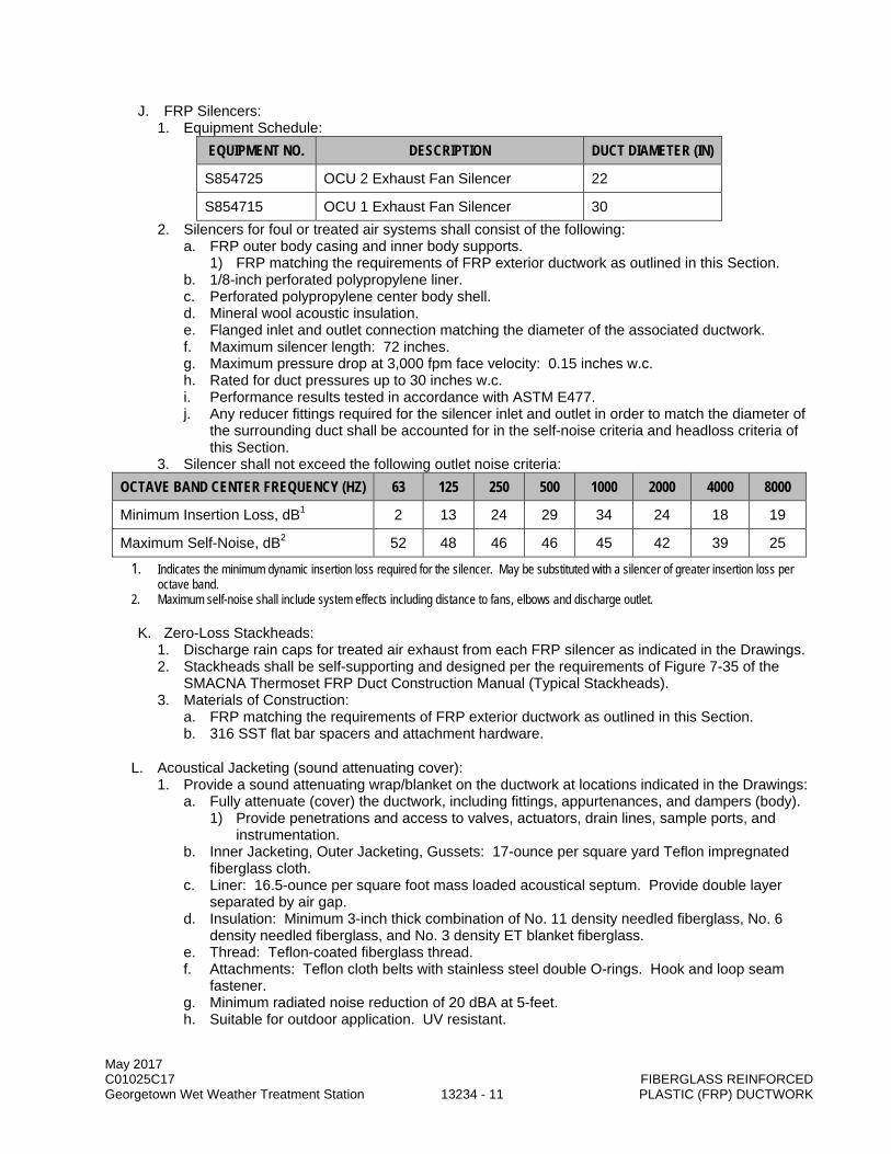
May 2017 C01025C17 FIBERGLASS REINFORCED Georgetown Wet Weather Treatment Station 13234 - 11 PLASTIC (FRP) DUCTWORK
J. FRP Silencers: 1. Equipment Schedule:
EQUIPMENT NO. DESCRIPTION DUCT DIAMETER (IN)
S854725 OCU 2 Exhaust Fan Silencer 22
S854715 OCU 1 Exhaust Fan Silencer 30 2. Silencers for foul or treated air systems shall consist of the following:
a. FRP outer body casing and inner body supports. 1) FRP matching the requirements of FRP exterior ductwork as outlined in this Section.
b. 1/8-inch perforated polypropylene liner. c. Perforated polypropylene center body shell. d. Mineral wool acoustic insulation. e. Flanged inlet and outlet connection matching the diameter of the associated ductwork. f. Maximum silencer length: 72 inches. g. Maximum pressure drop at 3,000 fpm face velocity: 0.15 inches w.c. h. Rated for duct pressures up to 30 inches w.c. i. Performance results tested in accordance with ASTM E477. j. Any reducer fittings required for the silencer inlet and outlet in order to match the diameter of
the surrounding duct shall be accounted for in the self-noise criteria and headloss criteria of this Section.
3. Silencer shall not exceed the following outlet noise criteria: OCTAVE BAND CENTER FREQUENCY (HZ) 63 125 250 500 1000 2000 4000 8000
Minimum Insertion Loss, dB1 2 13 24 29 34 24 18 19
Maximum Self-Noise, dB2 52 48 46 46 45 42 39 25
1. Indicates the minimum dynamic insertion loss required for the silencer. May be substituted with a silencer of greater insertion loss per octave band.
2. Maximum self-noise shall include system effects including distance to fans, elbows and discharge outlet.
K. Zero-Loss Stackheads: 1. Discharge rain caps for treated air exhaust from each FRP silencer as indicated in the Drawings. 2. Stackheads shall be self-supporting and designed per the requirements of Figure 7-35 of the
SMACNA Thermoset FRP Duct Construction Manual (Typical Stackheads). 3. Materials of Construction:
a. FRP matching the requirements of FRP exterior ductwork as outlined in this Section. b. 316 SST flat bar spacers and attachment hardware.
L. Acoustical Jacketing (sound attenuating cover): 1. Provide a sound attenuating wrap/blanket on the ductwork at locations indicated in the Drawings:
a. Fully attenuate (cover) the ductwork, including fittings, appurtenances, and dampers (body). 1) Provide penetrations and access to valves, actuators, drain lines, sample ports, and
instrumentation. b. Inner Jacketing, Outer Jacketing, Gussets: 17-ounce per square yard Teflon impregnated
fiberglass cloth. c. Liner: 16.5-ounce per square foot mass loaded acoustical septum. Provide double layer
separated by air gap. d. Insulation: Minimum 3-inch thick combination of No. 11 density needled fiberglass, No. 6
density needled fiberglass, and No. 3 density ET blanket fiberglass. e. Thread: Teflon-coated fiberglass thread. f. Attachments: Teflon cloth belts with stainless steel double O-rings. Hook and loop seam
fastener. g. Minimum radiated noise reduction of 20 dBA at 5-feet. h. Suitable for outdoor application. UV resistant.

May 2017 C01025C17 FIBERGLASS REINFORCED Georgetown Wet Weather Treatment Station 13234 - 12 PLASTIC (FRP) DUCTWORK
i. Wrap shall be easily removable for maintenance and not permanently adhered to the ductwork.
M. Inspection Plates: 1. Removable inspection plates, not less than six inches square or eight inches round, shall be
provided at fan inlet and discharge connections, and upstream and downstream from fittings. 2. Gasketed and make an airtight seal with the parent duct. 3. Fabricated of the same material as the parent duct. 4. Duct manufacturer shall propose and submit construction, location, and installation details.
N. Drains: 1. In addition to drains indicated in the Drawings, provide drains with 1-1/2-inch minimum flanged
outlets at low points in duct system. 2. Drain shall be fitted with a 1-1/2-inch PVC isolation ball valve with PTFE O-rings/gaskets.
O. Additional Equipment: 1. Fabrication details are provided in the Details included in Attachment A of this Section. 2. Where transitions, rectangular duct or other special system components not specifically detailed
in this Section are needed, manufacturer shall be responsible for the design of the component. Minimum safety factor for critical buckling due to vacuum shall be 5:1 and deflection of flat panels shall be limited to 1% of the width of the panel. Corrosion liner shall not be included in structural calculations.
2.05 SOURCE QUALITY CONTROL
A. Refer to Section 13230.
PART 3 EXECUTION
3.01 GENERAL
A. Refer to Section 13230.
3.02 INSTALLATION
A. Material and equipment shall be installed as specified and as required by the applicable state and local codes. Be responsible for changes in duct size, duct configuration, and location to conform to field conditions. Such changes shall be submitted for review per Section 01300 prior to fabrication or construction:
1. Field Joining Materials: FRP duct manufacturer shall provide materials needed for any required FRP duct field joining. Providing these materials shall be in accordance with the requirements of this Section and Section 13230.
2. Field Joining: Required field joining shall be accomplished in accordance with the requirements of this Section and Section 13230. a. Field joints shall maintain continuous corrosion resistance on the interior and exterior of the
duct. 3. FRP ductwork shall be installed and supported in accordance with Sections 15096, 15097 and
this Section. Large elbows and terminal ends of ducts shall be supported independently. 4. Flexible connections as described in this Section shall be provided between fans and ductwork,
and elsewhere as indicated in the Drawings. 5. Follow protocol of the duct manufacturer when backfilling buried duct, including temporary
supports, to avoid buckling or excessive deflection. 6. Long radius elbows shall be used for bends unless otherwise indicated in the Drawings. 7. Installation shall be certified on manufacturer’s Installation Certification Form 11000-A: Section
01999.

May 2017 C01025C17 FIBERGLASS REINFORCED Georgetown Wet Weather Treatment Station 13234 - 13 PLASTIC (FRP) DUCTWORK
3.03 FIELD QUALITY CONTROL
A. Testing: 1. Ductwork shall be leak-tested as described in Section 15050. 2. Audible leaks shall be sealed. 3. Provide a minimum of 24 hour notice of testing to the Project Representative. 4. Provide necessary fittings, blind flanges, tools and fittings to isolate sections of duct and to enable
sections of ductwork to be tested.
B. FRP Duct Manufacturer’s Services: 1. Representative shall be on-site at the start of the installation of the ductwork to supervise
installation of the FRP duct system and provide initial instruction regarding appropriate procedures for handling, cutting, construction of field joints and all other manufacturer recommendations.
2. Shall remain on-site to witness installation of ductwork to ensure proper procedures are being employed.
3. On-site no less than two 8-hour days during the start of installation. 4. Instruct on the proper installation procedures at any time the FRP duct manufacturer
representative and the Project Representative witness improper installation practices. 5. Provide a summary Field Inspection Report certifying that the duct has been installed per the
manufacturer’s recommendations.
3.04 FABRICATION DETAILS
A. Refer to Standard Detail Drawings and Tables in Attachment A for fabrication details, thickness and dimensions. Dimensions indicated are minimums. Be responsible to supply duct that meets the pressure and load requirements listed in this Section.
END OF SECTION

May 2017 C01025C17 FIBERGLASS REINFORCED Georgetown Wet Weather Treatment Station 13234 - 14 PLASTIC (FRP) DUCTWORK
This page intentionally left blank.

May 2017 C01025C17 FIBERGLASS REINFORCED Georgetown Wet Weather Treatment Station 13234 - 15 PLASTIC (FRP) DUCTWORK
ATTACHMENT A

May 2017 C01025C17 FIBERGLASS REINFORCED Georgetown Wet Weather Treatment Station 13234 - 16 PLASTIC (FRP) DUCTWORK
This page left intentionally blank.

May 2017 C01025C17 FIBERGLASS REINFORCED Georgetown Wet Weather Treatment Station 13234 - 17 PLASTIC (FRP) DUCTWORK
Detail – 1
A. FRP Duct and Fitting Thickness Table FRP DUCT AND FITTING THICKNESS
DUCT I.D.
FRP DUCT F.W. WALL THK.
( TABLE 1 )
FRP FITTINGS H.L.U. WALL THK.
( TABLE 2 ) 12" O.27" 0.30" 14" 0.27" 0.30" 16" 0.27" 0.30" 18" 0.32" 0.37" 20” 0.32" 0.37" 24" 0.37" 0.41" 30" 0.37" 0.41" 36" 0.42" 0.48" *42" 0.37" 0.41" *48” 0.42” 0.48” *54” 0.42” 0.48” *60” 0.42” 0.48” *72” 0.42” 0.48”
*See Detail-2 for stiffener attachment and spacing
B. General Notes: 1. Wall thickness of eccentric and concentric reducers to be that of the larger I.D. using the fitting
column thickness. 2. Wall thicknesses shown are considered minimums. The manufacturer shall increase the
thickness, if necessary, to meet the design and performance conditions of this Section.

May 2017 C01025C17 FIBERGLASS REINFORCED Georgetown Wet Weather Treatment Station 13234 - 18 PLASTIC (FRP) DUCTWORK
Detail - 2
A. FRP Duct Stiffener Installation
DUCT SIZE
A B C D E F G H
42” 15’-0” 2” 2” 1” 4” 2” 0.28” 0.29” 48” 15’-0” 2” 2” 1” 4” 2” 0.28” 0.29” 54” 15’-0” 2” 2” 1” 4” 2” 0.28” 0.29” 60” 15’-0” 3” 3” 1” 4” 2” 0.28” 0.29” 72” 10’-0” 3” 3” 1” 4” 2” 0.28” 0.29”
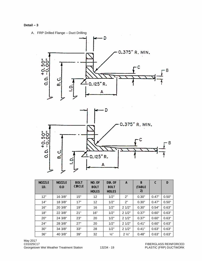
May 2017 C01025C17 FIBERGLASS REINFORCED Georgetown Wet Weather Treatment Station 13234 - 19 PLASTIC (FRP) DUCTWORK
Detail – 3
A. FRP Drilled Flange – Duct Drilling
NOZZLE I.D.
NOZZLE O.D
BOLT CIRCLE
NO. OF BOLT
HOLES
DIA. OF BOLT
HOLES
A B (TABLE
2)
C D
12" 16 3/8" 15" 12 1/2" 2" 0.30" 0.47" 0.50" 14" 18 3/8" 17" 12 1/2" 2" 0.30" 0.47" 0.50" 16" 20 3/8" 19" 16 1/2" 2 1/2" 0.30" 0.54" 0.63" 18" 22 3/8" 21" 16" 1/2" 2 1/2" 0.37" 0.60" 0.63" 20" 24 3/8" 23" 20 1/2" 2 1/2" 0.37" 0.60" 0.63" 24" 28 3/8" 27" 20 1/2" 2 1/2" 0.41" 0.60" 0.63" 30" 34 3/8" 33" 28 1/2" 2 1/2" 0.41" 0.63" 0.63" 36” 40 3/8” 39” 32 ½” 2 ½” 0.48” 0.63” 0.63”

May 2017 C01025C17 FIBERGLASS REINFORCED Georgetown Wet Weather Treatment Station 13234 - 20 PLASTIC (FRP) DUCTWORK
NOZZLE I.D.
NOZZLE O.D
BOLT CIRCLE
NO. OF BOLT
HOLES
DIA. OF BOLT
HOLES
A B (TABLE
2)
C D
42” 46 3/8” 45” 36 ½” 2 ½” 0.47” 0.75” 0.75” 48” 54 3/8” 52” 44 5/8” 3” 0.48” 0.75” 0.75” 54” 60 3/8” 58” 44 5/8” 4” 0.61” 1.00” 1.00” 60” 66 3/8” 64” 52 5/8” 4” 0.61” 1.00” 1.00”
72”X24” 80”X32” *** *** *** 4” 0.61” 1.00” 1.00” ***To be designed by Contractor

May 2017 C01025C17 FIBERGLASS REINFORCED Georgetown Wet Weather Treatment Station 13234 - 21 PLASTIC (FRP) DUCTWORK
Detail – 4
A. 1 ½” FRP Drilled Flange – For Duct Drain
125/150 PATTERN
NOZZLE I.D.
O.D B.C. NO. OF BOLT
HOLES
DIA. OF BOLT
HOLES
A B C D
1 ½” 5” 3 7/8” 4 5/8” 2” 0.22” 0.50” 0.50”

May 2017 C01025C17 FIBERGLASS REINFORCED Georgetown Wet Weather Treatment Station 13234 - 22 PLASTIC (FRP) DUCTWORK
Detail – 5
A. Duct Drain and Pressure Indicator Attachment Flange

May 2017 C01025C17 FIBERGLASS REINFORCED Georgetown Wet Weather Treatment Station 13234 - 23 PLASTIC (FRP) DUCTWORK
Detail – 6
A. FRP Blind Flange
NOZZLE O.D
BOLT CIRCLE NO. OF BOLT
HOLES
DIA. OF BOLT
HOLES
A (TABLE 2)
12" 16 3/8" 15" 12 1/2" 0.30" 14" 18 3/8" 17" 12 1/2" 0.30" 16" 20 3/8" 19" 16 1/2" 0.30" 18" 22 3/8" 21" 16" 1/2" 0.37" 20" 24 3/8" 23" 20 1/2" 0.37" 24" 28 3/8" 27" 20 1/2" 0.41" 30" 34 3/8" 33" 28 1/2" 0.41" 36” 40 3/8” 39” 32 ½” 0.48” 42” 46 3/8” 45” 36 ½” 0.47” 48” 54 3/8” 52” 44 5/8” 0.48” 54” 60 3/8” 58” 44 5/8” 0.61” 60” 66 3/8” 64” 52 5/8” 0.61”
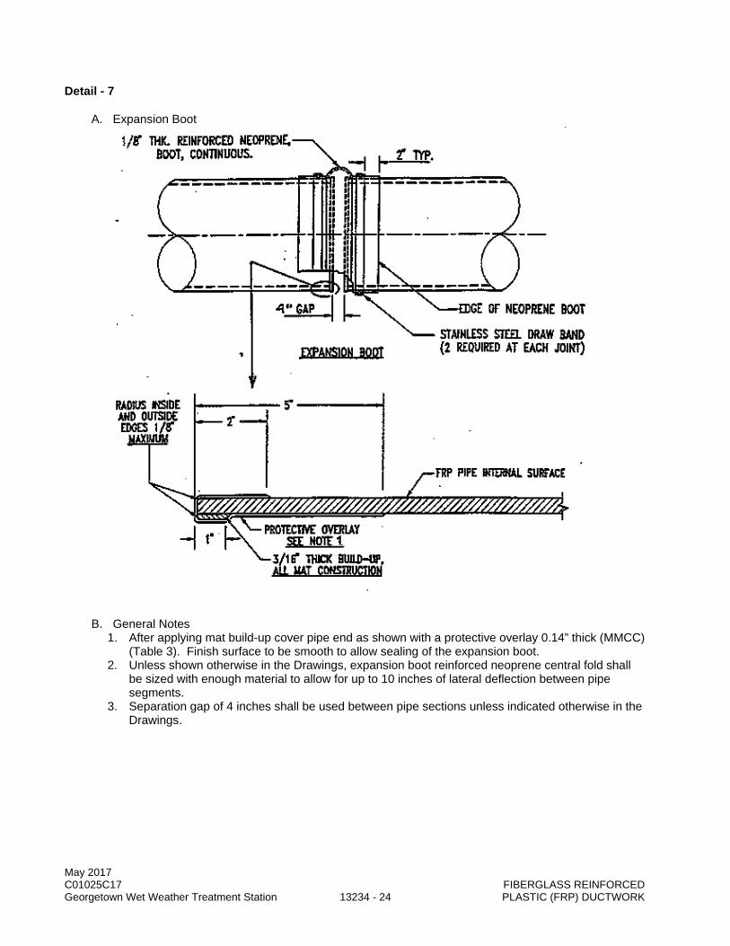
May 2017 C01025C17 FIBERGLASS REINFORCED Georgetown Wet Weather Treatment Station 13234 - 24 PLASTIC (FRP) DUCTWORK
Detail - 7
A. Expansion Boot
B. General Notes 1. After applying mat build-up cover pipe end as shown with a protective overlay 0.14” thick (MMCC)
(Table 3). Finish surface to be smooth to allow sealing of the expansion boot. 2. Unless shown otherwise in the Drawings, expansion boot reinforced neoprene central fold shall
be sized with enough material to allow for up to 10 inches of lateral deflection between pipe segments.
3. Separation gap of 4 inches shall be used between pipe sections unless indicated otherwise in the Drawings.

May 2017 C01025C17 FIBERGLASS REINFORCED Georgetown Wet Weather Treatment Station 13234 - 25 PLASTIC (FRP) DUCTWORK
Detail – 8
A. 1 ½” Diameter Duct Drain and P.I. Nozzle Installation
NOZZLE
I.D. EXTERNAL OVERLAY INTERNAL OVERLAY
THK. (TABLE 3)
WIDTH (TABLE 5)
THK. (TABLE 4)
WIDTH. (TABLE 6)
1 1/2” 0.29” 10” 0.11”-(MMCC)” 4”
B. General Notes: 1. Radius inside edge of nozzle, if internal overlay is applied, 1/8” min. to ¼” max. Where internal
overlay is not possible resin coat edges as shown in detail-10 and apply 0.30” thick external overlay.
2. Fill voids with resin putty. Flare putty into a radius ¼” min. to 3/8” max. 3. Locate vent hole as low as possible, resin coat edge of hole.
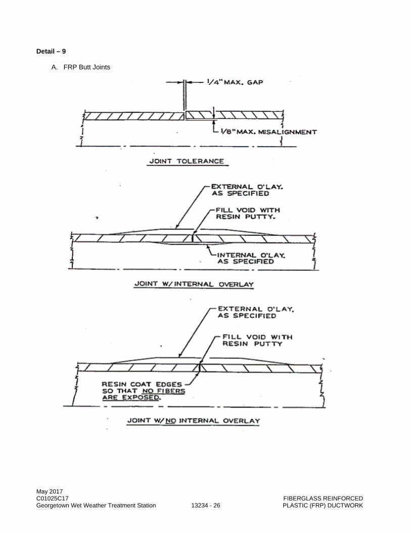
May 2017 C01025C17 FIBERGLASS REINFORCED Georgetown Wet Weather Treatment Station 13234 - 26 PLASTIC (FRP) DUCTWORK
Detail – 9
A. FRP Butt Joints

May 2017 C01025C17 FIBERGLASS REINFORCED Georgetown Wet Weather Treatment Station 13234 - 27 PLASTIC (FRP) DUCTWORK
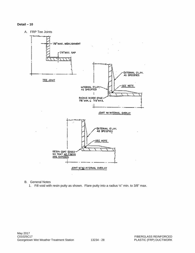
May 2017 C01025C17 FIBERGLASS REINFORCED Georgetown Wet Weather Treatment Station 13234 - 28 PLASTIC (FRP) DUCTWORK
Detail – 10
A. FRP Tee Joints
B. General Notes 1. Fill void with resin putty as shown. Flare putty into a radius ¼” min. to 3/8” max.

May 2017 C01025C17 FIBERGLASS REINFORCED Georgetown Wet Weather Treatment Station 13234 - 29 PLASTIC (FRP) DUCTWORK
Detail – 11
A. FRP Miter Joints

May 2017 C01025C17 FIBERGLASS REINFORCED Georgetown Wet Weather Treatment Station 13234 - 30 PLASTIC (FRP) DUCTWORK
Detail – 12
A. FRP Lateral Joints

May 2017 C01025C17 FIBERGLASS REINFORCED Georgetown Wet Weather Treatment Station 13234 - 31 PLASTIC (FRP) DUCTWORK
Detail – 13
A. FRP Butt Joint and Tee Joint Charts FRP DUCT BUTT JOINT OVERLAY
DUCT
EXTERNAL OVERLAY ( TABLE 2 )
I.D. THK. WIDTH 12" 0.30" 8" 14" 0.30" 8" 16" 0.30" 8" 18" 0.37" 10" 20” 0.37" 10" 24" 0.36" 10" 30" 0.36" 12" 36" 0.36" 14" 42" 0.36" 14" 48” 0.40” 14” 54” 0.47” 14” 60” 0.47” 16” 72” 0.47” 16”
B. General Notes 1. For 24” DIA. and larger, and where accessible apply an internal overlay (MMCCX6” wide)
FRP DUCT TEE JOINT OVERLAY DUCT EXTERNAL OVERLAY
( TABLE 2 ) I.D. THK. WIDTH 12" 0.30" 10" 14" 0.30" 10" 16" 0.30" 10" 18" 0.37" 12" 20" 0.37" 12" 24" 0.37" 12" 30" 0.37" 14" 36" 0.37" 14" 42" 0.4" 14" 48” 0.4” 16” 54” 0.4” 16” 60” 0.4” 16”
C. General Notes 1. For header diameter 24” and larger, and where accessible, apply an internal overlay (MMCCX6”
wide).
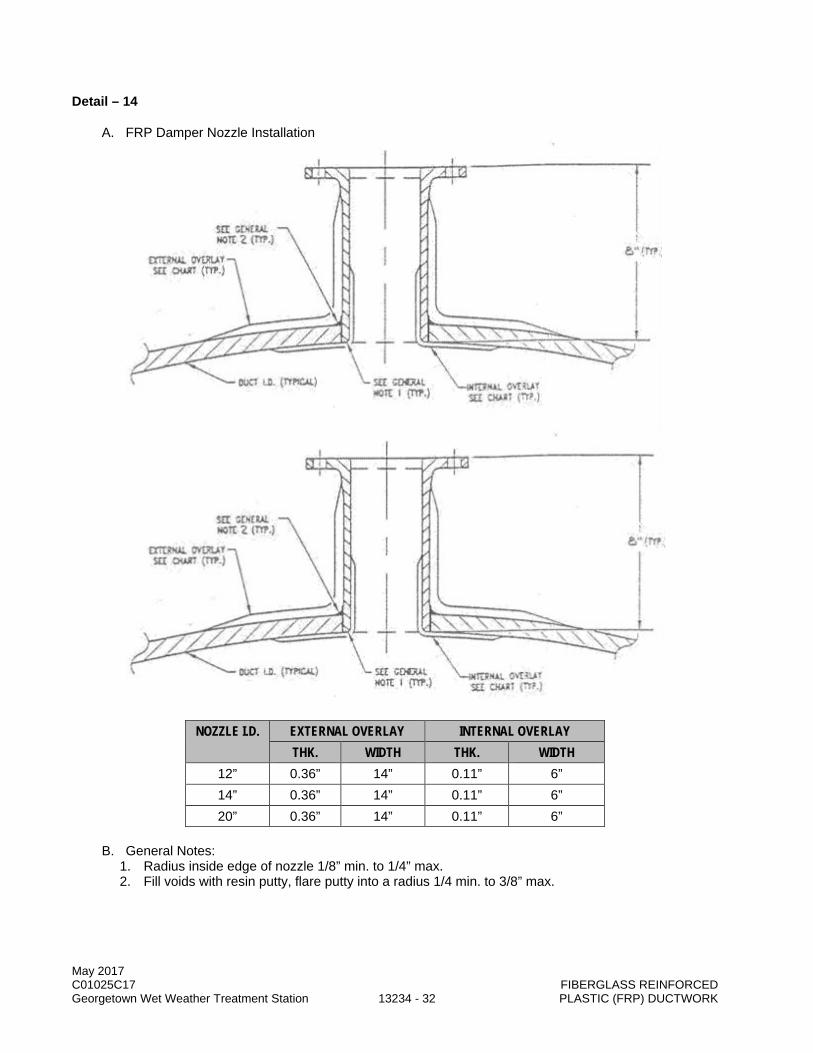
May 2017 C01025C17 FIBERGLASS REINFORCED Georgetown Wet Weather Treatment Station 13234 - 32 PLASTIC (FRP) DUCTWORK
Detail – 14
A. FRP Damper Nozzle Installation
NOZZLE I.D. EXTERNAL OVERLAY INTERNAL OVERLAY
THK. WIDTH THK. WIDTH 12” 0.36” 14” 0.11” 6” 14” 0.36” 14” 0.11” 6” 20” 0.36” 14” 0.11” 6”
B. General Notes: 1. Radius inside edge of nozzle 1/8” min. to 1/4” max. 2. Fill voids with resin putty, flare putty into a radius 1/4 min. to 3/8” max.
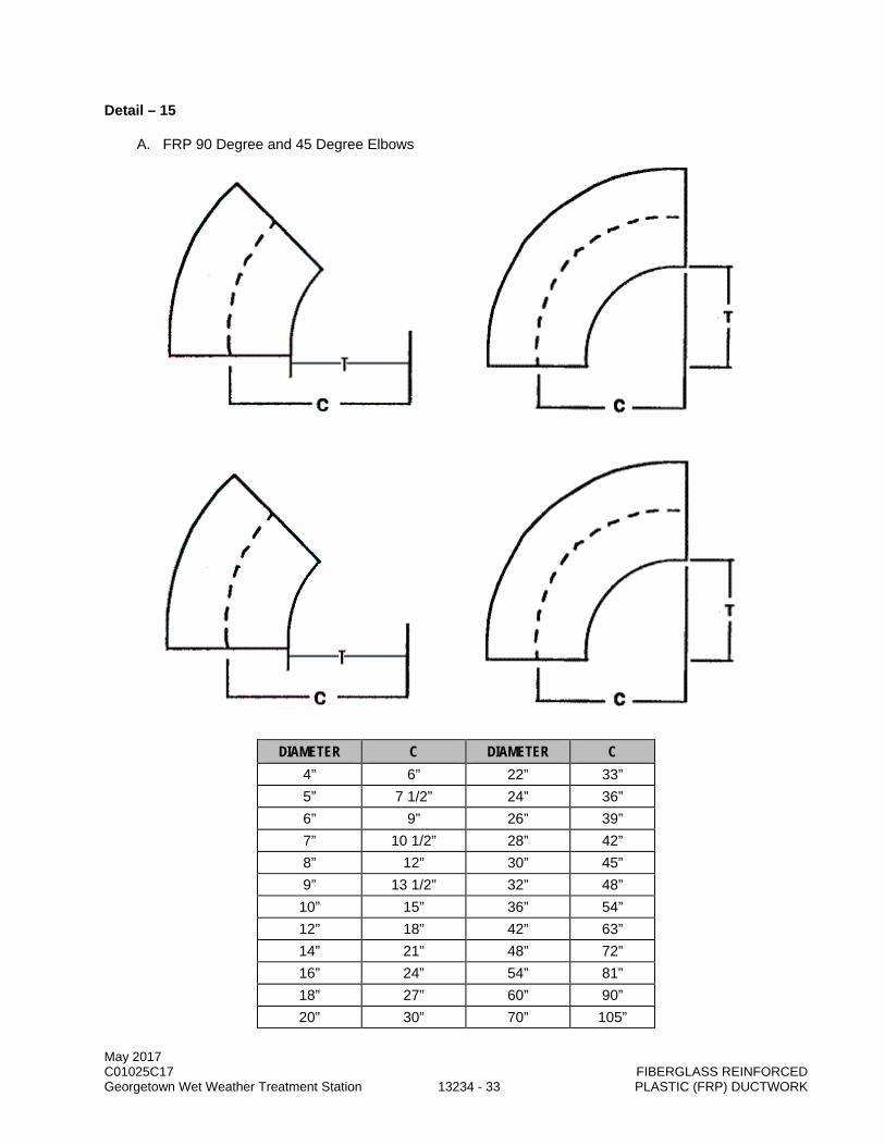
May 2017 C01025C17 FIBERGLASS REINFORCED Georgetown Wet Weather Treatment Station 13234 - 33 PLASTIC (FRP) DUCTWORK
Detail – 15
A. FRP 90 Degree and 45 Degree Elbows
DIAMETER C DIAMETER C
4” 6” 22” 33” 5” 7 1/2” 24” 36” 6” 9” 26” 39” 7” 10 1/2” 28” 42” 8” 12” 30” 45” 9” 13 1/2” 32” 48”
10” 15” 36” 54” 12” 18” 42” 63” 14” 21” 48” 72” 16” 24” 54” 81” 18” 27” 60” 90” 20” 30” 70” 105”

May 2017 C01025C17 FIBERGLASS REINFORCED Georgetown Wet Weather Treatment Station 13234 - 34 PLASTIC (FRP) DUCTWORK
ELBOWS LONG RADIUS ELBOWS SHORT RADIUS
C = 1.5 x DIAMETER C = 1.0 x DIAMETER T = 1.0 x DIAMETER T = 0.5 x DIAMETER
B. General Notes: 1. Elbows 2” dia. through 30” dia. are one (1) piece molded smooth radius. 32” dia. and larger are
five (5) piece mitered 90 degree elbows and 3 piece mitered 45 degree elbows.
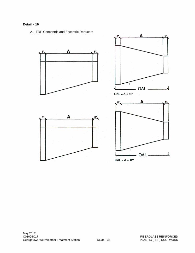
May 2017 C01025C17 FIBERGLASS REINFORCED Georgetown Wet Weather Treatment Station 13234 - 35 PLASTIC (FRP) DUCTWORK
Detail – 16
A. FRP Concentric and Eccentric Reducers
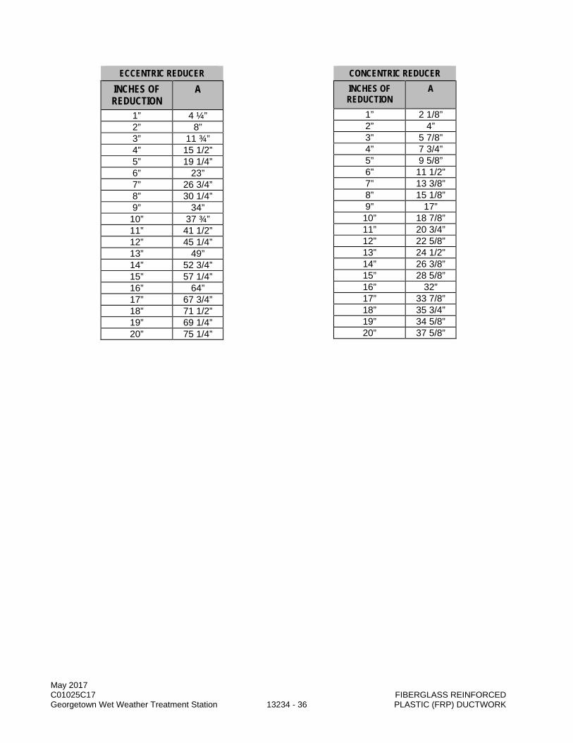
May 2017 C01025C17 FIBERGLASS REINFORCED Georgetown Wet Weather Treatment Station 13234 - 36 PLASTIC (FRP) DUCTWORK
ECCENTRIC REDUCER INCHES OF REDUCTION
A
1” 4 ¼” 2” 8” 3” 11 ¾” 4” 15 1/2” 5” 19 1/4” 6” 23” 7” 26 3/4” 8” 30 1/4” 9” 34” 10” 37 ¾” 11” 41 1/2” 12” 45 1/4” 13” 49” 14” 52 3/4” 15” 57 1/4” 16” 64” 17” 67 3/4” 18” 71 1/2” 19” 69 1/4” 20” 75 1/4”
CONCENTRIC REDUCER INCHES OF REDUCTION
A
1” 2 1/8” 2” 4” 3” 5 7/8” 4” 7 3/4” 5” 9 5/8” 6” 11 1/2” 7” 13 3/8” 8” 15 1/8” 9” 17” 10” 18 7/8” 11” 20 3/4” 12” 22 5/8” 13” 24 1/2” 14” 26 3/8” 15” 28 5/8” 16” 32” 17” 33 7/8” 18” 35 3/4” 19” 34 5/8” 20” 37 5/8”
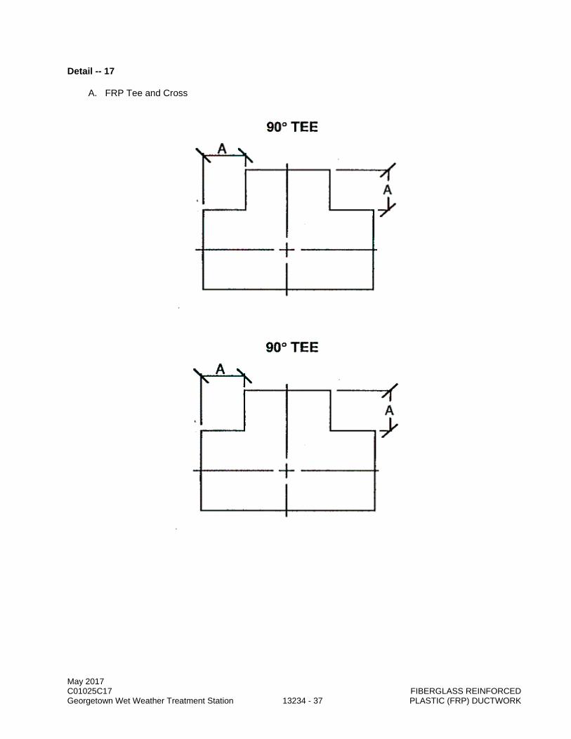
May 2017 C01025C17 FIBERGLASS REINFORCED Georgetown Wet Weather Treatment Station 13234 - 37 PLASTIC (FRP) DUCTWORK
Detail -- 17
A. FRP Tee and Cross

May 2017 C01025C17 FIBERGLASS REINFORCED Georgetown Wet Weather Treatment Station 13234 - 38 PLASTIC (FRP) DUCTWORK
B. General Notes 1. For diameters 10” dia. and smaller: A = 4” and for diameters 12” dia. and larger A =6”
END OF SECTION

May 2017 C01025C17 LARGE 4000 CFM ABOVE ACTIVATED CARBON Georgetown Wet Weather Treatment Station 13250 - 1 ODOR CONTROL UNITS
SECTION 13250
LARGE 4000 CFM ABOVE ACTIVATED CARBON ODOR CONTROL UNITS
PART 1 GENERAL
1.01 SUMMARY
A. This Section specifies 4,000 cfm and larger activated carbon odor control units complete with carbon, internal baffling and supports, instruments, components and accessories and appurtenances.
1.02 QUALITY ASSURANCE
A. Referenced Standards: This Section incorporates by reference the latest revision of the following documents. These references are a part of this Section as specified and modified. In case of conflict between the requirements of this Section and those of the listed documents, the requirements of this Section shall prevail. Reference Title AISI American Iron and Steel Institute ANSI B16 Standards of Pipes and Fittings ASME RTP-1 Reinforced Thermoset Plastic Corrosion Resistant Equipment ASTM C582 Standard Specification for Contact Molded Reinforced Thermosetting
Plastic (RTP) Laminates for Corrosion-Resistant Equipment ASTM D2583 Standard Test Method for Indentation Hardness of Rigid Plastics by
Means of a Barcol Impressor ASTM D2584 Standard Test Method for Ignition Loss of Cured Reinforced Resins ASTM D3299 Standard Specification for Filament-Wound, Fiberglass Reinforced
Thermoset Resin Chemical Resistant Tanks ASTM D4097 Standard Specification for Contact Molded, Glass Fiber Reinforced
Thermoset Resin Chemical Resistant Tanks ASTM E84 Test Method for Surface Burning Characteristics of Building Materials SBC Seattle Building Code
B. Qualifications: 1. Manufacturer:
a. At least ten years experience in the design, fabrication, and supply of odor control systems with the same geometry and carbon bed layout as the vessel specified in this Section.
b. At least five reference installations of dual bed carbon units treating a minimum air volume of 4,000 cfm per unit. 1) Data for each of the reference installations:
a) Facility location. b) Contact person, phone number. c) Number of odor control trains and model numbers. d) Installation date. e) Commissioning date. f) Years of service. g) Carbon unit design parameters/performance:
(1) Design flow range in cubic feet per minute (cfm). (2) Number of beds. (3) Orientation (vertical or horizontal). (4) Odor loading rates in ppmv. (5) Carbon type (Section 13525). (6) Odor removal efficiencies.
May 2017 C01025C17 LARGE 4000 CFM ABOVE ACTIVATED CARBON Georgetown Wet Weather Treatment Station 13250 - 2 ODOR CONTROL UNITS
c. At least one of the five installations shall include a unit treating an air volume in excess of 10,000 cfm.
d. At least one of the five installations shall include a horizontal dual bed unit as indicated. 2. Reference installations shall be operational treating primarily hydrogen sulfide and other reduced
organic sulfur compounds and shall include units operating under similar operating conditions as those specified herein. FRP Fabricator: a. The fabricator shall demonstrate, through past records, their capability in successful
manufacture of filament-wound or contact molded fiberglass. 3. FRP Vessel Fabricator's Quality Assurance Supervisor:
a. Minimum 3 years' experience in the fabrication of fiberglass structures. 4. Carbon Media Testing Laboratory:
a. Accredited laboratory in activated carbon sample analysis.
1.03 SUBMITTALS
A. Procedures: Section 01300.
B. Qualifications.
C. Forms11000-A and 11000-B: Section 01999.
D. Anchorage: Section 05501.
E. Product technical data and shop drawings: 1. Make, model, and weight of each equipment assembly. 2. Manufacturer's catalogue information, descriptive literature, specifications, and identification of
materials of construction. 3. Fabricator's detailed requirements for unit anchorage and foundations. Include certified
foundation drawings showing anchor bolt layouts and locations. 4. External utility requirements such as instrument air, water, power, drain, etc., for each
component. 5. Equipment layout plan and elevation drawings (all four sides) showing key element orientation,
overall dimensions, approximate piping interface points, and panel location. 6. Drawings and descriptions of all items of equipment, showing all dimensions, parts, construction
details, and materials of construction. Detailed description of the laminate and the type of reinforcing to be used. This shall be accompanied by a letter from the resin manufacturer stating: a. That the laminate and reinforcing material used will provide chemical resistance at least
equal to the specified chemical resistance for the resin for the intended application. b. That the resin will meet the performance requirements stated and is suitable for the service
conditions specified herein and the fabrication technique proposed. 7. Design calculations for the FRP vessels, vessel supports, fill piping supports, platforms, railing,
and structural members, prepared, stamped, dated, and signed by a Professional Engineer registered in the state of Washington. Calculations shall include the following: a. Exterior environment. b. Dead loads. c. Live loads. d. Environmental loads (seismic, wind, snow loadings). e. Carbon loads (wet and dry) and total vessel operating weight. f. Thermal aspects of elevated operating temperatures. g. Anchor lug attachment. h. Anchor bolt size and embedment requirements. i. Carbon support design. j. Vessel component connection design. k. Attachment lugs for ladders, platform, and structural members and other appurtenances. l. Material strength shall be based on certified test results.
May 2017 C01025C17 LARGE 4000 CFM ABOVE ACTIVATED CARBON Georgetown Wet Weather Treatment Station 13250 - 3 ODOR CONTROL UNITS
8. Material properties used in the calculations shall be derived from actual destructive testing of similar laminates. Fabricator shall provide documentation for all laminate properties used in the design.
9. Delivered carbon specification sheets. 10. Complete process calculations showing calculated hydrogen sulfide adsorption efficiencies,
estimated replacement intervals, and other suitable empirical data. Calculations shall include assumed values for ambient conditions, safety factors employed, and all other assumptions.
11. Performance data, including the following: a. Vessel pressure calculations at specified high and low flows in inches WC through unit
including carbon media, internal structural members, inlet, and outlet. b. Odor removal efficiencies and estimated carbon bed life at normal and peak odor loadings for
both high and low flow rates. c. Contact time at high and low flow rates.
12. Activated carbon vessel: a. Manufacturer's name and model number. b. All exterior and interior dimensions and wall thicknesses. c. Materials of construction. d. Vessel data including pressure rating, required stiffeners, and corrosion barrier thickness. e. Size, type, and location of all nozzle openings. f. Carbon media properties including:
1) Typical properties as specified in Section 13525. 2) Pressure drop data through the media as a function of foul air flow rates. 3) Crushing height: height of carbon that causes media to crush and/or fail structurally. 4) Information on expected settling rates of the carbon media.
g. Details of carbon media bed support system. h. Net weight (dry) of the carbon vessel in pounds. i. Operating weight of carbon vessel in pounds. j. Detailed instructions for carbon vessel installation.
13. Details for the carbon containment space illustrating complete confinement and fill without possibility of airflow short-circuiting carbon zone through any path. Bag containment of carbon within the tank is not allowed.
14. Control accessories: a. Manufacturer's name and model number. b. Materials of construction. c. Scale and operating range. d. Accuracy and repeatability. e. Detailed drawings showing all dimensions. f. Connection details including sizing. g. Manufacturer's descriptive literature.
15. Shop and Site Painting Systems: Manufacturer's descriptive technical catalogue literature and Specifications.
16. Recommended bolt torques for all bolted FRP connections. 17. Detailed information regarding factory authorized service and spare parts availability in the
Seattle area. Include name of service firm, contact person, address of firm, 24-hour telephone number, and estimated travel time to the project site for factory-trained mechanics.
18. Minimum clearance distances around equipment required to access equipment for service/repair/removal.
19. Detailed installation manuals. 20. Complete narrative including a description of the process, functional description. 21. Recommended procedure for the protection and handling of materials prior to installation. 22. Written guarantee that unit shall meet the removal rate performance specified herein. 23. Power and control wiring diagrams, including terminals and numbers.
F. Performance test plan.

May 2017 C01025C17 LARGE 4000 CFM ABOVE ACTIVATED CARBON Georgetown Wet Weather Treatment Station 13250 - 4 ODOR CONTROL UNITS
G. Certificates, Test Reports, and Procedures: 1. Activated carbon manufacturer's certificate of compliance with the Section 13250 and Section
13525 including test report data. 2. Fiberglass vessel fabricator's Certificate of Compliance with fabrication requirements. 3. The following factory and laboratory test results, reports, and certifications, including:
a. Inspection reports. b. Certified test reports for physical properties of standard laminates. c. Results of factory hydrostatic test for factory fabricated units. d. Results of glass/resin ratio burn tests. Test results shall provide relevant data for each layer
(structural layer, corrosion barrier, etc.). e. Results of Barcol testing. f. Fiberglass fabrication quality assurance procedures. g. Carbon unit factory test results completed with test program, data collected, corrections made
and conclusions. h. Certified calibration reports for test equipment.
4. If equipment or material to be provided under this Section is not specifically required to be tested in compliance with the requirements for this Section, the manufacturer's standard test used for quality control of the equipment or material shall be conducted and test results submitted. The tests shall have been performed within 2 years of submittal of the reports for approval.
5. All factory test results shall be submitted prior to shipping.
H. Fiberglass vessel fabricator's Quality Assurance Program.
I. Quality Assurance Inspection: 1. Initial QA Inspection Report. 2. Certification of Factory Testing.
J. Samples: As a minimum, submit the following items: 1. Representative laminate sample for carbon vessel. 2. Sample of carbon media, minimum 2 pounds.
K. Manufacturer's Certifications: 1. Certify that shop test equipment has been calibrated and checked against an approved standard
within the last 365 days. 2. Certify that field test equipment has been calibrated and checked against an approved standard
within the last 365 days.
L. Operation and maintenance information: Section 01730. 1. Material Safety Data Sheet (MSDS) on proposed carbon media including any special handling or
cleanup requirements. 2. Wiring and Schematic Diagrams. Maintenance, technical data, and trouble-shooting information
for all instruments mounted on the vessel. 3. Quality control information including:
a. Resin manufacturer's certificate listing resin nomenclature, composition, and characteristics for vessel and accessories.
b. Special shipping, storage and protection, and handling instructions. c. List of special tools and materials supplied with equipment for use prior to and during
commissioning and future maintenance.
M. Manufacturer's written/printed installation instructions, including: 1. Instructions for placing and removing carbon media. 2. Recommended bolt torques for all bolted FRP connections. 3. Routine maintenance requirements prior to facility commissioning.
N. Spare Parts: Section 01750.
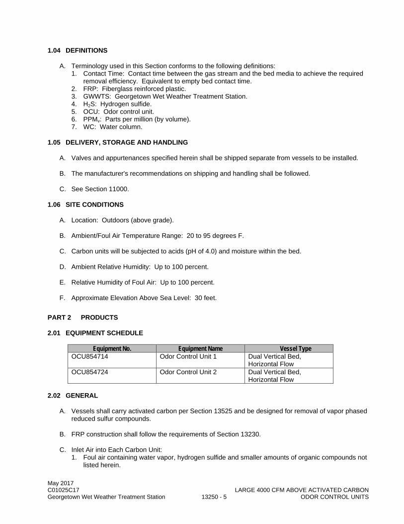
May 2017 C01025C17 LARGE 4000 CFM ABOVE ACTIVATED CARBON Georgetown Wet Weather Treatment Station 13250 - 5 ODOR CONTROL UNITS
1.04 DEFINITIONS
A. Terminology used in this Section conforms to the following definitions: 1. Contact Time: Contact time between the gas stream and the bed media to achieve the required
removal efficiency. Equivalent to empty bed contact time. 2. FRP: Fiberglass reinforced plastic. 3. GWWTS: Georgetown Wet Weather Treatment Station. 4. H2S: Hydrogen sulfide. 5. OCU: Odor control unit. 6. PPMv: Parts per million (by volume). 7. WC: Water column.
1.05 DELIVERY, STORAGE AND HANDLING
A. Valves and appurtenances specified herein shall be shipped separate from vessels to be installed.
B. The manufacturer's recommendations on shipping and handling shall be followed.
C. See Section 11000.
1.06 SITE CONDITIONS
A. Location: Outdoors (above grade).
B. Ambient/Foul Air Temperature Range: 20 to 95 degrees F.
C. Carbon units will be subjected to acids (pH of 4.0) and moisture within the bed.
D. Ambient Relative Humidity: Up to 100 percent.
E. Relative Humidity of Foul Air: Up to 100 percent.
F. Approximate Elevation Above Sea Level: 30 feet.
PART 2 PRODUCTS
2.01 EQUIPMENT SCHEDULE
Equipment No. Equipment Name Vessel Type OCU854714 Odor Control Unit 1 Dual Vertical Bed,
Horizontal Flow OCU854724 Odor Control Unit 2 Dual Vertical Bed,
Horizontal Flow
2.02 GENERAL
A. Vessels shall carry activated carbon per Section 13525 and be designed for removal of vapor phased reduced sulfur compounds.
B. FRP construction shall follow the requirements of Section 13230.
C. Inlet Air into Each Carbon Unit: 1. Foul air containing water vapor, hydrogen sulfide and smaller amounts of organic compounds not
listed herein.
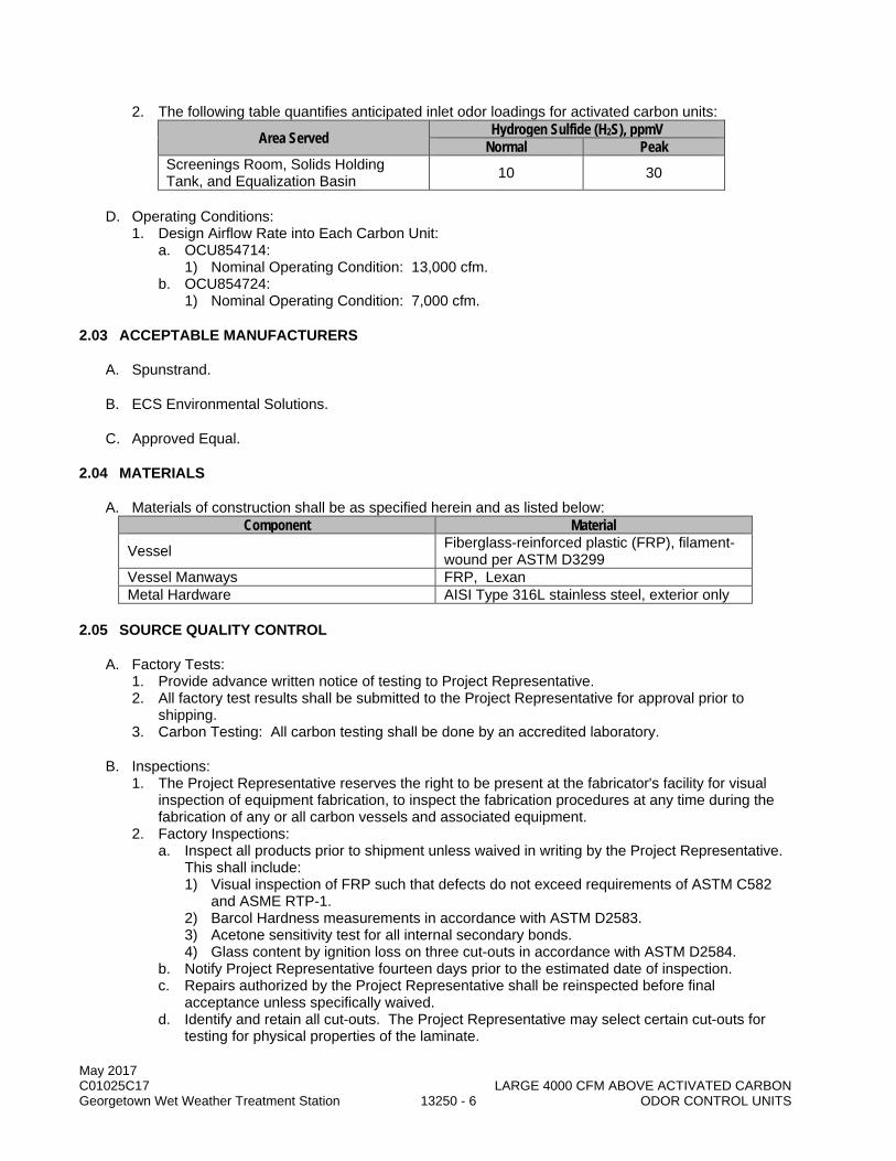
May 2017 C01025C17 LARGE 4000 CFM ABOVE ACTIVATED CARBON Georgetown Wet Weather Treatment Station 13250 - 6 ODOR CONTROL UNITS
2. The following table quantifies anticipated inlet odor loadings for activated carbon units:
Area Served Hydrogen Sulfide (H2S), ppmV Normal Peak
Screenings Room, Solids Holding Tank, and Equalization Basin 10 30
D. Operating Conditions: 1. Design Airflow Rate into Each Carbon Unit:
a. OCU854714: 1) Nominal Operating Condition: 13,000 cfm.
b. OCU854724: 1) Nominal Operating Condition: 7,000 cfm.
2.03 ACCEPTABLE MANUFACTURERS
A. Spunstrand.
B. ECS Environmental Solutions.
C. Approved Equal.
2.04 MATERIALS
A. Materials of construction shall be as specified herein and as listed below: Component Material
Vessel Fiberglass-reinforced plastic (FRP), filament-wound per ASTM D3299
Vessel Manways FRP, Lexan Metal Hardware AISI Type 316L stainless steel, exterior only
2.05 SOURCE QUALITY CONTROL
A. Factory Tests: 1. Provide advance written notice of testing to Project Representative. 2. All factory test results shall be submitted to the Project Representative for approval prior to
shipping. 3. Carbon Testing: All carbon testing shall be done by an accredited laboratory.
B. Inspections: 1. The Project Representative reserves the right to be present at the fabricator's facility for visual
inspection of equipment fabrication, to inspect the fabrication procedures at any time during the fabrication of any or all carbon vessels and associated equipment.
2. Factory Inspections: a. Inspect all products prior to shipment unless waived in writing by the Project Representative.
This shall include: 1) Visual inspection of FRP such that defects do not exceed requirements of ASTM C582
and ASME RTP-1. 2) Barcol Hardness measurements in accordance with ASTM D2583. 3) Acetone sensitivity test for all internal secondary bonds. 4) Glass content by ignition loss on three cut-outs in accordance with ASTM D2584.
b. Notify Project Representative fourteen days prior to the estimated date of inspection. c. Repairs authorized by the Project Representative shall be reinspected before final
acceptance unless specifically waived. d. Identify and retain all cut-outs. The Project Representative may select certain cut-outs for
testing for physical properties of the laminate.

May 2017 C01025C17 LARGE 4000 CFM ABOVE ACTIVATED CARBON Georgetown Wet Weather Treatment Station 13250 - 7 ODOR CONTROL UNITS
3. The Project Representative has the right to reject delivery of any or all pieces of equipment found, upon inspection, to not comply with the requirements of ASTM C582 and ASME RTP-1.
4. Rejection of an item shall require correction of the item as follows: a. Initial Correction: Field correction by the manufacturer may be attempted. If the outcome of
the field correction is not satisfactory to the Project Representative, then the item will remain rejected and may receive further correction.
b. Further Correction: The item shall be returned to the fabrication facility and either corrected or refabricated. After the item is corrected or refabricated, the inspection process shall be repeated until satisfactory to the Project Representative.
c. Correction of items resulting from inspection rejection shall be provided.
2.06 PERFORMANCE REQUIREMENTS
A. Odor Removal Rates: 1. Hydrogen Sulfide (H2S) Removal Efficiency: see Section 13525. 2. The following table summarizes the required odor discharge concentrations from activated carbon
units for targeted odors at the specified inlet odor concentrations when operating at any of the service conditions specified:
Treatment Vessel Discharge Odor Concentrations Hydrogen Sulfide (H2S), ppmV
Normal Peak Odor Control Unit 1 Odor Control Unit 2 0.10 0.30
B. Maximum Pressure Drop - Total through Carbon Vessel: 1. Five inches WC at design airflow rate. 2. Losses shall be calculated across the entire vessel, with carbon, from the external edge of the
inlet flange to the external edge of the outlet flange.
C. Maximum Carbon Bed Loading Rate: 1. 50-55 fpm at specified design airflow rate.
a. Minimum Contact Time: 2.8 seconds at specified normal/high flows.
2.07 DESIGN REQUIREMENTS
A. General: 1. Horizontal, cylindrical odor control unit of filament wound construction for activated carbon
treatment of foul air. 2. Unit shall normally be operated under negative pressure, with the fan located downstream and
pulling foul air through the vessel. 3. Each vessel shall utilize two vertical media beds (dual bed) and be provided complete with
supports and anchoring system, all nozzles, and access hatches. Vessels shall be designed to meet the performance requirements specified herein.
4. Each unit shall normally be operated under negative pressure, with the fan located downstream and pulling foul air through the vessel. Foul air will enter the vessel at the central flanged inlet, pass through the two carbon beds, and exit the vessel through the two flanged outlets on either end.
B. Dimensions: 1. Maximum length: 16 feet (apex of end cap/dome to apex of end cap/dome). 2. Diameter:
a. OCU854714: 14 feet. b. OCU854724: 10 feet.
May 2017 C01025C17 LARGE 4000 CFM ABOVE ACTIVATED CARBON Georgetown Wet Weather Treatment Station 13250 - 8 ODOR CONTROL UNITS
C. Foul Air Inlet/Outlet Sizes (per vessel): 1. Flanged Center Inlet:
a. Number: One. b. Size: See Drawings.
2. Flanged End Outlets: a. Number: Two. b. Size: See Drawings.
D. Structural Loads: 1. The following loads shall be assumed for the design of the various system components:
a. Top of Vessel Live Load: 50 pounds per square foot, minimum. b. Seismic Load: In accordance with Section 01031. c. Load Combination: Calculate in accordance with requirements of applicable code. d. Special Loads: Design for dead loads and all attached piping and duct loads. e. Carbon Loads: Design for operating loads with vessel full of carbon up to the top of the
carbon access fill ports. 1) Operating loads shall assume the carbon is wet and treating 100 percent relative
humidity air. f. Water Loads: Design vessel to be completely flooded with water without damage.
1) Flooding of the vessel is not considered a normal operating condition or a scenario that would occur during a seismic event.
g. Additional Environmental Loads (per the SBC): wind, snow.
E. Maximum Working Pressure on Carbon Units: 30 inches WC positive; 30 inches WC negative (vacuum).
F. Dry Operating Weight (including support saddles, vessel accessories, and dry carbon load): 1. OCU854714: 35,000 pounds. 2. OCU854724: 20,000 pounds.
2.08 FABRICATION AND MANUFACTURING
A. General: 1. Each unit shall include the following:
a. FRP vessel housing. b. Flanged inlet connection. c. Flanged outlet connections. d. Manways, sample ports, carbon replacement ports, and miscellaneous nozzles, as specified. e. Lifting and anchor lugs. f. Support saddles. g. Activated carbon media. h. Instrumentation. i. All other equipment and accessories necessary to provide a complete and properly operating
system. 2. Vessel shall consist of two vertical media beds (dual bed) of 3 feet depth. 3. Vessel shall be horizontal flow. 4. Designed to distribute air over cross-section of each carbon bed. 5. Vessel shall be designed to be completely filled with water. Due to the infrequent nature of this
condition, the fluid contents do not need to be considered in conjunction with seismic analysis. 6. Vessel shall include all supports required for the vessel internals including the media support
walls. Supports for vessel internals shall be fiberglass made with vinyl ester resins. a. The support shall be designed for handling impact from carbon loading, including force from a
light duty vibrator as recommended by the vessel manufacturer. These supports shall be supplied and installed by the vessel manufacturer.

May 2017 C01025C17 LARGE 4000 CFM ABOVE ACTIVATED CARBON Georgetown Wet Weather Treatment Station 13250 - 9 ODOR CONTROL UNITS
b. Carbon retention grating shall be provided on both sides of a carbon screen/mesh (polypropylene or vinyl ester FRP) for each carbon bed (a total of eight retention gratings for a dual bed vessel). 1) The retention grating inside each carbon bed (two internal retention gratings on each
carbon bed) shall consist of two half-circular pieces of grating to facilitate future removal for replacing the screen. The screens have to be securely attached to the retention gratings such that they cannot slip or move to allow voids to develop.
2) A full lip flange and a minimum of three vertical beams shall be provided to support each carbon retention grate.
3) Bag containment of the carbon within the tank is not allowed.
B. Design methods: 1. Horizontal vessels may be designed utilizing the computerized methodology described in
ASME RTP-1, or by other methods accepted as common industry practice or as specified herein. The specific issues of hoop stiffness and the stress concentrations occurring in the tank at the ends of the support saddles shall be addressed. Support saddles shall contact as much of the lower 180 degrees of the tank shell as possible. At each support, additional reinforcing thickness shall be used on the shell to distribute stresses, and full circumferential hoop stiffeners shall be located immediately adjacent to each side of the support saddle.
2. Maximum deflection limits for flat bottoms, beams, media support or similar components shall be 0.5 percent of the span or 0.5-inch, whichever is less.
3. Detailed design for vessels shall follow the procedures and methods, equations and formulas, and allowable design stresses and strains set forth in Subpart 3A and Part 4 of ASME RTP-1. Use of this standard, including the non-mandatory appendices where applicable, is required only for the design procedures and construction details. Shop qualification, qualification of laminators and joiners, QC documentation, and accreditation to RTP-1 is not required.
4. The vessel shall be designed for negative pressure service conditions as specified for Type II Grade 1 tanks in ASTM D3299, modified to the maximum working pressure listed in this Section. A 10:1 safety factor shall be used for internal pressure loadings and a 5:1 safety factor shall be used for external and vacuum loadings. Any system made of materials other than FRP is not acceptable.
C. FRP Fabrication: 1. The minimum properties of filament wound laminate shall be as specified in ASTM D3299 and
include a glass content of 55-65 percent by weight. a. Contact molding for vessel appurtenances shall be in accordance with ASTM D3299.
2. Visual defects shall be better than required by ASTM C582 and ASME RTP-1. 3. The vessel shall be shop assembled to assure proper fit. Subassemblies shall be numbered and
mating flanges or elements shall be match marked to assure correct alignment and correct field assembly. All FRP shall be protected from atmospheric or otherwise induced conditions of adverse temperatures, moisture, wind, or blowing dust and sand and other contaminants that would adversely affect the laminate or joint construction. The protective means shall be provided during the construction and curing period.
4. Interior fasteners shall be of corrosion resistant materials such as PVC or FRP.
D. Resin: 1. Resin shall be premium corrosion-resistant, fire-retardant vinyl ester resin:
a. Hetron 922. b. Derakane 411. c. Approved Equal.
2. FRP fabrications shall not exceed a flame spread index of 25 when tested in accordance with ASTM E84 Tunnel test.
3. Provide factory applied exterior UV inhibiting gelcoat finish. a. Use no dyes, pigments, or colorants, except in the exterior gel coat. b. Minimum coating thickness: 20 mil.

May 2017 C01025C17 LARGE 4000 CFM ABOVE ACTIVATED CARBON Georgetown Wet Weather Treatment Station 13250 - 10 ODOR CONTROL UNITS
c. Color: Selected by the Project Representative to match the surrounding FRP duct (Section 13234).
4. Resin shall contain, if necessary, a maximum of three (3%) percent antimony pentoxide to achieve the designed low flame spread index requirement.
5. Resin shall not contain any thixotropic agents: a. Curing System:
1) Use resin manufacturer's currently recommended cure system. 2) Cure all products to a minimum of 90 percent of the minimum Barcol hardness specified
by resin manufacturer. 3) Measure Barcol hardness according to ASTM D2583.
b. Post-cure the tank and appurtenances in accordance with resin manufacturer's recommendation for time and temperature. Post-curing shall be completed with warm-to-hot dry air, free of combustion products. Hot spots shall be avoided.
E. Reinforcement: 1. Fiber reinforcement shall have an epoxy compatible silane type surface finish and binder that is
specifically recommended by the reinforcement manufacturer for the particular resin system to be used.
2. Veil: Chemical surfacing mat, Type C (chemical) glass, 10 mils thick, with a finish and a binder compatible with the lay-up resin.
3. Corrosion Barrier: Resin-rich interior surface of nominal 100 to 120 mils using chopped strand mat backing the veil. Use no additive in the corrosion barrier.
4. Chopped Strand Mat: Type E glass, minimum 1-1/2 ounces per square foot, with silane finish and styrene soluble binder.
5. Continuous Roving Used in Chopper Gun for Spray-Up: Type E glass. 6. Woven Roving: Type E glass, nominal 24 ounces per square yard, 4 by 5 weave, with silane type
finish. 7. Continuous Roving Used for Filament Winding: Type E glass with a silane type finish, with a
nominal yield of at least 200 strand yards per pound.
F. Laminate: 1. Laminate shall consist of an inner surface (corrosion barrier), an interior layer, and an exterior
layer. One half of the corrosion liner shall be considered sacrificial and not included in determining structural wall thickness. In no case shall the total structural laminate thickness of the vessel shell or end caps be less than 0.375-inch.
2. Meet requirements of the mechanical properties and visual acceptance criteria in ASTM C582 and ASME RTP-1.
3. Inner Surface: a. Reinforce inner surface with a resin-rich, two ply surfacing veil of 10 to 20 mils thick (Nexus
111-10, or approved equal). Each ply shall be separately gelled prior to application of the subsequent ply.
b. The resin content of the inner surface shall be a minimum of 80 percent by weight. 4. Interior Layer:
a. Construct interior layer of resin reinforced with at least two plies of chopped strand mat. Thickness of interior layer shall be at least 100 mils.
b. The inner surface and interior layer shall be continuous throughout the tank interior. c. The resin content of the interior layer shall be a minimum of 75 percent by weight. d. Glass content of combined inner surface and interior layer shall be 27 percent plus or minus
5 percent. 5. Exterior Layer (Structural Layer) for Filament Wound Vessels: The exterior or structural layer
shall be filament wound. Filament winding shall be with continuous strand roving to provide a glass content of 50 to 80 percent by weight.
6. Exterior Layer (Structural Layer) for Contact Molded portions of the vessels: Consists of alternating layers of 14 ounces per square yard mat or chopped glass and 24 ounces per square yard woven roving.
7. Exterior surface of the vessel shall contain resin-rich single ply “C” veil or chopped strand mat.
May 2017 C01025C17 LARGE 4000 CFM ABOVE ACTIVATED CARBON Georgetown Wet Weather Treatment Station 13250 - 11 ODOR CONTROL UNITS
G. Support Saddles: 1. Support saddles, as designed by the manufacturer, shall be constructed of AISI Type 316L
stainless steel centered on beds, with neoprene pads to protect the FRP as required. 2. Saddle design shall include AISI Type 316 stainless steel anchor bolt sizing, embed, and
associated base plate. Each of these items shall be included as part of the vessel support components.
3. Manufacturer’s seismic design shall include attachments of the vessel to the saddle to prevent rotation, overturning, or lift that would otherwise occur during a seismic event.
4. Minimum number: Two.
H. Ground Rods: Each carbon bed shall be properly grounded with AISI Type 316 stainless steel grounding rod in accordance with the NEC.
I. Activated Carbon: 1. See Section 13525. 2. OCU manufacturer shall be responsible to supply the carbon for each vessel.
J. Vessel Appurtenances: 1. Carbon Access Fill Ports:
a. See Drawings for additional layout information. b. Minimum number of access ports: Two per vessel. c. Dimensions:
1) Length: 36 inches (span full depth of carbon bed). 2) Width: minimum 80% of vessel width (see Drawings).
d. Located above vertical carbon beds where indicated and designed to allow access to the carbon beds for removal and replacement of carbon as well as general cleaning and inspection of the vessel internals.
e. Flanges for access ports shall provide airtight and watertight seal with the access port covers to the maximum working pressure specified in this Section. Provide neoprene or Buna-N gaskets as required.
f. Access port covers: 1) Span the full dimensions of the access ports. 2) Held closed by quick-opening toggle clamps, AISI Type 316 stainless steel, minimum of
one per foot along the cover perimeter. a) Kakuta Model HH-300-S. b) McMaster-Carr. c) Approved Equal.
3) Lightweight. 4) Provide two AISI Type 316 stainless steel lifting lugs (one on each end) for each cover to
allow for easier removal once the quick-opening wing nuts are opened. Coordinate lug dimensions with overhead grating to avoid conflict.
g. Provide a 6-inch x 6-inch square, or 6-inch diameter round, transparent view window (Lexan or other suitable clear material) on the side of each fill port riser, with an air-tight seam. Locate the view windows on the same side of the OCU vessel as the sample ports (see Drawings).
2. Manway Access: a. Minimum number of manway access: one per vessel. b. Dimension: As indicated. c. Flanges for manway access shall provide airtight and watertight seal with the access covers
to the maximum working pressure specified in this Section. Provide neoprene or Buna-N gaskets as required.
3. Nozzles: a. Gussetted with conical type gussets rather than plate type gussets. b. Finished flush with the inside surface of the tank, unless specified otherwise.

May 2017 C01025C17 LARGE 4000 CFM ABOVE ACTIVATED CARBON Georgetown Wet Weather Treatment Station 13250 - 12 ODOR CONTROL UNITS
c. Provide two gaskets for each nozzle. Gaskets shall be 1/8-inch thick full-face elastomeric material having a hardness of Shore A60 plus or minus 5. Gasket material shall be suitable for the intended service.
d. The Back Face of all Flanges: Spot-faced, flat and parallel to the flange face of sufficient diameter to accept an SAE metal washer under the bolt head or nut.
e. Flange diameters and drillings shall meet ANSI B16.5 150-pound standard. f. Press-molded flanges are not acceptable. g. All FRP flanged nozzles shall be rated for 100 psi. h. Nozzles shall have a 6-inch projection as measured from the flange face to the nearest point
on the outside of the carbon unit unless otherwise indicated. i. Threaded full couplings shall be PVC. j. Flanged Nozzles:
1) Bottom drain nozzle: a) Size: 2 inches. b) Number: Three (3) per unit (one per inlet/outlet compartment). c) Location: As indicated.
2) Pressure Sensing Nozzles: a) Size: 3/4-inches. b) Number: Four (4) per unit (two (2) for each carbon bed). c) Pipe: 1/2-inch stainless steel tubing from nozzle to pressure transmitter. Support
tubing off of vessel with support brackets. Provide stainless steel ball valve at termination. Provide stainless steel ball valve and drains at tubing low points on each side of the pressure gauge as indicated.
4. Sampling Ports: a. Provide three 2-inch diameter FRP sample ports which extend into the carbon bed 12-inch
minimum, suitable for extracting carbon samples. b. Provide one grain thief that is capable of extracting a core sample of the in-place carbon
through the sample ports. c. Ports shall be adequate to provide suitable extraction of air samples from the carbon bed and
be non-blinding. d. Each port nozzle shall extend outside the vessel wall and be isolated with a 2-inch ball valve
meeting the requirements of plastic valves per Section 15064. e. Piping within media bed limits shall be stainless steel to prevent damage due to impacts
during fill operation. 5. Metal Hardware: AISI Type 316 stainless steel; no other metal to be used unless otherwise
indicated herein. a. AISI Type 316 stainless steel bolts and nuts.
6. Support Brackets: Provide for sample piping and pressure sensing tubing. Incorporate into the filament winding or contact molded system.
7. Lifting Lugs: Provide suitably attached for all equipment assemblies and components weighing over 100 pounds.
8. Marking: Provide 16-gauge AISI Type 316 stainless steel identification plate or clear paper label laminated into the final fiberglass coat in a readily visible location not more than 4 feet above bottom of support legs. Plate shall bear 1/4-inch high engraved block type black enamel filled lettering or 1-inch lettering for the laminated label. Plate or label shall state the following: a. Tag number. b. Unit name of “Activated Carbon Odor Control Unit.” c. Unit capacity in cfm. d. Unit length in feet. e. Unit height in feet. f. Unit diameter in feet. g. Media depth in feet. h. Manufacturer's name. i. Manufacturer's address. j. Allowable temperature range. k. Design pressure/vacuum.

May 2017 C01025C17 LARGE 4000 CFM ABOVE ACTIVATED CARBON Georgetown Wet Weather Treatment Station 13250 - 13 ODOR CONTROL UNITS
l. Design pressure drop in inches WC. m. Resin type, inner surface reinforcement, and resin manufacturer's name. n. Minimum thickness. o. Date of manufacture.
9. Anchor Bolts: AISI Type 316 stainless steel. Sized by manufacturer, 1/2-inch minimum diameter, and as specified in Section 05501.
K. Piping and Valves: Per Section 15050 and 15064.
L. Electrical: Electrical materials and provisions shall meet the requirements of Division 16.
M. Instrumentation and Controls: 1. Meet the requirements of Division 17. 2. Provide pressure differential indicators (across each carbon bed) as indicated.
a. See Section 17901.
2.09 SPARE PARTS
A. Procedures: Section 01750.
B. Furnish the following spare parts: 1. Three sets of gaskets for each flanged opening (duct or access flanges).
PART 3 EXECUTION
3.01 INSTALLATION
A. Installation of the carbon vessel shall be as indicated and in accordance with the manufacturer’s written instructions.
B. Prior to installing equipment, verify that equipment housekeeping pads are of sufficient size and that all anchor bolts are properly located.
C. Level vessels by means of support saddle grout base. Eliminate all strain from attached piping and conduit.
D. Pipe vessel drains as indicated.
E. Piping: 1. Pipe shall be cut, made up, and installed in accordance with the pipe manufacturer's
recommendations. 2. Extreme care shall be taken in the cutting, cleaning, and assembly of the piping, fittings, and
components.
F. Initial Carbon Filling: 1. Be responsible for filling carbon vessels prior to commissioning and Performance Test:
a. Filling shall be performed cleanly and orderly. b. Fill the carbon to within 6 inches of the underside of the carbon access fill port cover. c. Any carbon spillage or residual dust as a result of filling operations shall be removed and the
premises cleaned thoroughly. 2. Study the floor plan and equipment layout and decide on the method of loading and unloading the
carbon. In general, it is envisaged that the Contractor shall provide for a small mobile carbon filling/removal mechanism, such as mobile vacuum trucks, for the filling and the removal of carbon.
May 2017 C01025C17 LARGE 4000 CFM ABOVE ACTIVATED CARBON Georgetown Wet Weather Treatment Station 13250 - 14 ODOR CONTROL UNITS
G. Accurately place using equipment templates and as specified in Section 05501.
H. Upon completion of the installation, each piece of equipment and each system shall be tested for satisfactory operation without excessive noise, vibration, pressure drop, etc. All equipment shall be adjusted and checked for misalignment, clearances, supports, and adherence to safety standards.
3.02 FIELD QUALITY CONTROL
A. The Project Representative reserves the right to witness the tests specified.
B. Testing: In addition to any testing herein, perform all testing for this product or system consistent with the requirements of Section 01660, the applicable codes, and the manufacturer's current Quality Assurance program.
C. Field Inspection: Factory trained representatives who have complete knowledge and experience in the proper installation, commissioning and operation of the equipment, shall inspect the final installation and assist with all field functional tests of the equipment.
D. Re-examine the carbon vessels 30 days after commissioning and add carbon media to compensate for any settling of the bed.
E. Testing of Carbon to be Delivered: 1. Each lot of activated carbon prior to delivery to the jobsite shall be accompanied by an analysis
sheet of the measured characteristics of the carbon in that lot. One random sample per 10,000 pounds of the delivered carbon will be selected by the Project Representative for testing to ensure product quality.
2. If a random sample fails to meet the specifications, the manufacturer shall have the option of removing the lot of carbon off the location within two (2) days of notification or retesting another random sample at their sole expense. If the retest fails, the lot of carbon shall be removed within two (2) days of notification. Under no circumstances will more than one retest be allowed.
F. Performance Tests: 1. The performance test shall be carried out to demonstrate performance requirement specified in
this Section will be met or exceeded. 2. Prepare performance test plan at least 30 days prior to the proposed test date. The test plan
shall include the following: a. List of qualified personnel. b. Instruments to be used during the test. c. Location and installation of the instruments. d. Supplemental H2S injection equipment and proposed injection locations. e. Proposed test date.
3. The test shall be performed at the full design flow rate after system air flow balancing is completed and the GWWTS is in operation and providing foul air per the final design layout.
4. The test shall be continuous for at least 4 hours. During the 4-hr test, H2S shall be continuously monitored using electronic data logger at the activated carbon odor control unit inlet and outlet.
5. During the testing period, provide supplemental influent H2S as necessary to maintain an average inlet concentration of 10-15 ppm at the OCU. a. Supplemental hydrogen sulfide shall be injected upstream of the OCU at a point prior to the
grease and mist eliminator filter. b. All equipment and supply gas necessary for testing shall be supplied by the OCU
manufacturer. 6. Where the performance testing indicates that the specified minimum performance requirement for
H2S removal is not met, modify the equipment and/or operations and retest until the minimum performance requirement is met. Performance tests shall be repeated in their entirety.
May 2017 C01025C17 LARGE 4000 CFM ABOVE ACTIVATED CARBON Georgetown Wet Weather Treatment Station 13250 - 15 ODOR CONTROL UNITS
G. Provide onsite services of the factory-trained representative for the following activities: 1. Installation Assistance, Supervision and Inspection: Assist with installation inspection and field
testing for demonstration that, under normal conditions of operation, each carbon unit: a. Has not been damaged by transportation, storage, or installation. b. Has been properly installed. c. Has no mechanical defects. d. Will operate satisfactorily through the entire range of specified flow and conditions. e. Is free of objectionable vibration and noise. f. Is free of overloading of any parts.
2. Assistance in Component, System, and Operational Test Phases: a. Alignment test for all unit components. b. Hydrostatic testing of vessel for onsite fabricated units. c. Flow throughput in cubic feet per minute to confirm scrubber capacity. d. Discharge and inlet static pressures in inches WC to confirm pressure drop through carbon
unit. e. Confirm proper wiring of all instruments and field wired items: Confirm operation of carbon
units including fully functional instrumentation properly calibrated for each carbon unit. f. Confirm proper inlet/outlet piping connections installed according to manufacturer's
recommendations. 3. Performance Testing: Assist with the performance testing on each carbon unit as outlined in
within this Section. Testing shall be scheduled with the full knowledge and consent of the Project Representative and shall ensure no adverse affect on the operation of the facility.
4. Complete Form 11000-A: Section 01999. 5. Commissioning assistance.
3.03 TRAINING
A. Procedures: Section 01660.
B. Operator's Training: 1. A factory-trained representative shall provide:
a. Four hours of classroom and one eight-hour day of hands-on instruction which will cover the theory of operation and actual operation of the carbon units. 1) Each session will be conducted twice. One of each session per week on consecutive
weeks to accommodate the shift schedules of operation and maintenance staff. 2) 24 hours total of hands-on and classroom instruction.
b. One eight-hour day of operational supervision to train and supervise County's staff on the operation of the carbon units and on-the-job training.
C. Maintenance Training: 1. Provide four hours of classroom and one eight-hour day of hands-on training in separate sessions
for instrumentation and mechanical maintenance. a. Each session will be conducted twice. One of each session per week on consecutive weeks
to accommodate the shift schedules of operation and maintenance staff. b. 24 hours total of hands-on and classroom instruction.
D. Certify completion of training on Form 11000-B: Section 01999.
END OF SECTION

May 2017 C01025C17 LARGE 4000 CFM ABOVE ACTIVATED CARBON Georgetown Wet Weather Treatment Station 13250 - 16 ODOR CONTROL UNITS
This page intentionally left blank.
May 2017 C01025C17 Georgetown Wet Weather Treatment Station 13411 - 1 ABOVE GROUND STEEL FUEL STORAGE TANKS
SECTION 13411
ABOVE GROUND STEEL FUEL STORAGE TANKS
PART 1 GENERAL
1.01 SUMMARY
A. This Section specifies aboveground, horizontal double wall, welded steel tanks for storing petroleum products. The design, supply and coordination of this tank shall be included in the Engine Generator: Section 11083.
1.02 QUALITY ASSURANCE
A. Referenced Standards: This Section incorporates by reference the latest revision of the following documents. These references are a part of this Section as specified and modified. In case of conflict between the requirements of this Section and those of the listed documents, the requirements of this Section shall prevail.
Reference Title API 2028 Flame Arrestors in Piping Systems ASTM A36 Standard Specification for Carbon Steel NACE SP 0188 Discontinuity (Holiday) Testing of New Protective Coatings on Conductive
Substrates NFPA 30 Flammable and Combustible Liquids NFPA 704 Standard System for the Identification of the Hazards of Materials for
Emergency Response SBC Seattle Building Code SFC Seattle Fire Code UL 142 Steel Aboveground Tanks for Flammable and Combustible Liquids 7-32 FM Global Property Loss Prevention Data Sheets, Ignitable Liquid Operation 7-88 FM Global Property Loss Preventative Data Sheets, Flammable Liquids Storage Tanks
B. Qualifications: 1. Tank Manufacturer:
a. A firm regularly engaged in the design and fabrication of tanks of similar or greater complexity required under this Contract.
b. Licensed by Underwriters Laboratories, Inc. (UL) to fabricate tanks to meet UL 142. 2. Tank Design Engineer:
a. A Professional Engineer registered in the state of Washington.
1.03 SUBMITTALS
A. Procedures: Section 01300.
B. Qualifications.
C. Shop drawings of tank and appurtenances.
D. Technical product information.
E. Paint color chart for exterior coating.

May 2017 C01025C17 Georgetown Wet Weather Treatment Station 13411 - 2 ABOVE GROUND STEEL FUEL STORAGE TANKS
F. Tank Certification. 1. Certification of design in accordance with UL-142. 2. Certification of compliance with City of Seattle Fire Marshal requirements.
G. Tank design calculations.
H. Seismic design: Section 01031.
I. Details of the tank manufacturers installation requirements.
J. Test Results: 1. Hydrostatic test results. 2. Holiday test results. 3. Shop Coating Inspection Report.
K. Operation and Maintenance information: Section 01730.
L. Forms: 11000-A: Section 01999.
M. Tank Warranty.
N. Training agenda and Certification forms.
1.04 TANK CERTIFICATION
A. Prepare a tank manufacturer's written certification of compliance with the specified codes and standards and document, as a minimum, the following information: 1. Name and address of tank manufacturer, date of fabrication, and tank identification number. 2. Standards used for the design and fabrication of the primary tank. 3. Standards used for the design and fabrication of the secondary containment vessel, which shall
satisfy the requirements of NFPA 30 and SFC. 4. Testing procedures applied to both the primary tank and the containment vessel. 5. Tank testing data. 6. Certification that tank supplied meets specification requirements and standards.
1.05 WARRANTY
A. Tank shall have a 30 year manufactures material warranty and warranty for leakage from the secondary tank.
B. Tank connection fittings and common piping shall bear the same warranty as tank body. Submit specific evidence of compliance prior to tank fabrication.
PART 2 PRODUCTS
2.01 EQUIPMENT LIST
Equipment No. Description T854904 Engine Generator Fuel Storage Tank LCP854904A Leak Detection and Inventory Control Panel LCP854904B D/A Converter and Isolator Control Panel LCP854904C Fuel Tank Overfull Alarm Panel HRN854904 90% Full Horn

May 2017 C01025C17 Georgetown Wet Weather Treatment Station 13411 - 3 ABOVE GROUND STEEL FUEL STORAGE TANKS
Equipment No. Description FLT854904A Engine Generator Fuel Filter No. 1 FLT854904B Engine Generator Fuel Filter No. 2
2.02 GENERAL
A. 1000 gallon, steel, double wall diesel fuel tank, complete with fuel piping and functional with Vendor supplied control panels as indicated in the Drawings. Fuel Storage tank shall be supplied, designed, and coordinated as part of the Standby Generator, specified in Section 11083. Steel for primary tank shall be ASTM A36. Interior and exterior tank walls shall each be 3/16” minimum or thicker to meet standards.
B. Tank Design Engineer shall prepare design calculations.
C. Tank linings and coatings: 1. VOC compliant. 2. Lining: Interior of tank:
a. Coating System A-1: Section 09900. b. Minimum two layers.
3. Coating: Exterior of the tank: a. The exterior of the tank shall be coated with the Cowman-Campbell system listed below, or
Approved Equal, from Sherwin Williams, Tnemec, or other approved paint manufacturer. 1) Prime coat shall be a minimum thickness of 3 mils DFT of 1134 zinc chromate primer. 2) Finish coats shall be a minimum of 1.5 mils DFT each, for a total of no less than 3 mils
DFT additional thickness of CanDo Alkyd enamel series 400. 3) Finish color shall be as selected by the Project Representative.
4. Linings and coatings applied in the shop shall be inspected by a NACE-certified coatings inspector.
D. Shall be supplied, designed, and coordinated with the Engine Generator: Section 11083.
E. Conform to the requirements of UL 142.
2.03 ACCEPTABLE MANUFACTURERS
A. Northwest Pump and Equipment.
B. Mascott Equipment Co.
C. Ace Tank and Equipment.
D. Approved Equal.
2.04 TANK APPURTENANCES
A. Provided nozzles, connections and appurtenances as indicated in the Drawings to ensure fuel tank is a complete and operable system.
B. Level gage: 1. Manual Measuring Rod:
a. Provide one directly calibrated for indicating tank fill volume or a rod with a chart to show tank fill volume.
May 2017 C01025C17 Georgetown Wet Weather Treatment Station 13411 - 4 ABOVE GROUND STEEL FUEL STORAGE TANKS
C. Equip with an overfill/spill prevention system assembly, automatic overfill prevention valve, and lockable fill cap: 1. Acceptable Manufacturers:
a. EMCO Wheaton. b. Veeder Root. c. Morrison Brothers Co. d. Approved Equal.
2. Spill Container Volume: 7-1/2 gallons. 3. Fill Line connection size: 2” with cap.
D. Provide Fuel Storage Tank fill platform and ladder as shown in the drawings. Ladder and platform to be galvanized CS construction and shall meet all OSHA requirements.
E. Equipment tank with vent lines and flam arrestors per API 2028 and NFPA 30 and SFC.
2.05 DESIGN REQUIREMENTS
A. Tank: 1. Conform to the applicable requirements of the codes, standards, and regulations specified in this
Section. 2. Tank shall conform to the requirements of UL 142, as applicable to a tank with a secondary
containment vessel. 3. Meet SBC Seismic Design requirements. 4. Anchorage and bracing: Section 01031. 5. Is required to function after a seismic event. 6. Satisfy the requirements of NFPA 30 and SFC. 7. Shall be mounted on saddles that provide a minimum of 6 inches vertical clearance beneath the
tank for housekeeping. Mounting and bolting shall be part of suppliers calculations and certified Drawings.
B. Appurtenances: 1. Conform to the requirements of UL 142.
C. Tank emergency venting shall meet the requirements of UL 142, and SFC as applicable to tanks storing Class I or Class II liquids.
2.06 FUEL TANK FABRICATION REQUIREMENTS
A. Tank with its appurtenances shall be fabricated in conformance with the requirements of UL 142, NFPA 30 and SFC.
B. The secondary containment tank annulus shall be independently tested to the same pressure as the primary tank and in conformance with the requirements of UL 142.
C. Tank structure shall have anchoring adequate to meet the requirements of SBC seismic regulations and Section 01031.
2.07 NAMEPLATE
A. Identify tank by a nameplate indicating, in letters and numerals no less than 5/32-inch high, the manufacturer's name, tank identification number, design capacities, design pressures, design specific gravity, and fabrication date.
B. Fabricated of corrosion-resistant metal, attached to the tank shell plate by continuous, seal welding.
May 2017 C01025C17 Georgetown Wet Weather Treatment Station 13411 - 5 ABOVE GROUND STEEL FUEL STORAGE TANKS
2.08 FUEL LEAK DETECTION AND INVENTORY SYSTEM
A. See Section 16621, Division 16 and 17.
2.09 FUEL TANK CONTROL PANEL
A. Control panel shall be 480V with all necessary transformers to reduce voltage as needed by other day tank components.
B. Control panel shall include high/low/leak alarm conditions, and shall include audible alarm. 1. Wiring for instrumentation, control, and power shall be provided and terminated at termination
strips. 2. If three-phase power is used, provide control power transformer. 3. Controls shall be housed in NEMA 12 enclosure that can be field-mounted and meets the
specification requirements of Section 17110. 4. The following signals shall be transmitted to the engine-generator control panel and a common
trouble shall be provided for remote annunciation as a normally open dry contact: a. Leak into containment area. b. Low level trouble, critical low level trouble, and engine failure alarms. c. High level trouble alarm. d. Pump failure trouble alarm.
2.10 FUEL FILTERS
A. Fuel filters to be Parker Turbine Series 900 FH fuel filters, water separators, or Approved Equal.
2.11 FUSED LINK VALVE
A. Fused link valve to be Morrison Brothers Co. Model 346, External Emergency Valve, DI construction, or Approved Equal.
2.12 LABELING
A. Fuel Storage Tank and piping shall be labeled per NFPA 704.
PART 3 EXECUTION
3.01 INSTALLATION
A. Install in conformance with the tank manufacturer's instructions and recommendations and as indicated in the Drawings.
B. Tank and fuel piping shall be tested per NFPA 30 and SFC for leaks using water or other suitable fluid at normal system operating pressures, prior to connection to the Engine Generator and prior to filling with diesel fuel.
C. Meet City of Seattle requirements.
3.02 FIELD QUALITY CONTROL
A. Tank and fuel piping shall be tested for leaks using water or other suitable fluid at normal system operating pressures, prior to connection to the Engine Generator and prior to filling with diesel fuel. Document test results.
May 2017 C01025C17 Georgetown Wet Weather Treatment Station 13411 - 6 ABOVE GROUND STEEL FUEL STORAGE TANKS
B. Holiday testing: 1. Standard: Unless otherwise indicated, SP 0188. 2. When performed: On Site prior to installation of the final exterior color coating. 3. 100% of the exterior tank shall be tested. Defects allowed: 0. 4. Repair areas that do not pass test per manufacturer requirements. 5. Submit repair procedure prior to performing repairs.
3.03 TRAINING
A. Factory-trained representative shall allow a minimum of two four-hour field instruction sessions to personnel on the operation, monitoring and maintenance of the above ground tank per Section 01660.
B. The manufacturer shall submit list training agenda for the Project Representative’s approval.
C. Conduct one training session per week on consecutive weeks to accommodate the shift schedules of operation and maintenance staff.
D. Training shall be certified on Form 11000-B included in Section 01999.
3.04 DIESEL FUELING
A. Prior to filling with diesel fuel, clean the tank of matter that may be deleterious to the fuel including moisture.
B. Fill tank with diesel fuel.
END OF SECTION
May 2017 C01025C17 Georgetown Wet Weather Treatment Station 13525 - 1 ACTIVATED CARBON
SECTION 13525
ACTIVATED CARBON
PART 1 GENERAL
1.01 SUMMARY
A. This Section specifies activated carbon for odor reduction of foul air in odor control units (OCUs).
1.02 QUALITY ASSURANCE
A. Reference Standards: This Section incorporates by reference the latest revision of the following document. These references are part of this Section as specified and modified. In case of conflict between the requirements of this Section and those of the listed documents, the requirements of this Section shall prevail. Reference Title ASTM D2854 Test Method for Apparent Density of Activated Carbon ASTM D2862 Test Method for Particle Size Distribution of Granular Activated Carbon ASTM D2867 Test Method for Moisture in Activated Carbon ASTM D3467 Test Method for Carbon Tetrachloride Activity of Activated Carbon ASTM D3802 Test Method for Ball-Pan Hardness of Activated Carbon
B. Qualifications: 1. Supplier of activated carbon shall be experienced in the supply and operation of activated carbon
systems for vapor phase organic and hydrogen sulfide removal at wastewater treatment facilities.
1.03 SUBMITTALS
A. Procedures: Section 01300.
B. Detailed product information for the activated carbon proposed for the job, including verification of all properties specified in this Section, as well as total weight of carbon per bed.
C. Weights of the water-saturated carbon beds.
D. A detailed description of the procedure for installation and commissioning of the activated carbon.
E. Qualifications.
1.04 SITE CONDITIONS
A. Operating Conditions: properties of foul air and associated OCU design parameters are described in Section 13250.
PART 2 PRODUCTS
2.01 ACCEPTABLE MANUFACTURERS
A. PureAir Filtration AC-X Extruded Activated Carbon.
B. Calgon Carbon Corporation/Westates Carbon.

May 2017 C01025C17 Georgetown Wet Weather Treatment Station 13525 - 2 ACTIVATED CARBON
C. Approved Equal.
2.02 MATERIALS
A. Activated Carbon: 1. Non-impregnated, high surface area, cylindrical extruded type, specifically manufactured to
absorb vapor phase organic and malodorous compounds of the type typically generated from municipal wastewater.
2. Substrate: Bituminous. 3. Typical Properties:
Particle size (U.S. Sieve) 4x8 Mean particle diameter, millimeters (per ASTM D2862) 4.0 CCl4 number percent by weight minimum (per ASTM D3467) 60 Hardness number minimum (per ASTM D3802) 95 Maximum moisture content percent by weight (per ASTM D2867) 2 Apparent density, minimum gms/cc (per ASTM D2854) 0.46-0.50 Maximum head loss through bed at 65 fpm velocity, inches w.c./ft bed depth (see Note a)
1.5
H2S breakthrough capacity minimum, gms H2S removal/ gm carbon (see Note b)
0.09
Notes: a. Head loss shall be determined by passing dry air at 70 degrees F and 1 atm. pressure
through a 2-inch diameter by 12-inch deep bed of carbon placed in a dense packed arrangement per ASTM D2854.
b. The determination of H2S breakthrough capacity shall be made by passing a moist (70 percent RH) air stream containing 1 percent H2S at 1,450 cubic centimeter per minute flow through a test bed of uniformly packed activated carbon of the following dimensions: depth - 9 inches, diameter - 0.725 to 1.0 inch. The test shall be monitored to a 10 ppm breakthrough and the results expressed in gms H2S removal/gm carbon which is calculated from the carbon sample weight uncorrected for moisture.
2.03 PERFORMANCE AND DESIGN REQUIREMENTS
A. General: 1. Specifically manufactured for continuous exposure to moisture-laden foul air containing
concentrations of hydrogen sulfide up to 50 parts per million, as well as other malodorous compounds of municipal sewage origin such as ammonia, organic sulfides, indols, skatols, aldehydes, and mercaptans.
2. Minimum H2S removal at 1 ppm inlet: 90 percent. 3. Minimum H2S removal at 10 ppm inlet: 99 percent.
PART 3 EXECUTION
3.01 INSTALLATION
A. Be responsible for initial filling of carbon vessels as specified in Section 13250.
B. Install carbon in accordance with manufacturer's recommendations.
C. Pack each bed uniformly to the density specified with sample probes installed as shown.
D. The packed bed shall contain no void pockets including bed areas around the sampling probes and near the vessel walls.
E. Each bed shall have a smooth surface with uniform bed depth throughout.
May 2017 C01025C17 Georgetown Wet Weather Treatment Station 13525 - 3 ACTIVATED CARBON
3.02 TESTING
A. See Section 01660 and Section 13250.
END OF SECTION

May 2017 C01025C17 Georgetown Wet Weather Treatment Station 13525 - 4 ACTIVATED CARBON
This page intentionally left blank.

May 2017 C01025C17 Georgetown Wet Weather Treatment Station 13701 - 1 SECURITY CAMERA SYSTEM
SECTION 13701
SECURITY CAMERA SYSTEM
PART 1 GENERAL
1.01 SUMMARY
A. Section specifies the following: 1. Conduits and cables for video surveillance system. 2. Power over Ethernet switches/injectors and enclosures. 3. Cameras. 4. Network Digital Video Recorders. 5. Camera support hardware, labeling and identification.
B. Related Sections include but not necessarily limited to: 1. Division 0. 2. Division 1. 3. Section 16000. 4. Section 16110.
1.02 QUALITY ASSURANCE (NOT USED)
1.03 SUBMITTALS
A. Submittal Procedures: See Section 01300 for requirements for the mechanics and administration of the submittal process.
B. Approval Submittals: 1. Product technical data:
a. Provide submittal data for all products specified in this Section except: 1) Conduit fittings. 2) Support systems.
b. See Specification Section 16000 for additional requirements. 2. Fabrication and/or layout drawings:
a. Identify dimensional size of enclosure boxes to be used. b. Seismic location installation details.
1.04 SYSTEM DESCRIPTION
A. Provide equipment, including but not limited to cameras, network video recorders, and mounting hardware, raceways, enclosures for Power Over Ethernet injectors, and cabling, for complete fully-functional system.
B. Install, adjust, and focus cameras.
C. Label cameras and mounting hardware per Project Representative Instructions.
1.05 DELIVERY, STORAGE, AND HANDLING
A. Comply with Section 16000.

May 2017 C01025C17 Georgetown Wet Weather Treatment Station 13701 - 2 SECURITY CAMERA SYSTEM
PART 2 PRODUCTS
2.01 MANUFACTURED UNITS
A. Cabling: 1. Horizontal voice and data cable:
a. Category 6 per TIA/EIA/ANSI 568. b. Cable shall be label-verified. c. Cable jacket shall be factory marked at regular intervals indicating verifying organization and
performance level. d. Conductors: No. 24 AWG solid untinned copper or as indicated in the Drawings. e. Rated CMP per NFPA 70.
2. Conform to NFPA 262 and NFPA 70 Type ITC.
B. Raceways: 1. Comply with requirements of Section 16110.
C. Cameras: 1. Provide quantity of cameras as indicated in the Drawings and as specified below:
a. Video Quality – 4 megapixel (2560 x 1440 pixels). b. Night Vision -- Up to 100ft / 30m. c. Viewing Angle -- 84°. d. IR Cut Filter. e. ONVIF -- Profile S. f. Power -- Power over Ethernet. g. Indoor / Outdoor Use -- Indoor or Outdoor, IP67 Rating. h. Operating Temperature -- -22° to 140°F / -30° to 60°C.
2. See Drawings for camera locations. 3. Provide four (4) spare cameras.
D. Network Digital Video Recorders (DVR): 1. Provide network digital video recorder for surveillance system as indicated in the Drawings and
as specified below: a. 32-Channel NVR. b. Recording Resolution: 4 megapixel (MP). c. Playback Speed -- 20 FPS. d. Recording Modes -- Motion, Time Schedule, Manual, Alarm. e. Backup Options -- PC, Flash Drive, USB Hard Drive, eSATA. f. (2) Pre-Installed 5TB Hard Drives. g. (24) 100ft Cat5e Cables. h. 16-Port POE Injector. i. NVR Power Supply. j. HDMI Cable. k. NVR Mouse, Remote. l. Network Cable. m. 2-Year Warranty.
E. Provide cameras mounting hardware.
F. Power over Ethernet Injector: 1. Enable–IT 360. 2. Injector provided and installed by the Contractor in NEMA 4X stainless steel, 14 IN high x 12 IN
wide x 6 IN deep enclosure. Provide 120VAC receptacle mounted with enclosure.

May 2017 C01025C17 Georgetown Wet Weather Treatment Station 13701 - 3 SECURITY CAMERA SYSTEM
PART 3 EXECUTION
3.01 PREPARATION
A. Field Measurements: Verify all measurements on job site before beginning Work.
3.02 INSTALLATION
A. Install system in accordance with applicable codes and regulations, manufacturer’s written instructions, the Project Representative directions, and this Section.
B. Penetrations in fire-rated construction shall be firestopped.
C. Wiring shall be installed in accordance with TIA/EIA/ANSI Standards.
D. Cables shall not be installed in the same cable tray, conduit, utility pole compartment or junction or pull box with ac power cables.
E. Cables not installed in conduit or wireways shall be properly secured and neat in appearance and, if installed in plenums or other spaces used for environmental air, shall comply with NFPA 70 requirements for this type of installation.
F. The rated cable pulling tension shall not be exceeded.
G. Cable shall not be stressed such that twisting, stretching or kinking occurs.
H. Cable shall not be spliced.
I. Placement of cable parallel to power conductors shall be avoided, if possible; a minimum separation of 12 IN shall be maintained when such placement cannot be avoided.
J. Cables shall be terminated; no cable shall contain unterminated elements.
K. Minimum bending radius shall not be exceeded during installation or once installed.
L. Cable ties shall not be excessively tightened such that the transmission characteristics of the cable are altered.
3.03 TESTING
A. Testing shall conform to the TIA/EIA/ANSI Standards for Category 6 test parameters. 1. All test data sheets shall be downloaded from the tester, printed out and provided to the Project
Representative. 2. A CD ROM shall be provided to the Project Representative with all test results. 3. Tester shall be capable of testing parameters for the warranted system.
B. Materials and documentation to be furnished under this Section are subject to inspections and tests. 1. All components shall be terminated prior to testing. 2. Equipment and systems will not be accepted until the required inspections and tests have been
made, demonstrating that the cameras distribution system conforms to the requirements, and that the required equipment, systems, and documentation have been provided.
END OF SECTION

May 2017 C01025C17 Georgetown Wet Weather Treatment Station 13701 - 4 SECURITY CAMERA SYSTEM
This page intentionally left blank.
DIVISION 14 CONVEYANCE SYSTEMS

This page intentionally left blank.
May 2017 C01025C17 Georgetown Wet Weather Treatment Station 14310 - 1 MONORAIL HOISTS
SECTION 14310
MONORAIL HOISTS
PART 1 GENERAL
1.01 SUMMARY
A. This Section specifies electric and manual monorail hoists and trolleys, and davit cranes.
1.02 QUALITY ASSURANCE
A. Referenced Standards: This Section incorporates by reference the latest revision of the following documents. These references are a part of this Section as specified and modified. In case of conflict between the requirements of this Section and those of the listed documents, the requirements of this Section shall prevail. Reference Title ASME B30.11 Safety Standard for Monorails and Under hung Cranes ASMW B30.16 Overhead Hoists-Under hung ASTM A36 Standard Specification for Structural Steel ANSI Z535 Safety Alerting Standards CMMA Crane Manufacturer's Association of America HMI Hoist Manufacturer's Institute OSHA Occupational Safety and Health Act
B. All equipment furnished under this Section shall comply in all respects with the requirements of OSHA, the standards of the Crane Manufacturer's Association of America (CMAA) and the Hoist Manufacturer's Institute (HMI).
1.03 SUBMITTALS
A. Procedures: Section 01300.
B. Manufacturer's catalog data confirming rated capacity, equipment speeds, horsepower, electrical requirements, equipment dimensions, and material of construction.
C. Motor Information: Section 11060.
D. Certified testing data.
E. Operation and maintenance information: Section 01730.
F. Forms: 11000-A and 11060-A: Section 01999.
G. Spare Parts: Section 01750.
H. Field Quality Control test results.
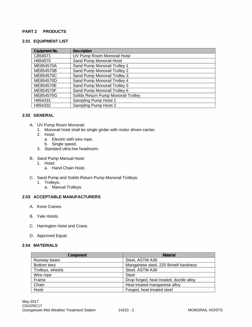
May 2017 C01025C17 Georgetown Wet Weather Treatment Station 14310 - 2 MONORAIL HOISTS
PART 2 PRODUCTS
2.01 EQUIPMENT LIST
Equipment No. Description C854571 UV Pump Room Monorail Hoist H854570 Sand Pump Monorail Hoist ME854570A Sand Pump Monorail Trolley 1 ME854570B Sand Pump Monorail Trolley 2 ME854570C Sand Pump Monorail Trolley 3 ME854570D Sand Pump Monorail Trolley 4 ME854570E Sand Pump Monorail Trolley 5 ME854570F Sand Pump Monorail Trolley 6 ME854570G Solids Return Pump Monorail Trolley H854331 Sampling Pump Hoist 1 H854332 Sampling Pump Hoist 2
2.02 GENERAL
A. UV Pump Room Monorail: 1. Monorail hoist shall be single girder with motor driven carrier. 2. Hoist:
a. Electric with wire rope. b. Single speed.
3. Standard ultra-low headroom.
B. Sand Pump Manual Hoist: 1. Hoist:
a. Hand Chain Hoist.
C. Sand Pump and Solids Return Pump Monorail Trolleys: 1. Trolleys:
a. Manual Trolleys.
2.03 ACCEPTABLE MANUFACTURERS
A. Kone Cranes.
B. Yale Hoists.
C. Harrington Hoist and Crane.
D. Approved Equal.
2.04 MATERIALS
Component Material Runway beam Steel, ASTM A36 Bottom tees Manganese steel, 225 Brinell hardness Trolleys, wheels Steel, ASTM A36 Wire rope Steel Frame Drop forged, heat treated, ductile alloy Chain Heat treated manganese alloy Hook Forged, heat treated steel
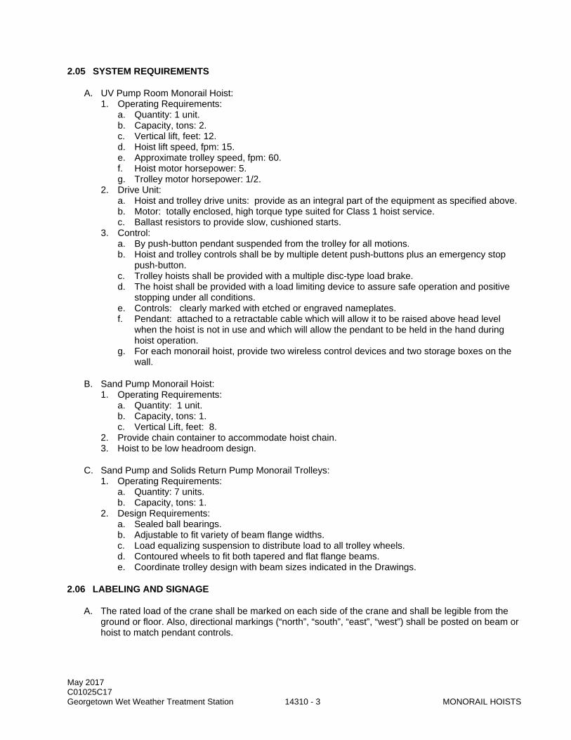
May 2017 C01025C17 Georgetown Wet Weather Treatment Station 14310 - 3 MONORAIL HOISTS
2.05 SYSTEM REQUIREMENTS
A. UV Pump Room Monorail Hoist: 1. Operating Requirements:
a. Quantity: 1 unit. b. Capacity, tons: 2. c. Vertical lift, feet: 12. d. Hoist lift speed, fpm: 15. e. Approximate trolley speed, fpm: 60. f. Hoist motor horsepower: 5. g. Trolley motor horsepower: 1/2.
2. Drive Unit: a. Hoist and trolley drive units: provide as an integral part of the equipment as specified above. b. Motor: totally enclosed, high torque type suited for Class 1 hoist service. c. Ballast resistors to provide slow, cushioned starts.
3. Control: a. By push-button pendant suspended from the trolley for all motions. b. Hoist and trolley controls shall be by multiple detent push-buttons plus an emergency stop
push-button. c. Trolley hoists shall be provided with a multiple disc-type load brake. d. The hoist shall be provided with a load limiting device to assure safe operation and positive
stopping under all conditions. e. Controls: clearly marked with etched or engraved nameplates. f. Pendant: attached to a retractable cable which will allow it to be raised above head level
when the hoist is not in use and which will allow the pendant to be held in the hand during hoist operation.
g. For each monorail hoist, provide two wireless control devices and two storage boxes on the wall.
B. Sand Pump Monorail Hoist: 1. Operating Requirements:
a. Quantity: 1 unit. b. Capacity, tons: 1. c. Vertical Lift, feet: 8.
2. Provide chain container to accommodate hoist chain. 3. Hoist to be low headroom design.
C. Sand Pump and Solids Return Pump Monorail Trolleys: 1. Operating Requirements:
a. Quantity: 7 units. b. Capacity, tons: 1.
2. Design Requirements: a. Sealed ball bearings. b. Adjustable to fit variety of beam flange widths. c. Load equalizing suspension to distribute load to all trolley wheels. d. Contoured wheels to fit both tapered and flat flange beams. e. Coordinate trolley design with beam sizes indicated in the Drawings.
2.06 LABELING AND SIGNAGE
A. The rated load of the crane shall be marked on each side of the crane and shall be legible from the ground or floor. Also, directional markings (“north”, “south”, “east”, “west”) shall be posted on beam or hoist to match pendant controls.

May 2017 C01025C17 Georgetown Wet Weather Treatment Station 14310 - 4 MONORAIL HOISTS
B. Floor-operated and remote-operated cranes shall have a safety label or labels affixed to the pendant station, portable operating station, or load block in compliance with ANSI Z535.4 and shall include, but not be limited to, cautionary language against: 1. Lifting more than rated load. 2. Operating hoist when load is not centered under hoist. 3. Operating hoist with twisted, kinked, or damaged chain or rope. 4. Lifting people. 5. Lifting loads over people. 6. Operating manual motions with other than manual power. 7. Removing or obscuring safety label. 8. Each control actuator shall be marked to indicate the direction of resultant motion matching
markings on beam or hoist.
2.07 SAMPLING PUMP HOISTS
A. Hoist requirements are separate from previously stated monorail hoist requirements.
B. 500 lb minimum capacity wire rope hoist with explosion proof (NEC Class I/Division 1) motor and pendant.
C. Provide with 60 foot minimum, 304 Stainless Steel, 3/16 IN diameter wire rope.
D. Manufacturer: 1. Columbia Winches and Hoists – HF series. 2. Approved Equal.
2.08 SPARE PARTS
A. Procedures: Section 01750.
B. Provide one spare battery for each monorail remote control device.
PART 3 EXECUTION
3.01 INSTALLATION
A. Install the trolleys and hoists at the locations indicated in the Drawings and in accordance with the manufacturer's recommendations.
B. Certify installation by manufacturer using form 11000A in Section 01999.
3.02 FIELD QUALITY CONTROL
A. After completion of installation, completely test each trolley and hoist to ensure compliance with the performance requirements as specified.
B. Load test monorail hoists in compliance with OSHA, ASME B30.11, and ASME B30.16.
C. Correct or immediately replace any defects.
3.03 USE BY CONTRACTOR
A. Project Representative written approval required prior to use.
B. Meet all requirements of Section 01015.

May 2017 C01025C17 Georgetown Wet Weather Treatment Station 14310 - 5 MONORAIL HOISTS
C. Train Contractor personnel on proper use of the specific type hoist.
D. Prior to turning over to the County, repair, repaint, and otherwise refurbish the hoist to a like-new condition prior to its Final Acceptance. Assume all responsibility for operation and maintenance.
END OF SECTION

May 2017 C01025C17 Georgetown Wet Weather Treatment Station 14310 - 6 MONORAIL HOISTS
This page intentionally left blank.

May 2017 C01025C17 Georgetown Wet Weather Treatment Station 14630 - 1 BRIDGE CRANE AND HOISTS
SECTION 14630
BRIDGE CRANE AND HOISTS
PART 1 GENERAL
1.01 SUMMARY
A. This Section specifies supply and installation of electric motor bridge cranes with radio remote and pendant control systems and the hand gear operated bridge crane with hand gear operated trolley and hand operated chain hoist.
1.02 QUALITY ASSURANCE
A. Referenced Standards: This Section incorporates by reference the latest revision of the following documents. These references are a part of this Section as specified and modified. In case of conflict between the requirements of this Section and that of the listed documents, the requirements of this Section shall prevail. Reference Title ANSI Z535 Safety Alerting Systems ASME B30.11 Safety Standard for Monorails and Underhung Cranes ASME B30.2 Overhead and Gantry Cranes (Top Running Bridge; Single or Multiple Girder;
Top Running Trolley Hoist) ASME B30.16 Overhead Hoists (Underhung) ASME B30.17 Overhead and Gantry Cranes (Top Running Bridge; Single Girder; Underhung
Hoist) CMAA Crane Manufacturer’s Association of America HMI Hoist Manufacturer’s Institute OSHA Occupational Safety and Health Administration WISHA Washington Industrial Safety and Health Act
B. All equipment furnished under this Section shall comply in all respects with the requirements of OSHA, WISHA, the standards of the CMAA and HMI.
1.03 SUBMITTALS
A. Procedures: Section 01300.
B. Manufacturer's structural installation drawings of the bridge crane.
C. Manufacturer's catalog data for bridge beam, end trucks, trolley, and hoist confirming rated capacity, structural requirements, and compliance with HMI and CMAA standards, equipment speeds, horsepower and electrical requirements.
D. Motor data in accordance with Section 11060.
E. Structural calculations and details for rail and support design.
F. The following product testing information shall be provided: 1. A written report describing the results of the field testing specified in this Section. 2. Factory test results as described in this Section.
G. Forms: 11000-A, 11000-B and 11060-A; Section 01999.
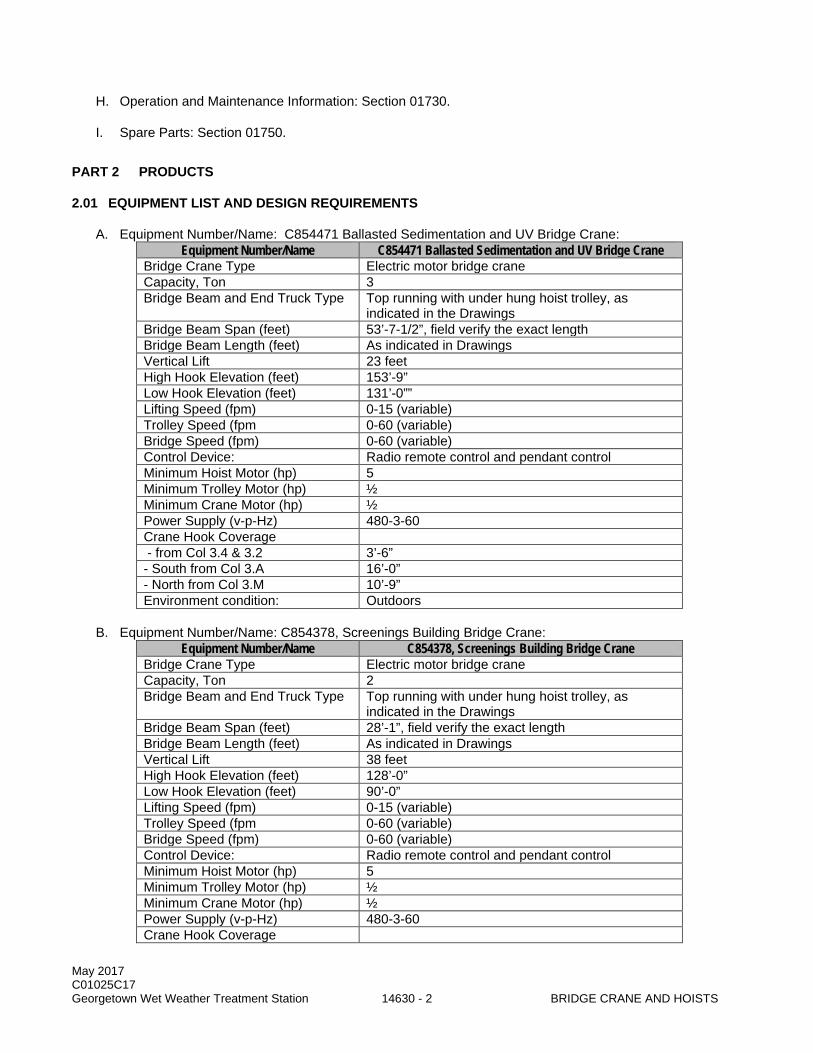
May 2017 C01025C17 Georgetown Wet Weather Treatment Station 14630 - 2 BRIDGE CRANE AND HOISTS
H. Operation and Maintenance Information: Section 01730.
I. Spare Parts: Section 01750.
PART 2 PRODUCTS
2.01 EQUIPMENT LIST AND DESIGN REQUIREMENTS
A. Equipment Number/Name: C854471 Ballasted Sedimentation and UV Bridge Crane: Equipment Number/Name C854471 Ballasted Sedimentation and UV Bridge Crane
Bridge Crane Type Electric motor bridge crane Capacity, Ton 3 Bridge Beam and End Truck Type Top running with under hung hoist trolley, as
indicated in the Drawings Bridge Beam Span (feet) 53’-7-1/2”, field verify the exact length Bridge Beam Length (feet) As indicated in Drawings Vertical Lift 23 feet High Hook Elevation (feet) 153’-9” Low Hook Elevation (feet) 131’-0”” Lifting Speed (fpm) 0-15 (variable) Trolley Speed (fpm 0-60 (variable) Bridge Speed (fpm) 0-60 (variable) Control Device: Radio remote control and pendant control Minimum Hoist Motor (hp) 5 Minimum Trolley Motor (hp) ½ Minimum Crane Motor (hp) ½ Power Supply (v-p-Hz) 480-3-60 Crane Hook Coverage - from Col 3.4 & 3.2 3’-6” - South from Col 3.A 16’-0” - North from Col 3.M 10’-9” Environment condition: Outdoors
B. Equipment Number/Name: C854378, Screenings Building Bridge Crane: Equipment Number/Name C854378, Screenings Building Bridge Crane
Bridge Crane Type Electric motor bridge crane Capacity, Ton 2 Bridge Beam and End Truck Type Top running with under hung hoist trolley, as
indicated in the Drawings Bridge Beam Span (feet) 28’-1”, field verify the exact length Bridge Beam Length (feet) As indicated in Drawings Vertical Lift 38 feet High Hook Elevation (feet) 128’-0” Low Hook Elevation (feet) 90’-0” Lifting Speed (fpm) 0-15 (variable) Trolley Speed (fpm 0-60 (variable) Bridge Speed (fpm) 0-60 (variable) Control Device: Radio remote control and pendant control Minimum Hoist Motor (hp) 5 Minimum Trolley Motor (hp) ½ Minimum Crane Motor (hp) ½ Power Supply (v-p-Hz) 480-3-60 Crane Hook Coverage
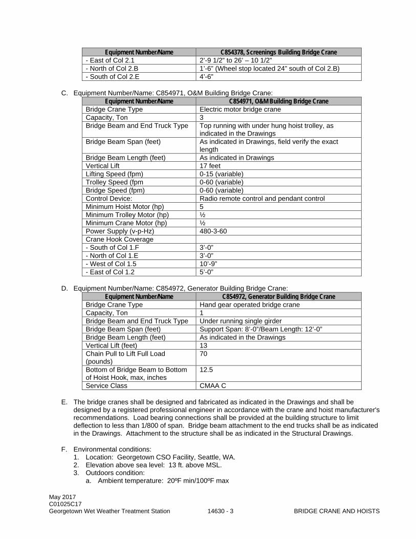
May 2017 C01025C17 Georgetown Wet Weather Treatment Station 14630 - 3 BRIDGE CRANE AND HOISTS
Equipment Number/Name C854378, Screenings Building Bridge Crane - East of Col 2.1 2’-9 1/2” to 26’ – 10 1/2” - North of Col 2.B 1’-6” (Wheel stop located 24” south of Col 2.B) - South of Col 2.E 4’-6”
C. Equipment Number/Name: C854971, O&M Building Bridge Crane: Equipment Number/Name C854971, O&M Building Bridge Crane
Bridge Crane Type Electric motor bridge crane Capacity, Ton 3 Bridge Beam and End Truck Type Top running with under hung hoist trolley, as
indicated in the Drawings Bridge Beam Span (feet) As indicated in Drawings, field verify the exact
length Bridge Beam Length (feet) As indicated in Drawings Vertical Lift 17 feet Lifting Speed (fpm) 0-15 (variable) Trolley Speed (fpm 0-60 (variable) Bridge Speed (fpm) 0-60 (variable) Control Device: Radio remote control and pendant control Minimum Hoist Motor (hp) 5 Minimum Trolley Motor (hp) ½ Minimum Crane Motor (hp) ½ Power Supply (v-p-Hz) 480-3-60 Crane Hook Coverage - South of Col 1.F 3’-0” - North of Col 1.E 3’-0” - West of Col 1.5 10’-9” - East of Col 1.2 5’-0”
D. Equipment Number/Name: C854972, Generator Building Bridge Crane: Equipment Number/Name C854972, Generator Building Bridge Crane
Bridge Crane Type Hand gear operated bridge crane Capacity, Ton 1 Bridge Beam and End Truck Type Under running single girder Bridge Beam Span (feet) Support Span: 8’-0”/Beam Length: 12’-0” Bridge Beam Length (feet) As indicated in the Drawings Vertical Lift (feet) 13 Chain Pull to Lift Full Load (pounds)
70
Bottom of Bridge Beam to Bottom of Hoist Hook, max, inches
12.5
Service Class CMAA C
E. The bridge cranes shall be designed and fabricated as indicated in the Drawings and shall be designed by a registered professional engineer in accordance with the crane and hoist manufacturer's recommendations. Load bearing connections shall be provided at the building structure to limit deflection to less than 1/800 of span. Bridge beam attachment to the end trucks shall be as indicated in the Drawings. Attachment to the structure shall be as indicated in the Structural Drawings.
F. Environmental conditions: 1. Location: Georgetown CSO Facility, Seattle, WA. 2. Elevation above sea level: 13 ft. above MSL. 3. Outdoors condition:
a. Ambient temperature: 20ºF min/100ºF max
May 2017 C01025C17 Georgetown Wet Weather Treatment Station 14630 - 4 BRIDGE CRANE AND HOISTS
b. Relative humidity: 10% humidity min/100% humidity max. 4. Indoor condition:
a. Temperature: 50ºF min/90ºF max. b. Relative humidity: 10% humidity min/100% humidity max.
G. The bridge crane capacity, material, rail system and dimensions shall meet or exceed the requirements of this Section as indicated in the Drawings.
H. Electric motor bridge cranes shall be designed in accordance with ASME B30.2, ASME B30.17 and all requirements of the CMMA and HMI.
I. For each electric bridge crane and hoist, provide two wireless control devices and two storage boxes mounted on the wall.
J. For hand geared operated bridge cranes: 1. Fit runway and bridge beams with rubber end bumpers to limit bridge end truck and hoist trolley
travel. 2. Hand chains: endless coil-type with a drop that is approximately two feet less than the specified
left of the hoist. 3. Equipment with galvanized steel chain containers.
K. The trolley hoists shall be ultra low headroom type with limited vertical distance to provide the minimum crane hook height as indicated in the Drawings.
2.02 ACCEPTABLE MANUFACTURERS
A. Acceptable manufacturers (hand gear operated bridge cranes): 1. Budgit. 2. Yale Hoist. 3. Chester Hoist. 4. Approved Equal.
B. Acceptable manufacturers (electric motor bridge cranes): 1. Shaw-Box. 2. R&M Material Handling, Inc. 3. Harrington Hoists and Cranes. 4. Approved Equal.
2.03 LABELING AND SIGNAGE
A. The rated load of the crane shall be marked on each side of the crane and shall be legible from the ground or floor. Also, directional markings (“north”, “south”, “east”, “west”) shall be posted on beam or hoist to match pendant controls.
B. Floor-operated and remote-operated cranes shall have a safety label or labels affixed to the pendant station, portable operating station, or load block in compliance with ANSI Z535.4 and shall include, but not be limited to, cautionary language against: 1. Lifting more than rated load. 2. Operating hoist when load is not centered under hoist. 3. Operating hoist with twisted, kinked, or damaged chain or rope. 4. Lifting people. 5. Lifting loads over people. 6. Operating manual motions with other than manual power. 7. Removing or obscuring safety label. 8. Each control actuator shall be marked to indicate the direction of resultant motion matching
markings on beam or hoist.

May 2017 C01025C17 Georgetown Wet Weather Treatment Station 14630 - 5 BRIDGE CRANE AND HOISTS
2.04 SOURCE QUALITY CONTROL
A. Manufacturer shall certify that models supplied are capable of lifting the specified capacity with an acceptable industry safety factor.
2.05 SPARE PARTS
A. Procedures: Section 01750.
B. Provide one spare battery for each electric motor bridge crane and hoist remote control device.
PART 3 EXECUTION
3.01 INSTALLATION
A. Install the complete bridge cranes, trolleys, and hoists as specified and indicated in the Drawings and in accordance with the manufacturer's recommendations.
3.02 FIELD QUALITY CONTROL
A. Manufacturer's representative shall test bridge crane, trolley, and hoist to verify smooth operation over the system's full range of movement with a verified load provided by the Contractor. Load test shall comply with WISHA, OSHA, ASME B30.11, and ASME B30.16.
3.03 TRAINING
A. Procedures: Section 01660.
B. Representative of the manufacturer to assist with start-up and provide a minimum of two 4-hour sessions of on-site training for each bridge crane. Conduct one training session per week on consecutive weeks to accommodate the shift schedules of operation and maintenance staff.
C. Training shall be certified on Form 11000-B per Section 01999.
END OF SECTION

May 2017 C01025C17 Georgetown Wet Weather Treatment Station 14630 - 6 BRIDGE CRANE AND HOISTS
This page intentionally left blank.