wearable robotics: challenges and trends - university of
TRANSCRIPT
Biosystems & Biorobotics
Juan C. Moreno · Jawad Masood · Urs Schneider · Christophe Maufroy · Jose L. Pons Editors
Wearable Robotics: Challenges and TrendsProceedings of the 5th International Symposium on Wearable Robotics, WeRob2020, and of WearRAcon Europe 2020, October 13–16, 2020

Biosystems & Biorobotics
Volume 27
Series Editor
Eugenio Guglielmelli, Laboratory of Biomedical Robotics, Campus Bio-MedicoUniversity of Rome, Rome, Italy
The BIOSYSTEMS & BIOROBOTICS (BioSysRob) series publishes the latestresearch developments in threemain areas: 1) understanding biological systems froma bioengineering point of view, i.e. the study of biosystems by exploiting engineeringmethods and tools to unveil their functioning principles and unrivalled performance;2) design and development of biologically inspired machines and systems to be usedfor different purposes and in a variety of application contexts. In particular, the serieswelcomes contributions on novel design approaches, methods and tools as well ascase studies on specific bio-inspired systems; 3) design and developments of nano-,micro-, macro- devices and systems for biomedical applications, i.e. technologiesthat can improve modern healthcare and welfare by enabling novel solutions forprevention, diagnosis, surgery, prosthetics, rehabilitation and independent living. Onone side, the series focuses on recent methods and technologies which allow multi-scale, multi-physics, high-resolution analysis and modeling of biological systems. Aspecial emphasis on this side is given to the use of mechatronic and robotic systemsas a tool for basic research in biology. On the other side, the series authoritativelyreports on current theoretical and experimental challenges and developments relatedto the “biomechatronic” design of novel biorobotic machines. A special emphasison this side is given to human-machine interaction and interfacing, and also to theethical and social implications of this emerging research area, as key challenges forthe acceptability and sustainability of biorobotics technology. The main target ofthe series are engineers interested in biology and medicine, and specifically bioengi-neers and bioroboticists.Volumepublished in the series comprisemonographs, editedvolumes, lecture notes, as well as selected conference proceedings and PhD theses.The series also publishes books purposely devoted to support education in bioengi-neering, biomedical engineering, biomechatronics and biorobotics at graduate andpost-graduate levels.
Indexed by SCOPUS, WTI Frankfurt eG, SCImago
More information about this series at http://www.springer.com/series/10421
Juan C. Moreno · Jawad Masood · Urs Schneider ·Christophe Maufroy · Jose L. PonsEditors
Wearable Robotics:Challenges and TrendsProceedings of the 5th InternationalSymposium on Wearable Robotics,WeRob2020, and of WearRAcon Europe2020, October 13–16, 2020
EditorsJuan C. MorenoCajal Institute, Madrid, Spain
Urs SchneiderFraunhofer Institute for ManufacturingEngineering and AutomationStuttgart, Germany
Jose L. PonsShirley Ryan AbilityLab (formerlyRehabilitation Institute of Chicago)Chicago, IL, USA
Jawad MasoodProcesses and Factories of the FutureCentro Tecnológico de Automoción deGaliciaPorriño, Spain
Christophe MaufroyFraunhofer Institute for ManufacturingEngineering and AutomationStuttgart, Germany
ISSN 2195-3562 ISSN 2195-3570 (electronic)Biosystems & BioroboticsISBN 978-3-030-69546-0 ISBN 978-3-030-69547-7 (eBook)https://doi.org/10.1007/978-3-030-69547-7
© The Editor(s) (if applicable) and The Author(s), under exclusive license to Springer NatureSwitzerland AG 2022This work is subject to copyright. All rights are solely and exclusively licensed by the Publisher, whetherthe whole or part of the material is concerned, specifically the rights of translation, reprinting, reuseof illustrations, recitation, broadcasting, reproduction on microfilms or in any other physical way, andtransmission or information storage and retrieval, electronic adaptation, computer software, or by similaror dissimilar methodology now known or hereafter developed.The use of general descriptive names, registered names, trademarks, service marks, etc. in this publicationdoes not imply, even in the absence of a specific statement, that such names are exempt from the relevantprotective laws and regulations and therefore free for general use.The publisher, the authors and the editors are safe to assume that the advice and information in this bookare believed to be true and accurate at the date of publication. Neither the publisher nor the authors orthe editors give a warranty, expressed or implied, with respect to the material contained herein or for anyerrors or omissions that may have been made. The publisher remains neutral with regard to jurisdictionalclaims in published maps and institutional affiliations.
This Springer imprint is published by the registered company Springer Nature Switzerland AGThe registered company address is: Gewerbestrasse 11, 6330 Cham, Switzerland
Contents
What Should We Expect from Passive Exoskeletons?
The Hidden Potential of Energetically Passive Exoskeletons . . . . . . . . . . . 3Amanda Sutrisno and David J. Braun
Effect of a Back-Assist Exosuit on Logistics Worker Perceptions,Acceptance, and Muscle Activity . . . . . . . . . . . . . . . . . . . . . . . . . . . . . . . . . . . . 7Matthew B. Yandell, Anna E. Wolfe, Matthew C. Marino,Mark P. Harris, and Karl E. Zelik
A Design Tool for Passive Wrist Support . . . . . . . . . . . . . . . . . . . . . . . . . . . . . 13Ali Amoozandeh Nobaveh, Giuseppe Radaelli, and Just L. Herder
The Key Elements in the Design of Passive Assistive Devices . . . . . . . . . . . 19Maziar A. Sharbafi
Novel Designs for Passive Elastic Lower Limb Exoskeletons . . . . . . . . . . . 27Daniel P. Ferris and W. Sebastian Barrutia
Passive Compliance in Legged Systems and Assistive Devices . . . . . . . . . . 33Andre Seyfarth
Spring Like Passive Elastic Exoskeletons May Improve Stabilityand Safety of Locomotion in Uneven Terrain . . . . . . . . . . . . . . . . . . . . . . . . . 39Laksh Kumar Punith, James Williamson, Taylor J. M. Dick,and Gregory S. Sawicki
Balance Recovery Support Using Wearable Robotic Devices
Ankle-Exoskeleton Control for Assisting in Balance RecoveryAfter Unexpected Disturbances During Walking . . . . . . . . . . . . . . . . . . . . . . 47C. Bayón, W. F. Rampeltshammer, A. Q. L. Keemink,H. van der Kooij, and E. H. F. van Asseldonk
v
vi Contents
Coupling an Active Pelvis Orthosis with Different Prosthetic KneesWhile Transfemoral Amputees Manage a Slippage: A Pilot Study . . . . . . 53Monaco Vito, Aprigliano Federica, Arnetoli Gabriele,Doronzio Stefano, Giffone Antonella, Vitiello Nicola, and Micera Silvestro
Self-induced Gyroscopic Torques in Lower Extremities DuringGait: A Pilot Study . . . . . . . . . . . . . . . . . . . . . . . . . . . . . . . . . . . . . . . . . . . . . . . . 59Saher Jabeen, Bram Sterke, Heike Vallery, and Daniel Lemus
Comparison of Balance Recovery Among Current ControlStrategies for Robotic Leg Prostheses . . . . . . . . . . . . . . . . . . . . . . . . . . . . . . . . 63Nitish Thatte and Hartmut Geyer
Reflex-Model with Additional COM Feedback Describes the AnkleStrategy in Perturbed Walking . . . . . . . . . . . . . . . . . . . . . . . . . . . . . . . . . . . . . 69Maarten Afschrift and Friedl De Groote
Optimising Balance Margin in Lower Limb Exoskeleton to AssistUser-Driven Gait Stability . . . . . . . . . . . . . . . . . . . . . . . . . . . . . . . . . . . . . . . . . . 75Xiruo Cheng, Justin Fong, Ying Tan, and Denny Oetomo
Active Life with Prosthesis
Control of Servomotor Rotation in a Myoelectric Upper-LimbProsthesis Using a 16-Channel sEMG Sensor System . . . . . . . . . . . . . . . . . 83Elisa Romero Avila, Elmar Junker, and Catherine Disselhorst-Klug
Compliant Control of a Transfemoral Prosthesis CombiningPredictive Learning and Primitive-Based Reference Trajectories . . . . . . . 89Sophie Heins and Renaud Ronsse
Design and Testing of a Fully-Integrated Electro-HydrostaticActuator for Powered Knee Prostheses . . . . . . . . . . . . . . . . . . . . . . . . . . . . . . 95Federico Tessari, Renato Galluzzi, Nicola Amati, Andrea Tonoli,Matteo Laffranchi, and Lorenzo De Michieli
Controlling Upper-Limb Prostheses with Body Compensations . . . . . . . . 101Mathilde Legrand, Nathanaël Jarrassé, Charlotte Marchand,Florian Richer, Amélie Touillet, Noël Martinet, Jean Paysant,and Guillaume Morel
HandMECH—Mechanical Hand Prosthesis: Conceptual Designof a Two Degrees-of-Freedom Compliant Wrist . . . . . . . . . . . . . . . . . . . . . . . 107Ahmed A. I. Elsayed and Ramazan Unal
HandMECH—Mechanical Hand Prosthesis: Conceptual Designof the Hand Compartment . . . . . . . . . . . . . . . . . . . . . . . . . . . . . . . . . . . . . . . . . 113Baris Baysal and Ramazan Unal
Contents vii
Legislation, Safety and Performance: Regulatory Aspects inWearable Robots
CO-GUIDING: Ergonomic Analysis of a Hand Guidance Systemfor Car Door Assembly . . . . . . . . . . . . . . . . . . . . . . . . . . . . . . . . . . . . . . . . . . . . 121Erika Triviño-Tonato, Jawad Masood, Ruben P. Cibeira,and Angel Dacal-Nieto
ATEX Certification for ALDAK Exoskeleton in PetrochemicalIndustry . . . . . . . . . . . . . . . . . . . . . . . . . . . . . . . . . . . . . . . . . . . . . . . . . . . . . . . . . . 127Ane Intxaurburu, Iñaki Díaz, Juan Martín, and Xabier Justo
Acceptance of Exoskeletons: Questionnaire Survey . . . . . . . . . . . . . . . . . . . 133Liên Wioland, J. Jean-Jacques, Atain-Kouadio, Latifa Debay,and Hugo Bréard
Perceived Exertion During Robot-Assisted Gait After Stroke . . . . . . . . . . 139Nina Lefeber, Emma De Keersmaecker, Eric Kerckhofs, and Eva Swinnen
Testing Safety of Lower Limbs Exoskeletons: Current RegulatoryGaps . . . . . . . . . . . . . . . . . . . . . . . . . . . . . . . . . . . . . . . . . . . . . . . . . . . . . . . . . . . . . 145Stefano Massardi, David Pinto-Fernandez, Jan F.Veneman,and Diego Torricelli
The Testing of Industrial Exoskeletons
Evaluation of Two Upper-Limb Exoskeletons for Ceiling Weldingin the Naval Industry . . . . . . . . . . . . . . . . . . . . . . . . . . . . . . . . . . . . . . . . . . . . . . 153Francisco Mouzo, Florian Michaud, Urbano Lugris, Jawad Masood,and Javier Cuadrado
Preliminary Study of an Exoskeleton Index for ErgonomicAssessment in the Workplace . . . . . . . . . . . . . . . . . . . . . . . . . . . . . . . . . . . . . . . 159Giorgia Chini, Christian Di Natali, Stefano Toxiri,Francesco Draicchio, Luigi Monica, Darwin G. Caldwell,and Jesús Ortiz
Effect of a New Passive Shoulder Exoskeleton on the Full BodyMusculoskeletal Load During Overhead Work . . . . . . . . . . . . . . . . . . . . . . . 165A. van der Have, S. Van Rossom, M. Rossini, and I. Jonkers
The Experience of Plasterers Towards Using an Arm SupportExoskeleton . . . . . . . . . . . . . . . . . . . . . . . . . . . . . . . . . . . . . . . . . . . . . . . . . . . . . . . 171Aijse W. de Vries, Michiel P. de Looze, and Frank Krause
Biomechanical Evaluation of the Effect of Three Trunk SupportExoskeletons on Spine Loading During Lifting . . . . . . . . . . . . . . . . . . . . . . . 177Idsart Kingma, Axel S. Koopman, Michiel P. de Looze, and Jaap H. van Dieën
viii Contents
Can HDEMG-Based Low Back Muscle Fatigue Estimates Be Usedin Exoskeleton Control During Prolonged Trunk Bending? A PilotStudy . . . . . . . . . . . . . . . . . . . . . . . . . . . . . . . . . . . . . . . . . . . . . . . . . . . . . . . . . . . . . 183Niels P. Brouwer, Ali Tabasi, Alejandro Moya-Esteban,Massimo Sartori, Wietse van Dijk, Idsart Kingma, and Jaap H. van Dieën
Back-Support Exoskeleton Control Using User’s TorsoAcceleration and Velocity to Assist Manual Material Handling . . . . . . . . . 189Maria Lazzaroni, Ali Tabasi, Stefano Toxiri, Darwin G. Caldwell,Idsart Kingma, Elena De Momi, and Jesús Ortiz
Subjective Assessment of Occupational Exoskeletons: FeasibilityStudy for a Custom Survey for Braces . . . . . . . . . . . . . . . . . . . . . . . . . . . . . . . 195M. Sposito, D. G. Caldwell, E. De Momi, and J. Ortiz
Evidenced-Based Indications/Contraindications for and PotentialBenefits of Exoskeletal-Assisted Walking in Persons with SpinalCord Injury
Alteration of Push-Off Mechanics During Walking with DifferentPrototype Designs of a Soft Exoskeleton in People with IncompleteSpinal Cord Injury—A Case Series . . . . . . . . . . . . . . . . . . . . . . . . . . . . . . . . . 203Eveline S. Graf, Christoph M. Bauer, Carole Pauli, and Markus Wirz
The Effect of Exoskeletal-Assisted Walking on Bowel and BladderFunction: Results from a Randomized Trial . . . . . . . . . . . . . . . . . . . . . . . . . . 209Peter H. Gorman, Gail F. Forrest, Pierre K. Asselin, William Scott,Stephen Kornfeld, Eunkyoung Hong, and Ann M. Spungen
Smartwear with Artificial Intelligence (AI) in Assessing Workloadin View of Ergonomics . . . . . . . . . . . . . . . . . . . . . . . . . . . . . . . . . . . . . . . . . . . . . 215Pekka Tolvanen, Riitta Simonen, and Janne Pylväs
Comparison of ReWalk® and Ekso® Powered Exoskeletonsfor Stepping and Speed During Training Sessions . . . . . . . . . . . . . . . . . . . . . 221Pierre K. Asselin,Gail F. Forrest, Stephen Kornfeld, Eunkyoung Hong,Peter H. Gorman, and Ann M. Spungen
Indications and Contraindications for Exoskeletal-AssistedWalking in Persons with Spinal Cord Injury . . . . . . . . . . . . . . . . . . . . . . . . . 227Ann M. Spungen, Peter H. Gorman, Gail F. Forrest, Pierre K. Asselin,Stephen Kornfeld, Eunkyoung Hong, and William A. Bauman
The Impact of Exoskeletal-Assisted Walking on the ImmuneSystem of Individuals with Chronic Spinal Cord Injury (SCI) . . . . . . . . . 233Anthony A. Arcese, Ann M. Spungen, and Ona Bloom
Contents ix
Exoskeleton Controller and Design Considerations: Effecton Training Response for Persons with Spinal Cord Injury . . . . . . . . . . . . 239Gail F. Forrest, Peter H. Gorman, Arvind Ramanujam,Pierre K. Asselin, Steven Knezevic, Sandra Wojciehowski,and Ann M. Spungen
Neuromechanical Modelling and Control for Wearable Robots:Enhancing Movement After Neuromuscular Injuries
Neuromusculoskeletal Model-Based Controller for Voluntaryand Continuous Assistance in a Broad Range of Locomotion Tasks . . . . . 247Guillaume Durandau, Wolfgang Rampeltshammer,Herman van der Kooij, and Massimo Sartori
Energy Cost of Transport in Overground Walkingof a Transfemoral Amputee Following One Monthof Robot-Mediated Training . . . . . . . . . . . . . . . . . . . . . . . . . . . . . . . . . . . . . . . . 251C. B. Sanz-Morère, E. Martini, G. Arnetoli, S. Doronzio, A. Giffone,B. Meoni, A. Parri, R. Conti, F. Giovacchini, Þ. Friðriksson, D. Romo,R. Molino-Lova, S. Crea, and N. Vitiello
Physical Therapy and Outdoor Assistance with the Myosuit:Preliminary Results . . . . . . . . . . . . . . . . . . . . . . . . . . . . . . . . . . . . . . . . . . . . . . . . 257Michele Xiloyannis, Florian L. Haufe, Jaime E. Duarte, Kai Schmidt,Peter Wolf, and Robert Riener
Predictive Simulation of Sit-to-Stand Movements . . . . . . . . . . . . . . . . . . . . . 263David Munoz, Leonardo Gizzi, Cristiano De Marchis, and Giacomo Severini
SimBionics: Neuromechanical Simulation and Sensory Feedbackfor the Control of Bionic Legs . . . . . . . . . . . . . . . . . . . . . . . . . . . . . . . . . . . . . . 269Jose Gonzalez-Vargas, Massimo Sartori, Strahinja Dosen,Herman van der Kooij, and Johan Rietman
Pseudo-online Muscle Onset Detection Algorithm with ThresholdAuto-Adjustment for Lower Limb Exoskeleton Control . . . . . . . . . . . . . . . 275J. Marvin Fernández García, Camila R. Carvalho, Filipe O. Barroso,and Juan C. Moreno
Benefits and Potential of a Neuromuscular Controllerfor Exoskeleton-Assisted Walking . . . . . . . . . . . . . . . . . . . . . . . . . . . . . . . . . . . 281N. L. Tagliamonte, A. R. Wu, I. Pisotta, F. Tamburella, M. Masciullo,M. Arquilla, E. H. F. van Asseldonk, H. van der Kooij, F. Dzeladini,A. J. Ijspeert, and M. Molinari
CANopen Robot Controller (CORC): An Open Software Stackfor Human Robot Interaction Development . . . . . . . . . . . . . . . . . . . . . . . . . . 287Justin Fong, Emek Barıs Küçüktabak, Vincent Crocher, Ying Tan,Kevin M. Lynch, Jose L. Pons, and Denny Oetomo
x Contents
Toward Efficient Human-Exoskeleton Symbiosis
Direct Collocation-Based Optimal Controller for Multi-modalAssistance: Simulation Study . . . . . . . . . . . . . . . . . . . . . . . . . . . . . . . . . . . . . . . 295Anh T. Nguyen, Vincent Bonnet, and Samer Mohammed
A Semi-active Upper-Body Exoskeleton for Motion Assistance . . . . . . . . . 301Shaoping Bai, Muhammad R. Islam, Karl Hansen, Jacob Nørgaard,Chin-Yin Chen, and Guilin Yang
Ultrasound-Based Sensing and Control of Functional ElectricalStimulation for Ankle Joint Dorsiflexion: Preliminary Study . . . . . . . . . . . 307Qiang Zhang, Ashwin Iyer, and Nitin Sharma
Towards Crutch-Free 3-D Walking Support with the Lower BodyExoskeleton Co-Ex: Self-balancing Squatting Experiments . . . . . . . . . . . . 313Sinan Coruk, Ahmed Fahmy Soliman, Oguzhan Dalgic,Mehmet C. Yildirim, Deniz Ugur, and Barkan Ugurlu
Ankle Dorsiflexion Assistance Using Adaptive FunctionalElectrical Stimulation and Actuated Ankle Foot Orthosis . . . . . . . . . . . . . 319Carlos Canchola-Hernandez, Hala Rifai, Yacine Amirat,and Samer Mohammed
Soft Wearable Robots for Health and Industry
Feasibility and Effectiveness of a Soft Exoskeleton for PediatricRehabilitation . . . . . . . . . . . . . . . . . . . . . . . . . . . . . . . . . . . . . . . . . . . . . . . . . . . . . 327Michele A. Lobo and Bai Li
FleXo—Modular Flexible Back-Support Passive Exoskeleton . . . . . . . . . . 333Jesús Ortiz, Jorge Fernández, Tommaso Poliero, Luigi Monica,Sara Anastasi, Francesco Draicchio, and Darwin G. Caldwell
A Model-Based Control Strategy for Upper Limb Exosuits . . . . . . . . . . . . 339N. Lotti, F. Missiroli, M. Xiloyannis, and L. Masia
Pneumatic Control System for Exoskeleton Joint Actuation . . . . . . . . . . . 345Pavel Venev, Ivanka Veneva, and Dimitar Chakarov
PowerGrasp: Development Aspects for Arm Support Systems . . . . . . . . . 351Jean-Paul Goppold, Jan Kuschan, Henning Schmidt, and Jörg Krüger
Mobile Unilateral Hip Flexion Exosuit Assistance for OvergroundWalking in Individuals Post-Stroke: A Case Series . . . . . . . . . . . . . . . . . . . . 357Richard W. Nuckols, Franchino Porciuncula, Chih-Kang Chang,Teresa C. Baker, Dorothy Orzel, Asa Eckert-Erdheim, David Perry,Terry Ellis, Louis Awad, and Conor J. Walsh
Contents xi
The SoftPro Wearable System for Grasp Compensation in StrokePatients . . . . . . . . . . . . . . . . . . . . . . . . . . . . . . . . . . . . . . . . . . . . . . . . . . . . . . . . . . . 363L. Franco, M. Tschiersky, G. Wolterink, F. Barontini, M. Poggiani,M. Catalano, G. Grioli, M. Bianchi, A. Bicchi, S. Rossi,D. Prattichizzo, and G. Salvietti
Towards a Fabric-Based Soft Hand Exoskeleton for Various GraspTaxonomies . . . . . . . . . . . . . . . . . . . . . . . . . . . . . . . . . . . . . . . . . . . . . . . . . . . . . . . 369Andrea Peñas, Juan C. Maldonado-Mejía, Orion Ramos,Marcela Múnera, Patricio Barria, Mehran Moazen, Helge Wurdemann,and Carlos A. Cifuentes
Musculoskeletal Modelling to Evaluate and Optimize Performanceof Wearable Robotic Devices
Predictive Gait Simulations of Human Energy Optimization . . . . . . . . . . . 377Anne D. Koelewijn and Jessica C. Selinger
Reconstruction of Hip Moments Through Constrained ShapePrimitives . . . . . . . . . . . . . . . . . . . . . . . . . . . . . . . . . . . . . . . . . . . . . . . . . . . . . . . . . 383Henri Laloyaux and Renaud Ronsse
Simulated Exoskeletons with Coupled Degrees-of-FreedomReduce the Metabolic Cost of Walking . . . . . . . . . . . . . . . . . . . . . . . . . . . . . . 389Nicholas A. Bianco, Patrick W. Franks, Jennifer L. Hicks, and Scott L. Delp
Model-Based Biomechanics for Conceptual Exoskeleton SupportEstimation Applied for a Lifting Task . . . . . . . . . . . . . . . . . . . . . . . . . . . . . . . 395Elena Gneiting, Jonas Schiebl, Mark Tröster, Verena Kopp,Christophe Maufroy, and Urs Schneider
Calibrating an EMG-Driven Muscle Model and a RegressionModel to Estimate Moments Generated Actively by Back Musclesfor Controlling an Actuated Exoskeleton with Limited Data . . . . . . . . . . . 401Ali Tabasi, Maria Lazzaroni, Niels P. Brouwer, Idsart Kingma,Wietse van Dijk, Michiel P. de Looze, Stefano Toxiri, Jesús Ortiz,and Jaap H. van Dieën
Effect of Mono- Versus Bi-Articular Ankle Foot Orthosison Muscular Performance of the Lower Leg . . . . . . . . . . . . . . . . . . . . . . . . . 407Mahdy Eslamy, Florian Mackes, and Arndt F. Schilling
Ultrasound Imaging of Plantarflexor Muscles During RoboticAnkle Assisted Walking: Effects on Muscle Tendon Dynamicsand Application Towards Improved Exoskeleton and ExosuitControl . . . . . . . . . . . . . . . . . . . . . . . . . . . . . . . . . . . . . . . . . . . . . . . . . . . . . . . . . . . 419Richard W. Nuckols, Sangjun Lee, Krithika Swaminathan,Conor J. Walsh, Robert D. Howe, and Gregory S. Sawicki
xii Contents
Simulation Platform for Dynamic Modeling of Lower LimbRehabilitation Exoskeletons: Exo-H3 Case Study . . . . . . . . . . . . . . . . . . . . . 425Sergey González-Mejía, José M. Ramírez-Scarpetta, Juan C. Moreno,and José L. Pons
Understanding Technology-Induced Compensation: Effectsof a Wrist-Constrained Robotic Hand Orthosis on GraspingKinematics . . . . . . . . . . . . . . . . . . . . . . . . . . . . . . . . . . . . . . . . . . . . . . . . . . . . . . . . 429Jan T. Meyer, Charlotte Werner, Sarah Hermann, László Demkó,Olivier Lambercy, and Roger Gassert
The Effects of Vestibular Stimulation to Enhance Rehabilitationand Enable Robotic Exoskeleton Training for Persons with CP . . . . . . . . 435Ghaith J. Androwis, Peter A. Michael, and Richard A. Foulds
Digitalization and Artificial Intelligence Applied to WearableTechnologies and Ergonomics
A New Terrain Recognition Approach for Predictive Controlof Assistive Devices Using Depth Vision . . . . . . . . . . . . . . . . . . . . . . . . . . . . . . 443Ali H. A. Al-dabbagh and Renaud Ronsse
Simulation-Based Optimization Methodology for Designinga Workspace with an Exoskeleton . . . . . . . . . . . . . . . . . . . . . . . . . . . . . . . . . . . 449Zohar Potash, Jawad Masood, and Raziel Riemer
Optimizing Active Spinal Exoskeletons to Minimize Low BackLoads . . . . . . . . . . . . . . . . . . . . . . . . . . . . . . . . . . . . . . . . . . . . . . . . . . . . . . . . . . . . 455Giorgos D. Marinou and Katja D. Mombaur
LSTM and CNN Based IMU Sensor Fusion Approach for HumanPose Identification in Manual Handling Activities . . . . . . . . . . . . . . . . . . . . 461Enrique Bances, Adnan Mushtaq Ali Karol, and Urs Schneider
Visual Feedback Strategy Based on Serious Games for Therapywith T-FLEX Ankle Exoskeleton . . . . . . . . . . . . . . . . . . . . . . . . . . . . . . . . . . . . 467Angie Pino, Daniel Gomez-Vargas, Marcela Múnera, and Carlos A. Cifuentes
The Utilization Effects of Powered Wearable Orthoticsin Improving Upper Extremity Function in Persons with SCI:A Case Study . . . . . . . . . . . . . . . . . . . . . . . . . . . . . . . . . . . . . . . . . . . . . . . . . . . . . 473Ghaith J. Androwis, Steven Kirshblum, and Guang Yue
Exoskeletons in Industry 4.0: Open Challenges and Perspectives
Using a Spring-Loaded Upper-Limb Exoskeleton in CleaningTasks: A Preliminary Study . . . . . . . . . . . . . . . . . . . . . . . . . . . . . . . . . . . . . . . . 481I. Pacifico, F. Aprigliano, A. Parri, G. Cannillo, I. Melandri,F. S. Violante, F. Molteni, F. Giovacchini, N. Vitiello, and S. Crea
Contents xiii
Methods for User Activity Recognition in Exoskeletons . . . . . . . . . . . . . . . 487Iñaki Díaz, Juan Martín, Xabier Justo, Carlos Fernández, and Jorge Juan Gil
ATopology-Optimization-BasedDesignMethodology forWearableRobots: Implementation and Application . . . . . . . . . . . . . . . . . . . . . . . . . . . . 493Lorenzo Bartalucci, Matteo Bianchi, Enrico Meli, Alessandro Ridolfi,Andrea Rindi, and Nicola Secciani
Lifting and Carrying: Do We Need Back-Support ExoskeletonVersatility? . . . . . . . . . . . . . . . . . . . . . . . . . . . . . . . . . . . . . . . . . . . . . . . . . . . . . . . 499Tommaso Poliero, Maria Lazzaroni, Stefano Toxiri,Christian Di Natali, Darwin G. Caldwell, and Jesús Ortiz
Exoskeletons Introduction in Industry. Methodologiesand Experience of Centro Ricerche Fiat (CRF) . . . . . . . . . . . . . . . . . . . . . . . 505Massimo Di Pardo, Rossella Monferino, Francesca Gallo, and Felice Tauro
Quantifying the Impact of a Lower Limb Exoskeletonon Whole-Body Manipulation Tasks. Methodological Approachand First Results . . . . . . . . . . . . . . . . . . . . . . . . . . . . . . . . . . . . . . . . . . . . . . . . . . 511Yaiza Benito Molpeceres, Guillermo Asín-Prieto,Juan Carlos García Orden, and Diego Torricelli
Assessment of Exoskeleton Related Changes in Kinematicsand Muscle Activity . . . . . . . . . . . . . . . . . . . . . . . . . . . . . . . . . . . . . . . . . . . . . . . 517Fabio V. dos Anjos, Taian M. Vieira, Giacinto L. Cerone,Talita P. Pinto, and Marco Gazzoni
Exoskeletons for Military Applications
Exoskeletons for Military Logistics and Maintenance . . . . . . . . . . . . . . . . . 525Mona Hichert, Markus Güttes, Ines Bäuerle, Nils Ziegenspeck,Nico Bölke, and Jonas Schiebl
Aerial Porter Exoskeleton (APEX) for Lifting and Pushing . . . . . . . . . . . . 529W. Brandon Martin, Alexander Boehler, Kevin W. Hollander,Darren Kinney, Joseph K. Hitt, Jay Kudva, and Thomas G. Sugar
Exoskeletons for Unarmed Military Use: Requirementsand Approaches to Support HumanMovements Using an Exampleof Protection Against Unknown CBRN Dangers . . . . . . . . . . . . . . . . . . . . . . 535C. Linnenberg, J. Klabunde, K. Hagner, and R. Weidner
Analysis of a Passive Ankle Exoskeleton for the Reductionof the Metabolic Costs During walking—A Preliminary Study . . . . . . . . . 541Luís P. Quinto, Pedro Pinheiro, Sérgio B. Gonçalves, Ivo F. Roupa,and Miguel T. Silva
xiv Contents
A Multivariate Analysis for Force Element Selection in PassiveAnkle Exoskeletons . . . . . . . . . . . . . . . . . . . . . . . . . . . . . . . . . . . . . . . . . . . . . . . . 545Nuno A. Ribeiro, Luís P. Quinto, Sérgio B. Gonçalves, Ivo F. Roupa,Paula P. Simões, and Miguel T. Silva
Application Industrial Exoskeletons
On the Design of Kalman Observers for Back-Support Exoskeletons . . . 553Erfan Shojaei Barjuei, Darwin G. Caldwell, and Jesús Ortiz
Subjective Perception of Shoulder Support Exoskeleton at GroupePSA . . . . . . . . . . . . . . . . . . . . . . . . . . . . . . . . . . . . . . . . . . . . . . . . . . . . . . . . . . . . . . 559Jawad Masood, Erika Triviño-Tonato,Maria Del Pilar Rivas-Gonzalez, Maria Del Mar Arias-Matilla,and Ana Elvira Planas-Lara
MH-Forces, a Motion-Capture Based Method to EvaluateWorkplace Ergonomics: Simulating Exoskeleton Effects . . . . . . . . . . . . . . 565Javier Marín, Juan de la Torre, and José J. Marín
A Methodology to Assess the Effectiveness and the Acceptanceof the Use of an Exoskeleton in a Company . . . . . . . . . . . . . . . . . . . . . . . . . . 571J. A. Tomás-Royo, M. Ducun-Lecumberri, A. E. Planas-Lara,and M. Arias-Matilla
Objective Techniques to Measure the Effect of an Exoskeleton . . . . . . . . . 577A. E. Planas-Lara, M. Ducun-Lecumberri, J. A. Tomás-Royo,Javier Marín, and José J. Marín
Designing an Integrated Tool Set Framework for IndustrialExoskeletons . . . . . . . . . . . . . . . . . . . . . . . . . . . . . . . . . . . . . . . . . . . . . . . . . . . . . . 583O. A. Moreno, F. Draicchio, L. Monica, S. Anastasi, D. G. Caldwell,and J. Ortiz
Benchmarking Wearable Robots
Wearable Robots Benchmarking: Comprehendingand Considering User Experience . . . . . . . . . . . . . . . . . . . . . . . . . . . . . . . . . . . 591Philipp Beckerle
Performance Indicators of Humanoid Posture Control and BalanceInspired by Human Experiments . . . . . . . . . . . . . . . . . . . . . . . . . . . . . . . . . . . . 597Vittorio Lippi, Thomas Mergner, Christoph Maurer, and Thomas Seel
Lower-Limbs Exoskeletons Benchmark Exploiting a Stairs-BasedTestbed: The STEPbySTEP Project . . . . . . . . . . . . . . . . . . . . . . . . . . . . . . . . . 603Nicole Maugliani,Marco Caimmi,Matteo Malosio, Francesco Airoldi,Diego Borro, Daniel Rosquete, Ausejo Sergio, Davide Giusino,Federico Fraboni, Giuseppe Ranieri, Luca Pietrantoni, and Loris Roveda
Contents xv
Towards a Unified Terminology for Benchmarking Bipedal Systems . . . . 609Anthony Remazeilles, Alfonso Dominguez, Pierre Barralon,and Diego Torricelli
A Methodology for Benchmarking Force Control Algorithms . . . . . . . . . . 615R. Vicario, A. Calanca, N. Murr, M. Meneghetti, E. Sartori, G. Zanni,and P. Fiorini
Limitation of Ankle Mobility Challenges Gait Stability WhileWalking on Lateral Inclines . . . . . . . . . . . . . . . . . . . . . . . . . . . . . . . . . . . . . . . . 621Maarten R. Prins, Nick Kluft, Wieke Philippart, Han Houdijk,Jaap H. van Dieën, and Sjoerd M. Bruijn
AWorkaround for Recruitment Issues in PreliminaryWR Studies:Audio Feedback and Instrumented Crutches to Train Test Subjects . . . . 627Matteo Lancini, Simone Pasinetti, Marco Ghidelli, Pietro Padovani,David Pinto-Fernández, Antonio J. del-Ama, and Diego Torricelli
3D Relative Motion Assessment in Lower-Limb Exoskeletons:A Case of Study with AGoRA Exoskeleton . . . . . . . . . . . . . . . . . . . . . . . . . . . 633Felipe Ballen-Moreno, Carlos A. Cifuentes, Thomas Provot,Maxime Bourgain, and Marcela Múnera
Robotic Rehabilitation in Cerebral Palsy: A Case Report . . . . . . . . . . . . . . 639Beatriz Moral, Óscar Rodríguez, Elena García, Eduardo Rocón,and Sergio Lerma
Test Method for Exoskeleton Locomotion on Irregular Terrains:Testbed Design and Construction . . . . . . . . . . . . . . . . . . . . . . . . . . . . . . . . . . . 645A. Torres-Pardo, D. Pinto-Fernández, E. Belalcázar-Bolaños,J. L. Pons, J. C. Moreno, and D. Torricelli
Small–Medium Enterprises in the Wearable Robotics Field: Toolsand Opportunities to Create a Successful Company
Private/Public Funding Strategies for Interactive RoboticsCompanies . . . . . . . . . . . . . . . . . . . . . . . . . . . . . . . . . . . . . . . . . . . . . . . . . . . . . . . . 653Arantxa Rentería-Bilbao
RobotUnion Project: Accelerating Startups in Robotics . . . . . . . . . . . . . . . 659Leire Martínez and Arantxa Rentería-Bilbao
Starting Up a Surgical Robotics Company: The Case of Kirubotics . . . . . 665Arantxa Renteria-Bilbao, Fernando Mateo, and Leire Martínez
Redesigning Tax Incentives for Inclusive and Green Roboticsin the European Union Reconstruction . . . . . . . . . . . . . . . . . . . . . . . . . . . . . . 671María Amparo Grau Ruiz
What Should We Expect from PassiveExoskeletons?
The Hidden Potential of EnergeticallyPassive Exoskeletons
Amanda Sutrisno and David J. Braun
Abstract Bicycles have successfully augmented tophumanmovement speeddespitesupplying no external power or increasing human limb force. This raises the questionon what are the fundamental requirements for moving faster, when increasing forceor supplying external power are not necessary to moving faster. This presentationwill communicate our recent efforts to develop analytical models to study the funda-mental physics of human locomotion, and the development of energetically passivedevices that maximize top running speed given the limited force and power of humanlimbs. We take inspiration from the bicycle, which uses pedals to allow the legs tosupply energy continuously instead of intermittently in running.
1 Introduction
How can bicycles and ice-skates increase human running speed compared to shoes,despite supplying no external energy? Understanding the disparity between cycling,ice-skating, and running shoes could lead to lightweight passive exoskeletons forfaster running [1].
We have investigated the fundamental physics of energetically passive humanaugmentation devices, and found that the top speed of human running is mainlylimited by the time available for human to supply energy. In running, the legs onlysupply energy on the ground, 20%of the step time, as opposed to the 100% in cycling.We proposed a method of increasing running speed by allowing the legs to supply
A. Sutrisno · D. J. Braun (B)Center for Rehabilitation Engineering and Assistive Technology, Advanced Robotics and ControlLaboratory, Vanderbilt University, 2031 Vanderbilt Place, Nashville, TN 37235, USAe-mail: [email protected]
A. Sutrisnoe-mail: [email protected]
Department of Mechanical Engineering, Vanderbilt University, 2031 Vanderbilt Place, Nashville,TN 37235, USA
© The Author(s), under exclusive license to Springer Nature Switzerland AG 2022J. C. Moreno et al. (eds.), Wearable Robotics: Challenges and Trends,Biosystems & Biorobotics 27, https://doi.org/10.1007/978-3-030-69547-7_1
3
4 A. Sutrisno and D. J. Braun
energy during swing instead of during stance [2]. This can be done using a variablestiffness spring compressed by the leg during swing which releases the stored energyon the ground to accelerate the body.
2 Materials and Methods
We use the simple spring mass model in [3] to theoretically compute the benefitof supplying energy during swing. We assumed that the spring stiffness can varybetween steps while it is constant during ground contact, and the spring is preloadedwith energy at touchdown Espr,td = plegtsw, where pleg is the energy supply rateof each leg [4] and tsw is the swing time. The spring stiffness is adjusted withoutchanging the energy stored inside the spring, to exert sufficient force to redirect thevertical motion of the body.
3 Results
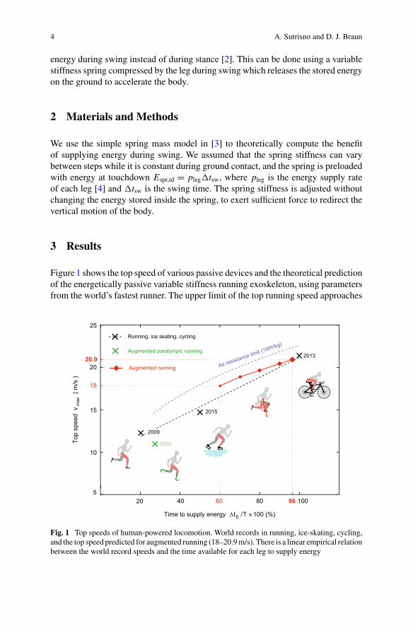
Figure1 shows the top speed of various passive devices and the theoretical predictionof the energetically passive variable stiffness running exoskeleton, using parametersfrom the world’s fastest runner. The upper limit of the top running speed approaches
Fig. 1 Top speeds of human-powered locomotion. World records in running, ice-skating, cycling,and the top speed predicted for augmented running (18–20.9m/s). There is a linear empirical relationbetween the world record speeds and the time available for each leg to supply energy
The Hidden Potential of Energetically Passive Exoskeletons 5
the top speed of cycling. We found that, even if the human only supplies energy 60%of the step time, they could still theoretically run at 18 m/s speed.
4 Discussion
Developing a variable stiffness spring exoskeleton for running requires a spring withenergy density of 600 J/kg; significantly higher compared to paralympic runningblades 150 J/kg. Therefore, fundamental advances in materials are still required todevelop the envisioned energetically passive running exoskeleton.
5 Conclusion
Running could theoretically reach the top cycling speed provided the legs couldsupply energy in the air instead of on the ground.
References
1. A.M. Dollar, H. Herr, Lower extremity exoskeletons and active orthoses: challenges and state-of-the-art. IEEE T. Robot. 24, 144–158 (2008)
2. A. Sutrisno, D.J. Braun, How to run 50% faster without external energy. Sci. Adv. 6(13),eaay1950 (2020)
3. R. Blickhan, The spring-mass model for running and hopping. J. Biomech. 22, 1217–1227(1989)
4. J.-B. Morin, M. Bourdin, P. Edouard, N. Peyrot, P. Samozino, J.-R. Lacour, Mechanical deter-minants of 100-m sprint running performance. Eur. J. Appl. Physiol. 112, 3921–3930 (2012)
Effect of a Back-Assist Exosuiton Logistics Worker Perceptions,Acceptance, and Muscle Activity
Matthew B. Yandell, Anna E. Wolfe, Matthew C. Marino, Mark P. Harris,and Karl E. Zelik
Abstract A workplace study was conducted to evaluate user perceptions, accep-tance, and muscle activity amongst logistics workers wearing an unmotorized, dual-mode, back-assist exosuit prototype. Eleven workers performed a lifting/loweringtask with versus without the exosuit, while back muscle activity was recorded. Theythen used the exosuit while performing their actual work tasks in a distribution centerbefore completing a questionnaire about their user experience. Worker perceptionsof the exosuit were overwhelmingly positive: 100% felt the exosuit could be usefuland fit into their daily job without interfering, >90% felt assisted and that the exosuitmade lifting easier, and >80% felt it was comfortable and that they were free to movenaturally while wearing the exosuit. Finally, the majority of workers showed reducedback muscle activity while wearing the exosuit during lifting/lowering, consistentwith results from prior lab studies. Worker feedback on this prototype was then usedto inform design of the HeroWear Apex exosuit.
Funding support was provided by NSF SBIR Award 1913763.
M. B. Yandell · M. C. Marino · M. P. Harris · K. E. Zelik (B)HeroWear, Nashville, TN, USAe-mail: [email protected]
M. B. Yandelle-mail: [email protected]
M. C. Marinoe-mail: [email protected]
M. P. Harrise-mail: [email protected]
A. E. Wolfe · K. E. ZelikCenter for Rehabilitation Engineering & Assistive Technology, Vanderbilt University, Nashville,TN, USAe-mail: [email protected]
© The Author(s), under exclusive license to Springer Nature Switzerland AG 2022J. C. Moreno et al. (eds.), Wearable Robotics: Challenges and Trends,Biosystems & Biorobotics 27, https://doi.org/10.1007/978-3-030-69547-7_2
7
8 M. B. Yandell et al.
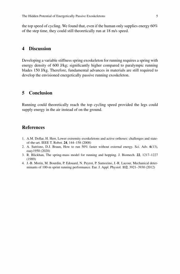
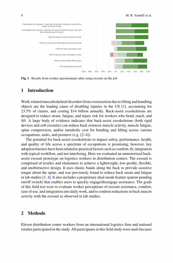
Fig. 1 Results from worker questionnaire after using exosuit on the job
1 Introduction
Work-relatedmusculoskeletal disorders fromoverexertion due to lifting and handlingobjects are the leading cause of disabling injuries in the US [1], accounting for23.5% of claims, and costing $14 billion annually. Back-assist exoskeletons aredesigned to reduce strain, fatigue, and injury risk for workers who bend, reach, andlift. A large body of evidence indicates that back-assist exoskeletons (both rigiddevices and soft exosuits) can reduce back extensor muscle activity, muscle fatigue,spine compression, and/or metabolic cost for bending and lifting across variousoccupations, tasks, and postures (e.g. [2–4]).
The potential for back-assist exoskeletons to impact safety, performance, health,and quality of life across a spectrum of occupations is promising; however, keyadoption barriers have been related to practical factors such as comfort, fit, integrationwith typical workflow, and not interfering. Here we evaluated an unmotorized back-assist exosuit prototype on logistics workers in distribution centers. The exosuit iscomprised of textiles and elastomers to achieve a lightweight, low-profile, flexible,and unobstructive design. It uses elastic bands along the back to provide assistivetorque about the spine, and was previously found to reduce back strain and fatiguein lab studies [3, 4]. It also includes a proprietary dual-mode feature (patent-pendingon/off switch) that enables users to quickly engage/disengage assistance. The goalsof this field test were to evaluate worker perceptions of exosuit assistance, comfort,ease of use, and integration into daily work, and to confirm reductions in backmuscleactivity with the exosuit as observed in lab studies.
2 Methods
Eleven distribution center workers from an international logistics firm and nationalretailer participated in the study. All participants in this field studyweremale because
Effect of a Back-Assist Exosuit on Logistics Worker … 9
the prototype available at the time of testing had amale-specific fit. Though it is notedthat both prior lab studies involved males and females, and the subsequent versionof this exosuit (HeroWear Apex) includes both male- and female-specific fits. Thisstudy was approved by the Vanderbilt University Institutional Review Board and theworkers gave informed written consent prior to participation.
2.1 Training
Workers were introduced to the exosuit over a 45-min period. This introductionincluded an overview of the exosuit and the testing protocol. Then each worker wasfit with the exosuit and allowed a limited amount of time to acclimate by performing aseries of general bending and lifting tasks to get a feel for how the device functioned.
2.2 Simulated Lifting and Lowering Tasks
Workerswere instrumentedwith electromyographical (EMG) sensors (DelsysTrignoMini) on six back muscles: left and right Multifidus, Longissimus Thoracis, and Ilio-costalis Lumborum.Workers then completed lifting cycles with and without wearingthe exosuit. A full cycle of the task involved beginning in an upright standing posture,lifting a 22-lb box from a pallet (5.5 in. in height), turning 90°, and setting the boxdown on a table (36 in. in height), then lifting, turning 90°, and lowering the boxdown to the starting location, and returning to upright standing. Each cycle wasrepeated 15 times. Workers were allowed to lift/lower using any technique theywould normally use at work (i.e., technique was not controlled). EMG data wereanalyzed to extract total and peak values, and averaged to obtain an EMG summarymetric for comparison purposes.
2.3 Real Work Environment Evaluation
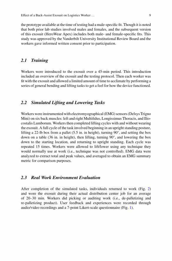
After completion of the simulated tasks, individuals returned to work (Fig. 2)and wore the exosuit during their actual distribution center job for an averageof 20–30 min. Workers did picking or auditing work (i.e., de-palletizing andre-palletizing product). User feedback and experiences were recorded throughaudio/video recordings and a 7-point Likert-scale questionnaire (Fig. 1).
10 M. B. Yandell et al.
Fig. 2 Distribution center workers using an exosuit prototype on the job for a variety of logisticstasks: picking, palletizing, forklift driving
3 Results
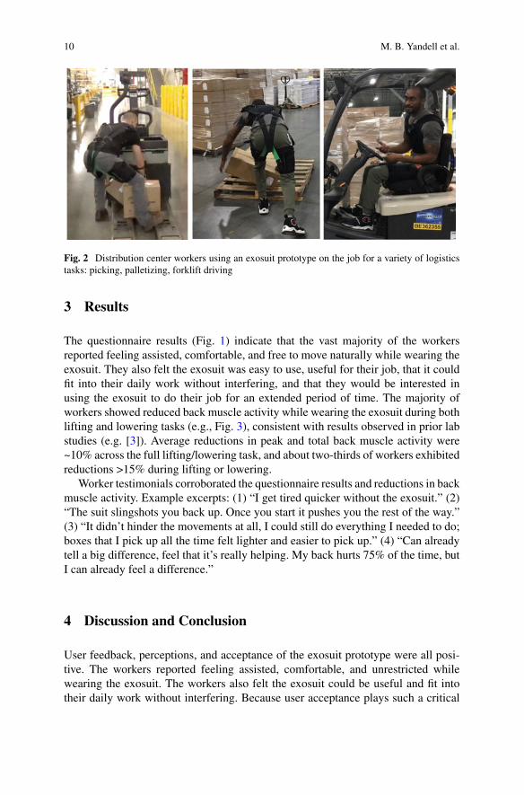
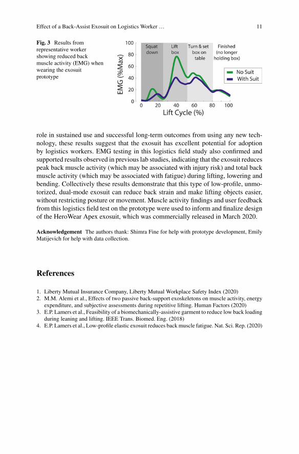
The questionnaire results (Fig. 1) indicate that the vast majority of the workersreported feeling assisted, comfortable, and free to move naturally while wearing theexosuit. They also felt the exosuit was easy to use, useful for their job, that it couldfit into their daily work without interfering, and that they would be interested inusing the exosuit to do their job for an extended period of time. The majority ofworkers showed reduced back muscle activity while wearing the exosuit during bothlifting and lowering tasks (e.g., Fig. 3), consistent with results observed in prior labstudies (e.g. [3]). Average reductions in peak and total back muscle activity were~10% across the full lifting/lowering task, and about two-thirds of workers exhibitedreductions >15% during lifting or lowering.
Worker testimonials corroborated the questionnaire results and reductions in backmuscle activity. Example excerpts: (1) “I get tired quicker without the exosuit.” (2)“The suit slingshots you back up. Once you start it pushes you the rest of the way.”(3) “It didn’t hinder the movements at all, I could still do everything I needed to do;boxes that I pick up all the time felt lighter and easier to pick up.” (4) “Can alreadytell a big difference, feel that it’s really helping. My back hurts 75% of the time, butI can already feel a difference.”
4 Discussion and Conclusion
User feedback, perceptions, and acceptance of the exosuit prototype were all posi-tive. The workers reported feeling assisted, comfortable, and unrestricted whilewearing the exosuit. The workers also felt the exosuit could be useful and fit intotheir daily work without interfering. Because user acceptance plays such a critical
Effect of a Back-Assist Exosuit on Logistics Worker … 11
Fig. 3 Results fromrepresentative workershowing reduced backmuscle activity (EMG) whenwearing the exosuitprototype
role in sustained use and successful long-term outcomes from using any new tech-nology, these results suggest that the exosuit has excellent potential for adoptionby logistics workers. EMG testing in this logistics field study also confirmed andsupported results observed in previous lab studies, indicating that the exosuit reducespeak back muscle activity (which may be associated with injury risk) and total backmuscle activity (which may be associated with fatigue) during lifting, lowering andbending. Collectively these results demonstrate that this type of low-profile, unmo-torized, dual-mode exosuit can reduce back strain and make lifting objects easier,without restricting posture or movement. Muscle activity findings and user feedbackfrom this logistics field test on the prototype were used to inform and finalize designof the HeroWear Apex exosuit, which was commercially released in March 2020.
Acknowledgement The authors thank: Shimra Fine for help with prototype development, EmilyMatijevich for help with data collection.
References
1. Liberty Mutual Insurance Company, Liberty Mutual Workplace Safety Index (2020)2. M.M. Alemi et al., Effects of two passive back-support exoskeletons on muscle activity, energy
expenditure, and subjective assessments during repetitive lifting. Human Factors (2020)3. E.P. Lamers et al., Feasibility of a biomechanically-assistive garment to reduce low back loading
during leaning and lifting. IEEE Trans. Biomed. Eng. (2018)4. E.P. Lamers et al., Low-profile elastic exosuit reduces backmuscle fatigue. Nat. Sci. Rep. (2020)
A Design Tool for Passive Wrist Support
Ali Amoozandeh Nobaveh, Giuseppe Radaelli, and Just L. Herder
Abstract A design tool for passive wrist support using compliant spatial beams asgravity balancer is presented. The aim of this assistive device is to reduce requiredeffort for pronation-supination and flexion-extension by 70% to help patients withmuscular weakness keeping their hand’s posture and doing daily tasks, while theforearm is rested. To reach this goal, a setup with three connection points to theuser’s hand, and two optimized spatial beams as elastic gravity compensators, aredeveloped. The overall shape and cross-sectional dimensions of the compliant beamsare attained using an optimization technique. The objective is reaching a desiredendpoint kinetostatic behaviour which is determined based on the hand’s weightand available muscular forces. A design case is presented to show the ability of themethod, and the final errors from the desired behaviour are clarified. In the end,possible further applications of the design tool are discussed.
1 Introduction
A plain wrist support can help people who are suffering frommuscular weakness [1]by keeping their hand in a normal posture and avoid further damages to the bodytissues due to hanging of the hand. The majority of mentioned people have controlon their muscles, but are not able to provide sufficient muscular power to keep thedesired postures, e.g., patients with Duchenne muscular dystrophy (DMD). Previ-ously there were only fixed orthoses available for those people. However, with recentdevelopments, there exist active and passive assistive devices to help them controltheir hand’s posture to some extent [2]. Among those, passive devices which mainlywork based on reducing required effort by static balancing of the hand’s weight aremore widespread as they are lighter and cheaper. In the case of using compliant
Supported by NWO (P16-05: Shell Skeletons).
A. Amoozandeh Nobaveh (B) · G. Radaelli · J. L. HerderPrecision and Microsystems Engineering Department, Delft University of Technology,Delft, The Netherlandse-mail: [email protected]
© The Author(s), under exclusive license to Springer Nature Switzerland AG 2022J. C. Moreno et al. (eds.), Wearable Robotics: Challenges and Trends,Biosystems & Biorobotics 27, https://doi.org/10.1007/978-3-030-69547-7_3
13
14 A. Amoozandeh Nobaveh et al.
mechanism instead of conventional linkages in the mentioned passive devices, theycould be even more flexible and slender.
The goal of this paper is to present a design tool for a flexible passive wristsupport using spatial compliant beams which work as elastic elements for gravitybalancing to keep the normal posture of hand and facilitate movement of the wrist ina limited range of motion while the forearm is rested horizontally. This design toolcan provide tunable sizing and kinetostatic characterization for gravity balancingbased on different user requirements, by using the elastic deformation of optimizedspatial compliant beams [3].
The paper is structured as follows. In Sect. 2, the design of the wrist support andits functional requirements are described together with the details of the spatial beamoptimizer. In Sect. 3 the results are shown for a case, and discussion is given on them.In the end, the conclusion and possible future applications are discussed in Sect. 4.
2 Methods
2.1 Proposed Design
The wrist support is designed to have three interfaces with the hand, two on the upperand lower forearm and one under the palmar side of the hand. These three points areconnected from the outer side of the hand with two slender compliant beams whichare shaped by the optimization process based on defined requirements. The handand lower forearm supination, while they are rested horizontally, are balanced by thefirst beam connecting the upper and lower forearm interfaces to provide the requiredmoment by elastic deformation. The required wrist extension balancing force isprovided by the elastic bending of the second beam between the lower forearm andpalmar side of the hand. The requirements for passive balancing beams are set toreach 30 ± 25 for the wrist pronation-supination and 0 ± 40 for the hand flexion-extension with 70% less muscular effort. The resulted beams could have differentshapes in restricted design area and base on dissimilar requirements of users.
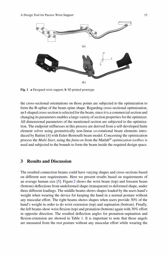
Figure1 shows the resulted beams and the wrist support interfaces. The handinterfaces are made based on the parallelogram mechanism, which leads to easierwearing and size adaptability of the device, as well as keeping the beams alignedwith the user’s hand.
2.2 Beam Shape Optimization
The developed optimization process uses the general shape of the beams and theircross-sectional properties to reach the design requirements. Concerning the generalshape of the beam, the coordinates of six control points along the beam together with
A Design Tool for Passive Wrist Support 15
Fig. 1 a Designed wrist support, b 3D printed prototype
the cross-sectional orientations on those points are subjected to the optimization toform the B-spline of the beam spine shape. Regarding cross-sectional optimization,an I-shaped cross-section is selected for the beam, since it is a commercial section andchanging its parameters enables a large variety of section properties for the optimizer.All dimensional parameters of the mentioned section are subjected to the optimiza-tion. The endpoint stiffnesses in this process are derived from a self-developed finiteelement solver using geometrically non-linear co-rotational beam elements intro-duced by Battini [4] with Euler-Bernoulli beam model. Concerning the optimizationprocess theMulti Start, using the fmincon from the Matlab® optimization toolbox isused and subjected to the bounds to form the beam inside the required design space.
3 Results and Discussion
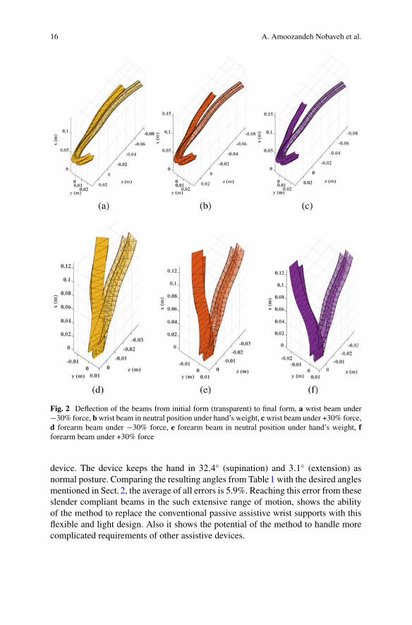
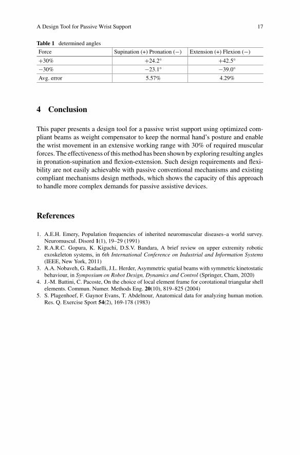
The resulted connection beams could have varying shapes and cross-sections basedon different user requirements. Here we present results based on requirements ofan average human size [5]. Figure2 shows the wrist beam (top) and forearm beam(bottom) deflections from undeformed shape (transparent) to deformed shape, underthree different loadings. The middle beams shows shapes loaded by the users hand’sweight when wearing the device for keeping the hand in a normal posture withoutany muscular effort. The right beams shows shapes when users provide 30% of thehand’s weight in order to do wrist extension (top) and supination (bottom). Finally,the left beams show wrist flexion (top) and pronation (bottom) again with 30% effortin opposite direction. The resulted deflection angles for pronation-supination andflexion-extension are showed in Table 1. It is important to note that those angelsare measured from the rest posture without any muscular effort while wearing the
16 A. Amoozandeh Nobaveh et al.
Fig. 2 Deflection of the beams from initial form (transparent) to final form, a wrist beam under−30% force, bwrist beam in neutral position under hand’s weight, c wrist beam under +30% force,d forearm beam under −30% force, e forearm beam in neutral position under hand’s weight, fforearm beam under +30% force
device. The device keeps the hand in 32.4 (supination) and 3.1 (extension) asnormal posture. Comparing the resulting angles from Table1 with the desired anglesmentioned in Sect. 2, the average of all errors is 5.9%. Reaching this error from theseslender compliant beams in the such extensive range of motion, shows the abilityof the method to replace the conventional passive assistive wrist supports with thisflexible and light design. Also it shows the potential of the method to handle morecomplicated requirements of other assistive devices.
A Design Tool for Passive Wrist Support 17
Table 1 determined angles
Force Supination (+) Pronation (−) Extension (+) Flexion (−)
+30% +24.2 +42.5
−30% −23.1 −39.0
Avg. error 5.57% 4.29%
4 Conclusion
This paper presents a design tool for a passive wrist support using optimized com-pliant beams as weight compensator to keep the normal hand’s posture and enablethe wrist movement in an extensive working range with 30% of required muscularforces. The effectiveness of thismethod has been shown by exploring resulting anglesin pronation-supination and flexion-extension. Such design requirements and flexi-bility are not easily achievable with passive conventional mechanisms and existingcompliant mechanisms design methods, which shows the capacity of this approachto handle more complex demands for passive assistive devices.
References
1. A.E.H. Emery, Population frequencies of inherited neuromuscular diseases–a world survey.Neuromuscul. Disord 1(1), 19–29 (1991)
2. R.A.R.C. Gopura, K. Kiguchi, D.S.V. Bandara, A brief review on upper extremity roboticexoskeleton systems, in 6th International Conference on Industrial and Information Systems(IEEE, New York, 2011)
3. A.A. Nobaveh, G. Radaelli, J.L. Herder, Asymmetric spatial beams with symmetric kinetostaticbehaviour, in Symposium on Robot Design, Dynamics and Control (Springer, Cham, 2020)
4. J.-M. Battini, C. Pacoste, On the choice of local element frame for corotational triangular shellelements. Commun. Numer. Methods Eng. 20(10), 819–825 (2004)
5. S. Plagenhoef, F. Gaynor Evans, T. Abdelnour, Anatomical data for analyzing human motion.Res. Q. Exercise Sport 54(2), 169-178 (1983)
The Key Elements in the Design ofPassive Assistive Devices
Maziar A. Sharbafi
Abstract Nowadays, enhancing the physical abilities of able-bodied humansattracted the researchers’ attention besides the development of assistive devices forpeople with mobility disorders. As a result, the interest in designing of cheap andsoft wearable exoskeletons called exosuits is distinctly growing. Careful investiga-tion of the biological musculoskeletal systems reveals three essential features sim-plifying gait control. The first property is the embedded compliance in the muscle-tendon-complex (MTC). Force-velocity or damper-likemuscle behavior is the secondfeature. The last useful feature is in the biological morphological design of multi-articular muscles. These properties can be implemented in passive, assistive devicesin isolation or combination. In this paper, we summarize a few studies on passivelower limb assistive devices that benefit from these two design concepts. We elabo-rate more on the outcomes of a recent study on a lower limb exosuit design with twobiarticular elastic elements that combine the two aforementioned mechanisms in asingle device.
1 Introduction
Biomechanical models with different levels of complexity are of advantage to under-stand the underlying principles of legged locomotion. This is an essential step todevelop machines that aim at assisting human locomotion, namely assistive devices.Nowadays, these devices assist not only impaired people, but also healthy humansby reducing metabolic cost, fatigue, or increasing comfort. Among different types
This article is partially supported by the German Research Foundation (DFG) under the Grant No.AH307/2-1.
M. A. Sharbafi (B)Lauflabor Locomotion Lab, Center of Cognitive Science, TU Darmstadt, Darmstadt, Germanye-mail: [email protected]
© The Author(s), under exclusive license to Springer Nature Switzerland AG 2022J. C. Moreno et al. (eds.), Wearable Robotics: Challenges and Trends,Biosystems & Biorobotics 27, https://doi.org/10.1007/978-3-030-69547-7_4
19
20 M. A. Sharbafi
of assistive technologies, passive devices became more popular due to their simple,cheap, light, and user-friendly designs. Removing electronics, includingmotors, sen-sors, and batteries from the exo design and development reduces the required effortand cost for maintenance. In short, people can wear passive wearable devices likeclothes or shoes needless to charge the batteries and carry heavy backpacks. The costfor achieving this level of comfort is the lacking of energy resources, which lowerthe potential performance of passive devices compared to active ones, regardingmetabolic consumption or supporting patients with severe disabilities (e.g., para-plegic patients). In other words, passive gait assistance devices can support energymanagement without energy injection.
Since passive devices can not inject energy, how can they improve energymanage-ment? The only possibilities are energy shuffling or dissipation; both are supported bybiological evidence. Energy shuffling can be performed regarding time or position. Inthat respect, elastic elements can store energy at a specific time domain (gait phase)and return it at another time. For this, springs are essential elements in different typesof passive assistive devices, from carbon foot prostheses to exoskeletons [3]. Moreadvanced techniques of using nonlinear springs or their combinations with clutchescan provide more significant advantages regarding energy management by definingmore complex force-length behaviors [6]. However, this is not the only method forenergy shuffling. Biarticular muscles are smart biological solutions for transferringenergy between two joints. For example, using cables [4] or springs [5] in a biarticulararrangement can easily implement energy shuffling between two positions (joints)in a robot as well as in an assistive device [6]. Regarding energy dissipation, biome-chanical studies demonstrated damper-like behavior in legged locomotion (e.g., kneejoint in downhill walking). This energy dissipation will be costly in the human bodyor active assistive devices. Instead, passive dampers (e.g., hydraulics) can providethis property, which could surprisingly yield improvement in gait performance bydissipating energy [7].
In this paper, we first present a brief overview of the state-of-the-art of passiveassistive devices, which are designed based on these three basic elements. Then, arecent study [2] on gait assistance with a passive exosuit having biarticular thighelastic elements will be briefly described. These compliant elements are in paral-lel to the hamstring and rectus femoris muscles of the leg, which combine energytransferring within time and location.
2 Methods
Passive assistive devices can be roughly categorized as: (1) Passive prostheses [8], (2)Exoskeletons supporting upper body (e.g., for load carrying [10]), and (3) exoskele-tons for supporting lower limb in locomotion [3, 9]. The focus of this article is onthe third category and also the compliance and biarticular design from the threeaforementioned key features.
The Key Elements in the Design of Passive Assistive Devices 21
2.1 Compliance and Multi Articular Engagement
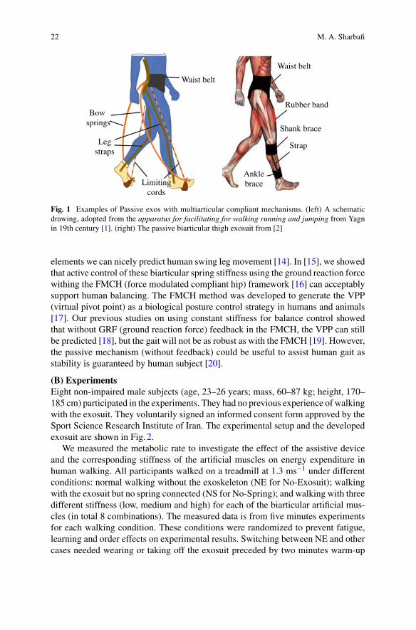
Employing passive devices for enabling amputees to locomote is not new [11]. Thedocumented schematic drawing from previous centuries demonstrates the interest ofresearchers to facilitate locomotion for healthy subjects using assistive devices. In[1], a multiarticular bow spring with a limited range of motion exerted by cords orchains was introduced to support humans for different gaits (see Fig. 1(left). The ideaof storing and returning energywith elastic elements and transferring energy betweendifferent joints provides the core concept of this invention in late 19 century. In 2003,van den Bogert introduced the exotendons as poly-articular elastic mechanisms witha significant contribution to the economy of legged locomotion [4]. This passiveassistive technology is based on long elastic cords attached to an exoskeleton andguided by pulleys, which are placed at the joints. With human experiment-basedsimulations, he demonstrated the ability of a complex exotendon system to reducethe joint moments required for normal walking by 71% and joint power by 74% [6].However, this amount of metabolic reduction could never be approached in reality.In [12], van Dijk et al. tested an exoskeleton with exotendons, which could reducehuman mechanical work up to 40% in simulations. Contrarily, the developed devicecould never reduce the metabolic in human experiments [6]. In 2015, Collins etal. developed an ankle exoskeleton that could reduce the metabolic cost of healthyhuman walking by more than 7%. This lightweight elastic device acts parallel withthe user’s calf muscles, off-loading muscle force in contractions. Using a mechanicalclutch to tune engagement of the spring supports the function of the calf muscles andAchilles tendon. In another recent study, Nasiri et al. developed a passive compliantexoskeleton which benefits from energy transfer between the right and left hip joints[13]. The simple spring can generate about 8% metaboic rate reduction by shufflingthe energy between the two hip joins during running at 2.5 ms−1. Using biarticularthigh springs, the significant advantages of biarticular springs in a newpassive exosuitwas demonstrated in [2]. A summary of the methods and achievements in this latterstudy will be presented in the following.
2.2 Case Study
(A) Design conceptInvestigating joint power consumption in human locomotion (e.g., walking) showsreciprocal behavior between hip and knee joints during swing phase. This means thatinstead of generating and dissipating energy in two adjacent joints, shuffling energybetween them using biarticular coupling is a much more efficient solution. In [2],this concept was utilized to develop a biarticular thigh exosuit, shown in Fig. 1(right).Instead of multi articular leaf springs of [1], we employed biarticular elastic rubberbands. In this bioinspired design, the passive artificial muscles (rubber bands) areutilized to mimic human rectus femoris and hamstring muscles. With these passive
22 M. A. Sharbafi
Fig. 1 Examples of Passive exos with multiarticular compliant mechanisms. (left) A schematicdrawing, adopted from the apparatus for facilitating for walking running and jumping from Yagnin 19th century [1]. (right) The passive biarticular thigh exosuit from [2]
elements we can nicely predict human swing leg movement [14]. In [15], we showedthat active control of these biarticular spring stiffness using the ground reaction forcewithing the FMCH (force modulated compliant hip) framework [16] can acceptablysupport human balancing. The FMCH method was developed to generate the VPP(virtual pivot point) as a biological posture control strategy in humans and animals[17]. Our previous studies on using constant stiffness for balance control showedthat without GRF (ground reaction force) feedback in the FMCH, the VPP can stillbe predicted [18], but the gait will not be as robust as with the FMCH [19]. However,the passive mechanism (without feedback) could be useful to assist human gait asstability is guaranteed by human subject [20].
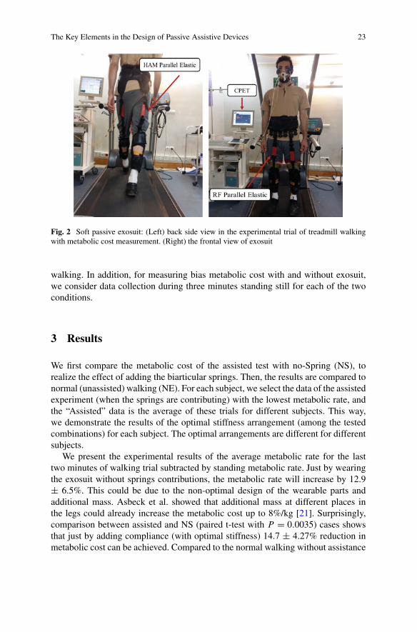
(B) ExperimentsEight non-impaired male subjects (age, 23–26 years; mass, 60–87 kg; height, 170–185 cm) participated in the experiments. They had no previous experience of walkingwith the exosuit. They voluntarily signed an informed consent form approved by theSport Science Research Institute of Iran. The experimental setup and the developedexosuit are shown in Fig. 2.
We measured the metabolic rate to investigate the effect of the assistive deviceand the corresponding stiffness of the artificial muscles on energy expenditure inhuman walking. All participants walked on a treadmill at 1.3 ms−1 under differentconditions: normal walking without the exoskeleton (NE for No-Exosuit); walkingwith the exosuit but no spring connected (NS for No-Spring); and walking with threedifferent stiffness (low, medium and high) for each of the biarticular artificial mus-cles (in total 8 combinations). The measured data is from five minutes experimentsfor each walking condition. These conditions were randomized to prevent fatigue,learning and order effects on experimental results. Switching between NE and othercases needed wearing or taking off the exosuit preceded by two minutes warm-up
The Key Elements in the Design of Passive Assistive Devices 23
Fig. 2 Soft passive exosuit: (Left) back side view in the experimental trial of treadmill walkingwith metabolic cost measurement. (Right) the frontal view of exosuit
walking. In addition, for measuring bias metabolic cost with and without exosuit,we consider data collection during three minutes standing still for each of the twoconditions.
3 Results
We first compare the metabolic cost of the assisted test with no-Spring (NS), torealize the effect of adding the biarticular springs. Then, the results are compared tonormal (unassisted) walking (NE). For each subject, we select the data of the assistedexperiment (when the springs are contributing) with the lowest metabolic rate, andthe “Assisted” data is the average of these trials for different subjects. This way,we demonstrate the results of the optimal stiffness arrangement (among the testedcombinations) for each subject. The optimal arrangements are different for differentsubjects.
We present the experimental results of the average metabolic rate for the lasttwo minutes of walking trial subtracted by standing metabolic rate. Just by wearingthe exosuit without springs contributions, the metabolic rate will increase by 12.9± 6.5%. This could be due to the non-optimal design of the wearable parts andadditional mass. Asbeck et al. showed that additional mass at different places inthe legs could already increase the metabolic cost up to 8%/kg [21]. Surprisingly,comparison between assisted and NS (paired t-test with P = 0.0035) cases showsthat just by adding compliance (with optimal stiffness) 14.7 ± 4.27% reduction inmetabolic cost can be achieved. Compared to the normal walking without assistance
24 M. A. Sharbafi
(NE), the proposed passive exosuit can reduce the average metabolic rate by 4.68 ±4.24%. More details can be found in [2].
4 Conclusion and Future Work
In this article, we summarized the key elements of designing passive assistive devicesin (1) elasticity, (2) multi-articular arrangements, and (3) damping. We focused onthe first two elements and, more specifically, on lower limb assistive devices. Afterpresenting a brief overview of the developed devices and state-of-the-art, we detailedmore about our passive exosuit with biarticular thigh springs.
In this device, we benefit from both elasticity and biarticular design. We showedthat transferring energy from hip to knee and vice versa could result in metaboliccost reduction. In spite of about 13% increase in metabolic cost just by wearing thesuit without compliant elements, involving the artificial biarticular thigh muscles(elastic bands) could reduce energy consumption even compared to normal walking(about 5%). These passive elements not only compensate for the effect of the imper-fect design but also provide additional benefit for walking efficiency. We improvedthe design and manufacturing to minimize the effects of additional mass and othernon-optimized mechanical parts of the wearable parts (without springs). The recentversion was successfully tested in pilot experiments (not reported). Doing experi-ments with more subjects will be the next step.
In the here presented experiments, we only tested three stiffness values for eachof the biarticular springs. Recently, Human-in-the-loop-Optimization (HILO) wasintroduced as a practical tool to optimize control parameters in the assistive devices[22]. This method can be used in the future to find the optimal stiffness with herepresented exosuit.
References
1. Apparatus for facilitating walking, running, and jumping2. H. Barazesh,M.A. Sharbafi, A biarticular passive exosuit to support balance control can reduce
metabolic cost of walking. Bioinspiration & Biomimetics 15(3), 036009 (2020)3. S.H. Collins, M. Bruce Wiggin, G.S. Sawicki, Reducing the energy cost of human walking
using an unpowered exoskeleton. Nature 522(7555), 212 (2015)4. A.J. Van Soest, A.L. Schwab, M.F. Bobbert, G.J. van Ingen Schenau, The influence of the
biarticularity of the gastrocnemiusmuscle on vertical-jumping achievement. J. Biomech. 26(1),1–8 (1993)
5. M.A. Sharbafi, C. Rode, S. Kurowski, D. Scholz, R. Möckel, K. Radkhah, G. Zhao, A.M.Rashty, Oskar von Stryk, A. Seyfarth, A new biarticular actuator design facilitates control ofleg function in biobiped3. Bioinspiration & biomimetics 11(4), 046003 (2016)
6. A.J. Van den Bogert, Exotendons for assistance of human locomotion. Biomed. Eng. Online2(1), 17 (2003)
The Key Elements in the Design of Passive Assistive Devices 25
7. S. Portnoy, A. Kristal, A. Gefen, I. Siev-Ner, Outdoor dynamic subject-specific evaluationof internal stresses in the residual limb: hydraulic energy-stored prosthetic foot compared toconventional energy-stored prosthetic feet. Gait & Posture 35(1), 121–125 (2012)
8. A. Naseri, M.M. Moghaddam, M. Gharini, M.A. Sharbafi, A novel adjustable damper designfor hybrid passive ankle prosthesis. Actuators (2020)
9. M.C. Faustini, R.R. Neptune, R.H. Crawford, S.J. Stanhope, Manufacture of passive dynamicankle-foot orthoses using selective laser sintering. IEEE Trans. Biomed. Eng. 55(2), 784–790(2008)
10. M.M. Alemi, S. Madinei, S. Kim, D. Srinivasan, M.A. Nussbaum, Effects of two passiveback-support exoskeletons on muscle activity, energy expenditure, and subjective assessmentsduring repetitive lifting. Hum. Factors 62(3), 458–474 (2020)
11. B.F. Palmer, Artificial leg. US Patent (1846)12. W. Van Dijk, H. Van der Kooij, E. Hekman, A passive exoskeleton with artificial tendons:
design and experimental evaluation, in 2011 IEEE International Conference on RehabilitationRobotics (IEEE, New York, 2011), pp. 1–6
13. R. Nasiri, A. Ahmadi, M.N. Ahmadabadi, Reducing the energy cost of human running usingan unpowered exoskeleton. IEEE Trans. Neural Syst. Rehab. Eng. 26(10), 2026–2032 (2018)
14. M.A. Sharbafi, A.M.N. Rashty, C. Rode, A. Seyfarth, Reconstruction of human swing legmotion with passive biarticular muscle models. Hum. Movement Sci. 52, 96–107 (2017)
15. M.A. Sharbafi, H. Barazesh, M. Iranikhah, A. Seyfarth, Leg force control through biarticularmuscles for human walking assistance. Front. Neurorobot. 12, 39 (2018)
16. M.A. Sharbafi, A. Seyfarth, FMCH: a new model for human-like postural control in walking,in 2015 IEEE/RSJ International Conference on Intelligent Robots and Systems (IROS) (IEEE,New York, 2015), pp. 5742–5747
17. H.-M. Maus, S.W. Lipfert, M. Gross, J. Rummel, A. Seyfarth, Upright human gait did notprovide a major mechanical challenge for our ancestors. Nat. Commun. 1, 70 (2010)
18. M.A. Sharbafi, M.N. Ahmadabadi, M.J. Yazdanpanah, A.M. Nejad, A. Seyfarth, Complianthip function simplifies control for hopping and running, in 2013 IEEE/RSJ International Con-ference on Intelligent Robots and Systems (IEEE, New York, 2013), pp. 5127–5133
19. M.A. Sharbafi, A. Seyfarth, Stable running by leg force-modulated hip stiffness, in 5th IEEERAS/EMBS International Conference on Biomedical Robotics and Biomechatronics (IEEE,New York, 2014), pp. 204–210
20. G. Zhao, M.A. Sharbafi, M. Vlutters, E. van Asseldonk, A. Seyfarth, Bio-inspired balancecontrol assistance can reduce metabolic energy consumption in human walking. IEEE Trans.Neural Syst. Rehab. Eng. (2019)
21. A.T. Asbeck, S.M.M. De Rossi, I. Galiana, Y. Ding, C.J. Walsh, Stronger, smarter, softer:next-generation wearable robots. IEEE Rob. Autom. Maga. 21(4), 22–33 (2014)
22. J. Zhang, P. Fiers, K.A. Witte, R.W. Jackson, K.L. Poggensee, C.G. Atkeson, S.H. Collins,Human-in-the-loop optimization of exoskeleton assistance duringwalking. Science 356(6344),1280–1284 (2017)
Novel Designs for Passive Elastic LowerLimb Exoskeletons
Daniel P. Ferris and W. Sebastian Barrutia
Abstract Engineers and scientists have long tried to build powered robotic lowerlimb exoskeletons without success (at least commercially). A major limitation hasbeen the need for large amounts of mechanical power from the actuators. Simplyput, human muscles are amazing motors. The size and mass of robotic actuatorsthat can match human muscle limit exoskeleton hardware designs. An alternativeto heavy motors that engineers have relied on throughout history has been poweramplification from passive elastic mechanisms. We review examples of successfulpassive elastic systems that have been previously used by humans and discuss howelastic mechanisms can be incorporated into lower limb exoskeletons for assistinghuman locomotion.
1 Introduction
Fifty years of building powered robotic lower limb exoskeletons have not yielded acommercially successful device [1]. There are many companies currently developingrobotic exoskeletons around the world, but none of them have gained enough profitfrom their sales to balance out past research and development investments into thetechnology. The large bulk and mass of actuators and frames are major obstaclesto successful human performance augmentation [1]. Another limitation has been aninability to develop controllers that truly move the exoskeleton synergistically withthe human [1]. Agile and smooth motion is necessary for the human user to chooseto use the exoskeleton.
One of the offshoots of exoskeleton research has been to turn to soft exosuitsthat deliver less mechanical power than rigid exoskeleton devices, but are fairlylightweight and more comfortable to wear [2]. They can be targeted to specific joints
D. P. Ferris · W. Sebastian Barrutia (B)J. Crayton Pruitt Family Department of Biomedical Engineering, University of Florida,Gainesville, FL, USAe-mail: [email protected]
D. P. Ferrise-mail: [email protected]
© The Author(s), under exclusive license to Springer Nature Switzerland AG 2022J. C. Moreno et al. (eds.), Wearable Robotics: Challenges and Trends,Biosystems & Biorobotics 27, https://doi.org/10.1007/978-3-030-69547-7_5
27
28 D. P. Ferris and W. Sebastian Barrutia
or specific activities, providing a smaller boost in mechanical power at the rightmoment to assist human locomotion [3]. However, even exosuits as they are currentlydesigned rely on external energy sources (i.e. batteries) to deliver mechanical energyto the human.
Another alternativewould be to rely on passive elasticmechanisms for storage andreturn of energy during humanmovement. Inventors have long relied on elasticmech-anisms for human power amplification. Sometimes the designs have been incrediblyinnovative and fundamentally changed the advancement of human society. Othertimes the designs have been small tweaks to existing devices, but still have hadpositive effects that have benefitted humans.
We will briefly review some of examples of passive elastic mechanisms that havebenefitted humankind. These can serve as examples covering some of the designspace for passive elastic devices. Next, we consider a few specific device designs thatwere able to provide storage and return of elastic energy during human movement.
2 Historical Devices
Prior to the creation of motorized robotic devices, human have looked to elasticmechanisms for amplifying human power output or assisting human movement.Both the traditional bow and the compound bow can greatly enhance mechanicalpower output of a human in launching projectiles [4]. In sports, humans have repeat-edly used elastic energy storage and return to increase mechanical power output.The use of fiberglass poles in the pole vault and elastic strings in a tennis racquetare just two examples. McMahon originally proposed elastic running surfaces forenhancing a runner’s speed [5, 6]. Although his theory was later invalidated due tothe nature of damping in the runner’s leg mechanics, a compliant running surfacecan indeed improve running performance [7, 8]. Building on McMahon’s ideas, VanPhillips created his elastic lower limb prosthesis for running, which has fundamen-tally changed the way that individuals with lower limb amputations approach athleticmobility [9]. Herr and Langman showed that tuning of elastic elements can indeedbe very important for maximizing human performance in an early exosuit [10]. Thishistory doesn’t even include novelties such as pogo sticks, kangaroo shoes, or bungeejumping tethers. The take home message, however, is that there is a rich collectionof previous elastic devices intended to assist with human movement.
3 Lower Limb Exoskeleton Devices
Michael Cherry set out to build a unique elastic lower limb exoskeleton for humanrunning. He joined the Human Neuromechanics Laboratory at the University ofMichigan in 2005. After multiple attempts at building elastic energy mechanismsinto a leg assist device, he settled on a design using both energy storing springs in a
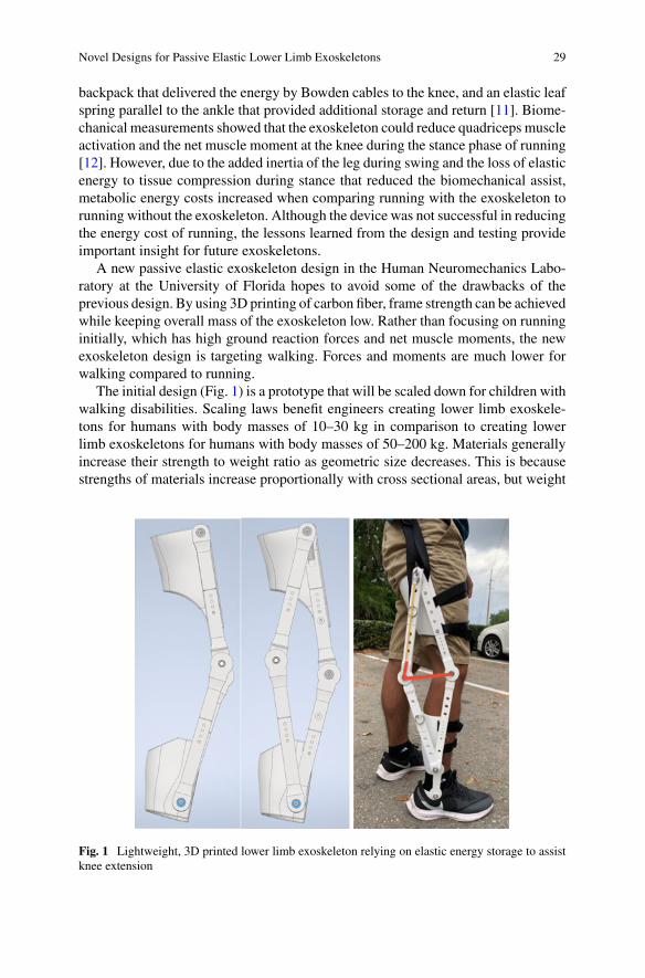
Novel Designs for Passive Elastic Lower Limb Exoskeletons 29
backpack that delivered the energy by Bowden cables to the knee, and an elastic leafspring parallel to the ankle that provided additional storage and return [11]. Biome-chanical measurements showed that the exoskeleton could reduce quadriceps muscleactivation and the net muscle moment at the knee during the stance phase of running[12]. However, due to the added inertia of the leg during swing and the loss of elasticenergy to tissue compression during stance that reduced the biomechanical assist,metabolic energy costs increased when comparing running with the exoskeleton torunning without the exoskeleton. Although the device was not successful in reducingthe energy cost of running, the lessons learned from the design and testing provideimportant insight for future exoskeletons.
A new passive elastic exoskeleton design in the Human Neuromechanics Labo-ratory at the University of Florida hopes to avoid some of the drawbacks of theprevious design. By using 3D printing of carbon fiber, frame strength can be achievedwhile keeping overall mass of the exoskeleton low. Rather than focusing on runninginitially, which has high ground reaction forces and net muscle moments, the newexoskeleton design is targeting walking. Forces and moments are much lower forwalking compared to running.
The initial design (Fig. 1) is a prototype that will be scaled down for children withwalking disabilities. Scaling laws benefit engineers creating lower limb exoskele-tons for humans with body masses of 10–30 kg in comparison to creating lowerlimb exoskeletons for humans with body masses of 50–200 kg. Materials generallyincrease their strength to weight ratio as geometric size decreases. This is becausestrengths of materials increase proportionally with cross sectional areas, but weight
Fig. 1 Lightweight, 3D printed lower limb exoskeleton relying on elastic energy storage to assistknee extension
30 D. P. Ferris and W. Sebastian Barrutia
increases proportionally with volumes. There are many different neurological anddevelopmental disabilities that cause muscle weakness in the knee extensors of chil-dren (e.g. cerebral palsy, spina bifida). A common approach to facilitate walkingexercise in these individuals is to use bodyweight support harnesses for walking on atreadmill. A passive lower limb exoskeleton that could allow walking exercise overground would enable more cognitively stimulating and physically diverse environ-ments (e.g. surface changes, obstacles, outdoor exercise). If the majority of the partsare 3D printed, it becomes easier to fabricate new parts for the exoskeleton as thechild grows [13].
4 Conclusion
The coming years will see more advances in passive elastic lower limb exoskeletonsdue to their advantages in minimizing exoskeletonmass and bulk. Additive manufac-turing technology allows 3D printers to generate carbon fiber and Kevlar frames thatcan be quickly customized for individual users. By taking advantage of the insightprovided by past elastic mechanisms designed to assist human movement, it may bepossible to design future exoskeletons to provide novel ways to recycle and amplifyenergy for walking and running, both in health and disability.
Acknowledgements Funded by NSF CBET-0347479, Lockheed Martin Corp., and the Leo Claire& Robert Adenbaum Foundation.
References
1. A.J.Young,D.P. Ferris, State of the art and future directions for lower limb robotic exoskeletons.IEEE Trans. Neural Syst. Rehabil. Eng. 25(2), 171–182 (2017)
2. J. Kim et al., Reducing the metabolic rate of walking and running with a versatile, portableexosuit. Science 365(6454), 668 (2019)
3. A.Asbeck, S. DeRossi, I. Galiana, Y.Ding, C.Walsh, Stronger, smarter, softer: next-generationwearable robots. Robot. Autom. Maga. 21(4), 22–33 (2014)
4. A.E. Minetti, Passive tools for enhancing muscle-driven motion and locomotion. J. Exp. Biol.207(8), 1265–1272 (2004)
5. T.A. Mcmahon, P.R. Greene, Fast running tracks. Sci. Am. 239(6), 148 (1978)6. T.A. Mcmahon, P.R. Greene, Influence of track compliance on running. J. Biomech. 12(12),
893–904 (1979)7. D.P. Ferris,M. Louie, C.T. Farley, Running in the real world: adjusting leg stiffness for different
surfaces. Proc. R. Soc. B-Biol. Sci. 265(1400), 989–994 (1998)8. A.E. Kerdok, A.A. Biewener, T.A. McMahon, P.G. Weyand, H.M. Herr, Energetics and
mechanics of human running on surfaces of different stiffnesses. J. Appl. Physiol. 92(2),469–478 (2002)
9. J. Poskett, The fastest man on no legs. Phys. World 25(7), 22–25 (2012)10. H. Herr, N. Langman, Optimization of human-powered elastic mechanisms for endurance
amplification. Struct. Optim. 13(1), 65–67 (1997)
Novel Designs for Passive Elastic Lower Limb Exoskeletons 31
11. M.S. Cherry, S. Kota, D.P. Ferris, An elastic exoskeleton for assisting human running, in ASME2009 InternationalDesignEngineeringTechnicalConferences andComputers and Informationin Engineering Conference (American Society of Mechanical Engineers, 2009), pp. 727–738
12. M.S. Cherry, S. Kota, A. Young, D.P. Ferris, Running with an elastic lower limb exoskeleton.J. Appl. Biomech. 32(3), 269–277 (2016)
13. T. Rahman et al., Passive exoskeletons for assisting limb movement. J. Rehab. Res. Dev. 43(5),583–589 (2006)
Passive Compliance in Legged Systemsand Assistive Devices
Andre Seyfarth
1 Summary
At the Cybathlon 2016 the performance of active and passive assistive devices forlegged locomotion was compared. In the category of legged prostheses, surprisinglypassive devices outperformed active ones regarding their performance in challengingtasks. Also the performance of active exoskeletons clearly demonstrated the stilllimited mobility performance in assisting the users. Why are passive systems arestill so powerful compared to active systems? What can be learned form the designand function of the human locomotor system regarding assisting legged locomotionby passive mechanisms?
In this paper selected design andmovement strategies of human legged locomotionare reflected with the aim to provide insights for the transfer into robotic and assistivesystems, such as prosthetic or orthotic devices for supporting human gait.
2 The Upright Human Body Posture
During human standing and walking, the body segments are aligned in a close tovertical arrangement. This can be compared to a tower with vertically arranged seg-ments of increasing mass with height. This has several advantages such as (1) a lowmechanical work required to move a given distance (cost of transport), (2) the loweffort to initiate gait, and (3) the ability to rapidly change the direction of movement(e.g. for manoeuvrability). At the same time this particular arrangement of bodysegments also poses some challenges regarding body design and movement con-trol. For instance, the almost straight knee configuration in midstance during humanwalking requires a delicate mechanical interplay between knee joint mechanics andneuromuscular control in the leg.
A. Seyfarth (B)Lauflabor Locomotion Laboratory, Institute of Sport Science and Centre for Cognitive Science,TU Darmstadt, Darmstadt, Germanye-mail: [email protected]
© The Author(s), under exclusive license to Springer Nature Switzerland AG 2022J. C. Moreno et al. (eds.), Wearable Robotics: Challenges and Trends,Biosystems & Biorobotics 27, https://doi.org/10.1007/978-3-030-69547-7_6
33
34 A. Seyfarth
3 Mechanical Design of Human Legged Locomotion
Human locomotion is a cyclic movement. It is characterized by a continuousexchange between kinetic and potential energy as reflected in a vertical excursion ofthe center of mass. This exchange of energies is moderated by muscle work whichbenefits from compliant structures in the muscle fibers and the tendons. Elastic ele-ments help to reduce the energetic costs of legged locomotion. With this, the legfunction becomes spring-like which can be described by characteristic parameterslike leg stiffness and joint stiffness. This poses the question of how to distributethe compliance in a segmented leg. Here, the human leg has a quite remarkabledesign with about equal shank and thigh length and a shorter foot, which is aboutperpendicular to the leg axis [1].
The foot provides a clever mechanisms to control the interaction with the ground.In walking, the heel contacts first, enabling the foot to cushion the impact of landingwith knee flexion and ankle plantarflexion. Once the foot is flat on the ground, the legpivots around the ankle joint with a shift of the centre for pressure from heel to toe.Finally, at the end of contact, the heel leaves the ground and the foot pivots aroundthe metatarsal joints by loading the toes. In this phase, the ankle joint already startsto accelerate forwards while the tip of the foot is still on the ground. The foot is thusan accelerator for the swing phase by quickly releasing energy stored around theankle joint. This catapult-like mechanisms is characteristic for human walking [2].Interestingly, this power-amplification mechanism based on elastic energy storagein calf muscles is more pronounced in walking than in jumping or running tasks.
4 Assistance by Compliant Mechanisms
The advantages of elastic structures attached to be body become visible in sports.Here the performance of Markus Rehm in long jump clearly shows that with ancompliant prosthetic foot similar and even larger jumping distance can be achievedcompared to non-amputee jumpers [3]. Still, the advantages of more efficient energystorage and release are counteracted by other challenges, e.g. in achieving a highrunning speed during approach with asymmetric leg function, which may requiredan increased control effort of the athlete.
By adding parallel (e.g. soft exoskeleton) or serial compliance to the human body(e.g. by a compliant foot prosthesis) the operation point of the human musculatureis shifted. In long jump, serial compliance can increase muscle work by extendingthe duration of eccentric muscle operation during the support phase [4]. So far, it ishowever not yet clear how the optimal tuning of the serial stiffness (e.g.muscle tendonstiffness in the human body) is achieved in the biological system. This challenge willbe discussed below.
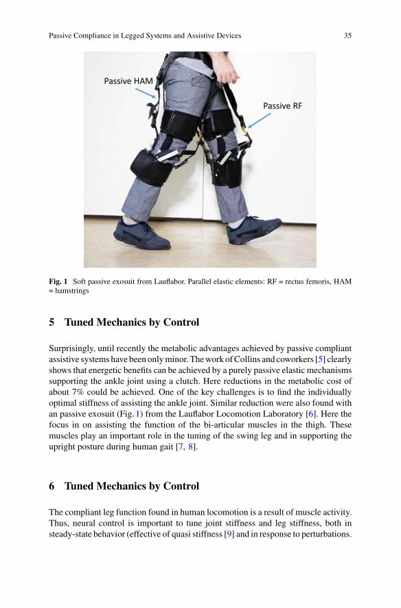
Passive Compliance in Legged Systems and Assistive Devices 35
Passive RF
Passive HAM
Fig. 1 Soft passive exosuit from Lauflabor. Parallel elastic elements: RF = rectus femoris, HAM= hamstrings
5 Tuned Mechanics by Control
Surprisingly, until recently the metabolic advantages achieved by passive compliantassistive systemshave beenonlyminor. Thework ofCollins and coworkers [5] clearlyshows that energetic benefits can be achieved by a purely passive elastic mechanismssupporting the ankle joint using a clutch. Here reductions in the metabolic cost ofabout 7% could be achieved. One of the key challenges is to find the individuallyoptimal stiffness of assisting the ankle joint. Similar reduction were also found withan passive exosuit (Fig. 1) from the Lauflabor Locomotion Laboratory [6]. Here thefocus in on assisting the function of the bi-articular muscles in the thigh. Thesemuscles play an important role in the tuning of the swing leg and in supporting theupright posture during human gait [7, 8].
6 Tuned Mechanics by Control
The compliant leg function found in human locomotion is a result of muscle activity.Thus, neural control is important to tune joint stiffness and leg stiffness, both insteady-state behavior (effective of quasi stiffness [9] and in response to perturbations.
36 A. Seyfarth
With this, stiffness will change during the gait cycle and may depend on sensoryconditions. For instance, leg force was found to be a possible tuning mechanism tocontrol hip stiffness [10]. With this, hip torques are small at the beginning and theend of ground contact. With the help of a specific mechanical design, this stiffnessadjustment strategy could be implemented in an assistive device.
7 Conclusion and Future Work
In this paper some passive mechanisms in human locomotion are reflected from abiomechanics perspective. The most promising passive assistive systems so far areusing elastic structures arranged in parallel to biological muscles (e.g. ankle muscles,bi-articular thigh muscles). One of the open challenges is the effective tuning ofthe passive structures assisting human movements. Here compliant and dampingproperties could be tuned depending on the gait and the phase of the gait cycle[11]. Similar to neuronal control of muscle properties there could be complementing(long-term) control loops to adjust the properties of passive compliant structuresin (or assisting the) human body. Finding such control laws would allow to designfuture prosthetic or orthotic systems which could adapt the morphological propertiesto the individual body andmovement conditions (morphological learning, see review[12]).
Acknowledgements This work was partially supported by the German Research Foundation(DFG) under grants No. SE1042/29-1.
References
1. A. Seyfarth, M. Günther, R. Blickhan, Stable operation of an elastic three-segment leg. Biol.Cybern. 84(5), 365–382 (2001)
2. S.W. Lipfert, M. Günther, D. Renjewski, A. Seyfarth, Impulsive ankle push-off powers legswing in human walking. J. Exp. Biol. 217(8), 1218–1228 (2014)
3. V. Wank, V. Keppler, Vor-und nachteile von sportlern mit hochleistungsprothesen im vergleichzu nichtbehinderten athleten. German J. Sports Med./Deutsche Zeitschrift fur Sportmedizin66(11) (2015)
4. A. Seyfarth, R. Blickhan, J.L. Van Leeuwen, Optimum take-off techniques and muscle designfor long jump. J. Exp. Biol. 203(4), 741–750 (2000)
5. S.H. Collins, M. Bruce Wiggin, G.S. Sawicki, Reducing the energy cost of human walkingusing an unpowered exoskeleton. Nature 522(7555), 212 (2015)
6. H. Barazesh,M.A. Sharbafi, A biarticular passive exosuit to support balance control can reducemetabolic cost of walking. Bioinspiration & Biomimetics 15(3), 036009 (2020)
7. C. Schumacher, M. Sharbafi, A. Seyfarth, C. Rode, Biarticular muscles in light of templatemodels, experiments and robotics: a review. J. R. Soc. Interface 17(163), 20180413 (2020)
8. C. Schumacher, A. Berry, D. Lemus, C. Rode, A. Seyfarth, H. Vallery, Biarticular muscles aremost responsive to upper-body pitch perturbations in human standing. Sci. Rep. 9(1), 1–14(2019)
Passive Compliance in Legged Systems and Assistive Devices 37
9. Y. Blum, S.W. Lipfert, A. Seyfarth, Effective leg stiffness in running. J. Biomech. 42(14),2400–2405 (2009)
10. A. Davoodi, O. Mohseni, A. Seyfarth, M.A. Sharbafi, From template to anchors: transferof virtual pendulum posture control balance template to adaptive neuromuscular gait modelincreases walking stability. R. Soc. Open Sci. 6(3), 181911 (2019)
11. S. Peter, S. Grimmer, S.W. Lipfert, A. Seyfarth, Variable joint elasticities in running, inAutonome Mobile Systems 2009 (Springer, Berlin, 2009), pp. 129–136
12. R. Pfeifer, M. Lungarella, F. Iida, Self-organization, embodiment, and biologically inspiredrobotics. Science 318(5853), 1088–1093 (2007)
Spring Like Passive Elastic ExoskeletonsMay Improve Stability and Safetyof Locomotion in Uneven Terrain
Laksh Kumar Punith, James Williamson, Taylor J. M. Dick,and Gregory S. Sawicki
Abstract Passive elastic exoskeletons have been shown to reduce the energetic costsof steady-state locomotion. However, it is unclear how they affect the stability ofunsteady movements, such as locomoting in uneven terrain. To answer this question,we developed amathematicmodel of a humanhoppingwith an ankle exoskeleton on aplatform that can arbitrarily change its height. Although passive elastic exoskeletonscannot generate or dissipate energy, we found that hopping with a passive elasticexoskeleton results in faster and safer recovery from unexpected changes in groundheight. Our results suggest that lightweight passive ankle exoskeletons have potentialto move beyond the lab and improve locomotor stability in real-world natural terrainenvironments.
1 Introduction
Exoskeletons are wearable robotic devices that externally support people’s limbs andaim to augment human movement. To date, lower limb exoskeletons have reducedthe energetic efforts required during hopping, walking, and running [1]. In fact, evenspring-like passive elastic exoskeletons—that cannot impart net energy to a person—have reduced the energetic effort associated with walking and running [1]. However,these exoskeletons were tested on subjects walking and running on level ground at
L. K. Punith (B) · G. S. SawickiPhysiology of Wearable Robotics Lab, Georgia Institute of Technology, Atlanta, GA, USAe-mail: [email protected]
G. S. Sawickie-mail: [email protected]
J. Williamson · T. J. M. DickNeuromuscular Biomechanics Laboratory, University of Queensland, St. Lucia, QLD, Australiae-mail: [email protected]
T. J. M. Dicke-mail: [email protected]
© The Author(s), under exclusive license to Springer Nature Switzerland AG 2022J. C. Moreno et al. (eds.), Wearable Robotics: Challenges and Trends,Biosystems & Biorobotics 27, https://doi.org/10.1007/978-3-030-69547-7_7
39
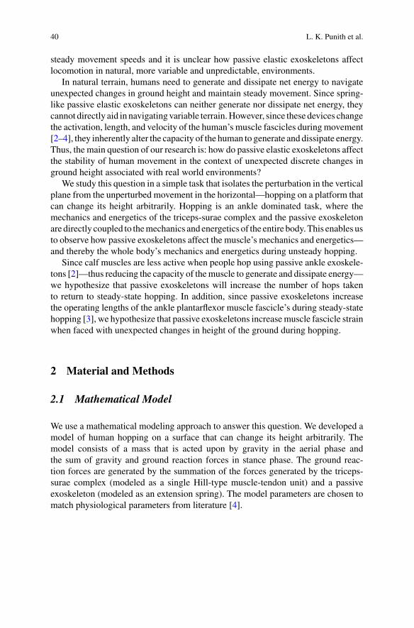
40 L. K. Punith et al.
steady movement speeds and it is unclear how passive elastic exoskeletons affectlocomotion in natural, more variable and unpredictable, environments.
In natural terrain, humans need to generate and dissipate net energy to navigateunexpected changes in ground height and maintain steady movement. Since spring-like passive elastic exoskeletons can neither generate nor dissipate net energy, theycannot directly aid in navigating variable terrain.However, since these devices changethe activation, length, and velocity of the human’s muscle fascicles duringmovement[2–4], they inherently alter the capacity of the human to generate and dissipate energy.Thus, the main question of our research is: how do passive elastic exoskeletons affectthe stability of human movement in the context of unexpected discrete changes inground height associated with real world environments?
We study this question in a simple task that isolates the perturbation in the verticalplane from the unperturbed movement in the horizontal—hopping on a platform thatcan change its height arbitrarily. Hopping is an ankle dominated task, where themechanics and energetics of the triceps-surae complex and the passive exoskeletonare directly coupled to themechanics and energetics of the entire body.This enables usto observe how passive exoskeletons affect the muscle’s mechanics and energetics—and thereby the whole body’s mechanics and energetics during unsteady hopping.
Since calf muscles are less active when people hop using passive ankle exoskele-tons [2]—thus reducing the capacity of themuscle to generate and dissipate energy—we hypothesize that passive exoskeletons will increase the number of hops takento return to steady-state hopping. In addition, since passive exoskeletons increasethe operating lengths of the ankle plantarflexor muscle fascicle’s during steady-statehopping [3], we hypothesize that passive exoskeletons increasemuscle fascicle strainwhen faced with unexpected changes in height of the ground during hopping.
2 Material and Methods
2.1 Mathematical Model
We use a mathematical modeling approach to answer this question. We developed amodel of human hopping on a surface that can change its height arbitrarily. Themodel consists of a mass that is acted upon by gravity in the aerial phase andthe sum of gravity and ground reaction forces in stance phase. The ground reac-tion forces are generated by the summation of the forces generated by the triceps-surae complex (modeled as a single Hill-type muscle-tendon unit) and a passiveexoskeleton (modeled as an extension spring). The model parameters are chosen tomatch physiological parameters from literature [4].
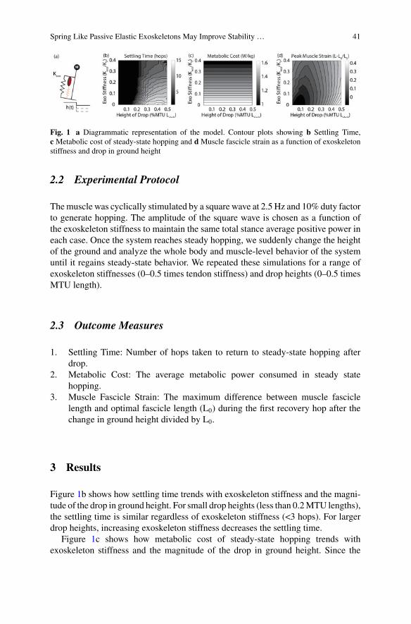
Spring Like Passive Elastic Exoskeletons May Improve Stability … 41
Fig. 1 a Diagrammatic representation of the model. Contour plots showing b Settling Time,c Metabolic cost of steady-state hopping and d Muscle fascicle strain as a function of exoskeletonstiffness and drop in ground height
2.2 Experimental Protocol
Themuscle was cyclically stimulated by a square wave at 2.5 Hz and 10% duty factorto generate hopping. The amplitude of the square wave is chosen as a function ofthe exoskeleton stiffness to maintain the same total stance average positive power ineach case. Once the system reaches steady hopping, we suddenly change the heightof the ground and analyze the whole body and muscle-level behavior of the systemuntil it regains steady-state behavior. We repeated these simulations for a range ofexoskeleton stiffnesses (0–0.5 times tendon stiffness) and drop heights (0–0.5 timesMTU length).
2.3 Outcome Measures
1. Settling Time: Number of hops taken to return to steady-state hopping afterdrop.
2. Metabolic Cost: The average metabolic power consumed in steady statehopping.
3. Muscle Fascicle Strain: The maximum difference between muscle fasciclelength and optimal fascicle length (L0) during the first recovery hop after thechange in ground height divided by L0.
3 Results
Figure 1b shows how settling time trends with exoskeleton stiffness and the magni-tude of the drop in ground height. For small drop heights (less than 0.2MTU lengths),the settling time is similar regardless of exoskeleton stiffness (<3 hops). For largerdrop heights, increasing exoskeleton stiffness decreases the settling time.
Figure 1c shows how metabolic cost of steady-state hopping trends withexoskeleton stiffness and the magnitude of the drop in ground height. Since the
42 L. K. Punith et al.
metabolic cost of steady-state hopping is unaffected by drop height, we findthat metabolic cost is only affected by exoskeleton stiffness and that increasingexoskeleton stiffness reduces metabolic cost.
Figure 1d shows how muscle fascicle strain changes with changes in exoskeletonstiffness and the magnitude of the drop in ground height. For small drop heights(<0.2MTU lengths), muscle strain increases with increasing exoskeleton stiffness—however the strain remains below0.3L0. For larger drops (>0.2MTU lengths),musclestrains exceed 0.3L0 without an exoskeleton and increasing exoskeleton stiffnessdecreases muscle strain to below 0.3L0.
4 Discussion
Although spring-like passive elastic exoskeletons cannot generate or dissipate netenergy, our results indicate that they may enable faster and safer recovery fromunexpected changes in ground height—contrary to our hypotheses.
At low drop heights, exoskeletons do not change the person’s ability to recoverfrom the perturbation and regain stable hopping. In addition, although the musclestrain increases with increasing exoskeleton stiffness, these strains stay below0.3L0—thus staying within the limits of muscle injury. At increasingly larger dropheights, exoskeletons decrease the number of hops required to recover from theperturbation and regain stable hopping. They also decrease muscle strain to below0.3 L0—thus enabling lower injury risk when compared to not using exoskeletons.
Preliminary experiments (single trial data) with a single human subject hoppingwith bilateral passive ankle exoskeletons on amoveable platform support these simu-lation results, displaying that recovery from a drop of 20cm in ground height is fasterwith an exoskeleton (2 hops) thanwithout (3 hops). In addition, soleus fascicle strains,measured using dynamic ultrasound imaging, were ~9% larger during the perturbedhop with an exoskeleton compared to without an exoskeleton. However, the abso-lute peak fascicle length (44.1 mm) was lower than L0 as reported in the literaturefor the soleus muscle used in our model [4]—potentially resembling the results forsmall drop heights in our simulations. Ongoing human experimental studies will becombined with these simulation results to provide a comprehensive understandingof how passive elastic exoskeletons affect movement in uneven terrain.
5 Conclusion
This study took a first step towards understanding how spring-like passive elasticexoskeletons affect movement in uneven terrain. We show that exoskeletons mayin fact enable faster and safer recovery from uneven terrain perturbations, whichis intriguing given that passive devices cannot generate or dissipate energy. This isan exciting result as it potentially indicates that lightweight portable passive elastic
Spring Like Passive Elastic Exoskeletons May Improve Stability … 43
exoskeletons not only augment steady-state locomotion energetics but also have theability to improve stability in uneven terrain. These devices have strong potential tomove beyond the research environment and into the real world.
References
1. G.S. Sawicki, O.N. Beck, I. Kang, A.J. Young, The exoskeleton expansion: improving walkingand running economy. J. Neuroeng. Rehabil. 17(1), 1–9 (2020)
2. D.J. Farris, G.S. Sawicki, Linking the mechanics and energetics of hopping with elastic ankleexoskeletons. J. Appl. Physiol. 113(12), 1862–1872 (2012)
3. D.J. Farris, B.D. Robertson, G.S. Sawicki, Elastic ankle exoskeletons reduce soleusmuscle forcebut not work in human hopping. J. Appl. Physiol. 115(5), 579–585 (2013)
4. B.D. Robertson, D.J. Farris, G.S. Sawicki, More is not always better: Modeling the effectsof elastic exoskeleton compliance on underlying ankle muscle–tendon dynamics. Bioinspir.Biomim. 9(4), 046018 (2014)

Balance Recovery Support Using WearableRobotic Devices
Ankle-Exoskeleton Control for Assistingin Balance Recovery After UnexpectedDisturbances During Walking
C. Bayón, W. F. Rampeltshammer, A. Q. L. Keemink, H. van der Kooij,and E. H. F. van Asseldonk
Abstract In the last two decades, lower-limb exoskeletons have been developed toassist human standing and locomotion. One of the ongoing challenges is still balancesupport. Here we present a control strategy for an ankle-exoskeleton to assist balancerecovery after unexpected disturbances during walking. We evaluated the controllerin two healthy participants wearing the ankles of the Symbitron exoskeleton whilereceiving forward pushes at the pelvis during walking. Providing low and mediumassistance resulted in improvement of balance recovery (decreased center of massmovement in the direction of the perturbation) and reduction of muscle activity,respect to trials with no assistance. These effects saturated with high levels of assis-tance. The results are promising, but the controller should be improved to use human’sreal-time response as a feedback to trigger the support.
1 Introduction
Balance is a fundamental skill to ensure upright standing and locomotion. An often-heard wish of exoskeletons users is to receive support with balance and decreasethe reliance on crutches [1]. Current studies involving the “assist-when-needed”approach for balance support with exoskeletons are mainly focused on hip control.However, the ankle is a crucial joint to maintain balance [2] and should be consideredfor recovery strategies.
In this work we present a controller intended to assist the ankles in balancerecovery after perturbations in the sagittal plane during walking. It is a first stepfor the support of balance with exoskeletons in challenging environments.
C. Bayón (B) · W. F. Rampeltshammer · A. Q. L. Keemink · H. van der Kooij ·E. H. F. van AsseldonkDepartment of Biomechanical Engineering, University of Twente, Enschede, The Netherlandse-mail: [email protected]
© The Author(s), under exclusive license to Springer Nature Switzerland AG 2022J. C. Moreno et al. (eds.), Wearable Robotics: Challenges and Trends,Biosystems & Biorobotics 27, https://doi.org/10.1007/978-3-030-69547-7_8
47
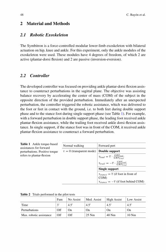
48 C. Bayón et al.
2 Material and Methods
2.1 Robotic Exoskeleton
The Symbitron is a force-controlled modular lower-limb exoskeleton with bilateralactuation on hip, knee and ankle. For this experiment, only the ankle modules of theexoskeleton were used. These modules have 4 degrees of freedom, of which 2 areactive (plantar-dorsi flexion) and 2 are passive (inversion-eversion).
2.2 Controller
The developed controller was focused on providing ankle plantar-dorsi flexion assis-tance to counteract perturbations in the sagittal plane. The objective was assistingbalance recovery by accelerating the center of mass (COM) of the subject in theopposite direction of the provided perturbation. Immediately after an unexpectedperturbation, the controller triggered the robotic assistance, which was delivered tothe foot or feet in contact with the ground, i.e. to both feet during double supportphase and to the stance foot during single support phase (see Table 1). For example,with a forward perturbation in double support phase, the leading foot received ankleplantar-flexion assistance, while the trailing foot received ankle dorsi-flexion assis-tance. In single support, if the stance foot was in front of the COM, it received ankleplantar-flexion assistance to counteract a forward perturbation.
Table 1 Ankle torque-basedassistances for forwardperturbations. Positive torquerefers to plantar-flexion
Normal walking Forward pert
τ = 0 (transparent mode) Double support
τlead = τ · GRFleadGRFTotal
τtrail = −τ · GRFtrailGRFTotal
Single support
τstance = τ (if foot in front ofCOM)τstance = −τ (if foot behind COM)
Table 2 Trials performed in the pilot tests
Fam No Assist Med. Assist High Assist Low Assist
Time 3’ 4.5’ 4.5’ 4.5’ 4.5’
Perturbations Off On On On On
Max. robotic assistance Off Off 25 Nm 40 Nm 10 Nm
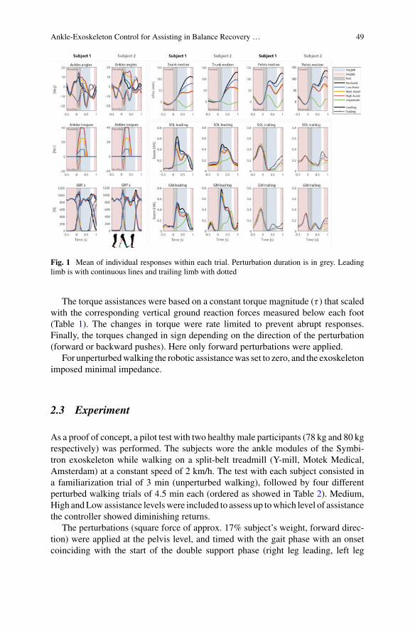
Ankle-Exoskeleton Control for Assisting in Balance Recovery … 49
Fig. 1 Mean of individual responses within each trial. Perturbation duration is in grey. Leadinglimb is with continuous lines and trailing limb with dotted
The torque assistances were based on a constant torque magnitude (τ ) that scaledwith the corresponding vertical ground reaction forces measured below each foot(Table 1). The changes in torque were rate limited to prevent abrupt responses.Finally, the torques changed in sign depending on the direction of the perturbation(forward or backward pushes). Here only forward perturbations were applied.
For unperturbedwalking the robotic assistancewas set to zero, and the exoskeletonimposed minimal impedance.
2.3 Experiment
As a proof of concept, a pilot test with two healthymale participants (78 kg and 80 kgrespectively) was performed. The subjects wore the ankle modules of the Symbi-tron exoskeleton while walking on a split-belt treadmill (Y-mill, Motek Medical,Amsterdam) at a constant speed of 2 km/h. The test with each subject consisted ina familiarization trial of 3 min (unperturbed walking), followed by four differentperturbed walking trials of 4.5 min each (ordered as showed in Table 2). Medium,High andLowassistance levelswere included to assess up towhich level of assistancethe controller showed diminishing returns.
The perturbations (square force of approx. 17% subject’s weight, forward direc-tion) were applied at the pelvis level, and timed with the gait phase with an onsetcoinciding with the start of the double support phase (right leg leading, left leg
50 C. Bayón et al.
trailing). Each perturbation lasted 0.2 s, so they ended during the start of right singlesupport (left swing).After a perturbation,weensured aminimumof6 s of unperturbedwalking before the next perturbation appeared.
Motion capture data was recorded with 8 Oqus cameras (Qualisys, Sweden).Markers located on the pelvis and on the center of the torso at the level of the clav-icle, were used to estimate the movement of the pelvis and trunk after a perturbation.Muscle activities (EMG) of tibialis anterior (TA), soleus (SOL), gastrocnemiusmedi-alis (GM) and gastrocnemius lateralis (GL) of each leg were recorded with 8 bipolarelectrodes (Bagnoli, Delsys, USA).
3 Results
An average of 27 perturbations for each trial were analyzed. The mean of the indi-vidual responses within each trial were processed to compare the results betweentrials (Fig. 1), taken 0.5 s before and 1 s after the perturbation onset.
The motion of the pelvis and trunk in forward direction decreased for all trialswith robotic assistance comparing to No Assist. On average for both subjects, theimprovements at the point of maximum motion for the pelvis were: Med.—36%,High—38%, Low—17%. For the trunk they were even larger: Med—49%, High—49%, Low—25%.
The EMG for SOL and GM improved in all trials with assistance, with respect toNoAssist. (e.g. averaged improvement for High Assist., leading limb: SOL—12.6%,GM—6.6%). For TA and GL the differences between trials were not that clear.
4 Discussion and Conclusion
We developed a controller that was effective in improving balance recovery. A satu-ration effect was detected between medium or high assistances profiles. The mainreduction of EMG in the leading limb was produced immediately after the pertur-bation, while for the trailing limb, the bigger differences appeared at the next heelstrike (reduced ground impact). In the present study, no algorithm was used to detectthe occurrence of the perturbation, therefore, the robotic assistance was prescribedsimultaneouslywith the perturbation signal. For future experiments, locallymeasuredinformation of theCOMwill be used in the controller to trigger and scale the providedassistance.
Acknowledgements This work is part of the research program Wearable Robotics with projectnumber P16-05, (partly) financed by the Dutch Research Council (NWO).

Ankle-Exoskeleton Control for Assisting in Balance Recovery … 51
References
1. A.W. Heinemann et al., Experience of robotic exoskeleton use at four spinal cord injury modelsystems centers. J. Neurol. Phys. Ther. 42(4), 256–267 (2018)
2. M. Vlutters, E.H.F. Van Asseldonk, H. Van Der Kooij, Lower extremity joint-level responses topelvis perturbation during human walking. Sci. Rep. p. 12 (2018)
Coupling an Active Pelvis Orthosiswith Different Prosthetic Knees WhileTransfemoral Amputees Managea Slippage: A Pilot Study
Monaco Vito, Aprigliano Federica, Arnetoli Gabriele, Doronzio Stefano,Giffone Antonella, Vitiello Nicola, and Micera Silvestro
Abstract This pilot study aimed at testing the hypothesis that the effectivenessof an Active Pelvis Orthosis (APO)—mediated strategy to counteract the fall risk intransfemoral amputees (TFAs) can depend on the adopted prosthetic knee. TwoTFAswith good and similar functional capabilities (k-level = 3) were asked to manageunexpected slipping like perturbations: the first used a hydraulic knee; the seconda microprocessor-controlled knee. Results revealed that the APO-mediated strategyagainst the fall risk was more effective in the second participant. Accordingly, theadopted prosthetic knee seems to significantly condition the overall balance responsedespite the balance recovery is supposed to be mainly driven by the APO assistance.Therefore, the prosthetic knee should be considered a confounding factor for thesetypes of experiments and its relevance deserves further investigations.
1 Introduction
The fall risk is widely described as one of the most disabling conditions that canaffect fragile persons since it compromises both physical capabilities (e.g., it reducespeople’s overall autonomy) and physiological status (e.g., it restricts social activitiesand community participation). Lower limb amputation is known to further impair
A. Gabriele, D. Stefano, G. Antonella are equally contributed.V. Nicola and M. Silvestro are equally contributed.
M. Vito (B) · A. Federica · V. Nicola · M. SilvestroDepartment of Excellence in Robotics & AI, The BioRobotics Institute, Scuola SuperioreSant’Anna, Pisa, Italye-mail: [email protected]
M. Vito · A. Gabriele · D. Stefano · G. AntonellaIRCCS Fondazione Don Carlo Gnocchi, 20148 Milan, Italy
M. SilvestroBertarelli Foundation Chair in Translational Neuroengineering, Center for Neuroprosthetics andInstitute of Bioengineering, School of Engineering, Ecole Polytechnique Federale de Lausanne,Lausanne, Switzerland
© The Author(s), under exclusive license to Springer Nature Switzerland AG 2022J. C. Moreno et al. (eds.), Wearable Robotics: Challenges and Trends,Biosystems & Biorobotics 27, https://doi.org/10.1007/978-3-030-69547-7_9
53
54 M. Vito et al.
walking capabilities andbalance control, thus increasing the fall risk and exacerbatingits consequences [1, 2].
Current research in the field of wearable robotics (e.g., powered exoskeleton,robotic prostheses) is exploring novel strategies to effectively support users whilerecovering their balance [3–6]. In this respect, subjects with lower limb amputation,especially transfemoral amputees (TFAs), can take advantage of such platforms tocounteract the inherent consequences of their disease [3].
Based on our previous research, an active pelvis orthosis (APO) can effectivelypromote balance control in TFA after a slippage [3]. However, amputees can showdifferent behavior in terms of balance recovery capabilities especially when theydon the APO. This result is in part due to the typical inter-subjects variability (e.g.,age, functional capabilities, etiology and level of the amputation). However, little isknown about if and how the used prosthesis can affect the balance recovery whileTFAs were assisted by the APO. In this respect, this pilot study aims at testing thehypothesis that our APO can be more effective against the fall risk when coupledwith a microprocessor-controlled knee.
2 Materials and Methods
2.1 Subjects, Experimental Setup, Protocol and DataAnalysis
For this study, we collected data from two male amputees who were experienced andsuccessful prosthesis wearers. A summary of their main features and the outcomes ofsome clinical tests (i.e., timed up and go, TUG; six minute walking test at ax speed,6 MWT) are reported in Table 1.
Participants were asked to manage antero-posterior (AP) slipping like perturba-tions unexpectedly delivered at the heel strike of the prosthetic foot while steadilywalking at their self selected speed (see [3, 6] andFig. 1 for further details).During theexperimental sessions, subjects donned an APO designed to assist balance recoveryin case of slippages [3, 6]. In particular, the APO could work either in transparent(Z-mode) or in assistive (A-mode) mode.
The 3D kinematics of 44 markers was collected by means of a 8-cameras system(Vicon) and used to assess the following variables at the heel strikes just after theonset of the perturbation: (i) the Margin of Stability along the AP direction (i.e.,MoSAP; [7]); (ii) the limb support quotient (i.e., SHip; [8]); (iii) the stability index(i.e., s; [8]).
Noticeably:
• negative [positive] values of s suggest that the dynamical status of the subjectsinvolve a backward fall risk [more stable condition];
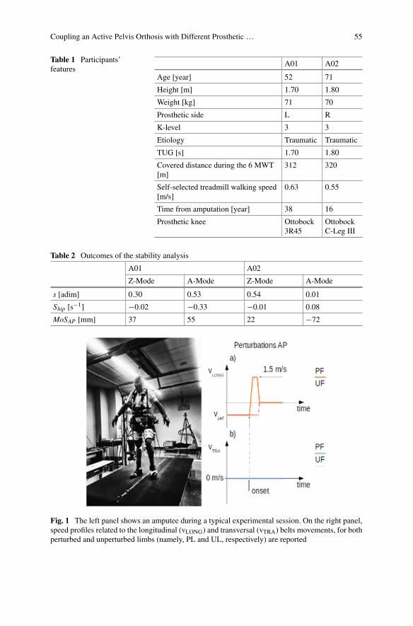
Coupling an Active Pelvis Orthosis with Different Prosthetic … 55
Table 1 Participants’features
A01 A02
Age [year] 52 71
Height [m] 1.70 1.80
Weight [kg] 71 70
Prosthetic side L R
K-level 3 3
Etiology Traumatic Traumatic
TUG [s] 1.70 1.80
Covered distance during the 6 MWT[m]
312 320
Self-selected treadmill walking speed[m/s]
0.63 0.55
Time from amputation [year] 38 16
Prosthetic knee Ottobock3R45
OttobockC-Leg III
Table 2 Outcomes of the stability analysis
A01 A02
Z-Mode A-Mode Z-Mode A-Mode
s [adim] 0.30 0.53 0.54 0.01
Ship [s−1] −0.02 −0.33 −0.01 0.08
MoSAP [mm] 37 55 22 −72
Fig. 1 The left panel shows an amputee during a typical experimental session. On the right panel,speed profiles related to the longitudinal (vLONG) and transversal (vTRA) belts movements, for bothperturbed and unperturbed limbs (namely, PL and UL, respectively) are reported
56 M. Vito et al.
• negative [positive] values of SHip involve downward [upward] movement of thebody center of mass;
• positive [negative] values of the MoSAP refer to a posterior [anterior] shift of thevelocity adjusted center of mass position, namely extrapolated center of mass,with respect to the base of support.
3 Results
Enrolled subjects showed good and comparable functional capabilities (Table 1)albeit they were mainly different in terms of age.
Table 2 reports the main outcomes of our analysis, referring to both transparentand assistedmodes. Results revealed that the subject A1 did not take advantage of theassistive APO: its dynamical status (see s) was always in the feasible stability regioneven if, when assisted by the APO, his center of mass was more directed backward(see MoSAP) and downward (see SHip) than in Z-mode. The subject A2 did benefitfrom the assistive APO: its dynamical status (see s andMoSAP) shifted from the riskof backward balance loss to the feasible stability region while his center of mass wasupward directed (see SHip) thanks to the assistive support of the APO.
4 Discussion and Conclusion
This study aimed at investigating the hypothesis that the outcome of the proposedAPO-mediated assistive strategy, in terms of balance recovery against slippages, canbe affected by the used prosthetic knee. To test this hypothesis, we enrolled twoTFAs with comparable functional capabilities but different age thus the older one(i.e., A2) was supposed to show worsen performance compared to the younger one.Noticeably, A1 and A2 donned their regular prosthetic knee, that is, the hydraulicOttobock 3R45 and the microprocessor-controlled knee C-Leg III knee, respectively.
Surprisingly, results revealed that A2 took greater advantage while being assistedby theAPO. In particular, all variables describing his dynamical status after a slippageimprovedwhen theAPOwas inA-mode (Table 1). Conversely, A1′s dynamical statusdid not show relevant improvements due to the assistive contribution of the APO.
Actually, we acknowledge that several factors could have led these results. Inaddition, the small number of enrolled subjects does not have any statistical power.However, we believe that one of the key aspects underlying the different behaviorsbetween subjects was the adopted prosthesis. In particular, results suggest that theefficacy of the proposed APO-mediated strategy can be further improved if thisdevice is coupled with smart prosthetic components, especially the knee. This insightpaves the way to two parallel conclusions: from the methodological viewpoint, theadopted prosthetic knee is expected to be a confounding factor which may affect theassessment the efficacy of the proposed robot-mediated strategy against the fall risk;
Coupling an Active Pelvis Orthosis with Different Prosthetic … 57
on the other hand, wearable robotic platforms purposely coupling exoskeletons andprosthesis can potentially be more effective to counteract the fall risk than the APOalone. In both cases, further investigations are required to confirm these conclusions.
5 Conclusion
The purpose of this pilot study was to provide initial, hypothesis-generating findingsfor the assessment of the effectiveness of an APO-mediated strategy against thefall risk in TFAs. Results suggest that the adopted prosthetic knee can significantlycondition the overall balance response despite the balance recovery is supposedto be mainly driven by the APO assistance. Accordingly, the prosthetic knee is aconfounding factor for these types of experiments and its relevance deserves furtherinvestigations.
Acknowledgements This work was supported by EU Grant CYBERLEGs++ (TheCYBERneticLowEr-Limb CoGnitive Ortho-prosthesis Plus, H2020-ICT-2015 731931).
References
1. J. Kulkarni et al., Falls in patients with lower limb amputations: prevalence and contributingfactors. Physiotherapy 82(2), 130–136 (1996)
2. J.M. Stepien et al., Activity levels among lower-limb amputees: self-report versus step activitymonitor. Arch. Phys. Med. Rehab. 88(7), 896–900 (2007)
3. V. Monaco et al., An ecologically-controlled exoskeleton can improve balance recovery afterslippage. Sci. Rep. 7 (2017)
4. N. Thatte et al., Toward balance recoverywith leg prostheses using neuromuscularmodel control.IEEE Trans. Biomed. Eng. (2015)
5. T. Zhang et al., Design and experimental verification of hip exoskeleton with balance capacitiesfor walking assistance. IEEE-ASME Trans. Mechatron. 23(1), 274–285 (2018)
6. F. Aprigliano et al., Effectiveness of a robot-mediated strategy while counteracting multidirec-tional slippages. Robotica (2019)
7. A.F. Hof et al., The condition for dynamic stability. J. Biomech. 38, 1–8 (2005)8. F. Yang et al., Limits of recovery against slip-induced falls while walking. J. Biomech. 44(15),
2607–2613 (2011)
Self-induced Gyroscopic Torques inLower Extremities During Gait:A Pilot Study
Saher Jabeen, Bram Sterke, Heike Vallery, and Daniel Lemus
Abstract To affect functional relevant task-space gait parameters such as footplacement or progression angle, conventional lower-limb robotic gait rehabilitationdevices require active control and synchronization of their actuators. As an alter-native, we propose the use of gyroscopic actuators, portable actuators that have theability to generate torques that are caused by and therefore intrinsically synchronizedwith the swing motion of the legs. Here we investigate the kinematic and kineticeffects at hip-joint level of self-induced gyroscopic torques of a shank-worn gyro-scopic actuator. Preliminary results show the wearer’s swing leg motion can inducegyroscopic effects that significantly alter the kinematics of the hip-joint (p < 0.05)for both tested conditions in hip-joint endo/exo rotation and ab/ad-duction.
1 Introduction
Wearable gait rehabilitation devices face large challenges in hardware and control.Conventional lower-limb wearable gait rehabilitation devices require actuators andtransmission structures that span multiple joints to affect functionally relevant task-space gait parameters such as foot placement or progression angle. Here gyroscopicactuators can affect such parameters in amore direct fashion, via free couplemomentsapplied at the shank. We have already demonstrated the higher effectiveness of suchan approach for step length [2]. Moreover, to affect these parameters, conventionalwearable gait rehabilitation devices require complex methods to generate referencesfor the control of assistive torques which must be synchronized to a user’s individualgait, for example using gait event detection methods and physiological reference
S. Jabeen · B. Sterke · H. Vallery · D. LemusBiomechanics Department, Delft University of Technology, Delft, The Netherlands
B. Sterke · H. Vallery (B) · D. LemusDepartment of Rehabilitation Medicine, Erasmus MC, Rotterdam, The Netherlandse-mail: [email protected]
© The Author(s), under exclusive license to Springer Nature Switzerland AG 2022J. C. Moreno et al. (eds.), Wearable Robotics: Challenges and Trends,Biosystems & Biorobotics 27, https://doi.org/10.1007/978-3-030-69547-7_10
59
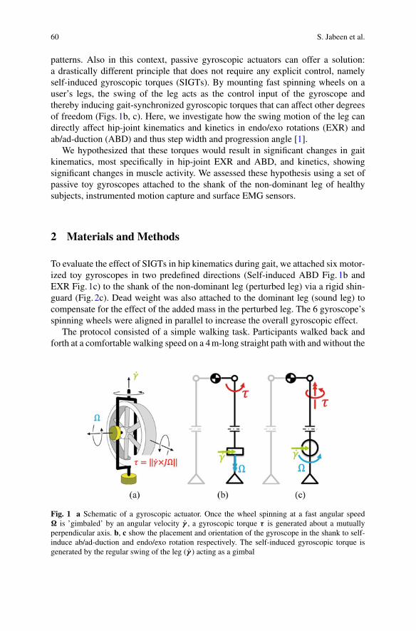
60 S. Jabeen et al.
patterns. Also in this context, passive gyroscopic actuators can offer a solution:a drastically different principle that does not require any explicit control, namelyself-induced gyroscopic torques (SIGTs). By mounting fast spinning wheels on auser’s legs, the swing of the leg acts as the control input of the gyroscope andthereby inducing gait-synchronized gyroscopic torques that can affect other degreesof freedom (Figs. 1b, c). Here, we investigate how the swing motion of the leg candirectly affect hip-joint kinematics and kinetics in endo/exo rotations (EXR) andab/ad-duction (ABD) and thus step width and progression angle [1].
We hypothesized that these torques would result in significant changes in gaitkinematics, most specifically in hip-joint EXR and ABD, and kinetics, showingsignificant changes in muscle activity. We assessed these hypothesis using a set ofpassive toy gyroscopes attached to the shank of the non-dominant leg of healthysubjects, instrumented motion capture and surface EMG sensors.
2 Materials and Methods
To evaluate the effect of SIGTs in hip kinematics during gait, we attached six motor-ized toy gyroscopes in two predefined directions (Self-induced ABD Fig. 1b andEXR Fig. 1c) to the shank of the non-dominant leg (perturbed leg) via a rigid shin-guard (Fig. 2c). Dead weight was also attached to the dominant leg (sound leg) tocompensate for the effect of the added mass in the perturbed leg. The 6 gyroscope’sspinning wheels were aligned in parallel to increase the overall gyroscopic effect.
The protocol consisted of a simple walking task. Participants walked back andforth at a comfortable walking speed on a 4m-long straight path with and without the
Fig. 1 a Schematic of a gyroscopic actuator. Once the wheel spinning at a fast angular speed is ’gimbaled’ by an angular velocity γ , a gyroscopic torque τ is generated about a mutuallyperpendicular axis. b, c show the placement and orientation of the gyroscope in the shank to self-induce ab/ad-duction and endo/exo rotation respectively. The self-induced gyroscopic torque isgenerated by the regular swing of the leg (γ ) acting as a gimbal
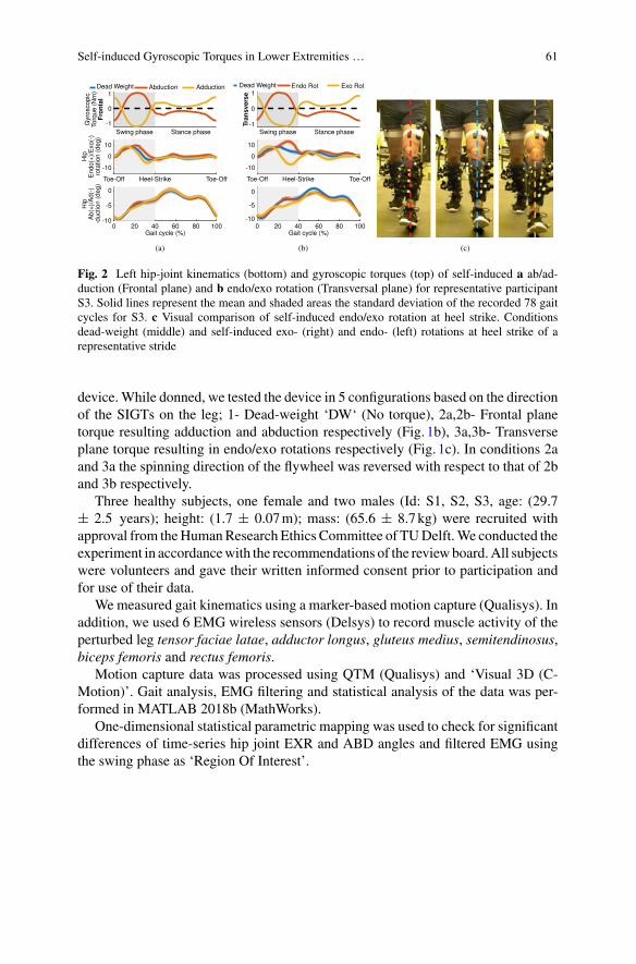
Self-induced Gyroscopic Torques in Lower Extremities … 61
Fig. 2 Left hip-joint kinematics (bottom) and gyroscopic torques (top) of self-induced a ab/ad-duction (Frontal plane) and b endo/exo rotation (Transversal plane) for representative participantS3. Solid lines represent the mean and shaded areas the standard deviation of the recorded 78 gaitcycles for S3. c Visual comparison of self-induced endo/exo rotation at heel strike. Conditionsdead-weight (middle) and self-induced exo- (right) and endo- (left) rotations at heel strike of arepresentative stride
device.While donned, we tested the device in 5 configurations based on the directionof the SIGTs on the leg; 1- Dead-weight ‘DW‘ (No torque), 2a,2b- Frontal planetorque resulting adduction and abduction respectively (Fig. 1b), 3a,3b- Transverseplane torque resulting in endo/exo rotations respectively (Fig. 1c). In conditions 2aand 3a the spinning direction of the flywheel was reversed with respect to that of 2band 3b respectively.
Three healthy subjects, one female and two males (Id: S1, S2, S3, age: (29.7± 2.5 years); height: (1.7 ± 0.07m); mass: (65.6 ± 8.7kg) were recruited withapproval from theHumanResearch Ethics Committee of TUDelft.We conducted theexperiment in accordancewith the recommendations of the reviewboard.All subjectswere volunteers and gave their written informed consent prior to participation andfor use of their data.
We measured gait kinematics using a marker-based motion capture (Qualisys). Inaddition, we used 6 EMG wireless sensors (Delsys) to record muscle activity of theperturbed leg tensor faciae latae, adductor longus, gluteus medius, semitendinosus,biceps femoris and rectus femoris.
Motion capture data was processed using QTM (Qualisys) and ‘Visual 3D (C-Motion)’. Gait analysis, EMG filtering and statistical analysis of the data was per-formed in MATLAB 2018b (MathWorks).
One-dimensional statistical parametric mapping was used to check for significantdifferences of time-series hip joint EXR and ABD angles and filtered EMG usingthe swing phase as ‘Region Of Interest’.
62 S. Jabeen et al.
3 Results and Discussion
Preliminary results showed that the SIGTs significantly affected hip-joint kinemat-ics during swing phase. Transverse plane SIGTs affected significantly hip EXR(p < 0.001, Fig. 1c middle) opposed to the weaker effect, yet significant, of frontalplane SIGTs in hip ABD (p < 0.05, Fig. 1b bottom). This can be explained by thedifference in magnitude of the rotational inertia between both EXR and ABD condi-tions. Interestingly both transverse and frontal plane SIGTs also significantly affected(p < 0.001) hip ABD and EXR (Fig. 1b middle and Fig. 1c bottom). This could beexplained by the musculoskeletal motion coupling between ABD and EXR.
Opposed to what we hypothesized, muscle activity of any of the 6 instrumentedmuscles did not show any significant differences during swing phase of both EXRand ABD conditions of the SIGTs respect to the baseline DW. Three main reasonscould explain the lack of significant differences in muscle activation. (i) Limitedaccess to endo/exo dominant rotators due to limitation of surface EMG. (ii) WeakSIGTs effect in ABD due to high inertia of the leg and low angular momentum of thegyros, and (iii) Lack of strong corrective strategies against the SIGTs, presumablydue to the lack of challenge in balance caused by the weak SIGTs of the devicedespite the strong kinematic effects in some conditions.
4 Conclusion
We showed that self-induced gyroscopic torques in lower extremities are suitable tosignificantly alter hip endo/exo rotation or ab/ad-duction. This passive effect can bebeneficial in therapy training to reinforce balance compensatory strategies or suppressundesired non-compensatory ones. In this sense passive gyroscopic actuators mightbe alternative to conventional wearable gait rehabilitation devices given that theirintrinsically gait-synchronized torques do not require the implementation of anycontroller.
Acknowledgements This researchwas supported by the Innovational Research Incentives SchemeVidi with Project No. 14865, which is (partly) financed by The Netherlands Organization for Sci-entific Research (NWO).
References
1. K.A. Bowsher, C.L. Vaughan, Effect of foot-progression angle on hip joint moments during gait.J. Biomech. 28(6), 759–762 (1995)
2. S. Jabeen et al., Assisting gaitwith freemoments or jointmoments on the swing leg, in 2019 IEEE16th International Conference on Rehabilitation Robotics (ICORR), pp. 1079–1084 (2019)
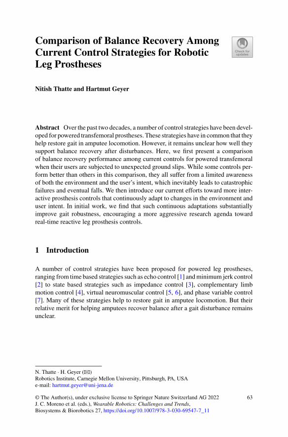
Comparison of Balance Recovery AmongCurrent Control Strategies for RoboticLeg Prostheses
Nitish Thatte and Hartmut Geyer
Abstract Over the past two decades, a number of control strategies have been devel-oped for powered transfemoral prostheses. These strategies have in common that theyhelp restore gait in amputee locomotion. However, it remains unclear how well theysupport balance recovery after disturbances. Here, we first present a comparisonof balance recovery performance among current controls for powered transfemoralwhen their users are subjected to unexpected ground slips. While some controls per-form better than others in this comparison, they all suffer from a limited awarenessof both the environment and the user’s intent, which inevitably leads to catastrophicfailures and eventual falls. We then introduce our current efforts toward more inter-active prosthesis controls that continuously adapt to changes in the environment anduser intent. In initial work, we find that such continuous adaptations substantiallyimprove gait robustness, encouraging a more aggressive research agenda towardreal-time reactive leg prosthesis controls.
1 Introduction
A number of control strategies have been proposed for powered leg prostheses,ranging from time based strategies such as echo control [1] andminimum jerk control[2] to state based strategies such as impedance control [3], complementary limbmotion control [4], virtual neuromuscular control [5, 6], and phase variable control[7]. Many of these strategies help to restore gait in amputee locomotion. But theirrelative merit for helping amputees recover balance after a gait disturbance remainsunclear.
N. Thatte · H. Geyer (B)Robotics Institute, Carnegie Mellon University, Pittsburgh, PA, USAe-mail: [email protected]
© The Author(s), under exclusive license to Springer Nature Switzerland AG 2022J. C. Moreno et al. (eds.), Wearable Robotics: Challenges and Trends,Biosystems & Biorobotics 27, https://doi.org/10.1007/978-3-030-69547-7_11
63
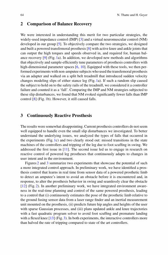
64 N. Thatte and H. Geyer
2 Comparison of Balance Recovery
We were interested in understanding this merit for two particular strategies, thewidely-used impedance control (IMP) [3] and a virtual neuromuscular control (NM)developed in our group [5]. To objectively compare the two strategies, we designedand built a powered transfemoral prosthesis [8] with active knee and ankle joints thatcan output the high torques and speeds observed in, and required for, human bal-ance recovery [9] (Fig. 1a). In addition, we developed new methods and algorithmsthat objectively and sample-efficiently tune parameters of prosthesis controllers withhigh-dimensional parameter spaces [6, 10]. Equipped with these tools, we then per-formed experimentswith non-amputee subjects who used the transfemoral prosthesisvia an adapter and walked on a split belt treadmill that introduced sudden velocitychanges modeling slips of either stance leg (Fig. 1a). If such a random slip causedthe subject to hold on to the safety rails of the treadmill, we considered it a controllerfailure and counted it as a ‘fall’. Comparing the IMP and NM strategies subjected tothese slip disturbances, we found that NM evoked significantly fewer falls than IMPcontrol [8] (Fig. 1b). However, it still caused falls.
3 Continuously Reactive Prosthesis
The results were somewhat disappointing. Current prosthesis controllers do not seemwell equipped to handle even the small slip disturbances we investigated. To betterunderstand the underlying issues, we analyzed the types of falls that occurred inthe experiments (Fig. 1c) and two clearly stood out: missed transitions in the statemachines of the controllers and tripping of the leg due to foot scuffing in swing. Weaddressed the first issue in [11]. The second issue led us to engage in research onreactive control of powered leg prostheses that continuously adapts to changes inuser intent and in the environment.
Figures2 and 3 summarize two experiments that showcase the potential of sucha more integrated control approach. In preliminary work, we have identified a pros-thesis control that learns in real time from sensor data of a powered prosthetic limbto detect an amputee’s intent to avoid an obstacle before it is encountered and, inresponse, to alter the prosthesis behavior in swing and seamlessly clear the obstacle[12] (Fig. 2). In another preliminary work, we have integrated environment aware-ness in the real-time planning and control of the same powered prosthesis, leadingto a control that (i) continuously estimates the pose of the prosthetic limb relative tothe ground fusing sensor data from a laser range finder and an inertial measurementunit mounted on the prosthesis, (ii) predicts future hip angles and heights of the userwith sparse Gaussian processes, and (iii) plans updated ankle and knee trajectorieswith a fast quadratic program solver to avoid foot scuffing and premature landingwith a flexed knee [13] (Fig. 3). In both experiments, the interactive controllers morethan halved the rate of tripping compared to state of the art controllers.
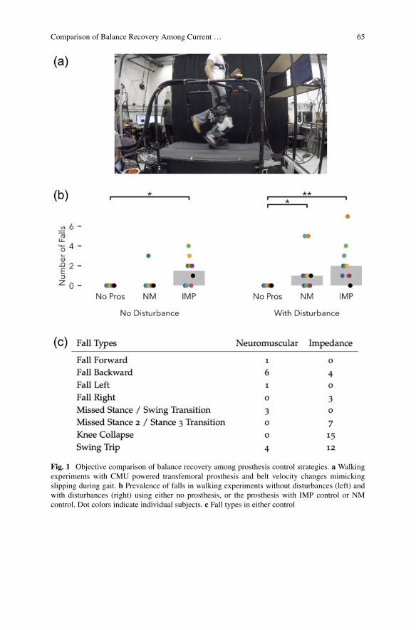
Comparison of Balance Recovery Among Current … 65
Fig. 1 Objective comparison of balance recovery among prosthesis control strategies. a Walkingexperiments with CMU powered transfemoral prosthesis and belt velocity changes mimickingslipping during gait. b Prevalence of falls in walking experiments without disturbances (left) andwith disturbances (right) using either no prosthesis, or the prosthesis with IMP control or NMcontrol. Dot colors indicate individual subjects. c Fall types in either control
66 N. Thatte and H. Geyer
Fig. 2 User intent recognition for interactive control of obstacle avoidance. (Top)Amputeewalkingon the CMU powered knee-ankle prosthesis with state of art control and tripping over obstacle.(Bottom) Prosthesis control learns in real time to predict the intent of an amputee to step over anobstacle before it is encountered and helps to clear it
Fig. 3 Environment integration for interactive planning and control of artificial limbmotion. aUserpurposefully lowering the hip of prosthesis side in swing to elicit foot scuffing. b State of art swingcontrols (blue) violate ground contact bounds on leg motion (dashed gray lines), increasing trippinghazard. By contrast, our environment-aware trajectory plan (red, prediction horizon in green) andexecution (black) lie within the bounds. c Inverse kinematics solutions for toe (purple) and heelcontact (yellow) define the bounds on the knee (panel b) and ankle trajectories (not shown) in swing
Comparison of Balance Recovery Among Current … 67
4 Conclusion
Current prosthesis (and exoskeleton) controllers focus mainly on steady gait, whicheven for small disturbances can lead to catastrophic failures. To substantially improveperformance including balance recovery, a shift toward real-time interactive con-trollers will be needed. These controllers should integrate more awareness abouttheir human user’s intent as well as about the environment condition. Additionally,these controllers should be capable of learning to accommodate drift in user behavior.
Acknowledgements This work was supported by NSF (grants #1527140 and #1734559) and iscurrently supported by NIH (grant #R01-EB029765).
References
1. D.L. Grimes, W.C. Flowers, M. Donath, Feasibility of an active control scheme for above kneeprostheses. J. Biomech. Eng. 99(4), 215–221 (1977)
2. T. Lenzi, L. Hargrove, J. Sensinger, Minimum jerk swing control allows variable cadence inpowered transfemoral prostheses, in Conference Proceedings IEEE Engineering in Medicineand Biology Society, pp. 2492–2495 (2014)
3. F. Sup, H.A. Varol, J. Mitchell, T.J. Withrow, M. Goldfarb, Preliminary evaluations of a self-contained anthropomorphic transfemoral prosthesis. IEEE/ASME Trans. Mech. 14(6), 667–676 (2009)
4. H. Vallery, R. Burgkart, C. Hartmann, J. Mitternacht, R. Riener, M. Buss, Complementary limbmotion estimation for the control of active knee prostheses. Biomedizinische Technik/Biomed.Eng. 56(1), 45–51 (2011)
5. N. Thatte, H. Geyer, Toward balance recovery with leg prostheses using neuromuscular modelcontrol. IEEE Trans. Biomed. Eng. 63(5), 904–913 (2016)
6. N. Thatte, H. Duan, H. Geyer, A sample-efficient black-box optimizer to train policies forhuman-in-the-loop systems with user preferences. IEEE Robot. Autom. Lett. (2017)
7. S. Rezazadeh, D. Quintero, N. Divekar, R.D. Gregg, A phase variable approach to volitionalcontrol of powered knee-ankle prostheses, in IEEE/RSJ International Conference on IntelligentRobots and Systems (IROS) (IEEE, New York, 2018), pp. 2292–2298
8. N. Thatte, Design and Evaluation of Robust Control Methods for Robotic Transfemoral Pros-theses. Doctoral Thesis, CMU-RI-TR-19-20 (2019)
9. M.D. Grabiner, T.J. Koh, T.M. Lundin, D.W. Jahnigen, Kinematics of recovery from a stumble.J. Gerontol. 48(3), M97–M102 (1993)
10. N. Thatte, H. Duan, H. Geyer, Amethod for online optimization of lower limb assistive deviceswith high dimensional parameter spaces, in Proceedings of the 2018 IEEE International Con-ference on Robotics and Automation (ICRA) (IEEE, New York, 2018)
11. N. Thatte, T. Shah, H. Geyer, Robust and adaptive lower limb prosthesis control via extendedKalman filter-based gait phase estimation, in Proceedings of the IEEE/RSJ International Con-ference on Intelligent Robots and Systems (IROS 2019) (2019)
12. M.Gordon, N. Thatte, H.Geyer, Online learning for proactive obstacle avoidancewith poweredtransfemoral prostheses, in 2019 IEEE International Conference on Robotics and Automation(ICRA) (IEEE, New York, 2019)
13. N. Thatte, N. Srinivasan, H. Geyer, Real-time reactive trip avoidance for powered transfemoralprostheses, in Proceedings of Robotics: Science and Systems (2019) (2019)
Reflex-Model with Additional COMFeedback Describes the Ankle Strategyin Perturbed Walking
Maarten Afschrift and Friedl De Groote
Abstract Here we evaluate if a neuromechanical model, controlled by reflexes, candescribe the reactive control of balance in response to anterior-posterior directedperturbations during walking. We optimized the parameters of the reflex model totrack the measured joint moments in unperturbed and perturbed walking.We showedthat an additional feedback loop, based on COM feedback, is needed to describe theresponse of the ankle muscles during perturbed walking.
1 Introduction
Neuromechanical models are currently being used to control wearable roboticdevices, such as exoskeletons and prostheses [1]. Reflex-driven models of the mus-culskeletal dynamics can describe humanwalking in forward simulations [2].Despitethe success of this approach in the control of wearable robotic devices [1], it is cur-rently unclear if these models can also assist in the control of walking balance.
In most neuromechanical models, balance is controlled by the adjustment of footplacement [3]. Human perturbation experiments during walking showed that adjust-ment of foot placement is indeed the main strategy in response to medio-lateraldirected perturbations [4], but not in response to anterior-posterior directed pertur-bations. Following anterior-posterior perturbations, balance is mainly controlled byadjusting the location of the center of pressure in the stance foot [5]. This is mainlyachieved through modulating the ankle moment and is therefore referred to as anklestrategy.
M. Afschrift (B)Department of Mechanical Engineering, KU, Leuven, Belgiume-mail: [email protected]
F. De GrooteDepartment of Movement Sciences, KU, Leuven, Belgium
© The Author(s), under exclusive license to Springer Nature Switzerland AG 2022J. C. Moreno et al. (eds.), Wearable Robotics: Challenges and Trends,Biosystems & Biorobotics 27, https://doi.org/10.1007/978-3-030-69547-7_12
69
70 M. Afschrift and F. De Groote
Here we will evaluate if a neuromechanical model [2], controlled by reflexes, candescribe the ankle strategy in perturbed walking. We hypothesize that an additionalfeedback loop is needed to describe the ankle strategy. Similar as in standing balancecontrol [6], we expect that the ankle strategy can be described by delayed feedbackof COM position and velocity.
2 Methods
We used a dataset with normal treadmill walking to identify the parameters of areflex-based model. We also identified reflex-parameters in perturbed walking andevaluated if an additional feedback loop is needed to describe the ankle strategy.
2.1 Experiments
Steady-state walking was perturbed by means of a sudden increase or decrease inspeed of the treadmill belts. Integratedmotion capture data was collected in 18 young(age 21 ± 2 std years) subjects to describe the human response to the perturbation.All subjects walked at 1.1m/s on a split-belt treadmill. Whole body motion wasrecorded using 3D motion capture with an extended plug in gait marker set (Vicon).Ground reaction forces were collected on a split-belt treadmill (Motek-ForceLink).
2.2 Inverse Kinematic and Dynamic Analysis
Joint kinematics and kinetics were computed using a scaled generic musculoskeletalmodel (gait 2392) inOpenSim. Thismodel was scaled to the anthropometry andmassof the subject based on the marker positions and ground reaction forces in the statictrials. Joint kinematics of the scaledmodelwere computed using aKalman smoothingalgorithm. Joint kinetics were computed with OpenSim’s inverse dynamics tool.Whole body COM position and velocity was computed from the joint kinematicsand the model of the skeleton, and was expressed relative to the position and velocityof the base of support.
2.3 Reflex Parameter Estimation
We used as data-driven approach to estimate the parameters of a reflex-based modelwith 7 hill-type muscles per leg [2, 7]. Similar a similar approach as in [7], withthe inverse kinematics and inverse dynamics as input the model, but optimized the
Reflex-Model with Additional COM Feedback … 71
feedback gains with a different numerical method and on beltspeed perturbations.The feedback gains (K ) of the reflex-model were optimized to track inverse dynamicjoint moments, which involves a forward simulation of the muscle dynamics. Weoptimized the parameters of the default reflexmodel to (1) track unperturbedwalkingand (2) track the response to a perturbation (Eq.1).
J (K ) =tend∫
to
M∑j=1
(Tid, j − Tm, j )2dt (1)
with t0 and tend the start and end time of in total three gait cycles, M the number ofmuscles Tid the inverse dynamic joint moments and Tm the joint moments generatedby the hill-type muscles (driven by feedback).
We also evaluated if extending the neuromechanical model with an additionalfeedback loop based on COM kinematics improves the tracking of the ankle jointmoments in response to a perturbation (Eq.2). This feedback loop was added to thesoleus, gastrocnemius and tibialis anterior.
e(t) = er (t) + kpCOM(t − τ) + kv ˙COM(t − τ) (2)
with e(t) the muscle excitation, er (t) the standard reflex excitations, kp and kv theposition and velocity feedback gains, COM and ˙COM the deviation in centerof mass position and velocity from the unperturbed trajectory and τ a time-delay of60 ms representing the time needed for signal transmission and sensory integrationin the nervous system.
The parameter estimation was solved using a direct collocation approach withan Euler integration scheme. We formulated the muscle dynamics in casadi withimplicit differential equations and solved the large sparse nonlinear program usingIPOPT. The optimization takes 120–250 on a standard laptop. The ’goodness of fit’was evaluated using the coefficient of determination(R2) and Root mean square error(RMSE) between the inverse dynamic joint moments and simulated joint momentsin the perturbed gait cycle.
3 Results
We found that the reflex-model model can reconstruct the ankle, knee and hip jointmoment during normal unperturbedwalking (respectively R2: 0.98 0.80 0.97,RMSE:8.92 7.08 7.33Nm).Despite re-optimization, the reflex-modelwas unable to track theankle joint moment in response to a sudden decrease (R2: 0.90, RMSE: 20.82 Nm) orincrease in beltspeed (R2: 0.93, RMSE: 14.87 Nm). Extending the neuromechanicalmodel with an additional feedback loop based on COM kinematics improves thetracking of the ankle joint moment in response to a decrease in beltspeed (R2: 0.94,RMSE: 6.75 Nm) and increase in beltspeed (R2: 0.99, RMSE: 5.42 Nm) (Fig. 1).
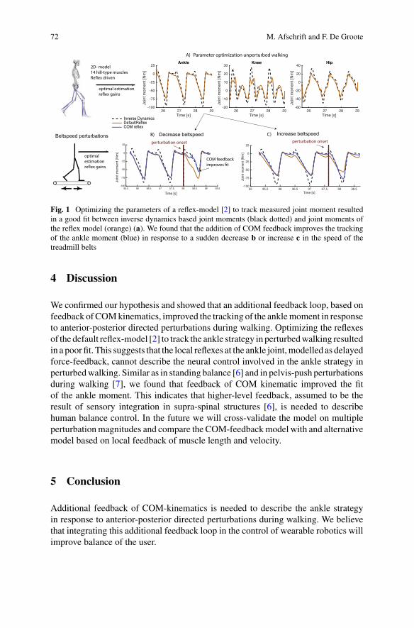
72 M. Afschrift and F. De Groote
Fig. 1 Optimizing the parameters of a reflex-model [2] to track measured joint moment resultedin a good fit between inverse dynamics based joint moments (black dotted) and joint moments ofthe reflex model (orange) (a). We found that the addition of COM feedback improves the trackingof the ankle moment (blue) in response to a sudden decrease b or increase c in the speed of thetreadmill belts
4 Discussion
We confirmed our hypothesis and showed that an additional feedback loop, based onfeedback ofCOMkinematics, improved the tracking of the anklemoment in responseto anterior-posterior directed perturbations during walking. Optimizing the reflexesof the default reflex-model [2] to track the ankle strategy in perturbedwalking resultedin a poor fit. This suggests that the local reflexes at the ankle joint,modelled as delayedforce-feedback, cannot describe the neural control involved in the ankle strategy inperturbedwalking. Similar as in standing balance [6] and in pelvis-push perturbationsduring walking [7], we found that feedback of COM kinematic improved the fitof the ankle moment. This indicates that higher-level feedback, assumed to be theresult of sensory integration in supra-spinal structures [6], is needed to describehuman balance control. In the future we will cross-validate the model on multipleperturbationmagnitudes and compare the COM-feedbackmodel with and alternativemodel based on local feedback of muscle length and velocity.
5 Conclusion
Additional feedback of COM-kinematics is needed to describe the ankle strategyin response to anterior-posterior directed perturbations during walking. We believethat integrating this additional feedback loop in the control of wearable robotics willimprove balance of the user.

Reflex-Model with Additional COM Feedback … 73
Funding FWO 12ZP120N.
References
1. A.R. Wu et al., Front. Neurorobot. 11, 1–14 (2017)2. H. Geyer, H. Herr, IEEE Trans. Neural Syst. Rehabil. Eng. 18(3), 263–73 (2010)3. S. Song, H. Geyer, J. Physiol. 593(16), 3493–3511 (2015)4. Y. Wang, M. Srinivasan, Biol. Lett. 10(9), 1–5 (2014)5. M. Vlutters, E.H.F. van Asseldonk, H. van der Kooij, J. Biomech. 68, 93–98 (2018)6. D.B. Lockhart, L.H. Ting, Nat. Neurosci. 10(10), 1329–36 (2007)7. T.J.H. Brug, A.Q.L. Keemink, E.H.F. van Asseldonk, H. van der Kooij, Abstract from Dynamic
Walking (Mariehamn, Finland, 2017)
Optimising Balance Margin in LowerLimb Exoskeleton to Assist User-DrivenGait Stability
Xiruo Cheng, Justin Fong, Ying Tan, and Denny Oetomo
Abstract When exoskeletons are driven in open loop with predetermined trajecto-ries, the onus is placed on the user to maintain balance through their crutches. Thiswork uses simulation of a human-exoskeleton model to explore the idea that suchtrajectories could be optimised to give the user the ‘best chance’ to maintain theirbalance in the presence of perturbations. The method evaluates a reward functionunder different gait trajectories and initial poses. It is concluded that such an opti-misation method could increase the set of perturbations which a user can counterwithout adding significant complexity or expense to the exoskeleton.
1 Introduction
In order to reduce device complexity and cost, many lower limb exoskeletons donot have sufficient actuated degrees of freedom to actively balance—instead, theyrely on the user to maintain balance with crutches. The control of these exoskele-tons generally combines an offline-generated reference trajectory and online balanceadjustment [1, 2]. Such strategies are viable when gait with low variability is feasible,such as in the clinic and other well-controlled environments. Outside of these cir-cumstances, however, these techniques become less effective due to ‘perturbations’to these nominal conditions. Perturbations may include physical interactions causedby collision with the exoskeleton-human system, variations to the ground level, orstationary or moving obstacles. Typically, able-bodied individuals adapt their gaitto handle such perturbations—for example, when navigating a bumpy road, shortersteps are used [3]—but the ability of the user to adapt is not considered whilst design-ing trajectories for exoskeletons.
The present work investigated the idea of using a step-specific optimisation of thegait trajectory to give the user the ‘best chance’ to dealwith perturbations. To do this, areward function related to the balance margin near (nominal) heel strike was defined.The balance margin is correlated with the size of perturbation that can successfully
X. Cheng (B) · J. Fong · Y. Tan · D. OetomoFourier Intelligence Joint Laboratory, University of Melbourne, Parkville, VIC, Australiae-mail: [email protected]
© The Author(s), under exclusive license to Springer Nature Switzerland AG 2022J. C. Moreno et al. (eds.), Wearable Robotics: Challenges and Trends,Biosystems & Biorobotics 27, https://doi.org/10.1007/978-3-030-69547-7_13
75
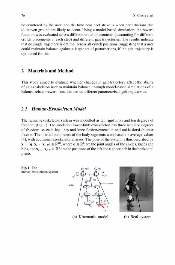
76 X. Cheng et al.
be countered by the user, and the time near heel strike is when perturbations dueto uneven ground are likely to occur. Using a model-based simulation, the rewardfunction was evaluated across different crutch placements (accounting for differentcrutch placements at each step) and different gait trajectories. The results indicatethat no single trajectory is optimal across all crutch positions, suggesting that a usercould maintain balance against a larger set of perturbations, if the gait trajectory isoptimised for this.
2 Materials and Method
This study aimed to evaluate whether changes in gait trajectory affect the abilityof an exoskeleton user to maintain balance, through model-based simulations of abalance-related reward function across different parameterised gait trajectories.
2.1 Human-Exoskeleton Model
The human-exoskeleton system was modelled as ten rigid links and ten degrees offreedom (Fig. 1). The modelled lower-limb exoskeleton has three actuated degreesof freedom on each leg—hip and knee flexion/extension and ankle dorsi-/plantarflexion. The inertial parameters of the body segments were based on average values[4], with additional exoskeleton masses. The pose of the system is thus described byx = [q, xc,L , xc,R] ∈ R
10, where q ∈ R6 are the joint angles of the ankles, knees and
hips, and xc,L , xc,R ∈ R2 are the positions of the left and right crutch in the horizontal
plane.
Fig. 1 Thehuman-exoskeleton system
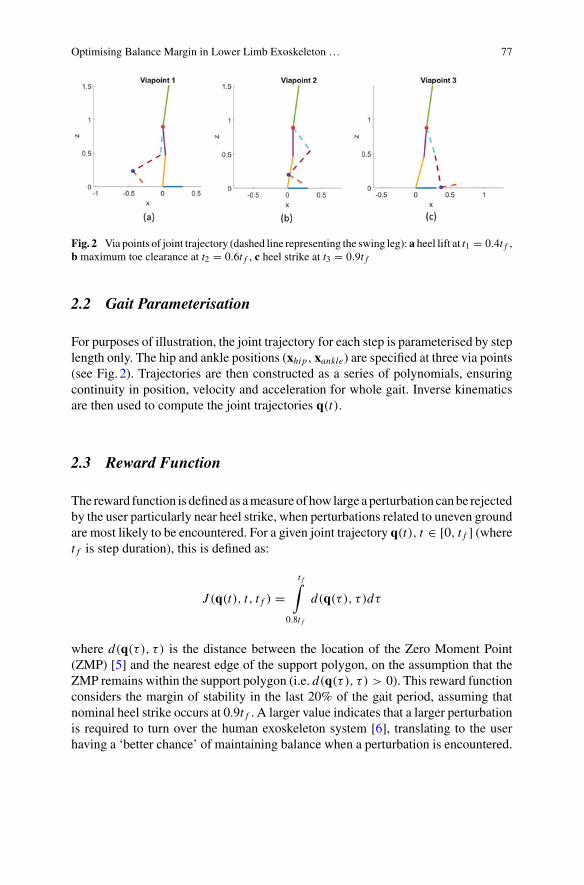
Optimising Balance Margin in Lower Limb Exoskeleton … 77
Fig. 2 Via points of joint trajectory (dashed line representing the swing leg): a heel lift at t1 = 0.4t f ,b maximum toe clearance at t2 = 0.6t f , c heel strike at t3 = 0.9t f
2.2 Gait Parameterisation
For purposes of illustration, the joint trajectory for each step is parameterised by steplength only. The hip and ankle positions (xhip, xankle) are specified at three via points(see Fig. 2). Trajectories are then constructed as a series of polynomials, ensuringcontinuity in position, velocity and acceleration for whole gait. Inverse kinematicsare then used to compute the joint trajectories q(t).
2.3 Reward Function
The reward function is defined as ameasure of how large aperturbation canbe rejectedby the user particularly near heel strike, when perturbations related to uneven groundare most likely to be encountered. For a given joint trajectory q(t), t ∈ [0, t f ] (wheret f is step duration), this is defined as:
J (q(t), t, t f ) =t f∫
0.8t f
d(q(τ ), τ )dτ
where d(q(τ ), τ ) is the distance between the location of the Zero Moment Point(ZMP) [5] and the nearest edge of the support polygon, on the assumption that theZMP remains within the support polygon (i.e. d(q(τ ), τ ) > 0). This reward functionconsiders the margin of stability in the last 20% of the gait period, assuming thatnominal heel strike occurs at 0.9t f . A larger value indicates that a larger perturbationis required to turn over the human exoskeleton system [6], translating to the userhaving a ‘better chance’ of maintaining balance when a perturbation is encountered.
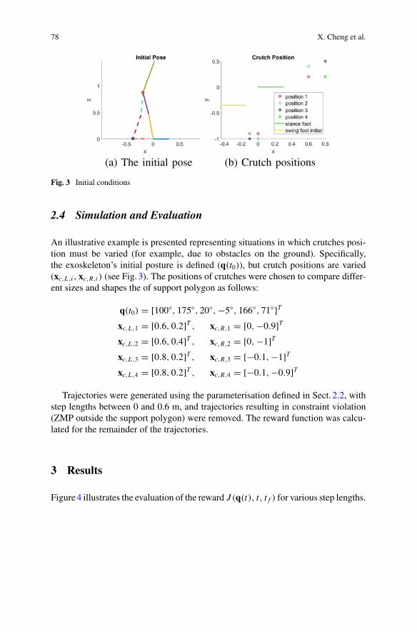
78 X. Cheng et al.
Fig. 3 Initial conditions
2.4 Simulation and Evaluation
An illustrative example is presented representing situations in which crutches posi-tion must be varied (for example, due to obstacles on the ground). Specifically,the exoskeleton’s initial posture is defined (q(t0)), but crutch positions are varied(xc,L ,i , xc,R,i ) (see Fig. 3). The positions of crutches were chosen to compare differ-ent sizes and shapes the of support polygon as follows:
q(t0) = [100, 175, 20,−5, 166, 71]Txc,L ,1 = [0.6, 0.2]T , xc,R,1 = [0,−0.9]Txc,L ,2 = [0.6, 0.4]T , xc,R,2 = [0,−1]Txc,L ,3 = [0.8, 0.2]T , xc,R,3 = [−0.1,−1]Txc,L ,4 = [0.8, 0.2]T , xc,R,4 = [−0.1,−0.9]T
Trajectories were generated using the parameterisation defined in Sect. 2.2, withstep lengths between 0 and 0.6 m, and trajectories resulting in constraint violation(ZMP outside the support polygon) were removed. The reward function was calcu-lated for the remainder of the trajectories.
3 Results
Figure4 illustrates the evaluation of the reward J (q(t), t, t f ) for various step lengths.
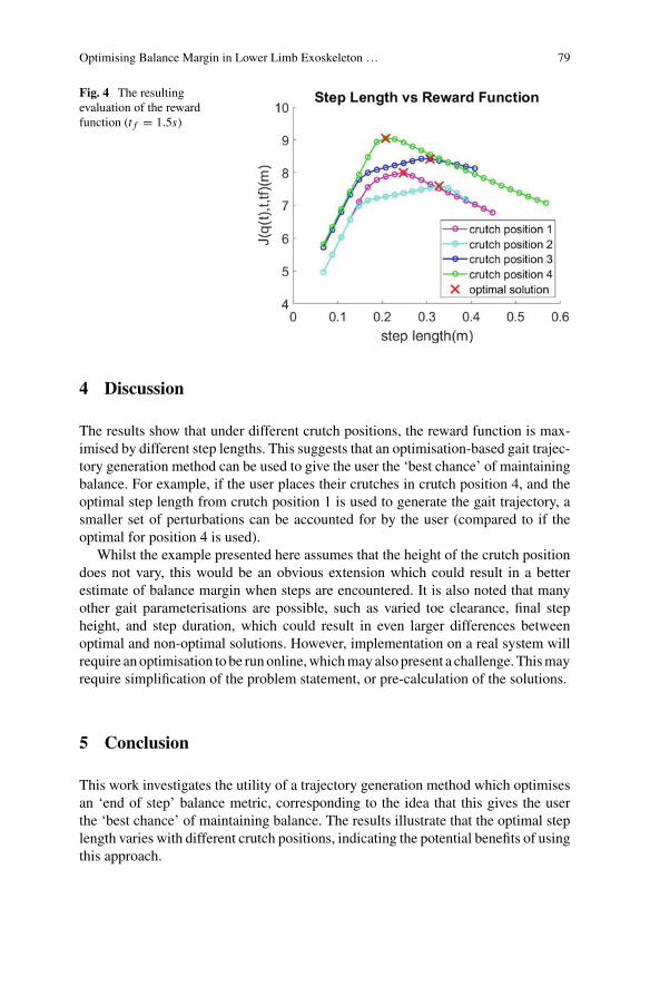
Optimising Balance Margin in Lower Limb Exoskeleton … 79
Fig. 4 The resultingevaluation of the rewardfunction (t f = 1.5s)
4 Discussion
The results show that under different crutch positions, the reward function is max-imised by different step lengths. This suggests that an optimisation-based gait trajec-tory generation method can be used to give the user the ‘best chance’ of maintainingbalance. For example, if the user places their crutches in crutch position 4, and theoptimal step length from crutch position 1 is used to generate the gait trajectory, asmaller set of perturbations can be accounted for by the user (compared to if theoptimal for position 4 is used).
Whilst the example presented here assumes that the height of the crutch positiondoes not vary, this would be an obvious extension which could result in a betterestimate of balance margin when steps are encountered. It is also noted that manyother gait parameterisations are possible, such as varied toe clearance, final stepheight, and step duration, which could result in even larger differences betweenoptimal and non-optimal solutions. However, implementation on a real system willrequire anoptimisation to be runonline,whichmayalso present a challenge.Thismayrequire simplification of the problem statement, or pre-calculation of the solutions.
5 Conclusion
This work investigates the utility of a trajectory generation method which optimisesan ‘end of step’ balance metric, corresponding to the idea that this gives the userthe ‘best chance’ of maintaining balance. The results illustrate that the optimal steplength varies with different crutch positions, indicating the potential benefits of usingthis approach.

80 X. Cheng et al.
References
1. T.Yan,M.Cempini, C.M.Oddo,N.Vitiello, Reviewof assistive strategies in powered lower-limborthoses and exoskeletons. Robot. Autonom. Syst. 64, 120–136 (2015)
2. M.F.B. Miskon, M.B.A.J. Yusof, Review of trajectory generation of exoskeleton robots, in IEEEInternational Symposium on Robotics and Manufacturing Automation (ROMA), vol. 2014, pp.12–17 (2014)
3. P.M. McAndrew, J.B. Dingwell, J.M. Wilken, Walking variability during continuous pseudo-random oscillations of the support surface and visual field. J. Biomech. 43(8), 1470–1475 (2010)
4. R. Drillis, R. Contini, M. Bluestein, Body segment parameters. Artif. Limbs 8(1), 44–66 (1964)5. M. Vukobratovic, B. Borovac, Zero-moment point thirty five years of its life. Int. J. Humanoid
Robot. 1(01), 157–173 (2004)6. J.H. Kim, Y. Xiang, R. Bhatt, J. Yang, H.-J. Chung, J. Arora, K. Abdel-Malek, Generating
effective whole-body motions of a human-like mechanism with efficient zmp formulation. Int.J. Robot. Autom. 24(2), 125 (2009)

Active Life with Prosthesis
Control of Servomotor Rotationin a Myoelectric Upper-Limb ProsthesisUsing a 16-Channel sEMG Sensor System
Elisa Romero Avila, Elmar Junker, and Catherine Disselhorst-Klug
Abstract The characteristics to consider during the development of myoelectricprostheses are the cultural, socio-economic and climatic conditions in which they areused. The weather condition affects in particular the recording of muscular activationfor the prosthesis control. The aim of this study was the development of an easyto use myoelectric control system that can be used for the myoelectric control ofopening and closing of the hand through electrodes that are not inside the prosthesissocket. Two time-domain features and Channel Selection were used to identify thespecific channels corresponding to the biceps and triceps muscles. Eleven healthysubjects were tested. Channel selection was correct in 80% of all trials ensuring thatthe myoelectric sensor system can be used in any position outside of the prosthesissocket. This study provides an essential step towards the development of amechanismfor grip control in a myoelectric-controlled prosthetic hand.
1 Introduction
Despite technological advances in myoelectric upper-limb prostheses, they continueto attain low user acceptance [1]. This is particularly in developing countries were themain challenges are related to the cultural, socio-economic and climatic conditions.An additional challenge is the prosthesis control throughmuscular activationwhich isinfluenced by the contact between the electrode and the skin, the electrode´s positionand the sEMG signal processing. The aim of this study is the development of aneasy to use myoelectric control system for developing countries. This system shouldallow the control of the opening and closing of the hand via electrodes that are notinside the prosthesis socket. By this, the myoelectric sensor system can be used inany position.
E. Romero Avila (B) · E. Junker · C. Disselhorst-KlugDepartment of Rehabilitation and Prevention Engineering, Institute of Applied MedicalEngineering - Helmholtz Institute, RWTH-Aachen University, Aachen, Germanye-mail: [email protected]
© The Author(s), under exclusive license to Springer Nature Switzerland AG 2022J. C. Moreno et al. (eds.), Wearable Robotics: Challenges and Trends,Biosystems & Biorobotics 27, https://doi.org/10.1007/978-3-030-69547-7_14
83
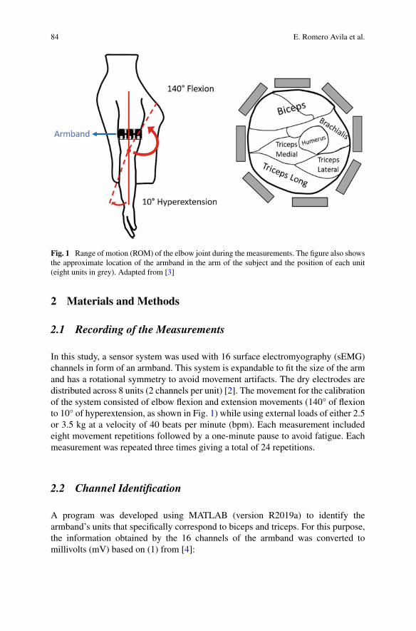
84 E. Romero Avila et al.
Fig. 1 Range of motion (ROM) of the elbow joint during the measurements. The figure also showsthe approximate location of the armband in the arm of the subject and the position of each unit(eight units in grey). Adapted from [3]
2 Materials and Methods
2.1 Recording of the Measurements
In this study, a sensor system was used with 16 surface electromyography (sEMG)channels in form of an armband. This system is expandable to fit the size of the armand has a rotational symmetry to avoid movement artifacts. The dry electrodes aredistributed across 8 units (2 channels per unit) [2]. The movement for the calibrationof the system consisted of elbow flexion and extension movements (140° of flexionto 10° of hyperextension, as shown in Fig. 1) while using external loads of either 2.5or 3.5 kg at a velocity of 40 beats per minute (bpm). Each measurement includedeight movement repetitions followed by a one-minute pause to avoid fatigue. Eachmeasurement was repeated three times giving a total of 24 repetitions.
2.2 Channel Identification
A program was developed using MATLAB (version R2019a) to identify thearmband’s units that specifically correspond to biceps and triceps. For this purpose,the information obtained by the 16 channels of the armband was converted tomillivolts (mV) based on (1) from [4]:
Control of Servomotor Rotation in a Myoelectric Upper-Limb … 85
EMGdata = data × Vre f
resolution(1)
where
data = armband output.
Vref = 3.3 V.
resolution = 65536 (16-Bits Resolution).Subsequently, the data obtained from the 16 channels were filtered according to
the SENIAM recommendations (Butterworth, 9th order, 10–500 Hz) [5]. To reducethe complexity of the system, two time-domain features and Channel Selection (CS)was used [5]. The mean absolute values (MAV) and the root mean square values(RMS) were obtained in 80 ms sEMG-windows [6]. The mean value of the sEMG-windows in the three measurements was then calculated and sorted in ascendingorder. The channels corresponding to the first six positions (out of 16) in both RMSand MAV were considered as the main channels corresponding to either biceps ortriceps. As six channels were identified, themean values of three units were obtained.Given that the loads affected mainly the flexion movement, the highest value of thethree units was assigned to biceps. The second value was considered to be possiblecrosstalk and since the movement was made with a hyperextension of ~10°, the thirdvalue was assigned to triceps.
2.3 Servomotor Control
A servomotor (Parallax Servo Motor) was used as an actuator for the prosthesis.The real time control of the rotational direction of the servomotor via the sEMGsensor system was made possible by an application designed in MATLAB using the“App Designer” function. The connection between MATLAB and the servomotorwas implemented using an Arduino Nano.
2.4 Validation
Measurements were performed on eleven healthy subjects (5 female, 6 men, age28.81 ± 9.04 years) while they wore the myoelectric sensor system. Each channelwas labeled, and the armband was arbitrarily positioned by the subjects on theirdominant arm (see Fig. 1).
The first component of the application described in Sect. 2.3 (Servomotor control)consisted of reading all the channels of the sensor system while performing thecalibration measurements. After channel identification, the channels correspondingto biceps and triceps were stored in the application. Then, the program read the two
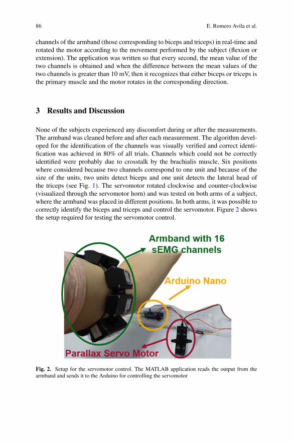
86 E. Romero Avila et al.
channels of the armband (those corresponding to biceps and triceps) in real-time androtated the motor according to the movement performed by the subject (flexion orextension). The application was written so that every second, the mean value of thetwo channels is obtained and when the difference between the mean values of thetwo channels is greater than 10 mV, then it recognizes that either biceps or triceps isthe primary muscle and the motor rotates in the corresponding direction.
3 Results and Discussion
None of the subjects experienced any discomfort during or after the measurements.The armband was cleaned before and after each measurement. The algorithm devel-oped for the identification of the channels was visually verified and correct identi-fication was achieved in 80% of all trials. Channels which could not be correctlyidentified were probably due to crosstalk by the brachialis muscle. Six positionswhere considered because two channels correspond to one unit and because of thesize of the units, two units detect biceps and one unit detects the lateral head ofthe triceps (see Fig. 1). The servomotor rotated clockwise and counter-clockwise(visualized through the servomotor horn) and was tested on both arms of a subject,where the armband was placed in different positions. In both arms, it was possible tocorrectly identify the biceps and triceps and control the servomotor. Figure 2 showsthe setup required for testing the servomotor control.
Fig. 2. Setup for the servomotor control. The MATLAB application reads the output from thearmband and sends it to the Arduino for controlling the servomotor
Control of Servomotor Rotation in a Myoelectric Upper-Limb … 87
4 Conclusion
Since themyoelectric sensor systemcan be positioned outside the prosthesis socket, itrepresents a solution for countries with humid weather conditions. Channel selectionwas correct in 80% of all trials ensuring that the myoelectric sensor system can beused in any position. Additionally, the calibration required for CS is quick and easyas well as the real-time control of a servomotor through the performance of elbowflexion or extension on either arm. This allows for the myoelectric sensor system tobe used by even unexperienced users. More subjects are needed to ensure a largerreproducibility of the control system of the servomotor in real-time. This studyrepresents an initial experiment towards the development of a potential mechanismfor grip adjustment in a myoelectric-controlled upper-limb prosthesis.
References
1. B. Peerdeman et al., Myoelectric forearm prostheses: State of the art from a user-centeredperspective. J. Rehabil. Res. Dev. 48(6), 719–738 (2011)
2. E. Junker, C. Disselhorst-Klug, S. Becker, Design of a portable 32-channel sEMG-IMU sensorsystem for the assessment of upper limbs’ movements in daily living, in XXVII Congress of theInternational Society of Biomechanics (ISB2019), 2019, p. 2178
3. D.L. Menkes, R. Pierce, Needle EMG muscle identification: A systematic approach to needleEMG examination. Clin. Neurophysiol. Pract. 4, 199–211 (2019)
4. T. Instruments, MSP430x55/MSP430x6xx Family User’s Guide, (SLAU208Q) (2018)5. D. Stegeman, H. Hermens, Standards for Surface Electromyography: The European Project
“Surface EMG for Non-invasive Assessment of Muscles (SENIAM)” (1999)6. U. Côté-Allard et al., Deep learning for electromyographic hand gesture signal classification
using transfer learning. IEEE Trans. Neural Syst. Rehabil. Eng. (2018)
Compliant Control of a TransfemoralProsthesis Combining PredictiveLearning and Primitive-Based ReferenceTrajectories
Sophie Heins and Renaud Ronsse
Abstract This paper reports the development of a novel compliant controller for atransfemoral prosthesis that combines a feed-forward prediction torque componentwith a feedback error correction. The controller architecture aims to track primitive-based reference trajectories by the prosthetic joints. It relies on Locally WeightedProjection Regression, a function approximator that acts as an inverse internal modelof the prosthesis. The proposed strategy is validated in a simulation environment.
1 Introduction
Despite the recent progress achieved in research on active lower-limb prostheses,developing efficient control strategies for these devices remains challenging. Giventhe dynamic nature of human locomotion and the periodic interactions with the envi-ronment, it is essential to design compliant control laws to ensure robustness to per-turbations [1]. Numerous control methods are being investigated in different devices[1], the most popular combining a finite state machine with impedance control, likein [2]. Other controllers are based on time- or phase-dependent trajectories to betracked by the prosthetic joints. A recent trend consists in adapting these trajectoriesto the user in real-time, such as in [3].
In this paper, we outline an adaptive control architecture aiming at tracking con-tinuous, primitive-based reference trajectories. The controller combines predictivelearning mechanisms in real-time with feedback error correction. The controller isvalidated in a simulation environment for normal walking.
S. Heins (B) · R. RonsseInstitute of Mechanics, Materials, and Civil Engineering, Université catholique de Louvain,Louvain, Belgiume-mail: [email protected]
Institute of Neuroscience, Université catholique de Louvain, Louvain, Belgium
Louvain Bionics, Université catholique de Louvain, Louvain, Belgium
© The Author(s), under exclusive license to Springer Nature Switzerland AG 2022J. C. Moreno et al. (eds.), Wearable Robotics: Challenges and Trends,Biosystems & Biorobotics 27, https://doi.org/10.1007/978-3-030-69547-7_15
89
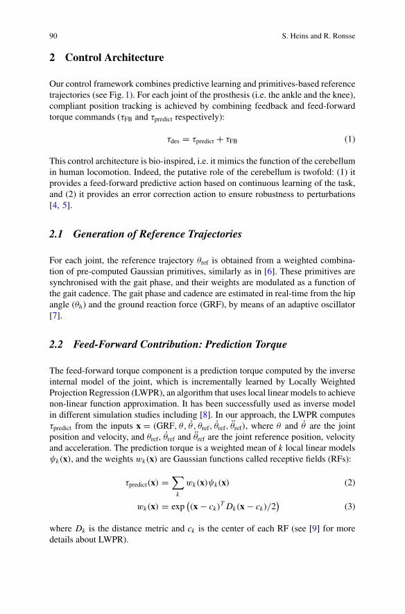
90 S. Heins and R. Ronsse
2 Control Architecture
Our control framework combines predictive learning and primitives-based referencetrajectories (see Fig. 1). For each joint of the prosthesis (i.e. the ankle and the knee),compliant position tracking is achieved by combining feedback and feed-forwardtorque commands (τFB and τpredict respectively):
τdes = τpredict + τFB (1)
This control architecture is bio-inspired, i.e. it mimics the function of the cerebellumin human locomotion. Indeed, the putative role of the cerebellum is twofold: (1) itprovides a feed-forward predictive action based on continuous learning of the task,and (2) it provides an error correction action to ensure robustness to perturbations[4, 5].
2.1 Generation of Reference Trajectories
For each joint, the reference trajectory θref is obtained from a weighted combina-tion of pre-computed Gaussian primitives, similarly as in [6]. These primitives aresynchronised with the gait phase, and their weights are modulated as a function ofthe gait cadence. The gait phase and cadence are estimated in real-time from the hipangle (θh) and the ground reaction force (GRF), by means of an adaptive oscillator[7].
2.2 Feed-Forward Contribution: Prediction Torque
The feed-forward torque component is a prediction torque computed by the inverseinternal model of the joint, which is incrementally learned by Locally WeightedProjection Regression (LWPR), an algorithm that uses local linear models to achievenon-linear function approximation. It has been successfully used as inverse modelin different simulation studies including [8]. In our approach, the LWPR computesτpredict from the inputs x = (GRF, θ, θ , θref, θref, θref), where θ and θ are the jointposition and velocity, and θref, θref and θref are the joint reference position, velocityand acceleration. The prediction torque is a weighted mean of k local linear modelsψk(x), and the weights wk(x) are Gaussian functions called receptive fields (RFs):
τpredict(x) =∑
k
wk(x)ψk(x) (2)
wk(x) = exp((x− ck)
T Dk(x− ck)/2)
(3)
where Dk is the distance metric and ck is the center of each RF (see [9] for moredetails about LWPR).
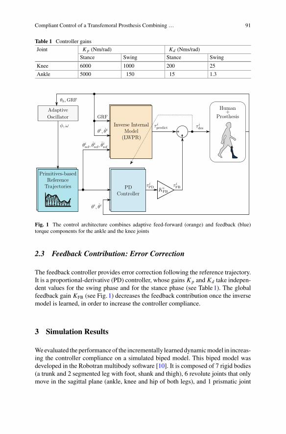
Compliant Control of a Transfemoral Prosthesis Combining … 91
Table 1 Controller gains
Joint Kp (Nm/rad) Kd (Nms/rad)
Stance Swing Stance Swing
Knee 6000 1000 200 25
Ankle 5000 150 15 1.3
Fig. 1 The control architecture combines adaptive feed-forward (orange) and feedback (blue)torque components for the ankle and the knee joints
2.3 Feedback Contribution: Error Correction
The feedback controller provides error correction following the reference trajectory.It is a proportional-derivative (PD) controller, whose gains Kp and Kd take indepen-dent values for the swing phase and for the stance phase (see Table1). The globalfeedback gain KFB (see Fig. 1) decreases the feedback contribution once the inversemodel is learned, in order to increase the controller compliance.
3 Simulation Results
Weevaluated theperformanceof the incrementally learneddynamicmodel in increas-ing the controller compliance on a simulated biped model. This biped model wasdeveloped in the Robotran multibody software [10]. It is composed of 7 rigid bodies(a trunk and 2 segmented leg with foot, shank and thigh), 6 revolute joints that onlymove in the sagittal plane (ankle, knee and hip of both legs), and 1 prismatic joint
92 S. Heins and R. Ronsse
0 20 40 60 80 1000
50
100(a
) F
B C
ontr
ibut
ion
[%]
High PD Gains Low PD Gains
ankleknee
0 20 40 60 80 100
Cycles
0
1
2
3
(b)
RM
SE
[%]
Fig. 2 The feedback torque contribution to the total joint torque per cycle rapidly decreases whilethe inverse internal model is learned, for both joints
that only moves in the vertical direction (the center of mass). In the ground contactmodel, only the vertical component of the GRF is modelled, and its computationis based on [11]. The hip, knee and ankle joints of the left leg and the hip joint ofthe right leg are forced to follow Winter angle trajectories for normal walking, cor-responding to a cadence of 0.83 stride/s [12]. The control architecture presented inSect. 2 is implemented on the knee and ankle joints of the right leg.
Results of the simulation showed that the LWPR was able to rapidly learn theinverse model of both joints and provided an accurate torque prediction after a fewcycles only. The evolution of the contribution of the feedback torque componentto the total joint torque per cycle is provided in Fig. 2, for both joints. It quicklyconverges to 30% for the ankle joint and 18% for the knee joint. Then, after 50 gaitcycles, the controller compliance was increased by reducing the gains of the PDcontroller, i.e. KFB was set to 25% for the ankle joint and to 5% for the knee joint,which are the lowest values associated with a tracking accuracy similar than withhigh PD gains. This further decreased the feedback contribution to the total torqueto 29% and 5% for the ankle and the knee respectively, while the RMSE of the ankleand knee angles remained under 2.1% and 1% of the maximum angular amplituderespectively (see Fig. 2). This lead to compliant position tracking.
Compliant Control of a Transfemoral Prosthesis Combining … 93
4 Discussion and Conclusion
We developed a bio-inspired controller for a transfemoral prosthesis that mimicsthe role of the cerebellum in human locomotion. The controller combines a feed-forward prediction torque command with a feedback error correction mechanism.The feed-forward action uses the LWPR algorithm, acting as an inverse internalmodel of the system. We validated the proposed approach on a simple biped model.Results showed that the LWPR is able to quickly learn the inverse model of eachjoint and provides accurate torque commands in real-time. This allows to decreasethe PD gains of the feedback action, leading to a more compliant position tracking.Future work includes the validation of this control architecture on a real transfemoralprosthesis.
Acknowledgements This work was supported by the European Community’s H2020 Researchand Innovation Programme under grant number 731931 (the CYBERLEGsPlusPlus collaborativeproject).
References
1. M.R. Tucker, J. Olivier, A. Pagel, H. Bleuler, M. Bouri, O. Lambercy, J.d.R. Milln, R. Riener,H. Vallery, R. Gassert, Control strategies for active lower extremity prosthetics and orthotics:a review. J. NeuroEng. Rehab. 12(1) (2015)
2. F. Sup, A. Bohara, M. Goldfarb, Design and control of a powered transfemoral prosthesis. Int.J. Robot. Res. (2008)
3. R.W. Jackson, S.H. Collins, Heuristic-based ankle exoskeleton control for co-adaptive assis-tance of human locomotion. IEEE Trans. Neural Syst. Rehabil. Eng. 27(10), 2059–2069 (2019)
4. I. Saunders, S. Vijayakumar, The role of feed-forward and feedback processes for closed-loopprosthesis control. J. NeuroEng. Rehab. 8, 60 (2011)
5. I. Pisotta, M. Molinari, Cerebellar contribution to feedforward control of locomotion. Front.Hum. Neurosci. 8 (2014)
6. S. Heins, L. Flynn, H. Laloyaux, J. Geeroms, D. Lefeber, R. Ronsse, Compliant control ofa transfemoral prosthesis by combining feed-forward and feedback, in 2020 8th IEEE RAS& EMBS International Conference on Biomedical Robotics and Biomechatronics (BioRob)Accepted for publication (2020)
7. T. Yan, A. Parri, V. Ruiz Garate, M. Cempini, R. Ronsse, N. Vitiello, An oscillator-basedsmooth real-time estimate of gait phase for wearable robotics. Autonom. Robot. 41, 759–774(2017)
8. S. Tolu, M. Vanegas, N.R. Luque, J.A. Garrido, E. Ros, Bio-inspired adaptive feedback errorlearning architecture for motor control. Biol. Cybern. 106, 507–522 (2012)
9. S. Vijayakumar, A. D’Souza, S. Schaal, Incremental online learning in high dimensions. NeuralComput. 17, 2602–34 (2006)
10. N. Docquier, A. Poncelet, P. Fisette, ROBOTRAN: a powerful symbolic generator ofmultibodymodels. Mech. Sci. 4(1), 199–219 (2013)
11. N. Van der Noot, A.J. Ijspeert, R. Ronsse, Bio-inspired controller achieving forward speedmodulation with a 3D bipedal walker. Int. J. Robot. Res. (2018)
12. D.A. Winter, The Biomechanics and Motor Control of Human Gait (University of WaterlooPress, 1987)
Design and Testing of a Fully-IntegratedElectro-Hydrostatic Actuator forPowered Knee Prostheses
Federico Tessari, Renato Galluzzi, Nicola Amati, Andrea Tonoli,Matteo Laffranchi, and Lorenzo De Michieli
Abstract Electro-hydrostatic actuation represents a well-suited alternative in pros-thetic and robotic applications to electro-mechanical actuation. In this regard, itsfavorable controllability and intrinsic back-drivability are key enabling features. Thiswork offers a specific design methodology to obtain a highly-integrated and back-drivable electro-hydrostatic unit for a powered knee prosthesis to be used both inactive and regenerative modes. The designed actuator was manufactured, assembledand tested in position tracking and admittance control, where promising performancewas attained.
1 Introduction
The last decade has foreseen a strong academic and industrial interest on poweredknee prostheses. This is due to the need of outperforming semi-active prostheses,which now represent the main solution for trans-femoral amputees.
According to Pieringer et al. and El-Sayed et al., most of the existing poweredknee prostheses are based on electro-mechanical actuation [1]: an electrical motorcoupled to a mechanical transmission mechanism, such as a harmonic drive or a ballscrew. In contrast, Electro-Hydrostatic Actuation (EHA) is based on the couplingof an electric motor to a bi-direction hydraulic pump, that in turn is connected to alinear or rotary hydraulic actuator.
Several works have already investigated EHA in different fields. Favorable con-trollability and back-drivability are two common attributes of EHA in literature, bothrepresenting key features in prosthetic devices [2, 3].
F. Tessari (B) · M. Laffranchi · L. De MichieliItalian Institute of Technology, Genoa, Italye-mail: [email protected]
R. Galluzzi · N. Amati · A. TonoliDepartment of Mechanical and Aerospace Engineering (DIMEAS),Politecnico di Torino, Turin, Italy
© The Author(s), under exclusive license to Springer Nature Switzerland AG 2022J. C. Moreno et al. (eds.), Wearable Robotics: Challenges and Trends,Biosystems & Biorobotics 27, https://doi.org/10.1007/978-3-030-69547-7_16
95
96 F. Tessari et al.
Nevertheless, many of the EHA devices in literature are based on commercial-off-the-shelf components, thus leading to non-optimized and poorly integrated actuatorsof difficult implementation in real-life applications.
In this work, the authors offer a specific design methodology for a custom EHAwith a high level of integration for a powered prosthetic knee, while also maintainingthe required performance based on the knee biomechanics.
2 Materials and Methods
2.1 Biomechanical Requirements
Aproper sizing of EHA subsystems requires the definition of geometrical constraintsfor the actuation, as well as torque-speed-power requirements. These specificationsare obtained from a biomechanical analysis of the human gait. Bovi et al. provideda wide database of biomechanical requirements for different gaits [4]. In this appli-cation, the actuator is designed for a level walking condition.
2.2 Kinematics of Actuation
In this application, a linear EHA unit is preferred over a rotary one. This choice isbased on two main advantages:
1. Advantageous mass distribution of the actuator: In contrast to rotary solutionsconstrained around the knee joint axis, linear actuators can be distributed alongthe prosthetic leg, hence mimicking the bulk of the calf muscle.
2. Variable transmission ratio: With proper mounting of the hydraulic cylinder, non-linear kinematics can be exploited to vary the effective length of the lever arm.
The kinematics of the actuator (Fig. 1) were defined by combining these observa-tions with geometrical constraints of the lower limb physiology [5].
2.3 EHA Unit
For the output actuator, a through-rod cylinder was selected due to its symmetry dur-ing motion and the lack of an additional accumulator. Its cross section Ap was sizedby considering the ratio among maximum required force and maximum allowablepressure. The hydraulic cylinder was equipped with low-friction spring-energizedPTFE seals.
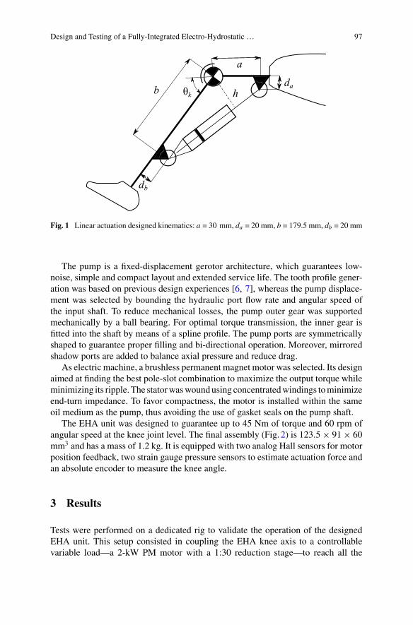
Design and Testing of a Fully-Integrated Electro-Hydrostatic … 97
Fig. 1 Linear actuation designed kinematics: a = 30 mm, da = 20 mm, b = 179.5 mm, db = 20 mm
The pump is a fixed-displacement gerotor architecture, which guarantees low-noise, simple and compact layout and extended service life. The tooth profile gener-ation was based on previous design experiences [6, 7], whereas the pump displace-ment was selected by bounding the hydraulic port flow rate and angular speed ofthe input shaft. To reduce mechanical losses, the pump outer gear was supportedmechanically by a ball bearing. For optimal torque transmission, the inner gear isfitted into the shaft by means of a spline profile. The pump ports are symmetricallyshaped to guarantee proper filling and bi-directional operation. Moreover, mirroredshadow ports are added to balance axial pressure and reduce drag.
As electric machine, a brushless permanent magnet motor was selected. Its designaimed at finding the best pole-slot combination to maximize the output torque whileminimizing its ripple. The statorwaswoundusing concentratedwindings tominimizeend-turn impedance. To favor compactness, the motor is installed within the sameoil medium as the pump, thus avoiding the use of gasket seals on the pump shaft.
The EHA unit was designed to guarantee up to 45 Nm of torque and 60 rpm ofangular speed at the knee joint level. The final assembly (Fig. 2) is 123.5× 91× 60mm3 and has a mass of 1.2 kg. It is equipped with two analog Hall sensors for motorposition feedback, two strain gauge pressure sensors to estimate actuation force andan absolute encoder to measure the knee angle.
3 Results
Tests were performed on a dedicated rig to validate the operation of the designedEHA unit. This setup consisted in coupling the EHA knee axis to a controllablevariable load—a 2-kW PM motor with a 1:30 reduction stage—to reach all the
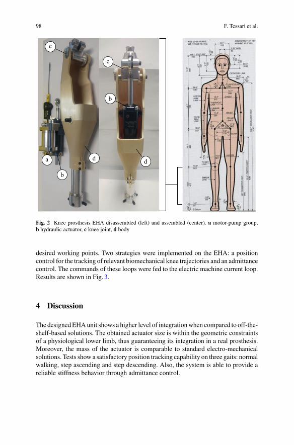
98 F. Tessari et al.
Fig. 2 Knee prosthesis EHA disassembled (left) and assembled (center). a motor-pump group,b hydraulic actuator, c knee joint, d body
desired working points. Two strategies were implemented on the EHA: a positioncontrol for the tracking of relevant biomechanical knee trajectories and an admittancecontrol. The commands of these loops were fed to the electric machine current loop.Results are shown in Fig. 3.
4 Discussion
The designedEHAunit shows a higher level of integrationwhen compared to off-the-shelf-based solutions. The obtained actuator size is within the geometric constraintsof a physiological lower limb, thus guaranteeing its integration in a real prosthesis.Moreover, the mass of the actuator is comparable to standard electro-mechanicalsolutions. Tests show a satisfactory position tracking capability on three gaits: normalwalking, step ascending and step descending. Also, the system is able to provide areliable stiffness behavior through admittance control.
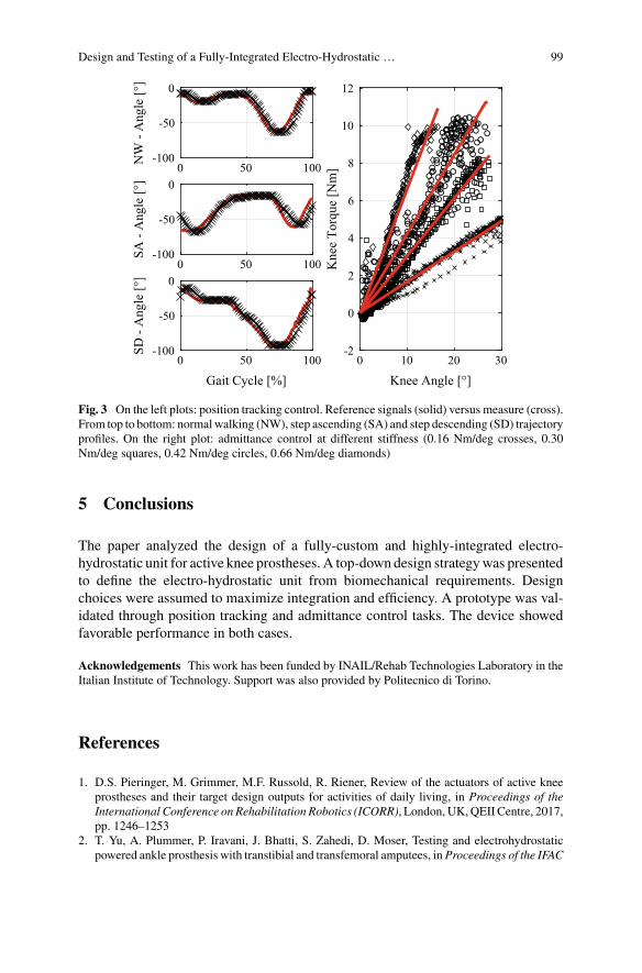
Design and Testing of a Fully-Integrated Electro-Hydrostatic … 99
Fig. 3 On the left plots: position tracking control. Reference signals (solid) versus measure (cross).From top to bottom: normalwalking (NW), step ascending (SA) and step descending (SD) trajectoryprofiles. On the right plot: admittance control at different stiffness (0.16 Nm/deg crosses, 0.30Nm/deg squares, 0.42 Nm/deg circles, 0.66 Nm/deg diamonds)
5 Conclusions
The paper analyzed the design of a fully-custom and highly-integrated electro-hydrostatic unit for active knee prostheses. A top-down design strategywas presentedto define the electro-hydrostatic unit from biomechanical requirements. Designchoices were assumed to maximize integration and efficiency. A prototype was val-idated through position tracking and admittance control tasks. The device showedfavorable performance in both cases.
Acknowledgements This work has been funded by INAIL/Rehab Technologies Laboratory in theItalian Institute of Technology. Support was also provided by Politecnico di Torino.
References
1. D.S. Pieringer, M. Grimmer, M.F. Russold, R. Riener, Review of the actuators of active kneeprostheses and their target design outputs for activities of daily living, in Proceedings of theInternational Conference on Rehabilitation Robotics (ICORR), London, UK,QEII Centre, 2017,pp. 1246–1253
2. T. Yu, A. Plummer, P. Iravani, J. Bhatti, S. Zahedi, D. Moser, Testing and electrohydrostaticpowered ankle prosthesis with transtibial and transfemoral amputees, inProceedings of the IFAC

100 F. Tessari et al.
Symposium on Mechatronic Systems, Loughborough University, Leicestershire, UK, 2016, pp.185–191
3. J. Fang, X. Wang, R. Li, S. Wang, W. Wang, Active ankle prosthesis powered by electrohydro-static actuation technology: design and implementation, in CSAA/IET International Conferenceon Aircraft Utility System (AUS 2018), Guiyang, China, IET, 2018, pp. 1170–1175
4. G. Bovi, M. Rabuffetti, P. Mazzoleni, M. Ferrarin, A multiple-task gait analysis approach:kinematic, kinetic and EMG reference data for healthy young and adult subjects. Gait & Posture33(1), 6–13 (2011)
5. H.D. Associates, A.R. Tilley, The Measure of Man and Woman: Human Factors in Design(Wiley, Hoboken, NJ, 2001)
6. R. Galluzzi, Y. Xu, N. Amati, A. Tonoli, Optimized design and characterization of motor-pumpunit for energy-regenerative shock absorbers. Appl. Energy 210(1), 16–27 (2018)
7. F. Tessari, R. Galluzzi, N. Amati, Efficiency-driven design methodology of gerotor hydraulicunits. J. Mech. Des. 142(6), 063 501 (1–12) (2020)
Controlling Upper-Limb Prostheses withBody Compensations
Mathilde Legrand, Nathanaël Jarrassé, Charlotte Marchand, Florian Richer,Amélie Touillet, Noël Martinet, Jean Paysant, and Guillaume Morel
Abstract With their advanced mechatronics, myoelectric upper-limb prosthesesnow have manymotion possibilities. Yet, the latter are not fully employed because ofthe inconvenient control and prostheses wearers often use their device as a rigid toolwhile achieving hand positioning and orientation with compensatory movements. Inthis paper, we propose to take advantage of this natural human behaviour to controlprosthesis motions: the user is in charge of the end-effector while the device’s roleis to correct the human posture when necessary. We here apply this concept to con-trol a prosthetic wrist pronosupination. A Rolyan clothespin test performed by twotransradial amputees shows that the proposed control is as efficient as myoelectriccontrol while requiring no learning.
M. Legrand (B) · N. Jarrassé · C. Marchand · F. Richer · G. MorelInstitute of Intelligent Systems and Robotics, Sorbonne University, CNRS UMR7222,INSERM U1150, Paris, Francee-mail: [email protected]
N. Jarrassée-mail: [email protected]
C. Marchande-mail: [email protected]
F. Richere-mail: [email protected]
G. Morele-mail: [email protected]
A. Touillet · N. Martinet · J. PaysantInstitut Régional de Réhabilitation, IRR UGECAM Nord-Est, Nancy, Francee-mail: [email protected]
N. Martinete-mail: [email protected]
J. Paysante-mail: [email protected]
© The Author(s), under exclusive license to Springer Nature Switzerland AG 2022J. C. Moreno et al. (eds.), Wearable Robotics: Challenges and Trends,Biosystems & Biorobotics 27, https://doi.org/10.1007/978-3-030-69547-7_17
101
102 M. Legrand et al.
1 Introduction
With the latest advances ofmechatronics, themotion possibilities of upper-limb (UL)prostheses have increased a lot [1, 2] but they are not fully exploited because thecontrol of these devices remains highly challenging.
The most widespread approach directly connects electromyographic signals gen-erated by the user to the movement of the prosthesis. It includes conventional myo-electric control (on/off or proportional), integrated into most of the commerciallyavailable devices, and pattern-recognition based myoelectric control. Performantenough when controlling one degree of freedom (DOF), these two schemes becomelimited with an increasing number of DOF [3]. The muscular fatigue and the mentalburden induced by theses control approaches often lead prostheses users to employtheir device as a rigid tool and move their end-effector with compensatory move-ments (see e.g. [4]). Body compensations are indeed efficient to achieve many tasks,but they are to be avoided since they cause musculoskeletal disorders [5].
In this paper, we propose to take advantage of this natural reaction of prosthesesusers to control the device: the end-effector task (placing and orientating the hand)will be achieved by the human subject while prosthesis motions will correct thehuman posture. This will be performed by servoing prosthetic joint motions to theuser’s compensatory movements. Note that this scheme is valid to control intermedi-ate joints likewrist, elbow and shoulder, but not for hand since no body compensationsubstitutes grasping functions.
This paradigm has already been explored and validated for the control of wristpronosupination with able-bodied subjects [6]. In the work presented here, we extendthis study to transradial amputated people, on a different task.
2 Materials and Methods
2.1 Control Law
The control law implemented to servo the prosthetic wrist pronosupination to theuser’s compensatory motions is the same as the one presented in [6]; we brieflyrecall it below. To supplant wrist pronosupination, amputated subjects tend to usetrunk and arm compensatory motions to change the hand orientation [4]. To avoidan artificial mapping between these motions and prosthesis’ motions, we directlymeasured the forearm rotation around its longitudinal axis (elbow-hand axis) andservoed the wrist motion to it.
First, the rotation between θ f a , the current posture of the lower-arm, and θ0, anobjective posture for the subject to go back to, is computed:
ε(t) = θ f a(t) − θ0 (1)
Controlling Upper-Limb Prostheses with Body Compensations 103
θ0 is set here as the initial forearm posture but can change if necessary, dependingon the task. ε is then used as the input of the control law, which pilots the prostheticwrist angular velocity, θ :
θ (t) =0 if |ε(t)| < ε0
λ(ε(t) − sign(ε(t) − ε0)ε0) otherwise,(2)
where ε0 is a deadzone threshold (here set to 5 deg) and λ is a scalar gain (set to2 s−1) that tunes the rate of correction. These values were chosen experimentally toensure stability.
2.2 Experimental Set-Up
Two transradial amputees, regular myoelectric-prosthesis users, participated to thisexperiment. They were asked to perform the refined Rolyan Clothespin test [7], bothwith their usual myoelectric control (MYO) and with the proposed control scheme,later called Compensations Cancellation Control (CCC). There were no specifictraining session and the Rolyan was achieved 5 times with each control mode. Forthe latter, the participants’ wrist rotator was replaced with one from the laboratory,including an encoder, and controlled with an external Raspberry Pi 3 c©. As CCCcannot be implemented for the hand, the usualmyoelectric control of each participantwas conserved for the grasping function. For this experiment, θ f a was obtainedwith an Inertial Measurement Unit located on the prosthetic forearm (see Fig. 1).The protocol of this experiment was approved by the Université Paris Descartesethic committee CERES. All participants gave their written informed consent inaccordance with the Declaration of Helsinki.
3 Results
3.1 Task Performance
Figure2a shows the time, averaged over trials, obtained with the two control modes,for both subjects. The times are clearly similar between the direction of the motion(upwards –horizontal-to-vertical– or downwards –vertical-to-horizontal–) and thecontrol modes. We can also notice that the standard deviation is small, for bothMYO and CCC.
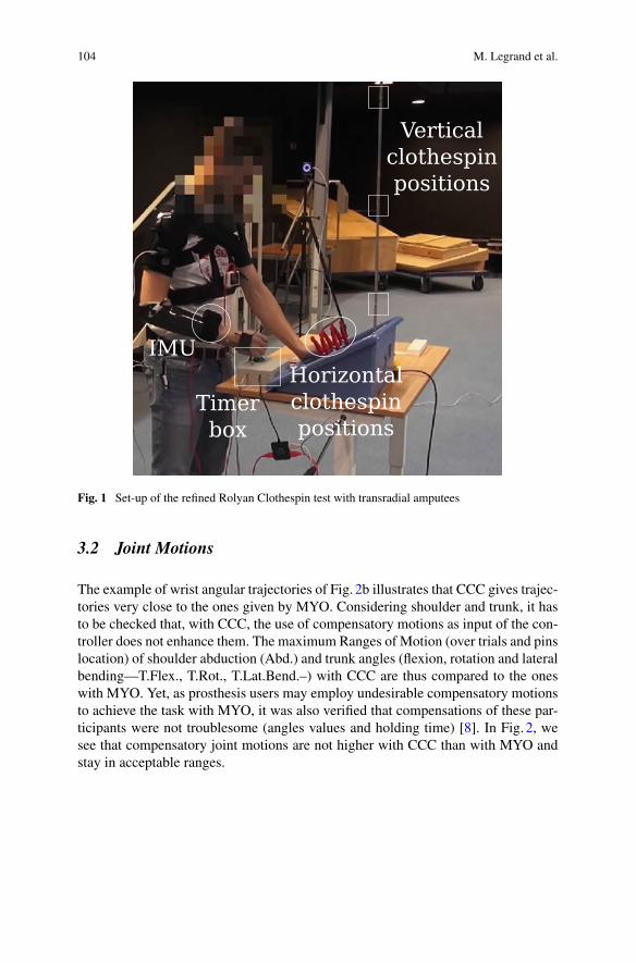
104 M. Legrand et al.
Fig. 1 Set-up of the refined Rolyan Clothespin test with transradial amputees
3.2 Joint Motions
The example of wrist angular trajectories of Fig. 2b illustrates that CCC gives trajec-tories very close to the ones given by MYO. Considering shoulder and trunk, it hasto be checked that, with CCC, the use of compensatory motions as input of the con-troller does not enhance them. The maximum Ranges of Motion (over trials and pinslocation) of shoulder abduction (Abd.) and trunk angles (flexion, rotation and lateralbending—T.Flex., T.Rot., T.Lat.Bend.–) with CCC are thus compared to the oneswith MYO. Yet, as prosthesis users may employ undesirable compensatory motionsto achieve the task with MYO, it was also verified that compensations of these par-ticipants were not troublesome (angles values and holding time) [8]. In Fig. 2, wesee that compensatory joint motions are not higher with CCC than with MYO andstay in acceptable ranges.
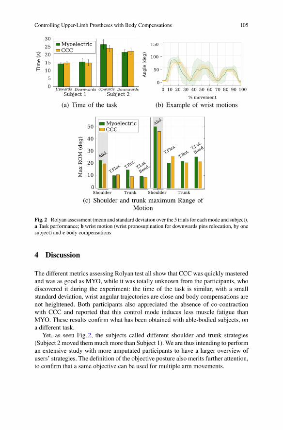
Controlling Upper-Limb Prostheses with Body Compensations 105
Fig. 2 Rolyan assessment (mean and standard deviation over the 5 trials for eachmode and subject).a Task performance; b wrist motion (wrist pronosupination for downwards pins relocation, by onesubject) and c body compensations
4 Discussion
The different metrics assessing Rolyan test all show that CCC was quickly masteredand was as good as MYO, while it was totally unknown from the participants, whodiscovered it during the experiment: the time of the task is similar, with a smallstandard deviation, wrist angular trajectories are close and body compensations arenot heightened. Both participants also appreciated the absence of co-contractionwith CCC and reported that this control mode induces less muscle fatigue thanMYO. These results confirm what has been obtained with able-bodied subjects, ona different task.
Yet, as seen Fig. 2, the subjects called different shoulder and trunk strategies(Subject 2 moved themmuch more than Subject 1). We are thus intending to performan extensive study with more amputated participants to have a larger overview ofusers’ strategies. The definition of the objective posture also merits further attention,to confirm that a same objective can be used for multiple arm movements.
106 M. Legrand et al.
5 Conclusion
The new control scheme for UL prostheses presented in this paper proposes to usethe device to control the user’s posture, while letting him/her in charge of the end-effector positioning and orientation. Tested with two transradial amputees, it was asgood as conventional myoelectric control without any specific learning, while poten-tially reducing the muscle fatigue. Following these promising results, the conceptdeveloped here could be extended to the control of more than one DOF. We thinkthat it could also be adapted to other rehabilitation devices like UL exoskeletons.
Acknowledgements This work was supported by the ANR-BYCEPS, ANR-18-CE19-0004.
References
1. F. Cordella et al., Literature review on needs of upper limb prosthesis users. Front. Neurosci. 3(2016)
2. N.M. Bajaj, A.J. Spiers, A.M. Dollar, State of the art in prosthetic wrists: commercial andresearch devices, in IEEE ICORR (2015)
3. G. Li, Advances in Applied Electromyography (IntechOpen, 2011)4. S.L. Carey, M.J. Highsmith, M.E. Maitland, R.V. Dubey, Compensatory movements of transra-
dial prosthesis users during common tasks. Clin. Biomech. 23(9), 1128–1135 (2008)5. K. Østlie, R.J. Franklin, O.H. Skjeldal, A. Skrondal, P. Magnus, Musculoskeletal pain and
overuse syndromes in adult acquired major upper-limb amputees. Arch. Phys. Med. Rehab.92(12), 1967–1973 (2011)
6. M. Legrand, N. Jarrassé, F. Richer, G.Morel, A closed-loop and ergonomic control for prostheticwrist rotation, in IEEE ICRA (2020)
7. A. Hussaini, W. Hill, P. Kyberd, Clinical evaluation of the refined clothespin relocation test: apilot study. Prosthet. Orthot. Int. 43(5), 485–491 (2019)
8. D. Kee, W. Karwowski, Luba: an assessment technique for postural loading on the upper bodybased on joint motion discomfort and maximum holding time. Appl. Ergon. 32, 357–366 (2001)
HandMECH—Mechanical HandProsthesis: Conceptual Design of a TwoDegrees-of-Freedom Compliant Wrist
Ahmed A. I. Elsayed and Ramazan Unal
Abstract A compliant wrist joint is important for positioning the hand in differentpositions to perform various daily tasks. It is also important that the wrist is able toachieve sufficient range of motion (RoM). The RoM is determined by classifying thedaily activities and the most critical applications. This study presents kinematical,structural and kinetic analyses of the conceptual design of a wrist joint in mechanicalhand prosthesis: HandMECH. Kinematic and kinetic analyses are carried out todetermine the design parameters of the wrist to handle daily activities. Structuralanalyses is performed to evaluate the stress distributed over the critical part of thewrist and show that the design with a mass of 50 g satisfies the applied boundarycondition.
1 Introduction
The human wrist is a complex structure that regulates the stiffness in accordancewith the task the person is about to do. It achieves that by contracting muscles thatcause the bones in the wrist to compress and becomes stiff [1, 2]. Currently, manyprosthetic hands lack the functionality of a wrist which causes the user to movehis upper body too much and put too much effort while performing simple tasksthat do not require a lot of body motion, e.g. using a computer mouse, picking upsmall objects. On the other hand, a light-weight wrist is always more beneficial as itprovides a low inertia. In this paper we attempt to achieve the RoM in ulnar/radialdeviations like the human hand and flexion/extension to ensure a natural transition ofthe wrist while performing tasks. Even though it is critical to have the 3rd DoF, i.e.rotation along the elbow axis [3], we decided not to implement this DoF and leave itto be compensated by the elbow rotation. This reduces the complexity and # of partsin design and allows achieving simpler, lightweight and compact wrist structure.
One study has approached to design a light-weight wrist by using a wire-basedjoint that is elliptical in shape as an attempt to mimic the human wrist [4]. In another
A. A. I. Elsayed · R. Unal (B)Department of Mechanical Engineering, Ozyegin University, Istanbul, Turkeye-mail: [email protected]
© The Author(s), under exclusive license to Springer Nature Switzerland AG 2022J. C. Moreno et al. (eds.), Wearable Robotics: Challenges and Trends,Biosystems & Biorobotics 27, https://doi.org/10.1007/978-3-030-69547-7_18
107
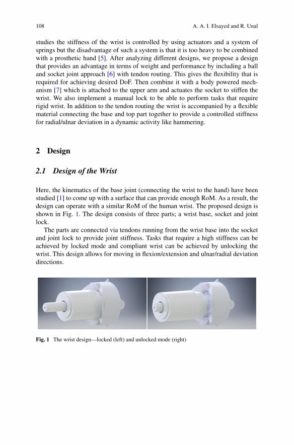
108 A. A. I. Elsayed and R. Unal
studies the stiffness of the wrist is controlled by using actuators and a system ofsprings but the disadvantage of such a system is that it is too heavy to be combinedwith a prosthetic hand [5]. After analyzing different designs, we propose a designthat provides an advantage in terms of weight and performance by including a balland socket joint approach [6] with tendon routing. This gives the flexibility that isrequired for achieving desired DoF. Then combine it with a body powered mech-anism [7] which is attached to the upper arm and actuates the socket to stiffen thewrist. We also implement a manual lock to be able to perform tasks that requirerigid wrist. In addition to the tendon routing the wrist is accompanied by a flexiblematerial connecting the base and top part together to provide a controlled stiffnessfor radial/ulnar deviation in a dynamic activity like hammering.
2 Design
2.1 Design of the Wrist
Here, the kinematics of the base joint (connecting the wrist to the hand) have beenstudied [1] to come up with a surface that can provide enough RoM. As a result, thedesign can operate with a similar RoM of the human wrist. The proposed design isshown in Fig. 1. The design consists of three parts; a wrist base, socket and jointlock.
The parts are connected via tendons running from the wrist base into the socketand joint lock to provide joint stiffness. Tasks that require a high stiffness can beachieved by locked mode and compliant wrist can be achieved by unlocking thewrist. This design allows for moving in flexion/extension and ulnar/radial deviationdirections.
Fig. 1 The wrist design—locked (left) and unlocked mode (right)
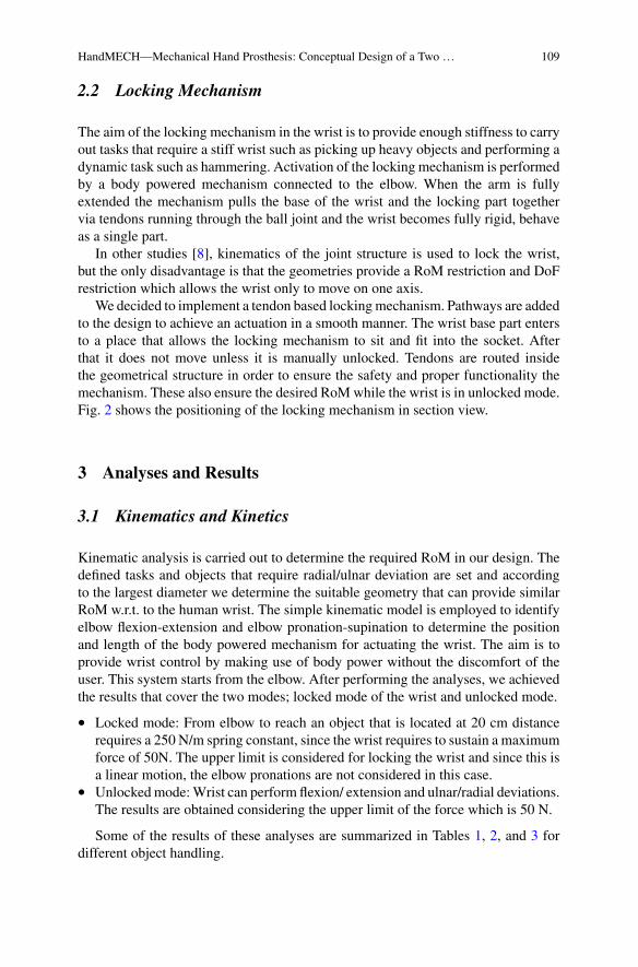
HandMECH—Mechanical Hand Prosthesis: Conceptual Design of a Two … 109
2.2 Locking Mechanism
The aim of the locking mechanism in the wrist is to provide enough stiffness to carryout tasks that require a stiff wrist such as picking up heavy objects and performing adynamic task such as hammering. Activation of the locking mechanism is performedby a body powered mechanism connected to the elbow. When the arm is fullyextended the mechanism pulls the base of the wrist and the locking part togethervia tendons running through the ball joint and the wrist becomes fully rigid, behaveas a single part.
In other studies [8], kinematics of the joint structure is used to lock the wrist,but the only disadvantage is that the geometries provide a RoM restriction and DoFrestriction which allows the wrist only to move on one axis.
We decided to implement a tendon based lockingmechanism. Pathways are addedto the design to achieve an actuation in a smooth manner. The wrist base part entersto a place that allows the locking mechanism to sit and fit into the socket. Afterthat it does not move unless it is manually unlocked. Tendons are routed insidethe geometrical structure in order to ensure the safety and proper functionality themechanism. These also ensure the desired RoMwhile the wrist is in unlocked mode.Fig. 2 shows the positioning of the locking mechanism in section view.
3 Analyses and Results
3.1 Kinematics and Kinetics
Kinematic analysis is carried out to determine the required RoM in our design. Thedefined tasks and objects that require radial/ulnar deviation are set and accordingto the largest diameter we determine the suitable geometry that can provide similarRoM w.r.t. to the human wrist. The simple kinematic model is employed to identifyelbow flexion-extension and elbow pronation-supination to determine the positionand length of the body powered mechanism for actuating the wrist. The aim is toprovide wrist control by making use of body power without the discomfort of theuser. This system starts from the elbow. After performing the analyses, we achievedthe results that cover the two modes; locked mode of the wrist and unlocked mode.
• Locked mode: From elbow to reach an object that is located at 20 cm distancerequires a 250 N/m spring constant, since the wrist requires to sustain a maximumforce of 50N. The upper limit is considered for locking the wrist and since this isa linear motion, the elbow pronations are not considered in this case.
• Unlockedmode:Wrist can perform flexion/ extension and ulnar/radial deviations.The results are obtained considering the upper limit of the force which is 50 N.
Some of the results of these analyses are summarized in Tables 1, 2, and 3 fordifferent object handling.
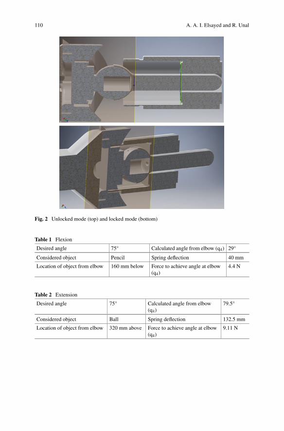
110 A. A. I. Elsayed and R. Unal
Fig. 2 Unlocked mode (top) and locked mode (bottom)
Table 1 Flexion
Desired angle 75° Calculated angle from elbow (q4) 29°
Considered object Pencil Spring deflection 40 mm
Location of object from elbow 160 mm below Force to achieve angle at elbow(q4)
4.4 N
Table 2 Extension
Desired angle 75° Calculated angle from elbow(q4)
79.5°
Considered object Ball Spring deflection 132.5 mm
Location of object from elbow 320 mm above Force to achieve angle at elbow(q4)
9.11 N
HandMECH—Mechanical Hand Prosthesis: Conceptual Design of a Two … 111
Table 3 Ulnar/radial deviation
Desired angle 35° Calculated angle from elbow(q4)
18°
Considered object Mouse Spring deflection 7.96 mm
Location of object from elbow 70 mm to right/left Force to achieve angle at elbow(q4)
15.3 N
3.2 Structural analysis
Here, we employed structural analysis to define design parameters of critical parts,such as the base of the wrist that is connected to a prosthetic hand. In this casewe set the heaviest mass as 5 kg as the heaviest object that hand carries duringdaily activities. According to this analysis max stress is 14.5 MPa and maximumdeformation is 0.128 mm.
4 Conclusion
This study presents a 2 DoF wrist joint for prosthetic hands. Kinematic and kineticanalyses are conducted to define thedesignparameters. Structural analyses are carriedout to check the critical parts under loading conditions. After the design and analyses,50g wrist that has a RoM of flexion/extension and ulnar/radial deviation in varioustasks is obtained.
References
1. S. Casini, et al., Design of an under-actuated wrist based on adaptive synergies, in IEEEInternational Conference on Robotics and Automation (ICRA) (2017)
2. A. Zonnino, F. Sergi, Model-based analysis of the stiffness of the wrist joint in active and passiveconditions. J. Biomech. Eng. 141(4) (2019)
3. S. Oyama, et al., Biomechanical reconstruction using the tacit learning system: intuitive controlof prosthetic hand rotation. Frontiers Neurorobot (2016)
4. N. Kim, W.H. Choi, D. Shin, Design optimization of a wire-based ellipsoid joint for bionicwrists, in 14th International Conference on Ubiquitous Robots and Ambient Intelligence (2017)
5. F. Montagnani, G. Smit, M. Controzzi, C. Cipriani, D.H. Plettenburg, A passive wrist withswitchable stiffness for a bodypowered hydraulically actuated hand prosthesis, in InternationalConference on Rehabilitation Robotics (London, UK, 2017)
6. N. M. Bajaj, A.J. Spiers, A.M. Dollar, State of the art in prosthetic wrists: commercial andresearch devices, in IEEE International Conference on Rehabilitation Robotics (2015).
7. T. Kulkarni, R. Uddanwadiker, Overview:mechanism and control of a prosthetic arm.MolecularCellular Biomech (2015)
8. O.A. van Nierop, A. van der Helm, K.J. Overbeeke, T.J.P. Djajadiningrat, A natural hand model.Visual Comput. 24, 31–44 (2008)
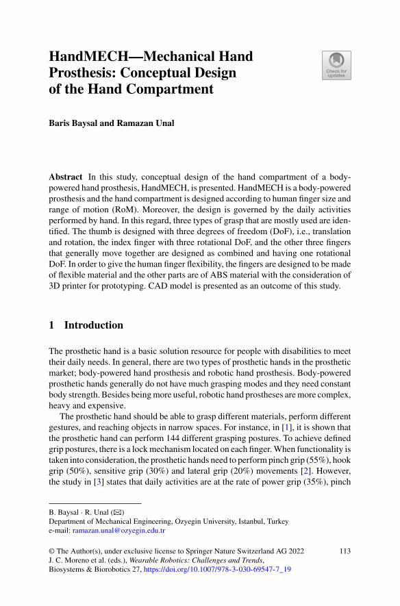
HandMECH—Mechanical HandProsthesis: Conceptual Designof the Hand Compartment
Baris Baysal and Ramazan Unal
Abstract In this study, conceptual design of the hand compartment of a body-powered hand prosthesis, HandMECH, is presented. HandMECH is a body-poweredprosthesis and the hand compartment is designed according to human finger size andrange of motion (RoM). Moreover, the design is governed by the daily activitiesperformed by hand. In this regard, three types of grasp that are mostly used are iden-tified. The thumb is designed with three degrees of freedom (DoF), i.e., translationand rotation, the index finger with three rotational DoF, and the other three fingersthat generally move together are designed as combined and having one rotationalDoF. In order to give the human finger flexibility, the fingers are designed to be madeof flexible material and the other parts are of ABS material with the consideration of3D printer for prototyping. CAD model is presented as an outcome of this study.
1 Introduction
The prosthetic hand is a basic solution resource for people with disabilities to meettheir daily needs. In general, there are two types of prosthetic hands in the prostheticmarket; body-powered hand prosthesis and robotic hand prosthesis. Body-poweredprosthetic hands generally do not have much grasping modes and they need constantbody strength. Besides beingmore useful, robotic hand prostheses aremore complex,heavy and expensive.
The prosthetic hand should be able to grasp different materials, perform differentgestures, and reaching objects in narrow spaces. For instance, in [1], it is shown thatthe prosthetic hand can perform 144 different grasping postures. To achieve definedgrip postures, there is a lockmechanism located on each finger.When functionality istaken into consideration, the prosthetic hands need to perform pinch grip (55%), hookgrip (50%), sensitive grip (30%) and lateral grip (20%) movements [2]. However,the study in [3] states that daily activities are at the rate of power grip (35%), pinch
B. Baysal · R. Unal (B)Department of Mechanical Engineering, Ozyegin University, Istanbul, Turkeye-mail: [email protected]
© The Author(s), under exclusive license to Springer Nature Switzerland AG 2022J. C. Moreno et al. (eds.), Wearable Robotics: Challenges and Trends,Biosystems & Biorobotics 27, https://doi.org/10.1007/978-3-030-69547-7_19
113
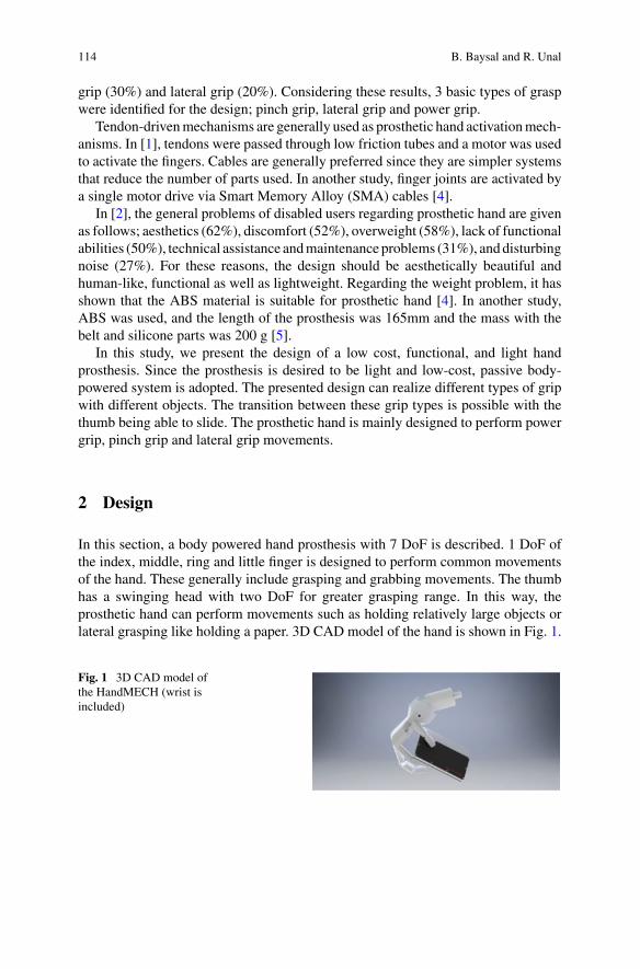
114 B. Baysal and R. Unal
grip (30%) and lateral grip (20%). Considering these results, 3 basic types of graspwere identified for the design; pinch grip, lateral grip and power grip.
Tendon-drivenmechanisms are generally used as prosthetic hand activationmech-anisms. In [1], tendons were passed through low friction tubes and a motor was usedto activate the fingers. Cables are generally preferred since they are simpler systemsthat reduce the number of parts used. In another study, finger joints are activated bya single motor drive via Smart Memory Alloy (SMA) cables [4].
In [2], the general problems of disabled users regarding prosthetic hand are givenas follows; aesthetics (62%), discomfort (52%), overweight (58%), lack of functionalabilities (50%), technical assistance andmaintenance problems (31%), anddisturbingnoise (27%). For these reasons, the design should be aesthetically beautiful andhuman-like, functional as well as lightweight. Regarding the weight problem, it hasshown that the ABS material is suitable for prosthetic hand [4]. In another study,ABS was used, and the length of the prosthesis was 165mm and the mass with thebelt and silicone parts was 200 g [5].
In this study, we present the design of a low cost, functional, and light handprosthesis. Since the prosthesis is desired to be light and low-cost, passive body-powered system is adopted. The presented design can realize different types of gripwith different objects. The transition between these grip types is possible with thethumb being able to slide. The prosthetic hand is mainly designed to perform powergrip, pinch grip and lateral grip movements.
2 Design
In this section, a body powered hand prosthesis with 7 DoF is described. 1 DoF ofthe index, middle, ring and little finger is designed to perform common movementsof the hand. These generally include grasping and grabbing movements. The thumbhas a swinging head with two DoF for greater grasping range. In this way, theprosthetic hand can perform movements such as holding relatively large objects orlateral grasping like holding a paper. 3D CAD model of the hand is shown in Fig. 1.
Fig. 1 3D CAD model ofthe HandMECH (wrist isincluded)
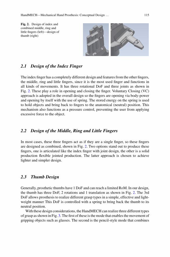
HandMECH—Mechanical Hand Prosthesis: Conceptual Design … 115
Fig. 2. Design of index andcombined middle, ring andlittle fingers (left)—design ofthumb (right)
2.1 Design of the Index Finger
The index finger has a completely different design and features from the other fingers,the middle, ring and little fingers, since it is the most used finger and functions inall kinds of movements. It has three rotational DoF and three joints as shown inFig. 2. These play a role in opening and closing the finger. Voluntary Closing (VC)approach is adopted in the overall design so the fingers are opening via body-powerand opening by itself with the use of spring. The stored energy on the spring is usedto hold objects and bring back to fingers to the anatomical (neutral) position. Thismechanism also functions as a pressure control, preventing the user from applyingexcessive force to the object.
2.2 Design of the Middle, Ring and Little Fingers
In most cases, these three fingers act as if they are a single finger, so these fingersare designed as combined, shown in Fig. 2. Two options stand out to produce thesefingers, one is articulated like the index finger with joint design, the other is a solidproduction flexible jointed production. The latter approach is chosen to achievelighter and simpler design.
2.3 Thumb Design
Generally, prosthetic thumbs have 1 DoF and can reach a limited RoM. In our design,the thumb has three DoF, 2 rotations and 1 translation as shown in Fig. 2. The 3rdDoF allows prosthesis to realize different grasp types in a simple, effective and light-weight manner This DoF is controlled with a spring to bring back the thumb to itsneutral position.
With these design considerations, theHandMECHcan realize three different typesof grasp as shown in Fig. 3. The first of these is themode that enables themovement ofgripping objects such as glasses. The second is the pencil-style mode that combines
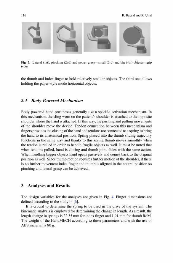
116 B. Baysal and R. Unal
Fig. 3. Lateral (1st), pinching (2nd) and power grasp—small (3rd) and big (4th) objects—griptypes
the thumb and index finger to hold relatively smaller objects. The third one allowsholding the paper-style mode horizontal objects.
2.4 Body-Powered Mechanism
Body-powered hand prostheses generally use a specific activation mechanism. Inthis mechanism, the sling worn on the patient’s shoulder is attached to the oppositeshoulder where the hand is attached. In this way, the pushing and pulling movementsof the shoulder move the device. Tendon connection between this mechanism andfingers provides the closing of the hand and tendons are connected to a spring to bringthe hand to its anatomical position. Spring placed into the thumb sliding trajectoryfunctions in the same way and thanks to this spring thumb moves smoothly whenthe tendon is pulled in order to handle fragile objects as well. It must be noted thatwhen tendons pulled, hand is closing and thumb joint slides with the same action.When handling bigger objects hand opens passively and comes back to the originalposition as well. Since thumbmotion requires further motion of the shoulder, if thereis no further movement index finger and thumb is aligned in the neutral position sopinching and lateral grasp can be achieved.
3 Analyses and Results
The design variables for the analyses are given in Fig. 4. Finger dimensions aredefined according to the study in [6].
It is crucial to determine the spring to be used in the drive of the system. Thekinematic analysis is employed for determining the change in length. As a result, thelength change in springs is 22.35 mm for index finger and 1.91 mm for thumb RoM.The weight of the HandMECH according to these parameters and with the use ofABS material is 80 g.
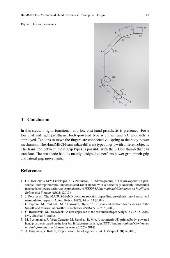
HandMECH—Mechanical Hand Prosthesis: Conceptual Design … 117
Fig. 4. Design parameters
4 Conclusion
In this study, a light, functional, and low-cost hand prosthesis is presented. For alow cost and light prosthesis, body-powered type is chosen and VC approach isemployed. Tendons to move the fingers are connected via spring to the body-powermechanism.TheHandMECHcan realize different types of gripwith different objects.The transition between these grip types is possible with the 3 DoF thumb that cantranslate. The prosthetic hand is mainly designed to perform power grip, pinch gripand lateral grip movements.
References
1. G.P.Kontoudis,M.V. Liarokapis, A.G. Zisimatos, C.I.Mavrogiannis, K.J. Kyriakopoulos,Open-source, anthropomorphic, underactuated robot hands with a selectively lockable differentialmechanism: towards affordable prostheses, in IEEE/RSJ International Conference on IntelligentRobots and Systems (IROS) (2015)
2. J. Pons et al., The MANUS-HAND dextrous robotics upper limb prosthesis: mechanical andmanipulation aspects. Auton. Robot. 16(2), 143–163 (2004)
3. C. Cipriani, M. Controzzi, M.C. Carrozza, Objectives, criteria and methods for the design of theSmartHand transradial prosthesis. Robotica 28(06), 919–927 (2009)
4. G. Roznowski, M. Drzewiecki, A new approach to the prosthetic finger design, in TCSET ’2004,Lviv-Slavsko, Ukraine.
5. M. Bustamante, R. Vega-Centeno, M. Sanchez, R. Mio, A parametric 3D-printed body-poweredhand prosthesis based on the four-bar linkagemechanism, in IEEE18th InternationalConferenceon Bioinformatics and Bioengineering (BIBE) (2018)
6. A. Buryanov, V. Kotiuk, Proportions of hand segments. Int. J. Morphol. 28(3) (2010)

Legislation, Safety and Performance:Regulatory Aspects in Wearable Robots
CO-GUIDING: Ergonomic Analysisof a Hand Guidance System for Car DoorAssembly
Erika Triviño-Tonato, Jawad Masood, Ruben P. Cibeira,and Angel Dacal-Nieto
Abstract HandGuidance is a type ofHuman-RobotCollaborationwith high interestin the manufacturing industry. In this paper, we present an ergonomic analysis of anassisted hand guidance operation of car door assembly that can also be appliedto the wearable robots. A simulated scenario and an experimental specific safetyprotocol are created. Two subjects perform a work cycle. Biomechanical data fromthe subjects and mechanical data from the robots are collected. We follow guidelinesof UNE-EN 1005–3:2002, UNE-EN 1005–5:2007 and UNE-EN ISO 8996:2005to execute risk assessment procedures. We consider the cycle time, applied force(push/pull), external load, muscle load, and workstation adaptability as key riskanalysis measures. The results show the external load is acceptable by the subjects;the applied forces on the subjects do not exceed the followed norms; arm musclesactivities (load) remains within acceptable ranges, and subject one shows better taskadaptability.
1 Introduction
Ergonomics studies the relationship between the working environment and thosewho do the work. It aims to reduce ailments and injuries arising from over-effortsat work [1]. In the automotive sector, assembly processes like collaborative doorassembly system (CDAS) are usually exposed to ergonomic risks like over-effort.
CO-GUIDING is a subproject of the European initiative COVR, which provides acommon approach to safety assessment across robotics fields and applications. TheCO-GUIDING project aims to improve safety of the assisted hand guidance CDAS.The system helps to mount side doors in the body in white (BIW) such that theoperator handles the complex trajectories and finished quality, while a robot takescare of door weight and accuracy. At CTAG, the CDAS is simulated according toautomotive standards.
E. Triviño-Tonato (B) · J. Masood · R. P. Cibeira · A. Dacal-NietoDepartment of CTAG, Centro Tecnológico de Automoción de Galicia, O Porriño, Spaine-mail: [email protected]
© The Author(s), under exclusive license to Springer Nature Switzerland AG 2022J. C. Moreno et al. (eds.), Wearable Robotics: Challenges and Trends,Biosystems & Biorobotics 27, https://doi.org/10.1007/978-3-030-69547-7_20
121
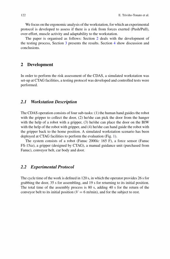
122 E. Triviño-Tonato et al.
We focus on the ergonomic analysis of the workstation, for which an experimentalprotocol is developed to assess if there is a risk from forces exerted (Push/Pull),over-effort, muscle activity and adaptability to the workstation.
The paper is organised as follows: Section 2 deals with the development ofthe testing process, Section 3 presents the results. Section 4 show discussion andconclusions.
2 Development
In order to perform the risk assessment of the CDAS, a simulated workstation wasset-up at CTAG facilities, a testing protocol was developed and controlled tests wereperformed.
2.1 Workstation Description
The CDAS operation consists of four sub-tasks: (1) the human hand guides the robotwith the gripper to collect the door, (2) he/she can pick the door from the hangerwith the help of a robot with a gripper, (3) he/she can place the door on the BIWwith the help of the robot with gripper, and (4) he/she can hand guide the robot withthe gripper back to the home position. A simulated workstation scenario has beendeployed at CTAG facilities to perform the evaluation (Fig. 1).
The system consists of a robot (Fanuc 2000ic 165 F), a force sensor (FanucFS-15ia), a gripper (designed by CTAG), a manual guidance unit (purchased fromFanuc), conveyor belt, car body and door.
2.2 Experimental Protocol
The cycle time of the work is defined in 120 s, in which the operator provides 26 s forgrabbing the door, 35 s for assembling, and 19 s for returning to its initial position.The total time of the assembly process is 80 s, adding 40 s for the return of theconveyor belt to its initial position (V = 6 m/min), and for the subject to rest.
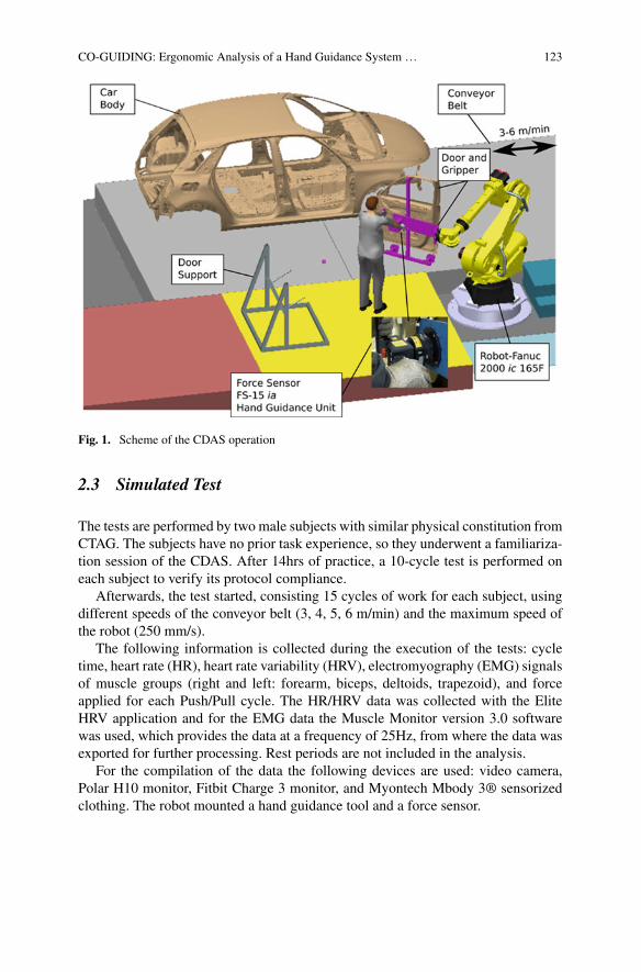
CO-GUIDING: Ergonomic Analysis of a Hand Guidance System … 123
Fig. 1. Scheme of the CDAS operation
2.3 Simulated Test
The tests are performed by two male subjects with similar physical constitution fromCTAG. The subjects have no prior task experience, so they underwent a familiariza-tion session of the CDAS. After 14hrs of practice, a 10-cycle test is performed oneach subject to verify its protocol compliance.
Afterwards, the test started, consisting 15 cycles of work for each subject, usingdifferent speeds of the conveyor belt (3, 4, 5, 6 m/min) and the maximum speed ofthe robot (250 mm/s).
The following information is collected during the execution of the tests: cycletime, heart rate (HR), heart rate variability (HRV), electromyography (EMG) signalsof muscle groups (right and left: forearm, biceps, deltoids, trapezoid), and forceapplied for each Push/Pull cycle. The HR/HRV data was collected with the EliteHRV application and for the EMG data the Muscle Monitor version 3.0 softwarewas used, which provides the data at a frequency of 25Hz, from where the data wasexported for further processing. Rest periods are not included in the analysis.
For the compilation of the data the following devices are used: video camera,Polar H10 monitor, Fitbit Charge 3 monitor, and Myontech Mbody 3® sensorizedclothing. The robot mounted a hand guidance tool and a force sensor.
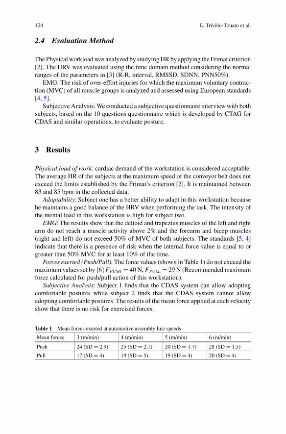
124 E. Triviño-Tonato et al.
2.4 Evaluation Method
ThePhysicalworkloadwas analyzed by studyingHRby applying the Frimat criterion[2]. The HRV was evaluated using the time domain method considering the normalranges of the parameters in [3] (R-R, interval, RMSSD, SDNN, PNN50%).
EMG: The risk of over-effort injuries for which the maximum voluntary contrac-tion (MVC) of all muscle groups is analyzed and assessed using European standards[4, 5].
Subjective Analysis:We conducted a subjective questionnaire interviewwith bothsubjects, based on the 10 questions questionnaire which is developed by CTAG forCDAS and similar operations, to evaluate posture.
3 Results
Physical load of work: cardiac demand of the workstation is considered acceptable.The average HR of the subjects at the maximum speed of the conveyor belt does notexceed the limits established by the Frimat’s criterion [2]. It is maintained between83 and 85 bpm in the collected data.
Adaptability: Subject one has a better ability to adapt in this workstation becausehe maintains a good balance of the HRV when performing the task. The intensity ofthe mental load in this workstation is high for subject two.
EMG: The results show that the deltoid and trapezius muscles of the left and rightarm do not reach a muscle activity above 2% and the forearm and bicep muscles(right and left) do not exceed 50% of MVC of both subjects. The standards [5, 4]indicate that there is a presence of risk when the internal force value is equal to orgreater than 50% MVC for at least 10% of the time.
Forces exerted (Push/Pull): The force values (shown in Table 1) do not exceed themaximum values set by [6] FPUSH = 40 N, FPULL = 29 N (Recommended maximumforce calculated for push/pull action of this workstation).
Subjective Analysis: Subject 1 finds that the CDAS system can allow adoptingcomfortable postures while subject 2 finds that the CDAS system cannot allowadopting comfortable postures. The results of the mean force applied at each velocityshow that there is no risk for exercised forces.
Table 1 Mean forces exerted at automotive assembly line speeds
Mean forces 3 (m/min) 4 (m/min) 5 (m/min) 6 (m/min)
Push 24 (SD = 2.9) 25 (SD = 2.1) 20 (SD = 1.7) 28 (SD = 1.5)
Pull 17 (SD = 4) 19 (SD = 5) 19 (SD = 4) 20 (SD = 4)
CO-GUIDING: Ergonomic Analysis of a Hand Guidance System … 125
4 Conclusions and Discussion
This study facilitates the validation of the developed protocol (according to the ISO–12100 regulations, and the UNE-EN Safety of machinery—Ergonomics regulations)that can help the community of collaborative robots to ensure safety and evaluatingwearable robots.
HR and HRV signals show that the physical workload is acceptable regardingcardiac demand for the subjects. Subject one is better adapted to the workstationthan subject two.
From the EMG records, medium-low activation values have been obtained for allmuscles analysed; the RMS value is in ranges less than 2 µV for subject one and forsubject two are found in values less than 7 µV, except in the left forearm (9.55 µV)and left biceps (8.85 µV). None of the upper limb muscles is found fatigued. Thedistribution of muscle activity in the forearm and right biceps at all velocity levelsof the conveyor belt is found at an average of 14% and the rest of the muscles onmean not exceeding 13%. Applied force (Push/Pull) results exhibit a small increasein force, observed as the speed of the conveyor increases.
From the subjective questionnaire analysis, we conclude that both subjects ratethe CDAS and the use-case as low physical demanding. The tests of this study areperformed for 2 h with less than 120 s cycle time, which does not guarantee theresults of a full day of work. In addition, we perform tests on only two subjects thatis a low number for conclusive evidence. We recommend larger pilot trials based onthe presented protocol to improve the fidelity of such systems.
Acknowledgement The authors want to thank the project COVR (Being safe around collaborativeand versatile robots in shared spaces), which has received funding from the European Union’sHorizon 2020 research and innovation programme under grant agreement No 779966, and supportsthis work.
References
1. H. Hendrick, Determining the cost-benefits of ergonomics projects and factors that lead to theirsuccess. Appl. Ergon. 34(5), 419–427 (2003)
2. GÓMEZ, Mª Dolores Solé. NTP 295: Assessment of physical load by monitoring heart rate.INSST. 1, 1–6 (1991)
3. D. Nunan, et al., A quantitative systematic review of normal values for short-term heart ratevariability in healthy adults. Pacing Clinical Electrophysiol 33(11), 1407–1417 (2010)
4. ISO, ISO 11228-3. Ergonomics—manual handling—Part 3: handling of low loads at highfrequency (AENOR, Madrid, 2007)
5. UNE-EN1005-5, Safety ofmachinery—Human physical performance—Part 5: Risk assessmentfor repetitive handling at high frequency (AENOR, Madrid)
6. UNE-EN 1005–3, + A1, 2009 Safety of machinery—Human physical performance—Part 3:recommended force limits for machinery operation. (AENOR, Madrid, 2002)
ATEX Certification for ALDAKExoskeleton in Petrochemical Industry
Ane Intxaurburu, Iñaki Díaz, Juan Martín, and Xabier Justo
Abstract Most certification processes require the complex and tedious analysis ofmultiple normative and references to understand and apply the appropriate methodsto get the desired mark. This work intends to ease the way for ATEX certification ofexoskeletons, especially relevant formining and petrochemical industries. GOGOA’sALDAK exoskeleton aims to become the first ATEX certified exoskeleton and thiswork reviews the process and steps to follow.
1 Introduction
Musculoskeletal disorders (MSDs) were the leading cause of disability in four ofthe six WHO regions in 2017. While the prevalence of musculoskeletal conditionsincreases with age, younger people are also affected, often during their peak income-earning years [1].
Industrial and service companies are involved in the challenge of improving theoccupational safety andhealth of their employees, facilitating theirwork and reducingmusculoskeletal injuries, but they have difficulties in finding the ideal solution thatrationally inclines them to its implementation. Technological solutions based onexoskeletons can help reinforce these ergonomic aspects for the benefit of theworker,the company and society.
A. Intxaurburu (B) · J. MartínGOGOA Mobility Robots S.L, Abadiano, Spaine-mail: [email protected]
J. Martíne-mail: [email protected]
I. Díaz · X. JustoSmart Systems for Industry 4.0 Group of CEIT-Basque Research and Technology Alliance(BRTA) and Universidad de Navarra, San Sebastián, Spaine-mail: [email protected]
X. Justoe-mail: [email protected]
© The Author(s), under exclusive license to Springer Nature Switzerland AG 2022J. C. Moreno et al. (eds.), Wearable Robotics: Challenges and Trends,Biosystems & Biorobotics 27, https://doi.org/10.1007/978-3-030-69547-7_21
127
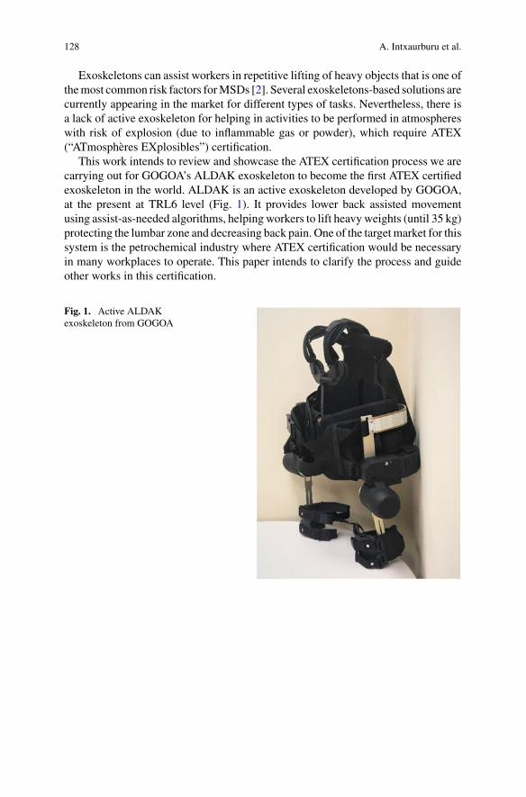
128 A. Intxaurburu et al.
Exoskeletons can assist workers in repetitive lifting of heavy objects that is one ofthemost common risk factors forMSDs [2]. Several exoskeletons-based solutions arecurrently appearing in the market for different types of tasks. Nevertheless, there isa lack of active exoskeleton for helping in activities to be performed in atmosphereswith risk of explosion (due to inflammable gas or powder), which require ATEX(“ATmosphères EXplosibles”) certification.
This work intends to review and showcase the ATEX certification process we arecarrying out for GOGOA’s ALDAK exoskeleton to become the first ATEX certifiedexoskeleton in the world. ALDAK is an active exoskeleton developed by GOGOA,at the present at TRL6 level (Fig. 1). It provides lower back assisted movementusing assist-as-needed algorithms, helping workers to lift heavy weights (until 35 kg)protecting the lumbar zone and decreasing back pain. One of the targetmarket for thissystem is the petrochemical industry where ATEX certification would be necessaryin many workplaces to operate. This paper intends to clarify the process and guideother works in this certification.
Fig. 1. Active ALDAKexoskeleton from GOGOA
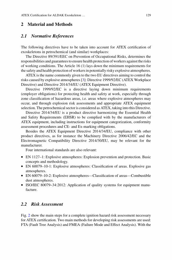
ATEX Certification for ALDAK Exoskeleton … 129
2 Material and Methods
2.1 Normative References
The following directives have to be taken into account for ATEX certification ofexoskeletons in petrochemical (and similar) workplaces:
The Directive 89/391/EEC on Prevention of Occupational Risks, determines theresponsibilities and guarantees to ensure health protection ofworkers against the risksof working conditions. The Article 16 (1) lays down the minimum requirements forthe safety and health protection ofworkers in potentially risky explosive atmospheres.
ATEX is the name commonly given to the two EU directives aiming to control therisks caused by explosive atmospheres [3]: Directive 1999/92/EC (ATEXWorkplaceDirective) and Directive 2014/34/EU (ATEX Equipment Directive).
Directive 1999/92/EC is a directive laying down minimum requirements(employer obligations) for protecting health and safety at work, especially throughzone classification of hazardous areas, i.e. areas where explosive atmospheres mayoccur, and through explosion risk assessments and appropriate ATEX equipmentselection. The petrochemical sector is considered asATEX, taking into this Directive.
Directive 2014/34/EU is a product directive harmonizing the Essential Healthand Safety Requirements (EHSR) to be complied with by the manufacturers ofATEX equipment, including instructions for equipment categorization, conformityassessment procedures and CE- and Ex-marking obligations.
Besides the ATEX Equipment Directive 2014/34/EU, compliance with otherproduct directives, as for instance the Machinery Directive 2006/42/EC and theElectromagnetic Compatibility Directive 2014/30/EU, may be relevant for themanufacturer.
Four international standards are also relevant:
• EN 1127–1: Explosive atmospheres: Explosion prevention and protection. Basicconcepts and methodology.
• EN 60079–10-1: Explosive atmospheres: Classification of areas. Explosive gasatmospheres.
• EN 60079–10-2: Explosive atmospheres—Classification of areas—Combustibledust atmospheres.
• ISO/IEC 80079–34:2012: Application of quality systems for equipment manu-facture.
2.2 Risk Assessment
Fig. 2 show the main steps for a complete ignition hazard risk assessment necessaryfor ATEX certification. Twomain methods for developing risk assessments are used:FTA (Fault Tree Analysis) and FMEA (Failure Mode and Effect Analysis). With the
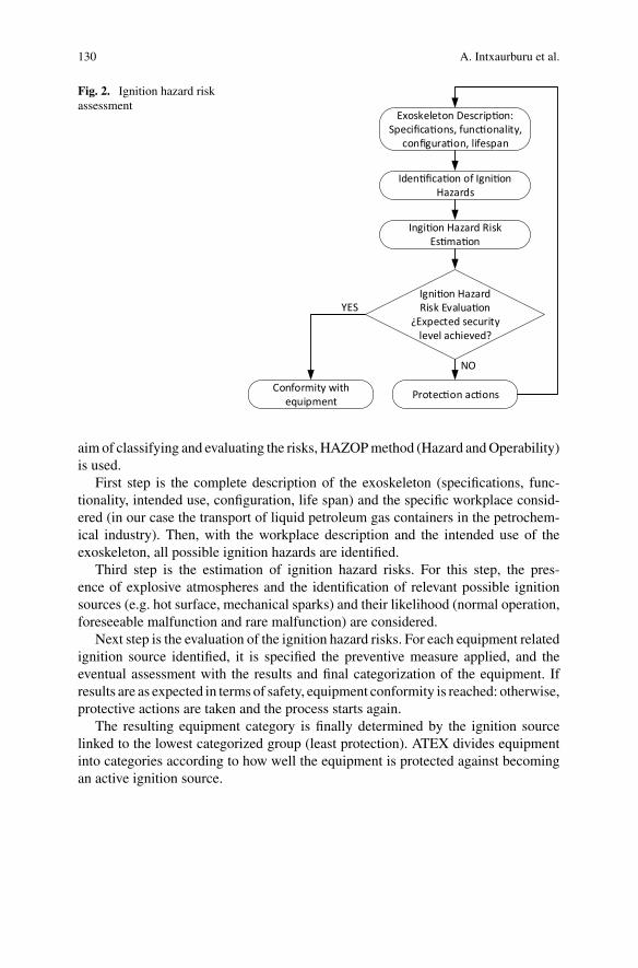
130 A. Intxaurburu et al.
Fig. 2. Ignition hazard riskassessment
Exoskeleton Descrip on:Specifica ons, func onality,
configura on, lifespan
Iden fica on of Igni on Hazards
Ingi on Hazard Risk Es ma on
Igni on HazardRisk Evalua on
¿Expected security level achieved?
Protec on ac onsConformity with equipment
YES
NO
aim of classifying and evaluating the risks, HAZOPmethod (Hazard andOperability)is used.
First step is the complete description of the exoskeleton (specifications, func-tionality, intended use, configuration, life span) and the specific workplace consid-ered (in our case the transport of liquid petroleum gas containers in the petrochem-ical industry). Then, with the workplace description and the intended use of theexoskeleton, all possible ignition hazards are identified.
Third step is the estimation of ignition hazard risks. For this step, the pres-ence of explosive atmospheres and the identification of relevant possible ignitionsources (e.g. hot surface, mechanical sparks) and their likelihood (normal operation,foreseeable malfunction and rare malfunction) are considered.
Next step is the evaluation of the ignition hazard risks. For each equipment relatedignition source identified, it is specified the preventive measure applied, and theeventual assessment with the results and final categorization of the equipment. Ifresults are as expected in terms of safety, equipment conformity is reached: otherwise,protective actions are taken and the process starts again.
The resulting equipment category is finally determined by the ignition sourcelinked to the lowest categorized group (least protection). ATEX divides equipmentinto categories according to how well the equipment is protected against becomingan active ignition source.
ATEX Certification for ALDAK Exoskeleton … 131
2.3 Technical Documentation and Marking
This certification process must be undertaken by an ATEX Notified Body. Technicaldocumentation requirements are:
• A general description of the equipment.• The design and manufacturing drawings and layouts/schemes, and description of
operation.• List of harmonized standards applied (or solutions adopted where standards have
not been applied).• Results of calculations, examinations and test reports.• The ignition hazard assessment report.• Certificates and other documents issued by a Notified Body (including relevant
documentation enabling the conformity of the product with the requirements ofthe directive to be assessed).
The certification process includes testing and assessment of the product, with anATEXcertificate and report being issued for conforming product. Equipment, protec-tive systems and devices must be accompanied by an EU Declaration of Confor-mity (and bearing the CE-marking affixed) with reference to the ATEX EquipmentDirective 2014/34/EU.
3 Conclusion
This works reviews main steps for carrying out an ignition hazard risk assessmentfor ATEX certification of exoskeletons, as well as main directives and standards tofollow and technical documentation andmarking description. Future work will detailthe risk assessment and evaluation carried out for ALDAK exoskeleton to get theATEX certification to operate in the petrochemical industry.
Acknowlegments This work has been supported by the European Union’s Horizon 2020 researchand innovation programme under COVR project, gran agreement No. 779966.
References
1. S.L. James et al., Global, regional, and national incidence, prevalence, and years lived withdisability for 354 diseases and injuries for 195 countries and territories, 1990–2017: a systematicanalysis for the global burden of disease study 2017. Lancet 392(10159), 1789–1858 (2018)
2. Eurofund, Sixth European working conditions survey, overview report, Publications Office ofthe European Union (Technical Report, 2016)
3. T. Jespen, ATEX—explosive atmospheres, risk assessment, control and compliance (SpringerSeries in Reliability Engineering, 2016)
Acceptance of Exoskeletons:Questionnaire Survey
Liên Wioland, J. Jean-Jacques, Atain-Kouadio, Latifa Debay,and Hugo Bréard
Abstract The introduction of exoskeletons in companies, like any new technology,is a major change. In this context the specific question of the acceptance of thesedevices by workers is addressed. To this end, a questionnaire was specifically devel-oped and administered to current and former exoskeleton users. The results presentedprovide information on the quality of the operator-exoskeleton interaction, andidentify blocking and/or facilitating points for the use of these devices.
1 Introduction
Exoskelettons are presented as systems that reduce physical demands, assist theoperator [1] or improve physical performance [2]. Companies consider them asdevices that could limit musculoskeletal disorders. Thus, they test themwith workerswho have very contrasting reactions. Some refuse to test them, others use them andthen reject them, while some integrate them into regular use. Therefore, even if anexoskeleton may appear simple to use and have potential, users will not necessarilyaccept it. The issue of acceptance is a challenge for both, designers and compa-nies. The objective of this study is to identify the determinants of acceptance andrejection of exoskeletons by users. The best known model to explain user intentis the Davis Technology Acceptance Model (TAM) [3]. He posits that intention touse is partly preceded by the “social normative factor” (normative beliefs and thejudgment of others). Then he incorporates two major concepts into his model: “per-ceived usefulness” (the degree to which an individual believes that using a systemimproves work performance) and “perceived ease of use” (the degree to which anindividual believes that using the system requires no effort). Venkatesh [4] merges
L. Wioland (B) · Atain-Kouadio · L. DebayDepartment of Working Life, French National Research and Safety Institute for the Prevention ofOccupational Accidents and Diseases (INRS), Paris, Francee-mail: [email protected]
J. Jean-Jacques · H. BréardParis-Nanterre University, Master Workplace Psychology, Ergonomics and Orientation, Paris,France
© The Author(s), under exclusive license to Springer Nature Switzerland AG 2022J. C. Moreno et al. (eds.), Wearable Robotics: Challenges and Trends,Biosystems & Biorobotics 27, https://doi.org/10.1007/978-3-030-69547-7_22
133
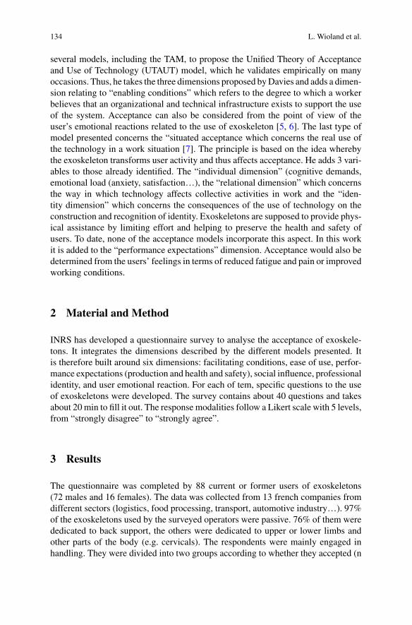
134 L. Wioland et al.
several models, including the TAM, to propose the Unified Theory of Acceptanceand Use of Technology (UTAUT) model, which he validates empirically on manyoccasions. Thus, he takes the three dimensions proposed byDavies and adds a dimen-sion relating to “enabling conditions” which refers to the degree to which a workerbelieves that an organizational and technical infrastructure exists to support the useof the system. Acceptance can also be considered from the point of view of theuser’s emotional reactions related to the use of exoskeleton [5, 6]. The last type ofmodel presented concerns the “situated acceptance which concerns the real use ofthe technology in a work situation [7]. The principle is based on the idea wherebythe exoskeleton transforms user activity and thus affects acceptance. He adds 3 vari-ables to those already identified. The “individual dimension” (cognitive demands,emotional load (anxiety, satisfaction…), the “relational dimension” which concernsthe way in which technology affects collective activities in work and the “iden-tity dimension” which concerns the consequences of the use of technology on theconstruction and recognition of identity. Exoskeletons are supposed to provide phys-ical assistance by limiting effort and helping to preserve the health and safety ofusers. To date, none of the acceptance models incorporate this aspect. In this workit is added to the “performance expectations” dimension. Acceptance would also bedetermined from the users’ feelings in terms of reduced fatigue and pain or improvedworking conditions.
2 Material and Method
INRS has developed a questionnaire survey to analyse the acceptance of exoskele-tons. It integrates the dimensions described by the different models presented. Itis therefore built around six dimensions: facilitating conditions, ease of use, perfor-mance expectations (production and health and safety), social influence, professionalidentity, and user emotional reaction. For each of tem, specific questions to the useof exoskeletons were developed. The survey contains about 40 questions and takesabout 20 min to fill it out. The response modalities follow a Likert scale with 5 levels,from “strongly disagree” to “strongly agree”.
3 Results
The questionnaire was completed by 88 current or former users of exoskeletons(72 males and 16 females). The data was collected from 13 french companies fromdifferent sectors (logistics, food processing, transport, automotive industry…). 97%of the exoskeletons used by the surveyed operators were passive. 76% of them werededicated to back support, the others were dedicated to upper or lower limbs andother parts of the body (e.g. cervicals). The respondents were mainly engaged inhandling. They were divided into two groups according to whether they accepted (n
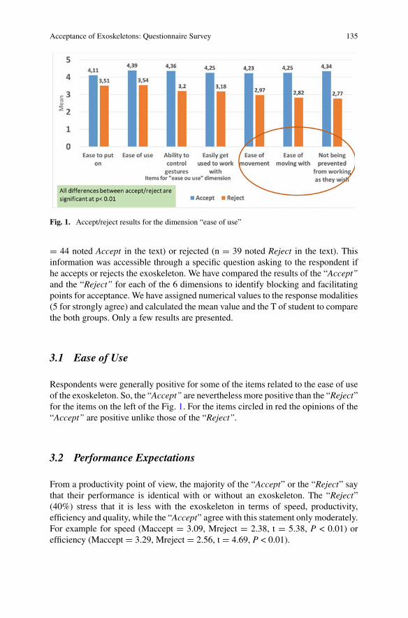
Acceptance of Exoskeletons: Questionnaire Survey 135
Fig. 1. Accept/reject results for the dimension “ease of use”
= 44 noted Accept in the text) or rejected (n = 39 noted Reject in the text). Thisinformation was accessible through a specific question asking to the respondent ifhe accepts or rejects the exoskeleton. We have compared the results of the “Accept”and the “Reject” for each of the 6 dimensions to identify blocking and facilitatingpoints for acceptance. We have assigned numerical values to the response modalities(5 for strongly agree) and calculated the mean value and the T of student to comparethe both groups. Only a few results are presented.
3.1 Ease of Use
Respondents were generally positive for some of the items related to the ease of useof the exoskeleton. So, the “Accept” are nevertheless more positive than the “Reject”for the items on the left of the Fig. 1. For the items circled in red the opinions of the“Accept” are positive unlike those of the “Reject”.
3.2 Performance Expectations
From a productivity point of view, the majority of the “Accept” or the “Reject” saythat their performance is identical with or without an exoskeleton. The “Reject”(40%) stress that it is less with the exoskeleton in terms of speed, productivity,efficiency and quality, while the “Accept” agree with this statement only moderately.For example for speed (Maccept = 3.09, Mreject = 2.38, t = 5.38, P < 0.01) orefficiency (Maccept = 3.29, Mreject = 2.56, t = 4.69, P < 0.01).
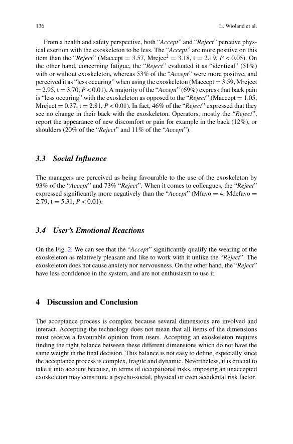
136 L. Wioland et al.
From a health and safety perspective, both “Accept” and “Reject” perceive phys-ical exertion with the exoskeleton to be less. The “Accept” are more positive on thisitem than the “Reject” (Maccept = 3.57, Mrejec2 = 3.18, t = 2.19, P < 0.05). Onthe other hand, concerning fatigue, the “Reject” evaluated it as “identical” (51%)with or without exoskeleton, whereas 53% of the “Accept” were more positive, andperceived it as “less occuring” when using the exoskeleton (Maccept= 3.59,Mreject= 2.95, t= 3.70, P < 0.01). A majority of the “Accept” (69%) express that back painis “less occuring” with the exoskeleton as opposed to the “Reject” (Maccept= 1.05,Mreject= 0.37, t= 2.81, P < 0.01). In fact, 46% of the “Reject” expressed that theysee no change in their back with the exoskeleton. Operators, mostly the “Reject”,report the appearance of new discomfort or pain for example in the back (12%), orshoulders (20% of the “Reject” and 11% of the “Accept”).
3.3 Social Influence
The managers are perceived as being favourable to the use of the exoskeleton by93% of the “Accept” and 73% “Reject”. When it comes to colleagues, the “Reject”expressed significantly more negatively than the “Accept” (Mfavo = 4, Mdefavo =2.79, t = 5.31, P < 0.01).
3.4 User’s Emotional Reactions
On the Fig. 2. We can see that the “Accept” significantly qualify the wearing of theexoskeleton as relatively pleasant and like to work with it unlike the “Reject”. Theexoskeleton does not cause anxiety nor nervousness. On the other hand, the “Reject”have less confidence in the system, and are not enthusiasm to use it.
4 Discussion and Conclusion
The acceptance process is complex because several dimensions are involved andinteract. Accepting the technology does not mean that all items of the dimensionsmust receive a favourable opinion from users. Accepting an exoskeleton requiresfinding the right balance between these different dimensions which do not have thesame weight in the final decision. This balance is not easy to define, especially sincethe acceptance process is complex, fragile and dynamic. Nevertheless, it is crucial totake it into account because, in terms of occupational risks, imposing an unacceptedexoskeleton may constitute a psycho-social, physical or even accidental risk factor.
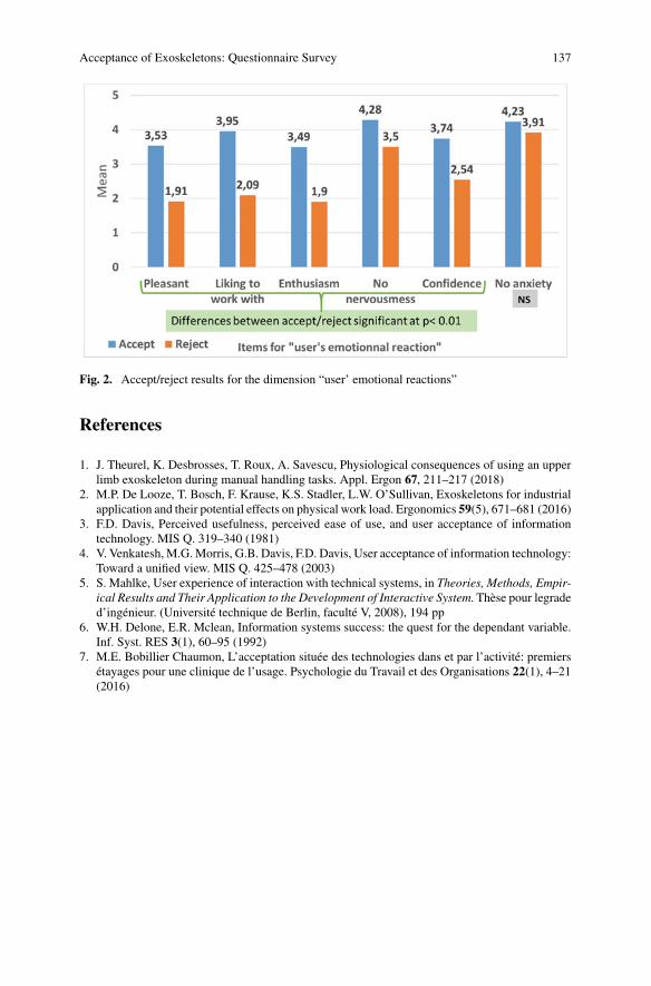
Acceptance of Exoskeletons: Questionnaire Survey 137
Fig. 2. Accept/reject results for the dimension “user’ emotional reactions”
References
1. J. Theurel, K. Desbrosses, T. Roux, A. Savescu, Physiological consequences of using an upperlimb exoskeleton during manual handling tasks. Appl. Ergon 67, 211–217 (2018)
2. M.P. De Looze, T. Bosch, F. Krause, K.S. Stadler, L.W. O’Sullivan, Exoskeletons for industrialapplication and their potential effects on physical work load. Ergonomics 59(5), 671–681 (2016)
3. F.D. Davis, Perceived usefulness, perceived ease of use, and user acceptance of informationtechnology. MIS Q. 319–340 (1981)
4. V. Venkatesh, M.G.Morris, G.B. Davis, F.D. Davis, User acceptance of information technology:Toward a unified view. MIS Q. 425–478 (2003)
5. S. Mahlke, User experience of interaction with technical systems, in Theories, Methods, Empir-ical Results and Their Application to the Development of Interactive System. Thèse pour legraded’ingénieur. (Université technique de Berlin, faculté V, 2008), 194 pp
6. W.H. Delone, E.R. Mclean, Information systems success: the quest for the dependant variable.Inf. Syst. RES 3(1), 60–95 (1992)
7. M.E. Bobillier Chaumon, L’acceptation située des technologies dans et par l’activité: premiersétayages pour une clinique de l’usage. Psychologie du Travail et des Organisations 22(1), 4–21(2016)
Perceived Exertion DuringRobot-Assisted Gait After Stroke
Nina Lefeber, Emma De Keersmaecker, Eric Kerckhofs, and Eva Swinnen
Abstract Thepresent study investigated the level of perceived exertion during robot-assisted walking in non-ambulatory stroke survivors. In addition, we studied therelationship between the user’s subjective level of perceived exertion and objectivemeasures of exertion (i.e. oxygen consumption and heart rate). Our results suggestthat stroke survivors perceive fully assisted Lokomat walking as extremely lightto very light and fully assisted Ekso GT walking as very light to somewhat hard.Weak positive correlations were found between subjective and objective measuresof exertion.
1 Introduction
Worldwide, stroke is a prevalent health issue. Each year, roughly 15 million peopleexperience a stroke. Initially after stroke, half of the stroke survivors is unable towalkand around 12% needs assistance of a person to walk [1]. As a result, stroke survivorsspend the majority of their rehabilitation time on practicing walking (25–45%) [2].
To induce neuroplasticity, gait rehabilitation requires sufficient training intensity.To increase the intensity and volume of gait rehabilitation, two types of lower limbrobotic exoskeletons have been introduced: (1) static (or treadmill-based) exoskele-tons, such as the Lokomat (Hocoma), and (2) dynamic (or wearable) exoskeletons,such as the Ekso GT (Ekso Bionics) [3]. However, few studies have evaluated thetraining intensity of robot-assisted gait rehabilitation after stroke [4].
The aims of this study were: (1) to investigate how physically exerting strokesurvivors perceive static and dynamic exoskeleton training and (2) to investigate if theuser’s subjective level of exertion correlates with objective physiological measuresof exertion.
N. Lefeber (B) · E. De Keersmaecker · E. Kerckhofs · E. SwinnenRehabilitation Research Group, Vrije Universiteit Brussel, Brussels, Belgiume-mail: [email protected]
© The Author(s), under exclusive license to Springer Nature Switzerland AG 2022J. C. Moreno et al. (eds.), Wearable Robotics: Challenges and Trends,Biosystems & Biorobotics 27, https://doi.org/10.1007/978-3-030-69547-7_23
139
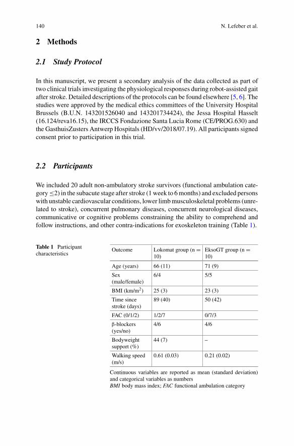
140 N. Lefeber et al.
2 Methods
2.1 Study Protocol
In this manuscript, we present a secondary analysis of the data collected as part oftwo clinical trials investigating the physiological responses during robot-assisted gaitafter stroke. Detailed descriptions of the protocols can be found elsewhere [5, 6]. Thestudies were approved by the medical ethics committees of the University HospitalBrussels (B.U.N. 143201526040 and 143201734424), the Jessa Hospital Hasselt(16.124/reva16.15), the IRCCS Fondazione Santa Lucia Rome (CE/PROG.630) andthe GasthuisZusters Antwerp Hospitals (HD/vv/2018/07.19). All participants signedconsent prior to participation in this trial.
2.2 Participants
We included 20 adult non-ambulatory stroke survivors (functional ambulation cate-gory≤2) in the subacute stage after stroke (1week to 6months) and excluded personswith unstable cardiovascular conditions, lower limbmusculoskeletal problems (unre-lated to stroke), concurrent pulmonary diseases, concurrent neurological diseases,communicative or cognitive problems constraining the ability to comprehend andfollow instructions, and other contra-indications for exoskeleton training (Table 1).
Table 1 Participantcharacteristics
Outcome Lokomat group (n =10)
EksoGT group (n =10)
Age (years) 66 (11) 71 (9)
Sex(male/female)
6/4 5/5
BMI (km/m2) 25 (3) 23 (3)
Time sincestroke (days)
89 (40) 50 (42)
FAC (0/1/2) 1/2/7 0/7/3
β-blockers(yes/no)
4/6 4/6
Bodyweightsupport (%)
44 (7) –
Walking speed(m/s)
0.61 (0.03) 0.21 (0.02)
Continuous variables are reported as mean (standard deviation)and categorical variables as numbersBMI body mass index; FAC functional ambulation category
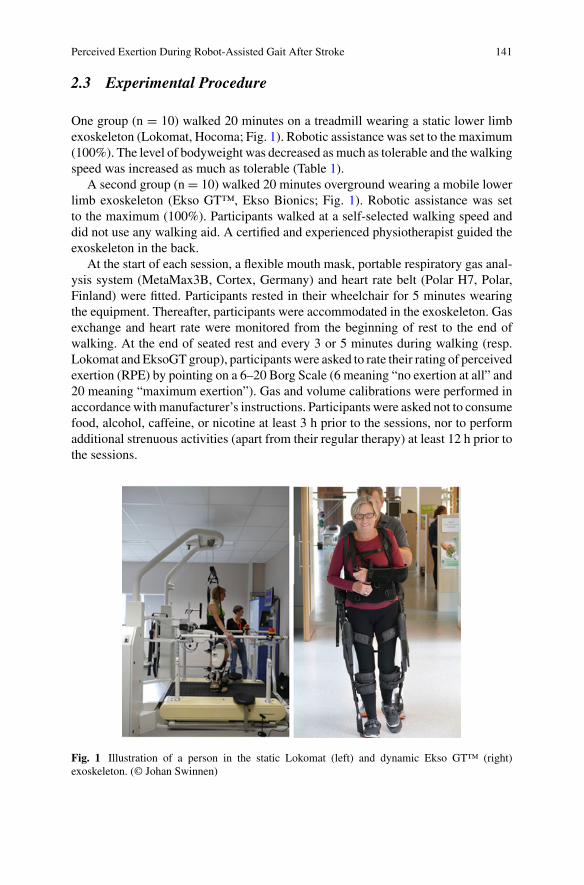
Perceived Exertion During Robot-Assisted Gait After Stroke 141
2.3 Experimental Procedure
One group (n = 10) walked 20 minutes on a treadmill wearing a static lower limbexoskeleton (Lokomat, Hocoma; Fig. 1). Robotic assistance was set to the maximum(100%). The level of bodyweight was decreased asmuch as tolerable and the walkingspeed was increased as much as tolerable (Table 1).
A second group (n = 10) walked 20 minutes overground wearing a mobile lowerlimb exoskeleton (Ekso GT™, Ekso Bionics; Fig. 1). Robotic assistance was setto the maximum (100%). Participants walked at a self-selected walking speed anddid not use any walking aid. A certified and experienced physiotherapist guided theexoskeleton in the back.
At the start of each session, a flexible mouth mask, portable respiratory gas anal-ysis system (MetaMax3B, Cortex, Germany) and heart rate belt (Polar H7, Polar,Finland) were fitted. Participants rested in their wheelchair for 5 minutes wearingthe equipment. Thereafter, participants were accommodated in the exoskeleton. Gasexchange and heart rate were monitored from the beginning of rest to the end ofwalking. At the end of seated rest and every 3 or 5 minutes during walking (resp.Lokomat and EksoGT group), participants were asked to rate their rating of perceivedexertion (RPE) by pointing on a 6–20 Borg Scale (6 meaning “no exertion at all” and20 meaning “maximum exertion”). Gas and volume calibrations were performed inaccordance withmanufacturer’s instructions. Participants were asked not to consumefood, alcohol, caffeine, or nicotine at least 3 h prior to the sessions, nor to performadditional strenuous activities (apart from their regular therapy) at least 12 h prior tothe sessions.
Fig. 1 Illustration of a person in the static Lokomat (left) and dynamic Ekso GT™ (right)exoskeleton. (© Johan Swinnen)
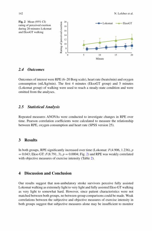
142 N. Lefeber et al.
Fig. 2 Mean (95% CI)rating of perceived exertionduring 20-minutes Lokomatand EksoGT walking
6
8
10
12
14
16
18
20
0 5 10 15 20
Rat
ing
of p
erce
ived
exe
rtion
Minute
Lokomat EksoGT
2.4 Outcomes
Outcomes of interest were RPE (6–20 Borg scale), heart rate (beats/min) and oxygenconsumption (mL/kg/min). The first 4 minutes (EksoGT group) and 5 minutes(Lokomat group) of walking were used to reach a steady-state condition and wereomitted from the analyses.
2.5 Statistical Analysis
Repeated measures ANOVAs were conducted to investigate changes in RPE overtime. Pearson correlation coefficients were calculated to measure the relationshipbetween RPE, oxygen consumption and heart rate (SPSS version 25).
3 Results
In both groups, RPE significantly increased over time (Lokomat: F(4.906, 1.236), p= 0.043; Ekso GT: F(8.791, 3), p = 0.0004; Fig. 2) and RPE was weakly correlatedwith objective measures of exercise intensity (Table 2).
4 Discussion and Conclusion
Our results suggest that non-ambulatory stroke survivors perceive fully assistedLokomat walking as extremely light to very light and fully assisted Ekso GTwalkingas very light to somewhat hard. However, since patient characteristics were notmatched between both groups, no between-group comparisons could be made.Weakcorrelations between the subjective and objective measures of exercise intensity inboth groups suggest that subjective measures alone may be insufficient to monitor
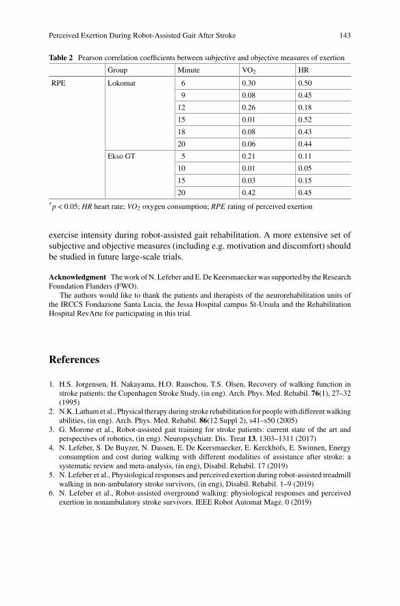
Perceived Exertion During Robot-Assisted Gait After Stroke 143
Table 2 Pearson correlation coefficients between subjective and objective measures of exertion
Group Minute VO2 HR
RPE Lokomat 6 0.30 0.50
9 0.08 0.45
12 0.26 0.18
15 0.01 0.52
18 0.08 0.43
20 0.06 0.44
Ekso GT 5 0.21 0.11
10 0.01 0.05
15 0.03 0.15
20 0.42 0.45
*p < 0.05; HR heart rate; VO2 oxygen consumption; RPE rating of perceived exertion
exercise intensity during robot-assisted gait rehabilitation. A more extensive set ofsubjective and objective measures (including e.g. motivation and discomfort) shouldbe studied in future large-scale trials.
Acknowledgment Thework ofN. Lefeber andE.DeKeersmaeckerwas supported by theResearchFoundation Flanders (FWO).
The authors would like to thank the patients and therapists of the neurorehabilitation units ofthe IRCCS Fondazione Santa Lucia, the Jessa Hospital campus St-Ursula and the RehabilitationHospital RevArte for participating in this trial.
References
1. H.S. Jorgensen, H. Nakayama, H.O. Raaschou, T.S. Olsen, Recovery of walking function instroke patients: the Copenhagen Stroke Study, (in eng). Arch. Phys. Med. Rehabil. 76(1), 27–32(1995)
2. N.K.Lathamet al., Physical therapyduring stroke rehabilitation for peoplewith differentwalkingabilities, (in eng). Arch. Phys. Med. Rehabil. 86(12 Suppl 2), s41–s50 (2005)
3. G. Morone et al., Robot-assisted gait training for stroke patients: current state of the art andperspectives of robotics, (in eng). Neuropsychiatr. Dis. Treat 13, 1303–1311 (2017)
4. N. Lefeber, S. De Buyzer, N. Dassen, E. De Keersmaecker, E. Kerckhofs, E. Swinnen, Energyconsumption and cost during walking with different modalities of assistance after stroke: asystematic review and meta-analysis, (in eng), Disabil. Rehabil. 17 (2019)
5. N. Lefeber et al., Physiological responses and perceived exertion during robot-assisted treadmillwalking in non-ambulatory stroke survivors, (in eng), Disabil. Rehabil. 1–9 (2019)
6. N. Lefeber et al., Robot-assisted overground walking: physiological responses and perceivedexertion in nonambulatory stroke survivors. IEEE Robot Automat Magz. 0 (2019)
Testing Safety of Lower LimbsExoskeletons: Current Regulatory Gaps
Stefano Massardi, David Pinto-Fernandez, Jan F.Veneman,and Diego Torricelli
Abstract Exoskeletons are a growing technology that is increasingly being studiedand researched in various application domains. However, new technologies must fitinto current regulations, which update more slowly than market needs. This paperanalyses themain regulations and standards inwhich exoskeletons canfit, underliningthe gaps and barriers that still exist and may hinder the smooth introduction ofexoskeleton technology in the market.
1 Introduction
Exoskeletons may be used in a wide range of applications, spanning frommilitary toindustrial use, personal care, and medical applications. Exoskeletons’ range of appli-cability is expanding with an increasing number of devices present on the market [1].Aging is associated with increasing mobility impairments, making the demand forrehabilitation and assistive devices growing every year [2]. An important challengeremains to have a clear unambiguous procedure for certification (CE-mark) of suchproducts. Both development and certification require the assessment of device perfor-mance and safety. Nevertheless, the literature on this topic is scarce [3]; protocols orstandards to validate exoskeletons are still limited. In recent years, several clinicalstudies into exoskeletons and their use have been performed, but researchers usuallyuse own protocols to evaluate the benefits and assess performances, often withouttaking into account the adverse events the user might experience. This paper aims
S. Massardi (B) · D. Pinto-FernandezNeural Rehabilitation Group of the Spanish National Research Council (CSIC), Madrid, Spain
D. Pinto-Fernandeze-mail: [email protected]
J. F.VenemanHocoma AG, Volketswil, Switzerland
D. TorricelliBioengineering Group of the Spanish National Research Council (CSIC), Madrid, Spaine-mail: [email protected]
© The Author(s), under exclusive license to Springer Nature Switzerland AG 2022J. C. Moreno et al. (eds.), Wearable Robotics: Challenges and Trends,Biosystems & Biorobotics 27, https://doi.org/10.1007/978-3-030-69547-7_24
145
146 S. Massardi et al.
to clarify the current state of the art regarding applicable standards and standardsdevelopment.
2 Legislations
2.1 EU Directives and Regulations
European legislation consists of directives and regulations. Some of them apply toexoskeletons such as the Electromagnetic Compatibility Directive 2014/30/EU [4],the LowVoltage Directive 2014/35/EU [5] and theMachinery Directive 2006/42/EC[6]. Additionally, in 2017 the new Medical Device Regulation (MDR) 2017/745 [7]came into force, whose final implementation in May 2021 will replace the MedicalDevice directive (MDD) 93/42/EC. Article 1.3 in MDR states “devices with both amedical and a non-medical intended purpose shall fulfill the requirements applicableto devices cumulatively with an intended medical purpose and those applicable todevices without an intendedmedical purpose” arising questions regarding the bound-aries between different fields where new exoskeleton technologies may apply. Fromthis statement, an exoskeleton shall apply the MDR independently from its medicalor non-medical purpose, if it reasonably can be expected to be used for medicalpurposes, making the intended purpose declared by the manufacturer playing a keyrole in the classification. Due to this, a lack of proper terminology and specific regu-lation may cause uncertainty about the practical application of the current legislation[8]. Annex I of MDR describes the general safety and performance requirementsa device shall meet, while Annex XIV defines the clinical evaluation and investi-gation that shall be performed. Being a law act, it cannot provide any guidance onhow to achieve the requirements. Proving compliance with regulations constitutesa complex task, in which manufacturers and other parties rely on additional tech-nical harmonized standards. However, specific standards related to exoskeletons indifferent domains are still scarce.
2.2 American Food and Drugs Administration (FDA)
For the US market, US food, and drug administration (FDA) is the federal agencycontrolling and supervising several products, including medical devices. FDAexplicitly mentions exoskeletons, describing them as “a prescription device that iscomposed of an external, powered, motorized orthosis that is placed over a person’sparalyzed or weakened limbs for medical purposes” (Regulation 21 CFR 890.3480)[9]. In the Federal register vol.80 n.36 [10] FDA identified 9 risks associated withexoskeleton use, each of them combined with related special controls to mitigatethe risk and provide assurance of safety and effectiveness. The document doesn’t
Testing Safety of Lower Limbs Exoskeletons: Current … 147
specify technical parameters or how to implement the tests mentioned, however,FDA guidelines successfully streamlined the approval of three exoskeleton devices[9].
2.3 ISO/IEC Standards
Compliance with European directives and regulations can be achieved throughharmonized standards. The consolidated standard ISO 10218-1 have evolved butlacks in addressing possible industrial use of wearable devices [11]. The needsfollowing the growing field of service robots led to the publication of the ISO 13482for personal care robots [12], where exoskeletons can fit in service robot category:‘Restrain type—Physical assistant robots’. ISO 13482 provides the guidelines toachieve the safety requirements starting from the well-accepted risk assessment andrisk reduction steps contained in ISO 12100. Attempting to help the user, Annex Aof ISO 13482 presents general requirements and risk reduction measures that canbe applied to control the risks associated with these hazards. Although ISO 13482is a specific standard for personal care robots, it cannot contain specific or practicalsections on how to achieve compliance with the stated requirements. An effort inthis direction has lately been taken by technical reports. Technical reports (TR) arenot International Standards (IS) and do not have the authority of an IS, but are rathercollections of data coming from surveys, informative reports, tests, or state of theart. They can be anyway useful in providing examples of how the standard can beused for a specific technology. Recently, ISO TR 23482-1 [13] and ISO TR 23482-2[14] have been published; the latter intended as a guide for users not familiar withthe risk assessment procedure. ISO TR 23482-2 presents risk assessment exampleswhile TR 23482-1 aims to guide manufacturers in proving compliance with ISO13482. Proposed test methods are either universal, e.g. applicable to all the personalcare robot families, or specific to one subfamily (mobile robots, physical assistancerobots).Work needs to be done to presentmore supportive procedures that still appeargeneric and sometimes without clear test pass/fail criteria. For medical applications,ISO 14971 [16] provides the general risk management approach to be applied tomedical exoskeletons and ISO TR 24971 [17] supports users normally not familiarwith risk assessment, focusing on themethod rather than the technical content. Underthe IEC 60601-1, the general standard for medical electrical devices, a particularspecification has been published: IEC 80601-2-78 [15]. These standards need to findthe balance between description and clarity taking into account the necessity of beingunambiguous and the impossibility of building a particular standard for each device.Further developments of IEC 80601-2-78 could be directed in a clearer and explicitinclusion of exoskeletons technologies, or they could be addressed in more detail asexamples in its annexes.
148 S. Massardi et al.
2.4 ASTM
The American Society for Testing and Materials (ASTM), is an international stan-dards organization that develops and publishes technical standards for awide range ofapplications. ASTM International Committee F48 on Exoskeletons and Exosuits wasfirst proposed in September 2017, to develop new standards and protocols directlyapplicable to exoskeletons in industrial use and especially in the lift supportingexoskeletons [18]. Conscious of the growing market, ASTM started a first attemptto fill the gap in standardization and information in exoskeleton applications. FromAugust 2018 new subcommittees (Sc) were proposed, charged to produce new stan-dards for safety, quality, and efficiency in different frameworks. F48 is then going inthe needed direction to produce a harmonized literature in the field. The main topicASTM subcommittees are currently covering regard labelling and information (ScF48.01), practice for training (ScF48.02), documenting environmental conditions (ScF48.03), practice for wearing andmaintenance (F48.014), and terminology (F48.91).Future efforts should be directed in experimental protocols to assess performanceand safety requirements. However, ASTM also explicitly stays out of the medicaland service robot domains, to not interfere with safety-related topics already coveredby ISO and IEC.
3 Conclusion
Standards and guidelines should support and clarify how to implement and demon-strate safety. Exoskeletons are approaching a growing range of environments andapplications, which pose several questions on their correct design and use accordingto current legislation and standards. Clear and validated testing procedures for safetyand performance are still largely missing. One important challenge would be to adaptregulations and standards such that exoskeletons are addressed explicitly and unam-biguously, distinguishing exoskeletons from traditional protective personal equip-ment and establishing supporting test methods that could guide manufacturers tocomply with the requirements of the related legislation and standards.
Acknowledgments This researchwas supported by the ‘Realistic Trial Award’ EXOSAFE, fundedby the European Union’s Horizon 2020 research and innovation programme under grant agreementNo 779966 (COVR Project).
References
1. M. Peters, S.Wischniewski, Discussion Paper—Impact of Using Exoskeletons on OSH (2019),p. 10
Testing Safety of Lower Limbs Exoskeletons: Current … 149
2. J. Vaibhav, Z. Wenlong, Design of a knee exoskeleton for gait assistance. J. Chem. Inf. Model.53(9), 1689–1699 (2013). https://doi.org/10.1017/CBO9781107415324.004
3. N.N. Rukina, A.N. Kuznetsov, V.V. Borzikov, O.V. Komkova, A.N. Belova, Principles of effi-ciency and safety assessment in using exoskeletons for patients with lower limb paralyses.Sovrem. Tehnol. v Med. 8(4), 231–240 (2016). https://doi.org/10.17691/stm2016.8.4.28
4. European Parliament and European Council, Directive 2014/30/EU Electromagnetic compat-ibility. Off. J. Eur. Union 29(3) 79–106 (2014)
5. Low Voltage Directive 2014, pp. 357–374 (2014)6. Machinery directive 2006. Manuf. Eng. 68(8), 46–48 (1989) https://doi.org/10.1049/me:198
901297. A.B. Weisse, Medical device regulation 2017. Hosp. Pract. (Off. Ed). 27(4), 97–100, 103, 113
(1992). https://doi.org/10.1080/21548331.1992.117054018. P. Wenger, C. Chevallereau, D. Pisla, H. Bleuler, A. Rodic (eds.), New Trends in Medical
and Service Robots Human Centered Analysis, Control and Design Mechanisms and MachineScience MMS 39 (Springer, Cham, 2016) https://doi.org/10.1007/978-3-319-30674-2
9. Y. He, D. Eguren, T.P. Luu, J.L. Contreras-Vidal, Risk management and regulations for lowerlimb medical exoskeletons: a review. Med. Devices Evid. Res. 10, 89–107 (2017). https://doi.org/10.2147/mder.s107134
10. A.C.M. Damian Farrow, J. Baker, Federal register 80(36), Nhk技研, 151(36), 10–17 (2015),https://doi.org/10.1145/3132847.3132886
11. B.S. Rupal, S. Rafique, A. Singla, E. Singla, M. Isaksson, G.S. Virk, Lower-limb exoskeletons:research trends and regulatory guidelines in medical and non-medical applications. Int. J. Adv.Robot. Syst. 14(6), 1–27 (2017). https://doi.org/10.1177/1729881417743554
12. ISO 13482:2014 Robots and robotic devices—Safety requirements for personal care robots13. ISO TR 23482–1:2020 Safety-related test methods for ISO 1348214. ISO TR 23482–2:2019 Application guide to ISO 1348215. IEC 80601-2-78:2019 Particular requirements for basic safety and essential performance of
medical robots for rehabilitation, assessment, compensation, or alleviation (2008)16. ISO 14971:2019 Medical devices—Application of risk management to medical devices17. ISO 24971:2020 Medical devices—Guidance on the application of ISO 1497118. B.D. Lowe, W.G. Billotte, D.R. Peterson, ASTM F48 Formation and standards for industrial
exoskeletons and exosuits. IISE Trans. Occup. Ergon. Hum. Factors 7(3–4), 230–236 (2019).https://doi.org/10.1080/24725838.2019.1579769

The Testing of Industrial Exoskeletons
Evaluation of Two Upper-LimbExoskeletons for Ceiling Weldingin the Naval Industry
Francisco Mouzo, Florian Michaud, Urbano Lugris, Jawad Masood,and Javier Cuadrado
Abstract Shipbuilding entails demanding operator tasks in several scenarios, likeworkshops, blocks or even ships under construction. This work focuses on ceilingwelding, a usual task in the two latter scenarios, for which two commercial upper-limb exoskeletons were evaluated. Tests were conducted with two expert opera-tors wearing the exoskeletons in a motion analysis lab equipped with an opticalmotion capture system, force plates and electromyographic sensors. Heart rate wasalso measured, videos were recorded and a questionnaire was filled by each oper-ator. Muscular activity, kinematics, driving torques, metabolic cost, donning/doffingand execution times, were compared for both operators without and with the twoexoskeletons in three assistance levels. It is concluded that improvement is achievedwith both exos in most indicators although the total time to perform the task is notalways reduced.
1 Introduction
Naval construction entails an intensive use of workforce characterized by high phys-ical demand andwear along theworkday.An investigationwas carried out atNavantiashipyard in Ferrol, Spain, to identify tasks whose labor conditions could be improved
F. Mouzo · F. Michaud · U. Lugris · J. Cuadrado (B)Laboratory of Mechanical Engineering, University of La Coruña, Ferrol, Spaine-mail: [email protected]
F. Mouzoe-mail: [email protected]
F. Michaude-mail: [email protected]
U. Lugrise-mail: [email protected]
J. MasoodFoF Department, CTAG—Centro Tecnologico de Automocion de Galicia, Porriño, Spaine-mail: [email protected]
© The Author(s), under exclusive license to Springer Nature Switzerland AG 2022J. C. Moreno et al. (eds.), Wearable Robotics: Challenges and Trends,Biosystems & Biorobotics 27, https://doi.org/10.1007/978-3-030-69547-7_25
153
154 F. Mouzo et al.
by assistive devices in general and, more specifically, by exoskeletons, which areproposed nowadays to relieve pain and fatigue to workers in factories [1]. For eachidentified task, the objective was to find out which assistive device could fit betterand to quantify the achievable improvement.
Several tasks were identified, among which ceiling welding, both in workshopor on board, was found to be the best candidate to begin with, as it implies longperiods of time with arms in stretched-up position and can be assisted by commercialupper-limb exoskeletons.
2 Material and Methods
2.1 Instrumentation
Tests were carried out at the Laboratory of Mechanical Engineering of Universityof La Coruña in Ferrol, which features a motion analysis lab equipped with anoptical motion capture system integrated by 12 infrared cameras to record the posi-tion of reflective markers, two force plates to measure foot-ground contact forces,a 16-channel EMG system to record muscular activity, and a software to generate asubject’s model that, from the captured motion and the measured ground reactions,calculates the driving torques occurred during the motion [2] and can even estimatethe exerted muscular forces [3].
2.2 Assistive Devices
The following two upper-limb exos were considered for the study: (i) ShoulderX,from suitX; (ii) Skelex, from the company of the same name. They were included inthe subject’s model alluded above by adding their inertias and applying the forcesthey generate to the corresponding human segments, in a similar way as that shownin [4].
2.3 Task Definition
Figure 1 shows the scenario prepared for the tests in the motion analysis lab. The taskto be done was to follow, with a MIG welding gun (heavier than those used for othertechniques), a 1-m horizontal line situated over the head of the worker. To providea reference for the subjects, the line was materialized by means of an aluminiumprofile.
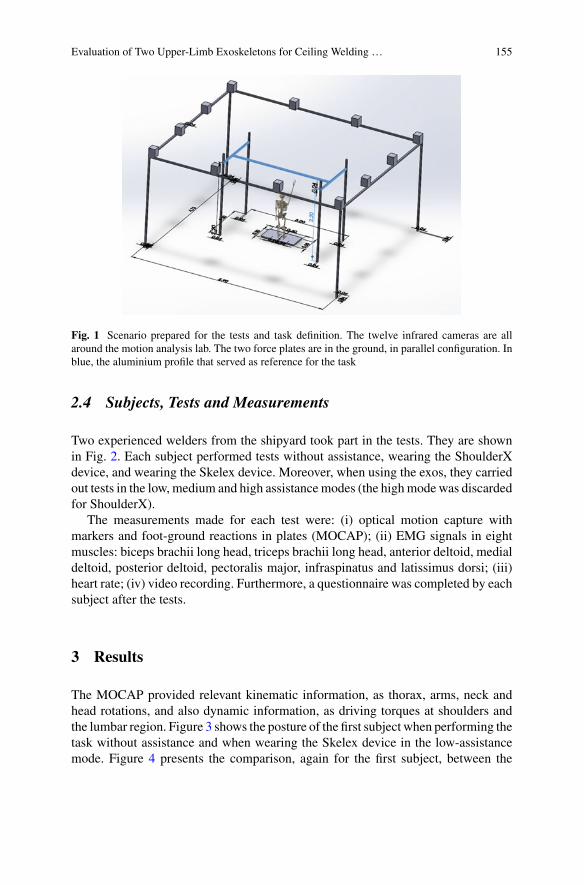
Evaluation of Two Upper-Limb Exoskeletons for Ceiling Welding … 155
Fig. 1 Scenario prepared for the tests and task definition. The twelve infrared cameras are allaround the motion analysis lab. The two force plates are in the ground, in parallel configuration. Inblue, the aluminium profile that served as reference for the task
2.4 Subjects, Tests and Measurements
Two experienced welders from the shipyard took part in the tests. They are shownin Fig. 2. Each subject performed tests without assistance, wearing the ShoulderXdevice, and wearing the Skelex device. Moreover, when using the exos, they carriedout tests in the low, medium and high assistancemodes (the highmode was discardedfor ShoulderX).
The measurements made for each test were: (i) optical motion capture withmarkers and foot-ground reactions in plates (MOCAP); (ii) EMG signals in eightmuscles: biceps brachii long head, triceps brachii long head, anterior deltoid, medialdeltoid, posterior deltoid, pectoralis major, infraspinatus and latissimus dorsi; (iii)heart rate; (iv) video recording. Furthermore, a questionnaire was completed by eachsubject after the tests.
3 Results
The MOCAP provided relevant kinematic information, as thorax, arms, neck andhead rotations, and also dynamic information, as driving torques at shoulders andthe lumbar region. Figure 3 shows the posture of the first subject when performing thetask without assistance and when wearing the Skelex device in the low-assistancemode. Figure 4 presents the comparison, again for the first subject, between the
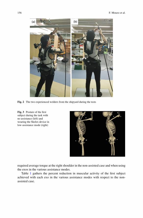
156 F. Mouzo et al.
Fig. 2 The two experienced welders from the shipyard during the tests
Fig. 3 Posture of the firstsubject during the task withno assistance (left) andwearing the Skelex device inlow-assistance mode (right)
required average torque at the right shoulder in the non-assisted case and when usingthe exos in the various assistance modes.
Table 1 gathers the percent reduction in muscular activity of the first subjectachieved with each exo in the various assistance modes with respect to the non-assisted case.
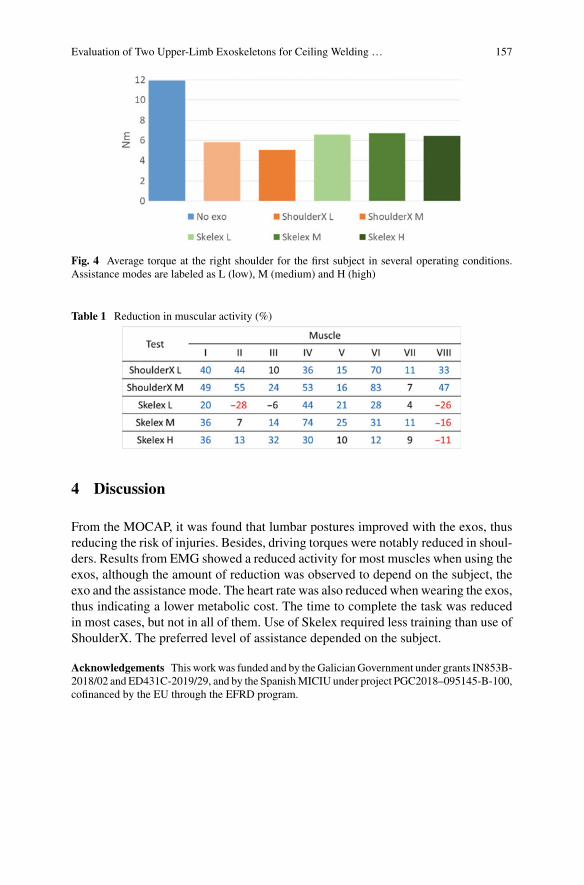
Evaluation of Two Upper-Limb Exoskeletons for Ceiling Welding … 157
Fig. 4 Average torque at the right shoulder for the first subject in several operating conditions.Assistance modes are labeled as L (low), M (medium) and H (high)
Table 1 Reduction in muscular activity (%)
4 Discussion
From the MOCAP, it was found that lumbar postures improved with the exos, thusreducing the risk of injuries. Besides, driving torques were notably reduced in shoul-ders. Results from EMG showed a reduced activity for most muscles when using theexos, although the amount of reduction was observed to depend on the subject, theexo and the assistance mode. The heart rate was also reduced when wearing the exos,thus indicating a lower metabolic cost. The time to complete the task was reducedin most cases, but not in all of them. Use of Skelex required less training than use ofShoulderX. The preferred level of assistance depended on the subject.
Acknowledgements This workwas funded and by theGalicianGovernment under grants IN853B-2018/02 and ED431C-2019/29, and by the SpanishMICIU under project PGC2018–095145-B-100,cofinanced by the EU through the EFRD program.

158 F. Mouzo et al.
References
1. K. Huysamen, T. Bosch, M. de Looze, K.S. Stadler, E. Graf, L.W. O’Sullivan, Evaluation of apassive exoskeleton for static upper limb activities. Appl. Ergon. 70, 148–155 (2018)
2. U. Lugris, J. Carlin, A. Luaces, J. Cuadrado, Gait analysis system for spinal cord-injured subjectsassisted by active orthoses and crutches. J. Multi-body Dyn. 227(4), 363–374 (2013)
3. F. Michaud, F. Mouzo, U. Lugris, J. Cuadrado, Energy expenditure estimation during crutch-orthosis-assisted gait of a spinal-cord-injured subject. Frontiers Neurorobot. 13(55), 11 (2019)
4. F.Mouzo, U. Lugris, R. Pamies-Vila, J. Cuadrado, Skeletal-level control-based forward dynamicanalysis of acquired healthy and assisted gait motion. Multibody Sys.Dyn. 44(1), 1–29 (2018).https://doi.org/10.1007/s11044-018-09634-4
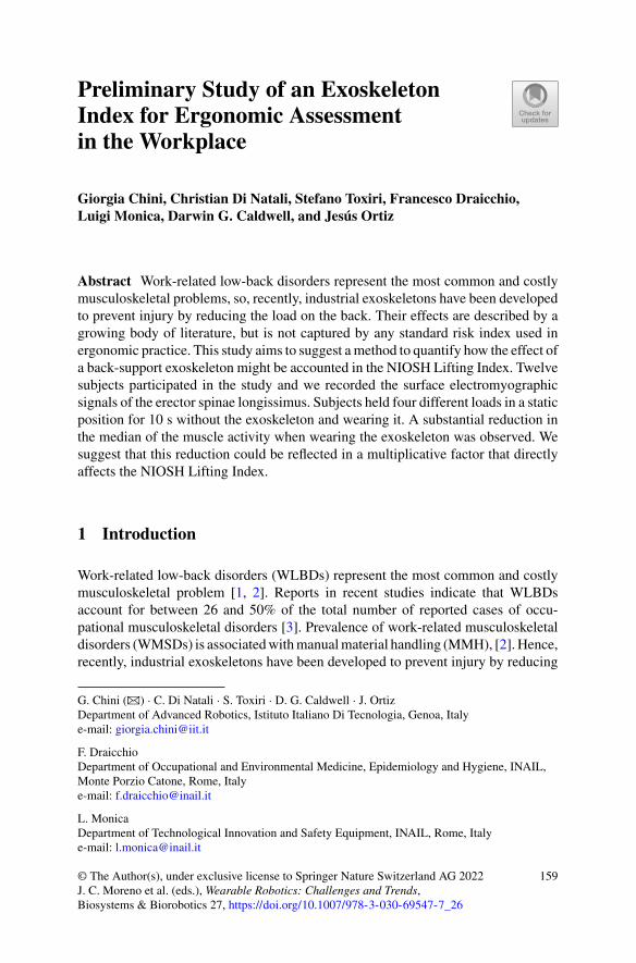
Preliminary Study of an ExoskeletonIndex for Ergonomic Assessmentin the Workplace
Giorgia Chini, Christian Di Natali, Stefano Toxiri, Francesco Draicchio,Luigi Monica, Darwin G. Caldwell, and Jesús Ortiz
Abstract Work-related low-back disorders represent the most common and costlymusculoskeletal problems, so, recently, industrial exoskeletons have been developedto prevent injury by reducing the load on the back. Their effects are described by agrowing body of literature, but is not captured by any standard risk index used inergonomic practice. This study aims to suggest amethod to quantify how the effect ofa back-support exoskeleton might be accounted in the NIOSH Lifting Index. Twelvesubjects participated in the study and we recorded the surface electromyographicsignals of the erector spinae longissimus. Subjects held four different loads in a staticposition for 10 s without the exoskeleton and wearing it. A substantial reduction inthe median of the muscle activity when wearing the exoskeleton was observed. Wesuggest that this reduction could be reflected in a multiplicative factor that directlyaffects the NIOSH Lifting Index.
1 Introduction
Work-related low-back disorders (WLBDs) represent the most common and costlymusculoskeletal problem [1, 2]. Reports in recent studies indicate that WLBDsaccount for between 26 and 50% of the total number of reported cases of occu-pational musculoskeletal disorders [3]. Prevalence of work-related musculoskeletaldisorders (WMSDs) is associatedwithmanualmaterial handling (MMH), [2].Hence,recently, industrial exoskeletons have been developed to prevent injury by reducing
G. Chini (B) · C. Di Natali · S. Toxiri · D. G. Caldwell · J. OrtizDepartment of Advanced Robotics, Istituto Italiano Di Tecnologia, Genoa, Italye-mail: [email protected]
F. DraicchioDepartment of Occupational and Environmental Medicine, Epidemiology and Hygiene, INAIL,Monte Porzio Catone, Rome, Italye-mail: [email protected]
L. MonicaDepartment of Technological Innovation and Safety Equipment, INAIL, Rome, Italye-mail: [email protected]
© The Author(s), under exclusive license to Springer Nature Switzerland AG 2022J. C. Moreno et al. (eds.), Wearable Robotics: Challenges and Trends,Biosystems & Biorobotics 27, https://doi.org/10.1007/978-3-030-69547-7_26
159
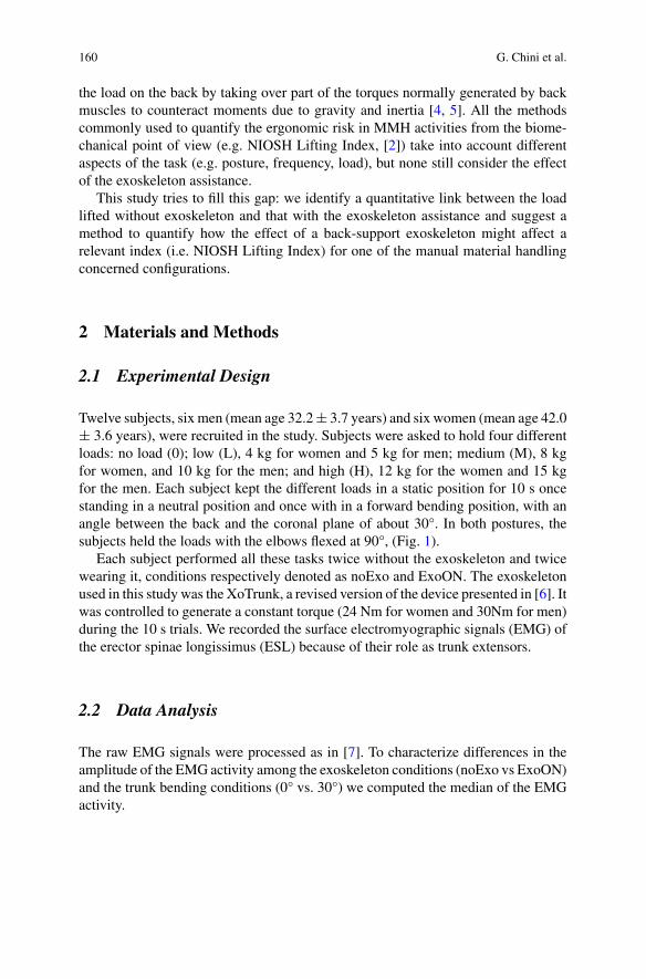
160 G. Chini et al.
the load on the back by taking over part of the torques normally generated by backmuscles to counteract moments due to gravity and inertia [4, 5]. All the methodscommonly used to quantify the ergonomic risk in MMH activities from the biome-chanical point of view (e.g. NIOSH Lifting Index, [2]) take into account differentaspects of the task (e.g. posture, frequency, load), but none still consider the effectof the exoskeleton assistance.
This study tries to fill this gap: we identify a quantitative link between the loadlifted without exoskeleton and that with the exoskeleton assistance and suggest amethod to quantify how the effect of a back-support exoskeleton might affect arelevant index (i.e. NIOSH Lifting Index) for one of the manual material handlingconcerned configurations.
2 Materials and Methods
2.1 Experimental Design
Twelve subjects, six men (mean age 32.2± 3.7 years) and six women (mean age 42.0± 3.6 years), were recruited in the study. Subjects were asked to hold four differentloads: no load (0); low (L), 4 kg for women and 5 kg for men; medium (M), 8 kgfor women, and 10 kg for the men; and high (H), 12 kg for the women and 15 kgfor the men. Each subject kept the different loads in a static position for 10 s oncestanding in a neutral position and once with in a forward bending position, with anangle between the back and the coronal plane of about 30°. In both postures, thesubjects held the loads with the elbows flexed at 90°, (Fig. 1).
Each subject performed all these tasks twice without the exoskeleton and twicewearing it, conditions respectively denoted as noExo and ExoON. The exoskeletonused in this study was the XoTrunk, a revised version of the device presented in [6]. Itwas controlled to generate a constant torque (24 Nm for women and 30Nm for men)during the 10 s trials. We recorded the surface electromyographic signals (EMG) ofthe erector spinae longissimus (ESL) because of their role as trunk extensors.
2.2 Data Analysis
The raw EMG signals were processed as in [7]. To characterize differences in theamplitude of the EMG activity among the exoskeleton conditions (noExo vs ExoON)and the trunk bending conditions (0° vs. 30°) we computed the median of the EMGactivity.
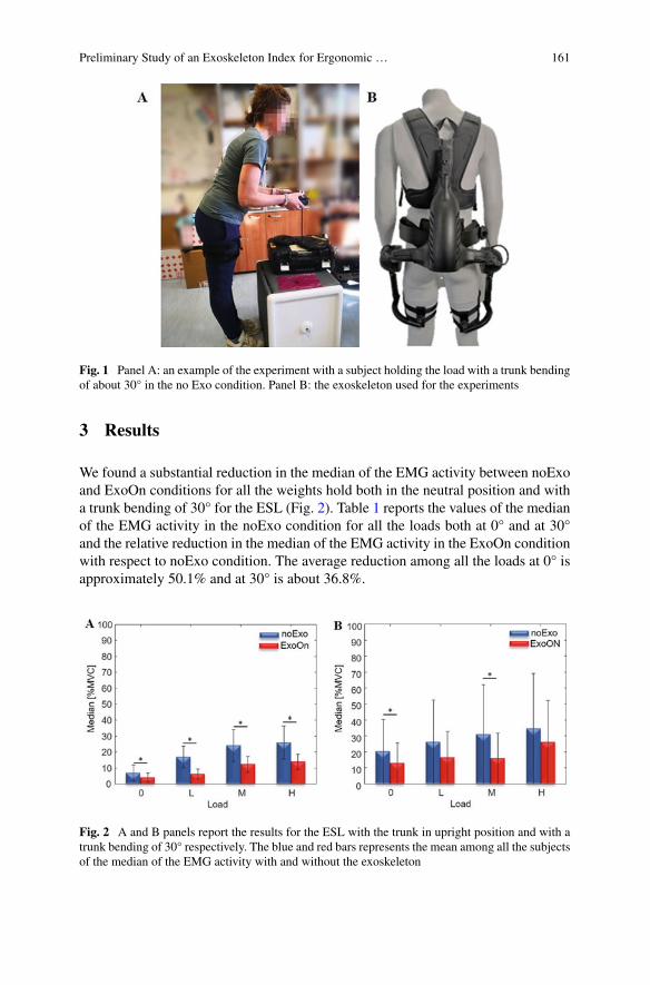
Preliminary Study of an Exoskeleton Index for Ergonomic … 161
Fig. 1 Panel A: an example of the experiment with a subject holding the load with a trunk bendingof about 30° in the no Exo condition. Panel B: the exoskeleton used for the experiments
3 Results
We found a substantial reduction in the median of the EMG activity between noExoand ExoOn conditions for all the weights hold both in the neutral position and witha trunk bending of 30° for the ESL (Fig. 2). Table 1 reports the values of the medianof the EMG activity in the noExo condition for all the loads both at 0° and at 30°and the relative reduction in the median of the EMG activity in the ExoOn conditionwith respect to noExo condition. The average reduction among all the loads at 0° isapproximately 50.1% and at 30° is about 36.8%.
Fig. 2 A and B panels report the results for the ESL with the trunk in upright position and with atrunk bending of 30° respectively. The blue and red bars represents the mean among all the subjectsof the median of the EMG activity with and without the exoskeleton
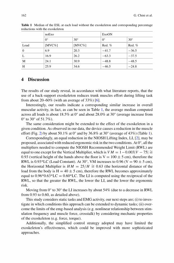
162 G. Chini et al.
Table 1 Median of the ESL at each load without the exoskeleton and corresponding percentagereductions with the exoskeleton
noExo ExoON
0° 30° 0° 30°
Load [MVC%] [MVC%] Red. % Red. %
0 6.9 20.3 −41.7 −36.5
L 16.9 26.2 −63.3 −37.5
M 24.1 30.9 −48.8 −48.5
H 25.9 34.6 −46.5 −24.8
4 Discussion
The results of our study reveal, in accordance with what literature reports, that theuse of a back-support exoskeleton reduces trunk muscles effort during lifting taskfrom about 20–60% (with an average of 33%) [6].
Interestingly, our results indicate a corresponding similar increase in overallmuscular activity, in fact, as can be seen in Table 1, the average median computedacross all loads is about 18.5% at 0° and about 28.0% at 30° (average increase from0° to 30° of 51.7%).
The same consideration might be extended to the effect of the exoskeleton in agiven condition. As observed in our data, the device causes a reduction in the muscleeffort (Fig. 2) by about 50.1% at 0° and by 36.8% at 30° (average of 43%) (Table 1).
Correspondingly, an equal reduction in the NIOSH Lifting Index, LI, [2], may beproposed, associated with reduced ergonomic risk in the two conditions. At 0°, all themultipliers needed to compute the NIOSH Recommended Weight Limit (RWL) areequal to one except for the Vertical Multiplier, which is V M = 1−0.003|V − 75| ∼=0.93 (vertical height of the hands above the floor is V = 100 ± 5 cm), therefore theRWL is 0.93*LC (Load Constant). At 30°, VM increases to 0.96 (V = 90 ± 5 cm),the Horizontal Multiplier is HM = 25/H ∼= 0.63 (the horizontal distance of theload from the body is H = 40 ± 5 cm), therefore the RWL becomes approximatelyequal to 0.96*0.63*LC = 0.60*LC. The LI is computed using the reciprocal of theRWL, so that the greater the RWL, the lower the LI, and the lower the ergonomicrisk.
Moving from 0° to 30° the LI increases by about 54% (due to a decrease in RWLfrom 0.93 to 0.60, as detailed above).
This study considers static tasks and EMG activity, our next steps are; (i) to inves-tigate in which conditions this approach can be extended to dynamic tasks; (ii) over-come the limits of the emg-based analysis (e.g. nonlinear relationship between stim-ulation frequency and muscle force, crosstalk) by considering mechanic propertiesof the exoskeleton (e.g. force, torque).
Additionally, the simplified control strategy adopted may have limited theexoskeleton’s effectiveness, which could be improved with more sophisticatedapproaches.
Preliminary Study of an Exoskeleton Index for Ergonomic … 163
5 Conclusion
The exoskeleton reduces muscle activity at the lower back while holding externalobjects. This reduction may be interpreted as if the subject is holding a lower loadthan the actual one. The exoskeleton could be accounted for by a factor that increasesthe NIOSH RWL and correspondingly decreases the Lifting Index.
Future works will focus on proposing a new multiplicative factor to add to theNIOSH Lifting Index to account for the assistance of the exoskeleton and expressingit in terms of equivalent weight.
Acknowlegments This work was supported by the Italian Workers’ Compensation Authority(INAIL).
References
1. M.L. Lu, T.R. Waters, E. Krieg, D. Werren, Efficacy of the revised NIOSH lifting equation topredict risk of low-back pain associated with manual lifting: a one-year prospective study. Hum.Factors 56(1), 73–85 (2014)
2. NIOSH, Work practices guide for manual lifting. NIOSH technical Report No. 81–122 (U.S.Dept. of Health and Human Services, National Institute for Occupational Safety and Health,Cincinnati, OH, 1981)
3. INAIL,Italian Worker’s Compensation Authority Annual Report. Part IV Statistics, Accidentsand Occupational Diseases (2011)
4. S. Toxiri, M.B. Näf, M. Lazzaroni, J. Fernández, M. Sposito, T. Poliero, L. Monica, S. Anas-tasi, D.G. Caldwell, J. Ortiz, Back-support exoskeletons for occupational use: an overview oftechnological advances and trends. IISE Trans. Occ. Erg. H. Fact. 1–13 (2019)
5. M.P. de Looze, T. Bosch, F. Krause, K.S. Stadler, L.W. O’Sullivan, Exoskeletons for industrialapplication and their potential effects on physical work load. Ergonomics 59(5), 671–681 (2016)
6. S. Toxiri, A.S. Koopman, M. Lazzaroni, J. Ortiz, V. Power, M. P. de Looze et al., Rationale,implementation and evaluation of assistive strategies for an active back-support exoskeleton.Front. Robot. AI (2018)
7. A. Ranavolo, T. Varrecchia, S. Iavicoli, A. Marchesi, M. Rinaldi, M. Serrao et al., “Surfaceelectromyography for risk assessment in work activities designed using the ‘revised NIOSHlifting equation. Int. J. Ind. Ergonom. 68, 34–45 (2018)
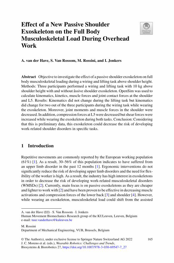
Effect of a New Passive ShoulderExoskeleton on the Full BodyMusculoskeletal Load During OverheadWork
A. van der Have, S. Van Rossom, M. Rossini, and I. Jonkers
Abstract Objective to investigate the effect of a passive shoulder exoskeleton on fullbody musculoskeletal loading during a wiring and lifting task above shoulder height.Methods: Three participants performed a wiring and lifting task with 10 kg aboveshoulder height with and without âssive shoulder exoskeleton. OpenSim was used tocalculate kinematics, kinetics, muscle forces and joint contact forces at the shoulderand L5. Results: Kinematics did not change during the lifting task but kinematicsdid change for two out of the three participants during the wiring task while wearingthe exoskeleton. Moreover, joint moments and muscle forces in the shoulder weredecreased. In addition, compression forces at L5were decreased but shear forceswereincreased while wearing the exoskeleton during both tasks. Conclusion: Consideringthat this is preliminary data, this exoskeleton could decrease the risk of developingwork-related shoulder disorders in specific tasks.
1 Introduction
Repetitive movements are commonly reported by the European working population(61%) [1]. As a result, 30–56% of this population indicates to have suffered froman upper limb disorder in the past 12 months [1]. Ergonomic interventions do notsignificantly reduce the risk of developing upper limb disorders and the need for flex-ibility of the worker is high. As a result, the industry has high interest in exoskeletonsin order to decrease the risk of developing work-related musculoskeletal disorders(WMSDs) [2]. Currently, main focus is on passive exoskeletons as they are cheaperand lighter toworkwith [2] and have been proven to be effective in decreasingmuscleactivations and compression forces of the lower back [3] and shoulder [4]. However,while wearing an exoskeleton, musculoskeletal load could shift from the assisted
A. van der Have (B) · S. Van Rossom · I. JonkersHuman Movement Biomechanics Research group of the KULeuven, Leuven, Belgiume-mail: [email protected]
M. RossiniDepartment of Mechanical Engineering, VUB, Brussels, Belgium
© The Author(s), under exclusive license to Springer Nature Switzerland AG 2022J. C. Moreno et al. (eds.), Wearable Robotics: Challenges and Trends,Biosystems & Biorobotics 27, https://doi.org/10.1007/978-3-030-69547-7_27
165
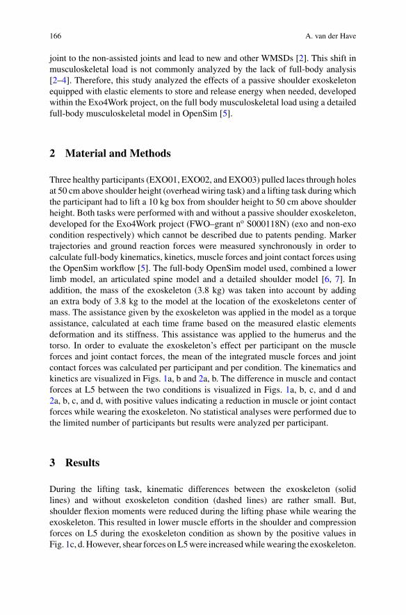
166 A. van der Have
joint to the non-assisted joints and lead to new and other WMSDs [2]. This shift inmusculoskeletal load is not commonly analyzed by the lack of full-body analysis[2–4]. Therefore, this study analyzed the effects of a passive shoulder exoskeletonequipped with elastic elements to store and release energy when needed, developedwithin the Exo4Work project, on the full body musculoskeletal load using a detailedfull-body musculoskeletal model in OpenSim [5].
2 Material and Methods
Three healthy participants (EXO01, EXO02, and EXO03) pulled laces through holesat 50 cm above shoulder height (overhead wiring task) and a lifting task during whichthe participant had to lift a 10 kg box from shoulder height to 50 cm above shoulderheight. Both tasks were performed with and without a passive shoulder exoskeleton,developed for the Exo4Work project (FWO–grant no S000118N) (exo and non-exocondition respectively) which cannot be described due to patents pending. Markertrajectories and ground reaction forces were measured synchronously in order tocalculate full-body kinematics, kinetics, muscle forces and joint contact forces usingthe OpenSim workflow [5]. The full-body OpenSim model used, combined a lowerlimb model, an articulated spine model and a detailed shoulder model [6, 7]. Inaddition, the mass of the exoskeleton (3.8 kg) was taken into account by addingan extra body of 3.8 kg to the model at the location of the exoskeletons center ofmass. The assistance given by the exoskeleton was applied in the model as a torqueassistance, calculated at each time frame based on the measured elastic elementsdeformation and its stiffness. This assistance was applied to the humerus and thetorso. In order to evaluate the exoskeleton’s effect per participant on the muscleforces and joint contact forces, the mean of the integrated muscle forces and jointcontact forces was calculated per participant and per condition. The kinematics andkinetics are visualized in Figs. 1a, b and 2a, b. The difference in muscle and contactforces at L5 between the two conditions is visualized in Figs. 1a, b, c, and d and2a, b, c, and d, with positive values indicating a reduction in muscle or joint contactforces while wearing the exoskeleton. No statistical analyses were performed due tothe limited number of participants but results were analyzed per participant.
3 Results
During the lifting task, kinematic differences between the exoskeleton (solidlines) and without exoskeleton condition (dashed lines) are rather small. But,shoulder flexion moments were reduced during the lifting phase while wearing theexoskeleton. This resulted in lower muscle efforts in the shoulder and compressionforces on L5 during the exoskeleton condition as shown by the positive values inFig. 1c, d.However, shear forces onL5were increasedwhilewearing the exoskeleton.
,Effect of a New Passive Shoulder Exoskeleton on the Full Body … 167
Fig. 1 a Shoulder flexion and extension angle, b Shoulder moments, c Difference in muscle forcesduring non-exo condition and exo condition of the m. bicpes longus, biceps brevis deltoideusmedius, trapezius descendens, pectoralis major, coracobrachialis d shear and compression forcesat L5 during the lifting task with 10kg. The blue, red and green colors are indicating the differentparticpants (in all 4 subplots) as the solid line (−) is indicating the exoskeleton condition as thedashed line (—) is indicating the non-exo condition
The magnitude of the exoskeleton effects was variable between participants but adecrease in musculoskeletal load was observed for all participants.
During the wiring task, a decreased flexion angle is observed for the participantsEXO02 (red) and EXO03 (green) as seen in Fig. 2a. Shoulder flexion moments weredecreased for all participants. This resulted in decreased muscle forces and compres-sion forces as described for the lifting task. Again, muscle forces in the shoulder andcompression forces onL5were decreased but shear forces onL5were increasedwhilewearing the exoskeleton. In contrast to the lifting task, the first participant (EXO01,blue) experienced the highest positive effectswhilewearing the exoskeleton as duringthe lifting task the third participant (EXO03, green) experienced the largest effects.
4 Discussion
The developed passive shoulder exoskeleton is decreasing joint moments andmuscleforces thereby decreasing musculoskeletal loading in the shoulder during the wiringand in the lifting task. In addition, compression forces at L5 were lowered but shearforces were increased during both tasks. As the exoskeleton is not limiting the kine-matics of the shoulder and decreasing the musculoskeletal load, the exoskeleton canbe considered a good ergonomic intervention in order to decrease the risk on devel-oping WMSDs for the shoulder joint. Moreover, musculoskeletal load did not shiftfrom the shoulder to the lower back as compression forces at L5 were not increased.
168 A. van der Have
Fig. 2 a Shoulder flexion and extension angle, b Shoulder moments, c Difference in muscle forcesduring non-exo condition and exo condition of the m. bicpes longus, biceps brevis deltoideusmedius, trapezius descendens, pectoralis major, coracobrachialis d shear and compression forcesat L5 during the lifting task with 10kg. The blue, red and green colors are indicating the differentparticpants (in all 4 subplots) as the solid line (−) is indicating the exoskeleton condition as thedashed line (—) is indicating the non-exo condition
This could be due to the fact that the mass of the exoskeleton is located at the back,posterior of the L5 vertebrae. However, shear forces did increase while wearing theexoskeleton which is considered a negative effect but this negative effect is rathersmall. Further full body analyses will show the effects on the full body muscu-loskeletal load while wearing the exoskeleton. However, multiple joint analyses areperformed for this study but are not presented in this abstract.
Moreover, all participants experienced a reduction in shoulder moments andmuscle forces but the magnitude of the effects were variable between participantsand even between the different tasks. This variability could be due to the time ofadaption to the exoskeleton but no evidence could support this statement.
5 Conclusion
Considering that this is preliminary data, the developed passive shoulder exoskeletonis decreasing musculoskeletal load in the shoulder and did not transfer this muscu-loskeletal load to the lower back during a lifting and wiring task. The presentedmethods could be used to investigate the effects of any exoskeleton on full bodymusculoskeletal load.
Acknowledgments This research was funded by Exo4Work, SBO-E-S000118N.
,Effect of a New Passive Shoulder Exoskeleton on the Full Body … 169
References
1. EU-OSHA European Agency for Safety and Health at Work, in Sixth European WorkingConditions Survey—Overview Report (2017 update), p. 164, https://doi.org/10.2806/422172.
2. M.P. de Looze, T. Bosch, F. Krause, K.S. Stadler, L.W. O’Sullivan, Exoskeletons for industrialapplication and their potential effects on physical work load. Ergonomics 59(5), 671–681 (2016).https://doi.org/10.1080/00140139.2015.1081988
3. A.S. Koopman, I. Kingma, G.S. Faber, M.P. de Looze, J.H. van Dieën, Effects of a passiveexoskeleton on the mechanical loading of the low back in static holding tasks. J. Biomech.(2018). https://doi.org/10.1016/j.jbiomech.2018.11.033
4. I. Pacifico et al., Experimental evaluation of the proto-MATE, a novel ergonomic upper-limbexoskeleton for reducing the worker’ s physical strain (2019)
5. S.L. Delp et al., OpenSim: Open source to create and analyze dynamic simulations ofmovement.IEEE Trans. Biomed. Eng. 54(11), 1940–1950 (2007). https://doi.org/10.1109/TBME.2007.901024
6. M. Christophy, N.A.F. Senan, J.C. Lotz, O.M. O’Reilly, AMusculoskeletal model for the lumbarspine. Biomech. Model. Mechanobiol. 11(1–2), 19–34 (2012). https://doi.org/10.1007/s10237-011-0290-6
7. K.R.S. Holzbaur, W.M. Murray, S.L. Delp, A model of the upper extremity for simulatingmusculoskeletal surgery and analyzing neuromuscular control. Ann. Biomed. Eng. 33(6), 829–840 (2005). https://doi.org/10.1007/s10439-005-3320-7
The Experience of Plasterers TowardsUsing an Arm Support Exoskeleton
Aijse W. de Vries, Michiel P. de Looze, and Frank Krause
Abstract Positive effects of arm support exoskeletons in reducing the shoulderload, have been reported mainly from laboratory studies. However, for exoskeletonsto provideworker support in practice, they need to be accepted aswell. Therefore, it isnecessary to obtain insight into the user experience and attitude towards exoskeletonuse, in relevant working fields. Eleven plasterers were recruited to perform theiractivities while wearing an arm support exoskeleton. Before the experiment, partici-pants were asked for which activities they could use support, and which body regionsthey wished to be supported. After working with the exoskeleton, they reported theirexperience and will to use the exoskeleton during daily work. Overall, the user expe-rience of the plasterers was positive, and all reported they would probably, or evendefinitely, use the exoskeleton for a selection of activities, mainly overhead work, butnot during the whole day. Together with earlier findings on reduced muscle activity,exoskeleton use in certain tasks seems promising.
1 Introduction
Heavy manual labor is still prevalent in many working fields. Especially workinvolving exposure to tiring or painful positions, carrying or moving heavy loads, orrepetitive movements can result in musculoskeletal diseases and sick leave [1]. Oneof the sectors in which workers are exposed to these conditions, is the constructionarea. 37% of the workers in this sector report that their work affects their healthnegatively [1]. Working with elevated arms, is one of the most important risk factorsfor the development of musculo-skeletal shoulder disorders [2, 3].
Arm support exoskeletons are a relatively new technology, that can support workwith elevated arms, by providing part of the required shoulder moment. In passiveexoskeletons this supportive moment is generated through spring like mechanisms,
A. W. de Vries (B) · M. P. de Looze · F. KrauseDepartment of Sustainable Productivity and Employability of Healthy Living, TNO, Leiden, TheNetherlandse-mail: [email protected]
© The Author(s), under exclusive license to Springer Nature Switzerland AG 2022J. C. Moreno et al. (eds.), Wearable Robotics: Challenges and Trends,Biosystems & Biorobotics 27, https://doi.org/10.1007/978-3-030-69547-7_28
171
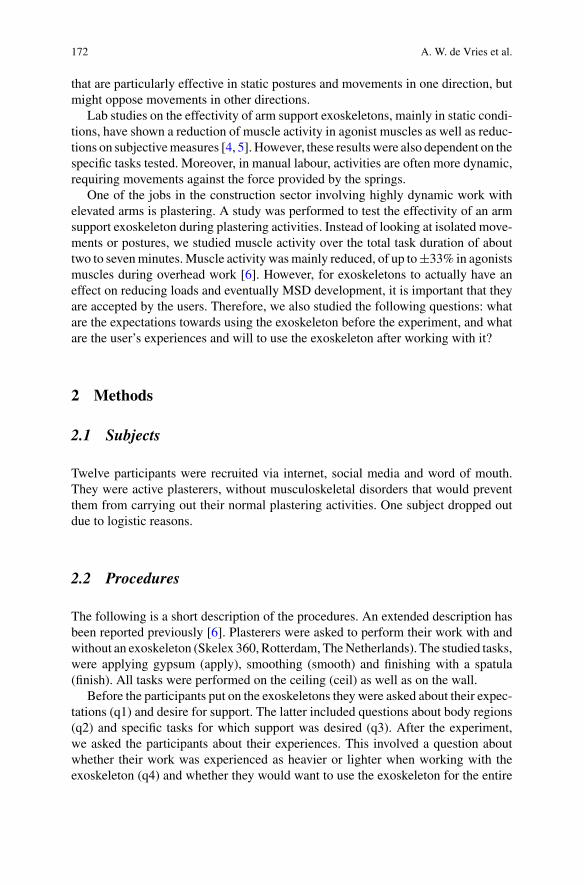
172 A. W. de Vries et al.
that are particularly effective in static postures and movements in one direction, butmight oppose movements in other directions.
Lab studies on the effectivity of arm support exoskeletons, mainly in static condi-tions, have shown a reduction of muscle activity in agonist muscles as well as reduc-tions on subjectivemeasures [4, 5]. However, these resultswere also dependent on thespecific tasks tested. Moreover, in manual labour, activities are often more dynamic,requiring movements against the force provided by the springs.
One of the jobs in the construction sector involving highly dynamic work withelevated arms is plastering. A study was performed to test the effectivity of an armsupport exoskeleton during plastering activities. Instead of looking at isolated move-ments or postures, we studied muscle activity over the total task duration of abouttwo to sevenminutes.Muscle activity wasmainly reduced, of up to±33% in agonistsmuscles during overhead work [6]. However, for exoskeletons to actually have aneffect on reducing loads and eventually MSD development, it is important that theyare accepted by the users. Therefore, we also studied the following questions: whatare the expectations towards using the exoskeleton before the experiment, and whatare the user’s experiences and will to use the exoskeleton after working with it?
2 Methods
2.1 Subjects
Twelve participants were recruited via internet, social media and word of mouth.They were active plasterers, without musculoskeletal disorders that would preventthem from carrying out their normal plastering activities. One subject dropped outdue to logistic reasons.
2.2 Procedures
The following is a short description of the procedures. An extended description hasbeen reported previously [6]. Plasterers were asked to perform their work with andwithout an exoskeleton (Skelex 360, Rotterdam, TheNetherlands). The studied tasks,were applying gypsum (apply), smoothing (smooth) and finishing with a spatula(finish). All tasks were performed on the ceiling (ceil) as well as on the wall.
Before the participants put on the exoskeletons they were asked about their expec-tations (q1) and desire for support. The latter included questions about body regions(q2) and specific tasks for which support was desired (q3). After the experiment,we asked the participants about their experiences. This involved a question aboutwhether their work was experienced as heavier or lighter when working with theexoskeleton (q4) and whether they would want to use the exoskeleton for the entire
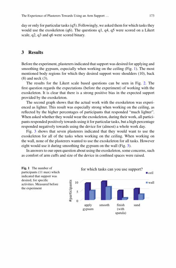
The Experience of Plasterers Towards Using an Arm Support … 173
day or only for particular tasks (q5). Followingly, we asked them for which tasks theywould use the exoskeleton (q6). The questions q1, q4, q5 were scored on a Likertscale, q2, q3 and q6 were scored binary.
3 Results
Before the experiment, plasterers indicated that support was desired for applying andsmoothing the gypsum, especially when working on the ceiling (Fig. 1). The mostmentioned body regions for which they desired support were shoulders (10), back(8) and neck (3).
The results for the Likert scale based questions can be seen in Fig. 2. Thefirst question regards the expectations (before the experiment) of working with theexoskeleton. It is clear that there is a strong positive bias in the expected supportprovided by the exoskeleton.
The second graph shows that the actual work with the exoskeleton was experi-enced as lighter. This result was especially strong when working on the ceiling, asreflected by the higher percentages of participants that responded “much lighter”.When asked whether they would wear the exoskeleton, during their work, all partici-pants responded positively towards using it for particular tasks, but a high percentageresponded negatively towards using the device for (almost) a whole work day.
Fig. 3 shows that seven plasterers indicated that they would want to use theexoskeleton for all of the tasks when working on the ceiling. When working onthe wall, none of the plasterers wanted to use the exoskeleton for all tasks. Howevereight would use it during smoothing the gypsum on the wall (Fig. 3).
In answers to our open question about using the exoskeleton, some concerns, suchas comfort of arm cuffs and size of the device in confined spaces were raised.
Fig. 1 The number ofparticipants (11 max) whichindicated that support wasdesired, for specificactivities. Measured beforethe experiment
0
5
10
applygypsum
smooth finish(with
spatula)
sand
for which tasks can you use support?ceil
wall
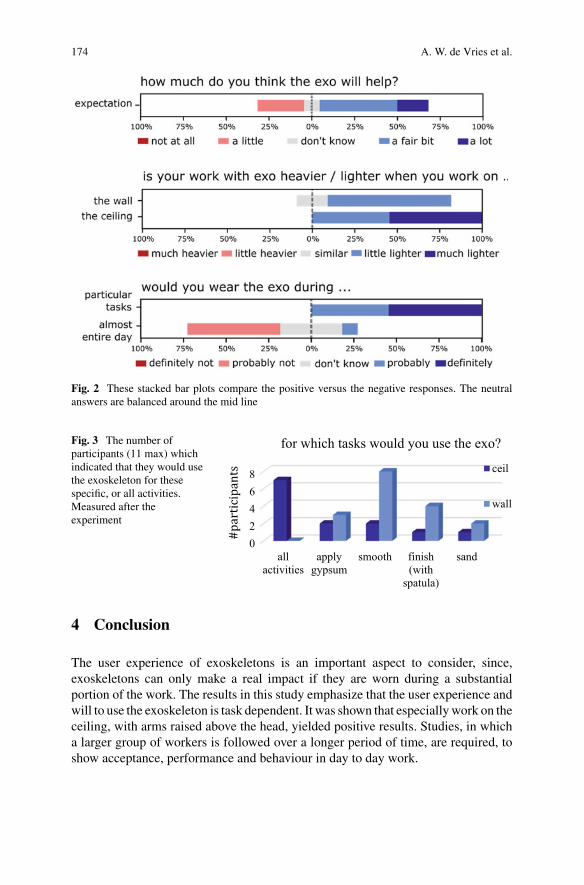
174 A. W. de Vries et al.
Fig. 2 These stacked bar plots compare the positive versus the negative responses. The neutralanswers are balanced around the mid line
Fig. 3 The number ofparticipants (11 max) whichindicated that they would usethe exoskeleton for thesespecific, or all activities.Measured after theexperiment
02468
allactivities
applygypsum
smooth finish(with
spatula)
sand
for which tasks would you use the exo?
ceil
wall
4 Conclusion
The user experience of exoskeletons is an important aspect to consider, since,exoskeletons can only make a real impact if they are worn during a substantialportion of the work. The results in this study emphasize that the user experience andwill to use the exoskeleton is task dependent. It was shown that especiallywork on theceiling, with arms raised above the head, yielded positive results. Studies, in whicha larger group of workers is followed over a longer period of time, are required, toshow acceptance, performance and behaviour in day to day work.
The Experience of Plasterers Towards Using an Arm Support … 175
Acknowledgements This research was supported by Knauf (supplier of plasterers materials) andDutch Topsector of Life Sciences and Health (TKI-LSH-VT2017). The exoskeleton was providedby Skelex and the test location by NOA.
Wewould like to thankKNAUF, Skelex andNOA, respectively formaking this research possible,providing the exoskeleton and test location.
References
1. S.E. Eurofound, Working Conditions Survey—Overview Report (2017 Update) (PublicationsOffice of the European Union, Luxembourg, 2017).
2. R.M. Van Rijn, B.M. Huisstede, B.W. Koes, A. Burdorf, Associations between work-relatedfactors and specific disorders of the shoulder—A systematic review of the literature. Scand. J.Work. Environ. Heal. 36(3), 189-201 (2010)
3. S.W. Svendsen, J.P. Bonde, S.E. Mathiassen, K. Stengaard-Pedersen, L.H. Frich, Work relatedshoulder disorders: quantitative exposure-response relations with reference to arm posture.Occup. Environ. Med. 61(10), 844-853 (2004)
4. T. McFarland, S. Fischer, Considerations for Industrial Use: A Systematic Review of the Impactof Active and Passive Upper Limb Exoskeletons on Physical Exposures, IISE Trans. Occup.Ergon. Hum Factors (2019)
5. A. De Vries, M. De Looze, The effect of arm support exoskeletons in realistic work activities:a review study. J Ergon. 9(4), 1–9 (2019)
6. A.W. de Vries, F. Krause, M.P. de Looze, The effectivity of a passive arm support exoskeletonin reducing muscle activation and perceived exertion during plastering activities. Ergonomics(2021)
Biomechanical Evaluation of the Effectof Three Trunk Support Exoskeletonson Spine Loading During Lifting
Idsart Kingma, Axel S. Koopman, Michiel P. de Looze,and Jaap H. van Dieën
Abstract To evaluate the biomechanical effect of exoskeletons during lifting, threestudies were performed to compare spine compression during lifting without andwith three exoskeletons (Laevo, Robo-Mate, SPEXOR). In these studies, partici-pants (11, 10 and 10, respectively) lifted boxes (10, 15 and 10 kg, respectively) fromankle height. Spine compression reductions ranged from minor changes in the firstexoskeleton to 17% and 14% reductions in the second and third exoskeleton, respec-tively. Lumbar flexion was increased by the first exoskeleton while it was reduced bythe second and unaffected by the third. Effects of exoskeletons on spine compressionwere affected by support moments, reductions in lifting speed and subtle changes inlifting style. Modifications of design and control could help to improve the timingand magnitude of support of exoskeletons during lifting.
1 Introduction
Worldwide, low back pain (LBP) affects about 37% of the population each year [1]and the recurrence rate is about 33% within a year [2]. Additionally, effect sizes oftreatments are moderate at best [2]. Consequently, more focus on prevention seemswarranted. Cumulative occupational low back loading has been shown to be a riskfactor for LBP [3]. This suggests that reduction of spine loading during activitiessuch as manual lifting could be effective in reducing the risk of LBP. However, onlysmall effects of interventions to reduce low back loading have been found [4], whichmight be attributable to interactions between lifting style and task conditions [5].
Trunk support exoskeletons might contribute to reduction of spine loading duringmanual work. While substantial effects of such devices have been reported for staticwork [6], a thorough evaluation of biomechanical effects during manual lifting was
I. Kingma (B) · A. S. Koopman · J. H. van DieënDepartment of Human Movement Sciences, Amsterdam Movement Sciences, Vrije Universiteit,Amsterdam, The Netherlandse-mail: [email protected]
M. P. de LoozeTNO, Leiden, The Netherlands
© The Author(s), under exclusive license to Springer Nature Switzerland AG 2022J. C. Moreno et al. (eds.), Wearable Robotics: Challenges and Trends,Biosystems & Biorobotics 27, https://doi.org/10.1007/978-3-030-69547-7_29
177
178 I. Kingma et al.
lacking until recently. Therefore, we recently performed a biomechanical analysis ofthe effects of three trunk support exoskeletons during dynamic lifting [7–9]. In thispaper we compare findings between those devices. We hypothesized that each of thedevices reduces spine loading during dynamic lifting.
2 Material and Methods
2.1 Participants, Exoskeletons and Procedure
After approval of the local ethics committee, three studieswere performed to evaluatethe biomechanical effect of three trunk support exoskeletons, that represented asubstantial range of support methods and magnitudes. Symmetrical dynamic liftswere performed without and with exoskeleton using a box with handles slightlyabove the ankle joint. In the first study, 11 male participants used two versions of alight weight passive (commercially available) device, the Laevo [7], while lifting a10 kg box from a near and a far location. In the second study, 10 male participantslifted a 15 kg box with a prototype actuated exoskeleton (Robo-Mate [10]), usingthree lifting techniques (stoop, squat, free) [9] and three modes of controlling theEXO (mode 1: support based on trunk inclination; mode 2: support based on forearmEMG;mode 3: 50%of the support based on each ofmodes 1 and 2). In the third study,10 male professional luggage handlers lifted a 10 kg box with a newly developedpassive exoskeleton (SPEXOR [11]), using the same three lifting techniques [8]. Thisdevice is also still a prototype. It contains features such as two joints, misalignmentcompensation, and stronger support, but it is substantially heavier than the Laevo.
2.2 Measurements and Analyses
During lifting, 3D kinematics of the lower and upper legs, pelvis and trunk wererecorded (50 samples/s; Optotrak opto-electronic motion analysis system). Groundreaction forces were recorded (200 samples/s) using a 1.0 by 1.0 m custom-madeforce plate. Surface EMGwas recorded (1000 samples/s) bilaterally on five back andabdominal muscles.
Using inverse dynamics, 3D net moments of subject plus exoskeleton at thelumbo-sacral joint (L5-S1) were calculated [12]. Support moments of the two passiveexoskeletons were calculated from measured bending angles, in combination withangle-moment relations measured prior to the lifting experiment. For the actuatedexoskeleton, support moments weremeasured in themotors at the hip joints. Subject-moments were calculated by subtracting exoskeleton support moments from netmoments.
Biomechanical Evaluation of the Effect of Three Trunk Support … 179
Net moments, lumbar flexion and trunk muscle activity normalized to maximumvoluntary contraction, were used as input to an EMG-driven trunkmuscle model [13]to calculate compression forces at the L5-S1 joint. Exoskeleton support momentsduring peak loading, subject moments, compression forces and peak lumbar flexionand trunk velocity were tested for effects of exoskeletons using repeated measuresANOVAs for each experiment separately.
3 Results
In all three studies, average total net moments during ankle height lifts rangedbetween 200 and 300 Nm. The maximum support the devices could generate, wasabout 30, 40 and 50 Nm, for the lightweight, actuated, and new passive exoskeleton.
With the light weight passive exoskeleton (Laevo) support moments during peakloading were less than 20 Nm. As a result, for far lifts, peak spine compressionslightly decreased, by 5% averaged over the two versions of the exoskeleton. For nearlifts, support effects were counteracted by slight changes in lifting style, resulting innon-significant changes in compression forces.
The actuated exoskeleton (Robo-Mate) generated, at the instant of peak spineloading, support moments of on average 17 Nm. Nevertheless, spine compression,averaged over lifting techniques, decreased by 17%. This decrease only slightlyvaried over lifting techniques (stoop, squat or free) and did not depend on controlmode.
The new passive exoskeleton (SPEXOR) generated a support moment of 33 Nmat the instant of peak spine loading. It resulted in a decrease of spine compression of14%, and this did not depend on lifting technique.
In all studies, lifting with the exoskeleton resulted in a reduction of peak trunkangular velocity (by 17, 26 and 17%, respectively). Lumbar flexion increased (8%)with the light weight exoskeleton, decreased (28%) with the actuated exoskeletonand was unaffected by the new passive exoskeleton.
4 Discussion
In this study, we evaluated the biomechanical effects of three exoskeletons on lowback loading during lifting. The actual support of the exoskeletons during peak spineloading was substantially lower than the maximum the devices could generate. Themain reason is that peak spine loading during lifting occurs early during the upwardphase of the movement, when the trunk accelerates upward. In this phase, passiveexoskeletons do not generate their maximum support. Additionally, the lightweightexoskeleton suffered from hysteresis [7], and the motors in the actuated exoskeletonfailed to generate the intended peak torque during upward acceleration.
180 I. Kingma et al.
Spine load reductions were not fully consistent with exoskeleton support. Specif-ically, for the lightweight exoskeleton subtle changes in lifting style counteracted theeffect of the support. For the actuated exoskeleton, the reduction in spine compres-sion (17%) was larger than expected, based on the support moment (17 Nm). Thiswasmainly due to a substantial reduction in lifting speedwhen using the exoskeleton.For the new passive exoskeleton, only minor changes in lifting style were found, andthe resultant reduction in compression force (14%) was consistent with the supportmoment (33 Nm). Based on our findings we would recommend for future design ofexoskeletons to increase the magnitude of the support, and to better align the timingof peak support with peak spine loading. Evaluation of exoskeletons should not bebased onEMGalone, as kinematicsmay changewhenwearing an exoskeleton,whichrequires correction of EMG. Furthermore, safety and versatility in tasks other thanlifting should be evaluated.
5 Conclusion
Peak spine compression during lifting was reduced by each of the three exoskeletonstested for the present study. The new passive exoskeleton reduced spine compressionmore than the lightweight passive exoskeleton. Additionally, spine load reductionswhen wearing the exoskeletons were affected by changes in lifting style and liftingspeed. Design changes (for passive exoskeletons) and control andmotor changes (foractuated exoskeletons) should enhance the timing and magnitude of their support.
Acknowledgements This work was supported by the European Union’s Horizon 2020 throughthe SPEXOR project, contract no. 687662, and by the Dutch Research Council (NWO), program‘perspectief’ (project P16–05).
References
1. J. Hartvigsen, M.J. Hancock, A. Kongsted, Q. Louw, M.L. Ferreira, S. Genevay et al., Whatlow back pain is and why we need to pay attention. Lancet 391, 2356–2367 (2018)
2. C. Maher, M. Underwood, R. Buchbinder, Non-specific low back pain. Lancet 389, 736–747(2017)
3. P. Coenen, I. Kingma, C.R. Boot, P.M. Bongers, J.H. van Dieën, Cumulative mechanical low-back load at work is a determinant of low-back pain. Occupat. Envirmon. Med. 71, 332–337(2014)
4. N.E. Foster, J.R. Anema, D. Cherkin, R. Chou, S.P. Cohen, D.P. Gross et al., Preventionand treatment of low back pain: evidence, challenges, and promising directions. Lancet 391,2368–2383 (2018)
5. I. Kingma, G.S. Faber, A.J. Bakker, J.H. van Dieën, Can low back loading during lifting bereduced by placing one leg beside the object to be lifted? Phys. Ther. 86, 1091–1105 (2006)
6. M.P. de Looze, T. Bosch, F. Krause, K.S. Stadler, L.W. O’Sullivan, Exoskeletons for industrialapplication and their potential effects on physical work load. Ergonomics 59, 671–681 (2016)
Biomechanical Evaluation of the Effect of Three Trunk Support … 181
7. A.S. Koopman, I. Kingma,M.P. de Looze, J.H. vanDieën, Effects of a passive back exoskeletonon the mechanical loading of the low-back during symmetric lifting. J. Biomech. 102, 109486(2020)
8. A.S. Koopman, M. Näf, S.J. Baltrusch, I. Kingma, C. Rodriguez-Guerrero, J. Babic et al.,Biomechanical evaluation of a new passive back support exoskeleton. J. Biomech. 105, 109795(2020)
9. A.S. Koopman, S. Toxiri, V. Power, I. Kingma, J.H. van Dieën, J. Ortiz et al., The effectof control strategies for an active back-support exoskeleton on spine loading and kinematicsduring lifting. J. Biomech. 91, 14–22 (2019)
10. S. Toxiri, A.S. Koopman, M. Lazzaroni, J. Ortiz, V. Power, M.P. de Looze et al., Rationale,implementation and evaluation of assistive strategies for an active back-support exoskeleton.Frontiers Robot AI 5, 1–4 (2018)
11. M.B. Näf, A.S. Koopman, S. Baltrusch, C. Rodriguez-Guerrero, B. Vanderborght, D. Lefeber,Passive back support exoskeleton improves range of motion using flexible beams. FrontiersRobot AI 5, 1–6 (2018)
12. I. Kingma, M.P. de Looze, H.M. Toussaint, J.G. Klijnsma, T.B.M. Bruijnen, Validation of afull body 3-D dynamic linked segment model. Hum. Mov. Sci. 15, 833–860 (1996)
13. J.H. van Dieën, I. Kingma, Effects of antagonistic co-contraction on differences betweenelectromyography based and optimization based estimates of spinal forces. Ergonomics 48,411–426 (2005)
Can HDEMG-Based Low Back MuscleFatigue Estimates Be Usedin Exoskeleton Control During ProlongedTrunk Bending? A Pilot Study
Niels P. Brouwer, Ali Tabasi, Alejandro Moya-Esteban, Massimo Sartori,Wietse van Dijk, Idsart Kingma, and Jaap H. van Dieën
Abstract The effectiveness of exoskeletons could be enhanced by incorporating lowback muscle fatigue estimates in their control. The aim of the present study was toevaluate whether low backmuscle fatigue can be estimated using the spectral contentof trunk extensor muscle high-density EMG (HDEMG) by considering the motorunit action potential conduction velocity (MUAP CV) as a reference. The HDEMG-based MUAP CV was estimated for multiple sites on the lower back consistentlythroughout a 30 degrees lumbar flexion endurance trial. Significant linear relation-ships were observed between MUAP CV and spectral content. However, MUAP CVand spectral changes over time did not show the expected decrease, probably due toadditional recruitment of motor units or alternating activity of synergistic muscles.The anatomical information about the sites that allow MUAP CV estimation can bevaluable for future low back muscle fatigue estimations.
1 Introduction
Excessive cumulative lowback load, for instance due to prolonged static bending, anda limited trunk extensor muscle endurance are considered important risk factors forlow back pain [1, 2]. Hence, actuated trunk support exoskeletons would benefit fromincluding low backmuscle fatigue estimates in their control. Muscle fatigue has beenestimated previously in the lower back using the shift in spectral content of the EMG[3], which has been associated with low back muscle endurance time [4]. In other
N. P. Brouwer (B) · A. Tabasi · I. Kingma · J. H. van DieënDepartment of Human Movement Sciences, Vrije Universiteit Amsterdam, AmsterdamMovement Sciences, Amsterdam, The Netherlandse-mail: [email protected]
A. Moya-Esteban · M. SartoriDepartment of Biomechanical Engineering, University of Twente, Enschede, The Netherlands
W. van DijkTNO, Leiden, The Netherlands
© The Author(s), under exclusive license to Springer Nature Switzerland AG 2022J. C. Moreno et al. (eds.), Wearable Robotics: Challenges and Trends,Biosystems & Biorobotics 27, https://doi.org/10.1007/978-3-030-69547-7_30
183
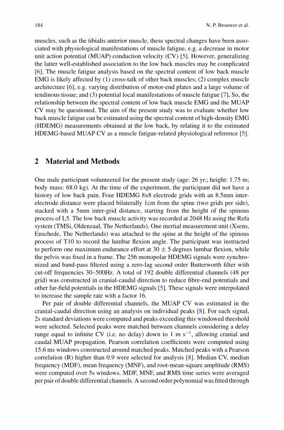
184 N. P. Brouwer et al.
muscles, such as the tibialis anterior muscle, these spectral changes have been asso-ciated with physiological manifestations of muscle fatigue, e.g. a decrease in motorunit action potential (MUAP) conduction velocity (CV) [5]. However, generalizingthe latter well-established association to the low back muscles may be complicated[6]. The muscle fatigue analysis based on the spectral content of low back muscleEMG is likely affected by (1) cross-talk of other back muscles; (2) complex musclearchitecture [6], e.g. varying distribution of motor-end plates and a large volume oftendinous tissue; and (3) potential local manifestations of muscle fatigue [7]. So, therelationship between the spectral content of low back muscle EMG and the MUAPCV may be questioned. The aim of the present study was to evaluate whether lowbackmuscle fatigue can be estimated using the spectral content of high-density EMG(HDEMG) measurements obtained at the low back, by relating it to the estimatedHDEMG-based MUAP CV as a muscle fatigue-related physiological reference [5].
2 Material and Methods
One male participant volunteered for the present study (age: 26 yr.; height: 1.75 m;body mass: 68.0 kg). At the time of the experiment, the participant did not have ahistory of low back pain. Four HDEMG 8x8 electrode grids with an 8.5mm inter-electrode distance were placed bilaterally 1cm from the spine (two grids per side),stacked with a 5mm inter-grid distance, starting from the height of the spinousprocess of L5. The low back muscle activity was recorded at 2048 Hz using the Refasystem (TMSi, Oldenzaal, The Netherlands). One inertial measurement unit (Xsens,Enschede, The Netherlands) was attached to the spine at the height of the spinousprocess of T10 to record the lumbar flexion angle. The participant was instructedto perform one maximum endurance effort at 30 ± 5 degrees lumbar flexion, whilethe pelvis was fixed in a frame. The 256 monopolar HDEMG signals were synchro-nized and band-pass filtered using a zero-lag second order Butterworth filter withcut-off frequencies 30–500Hz. A total of 192 double differential channels (48 pergrid) was constructed in cranial-caudal direction to reduce fibre-end potentials andother far-field potentials in the HDEMG signals [5]. These signals were interpolatedto increase the sample rate with a factor 16.
Per pair of double differential channels, the MUAP CV was estimated in thecranial-caudal direction using an analysis on individual peaks [8]. For each signal,2s standard deviations were computed and peaks exceeding this windowed thresholdwere selected. Selected peaks were matched between channels considering a delayrange equal to infinite CV (i.e. no delay) down to 1 m s−1, allowing cranial andcaudal MUAP propagation. Pearson correlation coefficients were computed using15.6 ms windows constructed around matched peaks. Matched peaks with a Pearsoncorrelation (R) higher than 0.9 were selected for analysis [8]. Median CV, medianfrequency (MDF), mean frequency (MNF), and root-mean-square amplitude (RMS)were computed over 5s windows. MDF, MNF, and RMS time series were averagedper pair of double differential channels.A second order polynomialwas fitted through
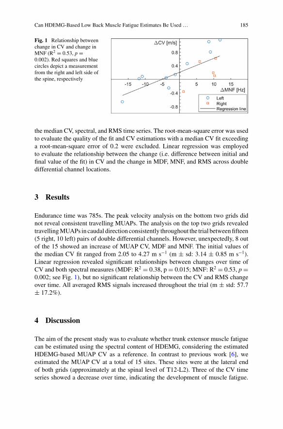
Can HDEMG-Based Low Back Muscle Fatigue Estimates Be Used … 185
Fig. 1 Relationship betweenchange in CV and change inMNF (R2 = 0.53, p =0.002). Red squares and bluecircles depict a measurementfrom the right and left side ofthe spine, respectively
the median CV, spectral, and RMS time series. The root-mean-square error was usedto evaluate the quality of the fit and CV estimations with a median CV fit exceedinga root-mean-square error of 0.2 were excluded. Linear regression was employedto evaluate the relationship between the change (i.e. difference between initial andfinal value of the fit) in CV and the change in MDF, MNF, and RMS across doubledifferential channel locations.
3 Results
Endurance time was 785s. The peak velocity analysis on the bottom two grids didnot reveal consistent travelling MUAPs. The analysis on the top two grids revealedtravellingMUAPs in caudal direction consistently throughout the trial betweenfifteen(5 right, 10 left) pairs of double differential channels. However, unexpectedly, 8 outof the 15 showed an increase of MUAP CV, MDF and MNF. The initial values ofthe median CV fit ranged from 2.05 to 4.27 m s−1 (m ± sd: 3.14 ± 0.85 m s−1).Linear regression revealed significant relationships between changes over time ofCV and both spectral measures (MDF: R2 = 0.38, p= 0.015; MNF: R2 = 0.53, p=0.002; see Fig. 1), but no significant relationship between the CV and RMS changeover time. All averaged RMS signals increased throughout the trial (m ± std: 57.7± 17.2%).
4 Discussion
The aim of the present study was to evaluate whether trunk extensor muscle fatiguecan be estimated using the spectral content of HDEMG, considering the estimatedHDEMG-based MUAP CV as a reference. In contrast to previous work [6], weestimated the MUAP CV at a total of 15 sites. These sites were at the lateral endof both grids (approximately at the spinal level of T12-L2). Three of the CV timeseries showed a decrease over time, indicating the development of muscle fatigue.
186 N. P. Brouwer et al.
However, the majority of the CV time series showed an increase, and this coincidedwith an increase in frequency content (Fig. 1). Asmight be supported by the observedincrease in amplitude for all channels, this could be related to additional recruitmentof larger, faster and more superficial motor units due to the reduced force capacityof the already recruited and fatigued motor units [6]. Additionally, this could alsobe related to alternating activity of synergistic trunk extensor muscles [7]. Bothmanifestations may have masked fatigue related spectral and CV changes.
The bottom two grids and medial side of the upper grids yielded no successfulMUAP CV estimates, probably due to the complex low back muscle architecture.Placement of electrodes close to the innervation zones or fibre-ends of musclescan affect the CV estimates and result in additional high frequency content [9].Nevertheless, the results of the present study indicate a potential anatomical loca-tion where the CV and low back muscle fatigue can be estimated using HDEMG.Future studies should evaluate the consistency of the present finding regarding theanatomical location of the CV estimates across subjects.
5 Conclusion
In the present pilot study, we estimated the trunk extensorMUAPCV using HDEMGfor multiple sites consistently throughout a 30 degrees lumbar flexion endurancetrial. Hence, the relationship between the CV and shift of the corresponding spectralcontent could be evaluated for the trunk extensor muscles. However, estimating trunkextensor muscle fatigue based on CV or surface EMG spectral content appears notfeasible yet, possibly due to the additional recruitment of motor units or alternatingactivity of synergistic muscles.
Acknowledgements This work was supported by the Dutch Research Council (NWO), program‘perspectief’ (project P16-05).
References
1. P. Coenen, I. Kingma et al., Cumulative low back load at work as a risk factor of low back pain:a prospective cohort study. J. Occup. Rehabil. 23(1), 11–18 (2013)
2. W.E. Hoogendoorn, P.M. Bongers, et al., Flexion and rotation of the trunk and lifting at workare risk factors for low back pain. Spine (Phila. Pa. 1976), 25(23), 3087–3092 (2000)
3. J.H. van Dieën, E.P. Westebring-van der Putten et al., Low-level activity of the trunkextensor muscles causes electromyographic manifestations of fatigue in absence of decreasedoxygenation. J. Electromyogr. Kinesiol. 19(3), 398–406 (2009)
4. J.H. van Dieën, H.H.E. Oude Vrielink, et al., Trunk extensor endurance and its relationship toelectromyogram parameters. Eur. J. Appl. Physiol. 66(5), 388–396 (1993)
5. R.Merletti, M. Knaflitz et al., Myoelectric manifestations of fatigue in voluntary and electricallyelicited contractions. J. Appl. Physiol. 69(5), 1810–1820 (1990)

Can HDEMG-Based Low Back Muscle Fatigue Estimates Be Used … 187
6. D. Farina, M. Gazzoni et al., Assessment of low back muscle fatigue by surface EMG signalanalysis: Methodological aspects. J. Electromyogr. Kinesiol. 13(4), 319–332 (2003)
7. J.H. Van Dieën, H.H.E. Oude Vrielink, et al., An investigation into the relevance of the patternof temporal activation with respect to erector spinae muscle endurance. Eur. J. Appl. Physiol.66(1), 70–75 (1993)
8. R.B.J. Beck, C.J. Houtman et al., A technique to track individual motor unit action potentials insurface EMG by monitoring their conduction velocities and amplitudes. IEEE Trans. Biomed.Eng. 52(4), 622–629 (2005)
9. J.Y. Hogrel, J. Duchêne et al., Variability of some SEMG parameter estimates with electrodelocation. J. Electromyogr. Kinesiol. 8(5), 305–315 (1998)
Back-Support Exoskeleton Control UsingUser’s Torso Acceleration and Velocity toAssist Manual Material Handling
Maria Lazzaroni, Ali Tabasi, Stefano Toxiri, Darwin G. Caldwell,Idsart Kingma, Elena De Momi, and Jesús Ortiz
Abstract This work analyzes the use of users’ dynamics to define the assistance ofa back-support exoskeleton for assisting manual material handling. Exploiting theacceleration and velocity of the user’s torso on the sagittal plane allows to distinguishbetween lifting and lowering phases and accordingly adapt the assistance. Theoreticaland practical issues of strategy implementation are discussed.
1 Introduction
In many industrial sectors, workers performmanual material handling (MMH) activ-ities, that overload and compress the spine causing injuries and musculoskeletal dis-orders (MSDs). Back-support exoskeletons are being introduced in industries, wherefull-automation is not feasible and human’s flexibility is required [1]. Exoskeletonspromise to reduce the MSDs risk, by reducing the compression of the spine [2].
Our group has developed a torque-controlled back-support exoskeleton for whichwe explore different possible control strategies to suit the need for assistance. Forimproving the effectiveness of the assistance provided in dynamic MMH tasks withrespect to state-of-the-art methods, valuable information can be obtained from theuser’s dynamics during the execution of the task. In a previous work [3] we presenteda new strategy that uses the user’s torso angular acceleration for assisting symmetriclifting and lowering, while a similar device [4] employed the torso angular velocityfor the same purpose.
Work funded by the Italian Workers’ Compensation Authority (INAIL).
M. Lazzaroni (B) · S. Toxiri · D. G. Caldwell · J. OrtizDepartment of Advanced Robotics, Istituto Italiano di Tecnologia, Genova, Italye-mail: [email protected]
M. Lazzaroni · E. De MomiDepartment of Electronics, Information and Bioengineering, Politecnico di Milano, Milan, Italy
A. Tabasi · I. KingmaDepartment of Human Movement Sciences, Faculty of Behavioural and Movement Sciences,Vrije Universiteit Amsterdam, Amsterdam, The Netherlands
© The Author(s), under exclusive license to Springer Nature Switzerland AG 2022J. C. Moreno et al. (eds.), Wearable Robotics: Challenges and Trends,Biosystems & Biorobotics 27, https://doi.org/10.1007/978-3-030-69547-7_31
189
190 M. Lazzaroni et al.
This work analyzes the difference of designing a control strategy using the accel-eration against using the velocity for assisting lifting and lowering tasks. The strate-gies were implemented on the XoTrunk back-support exoskeleton, an evolution ofthe prototype employed in [3].
2 Control Strategies
2.1 Rationale for Using User’s Dynamics
Most current strategies for assisting lifting and lowering tasks act to compensate forthe effect of gravity [1]. The assistance is based on the static characteristics of theuser’smovement (mainly torso inclination), and thuswould not adapt to different taskphases. An inclination-based strategy generates the peak assistance correspondingwith the maximum torso flexion, as happens for a passive exoskeleton.
However, as clarified in [5], the lumbar moment reaches its peak at the beginningof lifting, i.e. when the user grasps the box and starts to lift it (after the maximumflexion occurred), because upper body mass and the mass of the load requires accel-eration upwards. As a result, (1) an inclination-based strategy would not generatethe peak assistance corresponding with the peak in torque need [5]. Moreover, pro-viding the same assistive torque during the descent phase (lowering) and the ascentphase (lifting) (2) limits the maximum physical assistance, because increasing assis-tance in the latter corresponds to increasing hindrance in the former. Therefore, forinclination-based strategies, as for passive exoskeletons, the assistance provided forsupporting the user during lifting must be scaled according to his acceptance of hin-drance during lowering. because he has to accelerate upward his mass plus the massof the box.
Measuring the dynamics of the user’s torso allows to distinguish the lowering andthe lifting phases, and thus assist them differently. If the angular acceleration of theuser’s torso is used to proportionally define the assistive torque, additional supportis provided accordingly with the peak in the assistance need (1) i.e., when the usergrasps the box and starts the lifting phase, accelerating his and the box’s masses.On the other end, the reduction of the assistance due to the inclination-based torqueduring the lowering phase, achieved by employing the torso acceleration or velocity,reduces the hindrance for the flexion of the torso (2).
2.2 Implementation
Focusing on overcoming these two limitations (1) and (2), in a previous work [3]we presented a new strategy making use of the user’s torso angular acceleration.
Back-Support Exoskeleton Control Using User’s Torso Acceleration … 191
Additionally, we implemented a strategy based on user’s torso angular velocity onthe same exoskeleton for comparing the two strategies.
The angular velocity θh is measured with an Xsens MTw IMU (Xsens Technol-ogy), attached to the user’s torso (approximately at the sternum). The angular acceler-ation θh is obtained by differentiating and filtering the angular velocity on the sagittalplane (low-pass filter, cut-off frequency 1Hz). Then, dynamic torques τdynamic aredefined proportional to the torso angular velocity or acceleration, while the statictorque τstatic is proportional to torso inclination. The assistive torque τassistive isfinally computed as the sum of the static (inclination-based) and the dynamic (veloc-ity or acceleration-based) torques, that can be scaled adjusting the respective controlgains K :
τassistive = τstatic + τdynamic
τstatic = Kincl sin(θh) inclination-based
τdynamic =−Kvel θh velocity-based
−Kacc θh acceleration-based
In the following,acceleration and velocity strategies indicates that the assistive torqueis computed as the sum of the inclination-based with velocity or acceleration-basedtorques, respectively. The inclination strategy has τdynamic = 0.
3 Experimental Results
Experiments were done with 9 subjects. The differences in lumbar compressionpeaks (estimated as in [2]) of velocity and acceleration strategy w.r.t the conditionwithout the exoskeleton were statistically significant (ANOVA test, p < 0.05). Thedifference between velocity and acceleration strategy (compression force reductionsw.r.t no exoskeleton equal to 11% and 15%, respectively) was not significant.
4 Discussion
A noticeable difference between velocity and acceleration signals emerges at thebeginning of lifting (c), when the subject is accelerating upwards. As the accelera-tion increases, the acceleration strategy provides greater assistance which is in time
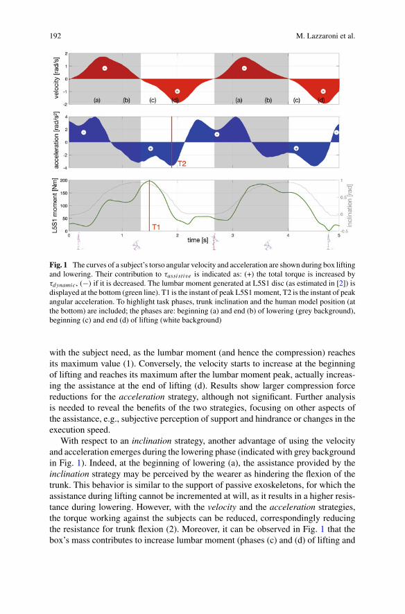
192 M. Lazzaroni et al.
Fig. 1 The curves of a subject’s torso angular velocity and acceleration are shown during box liftingand lowering. Their contribution to τassistive is indicated as: (+) the total torque is increased byτdynamic, (−) if it is decreased. The lumbar moment generated at L5S1 disc (as estimated in [2]) isdisplayed at the bottom (green line). T1 is the instant of peak L5S1moment, T2 is the instant of peakangular acceleration. To highlight task phases, trunk inclination and the human model position (atthe bottom) are included; the phases are: beginning (a) and end (b) of lowering (grey background),beginning (c) and end (d) of lifting (white background)
with the subject need, as the lumbar moment (and hence the compression) reachesits maximum value (1). Conversely, the velocity starts to increase at the beginningof lifting and reaches its maximum after the lumbar moment peak, actually increas-ing the assistance at the end of lifting (d). Results show larger compression forcereductions for the acceleration strategy, although not significant. Further analysisis needed to reveal the benefits of the two strategies, focusing on other aspects ofthe assistance, e.g., subjective perception of support and hindrance or changes in theexecution speed.
With respect to an inclination strategy, another advantage of using the velocityand acceleration emerges during the lowering phase (indicated with grey backgroundin Fig. 1). Indeed, at the beginning of lowering (a), the assistance provided by theinclination strategy may be perceived by the wearer as hindering the flexion of thetrunk. This behavior is similar to the support of passive exoskeletons, for which theassistance during lifting cannot be incremented at will, as it results in a higher resis-tance during lowering. However, with the velocity and the acceleration strategies,the torque working against the subjects can be reduced, correspondingly reducingthe resistance for trunk flexion (2). Moreover, it can be observed in Fig. 1 that thebox’s mass contributes to increase lumbar moment (phases (c) and (d) of lifting and
Back-Support Exoskeleton Control Using User’s Torso Acceleration … 193
(a) and (b) of lowering). A solution to account for this need of additional assistancewas evaluated in [2]: the assistance is increased when a load is detected on user’shands.
As regards the acceleration strategy, one limitation concerns the delay of theacceleration signal (T1-T2 in Fig. 1), as it results in the delay of the dynamic com-ponent of the assistance. Furthermore, stability may also be compromised, if theacceleration is overestimated. As this controller acts as compensating the inertia ofthe user’s upper body, overcompensating may lead to feedback inversion and insta-bility [6]. On the contrary, with the velocity strategy, force augmentation is achievedby positive feedback (i.e., the generated forces augment the movement initiated bythe wearer) that was proved to decrease the user’s stability [3]. A further limitationfor both strategies, particularly related with real workplace use, is the need to addan IMU on the user’s torso to acquire the angular velocity, instead of using the oneembedded in the exoskeleton. The need for this sensor is due to the user-exoskeletoncoupling, which allows for relative movement between the two, i.e., the motion ofthe exoskeleton is delayed respect to the user’s torso motion.
References
1. S. Toxiri, M.B. Näf, M. Lazzaroni, J. Fernández, M. Sposito, T. Poliero, L. Monica, S. Anas-tasi, D.G. Caldwell, J. Ortiz, Back-support exoskeletons for occupational use: an overview oftechnological advances and trends. IISE Trans. Occup. Ergon. Human Factors, 1–13 (2019)
2. A.S. Koopman, S. Toxiri, V. Power, I. Kingma, J.H. van Dieën, J. Ortiz, M.P. de Looze, Theeffect of control strategies for an active back-support exoskeletonon spine loading andkinematicsduring lifting. J. Biomech. (2019)
3. M. Lazzaroni, S. Toxiri, D.G. Caldwell, S. Anastasi, L. Monica, E. De Momi, J. Ortiz,Acceleration-based assistive strategy to control a back-support exoskeleton for load handling:preliminary evaluation, in 2019 IEEE 16th International Conference on Rehabilitation Robotics(ICORR) (2019)
4. H.K. Ko, S.W. Lee, D. Koo, I. Lee, D.J. Hyun,Waist-assistive exoskeleton powered by a singularactuation mechanism for prevention of back-injury. Robot. Auton. Syst. (2018)
5. A. S. Koopman, S. Toxiri, M.P. de Looze, I. Kingma, J.H. van Dieën, Effects of an inclination-controlled active spinal exoskeleton on spinal compression forces, in International Symposiumon Wearable Robotics, pp. 505–509 (2018)
6. A. Calanca, R. Muradore, P. Fiorini, Impedance control of series elastic actuators: passivity andacceleration-based control. Mechatronics 47, 37–48 (2017)
Subjective Assessment of OccupationalExoskeletons: Feasibility Study for aCustom Survey for Braces
M. Sposito, D. G. Caldwell, E. De Momi, and J. Ortiz
Abstract Occupational exoskeletons are emerging as a viable solution to mitigatethe effect of poor ergonomicwork tasks.However, there is still a lackof understandingof which are the key factors to improve the low acceptance rate, from a subjectivepoint of view. Effectively translating users’ feedback in requirements is of paramountimportance to raise adoption of exoskeletons. To this end, we present and evaluatea tailored set of constructs and questions to collect subjective ratings of braces, thatare the physical interface between users and exoskeletons and play a key role inacceptance rate.
1 Introduction
Occupational Exoskeletons (OEs) are showing their effectiveness to lower riskinjuries in un-ergonomic working tasks [1]. Researchers and designers still lacka substantial acceptance assessment from users because OE’s effectiveness is provedmostly in laboratory setups [2]. In particular, choosing a proper design to raisecomfort is central to enhance OE’s acceptance rates. Indeed, balancing mechani-cal requirements, human factors and users’ requirements is difficult and requiresintensive testing and effective data collection methods. In this paper we introduce afirst attempt to collect data of subjective comfort of an OE physical interfaces. Bracescan be composed of rigid shells (e.g. cuff) and compliant textiles (e.g. harness) andthey have two key functions: secure the exoskeleton to the limbs and unload assis-tance to the users. However, standard collection forms, like SUS or Nasa TLX, are
M. Sposito (B) · E. D. MomiDepartment of Electronics, Information and Bioengineering (DEIB), Politecnico di Milano,Milan, Italye-mail: [email protected]
M. Sposito · D. G. Caldwell · J. OrtizAdvanced Robotic Department (ADVR), Istituto Italiano di Tecnologia, Genova, Italy
© The Author(s), under exclusive license to Springer Nature Switzerland AG 2022J. C. Moreno et al. (eds.), Wearable Robotics: Challenges and Trends,Biosystems & Biorobotics 27, https://doi.org/10.1007/978-3-030-69547-7_32
195
196 M. Sposito et al.
not suitable to collect all the subjective perceptions regarding all of the OE’s com-ponents. In fact, [3, 4] and [5] present custom-made survey to collect subjective dataabout distinct parts of exoskeletons. We present a feasibility study of our customquestionnaire on an active OE and two different braces version (Alpha and Beta).We will show the subjective scores of the two versions and perform a formativeevaluation of the proposed custom constructs and items for the survey.
2 Methods
The feasability tests were conducted using the procotol described in this section. Wefirst introduce the physical arrangement that allow subjects to complete the sequenceof tasks. Work pattern reasonably resemble real activities to rate the comfort withcustom survey.
2.1 Experimental Setup
The experiments were performed using the XoTrunk, an updated revision of theOE presented in [6]. XoTrunk assists the lumbar region in tasks that, due to muscleoverload, could increase the risks of injuries; like carrying, lifting and lowering a load(i.e. Manual Material Handling (MMH)). The test is composed of a pattern, close toreal-work scenarios, repeated for 10 mins at a self-determined pace. Repetitions areperformed wearing always the same exoskeleton, varying braces’ version. The loadL is a 7kg box, for all the subjects. The pattern is composed of lifting, lowering,squatting, walking and carrying, details are provided in Table 1 and Fig. 1.
The subjects move between two different boxes, B1 and B2, with distinct heights(50 and 70cm). B1 and B2 allow the subjects to lower and lift L with differentbending angles and distinct techniques. NIOSH score of the test is 0.9, resemblinga low risk MMH activity. All the subjects were given 5min familiarization with theactivities, with and without the exoskeleton in one configuration. Assistance levelswere chosen during familiarization, based on each personal preferences and were thesame for the two trials. Assistance profiles are the same of the ones presented in [6].XoTrunk was fitted with the right harness sizes (where possible) to fit the subjects’body sizes and shapes.
2.2 Experimental Design
We chose 6 healthy volunteers (age 28± 2.2 years, height 171± 7.1 cm) for thetest. XoTrunk could be adjusted to fit every volunteer and be secured to the limbs, nosubject was excluded. The population is equally divided between males and females
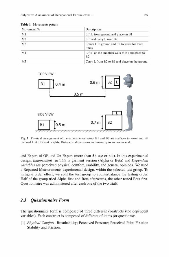
Subjective Assessment of Occupational Exoskeletons … 197
Table 1 Movements pattern
Movement Nr Description
M1 Lift L from ground and place on B1
M2 Lift and carry L over B2
M3 Lower L to ground and lift to waist for threetimes
M4 Lift L on B2 and then walk to B1 and back toB2
M5 Carry L from B2 to B1 and place on the ground
Fig. 1 Physical arrangement of the experimental setup. B1 and B2 are surfaces to lower and liftthe load L at different heights. Distances, dimensions and mannequin are not in scale
and Expert of OE and Un-Expert (more than 5h use or not). In this experimentaldesign, Independent variable is garment version (Alpha or Beta) and Dependentvariables are perceived physical comfort, usability, and general opinions. We useda Repeated Measurements experimental design, within the selected test group. Tomitigate order effect, we split the test group to counterbalance the testing order.Half of the group tried Alpha first and Beta afterwards, the other tested Beta first.Questionnaire was administered after each one of the two trials.
2.3 Questionnaire Form
The questionnaire form is composed of three different constructs (the dependentvariables). Each construct is composed of different of items (or questions):
(1) Physical Comfort: Breathability; Perceived Pressure; Perceived Pain; FixationStability and Friction.
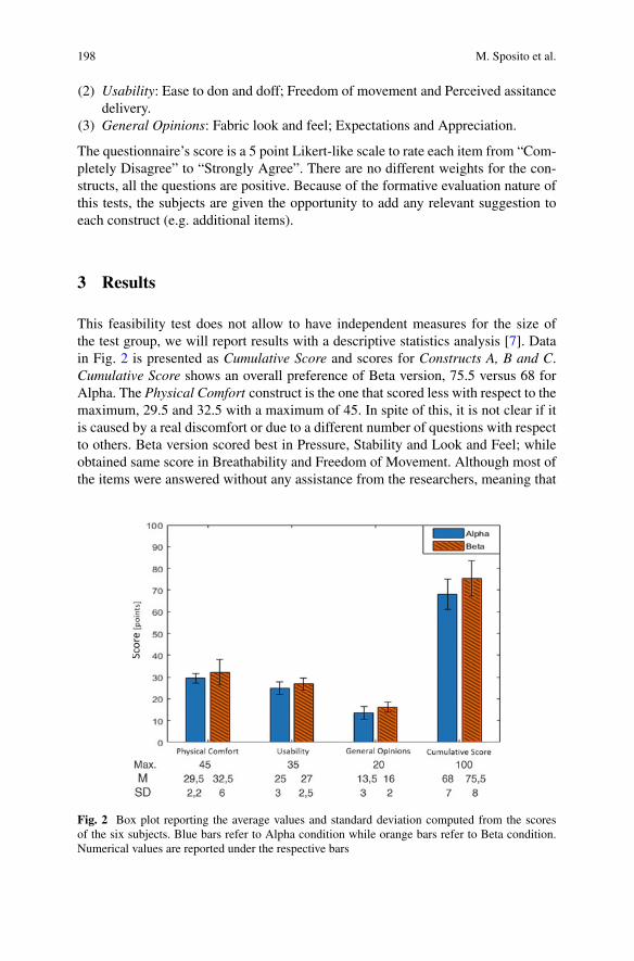
198 M. Sposito et al.
(2) Usability: Ease to don and doff; Freedom of movement and Perceived assitancedelivery.
(3) General Opinions: Fabric look and feel; Expectations and Appreciation.
The questionnaire’s score is a 5 point Likert-like scale to rate each item from “Com-pletely Disagree” to “Strongly Agree”. There are no different weights for the con-structs, all the questions are positive. Because of the formative evaluation nature ofthis tests, the subjects are given the opportunity to add any relevant suggestion toeach construct (e.g. additional items).
3 Results
This feasibility test does not allow to have independent measures for the size ofthe test group, we will report results with a descriptive statistics analysis [7]. Datain Fig. 2 is presented as Cumulative Score and scores for Constructs A, B and C.Cumulative Score shows an overall preference of Beta version, 75.5 versus 68 forAlpha. The Physical Comfort construct is the one that scored less with respect to themaximum, 29.5 and 32.5 with a maximum of 45. In spite of this, it is not clear if itis caused by a real discomfort or due to a different number of questions with respectto others. Beta version scored best in Pressure, Stability and Look and Feel; whileobtained same score in Breathability and Freedom of Movement. Although most ofthe items were answered without any assistance from the researchers, meaning that
Fig. 2 Box plot reporting the average values and standard deviation computed from the scoresof the six subjects. Blue bars refer to Alpha condition while orange bars refer to Beta condition.Numerical values are reported under the respective bars
Subjective Assessment of Occupational Exoskeletons … 199
the question meets the requirements of good wording, unambiguity and correct scoresystem, we were asked to add: Not Applicable for items in Usability and GeneralOpinions, increase the score to 7 points and add items for evaluation of single bodyarea in contact with the braces, especially in Physical Comfort.
4 Conclusion
We were able to collect valuable information from this formative evaluation: exper-imental protocol and the custom made constructs can be improved implementingtest subjects’ suggestions to overcome the problems highlighted. Though, the cus-tom questionnaire proved to be a good starting point. Indeed, data shows that Betaversion is preferred for every construct over Alpha, though no advancements wereconfirmed in Breathability and Freedom of Movement. A new testing campaigninvolving more users will allow to apply a between group experimental design andobtain relevant data, informing on how different brace’s version can affect user’scomfort and OE’s acceptance rate.
Acknowledgements This work has been co-founded by the Italian Workers’ CompensationAuthority (INAIL), The authors would like to thank Dr. G. Barresi for the helpful suggestionsregarding the experimental setup and analysis methods.
References
1. M.A. Nussbaum, B.D. Lowe, M. de Looze, C. Harris-Adamson, M. Smets, An introduction tothe special issue on occupational exoskeletons. IISE Trans. Occup. Ergon. Human Fact. 7(3–4),153–162 (2019)
2. L. Stirling, H.C. Siu, E. Jones, K. Duda, Human factors considerations for enabling functionaluse of exosystems in operational environments. IEEE Syst. J. 13(1), 1072–1083 (2019)
3. L. Shore et al., Exoscore: a design tool to evaluate factors associated with technology acceptanceof soft lower limb exosuits by older adults. Human Fact. (2019)
4. R. Hensel, M. Keil, Subjective evaluation of a passive industrial exoskeleton for lower-backsupport: a field study in the automotive sector. IISE Trans. Occup. Ergon. Human Fact. 7(3–4),213–221 (2019)
5. P. Maurice et al., Objective and subjective effects of a passive exoskeleton on overhead work.IEEE Trans. Neural Syst. Rehabil. Eng. 28(1), 152–164 (2020)
6. S. Toxiri, A.S. Koopman, M. Lazzaroni, J. Ortiz, V. Power, M.P. de Looze, L. O’Sullivan,D.G. Caldwell, Rationale, implementation and evaluation of assistive strategies for an activeback-support exoskeleton. Front. Robot. AI 5 (2018)
7. E.C. Lee, A.L. Whitehead, R.M. Jacques, S.A. Julious, The statistical interpretation of pilottrials: should significance thresholds be reconsidered? BMC Med. Res. Methodol. (2014)
Evidenced-BasedIndications/Contraindications
for and Potential Benefitsof Exoskeletal-Assisted Walking in Persons
with Spinal Cord Injury
Alteration of Push-Off Mechanics DuringWalking with Different PrototypeDesigns of a Soft Exoskeleton in Peoplewith Incomplete Spinal CordInjury—A Case Series
Eveline S. Graf, Christoph M. Bauer, Carole Pauli, and Markus Wirz
Abstract The push-off is a key factor determining the walking capability. Peoplewith impaired function due to incomplete spinal cord injury (iSCI) have alteredbiomechanics and are, therefore, at a disadvantage during activities of daily livingsuch as walking. XoSoft is a prototype soft exoskeleton designed to assist duringwalking. Different generations of XoSoft followed different strategies of tailoringthe garment (custom-made vs. one-size fits all). This may result in altered effects onthe mechanics of walking. In this study, we assessed two generations of XoSoft withthree people with iSCI and focused on the push-off mechanics (ankle kinematics &kinetics) during level walking. The results showed that XoSoft was able to supportthe gait, but systematic differences between prototype generations were not found.Consequently, a more general approach for the garment design may be feasible.
1 Introduction
The ankle joint and its ability to produce power during push-off is highly relevantfor gait [1, 2]. It has been shown that modulation of the peak ankle power has directimpact on the workload of the proximal leg muscles [2]. If people are unable toproduce the necessary power at the ankle, due to impairments such as incompletespinal cord injury (iSCI), the more proximal joint muscles, mainly at the hip, mayneed to compensate in order to allow for walking ability, which presents amechanicaldisadvantage. It has been shown that people with iSCI have altered ankle kinematicsand kinetics during different walking tasks [3, 4]. Also, it has been shown that theplantarflexor muscles have diminished ability to produce torque [5]. Consequently,they are at a disadvantage during everyday motion tasks such as walking.
Previous work using custom powered ankle-foot orthoses supporting the plan-tarflexion have shown that the ankle range of motion was increased with a powered
E. S. Graf (B) · C. M. Bauer · C. Pauli · M. WirzSchool of Health Professions, Institute of Physiotherapy, Zurich University of Applied Sciences,Winterthur, Switzerlande-mail: [email protected]
© The Author(s), under exclusive license to Springer Nature Switzerland AG 2022J. C. Moreno et al. (eds.), Wearable Robotics: Challenges and Trends,Biosystems & Biorobotics 27, https://doi.org/10.1007/978-3-030-69547-7_33
203
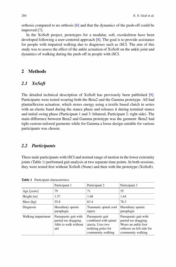
204 E. S. Graf et al.
orthosis compared to no orthosis [6] and that the dynamics of the push-off could beimproved [7].
In the XoSoft project, prototypes for a modular, soft, exoskeleton have beendeveloped following a user-centered approach [8]. The goal is to provide assistancefor people with impaired walking due to diagnoses such as iSCI. The aim of thisstudy was to assess the effect of the ankle actuation of XoSoft on the ankle joint anddynamics of walking during the push-off in people with iSCI.
2 Methods
2.1 XoSoft
The detailed technical description of XoSoft has previously been published [9].Participants were tested wearing both the Beta2 and the Gamma prototype. All hadplantarflexion actuation, which stores energy using a textile based clutch in serieswith an elastic band during the stance phase and releases it during terminal stanceand initial swing phase (Participant 1 and 3: bilateral, Participant 2: right side). Themain difference between Beta2 and Gamma prototype was the garment: Beta2 hadtight custom-tailored garments while for Gamma a loose design suitable for variousparticipants was chosen.
2.2 Participants
Three male participants with iSCI and normal range of motion in the lower extremityjoints (Table 1) performed gait analysis at two separate time points. In both sessions,they were tested first without XoSoft (None) and then with the prototype (XoSoft).
Table 1 Participant characteristics
Participant 1 Participant 2 Participant 3
Age [years] 79 71 55
Height [m] 1.57 1.68 1.64
Mass [kg] 55.8 63.4 78.3
Diagnosis Hereditary spasticparaplegia
Traumatic spinal cordinjury
Hereditary spasticparaplegia
Walking impairment Paraspastic gait withpartial toe dragging.Able to walk withoutaid
Paraspastic gaitcombined with spinalataxia. Uses twotrekking poles forcommunity walking
Paraspastic gait withpartial toe dragging.Wears an ankle footorthosis on left side forcommunity walking
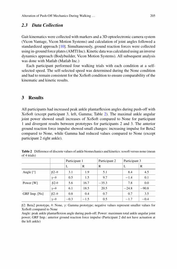
Alteration of Push-Off Mechanics During Walking … 205
2.3 Data Collection
Gait kinematics were collected with markers and a 3D optoelectronic camera system(Vicon Vantage, Vicon Motion Systems) and calculation of joint angles followed astandardized approach [10]. Simultaneously, ground reaction forces were collectedusing in-ground force plates (AMTI Inc). Kinetic datawas calculated using an inversedynamics approach (Bodybuilder, Vicon Motion Systems). All subsequent analysiswas done with Matlab (Matlab Inc.)
Each participant performed four walking trials with each condition at a self-selected speed. The self-selected speed was determined during the None conditionand had to remain consistent for the XoSoft condition to ensure comparability of thekinematic and kinetic results.
3 Results
All participants had increased peak ankle plantarflexion angles during push-off withXoSoft (except participant 3, left, Gamma; Table 2). The maximal ankle angularjoint power showed small increases of XoSoft compared to None for participant1 and divergent results between prototypes for participants 2 and 3. The anteriorground reaction force impulse showed small changes: increasing impulse for Beta2compared to None, while Gamma had reduced values compared to None (exceptparticipant 2 right ankle).
Table 2 Difference of discrete values of ankle biomechanics and kinetics: xosoft versus none (meanof 4 trials)
Participant 1 Participant 2 Participant 3
L R R L R
Angle [°] β2–θ 3.1 1.9 5.1 8.4 4.5
γ–θ 0.5 1.5 9.7 −1.4 0.1
Power [W] β2-θ 5.6 16.7 −35.3 7.8 0.0
γ–θ 6.1 18.5 20.5 −24.8 −90.8
GRF Imp. [Ns] β2–θ 0.8 0.4 0.7 0.7 3.5
γ–θ −0.3 −1.5 0.5 −1.7 −0.4
β2: Beta2 prototype, θ: None, γ: Gamma prototype; negative values represent smaller values forXoSoft compared to NoneAngle: peak ankle plantarflexion angle during push-off; Power: maximum total ankle angular jointpower; GRF Imp.: anterior ground reaction force impulse (Participant 2 did not have actuation atthe left ankle)
206 E. S. Graf et al.
4 Discussion
The increase of peak ankle plantarflexion angle during push-off of walking withXoSoft was a favorable result as it represents a movement pattern that supports amore dynamic push-off, which is necessary for a dynamic walking pattern [1, 6].However, the increased movement does not directly translate into more total jointpower. Participant 1 is able to generate more power with Beta2 and Gamma. Theimprovements were between 5 and 22%. Previous work has shown a decrease injoint moment generation of 26–38% in people with iSCI compared to healthy [5].It can be assumed that XoSoft is able to compensate some of the lost function forparticipant 1. Participant 3 showed small to no effects with Beta2 and reduced powerwith Gamma, while participant 2 was able to benefit from Gamma but not Beta2.
The ground reaction force impulse is one determining factor during the push-offas it propels the body forward [2]. The increases in GRF impulse are between 4 and43%. But, decreases (mainly for Gamma) in the range of 2–11% were also reported.Based on the combination of reported results, no clear trend on which prototypehas more promising effects on the walking mechanics can be concluded. Generally,the actuation strategy of XoSoft can influence the push-off during gait positively,however, not for every person. The participants were only given a short amount oftime to familiarize with XoSoft. Consequently, walking with XoSoft may have beenmore of a challenge than support leading to negative effects of XoSoft for someparticipants.
No clear trend emerged on which approach for garment design is favorable, asparticipant 2 seemed to benefit more from Gamma, for participant 3 it was Beta2that resulted in better outcomes (participant 1 with comparable results for Beta2 andGamma). The design of the garment is essential regarding the functionality of theactuation (anchor points need to be securely fastened to the leg in order to transferthe energy). It may be the individual’s characteristics that determine which designresults in a better fit and, therefore, a transfer of energy. Overall, the approach ofGamma with non-custom garments seems promising to follow up as it appears to becapable to serve the intended purpose.
5 Conclusion
Overall, it can be concluded that XoSoft has the potential to support the dynamicsof gait during push-off. However, there are no consistent findings yet based on thecase-series with three participants. A more systematic approach with larger samplesize is needed now to determine the detailed effects of XoSoft on gait mechanics.
Acknowledgements This work has received funding from the European Union’s Horizon 2020research and innovation programme under grant agreement No. 688175 (XoSoft).
The authors would like to acknowledge the contribution of the whole XoSoft Consortium to theproject and the development of the prototypes.

Alteration of Push-Off Mechanics During Walking … 207
References
1. R.R. Neptune, S.A. Kautz, F.E. Zajac, Contributions of the individual ankle plantar flexors tosupport, forward progression and swing initiation during walking. J. Biomech. 34, 1387–1398(2001)
2. S.N. Fickey,M.G. Browne, J.R. Franz, Biomechanical effects of augmented ankle power outputduring human walking. J. Exp. Biol. 221(22), (2018)
3. E. Desrosiers, C. Duclos, S. Nadeau, Gait adaptation during walking on an inclined pathwayfollowing spinal cord injury. Clin. Biomech. 29(5), 500–505 (2014)
4. A. Pépin, K.E. Norman, H. Barbeau, Treadmill walking in incomplete spinal-cord-injuredsubjects: 1. adaptation to changes in speed. Spinal Cord 41(5), 257–270 (2003)
5. A. Jayaraman et al., Lower extremity skeletal muscle function in persons with incompletespinal cord injury. Spinal Cord 44(11), 680–687 (2006)
6. G.S. Sawicki, A. Domingo, D.P. Ferris, The effects of powered ankle-foot orthoses on jointkinematics and muscle activation during walking in individuals with incomplete spinal cordinjury. J. Neuroeng. Rehabil. 3(3) (2006)
7. L.N. Awad et al., A soft robotic exosuit improves walking in patients after stroke. Sci. Transl.Med. 9(400) (2017)
8. V. Power, A. de Eyto, B. Hartigan, J. Ortiz, L.W. O’Sullivan, Application of a user-centereddesign approach to the development of XoSoft—A lower body soft exoskeleton. Biosyst.Biorobot. 22, 44–48 (2019), Springer International Publishing
9. J. Ortiz, C. Di Natali, D.G. Caldwell, XoSoft—Iterative design of a modular soft lower limbexoskeleton. Biosyst. Biorobot. 22, 351–355 (2019), Springer International Publishing
10. G. Wu et al., ISB recommendation on definitions of joint coordinate system of various jointsfor the reporting of human joint motion—part I: ankle, hip, spine. J. Biomech. 35, 543–548(2002)
The Effect of Exoskeletal-AssistedWalking on Bowel and Bladder Function:Results from a Randomized Trial
Peter H. Gorman, Gail F. Forrest, Pierre K. Asselin, William Scott,Stephen Kornfeld, Eunkyoung Hong, and Ann M. Spungen
Abstract A three center randomized controlled crossover clinical trial ofexoskeletal-assisted walking (EAW) compared to usual activity (UA) in people withchronic spinal cord injury (SCI) was performed. As secondary outcome measures,the effect of this intervention on bowel and bladder function was assessed using the10Q Bowel function Survey, the Bristol Stool Form Scale (BFS) and the bowel andbladder components of the Spinal Cord InjuryQuality of Life (SCI-QOL) instrument.Fifty subjects were completed the study, with bowel and bladder data available for49. The amount of time needed for the bowel program on average was reduced in24% of the participants after EAW. There was a trend toward normalization of stoolform noted. There were no significant effects in patient reported outcomes for bowelor bladder function on the SCI-QOL components, although time since injury mayhave played a role.
P. H. Gorman (B)University of Maryland School of Medicine, Baltimore, Maryland, USA
University of Maryland Rehabilitation and Orthopaedic Institute, Baltimore, Maryland, USA
G. F. ForrestKessler Foundation, West Orange, NJ, USA
Rutgers New Jersey Medical School-Rutgers University, Newark, NJ, USA
P. K. Asselin · E. Hong · A. M. SpungenSpinal Cord Damage Research Center, James J. Peters VA Medical Center, Bronx, NY, USA
P. K. Asselin · S. Kornfeld · E. Hong · A. M. SpungenIcahn School of Medicine at Mount Sinai, New York, NY, USA
W. ScottVA Maryland Healthcare System, Baltimore, MD, USA
S. KornfeldSpinal Cord Injury Service and the Spinal Cord Damage Research Center, James J. Peters VAMedical Center, Bronx, NY, USA
© The Author(s), under exclusive license to Springer Nature Switzerland AG 2022J. C. Moreno et al. (eds.), Wearable Robotics: Challenges and Trends,Biosystems & Biorobotics 27, https://doi.org/10.1007/978-3-030-69547-7_34
209
210 P. H. Gorman et al.
1 Introduction
Spinal cord injury (SCI) is well known to adversely affect bowel [1–3] and bladderfunction [4, 5]. Constipation related to slowed transit time and a sedentary lifestyleis a major issue as is incomplete bladder emptying related to positioning in non-ambulatory individuals. There are some suggestions that frequent upright posture[6] and locomotor training [7] could help bowel function in SCI, but the data isinconclusive [8]. Exoskeletal-assistedwalkingmaybe another intervention that couldpotentially improve bowel and bladder function in this population [9]. We thereforeproposed a randomized clinical trial of the effects of 36 sessions of exoskeletal-assisted walking on bowel and bladder function in individuals with chronic non-ambulatory SCI.
2 Materials and Methods
We designed and implemented a three-center randomized crossover controlled clin-ical trial of exoskeletal-assisted walking (EAW) in non-ambulatory individuals withchronic SCI (>6 months post injury). As secondary outcome measures, we inves-tigated whether this intervention would improve bowel and bladder function ascompared to usual activity (UA).
Individuals were screened using a complete history and physical examinationincorporating the following: the International Standards for Neurological Classifica-tion of SCI (ISNCSCI) examination to determine level and completeness of injury,range of motion at the hips, knees and ankles bilaterally, Ashworth spasticity exami-nation in the lower extremities, standing orthostatic tolerance test, and bone mineraldensity (BMD) scanning of bilateral knees (proximal tibia and distal femur) and hips(femoral neck and total hip) by Dual Energy X-ray Absorptiometry (DXA).
Eligible participants were randomized within site to one of two groups for 12weeks (three months): Group 1 received EAW first, three times per week for 12weeks then crossover (UA) for a second 12 weeks; Group 2 received UA first for 12weeks then crossover to EAW for 12 weeks of training.
Two powered exoskeleton devices were used in this study, namely theReWalk 6.0® (ReWalk Robotics, Marlborough, MA) [10] and the Ekso GT® (EksoBionics, Richmond, CA) [11]. These powered exoskeletons were chosen becausethey were the only devices commercially available and FDA approved for use withinrehabilitation centers at the time of study development.
Within the first two sessions, standing balance skills were practiced and achievedprior to progression to walking skills. Walking skills were then initiated utilizinga weight shifting pattern. Continuous walking resulted from serial performance ofweight shifting. Participants were advanced in their degree of activity and number ofsteps based on individual progress as determined by the instructing trainer. Missed
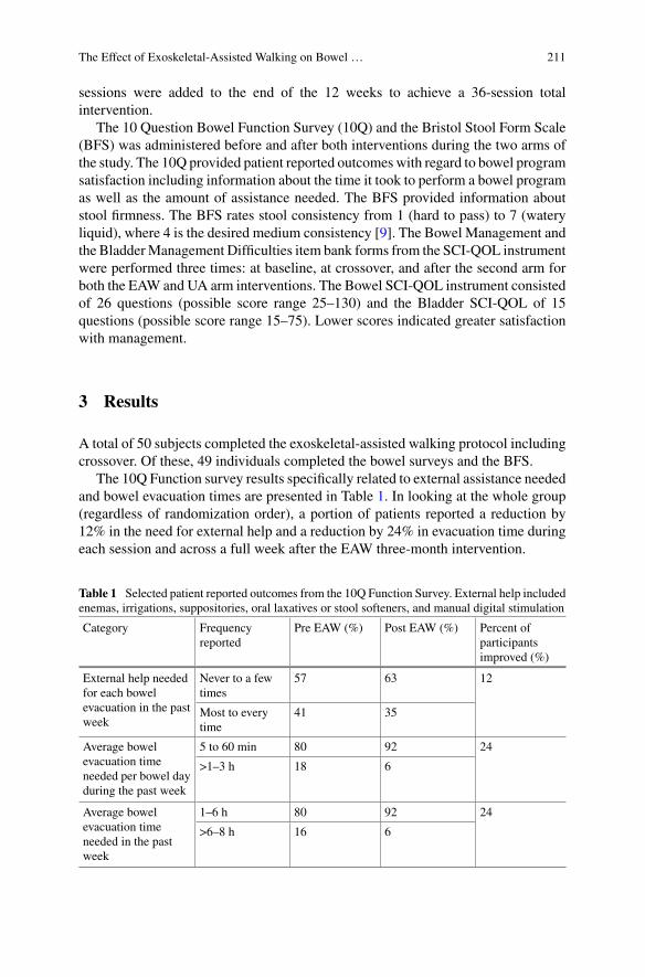
The Effect of Exoskeletal-Assisted Walking on Bowel … 211
sessions were added to the end of the 12 weeks to achieve a 36-session totalintervention.
The 10 Question Bowel Function Survey (10Q) and the Bristol Stool Form Scale(BFS) was administered before and after both interventions during the two arms ofthe study. The 10Q provided patient reported outcomes with regard to bowel programsatisfaction including information about the time it took to perform a bowel programas well as the amount of assistance needed. The BFS provided information aboutstool firmness. The BFS rates stool consistency from 1 (hard to pass) to 7 (wateryliquid), where 4 is the desired medium consistency [9]. The Bowel Management andthe BladderManagement Difficulties item bank forms from the SCI-QOL instrumentwere performed three times: at baseline, at crossover, and after the second arm forboth the EAW and UA arm interventions. The Bowel SCI-QOL instrument consistedof 26 questions (possible score range 25–130) and the Bladder SCI-QOL of 15questions (possible score range 15–75). Lower scores indicated greater satisfactionwith management.
3 Results
A total of 50 subjects completed the exoskeletal-assisted walking protocol includingcrossover. Of these, 49 individuals completed the bowel surveys and the BFS.
The 10Q Function survey results specifically related to external assistance neededand bowel evacuation times are presented in Table 1. In looking at the whole group(regardless of randomization order), a portion of patients reported a reduction by12% in the need for external help and a reduction by 24% in evacuation time duringeach session and across a full week after the EAW three-month intervention.
Table 1 Selected patient reported outcomes from the 10Q Function Survey. External help includedenemas, irrigations, suppositories, oral laxatives or stool softeners, and manual digital stimulation
Category Frequencyreported
Pre EAW (%) Post EAW (%) Percent ofparticipantsimproved (%)
External help neededfor each bowelevacuation in the pastweek
Never to a fewtimes
57 63 12
Most to everytime
41 35
Average bowelevacuation timeneeded per bowel dayduring the past week
5 to 60 min 80 92 24
>1–3 h 18 6
Average bowelevacuation timeneeded in the pastweek
1–6 h 80 92 24
>6–8 h 16 6
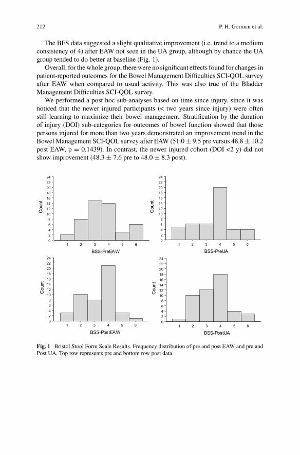
212 P. H. Gorman et al.
The BFS data suggested a slight qualitative improvement (i.e. trend to a mediumconsistency of 4) after EAW not seen in the UA group, although by chance the UAgroup tended to do better at baseline (Fig. 1).
Overall, for thewhole group, therewere no significant effects found for changes inpatient-reported outcomes for the Bowel Management Difficulties SCI-QOL surveyafter EAW when compared to usual activity. This was also true of the BladderManagement Difficulties SCI-QOL survey.
We performed a post hoc sub-analyses based on time since injury, since it wasnoticed that the newer injured participants (< two years since injury) were oftenstill learning to maximize their bowel management. Stratification by the durationof injury (DOI) sub-categories for outcomes of bowel function showed that thosepersons injured for more than two years demonstrated an improvement trend in theBowel Management SCI-QOL survey after EAW (51.0± 9.5 pre versus 48.8± 10.2post EAW, p = 0.1439). In contrast, the newer injured cohort (DOI <2 y) did notshow improvement (48.3 ± 7.6 pre to 48.0 ± 8.3 post).
02468
1012141618202224
Cou
nt
1 2 3 4 5 6
BSS-PreEAW
02468
1012141618202224
Cou
nt
1 2 3 4 5 6
BSS-PostEAW
02468
1012141618202224
Cou
nt
1 2 3 4 5 6
BSS-PreUA
02468
1012141618202224
Cou
nt
1 2 3 4 5 6
BSS-PostUA
Fig. 1 Bristol Stool Form Scale Results. Frequency distribution of pre and post EAW and pre andPost UA. Top row represents pre and bottom row post data
The Effect of Exoskeletal-Assisted Walking on Bowel … 213
4 Discussion
EAW training had a positive effect on about one quarter of the participants for thepatient-reported outcomes for bowel function and management. There were alsotrends towards normalization of stool form in the EAW group not seen in the UAgroup. The Bowel and Bladder SCI-QOL batteries were unable however to detecta significant improvement in patient’s perception of their evacuation managementwith the EAW intervention. Our time since injury sub-analysis suggested that thosewith newer SCI may still be adjusting and becoming competent with their bowelprogram, thus negating any potential positive effect from the EAW intervention.
5 Conclusion
A 36-session exoskeletal assisted walking program implemented over three monthsin non-ambulatory persons with spinal cord injury provided some, albeit limitedimprovement in severalmeasures of bowel functionwhencompared to ausual activitycontrol group. Most notable improvement (i.e. reduction) was seen in average bowelevacuation time and in a trend to normalization of bowel formconsistency. The degreeof subjective improvement as determined by quality of life survey instruments maybe in part related to the time since injury.
Acknowlegements Supported by the Department of Defense/CDMRP SC130234 Award:W81XWH-14-2-0170 and National Center for the Medical Consequences of SCI (B9212-C,B2020-C) at the James J. Peters VA Medical Center.
References
1. M.A. Korsten, N.R. Fajardo, A.S. Rosman, G.H. Creasey, A.M. Spungen, W.A. Bauman,Difficulty with evacuation after spinal cord injury: colonic motility during sleep and effects ofabdominal wall stimulation. J. Rehabil. Res. Dev. 41(1), 95–100 (2004)
2. J.J. Adriaansen, F.W. van Asbeck, D. van Kuppevelt, G.J. Snoek, M.W. Post, Outcomes ofneurogenic bowel management in individuals living with a spinal cord injury for at least 10years. Arch. Phys. Med. Rehabil. 96(5), 905–912 (2015)
3. P.M. Faaborg, P. Christensen, N. Finnerup, S. Laurberg, K. Krogh, The pattern of colorectaldysfunction changes with time since spinal cord injury. Spinal Cord. 46(3), 234–238 (2008)
4. G. Savic, H.L. Frankel, M.A. Jamous, B.M. Soni, S. Charlifue, Long-term bladder and bowelmanagement after spinal cord injury: a 20-year longitudinal study. Spinal Cord. 56(6), 575–581(2018)
5. R. Hamid, M.A. Averbeck, H. Chiang, A. Garcia, R.T. Al Mousa, S.J. Oh et al., Epidemiologyand pathophysiology of neurogenic bladder after spinal cord injury. World J. Urol. 36(10),1517–1527 (2018)
6. J.J. Eng, S.M. Levins, A.F. Townson, D. Mah-Jones, J. Bremner, G. Huston, Use of prolongedstanding for individuals with spinal cord injuries. Phys. Ther. 81(8), 1392–1399 (2001)
214 P. H. Gorman et al.
7. S.A. Morrison, D. Lorenz, C.P. Eskay, G.F. Forrest, D.M. Basso, Longitudinal recovery andreduced costs after 120 sessions of locomotor training for motor incomplete spinal cord injury.Arch. Phys. Med. Rehabil. 99(3), 555–562 (2018)
8. J.J.Wyndaele, Does regular standing improve bowel function in people with spinal cord injury?Spinal Cord. 53(1), 1 (2015)
9. D.B. Fineberg, M.A. Korsetn, P.K. Asselin, W.A. Bauman, N.Y. Harel, A. Spungen, Effectof robotic exoskeleton assisted ambulation on bowel function inpersons with paraplegia: one-month follow-up. J. Spinal Cord Med. 36, 533–534 (2013)
10. ReWalk [Available from: https://rewalk.com/]11. Ekso Bionics [Available from: https://eksobionics.com/eksohealth/]
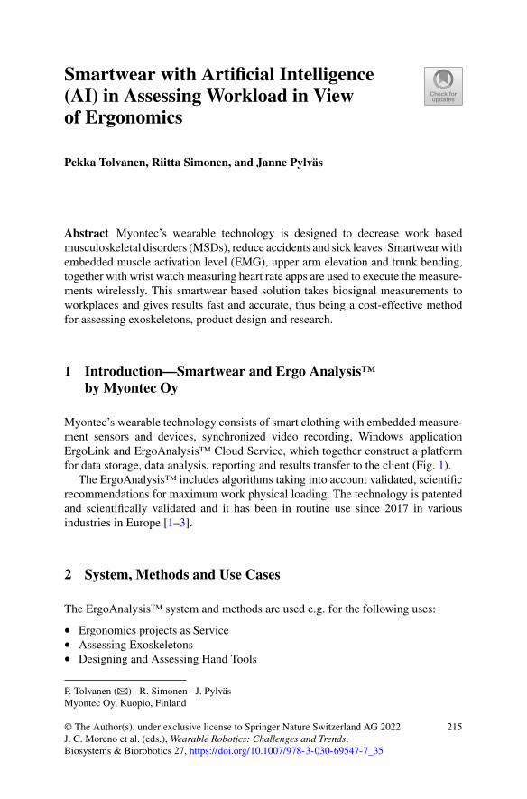
Smartwear with Artificial Intelligence(AI) in Assessing Workload in Viewof Ergonomics
Pekka Tolvanen, Riitta Simonen, and Janne Pylväs
Abstract Myontec’s wearable technology is designed to decrease work basedmusculoskeletal disorders (MSDs), reduce accidents and sick leaves. Smartwearwithembedded muscle activation level (EMG), upper arm elevation and trunk bending,together with wrist watch measuring heart rate apps are used to execute the measure-ments wirelessly. This smartwear based solution takes biosignal measurements toworkplaces and gives results fast and accurate, thus being a cost-effective methodfor assessing exoskeletons, product design and research.
1 Introduction—Smartwear and Ergo Analysis™by Myontec Oy
Myontec’s wearable technology consists of smart clothing with embedded measure-ment sensors and devices, synchronized video recording, Windows applicationErgoLink and ErgoAnalysis™ Cloud Service, which together construct a platformfor data storage, data analysis, reporting and results transfer to the client (Fig. 1).
The ErgoAnalysis™ includes algorithms taking into account validated, scientificrecommendations for maximum work physical loading. The technology is patentedand scientifically validated and it has been in routine use since 2017 in variousindustries in Europe [1–3].
2 System, Methods and Use Cases
The ErgoAnalysis™ system and methods are used e.g. for the following uses:
• Ergonomics projects as Service• Assessing Exoskeletons• Designing and Assessing Hand Tools
P. Tolvanen (B) · R. Simonen · J. PylväsMyontec Oy, Kuopio, Finland
© The Author(s), under exclusive license to Springer Nature Switzerland AG 2022J. C. Moreno et al. (eds.), Wearable Robotics: Challenges and Trends,Biosystems & Biorobotics 27, https://doi.org/10.1007/978-3-030-69547-7_35
215
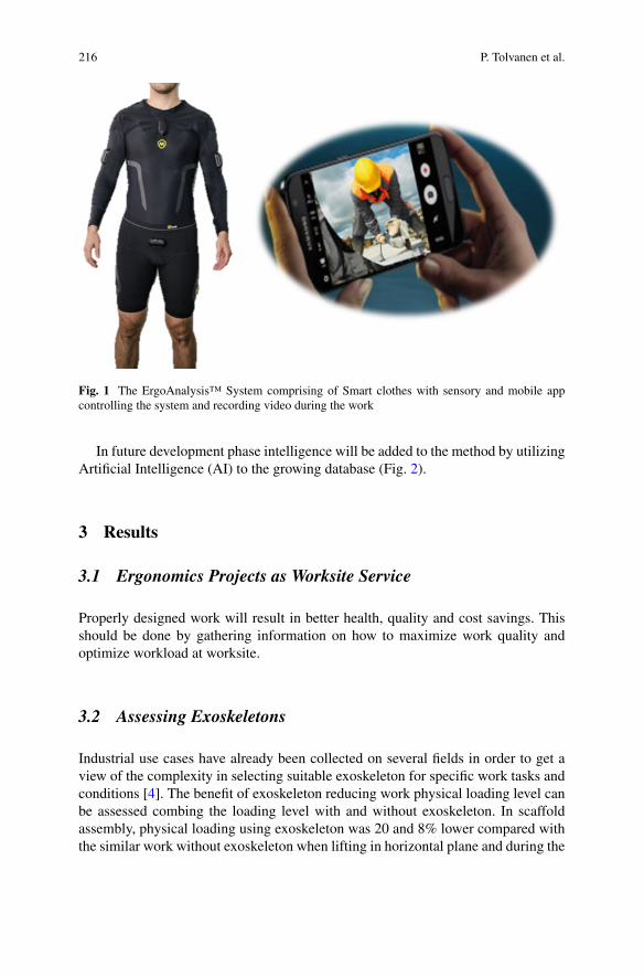
216 P. Tolvanen et al.
Fig. 1 The ErgoAnalysis™ System comprising of Smart clothes with sensory and mobile appcontrolling the system and recording video during the work
In future development phase intelligence will be added to the method by utilizingArtificial Intelligence (AI) to the growing database (Fig. 2).
3 Results
3.1 Ergonomics Projects as Worksite Service
Properly designed work will result in better health, quality and cost savings. Thisshould be done by gathering information on how to maximize work quality andoptimize workload at worksite.
3.2 Assessing Exoskeletons
Industrial use cases have already been collected on several fields in order to get aview of the complexity in selecting suitable exoskeleton for specific work tasks andconditions [4]. The benefit of exoskeleton reducing work physical loading level canbe assessed combing the loading level with and without exoskeleton. In scaffoldassembly, physical loading using exoskeleton was 20 and 8% lower compared withthe similar work without exoskeleton when lifting in horizontal plane and during the
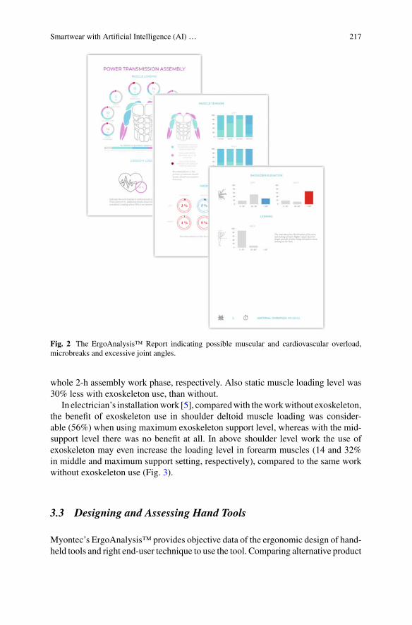
Smartwear with Artificial Intelligence (AI) … 217
Fig. 2 The ErgoAnalysis™ Report indicating possible muscular and cardiovascular overload,microbreaks and excessive joint angles.
whole 2-h assembly work phase, respectively. Also static muscle loading level was30% less with exoskeleton use, than without.
In electrician’s installationwork [5], comparedwith theworkwithout exoskeleton,the benefit of exoskeleton use in shoulder deltoid muscle loading was consider-able (56%) when using maximum exoskeleton support level, whereas with the mid-support level there was no benefit at all. In above shoulder level work the use ofexoskeleton may even increase the loading level in forearm muscles (14 and 32%in middle and maximum support setting, respectively), compared to the same workwithout exoskeleton use (Fig. 3).
3.3 Designing and Assessing Hand Tools
Myontec’s ErgoAnalysis™ provides objective data of the ergonomic design of hand-held tools and right end-user technique to use the tool. Comparing alternative product
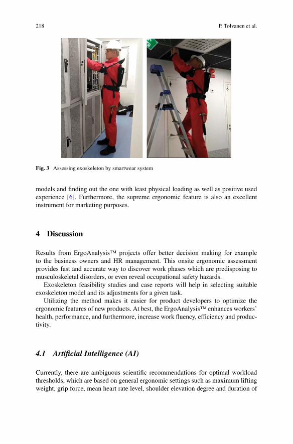
218 P. Tolvanen et al.
Fig. 3 Assessing exoskeleton by smartwear system
models and finding out the one with least physical loading as well as positive usedexperience [6]. Furthermore, the supreme ergonomic feature is also an excellentinstrument for marketing purposes.
4 Discussion
Results from ErgoAnalysis™ projects offer better decision making for exampleto the business owners and HR management. This onsite ergonomic assessmentprovides fast and accurate way to discover work phases which are predisposing tomusculoskeletal disorders, or even reveal occupational safety hazards.
Exoskeleton feasibility studies and case reports will help in selecting suitableexoskeleton model and its adjustments for a given task.
Utilizing the method makes it easier for product developers to optimize theergonomic features of new products. At best, the ErgoAnalysis™ enhances workers’health, performance, and furthermore, increase work fluency, efficiency and produc-tivity.
4.1 Artificial Intelligence (AI)
Currently, there are ambiguous scientific recommendations for optimal workloadthresholds, which are based on general ergonomic settings such as maximum liftingweight, grip force, mean heart rate level, shoulder elevation degree and duration of
Smartwear with Artificial Intelligence (AI) … 219
static muscle loading. However, the practical application of the recommendations todifferent work environments requires additional workplace-specific assessment byexperienced professionals.
ErgoCloud-database is an extensive digital storage of industry-specific referencedata obtained from the ErgoAnalysis™ projects. Artificial Intelligence methodsenable reference databases for most common occupations that provide customerswith more accurate, comparable, and illustrative information about the workloadquickly, easily, and cost-effectively.
5 Conclusion
The solution is made easy-to use so any health, work safety or quality professionalsor product developers can do the recordings, run quick results and make beneficialconclusions for their industry and customers.
References
1. P. Tolvanen, Myontec ErgoAnalysis™ in assessing benefits of an Exoskeleton in reducing upperextremity workload, Presentation at ExoBerlin congress October 22–23 (2019)
2. P. Tolvanen, Smart Clothing For Ergonomics Assessment In real working conditions, Presenta-tion at IDTechEx congress in Berlin April 10, (2019)
3. V. Louhevaara, Wearable EMG in the prevention of work-related Musculoskeletal disorders,Presentation at IEA International Ergonomics Association conference August 27. (Florence,Italy, 2018)
4. Article Interviewing Exoskeleton And Wearables Expert Matthew Marino. link https://www.myontec.com/post/interviewing-wearables-and-exoskeleton-expert-matthew-marino
5. R. Simonen, ,MyontecErgoanalysisTMworkshop, Presentation atNES-TheNordicErgonomicsand Human Factors Society congress 25–28. August 2019 in (Elsinore, Denmark, 2019)
6. K. Kokkonen, Video presentation regarding tool design by Fiskars Group. link https://www.fiskars.eu/products/gardening/professional-selection Fit for human use–Optimal Ergonomics
Comparison of ReWalk® and Ekso®
Powered Exoskeletons for Steppingand Speed During Training Sessions
Pierre K. Asselin, Gail F. Forrest, Stephen Kornfeld, Eunkyoung Hong,Peter H. Gorman, and Ann M. Spungen
Abstract Design attributes specific to the powered exoskeletons contribute to differ-ences in walking performance. As part of a large multicenter trial that used twopowered exoskeletons, the design attributes that contribute to the differences inaverage number of steps per session and walking speed were explored.
1 Introduction
The stepping performance of persons with spinal cord injury (SCI) using a poweredexoskeleton to ambulate overground is dependent on many factors. Within-deviceperformance relies on attributes of the individual user such as completeness and levelof injury (LOI) [1]. However, performance measures such as walking speed, initialstepping ability and rate of progression also depend on the design of the specificsystem. The goal of this investigation was to identify differences in walking perfor-mance between participants who used two different powered exoskeletons during a
P. K. Asselin (B) · S. Kornfeld · E. Hong · A. M. SpungenSpinal Cord Damage Research Center, James J. Peters VA Medical Center, Bronx, NY, USAe-mail: [email protected]
Icahn School of Medicine at Mount Sinai (ISMMS), New York, NY, USA
G. F. ForrestKessler Foundation, West Orange, NJ, USA
Rutgers New Jersey Medical School-Rutgers University, Newark, NJ, USA
S. KornfeldSpinal Cord Injury Service, James J. Peters VA Medical Center, Bronx, NY, USA
P. K. AsselinCenter for the Medical Consequences of Spinal Cord Injury, James J. Peters VA Medical Center,Bronx, NY, USA
P. H. GormanUniversity of Maryland School of Medicine, Baltimore, MD, USA
University of Maryland Rehabilitation and Orthopaedic Institute, Baltimore, MD, USA
© The Author(s), under exclusive license to Springer Nature Switzerland AG 2022J. C. Moreno et al. (eds.), Wearable Robotics: Challenges and Trends,Biosystems & Biorobotics 27, https://doi.org/10.1007/978-3-030-69547-7_36
221
222 P. K. Asselin et al.
36-session training protocol. Discussion of the different design considerations thatmay contribute to the difference performance level is provided.
2 Materials and Methods
2.1 Participants
Fifty volunteers with SCI participated in a randomized crossover study with a controlphase consisting of 12 weeks of observation and an intervention phase consisting of12 weeks of exoskeletal assisted walking (EAW). Male and female volunteers wereincluded if they were between the ages of 18–65, SCI ≥ 6 months, not communityambulators, height between 160 and 190 cm, weight under 100 kg, and able to holdcrutches. They were excluded if they had another neurological condition, concur-rent medical illness, fracture in the past two years, bone density by dual-energyx-ray absorptiometry (hip T-score < −3.5 and knee Bone Mineral Density (BMD) <0.60 g/cm2), limited range of motion at hip and knee, pressure ulcers, and any othercriteria that was felt to be a contraindication to using powered exoskeletons.
2.2 Exoskeleton Training
During the EAW training, two different exoskeletons (ReWalk 6.0® and EksoGT®)were used to train participants to walk for 36 sessions for up to one hour, threetimes a week. Participants with higher LOI were assigned to use the Ekso device asit provides support for the trunk and those with lower LOI were assigned the useof the ReWalk device. The initial training was focused on teaching the participantsbasic skills such as standing balance and the mechanism needed to walk using thepowered exoskeleton. As the sessions progressed, the focus shifted to walking faster,more independently and over different terrain. The number of steps taken during thetraining session was recorded. In addition, walking speed was determined duringsessions 12, 24 and 36 using a 10 m walk test (10MWT) [2, 3].
2.3 Statistical Analysis
Descriptive statistics were used to report the demographic characteristics of theparticipants. Total steps taken during training sessions were smoothed using a 5-session moving average. Differences in the smoothed total steps between devicesfrom the sessions were determined using a t-test. Differences in walking speed was
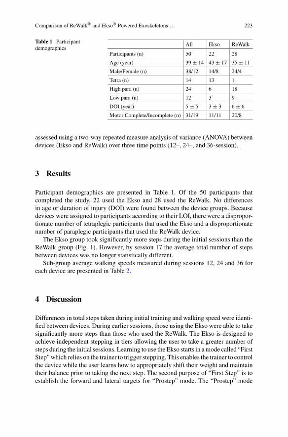
Comparison of ReWalk® and Ekso® Powered Exoskeletons … 223
Table 1 Participantdemographics
All Ekso ReWalk
Participants (n) 50 22 28
Age (year) 39 ± 14 43 ± 17 35 ± 11
Male/Female (n) 38/12 14/8 24/4
Tetra (n) 14 13 1
High para (n) 24 6 18
Low para (n) 12 3 9
DOI (year) 5 ± 5 3 ± 3 6 ± 6
Motor Complete/Incomplete (n) 31/19 11/11 20/8
assessed using a two-way repeated measure analysis of variance (ANOVA) betweendevices (Ekso and ReWalk) over three time points (12–, 24–, and 36-session).
3 Results
Participant demographics are presented in Table 1. Of the 50 participants thatcompleted the study, 22 used the Ekso and 28 used the ReWalk. No differencesin age or duration of injury (DOI) were found between the device groups. Becausedevices were assigned to participants according to their LOI, there were a dispropor-tionate number of tetraplegic participants that used the Ekso and a disproportionatenumber of paraplegic participants that used the ReWalk device.
The Ekso group took significantly more steps during the initial sessions than theReWalk group (Fig. 1). However, by session 17 the average total number of stepsbetween devices was no longer statistically different.
Sub-group average walking speeds measured during sessions 12, 24 and 36 foreach device are presented in Table 2.
4 Discussion
Differences in total steps taken during initial training and walking speed were identi-fied between devices. During earlier sessions, those using the Ekso were able to takesignificantly more steps than those who used the ReWalk. The Ekso is designed toachieve independent stepping in tiers allowing the user to take a greater number ofsteps during the initial sessions. Learning to use the Ekso starts in amode called “FirstStep”which relies on the trainer to trigger stepping. This enables the trainer to controlthe device while the user learns how to appropriately shift their weight and maintaintheir balance prior to taking the next step. The second purpose of “First Step” is toestablish the forward and lateral targets for “Prostep” mode. The “Prostep” mode
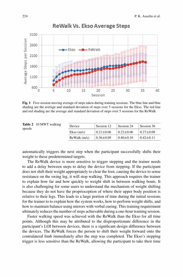
224 P. K. Asselin et al.
Fig. 1 Five-session moving average of steps taken during training sessions. The blue line and blueshading are the average and standard deviation of steps over 5 sessions for the Ekso. The red lineand red shading are the average and standard deviation of steps over 5 sessions for the ReWalk
Table 2 10 MWT walkingspeeds
Device Session 12 Session 24 Session 36
Ekso (m/s) 0.21±0.06 0.22±0.06 0.27±0.09
ReWalk (m/s) 0.36±0.09 0.40±0.10 0.42±0.11
automatically triggers the next step when the participant successfully shifts theirweight to these predetermined targets.
The ReWalk device is more sensitive to trigger stepping and the trainer needsto add a delay between steps to delay the device from stepping. If the participantdoes not shift their weight appropriately to clear the foot, causing the device to senseresistance on the swing leg, it will stop walking. This approach requires the trainerto explain how far and how quickly to weight shift in between walking bouts. Itis also challenging for some users to understand the mechanism of weight shiftingbecause they do not have the proprioception of where their upper body position isrelative to their legs. This leads to a large portion of time during the initial sessionsfor the trainer to to explain how the system works, how to perform weight shifts, andhow to maintain balance using mirrors with verbal cueing. This training requirementultimately reduces the number of steps achievable during a one-hour training session.
Faster walking speed was achieved with the ReWalk than the Ekso for all timepoints. Although this may be attributed to the disproportionate difference in theparticipant’s LOI between devices, there is a significant design difference betweenthe devices. The ReWalk forces the person to shift their weight forward onto thecontralateral limb immediately after the step was completed. The Ekso’s steppingtrigger is less sensitive than the ReWalk, allowing the participant to take their time
Comparison of ReWalk® and Ekso® Powered Exoskeletons … 225
and remain in double stance for longer periods of time while learning, ultimatelyreducing the walking speed.
The different device settings that control step length and speed of movementalso contribute to walking velocity. Comparisons of device settings is confoundedbecause the settings controlling these parameters are different. The Ekso uses stepheight, step length and step time parameters. The ReWalk uses hip range and a stepspeed setting. Further comparisons would be needed to explore how these settingsaffect the walking speed.
5 Conclusion
Both devices have their strengths and challenges. The Ekso design uses a tieredlearning approach. This enabled the user to have an easier time to take steps duringthe initial sessions, maximizing the number of steps achievable. The ReWalk requiresthe user to consistently take steps which makes initial use more difficult for some,but ultimately leads to faster walking speeds.
Acknowledgements We would like to thank all the participants and the powered exoskeletontrainers.
Supported by the Department of Defense/CDMRP SC130234 Award: W81XWH-14-2-0170and National Center for the Medical Consequences of SCI (B9212-C, B2020-C) at the James J.Peters VA Medical Center.
References
1. D.R. Louie, J.J. Eng, T. Lam, Gait speed using powered robotic exoskeletons after spinal cordinjury: a systematic review and correlational study. J. NeuroEng. Rehab. 12(1), 82 (2015)
2. H.J. van Hedel, M. Wirz, V. Dietz, Assessing walking ability in subjects with spinal cord injury:validity and reliability of 3 walking tests. Archiv. Phys. Med. Rehab. 86(2), 190–196 (2005)
3. E. Hong et al., Mobility skills with exoskeletal-assisted walking in person with sci: results froma three center randomized clinical trial. Front. Robot. AI 7, 93 (2020)
Indications and Contraindicationsfor Exoskeletal-Assisted Walkingin Persons with Spinal Cord Injury
Ann M. Spungen, Peter H. Gorman, Gail F. Forrest, Pierre K. Asselin,Stephen Kornfeld, Eunkyoung Hong, and William A. Bauman
Abstract Adopting appropriate eligibility criteria for research and clinical programsin which powered exoskeletal-assisted walking devices are used remains a chal-lenge to avoid risk of injury and to encourage the successful use of these devices.Reducing the risk of fracture is a primary concern when establishing eligibilitycriteria. Evidence from a three-site clinical trial supports the use of screening criteriafor bone mineral density at the knee to permit safe use of exoskeletal devices.
1 Introduction
Restoration of ambulatory function and the potential for improvement of health dueto increased upright mobility has long been a goal of rehabilitation research forthose with spinal cord injury (SCI). The use of powered exoskeletons may offer apartial solution to this problem. The establishment of appropriate eligibility criteriaremains a challenge to provide the proper balance between inclusion and exclusionin order to avoid risk of injury while concurrently encouraging successful use ofthese devices. While exclusion criteria for pressure ulcers, limited range of motionat lower extremity (LE) joints, non-modifiable contractures, severe spasticity, andmedical health problems were straightforward to implement, exclusion criteria tomitigate the risk of a fragility fracture, especially at the knee, were not so obvious.Existing literature available at time of planning used to develop exclusion criteria
A. M. Spungen (B) · P. K. Asselin · S. Kornfeld · E. Hong · W. A. BaumanSpinal Cord Damage Research Center, James J. Peters VA Medical Center, Bronx, NY, USAe-mail: [email protected]
Icahn School of Medicine at Mount Sinai (ISMMS), New York, NY, USA
P. H. GormanUniversity of Maryland School of Medicine, University of Maryland Rehabilitation andOrthopaedic Institute, Baltimore, MD, USA
G. F. ForrestKessler Foundation, West Orange, NJ, USA
Rutgers New Jersey Medical School-Rutgers University, Newark, NJ, USA
© The Author(s), under exclusive license to Springer Nature Switzerland AG 2022J. C. Moreno et al. (eds.), Wearable Robotics: Challenges and Trends,Biosystems & Biorobotics 27, https://doi.org/10.1007/978-3-030-69547-7_37
227
228 A. M. Spungen et al.
was limited to work by Garland et al. that reported those at increased risk of fractureby knee bone mineral density (BMD) obtained by dual-energy x-ray absorptiometry(DXA) [1, 2]. We are proposing that the inclusion/exclusion criteria used for thisstudy support the safe use of exoskeletons for hospital-based training.
2 Materials and Methods
A three-site, randomized (for order of intervention or control arm), crossover clinicaltrialwas conductedwith 12weeks of exoskeletal-assistedwalking (EAW)as the inter-vention arm and 12 weeks of usual activity (UA) as the control arm. Two exoskeletaldevices were available for use by participants (ReWalk 6.0® and Ekso GT®). Thecriteria for the choice of device for each participant has been reported previously [3].Participants with SCI were included who were non-community ambulators, durationof injury > 6 months, age 18–65 years, able to hold Loftstrand crutches or a walker,weight < 100 kg, and height between 160–190 cm. Medical and safety exclusioncriteria were also applied; a complete list of the eligibility criteria can be found atclinicaltrials.gov NCT02314221. The risk of fragility fracture was a major consid-eration in study design. A fragility fracture was defined as “a low impact fracturethat may occur under conditions such as, but not limited to, a fall from a seated posi-tion, during stretching or crossing one’s legs, during a transfer, bumping the lowerextremity, dropping a foot to the ground, a light object falling on a lower extremitybody part, carrying someone or something in one’s lap, or any fracture that occurredwithout the knowledge of its occurrence.” To reduce the risk of fragility fractureduring EAW, DXA scans were performed at the hip and knee. Participants wereexcluded who had a hip T-score < -3.5 or a knee BMD < 0.60 gm/cm2. No criteriaexist for BMD of the feet. An unhealed high impact LE fracture or any fragility orlow impact fracture of the LE since SCI.
3 Results
Fifty participants completed the 36 EAW sessions. A full description of the partic-ipants demographic characteristics by exoskeleton used for training are previouslyreported [3].
Of the 104 consented participants to screening, 33 were screen failures: 16 forknee BMD, eight for schedule conflicts, four for contractures, three for weight orlevel of SCI, and two for medical complications. Seventy-one participants wererandomized; 21 had an early withdrawal (11 for compliance, seven with medicalproblems (two related, two possibly, three unrelated to study participation), two forschedule conflicts, and one who lost interest. There were eight serious adverse events(SAE); four were possibly related and four were unrelated to study participation. Sixof the eight SAEswere resolvedwith the participants returning to complete the study.
Indications and Contraindications for Exoskeletal-Assisted … 229
Oneparticipantwas discontinued from the studybecause of anunrelatedknee fracturedue to a fall during vehicle transport and one for a possibly related medial malleolusfracture after the 2nd session.Most adverse events (AE) (41 of 75) were related to skinabrasion from contact with the devices; these occurred early in the course of the studyand were minimized with the gain of experience to more properly fit the participantsin the devices. There were 19 AEs for musculoskeletal/edema issues (four unrelated,seven possibly, eight related), six falls (four unrelated, two related, but no injuries),four urinary tract infections (unrelated) and four medical issues (unrelated); 70 of 75AEs were satisfactorily resolved with the participants continuing in the study. Twoparticipants were withdrawn due to shoulder or knee pain (both related), two werewithdrawn due to medical problems (unrelated), and one was withdrawn due to acalcaneal fracture (possibly related) after the 4th EAW session without trauma or fall.Both fractures were reported to be of indeterminate age, possibly representing pre-existing conditions that were undiagnosed. Because of the occurrence of the medialmalleolus and calcaneal fractures, bilateral foot x-rays were added to the screeningprocedures to rule out potentially undiagnosed foot fractures. More than 50% ofthe participants achieved successful mobility and walking skills by 12 sessions andmore than 75% by 36 sessions [3]. Successful achievement of the EAW skills wasnot dependent on device or level/completeness of injury [3].
4 Discussion
Although two participants may have had foot fractures from weight bearing andstepping in an exoskeleton, the 50 participants who successfully completed the studywithout fracture lend to support the use of the exclusion criteria that were chosenfor this study, which included knee BMD, hip T-score, bilateral foot x-rays, andfracture history. Subsequent to the development of these criteria, two studies havebeen reported that also support the use of a knee BMD of < 0.60 cm2 [4, 5]. It isimportant to note that during the sit-to-stand maneuver in an exoskeleton the forcesat the knee are greater than during weight bearing while walking and, thus, of greaterconcern for risk of fracture.
Excluding those with pre-existing, undiagnosed foot fractures from participa-tion is critical for preventing additional fracture complications as a result of weightbearing during EAW. Several case reports have detailed fractures during EAW[6–9]. Bass et al. reported bilateral ankle swelling after the first EAW session;computed tomography (CT) scan revealed bilateral calcaneal fractures without theirage reported [6]. In a report by Benson et al. a participant was found to have a swollenankle after the fourth exoskeletal walking session with magnetic resonance imagingidentifying a hairline fracture of the talus [7]. Two cases of fracture were reported byvan Herpen et al. [9]; one exoskeleton user had a left tibia fracture “during standingfrom the ground after a graceful collapse” [9]; the other had a fracture reported afterthe fifth training session when ankle swelling was noted and “radiography revealeda fracture of the distal tibia at the tibial plateau with damage of the subchondral bone
230 A. M. Spungen et al.
[9].” Similar to our foot fractures, in all three reports, swellingwas noted early duringtraining and imaging revealed fractures in the feet. Neither of the two foot fracturesobserved in this investigation, and none of the four reported from the cited literaturewere the result of trauma but appeared to be caused by simply weight bearing duringstanding and stepping in the exoskeletal devices. It is quite possible that persons withSCI may have pre-existing and undiagnosed foot fractures. In the past, standard ofcare for bilateral ankle or foot swelling consisted of elevation of the affected leg or, ifunilateral edema was present, a duplex venous ultrasound of the affected leg to ruleout deep venous thrombosis, but a foot x-ray was not routinely obtained. As such,there may be an indeterminate prevalence of undiagnosed foot fractures in the SCIpopulation. Because there are no DXA standards for measuring BMD of the feet, inaddition to the screening criteria for the hip and knee BMD, we are recommendingbilateral x-rays or CT scans of the feet prior to initiating EAW to identify any occultprior foot fractures that would predispose to recurrent fractures during normal weightbearing while using a powered exoskeleton.
5 Conclusion
Persons with non-ambulatory SCI, if screened appropriately for BMD at the kneeand other select skeletal criteria, appear to be able to safely participate in EAW.However, additional work is required to developmore accurate criteria for preventingor reducing the risk of fracture, as well as to maximize participation in EAW toachieve greater mobility and improved health. Clinicians should be vigilant duringhospital-based training programs for any AEs yet unappreciated that may result fromparticipation in EAW.
Acknowledgements Supported by the Department of Defense/CDMRP SC130234 Award:W81XWH-14-2-0170 and National Center for the Medical Consequences of SCI (B9212-C,B2020-C) at the James J. Peters VA Medical Center.
References
1. D. Garland, R. Adkins, Bone loss at the knee in spinal cord injury. Topics Spinal Cord InjuryRehab. 6(3), 37–46 (2001)
2. D. Garland, R. Adkins, V. Kushwaha, C. Stewart, Risk factors for osteoporosis at the knee inthe spinal cord injury population. J. Spinal Cord Med. 27(3), 202–206 (2003)
3. E. Hong et al., Mobility skills with exoskeletal-assisted walking in person with sci: results froma three center randomized clinical trial. Front. Robot. AI 7, 93 (2020)
4. D. Lala et al., Exploring the determinants of fracture risk among individuals with spinal cordinjury. Osteoporosis Int. 25(1), 177–185 (2014)
5. C. Tan et al., Adiponectin is associated with bone strength and fracture history in paralyzed menwith spinal cord injury. Osteoporosis Int. 25(11), 2599–2607 (2014)

Indications and Contraindications for Exoskeletal-Assisted … 231
6. A.Bass, S.Morin,M.Vermette,M.Aubertin-Leheudre,D.Gagnon, Incidental bilateral calcanealfractures following overgroundwalkingwith awearable robotic exoskeleton in awheelchair userwith a chronic spinal cord injury: is zero risk possible?, Osteoporosis Int.1–5 (2020)
7. I. Benson, K. Hart, D. Tussler, J.J. van Middendorp, Lower-limb exoskeletons for individualswith chronic spinal cord injury: findings from a feasibility study. Clinical Rehab. 30(1), 73–84(2016)
8. Y. He, D. Eguren, T. P. Luu, J. L. Contreras-Vidal, Risk management and regulations for lowerlimb medical exoskeletons: a review. Medical devices, vol. 10 (Auckland, NZ, 2017) pp. 89
9. F. vanHerpen, R. vanDijsseldonk, H. Rijken, N. Keijsers, J. Louwerens, I. vanNes, Case Report:description of two fractures during the use of a powered exoskeleton. Spinal Cord Series andCases 5(1), 1–4 (2019)
The Impact of Exoskeletal-AssistedWalking on the Immune Systemof Individuals with Chronic Spinal CordInjury (SCI)
Anthony A. Arcese, Ann M. Spungen, and Ona Bloom
Abstract Persons with chronic spinal cord injury (SCI) are at increased risk forstroke and cardiovascular disease (CVD). Systemic inflammation is commonlyobserved in persons with SCI and is inversely correlated with mobility. In the generalpopulation, light-moderate intensity exercise such as walking reduces risk of stroke,CVD and reduces systemic inflammation. Powered exoskeletons for persons withSCI offer a means to provide physical activity through overground ambulation. It iscurrently unclear if, and to what extent, exoskeletal-assisted walking (EAW) leadsto health benefits associated with walking. A pilot case series was performed todetermine if EAW impacts whole blood gene expression in persons with chronicSCI.
1 Introduction
Spinal cord injury (SCI) resulting in paralysis leads to drastically reduced mobility.Finding treatments to help lessen impacts of immobilization is important for thehealth of persons with SCI. Adults are advised by the American Heart Association tomaintain general health by performing 2.5 h of moderate intensity aerobic exerciseand at least 2 days of muscle-strengthening exercise per week.
Acute exercise triggers anti-inflammatory signals from muscles that help toimprove strength. Consistent exercise leads to weight loss and fat is a strong sourceof inflammatory signals [1]. Physical activity also modifies relative proportions and
A. A. Arcese · O. Bloom (B)Feinstein Institutes for Medical Research, Feinstein Institutes for Medical Research, Manhasset,NY, USA
A. M. SpungenIcahn School of Medicine at Mount Sinai, NY, USA
A. M. Spungen · O. BloomJames J. Peters VA Medical Center, Bronx, NY, USA
O. BloomZucker School of Medicine at Hofstra Northwell, Hempstead, NY, USA
© The Author(s), under exclusive license to Springer Nature Switzerland AG 2022J. C. Moreno et al. (eds.), Wearable Robotics: Challenges and Trends,Biosystems & Biorobotics 27, https://doi.org/10.1007/978-3-030-69547-7_38
233
234 A. A. Arcese et al.
biological activities of circulating white blood cells, including reducing expressionand signaling of Toll like Receptors [2]. In persons with SCI, mobility correlatesinversely with inflammation [3]. Unfortunately, persons with SCI are often unable todo upright activity/exercise or walking and/or do not have regular access to adaptivesports or gym equipment. Powered exoskeletons are a relatively new type of tech-nology to enable walking by persons with SCI. The US Centers for Medicare andMedicaid just approved a billing code for the ReWalk powered exoskeleton. Recentdata suggests that for persons with SCI, walking with assistance from an exoskeletonis a light-to-moderate intensity physical activity [4–7]. Several groups are investi-gating if exoskeletal-assisted walking (EAW) provides health benefits similar towalking in able-bodied persons. The aim of this pilot case series was to determine ifEAW (36 sessions) has an impact on whole blood gene expression in persons withchronic SCI.
2 Materials and Methods
Six adults (n = 3 males) in a phase III randomized controlled clinical trial(NCT02314221) were studied. The participant median age was 47.5 years (32.75IQR, range 22-69 years). The median time after SCI was 3.2 years (10.37 IQR,range 0.5-27 years). Neurological levels of injury were: one each at C4, C5, T3,and T10 and two at T4. AIS grades were: two each for A and B, and one each forC and D. Three participants used the Ekso and three participants used the ReWalkexoskeletons.
Blood was obtained before and after 36 sessions of EAW. Blood samples werealso obtained from uninjured (CTRL) participants (n = 2 males, 1 female; ages 63,64, and 66, respectively, from a convenience sample). RNA was extracted, RNASequencing (RNA-Seq) libraries were created with KAPA RNA Hyperprep Kits(Roche), and 100 base pair paired-end reads were collected on the NextSeq Illuminaplatform (Cold Spring Harbor Laboratories Genome Center). Trimmed reads werealigned using STAR to the human genome (hg38) assembly, filtered for expression≥ 50, normalized (TMM) and log2 transformed (Partek Genomics Flow, St. Louis,MO). Principal component analysis (PCA) was used to examine overall variation ingene expression profiles using default settings (9 components) for SCI pre-samplescompared to CTRL individuals (Partek). Differentially expressed (DE) genes wereidentified with a fold change≥ 2, using gene set enrichment analysis (GSA) betweengroups (SCI pre vs. CTRL) or within SCI participants (Post vs. Pre), using the step-up method of Benjamini-Hochberg to correct p-values with a false discovery rate(FDR) ≤ 0.05. For gene symbols present more than once (multiple transcripts), thetranscript with the smallest P-value was used for functional analysis performed usingEnrichr, a bioinformatics platform [8, 9].
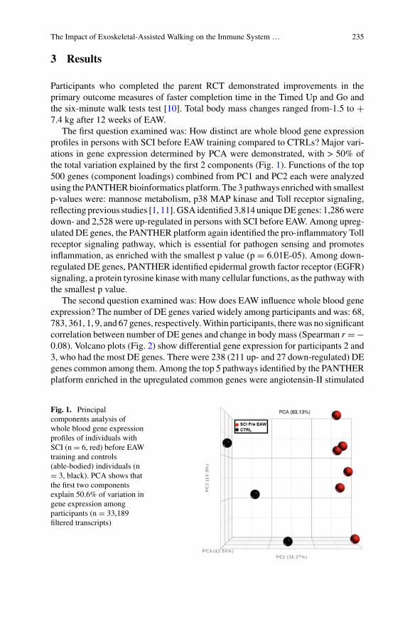
The Impact of Exoskeletal-Assisted Walking on the Immune System … 235
3 Results
Participants who completed the parent RCT demonstrated improvements in theprimary outcome measures of faster completion time in the Timed Up and Go andthe six-minute walk tests test [10]. Total body mass changes ranged from-1.5 to +7.4 kg after 12 weeks of EAW.
The first question examined was: How distinct are whole blood gene expressionprofiles in persons with SCI before EAW training compared to CTRLs? Major vari-ations in gene expression determined by PCA were demonstrated, with > 50% ofthe total variation explained by the first 2 components (Fig. 1). Functions of the top500 genes (component loadings) combined from PC1 and PC2 each were analyzedusing the PANTHERbioinformatics platform. The 3 pathways enrichedwith smallestp-values were: mannose metabolism, p38 MAP kinase and Toll receptor signaling,reflecting previous studies [1, 11].GSA identified 3,814 uniqueDEgenes: 1,286weredown- and 2,528 were up-regulated in persons with SCI before EAW. Among upreg-ulated DE genes, the PANTHER platform again identified the pro-inflammatory Tollreceptor signaling pathway, which is essential for pathogen sensing and promotesinflammation, as enriched with the smallest p value (p = 6.01E-05). Among down-regulated DE genes, PANTHER identified epidermal growth factor receptor (EGFR)signaling, a protein tyrosine kinase withmany cellular functions, as the pathwaywiththe smallest p value.
The second question examined was: How does EAW influence whole blood geneexpression? The number of DE genes varied widely among participants and was: 68,783, 361, 1, 9, and 67 genes, respectively.Within participants, therewas no significantcorrelation between number of DE genes and change in body mass (Spearman r = −0.08). Volcano plots (Fig. 2) show differential gene expression for participants 2 and3, who had the most DE genes. There were 238 (211 up- and 27 down-regulated) DEgenes common among them. Among the top 5 pathways identified by the PANTHERplatform enriched in the upregulated common genes were angiotensin-II stimulated
Fig. 1. Principalcomponents analysis ofwhole blood gene expressionprofiles of individuals withSCI (n = 6, red) before EAWtraining and controls(able-bodied) individuals (n= 3, black). PCA shows thatthe first two componentsexplain 50.6% of variation ingene expression amongparticipants (n = 33,189filtered transcripts)
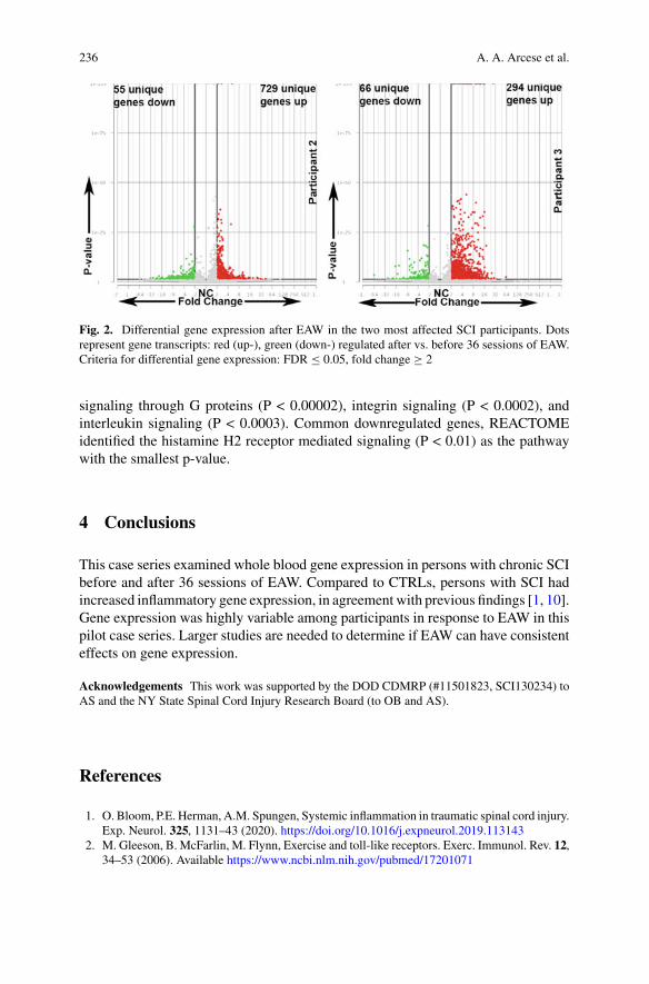
236 A. A. Arcese et al.
Fig. 2. Differential gene expression after EAW in the two most affected SCI participants. Dotsrepresent gene transcripts: red (up-), green (down-) regulated after vs. before 36 sessions of EAW.Criteria for differential gene expression: FDR ≤ 0.05, fold change ≥ 2
signaling through G proteins (P < 0.00002), integrin signaling (P < 0.0002), andinterleukin signaling (P < 0.0003). Common downregulated genes, REACTOMEidentified the histamine H2 receptor mediated signaling (P < 0.01) as the pathwaywith the smallest p-value.
4 Conclusions
This case series examined whole blood gene expression in persons with chronic SCIbefore and after 36 sessions of EAW. Compared to CTRLs, persons with SCI hadincreased inflammatory gene expression, in agreement with previous findings [1, 10].Gene expression was highly variable among participants in response to EAW in thispilot case series. Larger studies are needed to determine if EAW can have consistenteffects on gene expression.
Acknowledgements This work was supported by the DOD CDMRP (#11501823, SCI130234) toAS and the NY State Spinal Cord Injury Research Board (to OB and AS).
References
1. O. Bloom, P.E. Herman, A.M. Spungen, Systemic inflammation in traumatic spinal cord injury.Exp. Neurol. 325, 1131–43 (2020). https://doi.org/10.1016/j.expneurol.2019.113143
2. M. Gleeson, B. McFarlin, M. Flynn, Exercise and toll-like receptors. Exerc. Immunol. Rev. 12,34–53 (2006). Available https://www.ncbi.nlm.nih.gov/pubmed/17201071
The Impact of Exoskeletal-Assisted Walking on the Immune System … 237
3. L.R. Morse et al., Association between mobility mode and C-reactive protein levels in menwith chronic spinal cord injury. Arch. Phys. Med. Rehab. 89(4), 726–731 (2008)
4. P. Asselin et al., Heart rate and oxygen demand of powered exoskeleton-assisted walking inpersons with paraplegia. J. Rehab. Res. Dev. 52(2), 147–158 (2015)
5. C.-Y. Tsai, P.K. Asselin, S. Knezevic, N.Y. Harel, S.D. Kornfeld, A.M. Spungen, The effectof exoskeletal-assisted walking training on seated balance—a pilot study. in 2017 Interna-tional Symposium onWearable Robotics and Rehabilitation (WeRob), November 2017, pp. 1–2.https://doi.org/10.1109/werob.2017.8383818
6. N. Evans, C. Hartigan, C. Kandilakis, E. Pharo, I. Clesson, Acute cardiorespiratory andmetabolic responses during exoskeleton-assisted walking overground among persons withchronic spinal cord injury. Top Spinal Cord Inj. Rehab. 21(2), 122–132 (2015)
7. A. Ramanujam et al., Mechanisms for improving walking speed after longitudinal poweredrobotic exoskeleton training for individuals with spinal cord injury. Conf. Proc. IEEE Eng.Med. Biol. Soc. 2018, 2805–2808 (2018)
8. E.Y. Chen et al., Enrichr: interactive and collaborative HTML5 gene list enrichment analysistool. BMC Bioinf. 14, 128 (2013)
9. P. Herman, A. Stein, K. Gibbs, I. Korsunsky, P. Gregersen, O. Bloom, Persons withchronic spinal cord injury have decreased natural killer cell and increased toll-likereceptor/inflammatory gene expression. J. Neurotrauma 35(15), 1819–1829 (2018)
10. E. Hong et al., Mobility skills with exoskeletal-assisted walking in persons with SCI: resultsfrom a three center randomized clinical trial. Front. Robot. AI 7, 93 (2020)
11. P.E. Herman, O. Bloom, Altered leukocyte gene expression after traumatic spinal cord injury:clinical implications. Neural Regen. Res. 13(9), 1524–1529 (2018)
Exoskeleton Controller and DesignConsiderations: Effect on TrainingResponse for Persons with Spinal CordInjury
Gail F. Forrest, Peter H. Gorman, Arvind Ramanujam, Pierre K. Asselin,Steven Knezevic, Sandra Wojciehowski, and Ann M. Spungen
Abstract The objective of this research was to identify variables (demographic,device, neurological, clinical, and training session dose) that were associated withresults of the ten-minute walk test (10MWT) for individuals with a spinal cord injury(SCI) who participated in a large randomized crossover clinical trial of exoskeletalwalking. Fifty individuals were randomized into Group AB or BA (A = exoskeletonintervention arm, B = control arm). A generalized linear mixed model was appliedto model 10MWT and found that a training dose of 36 sessions and gender werethe most significant. These variables were more significant than neurological levelof injury or completeness of injury. Understanding the effects of exoskeleton/humaninterface for different devices is crucial for identifying suitable candidates to use thedevice and developing effective/efficient clinical training protocols for communityambulation, rehabilitation, and recovery post-SCI.
1 Introduction
The determinants of the exoskeleton/human interface that influence gait speed areespecially relevant when using powered robotic devices for rehabilitation of functionand community ambulation [1]. The device interface and user interaction needs to
G. F. Forrest (B) · A. RamanujamKessler Foundation, West Orange, NJ, USAe-mail: [email protected]
P. H. GormanUniversity of Maryland School of Medicine, University of Maryland, Baltimore, MD, USA
University of Maryland Rehabilitation and Orthopaedic Institute, University of Maryland,Baltimore, MD, USA
S. WojciehowskiPEAK Center at Craig Hospital, Englewood, CO, USA
P. K. Asselin · S. Knezevic · A. M. SpungenJames J. Peters Veterans Affairs Medical Center, Bronx, NY, USA
© The Author(s), under exclusive license to Springer Nature Switzerland AG 2022J. C. Moreno et al. (eds.), Wearable Robotics: Challenges and Trends,Biosystems & Biorobotics 27, https://doi.org/10.1007/978-3-030-69547-7_39
239
240 G. F. Forrest et al.
accommodate individuals with different levels of a spinal cord injury (SCI), associ-ated with different levels of impaired motor and sensory function [1]. Several studieshave evaluated the biomechanical and neural effects of exoskeletal training on kine-matic and biomechanical training variables among different devices and evaluatedthe gains in speeds and distance [2, 3]. However, there is minimal research evaluatingthe exoskeleton/human interface effect on exoskeleton ambulation. This study’smainaim was to determine the most significant determinants (Table 2) associated with theexoskeleton assisted gait speed after exoskeleton training.
2 Materials and Methods
2.1 Participant Demographics and Training Protocol
Fifty individuals with SCI participated in a randomized crossover clinical trialconsisting of an intervention phase (12 weeks, 36 sessions) of exoskeletal assistedwalking and a within-group control phase (12 weeks of observation, usual activity)[4]. Randomization determined group assignment: Group AB (intervention phasefollowed by control phase) and Group BA (control phase followed by interven-tion phase). The ambulatory performance outcome collected after 12, 24, and 36exoskeleton training sessions was ten-meter walk test (10MWT, secs). Partici-pants were included if they were between ages 18-65, SCI ≥ 6 months, unable toambulate, height between 160-190 cm, weight < 100 kg, and able to hold crutches.Individuals were excluded if there was another neurological condition, concurrentmedical illness, lower extremity fracture in the past two years, bone density by dual-energy x-ray absorptiometry less than criteria (hip T-score < −3.5 and knee BMD< 0.60 g/cm2), limited range of motion at hip and knee, pressure ulcers, and othercriteria felt to be a contraindication to using powered exoskeletons.
2.2 Exoskeleton Training
During exoskeleton training, two different exoskeletons (ReWalk 6.0®, ReWalkRobotics, Inc., Marlborough, MA and EksoGT®, Ekso Bionics, Richmond, CA)were used to train participants to walk for 36 sessions (up to 1 h). Participants withhigher level of injury (LOI) were assigned to the EksoGT device as it provides greatersupport for the trunk; those with lower LOI were assigned to the ReWalk device.
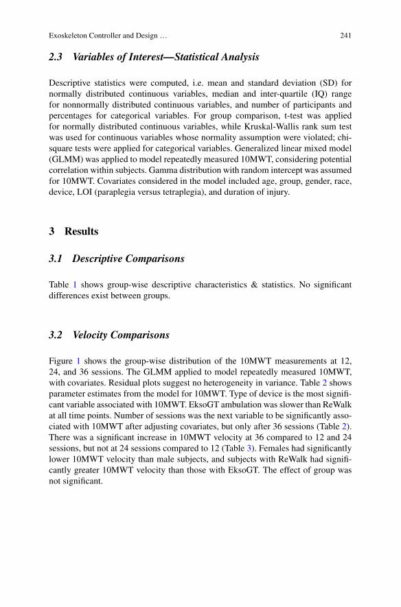
Exoskeleton Controller and Design … 241
2.3 Variables of Interest—Statistical Analysis
Descriptive statistics were computed, i.e. mean and standard deviation (SD) fornormally distributed continuous variables, median and inter-quartile (IQ) rangefor nonnormally distributed continuous variables, and number of participants andpercentages for categorical variables. For group comparison, t-test was appliedfor normally distributed continuous variables, while Kruskal-Wallis rank sum testwas used for continuous variables whose normality assumption were violated; chi-square tests were applied for categorical variables. Generalized linear mixed model(GLMM) was applied to model repeatedly measured 10MWT, considering potentialcorrelation within subjects. Gamma distribution with random intercept was assumedfor 10MWT. Covariates considered in the model included age, group, gender, race,device, LOI (paraplegia versus tetraplegia), and duration of injury.
3 Results
3.1 Descriptive Comparisons
Table 1 shows group-wise descriptive characteristics & statistics. No significantdifferences exist between groups.
3.2 Velocity Comparisons
Figure 1 shows the group-wise distribution of the 10MWT measurements at 12,24, and 36 sessions. The GLMM applied to model repeatedly measured 10MWT,with covariates. Residual plots suggest no heterogeneity in variance. Table 2 showsparameter estimates from the model for 10MWT. Type of device is the most signifi-cant variable associated with 10MWT. EksoGT ambulation was slower than ReWalkat all time points. Number of sessions was the next variable to be significantly asso-ciated with 10MWT after adjusting covariates, but only after 36 sessions (Table 2).There was a significant increase in 10MWT velocity at 36 compared to 12 and 24sessions, but not at 24 sessions compared to 12 (Table 3). Females had significantlylower 10MWT velocity than male subjects, and subjects with ReWalk had signifi-cantly greater 10MWT velocity than those with EksoGT. The effect of group wasnot significant.
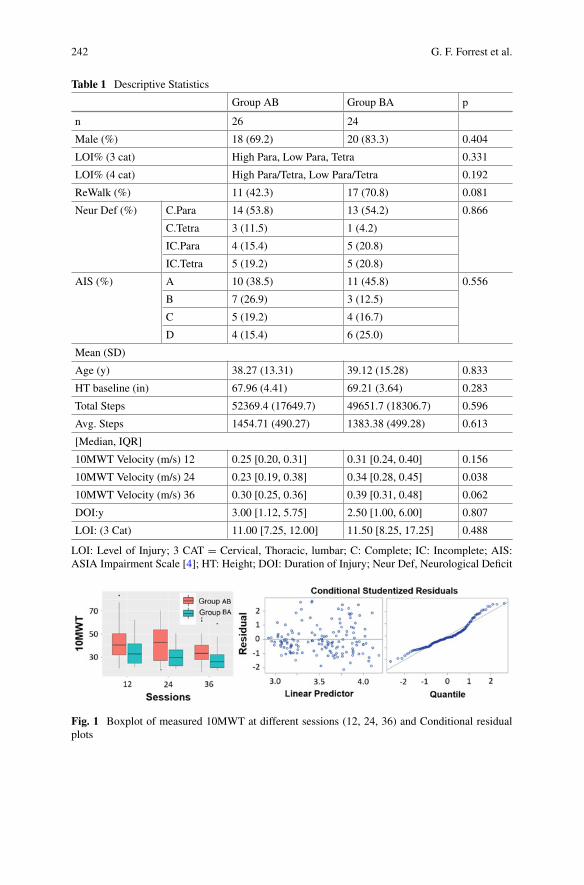
242 G. F. Forrest et al.
Table 1 Descriptive Statistics
Group AB Group BA p
n 26 24
Male (%) 18 (69.2) 20 (83.3) 0.404
LOI% (3 cat) High Para, Low Para, Tetra 0.331
LOI% (4 cat) High Para/Tetra, Low Para/Tetra 0.192
ReWalk (%) 11 (42.3) 17 (70.8) 0.081
Neur Def (%) C.Para 14 (53.8) 13 (54.2) 0.866
C.Tetra 3 (11.5) 1 (4.2)
IC.Para 4 (15.4) 5 (20.8)
IC.Tetra 5 (19.2) 5 (20.8)
AIS (%) A 10 (38.5) 11 (45.8) 0.556
B 7 (26.9) 3 (12.5)
C 5 (19.2) 4 (16.7)
D 4 (15.4) 6 (25.0)
Mean (SD)
Age (y) 38.27 (13.31) 39.12 (15.28) 0.833
HT baseline (in) 67.96 (4.41) 69.21 (3.64) 0.283
Total Steps 52369.4 (17649.7) 49651.7 (18306.7) 0.596
Avg. Steps 1454.71 (490.27) 1383.38 (499.28) 0.613
[Median, IQR]
10MWT Velocity (m/s) 12 0.25 [0.20, 0.31] 0.31 [0.24, 0.40] 0.156
10MWT Velocity (m/s) 24 0.23 [0.19, 0.38] 0.34 [0.28, 0.45] 0.038
10MWT Velocity (m/s) 36 0.30 [0.25, 0.36] 0.39 [0.31, 0.48] 0.062
DOI:y 3.00 [1.12, 5.75] 2.50 [1.00, 6.00] 0.807
LOI: (3 Cat) 11.00 [7.25, 12.00] 11.50 [8.25, 17.25] 0.488
LOI: Level of Injury; 3 CAT = Cervical, Thoracic, lumbar; C: Complete; IC: Incomplete; AIS:ASIA Impairment Scale [4]; HT: Height; DOI: Duration of Injury; Neur Def, Neurological Deficit
Fig. 1 Boxplot of measured 10MWT at different sessions (12, 24, 36) and Conditional residualplots
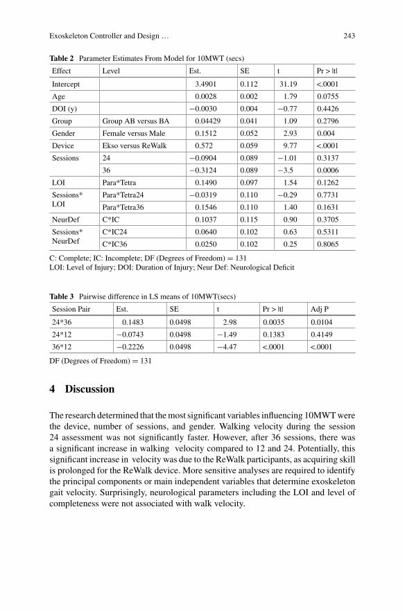
Exoskeleton Controller and Design … 243
Table 2 Parameter Estimates From Model for 10MWT (secs)
Effect Level Est. SE t Pr > |t|
Intercept 3.4901 0.112 31.19 <.0001
Age 0.0028 0.002 1.79 0.0755
DOI (y) −0.0030 0.004 −0.77 0.4426
Group Group AB versus BA 0.04429 0.041 1.09 0.2796
Gender Female versus Male 0.1512 0.052 2.93 0.004
Device Ekso versus ReWalk 0.572 0.059 9.77 <.0001
Sessions 24 −0.0904 0.089 −1.01 0.3137
36 −0.3124 0.089 −3.5 0.0006
LOI Para*Tetra 0.1490 0.097 1.54 0.1262
Sessions*LOI
Para*Tetra24 −0.0319 0.110 −0.29 0.7731
Para*Tetra36 0.1546 0.110 1.40 0.1631
NeurDef C*IC 0.1037 0.115 0.90 0.3705
Sessions*NeurDef
C*IC24 0.0640 0.102 0.63 0.5311
C*IC36 0.0250 0.102 0.25 0.8065
C: Complete; IC: Incomplete; DF (Degrees of Freedom) = 131LOI: Level of Injury; DOI: Duration of Injury; Neur Def: Neurological Deficit
Table 3 Pairwise difference in LS means of 10MWT(secs)
Session Pair Est. SE t Pr > |t| Adj P
24*36 0.1483 0.0498 2.98 0.0035 0.0104
24*12 −0.0743 0.0498 −1.49 0.1383 0.4149
36*12 −0.2226 0.0498 −4.47 <.0001 <.0001
DF (Degrees of Freedom) = 131
4 Discussion
The research determined that themost significant variables influencing 10MWTwerethe device, number of sessions, and gender. Walking velocity during the session24 assessment was not significantly faster. However, after 36 sessions, there wasa significant increase in walking velocity compared to 12 and 24. Potentially, thissignificant increase in velocity was due to the ReWalk participants, as acquiring skillis prolonged for the ReWalk device. More sensitive analyses are required to identifythe principal components or main independent variables that determine exoskeletongait velocity. Surprisingly, neurological parameters including the LOI and level ofcompleteness were not associated with walk velocity.
244 G. F. Forrest et al.
5 Conclusion
The method described in this report identifies the variables relevant toexoskeleton/user control for gait speed. Future work using this technique could beapplied to other ambulation measures (six minute walk test, timed up and go) andexamine dependent variables associated with recovery outside of the device.
Acknowlegements Research supported by Department of Defense/CDMRP SC130234 Award:W81XWH-14-2-0170.
References
1. J.R. Koller et al., Comparing neural control and mechanically intrinsic control of powered ankleexoskeletons. IEEE Int. Conf. Rehab. Robot. 2017, 294–299 (2017). https://doi.org/10.1109/ICORR.2017.8009262
2. A. Ramanujam, et.al., Neuromechanical adaptations during a robotic powered exoskeletonassisted walking session. J. Spinal Cord Méd. 41(5), 518–528 (2018)
3. G.F. Forrest et al., in Muscle Changes After Exoskeleton Training. ISCOS, (Dublin, Ireland,2017)
4. E. Hong et‘al., Results from a three center randomized clinical trial. Front. Robot. AI 7(93)(2020)
Neuromechanical Modelling and Controlfor Wearable Robots: Enhancing
Movement After Neuromuscular Injuries
Neuromusculoskeletal Model-BasedController for Voluntary and ContinuousAssistance in a Broad Rangeof Locomotion Tasks
Guillaume Durandau, Wolfgang Rampeltshammer, Herman van der Kooij,and Massimo Sartori
Abstract Neuromusculoskeletal modeling driven by electromyograms (EMG) hasshown the ability to predict joint torque for a wide variety of movements. Takingadvantage of this, we connected a real-time version of an EMG-driven model to abilateral ankle exoskeleton to continuously assist during a wide repertory of loco-motion tasks. The advantage is that the user controls the exoskeleton voluntarily,i.e. as a direct function of own muscle force. As a result, the developed frameworkcan seamlessly assist in different tasks as well as transitions between tasks withouthaving to change any parameters or using an additional algorithm to switch betweenstates. Results on three participants show that an exoskeleton controlled via thisframework reduces EMGs during locomotion tasks with various speeds and/or incli-nations. This is the first step toward creating controller allowing to assist in tasksindependent manner.
1 Introduction
Wearable exoskeletons have the potential to enhance patients mobility or protectthem from musculoskeletal injuries. For wide adoption of these devices volun-tary, continuous and task-independent assistance is needed. Currently, few wearablerobotic exoskeletons have shown metabolic benefit during locomotion [1]. Thesemethods rely on switching between states or using machine learning algorithms,which have various disadvantages such as misclassification or the inability to assistin the transition between tasks or in unknown conditions.
We previously showed that EMG-driven modelling after personalization offersextrapolation capabilities to unknown tasks and degree of freedom (DOF) [2]. In[3], we also showed that models calibrated via simple isometric movements couldenable voluntary control of robotic exoskeletons in neurologically injured patientsperforming knee and ankle movements from seated positions or control a softexosuit for the elbow [4]. Here, we extend our framework to control a bilateral
G. Durandau (B) · W. Rampeltshammer · H. van der Kooij ·M. SartoriDepartment of Biomechanical Engineering, Technical Medical Centre, University of Twente,Enschede 7522, NB, The Netherlands
© The Author(s), under exclusive license to Springer Nature Switzerland AG 2022J. C. Moreno et al. (eds.), Wearable Robotics: Challenges and Trends,Biosystems & Biorobotics 27, https://doi.org/10.1007/978-3-030-69547-7_40
247
248 G. Durandau et al.
ankle exoskeleton during complex tasks, i.e. a broad range of locomotion conditionsincluding transitions between those conditions.
2 Methods
Our framework is based on a real-time EMG-driven model previously developed [2].The framework is using a Hill-type muscle model with the following equation:
FMTU (t) = FT = FMax(f(LM
)f(V M
)E(t) + f p
(LM
))cos
(αM(t)
)(1)
With FMTU (t) the musculo-tendon unit (MTU) force at instant t, FT the tendonforce, FMax the maximum isometric force, f
(LM
)the force length relationship,
f(V M
)the force velocity relationship, E(t) the normalized muscle activation,
f p(LM
)the passive force length relationship and αM(t) the pennation angle. Muscle
tendon length andmoment arm are computed in real-time from joint angles viamulti-dimensional Bsplines [5]. Joint torques were computed by projecting MTU forcesvia muscle moment arm. The model contains four DOFs: left and right plantar dorsi-flexion and knee flexion extension as well as eight muscles: left and right soleus,tibia anterior, gastrocnemius medialis and lateralis.
To obtain joint torque personalized to the user, the model parameters need tobe calibrated to the user. For this, we first scaled the model using the scaling toolfrom OpenSim [6]. We then used a pre-tuning algorithm to personalize optimal fiberlength and tendon slack length [2]. These parameters as well as maximal isometricmuscle force andEMGshape factor are further calibrated using a simulated annealingoptimization algorithm that reduces the error between predicted and experimentaljoint torque.
The exoskeleton used is a bilateral ankle exoskeleton with two DOFs for eachmodule, active plantar dorsiflexion and passive subtalar. Each module is powered bya series elastic actuator with a peak torque of 100N.m and aweight of 4.5 kg. A back-pack contains a battery pack and a processing unit (NUC, Intel USA). Each modulecommunicates with the processing unit using real-time communication protocol(Ethercat, Berkhoff, Germany).
Predicted joint torques computed from EMG sensor after filtering and normaliza-tion and joint angle (Link, Xsens, the Netherlands for the knee and joint encoder forthe ankle) are sent to the main controller where they are multiplied by a support ratioand send to the actuator to provide assistance.
3 Experiments and Results
Three healthy subjects (age: 28.4± 5, height: 177.6± 6 cm, weight: 72.6± 6.5 kg)were recruited for this experiment. The experiment was conducted in three steps.
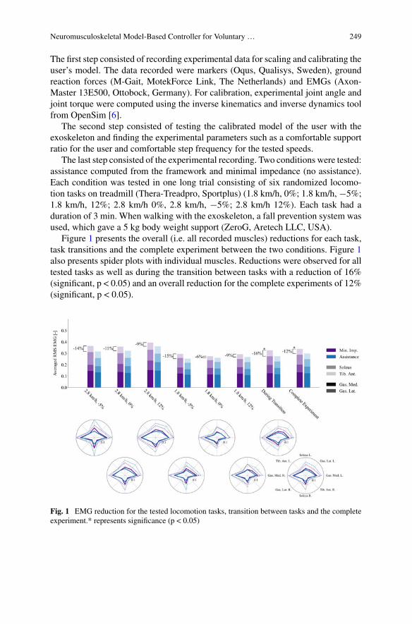
Neuromusculoskeletal Model-Based Controller for Voluntary … 249
The first step consisted of recording experimental data for scaling and calibrating theuser’s model. The data recorded were markers (Oqus, Qualisys, Sweden), groundreaction forces (M-Gait, MotekForce Link, The Netherlands) and EMGs (Axon-Master 13E500, Ottobock, Germany). For calibration, experimental joint angle andjoint torque were computed using the inverse kinematics and inverse dynamics toolfrom OpenSim [6].
The second step consisted of testing the calibrated model of the user with theexoskeleton and finding the experimental parameters such as a comfortable supportratio for the user and comfortable step frequency for the tested speeds.
The last step consisted of the experimental recording. Two conditions were tested:assistance computed from the framework and minimal impedance (no assistance).Each condition was tested in one long trial consisting of six randomized locomo-tion tasks on treadmill (Thera-Treadpro, Sportplus) (1.8 km/h, 0%; 1.8 km/h, −5%;1.8 km/h, 12%; 2.8 km/h 0%, 2.8 km/h, −5%; 2.8 km/h 12%). Each task had aduration of 3 min. When walking with the exoskeleton, a fall prevention system wasused, which gave a 5 kg body weight support (ZeroG, Aretech LLC, USA).
Figure 1 presents the overall (i.e. all recorded muscles) reductions for each task,task transitions and the complete experiment between the two conditions. Figure 1also presents spider plots with individual muscles. Reductions were observed for alltested tasks as well as during the transition between tasks with a reduction of 16%(significant, p < 0.05) and an overall reduction for the complete experiments of 12%(significant, p < 0.05).
Fig. 1 EMG reduction for the tested locomotion tasks, transition between tasks and the completeexperiment.* represents significance (p < 0.05)
250 G. Durandau et al.
Reduction in the predicted torque was also observed in all tasks (23% duringtransition (significant, p < 0.05) and 21% for the complete experiment (significant,p < 0.05)).
4 Discussion and Conclusion
These results demonstrated the possibility of using EMG-driven model for control-ling an exoskeleton and offering positive assistance for a wide repertoire oflocomotion tasks.
Furthermore, reduction in EMG was also observed during the transition duringtasks, which is enabled by the continuous and voluntary type of assistance offered bythe framework. All recorded muscles always underwent EMG reduction except forthe tibia anterior, which displayed increased EMGs in a few cases during the swingphase. This is due to the fact that 100% of the gait cycle was assisted, which causedinstability during the swing phase.
Future workwill go towards incorporating estimation ofmuscle and joint stiffnesswhich is extremely relevant for control, rehabilitation and musculoskeletal injuryprevention.
Acknowlegements The study was supported by ERC Starting Grant INTERACT (803035) andH2020 Grant SOPHIA (871237).
References
1. G.S. Sawicki, O.N. Beck, I. Kang, A.J. Young, The exoskeleton expansion: Improving walkingand running economy. J. Neuroeng. Rehabil. 17(1), 1–9 (2020)
2. G. Durandau, D. Farina, M. Sartori, Robust real-time musculoskeletal modeling driven byelectromyograms. IEEE Trans. Biomed. Eng. (2017)
3. G. Durandau et al., Voluntary control of wearable robotic exoskeletons by patients with paresisvia neuromechanical modeling. J. Neuroeng. Rehab. 16(1), 91 (2019)
4. N. Lotti et al., Adaptive model-based myoelectric control for a soft wearable arm exosuit: Anew generation of wearable robot control. IEEE Robot. Autom. Mag. 0 (2020)
5. M. Sartori, M. Reggiani, A.J. van den Bogert, D.G. Lloyd, Estimation of musculotendon kine-matics in large musculoskeletal models using multidimensional B-splines. J. Biomech. 45(3),595–601 (2012)
6. S.L. Delp et al., OpenSim: open-source software to create and analyze dynamic simulations ofmovement. Biomed. Eng. IEEE Trans. 54(11), 1940–1950 (2007)
Energy Cost of Transport in OvergroundWalking of a Transfemoral AmputeeFollowing One Month of Robot-MediatedTraining
C. B. Sanz-Morère, E. Martini, G. Arnetoli, S. Doronzio, A. Giffone,B. Meoni, A. Parri, R. Conti, F. Giovacchini, Þ. Friðriksson, D. Romo,R. Molino-Lova, S. Crea, and N. Vitiello
Abstract Transfemoral amputees (TFAs) require higher energy expenditure thanable-bodied individuals during walking. In this study we examined the effects onone TFA of training for a month with a portable bilateral hip exoskeleton on (i)energy cost of transport (CoT) and (ii) distance covered during a 6-minute walkingtest (6mWT), assessed without (NoExo) and with (Exo) the exoskeleton. Resultsshowed that in NoExo the CoT was reduced by 13.4% after the training, while the6mWT distance increased by 20.3%. However, the CoT increased in Exo comparedto NoExo both before (24.8%) and after (11.8%) the training. These results provideinitial evidence that robot-mediated training should deserve further exploration asa tool for improving walking efficiency of TFAs. Future research will investigatecustomized tuning procedures more in depth to maximize the beneficial effects ofthis approach.
Research supported by the European Commission under the CYBERLEGs Plus Plus project (grantn°731931), within the H2020 framework (H2020-ICT-25-2016-2017).
Part of the IP covering the technology presented in this paper has been exclusively licensed toIUVO for commercial exploitation.
C. B. Sanz-Morère (B) · E. Martini · S. Crea · N. VitielloBioRobotics Institute, Scuola Superiore Sant’Anna, 56127 Pisa, Italye-mail: [email protected]
G. Arnetoli · S. Doronzio · A. Giffone · B. Meoni · R. Molino-Lova · S. Crea · N. VitielloIRCCS Fondazione Don Carlo Gnocchi, 50143 Florence, Italy
S. Crea · N. VitielloDepartment of Excellence in Robotics & AI, Scuola Superiore Sant’Anna, 56127 Pisa, Italy
A. Parri · R. Conti · F. GiovacchiniIUVO S.R.L, Via Puglie, 9, 56025 Pontedera, PI, Italy
Þ. Friðriksson · D. RomoÖssur, Grjótháls 5, 110 Reykjavík, Iceland
© The Author(s), under exclusive license to Springer Nature Switzerland AG 2022J. C. Moreno et al. (eds.), Wearable Robotics: Challenges and Trends,Biosystems & Biorobotics 27, https://doi.org/10.1007/978-3-030-69547-7_41
251
252 C. B. Sanz-Morère et al.
1 Introduction
Trans-femoral amputees (TFAs) exhibit lowerwalking self-selected speed and higherenergy expenditure compared to able-bodied individuals, with subsequent secondarydisorders [1, 2]. Gait training programs for TFAs have been developed to normalizekinematics, reduce compensatory strategies and increase energetic efficiency ofwalking [3].
In the last decade, the use of robotic exoskeletons has shown promising resultsin the recovery of motor deficits. Among them, bilateral hip orthoses have beentested for the rehabilitation of stroke survivors and other frail individuals, improvingtreadmill walking efficiency after several weeks of training [4, 5].
In this study we explore the use of a portable powered hip exoskeleton, theActive Pelvis Orthosis (APO), to improve the energetic efficiency of walking ofTFAs following a one-month robot-mediated training program.
2 Materials and Methods
2.1 Active Pelvis Orthosis (APO)
The APO has been designed for gait support of frail individuals and provides flexion-extension assistance at the hip. The APO in this study is an advanced version of theprototype described in [5], with a similar weight (~ 6.5 kg) and a more conformantbelt-like physical human-robot interface, purposively designed by the Össur R&Dteam (Reykjavík, Iceland).
The APO control strategy was based on a hierarchical architecture [6]: (i) thestride phase was computed in real-time by means of a pool of adaptive-frequencyoscillators, and (ii) for each joint the assistive torque versus phase profile was a sumof two Gaussian functions, with tunable peak amplitude [N·m], peak occurrence [%of the stride phase], and duration [% of the stride phase].
2.2 Protocol
This study was included in the EU H2020 CYBERLEGs Plus Plus project approvedby the local Ethics Committee “Comitato Area Vasta Centro Toscana” (approvalnumber: 12739_spe) and carried out at the premises of Fondazione Don Gnocchi(Firenze, Italy). Here we report the results of a K2 right TFA amputated since 2017,aged 46 years old with a BMI of 37 kg/m2.
The protocol included the following 12 sessions.Enrolment session: To verify the participant’s compliance with inclu-
sion/exclusion criteria.
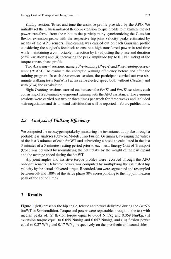
Energy Cost of Transport in Overground … 253
Tuning session: To set and tune the assistive profile provided by the APO. Weinitially set the Gaussian-based flexion-extension torque profile to maximize the netpower transferred from the robot to the participant by synchronizing the Gaussianflexion-extension peaks with the respective hip joint velocity peaks estimated bymeans of the APO sensors. Fine-tuning was carried out on each Gaussian profileconsidering the subject’s feedback to ensure a high transferred power in real-timewhile maintaining a comfortable interaction by (i) adjusting the phase and duration(<5% variations) and (ii) increasing the peak amplitude (up to 0.1 N‧m/kg) of thetorque versus phase profile.
Two Assessment sessions, namely Pre-training (PreTA) and Post-training Assess-ment (PostTA): To evaluate the energetic walking efficiency before and after thetraining program. In each Assessment session, the participant carried out two six-minute walking tests (6mWTs) at his self-selected speed both without (NoExo) andwith (Exo) the exoskeleton.
Eight Training sessions: carried out between the PreTA and PostTA sessions, eachconsisting of a 20-minute overground trainingwith the APO assistance. The Trainingsessions were carried out two or three times per week for three weeks and includedstair negotiation and sit-to-stand activities that will be reported in future publications.
2.3 Analysis of Walking Efficiency
Wecomputed the net oxygen uptake bymeasuring the instantaneous uptake through aportable gas analyser (Oxycon Mobile, CareFusion, Germany), averaging the valuesof the last 3 minutes of each 6mWT and subtracting a baseline calculated in the last3 minutes of a 5-minutes resting period prior to each test. Energy Cost of Transport(CoT) was obtained by normalizing the net uptake by the weight of the participantand the average speed during the 6mWT.
Hip joint angles and assistive torque profiles were recorded through the APOonboard sensors. Delivered power was computed by multiplying the estimated hipvelocity by the actual delivered torque. Recorded datawere segmented and resampledbetween 0% and 100% of the stride phase (0% corresponding to the hip joint flexionpeak of the sound limb).
3 Results
Figure 1 (left) presents the hip angle, torque and power delivered during the PostTA6mWT in Exo condition. Torque and power were repeatable throughout the test withmedian peaks of: (i) flexion torque equal to 0.064 Nm/kg and 0.069 Nm/kg, (ii)extension torque equal to 0.055 Nm/kg and 0.057 Nm/kg, and (iii) flexion powerequal to 0.27 W/kg and 0.17 W/kg, respectively on the prosthetic and sound sides.
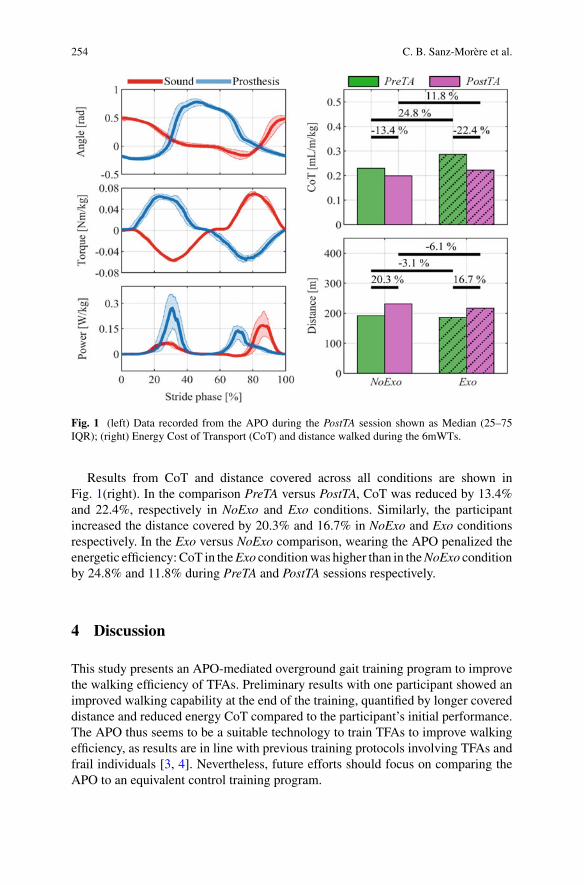
254 C. B. Sanz-Morère et al.
Fig. 1 (left) Data recorded from the APO during the PostTA session shown as Median (25–75IQR); (right) Energy Cost of Transport (CoT) and distance walked during the 6mWTs.
Results from CoT and distance covered across all conditions are shown inFig. 1(right). In the comparison PreTA versus PostTA, CoT was reduced by 13.4%and 22.4%, respectively in NoExo and Exo conditions. Similarly, the participantincreased the distance covered by 20.3% and 16.7% in NoExo and Exo conditionsrespectively. In the Exo versus NoExo comparison, wearing the APO penalized theenergetic efficiency: CoT in theExo conditionwas higher than in theNoExo conditionby 24.8% and 11.8% during PreTA and PostTA sessions respectively.
4 Discussion
This study presents an APO-mediated overground gait training program to improvethe walking efficiency of TFAs. Preliminary results with one participant showed animproved walking capability at the end of the training, quantified by longer covereddistance and reduced energy CoT compared to the participant’s initial performance.The APO thus seems to be a suitable technology to train TFAs to improve walkingefficiency, as results are in line with previous training protocols involving TFAs andfrail individuals [3, 4]. Nevertheless, future efforts should focus on comparing theAPO to an equivalent control training program.
Energy Cost of Transport in Overground … 255
The comparison between walking with and without the APO resulted in a lowerCoT when walking without the APO differently from what was observed in [5, 7].This result may be related to several factors such as the weight of the device or thedifferent assistive parameters. Indeed, in [7], the assistance was tuned for metaboliccost efficiencywhereas here the assistancewasmainly groundedonkinematic consid-erations which could have led to suboptimal energetic efficiency. A more suitableset of parameters might have been selected by considering the real-time effect of theassistance on the metabolic cost [7, 8]. Applying human-in-the-loop optimizationtechniques with TFAs is still an open challenge and will require dedicated futurestudies.
References
1. L. van Schaik, J.H.B. Geertzen, P.U. Dijkstra, R. Dekker, Metabolic costs of activities of dailyliving in persons with a lower limb amputation: a systematic review and meta-analysis. PLoSONE (2019). https://doi.org/10.1371/journal.pone.0213256
2. R. Gailey, K. Allen, J. Castles, J. Kucharik, M. Roeder, Review of secondary physical conditionsassociated with lower-limb amputation and long-term prosthesis use. J. Rehab. Res. Develop.(2008). https://doi.org/10.1682/JRRD.2006.11.0147
3. B.J. Darter, D.H. Nielsen, H.J. Yack, K.F. Janz, Home-based treadmill training to improve gaitperformance in persons with a chronic transfemoral amputation. Arch. Phys. Med. Rehabil.(2013). https://doi.org/10.1016/j.apmr.2013.08.001
4. H.J. Lee et al., Training for walking efficiency with a wearable hip-assist robot in patients withstroke a pilot randomized controlled trial. Stroke (2019) https://doi.org/10.1161/STROKEAHA.119.025950
5. E. Martini et al., Gait training using a robotic hip exoskeleton improves metabolic gait efficiencyin the elderly. Sci. Rep. 9(1), 1–12 (2019). https://doi.org/10.1038/s41598-019-43628-2
6. T. Yan, A. Parri, V. Ruiz Garate, M. Cempini, R. Ronsse, N. Vitiello, An oscillator-based smoothreal-time estimate of gait phase for wearable robotics. Auton. Robot. 41(3), 759–774 (2017).https://doi.org/10.1007/s10514-016-9566-0
7. E. Martini et al., Lower-limb amputees can reduce the energy cost of walking when assistedby an Active Pelvis Orthosis. in IEEE International Conference on Biomedical Robotics andBiomechatronics (Biorob) (2020)
8. M. Kim et al., Human-in-the-loop Bayesian optimization of wearable device parameters. PLoSOne (2017). https://doi.org/10.1371/journal.pone.0184054
Physical Therapy and OutdoorAssistance with the Myosuit:Preliminary Results
Michele Xiloyannis, Florian L. Haufe, Jaime E. Duarte, Kai Schmidt,Peter Wolf, and Robert Riener
Abstract Soft robotic suits are good candidates both for supporting physical therapyin clinical environments and for improving mobility in outdoor settings. Here, weinvestigate both modes of use using the Myosuit, a lightweight robotic suit for thelower limbs: (1) we show that it can be safely used to support a supervised physicaltherapy program, and (2) present a single-case study on the immediate effects thatMyosuit assistance can have in an outdoor setting. Eight participants with diversewalking impairments completed a five-sessions Myosuit-assisted training program,showing an average improvement in walking performance that is encouraging for thedesign of a future controlled study. When walking on a sloped mountain path, oneparticipant with incomplete spinal cord injury showed a 30% increase in walkingspeed and 9% reduction in cost of transport when assisted by the Myosuit, comparedto when not wearing the device.
1 Introduction
A plethora of neurological, muscular and traumatic disorders can significantly affectour ability to move. Conditions such as post-stroke hemiparesis, muscular dystrophy,multiple sclerosis or incomplete spinal cord injury (iSCI) can reduce one’s ability towalk at normal speeds in a safe and efficient way. Even after targeted rehabilitation,most individuals retain deficits that prevent them from reaching walking speeds suit-able for community ambulation, hindering social integration and ultimately affectingquality of life [1].
M. Xiloyannis (B) · F. L. Haufe · P. Wolf · R. RienerSensory-Motor Systems (SMS) Lab, Institute of Robotics and Intelligent Systems (IRIS), ETHZurich, Switzerlande-mail: [email protected]
Spinal Cord Injury Center, University Hospital Balgrist, University of Zurich, Zurich, Switzerland
J. E. Duarte · K. SchmidtMyoSwiss AG, Zurich, Switzerland
© The Author(s), under exclusive license to Springer Nature Switzerland AG 2022J. C. Moreno et al. (eds.), Wearable Robotics: Challenges and Trends,Biosystems & Biorobotics 27, https://doi.org/10.1007/978-3-030-69547-7_42
257
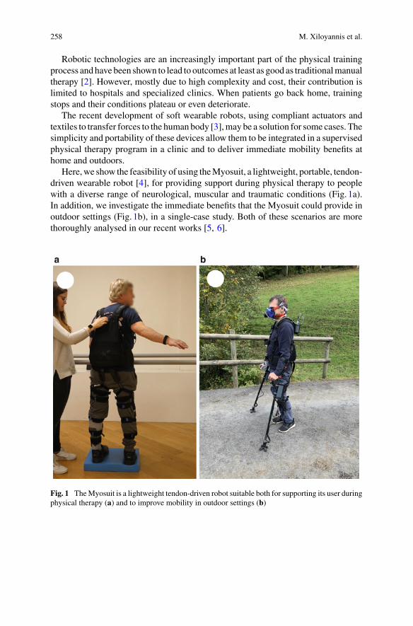
258 M. Xiloyannis et al.
Robotic technologies are an increasingly important part of the physical trainingprocess andhave been shown to lead to outcomes at least as good as traditionalmanualtherapy [2]. However, mostly due to high complexity and cost, their contribution islimited to hospitals and specialized clinics. When patients go back home, trainingstops and their conditions plateau or even deteriorate.
The recent development of soft wearable robots, using compliant actuators andtextiles to transfer forces to the human body [3],may be a solution for some cases. Thesimplicity and portability of these devices allow them to be integrated in a supervisedphysical therapy program in a clinic and to deliver immediate mobility benefits athome and outdoors.
Here,we show the feasibility of using theMyosuit, a lightweight, portable, tendon-driven wearable robot [4], for providing support during physical therapy to peoplewith a diverse range of neurological, muscular and traumatic conditions (Fig. 1a).In addition, we investigate the immediate benefits that the Myosuit could provide inoutdoor settings (Fig. 1b), in a single-case study. Both of these scenarios are morethoroughly analysed in our recent works [5, 6].
Fig. 1 TheMyosuit is a lightweight tendon-driven robot suitable both for supporting its user duringphysical therapy (a) and to improve mobility in outdoor settings (b)
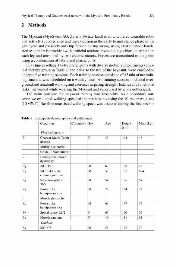
Physical Therapy and Outdoor Assistance with the Myosuit: Preliminary Results 259
2 Methods
The Myosuit (MyoSwiss AG, Zurich, Switzerland) is an untethered wearable robotthat actively supports knee and hip extension in the early to mid stance phase of thegait cycle and passively aids hip flexion during swing, using elastic rubber bands.Active support is provided with artificial tendons, routed along a biarticular path oneach leg and tensioned by two electric motors. Forces are transmitted to the jointsusing a combination of fabric and plastic cuffs.
In a clinical setting, twelve participants with diverse mobility impairments (phys-ical therapy group in Table1) and naive to the use of the Myosuit, were enrolled toundergo five training sessions. Each training session consisted of 45min of net train-ing time and was scheduled on a weekly basis. All training sessions included over-ground and treadmillwalking and exercises targeting strength, balance and functionaltasks, performed while wearing the Myosuit and supervised by a physiotherapist.
The main outcome for physical therapy was feasibility. As a secondary out-come we evaluated walking speed of the participants using the 10-meter walk test(10MWT). Baseline unassisted walking speed was assessed during the first session
Table 1 Participants demographics and pathologies
Condition Chronicity Sex Age Height(cm)
Mass (kg)
Physical therapy
P1 Charcot-Marie Toothdisease
F 43 164 48
– Multiple sclerosis
– Grade II brain tumor
– Limb-girdle muscledystrophy
P2 iSCI Th7 M 67 168 79
P3 iSCI L4 Caudaequina syndrome
M 32 185 104
P4 Syringomyelia atTh5
M 54 186 67
P5 Post-strokehemiparesis (L)
M 72 164 72
- Muscle dystrophy
P6 Post-strokehemiparesis (R)
M 63 177 73
P7 Spinal tumor L1/2 F 67 160 65
P8 Muscle sarcoma F 49 181 91
Outdoor
P9 iSCI C5 M 51 178 70
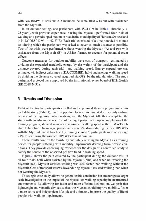
260 M. Xiloyannis et al.
with two 10MWTs; sessions 2–5 included the same 10MWTs but with assistancefrom the Myosuit.
In an outdoor setting, one participant with iSCI (P9 in Table1, chronicity >
25 years), with previous experience in using the Myosuit, performed four trials ofwalking on a paved slopedmountain road in themunicipality of Herisau, Switzerland(47 22′ 06.8′′ N 9 14′ 42.8′′ E). Each trial consisted of a time-bounded 4-minutetest during which the participant was asked to cover as much distance as possible.Two of the trials were performed without wearing the Myosuit (A) and two withassistance from the Myosuit (B), in ABBA format, to account for potential ordereffects.
Outcome measures for outdoor mobility were cost of transport—estimated bydividing the expended metabolic energy by the weight of the participant and thedistance covered during each trial—and walking speed. Energy expenditure wasestimated via indirect calorimetry (K5, COSMED, Italy) and average walking speedby dividing the distance covered, acquired via GPS, by the trial duration. The studydesign and protocol were approved by the institutional review board of ETH Zurich(EK 2018-N-31).
3 Results and Discussion
Eight of the twelve participants enrolled in the physical therapy programme com-pleted the study (Table1), three dropped out for reasons unrelated to the study and onebecause of feeling unsafe when walking with the Myosuit. All others completed thestudy with no adverse events. Five of the eight participants, upon completion of thetraining program, showed an increase in assisted walking speed in the 10MWTs rel-ative to baseline. On average, participants were 2% slower during the first 10MWTswith theMyosuit than at baseline. By training session 5, participants were on average27% faster during the assisted 10MWTs than at baseline.
These results confirm the feasibility and safety of using the Myosuit as a trainingdevice for people suffering with mobility impairments deriving from diverse con-ditions. They provide encouraging evidence for the design of a controlled study tocalrify the source of the observed positive trend in walking speed.
Figure2 shows the path covered by the participant during the outdoor test, inall four trials, both when assisted by the Myosuit (blue) and when not wearing theMyosuit (red). Myosuit-assisted walking was 30% faster than walking without theMyosuit. Cost of transport was 9% lower duringMyosuit-assistedwalking thanwhennot wearing the Myosuit.
This single-case study allows no generalizable conclusion but encourages a largerscale investigation on the impact of the Myosuit on walking capacity in unstructuredenvironments. By allowing for faster and more efficient locomotion, we posit thatlightweight and versatile devices such as the Myosuit could improve mobility, fostera more active and independent lifestyle and ultimately improve the quality of life ofpeople with walking impairments.
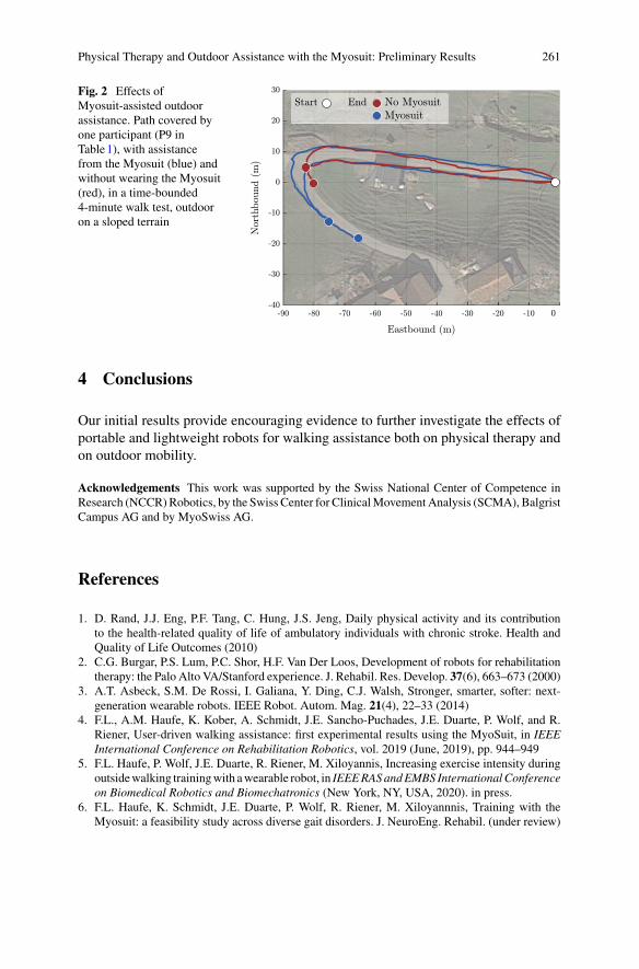
Physical Therapy and Outdoor Assistance with the Myosuit: Preliminary Results 261
Fig. 2 Effects ofMyosuit-assisted outdoorassistance. Path covered byone participant (P9 inTable1), with assistancefrom the Myosuit (blue) andwithout wearing the Myosuit(red), in a time-bounded4-minute walk test, outdooron a sloped terrain
4 Conclusions
Our initial results provide encouraging evidence to further investigate the effects ofportable and lightweight robots for walking assistance both on physical therapy andon outdoor mobility.
Acknowledgements This work was supported by the Swiss National Center of Competence inResearch (NCCR)Robotics, by the Swiss Center for ClinicalMovement Analysis (SCMA), BalgristCampus AG and by MyoSwiss AG.
References
1. D. Rand, J.J. Eng, P.F. Tang, C. Hung, J.S. Jeng, Daily physical activity and its contributionto the health-related quality of life of ambulatory individuals with chronic stroke. Health andQuality of Life Outcomes (2010)
2. C.G. Burgar, P.S. Lum, P.C. Shor, H.F. Van Der Loos, Development of robots for rehabilitationtherapy: the Palo Alto VA/Stanford experience. J. Rehabil. Res. Develop. 37(6), 663–673 (2000)
3. A.T. Asbeck, S.M. De Rossi, I. Galiana, Y. Ding, C.J. Walsh, Stronger, smarter, softer: next-generation wearable robots. IEEE Robot. Autom. Mag. 21(4), 22–33 (2014)
4. F.L., A.M. Haufe, K. Kober, A. Schmidt, J.E. Sancho-Puchades, J.E. Duarte, P. Wolf, and R.Riener, User-driven walking assistance: first experimental results using the MyoSuit, in IEEEInternational Conference on Rehabilitation Robotics, vol. 2019 (June, 2019), pp. 944–949
5. F.L. Haufe, P. Wolf, J.E. Duarte, R. Riener, M. Xiloyannis, Increasing exercise intensity duringoutsidewalking trainingwith awearable robot, in IEEERASandEMBS InternationalConferenceon Biomedical Robotics and Biomechatronics (New York, NY, USA, 2020). in press.
6. F.L. Haufe, K. Schmidt, J.E. Duarte, P. Wolf, R. Riener, M. Xiloyannnis, Training with theMyosuit: a feasibility study across diverse gait disorders. J. NeuroEng. Rehabil. (under review)
Predictive Simulation of Sit-to-StandMovements
David Munoz, Leonardo Gizzi, Cristiano De Marchis, and Giacomo Severini
Abstract The development of technology that can assist people during movementssuch as sit to stand canbenefit fromsimulations that can estimate the effect of differentassistance patterns. These simulations need to be based on frameworks that canreplicate the neuromechanical features of non-pathological sit-to-stand movements.In this study, we present a framework for predictive simulations of sit to stand thatcan be used to synthesize physiological data in the absence of experimental ones.Herewe reproduce sit-to-standmovements on amodel with 9 degrees of freedom and52 actuators by optimizing the parameters of a feedback controller that accounts forthe position, velocity and acceleration of the pelvis and torso, under the constraintsdictated by a specifically designed cost function.We obtained a simulation that couldreplicate the kinematics and muscular activation observed in previous studies.
1 Introduction
Sit-to-stand (STS) is an essential activity of daily living. Consequently, impairmentsthat affect mobility during the STS movement require training programmes that canbenefit from the use of assistive devices such as exoskeletons. Having the possi-bility to estimate the effect of different assistance patterns during STS would greatly
This work was supported by the H2020 Project EUROBENCH under Grant 779963.
D. Munoz · G. Severini (B)School of Electrical and Electronic Engineering and the Insight Centre for Data Analytics,University College of Dublin, Dublin, Irelande-mail: [email protected]
D. Munoze-mail: [email protected]
L. GizziInstitute for Modelling and Simulation of Biomechanical Systems, Continuum Biomechanics andMechanobiology Group, University of Stuttgart, Stuttgart, Germany
C. De MarchisDepartment of Engineering, Roma Tre University, Rome, Italy
© The Author(s), under exclusive license to Springer Nature Switzerland AG 2022J. C. Moreno et al. (eds.), Wearable Robotics: Challenges and Trends,Biosystems & Biorobotics 27, https://doi.org/10.1007/978-3-030-69547-7_43
263
264 D. Munoz et al.
facilitate the design of assistive devices. Bearing this in mind, predictive modellingcan be a useful tool for studying the neuromechanical characteristics of assistedmovements in absence of experimental data. Controller-based environments suchas SCONE [1], with the appropriate musculoskeletal model and controller, can beused to simulate several natural movements, including STS, and the potential effectof assistive devices. The aim of this work is to present a controller for STS predic-tive simulations and compare its performance with previous literature [2, 3]. Thecontroller uses feedback information from position, velocity and acceleration of theCenter of Mass (CoM) of the pelvis and the torso to calculate the activation of thedifferent muscles.
2 Methods
2.1 Musculoskeletal Model
A gait model with 9 degrees of freedom was used in the simulations [4–6]. Themodel consists of the lower limbs, the torso and the head. The muscles included aregluteus medius, gluteus maximus, erector spinae, iliacus, psoas, adductor magnus,rectus femoris, biceps femoris, semitendinosus, semimembranosus, gastrocnemius,soleus, tibialis posterior, tibialis anterior, vastus intermedius, vastus lateralis, flexordigitorum longus and flexor hallucis longus [7]. Each muscle can have more thanone actuator, for a total of 52 musculo-tendinous units between the two sides. Themodel represents a subject 1.8 m tall and with a mass of 80.17 kg. The pelvis and thetorso were placed above a platform to simulate a sitting initial position. The ankle,knee and hip angles in the sagittal plane were 23°,−103° and 80°, respectively. Themodel was implemented using OpenSim [8].
2.2 Feedback Controller
According to previous literature [2, 3], the STS movement can be segmented in 4consecutive phases (Fig. 1): (1) leaning forward; (2) momentum transfer; (3) exten-sion; (4) standing up/stabilization. The transition between the different phases wasimplemented in the controller by using phase-specific task-goals to be reached foradvancing to the following phase. Accordingly, the leaning forward phase was setto finish when the antero-posterior position of the CoM of the torso was closer than0.21 m to the calcaneus bone. The momentum transfer phase was set to finish whenthe pelvis moved upward by 0.12 m and forward (torso at 0.1 m from the calcaneus),and the feet become the new base of support. The extension phase, consisted of thehips, knee and ankle extending together to lift the body, and terminated when thevertical speed of the torso was lower than 0. Finally, in the fourth phase, the model
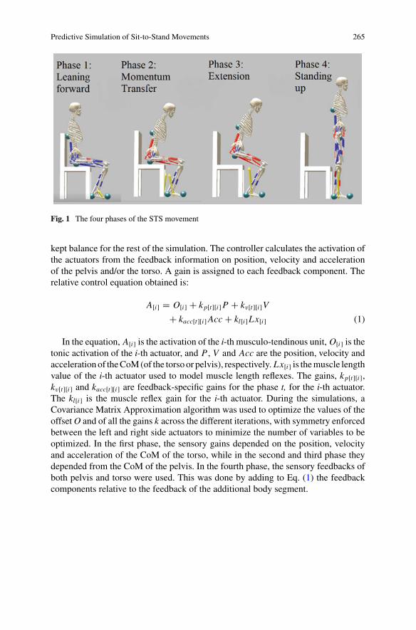
Predictive Simulation of Sit-to-Stand Movements 265
Fig. 1 The four phases of the STS movement
kept balance for the rest of the simulation. The controller calculates the activation ofthe actuators from the feedback information on position, velocity and accelerationof the pelvis and/or the torso. A gain is assigned to each feedback component. Therelative control equation obtained is:
A[i] = O[i] + kp[t][i]P + kv[t][i]V
+ kacc[t][i]Acc + kl[i]Lx[i] (1)
In the equation, A[i] is the activation of the i-th musculo-tendinous unit, O[i] is thetonic activation of the i-th actuator, and P , V and Acc are the position, velocity andaccelerationof theCoM(of the torso or pelvis), respectively. Lx[i] is themuscle lengthvalue of the i-th actuator used to model muscle length reflexes. The gains, kp[t][i],kv[t][i] and kacc[t][i] are feedback-specific gains for the phase t, for the i-th actuator.The kl[i] is the muscle reflex gain for the i-th actuator. During the simulations, aCovariance Matrix Approximation algorithm was used to optimize the values of theoffsetO and of all the gains k across the different iterations, with symmetry enforcedbetween the left and right side actuators to minimize the number of variables to beoptimized. In the first phase, the sensory gains depended on the position, velocityand acceleration of the CoM of the torso, while in the second and third phase theydepended from the CoM of the pelvis. In the fourth phase, the sensory feedbacks ofboth pelvis and torso were used. This was done by adding to Eq. (1) the feedbackcomponents relative to the feedback of the additional body segment.
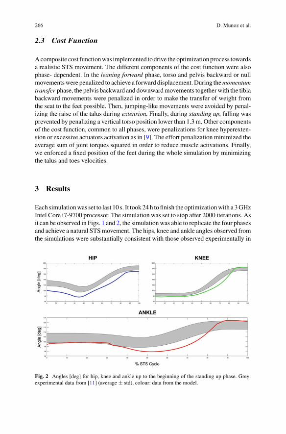
266 D. Munoz et al.
2.3 Cost Function
Acomposite cost functionwas implemented todrive theoptimizationprocess towardsa realistic STS movement. The different components of the cost function were alsophase- dependent. In the leaning forward phase, torso and pelvis backward or nullmovementswere penalized to achieve a forward displacement. During themomentumtransfer phase, the pelvis backward and downwardmovements togetherwith the tibiabackward movements were penalized in order to make the transfer of weight fromthe seat to the feet possible. Then, jumping-like movements were avoided by penal-izing the raise of the talus during extension. Finally, during standing up, falling wasprevented by penalizing a vertical torso position lower than 1.3 m. Other componentsof the cost function, common to all phases, were penalizations for knee hyperexten-sion or excessive actuators activation as in [9]. The effort penalization minimized theaverage sum of joint torques squared in order to reduce muscle activations. Finally,we enforced a fixed position of the feet during the whole simulation by minimizingthe talus and toes velocities.
3 Results
Each simulationwas set to last 10 s. It took 24h tofinish the optimizationwith a 3GHzIntel Core i7-9700 processor. The simulation was set to stop after 2000 iterations. Asit can be observed in Figs. 1 and 2, the simulationwas able to replicate the four phasesand achieve a natural STSmovement. The hips, knee and ankle angles observed fromthe simulations were substantially consistent with those observed experimentally in
Fig. 2 Angles [deg] for hip, knee and ankle up to the beginning of the standing up phase. Grey:experimental data from [11] (average ± std), colour: data from the model.
Predictive Simulation of Sit-to-Stand Movements 267
healthy individuals [3–11] and like those obtained in another simulative work [10].As can be observed in Fig. 2, knee and ankle angles changed physiologically duringthe STS movement.
4 Conclusion
Overall, our model can simulate a natural-like STS movement, with joints anglessimilar to the experimental ones. However, torso and pelvis position—together withthe profile of the hip angle—can be improved in the momentum transfer phase.In future simulations, these problems will be solved by adjusting the weights of thedifferent components of the cost function. Also, in further simulations, the height andweight of the model will be modified in order to test the robustness of the controller.Future works with the controller will aim at estimating the effect of different assistivedevices and assistance patterns on the STS task.
References
1. T. Geijtenbeek, SCONE: open source software for predictive simulation of biological motion.JOSS 4(38), (2019)
2. E.J. Caruthers, J.A. Thompson, A.M.W. Chaudhari, L.C. Schmitt, T.M. Best, K.R. Saul, R.A.Siston, Muscles forces and their contributions to vertical and horizontal acceleration of theCenter of Mass during Sit-to-Stand transfer in young, healthy adults. J. Appl. Biomech. 32,487–503 (2016)
3. M. Schenkman, R.A. Berger, P.O. Riley, R.W. Mann, W.A. Hodge, Whole-body movementsduring rising to standing from sitting. Phys. Ther. 70(10), 638–648 (1990)
4. S.L. Delp, J.P. Loan, M.G. Hoy, F.E. Zajac, E.L. Topp, J.M. Rosen, An interactive graphics-based model of the lower extremity to study orthopaedic surgical procedures. IEEE Trans.Biomed. Eng. 37, 757–767 (1990)
5. F.C. Anderson, M.G. Pandy, A dynamic optimization solution for vertical jumping in threedimensions. Comput. Method. Biomec. 2, 201–231 (1999)
6. F.C. Anderson, M.G. Pandy, Dynamic optimization of human walking. J. Biomech. Eng. 123,381–390 (2001)
7. E.M. Arnold, S.R. Ward, R.L. Lieber, S.L. Delp, A model of the lower limb for analysis ofhuman movement. Ann. Biomed. Eng. 38(2), 269–279 (2010)
8. S.L. Delp, F.C. Anderson, A.S. Arnold, P. Loan, A. Habib, C.T. John, E. Guendelman,D.G. Thelen, OpenSim: open-source software to create and analyze dynamic simulations ofmovement. IEEE Trans. Biomed. Eng. 54(11), (2007)
9. J.Wang, S. Hammer, S. Delp, V. Koltun, Optimizing locomotion controllers using biologically-based actuators and objectives. ACM Trans. Graph. 31(4), Article 25 (2012)
10. H.R. Yamasaki, H. Kambara, Y. Koike, Dynamic optimization of the Sit-to-Stand movement.JAB 54(11) (2007)
11. K. Kaneda, The features of muscle activity during chair standing and sitting motion insubmerged condition. PLoS ONE 14(8) (2019)
SimBionics: NeuromechanicalSimulation and Sensory Feedbackfor the Control of Bionic Legs
Jose Gonzalez-Vargas, Massimo Sartori, Strahinja Dosen,Herman van der Kooij, and Johan Rietman
Abstract Lower limb prosthetic technology has greatly advanced in the last decade,but there are still many challenges that need to be tackled to allow amputees towalk efficiently and safely on many different terrain conditions. Neuro-mechanicalmodelling and online simulations combined with somatosensory feedback, has thepotential to address this challenge. By virtually reconstructing the missing limbtogether with the associated somatosensory feedback, this approach could enableamputees to potentially perceive the bionic legs as extensions of their bodies.A prosthesis equipped with such biologically inspired closed-loop control couldduplicate the mechanics of walking far more accurately than conventional solu-tions. The project SimBionics aims to explore these opportunities and advance thestate-of-the-art in lower limb prosthesis control.
1 Introduction
The human musculoskeletal system is complex but optimized to provide safe andefficient locomotion [1]. The central mechanisms in the motor control of loco-motion include neuromechanical synergies (i.e. at joint, muscle and neural levels)that establish coupling between different joints, segments and muscles [2, 3]. Theneuromechanical synergies result in cyclical and automated movement patterns withrhythmic and coordinated motions of the trunk and lower extremities. However, afteran amputation, the synergies are compromised, and the motions of the joints of a
J. Gonzalez-Vargas (B)Ottobock SE & KGaA, Duderstadt, Germanye-mail: [email protected]
M. Sartori · H. van der Kooij · J. RietmanDepartment of Biomechanical Engineering, Twente University, Enschede, The Netherlands
S. DosenDepartment of Health Science and Technology, Aalborg University, Aalborg, Denmark
J. RietmanRoessingh Research and Development, Enschede, The Netherlands
© The Author(s), under exclusive license to Springer Nature Switzerland AG 2022J. C. Moreno et al. (eds.), Wearable Robotics: Challenges and Trends,Biosystems & Biorobotics 27, https://doi.org/10.1007/978-3-030-69547-7_44
269
270 J. Gonzalez-Vargas et al.
prosthetic device are not in synchrony with the movement of the rest of the body,which often results in non-natural compensatory movements. The compensatorymovements have been considered as the leading cause for the lack of comfort, higherenergy requirements during walking and standing, and cumulative trauma disorders[4].
In recent time, themechatronic knee and ankle prostheses have improved substan-tially in termsof technology, andnowa rangeof solutions fromsemi- to fully-actuatedare available. However, robust and intuitive control of these devices is still a majorchallenge. Most commercial and research systems are controlled by using a hard-coded set of rules that trigger predefined changes in the damping and activation of theknee and ankle joints [5, 6]. This is in a sharp contrast to the activation of biologicaljoints, which is based on continuous modulation of impedance (e.g. stiffness) andactive forces (e.g. torque) in response to biomechanical demands of the task and theenvironment (e.g., terrain roughness and inclination).
Furthermore, none of the current commercial prostheses provides explicitsomatosensory feedback to the user. Therefore, the user needs to rely on incidentalcues (e.g., forces through the socket) or visual observation to assess the state of his/herlower limb [7] This leads to increased cognitive load as well as inefficient walkingwith asymmetric gait, slower cadence, and poor balance [8, 9]. The research on thistopic is scarce, and the proposed non-invasive feedback systems are rather simple.Typically, the systems are based on a single stimulation point (a vibration motor)delivering simple information (e.g., heel strike). Also, due to delays in the embeddedand biological system, the prosthesis user perceives and interprets the stimulationsignal with a considerable delay, which makes it less effective in activities of dailyliving. This is far from the timely, continuous and spatially distributed feedback thatable-bodied humans receive from their lower limbs.
2 Neuromechanical Simulation for Control of Prosthesis
Using neuromechanical modelling and online simulations of the musculoskeletalsystem to control assistive device is not a new concept and have been proposed byseveral research groups in the past. Eilenberg et al. [10] proposed a muscle reflexcontroller based on simulation studies that mimic the neuromechanics of the ankleplantar flexor. This type of controller allows adaptability of an ankle prosthesis todifferent conditions by emulating the spinal reflexes that are activated while walking.Although simple, the approach has proven to be effective in some activities of dailyliving. For examples, the Empower ankle prosthesis from Ottobock uses this controlconcept to generate the desire output power of the device while walking. However,due to the reactive nature of this approach, it can only provide support in certainactivities. Also, this approach cannot be easily scaled for controlling a more complexsystem (e.g. knee-ankle prosthesis) or a semi-active prosthesis that does not providepositive torque but changes the joint characteristics (e.g. stiffness, dampening).
SimBionics: Neuromechanical Simulation and Sensory … 271
Neuromechanical simulations have also been proposed for the control of otherassistive and rehabilitation devices. Pizzolato et al. [11] provide a general outlook onhow neuromusculoskeletal modelling could be integrated with a variety of rehabilita-tion devices to improve the performance of the human-machine interface. Durandauet al. [12] successfully applied neuromechanical modelling to allow a neurologi-cally impaired patient to achieve voluntary control of a lower limb exoskeleton. Asimilar approach was employed by Sartori et al. [13] for the continuous control of aprosthetic hand.
The results of these and other studies [14, 15] illustrate the potential of neurome-chanical modelling and simulation for developing a biologically plausible control ofwearable robotic systems. Specifically for lower limb amputees, this approach can beused to reproduce and approximate the missing limb by using its virtual substitute.The virtual limb will be simulated online to calculate the musculoskeletal dynamicsand kinematics during balance and locomotion. This could be a game changer in thefield of lower limb prostheses. A patient-specific simulation can be used to enhancethe control of an assistive device by calculating the torque and impedance profilesthat are optimal for that specific user during the whole gait cycle. Importantly, asdemonstrated in [13], the neuromechanical simulation can enable continuous andvoluntary control of multiple degrees of freedom in a myoelectric prosthetic handby amputees.
2.1 Simbionics Project
SimBionics Project is funded by the EU—Marie Curie SkłodowskaAction as a Euro-pean IndustrialDoctorate research network.Thegoal is to combine neuro-mechanicalmodelling and sensory feedback into a real-time, closed-loop and biomimetic controlframework for bionic legs.
To achieve this goal, we will implement a control framework in which the feedfor-ward control and somatosensory feedback signals are internally consistent (Fig. 1). Tothis aim, both components of the control loopwill be developed in parallel throughoutthe project, with specific emphasis on their successful integration and interaction.Thus, the characteristics of the somatosensory feedback (e.g., resolution, range, andbandwidth) will complement the dynamics of the control commands and the systemand vice versa. By doing so, we expect that the control performance and embodimentof the devicewill significantly increase. Importantly, the neuromechanicalmodelwillbe able to estimate biomechanical parameters simultaneously within (e.g. joint stiff-ness and damping, together with torque) and across joints (e.g. knee and ankle). Inaddition, the feedback will be delivered using multichannel stimulation to increasethe quantity of information that can be transmitted to the user. The tactile stimulationwill be modulated in time and distributed spatially, mimicking the pressure patternsthat are characteristic for the biological feedback. This approach will thereby yielda robust, safe and intuitive interface between transfemoral amputees and the bionicleg while walking and balancing during the activities of daily living.
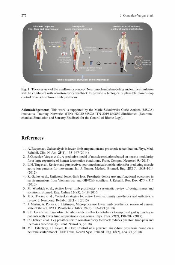
272 J. Gonzalez-Vargas et al.
Fig. 1 The overview of the SimBionics concept. Neuromechanical modeling and online simulationwill be combined with somatosensory feedback to provide a biologically plausible closed-loopcontrol of an active lower limb prosthesis
Acknowledgements This work is supported by the Marie Skłodowska-Curie Actions (MSCA)Innovative Training Networks (ITN) H2020-MSCA-ITN-2019-860850-SimBionics (Neurome-chanical Simulation and Sensory Feedback for the Control of Bionic Legs).
References
1. A. Esquenazi, Gait analysis in lower-limb amputation and prosthetic rehabilitation. Phys. Med.Rehabil. Clin. N. Am. 25(1), 153–167 (2014)
2. J. Gonzalez-Vargas et al., A predictivemodel of muscle excitations based onmusclemodularityfor a large repertoire of human locomotion conditions. Front. Comput. Neurosci. 9, (2015)
3. L.H. Ting et al., Review and perspective: neuromechanical considerations for predictingmuscleactivation patterns for movement. Int. J. Numer. Method. Biomed. Eng. 28(10), 1003–1014(2012)
4. R. Gailey et al., Unilateral lower-limb loss: Prosthetic device use and functional outcomes inservicemembers from Vietnam war and OIF/OEF conflicts. J. Rehabil. Res. Dev. 47(4), 317(2010)
5. M. Windrich et al., Active lower limb prosthetics: a systematic review of design issues andsolutions. Biomed. Eng. Online 15(S3), 5–19 (2016)
6. M.R. Tucker et al., Control strategies for active lower extremity prosthetics and orthotics: areview. J. Neuroeng. Rehabil. 12(1), 1 (2015)
7. J. Martin, A. Pollock, J. Hettinger, Microprocessor lower limb prosthetics: review of currentstate of the art. JPO J. Prosthetics Orthot. 22(3), 183–193 (2010)
8. S.B. Crea, et al., Time-discrete vibrotactile feedback contributes to improved gait symmetry inpatients with lower limb amputations: case series. Phys. Ther. 97(2), 198–207 (2017)
9. C. Dietrich et al., Leg prosthesis with somatosensory feedback reduces phantom limb pain andincreases functionality. Front. Neurol. 9, (2018)
10. M.F. Eilenberg, H. Geyer, H. Herr, Control of a powered ankle-foot prosthesis based on aneuromuscular model. IEEE Trans. Neural Syst. Rehabil. Eng. 18(2), 164–73 (2010)
SimBionics: Neuromechanical Simulation and Sensory … 273
11. C. Pizzolato et al., Neuromusculoskeletal modeling-based prostheses for recovery after spinalcord injury. Front. Neurorobot. (2019)
12. G. Durandau et al, Voluntary control of wearable robotic exoskeletons by patients with paresisvia neuromechanical modeling. J. Neuroeng. Rehabil. (2019)
13. M. Sreenivasa et al, (Ed).: Neuromechanics and control of physical behavior: From experi-mental and computational formulations to bio-inspired technologies. Front. Comput. Neurosci.(2019)
14. M. Sartori et al, Robust simultaneous myoelectric control of multiple degrees of freedom inwrist-hand prostheses by real-time neuromusculoskeletal modeling. J. Neural Eng. (2018)
15. M.A. Price, P. Beckerle, F.C. Sup, Design Optimization in Lower Limb Prostheses: a review.IEEE Trans. Neural Syst. Rehab. Eng. : a Publ. IEEE Eng. Med. Biol. Soc. (2019)
Pseudo-online Muscle Onset DetectionAlgorithm with ThresholdAuto-Adjustment for Lower LimbExoskeleton Control
J. Marvin Fernández García, Camila R. Carvalho, Filipe O. Barroso,and Juan C. Moreno
Abstract Spinal cord injury (SCI) is one of the main disabling injuries affectingpeople worldwide. The use of a wearable robot in rehabilitation reduces physicalexhaustion during training.Moreover, developing novel control paradigms that allowthewearable system tomove in amore intuitivelyway, resembling patients’ intention,may enhance rehabilitation outcomes. In this paper, we present an algorithm thatautomatically detects users’ onset and offset of lower limb muscle’s contractionusing electromyography (EMG) signals. The users’ intention was detected througha single threshold algorithm. The algorithm auto-adjusts the threshold accordingto individual EMG characteristics. The algorithm was tested with EMG data fromseven healthy subjects performing ankle and knee flexion/extension movements andcorrectly detected the intention of movement in approximately 96% of cases in anaverage time of 147.15ms. To conclude, this algorithm can potentially be explored infuture approaches to enable real-time triggering and control of awearable exoskeletonto be used in the rehabilitation setting.
1 Introduction
Spinal cord injury (SCI) is one of the main disabling injuries and affects around250,000 to 500,000 people worldwide every year [1]. The use of wearable robots inSCI rehabilitation can bring benefits and new outcomes for both patients and thera-pists, namely by assisting patients to achieve more precise and repetitive movements,and by reducing the physical burden to therapists [2].
The interaction between the wearable robot and the user is a critical factor toguarantee fluid and efficient control strategies. Systems based on biological signalssuch as electroencephalography (EEG) and electromyography (EMG) can be used toinfer human movement intention in a quasi-instantaneous way, with very short time
J. M. Fernández García (B) · C. R. Carvalho · F. O. Barroso · J. C. MorenoNeural Rehabilitation Group of the Spanish National Research Council, Madrid, Spain
J. M. Fernández GarcíaCEU San Pablo University, Madrid, Spain
© The Author(s), under exclusive license to Springer Nature Switzerland AG 2022J. C. Moreno et al. (eds.), Wearable Robotics: Challenges and Trends,Biosystems & Biorobotics 27, https://doi.org/10.1007/978-3-030-69547-7_45
275
276 J. M. Fernández García et al.
delays [3]. In this sense, constantlymonitoring the patient’s intention tomove is a keytask in systems that allow intuitive control of movement assistance in rehabilitation[4].
EMG signals are the most used biological signals in robotic rehabilitation [5] andcan be acquired through surface or intramuscular electrodes. Surface EMG (sEMG)is the most used modality [6]. Nonetheless, sEMG is more prone to muscle crosstalk,motion artefacts, and environmental conditions. On the other hand, most of the signalprocessing models are oriented to sEMG recordings and are not optimized to intra-muscular EMG (iEMG) signals, which in turn can overcome most of the drawbackspresented by sEMG. In this paper, we present an algorithm that automatically detectsusers’ onset and offset of muscle’s contraction using iEMG signals, which will beincorporated in a future application to control a lower limb exoskeleton.
2 Materials and Methods
EMG data from Vastus Lateralis (VL) and Tibialis Anterior (TA) of seven healthyparticipants (4 females and 3 males) was recorded with intramuscular thin wire elec-trodes (Fi-Wi2, Spes Medica). The participant is in a sitting position, without visualfeedback, and performs 10 cycles of knee flexion/extension and 10 cycles of ankleflexion/extension, in a randomly assigned order. All procedures were approved by alocal ethical committee (“Ethical Committee of Clinical Research with Medicinesof the Hospital Complex of Toledo, Spain”).
Todetect themuscle onset,weused aSingleThreshold (ST)method, first proposedby Cavanagh et al. in 1979 [7] that sets muscle onset timing when EMG amplitudesurpasses a previously defined threshold. The algorithm created is divided into apre-processing, training (performed offline) and detecting phase (performed pseudo-online), as shown in Fig. 1.
In the pre-processing block, EMG envelope is calculated through the applicationof the Hilbert-Huang transform followed by a second-order Butterworth low passfilter with cut-off frequency 480 Hz [8]. The training phase calculates the thresholdvalue for each subject by multiplying the standard deviation (STD) of the envelopesignal by an amplitude factor, calculated through visual inspection. The algorithmcan automatically adjust the threshold according to each subject’s characteristics.
The calculated threshold values were used during the detection phase to determinethe onset and offset of the experimental data using iEMG data from TA and VL from5 and 6 subjects respectively.
3 Results
The training phase used data recorded from up to three flexo-extension cycles tocorrectly determine the threshold values. The movement onset detection in tasks
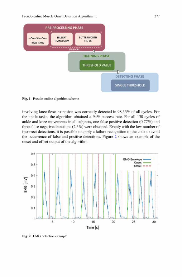
Pseudo-online Muscle Onset Detection Algorithm … 277
Fig. 1 Pseudo-online algorithm scheme
involving knee flexo-extension was correctly detected in 98.33% of all cycles. Forthe ankle tasks, the algorithm obtained a 94% success rate. For all 130 cycles ofankle and knee movements in all subjects, one false positive detection (0.77%) andthree false negative detections (2.3%) were obtained. Evenly with the low number ofincorrect detections, it is possible to apply a failure recognition to the code to avoidthe occurrence of false and positive detections. Figure 2 shows an example of theonset and offset output of the algorithm.
Fig. 2 EMG detection example
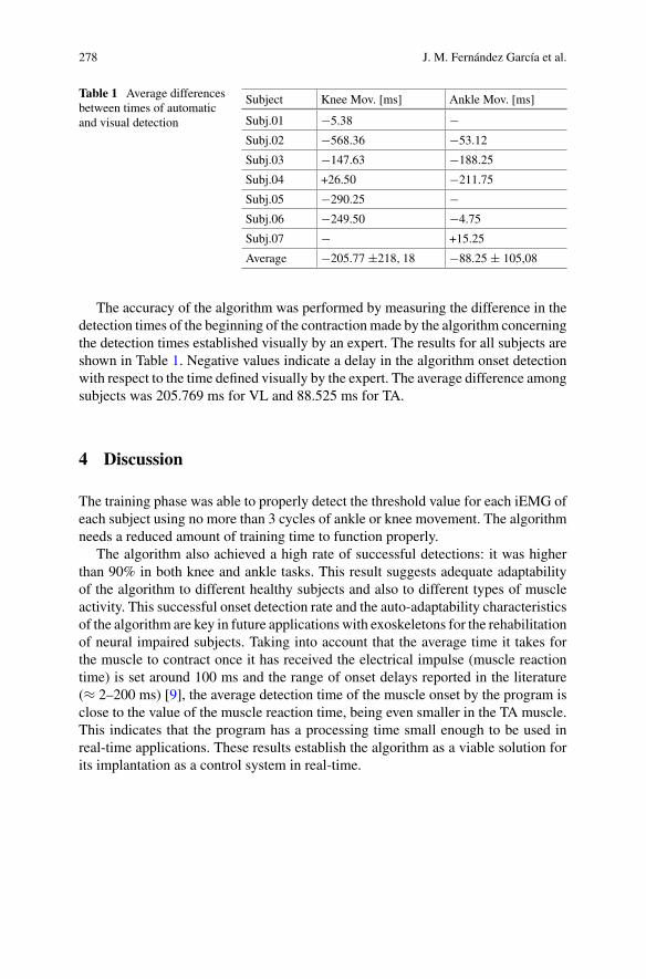
278 J. M. Fernández García et al.
Table 1 Average differencesbetween times of automaticand visual detection
Subject Knee Mov. [ms] Ankle Mov. [ms]
Subj.01 −5.38 −Subj.02 −568.36 −53.12
Subj.03 −147.63 −188.25
Subj.04 +26.50 −211.75
Subj.05 −290.25 −Subj.06 −249.50 −4.75
Subj.07 − +15.25
Average −205.77 ±218, 18 −88.25 ± 105,08
The accuracy of the algorithm was performed by measuring the difference in thedetection times of the beginning of the contractionmade by the algorithm concerningthe detection times established visually by an expert. The results for all subjects areshown in Table 1. Negative values indicate a delay in the algorithm onset detectionwith respect to the time defined visually by the expert. The average difference amongsubjects was 205.769 ms for VL and 88.525 ms for TA.
4 Discussion
The training phase was able to properly detect the threshold value for each iEMG ofeach subject using no more than 3 cycles of ankle or knee movement. The algorithmneeds a reduced amount of training time to function properly.
The algorithm also achieved a high rate of successful detections: it was higherthan 90% in both knee and ankle tasks. This result suggests adequate adaptabilityof the algorithm to different healthy subjects and also to different types of muscleactivity. This successful onset detection rate and the auto-adaptability characteristicsof the algorithm are key in future applications with exoskeletons for the rehabilitationof neural impaired subjects. Taking into account that the average time it takes forthe muscle to contract once it has received the electrical impulse (muscle reactiontime) is set around 100 ms and the range of onset delays reported in the literature(≈ 2–200 ms) [9], the average detection time of the muscle onset by the program isclose to the value of the muscle reaction time, being even smaller in the TA muscle.This indicates that the program has a processing time small enough to be used inreal-time applications. These results establish the algorithm as a viable solution forits implantation as a control system in real-time.
Pseudo-online Muscle Onset Detection Algorithm … 279
5 Conclusion
The algorithm has shown its capability of correctly detecting the intention of move-ment in 96.36% of cases in an average time of 147.15 ms, making it possible to applyit to the control of a robotic exoskeleton for rehabilitation in real-time. The systemwas able to achieve the objectives of detecting the users’ onset and offset detec-tion through intramuscular EMG signals. A reduction in the algorithm processingtime will improve algorithm performance in future real-time code applications withexoskeletons.
Acknowlegements This work was funded by the European Union’s Horizon 2020 research aninnovation project (project EXTEND–Bidirectional Hyper-Connected Neural System) under grantagreement No. 779982.
References
1. ISCOS, “International Perspectives onSpinal Cord Injury. World Heal. Organ. (2013). https://doi.org/10.1007/978-1-4939-7880-9_11
2. W.H. Chang, Y.-H. Kim, Robot-assisted therapy in stroke rehabilitation. J. Stroke 15(3), 174(2013). https://doi.org/10.5853/jos.2013.15.3.174
3. W. Huo, S. Mohammed, J.C. Moreno, Y. Amirat, Lower limb wearable robots for assistance andrehabilitation: a state of the art. IEEE Syst. J. 10(3), 1068–1081 (2016). https://doi.org/10.1109/JSYST.2014.2351491
4. D.J. Mcfarland, J.R. Wolpaw, in Brain–Computer Interfaces for the Operation of Robotic andProsthetic Devices (2010), 169–187
5. R.A.R.C. Gopura, K. Kiguchi, Y. Li, SUEFUL-7: A 7DOF upper-limb exoskeleton robot withmuscle-model-oriented EMG-based control. in 2009 IEEE/RSJ International Conference onIntelligent Robots and Systems, Oct. (2009), pp. 1126–1131. https://doi.org/10.1109/iros.2009.5353935
6. J. Perry, C.S. Easterday, D.J. Antonelli, surface versus intramuscular electrodes for electromyo-graphy of superficial and deep muscles. Phys. Ther. 61(1), 7–15 (1981). https://doi.org/10.1093/ptj/61.1.7
7. P.R. Cavanagh, P.V. Komi, Electromechanical delay in human skeletal muscle under concentricand eccentric contractions. Eur. J. Appl. Physiol. Occup. Physiol. 42(3), 159–163 (1979). https://doi.org/10.1007/BF00431022
8. P. Hodges, A comparison of computer-based methods for the determination of onset of musclecontraction using electromyography. Electroencephalogr. Clin. Neurophysiol. 101(6), (Dec,1996). https://doi.org/10.1016/S0013-4694(96)95190-5
9. S.J. Currie, C.A. Myers, A. Krishnamurthy, B.A. Enebo, B.S. Davidson, Methods of muscleactivation onset timing recorded during spinal manipulation. J. Manipulative Physiol. Therap.39(4), 279–287 (2016)
Benefits and Potential of aNeuromuscular Controller forExoskeleton-Assisted Walking
N. L. Tagliamonte, A. R. Wu, I. Pisotta, F. Tamburella, M. Masciullo,M. Arquilla, E. H. F. van Asseldonk, H. van der Kooij, F. Dzeladini,A. J. Ijspeert, and M. Molinari
Abstract Controlling wearable exoskeletons to interact with people suffering fromlocomotion disabilities due to lesions of the central nervous system is a complexchallenge since it entails fulfillment of many concurrent objectives: versatility in dif-ferent applications (assistance and rehabilitation), user-specific adaptation to residualmotor functions, compliance with different gait features (e.g. personal walking pat-terns and especially speed changes), smoothness of human-robot interaction, naturaland intuitive exoskeleton control, acceptability and usability of the worn system. Anovel bio-inspired modular controller for lower limb exoskeletons was developed bythe Authors, which delivers assistive joint torques by using a reflex-based neuromus-cular model. This paper presents an overview of previous and ongoing findings intesting this controller with the aim to highlight its benefits and potential in complyingwith user needs and with different applications.
Partial financial support was provided by: (i) the FP7 EU project SYMBITRON (ICT-2013-10-611626); (ii) the sub-project EXPERIENCE, funded by the FSTP-1 cascade funding program ofthe H2020 EU project EUROBENCH (ICT-2017-1-779963); (iii) the Italian Ministry of Healthunder Ricerca Corrente program.
N. L. Tagliamonte (B)Unit of Advanced Robotics and Human-Centred Technologies (CREO Lab), Universitá CampusBio-Medico di Roma, Rome, Italye-mail: [email protected]
A. R. WuDepartment of Mechanical and Materials Engineering, Queen’s University, Kingston, Canada
I. Pisotta · F. Tamburella · M. Masciullo · M. Arquilla · M. MolinariSpinal Rehabilitation Laboratory (SPIRE Lab) and Laboratory of Robotic Neurorehabilitation(NeuroRobot Lab), Neurorehabilitation 1 Department, Fondazione Santa Lucia, Rome, Italy
E. H. F. van Asseldonk · H. van der KooijDepartment of Biomechanical Engineering, University of Twente, Enschede, The Netherlands
F. Dzeladini · A. J. IjspeertBioRobotics Laboratory, School of Engineering, Institute of Bioengineering, Ecole PolytechniqueFederale de Lausanne, Lausanne, Switzerland
© The Author(s), under exclusive license to Springer Nature Switzerland AG 2022J. C. Moreno et al. (eds.), Wearable Robotics: Challenges and Trends,Biosystems & Biorobotics 27, https://doi.org/10.1007/978-3-030-69547-7_46
281
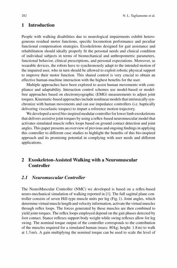
282 N. L. Tagliamonte et al.
1 Introduction
People with walking disabilities due to neurological impairments exhibit hetero-geneous residual motor functions, specific locomotion performance and peculiarfunctional compensation strategies. Exoskeletons designed for gait assistance andrehabilitation should ideally properly fit the personal needs and clinical conditionof individual subjects in terms of biomechanical and anthropometric parameters,functional behavior, clinical prescriptions, and personal expectations. Moreover, aswearable devices, the robots have to synchronously adapt to the intended motion ofthe impaired user, who in turn should be allowed to exploit robotic physical supportto improve their motor function. This shared control is very crucial to obtain aneffective human-machine interaction with the highest benefits for the user.
Multiple approaches have been explored to assist human movements with com-pliance and adaptability. Interaction control schemes use model-based or model-free approaches based on electromyographic (EMG) measurements to adjust jointtorques.Kinematic-based approaches include nonlinearmodels that intrinsically syn-chronize with human movements and can use impedance controllers (i.e. hapticallydelivering viscoelastic torques) to impart a reference motion trajectory.
We developed a novel bio-inspiredmodular controller for lower limb exoskeletonsthat delivers assistive joint torques by using a reflex-based neuromuscular model thatactivates simulated muscle reflex loops based on ground contact detection and jointangles. This paper presents an overview of previous and ongoing findings in applyingthis controller to different case studies to highlight the benefits of this bio-inspiredapproach and its promising potential in complying with user needs and differentapplications.
2 Exoskeleton-Assisted Walking with a NeuromuscularController
2.1 Neuromuscular Controller
The NeuroMuscular Controller (NMC) we developed is based on a reflex-basedneuro-mechanical simulation of walking reported in [1]. The full sagittal plane con-troller consists of seven Hill-type muscle units per leg (Fig. 1). Joint angles, whichdetermine virtualmuscle length and velocity information, activate the virtualmusclesthrough reflex loops. The forces generated by these muscles are then combined toyield joint torques. The reflex loops employed depend on the gait phases detected byfoot contact. Stance reflexes support body weight while swing reflexes allow for legswing. The nominal torque output of the controller corresponds to the contributionof the muscles required for a simulated human (mass: 80kg; height: 1.8m) to walkat 1.3m/s. A gain multiplying the nominal torque can be used to scale the level of
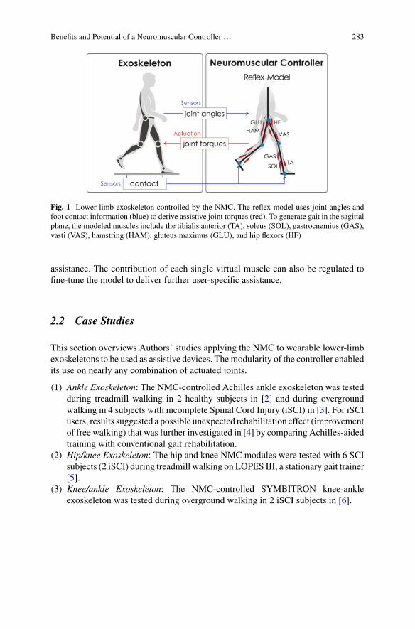
Benefits and Potential of a Neuromuscular Controller … 283
Fig. 1 Lower limb exoskeleton controlled by the NMC. The reflex model uses joint angles andfoot contact information (blue) to derive assistive joint torques (red). To generate gait in the sagittalplane, the modeled muscles include the tibialis anterior (TA), soleus (SOL), gastrocnemius (GAS),vasti (VAS), hamstring (HAM), gluteus maximus (GLU), and hip flexors (HF)
assistance. The contribution of each single virtual muscle can also be regulated tofine-tune the model to deliver further user-specific assistance.
2.2 Case Studies
This section overviews Authors’ studies applying the NMC to wearable lower-limbexoskeletons to be used as assistive devices. Themodularity of the controller enabledits use on nearly any combination of actuated joints.
(1) Ankle Exoskeleton: The NMC-controlled Achilles ankle exoskeleton was testedduring treadmill walking in 2 healthy subjects in [2] and during overgroundwalking in 4 subjects with incomplete Spinal Cord Injury (iSCI) in [3]. For iSCIusers, results suggested a possible unexpected rehabilitation effect (improvementof free walking) that was further investigated in [4] by comparing Achilles-aidedtraining with conventional gait rehabilitation.
(2) Hip/knee Exoskeleton: The hip and knee NMC modules were tested with 6 SCIsubjects (2 iSCI) during treadmill walking on LOPES III, a stationary gait trainer[5].
(3) Knee/ankle Exoskeleton: The NMC-controlled SYMBITRON knee-ankleexoskeleton was tested during overground walking in 2 iSCI subjects in [6].
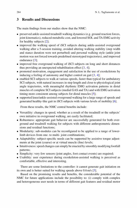
284 N. L. Tagliamonte et al.
3 Results and Discussions
The main findings from our studies show that the NMC:
• preserved ankle-assisted treadmill walking dynamics (e.g. ground reaction forces,joint kinematics), reduced metabolic cost, and lowered SOL and TA EMG activityfor healthy subjects [2];
• improved the walking speed of iSCI subjects during ankle-assisted overgroundwalking after a 5-session training, avoided altering walking stability (step widthand stance duration were not perturbed) and personal walking style (ankle jointmotion was not forced towards predefined stereotyped trajectories), and improvedendurance [3];
• improved free overground walking of iSCI subjects on long and short distancesthus providing an unexpected rehabilitation effect [3, 4];
• promoted motivation, engagement and satisfaction in the use of exoskeletons byinducing a feeling of autonomy and higher control on gait [3, 4];
• enabled SCI subjects to walk at various speeds, faster than typical for ambulatorySCI subjects, with natural increases in step length and close to physiological jointangle trajectories, with meaningful rhythmic EMG activation patterns in distalmuscles of complete SCI subjects (medial GAS and TA) and with EMG activationtiming more consistent among subjects for distal muscles [5];
• supported knee/ankle-assisted overground walking for a large range of speeds andgenerated healthy-like gait in iSCI subjects with various levels of mobility [6].
From these results, the NMC central benefits include:
• Versatility: changes in speed, whether as a result of the treadmill or the subjects’own initiative in overground walking, are easily facilitated;
• Robustness: appropriate gait behavior are successfully generated for both over-ground and treadmill walking for subjects with different anthropometric dimen-sions and residual functions;
• Modularity: sub-modules can be reconfigured to be applied to a range of lower-limb devices from one- to multi- joint combinations;
• Adaptability: subject-specific needs can be supported by assistive torque adjust-ments at the joint (coarse) or at virtual muscle (fine) levels;
• Intuitiveness: speed changes can simply be enacted by smoothlymodifying footfallpatterns;
• Simplicity: very few sensors (joint angles, foot contact events) are required;• Usability: user experience during exoskeleton-assisted walking is perceived ascomfortable, effective and interesting.
There are some limitations to the controller: it cannot generate gait initiation onits own and is better suited for walking speeds above 0.6m/s [5].
Based on the promising results and benefits, the considerable potential of theNMC for future applications include the possibility to: (i) comply with complexand heterogeneous user needs in terms of different gait features and residual motor
Benefits and Potential of a Neuromuscular Controller … 285
functions; (ii) be applied in both daily life assistive scenario and in clinical rehabili-tation environments; (iii) be used for both healthy (augmentation and energetic costreduction) and impaired subjects (assistance and rehabilitation).
4 Conclusion
A bio-inspired controller for lower limb exoskeletons was developed, which deliv-ers assistive joint torques by using a reflex-based neuromuscular model. Tests withSCI subjects with different impairments on various NMC-controlled devices demon-strated the NMC unique benefits and potential for gait assistance and rehabilitation.
References
1. H. Geyer, H. Herr, A muscle-reflex model that encodes principles of legged mechanics produceshuman walking dynamics and muscle activities. IEEE TNSRE 18(3), 263–273 (2010)
2. F. Dzeladini, et al., Effects of a neuromuscular controller on a powered ankle exoskeleton duringhuman walking, in IEEE BioRob (2016)
3. F. Tamburella, et al.,Neuromuscular controller embedded in a powered ankle exoskeleton: effectson gait, clinical features and subjective perspective of incomplete spinal cord injured subjects.IEEE TNSRE 28(5), 1157–1167 (2020)
4. F. Tamburella, et al., Gait training with achilles ankle exoskeleton in chronic incomplete spinalcord injury subjects. J. Biol. Regul. Homeostatic Agents 34(5 Suppl. 3), 147–164 (2020)
5. A.R. Wu et al., An adaptive neuromuscular controller for assistive lower-limb exoskeletons: apreliminary study on subjects with spinal cord injury. Front. Neurorob. 11, 30 (2017)
6. C. Meijneke, et al., Design, control and evaluation of a modular exoskeleton for incomplete andcomplete spinal cord injured subjects. IEEE TNSRE 29, 330–339 (2021)
CANopen Robot Controller (CORC):An Open Software Stack for HumanRobot Interaction Development
Justin Fong, Emek Barıs Küçüktabak, Vincent Crocher, Ying Tan,Kevin M. Lynch, Jose L. Pons, and Denny Oetomo
Abstract Interest in the investigation of novel software and control algorithms forwearable robotics is growing. However, entry into this field requires a significantinvestment in a testing platform. This work introduces CANopen Robot Controller(CORC)—an open source software stack designed to accelerate the development ofrobot software and control algorithms—justifying its choice of platform, describingits overall structure, and demonstrating its viability on two distinct platforms.
J. Fong (B) · V. Crocher · Y. Tan · D. OetomoUniversity of Melbourne and Fourier Intelligence Joint Laboratory, the University of Melbourne,Melbourne, Australiae-mail: [email protected]
V. Crochere-mail: [email protected]
Y. Tane-mail: [email protected]
D. Oetomoe-mail: [email protected]
E. B. Küçüktabak · K. M. Lynch · J. L. PonsMcCormick School of Engineering, Northwestern University,Evanston, USAe-mail: [email protected]
K. M. Lynche-mail: [email protected]
J. L. Ponse-mail: [email protected]
E. B. Küçüktabak · J. L. PonsLegs + Walking Lab, Shirley Ryan Ability Lab, Chicago, USA
© The Author(s), under exclusive license to Springer Nature Switzerland AG 2022J. C. Moreno et al. (eds.), Wearable Robotics: Challenges and Trends,Biosystems & Biorobotics 27, https://doi.org/10.1007/978-3-030-69547-7_47
287
288 J. Fong et al.
1 Introduction
The rapid progression of actuation, power and processing technologies has signifi-cantly improved the capabilities and possible applications of exoskeleton and wear-able robotic devices. With these developments, interest in developing controllersand control algorithms for gait trajectory planning and human-robot interactionsstrategies has risen, with this field being recently identified as a key developmentalopportunity for improving exoskeleton performance [1]. However, a key challengein the pursuit of this field is the development of tools for testing said algorithms. Thisis particularly true for wearable devices, which see large variations in actuator andsensor configurations and designs.
The present work introduces the CANopen Robot Controller (CORC)—an opensource software stack designed to accelerate the development of robotic devicesbased on CANopen hardware. CORC allows modular hardware use by leveragingthe CANopen standardisation while providing a real-time system meeting the safetyrequirements of wearable devices. Within this work, the design and architecture ofCORC is introduced, and the viability of the the stack is dermonstrated throughmeasurement of control loop period jitter on two CORC implementations runningrespectively on the Fourier Intelligence X2 exoskeleton [2] and the EMU upper-limbmanipulandum [3].
2 Materials and Methods
2.1 Goals and Objectives
CORCwas developed as a common development platform for robotswhich primarilyuse CANopen devices. CANopen has a 25+ year history as a communications pro-tocol in industrial automation, and is commonly used in robotic devices. Therefore,the objectives of CORC are to provide a flexible, modular architecture for differentapplications and devices, with a loop rate of 200Hz with low jitter.
2.2 Platform
Twomajor decision points weremade for the platform of the CORC software stack—the operating system and the programming language.
(1) Operating System—Linux-Based: Linux-based operating systems presentedthemselves as the obvious choice, primarily due to their open and stable nature,as well as their ability to be run with a real time kernel—which can be critical
CANopen Robot Controller (CORC): An Open Software … 289
in human-robot interactions. Furthermore, Linux is well-supported on a largerange of hardware platforms.
(2) Programming Language—C/C++: For efficiency reasons, C is used for the crit-ical sections of the software and C++ at the higher level to take advantage of theObject Oriented Programming design without sacrificing performance.
2.3 Software Architecture
The CORC software stack is divided into three distinct layers to enable flexibleimplementations on different platforms.
(1) CANopen Layer: The CANopen layer handles the application layer trans-fer of CAN messages, including poll-response (Service Data Object, SDO)and streamed (Process Data Object, PDO) protocols. This layer is based onCANopenSocket [4], and licensed under the Apache License, Version 2.0. Lim-ited changes are required to this layer to develop using CORC.
(2) Robot Layer: The robot layer describes the robotic structure, and links it with theinput (e.g. sensors) and output devices (e.g.motor drives). It acts as an abstractionbetween the control algorithms and the hardware, allowing implementation ofkinematic and/or dynamic models. CORC also contains base classes accordingto CAN in Automation (CiA) standards. This layer is designed to be modifiedonly when new hardware is added to the robotic device.
(3) Application Layer: The application layer implements overall program logic andcontrol algorithms. In CORC, each application is a dedicated state machine,derived from a common class. This architecture encourages safe execution whileleaving complete freedom for logic implementation. Specific ad hoc libraries canbe used at this level to extend capabilities such as providing Robot OperatingSystem (ROS) node capabilities to the application.Given an existing robot imple-mentation, only application layer modification is required to perform researchinto novel control strategies. With this approach, a CORC application can alsobe used as a robot firmware for a specific application with routine execution, orfor communication with a third-party software.
2.4 Viability Test
The viability test sought to demonstrate two key goals of the toolbox: flexibilityfor different hardware platforms, and consistency in control loop execution rate.Therefore, simple programs were implemented on two hardware platforms (Fig. 1),and executed at different control frequencies. The hardware platforms were:
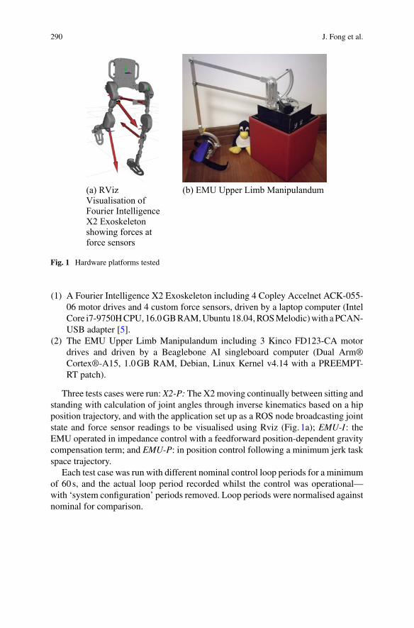
290 J. Fong et al.
(a) RVizVisualisation ofFourier IntelligenceX2 Exoskeletonshowing forces atforce sensors
(b) EMU Upper Limb Manipulandum
Fig. 1 Hardware platforms tested
(1) A Fourier Intelligence X2 Exoskeleton including 4 Copley Accelnet ACK-055-06 motor drives and 4 custom force sensors, driven by a laptop computer (IntelCore i7-9750HCPU,16.0GBRAM,Ubuntu18.04,ROSMelodic)with aPCAN-USB adapter [5].
(2) The EMU Upper Limb Manipulandum including 3 Kinco FD123-CA motordrives and driven by a Beaglebone AI singleboard computer (Dual Arm®Cortex®-A15, 1.0GB RAM, Debian, Linux Kernel v4.14 with a PREEMPT-RT patch).
Three tests cases were run: X2-P: The X2moving continually between sitting andstanding with calculation of joint angles through inverse kinematics based on a hipposition trajectory, and with the application set up as a ROS node broadcasting jointstate and force sensor readings to be visualised using Rviz (Fig. 1a); EMU-I: theEMU operated in impedance control with a feedforward position-dependent gravitycompensation term; and EMU-P: in position control following a minimum jerk taskspace trajectory.
Each test case was run with different nominal control loop periods for a minimumof 60s, and the actual loop period recorded whilst the control was operational—with ‘system configuration’ periods removed. Loop periods were normalised againstnominal for comparison.
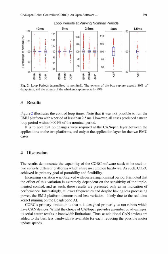
CANopen Robot Controller (CORC): An Open Software … 291
Fig. 2 Loop Periods (normalised to nominal). The extents of the box capture exactly 80% ofdatapoints, and the extents of the whiskers capture exactly 99%
3 Results
Figure2 illustrates the control loop times. Note that it was not possible to run theEMU platform with a period of less than 2.5ms. However, all cases produced a meanloop period within 0.001% of the nominal period.
It is to note that no changes were required at the CANopen layer between theapplications on the two platforms, and only at the application layer for the two EMUcases.
4 Discussion
The results demonstrate the capability of the CORC software stack to be used ontwo entirely different platforms which share no common hardware. As such, CORCachieved its primary goal of portability and flexibility.
Increasing variation was observed with decreasing nominal period. It is noted thatthe effect of this variation is extremely dependent on the sensitivity of the imple-mented control, and as such, these results are presented only as an indication ofperformance. Interestingly, at lower frequencies and despite having less processingpower, the EMU platform demonstrated less variation—likely due to the real timekernel running on the Beaglebone AI.
CORC’s primary limitation is that it is designed primarily to run robots whichhave CAN devices. Whilst the choice of CANopen provides a number of advantages,its serial nature results in bandwidth limitations. Thus, as additional CAN devices areadded to the bus, less bandwidth is available for each, reducing the possible motorupdate speeds.
292 J. Fong et al.
5 Conclusions
The present work introduces the CORC toolbox—a software stack designed forrobotic devices—to accelerate the development of control algorithms and trajectories.This first evaluation demonstrates its implementation flexibility and performancestability across different hardware platforms. This open software stack is available1
to the wearable robotics community for use and development. Future work includesthe development of a robust loggingmodule and further integrationwithROS, beyondthe currently-implemented broadcast functionality.
References
1. G.S. Sawicki, et al., The exoskeleton expansion: improving walking and running economy. J.Neuroeng. Rehabil. 17(1), 1–9 (2020)
2. Fourier Intelligence, X2 http://www.fftai-global.com/lower-extremity/3. J. Fong, et al. EMU: a transparent 3D robotic manipulandum for upper-limb rehabilitation, in
2017 IEEE International Conference on Rehabilitation Robotics (ICORR) (2017), pp. 771–7764. CANopenSocket https://github.com/CANopenNode/CANopenSocket5. PEAK-System, PCAN-USB https://www.peak-system.com
1https://github.com/UniMelbHumanRoboticsLab/CANOpenRobotController.

Toward Efficient Human-ExoskeletonSymbiosis
Direct Collocation-Based OptimalController for Multi-modal Assistance:Simulation Study
Anh T. Nguyen, Vincent Bonnet, and Samer Mohammed
Abstract Multi-modal assistive system is a hybrid system that aims to provideassistance-as-needed for paretic subjects. The hybrid system combines human mus-cle efforts, stimulated by a Functional Electric Stimulator (FES) and an lower-limbactive exoskeleton. With optimal sharing of the two activation inputs, a hybrid sys-tem could overcome several challenges, such as human force due to FES-inducedmuscular fatigue. In this paper, a novel optimal controller, based on an efficient (3.9ms to predict a time windows of 40 ms) closed-loop direct collocation approach isproposed to predict the control allocation between FES and exoskeleton. Simula-tion results, performed with dynamically varying desired trajectory, show that theproposed controller adapts the control input with respect to muscular fatigue.
1 Introduction
Multi-modal assistive systems, combining FES and active exoskeleton, aim to pro-vide assistance-as-needed to support paretic patients recovering normal walking gaitpatterns. However, to take into account the nonlinear muscular fatigue due to func-tional electrical stimulation, an adaptation of the level of support provided by eachassistive device is required. To address this challenge, researchers have explored con-trol allocation methods to automatically adjust the control tuning between FES andexoskeleton. In the literature, recent approaches based on high-bandwidth feedbackcontrol methods or non linear model predictive controller-based direct control allo-cation method developed by Kirsh et al. [1, 2] were proposed. These studies showssatisfactory results with patients. However, the investigated desired trajectories werelimited to a step-wise. Thus, this paper proposes a novel approach based on popularand computationally efficient direct collocation optimisation method to solve thecontrol allocation between FES and exoskeleton support during flexion/extensionmovements of the knee joint.
A. T. Nguyen · V. Bonnet (B) · S. MohammedUniv Paris Est Creteil, LISSI, 94400 Vitry, Francee-mail: [email protected]
© The Author(s), under exclusive license to Springer Nature Switzerland AG 2022J. C. Moreno et al. (eds.), Wearable Robotics: Challenges and Trends,Biosystems & Biorobotics 27, https://doi.org/10.1007/978-3-030-69547-7_48
295
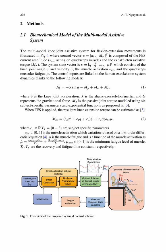
296 A. T. Nguyen et al.
2 Methods
2.1 Biomechanical Model of the Multi-modal AssistiveSystem
The multi-modal knee joint assistive system for flexion-extension movements isillustrated in Fig. 1 where control vector u = [uke Mm]T is composed of the FEScurrent amplitude (uke, acting on quadriceps muscle) and the exoskeleton assistivetorque (Mm). The system state vector is x = [q q ake µ]T which consists of theknee joint angle q and velocity q , the muscle activation ake, and the quadricepsmuscular fatigue µ. The control inputs are linked to the human-exoskeleton systemdynamics thanks to the following models:
J q = −G sin q − Mp + Mm + Mke (1)
where q is the knee joint acceleration. J is the shank-exoskeleton inertia, and Grepresents the gravitational force. Mp is the passive joint torque modeled using sixsubject-specific parameters and exponential functions as proposed in [3].
When FES is applied, the resultant knee extension torque can be estimated as [3]:
Mke = (c2q2 + c1q + c0)(1 + c3q)akeµ, (2)
where c j ∈ R∀ j = 0 − 3 are subject specific parameters.ake ∈ [0, 1] is themuscle activationwhich variation is based on a first-order differ-
ential equation [4].µ is themuscle fatigue and is a function of themuscle activation asµ = (µmin−µ)ake
T f+ (1−µ)(1−ake)
Tr. µmin ∈ [0, 1] is the minimum fatigue level of muscle,
Tr , T f are the recovery and fatigue time constant, respectively.
Fig. 1 Overview of the proposed optimal control scheme
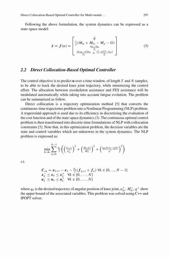
Direct Collocation-Based Optimal Controller for Multi-modal … 297
Following the above formulation, the system dynamics can be expressed as astate-space model:
x = f (u) =
⎡⎢⎢⎣
q1J (Mm + Mke − Mp − G)
uke−akeTa
(µmin−µ)akeT f
+ (1−µ)(1−ake)Tr
⎤⎥⎥⎦ (3)
2.2 Direct Collocation-Based Optimal Controller
The control objective is to predict u over a time window, of length T and N samples,to be able to track the desired knee joint trajectory, while minimizing the controleffort. The allocation between exoskeleton assistance and FES assistance will bemodulated automatically while taking into account fatigue evolution. The problemcan be summarized as follow.
Direct collocation is a trajectory optimization method [5] that converts thecontinuous-time trajectories problem into aNonlinear Programming (NLP) problem.A trapezoidal approach is used due to its efficiency in discretizing the evaluation ofthe cost function and of the state-space dynamics (3). The continuous optimal controlproblem is then transformed into discrete-time formulations of NLPwith collocationconstraints [5]. Note that, in this optimization problem, the decision variables are thestate and control variables which are unknowns in the system dynamics. The NLPproblem is expressed as:
minxk ,uk
N−1∑k=0
hk2
((uke(k)u+ke
)2 +(
Mm (k)M+
m
)2 +((qd (k))k−q(k)
q+
)2)
s.t.
Ceq = xk+1 − xk − hk2 ( f k+1 + f k) ∀k ∈ [0, ..., N − 1]
x−k ≤ xk ≤ x+
k ∀k ∈ [0, . . . , N ]u−k ≤ uk ≤ u+
k ∀k ∈ [0, . . . , N ]
where qd is the desired trajectory of angular position of knee joint, u+ke,M
+m , q
+ showthe upper bound of the associated variables. This problem was solved using C++ andIPOPT solver.
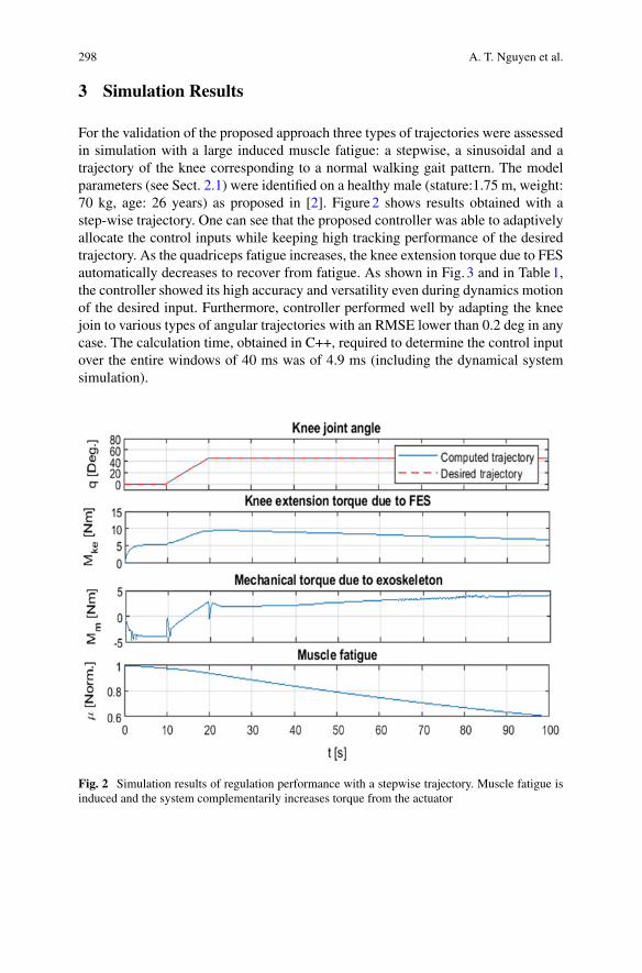
298 A. T. Nguyen et al.
3 Simulation Results
For the validation of the proposed approach three types of trajectories were assessedin simulation with a large induced muscle fatigue: a stepwise, a sinusoidal and atrajectory of the knee corresponding to a normal walking gait pattern. The modelparameters (see Sect. 2.1) were identified on a healthy male (stature:1.75 m, weight:70 kg, age: 26 years) as proposed in [2]. Figure2 shows results obtained with astep-wise trajectory. One can see that the proposed controller was able to adaptivelyallocate the control inputs while keeping high tracking performance of the desiredtrajectory. As the quadriceps fatigue increases, the knee extension torque due to FESautomatically decreases to recover from fatigue. As shown in Fig. 3 and in Table1,the controller showed its high accuracy and versatility even during dynamics motionof the desired input. Furthermore, controller performed well by adapting the kneejoin to various types of angular trajectories with an RMSE lower than 0.2 deg in anycase. The calculation time, obtained in C++, required to determine the control inputover the entire windows of 40 ms was of 4.9 ms (including the dynamical systemsimulation).
Fig. 2 Simulation results of regulation performance with a stepwise trajectory. Muscle fatigue isinduced and the system complementarily increases torque from the actuator
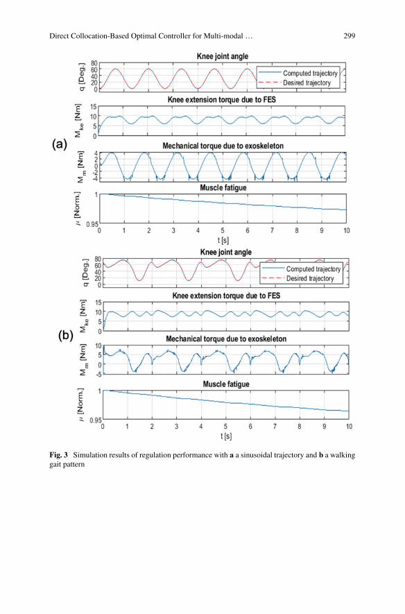
Direct Collocation-Based Optimal Controller for Multi-modal … 299
Fig. 3 Simulation results of regulation performance with a a sinusoidal trajectory and b a walkinggait pattern
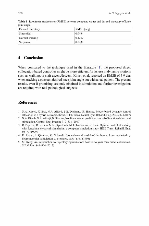
300 A. T. Nguyen et al.
Table 1 Root mean square error (RMSE) between computed values and desired trajectory of kneejoint angle
Desired trajectory RMSE [deg]
Sinusoidal 0.0434
Normal walking 0.1267
Step-wise 0.0238
4 Conclusion
When compared to the technique used in the literature [1], the proposed directcollocation-based controller might be more efficient for its use in dynamic motionssuch as walking, or stair ascent/descent. Kirsch et al. reported an RMSE of 3.9 degwhen tracking a constant desired knee joint angle but with a real patient. The presentresults, even if promising, are only obtained in simulation and further investigationare required with real-pathological subjects.
References
1. N.A. Kirsch, X. Bao, N.A. Alibeji, B.E. Dicianno, N. Sharma, Model-based dynamic controlallocation in a hybrid neuroprosthesis. IEEE Trans. Neural Syst. Rehabil. Eng. 224–232 (2017)
2. N.A.Kirsch,N.A.Alibeji, N. Sharma,Nonlinearmodel predictive control of functional electricalstimulation. Control Eng. Practice 319–331 (2017)
3. D. Popovic, R.B. Stein, M.N. Oguztoreli, M. Lebiedowska, S. Jonic, Optimal control of walkingwith functional electrical stimulation: a computer simulation study. IEEE Trans. Rehabil. Eng.69–79 (1999)
4. R. Riener, J. Quintern, G. Schmidt, Biomechanical model of the human knee evaluated byneuromuscular stimulation. J. Biomech. 1157–1167 (1996)
5. M. Kelly, An introduction to trajectory optimization: how to do your own direct collocation.SIAM Rev. 849–904 (2017)
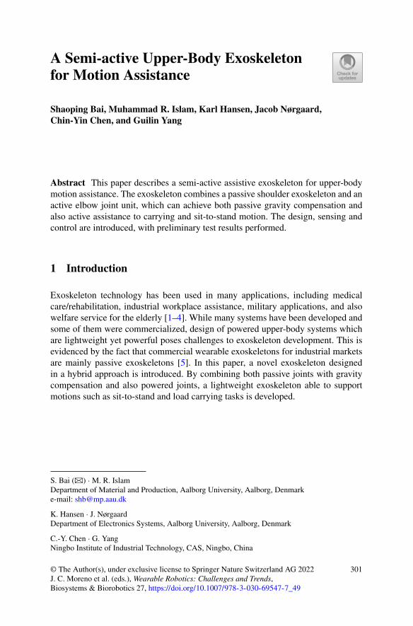
A Semi-active Upper-Body Exoskeletonfor Motion Assistance
Shaoping Bai, Muhammad R. Islam, Karl Hansen, Jacob Nørgaard,Chin-Yin Chen, and Guilin Yang
Abstract This paper describes a semi-active assistive exoskeleton for upper-bodymotion assistance. The exoskeleton combines a passive shoulder exoskeleton and anactive elbow joint unit, which can achieve both passive gravity compensation andalso active assistance to carrying and sit-to-stand motion. The design, sensing andcontrol are introduced, with preliminary test results performed.
1 Introduction
Exoskeleton technology has been used in many applications, including medicalcare/rehabilitation, industrial workplace assistance, military applications, and alsowelfare service for the elderly [1–4]. While many systems have been developed andsome of them were commercialized, design of powered upper-body systems whichare lightweight yet powerful poses challenges to exoskeleton development. This isevidenced by the fact that commercial wearable exoskeletons for industrial marketsare mainly passive exoskeletons [5]. In this paper, a novel exoskeleton designedin a hybrid approach is introduced. By combining both passive joints with gravitycompensation and also powered joints, a lightweight exoskeleton able to supportmotions such as sit-to-stand and load carrying tasks is developed.
S. Bai (B) ·M. R. IslamDepartment of Material and Production, Aalborg University, Aalborg, Denmarke-mail: [email protected]
K. Hansen · J. NørgaardDepartment of Electronics Systems, Aalborg University, Aalborg, Denmark
C.-Y. Chen · G. YangNingbo Institute of Industrial Technology, CAS, Ningbo, China
© The Author(s), under exclusive license to Springer Nature Switzerland AG 2022J. C. Moreno et al. (eds.), Wearable Robotics: Challenges and Trends,Biosystems & Biorobotics 27, https://doi.org/10.1007/978-3-030-69547-7_49
301
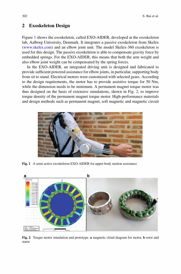
302 S. Bai et al.
2 Exoskeleton Design
Figure 1 shows the exoskeleton, called EXO-AIDER, developed at the exoskeletonlab, Aalborg University, Denmark. It integrates a passive exoskeleton from Skelex(www.skelex.com) and an elbow joint unit. The model Skelex-360 exoskeleton isused for this design. The passive exoskeleton is able to compensate gravity force byembedded springs. For the EXO-AIDER, this means that both the arm weight andalso elbow joint weight can be compensated by the spring forces.
In the EXO-AIDER, an integrated driving unit is designed and fabricated toprovide sufficient powered assistance for elbow joints, in particular, supporting bodyfrom sit to stand. Electrical motors were customized with selected gears. Accordingto the design requirements, the motor has to provide assistive torque for 50 Nm,while the dimension needs to be minimum. A permanent magnet torque motor wasthus designed on the basis of extensive simulations, shown in Fig. 2, to improvetorque density of the permanent magnet torque motor. High-performance materialsand design methods such as permanent magnet, soft magnetic and magnetic circuit
Fig. 1 A semi-active exoskeleton EXO-AIDER for upper-body motion assistance
Fig. 2 Torque motor simulation and prototype. a magnetic cloud diagram for motor, b rotor andstator
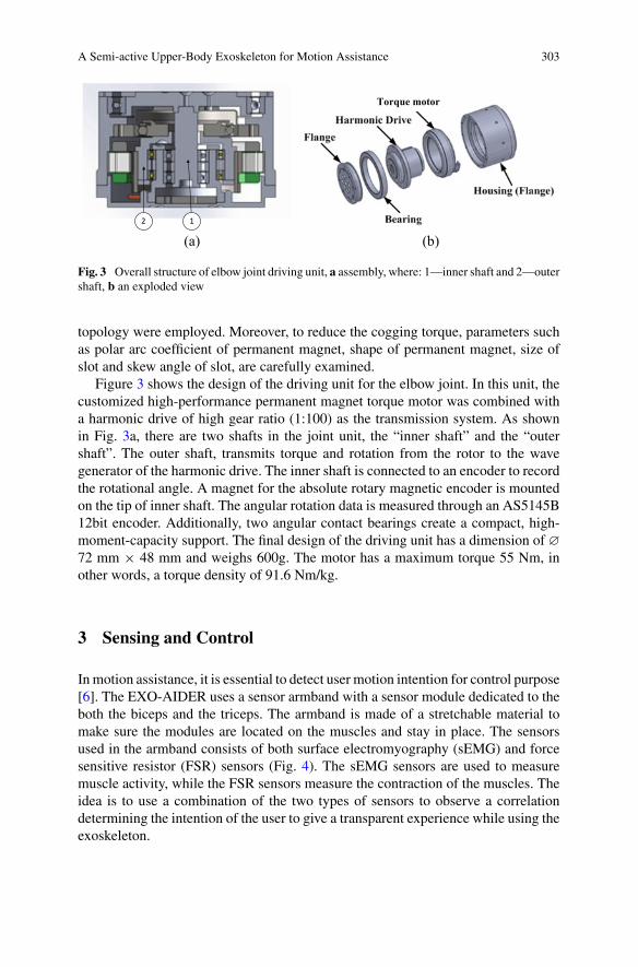
A Semi-active Upper-Body Exoskeleton for Motion Assistance 303
12
(a) (b)
Torque motor
Fig. 3 Overall structure of elbow joint driving unit, a assembly, where: 1—inner shaft and 2—outershaft, b an exploded view
topology were employed. Moreover, to reduce the cogging torque, parameters suchas polar arc coefficient of permanent magnet, shape of permanent magnet, size ofslot and skew angle of slot, are carefully examined.
Figure 3 shows the design of the driving unit for the elbow joint. In this unit, thecustomized high-performance permanent magnet torque motor was combined witha harmonic drive of high gear ratio (1:100) as the transmission system. As shownin Fig. 3a, there are two shafts in the joint unit, the “inner shaft” and the “outershaft”. The outer shaft, transmits torque and rotation from the rotor to the wavegenerator of the harmonic drive. The inner shaft is connected to an encoder to recordthe rotational angle. A magnet for the absolute rotary magnetic encoder is mountedon the tip of inner shaft. The angular rotation data is measured through an AS5145B12bit encoder. Additionally, two angular contact bearings create a compact, high-moment-capacity support. The final design of the driving unit has a dimension of ∅
72 mm × 48 mm and weighs 600g. The motor has a maximum torque 55 Nm, inother words, a torque density of 91.6 Nm/kg.
3 Sensing and Control
Inmotion assistance, it is essential to detect user motion intention for control purpose[6]. The EXO-AIDER uses a sensor armband with a sensor module dedicated to theboth the biceps and the triceps. The armband is made of a stretchable material tomake sure the modules are located on the muscles and stay in place. The sensorsused in the armband consists of both surface electromyography (sEMG) and forcesensitive resistor (FSR) sensors (Fig. 4). The sEMG sensors are used to measuremuscle activity, while the FSR sensors measure the contraction of the muscles. Theidea is to use a combination of the two types of sensors to observe a correlationdetermining the intention of the user to give a transparent experience while using theexoskeleton.
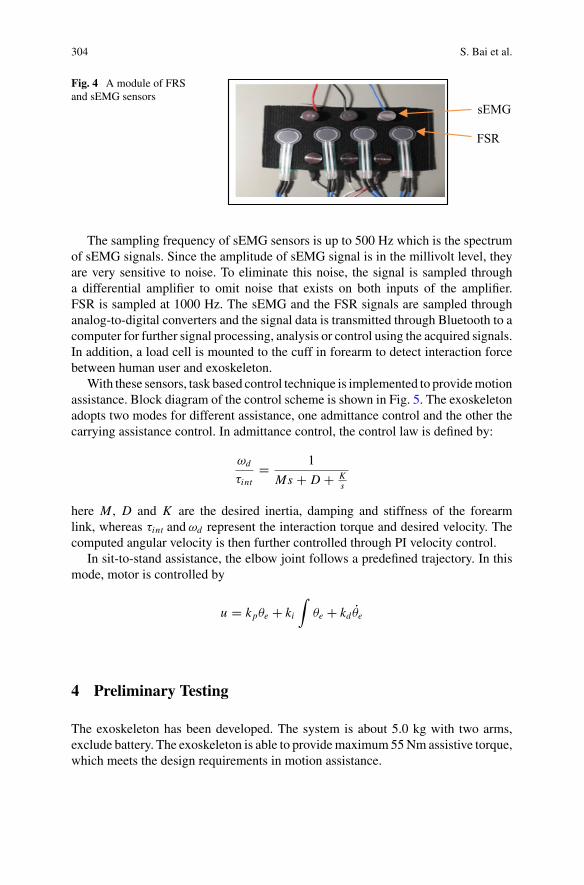
304 S. Bai et al.
Fig. 4 A module of FRSand sEMG sensors
sEMG
FSR
The sampling frequency of sEMG sensors is up to 500 Hz which is the spectrumof sEMG signals. Since the amplitude of sEMG signal is in the millivolt level, theyare very sensitive to noise. To eliminate this noise, the signal is sampled througha differential amplifier to omit noise that exists on both inputs of the amplifier.FSR is sampled at 1000 Hz. The sEMG and the FSR signals are sampled throughanalog-to-digital converters and the signal data is transmitted through Bluetooth to acomputer for further signal processing, analysis or control using the acquired signals.In addition, a load cell is mounted to the cuff in forearm to detect interaction forcebetween human user and exoskeleton.
With these sensors, task based control technique is implemented to providemotionassistance. Block diagram of the control scheme is shown in Fig. 5. The exoskeletonadopts two modes for different assistance, one admittance control and the other thecarrying assistance control. In admittance control, the control law is defined by:
ωd
τint= 1
Ms + D + Ks
here M , D and K are the desired inertia, damping and stiffness of the forearmlink, whereas τint andωd represent the interaction torque and desired velocity. Thecomputed angular velocity is then further controlled through PI velocity control.
In sit-to-stand assistance, the elbow joint follows a predefined trajectory. In thismode, motor is controlled by
u = kpθe + ki
∫θe + kd θe
4 Preliminary Testing
The exoskeleton has been developed. The system is about 5.0 kg with two arms,exclude battery. The exoskeleton is able to providemaximum55Nmassistive torque,which meets the design requirements in motion assistance.
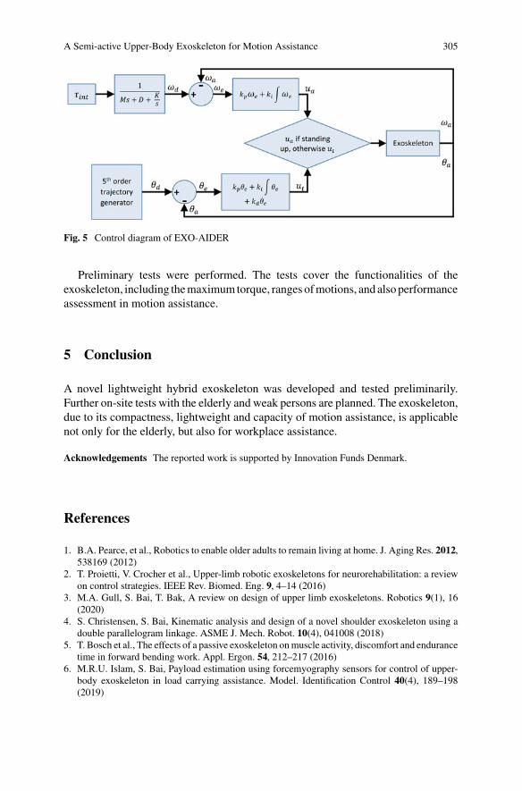
A Semi-active Upper-Body Exoskeleton for Motion Assistance 305
Fig. 5 Control diagram of EXO-AIDER
Preliminary tests were performed. The tests cover the functionalities of theexoskeleton, including themaximumtorque, ranges ofmotions, and alsoperformanceassessment in motion assistance.
5 Conclusion
A novel lightweight hybrid exoskeleton was developed and tested preliminarily.Further on-site tests with the elderly and weak persons are planned. The exoskeleton,due to its compactness, lightweight and capacity of motion assistance, is applicablenot only for the elderly, but also for workplace assistance.
Acknowledgements The reported work is supported by Innovation Funds Denmark.
References
1. B.A. Pearce, et al., Robotics to enable older adults to remain living at home. J. Aging Res. 2012,538169 (2012)
2. T. Proietti, V. Crocher et al., Upper-limb robotic exoskeletons for neurorehabilitation: a reviewon control strategies. IEEE Rev. Biomed. Eng. 9, 4–14 (2016)
3. M.A. Gull, S. Bai, T. Bak, A review on design of upper limb exoskeletons. Robotics 9(1), 16(2020)
4. S. Christensen, S. Bai, Kinematic analysis and design of a novel shoulder exoskeleton using adouble parallelogram linkage. ASME J. Mech. Robot. 10(4), 041008 (2018)
5. T. Bosch et al., The effects of a passive exoskeleton onmuscle activity, discomfort and endurancetime in forward bending work. Appl. Ergon. 54, 212–217 (2016)
6. M.R.U. Islam, S. Bai, Payload estimation using forcemyography sensors for control of upper-body exoskeleton in load carrying assistance. Model. Identification Control 40(4), 189–198(2019)
Ultrasound-Based Sensing and Controlof Functional Electrical Stimulationfor Ankle Joint Dorsiflexion: PreliminaryStudy
Qiang Zhang, Ashwin Iyer, and Nitin Sharma
Abstract Functional electrical stimulation (FES) is a potential technique for rean-imating paralyzed muscles post neurological injury/disease. Several technical chal-lenges, including the difficulty in measuring FES-induced muscle activation andmuscle fatigue, and compensating for the electromechanical delay (EMD) duringmuscle force generation, inhibit its satisfactory control performance. In this paper,an ultrasound (US) imaging approach is proposed to observe muscle activation andfatigue levels during FES-elicited ankle dorsiflexors. Due to the low sampling rate oftheUS imaging-derived signal, a sampled-data observer (SDO) is designed to contin-uously estimate themuscle activation and fatiguebasedon their continuous dynamics.The SDO is combined with a delay compensation term to address the ankle dorsi-flexion trajectory tracking problemwith a known input delay. Experimental results onan able-bodied participant show the effectiveness of the proposed control method,and the superior tracking performance compared to a traditional control method,where the muscle activation and fatigue are computed from an off-line identifiedmodel.
1 Introduction
Drop foot is a typical symptom of weakened dorsiflexion function and is a commongait abnormality due to cerebral vascular accidents and neurological disorders suchas multiple sclerosis [1]. Functional Electrical Stimulation (FES) has been acknowl-edged as a technique to correct drop foot by artificially stimulating the tibialis ante-rior (TA) muscle with externally applied electrical currents. Closed-loop control of ahuman joint using FES has been shown to provide robust performance and recreateprecise and accurate functional movements, e.g., walking [2]. Current sensingapproaches in FES control use angle encoders or inertial measurement units for limbkinematics as feedback. These control approaches miss real-time measurements of
Q. Zhang · A. Iyer · N. Sharma (B)UNC & NC State Joint Department of Biomedical Engineering, NC State University, Raleigh,NC, USAe-mail: [email protected]
© The Author(s), under exclusive license to Springer Nature Switzerland AG 2022J. C. Moreno et al. (eds.), Wearable Robotics: Challenges and Trends,Biosystems & Biorobotics 27, https://doi.org/10.1007/978-3-030-69547-7_50
307
308 Q. Zhang et al.
muscle state variables, including FES-induced muscle activation and muscle fatigue.Using muscle activation and muscle fatigue as biofeedback can improve controlperformance as well as the design of new fatigue-resistant FES control approaches.
One solution to access muscle activation and fatigue levels during FES is evokedelectromyography (eEMG) [3, 4]. However, this methodology required accuratetiming differentiation of the artifacts between FES input signal and eEMG outputsignal. Poor differentiation will introduce high FES interference to eEMG, whichwill significantly deteriorate the muscle state detection. Also, the capability of usingeEMG to measure muscle activation and fatigue levels during high-frequency FESis relatively limited.
Wepropose to use ultrasound (US) imaging-derivedmeasures ofmuscle activationand muscle fatigue in FES control. With the advent of wearable US technology[5, 6], US imaging-based closed-loop FES control of neuromuscular system hasbecome feasible. In this paper, the control scheme uses a sampled-data observer(SDO) to observe tibialis anterior (TA) muscle activation and FES-induced fatiguelevels based on low-rate sampled echogenicity measurements from US imaging.The SDO is combined with a PID-type dynamic surface controller plus a delaycompensation term to guarantee trajectory tracking performance for the nonlinearankle neuromusculoskeletal system with a known input delay.
2 Methods
The study was approved by the Institutional Review Board (IRB) at the NorthCarolina State University (IRB approval number: 20602). The proposed closed-loopcontrol methodology was tested on one male participant without any neuromusculardisorders. The participant signed an informed consent form before participating inthe experiments.
The experimental setup is shown in Fig. 1a. The participant was seated on a chairwith adjustable height and the right foot was kept suspended in the air to guarantee
Fig. 1 a Experimental setup of the ankle neuromusculoskeletal system by applying FES for closed-loop control. Both the FES electrodes andUS transducer are placed on the TAmuscle belly. bExper-imental results of trajectory tracking obtained from an able-bodied participant for each muscleactivation and fatigue estimation method. c US imaging-derived muscle activation measurement,muscle activation and fatigue estimation from SDO and pure off-line identified model
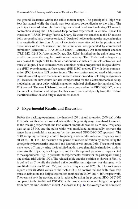
Ultrasound-Based Sensing and Control of Functional Electrical … 309
the ground clearance within the ankle motion range. The participant’s thigh waskept horizontal while the shank was kept almost perpendicular to the thigh. Theparticipant was asked to relax both thigh and shank, and avoid voluntary TA musclecontraction during the FES closed-loop control experiment. A clinical linear UStransducer (L7.5SC Prodigy Probe, S-Sharp, Taiwan) was attached to the TAmusclebelly perpendicularly by a customized 3-Dprinted holder to image the targeted regionin a longitudinal direction. A pair of electrodes were attached to the proximal anddistal sides of the TA muscle, and the stimulation was generated by commercialstimulator (Rehastim 2, HASOMED GmbH, Germany). An incremental encoder(TRD-MX1024BD, AutomationDirect, GA, USA) installed on the ankle brace wasused to measure the angular position and velocity. The US-derived echogenicitywas passed through SDO to obtain continuous estimates of muscle activation andmuscle fatigue. These estimates were combined with a proportional-integral deriva-tive (PID)-type dynamic surface control (PID-DSC) method [7] with delay compen-sation (DC) to obtain FES control inputs. The new control method used a third-ordermusculoskeletal system that contains muscle activation andmuscle fatigue dynamics[8]. Besides, the new controller also compensated for the electromechanical delay,modeled as an input delay, which is another technical challenge during closed-loopFES control. The new US-based control was compared to the PID-DSC-DC, wherethe muscle activation and fatigue feedback were calculated purely from the off-lineidentified activation and fatigue dynamical model.
3 Experimental Results and Discussion
Before the tracking experiment, the threshold (60 µs) and saturation (500 µs) of theFESpulsewidthwere determined,where the echogenicity rangewas also determined.In the tracking experiment, the FES current amplitude was set as 25 mA, frequencywas set as 35 Hz, and the pulse width was modulated automatically between therange from threshold to saturation by the proposed SDO-DSC-DC approach. TheSDO sampling frequency, control frequency, and encoder measure frequency wereall set as 1000 Hz. The measure time period of muscle activation by normalizing theechogenicity between the threshold and saturationwas around 0.6 s. The control gainswere tuned off-line by using the identifiedmodel throughmultiple simulation trials tominimize the trajectory tracking error, and then the optimal gains were implementedto the experiments. Fig. 1b presents the experimental results for the participant duringone typical trial within 100 s. The relaxed ankle angular position as shown in Fig. 1b,is defined as 0°, while the desired ankle dorsiflexion trajectory was designed withamplitude between 0° and 35°, and with a frequency of 0.25 Hz. The root meansquare error (RMSE) values of the PZD-DSC-DC control method with those twomuscle activation and fatigue estimation methods are 5.09° and 4.46°, respectively.The results show the tracking error is reduced by using the proposed SDO-DSC-DCcompared to the traditional DSC-DC with muscle activation and fatigue computedfrom pure off-line identified model. As shown in Fig. 1c, the average value of muscle
310 Q. Zhang et al.
activation level observed by the SDO is higher than that calculated from the off-lineidentifiedmodel. This observation by usingUSmeasurements could represent amorerealisticmuscle physiological state than an idealization from the off-linemodel.Also,the muscle fatigue calculated from the off-line identified model under-estimates theactual fatigue level, which would deteriorate the trajectory tracking performancewhen implementing DSC-DC control method.
4 Conclusion
An SDO method was designed to continuously estimate the muscle activation andfatigue levels based on the discrete US imaging-derived echogenicity measurement,while a DSC method combined with a DC technique was used to deal with theEMD during FES control. Experimental results on a participant without neurologicaldisorders validated the proposed SDO-DSC-DC method, and also showed a bettertrajectory tracking performance compared to the traditional DSC-DC method withpure muscle activation and fatigue calculation from the off-line identified model.This study indicates that US-derived measurements can be used to accurately reflectskeletal muscle activation and fatigue levels, which will potentially improve the FEScontrol performance with the measurable the muscle’s physiological state.
Acknowledgements This work was funded by NSF CAREER Award # 1750748.
References
1. M.H. Granat, D.J. Maxwell, A.C. Ferguson, K.R. Lees, J.C. Barbenet, Peroneal stimulator:evaluation for the correction of spastic drop foot in hemiplegia. Arch. Phys. Med. Rehabil.77(1), 19–24 (1996)
2. N.A. Alibeji, V. Molazadeh, F. Moore-Clingenpeel, N. Sharma, A muscle synergy-inspiredcontrol design to coordinate functional electrical stimulation and a powered exoskeleton: artifi-cial generation of synergies to reduce input dimensionality. IEEE Cont. Syst. Mag. 38(6), 35–60(2018)
3. Q. Zhang, M. Hayashibe, C. Azevedo-Coste, Evoked electromyography-based closed-looptorque control in functional electrical stimulation. IEEE Trans. Biomed. Eng. 60(8), 2299–2307(2013)
4. Q. Zhang, M. Hayashibe, P. Fraisse, D. Guiraud, FES-induced torque prediction with evokedEMG sensing for muscle fatigue tracking. IEEE/ASME Trans. Mechatron. 16(5), 816–826(2011)
5. M.H. Jahanandish, N.P. Fey, K. Hoyt, Lower-limb motion estimation using ultrasound imaging:a framework for assistive device control. IEEE J. Biomed. Health Inform. 23(6), 2505–2514(2019)
6. Q. Zhang, K. Kim, N. Sharma, Prediction of ankle dorsiflexion moment by combined ultrasoundsonography and electromyography. IEEE Trans. Neural Syst. Rehabil. Eng. 28(1), 318–327(2020)

Ultrasound-Based Sensing and Control of Functional Electrical … 311
7. N. Alibeji, N. Kirsch, B.E. Dicianno, N. Sharma, A modified dynamic surface controller fordelayedneuromuscular electrical stimulation. IEEE/ASMETrans.Mechatron.22(4), 1755–1764(2017)
8. N. Sharma, N.A. Kirsch, N.A. Alibeji, W.E. Dixon, A non-linear control method to compensatefor muscle fatigue during neuromuscular electrical stimulation. Front. Robot. AI 4, 68 (2017)
Towards Crutch-Free 3-D WalkingSupport with the Lower BodyExoskeleton Co-Ex: Self-balancingSquatting Experiments
Sinan Coruk, Ahmed Fahmy Soliman, Oguzhan Dalgic, Mehmet C. Yildirim,Deniz Ugur, and Barkan Ugurlu
Abstract In this paper, we succinctly present the hardware properties and capa-bilities of the lower body exoskeleton Co-Ex, which was developed to attain self-balancing and crutch-free walking support for those experiencing ambulatory diffi-culties in general. To provide full 3-D walking support while containing the numberof required actuators, it includes 4 active joints per leg. Custom-built series elasticactuators enable the torque sensing and controllability at each joint, enhancing therobot’s physical interaction capabilities. While limiting the number of active jointsminimizes the weight and energy requirements, the underactuated leg configurationincreased the computational load. The preliminary squatting experiments revealedthat Co-Ex may provide crutch-free 3-D movement support.
1 Introduction
Robot-aided walking support and rehabilitation enabled various patients with gaitdisorders to regain ambulatory functionality. The recent advances in lower bodyexoskeleton technology allowed a significant leap to ensure safe and dependablewalking support, particularly for SCI patients. A great majority of SCI walkingsupport exoskeletons have 2 active joints per leg to support hip and knee jointsthrough theF/E (Flexion/Extension) axis [1].While such a configuration significantlysimplifies the hardware, users must engage their upper bodies via crutches to achievestatic balancing.
An active ankle D/PF (Dorsi/Plantar Flexion) joint is definitely required for bal-ancing in the sagittal plane. With this addition, Morimoto et al. developed the lower-body exoskeletonXoR,which can provide crutch-free sit down& stand up rehabilita-
S. Coruk and A. F. Soliman equally contributed to this works as primary authors.
S. Coruk · A. F. Soliman · O. Dalgic · D. Ugur · B. Ugurlu (B)Biomechatronics Laboratory, Faculty of Engineering, Ozyegin University, 34794 Istanbul, Turkeye-mail: [email protected]
M. C. YildirimChair of Robotics Science and Systems Intelligence, Technical University of Munich (TUM),80333 Munich, Germany
© The Author(s), under exclusive license to Springer Nature Switzerland AG 2022J. C. Moreno et al. (eds.), Wearable Robotics: Challenges and Trends,Biosystems & Biorobotics 27, https://doi.org/10.1007/978-3-030-69547-7_51
313
314 S. Coruk et al.
tion and can actively reject disturbances in the sagittal plane [2]. In a recent example,Harib et al. developed a fully-actuated lower-body exoskeleton named Atalante,which possesses 6 active joints per leg [3]. This impressive wearable humanoid isa great achievement as it was able to fully support SCI patients with no need forcrutches.
Although the solution provided byHarib et al. [3] solves the issues related to upperbody engagement, the equipment of 12 active joints causes hardware complexityproblems. Unlike the case of humanoids, the placement of motors and sensors arequite challenging. Another major concern appears to be power requirement andenergy autonomy. All these issues raise several questions: Do we really need toplace 6 active joints per leg?What is the minimum number of active joints to achievecrutch-free 3D walking support?
In addition to knee andhipF/E joints,which are included in conventional exoskele-tons, an active ankle joint along the D/PF axis is necessary for balancing [2]. Further-more, the study in [4] suggested that a hip joint along theA/A (Adduction/Abduction)axis is essential in 3D walking to achieve lateral swaying. Combining these pieces ofinformation, we built an exoskeleton with 4 active joints per leg to see to what extent3-D walking support can be provided [5, 6]. The rest of the paper is organized asfollows: In Sect. 2, our methodology is succinctly explained. The paper is concludedin Sect. 3 with further discussion.
2 Methods
2.1 Hardware of Co-Ex
The lower body exoskeleton Co-Ex is a torque-controllable system, actuated viacustom-built series elastic actuators with a high torque-to-weight ratio (94/2.45Nm/kg). Each leg contains 4 DoF (Degrees of Freedom), namely, a 2 DoF hip jointthat can rotate along with the A/A and F/E axes, a 1 DoF F/E knee joint, and a 1DoF D/PF ankle joint. To improve usability and to reduce leg inertia, all actuatorsare gathered around the waist. A series of 4-bar mechanisms are used to transmittorque. Figure1 illustrates the actual robot and its joint configuration.
The robot is equipped with an IMU (Lord 3DM-GX5-15 VRU) at the pelvis. Agroup of distributed force sensing elements (Interlink FSR UX 406) is placed at eachfoot sole to provide vertical force and center of pressure information. Furthermore,SEA units at each joint can provide real-time torque measurement with a torqueresolution of 3.93 mNm. The main controller comprises an Intel Coffee Lake i59600K 3.7GHz CPU including an 8 GB DDR4 RAM, and a Samsung 250 GB 860Evo SSD storage device. It runs on a 64-bit GNU/Linux operating system with anRT_Preempt patch enabled Linux kernel. Data communication is performed via acustom-built real-time Ethernet protocol.
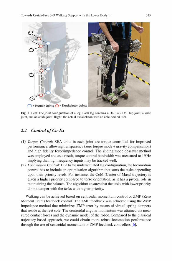
Towards Crutch-Free 3-D Walking Support with the Lower Body … 315
Fig. 1 Left: The joint configuration of a leg. Each leg contains 4 DoF: a 2 DoF hip joint, a kneejoint, and an ankle joint. Right: the actual exoskeleton with an able-bodied user
2.2 Control of Co-Ex
(1) Torque Control: SEA units in each joint are torque-controlled for improvedperformance, allowing transparency (zero torque mode + gravity compensation)and high fidelity force/impedance control. The sliding mode observer methodwas employed and as a result, torque control bandwidth was measured to 19Hzimplying that high frequency inputs may be tracked well.
(2) Locomotion Control: Due to the underactuated leg configuration, the locomotioncontrol has to include an optimization algorithm that sorts the tasks dependingupon their priority levels. For instance, the CoM (Center of Mass) trajectory isgiven a higher priority compared to torso orientation, as it has a pivotal role inmaintaining the balance. The algorithm ensures that the tasks with lower prioritydo not tamper with the tasks with higher priority.
Walking can be achieved based on centroidal momentum control or ZMP (ZeroMoment Point) feedback control. The ZMP feedback was achieved using the ZMPimpedance method that minimizes ZMP error by means of virtual spring dampersthat reside at the feet sole. The centroidal angular momentum was attained via mea-sured contact forces and the dynamic model of the robot. Compared to the classicaltrajectory-based approach, we could obtain more robust locomotion performancethrough the use of centroidal momentum or ZMP feedback controllers [6].
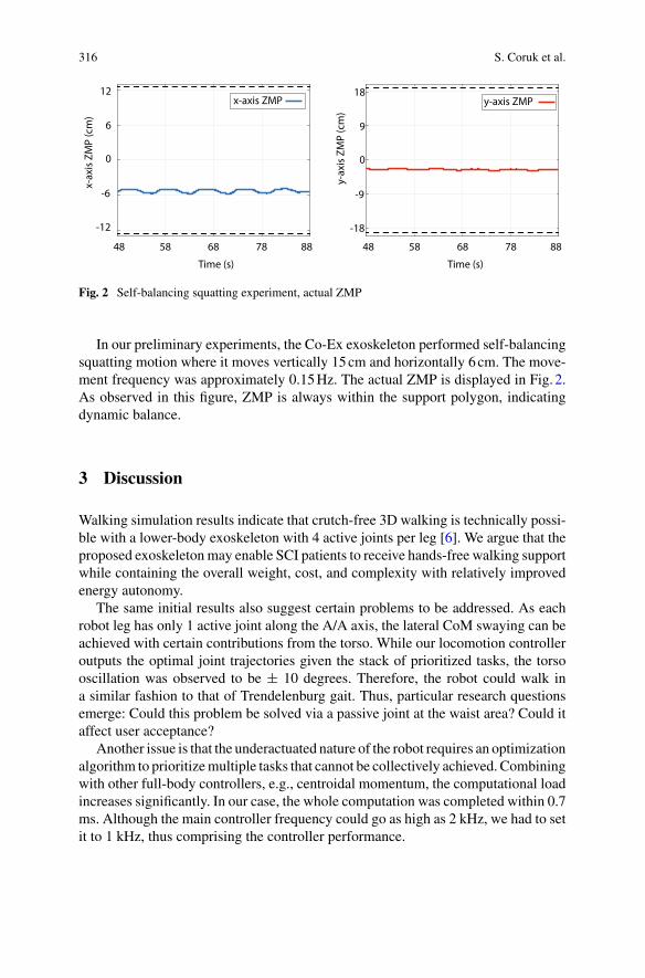
316 S. Coruk et al.
48 58 68 78 88
Time (s)
-18
-9
0
9
18
y-ax
is Z
MP
(cm
)
-12
-6
0
6
12x-
axis
ZM
P (c
m)
48 58 68 78 88
Time (s)
x-axis ZMP y-axis ZMP
Fig. 2 Self-balancing squatting experiment, actual ZMP
In our preliminary experiments, the Co-Ex exoskeleton performed self-balancingsquatting motion where it moves vertically 15cm and horizontally 6cm. The move-ment frequency was approximately 0.15Hz. The actual ZMP is displayed in Fig. 2.As observed in this figure, ZMP is always within the support polygon, indicatingdynamic balance.
3 Discussion
Walking simulation results indicate that crutch-free 3D walking is technically possi-ble with a lower-body exoskeleton with 4 active joints per leg [6]. We argue that theproposed exoskeletonmay enable SCI patients to receive hands-free walking supportwhile containing the overall weight, cost, and complexity with relatively improvedenergy autonomy.
The same initial results also suggest certain problems to be addressed. As eachrobot leg has only 1 active joint along the A/A axis, the lateral CoM swaying can beachieved with certain contributions from the torso. While our locomotion controlleroutputs the optimal joint trajectories given the stack of prioritized tasks, the torsooscillation was observed to be ± 10 degrees. Therefore, the robot could walk ina similar fashion to that of Trendelenburg gait. Thus, particular research questionsemerge: Could this problem be solved via a passive joint at the waist area? Could itaffect user acceptance?
Another issue is that the underactuated nature of the robot requires an optimizationalgorithm to prioritizemultiple tasks that cannot be collectively achieved. Combiningwith other full-body controllers, e.g., centroidal momentum, the computational loadincreases significantly. In our case, the whole computation was completed within 0.7ms. Although the main controller frequency could go as high as 2 kHz, we had to setit to 1 kHz, thus comprising the controller performance.
Towards Crutch-Free 3-D Walking Support with the Lower Body … 317
In this paper, we reported balanced squatting & swaying experiments where theactual ZMP was within the support polygon. Currently, the walking experimentswith dummy load are being conducted and initial tests will be finalized soon. Wewill report crutch-free 3D walking experiments in our next paper.
Acknowledgements This work is supported by the Scientific and Technological Research Councilof Turkey (TÜBITAK), with the project 215E138.
References
1. A. J. Young, D.P. Ferris, State of the art and future directions for lower limb robotic exoskeletons.IEEE Trans. Neural Syst. Rehabil. Eng. 25(1), 171–182 (2017)
2. B. Ugurlu, C. Doppmann, M. Hamaya, P. Forni, T. Teramae, T. Noda, J. Morimoto, VariableAnkle Stiffness Improves Balance Control: experiments on a Bipedal Exoskeleton. IEEE/ASMETrans. Mechatronics 21(1), 79–87 (2016)
3. O. Harib, A. Hereid, A. Agrawal, T. Gurriet, S. Finet, G. Boeris, A. Duburcq, M.E. Mungai,M. Masselin, A.D. Ames, K. Sreenath, J.W. Grizzle, Feedback control of an exoskeleton forparaplegics: toward robustly stable, hands-free dynamicwalking. IEEEControl Syst.Mag.38(6),61–87 (2018)
4. M.M. van der Krogt, S.L. Delp, M.H. Schwartz, How robust is human gait to muscle weakness?Gait Posture 36(1), 113–119 (2012)
5. M.C. Yildirim, A.T. Kansizoglu, S. Emre, M. Derman, S. Coruk, A.F. Soliman, P. Sendur,B. Ugurlu, Co-Ex: a torque-controllable lower body exoskeleton for dependable human-robotco-existence, in IEEE International Conference on Rehabilitation Robotics, Toronto, Canada(2019), pp. 605–610
6. A.F. Soliman, B. Ugurlu, Robust locomotion control of a self-balancing and underactuatedbipedal exoskeleton: task prioritization and feedback control, IEEE Robotics and AutomationLetters (in print). https://doi.org/10.1109/LRA.2021.3082016
Ankle Dorsiflexion Assistance UsingAdaptive Functional ElectricalStimulation and Actuated Ankle FootOrthosis
Carlos Canchola-Hernandez, Hala Rifai, Yacine Amirat,and Samer Mohammed
Abstract This work presents the development of a hybrid control strategy to assistankle joint dorsiflexion movements during walking. An actuated ankle foot ortho-sis (AAFO) is used in conjunction with Adaptive Functional Electrical Stimulation(AFES) of the peroneal nerve at the Tibialis Anterior (TA) muscle level. The purposeis to provide sufficient ankle dorsiflexion during the swing phase to compensate forfoot-drop in paretic patients. The degree of ankle dorsiflexion is indexed with respectto the knee flexion through an adaptive FES paradigm.
1 Introduction
The merging of robotic technology and neuroprosthesis was originally conceivedto compensate the individual drawbacks of the use of either Functional ElectricalStimulation (FES) or actuated orthosis separately [1]. The limitations of using FES-based techniques for rehabilitation purposes have been extensively reported in theliterature. They include mainly the use of open-loop FES control strategies, inducingpremature fatigue and uncertainties in human torque estimation and systemmodeling[2, 3].
One of the objectives of this research is to study the combination of an adaptiveknee-joint based Functional Electrical Stimulation (AFES) system based on a pre-vious work [4] along with an actuated ankle foot orthosis (AAFO). The goal is toreduce the stimulation intensity, compensate muscular induced fatigue and improve
C. Canchola-Hernandez (B) · H. Rifai · Y. Amirat · S. MohammedUniv Paris Est Creteil, LISSI, 94400 Vitry, Francee-mail: [email protected]
H. Rifaie-mail: [email protected]
Y. Amirate-mail: [email protected]
S. Mohammede-mail: [email protected]
© The Author(s), under exclusive license to Springer Nature Switzerland AG 2022J. C. Moreno et al. (eds.), Wearable Robotics: Challenges and Trends,Biosystems & Biorobotics 27, https://doi.org/10.1007/978-3-030-69547-7_52
319
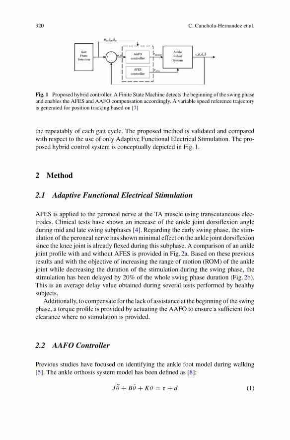
320 C. Canchola-Hernandez et al.
Fig. 1 Proposed hybrid controller. A Finite StateMachine detects the beginning of the swing phaseand enables the AFES and AAFO compensation accordingly. A variable speed reference trajectoryis generated for position tracking based on [7]
the repeatably of each gait cycle. The proposed method is validated and comparedwith respect to the use of only Adaptive Functional Electrical Stimulation. The pro-posed hybrid control system is conceptually depicted in Fig. 1.
2 Method
2.1 Adaptive Functional Electrical Stimulation
AFES is applied to the peroneal nerve at the TA muscle using transcutaneous elec-trodes. Clinical tests have shown an increase of the ankle joint dorsiflexion angleduring mid and late swing subphases [4]. Regarding the early swing phase, the stim-ulation of the peroneal nerve has shownminimal effect on the ankle joint dorsiflexionsince the knee joint is already flexed during this subphase. A comparison of an anklejoint profile with and without AFES is provided in Fig. 2a. Based on these previousresults and with the objective of increasing the range of motion (ROM) of the anklejoint while decreasing the duration of the stimulation during the swing phase, thestimulation has been delayed by 20% of the whole swing phase duration (Fig. 2b).This is an average delay value obtained during several tests performed by healthysubjects.
Additionally, to compensate for the lack of assistance at the beginning of the swingphase, a torque profile is provided by actuating the AAFO to ensure a sufficient footclearance where no stimulation is provided.
2.2 AAFO Controller
Previous studies have focused on identifying the ankle foot model during walking[5]. The ankle orthosis system model has been defined as [8]:
J θ + Bθ + K θ = τ + d (1)
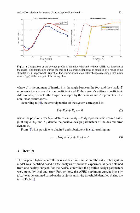
Ankle Dorsiflexion Assistance Using Adaptive Functional … 321
Fig. 2 a Comparison of the average profile of an ankle with and without AFES. An increase inthe ankle joint dorsiflexion during the mid and late swing subphases is obtained as a result of thestimulation. b Proposed AFES profile. The current stimulation value changes reaching a maximumvalue (Imax) at the last part of the swing phase
where J is the moment of inertia, θ is the angle between the foot and the shank, Brepresents the viscous friction coefficient and K the system’s stiffness coefficient.Additionally, τ denotes the torque developed by the actuator and d represents all thenon linear disturbances.
According to [6], the error dynamics of the system correspond to:
e + Kv e + Kpe = 0 (2)
where the position error (e) is defined as e = θd − θ , θd represents the desired anklejoint angle, Kp and Kv denote the positive design parameters of the desired errordynamics.
From (2), it is possible to obtain θ and substitute it in (1), resulting in:
τ = J (θd + Kv e + Kpe) + d (3)
3 Results
The proposed hybrid controller was validated in simulation. The ankle robot systemmodel was identified based on the analysis of previous experimental data obtainedfrom one healthy subject. For the AAFO controller, the positive design parameterswere tuned by trial and error. Furthermore, the AFES maximum current intensity(Imax) was determined based on the subject sensitivity threshold identified during thetests (Table 1).
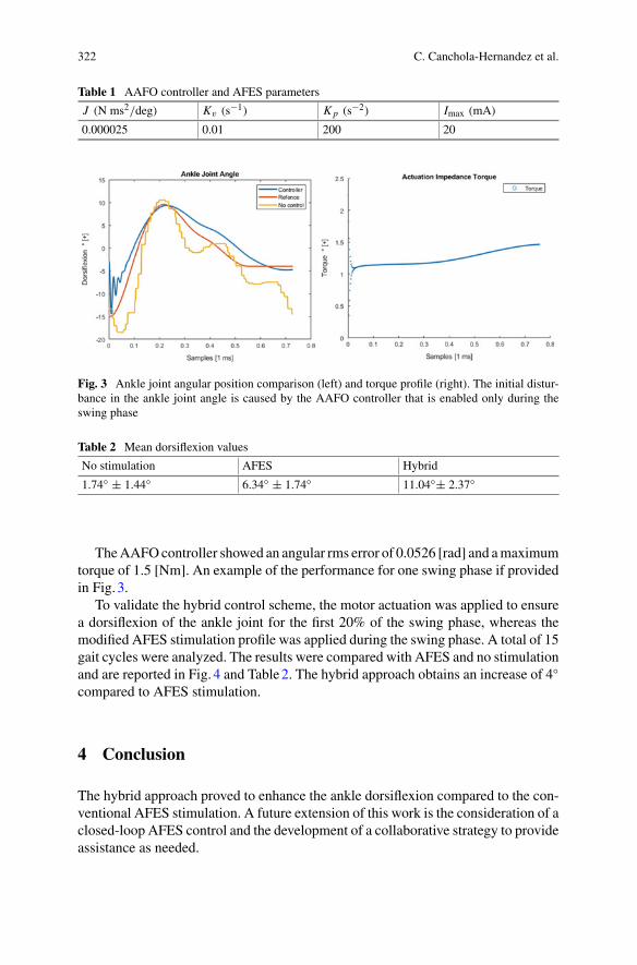
322 C. Canchola-Hernandez et al.
Table 1 AAFO controller and AFES parameters
J (N ms2/deg) Kv (s−1) Kp (s−2) Imax (mA)
0.000025 0.01 200 20
Fig. 3 Ankle joint angular position comparison (left) and torque profile (right). The initial distur-bance in the ankle joint angle is caused by the AAFO controller that is enabled only during theswing phase
Table 2 Mean dorsiflexion values
No stimulation AFES Hybrid
1.74 ± 1.44 6.34 ± 1.74 11.04± 2.37
TheAAFOcontroller showed an angular rms error of 0.0526 [rad] and amaximumtorque of 1.5 [Nm]. An example of the performance for one swing phase if providedin Fig. 3.
To validate the hybrid control scheme, the motor actuation was applied to ensurea dorsiflexion of the ankle joint for the first 20% of the swing phase, whereas themodified AFES stimulation profile was applied during the swing phase. A total of 15gait cycles were analyzed. The results were compared with AFES and no stimulationand are reported in Fig. 4 and Table2. The hybrid approach obtains an increase of 4compared to AFES stimulation.
4 Conclusion
The hybrid approach proved to enhance the ankle dorsiflexion compared to the con-ventional AFES stimulation. A future extension of this work is the consideration of aclosed-loop AFES control and the development of a collaborative strategy to provideassistance as needed.
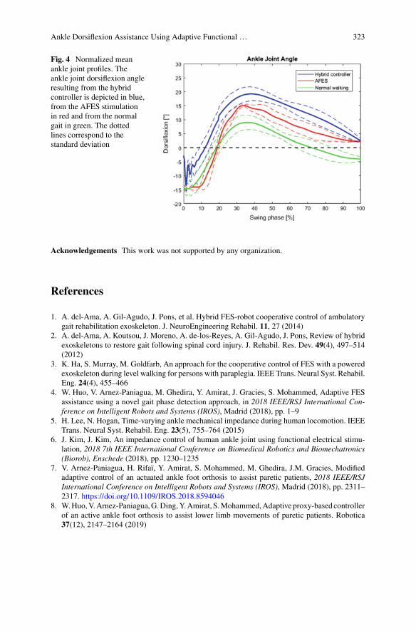
Ankle Dorsiflexion Assistance Using Adaptive Functional … 323
Fig. 4 Normalized meanankle joint profiles. Theankle joint dorsiflexion angleresulting from the hybridcontroller is depicted in blue,from the AFES stimulationin red and from the normalgait in green. The dottedlines correspond to thestandard deviation
Acknowledgements This work was not supported by any organization.
References
1. A. del-Ama, A. Gil-Agudo, J. Pons, et al. Hybrid FES-robot cooperative control of ambulatorygait rehabilitation exoskeleton. J. NeuroEngineering Rehabil. 11, 27 (2014)
2. A. del-Ama, A. Koutsou, J. Moreno, A. de-los-Reyes, A. Gil-Agudo, J. Pons, Review of hybridexoskeletons to restore gait following spinal cord injury. J. Rehabil. Res. Dev. 49(4), 497–514(2012)
3. K. Ha, S. Murray, M. Goldfarb, An approach for the cooperative control of FES with a poweredexoskeleton during level walking for persons with paraplegia. IEEE Trans. Neural Syst. Rehabil.Eng. 24(4), 455–466
4. W. Huo, V. Arnez-Paniagua, M. Ghedira, Y. Amirat, J. Gracies, S. Mohammed, Adaptive FESassistance using a novel gait phase detection approach, in 2018 IEEE/RSJ International Con-ference on Intelligent Robots and Systems (IROS), Madrid (2018), pp. 1–9
5. H. Lee, N. Hogan, Time-varying ankle mechanical impedance during human locomotion. IEEETrans. Neural Syst. Rehabil. Eng. 23(5), 755–764 (2015)
6. J. Kim, J. Kim, An impedance control of human ankle joint using functional electrical stimu-lation, 2018 7th IEEE International Conference on Biomedical Robotics and Biomechatronics(Biorob), Enschede (2018), pp. 1230–1235
7. V. Arnez-Paniagua, H. Rifaï, Y. Amirat, S. Mohammed, M. Ghedira, J.M. Gracies, Modifiedadaptive control of an actuated ankle foot orthosis to assist paretic patients, 2018 IEEE/RSJInternational Conference on Intelligent Robots and Systems (IROS), Madrid (2018), pp. 2311–2317. https://doi.org/10.1109/IROS.2018.8594046
8. W.Huo,V.Arnez-Paniagua,G.Ding,Y.Amirat, S.Mohammed,Adaptive proxy-based controllerof an active ankle foot orthosis to assist lower limb movements of paretic patients. Robotica37(12), 2147–2164 (2019)

Soft Wearable Robots for Healthand Industry
Feasibility and Effectiveness of a SoftExoskeleton for Pediatric Rehabilitation
Michele A. Lobo and Bai Li
Abstract Exoskeletons have the potential to improve outcomes for rehabilitationclients. For these devices to be effective, rehabilitation professionals and end usersmust be involved throughout the design process, so the devices meet the broad needsof users. In this article, we present a model to guide the design of rehabilitationdevices. This model is user-centered and focuses on users’ functional, expressive,aesthetic, and accessibility needs (FEA2) for devices. We then summarize the resultsof the first studies evaluating the feasibility and effectiveness of the Playskin Lift™soft exoskeleton for pediatric populations utilized for intervention in the naturalenvironment. The exoskeleton was feasible for daily use by families in the naturalenvironment. For infants and toddlers with physical disabilities, the exoskeletonassisted reaching and play performance within a single session when it was wornand improved independent reaching function and play activity after months of dailyintervention with the exoskeleton.
1 Introduction
Children with diagnoses such as arthrogryposis and muscular dystrophy have weak-ness that can impair their arm function for critical daily tasks [1, 2]. Young childrenborn preterm or with a brain injury also demonstrate arm movement impairmentsthat restrict interaction with objects, limiting children’s ability to gather informationand learn [3, 4]. Therefore, there are a number of pediatric populations that maybenefit from rehabilitation devices aimed at supporting and assisting arm function.
Exoskeletons have been increasingly investigated with adult and adolescent reha-bilitation populations [5, 6]. However, until recently, these devices had not been
M. A. Lobo (B)Move To Learn Innovation Lab, Super Suits FUNctional Fashion & Wearable TechnologyProgram, Department of Physical Therapy and Biomechanics and Movement Science Program,University of Delaware, Newark, DE, USAe-mail: [email protected]
B. LiBiomechanics and Movement Science Program, University of Delaware, Newark, DE, USA
© The Author(s), under exclusive license to Springer Nature Switzerland AG 2022J. C. Moreno et al. (eds.), Wearable Robotics: Challenges and Trends,Biosystems & Biorobotics 27, https://doi.org/10.1007/978-3-030-69547-7_53
327
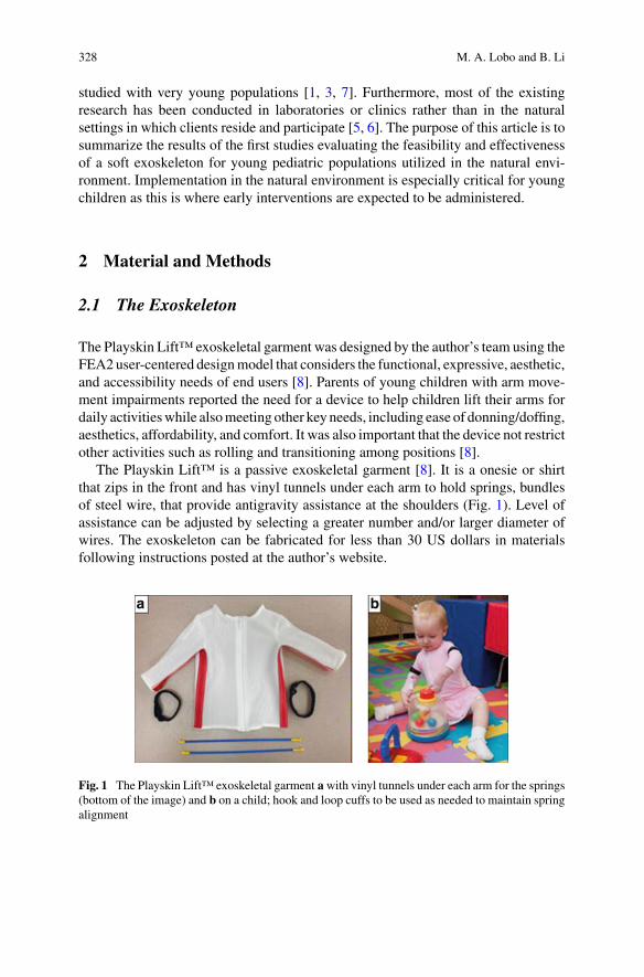
328 M. A. Lobo and B. Li
studied with very young populations [1, 3, 7]. Furthermore, most of the existingresearch has been conducted in laboratories or clinics rather than in the naturalsettings in which clients reside and participate [5, 6]. The purpose of this article is tosummarize the results of the first studies evaluating the feasibility and effectivenessof a soft exoskeleton for young pediatric populations utilized in the natural envi-ronment. Implementation in the natural environment is especially critical for youngchildren as this is where early interventions are expected to be administered.
2 Material and Methods
2.1 The Exoskeleton
The Playskin Lift™ exoskeletal garment was designed by the author’s team using theFEA2 user-centered designmodel that considers the functional, expressive, aesthetic,and accessibility needs of end users [8]. Parents of young children with arm move-ment impairments reported the need for a device to help children lift their arms fordaily activitieswhile alsomeeting other key needs, including ease of donning/doffing,aesthetics, affordability, and comfort. It was also important that the device not restrictother activities such as rolling and transitioning among positions [8].
The Playskin Lift™ is a passive exoskeletal garment [8]. It is a onesie or shirtthat zips in the front and has vinyl tunnels under each arm to hold springs, bundlesof steel wire, that provide antigravity assistance at the shoulders (Fig. 1). Level ofassistance can be adjusted by selecting a greater number and/or larger diameter ofwires. The exoskeleton can be fabricated for less than 30 US dollars in materialsfollowing instructions posted at the author’s website.
Fig. 1 The Playskin Lift™ exoskeletal garment awith vinyl tunnels under each arm for the springs(bottom of the image) and b on a child; hook and loop cuffs to be used as needed to maintain springalignment
Feasibility and Effectiveness of a Soft Exoskeleton for Pediatric Rehabilitation 329
2.2 Methods
Feasibility and effectiveness of the Playskin Lift™ were evaluated in two groups ofyoung children. The first group was of 10 infants born preterm and/or with a signifi-cant brain injury (PT/BI) [3]. They began the study at about 2months of age, adjustedfor prematurity. The second group was of 17 infants and toddlers with significantarm weakness due to arthrogryposis [1, 7]. They began the study between 6 and35 months of age. Both groups were evaluated biweekly throughout a 1–2-monthbaseline (control), a 4-month intervention (with daily, parent-provided home inter-vention activities with the exoskeleton donned), and a 1-month post-interventionphase. Daily wearing logs and parent perception questionnaires assessed feasibility.A standardized reaching assessment was performed biweekly with and without thedevice to assess effectiveness for both groups. The arthrogryposis group was alsoassessed for active range of motion (AROM) and play ability as this group demon-strated limitedAROMandplaywas developmentally appropriate for this older group.Experimenters blind to visit timing and participant details scored all assessments.Hierarchical linear modeling analyzed assistive effects (changes within a sessionwith the exoskeleton donned) and rehabilitative effects (changes in independentperformance across time) with p ≤ 0.05 representing significance.
3 Results
3.1 Feasibility
The Playskin Lift™ exoskeletal garment was feasible for use by parents for dailyintervention with infants and toddlers in the natural environment [1, 3]. Parents wereasked to use the exoskeleton for intervention 45 min/day each day, skipping days asneeded. Parents in the PT/BI group reported wearing times of 44.4 ± 9.3 min/day3.9 ± 1.7 days/week; parents in the arthrogryposis group 96.8 ± 81.4 min/day 5.8 ±1.2 days/week. Likert ratings on a scale from 1 to 5with 5 being the best were positivefor all outcomes, including ease of donning (PT/BI: 4.5 ± 0.5; arthrogryposis: 4.4± 0.4) and doffing (PT/BI: 4.5 ± 0.5; arthrogryposis: 4.6 ± 0.4), comfort (PT/BI:4.3 ± 0.9; arthrogryposis: 4.7 ± 0.4), aesthetics (PT/BI: 3.7 ± 1.2; arthrogryposis:3.9 ± 0.7), and restriction of other activities (PT/BI: 3.9 ± 1.2; arthrogryposis: 4.2± 0.7).
3.2 Assistive Effects
Infants and toddlers showed better reaching performance within sessions withthe Playskin Lift™ donned [1, 3]. Infants with PT/BI showed significantly more
330 M. A. Lobo and B. Li
bimanual reaching, open-handed grasping, andmultimodal (visual-manual) behaviorwhen wearing the exoskeleton [3]. Toddlers with arthrogryposis showed signifi-cantly more unimanual and bimanual reaching, open-handed grasping with the palm,visual attention to objects, and multimodal behavior along with increased inten-sity of activity [1]. Toddlers with arthrogryposis showed better play performance,with significantly more object contacts, lifting of objects, bimanual object manipu-lation, and multimodal behavior along with increased intensity and variability of thebehaviors performed [7].
3.3 Rehabilitative Effects
Infants and toddlers showed improved independent reaching performance acrosstime after intervention with the Playskin Lift™ [1, 3]. Infants with PT/BI showedsignificantlymore unimanual and bimanual reaching, open-handed grasping with thepalm, attention to objects, and multimodal behavior along with increased intensityof activity [3]. Toddlers with arthrogryposis showed significantly improved AROMfor both upper extremities, more unimanual reaching, open-handed grasping withthe palm, visual attention to objects, and multimodal behavior along with increasedintensity of activity [1]. Toddlers with arthrogryposis had better play performance,with significantly more object contacts, lifting of objects, unimanual object manipu-lation, and multimodal behavior along with increased intensity and variability of thebehaviors performed [7].
4 Conclusion
This work suggests that upper extremity exoskeletons, such as the Playskin Lift™,designed tomeet the broad needs of users are feasible for use in intervention programsimplemented by parents for very young pediatric populations in the natural environ-ment [1, 3, 7, 8]. Exoskeletons like the Playskin Lift™ can provide more immediateeffects on reaching and play abilities (assistive effects when donned) for youngchildren with upper extremity disability [1, 3, 7]. When coupled with effective inter-vention activities, they can also improve independent AROM, reaching, and playabilities across time [1, 3, 7]. Exoskeletons that improve motor performance foryoung children may lead to cascading benefits in cognition, language, and socialabilities [3, 4]. Key limitations of the Playskin Lift™ for populations over 3 yearsof age are that it cannot support the weight of longer, heavier arms and it does notallow users to adjust the level of support in real time. Future research should applythe FEA2 design model to develop soft exoskeletons that address these limitationsand the needs of older pediatric and adult populations.
Feasibility and Effectiveness of a Soft Exoskeleton for Pediatric Rehabilitation 331
Acknowledgements This workwas supported by the Eunice Kennedy Shriver National Institute ofChildDevelopment (NICHD; 1R21HD076092-01A1) andNational Science Foundation (1722596).
Thanks to the participating families & M2L members.
References
1. I. Babik, A.B. Cunha, M.A. Lobo, Assistive and rehabilitative effects of the Playskin LiftTM
exoskeletal garment on reaching and object exploration in children with arm weakness. Am. J.Occup. Therapy (in press)
2. R. Suthar, N. Sankhyan, Duchenne muscular dystrophy: a practice update. Indian J. Pediatr.85(4), 276–281 (2018)
3. I. Babik, A.B. Cunha, M. Moeyaert, M.L. Hall, D.A. Paul, A. Mackley, M.A. Lobo, Feasibilityand effectiveness of intervention with the Playskin LiftTM exoskeletal garment for infants atrisk. Phys. Therapy 99(6), 666–676 (2019)
4. M.A. Lobo, R.T. Harbourne, S.C. Dusing, S.W. McCoy, Grounding early intervention: physicaltherapy cannot just be about motor skills anymore. Phys. Ther. 93(1), 94–103 (2013)
5. N. Rehmat, J. Zuo,W.Meng, Q. Liu, S.Q. Xie, H. Liang, Upper limb rehabilitation using roboticexoskeleton systems: a systematic review. Int. J. Intell. Robot. Appl. 3(3), 283–295 (2018)
6. T.Estilowet al.,Use of theWilmingtonRoboticExoskeleton to improve upper extremity functionin patients with Duchenne muscular dystrophy. Am. J. Occup. Ther. 72(2), 1–5 (2018)
7. I. Babik, A.B. Cunha, M.A. Lobo, Play with objects in children with arthrogryposis: assistiveand rehabilitative effects of the Playskin LiftTM exoskeletal garment. Am. J. Med. Genetics, PartC 181(3), 393–403 (2019)
8. M.L. Hall, M.A. Lobo, Design and development of the first exoskeletal garment to enhance armmobility for children with movement impairments. Assist. Technol. 30(5), 251–258 (2017)
FleXo—Modular Flexible Back-SupportPassive Exoskeleton
Jesús Ortiz, Jorge Fernández, Tommaso Poliero, Luigi Monica, Sara Anastasi,Francesco Draicchio, and Darwin G. Caldwell
Abstract This paper presents a back-support exoskeleton concept, which mimicsthe biological structure of the human back. The design is based on a novel modularflexible mechanism, that allows a complete freedom ofmovement and a good level ofcomfort. The assistive forces are transmitted perpendicularly to the body, improvingthe benefits of the system, and distributed efficiently through the body thanks toa smart routing system. The current implementation, called FleXo, uses passiveactuation based on an elastic band.
1 Introduction
Industrial exoskeletons are emerging as a promising solution to reduce the incidenceof musculoskeletal disorders (MSD). In Italy during 2019, approximately 66% of thework-related injurieswere associated toMSD.1 While current industrial exoskeletonsare showing a promising level of support and performance [1],most of them are basedon rigid structures. This aspect limits the acceptability due to weight, complexity,reduced freedom ofmovement andwearability. The introduction of soft exoskeletonscould improve significantly all these aspects, however theway they transmit the forcesto the wearer affects significantly the level of assistance. For this reason, examplesof soft industrial exoskeletons are scarce and limited to tasks that do not require ahigh level of assistance, such as the Bioservo Ironhand (Bioservo Technologies AB,Sweden). In the other hand, in the rehabilitation field, soft exoskeletons have been
1INAIL Open Data, https://dati.inail.it.
J. Ortiz (B) · J. Fernández · T. Poliero · D. G. CaldwellAdvanced Robotics, Istituto Italiano di Tecnologia, Via Morego, 30, 16163 Genova, Italye-mail: [email protected]
L. Monica · S. AnastasiDepartment of Technological Innovation and Safety Equipment, INAIL, Rome, Italy
F. DraicchioDepartment of Occupational and Environmental Medicine, Epidemiology and Hygiene, INAIL,Monte Porzio Catone, Rome, Italy
© The Author(s), under exclusive license to Springer Nature Switzerland AG 2022J. C. Moreno et al. (eds.), Wearable Robotics: Challenges and Trends,Biosystems & Biorobotics 27, https://doi.org/10.1007/978-3-030-69547-7_54
333
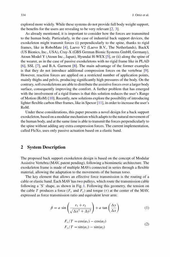
334 J. Ortiz et al.
explored more widely. While these systems do not provide full body weight support,the benefits for the users are revealing to be very relevant [2, 3].
As already mentioned, it is important to consider how the forces are transmittedto the human body. Particularly, in the case of industrial back support devices, theexoskeleton might transmit forces (i) perpendicularly to the spine, thanks to rigidframes, like in RoboMate [4], Laevo V2 (Laevo B.V., The Netherlands), BackX(US Bionics, Inc., USA), Cray-X (GBS German Bionic Systems GmbH, Germany),Atoun Model Y (Atoun Inc., Japan), Hyundai H-WEX [5], or (ii) along the spine ofthe wearer, as in the case of passive exoskeletons with no rigid frame like in PLAD[6], SSL [7], and B.A. Garment [8]. The main advantage of the former examplesis that they do not introduce additional compression forces on the vertebrae [9].However, reaction forces are applied on a restricted number of application points,mainly thighs and pelvis, producing significantly high pressures of the body. On thecontrary, soft exoskeletons are able to distribute the assistive forces over a larger bodysurface, consequently improving the comfort. A further problem that has emergedwith the involvement of a rigid frames is that this solution reduces the user’s RangeofMotion (RoM) [10]. Recently, new solutions explore the possibility of introducinglighter flexible carbon fiber frames, like in Spexor [11], in order to increase the user’sRoM.
Under these considerations, this paper presents a novel design for a back supportexoskeleton, based on amodularmechanismwhich adapts to the naturalmovement ofthe human body, and at the same time is able to transmit the forces perpendicularly tothe spine without adding any extra compression forces. The current implementation,called FleXo, uses only passive actuation based on a elastic band.
2 System Description
The proposed back support exoskeleton design is based on the concept of ModularAssistive Vertebra (MAV, patent pending), following a biomimetic architecture. Theexoskeleton frame is made of multiple MAVs connected in series through a flexiblematerial, allowing the adaptation to the movements of the human torso.
The key element that allows an effective force transmission is the routing of acable or elastic band. EachMAV has two pulleys, which route the transmission cablefollowing a ’S’ shape, as shown in Fig. 1. Following this geometry, the tension onthe cable T produces a force (Fx and Fy) and torque (τ ) at the center of the MAV,expressed as force transmission ratio and equivalent lever arm:
β = a sin
(r1 + r2√
x2 + y2
)+ a tan
(y
x
)(1)
Fx/T = cos(α1) − cos(α2)
Fy/T = sin(α1) − sin(α2)(2)
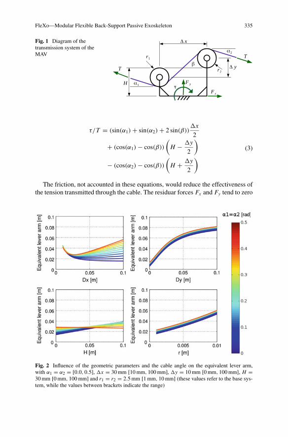
FleXo—Modular Flexible Back-Support Passive Exoskeleton 335
Fig. 1 Diagram of thetransmission system of theMAV
τ/T = (sin(α1) + sin(α2) + 2 sin(β))x
2
+ (cos(α1) − cos(β))
(H − y
2
)
− (cos(α2) − cos(β))
(H + y
2
) (3)
The friction, not accounted in these equations, would reduce the effectiveness ofthe tension transmitted through the cable. The residuar forces Fx and Fy tend to zero
Fig. 2 Influence of the geometric parameters and the cable angle on the equivalent lever arm,with α1 = α2 = [0.0, 0.5], x = 30mm [10mm, 100mm], y = 10mm [0mm, 100mm], H =30mm [0mm, 100mm] and r1 = r2 = 2.5mm [1mm, 10mm] (these values refer to the base sys-tem, while the values between brackets indicate the range)
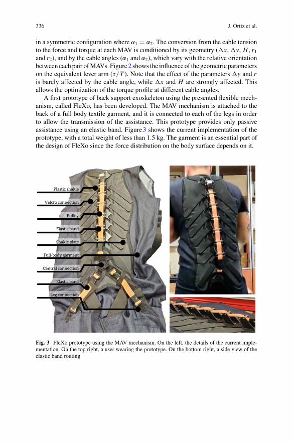
336 J. Ortiz et al.
in a symmetric configuration where α1 = α2. The conversion from the cable tensionto the force and torque at each MAV is conditioned by its geometry (x , y, H , r1and r2), and by the cable angles (α1 and α2), which vary with the relative orientationbetween each pair ofMAVs. Figure2 shows the influence of the geometric parameterson the equivalent lever arm (τ/T ). Note that the effect of the parameters y and ris barely affected by the cable angle, while x and H are strongly affected. Thisallows the optimization of the torque profile at different cable angles.
A first prototype of back support exoskeleton using the presented flexible mech-anism, called FleXo, has been developed. The MAV mechanism is attached to theback of a full body textile garment, and it is connected to each of the legs in orderto allow the transmission of the assistance. This prototype provides only passiveassistance using an elastic band. Figure3 shows the current implementation of theprototype, with a total weight of less than 1.5 kg. The garment is an essential part ofthe design of FleXo since the force distribution on the body surface depends on it.
Fig. 3 FleXo prototype using the MAV mechanism. On the left, the details of the current imple-mentation. On the top right, a user wearing the prototype. On the bottom right, a side view of theelastic band routing
FleXo—Modular Flexible Back-Support Passive Exoskeleton 337
3 Conclusion and Discussion
In this paper we presented a passive back support exoskeleton based on a modularflexible mechanism. The current prototype is a proof of concept to demonstratethe feasibility of the mechanism. Preliminary testing showed that FleXo is ableto transmit assistive forces to the wearer without limiting significantly the rangeof motion in the sagittal plane. Extensive laboratory testing will be carried out tovalidate this preliminary assessment, focused on the measurement of the effectiveassistance that FleXo provides to the wearer, and the efficiency and stability of thegarment.
Acknowledgements This work has been co-funded by the ItalianWorkers’ Compensation Author-ity (INAIL).
References
1. M.P. de Looze, T. Bosch, F. Krause, K.S. Stadler, L.W. O’Sullivan, Exoskeletons for industrialapplication and their potential effects on physical work load. Ergonomics 59(5), 671–681(2016)
2. J. Ortiz, C. Di Natali, D.G. Caldwell, Xosoft-iterative design of a modular soft lower limbexoskeleton, in International Symposium on Wearable Robotics (Springer, Berlin, 2018), pp.351–355
3. L.N. Awad, P. Kudzia, D.A. Revi, T.D. Ellis, C.J. Walsh, Walking faster and farther with a softrobotic exosuit: implications for post-stroke gait assistance and rehabilitation. IEEE Open J.Eng. Med. Biol. 1, 108–115 (2020)
4. S. Toxiri, A.S. Koopman, M. Lazzaroni, J. Ortiz, V. Power, M.P. de Looze, L. O’Sullivan,D.G. Caldwell, Rationale, implementation and evaluation of assistive strategies for an activeback-support exoskeleton. Front. Robot. AI 5, 53 (2018)
5. H.K. Ko, S.W. Lee, D.H. Koo, I. Lee, D.J. Hyun, Waist-assistive exoskeleton powered by asingular actuation mechanism for prevention of back-injury. Robot. Autonom. Syst. 107, 1–9(2018)
6. M. Abdoli-e, M.J. Agnew, J.M. Stevenson, An on-body personal lift augmentation device(PLAD) reduces EMG amplitude of erector spinae during lifting tasks. Clin. Biomech. 21(5),456–465 (2006)
7. Y. Imamura, T. Tanaka, Y. Suzuki, K. Takizawa, M. Yamanaka, Motion-based design of elasticbelts for passive assistive device using musculoskeletal model, in 2011 IEEE InternationalConference on Robotics and Biomimetics (IEEE, 2011), pp. 1343–1348
8. E.P. Lamers,A.J. Yang,K.E. Zelik, Feasibility of a biomechanically-assistive garment to reducelow back loading during leaning and lifting. IEEE Trans. Biomed. Eng. 65(8), 1674–1680(2018)
9. S. Toxiri, J. Ortiz, J. Masood, J. Fernández, L.A. Mateos, D.G. Caldwell, A wearable devicefor reducing spinal loads during lifting tasks: biomechanics and design concepts, in ROBIO(IEEE, 2015), pp. 2295–2300
10. S. Baltrusch, J. Van Dieën, C. Van Bennekom, H. Houdijk, The effect of a passive trunkexoskeleton on functional performance in healthy individuals. Appl. Ergon. 72, 94–106 (2018)
11. M.B. Näf, A.S. Koopman, S. Baltrusch, C. Rodriguez-Guerrero, B. Vanderborght, D. Lefeber,Passive back support exoskeleton improves range ofmotion using flexible beams. Front. Robot.AI 5, 72 (2018)
AModel-Based Control Strategy forUpper Limb Exosuits
N. Lotti, F. Missiroli, M. Xiloyannis, and L. Masia
Abstract Increase the symbiosis between the human and the machine, is the majoropen challenge in wearable robotics research. Limitations are not only in hardwarebut also on the control side which is often limited in its bandwidth lacking to matchfrequency ranges of biomechanics, but also in detecting and interpreting humanintention. In this work we propose a control framework for an upper limb exosuitwhich works using an EMG model based myoprocessor module. Results suggestthat using biosignal in the control loop for wearable robotics improves reliabilityand interaction between the device and its pilot.
1 Introduction
Exosuits represent one of the novel frontiers of robotics, embracing the two com-plementary realms of clinical rehabilitation and human augmentation. These kindof device has been conceived to improve the human-machine symbiosis, by partlysolving the drawbacks arising from their predecessors: rigid exoskeletons. Yet, eventhe light exosuits without using biosignals in the loop, may reach their limits ininferring the intention of the user action therefore jeopardizing the acceptance andefficiency of such technology. The paradigms [1], relying on mechanical manifes-tations of movements, detected by sensors embedded in the robot, being triggeredby the outcomes of human intention will inevitably suffer from a time lag betweenthe device and its pilot, with a consequent degradation of the haptic rendering andsense of authority. A solution to these drawbacks can solely come if one considers aninterface directly perceiving the signals arising from the brain and generating mus-cular activation. Proportional myoelectric controllers, for example, provide assistiveforces proportional to the user’smuscle recruitment [2].Moreover, since electromyo-graphic (EMG) signals are precursors of motion [3], the robot is more likely able
N. Lotti · F. Missiroli · L. Masia (B)Institut für Technische Informatik (ZITI), Heidelberg University, 69120 Heidelberg, Germanye-mail: [email protected]
M. XiloyannisInstitute of Robotics and Intelligent Systems, ETH Zürich, Zürich 8092, Switzerland
© The Author(s), under exclusive license to Springer Nature Switzerland AG 2022J. C. Moreno et al. (eds.), Wearable Robotics: Challenges and Trends,Biosystems & Biorobotics 27, https://doi.org/10.1007/978-3-030-69547-7_55
339
340 N. Lotti et al.
to match the movement timing of its user. In our recent work [4], we showed thatthe combination of EMG detection with an accurate modelling of musculoskeletalgeometry and activation dynamics, can be a powerful tool to control exosuits [5]. Inthe present paper we repropose the application of a reshaped and improved model-based EMG approach (myoprocessor) for the control of an elbow exosuit to simulatedaily gestures typical of daily activities. Our aim was to assert how the controller canenhance the dualism between human and machine in terms of promptness, respon-siveness and stability. To achieve this goal, we evaluated the controller performanceby simulating a functional daily task that involves elbow movements.
2 Materials and Methods
2.1 Myoprocessor Module
Themyoprocessor is a layer of the controller which computes the biological torque atthe elbow joint from the EMG activities and successively feedbacks the value to theactuation stage for assistance delivery. The module comprises of four components:
• The Activation dynamics component converting the two recorded EMG signalsinto muscle fibers recruitment via second-order muscle twitch model and a non-linear transfer function [6].
• TheMuscle tendon kinematics synthesizes the three-dimensional musculoskeletalgeometry of the human arm into a set of multidimensional cubic B-splines.
• TheMuscle tendon dynamics solves for muscle and tendon force using a Hill-typemuscle model.
• The Torque computation projects forces onto the elbow joint using and estimationof the moment arms of the muscles.
The resulting elbow torque was scaled based on the desired level of assistance andthen tracked by an indirect torque controller which send input to an actuation stage.
2.2 Experimental Setup
The exosuit shown in Fig. 1 comprises a tendon driven off board actuationmobilizingan elbow harness as described in [4]. Amulti-channel EMG system (Trigno wireless,Delsys, Natick MA, USA) was used to record the two agonist and antagonist elbowmuscles: biceps brachii (BIC) and triceps brachii (TRI). A DAQ board (QuanserQPIDe, Markham, Ontario, Canada) acquired all signals, with a sampling frequencyof 1 kHz. The exosuit actuation was driven by a dedicated motor controller (EPOS2
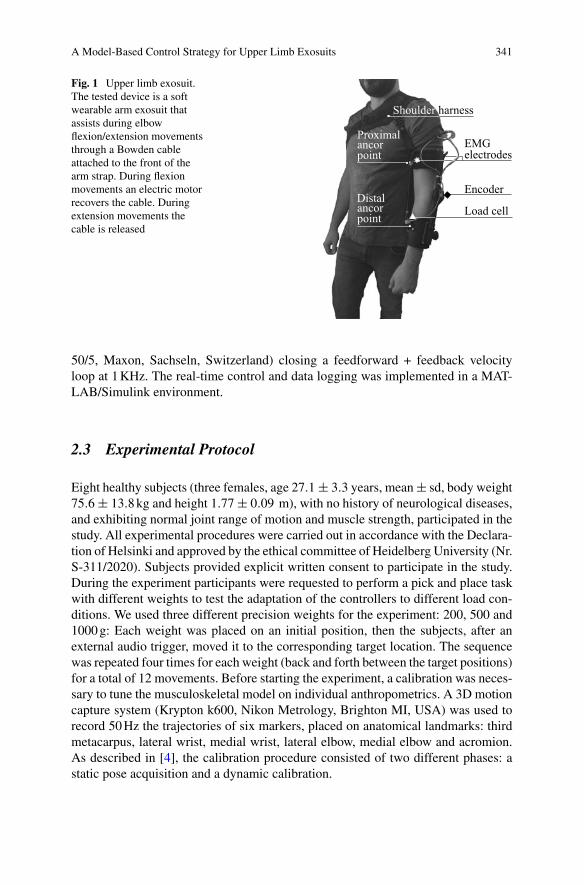
A Model-Based Control Strategy for Upper Limb Exosuits 341
Fig. 1 Upper limb exosuit.The tested device is a softwearable arm exosuit thatassists during elbowflexion/extension movementsthrough a Bowden cableattached to the front of thearm strap. During flexionmovements an electric motorrecovers the cable. Duringextension movements thecable is released
50/5, Maxon, Sachseln, Switzerland) closing a feedforward + feedback velocityloop at 1KHz. The real-time control and data logging was implemented in a MAT-LAB/Simulink environment.
2.3 Experimental Protocol
Eight healthy subjects (three females, age 27.1± 3.3 years, mean± sd, body weight75.6± 13.8kg and height 1.77± 0.09 m), with no history of neurological diseases,and exhibiting normal joint range of motion and muscle strength, participated in thestudy. All experimental procedures were carried out in accordance with the Declara-tion of Helsinki and approved by the ethical committee of Heidelberg University (Nr.S-311/2020). Subjects provided explicit written consent to participate in the study.During the experiment participants were requested to perform a pick and place taskwith different weights to test the adaptation of the controllers to different load con-ditions. We used three different precision weights for the experiment: 200, 500 and1000g: Each weight was placed on an initial position, then the subjects, after anexternal audio trigger, moved it to the corresponding target location. The sequencewas repeated four times for each weight (back and forth between the target positions)for a total of 12 movements. Before starting the experiment, a calibration was neces-sary to tune the musculoskeletal model on individual anthropometrics. A 3D motioncapture system (Krypton k600, Nikon Metrology, Brighton MI, USA) was used torecord 50Hz the trajectories of six markers, placed on anatomical landmarks: thirdmetacarpus, lateral wrist, medial wrist, lateral elbow, medial elbow and acromion.As described in [4], the calibration procedure consisted of two different phases: astatic pose acquisition and a dynamic calibration.
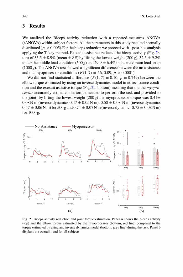
342 N. Lotti et al.
3 Results
We analized the Biceps activity reduction with a repeated-measures ANOVA(rANOVA) within-subject factors. All the parameters in this study resulted normallydistributed (p < 0.005).For the biceps reductionwe proceedwith a post-hoc analysisapplying the Tukey method. Exosuit assistance reduced the biceps activity (Fig. 2b,top) of 35.5± 8.9% (mean ± SE) by lifting the lowest weight (200g), 32.5± 9.2%under the middle load condition (500g) and 29.9± 6.4% in the maximum load setup(1000g). The ANOVA test showed a significant difference between the no assistanceand the myoprocessor conditions (F(1, 7) = 56, 0.09, p < 0.0001).
We did not find statistical difference (F(1, 7) = 0.10, p = 0.749) between theelbow torque estimated by using an inverse dynamics model in no assistance condi-tion and the exosuit assistive torque (Fig. 2b. bottom) meaning that the the myopro-cessor accurately estimates the torque needed to perform the task and provided tothe joint: by lifting the lowest weight (200g) the myoprocessor torque was 0.41±0.08N m (inverse dynamics 0.47± 0.05N m), 0.58± 0.08 N m (inverse dynamics0.57± 0.06Nm) for 500g and 0.74± 0.07Nm (inverse dynamics 0.75± 0.08Nm)for 1000g.
Fig. 2 Biceps activity reduction and joint torque estimation. Panel a shows the biceps activity(top) and the elbow torque estimated by the myoprocessor (bottom, red line) compared to thetorque estimated by using and inverse dynamics model (bottom, grey line) during the task. Panel bdisplays the overall trend for all subjects
A Model-Based Control Strategy for Upper Limb Exosuits 343
4 Conclusion
The myoprocessor module can control a soft exosuit and smoothly adapt the assis-tance by online estimating elbow torque during task. It represents a reliable strategyto detect movement intention and acting in concert with the human wearer. Theproposed approach has advantage in human robot interaction robustness respect tocontroller not using biolsignals in the assistance loop, but requires additional workduring the set up which needs extensive calibration procedure to be tuned on the userantropometry.
References
1. J.R. Koller, D.A. Jacobs, D.P. Ferris, C.D. Remy, Learning to walk with an adaptive gain pro-portional myoelectric controller for a robotic ankle exoskeleton. J. NeuroEng. Rehabil. 12(1),1–14 (2015). https://doi.org/10.1186/s12984-015-0086-5
2. A. Fougner, O. Stavdahl, P.J. Kyberd, Y.G. Losier, P.A. Parker, Control of upper limb prostheses:terminology and proportional myoelectric control—a review. IEEE Trans. Neural Syst. Rehabil.Eng. (2012)
3. R. Merletti, P. Parker, Electromyography: Physiology, Engineering, and Noninvasive Applica-tions, 11th ed. (Wiley, IEEE Press, 2004)
4. N. Lotti,M. Xiloyannis, G. Durandau, E. Galofaro, V. Sanguineti, L.Masia,M. Sartori, Adaptivemodel-based myoelectric control for a soft wearable arm exosuit: a new generation of wearablerobot control. IEEE Robot. Autom. Mag. (2020)
5. D. Chiaradia, M. Xiloyannis, C.W. Antuvan, A. Frisoli, L. Masia, Design and embedded controlof a soft elbow exosuit, in IEEE International Conference on Soft Robotics (RoboSoft) (2018),pp. 565–571
6. D.G. Lloyd, T.F. Besier, An EMG-driven musculoskeletal model to estimate muscle forces andknee joint moments in vivo. J. Biomech. 36(6), 765–776 (2003)
Pneumatic Control Systemfor Exoskeleton Joint Actuation
Pavel Venev, Ivanka Veneva, and Dimitar Chakarov
Abstract The aim of the work is to present the design and construction of a pneu-matic system for actuation of an exoskeleton for upper limbs, suitable for rehabilita-tion and training. Testing and adjustment of control system of the prototype as wellas experimentation of the functionality of the exoskeleton and evaluation of jointactuation have been performed.
1 Introduction
One of the known approaches for exoskeleton actuation is the use of pneumaticartificial muscles (PAMs) [1]. Compared to other actuation systems PAMs are seenas an effective solution to safety problems [2] and light designwith highpower/weightratio [3]. Due to the low inertia and inherent compliance of the compressed air, theimpedance of the pneumatic muscle is low in a wide frequency range, reducingthe influence of uncontrolled external forces to potentially safe levels. Pneumaticactuator produces torque as a result of the difference in the applied antagonisticforces and allows to adjust the stiffness of the joint by simultaneously contractingthe antagonistic muscles [4].
The work presents a new appropriate solution for the construction and pneumaticactuation of an exoskeleton for upper limbs, suitable for rehabilitation and training,providing transparency and natural safety, as well as force and mobility. A newprototype control unit has been created. The control system is based on informationfrom position, pressure and force sensors. The presented exoskeleton can be used as
P. Venev · I. Veneva (B) · D. ChakarovMechatronics Department, Institute of Mechanics, Bulgarian Academy of Sciences, Sofia,Bulgariae-mail: [email protected]
P. Veneve-mail: [email protected]
D. Chakarove-mail: [email protected]
© The Author(s), under exclusive license to Springer Nature Switzerland AG 2022J. C. Moreno et al. (eds.), Wearable Robotics: Challenges and Trends,Biosystems & Biorobotics 27, https://doi.org/10.1007/978-3-030-69547-7_56
345
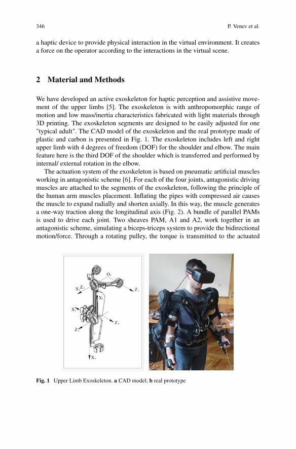
346 P. Venev et al.
a haptic device to provide physical interaction in the virtual environment. It createsa force on the operator according to the interactions in the virtual scene.
2 Material and Methods
We have developed an active exoskeleton for haptic perception and assistive move-ment of the upper limbs [5]. The exoskeleton is with anthropomorphic range ofmotion and low mass/inertia characteristics fabricated with light materials through3D printing. The exoskeleton segments are designed to be easily adjusted for one"typical adult". The CAD model of the exoskeleton and the real prototype made ofplastic and carbon is presented in Fig. 1. The exoskeleton includes left and rightupper limb with 4 degrees of freedom (DOF) for the shoulder and elbow. The mainfeature here is the third DOF of the shoulder which is transferred and performed byinternal/ external rotation in the elbow.
The actuation system of the exoskeleton is based on pneumatic artificial musclesworking in antagonistic scheme [6]. For each of the four joints, antagonistic drivingmuscles are attached to the segments of the exoskeleton, following the principle ofthe human arm muscles placement. Inflating the pipes with compressed air causesthe muscle to expand radially and shorten axially. In this way, the muscle generatesa one-way traction along the longitudinal axis (Fig. 2). A bundle of parallel PAMsis used to drive each joint. Two sheaves PAM, A1 and A2, work together in anantagonistic scheme, simulating a biceps-triceps system to provide the bidirectionalmotion/force. Through a rotating pulley, the torque is transmitted to the actuated
Fig. 1 Upper Limb Exoskeleton. a CAD model; b real prototype
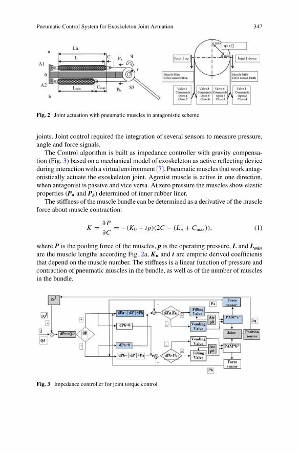
Pneumatic Control System for Exoskeleton Joint Actuation 347
Fig. 2 Joint actuation with pneumatic muscles in antagonistic scheme
joints. Joint control required the integration of several sensors to measure pressure,angle and force signals.
The Control algorithm is built as impedance controller with gravity compensa-tion (Fig. 3) based on a mechanical model of exoskeleton as active reflecting deviceduring interactionwith a virtual environment [7]. Pneumaticmuscles thatwork antag-onistically actuate the exoskeleton joint. Agonist muscle is active in one direction,when antagonist is passive and vice versa. At zero pressure the muscles show elasticproperties (Pa and Pb) determined of inner rubber liner.
The stiffness of the muscle bundle can be determined as a derivative of the muscleforce about muscle contraction:
K = ∂P
∂C= −(K0 + tp)(2C − (Ln + Cmax)), (1)
where P is the pooling force of the muscles, p is the operating pressure, L and Lminare the muscle lengths according Fig. 2a, Ko and t are empiric derived coefficientsthat depend on the muscle number. The stiffness is a linear function of pressure andcontraction of pneumatic muscles in the bundle, as well as of the number of musclesin the bundle.
Fig. 3 Impedance controller for joint torque control
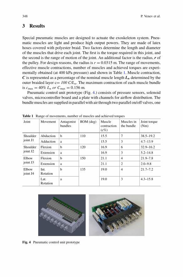
348 P. Venev et al.
3 Results
Special pneumatic muscles are designed to actuate the exoskeleton system. Pneu-matic muscles are light and produce high output powers. They are made of latexhoses covered with polyester braid. Two factors determine the length and diameterof the muscles that drive each joint. The first is the torque required in this joint, andthe second is the range of motion of the joint. An additional factor is the radius, r ofthe pulley. For design reasons, the radius is r = 0.0315 m. The range of movements,effective muscle contractions, number of muscles and achieved torques are experi-mentally obtained (at 400 kPa pressure) and shown in Table 1. Muscle contraction,C is represented as a percentage of the nominal muscle length Ln determined by theouter braided layer c= 100 C/Ln. The maximum contraction of each muscle bundleis cmax = 40% Ln or Cmax = 0.156 m.
Pneumatic control unit prototype (Fig. 4.) consists of pressure sensors, solenoidvalves, microcontroller board and a plate with channels for airflow distribution. Thebundlemuscles are supplied in parallelwith air through twoparallel on/off valves, one
Table 1 Range of movements, number of muscles and achieved torques
Joint Movement Antagonistbundles
ROM (deg) Musclecontraction(c%)
Muscles inthe bundle
Joint torque(Nm)
Shoulderjoint J1
Abduction b 110 15.5 7 38.5–19.2
Adduction a 15.5 3 4.7–13.9
Shoulderjoint J2
Flexion b 120 16.9 6 32.9–16.2
Extension a 16.9 3 5.2–14.8
Elbowjoint J3
Flexion b 150 21.1 4 21.9–7.8
Extension a 21.1 2 2.0–9.8
Elbowjoint J4
Int.Rotation
b 135 19.0 4 21.7–7.2
Lat.Rotation
a 19.0 3 4.3–15.8
Fig. 4 Pneumatic control unit prototype
Pneumatic Control System for Exoskeleton Joint Actuation 349
of which is used to supply pressure and the other to discharge into the atmosphere.4 Port Solenoid Valve Series S070s (SMC Pneumatics) were used to actuate thejoint, which are controlled by the ULN2803 driver. These valves supply muscleswith compressed air up to 5 bar through a pneumatic plate with channels for air flowdistribution. The Atmega 32U4 microcontroller is used to perform analog-to-digitalconversions and digital filtering. Themicrocontroller uses angle and pressure sensorsto monitor the position and valve control. For pressure measurement, 2 piezoresistivepressure sensorsHoneywell 40PC100Gwith 0.2%accuracywere used.These sensorsoperate in the range between 0 and 100psi (6 bar) with 40.0mV/psi output signal.The Bourns Inc. Magnetic encoder AMS22B5 was used to measure the angle whichhas 12 bit resolution and can rotate up to 360°. This magnetic encoder converts theangular rotation into an analog signal.
3.1 Experiments with the Active Exoskeleton with Volunteers
Weight Lifting experiments with 15 middle aged male volunteers wearing theexoskeleton has been completed in virtual GYM (from a first person perspective).An evaluation of pneumatically compliable joint actuation have been performed.Questionnaires were completed to determine the comfort and degree of freedom ofthe exoskeleton. The analysis of the results for validation of the exoskeleton func-tionality showed that over 80% of the participants in the experiment gave a positiveassessment.
4 Discussion
The experiments prove that the approach with pneumatic actuation of the activeorthosis allows natural, safe and comfortable physical interaction and support of thehuman operator. The overall assessment of the system shows that participants feelcomfortable with the exoskeleton and have not noticed a sharp or painful part of theexoskeleton and the weight of the device. Participants said they could perform themovements correctly and did not feel strange during the test.
5 Conclusion
An appropriate solution for the construction and pneumatic actuation of anexoskeleton for upper limbs, suitable for rehabilitation and training, providingtransparency and natural safety, as well as force and mobility was presented.Tests and adjustments of all systems of the prototype were performed, as well asexperimentation of the functionality of the orthosis with adjustable compliable joints.
350 P. Venev et al.
Acknowledgments This research was supported by the EC (FP7 Project VERE-257695);Bulgarian Science Found (Project AWERON, DN 07/9) and Ministry of Education and Sciencein Bulgaria (National Scientific Program ICTinSES, contract No DO1–205/23.11.2018).
References
1. D.G. Caldwell et al., “Soft” exoskeletons for upper and lower body rehabilitation—design,control and testing. Int. J. Humanoid Robot. 4(3), 549–573 (2007)
2. P. Chou, B. Hannaford, Measurement and modeling of McKibben pneumatic artificial muscles.IEEE Trans. Robot. Autom. 12(1) (1996)
3. B. Vanderborght, et al., Variable impedance actuators: a review. Robot. Autonomous Syst. 61,1601–1614 (2013)
4. N. Tsagarakis, D.G. Caldwell, Improved modelling and assessment of pneumatic muscleactuators, in ICRA 2000, San Francisco (2000)
5. I. Veneva, D. Chakarov, M. Tsveov, D. Trifonov, E. Zlatanov, P. Venev, Active orthotic systemfor assistance and rehabilitation, in 20th International Conference on CLAWAR 2017, Porto,Spain (2017), pp. 597–604
6. I. Veneva, D. Chakarov, M. Tsveov, D. Trifonov, E. Zlatanov, P. Venev, Active assistive orthoticsystem: (exoskeleton) enhancing movement, in Handbook of Research on Biomimetics andBiomedical Robotics (IGI Global eEditorial Discovery, 2017), pp. 48–75
7. D. Chakarov, I. Veneva, M. Tsveov, P. Venev, Powered upper limb orthosis actuation systembased on pneumatic artificial muscles. J. Theor. App. Mech. 48(1), 23–36 (2018)
PowerGrasp: Development Aspects forArm Support Systems
Jean-Paul Goppold, Jan Kuschan, Henning Schmidt, and Jörg Krüger
Abstract Exoskeletons can support workers on physically demanding tasks, butin industry they lack of acceptance. This contribution gives an insight into designaspects for upper body exoskeletons, especially howactive exoskeletons for industrialapplications differ from military and medical use-cases. To overcome typical rigidexoskeleton problems, we suggest the use of modular soft-exosuit support systemsand therefore checked different types of soft actuation principles for their eligibilityfor the use on upper body joints. Most promising approach is using two-layeredactuators sting of robust fabric with embedded rubber tubes as pressure chambers.By inflating the tubes, it is possible to vary the stiffness of the chambers, which can beeffectively used to generate assisting forces and moments at human joints (shoulder,elbow, wrist, finger).
1 Introduction
Physically demanding manual tasks in manufacturing, logistics, handcraft and ser-vice are major contributors to early damage of the musculoskeletal system (approx.19% of all work disabilities) and especially the spine (approx. 47% of muscoskele-tal disabilities) [1] and are responsible for a loss of the gross domestic product ofapproximately 1% [2]. Formilitary and rehabilitation use-cases, exoskeletons alreadyshowed thatwearable systems support themuscle activity of thewearer.Nevertheless,the criteria differ largely from industrial applications (requirements for plug&playbehaviour and longtime wear) and first rigid exoskeletons in assembly lines oftensuffer on the wearers acceptance [3]. As a result, the exoskeleton-market nowadays ismainly restricted to passive exoskeletons [4], which are practical, individually adap-tive, not power restricted andmuch cheaper than their active counterparts. But, activeexoskeletons suit the flexibility required by industrial environments more, whichopens a wider industrial acceptance if the focus of the classical design-principles ofexoskeletons will shift to more medically dominated topics like effects of long-termwear and ergonomics.
J.-P. Goppold (B) · J. Kuschan · H. Schmidt · J. KrügerFraunhofer Institute for Production Systems and Design Technology (IPK), Berlin, Germanye-mail: [email protected]
© The Author(s), under exclusive license to Springer Nature Switzerland AG 2022J. C. Moreno et al. (eds.), Wearable Robotics: Challenges and Trends,Biosystems & Biorobotics 27, https://doi.org/10.1007/978-3-030-69547-7_57
351
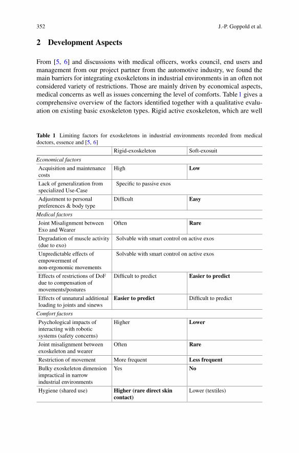
352 J.-P. Goppold et al.
2 Development Aspects
From [5, 6] and discussions with medical officers, works council, end users andmanagement from our project partner from the automotive industry, we found themain barriers for integrating exoskeletons in industrial environments in an often notconsidered variety of restrictions. Those are mainly driven by economical aspects,medical concerns as well as issues concerning the level of comforts. Table1 gives acomprehensive overview of the factors identified together with a qualitative evalu-ation on existing basic exoskeleton types. Rigid active exoskeleton, which are well
Table 1 Limiting factors for exoskeletons in industrial environments recorded from medicaldoctors, essence and [5, 6]
Rigid-exoskeleton Soft-exosuit
Economical factors
Acquisition and maintenancecosts
High Low
Lack of generalization fromspecialized Use-Case
Specific to passive exos
Adjustment to personalpreferences & body type
Difficult Easy
Medical factors
Joint Misalignment betweenExo and Wearer
Often Rare
Degradation of muscle activity(due to exo)
Solvable with smart control on active exos
Unpredictable effects ofempowerment ofnon-ergonomic movements
Solvable with smart control on active exos
Effects of restrictions of DoFdue to compensation ofmovements/postures
Difficult to predict Easier to predict
Effects of unnatural additionalloading to joints and sinews
Easier to predict Difficult to predict
Comfort factors
Psychological impacts ofinteracting with roboticsystems (safety concerns)
Higher Lower
Joint misalignment betweenexoskeleton and wearer
Often Rare
Restriction of movement More frequent Less frequent
Bulky exoskeleton dimensionimpractical in narrowindustrial environments
Yes No
Hygiene (shared use) Higher (rare direct skincontact)
Lower (textiles)
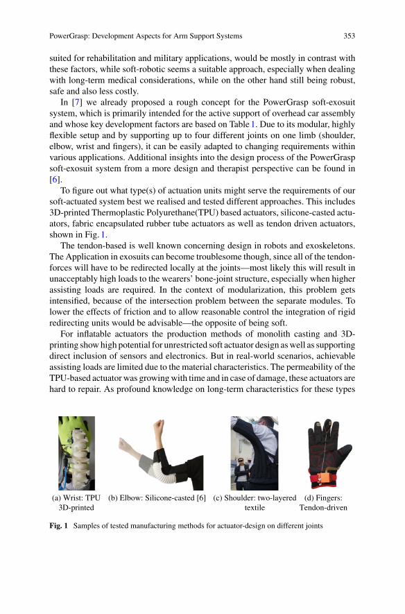
PowerGrasp: Development Aspects for Arm Support Systems 353
suited for rehabilitation and military applications, would be mostly in contrast withthese factors, while soft-robotic seems a suitable approach, especially when dealingwith long-term medical considerations, while on the other hand still being robust,safe and also less costly.
In [7] we already proposed a rough concept for the PowerGrasp soft-exosuitsystem, which is primarily intended for the active support of overhead car assemblyand whose key development factors are based on Table1. Due to its modular, highlyflexible setup and by supporting up to four different joints on one limb (shoulder,elbow, wrist and fingers), it can be easily adapted to changing requirements withinvarious applications. Additional insights into the design process of the PowerGraspsoft-exosuit system from a more design and therapist perspective can be found in[6].
To figure out what type(s) of actuation units might serve the requirements of oursoft-actuated system best we realised and tested different approaches. This includes3D-printed Thermoplastic Polyurethane(TPU) based actuators, silicone-casted actu-ators, fabric encapsulated rubber tube actuators as well as tendon driven actuators,shown in Fig. 1.
The tendon-based is well known concerning design in robots and exoskeletons.The Application in exosuits can become troublesome though, since all of the tendon-forces will have to be redirected locally at the joints—most likely this will result inunacceptably high loads to the wearers’ bone-joint structure, especially when higherassisting loads are required. In the context of modularization, this problem getsintensified, because of the intersection problem between the separate modules. Tolower the effects of friction and to allow reasonable control the integration of rigidredirecting units would be advisable—the opposite of being soft.
For inflatable actuators the production methods of monolith casting and 3D-printing showhigh potential for unrestricted soft actuator design aswell as supportingdirect inclusion of sensors and electronics. But in real-world scenarios, achievableassisting loads are limited due to the material characteristics. The permeability of theTPU-based actuatorwas growingwith time and in case of damage, these actuators arehard to repair. As profound knowledge on long-term characteristics for these types
(a) Wrist: TPU3D-printed
(b) Elbow: Silicone-casted [6] (c) Shoulder: two-layeredtextile
(d) Fingers:Tendon-driven
Fig. 1 Samples of tested manufacturing methods for actuator-design on different joints
354 J.-P. Goppold et al.
of actuators is not available, we consider this fact as critical to a potential applicationin an industrial environment.
Alternative ways to create inflatable actuators is by using two-layer material set-ups. One approach uses an-isotropic structural behaviour of the outer layer (e.g.“bionic muscles”). Another uses predefined textile-patterns on the outer layer toachieve the (use-case specific) intended force vector and is mainly driven by varyingthe stiffness of the structure through pressure variation. Even though the design flex-ibility of this approach is lower compared to the generative approaches, one can stillgenerate a large variety of actuation schemes. A major advantage, especially in thestiffness variation approach, is the high robustness of the setup due to the functionalseparation of inner and outer layer. The pattern of the outer layer indicates the result-ing force vector as well as defines the overall flexibility and robustness against poten-tial physical damage. The inner layer can be specifically designed to encapsulatinghigh pressure. The functional separation also allows for easy maintenance and repair.Additionally, the actuators are flexible as textiles when depressurized - thus allowinga maximum of comfort. Because of the many advantages the actuation modules ofthe PowerGrasp system were finally designed according to the approach based onstiffness-control of a two-layered textile actuator—utilizing nylon polyamide fabricas outer layer and butyl tubes as inner layer—a sample can be seen in Fig. 1c. The useof Stratos–Cordura® 3-layer laminate (highly stressable) as outer layer allows theapplication of high pressuring states by far surpassing the other actuation methods(pressure of up to 3 bar repeatably applicable).
3 Conclusion and Discussion
To not only show technical feasibility but also to achieve high acceptance-ratesfor applications in industrial environment we made a revision of requirements forthe design of exoskeletons and extended the scope from technical and economicalaspects (classically references) by also considering medical concerns, medical long-term concerns and comfort (Table1). We believe that considering these aspects in thedesign of future exoskeletons will play an essential role in the integration process ofexoskeletons into the industrial environment. Next, we want to focus on identifyingthe control characteristics of the actuation units and include smart control schemeson the soft-exosuit to bring the benefits of the system to a maximum.
Acknowledgements PowerGrasp was funded by the German Federal Ministry of Education andResearch (BMBF).
PowerGrasp: Development Aspects for Arm Support Systems 355
References
1. D. Hoy, P. Brooks, F. Blyth, R. Buchbinder, The epidemiology of low back pain. Best PracticeRes. Clin. Rheumatol. 24, 769–781 (2010)
2. C. Maar, R. Fricker, Vorteil Vorsorge Die Rolle der betrieblichen Gesundheitsvorsorge für dieZukunftsfähigkeit des Wirtschaftsstandortes Deutschland (Booz & Company, 2009)
3. M.P. De Looze, T. Bosch, F. Krause, K.S. Stadler, L.W. O’Sullivan, Exoskeletons for industrialapplication and their potential effects on physical work load. Ergonomics 59(5), 671–681 (2016)
4. T. Butler, J.C. Gillette, Exoskeletons: used as PPE for injury prevention, in Professional Safety(2019), p. 33
5. R. Gopura, K. Kiguchi, Mechanical designs of active upper-limb exoskeleton robots: state-of-the-art and design difficulties, in2009 IEEE InternationalConference onRehabilitationRobotics(IEEE, 2009), pp. 178–187
6. R. Flechtner, K. Lorenz, G. Joost, Designing a wearable soft-robotic orthosis: a body-centeredapproach, in Proceedings of the Fourteenth International Conference on Tangible, Embedded,and Embodied Interaction (TEI-2020), Future Bodies, Future Technologies (ACM, 2020), pp.863–875
7. J. Kuschan, J. Goppold, H. Schmidt, J. Krueger, Powergrasp: concept for a novel soft-roboticarm support system, in ISR 2018; 50th International Symposium on Robotics (2018), pp. 1–6
Mobile Unilateral Hip Flexion ExosuitAssistance for Overground Walking inIndividuals Post-Stroke: A Case Series
Richard W. Nuckols, Franchino Porciuncula, Chih-Kang Chang,Teresa C. Baker, Dorothy Orzel, Asa Eckert-Erdheim, David Perry,Terry Ellis, Louis Awad, and Conor J. Walsh
Abstract Stroke is a leading medical issue that can impact the person’s abilityto walk effectively. There is limited research into the design and biomechanicalresponse for exosuits that assist more proximal joints such as the hip. For this caseseries, three subjects with chronic stroke participated in a single-session study toevaluate hip flexion exosuit assistance in overground walking. We iteratively tunedthe unilateral hip flexion assistance profiles in overground gait. Compared to theinitial unpowered baseline, walking speed at the end of tuning and with the devicepowered increased for 2 of 3 individuals and on average by 0.16m s−1. We thencompared powered versus unpowered overground walking during a 5min evaluationperiod. Circumduction was reduced by 9 ±1mm and cost of transport was reducedby 8.6 ±1.7% for the 3 participants.
1 Introduction
Gait deficits following stroke can have varied effects on the joints of the paretic limb[1]. While much effort has focused on improving ankle function [2], the hip alsoprovides important contributions to gait particularly in swing. In fact, for groundclearance during swing, hip flexion contribution to limb shortening is potentiallymore important than the contribution from ankle dorsiflexion [3]. Recently, therehave been efforts to assist more proximal joints such as the hip during walking[4–6], but how exosuits can affect the mechanics of the hip and how best to applyassistance at the hip for individuals after stroke needs further understanding.
This study was supported by NIH BRG R01HD088619, NSF CNS-1446464, Wyss Institute forBiologically Inspired Engineering and the Harvard School of Engineering and Applied Sciences.
R. W. Nuckols · F. Porciuncula · C.-K. Chang · D. Orzel · A. Eckert-Erdheim · D. Perry ·C. J. Walsh (B)School of Engineering and Applied Sciences, Harvard University, Cambridge, MA, USAe-mail: [email protected]
T. C. Baker · T. Ellis · L. AwadDepartment of Physical Therapy and Athletic Training, Sargent College, Boston University,Boston, MA, USA
© The Author(s), under exclusive license to Springer Nature Switzerland AG 2022J. C. Moreno et al. (eds.), Wearable Robotics: Challenges and Trends,Biosystems & Biorobotics 27, https://doi.org/10.1007/978-3-030-69547-7_58
357
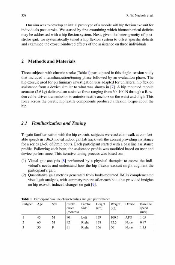
358 R. W. Nuckols et al.
Our aimwas to develop an initial prototype of a mobile soft hip flexion exosuit forindividuals post-stroke. We started by first examining which biomechanical deficitsmay be addressed with a hip flexion system. Next, given the heterogeneity of post-stroke gait, we systematically tuned a hip flexion system to offset specific deficitsand examined the exosuit-induced effects of the assistance on three individuals.
2 Methods and Materials
Three subjects with chronic stroke (Table1) participated in this single-session studythat included a familiarization/tuning phase followed by an evaluation phase. Thehip exosuit used for preliminary investigation was adapted for unilateral hip flexionassistance from a device similar to what was shown in [7]. A hip mounted mobileactuator (2.6kg) delivered an assistive force ranging from 60–100 N through a Bow-den cable-driven transmission to anterior textile anchors on the waist and thigh. Thisforce across the paretic hip textile components produced a flexion torque about thehip.
2.1 Familiarization and Tuning
To gain familiarization with the hip exosuit, subjects were asked to walk at comfort-able speeds in a 36.3m oval indoor gait lab trackwith the exosuit providing assistancefor a series (3–5) of 2min bouts. Each participant started with a baseline assistanceprofile. Following each bout, the assistance profile was modified based on user anddevice performance. This iterative tuning process was based on:
(1) Visual gait analysis [8] performed by a physical therapist to assess the indi-vidual’s needs and understand how the hip flexion exosuit might augment theparticipant’s gait.
(2) Quantitative gait metrics generated from body-mounted IMUs complementedvisual gait analysis, with summary reports after each bout that provided insightson hip exosuit-induced changes on gait [9].
Table 1 Participant baseline characteristics and gait performance
Subject Age Sex Strokeonset(months)
PareticSide
Height(cm)
Weight(kg)
Device Baselinespeed(m/s)
1 45 M 90 Left 179 100.5 AFO 1.05
2 60 M 92 Right 178 72.5 None 0.97
3 50 F 91 Right 166 60 None 1.35
Mobile Unilateral Hip Flexion Exosuit Assistance for Overground Walking … 359
(3) Walking speeds during the 2-min walk to assess whole-body response to exosuitassistance measured by a researcher following with a measuring wheel.
The “optimized” assistance profile was identified based on settings that providedfastest walking speedwithout clinical gait decline per quantifiedmetrics and physicaltherapist observations.
2.2 Evaluation of Assistance: Five Minute Walk Tests
To evaluate hip exosuit-induced effects, we asked participants to walk for 5minaround the indoor gait lab track at comfortable walking speed under the followingconditions: (a) hip exosuit powered on (Active), and (b) unpowered (Slack). Wecollected data on energy consumption of walking using a mobile metabolic system(Cosmed K5, Italy), and kinematic data using motion capture (Qualysis, Sweden).To examine within-subject changes between Active vs Slack, we used the WilcoxonExact test.
3 Results
Relative to the initial unpowered baseline, walking speeds at the end of tuning withthe device powered increased for 2 of 3 individuals and on average by 0.16m s−1
(Subjects 1–3: 0.0, 0.33, 0.15m s−1, respectively). For the evaluation phase, Subjects1, 2 and 3 were provided peak applied forces of 83.7, 90.7, 63.5N, with timingonsets at 40%, 23%, and 40% of the gait cycle, respectively (Fig. 1). For the Activecondition, circumduction was reduced on average by 9 ± 1mm (Subjects 1–3: 11,7, 7mm) compared to Slack. Only modest changes to walking speeds were observedin response to Active assistance (Subjects 1–3: 1.22 (+0.02), 1.24 (−0.04), 1.51(+0.04) m s−1). Reductions in cost of transport (walking efficiency) were observedin Active relative to Slack, with average reduction of 8.6± 1.7% (Subjects 1–3: 6.4,7.7, 10.4%).
Subject 1 responded with significant changes in various kinematic measures:increased ground clearance (2.2± 0.02mm, p < 0.0001), increased peak knee flex-ion angle (12.2± 1 deg, p < 0.0001), and decreased circumduction (11± 5mm,p = 0.0196). Subject 2 demonstrated small reduction in circumduction (p > 0.05),and Subject 3 had slight decrease in knee hyperextension during mid/late stance (4deg, p > 0.05), however these were not statistically significant.
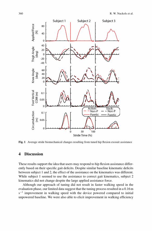
360 R. W. Nuckols et al.
Fig. 1 Average stride biomechanical changes resulting from tuned hip flexion exosuit assistance
4 Discussion
These results support the idea that users may respond to hip flexion assistance differ-ently based on their specific gait deficits. Despite similar baseline kinematic deficitsbetween subject 1 and 2, the effect of the assistance on the kinematics was different.While subject 1 seemed to use the assistance to correct gait kinematics, subject 2kinematics did not change despite the large applied assistance force.
Although our approach of tuning did not result in faster walking speed in theevaluation phase, our limited data suggest that the tuning process resulted in a 0.16ms−1 improvement in walking speed with the device powered compared to initialunpowered baseline. We were also able to elicit improvement in walking efficiency
Mobile Unilateral Hip Flexion Exosuit Assistance for Overground Walking … 361
for each participant when walking with device powered versus unpowered, but wedid not compare to a condition where the participant walked without a device.
5 Conclusions
This initial work suggests that individuals use unilateral hip flexion to improve walk-ing efficiency through different biomechanical mechanisms. Additional work willneed to dig deeper into these findings to understand how individuals effectively usethe assistance and address additional metrics such as spatiotemporal parameters.Future work will also focus on developing a smaller and more lightweight systemdesigned for the requirements of unilateral hip flexion support.
References
1. I. Jonkers, S. Delp, C. Patten, Capacity to increase walking speed is limited by impaired hip andankle power generation in lower functioning persons post-stroke. Gait Posture 29(1), 129–137(2009)
2. L.N. Awad, et al., A soft robotic exosuit improves walking in patients after stroke. Sci. Transl.Med. 9(400) (2017)
3. V.L. Little, T.E. McGuirk, C. Patten, Impaired limb shortening following stroke: what’s in aname? PloS One 9(10), e110140 (2014)
4. C. Buesing et al., Effects of a wearable exoskeleton stride management assist system (SMA®)on spatiotemporal gait characteristics in individuals after stroke: a randomized controlled trial.J. Neuroeng. Rehabil. 12(1), 69 (2015)
5. C. Di Natali et al., Design and evaluation of a soft assistive lower limb exoskeleton. Robotica37(12), 2014–34 (2019)
6. M. Sposito, et al., Evaluation of XoSoft Beta-1 lower limb exoskeleton on a post stroke patient,in Sixth National Congress of Bioengineering, Milan, Italy, June 25–27, 2018
7. J. Kim et al., Reducing the metabolic rate of walking and running with a versatile, portableexosuit. Science 365(6454), 668–72 (2019)
8. F. Ferrarello et al., Tools for observational gait analysis: a systematic review. Phys. Ther. 93(12),1673–1685 (2013)
9. P. Arens, et al., Real-time gait metric estimation for everyday gait training with wearable devicesin people poststroke. Wearable Technol. (submitted for publication (accepted))
The SoftPro Wearable System for GraspCompensation in Stroke Patients
L. Franco, M. Tschiersky, G. Wolterink, F. Barontini, M. Poggiani,M. Catalano, G. Grioli, M. Bianchi, A. Bicchi, S. Rossi, D. Prattichizzo,and G. Salvietti
Abstract This extended abstract presents a wearable system for assistance that isa combination of different technologies including sensing, haptics, orthotics androbotics. The result is a device that, by compensating for force deficiencies, helpslifting the forearm and thanks to a robotic supernumerary finger improves the grasp-ing ability of an impaired hand. A pilot study involving three post-stroke patientswas conducted to test the effectiveness of the device to assist in performing activitiesof daily living (ADLs), confirming its usefulness.
1 Introduction
Robotic devices have been developed to give supervised assistance to patients withmild to extreme motor disabilities after neurologic injury [1]. In the context of theEU project SoftPro (https://www.softpro.eu), a consortium of universities and com-panies has investigated novel solutions for assistive robotic tools to be used at homeby chronic stroke patients. In addition to classical exoskeleton approaches [2], wehave introduced the concept of using wearable robots as assistive tools for restoringgrasping capabilities in people with paretic arms. We have also designed an sEMGinterface embedded in a cap called e-CAP for the systemcontrol and awearable hapticinterface called CUFFwhich provides force feedback from awearable robotic finger.We attached all devices to the Assistive Elbow Orthosis, a light passive exoskeletonthat assists elbow flexion, to enlarge the number of potential final users.
L. Franco (B) · S. Rossi · D. Prattichizzo · G. SalviettiUniversity of Siena, Siena, Italye-mail: [email protected]
M. Tschiersky · G. WolterinkUniversity of Twente, Enschede, The Netherlands
F. Barontini · M. Poggiani · M. Catalano · G. Grioli · A. Bicchi · D. Prattichizzo · G. SalviettiIstituto Italiano di Tecnologia, Genova, Italy
M. Bianchi · A. BicchiUniversity of Pisa, Pisa, Italy
© The Author(s), under exclusive license to Springer Nature Switzerland AG 2022J. C. Moreno et al. (eds.), Wearable Robotics: Challenges and Trends,Biosystems & Biorobotics 27, https://doi.org/10.1007/978-3-030-69547-7_59
363
364 L. Franco et al.
2 System Components
The Robotoic Sixth Finger is a wearable supernumerary robotic finger created by theUniversity of Siena (US). It is an extra finger that acts as a functional replacement ofthe thumb, and has been demonstrated to compensate missing grasping capabilitiesof stroke subjects [3]. In the integrated device, the Sixth Finger has the end-effectorfunction. It is the device of the system that enables the stroke patient to grasp objects incombinationwith the impaired limb. The e-Cap is a human-robot interface embeddedin a regular capwhich is easy towear and can recognize themovement of the eyebrowsthrough real-time sEMG measurement of the frontalis muscle [4, 5]. The e-Capconsists of an sEMG acquisition chain composed of dry electrodes, a commercialinstrumentation amplifier and a Teensy 3.2 microcontroller to sample the analogsignal. For the dry electrodes, we proposed a solution which combines a reusablesticky plastic tape and non-gelled 3D-printed flexible TPU-based sEMG electrodesdeveloped by University of Twente (UT) [6].
The e-Cap electronic board is equipped with a Bluetooth antenna with whichit can communicate with the Sixth Finger. Finally, at the back of the cap thereis a 3D-printed box for the battery. Being an sEMG-based interface, it requires acalibration before operational use. The trigger for the calibration was upgraded incomparison to previous versions [4, 5]. The physical switch was replaced by a cop-per touch button. The described system maps the Sixth Finger’s current load, anestimate of the force exerted onto the grasped object, to the CUFF [7]—a devicedeveloped by University of Pisa (UP) in collaboration with Istituto Italiano di Tec-nologia (IIT), which renders a real-time force feedback by squeezing the arm. Thedevice is composed of the structural frame, two mechanical actuation units and thefeedback interface. A fabric band is attached to both motors, in such a way that whenactuated in a counter-rotating motion the length of the band is reduced, squeezingthe arm. Each added device increases the overall weight that the stroke patient hasto lift when grasping something. To address this issue, we consider the use of theAssistive Elbow Orthosis [8], a passive gravity balancing device developed by theUniversity of Twente, featuring a 3D-printed spring which is designed to provideweight compensation to the forearm of the affected limb. The device consists ofa modified Wilmer elbow orthosis (Ambroise, Enschede, The Netherlands) whichacts as the mechanical interface to the wearer, and a stack of nested springs that ismounted laterally onto the orthosis. The spring shape has been optimized to providean angle-dependent moment at the elbow, which counteracts the moment caused bygravity acting on the forearm. The final prototype is shown in Fig. 1.
3 System Integration
When the patient raises the eyebrows, the e-Cap recognizes the gesture by sEMGreal-time processing and triggers the Sixth Finger to close, in order to perform agrasp. This trigger signal is sent via Bluetooth antenna to the Robotic Sixth Finger,
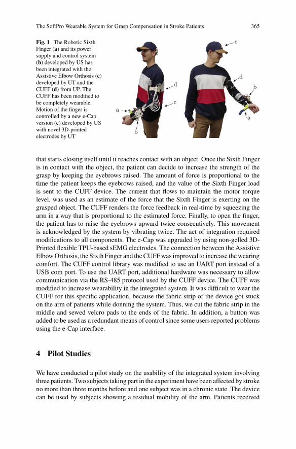
The SoftPro Wearable System for Grasp Compensation in Stroke Patients 365
Fig. 1 The Robotic SixthFinger (a) and its powersupply and control system(b) developed by US hasbeen integrated with theAssistive Elbow Orthosis (c)developed by UT and theCUFF (d) from UP. TheCUFF has been modified tobe completely wearable.Motion of the finger iscontrolled by a new e-Capversion (e) developed by USwith novel 3D-printedelectrodes by UT
that starts closing itself until it reaches contact with an object. Once the Sixth Fingeris in contact with the object, the patient can decide to increase the strength of thegrasp by keeping the eyebrows raised. The amount of force is proportional to thetime the patient keeps the eyebrows raised, and the value of the Sixth Finger loadis sent to the CUFF device. The current that flows to maintain the motor torquelevel, was used as an estimate of the force that the Sixth Finger is exerting on thegrasped object. The CUFF renders the force feedback in real-time by squeezing thearm in a way that is proportional to the estimated force. Finally, to open the finger,the patient has to raise the eyebrows upward twice consecutively. This movementis acknowledged by the system by vibrating twice. The act of integration requiredmodifications to all components. The e-Cap was upgraded by using non-gelled 3D-Printed flexible TPU-based sEMG electrodes. The connection between the AssistiveElbowOrthosis, the Sixth Finger and theCUFFwas improved to increase thewearingcomfort. The CUFF control library was modified to use an UART port instead of aUSB com port. To use the UART port, additional hardware was necessary to allowcommunication via the RS-485 protocol used by the CUFF device. The CUFF wasmodified to increase wearability in the integrated system. It was difficult to wear theCUFF for this specific application, because the fabric strip of the device got stuckon the arm of patients while donning the system. Thus, we cut the fabric strip in themiddle and sewed velcro pads to the ends of the fabric. In addition, a button wasadded to be used as a redundant means of control since some users reported problemsusing the e-Cap interface.
4 Pilot Studies
We have conducted a pilot study on the usability of the integrated system involvingthree patients. Two subjects taking part in the experiment have been affected by strokeno more than three months before and one subject was in a chronic state. The devicecan be used by subjects showing a residual mobility of the arm. Patients received
366 L. Franco et al.
the system on their paretic arm, the left hand for two subjects and the right one forthe other. Patients were asked to wear the system, familiarise with the controls andthen use the system to execute a series of bimanual tasks common of ADLs: openinga bottle, removing the cap from a jar, and peeling an apple. The paretic arm andthe wearable system were used to stabilize the objects. We perform a qualitativeevaluation of the system asking the participants to answer the ten questions of theSystem Usability Scale (SUS) [9] after 30min of use. A quantitative analysis usingadapted evaluation scales starting from the ARAT and the Frenchay Arm test willbe performed as future work. The patients scored 70, 95 and 90, respectively. Thismeans that the integration was deemed useful and the resulting device easy to use.We also collected suggestions for further improvements of the system. One patientsuggested to provide the ability of adapting finger length depending on the task. Twopatients suggested to further reduce the encumbrance of the feedback device. Finallyone patient suggested to add the ability of regulating closing velocity and appliedforce through knobs embedded in the control box at the forearm.
5 Conclusion
In this work, different technologies such as a supernumerary robotic finger, an sEMGinput device using 3D-printed electrodes, a wearable force feedback device, and agravity balancing armorthosiswere combined to generate a newdevice that can assistan impaired arm. The positive response of the subjects that participated in the pilotstudy indicates the need for robotic assistive devices. The collected first impressionsof the users will provide the starting point for further development.
References
1. A.C. Lo, P.D. Guarino, L.G. Richards, J.K. Haselkorn, G.F. Wittenberg, D.G. Federman, R.J.Ringer, T.H. Wagner, H.I. Krebs, B.T. Volpe et al., Robot-assisted therapy for long-term upper-limb impairment after stroke. N. Engl. J. Med. 362(19), 1772–1783 (2010)
2. G. Kwakkel, B.J. Kollen, H.I. Krebs, Effects of robot-assisted therapy on upper limb recoveryafter stroke: a systematic review. Neurorehabil. Neural Repair (2007)
3. G. Salvietti, I. Hussain, D. Cioncoloni, S. Taddei, S. Rossi, D. Prattichizzo, Compensating handfunction in chronic stroke patients through the robotic sixth finger. Trans. Neural Syst. Rehabil.Eng. 25(2), 142–150 (2017)
4. I. Hussain, G. Salvietti, G. Spagnoletti, D. Prattichizzo, The soft-sixthfinger: a wearable EMGcontrolled robotic extra-finger for grasp compensation in chronic stroke patients. IEEE Robot.Autom. Lett. 1(2), 1000–1006 (2016)
5. L. Franco, G. Salvietti, D. Prattichizzo, Command acknowledge through tactile feedbackimproves the usability of an emg-based interface for the frontalis muscle, in IEEEWorld HapticsConference (WHC) (2019), pp. 574–579
6. G. Wolterink, P. Dias, R.G. Sanders, F. Muijzer, B.-J. van Beijnum, P. Veltink, G. Krijnen,Development of soft sEMG sensing structures using 3d-printing technologies. Sensors 20(15),4292 (2020)
The SoftPro Wearable System for Grasp Compensation in Stroke Patients 367
7. S. Casini, M. Morvidoni, M. Bianchi, M. Catalano, G. Grioli, A. Bicchi, Design and realizationof the cuff - clenching upper-limb force feedbackwearable device for distributedmechano-tactilestimulation of normal and tangential skin forces, in IEEE/RSJ IROS (2015), pp. 1186–1193
8. M. Tschiersky, E.E.G. Hekman, D.M. Brouwer, J.L. Herder, Gravity balancing flexure springsfor an assistive elbow orthosis. IEEE Trans. Med. Robot. Bionics 1(3), 177–188 (2019)
9. J. Brooke, SUS: a ‘quick and dirty’ usability scale, in Usability Evaluation in Industry (1996),p. 189
Towards a Fabric-Based Soft HandExoskeleton for Various GraspTaxonomies
Andrea Peñas, Juan C. Maldonado-Mejía, Orion Ramos, Marcela Múnera,Patricio Barria, Mehran Moazen, Helge Wurdemann, and Carlos A. Cifuentes
Abstract This paper describes a functional evaluation test of a fabric-based handexoskeleton for various grasp taxonomies. We conducted an adapted version of theJebsen Taylor Hand Function Test (JTHFT) with a healthy subject. The evaluationinvestigates a comparison of the times it takes the user to perform the task with andwithout the device, establishing a range of actionswith a delay of 2.0–6.0 smaximum.This preliminary study aims to understand the implications of future clinical studieswith post-stroke patients for rehabilitation.
Keywords Soft-robotics · Fabric-based exoskeleton · Rehabilitation robotics ·Hand rehabilitation
A. Peñas · J. C. Maldonado-Mejía · O. Ramos ·M. Múnera · C. A. Cifuentes (B)Department of Biomedical Engineering, Colombian School of Engineering Julio Garavito,Bogotá, Colombiae-mail: [email protected]
A. Peñase-mail: [email protected]
J. C. Maldonado-Mejíae-mail: [email protected]
O. Ramose-mail: [email protected]
M. Múnerae-mail: [email protected]
M. Moazen · H. WurdemannDepartment of Mechanical Engineering, University College London, London, UKe-mail: [email protected]
H. Wurdemanne-mail: [email protected]
P. BarriaResearch and Development Unit, Club de Leones Cruz del Sur Rehabilitation Center, PuntaArenas, Chilee-mail: [email protected]
Department of Electrical Engineering, University of Magallanes, Punta Arenas, Chile
© The Author(s), under exclusive license to Springer Nature Switzerland AG 2022J. C. Moreno et al. (eds.), Wearable Robotics: Challenges and Trends,Biosystems & Biorobotics 27, https://doi.org/10.1007/978-3-030-69547-7_60
369
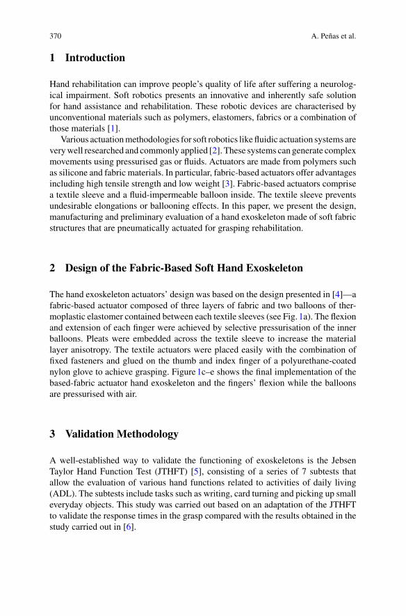
370 A. Peñas et al.
1 Introduction
Hand rehabilitation can improve people’s quality of life after suffering a neurolog-ical impairment. Soft robotics presents an innovative and inherently safe solutionfor hand assistance and rehabilitation. These robotic devices are characterised byunconventional materials such as polymers, elastomers, fabrics or a combination ofthose materials [1].
Various actuationmethodologies for soft robotics like fluidic actuation systems areverywell researched and commonly applied [2]. These systems can generate complexmovements using pressurised gas or fluids. Actuators are made from polymers suchas silicone and fabric materials. In particular, fabric-based actuators offer advantagesincluding high tensile strength and low weight [3]. Fabric-based actuators comprisea textile sleeve and a fluid-impermeable balloon inside. The textile sleeve preventsundesirable elongations or ballooning effects. In this paper, we present the design,manufacturing and preliminary evaluation of a hand exoskeleton made of soft fabricstructures that are pneumatically actuated for grasping rehabilitation.
2 Design of the Fabric-Based Soft Hand Exoskeleton
The hand exoskeleton actuators’ design was based on the design presented in [4]—afabric-based actuator composed of three layers of fabric and two balloons of ther-moplastic elastomer contained between each textile sleeves (see Fig. 1a). The flexionand extension of each finger were achieved by selective pressurisation of the innerballoons. Pleats were embedded across the textile sleeve to increase the materiallayer anisotropy. The textile actuators were placed easily with the combination offixed fasteners and glued on the thumb and index finger of a polyurethane-coatednylon glove to achieve grasping. Figure1c–e shows the final implementation of thebased-fabric actuator hand exoskeleton and the fingers’ flexion while the balloonsare pressurised with air.
3 Validation Methodology
A well-established way to validate the functioning of exoskeletons is the JebsenTaylor Hand Function Test (JTHFT) [5], consisting of a series of 7 subtests thatallow the evaluation of various hand functions related to activities of daily living(ADL). The subtests include tasks such as writing, card turning and picking up smalleveryday objects. This study was carried out based on an adaptation of the JTHFTto validate the response times in the grasp compared with the results obtained in thestudy carried out in [6].
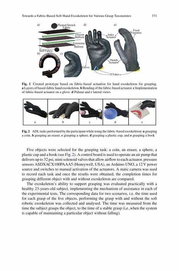
Towards a Fabric-Based Soft Hand Exoskeleton for Various Grasp Taxonomies 371
Pleated StretchFabric
Stiff Fabric
Flexion Balloon
ExtensionBalloon
d)
c)
e)
ThumbActuator
IndexActuator
Tubes
FixedFasteners
Glove
b)
a)
Fig. 1 Created prototype based on fabric-based actuation for hand exoskeleton for grasping.aLayers of based-fabric hand exoskeleton.bBending of the fabric-based actuator. c Implementationof fabric-based actuator on a glove. d Palmar and e lateral views
a b c d e
Fig. 2 ADL tasks performed by the participantwhile using the fabric-based exoskeleton: a graspinga coin, b grasping an eraser, c grasping a sphere, d grasping a plastic cup, and e grasping a book
Five objects were selected for the grasping task: a coin, an eraser, a sphere, aplastic cup and a book (see Fig. 2). A control board is used to operate an air pump thatdelivers up to 32 psi, mini solenoid valves that allow airflow to each actuator, pressuresensors ASDXACX100PAAA5 (Honeywell, USA), an Arduino UNO, a 12V powersource and switches to manual activation of the actuators. A static camera was usedto record each task and once the results were obtained, the completion times forgrasping different object with and without exoskeleton are compared.
The exoskeleton’s ability to support grasping was evaluated practically with ahealthy 23-years-old subject, implementing the mechanism of assistance in each ofthe experimental tests. The corresponding data for two scenarios, i.e. the time usedfor each grasp of the five objects, performing the grasp with and without the softrobotic exoskeleton was collected and analysed. The time was measured from thetime the subject grasps the object, to the time of a stable grasp (i,e.,when the systemis capable of maintaining a particular object without falling).
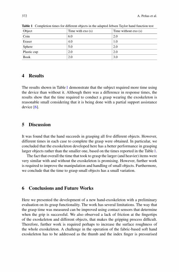
372 A. Peñas et al.
Table 1 Completion times for different objects in the adapted Jebsen Taylor hand function test
Object Time with exo (s) Time without exo (s)
Coin 6.0 2.0
Eraser 4.0 1.0
Sphere 5.0 2.0
Plastic cup 2.0 2.0
Book 2.0 3.0
4 Results
The results shown in Table1 demonstrate that the subject required more time usingthe device than without it. Although there was a difference in response times, theresults show that the time required to conduct a grasp wearing the exoskeleton isreasonable small considering that it is being done with a partial support assistancedevice [6].
5 Discussion
It was found that the hand succeeds in grasping all five different objects. However,different times in each case to complete the grasp were obtained. In particular, weconcluded that the exoskeleton developed here has a better performance in graspinglarger objects rather than the smaller one, based on the times reported in the Table1.
The fact that overall the time that took to grasp the larger (and heavier) items werevery similar with and without the exoskeleton is promising. However, further workis required to improve the manipulation and handling of small objects. Furthermore,we conclude that the time to grasp small objects has a small variation.
6 Conclusions and Future Works
Here we presented the development of a new hand-exoskeleton with a preliminaryevaluation on its grasp functionality. The work has several limitations. The way thatthe grasp time was measured can be improved using contact sensors that determinewhen the grip is successful. We also observed a lack of friction at the fingertipsof the exoskeleton and different objects, that makes the gripping process difficult.Therefore, further work is required perhaps to increase the surface roughness ofthe whole exoskeleton. A challenge in the operation of the fabric-based soft handexoskeleton has to be addressed as the thumb and the index finger is pressurised
Towards a Fabric-Based Soft Hand Exoskeleton for Various Grasp Taxonomies 373
through the same airline. This leads to different timing in closure of thumb and indexfinger (see Fig. 1d). Thus, an unstable grip movement is generated.
Results show that the device will be able to provide the gripping ability to userswith hand movement disabilities, the future work will focus on (1) implementing apressure control mechanism for the balloon arrangement to contribute in a decreaseof response time in the grip and (2) testing the exoskeleton in pathological users.
Additionally, although this test was evaluated by a healthy subject, in the futurewe will work on the evaluation with a group of stroke survivors in the rehabilitationcentre “Corporación de Rehabilitación Club de Leones Cruz del Sur” in Chile.
Acknowledgements This work was supported by The Royal Academy of Engineering-Industry-Academia Partnership Programme Colombia/UK (IAPP18-1964), PrExHand Project.
References
1. S. Bagchi, M. Bishay, Soft robotics. IEEE Robot. Autom. Mag. 20(3), 2011–2013 (2013)2. T. Shahid, D. Gouwanda, S.G. Nurzaman, A.A. Gopalai, Moving toward soft robotics: a decade
review of the design of hand exoskeletons, Biomimetics 3(3) (2018)3. L. Cappello, J.T.Meyer, K.C. Galloway, J.D. Peisner, R. Granberry, D.A.Wagner, S. Engelhardt,
S. Paganoni, C.J. Walsh, Assisting hand function after spinal cord injury with a fabric-basedsoft robotic glove. J. NeuroEng. Rehabil. 15(1), 1–10 (2018)
4. L. Cappello, K.C. Galloway, S. Sanan, D.A. Wagner, R. Granberry, S. Engelhardt, F.L. Haufe,J.D. Peisner, C.J. Walsh, Exploiting textile mechanical anisotropy for fabric-based pneumaticactuators. Soft Robot. 5(5), 662–674 (2018)
5. E.D. Sears, K.C. Chung, Validity and responsiveness of the Jebsen-Taylor hand function test. J.Hand Surg. 35(1), 30–37 (2010)
6. P. Tran, S. Jeong, S.L.Wolf, J.P. Desai, Patient-specific, voice-controlled, robotic FLEXotendonGlove-II system for spinal cord injury. IEEE Robot. Autom. Lett. 5(2), 898–905 (2020)
Musculoskeletal Modelling to Evaluateand Optimize Performance of Wearable
Robotic Devices
Predictive Gait Simulations of HumanEnergy Optimization
Anne D. Koelewijn and Jessica C. Selinger
Abstract Wepreviously demonstrated that humans can continuously adapt their gaitto optimize energetic cost in real-timewhenwearing a lower-limb exoskeleton. Here,we aim to recreate this paradigm using predictive gait simulations to further investi-gate how the nervous system performs this optimization and how energy costs changelocally. To match the real-world experiment, we modeled a knee-worn exoskeletonthat applied resistive torques that were either proportional or inversely proportional tostep frequency—decreasing or increasing the energy optimal step frequency, respec-tively. We solved simulations with and without the knee exoskeleton and with fixedand free step frequency. We were able to replicate the experiment, finding higherand lower optimal step frequencies than in the natural walking under each respectivecondition. Our simulated resistive torques and optimized objective function resem-bled the measured experimental resistive torque and metabolic energy landscape.Musclemetabolic power changed for individual muscles spanning all three joints andrevealed distinct coordination strategies consistent with each exoskeleton controllercondition.
1 Introduction
Humans can adapt their gait to continuously optimize energetic cost in real-time.We have previously demonstrated this using robotic exoskeletons to shift people’senergetically optimal step frequency to frequencies higher and lower than normallypreferred [1]. In response, we found that subjects adapted their step frequency toconverge on the new energetic optima within minutes and in response to relatively
A. D. Koelewijn (B)Machine Learning and Data Analytics (MaD) Lab, Faculty of Engineering,Friedrich-Alexander-Universität Erlangen-Nürnberg, Erlangen, Germanye-mail: [email protected]
J. C. SelingerNeuromechanics Lab, School of Kinesiology and Health, Queen’s University, Kingston, Canadae-mail: [email protected]
© The Author(s), under exclusive license to Springer Nature Switzerland AG 2022J. C. Moreno et al. (eds.), Wearable Robotics: Challenges and Trends,Biosystems & Biorobotics 27, https://doi.org/10.1007/978-3-030-69547-7_61
377
378 A. D. Koelewijn and J. C. Selinger
small savings in cost. However, how the nervous system actually performs this opti-mization in real-time—navigating an expanse of possible movements to arrive atthe optimal coordination—is largely unknown. Here, we aim to re-create our exper-imental paradigm, where added torques at the knee alter the preferred and energyoptimal gait, using predictive gait simulations. This modeling testbed will allow us toprobe mechanisms underlying the energy optimization of gait—generating predic-tions of human behaviour and insight into aspects of optimization that are inherentlydifficult to investigate experimentally.
2 Methods
A. Musculoskeletal and Exoskeleton Models
We used a sagittal plane nine-degree of freedom musculoskeletal model of thelower limb [2]. We then added an ideal, massless, exoskeleton to our simulationsby applying torques at the knee joints that resist both knee flexion and extension,and thereby added an energetic penalty. To replicate the control of the real-worldexoskeleton, we made the average resistive torque throughout the stride propor-tional or inversely proportional to step frequency (penalize-high and penalize-lowcontroller conditions, respectively), the within stride torque proportional to kneeangular velocity, and the maximum allowable torque 12 Nm.
B. Energy-optimal Gait Simulations
We generated muscle-driven simulations of walking at 1.3 m/s by optimizing anobjective that highly weighted effort minimization (cubed muscle activation) overerror minimization (tracking of joint angles and ground reaction forces [3]) withan effort/error weighting ratio of 1000:1. Removing error from the objective func-tion led to kinematically unrealistic gaits, but the effort weight was two orders ofmagnitudes higher than previous work [2]. Details of the optimization procedure aregiven in [2]. We generated walking simulations for all three exoskeleton controllerconditions, where step frequency was free and optimized. Next, we generated simu-lations at a range of fixed step frequencies (−20 to +20% of natural preferred stepfrequency, at increments of 1%) for three conditions: exoskeleton controller onpenalize-high, exoskeleton controller on penalize-low, and exoskeleton controlleroff, natural walking.
3 Results
Our simulated exoskeleton torques, both throughout the stride and averaged overthe stride, resembled that from human experiments (Fig. 1a, b). These torques
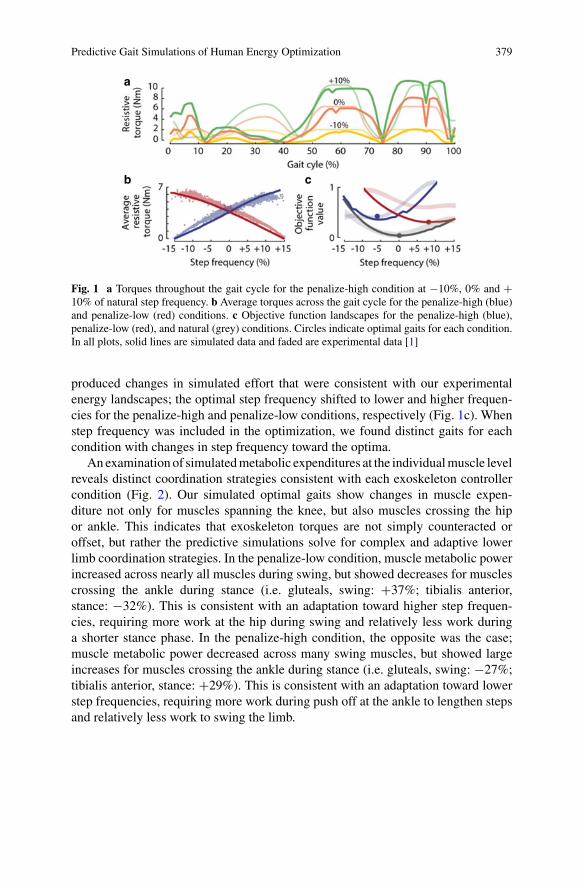
Predictive Gait Simulations of Human Energy Optimization 379
a
b c
Fig. 1 a Torques throughout the gait cycle for the penalize-high condition at −10%, 0% and +10% of natural step frequency. b Average torques across the gait cycle for the penalize-high (blue)and penalize-low (red) conditions. c Objective function landscapes for the penalize-high (blue),penalize-low (red), and natural (grey) conditions. Circles indicate optimal gaits for each condition.In all plots, solid lines are simulated data and faded are experimental data [1]
produced changes in simulated effort that were consistent with our experimentalenergy landscapes; the optimal step frequency shifted to lower and higher frequen-cies for the penalize-high and penalize-low conditions, respectively (Fig. 1c). Whenstep frequency was included in the optimization, we found distinct gaits for eachcondition with changes in step frequency toward the optima.
An examination of simulatedmetabolic expenditures at the individualmuscle levelreveals distinct coordination strategies consistent with each exoskeleton controllercondition (Fig. 2). Our simulated optimal gaits show changes in muscle expen-diture not only for muscles spanning the knee, but also muscles crossing the hipor ankle. This indicates that exoskeleton torques are not simply counteracted oroffset, but rather the predictive simulations solve for complex and adaptive lowerlimb coordination strategies. In the penalize-low condition, muscle metabolic powerincreased across nearly all muscles during swing, but showed decreases for musclescrossing the ankle during stance (i.e. gluteals, swing: +37%; tibialis anterior,stance: −32%). This is consistent with an adaptation toward higher step frequen-cies, requiring more work at the hip during swing and relatively less work duringa shorter stance phase. In the penalize-high condition, the opposite was the case;muscle metabolic power decreased across many swing muscles, but showed largeincreases for muscles crossing the ankle during stance (i.e. gluteals, swing: −27%;tibialis anterior, stance: +29%). This is consistent with an adaptation toward lowerstep frequencies, requiring more work during push off at the ankle to lengthen stepsand relatively less work to swing the limb.
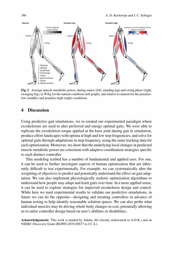
380 A. D. Koelewijn and J. C. Selinger
Fig. 2 Average muscle metabolic power, during stance (left, standing leg) and swing phase (right,swinging leg), inW/kg for the natural condition (left graph), and relative to natural for the penalize-low (middle) and penalize-high (right) conditions
4 Discussion
Using predictive gait simulations, we re-created our experimental paradigm whereexoskeletons are used to alter preferred and energy optimal gaits. We were able toreplicate the exoskeleton torque applied at the knee joint during gait in simulation,produce effort landscapes with optima at high and low step frequencies, and solve foroptimal gaits through adaptations in step frequency, using the same tracking data foreach optimization. Moreover, we show that the underlying local changes in predictedmuscle metabolic power are consistent with adaptive coordination strategies specificto each distinct controller.
This modeling testbed has a number of fundamental and applied uses. For one,it can be used to further investigate aspects of human optimization that are inher-ently difficult to test experimentally. For example, we can systematically alter theweighting of objectives to predict and potentially understand the effect on gait adap-tation. We can also implement physiologically realistic optimization algorithms tounderstand how people may adapt and learn gaits over time. In a more applied sense,it can be used to explore strategies for improved exoskeleton design and control.While here we used experimental results to validate our predictive simulations, infuture we can do the opposite—designing and iterating controllers in advance ofhuman testing to help identify reasonable solution spaces. We can also probe whatindividual muscles may be driving whole body changes in cost, potentially allowingus to tailor controller design based on user’s abilities or disabilities.
Acknowledgements This work is funded by Adidas AG (faculty endowment to A.D.K.) and anNSERC Discovery Grant (RGPIN-2019-05677 to J.C.S.).

Predictive Gait Simulations of Human Energy Optimization 381
References
1. J.C. Selinger, S.M. O’Connor, J.D. Wong, J.M. Donelan, Humans can continuously optimizeenergetic cost during walking. Curr. Biol. 25, 2452–2456 (2015)
2. A.D. Koelewijn, A.J. van den Bogert, Joint contact forces can be reduced by improving jointmoment symmetry in below-knee amputee gait simulations. Gait Posture 49, 219–225 (2016)
3. D.A.Winter, Biomechanics andMotor Control of HumanMovement, 3rd edn. (Wiley, Hoboken,NJ, 2005)
Reconstruction of Hip Moments ThroughConstrained Shape Primitives
Henri Laloyaux and Renaud Ronsse
Abstract Among the various control laws developed for lower-limb wearablerobotics, several intend to replicate leg joint moments observed in healthy humans.While this can be achieved by different means, inspiration can be gained from theso-called motor primitives, i.e. a small set of fundamental signals used by the ner-vous system to recruit numerous motor pools in a task-specific way. Here we report amethodology for the extraction of constrained-shape primitives. Stimulations of twoantagonist hip muscles are initially retrieved from a database composed of differentlocomotion tasks. A first guess of the primitives parameters is then performed inorder to reconstitute these stimulations. Finally these parameters are optimized withthe aim of retrieving the original databasemoments. Our findings suggest that a smallnumber of symmetric Gaussian-like periodic primitives may reconstruct these hipmoments with a level of fidelity that would be sufficient for providing a task-specificuser support.
1 Introduction
In the recent years several hip exoskeletons have been developed [1–3] with theprospect of assisting different profiles of disabled users, such as post-stroke patients[1], the elderly [3] and lower-limb amputees [4].
While there exist many different control strategies for these devices, few of themtake into account the natural impedance of the human body. In order to incorporate adirect model of the body impedance in an assistive strategy, we previously designedand validated a control framework for lower-limb orthoses that models the humanmusculoskeletal system and uses arbitrary-shaped primitives [5]. Motor primitives
H. Laloyaux (B)PhD Student, Institute of Mechanics, Materials, and Civil Engineering (iMMC), Louvain Bionics,Université catholique de Louvain, Louvain-la-Neuve, Belgiume-mail: [email protected]
R. RonsseInstitute of Mechanics, Materials, and Civil Engineering (iMMC), Institute of NeuroScience(IoNS), Louvain Bionics, Université catholique de Louvain, Louvain-la-Neuve, Belgium
© The Author(s), under exclusive license to Springer Nature Switzerland AG 2022J. C. Moreno et al. (eds.), Wearable Robotics: Challenges and Trends,Biosystems & Biorobotics 27, https://doi.org/10.1007/978-3-030-69547-7_62
383
384 H. Laloyaux and R. Ronsse
are low-dimensional signals that can be combined to reconstruct a large set of musclestimulations, corresponding to different locomotion tasks.
Here,weextend themethodologypresented in [6] by extracting simple constrained-shape primitives focusing on the reconstruction of hip moments, with the objectiveto test this approach with a wearable device in the near future.
2 Materials and Methods
2.1 Computation of Muscular Stimulations
A database of hip moments and their associated kinematics has been assembled fromhealthy gait data reported by three papers. This includes some of the most frequentlocomotion tasks, namely ground level walking at different cadences [7], walking onslopes with various inclinations [8], and ascending/descending three different typesof stairs [9].
These hip moments and kinematics were periodicized and low-pass filtered so asto guarantee their continuity at the end/start of the gait cycle.
Virtual muscular stimulations were then computed from these biomechanical sig-nals by injecting them into an inverse musculoskeletal model. This model is based onthe well-known Hill-type muscle model. We followed the same implementation asthe one reported in [10], keeping only the hip mono-articular muscles in the sagittalplane, i.e. the lumped hip flexors (HFL) and the glutei (GLU). In the model param-eters, the maximal isometric force of these muscles was furthermore increased sothat the maximum hip flexion and extension torques while standing up are the sameas the ones produced by the original model. The corresponding muscle forces thusgenerate net hip torques equal to those reported in the literature for every locomotioncondition.
2.2 Extraction of the Motor Primitives
The primitives that we consider are periodic Gaussian-like functions with a poten-tial asymmetry. They are combined through weights that follow quadratic evolutionlaws according to (a) the gait cadence and the slope inclination, or to (b) the stairsinclination, see details in [6]. This framework brings a sharp dimensionality reduc-tion since only 2–3 parameters are needed to characterize each primitive (i.e. peaklocation, width, and possible level of asymmetry) and 3 or 5 parameters for eachweight characterizing the weight modulation for a given locomotion task.
(i) Stimulations-Oriented Primitives
Reconstruction of Hip Moments Through Constrained Shape Primitives 385
As we previously did in [6], primitives were first extracted by searching theparameters producing the best reconstruction of the virtual muscle stimulations.Since a convex method for extracting constrained-shape primitives from a givensignal does not exist to our knowledge, a heuristic optimization was performed withthe mean Variance Accounted For (VAF) of the reconstructed stimulations as fitnessfunction.
(ii) Moments-Oriented Primitives
A second optimization was then performed on the retrieved primitive parametersand their associated weight coefficients. The objective here is to maximize the good-ness of reconstruction of the hip moments when the primitives are combined andinjected as muscular stimulations into the musculoskeletal model in a direct way.
Since the VAF of two signals does not account for their mean values, we used aslightly modified version of this metric as fitness function for the moments recon-struction, i.e. the so-called Mean-Square Accounted For (MSAF) that is defined as:
MSAF(y, y) (1− i (yi − yi )
2/i y2i
) · 100%.
Optimizations were performed by the fminunc function of MATLAB (R2016b,The MathWorks Inc., Natick, MA). We did not use a heuristic method for this sec-ond optimization stage because a starting point already existed, i.e. the symmetricprimitives extracted after step (i).
3 Results and Discussion
We have found that 4 symmetric primitives already accounted for 74.5% of thevariance of the extracted stimulations. In [6], we had to use 5 asymmetric primitivesto account for 66% of the variance of the stimulations extracted for the 3 main legjoints. This likely comes from the fact that 9 muscles were used in the model of [6]instead of 2 here, and one more task was considered, i.e. running. We thus selectedthese 4 primitives for the second optimization step.
The averaged MSAF of the reconstructed moments increased from 87.1 to 93.1%by improving these 4 (i) stimulations-oriented primitives into (ii) moments-orientedones. This increase in MSAF was observed for every locomotion condition, exceptfor 2 conditions of flat ground walking which decreased by less than 5% of themean-square values of the original moments. Figure 1 shows the worst and bestreconstructions of the (ii) moments-oriented primitives, with an MSAF respectivelyof 72.7 and 99.2%.
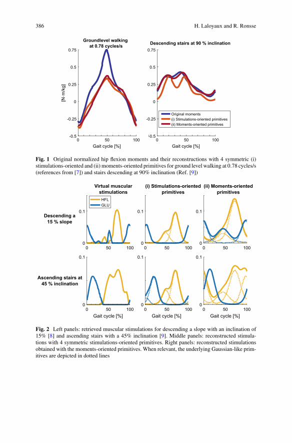
386 H. Laloyaux and R. Ronsse
0 50 100Gait cycle [%]
-0.5
-0.25
0
0.25
0.5
0.75
[Nm
/kg]
0 50 100Gait cycle [%]
-0.5
-0.25
0
0.25
0.5
0.75Descending stairs at 90 % inclination
Original moments(i) Stimulations-oriented primitives(ii) Moments-oriented primitives
Groundlevel walking at 0.78 cycles/s
Fig. 1 Original normalized hip flexion moments and their reconstructions with 4 symmetric (i)stimulations-oriented and (ii) moments-oriented primitives for ground level walking at 0.78 cycles/s(references from [7]) and stairs descending at 90% inclination (Ref. [9])
0 50 1000
0.1
0 50 1000
0.1
HFLGLU
0 50 1000
0.1
0 50 100Gait cycle [%]
0
0.1
0 50 100Gait cycle [%]
0
0.1
0 50 100Gait cycle [%]
0
0.1
(ii) Moments-oriented primitives
(i) Stimulations-oriented primitives
Virtual muscular stimulations
Descending a 15 % slope
Ascending stairs at 45 % inclination
Fig. 2 Left panels: retrieved muscular stimulations for descending a slope with an inclination of15% [8] and ascending stairs with a 45% inclination [9]. Middle panels: reconstructed stimula-tions with 4 symmetric stimulations-oriented primitives. Right panels: reconstructed stimulationsobtained with the moments-oriented primitives. When relevant, the underlying Gaussian-like prim-itives are depicted in dotted lines
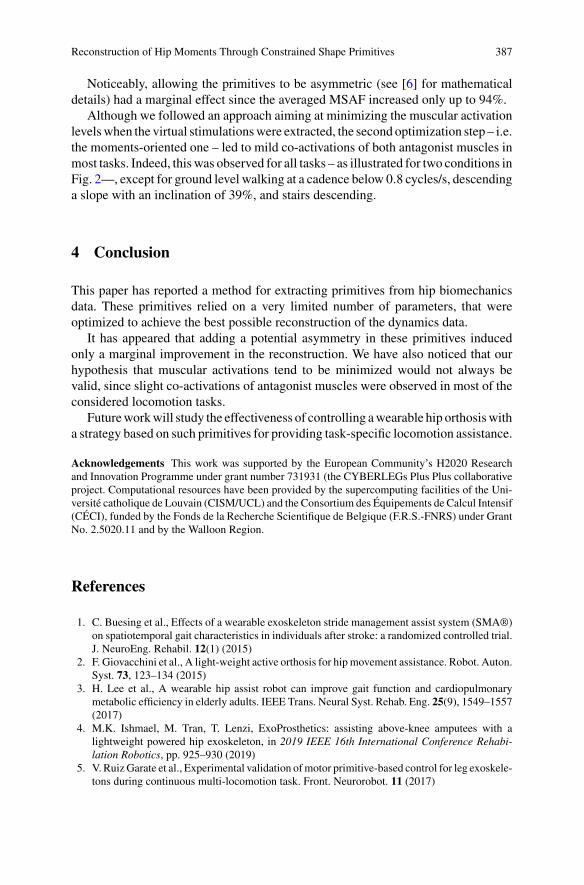
Reconstruction of Hip Moments Through Constrained Shape Primitives 387
Noticeably, allowing the primitives to be asymmetric (see [6] for mathematicaldetails) had a marginal effect since the averaged MSAF increased only up to 94%.
Although we followed an approach aiming at minimizing the muscular activationlevelswhen the virtual stimulationswere extracted, the second optimization step – i.e.the moments-oriented one – led to mild co-activations of both antagonist muscles inmost tasks. Indeed, thiswas observed for all tasks – as illustrated for two conditions inFig. 2—, except for ground level walking at a cadence below 0.8 cycles/s, descendinga slope with an inclination of 39%, and stairs descending.
4 Conclusion
This paper has reported a method for extracting primitives from hip biomechanicsdata. These primitives relied on a very limited number of parameters, that wereoptimized to achieve the best possible reconstruction of the dynamics data.
It has appeared that adding a potential asymmetry in these primitives inducedonly a marginal improvement in the reconstruction. We have also noticed that ourhypothesis that muscular activations tend to be minimized would not always bevalid, since slight co-activations of antagonist muscles were observed in most of theconsidered locomotion tasks.
Futureworkwill study the effectiveness of controlling awearable hip orthosiswitha strategy based on such primitives for providing task-specific locomotion assistance.
Acknowledgements This work was supported by the European Community’s H2020 Researchand Innovation Programme under grant number 731931 (the CYBERLEGs Plus Plus collaborativeproject. Computational resources have been provided by the supercomputing facilities of the Uni-versité catholique de Louvain (CISM/UCL) and the Consortium des Équipements de Calcul Intensif(CÉCI), funded by the Fonds de la Recherche Scientifique de Belgique (F.R.S.-FNRS) under GrantNo. 2.5020.11 and by the Walloon Region.
References
1. C. Buesing et al., Effects of a wearable exoskeleton stride management assist system (SMA®)on spatiotemporal gait characteristics in individuals after stroke: a randomized controlled trial.J. NeuroEng. Rehabil. 12(1) (2015)
2. F. Giovacchini et al., A light-weight active orthosis for hip movement assistance. Robot. Auton.Syst. 73, 123–134 (2015)
3. H. Lee et al., A wearable hip assist robot can improve gait function and cardiopulmonarymetabolic efficiency in elderly adults. IEEE Trans. Neural Syst. Rehab. Eng. 25(9), 1549–1557(2017)
4. M.K. Ishmael, M. Tran, T. Lenzi, ExoProsthetics: assisting above-knee amputees with alightweight powered hip exoskeleton, in 2019 IEEE 16th International Conference Rehabi-lation Robotics, pp. 925–930 (2019)
5. V. RuizGarate et al., Experimental validation ofmotor primitive-based control for leg exoskele-tons during continuous multi-locomotion task. Front. Neurorobot. 11 (2017)

388 H. Laloyaux and R. Ronsse
6. H. Laloyaux, R. Ronsse, Extraction of simple monophasic motor primitives towards bio-inspired locomotion assistance, in 2019 IEEE International Conference on Cyborg and BionicSystems, pp. 253–260 (2019)
7. B. Koopman, W. van Dijk, Basic Gait Kinematics: Reference Data of Normal Subjects (Univ.of Twente, Experimental data, 2010)
8. A.N. Lay, C.J. Hass, R.J. Gregor, The effects of sloped surfaces on locomotion: a kinematicand kinetic analysis. J. Biomech. 39(9), 1621–1628 (2006)
9. R.Riener,M.Rabuffetti, C. Frigo, Stair ascent and descent at different inclinations.Gait Posture15(1), 32–44 (2002)
10. S. Song, H. Geyer, A neural circuitry that emphasizes spinal feedback generates diversebehaviours of human locomotion. J. Physiol. 593(16), 3493–3511 (2015)
Simulated Exoskeletons with CoupledDegrees-of-Freedom Reducethe Metabolic Cost of Walking
Nicholas A. Bianco, Patrick W. Franks, Jennifer L. Hicks, and Scott L. Delp
Abstract Exoskeletons that assist multiple joints could reduce the metabolic costof walking beyond reductions achieved with single-joint devices. However, assist-ing many degrees-of-freedom can require multiple actuators with complicated con-trollers and long experiment times to tune these controllers. Coupled assistance,where the same control signal is applied to multiple joints, may help simplifyexoskeleton design but has not been tested extensively. In this study, we used directcollocation optimal control and a lower-limb musculoskeletal model to simulate fivedifferent exoskeleton control strategies to assist multiple joints during walking. Wesimulated strategies where the torque provided at each joint was controlled inde-pendently or coupled between joints. We found that coupled assistance was ableto provide similar savings in whole-body metabolic power consumption comparedto independent assistance. Our results may help device designers create exoskele-tons that achieve good metabolic savings while requiring fewer actuators and lessexperimental testing to create effective assistance strategies.
N. A. Bianco (B) · P. W. FranksDepartment of Mechanical Engineering, Stanford University,Building 530, 440 Escondido Mall, Stanford, CA 94305, USAe-mail: [email protected]
P. W. Frankse-mail: [email protected]
J. L. HicksDepartment of Bioengineering, Stanford University, 443 Via Ortega, Stanford, CA 94305, USAe-mail: [email protected]
S. L. DelpDepartment of Mechanical Engineering, Department of Bioengineering, and Department ofOrthopaedic Surgery, Stanford University, Building 530, 440 Escondido Mall, Stanford, CA94305, USAe-mail: [email protected]
© The Author(s), under exclusive license to Springer Nature Switzerland AG 2022J. C. Moreno et al. (eds.), Wearable Robotics: Challenges and Trends,Biosystems & Biorobotics 27, https://doi.org/10.1007/978-3-030-69547-7_63
389
390 N. A. Bianco et al.
1 Introduction
Wearable robotic exoskeletons have the potential to improve human mobility. Onecommon goal of exoskeleton devices is to reduce the metabolic cost of walking[1]. Many recent exoskeleton designs have successfully reduced metabolic cost,but most focus assistance at one lower-limb degree-of-freedom [1]. Exoskeletondevices that assist multiple joints at once, or “multi-joint” exoskeletons, have poten-tial for improved metabolic savings compared to single degree-of-freedom devices[2]. However, the large number of assistance strategies possible with multi-jointexoskeletons can make controller design challenging, often leading to long exper-iment times. Assistance applied to multiple joints based on the same controller, or“coupled” assistance, could be a potential approach to simplify multi-joint exoskele-ton designs. Recent experiments have achieved metabolic reductions by assistingmultiple joints at once using a single actuator, demonstrating that coupled assistancestrategies are feasible [3, 4]. However, it is unclear if exoskeleton designers shoulduse coupled assistance as a design approach or if coupling would reduce the efficacyof assistance compared to controlling joints independently.
Musculoskeletal simulation has emerged as a promising approach for optimizingexoskeleton designs for a variety of motion tasks [5]. Simulations could test a widerange of multi-joint exoskeleton designs that would be prohibitively time consumingto evaluatewith experiments; however, no study has used simulation to analyzemulti-joint assistance for walking or to evaluate the efficacy of coupled control strategies. Inthis study, we evaluated ideal, massless multi-joint assistive devices added to lower-limb simulations of walking. Devices assisted joints using independent controls andusing controls thatwere coupled across joints. Our aimwas to determine ifmulti-jointdevices with coupled assistance could achieve similar metabolic savings comparedto devices with independent assistance.
2 Methods
We used direct collocation optimal control and a musculoskeletal model to optimizeassistance for five different simulated multi-joint exoskeleton devices. Our mus-culoskeletal model had one leg with three sagittal plane degrees-of-freedom (hipflexion-extension, knee flexion-extension, and ankle plantarflexion-dorsiflexion) and9 lower-limb muscles based on a previous study that could produce the major func-tions of normal gait [6]. We used 3 previously collected gait cycles of motion capturedata from 5 healthy adult subjects during treadmill walking at 1.25m/s [7]. Thegeneric model was scaled to match subjects’ static marker trials; joint and musclekinematic and kinetic information was computed using OpenSim [8].
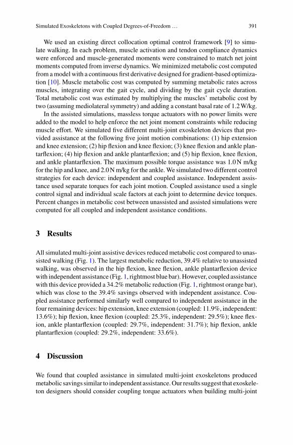
Simulated Exoskeletons with Coupled Degrees-of-Freedom … 391
We used an existing direct collocation optimal control framework [9] to simu-late walking. In each problem, muscle activation and tendon compliance dynamicswere enforced and muscle-generated moments were constrained to match net jointmoments computed from inverse dynamics. Weminimized metabolic cost computedfrom amodel with a continuous first derivative designed for gradient-based optimiza-tion [10]. Muscle metabolic cost was computed by summing metabolic rates acrossmuscles, integrating over the gait cycle, and dividing by the gait cycle duration.Total metabolic cost was estimated by multiplying the muscles’ metabolic cost bytwo (assuming mediolateral symmetry) and adding a constant basal rate of 1.2W/kg.
In the assisted simulations, massless torque actuators with no power limits wereadded to the model to help enforce the net joint moment constraints while reducingmuscle effort. We simulated five different multi-joint exoskeleton devices that pro-vided assistance at the following five joint motion combinations: (1) hip extensionand knee extension; (2) hip flexion and knee flexion; (3) knee flexion and ankle plan-tarflexion; (4) hip flexion and ankle plantarflexion; and (5) hip flexion, knee flexion,and ankle plantarflexion. The maximum possible torque assistance was 1.0N m/kgfor the hip and knee, and 2.0Nm/kg for the ankle.We simulated two different controlstrategies for each device: independent and coupled assistance. Independent assis-tance used separate torques for each joint motion. Coupled assistance used a singlecontrol signal and individual scale factors at each joint to determine device torques.Percent changes in metabolic cost between unassisted and assisted simulations werecomputed for all coupled and independent assistance conditions.
3 Results
All simulated multi-joint assistive devices reduced metabolic cost compared to unas-sisted walking (Fig. 1). The largest metabolic reduction, 39.4% relative to unassistedwalking, was observed in the hip flexion, knee flexion, ankle plantarflexion devicewith independent assistance (Fig. 1, rightmost blue bar). However, coupled assistancewith this device provided a 34.2%metabolic reduction (Fig. 1, rightmost orange bar),which was close to the 39.4% savings observed with independent assistance. Cou-pled assistance performed similarly well compared to independent assistance in thefour remaining devices: hip extension, knee extension (coupled: 11.9%, independent:13.6%); hip flexion, knee flexion (coupled: 25.3%, independent: 29.5%); knee flex-ion, ankle plantarflexion (coupled: 29.7%, independent: 31.7%); hip flexion, ankleplantarflexion (coupled: 29.2%, independent: 33.6%).
4 Discussion
We found that coupled assistance in simulated multi-joint exoskeletons producedmetabolic savings similar to independent assistance.Our results suggest that exoskele-ton designers should consider coupling torque actuators when building multi-joint
392 N. A. Bianco et al.
Fig. 1 Metabolic savings formulti-joint assistance strategies. Percent changes in metabolic costrelative to unassisted walking for coupled (orange) and independent (blue) multi-joint assistancestrategies. Each bar represents the mean (solid bars) and one standard deviation (whiskers) acrosssubjects
exoskeletons. In addition, the largest metabolic reduction with coupled assistedoccurred when assisting hip flexion, knee flexion, and ankle plantarflexion simul-taneously, suggesting that assisting more than two joints with one actuator can bebeneficial.
We focused on comparing the relative efficacy of coupled and independent devicesin reducing metabolic cost, since we have greater confidence in relative metaboliccost changes between simulation conditions than in absolute percent reductions [2].To better estimate absolute percent metabolic changes, future work could modelfrontal plane muscles (e.g., hip adductors-abductors) to improve absolute metaboliccost predictions. In addition, future simulations could allow changes in walkingkinematics due to assistance, which could impact predicted metabolic reductions.
5 Conclusion
Our simulation results showed that coupled assistance did not incur a large metabolicpenalty in multi-joint exoskeletons. Exoskeleton designers should consider coupledassistance to simplify wearable devices, increase metabolic reductions when actua-tion is limited, and help keep experiment times tractable.
Simulated Exoskeletons with Coupled Degrees-of-Freedom … 393
Acknowledgements N.A.B. received funding from the National Science Foundation GraduateResearch Fellowship Program and the Stanford Graduate Fellowship Program. P.W.F. receivedfunding from the U.S. Army Natick Soldier Research, Development and Engineering Center(W911QY18C0140). J.L.H. and S.L.D. received funding from the National Institutes of Health(P2C HD065690).
References
1. A.J.Young,D.P. Ferris, State of the art and future directions for lower limb robotic exoskeletons.IEEE Trans. Neural. Syst. Rehabil. Eng. 25, 171–182 (2017)
2. P.W. Franks, N.A. Bianco, G.M. Bryan, J.L. Hicks, S.L. Delp, S.H. Collins,Testing simulatedassistance strategies on a hip-knee-ankle exoskeleton: a case study, in Proceedings IEEE Inter-national Conference on Biomedical Robotics Biomechatronics (2020)
3. B.T. Quinlivan , L. Sangjun, P. Malcolm, D.M. Rossi, M. Grimmer, C. Siviy, et al., Assistancemagnitude versus metabolic cost reductions for a tethered multiarticular soft exosuit. Sci.Robot. 2, eaah4416 (2017)
4. P. Malcolm, S. Galle, W. Derave, D. de Clercq, Bi-articular knee-ankle-foot exoskeleton pro-duces higher metabolic cost reduction than weight-matchedmono-articular exoskeleton. Front.Neurosci. 12(69) (2018)
5. E.P. Grabke, K. Masani, J. Andrysek, Lower limb assistive device design optimization usingmusculoskeletal modeling: a review. J. Med. Devices 13(4) (2019). https://doi.org/10.1115/1.4044739
6. C.F. Ong, T. Geijtenbeek, J.L. Hicks, S.L. Delp, Predicting gait adaptations due to ankle plan-tarflexor muscle weakness and contracture using physics-based musculoskeletal simulations.PLOS Comp. Bio. 15(10), e1006993 (2019)
7. E.M. Arnold, S.R. Hamner, A. Seth, M. Millard, S. Delp, How muscle fiber lengths and veloc-ities affect muscle force generation as humans walk and run at different speeds. J. Exp. Biol.216(11), 2150–2160 (2013)
8. A. Seth, J.L. Hicks, T.K. Uchida, A. Habib, C.L. Dembia, et al., OpenSim: simulating muscu-loskeletal dynamics and neuromuscular control to study human and animal movement. PLOSComp. Bio. 14(7), e1006223 (2018)
9. F. De Groote, A.L. Kinney, A.V. Rao, B.J. Fregly, Evaluation of direct collocation optimalcontrol problem formulations for solving the muscle redundancy problem. Ann. Biomech.Eng. (2016). https://doi.org/10.1007/s10439-016-1591-9
10. A.D. Koelewijn, E. Dorschky, A.J. van den Bogert, A metabolic energy expenditure modelwith a continuous first derivative and its application to predictive simulations of gait. Comput.Methods Biomech. Biomed. Eng. 21, 521–531 (2018)
Model-Based Biomechanicsfor Conceptual Exoskeleton SupportEstimation Applied for a Lifting Task
Elena Gneiting, Jonas Schiebl, Mark Tröster, Verena Kopp,Christophe Maufroy, and Urs Schneider
Abstract The aimof this studywas to analyse biomechanics in lifting tasks and eval-uate an exoskeleton concept usingmusculoskeletalmodel-based analysis. Threemaleparticipants lifted a box of 21 kg from waist level to 1.46 m height. Movement wasrecordedwithmotion capture and simulatedwith individualmusculoskeletal models.The effect of an exoskeleton concept supporting the upper arm and/or forearm withexternal torque around the shoulder was examined for one subject. Muscle activitywas reduced for arm flexors and shoulder muscles. Glenohumeral and elbow jointforces were also decreased by the support concept.
1 Introduction
DESPITE the ongoing automatization in the industry, musculoskeletal disorders(MSD) are ranked the most common occupational diseases (38.1 %) in the EU dueto exposure to high physical stress of many workers [1].
Exoskeletons have the potential to reduce the risk of work-related MSDs byreducing physical stress at exposure limits. However, they may also increase the
E. Gneiting · J. Schiebl (B) · M. Tröster · V. Kopp · C. Maufroy · U. SchneiderDepartment of Biomechatronic Systems of the Fraunhofer Institute for ManufacturingEngineering and Automation IPA, Stuttgart, Germanye-mail: [email protected]
E. Gneitinge-mail: [email protected]
M. Tröstere-mail: [email protected]
V. Koppe-mail: [email protected]
C. Maufroye-mail: [email protected]
U. Schneidere-mail: [email protected]
© The Author(s), under exclusive license to Springer Nature Switzerland AG 2022J. C. Moreno et al. (eds.), Wearable Robotics: Challenges and Trends,Biosystems & Biorobotics 27, https://doi.org/10.1007/978-3-030-69547-7_64
395
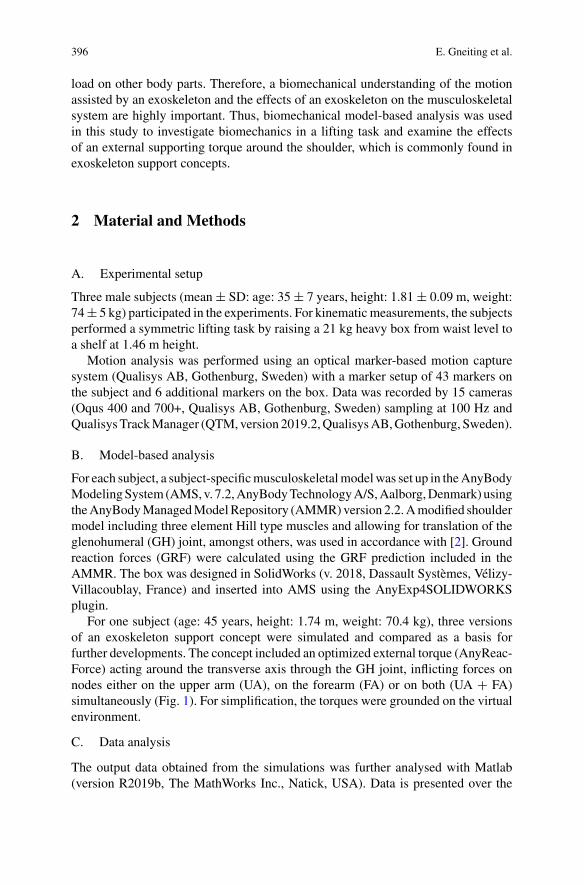
396 E. Gneiting et al.
load on other body parts. Therefore, a biomechanical understanding of the motionassisted by an exoskeleton and the effects of an exoskeleton on the musculoskeletalsystem are highly important. Thus, biomechanical model-based analysis was usedin this study to investigate biomechanics in a lifting task and examine the effectsof an external supporting torque around the shoulder, which is commonly found inexoskeleton support concepts.
2 Material and Methods
A. Experimental setup
Three male subjects (mean± SD: age: 35± 7 years, height: 1.81± 0.09 m, weight:74± 5 kg) participated in the experiments. For kinematic measurements, the subjectsperformed a symmetric lifting task by raising a 21 kg heavy box from waist level toa shelf at 1.46 m height.
Motion analysis was performed using an optical marker-based motion capturesystem (Qualisys AB, Gothenburg, Sweden) with a marker setup of 43 markers onthe subject and 6 additional markers on the box. Data was recorded by 15 cameras(Oqus 400 and 700+, Qualisys AB, Gothenburg, Sweden) sampling at 100 Hz andQualisysTrackManager (QTM,version 2019.2,QualisysAB,Gothenburg, Sweden).
B. Model-based analysis
For each subject, a subject-specificmusculoskeletalmodelwas set up in theAnyBodyModelingSystem (AMS,v. 7.2,AnyBodyTechnologyA/S,Aalborg,Denmark) usingtheAnyBodyManagedModelRepository (AMMR)version 2.2.Amodified shouldermodel including three element Hill type muscles and allowing for translation of theglenohumeral (GH) joint, amongst others, was used in accordance with [2]. Groundreaction forces (GRF) were calculated using the GRF prediction included in theAMMR. The box was designed in SolidWorks (v. 2018, Dassault Systèmes, Vélizy-Villacoublay, France) and inserted into AMS using the AnyExp4SOLIDWORKSplugin.
For one subject (age: 45 years, height: 1.74 m, weight: 70.4 kg), three versionsof an exoskeleton support concept were simulated and compared as a basis forfurther developments. The concept included an optimized external torque (AnyReac-Force) acting around the transverse axis through the GH joint, inflicting forces onnodes either on the upper arm (UA), on the forearm (FA) or on both (UA + FA)simultaneously (Fig. 1). For simplification, the torques were grounded on the virtualenvironment.
C. Data analysis
The output data obtained from the simulations was further analysed with Matlab(version R2019b, The MathWorks Inc., Natick, USA). Data is presented over the
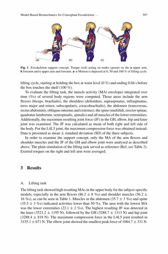
Model-Based Biomechanics for Conceptual Exoskeleton … 397
Fig. 1 Exoskeleton support concept. Torque (red) acting on nodes (green) on the a upper arm,b forearm and c upper arm and forearm. a–cMotion is depicted at 0, 50 and 100 % of lifting cycle.
lifting cycle, starting at holding the box at waist level (0 %) and ending 0.04 s beforethe box touches the shelf (100 %).
To evaluate the lifting task, the muscle activity (MA) envelopes integrated overtime (%s) of several body regions were computed. Those areas include the armflexors (biceps, brachialis), the shoulders (deltoideus, supraspinatus, infraspinatus,teres major and minor, subscapularis, coracobrachialis), the abdomen (transversus,rectus abdominis, obliquus internus and externus), the spine (multifidi, erector spinae,quadratus lumborum, semispinalis, spinalis) and all muscles of the lower extremities.Additionally, the maximum resulting joint force (JF) in the GH, elbow, hip and kneejoint was examined. The JF was calculated as mean of both right and left side ofthe body. For the L4L5 joint, the maximum compression force was obtained instead.Data is presented as mean ± standard deviation (SD) of the three subjects.
In order to examine the support concept, only the MA of the arm flexors andshoulder muscles and the JF of the GH and elbow joint were analysed as describedabove. The plain simulation of the lifting task served as reference (Ref, see Table 2).Exerted torques on the right and left arm were averaged.
3 Results
A. Lifting task
The lifting task showed high resultingMAs in the upper body for the subject-specificmodels, especially in the arm flexors (86.2 ± 8 %s) and shoulder muscles (56.2 ±16 %s), as can be seen in Table 1. Muscles in the abdomen (35.7 ± 3 %s) and spine(35.5 ± 3 %s) indicated activities lower than 50 %s. The area with the lowest MAwas the lower extremities (22.1 ± 2 %s). The highest resulting JF was detected inthe knee (3521.2 ± 1195 N), followed by the GH (3288.7 ± 1313 N) and hip joint(3288.4 ± 818 N). The maximum compression force in the L4L5 joint resulted in3155.1± 671 N. The elbow joint showed the smallest peak force of 1084.7± 331 N.
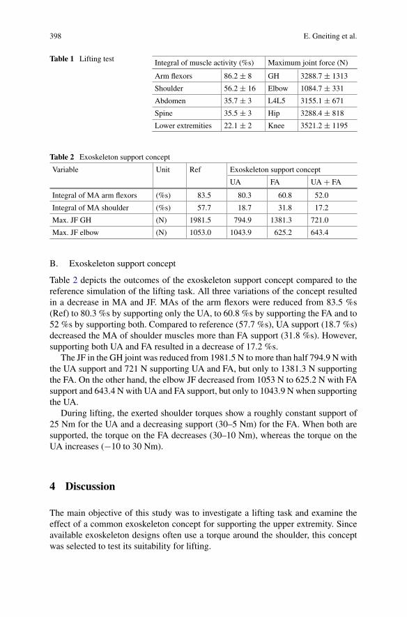
398 E. Gneiting et al.
Table 1 Lifting test Integral of muscle activity (%s) Maximum joint force (N)
Arm flexors 86.2 ± 8 GH 3288.7 ± 1313
Shoulder 56.2 ± 16 Elbow 1084.7 ± 331
Abdomen 35.7 ± 3 L4L5 3155.1 ± 671
Spine 35.5 ± 3 Hip 3288.4 ± 818
Lower extremities 22.1 ± 2 Knee 3521.2 ± 1195
Table 2 Exoskeleton support concept
Variable Unit Ref Exoskeleton support concept
UA FA UA + FA
Integral of MA arm flexors (%s) 83.5 80.3 60.8 52.0
Integral of MA shoulder (%s) 57.7 18.7 31.8 17.2
Max. JF GH (N) 1981.5 794.9 1381.3 721.0
Max. JF elbow (N) 1053.0 1043.9 625.2 643.4
B. Exoskeleton support concept
Table 2 depicts the outcomes of the exoskeleton support concept compared to thereference simulation of the lifting task. All three variations of the concept resultedin a decrease in MA and JF. MAs of the arm flexors were reduced from 83.5 %s(Ref) to 80.3 %s by supporting only the UA, to 60.8 %s by supporting the FA and to52 %s by supporting both. Compared to reference (57.7 %s), UA support (18.7 %s)decreased the MA of shoulder muscles more than FA support (31.8 %s). However,supporting both UA and FA resulted in a decrease of 17.2 %s.
The JF in the GH joint was reduced from 1981.5 N to more than half 794.9 N withthe UA support and 721 N supporting UA and FA, but only to 1381.3 N supportingthe FA. On the other hand, the elbow JF decreased from 1053 N to 625.2 N with FAsupport and 643.4 N with UA and FA support, but only to 1043.9 N when supportingthe UA.
During lifting, the exerted shoulder torques show a roughly constant support of25 Nm for the UA and a decreasing support (30–5 Nm) for the FA. When both aresupported, the torque on the FA decreases (30–10 Nm), whereas the torque on theUA increases (−10 to 30 Nm).
4 Discussion
The main objective of this study was to investigate a lifting task and examine theeffect of a common exoskeleton concept for supporting the upper extremity. Sinceavailable exoskeleton designs often use a torque around the shoulder, this conceptwas selected to test its suitability for lifting.
Model-Based Biomechanics for Conceptual Exoskeleton … 399
The analysis of the lifting task showed that especially the upper extremities needassistance due to a highMAof arm flexors and shoulder muscles of over 50%s. Also,during the lifting task, the GH joint force reached twice the magnitude of in vivomeasurements detected during forward flexion over 90° holding 2 kg weight [3].
The exoskeleton support concept showed reduced musculoskeletal outcomes inall three conditions. Supporting the upper arm mainly assists the shoulder, whereassupporting the forearm assists the arm flexors and elbow. A combination of bothwould result in the best outcome, assuming it is technically feasible. However, in thepreliminary analysis directions of resulting forces and their possible effects on tissuedeformation and comfort (e.g. inflicted by shear forces) were not yet considered.
Another limitation of simulating the support concept is that it only affected theupper limb, since the torque around the shoulder was not redirected back onto themusculoskeletal system. Hence, no conclusions can be drawn upon how the conceptaffects the rest of the body.
5 Conclusion and Future Work
An exoskeleton concept that induces a torque around the shoulder seems biome-chanically efficient in supporting the upper extremities during lifting. In a next step,fully constructed exoskeleton designs will be simulated to evaluate the impact on theentire body. Also, biomechanical side effects as well as interaction force directionscausing potential tissue deformations should be considered.
Acknowledgements This workwas supported by the Exolog Project funded by theGermanArmedForces (Bundeswehr) under Grant No E/U2Ci/KA225/JF080.
References
1. E. Schneider, S. Copsey, X. Irastorza, Osh in figures: Work-related musculoskeletal disorders inthe EU—facts and figures.Office for Official Publications of the European Communities (2010)
2. M.Aurbach, J. Spicka, F. Süß, S.Dendorfer, Evaluationofmusculoskeletalmodellingparametersof the shoulder complex during humeral abduction above 90°. J. Biomech. 109817 (2020)
3. G. Bergmann et al., In vivo gleno-humeral joint loads during forward flexion and abduction. J.Biomech. 44(8), 1543–1552 (2011)
Calibrating an EMG-Driven MuscleModel and a Regression Modelto Estimate Moments Generated Activelyby Back Muscles for Controllingan Actuated Exoskeleton with LimitedData
Ali Tabasi, Maria Lazzaroni, Niels P. Brouwer, Idsart Kingma,Wietse van Dijk, Michiel P. de Looze, Stefano Toxiri, Jesús Ortiz,and Jaap H. van Dieën
Abstract Estimation of low-back load can be used to determine the assistance tobe provided by an actuated back-support exoskeleton. To this end, an EMG-drivenmusclemodel and a regressionmodel can be implemented. The goal of the regressionmodel is to reduce the number of required sensors for load estimation. Both modelsneed to be calibrated. This study aims to find the impacts of limiting calibration dataon low-back loading estimation through these models.
1 Introduction
Using a back-support exoskeleton helps to reduce the low-back load during manualload handling, which may decrease the risk of low back pain. In actuated exoskele-tons, the assistive moments are generated by active components, e.g., motors. Theseactive components are operated by a control system that utilizes a reference signal toregulate the assistivemoment [1]. A logical solution to reduce the low-back loading isto derive the reference signal from a real-time estimation of low-back load measures,such as moments around the L5/S1 joint.
A. Tabasi (B) · N. P. Brouwer · I. Kingma · J. H. van DieënDepartment of Human Movement Sciences, Vrije Universiteit Amsterdam, Amsterdam,The Netherlandse-mail: [email protected]
M. Lazzaroni · S. Toxiri · J. OrtizDepartment of Advanced Robotics, Istituto Italiano di Tecnologia, Genova, Italy
M. LazzaroniDepartment of Electronics, Information and Bioengineering, Politecnico di Milano, Milan, Italy
W. van Dijk · M. P. de LoozeTNO, Leiden, The Netherlands
© The Author(s), under exclusive license to Springer Nature Switzerland AG 2022J. C. Moreno et al. (eds.), Wearable Robotics: Challenges and Trends,Biosystems & Biorobotics 27, https://doi.org/10.1007/978-3-030-69547-7_65
401
402 A. Tabasi et al.
Using body kinematics and external forces/moments, the net moment around theL5/S1 joint (MID
Net ) can be estimated through inverse dynamics (ID) [2]. The super-script here and below denotes the primary model used to determine the variable.MID
Net is counterbalanced by a combination of the moment generated by the human(MHuman) and any assistive device. MHuman consists of the moments generated bytrunk muscles active forces (MActive) and moments produced by trunk tissue passiveforces (MPassive). MPassive is coupled to lumbar flexion and cannot be compensatedby any assistive moment by the exoskeleton. Moreover, it reaches substantial magni-tudes at extreme flexion angles [3]. Thus, ignoring it leads to overestimating therequired assistive moment. To avoid this overestimation, the reference signal shouldbe determined based on MActive.
MActive and MPassive can be estimated separately through an EMG-driven musclemodel (EMGMod) using 12 EMG channels from trunk muscles and the lumbarflexion angle [4, 5]. In order to circumvent the need for many sensors on the humanbody, a regression model (RegMod) can be fitted between signals recorded by two ofthe EMG sensors and built-in exoskeleton kinematic sensors as the input variablesand MActive as the output variable [6]. The advantage of RegMod over EMGMod isthat RegMod requires fewer EMG sensors attached to the body to estimate MActive
for exoskeleton control. With fewer sensors, real-time MActive estimation in theworkplace becomes more feasible.
EMGMod and RegMod need to be calibrated for each individual through severallifting trials. The number and type of calibration trials might affect the practicalfeasibility of using themodels for exoskeleton control. Therefore, limiting calibrationtrials might be beneficial. This study aims to determine the impacts of using limiteddata for calibration on the estimation accuracy of EMGMod and RegMod.
2 Material and Methods
Ten healthy male participants lifted and lowered 7.5 and 15 kg boxes fromankle height to upright posture without and with wearing an active back-supportexoskeleton [7]. Lifting trials were performed with three different techniques andat three speeds. Ground reaction forces and moments, and body kinematics wererecorded. In addition, back and abdominal muscle EMG activities were recorded,filtered and normalized to MVC.
Post-processing steps are as follows. First, MIDNet was calculated using a bottom-
up ID model. Then, for trials with an exoskeleton, MIDHuman was determined by
subtracting the assistive moment generated by the exoskeleton from MIDNet . In trials
without an exoskeleton, MIDHuman equals MID
Net . Next, a combination of a limitednumber of trials without exoskeleton was selected and used as calibration trialsto calibrate EMGMod, i.e., optimize parameters reflecting mechanical propertiesof trunk muscles and tissues for each participant. Employing calibrated EMGMod,MEMGMod
Active was estimated, combinedwith correspondingEMGandkinematic signals,and used to calibrate RegMod.
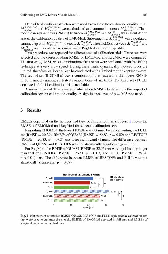
Calibrating an EMG-Driven Muscle Model … 403
Data of trials with exoskeleton were used to evaluate the calibration quality. First,MEMGMod
Active and MEMGModPassive were calculated and summed to create MEMGMod
Human . Then,root mean square error (RMSE) between MEMGMod
Human and MIDHuman was calculated to
assess the calibration quality of EMGMod. Subsequently, MRegModActive was calculated,
summed up with MEMGModPassive to create MRegMod
Human . Then, RMSE between MRegModHuman and
MIDHuman was calculated as a measure of RegMod calibration quality.This procedure was repeated for different sets of calibration trials. Three sets were
selected and the corresponding RMSE of EMGMod and RegMod were compared.The first set (QUASI)was a combination of trials thatwere performedwith free liftingtechnique at a very slow speed. During these trials, dynamically-induced loads arelimited; therefore, calibration can be conductedwith a limitedmotion capture system.The second set (BESTOF6) was a combination that resulted in the lowest RMSEsin both models among all tested combinations of six trials. The third set (FULL)consisted of all 14 calibration trials available.
A series of paired T-tests were conducted on RMSEs to determine the impact ofcalibration sets on calibration quality. A significance level of p = 0.05 was used.
3 Results
RMSEs depended on the number and type of calibration trials. Figure 1 shows theRMSEs of EMGMod and RegMod for selected calibration sets.
Regarding EMGMod, the lowest RMSEwas obtained by implementing the FULLset (RMSE= 20.29). RMSEs of QUASI (RMSE= 22.83, p= 0.02) and BESTOF6(RMSE = 20.83, p = 0.03) sets were significantly larger. The difference betweenRMSE of QUASI and BESTOF6 was not statistically significant (p = 0.05).
For RegMod, the RMSE of QUASI (RMSE = 32.53) set was significantly largerthan that of BESTOF6 (RMSE = 26.51, p = 0.03) and FULL (RMSE = 25.04,p < 0.01) sets. The difference between RMSE of BESTOF6 and FULL was notstatistically significant (p = 0.07).
25.04
26.51
32.53
20.29
20.83
22.83
0 10 20 30 40RMSE (Nm)
Net Moment Estimation RMSEQUASI
BESTOF6
FULL
EMGModRegMod
QUASI
BESTOF6
FULL
* *
* *
Fig. 1 Net moment estimation RMSE. QUASI, BESTOF6 and FULL represent the calibration setsthat were used to calibrate the models. RMSEs of EMGMod depicted in full bars and RMSEs ofRegMod depicted in hatched bars
404 A. Tabasi et al.
4 Discussion
The resultant RMSEs show that EMGMod calibration was enhanced by imple-menting the FULL set. However, RMSEs of BESTOF6 and QUASI sets were onlyslightly higher. This suggests that EMGMod can be calibrated relatively accuratelywith just a few quasi-static calibration trials.
Resultant RMSEs of RegMod showed that the QUASI set resulted in considerablylarger RMSE compared to BESTOF6 and FULL set. This can be a consequenceof neglecting the effects of dynamically-induced loads when calibrating using theQUASI set. On the other hand, the lack of difference between RMSEs of BESTOF6and FULL sets suggests that limited calibration of RegMod can result in similarcalibration quality as a fully calibrated model.
It should be considered that some of the examined calibration sets result in consid-erably higher RMSEs than the BESTOF6 set, while the number of included trials wasthe same. This shows that not only the number of calibration trials is important, butalso the selected lifting conditions is a factor to consider. The BESTOF6 set includedtrials with two choices for each lifting task characteristic, i.e., both weights lifted,two of the three speeds and two of the three lifting techniques.
Another issue that should be noted is that the RMSE of RegMod was alwayshigher than that of EMGMod. One reason can be that RegMod was calibrated usingan outcome of EMGMod, i.e., MEMGMod
Active . Thus, estimation errors of EMGModhave adverse effects on the performance of RegMod. Another reason might be thatRegMod employs a limited number of variables. This means that some relevantinformation might be neglected. Hence, additional minor errors in estimation areexpected.
One limitation of this study is that bothmodels were calibrated and examined overlimitedmanual lifting conditions. However, in theworkplace,manual liftings in otherconditions and other tasks such as pulling and pushing are being done, which can beassisted with an exoskeleton. Thus, the estimation quality of the proposed modelsshould be evaluated for other work-related tasks and conditions.
5 Conclusion
The current study shows that an EMG-driven muscle model can be calibrated rela-tively accurately with a few number of lifting trials. In contrast, a regression modelrequires more but still a limited number of trials for proper calibration. The presentstudy showed that an appropriate set of calibration trials for a regressionmodel shouldcontain lifts with different loads, speeds and lifting techniques.
Acknowledgements This researchwas fundedby the i-BoticsEarlyResearchProgramofTNO(theNetherlands Organization for Applied Scientific Research). Additionally, this work was supportedby the Dutch Research Council (NWO), program ‘perspectief’ (project P16-05).
Calibrating an EMG-Driven Muscle Model … 405
References
1. M.P. De Looze, T. Bosch, F. Krause, K.S. Stadler, W.O. Sullivan, Exoskeletons for industrialapplication and their potential effects on physical work load. Ergonomics 0139, 1–1 (2016)
2. I. Kingma, M.P. De Looze, H.M. Toussaint, H.G. Klijnsma, T.B.M. Bruijnen, Validation of afull body 3-D dynamic linked segment model. Hum. Mov. Sci. 15(6), 833–860 (1996)
3. H.M. Toussaint, A.F. de Winter, Y. de Haas, M.P. de Looze, J.H. Van Dieën, I. Kingma, Flexionrelaxation during lifting: Implications for torque production by muscle activity and tissue strainat the lumbo-sacral joint. J. Biomech. 28(2), 199–210 (1995)
4. J.H. Van Dieën, Are recruitment patterns of the trunk musculature compatible with a synergybased on the maximization of endurance? J. Biomech. 30(11–12), 1095–1100 (1997)
5. J.H. van Dieen, I. Kingma, Effects of antagonistic co-contraction on differences between elec-tromyography based and optimization based estimates of spinal forces. Ergonomics 48(4),411–426 (2005)
6. A. Tabasi, I. Kingma, M. P. de Looze, W. van Dijk, A. S. Koopman, J.H. van Dieën, Selectingthe appropriate input variables in a regression approach to estimate actively generated musclemoments around L5/S1 for exoskeleton control. J. Biomech. 102 (2020)
7. M. Lazzaroni, et al., Evaluation of an acceleration-based assistive strategy to control a back-support exoskeleton formanualmaterial handling.WearableTechnol. (submitted for publication)
Effect of Mono- Versus Bi-ArticularAnkle Foot Orthosis on MuscularPerformance of the Lower Leg
Mahdy Eslamy, Florian Mackes, and Arndt F. Schilling
Abstract Ankle foot orthoses (AFOs) are used to assist impaired gait. In this study,we investigated the effects of a mono- and a bi-articular AFO with different stiffnesson the muscles’ performance in the lower extremities. The effects of both AFOs onthe activation level and power of gastrocnemius, soleus and tibialis anterior musclestogether with knee extensors and flexors were simulated in Opensim. The muscu-lar performances were compared between the case without orthosis and the casewith mono- and bi-articular AFO with different stiffness values (5, 10, 15, 20 and25 kN/m). The simulations showed that increasing the stiffness of both AFOs ledto reductions (up to 70%) of the activation levels of soleus and gastrocnemius incomparison to the case without orthosis. The overall stronger effects caused by thebi-articular configuration led us to investigate its effects on the knee extensors andflexors. Indeed, bi-articular AFO led to strong activation of the knee extensor mus-cles, suggesting a power interaction between upper and lower leg. Therefore, anintelligent design of mono- and bi-articular AFO with soft springs (<10 kN/m) maypotentially allow to balance muscle activation and power consumption of the respec-tive muscles of the leg. Experiments with customized patient-specific AFOs andwithdifferent human subjects walking at different speeds will be required to validate theseconclusions.
1 Introduction
The collaboration of the ankle plantar flexors (soleus and gastrocnemius togetherwith the Achilles tendon) has a key role in human propulsion during push-off phasethrough providing about half of the required muscle work [1]. Adaptation of the
M. Eslamy (B) · F. Mackes · A. F. SchillingApplied Rehabilitation Technology ART Lab, Department for Trauma Surgery, Orthopaedics andPlastic Surgery, Universitätsmedizin Göttingen (UMG), 37075 Göttingen, Germanye-mail: [email protected]
A. F. Schillinge-mail: [email protected]
© The Author(s), under exclusive license to Springer Nature Switzerland AG 2022J. C. Moreno et al. (eds.), Wearable Robotics: Challenges and Trends,Biosystems & Biorobotics 27, https://doi.org/10.1007/978-3-030-69547-7_66
407
408 M. Eslamy et al.
muscles in human lower extremities to walking, has led to very efficient gait, keepingmetabolic costs at a minimum level [2].
To augment the ankle joint power or assist individuals with impaired ankle func-tionality, ankle foot orthoses (AFOs) are commonly used. Different active or passiveAFOs have been developed [3–7]. Active devices are equipped with motor actuatorsand the required electronics. This added mass can however hinder the effectivenessof active AFOs in reducing the metabolic costs of walking. On the other side, passivedevices are lighter, but they have less flexibility to provide the required power fordifferent gaits and speeds. Different studies have concluded that one reason of lowmetabolic costs in walking can be attributed to the Achilles tendon [8]. The elas-ticity of the Achilles tendon allows storing and releasing energy and thus reducesnecessary muscle work. Furthermore, it allows the ankle plantar-flexors to remainapproximately in isometric condition during walking, thus reducing the mechanicalwork of the soleus and gastrocnemius muscles [8]. To emulate the functionality ofthis ankle plantar-flexors complex (soleus-gastrocnemius-Achilles-tendon), AFOsare usually equipped with a spring [4, 6, 9, 10].
The hypothesis behind using an AFO is that because of its similarity to the ankleplantar-flexor complex, it can take up the role of the ankle extensors and thereforereduce their workload and eventually reduce the walking metabolic costs. For long,bringing the walking metabolic costs further down through assistive devices seemeddifficult [3, 11]. This was mainly attributed to mass issues and appropriate timing ofthe external assistance. Recent studies have now shown some promising first resultsfor reducing thewalkingmetabolic costs through passive [10] or active [4, 12] AFOs.
The main concentration of research in AFOs has been devoted to mono-articularstructures, where the upper end of AFO is connected to the shank and the lowerend to the heel-foot complex. The human ankle plantar-flexors however consist oftwo types; the mono-articular soleus, and the bi-articular gastrocnemius in whichthe upper end is connected to the lower section of the femur. Different studies haveshown benefits of the bi-articular gastrocnemius, especially for power transfer fromknee to ankle during explosive activities such as upward jumping or running [13–15]. The possibility to transfer power allows to reduce the mass and workload of thedistal muscles [16]. Nevertheless, less attention has been paid to the development ofbi-articular AFOs.
In this paper, we aimed to study possible effects of the mono- and bi-articularAFOs on the muscular performance of human lower extremities when a user wearsthem. To do so, we simulated and compared the effects of mono- and bi-articularAFOs with different stiffness values.
2 Methods
We used the Opensim simulation environment [17] to investigate the biomechancsof normal walking on a level ground. The Gait2392 model [18, 19] which includes92 musculotendon actuators and 23-degree-of-freedom, was used for this purpose.
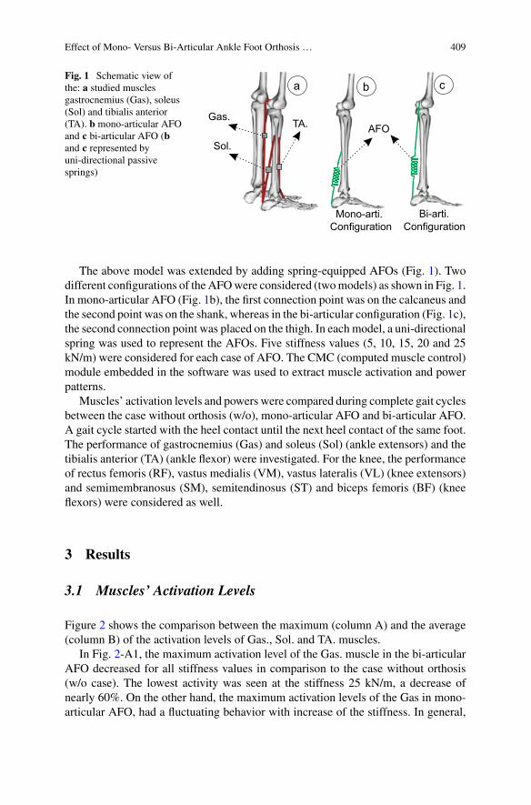
Effect of Mono- Versus Bi-Articular Ankle Foot Orthosis … 409
Fig. 1 Schematic view ofthe: a studied musclesgastrocnemius (Gas), soleus(Sol) and tibialis anterior(TA). b mono-articular AFOand c bi-articular AFO (band c represented byuni-directional passivesprings)
Gas.
Sol.
TA.
Bi-arti.Mono-arti.
a
ConfigurationConfiguration
AFO
b c
The above model was extended by adding spring-equipped AFOs (Fig. 1). Twodifferent configurations of theAFOwere considered (twomodels) as shown in Fig. 1.In mono-articular AFO (Fig. 1b), the first connection point was on the calcaneus andthe second point was on the shank, whereas in the bi-articular configuration (Fig. 1c),the second connection point was placed on the thigh. In each model, a uni-directionalspring was used to represent the AFOs. Five stiffness values (5, 10, 15, 20 and 25kN/m) were considered for each case of AFO. The CMC (computed muscle control)module embedded in the software was used to extract muscle activation and powerpatterns.
Muscles’ activation levels and powers were compared during complete gait cyclesbetween the case without orthosis (w/o), mono-articular AFO and bi-articular AFO.A gait cycle started with the heel contact until the next heel contact of the same foot.The performance of gastrocnemius (Gas) and soleus (Sol) (ankle extensors) and thetibialis anterior (TA) (ankle flexor) were investigated. For the knee, the performanceof rectus femoris (RF), vastus medialis (VM), vastus lateralis (VL) (knee extensors)and semimembranosus (SM), semitendinosus (ST) and biceps femoris (BF) (kneeflexors) were considered as well.
3 Results
3.1 Muscles’ Activation Levels
Figure 2 shows the comparison between the maximum (column A) and the average(column B) of the activation levels of Gas., Sol. and TA. muscles.
In Fig. 2-A1, the maximum activation level of the Gas. muscle in the bi-articularAFO decreased for all stiffness values in comparison to the case without orthosis(w/o case). The lowest activity was seen at the stiffness 25 kN/m, a decrease ofnearly 60%. On the other hand, the maximum activation levels of the Gas in mono-articular AFO, had a fluctuating behavior with increase of the stiffness. In general,
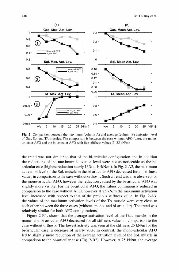
410 M. Eslamy et al.
0.2
0.4
0.6
0.8
1Gas. Max. Act. Lev.
Mono_arti. AFOBi_arti. AFO
0
0.1
0.2
0.3Gas. Mean Act. Lev.
0.4
0.6
0.8
Sol. Max. Act. Lev.
Mono_arti. AFOBi_arti. AFO
0.060.08
0.10.120.140.16
Sol. Mean Act. Lev.
w/o 5 10 15 20 25 [kN/m]0.985
0.99
0.995
1TA. Max. Act. Lev.
Mono_arti. AFOBi_arti. AFO
w/o 5 10 15 20 25 [kN/m]0.4
0.6
0.8
1TA. Mean Act. Lev.
(a) (b)
1
2
3
Fig. 2 Comparison between the maximum (column A) and average (column B) activation levelof Gas, Sol and TA muscles. The comparison is between the case without AFO (w/o), the mono-articular AFO and the bi-articular AFO with five stiffness values (5–25 kN/m)
the trend was not similar to that of the bi-articular configuration and in additionthe reductions of the maximum activation level were not as noticeable as the bi-articular case (highest reduction nearly 13% at 10 kN/m). In Fig. 2-A2, themaximumactivation level of the Sol. muscle in the bi-articular AFO decreased for all stiffnessvalues in comparison to the case without orthosis. Such a trend was also observed forthe mono-articular AFO, however the reduction caused by the bi-articular AFO wasslightly more visible. For the bi-articular AFO, the values continuously reduced incomparison to the case without AFO, however at 25 kN/m the maximum activationlevel increased with respect to that of the previous stiffness value. In Fig. 2-A3,the values of the maximum activation levels of the TA muscle were very close toeach other between the three cases (without, mono- and bi-articular). The trend wasrelatively similar for both AFO configurations.
Figure 2-B1, shows that the average activation level of the Gas. muscle in themono- and bi-articular AFO decreased for all stiffness values in comparison to thecase without orthosis. The lowest activity was seen at the stiffness 25 kN/m for thebi-articular case, a decrease of nearly 70%. In contrast, the mono-articular AFOled to slightly more reduction of the average activation level of the Sol. muscle incomparison to the bi-articular case (Fig. 2-B2). However, at 25 kN/m, the average
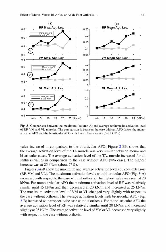
Effect of Mono- Versus Bi-Articular Ankle Foot Orthosis … 411
0.2
0.4
0.6
0.8 RF Max. Act. Lev.Mono_arti. AFOBi_arti. AFO
0.05
0.1
0.15
0.2
0.25 RF Mean Act. Lev.
0.2
0.4
0.6
0.8 VM Max. Act. Lev.
Mono_arti. AFOBi_arti. AFO
0
0.05
0.1
0.15
0.2
VM Mean Act. Lev.
w/o 5 10 15 20 25 [kN/m]0.2
0.4
0.6
0.8
1 VL Max. Act. Lev.
Mono_arti. AFOBi_arti. AFO
w/o 5 10 15 20 25 [kN/m]0
0.1
0.2
0.3 VL Mean Act. Lev.
(a) (b)
1
2
3
Fig. 3 Comparison between the maximum (column A) and average (column B) activation levelof RF, VM and VL muscles. The comparison is between the case without AFO (w/o), the mono-articular AFO and the bi-articular AFO with five stiffness values (5–25 kN/m)
value increased in comparison to the bi-articular AFO. Figure 2-B3, shows thatthe average activation level of the TA muscle was very similar between mono- andbi-articular cases. The average activation level of the TA. muscle increased for allstiffness values in comparison to the case without AFO (w/o case). The highestincrease was at 25 kN/m (about 75%).
Figures 3A-B show the maximum and average activation levels of knee extensors(RF, VM and VL). The maximum activation levels with bi-articular AFO (Fig. 3-A)increased with respect to the case without orthosis. The highest value was seen at 20kN/m. For mono-articular AFO the maximum activation level of RF was relativelysimilar until 15 kN/m and then decreased at 20 kN/m and increased at 25 kN/m.The maximum activation level of VM or VL changed very slightly with respect tothe case without orthosis. The average activation levels with bi-articular AFO (Fig.3-B) increased with respect to the case without orthosis. For mono-articular AFO theaverage activation level of RF was relatively similar until 20 kN/m, and increasedslightly at 25 kN/m. The average activation level ofVMorVLdecreased very slightlywith respect to the case without orthosis.
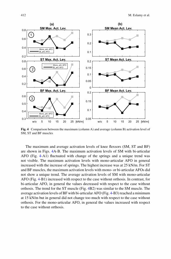
412 M. Eslamy et al.
0.2
0.4
0.6
0.8 SM Max. Act. Lev.
Mono_arti. AFOBi_arti. AFO 0.1
0.2
0.3
SM Mean Act. Lev.
0.2
0.4
0.6
0.8 ST Max. Act. Lev.Mono_arti. AFOBi_arti. AFO
0
0.05
0.1
0.15
0.2 ST Mean Act. Lev.
w/o 5 10 15 20 25 [kN/m]0.3
0.4
0.5
0.6
BF Max. Act. Lev.
Mono_arti. AFOBi_arti. AFO
w/o 5 10 15 20 25 [kN/m]0.05
0.1
0.15
0.2 BF Mean Act. Lev.
(a) (b)
3
2
1
Fig. 4 Comparison between the maximum (column A) and average (column B) activation level ofSM, ST and BF muscles
The maximum and average activation levels of knee flexsors (SM, ST and BF)are shown in Figs. 4A-B. The maximum activation levels of SM with bi-articularAFO (Fig. 4-A1) fluctuated with change of the springs and a unique trend wasnot visible. The maximum activation levels with mono-articular AFO in generalincreased with the increase of springs. The highest increase was at 25 kN/m. For STand BFmuscles, the maximum activation levels with mono- or bi-articular AFOs didnot show a unique trend. The average activation levels of SM with mono-articularAFO (Fig. 4-B1) increased with respect to the case without orthosis. In contrast, forbi-articular AFO, in general the values decreased with respect to the case withoutorthosis. The trend for the ST muscle (Fig. 4B2) was similar to the SM muscle. Theaverage activation levels of BFwith bi-articular AFO (Fig. 4-B3) reached aminimumat 15 kN/m but in general did not change too much with respect to the case withoutorthosis. For the mono-articular AFO, in general the values increased with respectto the case without orthosis.
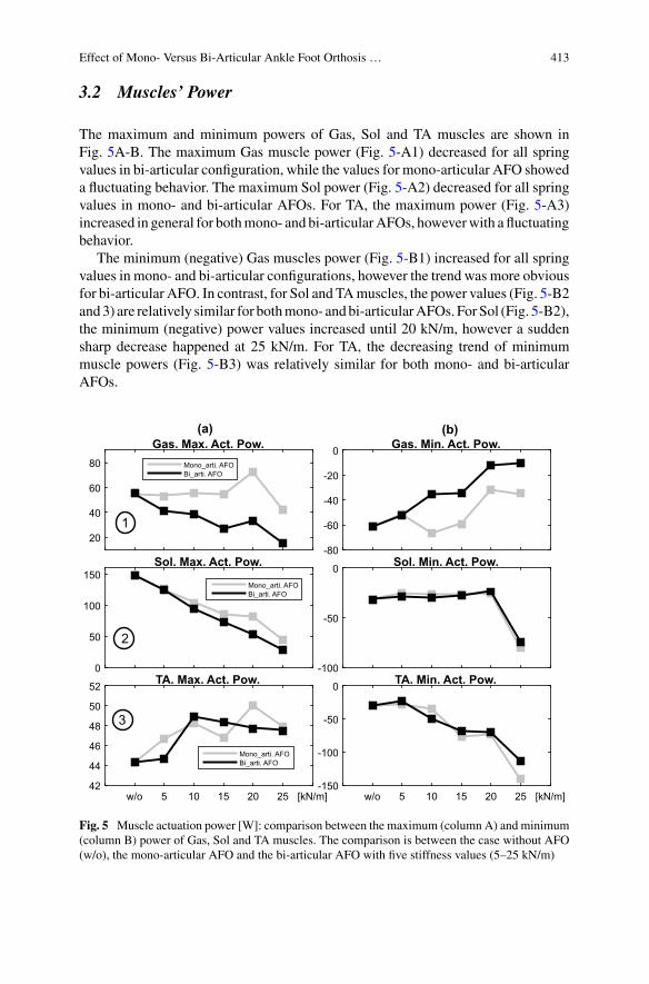
Effect of Mono- Versus Bi-Articular Ankle Foot Orthosis … 413
3.2 Muscles’ Power
The maximum and minimum powers of Gas, Sol and TA muscles are shown inFig. 5A-B. The maximum Gas muscle power (Fig. 5-A1) decreased for all springvalues in bi-articular configuration, while the values for mono-articular AFO showeda fluctuating behavior. The maximum Sol power (Fig. 5-A2) decreased for all springvalues in mono- and bi-articular AFOs. For TA, the maximum power (Fig. 5-A3)increased in general for bothmono- and bi-articularAFOs, howeverwith a fluctuatingbehavior.
The minimum (negative) Gas muscles power (Fig. 5-B1) increased for all springvalues in mono- and bi-articular configurations, however the trend was more obviousfor bi-articular AFO. In contrast, for Sol and TAmuscles, the power values (Fig. 5-B2and3) are relatively similar for bothmono- andbi-articularAFOs. ForSol (Fig. 5-B2),the minimum (negative) power values increased until 20 kN/m, however a suddensharp decrease happened at 25 kN/m. For TA, the decreasing trend of minimummuscle powers (Fig. 5-B3) was relatively similar for both mono- and bi-articularAFOs.
20
40
60
80
Gas. Max. Act. Pow.Mono_arti. AFOBi_arti. AFO
-80
-60
-40
-20
0 Gas. Min. Act. Pow.
0
50
100
150Sol. Max. Act. Pow.
Mono_arti. AFOBi_arti. AFO
-100
-50
0 Sol. Min. Act. Pow.
w/o 5 10 15 20 25 [kN/m]42
44
46
48
50
52 TA. Max. Act. Pow.
Mono_arti. AFOBi_arti. AFO
w/o 5 10 15 20 25 [kN/m]-150
-100
-50
0 TA. Min. Act. Pow.
(a) (b)
1
2
3
Fig. 5 Muscle actuation power [W]: comparison between the maximum (column A) and minimum(column B) power of Gas, Sol and TA muscles. The comparison is between the case without AFO(w/o), the mono-articular AFO and the bi-articular AFO with five stiffness values (5–25 kN/m)
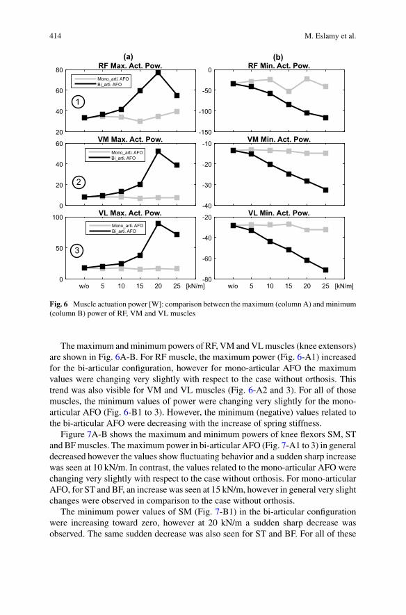
414 M. Eslamy et al.
20
40
60
80 RF Max. Act. Pow.Mono_arti. AFOBi_arti. AFO
-150
-100
-50
0 RF Min. Act. Pow.
0
20
40
60 VM Max. Act. Pow.Mono_arti. AFOBi_arti. AFO
-40
-30
-20
-10 VM Min. Act. Pow.
w/o 5 10 15 20 25 [kN/m]0
50
100 VL Max. Act. Pow.Mono_arti. AFOBi_arti. AFO
w/o 5 10 15 20 25 [kN/m]-80
-60
-40
-20 VL Min. Act. Pow.
(a) (b)
3
2
1
Fig. 6 Muscle actuation power [W]: comparison between the maximum (column A) and minimum(column B) power of RF, VM and VL muscles
Themaximum andminimum powers of RF, VM andVLmuscles (knee extensors)are shown in Fig. 6A-B. For RF muscle, the maximum power (Fig. 6-A1) increasedfor the bi-articular configuration, however for mono-articular AFO the maximumvalues were changing very slightly with respect to the case without orthosis. Thistrend was also visible for VM and VL muscles (Fig. 6-A2 and 3). For all of thosemuscles, the minimum values of power were changing very slightly for the mono-articular AFO (Fig. 6-B1 to 3). However, the minimum (negative) values related tothe bi-articular AFO were decreasing with the increase of spring stiffness.
Figure 7A-B shows the maximum and minimum powers of knee flexors SM, STand BFmuscles. Themaximum power in bi-articular AFO (Fig. 7-A1 to 3) in generaldecreased however the values show fluctuating behavior and a sudden sharp increasewas seen at 10 kN/m. In contrast, the values related to the mono-articular AFO werechanging very slightly with respect to the case without orthosis. For mono-articularAFO, for ST and BF, an increase was seen at 15 kN/m, however in general very slightchanges were observed in comparison to the case without orthosis.
The minimum power values of SM (Fig. 7-B1) in the bi-articular configurationwere increasing toward zero, however at 20 kN/m a sudden sharp decrease wasobserved. The same sudden decrease was also seen for ST and BF. For all of these
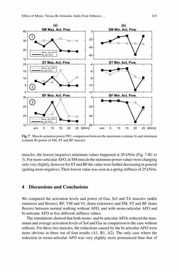
Effect of Mono- Versus Bi-Articular Ankle Foot Orthosis … 415
10
20
30
40 SM Max. Act. Pow.
Mono_arti. AFOBi_arti. AFO -60
-40
-20
0 SM Min. Act. Pow.
0
5
10
15
20 ST Max. Act. Pow.Mono_arti. AFOBi_arti. AFO
-12
-10
-8
-6
-4 ST Min. Act. Pow.
w/o 5 10 15 20 25 [kN/m]15
20
25
30 BF Max. Act. Pow.
Mono_arti. AFOBi_arti. AFO
w/o 5 10 15 20 25 [kN/m]-60
-40
-20
0 BF Min. Act. Pow.
(a) (b)
1
2
3
Fig. 7 Muscle actuation power [W]: comparison between the maximum (column A) and minimum(column B) power of SM, ST and BF muscles
muscles, the lowest (negative) minimum values happened at 20 kN/m (Fig. 7-B1 to3). Formono-articularAFO, in SMmuscle theminimumpower valueswere changingonly very slightly, however for ST andBF the valuewere further decreasing in general(getting more negative). Their lowest value was seen at a spring stiffness of 25 kN/m.
4 Discussions and Conclusions
We compared the activation levels and power of Gas, Sol and TA muscles (ankleextensors and flexors), RF, VM and VL (knee extensors) and SM, ST and BF (kneeflexors) between normal walking without AFO, and with mono-articular AFO andbi-articular AFO at five different stiffness values.
The simulations showed that both mono- and bi-articular AFOs reduced the max-imum and average activation levels of Sol and Gas in comparison to the case withoutorthosis. For these two muscles, the reductions caused by the bi-articular AFO weremore obvious in three out of four results (A1, B1, A2). The only case where thereduction in mono-articular AFO was very slightly more pronounced than that of
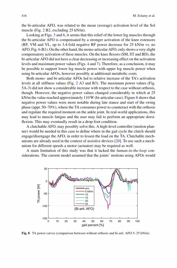
416 M. Eslamy et al.
the bi-articular AFO, was related to the mean (average) activation level of the Solmuscle (Fig. 2 B2, excluding 25 kN/m).
Looking at Figs. 3 and 6, it seems that this relief of the lower leg muscles throughthe bi-articular AFO is compensated by a stronger activation of the knee extensors(RF, VM and VL, up to 3.4-fold negative RF power decrease for 25 kN/m vs. noAFO,Fig. 6-B1).On the other hand, themono-articularAFO, only shows a very slightcompensatory activation of these muscles. On the knee flexors (SM, ST and BD), thebi-articular AFO did not have a clear decreasing or increasing effect on the activationlevels and maximum power values (Figs. 4 and 7). Therefore, as a conclusion, it maybe possible to support lower leg muscle power with upper leg muscle power whenusing bi-articular AFOs, however possibly at additional metabolic costs.
Both mono- and bi-articular AFOs led to relative increase of the TA’s activationlevels at all stiffness values (Fig. 2 A3 and B3). The maximum power values (Fig.5A-3) did not show a considerable increase with respect to the case without orthosis,though. However, the negative power values changed considerably in which at 25kN/m the value reached approximately 110W (bi-articular case). Figure 8 shows thatnegative power values were more notable during late stance and start of the swingphase (appr. 50–70%), where the TA consumes power to counteract with the orthosisand regulate the required moment on the ankle joint. In real-world applications, thismay lead to muscle fatigue and the user may fail to perform an appropriate dorsi-flexion. This may eventually result in a drop-foot condition.
A clutchable AFO, may possibly solve this. A high-level controller (motion plan-ner) would be needed in this case to define where in the gait cycle the clutch shouldengage/disengage the AFO, in order to lessen the load on the TA. Clutchable mech-anisms are already used in the context of assistive devices [20]. To use such a mech-anism for different speeds a motor (actuator) may be required as well.
A main limitation of this study was that it lacked the human-in-the-loop con-siderations. The current model assumed that the joints’ motions using AFOs would
gait percent [%]0 10 20 30 40 50 60 70 80 90 100
TApo
wer
[W]
-150
-100
-50
0
50
w/o5 kN/m10152025
(Bi-arti. AFO)
Fig. 8 TA power curves (comparison between without orthosis and bi-arti. AFO 5–25 kN/m)
Effect of Mono- Versus Bi-Articular Ankle Foot Orthosis … 417
be similar to the case without orthosis. It was not possible to simulate the humaninteraction in Opensim software, e.g., to check if the subject is really interested toactuate his/her ankle joint at stiffer 25 kN/m springs similar to the case they don’twear an AFO.
Therefore, in reality the subjects may possibly change their ankle joint motionto avoid muscle fatigue and associated negative feelings. Thus, the maximum andminimum TA power level (Fig. 5-A3 and B3), may possibly differ from what wouldhappen in real world.
In conclusion, the general results show thatAFOswith softer springs (based on ourresults, <10 kN/m) may potentially lead to some benefits in both muscle activationand power decrease of the lower leg muscles. However it needs to be validated withdifferent human subjects walking at different speeds. A customized patient-specificAFO may allow to further facilitate muscular interactions.
Acknowledgements This work was supported by the Grant from the Bundesministerium für Bil-dung und Forschung (BMBF-INOPRO-16SV7656).
References
1. D.A. Winter, Energy generation and absorption at the ankle and knee during fast, natural, andslow cadences. Clin. Orthopaedics Related Res. 175, 147–154 (1983)
2. A. Hreljac, Preferred and energetically optimal gait transition speeds in human locomotion.Med. Sci. Sports Exer. 25(10), 1158–1162 (1993)
3. G.S. Sawicki, D.P. Ferris, Powered ankle exoskeletons reveal the metabolic cost of plantarflexor mechanical work during walking with longer steps at constant step frequency. J. Exp.Biol. 212(1), 21–31 (2009)
4. P.Malcolm,W. Derave, S. Galle, D. De Clercq, A simple exoskeleton that assists plantarflexioncan reduce the metabolic cost of human walking. PloS One 8(2), e56137 (2013)
5. J. Hitt, A.M. Oymagil, T. Sugar, K. Hollander, A. Boehler, J. Fleeger, Dynamically controlledankle-foot orthosis (dco) with regenerative kinetics: Incrementally attaining user portability,in IEEE International Conference on Robotics and Automation (2007), pp. 1541–1546
6. M.Wiggin, G. Sawicki, S. Collins, An exoskeleton using controlled energy storage and releaseto aid ankle propulsion, in IEEE International Conference on Rehabilitation Robotics (ICORR)(2011), pp. 1–5
7. A. Danielsson, K.S. Sunnerhagen, Energy expenditure in stroke subjects walking with a carboncomposite ankle foot orthosis. J. Rehabil. Med. 36(4), 165–168 (2004)
8. G. Sawicki, C. Lewis, D. Ferris, It pays to have a spring in your step. Exer. Sport Sci. Rev.37(3), 130 (2009)
9. E.S. Arch, S.J. Stanhope, J.S. Higginson, Passive-dynamic ankle-foot orthosis replicates soleusbut not gastrocnemius muscle function during stance in gait: insights for orthosis prescription.Prosthetics Ortho. Int. 40(5), 606–616 (2016)
10. S.H. Collins, M.B. Wiggin, G.S. Sawicki, Reducing the energy cost of human walking usingan unpowered exoskeleton. Nature 522(7555), 212–215 (2015)
11. J.A. Norris, K.P. Granata, M.R. Mitros, E.M. Byrne, A.P. Marsh, Effect of augmented plan-tarflexion power on preferred walking speed and economy in young and older adults. GaitPosture 25(4), 620–627 (2007)
12. L.M. Mooney, E.J. Rouse, H.M. Herr, Autonomous exoskeleton reduces metabolic cost ofhuman walking. J. Neuroeng. Rehabil. 11(1), 151 (2014)
418 M. Eslamy et al.
13. J. Babic, B. Lim, D. Omrcen, J. Lenarcic, F. Park, A biarticulated robotic leg for jumpingmovements: theory and experiments. ASME J. Mech. Robot. (2008)
14. G.V. van Ingen Schenau, M. Bobbert, R. Rozendal, The unique action of bi-articular musclesin complex movements. J. Anatomy 155, 1 (1987)
15. M.Eslamy,M.Grimmer,A. Seyfarth,Adding passive biarticular spring to activemono-articularfoot prosthesis: effects on power and energy requirement, in IEEE-RAS International Confer-ence on Humanoid Robots (2014), pp. 677–684
16. J. Cleland, On the actions of muscles passing over more than one joint. J. Anatomy Physiol.1(1), 85 (1867)
17. S.L. Delp, F.C. Anderson, A.S. Arnold, P. Loan, A. Habib, C.T. John, E. Guendelman, D.G.Thelen, Opensim: open-source software to create and analyze dynamic simulations of move-ment. IEEE Trans. Biomed. Eng. 54(11), 1940–1950 (2007)
18. C.T. John, A. Seth, M.H. Schwartz, S.L. Delp, Contributions of muscles to mediolateral groundreaction force over a range of walking speeds. J. Biomech. 45(14), 2438–2443 (2012)
19. M.Q. Liu, F.C. Anderson, M.H. Schwartz, S.L. Delp, Muscle contributions to support andprogression over a range of walking speeds. J. Biomech. 41(15), 3243–3252 (2008)
20. E.J. Rouse, L.M. Mooney, H.M. Herr, Clutchable series-elastic actuator: implications for pros-thetic knee design. Int. J. Robot. Res. 33(13), 1611–1625 (2014)
Ultrasound Imaging of PlantarflexorMuscles During Robotic Ankle AssistedWalking: Effects on Muscle TendonDynamics and Application TowardsImproved Exoskeleton and ExosuitControl
Richard W. Nuckols, Sangjun Lee, Krithika Swaminathan, Conor J. Walsh,Robert D. Howe, and Gregory S. Sawicki
Abstract Ankle exosuits/exoskeletons can improve gait but the assistance needsto be tuned to the individual. We suspect that ankle assistance can affect under-lying muscle-tendon dynamics and should be accounted for in the control design.We highlight two complementary studies that begin to address these issues. First,we use ultrasound imaging to directly measure the effect of ankle exoskeleton rota-tional stiffness on soleus contractile dynamics. With increasing stiffness, the soleusoperating length and muscle economy increased in early stance, but this was offsetby increased shortening velocity and reduced muscle economy in late stance. Sec-ond, we demonstrate an approach to rapidly estimate muscle contractile state and itsapplication in prescribing assistance profiles. These results provide evidence for theimportance of muscle dynamics and how it can be used to inform design of wearabledevices.
Part of this work was supported by grants to G.S.S from the National Institute of Nursing Researchof the National Institutes of Health (R01NR014756) and the U.S. Army Natick Soldier Research,Development and Engineering Center (W911QY18C0140). Part is based upon the work supportedby the Harvard John A. Paulson School of Engineering and Applied Sciences TEAM initiative,National Institutes of Health (BRG R01HD088619) and the National Science Foundation (CNS-1446464) to C.J.W and the Wyss Institute for Biologically Inspired Engineering. K.S. is also sup-ported by a National Science Foundation Graduate Research Fellowship, and S.L. is supported bySamsung Scholarship.
R. W. Nuckols (B) · S. Lee · K. Swaminathan · C. J. Walsh · R. D. HoweJohn A. Paulson School of Engineering and Applied Science,Harvard University, Cambridge, MA, USAe-mail: [email protected]
G. S. SawickiGeorgia Tech, Atlanta, GA, USA
© The Author(s), under exclusive license to Springer Nature Switzerland AG 2022J. C. Moreno et al. (eds.), Wearable Robotics: Challenges and Trends,Biosystems & Biorobotics 27, https://doi.org/10.1007/978-3-030-69547-7_67
419
420 R. W. Nuckols et al.
1 Introduction
Ankle exoskeletons/exosuits are capable of improving metabolic demand [1], but thecorrect assistance timing and magnitude must be provided for the user to effectivelyinteract with the device. Models of walking predict that assistance can disrupt thenormally tuned interaction of the ankle plantarflexors andAchilles Tendon [2], but nostudy had validated the effect of exosuit assistance on muscle dynamics experimen-tally. Understanding how assistive devices affect muscle dynamics is crucial becausethe coordinated interaction of the ankle plantarflexors and the Achilles tendon allowsfor efficient force and power production during walking.
In the PoWeRLab (Sawicki), we directlymeasured soleusmuscle fascicle dynam-ics using B-mode ultrasound imaging during exoskeleton assisted walking [3]. Wehypothesized that increasing exoskeleton stiffness would result in longer fasciclelengths, increased shortening velocity, and altered soleus muscle economy. Further-more, we expected that the change in fascicle dynamics would help explain why toomuch assistance is detrimental to exoskeleton effectiveness.
In a later study in the Harvard Biodesign and Biorobotics Lab (Walsh, Howe), weextended these ideas towards development of exosuit assistance profiles that accountfor muscle dynamics [4]. We hypothesized that we could measure the onset time ofmuscle concentric contraction using B-mode ultrasound imaging, and use that timeto inform individualized exosuit control for level and incline walking.
2 Materials and Methods
2.1 PoWeR Lab
Eleven individuals walked at 1.25m s−1 for 5 exoskeleton stiffnesses (0, 50, 100, 150and 250 Nm rad−1). We measured metabolic demand, joint dynamics, and muscleactivation. We calculated force per activation by dividing the estimated muscle force(derived from joint dynamics) by activation.We recorded B-mode ultrasound imagesof the soleus with a low-profile ultrasound probe. We tracked the fascicles using anautomated tracking software [5] and calculated the length and velocity of the soleusfascicles for the 5 conditions.
2.2 Harvard Biodesign and Biorobotics
Our sensing/measurement approach used B-mode ultrasound to detect, at real-timerates, when the muscle begins to concentrically contract and generate positive powerbefore push-off. For this, we modeled the ankle soleus-AT complex as an elasticelement and contractile element in series. While subjects walked on a treadmill, we
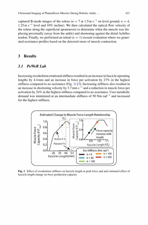
Ultrasound Imaging of Plantarflexor Muscles During Robotic Ankle … 421
captured B-mode images of the soleus (n = 7 at 1.5m s−1 on level ground; n = 4,1.25m s−1 level and 10% incline). We then calculated the optical flow velocity ofthe soleus along the superficial aponeurosis to determine when the muscle was dis-placing proximally (away from the ankle) and shortening against the distal Achillestendon. Finally, we performed an initial (n = 1) exosuit evaluation where we gener-ated assistance profiles based on the detected onset of muscle contraction.
3 Results
3.1 PoWeR Lab
Increasing exoskeleton rotational stiffness resulted in an increase in fascicle operatinglengths by 4.4mm and an increase in force per activation by 27% in the higheststiffness compared to no assistance (Fig. 1) [3]. Increasing stiffness also resulted inan increase in shortening velocity by 3.7mm s−1 and a reduction in muscle force peractivation by 24% in the highest stiffness compared to no assistance. User metabolicdemand was minimized at an intermediate stiffness of 50 Nm rad−1 and increasedfor the highest stiffness.
Fig. 1 Effect of exoskeleton stiffness on fascicle length at peak force and and estimated effect offascicle length change on force production capacity
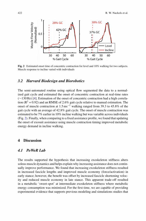
422 R. W. Nuckols et al.
Fig. 2 Estimated onset time of concentric contraction for level and 10% walking for two subjects.Muscle response to incline varied with individuals
3.2 Harvard Biodesign and Biorobotics
The semi-automated routine using optical flow segmented the data to a normal-ized gait cycle and estimated the onset of concentric contraction at real-time rates(∼130Hz) [4]. Estimation of the onset of concentric contraction had a high correla-tion (R2 = 0.92) and an RMSE of 2.6% gait cycle relative to manual estimation. Theonset of muscle contraction at 1.5ms−1 walking ranged from 39.3 to 45.8% of thegait cycle with an average of 42.8% gait cycle. The onset of muscle contraction wasestimated to be 7% earlier in 10% incline walking but was variable across individuals(Fig. 2). Finally, when comparing to a fixed assistance profile, we found that updatingthe onset of exosuit assistance using muscle contraction timing improved metabolicenergy demand in incline walking.
4 Discussion
4.1 PoWeR Lab
The results supported the hypothesis that increasing exoskeleton stiffness alterssoleusmuscle dynamics and helps explain why increasing assistance does not contin-ually improve performance. We found that increasing exoskeleton stiffness resultedin increased fascicle lengths and improved muscle economy (force/activation) inearly stance; however, the benefit was offset by increased fascicle shortening veloc-ity and reduced muscle economy in late stance. This apparent trade-off resultedin a metabolic ‘sweet-spot’ at intermediate exoskeleton stiffness where metabolicenergy consumption was minimized. For the first time, we are capable of providingexperimental evidence that supports previous modeling and simulations studies that
Ultrasound Imaging of Plantarflexor Muscles During Robotic Ankle … 423
predict changes to muscle fascicle dynamics resulting from exoskeleton assistance.These experimental results provides insight into how muscle-tendon dynamics canbe incorporated into design for wearable devices.
4.2 Harvard Biodesign and Biorobotics
The transition to muscle concentric contraction shown from this technique alignswith reported group average data from prior studies [6]. The determination that theonset of muscle concentric contraction is variable may help explain why individualresponse to fixed exosuit assistance is so varied. Though preliminary, the exosuit pilotdemonstrates that we may be able to improve exosuit performance by accounting forbiomechanical changes in the user’s muscle dynamics.
5 Conclusion
This work highlights the importance of understanding muscle-tendon dynamics fordeveloping effective exoskeleton/exosuit controllers.We highlight some recent workthat suggest howmuscle tendon dynamicsmight be used for individualized assistanceprofiles that are adaptive to the task demands. In the future, exosuit controllers thatsample the individual’s muscle-tendon state may enable muscle-in-the-loop con-trollers capable of offloading muscle force while maintaining efficient contractiledynamics.
References
1. G.S. Sawicki, O.N. Beck, I. Kang, A.J. Young, The exoskeleton expansion: improving walkingand running economy. J. Neuroeng. Rehabil. 17(1), 25 (2020)
2. R.W. Jackson, C.L. Dembia, S.L. Delp, S.H. Collins, Muscle-tendon mechanics explain unex-pected effects of exoskeleton assistance on metabolic rate during walking. J. Exp. Biol. 220(Pt11), 2082–2095 (2017)
3. R.W. Nuckols, T.J.M. Dick, O.N. Beck, G.S. Sawicki, Ultrasound imaging links soleus muscleneuromechanics and energetics during human walking with elastic ankle exoskeletons. Sci.Reports 10(1), 3604 (2020)
4. R.W. Nuckols et al., Automated detection of soleus concentric contraction in variable gait condi-tions for improved exosuit control, in IEEE International Conference on Robotics and Automa-tion (ICRA) (2020)
5. D.J. Farris, G.A. Lichtwark, UltraTrack: software for semi-automated tracking of muscle fas-cicles in sequences of B-mode ultrasound images. Comput. Methods Programs Biomed. 128,111–8 (2016)
6. N.J. Cronin, J. Avela, T. Finni, J. Peltonen, Differences in contractile behaviour between thesoleus and medial gastrocnemius muscles during human walking. J. Exp. Biol. 216(5), 909–914(2013)
Simulation Platform for DynamicModeling of Lower Limb RehabilitationExoskeletons: Exo-H3 Case Study
Sergey González-Mejía, José M. Ramírez-Scarpetta, Juan C. Moreno,and José L. Pons
Abstract A flexible simulation platform for human gait with exoskeletons ispresented to support the analysis of the human-robot interaction and performanceassessment of control strategies design, e.g., assist-as-needed. The platform includesthe dynamic modeling of the lower limb’s exoskeleton-human with six degrees offreedom in sagittal plane, actuated by servomotors, where the movement equationsare explicitly obtained through theEuler-Lagrange approach. The fullmodel is hybridand it contains four sub-models that are switched between themselves according tothe gait cycle phases; also, it comprises the joint actuators dynamics and the lowlevel control system, this modeling was assembled in Simulink-Matlab. It is shownthat the proposed platform is a useful tool for assistance control strategies in the gaitrehabilitation. Furthermore, simulation results for the Exo-H3 exoskeleton show thesuccessful tracking of angular trajectories, the level of human participation, and therealistic torques.
1 Introduction
Most of the foundational concepts and control techniques for human gait exoskele-tons are inspired or emerge from the bipedal robotics field. Wearable exoskeletonsare characterized by their kinematic and dynamic behavior, which in turn deter-mine the design of mechanical structures and model-based control systems [1, 2];these features can be modeled and implemented to run dynamic simulations for
S. González-Mejía (B) · J. M. Ramírez-ScarpettaIndustrial Control Research Group of Universidad del Valle, Cali, Colombiae-mail: [email protected]
J. C. MorenoNeural Rehabilitation Group of the Spanish National Research Council, Madrid, Spaine-mail: [email protected]
J. L. PonsShirley Ryan Ability Lab, Chicago, IL, USAe-mail: [email protected]
© The Author(s), under exclusive license to Springer Nature Switzerland AG 2022J. C. Moreno et al. (eds.), Wearable Robotics: Challenges and Trends,Biosystems & Biorobotics 27, https://doi.org/10.1007/978-3-030-69547-7_68
425
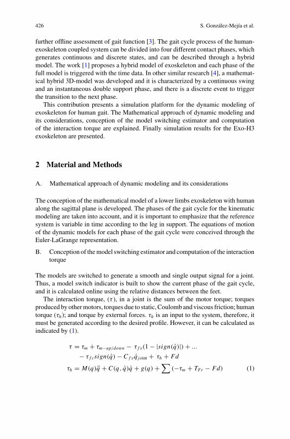
426 S. González-Mejía et al.
further offline assessment of gait function [3]. The gait cycle process of the human-exoskeleton coupled system can be divided into four different contact phases, whichgenerates continuous and discrete states, and can be described through a hybridmodel. The work [1] proposes a hybrid model of exoskeleton and each phase of thefull model is triggered with the time data. In other similar research [4], a mathemat-ical hybrid 3D-model was developed and it is characterized by a continuous swingand an instantaneous double support phase, and there is a discrete event to triggerthe transition to the next phase.
This contribution presents a simulation platform for the dynamic modeling ofexoskeleton for human gait. The Mathematical approach of dynamic modeling andits considerations, conception of the model switching estimator and computationof the interaction torque are explained. Finally simulation results for the Exo-H3exoskeleton are presented.
2 Material and Methods
A. Mathematical approach of dynamic modeling and its considerations
The conception of the mathematical model of a lower limbs exoskeleton with humanalong the sagittal plane is developed. The phases of the gait cycle for the kinematicmodeling are taken into account, and it is important to emphasize that the referencesystem is variable in time according to the leg in support. The equations of motionof the dynamic models for each phase of the gait cycle were conceived through theEuler-LaGrange representation.
B. Conception of themodel switching estimator and computation of the interactiontorque
The models are switched to generate a smooth and single output signal for a joint.Thus, a model switch indicator is built to show the current phase of the gait cycle,and it is calculated online using the relative distances between the feet.
The interaction torque, (τ ), in a joint is the sum of the motor torque; torquesproduced by othermotors, torques due to static, Coulomb and viscous friction; humantorque (τh); and torque by external forces. τh is an input to the system, therefore, itmust be generated according to the desired profile. However, it can be calculated asindicated by (1).
τ = τm + τm−up/down − τ f s(1− |sign(q)|) + ...
− τ f csign(q) − C f vq joint + τh + Fd
τh = M(q)q + C(q, q)q + g(q) +∑
(−τm + TFr − Fd) (1)
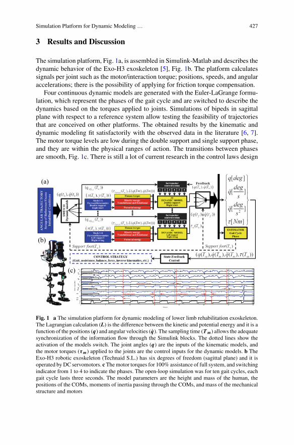
Simulation Platform for Dynamic Modeling … 427
3 Results and Discussion
The simulation platform, Fig. 1a, is assembled in Simulink-Matlab and describes thedynamic behavior of the Exo-H3 exoskeleton [5], Fig. 1b. The platform calculatessignals per joint such as the motor/interaction torque; positions, speeds, and angularaccelerations; there is the possibility of applying for friction torque compensation.
Four continuous dynamic models are generated with the Euler-LaGrange formu-lation, which represent the phases of the gait cycle and are switched to describe thedynamics based on the torques applied to joints. Simulations of bipeds in sagittalplane with respect to a reference system allow testing the feasibility of trajectoriesthat are conceived on other platforms. The obtained results by the kinematic anddynamic modeling fit satisfactorily with the observed data in the literature [6, 7].The motor torque levels are low during the double support and single support phase,and they are within the physical ranges of action. The transitions between phasesare smooth, Fig. 1c. There is still a lot of current research in the control laws design
0 5 10 15 20 25 30 35
-50
0
50
Mot
or to
rque
[Nm
]
0 5 10 15 20 25 30 35-50
0
50
0 5 10 15 20 25 30 35-50
0
50
0 5 10 15 20 25 30 35
-40-20
020
0 5 10 15 20 25 30 35
-100
0
100
0 5 10 15 20 25 30 35-200
-100
0
0 5 10 15 20 25 30 35024
Time [s]
Right ankle
Right knee
Right hip
Left hip
Left knee
Left ankleGait cycle
Double support - left start
Left single support Right single support
Double support - right start
(a)
(b)
(c)
Fig. 1 a The simulation platform for dynamic modeling of lower limb rehabilitation exoskeleton.The Lagrangian calculation (L) is the difference between the kinetic and potential energy and it is afunction of the positions (q) and angular velocities (q). The sampling time (Tm) allows the adequatesynchronization of the information flow through the Simulink blocks. The dotted lines show theactivation of the models switch. The joint angles (q) are the inputs of the kinematic models, andthe motor torques (τm) applied to the joints are the control inputs for the dynamic models. b TheExo-H3 robotic exoskeleton (Technaid S.L.) has six degrees of freedom (sagittal plane) and it isoperated by DC servomotors. c Themotor torques for 100% assistance of full system, and switchingindicator from 1 to 4 to indicate the phases. The open-loop simulation was for ten gait cycles, eachgait cycle lasts three seconds. The model parameters are the height and mass of the human, thepositions of the COMs, moments of inertia passing through the COMs, and mass of the mechanicalstructure and motors
428 S. González-Mejía et al.
for an exoskeleton assisting a patient, including the treatment of constraints anddisturbances to add robustness to the control system.
4 Conclusions and Outlook
The simulation platform shows that it is a versatile and flexible tool for research inassisted rehabilitation of the human gait. Therefore, the platform is useful for theanalysis of gait, and control strategies design; it is used to simulate control conditionfor static and dynamic balance, gait assist, impedance, force feedback, etc.; thevalidation of the forward kinematic modeling achieves a successful tracking of theexperimental displacement trajectories, which were previously applied to the inversekinematics model; the transfer of final conditions during the models switching andthe synchronized resetting of the integrators allow obtaining smooth and boundedoutputs at the beginning of double support; for future works, assist-as-needed controlwill be developed to measure the rehabilitation effectiveness of patients and variousclinical protocols to validate them.
Acknowledgements Thisworkwas sponsored by theAdministrativeDepartment of Science, Tech-nology and Innovation (Colciencias) under grant agreement No. 647-2014 at the Universidad delValle, Colombia; and it was supported through computational and processing resources providedby Neural Rehabilitation Group and Technaid S.L. at the Cajal Institute, CSIC, Spain.
References
1. X. Wang, H. Wang, Y. Tian, Gait planning and hybrid model based tracking control of lowerextremity exoskeleton, in 2016 35th Chinese Control Conference (CCC), July 2016, pp. 6019–6024
2. Z. Yang, W. Gu, J. Zhang, L. Gui, Force Control Theory and Method of Human Load CarryingExoskeleton Suit (Springer, Berlin, Heidelberg, 2017).
3. Y. Zhu, G. Zhang, C. Zhang, G. Liu, J. Zhao, Biomechanical modeling and load-carryingsimulation of lower limb exoskeleton. Bio-Med. Mater. Eng. 26(s1), S729–S738 (2015)
4. A. Agrawal et al., First steps towards translating HZD control of bipedal robots to decentralizedcontrol of exoskeletons. IEEE Access 5, 9919–9934 (2017)
5. Technaid—Leading Motion, Exoesqueleto Exo-H3 (2020). https://www.technaid.com/es/productos/robotic-exoskeleton-exo-h3/. Accessed 28 July 2020
6. J. Fan Zhang, Y. Ming Dong, C. Jun Yang, Y. Geng, Y. Chen, Y. Yang, 5-link model basedgait trajectory adaption control strategies of the gait rehabilitation exoskeleton for post-strokepatients. Mechatronics 20(3), 368–376, 2010
7. Y.Long,Z.Du,L.Cong,W.Wang,Z.Zhang,W.Dong,Active disturbance rejection control basedhuman gait tracking for lower extremity rehabilitation exoskeleton. ISA Trans. 67, 389–397(2017)
Understanding Technology-InducedCompensation: Effects of aWrist-Constrained Robotic HandOrthosis on Grasping Kinematics
Jan T. Meyer, Charlotte Werner, Sarah Hermann, László Demkó,Olivier Lambercy, and Roger Gassert
Abstract Robotic hand orthoses have the potential of supporting grasp function ofpeople with sensorimotor impairments. To achieve lightweight and simple solutions,most devices focus on supporting only a subset of the functional abilities of the hand.This study investigates the effect of such a design trade-off in a wrist-constrainedrobotic hand orthosis and its effects on upper limb kinematics and grasping abilitiesof seven able-bodied subjects. Using wearable, inertial sensors on hand, arm, andshoulder we quantified how a reduction of degrees of freedom affected movementstrategies in eleven grasping tasks. This analysis helps to understand how simplifieddesign solutions may affect movement patterns of the target end-users, dependingon their residual level of functionality. Also, this further highlights the issue ofusability-related design trade-offs between compact and lightweight solutions, andmore complex multi-degree of freedom devices.
1 Introduction
In early rehabilitation, functional recovery of patients with sensorimotor deficitsresulting from, e.g. a spinal cord injury (SCI) is mainly driven by neuroplasticity andthe learning of compensation strategies [1]. This enables the persons with disabilitiesto perform activities of daily living and thereby increase their independence. Duringprehension tasks, this compensation is often realized by grip alterations such as thetenodesis grasp, or by strategies that involve shoulder abduction.However, dependingon the impairment and potential neuromuscular restrictions, such alternative graspingstrategies are not always applicable.
The first two authors contributed equally to this work.
J. T. Meyer (B) · S. Hermann · O. Lambercy · R. GassertRehabilitation Engineering Laboratory, Department of Health Sciences and Technology,ETH Zurich, Zurich, Switzerlande-mail: [email protected]
C. Werner · L. DemkóSpinal Cord Injury Center, Balgrist University Hospital, Zurich, Switzerland
© The Author(s), under exclusive license to Springer Nature Switzerland AG 2022J. C. Moreno et al. (eds.), Wearable Robotics: Challenges and Trends,Biosystems & Biorobotics 27, https://doi.org/10.1007/978-3-030-69547-7_69
429
430 J. T. Meyer et al.
In order to further improve the functional independence of people with a lim-ited hand function, promising robotic hand orthoses (RHO) have been proposed andtested in a variety of target users [2]. The aim of novel RHO is to restore func-tional and potentially natural grasping patterns. Most user studies of RHO focuson the functional benefit gained through device usage by comparing the immediateinterventional effect with clinical measures, such as the Action Research Arm Test(ARAT), the Toronto Rehabilitation Institute Hand Function Test (TRI-HFT) andthe Jebsen Taylor Hand Function Test (JTHFT) [3–5]. However, the effects on upperlimb kinematics, such as grasping strategies and either trained, or unnatural com-pensatory movements are often neglected. As RHOs become more advanced, it isimportant to also consider the effect of potential movement constraints while aimingfor particularly lightweight and compact solutions.
In this study, we aimed to investigate the effect of a RHO with a constrainedwrist on upper limb movement kinematics in able-bodied subjects. With the use ofwearable sensors, we analyzed to what extend a compromise in degrees of freedom(DOF) affects the ability and naturalness of handling objects of daily living. Theseinsights help us to weigh off design trade-offs for RHOs and further understand theireffects on target-user performance.
2 Methods
2.1 Robotic Hand Orthosis
For this study, a lightweight RHO (148g) developed for people with hand sensori-motor deficits was used. The prototype can assist various grasp types through activefinger flexion and extension [5]. To simplify the design of the RHO, the wrist jointwas fixed at a 25 extension angle. This was also intended to provide target userswith SCI with further grasping stability. A large-diameter push button was used totrigger opening/closing movements of the orthosis.
2.2 Participants
Seven able-bodied participants (28.4 ± 11.4 years, 3 female, 5 right-handed) wererecruited and tested with compliance to SARS-CoV-2-related interaction restrictionsand precautions. All subjects gave written informed consent and all experimentalprocedures were approved by the local ethics committee (Ref. 2018-N-90).
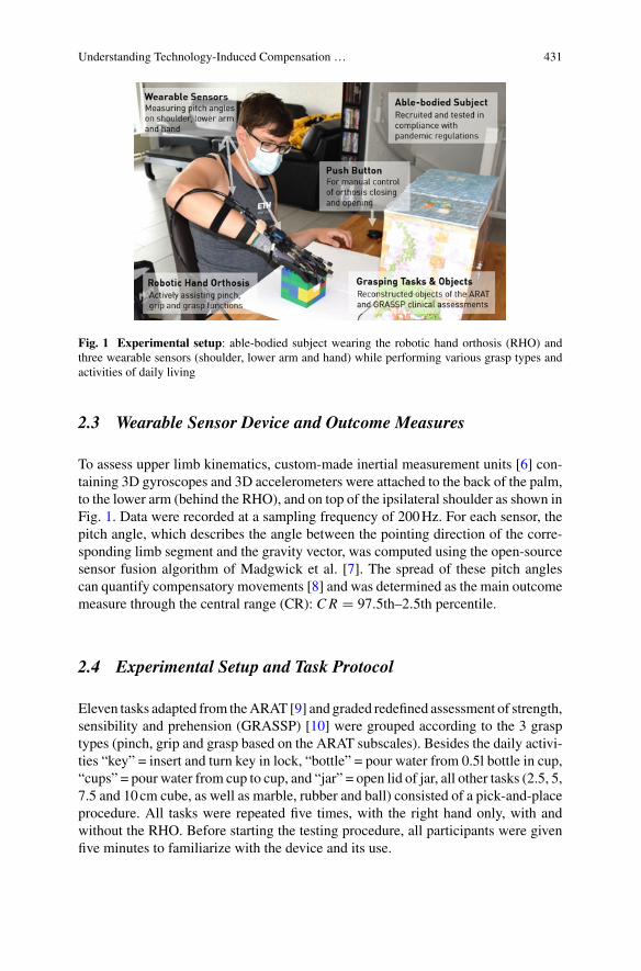
Understanding Technology-Induced Compensation … 431
Fig. 1 Experimental setup: able-bodied subject wearing the robotic hand orthosis (RHO) andthree wearable sensors (shoulder, lower arm and hand) while performing various grasp types andactivities of daily living
2.3 Wearable Sensor Device and Outcome Measures
To assess upper limb kinematics, custom-made inertial measurement units [6] con-taining 3D gyroscopes and 3D accelerometers were attached to the back of the palm,to the lower arm (behind the RHO), and on top of the ipsilateral shoulder as shown inFig. 1. Data were recorded at a sampling frequency of 200Hz. For each sensor, thepitch angle, which describes the angle between the pointing direction of the corre-sponding limb segment and the gravity vector, was computed using the open-sourcesensor fusion algorithm of Madgwick et al. [7]. The spread of these pitch anglescan quantify compensatory movements [8] and was determined as the main outcomemeasure through the central range (CR): CR = 97.5th–2.5th percentile.
2.4 Experimental Setup and Task Protocol
Eleven tasks adapted from theARAT [9] and graded redefined assessment of strength,sensibility and prehension (GRASSP) [10] were grouped according to the 3 grasptypes (pinch, grip and grasp based on the ARAT subscales). Besides the daily activi-ties “key” = insert and turn key in lock, “bottle” = pour water from 0.5l bottle in cup,“cups” = pour water from cup to cup, and “jar” = open lid of jar, all other tasks (2.5, 5,7.5 and 10cm cube, as well as marble, rubber and ball) consisted of a pick-and-placeprocedure. All tasks were repeated five times, with the right hand only, with andwithout the RHO. Before starting the testing procedure, all participants were givenfive minutes to familiarize with the device and its use.
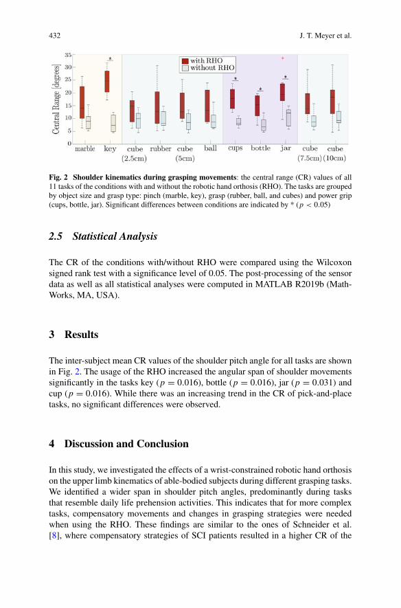
432 J. T. Meyer et al.
Fig. 2 Shoulder kinematics during grasping movements: the central range (CR) values of all11 tasks of the conditions with and without the robotic hand orthosis (RHO). The tasks are groupedby object size and grasp type: pinch (marble, key), grasp (rubber, ball, and cubes) and power grip(cups, bottle, jar). Significant differences between conditions are indicated by * (p < 0.05)
2.5 Statistical Analysis
The CR of the conditions with/without RHO were compared using the Wilcoxonsigned rank test with a significance level of 0.05. The post-processing of the sensordata as well as all statistical analyses were computed in MATLAB R2019b (Math-Works, MA, USA).
3 Results
The inter-subject mean CR values of the shoulder pitch angle for all tasks are shownin Fig. 2. The usage of the RHO increased the angular span of shoulder movementssignificantly in the tasks key (p = 0.016), bottle (p = 0.016), jar (p = 0.031) andcup (p = 0.016). While there was an increasing trend in the CR of pick-and-placetasks, no significant differences were observed.
4 Discussion and Conclusion
In this study, we investigated the effects of a wrist-constrained robotic hand orthosison the upper limb kinematics of able-bodied subjects during different grasping tasks.We identified a wider span in shoulder pitch angles, predominantly during tasksthat resemble daily life prehension activities. This indicates that for more complextasks, compensatory movements and changes in grasping strategies were neededwhen using the RHO. These findings are similar to the ones of Schneider et al.[8], where compensatory strategies of SCI patients resulted in a higher CR of the
Understanding Technology-Induced Compensation … 433
forearm pitch angle. Purely soft, such as textile- or silicone-based hand orthoses[3, 4] which do not restrict the wrist joint may allow for more natural graspingpatterns than fixed-wrist approaches. However, a stabilized wrist can be importantfor target populations with minimal residual wrist function such as tetraplegic users.Moreover, using compensatory strategies and thereby an unnatural grasping patternwhen wearing a lightweight, fixed-wrist RHO might be acceptable for the user dueto the increase in functional independence. The advantages of such devices mightoutperform more complex, often heavy, and expensive solutions that allow for morenatural grasping movements.
With this study we aim to underline the importance of understanding upper limbkinematics when investigating the benefits and constraints of wearable robotic assis-tive technology.
Acknowledgements The authors would like to thank the study participants for their time anddedication. This work is supported by the Vontobel Foundation and the Swiss National ScienceFoundation through the National Centre of Competence in Research on Robotics.
References
1. S. Mateo, A. Roby-Brami et al., Upper limb kinematics after cervical spinal cord injury: areview. J. Neuroeng. Rehabil. 12(1), 9 (2015)
2. R.A.Bos,C.J.Haarman et al., A structured overviewof trends and technologies used in dynamichand orthoses. J. NeuroEng. Rehabil. 1, 1–25
3. C. Correia, K. Nuckols et al., Improving grasp function after spinal cord injury with a softrobotic glove. IEEE Trans. Neural Syst. Rehabil. Eng. (2020)
4. B.A. Osuagwu, S. Timms et al., Home-based rehabilitation using a soft robotic hand glovedevice leads to improvement in hand function in people with chronic spinal cord injury: a pilotstudy. J. Neuroeng. Rehabil. 17(1), 1–15 (2020)
5. T. Bützer, O. Lambercy et al., Fully wearable actuated soft exoskeleton for grasping assistancein everyday activities. Soft Robot. (2020)
6. ZurichMOVE (2019). Available http://zurichmove.com7. S.O. Madgwick, A.J. Harrison, R. Vaidyanathan, Estimation of IMU and MARG orienta-
tion using a gradient descent algorithm, in IEEE International Conference on RehabilitationRobotics (2011)
8. S. Schneider, W.L. Popp et al., Predicting upper limb compensation during prehension tasks intetraplegic spinal cord injured patients using a single wearable sensor, in IEEE InternationalConference on Rehabilitation Robotics (2019)
9. D. Carroll, A quantitative test of upper extremity function. J. Chron. Diseases 18(5), 479–491(1965)
10. S.Kalsi-Ryan,A.Curt et al., Development of the graded redefined assessment of strength, sensi-bility and prehension (grassp): reviewingmeasurement specific to the upper limb in tetraplegia.J. Neurosurg. Spine 17(Suppl 1), 65–76 (2012)
The Effects of Vestibular Stimulationto Enhance Rehabilitation and EnableRobotic Exoskeleton Trainingfor Persons with CP
Ghaith J. Androwis, Peter A. Michael, and Richard A. Foulds
Abstract Reduction of spasticity in persons with cerebral palsy is possible using theapplication of non-invasive mechanical vestibular stimulation (VS) to the otoliths (inthe inner ear). In this study we examined the effects of providing a single session ofVS (15 min of a 3-in. of vertical oscillation) to a 35-year old male with spasticity dueto CP. This investigation shows promising results of VS application as an interven-tion that could magnify the effectiveness of conventionally prescribed rehabilitationtraining/exercises, and can even unlock newly established rehabilitation options (e.g.gait training using robotic exoskeleton).
1 Introduction
Cerebral palsy (CP) is a group of disorders that affect a person’s ability to move,maintain balance and posture [1–3]. CP is the most common motor disability ofchildhood as 1 in 323 children has been identified with CP in the US [3]. Thereare approximately 764,000 individuals living with CP in the US, and most of them(~75–85%) have spastic CP resulting in significant movement impairments [2, 4].The US CDC estimates that between 50 and 79% have difficulty walking [5], andabout 10% of children with CP walk using a hand-held mobility device [2].
Spasticity is a velocity dependent hypersensitivity of reflexes, and increasedmuscle tone [6]. It is considered as a major disabling state which alters functionalactivities. Andersson and Mattsson found that 79% of children with spastic diplegiawere able to walk with or without walking aids [7], with a reduction in walking speedand limited control of posture and coordination that result in falls, and increaseddouble support time [6, 8, 9]. More than half, their independent ambulation dramati-cally decreased with age [7]. Thus, it is crucially important to utilize new strategies,
G. J. Androwis (B)Rehabilitation Robotics and Research Laboratory- CMRER, Kessler Foundation, West Orange,NJ, USAe-mail: [email protected]
G. J. Androwis · P. A. Michael · R. A. FouldsBiomedical Engineering Department, New Jersey Institute of Technology, Newark, NJ, USA
© The Author(s), under exclusive license to Springer Nature Switzerland AG 2022J. C. Moreno et al. (eds.), Wearable Robotics: Challenges and Trends,Biosystems & Biorobotics 27, https://doi.org/10.1007/978-3-030-69547-7_70
435
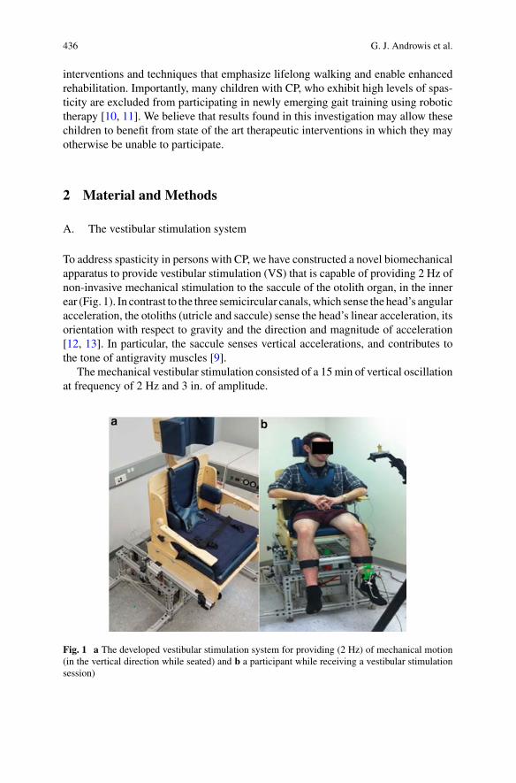
436 G. J. Androwis et al.
interventions and techniques that emphasize lifelong walking and enable enhancedrehabilitation. Importantly, many children with CP, who exhibit high levels of spas-ticity are excluded from participating in newly emerging gait training using robotictherapy [10, 11]. We believe that results found in this investigation may allow thesechildren to benefit from state of the art therapeutic interventions in which they mayotherwise be unable to participate.
2 Material and Methods
A. The vestibular stimulation system
To address spasticity in persons with CP, we have constructed a novel biomechanicalapparatus to provide vestibular stimulation (VS) that is capable of providing 2 Hz ofnon-invasive mechanical stimulation to the saccule of the otolith organ, in the innerear (Fig. 1). In contrast to the three semicircular canals,which sense the head’s angularacceleration, the otoliths (utricle and saccule) sense the head’s linear acceleration, itsorientation with respect to gravity and the direction and magnitude of acceleration[12, 13]. In particular, the saccule senses vertical accelerations, and contributes tothe tone of antigravity muscles [9].
Themechanical vestibular stimulation consisted of a 15min of vertical oscillationat frequency of 2 Hz and 3 in. of amplitude.
Fig. 1 a The developed vestibular stimulation system for providing (2 Hz) of mechanical motion(in the vertical direction while seated) and b a participant while receiving a vestibular stimulationsession)
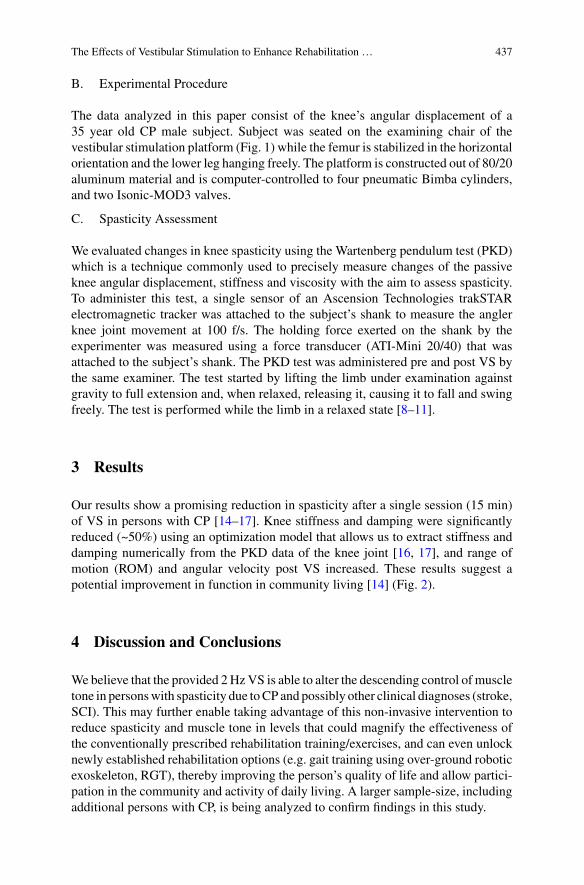
The Effects of Vestibular Stimulation to Enhance Rehabilitation … 437
B. Experimental Procedure
The data analyzed in this paper consist of the knee’s angular displacement of a35 year old CP male subject. Subject was seated on the examining chair of thevestibular stimulation platform (Fig. 1) while the femur is stabilized in the horizontalorientation and the lower leg hanging freely. The platform is constructed out of 80/20aluminum material and is computer-controlled to four pneumatic Bimba cylinders,and two Isonic-MOD3 valves.
C. Spasticity Assessment
We evaluated changes in knee spasticity using the Wartenberg pendulum test (PKD)which is a technique commonly used to precisely measure changes of the passiveknee angular displacement, stiffness and viscosity with the aim to assess spasticity.To administer this test, a single sensor of an Ascension Technologies trakSTARelectromagnetic tracker was attached to the subject’s shank to measure the anglerknee joint movement at 100 f/s. The holding force exerted on the shank by theexperimenter was measured using a force transducer (ATI-Mini 20/40) that wasattached to the subject’s shank. The PKD test was administered pre and post VS bythe same examiner. The test started by lifting the limb under examination againstgravity to full extension and, when relaxed, releasing it, causing it to fall and swingfreely. The test is performed while the limb in a relaxed state [8–11].
3 Results
Our results show a promising reduction in spasticity after a single session (15 min)of VS in persons with CP [14–17]. Knee stiffness and damping were significantlyreduced (~50%) using an optimization model that allows us to extract stiffness anddamping numerically from the PKD data of the knee joint [16, 17], and range ofmotion (ROM) and angular velocity post VS increased. These results suggest apotential improvement in function in community living [14] (Fig. 2).
4 Discussion and Conclusions
Webelieve that the provided 2HzVS is able to alter the descending control of muscletone in personswith spasticity due toCP and possibly other clinical diagnoses (stroke,SCI). This may further enable taking advantage of this non-invasive intervention toreduce spasticity and muscle tone in levels that could magnify the effectiveness ofthe conventionally prescribed rehabilitation training/exercises, and can even unlocknewly established rehabilitation options (e.g. gait training using over-ground roboticexoskeleton, RGT), thereby improving the person’s quality of life and allow partici-pation in the community and activity of daily living. A larger sample-size, includingadditional persons with CP, is being analyzed to confirm findings in this study.
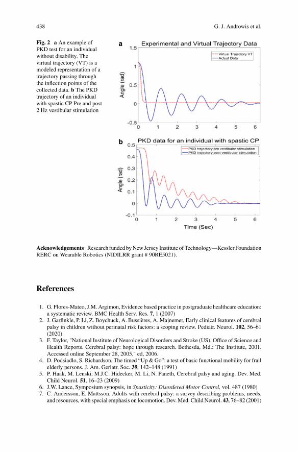
438 G. J. Androwis et al.
Fig. 2 a An example ofPKD test for an individualwithout disability. Thevirtual trajectory (VT) is amodeled representation of atrajectory passing throughthe inflection points of thecollected data. b The PKDtrajectory of an individualwith spastic CP Pre and post2 Hz vestibular stimulation
Acknowledgements Research funded byNewJersey Institute ofTechnology—Kessler FoundationRERC on Wearable Robotics (NIDILRR grant # 90RE5021).
References
1. G. Flores-Mateo, J.M. Argimon, Evidence based practice in postgraduate healthcare education:a systematic review. BMC Health Serv. Res. 7, 1 (2007)
2. J. Garfinkle, P. Li, Z. Boychuck, A. Bussières, A. Majnemer, Early clinical features of cerebralpalsy in children without perinatal risk factors: a scoping review. Pediatr. Neurol. 102, 56–61(2020)
3. F. Taylor, "National Institute of Neurological Disorders and Stroke (US), Office of Science andHealth Reports. Cerebral palsy: hope through research. Bethesda, Md.: The Institute, 2001.Accessed online September 28, 2005," ed, 2006.
4. D. Podsiadlo, S. Richardson, The timed “Up & Go”: a test of basic functional mobility for frailelderly persons. J. Am. Geriatr. Soc. 39, 142–148 (1991)
5. P. Haak, M. Lenski, M.J.C. Hidecker, M. Li, N. Paneth, Cerebral palsy and aging. Dev. Med.Child Neurol. 51, 16–23 (2009)
6. J.W. Lance, Symposium synopsis, in Spasticity: Disordered Motor Control, vol. 487 (1980)7. C. Andersson, E. Mattsson, Adults with cerebral palsy: a survey describing problems, needs,
and resources, with special emphasis on locomotion. Dev.Med. Child Neurol. 43, 76–82 (2001)
The Effects of Vestibular Stimulation to Enhance Rehabilitation … 439
8. S.M. Day, Y.W. Wu, D.J. Strauss, R.M. Shavelle, R.J. Reynolds, Change in ambulatory abilityof adolescents and young adults with cerebral palsy. Dev. Med. Child Neurol. 49, 647–653(2007)
9. J. Hutton, P. Pharoah, Effects of cognitive,motor, and sensory disabilities on survival in cerebralpalsy. Arch. Dis. Child. 86, 84–89 (2002)
10. L. Ahlborg, C. Andersson, P. Julin, Whole-body vibration training compared with resistancetraining: effect on spasticity, muscle strength and motor performance in adults with cerebralpalsy. J. Rehabil. Med. 38, 302–308 (2006)
11. E. Garcia, M. Cestari, D. Sanz-Merodio, Wearable exoskeletons for the physical treatmentof children with quadriparesis, in Humanoid Robots (Humanoids), 2014 14th IEEE-RASInternational Conference on (2014), pp. 425–430
12. K Cullen, Understanding space sickness, Department of Physiology, McGill University (2006)13. J. Goldberg, G. Desmadryl, R. Baird, C. Fernandez, The vestibular nerve of the chinchilla. IV.
Discharge properties of utricular afferents. J. Neurophysiol. 63, 781–790 (1990)14. G.J.M. Androwis, A. Peter, D. Jewaid, K.J. Nolan, R. Pilkar, A. Strongwater, R.A. Foulds, The
effect of mechanical vestibular stimulation on electromyography onset in a child with cerebralpalsy: a case study (2015)
15. G.J. Androwis, P.A. Michael, K.J. Nolan, A. Strongwater, R.A. Foulds, The effect of vestibularstimulation on knee angular trajectory and velocity in children with cerebral palsy, inBiomedical Engineering Conference (NEBEC), 2015 41st Annual Northeast (2015), pp. 1–2
16. G.J. Androwis, A. Strongwater, R.A. Foulds, Spasticity and dystonia differentiated via the equi-libriumpoint hypothesis, inBioengineeringConference (NEBEC), 2014 40th Annual Northeast(2014), pp. 1–2
17. G.J. Androwis, R.A. Foulds, A. Strongwater, D. Stone, Quantifying the effect of mechanicalvestibular stimulation on muscle tone and spasticity, in Bioengineering Conference (NEBEC),2013 39th Annual Northeast (2013), pp. 17–18

Digitalization and Artificial IntelligenceApplied to Wearable Technologies
and Ergonomics
A New Terrain Recognition Approach forPredictive Control of Assistive DevicesUsing Depth Vision
Ali H. A. Al-dabbagh and Renaud Ronsse
Abstract Vision based systems for terrain detection play important roles in mobilerobotics, and recently such systems emerged for locomotion assistance of disabledpeople. For instance, they can be used as wearable devices to assist blind people orto guide prosthesis or exoskeleton controller to retrieve gait patterns being adaptedto the executed task (overground walking, stairs, slopes, etc.). In this paper, wepresent a computer vision-based algorithm achieving the detection of flat ground,steps, and ramps using a depth camera. Starting from point cloud data collectedby the camera, it classifies the environment as a function of extracted features. Wefurther provide a pilot validation in an indoor environment containing a rich set ofdifferent types of terrains, even with partial occlusion, and observed that the overallsystem accuracy is above 94%. The paper further shows that our system needs lesscomputational resources than recently published concurrent approaches, owing tothe original transformation method we developed.
1 Introduction
The biomechanics of locomotion reveals that leg joints often produce mechanicalenergy in various locomotion tasks likewalking or stair ascending.Moreover, each ofthese tasks corresponds to different kinetic and kinematic patterns, even in steady-state. As consequence, active prostheses or exoskeletons are necessary to providedisabled users with the capacity to display healthy gait patterns. The control of suchdevices should be adaptive to the task being executed (walking, taking stairs, etc.)and several researchers recently developed such adaptive algorithms, for instance
This work was supported by the Conseil de l’action internationale of UCLouvain.
A. H. A. Al-dabbagh (B) · R. RonsseInstitute of Mechanics, Materials, and Civil Engineering Institute of Neuroscience; and LouvainBionics, Université catholique de Louvain, Louvain-la-Neuve, Belgiume-mail: [email protected]
R. Ronssee-mail: [email protected]
© The Author(s), under exclusive license to Springer Nature Switzerland AG 2022J. C. Moreno et al. (eds.), Wearable Robotics: Challenges and Trends,Biosystems & Biorobotics 27, https://doi.org/10.1007/978-3-030-69547-7_71
443
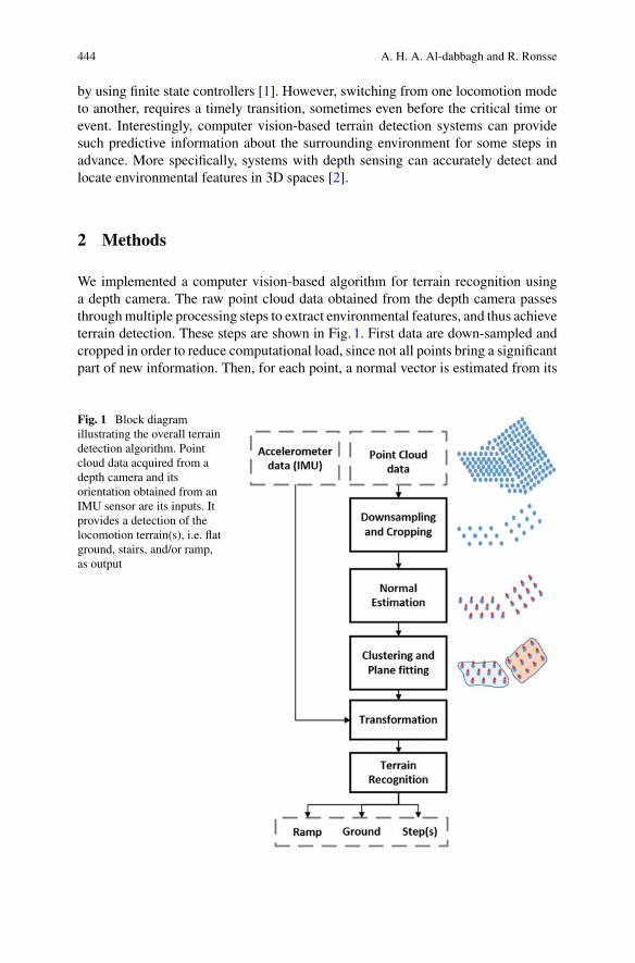
444 A. H. A. Al-dabbagh and R. Ronsse
by using finite state controllers [1]. However, switching from one locomotion modeto another, requires a timely transition, sometimes even before the critical time orevent. Interestingly, computer vision-based terrain detection systems can providesuch predictive information about the surrounding environment for some steps inadvance. More specifically, systems with depth sensing can accurately detect andlocate environmental features in 3D spaces [2].
2 Methods
We implemented a computer vision-based algorithm for terrain recognition usinga depth camera. The raw point cloud data obtained from the depth camera passesthroughmultiple processing steps to extract environmental features, and thus achieveterrain detection. These steps are shown in Fig. 1. First data are down-sampled andcropped in order to reduce computational load, since not all points bring a significantpart of new information. Then, for each point, a normal vector is estimated from its
Fig. 1 Block diagramillustrating the overall terraindetection algorithm. Pointcloud data acquired from adepth camera and itsorientation obtained from anIMU sensor are its inputs. Itprovides a detection of thelocomotion terrain(s), i.e. flatground, stairs, and/or ramp,as output
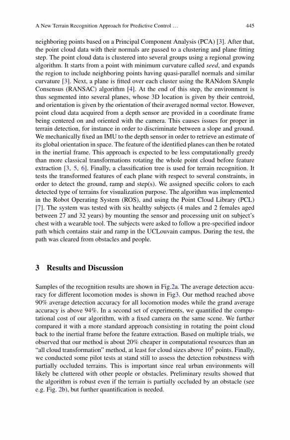
A New Terrain Recognition Approach for Predictive Control … 445
neighboring points based on a Principal Component Analysis (PCA) [3]. After that,the point cloud data with their normals are passed to a clustering and plane fittingstep. The point cloud data is clustered into several groups using a regional growingalgorithm. It starts from a point with minimum curvature called seed, and expandsthe region to include neighboring points having quasi-parallel normals and similarcurvature [3]. Next, a plane is fitted over each cluster using the RANdom SAmpleConsensus (RANSAC) algorithm [4]. At the end of this step, the environment isthus segmented into several planes, whose 3D location is given by their centroid,and orientation is given by the orientation of their averaged normal vector. However,point cloud data acquired from a depth sensor are provided in a coordinate framebeing centered on and oriented with the camera. This causes issues for proper interrain detection, for instance in order to discriminate between a slope and ground.We mechanically fixed an IMU to the depth sensor in order to retrieve an estimate ofits global orientation in space. The feature of the identified planes can then be rotatedin the inertial frame. This approach is expected to be less computationally greedythan more classical transformations rotating the whole point cloud before featureextraction [3, 5, 6]. Finally, a classification tree is used for terrain recognition. Ittests the transformed features of each plane with respect to several constraints, inorder to detect the ground, ramp and step(s). We assigned specific colors to eachdetected type of terrains for visualization purpose. The algorithm was implementedin the Robot Operating System (ROS), and using the Point Cloud Library (PCL)[7]. The system was tested with six healthy subjects (4 males and 2 females agedbetween 27 and 32 years) by mounting the sensor and processing unit on subject’schest with a wearable tool. The subjects were asked to follow a pre-specified indoorpath which contains stair and ramp in the UCLouvain campus. During the test, thepath was cleared from obstacles and people.
3 Results and Discussion
Samples of the recognition results are shown in Fig.2a. The average detection accu-racy for different locomotion modes is shown in Fig3. Our method reached above90% average detection accuracy for all locomotion modes while the grand averageaccuracy is above 94%. In a second set of experiments, we quantified the compu-tational cost of our algorithm, with a fixed camera on the same scene. We furthercompared it with a more standard approach consisting in rotating the point cloudback to the inertial frame before the feature extraction. Based on multiple trials, weobserved that our method is about 20% cheaper in computational resources than an“all cloud transformation” method, at least for cloud sizes above 105 points. Finally,we conducted some pilot tests at stand still to assess the detection robustness withpartially occluded terrains. This is important since real urban environments willlikely be cluttered with other people or obstacles. Preliminary results showed thatthe algorithm is robust even if the terrain is partially occluded by an obstacle (seee.g. Fig. 2b), but further quantification is needed.
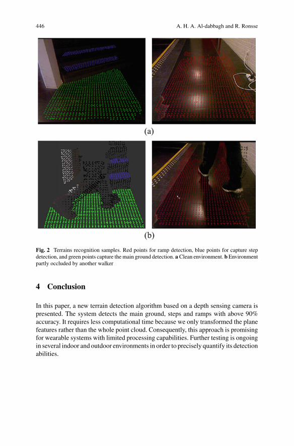
446 A. H. A. Al-dabbagh and R. Ronsse
Fig. 2 Terrains recognition samples. Red points for ramp detection, blue points for capture stepdetection, and green points capture the main ground detection. a Clean environment. bEnvironmentpartly occluded by another walker
4 Conclusion
In this paper, a new terrain detection algorithm based on a depth sensing camera ispresented. The system detects the main ground, steps and ramps with above 90%accuracy. It requires less computational time because we only transformed the planefeatures rather than the whole point cloud. Consequently, this approach is promisingfor wearable systems with limited processing capabilities. Further testing is ongoingin several indoor and outdoor environments in order to precisely quantify its detectionabilities.
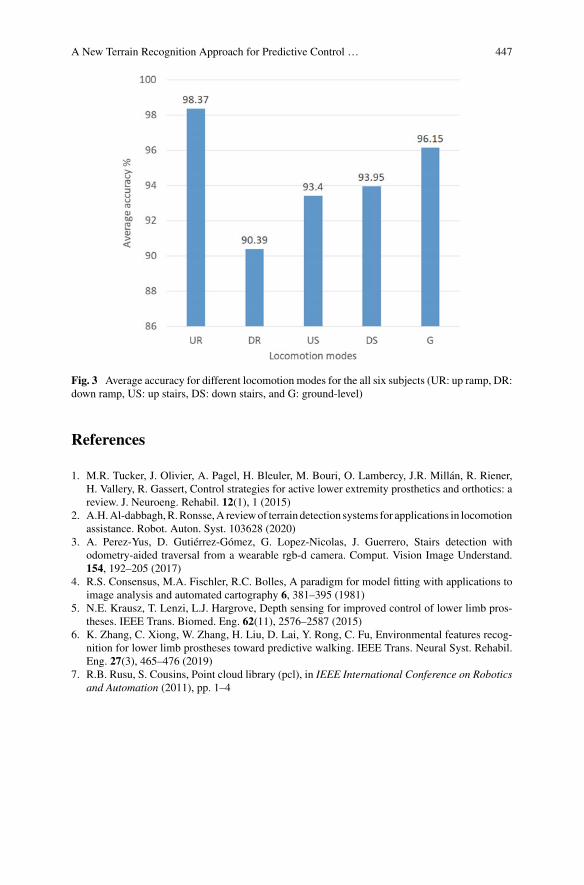
A New Terrain Recognition Approach for Predictive Control … 447
Fig. 3 Average accuracy for different locomotion modes for the all six subjects (UR: up ramp, DR:down ramp, US: up stairs, DS: down stairs, and G: ground-level)
References
1. M.R. Tucker, J. Olivier, A. Pagel, H. Bleuler, M. Bouri, O. Lambercy, J.R. Millán, R. Riener,H. Vallery, R. Gassert, Control strategies for active lower extremity prosthetics and orthotics: areview. J. Neuroeng. Rehabil. 12(1), 1 (2015)
2. A.H.Al-dabbagh,R.Ronsse,A reviewof terrain detection systems for applications in locomotionassistance. Robot. Auton. Syst. 103628 (2020)
3. A. Perez-Yus, D. Gutiérrez-Gómez, G. Lopez-Nicolas, J. Guerrero, Stairs detection withodometry-aided traversal from a wearable rgb-d camera. Comput. Vision Image Understand.154, 192–205 (2017)
4. R.S. Consensus, M.A. Fischler, R.C. Bolles, A paradigm for model fitting with applications toimage analysis and automated cartography 6, 381–395 (1981)
5. N.E. Krausz, T. Lenzi, L.J. Hargrove, Depth sensing for improved control of lower limb pros-theses. IEEE Trans. Biomed. Eng. 62(11), 2576–2587 (2015)
6. K. Zhang, C. Xiong, W. Zhang, H. Liu, D. Lai, Y. Rong, C. Fu, Environmental features recog-nition for lower limb prostheses toward predictive walking. IEEE Trans. Neural Syst. Rehabil.Eng. 27(3), 465–476 (2019)
7. R.B. Rusu, S. Cousins, Point cloud library (pcl), in IEEE International Conference on Roboticsand Automation (2011), pp. 1–4
Simulation-Based OptimizationMethodology for Designing a Workspacewith an Exoskeleton
Zohar Potash, Jawad Masood, and Raziel Riemer
Abstract We present a preliminary concept of simulation-based optimizationmethodology framework for designing workspace with exoskeleton. The frame-work consists of three main elements human (ergonomic performance), workspace(industrial tasks, sub-tasks, environment, safety) and exoskeleton (assistance levels,robustness, workspace, imposed constraints), mathematical models and interactionsthat can converge to an optimal solution i.e. workspace design recommendations.We select the changing the drill bit in for the vertical drilling machine as an indus-trial task. The human and workspace mathematical modelling is performed using theJack software and Process Simulate software. In future, we will focus on develop-ing exoskeletonmathematical model and establishmathematical interaction betweenhuman model and the exoskeleton model.
1 Introduction
Work-related musculoskeletal disorders (MSDs) are responsible for 30% of lostworkdays due to injury and result in annual costs of up to $54 billion in the USalone [1]. The major source of work-related costs due to MSDs is manual materialhandling tasks, such as lifting, carrying and lowering objects accounting for 36%of costs [2]. One way to reduce workloads and injuries is to change the workplacedesign. However, using method such as NIOSH lifting equation [3] or digital humanmodel software’s and changing the workplace design parameters require the designiterations that takes relatively along time thus in many cases the solution foundalthough meet the ergonomics guideline may not be optimal in terms of productivity.
Z. Potash (B) · R. RiemerBiomechanics and Robotics Laboratory of the Ben-Gurion, University of the Negev,Beer-Sheva 84105, Israele-mail: [email protected]
J. MasoodProcesses and Factory of the Future Department of CTAG,Centro Tecnológico de Automoción de Galicia, O Porriño, Spaine-mail: [email protected]
© The Author(s), under exclusive license to Springer Nature Switzerland AG 2022J. C. Moreno et al. (eds.), Wearable Robotics: Challenges and Trends,Biosystems & Biorobotics 27, https://doi.org/10.1007/978-3-030-69547-7_72
449
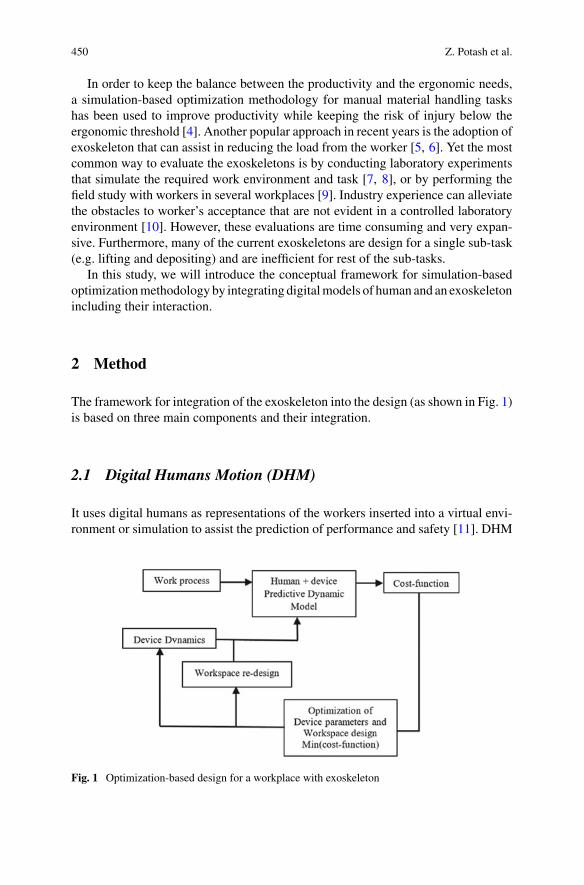
450 Z. Potash et al.
In order to keep the balance between the productivity and the ergonomic needs,a simulation-based optimization methodology for manual material handling taskshas been used to improve productivity while keeping the risk of injury below theergonomic threshold [4]. Another popular approach in recent years is the adoption ofexoskeleton that can assist in reducing the load from the worker [5, 6]. Yet the mostcommon way to evaluate the exoskeletons is by conducting laboratory experimentsthat simulate the required work environment and task [7, 8], or by performing thefield study with workers in several workplaces [9]. Industry experience can alleviatethe obstacles to worker’s acceptance that are not evident in a controlled laboratoryenvironment [10]. However, these evaluations are time consuming and very expan-sive. Furthermore, many of the current exoskeletons are design for a single sub-task(e.g. lifting and depositing) and are inefficient for rest of the sub-tasks.
In this study, we will introduce the conceptual framework for simulation-basedoptimizationmethodology by integrating digitalmodels of human and an exoskeletonincluding their interaction.
2 Method
The framework for integration of the exoskeleton into the design (as shown in Fig. 1)is based on three main components and their integration.
2.1 Digital Humans Motion (DHM)
It uses digital humans as representations of the workers inserted into a virtual envi-ronment or simulation to assist the prediction of performance and safety [11]. DHM
Fig. 1 Optimization-based design for a workplace with exoskeleton
Simulation-Based Optimization Methodology … 451
includes biomechanics model, range of motion (ROM), visualizations of the human(appearance, skin, body dimensions).
2.2 Exoskeleton Modeling
We will develop an exoskeleton model that includes parameters such as assistivejoint torques, forces, changes in the ROM and additional mass carried by the humanand its relative position.
2.3 Optimization Methodology
Uses a framework for formulating workplace design as an optimization problemthat maximizes productivity while maintaining ergonomic thresholds. Applicationof constraint optimization using genetic algorithm could be the best solution [4].
By using the exoskeleton and the human modeling it will be possible by test theeffect of the different design parameter of the exoskeleton on the biomechanicalloads in this optimization framework. The simulation will enable to examine theexoskeleton impact in the existing workspace. Furthermore, using the optimizationproblem will enable us to test both the possibility of changing the workspace with orwithout the exoskeleton to reveal the best possible solution. Further, we could alsochange the exoskeleton parameter with the aim of giving guideline for better designof an exoskeleton before acutely building and testing. Here we will demonstrate theidea of how results of such framework could assist theworkspace and the exoskeletondesign.
2.3.1 Step 1: Feeding Industrial Task Information
The figure performs lift of tool (15kg) from a platform (table height 91.4cm), carry-ing several meters, lifting to a machine (height 170cm), re-grasp with the left handand pressing a button located on the side (height 200cm) with the right hand.
2.3.2 Step 2: Enriching the Mathematical Model
In the second stepwewill build a simulation that represents the task and add the forcesacting on the body with the addition of the exoskeleton. This will be performed bymodeling the rigid links and mechanism of the shoulder exoskeleton (support liftingtasks) and finding the location of the center of mass and inertia distribution of thedevice. We will include the information of the individual link mass-inertia to thecorresponding body part of the human model. One interesting aspect is to consider
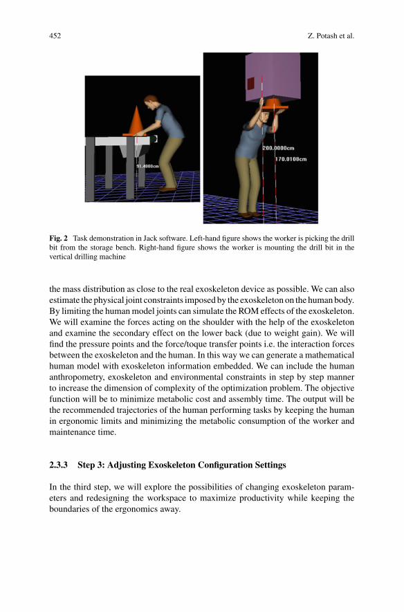
452 Z. Potash et al.
Fig. 2 Task demonstration in Jack software. Left-hand figure shows the worker is picking the drillbit from the storage bench. Right-hand figure shows the worker is mounting the drill bit in thevertical drilling machine
the mass distribution as close to the real exoskeleton device as possible. We can alsoestimate the physical joint constraints imposedby the exoskeleton on the humanbody.By limiting the humanmodel joints can simulate the ROM effects of the exoskeleton.We will examine the forces acting on the shoulder with the help of the exoskeletonand examine the secondary effect on the lower back (due to weight gain). We willfind the pressure points and the force/toque transfer points i.e. the interaction forcesbetween the exoskeleton and the human. In this way we can generate a mathematicalhuman model with exoskeleton information embedded. We can include the humananthropometry, exoskeleton and environmental constraints in step by step mannerto increase the dimension of complexity of the optimization problem. The objectivefunction will be to minimize metabolic cost and assembly time. The output will bethe recommended trajectories of the human performing tasks by keeping the humanin ergonomic limits and minimizing the metabolic consumption of the worker andmaintenance time.
2.3.3 Step 3: Adjusting Exoskeleton Configuration Settings
In the third step, we will explore the possibilities of changing exoskeleton param-eters and redesigning the workspace to maximize productivity while keeping theboundaries of the ergonomics away.
Simulation-Based Optimization Methodology … 453
3 Conclusion
The preliminary conceptual framework for simulation-based optimization method-ology for designing a workspace with an exoskeleton is presented. We have alreadyverify the workspace and human simulation using Jack and Process. Future researchis needed to validate and verify the full framework and understand the shortcom-ing of the approach. Future efforts will consists of development of the exoskeletonmathematical model and defining constraints to generate a high fidelity exo-humandigital interaction.
Acknowledgements This work was supported by the Processes and Factory of the Future Depart-ment of CTAG—Centro Tecnológico de Automoción de Galicia.
References
1. P.M. Harris, Nonfatal Occupational Injuries Involving the Eyes, 2004 (Compensation andworking conditions online US Department of Labor, Bureau of Labor Statistics, 2008)
2. P.L. Murphy, G.S. Sorock, T.K. Courtney, B.S. Webster, T.B. Leamon, Injury and illness in theAmerican workplace: a comparison of data sources. Am. J. Ind. Med. 30(2), 130–141 (1996)
3. H. D. of Biomedical and B. Science,Work Practices Guide for Manual Lifting (US Departmentof Health and Human Services, Public Health Service, Centers..., 1981), no. 81–122
4. Y. Harari, A. Bechar, R. Riemer, Simulation-based optimization methodology for a manualmaterial handling task design that maximizes productivity while considering ergonomic con-straints. IEEE Trans. Human-Mach. Syst. 49(5), 440–448 (2019)
5. M. Wehner, D. Rempel, H. Kazerooni, Lower extremity exoskeleton reduces back forces inlifting, in Dynamic Systems and Control Conference, vol. 48937 (2009), pp. 49–56
6. N. Sylla, V. Bonnet, F. Colledani, P. Fraisse, Ergonomic contribution of able exoskeleton inautomotive industry. Int. J. Ind. Ergon. 44(4), 475–481 (2014)
7. P.H. Crowell, J.H. Park, C.A. Haynes, J.M. Neugebauer, C.A. Boynton, Design, evaluation,and research challenges relevant to exoskeletons and exosuits: a 26-year perspective from theus army research laboratory. IISE Trans. Occupational Ergon. Human Fact. 7(3–4), 199–212(2019)
8. T. Luger, T.J. Cobb, R. Seibt, M.A. Rieger, B. Steinhilber, Subjective evaluation of a passivelower-limb industrial exoskeleton used during simulated assembly. IISE Trans. OccupationalErgon. Human Fact. 7(3–4), 175–184 (2019)
9. R. Hensel, M. Keil, Subjective evaluation of a passive industrial exoskeleton for lower-backsupport: a field study in the automotive sector. IISE Trans. Occupational Ergon. Human Fact.7(3–4), 213–221 (2019)
10. S. Spada, L. Ghibaudo, S. Gilotta, L. Gastaldi, M.P. Cavatorta, Investigation into the applica-bility of a passive upper-limb exoskeleton in automotive industry. Proc. Manuf. 11, 1255–1262(2017)
11. H.O. Demirel, V.G. Duffy, Applications of digital humanmodeling in industry, in InternationalConference on Digital Human Modeling (Springer, 2007), pp. 824–832
Optimizing Active Spinal Exoskeletonsto Minimize Low Back Loads
Giorgos D. Marinou and Katja D. Mombaur
Abstract The design and control of exoskeletons is not a straight forward taskand presents a lot of challenges. Especially in cases of preventing biomechanicaldamages, for example low back loads, exoskeletons should be able to provide thenecessary amount of support without hindering or hurting the user in any way. To thisextend, this study exploits optimal control to evaluate cost functions that minimize(a) cumulative low back loads, (b) peak low back loads and (c) a combination ofthe previous, while constraining contact (interaction) forces between human andexoskeleton. The results are compared to a kinematic reconstruction from a humanwithout exoskeleton performing the same task of lifting a 10 kg box. Cost function(c) performs the best in terms of achieving an equilibrium between minimizingcumulative and peak lumbar torques—subject to the actuator’s torque and speedlimit—reducing the peak torque by 48%.
1 Introduction
LOWER back injuries and consequently low back pain is one of the most prevalenthazards within the working environment and especially in industrial settings [1].Recent developments and potential applications of wearable assistive technologiesare exponentially increasing. In the context of alleviating lower back loads a fewsolutions have been researched or even commercialized, including passive [2–4] andactive [5–7] exoskeletons.Oneof the current challenges still, is predicting appropriatesupport torques for both the passive and active elements of exoskeletons as to alleviatelow back loads whilst ensuring comfort of the user. By the means of optimization,
G. D. Marinou (B)Optimization, Robotics and Biomechanics Lab, Institute of Computer Engineering (ZITI),Heidelberg University, Heidelberg, Germanye-mail: [email protected]
K. D. MombaurCanada Excellence Research Chair in Human-Centre Robotics and Machine Intelligence, SystemsDesign Engineering & Mechanical and Mechatronics Engineering, University of Waterloo,Waterloo, Canada
© The Author(s), under exclusive license to Springer Nature Switzerland AG 2022J. C. Moreno et al. (eds.), Wearable Robotics: Challenges and Trends,Biosystems & Biorobotics 27, https://doi.org/10.1007/978-3-030-69547-7_73
455
456 G. D. Marinou and K. D. Mombaur
the mechanical design of the passive elements can be informed as to provide optimalsupport [8]. For the active parts of the exoskeleton, optimal control can provideoptimal torque profiles for specific motions, such as the stoop lift investigated in thispaper.
Based on the development of spinal exoskeletons in the European projectSPEXOR [9] and building upon previous work on predicting human lifting motionsusing optimal control to minimize muscle activation at all joints [10], this studyaims to use appropriate cost functions in order to minimize both cumulative andpeaks torques [11] about the lumbosacral joint L5/S1 and produce optimal torqueprofiles for a hip joint hydraulic actuator. We evaluate and present the results interms of lumbar moments reduction compared to an unassisted motion and moreoverinvestigate the torque profiles yielded for the hip actuator.
2 Methods
Dynamic multibody systemmodels of human and exoskeleton are created accordingto mass, inertia properties and segment lengths. A stoop lift has been recorded andaccording to that we track the kinematics and reconstruct the motion using optimalcontrol and a least squares objective function on errors in the trajectory. We also useoptimal control to predict a stoop lift with minimum lumbar moments, accordingto the cost functions detailed below. The following sections describe the modelingpipeline, optimal control problem (OCP) formulations and the evaluation of the costfunctions used.
A. Modeling
Through collecting anthropometric data, subject-specific dynamic models of thehuman are created. They are combined with a corresponding spinal exoskeletonmodel of an active prototype developed in SPEXOR. Both models are representedby rigid 2D multibody systems that are projected in the sagittal plane. We model thehuman body as a planar floating base, that consists of 11 segments (pelvis, trunk,head, thighs, shanks, feet, upper arms forearms incl. Hands) and has 13 degreesof freedom (DOF), including a complex lumbar joint which resembles the L1–L5vertebrae and assumes symmetry. For actuating the human, we use direct torquesat each joint, limited by the estimated maximum torques in positive and negativedirection. The exoskeleton model consists of 5 segments (pelvis, thigh and uppertorso bracemodules, torso beams, thigh interface carrying the actuator) with a total of8 DOF. Unique to the SPEXOR exoskeleton model are three passive beams—placedat the back of the torso—with a spring-like behavior which produce a torque betweenlumbar and torso module, and two hydraulic actuators which produce torques at thelevel of the hips. The dynamics governing the motion are solved using the RigidBody Dynamics Library (RBDL) [12]. We use kinematic constraints to attach theexoskeleton to the body, the feet to the ground and the hands on the box.
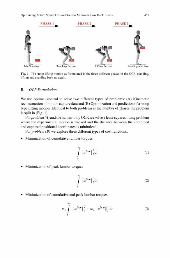
Optimizing Active Spinal Exoskeletons to Minimize Low Back Loads 457
Fig. 1 The stoop lifting motion as formulated in the three different phases of the OCP: standing,lifting and standing back up again.
B. OCP Formulation
We use optimal control to solve two different types of problems: (A) Kinematicreconstruction of motion capture data and (B) Optimization and prediction of a stooptype lifting motion. Identical to both problems is the number of phases the problemis split in (Fig. 1).
For problem (A) and the human-onlyOCP,we solve a least-squares fitting problemwhere the experimental motion is tracked and the distance between the computedand captured positional coordinates is minimized.
For problem (B) we explore three different types of cost functions:
• Minimization of cumulative lumbar torques
ti+1∫
ti
∥∥ulum∥∥2
2dt (1)
• Minimization of peak lumbar torques
ti+1∫
ti
∥∥ulum∥∥4
2dt (2)
• Minimization of cumulative and peak lumbar torques
w1
ti+1∫
ti
∥∥ulum∥∥2
2 + w2
∥∥ulum∥∥4
2 dt (3)
458 G. D. Marinou and K. D. Mombaur
where w1 and w2 are given weights to the objective function terms to emphasizethe importance of each and ulum are the controls of the lumbar vertebrae L1–L5.Identical to both problems, are the contact constraints we enforce between thehuman and the exoskeleton, to ensure comfort well under pain limits. For theprediction of the motion, we suggest the initial values of the state vector in ourOCP with the data captured in the experiment. For optimizing we use the directmultiple shooting method implemented in MUSCOD-II [13].
3 Results and Discussion
In investigating the effect of the exoskeleton through cost functions (2)–(4), it is clearthat there is an evident reduction in both cumulative and peak lumbar moments. Forthe cumulative-OCP we can see a reduction to a peak moment of 180 Nm andcumulative moments of 119 Nm. For the peak-OCP, peak moments were reducedto 110 Nm and cumulative moments to 150 Nm. Finally, for the hybrid-OCP, peakmoments were reduced to 140 Nm and cumulative ones to 135 Nm. In Fig. 2b it isclear that the human subject had a small range of motion when it comes to lumbarflexion as the angle is much lower than for the optimized with-exoskeleton OCPs.The lumbar flexion angles for thewith-exoskeletonOCP resemble the L5moments interms of magnitude, as we can see that the highest peaks in moments were performedby the cumulative-OCP where we can also see the highest lumbar flexion angles atthe point lifting the box from the ground.
Figure 2c shows the contributions of the hydraulic actuator at the hip and the beamsat the back of the torso. We can see that they follow a similar shape throughout themotion of lifting the box, with the highest contributions being at the second phasebetween touching and beginning to lift the box. Figure 2c shows that with higheractuator output, for example the hybrid-OCP, the lumbar flexion angle observed inFig. 2b is smaller throughout the motion, so the actuator manages to reduce thehuman lumbar flexion.
Especially when observing Fig. 2a, it is clear that the hybrid OCP performs in thebest way in terms of concluding to a desired equilibrium between minimum peakand cumulative torques. In terms of cumulative low back loads, the area under thegraph is less than the cumulative OCP and the peak moment is less than the peak ofthe cumulative OCP.
4 Conclusions
Based on the study performed in evaluating three different cost functions for mini-mizing cumulative and peak lumbar torques, we have successfully managed to iden-tify a hybrid cost function that minimizes both with respective weights. We success-fully predicted and tailored the torque profiles of exoskeleton actuators according to
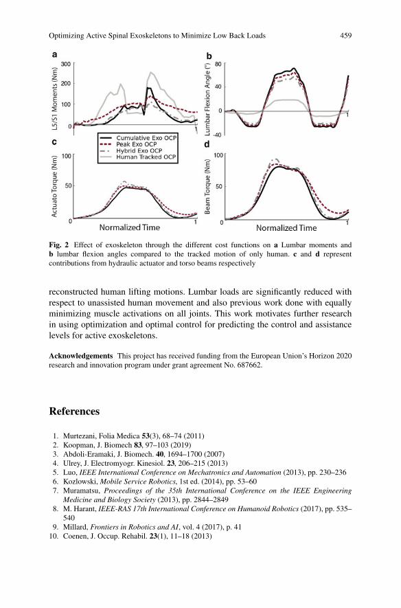
Optimizing Active Spinal Exoskeletons to Minimize Low Back Loads 459
Fig. 2 Effect of exoskeleton through the different cost functions on a Lumbar moments andb lumbar flexion angles compared to the tracked motion of only human. c and d representcontributions from hydraulic actuator and torso beams respectively
reconstructed human lifting motions. Lumbar loads are significantly reduced withrespect to unassisted human movement and also previous work done with equallyminimizing muscle activations on all joints. This work motivates further researchin using optimization and optimal control for predicting the control and assistancelevels for active exoskeletons.
Acknowledgements This project has received funding from the European Union’s Horizon 2020research and innovation program under grant agreement No. 687662.
References
1. Murtezani, Folia Medica 53(3), 68–74 (2011)2. Koopman, J. Biomech 83, 97–103 (2019)3. Abdoli-Eramaki, J. Biomech. 40, 1694–1700 (2007)4. Ulrey, J. Electromyogr. Kinesiol. 23, 206–215 (2013)5. Luo, IEEE International Conference on Mechatronics and Automation (2013), pp. 230–2366. Kozlowski, Mobile Service Robotics, 1st ed. (2014), pp. 53–607. Muramatsu, Proceedings of the 35th International Conference on the IEEE Engineering
Medicine and Biology Society (2013), pp. 2844–28498. M. Harant, IEEE-RAS 17th International Conference on Humanoid Robotics (2017), pp. 535–
5409. Millard, Frontiers in Robotics and AI, vol. 4 (2017), p. 4110. Coenen, J. Occup. Rehabil. 23(1), 11–18 (2013)
460 G. D. Marinou and K. D. Mombaur
11. J. Babic, SN Appl. Sci. 262 (2019)12. M.L. Felis, RBDL: an efficient rigid-body dynamics library using recursive algorithms. Auton.
Robot. 41(2), 495–511 (2016). https://doi.org/10.1007/s10514-016-9574-013. D.B. Leineweber et al., Comput. Chem. Eng. (2013)
LSTM and CNN Based IMU SensorFusion Approach for Human PoseIdentification in Manual HandlingActivities
Enrique Bances, Adnan Mushtaq Ali Karol, and Urs Schneider
Abstract In recent years, human pose estimation has become a very importantresearch topic in the context of control engines, and exoskeletons. In this paper, wepropose a Long Short-Term Memory (LSTM) and Convolutional Neural Networks(CNN) based Hybrid Deep Neural network, aimed to estimate human pose whilehandling of loads. The proposed model is capable to identify three such activities,i.e. load lifting from the ground, load shifting, and uplifting of the load. For thispurpose, a inertial sensor unit (IMU)-based system was developed to collect theraw data. Next, to obtain more robust and accurate results, Kalman filtering has beenused as a fusion technique. Rigorous fine-tuning and simulations show that themodelobtained from the Kalman filtering achieves better results as compared to the rawdata. Our proposed model can classify the target activities with a test accuracy of86%.
1 Introduction
Industries, like logistics and warehouses, are labor-intensive as well as physicallydemanding, where heavy manual material handling is often required which intro-duces unhealthy work postures. Hence, the workers are exposed to the danger ofdeveloping work-related musculoskeletal disorders (MSD). MSDs are one of themost common work-related complaints, affecting millions of workers and costingbillions of euros. For instance, in 2015, more than 61% of workers reported somekind of MSD in Europe [8], increasing by 21% compared to the previous study car-ried out in 2012 [9]. Wearable exoskeletons could offer an alternative solution to thisproblem of heavy weight-lifting since it helps to reduce fatigue.
One of the powered exoskeletons challenges in the development is the complexalgorithms to assure security, confort and, energy efficiency. An AI model could helpto optimize the control system implementation. Once the activities that are being
E. Bances (B) · A. M. A. Karol · U. SchneiderInstitute of Industrial Manufacturing and Management-IFF, University of Stuttgart, Nobelstr 12,70569 Stuttgart, Germanye-mail: [email protected]
© The Author(s), under exclusive license to Springer Nature Switzerland AG 2022J. C. Moreno et al. (eds.), Wearable Robotics: Challenges and Trends,Biosystems & Biorobotics 27, https://doi.org/10.1007/978-3-030-69547-7_74
461
462 E. Bances et al.
performed are identified, it is possible for the exoskeleton to infer information andchange the state of the mechanical system, like the torque and the angular velocityof motors for an activity.
In this work, we identify three such activities, i.e. holding (label ‘0’), carrying(label ‘1’), and lifting (label ‘2’), based on a long short-termmemory (LSTM) [4], aswell as convolutional neural networks (CNN) model using IMU sensor fusion data.
2 Related Work
SensorFusionwasused for humanactivity recognition such as sitting, lying, standing,washing dishes, vacuuming, sweeping, walking, ascending stairs, descending stairs,treadmill running, and bicycling. After the analysis of different types of filters forthe sensor, Kalman filter and complimentary filter were suggested [1].
Human activities pose identification, like, eating, driving, and cooking are pre-dicted using an Apple watch on the right-hand using LSTM architecture. The pro-posed dataset HAD-AW with LSTM gave an accuracy of 0.953 as compared to theexisting datasets [2]. In addition, work involving exoskeletons and classification useadditional force sensors for task classification, to lift and to lower, with FSR (ForceSensing Resistor) to dynamically detect weight differences in an exoskeleton device[3].
3 Model Architecture and Description
An IMU-based suit was implemented to collect data. Two IMU sensors were usedto record data, which were placed on the spinal cord and the right arm of the per-son. IMU 9DoF was used, which measures the accelerometer, gyroscope, and themagnetometer values along the three-axis. The model consists of LSTM layers withAdam algorithm (adaptive moment estimation) as the optimizer and the learningrate of 0.0001. Convolution layers were also used to increase overall accuracy. Twodifferent models were created, one for the sensor raw values and another for sensorfusion values. Categorical-cross entropy was used as the loss function in both mod-els. For training and validation, the dataset was divided into 0.8 and 0.2 ratios. Allthe experiments have been performed in Google Colab with GPU and 12GB RAM.
4 Model Implementation
No relatable data with respect to the problem statement was available and thus adataset had to be created. The dataset was recorded by 20 people performing eachactivity to be recognized 10 times with a proper hardware setup. The data was then
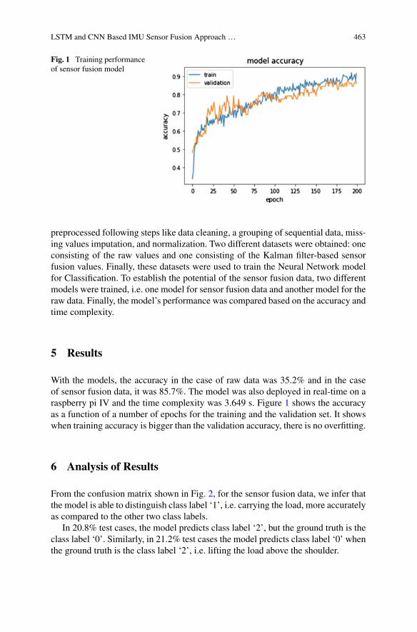
LSTM and CNN Based IMU Sensor Fusion Approach … 463
Fig. 1 Training performanceof sensor fusion model
preprocessed following steps like data cleaning, a grouping of sequential data, miss-ing values imputation, and normalization. Two different datasets were obtained: oneconsisting of the raw values and one consisting of the Kalman filter-based sensorfusion values. Finally, these datasets were used to train the Neural Network modelfor Classification. To establish the potential of the sensor fusion data, two differentmodels were trained, i.e. one model for sensor fusion data and another model for theraw data. Finally, the model’s performance was compared based on the accuracy andtime complexity.
5 Results
With the models, the accuracy in the case of raw data was 35.2% and in the caseof sensor fusion data, it was 85.7%. The model was also deployed in real-time on araspberry pi IV and the time complexity was 3.649 s. Figure 1 shows the accuracyas a function of a number of epochs for the training and the validation set. It showswhen training accuracy is bigger than the validation accuracy, there is no overfitting.
6 Analysis of Results
From the confusion matrix shown in Fig. 2, for the sensor fusion data, we infer thatthe model is able to distinguish class label ‘1’, i.e. carrying the load, more accuratelyas compared to the other two class labels.
In 20.8% test cases, the model predicts class label ‘2’, but the ground truth is theclass label ‘0’. Similarly, in 21.2% test cases the model predicts class label ‘0’ whenthe ground truth is the class label ‘2’, i.e. lifting the load above the shoulder.
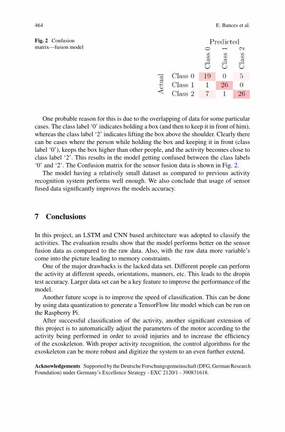
464 E. Bances et al.
Fig. 2 Confusionmatrix—fusion model
One probable reason for this is due to the overlapping of data for some particularcases. The class label ‘0’ indicates holding a box (and then to keep it in front of him),whereas the class label ‘2’ indicates lifting the box above the shoulder. Clearly therecan be cases where the person while holding the box and keeping it in front (classlabel ‘0’), keeps the box higher than other people, and the activity becomes close toclass label ‘2’. This results in the model getting confused between the class labels‘0’ and ‘2’. The Confusion matrix for the sensor fusion data is shown in Fig. 2.
The model having a relatively small dataset as compared to previous activityrecognition system performs well enough. We also conclude that usage of sensorfused data significantly improves the models accuracy.
7 Conclusions
In this project, an LSTM and CNN based architecture was adopted to classify theactivities. The evaluation results show that the model performs better on the sensorfusion data as compared to the raw data. Also, with the raw data more variable’scome into the picture leading to memory constraints.
One of the major drawbacks is the lacked data set. Different people can performthe activity at different speeds, orientations, manners, etc. This leads to the dropintest accuracy. Larger data set can be a key feature to improve the performance of themodel.
Another future scope is to improve the speed of classification. This can be doneby using data quantization to generate a TensorFlow lite model which can be run onthe Raspberry Pi.
After successful classification of the activity, another significant extension ofthis project is to automatically adjust the parameters of the motor according to theactivity being performed in order to avoid injuries and to increase the efficiencyof the exoskeleton. With proper activity recognition, the control algorithms for theexoskeleton can be more robust and digitize the system to an even further extend.
Acknowledgements Supportedby theDeutscheForschungsgemeinschaft (DFG,GermanResearchFoundation) under Germany’s Excellence Strategy - EXC 2120/1 - 390831618.
LSTM and CNN Based IMU Sensor Fusion Approach … 465
References
1. H.F. Nweke, Y.W. Teh, G. Mujtaba, U.R. Alo, M.A. Al-garadi, Multi-sensor fusion based onmultiple classifier systems for human activity identification. Human-Centric Comput. Inf. Sci.9(1), 34 (2019)
2. S. Ashry, R. Elbasiony, W. Gomaa, An LSTM-based descriptor for human activities recog-nition using IMU sensors, in Proceedings of the 15th International Conference on Informaticsin Control, Automation and Robotics, ICINCO, vol. 1 (2018), pp. 494–501
3. L.A. Mateos, Characterizing Lifting and Lowering Activities with Insole FSR sensors in indus-trial exoskeletons (2017). arXiv:1706.05440
4. S. Hochreiter, J. Schmidhuber, Long short-term memory. Neural Comput. 9(8), 1735–1780(1997)
5. Y. Kim, H. Bang, Introduction to Kalman filter and its applications by Submitted: April 26th2018, Reviewed: July 30th 2018, Published: November 5th 2018. https://doi.org/10.5772/intechopen.80600
6. European foundation for the improvement of living and working conditions, in First Findings:Sixth European Working Conditions Survey: Résu-mé (Publications Office, 2015)
7. D. Anxo, C. Franz, A. Kümmerling, Working time and work–life balance in a life course per-spective: a report based on the fifth European working conditions survey (Eurofound, 2013)
8. European Foundation, for the improvement of living and working conditions and others, inFirst Findings: Sixth European Working Conditions Survey (Publications Office, 2015). ISBN:978-92-897-1429-7. https://doi.org/10.2806/59106
9. D. Anxo, C. Franz, A. Kümmerling, Working time and work–life balance in a life course per-spective: a report based on the fifth European working conditions survey (Eurofound, 2013).http://urn.kb.se/resolve?urn=urn:nbn:se:lnu:diva-30766
Visual Feedback Strategy Based onSerious Games for Therapy with T-FLEXAnkle Exoskeleton
Angie Pino, Daniel Gomez-Vargas, Marcela Múnera, and Carlos A. Cifuentes
Abstract Therapies with repetitive exercises can result in a lack of interest andmotivation of the patient. Therefore, the inclusion of feedback strategies, such asserious games, evidences a significant improvement in those aspects. This paperpresents the development and a preliminary validation with a healthy subject ofa visual and interactive interface based on serious games for the rehabilitation ofpatients with ankle dysfunctions. The results show a high level of adaptation of theuser to the interface and positive perception in this application.
Keywords Serious games · Ankle exoskeleton · Gait rehabilitation · Visualfeedback ·Movement intention detection
1 Introduction
Physical therapy aims to counteract stroke after-effects and provide independenceto the survivor. However, different studies associated with the inclusion of roboticdevices present promising results (e.g., ankle exoskeletons) in the motor recovery ofthe patient [1].
Specifically, the T-FLEX ankle exoskeleton improved motor recovery during 18sessions of repetitive movements [2]. Nevertheless, the study exhibited a lack ofinteraction and patient attention in the session [2]. Considering that repetitive exer-cises can result in low motivation and tedious experience [3], the use of T-FLEXcould have better results.
A. Pino · D. Gomez-Vargas ·M. Múnera · C. A. Cifuentes (B)Department of Biomedical Engineering, Colombian School of Engineering Julio Garavito,Bogota, Colombiae-mail: [email protected]
A. Pinoe-mail: [email protected]
D. Gomez-Vargase-mail: [email protected]
M. Múnerae-mail: [email protected]
© The Author(s), under exclusive license to Springer Nature Switzerland AG 2022J. C. Moreno et al. (eds.), Wearable Robotics: Challenges and Trends,Biosystems & Biorobotics 27, https://doi.org/10.1007/978-3-030-69547-7_75
467
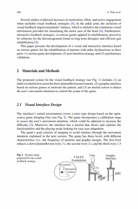
468 A. Pino et al.
Several studies evidenced increases in motivation, effort, and active engagementwhen included visual feedback strategies [4]. In the ankle joint, the inclusion ofvisual feedback improved patients’ balance, which is related to the continuous visualinformation provided for stimulating the motor area of the brain [4]. Furthermore,interactive feedback strategies, or serious games applied in rehabilitation, proved tobe solutions for the discouragement found in long-term therapies and efficient gaitrehabilitation [5].
This paper presents the development of a visual and interactive interface basedon serious games for the rehabilitation of patients with ankle dysfunctions in threeparts: (1) serious game development, (2) user intention strategy, and (3) a preliminaryvalidation.
2 Materials and Methods
The proposed system for the visual feedback strategy (see Fig. 1) includes (1) anankle exoskeleton to assist the dorsi-plantarflexionmovements, (2) a graphic interfacebased on serious-games to motivate the patient, and (3) an inertial sensor to detectthe user’s movement intention to control the avatar of the game.
2.1 Visual Interface Design
The interface’s virtual environment covers a retro type design based on the open-source game Jumping Guy (see Fig. 2). The game incorporates a calibration stageto assess the user’s movement intention, which could be adjusted to increase thedifficulty [3]. Moreover, the interface has a tutorial that shows and explains thefunctionalities and the playing mode looking for easy user adaptation.
The game’s goal consists of jumping to avoid enemies through the movementintention explained in the next section. The game has three levels with differentcharacteristics (i.e., the frequency of enemies and graphic design). The first levelinduces a dorsi-plantarflexion every 3 s, the second every 2 s, and the third every 1.5
Fig. 1 System setupproposed for the visualfeedback strategy
UserT-FLEX Exoskeleton
IMU
Graphic Interface
Servomotors
BioinspiredTendons
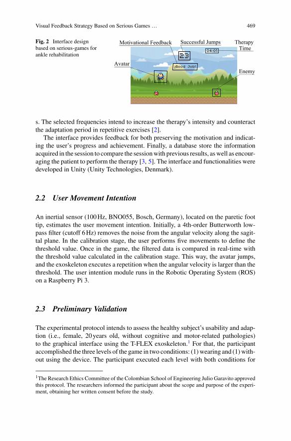
Visual Feedback Strategy Based on Serious Games … 469
Fig. 2 Interface designbased on serious-games forankle rehabilitation
EnemyAvatar
Motivational Feedback Successful Jumps Therapy Time
s. The selected frequencies intend to increase the therapy’s intensity and counteractthe adaptation period in repetitive exercises [2].
The interface provides feedback for both preserving the motivation and indicat-ing the user’s progress and achievement. Finally, a database store the informationacquired in the session to compare the sessionwith previous results, aswell as encour-aging the patient to perform the therapy [3, 5]. The interface and functionalities weredeveloped in Unity (Unity Technologies, Denmark).
2.2 User Movement Intention
An inertial sensor (100Hz, BNO055, Bosch, Germany), located on the paretic foottip, estimates the user movement intention. Initially, a 4th-order Butterworth low-pass filter (cutoff 6Hz) removes the noise from the angular velocity along the sagit-tal plane. In the calibration stage, the user performs five movements to define thethreshold value. Once in the game, the filtered data is compared in real-time withthe threshold value calculated in the calibration stage. This way, the avatar jumps,and the exoskeleton executes a repetition when the angular velocity is larger than thethreshold. The user intention module runs in the Robotic Operating System (ROS)on a Raspberry Pi 3.
2.3 Preliminary Validation
The experimental protocol intends to assess the healthy subject’s usability and adap-tion (i.e., female, 20years old, without cognitive and motor-related pathologies)to the graphical interface using the T-FLEX exoskeleton.1 For that, the participantaccomplished the three levels of the game in two conditions: (1)wearing and (1)with-out using the device. The participant executed each level with both conditions for
1The Research Ethics Committee of the Colombian School of Engineering Julio Garavito approvedthis protocol. The researchers informed the participant about the scope and purpose of the experi-ment, obtaining her written consent before the study.
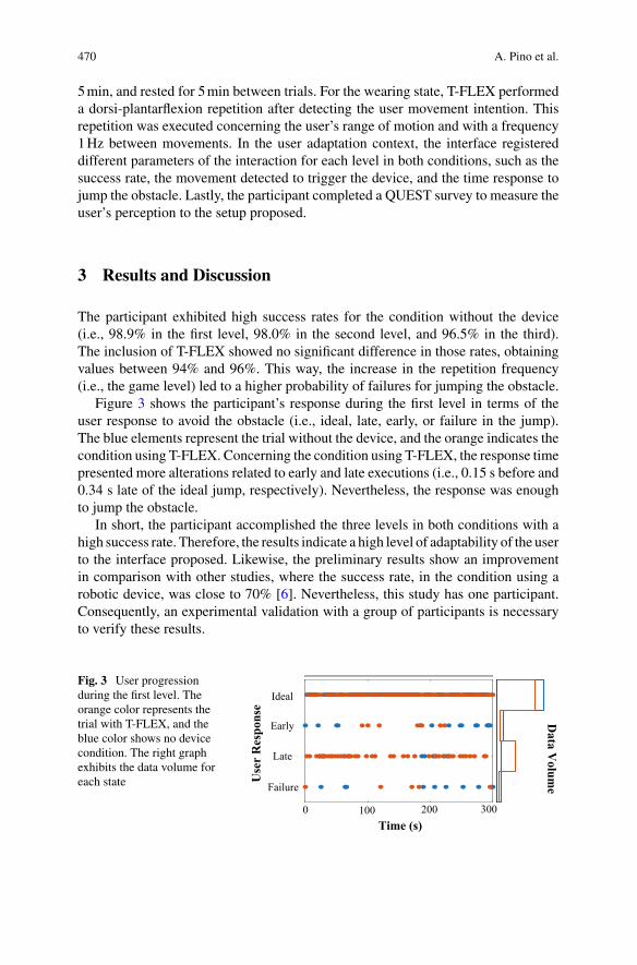
470 A. Pino et al.
5min, and rested for 5min between trials. For the wearing state, T-FLEX performeda dorsi-plantarflexion repetition after detecting the user movement intention. Thisrepetition was executed concerning the user’s range of motion and with a frequency1Hz between movements. In the user adaptation context, the interface registereddifferent parameters of the interaction for each level in both conditions, such as thesuccess rate, the movement detected to trigger the device, and the time response tojump the obstacle. Lastly, the participant completed a QUEST survey to measure theuser’s perception to the setup proposed.
3 Results and Discussion
The participant exhibited high success rates for the condition without the device(i.e., 98.9% in the first level, 98.0% in the second level, and 96.5% in the third).The inclusion of T-FLEX showed no significant difference in those rates, obtainingvalues between 94% and 96%. This way, the increase in the repetition frequency(i.e., the game level) led to a higher probability of failures for jumping the obstacle.
Figure 3 shows the participant’s response during the first level in terms of theuser response to avoid the obstacle (i.e., ideal, late, early, or failure in the jump).The blue elements represent the trial without the device, and the orange indicates thecondition using T-FLEX. Concerning the condition using T-FLEX, the response timepresented more alterations related to early and late executions (i.e., 0.15 s before and0.34 s late of the ideal jump, respectively). Nevertheless, the response was enoughto jump the obstacle.
In short, the participant accomplished the three levels in both conditions with ahigh success rate. Therefore, the results indicate a high level of adaptability of the userto the interface proposed. Likewise, the preliminary results show an improvementin comparison with other studies, where the success rate, in the condition using arobotic device, was close to 70% [6]. Nevertheless, this study has one participant.Consequently, an experimental validation with a group of participants is necessaryto verify these results.
Fig. 3 User progressionduring the first level. Theorange color represents thetrial with T-FLEX, and theblue color shows no devicecondition. The right graphexhibits the data volume foreach state Failure
Use
r R
espo
nse
Data V
olume
Time (s)
Late
Early
Ideal
0 100 200 300
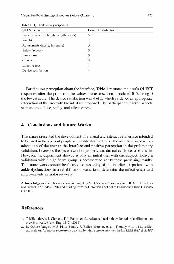
Visual Feedback Strategy Based on Serious Games … 471
Table 1 QUEST survey responses
QUEST item Level of satisfaction
Dimensions (size, height, length, width) 5
Weight 4
Adjustments (fixing, fastening) 3
Safety (secure) 5
Ease of use 5
Comfort 3
Effectiveness 4
Device satisfaction 4
For the user perception about the interface, Table 1 resumes the user’s QUESTresponses after the protocol. The values are assessed on a scale of 0–5, being 0the lowest score. The device satisfaction was 4 of 5, which evidence an appropriateinteraction of the user with the interface proposed. The participant remarked aspectssuch as ease of use, safety, and effectiveness.
4 Conclusions and Future Works
This paper presented the development of a visual and interactive interface intendedto be used in therapies of people with ankle dysfunctions. The results showed a highadaptation of the user to the interface and positive perception in the preliminaryvalidation. Likewise, the system worked properly and did not evidence to be unsafe.However, the experiment showed is only an initial trial with one subject. Hence avalidation with a significant group is necessary to verify these promising results.The future works should be focused on assessing of the interface in patients withankle dysfunctions in a rehabilitation scenario to determine the effectiveness andimprovements in motor recovery.
Acknowledgements This work was supported byMinCiencias Colombia (grant IDNo. 801-2017)and (grant IDNo. 845-2020), and funding from theColombian School of Engineering JulioGaravito(ECIJG).
References
1. T. Mikolajczyk, I. Ciobanu, D.I. Badea, et al., Advanced technology for gait rehabilitation: anoverview. Adv. Mech. Eng. 10(7) (2018)
2. D. Gomez-Vargas, M.J. Pinto-Bernal, F. Ballen-Moreno, et al., Therapy with t-flex ankle-exoskeleton for motor recovery: a case study with a stroke survivor, in 8th IEEE RAS & EMBS

472 A. Pino et al.
International Conference on Biomedical Robotics and Biomechatronics (BioRob) (2020)3. N. Barrett, I. Swain, C. Gatzidis, et al., The use and effect of video game design theory in the
creation of game-based systems for upper limb stroke rehabilitation. J. Rehabil. Assist. Technol.Eng. 3 (2016)
4. S.-N. Jeon, J.-H. Choi, The effects of ankle joint strategy exercises with and without visualfeedback on the dynamic balance of stroke patients. J. Phys. Therapy Sci. 27(8), 2515–2518(2015)
5. K. Lohse, N. Shirzad, A. Verster et al., Video games and rehabilitation: using design principlesto enhance engagement in physical therapy. J. Neurol. Phys. Therapy 37(4), 166–175 (2013)
6. G. Asín-Prieto, A. Martínez-Expósito, F.O. Barroso et al., Haptic adaptive feedback to promotemotor learning with a robotic ankle exoskeleton integrated with a video game. Front. Bioeng.Biotechnol. 8, 113 (2020)
The Utilization Effects of PoweredWearable Orthotics in Improving UpperExtremity Function in Persons with SCI:A Case Study
Ghaith J. Androwis, Steven Kirshblum, and Guang Yue
Abstract Persons with upper extremity (UE) impairments due to spinal cord injury(SCI) have limited capacity tomove or perform basic activities of daily living (ADL).Such movement limitations significantly reduce a patient’s quality of life (QOL) andlevel of independence.Restoration ofUEmotor function in peoplewithSCI remains ahigh priority in rehabilitation and in the field of assistive technology. UEmyoelectricpowered wearable orthoses (UE-MPWO) specifically designed to restore wrist/handmovements may help fill the gap by increasing strength of the participating muscles,range of motion (ROM) of the joints, and ability to perform daily tasks involvingusingwrist/hand in personswith SCI. The goal of this studywas to evaluate the effectsof the UE-MPWO (MyoPro) in ameliorating wrist/hand/UE movement capability,and increasing ADL and QOL in people with SCI.
1 Introduction
Spinal cord injury (SCI) is a medically complex and life-disrupting condition. Anestimated incidence of 17,700 new traumatic SCI cases are reported each year inthe United States [1]. In about half of those, the injury involves some part of thearm and hand, representing significant disability and dependence for those patients[1–4]. Following an SCI there is also often loss of sensory and/or motor control ofthe upper and lower limbs. The characteristics of the impairment depends on theextent and level of the SCI [5, 6]. Individuals with higher levels of SCI have limitedcapacity to move or perform basic activities of daily living (ADL). Such movement
G. J. Androwis (B) · G. YueRehabilitation Robotics and Research Laboratory- CMRER, Kessler Foundation, West Orange,NJ, USAe-mail: [email protected]
G. J. AndrowisBioengineering Department, New Jersey Institute of Technology, Newark, NJ, USA
S. KirshblumPhysical Medicine and Rehabilitation, Kessler Institute for Rehabilitation, West Orange, NJ, USA
© The Author(s), under exclusive license to Springer Nature Switzerland AG 2022J. C. Moreno et al. (eds.), Wearable Robotics: Challenges and Trends,Biosystems & Biorobotics 27, https://doi.org/10.1007/978-3-030-69547-7_76
473
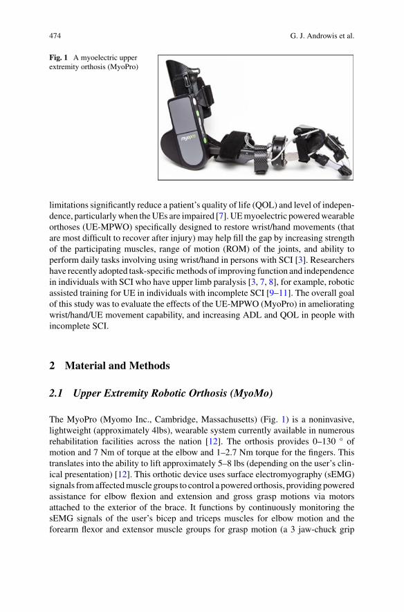
474 G. J. Androwis et al.
Fig. 1 A myoelectric upperextremity orthosis (MyoPro)
limitations significantly reduce a patient’s quality of life (QOL) and level of indepen-dence, particularlywhen theUEs are impaired [7]. UEmyoelectric poweredwearableorthoses (UE-MPWO) specifically designed to restore wrist/hand movements (thatare most difficult to recover after injury) may help fill the gap by increasing strengthof the participating muscles, range of motion (ROM) of the joints, and ability toperform daily tasks involving using wrist/hand in persons with SCI [3]. Researchershave recently adopted task-specificmethods of improving function and independencein individuals with SCI who have upper limb paralysis [3, 7, 8], for example, roboticassisted training for UE in individuals with incomplete SCI [9–11]. The overall goalof this study was to evaluate the effects of the UE-MPWO (MyoPro) in amelioratingwrist/hand/UE movement capability, and increasing ADL and QOL in people withincomplete SCI.
2 Material and Methods
2.1 Upper Extremity Robotic Orthosis (MyoMo)
The MyoPro (Myomo Inc., Cambridge, Massachusetts) (Fig. 1) is a noninvasive,lightweight (approximately 4lbs), wearable system currently available in numerousrehabilitation facilities across the nation [12]. The orthosis provides 0–130 ° ofmotion and 7 Nm of torque at the elbow and 1–2.7 Nm torque for the fingers. Thistranslates into the ability to lift approximately 5–8 lbs (depending on the user’s clin-ical presentation) [12]. This orthotic device uses surface electromyography (sEMG)signals fromaffectedmuscle groups to control a powered orthosis, providing poweredassistance for elbow flexion and extension and gross grasp motions via motorsattached to the exterior of the brace. It functions by continuously monitoring thesEMG signals of the user’s bicep and triceps muscles for elbow motion and theforearm flexor and extensor muscle groups for grasp motion (a 3 jaw-chuck grip
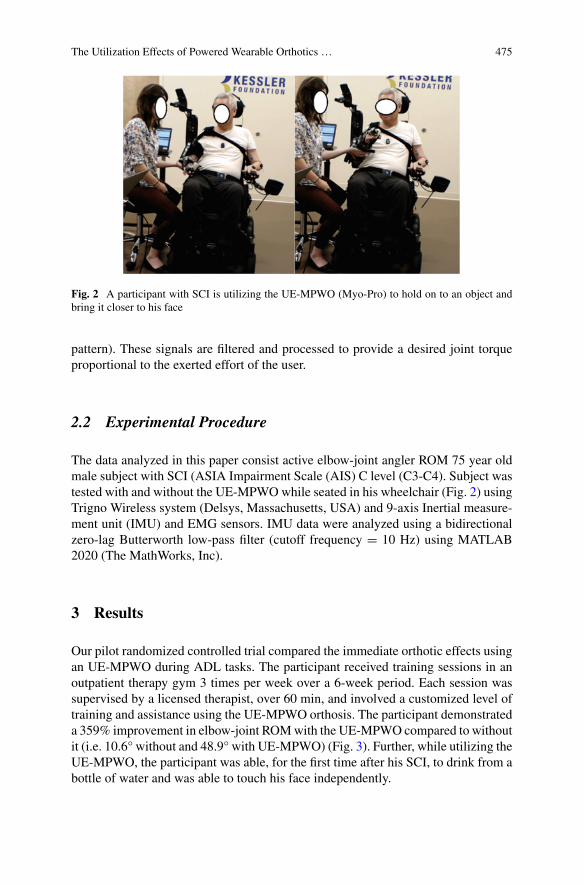
The Utilization Effects of Powered Wearable Orthotics … 475
Fig. 2 A participant with SCI is utilizing the UE-MPWO (Myo-Pro) to hold on to an object andbring it closer to his face
pattern). These signals are filtered and processed to provide a desired joint torqueproportional to the exerted effort of the user.
2.2 Experimental Procedure
The data analyzed in this paper consist active elbow-joint angler ROM 75 year oldmale subject with SCI (ASIA Impairment Scale (AIS) C level (C3-C4). Subject wastested with and without the UE-MPWOwhile seated in his wheelchair (Fig. 2) usingTrigno Wireless system (Delsys, Massachusetts, USA) and 9-axis Inertial measure-ment unit (IMU) and EMG sensors. IMU data were analyzed using a bidirectionalzero-lag Butterworth low-pass filter (cutoff frequency = 10 Hz) using MATLAB2020 (The MathWorks, Inc).
3 Results
Our pilot randomized controlled trial compared the immediate orthotic effects usingan UE-MPWO during ADL tasks. The participant received training sessions in anoutpatient therapy gym 3 times per week over a 6-week period. Each session wassupervised by a licensed therapist, over 60 min, and involved a customized level oftraining and assistance using the UE-MPWO orthosis. The participant demonstrateda 359% improvement in elbow-joint ROMwith the UE-MPWO compared to withoutit (i.e. 10.6° without and 48.9° with UE-MPWO) (Fig. 3). Further, while utilizing theUE-MPWO, the participant was able, for the first time after his SCI, to drink from abottle of water and was able to touch his face independently.
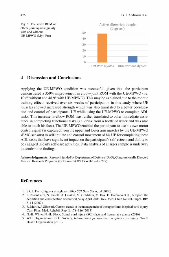
476 G. J. Androwis et al.
Fig. 3 The active ROM ofelbow-joint against gravitywith and withoutUE-MPWO (Myo-Pro)
4 Discussion and Conclusions
Applying the UE-MPWO condition was successful, given that, the participantdemonstrated a 359% improvement in elbow-joint ROM with the UE-MPWO (i.e.10.6º without and 48.9° with UE-MPWO). This may be explained due to the robotictraining effects received over six weeks of participation in this study where UEmuscles showed increased strength which was also translated to a better coordina-tion and control of participants’ UE while using the UE-MPWO to complete ADLtasks. This increase in elbow ROM was further translated to other immediate assis-tance in completing functional tasks (i.e. drink from a bottle of water and was alsoable to touch his face). The UE-MPWO enabled the participant to use his own motorcontrol signal (as captured from the upper and lower armmuscles by the UE-MPWOsEMG sensors) to self-initiate and control movement of his UE for completing theseADL tasks that have significant impact on the participant’s self-esteem and ability tobe engaged in daily self-care activities. Data analysis of a larger sample is underwayto confirm the findings.
Acknowledgements Research funded byDepartment ofDefense (DoD),CongressionallyDirectedMedical Research Programs (DoD award#:W81XWH-18–1-0728).
References
1. S.C.I. Facts, Figures at a glance. 2019 SCI Data Sheet, ed (2020)2. P. Rosenbaum, N. Paneth, A. Leviton, M. Goldstein, M. Bax, D. Damiano et al., A report: the
definition and classification of cerebral palsy April 2006. Dev. Med. Child Neurol. Suppl. 109,8–14 (2007)
3. R.Martin, J. Silvestri, Current trends in the management of the upper limb in spinal cord injury.Curr. Phys. Med. Rehabil. Rep. 1, 178–186 (2013)
4. N.-H. White, N.-H. Black, Spinal cord injury (SCI) facts and figures at a glance (2016)5. W.H. Organization, I.S.C. Society, International perspectives on spinal cord injury. World
Health Organization (2013)
The Utilization Effects of Powered Wearable Orthotics … 477
6. M. J. Kuipers, Functional Electrical Stimulation as a neuroprosthesis for sitting balance:measuring respiratory function and seated postural control in able-bodied individuals andindividuals with spinal cord injury, University of Toronto (Canada) (2013)
7. P. Maciejasz, J. Eschweiler, K. Gerlach-Hahn, A. Jansen-Troy, S. Leonhardt, A survey onrobotic devices for upper limb rehabilitation. J. Neuroeng. Rehabil. 11, 3 (2014)
8. S. Hesse, H. Schmidt, C. Werner, A. Bardeleben, Upper and lower extremity robotic devicesfor rehabilitation and for studying motor control. Curr. Opin. Neurol. 16, 705–710 (2003)
9. K.D. Fitle, A.U. Pehlivan, M.K. O’Malley, A robotic exoskeleton for rehabilitation and assess-ment of the upper limb following incomplete spinal cord injury, in 2015 IEEE InternationalConference on Robotics and Automation (ICRA), pp. 4960–4966 (2015)
10. J.M.Frullo, J. Elinger,A.U.Pehlivan,K.Fitle,K.Nedley,G.E. Francisco, et al., Effects of assist-as-needed upper extremity robotic therapy after incomplete spinal cord injury: a parallel-groupcontrolled trial. Frontiers in Neurorobotics 11 (2017)
11. D. Vanmulken, A. Spooren, H. Bongers, H. Seelen, Robot-assisted task-oriented upperextremity skill training in cervical spinal cord injury: a feasibility study. Spinal Cord 53, 547(2015)
12. S. Dunaway, D.B. Dezsi, J. Perkins, D. Tran, J. Naft, Case report on the use of a custommyoelectric elbow–wrist–hand orthosis for the remediation of upper extremity paresis and lossof function in chronic stroke. Mil. Med. 182, e1963–e1968 (2017)

Exoskeletons in Industry 4.0: OpenChallenges and Perspectives
Using a Spring-Loaded Upper-LimbExoskeleton in Cleaning Tasks:A Preliminary Study
I. Pacifico, F. Aprigliano, A. Parri, G. Cannillo, I. Melandri, F. S. Violante,F. Molteni, F. Giovacchini, N. Vitiello, and S. Crea
Abstract In the next few years, exoskeletons for workers’ support are expectedto be key players in the global industrial market. Interventional studies to explorethe exoskeletons’ effectiveness in real and realistic simulated scenarios have to becarried out in the wide variety of use cases. This work introduces a preliminarycomprehensive assessment of a spring-loaded upper-limb exoskeleton, carried outusing both instrumental and perception-relatedmetrics in a realistically simulated job
N. Vitiello and S. Crea—These authors share the senior authorship.A. Parri, F. Giovacchini, N. Vitiello and S. Crea have interests in the spin-off company (IUVO
S.r.l.). IUVO S.r.l. has developed the MATE technology. The IP protecting the MATE technologyis owned by IUVO S.r.l. (Pontedera, Italy) and licensed to COMAU S.p.A. (Grugliasco, Italy) forcommercial purposes in the industrial market. F. S. Violante, F. Molteni, N. Vitiello, and S. Creaare scientific advisors of IUVO S.r.l.
I. Pacifico (B) · N. Vitiello · S. Crea (B)The BioRobotics Institute, Scuola Superiore Sant’Anna, viale Rinaldo Piaggio 34,56025 Pontedera, Pisa, Italye-mail: [email protected]
S. Creae-mail: [email protected]
Department of Excellence in Robotics & AI, Scuola Superiore Sant’Anna, Piazza Martiri dellaLibertà, 33, 56127 Pisa, Italy
F. Aprigliano · A. Parri · F. GiovacchiniIUVO S.R.L, via Puglie 9, 56025 Pontedera, Pisa, Italy
G. Cannillo · I. MelandriFormula Servizi, Via Monteverdi, 31, 47122 Forlì, Italy
F. S. ViolanteDipartimento di Scienze Mediche e Chirurgiche, Università di Bologna, Via Massarenti 9,40138 Bologna, Italy
F. MolteniVilla Beretta Rehabilitation Center, Valduce Hospital, Via N. Sauro 17, 23845 Costa Masnaga,Lecco, Italy
N. Vitiello · S. CreaIRCCS Fondazione Don Carlo Gnocchi, 50143 Florence, Italy
© The Author(s), under exclusive license to Springer Nature Switzerland AG 2022J. C. Moreno et al. (eds.), Wearable Robotics: Challenges and Trends,Biosystems & Biorobotics 27, https://doi.org/10.1007/978-3-030-69547-7_77
481
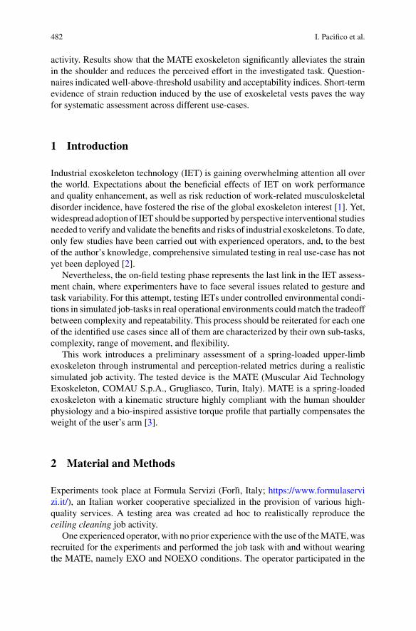
482 I. Pacifico et al.
activity. Results show that the MATE exoskeleton significantly alleviates the strainin the shoulder and reduces the perceived effort in the investigated task. Question-naires indicated well-above-threshold usability and acceptability indices. Short-termevidence of strain reduction induced by the use of exoskeletal vests paves the wayfor systematic assessment across different use-cases.
1 Introduction
Industrial exoskeleton technology (IET) is gaining overwhelming attention all overthe world. Expectations about the beneficial effects of IET on work performanceand quality enhancement, as well as risk reduction of work-related musculoskeletaldisorder incidence, have fostered the rise of the global exoskeleton interest [1]. Yet,widespread adoption of IET should be supported byperspective interventional studiesneeded to verify and validate the benefits and risks of industrial exoskeletons. To date,only few studies have been carried out with experienced operators, and, to the bestof the author’s knowledge, comprehensive simulated testing in real use-case has notyet been deployed [2].
Nevertheless, the on-field testing phase represents the last link in the IET assess-ment chain, where experimenters have to face several issues related to gesture andtask variability. For this attempt, testing IETs under controlled environmental condi-tions in simulated job-tasks in real operational environments couldmatch the tradeoffbetween complexity and repeatability. This process should be reiterated for each oneof the identified use cases since all of them are characterized by their own sub-tasks,complexity, range of movement, and flexibility.
This work introduces a preliminary assessment of a spring-loaded upper-limbexoskeleton through instrumental and perception-related metrics during a realisticsimulated job activity. The tested device is the MATE (Muscular Aid TechnologyExoskeleton, COMAU S.p.A., Grugliasco, Turin, Italy). MATE is a spring-loadedexoskeleton with a kinematic structure highly compliant with the human shoulderphysiology and a bio-inspired assistive torque profile that partially compensates theweight of the user’s arm [3].
2 Material and Methods
Experiments took place at Formula Servizi (Forlì, Italy; https://www.formulaservizi.it/), an Italian worker cooperative specialized in the provision of various high-quality services. A testing area was created ad hoc to realistically reproduce theceiling cleaning job activity.
One experienced operator, with no prior experiencewith the use of theMATE,wasrecruited for the experiments and performed the job task with and without wearingthe MATE, namely EXO and NOEXO conditions. The operator participated in the
Using a Spring-Loaded Upper-Limb Exoskeleton … 483
ceiling cleaning task, which consisted of cleaning up cobwebs from high ceilings(~7 m) using an extensible duster (Fig. 1a). The gesture required to execute twowide brushes by sustaining the pole from the bottom with one arm and directingits movement with the other arm, kept in an elevated position (i.e., ~120–135°).The participant repeated 20 times the gesture sequence, which started and finishedwith the arms along the trunk. Before taking part in the experiment, the volunteerwas informed about the goals of the study and signed a written informed consentform. The measurements were performed following the declaration of Helsinki andthe study was approved by The Institutional Review Board of Scuola SuperioreSant’Anna (study n. 10 of year 2020). The electromyographic activity of the anteriordeltoid (AD), medial deltoid (MD), upper trapezius (UT), posterior deltoid (PD), andpectoralis major (PM)muscles was acquired on the side of the elevated arm using theBTS FREE EMG 1000 (BTS Bioengineering, Milan, Italy) at a sampling frequencyof 1 kHz. A twin-axis electrogoniometer SG150 (Biometrics Ltd, Newport, UK) wasplaced ipsilaterally on the shoulder joint for signals segmentation. Raw EMG signalswere rectified and low-pass filtered (zero-lag 2nd order Butterworth, filter range:20–450 Hz; zero-lag 2nd order IIR notch filter at 50 Hz; 100 ms moving averagefilter), normalized to maximum voluntary exertions (nEMG) and then summed toobtain the Total nEMG signal as proposed in [4]. To segment nEMG and TotalnEMG signals, time instances corresponding to the beginning and end of the gesturewere detected by visually inspecting EGN signals and double-checked with videoscaptured throughout the trial. Finally, iEMG and Total iEMG were computed fromsegmented signals by integrating and normalizing them by the task duration. Thepercentage variation between the muscle activation under the EXO condition andNOEXO condition was calculated. Statistical evaluation of iEMG and Total iEMGdifferences between the two conditions were performed using a two-sidedWilcoxonrank-sum test with the significance level set to 0.05. The rated perceived exertion(RPE) was monitored using the Borg CR10 scale [5], assigned by the participant atthe end of the task in both experimental conditions. The System Usability Scale [6]and the Technology Acceptance Model [7] questionnaires were administered to theoperator.
3 Results
The results of the EMG analysis are shown in Fig. 1b, c. Completing the ceilingcleaning task with the exoskeleton support significantly reduced individual andoverall muscle activities. The EXO condition produced the largest reductions at theAD,MD, and UT (reduction of 23, 29, and 13% compared to the NOEXO condition,p= 0.003, p < 0.001, and p= 0.01,for AD,MD, UT, respectively see Fig. 1b), whichwere the most active among the recorded muscles during the NOEXO condition (8–13% MVC). PD also significantly reduced in the EXO compared to the NOEXOcondition (reduction of 11%, p = 0.016), whereas a minor non-significant variationwas observed in PM (reduction of 9%, p= 0.08). A reduction trendwas also recorded
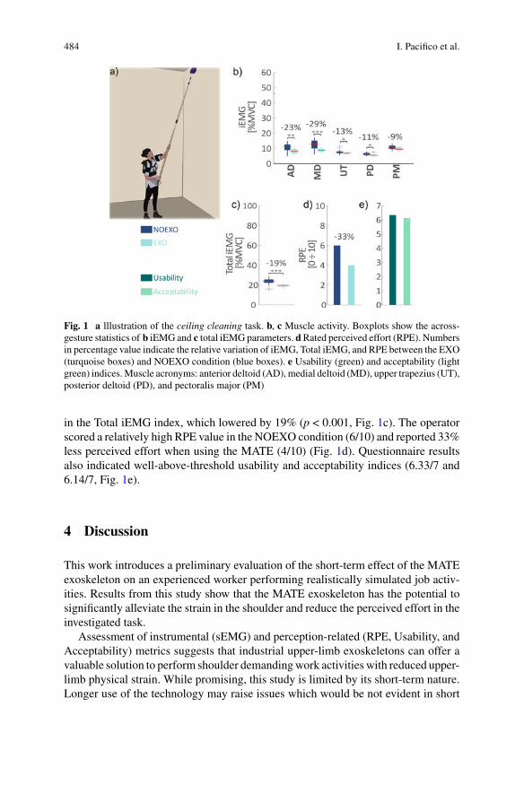
484 I. Pacifico et al.
Fig. 1 a lllustration of the ceiling cleaning task. b, c Muscle activity. Boxplots show the across-gesture statistics of b iEMG and c total iEMGparameters. dRated perceived effort (RPE). Numbersin percentage value indicate the relative variation of iEMG, Total iEMG, and RPE between the EXO(turquoise boxes) and NOEXO condition (blue boxes). e Usability (green) and acceptability (lightgreen) indices.Muscle acronyms: anterior deltoid (AD),medial deltoid (MD), upper trapezius (UT),posterior deltoid (PD), and pectoralis major (PM)
in the Total iEMG index, which lowered by 19% (p < 0.001, Fig. 1c). The operatorscored a relatively high RPE value in the NOEXO condition (6/10) and reported 33%less perceived effort when using the MATE (4/10) (Fig. 1d). Questionnaire resultsalso indicated well-above-threshold usability and acceptability indices (6.33/7 and6.14/7, Fig. 1e).
4 Discussion
This work introduces a preliminary evaluation of the short-term effect of the MATEexoskeleton on an experienced worker performing realistically simulated job activ-ities. Results from this study show that the MATE exoskeleton has the potential tosignificantly alleviate the strain in the shoulder and reduce the perceived effort in theinvestigated task.
Assessment of instrumental (sEMG) and perception-related (RPE, Usability, andAcceptability) metrics suggests that industrial upper-limb exoskeletons can offer avaluable solution to perform shoulder demandingwork activities with reduced upper-limb physical strain. While promising, this study is limited by its short-term nature.Longer use of the technology may raise issues which would be not evident in short
Using a Spring-Loaded Upper-Limb Exoskeleton … 485
studies. Future works will focus on the systematic assessment of IET via monitoringthe persistency of the device’s effectiveness over time and possible long-term sideeffects.
Acknowledgements Thisworkhas been supported in part byFormulaServizi andScuolaSuperioreSant’Anna.
References
1. W. Rian, An exciting future for exoskeletons [WWW Document] (2019). https://www.abiresearch.com/blogs/15J/ (accessed 12.03.21)
2. T. McFarland, S. Fischer, Considerations for industrial use: A systematic review of the impactof active and passive upper limb exoskeletons on physical exposures. IISE Trans. Occup. Ergon.Hum. Factors 7(3–4), 322–347 (2019)
3. I. Pacifico et al., Experimental evaluation of the proto-MATE: a novel ergonomic upper-limbexoskeleton for reducing the worker’s physical strain. IEEE Robot. Autom. Mag. 0 (2020)
4. D.C.Lee,H.K.Lim,W.B.McKay,M.M.Priebe, S.A.Holmes,A.M.Sherwood,Toward anobjec-tive interpretation of surface EMG patterns: A voluntary response index (VRI). J. Electromyogr.Kinesiol. 14(3), 379–388 (2004)
5. G. Borg, Borg’s Perceived Exertion and Pain Scales. (Human Kinetics, 1998)6. J. Brooke, SUS-a quick and dirty usability scale. Usability Eval. Ind. (1996)7. V. Venkatesh, F.D. Davis, Theoretical extension of the technology acceptance model: Four
longitudinal field studies. Manage. Sci. 46(2), 186–204 (2000)

Methods for User Activity Recognitionin Exoskeletons
Iñaki Díaz, Juan Martín, Xabier Justo, Carlos Fernández,and Jorge Juan Gil
Abstract Exoskeleton technology is making its way into the industry as an assis-tance tool to prevent workers from suffering musculoskeletal disorders. However,current control algorithms do not yet allow for a natural human-robot collaborationinterface. A key issue to develop efficient exoskeleton controllers resides in the user’sactivity recognition. This work describes several exoskeleton sensorization optionsand Machine Learning methods tested on GOGOA’s ALDAK active exoskeleton toidentify user activity type.
1 Introduction
MUSCULOSKELETAL disorders (MSDs) are injuries and disorders that affect thehuman body’s musculoskeletal system. They represent the main occupational riskfactor and usually result in a loss of productivity while also posing a risk to theemployee’s health. Exoskeletons can assist workers in repetitive lifting of heavyobjects that is one of the most common risk factors for MSDs. Everyday manyworkers have to lift heavy loads during theworking day. The sixth EuropeanWorking
I. Díaz (B) · X. Justo · J. J. GilSmart Systems for Industry 4.0 Group of CEIT-Basque Research and Technology Alliance(BRTA), San Sebastián, Spaine-mail: [email protected]
Universidad de Navarra, San Sebastián, Spain
X. Justoe-mail: [email protected]
J. J. Gile-mail: [email protected]
J. Martín · C. FernándezGOGOA Mobility Robots S.L, Abadiano, Spaine-mail: [email protected]
C. Fernándeze-mail: [email protected]
© The Author(s), under exclusive license to Springer Nature Switzerland AG 2022J. C. Moreno et al. (eds.), Wearable Robotics: Challenges and Trends,Biosystems & Biorobotics 27, https://doi.org/10.1007/978-3-030-69547-7_78
487
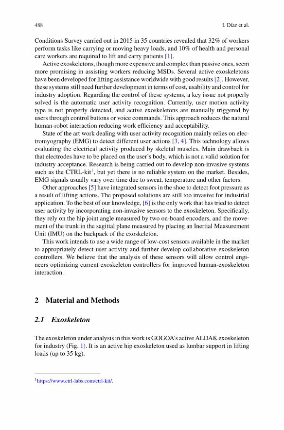
488 I. Díaz et al.
Conditions Survey carried out in 2015 in 35 countries revealed that 32% of workersperform tasks like carrying or moving heavy loads, and 10% of health and personalcare workers are required to lift and carry patients [1].
Active exoskeletons, thoughmore expensive and complex than passive ones, seemmore promising in assisting workers reducing MSDs. Several active exoskeletonshave been developed for lifting assistance worldwide with good results [2]. However,these systems still need further development in terms of cost, usability and control forindustry adoption. Regarding the control of these systems, a key issue not properlysolved is the automatic user activity recognition. Currently, user motion activitytype is not properly detected, and active exoskeletons are manually triggered byusers through control buttons or voice commands. This approach reduces the naturalhuman-robot interaction reducing work efficiency and acceptability.
State of the art work dealing with user activity recognition mainly relies on elec-tromyography (EMG) to detect different user actions [3, 4]. This technology allowsevaluating the electrical activity produced by skeletal muscles. Main drawback isthat electrodes have to be placed on the user’s body, which is not a valid solution forindustry acceptance. Research is being carried out to develop non-invasive systemssuch as the CTRL-kit1, but yet there is no reliable system on the market. Besides,EMG signals usually vary over time due to sweat, temperature and other factors.
Other approaches [5] have integrated sensors in the shoe to detect foot pressure asa result of lifting actions. The proposed solutions are still too invasive for industrialapplication. To the best of our knowledge, [6] is the only work that has tried to detectuser activity by incorporating non-invasive sensors to the exoskeleton. Specifically,they rely on the hip joint angle measured by two on-board encoders, and the move-ment of the trunk in the sagittal plane measured by placing an Inertial MeasurementUnit (IMU) on the backpack of the exoskeleton.
This work intends to use a wide range of low-cost sensors available in the marketto appropriately detect user activity and further develop collaborative exoskeletoncontrollers. We believe that the analysis of these sensors will allow control engi-neers optimizing current exoskeleton controllers for improved human-exoskeletoninteraction.
2 Material and Methods
2.1 Exoskeleton
The exoskeleton under analysis in this work is GOGOA’s activeALDAKexoskeletonfor industry (Fig. 1). It is an active hip exoskeleton used as lumbar support in liftingloads (up to 35 kg).
1https://www.ctrl-labs.com/ctrl-kit/.
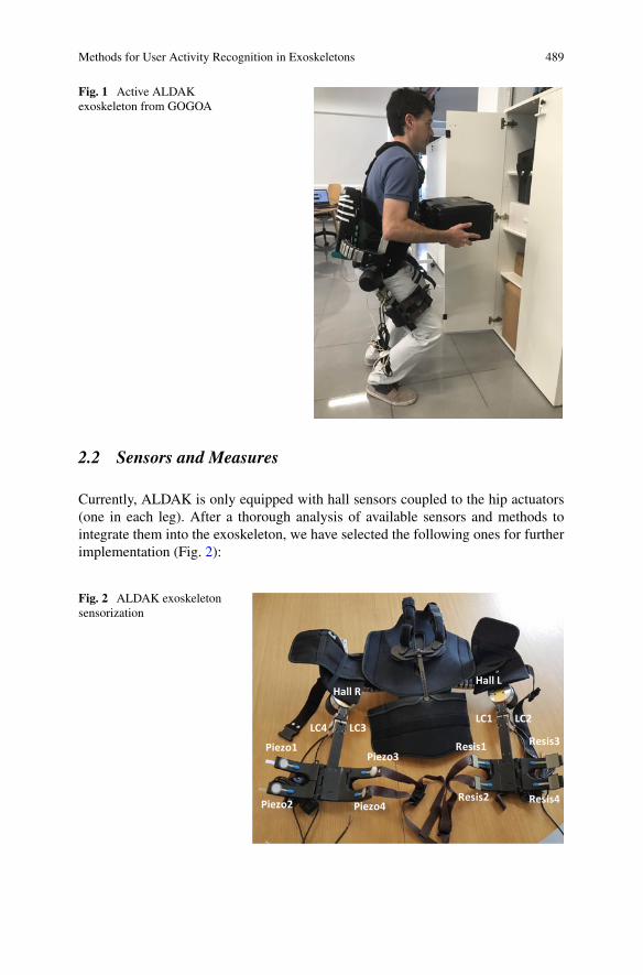
Methods for User Activity Recognition in Exoskeletons 489
Fig. 1 Active ALDAKexoskeleton from GOGOA
2.2 Sensors and Measures
Currently, ALDAK is only equipped with hall sensors coupled to the hip actuators(one in each leg). After a thorough analysis of available sensors and methods tointegrate them into the exoskeleton, we have selected the following ones for furtherimplementation (Fig. 2):
Fig. 2 ALDAK exoskeletonsensorization
Hall R
LC4 LC3LC1 LC2
Hall L
Piezo1
Piezo2
Piezo3
Piezo4
Resis1
Resis2
Resis3
Resis4
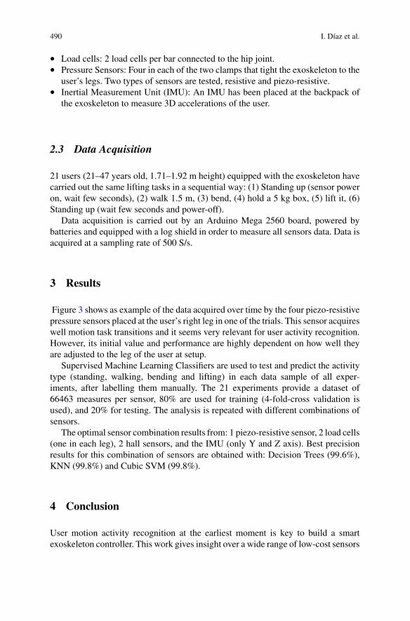
490 I. Díaz et al.
• Load cells: 2 load cells per bar connected to the hip joint.• Pressure Sensors: Four in each of the two clamps that tight the exoskeleton to the
user’s legs. Two types of sensors are tested, resistive and piezo-resistive.• Inertial Measurement Unit (IMU): An IMU has been placed at the backpack of
the exoskeleton to measure 3D accelerations of the user.
2.3 Data Acquisition
21 users (21–47 years old, 1.71–1.92 m height) equipped with the exoskeleton havecarried out the same lifting tasks in a sequential way: (1) Standing up (sensor poweron, wait few seconds), (2) walk 1.5 m, (3) bend, (4) hold a 5 kg box, (5) lift it, (6)Standing up (wait few seconds and power-off).
Data acquisition is carried out by an Arduino Mega 2560 board, powered bybatteries and equipped with a log shield in order to measure all sensors data. Data isacquired at a sampling rate of 500 S/s.
3 Results
Figure 3 shows as example of the data acquired over time by the four piezo-resistivepressure sensors placed at the user’s right leg in one of the trials. This sensor acquireswell motion task transitions and it seems very relevant for user activity recognition.However, its initial value and performance are highly dependent on how well theyare adjusted to the leg of the user at setup.
Supervised Machine Learning Classifiers are used to test and predict the activitytype (standing, walking, bending and lifting) in each data sample of all exper-iments, after labelling them manually. The 21 experiments provide a dataset of66463 measures per sensor, 80% are used for training (4-fold-cross validation isused), and 20% for testing. The analysis is repeated with different combinations ofsensors.
The optimal sensor combination results from: 1 piezo-resistive sensor, 2 load cells(one in each leg), 2 hall sensors, and the IMU (only Y and Z axis). Best precisionresults for this combination of sensors are obtained with: Decision Trees (99.6%),KNN (99.8%) and Cubic SVM (99.8%).
4 Conclusion
User motion activity recognition at the earliest moment is key to build a smartexoskeleton controller. This work gives insight over a wide range of low-cost sensors
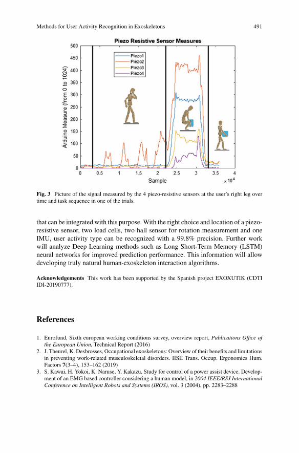
Methods for User Activity Recognition in Exoskeletons 491
Fig. 3 Picture of the signal measured by the 4 piezo-resistive sensors at the user’s right leg overtime and task sequence in one of the trials.
that can be integrated with this purpose.With the right choice and location of a piezo-resistive sensor, two load cells, two hall sensor for rotation measurement and oneIMU, user activity type can be recognized with a 99.8% precision. Further workwill analyze Deep Learning methods such as Long Short-Term Memory (LSTM)neural networks for improved prediction performance. This information will allowdeveloping truly natural human-exoskeleton interaction algorithms.
Acknowledgements This work has been supported by the Spanish project EXOXUTIK (CDTIIDI-20190777).
References
1. Eurofund, Sixth european working conditions survey, overview report, Publications Office ofthe European Union, Technical Report (2016)
2. J. Theurel, K. Desbrosses, Occupational exoskeletons: Overview of their benefits and limitationsin preventing work-related musculoskeletal disorders. IISE Trans. Occup. Ergonomics Hum.Factors 7(3–4), 153–162 (2019)
3. S. Kawai, H. Yokoi, K. Naruse, Y. Kakazu, Study for control of a power assist device. Develop-ment of an EMG based controller considering a human model, in 2004 IEEE/RSJ InternationalConference on Intelligent Robots and Systems (IROS), vol. 3 (2004), pp. 2283–2288

492 I. Díaz et al.
4. H. Kawamoto, Suwoong Lee, S. Kanbe, Y. Sankai, Power assist method for hal-3 using EMG-based feedback controller, in IEEE International Conference on Systems, Man and Cybernetics,vol. 2 (2003), pp. 1648–1653
5. L. A. Mateos, J. Ortiz, S. Toxiri, J. Fernandez, J. Masood, D.G. Caldwell, Exoshoe: A sensorysystem tomeasure foot pressure in industrial exoskeleton,” in 6th IEEE International Conferenceon Biomedical Robotics and Biomechatronics (BioRob), (2016), pp. 99–105
6. B. Chen, L. Grazi, F. Lanotte, N. Vitiello, S. Crea, A real-time lift detection strategy for a hipexoskeleton. Front. Neurorobot. 12, 1–7 (2018)
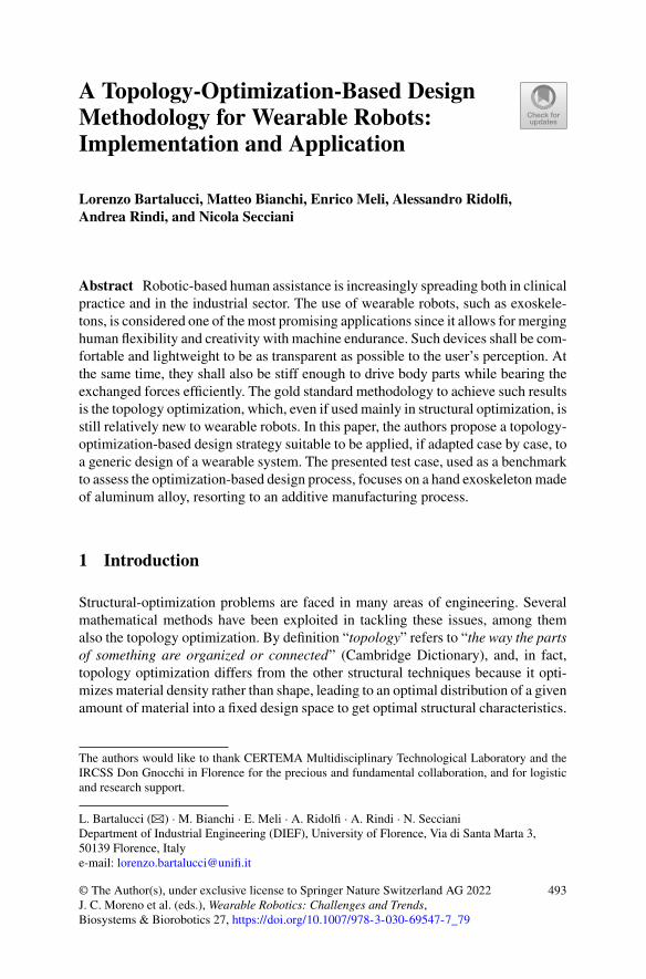
A Topology-Optimization-Based DesignMethodology for Wearable Robots:Implementation and Application
Lorenzo Bartalucci, Matteo Bianchi, Enrico Meli, Alessandro Ridolfi,Andrea Rindi, and Nicola Secciani
Abstract Robotic-based human assistance is increasingly spreading both in clinicalpractice and in the industrial sector. The use of wearable robots, such as exoskele-tons, is considered one of the most promising applications since it allows for merginghuman flexibility and creativity with machine endurance. Such devices shall be com-fortable and lightweight to be as transparent as possible to the user’s perception. Atthe same time, they shall also be stiff enough to drive body parts while bearing theexchanged forces efficiently. The gold standard methodology to achieve such resultsis the topology optimization, which, even if used mainly in structural optimization, isstill relatively new to wearable robots. In this paper, the authors propose a topology-optimization-based design strategy suitable to be applied, if adapted case by case, toa generic design of a wearable system. The presented test case, used as a benchmarkto assess the optimization-based design process, focuses on a hand exoskeletonmadeof aluminum alloy, resorting to an additive manufacturing process.
1 Introduction
Structural-optimization problems are faced in many areas of engineering. Severalmathematical methods have been exploited in tackling these issues, among themalso the topology optimization. By definition “topology” refers to “the way the partsof something are organized or connected” (Cambridge Dictionary), and, in fact,topology optimization differs from the other structural techniques because it opti-mizes material density rather than shape, leading to an optimal distribution of a givenamount of material into a fixed design space to get optimal structural characteristics.
The authors would like to thank CERTEMA Multidisciplinary Technological Laboratory and theIRCSS Don Gnocchi in Florence for the precious and fundamental collaboration, and for logisticand research support.
L. Bartalucci (B) · M. Bianchi · E. Meli · A. Ridolfi · A. Rindi · N. SeccianiDepartment of Industrial Engineering (DIEF), University of Florence, Via di Santa Marta 3,50139 Florence, Italye-mail: [email protected]
© The Author(s), under exclusive license to Springer Nature Switzerland AG 2022J. C. Moreno et al. (eds.), Wearable Robotics: Challenges and Trends,Biosystems & Biorobotics 27, https://doi.org/10.1007/978-3-030-69547-7_79
493
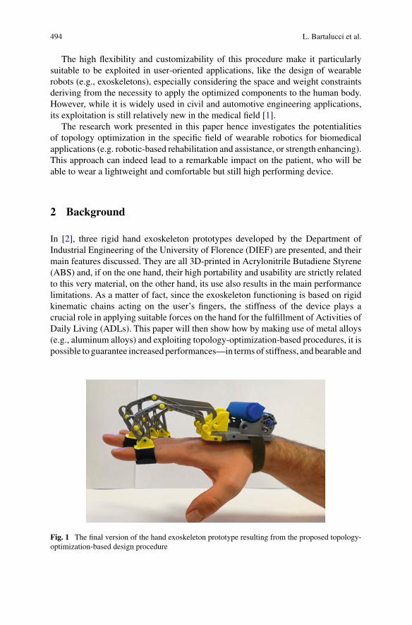
494 L. Bartalucci et al.
The high flexibility and customizability of this procedure make it particularlysuitable to be exploited in user-oriented applications, like the design of wearablerobots (e.g., exoskeletons), especially considering the space and weight constraintsderiving from the necessity to apply the optimized components to the human body.However, while it is widely used in civil and automotive engineering applications,its exploitation is still relatively new in the medical field [1].
The research work presented in this paper hence investigates the potentialitiesof topology optimization in the specific field of wearable robotics for biomedicalapplications (e.g. robotic-based rehabilitation and assistance, or strength enhancing).This approach can indeed lead to a remarkable impact on the patient, who will beable to wear a lightweight and comfortable but still high performing device.
2 Background
In [2], three rigid hand exoskeleton prototypes developed by the Department ofIndustrial Engineering of the University of Florence (DIEF) are presented, and theirmain features discussed. They are all 3D-printed in Acrylonitrile Butadiene Styrene(ABS) and, if on the one hand, their high portability and usability are strictly relatedto this very material, on the other hand, its use also results in the main performancelimitations. As a matter of fact, since the exoskeleton functioning is based on rigidkinematic chains acting on the user’s fingers, the stiffness of the device plays acrucial role in applying suitable forces on the hand for the fulfillment of Activities ofDaily Living (ADLs). This paper will then show how by making use of metal alloys(e.g., aluminum alloys) and exploiting topology-optimization-based procedures, it ispossible to guarantee increased performances—in termsof stiffness, and bearable and
Fig. 1 The final version of the hand exoskeleton prototype resulting from the proposed topology-optimization-based design procedure
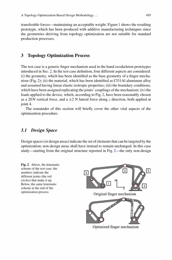
A Topology-Optimization-Based Design Methodology … 495
transferable forces—maintaining an acceptable weight. Figure1 shows the resultingprototype, which has been produced with additive manufacturing techniques sincethe geometries deriving from topology optimization are not suitable for standardproduction processes.
3 Topology Optimization Process
The test case is a generic finger mechanism used in the hand exoskeleton prototypesintroduced in Sec. 2. In the test case definition, four different aspects are considered:(i) the geometry, which has been identified as the base geometry of a finger mecha-nism (Fig. 2); (ii) the material, which has been identified as Cl31Al aluminum alloyand assumed having linear elastic isotropic properties; (iii) the boundary conditions,which have been assigned replicating the joints’ couplings of the mechanism; (iv) theloads applied to the device, which, according to Fig. 2, have been reasonably chosenas a 20N vertical force, and a ±2 N lateral force along z direction, both applied atjoint 4.
The remainder of this section will briefly cover the other vital aspects of theoptimization procedure.
3.1 Design Space
Design spaces (or design areas) indicate the set of elements that can be targeted by theoptimization; non-design areas shall have instead to remain unchanged. In this casestudy—starting from the original structure reported in Fig. 2—the only non-design
Fig. 2 Above, the kinematicscheme of the test case: thenumbers indicate thedifferent joints (the redcircles) that make it up.Below, the same kinematicscheme at the end of theoptimization process
496 L. Bartalucci et al.
areas have been defined as the regions around each joint, which should have had tobe left unchanged not to change the kinematics.
3.2 Objective Function and Optimization Constraints
the compliance minimization [3] has been carried out in the presented framework.Optimizing this quantity means looking for the material density distribution thatminimizes the structure deformation under the defined loading conditions. The com-pliance, l(u), is calculated as follow:
l(u) =∫
f · u d +∫
T
t · u ds, (1)
where f are the body forces on the domain , t are the external forces on thetraction part of the boundary T ⊂ ∂, u is the vector collecting the displacements,and ds is the infinitesimal part of T . Finally, the maximum allowable stress values,displacements, and volume fraction have been set as the optimization constraints.
3.3 Optimization Algorithm
the algorithm used has been the density method, also known as the Solid IsotropicMaterial with Penalization (SIMP)method [4]. A pseudo-density function ρ f ∈ [0 1]is defined as the design variable and assigned to different portions of the material.Suchdensity varies continuously between0 and1, defining the element as being eithervoid or solid. The solver, OptiStruct (Structural Analysis Solver), hence removesmaterial where the pseudo-density drops below a fixed threshold.
4 Results and Conclusion
The optimization problem thus set has been solved for the entire index mechanism.A comparison between the mass of the original mechanism and the optimized one isreported both in absolute terms and as a percentage in Table1.
Such a comparison has been accompanied by a detailed static Finite ElementAnalysis (FEA) aiming to assess the maximum deformation for each of the compo-nents that make up the mechanism. It has been seen that, when taken individually,the components can deform up to 6mm under the same loading conditions reportedin Sect. 3, against a maximum value of 2.5mm of the non-optimized component;
A Topology-Optimization-Based Design Methodology … 497
Table 1 Mechanism mass before and after the topology optimization
Component Original Optimized Reduction
mass (g) mass (g) mass %
Finger mechanism 13.34 10.6 20.5
however, a maximum displacement of 0.8mm has been recorded while analyzing allthe components coupled together.
To mention that the geometries of the optimized models of each component,directly obtained by the solver, are dependent on the mesh and do not have a homo-geneous surface. The last stage of the process involved a smoothing of the surfaces,resulting in what is visible in Fig. 2.
Lightness and stiffness are crucial characteristics of wearable robots, whatever thefield of application (e.g., healthcare aswell as the construction industry) andwhateverpart of the body is concerned (e.g., upper or lower limbs). The work reported in thispaper aimed to assess the efficacy of topology optimization for the design of suchdevices for which even a small reduction in weight translates into significant energysavings for the wearer. The exploitation of the SIMP method allows for a fine tuningof the stiffness to lightness ratio by varying the way the solver interprets differentvalues of pseudo-density. The use of such a strategy for the proposed test case showedpromising results, culminating in amass reduction of the 20%,without compromisingrigidity.
References
1. M. Bianchi, F. Buonamici, R. Furferi, N. Vanni, Design and optimization of a Flexion/extensionmechanism for a hand exoskeleton system, in ASME 2016 International Design EngineeringTechnical Conferences and Computers and Information in Engineering Conference, August2016
2. N. Secciani, M. Bianchi, A. Meschini, A. Ridolfi, Y. Volpe, L. Governi, B. Allotta, Assistivehand exoskeletons: the prototypes evolution at the university of florence, in Advances in ItalianMechanism Science, ed. byG.Carbone,A.Gasparetto (Springer International Publishing, Cham,2019), pp. 307–315
3. S. Wang, K. Lim, B. Khoo, M. Wang, An extended level set method for shape and topol-ogy optimization, J. Comput. Phys. 221(1), 395–421 (2007). (Online). Available: http://www.sciencedirect.com/science/article/pii/S0021999106002968
4. L. Shu, M.Y. Wang, Z. Fang, Z. Ma, P. Wei, Level set based structural topology optimization forminimizing frequency response. J. Sound Vib. 330(24), 5820–5834 (2011). (Online). Available:http://www.sciencedirect.com/science/article/pii/S0022460X11006079
Lifting and Carrying: Do We NeedBack-Support Exoskeleton Versatility?
Tommaso Poliero, Maria Lazzaroni, Stefano Toxiri, Christian Di Natali,Darwin G. Caldwell, and Jesús Ortiz
Abstract In recent years, back-support exoskeletons have shown potential to miti-gate the ergonomic risk associated with lifting activities. In addition to lifting, car-rying is known to represent a risk for the workers. In this work, we elaborate onthe effects of an active back-support exoskeleton (XoTrunk) assisting with carryingactivities, using the same control strategy adopted in lifting-assistance. The resultsshow that for most of the users (7 out of 9) such assistance is hindering the leg move-ments. As a consequence, exoskeletons should embed task recognition capabilitiesin order to switch control strategies according to the performed task.
1 Introduction
Back-support exoskeleton usage can be related to a reduction of lower-back muscleactivation that, in turn, can be linked to a mitigated risk of injuries [1–3]. At first,studies have focused on understanding the effects that the assistance delivered bythese devices could have on the erector-spinae muscles, while performing liftingactivities or static bending [4]. Nevertheless, in themanualmaterial handling (MMH)framework, the International Standard ISO 11228 establishes ergonomic guidelinesnot only tomitigate lifting but also activities such as carrying, pushing andpulling. So,the first question that arises is whether exoskeletons should be designed specificallyfor a task or should they be intrinsically versatile to support different activities.Of course, the choice of how to actuate the exoskeleton plays a paramount rolein this context. Indeed, exoskeletons relying on purely passive elements such asgas/coil springs or elastic bands, cannot tune, according to the task, the amount of
T. Poliero · M. Lazzaroni · S. Toxiri · C. D. Natali · D. G. Caldwell · J. OrtizDepartment of Advanced Robotics, Istituto Italiano di Tecnologia, Genoa, Italy
T. Poliero (B)Department of Informatics Bioengineering Robotics and Systems Engineering,University of Genoa, Genoa, Italye-mail: [email protected]
M. LazzaroniDepartment of Electronics, Information and Bioengineering, Politecnico di Milano, Milan, Italy
© The Author(s), under exclusive license to Springer Nature Switzerland AG 2022J. C. Moreno et al. (eds.), Wearable Robotics: Challenges and Trends,Biosystems & Biorobotics 27, https://doi.org/10.1007/978-3-030-69547-7_80
499
500 T. Poliero et al.
assistance they provide. On the other hand, exoskeletons that exploit active elementssuch as motors or electro-magnetic clutches, can generate torques congruously withthe task being performed and, thus, make the best of the versatility provided bytheir actuators. As a consequence, recent research has started focusing on how toapply Human Activity Recognition (HAR) to back-support exoskeletons in order toproperly control the exoskeleton according to the task being executed [5–7].
In this work, we elaborate on the need to design back-support exoskeleton con-trollers that are aware of the performed task and can distinguish lifting activitiesfrom carrying ones. To this end, we investigated the subjective perceptions of 9 usersperforming carrying while being assisted according to a control strategy designedfor symmetric lifting tasks and presented in [8].
2 Materials and Methods
Nine male healthy subjects (1.78± 0.04 m, 76.55± 8.22 kg, 31± 3.46 years old)were recruited and signed an informed consent. The experimental task consisted ofcarrying, i.e., straight level walking for 7.5 m, while holding a 15 kg box close tothe trunk at a self-selected speed. This task was repeated 3 times, with and withoutexoskeleton, in randomized order. The back-support exoskeleton used in this assess-ment was XoTrunk, an improved version of the Robo-Mate prototype, presented in[8] and discussed in further details concerning actuators and kinematics in [9] and[10], respectively.
In [8], the authors presented a control strategy that provides assistance proportion-ally to the wearer’s trunk inclination and forearmmuscle activity. In the carrying taskanalysed in this work, the trunk inclination can be neglected, whereas forearm mus-cle activity can be considered constant as the payload did not change. Therefore, thecontrol strategy running on the exoskeleton was simplified for these experiments.Specifically, motors were set to produce a constant torque of 10Nm per side. Asmotors generate torques, these result in a simultaneous extension moment at theback and both hips.
To understand whether there is a need to design different controllers according tothe task or it is sufficient to use the same controllers developed for lifting, an anal-ysis was made on the users’ subjective perception of the assistance. In particular,filling-in a simplified rating of perceived exertion questionnaire, each user indicatedif executing the task with the exoskeleton they could perceive a benefit or a discom-fort/hindrance with respect to the no-exoskeleton case. The analysed body regionswere shoulders, arms, back/trunk, waist and legs.
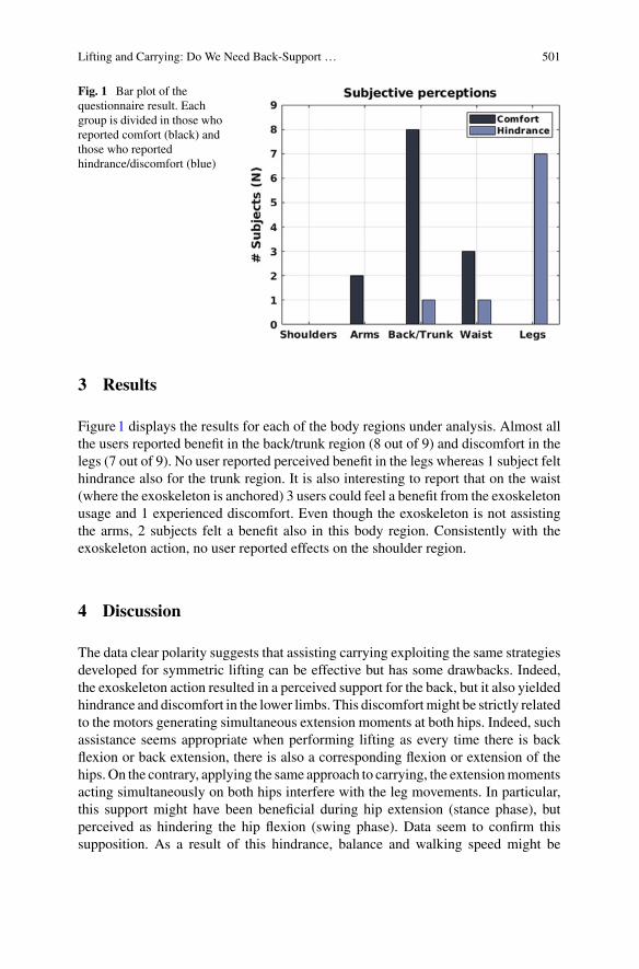
Lifting and Carrying: Do We Need Back-Support … 501
Fig. 1 Bar plot of thequestionnaire result. Eachgroup is divided in those whoreported comfort (black) andthose who reportedhindrance/discomfort (blue)
3 Results
Figure1 displays the results for each of the body regions under analysis. Almost allthe users reported benefit in the back/trunk region (8 out of 9) and discomfort in thelegs (7 out of 9). No user reported perceived benefit in the legs whereas 1 subject felthindrance also for the trunk region. It is also interesting to report that on the waist(where the exoskeleton is anchored) 3 users could feel a benefit from the exoskeletonusage and 1 experienced discomfort. Even though the exoskeleton is not assistingthe arms, 2 subjects felt a benefit also in this body region. Consistently with theexoskeleton action, no user reported effects on the shoulder region.
4 Discussion
The data clear polarity suggests that assisting carrying exploiting the same strategiesdeveloped for symmetric lifting can be effective but has some drawbacks. Indeed,the exoskeleton action resulted in a perceived support for the back, but it also yieldedhindrance and discomfort in the lower limbs. This discomfortmight be strictly relatedto the motors generating simultaneous extension moments at both hips. Indeed, suchassistance seems appropriate when performing lifting as every time there is backflexion or back extension, there is also a corresponding flexion or extension of thehips. On the contrary, applying the same approach to carrying, the extensionmomentsacting simultaneously on both hips interfere with the leg movements. In particular,this support might have been beneficial during hip extension (stance phase), butperceived as hindering the hip flexion (swing phase). Data seem to confirm thissupposition. As a result of this hindrance, balance and walking speed might be
502 T. Poliero et al.
significantly affected, resulting both in productivity losses and limited acceptanceof the exoskeleton. Using transparency (zero-torque) control during carrying wouldsolve/reduce hindrance, but correspondingly give up the positive support for theback during a task that the International Standard marks as worthy of attention.Transparency control can be achieved both by active and quasi-passive/semi-activeexoskeletons. These latter are devices that exploit actively controlled elements suchas electro-magnetic clutches for the engagement or dis-engagement of the passiveelements. On the contrary, to provide support also during carrying, it is necessary touse active exoskeletons. Anyhow, to fully exploit active back-support exoskeletoncapabilities and versatility it is important to introduce task awareness (HAR). Indeed,once the task being performed is recognized, itwould allow to activate the best controlstrategy. As an example, in this study, it would have been possible to switch betweena strategy that has been implemented taking inspiration from symmetric lifting tasksto a novel control strategy specifically designed for carrying assistance. As presentedin recent works, HAR can be achieved by exploiting common exoskeleton on-boardsensors (such as encoders and IMUs) and, so, most exoskeletons could implement it,[5–7]. In particular, in [6], we showed howXoTrunk control strategy can be expandedto include on-line task recognition to distinguish between walking, lifting, standingand carrying.
Finally, to effectively understand the importance of supporting carrying activitiesand the exoskeleton effects, futureworks should present a rigorous analysis onmuscleactivation and kinematics.
5 Conclusion
In thiswork,we have presented the subjective perceptions from9 subjects performingcarrying tasks while being assisted by an active back-support exoskeleton. A controlstrategy suited for symmetric lifting tasks was adopted. The results show that theexoskeleton action was perceived as beneficial for the back but hindering the naturalleg movement patterns occurring while walking. This highlights the importance ofcontrol strategies suited to different tasks, as well as of the capability to distinguishthe activity being performed to select the most appropriate strategy.
Acknowledgements This work has also been funded by the Italian Workers’ CompensationAuthority (INAIL).
References
1. M.P. de Looze, T. Bosch, F. Krause, K.S. Stadler, L.W. O’Sullivan, Exoskeletons for industrialapplication and their potential effects on physical work load. Ergonomics 59(5), 671–681(2016)
Lifting and Carrying: Do We Need Back-Support … 503
2. J. Theurel,K.Desbrosses,Occupational exoskeletons: overviewof their benefits and limitationsin preventing work-related musculoskeletal disorders. IISE Trans. Occup. Ergonomics Hum.Factors, 1–17 (2019)
3. S. Toxiri, M.B. Nöf, M. Lazzaroni, J. Fernndez, M. Sposito, T. Poliero, L. Monica, S. Anastasi,D.G. Caldwell, J. Ortiz, Back-support exoskeletons for occupational use: an overview of tech-nological advances and trends. IISE Trans. Occup. Ergonomics Hum. Factors 7(3-4), 237–249(2019). (Online). Available: https://doi.org/10.1080/24725838.2019.1626303
4. L. Grazi, B. Chen, F. Lanotte, N. Vitiello, S. Crea, Towards methodology and metrics forassessing lumbar exoskeletons in industrial applications, in, II Workshop on Metrology forIndustry 4.0 and IoT (MetroInd4. 0&IoT). (IEEE, 2019) 2019, pp. 400–404
5. B. Chen, F. Lanotte, L. Grazi, N. Vitiello, S. Crea, Classification of lifting techniques forapplication of a robotic hip exoskeleton. Sensors 19(4), 963 (2019)
6. T. Poliero, S. Toxiri, S. Anastasi, L. Monica, D.G. Caldwell, C.J. Ortiz, Assessment of anon-board classifier for activity recognition on an active back-support exoskeleton, in 2019IEEE 16th International Conference on Rehabilitation Robotics (ICORR). (IEEE, 2019), pp.559–564
7. M. Jamšek, T. Petric, J. Babic, Gaussian mixture models for control of quasi-passive spinalexoskeletons. Sensors 20(9), 2705 (2020)
8. S. Toxiri, A.S. Koopman, M. Lazzaroni, J. Ortiz, V. Power, M.P. de Looze, L. O’Sullivan,D.G. Caldwell, Rationale, implementation and evaluation of assistive strategies for an activeback-support exoskeleton. Front. Robot. AI 5, 53 (2018)
9. C. Di Natali, S. Toxiri, S. Ioakeimidis, D.G. Caldwell, J. Ortiz, Systematic framework forperformance evaluation of exoskeleton actuators, inWearable Technologies (2020, in press)
10. M. Sposito, C. Di Natali, S. Toxiri, D.G. Caldwell, E.De Momi, J. Ortiz, Exoskeleton kine-matic design robustness: an assessment method to account for human variability, WearableTechnologies (2020, in press)
Exoskeletons Introduction in Industry.Methodologies and Experience of CentroRicerche Fiat (CRF)
Massimo Di Pardo, Rossella Monferino, Francesca Gallo, and Felice Tauro
Abstract Exoskeletons and other technologies for aiding work need to be tested andselected before starting the implementation plan or further evaluation phases. Inno-vation in this field is highly dynamic and new products are frequently proposed atprototype level so discriminating phase is important. This paper aims to explain howFCA–CRF is approaching the evaluation of new products and the new technologiesfor aiding work. The evaluation is based on applicative cases and on testing proce-dures as well as on testing session results. The selection phase is important to defineif exoskeleton or other technology under investigation fits the needs of workstationand tasks to be faced during work activity. In this way an objective performance eval-uation of the exoskeletonmatching theworkplace needs can be operated. The appliedtesting procedure for this exoskeletons investigation demonstrated its usefulness atlaboratory and pilot case level.
1 Introduction
Exoskeletons are external mechanical structures, active or passive, that support theworker in specific work tasks [1]. These systems are designed to give support incertain body districts; those addressed to the industrial world are mainly orientedto assist the back and upper limbs with targets of postural assistance, applied forcereduction, manual material handling and supporting tools. CRF is working in the
M. Di Pardo (B) · R. Monferino · F. GalloCentro Ricerche Fiat (CRF), Orbassano, Italye-mail: [email protected]
R. Monferinoe-mail: [email protected]
F. Galloe-mail: [email protected]
F. TauroCentro Ricerche Fiat (CRF), Melfi, Italye-mail: [email protected]
© The Author(s), under exclusive license to Springer Nature Switzerland AG 2022J. C. Moreno et al. (eds.), Wearable Robotics: Challenges and Trends,Biosystems & Biorobotics 27, https://doi.org/10.1007/978-3-030-69547-7_81
505
506 M. Di Pardo et al.
research of technological solutions for supporting workers (for instance by modi-fication of workstation and work methods, or by implementation of tools, equip-ment, exoskeletons). These solutions are sought in order to bring benefits both forthe improvement of the operator’s working conditions and in terms of efficiencyand quality of the production process. The procedures for exoskeleton evaluationare mainly focused on performances assessment of the device [2]. SEMG (SurfaceElectroMyography) is often the discriminating instrument used for effectiveness esti-mation, but it’s complicated to apply it in the real environment [3]. Several methodsdeveloped for practical evaluation are available according to the experience of thecase [4], but need to be generalized and linked to the needs of the workstation. Sinceno standard evaluation method is available in the literature at present, we proposea methodology (this is the novelty in respect to the state of art) that assesses andcompares functionalities, performances, usability and applicability of passive devicesin simulated and real workplaces. The result of this work, improves the exoskeletonsevaluation because based on numerical, objective and standard criteria linked to theworkstation needs. It makes possible a comparison among different devices.
2 Methodology and Instruments
2.1 Objectives
The first objective is to detect the most suitable exoskeleton for the workstationappointed for a specific task. This objective is focused on the fulfillment of the needsof the work task and the related workstation including the equipment.
The second objective is to estimate the level of fitting and the compliance degreebetween the selected exoskeleton and the workstation under analysis. This meansto know the performances and functionalities of the exoskeletons available on themarket, and put them in relationship with the workstation needs. Finally, the thirdobjective is to improve the workstation ergonomics increasing the worker wellbeing.This objective is achievable by the fulfillment of the previous two objectives, and bythe fulfillment of usability requirements for the selected exoskeleton.
2.2 Methodology
The methodology aims to mathematize qualitative evaluation and to make a correla-tion between the needs of the production system (made of workstation, work task andworker) and the exoskeleton performances. The best matching between productionsystem needs and exoskeleton performances helps the worker in his task, increasingergonomics and wellbeing perception. The methodology is made of two phases: thefirst phase is the exoskeleton selection through laboratory testing. The second phase
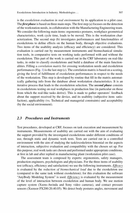
Exoskeletons Introduction in Industry. Methodologies … 507
is the exoskeleton evaluation in real environment by its application to a pilot case.The first phase is based on threemain steps. The first step (a) focuses on the detectionof the workstation needs, in collaboration with theManufacturing Engineering team.We consider the following main items: ergonomics postures, workplace geometricalcharacteristics, work cycle time, loads to be moved. This is the workstation char-acterization. The second step (b) investigates performances and functionalities ofexoskeletons to define effects on the human body, through objective evaluations.Two items of the usability analysis (efficacy and efficiency) are considered. Thisevaluation is carried out by measurement instruments and biomechanical simula-tion tools, in comparative tests on working tasks performed with and without theexoskeleton. This part of the work is carried out in the CRF laboratory on real-liketasks, in order to classify exoskeletons and build a database of the main function-alities. Filling a correlation matrix for crossing workstation needs and exoskeletonperformances (Fig. 1) is the last step (c). The correlation matrix is based on a scoring,giving the level of fulfillment of exoskeleton performances in respect to the needsof the workstation. This step is developed by routine that fill in the matrix automat-ically gathering info from the database about workstation characteristics. It is aniterative process that leads to the exoskeleton selection. The second phase consistsin exoskeletons testing on real workplaces in production line (in particular on thosefrom which the real-like tasks derive). This is made to gather operators’ feedbackabout the support received by the device, and its usability (subjective item: satis-faction), applicability (vs. Technical and managerial constraints) and acceptability(by the social environment).
2.3 Procedures and Instruments
Test procedures, developed at CRF, focuses on task execution and measurement byinstruments. Measurements of usability are carried out with the aim of evaluatingthe support provided by the investigated exoskeletons under different conditions ofuse, through static and dynamic work tests. Tests are carried out in a controlledenvironment with the aim of studying the task/exoskeleton binomial on the aspectsof interaction, subjective evaluation and compatibility with the chosen set up. Forthis purpose, real work tasks are chosen and performed under appropriate conditions,at first in lab and after replied in manufacturing plant (workstation pilot case).
The assessment team is composed by experts: ergonomists, safety managers,production engineers, psychologists and physicians. For the three items of usabilitytest (efficacy, efficiency and satisfaction) we use the following instruments. Efficacyis evaluated by the reduction of biomechanical load due to the exoskeleton use(compared to the same task without exoskeleton); for this evaluation the software“AnyBody Modeling System” is used. Efficiency is evaluated by the measurementof the level of interaction between exoskeleton and human body. We use motioncapture system (Xsens-Awinda and Sony video cameras), and contact pressuresensors (Xsensor PX200:20.40.05). We detect body postures angles, movement and
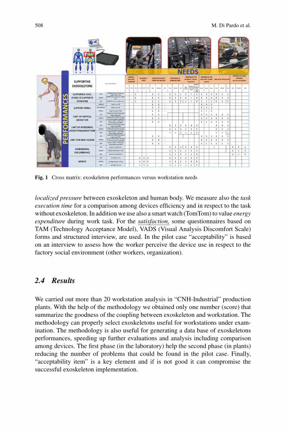
508 M. Di Pardo et al.
Fig. 1 Cross matrix: exoskeleton performances versus workstation needs
localized pressure between exoskeleton and human body. We measure also the taskexecution time for a comparison among devices efficiency and in respect to the taskwithout exoskeleton. In additionwe use also a smartwatch (TomTom) to value energyexpenditure during work task. For the satisfaction, some questionnaires based onTAM (Technology Acceptance Model), VADS (Visual Analysis Discomfort Scale)forms and structured interview, are used. In the pilot case “acceptability” is basedon an interview to assess how the worker perceive the device use in respect to thefactory social environment (other workers, organization).
2.4 Results
We carried out more than 20 workstation analysis in “CNH-Industrial” productionplants. With the help of the methodology we obtained only one number (score) thatsummarize the goodness of the coupling between exoskeleton and workstation. Themethodology can properly select exoskeletons useful for workstations under exam-ination. The methodology is also useful for generating a data base of exoskeletonsperformances, speeding up further evaluations and analysis including comparisonamong devices. The first phase (in the laboratory) help the second phase (in plants)reducing the number of problems that could be found in the pilot case. Finally,“acceptability item” is a key element and if is not good it can compromise thesuccessful exoskeleton implementation.
Exoskeletons Introduction in Industry. Methodologies … 509
3 Conclusion
All these measurements gives us the global effect of introducing an exoskeleton ona specific workstation considering the realistic context of use. Based on the wholemethodologywe are able to provide guideline to the production sectors of FCA/CNHIfor exoskeleton choice and application. This is an important help for keeping standardproduction alignedwith theWordClassManufacturing rules. An important extensionof the methodology could be its automatization through sensors and software toolsfor speed up the analysis and increase precision.
References
1. DeLooze et al, 2016. Exoskeletons for industrial application and their potential effects onphysical work load. Ergonomics 59(5):671–81
2. Spada et al, 2018. Analysis of exoskeleton introduction in industrial reality. InternationalConference on Applied Human Factors and Ergonomics AHFE 2017, pp. 236–244
3. Bostelman et al., Cross-industry standard test method developments. Frontiers of InformationTechnology and Electronic Engineering 18(10), 1447–1457 (2017)
4. Bosch et al, 2016. The effects of a passive exoskeleton on muscle activity, discomfort andendurance time in forward bending work. Applied ergonomics 54:212–217
Quantifying the Impact of a Lower LimbExoskeleton on Whole-BodyManipulation Tasks. MethodologicalApproach and First Results
Yaiza Benito Molpeceres, Guillermo Asín-Prieto, Juan Carlos García Orden,and Diego Torricelli
Abstract In recent years, back-support exoskeletons have been postulated as a com-petitive solution to reducemechanical loading during lifting tasks, contributing to theprevention of low back pain. However, little research involving lower body exoskele-tons has been done on this matter. The present study evaluates the impact of theH2 robotic exoskeleton on whole-body manipulation tasks, through a standardizedexperimental protocol and a set of objectivemetrics.Wearing the exoskeleton allowedthe subject to perform the tasks successfully, occasionally showing magnified rangeof movement values at certain joints. In addition, its use reduced back mechanicalloading of loaded-box lifts. However, the device also had a non-desirable impact onfunctional performance, increasing postural instability, slowing down tasks comple-tion, and diminishing movement smoothness.
1 Introduction
During the last decade, the increasing availability of exoskeletons have started anew exciting era for robotics. Companies are considering the use of such devicesto improve workers’ safety and ergonomics, and the scientific community is morethan ever active in this field [1]. Nowadays, most of the exoskeletons aimed at reduc-
Y. B. Molpeceres (B) · J. C. G. OrdenDepartment of Continuum Mechanics and Theory of Structures of the Universidad Politécnica,de Madrid, Spaine-mail: [email protected]
J. C. G. Ordene-mail: [email protected]
G. Asín-Prieto · D. TorricelliNeural Rehabilitation Group of the Spanish National Research Council, Madrid, Spaine-mail: [email protected]
D. Torricellie-mail: [email protected]
G. Asín-PrietoGogoa Mobility Robots S.L., Abadiño, Spain
© The Author(s), under exclusive license to Springer Nature Switzerland AG 2022J. C. Moreno et al. (eds.), Wearable Robotics: Challenges and Trends,Biosystems & Biorobotics 27, https://doi.org/10.1007/978-3-030-69547-7_82
511
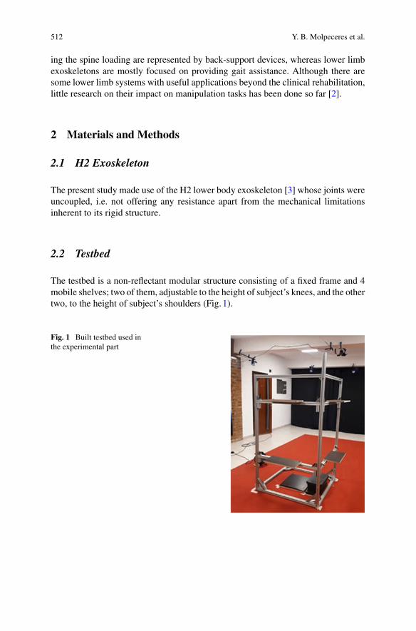
512 Y. B. Molpeceres et al.
ing the spine loading are represented by back-support devices, whereas lower limbexoskeletons are mostly focused on providing gait assistance. Although there aresome lower limb systems with useful applications beyond the clinical rehabilitation,little research on their impact on manipulation tasks has been done so far [2].
2 Materials and Methods
2.1 H2 Exoskeleton
The present study made use of the H2 lower body exoskeleton [3] whose joints wereuncoupled, i.e. not offering any resistance apart from the mechanical limitationsinherent to its rigid structure.
2.2 Testbed
The testbed is a non-reflectant modular structure consisting of a fixed frame and 4mobile shelves; two of them, adjustable to the height of subject’s knees, and the othertwo, to the height of subject’s shoulders (Fig. 1).
Fig. 1 Built testbed used inthe experimental part
Quantifying the Impact of a Lower Limb … 513
2.3 Experimental Protocol
The experimental protocol was approved by the Ethical Committee of the SpanishNational Research Council (092/219). It consists of two tasks vinculated to manip-ulation skills from bipedal standing: Sagittal Lifting and Lateral Box Transfer. Thethree factors involved in the experiment are: System (No exoskeleton/ Exoskeleton),Load (0kg/ 10% of subject’s body weight) and Lift Type (for sagittal lifting,Floor-to-Knee (F2K)/ Floor-to-Shoulder (F2S)/ Knee-to-Shoulder (K2S); and for lateral boxtransfer, Knee-to-Knee (K2K)/ Shoulder-to-Shoulder (S2S)). Lateral box transfertask results are not presented in this paper.
2.4 Testing Procedure
By the moment, one young healthy male subject has been tested. Human motionin the sagittal plane was recorded at 100Hz using a photogrammetric marker-basedmotion capture system (Vicon, Oxford Metrics), and the kinematic data were low-pass filtered with a zero-phase lag 4th order Butterworth filter at 8Hz. Prior to thestart of the experiment, the exoskeleton was fitted to the subject and the mobileshelves of the testbed were adjusted to his knees and shoulders’ height. The 14mm-diameter retroreflective markers were placed according to the Full Body Plug-in-Gait protocol [4]. The dynamic trials were performed in a randomized order, so asto prevent learning effects. Between trials, the subject was asked to close his eyesmaking him unaware of the boxes’ interchange performed by the researchers.
2.5 Movement Quantification: Metrics
We developed the following set of objective metrics based on kinematic data: A.Range of movement (RoM); B. Postural instability, assessed by computing the devi-ation between the centre of mass and the centre of the base of support [5]; C. Per-formance time, or required time to complete the task; D. Spinal loads estimation,given by the L4-L5 and L5-S1 compression and shear forces [6]; and E. Smoothness,obtained by computing the arc length of the joint’s speed spectral profile [7].
3 Results
All the results described below refer to Table1
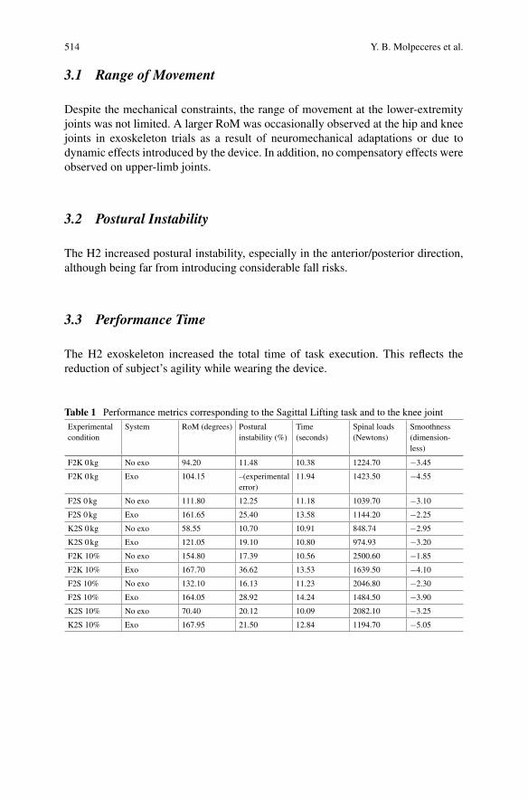
514 Y. B. Molpeceres et al.
3.1 Range of Movement
Despite the mechanical constraints, the range of movement at the lower-extremityjoints was not limited. A larger RoM was occasionally observed at the hip and kneejoints in exoskeleton trials as a result of neuromechanical adaptations or due todynamic effects introduced by the device. In addition, no compensatory effects wereobserved on upper-limb joints.
3.2 Postural Instability
The H2 increased postural instability, especially in the anterior/posterior direction,although being far from introducing considerable fall risks.
3.3 Performance Time
The H2 exoskeleton increased the total time of task execution. This reflects thereduction of subject’s agility while wearing the device.
Table 1 Performance metrics corresponding to the Sagittal Lifting task and to the knee jointExperimentalcondition
System RoM (degrees) Posturalinstability (%)
Time(seconds)
Spinal loads(Newtons)
Smoothness(dimension-less)
F2K 0kg No exo 94.20 11.48 10.38 1224.70 −3.45
F2K 0kg Exo 104.15 –(experimentalerror)
11.94 1423.50 −4.55
F2S 0kg No exo 111.80 12.25 11.18 1039.70 −3.10
F2S 0kg Exo 161.65 25.40 13.58 1144.20 −2.25
K2S 0kg No exo 58.55 10.70 10.91 848.74 −2.95
K2S 0kg Exo 121.05 19.10 10.80 974.93 −3.20
F2K 10% No exo 154.80 17.39 10.56 2500.60 −1.85
F2K 10% Exo 167.70 36.62 13.53 1639.50 −4.10
F2S 10% No exo 132.10 16.13 11.23 2046.80 −2.30
F2S 10% Exo 164.05 28.92 14.24 1484.50 −3.90
K2S 10% No exo 70.40 20.12 10.09 2082.10 −3.25
K2S 10% Exo 167.95 21.50 12.84 1194.70 −5.05
Quantifying the Impact of a Lower Limb … 515
3.4 Spinal Loads Estimation
In empty-box lifts, compression forces are greater in exoskeleton trials than in thoseperformed without the device. However, in loaded-box lifts, although the back forcesincreased without the exoskeleton, a reduction on them was observed when usingthe device.
3.5 Smoothness
A slightly smoother trend is observed in the exo-free trials. Smoother manoeuvrescorrespond to the upper-limb joints, and the more abrupt ones to the hip joint.
4 Discussion
Themain goal of this studywas to quantify the impact of a lower limb exoskeleton onmanipulation tasks. A limitation in the RoMwas expected; however, the exoskeletonallowed the subject to performnaturalmovements.We expected that lifting the loadedbox while wearing the exoskeleton will affect subject’s stability. It was observed thatthe loaded box slightly increased instability in the exoskeleton trials. As expected, theexoskeleton increased the performance time. Moreover, the H2 relieved the subject’sback loading when lifting the loaded box. Lastly, the exoskeleton slightly decreasedthe smoothness, which varied across joints.
5 Conclusions
Given our results, even though this study can not be considered definitive in any wayas only one subject was tested, the H2 exoskeleton assessed did not negatively affectthe subject’s RoM nor his back mechanical loading. However, it is responsible forthe increase of postural instability and performance time, and for the decrease ofmovement smoothness. As future work, more subjects should be tested, movementin other planes should be studied, and the effects of the powered exoskeleton shouldbe investigated.
Acknowledgements The work presented in this paper was supported by the European Union’sHorizon2020 research and innovation programunder grant agreementNo779963—EUROBENCH.The authors would like to acknowledge the support of Technaid S.L. for unconditionally providing
the exoskeleton for this research.
516 Y. B. Molpeceres et al.
References
1. D. Torricelli, J.L. Pons, EUROBENCH: preparing robots for the real world. In: WearableRobotics: Challenges and Trends. WeRob 2018. Biosyst. Biorobot. 22, 375–378, 2018.(Springer)
2. T. Luger et al., Influence of a passive lower-limb exoskeleton during simulated industrial worktasks on physical load, upper body posture, postural control and discomfort. Appl. Ergonomics80, 152–160 (2019)
3. M. Bortole et al., The H2 robotic exoskeleton for gait rehabilitation after stroke: early findingsfrom a clinical study. J. Neuroeng. Rehabili. 12(1), 54 (2015)
4. Vicon, Plug-in-Gait Reference Guide5. M. Alamoudi, Investigation and Analysis of the Effects of Manual Lifting and Carrying Activi-
ties onPostural andGait Stability inNormal Subjects (Research repository ofMiamiUniversity,2017)
6. F. Ghezelbash et al., Subject-specific regression equations to estimate lower spinal loads duringsymmetric and asymmetric static lifting. J. Biomech. 102, 109550 (2020)
7. S. Balasubramanian et al., A robust and sensitivemetric for quantifyingmovement smoothness.IEEE Trans. Biomed. Eng. 59(8), 2126–2136 (2012)
Assessment of Exoskeleton RelatedChanges in Kinematics and MuscleActivity
Fabio V. dos Anjos, Taian M. Vieira, Giacinto L. Cerone, Talita P. Pinto,and Marco Gazzoni
Abstract Work-related musculoskeletal disorders, reported at shoulder and lowback regions, rank among themost serious health problems in industry.Owing to theirability in providing support to the shoulder and back regions during sustained andrepetitive tasks, passive exoskeletons are expected to prevent work-related disorders.In this work, experimental protocols were conducted for the extraction of relevantinformation regarding the neuromuscular activation and kinematics during simulatedworking activities with passive exoskeletons. Our results support the notion thesepassive exoskeletons have the potential to alleviate muscular loading and thereforeto prevent musculoskeletal disorders in the industrial sector.
1 Introduction
EXOSKELETONS have been proposed as a promising solution for the prevention ofwork-related musculoskeletal disorders (MSD) [1, 2]. However, the current knowl-edge does not fully clarify the impact of exoskeletons on MSD prevention [3]. Evenif many factors must be considered in MSD prevention, excessive muscular stress
F. V. dos AnjosPostgraduate Program of Rehabilitation Sciences, Augusto Motta University (UNISUAM), Rio deJaneiro, Brazile-mail: [email protected]
T. M. Vieira · G. L. Cerone · T. P. Pinto · M. Gazzoni (B)Laboratory for Engineering of the Neuromuscular System (LISiN), Politecnico di Torino, Torino,Italye-mail: [email protected]
T. M. Vieirae-mail: [email protected]
G. L. Ceronee-mail: [email protected]
T. P. Pintoe-mail: [email protected]
© The Author(s), under exclusive license to Springer Nature Switzerland AG 2022J. C. Moreno et al. (eds.), Wearable Robotics: Challenges and Trends,Biosystems & Biorobotics 27, https://doi.org/10.1007/978-3-030-69547-7_83
517
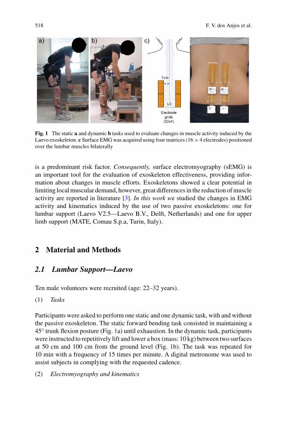
518 F. V. dos Anjos et al.
Fig. 1 The static a and dynamic b tasks used to evaluate changes in muscle activity induced by theLaevo exoskeleton. c Surface EMGwas acquired using four matrices (16× 4 electrodes) positionedover the lumbar muscles bilaterally
is a predominant risk factor. Consequently, surface electromyography (sEMG) isan important tool for the evaluation of exoskeleton effectiveness, providing infor-mation about changes in muscle efforts. Exoskeletons showed a clear potential inlimiting localmuscular demand, however, great differences in the reduction ofmuscleactivity are reported in literature [3]. In this work we studied the changes in EMGactivity and kinematics induced by the use of two passive exoskeletons: one forlumbar support (Laevo V2.5—Laevo B.V., Delft, Netherlands) and one for upperlimb support (MATE, Comau S.p.a, Turin, Italy).
2 Material and Methods
2.1 Lumbar Support—Laevo
Ten male volunteers were recruited (age: 22–32 years).
(1) Tasks
Participants were asked to perform one static and one dynamic task, with and withoutthe passive exoskeleton. The static forward bending task consisted in maintaining a45° trunk flexion posture (Fig. 1a) until exhaustion. In the dynamic task, participantswere instructed to repetitively lift and lower a box (mass: 10 kg) between two surfacesat 50 cm and 100 cm from the ground level (Fig. 1b). The task was repeated for10 min with a frequency of 15 times per minute. A digital metronome was used toassist subjects in complying with the requested cadence.
(2) Electromyography and kinematics
Assessment of Exoskeleton Related Changes in Kinematics … 519
Monopolar sEMG signals were collected from the low back muscles bilaterally withfour electrode grids (8 × 4 electrodes, inter-electrode distance: 10 mm; Fig. 1c)organized in two groups of 32× 4 electrodes. Signals were conditioned and sampledusing four 32 channel acquisition systems for HD-sEMG (2048 samples/s; 16-bit)(LISiN, Politecnico di Torino and OT Bioelettronica) [4]. Hip and knee joint anglesof the right leg were collected from two electrogoniometers (Twin-Axis Electrogo-niometer SG150, Biometrics Ltd., Newport, United Kingdom), with zero degreescorresponding to full knee and hip extension.
(3) Data processing and statistical analysis
For the static task, Root Mean Square (RMS) values were computed from single-differential EMGs over 1s epochs, while for the dynamic task, RMS values andmaximumandminimum joint angleswere calculated over individual lifting -loweringcycles. RMS maps were obtained by averaging RMS values at 10% increments intime over the duration of task. For each task, the degree of activity was computedfrom the maps at the beginning, mid and end of task as the average RMS over thechannels showing an RMS value higher than 70% of the maximum RMS in the map[5]. The coordinates of the centroid of RMS distribution along the cranial-caudaldirection were also computed. About the kinematic data, the average maximum andminimum angles were extracted from the first, middle and last decile of task for bothlifting and lowering. A 2-way and 3-way ANOVA were applied separately for eachcycle phase to respectively assess the effect of Time and Device on the joint anglesand the effect of Time, Device and Side on the degree of activity and the centroid ofRMS distribution (post-hoc Tukey and significance level of 5%).
2.2 Upper Limb Support—MATE
Twelve young healthy volunteers (age: 20–30 years) participated in the study.
(1) Tasks
Subjectswere instructed tomaintain four static postures (Fig. 2a) for 20s in two condi-tions (without and with the passive exoskeleton MATE). The considered postureswere: (P1) shoulder abducted at 90°, elbow flexed at 90°, elbow pronated at 90°;(P2) shoulder flexed at 90°, elbow flexed at 90°, elbow pronated at 90°; (P3) shoulderflexed at 90°, elbow pronated at 90°; (P4) shoulder abducted at 90°, elbow pronatedat 90°. Each task was repeated 5 consecutive times. The assistance level was set asrecommended by the manufacturer in relation to height and weight of the user.
(2) Electromyography and kinematics
Bipolar EMGs were collected from the anterior, medial and posterior deltoids andthe upper trapezius of the right upper limb using pairs of surface electrodes (30 mm
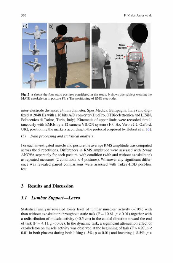
520 F. V. dos Anjos et al.
Fig. 2 a shows the four static postures considered in the study. b shows one subject wearing theMATE exoskeleton in posture P3. c The positioning of EMG electrodes
inter-electrode distance, 24 mm diameter, Spes Medica, Battipaglia, Italy) and digi-tized at 2048 Hz with a 16 bits A/D converter (DuePro, OTBioelettronica and LISiN,Politecnico di Torino, Turin, Italy). Kinematic of upper limbs were recorded simul-taneously with EMGs by a 12 camera VICON system (100 Hz, Vero v2.2, Oxford,UK), positioning the markers according to the protocol proposed by Hebert et al. [6].
(3) Data processing and statistical analysis
For each investigated muscle and posture the average RMS amplitude was computedacross the 5 repetitions. Differences in RMS amplitude were assessed with 2-wayANOVA separately for each posture, with condition (with and without exoskeleton)as repeated measures (2 conditions × 4 postures). Whenever any significant differ-ence was revealed paired comparisons were assessed with Tukey-HSD post-hoctest.
3 Results and Discussion
3.1 Lumbar Support—Laevo
Statistical analysis revealed lower level of lumbar muscles’ activity (~10%) withthan without exoskeleton throughout static task (F = 10.61, p < 0.01) together witha redistribution of muscle activity (~0.5 cm) in the caudal direction toward the endof task (F = 4.11, p < 0.02). In the dynamic task, a significant attenuation effect ofexoskeleton on muscle activity was observed at the beginning of task (F > 4.97, p <0.01 in both phases) during both lifting (~5%; p = 0.01) and lowering (~8.5%; p <
Assessment of Exoskeleton Related Changes in Kinematics … 521
0.01). A trend toward a redistribution of muscle activity to the distal muscle regionduring the task (~0.5 cm; F= 2.60, p < 0.09) was observed without than with the useof exoskeleton. This finding seems to indicate that exoskeleton may reduce muscleloading at the beginning of the task. Moreover, for the knee joint, a lower maximumangular position (~6.5°) was observed with than without exoskeleton, regardlessof cycle phase (Device effect: F > 8.72, p < 0.01; post-hoc: p < 0.01), suggestingexoskeleton might affect the range of motion during the dynamic task.
3.2 Shoulder Support—MATE
A main Device effect was observed for anterior and medial deltoids and uppertrapezius, with lower RMS values with than without exoskeleton (F > 6.10; p <0.018 for all cases). Significant interaction was observed for posterior deltoid, withlower amplitude values with than without exoskeleton for P1 and P4 (post-hoc F >3.53 and p < 0.025). These findings revealed the attenuation effect of exoskeleton onmuscle activity was manifested at all muscles evaluated, though not for all postureswhen considering posterior deltoid.
4 Conclusion
The results suggest the passive exoskeletons tested seem to be potentially relevant toattenuate the muscular effort, with implications for the prevention of work-relatedmusculoskeletal disorders. The extension of the study to dynamic conditions withthe MATE exoskeleton is ongoing.
Acknowledgements This work was supported by Regione Piemonte and the Ministry of Educa-tion, University, and Research in the POR FESR 2014/2020 framework Project “Human centeredManufacturing Systems (HuManS)” and by IUVO Srl.
References
1. T. Bosch, J. van Eck, K. Knitel, M. de Looze, The effects of a passive exoskeleton on muscleactivity. Appl Ergon. 54, 212–217 (2016)
2. K. Huysamen, T. Bosch, M. de Looze, K.S. Stadler, E. Graf, L.W. O’Sullivan, Evaluation of apassive exoskeleton for static upper limb activities. Appl. Ergon. 70, 148–155 (2018)
3. J. Theurel, K. Desbrosses, Occupational exoskeletons: overview of their benefits and limitationsin preventing work-related musculoskeletal disorders. IISE Trans. Occup. Ergon. Hum. Factors(2019)
4. G.L. Cerone, A. Botter, M. Gazzoni, A modular, smart, and wearable system for high densitysEMG detection. IEEE Trans. Biomed. Eng. Eng. 66(22), 3371–3380 (2019). https://doi.org/10.1109/TBME.2019.2904398

522 F. V. dos Anjos et al.
5. T.M.M. Vieira, R. Merletti, L. Mesin, Automatic segmentation of surface EMG images:Improving the estimation of neuromuscular activity. J. Biomech. (2010). https://doi.org/10.1016/j.jbiomech.2010.03.049
6. J.S. Hebert, J. Lewicke, T.R.Williams, A.H. Vette, Normative data for modified Box and Blockstest measuring upper-limb function via motion capture. J. Rehabil. Res. Dev. 51(6), 918–932(2014)

Exoskeletons for Military Applications
Exoskeletons for Military Logisticsand Maintenance
Mona Hichert, Markus Güttes, Ines Bäuerle, Nils Ziegenspeck, Nico Bölke,and Jonas Schiebl
Abstract Field studies were performed at various logistics and maintenance facili-ties of the German armed forces, with the aim to develop a set of design requirementsfor novel exoskeletons in military logistics applications. This led to an improvedunderstanding of common logistics tasks and a list of design requirements includingmain and secondary activities, ranges ofmotion and environmental parameters. Fromthese design requirements, designs and first prototypes were derived.
1 Introduction
Inmany areas of logistics andmaintenance,workers have to performphysically stren-uous work, such as lifting and carrying heavy objects, as well as working in forcedpostures (e.g. forward bent posture or overhead work) or while standing. The strainon the musculoskeletal system can lead to serious damage of the back or shouldersresulting in a reduced quality of life, increased sick days and reduced productivity [1].
M. Hichert (B) · M. Güttes · I. BäuerleFraunhofer FKIE–Fraunhofer Institute of Communication Information Processing andErgonomics, Bonn, Germanye-mail: [email protected]
M. Güttese-mail: [email protected]
I. Bäuerlee-mail: [email protected]
N. Ziegenspeck · N. Bölke · J. SchieblFraunhofer IPA–Fraunhofer Institute for Manufacturing Engineering and Automation, Stuttgart,Germanye-mail: [email protected]
N. Bölkee-mail: [email protected]
J. Schieble-mail: [email protected]
© The Author(s), under exclusive license to Springer Nature Switzerland AG 2022J. C. Moreno et al. (eds.), Wearable Robotics: Challenges and Trends,Biosystems & Biorobotics 27, https://doi.org/10.1007/978-3-030-69547-7_84
525
526 M. Hichert et al.
Musculoskeletal disorders are one of the major reasons for work incapacity [2]. Sickdays are not only costly, but are also accompanied by loss of knowledge, experienceand routine of specialized workers. Exoskeletons are innovative ergonomic tools,which potentially decrease the strain on the body [3]. Exoskeletons can be catego-rized in passive systems that support by mechanical elements like springs or elasticbands and active systems that provide support from e.g. electric motors. An interme-diate approach are adaptive or semi-active exoskeletons that use motors to activateor adjust a passive support system.
To investigate the potential benefits of exoskeletons in the logistics of the Germanarmed forces, the project “ExoLog” was launched in June 2019. The two FraunhoferInstitutes FKIE (Fraunhofer Institute for Communication, Information Processingand Ergonomics) and IPA (Fraunhofer Institute for Manufacturing Engineering andAutomation) are developing novel exoskeletons in close cooperation with partnersof the German armed forces until the end of 2021. First, design requirements for thestationary military logistics base were set, followed by a comparison to the mobilelogistic tasks and the corresponding changes in requirements. This extended abstractfocuses on the stationary military logistics.
2 Method
Different military stationary logistics facilities, like ammunition depots, materialwarehouses materials management center deployment and naval bases, were exam-ined. Inspection of workspaces led to a selection of activities, in which soldiersand civilian workers can potentially benefit from exoskeletons. The focus was onoverhead work, lifting and carrying, and tasks in forward bent postures. Movementsduring these selected tasks were recorded by a mobile motion capture system (MTwAwinda, Xsens, Enschede, the Netherlands). Resulting joint angles were calculatedfrom the generated movement data and compared to occupational safety recommen-dations [4]. According to the soldiers subjective rating, the lower back and shouldersare the areas that experience the highest strain.
Furthermore, some soldierswere introduced to and fittedwith commercially avail-able exoskeletons and were asked to execute their tasks wearing exoskeletons. Theused exoskeletons included several passive exoskeletons for overhead work and forlifting tasks. After completing the tasks, their judgement was recorded through ques-tionnaires and interviews. Thiswas a first exploratory investigation into the subjectiveperception of the application of exoskeletons. The small number of participants, shortduration and variability of tasks do not allow statistical conclusions. The aim was toget an indication of the potential benefits in stationary military logistics and roomfor improvement for novel devices.
Subsequently, the observations of the visits were summarized in a list ofrequirements.
Exoskeletons for Military Logistics and Maintenance 527
3 Results
Derived from the observations, two novel exoskeletons that fulfill the summarizedrequirements and provide better functionality as well as user acceptance of commer-cial exoskeletons are being developed in the scope of this project. The first noveldevice is focused on the shoulder area, supporting overhead work as well as liftingbetween hip height and overhead height, while the second device is focused on liftingtasks between floor and hip height as well as forward bent work. The list of require-ments for exoskeletons in the stationary military logistics was subcategorized intomain activities that can be supported by, and secondary activities that should befeasible with the exoskeleton.
The main activities included lifting and laying down at and from waist level (withand without mesh stillages), carrying at waist level, lifting up to and down fromshoulder level, overhead work and forward bent tasks. Joint angles, which could leadto musculoskeletal diseases when they occur often or over a prolonged period of timewere found in several tasks. Affected areas were hip flexion, shoulder flexion andabduction and in some cases head extension.
In addition, environmental parameters, available infrastructure, users and theiranthropometric data, executed range of motion during the main activities, perfor-mance data, usability, comfort, and safety requirements were identified. Usability,comfort and safety requirements included weight of the device, time and ease to donand doff, adaptability to different user sizes, size of the device, noise levels, powersupply and compatibility with everyday equipment and clothing of the worker.
4 Discussion
Visits at different military stationary logistics facilities resulted in a list of require-ments for novel exoskeletons.
Thepresented joint angle data underlines the potential benefits utilizing ergonomictools, like exoskeletons, in the execution of these tasks.
The measured data allow us to formulate specific joint angles which workersshould be able to execute while wearing an exoskeleton without restriction ofmovement, as well as certain specific movements that should be supported.
Furthermore, the developed list of design requirements with all its categories,which were not discussed in detail here, gives an informed starting point for thedevelopment of novel exoskeletons.
Ongoing work as part of the project includes laboratory experiments andexoskeleton development and engineering. An experimental methodology has beendeveloped to evaluate existing commercial exoskeletons, followed by newly devel-oped prototypes, by imitating themainfield test tasks in the Fraunhofer humanperfor-mance laboratory under controlled conditions. Muscle activity (EMG), metabolic
528 M. Hichert et al.
cost and kinematics will be recorded. By inverse dynamic calculations resultingjoint moments will be evaluated.
Novel exoskeleton development focuses on passive, semi-active and adaptiveexoskeletons for shoulder and back support. Overall, the aim is to investigate theexoskeletons benefits for logistic workers by quantifying physiological and biome-chanical data in the scope of occupational health and safety. Reducing the physicalstrain might also enable the soldiers and civilian workers to perform tasks undermore healthy conditions for longer periods of time.
For now, the focus is on stationary military logistics, but applications are intendedfor mobile logistics as well. We observed similarities in stationary military logisticsand civil logistics. However, differences were found in more Personal ProtectionEquipment (PPE, e.g. bulletproof vests), higher time pressure, higher weight ofmanually transported objects and longer task duration in the military setting.
5 Conclusion
Aset of design requirements, derived fromfield experiments and interviewswith staffof the German armed forces has been developed for the application of exoskeletonsin military logistics. Next steps include the development of passive and semi-activeadaptive exoskeletons and laboratory test methodology to evaluate and compareexoskeletons (existing and new), and improve understanding about the physiologicalperformance of humans using exoskeletons during military logistics tasks.
Acknowledgements This workwas supported by the Exolog Project funded by theGermanArmedForces (Bundeswehr) under Grant No E/U2Ci/KA225/JF080.
The authors like to thank the soldiers and civilworkers at themilitary stationary logistics facilitiesfor participating in the field tests and our partners in the German armed forces for their valuableinput.
References
1. L.L. Andersen, N. Fallentin, J.Z.N. Ajslev, M.D. Jakobsen, E. Sundstrup, Association betweenoccupational lifting and day-to-day change in low-back pain intensity based on company recordsand text messages. Scand. J. Work Environ. Health 43(1), 68–74 (2017).
2. H.F. van der Molen, C. Foresti, J.G. Daams, M.H.W. Frings-Dresen, P.P.F.M. Kuijer, Work-related risk factors for specific shoulder disorders: A systematic review and meta-analysis.Occup. Environ. Med. 74(10), 745–755 (2017).
3. M.P. de Looze, T. Bosch, F. Krause, K.S. Stadler, L.W. O’Sullivan, Exoskeletons for industrialapplication and their potential effects on physical work load. Ergonomics 59(5), 671–681 (2016).
4. Deutsche Gesetzliche Unfallversicherung e.V. (DGUV), DGUV Information 208–033: Belas-tungen für den Rücken und Gelenke - was geht mich das an? (2016). (Online). Available: https://publikationen.dguv.de/widgets/pdf/download/article/458
Aerial Porter Exoskeleton (APEX)for Lifting and Pushing
W. Brandon Martin, Alexander Boehler, Kevin W. Hollander,Darren Kinney, Joseph K. Hitt, Jay Kudva, and Thomas G. Sugar
Abstract A hip exoskeleton was designed that can assist hip extension duringsquat lifting and pushing. The device incorporates a motor, ball screw in a compactlightweight package. The total weight of the system including the battery is 3.94 kgand the system can supply over 30 Nm of torque to each leg. The device assists liftingand pushing and is not engaged during walking, running or other tasks.
1 Introduction
Wearable robotic systems are being developed to assist at the hips [1–6]. Thesesystems must be lightweight, energy efficient, and must conform to the human. Forsystems to assist during load handling tasks, they must not interfere with the humangait such as walking and jogging.
We have developed a hip exoskeleton, APEX (Aerial Porter Exoskeleton). Asimilar system, HeSA, was designed in 2016–2018 to assist soldiers walking onpatrol, wearing a tactical vest that holds body armor. The current system is designedfor logistics handling and will only operate during lifting and pushing. The designand testing of the system will be described.
USAF, Contract FA8606–19-C-0018.
W. Brandon Martin · A. Boehler · T. G. SugarHuman Machine Integration Laboratory, Arizona State University, Tempe, AZ, USA
T. G. Sugar (B)Arizona State University, Tempe, AZ, USAe-mail: [email protected]
K. W. Hollander · D. KinneyAugspurger Komm Engineering Inc., Phoenix, AZ, USA
J. K. HittGoX Labs, Phoenix, USA
J. KudvaNextgen Aeronautics, Torrance, USA
© The Author(s), under exclusive license to Springer Nature Switzerland AG 2022J. C. Moreno et al. (eds.), Wearable Robotics: Challenges and Trends,Biosystems & Biorobotics 27, https://doi.org/10.1007/978-3-030-69547-7_85
529
530 W. Brandon Martin et al.
2 Design Goals
The goal is to develop a lightweight, hip exoskeleton to reduce workplace injuriesand improve productivity, efficiency, and quality during logistics operations. Wewill focus on pushing large pallets (4500 kg) onto cargo aircraft and the lifting ofsome light (1–4.5 kg), medium, (4.5–13.6 kg) and heavy objects (13.6–22.7 kg),specifically:
1. A comfortable, lightweight design is proposed that is easily donned and doffed.The current system can be donned in less than 1 min.
2. Utilizing the unique “catch and release lever arm” approach, the systemwill notconstrain postures or walking.
3. With the unique catch and release lever arm, the system will allow operators toget in and out of vehicles and sit on a forklift.
4. The device is intuitive to operate with no need for user input. There is noextended training period for the control system that is always in-phase with theuser based on our unique phase-oscillator controller.
5. The system will be adjustable to accommodate small and large workers.6. The powered system is very efficient and will only be used to assist pushing and
lifting.
Powered System versus Passive System: Passive back exoskeletons are func-tioning very well. Current commercial systems include SuitX, Laevo, Hunic, andHeroWear. Passive back exoskeletons have been shown to reduce metabolic cost andassist the user in performing more ergonomic lifts, decreasing injury potential. Apassive system is lighter and more cost effective than a powered system as well.However, a passive system cannot supply extra power and torque when needed toperform heavy lifting and pushing all-day. A passive system can only return theamount of stored energy that the person puts into it. Most importantly, most passivesystems cannot get out of the way when walking or running.
We do not feel that a passive system can assist in heavy pushing tasks. If theworkerjust cannot push the pallet, without the need for extra crew members, then a passivesystem will not help because it cannot supply any extra enhancement. However, apowered system will supply extra hip extension torque for pushing tasks. Our mainbenefit is to increase the leg extension torque reducing muscle fatigue.
3 Design
Wehad discussionswith airport logistics companies about pushing and loading cargoonto aircraft. Firstly, we were informed that nothing should be at the feet/shoes sincethe worker is moving inside of cramped areas and there can be objects on the groundsuch as transfer balls.
Secondly, we learned that turning around and pushing with your back is easieron the legs. This occurs because the lumbar region is supported; some of the weight
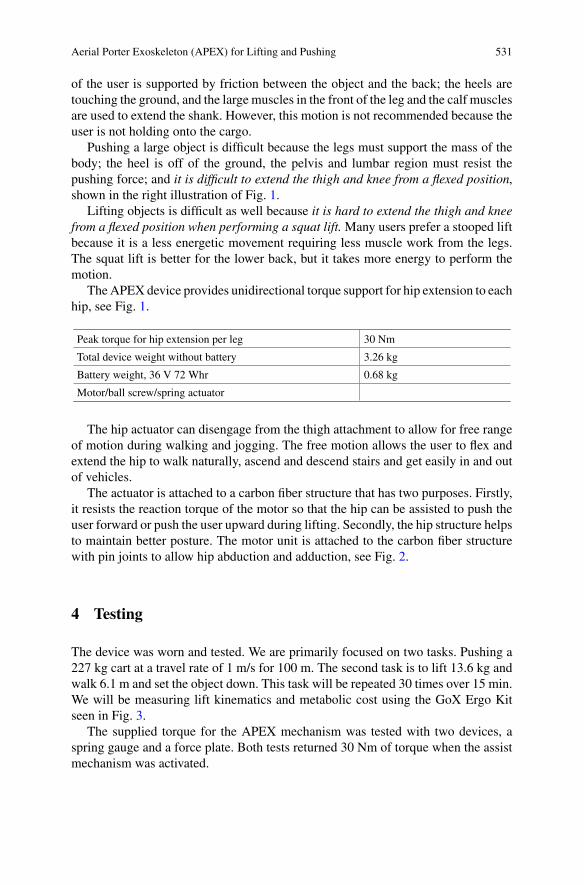
Aerial Porter Exoskeleton (APEX) for Lifting and Pushing 531
of the user is supported by friction between the object and the back; the heels aretouching the ground, and the large muscles in the front of the leg and the calf musclesare used to extend the shank. However, this motion is not recommended because theuser is not holding onto the cargo.
Pushing a large object is difficult because the legs must support the mass of thebody; the heel is off of the ground, the pelvis and lumbar region must resist thepushing force; and it is difficult to extend the thigh and knee from a flexed position,shown in the right illustration of Fig. 1.
Lifting objects is difficult as well because it is hard to extend the thigh and kneefrom a flexed position when performing a squat lift.Many users prefer a stooped liftbecause it is a less energetic movement requiring less muscle work from the legs.The squat lift is better for the lower back, but it takes more energy to perform themotion.
TheAPEX device provides unidirectional torque support for hip extension to eachhip, see Fig. 1.
Peak torque for hip extension per leg 30 Nm
Total device weight without battery 3.26 kg
Battery weight, 36 V 72 Whr 0.68 kg
Motor/ball screw/spring actuator
The hip actuator can disengage from the thigh attachment to allow for free rangeof motion during walking and jogging. The free motion allows the user to flex andextend the hip to walk naturally, ascend and descend stairs and get easily in and outof vehicles.
The actuator is attached to a carbon fiber structure that has two purposes. Firstly,it resists the reaction torque of the motor so that the hip can be assisted to push theuser forward or push the user upward during lifting. Secondly, the hip structure helpsto maintain better posture. The motor unit is attached to the carbon fiber structurewith pin joints to allow hip abduction and adduction, see Fig. 2.
4 Testing
The device was worn and tested. We are primarily focused on two tasks. Pushing a227 kg cart at a travel rate of 1 m/s for 100 m. The second task is to lift 13.6 kg andwalk 6.1 m and set the object down. This task will be repeated 30 times over 15 min.We will be measuring lift kinematics and metabolic cost using the GoX Ergo Kitseen in Fig. 3.
The supplied torque for the APEX mechanism was tested with two devices, aspring gauge and a force plate. Both tests returned 30 Nm of torque when the assistmechanism was activated.
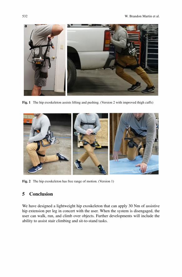
532 W. Brandon Martin et al.
Fig. 1 The hip exoskeleton assists lifting and pushing. (Version 2 with improved thigh cuffs)
Fig. 2 The hip exoskeleton has free range of motion. (Version 1)
5 Conclusion
We have designed a lightweight hip exoskeleton that can apply 30 Nm of assistivehip extension per leg in concert with the user. When the system is disengaged, theuser can walk, run, and climb over objects. Further developments will include theability to assist stair climbing and sit-to-stand tasks.
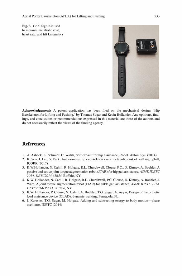
Aerial Porter Exoskeleton (APEX) for Lifting and Pushing 533
Fig. 3 GoX Ergo Kit usedto measure metabolic cost,heart rate, and lift kinematics
Acknowledgements A patent application has been filed on the mechanical design “HipExoskeleton for Lifting and Pushing,” by Thomas Sugar and Kevin Hollander. Any opinions, find-ings, and conclusions or recommendations expressed in this material are those of the authors anddo not necessarily reflect the views of the funding agency.
References
1. A. Asbeck, K. Schmidt, C. Walsh, Soft exosuit for hip assistance, Robot. Auton. Sys. (2014)2. K. Seo, J. Lee, Y. Park, Autonomous hip exoskeleton saves metabolic cost of walking uphill,
ICORR (2017)3. K.W.Hollander, N. Cahill, R. Holgate, R.L. Churchwell, Clouse, P.C., D. Kinney, A. Boehler, A
passive and active joint torque augmentation robot (JTAR) for hip gait assistance, ASME IDETC2014, DETC2014-35654, Buffalo, NY
4. K.W. Hollander, N. Cahill, R. Holgate, R.L. Churchwell, P.C. Clouse, D. Kinney, A. Boehler, J.Ward, A joint torque augmentation robot (JTAR) for ankle gait assistance, ASME IDETC 2014,DETC2014-35653, Buffalo, NY
5. K.W. Hollander, P. Clouse, N. Cahill, A. Boehler, T.G. Sugar, A. Ayyar, Design of the orthoticload assistance device (OLAD), dynamic walking, Pensacola, FL.
6. J. Kerestes, T.G. Sugar, M. Holgate, Adding and subtracting energy to body motion—phaseoscillator, IDETC (2014)
Exoskeletons for Unarmed Military Use:Requirements and Approachesto Support Human Movements Usingan Example of Protection AgainstUnknown CBRN Dangers
C. Linnenberg, J. Klabunde, K. Hagner, and R. Weidner
Abstract Using individual protective equipment (IPE) while handling unknownchemical, biological, radiological and nuclear (CBRN) dangers can lead to highphysical stress on the user. The use of exoskeletons may be a good approach to helprelieving the user andmay increase the overall wear time of the IPE.Due to the uniqueenvironment and equipment, this use case applies additional requirements on theexoskeletal functions, design and interactionwith the IPE.By the example of disposalof unknown CBRN dangers, this contribution observes and analyses the differenttasks in the field of handling unknown CBRN dangers and deduces requirementsfor the combination of the IPE and exoskeletons. The results recommend the use ofexoskeletons combined with the IPE, especially the gas-tight protective suit and afew approaches to include exoskeletal systems in the security measures.
1 Introduction
HANDLING CBRN hazardous substances requires a high degree of safety precau-tions. In order to be able to comply with these, it is necessary to use protective suitswith an adequate protection level and hazard-depending respiratory protection. The
The research is funded by Bundeswehr Research Institute for Protective Technologies andNBC Protection, Project: “Entlastung beim Tragen von CBRN-Schutzausrüstung”, (grant numberE/E590/IZ014/HF120). The sole responsibility for the manuscript contents lies by the authors. Wethank the partners for their support and cooperation.
C. Linnenberg (B) · R. WeidnerProduction Technology, Institute for Mechatronics, University Innsbruck, Innsbruck, Austriae-mail: [email protected]
J. Klabunde · R. WeidnerLaboratory for Production Technology, Helmut Schmidt University, University of the GermanFederal Armed Forces Hamburg, Hamburg, Germany
K. HagnerDepartment of Individual and Collective Protection, Bundeswehr Research Institute for ProtectiveTechnologies and NBC Protection, Munster, Germany
© The Author(s), under exclusive license to Springer Nature Switzerland AG 2022J. C. Moreno et al. (eds.), Wearable Robotics: Challenges and Trends,Biosystems & Biorobotics 27, https://doi.org/10.1007/978-3-030-69547-7_86
535
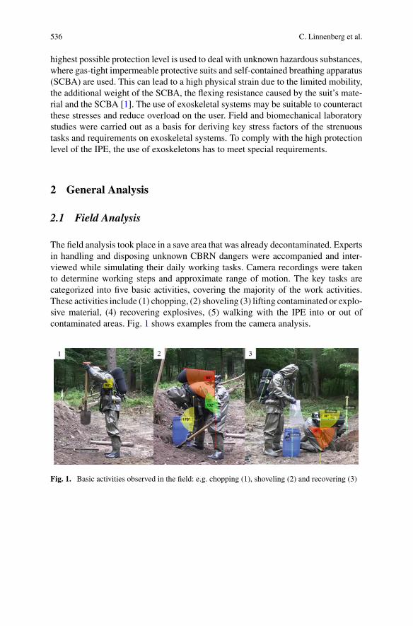
536 C. Linnenberg et al.
highest possible protection level is used to deal with unknown hazardous substances,where gas-tight impermeable protective suits and self-contained breathing apparatus(SCBA) are used. This can lead to a high physical strain due to the limited mobility,the additional weight of the SCBA, the flexing resistance caused by the suit’s mate-rial and the SCBA [1]. The use of exoskeletal systems may be suitable to counteractthese stresses and reduce overload on the user. Field and biomechanical laboratorystudies were carried out as a basis for deriving key stress factors of the strenuoustasks and requirements on exoskeletal systems. To comply with the high protectionlevel of the IPE, the use of exoskeletons has to meet special requirements.
2 General Analysis
2.1 Field Analysis
The field analysis took place in a save area that was already decontaminated. Expertsin handling and disposing unknown CBRN dangers were accompanied and inter-viewed while simulating their daily working tasks. Camera recordings were takento determine working steps and approximate range of motion. The key tasks arecategorized into five basic activities, covering the majority of the work activities.These activities include (1) chopping, (2) shoveling (3) lifting contaminated or explo-sive material, (4) recovering explosives, (5) walking with the IPE into or out ofcontaminated areas. Fig. 1 shows examples from the camera analysis.
Fig. 1. Basic activities observed in the field: e.g. chopping (1), shoveling (2) and recovering (3)
Exoskeletons for Unarmed Military Use: Requirements … 537
2.2 Laboratory Study
The results of the field analysis were used to set up the laboratory test environment.The five basic activities from the field study were each performed in three differentconditions: (1) without any equipment, to capture the strain of the actual activityitself (2) with SCBA to detect strains caused by the additional weight and (3) infull gear with SCBA and IPE (suit, boots and gloves) to record total strains. Thetests carried out in the study contain kinematic, electromyographic (EMG), electro-cardiographic (ECG) and posturographic measurements to draw conclusions on thechange in themovement pattern, muscle activity, cardio-pulmonal stress and posturalcontrol. EMG-Data were standardized by maximal voluntary contractions (MVC)on the observed muscles. The test set was carried out by six subjects with an averageage of 32.5 years. Methodological details are published in [2].
Performance duration prolonged over the test condition in every test set, e.g.lifting contaminated material took 31% longer with SCBA and IPE. On averageECG frequency increased for 14% in condition with SCBA&IPE compared to basiccondition with a mean frequency of 102 bpm. Wearing SCBA caused higher fluc-tuations of body’s center of gravity for 23%, wearing IPE additionally caused 50%higher fluctuations compared to basis. It can be assumed that the influence of thebackpack weight is about as strong as the influence of the protective suit on themotoric and postural control. Kinematic and EMG data are quite task specific anddetailed. Over all it can be summarized that, among others, the most strenuous bodypart is the shoulder neck region especially in the chopping and recovering tasks withup to 81%MVC mean activity of the trapezius muscle. It is followed by the lowerback that shows mean activities of the erector spinae muscle up to 34% at liftingand recovering tasks. Kinematic data for instance show obviously restrictions inmobility caused by the suit. Then again, kinematic data revealed the positive influ-ence of the SCBA backpack, serving as a counteracting balancer at the lifting taskby the means of smaller back angles and less erector muscle activity in conditionSCBA and SCBA&IPE.
3 General Results
There are different measures to improve the actual work. One is using organiza-tional measures as optimized workflows or specification of work processes. Thisincludes, e.g., work specific personal training, ergonomic positioning of the equip-ment. Another approach using technological improvements utilizes, e.g., an opti-mized backpack structure, implementing lifting gear and transportation systems, acustomized excavator or exoskeletal systems. Due to the large variety of operationareas, most technological measures are only suitable for a very limited number ofscenarios.Using active exoskeletonswith an adaptable range of functions and supportpower turns out to be the most suitable solution.
538 C. Linnenberg et al.
According to the laboratory study there aremainly two overloaded body areas thatoffer a good starting point for relief with exoskeletons. One is the shoulder-neck-areaand the other one is the lower back. Since the body parts are apart from one another,two different approaches may be implemented in one exoskeletal system.
4 Requirements for the Use of Exoskeletonsin Combination with CBRN Protective Gear
There are mainly four influencing variables of exoskeletal support: human, activity,social surrounding and work environment. Typical examples are the different anthro-pometry of humans or physical precondition, range of motion of an activity or workcontent that requires different support. The work environment must be taken intoaccount, e.g., with different local climatic conditions or workstations, as well as thesocial environment with its staff and different affinity to technology.
Handling unknown CRBN dangers requires additional factors of the influencingvariables: First, the working environment is characterized by the risk of contamina-tion. In particular, requirements arise from weather condition, the breathing protec-tion (SCBA/powered air purifying respirator PAPR) and the impacts of the suititself, that are inhibited vaporization, high humidity inside the suit because of theimpermeable and gas-tight material, limited mobility and field of view. Second, theactivity tasks themselves are characterized especially by the high backpack weights(SCBA/PAPR), the permanent change of tools and breathing protection dependingon the security level.
Accordingly, safety demands arise and the safety functions, according to DIN ENISO 13482, and the integrity of the suit must be met. Realizing a lightweight systemwould decrease the load and improve the breathing by using accessory respiratorymuscles. To prevent further limited mobility of the suit, the exoskeleton has to beintegrated within the suit. On the other hand, the suit must fully cover the exoskeletonand has to be detachable from one another while taking off the IPE to prevent contam-ination of the exoskeleton and the user. A high resistance of the exoskeletons mainparts against humidity and sweat has to be given to ensure a high reliability and actionsafety. Integration of the exoskeleton and a functional back structure is necessary toswitch or change the breathing protection, transfers the load to the lower extremityand relieves shoulders, neck and breathing. This also ensures fewer restrictions whenperforming different kinds of movements, that need to be e.g., empowered, facili-tated or stabilized [3]. Providing the best postural results in stance, SCBA/ PAPRshould have a high center of gravity on the body, respectively the shoulders. Dynamicactuators that meet the natural movements, movement velocity and acceleration aswell as joint specific and position depended application of force until joints end posi-tions should be approached to lower energy consumption and increase the metabolicefficiency.
Exoskeletons for Unarmed Military Use: Requirements … 539
5 Conclusion
In this contribution, special requirements for exoskeletons in the use of unarmedmilitary CBRN handling and their determination were described and conclusions forgeneral approaches of exoskeleton systemswithin the working area were drawn. Oneof the main points are the special demands of the IPE for the functionalities of theexoskeleton. The protective function has to be preserved under any circumstanceswhile the gear affects the user with additional strains due to its function-relatedlimitations. As mainly overloaded body areas the shoulder-neck-area and the lowerback were addressed. Thus, exoskeletal approaches for each of the correspondingtasks have to be implemented. The field and laboratory tests carried out serve as acomparison to validate the use and effectiveness of possible support systems. Never-theless, it is necessary to consider the user of the IPE in the implementation as well inorder to achieve a high level of acceptance of the system combination. Further stepsinclude the implementation of exoskeletal approaches in the suit and the testing ofthe functionalities in the laboratory and field tests.
References
1. K.J. Glitz, U. Seibel, W. Gorges, C. Piekarski, D. Leyk,Gesundheit und Leistung im Klima, vol.12, Wehrmedizin und Wehrpharmazie (2011)
2. K. Hagner, C. Linnenberg, A.Werner, R. Tandon, A. Overkamp, Entlastungsmöglichkeiten beimTragen impermeabler ABC-Schutzausrüstung, in 3. transdisziplinäre Konferenz "TdchnischeUnterstützungssysteme, die die Menschen wirklich wollen (2018)
3. A. Karafillidis, R. Weidner, Distinguishing support technologies. A general scheme and itsapplication to Exo-skeletons, in Developing Support Technologies, pp. S.85–100. Springer(2018)
Analysis of a Passive Ankle Exoskeletonfor the Reduction of the Metabolic CostsDuring walking—A Preliminary Study
Luís P. Quinto, Pedro Pinheiro, Sérgio B. Gonçalves, Ivo F. Roupa,and Miguel T. Silva
Abstract The present study has as main objective the design and development of apassive exoskeleton for the reduction of the metabolic costs during gait. The proto-type was designed based on an existing concept, exploring specific issues relatedto ankle mobility, user’s ergonomics and structural customization. The evaluationof the exoskeleton performance was performed by 15 volunteers belonging to thePortugueseArmy, based on the 6MWT. The exoskeletonwas tested considering threeforce elements with different stiffnesses to assess the influence of this parameter in itsperformance. A qualitative analysis was also performed to assess the users’ percep-tion during the trials. Results showed a reduction of themetabolic costs in 10 subjects,presenting an average value of 3%. Moreover, the results indicate that the selectionof the force elements and the tuning of the spring-engaging mechanism plays a keyrole in the efficiency of the developed solution.
1 Introduction
In recent years, the interest for human enhancing systems has grown significantly,particularly in the areas of defence, industry and rehabilitation. Military operationsrequire a high energy expenditure, which could result in high exhaustion rates and
The authors would like to thank the Portuguese Army, though CINAMIL (ELITE/2019/CINAMIL)and FCT through IDMEC, under LAETA, project (UIDB/50022/2020).
L. P. Quinto (B) · P. PinheiroCINAMIL, Academia Militar, Instituto Universitário Militar, Lisbon, Portugale-mail: [email protected]
P. Pinheiroe-mail: [email protected]
L. P. Quinto · P. Pinheiro · S. B. Gonçalves · I. F. Roupa · M. T. SilvaIDMEC, Instituto Superior Técnico, Universidade de Lisboa, Lisbon, Portugale-mail: [email protected]
M. T. Silvae-mail: [email protected]
© The Author(s), under exclusive license to Springer Nature Switzerland AG 2022J. C. Moreno et al. (eds.), Wearable Robotics: Challenges and Trends,Biosystems & Biorobotics 27, https://doi.org/10.1007/978-3-030-69547-7_87
541
542 L. P. Quinto et al.
in an increase of the injury risk of soldiers [1, 2]. In these cases, exoskeletons canbe a useful resource, as they can reduce the metabolic costs associated to the perfor-mance of a given task, increase the human capabilities and reduce the risk of derivedmusculoskeletal pathologies [1]. The main objective of this study is the developmentof a passive ankle exoskeleton to be applied in a military context, which allows forthe reduction of the metabolic costs during walking. Hence, the developed solutionshould be versatile and compliant with a wide variety of terrains. It should also beeasily adaptable to other applications aiming its use by a broad spectre of users.To do so, specific requirements should be taken into consideration like comfort,ergonomics, range of motion of the actuated joint and adaptability to the user’santhropometry and footwear. The main contributions of this work are the identifi-cation of the product requirements aiming its final application and the developmentof a functional prototype for laboratory tests (TRL 4) using additive manufacturing.The solution should take into consideration specific military requirements, such ascomfort for long periods of time, range-of-motion of the ankle joint, no electro-magnetic signatures, among others. While complying with these requirements, theexoskeleton should allow for the reduction of the metabolic cost during gait, one ofthe critical activities in military operations.
2 Materials and Methods
In order to achieve a final prototype that could be tested in a laboratory, thedevelopment of the exoskeleton followed four major steps:
(1) Exoskeleton Requirements: a concept development process, based on [3], wasimplemented to define the exoskeleton technical specifications. A set of inter-views was conducted with individuals with experience in military operationsto identify the major specifications. The guidelines proposed by the majormilitary agencies, such as the North Atlantic Treaty Organization (NATO) orEuropean Defence Agency (EDA), were also taken into consideration duringthis phase [4]. The relevance of each specification was analysed by applying aMudge diagram and aKanomodel. At the end of this process, a set of requisiteswere defined as mandatory, and the project evolved for the concept design.
(2) Concept Generation: the development of the exoskeleton considered twomajoractivities, the development of the structural part and the development of theactuation unit. The structural part considered a novel approach with one lateralrod and a planar spherical bearing to allow for the free movement of theankle joint. An external fixation to the shoe was also developed to maintainthe footwear ergonomics. For the actuation unit, the mechanism proposed byCollins et al. [5] was adopted with the required modifications to fit in thedeveloped structure.
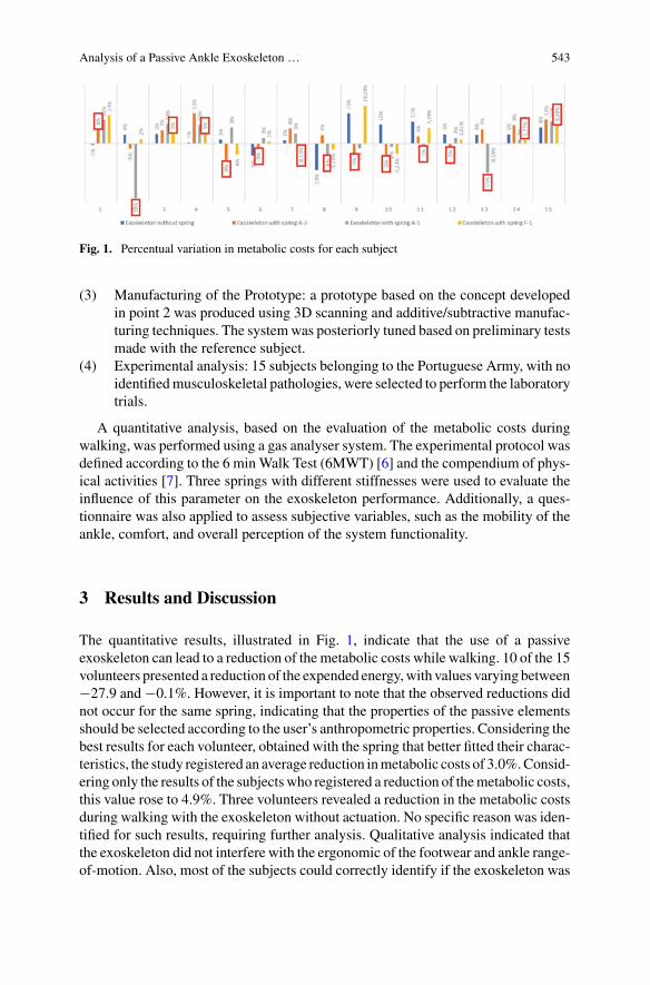
Analysis of a Passive Ankle Exoskeleton … 543
Fig. 1. Percentual variation in metabolic costs for each subject
(3) Manufacturing of the Prototype: a prototype based on the concept developedin point 2 was produced using 3D scanning and additive/subtractive manufac-turing techniques. The systemwas posteriorly tuned based on preliminary testsmade with the reference subject.
(4) Experimental analysis: 15 subjects belonging to the Portuguese Army, with noidentifiedmusculoskeletal pathologies, were selected to perform the laboratorytrials.
A quantitative analysis, based on the evaluation of the metabolic costs duringwalking, was performed using a gas analyser system. The experimental protocol wasdefined according to the 6 minWalk Test (6MWT) [6] and the compendium of phys-ical activities [7]. Three springs with different stiffnesses were used to evaluate theinfluence of this parameter on the exoskeleton performance. Additionally, a ques-tionnaire was also applied to assess subjective variables, such as the mobility of theankle, comfort, and overall perception of the system functionality.
3 Results and Discussion
The quantitative results, illustrated in Fig. 1, indicate that the use of a passiveexoskeleton can lead to a reduction of the metabolic costs while walking. 10 of the 15volunteers presented a reduction of the expended energy,with values varying between−27.9 and−0.1%. However, it is important to note that the observed reductions didnot occur for the same spring, indicating that the properties of the passive elementsshould be selected according to the user’s anthropometric properties. Considering thebest results for each volunteer, obtained with the spring that better fitted their charac-teristics, the study registered an average reduction inmetabolic costs of 3.0%.Consid-ering only the results of the subjectswho registered a reduction of themetabolic costs,this value rose to 4.9%. Three volunteers revealed a reduction in the metabolic costsduring walking with the exoskeleton without actuation. No specific reason was iden-tified for such results, requiring further analysis. Qualitative analysis indicated thatthe exoskeleton did not interfere with the ergonomic of the footwear and ankle range-of-motion. Also, most of the subjects could correctly identify if the exoskeleton was
544 L. P. Quinto et al.
reducing or increasing the metabolic costs during walking. Limited efficiency orergonomic issues could have resulted from the fact that, for practical reasons, everysubject performed the trials with a structure modelled to best fit the physical char-acteristics of subject zero (reference subject). Preliminary tests also showed thatthe tuning of the spring-engaging mechanism plays a vital role in the exoskeletonperformance.
4 Conclusion
The findings achieved in this work suggest that the use of a solution as the oneproposed in this work can lead to a reduction of the metabolic costs, with 10 ofthe 15 individuals, revealing a decrease of metabolic costs. The developed structuremaintains the ergonomics of the footwear and the range of motion of the ankle. Theuse of additive manufacturing to build the exoskeleton structure allows for a custom-made structure with a low acquisition cost. Future work will address the selection ofdifferent structural materials for a lighter and less bulky structure, and the evolutionof the spring-engaging mechanism. Amethodology for the selection of the force unitwill also be addressed in future studies.
Acknowledgements To all the volunteers that participated in this project and to the LisbonBiomechanics Laboratory, for the support and availability in the collection of anthropometric data.
References
1. H.P. Crowell et al., Methodologies for evaluating the effects of physical augmentation technolo-gies on soldier performance, US Army Res. Lab. Aberdeen Proving Gr. United States, no. May,p. 78 (2018). doi: https://doi.org/10.13140/RG.2.2.13662.48961
2. J.J. Knapik, K.L. Reynolds, E. Harman, Soldier load carriage: historical, physiological, biome-chanical, andmedical aspects. Mil. Med. 169(1), 45–56 (2004). https://doi.org/10.7205/milmed.169.1.45
3. K.T. Ulrich, S.D. Eppinger, Product Design and Development, 5th edn. (McGraw-Hill/Irwin,New York, 2012).
4. Report from the 2nd Integration of the Exoskeleton in the Battlefield Workshop (2nd IEB WS)(2018)
5. S.H. Collins, M.B. Wiggin, G.S. Sawicki, Reducing the energy cost of human walking usingan unpowered exoskeleton. Nature 522(7555), 212–215 (2015). https://doi.org/10.1038/nature14288
6. R.O. Crapo, P.L. Enright, R.J. Zeballos, ATS Statement: guidelines for the six-minute walk test.Am. J. Respir. Crit. Care Med. 166(1), 111–117 (2002). https://doi.org/10.1164/ajrccm.166.1.at1102
7. B.E. Ainsworth et al., Compendium of physical activities: a second update of codes and METvalues. Med. Sci. Sport. Exerc 43(8), 1575–1581 (2011). https://doi.org/10.1249/MSS.0b013e31821ece12
AMultivariate Analysis for ForceElement Selection in Passive AnkleExoskeletons
Nuno A. Ribeiro, Luís P. Quinto, Sérgio B. Gonçalves, Ivo F. Roupa,Paula P. Simões, and Miguel T. Silva
Abstract Exoskeletons performance is influenced by several factors such asergonomics, actuation force or actuation timing. In particular, for passive exoskele-tons, the force element specifications are crucial for its performance. This study aimsto infer the existence of a relation between the stiffness of the force element installedon an ankle exoskeleton and the anthropometric parameters of its user. Multivariatestatistical techniques were applied to analyse the relevance of the anthropometricdata in the energy expenditure of 15 subjects, during the execution of the six-minutewalk test using a passive ankle exoskeleton. Results suggest a multiple linear relationbetween the anthropometric data and the metabolic results obtained for each volun-teer. In conclusion, the presented methodology enables the selection of the mostappropriate spring for each user, without resorting to time-consuming laboratory orfield tests.
The authors would like to thank the Portuguese Army, though CINAMIL (ELITE/2019/CINAMIL)and FCT through IDMEC, under LAETA, project (UIDB/50022/2020).
N. A. Ribeiro · L. P. Quinto (B) · P. P. SimõesCINAMIL, Academia Militar, Instituto Universitário Militar, Lisbon, Portugale-mail: [email protected]
N. A. Ribeiroe-mail: [email protected]
P. P. Simõese-mail: [email protected]
L. P. Quinto · S. B. Gonçalves · I. F. Roupa · M. T. SilvaIDMEC, Instituto Superior Técnico, Universidade de Lisboa, Lisbon, Portugale-mail: [email protected]
M. T. Silvae-mail: [email protected]
P. P. SimõesCMA-Faculdade de Ciências E Tecnologia, Universidade Nova de Lisboa, Lisbon, Portugal
© The Author(s), under exclusive license to Springer Nature Switzerland AG 2022J. C. Moreno et al. (eds.), Wearable Robotics: Challenges and Trends,Biosystems & Biorobotics 27, https://doi.org/10.1007/978-3-030-69547-7_88
545
546 N. A. Ribeiro et al.
1 Introduction
Soldiers are assigned functions that are associated with intense physical efforts, suchas long marches or the handling and transportation of heavy loads. These efforts areaggravated by exposure to unpredictable situations, inherent to the complexity of atheatre of operations. The increase in the likelihood of injury and the reduction of thereadiness level of the force [1] concerns both political decision-makers and militaryofficials. Exoskeletons are a possible solution to these issues, since they reduce themetabolic costs of the military, increasing their readiness level and reducing theirrisk of injury [2–4].
Most of the exoskeleton solutions require the identification of several biomechan-ical and anthropometric parameters of its user to design and tune different compo-nents. This customisation will significantly improve the overall performance of thesystem [3, 5].
In the case of passive solutions used to reduce the metabolic costs during walking,the selection of the force element plays a vital role. In ankle exoskeletons that usesprings the stiffness of its force elements must be carefully selected accordingly tothe user. This feature is vital since this element will store the energy during certainphases of the gait, releasing it in others, providing adequate support to the exoskeletonuser.
However, the identification of the force element stiffness is usually based in proto-cols which are both complex and time-consuming [3, 5]. Therefore, these proto-cols are difficult to use in field conditions, which limits the overall use of theseexoskeletons.
The main objective of this work is to infer the existence of a relationship betweenthe anthropometric parameters of each volunteer and the stiffness of the force elementduring walking, to define a selection procedure for this element taking into accountthe physical characteristics of the user.
2 Methods
Initially, a passively actuated ankle exoskeletonwas developed and built, based on theworking principle proposed by Collins et al. [3]. Afterwards, this solution was testedby fifteen subjects belonging to the Portuguese Army, in the Lisbon BiomechanicsLaboratory comprising quantitative and qualitative analysis.
The experimental protocol involved the evaluation of the metabolic costs of eachsubject during the execution of the six-minutewalk test [5] using three force elementswith different stiffness values (see Table 1).
The metabolic expenditure was measured through the Metabolic Equivalent Task(MET). After the trials, each subject filled in a survey to evaluate several aspectsrelated to the exoskeleton like its comfort, ankle range of motion or the supportprovided by each of the springs, amongst others. Additionally, a specific protocol
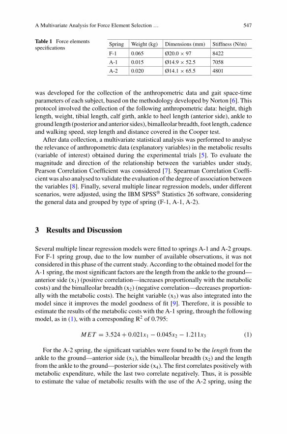
A Multivariate Analysis for Force Element Selection … 547
Table 1 Force elementsspecifications
Spring Weight (kg) Dimensions (mm) Stiffness (N/m)
F-1 0.065 Ø20.0 × 97 8422
A-1 0.015 Ø14.9 × 52.5 7058
A-2 0.020 Ø14.1 × 65.5 4801
was developed for the collection of the anthropometric data and gait space-timeparameters of each subject, based on the methodology developed by Norton [6]. Thisprotocol involved the collection of the following anthropometric data: height, thighlength, weight, tibial length, calf girth, ankle to heel length (anterior side), ankle toground length (posterior and anterior sides), bimalleolar breadth, foot length, cadenceand walking speed, step length and distance covered in the Cooper test.
After data collection, a multivariate statistical analysis was performed to analysethe relevance of anthropometric data (explanatory variables) in the metabolic results(variable of interest) obtained during the experimental trials [5]. To evaluate themagnitude and direction of the relationship between the variables under study,Pearson Correlation Coefficient was considered [7]. Spearman Correlation Coeffi-cientwas also analysed to validate the evaluation of the degree of association betweenthe variables [8]. Finally, several multiple linear regression models, under differentscenarios, were adjusted, using the IBM SPSS® Statistics 26 software, consideringthe general data and grouped by type of spring (F-1, A-1, A-2).
3 Results and Discussion
Several multiple linear regression models were fitted to springs A-1 and A-2 groups.For F-1 spring group, due to the low number of available observations, it was notconsidered in this phase of the current study. According to the obtained model for theA-1 spring, the most significant factors are the length from the ankle to the ground—anterior side (x1) (positive correlation—increases proportionally with the metaboliccosts) and the bimalleolar breadth (x2) (negative correlation—decreases proportion-ally with the metabolic costs). The height variable (x3) was also integrated into themodel since it improves the model goodness of fit [9]. Therefore, it is possible toestimate the results of the metabolic costs with the A-1 spring, through the followingmodel, as in (1), with a corresponding R2 of 0.795:
MET = 3.524+ 0.021x1 − 0.045x2 − 1.211x3 (1)
For the A-2 spring, the significant variables were found to be the length from theankle to the ground—anterior side (x1), the bimalleolar breadth (x2) and the lengthfrom the ankle to the ground—posterior side (x4). The first correlates positively withmetabolic expenditure, while the last two correlate negatively. Thus, it is possibleto estimate the value of metabolic results with the use of the A-2 spring, using the
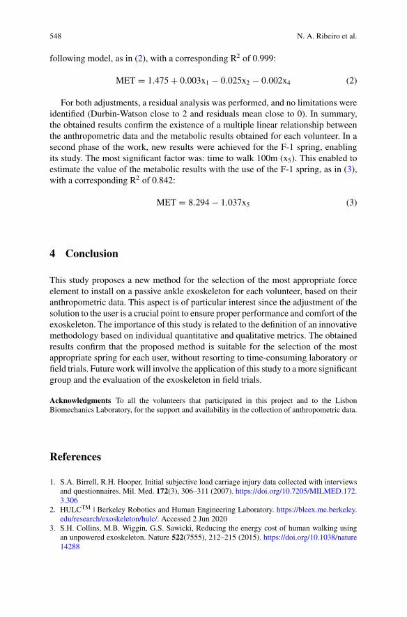
548 N. A. Ribeiro et al.
following model, as in (2), with a corresponding R2 of 0.999:
MET = 1.475+ 0.003x1 − 0.025x2 − 0.002x4 (2)
For both adjustments, a residual analysis was performed, and no limitations wereidentified (Durbin-Watson close to 2 and residuals mean close to 0). In summary,the obtained results confirm the existence of a multiple linear relationship betweenthe anthropometric data and the metabolic results obtained for each volunteer. In asecond phase of the work, new results were achieved for the F-1 spring, enablingits study. The most significant factor was: time to walk 100m (x5). This enabled toestimate the value of the metabolic results with the use of the F-1 spring, as in (3),with a corresponding R2 of 0.842:
MET = 8.294− 1.037x5 (3)
4 Conclusion
This study proposes a new method for the selection of the most appropriate forceelement to install on a passive ankle exoskeleton for each volunteer, based on theiranthropometric data. This aspect is of particular interest since the adjustment of thesolution to the user is a crucial point to ensure proper performance and comfort of theexoskeleton. The importance of this study is related to the definition of an innovativemethodology based on individual quantitative and qualitative metrics. The obtainedresults confirm that the proposed method is suitable for the selection of the mostappropriate spring for each user, without resorting to time-consuming laboratory orfield trials. Future work will involve the application of this study to amore significantgroup and the evaluation of the exoskeleton in field trials.
Acknowledgments To all the volunteers that participated in this project and to the LisbonBiomechanics Laboratory, for the support and availability in the collection of anthropometric data.
References
1. S.A. Birrell, R.H. Hooper, Initial subjective load carriage injury data collected with interviewsand questionnaires. Mil. Med. 172(3), 306–311 (2007). https://doi.org/10.7205/MILMED.172.3.306
2. HULCTM | Berkeley Robotics and Human Engineering Laboratory. https://bleex.me.berkeley.edu/research/exoskeleton/hulc/. Accessed 2 Jun 2020
3. S.H. Collins, M.B. Wiggin, G.S. Sawicki, Reducing the energy cost of human walking usingan unpowered exoskeleton. Nature 522(7555), 212–215 (2015). https://doi.org/10.1038/nature14288
A Multivariate Analysis for Force Element Selection … 549
4. L.M.Mooney, E.J. Rouse,H.M.Herr,Autonomous exoskeleton reducesmetabolic cost of humanwalking during load carriage. J. Neuroeng. Rehabil. 11, 80 (2014). https://doi.org/10.1186/1743-0003-11-80
5. P. Pinheiro, L. Quinto, S.B. Gonçalves, M.T. Silva, Analysis of the Performance of a PassiveAnkle Exoskeleton for Reduction of the Metabolic Costs in Gait (2019), p. 2
6. K. Norton, Standards for anthropometry assessment, in Kinanthropometry and ExercisePhysiology, 4th ed. (2018), pp 68–137
7. J. Cohen, P. Cohen, S.G. West, L.S. Aiken, Applied Multiple Regression/Correlation Analysisfor the Behavioral Sciences, 3rd Ed., no. 1. (2003)
8. J.O. Rawlings, S.G. Pantula, D.ADickey,Applied RegressionAnalysis : AResearch Tool, SecondEdition Springer Texts in Statistics (1998)
9. A. Field, Discovering Statistics using SPSS, 3rd ed., vol. 622. (SAGE Publications Inc., 2009)

Application Industrial Exoskeletons
On the Design of Kalman Observers forBack-Support Exoskeletons
Erfan Shojaei Barjuei, Darwin G. Caldwell, and Jesús Ortiz
Abstract This paper presents the synthesis of a Kalman state observer for an indus-trial back-support exoskeleton. The design of a state observer always should be basedon amodel providing an adequate description of the systemdynamics; however,whenback-support exoskeletons are considered, the synthesis of a state observer becomesvery challenging, since only nonlinear models may be adopted to reproduce thesystem dynamic response with adequate accuracy. In this work, the possibility ofemploying a Kalman state observer together with a suitable linear model is investi-gated. Simulated results illustrate the effectiveness of the proposed approach whenit is applied to the synthesis of a state observer for a back-support exoskeleton.
1 Introduction
Considerable research effort has been recently devoted to the development of ade-quate models and control approaches for wearable robots such as exoskeletons [1].Moreover, exoskeletons might be profitably employed in in the industrial field andalso in military and rehabilitation applications [2]. Basically, an industrial exoskele-ton is worn by a user to provide support and reduce the risk of musculoskeletaldisorders (MSD) due to physically demanding activities by generating appropriateassistive force(s) and torque(s). An example of an industrial back-support exoskele-ton is shown in Fig. 1a.
In general, muscle impedance properties are neutrally modulated to generateappropriate bio-mechanical energies in biological systems. This fact needs to sensethe torque due to human-robot interaction [3]. On this basis, the synthesis of a stateobserver based on Kalman filter [4] for a back-support exoskeleton for estimatinginteraction force/torque has been proposed and developed in this paper. Kalman fil-ters are usually very sensitive to modeling errors. Despite this problem they can workwell in a closed loop environment providing closed loop stability and good perfor-mance despite of large errors in the estimated values. The proposed state observer
E. Shojaei Barjuei (B) · D. G. Caldwell · J. OrtizAdvanced Robotics, Istituto Italiano di Tecnologia, 16163 Ge Genoa, Italye-mail: [email protected]
© The Author(s), under exclusive license to Springer Nature Switzerland AG 2022J. C. Moreno et al. (eds.), Wearable Robotics: Challenges and Trends,Biosystems & Biorobotics 27, https://doi.org/10.1007/978-3-030-69547-7_89
553
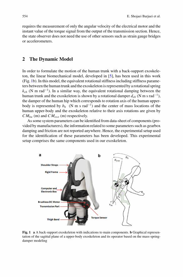
554 E. Shojaei Barjuei et al.
requires the measurement of only the angular velocity of the electrical motor and theinstant value of the torque signal from the output of the transmission section. Hence,the state observer does not need the use of other sensors such as strain gauge bridgesor accelerometers.
2 The Dynamic Model
In order to formulate the motion of the human trunk with a back-support exoskele-ton, the linear biomechanical model, developed in [5], has been used in this work(Fig. 1b). In this model, the equivalent rotational stiffness including stiffness parame-ters between the human trunk and the exoskeleton is represented by a rotational springkeh (N m rad−1). In a similar way, the equivalent rotational damping between thehuman trunk and the exoskeleton is shown by a rotational damper deh (N m s rad−1),the damper of the human hip which corresponds to rotation axis of the human upper-body is represented by bh (N m s rad−1) and the center of mass locations of thehuman upper-body and the exoskeleton relative to their axis rotations are given byCMhu (m) and CMexo (m) respectively.
As some system parameters can be identified from data-sheet of components (pro-vided bymanufacturers), the information related to some parameters such as gearboxdamping and friction are not reported anywhere. Hence, the experimental setup usedfor the identification of these parameters has been developed. This experimentalsetup comprises the same components used in our exoskeleton.
Fig. 1 a A back-support exoskeleton with indications to main components. b Graphical represen-tation of the sagittal plane of a upper-body exoskeleton and its operator based on the mass-spring-damper modeling
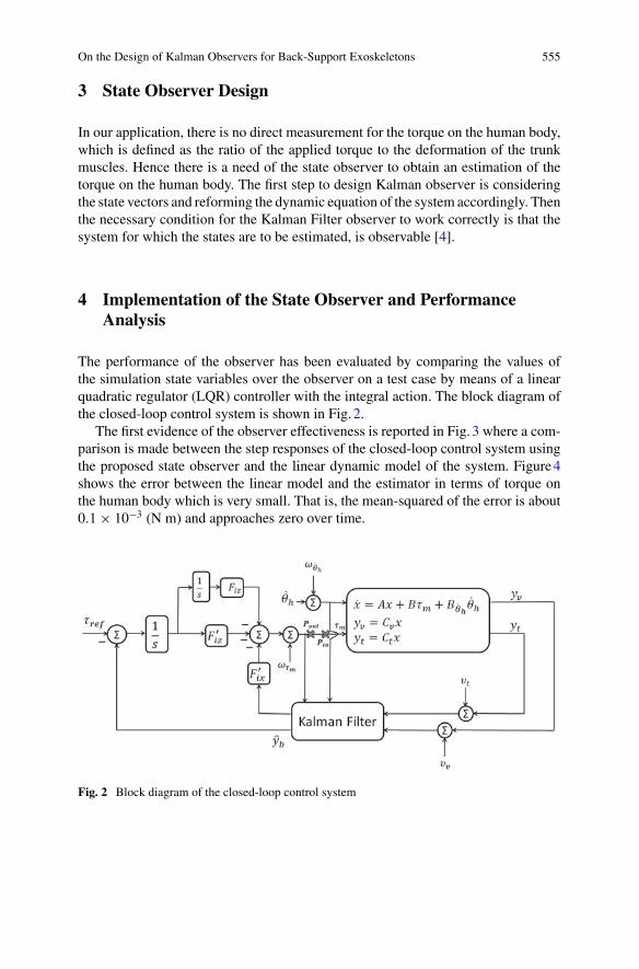
On the Design of Kalman Observers for Back-Support Exoskeletons 555
3 State Observer Design
In our application, there is no direct measurement for the torque on the human body,which is defined as the ratio of the applied torque to the deformation of the trunkmuscles. Hence there is a need of the state observer to obtain an estimation of thetorque on the human body. The first step to design Kalman observer is consideringthe state vectors and reforming the dynamic equation of the system accordingly. Thenthe necessary condition for the Kalman Filter observer to work correctly is that thesystem for which the states are to be estimated, is observable [4].
4 Implementation of the State Observer and PerformanceAnalysis
The performance of the observer has been evaluated by comparing the values ofthe simulation state variables over the observer on a test case by means of a linearquadratic regulator (LQR) controller with the integral action. The block diagram ofthe closed-loop control system is shown in Fig. 2.
The first evidence of the observer effectiveness is reported in Fig. 3 where a com-parison is made between the step responses of the closed-loop control system usingthe proposed state observer and the linear dynamic model of the system. Figure4shows the error between the linear model and the estimator in terms of torque onthe human body which is very small. That is, the mean-squared of the error is about0.1 × 10−3 (N m) and approaches zero over time.
Fig. 2 Block diagram of the closed-loop control system
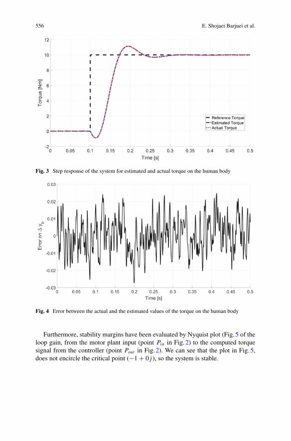
556 E. Shojaei Barjuei et al.
Fig. 3 Step response of the system for estimated and actual torque on the human body
Fig. 4 Error between the actual and the estimated values of the torque on the human body
Furthermore, stability margins have been evaluated by Nyquist plot (Fig. 5 of theloop gain, from the motor plant input (point Pin in Fig. 2) to the computed torquesignal from the controller (point Pout in Fig. 2). We can see that the plot in Fig. 5,does not encircle the critical point (−1 + 0 j), so the system is stable.
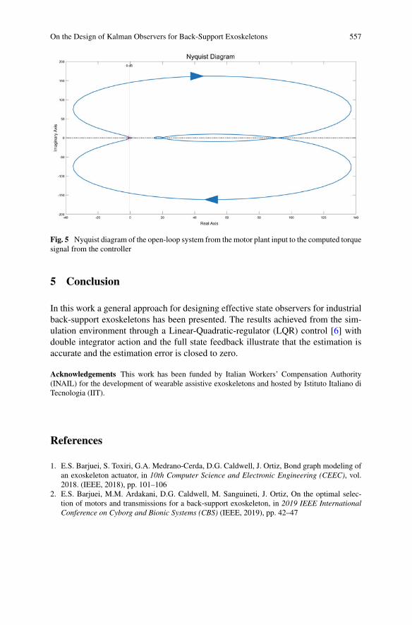
On the Design of Kalman Observers for Back-Support Exoskeletons 557
Fig. 5 Nyquist diagram of the open-loop system from the motor plant input to the computed torquesignal from the controller
5 Conclusion
In this work a general approach for designing effective state observers for industrialback-support exoskeletons has been presented. The results achieved from the sim-ulation environment through a Linear-Quadratic-regulator (LQR) control [6] withdouble integrator action and the full state feedback illustrate that the estimation isaccurate and the estimation error is closed to zero.
Acknowledgements This work has been funded by Italian Workers’ Compensation Authority(INAIL) for the development of wearable assistive exoskeletons and hosted by Istituto Italiano diTecnologia (IIT).
References
1. E.S. Barjuei, S. Toxiri, G.A. Medrano-Cerda, D.G. Caldwell, J. Ortiz, Bond graph modeling ofan exoskeleton actuator, in 10th Computer Science and Electronic Engineering (CEEC), vol.2018. (IEEE, 2018), pp. 101–106
2. E.S. Barjuei, M.M. Ardakani, D.G. Caldwell, M. Sanguineti, J. Ortiz, On the optimal selec-tion of motors and transmissions for a back-support exoskeleton, in 2019 IEEE InternationalConference on Cyborg and Bionic Systems (CBS) (IEEE, 2019), pp. 42–47
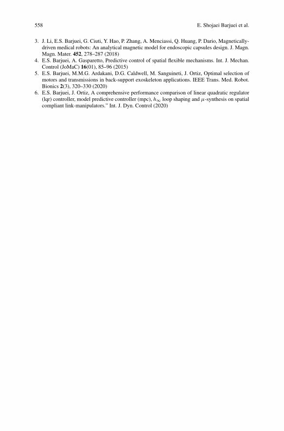
558 E. Shojaei Barjuei et al.
3. J. Li, E.S. Barjuei, G. Ciuti, Y. Hao, P. Zhang, A. Menciassi, Q. Huang, P. Dario, Magnetically-driven medical robots: An analytical magnetic model for endoscopic capsules design. J. Magn.Magn. Mater. 452, 278–287 (2018)
4. E.S. Barjuei, A. Gasparetto, Predictive control of spatial flexible mechanisms. Int. J. Mechan.Control (JoMaC) 16(01), 85–96 (2015)
5. E.S. Barjuei, M.M.G. Ardakani, D.G. Caldwell, M. Sanguineti, J. Ortiz, Optimal selection ofmotors and transmissions in back-support exoskeleton applications. IEEE Trans. Med. Robot.Bionics 2(3), 320–330 (2020)
6. E.S. Barjuei, J. Ortiz, A comprehensive performance comparison of linear quadratic regulator(lqr) controller, model predictive controller (mpc), h∞ loop shaping and µ-synthesis on spatialcompliant link-manipulators.” Int. J. Dyn. Control (2020)
Subjective Perception of ShoulderSupport Exoskeleton at Groupe PSA
Jawad Masood, Erika Triviño-Tonato, Maria Del Pilar Rivas-Gonzalez,Maria Del Mar Arias-Matilla, and Ana Elvira Planas-Lara
Abstract The emerging Industrial ExoskeletonTechnology (IET) adoption in indus-try requires an assessment of its long duration impact. We present the subjectiveassessment of the shoulder support exoskeleton (Levitate AIRFRAME) at GroupePSA Vigo factory by setting-up evaluation phases in the assembly line under indus-trial conditions. These phases are the preliminary-term [28 workers, 14h], short-term [8 workers 75h] and the medium-term [11 workers, 240h]. We continuouslymonitored the workers and gradually increased the usage time until full autonomywas achieved for full shift. We discovered that searching the initial static fit of theexoskeleton is a non-trivial task. In addition, we noted that the usability and reliabilityaspects which were absent in preliminary-term and short-term testing are influentialinmedium-term testing such as body temperature elevation and exoskeletonmechan-ical wear and tear. Finally, we observed the gradual decrease in the exoskeleton usageamong workers contrary to our hypothesis.
1 Introduction
Work-related musculoskeletal disorders (WRMSDs) show symptoms of constantpain of muscles, tendons, nerves and blood vessels, which is mostly caused by repet-itive motion or overexertion [1]. In Spain, according to data from Communication
The authors acknowledge the contributions of the F4.0 Automation consortium in general andGroupe PSA in particular.
J. Masood (B) · E. Triviño-TonatoProcesses and Factory of the Future Department of CTAG, Centro Tecnológico de Automoción deGalicia, O Porriño, Spaine-mail: [email protected]
M. D. P. Rivas-GonzalezErgonomics Area at Groupe PSA Vigo Factory, Groupe PSA Centro de Vigo,Avda. Citroën 3 y 5, Vigo, Spain
M. D. M. Arias-Matilla · A. E. Planas-LaraMutua Universal, Av. Tibidabo 17–19, 08022 Barcelona, Spain
© The Author(s), under exclusive license to Springer Nature Switzerland AG 2022J. C. Moreno et al. (eds.), Wearable Robotics: Challenges and Trends,Biosystems & Biorobotics 27, https://doi.org/10.1007/978-3-030-69547-7_90
559
560 J. Masood et al.
of Occupational Diseases in Social Security (CEPROSS) [2], 2019 was closed with23,146 reported cases of occupational disease (group 2: physical agents), an increaseof 16.7% from 2018.
This growing WRMSDs rate in recent years calls for a solution. Exoskeletonsare one of the most promising solutions to reduce WRMSDs. These devices facili-tate assistance to certain anatomical areas that receive more biomechanical loading.Today, there are 30 commercial industrial exoskeleton manufacturers, whereas 12of them provide shoulder support exoskeletons [3]. However, their usage is minimaldue to the gap between end-user needs and specification, lack of standardization, andbenchmarking [4].
The literature review reveals that the testing of the industrial exoskeletons mainlyfocuses on analyzing the variation in muscle activity by measuring the Electromyo-graphy level (EMG) of the primary muscles involved in the workplace. The standardpractice is to collect this data by simulating the workstation in ergonomic laborato-ries or perform short tests within a controlled environment. Subjects who carry outthe tests often have no experience performing the workstation activities, therefore,you cannot verify the fidelity of exoskeleton impact. Currently, there is no studyin the literature that demonstrate the evolution of the device’s acceptability by thelarger worker population or long-duration testing case study of the shoulder supportexoskeleton [5].
CTAG, Mutua Universal and Groupe PSA Vigo factory have been working ona project since 2016. The aim of the project is to find a device that mitigated theWRMSDs and achieving its implementation on the assembly line. We selected theLevitate Airframe, which is a wearable exoskeleton to improve upper extremity mus-culoskeletal health for workers by following our previously developed protocol [4].In this work, we present a subjective perception with regards to the usability, impactand utility. It was carried by experienced workers at Groupe PSA Vigo factory.
2 Development
The testing process at Groupe PSA [4] was structured in four phases, (I) Selectionof the exoskeleton (Expression of needs), (II) Laboratory Test, (III) Simulated Test(Offline Emulated Task), (IV) In-line test (Assembly line Real tasks). In this paper,we will focus on phase IV.
2.1 Scope and Planning
Phase IV was developed at Groupe PSA facilities. It corresponded to the in-line testunder real production conditions. The objective was to achieve a progressive imple-mentation process, in which workers were accompanied throughout the process andtheir level of acceptance and adaptation to exoskeleton were assessed. The selected
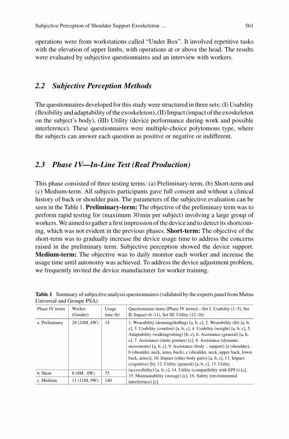
Subjective Perception of Shoulder Support Exoskeleton … 561
operations were from workstations called “Under Box”. It involved repetitive taskswith the elevation of upper limbs, with operations at or above the head. The resultswere evaluated by subjective questionnaires and an interview with workers.
2.2 Subjective Perception Methods
The questionnaires developed for this studywere structured in three sets: (I) Usability(flexibility and adaptability of the exoskeleton), (II) Impact (impact of the exoskeletonon the subject’s body), (III) Utility (device performance during work and possibleinterference). These questionnaires were multiple-choice polytomous type, wherethe subjects can answer each question as positive or negative or indifferent.
2.3 Phase 1V—In-Line Test (Real Production)
This phase consisted of three testing terms: (a) Preliminary-term, (b) Short-term and(c) Medium-term. All subjects participants gave full consent and without a clinicalhistory of back or shoulder pain. The parameters of the subjective evaluation can beseen in the Table1. Preliminary-term: The objective of the preliminary term was toperform rapid testing for (maximum 30min per subject) involving a large group ofworkers.Weaimed to gather afirst impression of the device and to detect its shortcom-ing, which was not evident in the previous phases. Short-term: The objective of theshort-term was to gradually increase the device usage time to address the concernsraised in the preliminary term. Subjective perception showed the device support.Medium-term: The objective was to daily monitor each worker and increase theusage time until autonomy was achieved. To address the device adjustment problem,we frequently invited the device manufacturer for worker training.
Table 1 Summary of subjective analysis questionnaires (validated by the experts panel fromMutuaUniversal and Groupe PSA)Phase IV terms Worker
(Gender)Usagetime (h)
Questionnaire items [Phase IV terms]—Set I: Usability (1–5), SetII: Impact (6–11), Set III: Utility (12–16)
a. Preliminary 28 (24M, 4W) 14 1. Wearability (donning/doffing) [a, b, c], 2. Wearability (fit) [a, b,c], 3. Usability (comfort) [a, b, c], 4. Usability (weight) [a, b, c], 5.Adaptability (walking/sitting) [b, c], 6. Assistance (general) [a, b,c], 7. Assistance (static posture) [c], 8. Assistance (dynamicmovements) [a, b, c], 9. Assistance (body .. support) [a (shoulder),b (shoulder, neck, arms, back), c (shoulder, neck, upper back, lowerback, arms)], 10. Impact (other body parts) [a, b, c], 11. Impact(cognitive) [b], 12. Utility (general) [a, b, c], 13. Utility(accessibility) [a, b, c], 14. Utility (compatibility with EPI’s) [c],15. Maintainability (storage) [c], 16. Safety (environmentalinterference) [c]
b. Short 8 (8M , 0W) 75
c. Medium 11 (11M, 0W) 140
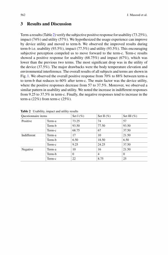
562 J. Masood et al.
3 Results and Discussion
Term-a results (Table 2) verify the subjective positive response for usability (73.25%),impact (74%) and utility (57%). We hypothesized the usage experience can improveby device utility and moved to term-b. We observed the improved results duringterm-b i.e. usability (93.5%), impact (77.5%) and utility (93.5%). This encouragingsubjective perception compeled us to move forward to the term-c. Term-c resultsshowed a positive response for usability (68.75%) and impact (67%), which waslower than the previous two terms. The most significant drop was in the utility ofthe device (37.5%). The major drawbacks were the body temperature elevation andenvironmental interference. The overall results of all subjects and terms are shown inFig. 1. We observed the overall positive response from 70% to 88% between term-ato term-b that reduces to 60% after term-c. The main factor was the device utility,where the positive responses decrease from 57 to 37.5%. Moreover, we observed asimilar pattern in usability and utility. We noted the increase in indifferent responsesfrom 9.25 to 37.5% in term-c. Finally, the negative responses tend to increase in theterm-a (22%) from term-c (25%).
Table 2 Usability, impact and utility results
Questionnaire items Set I (%) Set II (%) Set III (%)
Positive Term-a 73.25 74 57
Term-b 93.50 77.50 93.50
Term-c 68.75 67 37.50
Indifferent Term-a 17 10 21.50
Term-b 6.50 18.50 6.50
Term-c 9.25 24.25 37.50
Negative Term-a 10 16 21.50
Term-b 0 4 0
Term-c 22 8.75 25
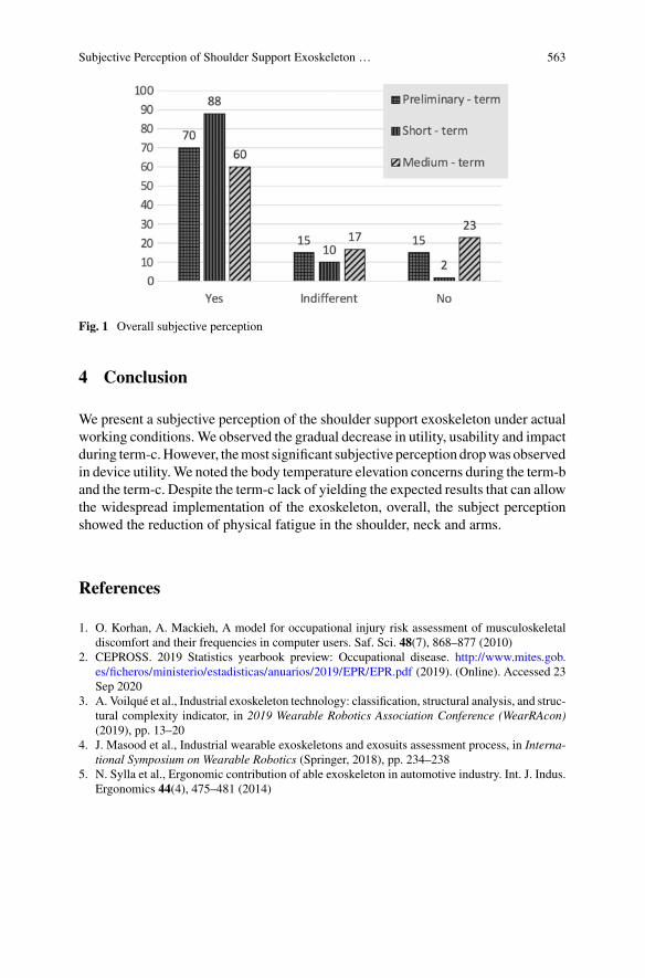
Subjective Perception of Shoulder Support Exoskeleton … 563
Fig. 1 Overall subjective perception
4 Conclusion
We present a subjective perception of the shoulder support exoskeleton under actualworking conditions.We observed the gradual decrease in utility, usability and impactduring term-c.However, themost significant subjective perception dropwas observedin device utility.We noted the body temperature elevation concerns during the term-band the term-c. Despite the term-c lack of yielding the expected results that can allowthe widespread implementation of the exoskeleton, overall, the subject perceptionshowed the reduction of physical fatigue in the shoulder, neck and arms.
References
1. O. Korhan, A. Mackieh, A model for occupational injury risk assessment of musculoskeletaldiscomfort and their frequencies in computer users. Saf. Sci. 48(7), 868–877 (2010)
2. CEPROSS. 2019 Statistics yearbook preview: Occupational disease. http://www.mites.gob.es/ficheros/ministerio/estadisticas/anuarios/2019/EPR/EPR.pdf (2019). (Online). Accessed 23Sep 2020
3. A. Voilqué et al., Industrial exoskeleton technology: classification, structural analysis, and struc-tural complexity indicator, in 2019 Wearable Robotics Association Conference (WearRAcon)(2019), pp. 13–20
4. J. Masood et al., Industrial wearable exoskeletons and exosuits assessment process, in Interna-tional Symposium on Wearable Robotics (Springer, 2018), pp. 234–238
5. N. Sylla et al., Ergonomic contribution of able exoskeleton in automotive industry. Int. J. Indus.Ergonomics 44(4), 475–481 (2014)
MH-Forces, a Motion-Capture BasedMethod to Evaluate WorkplaceErgonomics: Simulating ExoskeletonEffects
Javier Marín, Juan de la Torre, and José J. Marín
Abstract In this document, we explain the MoveHuman-Forces (MH-Forces)method, which aims to evaluate the ergonomics of a specific workplace. This methodprovides the level of risk to suffer an injury on each body joint. The risk calculationis based on a motion-capture measurement in the workplace. This method can beused for the assessment of existing workplaces and the validation of new ones. Afterintroducing their foundations, we introduce how MH-Forces can be used to assessthe inclusion of exoskeletons in workplaces.
1 Introduction
The repetitive strain injury (RSI) is an occupational diseasewith the highest incidencein the workplace and entails high costs for companies [1]. Ergonomic evaluationsare especially helpful in preventing RSIs. They aim to improve workers’ health andproductivity.
To conduct ergonomic evaluations, observational methods, such as REBA(postural load), NIOSH (load manipulation), or OCRA (repetitive tasks), are usuallyapplied. However, these methods are generally not automated, require considerableevaluator time, and have an important subjective factor. Therefore, methods basedon objective information that can be applied in an automated manner are required[2].
Likewise, exoskeletons have become an interesting solution to reduce the numberof injuries and improve the ergonomic factors of particular workplaces. However,
J. Marín (B) · J. de la Torre · J. J. MarínIDERGO (Research and Development in Ergonomics) Research Group, I3A (Aragon Institute ofEngineering Research), Department of Design and Manufacturing Engineering, University ofZaragoza, C/Mariano Esquillor s/n, 50018 Zaragoza, Spaine-mail: [email protected]
J. de la Torree-mail: [email protected]
J. J. Maríne-mail: [email protected]
© The Author(s), under exclusive license to Springer Nature Switzerland AG 2022J. C. Moreno et al. (eds.), Wearable Robotics: Challenges and Trends,Biosystems & Biorobotics 27, https://doi.org/10.1007/978-3-030-69547-7_91
565
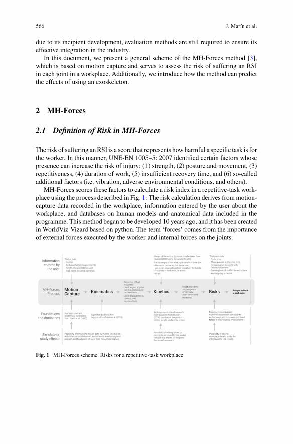
566 J. Marín et al.
due to its incipient development, evaluation methods are still required to ensure itseffective integration in the industry.
In this document, we present a general scheme of the MH-Forces method [3],which is based on motion capture and serves to assess the risk of suffering an RSIin each joint in a workplace. Additionally, we introduce how the method can predictthe effects of using an exoskeleton.
2 MH-Forces
2.1 Definition of Risk in MH-Forces
The risk of suffering anRSI is a score that represents howharmful a specific task is forthe worker. In this manner, UNE-EN 1005–5: 2007 identified certain factors whosepresence can increase the risk of injury: (1) strength, (2) posture and movement, (3)repetitiveness, (4) duration of work, (5) insufficient recovery time, and (6) so-calledadditional factors (i.e. vibration, adverse environmental conditions, and others).
MH-Forces scores these factors to calculate a risk index in a repetitive-task work-place using the process described in Fig. 1. The risk calculation derives frommotion-capture data recorded in the workplace, information entered by the user about theworkplace, and databases on human models and anatomical data included in theprogramme. This method began to be developed 10 years ago, and it has been createdin WorldViz-Vizard based on python. The term ‘forces’ comes from the importanceof external forces executed by the worker and internal forces on the joints.
Fig. 1 MH-Forces scheme. Risks for a repetitive-task workplace
MH-Forces, a Motion-Capture Based Method to Evaluate Workplace … 567
2.2 Motion Capture and Kinematics
TheMH-Forcesmethod does not impose the use of a specificmotion-capture system.In our case, we use the MH-Sensor system [4]. This system uses magnetometer-freeinertial sensors to avoid magnetic disturbances, which are common in industrialenvironments. Marin et al. [4] assessed and described how this system calculatesthe kinematics, including angles and displacements, and how it detects the supportpoints when the worker is standing or walking.
2.3 Calculating Kinetics
MH-Forces computes the forces and torques in each joint and posture using Hustonequations [5]. To accomplish this, the method uses the information from the humanmodel (i.e. the length, weight, position of the gravity centre, and inertia tensor ofeach body segment), and the forces and torques that the worker performs duringthe work cycle, which has to be introduced by the user (e.g. a vertical load of 5 kgbetween the second 5 and 21 of the motion recording).
2.4 Calculating Risks
For the risk calculation in each joint and posture (i.e., one frame of the capture), wepropose a logic based on the risk factors of UNE-EN 1005–5:2007. Factors 1 and2 are scored according to the kinematics and kinetics data, and factors 3–6, whichdepend on the worker schedule, penalise the result. To calculate a value derived fromfactors 1 and 2 we multiply the ‘angle’ (weighted from 1–2), ‘angular acceleration’(from 1–1.5), ‘force’ (from 1–2), ‘torque’ (from 1–2.5), and ‘grip’ (from 1–2; onlyapplicable to the wrist joint). We assign the maximumweight to each factor when therecorded measurement approaches the maximum possible value of the ‘maximumrisk database’ and the minimum score when the measurement approaches zero. The‘maximum risk database’ was obtained recording volunteers moving their joints withthe maximum loads and speeds that occur in the industrial environment. Then, toconsider the full capture and the 3–6 factors, the values for each posture are addedand multiplied by a receptiveness factor (from 1–9; one if the value in the postureis the minimum possible, and nine if it is the maximum). In this manner, thosepositions with high risk affect more. Subsequently, the resulted score is multipliedby a recovery factor (from 1–2.6) and a duration factor (from 0.5–2), which dependon the time assigned to the worker for that task during the working day, and a penaltyfor additional factors (from 1–1.18) that exists on the workplace. Finally, the result ismultiplied by 60 and divided by the cycle time to calculate the risks per minute. Thefinal value of the risk is presented as a percentage of the maximum achievable value
568 J. Marín et al.
(sum of the maximum scores described in a minute), and it is transformed into athree-level score: acceptable <25%, conditional 25–40%, and non-acceptable >40%.
2.5 Simulating Exoskeleton Effects
The effect of an exoskeleton has to be considered in the ‘Calculating Kinetics’ stage,and the exoskeleton has to be modelled as a set of forces and moments applied on thebody in specific instants. In a preliminary study, we modelled the Laevo V2.5, whichis a passive exoskeleton designed to support bent-forward work and repetitive liftingmovements. Our model included a vertical load on the hips (weight of the device),and three forces, one applied on the reference systemof the chest and the others on thereference system of the tights. These forces only occur when the user bent-forwardmore than an adjustable angle (from 0 to 35°). Their value was calculated measuringthe torque of the mechanical joint and the distances to the application points. In thesepilot tests, the user lifted 6 kg from the ground several times, and the exoskeletonimplied a substantial reduction of the risk in the lower back and a slight incrementof the risk in the knees.
3 Discussion and Conclusions
In this document, we present the scheme of theMH-Forcesmethod [2] and explain itsfoundations. This method can have a relevant practical utility to prevent RSI. Whenthe MH-Forces method is applied to various workplaces, it provides the so-called‘risk map’ (i.e., a matrix with one risk score for each joint and workplace). This riskmap is a valuable result, in the first place, to manage the rotations of workers, in abalanced manner, without overload certain joins. Additionally, the risk map is alsovaluable, to visualise those workplaces with non-acceptable risk, which has to beimproved. For this second application, many solutions may be considered, amongwe found the exoskeletons. In this regard, MH-Forces can assess the risk reductionthat an exoskeleton may suppose. Nevertheless, to integrate this technology in theindustry, the risk reduction has to be combined with other factors that have to bestudied, such as the mental stress related with it, or other subjective or organisationalfactors.
Acknowledgements We would like to thank Mutua Universal, BSH, Quiron Prevencion, Volk-swagen, and recently Gesinor, which have contributed to developing and adjusting this method.
The project was co-financed by theGovernment ofAragon, the EuropeanRegionalDevelopmentFund, and the University of Zaragoza (Spain).

MH-Forces, a Motion-Capture Based Method to Evaluate Workplace … 569
References
1. Eurofound. Sixth European Survey on Working Conditions: General Report (Publications-Office-of-the-European-Union, Luxembourg, 2018)
2. J. Diego-Mas, R. Poveda-Bautista, D. Garzon-Leal, Influences on the use of observationalmethods by practitioners when identifying risk factors in physical work. Ergonomics 58,1660–1670 (2015)
3. M.J. Bone-Pina, Método de Evaluación Ergonómica de Tareas Repetitivas, Basado en Simu-lación Dinámica de Esfuerzos con Modelos Humanos. PhD thesis, University of Zaragoza,2016
4. J. Marín, T. Blanco, J. Torre, J.J. Marín, Gait analysis in a box: a system based onmagnetometer-free IMUs or clusters of optical markers with automatic event detection. Sensors 20, 3338(2020)
5. R. Huston, Principles of Biomechanics (CRC, 2008)
AMethodology to Assessthe Effectiveness and the Acceptanceof the Use of an Exoskeletonin a Company
J. A. Tomás-Royo, M. Ducun-Lecumberri, A. E. Planas-Lara,and M. Arias-Matilla
Abstract The integration of new technologies in the workplace and, in particular,the use of exoskeletons, requires a precise analysis of the effects these devices haveon the workers and their environment. This analysis will allow us to assess theadvantages and effectiveness of the implementation. A structured and systematicmethodology for the subjective and objective analysis of the use of exoskeletonsin the field is presented in this work, as a result of years of experience workingwith different companies. The methodology is developed in four phases of work,from a preliminary needs analysis to the implementation of the exoskeleton in theworkplace.
1 Introduction
The reduction of musculoskeletal disorders (MSD) is one of the main challenges thatcompanies and society face worldwide nowadays. Instead of reducing, the incidenceof musculoskeletal accidents and illnesses remains constant over time [1] and it willprobably worse due to the growing ageing of the workforce [2]. Industry 4.0 and thedevelopment of new wearable technologies may contribute to preventing MSD [3].
Many exoskeletons available in themarket are supposed to be effective in reducingphysical load and improving working conditions. However, laboratory conditions in
J. A. Tomás-Royo (B) · M. Ducun-Lecumberri · A. E. Planas-LaraErgonomics Laboratory, R&D Technical Management of Mutua Universal, Barcelona, Spaine-mail: [email protected]
M. Ducun-Lecumberrie-mail: [email protected]
A. E. Planas-Larae-mail: [email protected]
M. Arias-MatillaPsychosociology Area at Occupation Risk Prevention, Department of Mutua Universal,Barcelona, Spaine-mail: [email protected]
© The Author(s), under exclusive license to Springer Nature Switzerland AG 2022J. C. Moreno et al. (eds.), Wearable Robotics: Challenges and Trends,Biosystems & Biorobotics 27, https://doi.org/10.1007/978-3-030-69547-7_92
571
572 J. A. Tomás-Royo et al.
which their trials were made at the design phase are generally different from fieldconditions in the industry.
The use of an exoskeleton supposes a close interaction between the user and theassistance device, as well as an interaction between them and the work environment.Hence, it seems reasonable the need for a structured, methodological and systematicanalysis to assess the impacts and potential consequences on both the worker andcompany management.
2 Materials and Methods
This methodology is developed from the experience in the field, after more than threeyears of work, in which the implementation of exoskeletons in the workplace hasbeen studied and put into practice in collaborationwith several associated companies.
The observation of needs expressed by the companies leads us to suggest that, inorder to assess the real impact of the exoskeleton on a workplace, it is necessary toknow:
(A) On one hand, the “objective” effect of the exoskeleton on the user´s body toassess the reduction in their muscular effort, the smoothness of their motionand the lack of overloads in their body.
(B) On the other hand, the “subjective” effect on the worker to assess theircomfortability, acceptance and adaptation to the exoskeleton that confirmsthe assistance device will not be rejected.
(C) Moreover, the effect of the use of the exoskeleton on the production pace, theenvironment and the manufactured product that will ensure the company abalance between the potential advantages and disadvantages.
3 Results
Themain aim of the developed methodology is to assess whether the implementationof an exoskeleton in the workplace will reduce workers´ physical load, will notdamage users nor generate any disturbance in thework environment andwill improvethe work conditions ostensibly. It is recommended a multidisciplinary work team toparticipate throughout all the study. The team should be consisted of, at least, somecompany technical department, the medical service, workers representatives, expertson ergonomics, biomechanics and psychosociology and the support of the assistancedevice supplier.
The methodology establishes 4 phases of work. After each phase, the multidisci-plinary team evaluates, depending on the results obtained, whether or not to proceedto the next phase (Fig. 1).
Each phase duration depends on the size and complexity of the company, the timeand the resources available.
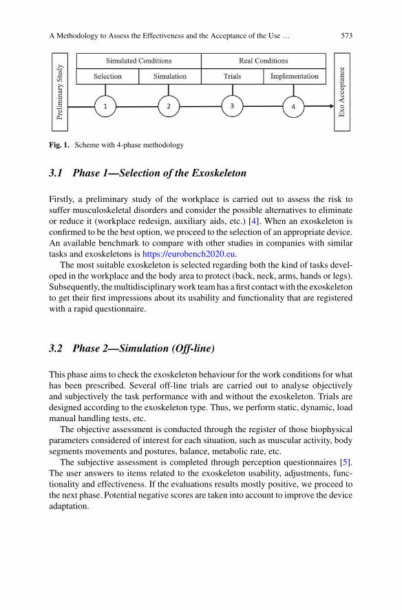
A Methodology to Assess the Effectiveness and the Acceptance of the Use … 573
Fig. 1. Scheme with 4-phase methodology
3.1 Phase 1—Selection of the Exoskeleton
Firstly, a preliminary study of the workplace is carried out to assess the risk tosuffer musculoskeletal disorders and consider the possible alternatives to eliminateor reduce it (workplace redesign, auxiliary aids, etc.) [4]. When an exoskeleton isconfirmed to be the best option, we proceed to the selection of an appropriate device.An available benchmark to compare with other studies in companies with similartasks and exoskeletons is https://eurobench2020.eu.
The most suitable exoskeleton is selected regarding both the kind of tasks devel-oped in the workplace and the body area to protect (back, neck, arms, hands or legs).Subsequently, themultidisciplinarywork teamhas a first contactwith the exoskeletonto get their first impressions about its usability and functionality that are registeredwith a rapid questionnaire.
3.2 Phase 2—Simulation (Off-line)
This phase aims to check the exoskeleton behaviour for the work conditions for whathas been prescribed. Several off-line trials are carried out to analyse objectivelyand subjectively the task performance with and without the exoskeleton. Trials aredesigned according to the exoskeleton type. Thus, we perform static, dynamic, loadmanual handling tests, etc.
The objective assessment is conducted through the register of those biophysicalparameters considered of interest for each situation, such as muscular activity, bodysegments movements and postures, balance, metabolic rate, etc.
The subjective assessment is completed through perception questionnaires [5].The user answers to items related to the exoskeleton usability, adjustments, func-tionality and effectiveness. If the evaluations results mostly positive, we proceed tothe next phase. Potential negative scores are taken into account to improve the deviceadaptation.
574 J. A. Tomás-Royo et al.
3.3 Phase 3—In-line Trials
This phase aims to verify the exoskeleton behaviour in the real work conditions, withthe regular production paces, to detect the effect on theworker (degree of acceptance),on the work environment (safety, quality and layout) and on the work organization(cycle times, production rates, etc.)
We ask voluntary workers, as many ones as possible, for performing their usualtasks wearing the exoskeleton for a brief time (less than 1 h) and under somemembers of the multidisciplinary work team face-to-face supervision. Then, theuser answers a subjective perception questionnaire about their impressions duringthe exoskeletonuse (adjustments, interferences, discomfort, etc.). If a highpercentageof users consider the device inadequate, the company will probably reject it.
3.4 Phase 4—Implementation
This phase, likewise the previous one, is executed under usual production conditions.Some trials are carried out with a limited number of voluntary workers who havevalued the use of the exoskeleton positively in Phase 3.
The aim is to assess performance after the extended use of the exoskeleton. For thatpurpose, initially, the users wear the exoskeleton for a short time (1 h), progressivelyincreasing this time for several weeks (until 4, 6 or 8 h of use per shift). After eachperiod of use, the worker fulfils a subjective perception questionnaire with theirimpressions and is interviewed by the multidisciplinary team psychologist.
Once the adaptation and appropriation period of the user with the exoskeleton hasfinished, a new objective analysis is conducted. Namely, biophysical parameters ofinterest are recorded to assess the performance of the tasks in the workplace carriedout without and with the exoskeleton.
To conclude, the company decides, according to the results from the objectiveand subjective assessment and the overall evaluation of the experience, whether theintroduction of the exoskeleton is approved or not for the usual development of tasksin that workplace.
4 Discussion
This methodology requires time and resources from the company. However, they aremuch less than those that the incorporation of an inappropriate device would imply,avoiding unnecessary investments. Obviously, a balance should be found betweentime spent on testing and the prevention of potential negative impacts.
A Methodology to Assess the Effectiveness and the Acceptance of the Use … 575
On the other hand, to avoid workers can potentially reject the use of anexoskeleton considered adequate, the implementation process should be conductedin a progressive, structured and participatory way.
Furthermore, the effects of the continuous use of the exoskeleton in the mediumand long term are unknown. Therefore, it is essential to go on evaluating the impactsof the device on the workers´ health throughout the time it is being used.
5 Conclusion
Issues such as an exoskeleton inappropriate for the tasks performed, poorly adjustedto the worker, a lack of an adaptation period or inadequate periods of use, cannegatively affect both the health of the workers and the management of the company.Thus, the implementation of an exoskeleton in a workplace should be done withcaution.
A systematic methodology involving an objective and subjective analysis is atool that provides the needed feedback about how the exoskeleton influences on themuscular activity, the working postures and movements, the perceived efforts, justas the comfortability, functionality and effectiveness of the exoskeleton.
References
1. J.O. Crawford, R. Graveling, A. Davis, E. Giagloglou, M. Fernandes, A. Markowska, M. Jones,E. Fries-Tersch, Work-Related Musculoskeletal Disorders: From Research to Practice. Whatcan be Learnt? European Risk Observatory Report (European Agency for Safety and Health atWork—EU-OSHA, 2020)
2. B. Rechel, E. Grundy, J.-M. Robine, J. Cylus, J.P. Mackenbach, C. Knai, M. McKee, Ageing inthe European Union. Lancet 181, 1312–1322 (2013)
3. B.A. Kadir, O. Broberg, Human well-being and system performance in the transition to industry4.0. Int. J. Ind. Ergon. 76, 102936 (2020)
4. A.E. Planas-Lara, J.A Tomás-Royo, M. Ducun-Lecumberri, Ergonomics 4.0 and Exoskeletons.Myths, Legends and Truths (Ed. Mutua Universal, 2020)
5. J.Masood, E. Triviño-Tonato, P.Rivas-González,M.Arias-Matilla,A.E. Planas-Lara, SubjectivePerception of Shoulder Support Exoskeleton at Groupe PSA (WeRob2020) (Chapter 90, thisvolume)
Objective Techniques to Measurethe Effect of an Exoskeleton
A. E. Planas-Lara, M. Ducun-Lecumberri, J. A. Tomás-Royo, Javier Marín,and José J. Marín
Abstract Know in advance the effects of an exoskeleton on the worker’s body,before its implementation in theworkplace, will give us valuable information tomakedecisions and optimize company resources. Three objective techniques (surface elec-tromyography, 3D motion capture and dynamometry for the biomechanical analysiswith theMH-Forces ergonomics assessment method) are used for this aim.Measure-ments results will show how the use of an exoskeleton while performing a taskcan modify the efforts, the muscular activity, the postures, the movements and theforces on theworker’s joints. These objective techniques can provide quantitative andreliable data to prevent potential exoskeleton users from suffering musculoskeletaldisorders.
1 Introduction
Exoskeletons can be a satisfactory option to tackle musculoskeletal disorders (CTD)[1]. However, the implementation of an exoskeleton means changes [2] in theworkplace that will affect the user, their workmates and their environment [3].
Mutua Universal has developed a methodology to assess the effectiveness andthe acceptance of the use of exoskeletons in a company [4]. One of the axes of thismethodology is the objective analysis of the effect of the exoskeleton on the worker’sbody. This analysis tries to verify whether the exoskeleton generates neither overloadnor unnecessary effort on the worker.
A. E. Planas-Lara (B) · M. Ducun-Lecumberri · J. A. Tomás-RoyoErgonomics Laboratory at Mutua Universal, Av. Tibidabo 17-19, 08022 Barcelona, Spaine-mail: [email protected]
J. Marín · J. J. MarínIDERGO (Research and Development in Ergonomics) Research Group, Department of Designand Manufacturing Engineering, I3A (Aragon Institute of Engineering Research), University ofZaragoza, C/Mariano Esquillor s/n, 50018 Zaragoza, Spaine-mail: [email protected]
J. J. Maríne-mail: [email protected]
© The Author(s), under exclusive license to Springer Nature Switzerland AG 2022J. C. Moreno et al. (eds.), Wearable Robotics: Challenges and Trends,Biosystems & Biorobotics 27, https://doi.org/10.1007/978-3-030-69547-7_93
577
578 A. E. Planas-Lara et al.
The aim of the objective techniques is to confirm that the exoskeleton does notinvolve overexertion or unnecessary strain on the worker’s body. Accordingly, weneed to register biophysical parameters such as the muscular activity performed,postures, body segments motion or internal forces on the joints caused by the weight,the loads handled and other external forces the worker does.
The purpose of this work is not to present a specific data analysis from a giventrial, but to offer the instrumental techniques on which a researcher can rely on toperform an objective analysis of the impact of the exoskeleton on the user in realworking conditions.
2 Measuring Techniques
This document presents three measuring techniques to register biophysical parame-ters that can be applied to the ergonomic study of exoskeletons. These techniques aresurface electromyography, 3D motion capture and dynamometry for biomechanicalanalysis.
2.1 Surface Electromyography
Surface electromyography (SEMG) is a non-invasivemeasuring technique that, whenapplied in ergonomics, allows, among other applications, to identify the musculargroups having the principal role in the tasks performed, analyse muscular activity ineach muscular group of interest or compare the muscular behaviour when the sametasks are executed throughout different processes [5].
When applied to exoskeleton analysis, it permits us to compare the muscularactivity developed by the worker when performing the task with and without theexoskeleton.
The protocol to perform themeasurements consists of: (1) identifying themusclesinvolved in the actions the worker carries out, (2) placing the electrodes on their skin,(3) recording the Maximum Voluntary Contraction (MVC) for every muscle to usethem as a reference and finally (4) recording the electromyographic signals whilethe worker is developing the working tasks. A significant number of workers will beestablished for the analysis depending on the resources available and the scope ofthe study.
The results obtained through SEMG show if the activity required by a particularmuscular group is higher or lower with the use of the exoskeleton.
The percentage of difference in the muscular activity between with and withoutexoskeleton considered significant is established according to the muscular groupand the type of exoskeleton. For example, a 9% of the difference in the trunkextensor activity is considered significant in the case of using a passive exoskeletonfor assistance for the back [6].
Objective Techniques to Measure the Effect of an Exoskeleton 579
Based on these results, and depending on the quantity each muscle contributesto the task, a study is carried out whose conclusions guide the decision-making interms of implementation or not of the exoskeleton in the workplace.
2.2 3D Motion Capture
The ranges of motion for the different joints constitute another one fundamentalparameter of analysis. They allow us to verify how postures and movements arealtered with the use of the exoskeleton and if comfort areas are surpassed.
One of the most practical techniques to register the motion of all body segmentsis through inertial sensors.
In this sense, it is possible to apply the MH-Sensors motion-capture system basedon inertial sensors [7]. This system has significant advantages for application in theworkplace: (1) portability, which allows real-time capturing in the workplace, (2) astraightforward process of anatomical calibration or sensor-to-segment alignment,which adjusts the human model to the anthropometric measurements of the analysedsubject in-situ, (3) non-influence of magnetic disturbances, which could negativelyaffect this type of technology, especially in production environments.
The protocol followed to measure motion consists of: (1) identifying the bodyjoints involved in the actions carried out by theworker, (2) placing the inertial sensorson the relevant body segments under study, (3) recording the initial posture as a refer-ence to calibrate the system, (4) recording the motion signal during the performanceof the tasks and (5) creating a biomechanicalmodel to reproduceworker’smovementsto obtain the ranges of motion for each joint.
The outcomes obtained through this instrumental technique allow us to concludewhether the movements executed by the worker are less or more demanding with theuse of the exoskeleton. The percentage of difference in the range of motion betweenwith and without exoskeleton that is considered significant is established accordingto the body area and the type of exoskeleton.
2.3 Dynamometry for the Biomechanical Analysis
Another remarkable aspect to analyse is how the weight and the stiffness of theexoskeleton can influence the worker’s joints and if this impact might cause damagein the medium and the long term.
In this sense, to assess the ergonomics of the workplace, the MH-Forces [8]method uses motion capture to calculate joint forces and moments and, with thisinformation, estimates a joint risk index (0 minimum risk to 5 maximum risk). Forits application, the forces and moments that the worker performs during the workcycle must be introduced. Similarly, this method would allow the consideration ofthe forces and moments caused by the exoskeleton acting on the body. In this way,
580 A. E. Planas-Lara et al.
the expected effect of the exoskeleton on the biomechanics (kinematics and kinetics)of the worker during the execution of the task can be objectified by simulation.
3 Challenges
Despite the fact that the objective measuring techniques provide valuable resultsthat help the decision-making in terms of the convenience or not to implement anexoskeleton, they involve some difficulties in practice.
Wearing an unfamiliar element on the body, such as an exoskeleton, is a challengefor the worker because of the addition of weight, the extra volume and the resistanceto movement that it supposes. It causes physical interferences in the environmentand hinders worker mobility.
Furthermore, sensors and elements attached to the worker’s body that are requiredto monitor the performance increase this feeling of uncomfortability.
We require small, light andflexible devices that canbeplacedbetween theworker’sbody and the exoskeleton and be as unnoticeable as possible to achieve the leastinvasive possible measurement for the worker performing the activity.
Long-term studies entail time and resources, thus, they are difficult to carry out.The development of versatile and practical software will let the researchers achieveobjective and reliable results with the minimal time investment.
4 Conclusion
The implementation of an exoskeleton in a company is costly in terms of time, staffand other resources involved.
The use of measuring objective techniques to analyse the effects of an exoskeletonon a user allows us to achieve reliable results and establish a precise diagnosis ofthe situation. It is possible to objectify the potential percentage in muscular activityreduction, the force reaction magnitude on the different joints and the periods duringwhich the worker is adopting awkward postures.
In addition to this, it avoids false expectations about the convenience of theexoskeleton and confirms that it does not physically harm in the short term. Theuse of these instrumental techniques let us know in advance these effects willallow the decision-making and optimise the company resources before a potentialimplementation.
Acknowledgements Mutua Universal wishes to thank its associated companies for the collabora-tion provided in the studies with exoskeletons that have served as the basis for this work.
Objective Techniques to Measure the Effect of an Exoskeleton 581
References
1. OSHA-EU, The impact of using exoskeletons on occupational safety and health(2019). https://osha.europa.eu/en/publications/impact-using-exoskeletons-occupational-safety-and-health/view
2. S. Kim et al., Assessing the potential for “undesired” effects of passive back-support exoskeletonuse during a simulated manual assembly task: muscle activity, posture, balance, discomfort, andusability. Appl. Ergon. 89, 103194 (2020)
3. A.E. Planas-Lara, J.A Tomás-Royo, M. Ducun-Lecumberri, Ergonomics 4.0 and Exoskeletons:Myths, Legends and Truths (Ed. Mutua Universal, 2020)
4. J.A. Tomás-Royo, M. Ducun-Lecumberri, A.E. Planas-Lara, M.M. Arias-Matilla, in A Method-ology to Assess the Effectiveness and the Acceptance of the Use of an Exoskeleton in a Company,ed. by JuanC. Moreno et al. Biosystems & Biorobotics, Wearable Robotics: Challenges andTrends, 978-3-030-69546-0, vol. 27
5. S. Kumar, A. Mital, Electromyography in Ergonomics (Ed. Taylor & Francis, 1996)6. S. Madinei, Biomechanical assessment of two back-support exoskeletons in symmetric and
asymmetric repetitive lifting with moderate postural demands. Appl. Ergon. 88, 103156 (2020)7. J. Marín, T. Blanco, J. de la Torre, J.J. Marín, Gait analysis in a box: a system based on
magnetometer-free IMUs or clusters of optical markers with automatic event detection. Sensors20, 3338 (2020)
8. M. Boné, Método de evaluación ergonómica de tareas repetitivas, basado en simulacióndinámica de esfuerzos con modelos humanos. Ph.D. Thesis. University of Zaragoza, Spain,2016
Designing an Integrated Tool SetFramework for Industrial Exoskeletons
O. A. Moreno, F. Draicchio, L. Monica, S. Anastasi, D. G. Caldwell,and J. Ortiz
Abstract The main objective of industrial exoskeletons is to provide physical assis-tance to prevent musculoskeletal disorder in workers. A group of active exoskeletonsare powered by electrical actuators, in this scenario different challenges appear whenmodulating the effective active assistance. This paper presents a digital tool set frame-work as a strategy to improve the industrial exoskeleton performance during testingsessions and real scenarios. The design considerations are based on the requiredvisual interfaces of this framework. The proposed human-machine interface is com-posed by (i) the user-command interface, a wearable device for user settings input (ii)the monitor-system, a desktop visual interface, and (iii) the gain-system interface, amobile parameter configuration manager. Case studies where the framework poten-tially can be implemented are presented; the framework is designed to be compatiblewith the industrial exoskeleton XoTrunk.
O. A. Moreno (B) · D. G. Caldwell · J. OrtizAdvanced Robotics Department, Istituto Italiano di Tecnologia,Via Morego 30, 16163 Genova, Italye-mail: [email protected]
F. DraicchioDepartment of Occupational Environmental Medicine, Epidemiology and Hygiene, INAIL,Monte Porzio Catone, Rome, Italye-mail: [email protected]
L. Monica · S. AnastasiDepartment of Technological Innovation and Safety Equipment, INAIL, Monte Porzio Catone,Rome, Italye-mail: [email protected]
S. Anastasie-mail: [email protected]
© The Author(s), under exclusive license to Springer Nature Switzerland AG 2022J. C. Moreno et al. (eds.), Wearable Robotics: Challenges and Trends,Biosystems & Biorobotics 27, https://doi.org/10.1007/978-3-030-69547-7_94
583
584 O. A. Moreno et al.
1 Introduction
The exoskeleton is an external system suit that generates appropriate assistive forces,providing support and protection to the user who wears it [1]. A relevant interestfor the manufacturing sector is to avoid the difficulties for workers during manualhandling tasks [2].
One objective of industrial exoskeletons is to prevent musculoskeletal disorders(MSD) [3] such as articulation rigidity, pain, and loss of strength. An exoskeletoncould be a passive (non-actuated) or an active (actuated) device. In [2], it is showna list with 52% of active exoskeletons, in contrast of 48% passive ones. Toxiri etal. [4] describe active exoskeletons are likely to be more effective and versatile thanpassive ones, but it’s design entails challenges reflected in the control methods andthe active assistance modulation.
Different studies on control approach [5], and activity recognition [6] showed thevariety of gains, variables and signals involved in the process to achieve a robust activeexoskeleton controller. In this scenario, it is important to design an essential support-ing digital structure to configure, calibrate, and tune up the system capabilities. Thiswork presents the design of a standardized digital tool set as a human-machine inter-face (HMI) framework compatible with the next generation of industrial exoskeletonXoTrunk [7], to command, monitor and control back support system properties.
2 The Framework Structure
The tool set framework is a strategy to improve the capabilities of industrial exoskele-tons based on the integration of data management, a monitoring system and a cus-tomized hardware. The framework structure will not process nor store any personaldata of the user, such as daily activities or work performance.
2.1 User-Command Interface (UCI)
The UCI objective is to provide an adaptable setup system considering the variabilitybetween tasks and users. Since the assistive force/torque provided by the exoskele-ton is user/task dependent, it is necessary an interface to adjust system configurationparameters for instance torques. Besides, it gives simple access to personalize dif-ferent profiles according to the user’s characteristics such as height and weight.
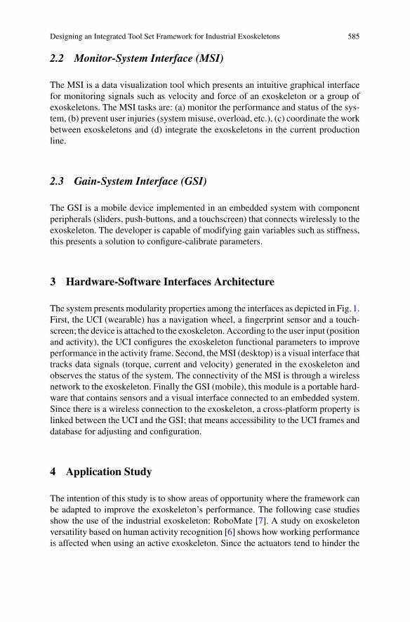
Designing an Integrated Tool Set Framework for Industrial Exoskeletons 585
2.2 Monitor-System Interface (MSI)
The MSI is a data visualization tool which presents an intuitive graphical interfacefor monitoring signals such as velocity and force of an exoskeleton or a group ofexoskeletons. The MSI tasks are: (a) monitor the performance and status of the sys-tem, (b) prevent user injuries (systemmisuse, overload, etc.), (c) coordinate the workbetween exoskeletons and (d) integrate the exoskeletons in the current productionline.
2.3 Gain-System Interface (GSI)
The GSI is a mobile device implemented in an embedded system with componentperipherals (sliders, push-buttons, and a touchscreen) that connects wirelessly to theexoskeleton. The developer is capable of modifying gain variables such as stiffness,this presents a solution to configure-calibrate parameters.
3 Hardware-Software Interfaces Architecture
The system presents modularity properties among the interfaces as depicted in Fig. 1.First, the UCI (wearable) has a navigation wheel, a fingerprint sensor and a touch-screen; the device is attached to the exoskeleton. According to the user input (positionand activity), the UCI configures the exoskeleton functional parameters to improveperformance in the activity frame. Second, theMSI (desktop) is a visual interface thattracks data signals (torque, current and velocity) generated in the exoskeleton andobserves the status of the system. The connectivity of the MSI is through a wirelessnetwork to the exoskeleton. Finally the GSI (mobile), this module is a portable hard-ware that contains sensors and a visual interface connected to an embedded system.Since there is a wireless connection to the exoskeleton, a cross-platform property islinked between the UCI and the GSI; that means accessibility to the UCI frames anddatabase for adjusting and configuration.
4 Application Study
The intention of this study is to show areas of opportunity where the framework canbe adapted to improve the exoskeleton’s performance. The following case studiesshow the use of the industrial exoskeleton: RoboMate [7]. A study on exoskeletonversatility based on human activity recognition [6] shows how working performanceis affected when using an active exoskeleton. Since the actuators tend to hinder the
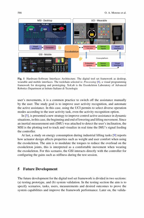
586 O. A. Moreno et al.
Fig. 1 Hardware-Software Interfaces Architecture. The digital tool set framework as desktop,wearable and mobile interfaces. The toolchain selected is: Processing [8], a visual programmingframework for designing and prototyping. XoLab is the Exoskeleton Laboratory of AdvancedRobotics Department at Istituto Italiano di Tecnologia
user’s movements, it is a common practice to switch off the assistance manuallyby the user. The study goal is to improve user activity recognition, and automatethe active assistance. In this case, using the UCI permits to select diverse operationmodes according to the user activity task, even the activity recognition option.
In [5], is presented a new strategy to improve control active assistance in dynamicsituations, in this case, the beginning and end of lowering and liftingmovement. Sincean inertial measurement unit (IMU) was attached to detect the user’s inclination, theMSI is the plotting tool to track and visualize in real time the IMU’s signal feedingthe controller.
At last, a study on energy consumption during industrial lifting tasks [9] reportshow actuator design affects properties such as weight and user comfort when usingthe exoskeleton. The aim is to modulate the torques to reduce the overload on theexoskeleton joints, this is interpreted as a comfortable movement when wearingthe exoskeleton. For this scenario, the GSI interacts directly with the controller forconfiguring the gains such as stiffness during the test session.
5 Future Development
The future development for the digital tool set framework is divided in two sections:(a) testing prototype, and (b) system validation. In the testing section the aim is tospecify scenarios, tasks, users, measurements and desired outcomes to prove thesystem capabilities and improve the framework performance. Later on, the valida-

Designing an Integrated Tool Set Framework for Industrial Exoskeletons 587
tion section will include locations, environment conditions, tasks, subject requisites,metrics and evaluation forms, the system should be successfully used in the definedenvironment in certain tasks.
6 Conclusion
The digital tool set framework design shown in this work presents a potential utilityfor industrial active exoskeletons. Initially, the UCI as wearable device attached tothe exoskeleton configures user settings for better performance. Second, the MSIis a desktop monitoring system to track the exoskeleton signals. Lastly the GSI,a mobile interface with sensors and a graphic environment used to configure theexoskeleton parameters during testing. The case studies presented belong to theindustrial exoskeleton RoboMate and the framework aims to be part of the nextexoskeleton generation called XoTrunk. Testing and validating the system featureswill improve the performance of the exoskeleton in real task scenarios.
Acknowledgements This work has been funded by the Italian Workers’ Compensation Authority(INAIL).
References
1. E.S. Barjuei, M.M.G. Ardakani, D.G. Caldwell, M. Sanguineti, J. Ortiz, Optimal Selection ofmotors and transmissions in back-support exoskeleton applications. IEEE Trans. Med. Robot.Bionics 1 (2020)
2. A. Voilqué, J. Masood, J. Fauroux, L. Sabourin, O. Guezet, Industrial exoskeleton technology:classification, structural analysis, and structural complexity indicator, in 2019Wearable RoboticsAssociation Conference (WearRAcon) (2019), pp. 13–20
3. H.-W. Choi, Y.-K. Kim, D.-M. Kang, J.-E. Kim, B.-Y. Jang, Characteristics of occupationalmusculoskeletal disorders of five sectors in service industry between 2004 and 2013. AnnalsOccup. Environ. Med. 29, 41 (2017)
4. S. Toxiri, A.S. Koopman, M. Lazzaroni, J. Ortiz, V. Power, M.P. de Looze, L. O’Sullivan,D.G. Caldwell, Rationale, implementation and evaluation of assistive strategies for an activeback-support exoskeleton. Front. Robot. AI 5, 53 (2018)
5. M. Lazzaroni, S. Toxiri, D.G. Caldwell, S. Anastasi, L. Monica, E.D. Momi, J. Ortiz,Acceleration-based assistive strategy to control a back-support exoskeleton for load handling:preliminary evaluation, in 2019 IEEE 16th International Conference on Rehabilitation Robotics(ICORR) (2019), pp. 625–630. ISSN: 1945-7901
6. T. Poliero, L. Mancini, D.G. Caldwell, J. Ortiz, Enhancing back-support exoskeleton versatil-ity based on human activity recognition, in 2019 Wearable Robotics Association Conference(WearRAcon) (2019), pp. 86–91
7. J. Ortiz, S. Toxiri, D.G. Caldwell, Beyond robo-mate: towards the next generation of industrialexoskeletons in Europe, in Wearable Robotics: Challenges and Trends, ed. by M.C. Carrozza,S. Micera, J.L. Pons, eds. Biosystems & Biorobotics (Springer International Publishing, Cham,2019), pp. 365–369

588 O. A. Moreno et al.
8. C. Reas, B. Fry, J. Maeda, Processing: A Programming Handbook for Visual Designers andArtists (The MIT Press, Cambridge, 2007)
9. S. Toxiri, T. Verstraten, A. Calanca, D.G. Caldwell, J. Ortiz, Using parallel elasticity in back-support exoskeletons: a study on energy consumption during industrial lifting tasks, in 2019Wearable Robotics Association Conference (WearRAcon) (2019), pp. 1–6

Benchmarking Wearable Robots
Wearable Robots Benchmarking:Comprehending and Considering UserExperience
Philipp Beckerle
Abstract In real-world applications, wearable robots need to serve functionalrequirements, but also satisfy user demands. A systematic evaluation will requiremultidisciplinary benchmarking methods. Since user experience seems to be of dis-tinct relevance, this paper analyzes how user experience influences wearable robotsuse and how it can be considered in benchmarking. Focus is set on potential metricsand how we could include them in human-centered benchmarking approaches.
1 Introduction
Currently, we witness wearable robots entering practical applications, e.g., exoskele-tons and prostheses [1, 2]. To achieve their application-specific objectives, perfor-mance evaluation needs reliable and replicable testing methods [1].
Going beyond a functional perspective, we should consider the users’ needs viaappropriate benchmarking methods [3]. Actually, users’ experiences and needs areunderstood to distinctly influence functional outcomes of wearable robot use [4, 5]and even determine whether devices are used at all [6]. Research is just starting totackle this by multidisciplinary evaluation methods [7, 8], which take perceptual,emotional, and cognitive processes into account [3].
The above-mentioned processes are strongly related to physical and cognitivehuman-robot interaction. Especially, co-adaptation between user and robot is highlyrelevant and might be exploited to improve functional, but also experience-relatedoutcomes [4, 5]. Due to these entanglements and the issue that some aspects ofexperience might not be quantifiable, human-centered approaches in general andhuman-in-the-loop techniques in particular are promising for the investigation of theusers’ satisfaction, comfort, body experience in real interaction scenarios [5].
P. Beckerle (B)Chair of Autonomous Systems and Mechatronics, Department of Electrical Engineering,Friedrich-Alexander-University Erlangen-Nürnberg, Erlangen, Germanye-mail: [email protected]
Department of Mechanical Engineering, Institute for Mechatronic Systems, TU Darmstadt,Darmstadt, Germany
© The Author(s), under exclusive license to Springer Nature Switzerland AG 2022J. C. Moreno et al. (eds.), Wearable Robotics: Challenges and Trends,Biosystems & Biorobotics 27, https://doi.org/10.1007/978-3-030-69547-7_95
591
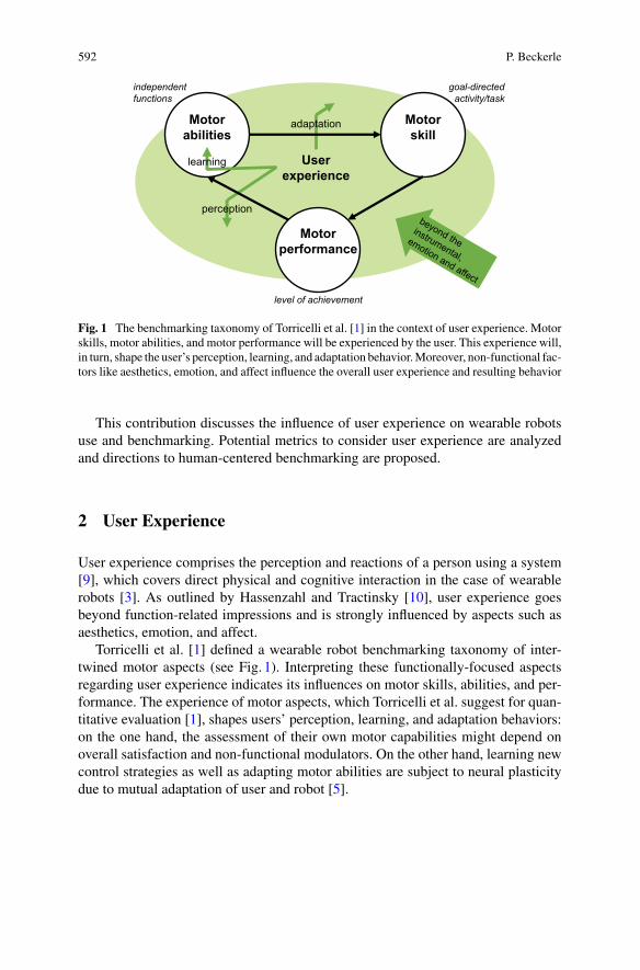
592 P. Beckerle
Motor skill
Motorperformance
Motorabilities
independentfunctions
goal-directedactivity/task
level of achievement
adaptation
Userexperience
perception
learning
Fig. 1 The benchmarking taxonomy of Torricelli et al. [1] in the context of user experience. Motorskills, motor abilities, and motor performance will be experienced by the user. This experience will,in turn, shape the user’s perception, learning, and adaptation behavior.Moreover, non-functional fac-tors like aesthetics, emotion, and affect influence the overall user experience and resulting behavior
This contribution discusses the influence of user experience on wearable robotsuse and benchmarking. Potential metrics to consider user experience are analyzedand directions to human-centered benchmarking are proposed.
2 User Experience
User experience comprises the perception and reactions of a person using a system[9], which covers direct physical and cognitive interaction in the case of wearablerobots [3]. As outlined by Hassenzahl and Tractinsky [10], user experience goesbeyond function-related impressions and is strongly influenced by aspects such asaesthetics, emotion, and affect.
Torricelli et al. [1] defined a wearable robot benchmarking taxonomy of inter-twined motor aspects (see Fig. 1). Interpreting these functionally-focused aspectsregarding user experience indicates its influences on motor skills, abilities, and per-formance. The experience of motor aspects, which Torricelli et al. suggest for quan-titative evaluation [1], shapes users’ perception, learning, and adaptation behaviors:on the one hand, the assessment of their own motor capabilities might depend onoverall satisfaction and non-functional modulators. On the other hand, learning newcontrol strategies as well as adapting motor abilities are subject to neural plasticitydue to mutual adaptation of user and robot [5].
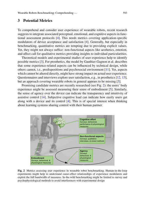
Wearable Robots Benchmarking: Comprehending … 593
3 Potential Metrics
To comprehend and consider user experience of wearable robots, recent researchsuggests to integrate associated perceptual, emotional, and cognitive aspects in func-tional assessment protocols [4]. This needs metrics covering application-specificmodulators of device acceptance and satisfaction [4]. Generally, but especially inbenchmarking, quantitative metrics are tempting due to providing explicit values.Yet, they might not always suffice: non-functional aspects like aesthetics, emotion,and affect call for qualitative metrics providing insights to individual particularities.
Theoretical models and experimental studies of user experience help to identifypossible metrics [3]. For prosthetics, the model by Gauthier-Gagnon et al. describesthat some experience-related aspects can be influenced by technical design, whileothers cannot, i.e., predispositions and psychosocial environment [11]. Yet, aspectswhich cannot be altered directly, might have strong impact on actual user experience.Questionnaires and interviews explore user satisfaction, e.g., in prosthetics [12, 13],but an approach covering wearable robots in general appears to be missing [3].
Promising candidate metrics are recently researched (see Fig. 2): the users’ bodyexperience might be assessed measuring their sense of embodiment [5]. Similarly,the sense of agency over the device can indicate the transparency and intuitivity ofassistive control [14]. Subjective cognitive load can indicate how easily users getalong with a device and its control [4]. This is of special interest when thinkingabout learning systems sharing control with their human partner.
EmbodimentSurveys, behavioral, & physiological measures
Cognitive effortSurveys, behavioral, performance & physiological measures
AgencySurveys, behavioral, & physiological measures
Non-functional aspectsSurveys, qualitative interviews, & mixed methods
Fig. 2 Metrics assessing user experience in wearable robot benchmarking. Human-in-the-loopexperiments might help to understand cause-effect relationships of experience modulators andexploit the full bandwidth of measures. In-the-wild benchmarking might be limited to survey andpsychophysiological methods to avoid interferences with experimental design
594 P. Beckerle
4 Human-Centered Benchmarking
To holistically consider functional and experience-related aspects, benchmarkingmight take inspiration from human-centered design [12, 15]. While continuoususer involvement appears obvious, benchmarking could benefit from systematicuser experience assessment, e.g., to weight functional observations considering non-functional aspects.
Human-in-the-loop experiments are promising to understand cause-effect rela-tions underlying human-robot interaction and user experience [4, 5]. They can sys-tematically vary modulating factors and exploit all potential experience measures.To assess embodiment, agency, and cognitive effort, psychometric [16, 17], psy-chophysiological [17], performance-related [18], and behavioral [14, 17] measuresexist. Since the latter demand specific designs, they are valuable in the laboratory,but might not be feasible outside.
5 Conclusions
Wearable robot benchmarking is highly important to keep track of user outcomes. Fora holistic, possibly human-centered, perspective we will need a deep understandingof motor-experience correlations and their metrics in benchmarking. Consideringuser experience throughout the evaluation process, we might be able to improve useroutcomes.
References
1. D. Torricelli, J. Gonzalez-Vargas, J.F. Veneman, K.Mombaur, N. Tsagarakis, A.J. Del-Ama, A.Gil-Agudo, J.C. Moreno, J.L. Pons, Benchmarking bipedal locomotion: a unified scheme forhumanoids, wearable robots, and humans. IEEE Robot. Autom. Mag. 22(3), 103–115 (2015)
2. M. Windrich, M. Grimmer, O. Christ, S. Rinderknecht, P. Beckerle, Active lower limb pros-thetics: a systematic review of design issues and solutions. BioMed. Eng. OnLine 15(3), 5–19(2016)
3. D. Torricelli, C. Rodriguez-Guerrero, J.F. Veneman, S. Crea, K. Briem, B. Lenggenhager,P. Beckerle, Benchmarking wearable robots: challenges and recommendations from functional(user experience and methodological perspectives (in revision))
4. P. Beckerle, G. Salvietti, R. Unal, D. Prattichizzo, S. Rossi, C. Castellini, S. Hirche, S. Endo,H. Ben Amor, M. Ciocarlie, F. Mastrogiovanni, B.D. Argall, M. Bianchi, A human-robot inter-action perspective on assistive and rehabilitation robotics. Front. Neurorobot. 11(24) (2017)
5. P. Beckerle, C. Castellini, B. Lenggenhager, Robotic interfaces for cognitive psychology andembodiment research: a research roadmap. Wiley Interdiscipl. Rev. Cogn. Sci. 10(2), e1486(2019)
6. N. Jiang, S. Došen, K. Müller, D. Farina, Myoelectric control of artificial limbs—is there aneed to change focus? IEEE Signal Process. Mag. 29(5), 148–152 (2012)
Wearable Robots Benchmarking: Comprehending … 595
7. A.L. Ármannsdóttir, P. Beckerle, J.C.Moreno, E.H.F. van Asseldonk,M.-T.Manrique-Sancho,A. del Ama, J. Veneman, K. Briem, Assessing the involvement of users during development oflower limb wearable robotic exoskeletons: a survey study. Human Fact. 62, 351–364 (2020)
8. J. Ghillebert, S. De Bock, F. Flynn, J. Geeroms, B. Tassignon, B. Roelands, D. Lefeber, B.Vanderborght, R. Meeusen, K. De Pauw, Guidelines and recommendations to investigate theefficacy of a lower-limb prosthetic device: a systematic review. IEEE Trans. Med. Robot. Bion.1(4), 279–296 (2019)
9. DINDeutsches Institut fürNormung e.V., EN ISO9241-9:2000, ErgonomischeAnforderungenfür Bürotätigkeiten mit Bildschirmgeräten (2000)
10. M. Hassenzahl, N. Tractinsky, User experience—a research agenda. Behav. Inf. Technol. 25(2),91–97 (2006)
11. C. Gauthier-Gagnon, M.C. Grisé, Enabling factors related to prosthetic use by people withtranstibial and transfemoral amputation, Arch. Phys. Med. Rehabil. 80(6), 706–713 (1999)
12. P.Beckerle,O.Christ, T. Schürmann, J.Vogt,O. vonStryk, S.Rinderknecht,Ahuman-machine-centered design method for (powered) lower limb prosthetics. Robot. Auton. Syst. 95, 1–12(2017)
13. E.C. Baars, E. Schrier, P.U. Dijkstra, J.H.B. Geertzen, Prosthesis satisfaction in lower limbamputees: a systematic reviewof associated factors and questionnaires.Medicine 97(39) (2018)
14. S. Endo, J. Fröhner, S. Music, S. Hirche, P. Beckerle, Effect of external force on agency inphysical human-machine interaction. Front. Human Neurosci. 14 (2020)
15. T. Jokela, N. Iivari, J. Matero, M. Karukka, The standard of user-centered design and thestandard definition of usability: analyzing iso 13407 against iso 9241-11, in Proceedings of theLatin American Conference on Human-computer Interaction (2003), pp. 53–60
16. S.G. Hart, L.E. Staveland, Development of nasa-tlx (task load index): results of empirical andtheoretical research. Adv. Psychol. 52, 139–183 (1988)
17. O. Christ, M. Reiner, Perspectives and possible applications of the rubber hand and virtual handillusion in non-invasive rehabilitation: technological improvements and their consequences.Neurosci. Biobehav. Rev. 44, 33–44 (2014)
18. A. Erdogan, B.D. Argall, The effect of robotic wheelchair control paradigm and interface onuser performance, effort and preference: an experimental assessment. Robot. Auton. Syst. 94,282–297 (2017)
Performance Indicators of HumanoidPosture Control and Balance Inspiredby Human Experiments
Vittorio Lippi, Thomas Mergner, Christoph Maurer, and Thomas Seel
Abstract Posture control and maintaining balance are fundamental elements ofhumanoid robot control and have a significant impact for the performance of robots.The evaluation of robotic performance, at the state of the art, is mostly evaluated atgoal level, e.g. with robot competitions. While falling is a typical reason beyond thefailure of the humanoid operation, the failure itself does not provide many detailsabout the nature of the underlying problem that can be used to improve the control.In order to provide a more specific analysis of posture control and balance, thiscontribution presents a set of performance indicators, i.e. indexes that can be used tocompare the performance of robots with the human control systems. The inspirationfor the proposed tests and indicators comes from human experiments and particularemphasis is placed on human-robot comparison.
1 Introduction
Posture control and balance are required to maintain equilibrium when walking orstanding and to provide buttress when performing a motor task. Losing balance isone of the typical reasons of failure for humanoids, often damaging the hardware, asreported for example for the DARPA challenges [1–3]. During such a challenge therobot is evaluated in terms of goal achievement, without (directly) going into detailsof the reason of the failure. An evaluation system focused on the details of posturecontrol is envisaged to be useful to inspire the improvement of the components ofthe control system. The study of human posture control can provide inspiration forthe control of humanoids [4–7] and, on the other hand, humanoids represent a poten-tial testbed for theories for human neurology [8]. Studies involving human-inspiredposture control systems usually include an ad hoc specified test of performance,
V. Lippi (B) · T. SeelFachgebiet Regelungssysteme (Control Systems Group), Technische Universität Berlin,Einsteinufer 17, Berlin, Germanye-mail: [email protected]
T. Mergner · C. MaurerNeurology, University Clinic of Freiburg, Freiburg, Germany
© The Author(s), under exclusive license to Springer Nature Switzerland AG 2022J. C. Moreno et al. (eds.), Wearable Robotics: Challenges and Trends,Biosystems & Biorobotics 27, https://doi.org/10.1007/978-3-030-69547-7_96
597
598 V. Lippi et al.
while neurology works exploiting the robot as a simulation device for the compar-ison between human and robot behavior defined on some quantitative basis (e.g.body-sway frequency response to external disturbances). In this work we specify aset of tests and performance indicators (PI) that are meant to make such evaluationsrepeatable and comparable between different robots. This fits in the more generaleffort of producing benchmarking tools for humanoid robots [6, 9–12].
2 Tests and Performance Indicators
Sinusoidal disturbance. Providing an external disturbance with a sinusoidal profileallows for an evaluation of the performance in terms of disturbance rejection.Different kinds of stimuli can be used, e.g. surface tilt or translation. The responseconsisting of the induced body sway is used to compute gain on a specific frequencyas ratio between response and stimulus [13]. The periodic nature of the stimulus cantest the ability of the robot to exploit prediction [14]. Considering that in general theresponse of the robot is not linear, several frequencies and amplitudes can be testedobtaining several scores. In general, a smaller gain is considered a better performance,nevertheless a more “relaxed” compensation of the disturbances may be more effi-cient and hence the gain may be evaluated together with energy consumption ormechanical work produced by the actuators [13].
For testing the movement of the support surface with a sinusoidal profile, thepi is the body sway over the stimulus: gain. The smaller the gain the better theperformance.
Raised Cosine. A support surface movement, e.g. translation or tilt, with a velocityprofile of a raised cosine represents a smooth version of a step function that canbe used safely for humanoids and human subjects [15]. In this way the transientresponse to external stimuli can be evaluated in terms of characteristics like risetime, overshoot, settling time, peak time and delay-time.
Raised cosine is a “safe” version of the step function that can be used to eval-uate aPI reflecting the transient response characteristics: rise time,overshoot,settling time, peak time and delay-time.
Model parameters. Parametric models of human posture control can be fitted onexperimental data. This transforms a series of body sway measures and input stimuliinto a set of parameters. In particular we developed a system to fit the nonlinear DEC
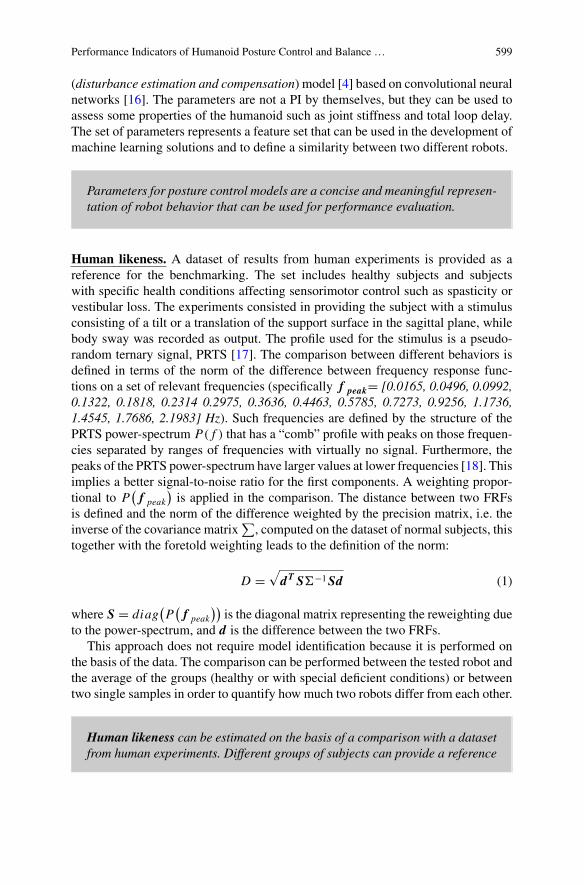
Performance Indicators of Humanoid Posture Control and Balance … 599
(disturbance estimation and compensation) model [4] based on convolutional neuralnetworks [16]. The parameters are not a PI by themselves, but they can be used toassess some properties of the humanoid such as joint stiffness and total loop delay.The set of parameters represents a feature set that can be used in the development ofmachine learning solutions and to define a similarity between two different robots.
Parameters for posture control models are a concise and meaningful represen-tation of robot behavior that can be used for performance evaluation.
Human likeness. A dataset of results from human experiments is provided as areference for the benchmarking. The set includes healthy subjects and subjectswith specific health conditions affecting sensorimotor control such as spasticity orvestibular loss. The experiments consisted in providing the subject with a stimulusconsisting of a tilt or a translation of the support surface in the sagittal plane, whilebody sway was recorded as output. The profile used for the stimulus is a pseudo-random ternary signal, PRTS [17]. The comparison between different behaviors isdefined in terms of the norm of the difference between frequency response func-tions on a set of relevant frequencies (specifically f peak= [0.0165, 0.0496, 0.0992,0.1322, 0.1818, 0.2314 0.2975, 0.3636, 0.4463, 0.5785, 0.7273, 0.9256, 1.1736,1.4545, 1.7686, 2.1983] Hz). Such frequencies are defined by the structure of thePRTS power-spectrum P( f ) that has a “comb” profile with peaks on those frequen-cies separated by ranges of frequencies with virtually no signal. Furthermore, thepeaks of the PRTS power-spectrum have larger values at lower frequencies [18]. Thisimplies a better signal-to-noise ratio for the first components. A weighting propor-tional to P
(f peak
)is applied in the comparison. The distance between two FRFs
is defined and the norm of the difference weighted by the precision matrix, i.e. theinverse of the covariance matrix
∑, computed on the dataset of normal subjects, this
together with the foretold weighting leads to the definition of the norm:
D =√dT S−1Sd (1)
where S = diag(P
(f peak
))is the diagonal matrix representing the reweighting due
to the power-spectrum, and d is the difference between the two FRFs.This approach does not require model identification because it is performed on
the basis of the data. The comparison can be performed between the tested robot andthe average of the groups (healthy or with special deficient conditions) or betweentwo single samples in order to quantify how much two robots differ from each other.
Human likeness can be estimated on the basis of a comparison with a datasetfrom human experiments. Different groups of subjects can provide a reference
600 V. Lippi et al.
to ‘diagnose’ a specific behavior. The measure in (1) defines a norm that canbe used also to compare two specific trials.
3 Conclusion
In this contribution we presented a set of PIs for posture control and an overviewof our humanoid performance benchmarking principles. The human experimentaldataset, the software implementing the proposed analysis and the hardware requiredto perform the proposed tests will be available through the EUROBENCH initiative(https://eurobench2020.eu/). Specifically, themoving platform has been designed forhumanoids, but, provided that safety for users is properly ensured, the here describedPIs can be applied to the study of wearable robots.
Acknowledgements This work is supported by the project EUROBENCH (European RoboticFramework for Bipedal Locomotion Benchmarking, www.eurobench2020.eu ) funded by H2020Topic ICT 27–2017 under grant agreement number 779963.
References
1. E.Guizzo, E.Ackerman, The hard lessons ofDARPA’s robotics challenge [News]. IEEESpectr.(2015). https://doi.org/10.1109/mspec.2015.7164385
2. C.G. Atkeson et al., No falls, no resets: reliable humanoid behavior in the DARPA roboticschallenge. in IEEE-RAS International Conference on Humanoid Robots (2015). https://doi.org/10.1109/HUMANOIDS.2015.7363436
3. C.G. Atkeson et al., What happened at the DARPA robotics challenge finals. in Springer Tractsin Advanced Robotics (2018)
4. V. Lippi, T. Mergner, Human-derived disturbance estimation and compensation (DEC) methodlends itself to a modular sensorimotor control in a humanoid robot. Front. Neurorobot. 11,(2017). https://doi.org/10.3389/fnbot.2017.00049
5. A.V. Alexandrov, V. Lippi, T. Mergner, A.A. Frolov, G. Hettich, D. Husek, Human-inspiredEigen movement concept provides coupling-free sensorimotor control in humanoid robot.Front. Neurorobot. 11, (2017). https://doi.org/10.3389/fnbot.2017.00022
6. V. Lippi, D. Torricelli, G. Hettich, T.Mergner, Benchmarking human-likeness of robot posturalcontrol—suggestions from human experiments. in Workshop in Benchmarking Human-LikeLocomotion Humanoids 2013 Conference, (2013)
7. C. Ott et al., Good posture, good balance: comparison of bioinspired and model-basedapproaches for posture control of humanoid robots. IEEE Robot. Autom. Mag. 23(1), 22–33(2016). https://doi.org/10.1109/MRA.2015.2507098
8. V. Lippi, T. Mergner, Humanoid neurorobotics-posture, balance and movement control. inSchool and Symposium on Advanced Neurorehabilitation (SSNR2016), (2016)
9. D. Torricelli et al., Benchmarking human likeness of bipedal robot locomotion: state of the artand future trends. in Metrics of Sensory Motor Coordination and Integration in Robots andAnimals (Springer, 2020), pp. 147–166
Performance Indicators of Humanoid Posture Control and Balance … 601
10. R. Conti, F. Giovacchini, L. Saccares, N. Vitiello, J.L. Pons, D. Torricelli, What do peopleexpect from benchmarking of bipedal robots? Preliminary results of the EUROBENCH survey.in Biosystems and Biorobotics (2019)
11. D. Torricelli, J.L. Pons, EUROBENCH: preparing robots for the real world. in Biosystems andBiorobotics (2019)
12. T. Mergner, V. Lippi, Posture control—human-inspired approaches for humanoid robot bench-marking: conceptualizing tests, protocols and analyses. Front. Neurorobot. 12, (2018). https://doi.org/10.3389/fnbot.2018.00021
13. V. Lippi, T. Mergner, T. Seel, C. Maurer, COMTEST project: a complete modular test standfor human and humanoid posture control and balance. in IEEE-RAS International Conferenceon Humanoid Robots (2019). https://doi.org/10.1109/Humanoids43949.2019.9035081
14. V. Lippi, Prediction in the context of a human-inspired posture control model. Rob. Auton.Syst. (2018). https://doi.org/10.1016/j.robot.2018.05.012
15. V. Lippi, G. Hettich, T. Mergner, Modeling postural control of support surface translations. inIEEE Humanoids, Workshop on Cognition, Perception and Postural Control for Humanoids(Madrid, Spain, 2014)
16. V. Lippi, T. Mergner, C. Maurer, Deep learning for posture control nonlinear model systemand noise identification. in Proceedings of the 17th International Conference on Informatics inControl, Automation and Robotics—vol. 1: ICINCO, ISBN 978-989-758-442-8, pages 607–614. (2020) https://doi.org/10.5220/0009148106070614
17. R.J. Peterka, Sensorimotor integration in human postural control. J. Neurophysiol. (2002).https://doi.org/10.1152/jn.2002.88.3.1097
18. D. Joseph Jilk, S.A. Safavynia, L.H. Ting, Contribution of vision to postural behaviors duringcontinuous support-surface translations. Exp. Brain Res. 232(1), 169–180 (2013). https://doi.org/10.1007/s00221-013-3729-4
Lower-Limbs Exoskeletons BenchmarkExploiting a Stairs-Based Testbed:The STEPbySTEP Project
Nicole Maugliani, Marco Caimmi, Matteo Malosio, Francesco Airoldi,Diego Borro, Daniel Rosquete, Ausejo Sergio, Davide Giusino,Federico Fraboni, Giuseppe Ranieri, Luca Pietrantoni, and Loris Roveda
Abstract Wearable exoskeletons can be valuable assistive robots to physically sup-port humans in a wide variety of daily living activities. However, there is a lack ofstandards for the devices benchmark and evaluation. The STEPbySTEP project isdeveloping a modular and sensorized reconfigurable staircase testbed for lower-limbexoskeletons benchmarking to be included in themain EUROBENCHproject testingfacility. In addition, metrics for the benchmark and evaluation of different solutionsare defined, including physical interaction metrics, ergonomics metrics, and humanfactors metrics.
1 Testbed Description
The STEPbySTEP project proposes the development of a modular, sensorized andreconfigurable staircase testbed to be used in a systematic procedure aimed at val-idating lower-limbs exoskeletons (LLEs) abilities, performance and effects on userexperience during ascending/descending stairs. The proposed testbed is shown inFig. 1. The capability of the setup to reconfigure the inclination of the staircase (i.e.,the height of the steps) is of great importance to test the LLEs in different situations.Such inclination can be set by changing the height of the landing through the Actu-
N. Maugliani · M. Caimmi · M. Malosio · F. AiroldiInstitute of Intelligent Industrial Technologies and Systems for Advanced Manufacturing(STIIMA) of Italian National Research Council (CNR), via Corti, 12, 20133 Milan, Italy
D. Borro · D. Rosquete · A. SergioCEIT-Basque Research and Technology Alliance (BRTA) and Tecnun, (University of Navarra),Manuel Lardizabal 15, 20018 Donostia-San Sebastian, Spain
D. Giusino · F. Fraboni · G. Ranieri · L. PietrantoniDepartment of Psychology, University of Bologna, via Filippo Re, 10, 40126 Bologna, Italy
L. Roveda (B)Istituto Dalle Molle di studi sull’Intelligenza Artificiale (IDSIA), Scuola universitariaprofessionale della Svizzera italiana (SUPSI), Università della Svizzera italiana (USI), viaCantonale, 6928 Manno, Switzerlande-mail: [email protected]
© The Author(s), under exclusive license to Springer Nature Switzerland AG 2022J. C. Moreno et al. (eds.), Wearable Robotics: Challenges and Trends,Biosystems & Biorobotics 27, https://doi.org/10.1007/978-3-030-69547-7_97
603
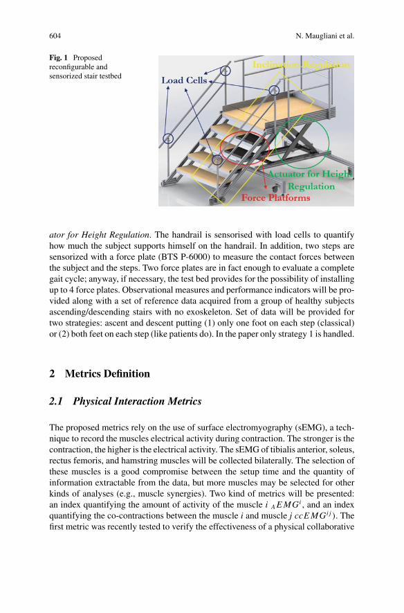
604 N. Maugliani et al.
Fig. 1 Proposedreconfigurable andsensorized stair testbed
ator for Height Regulation. The handrail is sensorised with load cells to quantifyhow much the subject supports himself on the handrail. In addition, two steps aresensorized with a force plate (BTS P-6000) to measure the contact forces betweenthe subject and the steps. Two force plates are in fact enough to evaluate a completegait cycle; anyway, if necessary, the test bed provides for the possibility of installingup to 4 force plates. Observational measures and performance indicators will be pro-vided along with a set of reference data acquired from a group of healthy subjectsascending/descending stairs with no exoskeleton. Set of data will be provided fortwo strategies: ascent and descent putting (1) only one foot on each step (classical)or (2) both feet on each step (like patients do). In the paper only strategy 1 is handled.
2 Metrics Definition
2.1 Physical Interaction Metrics
The proposed metrics rely on the use of surface electromyography (sEMG), a tech-nique to record the muscles electrical activity during contraction. The stronger is thecontraction, the higher is the electrical activity. The sEMG of tibialis anterior, soleus,rectus femoris, and hamstring muscles will be collected bilaterally. The selection ofthese muscles is a good compromise between the setup time and the quantity ofinformation extractable from the data, but more muscles may be selected for otherkinds of analyses (e.g., muscle synergies). Two kind of metrics will be presented:an index quantifying the amount of activity of the muscle i AEMGi , and an indexquantifying the co-contractions between the muscle i and muscle j ccEMGi j ). Thefirst metric was recently tested to verify the effectiveness of a physical collaborative
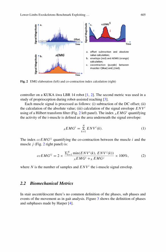
Lower-Limbs Exoskeletons Benchmark Exploiting … 605
Fig. 2 EMG elaboration (left) and co-contraction index calculation (right)
controller on a KUKA iiwa LBR 14 robot [1, 2]. The second metric was used in astudy of proprioception during robot-assisted reaching [3].
Each muscle signal is processed as follows: (i) subtraction of the DC offset; (ii)the calculation of the absolute value; (iii) calculation of the signal envelope ENV i
using of a Hilbert transform filter (Fig. 2 left panel). The index AEMGi quantifyingthe activity of the i-muscle is defined as the area underneath the signal envelope:
AEMGi = Nk=1
ENV i (k). (1)
The index ccEMGi j quantifying the co-contraction between the muscle i and themuscle j (Fig. 2 right panel) is:
ccEMGi j = 2× Nk=1 min(ENV i (k), ENV j (k))
AEMGi +A EMG j× 100%, (2)
where N is the number of samples and ENV i the i-muscle signal envelop.
2.2 Biomechanical Metrics
In stair ascent/descent there’s no common definition of the phases, sub phases andevents of the movement as in gait analysis. Figure 3 shows the definition of phasesand subphases made by Harper [4].
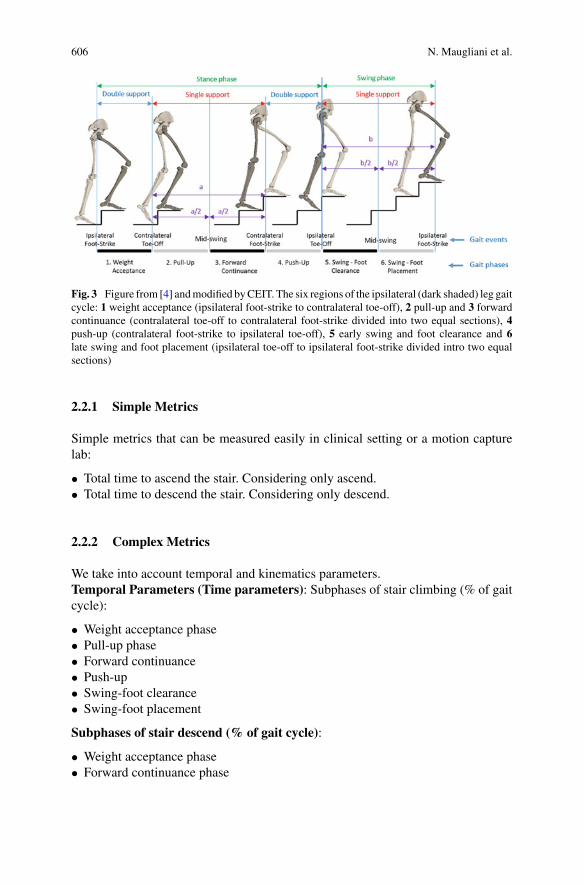
606 N. Maugliani et al.
Fig. 3 Figure from [4] andmodified byCEIT. The six regions of the ipsilateral (dark shaded) leg gaitcycle: 1 weight acceptance (ipsilateral foot-strike to contralateral toe-off), 2 pull-up and 3 forwardcontinuance (contralateral toe-off to contralateral foot-strike divided into two equal sections), 4push-up (contralateral foot-strike to ipsilateral toe-off), 5 early swing and foot clearance and 6late swing and foot placement (ipsilateral toe-off to ipsilateral foot-strike divided intro two equalsections)
2.2.1 Simple Metrics
Simple metrics that can be measured easily in clinical setting or a motion capturelab:
• Total time to ascend the stair. Considering only ascend.• Total time to descend the stair. Considering only descend.
2.2.2 Complex Metrics
We take into account temporal and kinematics parameters.Temporal Parameters (Time parameters): Subphases of stair climbing (% of gaitcycle):
• Weight acceptance phase• Pull-up phase• Forward continuance• Push-up• Swing-foot clearance• Swing-foot placement
Subphases of stair descend (% of gait cycle):
• Weight acceptance phase• Forward continuance phase
Lower-Limbs Exoskeletons Benchmark Exploiting … 607
• Controlled lowering phase• Leg pull through• Foot placement
Kinematic and kinetic parameters:
• Joint angles versus % of gait cycle.• Peak values of angles and time occurrence (% of gait cycle) at the hip, knee andankle joint.
• Peak values of vertical ground reaction force, anterior-posterior and medium-lateral center of progression
• Peak value of forces applied on the handrail.
2.3 Human Factors Metrics
Based on previous literature regarding the evaluation of medical LLEs’ impact onusers’perceptions and behaviors [5], the STEPbySTEP project aims to develop aHuman Factors benchmarking framework based on the integration of well-accreditedevaluation tools. Two types ofmetricswill be included.Cognitivemetricswill encom-pass: cognitive-motor interference, measured by the Single-Dual Task Paradigm [6],andperceivedmusculoskeletal pressure/discomfort,measuredby theLocal PerceivedPressure Method [7]. Behavioral metric will correspond to an ad-hoc observationalchecklist measuring user-exoskeleton interaction. The protocol will be divided inthree phases. The first phase (before task, 25min) entails a semi-structured inter-view (15minutes) concerning user expectations about his/her experience with theexoskeleton, along with a questionnaire about age, sex, anthropometric features andexpertise with assistive devices. The second phase (during task, 20min) consistsof climbing the staircase testbed. In turn, two experimental conditions will be run,such as without and with cognitive-motor interference. The third phase (after task,30min) encompasses a semi-structured interview (15min) regarding user attitudesabout his/her experience with the exoskeleton, along with a questionnaire about localperceived pressure.
References
1. L. Roveda et al., Fuzzy impedance control for enhancing capabilities of humans in onerous tasksexecution, in 2018 15th International Conference on Ubiquitous Robots (UR) (IEEE, 2018), pp.406–411
2. L. Roveda et al., Assisting operators in heavy industrial tasks: on the design of an optimizedcooperative impedance fuzzy-controller with embedded safety rules. Front. Robot. AI 6, 75(2019)
3. M. Caimmi et al., Proprioceptivity and upper-extremity dynamics in robot-assisted reachingmovement, in 2012 4th IEEE RAS & EMBS International Conference on Biomedical Roboticsand Biomechatronics (BioRob) (IEEE, 2012), pp. 1316–1322

608 N. Maugliani et al.
4. N. Harper et al., Muscle function and coordination of stair ascent. J. Biomech. Eng. 140(1)(2017)
5. Ármannsdóttir Anna et al., Assessing the involvement of users during development of lowerlimb wearable robotic exoskeletons: a survey study. Human Fact. 62(3), 351–364 (2020)
6. P. Plummer-D’Amato et al., Interactions between cognitive tasks and gait after stroke: a dualtask study. Gait Post. 27(4), 683–688 (2008)
7. H. van Reenen Heleen et al., Does musculoskeletal discomfort at work predict future muscu-loskeletal pain? Ergonomics 51(5), 637–648 (20080
Towards a Unified Terminology forBenchmarking Bipedal Systems
Anthony Remazeilles, Alfonso Dominguez, Pierre Barralon,and Diego Torricelli
Abstract In the European project EUROBENCH, we are developing a frameworkfor benchmarking the performances of bipedal systems: from humans to humanoidsthrough wearable robots. Fair benchmarking requires defining and sharing clear andcomplete protocols so that bipedal systems can be studied and compared withinsimilar and reproducible conditions. Even if the experimental methods and systemcomparisons are common scientific tasks, the description of the experimental proto-cols that are followed are rarely complete enough to allow it to be replicated. We list,in this article, the information required to properly define a protocol (e.g. experimentobjectives, testbeds, type of collected and processed data, performance indicatorsused to score and compare experiments). Agreeing on a common terminology forbenchmarking concepts will ease the evaluation of new technologies and promotecommunication between the different stakeholders involved in the development anduse of bipedal systems.
1 Introduction
It is widely recognized that the validation of any technological development requiresdemonstrating experimentally its technical soundness. Furthermore, proper exploita-tion of scientific results requires replicating someone else experiment, to compare
A. Remazeilles · A. Dominguez · P. BarralonTECNALIA, Basque Research and Technology Alliance (BRTA), Paseo Mikeletegi 1, 20009 SanSebastian, Spaine-mail: [email protected]
A. Domingueze-mail: [email protected]
P. Barralone-mail: [email protected]
D. Torricelli (B)Neural Rehabilitation Group, Spanish National Research Council (CSIC),Cajal Institute, Madrid, Spaine-mail: [email protected]
© The Author(s), under exclusive license to Springer Nature Switzerland AG 2022J. C. Moreno et al. (eds.), Wearable Robotics: Challenges and Trends,Biosystems & Biorobotics 27, https://doi.org/10.1007/978-3-030-69547-7_98
609
610 A. Remazeilles et al.
its outcomes with new results (e.g. using a different robotic system or control law),using well-chosen performance criteria [3]. In the emerging field of wearable robotsand bipedal systems in general, there is still a lack of common methodologies andbenchmarking frameworks to effectively compare system performance [4]. Com-petition events like Cybathlon allow the comparison of bipedal systems, but theyonly focus on simple metrics like completion time [5], and cannot characterize andcompare more precisely the performance of the systems under consideration.
In the European project EUROBENCH we are creating a framework suitable forbenchmarking bipedal locomotion systems, including humans and wearable robots,as well as humanoid robots [1]. We are designing a set of protocols and testbeds thatwill be available in two physical facilities. Protocols are described in sufficient detailto permit any experimenter to reproduce them in his/her own facilities. Fair com-parisons are obtained with an automatic scoring mechanism that uses benchmarkingalgorithms associated to the protocol followed to extract performance scores fromthe data collected.
Designing a systematic benchmarking system requires a clear and complete def-inition of the protocols to guarantee that experimenters, later, will conduct theirexperiments as expected. This is a challenging process, as practices and concernsmay vary significantly from one community to another. We are thus sharing in thisarticle the set of information we consider necessary to have a clear and replicableprotocol, together with its associated terminology.
2 Terminology
We arbitrarily segment the key concepts as follows: (i) the protocol description,from which an experimenter shall learn all objectives, means and requirements, (ii)the experimentation in which data is collected, and (iii) the scoring, in which thecollected data are assessed according to the metrics associated to the protocol.
2.1 Benchmarking Protocol
Per se, a protocol description should provide clear prescriptions on all the conceptsintroduced in the three categories. By reading it, an experimenter should be able toverify if it fits his needs (objectives and associated metrics), and if he has access tothe appropriate material to conduct it (tesbded). We highlight some key features tobe provided.Scenario: Description of the functional task(s) to be performed in a given envi-ronment (e.g. “walking on a moving surface”). A scenario can act as a namespacegathering protocols dealing with similar functional task(s), for example.Objective: Textual description of the features to be characterized through this pro-tocol.
Towards a Unified Terminology for Benchmarking Bipedal Systems 611
Target subjects: Definition of the subjects that can take part in the experimentation(humanoid, humanwith prosthesis,…), possiblywith inclusion and exclusion criteria(e.g. healthy humans, or those with a given pathology).Testbed: A description of the equipment required to perform the experiments, whichincludes the physical objects involved in the tests (e.g. stairs, slopes), with a definitionof their location in the scene [6], as well as the hardware required for sensing (e.g.motion capture, force platform) and acting (e.g. treadmill, “pusher”). The softwareused to control these items and to collect data is part of the testbed. The protocol mayaccept slightly different types of equipment, as long as the data required to score theexperiment is collected.Performance indicator (PI): A numerical quantity describing the performance ofthe system under investigation, according to the protocol objectives. A PI can be (i) ameasured physical quantity or derived from several such quantities, (ii) dimensionalor dimensionless, (iii) a unique value or a time-series. Several PIs may be needed tofully describe a system’s level of ability.Protocol procedure: As in a cooking recipe, the protocol steps should describe allthe successive operations an experimenter must follow, from the setup configuration,subject preparation and guidance, to the experiment execution, data collection andpreparation for scoring.
2.2 Experimentation-Related Concepts
Following the protocol definition and procedure, the experimenter is ready to conductan experiment.
According to the procedure, the experiment may include N repetitions, or runs.A run is a single execution of the action, but the subject may be requested to repeatexactly the same actions for statistical purposes. The protocol can also suggest eval-uating different variants of the conditions. If so, the total number of runs is C × N .The experiment can also involve several human subjects. Data collected should belabelled so that anybody can a posteriori deduce the participant’s ID number, theexperiment conditions or variant, and the run number of each datafile.
In an experiment report, the experimenter must provide information on the fol-lowing items:Experiment subject: Specification of the subject(s) involved in the experiment. Inour context, the bipedal systemmay be only a human, only a robot (i.e. a humanoid),or a combination of both (human wearing an exoskeleton or a prosthesis). The proto-col may require storing specific parameters, such as anthropometric (or robot-metric)measures. The experimenter may also collect additional descriptive information (likeclinical/demographic parameters, design or robot control strategies), to enrich thesubject description and enable further meta-analysis. All this data collection shouldcomply with privacy and regulatory concerns.Experimental data: Set of measures needed to compute the PIs. We differentiatethe raw data and the pre-processed data. Raw data is that which is directly collected
612 A. Remazeilles et al.
by the software of the testbed, in a format that may be specific to the brand of theequipment used. The Pre-processed data is derived from the raw data to describe arelevant physical quantity (e.g. joint angle), irrespective of the sensor(s) used.Controlled variables: Conditions and parameters that must be logged by the experi-menter, as they may not be measured by the instrumented tesbed but are neverthelessneeded to fully describe the experimental settings. These variables shall not changeduring a run execution, and shall remain constant during the N repetitions. They canbe related to either: (i) a configuration of the testbed (e.g. slope angle and lengthfor a walking on slope protocol), (ii) a configuration of the robotic system (such asdifferent assistance levels of an exoskeleton, or different tuning parameter sets of anhumanoid), or (iii) behavioural instructions provided to the subject (such as “do theactionwith eyes closed”). Each of theC experimental conditions should be describedby well controlled variables.
After experiment completion, a set of files is gathered: (i) the bipedal systeminvolved, (ii) values of the controlled variables per condition, (iii) a set of captureddata files, organized per content type, run, condition and subject numbers.
2.3 Computation of Metrics
The benchmarking process consists, then, of computing the PIs (see Sect. 2.1) fromthe collected data. To be as objective as possible, and following a separation ofconcerns, the metric computation should not be linked to the experiment itself; itshould accept data from any experiments that have followed the same protocol andcollected the appropriate data.Benchmarking algorithm: algorithm able to compute one or more performanceindicators from experimental data.Benchmarking metric routine: Code implementing one or more benchmarkingalgorithms. This code receives as input the data (preferably pre-processed, for thesake of generality and reusability), the bipedal system specs and the condition set-tings. It returns as output the PI(s) value(s). Publicly available code is preferred andencouraged to permit code evaluation, contrast and maintenance.Performance Indicator scope: Ideally, a PI should be computed given the data ofa single run. In general, the computation of a score is an iterative evaluation of eachdata run, followed by an aggregation process.Performance Indicator aggregation: the PI should provide the means for aggre-gating scores obtained per run, to combine all PI runs of a same condition setting,to combine PI of each condition, and possibly to combine the PIs obtained by eachhuman subject. A clear separation of the computation for a single run and for thesuccessive aggregations results in code that is much easier to maintain.
Towards a Unified Terminology for Benchmarking Bipedal Systems 613
3 Conclusion
We have described in this document a set of concepts and information requiredto define a reproducible protocol for benchmarking robotic systems. It is currentlybeing used and implemented for all the benchmarking protocols developed withinEurobench, and will permit the automatic evaluation and comparison of any exper-iment following these protocols. We develop the Eurobench framework in collab-oration with numerous institutions, and the framework concepts and terminologiesare being discussed through publicly visible documentation [2]. Even though thisframework is developed specifically for benchmarking bipedal systems, it could beeasily extended to other robotic systems and applications.
Acknowledgements Supported by the H2020 EUROBENCH project, grant No. 779963.
References
1. Eurobench. http://eurobench2020.eu/ (2020)2. Eurobench software documentation. https://github.com/aremazeilles/eurobench_
documentation (2020)3. F. Bonsignorio, A. del Pobil, Toward replicable andmeasurable robotics research (from the guest
editors). IEEE Robot. Autom. Mag. 22(3), 32–35 (2015)4. D. Pinto-Fernandez, D. Torricelli, M.D.C. Sanchez-Villamanan, F. Aller, K.Mombaur, R. Conti,
N. Vitiello, J.C. Moreno, J.L. Pons, Performance evaluation of lower limb exoskeletons: a sys-tematic review. IEEE Trans. Neural Syst. Rehabil. Eng. 28(7), 1573–1583 (2020)
5. R. Riener, The cybathlon promotes the development of assistive technology for people withphysical disabilities. J. NeuroEng. Rehabil. 49 (2016)
6. C. Shirota, E. van Asseldonk, Z. Matjacic, H. Vallery, P. Barralon, S. Maggioni, J.H. Buurke,J.F. Veneman, Robot-supported assessment of balance in standing and walking. J. Neuroeng.Rehabil. 14, 80 (2017)
AMethodology for Benchmarking ForceControl Algorithms
R. Vicario, A. Calanca, N. Murr, M. Meneghetti, E. Sartori, G. Zanni,and P. Fiorini
Abstract Force control is nowadays a mature technology, widespread in modernrobotics systems and commercialized within several application domains. However,assessing the performance of a force-controlled system is not a trivial task becauseit may be strongly influenced by the environment dynamics. Exerting a force on asoft environment is different from exerting a force on a rigid environment. Indeed,the same force-controlled robot can have different force responses in different envi-ronments and a standardized and comprehensive method to assess the performanceof a force-controlled system is not available yet. This paper, as part of the Forecastproject, aims at filling this gap by proposing a benchmarking method able to define acomprehensive score for a given force-controlled system accounting for its sensitivityto environment uncertainties and variations. This paper describes such benchmarkingmethodologywhich allows to compare force control algorithms on a common groundand to determine the preferable control solutions in a specific application domain.
1 Introduction
ONE of the main problems in force control is that performance doesn’t only dependson the dynamics of the robot, but also on the dynamics of the environment, whichis usually uncertain and possibly time-varying. This can lead to unpredictable forcecontrol performance [2]. Many solutions based on advanced control techniques havebeen proposed in recent years to overcome such performance issues (e.g. based ondisturbance observers, robust control, adaptive control, acceleration feedback). Aforce controller that works perfectly for any model and environment does currentlynot exist. Given these premises, in this abstract we propose a methodology to stan-dardize the benchmarking of force control algorithms applied to different actuationarchitectures and considering a wide set of possible environments and disturbances,defined by the application of interest.
R. Vicario (B) · A. Calanca · N. Murr · M. Meneghetti · E. Sartori · G. Zanni · P. FioriniAltair Robotics Laboratory, University of Verona, Verona, Italye-mail: [email protected]: http://www.metropolis.scienze.univr.it
© The Author(s), under exclusive license to Springer Nature Switzerland AG 2022J. C. Moreno et al. (eds.), Wearable Robotics: Challenges and Trends,Biosystems & Biorobotics 27, https://doi.org/10.1007/978-3-030-69547-7_99
615
616 R. Vicario et al.
2 Forecast Project
Experimentally testing control algorithms on different systems and environmentsmay be extremely time consuming and pratically unfeasible. For this reason, wepropose an implementation of a simulation framework to comprehensively quantifythe performance of force control algorithms in different working conditions. A spe-cific effort is devoted to maximize the informativity of simulations and to provideexhaustive performance metrics, still giving easy-to-read data to the user. In ourconcept, the system designer only needs to provide data about their own system, thepossible environment of interest and some candidate force control implementation totest. Eventually, he/she can choose among a library of force control implementationsprovided within the benchmarking software. The output of the benchmarking systemwill be a few plots and values that comprehensively measure the algorithm behaviourin different environments. The evaluation metric calculates the discrepancy betweenthe actual and the desired behaviour within all the interesting working conditionsand when the system is subject to disturbances in a well-defined frequency range.
2.1 Simulation Software
The simulation software considers relevant details of force control imprementation(e.g. real-time periodic execution), different electromagnetic motor choices (e.g.voltage or current controlled motors) and specific actuator parameters (motor inertia,friction, saturations, series stiffness). According to most common environment mod-elling, the benchmarking system takes into account environment stiffness, dampingand inertia.
The simulation architecture is object-oriented, written in Matlab and uses theSimulink simulation engine [3]. To run the proper set of simulations, the user mustchoose:
• The actuator model (from a library of already implemented models);• A force controller (it’s possible to implement a new controller or choose it from alibrary of already implemented controllers);
• A range of environment parameters.
2.2 Evaluation Software
The proposed benchmarking system records the systembehavior in response to awelldefined force reference in different environments and computes the performanceindicators listed in the Table 1. Mean quantities in Table 1 describe the averagevalue across different environments and standard deviation describes the sensitivity
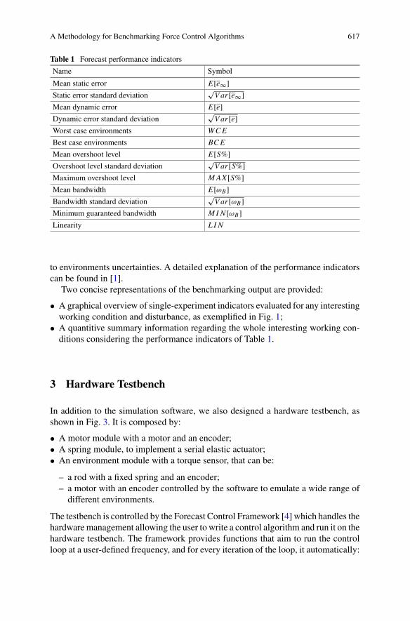
A Methodology for Benchmarking Force Control Algorithms 617
Table 1 Forecast performance indicators
Name Symbol
Mean static error E[e∞]Static error standard deviation
√Var [e∞]
Mean dynamic error E[e]Dynamic error standard deviation
√Var [e]
Worst case environments WCE
Best case environments BCE
Mean overshoot level E[S%]Overshoot level standard deviation
√Var [S%]
Maximum overshoot level MAX [S%]Mean bandwidth E[ωB ]Bandwidth standard deviation
√Var [ωB ]
Minimum guaranteed bandwidth MI N [ωB ]Linearity L I N
to environments uncertainties. A detailed explanation of the performance indicatorscan be found in [1].
Two concise representations of the benchmarking output are provided:
• Agraphical overview of single-experiment indicators evaluated for any interestingworking condition and disturbance, as exemplified in Fig. 1;
• A quantitive summary information regarding the whole interesting working con-ditions considering the performance indicators of Table 1.
3 Hardware Testbench
In addition to the simulation software, we also designed a hardware testbench, asshown in Fig. 3. It is composed by:
• A motor module with a motor and an encoder;• A spring module, to implement a serial elastic actuator;• An environment module with a torque sensor, that can be:
– a rod with a fixed spring and an encoder;– a motor with an encoder controlled by the software to emulate a wide range ofdifferent environments.
The testbench is controlled by the Forecast Control Framework [4] which handles thehardware management allowing the user to write a control algorithm and run it on thehardware testbench. The framework provides functions that aim to run the controlloop at a user-defined frequency, and for every iteration of the loop, it automatically:
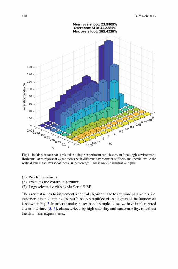
618 R. Vicario et al.
Fig. 1 In this plot each bar is related to a single experiment, which account for a single environment.Horizontal axes represent experiments with different environment stiffness and inertia, while thevertical axis is the overshoot index, in percentage. This is only an illustrative figure
(1) Reads the sensors;(2) Executes the control algorithm;(3) Logs selected variables via Serial/USB.
The user just needs to implement a control algorithm and to set some parameters, i.e.the environment damping and stiffness. A simplified class diagram of the frameworkis shown in Fig. 2. In order tomake the testbench simple to use, we have implementeda user interface [5, 6], characterized by high usability and customability, to collectthe data from experiments.
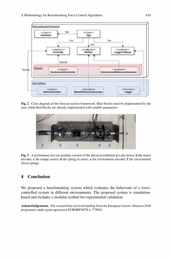
A Methodology for Benchmarking Force Control Algorithms 619
Fig. 2 Class diagram of the forecast nucleo framework. Blue blocks must be implemented by theuser, while Red blocks are already implemented with settable parameters
Fig. 3 A preliminary not yet modular version of the physical testbench a is the motor, b the motorencoder, c the torque sensor, d the spring in series, e the environment encoder, f the environment(fixed spring)
4 Conclusion
We proposed a benchmarking system which evaluates the behaviour of a force-controlled system in different environments. The proposed system is simulation-based and includes a modular testbed for experimental validation.
Acknowledgements The research has received funding from the European Union’s Horizon 2020programme under grant agreement EUROBENCH n. 779963.

620 R. Vicario et al.
References
1. R. Vicario, A methodology for benchmarking force control algorithms (2020). https://doi.org/10.13140/RG.2.2.18759.11680
2. R. Muradore, A. Calanca, P. Fiorini, A review of algorithms for compliant control of stiff andfixed compliance robots. IEEE Trans. Mechatron. 21, 613–624 (2016)
3. Repository of SESim, http://www.gitlab.com/altairLab/elasticteam/SESim4. Repository of Forecast Control Framework, http://www.gitlab.com/altairLab/elasticteam/
forecastnucleoframework5. Forecast UI showcase video, http://www.youtube.com/watch?v=40l8gGEEiSE6. Repository of Forecast UI, http://www.gitlab.com/altairLab/elasticteam/forecast/forecast-atlas
Limitation of Ankle Mobility ChallengesGait Stability While Walking on LateralInclines
Maarten R. Prins, Nick Kluft, Wieke Philippart, Han Houdijk,Jaap H. van Dieën, and Sjoerd M. Bruijn
Abstract Exoskeletons often allow limited movement of the ankle joint. This couldincrease the chance of falling while walking, particularly on challenging surfaces,such as lateral inclines. In this study, the effect of a mobility limiting ankle brace ongait stability in the frontal plane was assessed, while participants walked on lateralinclines. The brace negatively affected gait stability when it was worn on the leg thatwas on the vertically lower side or ‘valley side’ of the lateral incline, which wouldindicate an increased risk of falling in that direction.
1 Introduction
STABILITY of gait is challenged by slopes, such as laterally inclined surfaces.Computer controlled walking devices, such as humanoid robots and exoskeletons,should be able to adapt to changes in surface angle to reduce the risk of falling.Many of such devices have limited joint mobility in the lower extremities comparedto healthy humans. This could hamper the ability to adapt to slopes while walking. In
This project was sponsored by a grant from the EUropean ROBotic framework for bipedal locomo-tion bENCHmarking (EUROBENCH), EU Grant 779963.
N. Kluft · W. Philippart · J. H. van Dieën · S. M. Bruijn (B)VU University, Amsterdam, The Netherlandse-mail: [email protected]
N. Klufte-mail: [email protected]
M. R. PrinsMilitary Rehabilitation Center Aardenburg, Doorn, The Netherlandse-mail: [email protected]
N. KluftDelft University of Technology, Delft, The Netherlands
H. HoudijkUniversity Medical Center Groningen, Groningen, The Netherlandse-mail: [email protected]
© The Author(s), under exclusive license to Springer Nature Switzerland AG 2022J. C. Moreno et al. (eds.), Wearable Robotics: Challenges and Trends,Biosystems & Biorobotics 27, https://doi.org/10.1007/978-3-030-69547-7_100
621
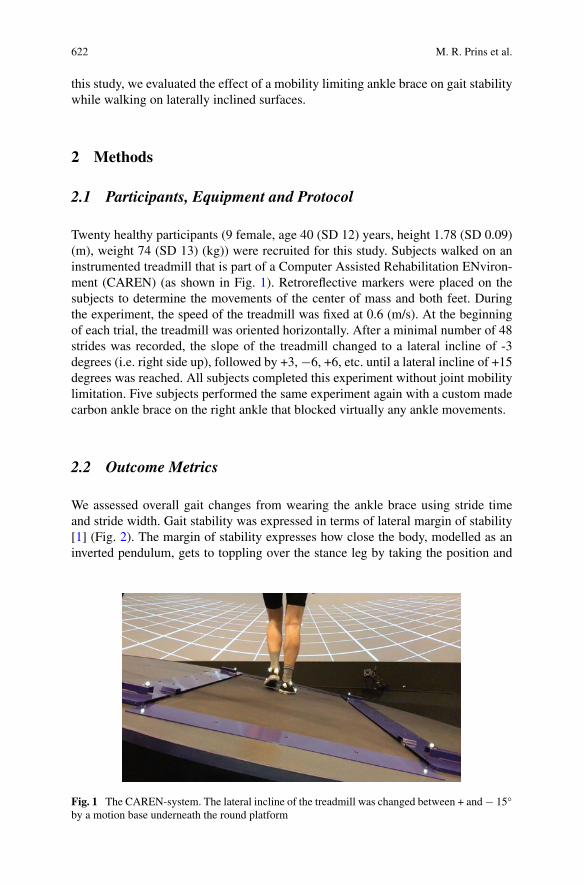
622 M. R. Prins et al.
this study, we evaluated the effect of a mobility limiting ankle brace on gait stabilitywhile walking on laterally inclined surfaces.
2 Methods
2.1 Participants, Equipment and Protocol
Twenty healthy participants (9 female, age 40 (SD 12) years, height 1.78 (SD 0.09)(m), weight 74 (SD 13) (kg)) were recruited for this study. Subjects walked on aninstrumented treadmill that is part of a Computer Assisted Rehabilitation ENviron-ment (CAREN) (as shown in Fig. 1). Retroreflective markers were placed on thesubjects to determine the movements of the center of mass and both feet. Duringthe experiment, the speed of the treadmill was fixed at 0.6 (m/s). At the beginningof each trial, the treadmill was oriented horizontally. After a minimal number of 48strides was recorded, the slope of the treadmill changed to a lateral incline of -3degrees (i.e. right side up), followed by +3, −6, +6, etc. until a lateral incline of +15degrees was reached. All subjects completed this experiment without joint mobilitylimitation. Five subjects performed the same experiment again with a custom madecarbon ankle brace on the right ankle that blocked virtually any ankle movements.
2.2 Outcome Metrics
We assessed overall gait changes from wearing the ankle brace using stride timeand stride width. Gait stability was expressed in terms of lateral margin of stability[1] (Fig. 2). The margin of stability expresses how close the body, modelled as aninverted pendulum, gets to toppling over the stance leg by taking the position and
Fig. 1 The CAREN-system. The lateral incline of the treadmill was changed between + and − 15by a motion base underneath the round platform
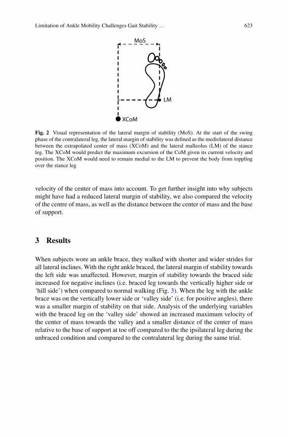
Limitation of Ankle Mobility Challenges Gait Stability … 623
XCoM
MoS
LM
Fig. 2 Visual representation of the lateral margin of stability (MoS). At the start of the swingphase of the contralateral leg, the lateral margin of stability was defined as the mediolateral distancebetween the extrapolated center of mass (XCoM) and the lateral malleolus (LM) of the stanceleg. The XCoM would predict the maximum excursion of the CoM given its current velocity andposition. The XCoM would need to remain medial to the LM to prevent the body from topplingover the stance leg
velocity of the center of mass into account. To get further insight into why subjectsmight have had a reduced lateral margin of stability, we also compared the velocityof the centre of mass, as well as the distance between the center of mass and the baseof support.
3 Results
When subjects wore an ankle brace, they walked with shorter and wider strides forall lateral inclines. With the right ankle braced, the lateral margin of stability towardsthe left side was unaffected. However, margin of stability towards the braced sideincreased for negative inclines (i.e. braced leg towards the vertically higher side or‘hill side’) when compared to normal walking (Fig. 3). When the leg with the anklebrace was on the vertically lower side or ‘valley side’ (i.e. for positive angles), therewas a smaller margin of stability on that side. Analysis of the underlying variableswith the braced leg on the ‘valley side’ showed an increased maximum velocity ofthe center of mass towards the valley and a smaller distance of the center of massrelative to the base of support at toe off compared to the the ipsilateral leg during theunbraced condition and compared to the contralateral leg during the same trial.
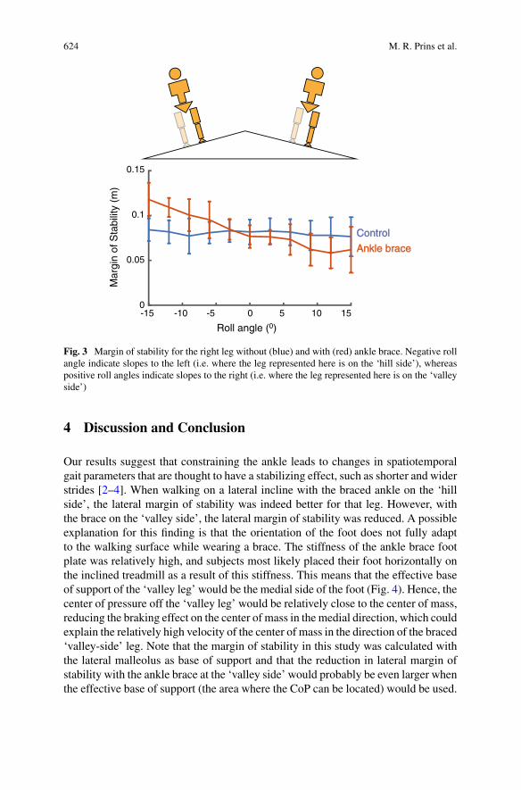
624 M. R. Prins et al.
-10 -5 10 15
Roll angle (0)
0
0.05
0.1
0.15
Mar
gin
of S
tabi
lity
(m)
50-15
Control
Ankle brace
Fig. 3 Margin of stability for the right leg without (blue) and with (red) ankle brace. Negative rollangle indicate slopes to the left (i.e. where the leg represented here is on the ‘hill side’), whereaspositive roll angles indicate slopes to the right (i.e. where the leg represented here is on the ‘valleyside’)
4 Discussion and Conclusion
Our results suggest that constraining the ankle leads to changes in spatiotemporalgait parameters that are thought to have a stabilizing effect, such as shorter and widerstrides [2–4]. When walking on a lateral incline with the braced ankle on the ‘hillside’, the lateral margin of stability was indeed better for that leg. However, withthe brace on the ‘valley side’, the lateral margin of stability was reduced. A possibleexplanation for this finding is that the orientation of the foot does not fully adaptto the walking surface while wearing a brace. The stiffness of the ankle brace footplate was relatively high, and subjects most likely placed their foot horizontally onthe inclined treadmill as a result of this stiffness. This means that the effective baseof support of the ‘valley leg’ would be the medial side of the foot (Fig. 4). Hence, thecenter of pressure off the ‘valley leg’ would be relatively close to the center of mass,reducing the braking effect on the center of mass in the medial direction, which couldexplain the relatively high velocity of the center of mass in the direction of the braced‘valley-side’ leg. Note that the margin of stability in this study was calculated withthe lateral malleolus as base of support and that the reduction in lateral margin ofstability with the ankle brace at the ‘valley side’ would probably be even larger whenthe effective base of support (the area where the CoP can be located) would be used.
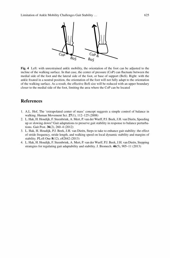
Limitation of Ankle Mobility Challenges Gait Stability … 625
CoPBoS
CoP & BoS
Fig. 4 Left: with unrestrained ankle mobility, the orientation of the foot can be adjusted to theincline of the walking surface. In that case, the center of pressure (CoP) can fluctuate between themedial side of the foot and the lateral side of the foot, or base of support (BoS). Right: with theankle fixated in a neutral position, the orientation of the foot will not fully adapt to the orientationof the walking surface. As a result, the effective BoS size will be reduced with an upper boundarycloser to the medial side of the foot, limiting the area where the CoP can be located
References
1. A.L. Hof, The ‘extrapolated center of mass’ concept suggests a simple control of balance inwalking. Human Movement Sci. 27(1), 112–125 (2008)
2. L. Hak, H. Houdijk, F. Steenbrink, A.Mert, P. van derWurff, P.J. Beek, J.H. van Dieën, Speedingup or slowing down? Gait adaptations to preserve gait stability in response to balance perturba-tions. Gait Post. 36(2), 260–4 (2012)
3. L. Hak, H. Houdijk, P.J. Beek, J.H. van Dieën, Steps to take to enhance gait stability: the effectof stride frequency, stride length, and walking speed on local dynamic stability and margins ofstability. PLoS One 8(12), e82842 (2013)
4. L. Hak, H. Houdijk, F. Steenbrink, A.Mert, P. van derWurff, P.J. Beek, J.H. van Dieën, Steppingstrategies for regulating gait adaptability and stability. J. Biomech. 46(5), 905–11 (2013)
AWorkaround for Recruitment Issuesin Preliminary WR Studies: AudioFeedback and Instrumented Crutchesto Train Test Subjects
Matteo Lancini, Simone Pasinetti, Marco Ghidelli, Pietro Padovani,David Pinto-Fernández, Antonio J. del-Ama, and Diego Torricelli
Abstract One of the main problems in studies involving exoskeletons for assistinggait of Spinal Cord Injury (SCI) users is recruitment of a suitable number of subjects,especially when age, gender, and pathologies are considered. Studies involving able-bodied subjects could instead rely on a considerable number of subjects, but thereliability of the results when transferred to real exoskeleton users is limited. Thislimitation could be partially solved using able-bodied subjects for preliminary tests.In this paper, we describe a first approach to train able-bodied subjects to behave asSCI subjects during walking. An audio feedback driven by a pair of instrumentedcrutches has been used to train healthy subjects during exoskeleton walking. To testthe system, 22 able-bodied subjects have been analyzed during a straight walk withand without the audio feedback. Results show that the audio feedback induces alearning effect and a persistency effect in the participants.
1 Introduction
Lower limb powered exoskeletons used for gait therapy, demonstrated functionalimprovements and potential to improve the daily life of people with SCI [1]. In the
M. Lancini (B) · S. Pasinetti · P. PadovaniDepartment of Mechanical and Industrial Engineering, University of Brescia, Brescia, Italye-mail: [email protected]
M. GhidelliDepartment of Information Engineering, University of Brescia, Brescia, Italy
D. Pinto-FernándezUniversidad Politécnica de Madrid, Madrid, Spain
Diego TorricelliSpanish Research Council (CSIC), Madrid, Spain
A. J. del-AmaNational Hospital for Paraplegics, Toledo, Spain
Rey Juan Carlos University, Madrid, Spain
© The Author(s), under exclusive license to Springer Nature Switzerland AG 2022J. C. Moreno et al. (eds.), Wearable Robotics: Challenges and Trends,Biosystems & Biorobotics 27, https://doi.org/10.1007/978-3-030-69547-7_101
627
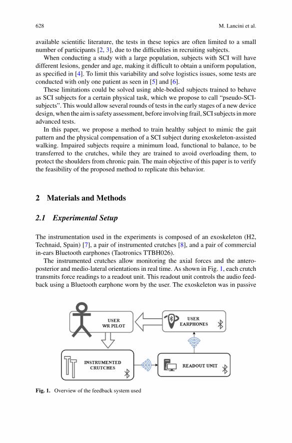
628 M. Lancini et al.
available scientific literature, the tests in these topics are often limited to a smallnumber of participants [2, 3], due to the difficulties in recruiting subjects.
When conducting a study with a large population, subjects with SCI will havedifferent lesions, gender and age, making it difficult to obtain a uniform population,as specified in [4]. To limit this variability and solve logistics issues, some tests areconducted with only one patient as seen in [5] and [6].
These limitations could be solved using able-bodied subjects trained to behaveas SCI subjects for a certain physical task, which we propose to call “pseudo-SCI-subjects”. This would allow several rounds of tests in the early stages of a new devicedesign,when the aim is safety assessment, before involving frail, SCI subjects inmoreadvanced tests.
In this paper, we propose a method to train healthy subject to mimic the gaitpattern and the physical compensation of a SCI subject during exoskeleton-assistedwalking. Impaired subjects require a minimum load, functional to balance, to betransferred to the crutches, while they are trained to avoid overloading them, toprotect the shoulders from chronic pain. The main objective of this paper is to verifythe feasibility of the proposed method to replicate this behavior.
2 Materials and Methods
2.1 Experimental Setup
The instrumentation used in the experiments is composed of an exoskeleton (H2,Technaid, Spain) [7], a pair of instrumented crutches [8], and a pair of commercialin-ears Bluetooth earphones (Taotronics TTBH026).
The instrumented crutches allow monitoring the axial forces and the antero-posterior and medio-lateral orientations in real time. As shown in Fig. 1, each crutchtransmits force readings to a readout unit. This readout unit controls the audio feed-back using a Bluetooth earphone worn by the user. The exoskeleton was in passive
Fig. 1. Overview of the feedback system used
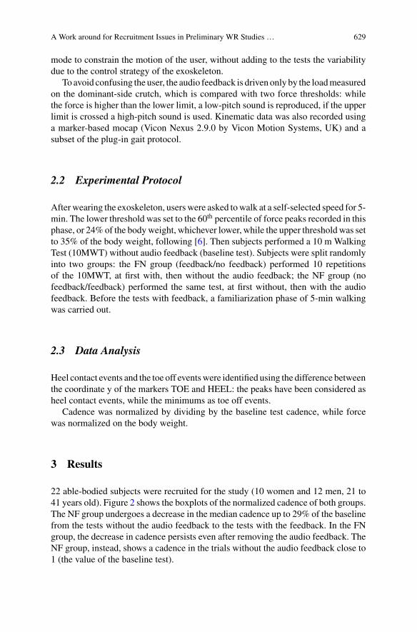
AWork around for Recruitment Issues in Preliminary WR Studies … 629
mode to constrain the motion of the user, without adding to the tests the variabilitydue to the control strategy of the exoskeleton.
To avoid confusing the user, the audio feedback is driven only by the loadmeasuredon the dominant-side crutch, which is compared with two force thresholds: whilethe force is higher than the lower limit, a low-pitch sound is reproduced, if the upperlimit is crossed a high-pitch sound is used. Kinematic data was also recorded usinga marker-based mocap (Vicon Nexus 2.9.0 by Vicon Motion Systems, UK) and asubset of the plug-in gait protocol.
2.2 Experimental Protocol
After wearing the exoskeleton, userswere asked towalk at a self-selected speed for 5-min. The lower threshold was set to the 60th percentile of force peaks recorded in thisphase, or 24%of the bodyweight, whichever lower, while the upper thresholdwas setto 35% of the body weight, following [6]. Then subjects performed a 10 m WalkingTest (10MWT) without audio feedback (baseline test). Subjects were split randomlyinto two groups: the FN group (feedback/no feedback) performed 10 repetitionsof the 10MWT, at first with, then without the audio feedback; the NF group (nofeedback/feedback) performed the same test, at first without, then with the audiofeedback. Before the tests with feedback, a familiarization phase of 5-min walkingwas carried out.
2.3 Data Analysis
Heel contact events and the toe off eventswere identified using the difference betweenthe coordinate y of the markers TOE and HEEL: the peaks have been considered asheel contact events, while the minimums as toe off events.
Cadence was normalized by dividing by the baseline test cadence, while forcewas normalized on the body weight.
3 Results
22 able-bodied subjects were recruited for the study (10 women and 12 men, 21 to41 years old). Figure 2 shows the boxplots of the normalized cadence of both groups.The NF group undergoes a decrease in the median cadence up to 29% of the baselinefrom the tests without the audio feedback to the tests with the feedback. In the FNgroup, the decrease in cadence persists even after removing the audio feedback. TheNF group, instead, shows a cadence in the trials without the audio feedback close to1 (the value of the baseline test).
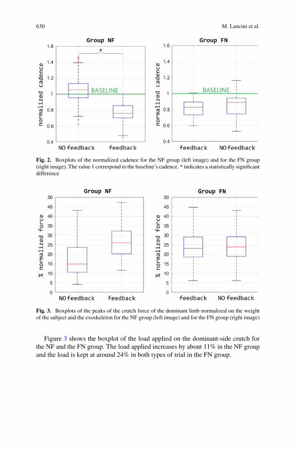
630 M. Lancini et al.
Fig. 2. Boxplots of the normalized cadence for the NF group (left image) and for the FN group(right image). The value 1 correspond to the baseline’s cadence. * indicates a statistically significantdifference
Fig. 3. Boxplots of the peaks of the crutch force of the dominant limb normalized on the weightof the subject and the exoskeleton for the NF group (left image) and for the FN group (right image)
Figure 3 shows the boxplot of the load applied on the dominant-side crutch forthe NF and the FN group. The load applied increases by about 11% in the NF groupand the load is kept at around 24% in both types of trial in the FN group.
AWork around for Recruitment Issues in Preliminary WR Studies … 631
4 Discussion
The audio feedback showed an influence on cadence. The analysis of the NF groupindicates that the audio feedback produces stronger variation in gait parameters thatsimple instructions given to the user, since tests with no feedback are closer to thebaseline of self-selected speed. The analysis of the FN group suggests that there is alearning effect that persists even after the feedback is removed, at least for the hourneeded to repeat the tests. This demonstrate the feasibility of training the subjects fortests with exoskeletons prototypes, by having them perform a short training sessionwith the instrumented crutches before the actual tests.
Similar conclusions are drawn by looking at the force: as for the cadence, the forceinduced by the feedback persists even without the audio feedback. This shows howthe change induced involves both dynamic and kinematic gait parameters. Furtherexperiments must be performed to analyze the effective performances of our method,focusing on (i) the recruitment of more able-bodied subjects and (ii) the comparisonbetween kinematics of pseudo-SCI and SCI subjects.
Acknowledgements The authors would thankMarcello Domenighini for the preliminary tests andTechnaid srl for the logistic support. This work was supported by COST Action CA16116, and byEuropean project EUROBENCH (grant 779963).
References
1. H. Fritz, D. Patzer, S.S. Galen, Robotic exoskeletons for reengaging in everyday activities:promises, pitfalls, and opportunities. Disab. Rehab. 41, 560–563 (2019)
2. D.R. Louie, J.J. Eng, T. Lam, Spinal Cord Injury Research Evidence (SCIRE) Research Team,Gait speed using powered robotic exoskeletons after spinal cord injury: a systematic review andcorrelational study. J. NeuroEng. Rehab. 12(82), (2015)
3. M. Arazpour, M. Samadian, K. Ebrahimzadeh, M. Ahmadi Bani, S.W. Hutchins, The influenceof orthosis options on walking parameters in spinal cord-injured patients a literature review.Spinal Cord 54, 412–422, (2016)
4. L.E. Miller, A.K. Zimmermann, W.G. Herbert, Clinical effectiveness and safety of poweredexoskeleton-assisted walking in patients with spinal cord injury: systematic review with meta-analysis. Med. Devices (Auckl) 9, 455–466 (2016)
5. J.L.A.Contreras-Vidal, N.Bhagat, J. Brantley, J.G.Cruz-Garza,Y.He,Q.Manley, S.Nakagome,K. Natham, S.H. Tan, F. Zhu, L. Pons, Powered exoskeletons for bipedal locomotion after spinalcord injury. J. Neural Eng. 13(031001), (2016)
6. M. Lancini, S. Pasinetti, V. Montini, G. Sansoni, Monitoring upper limbs during exoskeleton-assisted gait outdoors. Biosys. Biorob. 22, 127–131 (2019)
7. M. Bortole, A. Venkatakrishnan, F. Zhu, J.C. Moreno, G.E. Francisco, J.L. Pons, J.L. Contreas-Vidal, The H2 robotic exoskeleton for gait rehabilitation after stroke: early findings from aclinical study. J. NeuroEng. Rehabil. 12(54), (2015)
8. E. Sardini, M. Serpelloni, M. Lancini, S. Pasinetti, Wireless instrumented crutches for force andtilt monitoring in lower limb rehabilitation. Procedia Eng. 87, 348–351 (2014)
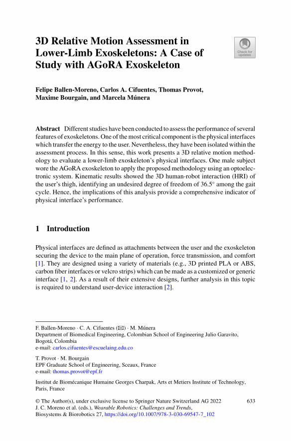
3D Relative Motion Assessment inLower-Limb Exoskeletons: A Case ofStudy with AGoRA Exoskeleton
Felipe Ballen-Moreno, Carlos A. Cifuentes, Thomas Provot,Maxime Bourgain, and Marcela Múnera
Abstract Different studies have been conducted to assess the performance of severalfeatures of exoskeletons. One of themost critical component is the physical interfaceswhich transfer the energy to the user. Nevertheless, they have been isolated within theassessment process. In this sense, this work presents a 3D relative motion method-ology to evaluate a lower-limb exoskeleton’s physical interfaces. One male subjectwore the AGoRA exoskeleton to apply the proposedmethodology using an optoelec-tronic system. Kinematic results showed the 3D human-robot interaction (HRI) ofthe user’s thigh, identifying an undesired degree of freedom of 36.5 among the gaitcycle. Hence, the implications of this analysis provide a comprehensive indicator ofphysical interface’s performance.
1 Introduction
Physical interfaces are defined as attachments between the user and the exoskeletonsecuring the device to the main plane of operation, force transmission, and comfort[1]. They are designed using a variety of materials (e.g., 3D printed PLA or ABS,carbon fiber interfaces or velcro strips) which can bemade as a customized or genericinterface [1, 2]. As a result of their extensive designs, further analysis in this topicis required to understand user-device interaction [2].
F. Ballen-Moreno · C. A. Cifuentes (B) · M. MúneraDepartment of Biomedical Engineering, Colombian School of Engineering Julio Garavito,Bogotá, Colombiae-mail: [email protected]
T. Provot · M. BourgainEPF Graduate School of Engineering, Sceaux, Francee-mail: [email protected]
Institut de Biomécanique Humaine Georges Charpak, Arts et Metiers Institute of Technology,Paris, France
© The Author(s), under exclusive license to Springer Nature Switzerland AG 2022J. C. Moreno et al. (eds.), Wearable Robotics: Challenges and Trends,Biosystems & Biorobotics 27, https://doi.org/10.1007/978-3-030-69547-7_102
633
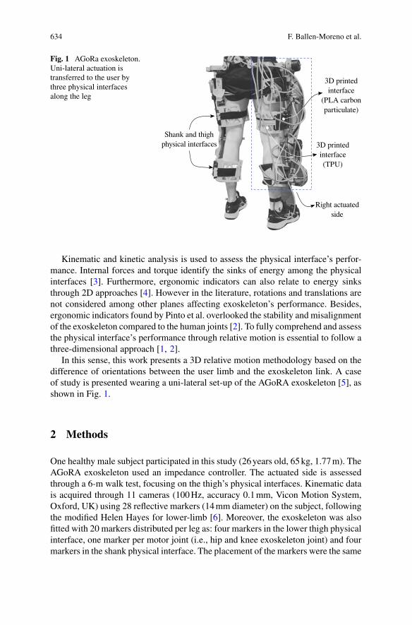
634 F. Ballen-Moreno et al.
Fig. 1 AGoRa exoskeleton.Uni-lateral actuation istransferred to the user bythree physical interfacesalong the leg
Kinematic and kinetic analysis is used to assess the physical interface’s perfor-mance. Internal forces and torque identify the sinks of energy among the physicalinterfaces [3]. Furthermore, ergonomic indicators can also relate to energy sinksthrough 2D approaches [4]. However in the literature, rotations and translations arenot considered among other planes affecting exoskeleton’s performance. Besides,ergonomic indicators found by Pinto et al. overlooked the stability and misalignmentof the exoskeleton compared to the human joints [2]. To fully comprehend and assessthe physical interface’s performance through relative motion is essential to follow athree-dimensional approach [1, 2].
In this sense, this work presents a 3D relative motion methodology based on thedifference of orientations between the user limb and the exoskeleton link. A caseof study is presented wearing a uni-lateral set-up of the AGoRA exoskeleton [5], asshown in Fig. 1.
2 Methods
One healthy male subject participated in this study (26years old, 65kg, 1.77m). TheAGoRA exoskeleton used an impedance controller. The actuated side is assessedthrough a 6-m walk test, focusing on the thigh’s physical interfaces. Kinematic datais acquired through 11 cameras (100Hz, accuracy 0.1mm, Vicon Motion System,Oxford, UK) using 28 reflective markers (14mm diameter) on the subject, followingthe modified Helen Hayes for lower-limb [6]. Moreover, the exoskeleton was alsofitted with 20 markers distributed per leg as: four markers in the lower thigh physicalinterface, one marker per motor joint (i.e., hip and knee exoskeleton joint) and fourmarkers in the shank physical interface. The placement of the markers were the same
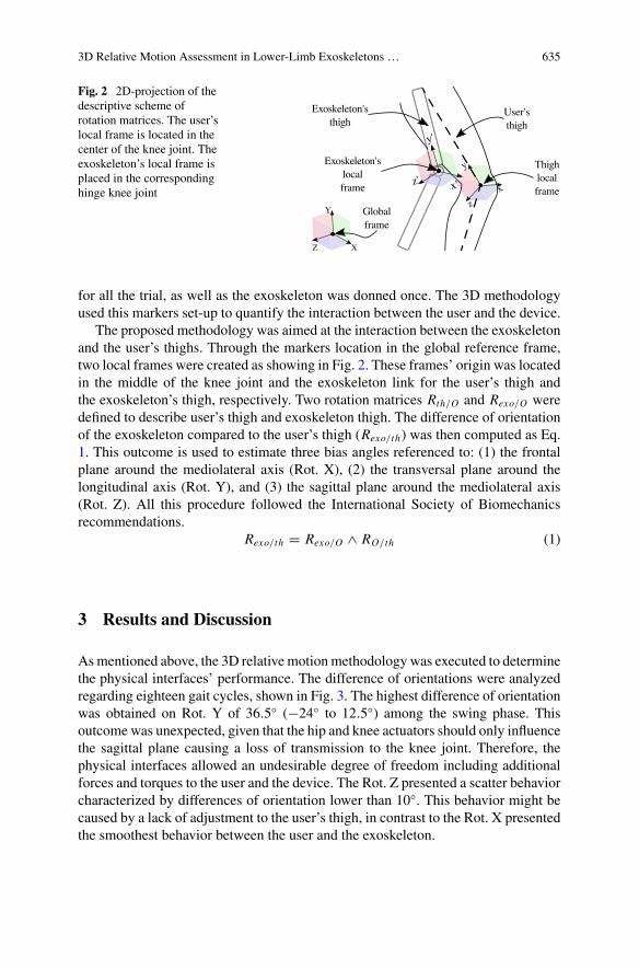
3D Relative Motion Assessment in Lower-Limb Exoskeletons … 635
Fig. 2 2D-projection of thedescriptive scheme ofrotation matrices. The user’slocal frame is located in thecenter of the knee joint. Theexoskeleton’s local frame isplaced in the correspondinghinge knee joint
for all the trial, as well as the exoskeleton was donned once. The 3D methodologyused this markers set-up to quantify the interaction between the user and the device.
The proposed methodology was aimed at the interaction between the exoskeletonand the user’s thighs. Through the markers location in the global reference frame,two local frames were created as showing in Fig. 2. These frames’ origin was locatedin the middle of the knee joint and the exoskeleton link for the user’s thigh andthe exoskeleton’s thigh, respectively. Two rotation matrices Rth/O and Rexo/O weredefined to describe user’s thigh and exoskeleton thigh. The difference of orientationof the exoskeleton compared to the user’s thigh (Rexo/th) was then computed as Eq.1. This outcome is used to estimate three bias angles referenced to: (1) the frontalplane around the mediolateral axis (Rot. X), (2) the transversal plane around thelongitudinal axis (Rot. Y), and (3) the sagittal plane around the mediolateral axis(Rot. Z). All this procedure followed the International Society of Biomechanicsrecommendations.
Rexo/th = Rexo/O ∧ RO/th (1)
3 Results and Discussion
Asmentioned above, the 3D relative motionmethodology was executed to determinethe physical interfaces’ performance. The difference of orientations were analyzedregarding eighteen gait cycles, shown in Fig. 3. The highest difference of orientationwas obtained on Rot. Y of 36.5 (−24 to 12.5) among the swing phase. Thisoutcome was unexpected, given that the hip and knee actuators should only influencethe sagittal plane causing a loss of transmission to the knee joint. Therefore, thephysical interfaces allowed an undesirable degree of freedom including additionalforces and torques to the user and the device. The Rot. Z presented a scatter behaviorcharacterized by differences of orientation lower than 10. This behavior might becaused by a lack of adjustment to the user’s thigh, in contrast to the Rot. X presentedthe smoothest behavior between the user and the exoskeleton.
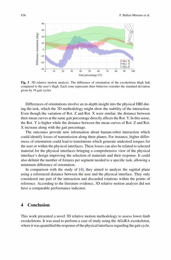
636 F. Ballen-Moreno et al.
0 10 20 30 40 50 60 70 80 90 100
Gait percentage [%]
-30
-20
-10
0
10
20
30
40
Dif
fere
nce
orie
ntat
ion
[deg
]
Rot. XRot. YRot. Z
Fig. 3 3D relative motion analysis. The difference of orientation of the exoskeleton thigh linkcompared to the user’s thigh. Each zone represents their behavior consider the standard deviationgiven by 18 gait cycles
Differences of orientations involve an in-depth insight into the physical HRI dur-ing the task, which the 3D methodology might show the stability of the interaction.Even though the variation of Rot. Z and Rot. X were similar; the distance betweentheir mean curves at the same gait percentage directly affects the Rot. Y. In this sense,the Rot. Y is higher while the distance between the mean curves of Rot. Z and Rot.X increase along with the gait percentage.
The outcomes provide new information about human-robot interaction whichcould identify losses of transmission along three planes. For instance, higher differ-ences of orientation could lead to translations which generate undesired torques forthe user or within the physical interfaces. These losses can also be related to selectedmaterial for the physical interfaces bringing a comprehensive view of the physicalinterface’s design improving the selection of materials and their response. It couldalso delimit the number of fixtures per segment needed to a specific task, allowing aminimum difference of orientation.
In comparison with the study of [4], they aimed to analyze the sagittal planeusing a referenced distance between the user and the physical interface. They onlyconsidered one part of the interaction and discarded rotations within the points ofreference. According to the literature evidence, 3D relative motion analysis did nothave a comparable performance indicator.
4 Conclusion
This work presented a novel 3D relative motion methodology to assess lower-limbexoskeletons. It was used to perform a case of study using the AGoRA exoskeleton,where itwas quantified the response of the physical interfaces regarding the gait cycle.
3D Relative Motion Assessment in Lower-Limb Exoskeletons … 637
Besides, this methodology gave significant insights. Future works will be focusedon increase the number of subjects enrolled in the study to analyze the impact ofsubjects’ anthropometric variation within the methodology.
Acknowledgements This work was financially supported by the Minciencias grant (801-2017)and (845-2020), and internal fundings from the Colombian School of Engineering Julio Garavito,EPF Graduate School of Engineering, and Institut de Biomécanique Humaine Georges Charpak.
References
1. M.D.C. Sanchez-Villamañan, J. Gonzalez-Vargas, D. Torricelli, et al., Compliant lower limbexoskeletons: a comprehensive review on mechanical design principles. J. NeuroEng. Rehabil.(2019)
2. D. Pinto-Fernandez, D. Torricelli, M.D.C. Sanchez-Villamanan, et al., Performance evaluationof lower limb exoskeletons: a systematic review. IEEE Trans. Neural Syst. Rehabil. Eng. (2020)
3. J. Li, S. Zuo, C. Xu et al., Influence of a compatible design on physical human-robot interactionforce: a case study of a self-adapting lower-limb exoskeleton mechanism. J. Intell. Robot. Syst.Theory Appl. 98, 525–538 (2020)
4. K. Langlois, M. Moltedo, T. Bacek, et al., Design and development of customized physicalinterfaces to reduce relative motion between the user and a powered ankle foot exoskeleton, in2018 7th IEEE International Conference on Biomedical Robotics and Biomechatronics (Biorob)(IEEE, 2018), pp. 1083–1088
5. M. Sanchez-Manchola, D. Gomez-Vargas, D. Casas-Bocanegra, Development of a roboticlower-limb exoskeleton for gait rehabilitation: AGoRA exoskeleton, in IEEE ANDESCON(IEEE,2018), pp. 1–6
6. M.P. Kadaba, H.K. Ramakrishnan, M.E. Wootten, Measurement of lower extremity kinematicsduring level walking. J. Orthop. Res. 383–392 (1990)
Robotic Rehabilitation in Cerebral Palsy:A Case Report
Beatriz Moral, Óscar Rodríguez, Elena García, Eduardo Rocón,and Sergio Lerma
Abstract Cerebral palsy includes several posture and movement disorders whichproduce limitations in functional activities such as gait. In recent years roboticshave been used as a complement of the treatment of neurological pathologies. Theexoskeleton Ekso bionics enables professionals to perform treatments to improve gaitin patients with cerebral palsy. After 24 sessions many spatiotemporal and kinematicparameters were improved in one patient with cerebral palsy.
1 Introduction
Cerebral palsy (CP) includes a number of posture and movement disorders whichappear after an injury in an immature cerebellum during the fatal development orduring the first year of life. It causes limitations in many daily life activities includinggait [1]. Gait impairment is one of the most important difficulties that a child withCP can face. Thus, improving gait is one of the most important treatments withinrehabilitation, as it contributes the patient’s independence and an improvement in
B. Moral (B) · Ó. Rodríguez · E. GarcíaInstituto de Rehabilitación, Funcional La Salle, Madrid, Spaine-mail: [email protected]
Ó. Rodrígueze-mail: [email protected]
E. Garcíae-mail: [email protected]
Ó. RodríguezUniversidad CEU San Pablo, Madrid, Spain
E. RocónConsejo Superior de Investigaciones Científicas, CSIC, Madrid, Spaine-mail: [email protected]
S. LermaCentro Superior de Estudios Universitarios La Salle, Madrid, Spaine-mail: [email protected]
© The Author(s), under exclusive license to Springer Nature Switzerland AG 2022J. C. Moreno et al. (eds.), Wearable Robotics: Challenges and Trends,Biosystems & Biorobotics 27, https://doi.org/10.1007/978-3-030-69547-7_103
639
640 B. Moral et al.
his quality of life [2]. The use of robotics as a complement in gait rehabilitation inadults and children with neurological pathologies has been implemented recently,showing good results in patients with spinal cord injury or brain damage such asstrokes [3, 4].
2 Material and Methods
2.1 Subject
The subject of the present study is an 18 years old male diagnosed with spasticdiplegia and a Gross Motor Functional Classification System III (GMFCS III).
2.2 Treatment
The gait rehabilitation was supported with Ekso GT, with the Software SmartAs-sist™, a robotic exoskeleton made by EksoBionics. The treatment consisted of two60 min sessions each week. A total number of 24 sessions were conducted, using10–15 min of each of them to calibrate the device and record all data. The sessionstook place in Instituto de Rehabilitación Funcional La Salle (Madrid). In addition,the patient was doing one 60 min session of in-group therapeutic exercise designedby physiotherapists.
In the 16th session the centre where the sessions were carried out was closedfor 3 months due to the sanitary crisis caused by COVID-19. During that time, thepatient hardly did any exercise at home. When the restrictions ended the sessionswere resumed, but without the in-group sessions, as the centre where they werecarried out was still closed.
During the treatment, the exo-skeleton aids for the oscillation phase weredecreased gradually session by session. Once the patient reached the minimal aidvalues, ankle weights were added (1 kg for 14th and 15th sessions and 2 kg for 21st,22nd, 23rd and 24th sessions).
2.3 Assessment Method
The assessments were carried out pre and post treatment. A 3D gait analysis wasrecorded at 200 Hz using a motion capture system Smart-DX (BTS Bioengineering,Italy). In order to obtain gait kinetics, a set of reflective markers were placed overthe skin on discrete anatomical sites according to the Helen Hayes Model. Also thevalues from the Ekso device were recorded each session.
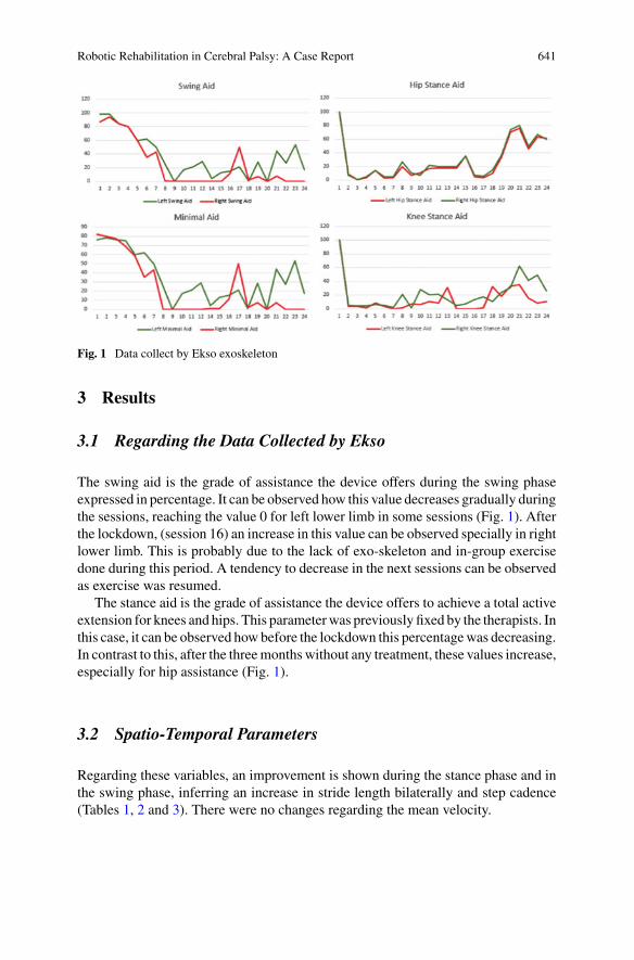
Robotic Rehabilitation in Cerebral Palsy: A Case Report 641
Fig. 1 Data collect by Ekso exoskeleton
3 Results
3.1 Regarding the Data Collected by Ekso
The swing aid is the grade of assistance the device offers during the swing phaseexpressed in percentage. It can be observed how this value decreases gradually duringthe sessions, reaching the value 0 for left lower limb in some sessions (Fig. 1). Afterthe lockdown, (session 16) an increase in this value can be observed specially in rightlower limb. This is probably due to the lack of exo-skeleton and in-group exercisedone during this period. A tendency to decrease in the next sessions can be observedas exercise was resumed.
The stance aid is the grade of assistance the device offers to achieve a total activeextension for knees and hips. This parameterwas previously fixed by the therapists. Inthis case, it can be observed howbefore the lockdown this percentagewas decreasing.In contrast to this, after the threemonthswithout any treatment, these values increase,especially for hip assistance (Fig. 1).
3.2 Spatio-Temporal Parameters
Regarding these variables, an improvement is shown during the stance phase and inthe swing phase, inferring an increase in stride length bilaterally and step cadence(Tables 1, 2 and 3). There were no changes regarding the mean velocity.
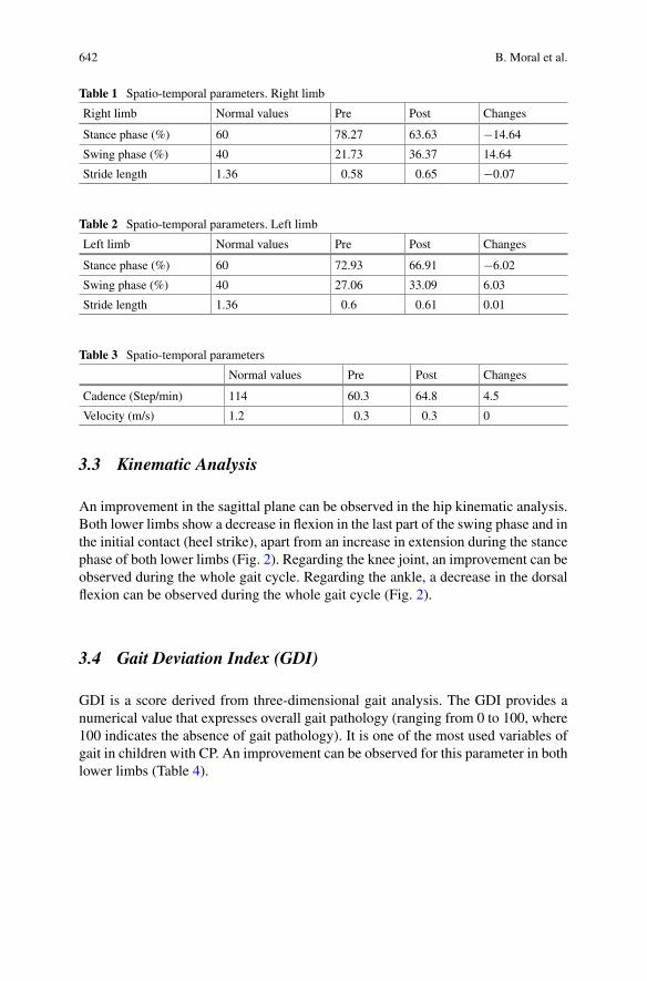
642 B. Moral et al.
Table 1 Spatio-temporal parameters. Right limb
Right limb Normal values Pre Post Changes
Stance phase (%) 60 78.27 63.63 −14.64
Swing phase (%) 40 21.73 36.37 14.64
Stride length 1.36 0.58 0.65 −0.07
Table 2 Spatio-temporal parameters. Left limb
Left limb Normal values Pre Post Changes
Stance phase (%) 60 72.93 66.91 −6.02
Swing phase (%) 40 27.06 33.09 6.03
Stride length 1.36 0.6 0.61 0.01
Table 3 Spatio-temporal parameters
Normal values Pre Post Changes
Cadence (Step/min) 114 60.3 64.8 4.5
Velocity (m/s) 1.2 0.3 0.3 0
3.3 Kinematic Analysis
An improvement in the sagittal plane can be observed in the hip kinematic analysis.Both lower limbs show a decrease in flexion in the last part of the swing phase and inthe initial contact (heel strike), apart from an increase in extension during the stancephase of both lower limbs (Fig. 2). Regarding the knee joint, an improvement can beobserved during the whole gait cycle. Regarding the ankle, a decrease in the dorsalflexion can be observed during the whole gait cycle (Fig. 2).
3.4 Gait Deviation Index (GDI)
GDI is a score derived from three-dimensional gait analysis. The GDI provides anumerical value that expresses overall gait pathology (ranging from 0 to 100, where100 indicates the absence of gait pathology). It is one of the most used variables ofgait in children with CP. An improvement can be observed for this parameter in bothlower limbs (Table 4).
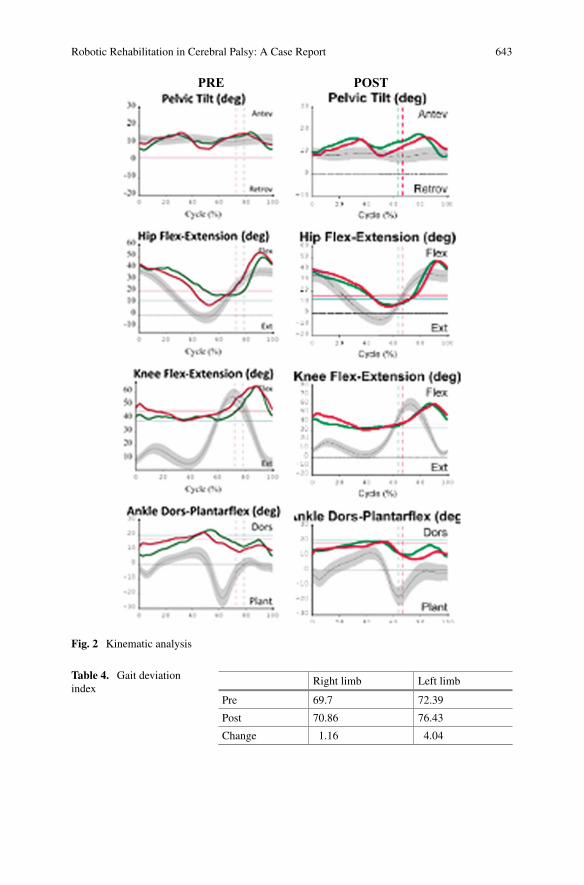
Robotic Rehabilitation in Cerebral Palsy: A Case Report 643
PRE POST
Fig. 2 Kinematic analysis
Table 4. Gait deviationindex
Right limb Left limb
Pre 69.7 72.39
Post 70.86 76.43
Change 1.16 4.04
644 B. Moral et al.
3.5 Patient’s Feedback
The patient and family satisfaction are other values to take into account. Both familyand patient were very thankful during the whole procedure as they perceived animprovement in his gait and had a feeling of having made a medium/high physicaleffort during each session.
4 Discussion
A larger sample size is needed so that the results in this investigation are comparableto other studies using this exoskeleton but with different pathologies such as spinalcord injury or brain damage. It would also be useful to study how changing thenumber of sessions affects the results and the influence of psychosocial parameterson gait-related parameters [3–5].
5 Conclusion
The use of the Ekso exoskeleton in patients with cerebral palsymight be promising asa complement to gait rehabilitation. In this case, an improvement in gait kinematics,spatiotemporal parameters and GDI, have been shown. Future investigations shouldinclude a larger sample size to extrapolate the results more reliably.
References
1. M. Bax,M. Goldstein, P. Rosenbaum, A. Leviton, N. Paneth, B. Dan, B. Jacobsson, D. Damiano,Proposed definition and classification of cerebral palsy, April 2005. Dev. Med. Child. Neurol.47(8), 571–576 (2005)
2. N.G. Moreau, A.W. Bodkin, K. Bjornson, A. Hobbs, M. Soileau, K. Lahasky, Effectiveness ofrehabilitation interventions to improve gait speed in children with cerebral palsy: systematicreview and metaanalysis. Phys. Ther. 96(12), 1938–1954 (2016)
3. Physiotherapists’ Experiences Using the Ekso Bionic Exoskeleton with Patients in a Neurolog-ical Rehabilitation Hospital: A Qualitative Study.
4. E. Read, C. Woolsey, C.A. McGibbon, C. O’Connell, Rehabil Res Pract. 2020, 2939573 (2020).C. Fisahn et al., Gait training after spinal cord injury: safety, feasibility and gait functionfollowing 8 weeks of training with the exoskeletons from Ekso bionics. Global Spine J. 6(8),822–841 (2016)
5. S.-H. Chang, T. Afzal, J. Berliner, G.E. Francisco, Exoskeleton-assisted gait training to improvegait in individuals with spinal cord injury: a pilot randomized study. Pilot Feasibility Stud. 4, 62(2018)
Test Method for Exoskeleton Locomotionon Irregular Terrains: Testbed Designand Construction
A. Torres-Pardo, D. Pinto-Fernández, E. Belalcázar-Bolaños, J. L. Pons,J. C. Moreno, and D. Torricelli
Abstract This work aims to define a benchmarking scenario for the evaluation ofthe performance of lower limb exoskeletons while walking on irregular terrains. Wedesigned a modular testbed that can be easily configured to replicate a wide rangeof uneven terrains. The testbed, based on several design criteria such as modularity,reproducibility, robustness and low-cost, aims to be a concrete solution to researchersand developers to test their systems according to a standardized method. The longterm goal is to provide means to demonstrate the ability of new exoskeletal systemsto operate safely and reliably in realistic out-of-the-lab conditions.
1 Introduction
Robotics is undergoing an unprecedented era due to the increased abilities of roboticsystems towork in close interactionwith humans. This is especially the case forwear-able robots, which are generating high expectations in several applications domains.Nevertheless, wearable robots are yet to demonstrate their ability to operate safely
A. Torres-Pardo · D. Pinto-Fernández · J. C. Moreno · D. Torricelli (B)Neural Rehabilitation Group of the Spanish National Research Council, Madrid, Spaine-mail: [email protected]
D. Pinto-FernándezUniversidad Politécnica de Madrid, Madrid, Spain
E. Belalcázar-BolañosTechnaid S.L, Madrid, Spain
J. L. PonsLegs and Walking Lab, Shirley Ryan AbilityLab (Formerly Rehabilitation Institute of Chicago),Chicago, IL, USA
Department of Physical Medicine and Rehabilitation, Feinberg School of Medicine, NorthwesternUniversity, Chicago, IL, USA
Department of Biomedical Engineering, McCormick School of Engineering and Applied Science,Northwestern University, Chicago, IL, USA
© The Author(s), under exclusive license to Springer Nature Switzerland AG 2022J. C. Moreno et al. (eds.), Wearable Robotics: Challenges and Trends,Biosystems & Biorobotics 27, https://doi.org/10.1007/978-3-030-69547-7_104
645
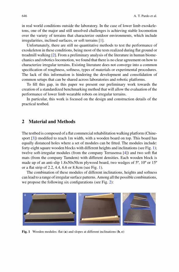
646 A. T. Pardo et al.
in real world conditions outside the laboratory. In the case of lower limb exoskele-tons, one of the major and still unsolved challenges is achieving stable locomotionover the variety of terrains that characterize outdoor environments, which includeirregularities, inclined surfaces, or soft terrains [1].
Unfortunately, there are still no quantitative methods to test the performance ofexoskeleton in these conditions, being most of the tests realized during flat ground ortreadmill walking [2]. From a preliminary analysis of the literature in human biome-chanics and robotics locomotion, we found that there is no clear agreement on how tocharacterize irregular terrains. Existing literature does not converge into a commonspecification of roughness, softness, types of materials or experimental procedures.The lack of this information is hindering the development and consolidation ofcommon setups that can be shared across laboratories and robotic platforms.
To fill this gap, in this paper we present our preliminary work towards thecreation of a standardized benchmarking method that will allow the evaluation of theperformance of lower limb wearable robots on irregular terrains.
In particular, this work is focused on the design and construction details of thepractical testbed.
2 Material and Methods
The testbed is composed of a flat commercial rehabilitationwalking platform (Chine-sport [3]) modified to reach 1m width, with a wooden board on top. This board hasequally distanced holes where a set of modules can be fitted. The modules include:forty-eight square wooden blocks with different heights and inclinations (see Fig. 1);twelve soft-irregular modules (from the company Terrasensa [4]) and two soft flatmats (from the company Tamdem) with different densities. Each wooden block ismade up of an anti-slip 1.8x50x50cm plywood board, two wedges of 5º, 10º or 15ºor a flat strip of 2.2, 4.4, 6.6 or 8.8cm (see Fig. 1).
The combination of these modules of different inclinations, heights and softnesscan lead to a range of irregular surface patterns. Among all the possible combinations,we propose the following six configurations (see Fig. 2):
Fig. 1 Wooden modules: flat (a) and slopes at different inclinations (b, c)
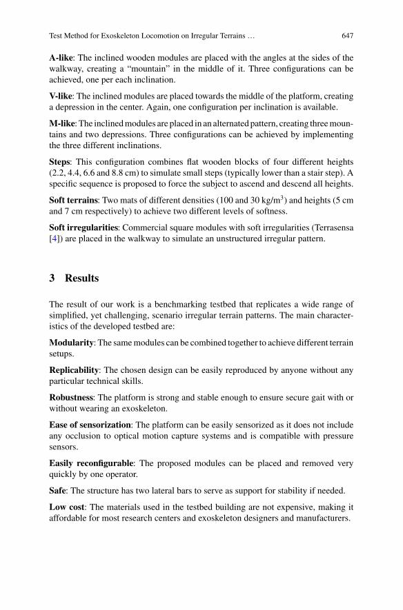
Test Method for Exoskeleton Locomotion on Irregular Terrains … 647
A-like: The inclined wooden modules are placed with the angles at the sides of thewalkway, creating a “mountain” in the middle of it. Three configurations can beachieved, one per each inclination.
V-like: The inclined modules are placed towards the middle of the platform, creatinga depression in the center. Again, one configuration per inclination is available.
M-like: The inclinedmodules are placed in an alternatedpattern, creating threemoun-tains and two depressions. Three configurations can be achieved by implementingthe three different inclinations.
Steps: This configuration combines flat wooden blocks of four different heights(2.2, 4.4, 6.6 and 8.8 cm) to simulate small steps (typically lower than a stair step). Aspecific sequence is proposed to force the subject to ascend and descend all heights.
Soft terrains: Two mats of different densities (100 and 30 kg/m3) and heights (5 cmand 7 cm respectively) to achieve two different levels of softness.
Soft irregularities: Commercial square modules with soft irregularities (Terrasensa[4]) are placed in the walkway to simulate an unstructured irregular pattern.
3 Results
The result of our work is a benchmarking testbed that replicates a wide range ofsimplified, yet challenging, scenario irregular terrain patterns. The main character-istics of the developed testbed are:
Modularity: The samemodules can be combined together to achieve different terrainsetups.
Replicability: The chosen design can be easily reproduced by anyone without anyparticular technical skills.
Robustness: The platform is strong and stable enough to ensure secure gait with orwithout wearing an exoskeleton.
Ease of sensorization: The platform can be easily sensorized as it does not includeany occlusion to optical motion capture systems and is compatible with pressuresensors.
Easily reconfigurable: The proposed modules can be placed and removed veryquickly by one operator.
Safe: The structure has two lateral bars to serve as support for stability if needed.
Low cost: The materials used in the testbed building are not expensive, making itaffordable for most research centers and exoskeleton designers and manufacturers.
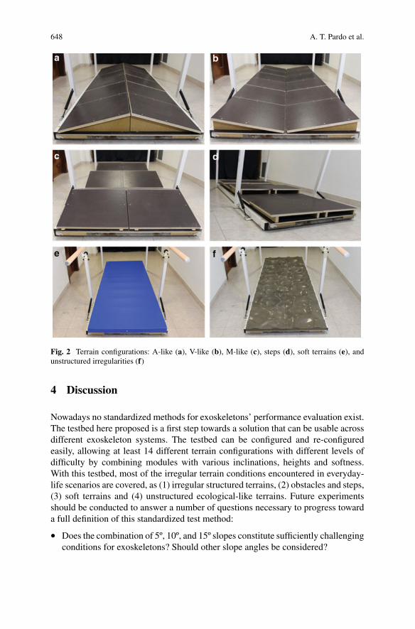
648 A. T. Pardo et al.
Fig. 2 Terrain configurations: A-like (a), V-like (b), M-like (c), steps (d), soft terrains (e), andunstructured irregularities (f)
4 Discussion
Nowadays no standardized methods for exoskeletons’ performance evaluation exist.The testbed here proposed is a first step towards a solution that can be usable acrossdifferent exoskeleton systems. The testbed can be configured and re-configuredeasily, allowing at least 14 different terrain configurations with different levels ofdifficulty by combining modules with various inclinations, heights and softness.With this testbed, most of the irregular terrain conditions encountered in everyday-life scenarios are covered, as (1) irregular structured terrains, (2) obstacles and steps,(3) soft terrains and (4) unstructured ecological-like terrains. Future experimentsshould be conducted to answer a number of questions necessary to progress towarda full definition of this standardized test method:
• Does the combination of 5º, 10º, and 15º slopes constitute sufficiently challengingconditions for exoskeletons? Should other slope angles be considered?
Test Method for Exoskeleton Locomotion on Irregular Terrains … 649
• What metrics and performance indicators can/should be calculated over theseterrains to properly quantify walking performance?
• Will the values of softness be sufficient to span the range of soft terrains that canbe found out of the lab?
• How many runs over these terrains should be performed to obtain statisticallyrelevant results?
• What sensors are needed to extract the relevant information across a wide varietyof exoskeleton solutions?
5 Conclusion
The testbed here presented aims to be the first step towards a unified bench-marking tool for the evaluation of performance of robotic systems on irregular terrainconditions.
This testbed, together with a set of clear performance indicators, is expected tofacilitate the decision-making process during the process of technical developmentas well as during the purchasing of exoskeleton products by end-users. The testbed,designed to be easily replicated by different laboratories, is one of the first concreteefforts in reproducing real-life unstructured conditions in a standardized way in thefield ofwearable robots.We expect that the availability of such standard platformwillpromote the evaluation of exoskeletons in realistic scenarios as a common practice,facilitating the introduction of new solutions beyond clinical rehabilitation, e.g. inthe workplace or in outdoor environments.
Acknowledgements This work has been supported by the H2020 Project EUROBENCH (grantnumber 779963, https://eurobench2020.eu/).
References
1. A. Abouhossein, U. Martinez-Hernandez, M.I. Awad, I. Mahmood, D. Yilmaz, A.A. Dehghani-Sanij, Assistive gait wearable robots—from the laboratory to the real environment. In:Reinventing Mechatronics, (Springer International Publishing, 2020), pp. 75–92
2. D. Pinto-Fernandez et al., Performance evaluation of lower limb exoskeletons: a systematicreview. IEEE Trans. Neural Syst. Rehabil. Eng. 1 (2020)
3. Chinesports Webpage. PARALELA PLUS 3M. Available: https://www.chinesport.es/catalogo-general/paralelas-y-escaleras-para-rehabilitacion/paralelas-para-rehabilitaci--n-l--nea-plus/01326-paralela-plus-3m. Accessed: 01-Sep-2019.
4. Terrasensa Webpage. Terrasensa® New ways in therapy and training with the terrasensa®system English brochure. Available: https://www.blackroll.no/wp-content/uploads/2013/08/Terrasensa-brosjyre.pdf. Accessed: 01-Sep-2019

Small–Medium Enterprisesin the Wearable Robotics Field: Tools
and Opportunities to Create a SuccessfulCompany
Private/Public Funding Strategiesfor Interactive Robotics Companies
Arantxa Rentería-Bilbao
Abstract The aim of is paper is to provide a structured view of funding possibilitiesfor companies in the field of interactive robotics. The paper presents a set of fundingsources which are of interests for start-ups, spin-off and young companies workingin the design and development of interactive robots, including wearable devices.This paper is divided into three chapters, covering private funding (types of existingfunding sources, their specific target companies and requirements, and the reasonson how and why investors invest), public funding (mainly coming from Europeangrants under several programs) and the conclusions.
1 Introduction
The world of start-ups dealing with interactive robotics (IR) is full of researcherswith good ideas, willing to go ahead with the new company. But they lack funds totransform their inspiration and push into a successful business.
Others, on the contrary, have the money and are looking for that spark ofentrepreneurial creativity, which aims to connect the needs of our society witheffective technological solutions. Most entrepreneurs agree on the idea that thecollaboration between private and public support is of key importance [1].
One of the main outcomes of the survey carried out in INBOTS project [2] showsthe importance of the access to funding, financial resources, potential investors andbusiness networks. There are economic barriers, including the accurate identificationof the real needs of the target market, access to funding, and various legal servicessuch as those related to intellectual property.
A. Rentería-Bilbao (B)Medical Robotics Group of Tecnalia, Basque Research Alliance, Derio, Spaine-mail: [email protected]
© The Author(s), under exclusive license to Springer Nature Switzerland AG 2022J. C. Moreno et al. (eds.), Wearable Robotics: Challenges and Trends,Biosystems & Biorobotics 27, https://doi.org/10.1007/978-3-030-69547-7_105
653
654 A. Rentería-Bilbao
2 Private Fund Raising
2.1 How to Identify the Opportunity
In order to attract potential investors to fund the innovative newcompanies developingIR, the entrepreneurs need to know how to identify the opportunity for their newbusiness related to integrating/using IRs. The open questions include:
• Customer-Problem-Solution• Does the opportunity match the founders experience, skills and interests?• Can they recruit and lead the team needed to exploit the opportunity?• Do the resource needs of the opportunity shorten the odds-on success?• Is the timing of the opportunity, right?• Do they need to comply with legal requirements?• Does the opportunity constitute a scalable (and saleable) business?
2.2 Why Investors Invest
It is also important to know why investors invest, they must believe in the proposedbusiness/idea:
• Trustworthiness of the entrepreneur• Expertise of the entrepreneur• Enthusiasm of the entrepreneur• Track record of the entrepreneur• Perceived rewards for the investors• Sales potential of the market.
Some things the entrepreneur should know about potential investors include:
• What kinds of investments have they made in the past?• What kinds of deals are they looking for currently?• How do they make investment decisions? What kinds of deals do they like?
The entrepreneur must be ready to answer to potential questions the investors ask:
• Can the new company accomplish the tasks described in the business plan?• How does the new company and IR product fit into the industry?• What are the trends in the IR market?• What are the drivers to success in the IR industry?
Private/Public Funding Strategies for Interactive Robotics … 655
2.3 Some Private Funding Sources
While startups in the United States have sought funding from private entities, newcompanies in the European Union have relied on credits from banks in order to fundtheir growth.More recently, mainly from the 2008 crisis, the companies seek fundingfrom business angels and venture capitalists.
One example is Tecnalia Ventures [3], which develops business opportunities forthe valorization and commercialization of technology by connecting the main pillarsof an entrepreneurial ecosystem: minds, management and money. When the resultsof a research project reach a certain Technology Readiness Level (TRL), they lookfor:
• people with an entrepreneurial profile / business vision capable of transferring thedeveloped technology to the market, thus generating real business opportunities.These are profiles to which the value proposition of transforming a technologicalspin-off into a growing Small andMedium Enterprise (SME) is attractive to them.
• smart investors that not only provide the necessary financial muscle to transformtechnologies into revenues butwho are also committed to support the developmentof the company.
Angel investing is equity finance. An angel investor is a high net worth individualwho makes use of their personal disposable finance and makes their own decisionabout making the investment. The investor would normally take shares (an equitystake) in your business in return for providing equity finance (funds). The angelsnormally seek to not only provide the business with money to grow, but also bringtheir experience and knowledge to help the company achieve success. They can investalone, or as part of a syndicate (a group of angels) [4].
Venture capital differs from angel investing because it invests in businessesthrough managed funds, coming from private or public money. The venture capi-talist manager invests the money on behalf of the fund which has to be profitableand make a return for the fund’s investors. Due to high costs of administration andthe need to be very selective to ensure a return on the fund, VC funds are more riskaverse and thus make fewer small investments in start and seed stage.
There are also tax reductions at national level in EU for startups. Different require-ments (company´s age and nature, number of workers, etc.) and funding schemes(income tax reduction, grants for investors, etc.), apply in each country.
3 Public Fund Raising in H2020 and Horizon Europe
Funding opportunities under Horizon 2020 are set out in multiannual workprogrammes which cover the large majority of support available. The workprogrammes are prepared by the European Commission within the frameworkprovided by the Horizon 2020 legislation and through a strategic programming
656 A. Rentería-Bilbao
process, integrating EU policy objectives in the priority setting. Robotics can befound on many of the current H2020 programmes and calls.
3.1 Robotics in LEIT-ICT Program
The topics addressed in this Work Programme part cover the ICT technology in acomprehensive way, from technologies for Digitising European Industry, HPC, BigData and Cloud, 5G and Next Generation Internet. This Work Programme supportscore ICT industries through roadmap-based Public Private Partnerships (PPs).
3.2 Robotics in NMBP and FET Programs
This program covers different areas: Nanotechnologies, Advanced materials,Advanced manufacturing and processing and Biotechnology. Activities of the workprogramme will address the whole innovation chain with technology readinesslevels spanning the crucial range from medium levels to high levels preceding massproduction and helping to bridge the gaps (“valley of death”) in this range.
Future and Emerging Technologies (FET) Open, which represents 40% of theoverall FET budget in Horizon 2020, is entirely non-prescriptive with regards tothe nature or purpose of the technologies that are envisaged. FET Open covers alltechnological areas and no budget is specifically earmarked for ICT or Robotics.
3.3 Robotics in EIC PILOT and Societal ChallengesPrograms
SME participation is encouraged throughout the work programme and in partic-ular in the priorities ‘Industrial Leadership’ and ‘Societal Challenges’. DedicatedSME support is channeled through the SME Instrument, introduced in the WorkProgramme 2014–2015, which promotes SMEs’ innovation activities from conceptto market. In 2016–17, all topics using the SME instrument were grouped in a contin-uously open common call. For 2018–20, this consolidation is pursued and the supportto SMEs through this dedicated instrument takes the form of a single topic with afully bottom-up approach (still with continuously open call with four deadlines peryear).
Robotic research is expected to continue under the new Horizon Europe fundingprogram of the European Commission, with a general proposed budget of 100 Be.Specific area of intervention of artificial intelligence and robotics, and clusters related
Private/Public Funding Strategies for Interactive Robotics … 657
to health, digital industry, space, etc., could be the umbrella to new research projectson interactive robotics.
4 Conclusion
The investment risks depend on the TRL of the product: high risk for early stage(TRL 1–3), low risk for market ready (TRL 7–9). Usually the financing followsthese three main stages:
1. Financing early stage technologies to make ready for license or sale (pre-seedor seed funding).
2. Financing a start-up.3. Financing a company for growth and exit by investors.
Main outcomes of the HUM and WRs fields are that these two fields are veryattractive both in terms of companies founded in the last 5 years and in terms ofpotential market. Indeed, one of the main aspects that emerges by the interviewscarried out with founders of companies is that the market seems to be enough matureto accept humanoid robots or wearable products. However, some negative issues stillremain: the lack of clear normative framework and the selection of the right businessmodel to guarantee self-sustainability as well as some residual psychological barriersin accepting new technologies.
Acknowlegements This work has received the financial support of INBOTS project, which hasreceived funding from the European Union’s Horizon 2020 research and innovation programmeunder grant agreement No 780073.
References
1. C.Benito,B-Venture busca en su cuarta edición ser un punto de inflexión para los emprendedores.El Correo J. (2019)
2. INBOTS, Inclusive Robots for a Better Society, https://inbots.eu3. https://www.tecnaliaventures.com/?lang=en. Last accessed 6 February 20204. The UK Angel Market Survey, https://www.ukbaa.org.uk/. Last accessed 7 February 2020
RobotUnion Project: AcceleratingStartups in Robotics
Leire Martínez and Arantxa Rentería-Bilbao
Abstract RobotUnion discovers, supports and funds 20 European scaleupsconfirmed by venture capital investors and global corporates of four market domainsfor robotics: manufacturing, agriculture, healthcare and civil infrastructure. 40companies developing selected out of a pan-European deal flow of 300 scaleupsthrough 2 Open Calls. The top 20 have joined an acceleration programme that helpsthem progress from TRL4 to TRL7 onwards. The programme provides them withtechnical and non-technical support services: researchers in residence, entrepreneursin residence, vouchers to access to facilities and technical services, public and privatefunding.
1 Introduction
Themain goal ofRobotUnion [1] is to stimulate small andmedium enterprises (SME)in the robotics sector and to develop novel and challenging technology and systemsapplicable to markets. RobotUnion is supporting Scaleups: companies presentinghigh growth potential in developing and providing robotics. As Scaleups companies,we consider both emerging start-ups presenting disruptive technologies and businessmodels, but also more established companies with existing activities that plan totransform their industries and markets through robotics solutions.
The consortium was designed to contribute to the overcoming of the systemicchallenges (# innovation barriers) that are constraining the capability of Europeanpromising companies to develop novel and innovative technology that has the poten-tial to open new markets for Robotics in domains like Manufacturing, Agri-Food,Healthcare and Civil infrastructure.
L. Martínez · A. Rentería-Bilbao (B)Medical Robotics Group of Tecnalia, Basque Research Alliance, Derio, Spaine-mail: [email protected]
L. Martíneze-mail: [email protected]
© The Author(s), under exclusive license to Springer Nature Switzerland AG 2022J. C. Moreno et al. (eds.), Wearable Robotics: Challenges and Trends,Biosystems & Biorobotics 27, https://doi.org/10.1007/978-3-030-69547-7_106
659
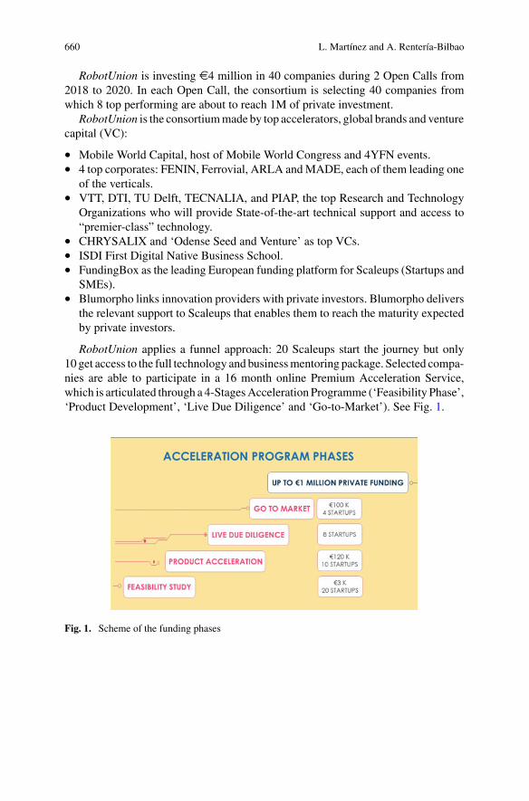
660 L. Martínez and A. Rentería-Bilbao
RobotUnion is investing e4 million in 40 companies during 2 Open Calls from2018 to 2020. In each Open Call, the consortium is selecting 40 companies fromwhich 8 top performing are about to reach 1M of private investment.
RobotUnion is the consortiummade by top accelerators, global brands and venturecapital (VC):
• Mobile World Capital, host of Mobile World Congress and 4YFN events.• 4 top corporates: FENIN, Ferrovial, ARLA andMADE, each of them leading one
of the verticals.• VTT, DTI, TU Delft, TECNALIA, and PIAP, the top Research and Technology
Organizations who will provide State-of-the-art technical support and access to“premier-class” technology.
• CHRYSALIX and ‘Odense Seed and Venture’ as top VCs.• ISDI First Digital Native Business School.• FundingBox as the leading European funding platform for Scaleups (Startups and
SMEs).• Blumorpho links innovation providers with private investors. Blumorpho delivers
the relevant support to Scaleups that enables them to reach the maturity expectedby private investors.
RobotUnion applies a funnel approach: 20 Scaleups start the journey but only10 get access to the full technology and businessmentoring package. Selected compa-nies are able to participate in a 16 month online Premium Acceleration Service,which is articulated through a 4-StagesAcceleration Programme (‘Feasibility Phase’,‘Product Development’, ‘Live Due Diligence’ and ‘Go-to-Market’). See Fig. 1.
Fig. 1. Scheme of the funding phases
RobotUnion Project: Accelerating Startups in Robotics 661
2 Value Proposition for Startups
RobotUnion offers an attractive full package of services for Startups at growth stage,composed by:
• Financial support up to e1,2M (e223K EU Funding equity free and e1M by topVC’s in Robotics field such as CHRYSALIX and Odense Seed and Venture).
• State-of-the-art technical support and access to “premier-class” technologyprovided by VTT, DTI, DELFT, TECNALIA and PIAP.
• World class Training and high-level Mentoring by the pool of 1st level mentorsfrom Google, Airbnb, Ikea, Yahoo, Prisa, Microsoft, among others, provided byISDI.
• Presence in top EU Scaleups events such as 4YFN@Mobile World Congress,Slush, Web Summit
• International PR exposure powered by Mobile World Congress.• Fundraising services provided by Blumorpho (private funding) and FundingBox
(public funding). Contactwith topVC’s and equity-based crowdfunding platformsat EU level
• A Direct access to world top industry leaders such as MADE representing worldManufacturing leaders like Danfoss, Grundfos, Vestas and LEGO and amongothers plus ARLA in Agri Food; FENIN in Healthcare and FERROVIAL in CivilInfrastructure.
3 Developed Work
The work performed in the project was clustered around 6 main work packages.
3.1 WP1 Community Building and Marketplace
RobotUnion awareness strategy includes a campaign that strongly communicatesthe project’s activities and results, with a view of optimizing their value and impact.The project has been present at 33 international Startups and robotic related eventsand has organized 31 info sessions to disseminate the Open Calls. As support tothe Dissemination Strategy a RobotUnion Community (1.085 users) and a RobotU-nion Marketplace was created. At a first stage it was tested within the RobotUnionConsortium and selected companies from the 1st Batch who were the only ones tohave access to the group. The goal is that Marketplace could become a supportivetool for the selected startups who can use it to search for suppliers which could beused for the Technical Vouchers. Since July 2019 the Marketplace become publicand special marketing campaign focused on attracting more users has been created.
662 L. Martínez and A. Rentería-Bilbao
3.2 WP2 Open Call Management and Beneficiaries Selection
RobotUnion launched twoOpenCalls (in 2018 and2019) to select the 40beneficiarieswho entered Stage 1 of the program. The goal of the Open Calls was to receive asatisfactory number of applications and to ensure the quality of the beneficiariesselected to the program. As a result, in both Open Calls 1.138 applications werestarted and 424 of them were submitted and eligible for the program.
3.3 WP3 Research and Product Development
After aWelcome Camp Event for Stage 1, a first batch of companies had two monthsto create the final version of Feasibility Plans with the support of Technical andBusinessMentors. The 10most promising startups were selected to enter the Stage 2,Research & Product Development.With the assistance of assigned technical mentorsthe Individual Technical Mentoring Plans (ITMPs) were created, detailing technicaldevelopment schedule and targets for each quarter of the 12 months stage as well asrequested support from the Acceleration Program.
3.4 WP4 Live Due Diligence (Business Ignition)
The live due diligence consisted of an intensive mentoring and training programprovided by key digital business ecosystem experts and entrepreneurs where teamswere provided with the tools necessary to consolidate and thrive in their respectivemarkets.
3.5 WP5 Pre-seed Round and Corporate Brokerage
The first strategy for the Startups investment mentoring was already issued. Intro-ductions to the potential investors interested in RobotUnion Startups are executedcontinuously if the opportunity occurs.
3.6 WP6 Go-To-Market and Sustainability Plan
As a way to ensure the sustainability of the RobotUnion Acceleration Program andother products after the end of the project, the plan for exploitation and disseminationwas developed in June 2018 and was updated in June 2019. The plan focuses on the
RobotUnion Project: Accelerating Startups in Robotics 663
value propositions and business model canvases for all products created through theprogram.
Furthermore, RobotUnion has established a sustainability work group with part-ners whose task is to elaborate the elements of the future RobotUnion Business Planand Toolkit.
4 Conclusion
The companies supported in the first call were TENDO (artificial tendon to grip,hold and release objects), ACCREA (Remote Medical Diagnostician), CYBER-SURGERY (robot for spine surgery) and LEGEXO (most lightweight exoskeleton).In the 2nd call, the supported companies were AXILES BIONICS (bionic feet),AETHER MEDICAL (multi action bionic limb), CYBERSURGERY (returningstartup) and LIFESCIENCE ROBOTICS (robot for efficient rehabilitation and earlymobilization of patients).
RobotUnion has been conceived to be a sustainable pan-EuropeanRoboticsAccel-erator beyond the project, by providing a sustainable path for Scaleups (Path based onPrivate Funding support and Corporates agreements exposure to scale hand-in-handwith the corporations). RobotUnion has also a continuity strategy for the ‘Acceler-ation Program’ through the creation of a ‘pan-European Continuity Fund’, for theaccelerator set up in the course of the project, and the standardisation of ’Robo-tUnion Accelerator’, as an innovation instrument for European Regions, to fosterthe entrepreneurial discovery in the framework of their Research and InnovationStrategies for Smart Specialisation (RIS3) [2].
References
1. RobotUnion Project Website, https://robotunion.eu/. Accessed 20 July 20202. European Commission, Smart Specialisation Platform: A Guide to RIS3. https://s3platform.jrc.
ec.europa.eu/s3-guide. Accessed 20 July 2020
Starting Up a Surgical RoboticsCompany: The Case of Kirubotics
Arantxa Renteria-Bilbao, Fernando Mateo, and Leire Martínez
Abstract This paper presents the steps followed by the Spanish start-up companyKirubotics, whose aim is to develop and market an innovative concept of surgicalrobot. It covers the phases of design, development of a functional protype, testsin laboratory, market research, analysis of regulatory requirements and contacts andagreements with future potential providers of components. In parallel, different typesof funding sources have been achieved, while others are still being looked for. Theprocess is still open. Preliminary results show that, as important as an innovativeidea and a good technical team, it is to have enough economic backup at the rightmoment of the overall process.
1 Introduction
The Spanish operation robot BROCA (Brazo Robotico para Operaciones, (roboticarm for operations) Córdoba Andalucia), developed by Tecnalia together with theUniversity Hospital Reina Sofía in Córdoba, not only features amodular constructionbut also offers intuitive operation and a universal scope of application. In compar-ison with other solutions in the market, the system is first and foremost affordable.The goal of its developers is to facilitate access for hospitals on a global scale torobotic surgery with the aid of BROCA—a purpose that, in view of frequently citedbudget cuts accompanied by a shortage of personnel in the health care and nursingsector, could not be more relevant. In order to accomplish further development andcommercialization phases, a start-up company, Kirubotics, was established in 2017.
A. Renteria-Bilbao (B) · L. MartínezMedical Robotics Group of Tecnalia, Basque Research Alliance, Derio, Spaine-mail: [email protected]
F. MateoKirubotics, Córdoba, Spain
© The Author(s), under exclusive license to Springer Nature Switzerland AG 2022J. C. Moreno et al. (eds.), Wearable Robotics: Challenges and Trends,Biosystems & Biorobotics 27, https://doi.org/10.1007/978-3-030-69547-7_107
665
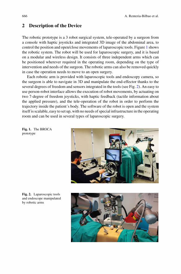
666 A. Renteria-Bilbao et al.
2 Description of the Device
The robotic prototype is a 3 robot surgical system, tele-operated by a surgeon froma console with haptic joysticks and integrated 3D image of the abdominal area, tocontrol the position and open/close movements of laparoscopic tools. Figure 1 showsthe robotic system. The robot will be used for laparoscopic surgery, and it is basedon a modular and wireless design. It consists of three independent arms which canbe positioned wherever required in the operating room, depending on the type ofintervention and needs of the surgeon. The robotic arms can also be removed quicklyin case the operation needs to move to an open surgery.
Each robotic arm is provided with laparoscopic tools and endoscopy camera, sothe surgeon is able to navigate in 3D and manipulate the end-effector thanks to theseveral degrees of freedom and sensors integrated in the tools (see Fig. 2). An easy touse person-robot interface allows the execution of robot movements, by actuating ontwo 7-degree of freedom joysticks, with haptic feedback (tactile information aboutthe applied pressure), and the tele-operation of the robot in order to perform thetrajectory inside the patient´s body. The software of the robot is open and the systemitself is scalable, easy to set up,with no needs of special infrastructure in the operatingroom and can be used in several types of laparoscopic surgery.
Fig. 1. The BROCAprototype
Fig. 2. Laparoscopic toolsand endoscope manipulatedby robotic arms
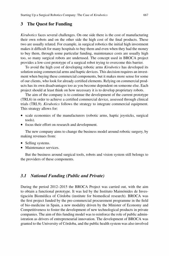
Starting Up a Surgical Robotics Company: The Case of Kirubotics 667
3 The Quest for Funding
Kirubotics faces several challenges. On one side there is the cost of manufacturingtheir own robots and on the other side the high cost of the final products. Thesetwo are usually related. For example, in surgical robotics the initial high investmentmakes it difficult for many hospitals to buy them and even when they had the moneyto buy them, through some particular funding, maintenance costs are usually hightoo, so many surgical robots are underused. The concept used in BROCA projectprovides a low-cost prototype of a surgical robot trying to overcome this barrier.
To avoid the high cost of developing robotic arms Kirubotics has developed itssolution using commercial arms and haptic devices. This decision requires an invest-ment when buying these commercial components, but it makes more sense for someof our clients, who look for already certified elements. Relying on commercial prod-ucts has its own disadvantages too as you become dependent on someone else. Eachproject should at least think on how necessary it is to develop proprietary robots.
The aim of the company is to continue the development of the current prototype(TRL6) in order to achieve a certified commercial device, assessed through clinicaltrials (TRL9). Kirubotics follows the strategy to integrate commercial equipment.This strategy allows for:
• scale economies of the manufacturers (robotic arms, haptic joysticks, surgicaltools).
• focus their effort on research and development.
The new company aims to change the business model around robotic surgery, bymaking revenues from:
• Selling systems.• Maintenance services.
But the business around surgical tools, robots and vision system still belongs tothe providers of these components.
3.1 National Funding (Public and Private)
During the period 2012–2015 the BROCA Project was carried out, with the aimto obtain a functional prototype. It was led by the Instituto Maimónides de Inves-tigación Biomédica of Córdoba (institute for biomedical research). BROCA wasthe first project funded by the pre-commercial procurement programme in the fieldof bio-medicine in Spain, a new modality driven by the Minister of Economy andCompetitiveness to foster the development of new technological products in privatecompanies. The aim of this funding model was to reinforce the role of public admin-istration as drivers of entrepreneurial innovation. The development of BROCA wasgranted to the University of Córdoba, and the public health system was also involved
668 A. Renteria-Bilbao et al.
with the partnership of surgeons from Hospital Reina Sofía, as consultants for thetechnical team. For the technical development, University of Córdoba subcontractedTecnalia and University of Málaga.
Related to private funding, Kirubotics offers to private investors the possibilityto share stocks of the company for the development phase and market launch. Thecompany is currentlyworking in updating its business plan,market positioning, targetcustomers, selling strategies and analysis of the competency. A first round of privatefunding is under process, but the final confirmation depends on the availability ofcomplementing national public grant.
3.2 Public European Funding
Additionally,Kirubotics have been involved in several proposal inH2020 programmerelated to surgical robotics in ICT related calls.
4 Market Analysis
The first claiming for patents and business plan is alreadymade. The expected sellingprice is around 0.7 Me. Spanish public hospitals will be the main customers of thesystem, due to their impossibility to access to the expensive Da Vinci system. At firstglance, the main differences between the BROCA robot and Da Vinci robot (apartfrom the price), are the different surgical procedures they are aimed to, the level oftool accessibility (better DaVinci’s), and the haptic feedback and quick set-up (betterBROCA’s) [1]. Each country has its own health system, different from each otherand with different levels of coverage, which makes it more complex to put a healthrobot in the market successfully.
Some market forecasts, referred to European Union [2]:
• 35 million of surgery procedures per year.• 31.25 million of non-laparoscopic procedures.• 3.75 million of laparoscopic procedures.• 3.65 million of non-robotized procedures.• million of robotized laparoscopic procedures.
5 Conclusion
There are some critical points along the development of the entrepreneurial project.Among them, the delay or lack of availability of commercial components, faultycomponents, delay in the achievement of planned milestones which may pose a riskon the reliability of the project (and put some doubts on investors’ side), problems

Starting Up a Surgical Robotics Company: The Case of Kirubotics 669
with technical developments or clinical trials, and difficulties during the certificationprocess.
References
1. A. Brodie, N. Vasdev, The future of robotic surgery. Robot.: Ann. R. Coll. Surg. Engl. 100, 4–13(2018)
2. A. Kumar,Medical Robotics and Computer Assisted Surgery (The global market, BCCResearchLLC, 2017).
Redesigning Tax Incentives for Inclusiveand Green Robotics in the EuropeanUnion Reconstruction
María Amparo Grau Ruiz
Abstract With a view to help with the urgent socio-economic recovery after theCOVID-19 pandemic, the goal of this paper is to show a possible path to promote,through tax incentives for Responsible Research and Innovation, sound uses of robotsin this context. Its scope is in line with the current priorities in the European Union,which are in turn alignedwith theUnitedNations 2030Agenda on global SustainableDevelopment. Some proposals are made to address the needs of social returns in theform of inclusive and green robotics, based upon the results of a jurisprudentialcritical review (focused in the Spanish experience as a tool for comparative Lawanalysis), bearing in mind relevant previous judgments of the European Union Courtof Justice in the field and a recent tool presented by the OECD.
1 Introduction
Over the past two decades, many countries have increased the availability, simplicityof use and generosity of R&D (research and development) tax incentives. In 2018,30 out of 36 OECD countries give preferential tax treatment for business R&Dexpenditures, up from 19 OECD countries in 2000. The EUMember States offeringR&D tax relief increased from 12 in 2000 to 21 in 2018. Over the 2006–16 period,tax support for business R&D expenditure as a percentage of GDP increased in26 out of 44 countries for which data are available [1, 2]. With few exceptions, ageneralised shift towards this indirect type of support versus direct funding (throughgrants or public procurement) has been facilitated by the existence of internationalrules on trade and competition. Direct measures of support can be better targetedtowards activities, firms and areas where higher additionality and spillovers could
Inbots project “Inclusive Robotics for a Better Society”, European Union’s Horizon 2020 researchand innovation programme, Grant agreement No. 780073.
M. A. Grau Ruiz (B)Universidad Complutense de Madrid, Madrid, Spaine-mail: [email protected]
Northwestern University, Chicago, IL, USA
© The Author(s), under exclusive license to Springer Nature Switzerland AG 2022J. C. Moreno et al. (eds.), Wearable Robotics: Challenges and Trends,Biosystems & Biorobotics 27, https://doi.org/10.1007/978-3-030-69547-7_108
671
672 M. A. Grau Ruiz
be generated. However, this entails higher costs of administration and also highercompliance costs for firms [1].
2 Materials and Methods
R&D tax incentives are complex objects of study. They may be subject to a combi-nation of methods of evaluation from different perspectives. Here the legal methodis used to highlight some critical aspects debated at various instances.
2.1 Results
2.2 The Court of Justice of the European Union
In the Judgment of 10 March 2005, Case C-39/04, Laboratoires Fournier SA vDirection des vérifications nationales et internationals ECLI:EU:C:2005:161, theCourt declares that the Article 49 EC precludes legislation of a Member State whichrestricts the benefit of a tax credit for research only to research carried out in thatMember State. The Court relies on the previous Case C-254/97, Société Baxter,Judgment of 8 July 1999. Paragraph 23 reads “Such legislation is directly contrary tothe objective of the Community policy on research and technological developmentwhich, according to Article 163(1) EC is, inter alia, ‘strengthening the scientificand technological bases of Community industry and encouraging it to become morecompetitive at international level’. Paragraph 25 adds “national legislation whichabsolutely prevents the taxpayer from submitting evidence that expenditure relatingto research carried out in otherMember States has actually been incurred and satisfiesthe prescribed requirements cannot be justified in the name of effectiveness of fiscalsupervision”.
In its Judgment of 13March 2008, Case C-248/06, Commission of the EuropeanCommunities v Kingdom of Spain, ECLI:EU:C:2008:161, the Court declares that,by maintaining in force rules for the deduction of costs relating to research anddevelopment and technological innovation which are less favorable in respect ofcosts incurred abroad than costs incurred in Spain (ex Article 35 of the Law oncorporation tax, as amended by Royal Legislative Decree 4/2004 of 5 March 2004),Spain has failed to fulfil its obligations under Articles 43 EC and 49 EC on freedomof establishment and the freedom to provide services.
Redesigning Tax Incentives for Inclusive and Green Robotics … 673
2.3 The Spanish Courts
Judgment 225/2015 of 28 April 2015, Madrid High Court of Justice, no. 152/2014.According to the Judgment of the Supreme Court of 20 May 2013, No.6383/2011,R&D activity is an indeterminate legal concept that requires the assistance of tech-nical/expert opinions/reports from experts in the field when determining its meaningand scope. The Advocate General points out that the technical reports of the certi-fication bodies are mandatory but not binding, that the Ministry must ensure thegeneral interest and correct use of public funds and that the technical reports of theAdministration enjoy the presumption of impartiality and objectivity. However, theCourt finds that the publication in the European Patent Register has an effect on theclassification of the project for the purposes of the nature of the deductions for thecorporation tax in respect of the financial year in which it has been carried out. Thecompetent body at European level has assessed that the patented product or processmeets the requirements of constituting a novelty that is not in the state of the art andmay have industrial use. Based on the Judgment of the SupremeCourt of 12 January2014, No. 843/2011, it concludes that, although there are as many technical reportsfrom the Administration as from the appellant, the criterion of the inversion of theburden of proof can be applied to the Administration which, despite knowing theproject was considered as an invention at a European level decided that it did notdeserve the qualification of Research and Development. The appeal is upheld.
Judgment of 3 May 2013, National Audience, No. 161/2010 on a project for apalletizer with robot for pet drink bottles. It is noteworthy that the tax auditor clarifiedthe question of the deduction without the technical assistance of experts. However,the expert reports provided by the appellant are limited to stating that the Centre forthe Development of Industrial Technology approved its participation in the project,with insufficient accreditation of compliance with the requirements for applying thededuction. Nor can the report of the Patent and Trademark Office on the existenceof any patent on the project support the claim because the technical characteristicsof the project are missing from the proposal of the evidence. The non-exhaustiveretrospective search in the database of Spanish Patents and Utility Models showsthat numerous patent and utility model documents have been found. The action isdismissed.
3 Discussion
From the Governments’ perspective, the European Commission adopted rules tofacilitate the granting of aid measures by Member States in support of R&D+i(research, development and innovation). The specific state aid Framework sets outthe conditions and the General Block Exemption Regulation clarifies the scope ofmeasures that do not need to be notified to the Commission for prior approval [3].After the COVID-19 crisis, the Commission Regulation (EU) 2020/972 of 2 July
674 M. A. Grau Ruiz
2020 has amended Regulation (EU) No 1407/2013 as regards its prolongation andRegulation (EU) No 651/2014 as regards its prolongation and relevant adjustments.
Many Goverments are currently reviewing the tax incentives. In Spain, the“Autoridad Independiente de Responsabilidad Fiscal” [4] has recently suggested toframe any change of the fiscal benefits in the strategic planning of public policies towhich they are related, assessing their ex ante effects and their ex post achievements.The National Institute of Statistics and the Tax Agency, following strict confiden-tiality criteria, have merged the Corporate Income Tax returns with the Survey onBusiness Innovation to evaluate the R&D+i tax benefit. Unfortunately, the evaluationwas interrupted by the state of alarm and the expected publication was postponed.From the firms’ perspective, binding rulings in Spain are issued by the Departmentwith competencies in Science and Technology to provide certainty for taxpayers withregard to the qualification of activities that entitle fiscal incentives to innovation, aswell to clarify the exclusive secondment of researchers to them. The interactionbetween different types of rulings (including advance agreements) and proceduralaspects could be improved to avoid costs and delays [5]. In general, the R&D effortsin response to policy changes may vary depending whether these are perceived to bepermanent or transitory by the firms. Ultimately, the public support may be adjustedin accordance to their behavior.
4 Conclusion
Fiscal policy has a key role in matter of trust and in the road to the SustainableDevelopment Goals. Policy makers should redefine the existing R&I incentives orintroduce new ones to make them more efficient in terms of the social and envi-ronmental impact of robotics in the EU territory, respecting fundamental freedomsand the State aid rules. They should be drafted in a controllable way, by adjustingrequirements (not only considering the input or output, but also the process) andprocedures with other administrative Departments. Whether R&D+i tax incentivesare good value for money should be assessed on a country-by-country basis. Thefinding of a partial crowding out effect does not necessarily mean that R&D taxrelief measures are inefficient–their net benefit can still be positive if the combinedprivate and social returns to R&D are sufficiently high [1].
Acknowledgements The author (INBOTS WP2 leader) acknowledges the invitation received byDr. Conti (INBOTSWP1 leader) to show our cooperation. Prof. Grau leads the AudIT-S project on"Legal and financial significance of sustainability audit schemes through smart data management"(PID2019-105959RB-I00I).
Redesigning Tax Incentives for Inclusive and Green Robotics … 675
References
1. S. Appelt, F. Galindo-Rueda, A. González Cabral, Measuring R&D tax support: findings fromthe new OECD R&D tax incentives database. In: OECD Science, Technology and IndustryWorking Papers, No. 2019/06, (OECD Publishing, Paris 2019). https://doi.org/10.1787/d16e6072-en. At 18, 20, 47
2. CPB Netherlands Bureau for Economic Policy Analysis, A Study on R&D tax incentives annex:country fiches FINAL REPORT TAXUD/2013/DE/315 FWC No. TAXUD/2010/CC/104, (TheHague, 2014). https://ec.europa.eu/taxation_customs/sites/taxation/files/resources/documents/taxation/gen_info/economic_analysis/tax_papers/country_fiches.pdf
3. https://ec.europa.eu/commission/presscorner/detail/en/MEMO_14_368, https://ec.europa.eu/competition/state_aid/modernisation/index_en.html#rdi, https://ec.europa.eu/competition/state_aid/legislation/block.html#gber
4. Presentación segunda fase Spending review: la Airef resalta el coste de oportunidad que suponenlos beneficios fiscales y la importancia de garantizar su eficacia, Madrid, 22/07/2020. https://www.airef.es/wp-content/uploads/2020/07/BFISCALES/Nota-de-Prensa.pdf
5. M. Fabra Valls, Binding rulings as an instrument for the interpretation and application of fiscalincentives for innovation. RCyT. CEF, No. 412 (July 2017), pp. 47–82