volume i of ii (divisions 00 – 14) - va vendor portal
TRANSCRIPT
TECHNICAL
SPECIFICATION COVER
Page 1
TECHNICAL SPECIFICATIONS FOR
AE RENOVATE PARKING GARAGE
VAMC WEST ROXBURY
523-400
Project Location: DVA MEDICAL CENTER – Boston Healthcare System (VISN 1)
West Roxbury Campus 1400 VFW Parkway
WEST ROXBURY, MASSACHUSETTS 02132
Volume I of II (Divisions 00 – 14)
Submission Type: 100% Bid Documents
Submission Date: Monday, June 15th, 2015
VA Project Engineers:
Denis McLaughlin Tel: (857)-364-5419
VA Contracting Officer:
Stephen Flynn Tel: (774)-826-2617
- - - E N D - - -
Page 1 of 534
VA Medical Center Parking Garage West Roxbury, Massachusetts VA Project No. 523-400
March 11, 2016 100% Construction Document Submission
PROJECT BID STATEMENT SUMMARY PARKING GARAGE WEST ROXBURYT – PROJECT 523-400
Page 1
PROJECT BID STATEMENT SUMMARY
Item 1 – Base Bid Offer: Provide all labor, materials, equipment, transportation, supervision, general demolition, general construction, alterations, roads, walks, grading, drainage, mechanical and electrical work, utility systems, elevators necessary removal of existing structures and construction and certain other items for the Parking Garage at the VA Boston Healthcare System in accordance with the terms, conditions, specifications, drawings for Project 523-400 and applicable wage rates as incorporated. It is intended that contract award will be made on the Base Offer. The Contractor shall as part of the Base Offer include a minimum of 100 off-site parking spaces, starting with the start of onsite work and concluding with the release of newly built parking spaces to the VA, refer to Specification section 01 55 19. Included in the Base Offer are items that are identified with bid quantities and unit prices for quantity modification; containment, excavation, removal and legal disposal of 500 cubic yards of hydrocarbon contaminated soil together with placing compacted graded gravel backfill in place of the hydrocarbon contaminated soil. Additionally, due to the current work in progress, Deduct Alternate 1 eliminate scope of work to relocate Electrical Duct Bank is now to be included as part of the Base Bid as the Electrical Duct Bank has been relocated by another construction project with expected completion in 2017.
1) Parking Garage @ West Roxbury…...……………………………………………………………$
Total Contract Duration: 633 calendar days (based on … 90 + 550-7) after receipt of Notice to Proceed performed as specified. Refer to Section 01 00 00 Attachment A “Project Sequential Phasing Plan” …
Part One shall be completed within 90 calendar days after the NTP. Part One is administrative in nature (Submittals, Precast structural design calculations, Long Lead Time Ordering). Before Part Two starts, Part One shall be completed. Site Work (demolition and improvements) shall start within 14 calendar days after Part One. VA will vacate the location to be placed under construction prior to Part Two. Part Two (Site Work) is subdivided into Phases with additional limitations. Refer to Section 01 00 00 for specific sequence of construction/ preliminary construction schedule.
Item 2 – Deduct Alternates: Offerors must submit prices for each Deduct Alternate item, should offers exceed the funds available, award will be made on Base Offer minus the Deduct Alternates with the priority order indicated. Deduct Alternate work is on various drawings and described in Section 01 00 00. . If the Base Offer minus Deduct Alternate 8 exceeds funding limitations then the solicitation will be cancelled. NOTE: Offerors must provide a price for all Deduct Alternates (Deduct Alternates 2 thru 8).
Deduct Alternate 1 – Deduct Alternate 1 is deleted. The scope of work to relocate Electrical Duct Bank has been completed as part of another project. There are 7 Deduct Alternates, Number 2 to 8 for this proposal. Deduct Alternate 2 – Phase 4; Eliminate 1/2 level of parking; reduce elevator programing by one stop. Period of performance
reduction from the base offer is twenty-one (21) days. Completion time for Deduct Alternate 2 is 612 calendar days from the Notice to Proceed. .............................................................................................................................. $
Deduct Alternate 3 – Includes Deduct Alternate 2 and Phase 3; Eliminate 1/2 level of parking; reduce Stair 2 by one level Period of performance reduction from the base offer is twenty-one (21) days. Completion time for Deduct Alternate 3 is 591 calendar days from the Notice to Proceed. ..................................................................................... $
Page 2 of 534
VA Medical Center Parking Garage West Roxbury, Massachusetts VA Project No. 523-400
March 11, 2016 100% Construction Document Submission
PROJECT BID STATEMENT SUMMARY PARKING GARAGE WEST ROXBURYT – PROJECT 523-400
Page 2
Deduct Alternate 4 – Includes Deduct Alternate 3 and Phase 2; Eliminate 1/2 level of parking; reduce elevator programing by one stop. Period of performance reduction from the base offer is twenty-one (21) days. Completion time for Deduct Alternate 4 is 570 calendar days from the Notice to Proceed. ................................................................. $
Deduct Alternate 5 – Includes Deduct Alternate 4; Eliminate one elevator. Period of performance reduction from the base offer is seven (7) days. Completion time for Deduct Alternate 5 is 563 calendar days from the Notice to Proceed. …………......................................................................................................................................................... $
Deduct Alternate 6 – Includes Deduct Alternate 5; Eliminate safety fencing from top of spandrels. No period of performance reduction from the base offer. Completion time for Deduct Alternate 6 is 563 calendar days from the Notice to Proceed.
…………......................................................................................................................................................... $
Deduct Alternate 7 – Includes Deduct Alternate 6; Eliminate anti-climb fencing from top level. No period of performance reduction from the base offer. Completion time for Deduct Alternate 7 is 563 calendar days from the Notice to Proceed. …………......................................................................................................................................................... $
Deduct Alternate 8 – Includes Deduct Alternate 7; Restriping / resealing the parking lot in the configuration shown on the civil drawings. No period of performance reduction from the base offer. Completion time for Deduct Alternate 8 is 563 calendar days from the Notice to Proceed. ............................................................................................................. $
Item 3 – Unit Price Items: Offerors must submit unit prices for Additions and Deductions to Base Bid unit quantities as identified below. Should the quantity found differ from that required in the Base Bid quantity, the Contract price will be modified by the identified quantity, either increase or decrease, at the below specified unit price.
3a) Removal of hydrocarbon contaminated soil; to allow for the increase or decrease in quantities beyond that included in the Base Bid, the unit price to remove hydrocarbon contaminated soil including containment, excavation, removal and legal offsite disposal of contaminated soil together with then placing compacted graded gravel backfill in place of the removed hydrocarbon contaminated soil is at a unit price of $ per cubic yard.
- - - E N D - - -
Page 3 of 534
05-01-14
TABLE OF CONTENTS 00 01 10 - 1 Project No. 523-400
DEPARTMENT OF VETERANS AFFAIRSVHA MASTER SPECIFICATIONS
TABLE OF CONTENTSSection 00 01 10
DIVISION 00 - SPECIAL SECTIONS DATE
00 01 15 List of Drawing Sheets 09-11
DIVISION 01 - GENERAL REQUIREMENTS
01 00 00 General Requirements 10-13 01 33 23 Shop Drawings, Product Data, and Samples 11-08 01 35 26 Safety Requirements 04-14 01 42 19 Reference Standards 09-11 01 45 29 Testing Laboratory Services 07-13 01 55 19 Temporary Offsite Parking 04-16 01 57 19 Temporary Environmental Controls 01-11 01 74 19 Construction Waste Management 09-13 01 91 00 General Commissioning Requirements 06-13
DIVISION 02 – EXISTING CONDITIONS
DIVISION 03 – CONCRETE03 30 00 Cast-in-Place Concrete 10-12 03 41 33 Precast Structural Pretension Concrete 07-11 03 45 00 Precast Architectural Concrete 09-11
DIVISION 04 – MASONRY
04 05 13 Masonry Mortaring 09-11 04 05 16 Masonry Grouting 09-11 04 20 00 Unit Masonry 05-12
DIVISION 05 – METALS
05 12 00 Structural Steel Framing 11-12 05 31 00 Steel Decking 10-12 05 40 00 Cold-Formed Metal Framing 07-11 05 50 00 Metal Fabrications 09-11
DIVISION 06 – WOOD,PLASTICS AND COMPOSITES
06 10 00 Rough Carpentry 09-11
DIVISION 07 - THERMAL AND MOISTURE PROTECTION
07 11 13 Bituminous Dampproofing 05-12 07 13 52 Modified Bituminous Sheet Waterproofing 04-13 07 18 10 Vehicular Traffic Coatings 05-15 07 21 13 Thermal Insulation 03-09
Page 4 of 534
05-01-14
TABLE OF CONTENTS 00 01 10 - 2 Project No. 523-400
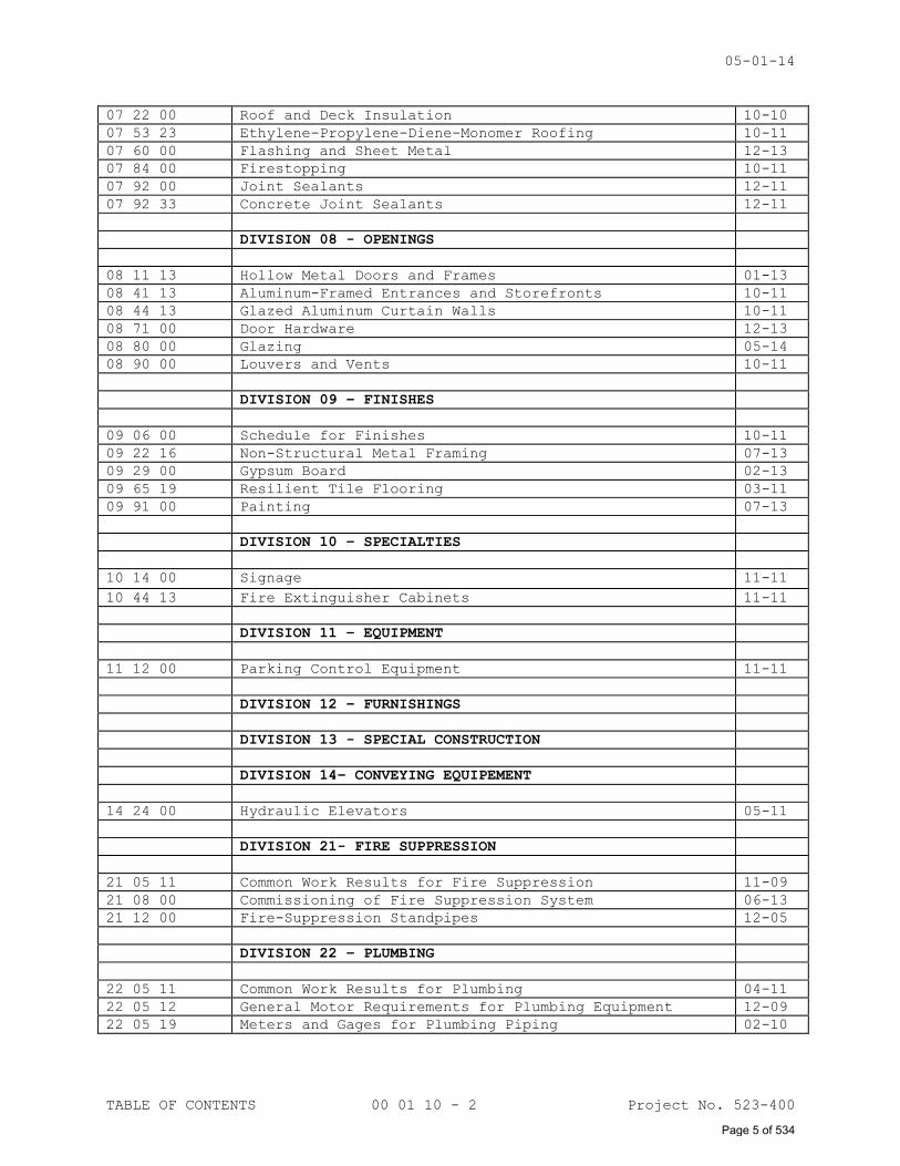
07 22 00 Roof and Deck Insulation 10-10
07 53 23 Ethylene-Propylene-Diene-Monomer Roofing 10-11
07 60 00 Flashing and Sheet Metal 12-13
07 84 00 Firestopping 10-11
07 92 00 Joint Sealants 12-11
07 92 33 Concrete Joint Sealants 12-11
DIVISION 08 - OPENINGS
08 11 13 Hollow Metal Doors and Frames 01-13
08 41 13 Aluminum-Framed Entrances and Storefronts 10-11
08 44 13 Glazed Aluminum Curtain Walls 10-11
08 71 00 Door Hardware 12-13
08 80 00 Glazing 05-14
08 90 00 Louvers and Vents 10-11
DIVISION 09 – FINISHES
09 06 00 Schedule for Finishes 10-11
09 22 16 Non-Structural Metal Framing 07-13
09 29 00 Gypsum Board 02-13
09 65 19 Resilient Tile Flooring 03-11
09 91 00 Painting 07-13
DIVISION 10 – SPECIALTIES
10 14 00 Signage 11-11
10 44 13 Fire Extinguisher Cabinets 11-11
DIVISION 11 – EQUIPMENT
11 12 00 Parking Control Equipment 11-11
DIVISION 12 – FURNISHINGS
DIVISION 13 - SPECIAL CONSTRUCTION
DIVISION 14– CONVEYING EQUIPEMENT
14 24 00 Hydraulic Elevators 05-11
DIVISION 21- FIRE SUPPRESSION
21 05 11 Common Work Results for Fire Suppression 11-09
21 08 00 Commissioning of Fire Suppression System 06-13
21 12 00 Fire-Suppression Standpipes 12-05
DIVISION 22 – PLUMBING
22 05 11 Common Work Results for Plumbing 04-11
22 05 12 General Motor Requirements for Plumbing Equipment 12-09
22 05 19 Meters and Gages for Plumbing Piping 02-10
Page 5 of 534
05-01-14
TABLE OF CONTENTS 00 01 10 - 3 Project No. 523-400
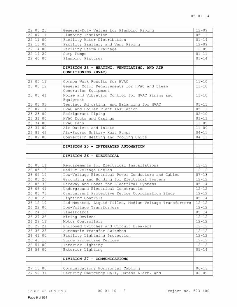
22 05 23 General-Duty Valves for Plumbing Piping 12-09
22 07 11 Plumbing Insulation 05-11
22 11 00 Facility Water Distribution 01-14
22 13 00 Facility Sanitary and Vent Piping 12-09
22 14 00 Facility Storm Drainage 12-09
22 14 29 Sump Pumps 01-11
22 40 00 Plumbing Fixtures 01-14
DIVISION 23 – HEATING, VENTILATING, AND AIR
CONDITIONING (HVAC)
23 05 11 Common Work Results for HVAC 11-10
23 05 12 General Motor Requirements for HVAC and Steam
Generation Equipment
11-10
23 05 41 Noise and Vibration Control for HVAC Piping and
Equipment
11-10
23 05 93 Testing, Adjusting, and Balancing for HVAC 05-11
23 07 11 HVAC and Boiler Plant Insulation 05-11
23 23 00 Refrigerant Piping 02-10
23 31 00 HVAC Ducts and Casings 03-13
23 34 00 HVAC Fans 11-09
23 37 00 Air Outlets and Inlets 11-09
23 81 43 Air-Source Unitary Heat Pumps 04-11
23 82 00 Convection Heating and Cooling Units 04-11
DIVISION 25 – INTEGRATED AUTOMATION
DIVISION 26 – ELECTRICAL
26 05 11 Requirements for Electrical Installations 12-12
26 05 13 Medium-Voltage Cables 12-12
26 05 19 Low-Voltage Electrical Power Conductors and Cables 07-13
26 05 26 Grounding and Bonding for Electrical Systems 12-12
26 05 33 Raceway and Boxes for Electrical Systems 05-14
26 05 41 Underground Electrical Construction 12-12
26 05 73 Overcurrent Protective Device Coordination Study 12-12
26 09 23 Lighting Controls 05-14
26 12 19 Pad-Mounted, Liquid-Filled, Medium-Voltage Transformers 12-12
26 22 00 Low-Voltage Transformers 12-12
26 24 16 Panelboards 05-14
26 27 26 Wiring Devices 12-12
26 29 11 Motor Controllers 12-12
26 29 21 Enclosed Switches and Circuit Breakers 12-12
26 36 23 Automatic Transfer Switches 12-12
26 41 00 Facility Lightning Protection 12-12
26 43 13 Surge Protective Devices 12-12
26 51 00 Interior Lighting 12-12
26 56 00 Exterior Lighting 05-14
DIVISION 27 – COMMUNICATIONS
27 15 00 Communications Horizontal Cabling 06-13
27 52 31 Security Emergency Call, Duress Alarm, and 02-09
Page 6 of 534
05-01-14
TABLE OF CONTENTS 00 01 10 - 4 Project No. 523-400
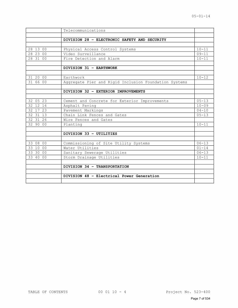
Telecommunications
DIVISION 28 – ELECTRONIC SAFETY AND SECURITY
28 13 00 Physical Access Control Systems 10-11
28 23 00 Video Surveillance 09-11
28 31 00 Fire Detection and Alarm 10-11
DIVISION 31 – EARTHWORK
31 20 00 Earthwork 10-12
31 66 00 Aggregate Pier and Rigid Inclusion Foundation Systems
DIVISION 32 – EXTERIOR IMPROVEMENTS
32 05 23 Cement and Concrete for Exterior Improvements 05-13
32 12 16 Asphalt Paving 10-09
32 17 23 Pavement Markings 04-10
32 31 13 Chain Link Fences and Gates 05-13
32 31 26 Wire Fences and Gates
32 90 00 Planting 10-11
DIVISION 33 – UTILITIES
33 08 00 Commissioning of Site Utility Systems 06-13
33 10 00 Water Utilities 01-14
33 30 00 Sanitary Sewerage Utilities 06-13
33 40 00 Storm Drainage Utilities 10-11
DIVISION 34 – TRANSPORTATION
DIVISION 48 – Electrical Power Generation
Page 7 of 534
09-11
LIST OF DRAWING SHEETS 00 01 15 - 1 Project No. 523-400
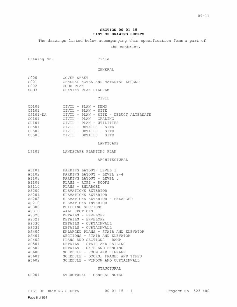
SECTION 00 01 15
LIST OF DRAWING SHEETS
The drawings listed below accompanying this specification form a part of
the contract.
Drawing No. Title
GENERAL
G000 COVER SHEET
G001 GENERAL NOTES AND MATERIAL LEGEND
G002 CODE PLAN
GOO3 PHASING PLAN DIAGRAM
CIVIL
CD101 CIVIL – PLAN - DEMO
CS101 CIVIL – PLAN - SITE
CS101-DA CIVIL – PLAN – SITE – DEDUCT ALTERNATE
CG101 CIVIL – PLAN – GRADING
CU101 CIVIL – PLAN - UTILITIES
CS501 CIVIL – DETAILS - SITE
CS502 CIVIL – DETAILS - SITE
CS503 CIVIL – DETAILS - SITE
LANDSCAPE
LP101 LANDSCAPE PLANTING PLAN
ARCHITECTURAL
AS101 PARKING LAYOUT- LEVEL 1
AS102 PARKING LAYOUT - LEVEL 2-4
AS103 PARKING LAYOUT - LEVEL 5
AS106 PLANS – RCPS - ROOFS
AS110 PLANS - ENLARGED
AS200 ELEVATIONS EXTERIOR
AS201 ELEVATIONS EXTERIOR
AS202 ELEVATIONS EXTERIOR – ENLARGED
AS210 ELEVATIONS INTERIOR
AS300 BUILDING SECTIONS
AS310 WALL SECTIONS
AS320 DETAILS - ENVELOPE
AS321 DETAILS – ENVELOPE
AS330 DETAILS – CURTAINWALL
AS331 DETAILS – CURTAINWALL
AS400 ENLARGED PLANS - STAIR AND ELEVATOR
AS401 SECTIONS - STAIR AND ELEVATOR
AS402 PLANS AND SECTIONS - RAMP
AS501 DETAILS - STAIR AND RAILING
AS502 DETAILS – GATE AND FENCING
AS600 SCHEDULE - ROOM AND SIGNAGE
AS601 SCHEDULE - DOORS, FRAMES AND TYPES
AS602 SCHEDULE - WINDOW AND CURTAINWALL
STRUCTURAL
SS001 STRUCTURAL - GENERAL NOTES
Page 8 of 534
09-11
LIST OF DRAWING SHEETS 00 01 15 - 2 Project No. 523-400
SF101 STRUCTURAL - PLAN LEVEL 1/FOUNDATION
SF102 STRUCTURAL - TYPICAL CONCRETE SECTIONS AND DETAILS
SF103 STRUCTURAL - FOUNDATIONS SECTIONS
SF104 STRUCTURAL - FOUNDATIONS SECTIONS
SF105 STRUCTURAL - FOUNDATIONS SECTIONS
SS102 STRUCTURAL - PLAN LEVEL 2
SS103 STRUCTURAL - PLAN LEVEL 3
SS104 STRUCTURAL - PLAN LEVEL 4
SS105 STRUCTURAL - PLAN LEVEL 5
SS501 STRUCTURAL - TYPICAL PRECAST SECTIONS AND DETAILS
SS502 STRUCTURAL – FRAMING SECTIONS
SS503 STRUCTURAL – FRAMING SECTIONS
PLUMBING
PL001 PLUMBING - LEGEND & GENERAL NOTES
PL100 PLUMBING - PLAN - UNDERSLAB
PL101 PLUMBING - PLAN - LEVEL 1
PL102 PLUMBING - PLAN - LEVEL 2
PL103 PLUMBING - PLAN - LEVEL 3
PL301 PLUMBING - ENLARGED PLANS AND SECTION
PL501 PLUMBING DETAILS AND SCHEDULES
MECHANICAL
MH001 MECHANICAL - LEGEND & GENERAL NOTES
MH101 MECHANICAL - PLAN - LEVEL 1
MH102 MECHANICAL - PLAN - LEVEL 2
MH103 MECHANICAL - PLAN - LEVEL 3
MH501 MECHANICAL - DETAILS
MH601 MECHANICAL - SCHEDULES
ELECTRICAL
E001 ELECTRICAL - GENERAL NOTES AND LEGEND
E002 ELECTRICAL - ONE-LINE RISER DIAGRAMS
E003 ELECTRICAL - SYSTEMS - ONE-LINE RISER DIAGRAMS
ES100 ELECTRICAL - SITE DEMO
ES101 ELECTRICAL - SITE NEW
ES101A ELECTRICAL – NEW SITE PLAN – ALTERNATE PARKING
ES501 ELECTRICAL - SITE DETAILS
EL101 ELECTRICAL - LIGHTING PLAN - LEVEL 1
EL102 ELECTRICAL - LIGHTING PLAN - LEVEL 2
EL103 ELECTRICAL - LIGHTING PLAN - LEVEL 3
EL104 ELECTRICAL - LIGHTING PLAN - LEVEL 4
EL105 ELECTRICAL - LIGHTING PLAN - LEVEL 5
EP101 ELECTRICAL - POWER PLAN - LEVEL 1
EP102 ELECTRICAL - POWER PLAN - LEVEL 2
EP103 ELECTRICAL - POWER PLAN - LEVEL 3
EP104 ELECTRICAL - POWER PLAN - LEVEL 4
EP105 ELECTRICAL - POWER PLAN - LEVEL 5
EJ101 ELECTRICAL – SYSTEMS PLANS LEVEL 1
EJ102 ELECTRICAL – SYSTEMS PLANS LEVEL 2
EJ103 ELECTRICAL – SYSTEMS PLANS LEVEL 3
EJ104 ELECTRICAL – SYSTEMS PLANS LEVEL 4
EJ105 ELECTRICAL – SYSTEMS PLANS LEVEL 5
E401 ELECTRICAL – LAREGE SCALE PLANS
E402 ELECTRICAL – LAREGE SCALE PLANS
E403 ELECTRICAL – LAREGE SCALE PLANS
E404 ELECTRICAL – LAREGE SCALE PLANS
E501 ELECTRICAL - DETAILS
Page 9 of 534
09-11
LIST OF DRAWING SHEETS 00 01 15 - 3 Project No. 523-400
E502 ELECTRICAL - DETAILS
E503 ELECTRICAL - DETAILS
E504 ELECTRICAL - DETAILS
E505 ELECTRICAL - DETAILS
E506 ELECTRICAL - DETAILS
E601 ELECTRICAL – SCHEDULES AND DIAGRAMS
E602 ELECTRICAL – SCHEDULES AND DIAGRAMS
FIRE PROTECTION
FP001 FIRE PROTECTION - TITLE SHEET
FP101 FIRE PROTECTION - PLAN - LEVEL 1/FOUNDATION
FP102 FIRE PROTECTION - PLAN - LEVEL 2
FP103 FIRE PROTECTION - PLAN - LEVEL 3
FP104 FIRE PROTECTION - PLAN - LEVEL 4
FP105 FIRE PROTECTION - PLAN - LEVEL 5
- - - END - - -
Page 10 of 534
10-01-13
i
SECTION 01 00 00
GENERAL REQUIREMENTS
TABLE OF CONTENTS
1.1 GENERAL INTENTION .................................................................................................................... 1
1.2 STATEMENT OF BID ITEM(S) ................................................................................................... 2
1.3 SPECIFICATIONS AND DRAWINGS FOR CONTRACTOR ........................................................ 2
1.4 CONSTRUCTION SECURITY REQUIREMENTS ............................................................................ 3
1.5 FIRE SAFETY ................................................................................................................................... 5
1.6 OPERATIONS AND STORAGE AREAS .......................................................................................... 7
1.7 ALTERATIONS ................................................................................................................................. 11
1.8 INFECTION PREVENTION MEASURES...................................................................................... 11
1.9 DISPOSAL AND RETENTION ...................................................................................................... 11
1.10 PROTECTION OF EXISTING VEGETATION, STRUCTURES, EQUIPMENT,
UTILITIES, AND IMPROVEMENTS .................................................................................................... 11
1.11 RESTORATION .............................................................................................................................. 12
1.12 PHYSICAL DATA ......................................................................................................................... 13
1.13 PROFESSIONAL SURVEYING SERVICES .............................................................................. 14
1.14 LAYOUT OF WORK ....................................................................................................................... 14
1.15 AS-BUILT DRAWINGS ................................................................................................................ 16
1.16 USE OF ROADWAYS ..................................................................................................................... 16
1.17 PROJECT ENGINEER'S FIELD OFFICE .............................................................................. 16
1.18 TEMPORARY USE OF MECHANICAL AND ELECTRICAL EQUIPMENT ............................ 16
1.19 TEMPORARY USE OF EXISTING ELEVATORS ..................................................................... 17
1.20 TEMPORARY USE OF NEW ELEVATORS ................................................................................. 18
1.21 TEMPORARY TOILETS ................................................................................................................ 18
1.22 AVAILABILITY AND USE OF UTILITY SERVICES ......................................................... 18
1.23 NEW TELEPHONE EQUIPMENT ................................................................................................. 18
Page 11 of 534
10-01-13
ii
1.24 TESTS............................................................................................................................................. 19
1.25 INSTRUCTIONS ............................................................................................................................ 19
1.26 GOVERNMENT-FURNISHED PROPERTY ................................................................................... 20
1.27 RELOCATED EQUIPMENT AND ITEMS ................................................................................... 21
1.28 STORAGE SPACE FOR DEPARTMENT OF VETERANS AFFAIRS EQUIPMENT .............. 21
1.29 CONSTRUCTION SIGN ................................................................................................................ 21
1.30 SAFETY SIGN .............................................................................................................................. 21
1.31 PHOTOGRAPHIC DOCUMENTATION .......................................................................................... 22
1.32 FINAL ELEVATION Digital Images ................................................................................. 25
1.33 HISTORIC PRESERVATION ...................................................................................................... 26
1.34 VA TRIRIGA………………………………………………………………………………………………………………………………………… 53
Page 12 of 534
05-01-13
GENERAL REQUIREMENTS 01 00 00 - 1 Project No. 523-400
SECTION 01 00 00
GENERAL REQUIREMENTS
1.1 GENERAL INTENTION
A. Contractor shall completely prepare site for building operations,
including demolition and removal of existing structures, and furnish
labor and materials and perform work for Renovate Parking Garage VAMC
WR as required by drawings and specifications.
B. Visits to the site by Bidders may be made only by appointment with the
Medical Center Contracting Officer.
C. Offices of Architect, (All contact shall be through CO and or COR) as
Architect-Engineers, will render certain technical services during
construction. Such services shall be considered as advisory to the
Government and shall not be construed as expressing or implying a
contractual act of the Government without affirmations by Contracting
Officer or his duly authorized representative.
D. Before placement and installation of work subject to tests by testing
laboratory retained by Department of Veterans Affairs, the Contractor
shall notify the Project Engineer in sufficient time to enable testing
laboratory personnel to be present at the site in time for proper taking
and testing of specimens and field inspection. Such prior notice shall
be not less than three work days unless otherwise designated by the
Project Engineer.
E. All employees of general contractor and subcontractors shall comply with
VA security management program and obtain permission of the VA police,
be identified by project and employer, and restricted from unauthorized
access.
F. Prior to commencing work, general contractor shall provide proof that a
OSHA designated “competent person” (CP) (29 CFR 1926.20(b)(2) will
maintain a presence at the work site whenever the general or
subcontractors are present.
G. Training:
1. All employees of general contractor or subcontractors shall have the
10-hour or 30-hour OSHA Construction Safety course and other relevant
competency training, as determined by RE/COR acting as the
Construction Safety Officer with input from the facility Construction
Safety Committee.
Page 13 of 534
05-01-13
GENERAL REQUIREMENTS 01 00 00 - 2 Project No. 523-400
2. Submit training records of all such employees for approval before the
start of work.
H. VHA Directive 2011-36, Safety and Health during Construction, dated
9/22/2011 in its entirety is made a part of this section
1.2 STATEMENT OF BID ITEM(S)
A. ITEM I, GENERAL CONSTRUCTION: Renovate Parking Garage VAMC WR :
Provide all labor, materials, equipment, transportation, supervision,
general demolition, general construction, alterations, roads, walks,
grading, drainage, mechanical and electrical work, utility systems,
elevators necessary removal of existing structures and construction and
certain other items.
C. DEDUCT ALTERNATE NO. 1: Eliminate scope of work to relocate Electrical
Duct Bank.
B. DEDUCT ALTERNATE NO. 2: Phase 4; Eliminate 1/2 level of parking; reduce
elevator programing by one stop.
C. DEDUCT ALTERNATE NO. 3: Phase 3; Eliminate additional 1/2 level of
parking. Reduce stair 2 by one level.
D. DEDUCT ALTERNATE NO. 4: Phase 2; Eliminate 1/2 level of parking; reduce
elevator programing by one stop.
E. DEDUCT ALTERNATE NO. 5: Eliminate one elevator.
F. DEDUCT ALTERNATE NO. 6: Eliminate safety fencing from top of spandrels.
G. DEDUCT ALTERNATE NO. 7: Eliminate anti-climb fencing from top level.
H. DEDUCT ALTERNATE NO. 8: Restriping / resealing the parking lot in the
configuration shown on the Civil drawings.
I. Period of Performance for Base Offer: 425 Calendar Days from Notice to
Proceed as indicated on Attachment A.
J. Period of Performance Reduction for Deduct Alternate 1: Reduction of 7 calendar days.
K. Period of Performance Reduction for Deduct Alternate 2: Reduction of 21
calendar days.
L. Period of Performance Reduction for Deduct Alternate 3: Reduction of 21
calendar days.
Page 14 of 534
05-01-13
GENERAL REQUIREMENTS 01 00 00 - 3 Project No. 523-400
M. Period of Performance Reduction for Deduct Alternate 4: Reduction of 21
calendar days.
N. Period of Performance Reduction for Deduct Alternate 5: No reduction of
calendar days.
O. Period of Performance Reduction for Deduct Alternate 6: No reduction of
calendar days.
P. Period of Performance Reduction for Deduct Alternate 7: No reduction of
calendar days.
Q. Period of Performance Reduction for Deduct Alternate 8: No reduction of
calendar days.
1.3 SPECIFICATIONS AND DRAWINGS FOR CONTRACTOR
A. AFTER AWARD OF CONTRACT, one (1) electronic set in PDF format of
specifications and one (1) electronic set in PDF format of drawings will
be provided by the VA Contracting Officer.
1.4 CONSTRUCTION SECURITY REQUIREMENTS
A. Security Plan:
1. The security plan defines both physical and administrative security
procedures that will remain effective for the entire duration of the
project.
2. The General Contractor is responsible for assuring that all sub-
contractors working on the project and their employees also comply
with these regulations.
B. Security Procedures:
1. General Contractor’s employees shall not enter the project site
without appropriate badge. They may also be subject to inspection of
their personal effects when entering or leaving the project site.
2. For working outside the “regular hours” as defined in the contract,
The General Contractor shall give 3 days notice to the Contracting
Officer so that security arrangements can be provided for the
employees. This notice is separate from any notices required for
utility shutdown described later in this section.
3. No photography of VA premises is allowed without written permission
of the Contracting Officer.
Page 15 of 534
05-01-13
GENERAL REQUIREMENTS 01 00 00 - 4 Project No. 523-400
4. VA reserves the right to close down or shut down the project site and
order General Contractor’s employees off the premises in the event of
a national emergency. The General Contractor may return to the site
only with the written approval of the Contracting Officer.
C. Guards: Not Applicable.
D. Key Control:
1. The General Contractor shall provide duplicate keys and lock
combinations to the Project Engineer for the purpose of security
inspections of every area of project including tool boxes and parked
machines and take any emergency action.
2. The General Contractor shall turn over all permanent lock cylinders
to the VA locksmith for permanent installation. See Section 08 71 00,
DOOR HARDWARE and coordinate.
E. Document Control:
1. Before starting any work, the General Contractor/Sub Contractors
shall submit an electronic security memorandum describing the
approach to following goals and maintaining confidentiality of
“sensitive information”.
2. The General Contractor is responsible for safekeeping of all
drawings, project manual and other project information. This
information shall be shared only with those with a specific need to
accomplish the project.
3. Certain documents, sketches, videos or photographs and drawings may
be marked “Law Enforcement Sensitive” or “Sensitive Unclassified”.
Secure such information in separate containers and limit the access
to only those who will need it for the project. Return the
information to the Contracting Officer upon request.
4. These security documents shall not be removed or transmitted from the
project site without the written approval of Contracting Officer.
5. All paper waste or electronic media such as CD’s and diskettes shall
be shredded and destroyed in a manner acceptable to the VA.
6. Notify Contracting Officer and Site Security Officer immediately when
there is a loss or compromise of “sensitive information”.
Page 16 of 534
05-01-13
GENERAL REQUIREMENTS 01 00 00 - 5 Project No. 523-400
7. All electronic information shall be stored in specified location
following VA standards and procedures using an Engineering Document
Management Software (EDMS).
a. Security, access and maintenance of all project drawings, both
scanned and electronic shall be performed and tracked through the
EDMS system.
b. “Sensitive information” including drawings and other documents may
be attached to e-mail provided all VA encryption procedures are
followed.
F. Motor Vehicle Restrictions
1. Vehicle authorization request shall be required for any vehicle
entering the site and such request shall be submitted 24 hours before
the date and time of access. Access shall be restricted to picking up
and dropping off materials and supplies.
2. Separate permits shall be issued for General Contractor and its
employees for parking in designated areas only.
1.5 FIRE SAFETY
A. Applicable Publications: Publications listed below form part of this
Article to extent referenced. Publications are referenced in text by
basic designations only.
1. American Society for Testing and Materials (ASTM):
E84-2009.............Surface Burning Characteristics of Building
Materials
2. National Fire Protection Association (NFPA):
10-2010..............Standard for Portable Fire Extinguishers
30-2008..............Flammable and Combustible Liquids Code
51B-2009.............Standard for Fire Prevention During Welding,
Cutting and Other Hot Work
70-2011..............National Electrical Code
101-2012.............Life Safety Code
Page 17 of 534
05-01-13
GENERAL REQUIREMENTS 01 00 00 - 6 Project No. 523-400
241-2009.............Standard for Safeguarding Construction,
Alteration, and Demolition Operations
3. Occupational Safety and Health Administration (OSHA):
29 CFR 1926..........Safety and Health Regulations for Construction
4. VHA Directive 2005-007
B. Fire Safety Plan: Establish and maintain a fire protection program in accordance with 29 CFR 1926. Prior to start of work, prepare a plan
detailing project-specific fire safety measures, including periodic
status reports, and submit to Project Engineer and Facility Safety
Officer for review for compliance with VHA Directive 2005-007, NFPA 101
and NFPA 241.Prior to beginning work, all employees of the contractor
and/or any subcontractors shall undergo a safety briefing provided by
the general contractor’s competent person per OSHA requirements. This
briefing shall include information on the construction limits, VAMC
safety guidelines, means of egress, break areas, work hours, locations
of restrooms, use of VAMC equipment, etc. Provide documentation to the
Project Engineer that all construction workers have undergone
contractor’s safety briefing.
C. Site and Building Access: Maintain free and unobstructed access to
facility emergency services and for fire, police and other emergency
response forces in accordance with NFPA 241.
D. Separate temporary facilities, such as trailers, storage sheds, and
dumpsters, from existing buildings and new construction by distances in
accordance with NFPA 241. For small facilities with less than 6 m (20
feet) exposing overall length, separate by 3m (10 feet).
E. Temporary Construction Partitions: Not Applicable.
F. Temporary Heating and Electrical: Install, use and maintain
installations in accordance with 29 CFR 1926, NFPA 241 and NFPA 70.
G. Means of Egress: Do not block exiting for occupied buildings, including
paths from exits to roads. Minimize disruptions and coordinate with
Project Engineer and Facility Safety Officer.
H. Egress Routes for Construction Workers: Maintain free and unobstructed
egress. Inspect daily. Report findings and corrective actions weekly to
Project Engineer and Facility Safety Officer.
Page 18 of 534
05-01-13
GENERAL REQUIREMENTS 01 00 00 - 7 Project No. 523-400
I. Fire Extinguishers: Provide and maintain extinguishers in construction
areas and temporary storage areas in accordance with 29 CFR 1926, NFPA
241 and NFPA 10.
J. Flammable and Combustible Liquids: Store, dispense and use liquids in
accordance with 29 CFR 1926, NFPA 241 and NFPA 30.
K. Standpipes: Not applicable.
L. Sprinklers: Not applicable.
M. Existing Fire Protection: Not Applicable.
N. Smoke Detectors: Not Applicable.
O. Hot Work: Perform and safeguard hot work operations in accordance with
NFPA 241 and NFPA 51B. Coordinate with Project Engineer. Obtain permits
from Facility Safety Officer at least 72 hours in advance. Designate
contractor's responsible project-site fire prevention program manager to
permit hot work.
P. Fire Hazard Prevention and Safety Inspections: Inspect entire
construction areas weekly. Coordinate with, and report findings and
corrective actions weekly to Project Engineer and Facility Safety
Officer.
Q. Smoking: Smoking is prohibited in and adjacent to construction areas
inside existing buildings and additions under construction. In separate
and detached buildings under construction, smoking is prohibited except
in designated smoking rest areas.
R. Dispose of waste and debris in accordance with NFPA 241. Remove from
buildings daily.
S. Perform other construction, alteration and demolition operations in
accordance with 29 CFR 1926.
T. If required, submit documentation to the Project Engineer that personnel
have been trained in the fire safety aspects of working in areas with
impaired structural or compartmentalization features.
1.6 OPERATIONS AND STORAGE AREAS
A. The Contractor shall confine all operations (including storage of
materials) on Government premises to areas authorized or approved by the
Contracting Officer. The Contractor shall hold and save the Government,
Page 19 of 534
05-01-13
GENERAL REQUIREMENTS 01 00 00 - 8 Project No. 523-400
its officers and agents, free and harmless from liability of any nature
occasioned by the Contractor's performance.
B. Temporary buildings (e.g., storage sheds, shops, offices) and utilities
may be erected by the Contractor only with the approval of the
Contracting Officer and shall be built with labor and materials
furnished by the Contractor without expense to the Government. The
temporary buildings and utilities shall remain the property of the
Contractor and shall be removed by the Contractor at its expense upon
completion of the work. With the written consent of the Contracting
Officer, the buildings and utilities may be abandoned and need not be
removed.
C. The Contractor shall, under regulations prescribed by the Contracting
Officer, use only established roadways, or use temporary roadways
constructed by the Contractor when and as authorized by the Contracting
Officer. When materials are transported in prosecuting the work,
vehicles shall not be loaded beyond the loading capacity recommended by
the manufacturer of the vehicle or prescribed by any Federal, State, or
local law or regulation. When it is necessary to cross curbs or
sidewalks, the Contractor shall protect them from damage. The Contractor
shall repair or pay for the repair of any damaged curbs, sidewalks, or
roads.
D. Working space and space available for storing materials shall be as
shown on the drawings.
E Execute work in such a manner as to interfere as little as possible with
work being done by others. Keep roads clear of construction materials,
debris, standing construction equipment and vehicles at all times.
F. Utilities Services: Where necessary to cut existing pipes, electrical
wires, conduits, cables, etc., of utility services, or of fire
protection systems or communications systems (except telephone), they
shall be cut and capped at suitable places where shown; or, in absence
of such indication, where directed by Project Engineer. All such actions
shall be coordinated with the Utility Company involved:
1. Whenever it is required that a connection fee be paid to a public
utility provider for new permanent service to the construction
project, for such items as water, sewer, electricity, gas or steam,
Page 20 of 534
05-01-13
GENERAL REQUIREMENTS 01 00 00 - 9 Project No. 523-400
payment of such fee shall be the responsibility of the Government and
not the Contractor.
G. Phasing: Not Applicable.
H. Not Applicable.
I. Construction Fence: Before construction operations begin, Contractor
shall provide a chain link construction fence, 2.1m (seven feet) minimum
height, around the construction area indicated on the drawings. Provide
gates as required for access with necessary hardware, including hasps
and padlocks. Fasten fence fabric to terminal posts with tension bands
and to line posts and top and bottom rails with tie wires spaced at
maximum 375mm (15 inches). Bottom of fences shall extend to 25mm (one
inch) above grade. Remove the fence when directed by Project Engineer.
J. Not Applicable.
K. Utilities Services: Maintain existing underground utility services for
Medical Center at all times. Provide temporary facilities, labor,
materials, equipment, connections, and utilities to assure uninterrupted
services. Where necessary to cut existing water, steam, gases, sewer or
air pipes, or conduits, wires, cables, etc. of utility services or of
fire protection systems and communications systems (including
telephone), they shall be cut and capped at suitable places where shown;
or, in absence of such indication, where directed by Project Engineer.
1. No utility service such as water, sewers or electricity, or
communications systems may be interrupted without prior approval of
Project Engineer. Electrical work shall be accomplished with all
affected circuits or equipment de-energized. When an electrical
outage cannot be accomplished, work on any energized circuits or
equipment shall not commence without the Medical Center Director’s
prior knowledge and written approval. Refer to specification Sections
26 05 11, REQUIREMENTS FOR ELECTRICAL INSTALLATIONS, 27 15 00
COMMUNICATIONS HORIZONTAL CABLING and 28 15 00, PHYSICAL ACCESS
CONTROL SYSTEM for additional requirements.
2. Contractor shall submit a request to interrupt any such services to
Project Engineer, in writing, 48 hours in advance of proposed
interruption. Request shall state reason, date, exact time of, and
approximate duration of such interruption.
Page 21 of 534
05-01-13
GENERAL REQUIREMENTS 01 00 00 - 10 Project No. 523-400
3. Contractor will be advised (in writing) of approval of request, or of
which other date and/or time such interruption will cause least
inconvenience to operations of Medical Center. Interruption time
approved by Medical Center may occur at other than Contractor's
normal working hours.
4. Major interruptions of any system must be requested, in writing, at
least 15 calendar days prior to the desired time and shall be
performed as directed by the Project Engineer.
5. In case of a contract construction emergency, service will be
interrupted on approval of Project Engineer. Such approval will be
confirmed in writing as soon as practical.
6. Whenever it is required that a connection fee be paid to a public
utility provider for new permanent service to the construction
project, for such items as water, sewer, electricity, gas or steam,
payment of such fee shall be the responsibility of the Government and
not the Contractor.
L. Abandoned Lines: All service lines such as wires, cables, conduits,
ducts, pipes and the like, and their hangers or supports, which are to
be abandoned but are not required to be entirely removed, shall be
sealed, capped or plugged. The lines shall not be capped in finished
areas, but shall be removed and sealed, capped or plugged in ceilings,
within furred spaces, in unfinished areas, or within walls or
partitions; so that they are completely behind the finished surfaces.
M. To minimize interference of construction activities with flow of Medical
Center traffic, comply with the following:
1. Keep roads, walks and entrances to grounds, to parking and to
occupied areas of buildings clear of construction materials, debris
and standing construction equipment and vehicles. Wherever excavation
for new utility lines cross existing roads, at least one lane must be
open to traffic at all times.
2. Method and scheduling of required cutting, altering and removal of
existing roads, walks and entrances must be approved by the Project
Engineer.
N. Coordinate the work for this contract with other construction operations
as directed by Project Engineer. This includes the scheduling of traffic
and the use of roadways, as specified in Article 1.6 USE OF ROADWAYS.
Page 22 of 534
05-01-13
GENERAL REQUIREMENTS 01 00 00 - 11 Project No. 523-400
1.7 ALTERATIONS
Not Applicable
1.8 INFECTION PREVENTION MEASURES
Not Applicable
1.9 DISPOSAL AND RETENTION
A. Materials and equipment accruing from work removed and from demolition
of buildings or structures, or parts thereof, shall be disposed of as
follows:
1. Reserved items which are to remain property of the Government are
identified by attached tags or noted on drawings or in specifications
as items to be stored. Items that remain property of the Government
shall be removed or dislodged from present locations in such a manner
as to prevent damage which would be detrimental to re-installation
and reuse. Store such items where directed by Project Engineer.
2. Items not reserved shall become property of the Contractor and be
removed by Contractor from Medical Center.
1.10 PROTECTION OF EXISTING VEGETATION, STRUCTURES, EQUIPMENT, UTILITIES, AND
IMPROVEMENTS
A. The Contractor shall preserve and protect all structures, equipment, and
vegetation (such as trees, shrubs, and grass) on or adjacent to the work
site, which are not to be removed and which do not unreasonably
interfere with the work required under this contract. The Contractor
shall only remove trees when specifically authorized to do so, and shall
avoid damaging vegetation that will remain in place. If any limbs or
branches of trees are broken during contract performance, or by the
careless operation of equipment, or by workmen, the Contractor shall
trim those limbs or branches with a clean cut and paint the cut with a
tree-pruning compound as directed by the Contracting Officer.
B. The Contractor shall protect from damage all existing improvements and
utilities at or near the work site and on adjacent property of a third
party, the locations of which are made known to or should be known by
the Contractor. The Contractor shall repair any damage to those
facilities, including those that are the property of a third party,
resulting from failure to comply with the requirements of this contract
or failure to exercise reasonable care in performing the work. If the
Contractor fails or refuses to repair the damage promptly, the
Page 23 of 534
05-01-13
GENERAL REQUIREMENTS 01 00 00 - 12 Project No. 523-400
Contracting Officer may have the necessary work performed and charge the
cost to the Contractor.
C. Refer to Section 01 57 19, TEMPORARY ENVIRONMENTAL CONTROLS, for
additional requirements on protecting vegetation, soils and the
environment. Refer to Articles, "1.7 Alterations", "1.11
Restoration", and "1.6 Operations and Storage Areas" for additional
instructions concerning repair of damage to structures and site
improvements.
D. Refer to Section 01 57 19, TEMPORARY ENVIRONMENTAL CONTROLS, which is
included herein. A National Pollutant Discharge Elimination System
(NPDES) permit is required for this project. The Contractor is
considered an "operator" under the permit and has extensive
responsibility for compliance with permit requirements. VA will make
the permit application available at the (appropriate medical center)
office. The apparent low bidder, contractor and affected subcontractors
shall furnish all information and certifications that are required to
comply with the permit process and permit requirements. Many of the
permit requirements will be satisfied by completing construction as
shown and specified. Some requirements involve the Contractor's method
of operations and operations planning and the Contractor is responsible
for employing best management practices. The affected activities often
include, but are not limited to the following:
- Designating areas for equipment maintenance and repair;
- Providing waste receptacles at convenient locations and provide
regular collection of wastes;
- Locating equipment wash down areas on site, and provide appropriate
control of wash-waters;
- Providing protected storage areas for chemicals, paints, solvents,
fertilizers, and other potentially toxic materials; and
- Providing adequately maintained sanitary facilities.
1.11 RESTORATION
A. Remove, cut, alter, replace, patch and repair existing site work as
necessary to install new work. Existing work to be altered or extended
and that is found to be defective in any way, shall be reported to the
Project Engineer before it is disturbed. Materials and workmanship used
Page 24 of 534
05-01-13
GENERAL REQUIREMENTS 01 00 00 - 13 Project No. 523-400
in restoring work, shall conform in type and quality to that of original
existing construction, except as otherwise shown or specified.
B. Upon completion of contract, deliver work complete and undamaged.
Existing work (lawns, paving, roads, walks, etc.) disturbed or removed
as a result of performing required new work, shall be patched, repaired,
reinstalled, or replaced with new work, and refinished and left in as
good condition as existed before commencing work.
C. At Contractor's own expense, Contractor shall immediately restore to
service and repair any damage caused by Contractor's workmen to existing
piping and conduits, wires, cables, etc., of utility services or of
communications systems (including telephone) which are indicated on
drawings and which are not scheduled for discontinuance or abandonment.
D. Expense of repairs to such utilities and systems not shown on drawings
or locations of which are unknown will be covered by adjustment to
contract time and price in accordance with the Construction Contract
clause entitled "CHANGES" and "DIFFERING SITE CONDITIONS".
1.12 PHYSICAL DATA
A. Data and information furnished or referred to below is for the
Contractor's information. The Government shall not be responsible for
any interpretation of or conclusion drawn from the data or information
by the Contractor.
1. The indications of physical conditions on the drawings and in the
specifications are the result of site investigations by R. W.
Gillespie & Associated, Inc., 44 Wood Avenue, Suite 1, Mansfield,
MA 02048.
B. Subsurface conditions have been developed by core borings and test pits.
Logs of subsurface exploration are shown diagrammatically on drawings.
C. A copy of the soil report will be made available for inspection by
bidders upon request to the Engineering Officer at the VA Medical
Center, and shall be considered part of the contract documents.
D. Government does not guarantee that other materials will not be
encountered nor that proportions, conditions or character of several
materials will not vary from those indicated by explorations. Bidders
Page 25 of 534
05-01-13
GENERAL REQUIREMENTS 01 00 00 - 14 Project No. 523-400
are expected to examine site of work and logs of borings; and, after
investigation, decide for themselves character of materials and make
their bids accordingly. Upon proper application to Department of
Veterans Affairs, bidders will be permitted to make subsurface
explorations of their own at site.
1.13 PROFESSIONAL SURVEYING SERVICES
A registered professional land surveyor or registered civil engineer
whose services are retained and paid for by the Contractor shall perform
services specified herein and in other specification sections. The
Contractor shall certify that the land surveyor or civil engineer is not
one who is a regular employee of the Contractor, and that the land
surveyor or civil engineer has no financial interest in this contract.
1.14 LAYOUT OF WORK
A. The Contractor shall lay out the work from Government established base
lines and bench marks, indicated on the drawings, and shall be
responsible for all measurements in connection with the layout. The
Contractor shall furnish, at Contractor's own expense, all stakes,
templates, platforms, equipment, tools, materials, and labor required to
lay out any part of the work. The Contractor shall be responsible for
executing the work to the lines and grades that may be established or
indicated by the Contracting Officer. The Contractor shall also be
responsible for maintaining and preserving all stakes and other marks
established by the Contracting Officer until authorized to remove them.
If such marks are destroyed by the Contractor or through Contractor's
negligence before their removal is authorized, the Contracting Officer
may replace them and deduct the expense of the replacement from any
amounts due or to become due to the Contractor.
B. Establish and plainly mark center lines for each building and such other
lines and grades that are reasonably necessary to properly assure that
location, orientation, and elevations established for each such
structure and/or roads, parking lots, are in accordance with lines and
elevations shown on contract drawings.
C. Following completion of general mass excavation and before any other
permanent work is performed, establish and plainly mark (through use of
appropriate batter boards or other means) sufficient additional survey
control points or system of points as may be necessary to assure proper
Page 26 of 534
05-01-13
GENERAL REQUIREMENTS 01 00 00 - 15 Project No. 523-400
alignment, orientation, and grade of all major features of work. Survey
shall include, but not be limited to, location of lines and grades of
footings, exterior walls, center lines of columns in both directions,
major utilities and elevations of floor slabs:
1. Such additional survey control points or system of points thus
established shall be checked and certified by a registered land
surveyor or registered civil engineer. Furnish such certification to
the Project Engineer before any work (such as footings, floor slabs,
columns, walls, utilities and other major controlling features) is
placed.
D. During progress of work, and particularly as work progresses from floor
to floor, Contractor shall have line grades and plumbness of all major
form work checked and certified by a registered land surveyor or
registered civil engineer as meeting requirements of contract drawings.
Furnish such certification to the Project Engineer before any major
items of concrete work are placed. In addition, Contractor shall also
furnish to the Project Engineer certificates from a registered land
surveyor or registered civil engineer that the following work is
complete in every respect as required by contract drawings.
1. Lines of each building.
2. Elevations of bottoms of footings and tops of floors of each
building.
3. Lines and elevations of sewers and of all outside distribution
systems.
4. Not applicable.
5. Not applicable.
6. Lines and elevations of roads, and parking lots.
E. Whenever changes from contract drawings are made in line or grading
requiring certificates, record such changes on a reproducible drawing
bearing the registered land surveyor or registered civil engineer seal,
and forward these drawings upon completion of work to Project Engineer.
F. The Contractor shall perform the surveying and layout work of this and
other articles and specifications in accordance with the provisions of
Article "Professional Surveying Services".
Page 27 of 534
05-01-13
GENERAL REQUIREMENTS 01 00 00 - 16 Project No. 523-400
1.15 AS-BUILT DRAWINGS
A. The contractor shall maintain two full size sets of as-built drawings
which will be kept current during construction of the project, to
include all contract changes, modifications and clarifications.
B. All variations shall be shown in the same general detail as used in the
contract drawings. To insure compliance, as-built drawings shall be made
available for the Project Engineer's review, as often as requested.
C. Contractor shall deliver two approved completed sets of as-built
drawings to the Project Engineer within 15 calendar days after each
completed phase and after the acceptance of the project by the Project
Engineer.
D. Paragraphs A, B, & C shall also apply to all shop drawings.
1.16 USE OF ROADWAYS
A. For hauling, use only established public roads and roads on Medical
Center property and, when authorized by the Project Engineer, such
temporary roads which are necessary in the performance of contract work.
Temporary roads shall be constructed by the Contractor at Contractor's
expense.
B. When new permanent roads are to be a part of this contract, Contractor
may construct them immediately for use to facilitate building
operations. These roads may be used by all who have business thereon
within zone of building operations.
C. When certain buildings (or parts of certain buildings) are required to
be completed in advance of general date of completion, all roads leading
thereto must be completed and available for use at time set for
completion of such buildings or parts thereof.
1.17 PROJECT ENGINEER'S FIELD OFFICE
Not Applicable
1.18 TEMPORARY USE OF MECHANICAL AND ELECTRICAL EQUIPMENT
A. Use of new installed mechanical and electrical equipment to provide
heat, ventilation, plumbing, light and power will be permitted subject
to compliance with the following provisions:
1. Permission to use each unit or system must be given by Project
Engineer. If the equipment is not installed and maintained in
Page 28 of 534
05-01-13
GENERAL REQUIREMENTS 01 00 00 - 17 Project No. 523-400
accordance with the following provisions, the Project Engineer will
withdraw permission for use of the equipment.
2. Electrical installations used by the equipment shall be completed in
accordance with the drawings and specifications to prevent damage to
the equipment and the electrical systems, i.e. transformers, relays,
circuit breakers, fuses, conductors, motor controllers and their
overload elements shall be properly sized, coordinated and adjusted.
Voltage supplied to each item of equipment shall be verified to be
correct and it shall be determined that motors are not overloaded.
The electrical equipment shall be thoroughly cleaned before using it
and again immediately before final inspection including vacuum
cleaning and wiping clean interior and exterior surfaces.
3. Units shall be properly lubricated, balanced, and aligned. Vibrations
must be eliminated.
4. Automatic temperature control systems for preheat coils shall
function properly and all safety controls shall function to prevent
coil freeze-up damage.
5. The air filtering system utilized shall be that which is designed for
the system when complete, and all filter elements shall be replaced
at completion of construction and prior to testing and balancing of
system.
6. All components of heat production and distribution system, metering
equipment, and other auxiliary facilities used in temporary service
shall be cleaned prior to use; maintained to prevent corrosion
internally and externally during use; and cleaned, maintained and
inspected prior to acceptance by the Government.
B. Prior to final inspection, the equipment or parts used which show wear
and tear beyond normal, shall be replaced with identical replacements,
at no additional cost to the Government.
C. This paragraph shall not reduce the requirements of the mechanical and
electrical specifications sections.
1.19 TEMPORARY USE OF EXISTING ELEVATORS
Not Applicable
Page 29 of 534
05-01-13
GENERAL REQUIREMENTS 01 00 00 - 18 Project No. 523-400
1.20 TEMPORARY USE OF NEW ELEVATORS
A. Contractor will not be allowed the use of new elevators. Outside type
hoist shall be used by Contractor for transporting materials and
equipment.
1.21 TEMPORARY TOILETS
A. Provide where directed, (for use of all Contractor's workmen) ample
temporary sanitary toilet accommodations with suitable sewer and water
connections; or, when approved by Project Engineer, provide suitable dry
closets where directed. Keep such places clean and free from flies, and
all connections and appliances connected therewith are to be removed
prior to completion of contract, and premises left perfectly clean.
1.22 AVAILABILITY AND USE OF UTILITY SERVICES
A. Not applicable.
B. Not applicable.
C. Not applicable.
D. Heat: Furnish temporary heat necessary to prevent injury to work and
materials through dampness and cold. Use of open salamanders or any
temporary heating devices which may be fire hazards or may smoke and
damage finished work, will not be permitted. Maintain minimum
temperatures as specified for various materials:
E. Electricity (for Construction and Testing): Furnish all temporary
electric services.
F. Water (for Construction and Testing): Furnish temporary water service.
1. Obtain water by connecting to the Medical Center water distribution
system. Provide reduced pressure backflow preventer at each
connection. Water is available at no cost to the Contractor.
2. Maintain connections, pipe, fittings and fixtures and conserve
water-use so none is wasted. Failure to stop leakage or other wastes
will be cause for revocation (at Project Engineer's discretion) of
use of water from Medical Center's system.
1.23 NEW TELEPHONE EQUIPMENT
The contractor shall coordinate with the VA, their work for
installation of telephone equipment. This work shall be completed
before the building is turned over to VA.
Page 30 of 534
05-01-13
GENERAL REQUIREMENTS 01 00 00 - 19 Project No. 523-400
1.24 TESTS
A. Pre-test mechanical and electrical equipment and systems and make
corrections required for proper operation of such systems before
requesting final tests. Final test will not be conducted unless
pre-tested.
B. Conduct final tests required in various sections of specifications in
presence of an authorized representative of the Contracting Officer.
Contractor shall furnish all labor, materials, equipment, instruments,
and forms, to conduct and record such tests.
C. Mechanical and electrical systems shall be balanced, controlled and
coordinated. A system is defined as the entire complex which must be
coordinated to work together during normal operation to produce results
for which the system is designed. For example, air conditioning supply
air is only one part of entire system which provides comfort conditions
for a building. Other related components are return air, exhaust air,
steam, chilled water, refrigerant, hot water, controls and electricity,
etc. Another example of a complex which involves several components of
different disciplines is a boiler installation. Efficient and acceptable
boiler operation depends upon the coordination and proper operation of
fuel, combustion air, controls, steam, feedwater, condensate and other
related components.
D. All related components as defined above shall be functioning when any
system component is tested. Tests shall be completed within a reasonably
short period of time during which operating and environmental conditions
remain reasonably constant.
E. Individual test result of any component, where required, will only be
accepted when submitted with the test results of related components and
of the entire system.
1.25 INSTRUCTIONS
A. Contractor shall furnish Maintenance and Operating manuals (hard copies
and electronic) and verbal instructions when required by the various
sections of the specifications and as hereinafter specified.
B. Manuals: Maintenance and operating manuals and one compact disc (four
hard copies and one electronic copy each) for each separate piece of
equipment shall be delivered to the Project Engineer coincidental with
the delivery of the equipment to the job site. Manuals shall be
complete, detailed guides for the maintenance and operation of
Page 31 of 534
05-01-13
GENERAL REQUIREMENTS 01 00 00 - 20 Project No. 523-400
equipment. They shall include complete information necessary for
starting, adjusting, maintaining in continuous operation for long
periods of time and dismantling and reassembling of the complete units
and sub-assembly components. Manuals shall include an index covering all
component parts clearly cross-referenced to diagrams and illustrations.
Illustrations shall include "exploded" views showing and identifying
each separate item. Emphasis shall be placed on the use of special tools
and instruments. The function of each piece of equipment, component,
accessory and control shall be clearly and thoroughly explained. All
necessary precautions for the operation of the equipment and the reason
for each precaution shall be clearly set forth. Manuals must reference
the exact model, style and size of the piece of equipment and system
being furnished. Manuals referencing equipment similar to but of a
different model, style, and size than that furnished will not be
accepted.
C. Instructions: Contractor shall provide qualified, factory-trained
manufacturers' representatives to give detailed instructions to assigned
Department of Veterans Affairs personnel in the operation and complete
maintenance for each piece of equipment. All such training will be at
the job site. These requirements are more specifically detailed in the
various technical sections. Instructions for different items of
equipment that are component parts of a complete system, shall be given
in an integrated, progressive manner. All instructors for every piece of
component equipment in a system shall be available until instructions
for all items included in the system have been completed. This is to
assure proper instruction in the operation of inter-related systems. All
instruction periods shall be at such times as scheduled by the Project
Engineer and shall be considered concluded only when the Project
Engineer is satisfied in regard to complete and thorough coverage. The
Department of Veterans Affairs reserves the right to request the removal
of, and substitution for, any instructor who, in the opinion of the
Project Engineer, does not demonstrate sufficient qualifications in
accordance with requirements for instructors above.
1.26 GOVERNMENT-FURNISHED PROPERTY
Not Applicable
Page 32 of 534
05-01-13
GENERAL REQUIREMENTS 01 00 00 - 21 Project No. 523-400
1.27 RELOCATED EQUIPMENT AND ITEMS
A. Contractor shall disconnect, dismantle as necessary, remove and
reinstall in new location, all existing equipment and items indicated by
symbol "R" or otherwise shown to be relocated by the Contractor.
B. Perform relocation of such equipment or items at such times and in such
a manner as directed by the Project Engineer.
C. Suitably cap existing service lines, such as steam, condensate return,
water, drain, gas, air, vacuum and/or electrical, whenever such lines
are disconnected from equipment to be relocated. Remove abandoned lines
in finished areas and cap as specified herein before under paragraph
"Abandoned Lines".
D. Provide all mechanical and electrical service connections, fittings,
fastenings and any other materials necessary for assembly and
installation of relocated equipment; and leave such equipment in proper
operating condition.
E. Not applicable.
F. All service lines such as noted above for relocated equipment shall be
in place at point of relocation ready for use before any existing
equipment is disconnected. Make relocated existing equipment ready for
operation or use immediately after reinstallation.
1.28 STORAGE SPACE FOR DEPARTMENT OF VETERANS AFFAIRS EQUIPMENT
Not Applicable
1.29 CONSTRUCTION AND SAFETY SIGN
A. Provide industry grade Construction and Safety Signs
appropriately sized and mounted where directed by the Project
Engineer. Signage text shall be as approved by the Project
Engineer.
B. Maintain sign and remove it when directed by the Project
Engineer.
1.30 SAFETY SIGN
Not Applicable
Page 33 of 534
05-01-13
GENERAL REQUIREMENTS 01 00 00 - 22 Project No. 523-400
1.31 PHOTOGRAPHIC DOCUMENTATION
A. During the construction period through completion, provide photographic
documentation of construction progress and at selected milestones
including electronic indexing, navigation, storage and remote access to
the documentation, as per these specifications. The commercial
photographer or the subcontractor used for this work shall meet the
following qualifications:
1. Demonstrable minimum experience of three (3) years in operation
providing documentation and advanced indexing/navigation systems
including a representative portfolio of construction projects of
similar type, size, duration and complexity as the Project.
2. Demonstrable ability to service projects throughout North America,
which shall be demonstrated by a representative portfolio of active
projects of similar type, size, duration and complexity as the
Project.
B. Photographic documentation elements:
1. Each digital image shall be taken with a professional grade camera
with minimum size of 6 megapixels (MP) capable of producing 200x250mm
(8 x 10 inch) prints with a minimum of 2272 x 1704 pixels and
400x500mm (16 x 20 inch) prints with a minimum 2592 x 1944 pixels.
2. Indexing and navigation system shall utilize actual AUTOCAD
construction drawings, making such drawings interactive on an on-line
interface. For all documentation referenced herein, indexing and
navigation must be organized by both time (date-stamped) and location
throughout the project.
3. Documentation shall combine indexing and navigation system with
inspection-grade digital photography designed to capture actual
conditions throughout construction and at critical milestones.
Documentation shall be accessible on-line through use of an internet
connection. Documentation shall allow for secure multiple-user
access, simultaneously, on-line.
4. Before construction, the building pad, adjacent streets, roadways,
parkways, driveways, curbs, sidewalks, landscaping, adjacent
utilities and adjacent structures surrounding the building pad and
site shall be documented. Overlapping photographic techniques shall
be used to insure maximum coverage. Indexing and navigation
Page 34 of 534
05-01-13
GENERAL REQUIREMENTS 01 00 00 - 23 Project No. 523-400
accomplished through interactive architectural drawings. If site
work or pad preparation is extensive, this documentation may be
required immediately before construction and at several pre-
determined intervals before building work commences.
5. Construction progress for all trades shall be tracked at pre-
determined intervals, but not less than once every thirty (30)
calendar days (“Progressions”). Progression documentation shall
track both the exterior and interior construction of the building.
Exterior Progressions shall track 360 degrees around the site and
each building. Interior Progressions shall track interior
improvements beginning when stud work commences and continuing until
Project completion.
6. As-built condition of pre-slab utilities and site utilities shall be
documented prior to pouring slabs, placing concrete and/or
backfilling. This process shall include all underground and in-slab
utilities within the building(s) envelope(s) and utility runs in the
immediate vicinity of the building(s) envelope(s). This may also
include utilities enclosed in slab-on-deck in multi-story buildings.
Overlapping photographic techniques shall be used to insure maximum
coverage. Indexing and navigation accomplished through interactive
site utility plans.
7. As-built conditions of mechanical, electrical, plumbing and all other
systems shall be documented post-inspection and pre-insulation, sheet
rock or dry wall installation. This process shall include all
finished systems located in the walls and ceilings of all buildings
at the Project. Overlapping photographic techniques shall be used to
insure maximum coverage. Indexing and navigation accomplished
through interactive architectural drawings.
8. As-built conditions of exterior skin and elevations shall be
documented with an increased concentration of digital photographs as
directed by the Project Engineer in order to capture pre-determined
focal points, such as waterproofing, window flashing, radiused steel
work, architectural or Exterior Insulation and Finish Systems (EIFS)
detailing. Overlapping photographic techniques shall be used to
insure maximum coverage. Indexing and navigation accomplished through
interactive elevations or elevation details.
9. As-built finished conditions of the interior of each building
including floors, ceilings and walls shall be documented at
Page 35 of 534
05-01-13
GENERAL REQUIREMENTS 01 00 00 - 24 Project No. 523-400
certificate of occupancy or equivalent, or just prior to occupancy,
or both, as directed by the Project Engineer. Overlapping
photographic techniques shall be used to insure maximum coverage.
Indexing and navigation accomplished through interactive
architectural drawings.
10. Miscellaneous events that occur during any Contractor site visit, or
events captured by the Department of Veterans Affairs independently,
shall be dated, labeled and inserted into a Section in the navigation
structure entitled “Slideshows,” allowing this information to be
stored in the same “place” as the formal scope.
11. Customizable project-specific digital photographic documentation of
other details or milestones. Indexing and navigation accomplished
through interactive architectural plans.
12. Monthly (29 max) exterior progressions (360 degrees around the
project) and slideshows (all elevations and building envelope). The
slideshows allow for the inclusion of Department of Veterans Affairs
pictures, aerial photographs, and timely images which do not fit into
any regular monthly photograph.
13. Weekly (21 Max) Site Progressions - Photographic documentation
capturing the project at different stages of construction. These
progressions shall capture underground utilities, excavation,
grading, backfill, landscaping and road construction throughout the
duration of the project.
14. Regular (8 max) interior progressions of all walls of the entire
project to begin at time of substantial framed or as directed by the
Project Engineer through to completion.
15. Detailed Exact-Built of all Slabs for all project slab pours just
prior to placing concrete or as directed by the Project Engineer.
16. Detailed Interior exact built overlapping photos of the entire
building to include documentation of all mechanical, electrical and
plumbing systems in every wall and ceiling, to be conducted after
rough-ins are complete, just prior to insulation and or drywall, or
as directed by Project Engineer.
17. Finished detailed Interior exact built overlapping photos of all
walls, ceilings, and floors to be scheduled by Project Engineer prior
to occupancy.
Page 36 of 534
05-01-13
GENERAL REQUIREMENTS 01 00 00 - 25 Project No. 523-400
18. In event a greater or lesser number of images than specified above
are required by the Project Engineer, adjustment in contract
price will be made in accordance with the Construction Contract
clause entitled "CHANGES".
C. Images shall be taken by a commercial photographer and must show
distinctly, at as large a scale as possible, all parts of work embraced
in the picture.
D. Coordination of photo shoots is accomplished through Project Engineer.
Contractor shall also attend construction team meetings as necessary.
Contractor’s operations team shall provide regular updates regarding the
status of the documentation, including photo shoots concluded, the
availability of new Progressions or Exact-Builts viewable on-line and
anticipated future shoot dates.
E. Contractor shall provide all on-line domain/web hosting, security
measures, and redundant server back-up of the documentation.
F. Contractor shall provide technical support related to using the system
or service.
G. Upon completion of the project, final copies of the documentation (the
“Permanent Record”) with the indexing and navigation system embedded
(and active) shall be provided in an electronic media format, typically
a DVD or external hard-drive. Permanent Record shall have Building
Information Modeling (BIM) interface capabilities. On-line access
terminates upon delivery of the Permanent Record.
1.32 FINAL ELEVATION DIGITAL IMAGES
A. A minimum of four (4) images of each elevation shall be taken with a minimum 6 MP camera, by a professional photographer with different
settings to allow the Project Engineer to select the image to be
printed. All images are provided to the RE on a CD.
B. Photographs shall be taken upon completion, including landscaping. They shall be taken on a clear sunny day to obtain sufficient detail to show
depth and to provide clear, sharp pictures. Pictures shall be 400 mm x
500 mm (16 by 20 inches), printed on regular weight paper, matte finish
archival grade photographic paper and produced by a RA4 process from the
digital image with a minimum 300 PPI. Identifying data shall be carried
on label affixed to back of photograph without damage to photograph and
shall be similar to that provided for final construction photographs.
Page 37 of 534
05-01-13
GENERAL REQUIREMENTS 01 00 00 - 26 Project No. 523-400
C. Furnish six (6) 400 mm x 500 mm (16 by 20 inch) color prints of the
following buildings constructed under this project (elevations as
selected by the RE from the images taken above). Photographs shall be
artistically composed showing full front elevations. All images shall
become property of the Government. Each of the selected six prints
shall be place in a frame with a minimum of 2 inches of appropriate
matting as a border. Provide a selection of a minimum of 3 different
frames from which the SRE will select one style to frame all six prints.
Photographs with frames shall be delivered to the Project Engineer in
boxes suitable for shipping.
1. Parking Building No. ____.
1.33 HISTORIC PRESERVATION
Where the Contractor or any of the Contractor's employees, prior to, or
during the construction work, are advised of or discover any possible
archeological, historical and/or cultural resources, the Contractor
shall immediately notify the Project Engineer verbally, and then with a
written follow up.
1.34 VA TRIRIGA CPMS
VA contractors, selected by award to perform work, are required to get
access to the VA TRIRIGA CPMS. The TRIRIGA CPMS is the management and
collaborative environment that the VA uses for all Major, Minor and Non-
Recurring Maintenance (NRM) projects within the Office of Construction &
Facilities Management (CFM), Veterans Health Administration (VHA),
National Cemetery Administration (NCA), and the Veterans Benefits
Administration (VBA).
The contractor is solely responsible for acquiring access to the VA
TRIRIGA CPMS.
To gain access to the VA TRIRIGA CPMS the contractor is encouraged to
follow the licensing process outline as specified below:
A. Requirement: TRIRIGA is the management and collaborative environment that VA uses for all construction projects. VA requires its contractors
to procure TRIRIGA access as part of the cost of performance for a VA
construction related contract.
B. Access Request and Payment can be made through the following URL
https://valicensing.oncfi.com/
Page 38 of 534
05-01-13
GENERAL REQUIREMENTS 01 00 00 - 27 Project No. 523-400
Inquiries or to request additional services, contact the following:
Craig Alsheimer, Federal Account Manager
Computerized Facility Integrations, LLC
18000 West Nine Mile Road
Suite 700
Southfield, MI 48075
Email: [email protected]
Phone: 248-557-4234 Extension 6010; 410-292-7006
C. Process:
1. Once the contractor has been notified by VA of the award and a unique
contract number, the contractor can enter a request for access to
TRIRIGA at URL https://valicensing.oncfi.com/
2. CFI will process the request for access and payment. CFI will create
the USER ID and a password. Security provisions required to align the
contractor to the Contract Number will be entered and an email will
be generated and submitted to the requestor.
3. CFI will also provide standard terms and conditions related to the
transaction and use agreement.
- - - E N D - - -
1.35 Waranty of Construction
All work shall be warranted for a period of one year, as specified under Warranty of Construction FAR clause 52.246-21, to be free of any defect in equipment, material, or design furnished, or workmanship performed by the Contractor or any subcontractor or supplier at any tier.
A.
B. Contractor shall also, as specified under Warranty in FAR clause 52.246-21, obtain all warranties that would be given in normal commercial practice executed, in writing, for the benefit of the Government.
C. This contract shall be subject to all parts of FAR clause 52.246-21 and it's Alternate 1.
Page 39 of 534
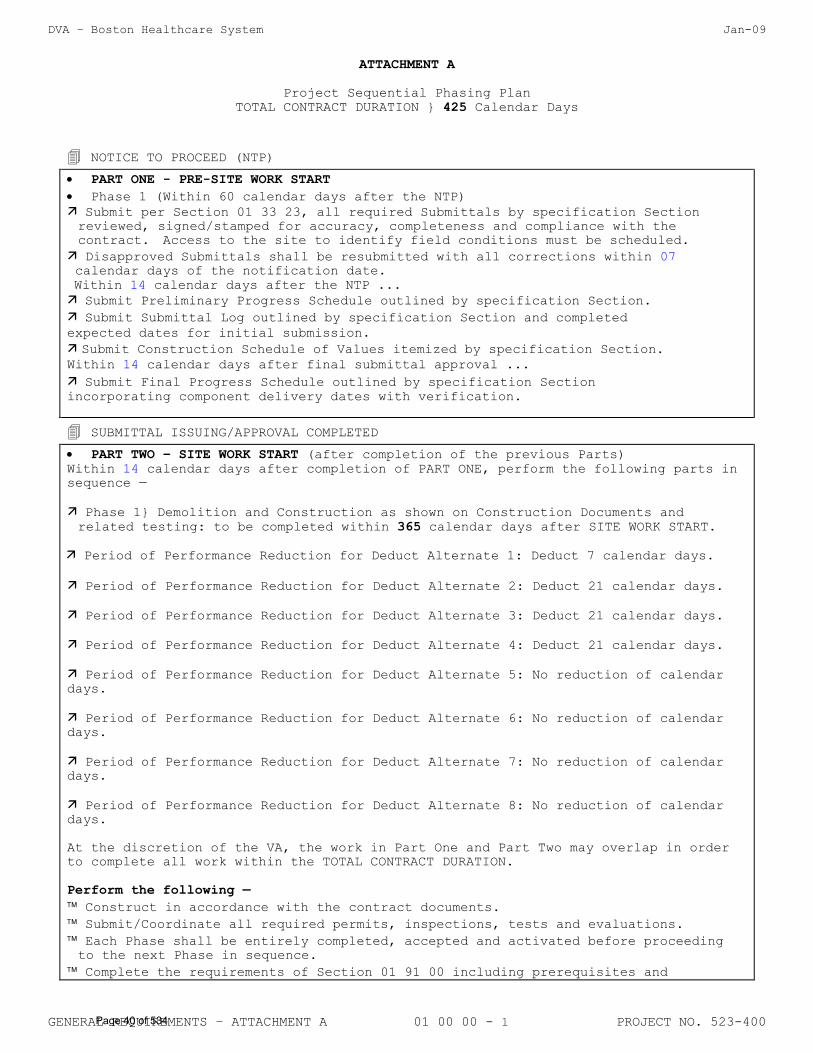
DVA – Boston Healthcare System Jan-09
GENERAL REQUIREMENTS – ATTACHMENT A 01 00 00 - 1 PROJECT NO. 523-400
ATTACHMENT A
Project Sequential Phasing Plan
TOTAL CONTRACT DURATION } 425 Calendar Days
NOTICE TO PROCEED (NTP)
PART ONE - PRE-SITE WORK START
Phase 1 (Within 60 calendar days after the NTP)
Submit per Section 01 33 23, all required Submittals by specification Section
reviewed, signed/stamped for accuracy, completeness and compliance with the
contract. Access to the site to identify field conditions must be scheduled.
Disapproved Submittals shall be resubmitted with all corrections within 07
calendar days of the notification date.
Within 14 calendar days after the NTP ...
Submit Preliminary Progress Schedule outlined by specification Section. Submit Submittal Log outlined by specification Section and completed expected dates for initial submission.
Submit Construction Schedule of Values itemized by specification Section. Within 14 calendar days after final submittal approval ...
Submit Final Progress Schedule outlined by specification Section incorporating component delivery dates with verification.
SUBMITTAL ISSUING/APPROVAL COMPLETED
PART TWO – SITE WORK START (after completion of the previous Parts)
Within 14 calendar days after completion of PART ONE, perform the following parts in
sequence —
Phase 1} Demolition and Construction as shown on Construction Documents and
related testing: to be completed within 365 calendar days after SITE WORK START.
Period of Performance Reduction for Deduct Alternate 1: Deduct 7 calendar days.
Period of Performance Reduction for Deduct Alternate 2: Deduct 21 calendar days.
Period of Performance Reduction for Deduct Alternate 3: Deduct 21 calendar days.
Period of Performance Reduction for Deduct Alternate 4: Deduct 21 calendar days.
Period of Performance Reduction for Deduct Alternate 5: No reduction of calendar
days.
Period of Performance Reduction for Deduct Alternate 6: No reduction of calendar
days.
Period of Performance Reduction for Deduct Alternate 7: No reduction of calendar
days.
Period of Performance Reduction for Deduct Alternate 8: No reduction of calendar
days.
At the discretion of the VA, the work in Part One and Part Two may overlap in order
to complete all work within the TOTAL CONTRACT DURATION.
Perform the following —
Construct in accordance with the contract documents.
Submit/Coordinate all required permits, inspections, tests and evaluations.
Each Phase shall be entirely completed, accepted and activated before proceeding to the next Phase in sequence.
Complete the requirements of Section 01 91 00 including prerequisites and
Page 40 of 534
DVA – Boston Healthcare System Jan-09
GENERAL REQUIREMENTS – ATTACHMENT A 01 00 00 - 1 PROJECT NO. 523-400
occupancy checklist as specified before final inspection of each Phase in sequence.
FINAL ACCEPTANCE
Page 41 of 534
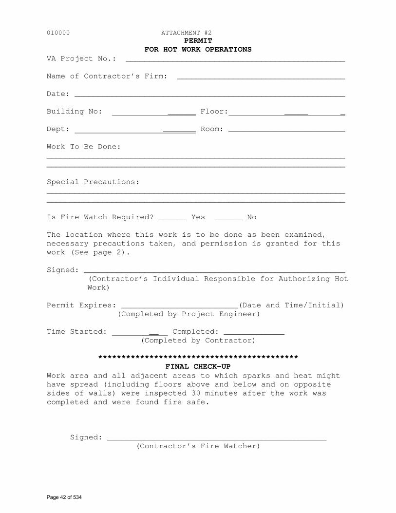
010000 ATTACHMENT #2PERMIT
FOR HOT WORK OPERATIONS VA Project No.: _______________________________________________
Name of Contractor’s Firm: ____________________________________
Date: __________________________________________________________
Building No: ______ Floor: _____ _
Dept: _______ Room: _________________________
Work To Be Done: ________________________________________________________________________________________________________________________________
Special Precautions: ________________________________________________________________________________________________________________________________
Is Fire Watch Required? ______ Yes ______ No
The location where this work is to be done as been examined, necessary precautions taken, and permission is granted for this work (See page 2).
Signed: ________________________________________________________ (Contractor’s Individual Responsible for Authorizing Hot Work)
Permit Expires: _________________________(Date and Time/Initial) (Completed by Project Engineer)
Time Started: __ Completed: _____________ (Completed by Contractor)
******************************************* FINAL CHECK-UP
Work area and all adjacent areas to which sparks and heat might have spread (including floors above and below and on opposite sides of walls) were inspected 30 minutes after the work was completed and were found fire safe.
Signed: _______________________________________________(Contractor’s Fire Watcher)
Page 42 of 534
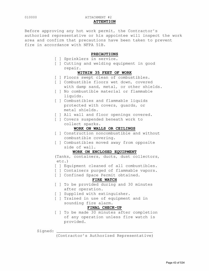
010000 ATTACHMENT #2ATTENTION
Before approving any hot work permit, the Contractor’s authorized representative or his appointee will inspect the work area and confirm that precautions have been taken to prevent fire in accordance with NFPA 51B.
PRECAUTIONS [ ] Sprinklers in service. [ ] Cutting and welding equipment in good
repair. WITHIN 35 FEET OF WORK
[ ] Floors swept clean of combustibles. [ ] Combustible floors wet down, covered
with damp sand, metal, or other shields. [ ] No combustible material or flammable
liquids. [ ] Combustibles and flammable liquids
protected with covers, guards, or metal shields.
[ ] All wall and floor openings covered. [ ] Covers suspended beneath work to
collect sparks. WORK ON WALLS OR CEILINGS
[ ] Construction noncombustible and without combustible covering.
[ ] Combustibles moved away from opposite side of wall.
WORK ON ENCLOSED EQUIPMENT (Tanks, containers, ducts, dust collectors, etc.) [ ] Equipment cleaned of all combustibles. [ ] Containers purged of flammable vapors. [ ] Confined Space Permit obtained.
FIRE WATCH [ ] To be provided during and 30 minutes
after operation. [ ] Supplied with extinguisher. [ ] Trained in use of equipment and in
sounding fire alarm. FINAL CHECK-UP
[ ] To be made 30 minutes after completion of any operation unless fire watch is provided.
Signed: _______________________________________ (Contractor’s Authorized Representative)
Page 43 of 534
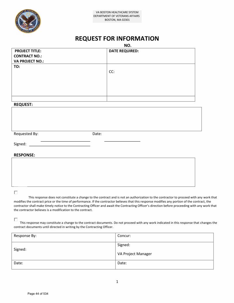
1
REQUEST FOR INFORMATIONNO.
PROJECT TITLE: CONTRACT NO.: VA PROJECT NO.:
DATE REQUIRED:
TO: CC:
REQUEST:
Requested By: Date:
Signed:
RESPONSE:
This response does not constitute a change to the contract and is not an authorization to the contractor to proceed with any work that modifies the contract price or the time of performance. If the contractor believes that this response modifies any portion of the contract, the contractor shall make timely notice to the Contracting Officer and await the Contracting Officer’s direction before proceeding with any work that the contractor believes is a modification to the contract.
This response may constitute a change to the contract documents. Do not proceed with any work indicated in this response that changes the contract documents until directed in writing by the Contracting Officer.
Response By: Concur:
Signed: Signed:
VA Project Manager
Date: Date:
VA BOSTON HEALTHCARE SYSTEM DEPARTMENT OF VETERANS AFFAIRS
BOSTON, MA 02301
Page 44 of 534
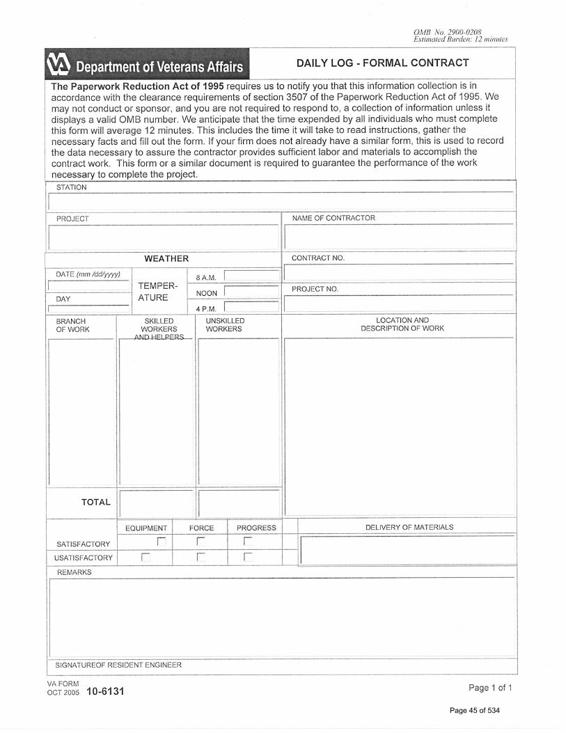
Page 45 of 534
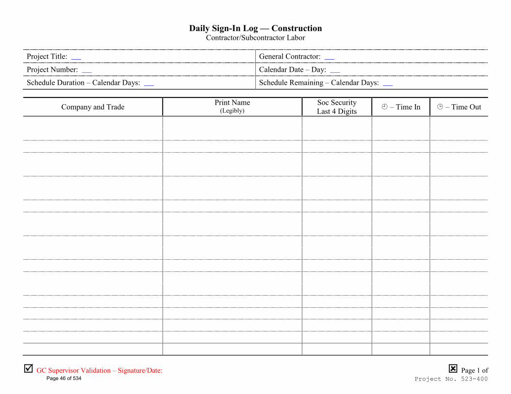
GC Supervisor Validation – Signature/Date: Page 1 of Project No. 523-400
Daily Sign-In Log — Construction Contractor/Subcontractor Labor
Project Title: ___ General Contractor: ___
Project Number: ___ Calendar Date – Day: ___
Schedule Duration – Calendar Days: ___ Schedule Remaining – Calendar Days: ___
Company and Trade Print Name (Legibly)
Soc Security Last 4 Digits – Time In – Time Out
Page 46 of 534
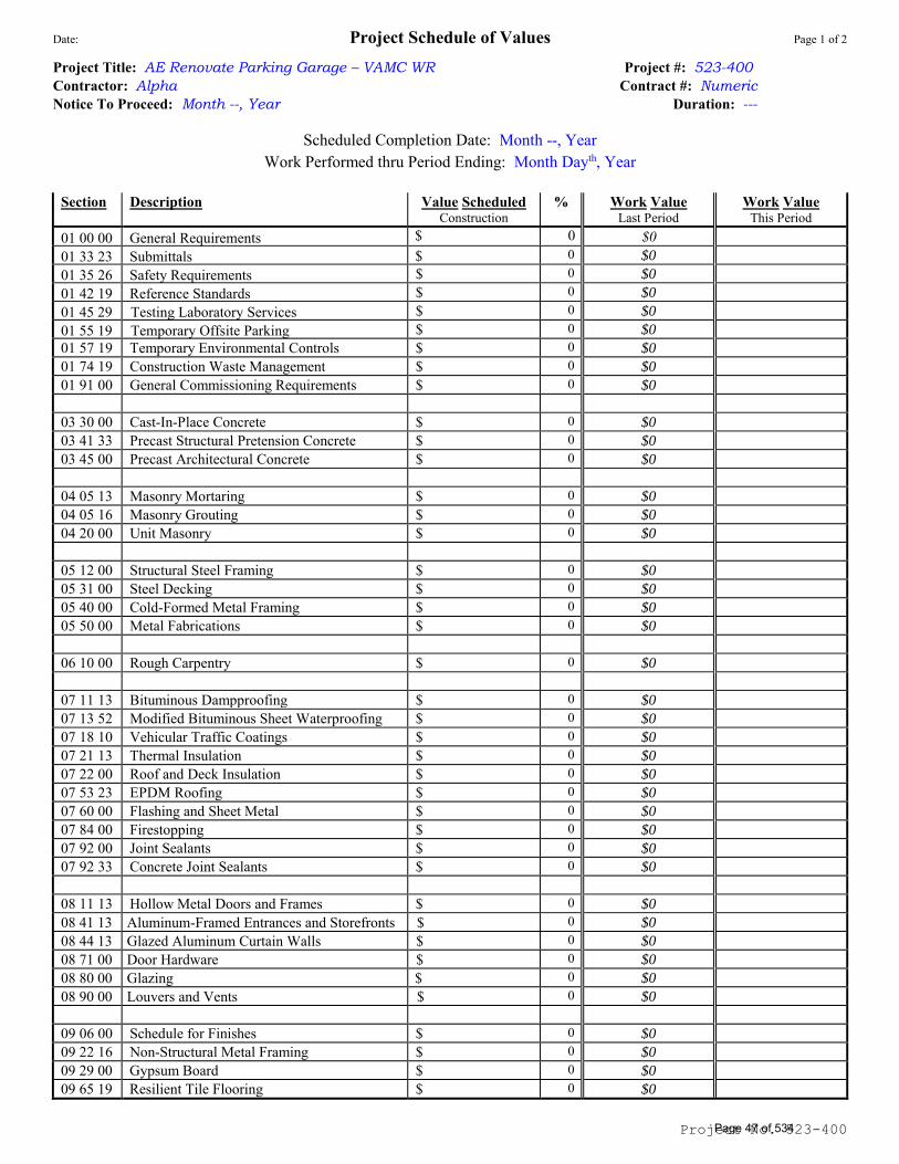
Date: Project Schedule of Values Page 1 of 2
Project No. 523-400
Project Title: AE Renovate Parking Garage – VAMC WR Project #: 523-400
Contractor: Alpha Contract #: Numeric Notice To Proceed: Month --, Year Duration: ---
Scheduled Completion Date: Month --, Year Work Performed thru Period Ending: Month Dayth, Year
Section Description Value Scheduled Construction
% Work Value Last Period
Work Value This Period
$ 0 $0
$ 0 $0
$ 0 $0
01 00 00 General Requirements 01 33 23 Submittals 01 35 26 Safety Requirements 01 42 19 Reference Standards 01 45 29 Testing Laboratory Services01 55 19 Temporary Offsite Parking
$ 0 $0
$ 0 $0
01 57 19 Temporary Environmental Controls $ 0 $0
01 74 19 Construction Waste Management $ 0 $0
01 91 00 General Commissioning Requirements $ 0 $0
03 30 00 Cast-In-Place Concrete $ 0 $0
03 41 33 Precast Structural Pretension Concrete $ 0 $0
03 45 00 Precast Architectural Concrete $ 0 $0
04 05 13 Masonry Mortaring $ 0 $0
04 05 16 Masonry Grouting $ 0 $0
04 20 00 Unit Masonry $ 0 $0
05 12 00 Structural Steel Framing $ 0 $0
05 31 00 Steel Decking $ 0 $0
05 40 00 Cold-Formed Metal Framing $ 0 $0
05 50 00 Metal Fabrications $ 0 $0
06 10 00 Rough Carpentry $ 0 $0
07 11 13 Bituminous Dampproofing $ 0 $0
07 13 52 Modified Bituminous Sheet Waterproofing $ 0 $0
07 18 10 Vehicular Traffic Coatings $ 0 $0
07 21 13 Thermal Insulation $ 0 $0
07 22 00 Roof and Deck Insulation $ 0 $0
07 53 23 EPDM Roofing $ 0 $0
07 60 00 Flashing and Sheet Metal $ 0 $0
07 84 00 Firestopping $ 0 $0
07 92 00 Joint Sealants $ 0 $0
07 92 33 Concrete Joint Sealants $ 0 $0
08 11 13 Hollow Metal Doors and Frames $ 0 $0
0 $0
0 $0
0 $0
0 $0
08 41 13 Aluminum-Framed Entrances and Storefronts $ 08 44 13 Glazed Aluminum Curtain Walls $ 08 71 00 Door Hardware $ 08 80 00 Glazing $ 08 90 00 Louvers and Vents $ 0 $0
$ 0 $0
$ 0 $0
$ 0 $0
09 06 00 Schedule for Finishes 09 22 16 Non-Structural Metal Framing 09 29 00 Gypsum Board 09 65 19 Resilient Tile Flooring $ 0 $0
$ 0 $0
Page 47 of 534
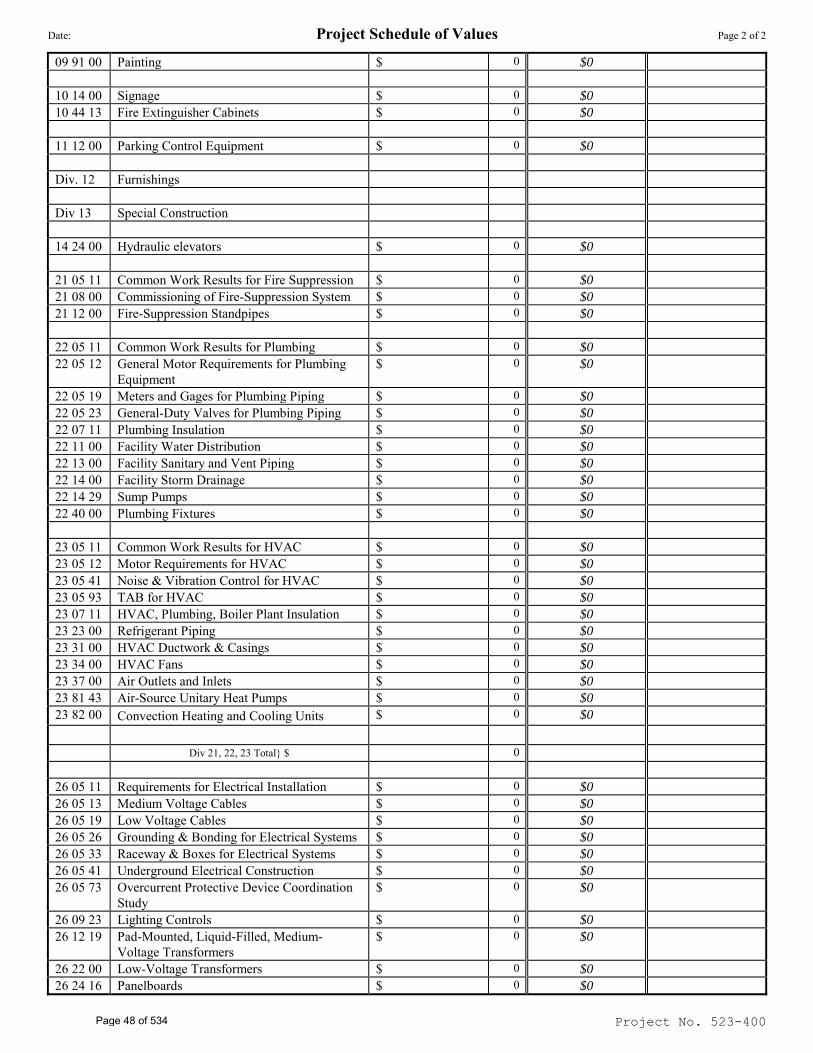
Date: Project Schedule of Values Page 2 of 2
Project No. 523-400
09 91 00 Painting $ 0 $0
10 14 00 Signage $ 0 $0
10 44 13 Fire Extinguisher Cabinets $ 0 $0
11 12 00 Parking Control Equipment $ 0 $0
Div. 12 Furnishings
Div 13 Special Construction
14 24 00 Hydraulic elevators $ 0 $0
21 05 11 Common Work Results for Fire Suppression $ 0 $0
21 08 00 Commissioning of Fire-Suppression System $ 0 $0
21 12 00 Fire-Suppression Standpipes $ 0 $0
22 05 11 Common Work Results for Plumbing $ 0 $0
22 05 12 General Motor Requirements for Plumbing
Equipment
$ 0 $0
22 05 19 Meters and Gages for Plumbing Piping $ 0 $0
22 05 23 General-Duty Valves for Plumbing Piping $ 0 $0
22 07 11 Plumbing Insulation $ 0 $0
22 11 00 Facility Water Distribution $ 0 $0
22 13 00 Facility Sanitary and Vent Piping $ 0 $0
22 14 00 Facility Storm Drainage $ 0 $0
22 14 29 Sump Pumps $ 0 $0
22 40 00 Plumbing Fixtures $ 0 $0
23 05 11 Common Work Results for HVAC $ 0 $0
23 05 12 Motor Requirements for HVAC $ 0 $0
23 05 41 Noise & Vibration Control for HVAC $ 0 $0
23 05 93 TAB for HVAC $ 0 $0
23 07 11 HVAC, Plumbing, Boiler Plant Insulation $ 0 $0
23 23 00 Refrigerant Piping $ 0 $0
23 31 00 HVAC Ductwork & Casings $ 0 $0
23 34 00 HVAC Fans $ 0 $0
23 37 00 Air Outlets and Inlets $ 0 $0
23 81 43 Air-Source Unitary Heat Pumps $ 0 $0
23 82 00 Convection Heating and Cooling Units $ 0 $0
Div 21, 22, 23 Total} $ 0
26 05 11 Requirements for Electrical Installation $ 0 $0
26 05 13 Medium Voltage Cables $ 0 $0
26 05 19 Low Voltage Cables $ 0 $0
26 05 26 Grounding & Bonding for Electrical Systems $ 0 $0
26 05 33 Raceway & Boxes for Electrical Systems $ 0 $0
26 05 41 Underground Electrical Construction $ 0 $0
26 05 73 Overcurrent Protective Device Coordination Study
$ 0 $0
26 09 23 Lighting Controls $ 0 $0
26 12 19 Pad-Mounted, Liquid-Filled, Medium-
Voltage Transformers
$ 0 $0
26 22 00 Low-Voltage Transformers $ 0 $0
26 24 16 Panelboards $ 0 $0
Page 48 of 534
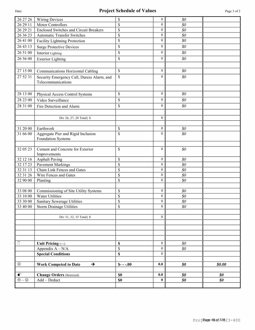
Date: Project Schedule of Values Page 3 of 2
Project No. 523-400
26 27 26 Wiring Devices $ 0 $0
26 29 11 Motor Controllers $ 0 $0
26 29 21 Enclosed Switches and Circuit Breakers $ 0 $0
26 36 23 Automatic Transfer Switches $ 0 $0
26 41 00 Facility Lightning Protection $ 0 $0
26 43 13 Surge Protective Devices $ 0 $0
26 51 00 Interior Lighting $ 0 $0
26 56 00 Exterior Lighting $ 0 $0
27 15 00 Communications Horizontal Cabling $ 0 $0
27 52 31 Security Emergency Call, Duress Alarm, and
Telecommunications
$ 0 $0
28 13 00 Physical Access Control Systems $ 0 $0
28 23 00 Video Surveillance $ 0 $0
28 31 00 Fire Detection and Alarm $ 0 $0
Div 26, 27, 28 Total} $ 0
31 20 00 Earthwork $ 0 $0
31 66 00 Aggregate Pier and Rigid Inclusion Foundation Systems
$ 0 $0
32 05 23 Cement and Concrete for Exterior Improvements
$ 0 $0
32 12 16 Asphalt Paving $ 0 $0
32 17 23 Pavement Markings $ 0 $0
32 31 13 Chain Link Fences and Gates $ 0 $0
32 31 26 Wire Fences and Gates $ 0 $0
32 90 00 Planting $ 0 $0
33 08 00 Commissioning of Site Utility Systems $ 0 $0
33 10 00 Water Utilities $ 0 $0
33 30 00 Sanitary Sewerage Utilities $ 0 $0
33 40 00 Storm Drainage Utilities $ 0 $0
Div 31, 32, 33 Total} $ 0
Unit Pricing (---) $ 0 $0
Appendix A – N/A $ 0 $0
Special Conditions $ 0
Work Competed to Date $- - -.00 0.0 $0 $0.00
Change Orders (Itemized) $0 0.0 $0 $0
– Add – Deduct $0 0 $0 $0
Page 49 of 534
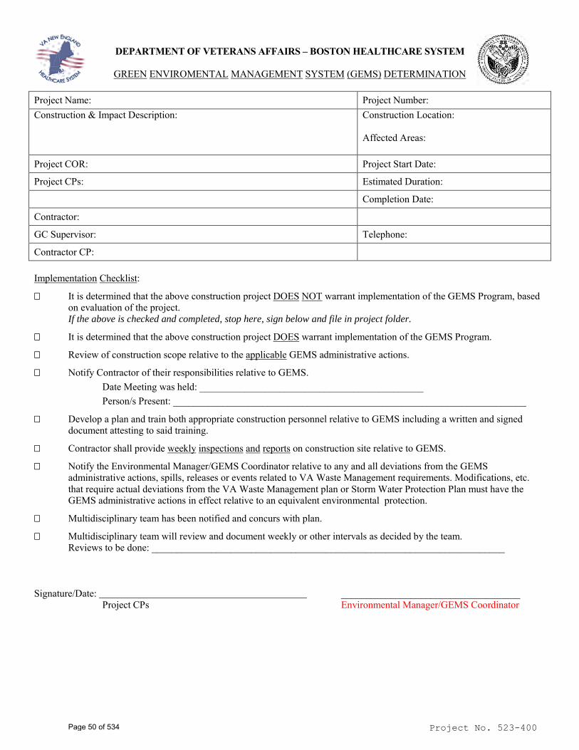
Project No. 523-400
DEPARTMENT OF VETERANS AFFAIRS – BOSTON HEALTHCARE SYSTEM
GREEN ENVIROMENTAL MANAGEMENT SYSTEM (GEMS) DETERMINATION
Project Name: Project Number: Construction & Impact Description: Construction Location:
Affected Areas:
Project COR: Project Start Date:
Project CPs: Estimated Duration:
Completion Date:
Contractor:
GC Supervisor: Telephone:
Contractor CP:
Implementation Checklist:
It is determined that the above construction project DOES NOT warrant implementation of the GEMS Program, based on evaluation of the project. If the above is checked and completed, stop here, sign below and file in project folder.
It is determined that the above construction project DOES warrant implementation of the GEMS Program.
Review of construction scope relative to the applicable GEMS administrative actions.
Notify Contractor of their responsibilities relative to GEMS. Date Meeting was held: _____________________________________________ Person/s Present: _______________________________________________________________________
Develop a plan and train both appropriate construction personnel relative to GEMS including a written and signed document attesting to said training.
Contractor shall provide weekly inspections and reports on construction site relative to GEMS.
Notify the Environmental Manager/GEMS Coordinator relative to any and all deviations from the GEMS administrative actions, spills, releases or events related to VA Waste Management requirements. Modifications, etc. that require actual deviations from the VA Waste Management plan or Storm Water Protection Plan must have the GEMS administrative actions in effect relative to an equivalent environmental protection.
Multidisciplinary team has been notified and concurs with plan.
Multidisciplinary team will review and document weekly or other intervals as decided by the team. Reviews to be done: _______________________________________________________________________
Signature/Date: ____________________________________ Project CPs Environmental Manager/GEMS Coordinator
Page 50 of 534
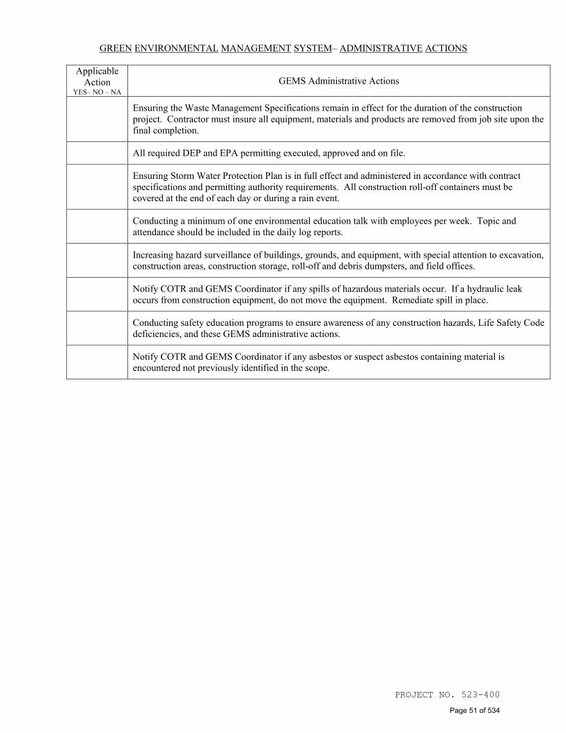
PROJECT NO. 523-400
GREEN ENVIRONMENTAL MANAGEMENT SYSTEM– ADMINISTRATIVE ACTIONS
Applicable Action
YES– NO – NA GEMS Administrative Actions
Ensuring the Waste Management Specifications remain in effect for the duration of the construction project. Contractor must insure all equipment, materials and products are removed from job site upon the final completion.
All required DEP and EPA permitting executed, approved and on file.
Ensuring Storm Water Protection Plan is in full effect and administered in accordance with contract
specifications and permitting authority requirements. All construction roll-off containers must be covered at the end of each day or during a rain event.
Conducting a minimum of one environmental education talk with employees per week. Topic and
attendance should be included in the daily log reports.
Increasing hazard surveillance of buildings, grounds, and equipment, with special attention to excavation,
construction areas, construction storage, roll-off and debris dumpsters, and field offices.
Notify COTR and GEMS Coordinator if any spills of hazardous materials occur. If a hydraulic leak
occurs from construction equipment, do not move the equipment. Remediate spill in place.
Conducting safety education programs to ensure awareness of any construction hazards, Life Safety Code
deficiencies, and these GEMS administrative actions.
Notify COTR and GEMS Coordinator if any asbestos or suspect asbestos containing material is
encountered not previously identified in the scope.
Page 51 of 534
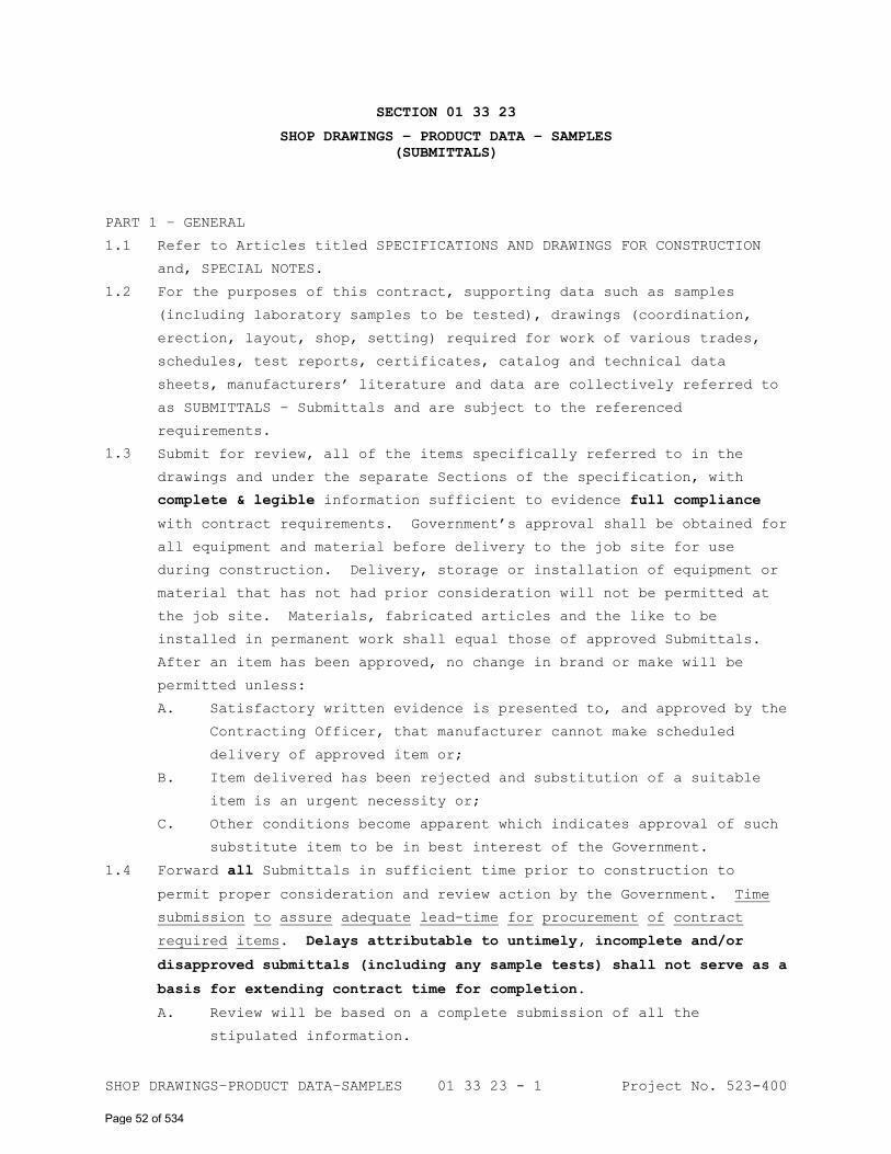
SHOP DRAWINGS–PRODUCT DATA–SAMPLES 01 33 23 - 1 Project No. 523-400
SECTION 01 33 23
SHOP DRAWINGS – PRODUCT DATA – SAMPLES
(SUBMITTALS)
PART 1 – GENERAL
1.1 Refer to Articles titled SPECIFICATIONS AND DRAWINGS FOR CONSTRUCTION
1.2
1.3
and, SPECIAL NOTES.
For the purposes of this contract, supporting data such as samples
(including laboratory samples to be tested), drawings (coordination,
erection, layout, shop, setting) required for work of various trades,
schedules, test reports, certificates, catalog and technical data
sheets, manufacturers’ literature and data are collectively referred to
as SUBMITTALS – Submittals and are subject to the referenced
requirements.
Submit for review, all of the items specifically referred to in the
drawings and under the separate Sections of the specification, with
complete & legible information sufficient to evidence full compliance
with contract requirements. Government’s approval shall be obtained for
all equipment and material before delivery to the job site for use
during construction. Delivery, storage or installation of equipment or
material that has not had prior consideration will not be permitted at
the job site. Materials, fabricated articles and the like to be
installed in permanent work shall equal those of approved Submittals.
After an item has been approved, no change in brand or make will be
permitted unless:
A. Satisfactory written evidence is presented to, and approved by the
Contracting Officer, that manufacturer cannot make scheduled
delivery of approved item or;
B. Item delivered has been rejected and substitution of a suitable
item is an urgent necessity or;
C. Other conditions become apparent which indicates approval of such
substitute item to be in best interest of the Government.
1.4 Forward all Submittals in sufficient time prior to construction to
permit proper consideration and review action by the Government. Time
submission to assure adequate lead-time for procurement of contract
required items. Delays attributable to untimely, incomplete and/or
disapproved submittals (including any sample tests) shall not serve as a
basis for extending contract time for completion.
A. Review will be based on a complete submission of all the
stipulated information.
Page 52 of 534
SHOP DRAWINGS–PRODUCT DATA–SAMPLES 01 33 23 - 2 Project No. 523-400
B. Submittals shall be sent electronically in the following manner:
1. Contractor shall digitally sign submittals using PDF writer
software (eg, Adobe Acrobat or Nuance PDF Converter).
Submittals will receive consideration only when sent via
electronic methods and signed by the Contractor.
2. Contractor shall have equipment to scan supporting data
(submittals) in PDF format. Contractor shall include
electronic supporting data in PDF format with each
Submittal.
1.5
1.6
1.7
1.8
Submittals will be reviewed for compliance with contract requirements by
the Government designee, if requested by the Contracting Officer, the VA
Project Engineer (COTR), and final action thereon (Approval/Disapproval)
taken by the Contracting Officer. Such review by the Government or
designee shall not alleviate the Contractor of complying with the terms
and conditions specified in the contract documents.
The Government reserves the right to require additional submittals,
whether or not particularly mentioned in this contract. If additional
submittals beyond those required by the contract are furnished pursuant
to request thereof by Contracting Officer, adjustment in contract price
and time will be made in accordance with the Construction Contact
clauses CHANGES and CHANGES SUPPLEMENT.
Schedules and Drawings (coordination, erection, layout, shop, setting)
required by the contract documents shall be submitted for use and
information of the Government and if requested by the Contracting
Office, the Project Engineer. However, the Contractor shall assume
responsibility for coordinating and verifying conditions. The
Government assumes no responsibility for checking schedules or
drawings for exact sizes, exact numbers and detailed positioning of
items.
Submission for Section 01 33 23, SHOP DRAWINGS – PRODUCT DATA –
SAMPLES, shall be made within the performance timeline specified in
Section 01 00 00, GENERAL REQUIREMENTS. Delays attributable to the
untimely, incomplete and/or disapproval of submittals shall not serve as
a basis for extending contract time for completion. Contractor shall
submit a “Submittal Log” and all required submittal items identified in
the contract documents applicable to each specification Section with an
itemized “Submittal Checklist Table” under each separate specification
Section submittal. Contractor shall provide dates in the “Expected”
column of the Submittal Log in chronological order by dates required by
construction schedule. Include time required for review, ordering,
Page 53 of 534
SHOP DRAWINGS–PRODUCT DATA–SAMPLES 01 33 23 - 3 Project No. 523-400
manufacturing, fabrication, and delivery when establishing dates.
Include additional time required for making corrections or revisions to
submittals noted by VA Project Engineer (COTR) and additional time for
handling and reviewing submittals required by those corrections.
A. Submittals and Schedules required by the construction documents
shall be checked before submission by technically qualified
employees of the Contractor for accuracy, completeness and
compliance with the contract requirements. These documents shall
be electronically signed/stamped by the Contractor certificating
to this review. Drawings (coordination, erection, layout, shop,
setting) for all equipment and component installation are
required. Required certificates shall be signed by an authorized
representative of the manufacturer or supplier of material, and
the Contractor.
B. Submittals for individual systems and equipment assemblies that
consist of more than one item or component shall be made for the
system or assembly as a whole. Submittals shall include adequate
descriptive literature (catalog and technical data, drawings, etc)
and other information necessary for the Government to ascertain
that the proposed equipment and materials comply with
specification requirements. Submitted information shall be
legible and clearly identify the specific items proposed. Failure
to comply with the Submittal requirements shall not serve as a
basis for extending the contract time.
C. Submittals shall receive consideration only when issued with
complete & legible information sufficient to evidence full
compliance with contract requirements. Submittals shall contain
adequate descriptive information, including the Medical Center
name & address, Contractor name & address, Project name & number,
and other information required for exact identification and
location for each item being furnished.
1. Submittals shall be assembled by each specification Section
using the Section 01 33 23 Cover Sheet – Checklist Table
(Attachment A), and Submittal Log (Attachment D). One
Submittal package only (with the specified sets) shall be
issued for each applicable specification Section. Each
Submittal package shall itemize all required items
identified in the contract documents applicable to the
Section being submitted.
Page 54 of 534
SHOP DRAWINGS–PRODUCT DATA–SAMPLES 01 33 23 - 4 Project No. 523-400
2. Submittals shall be sequentially numbered by specification
Section using the Submittal Log (Attachment D). In
subsequent correspondence, this file and identification
number shall be used to expedite tracking and communication.
3. Submittals shall contain a list of all items specified
referencing the applicable specification Section & Article
numbers and/or applicable Drawing numbers (and other
information required for exact identification and location),
and additional information as may be required by
specification Section for each item.
4. Submitted information shall include the manufacturer, brand,
make, model, size, quantity, catalog and technical data
sheets (marked to indicate specific items submitted),
drawings (coordination, erection, layout, shop, setting),
pictures, nameplates, test reports, specified Publication
number and other specified requirements highlighted, and
other information as may be required that demonstrates
compliance with the contract requirements.
5. Items submitted that deviate from the contract requirements
shall be marked “Deviation” and include a detailed
explanation of why the deviation is being proposed and why
the submitted product is an acceptable substitution from
that specified. Such deviations are subject to approval and
review by the Contracting Officer. Forward all deviations
in sufficient time prior to construction to permit proper
consideration, review and action by the Government. Delays
attributable to untimely notification of deviations shall
not serve as a basis for extending contract time.
D. Disapproved submittals shall be resubmitted with all the required
corrections within the performance timeline specified in Section
01 00 00, GENERAL REQUIREMENTS. Such revised submittals shall be
marked “Resubmission” with an incremental Issue number.
“Section Number __________ Submittal Number __________ “Issue
Number __________ ”.
1.9 If the Contractor is unable to scan electronically large documents, upon
Contracting Officer approval, the submittals may be shipped by the
Contractor prepaid to the designees authorized.
A. Submit approved quantities of samples (including laboratory
samples to be tested), drawings (coordination, erection, layout,
shop, setting) required for work of various trades, schedules,
Page 55 of 534
SHOP DRAWINGS–PRODUCT DATA–SAMPLES 01 33 23 - 5 Project No. 523-400
test reports, certificates, catalog and technical data sheets,
manufacturers’ literature and data for review as required.
1. Submittals shall contain adequate descriptive information,
including the Medical Center name & address, Contractor name
& address, Project name & number, applicable specification
Section & Article numbers, applicable Drawing numbers (and
other information required for exact identification and
location for each item), manufacturer, brand, make, model,
size, quantity, specified Publication number and other
specified requirements highlighted, catalogs shall be marked
to indicate specific items submitted for approval, and other
information as may be required that demonstrates compliance
with the contract requirements for the items being
furnished.
2. A space 120 mm by 125 mm (4-3/4 inches by 5 inches) shall be
reserved on each submittal to accommodate
Approved/Disapproved stamps.
3. Submittals shall be transmitted under one cover to
Architect/Engineer and/or Project Engineer (COTR), as
requested by the Contracting Officer.
4. One reproducible print of each Approved/Disapproved
Submittal will be returned to the Contractor.
B. Submit physical samples (except laboratory samples) in quantities
specified. An identification letter must be enclosed with items,
and any items received without identification letter will be
considered “unclaimed goods” and held for a limited time only.
1.10 Upon Contracting Officer’s approval, Submittals shall be transmitted for
review to:
Names and Addresses to be provided after Award …
_________________________
_________________________
_________________________
A. At the time of transmittal to the Architect/Engineer, if requested
by the Contracting Officer, the Contractor shall send electronic
copies of Submittals to the VA COTR and Contracting Officer.
B. Submittals sent for review to the Architect/Engineer shall contain
sufficient information as necessary for exact identification of
each item, and such additional information as required by the
specification Section including …
“Section Number __________ Submittal Number __________ “Issue
Number __________ ”.
Page 56 of 534
SHOP DRAWINGS–PRODUCT DATA–SAMPLES 01 33 23 - 6 Project No. 523-400
1.11 In addition to complying with the applicable requirements specified,
samples that are required to have Laboratory Tests under the separate
Sections of the specification shall be tested, at the expense of
Contractor, in a commercial laboratory approved by the Contracting
Officer.
A. Laboratory shall furnish the Contracting Officer with a
certificate stating that it is fully equipped and qualified to
perform intended work, is fully acquainted with specification
requirements and intended use of materials and is an independent
establishment in no way connected with organization of Contractor
or with manufacturer or supplier of materials to be tested.
B. Laboratory test reports shall list specification test requirements
and a comparative list of the laboratory test results. When tests
show that the material meets specification requirements, the
laboratory shall so certify on the test report.
1.12 Approved Submittal packages shall be kept on file by the Contractor at
the site until the contract completion, and shall be utilized by the
project participants to verify contract compliance of delivered
materials. Approved samples will be kept on file by the VA Project
Engineer until the contract completion, at which time such samples will
be returned to the Contractor only upon request and at the Contractor’s
expense. Where permitted in the individual specification Sections,
approved samples in good condition may be used in their proper locations
in contract work. At the completion of the contract, samples that are
not approved will be returned to the Contractor only upon request and at
the Contractor’s expense. Disapproved samples that are not requested
for return by Contractor will be discarded. Return requests shall be
made in a timely manner prior to the contract completion.
PART 2 – PRODUCTS
Refer to individual Sections for list of products.
PART 3 – EXECUTION
Refer to individual Sections for requirements.
- - - E N D - - -
ATTACHMENTS FOLLOW
Page 57 of 534
SHOP DRAWINGS–PRODUCT DATA–SAMPLES 01 33 23 - 7 Project No. 523-400
Submittal Cover Sheet – Checklist Table (NB: Contractor ATTACHMENT A:
Prepared) … 2 Pages
ATTACHMENT B:
ATTACHMENT C
Submittal Log … 8 Pages
Material Submittal List … 8 Pages
Page 58 of 534
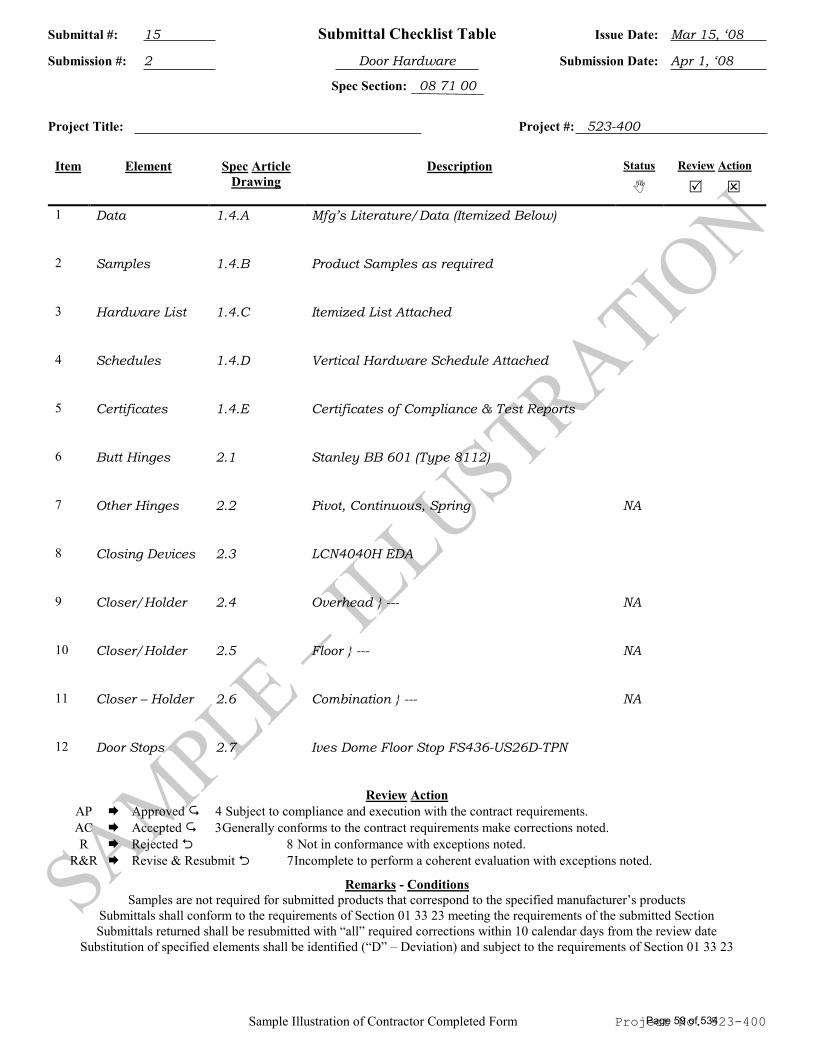
Submittal #: 15 Submittal Checklist Table Issue Date: Mar 15, ‘08
Submission #: 2 Door Hardware Submission Date: Apr 1, ‘08
Spec Section: 08 71 00
Sample Illustration of Contractor Completed Form Project No. 523-400
Project Title: Project #: 523-400
Item Element Spec Article
Drawing Description Status
Review Action
1 Data 1.4.A Mfg’s Literature/Data (Itemized Below)
2 Samples 1.4.B Product Samples as required
3 Hardware List 1.4.C Itemized List Attached
4 Schedules 1.4.D Vertical Hardware Schedule Attached
5 Certificates 1.4.E Certificates of Compliance & Test Reports
6 Butt Hinges 2.1 Stanley BB 601 (Type 8112)
7 Other Hinges 2.2 Pivot, Continuous, Spring NA
8 Closing Devices 2.3 LCN4040H EDA
9 Closer/Holder 2.4 Overhead } --- NA
10 Closer/Holder 2.5 Floor } --- NA
11 Closer – Holder 2.6 Combination } --- NA
12 Door Stops 2.7 Ives Dome Floor Stop FS436-US26D-TPN
Review Action AP Approved Subject to compliance and execution with the contract requirements. AC Accepted Generally conforms to the contract requirements make corrections noted. R Rejected Not in conformance with exceptions noted. R&R Revise & Resubmit Incomplete to perform a coherent evaluation with exceptions noted.
Remarks - Conditions Samples are not required for submitted products that correspond to the specified manufacturer’s products
Submittals shall conform to the requirements of Section 01 33 23 meeting the requirements of the submitted Section Submittals returned shall be resubmitted with “all” required corrections within 10 calendar days from the review date
Substitution of specified elements shall be identified (“D” – Deviation) and subject to the requirements of Section 01 33 23
Page 59 of 534
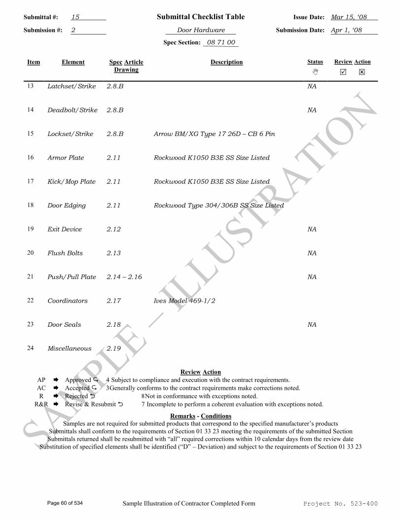
Submittal #: 15 Submittal Checklist Table Issue Date: Mar 15, ‘08
Submission #: 2 Door Hardware Submission Date: Apr 1, ‘08
Spec Section: 08 71 00
Sample Illustration of Contractor Completed Form Project No. 523-400
Item Element Spec Article
Drawing Description Status
Review Action
13 Latchset/Strike 2.8.B NA
14 Deadbolt/Strike 2.8.B NA
15 Lockset/Strike 2.8.B Arrow BM/XG Type 17 26D – CB 6 Pin
16 Armor Plate 2.11 Rockwood K1050 B3E SS Size Listed
17 Kick/Mop Plate 2.11 Rockwood K1050 B3E SS Size Listed
18 Door Edging 2.11 Rockwood Type 304/306B SS Size Listed
19 Exit Device 2.12 NA
20 Flush Bolts 2.13 NA
21 Push/Pull Plate 2.14 – 2.16 NA
22 Coordinators 2.17 Ives Model 469-1/2
23 Door Seals 2.18 NA
24 Miscellaneous 2.19
Review Action AP Approved Subject to compliance and execution with the contract requirements. AC Accepted Generally conforms to the contract requirements make corrections noted. R Rejected Not in conformance with exceptions noted. R&R Revise & Resubmit Incomplete to perform a coherent evaluation with exceptions noted.
Remarks - Conditions Samples are not required for submitted products that correspond to the specified manufacturer’s products
Submittals shall conform to the requirements of Section 01 33 23 meeting the requirements of the submitted Section Submittals returned shall be resubmitted with “all” required corrections within 10 calendar days from the review date
Substitution of specified elements shall be identified (“D” – Deviation) and subject to the requirements of Section 01 33 23
Page 60 of 534
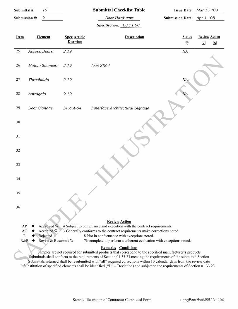
Submittal #: 15 Submittal Checklist Table Issue Date: Mar 15, ‘08
Submission #: 2 Door Hardware Submission Date: Apr 1, ‘08
Spec Section: 08 71 00
Sample Illustration of Contractor Completed Form Project No. 523-400
Item Element Spec Article
Drawing Description Status
Review Action
25 Access Doors 2.19 NA
26 Mutes/Silencers 2.19 Ives SR64
27 Thresholds 2.19 NA
28 Astragals 2.19 NA
29 Door Signage Dwg A-04 Innerface Architectural Signage
30
31
32
33
34
35
36
Review Action AP Approved Subject to compliance and execution with the contract requirements. AC Accepted Generally conforms to the contract requirements make corrections noted. R Rejected Not in conformance with exceptions noted. R&R Revise & Resubmit Incomplete to perform a coherent evaluation with exceptions noted.
Remarks - Conditions Samples are not required for submitted products that correspond to the specified manufacturer’s products
Submittals shall conform to the requirements of Section 01 33 23 meeting the requirements of the submitted Section Submittals returned shall be resubmitted with “all” required corrections within 10 calendar days from the review date
Substitution of specified elements shall be identified (“D” – Deviation) and subject to the requirements of Section 01 33 23
Page 61 of 534
Project No. 523-400
Submittal #: Submittal Checklist Table Issue Date:
Submission #: Submission Date:
Spec Section:
Project Title: Project #: 523-400
Item Element Spec Article
Drawing Description Status
Review Action
1
2
3
4
5
6
7
8
9
10
11
12
Review Action AP Approved Subject to compliance and execution with the contract requirements. AC Accepted Generally conforms to the contract requirements make corrections noted. R Rejected Not in conformance with exceptions noted. R&R Revise & Resubmit Incomplete to perform a coherent evaluation with exceptions noted.
Remarks – Conditions Samples are not required for submitted products that correspond to the specified manufacturer’s products
Submittals shall conform to the requirements of Section 01 33 23 meeting the requirements of the submitted Section Submittals returned shall be resubmitted with “all” required corrections within 10 calendar days from the review date
Substitution of specified elements shall be identified (“D” – Deviation) and subject to the requirements of Section 01 33 23
Page 62 of 534
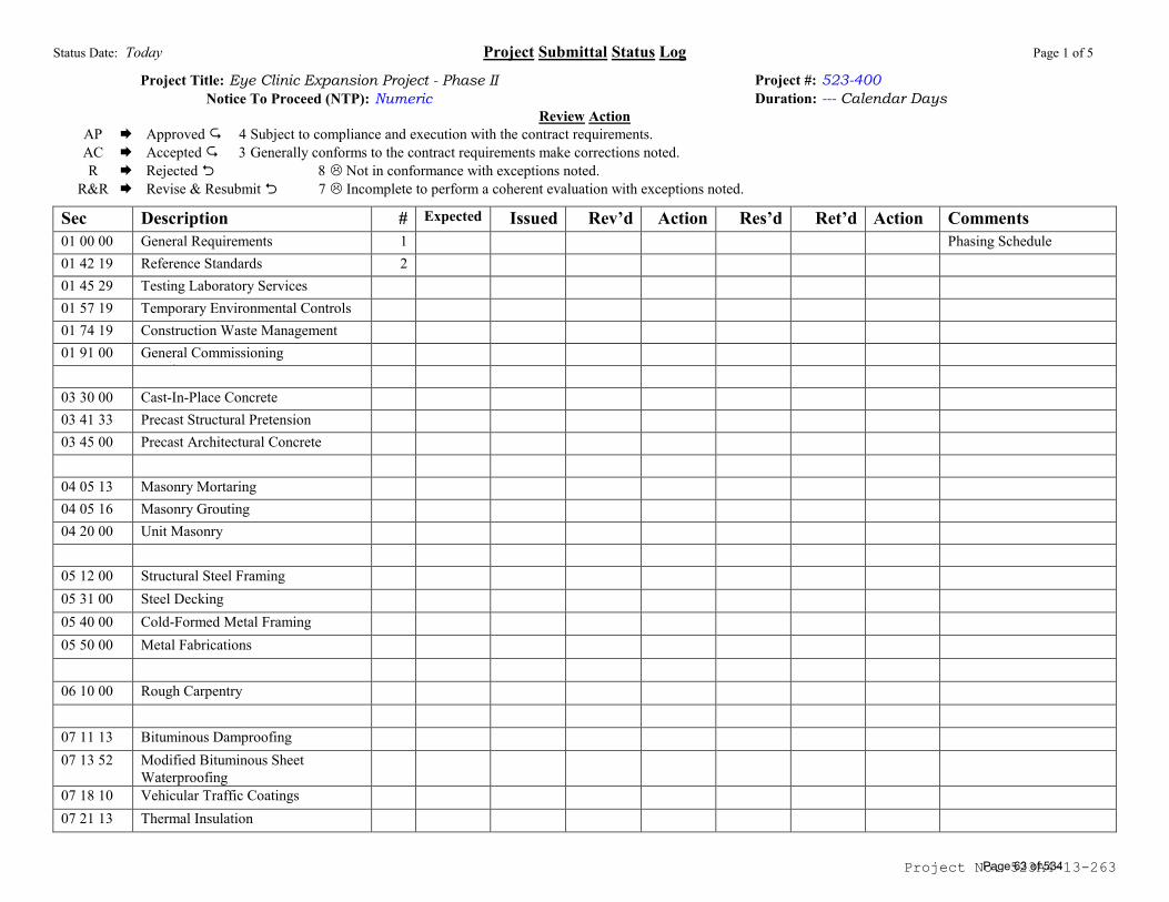
Status Date: Today Project Submittal Status Log Page 1 of 5
Project No. 523A4-13-263
Project Title: Eye Clinic Expansion Project - Phase II Notice To Proceed (NTP): Numeric
Project #: 523-400 Duration: --- Calendar Days
Review Action AP Approved Subject to compliance and execution with the contract requirements. AC Accepted Generally conforms to the contract requirements make corrections noted. R Rejected Not in conformance with exceptions noted.
R&R Revise & Resubmit Incomplete to perform a coherent evaluation with exceptions noted.
Sec Description # Expected Issued Rev’d Action Res’d Ret’d Action Comments 01 00 00 General Requirements 1 Phasing Schedule 01 42 19 Reference Standards 2 01 45 29 Testing Laboratory Services 01 57 19 Temporary Environmental Controls
01 74 19 Construction Waste Management 01 91 00 General Commissioning
Requirements 03 30 00 Cast-In-Place Concrete 03 41 33 Precast Structural Pretension
Concrete 03 45 00 Precast Architectural Concrete
04 05 13 Masonry Mortaring 04 05 16 Masonry Grouting 04 20 00 Unit Masonry
05 12 00 Structural Steel Framing 05 31 00 Steel Decking 05 40 00 Cold-Formed Metal Framing 05 50 00 Metal Fabrications
06 10 00 Rough Carpentry
07 11 13 Bituminous Damproofing 07 13 52 Modified Bituminous Sheet
Waterproofing 07 18 10 Vehicular Traffic Coatings 07 21 13 Thermal Insulation
Page 63 of 534
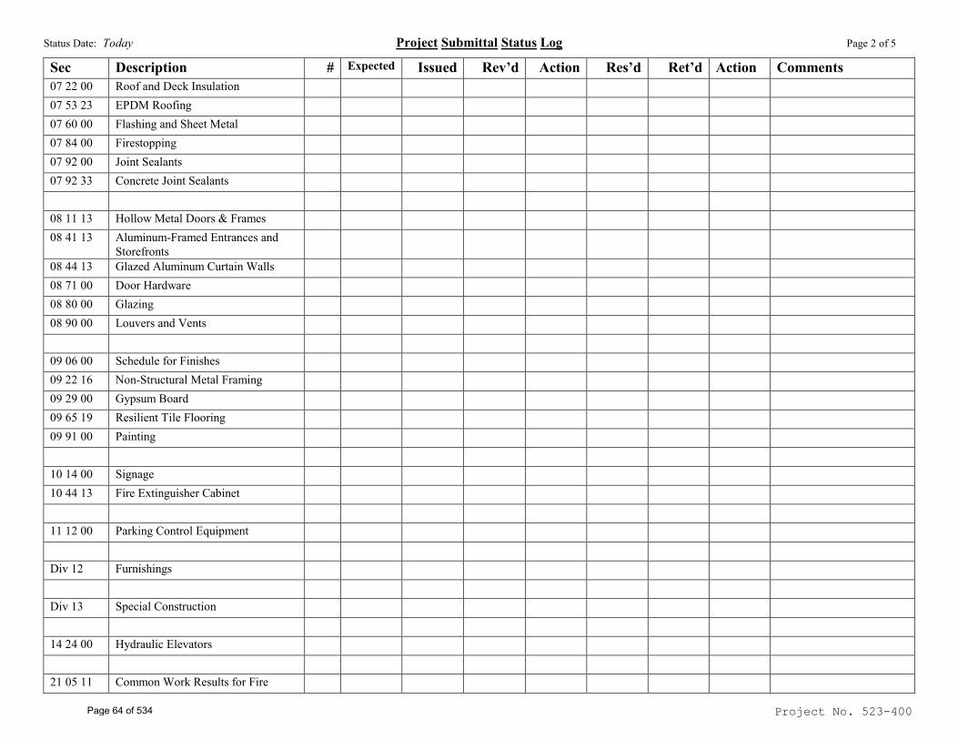
Status Date: Today Project Submittal Status Log Page 2 of 5
Project No. 523-400
Sec Description # Expected Issued Rev’d Action Res’d Ret’d Action Comments 07 22 00 Roof and Deck Insulation 07 53 23 EPDM Roofing 07 60 00 Flashing and Sheet Metal 07 84 00 Firestopping 07 92 00 Joint Sealants 07 92 33 Concrete Joint Sealants
08 11 13 Hollow Metal Doors & Frames 08 41 13 Aluminum-Framed Entrances and
Storefronts 08 44 13 Glazed Aluminum Curtain Walls 08 71 00 Door Hardware 08 80 00 Glazing 08 90 00 Louvers and Vents
09 06 00 Schedule for Finishes 09 22 16 Non-Structural Metal Framing
09 29 00 Gypsum Board
09 65 19 Resilient Tile Flooring 09 91 00 Painting
10 14 00 Signage 10 44 13 Fire Extinguisher Cabinet
11 12 00 Parking Control Equipment
Div 12 Furnishings
Div 13 Special Construction
14 24 00 Hydraulic Elevators
21 05 11 Common Work Results for Fire
Page 64 of 534
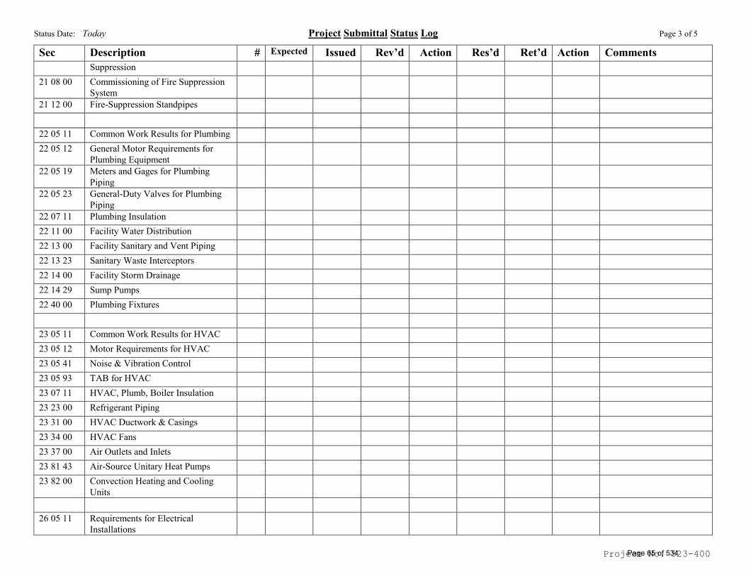
Status Date: Today Project Submittal Status Log Page 3 of 5
Project No. 523-400
Sec Description # Expected Issued Rev’d Action Res’d Ret’d Action Comments Suppression
21 08 00 Commissioning of Fire Suppression
System
21 12 00 Fire-Suppression Standpipes
22 05 11 Common Work Results for Plumbing
22 05 12 General Motor Requirements for
Plumbing Equipment
22 05 19 Meters and Gages for Plumbing
Piping
22 05 23 General-Duty Valves for Plumbing
Piping
22 07 11 Plumbing Insulation
22 11 00 Facility Water Distribution
22 13 00 Facility Sanitary and Vent Piping
22 13 23 Sanitary Waste Interceptors
22 14 00 Facility Storm Drainage
22 14 29 Sump Pumps
22 40 00 Plumbing Fixtures
23 05 11 Common Work Results for HVAC
23 05 12 Motor Requirements for HVAC 23 05 41 Noise & Vibration Control 23 05 93 TAB for HVAC 23 07 11 HVAC, Plumb, Boiler Insulation 23 23 00 Refrigerant Piping
23 31 00 HVAC Ductwork & Casings 23 34 00 HVAC Fans 23 37 00 Air Outlets and Inlets
23 81 43 Air-Source Unitary Heat Pumps
23 82 00 Convection Heating and Cooling
Units
26 05 11 Requirements for Electrical
Installations
Page 65 of 534
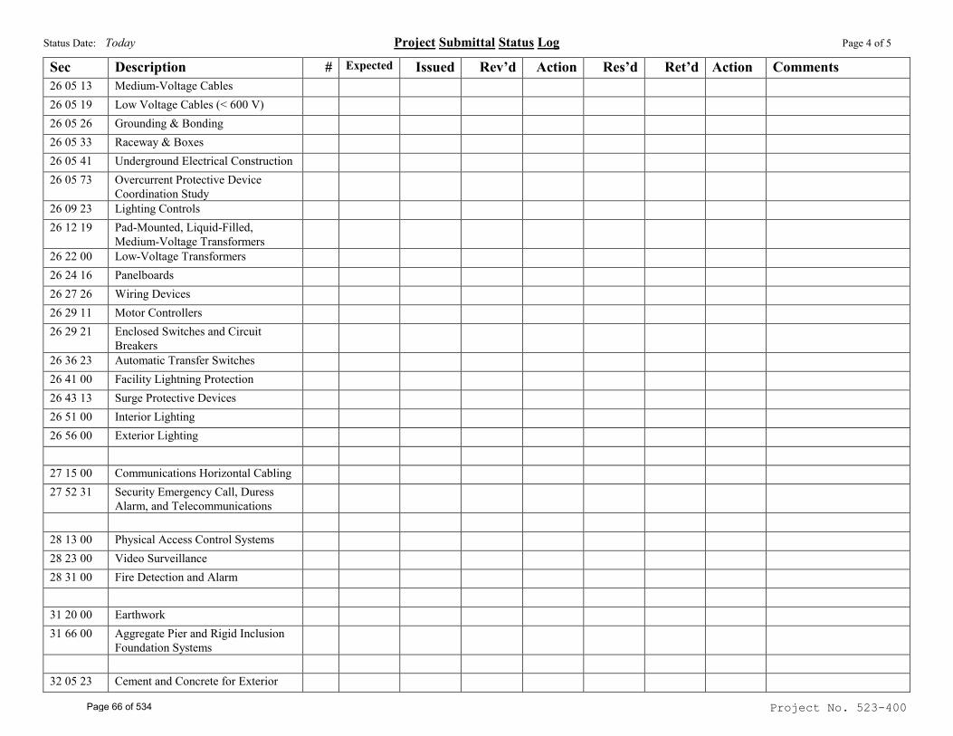
Status Date: Today Project Submittal Status Log Page 4 of 5
Project No. 523-400
Sec Description # Expected Issued Rev’d Action Res’d Ret’d Action Comments 26 05 13 Medium-Voltage Cables
26 05 19 Low Voltage Cables (< 600 V) 26 05 26 Grounding & Bonding 26 05 33 Raceway & Boxes 26 05 41 Underground Electrical Construction
26 05 73 Overcurrent Protective Device
Coordination Study
26 09 23 Lighting Controls
26 12 19 Pad-Mounted, Liquid-Filled,
Medium-Voltage Transformers
26 22 00 Low-Voltage Transformers
26 24 16 Panelboards
26 27 26 Wiring Devices 26 29 11 Motor Controllers
26 29 21 Enclosed Switches and Circuit
Breakers
26 36 23 Automatic Transfer Switches
26 41 00 Facility Lightning Protection
26 43 13 Surge Protective Devices
26 51 00 Interior Lighting
26 56 00 Exterior Lighting
27 15 00 Communications Horizontal Cabling
27 52 31 Security Emergency Call, Duress
Alarm, and Telecommunications
28 13 00 Physical Access Control Systems
28 23 00 Video Surveillance
28 31 00 Fire Detection and Alarm
31 20 00 Earthwork
31 66 00 Aggregate Pier and Rigid Inclusion
Foundation Systems
32 05 23 Cement and Concrete for Exterior
Page 66 of 534
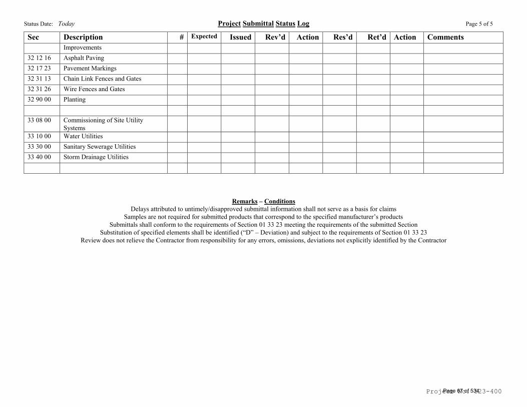
Status Date: Today Project Submittal Status Log Page 5 of 5
Project No. 523-400
Sec Description # Expected Issued Rev’d Action Res’d Ret’d Action Comments Improvements
32 12 16 Asphalt Paving
32 17 23 Pavement Markings
32 31 13 Chain Link Fences and Gates
32 31 26 Wire Fences and Gates
32 90 00 Planting
33 08 00 Commissioning of Site Utility
Systems
33 10 00 Water Utilities
33 30 00 Sanitary Sewerage Utilities
33 40 00 Storm Drainage Utilities
Remarks – Conditions Delays attributed to untimely/disapproved submittal information shall not serve as a basis for claims
Samples are not required for submitted products that correspond to the specified manufacturer’s products Submittals shall conform to the requirements of Section 01 33 23 meeting the requirements of the submitted Section
Substitution of specified elements shall be identified (“D” – Deviation) and subject to the requirements of Section 01 33 23 Review does not relieve the Contractor from responsibility for any errors, omissions, deviations not explicitly identified by the Contractor
Page 67 of 534
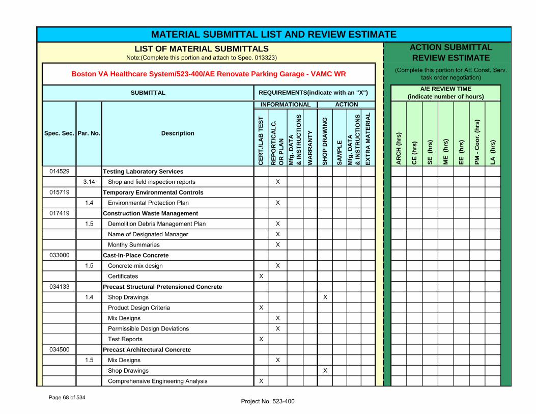
CE
RT
./L
AB
TE
ST
RE
PO
RT
/CA
LC
.
OR
PL
AN
Mfg
. D
AT
A
& I
NS
TR
UC
TIO
NS
WA
RR
AN
TY
SH
OP
DR
AW
ING
SA
MP
LE
Mfg
. D
AT
A
& I
NS
TR
UC
TIO
NS
EX
TR
A M
AT
ER
IAL
014529 Testing Laboratory Services
3.14 Shop and field inspection reports X
015719 Temporary Environmental Controls
1.4 Environmental Protection Plan X
017419 Construction Waste Management
1.5 Demolition Debris Management Plan X
Name of Designated Manager X
Monthy Summaries X
033000 Cast-In-Place Concrete
1.5 Concrete mix design X
Certificates X
034133 Precast Structural Pretensioned Concrete
1.4 Shop Drawings X
Product Design Criteria X
Mix Designs X
Permissible Design Deviations X
Test Reports X
034500 Precast Architectural Concrete
1.5 Mix Designs X
Shop Drawings X
Comprehensive Engineering Analysis X
Spec. Sec.
ACTION
REQUIREMENTS(indicate with an "X")
CE
(h
rs)
SE
(h
rs)
EE
(h
rs)
(Complete this portion for AE Const. Serv. task order negotiation)
PM
- C
oo
r. (
hrs
)
AR
CH
(h
rs)
LA
(h
rs)
Par. No. Description
INFORMATIONAL
MATERIAL SUBMITTAL LIST AND REVIEW ESTIMATE
LIST OF MATERIAL SUBMITTALSNote:(Complete this portion and attach to Spec. 013323)
A/E REVIEW TIME
(indicate number of hours)
ACTION SUBMITTAL
REVIEW ESTIMATE
Boston VA Healthcare System/523-400/AE Renovate Parking Garage - VAMC WR
SUBMITTAL
ME
(h
rs)
Project No. 523-400Page 68 of 534
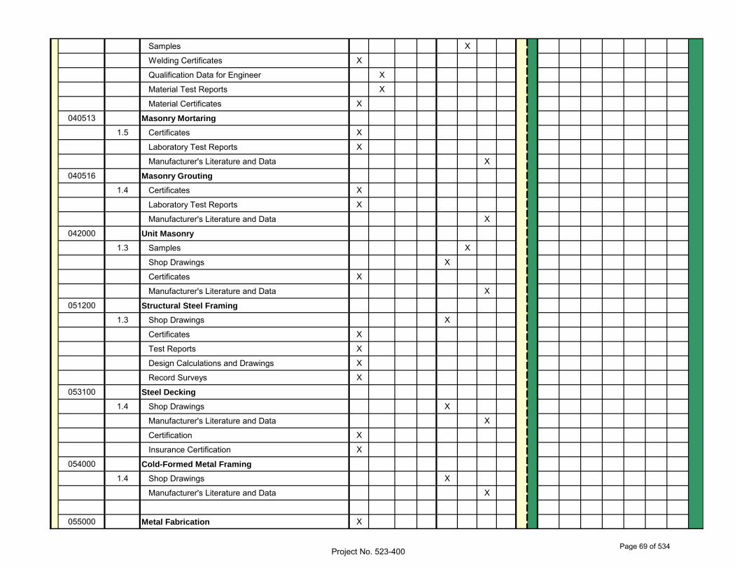
Samples X
Welding Certificates X
Qualification Data for Engineer X
Material Test Reports X
Material Certificates X
040513 Masonry Mortaring
1.5 Certificates X
Laboratory Test Reports X
Manufacturer's Literature and Data X
040516 Masonry Grouting
1.4 Certificates X
Laboratory Test Reports X
Manufacturer's Literature and Data X
042000 Unit Masonry
1.3 Samples X
Shop Drawings X
Certificates X
Manufacturer's Literature and Data X
051200 Structural Steel Framing
1.3 Shop Drawings X
Certificates X
Test Reports X
Design Calculations and Drawings X
Record Surveys X
053100 Steel Decking
1.4 Shop Drawings X
Manufacturer's Literature and Data X
Certification X
Insurance Certification X
054000 Cold-Formed Metal Framing
1.4 Shop Drawings X
Manufacturer's Literature and Data X
055000 Metal Fabrication X
Project No. 523-400Page 69 of 534
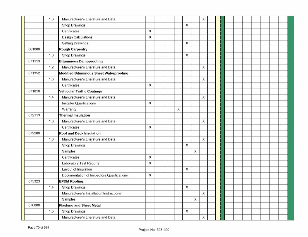
1.3 Manufacturer's Literature and Data X
Shop Drawings X
Certificates X
Design Calculations X
Setting Drawings X
061000 Rough Carpentry
1.3 Shop Drawings X
071113 Bituminous Dampproofing
1.2 Manufacturer's Literature and Data X
071352 Modified Bituminous Sheet Waterproofing
1.3 Manufacturer's Literature and Data X
Certificates X
071810 Vehicular Traffic Coatings
1.4 Manufacturer's Literature and Data X
Installer Qualifications X
Warranty X
072113 Thermal Insulation
1.3 Manufacturer's Literature and Data X
Certificates X
072200 Roof and Deck Insulation
1.6 Manufacturer's Literature and Data X
Shop Drawings X
Samples X
Certificates X
Laboratory Test Reports X
Layout of Insulation X
Documentation of Inspectors Qualifications X
075323 EPDM Roofing
1.4 Shop Drawings X
Manufacturer's Installation Instructions X
Samples X
076000 Flashing and Sheet Metal
1.5 Shop Drawings X
Manufacturer's Literature and Data X
Project No. 523-400Page 70 of 534
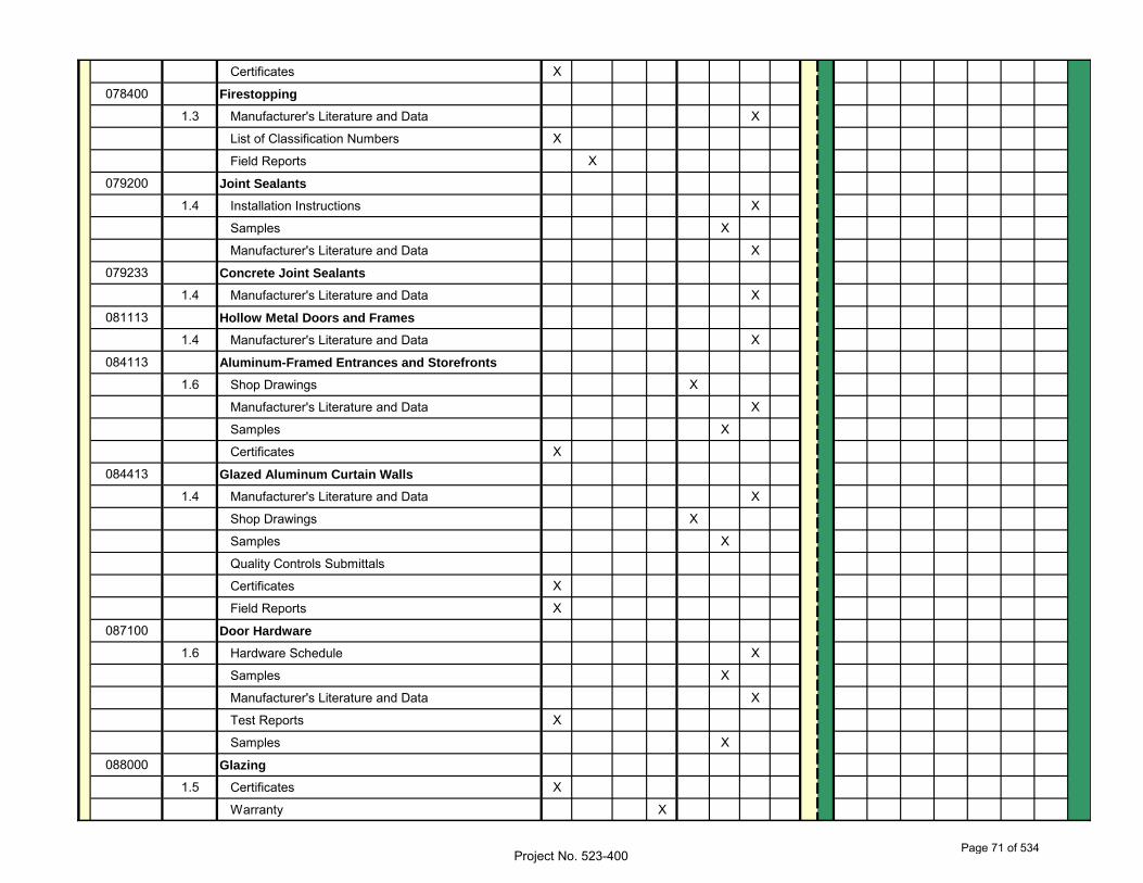
Certificates X
078400 Firestopping
1.3 Manufacturer's Literature and Data X
List of Classification Numbers X
Field Reports X
079200 Joint Sealants
1.4 Installation Instructions X
Samples X
Manufacturer's Literature and Data X
079233 Concrete Joint Sealants
1.4 Manufacturer's Literature and Data X
081113 Hollow Metal Doors and Frames
1.4 Manufacturer's Literature and Data X
084113 Aluminum-Framed Entrances and Storefronts
1.6 Shop Drawings X
Manufacturer's Literature and Data X
Samples X
Certificates X
084413 Glazed Aluminum Curtain Walls
1.4 Manufacturer's Literature and Data X
Shop Drawings X
Samples X
Quality Controls Submittals
Certificates X
Field Reports X
087100 Door Hardware
1.6 Hardware Schedule X
Samples X
Manufacturer's Literature and Data X
Test Reports X
Samples X
088000 Glazing
1.5 Certificates X
Warranty X
Project No. 523-400Page 71 of 534
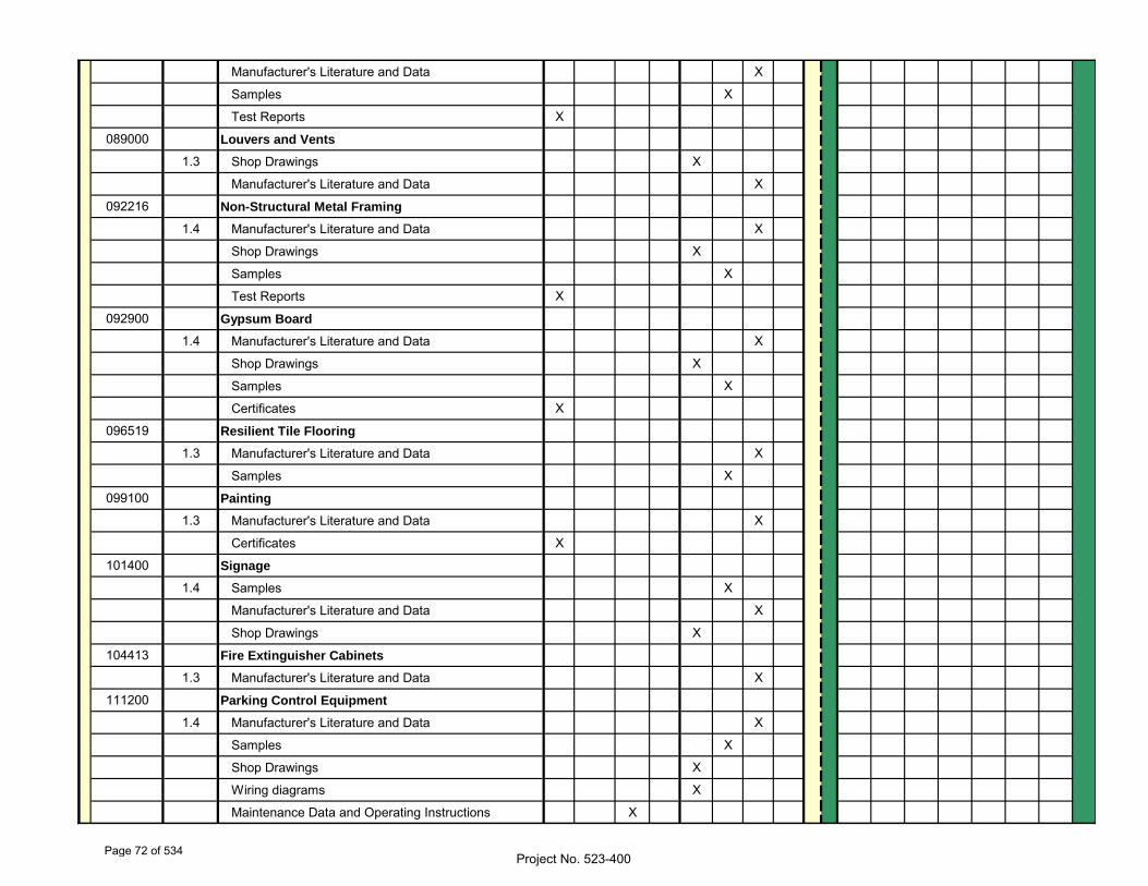
Manufacturer's Literature and Data X
Samples X
Test Reports X
089000 Louvers and Vents
1.3 Shop Drawings X
Manufacturer's Literature and Data X
092216 Non-Structural Metal Framing
1.4 Manufacturer's Literature and Data X
Shop Drawings X
Samples X
Test Reports X
092900 Gypsum Board
1.4 Manufacturer's Literature and Data X
Shop Drawings X
Samples X
Certificates X
096519 Resilient Tile Flooring
1.3 Manufacturer's Literature and Data X
Samples X
099100 Painting
1.3 Manufacturer's Literature and Data X
Certificates X
101400 Signage
1.4 Samples X
Manufacturer's Literature and Data X
Shop Drawings X
104413 Fire Extinguisher Cabinets
1.3 Manufacturer's Literature and Data X
111200 Parking Control Equipment
1.4 Manufacturer's Literature and Data X
Samples X
Shop Drawings X
Wiring diagrams X
Maintenance Data and Operating Instructions X
Project No. 523-400Page 72 of 534
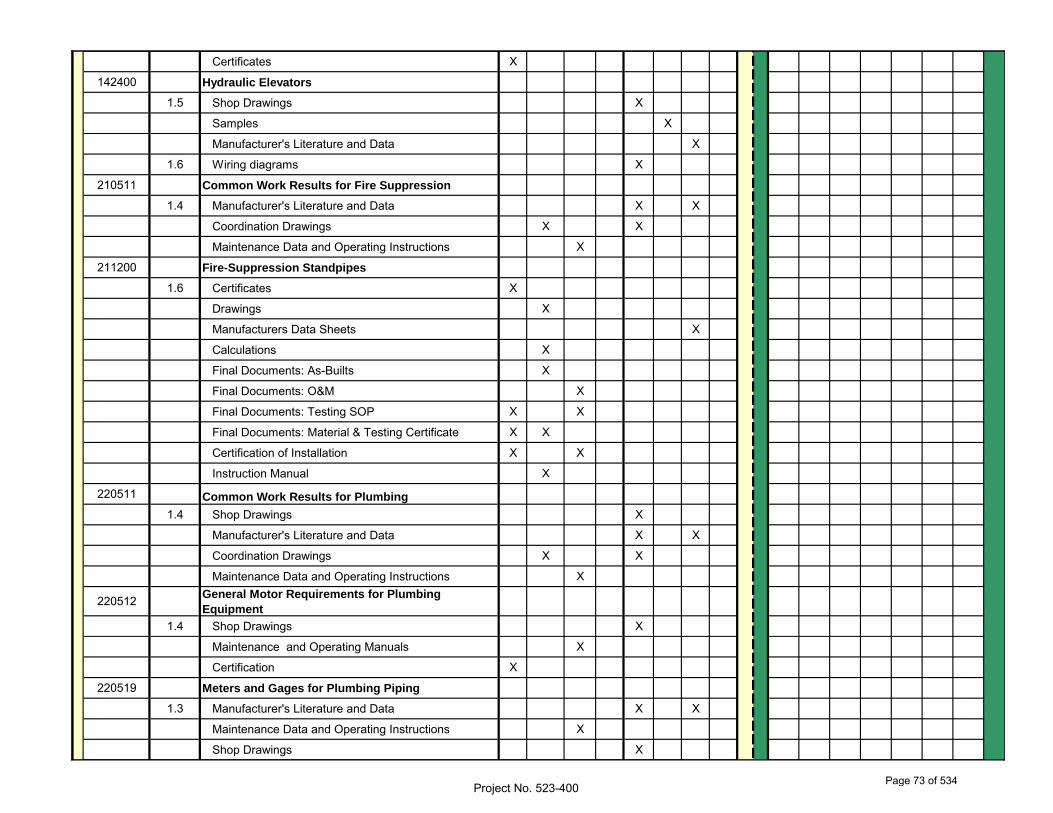
Certificates X
142400 Hydraulic Elevators
1.5 Shop Drawings X
Samples X
Manufacturer's Literature and Data X
1.6 Wiring diagrams X
210511 Common Work Results for Fire Suppression
1.4 Manufacturer's Literature and Data X X
Coordination Drawings X X
Maintenance Data and Operating Instructions X
211200 Fire-Suppression Standpipes
1.6 Certificates X
Drawings X
Manufacturers Data Sheets X
Calculations X
Final Documents: As-Builts X
Final Documents: O&M X
Final Documents: Testing SOP X X
Final Documents: Material & Testing Certificate X X
Certification of Installation X X
Instruction Manual X
220511 Common Work Results for Plumbing
1.4 Shop Drawings X
Manufacturer's Literature and Data X X
Coordination Drawings X X
Maintenance Data and Operating Instructions X
220512 General Motor Requirements for Plumbing
Equipment
1.4 Shop Drawings X
Maintenance and Operating Manuals X
Certification X
220519 Meters and Gages for Plumbing Piping
1.3 Manufacturer's Literature and Data X X
Maintenance Data and Operating Instructions X
Shop Drawings X
Project No. 523-400Page 73 of 534
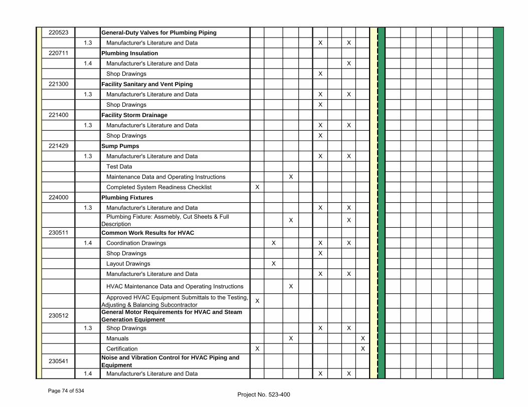
220523 General-Duty Valves for Plumbing Piping
1.3 Manufacturer's Literature and Data X X
220711 Plumbing Insulation
1.4 Manufacturer's Literature and Data X
Shop Drawings X
221300 Facility Sanitary and Vent Piping
1.3 Manufacturer's Literature and Data X X
Shop Drawings X
221400 Facility Storm Drainage
1.3 Manufacturer's Literature and Data X X
Shop Drawings X
221429 Sump Pumps
1.3 Manufacturer's Literature and Data X X
Test Data
Maintenance Data and Operating Instructions X
Completed System Readiness Checklist X
224000 Plumbing Fixtures
1.3 Manufacturer's Literature and Data X X Plumbing Fixture: Assmebly, Cut Sheets & Full Description X X
230511 Common Work Results for HVAC
1.4 Coordination Drawings X X X
Shop Drawings X
Layout Drawings X
Manufacturer's Literature and Data X X
HVAC Maintenance Data and Operating Instructions X
Approved HVAC Equipment Submittals to the Testing, Adjusting & Balancing Subcontractor X
230512 General Motor Requirements for HVAC and Steam
Generation Equipment
1.3 Shop Drawings X X
Manuals X X
Certification X X
230541 Noise and Vibration Control for HVAC Piping and
Equipment
1.4 Manufacturer's Literature and Data X X
Project No. 523-400Page 74 of 534
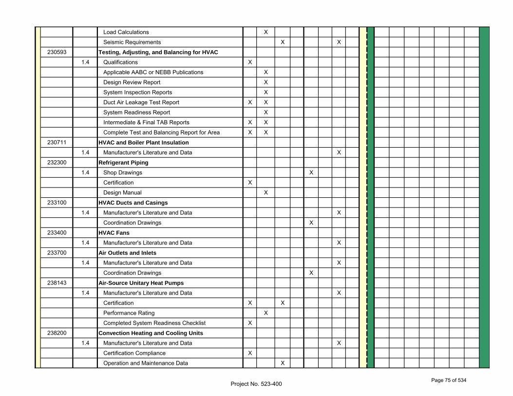
Load Calculations X
Seismic Requirements X X
230593 Testing, Adjusting, and Balancing for HVAC
1.4 Qualifications X
Applicable AABC or NEBB Publications X
Design Review Report X
System Inspection Reports X
Duct Air Leakage Test Report X X
System Readiness Report X
Intermediate & Final TAB Reports X X
Complete Test and Balancing Report for Area X X
230711 HVAC and Boiler Plant Insulation
1.4 Manufacturer's Literature and Data X
232300 Refrigerant Piping
1.4 Shop Drawings X
Certification X
Design Manual X
233100 HVAC Ducts and Casings
1.4 Manufacturer's Literature and Data X
Coordination Drawings X
233400 HVAC Fans
1.4 Manufacturer's Literature and Data X
233700 Air Outlets and Inlets
1.4 Manufacturer's Literature and Data X
Coordination Drawings X
238143 Air-Source Unitary Heat Pumps
1.4 Manufacturer's Literature and Data X
Certification X X
Performance Rating X
Completed System Readiness Checklist X
238200 Convection Heating and Cooling Units
1.4 Manufacturer's Literature and Data X
Certification Compliance X
Operation and Maintenance Data X
Project No. 523-400Page 75 of 534
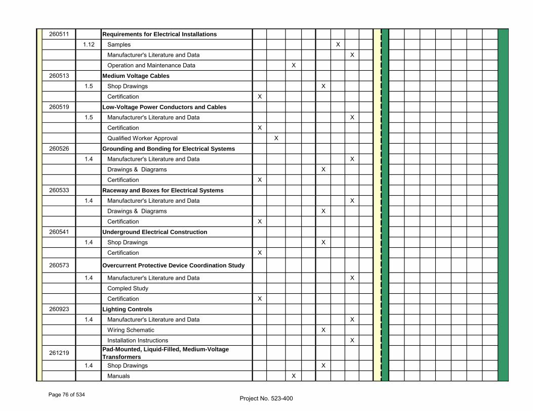
260511 Requirements for Electrical Installations
1.12 Samples X
Manufacturer's Literature and Data X
Operation and Maintenance Data X
260513 Medium Voltage Cables
1.5 Shop Drawings X
Certification X
260519 Low-Voltage Power Conductors and Cables
1.5 Manufacturer's Literature and Data X
Certification X
Qualified Worker Approval X
260526 Grounding and Bonding for Electrical Systems
1.4 Manufacturer's Literature and Data X
Drawings & Diagrams X
Certification X
260533 Raceway and Boxes for Electrical Systems
1.4 Manufacturer's Literature and Data X
Drawings & Diagrams X
Certification X
260541 Underground Electrical Construction
1.4 Shop Drawings X
Certification X
260573 Overcurrent Protective Device Coordination Study
1.4 Manufacturer's Literature and Data X
Compled Study
Certification X
260923 Lighting Controls
1.4 Manufacturer's Literature and Data X
Wiring Schematic X
Installation Instructions X
261219 Pad-Mounted, Liquid-Filled, Medium-Voltage
Transformers
1.4 Shop Drawings X
Manuals X
Project No. 523-400Page 76 of 534
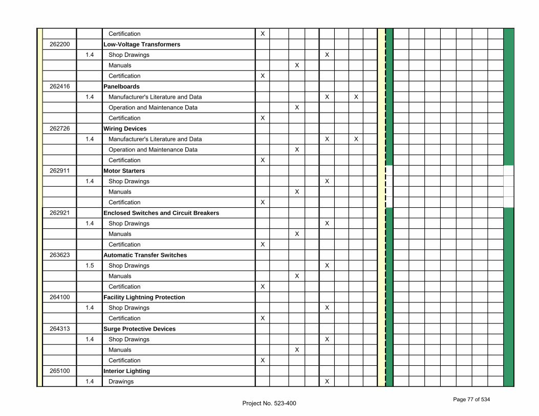
Certification X
262200 Low-Voltage Transformers
1.4 Shop Drawings X
Manuals X
Certification X
262416 Panelboards
1.4 Manufacturer's Literature and Data X X
Operation and Maintenance Data X
Certification X
262726 Wiring Devices
1.4 Manufacturer's Literature and Data X X
Operation and Maintenance Data X
Certification X
262911 Motor Starters
1.4 Shop Drawings X
Manuals X
Certification X
262921 Enclosed Switches and Circuit Breakers
1.4 Shop Drawings X
Manuals X
Certification X
263623 Automatic Transfer Switches
1.5 Shop Drawings X
Manuals X
Certification X
264100 Facility Lightning Protection
1.4 Shop Drawings X
Certification X
264313 Surge Protective Devices
1.4 Shop Drawings X
Manuals X
Certification X
265100 Interior Lighting
1.4 Drawings X
Project No. 523-400Page 77 of 534
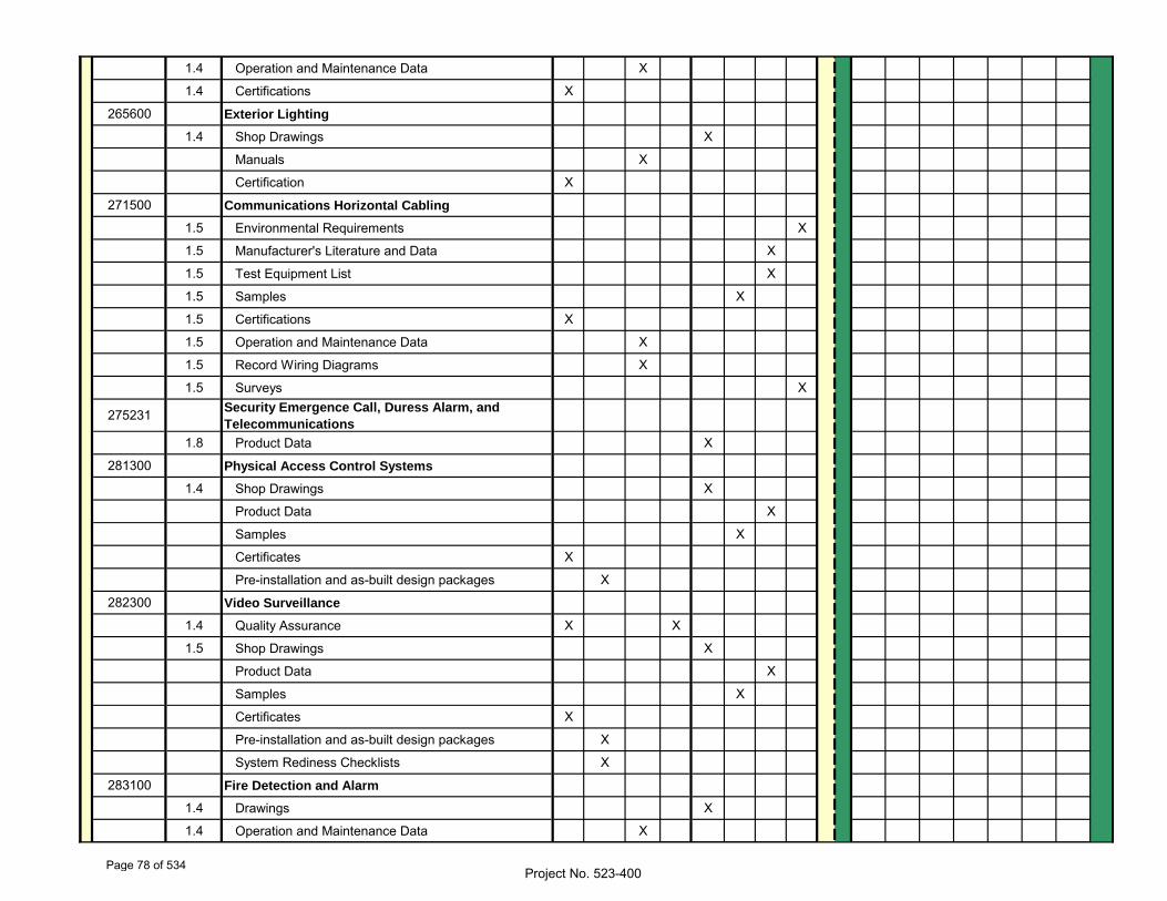
1.4 Operation and Maintenance Data X
1.4 Certifications X
265600 Exterior Lighting
1.4 Shop Drawings X
Manuals X
Certification X
271500 Communications Horizontal Cabling
1.5 Environmental Requirements X
1.5 Manufacturer's Literature and Data X
1.5 Test Equipment List X
1.5 Samples X
1.5 Certifications X
1.5 Operation and Maintenance Data X
1.5 Record Wiring Diagrams X
1.5 Surveys X
275231 Security Emergence Call, Duress Alarm, and
Telecommunications
1.8 Product Data X
281300 Physical Access Control Systems
1.4 Shop Drawings X
Product Data X
Samples X
Certificates X
Pre-installation and as-built design packages X
282300 Video Surveillance
1.4 Quality Assurance X X
1.5 Shop Drawings X
Product Data X
Samples X
Certificates X
Pre-installation and as-built design packages X
System Rediness Checklists X
283100 Fire Detection and Alarm
1.4 Drawings X
1.4 Operation and Maintenance Data X
Project No. 523-400Page 78 of 534
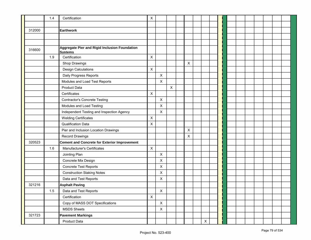
1.4 Certification X
312000 Earthwork
316600 Aggregate Pier and Rigid Inclusion Foundation
Systems
1.9 Certification X
Shop Drawings X
Design Calculations X
Daily Progress Reports X
Modules and Load Test Reports X
Product Data X
Certificates X
Contractor's Concrete Testing X
Modules and Load Testing X
Independent Testing and Inspection Agency X
Welding Certificates X
Qualification Data X
Pier and Inclusion Location Drawings X
Record Drawings X
320523 Cement and Concrete for Exterior Improvement
1.6 Manufacturer's Certificates X
Jointing Plan X
Concrete Mix Design X
Concrete Test Reports X
Construction Staking Notes X
Data and Test Reports X
321216 Asphalt Paving
1.5 Data and Test Reports X
Certification X
Copy of MASS DOT Specifications X
MSDS Sheets X
321723 Pavement Markings
Product Data X
Project No. 523-400Page 79 of 534
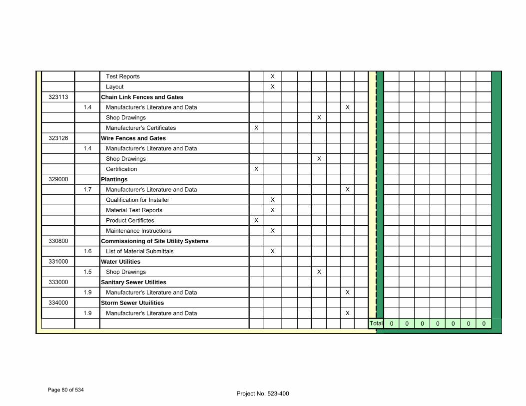
Test Reports X
Layout X
323113 Chain Link Fences and Gates
1.4 Manufacturer's Literature and Data X
Shop Drawings X
Manufacturer's Certificates X
323126 Wire Fences and Gates
1.4 Manufacturer's Literature and Data
Shop Drawings X
Certification X
329000 Plantings
1.7 Manufacturer's Literature and Data X
Qualification for Installer X
Material Test Reports X
Product Certifictes X
Maintenance Instructions X
330800 Commissioning of Site Utility Systems
1.6 List of Material Submittals X
331000 Water Utilities
1.5 Shop Drawings X
333000 Sanitary Sewer Utilities
1.9 Manufacturer's Literature and Data X
334000 Storm Sewer Utuilities
1.9 Manufacturer's Literature and Data X
0 0 0 0 0 0 0Total
Project No. 523-400Page 80 of 534
04-30-14
SAFETY REQUIREMENTS 01 35 26 - 1 Project No. 523-400
SECTION 01 35 26
SAFETY REQUIREMENTS
TABLE OF CONTENTS
1.1 APPLICABLE PUBLICATIONS ................................................................................................... 3
1.2 DEFINITIONS ................................................................................................................................ 4
1.3 REGULATORY REQUIREMENTS ................................................................................................... 5
1.4 ACCIDENT PREVENTION PLAN (APP) ................................................................................... 5
1.5 ACTIVITY HAZARD ANALYSES (AHAs) .............................................................................. 10
1.6 PRECONSTRUCTION CONFERENCE .......................................................................................... 12
1.7 “SITE SAFETY AND HEALTH OFFICER” (SSHO) and “COMPETENT PERSON”
(CP) ........................................................................................................................................................ 12
1.8 TRAINING ..................................................................................................................................... 13
1.9 INSPECTIONS .............................................................................................................................. 14
1.10 ACCIDENTS, OSHA 300 LOGS, AND MAN-HOURS ....................................................... 15
1.11 PERSONAL PROTECTIVE EQUIPMENT (PPE) ................................................................. 16
1.12 INFECTION CONTROL ............................................................................................................ 17
1.13 TUBERCULOSIS SCREENING ................................................................................................ 17
1.14 FIRE SAFETY .......................................................................................................................... 17
1.15 ELECTRICAL ............................................................................................................................. 18
1.16 FALL PROTECTION ................................................................................................................. 20
1.17 SCAFFOLDS AND OTHER WORK PLATFORMS ................................................................... 20
1.18 EXCAVATION AND TRENCHES ............................................................................................. 21
1.19 CRANES ...................................................................................................................................... 22
1.20 CONTROL OF HAZARDOUS ENERGY (LOCKOUT/TAGOUT) ........................................... 23
1.21 CONFINED SPACE ENTRY ..................................................................................................... 23
1.22 WELDING AND CUTTING ....................................................................................................... 23
1.23 LADDERS .................................................................................................................................... 23
Page 81 of 534
04-30-14
SAFETY REQUIREMENTS 01 35 26 - 2 Project No. 523-400
1.24 FLOOR & WALL OPENINGS .................................................................................................. 24
Page 82 of 534
04-30-14
SAFETY REQUIREMENTS 01 35 26 - 3 Project No. 523-400
SECTION 01 35 26
SAFETY REQUIREMENTS
1.1 APPLICABLE PUBLICATIONS:
A. Latest publications listed below form part of this Article to extent referenced. Publications are referenced in text by basic designations
only.
1. American Society of Safety Engineers (ASSE):
A10.1-2011...........Pre-Project & Pre-Task Safety and Health
Planning
A10.34-2012..........Protection of the Public on or Adjacent to
Construction Sites
A10.38-2013..........Basic Elements of an Employer’s Program to
Provide a Safe and Healthful Work Environment
American National Standard Construction and
Demolition Operations
2. American Society for Testing and Materials (ASTM):
E84-2013.............Surface Burning Characteristics of Building
Materials
3. The Facilities Guidelines Institute (FGI):
FGI Guidelines-2010Guidelines for Design and Construction of
Healthcare Facilities
4. National Fire Protection Association (NFPA):
10-2013..............Standard for Portable Fire Extinguishers
30-2012..............Flammable and Combustible Liquids Code
51B-2014.............Standard for Fire Prevention During Welding,
Cutting and Other Hot Work
70-2014..............National Electrical Code
70B-2013.............Recommended Practice for Electrical Equipment
Maintenance
70E-2012 ............Standard for Electrical Safety in the Workplace
Page 83 of 534
04-30-14
SAFETY REQUIREMENTS 01 35 26 - 4 Project No. 523-400
241-2013.............Standard for Safeguarding Construction,
Alteration, and Demolition Operations
5. The Joint Commission (TJC)
TJC Manual ..........Comprehensive Accreditation and Certification
Manual
6. U. S. Nuclear Regulatory Commission
10 CFR 20 ...........Standards for Protection Against Radiation
7. U. S. Occupational Safety and Health Administration (OSHA):
29 CFR 1904 .........Reporting and Recording Injuries & Illnesses
29 CFR 1910 .........Safety and Health Regulations for General
Industry
29 CFR 1926 .........Safety and Health Regulations for Construction
Industry
CPL 2-0.124..........Multi-Employer Citation Policy
8. VHA Directive 2005-007
1.2 DEFINITIONS:
A. OSHA “Competent Person” (CP). One who is capable of identifying existing and predictable hazards in the surroundings and working conditions which
are unsanitary, hazardous or dangerous to employees, and who has the
authorization to take prompt corrective measures to eliminate them (see 29
CFR 1926.32(f)).
B. "Qualified Person" means one who, by possession of a recognized degree, certificate, or professional standing, or who by extensive knowledge,
training and experience, has successfully demonstrated his ability to
solve or resolve problems relating to the subject matter, the work, or
the project.
C. High Visibility Accident. Any mishap which may generate publicity or high visibility.
D. Medical Treatment. Treatment administered by a physician or by registered professional personnel under the standing orders of a
Page 84 of 534
04-30-14
SAFETY REQUIREMENTS 01 35 26 - 5 Project No. 523-400
physician. Medical treatment does not include first aid treatment even
through provided by a physician or registered personnel.
E. Recordable Injuries or Illnesses. Any work-related injury or illness that results in:
1. Death, regardless of the time between the injury and death, or the
length of the illness;
2. Days away from work (any time lost after day of injury/illness
onset);
3. Restricted work;
4. Transfer to another job;
5. Medical treatment beyond first aid;
6. Loss of consciousness; or
7. A significant injury or illness diagnosed by a physician or other
licensed health care professional, even if it did not result in (1)
through (6) above.
1.3 REGULATORY REQUIREMENTS:
A. In addition to the detailed requirements included in the provisions of this contract, comply with 29 CFR 1926, comply with 29 CFR 1910 as
incorporated by reference within 29 CFR 1926, comply with ASSE A10.34,
and all applicable [federal, state, and local] laws, ordinances,
criteria, rules and regulations. Submit matters of interpretation of
standards for resolution before starting work. Where the requirements of
this specification, applicable laws, criteria, ordinances, regulations,
and referenced documents vary, the most stringent requirements govern
except with specific approval and acceptance by the Resident Engineer or
Contracting Officer Representative
1.4 ACCIDENT PREVENTION PLAN (APP):
A. The APP (aka Construction Safety & Health Plan) shall interface with the Contractor's overall safety and health program. Include any portions of
the Contractor's overall safety and health program referenced in the APP
in the applicable APP element and ensure it is site-specific. The
Government considers the Prime Contractor to be the "controlling
authority" for all worksite safety and health of each subcontractor(s).
Page 85 of 534
04-30-14
SAFETY REQUIREMENTS 01 35 26 - 6 Project No. 523-400
Contractors are responsible for informing their subcontractors of the
safety provisions under the terms of the contract and the penalties for
noncompliance, coordinating the work to prevent one craft from
interfering with or creating hazardous working conditions for other
crafts, and inspecting subcontractor operations to ensure that accident
prevention responsibilities are being carried out.
B. The APP shall be prepared as follows:
1. Written in English by a qualified person who is employed by the Prime
Contractor articulating the specific work and hazards pertaining to
the contract (model language can be found in ASSE A10.33).
Specifically articulating the safety requirements found within these
VA contract safety specifications.
2. Address both the Prime Contractors and the subcontractors work
operations.
3. State measures to be taken to control hazards associated with
materials, services, or equipment provided by suppliers.
4. Address all the elements/sub-elements and in order as follows:
a. SIGNATURE SHEET. Title, signature, and phone number of the
following:
(1) Plan preparer (Qualified Person such as corporate safety staff person or contracted Certified Safety Professional with
construction safety experience);
(2) Plan approver (company/corporate officers authorized to obligate the company);
(3) Plan concurrence (e.g., Chief of Operations, Corporate Chief of Safety, Corporate Industrial Hygienist, project manager or
superintendent, project safety professional). Provide
concurrence of other applicable corporate and project
personnel (Contractor).
b. BACKGROUND INFORMATION. List the following:
(1) Contractor;
(2) Contract number;
Page 86 of 534
04-30-14
SAFETY REQUIREMENTS 01 35 26 - 7 Project No. 523-400
(3) Project name;
(4) Brief project description, description of work to be performed, and location; phases of work anticipated (these
will require an AHA).
c. STATEMENT OF SAFETY AND HEALTH POLICY. Provide a copy of current
corporate/company Safety and Health Policy Statement, detailing
commitment to providing a safe and healthful workplace for all
employees. The Contractor’s written safety program goals,
objectives, and accident experience goals for this contract should
be provided.
d. RESPONSIBILITIES AND LINES OF AUTHORITIES. Provide the following:
(1) A statement of the employer’s ultimate responsibility for the implementation of his SOH program;
(2) Identification and accountability of personnel responsible for safety at both corporate and project level. Contracts
specifically requiring safety or industrial hygiene personnel
shall include a copy of their resumes.
(3) The names of Competent and/or Qualified Person(s) and proof of competency/qualification to meet specific OSHA
Competent/Qualified Person(s) requirements must be attached.;
(4) Requirements that no work shall be performed unless a designated competent person is present on the job site;
(5) Requirements for pre-task Activity Hazard Analysis (AHAs);
(6) Lines of authority;
(7) Policies and procedures regarding noncompliance with safety requirements (to include disciplinary actions for violation of
safety requirements) should be identified;
e. SUBCONTRACTORS AND SUPPLIERS. If applicable, provide procedures
for coordinating SOH activities with other employers on the job
site:
(1) Identification of subcontractors and suppliers (if known);
(2) Safety responsibilities of subcontractors and suppliers.
Page 87 of 534
04-30-14
SAFETY REQUIREMENTS 01 35 26 - 8 Project No. 523-400
f. TRAINING.
(1) Site-specific SOH orientation training at the time of initial hire or assignment to the project for every employee before
working on the project site is required.
(2) Mandatory training and certifications that are applicable to this project (e.g., explosive actuated tools, crane operator,
rigger, crane signal person, fall protection, electrical
lockout/NFPA 70E, machine/equipment lockout, confined space,
etc…) and any requirements for periodic
retraining/recertification are required.
(3) Procedures for ongoing safety and health training for supervisors and employees shall be established to address
changes in site hazards/conditions.
(4) OSHA 10-hour training is required for all workers on site and the OSHA 30-hour training is required for Trade Competent
Persons (CPs)
g. SAFETY AND HEALTH INSPECTIONS.
(1) Specific assignment of responsibilities for a minimum daily
job site safety and health inspection during periods of work
activity: Who will conduct (e.g., “Site Safety and Health
CP”), proof of inspector’s training/qualifications, when
inspections will be conducted, procedures for documentation,
deficiency tracking system, and follow-up procedures.
(2) Any external inspections/certifications that may be required (e.g., contracted CSP or CSHT)
h. ACCIDENT INVESTIGATION & REPORTING. The Contractor shall conduct
mishap investigations of all OSHA Recordable Incidents. The APP
shall include accident/incident investigation procedure & identify
person(s) responsible to provide the following to the Resident
Engineer or Contracting Officer Representative:
(1) Exposure data (man-hours worked);
(2) Accident investigations, reports, and logs.
i. PLANS (PROGRAMS, PROCEDURES) REQUIRED. Based on a risk assessment
of contracted activities and on mandatory OSHA compliance
Page 88 of 534
04-30-14
SAFETY REQUIREMENTS 01 35 26 - 9 Project No. 523-400
programs, the Contractor shall address all applicable occupational
risks in site-specific compliance and accident prevention plans.
These Plans shall include but are not be limited to procedures for
addressing the risks associates with the following:
(1) Emergency response ;
(2) Contingency for severe weather;
(3) Fire Prevention ;
(4) Medical Support;
(5) Posting of emergency telephone numbers;
(6) Prevention of alcohol and drug abuse;
(7) Site sanitation (housekeeping, drinking water, toilets);
(8) Night operations and lighting ;
(9) Hazard communication program;
(10) Welding/Cutting “Hot” work ;
(11) Electrical Safe Work Practices (Electrical LOTO/NFPA 70E);
(12) General Electrical Safety
(13) Hazardous energy control (Machine LOTO);
(14) Site-Specific Fall Protection & Prevention;
(15) Excavation/trenching;
(16) Asbestos abatement;
(17) Lead abatement;
(18) Crane Critical lift;
(19) Respiratory protection;
(20) Health hazard control program;
(21) Radiation Safety Program;
(22) Abrasive blasting;
Page 89 of 534
04-30-14
SAFETY REQUIREMENTS 01 35 26 - 10 Project No. 523-400
(23) Heat/Cold Stress Monitoring;
(24) Crystalline Silica Monitoring (Assessment);
(25) Demolition plan (to include engineering survey);
(26) Formwork and shoring erection and removal;
(27) PreCast Concrete.
C. Submit the APP to the Resident Engineer or Contracting Officer Representative for review for compliance with contract requirements in
accordance with Section 01 33 23, SHOP DRAWINGS, PRODUCT DATA AND
SAMPLES 15 calendar days prior to the date of the preconstruction
conference for acceptance. Work cannot proceed without an accepted APP.
D. Once accepted by the Resident Engineer or Contracting Officer Representative, the APP and attachments will be enforced as part of the
contract. Disregarding the provisions of this contract or the accepted
APP will be cause for stopping of work, at the discretion of the
Contracting Officer, until the matter has been rectified.
E. Once work begins, changes to the accepted APP shall be made with the knowledge and concurrence of the Resident Engineer project
superintendent, project overall designated OSHA Competent Person, and
facility Safety Officer or Contracting Officer Representative. Should
any severe hazard exposure, i.e. imminent danger, become evident, stop
work in the area, secure the area, and develop a plan to remove the
exposure and control the hazard. Notify the Contracting Officer within
24 hours of discovery. Eliminate/remove the hazard. In the interim, take
all necessary action to restore and maintain safe working conditions in
order to safeguard onsite personnel, visitors, the public (as defined by
ASSE/SAFE A10.34) and the environment.
1.5 ACTIVITY HAZARD ANALYSES (AHAs):
A. AHAs are also known as Job Hazard Analyses, Job Safety Analyses, and Activity Safety Analyses. Before beginning each work activity involving
a type of work presenting hazards not experienced in previous project
operations or where a new work crew or sub-contractor is to perform the
work, the Contractor(s) performing that work activity shall prepare an
AHA (Example electronic AHA forms can be found on the US Army Corps of
Engineers web site)
Page 90 of 534
04-30-14
SAFETY REQUIREMENTS 01 35 26 - 11 Project No. 523-400
B. AHAs shall define the activities being performed and identify the work sequences, the specific anticipated hazards, site conditions, equipment,
materials, and the control measures to be implemented to eliminate or
reduce each hazard to an acceptable level of risk.
C. Work shall not begin until the AHA for the work activity has been accepted by the Resident Engineer or Contracting Officer Representative
and discussed with all engaged in the activity, including the
Contractor, subcontractor(s), and Government on-site representatives at
preparatory and initial control phase meetings.
1. The names of the Competent/Qualified Person(s) required for a
particular activity (for example, excavations, scaffolding, fall
protection, other activities as specified by OSHA and/or other State
and Local agencies) shall be identified and included in the AHA.
Certification of their competency/qualification shall be submitted to
the Government Designated Authority (GDA) for acceptance prior to the
start of that work activity.
2. The AHA shall be reviewed and modified as necessary to address
changing site conditions, operations, or change of
competent/qualified person(s).
a. If more than one Competent/Qualified Person is used on the AHA
activity, a list of names shall be submitted as an attachment to
the AHA. Those listed must be Competent/Qualified for the type of
work involved in the AHA and familiar with current site safety
issues.
b. If a new Competent/Qualified Person (not on the original list) is
added, the list shall be updated (an administrative action not
requiring an updated AHA). The new person shall acknowledge in
writing that he or she has reviewed the AHA and is familiar with
current site safety issues.
3. Submit AHAs to the Resident Engineer or Contracting Officer
Representative for review for compliance with contract requirements
in accordance with Section 01 33 23, SHOP DRAWINGS, PRODUCT DATA AND
SAMPLES for review at least 15 calendar days prior to the start of
each phase. Subsequent AHAs as shall be formatted as amendments to
the APP. The analysis should be used during daily inspections to
ensure the implementation and effectiveness of the activity's safety
and health controls.
Page 91 of 534
04-30-14
SAFETY REQUIREMENTS 01 35 26 - 12 Project No. 523-400
4. The AHA list will be reviewed periodically (at least monthly) at the
Contractor supervisory safety meeting and updated as necessary when
procedures, scheduling, or hazards change.
5. Develop the activity hazard analyses using the project schedule as
the basis for the activities performed. All activities listed on the
project schedule will require an AHA. The AHAs will be developed by
the contractor, supplier, or subcontractor and provided to the prime
contractor for review and approval and then submitted to the Resident
Engineer or Contracting Officer Representative.
1.6 PRECONSTRUCTION CONFERENCE:
A. Contractor representatives who have a responsibility or significant role in implementation of the accident prevention program, as required by 29
CFR 1926.20(b)(1), on the project shall attend the preconstruction
conference to gain a mutual understanding of its implementation. This
includes the project superintendent, subcontractor superintendents, and
any other assigned safety and health professionals.
B. Discuss the details of the submitted APP to include incorporated plans, programs, procedures and a listing of anticipated AHAs that will be
developed and implemented during the performance of the contract. This
list of proposed AHAs will be reviewed at the conference and an
agreement will be reached between the Contractor and the Contracting
Officer's representative as to which phases will require an analysis. In
addition, establish a schedule for the preparation, submittal, review,
and acceptance of AHAs to preclude project delays.
C. Deficiencies in the submitted APP will be brought to the attention of the Contractor within 14 days of submittal, and the Contractor shall
revise the plan to correct deficiencies and re-submit it for acceptance.
Do not begin work until there is an accepted APP.
1.7 “SITE SAFETY AND HEALTH OFFICER” (SSHO) and “COMPETENT PERSON” (CP):
A. The Prime Contractor shall designate a minimum of one SSHO at each project site that will be identified as the SSHO to administer the
Contractor's safety program and government-accepted Accident Prevention
Plan. Each subcontractor shall designate a minimum of one CP in
compliance with 29 CFR 1926.20 (b)(2) that will be identified as a CP to
administer their individual safety programs.
Page 92 of 534
04-30-14
SAFETY REQUIREMENTS 01 35 26 - 13 Project No. 523-400
B. Further, all specialized Competent Persons for the work crews will be supplied by the respective contractor as required by 29 CFR 1926 (i.e.
Asbestos, Electrical, Cranes, & Derricks, Demolition, Fall Protection,
Fire Safety/Life Safety, Ladder, Rigging, Scaffolds, and
Trenches/Excavations).
C. These Competent Persons can have collateral duties as the subcontractor’s superintendent and/or work crew lead persons as well as
fill more than one specialized CP role (i.e. Asbestos, Electrical,
Cranes, & Derricks, Demolition, Fall Protection, Fire Safety/Life
Safety, Ladder, Rigging, Scaffolds, and Trenches/Excavations).
D. The SSHO or an equally-qualified Designated Representative/alternate will maintain a presence on the site during construction operations.
CPs will maintain presence during their construction activities in
accordance with above mentioned clause. A listing of the designated
SSHO and all known CPs shall be submitted prior to the start of work
as part of the APP with the training documentation and/or AHA as
listed in Section 1.8 below.
E. The repeated presence of uncontrolled hazards during a contractor’s work operations will result in the designated CP as being deemed
incompetent and result in the required removal of the employee.
1.8 TRAINING:
A. The designated Prime Contractor SSHO must meet the requirements of all applicable OSHA standards and be capable (through training, experience,
and qualifications) of ensuring that the requirements of 29 CFR 1926.16
and other appropriate Federal, State and local requirements are met for
the project. As a minimum the SSHO must have completed the OSHA 30-hour
Construction Safety class and have five (5) years of construction
industry safety experience or three (3) years if he/she possesses a
Certified Safety Professional (CSP) or certified Construction Safety and
Health Technician (CSHT) certification or have a safety and health
degree from an accredited university or college.
B. All designated CPs shall have completed the OSHA 30-hour Construction Safety course within the past 5 years.
Page 93 of 534
04-30-14
SAFETY REQUIREMENTS 01 35 26 - 14 Project No. 523-400
C. In addition to the OSHA 30 Hour Construction Safety Course, all CPs with high hazard work operations such as operations involving asbestos,
electrical, cranes, demolition, work at heights/fall protection, fire
safety/life safety, ladder, rigging, scaffolds, and trenches/excavations
shall have a specialized formal course in the hazard recognition &
control associated with those high hazard work operations. Documented
“repeat” deficiencies in the execution of safety requirements will
require retaking the requisite formal course.
D. All other construction workers shall have the OSHA 10-hour Construction Safety Outreach course and any necessary safety training to be able to
identify hazards within their work environment.
E. Submit training records associated with the above training requirements to the Resident Engineer or Contracting Officer Representative for
review for compliance with contract requirements in accordance with
Section 01 33 23, SHOP DRAWINGS, PRODUCT DATA AND SAMPLES 15 calendar
days prior to the date of the preconstruction conference for acceptance.
F. Prior to any worker for the contractor or subcontractors beginning work, they shall undergo a safety briefing provided by the SSHO or his/her
designated representative. As a minimum, this briefing shall include
information on the site-specific hazards, construction limits, VAMC
safety guidelines, means of egress, break areas, work hours, locations
of restrooms, use of VAMC equipment, emergency procedures, accident
reporting etc... Documentation shall be provided to the Resident
Engineer that individuals have undergone contractor’s safety briefing.
G. Ongoing safety training will be accomplished in the form of weekly documented safety meeting.
1.9 INSPECTIONS:
A. The SSHO shall conduct frequent and regular safety inspections (daily) of the site and each of the subcontractors CPs shall conduct frequent
and regular safety inspections (daily) of the their work operations as
required by 29 CFR 1926.20(b)(2). Each week, the SSHO shall conduct a
formal documented inspection of the entire construction areas with the
subcontractors’ “Trade Safety and Health CPs” present in their work
areas. Coordinate with, and report findings and corrective actions
weekly to Resident Engineer or Contracting Officer Representative.
Page 94 of 534
04-30-14
SAFETY REQUIREMENTS 01 35 26 - 15 Project No. 523-400
B. A Certified Safety Professional (CSP) with specialized knowledge in construction safety or a certified Construction Safety and Health
Technician (CSHT) shall randomly conduct a monthly site safety
inspection. The CSP or CSHT can be a corporate safety professional or
independently contracted. The CSP or CSHT will provide their
certificate number on the required report for verification as necessary.
1. Results of the inspection will be documented with tracking of the
identified hazards to abatement.
2. The Resident Engineer or Contracting Officer Representative will be
notified immediately prior to start of the inspection and invited to
accompany the inspection.
3. Identified hazard and controls will be discussed to come to a mutual
understanding to ensure abatement and prevent future reoccurrence.
4. A report of the inspection findings with status of abatement will be
provided to the Resident Engineer or Contracting Officer
Representative within one week of the onsite inspection.
1.10 ACCIDENTS, OSHA 300 LOGS, AND MAN-HOURS:
A. Notify the Resident Engineer or Contracting Officer Representative as soon as practical, but no more than four hours after any accident
meeting the definition of OSHA Recordable Injuries or Illnesses or High
Visibility Accidents, property damage equal to or greater than $5,000,
or any weight handling equipment accident. Within notification include
contractor name; contract title; type of contract; name of activity,
installation or location where accident occurred; date and time of
accident; names of personnel injured; extent of property damage, if any;
extent of injury, if known, and brief description of accident (to
include type of construction equipment used, PPE used, etc.). Preserve
the conditions and evidence on the accident site until the Resident
Engineer or Contracting Officer Representative determine whether a
government investigation will be conducted.
B. Conduct an accident investigation for recordable injuries and illnesses, for Medical Treatment defined in paragraph DEFINITIONS, and property
damage accidents resulting in at least $20,000 in damages, to establish
the root cause(s) of the accident. Complete the VA Form 2162, and
provide the report to the Resident Engineer or Contracting Officer
Representative within 5 calendar days of the accident. The Resident
Page 95 of 534
04-30-14
SAFETY REQUIREMENTS 01 35 26 - 16 Project No. 523-400
Engineer or Contracting Officer Representative will provide copies of
any required or special forms.
C. A summation of all man-hours worked by the contractor and associated sub-contractors for each month will be reported to the Resident Engineer
or Contracting Officer Representative monthly.
D. A summation of all OSHA recordable accidents experienced on site by the contractor and associated sub-contractors for each month will be
provided to the Resident Engineer or Contracting Officer Representative
monthly. The contractor and associated sub-contractors’ OSHA 300 logs
will be made available to the Resident Engineer or Contracting Officer
Representative as requested.
1.11 PERSONAL PROTECTIVE EQUIPMENT (PPE):
A. PPE is governed in all areas by the nature of the work the employee is performing.
B. Mandatory PPE includes:
1. Hard Hats – unless written authorization is given by the Resident
Engineer or Contracting Officer Representative in circumstances of
work operations that have limited potential for falling object
hazards such as during finishing work or minor remodeling. However
even with authorization to relax the requirement of hard hats, if a
worker becomes exposed to an overhead falling object hazard, then
hard hats would be required in accordance with the OSHA regulations.
2. Safety glasses - unless written authorization is given by the
Resident Engineer or Contracting Officer Representative appropriate
safety glasses meeting the ANSI Z.87.1 standard must be worn by each
person on site.
3. Appropriate Safety Shoes – based on the hazards present, safety shoes
meeting the requirements of ASTM F2413-11 shall be worn by each
person on site unless written authorization is given by the Resident
Engineer or Contracting Officer Representative.
4. Hearing protection - Use personal hearing protection at all times in
designated noise hazardous areas or when performing noise hazardous
tasks.
Page 96 of 534
04-30-14
SAFETY REQUIREMENTS 01 35 26 - 17 Project No. 523-400
1.12 INFECTION CONTROL
A. Not Applicable.
1.13 TUBERCULOSIS SCREENING
A. Not Applicable.
1.14 FIRE SAFETY
A. Fire Safety Plan: Establish and maintain a site-specific fire protection program in accordance with 29 CFR 1926. Prior to start of work, prepare
a plan detailing project-specific fire safety measures, including
periodic status reports, and submit to Resident Engineer or Contracting
Officer Representative for review for compliance with contract
requirements in accordance with Section 01 33 23, SHOP DRAWINGS, PRODUCT
DATA AND SAMPLES. This plan may be an element of the Accident Prevention
Plan.
B. Site and Building Access: Maintain free and unobstructed access to facility emergency services and for fire, police and other emergency
response forces in accordance with NFPA 241.
C. Separate temporary facilities, such as trailers, storage sheds, and
dumpsters, from existing buildings and new construction by distances in
accordance with NFPA 241. For small facilities with less than 6 m (20
feet) exposing overall length, separate by 3m (10 feet).
D. Temporary Construction Partitions:
1. Not Applicable.
E. Temporary Heating and Electrical: Install, use and maintain
installations in accordance with 29 CFR 1926, NFPA 241 and NFPA 70.
F. Not Applicable.
G. Egress Routes for Construction Workers: Maintain free and unobstructed
egress. Inspect daily. Report findings and corrective actions weekly to
Resident Engineer or Contracting Officer Representative.
H. Fire Extinguishers: Provide and maintain extinguishers in construction
areas and temporary storage areas in accordance with 29 CFR 1926, NFPA
241 and NFPA 10.
Page 97 of 534
04-30-14
SAFETY REQUIREMENTS 01 35 26 - 18 Project No. 523-400
I. Flammable and Combustible Liquids: Store, dispense and use liquids in
accordance with 29 CFR 1926, NFPA 241 and NFPA 30.
J. Sprinklers: Install, test and activate new automatic sprinklers prior to
removing existing sprinklers.
K. Not Applicable.
L. Smoke Detectors: Prevent accidental operation. Remove temporary covers
at end of work operations each day. Coordinate with Resident Engineer or
Contracting Officer Representative.
M. Hot Work: Perform and safeguard hot work operations in accordance with
NFPA 241 and NFPA 51B. Coordinate with Resident Engineer. Obtain permits
from Resident Engineer at least 48 hours in advance. Designate
contractor's responsible project-site fire prevention program manager to
permit hot work.
N. Fire Hazard Prevention and Safety Inspections: Inspect entire
construction areas weekly. Coordinate with, and report findings and
corrective actions weekly to Resident Engineer or Contracting Officer
Representative.
O. Smoking: Smoking is prohibited in and adjacent to construction areas
inside existing buildings and additions under construction. In separate
and detached buildings under construction, smoking is prohibited except
in designated smoking rest areas.
P. Dispose of waste and debris in accordance with NFPA 241. Remove from
buildings daily.
R. If required, submit documentation to the Resident Engineer or COR that
personnel have been trained in the fire safety aspects of working in
areas with impaired structural or compartmentalization features.
1.15 ELECTRICAL
A. All electrical work shall comply with NFPA 70 (NEC), NFPA 70B, NFPA 70E, OSHA Part 1910 subpart J – General Environmental Controls, and OSHA Part
1910 subpart S – Electrical, in addition to other references required by
contract.
B. All qualified persons performing electrical work under this contract shall be licensed journeyman or master electricians in the state where
the project is located. All apprentice electricians performing under
Page 98 of 534
04-30-14
SAFETY REQUIREMENTS 01 35 26 - 19 Project No. 523-400
this contract shall be deemed unqualified persons unless they are
working under the immediate supervision of a licensed electrician or
master electrician.
C. All electrical work will be accomplished de-energized and in the Electrically Safe Work Condition (i.e. anything beyond simple testing
and troubleshooting with a multimeter). Any Contractor, subcontractor
or temporary worker who fails to fully comply with this requirement is
subject to immediate termination. Only in rare circumstance where
achieving an electrically safe work condition prior to beginning work
would increase or cause additional hazards, or is infeasible due to
equipment design or operational limitations is energized work permitted.
The Resident Engineer or Contracting Officer Representative with
approval of the Medical Center Director will make the determination if
the circumstances would meet the exception outlined above. An AHA
specific to energized work activities will be developed, reviewed, and
accepted prior to the start of that work.
1. Development of a Hazardous Electrical Energy Control Procedure is
required prior to de-energization. A single Simple Lockout/Tagout
Procedure for multiple work operations can only be used for work
involving qualified person(s) de-energizing one set of conductors
or circuit part source. Task specific Complex Lockout/Tagout
Procedures are required at all other times.
2. Verification of the absence of voltage after de-energization and
lockout/tagout is considered “energized electrical work” (live
work) under NFPA 70 70E, and shall only be performed by qualified
persons wearing appropriate shock protective (voltage rated)
gloves and arc rate personal protective clothing and equipment,
using Underwriters Laboratories (UL) tested and appropriately
rated contact electrical testing instruments or equipment
appropriate for the environment in which they will be used.
3. Personal Protective Equipment (PPE) and electrical testing
instruments will be readily available for inspection by the The
Resident Engineer or Contracting Officer Representative.
D. Before beginning any electrical work, an AHA will be conducted to
include Shock Hazard and Arc Flash Hazard analyses (NFPA Tables can be
used only as a last alterative and it is strongly suggested a full Shock
Page 99 of 534
04-30-14
SAFETY REQUIREMENTS 01 35 26 - 20 Project No. 523-400
and Arc Flash Hazard Analyses be conducted). Work shall not begin until
the AHA for the work activity has been accepted by the Resident Engineer
or Contracting Officer Representative and discussed with all engaged in
the activity, including the Contractor, subcontractor(s), and Government
on-site representatives at preparatory and initial control phase
meetings.
E. Ground-fault circuit interrupters. All 120-volt, single-phase 15- and
20-ampere receptacle outlets on construction sites, which are not a part
of the permanent wiring of the building or structure and which are in
use by employees, shall have approved ground-fault circuit interrupters
for personnel protection unless written authorization is given by the
Resident Engineer or Contracting Officer Representative during final
finishing work or minor remodeling with permanent power available.
“Assured Equipment Grounding Conductor Program” only is not allowed.
1.16 FALL PROTECTION
A. The fall protection (FP) threshold height requirement is 6 ft (1.8 m) for ALL WORK, unless specified differently or the OSHA 29 CFR 1926
requirements are more stringent, to include steel erection activities,
systems-engineered activities (prefabricated) metal buildings,
residential (wood) construction and scaffolding work.
1. The use of a Safety Monitoring System (SMS) as a fall protection
method is prohibited.
2. The use of Controlled Access Zone (CAZ) as a fall protection
method is prohibited.
3. A Warning Line System (WLS) may ONLY be used on floors or flat or
low-sloped roofs (between 0 - 18.4 degrees or 4:12 slope) and
shall be erected around all sides of the work area (See 29 CFR
1926.502(f) for construction of WLS requirements). Working within
the WLS does not require FP. No worker shall be allowed in the
area between the roof or floor edge and the WLS without FP. FP is
required when working outside the WLS.
4. Fall protection while using a ladder will be governed by the OSHA
requirements.
1.17 SCAFFOLDS AND OTHER WORK PLATFORMS
Page 100 of 534
04-30-14
SAFETY REQUIREMENTS 01 35 26 - 21 Project No. 523-400
A. All scaffolds and other work platforms construction activities shall comply with 29 CFR 1926 Subpart L.
B. The fall protection (FP) threshold height requirement is 6 ft (1.8 m) as stated in Section 1.16.
C. The following hierarchy and prohibitions shall be followed in selecting appropriate work platforms.
1. Scaffolds, platforms, or temporary floors shall be provided
for all work except that can be performed safely from the
ground or similar footing.
2. Ladders less than 20 feet may be used as work platforms only
when use of small hand tools or handling of light material
is involved.
3. Ladder jacks, lean-to, and prop-scaffolds are prohibited.
4. Emergency descent devices shall not be used as working
platforms.
D. Contractors shall use a scaffold tagging system in which all scaffolds are tagged by the Competent Person. Tags shall be color-coded: green
indicates the scaffold has been inspected and is safe to use; red
indicates the scaffold is unsafe to use. Tags shall be readily visible,
made of materials that will withstand the environment in which they are
used, be legible and shall include:
1. The Competent Person’s name and signature;
2. Dates of initial and last inspections.
E. Mast Climbing work platforms: When access ladders, including masts designed as ladders, exceed 20 ft (6 m) in height, positive fall
protection shall be used.
1.18 EXCAVATION AND TRENCHES
A. All excavation and trenching work shall comply with 29 CFR 1926 Subpart
P.
B. All excavations and trenches 5 feet in depth or greater shall require a
written trenching and excavation permit (NOTE – some States and other
local jurisdictions require separate state/jurisdiction-issued
Page 101 of 534
04-30-14
SAFETY REQUIREMENTS 01 35 26 - 22 Project No. 523-400
excavation permits). The permit shall be completed and provided to the
Project Engineer and/or Facility Safety Officer and/or other Government
Designated Authority prior to commencing work for the day. At the end of
the day, the permit shall be closed out and provided to the Project
Engineer and/or Facility Safety Officer and/or other Government
Designated Authority. The permit shall be maintained onsite and include
the following:
1. Determination of soil classification
2. Indication that utilities have been located and identified. If
utilities could not be located after all reasonable attempt, then
excavating operations will proceed cautiously.
3. Indication of selected excavation protective system.
4. Indication that the spoil pile will be stored at least 2 feet from
the edge of the excavation and safe access provided within 25 feet
of the workers.
5. Indication of assessment for a potential toxic, explosive, or
oxygen deficient atmosphere.
C. If not using an engineered protective system such as a trench box,
shielding, shoring, or other Professional Engineer designed system and
using a sloping or benching system, soil classification cannot be Solid
Rock or Type A. All soil will be classified as Type B or Type C and
sloped or benched in accordance with Appendix B of 29 CFR 1926.
1.1 CRANES
A. All crane work shall comply with 29 CFR 1926 Subpart CC.
B. Prior to operating a crane, the operator must be licensed, qualified or certified to operate the crane. Thus, all the provisions contained with
Subpart CC are effective and there is no “Phase In” date of November 10,
2014.
C. Crane operators shall not carry loads
1. over the general public or VAMC personnel
2. over any occupied building unless
i. the top two floors are vacated
Page 102 of 534
04-30-14
SAFETY REQUIREMENTS 01 35 26 - 23 Project No. 523-400
ii. or overhead protection with a design live load of 300 psf is
provided
1.2 CONTROL OF HAZARDOUS ENERGY (LOCKOUT/TAGOUT)
A. All maintenance and servicing of equipment or machinery shall comply with 29 CFR 1910.147 except for specifically referenced operations in 29
CFR 1926 such as concrete & masonry equipment [1926.702(j)], heavy
machinery & equipment [1926.600(a)(3)(i)], and process safety management
of highly hazardous chemicals (1926.64). Control of hazardous
electrical energy during the installation, maintenance, or servicing of
electrical equipment shall comply with Section 1.15 to include NFPA 70E
and other VA specific requirements discussed in the section.
1.3 CONFINED SPACE ENTRY
A. All maintenance and servicing of equipment or machinery shall comply with 29 CFR 1910.146 except for specifically referenced operations in 29
CFR 1926 such as excavations/trenches [1926.651(g)].
B. A site-specific Confined Space Entry Plan (including permitting process) shall be developed and submitted to the Resident Engineer.
1.4 WELDING AND CUTTING
A. As specified in section 1.14, Hot Work: Perform and safeguard hot work operations in accordance with NFPA 241 and NFPA 51B. Coordinate with
Resident Engineer. Obtain permits from Resident Engineer at least 48
hours in advance. Designate contractor's responsible project-site fire
prevention program manager to permit hot work.
1.5 LADDERS
A. All Ladder use shall comply with 29 CFR 1926 Subpart X.
B. All portable ladders shall be of sufficient length and shall be placed so that workers will not stretch or assume a hazardous position.
C. Manufacturer safety labels shall be in place on ladders
D. Step Ladders shall not be used in the closed position
E. Top steps or cap of step ladders shall not be used as a step
F. Portable ladders, used as temporary access, shall extend at least 3 ft (0.9 m) above the upper landing surface.
Page 103 of 534
04-30-14
SAFETY REQUIREMENTS 01 35 26 - 24 Project No. 523-400
1. When a 3 ft (0.9-m) extension is not possible, a grasping device
(such as a grab rail) shall be provided to assist workers in
mounting and dismounting the ladder.
2. In no case shall the length of the ladder be such that ladder
deflection under a load would, by itself, cause the ladder to slip
from its support.
G. Ladders shall be inspected for visible defects on a daily basis and after any occurrence that could affect their safe use. Broken or damaged
ladders shall be immediately tagged "DO NOT USE," or with similar
wording, and withdrawn from service until restored to a condition
meeting their original design.
1.6 FLOOR & WALL OPENINGS
A. All floor and wall openings shall comply with 29 CFR 1926 Subpart M.
B. Floor and roof holes/openings are any that measure over 2 in (51 mm) in any direction of a walking/working surface which persons may trip or
fall into or where objects may fall to the level below. See 21.F for
covering and labeling requirements. Skylights located in floors or
roofs are considered floor or roof hole/openings.
C. All floor, roof openings or hole into which a person can accidentally walk or fall through shall be guarded either by a railing system with
toeboards along all exposed sides or a load-bearing cover. When the
cover is not in place, the opening or hole shall be protected by a
removable guardrail system or shall be attended when the guarding system
has been removed, or other fall protection system.
1. Covers shall be capable of supporting, without failure, at least
twice the weight of the worker, equipment and material combined.
2. Covers shall be secured when installed, clearly marked with the
word “HOLE”, “COVER” or “Danger, Roof Opening-Do Not Remove” or
color-coded or equivalent methods (e.g., red or orange “X”).
Workers must be made aware of the meaning for color coding and
equivalent methods.
3. Roofing material, such as roofing membrane, insulation or felts,
covering or partly covering openings or holes, shall be
immediately cut out. No hole or opening shall be left unattended
unless covered.
Page 104 of 534
04-30-14
SAFETY REQUIREMENTS 01 35 26 - 25 Project No. 523-400
4. Non-load-bearing skylights shall be guarded by a load-bearing
skylight screen, cover, or railing system along all exposed sides.
5. Workers are prohibited from standing/walking on skylights.
- - - E N D - - -
Page 105 of 534
09-11
REFERENCE STANDARDS 01 42 19 - 1 Project No. 523-400
SECTION 01 42 19
REFERENCE STANDARDS
PART 1 - GENERAL
1.1 DESCRIPTION
This section specifies the availability and source of references and
standards specified in the project manual under paragraphs APPLICABLE
PUBLICATIONS and/or shown on the drawings.
1.2 AVAILABILITY OF SPECIFICATIONS LISTED IN THE GSA INDEX OF FEDERAL
SPECIFICATIONS, STANDARDS AND COMMERCIAL ITEM DESCRIPTIONS FPMR PART 101-29
(AUG 1998)
A. The GSA Index of Federal Specifications, Standards and Commercial Item
Descriptions, FPMR Part 101-29 and copies of specifications, standards,
and commercial item descriptions cited in the solicitation may be
obtained for a fee by submitting a request to – GSA Federal Supply
Service, Specifications Section, Suite 8100, 470 East L’Enfant Plaza,
SW, Washington, DC 20407, Telephone (202) 619-8925, Facsimile (202) 619-
8978.
B. If the General Services Administration, Department of Agriculture, or
Department of Veterans Affairs issued this solicitation, a single copy
of specifications, standards, and commercial item descriptions cited in
this solicitation may be obtained free of charge by submitting a request
to the addressee in paragraph (a) of this provision. Additional copies
will be issued for a fee.
1.3 AVAILABILITY FOR EXAMINATION OF SPECIFICATIONS NOT LISTED IN THE GSA INDEX
OF FEDERAL SPECIFICATIONS, STANDARDS AND COMMERCIAL ITEM DESCRIPTIONS
(JUN 1988)
The specifications and standards cited in this solicitation can be
examined at the following location:
DEPARMENT OF VETERANS AFFAIRS
Office of Construction & Facilities Management
Facilities Quality Service (00CFM1A)
425 Eye Street N.W, (sixth floor)
Washington, DC 20001
Telephone Numbers: (202) 632-5249 or (202) 632-5178
Between 9:00 AM - 3:00 PM
1.4 AVAILABILITY OF SPECIFICATIONS NOT LISTED IN THE GSA INDEX OF FEDERAL
SPECIFICATIONS, STANDARDS AND COMMERCIAL ITEM DESCRIPTIONS (FAR 52.211-3)
(JUN 1988)
The specifications cited in this solicitation may be obtained from the
associations or organizations listed below.
AA Aluminum Association Inc.
http://www.aluminum.org
Page 106 of 534
09-11
REFERENCE STANDARDS 01 42 19 - 2 Project No. 523-400
AABC Associated Air Balance Council
http://www.aabchq.com
AAMA American Architectural Manufacturer's Association
http://www.aamanet.org
AAN American Nursery and Landscape Association
http://www.anla.org
AASHTO American Association of State Highway and Transportation Officials
http://www.aashto.org
AATCC American Association of Textile Chemists and Colorists
http://www.aatcc.org
ACGIH American Conference of Governmental Industrial Hygienists
http://www.acgih.org
ACI American Concrete Institute
http://www.aci-int.net
ACPA American Concrete Pipe Association
http://www.concrete-pipe.org
ACPPA American Concrete Pressure Pipe Association
http://www.acppa.org
ADC Air Diffusion Council
http://flexibleduct.org
AGA American Gas Association
http://www.aga.org
AGC Associated General Contractors of America
http://www.agc.org
AGMA American Gear Manufacturers Association, Inc.
http://www.agma.org
AHAM Association of Home Appliance Manufacturers
http://www.aham.org
AISC American Institute of Steel Construction
http://www.aisc.org
AISI American Iron and Steel Institute
http://www.steel.org
AITC American Institute of Timber Construction
http://www.aitc-glulam.org
AMCA Air Movement and Control Association, Inc.
http://www.amca.org
ANLA American Nursery & Landscape Association
http://www.anla.org
ANSI American National Standards Institute, Inc.
http://www.ansi.org
Page 107 of 534
09-11
REFERENCE STANDARDS 01 42 19 - 3 Project No. 523-400
APA The Engineered Wood Association
http://www.apawood.org
ARI Air-Conditioning and Refrigeration Institute
http://www.ari.org
ASAE American Society of Agricultural Engineers
http://www.asae.org
ASCE American Society of Civil Engineers
http://www.asce.org
ASHRAE American Society of Heating, Refrigerating, and
Air-Conditioning Engineers
http://www.ashrae.org
ASME American Society of Mechanical Engineers
http://www.asme.org
ASSE American Society of Sanitary Engineering
http://www.asse-plumbing.org
ASTM American Society for Testing and Materials
http://www.astm.org
AWI Architectural Woodwork Institute
http://www.awinet.org
AWS American Welding Society
http://www.aws.org
AWWA American Water Works Association
http://www.awwa.org
BHMA Builders Hardware Manufacturers Association
http://www.buildershardware.com
BIA Brick Institute of America
http://www.bia.org
CAGI Compressed Air and Gas Institute
http://www.cagi.org
CGA Compressed Gas Association, Inc.
http://www.cganet.com
CI The Chlorine Institute, Inc.
http://www.chlorineinstitute.org
CISCA Ceilings and Interior Systems Construction Association
http://www.cisca.org
CISPI Cast Iron Soil Pipe Institute
http://www.cispi.org
CLFMI Chain Link Fence Manufacturers Institute
http://www.chainlinkinfo.org
CPMB Concrete Plant Manufacturers Bureau
http://www.cpmb.org
Page 108 of 534
09-11
REFERENCE STANDARDS 01 42 19 - 4 Project No. 523-400
CRA California Redwood Association
http://www.calredwood.org
CRSI Concrete Reinforcing Steel Institute
http://www.crsi.org
CTI Cooling Technology Institute
http://www.cti.org
DHI Door and Hardware Institute
http://www.dhi.org
EGSA Electrical Generating Systems Association
http://www.egsa.org
EEI Edison Electric Institute
http://www.eei.org
EPA Environmental Protection Agency
http://www.epa.gov
ETL ETL Testing Laboratories, Inc.
http://www.et1.com
FAA Federal Aviation Administration
http://www.faa.gov
FCC Federal Communications Commission
http://www.fcc.gov
FPS The Forest Products Society
http://www.forestprod.org
GANA Glass Association of North America
http://www.cssinfo.com/info/gana.html/
FM Factory Mutual Insurance
http://www.fmglobal.com
GA Gypsum Association
http://www.gypsum.org
GSA General Services Administration
http://www.gsa.gov
HI Hydraulic Institute
http://www.pumps.org
HPVA Hardwood Plywood & Veneer Association
http://www.hpva.org
ICBO International Conference of Building Officials
http://www.icbo.org
ICEA Insulated Cable Engineers Association Inc.
http://www.icea.net
\ICAC Institute of Clean Air Companies
http://www.icac.com
Page 109 of 534
09-11
REFERENCE STANDARDS 01 42 19 - 5 Project No. 523-400
IEEE Institute of Electrical and Electronics Engineers
http://www.ieee.org\
IMSA International Municipal Signal Association
http://www.imsasafety.org
IPCEA Insulated Power Cable Engineers Association
NBMA Metal Buildings Manufacturers Association
http://www.mbma.com
MSS Manufacturers Standardization Society of the Valve and Fittings
Industry Inc.
http://www.mss-hq.com
NAAMM National Association of Architectural Metal Manufacturers
http://www.naamm.org
NAPHCC Plumbing-Heating-Cooling Contractors Association
http://www.phccweb.org.org
NBS National Bureau of Standards
See - NIST
NBBPVI National Board of Boiler and Pressure Vessel Inspectors
http://www.nationboard.org
NEC National Electric Code
See - NFPA National Fire Protection Association
NEMA National Electrical Manufacturers Association
http://www.nema.org
NFPA National Fire Protection Association
http://www.nfpa.org
NHLA National Hardwood Lumber Association
http://www.natlhardwood.org
NIH National Institute of Health
http://www.nih.gov
NIST National Institute of Standards and Technology
http://www.nist.gov
NLMA Northeastern Lumber Manufacturers Association, Inc.
http://www.nelma.org
NPA National Particleboard Association
18928 Premiere Court
Gaithersburg, MD 20879
(301) 670-0604
NSF National Sanitation Foundation
http://www.nsf.org
NWWDA Window and Door Manufacturers Association
http://www.nwwda.org
Page 110 of 534
09-11
REFERENCE STANDARDS 01 42 19 - 6 Project No. 523-400
OSHA Occupational Safety and Health Administration
Department of Labor
http://www.osha.gov
PCA Portland Cement Association
http://www.portcement.org
PCI Precast Prestressed Concrete Institute
http://www.pci.org
PPI The Plastic Pipe Institute
http://www.plasticpipe.org
PEI Porcelain Enamel Institute, Inc.
http://www.porcelainenamel.com
PTI Post-Tensioning Institute
http://www.post-tensioning.org
RFCI The Resilient Floor Covering Institute
http://www.rfci.com
RIS Redwood Inspection Service
See - CRA
RMA Rubber Manufacturers Association, Inc.
http://www.rma.org
SCMA Southern Cypress Manufacturers Association
http://www.cypressinfo.org
SDI Steel Door Institute
http://www.steeldoor.org
IGMA Insulating Glass Manufacturers Alliance
http://www.igmaonline.org
SJI Steel Joist Institute
http://www.steeljoist.org
SMACNA Sheet Metal and Air-Conditioning Contractors
National Association, Inc.
http://www.smacna.org
SSPC The Society for Protective Coatings
http://www.sspc.org
STI Steel Tank Institute
http://www.steeltank.com
SWI Steel Window Institute
http://www.steelwindows.com
TCA Tile Council of America, Inc.
http://www.tileusa.com
TEMA Tubular Exchange Manufacturers Association
http://www.tema.org
Page 111 of 534
09-11
REFERENCE STANDARDS 01 42 19 - 7 Project No. 523-400
TPI
UBC
UL
ULC
WCLIB
WRCLA
WWPA
Truss Plate Institute, Inc.
http://www.tpinst.org
The Uniform Building Code
See ICBO
Underwriters' Laboratories
Incorporated http://www.ul.com
Underwriters' Laboratories of Canada
http://www.ulc.ca
West Coast Lumber Inspection Bureau
http://www.wclib.org
Western Red Cedar Lumber Association
http://www.realcedar.com
Western Wood Products Association
http://www.wwpa.org
- - - E N D - - -
Page 112 of 534
07-01-13
TESTING LABORATORY SERVICES 01 45 29 - 1 Project No. 523-400
SECTION 01 45 29
TESTING LABORATORY SERVICES
PART 1 - GENERAL
1.1 DESCRIPTION:
This section specifies materials testing activities and inspection
services required during project construction to be provided by a
Testing Laboratory retained by Department of Veterans.
1.2 APPLICABLE PUBLICATIONS:
A. The publications listed below form a part of this specification to the
extent referenced. The publications are referred to in the text by the
basic designation only.
B. American Association of State Highway and Transportation Officials
(AASHTO):
T27-11..................Standard Method of Test for Sieve Analysis of
Fine and Coarse Aggregates
T96-02 (R2006)..........Standard Method of Test for Resistance to
Degradation of Small-Size Coarse Aggregate by
Abrasion and Impact in the Los Angeles Machine
T99-10..................Standard Method of Test for Moisture-Density
Relations of Soils Using a 2.5 Kg (5.5 lb.)
Rammer and a 305 mm (12 in.) Drop
T104-99 (R2007).........Standard Method of Test for Soundness of
Aggregate by Use of Sodium Sulfate or Magnesium
Sulfate
T180-10.................Standard Method of Test for Moisture-Density
Relations of Soils using a 4.54 kg (10 lb.)
Rammer and a 457 mm (18 in.) Drop
T191-02(R2006)..........Standard Method of Test for Density of Soil In-
Place by the Sand-Cone Method
C. American Concrete Institute (ACI):
506.4R-94 (R2004).......Guide for the Evaluation of Shotcrete
D. American Society for Testing and Materials (ASTM):
A325-10.................Standard Specification for Structural Bolts,
Steel, Heat Treated, 120/105 ksi Minimum Tensile
Strength
A370-12.................Standard Test Methods and Definitions for
Mechanical Testing of Steel Products
A416/A416M-10...........Standard Specification for Steel Strand,
Uncoated Seven-Wire for Prestressed Concrete
Page 113 of 534
07-01-13
TESTING LABORATORY SERVICES 01 45 29 - 2 Project No. 523-400
A490-12.................Standard Specification for Heat Treated Steel
Structural Bolts, 150 ksi Minimum Tensile
Strength
A880....................
C31/C31M-10.............Standard Practice for Making and Curing Concrete
Test Specimens in the Field
C33/C33M-11a............Standard Specification for Concrete Aggregates
C39/C39M-12.............Standard Test Method for Compressive Strength of
Cylindrical Concrete Specimens
C109/C109M-11b..........Standard Test Method for Compressive Strength of
Hydraulic Cement Mortars
C136-06.................Standard Test Method for Sieve Analysis of Fine
and Coarse Aggregates
C138/C138M-10b..........Standard Test Method for Density (Unit Weight),
Yield, and Air Content (Gravimetric) of Concrete
C140-12.................Standard Test Methods for Sampling and Testing
Concrete Masonry Units and Related Units
C143/C143M-10a..........Standard Test Method for Slump of Hydraulic
Cement Concrete
C172/C172M-10...........Standard Practice for Sampling Freshly Mixed
Concrete
C173/C173M-10b..........Standard Test Method for Air Content of freshly
Mixed Concrete by the Volumetric Method
C330/C330M-09...........Standard Specification for Lightweight
Aggregates for Structural Concrete
C567/C567M-11...........Standard Test Method for Density Structural
Lightweight Concrete
C780-11.................Standard Test Method for Pre-construction and
Construction Evaluation of Mortars for Plain and
Reinforced Unit Masonry
C1019-11................Standard Test Method for Sampling and Testing
Grout
C1064/C1064M-11.........Standard Test Method for Temperature of Freshly
Mixed Portland Cement Concrete
C1077-11c...............Standard Practice for Agencies Testing Concrete
and Concrete Aggregates for Use in Construction
and Criteria for Testing Agency Evaluation
C1314-11a...............Standard Test Method for Compressive Strength of
Masonry Prisms
D422-63(2007)...........Standard Test Method for Particle-Size Analysis
of Soils
Page 114 of 534
07-01-13
TESTING LABORATORY SERVICES 01 45 29 - 3 Project No. 523-400
D698-07e1...............Standard Test Methods for Laboratory Compaction
Characteristics of Soil Using Standard Effort
D1140-00(2006)..........Standard Test Methods for Amount of Material in
Soils Finer than No. 200 Sieve
D1143/D1143M-07e1.......Standard Test Methods for Deep Foundations Under
Static Axial Compressive Load
D1188-07e1..............Standard Test Method for Bulk Specific Gravity
and Density of Compacted Bituminous Mixtures
Using Coated Samples
D1556-07................Standard Test Method for Density and Unit Weight
of Soil in Place by the Sand-Cone Method
D1557-09................Standard Test Methods for Laboratory Compaction
Characteristics of Soil Using Modified Effort
(56,000ft lbf/ft3 (2,700 KNm/m3))
D2166-06................Standard Test Method for Unconfined Compressive
Strength of Cohesive Soil
D2167-08)...............Standard Test Method for Density and Unit Weight
of Soil in Place by the Rubber Balloon Method
D2216-10................Standard Test Methods for Laboratory
Determination of Water (Moisture) Content of
Soil and Rock by Mass
D2974-07a...............Standard Test Methods for Moisture, Ash, and
Organic Matter of Peat and Other Organic Soils
D3666-11................Standard Specification for Minimum Requirements
for Agencies Testing and Inspecting Road and
Paving Materials
D3740-11................Standard Practice for Minimum Requirements for
Agencies Engaged in Testing and/or Inspection
of Soil and Rock as used in Engineering Design
and Construction
D6938-10................Standard Test Method for In-Place Density and
Water Content of Soil and Soil-Aggregate by
Nuclear Methods (Shallow Depth)
E94-04(2010)............Standard Guide for Radiographic Examination
E164-08.................Standard Practice for Contact Ultrasonic Testing
of Weldments
E329-11c................Standard Specification for Agencies Engaged in
Construction Inspection, Testing, or Special
Inspection
E543-09.................Standard Specification for Agencies Performing
Non-Destructive Testing
Page 115 of 534
07-01-13
TESTING LABORATORY SERVICES 01 45 29 - 4 Project No. 523-400
E605-93(R2011)..........Standard Test Methods for Thickness and Density
of Sprayed Fire Resistive Material (SFRM)
Applied to Structural Members
E709-08.................Standard Guide for Magnetic Particle Examination
E1155-96(R2008).........Determining FF Floor Flatness and FL Floor
Levelness Numbers
E. American Welding Society (AWS):
D1.D1.1M-10.............Structural Welding Code-Steel
1.3 REQUIREMENTS:
A. Accreditation Requirements: Construction materials testing laboratories
must be accredited by a laboratory accreditation authority and will be
required to submit a copy of the Certificate of Accreditation and Scope
of Accreditation. The laboratory’s scope of accreditation must include
the appropriate ASTM standards (i.e.; E329, C1077, D3666, D3740, A880,
E543) listed in the technical sections of the specifications.
Laboratories engaged in Hazardous Materials Testing shall meet the
requirements of OSHA and EPA. The policy applies to the specific
laboratory performing the actual testing, not just the “Corporate
Office.”
B. Inspection and Testing: Testing laboratory shall inspect materials and
workmanship and perform tests described herein and additional tests
requested by Resident Engineer. When it appears materials furnished, or
work performed by Contractor fail to meet construction contract
requirements, Testing Laboratory shall direct attention of Resident
Engineer to such failure.
C. Written Reports: Testing laboratory shall submit test reports to
Resident Engineer, Contractor, unless other arrangements are agreed to
in writing by the Resident Engineer. Submit reports of tests that fail
to meet construction contract requirements on colored paper.
D. Verbal Reports: Give verbal notification to Project Engineer immediately
of any irregularity.
PART 2 - PRODUCTS (NOT USED)
PART 3 - EXECUTION
3.1 EARTHWORK:
A. General: The Testing Laboratory shall provide qualified personnel,
materials, equipment, and transportation as required to perform the
services identified/required herein, within the agreed to schedule
and/or time frame. The work to be performed shall be as identified
herein and shall include but not be limited to the following:
Page 116 of 534
07-01-13
TESTING LABORATORY SERVICES 01 45 29 - 5 Project No. 523-400
1. Observe fill and subgrades during proof-rolling to evaluate
suitability of surface material to receive fill or base course.
Provide recommendations to the Project Engineer regarding suitability
or unsuitability of areas where proof-rolling was observed. Where
unsuitable results are observed, witness excavation of unsuitable
material and recommend to Resident Engineer extent of removal and
replacement of unsuitable materials and observe proof-rolling of
replaced areas until satisfactory results are obtained.
2. Provide a geotechnical technician for the observation of fill
placement and compaction and field density testing in building areas
and provide a geotechnical technician for the observation of fill
placement and compaction and field density testing in pavement areas
to verify that earthwork compaction obtained is in accordance with
contract documents.
3. Provide supervised geotechnical technician to inspect excavation,
subsurface preparation, and backfill for structural fill.
B. Testing Compaction:
1. Determine maximum density and optimum moisture content for each type
of fill, backfill and subgrade material used, in compliance with
AASHTO, T99/T180 Method A; ASTM, D698 and or D1557 Method A; ASTM,
D698 and/or ASTM D1557 methodology as applicable.
2. Make field density tests in accordance with the primary testing
method following ASTM D6938 or AASHTO T238 wherever possible. Field
density tests utilizing ASTM D1556, AASHTO T191, or ASTM D2167 shall
be utilized on a case by case basis only if there are problems with
the validity of the results from the primary method due to specific
site field conditions. Should the testing laboratory propose these
alternative methods, they should provide satisfactory explanation to
the Resident Engineer before the tests are conducted.
a. Building Slab Subgrade: At least one test of subgrade for every
185 m2 (2000 square feet) of building slab, but in no case fewer
than three tests. In each compacted fill layer, perform one test
for every 185 m2 (2000 square feet) of overlaying building slab,
but in no case fewer than three tests.
b. Foundation Wall Backfill: One test per 30 m (100 feet) of each
layer of compacted fill but in no case fewer than two tests.
c. Pavement Subgrade: One test for each 335 m2 (400 square yards),
but in no case fewer than two tests.
d. Curb, Gutter, and Sidewalk: One test for each 90 m (300 feet), but
in no case fewer than two tests.
Page 117 of 534
07-01-13
TESTING LABORATORY SERVICES 01 45 29 - 6 Project No. 523-400
e. Trenches: One test at maximum 30 m (100 foot) intervals per 1200
mm (4 foot) of vertical lift and at changes in required density,
but in no case fewer than two tests.
f. Footing Subgrade: At least one test for each layer of soil on
which footings will be placed. Subsequent verification and
approval of each footing subgrade may be based on a visual
comparison of each subgrade with related tested subgrade when
acceptable to Resident Engineer. In each compacted fill layer
below wall footings, perform one field density test for every 30 m
(100 feet) of wall. Verify subgrade is level, all loose or
disturbed soils have been removed, and correlate actual soil
conditions observed with those indicated by test borings.
C. Fill and Backfill Material Gradation: One test per one hundred (100 C.Y.)
cubic yards stockpiled or in-place source material. Gradation of
fill and backfill material shall be determined in accordance
with ASTM C136, ASTM D422 or ASTM D1140 as applicable.
D. Testing for Footing Bearing Capacity: Evaluate if suitable bearing
capacity material is encountered in footing subgrade.
E. Testing Materials: Test suitability of on-site and off-site borrow as
directed by Resident Engineer.
3.2 FOUNDATION PILES:
Not Applicable
3.3 FOUNDATION CAISSONS:
Not Applicable
3.4 LANDSCAPING:
A. Test topsoil for organic materials, pH, phosphate, potash content, and
gradation of particles.
1. Test for organic material by using ASTM D2974.
2. Determine percent of silt, sand, clay, and foreign materials such as
rock, roots, and vegetation.
B. Submit laboratory test report of topsoil to Resident Engineer.
3.5 ASPHALT CONCRETE PAVING:
A. Aggregate Base Course:
1. Determine maximum density and optimum moisture content for aggregate
base material in accordance with MASS DOT.
2. Make a minimum of three field density tests on each day's final
compaction on each aggregate course in accordance with MASS DOT.
3. Sample and test aggregate as necessary to insure compliance with
specification requirements for gradation, wear, and soundness as
Page 118 of 534
07-01-13
TESTING LABORATORY SERVICES 01 45 29 - 7 Project No. 523-400
specified in the applicable state highway standards and
specifications.
B. Asphalt Concrete:
1. Aggregate: Sample and test aggregates in stock pile and hot-bins as
necessary to insure compliance with specification requirements for
gradation (AASHTO T27), wear (AASHTO T96), and soundness (AASHTO
T104).
2. Temperature: Check temperature of each load of asphalt concrete at
mixing plant and at site of paving operation.
3. Density: Make a minimum of two field density tests in accordance with
ASTM D1188 of asphalt base and surface course for each day's paving
operation.
3.6 SITE WORK CONCRETE:
Test site work concrete including materials for concrete as required in
Article CONCRETE of this section.
3.7 POST-TENSIONING OF CONCRETE:
Not Applicable
3.8 CONCRETE:
A. Batch Plant Inspection and Materials Testing:
1. Perform continuous batch plant inspection until concrete quality is
established to satisfaction of Resident Engineer with concurrence of
Contracting Officer and perform periodic inspections thereafter as
determined by Resident Engineer.
2. Periodically inspect and test batch proportioning equipment for
accuracy and report deficiencies to Resident Engineer.
3. Sample and test mix ingredients as necessary to insure compliance
with specifications.
4. Sample and test aggregates daily and as necessary for moisture
content. Test the dry rodded weight of the coarse aggregate whenever
a sieve analysis is made, and when it appears there has been a change
in the aggregate.
5. Certify, in duplicate, ingredients and proportions and amounts of
ingredients in concrete conform to approved trial mixes. When
concrete is batched or mixed off immediate building site, certify (by
signing, initialing or stamping thereon) on delivery slips
(duplicate) that ingredients in truck-load mixes conform to
proportions of aggregate weight, cement factor, and water-cement
ratio of approved trial mixes.
B. Field Inspection and Materials Testing:
1. Provide a technician at site of placement at all times to perform
concrete sampling and testing.
Page 119 of 534
07-01-13
TESTING LABORATORY SERVICES 01 45 29 - 8 Project No. 523-400
2. Review the delivery tickets of the ready-mix concrete trucks arriving
on-site. Notify the Contractor if the concrete cannot be placed
within the specified time limits or if the type of concrete delivered
is incorrect. Reject any loads that do not comply with the
Specification requirements. Rejected loads are to be removed from the
site at the Contractor’s expense. Any rejected concrete that is
placed will be subject to removal.
3. Take concrete samples at point of placement in accordance with ASTM
C172. Mold and cure compression test cylinders in accordance with
ASTM C31. Make at least four cylinders for each 40 m3 (50 cubic
yards) or less of each concrete type, and at least four cylinders for
any one day's pour for each concrete type. Label each cylinder with
an identification number. Resident Engineer may require additional
cylinders to be molded and cured under job conditions.
4. Perform slump tests in accordance with ASTM C143. Test the first
truck each day, and every time test cylinders are made. Test pumped
concrete at the hopper and at the discharge end of the hose at the
beginning of each day’s pumping operations to determine change in
slump.
5. Determine the air content of concrete per ASTM C173. For concrete
required to be air-entrained, test the first truck and every 20 m3
(25 cubic yards) thereafter each day. For concrete not required to be
air-entrained, test every 80 m3 (100 cubic yards) at random. For
pumped concrete, initially test concrete at both the hopper and the
discharge end of the hose to determine change in air content.
6. If slump or air content fall outside specified limits, make another
test immediately from another portion of same batch.
7. Perform unit weight tests in compliance with ASTM C138 for normal
weight concrete and ASTM C567 for lightweight concrete. Test the
first truck and each time cylinders are made.
8. Notify laboratory technician at batch plant of mix irregularities and
request materials and proportioning check.
9. Verify that specified mixing has been accomplished.
10. Environmental Conditions: Determine the temperature per ASTM C1064
for each truckload of concrete during hot weather and cold weather
concreting operations:
a. When ambient air temperature falls below 4.4 degrees C (40 degrees
F), record maximum and minimum air temperatures in each 24 hour
period; record air temperature inside protective enclosure; record
minimum temperature of surface of hardened concrete.
Page 120 of 534
07-01-13
TESTING LABORATORY SERVICES 01 45 29 - 9 Project No. 523-400
b. When ambient air temperature rises above 29.4 degrees C (85
degrees F), record maximum and minimum air temperature in each 24
hour period; record minimum relative humidity; record maximum wind
velocity; record maximum temperature of surface of hardened
concrete.
11. Inspect the reinforcing steel placement, including bar size, bar
spacing, top and bottom concrete cover, proper tie into the chairs,
and grade of steel prior to concrete placement. Submit detailed
report of observations.
12. Observe conveying, placement, and consolidation of concrete for
conformance to specifications.
13. Observe condition of formed surfaces upon removal of formwork prior
to repair of surface defects and observe repair of surface defects.
14. Observe curing procedures for conformance with specifications, record
dates of concrete placement, start of preliminary curing, start of
final curing, end of curing period.
15. Observe preparations for placement of concrete:
a. Inspect handling, conveying, and placing equipment, inspect
vibrating and compaction equipment.
b. Inspect preparation of construction, expansion, and isolation
joints.
16. Observe preparations for protection from hot weather, cold weather,
sun, and rain, and preparations for curing.
17. Observe concrete mixing:
a. Monitor and record amount of water added at project site.
b. Observe minimum and maximum mixing times.
18. Measure concrete flatwork for levelness and flatness as follows:
a. Perform Floor Tolerance Measurements FF and FL in accordance with
ASTM E1155. Calculate the actual overall F- numbers using the
inferior/superior area method.
b. Perform all floor tolerance measurements within 48 hours after
slab installation and prior to removal of shoring and formwork.
c. Provide the Contractor and the Resident Engineer with the results
of all profile tests, including a running tabulation of the
overall FF and FL values for all slabs installed to date, within
72 hours after each slab installation.
19. Other inspections:
a. Grouting under base plates.
b. Grouting anchor bolts and reinforcing steel in hardened concrete.
C. Laboratory Tests of Field Samples:
Page 121 of 534
07-01-13
TESTING LABORATORY SERVICES 01 45 29 - 10 Project No. 523-400
1. Test compression test cylinders for strength in accordance with ASTM
C39. For each test series, test one cylinder at 7 days and one
cylinder at 28 days. Use remaining cylinder as a spare tested as
directed by Resident Engineer. Compile laboratory test reports as
follows: Compressive strength test shall be result of one cylinder,
except when one cylinder shows evidence of improper sampling, molding
or testing, in which case it shall be discarded and strength of spare
cylinder shall be used.
2. Make weight tests of hardened lightweight structural concrete in
accordance with ASTM C567.
3. Furnish certified compression test reports (duplicate) to Resident
Engineer. In test report, indicate the following information:
a. Cylinder identification number and date cast.
b. Specific location at which test samples were taken.
c. Type of concrete, slump, and percent air.
d. Compressive strength of concrete in MPa (psi).
e. Weight of lightweight structural concrete in kg/m3 (pounds per
cubic feet).
f. Weather conditions during placing.
g. Temperature of concrete in each test cylinder when test cylinder
was molded.
h. Maximum and minimum ambient temperature during placing.
i. Ambient temperature when concrete sample in test cylinder was
taken.
j. Date delivered to laboratory and date tested.
3.9 REINFORCEMENT:
A. Review mill test reports furnished by Contractor. Ensure test reports
indicate sampling at fabricating plant equals or exceeds two samples from
each 25 tons or fraction thereof of each size of reinforcing steel No. 3
thru No. 18.
B. Make one tensile and one bend test in accordance with ASTM A370 from
each pair of samples obtained.
C. Written report shall include, in addition to test results, heat number,
manufacturer, type and grade of steel, and bar size.
D. Perform tension tests of mechanical and welded splices in accordance
with ASTM A370.
3.10 SHOTCRETE:
Not Applicable
Page 122 of 534
07-01-13
TESTING LABORATORY SERVICES 01 45 29 - 11 Project No. 523-400
3.11 PRESTRESSED CONCRETE:
A. Inspection at Plant: Forms, placement and concrete cover of reinforcing
steel and tendons, placement and finishing of concrete, and tensioning
of tendons.
B. Concrete Testing: Test concrete including materials for concrete
required in Article, CONCRETE of this section, except make two test
cylinders for each day's production of each strength of concrete
produced.
C. Test tendons for conformance with ASTM A416 and furnish report to
Resident Engineer.
D. Inspect members to insure that specification requirements for curing and
finishes have been met.
3.12 ARCHITECTURAL PRECAST CONCRETE:
A. Inspection at Plant: Forms, placement of reinforcing steel, concrete
cover, and placement and finishing of concrete.
B. Concrete Testing: Test concrete including materials for concrete as
required in Article CONCRETE of this section, except make two test
cylinders for each day's production of each strength of concrete
produced.
C. Inspect members to insure specification requirements for curing and
finishes have been met.
3.13 MASONRY:
A. Mortar Tests:
1. Laboratory compressive strength test:
a. Comply with ASTM C780.
b. Obtain samples during or immediately after discharge from batch
mixer.
c. Furnish molds with 50 mm (2 inch), 3 compartment gang cube.
d. Test one sample at 7 days and 2 samples at 28 days.
2. Two tests during first week of operation; one test per week after
initial test until masonry completion.
B. Grout Tests:
1. Laboratory compressive strength test:
a. Comply with ASTM C1019.
b. Test one sample at 7 days and 2 samples at 28 days.
c. Perform test for each 230 m2 (2500 square feet) of masonry.
3.14 STRUCTURAL STEEL:
A. General: Provide shop and field inspection and testing services to
certify structural steel work is done in accordance with contract
documents. Welding shall conform to AWS D1.1 Structural Welding Code.
Page 123 of 534
07-01-13
TESTING LABORATORY SERVICES 01 45 29 - 12 Project No. 523-400
B. Prefabrication Inspection:
1. Review design and shop detail drawings for size, length, type and
location of all welds to be made.
2. Approve welding procedure qualifications either by pre-qualification
or by witnessing qualifications tests.
3. Approve welder qualifications by certification or retesting.
4. Approve procedure for control of distortion and shrinkage stresses.
5. Approve procedures for welding in accordance with applicable sections
of AWS D1.1.
C. Fabrication and Erection:
1. Weld Inspection:
a. Inspect welding equipment for capacity, maintenance and working
condition.
b. Verify specified electrodes and handling and storage of electrodes
in accordance with AWS D1.1.
c. Inspect preparation and assembly of materials to be welded for
conformance with AWS D1.1.
d. Inspect preheating and interpass temperatures for conformance with
AWS D1.1.
e. Measure 25 percent of fillet welds.
f. Welding Magnetic Particle Testing: Test in accordance with ASTM
E709 for a minimum of:
1) 20 percent of all shear plate fillet welds at random, final
pass only.
2) 20 percent of all continuity plate and bracing gusset plate
fillet welds, at random, final pass only.
3) 100 percent of tension member fillet welds (i.e., hanger
connection plates and other similar connections) for root and
final passes.
4) 20 percent of length of built-up column member partial
penetration and fillet welds at random for root and final
passes.
5) 100 percent of length of built-up girder member partial
penetration and fillet welds for root and final passes.
g. Not applicable.
h. Not applicable.
i. Verify that correction of rejected welds are made in accordance
with AWS D1.1.
j. Testing and inspection do not relieve the Contractor of the
responsibility for providing materials and fabrication procedures
in compliance with the specified requirements.
Page 124 of 534
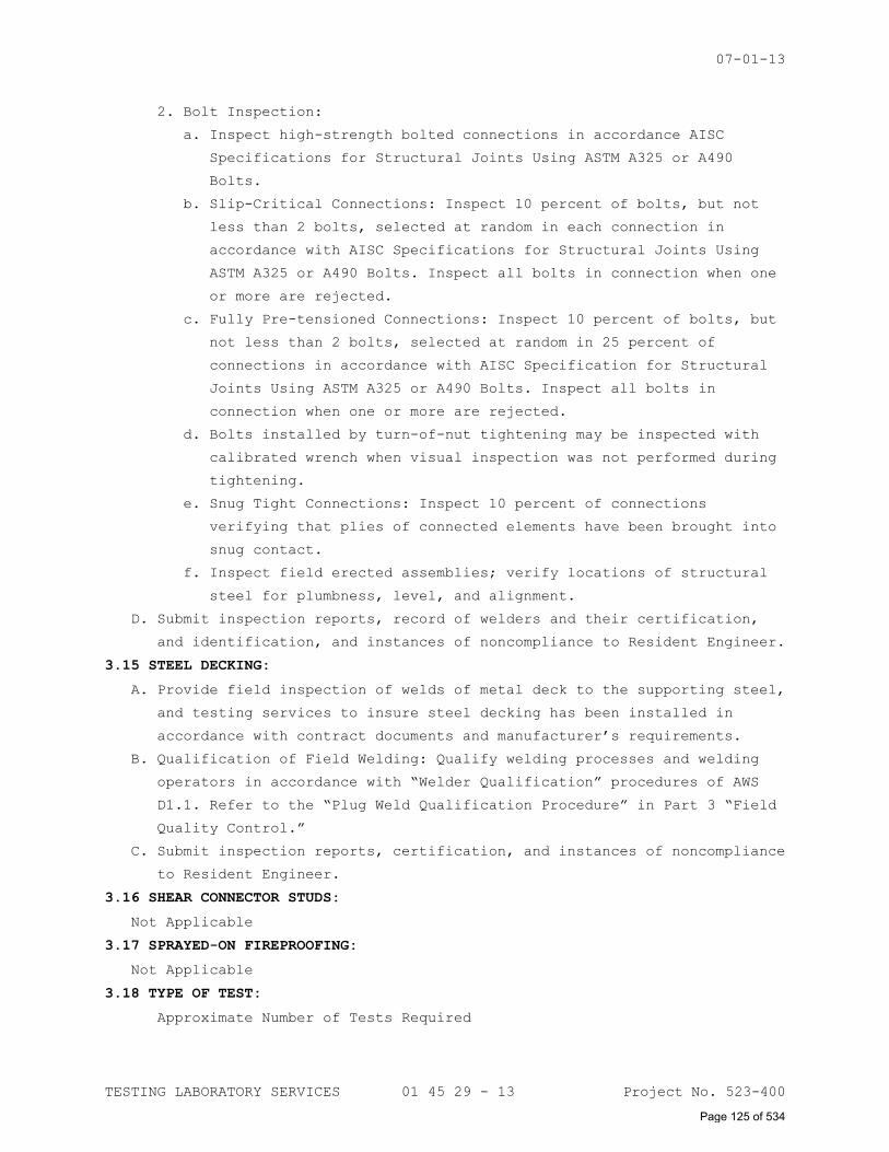
07-01-13
TESTING LABORATORY SERVICES 01 45 29 - 13 Project No. 523-400
2. Bolt Inspection:
a. Inspect high-strength bolted connections in accordance AISC
Specifications for Structural Joints Using ASTM A325 or A490
Bolts.
b. Slip-Critical Connections: Inspect 10 percent of bolts, but not
less than 2 bolts, selected at random in each connection in
accordance with AISC Specifications for Structural Joints Using
ASTM A325 or A490 Bolts. Inspect all bolts in connection when one
or more are rejected.
c. Fully Pre-tensioned Connections: Inspect 10 percent of bolts, but
not less than 2 bolts, selected at random in 25 percent of
connections in accordance with AISC Specification for Structural
Joints Using ASTM A325 or A490 Bolts. Inspect all bolts in
connection when one or more are rejected.
d. Bolts installed by turn-of-nut tightening may be inspected with
calibrated wrench when visual inspection was not performed during
tightening.
e. Snug Tight Connections: Inspect 10 percent of connections
verifying that plies of connected elements have been brought into
snug contact.
f. Inspect field erected assemblies; verify locations of structural
steel for plumbness, level, and alignment.
D. Submit inspection reports, record of welders and their certification,
and identification, and instances of noncompliance to Resident Engineer.
3.15 STEEL DECKING:
A. Provide field inspection of welds of metal deck to the supporting steel,
and testing services to insure steel decking has been installed in
accordance with contract documents and manufacturer’s requirements.
B. Qualification of Field Welding: Qualify welding processes and welding
operators in accordance with “Welder Qualification” procedures of AWS
D1.1. Refer to the “Plug Weld Qualification Procedure” in Part 3 “Field
Quality Control.”
C. Submit inspection reports, certification, and instances of noncompliance
to Resident Engineer.
3.16 SHEAR CONNECTOR STUDS:
Not Applicable
3.17 SPRAYED-ON FIREPROOFING:
Not Applicable
3.18 TYPE OF TEST:
Approximate Number of Tests Required
Page 125 of 534
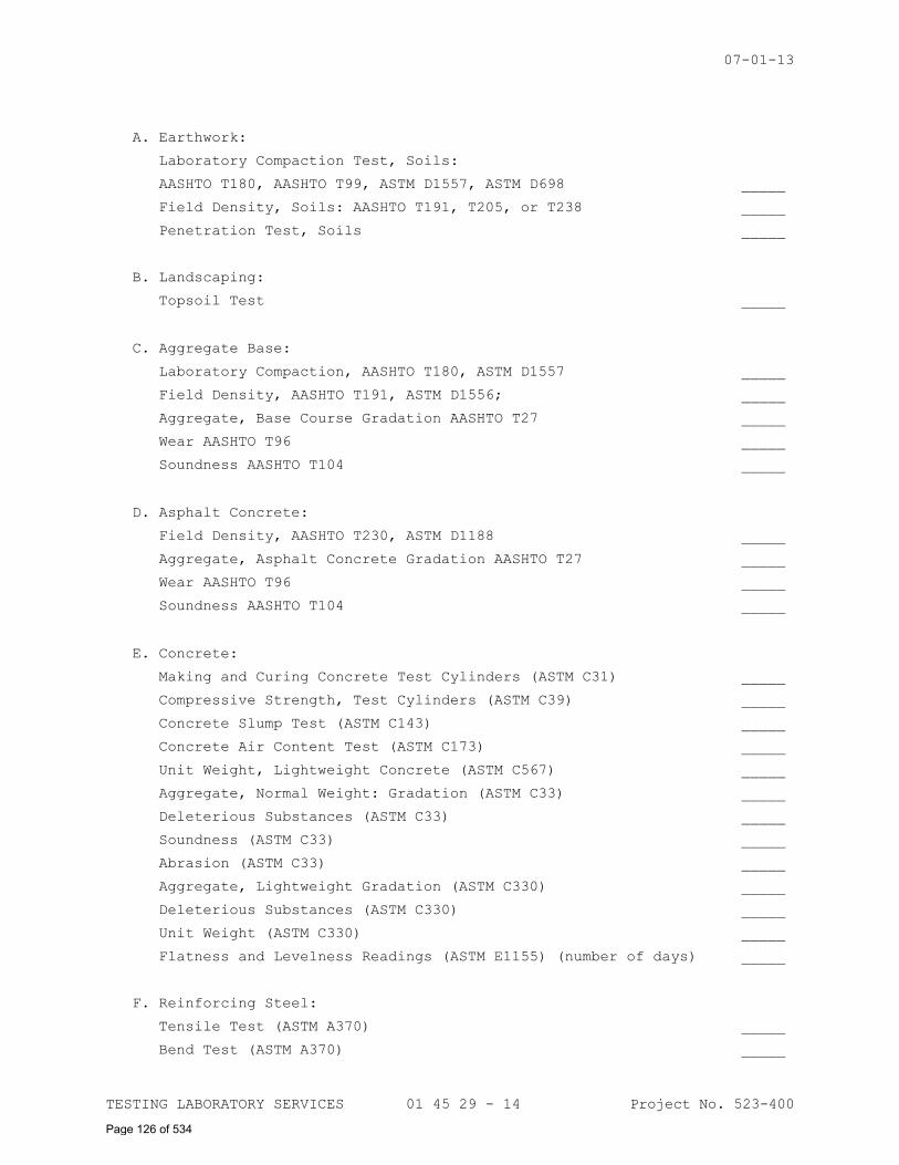
07-01-13
TESTING LABORATORY SERVICES 01 45 29 - 14 Project No. 523-400
A. Earthwork:
_____
_____
Laboratory Compaction Test, Soils:
AASHTO T180, AASHTO T99, ASTM D1557, ASTM D698
Field Density, Soils: AASHTO T191, T205, or T238
Penetration Test, Soils _____
B. Landscaping:
Topsoil Test _____
C. Aggregate Base:
_____
_____
_____
_____
Laboratory Compaction, AASHTO T180, ASTM D1557
Field Density, AASHTO T191, ASTM D1556;
Aggregate, Base Course Gradation AASHTO T27
Wear AASHTO T96
Soundness AASHTO T104 _____
D. Asphalt Concrete:
_____
_____
_____
Field Density, AASHTO T230, ASTM D1188
Aggregate, Asphalt Concrete Gradation AASHTO T27
Wear AASHTO T96
Soundness AASHTO T104 _____
E. Concrete:
Making and Curing Concrete Test Cylinders (ASTM C31) _____
Compressive Strength, Test Cylinders (ASTM C39) _____
Concrete Slump Test (ASTM C143) _____
Concrete Air Content Test (ASTM C173) _____
Unit Weight, Lightweight Concrete (ASTM C567) _____
Aggregate, Normal Weight: Gradation (ASTM C33) _____
Deleterious Substances (ASTM C33) _____
Soundness (ASTM C33) _____
Abrasion (ASTM C33) _____
Aggregate, Lightweight Gradation (ASTM C330) _____
Deleterious Substances (ASTM C330) _____
Unit Weight (ASTM C330) _____
Flatness and Levelness Readings (ASTM E1155) (number of days) _____
F. Reinforcing Steel:
Tensile Test (ASTM A370) _____
Bend Test (ASTM A370) _____
Page 126 of 534
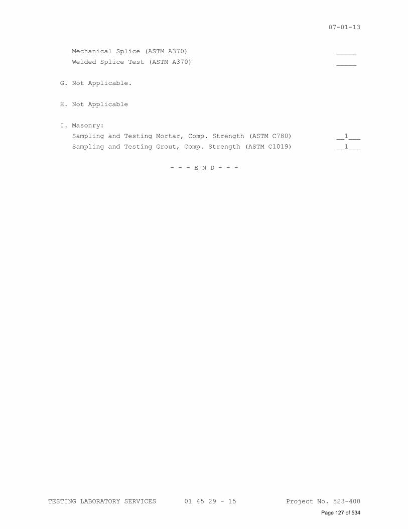
07-01-13
TESTING LABORATORY SERVICES 01 45 29 - 15 Project No. 523-400
Mechanical Splice (ASTM A370) _____
Welded Splice Test (ASTM A370) _____
G. Not Applicable.
H. Not Applicable
I. Masonry:
Sampling and Testing Mortar, Comp. Strength (ASTM C780) __1___
Sampling and Testing Grout, Comp. Strength (ASTM C1019) __1___
- - - E N D - - -
Page 127 of 534
SECTION 01 55 19 TEMPORARY OFFSITE PARKING
PART 1 - GENERAL
1.1 DESCRIPTION
A. This section specifies the criteria for temporary offsite parking and
shuttle services to be provided to offset existing parking spaces
impacted by construction. It includes management of the offsite parking
areas. The Contractor is obligated to consider specified control
measures with the costs included within the various contract items of
work.
1.2 QUALITY CONTROL
A. Establish and maintain quality control for the provision of temporary
offsite parking.
B. Record on daily reports any problems in complying with laws,
regulations, and ordinances. Note any corrective action taken.
1.3 REFERENCES
A. The publications listed below form a part of this specification to the
extent referenced. The publications are referred to in the text by basic
designation only.
B. U.S. National Archives and Records Administration (NARA):
33 CFR 328..............Definitions
1.4 SUBMITTALS
A. In accordance with Section, 01 33 23, SHOP DRAWINGS, PRODUCT DATA, AND
SAMPLES, furnish the following:
1. Temporary Offsite Parking Plan: After the contract is awarded and
prior to the commencement of the work, the Contractor shall meet with
the Resident Engineer to discuss the proposed Offsite Parking Plan
and to develop mutual understanding relative to the location of the
offsite parking area(s) and the thresholds to quantity of spaces
required. Not more than 20 days after the meeting, the Contractor
shall prepare and submit to the Project Engineer and the Contracting
Officer for approval, a written and/or graphic Temporary Offsite
Parking Plan including, but not limited to, the following:
a. Name(s) of person(s) within the Contractor's organization who is
(are) responsible for ensuring adherence to the Temporary Offsite
Parking Plan.
b. Location, Owner’s Name and tiered quantity of temporary parking
spaces for each offsite parking area.
c. Methods for protection and security of the offsite parking area.
Page 128 of 534
01-11
TEMPORARY OFFSITE PARKING 01 55 19 - 2 Project No. 523-400
d. Work Area Plan showing the proposed activity in each portion of
the area and identifying the replication of impacted parking
spaces. Plan should include measures for marking the limits of use
areas. This plan may be incorporated within the Temporary Offsite
Parking Plan.
e. Approval of the Contractor's Temporary Offsite Parking Plan will
not relieve the Contractor of responsibility to minimize impact to
existing parking areas within the facility property.
PART 2 - SERVICES
2.1 PARKING
A. The contractor shall provide all labor, equipment, supplies, services,
and security, necessary to provide a minimum of 100 offsite parking
spaces for VA employees starting when Contractor initiates site work and
continuing until the Contractor releases and the VA accepts new parking
spaces. Contractor shall increase the quantity of offsite parking spaces
to offset impacted onsite parking spaces at a one for one replacement
for any quantity over the 100 space minimum.
1. The Contractor shall provide 100 parking spaces for Boston VA
employees at up to two (2) different locations.
2. Contractor shall provide two areas for parking within one mile of the
facility campus, 1400 VFW Parkway, West Roxbury.
3. VA employees must be able to use the lot from 6 AM – 6 PM, Monday
through Friday.
4. The location of the offsite parking area shall be at an area
currently used for parking, be paved, have painted lines and be in
good condition.
5. The Contractor is responsible for providing a method for verifying
the space is being used by a VA employee and documenting this.
6. The Contractor shall increase the number of spots obligated to offset
and replace existing parking spaces impacted by their construction.
The increment shall be 5 minimum with 30 days’ notice.
7. VA Employee shall be allowed access to lots at presentation of a
valid VA ID. Pass collection may be employed by the Contractor, but
shall not incur cost to the Government or determine access for
employees.
8. Vendor shall maintain daily tally of spaces used at both sites such
that if parking becomes unavailable at one lot, attendants shall be
able to inform VA personnel whether parking is available at the
secondary lot.
Page 129 of 534
PART 3 - EXECUTION
3.1 PARKING
A. The Contractor shall request in writing forty five (45) days prior to
the impact on parking, permission to cordon off and work within said
area.
B. The VA shall approve or request changes to the request.
C. The Contractor shall schedule thirty (30) days in advance and give
notice to the VA the actual start date of parking space impact or change
in quantity thereof.
D. The VA shall notify its employees two weeks prior to the start date of
parking space availability or change thereto.
- - - E N D - - -
Page 130 of 534
01-11
TEMPORARY ENVIRONMENTAL CONTROLS 01 57 19 - 1 Project No. 523-400
SECTION 01 57 19
TEMPORARY ENVIRONMENTAL CONTROLS
PART 1 - GENERAL
1.1 DESCRIPTION
A. This section specifies the control of environmental pollution and damage
that the Contractor must consider for air, water, and land resources. It
includes management of visual aesthetics, noise, solid waste, radiant
energy, and radioactive materials, as well as other pollutants and
resources encountered or generated by the Contractor. The Contractor is
obligated to consider specified control measures with the costs included
within the various contract items of work.
B. Environmental pollution and damage is defined as the presence of
chemical, physical, or biological elements or agents which:
1. Adversely effect human health or welfare,
2. Unfavorably alter ecological balances of importance to human life,
3. Effect other species of importance to humankind, or;
4. Degrade the utility of the environment for aesthetic, cultural, and
historical purposes.
C. Definitions of Pollutants:
1. Chemical Waste: Petroleum products, bituminous materials, salts,
acids, alkalis, herbicides, pesticides, organic chemicals, and
inorganic wastes.
2. Debris: Combustible and noncombustible wastes, such as leaves, tree
trimmings, ashes, and waste materials resulting from construction or
maintenance and repair work.
3. Sediment: Soil and other debris that has been eroded and transported
by runoff water.
4. Solid Waste: Rubbish, debris, garbage, and other discarded solid
materials resulting from industrial, commercial, and agricultural
operations and from community activities.
5. Surface Discharge: The term "Surface Discharge" implies that the
water is discharged with possible sheeting action and subsequent soil
erosion may occur. Waters that are surface discharged may terminate
in drainage ditches, storm sewers, creeks, and/or "water of the
United States" and would require a permit to discharge water from the
governing agency.
6. Rubbish: Combustible and noncombustible wastes such as paper, boxes,
glass and crockery, metal and lumber scrap, tin cans, and bones.
Page 131 of 534
01-11
TEMPORARY ENVIRONMENTAL CONTROLS 01 57 19 - 2 Project No. 523-400
7. Sanitary Wastes:
a. Sewage: Domestic sanitary sewage and human and animal waste.
b. Garbage: Refuse and scraps resulting from preparation, cooking,
dispensing, and consumption of food.
1.2 QUALITY CONTROL
A. Establish and maintain quality control for the environmental protection
of all items set forth herein.
B. Record on daily reports any problems in complying with laws,
regulations, and ordinances. Note any corrective action taken.
1.3 REFERENCES
A. The publications listed below form a part of this specification to the
extent referenced. The publications are referred to in the text by basic
designation only.
B. U.S. National Archives and Records Administration (NARA):
33 CFR 328..............Definitions
1.4 SUBMITTALS
A. In accordance with Section, 01 33 23, SHOP DRAWINGS, PRODUCT DATA, AND
SAMPLES, furnish the following:
1. Environmental Protection Plan: After the contract is awarded and
prior to the commencement of the work, the Contractor shall meet with
the Resident Engineer to discuss the proposed Environmental
Protection Plan and to develop mutual understanding relative to
details of environmental protection. Not more than 20 days after the
meeting, the Contractor shall prepare and submit to the Project
Engineer and the Contracting Officer for approval, a written and/or
graphic Environmental Protection Plan including, but not limited to,
the following:
a. Name(s) of person(s) within the Contractor's organization who is
(are) responsible for ensuring adherence to the Environmental
Protection Plan.
b. Name(s) and qualifications of person(s) responsible for
manifesting hazardous waste to be removed from the site.
c. Name(s) and qualifications of person(s) responsible for training
the Contractor's environmental protection personnel.
d. Description of the Contractor's environmental protection personnel
training program.
e. A list of Federal, State, and local laws, regulations, and permits
concerning environmental protection, pollution control, noise
control and abatement that are applicable to the Contractor's
proposed operations and the requirements imposed by those laws,
regulations, and permits.
Page 132 of 534

01-11
TEMPORARY ENVIRONMENTAL CONTROLS 01 57 19 - 3 Project No. 523-400
f. Methods for protection of features to be preserved within
authorized work areas including trees, shrubs, vines, grasses,
ground cover, landscape features, air and water quality, fish and
wildlife, soil, historical, and archeological and cultural
resources.
g. Procedures to provide the environmental protection that comply
with the applicable laws and regulations. Describe the procedures
to correct pollution of the environment due to accident, natural
causes, or failure to follow the procedures as described in the
Environmental Protection Plan.
h. Permits, licenses, and the location of the solid waste disposal
area.
i. Drawings showing locations of any proposed temporary excavations
or embankments for haul roads, material storage areas, structures,
sanitary facilities, and stockpiles of excess or spoil materials.
Include as part of an Erosion Control Plan approved by the
District Office of the U.S. Soil Conservation Service and the
Department of Veterans Affairs.
j. Environmental Monitoring Plans for the job site including land,
water, air, and noise.
k. Work Area Plan showing the proposed activity in each portion of
the area and identifying the areas of limited use or nonuse. Plan
should include measures for marking the limits of use areas. This
plan may be incorporated within the Erosion Control Plan.
B. Approval of the Contractor's Environmental Protection Plan will not
relieve the Contractor of responsibility for adequate and continued
control of pollutants and other environmental protection measures.
1.5 PROTECTION OF ENVIRONMENTAL RESOURCES
A. Protect environmental resources within the project boundaries and those
affected outside the limits of permanent work during the entire period
of this contract. Confine activities to areas defined by the
specifications and drawings.
B. Protection of Land Resources: Prior to construction, identify all land
resources to be preserved within the work area. Do not remove, cut,
deface, injure, or destroy land resources including trees, shrubs,
vines, grasses, top soil, and land forms without permission from the
Resident Engineer. Do not fasten or attach ropes, cables, or guys to
trees for anchorage unless specifically authorized, or where special
emergency use is permitted.
1. Work Area Limits: Prior to any construction, mark the areas that
require work to be performed under this contract. Mark or fence
Page 133 of 534
01-11
TEMPORARY ENVIRONMENTAL CONTROLS 01 57 19 - 4 Project No. 523-400
isolated areas within the general work area that are to be saved and
protected. Protect monuments, works of art, and markers before
construction operations begin. Convey to all personnel the purpose of
marking and protecting all necessary objects.
2. Protection of Landscape: Protect trees, shrubs, vines, grasses, land
forms, and other landscape features shown on the drawings to be
preserved by marking, fencing, or using any other approved
techniques.
a. Box and protect from damage existing trees and shrubs to remain on
the construction site.
b. Immediately repair all damage to existing trees and shrubs by
trimming, cleaning, and painting with antiseptic tree paint.
c. Do not store building materials or perform construction activities
closer to existing trees or shrubs than the farthest extension of
their limbs.
3. Reduction of Exposure of Unprotected Erodible Soils: Plan and conduct
earthwork to minimize the duration of exposure of unprotected soils.
Clear areas in reasonably sized increments only as needed to use.
Form earthwork to final grade as shown. Immediately protect side
slopes and back slopes upon completion of rough grading.
4. Temporary Protection of Disturbed Areas: Construct diversion ditches,
benches, and berms to retard and divert runoff from the construction
site to protected drainage areas approved under paragraph 208 of the
Clean Water Act.
a. Sediment Basins: Trap sediment from construction areas in
temporary or permanent sediment basins that accommodate the runoff
of a local two (design year) storm. After each storm, pump the
basins dry and remove the accumulated sediment. Control overflow/
drainage with paved weirs or by vertical overflow pipes, draining
from the surface.
b. Reuse or conserve the collected topsoil sediment as directed by
the Resident Engineer. Topsoil use and requirements are specified
in Section 31 20 00, EARTH MOVING.
c. Institute effluent quality monitoring programs as required by
Federal, State, and local environmental agencies.
5. Erosion and Sedimentation Control Devices: The erosion and sediment
controls selected and maintained by the Contractor shall be such that
water quality standards are not violated as a result of the
Contractor's activities. Construct or install all temporary and
permanent erosion and sedimentation control features shown on the
Environmental Protection Plan. Maintain temporary erosion and
Page 134 of 534
01-11
TEMPORARY ENVIRONMENTAL CONTROLS 01 57 19 - 5 Project No. 523-400
sediment control measures such as berms, dikes, drains, sedimentation
basins, grassing, and mulching, until permanent drainage and erosion
control facilities are completed and operative.
6. Manage borrow areas on and off Government property to minimize
erosion and to prevent sediment from entering nearby water courses or
lakes.
7. Manage and control spoil areas on and off Government property to
limit spoil to areas shown on the Environmental Protection Plan and
prevent erosion of soil or sediment from entering nearby water
courses or lakes.
8. Protect adjacent areas from despoilment by temporary excavations and
embankments.
9. Handle and dispose of solid wastes in such a manner that will prevent
contamination of the environment. Place solid wastes (excluding
clearing debris) in containers that are emptied on a regular
schedule. Transport all solid waste off Government property and
dispose of waste in compliance with Federal, State, and local
requirements.
10. Store chemical waste away from the work areas in corrosion resistant
containers and dispose of waste in accordance with Federal, State,
and local regulations.
11. Handle discarded materials other than those included in the solid
waste category as directed by the Resident Engineer.
C. Protection of Water Resources: Keep construction activities under
surveillance, management, and control to avoid pollution of surface and
ground waters and sewer systems. Implement management techniques to
control water pollution by the listed construction activities that are
included in this contract.
1. Washing and Curing Water: Do not allow wastewater directly derived
from construction activities to enter water areas. Collect and place
wastewater in retention ponds allowing the suspended material to
settle, the pollutants to separate, or the water to evaporate.
2. Control movement of materials and equipment at stream crossings
during construction to prevent violation of water pollution control
standards of the Federal, State, or local government.
3. Monitor water areas affected by construction.
D. Protection of Fish and Wildlife Resources: Keep construction activities
under surveillance, management, and control to minimize interference
with, disturbance of, or damage to fish and wildlife. Prior to beginning
Page 135 of 534
01-11
TEMPORARY ENVIRONMENTAL CONTROLS 01 57 19 - 6 Project No. 523-400
construction operations, list species that require specific attention
along with measures for their protection.
E. Protection of Air Resources: Keep construction activities under
surveillance, management, and control to minimize pollution of air
resources. Burning is not permitted on the job site. Keep activities,
equipment, processes, and work operated or performed, in strict
accordance with the Commonwealth of Massachussetts Department of
Environmental rules and regulations and Federal emission and
performance laws and standards. Maintain ambient air quality standards
set by the Environmental Protection Agency, for those construction
operations and activities specified.
1. Particulates: Control dust particles, aerosols, and gaseous by-
products from all construction activities, processing, and
preparation of materials (such as from asphaltic batch plants) at all
times, including weekends, holidays, and hours when work is not in
progress.
2. Particulates Control: Maintain all excavations, stockpiles, haul
roads, permanent and temporary access roads, plant sites, spoil
areas, borrow areas, and all other work areas within or outside the
project boundaries free from particulates which would cause a hazard
or a nuisance. Sprinklering, chemical treatment of an approved type,
light bituminous treatment, baghouse, scrubbers, electrostatic
precipitators, or other methods are permitted to control particulates
in the work area.
3. Hydrocarbons and Carbon Monoxide: Control monoxide emissions from
equipment to Federal and State allowable limits.
4. Odors: Control odors of construction activities and prevent obnoxious
odors from occurring.
F. Reduction of Noise: Minimize noise using every action possible. Perform
noise-producing work in less sensitive hours of the day or week as
directed by the Resident Engineer. Maintain noise-produced work at or
below the decibel levels and within the time periods specified.
1. Perform construction activities involving repetitive, high-level
impact noise only between 8:00 a.m. and 6:00 p.m unless otherwise
permitted by local ordinance or the Resident Engineer. Repetitive
impact noise on the property shall not exceed the following dB
limitations:
Time Duration of Impact Noise Sound Level in dB
More than 12 minutes in any hour 70
Less than 30 seconds of any hour 85
Page 136 of 534
01-11
TEMPORARY ENVIRONMENTAL CONTROLS 01 57 19 - 7 Project No. 523-400
Less than three minutes of any hour 80
Less than 12 minutes of any hour 75
2. Provide sound-deadening devices on equipment and take noise abatement
measures that are necessary to comply with the requirements of this
contract, consisting of, but not limited to, the following:
a. Maintain maximum permissible construction equipment noise levels
at 15 m (50 feet) (dBA):
EARTHMOVING FRONT
LOADERS 75
MATERIALS HANDLING
CONCRETE MIXERS 75
BACKHOES 75 CONCRETE PUMPS 75
DOZERS 75 CRANES 75
TRACTORS 75 DERRICKS IMPACT 75
SCAPERS 80 PILE DRIVERS 95
GRADERS 75 JACK HAMMERS 75
TRUCKS 75 ROCK DRILLS 80
PAVERS,
STATIONARY
80 PNEUMATIC TOOLS 80
PUMPS 75 BLASTING 80
GENERATORS 75 SAWS 75
COMPRESSORS 75 VIBRATORS 75
b. Use shields or other physical barriers to restrict noise
transmission.
c. Provide soundproof housings or enclosures for noise-producing
machinery.
d. Use efficient silencers on equipment air intakes.
e. Use efficient intake and exhaust mufflers on internal combustion
engines that are maintained so equipment performs below noise
levels specified.
f. Line hoppers and storage bins with sound deadening material.
g. Conduct truck loading, unloading, and hauling operations so that
noise is kept to a minimum.
3. Measure sound level for noise exposure due to the construction at
least once every five successive working days while work is being
performed above 55 dB(A) noise level. Measure noise exposure at the
property line or 15 m (50 feet) from the noise source, whichever is
greater. Measure the sound levels on the A weighing network of a
General Purpose sound level meter at slow response. To minimize the
effect of reflective sound waves at buildings, take measurements at
Page 137 of 534
01-11
TEMPORARY ENVIRONMENTAL CONTROLS 01 57 19 - 8 Project No. 523-400
900 to 1800 mm (three to six feet) in front of any building face.
Submit the recorded information to the Resident Engineer noting any
problems and the alternatives for mitigating actions.
G. Restoration of Damaged Property: If any direct or indirect damage is
done to public or private property resulting from any act, omission,
neglect, or misconduct, the Contractor shall restore the damaged
property to a condition equal to that existing before the damage at no
additional cost to the Government. Repair, rebuild, or restore property
as directed or make good such damage in an acceptable manner.
H. Final Clean-up: On completion of project and after removal of all
debris, rubbish, and temporary construction, Contractor shall leave the
construction area in a clean condition satisfactory to the Resident
Engineer. Cleaning shall include off the station disposal of all items
and materials not required to be salvaged, as well as all debris and
rubbish resulting from demolition and new work operations.
- - - E N D - - -
Page 138 of 534
09-01-13
CONSTRUCTION WASTE MANAGEMENT 01 74 19 - 1 Project No. 523-400
SECTION 01 74 19
CONSTRUCTION WASTE MANAGEMENT
PART 1 – GENERAL
1.1 DESCRIPTION
A. This section specifies the requirements for the management of non-
hazardous building construction and demolition waste.
B. Waste disposal in landfills shall be minimized to the greatest extent
possible. Of the inevitable waste that is generated, as much of the
waste material as economically feasible shall be salvaged, recycled or
reused.
C. Contractor shall use all reasonable means to divert construction and
demolition waste from landfills and incinerators, and facilitate their
salvage and recycle not limited to the following:
1. Waste Management Plan development and implementation.
2. Techniques to minimize waste generation.
3. Sorting and separating of waste materials.
4. Salvage of existing materials and items for reuse or resale.
5. Recycling of materials that cannot be reused or sold.
D. At a minimum the following waste categories shall be diverted from
landfills:
1. Soil.
2. Inerts (eg, concrete, masonry and asphalt).
3. Clean dimensional wood and palette wood.
4. Green waste (biodegradable landscaping materials).
5. Engineered wood products (plywood, particle board and I-joists,
etc).
6. Metal products (eg, steel, wire, beverage containers, copper, etc).
7. Cardboard, paper and packaging.
8. Bitumen roofing materials.
9. Plastics (eg, ABS, PVC).
10. Carpet and/or pad.
11. Gypsum board.
12. Insulation.
13. Paint.
14. Fluorescent lamps.
1.2 RELATED WORK
A. Section 01 00 00, GENERAL REQUIREMENTS.
Page 139 of 534
09-01-13
CONSTRUCTION WASTE MANAGEMENT 01 74 19 - 2 Project No. 523-400
1.3 QUALITY ASSURANCE
A. Contractor shall practice efficient waste management when sizing,
cutting and installing building products. Processes shall be employed
to ensure the generation of as little waste as possible. Construction
/Demolition waste includes products of the following:
1. Excess or unusable construction materials.
2. Packaging used for construction products.
3. Poor planning and/or layout.
4. Construction error.
5. Over ordering.
6. Weather damage.
7. Contamination.
8. Mishandling.
9. Breakage.
B. Establish and maintain the management of non-hazardous building
construction and demolition waste set forth herein. Conduct a site
assessment to estimate the types of materials that will be generated by
demolition and construction.
C. Contractor shall develop and implement procedures to recycle
construction and demolition waste to a minimum of 50 percent.
D. Contractor shall be responsible for implementation of any special
programs involving rebates or similar incentives related to recycling.
Any revenues or savings obtained from salvage or recycling shall accrue
to the contractor.
E. Contractor shall provide all demolition, removal and legal disposal of
materials. Contractor shall ensure that facilities used for recycling,
reuse and disposal shall be permitted for the intended use to the
extent required by local, state, federal regulations. The Whole
Building Design Guide website http://www.wbdg.org/tools/cwm.php
provides a Construction Waste Management Database that contains
information on companies that haul, collect, and process recyclable
debris from construction projects.
F. Contractor shall assign a specific area to facilitate separation of
materials for reuse, salvage, recycling, and return. Such areas are to
be kept neat and clean and clearly marked in order to avoid
contamination or mixing of materials.
Page 140 of 534
09-01-13
CONSTRUCTION WASTE MANAGEMENT 01 74 19 - 3 Project No. 523-400
G. Contractor shall provide on-site instructions and supervision of
separation, handling, salvaging, recycling, reuse and return methods to
be used by all parties during waste generating stages.
H. Record on daily reports any problems in complying with laws,
regulations and ordinances with corrective action taken.
1.4 TERMINOLOGY
A. Class III Landfill: A landfill that accepts non-hazardous resources
such as household, commercial and industrial waste resulting from
construction, remodeling, repair and demolition operations.
B. Clean: Untreated and unpainted; uncontaminated with adhesives, oils,
solvents, mastics and like products.
C. Construction and Demolition Waste: Includes all non-hazardous resources
resulting from construction, remodeling, alterations, repair and
demolition operations.
D. Dismantle: The process of parting out a building in such a way as to
preserve the usefulness of its materials and components.
E. Disposal: Acceptance of solid wastes at a legally operating facility
for the purpose of land filling (includes Class III landfills and inert
fills).
F. Inert Backfill Site: A location, other than inert fill or other
disposal facility, to which inert materials are taken for the purpose
of filling an excavation, shoring or other soil engineering operation.
G. Inert Fill: A facility that can legally accept inert waste, such as
asphalt and concrete exclusively for the purpose of disposal.
H. Inert Solids/Inert Waste: Non-liquid solid resources including, but not
limited to, soil and concrete that does not contain hazardous waste or
soluble pollutants at concentrations in excess of water-quality
objectives established by a regional water board, and does not contain
significant quantities of decomposable solid resources.
I. Mixed Debris: Loads that include commingled recyclable and non-
recyclable materials generated at the construction site.
J. Mixed Debris Recycling Facility: A solid resource processing facility
that accepts loads of mixed construction and demolition debris for the
purpose of recovering re-usable and recyclable materials and disposing
non-recyclable materials.
K. Permitted Waste Hauler: A company that holds a valid permit to collect
and transport solid wastes from individuals or businesses for the
purpose of recycling or disposal.
Page 141 of 534
09-01-13
CONSTRUCTION WASTE MANAGEMENT 01 74 19 - 4 Project No. 523-400
L. Recycling: The process of sorting, cleansing, treating, and
reconstituting materials for the purpose of using the altered form in
the manufacture of a new product. Recycling does not include burning,
incinerating or thermally destroying solid waste.
1. On-site Recycling – Materials that are sorted and processed on site
for use in an altered state in the work, i.e. concrete crushed for
use as a sub-base in paving.
2. Off-site Recycling – Materials hauled to a location and used in an
altered form in the manufacture of new products.
M. Recycling Facility: An operation that can legally accept materials for
the purpose of processing the materials into an altered form for the
manufacture of new products. Depending on the types of materials
accepted and operating procedures, a recycling facility may or may not
be required to have a solid waste facilities permit or be regulated by
the local enforcement agency.
N. Reuse: Materials that are recovered for use in the same form, on-site
or off-site.
O. Return: To give back reusable items or unused products to vendors for
credit.
P. Salvage: To remove waste materials from the site for resale or re-use
by a third party.
Q. Source-Separated Materials: Materials that are sorted by type at the
site for the purpose of reuse and recycling.
R. Solid Waste: Materials that have been designated as non-recyclable and
are discarded for the purposes of disposal.
S. Transfer Station: A facility that can legally accept solid waste for
the purpose of temporarily storing the materials for re-loading onto
other trucks and transporting them to a landfill for disposal, or
recovering some materials for re-use or recycling.
1.5 SUBMITTALS
A. In accordance with Section 01 33 23, SHOP DRAWINGS, PRODUCT DATA, and
SAMPLES, furnish the following:
B. Prepare and submit to the Project Engineer a written
demolition debris management plan. The plan shall include, but not be
limited to, the following information:
1. Procedures to be used for debris management.
2. Techniques to be used to minimize waste generation.
3. Analysis of the estimated job site waste to be generated:
Page 142 of 534
09-01-13
CONSTRUCTION WASTE MANAGEMENT 01 74 19 - 5 Project No. 523-400
a. List of each material and quantity to be salvaged, reused,
recycled.
b. List of each material and quantity proposed to be taken to a
landfill.
4. Detailed description of the Means/Methods to be used for material
handling.
a. On site: Material separation, storage, protection where
applicable.
b. Off site: Transportation means and destination. Include list of
materials.
1) Description of materials to be site-separated and self-hauled
to designated facilities.
2) Description of mixed materials to be collected by designated
waste haulers and removed from the site.
c. The names and locations of mixed debris reuse and recycling
facilities or sites.
d. The names and locations of trash disposal landfill facilities or
sites.
e. Documentation that the facilities or sites are approved to
receive the materials.
C. Designated Manager responsible for instructing personnel, supervising,
documenting and administer over meetings relevant to the Waste
Management Plan.
D. Monthly summary of construction and demolition debris diversion and
disposal, quantifying all materials generated at the work site and
disposed of or diverted from disposal through recycling.
1.6 APPLICABLE PUBLICATIONS
A Publications listed below form a part of this specification to the
extent referenced. Publications are referenced by the basic designation
only. In the event that criteria requirements conflict, the most
stringent requirements shall be met.
B. U.S. Green Building Council (USGBC):
LEED Green Building Rating System for New Construction
1.7 RECORDS
Maintain records to document the quantity of waste generated; the
quantity of waste diverted through sale, reuse, or recycling; and the
quantity of waste disposed by landfill or incineration. Records shall
be kept in accordance with the LEED Reference Guide and LEED Template.
Page 143 of 534
09-01-13
CONSTRUCTION WASTE MANAGEMENT 01 74 19 - 6 Project No. 523-400
PART 2 - PRODUCTS
2.1 MATERIALS
A. List of each material and quantity to be salvaged, recycled, reused.
B. List of each material and quantity proposed to be taken to a landfill.
C. Material tracking data: Receiving parties, dates removed,
transportation costs, weight tickets, tipping fees, manifests,
invoices, net total costs or savings.
PART 3 - EXECUTION
3.1 COLLECTION
A. Provide all necessary containers, bins and storage areas to facilitate
effective waste management.
B. Clearly identify containers, bins and storage areas so that recyclable
materials are separated from trash and can be transported to respective
recycling facility for processing.
C. Hazardous wastes shall be separated, stored, disposed of according to
local, state, federal regulations.
3.2 DISPOSAL
A. Contractor shall be responsible for transporting and disposing of
materials that cannot be delivered to a source-separated or mixed
materials recycling facility to a transfer station or disposal facility
that can accept the materials in accordance with state and federal
regulations.
B. Construction or demolition materials with no practical reuse or that
cannot be salvaged or recycled shall be disposed of at a landfill or
incinerator.
3.3 REPORT
A. With each application for progress payment, submit a summary of
construction and demolition debris diversion and disposal including
beginning and ending dates of period covered.
B. Quantify all materials diverted from landfill disposal through salvage
or recycling during the period with the receiving parties, dates
removed, transportation costs, weight tickets, manifests, invoices.
Include the net total costs or savings for each salvaged or recycled
material.
C. Quantify all materials disposed of during the period with the receiving
parties, dates removed, transportation costs, weight tickets, tipping
fees, manifests, invoices. Include the net total costs for each
disposal.
- - - E N D - - -
Page 144 of 534
06-01-13
GENERAL COMMISSIONING REQUIREMENTS 01 91 00 - 1 Project No. 523-400
SECTION 01 91 00
GENERAL COMMISSIONING REQUIREMENTS
PART 1 - GENERAL
1.1 COMMISSIONING DESCRIPTION
A. This Section 01 91 00 GENERAL COMMISSIONING REQUIREMENTS shall form the
basis of the construction phase commissioning process and procedures.
The Commissioning Agent shall add, modify, and refine the commissioning
procedures, as approved by the Department of Veterans Affairs (VA), to
suit field conditions and actual manufacturer's equipment, incorporate
test data and procedure results, and provide detailed scheduling for
all commissioning tasks.
B. Various sections of the project specifications require equipment
startup, testing, and adjusting services. Requirements for startup,
testing, and adjusting services specified in the Division 33 series
sections of these specifications are intended to be provided in
coordination with the commissioning services and are not intended to
duplicate services. The Contractor shall coordinate the work required
by individual specification sections with the commissioning services
requirements specified herein.
C. Where individual testing, adjusting, or related services are required
in the project specifications and not specifically required by this
commissioning requirements specification, the specified services shall
be provided and copies of documentation, as required by those
specifications shall be submitted to the VA and the Commissioning Agent
to be indexed for future reference.
D. Where training or educational services for VA are required and
specified in other sections of the specifications, including but not
limited to Division 33 series sections of the specification, these
services are intended to be provided in addition to the training and
educational services specified herein.
E. Commissioning is a systematic process of verifying that the building
systems perform interactively according to the construction documents
and the VA’s operational needs. The commissioning process shall
encompass and coordinate the system documentation, equipment startup,
control system calibration, testing and balancing, performance testing
and training. Commissioning during the construction and post-occupancy
Page 145 of 534
06-01-13
GENERAL COMMISSIONING REQUIREMENTS 01 91 00 - 2 Project No. 523-400
phases is intended to achieve the following specific objectives
according to the contract documents:
1. Verify that the applicable equipment and systems are installed in
accordance with the contact documents and according to the
manufacturer's recommendations.
2. Verify and document proper integrated performance of equipment and
systems.
3. Verify that Operations & Maintenance documentation is complete.
4. Verify that all components requiring servicing can be accessed,
serviced and removed without disturbing nearby components including
ducts, piping, cabling or wiring.
5. Verify that the VA’s operating personnel are adequately trained to
enable them to operate, monitor, adjust, maintain, and repair
building systems in an effective and energy-efficient manner.
6. Document the successful achievement of the commissioning objectives
listed above.
F. The commissioning process does not take away from or reduce the
responsibility of the Contractor to provide a finished and fully
functioning product.
1.2 CONTRACTUAL RELATIONSHIPS
A. For this construction project, the Department of Veterans Affairs
contracts with a Contractor to provide construction services. The
contracts are administered by the VA Contracting Officer and the
Resident Engineer as the designated representative of the Contracting
Officer. On this project, the authority to modify the contract in any
way is strictly limited to the authority of the Contracting Officer.
B. In this project, only two contract parties are recognized and
communications on contractual issues are strictly limited to VA
Resident Engineer and the Contractor. It is the practice of the VA to
require that communications between other parties to the contracts
(Subcontractors and Vendors) be conducted through the Resident Engineer
and Contractor. It is also the practice of the VA that communications
between other parties of the project (Commissioning Agent and
Architect/Engineer) be conducted through the Resident Engineer.
C. Whole Building Commissioning is a process that relies upon frequent and
direct communications, as well as collaboration between all parties to
the construction process. By its nature, a high level of communication
and cooperation between the Commissioning Agent and all other parties
Page 146 of 534
06-01-13
GENERAL COMMISSIONING REQUIREMENTS 01 91 00 - 3 Project No. 523-400
(Architects, Engineers, Subcontractors, Vendors, third party testing
agencies, etc.) is essential to the success of the Commissioning
effort.
D. With these fundamental practices in mind, the commissioning process
described herein has been developed to recognize that, in the execution
of the Commissioning Process, the Commissioning Agent must develop
effective methods to communicate with every member of the construction
team involved in delivering commissioned systems while simultaneously
respecting the exclusive contract authority of the Contracting Officer
and Resident Engineer. Thus, the procedures outlined in this
specification must be executed within the following limitations:
1. No communications (verbal or written) from the Commissioning Agent
shall be deemed to constitute direction that modifies the terms of
any contract between the Department of Veterans Affairs and the
Contractor.
2. Commissioning Issues identified by the Commissioning Agent will be
delivered to the Resident Engineer and copied to the designated
Commissioning Representatives for the Contractor and subcontractors
on the Commissioning Team for information only in order to expedite
the communication process. These issues must be understood as the
professional opinion of the Commissioning Agent and as suggestions
for resolution.
3. In the event that any Commissioning Issues and suggested resolutions
are deemed by the Resident Engineer to require either an official
interpretation of the construction documents or require a
modification of the contract documents, the Contracting Officer or
Resident Engineer will issue an official directive to this effect.
4. All parties to the Commissioning Process shall be individually
responsible for alerting the Resident Engineer of any issues that
they deem to constitute a potential contract change prior to acting
on these issues.
5. Authority for resolution or modification of design and construction
issues rests solely with the Contracting Officer or Resident
Engineer, with appropriate technical guidance from the
Architect/Engineer and/or Commissioning Agent.
1.3 RELATED WORK
A. Section 01 00 00 GENERAL REQUIREMENTS.
B. Section 01 33 23 SHOP DRAWINGS, PRODUCT DATA, AND SAMPLES
Page 147 of 534
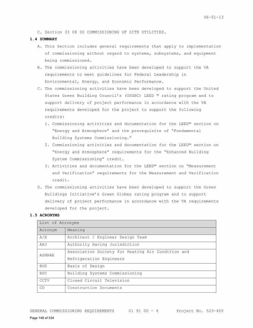
06-01-13
GENERAL COMMISSIONING REQUIREMENTS 01 91 00 - 4 Project No. 523-400
C. Section 33 08 00 COMMISSIONING OF SITE UTILITIES.
1.4 SUMMARY
A. This Section includes general requirements that apply to implementation
of commissioning without regard to systems, subsystems, and equipment
being commissioned.
B. The commissioning activities have been developed to support the VA
requirements to meet guidelines for Federal Leadership in
Environmental, Energy, and Economic Performance.
C. The commissioning activities have been developed to support the United
States Green Building Council’s (USGBC) LEED ™ rating program and to
support delivery of project performance in accordance with the VA
requirements developed for the project to support the following
credits:
1. Commissioning activities and documentation for the LEED™ section on
“Energy and Atmosphere” and the prerequisite of “Fundamental
Building Systems Commissioning.”
2. Commissioning activities and documentation for the LEED™ section on
“Energy and Atmosphere” requirements for the “Enhanced Building
System Commissioning” credit.
3. Activities and documentation for the LEED™ section on “Measurement
and Verification” requirements for the Measurement and Verification
credit.
D. The commissioning activities have been developed to support the Green
Buildings Initiative’s Green Globes rating program and to support
delivery of project performance in accordance with the VA requirements
developed for the project.
1.5 ACRONYMS
List of Acronyms
Acronym Meaning
A/E Architect / Engineer Design Team
AHJ Authority Having Jurisdiction
ASHRAE Association Society for Heating Air Condition and
Refrigeration Engineers
BOD Basis of Design
BSC Building Systems Commissioning
CCTV Closed Circuit Television
CD Construction Documents
Page 148 of 534
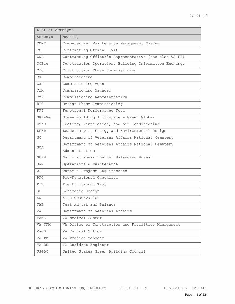
06-01-13
GENERAL COMMISSIONING REQUIREMENTS 01 91 00 - 5 Project No. 523-400
List of Acronyms
Acronym Meaning
CMMS Computerized Maintenance Management System
CO Contracting Officer (VA)
COR Contracting Officer’s Representative (see also VA-RE)
COBie Construction Operations Building Information Exchange
CPC Construction Phase Commissioning
Cx Commissioning
CxA Commissioning Agent
CxM Commissioning Manager
CxR Commissioning Representative
DPC Design Phase Commissioning
FPT Functional Performance Test
GBI-GG Green Building Initiative - Green Globes
HVAC Heating, Ventilation, and Air Conditioning
LEED Leadership in Energy and Environmental Design
NC Department of Veterans Affairs National Cemetery
NCA Department of Veterans Affairs National Cemetery
Administration
NEBB National Environmental Balancing Bureau
O&M Operations & Maintenance
OPR Owner’s Project Requirements
PFC Pre-Functional Checklist
PFT Pre-Functional Test
SD Schematic Design
SO Site Observation
TAB Test Adjust and Balance
VA Department of Veterans Affairs
VAMC VA Medical Center
VA CFM VA Office of Construction and Facilities Management
VACO VA Central Office
VA PM VA Project Manager
VA-RE VA Resident Engineer
USGBC United States Green Building Council
Page 149 of 534
06-01-13
GENERAL COMMISSIONING REQUIREMENTS 01 91 00 - 6 Project No. 523-400
1.6 DEFINITIONS
Acceptance Phase Commissioning: Commissioning tasks executed after most
construction has been completed, most Site Observations and Static
Tests have been completed and Pre-Functional Testing has been completed
and accepted. The main commissioning activities performed during this
phase are verification that the installed systems are functional by
conducting Systems Functional Performance tests and Owner Training.
Accuracy: The capability of an instrument to indicate the true value of
a measured quantity.
Back Check: A back check is a verification that an agreed upon
solution to a design comment has been adequately addressed in a
subsequent design review
Basis of Design (BOD): The Engineer’s Basis of Design is comprised of
two components: the Design Criteria and the Design Narrative, these
documents record the concepts, calculations, decisions, and product
selections used to meet the Owner’s Project Requirements (OPR) and to
satisfy applicable regulatory requirements, standards, and guidelines.
Benchmarks: Benchmarks are the comparison of a building’s energy usage
to other similar buildings and to the building itself.. For example,
ENERGY STAR Portfolio Manager is a frequently used and nationally
recognized building energy benchmarking tool.
Building Information Modeling (BIM): Building Information Modeling is
a parametric database which allows a building to be designed and
constructed virtually in 3D, and provides reports both in 2D views and
as schedules. This electronic information can be extracted and reused
for pre-populating facility management CMMS systems. Building Systems
Commissioning (BSC): NEBB acronym used to designate its commissioning
program.
Calibrate: The act of comparing an instrument of unknown accuracy with
a standard of known accuracy to detect, correlate, report, or eliminate
by adjustment any variation in the accuracy of the tested instrument.
CCTV: Closed circuit Television. Normally used for security
surveillance and alarm detections as part of a special electrical
security system.
COBie: Construction Operations Building Information Exchange (COBie)
is an electronic industry data format used to transfer information
developed during design, construction, and commissioning into the
Computer Maintenance Management Systems (CMMS) used to operate
Page 150 of 534
06-01-13
GENERAL COMMISSIONING REQUIREMENTS 01 91 00 - 7 Project No. 523-400
facilities. See the Whole Building Design Guide website for further
information (http://www.wbdg.org/resources/cobie.php)
Commissionability: Defines a design component or construction process
that has the necessary elements that will allow a system or component
to be effectively measured, tested, operated and commissioned
Commissioning Agent (CxA): The qualified Commissioning Professional who
administers the Cx process by managing the Cx team and overseeing the
Commissioning Process. Where CxA is used in this specification it means
the Commissioning Agent, members of his staff or appointed members of
the commissioning team. Note that LEED uses the term Commissioning
Authority in lieu of Commissioning Agent.
Commissioning Checklists: Lists of data or inspections to be verified
to ensure proper system or component installation, operation, and
function. Verification checklists are developed and used during all
phases of the commissioning process to verify that the Owner’s Project
Requirements (OPR) is being achieved.
Commissioning Design Review: The commissioning design review is a
collaborative review of the design professionals design documents for
items pertaining to the following: owner’s project requirements; basis
of design; operability and maintainability (O&M) including
documentation; functionality; training; energy efficiency, control
systems’ sequence of operations including building automation system
features; commissioning specifications and the ability to functionally
test the systems.
Commissioning Issue: A condition identified by the Commissioning Agent
or other member of the Commissioning Team that adversely affects the
commissionability, operability, maintainability, or functionality of a
system, equipment, or component. A condition that is in conflict with
the Contract Documents and/or performance requirements of the installed
systems and components. (See also – Commissioning Observation).
Commissioning Manager (CxM): A qualified individual appointed by the
Contractor to manage the commissioning process on behalf of the
Contractor.
Commissioning Observation: An issue identified by the Commissioning
Agent or other member of the Commissioning Team that does not conform
to the project OPR, contract documents or standard industry best
practices. (See also Commissioning Issue)
Page 151 of 534
06-01-13
GENERAL COMMISSIONING REQUIREMENTS 01 91 00 - 8 Project No. 523-400
Commissioning Plan: A document that outlines the commissioning process,
commissioning scope and defines responsibilities, processes, schedules,
and the documentation requirements of the Commissioning Process.
Commissioning Process: A quality focused process for enhancing the
delivery of a project. The process focuses upon verifying and
documenting that the facility and all of its systems, components, and
assemblies are planned, designed, installed, tested, can be operated,
and maintained to meet the Owner's Project Requirements.
Commissioning Report: The final commissioning document which presents
the commissioning process results for the project. Cx reports include
an executive summary, the commissioning plan, issue log,
correspondence, and all appropriate check sheets and test forms.
Commissioning Representative (CxR): An individual appointed by a sub-
contractor to manage the commissioning process on behalf of the sub-
contractor.
Commissioning Specifications: The contract documents that detail the
objective, scope and implementation of the commissioning process as
developed in the Commissioning Plan.
Commissioning Team: Individual team members whose coordinated actions
are responsible for implementing the Commissioning Process.
Construction Phase Commissioning: All commissioning efforts executed
during the construction process after the design phase and prior to the
Acceptance Phase Commissioning.
Contract Documents (CD): Contract documents include design and
construction contracts, price agreements and procedure agreements.
Contract Documents also include all final and complete drawings,
specifications and all applicable contract modifications or
supplements.
Construction Phase Commissioning (CPC): All commissioning efforts
executed during the construction process after the design phase and
prior to the Acceptance Phase Commissioning.
Coordination Drawings: Drawings showing the work of all trades that are
used to illustrate that equipment can be installed in the space
allocated without compromising equipment function or access for
maintenance and replacement. These drawings graphically illustrate and
dimension manufacturers’ recommended maintenance clearances. On
mechanical projects, coordination drawings include structural steel,
Page 152 of 534
06-01-13
GENERAL COMMISSIONING REQUIREMENTS 01 91 00 - 9 Project No. 523-400
ductwork, major piping and electrical conduit and show the elevations
and locations of the above components.
Data Logging: The monitoring and recording of temperature, flow,
current, status, pressure, etc. of equipment using stand-alone data
recorders.
Deferred System Test: Tests that cannot be completed at the end of the
acceptance phase due to ambient conditions, schedule issues or other
conditions preventing testing during the normal acceptance testing
period.
Deficiency: See “Commissioning Issue”.
Design Criteria: A listing of the VA Design Criteria outlining the
project design requirements, including its source. These are used
during the design process to show the design elements meet the OPR.
Design Intent: The overall term that includes the OPR and the BOD. It
is a detailed explanation of the ideas, concepts, and criteria that are
defined by the owner to be important. The design intent documents are
utilized to provide a written record of these ideas, concepts and
criteria.
Design Narrative: A written description of the proposed design
solutions that satisfy the requirements of the OPR.
Design Phase Commissioning (DPC): All commissioning tasks executed
during the design phase of the project.
Environmental Systems: Systems that use a combination of mechanical
equipment, airflow, water flow and electrical energy to provide
heating, ventilating, air conditioning, humidification, and
dehumidification for the purpose of human comfort or process control of
temperature and humidity.
Executive Summary: A section of the Commissioning report that reviews
the general outcome of the project. It also includes any unresolved
issues, recommendations for the resolution of unresolved issues and all
deferred testing requirements.
Functionality: This defines a design component or construction process
which will allow a system or component to operate or be constructed in
a manner that will produce the required outcome of the OPR.
Functional Test Procedure (FTP): A written protocol that defines
methods, steps, personnel, and acceptance criteria for tests conducted
on components, equipment, assemblies, systems, and interfaces among
systems.
Page 153 of 534
06-01-13
GENERAL COMMISSIONING REQUIREMENTS 01 91 00 - 10 Project No. 523-400
Industry Accepted Best Practice: A design component or construction
process that has achieved industry consensus for quality performance
and functionality. Refer to the current edition of the NEBB Design
Phase Commissioning Handbook for examples.
Installation Verification: Observations or inspections that confirm
the system or component has been installed in accordance with the
contract documents and to industry accepted best practices.
Integrated System Testing: Integrated Systems Testing procedures entail
testing of multiple integrated systems performance to verify proper
functional interface between systems. Typical Integrated Systems
Testing includes verifying that building systems respond properly to
loss of utility, transfer to emergency power sources, re-transfer from
emergency power source to normal utility source; interface between HVAC
controls and Fire Alarm systems for equipment shutdown, interface
between Fire Alarm system and elevator control systems for elevator
recall and shutdown; interface between Fire Alarm System and Security
Access Control Systems to control access to spaces during fire alarm
conditions; and other similar tests as determined for each specific
project.
Issues Log: A formal and ongoing record of problems or concerns – and
their resolution – that have been raised by members of the
Commissioning Team during the course of the Commissioning Process.
Lessons Learned Workshop: A workshop conducted to discuss and document
project successes and identify opportunities for improvements for
future projects.
Maintainability: A design component or construction process that will
allow a system or component to be effectively maintained. This includes
adequate room for access to adjust and repair the equipment.
Maintainability also includes components that have readily obtainable
repair parts or service.
Manual Test: Testing using hand-held instruments, immediate control
system readouts or direct observation to verify performance (contrasted
to analyzing monitored data taken over time to make the ‘observation’).
Owner’s Project Requirements (OPR): A written document that details the
project requirements and the expectations of how the building and its
systems will be used and operated. These include project goals,
measurable performance criteria, cost considerations, benchmarks,
success criteria, and supporting information.
Page 154 of 534
06-01-13
GENERAL COMMISSIONING REQUIREMENTS 01 91 00 - 11 Project No. 523-400
Peer Review: A formal in-depth review separate from the commissioning
review processes. The level of effort and intensity is much greater
than a typical commissioning facilitation or extended commissioning
review. The VA usually hires an independent third-party (called the
IDIQ A/E) to conduct peer reviews.
Precision: The ability of an instrument to produce repeatable readings
of the same quantity under the same conditions. The precision of an
instrument refers to its ability to produce a tightly grouped set of
values around the mean value of the measured quantity.
Pre-Design Phase Commissioning: Commissioning tasks performed prior to
the commencement of design activities that includes project programming
and the development of the commissioning process for the project
Pre-Functional Checklist (PFC): A form used by the contractor to
verify that appropriate components are onsite, correctly installed, set
up, calibrated, functional and ready for functional testing.
Pre-Functional Test (PFT): An inspection or test that is done before
functional testing. PFT’s include installation verification and system
and component start up tests.
Procedure or Protocol: A defined approach that outlines the execution
of a sequence of work or operations. Procedures are used to produce
repeatable and defined results.
Range: The upper and lower limits of an instrument’s ability to measure
the value of a quantity for which the instrument is calibrated.
Resolution: This word has two meanings in the Cx Process. The first
refers to the smallest change in a measured variable that an instrument
can detect. The second refers to the implementation of actions that
correct a tested or observed deficiency.
Site Observation Visit: On-site inspections and observations made by
the Commissioning Agent for the purpose of verifying component,
equipment, and system installation, to observe contractor testing,
equipment start-up procedures, or other purposes.
Site Observation Reports (SO): Reports of site inspections and
observations made by the Commissioning Agent. Observation reports are
intended to provide early indication of an installation issue which
will need correction or analysis.
Special System Inspections: Inspections required by a local code
authority prior to occupancy and are not normally a part of the
commissioning process.
Page 155 of 534
06-01-13
GENERAL COMMISSIONING REQUIREMENTS 01 91 00 - 12 Project No. 523-400
Static Tests: Tests or inspections that validate a specified static
condition such as pressure testing. Static tests may be specification
or code initiated.
Start Up Tests: Tests that validate the component or system is ready
for automatic operation in accordance with the manufactures
requirements.
Systems Manual: A system-focused composite document that includes all
information required for the owners operators to operate the systems.
Test Procedure: A written protocol that defines methods, personnel, and
expectations for tests conducted on components, equipment, assemblies,
systems, and interfaces among systems.
Testing: The use of specialized and calibrated instruments to measure
parameters such as: temperature, pressure, vapor flow, air flow, fluid
flow, rotational speed, electrical characteristics, velocity, and other
data in order to determine performance, operation, or function.
Testing, Adjusting, and Balancing (TAB): A systematic process or
service applied to heating, ventilating and air-conditioning (HVAC)
systems and other environmental systems to achieve and document air and
hydronic flow rates. The standards and procedures for providing these
services are referred to as “Testing, Adjusting, and Balancing” and are
described in the Procedural Standards for the Testing, Adjusting and
Balancing of Environmental Systems, published by NEBB or AABC.
Thermal Scans: Thermographic pictures taken with an Infrared
Thermographic Camera. Thermographic pictures show the relative
temperatures of objects and surfaces and are used to identify leaks,
thermal bridging, thermal intrusion, electrical overload conditions,
moisture containment, and insulation failure.
Training Plan: A written document that details, in outline form the
expectations of the operator training. Training agendas should include
instruction on how to obtain service, operate, startup, shutdown and
maintain all systems and components of the project.
Trending: Monitoring over a period of time with the building
automation system.
Unresolved Commissioning Issue: Any Commissioning Issue that, at the
time that the Final Report or the Amended Final Report is issued that
has not been either resolved by the construction team or accepted by
the VA. Validation: The process by which work is verified as complete
and operating correctly:
Page 156 of 534
06-01-13
GENERAL COMMISSIONING REQUIREMENTS 01 91 00 - 13 Project No. 523-400
1. First party validation occurs when a firm or individual verifying
the task is the same firm or individual performing the task.
2. Second party validation occurs when the firm or individual verifying
the task is under the control of the firm performing the task or has
other possibilities of financial conflicts of interest in the
resolution (Architects, Designers, General Contractors and Third
Tier Subcontractors or Vendors).
3. Third party validation occurs when the firm verifying the task is
not associated with or under control of the firm performing or
designing the task.
Verification: The process by which specific documents, components,
equipment, assemblies, systems, and interfaces among systems are
confirmed to comply with the criteria described in the Owner’s Project
Requirements.
Warranty Phase Commissioning: Commissioning efforts executed after a
project has been completed and accepted by the Owner. Warranty Phase
Commissioning includes follow-up on verification of system performance,
measurement and verification tasks and assistance in identifying
warranty issues and enforcing warranty provisions of the construction
contract.
Warranty Visit: A commissioning meeting and site review where all
outstanding warranty issues and deferred testing is reviewed and
discussed.
Whole Building Commissioning: Commissioning of building systems such as
Building Envelope, HVAC, Electrical, Special Electrical (Fire Alarm,
Security & Communications), Plumbing and Fire Protection as described
in this specification.
1.7 SYSTEMS TO BE COMMISSIONED
A. Commissioning of a system or systems specified for this project is part
of the construction process. Documentation and testing of these
systems, as well as training of the VA’s Operation and Maintenance
personnel, is required in cooperation with the VA and the Commissioning
Agent.
B. The following systems will be commissioned as part of this project:
Systems To Be Commissioned
System Description
Page 157 of 534
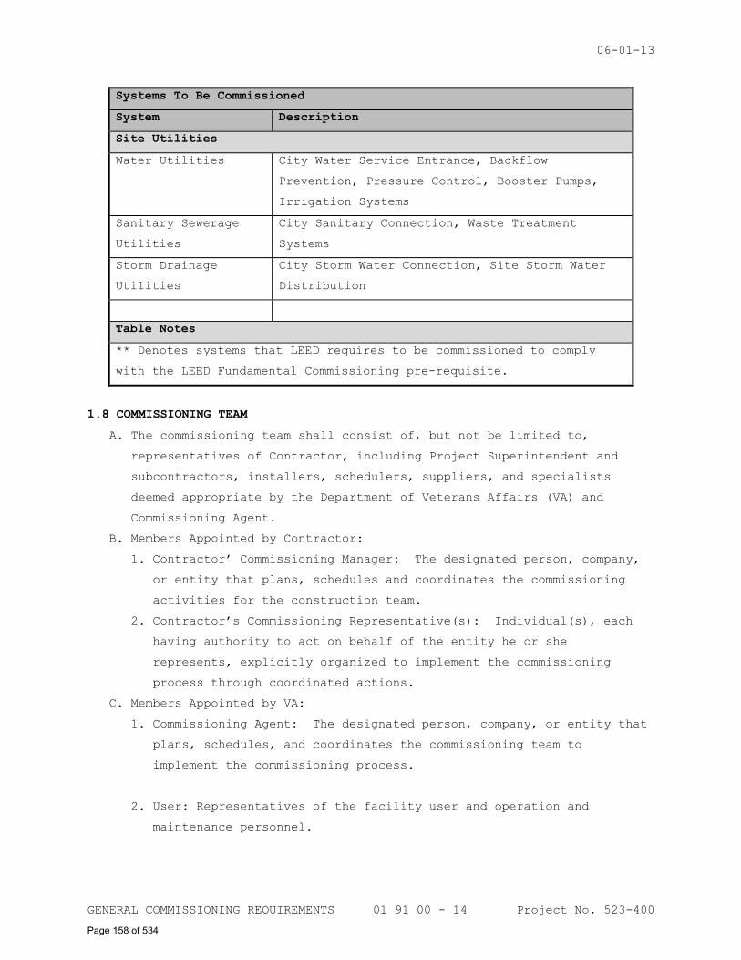
06-01-13
GENERAL COMMISSIONING REQUIREMENTS 01 91 00 - 14 Project No. 523-400
Systems To Be Commissioned
System Description
Site Utilities
Water Utilities City Water Service Entrance, Backflow
Prevention, Pressure Control, Booster Pumps,
Irrigation Systems
Sanitary Sewerage
Utilities
City Sanitary Connection, Waste Treatment
Systems
Storm Drainage
Utilities
City Storm Water Connection, Site Storm Water
Distribution
Table Notes
** Denotes systems that LEED requires to be commissioned to comply
with the LEED Fundamental Commissioning pre-requisite.
1.8 COMMISSIONING TEAM
A. The commissioning team shall consist of, but not be limited to,
representatives of Contractor, including Project Superintendent and
subcontractors, installers, schedulers, suppliers, and specialists
deemed appropriate by the Department of Veterans Affairs (VA) and
Commissioning Agent.
B. Members Appointed by Contractor:
1. Contractor’ Commissioning Manager: The designated person, company,
or entity that plans, schedules and coordinates the commissioning
activities for the construction team.
2. Contractor’s Commissioning Representative(s): Individual(s), each
having authority to act on behalf of the entity he or she
represents, explicitly organized to implement the commissioning
process through coordinated actions.
C. Members Appointed by VA:
1. Commissioning Agent: The designated person, company, or entity that
plans, schedules, and coordinates the commissioning team to
implement the commissioning process.
2. User: Representatives of the facility user and operation and
maintenance personnel.
Page 158 of 534
06-01-13
GENERAL COMMISSIONING REQUIREMENTS 01 91 00 - 15 Project No. 523-400
3. A/E: Representative of the Architect and engineering design
professionals.
1.9 VA'S COMMISSIONING RESPONSIBILITIES
A. Appoint an individual, company or firm to act as the Commissioning
Agent.
B. Assign operation and maintenance personnel and schedule them to
participate in commissioning team activities including, but not limited
to, the following:
1. Coordination meetings.
2. Training in operation and maintenance of systems, subsystems, and
equipment.
3. Testing meetings.
4. Witness and assist in Systems Functional Performance Testing.
5. Demonstration of operation of systems, subsystems, and equipment.
C. Provide the Construction Documents, prepared by Architect and approved
by VA, to the Commissioning Agent and for use in managing the
commissioning process, developing the commissioning plan, systems
manuals, and reviewing the operation and maintenance training plan.
1.10 CONTRACTOR'S COMMISSIONING RESPONSIBILITIES
A. The Contractor shall assign a Commissioning Manager to manage
commissioning activities of the Contractor, and subcontractors.
B. The Contractor shall ensure that the commissioning responsibilities
outlined in these specifications are included in all subcontracts and
that subcontractors comply with the requirements of these
specifications.
C. The Contractor shall ensure that each installing subcontractor shall
assign representatives with expertise and authority to act on behalf of
the subcontractor and schedule them to participate in and perform
commissioning team activities including, but not limited to, the
following:
1. Participate in commissioning coordination meetings.
2. Conduct operation and maintenance training sessions in accordance
with approved training plans.
3. Verify that Work is complete and systems are operational according
to the Contract Documents, including calibration of instrumentation
and controls.
4. Evaluate commissioning issues and commissioning observations
identified in the Commissioning Issues Log, field reports, test
Page 159 of 534
06-01-13
GENERAL COMMISSIONING REQUIREMENTS 01 91 00 - 16 Project No. 523-400
reports or other commissioning documents. In collaboration with
entity responsible for system and equipment installation, recommend
corrective action.
5. Review and comment on commissioning documentation.
6. Participate in meetings to coordinate Systems Functional Performance
Testing.
7. Provide schedule for operation and maintenance data submittals,
equipment startup, and testing to Commissioning Agent for
incorporation into the commissioning plan.
8. Provide information to the Commissioning Agent for developing
commissioning plan.
9. Participate in training sessions for VA's operation and maintenance
personnel.
10. Provide technicians who are familiar with the construction and
operation of installed systems and who shall develop specific test
procedures to conduct Systems Functional Performance Testing of
installed systems.
1.11 COMMISSIONING AGENT’S RESPONSIBILITIES
A. Organize and lead the commissioning team.
B. Prepare the commissioning plan. See Paragraph 1.11-A of this
specification Section for further information.
C. Review and comment on selected submittals from the Contractor for
general conformance with the Construction Documents. Review and
comment on the ability to test and operate the system and/or equipment,
including providing gages, controls and other components required to
operate, maintain, and test the system. Review and comment on
performance expectations of systems and equipment and interfaces
between systems relating to the Construction Documents.
D. At the beginning of the construction phase, conduct an initial
construction phase coordination meeting for the purpose of reviewing
the commissioning activities and establishing tentative schedules for
operation and maintenance submittals; operation and maintenance
training sessions; TAB Work; Pre-Functional Checklists, Systems
Functional Performance Testing; and project completion.
E. Convene commissioning team meetings for the purpose of coordination,
communication, and conflict resolution; discuss status of the
commissioning processes. Responsibilities include arranging for
facilities, preparing agenda and attendance lists, and notifying
Page 160 of 534
06-01-13
GENERAL COMMISSIONING REQUIREMENTS 01 91 00 - 17 Project No. 523-400
participants. The Commissioning Agent shall prepare and distribute
minutes to commissioning team members and attendees within five
workdays of the commissioning meeting.
F. Observe construction and report progress, observations and issues.
Observe systems and equipment installation for adequate accessibility
for maintenance and component replacement or repair, and for general
conformance with the Construction Documents.
G. Prepare Project specific Pre-Functional Checklists and Systems
Functional Performance Test procedures.
H. Coordinate Systems Functional Performance Testing schedule with the
Contractor.
I. Witness selected systems startups.
J. Verify selected Pre-Functional Checklists completed and submitted by
the Contractor.
K. Witness and document Systems Functional Performance Testing.
L. Compile test data, inspection reports, and certificates and include
them in the systems manual and commissioning report.
M. Review and comment on operation and maintenance (O&M) documentation and
systems manual outline for compliance with the Contract Documents.
Operation and maintenance documentation requirements are specified in
Paragraph 1.25, Section 01 00 00 GENERAL REQUIREMENTS.
N. Review operation and maintenance training program developed by the
Contractor. Verify training plans provide qualified instructors to
conduct operation and maintenance training.
O. Prepare commissioning Field Observation Reports.
P. Prepare the Final Commissioning Report.
Q. Return to the site at 10 months into the 12 month warranty period and
review with facility staff the current building operation and the
condition of outstanding issues related to the original and seasonal
Systems Functional Performance Testing. Also interview facility staff
and identify problems or concerns they have operating the building as
originally intended. Make suggestions for improvements and for
recording these changes in the O&M manuals. Identify areas that may
come under warranty or under the original construction contract. Assist
facility staff in developing reports, documents and requests for
services to remedy outstanding problems.
R. Assemble the final commissioning documentation, including the Final
Commissioning Report and Addendum to the Final Commissioning Report.
Page 161 of 534
06-01-13
GENERAL COMMISSIONING REQUIREMENTS 01 91 00 - 18 Project No. 523-400
1.12 COMMISSIONING DOCUMENTATION
A. Commissioning Plan: A document, prepared by Commissioning Agent, that
outlines the schedule, allocation of resources, and documentation
requirements of the commissioning process, and shall include, but is
not limited, to the following:
1. Plan for delivery and review of submittals, systems manuals, and
other documents and reports. Identification of the relationship of
these documents to other functions and a detailed description of
submittals that are required to support the commissioning processes.
Submittal dates shall include the latest date approved submittals
must be received without adversely affecting commissioning plan.
2. Description of the organization, layout, and content of
commissioning documentation (including systems manual) and a
detailed description of documents to be provided along with
identification of responsible parties.
3. Identification of systems and equipment to be commissioned.
4. Schedule of Commissioning Coordination meetings.
5. Identification of items that must be completed before the next
operation can proceed.
6. Description of responsibilities of commissioning team members.
7. Description of observations to be made.
8. Description of requirements for operation and maintenance training.
9. Schedule for commissioning activities with dates coordinated with
overall construction schedule.
10. Process and schedule for documenting changes on a continuous basis
to appear in Project Record Documents.
11. Process and schedule for completing prestart and startup checklists
for systems, subsystems, and equipment to be verified and tested.
12. Preliminary Systems Functional Performance Test procedures.
B. Systems Functional Performance Test Procedures: The Commissioning
Agent will develop Systems Functional Performance Test Procedures for
each system to be commissioned, including subsystems, or equipment and
interfaces or interlocks with other systems. Systems Functional
Performance Test Procedures will include a separate entry, with space
for comments, for each item to be tested. Preliminary Systems
Functional Performance Test Procedures will be provided to the VA,
Architect/Engineer, and Contractor for review and comment. The Systems
Performance Test Procedure will include test procedures for each mode
Page 162 of 534
06-01-13
GENERAL COMMISSIONING REQUIREMENTS 01 91 00 - 19 Project No. 523-400
of operation and provide space to indicate whether the mode under test
responded as required. Each System Functional Performance Test
procedure, regardless of system, subsystem, or equipment being tested,
shall include, but not be limited to, the following:
1. Name and identification code of tested system.
2. Test number.
3. Time and date of test.
4. Indication of whether the record is for a first test or retest
following correction of a problem or issue.
5. Dated signatures of the person performing test and of the witness,
if applicable.
6. Individuals present for test.
7. Observations and Issues.
8. Issue number, if any, generated as the result of test.
C. Pre-Functional Checklists: The Commissioning Agent will prepare Pre-
Functional Checklists. Pre-Functional Checklists shall be completed
and signed by the Contractor, verifying that systems, subsystems,
equipment, and associated controls are ready for testing. The
Commissioning Agent will spot check Pre-Functional Checklists to verify
accuracy and readiness for testing. Inaccurate or incomplete Pre-
Functional Checklists shall be returned to the Contractor for
correction and resubmission.
D. Test and Inspection Reports: The Commissioning Agent will record test
data, observations, and measurements on Systems Functional Performance
Test Procedure. The report will also include recommendation for system
acceptance or non-acceptance. Photographs, forms, and other means
appropriate for the application shall be included with data.
Commissioning Agent Will compile test and inspection reports and test
and inspection certificates and include them in systems manual and
commissioning report.
E. Corrective Action Documents: The Commissioning Agent will document
corrective action taken for systems and equipment that fail tests. The
documentation will include any required modifications to systems and
equipment and/or revisions to test procedures, if any. The
Commissioning Agent will witness and document any retesting of systems
and/or equipment requiring corrective action and document retest
results.
Page 163 of 534
06-01-13
GENERAL COMMISSIONING REQUIREMENTS 01 91 00 - 20 Project No. 523-400
F. Commissioning Issues Log: The Commissioning Agent will prepare and
maintain Commissioning Issues Log that describes Commissioning Issues
and Commissioning Observations that are identified during the
Commissioning process. These observations and issues include, but are
not limited to, those that are at variance with the Contract Documents.
The Commissioning Issues Log will identify and track issues as they are
encountered, the party responsible for resolution, progress toward
resolution, and document how the issue was resolved. The Master
Commissioning Issues Log will also track the status of unresolved
issues.
1. Creating an Commissioning Issues Log Entry:
a. Identify the issue with unique numeric or alphanumeric identifier
by which the issue may be tracked.
b. Assign a descriptive title for the issue.
c. Identify date and time of the issue.
d. Identify test number of test being performed at the time of the
observation, if applicable, for cross reference.
e. Identify system, subsystem, and equipment to which the issue
applies.
f. Identify location of system, subsystem, and equipment.
g. Include information that may be helpful in diagnosing or
evaluating the issue.
h. Note recommended corrective action.
i. Identify commissioning team member responsible for corrective
action.
j. Identify expected date of correction.
k. Identify person that identified the issue.
2. Documenting Issue Resolution:
a. Log date correction is completed or the issue is resolved.
b. Describe corrective action or resolution taken. Include
description of diagnostic steps taken to determine root cause of
the issue, if any.
c. Identify changes to the Contract Documents that may require
action.
d. State that correction was completed and system, subsystem, and
equipment are ready for retest, if applicable.
e. Identify person(s) who corrected or resolved the issue.
f. Identify person(s) verifying the issue resolution.
Page 164 of 534
06-01-13
GENERAL COMMISSIONING REQUIREMENTS 01 91 00 - 21 Project No. 523-400
G. Final Commissioning Report: The Commissioning Agent will document
results of the commissioning process, including unresolved issues, and
performance of systems, subsystems, and equipment. The Commissioning
Report will indicate whether systems, subsystems, and equipment have
been properly installed and are performing according to the Contract
Documents. This report will be used by the Department of Veterans
Affairs when determining that systems will be accepted. This report
will be used to evaluate systems, subsystems, and equipment and will
serve as a future reference document during VA occupancy and operation.
It shall describe components and performance that exceed requirements
of the Contract Documents and those that do not meet requirements of
the Contract Documents. The commissioning report will include, but is
not limited to, the following:
1. Lists and explanations of substitutions; compromises; variances with
the Contract Documents; record of conditions; and, if appropriate,
recommendations for resolution. Design Narrative documentation
maintained by the Commissioning Agent.
2. Commissioning plan.
3. Pre-Functional Checklists completed by the Contractor, with
annotation of the Commissioning Agent review and spot check.
4. Systems Functional Performance Test Procedures, with annotation of
test results and test completion.
5, Commissioning Issues Log.
6. Listing of deferred and off season test(s) not performed, including
the schedule for their completion.
H. Addendum to Final Commissioning Report: The Commissioning Agent will
prepare an Addendum to the Final Commissioning Report near the end of
the Warranty Period. The Addendum will indicate whether systems,
subsystems, and equipment are complete and continue to perform
according to the Contract Documents. The Addendum to the Final
Commissioning Report shall include, but is not limited to, the
following:
1. Documentation of deferred and off season test(s) results.
2. Completed Systems Functional Performance Test Procedures for off
season test(s).
3. Documentation that unresolved system performance issues have been
resolved.
Page 165 of 534
06-01-13
GENERAL COMMISSIONING REQUIREMENTS 01 91 00 - 22 Project No. 523-400
4. Updated Commissioning Issues Log, including status of unresolved
issues.
5. Identification of potential Warranty Claims to be corrected by the
Contractor.
I. Systems Manual: The Commissioning Agent will gather required
information and compile the Systems Manual. The Systems Manual will
include, but is not limited to, the following:
1. Design Narrative, including system narratives, schematics, single-
line diagrams, flow diagrams, equipment schedules, and changes made
throughout the Project.
2. Reference to Final Commissioning Plan.
3. Reference to Final Commissioning Report.
4. Approved Operation and Maintenance Data as submitted by the
Contractor.
1.13 SUBMITTALS
A. Preliminary Commissioning Plan Submittal: The Commissioning Agent has
prepared a Preliminary Commissioning Plan based on the final
Construction Documents. The Preliminary Commissioning Plan is included
as an Appendix to this specification section. The Preliminary
Commissioning Plan is provided for information only. It contains
preliminary information about the following commissioning activities:
1. The Commissioning Team: A list of commissioning team members by
organization.
2. Systems to be commissioned. A detailed list of systems to be
commissioned for the project. This list also provides preliminary
information on systems/equipment submittals to be reviewed by the
Commissioning Agent; preliminary information on Pre-Functional
Checklists that are to be completed; preliminary information on
Systems Performance Testing, including information on testing sample
size (where authorized by the VA).
3. Commissioning Team Roles and Responsibilities: Preliminary roles and
responsibilities for each Commissioning Team member.
4. Commissioning Documents: A preliminary list of commissioning-related
documents, include identification of the parties responsible for
preparation, review, approval, and action on each document.
5. Commissioning Activities Schedule: Identification of Commissioning
Activities, including Systems Functional Testing, the expected
duration and predecessors for the activity.
Page 166 of 534
06-01-13
GENERAL COMMISSIONING REQUIREMENTS 01 91 00 - 23 Project No. 523-400
6. Pre-Functional Checklists: Preliminary Pre-Functional Checklists
for equipment, components, subsystems, and systems to be
commissioned. These Preliminary Pre-Functional Checklists provide
guidance on the level of detailed information the Contractor shall
include on the final submission.
7. Systems Functional Performance Test Procedures: Preliminary step-
by-step System Functional Performance Test Procedures to be used
during Systems Functional Performance Testing. These Preliminary
Systems Functional Performance procedures provide information on the
level of testing rigor, and the level of Contractor support required
during performance of system’s testing.
B. Final Commissioning Plan Submittal: Based on the Final Construction
Documents and the Contractor’s project team, the Commissioning Agent
will prepare the Final Commissioning Plan as described in this section.
The Commissioning Agent will submit three hard copies and three sets of
electronic files of Final Commissioning Plan. The Contractor shall
review the Commissioning Plan and provide any comments to the VA. The
Commissioning Agent will incorporate review comments into the Final
Commissioning Plan as directed by the VA.
C. Systems Functional Performance Test Procedure: The Commissioning Agent
will submit preliminary Systems Functional Performance Test Procedures
to the Contractor, and the VA for review and comment. The Contractor
shall return review comments to the VA and the Commissioning Agent.
The VA will also return review comments to the Commissioning Agent. The
Commissioning Agent will incorporate review comments into the Final
Systems Functional Test Procedures to be used in Systems Functional
Performance Testing.
D. Pre-Functional Checklists: The Commissioning Agent will submit Pre-
Functional Checklists to be completed by the Contractor.
E. Test and Inspection Reports: The Commissioning Agent will submit test
and inspection reports to the VA with copies to the Contractor and the
Architect/Engineer.
F. Corrective Action Documents: The Commissioning Agent will submit
corrective action documents to the VA Resident Engineer with copies to
the Contractor and Architect.
G. Preliminary Commissioning Report Submittal: The Commissioning Agent
will submit three electronic copies of the preliminary commissioning
Page 167 of 534
06-01-13
GENERAL COMMISSIONING REQUIREMENTS 01 91 00 - 24 Project No. 523-400
report. One electronic copy, with review comments, will be returned to
the Commissioning Agent for preparation of the final submittal.
H. Final Commissioning Report Submittal: The Commissioning Agent will
submit four sets of electronically formatted information of the final
commissioning report to the VA. The final submittal will incorporate
comments as directed by the VA.
I. Data for Commissioning:
1. The Commissioning Agent will request in writing from the Contractor
specific information needed about each piece of commissioned
equipment or system to fulfill requirements of the Commissioning
Plan.
2. The Commissioning Agent may request further documentation as is
necessary for the commissioning process or to support other VA data
collection requirements, including Construction Operations Building
Information Exchange (COBIE), Building Information Modeling (BIM),
etc.
1.14 COMMISSIONING PROCESS
A. The Commissioning Agent will be responsible for the overall management
of the commissioning process as well as coordinating scheduling of
commissioning tasks with the VA and the Contractor. As directed by the
VA, the Contractor shall incorporate Commissioning tasks, including,
but not limited to, Systems Functional Performance Testing (including
predecessors) with the Master Construction Schedule.
B. Within 30 days of contract award, the Contractor shall designate a
specific individual as the Commissioning Manager (CxM) to manage and
lead the commissioning effort on behalf of the Contractor. The
Commissioning Manager shall be the single point of contact and
communications for all commissioning related services by the
Contractor.
C. Within 30 days of contract award, the Contractor shall ensure that each
subcontractor designates specific individuals as Commissioning
Representatives (CXR) to be responsible for commissioning related
tasks. The Contractor shall ensure the designated Commissioning
Representatives participate in the commissioning process as team
members providing commissioning testing services, equipment operation,
adjustments, and corrections if necessary. The Contractor shall ensure
that all Commissioning Representatives shall have sufficient authority
to direct their respective staff to provide the services required, and
Page 168 of 534
06-01-13
GENERAL COMMISSIONING REQUIREMENTS 01 91 00 - 25 Project No. 523-400
to speak on behalf of their organizations in all commissioning related
contractual matters.
1.15 QUALITY ASSURANCE
A. Instructor Qualifications: Factory authorized service representatives
shall be experienced in training, operation, and maintenance procedures
for installed systems, subsystems, and equipment.
B. Test Equipment Calibration: The Contractor shall comply with test
equipment manufacturer's calibration procedures and intervals.
Recalibrate test instruments immediately whenever instruments have been
repaired following damage or dropping. Affix calibration tags to test
instruments. Instruments shall have been calibrated within six months
prior to use.
1.16 COORDINATION
A. Management: The Commissioning Agent will coordinate the commissioning
activities with the VA and Contractor. The Commissioning Agent will
submit commissioning documents and information to the VA. All
commissioning team members shall work together to fulfill their
contracted responsibilities and meet the objectives of the contract
documents.
B. Scheduling: The Contractor shall work with the Commissioning Agent and
the VA to incorporate the commissioning activities into the
construction schedule. The Commissioning Agent will provide sufficient
information (including, but not limited to, tasks, durations and
predecessors) on commissioning activities to allow the Contractor and
the VA to schedule commissioning activities. All parties shall address
scheduling issues and make necessary notifications in a timely manner
in order to expedite the project and the commissioning process. The
Contractor shall update the Master Construction as directed by the VA.
C. Initial Schedule of Commissioning Events: The Commissioning Agent will
provide the initial schedule of primary commissioning events in the
Commissioning Plan and at the commissioning coordination meetings. The
Commissioning Plan will provide a format for this schedule. As
construction progresses, more detailed schedules will be developed by
the Contractor with information from the Commissioning Agent.
D. Commissioning Coordinating Meetings: The Commissioning Agent will
conduct periodic Commissioning Coordination Meetings of the
commissioning team to review status of commissioning activities, to
Page 169 of 534
06-01-13
GENERAL COMMISSIONING REQUIREMENTS 01 91 00 - 26 Project No. 523-400
discuss scheduling conflicts, and to discuss upcoming commissioning
process activities.
E. Pretesting Meetings: The Commissioning Agent will conduct pretest
meetings of the commissioning team to review startup reports, Pre-
Functional Checklist results, Systems Functional Performance Testing
procedures, testing personnel and instrumentation requirements.
F. Systems Functional Performance Testing Coordination: The Contractor
shall coordinate testing activities to accommodate required quality
assurance and control services with a minimum of delay and to avoid
necessity of removing and replacing construction to accommodate testing
and inspecting. The Contractor shall coordinate the schedule times for
tests, inspections, obtaining samples, and similar activities.
PART 2 - PRODUCTS
2.1 TEST EQUIPMENT
A. The Contractor shall provide all standard and specialized testing
equipment required to perform Systems Functional Performance Testing.
Test equipment required for Systems Functional Performance Testing will
be identified in the detailed System Functional Performance Test
Procedure prepared by the Commissioning Agent.
B. Data logging equipment and software required to test equipment shall be
provided by the Contractor.
C. All testing equipment shall be of sufficient quality and accuracy to
test and/or measure system performance with the tolerances specified in
the Specifications. If not otherwise noted, the following minimum
requirements apply: Temperature sensors and digital thermometers shall
have a certified calibration within the past year to an accuracy of 0.5
oC (1.0 oF) and a resolution of + or - 0.1 oC (0.2 oF). Pressure sensors
shall have an accuracy of + or - 2.0% of the value range being measured
(not full range of meter) and have been calibrated within the last
year. All equipment shall be calibrated according to the manufacturer's
recommended intervals and following any repairs to the equipment.
Calibration tags shall be affixed or certificates readily available.
Page 170 of 534
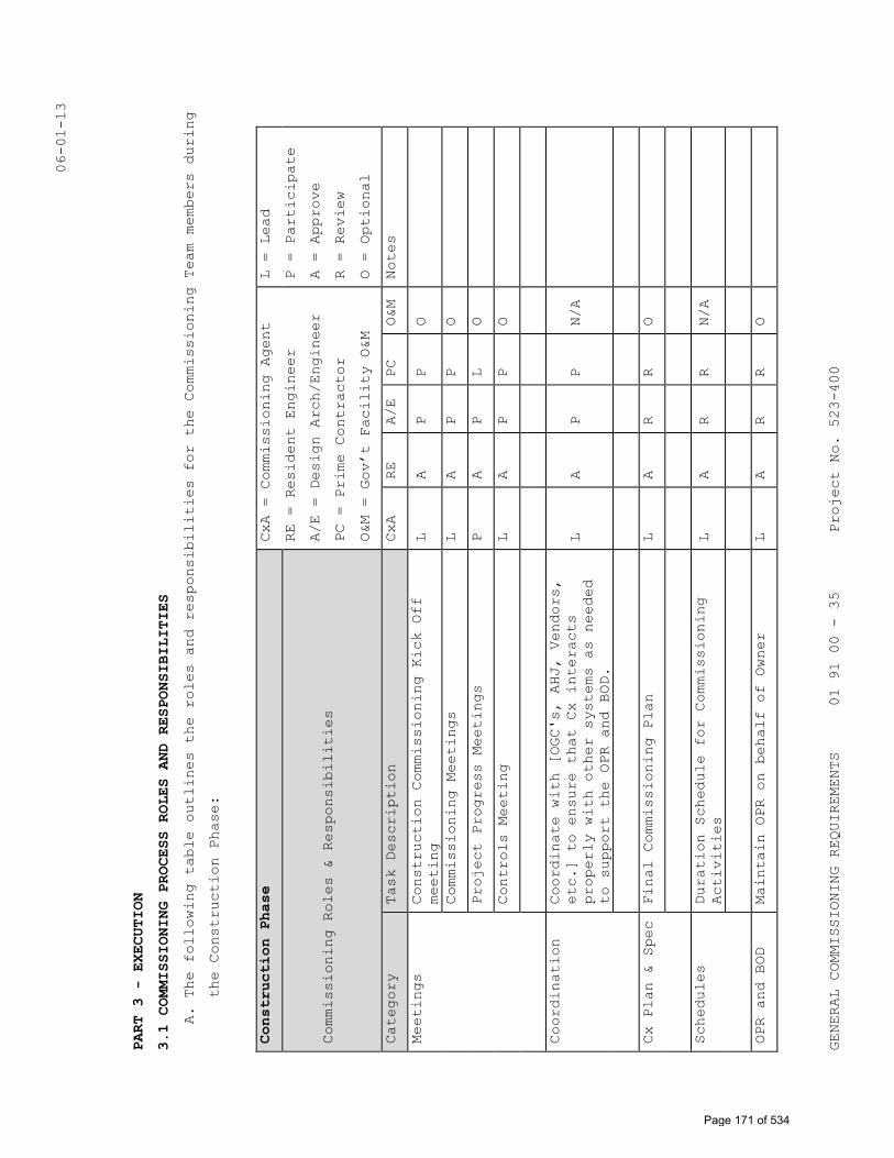
06-01-13
GENERAL COMMISSIONING REQUIREMENTS
01 91 00 - 35
Project No. 523-400
PART 3 - EXECUTION
3.1 COMMISSIONING PROCESS ROLES AND RESPONSIBILITIES
A. The following table outlines the roles and responsibilities for the Commissioning Team members during
the Construction Phase:
Construction Phase
CxA = Commissioning Agent
RE = Resident Engineer
A/E = Design Arch/Engineer
PC = Prime Contractor
O&M = Gov’t Facility O&M
L = Lead
P = Participate
A = Approve
R = Review
O = Optional
Commissioning Roles & Responsibilities
Category
Task Description
CxA
RE
A/E
PC
O&M
Notes
Meetings
Construction Commissioning Kick Off
meeting
L
A
P
P
O
Commissioning Meetings
L
A
P
P
O
Project Progress Meetings
P
A
P
L
O
Controls Meeting
L
A
P
P
O
Coordination
Coordinate with [OGC's, AHJ, Vendors,
etc.] to ensure that Cx interacts
properly with other systems as needed
to support the OPR and BOD.
L
A
P
P
N/A
Cx Plan & Spec Final Commissioning Plan
L
A
R
R
O
Schedules
Duration Schedule for Commissioning
Activities
L
A
R
R
N/A
OPR and BOD
Maintain OPR on behalf of Owner
L
A
R
R
O
Page 171 of 534
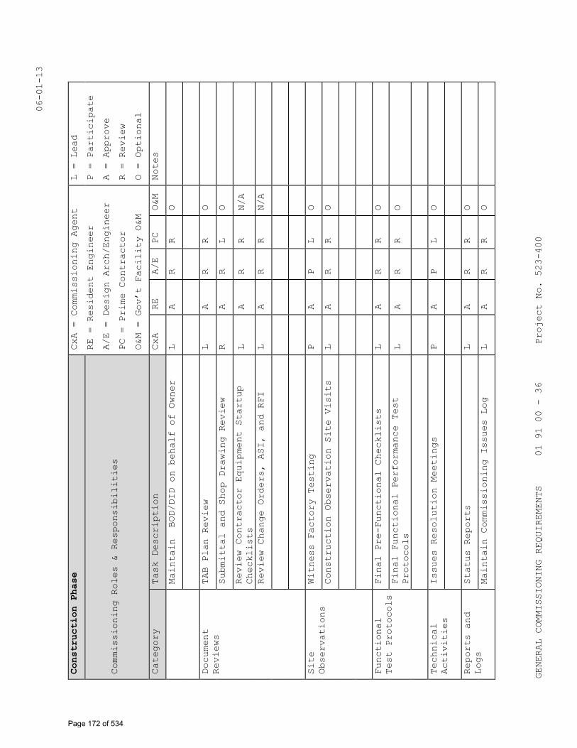
06-01-13
GENERAL COMMISSIONING REQUIREMENTS
01 91 00 - 36
Project No. 523-400
Construction Phase
CxA = Commissioning Agent
RE = Resident Engineer
A/E = Design Arch/Engineer
PC = Prime Contractor
O&M = Gov’t Facility O&M
L = Lead
P = Participate
A = Approve
R = Review
O = Optional
Commissioning Roles & Responsibilities
Category
Task Description
CxA
RE
A/E
PC
O&M
Notes
Maintain BOD/DID on behalf of Owner
L
A
R
R
O
Document
Reviews
TAB Plan Review
L
A
R
R
O
Submittal and Shop Drawing Review
R
A
R
L
O
Review Contractor Equipment Startup
Checklists
L
A
R
R
N/A
Review Change Orders, ASI, and RFI
L
A
R
R
N/A
Site
Observations
Witness Factory Testing
P
A
P
L
O
Construction Observation Site Visits
L
A
R
R
O
Functional
Test Protocols
Final Pre-Functional Checklists
L
A
R
R
O
Final Functional Performance Test
Protocols
L
A
R
R
O
Technical
Activities
Issues Resolution Meetings
P
A
P
L
O
Reports and
Logs
Status Reports
L
A
R
R
O
Maintain Commissioning Issues Log
L
A
R
R
O
Page 172 of 534
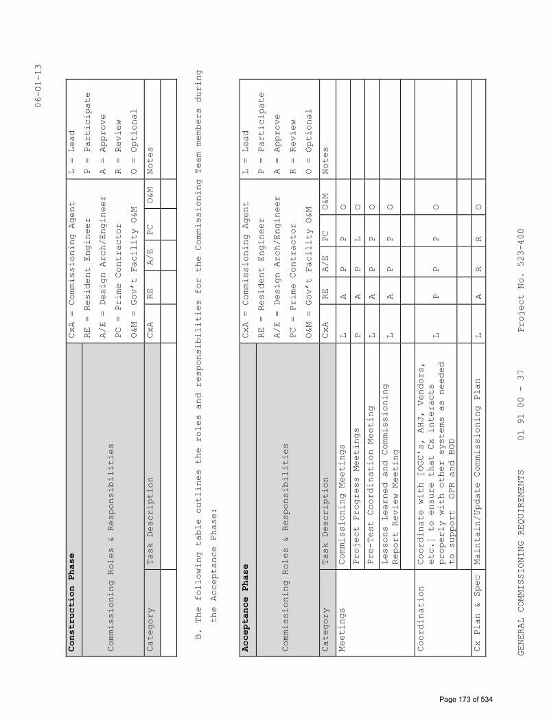
06-01-13
GENERAL COMMISSIONING REQUIREMENTS
01 91 00 - 37
Project No. 523-400
Construction Phase
CxA = Commissioning Agent
RE = Resident Engineer
A/E = Design Arch/Engineer
PC = Prime Contractor
O&M = Gov’t Facility O&M
L = Lead
P = Participate
A = Approve
R = Review
O = Optional
Commissioning Roles & Responsibilities
Category
Task Description
CxA
RE
A/E
PC
O&M
Notes
B. The following table outlines the roles and responsibilities for the Commissioning Team members during
the Acceptance Phase:
Acceptance Phase
CxA = Commissioning Agent
RE = Resident Engineer
A/E = Design Arch/Engineer
PC = Prime Contractor
O&M = Gov’t Facility O&M
L = Lead
P = Participate
A = Approve
R = Review
O = Optional
Commissioning Roles & Responsibilities
Category
Task Description
CxA
RE
A/E
PC
O&M
Notes
Meetings
Commissioning Meetings
L
A
P
P
O
Project Progress Meetings
P
A
P
L
O
Pre-Test Coordination Meeting
L
A
P
P
O
Lessons Learned and Commissioning
Report Review Meeting
L
A
P
P
O
Coordination
Coordinate with [OGC's, AHJ, Vendors,
etc.] to ensure that Cx interacts
properly with other systems as needed
to support OPR and BOD
L
P
P
P
O
Cx Plan & Spec Maintain/Update Commissioning Plan
L
A
R
R
O
Page 173 of 534
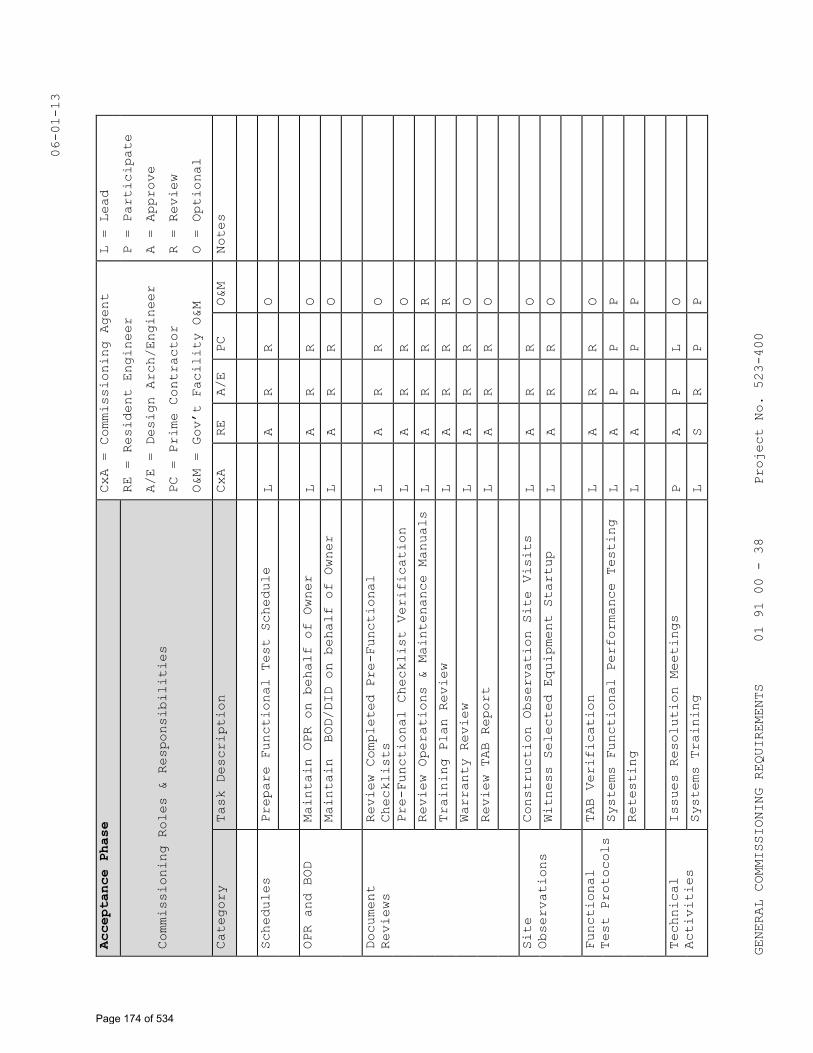
06-01-13
GENERAL COMMISSIONING REQUIREMENTS
01 91 00 - 38
Project No. 523-400
Acceptance Phase
CxA = Commissioning Agent
RE = Resident Engineer
A/E = Design Arch/Engineer
PC = Prime Contractor
O&M = Gov’t Facility O&M
L = Lead
P = Participate
A = Approve
R = Review
O = Optional
Commissioning Roles & Responsibilities
Category
Task Description
CxA
RE
A/E
PC
O&M
Notes
Schedules
Prepare Functional Test Schedule
L
A
R
R
O
OPR and BOD
Maintain OPR on behalf of Owner
L
A
R
R
O
Maintain BOD/DID on behalf of Owner
L
A
R
R
O
Document
Reviews
Review Completed Pre-Functional
Checklists
L
A
R
R
O
Pre-Functional Checklist Verification
L
A
R
R
O
Review Operations & Maintenance Manuals
L
A
R
R
R
Training Plan Review
L
A
R
R
R
Warranty Review
L
A
R
R
O
Review TAB Report
L
A
R
R
O
Site
Observations
Construction Observation Site Visits
L
A
R
R
O
Witness Selected Equipment Startup
L
A
R
R
O
Functional
Test Protocols
TAB Verification
L
A
R
R
O
Systems Functional Performance Testing
L
A
P
P
P
Retesting
L
A
P
P
P
Technical
Activities
Issues Resolution Meetings
P
A
P
L
O
Systems Training
L
S
R
P
P
Page 174 of 534
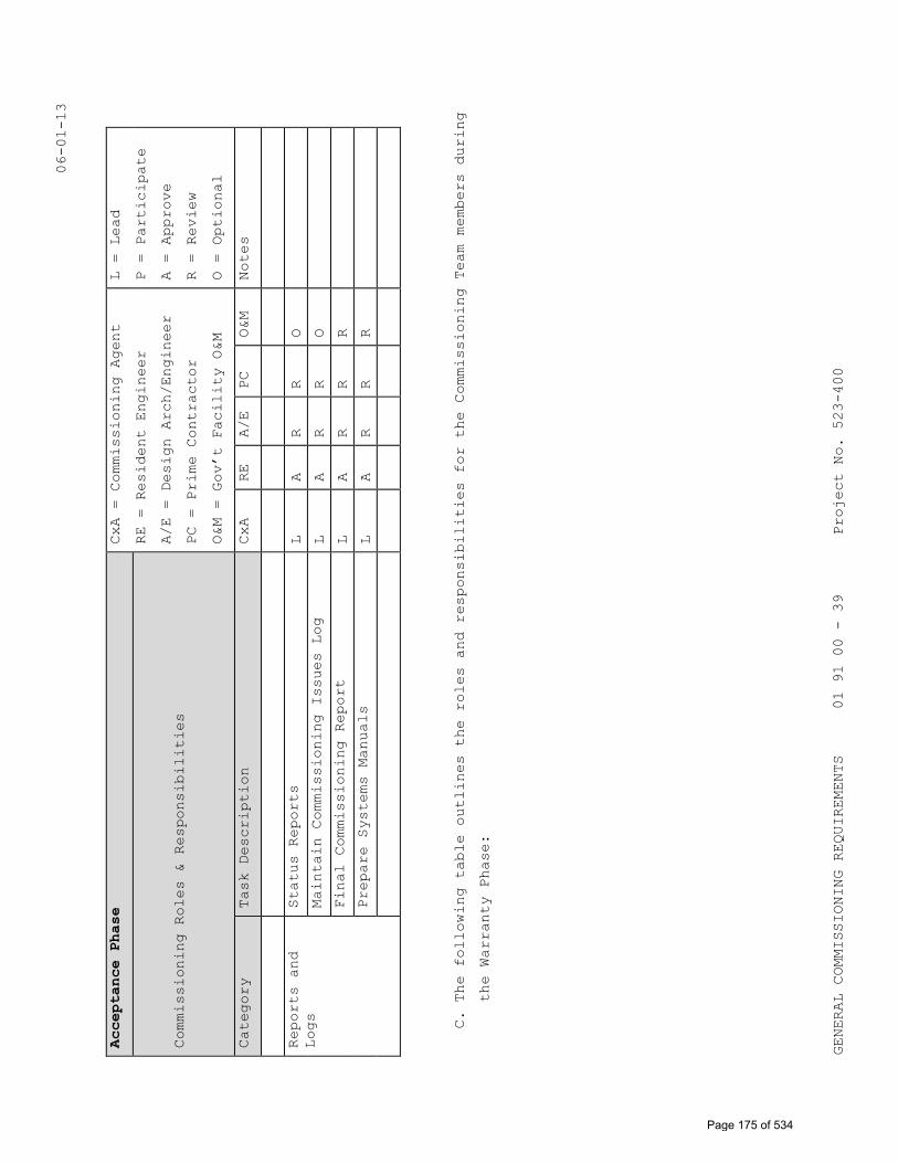
06-01-13
GENERAL COMMISSIONING REQUIREMENTS
01 91 00 - 39
Project No. 523-400
Acceptance Phase
CxA = Commissioning Agent
RE = Resident Engineer
A/E = Design Arch/Engineer
PC = Prime Contractor
O&M = Gov’t Facility O&M
L = Lead
P = Participate
A = Approve
R = Review
O = Optional
Commissioning Roles & Responsibilities
Category
Task Description
CxA
RE
A/E
PC
O&M
Notes
Reports and
Logs
Status Reports
L
A
R
R
O
Maintain Commissioning Issues Log
L
A
R
R
O
Final Commissioning Report
L
A
R
R
R
Prepare Systems Manuals
L
A
R
R
R
C. The following table outlines the roles and responsibilities for the Commissioning Team members during
the Warranty Phase:
Page 175 of 534
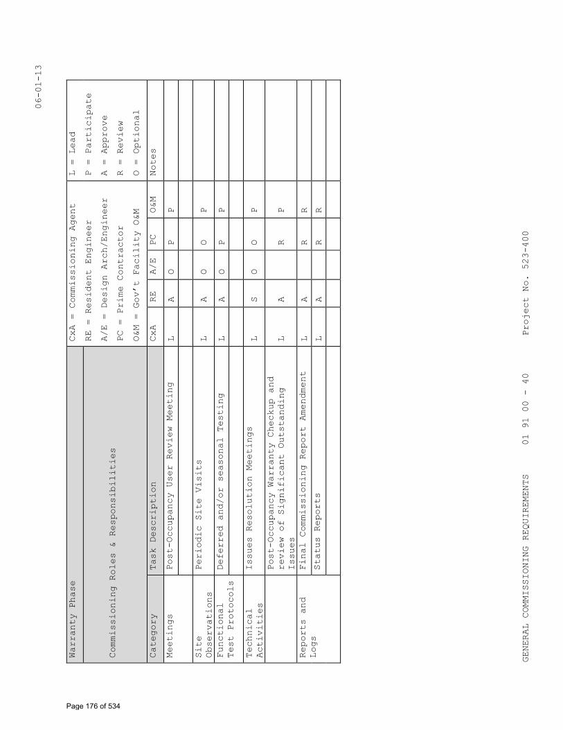
06-01-13
GENERAL COMMISSIONING REQUIREMENTS
01 91 00 - 40
Project No. 523-400
Warranty Phase
CxA = Commissioning Agent
RE = Resident Engineer
A/E = Design Arch/Engineer
PC = Prime Contractor
O&M = Gov’t Facility O&M
L = Lead
P = Participate
A = Approve
R = Review
O = Optional
Commissioning Roles & Responsibilities
Category
Task Description
CxA
RE
A/E
PC
O&M
Notes
Meetings
Post-Occupancy User Review Meeting
L
A
O
P
P
Site
Observations
Periodic Site Visits
L
A
O
O
P
Functional
Test Protocols
Deferred and/or seasonal Testing
L
A
O
P
P
Technical
Activities
Issues Resolution Meetings
L
S
O
O
P
Post-Occupancy Warranty Checkup and
review of Significant Outstanding
Issues
L
A
R
P
Reports and
Logs
Final Commissioning Report Amendment
L
A
R
R
Status Reports
L
A
R
R
Page 176 of 534
06-01-13
GENERAL COMMISSIONING REQUIREMENTS 01 91 00 - 41 Project No. 523-400
3.2 STARTUP, INITIAL CHECKOUT, AND PRE-FUNCTIONAL CHECKLISTS
A. The following procedures shall apply to all equipment and systems to be
commissioned, according to Part 1, Systems to Be Commissioned.
1. Pre-Functional Checklists are important to ensure that the equipment
and systems are hooked up and operational. These ensure that Systems
Functional Performance Testing may proceed without unnecessary
delays. Each system to be commissioned shall have a full Pre-
Functional Checklist completed by the Contractor prior to Systems
Functional Performance Testing. No sampling strategies are used.
a. The Pre-Functional Checklist will identify the trades responsible
for completing the checklist. The Contractor shall ensure the
appropriate trades complete the checklists.
b. The Commissioning Agent will review completed Pre-Functional
Checklists and field-verify the accuracy of the completed
checklist using sampling techniques.
2. Startup and Initial Checkout Plan: The Contractor shall develop
detailed startup plans for all equipment. The primary role of the
Contractor in this process is to ensure that there is written
documentation that each of the manufacturer recommended procedures
have been completed. Parties responsible for startup shall be
identified in the Startup Plan and in the checklist forms.
a. The Contractor shall develop the full startup plan by combining
(or adding to) the checklists with the manufacturer's detailed
startup and checkout procedures from the O&M manual data and the
field checkout sheets normally used by the Contractor. The plan
shall include checklists and procedures with specific boxes or
lines for recording and documenting the checking and inspections
of each procedure and a summary statement with a signature block
at the end of the plan.
b. The full startup plan shall at a minimum consist of the following
items:
1) The Pre-Functional Checklists.
2) The manufacturer's standard written startup procedures copied
from the installation manuals with check boxes by each
procedure and a signature block added by hand at the end.
3) The manufacturer's normally used field checkout sheets.
c. The Commissioning Agent will submit the full startup plan to the
VA and Contractor for review. Final approval will be by the VA.
Page 177 of 534
06-01-13
GENERAL COMMISSIONING REQUIREMENTS 01 91 00 - 42 Project No. 523-400
d. The Contractor shall review and evaluate the procedures and the
format for documenting them, noting any procedures that need to
be revised or added.
3. Sensor and Actuator Calibration
a. All field installed temperature, relative humidity, CO2 and
pressure sensors and gages, and all actuators (dampers and
valves) on all equipment shall be calibrated using the methods
described in Division 21, Division 22, Division 23, Division 26,
Division 27, and Division 28 specifications.
b. All procedures used shall be fully documented on the Pre-
Functional Checklists or other suitable forms, clearly
referencing the procedures followed and written documentation of
initial, intermediate and final results.
3.3 DEFICIENCIES, NONCONFORMANCE, AND APPROVAL IN CHECKLISTS AND STARTUP
A. The Contractor shall clearly list any outstanding items of the initial
startup and Pre-Functional Checklist procedures that were not completed
successfully, at the bottom of the procedures form or on an attached
sheet. The procedures form and any outstanding deficiencies shall be
provided to the VA and the Commissioning Agent within two days of
completion.
B. The Commissioning Agent will review the report and submit comments to
the VA. The Commissioning Agent will work with the Contractor to
correct and verify deficiencies or uncompleted items. The Commissioning
Agent will involve the VA and others as necessary. The Contractor shall
correct all areas that are noncompliant or incomplete in the checklists
in a timely manner, and shall notify the VA and Commissioning Agent as
soon as outstanding items have been corrected. The Contractor shall
submit an updated startup report and a Statement of Correction on the
original noncompliance report. When satisfactorily completed, the
Commissioning Agent will recommend approval of the checklists and
startup of each system to the VA.
C. The Contractor shall be responsible for resolution of deficiencies as
directed the VA.
3.4 PHASED COMMISSIONING
Not Applicable
3.5 DDC SYSTEM TRENDING FOR COMMISSIONING
Not Applicable
Page 178 of 534
06-01-13
GENERAL COMMISSIONING REQUIREMENTS 01 91 00 - 43 Project No. 523-400
3.6 SYSTEMS FUNCTIONAL PERFORMANCE TESTING
A. This paragraph applies to Systems Functional Performance Testing of
systems for all referenced specification Divisions.
B. Objectives and Scope: The objective of Systems Functional Performance
Testing is to demonstrate that each system is operating according to
the Contract Documents. Systems Functional Performance Testing
facilitates bringing the systems from a state of substantial completion
to full dynamic operation. Additionally, during the testing process,
areas of noncompliant performance are identified and corrected, thereby
improving the operation and functioning of the systems. In general,
each system shall be operated through all modes of operation (seasonal,
occupied, unoccupied, warm-up, cool-down, part- and full-load, fire
alarm and emergency power) where there is a specified system response.
The Contractor shall verify each sequence in the sequences of
operation. Proper responses to such modes and conditions as power
failure, freeze condition, low oil pressure, no flow, equipment
failure, etc. shall also be tested.
C. Development of Systems Functional Performance Test Procedures: Before
Systems Functional Performance Test procedures are written, the
Contractor shall submit all requested documentation and a current list
of change orders affecting equipment or systems, including an updated
points list, program code, control sequences and parameters. Using the
testing parameters and requirements found in the Contract Documents and
approved submittals and shop drawings, the Commissioning Agent will
develop specific Systems Functional Test Procedures to verify and
document proper operation of each piece of equipment and system to be
commissioned. The Contractor shall assist the Commissioning Agent in
developing the Systems Functional Performance Test procedures as
requested by the Commissioning Agent i.e. by answering questions about
equipment, operation, sequences, etc. Prior to execution, the
Commissioning Agent will provide a copy of the Systems Functional
Performance Test procedures to the VA, the Architect/Engineer, and the
Contractor, who shall review the tests for feasibility, safety,
equipment and warranty protection.
D. Purpose of Test Procedures: The purpose of each specific Systems
Functional Performance Test is to verify and document compliance with
the stated criteria of acceptance given on the test form.
Representative test formats and examples are found in the Commissioning
Page 179 of 534
06-01-13
GENERAL COMMISSIONING REQUIREMENTS 01 91 00 - 44 Project No. 523-400
Plan for this project. (The Commissioning Plan is issued as a separate
document and is available for review.) The test procedure forms
developed by the Commissioning Agent will include, but not be limited
to, the following information:
1. System and equipment or component name(s)
2. Equipment location and ID number
3. Unique test ID number, and reference to unique Pre-Functional
Checklists and startup documentation, and ID numbers for the piece
of equipment
4. Date
5. Project name
6. Participating parties
7. A copy of the specification section describing the test requirements
8. A copy of the specific sequence of operations or other specified
parameters being verified
9. Formulas used in any calculations
10. Required pretest field measurements
11. Instructions for setting up the test.
12. Special cautions, alarm limits, etc.
13. Specific step-by-step procedures to execute the test, in a clear,
sequential and repeatable format
14. Acceptance criteria of proper performance with a Yes / No check box
to allow for clearly marking whether or not proper performance of
each part of the test was achieved.
15. A section for comments.
16. Signatures and date block for the Commissioning Agent. A place for
the Contractor to initial to signify attendance at the test.
E. Test Methods: Systems Functional Performance Testing shall be achieved
by manual testing (i.e. persons manipulate the equipment and observe
performance) and/or by monitoring the performance and analyzing the
results using the control system's trend log capabilities or by
standalone data loggers. The Contractor and Commissioning Agent shall
determine which method is most appropriate for tests that do not have a
method specified.
1. Simulated Conditions: Simulating conditions (not by an overwritten
value) shall be allowed, although timing the testing to experience
actual conditions is encouraged wherever practical.
Page 180 of 534
06-01-13
GENERAL COMMISSIONING REQUIREMENTS 01 91 00 - 45 Project No. 523-400
2. Overwritten Values: Overwriting sensor values to simulate a
condition, such as overwriting the outside air temperature reading
in a control system to be something other than it really is, shall
be allowed, but shall be used with caution and avoided when
possible. Such testing methods often can only test a part of a
system, as the interactions and responses of other systems will be
erroneous or not applicable. Simulating a condition is preferable.
e.g., for the above case, by heating the outside air sensor with a
hair blower rather than overwriting the value or by altering the
appropriate setpoint to see the desired response. Before simulating
conditions or overwriting values, sensors, transducers and
devices shall have been calibrated.
3. Simulated Signals: Using a signal generator which creates a
simulated signal to test and calibrate transducers and DDC constants
is generally recommended over using the sensor to act as the signal
generator via simulated conditions or overwritten values.
4. Altering Setpoints: Rather than overwriting sensor values, and when
simulating conditions is difficult, altering setpoints to test a
sequence is acceptable. For example, to see the Air Conditioning
compressor lockout initiate at an outside air temperature below 12 C
(54 F), when the outside air temperature is above 12 C (54 F),
temporarily change the lockout setpoint to be 2 C (4 F) above the
current outside air temperature.
5. Indirect Indicators: Relying on indirect indicators for responses
or performance shall be allowed only after visually and directly
verifying and documenting, over the range of the tested parameters,
that the indirect readings through the control system represent
actual conditions and responses. Much of this verification shall be
completed during systems startup and initial checkout.
F. Setup: Each function and test shall be performed under conditions that
simulate actual conditions as closely as is practically possible. The
Contractor shall provide all necessary materials, system modifications,
etc. to produce the necessary flows, pressures, temperatures, etc.
necessary to execute the test according to the specified conditions. At
completion of the test, the Contractor shall return all affected
building equipment and systems, due to these temporary modifications,
to their pretest condition.
Page 181 of 534
06-01-13
GENERAL COMMISSIONING REQUIREMENTS 01 91 00 - 46 Project No. 523-400
G. Sampling: No sampling is allowed in completing Pre-Functional
Checklists. Sampling is allowed for Systems Functional Performance
Test Procedures execution. The Commissioning Agent will determine the
sampling rate. If at any point, frequent failures are occurring and
testing is becoming more troubleshooting than verification, the
Commissioning Agent may stop the testing and require the Contractor to
perform and document a checkout of the remaining units, prior to
continuing with Systems Functional Performance Testing of the remaining
units.
H. Cost of Retesting: The cost associated with expanded sample System
Functional Performance Tests shall be solely the responsibility of the
Contractor. Any required retesting by the Contractor shall not be
considered a justified reason for a claim of delay or for a time
extension by the Contractor.
I. Coordination and Scheduling: The Contractor shall provide a minimum of
7 days’ notice to the Commissioning Agent and the VA regarding the
completion schedule for the Pre-Functional Checklists and startup of
all equipment and systems. The Commissioning Agent will schedule
Systems Functional Performance Tests with the Contractor and VA. The
Commissioning Agent will witness and document the Systems Functional
Performance Testing of systems. The Contractor shall execute the tests
in accordance with the Systems Functional Performance Test Procedure.
J. Testing Prerequisites: In general, Systems Functional Performance
Testing will be conducted only after Pre-Functional Checklists have
been satisfactorily completed. The control system shall be sufficiently
tested and approved by the Commissioning Agent and the VA before it is
used to verify performance of other components or systems. The air
balancing and water balancing shall be completed before Systems
Functional Performance Testing of air-related or water-related
equipment or systems are scheduled. Systems Functional Performance
Testing will proceed from components to subsystems to systems. When the
proper performance of all interacting individual systems has been
achieved, the interface or coordinated responses between systems will
be checked.
K. Problem Solving: The Commissioning Agent will recommend solutions to
problems found, however the burden of responsibility to solve, correct
and retest problems is with the Contractor.
Page 182 of 534
06-01-13
GENERAL COMMISSIONING REQUIREMENTS 01 91 00 - 47 Project No. 523-400
3.7 DOCUMENTATION, NONCONFORMANCE AND APPROVAL OF TESTS
A. Documentation: The Commissioning Agent will witness, and document the
results of all Systems Functional Performance Tests using the specific
procedural forms developed by the Commissioning Agent for that purpose.
Prior to testing, the Commissioning Agent will provide these forms to
the VA and the Contractor for review and approval. The Contractor shall
include the filled out forms with the O&M manual data.
B. Nonconformance: The Commissioning Agent will record the results of the
Systems Functional Performance Tests on the procedure or test form. All
items of nonconformance issues will be noted and reported to the VA on
Commissioning Field Reports and/or the Commissioning Master Issues Log.
1. Corrections of minor items of noncompliance identified may be made
during the tests. In such cases, the item of noncompliance and
resolution shall be documented on the Systems Functional Test
Procedure.
2. Every effort shall be made to expedite the systems functional
Performance Testing process and minimize unnecessary delays, while
not compromising the integrity of the procedures. However, the
Commissioning Agent shall not be pressured into overlooking
noncompliant work or loosening acceptance criteria to satisfy
scheduling or cost issues, unless there is an overriding reason to
do so by direction from the VA.
3. As the Systems Functional Performance Tests progresses and an item
of noncompliance is identified, the Commissioning Agent shall
discuss the issue with the Contractor and the VA.
4. When there is no dispute on an item of noncompliance, and the
Contractor accepts responsibility to correct it:
a. The Commissioning Agent will document the item of noncompliance
and the Contractor's response and/or intentions. The Systems
Functional Performance Test then continues or proceeds to another
test or sequence. After the day's work is complete, the
Commissioning Agent will submit a Commissioning Field Report to
the VA. The Commissioning Agent will also note items of
noncompliance and the Contractor’s response in the Master
Commissioning Issues Log. The Contractor shall correct the item
of noncompliance and report completion to the VA and the
Commissioning Agent.
Page 183 of 534
06-01-13
GENERAL COMMISSIONING REQUIREMENTS 01 91 00 - 48 Project No. 523-400
b. The need for retesting will be determined by the Commissioning
Agent. If retesting is required, the Commissioning Agent and the
Contractor shall reschedule the test and the test shall be
repeated.
5. If there is a dispute about item of noncompliance, regarding whether
it is an item of noncompliance, or who is responsible:
a. The item of noncompliance shall be documented on the test form
with the Contractor's response. The item of noncompliance with
the Contractor’s response shall also be reported on a
Commissioning Field Report and on the Master Commissioning Issues
Log.
b. Resolutions shall be made at the lowest management level
possible. Other parties are brought into the discussions as
needed. Final interpretive and acceptance authority is with the
Department of Veterans Affairs.
c. The Commissioning Agent will document the resolution process.
d. Once the interpretation and resolution have been decided, the
Contractor shall correct the item of noncompliance, report it to
the Commissioning Agent. The requirement for retesting will be
determined by the Commissioning Agent. If retesting is required,
the Commissioning Agent and the Contractor shall reschedule the
test. Retesting shall be repeated until satisfactory performance
is achieved.
C. Cost of Retesting: The cost to retest a System Functional Performance
Test shall be solely the responsibility of the Contractor. Any
required retesting by the Contractor shall not be considered a
justified reason for a claim of delay or for a time extension by the
Contractor.
D. Failure Due to Manufacturer Defect: If 10%, or three, whichever is
greater, of identical pieces (size alone does not constitute a
difference) of equipment fail to perform in compliance with the
Contract Documents (mechanically or substantively) due to manufacturing
defect, not allowing it to meet its submitted performance
specifications, all identical units may be considered unacceptable by
the VA. In such case, the Contractor shall provide the VA with the
following:
1. Within one week of notification from the VA, the Contractor shall
examine all other identical units making a record of the findings.
Page 184 of 534
06-01-13
GENERAL COMMISSIONING REQUIREMENTS 01 91 00 - 49 Project No. 523-400
The findings shall be provided to the VA within two weeks of the
original notice.
2. Within two weeks of the original notification, the Contractor shall
provide a signed and dated, written explanation of the problem,
cause of failures, etc. and all proposed solutions which shall
include full equipment submittals. The proposed solutions shall not
significantly exceed the specification requirements of the original
installation.
3. The VA shall determine whether a replacement of all identical units
or a repair is acceptable.
4. Two examples of the proposed solution shall be installed by the
Contractor and the VA shall be allowed to test the installations for
up to one week, upon which the VA will decide whether to accept the
solution.
5. Upon acceptance, the Contractor shall replace or repair all
identical items, at their expense and extend the warranty
accordingly, if the original equipment warranty had begun. The
replacement/repair work shall proceed with reasonable speed
beginning within one week from when parts can be obtained.
E. Approval: The Commissioning Agent will note each satisfactorily
demonstrated function on the test form. Formal approval of the Systems
Functional Performance Test shall be made later after review by the
Commissioning Agent and by the VA. The Commissioning Agent will
evaluate each test and report to the VA using a standard form. The VA
will give final approval on each test using the same form, and provide
signed copies to the Commissioning Agent and the Contractor.
3.8 DEFERRED TESTING
A. Unforeseen Deferred Systems Functional Performance Tests: If any
Systems Functional Performance Test cannot be completed due to the
building structure, required occupancy condition or other conditions,
execution of the Systems Functional Performance Testing may be delayed
upon approval of the VA. These Systems Functional Performance Tests
shall be conducted in the same manner as the seasonal tests as soon as
possible. Services of the Contractor to conduct these unforeseen
Deferred Systems Functional Performance Tests shall be negotiated
between the VA and the Contractor.
B. Deferred Seasonal Testing: Deferred Seasonal Systems Functional
Performance Tests are those that must be deferred until weather
Page 185 of 534
06-01-13
GENERAL COMMISSIONING REQUIREMENTS 01 91 00 - 50 Project No. 523-400
conditions are closer to the systems design parameters. The
Commissioning Agent will review systems parameters and recommend which
Systems Functional Performance Tests should be deferred until weather
conditions more closely match systems parameters. The Contractor shall
review and comment on the proposed schedule for Deferred Seasonal
Testing. The VA will review and approve the schedule for Deferred
Seasonal Testing. Deferred Seasonal Systems Functional Performances
Tests shall be witnessed and documented by the Commissioning Agent.
Deferred Seasonal Systems Functional Performance Tests shall be
executed by the Contractor in accordance with these specifications.
3.9 OPERATION AND MAINTENANCE TRAINING REQUIREMENTS
Not Applicable
----- END -----
Page 186 of 534
CAST-IN-PLACE CONCRETE 03 30 00 - 1 Project No. 523-400
SECTION 03 30 00
CAST-IN-PLACE CONCRETE
PART 1 - GENERAL
1.1 DESCRIPTION:
This section specifies cast-in-place structural concrete and materials
and mixes for other concrete.
1.2 RELATED WORK:
A. Materials testing and inspection during construction: Section 01 45 29,
TESTING LABORATORY SERVICES.
B. Concrete roads, walks, and similar exterior site work: Section 32 05
23, CEMENT AND CONCRETE FOR EXTERIOR IMPROVEMENTS.
1.3 TESTING AGENCY FOR CONCRETE MIX DESIGN:
A. Testing agency for the trial concrete mix design retained and
reimbursed by the Contractor and approved by Resident Engineer. For all
other testing, refer to Section 01 45 29 Testing Laboratory Services.
B. Testing agency maintaining active participation in Program of Cement
and Concrete Reference Laboratory (CCRL) of National Institute of
Standards and Technology. Accompany request for approval of testing
agency with a copy of Report of Latest Inspection of Laboratory
Facilities by CCRL.
C. Testing agency shall furnish equipment and qualified technicians to
establish proportions of ingredients for concrete mixes.
1.4 TOLERANCES:
A. Formwork: ACI 117, except the elevation tolerance of formed surfaces
before removal of shores is +0 mm (+0 inch) and -20 mm (-3/4 inch).
B. Reinforcement Fabricating and Placing: ACI 117, except that fabrication
tolerance for bar sizes Nos. 10, 13, and 16 (Nos. 3, 4, and 5)
(Tolerance Symbol 1 in Fig. 2.1(a), ACI, 117) used as column ties or
stirrups is +0 mm (+0 inch) and -13 mm (-1/2 inch) where gross bar
length is less than 3600 mm (12 feet), or +0 mm (+0 inch) and -20 mm (-
3/4 inch) where gross bar length is 3600 mm (12 feet) or more.
C. Cross-Sectional Dimension: ACI 117, except tolerance for thickness of
slabs 12 inches or less is +20 mm (+3/4 inch) and - 6 mm (-1/4 inch).
Tolerance of thickness of beams more than 300 mm (12 inch) but less
than 900 mm (3 feet) is +20 mm (+3/4 inch) and -10 mm (-3/8 inch).
D. Slab Finishes: ACI 117, Section 4.5.6, F-number method in accordance
with ASTM E1155, except as follows:
Page 187 of 534
10-01-14
CAST-IN-PLACE CONCRETE 03 30 00 - 2 Project No. 523-400
1. Test entire slab surface, including those areas within 600 mm (2
feet) of construction joints and vertical elements that project
through slab surface.
2. Maximum elevation change which may occur within 600 mm (2 feet) of
any column or wall element is 6 mm (0.25 inches).
3. Allow sample measurement lines that are perpendicular to
construction joints to extend past joint into previous placement no
further than 1500 mm (5 feet).
1.5 REGULATORY REQUIREMENTS:
A. ACI SP-66 – ACI Detailing Manual.
B. ACI 318 - Building Code Requirements for Reinforced Concrete.
C. ACI 301 – Standard Specifications for Structural Concrete.
1.6 SUBMITTALS:
A. Submit in accordance with Section 01 33 23, SHOP DRAWINGS, PRODUCT
DATA, and SAMPLES.
B. Shop Drawings: Reinforcing steel: Complete shop drawings
C. Mill Test Reports:
1. Reinforcing Steel.
2. Cement.
D. Manufacturer's Certificates:
1. Air-entraining admixture.
2. Chemical admixtures, including chloride ion content.
3. Waterproof paper for curing concrete.
4. Liquid membrane-forming compounds for curing concrete.
5. Non-shrinking grout.
6. Waterstops.
7. Expansion joint filler.
E. Testing Agency for Concrete Mix Design: Approval request including
qualifications of principals and technicians and evidence of active
participation in program of Cement and Concrete Reference Laboratory
(CCRL) of National Institute of Standards and Technology and copy of
report of latest CCRL, Inspection of Laboratory.
F. Test Report for Concrete Mix Designs: Trial mixes including
water-cement fly ash ratio curves, concrete mix ingredients, and
admixtures.
Page 188 of 534
10-01-14
CAST-IN-PLACE CONCRETE 03 30 00 - 3 Project No. 523-400
1.7 DELIVERY, STORAGE, AND HANDLING:
A. Conform to ACI 304. Store aggregate separately for each kind or grade,
to prevent segregation of sizes and avoid inclusion of dirt and other
materials.
B. Deliver cement in original sealed containers bearing name of brand and
manufacturer, and marked with net weight of contents. Store in suitable
watertight building in which floor is raised at least 300 mm (1 foot)
above ground. Store bulk cement and fly ash in separate suitable bins.
C. Deliver other packaged materials for use in concrete in original sealed
containers, plainly marked with manufacturer's name and brand, and
protect from damage until used.
1.8 PRE-CONCRETE CONFERENCE:
A. General: At least 15 days prior to submittal of design mixes, conduct a
meeting to review proposed methods of concrete construction to achieve
the required results.
B. Agenda: Includes but is not limited to:
1. Submittals.
2. Coordination of work.
3. Availability of material.
4. Concrete mix design including admixtures.
5. Methods of placing, finishing, and curing.
6. Finish criteria required to obtain required flatness and levelness.
7. Timing of floor finish measurements.
8. Material inspection and testing.
C. Attendees: Include but not limited to representatives of Contractor;
subcontractors involved in supplying, conveying, placing, finishing,
and curing concrete; admixture manufacturers; Resident Engineer;
Consulting Engineer; Department of Veterans Affairs retained testing
laboratories for concrete testing and finish (F-number) verification.
D. Minutes of the meeting: Contractor shall take minutes and type and
distribute the minutes to attendees within five days of the meeting.
1.9 APPLICABLE PUBLICATIONS:
A. Publications listed below form a part of this specification to extent
referenced. Publications are referenced in text by basic designation
only.
B. American Concrete Institute (ACI):
Page 189 of 534
10-01-14
CAST-IN-PLACE CONCRETE 03 30 00 - 4 Project No. 523-400
117-10..................Specifications for Tolerances for Concrete
Construction and Materials and Commentary
211.1-91(R2009).........Standard Practice for Selecting Proportions for
Normal, Heavyweight, and Mass Concrete
214R-11.................Guide to Evaluation of Strength Test Results of
Concrete
301-10..................Standard Practice for Structural Concrete
304R-00(R2009)..........Guide for Measuring, Mixing, Transporting, and
Placing Concrete
305.1-06................Specification for Hot Weather Concreting
306.1-90(R2002).........Standard Specification for Cold Weather
Concreting
308.1-11................Specification for Curing Concrete
309R-05.................Guide for Consolidation of Concrete
318-11..................Building Code Requirements for Structural
Concrete and Commentary
347-04..................Guide to Formwork for Concrete
SP-66-04................ACI Detailing Manual
C. American National Standards Institute and American Hardboard
Association (ANSI/AHA):
A135.4-2004.............Basic Hardboard
D. American Society for Testing and Materials (ASTM):
A82/A82M-07.............Standard Specification for Steel Wire, Plain,
for Concrete Reinforcement
A185/185M-07............Standard Specification for Steel Welded Wire
Reinforcement, Plain, for Concrete
A615/A615M-09...........Standard Specification for Deformed and Plain
Carbon Steel Bars for Concrete Reinforcement
A653/A653M-11...........Standard Specification for Steel Sheet, Zinc
Coated (Galvanized) or Zinc Iron Alloy Coated
(Galvannealed) by the Hot Dip Process
A706/A706M-09...........Standard Specification for Low Alloy Steel
Deformed and Plain Bars for Concrete
Reinforcement
A820-11.................Standard Specification for Steel Fibers for
Fiber Reinforced Concrete
A996/A996M-09...........Standard Specification for Rail Steel and Axle
Steel Deformed Bars for Concrete Reinforcement
Page 190 of 534
10-01-14
CAST-IN-PLACE CONCRETE 03 30 00 - 5 Project No. 523-400
C31/C31M-10.............Standard Practice for Making and Curing
Concrete Test Specimens in the field
C33/C33M-11A............Standard Specification for Concrete Aggregates
C39/C39M-12.............Standard Test Method for Compressive Strength
of Cylindrical Concrete Specimens
C94/C94M-12.............Standard Specification for Ready Mixed Concrete
C143/C143M-10...........Standard Test Method for Slump of Hydraulic
Cement Concrete
C150-11.................Standard Specification for Portland Cement
C171-07.................Standard Specification for Sheet Materials for
Curing Concrete
C172-10.................Standard Practice for Sampling Freshly Mixed
Concrete
C173-10.................Standard Test Method for Air Content of Freshly
Mixed Concrete by the Volumetric Method
C192/C192M-07...........Standard Practice for Making and Curing
Concrete Test Specimens in the Laboratory
C231-10.................Standard Test Method for Air Content of Freshly
Mixed Concrete by the Pressure Method
C260-10.................Standard Specification for Air Entraining
Admixtures for Concrete
C309-11.................Standard Specification for Liquid Membrane
Forming Compounds for Curing Concrete
C494/C494M-11...........Standard Specification for Chemical Admixtures
for Concrete
C618-12.................Standard Specification for Coal Fly Ash and Raw
or Calcined Natural Pozzolan for Use in
Concrete
C666/C666M-03(R2008)....Standard Test Method for Resistance of Concrete
to Rapid Freezing and Thawing
C881/C881M-10...........Standard Specification for Epoxy Resin Base
Bonding Systems for Concrete
C1107/1107M-11..........Standard Specification for Packaged Dry,
Hydraulic-Cement Grout (Non-shrink)
C1315-11................Standard Specification for Liquid Membrane
Forming Compounds Having Special Properties for
Curing and Sealing Concrete
Page 191 of 534
10-01-14
CAST-IN-PLACE CONCRETE 03 30 00 - 6 Project No. 523-400
D6-95(R2011)............Standard Test Method for Loss on Heating of Oil
and Asphaltic Compounds
D297-93(R2006)..........Standard Methods for Rubber Products Chemical
Analysis
D412—06AE2..............Standard Test Methods for Vulcanized Rubber and
Thermoplastic Elastomers - Tension
D1751-04(R2008).........Standard Specification for Preformed Expansion
Joint Filler for Concrete Paving and Structural
Construction (Non-extruding and Resilient
Bituminous Types)
D4263-83(2012)..........Standard Test Method for Indicating Moisture in
Concrete by the Plastic Sheet Method.
D4397-10................Standard Specification for Polyethylene
Sheeting for Construction, Industrial and
Agricultural Applications
E1155-96(R2008).........Standard Test Method for Determining FF Floor
Flatness and FL Floor Levelness Numbers
F1869-11................Standard Test Method for Measuring Moisture
Vapor Emission Rate of Concrete Subfloor Using
Anhydrous Calcium Chloride.
E. American Welding Society (AWS):
D1.4/D1.4M-11...........Structural Welding Code - Reinforcing Steel
F. Concrete Reinforcing Steel Institute (CRSI):
Handbook 2008
G. National Cooperative Highway Research Program (NCHRP):
Report On...............Concrete Sealers for the Protection of Bridge
Structures
H. U. S. Department of Commerce Product Standard (PS):
PS 1....................Construction and Industrial Plywood
PS 20...................American Softwood Lumber
I. U. S. Army Corps of Engineers Handbook for Concrete and Cement:
CRD C513................Rubber Waterstops
CRD C572................Polyvinyl Chloride Waterstops
PART 2 – PRODUCTS:
2.1 FORMS:
A. Wood: PS 20 free from loose knots and suitable to facilitate finishing
concrete surface specified; tongue and grooved.
Page 192 of 534
10-01-14
CAST-IN-PLACE CONCRETE 03 30 00 - 7 Project No. 523-400
B. Plywood: PS-1 Exterior Grade B-B (concrete-form) 16 mm (5/8 inch), or
20 mm (3/4 inch) thick for unlined contact form. B-B High Density
Concrete Form Overlay optional.
C. Metal for Concrete Rib-Type Construction: Steel (removal type) of
suitable weight and form to provide required rigidity.
D. Permanent Steel Form for Concrete Slabs: Corrugated, ASTM A653, Grade
E, and Galvanized, ASTM A653, G90. Provide venting where insulating
concrete fill is used.
E. Corrugated Fiberboard Void Boxes: Double faced, completely impregnated
with paraffin and laminated with moisture resistant adhesive, size as
shown. Design forms to support not less than 48 KPa (1000 psf) and not
lose more than 15 percent of their original strength after being
completely submerged in water for 24 hours and then air dried.
F. Form Lining:
1. Hardboard: ANSI/AHA A135.4, Class 2 with one (S1S) smooth side)
2. Plywood: Grade B-B Exterior (concrete-form) not less than 6 mm (1/4
inch) thick.
3. Plastic, fiberglass, or elastomeric capable of reproducing the
desired pattern or texture.
G. Form Ties: Develop a minimum working strength of 13.35 kN (3000 pounds)
when fully assembled. Ties shall be adjustable in length to permit
tightening of forms and not have any lugs, cones, washers to act as
spreader within form, nor leave a hole larger than 20 mm (3/4 inch)
diameter, or a depression in exposed concrete surface, or leave metal
closer than 40 mm (1 1/2 inches) to concrete surface. Wire ties not
permitted. Cutting ties back from concrete face not permitted.
2.2 MATERIALS:
A. Portland Cement: ASTM C150 Type I or II.
B. Fly Ash: ASTM C618, Class C or F including supplementary optional
requirements relating to reactive aggregates and alkalies, and loss on
ignition (LOI) not to exceed 5 percent.
C. Coarse Aggregate: ASTM C33.
1. Size 67 or Size 467 may be used for footings and walls over 300 mm
(12 inches) thick.
2. Coarse aggregate for applied topping, encasement of steel columns,
and metal pan stair fill shall be Size 7.
3. Maximum size of coarse aggregates not more than one-fifth of
narrowest dimension between sides of forms, one-third of depth of
Page 193 of 534
10-01-14
CAST-IN-PLACE CONCRETE 03 30 00 - 8 Project No. 523-400
slabs, nor three-fourth of minimum clear spacing between reinforcing
bars.
D. Fine Aggregate: ASTM C33. Fine aggregate for applied concrete floor
topping shall pass a 4.75 mm (No. 4) sieve, 10 percent maximum shall
pass a 150 µm (No. 100) sieve.
E. Mixing Water: Fresh, clean, and potable.
F. Admixtures:
1. Water Reducing Admixture: ASTM C494, Type A and not contain more
chloride ions than are present in municipal drinking water.
2. Water Reducing, Retarding Admixture: ASTM C494, Type D and not
contain more chloride ions than are present in municipal drinking
water.
3. High-Range Water-Reducing Admixture (Superplasticizer): ASTM C494,
Type F or G, and not contain more chloride ions than are present in
municipal drinking water.
4. Non-Corrosive, Non-Chloride Accelerator: ASTM C494, Type C or E, and
not contain more chloride ions than are present in municipal
drinking water. Admixture manufacturer must have long-term non-
corrosive test data from an independent testing laboratory of at
least one year duration using an acceptable accelerated corrosion
test method such as that using electrical potential measures.
5. Air Entraining Admixture: ASTM C260.
6. Microsilica: Use only with prior review and acceptance of the
Resident Engineer. Use only in conjunction with high range water
reducer.
7. Calcium Nitrite corrosion inhibitor: ASTM C494 Type C.
8. Prohibited Admixtures: Calcium chloride, thiocyanate or admixtures
containing more than 0.05 percent chloride ions are not permitted.
9. Certification: Written conformance to the requirements above and the
chloride ion content of the admixture prior to mix design review.
G. Vapor Barrier: ASTM D4397, 0.38 mm (15 mil).
H. Reinforcing Steel: ASTM A615, or ASTM A996, deformed, grade as shown.
I. Welded Wire Fabric: ASTM A185.
J. Supports, Spacers, and Chairs: Types which will hold reinforcement in
position shown in accordance with requirements of ACI 318 except as
specified.
K. Expansion Joint Filler: ASTM D1751.
L. Sheet Materials for Curing Concrete: ASTM C171.
Page 194 of 534
10-01-14
CAST-IN-PLACE CONCRETE 03 30 00 - 9 Project No. 523-400
M. Liquid Membrane-forming Compounds for Curing Concrete: ASTM C309, Type
I, with fugitive dye, and shall meet the requirements of ASTM
C1315.Compound shall be compatible with scheduled surface treatment,
such as paint and resilient tile, and shall not discolor concrete
surface.
N. Penetrating Sealer: For use on parking garage ramps and decks. High
penetration silane sealer providing minimum 95 percent screening per
National Cooperative Highway Research Program (NCHRP) No. 244 standards
for chloride ion penetration resistance. Requires moist (non-membrane)
curing of slab.
O. Non-Shrink Grout:
1. ASTM C1107, pre-mixed, produce a compressive strength of at least 18
MPa at three days and 35 MPa (5000 psi) at 28 days. Furnish test
data from an independent laboratory indicating that the grout when
placed at a fluid consistency shall achieve 95 percent bearing under
a 1200 mm x 1200 mm (4 foot by 4 foot) base plate.
2. Where high fluidity or increased placing time is required, furnish
test data from an independent laboratory indicating that the grout
when placed at a fluid consistency shall achieve 95 percent under an
450 mm x 900 mm (18 inch by 36 inch) base plate.
P. Waterstops:
1. Bentonite Waterstop: Flexible strip of bentonite 25 mm x 20 mm (1
inch by 3/4 inch), weighing 8.7 kg/m (5.85 lbs. per foot) composed
of Butyl Rubber Hydrocarbon (ASTM D297), Bentonite (SS-S-210-A) and
Volatile Matter (ASTM D6).
Q. Porous Backfill: Crushed stone or gravel graded from 25 mm to 20 mm (1
inch to 3/4 inch).
R. Fibers:
1. Synthetic Fibers: Monofilament or fibrillated polypropylene fibers
for secondary reinforcing of concrete members. Use appropriate
length and 0.9 kg/m3 (1.5 lb. per cubic yard). Product shall have a
UL rating.
S. Epoxy Joint Filler: Two component, 100 percent solids compound, with a
minimum shore D hardness of 50.
T. Bonding Admixture: Non-rewettable, polymer modified, bonding compound.
U. Architectural Concrete: For areas designated as architectural concrete
on the Contract Documents, use colored cements and specially selected
Page 195 of 534
10-01-14
CAST-IN-PLACE CONCRETE 03 30 00 - 10 Project No. 523-400
aggregates as necessary to produce a concrete of a color and finish
which exactly matches the designated sample panel.
2.3 CONCRETE MIXES:
A. Mix Designs: Proportioned in accordance with Section 5.3,
"Proportioning on the Basis of Field Experience and/or Trial Mixtures"
of ACI 318.
1. If trial mixes are used, make a set of at least 6 cylinders in
accordance with ASTM C192 for test purposes from each trial mix;
test three for compressive strength at 7 days and three at 28 days.
2. Submit a report of results of each test series, include a detailed
listing of the proportions of trial mix or mixes, including cement,
fly ash, admixtures, weight of fine and coarse aggregate per m3
(cubic yard) measured dry rodded and damp loose, specific gravity,
fineness modulus, percentage of moisture, air content, water-cement
ratio, and consistency of each cylinder in terms of slump.
3. Prepare a curve showing relationship between water-cement ratio at
7-day and 28-day compressive strengths. Plot each curve using at
least three specimens.
4. If the field experience method is used, submit complete standard
deviation analysis.
B. Fly Ash Testing: Submit certificate verifying conformance with ASTM 618
initially with mix design and for each truck load of fly ash delivered
from source. Submit test results performed within 6 months of submittal
date. Notify Resident Engineer immediately when change in source is
anticipated.
1. Testing Laboratory used for fly ash certification/testing shall
participate in the Cement and Concrete Reference Laboratory (CCRL)
program. Submit most recent CCRL inspection report.
C. After approval of mixes no substitution in material or change in
proportions of approval mixes may be made without additional tests and
approval of Resident Engineer or as specified. Making and testing of
preliminary test cylinders may be carried on pending approval of
cement, providing Contractor and manufacturer certify that ingredients
used in making test cylinders are the same. Resident Engineer may allow
Contractor to proceed with depositing concrete for certain portions of
work, pending final approval of cement and fly ash and approval of
design mix.
Page 196 of 534
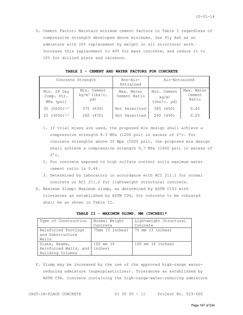
10-01-14
CAST-IN-PLACE CONCRETE 03 30 00 - 11 Project No. 523-400
D. Cement Factor: Maintain minimum cement factors in Table I regardless of
compressive strength developed above minimums. Use Fly Ash as an
admixture with 20% replacement by weight in all structural work.
Increase this replacement to 40% for mass concrete, and reduce it to
10% for drilled piers and caissons.
TABLE I - CEMENT AND WATER FACTORS FOR CONCRETE
Concrete Strength Non-Air-
Entrained
Air-Entrained
Min. 28 Day
Comp. Str.
MPa (psi)
Min. Cement
kg/m3 (lbs/c.
yd)
Max. Water
Cement Ratio
Min. Cement
kg/m3
(lbs/c. yd)
Max. Water
Cement
Ratio
35 (5000)1,3 375 (630) Not Permitted 385 (650) 0.40
25 (3000)1,3 280 (470) Not Permitted 290 (490) 0.55
1. If trial mixes are used, the proposed mix design shall achieve a
compressive strength 8.3 MPa (1200 psi) in excess of f'c. For
concrete strengths above 35 Mpa (5000 psi), the proposed mix design
shall achieve a compressive strength 9.7 MPa (1400 psi) in excess of
f’c.
2. For concrete exposed to high sulfate content soils maximum water
cement ratio is 0.44.
3. Determined by Laboratory in accordance with ACI 211.1 for normal
concrete or ACI 211.2 for lightweight structural concrete.
E. Maximum Slump: Maximum slump, as determined by ASTM C143 with
tolerances as established by ASTM C94, for concrete to be vibrated
shall be as shown in Table II.
TABLE II - MAXIMUM SLUMP, MM (INCHES)*
Type of Construction Normal Weight
Concrete
Lightweight Structural
Concrete
Reinforced Footings
and Substructure
Walls
75mm (3 inches) 75 mm (3 inches)
Slabs, Beams,
Reinforced Walls, and
Building Columns
100 mm (4
inches)
100 mm (4 inches)
F. Slump may be increased by the use of the approved high-range water-
reducing admixture (superplasticizer). Tolerances as established by
ASTM C94. Concrete containing the high-range-water-reducing admixture
Page 197 of 534
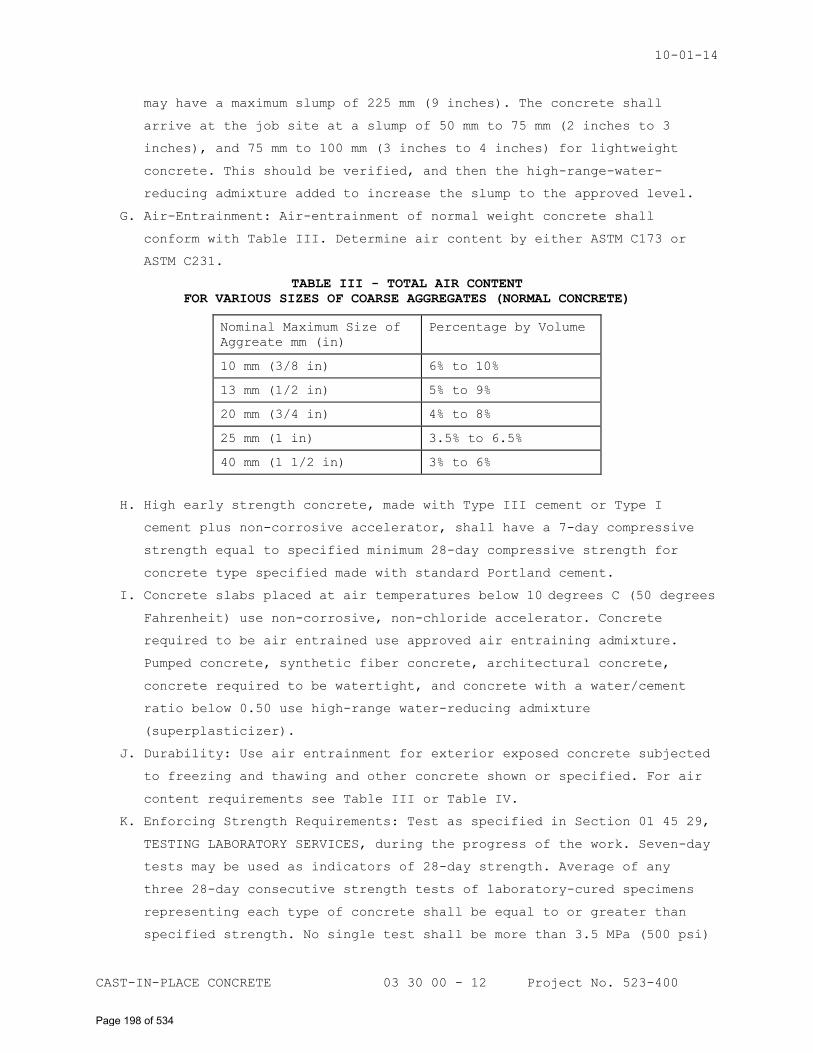
10-01-14
CAST-IN-PLACE CONCRETE 03 30 00 - 12 Project No. 523-400
may have a maximum slump of 225 mm (9 inches). The concrete shall
arrive at the job site at a slump of 50 mm to 75 mm (2 inches to 3
inches), and 75 mm to 100 mm (3 inches to 4 inches) for lightweight
concrete. This should be verified, and then the high-range-water-
reducing admixture added to increase the slump to the approved level.
G. Air-Entrainment: Air-entrainment of normal weight concrete shall
conform with Table III. Determine air content by either ASTM C173 or
ASTM C231.
TABLE III - TOTAL AIR CONTENT
FOR VARIOUS SIZES OF COARSE AGGREGATES (NORMAL CONCRETE)
Nominal Maximum Size of
Aggreate mm (in)
Percentage by Volume
10 mm (3/8 in) 6% to 10%
13 mm (1/2 in) 5% to 9%
20 mm (3/4 in) 4% to 8%
25 mm (1 in) 3.5% to 6.5%
40 mm (1 1/2 in) 3% to 6%
H. High early strength concrete, made with Type III cement or Type I
cement plus non-corrosive accelerator, shall have a 7-day compressive
strength equal to specified minimum 28-day compressive strength for
concrete type specified made with standard Portland cement.
I. Concrete slabs placed at air temperatures below 10 degrees C (50 degrees
Fahrenheit) use non-corrosive, non-chloride accelerator. Concrete
required to be air entrained use approved air entraining admixture.
Pumped concrete, synthetic fiber concrete, architectural concrete,
concrete required to be watertight, and concrete with a water/cement
ratio below 0.50 use high-range water-reducing admixture
(superplasticizer).
J. Durability: Use air entrainment for exterior exposed concrete subjected
to freezing and thawing and other concrete shown or specified. For air
content requirements see Table III or Table IV.
K. Enforcing Strength Requirements: Test as specified in Section 01 45 29,
TESTING LABORATORY SERVICES, during the progress of the work. Seven-day
tests may be used as indicators of 28-day strength. Average of any
three 28-day consecutive strength tests of laboratory-cured specimens
representing each type of concrete shall be equal to or greater than
specified strength. No single test shall be more than 3.5 MPa (500 psi)
Page 198 of 534
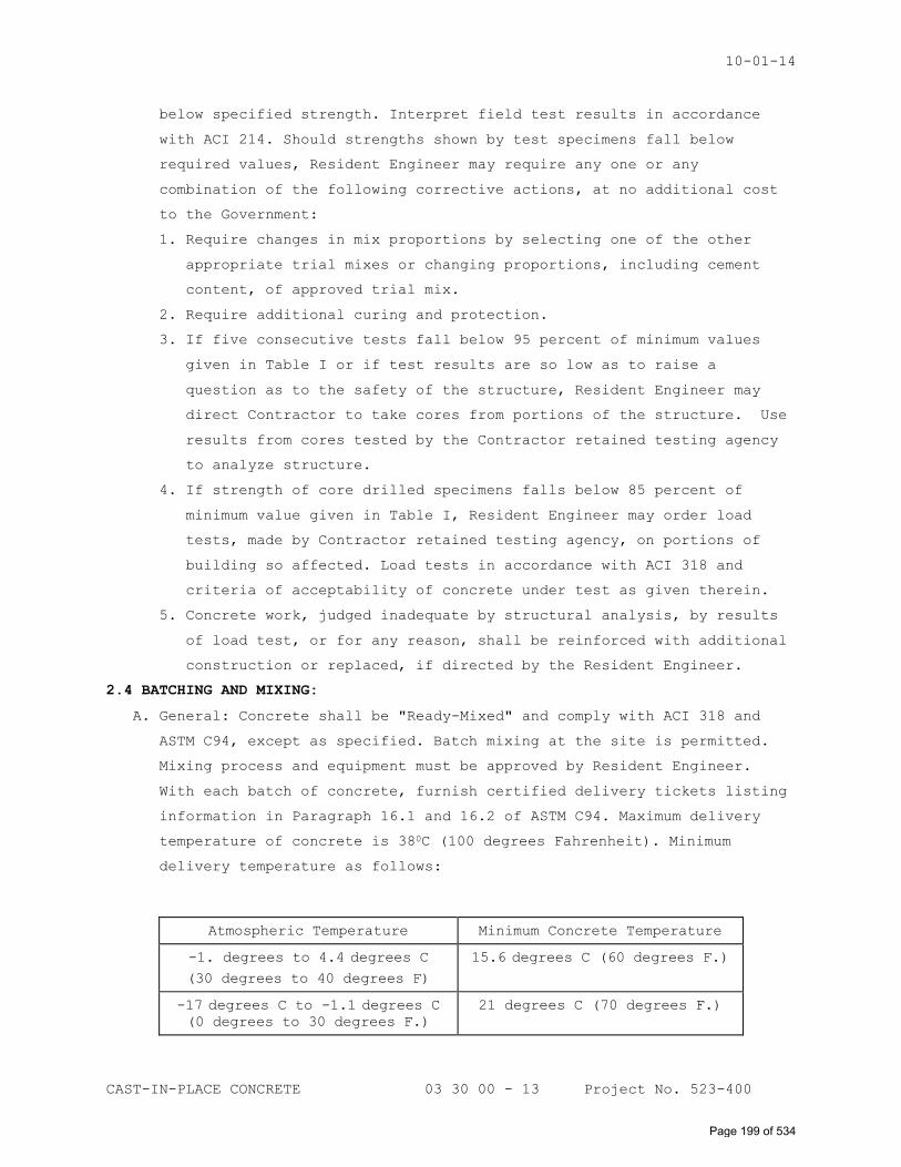
10-01-14
CAST-IN-PLACE CONCRETE 03 30 00 - 13 Project No. 523-400
below specified strength. Interpret field test results in accordance
with ACI 214. Should strengths shown by test specimens fall below
required values, Resident Engineer may require any one or any
combination of the following corrective actions, at no additional cost
to the Government:
1. Require changes in mix proportions by selecting one of the other
appropriate trial mixes or changing proportions, including cement
content, of approved trial mix.
2. Require additional curing and protection.
3. If five consecutive tests fall below 95 percent of minimum values
given in Table I or if test results are so low as to raise a
question as to the safety of the structure, Resident Engineer may
direct Contractor to take cores from portions of the structure. Use
results from cores tested by the Contractor retained testing agency
to analyze structure.
4. If strength of core drilled specimens falls below 85 percent of
minimum value given in Table I, Resident Engineer may order load
tests, made by Contractor retained testing agency, on portions of
building so affected. Load tests in accordance with ACI 318 and
criteria of acceptability of concrete under test as given therein.
5. Concrete work, judged inadequate by structural analysis, by results
of load test, or for any reason, shall be reinforced with additional
construction or replaced, if directed by the Resident Engineer.
2.4 BATCHING AND MIXING:
A. General: Concrete shall be "Ready-Mixed" and comply with ACI 318 and
ASTM C94, except as specified. Batch mixing at the site is permitted.
Mixing process and equipment must be approved by Resident Engineer.
With each batch of concrete, furnish certified delivery tickets listing
information in Paragraph 16.1 and 16.2 of ASTM C94. Maximum delivery
temperature of concrete is 380C (100 degrees Fahrenheit). Minimum
delivery temperature as follows:
Atmospheric Temperature Minimum Concrete Temperature
-1. degrees to 4.4 degrees C
(30 degrees to 40 degrees F)
15.6 degrees C (60 degrees F.)
-17 degrees C to -1.1 degrees C
(0 degrees to 30 degrees F.)
21 degrees C (70 degrees F.)
Page 199 of 534
10-01-14
CAST-IN-PLACE CONCRETE 03 30 00 - 14 Project No. 523-400
1. Services of aggregate manufacturer's representative shall be
furnished during the design of trial mixes and as requested by the
Resident Engineer for consultation during batching, mixing, and
placing operations of lightweight structural concrete. Services will
be required until field controls indicate that concrete of required
quality is being furnished. Representative shall be thoroughly
familiar with the structural lightweight aggregate, adjustment and
control of mixes to produce concrete of required quality.
Representative shall assist and advise Resident Engineer.
PART 3 – EXECUTION
3.1 FORMWORK:
A. General: Design in accordance with ACI 347 is the responsibility of the
Contractor. The Contractor shall retain a registered Professional
Engineer to design the formwork, shores, and reshores.
1. Form boards and plywood forms may be reused for contact surfaces of
exposed concrete only if thoroughly cleaned, patched, and repaired
and Resident Engineer approves their reuse.
2. Provide forms for concrete footings unless Resident Engineer
determines forms are not necessary.
3. Corrugated fiberboard forms: Place forms on a smooth firm bed, set
tight, with no buckled cartons to prevent horizontal displacement,
and in a dry condition when concrete is placed.
B. Treating and Wetting: Treat or wet contact forms as follows:
1. Coat plywood and board forms with non-staining form sealer. In hot
weather, cool forms by wetting with cool water just before concrete
is placed.
2. Clean and coat removable metal forms with light form oil before
reinforcement is placed. In hot weather, cool metal forms by
thoroughly wetting with water just before placing concrete.
3. Use sealer on reused plywood forms as specified for new material.
C. Size and Spacing of Studs: Size and space studs, wales and other
framing members for wall forms so as not to exceed safe working stress
of kind of lumber used nor to develop deflection greater than 1/270 of
free span of member.
D. Unlined Forms: Use plywood forms to obtain a smooth finish for concrete
surfaces. Tightly butt edges of sheets to prevent leakage. Back up all
vertical joints solidly and nail edges of adjacent sheets to same stud
with 6d box nails spaced not over 150 mm (6 inches) apart.
Page 200 of 534
10-01-14
CAST-IN-PLACE CONCRETE 03 30 00 - 15 Project No. 523-400
E. Lined Forms: May be used in lieu of unlined plywood forms. Back up form
lining solidly with square edge board lumber securely nailed to studs
with all edges in close contact to prevent bulging of lining. No joints
in lining and backing may coincide. Nail abutted edges of sheets to
same backing board. Nail lining at not over 200 mm (8 inches) on center
along edges and with at least one nail to each square foot of surface
area; nails to be 3d blued shingle or similar nails with thin
flatheads.
F. Architectural Liner: Attach liner as recommended by the manufacturer
with tight joints to prevent leakage.
G. Wall Form Ties: Locate wall form ties in symmetrically level horizontal
rows at each line of wales and in plumb vertical tiers. Space ties to
maintain true, plumb surfaces. Provide one row of ties within 150 mm (6
inches) above each construction joint. Space through-ties adjacent to
horizontal and vertical construction joints not over 450 mm (18 inches)
on center.
1. Tighten row of ties at bottom of form just before placing concrete
and, if necessary, during placing of concrete to prevent seepage of
concrete and to obtain a clean line. Ties to be entirely removed
shall be loosened 24 hours after concrete is placed and shall be
pulled from least important face when removed.
2. Coat surfaces of all metal that is to be removed with paraffin, cup
grease or a suitable compound to facilitate removal.
H. Inserts, Sleeves, and Similar Items: Flashing reglets, steel strips,
masonry ties, anchors, wood blocks, nailing strips, grounds, inserts,
wire hangers, sleeves, drains, guard angles, forms for floor hinge
boxes, inserts or bond blocks for elevator guide rails and supports,
and other items specified as furnished under this and other sections of
specifications and required to be in their final position at time
concrete is placed shall be properly located, accurately positioned,
and built into construction, and maintained securely in place.
1. Locate inserts or hanger wires for furred and suspended ceilings
only in bottom of concrete joists, or similar concrete member of
overhead concrete joist construction.
2. Install sleeves, inserts and similar items for mechanical services
in accordance with drawings prepared specially for mechanical
services. Contractor is responsible for accuracy and completeness
Page 201 of 534
10-01-14
CAST-IN-PLACE CONCRETE 03 30 00 - 16 Project No. 523-400
of drawings and shall coordinate requirements for mechanical
services and equipment.
3. Do not install sleeves in beams, joists or columns except where
shown or permitted by Resident Engineer. Install sleeves in beams,
joists, or columns that are not shown, but are permitted by the
Resident Engineer, and require no structural changes, at no
additional cost to the Government.
4. Minimum clear distance of embedded items such as conduit and pipe is
at least three times diameter of conduit or pipe, except at stub-ups
and other similar locations.
5. Provide recesses and blockouts in floor slabs for door closers and
other hardware as necessary in accordance with manufacturer's
instructions.
I. Construction Tolerances:
1. Set and maintain concrete formwork to assure erection of completed
work within tolerances specified and to accommodate installation of
other rough and finish materials. Accomplish remedial work necessary
for correcting excessive tolerances. Erected work that exceeds
specified tolerance limits shall be remedied or removed and
replaced, at no additional cost to the Government.
2. Permissible surface irregularities for various classes of materials
are defined as "finishes" in specification sections covering
individual materials. They are to be distinguished from tolerances
specified which are applicable to surface irregularities of
structural elements.
3.2 PLACING REINFORCEMENT:
A. General: Details of concrete reinforcement in accordance with ACI 318
unless otherwise shown.
B. Placing: Place reinforcement conforming to CRSI DA4, unless otherwise
shown.
1. Place reinforcing bars accurately and tie securely at intersections
and splices with 1.6 mm (16 gauge) black annealed wire. // Use
epoxy-coated tie wire with epoxy-coated reinforcing. // Secure
reinforcing bars against displacement during the placing of concrete
by spacers, chairs, or other similar supports. Portions of supports,
spacers, and chairs in contact with formwork shall be made of
plastic in areas that will be exposed when building is occupied.
Type, number, and spacing of supports conform to ACI 318. Where
Page 202 of 534
10-01-14
CAST-IN-PLACE CONCRETE 03 30 00 - 17 Project No. 523-400
concrete slabs are placed on ground, use concrete blocks or other
non-corrodible material of proper height, for support of
reinforcement. Use of brick or stone supports will not be permitted.
2. Lap welded wire fabric at least 1 1/2 mesh panels plus end extension
of wires not less than 300 mm (12 inches) in structural slabs. Lap
welded wire fabric at least 1/2 mesh panels plus end extension of
wires not less than 150 mm (6 inches) in slabs on grade.
3. Splice column steel at no points other than at footings and floor
levels unless otherwise shown.
C. Spacing: Minimum clear distances between parallel bars, except in
columns and multiple layers of bars in beams shall be equal to nominal
diameter of bars. Minimum clear spacing is 25 mm (1 inch) or 1-1/3
times maximum size of coarse aggregate.
D. Splicing: Splices of reinforcement made only as required or shown or
specified. Accomplish splicing as follows:
1. Lap splices: Do not use lap splices for bars larger than Number 36
(Number 11). Minimum lengths of lap as shown.
2. Welded splices: Splicing by butt-welding of reinforcement permitted
providing the weld develops in tension at least 125 percent of the
yield strength (fy) for the bars. Welding conform to the
requirements of AWS D1.4. Welded reinforcing steel conform to the
chemical analysis requirements of AWS D1.4.
a. Submit test reports indicating the chemical analysis to establish
weldability of reinforcing steel.
b. Submit a field quality control procedure to insure proper
inspection, materials and welding procedure for welded splices.
c. Department of Veterans Affairs retained testing agency shall test
a minimum of three splices, for compliance, locations selected by
Resident Engineer.
3. Mechanical Splices: Develop in tension and compression at least 125
percent of the yield strength (fy) of the bars. Stresses of
transition splices between two reinforcing bar sizes based on area
of smaller bar. Provide mechanical splices at locations indicated.
Use approved exothermic, tapered threaded coupling, or swaged and
threaded sleeve. Exposed threads and swaging in the field not
permitted.
a. Initial qualification: In the presence of Resident Engineer, make
three test mechanical splices of each bar size proposed to be
Page 203 of 534
10-01-14
CAST-IN-PLACE CONCRETE 03 30 00 - 18 Project No. 523-400
spliced. Department of Veterans Affairs retained testing
laboratory will perform load test.
b. During installation: Furnish, at no additional cost to the
Government, one companion (sister) splice for every 50 splices
for load testing. Department of Veterans Affairs retained testing
laboratory will perform the load test.
E. Bending: Bend bars cold, unless otherwise approved. Do not field bend
bars partially embedded in concrete, except when approved by Resident
Engineer.
F. Cleaning: Metal reinforcement, at time concrete is placed, shall be
free from loose flaky rust, mud, oil, or similar coatings that will
reduce bond.
G. Future Bonding: Protect exposed reinforcement bars intended for bonding
with future work by wrapping with felt and coating felt with a
bituminous compound unless otherwise shown.
3.3 VAPOR BARRIER:
A. Except where membrane waterproofing is required, interior concrete slab
on grade shall be placed on a continuous vapor barrier.
1. Place 100 mm (4 inches) of fine granular fill over the vapor barrier
to act as a blotter for concrete slab.
2. Vapor barrier joints lapped 150 mm (6 inches) and sealed with
compatible waterproof pressure-sensitive tape.
3. Patch punctures and tears.
3.4 CONSTRUCTION JOINTS:
A. Unless otherwise shown, location of construction joints to limit
individual placement shall not exceed 24,000 mm (80 feet) in any
horizontal direction, except slabs on grade which shall have
construction joints shown. Allow 48 hours to elapse between pouring
adjacent sections unless this requirement is waived by Resident
Engineer.
B. Locate construction joints in suspended floors near the quarter-point
of spans for slabs, beams or girders, unless a beam intersects a girder
at center, in which case joint in girder shall be offset a distance
equal to twice width of beam. Provide keys and inclined dowels as
shown. Provide longitudinal keys as shown.
C. Place concrete for columns slowly and in one operation between joints.
Install joints in concrete columns at underside of deepest beam or
girder framing into column.
Page 204 of 534
10-01-14
CAST-IN-PLACE CONCRETE 03 30 00 - 19 Project No. 523-400
D. Allow 2 hours to elapse after column is cast before concrete of
supported beam, girder or slab is placed. Place girders, beams, grade
beams, column capitals, brackets, and haunches at the same time as slab
unless otherwise shown.
E. Install rubber water seals, as shown in accordance with manufacturer's
instructions, to form continuous watertight seal.
3.5 EXPANSION JOINTS AND CONTRACTION JOINTS:
A. Clean expansion joint surfaces before installing premolded filler and
placing adjacent concrete.
B. Install rubber water seals, as shown in accordance with manufacturer's
instructions, to form continuous watertight seal.
C. Provide contraction (control) joints in floor slabs as indicated on the
contract drawings. Joints shall be either formed or saw cut, to the
indicated depth after the surface has been finished. Complete saw
joints within 4 to 12 hours after concrete placement. Protect joints
from intrusion of foreign matter.
3.6 PLACING CONCRETE:
A. Preparation:
1. Remove hardened concrete, wood chips, shavings and other debris from
forms.
2. Remove hardened concrete and foreign materials from interior
surfaces of mixing and conveying equipment.
3. Have forms and reinforcement inspected and approved by Resident
Engineer before depositing concrete.
4. Provide runways for wheeling equipment to convey concrete to point
of deposit. Keep equipment on runways which are not supported by or
bear on reinforcement. Provide similar runways for protection of
vapor barrier on coarse fill.
B. Bonding: Before depositing new concrete on or against concrete which
has been set, thoroughly roughen and clean existing surfaces of
laitance, foreign matter, and loose particles.
1. Preparing surface for applied topping:
a. Remove laitance, mortar, oil, grease, paint, or other foreign
material by sand blasting. Clean with vacuum type equipment to
remove sand and other loose material.
b. Broom clean and keep base slab wet for at least four hours before
topping is applied.
Page 205 of 534
10-01-14
CAST-IN-PLACE CONCRETE 03 30 00 - 20 Project No. 523-400
c. Use a thin coat of one part Portland cement, 1.5 parts fine sand,
bonding admixture; and water at a 50: 50 ratio and mix to achieve
the consistency of thick paint. Apply to a damp base slab by
scrubbing with a stiff fiber brush. New concrete shall be placed
while the bonding grout is still tacky.
C. Conveying Concrete: Convey concrete from mixer to final place of
deposit by a method which will prevent segregation. Method of conveying
concrete is subject to approval of Resident Engineer.
D. Placing: For special requirements see Paragraphs, HOT WEATHER and COLD
WEATHER.
1. Do not place concrete when weather conditions prevent proper
placement and consolidation, or when concrete has attained its
initial set, or has contained its water or cement content more than
1 1/2 hours.
2. Deposit concrete in forms as near as practicable in its final
position. Prevent splashing of forms or reinforcement with concrete
in advance of placing concrete.
3. Do not drop concrete freely more than 3000 mm (10 feet) for concrete
containing the high-range water-reducing admixture
(superplasticizer) or 1500 mm (5 feet) for conventional concrete.
Where greater drops are required, use a tremie or flexible spout
(canvas elephant trunk), attached to a suitable hopper.
4. Discharge contents of tremies or flexible spouts in horizontal
layers not exceeding 500 mm (20 inches) in thickness, and space
tremies such as to provide a minimum of lateral movement of
concrete.
5. Continuously place concrete until an entire unit between
construction joints is placed. Rate and method of placing concrete
shall be such that no concrete between construction joints will be
deposited upon or against partly set concrete, after its initial set
has taken place, or after 45 minutes of elapsed time during concrete
placement.
6. On bottom of members with severe congestion of reinforcement,
deposit 25 mm (1 inch) layer of flowing concrete containing the
specified high-range water-reducing admixture (superplasticizer).
Successive concrete lifts may be a continuation of this concrete or
concrete with a conventional slump.
7. Concrete on metal deck:
Page 206 of 534
10-01-14
CAST-IN-PLACE CONCRETE 03 30 00 - 21 Project No. 523-400
a. Concrete on metal deck shall be minimum thickness shown. Allow
for deflection of steel beams and metal deck under the weight of
wet concrete in calculating concrete quantities for slab.
1) The Contractor shall become familiar with deflection
characteristics of structural frame to include proper amount
of additional concrete due to beam/deck deflection.
E. Consolidation: Conform to ACI 309. Immediately after depositing, spade
concrete next to forms, work around reinforcement and into angles of
forms, tamp lightly by hand, and compact with mechanical vibrator
applied directly into concrete at approximately 450 mm (18 inch)
intervals. Mechanical vibrator shall be power driven, hand operated
type with minimum frequency of 5000 cycles per minute having an
intensity sufficient to cause flow or settlement of concrete into
place. Vibrate concrete to produce thorough compaction, complete
embedment of reinforcement and concrete of uniform and maximum density
without segregation of mix. Do not transport concrete in forms by
vibration.
1. Use of form vibration shall be approved only when concrete sections
are too thin or too inaccessible for use of internal vibration.
2. Carry on vibration continuously with placing of concrete. Do not
insert vibrator into concrete that has begun to set.
3.7 HOT WEATHER:
Follow the recommendations of ACI 305 or as specified to prevent
problems in the manufacturing, placing, and curing of concrete that can
adversely affect the properties and serviceability of the hardened
concrete. Methods proposed for cooling materials and arrangements for
protecting concrete shall be made in advance of concrete placement and
approved by Resident Engineer.
3.8 COLD WEATHER:
Follow the recommendations of ACI 306 or as specified to prevent
freezing of concrete and to permit concrete to gain strength properly.
Use only the specified non-corrosive, non-chloride accelerator. Do not
use calcium chloride, thiocyantes or admixtures containing more than
0.05 percent chloride ions. Methods proposed for heating materials and
arrangements for protecting concrete shall be made in advance of
concrete placement and approved by Resident Engineer.
Page 207 of 534
10-01-14
CAST-IN-PLACE CONCRETE 03 30 00 - 22 Project No. 523-400
3.9 PROTECTION AND CURING:
A. Conform to ACI 308: Initial curing shall immediately follow the
finishing operation. Protect exposed surfaces of concrete from
premature drying, wash by rain and running water, wind, mechanical
injury, and excessively hot or cold temperatures. Keep concrete not
covered with membrane or other curing material continuously wet for at
least 7 days after placing, except wet curing period for high-early-
strength concrete shall be not less than 3 days. Keep wood forms
continuously wet to prevent moisture loss until forms are removed. Cure
exposed concrete surfaces as described below. Other curing methods may
be used if approved by Resident Engineer.
1. Liquid curing and sealing compounds: Apply by power-driven spray or
roller in accordance with the manufacturer’s instructions. Apply
immediately after finishing. Maximum coverage 10m2/L (400 square feet
per gallon) on steel troweled surfaces and 7.5m2/L (300 square feet
per gallon) on floated or broomed surfaces for the curing/sealing
compound.
2. Plastic sheets: Apply as soon as concrete has hardened sufficiently
to prevent surface damage. Utilize widest practical width sheet and
overlap adjacent sheets 50 mm (2 inches). Tightly seal joints with
tape.
3. Paper: Utilize widest practical width paper and overlap adjacent
sheets 50 mm (2 inches). Tightly seal joints with sand, wood planks,
pressure-sensitive tape, mastic or glue.
3.10 REMOVAL OF FORMS:
A. Remove in a manner to assure complete safety of structure after the
following conditions have been met.
1. Where structure as a whole is supported on shores, forms for beams
and girder sides, columns, and similar vertical structural members
may be removed after 24 hours, provided concrete has hardened
sufficiently to prevent surface damage and curing is continued
without any lapse in time as specified for exposed surfaces.
2. Take particular care in removing forms of architectural exposed
concrete to insure surfaces are not marred or gouged, and that
corners and arises are true, sharp and unbroken.
B. Control Test: Use to determine if the concrete has attained sufficient
strength and curing to permit removal of supporting forms. Cylinders
required for control tests taken in accordance with ASTM C172, molded
Page 208 of 534
10-01-14
CAST-IN-PLACE CONCRETE 03 30 00 - 23 Project No. 523-400
in accordance with ASTM C31, and tested in accordance with ASTM C39.
Control cylinders cured and protected in the same manner as the
structure they represent. Supporting forms or shoring not removed until
strength of control test cylinders have attained at least 70 percent of
minimum 28-day compressive strength specified. Exercise care to assure
that newly unsupported portions of structure are not subjected to heavy
construction or material loading.
C. Reshoring: Reshoring is required if superimposed load plus dead load of
the floor exceeds the capacity of the floor at the time of loading.
Reshoring accomplished in accordance with ACI 347 at no additional cost
to the Government.
3.11 CONCRETE SURFACE PREPARATION:
A. Metal Removal: Unnecessary metal items cut back flush with face of
concrete members.
B. Patching: Maintain curing and start patching as soon as forms are
removed. Do not apply curing compounds to concrete surfaces requiring
patching until patching is completed. Use cement mortar for patching of
same composition as that used in concrete. Use white or gray Portland
cement as necessary to obtain finish color matching surrounding
concrete. Thoroughly clean areas to be patched. Cut out honeycombed or
otherwise defective areas to solid concrete to a depth of not less than
25 mm (1 inch). Cut edge perpendicular to surface of concrete. Saturate
with water area to be patched, and at least 150 mm (6 inches)
surrounding before placing patching mortar. Give area to be patched a
brush coat of cement grout followed immediately by patching mortar.
Cement grout composed of one part Portland cement, 1.5 parts fine sand,
bonding admixture, and water at a 50:50 ratio, mix to achieve
consistency of thick paint. Mix patching mortar approximately 1 hour
before placing and remix occasionally during this period without
addition of water. Compact mortar into place and screed slightly higher
than surrounding surface. After initial shrinkage has occurred, finish
to match color and texture of adjoining surfaces. Cure patches as
specified for other concrete. Fill form tie holes which extend entirely
through walls from unexposed face by means of a pressure gun or other
suitable device to force mortar through wall. Wipe excess mortar off
exposed face with a cloth.
C. Upon removal of forms, clean vertical concrete surface that is to
receive bonded applied cementitious application with wire brushes or by
Page 209 of 534
10-01-14
CAST-IN-PLACE CONCRETE 03 30 00 - 24 Project No. 523-400
sand blasting to remove unset material, laitance, and loose particles
to expose aggregates to provide a clean, firm, granular surface for
bond of applied finish.
3.12 CONCRETE FINISHES:
A. Vertical and Overhead Surface Finishes:
1. Unfinished areas: Vertical and overhead concrete surfaces exposed in
pipe basements, elevator and dumbwaiter shafts, pipe spaces, pipe
trenches, above suspended ceilings, manholes, and other unfinished
areas will not require additional finishing.
2. Interior and exterior exposed areas to be painted: Remove fins,
burrs and similar projections on surfaces flush, and smooth by
mechanical means approved by Resident Engineer, and by rubbing
lightly with a fine abrasive stone or hone. Use ample water during
rubbing without working up a lather of mortar or changing texture of
concrete.
3. Interior and exterior exposed areas finished: Give a grout finish of
uniform color and smooth finish treated as follows:
a. After concrete has hardened and laitance, fins and burrs removed,
scrub concrete with wire brushes. Clean stained concrete surfaces
by use of a hone stone.
b. Apply grout composed of one part of Portland cement, one part
fine sand, smaller than a 600 µm (No. 30) sieve. Work grout into
surface of concrete with cork floats or fiber brushes until all
pits, and honeycombs are filled.
c. After grout has hardened slightly, but while still plastic,
scrape grout off with a sponge rubber float and, about 1 hour
later, rub concrete vigorously with burlap to remove any excess
grout remaining on surfaces.
d. In hot, dry weather use a fog spray to keep grout wet during
setting period. Complete finish of area in same day. Make limits
of finished areas at natural breaks in wall surface. Leave no
grout on concrete surface overnight.
4. Textured: Finish as specified. Maximum quantity of patched area 0.2
m2 (2 square feet) in each 93 m2 (1000 square feet) of textured
surface.
B. Slab Finishes:
1. Monitoring and Adjustment: Provide continuous cycle of placement,
measurement, evaluation and adjustment of procedures to produce
Page 210 of 534
10-01-14
CAST-IN-PLACE CONCRETE 03 30 00 - 25 Project No. 523-400
slabs within specified tolerances. Monitor elevations of structural
steel in key locations before and after concrete placement to
establish typical deflection patterns for the structural steel.
Determine elevations of cast-in-place slab soffits prior to removal
of shores. Provide information to Resident Engineer and floor
consultant for evaluation and recommendations for subsequent
placements.
2. Set perimeter forms to serve as screed using either optical or laser
instruments. For slabs on grade, wet screeds may be used to
establish initial grade during strike-off, unless Resident Engineer
determines that the method is proving insufficient to meet required
finish tolerances and directs use of rigid screed guides. Where wet
screeds are allowed, they shall be placed using grade stakes set by
optical or laser instruments. Use rigid screed guides, as opposed to
wet screeds, to control strike-off elevation for all types of
elevated (non slab-on-grade) slabs. Divide bays into halves or
thirds by hard screeds. Adjust as necessary where monitoring of
previous placements indicates unshored structural steel deflections
to other than a level profile.
3. Place slabs monolithically. Once slab placement commences, complete
finishing operations within same day. Slope finished slab to floor
drains where they occur, whether shown or not.
4. Use straightedges specifically made for screeding, such as hollow
magnesium straightedges or power strike-offs. Do not use pieces of
dimensioned lumber. Strike off and screed slab to a true surface at
required elevations. Use optical or laser instruments to check
concrete finished surface grade after strike-off. Repeat strike-off
as necessary. Complete screeding before any excess moisture or
bleeding water is present on surface. Do not sprinkle dry cement on
the surface.
5. Immediately following screeding, and before any bleed water appears,
use a 3000 mm (10 foot) wide highway straightedge in a cutting and
filling operation to achieve surface flatness. Do not use bull
floats or darbys, except that darbying may be allowed for narrow
slabs and restricted spaces.
6. Wait until water sheen disappears and surface stiffens before
proceeding further. Do not perform subsequent operations until
Page 211 of 534
10-01-14
CAST-IN-PLACE CONCRETE 03 30 00 - 26 Project No. 523-400
concrete will sustain foot pressure with maximum of 6 mm (1/4 inch)
indentation.
7. Scratch Finish: Finish base slab to receive a bonded applied
cementitious application as indicated above, except that bull floats
and darbys may be used. Thoroughly coarse wire broom within two
hours after placing to roughen slab surface to insure a permanent
bond between base slab and applied materials.
8. Float Finish: Slabs to receive unbonded toppings, steel trowel
finish, fill, mortar setting beds, or a built-up roof, and ramps,
stair treads, platforms (interior and exterior), and equipment pads
shall be floated to a smooth, dense uniform, sandy textured finish.
During floating, while surface is still soft, check surface for
flatness using a 3000 mm (10 foot) highway straightedge. Correct
high spots by cutting down and correct low spots by filling in with
material of same composition as floor finish. Remove any surface
projections and re-float to a uniform texture.
9. Steel Trowel Finish: Concrete surfaces to receive resilient floor
covering or carpet, monolithic floor slabs to be exposed to view in
finished work, future floor roof slabs, applied toppings, and other
interior surfaces for which no other finish is indicated. Steel
trowel immediately following floating. During final troweling, tilt
steel trowel at a slight angle and exert heavy pressure to compact
cement paste and form a dense, smooth surface. Finished surface
shall be smooth, free of trowel marks, and uniform in texture and
appearance.
10. Broom Finish: Finish exterior slabs, ramps, and stair treads with a
bristle brush moistened with clear water after surfaces have been
floated. Brush in a direction transverse to main traffic. Match
texture approved by Resident Engineer from sample panel.
11. Finished slab flatness (FF) and levelness (FL) values comply with
the following minimum requirements:
a. Areas covered with carpeting, or not specified otherwise in b.
below:
1) Slab on Grade:
a) Specified overall value FF 25/FL 20
b) Minimum local value FF 17/FL 15
2) Level suspended slabs (shored until after testing) and topping
slabs:
Page 212 of 534
10-01-14
CAST-IN-PLACE CONCRETE 03 30 00 - 27 Project No. 523-400
a) Specified overall value FF 25/FL 20
b) Minimum local value FF 17/FL 15
3) Unshored suspended slabs:
a) Specified overall value FF 25
b) Minimum local value FF 17
4) Level tolerance such that 80 percent of all points fall within
a 20 mm (3/4 inch) envelope +10 mm, -10 mm (+3/8 inch, -3/8
inch) from the design elevation.
c. "Specified overall value" is based on the composite of all
measured values in a placement derived in accordance with ASTM
E1155.
d. "Minimum local value" (MLV) describes the flatness or levelness
below which repair or replacement is required. MLV is based on
the results of an individual placement and applies to a minimum
local area. Minimum local area boundaries may not cross a
construction joint or expansion joint. A minimum local area will
be bounded by construction and/or control joints, or by column
lines and/or half-column lines, whichever is smaller.
12. Measurements
a. Department of Veterans Affairs retained testing laboratory will
take measurements as directed by Resident Engineer, to verify
compliance with FF, FL, and other finish requirements.
Measurements will occur within 72 hours after completion of
concrete placement (weekends and holidays excluded). Make
measurements before shores or forms are removed to insure the
"as-built" levelness is accurately assessed. Profile data for
above characteristics may be collected using a laser level or any
Type II apparatus (ASTM E1155, "profileograph" or "dipstick").
Contractor's surveyor shall establish reference elevations to be
used by Department of Veterans Affairs retained testing
laboratory.
b. Contractor not experienced in using FF and FL criteria is
encouraged to retain the services of a floor consultant to assist
with recommendations concerning adjustments to slab thicknesses,
finishing techniques, and procedures on measurements of the
finish as it progresses in order to achieve the specific flatness
and levelness numbers.
Page 213 of 534
10-01-14
CAST-IN-PLACE CONCRETE 03 30 00 - 28 Project No. 523-400
13. Acceptance/ Rejection:
a. If individual slab section measures less than either of specified
minimum local FF/FL numbers, that section shall be rejected and
remedial measures shall be required. Sectional boundaries may be
set at construction and contraction (control) joints, and not
smaller than one-half bay.
b. If composite value of entire slab installation, combination of
all local results, measures less than either of specified overall
FF/FL numbers, then whole slab shall be rejected and remedial
measures shall be required.
14. Remedial Measures for Rejected Slabs: Correct rejected slab areas by
grinding, planing, surface repair with underlayment compound or
repair topping, retopping, or removal and replacement of entire
rejected slab areas, as directed by Resident Engineer, until a slab
finish constructed within specified tolerances is accepted.
3.13 SURFACE TREATMENTS:
A. Use on exposed concrete floors and concrete floors to receive carpeting
except those specified to receive non-slip finish.
B. Liquid Densifier/Sealer: Apply in accordance with manufacturer's
directions just prior to completion of construction.
C. Non-Slip Finish: Except where safety nosing and tread coverings are
shown, apply non-slip abrasive aggregate to treads and platforms of
concrete steps and stairs, and to surfaces of exterior concrete ramps
and platforms. Broadcast aggregate uniformly over concrete surface at
rate of application of 8% per 1/10th m2 (7.5 percent per square foot) of
area. Trowel concrete surface to smooth dense finish. After curing, rub
treated surface with abrasive brick and water to slightly expose
abrasive aggregate.
3.14 APPLIED TOPPING:
A. Separate concrete topping on floor base slab of thickness and strength
shown. Topping mix shall have a maximum slump of 200 mm (8 inches) for
concrete containing a high-range water-reducing admixture
(superplasticizer) and 100 mm (4 inches) for conventional mix. Neatly
bevel or slope at door openings and at slabs adjoining spaces not
receiving an applied finish.
B. Placing: Place continuously until entire section is complete, struck
off with straightedge, leveled with a highway straightedge or highway
bull float, floated and troweled by machine to a hard dense finish.
Page 214 of 534
10-01-14
CAST-IN-PLACE CONCRETE 03 30 00 - 29 Project No. 523-400
Slope to floor drains as required. Do not start floating until free
water has disappeared and no water sheen is visible. Allow drying of
surface moisture naturally. Do not hasten by "dusting" with cement or
sand.
3.15 RETAINING WALLS:
A. Use air-entrained concrete.
B. Expansion and contraction joints, waterstops, weep holes, reinforcement
and railing sleeves installed and constructed as shown.
C. Exposed surfaces finished to match adjacent concrete surfaces, new or
existing.
D. Place porous backfill as shown.
- - - E N D - - -
Page 215 of 534
07-11
03 41 33 - 1
SECTION 03 41 33
PRECAST STRUCTURAL PRETENSIONED CONCRETE
PART 1 - GENERAL
1.1 DESCRIPTION:
A. This section specifies precast prestressed concrete construction
including design not shown, fabrication, erection, and other related
items including bearing pads and anchorage.
B. Precast prestressed concrete includes double tees, beams and spandrels,
columns, stair units, and wall panels.
1.2 RELATED WORK:
A. Materials testing and inspection during construction: Section 01 45 29,
TESTING LABORATORY SERVICES.
B. Concrete: Section 03 30 00, CAST-IN-PLACE CONCRETE.
C. Sealants and Caulking: Section 07 92 00, JOINT SEALANTS.
D. Repair of abraded galvanized and painted surfaces: Section 09 91 00,
PAINTING.
1.3 QUALITY ASSURANCE:
A. Manufacturer Qualifications: Precast concrete manufacturing plant shall
be certified by Prestressed Concrete Institute, Plant Certification
Program, prior to start of production.
B. Precast concrete work shall be performed by firms that have demonstrated
capability, subject to approval, to produce and erect type of work
specified.
C. Precast concrete manufacturer shall have on staff or shall retain a
qualified registered Professional Structural Engineer in the State of
Massachusetts to certify precast concrete conforms in all aspects to
requirements of ACI 318.
D. Erector Qualifications: Regularly engaged for at least 5 years in
erection of precast structural concrete similar to requirements of this
project.
1. Erector shall be PCI Certified for Category S2-Complex Structural
Systems.
E. Requirements of Regulatory Agencies: Local codes plus applicable
specifications, standards and codes are a part of these specifications.
1.4 SUBMITTALS:
A. Submit in accordance with Section 01 33 23, SHOP DRAWINGS, PRODUCT DATA,
AND SAMPLES.
B. Shop Drawings:
1. Erection Drawings:
PRECAST STRUCTURAL PRETENSIONED CONCRETE
Project No. 523-400
Page 216 of 534
07-11
03 41 33 - 2
a. Plans and/or elevations locating and defining material furnished
by manufacturer.
b. Sections and details showing connections, cast-in items and their
relation to structure.
c. Description of all loose, cast-in and field hardware.
d. Field installed anchor location drawings.
e. Erection sequences and handling requirements.
f. Dead, live, wind, seismic and other applicable loads used in
design.
2. Production drawings:
a. Elevation view of each member.
b. Sections and details to indicate quantities and position of
reinforcing steel, anchors, inserts, and essential embedded
hardware.
c. Lifting and erection inserts.
d. Dimensions and finishes.
e. Prestress for strand and concrete strengths.
f. Estimated cambers.
g. Method of transportation.
C. Product Design Criteria:
1. Loadings for design:
a. Initial handling and erection stresses.
b. Dead and live loads as specified on contract drawings.
c. Other loads specified for member where they are applicable.
d. Deflection of precast members shall be limited as follows:
1) Vertical Live Load - Span/360
2) Wind Load - 0.0025 x Floor to Floor Height
3) Seismic Load – 0.02 x Floor to Floor Height, with consideration
of all deflection amplification modifiers as required by code.
e. Design shall provide for thermal movements of completed structure.
2. Design calculations of products shall be performed by a registered
Professional Engineer in the State of Massachusetts experienced in
precast prestressed concrete design.
3. Design shall be in accordance with applicable codes, ACI 318 and the
PCI Design Handbook (latest edition).
4. Details for waterproof joints between precast members.
D. Mix Designs: Submit proposed concrete mix designs and appropriate test
data as specified in Part 2 of this section.
E. Permissible Design Deviations:
1. Design connections according to the conceptual details shown in the
contract documents.
Project No. 523-400 PRECAST STRUCTURAL PRETENSIONED CONCRETE
Page 217 of 534
07-11
03 41 33 - 3
2. Design deviations will be permitted only after Resident Engineer's
written approval of manufacturer's proposed design supported by
complete design calculations and drawings.
3. Design deviations shall provide an installation equivalent to basic
intent without incurring additional cost to the Government.
F. Test Reports: Concrete and other material.
1.5 PRODUCT DELIVERY, STORAGE AND HANDLING:
A. Delivery and Handling:
1. Lift and support precast concrete members during manufacturing,
stockpiling, transporting and erection operations only at lifting or
supporting points, or both, as shown on contract and shop drawings,
and with approved lifting devices. Lifting devices shall have a
minimum safety factor of 4. Exterior lifting hardware shall have a
minimum safety factor of 5.
2. Transportation, site handling, and erection shall be performed with
acceptable equipment and methods, and by qualified personnel.
B. Storage:
1. Store all units off ground.
2. Place stored units so that identification marks are discernible.
3. Separate stacked members by battens across full width of each bearing
point.
4. Stack so that lifting devices are accessible and undamaged.
5. Do not use upper members of stacked tier as storage area for shorter
member or heavy equipment.
1.6 PERFORMANCE REQUIREMENTS
A. Parking Structure contract drawings are based on performance type design
for the precast superstructure. Preparation of the final design and
shop drawings is the responsibility of the Precaster. Design
Calculations and shop drawings are required in accordance with this
section.
B. Design shall be completed by a qualified registered professional
Engineer, licensed in the State of Massachusetts. They shall prepare
and seal final structural design drawings, design calculations, and shop
drawings.
C. Structural Performance: Provide structural precast concrete members and
connections capable of withstanding the following design loads within
limits and under conditions indicated wings and specifications.
1. Building Codes/Standards: International Building Code, 2012 edition;
ASCE 7-10 Minimum Design Loads for Buildings and Other Structures.
2. Dead Loads: Weight of all permanent materials and equipement.
3. Live Loads: 40 psf at parking areas.
Project No. 523-400 PRECAST STRUCTURAL PRETENSIONED CONCRETE
Page 218 of 534
07-11
03 41 33 - 4
4. 100 psf at stairs and other public areas.
5. Basic Ground Snow Load: 45 psf
6. Flat Roof Snow Load: 38 psf
7. Concrete Topping Thickness: N/A, pretopped system.
8. Wind Loads: (refer to the contract drawings).
9. Seismic Loads: (refer to the contract drawings).
10. Design structural precast concrete framing system and connections to
maintain clearances at openings, to allow for fabrication and
construction tolerances, to accommodate live-load deflection,
shrinkage and creep of primary building structure, and other
building movements. Maintain structural precast concrete
deflections within limits of ACI 318 (ACI 318M).
11. Thermal Movements: Provide for thermal movements noted.
a. The precast system design shall consider the maximum seasonal
climatic temperature change.
b. In plane thermal movements of individual members directly
exposed to the sun shall consider a temperature range of <Insert
temperature range>.
c. Member connection design shall consider through thickness
thermal gradients as appropriate
12. Vehicular Impact Loads: Design spandrel beams acting as vehicular
barriers for passenger cars to resist a single load of 6,000 lb
[26.7 kN] service load applied horizontally in any direction to the
spandrel beam, with anchorages or attachments capable of
transferring this load to the structure. Design spandrel beams,
assuming the load to act at a height of 18 in (457 mm) and 27 in
(686 mm) above the floor or ramp surface on an area not to exceed 1
ft2 (0.093 m2).
D. Phased Construction:
1. In the event that phased construction is implemented where the base
bid garage (5 levels) is erected in multiple phases occurring over
several, isolated construction processes, the superstructure that
results shall be designed to resist all the gravity and lateral
forces imposed by the future phases.
2. Vertical elements shall be fabricated with splices that allow for
expansion during future phases of construction. Any openings or voids
that result from the splices shall be capped and/or sealed to prevent
moisture infiltration into the precast.
Project No. 523-400 PRECAST STRUCTURAL PRETENSIONED CONCRETE
Page 219 of 534
07-11
03 41 33 - 5
1.7 DURABILITY REQUIREMENTS
A. Parking Structure design shall conform to durability requirements of ACI
362.
1. Zone III
1.8 CONCRETE TESTING
A. Concrete Materials
B. Concrete Mix Designs
C. Quality Control and Testing During Fabrication
1.9 APPLICABLE PUBLICATIONS:
A. Publications listed below form a part of this specification to extent
referenced. Publications are referenced in text by basic designation
only.
B. American Society for Testing and Materials (ASTM):
A36/A36M-08.............Standard Specifications for Carbon Structural
Steel
A82-07..................Standard Specifications for Steel Wire, Plain,
for Concrete Reinforcement
A123/A123M-09...........Standard Specifications for Zinc (Hot-Dip
Galvanized) Coatings on Iron and Steel Products
A153/A153M-09...........Standard Specifications for Zinc Coating (Hot-
Dip) on Iron and Steel Hardware
A185-07.................Standard Specifications for Steel Welded Wire,
Fabric, Plain, for Concrete Reinforcement
A307-10.................Standard Specifications for Carbon Steel Bolts
and Studs
A325-10.................Standard Specifications for Structural Bolts,
Steel, Heat Treated
A416/A416M-10...........Standard Specifications for Steel Strand,
Uncoated Seven-Wire for Prestressed Concrete
A615/A615M-09...........Standard Specifications for Deformed and Plain
Billet-Steel Bars for Concrete Reinforcement
A706/A706M-09...........Standard Specifications for Low-Allow Steel
Deformed and Plain Bars for Concrete
Reinforcement
A767/A767M-09...........Standard Specifications for Zinc-Coated
(Galvanized) Steel Bars for Concrete
Reinforcement
A775/A775M-03(R2008)....Standard Specifications for Epoxy-Coated
Reinforcing Steel Bars
Project No. 523-400 PRECAST STRUCTURAL PRETENSIONED CONCRETE Page 220 of 534
07-11
03 41 33 - 6
C33-03..................Standard Specifications for Concrete Aggregates
C88-05..................Standard Test Method for Soundness of Aggregates
by Use of Sodium Sulfate or Magnesium Sulfate
C150-07.................Standard Specifications for Portland Cement
C260-10.................Standard Specifications for Air-Entraining
Admixtures for Concrete
C330-05.................Standard Specifications for Lightweight
Aggregates for Structural Concrete
C494/C494M-10...........Standard Specification for Chemical Admixtures
for Concrete
C. American Concrete Institute (ACI):
117-10..................Standard Specifications for Tolerances for
Concrete Construction and Materials
318-08..................Building Code Requirements for Structural
Concrete and Commentary
362.1R-12...............Guide for the Design and Construction of Durable
Concrete Parking Structures.
D. Prestressed Concrete Institute (PCI):
MNL-116-15 4th Ed .......Manual for Quality Control for Plants and
Production of Precast Concrete Products Fourth
Edition
MNL-127-99..............Erector’s Manual: Standards and Guidelines for
the Erection of Precast Concrete Products
MNL-132 (latest Ed).....Erection Safety for Precast and Prestressed
Concrete.
MNL-120 (7th Ed)........ PCI Design Handbook
F. American Welding Society (AWS):
D1.1/D1.1M-10...........Structural Welding Code - Steel
D1.4-11.................Structural Welding Code - Reinforcing Steel
PART 2 - PRODUCTS
2.1 MATERIALS:
A. Portland Cement: ASTM C150, Type I or III.
B. Aggregates: ASTM C33, Coarse and Fine.
C. Lightweight Coarse Aggregate: ASTM C330, maximum size 19mm (3/4 inch),
maximum 15 percent loss when tested in accordance with ASTM C88.
D. Air-entraining Admixture: ASTM C260.
E. Chemical Admixtures: ASTM C494.
F. Mixing Water: Fresh, clean, and potable.
G. Reinforcing Steel: ASTM A615M, Grade 400 MPa (ASTM A615, Grade 60),
deformed.
Project No. 523-400 PRECAST STRUCTURAL PRETENSIONED CONCRETE
Page 221 of 534
07-11
03 41 33 - 7
H. Weldable Reinforcing Steel: ASTM A706M, Grade 400 MPa, (ASTM A706 Grade
60).
I. Galvanized Reinforcing Steel: ASTM A767M, Grade 400 MPa, (ASTM A767,
Grade 60) Class II, hot-dipped galvanized after fabrication and bending.
J. Epoxy-Coated Reinforcing Steel: ASTM A775M, Grade 400 MPa, (ASTM A775,
Grade 60).
K. Anchor Bolts: ASTM A307, low-carbon steel bolts, regular hexagon nuts
and carbon steel washers, galvanized.
L. High-Strength Threaded Fasteners: Heavy hexagon structural bolts, heavy
hexagon bolts, and hardened washers complying with ASTM A325,
galvanized.
M. Welded Wire Fabric: ASTM A185.
N. Wire Reinforcement: ASTM A82.
O. Prestressing Steel: ASTM A416, Grade 250K or 270K, uncoated, 7-wire,
stress-relieved strand.
P. Anchors and Inserts: ASTM A36 structural steel plates and shapes, ASTM
A153 or ASTM A123 hot dipped galvanized finish.
Q. Non-metallic Shrinkage-Resistant Grout: Proprietary pre-mixed, non-
metallic, non-corrosive, non-staining product containing selected silica
sands, Portland cement, shrinkage compensating agents, plasticizing and
water reducing agents, complying with CRD-C-621. Minimum cube strength
of 62 MPa (9000 psi) at 28 days when placed at flowable consistency.
R. Bearing Pads:
1. Elastomeric Pads: Vulcanized, chloroprene elastomeric compound,
molded to size or cut from a molded sheet, 50-60 shore A durometer.
2. Laminated Fabric-Rubber Pads: Preformed, unused synthetic fibers and
new, unvulcanized rubber. Surface hardness of 70-80 shore A
durometer.
4. Sliding Pads: Manufactured assembly with Polyetrafluoroethylene
(PTFE) surface, with glass fiber reinforcing as required for service
load bearing stress. Combine with elastomeric base where required for
full contact bearing.
5. Plastic: Multi-monomer plastic strips, non-leaching and able to
support construction loads with no visible overall expansion.
S. Welded Studs: AWS D1.1.
T. Welded Rebar: AWS D1.4.
U. Caulking and Sealants: Specified under Section 07 92 00, JOINT SEALANTS.
V. Accessories: Provide clips, hangers, and other accessories required for
installation of project units and for support of subsequent construction
or finishes.
Project No. 523-400
PRECAST STRUCTURAL PRETENSIONED CONCRETE PRECAST STRUCTURAL PRETENSIONED CONCRETE
PRECAST STRUCTURAL PRETENSIONED CONCRETE
Page 222 of 534
07-11
03 41 33 - 8
2.2 CONCRETE MIXES:
A. Normal-Weight Concrete:
1. Compressive Strength: 35 MPa (5000 psi) minimum at 28 days.
2. Release Strength: 25 MPa (3500 psi) minimum at transfer of prestress.
B. Do not use calcium chloride, chloride ions or other salts.
2.3 FABRICATION:
A. Fabrication Procedures: PCI MNL-116.
B. Fabrication Tolerances: PC MNL-ll6 and ACI 117 for reinforcing steel
placement.
C. Finishes:
1. Standard Underside: Resulting from casting against approved forms
using good industry practice in cleaning of forms, design of concrete
mix, placing and curing. Small surface holes caused by air bubbles,
normal color variations, normal form joint marks, and minor chips and
spalls will be tolerated, but no major or unsightly imperfections,
honeycomb, or other defects will be permitted.
2. Standard Top: Result of vibrating screed and additional hand
finishing at projections. Normal color variations, minor
indentations, minor chips and spalls will be permitted. No major
imperfections, honeycomb, or defects will be permitted.
3. Exposed Vertical Ends: Strands shall be recessed and the ends of
member will receive sacked finish.
D. Supports for Reinforcement: Provide supports for reinforcement including
bolsters, chairs, spacers and other devices for spacing, supporting and
fastening reinforcing, complying with CRSI recommendations. For exposed-
to-view concrete surfaces, shear legs of supports are in contact with
forms, provide supports with legs that are plastic protected or
stainless steel protected.
E. Use epoxy coated reinforcing whenever concrete cover is less than 50 mm
(2 inches) for top surfaces exposed to deicing salts, brackish water or
salt spray, such as in parking garage decks.
F. Openings: Primarily on thin sections, factory fabricate those openings
250 mm (10 inches) round or square or larger as shown on drawings.
Locate and field drill or cut other openings where no contact is made
with prestressing or reinforcing steel after precast prestressed
products have been erected. Opening shall be approved by Resident
Engineer before drilling or cutting.
G. Patching: Patching will be acceptable providing structural adequacy of
product and appearance are not impaired.
H. Defective Work: Precast concrete units which do not conform to specified
requirements, including strength, tolerances, and finishes, shall be
Project No. 523-400
PRECAST STRUCTURAL PRETENSIONED CONCRETE
PRECAST STRUCTURAL PRETENSIONED CONCRETE
Page 223 of 534
07-11
03 41 33 - 9
removed and replaced with precast concrete units that meet the
requirements of this section. Contractor is also responsible for cost of
corrections to other work affected by or resulting from corrections to
precast concrete work.
I. Fasteners: Cast in galvanized hardware such structural inserts, bolts
and plates as required by drawings.
PART 3 - EXECUTION
3.1 ERECTION:
A. Site Access: Provide suitable access to building, proper drainage, and
firm, level bearing for hauling and erection equipment to operate under
their own power.
B. Preparation:
1. Provide true, level surfaces on field placed bearing walls and other
field placed supporting members.
2. Place and accurate align anchor bolts, plates or dowels in column
footings, grade beams and other field placed support members.
3. Shoring required for composite beams and slab shall have a minimum
load factor of 1.5 times (dead load plus construction loads).
C. Installation: Installation of precast prestressed concrete shall be
performed by the fabricator or a competent erector in accordance with
PCI MNL-127. Lift members with suitable lifting devices at points
provided by manufacturer. Temporary shoring and bracing, when necessary,
shall comply with manufacturer's recommendations.
D. Alignment: Align and level precast members as required by the approved
shop drawings. Level out variations between adjacent members by jacking,
loading, or any other feasible method as recommended by the manufacturer
and acceptable to Resident Engineer. Individual pieces are considered
plumb, level, and aligned if the error does not exceed 1:500 excluding
structural deformation caused by loads.
3.2 FIELD WELDING:
A. Field welding is to be done by qualified welders using equipment and
materials compatible to base material in accordance with AWS D1.1 and
AWS D1.4.
B. Field coat with galvanized paint specified under Section 09 91 00,
PAINTING all welded connections.
3.3 ATTACHMENTS:
Do not use powder-actuated or air-driven fasteners or drill the precast
units for surface attachment of accessory items unless otherwise
accepted by the precast manufacturer.
Project No. 523-400 PRECAST STRUCTURAL PRETENSIONED CONCRETE Page 224 of 534
07-11
03 41 33 - 10
3.4 INSPECTION AND ACCEPTANCE:
Final inspection and acceptance of erected precast prestressed concrete
shall be made by Resident Engineer to verify conformance with drawings
and specifications.
- - - E N D - - -
Project No. 523-400 PRECAST STRUCTURAL PRETENSIONED CONCRETE
Page 225 of 534
09-11
PRECAST ARCHITECTURAL CONCRETE 03 45 00 - 1 Project No. 523-400
SECTION 03 45 00
PRECAST ARCHITECTURAL CONCRETE
PART 1 - GENERAL
1.1 DESCRIPTION
This section includes the performance criteria, materials, production, and
erection of architectural precast concrete stair units. The work performed
under this section includes all labor, material, equipment, related
services, and supervision required for the manufacture and erection of the
architectural precast concrete work shown on the contract drawings.
1.2 RELATED WORK
A. Materials testing and inspection during construction: Section 01 45 29,
TESTING LABORATORY SERVICES.
B. Concrete: Section 03 30 00, CAST-IN-PLACE CONCRETE.
C. Precast structural building elements: Section 03 41 33, PRECAST STRUCTURAL
PRETENSION CONCRETE.
D. Not applicable.
E. Not applicable.
F. Not applicable.
G. Not applicable.
H. Sealants and Caulking: Section 07 92 00, JOINT SEALANTS.
I. Not applicable.
J. Not applicable.
K. Repair of abraded galvanized and painted surfaces: Section 09 91 00,
PAINTING.
1.3 QUALITY ASSURANCE
A. Fabricator Qualifications: A firm that complies with PCI MNL 117 and the
following requirements and is experienced in producing units similar to
those indicated for this Project and with a record of successful in-
service performance:
1. Assumes responsibility for engineering units to comply with performance
requirements. A Comprehensive Engineering Analysis shall be performed
by a qualified professional engineer who is legally qualified to
practice in jurisdiction where Project is located and who is
experienced in providing engineering services of the kind indicated.
2. Participates in PCI’s Plant Certification program at the time of
bidding and is designated a PCI-certified plant for Group A, Category
A1- Architectural Cladding and Load Bearing Units.
3. Has sufficient production capacity to produce required units without
delaying the work.
B. Erector Qualifications:
Page 226 of 534
09-11
PRECAST ARCHITECTURAL CONCRETE 03 45 00 - 2 Project No. 523-400
1. Not applicable.
2. An erector with a minimum of 2 years of experience who has completed
architectural precast concrete work similar in material, design, and
extent to that indicated for this Project and whose work has resulted
in construction with a record of successful in-service performance and
who meets the following requirements:
C. Quality-Control Standard: For manufacturing procedures and testing
requirements, quality-control recommendations, and dimensional tolerances
for types of units required, comply with PCI MNL 117.
D. Sample Panels: After sample approval and before fabricating units,
produce a minimum of two sample panels approximately 1.5 sq. m. (16 sq.
ft.) in size for review by Resident Engineer. Incorporate full scale
details of architectural features, finishes, textures, and transitions in
the sample panels. Approved sample panel may be used for mockup and range
sample.
1. Locate panels where indicated or, if not indicated, as directed by
Resident Engineer.
2. Damage part of an exposed-face surface for each finish, color, and
texture, and demonstrate adequacy of repair techniques proposed for
repair of surface blemishes.
3. After acceptance of repair technique, maintain one sample panel at the
manufacturer’s plant and one at the project site in an undisturbed
condition as a standard for judging the completed work.
4. Not applicable.
5. Demolish and remove sample panels only when directed.
1.4 PERFORMANCE REQUIREMENTS
A. Structural Performance: Provide units and connections capable of
withstanding: the design criteria specified on the drawings, self weights
and weights of materials supported or attached, for the conditions
indicated.
1. Design Standards: Comply with ACI 318 (ACI 318M) and the design
recommendations of PCI MNL 120, applicable to types of units indicated.
2. Limit deflection of precast members as follows:
Vertical live load – Span / 360.
Wind load – Floor to floor height times 0.0025.
3. Design for handling, transportation and erection stresses.
B. Design framing system and connections to maintain clearances at openings,
to allow for fabrication and construction tolerances, to accommodate live
load deflection, shrinkage and creep of primary building structure, and
other building movements.
Page 227 of 534
09-11
PRECAST ARCHITECTURAL CONCRETE 03 45 00 - 3 Project No. 523-400
C. Thermal Movements: Provide for in-plane thermal movements resulting from
annual ambient temperature changes of 27 deg C (80 deg F). Use other
values, greater or smaller, whenever justified by climatic conditions at
the project site.
1.5 SUBMITTALS
A. Product Data: For each type of product indicated. Retain quality control
records and certificates of compliance for 5 years or period of warranty,
whichever is greater.
B. Design Mixes: For each concrete mix along with compressive strength and
water-absorption tests.
C. Shop (Erection) Drawings: Detail fabrication and installation of units.
1. Indicate member locations with distinctive marks that match marks
placed on the panels. Provide plans, elevations, dimensions, corner
details, shapes, cross sections and relationships to adjacent
materials.
2. Indicate aesthetic intent including joints, reveals, and extent and
location of each surface finish.
3. Indicate separate face and backup mix locations, and thicknesses.
Indicate locations, extent and treatment of dry joints if two-stage
casting is proposed.
4. Indicate welded connections by AWS standard symbols. Detail loose and
cast-in hardware, and connections.
5. Indicate locations, tolerances and details of anchorage devices to be
embedded in or attached to structure or other construction.
6. Indicate sequence of erection.
D. Comprehensive Engineering Analysis: Provide calculations signed and sealed
by the qualified professional engineer responsible for the product design.
Show governing panel types, connections, and types of reinforcement,
including special reinforcement. Indicate design criteria and loads.
Indicate the location, type, magnitude and direction of all imposed
loadings from the precast system to the building structural frame.
E. Samples: Design reference samples for initial verification of design
intent, approximately 300 by 300 by 50 mm (12 by 12 by 2 inches),
representative of finishes, color, and textures of exposed surfaces of
units.
F. Not applicable.
G. Welding Certificates: Copies of certificates for welding procedure
specifications (WPS) and personnel.
H. Qualification Data for fabricator and professional engineer: List of
completed projects with project names and addresses, names and addresses
of Resident Engineers and owners, and other information specified.
Page 228 of 534
09-11
PRECAST ARCHITECTURAL CONCRETE 03 45 00 - 4 Project No. 523-400
I. Material Test Reports: From a qualified testing agency indicating and
interpreting test results of the following for compliance with
requirements indicated:
1. Concrete strengths and mix designs.
J. Material Certificates: Signed by manufacturers certifying that each of the
following items complies with requirements.
1. Concrete materials.
2. Reinforcing materials.
3. Admixtures.
4. Bearing pads.
5. Not applicable.
6. Not applicable.
7. Not applicable.
8. Anchors.
1.6 PRODUCT DELIVERY, STORAGE AND HANDLING
A. Product handling requirements of PCI MNL 117 shall be followed at the
plant and project site.
B. Deliver all units to the project site in such quantities and at such times
to assure compliance with the agreed project schedule and proper setting
sequence so as to limit unloading units temporarily on the ground.
C. Lift and support units only at designated points shown on the Shop
Drawings.
D. Furnish loose connection hardware and anchorage items to be embedded in or
attached to other construction without delaying the Work. Provide setting
diagrams, templates, instructions, and directions, as required, for
installation.
1.7 WARRANTY
A. Warranty of precast concrete work, including anchorage, joint treatment
and related components to be free from defects in materials and
workmanship, including cracking and spalling.
B. After erection, completed work will be weathertight, subject to terms of
the Construction Contract “Warranty of Construction”, except warranty
period is extended to five years.
1.8 APPLICABLE PUBLICATIONS
A. Publications listed below form a part of specification to extent
referenced. Publications are referenced in text by basic designation
only.
B. American Society for Testing and Materials (ASTM):
A27/A27M-10..........Steel Castings, Carbon, for General Application
A36/A36M-08..........Carbon Structural Steel
Page 229 of 534
09-11
PRECAST ARCHITECTURAL CONCRETE 03 45 00 - 5 Project No. 523-400
A108-07..............Steel Bar, Carbon and Alloy, Cold-Finished
A123/A123M-09........Zinc (Hot-Dip Galvanized) Coatings on Iron and
Steel Products
A153/A153M-09........Zinc Coating (Hot-Dip) on Iron and Steel Hardware
A184/A184M-06........Fabricated Deformed Steel Bar Mats for Concrete
Reinforcement
A185-07..............Steel Welded Wire Fabric, Plain, for Concrete
Reinforcement
A283/A283M-03(R2007).Low and Intermediate Tensile Strength Carbon Steel
Plates
A307-10..............Carbon Steel Bolts and Studs, 60 000 PSI Tensile
Strength
A496-07..............Steel Wire, Deformed, for Concrete Reinforcement
A497-07..............Steel Welded Wire Reinforcement, Deformed, for
Concrete
A563/A563M-07........Carbon and Alloy Steel Nuts
A615/A615M-09........Deformed and Plain Billet-Steel Bars for Concrete
Reinforcement
A706/A706M-09........Low-Alloy Steel Deformed and Plain Bars for
Concrete Reinforcement
A780-09..............Repair of Damaged and Uncoated Areas of Hot-Dip
Galvanized Coatings
C33-11...............Concrete Aggregates
C144-04..............Aggregate for Masonry Mortar
C150-09..............Portland Cement
C260-10..............Air-Entraining Admixtures for Concrete
C330-09..............Lightweight Aggregates for Structural Concrete
C404-07..............Aggregate for Masonry Grout
C494/C494M-10........Chemical Admixtures for Concrete
C618-08..............Coal Fly Ash and Raw or Calcined Natural Pozzolan
for Use as a Mineral Admixture in Concrete
C881/C881M-10........for Epoxy-Resin-Base Bonding Systems for Concrete
C989-10..............Ground Granulated Blast-Furnace Slag for Use in
Concrete and Mortars
C1017/C1017M-07......Chemical Admixtures for Use in Producing Flowing
Concrete
C1107-08.............Packaged Dry, Hydraulic-Cement Grout (Nonshrink)
C1218/C1218M-99(R2008)Test Method for Water-Soluble Chloride in Mortar
and Concrete
C1240-10.............Silica Fume Used in Cementitious Mixtures
D412-06..............Test Methods for Vulcanized Rubber and
Thermoplastic Elastomers—Tension
Page 230 of 534
09-11
PRECAST ARCHITECTURAL CONCRETE 03 45 00 - 6 Project No. 523-400
D2240-05(R2010)......Test Method for Rubber Property—Durometer Hardness
F568M-07.............Carbon and Alloy Steel Externally Threaded Metric
Fasteners
F844-07..............Washers, Steel, Plain (Flat), Unhardened for
General Use
C. American Concrete Institute (ACI):
ACI 211.1-91(R2009)..Selecting Proportions for Normal, Heavyweight and
Mass Concrete (Reapproved 2002)
ACI 318-11...........Building Code Requirements for Structural Concrete
D. American Association of State Highway and Transportation Officials
AASHTO LFRD-2010.....LRFD Bridge Design Specifications, U.S., 3rd
Edition
AASHTO M251-06.......Elastomeric Bearings
E. Precast/Prestressed Concrete Institute (PCI):
MNL-117-96...........Quality Control for Plants and Production of
Architectural Precast Concrete Products
TR-6-03..............Interim Guidelines for the Use of Self-
Consolidating Concrete
F. Military Specifications (MIL. Spec):
MIL-C882E-89.........Cloth, Duck, Cotton or Cotton-Polyester Blend
Synthetic Rubber, Impregnated, and Laminated, Oil
Resistant.
G. Structural Steel Painting Council (SSPC):
SSPC-Paint 20 (2002).Zinc-Rich Primers (Type I, Inorganic, and Type II,
Organic).
PART 2 - PRODUCTS
2.1 MOLD MATERIALS
A. Molds: Rigid, dimensionally stable, nonabsorptive material, warp and
buckle free, that will provide continuous and true precast concrete
surfaces within fabrication tolerances indicated; non-reactive with
concrete and suitable for producing required finishes:
1. Mold-Release Agent: Commercially produced liquid-release agent that
will not bond with, stain or adversely affect precast concrete surfaces
and will not impair subsequent surface or joint treatments of precast
concrete.
2.2 REINFORCING MATERIALS
A. Reinforcing Steel: ASTM A615/A615M, Grade 60 (Grade 420), deformed.
B. Weldable Reinforcing Bars: ASTM A706/A706M, deformed.
1. Not applicable.
2. Not applicable.
Page 231 of 534
09-11
PRECAST ARCHITECTURAL CONCRETE 03 45 00 - 7 Project No. 523-400
3. Steel Bar Mats: ASTM A184/A184M, assembled with clips.
a. Plain-Steel Welded Wire Reinforcement: ASTM A185, fabricated from
as-drawn steel wire into flat sheets.
b. Deformed-Steel Welded Wire Reinforcement: ASTM A497, flat sheet.
C. Not applicable.
D. Not applicable.
E. Supports: Suspend reinforcement from back of mold or use bolsters, chairs,
spacers, and other devices for spacing, supporting, and fastening
reinforcing bars and welded wire reinforcement in place according to PCI
MNL 117.
2.3 CONCRETE MATERIALS
A. Portland Cement: ASTM C150, Type I or III.
1. For surfaces exposed to view in finished structure, use gray, same
type, brand, and mill source throughout the precast concrete
production.
B. Supplementary Cementitious Materials for unexposed surfaces (backup
concrete) only.
1. Fly Ash Admixture: ASTM C618, Class C or F with maximum loss on
ignition of 3 percent.
2. Metakaolin Admixture: ASTM C618, Class N.
3. Silica Fume Admixture: ASTM C1240 with optional chemical and physical
requirement.
4. Ground Granulated Blast-Furnace Slag: ASTM C989, Grade 100 or 120.
C. Normal-Weight Aggregates: Except as modified by PCI MNL 117, ASTM C33,
with coarse aggregates complying with Class 5S. Provide and stockpile fine
and coarse aggregates for each type of exposed finish from a single source
(pit or quarry) for entire project.
1. Face-Mix Coarse Aggregates: Selected, hard, and durable; free of
material that reacts with cement or causes staining; to match selected
finish sample.
a. Gradation: Uniformly graded.
2. Face-Mix Fine Aggregates: Selected, natural or manufactured sand of the
same material as coarse aggregate, unless otherwise approved by
Resident Engineer.
D. Not applicable.
E. Unexposed Surface (Backup) Concrete Aggregates: ASTM C33 or C330.
F. Admixtures: Admixtures containing calcium chloride, or more than 0.15
percent chloride ions or other salts by weight of admixture are not
permitted.
1. Not applicable.
Page 232 of 534
09-11
PRECAST ARCHITECTURAL CONCRETE 03 45 00 - 8 Project No. 523-400
2. Air Entraining Admixture: ASTM C260, certified by manufacturer to be
compatible with other required admixtures.
3. Water-Reducing Admixture: ASTM C494/C494M, Type A.
4. Retarding Admixture: ASTM C494/C494M, Type B.
5. Water-Reducing and Retarding Admixture: ASTM C494/C494M, Type D.
6. High-Range, Water-Reducing Admixture: ASTM C494/C494M, Type F.
7. High-Range, Water-Reducing and Retarding Admixture: ASTM C494/C494M,
Type G.
8. Plasticizing Admixture for Flowable Concrete: ASTM C1017/C1017M.
G. Water: Potable; free from deleterious material that may affect color
stability, setting, or strength of concrete and complying with chemical
limits of PCI MNL 117.
2.4 STEEL CONNECTION MATERIALS
A. Carbon-Steel Shapes and Plates: ASTM A36/A36M except silicon (Si) content
in the range of 0 to 0.03% or 0.15 to 0.25% for materials to be
galvanized. Steel with chemistry conforming to the formula Si + 2.5P <
0.09 is also acceptable.
B. Carbon-Steel Headed Studs: ASTM A108, Grades 1018 through 1020, cold
finished and bearing the minimum mechanical properties for studs as
indicated under PCI MNL 117, Table 3.2.3.; AWS D1.1, Type A or B, with arc
shields.
C. Carbon-Steel Plate: ASTM A283/A283M.
D. Not applicable.
E. Carbon-Steel Castings: ASTM A27/A27M, Grade U-60-30 (Grade 415-205).
F. Not applicable.
G. Not applicable.
H. Not applicable.
I. Deformed-Steel Wire or Bar Anchors: ASTM A496 or ASTM A706/A706M.
J. Carbon-Steel Bolts and Studs: ASTM A307, Grade A (ASTM F568M, Property
Class 4.6) carbon-steel, hex-head bolts and studs; carbon-steel nuts (ASTM
A563/A563M, Grade A); and flat, unhardened steel washers (ASTM F844).
K. Not applicable.
L. Finish: For exterior steel items and items indicated for galvanizing,
apply zinc coating by hot-dip process according to ASTM A123/A123M, after
fabrication, or ASTM A153/A153M, as applicable
1. Galvanizing Repair Paint: High-zinc-dust-content paint with dry film
containing not less than 94 percent zinc dust by weight, and complying
with SSPC-Paint 20.
M. Welding Electrodes: Comply with AWS standards.
2.5 STAINLESS-STEEL CONNECTION MATERIALS
Not Applicable
Page 233 of 534
09-11
PRECAST ARCHITECTURAL CONCRETE 03 45 00 - 9 Project No. 523-400
2.6 BEARING PADS AND OTHER ACCESSORIES
A. Provide bearing pads for units as follows:
1. Elastomeric Pads: AASHTO M251, plain, vulcanized, 100 percent
polychloroprene (neoprene) elastomer, molded to size or cut from a
molded sheet, 50 to 70 Shore A durometer according to ASTM D2240,
minimum tensile strength 15.5 MPa (2250 psi) per ASTM D412.
2. Random-Oriented, Fiber-Reinforced Elastomeric Pads: Preformed, randomly
oriented synthetic fibers set in elastomer. Surface hardness of 70 to
90 Shore A durometer according to ASTM D2240. Capable of supporting a
compressive stress of 20.7 MPa (3000 psi) with no cracking, splitting
or delaminating in the internal portions of the pad. Test one specimen
for each 200 pads used in the project.
3. Cotton-Duck-Fabric-Reinforced Elastomeric Pads: Preformed, horizontally
layered cotton-duck fabric bonded to an elastomer. Surface hardness of
80 to 100 Shore A durometer according to ASTM D2240. Conforming to
Division II, Section 18.10.2 of AASHTO LFRD, or MIL-C-882E.
4. Frictionless Pads: Tetrafluoroethylene (teflon), glass-fiber
reinforced, bonded to stainless or mild-steel plates, of type required
for in-service stress.
5. High-Density Plastic: Multimonomer, nonleaching, plastic strip.
B. Not applicable.
C. Not applicable.
D. Accessories: Provide clips, hangers, plastic or steel shims, and other
accessories required to install units.
E. Safety Nosings: Fed. Spec. RR-T-650, Type C.
1. Aluminum: Class 2, Style 2.
2. Fabricate nosings approximately 100 mm (4 inches) wide with not more
than 9 mm (3/8 inch) nose.
3. Provide nosings with integral type anchors spaced not more than 100 mm
(4 inches) from each end and intermediate anchors spaced approximately
375 mm (15 inches) on center.
4. Fabricate nosings to extend within 100 mm (4 inches) of ends of
concrete stair treads except where shown to extend full width.
2.7 GROUT MATERIALS
A. Sand-Cement Grout: Portland Cement, ASTM C150, Type I, and clean, natural
sand, ASTM C144, or ASTM C404. Mix at ratio of 1 part cement to 2-1/2
parts sand, by volume, with minimum water required for placement and
hydration.
B. Nonmetallic, Nonshrink Grout: Premixed, nonmetallic, noncorrosive,
nonstaining grout containing selected silica sands, portland cement,
shrinkage-compensating agents, plasticizing and water-reducing agents,
Page 234 of 534
09-11
PRECAST ARCHITECTURAL CONCRETE 03 45 00 - 10 Project No. 523-400
complying with ASTM C1107, Grade A for drypack and Grades B and C for
flowable grout and of a consistency suitable for application within a 30-
minute working time.
2.8 FACING UNITS AND ACCESSORIES
A. Refer to the related specification for facing units and facing
accessories.
B. Epoxy Anchor Hole Filler: ASTM C881, 100 percent solids, sand–filled non-
shrinking, non-staining of type, class, and grade to suit application.
2.9 INSULATED PANEL ACCESSORIES
Not Applicable
2.10 CONCRETE MIXES
A. Prepare design mixes to match Resident Engineer’s sample for each type of
concrete required.
1. Limit use of fly ash and granulated blast-furnace slag to 20 percent
replacement of Portland cement by weight.
B. Design mixes shall be prepared by a qualified independent testing agency
or by qualified precast plant personnel at fabricator’s option.
C. Limit water-soluble chloride ions to the maximum percentage by weight of
cement permitted by ACI 318 (ACI 318M) or PCI MNL 117 when tested in
accordance with ASTM C1218/C1218M.
D. Proportion mixes by either laboratory trial batch or field test data
methods according to ACI 211.1, with materials to be used on project, to
provide normal-weight concrete with the following properties:
1. Compressive Strength (28 Days): 34.5 MPa (5000 psi).
2. Maximum Water-Cementitious Materials Ratio: 0.45.
3. Release Strength at Transfer of Prestress: 24.1 MPa (3500 psi).
E. Not applicable.
F. Water Absorption: 6 percent by weight or 14 percent by volume, tested
according to PCI MNL 117.
G. Add air-entraining admixture at manufacturer’s prescribed rate to result
in concrete at point of placement having an air content complying with PCI
MNL 117.
H. When included in design mixes, add other admixtures to concrete mixes
according to manufacturer’s written instructions.
2.11 MOLD FABRICATION
A. Molds: Accurately construct and maintain molds, mortar tight, within
fabrication tolerances and of sufficient strength to withstand pressures
due to concrete-placement and vibration operations and temperature changes
and for prestressing and detensioning operations.
Page 235 of 534
09-11
PRECAST ARCHITECTURAL CONCRETE 03 45 00 - 11 Project No. 523-400
1. Form joints are not permitted on faces exposed to view in the finished
work.
2. Edge and Corner Treatment: Uniformly chamfered.
3. Not applicable.
4. Coat contact surfaces of molds with release agent before reinforcement
is placed. Avoid contamination of reinforcement and prestressing
tendons by release agent.
2.12 SETTING FACING UNITS
Not Applicable
A. Place form liner templates accurately to provide grid for brick facings.
Provide solid backing and supports to maintain stability of liners while
placing bricks and during placing of concrete.
B. Securely place brick units face down into form liner pockets and place
precast concrete backing mix.
C. Clean faces and joints of brick facing.
2.13 FABRICATION
A. Cast-in Anchors, Inserts, Plates, Angles, and Other Anchorage Hardware:
Fabricate anchorage hardware with sufficient anchorage and embedment to
comply with design requirements. Accurately position for attachment of
loose hardware and secure in place during precasting operations. Locate
anchorage hardware where it does not affect position of main reinforcement
or concrete placement.
Weld headed studs and deformed bar anchors used for anchorage.
B. Furnish loose hardware items including steel plates, clip angles, seat
angles, anchors, dowels, cramps, hangers, and other hardware shapes for
securing units to supporting and adjacent construction.
C. Not applicable.
D. Not applicable.
E. Reinforcement: Comply with recommendations in PCI MNL 117 for fabrication,
placing, and supporting reinforcement.
1. Place reinforcing steel and prestressing strand to maintain at least 19
mm (3/4 inch) minimum concrete cover. Arrange, space, and securely tie
bars and bar supports to hold reinforcement in position while placing
concrete.
2. Install welded wire reinforcement in lengths as long as practicable.
Lap adjoining pieces at least one full mesh spacing and wire tie laps,
where required by design. Offset laps of adjoining widths to prevent
continuous laps in either direction.
F. Not applicable.
G. Mix concrete according to PCI MNL 117 and requirements in this Section.
After concrete batching, no additional water may be added.
Page 236 of 534
09-11
PRECAST ARCHITECTURAL CONCRETE 03 45 00 - 12 Project No. 523-400
1. At the fabricator’s option either of the following mix design/casting
techniques may be used:
a. A single design mix throughout the entire thickness of panel.
b. Design mixes for facing and backup; using cement and aggregates for
each type as indicated, for consecutive placement in the mold. Use
cement and aggregate specified for facing mix, use cement and
aggregate for backup mix complying with criteria specified as
selected by the fabricator.
H. Place concrete in a continuous operation to prevent seams or planes of
weakness from forming in precast concrete units. Comply with requirements
in PCI MNL 117.
1. Place backup concrete to ensure bond with face mix concrete.
2. Place self-consolidating concrete without vibration in accordance with
PCI TR-6.
I. Identify pickup points of units and orientation in structure with
permanent markings, complying with markings indicated on Shop Drawings.
Imprint or permanently mark casting date on each unit on a surface that
will not show in finished structure.
J. Install safety nosings at precast concrete stairs.
1. Install flush with horizontal and vertical surfaces.
2. Install nosing to within 100 mm (4 inches) of ends of concrete stair
treads, except where shown to extend full width.
K. Cure concrete, according to requirements in PCI MNL 117, by moisture
retention without heat or by accelerated heat curing using low-pressure
live steam or radiant heat and moisture.
L. Repair damaged units to meet acceptability requirements of PCI MNL 117 and
the Resident Engineer.
2.14 INSULATED PANEL CASTING
Not Applicable
2.15 FABRICATION TOLERANCES
A. Fabricate units straight and true to size and shape with exposed edges and
corners precise and true so each finished unit complies with PCI MNL 117
product tolerances as well as position tolerances for cast-in items.
1. Additional Position Tolerances: For cast-in items measured from datum
line location, as indicated on Shop Drawings.
a. Location of Bearing Surface from End of Member: Plus or Minus 6 mm
(1/4 inch).
b. Position of Sleeve: Plus or Minus 13 mm (1/2 inch).
Page 237 of 534

09-11
PRECAST ARCHITECTURAL CONCRETE 03 45 00 - 13 Project No. 523-400
2.16 FINISHES
A. Panel faces shall be free of joint marks, grain, and other obvious
defects. Corners, including false joints shall be uniform, straight and
sharp. Finish exposed-face surfaces of units to match approved sample
panels and as follows:
1. PCI’s “Architectural Precast Concrete –Color and Texture Selection
Guide,” of plate numbers indicated.
2. As-Cast Surface Finish: Provide surfaces free of excessive air voids,
sand streaks, and honeycombs.
3. Not applicable.
4. Not applicable.
5. Not applicable.
6. Abrasive-Blast Finish: Use abrasive grit, equipment, application
techniques, and cleaning procedures to expose aggregate and surrounding
matrix surfaces.
7. Broom Finish: Finish exposed top of treads with fine broom finish.
B. Finish exposed treads and riser surfaces of units to match face-surface
finish.
C. Finish unexposed surfaces bottom and back of units by smooth steel-trowel
finish.
D. Finish unexposed surfaces of units by float finish.
2.17 SOURCE QUALITY CONTROL
A. Quality-Control Testing: Test and inspect precast concrete according to
Section 01 45 29, TESTING LABORATORY SERVICES and PCI MNL 117 requirements
respectively. If using self-consolidating concrete also test and inspect
according to PCI TR-6.
B. Testing: If there is evidence that the concrete strength of precast
concrete units may be deficient, Precaster will employ an independent
testing agency to obtain, prepare, and test cores drilled from hardened
concrete to determine compressive strength according to PCI MNL 117:
1. Test results will be made in writing on the same day that tests are
performed, with copies to Resident Engineer, Contractor, and precast
concrete fabricator. Test reports will include the information required
in Section TESTING LABORATORY SERVICES and the following:
a. Identification mark and type of precast concrete units represented
by core tests; design compressive strength; type of break;
compressive strength at breaks, corrected for length-diameter ratio;
and direction of applied load to core in relation to horizontal
plane of concrete as placed.
C. Defective or Damaged Work: Units that do not comply with acceptability
requirements, including concrete strength, manufacturing tolerances, and
Page 238 of 534
09-11
PRECAST ARCHITECTURAL CONCRETE 03 45 00 - 14 Project No. 523-400
color and texture range are unacceptable. Chipped, spalled or cored units
may be repaired, if repaired units match the visual mock-up. The Resident
Engineer reserves the right to reject any unit if it does not match the
accepted samples and visual mock-up. Replace unacceptable units with
precast concrete units that comply with requirements.
PART 3 - EXECUTION
3.1 PREPARATION
A. Deliver anchorage devices that are embedded in or attached to the building
structural frame or foundation before start of such work. Provide
locations, setting diagrams, and templates for the proper installation of
each anchorage device.
B. Examine supporting structural frame or foundation and conditions for
compliance with requirements for installation tolerances, true and level
bearing surfaces, and other conditions affecting performance. Proceed
with installation only after unsatisfactory conditions have been
corrected.
C. Do not install units until supporting cast-in place concrete building,
structural framing has attained minimum allowable design strength or
supporting steel or other structure is structurally ready to receive loads
from precast.
3.2 ERECTION
A. Erect level, plumb and square within the specified allowable tolerances.
Provide temporary supports and bracing as required to maintain position,
stability, and alignment of units until permanent connections are
completed.
1. Install temporary steel or plastic spacing shims or bearing pads as
precast concrete units are being erected. Tack weld steel shims to each
other to prevent shims from separating.
2. Maintain horizontal and vertical joint alignment and uniform joint
width as erection progresses.
3. Remove projecting lifting devices and use sand-cement grout to fill
voids within recessed lifting devices flush with surface of adjacent
precast concrete surfaces when recess is exposed.
4. Unless otherwise shown provide for uniform joint widths of 19mm (3/4
inch).
B. Connect units in position by bolting, welding, grouting, or as otherwise
indicated on approved Erection Drawings. Remove temporary shims, wedges,
and spacers as soon as practical after connecting and/or grouting are
completed.
Page 239 of 534
09-11
PRECAST ARCHITECTURAL CONCRETE 03 45 00 - 15 Project No. 523-400
1. Disruption of roof flashing continuity by connections is not permitted;
concealment within roof insulation is acceptable.
2. Welding: Comply with applicable requirements for welding.
a. Protect units and bearing pads from damage by field welding or
cutting operations and provide noncombustible shields as required.
b. Welds not specified shall be continuous fillet welds, using not less
than the minimum fillet as specified by AWS.
c. Clean weld affected metal surfaces and apply a minimum 100 μm (0.004
inch) thick coat of galvanized repair paint to galvanized surfaces
in conformance with ASTM A780.
d. Visually inspect all welds critical to precast connections.
Visually check all welds for completion and remove, reweld or repair
all defective welds.
3. At bolted connections, use lock washers, tack welding, or other
acceptable means to prevent loosening of nuts after final adjustment.
a. Where slotted connections are used, verify bolt position and
tightness. For sliding connections, properly secure bolt but allow
bolt to move within connection slot. For friction connection apply
specified bolt torque and check 25 percent of bolts at random by
calibrated torque wrench.
4. Grouting Connections: Grout connections where required or indicated.
Retain grout in place until hard enough to support itself. Pack spaces
with stiff grout material, tamping until voids are completely filled.
Place grout to finish smooth, level, and plumb with adjacent concrete
surfaces. Promptly remove grout material from exposed surfaces before
it affects finishes or hardens.
C. Attachments: Upon approval of Resident Engineer, precast pre-stressed
products may be drilled or "shot" for fasteners or small openings.
Provided reinforcing or pre-stressing steel is not damaged or cut.
1. Should spalling occur, repair according to this specification section.
D. Not applicable.
E. Setting: Where shown, fill joints with cement mortar specified in
Section 04 05 13, MASONRY MORTARING.
1. Clean surfaces forming beds and other joints for precast concrete
panels of dust, dirt, and other foreign matter, and wet thoroughly to
prevent suction before precast concrete, elements are set.
2. Set precast element level and true to line with uniform joints filled
completely with mortar.
Rake out joints 25 mm (1-inch) deep for pointing or sealants.
Joints required to have only sealant: Kept free of mortar for full
depth.
3. Keep exposed faces of precast concrete elements free of mortar.
Page 240 of 534
09-11
PRECAST ARCHITECTURAL CONCRETE 03 45 00 - 16 Project No. 523-400
4. Remove wedges, spacers, or other appliances which are likely to cause
staining from joints.
5. Where parging is shown, parge back of elements solid with mortar.
Apply paging without skips or holidays.
F. Pointing: Wash and brush clean, leaving joints free from loose mortar,
dust and other foreign material.
1. Carefully point with a slightly concave joint.
2. Mortar for pointing as specified in Section 04 05 13, MASONRY
MORTARING. Use same material and color sand used in fabrication of
precast concrete elements when specified in Section 09 06 00, SCHEDULE
FOR FINISHES.
G. Sealing of Joints: Where shown and where required to make work watertight:
clean, dry and seal joints between precast concrete elements and between
precast elements and adjoining materials as specified in Section 07 92 00,
JOINT SEALANTS.
3.3 ERECTION TOLERANCES
A. Erect units level, plumb, square, true, and in alignment without exceeding
the erection tolerances of PCI MNL 117, Appendix I.
3.4 FIELD QUALITY CONTROL
Not Applicable
3.5 REPAIRS
A. Repairs will be permitted provided structural adequacy of units and
appearance are not impaired.
B. Mix patching materials and repair units so cured patches blend with color,
texture, and uniformity of adjacent exposed surfaces and show no apparent
line of demarcation between original and repaired work, when viewed in
typical daylight illumination from a distance of 6 m (20 feet).
C. Prepare and repair damaged galvanized coatings with galvanizing repair
paint according to ASTM A780.
D. Remove and replace damaged units when repairs do not meet requirements.
3.6 CLEANING
A. Clean all surfaces of precast concrete to be exposed to view, as
necessary, prior to shipping.
B. Clean mortar, plaster, fireproofing, weld slag, and any other deleterious
material from concrete surfaces and adjacent materials immediately.
C. Clean exposed surfaces of precast concrete units after erection and
completion of joint treatment to remove weld marks, other markings, dirt,
and stains.
1. Perform cleaning procedures, if necessary, according to precast
concrete fabricator’s recommendations. Clean soiled precast concrete
Page 241 of 534
09-11
PRECAST ARCHITECTURAL CONCRETE 03 45 00 - 17 Project No. 523-400
surfaces with detergent and water, using stiff fiber brushes and
sponges, and rinse with clean water. Protect other work from staining
or damage due to cleaning operations.
2. Do not use cleaning materials or processes that could change the
appearance of exposed concrete finishes or damage adjacent materials.
- - - E N D - - -
Page 242 of 534
09-11
MASONRY MORTARING 04 05 13 - 1 Project No. 523-400
SECTION 04 05 13
MASONRY MORTARING
PART 1 - GENERAL
1.1 DESCRIPTION:
Section specifies mortar materials and mixes.
1.2 RELATED WORK:
A. Mortar used in Section:
1. Section 03 45 00, PRECAST ARCHITECTURAL CONCRETE.
2. Section 04 05 16, MASONRY GROUTING.
3. Section 04 20 00, UNIT MASONRY.
1.3 TESTING LABORATORY-CONTRACTOR RETAINED
A. Engage a commercial testing laboratory approved by Project Engineer to
perform tests specified below.
B. Submit information regarding testing laboratory's facilities and
qualifications of technical personnel to Project Engineer.
1.4 TESTS
A. Test mortar and materials specified.
B. Certified test reports.
C. Identify materials by type, brand name and manufacturer or by origin.
D. Do not use materials until laboratory test reports are approved by
Project Engineer.
E. After tests have been made and materials approved, do not change without
additional test and approval of Project Engineer.
F. Testing:
1. Test materials proposed for use for compliance with specifications in
accordance with test methods contained in referenced specifications
and as follows:
2. Mortar:
a. Test for compressive strength and water retention; ASTM C270.
b. Mortar compressive strengths 28 days as follows:
Type M: Minimum 17230 kPa (2500 psi) at 28 days.
Type S: Minimum 12400 kPa (1800 psi) at 28 days.
3. Cement:
a. Test for water soluble alkali (nonstaining) when nonstaining
cement is specified.
b. Nonstaining cement shall contain not more than 0.03 percent water
soluble alkali.
4. Sand: Test for deleterious substances, organic impurities, soundness
and grading.
Page 243 of 534
09-11
MASONRY MORTARING 04 05 13 - 2 Project No. 523-400
G. During progress of work, testing laboratory specified in Section 01 45
29, TESTING LABORATORY SERVICES, takes and tests samples as specified in
that section. Testing procedures and test methods in ASTM C780.
1.5 SUBMITTALS
A. Submit in accordance with Section 01 33 23, SHOP DRAWINGS, PRODUCT DATA,
AND SAMPLES.
B. Certificates:
1. Testing laboratory's facilities and qualifications of its technical
personnel.
2. Indicating that following items meet specifications:
a. Portland cement.
b. Masonry cement.
c. Mortar cement.
d. Hydrated lime.
e. Fine aggregate (sand).
C. Laboratory Test Reports:
1. Mortar, each type.
2. Admixtures.
D. Manufacturer's Literature and Data:
1. Cement, each kind.
2. Hydrated lime.
3. Admixtures.
4. Liquid acrylic resin.
5. Integral water repellent.
1.6 PRODUCT DELIVERY, STORAGE AND HANDLING
A. Deliver masonry materials in original sealed containers marked with name
of manufacturer and identification of contents.
B. Store masonry materials under waterproof covers on planking clear of
ground, and protect damage from handling, dirt, stain, water and wind.
1.7 APPLICABLE PUBLICATIONS
A. Publications listed below form a part of specification to extent
referenced. Publications are referenced in text by basic designation
only.
B. American Society for Testing and Materials (ASTM):
C144-04.................Aggregate for Masonry Mortar
C150-09.................Portland Cement
C207-06.................Hydrated Lime for Masonry Purposes
C270-10.................Mortar for Unit Masonry
C780-10.................Preconstruction and Construction Evaluation of
Mortars for Plain and Reinforced Unit Masonry
Page 244 of 534
09-11
MASONRY MORTARING 04 05 13 - 3 Project No. 523-400
E514....................Standard Test Method for Water Penetration and
Leakage Through Masonry.
PART 2 - PRODUCTS
2.1 HYDRATED LIME
ASTM C207, Type S.
2.2 AGGREGATE FOR MASONRY MORTAR
A. ASTM C144.
2.3 BLENDED HYDRAULIC CEMENT
Not Applicable
2.4 MASONRY CEMENT
Not Applicable
2.5 MORTAR CEMEMT
Not Applicable
2.6 PORTLAND CEMENT
A. ASTM C150, Type I.
2.7 LIQUID ACRYLIC RESIN
Not Applicable
2.8 WATER
Potable, free of substances that are detrimental to mortar, masonry, and
metal.
2.9 POINTING MORTAR
Not Applicable
2.10 MASONRY MORTAR
A. Conform to ASTM C270.
B. Admixtures:
1. Do not use mortar admixtures, unless approved by Project Engineer.
2. Submit laboratory test report showing effect of proposed admixture on
strength, water retention, and water repellency of mortar.
3. Do not use antifreeze compounds.
2.11 HIGH BOND MORTAR
Not Applicable
2.12 WATER REPELLENT ADMIXTURE
A. Liquid polymeric, integral water-repellent admixture that does not
reduce flexural bond strength. Units made with integral water
repellent, when tested as a wall assembly made with mortar containing
integral water-repellent manufacturer's mortar additive according to
ASTM E 514, with test period extended to 24 hours, show no visible water
or leaks on the back of test specimen.
Page 245 of 534
09-11
MASONRY MORTARING 04 05 13 - 4 Project No. 523-400
PART 3 - EXECUTION
3.1 MIXING
A. Mix in a mechanically operated mortar mixer.
1. Mix mortar for at least three minutes but not more than five minutes.
B. Measure ingredients by volume. Measure by the use of a container of
known capacity.
C. Mix water with dry ingredients in sufficient amount to provide a
workable mixture which will adhere to vertical surfaces of masonry
units.
D. Mortar that has stiffened because of loss of water through evaporations:
1. Re-tempered by adding water to restore to proper consistency and
workability.
2. Discard mortar that has reached its initial set or has not been used
within two hours.
E. Pointing Mortar:
1. Mix dry ingredients with enough water to produce a damp mixture of
workable consistency which will retain its shape when formed into a
ball.
2. Allow mortar to stand in dampened condition for one to 1-1/2 hours.
3. Add water to bring mortar to a workable consistency prior to
application.
3.2 MORTAR USE LOCATION
A. Use Type M mortar for precast concrete panels.
B. Use Type S mortar for masonry containing vertical reinforcing bars (non-
engineered).
C. Use water repellent admixture for CMU veneer units.
D. Use pointing mortar for items specified.
- - - E N D - - -
Page 246 of 534
09-11
MASONRY GROUTING 04 05 16 - 1 Project No. 523-400
SECTION 04 05 16
MASONRY GROUTING
PART 1 - GENERAL
1.1 DESCRIPTION:
Section specifies grout materials and mixes.
1.2 RELATED WORK:
A. Grout used in Section:
1. Section 03 45 00, PRECAST ARCHITECTURAL CONCRETE.
2. Section 04 20 00, UNIT MASONRY.
1.3 TESTS:
A. Test grout and materials specified.
B. Certified test reports.
C. Identify materials by type, brand name and manufacturer or by origin.
D. Do not use materials until laboratory test reports are approved by
Resident Engineer.
E. After tests have been made and materials approved, do not change without
additional test and approval of Resident Engineer.
F. Testing:
1. Test materials proposed for use for compliance with specifications in
accordance with test methods contained in referenced specifications
and as follows:
2. Grout:
a. Test for compressive strength; ASTM C1019.
b. Grout compressive strength of 13790 kPa (2000 psi) at 28 days.
3. Cement:
a. Test for water soluble alkali (nonstaining) when nonstaining
cement is specified.
b. Nonstaining cement shall contain not more than 0.03 percent water
soluble alkali.
4. Sand: Test for deleterious substances, organic impurities, soundness
and grading.
1.4 SUBMITTALS:
A. Submit in accordance with Section 01 33 23, SHOP DRAWINGS, PRODUCT DATA,
AND SAMPLES.
B. Certificates:
1. Indicating that following items meet specifications:
a. Portland cement.
b. Masonry cement.
c. Grout.
d. Hydrated lime.
Page 247 of 534
09-11
MASONRY GROUTING 04 05 16 - 2 Project No. 523-400
e. Fine aggregate (sand).
C. Laboratory Test Reports:
1. Grout, each type.
2. Admixtures.
D. Manufacturer's Literature and Data:
1. Cement, each kind.
2. Hydrated lime.
3. Admixtures.
4. Liquid acrylic resin.
1.5 PRODUCT DELIVERY, STORAGE AND HANDLING:
A. Deliver masonry materials in original sealed containers marked with name
of manufacturer and identification of contents.
B. Store masonry materials under waterproof covers on planking clear of
ground, and protect damage from handling, dirt, stain, water and wind.
1.6 APPLICABLE PUBLICATIONS:
A. Publications listed below form a part of specification to extent
referenced. Publications are referenced in text by basic designation
only.
B. American Society for Testing and Materials (ASTM):
C150-09.................Portland Cement
C207-06.................Hydrated Lime for Masonry Purposes
C404-07.................Aggregate for Masonry Grout
C476-10.................Grout for Masonry
C1019-11................Sampling and Testing Grout
PART 2 - PRODUCTS
2.1 HYDRATED LIME:
ASTM C207, Type S.
2.2 AGGREGATE FOR MASONRY GROUT:
ASTM C404, Size 8.
2.3 BLENDED HYDRAULIC CEMENT:
Not Applicable
2.4 MASONRY CEMENT:
Not Applicable
2.5 PORTLAND CEMENT:
A. ASTM C150, Type I.
2.6 LIQUID ACRYLIC RESIN:
Not Applicable
2.7 WATER:
Potable, free of substances that are detrimental to grout, masonry, and
metal.
Page 248 of 534
09-11
MASONRY GROUTING 04 05 16 - 3 Project No. 523-400
2.8 GROUT:
A. Conform to ASTM C476 except as specified.
B. Grout type proportioned by volume as follows:
1. Fine Grout:
a. Portland cement or blended hydraulic cement: one part.
b. Hydrated lime: 0 to 1/10 part.
c. Fine aggregate: 2-1/4 to three times sum of volumes of cement and
lime used.
2. Coarse Grout:
a. Portland cement or blended hydraulic cement: one part.
b. Hydrated lime: 0 to 1/10 part.
c. Fine aggregate: 2-1/4 to three times sum of volumes of cement and
lime used.
d. Coarse aggregate: one to two times sum of volumes of cement and
lime used.
3. Sum of volumes of fine and coarse aggregates: Do not exceed four
times sum of volumes of cement and lime used.
2.9 COLOR ADMIXTURE:
Not Applicable
PART 3 - EXECUTION
3.1 MIXING:
A. Mix in a mechanically operated grout mixer.
1. Mix grout for at least five minutes.
B. Measure ingredients by volume. Measure by the use of a container of
known capacity.
C. Mix water with grout dry ingredients in sufficient amount to bring grout
mixture to a pouring consistency.
3.2 GROUT USE LOCATIONS:
A. Use fine grout for filling wall cavities and cells of concrete masonry
units where the smallest dimension is 50 mm (2 inches) or less.
B. Use either fine grout or coarse grout for filling wall cavities and
cells of concrete masonry units where the smallest dimension is greater
than 50 mm (2 inches).
C. Do not use grout for filling bond beam or lintel units.
- - - E N D - - -
Page 249 of 534
05-01-12
UNIT MASONRY 04 20 00 - 1 Project No. 523-400
SECTION 04 20 00
UNIT MASONRY
PART 1 - GENERAL
1.1 DESCRIPTION
This section specifies requirements for construction of masonry unit
walls.
1.2 RELATED WORK
A. Mortars and grouts: Section 04 05 13, MASONRY MORTARING, Section 04 05
16, MASONRY GROUTING.
B. Steel lintels and shelf angles: Section 05 50 00, METAL FABRICATIONS.
C. Sealants and sealant installation: Section 07 92 00, JOINT SEALANTS.
D. Color and texture of masonry units: Section 09 06 00, SCHEDULE FOR
FINISHES.
1.3 SUBMITTALS
A. Submit in accordance with Section 01 33 23, SHOP DRAWINGS, PRODUCT DATA
AND SAMPLES.
B. Samples:
1. Not applicable.
2. Concrete masonry units, when exposed in finish work.
3. Anchors, and ties, one each and joint reinforcing 1200 mm (48 inches)
long.
C. Shop Drawings:
1. Not applicable.
2. Not applicable.
3. Not applicable.
4. Not applicable.
5. Shop Drawings: Submit shop drawings for fabrication, bending, and
placement of reinforcing bars. Comply with ACI 315. Show bar
schedules, diagrams of bent bars, stirrup spacing, lateral ties and
other arrangements and assemblies as required for fabrication and
placement of reinforcement for unit masonry work.
D. Certificates:
1. Certificates signed by manufacturer, including name and address of
contractor, project location, and the quantity, and date or dates of
shipment of delivery to which certificate applies.
2. Indicating that the following items meet specification requirements:
a. Not applicable.
b. Solid and load-bearing concrete masonry units, including fire-
resistant rated units.
Page 250 of 534
05-01-12
UNIT MASONRY 04 20 00 - 2 Project No. 523-400
3. Testing laboratories facilities and qualifications of its principals
and key personnel to perform tests specified.
E. Not applicable.
F. Manufacturer's Literature and Data:
1. Anchors, ties, and reinforcement.
2. Not applicable.
3. Reinforcing bars.
4. Integral water repellent.
1.4 SAMPLE PANEL
Not Applicable
1.5 WARRANTY
Not Applicable
1.6 APPLICABLE PUBLICATIONS
A. Publications listed below form a part of this specification to the
extent referenced. Publications are referenced in the text by the basic
designation only.
B. American Society for Testing and Materials (ASTM):
A951-06.................Steel Wire for Masonry Joint Reinforcement.
A615/A615M-09...........Deformed and Plain Billet-Steel Bars for
Concrete Reinforcement.
C90-11..................Load-Bearing Concrete Masonry Units
C476-10.................Standard Specification for Grout for Masonry
C612-10.................Mineral Fiber Block and Board Thermal Insulation
D1056-07................Flexible Cellular Materials - Sponge or Expanded
Rubber
E514....................Standard Test Method for Water Penetration and
Leakage Through Masonry.
C. Masonry Industry Council:
Hot and Cold Weather Masonry Construction Manual-98 (R2000).
D. American Welding Society (AWS):
D1.4-11 Structural Welding Code – Reinforcing Steel.
PART 2 - PRODUCTS
2.1 BRICK
Not Applicable
2.2 CONCRETE MASONRY UNITS
A. Hollow and Solid Load-Bearing Concrete Masonry Units: ASTM C90.
1. Unit Weight: Normal weight.
2. Fire rated units for fire rated partitions.
3. Sizes: Modular.
Page 251 of 534
05-01-12
UNIT MASONRY 04 20 00 - 3 Project No. 523-400
4. For molded faces used as a finished surface, use concrete masonry
units with uniform fine to medium surface texture unless specified
otherwise.
B. Integral Water Repellent: Liquid polymeric, integral water-repellent
admixture that does not reduce flexural bond strength. Units made with
integral water repellent, when tested as a wall assembly made with
mortar containing integral water-repellent manufacturer's mortar
additive according to ASTM E 514, with test period extended to 24 hours,
show no visible water or leaks on the back of test specimen.
1. Provide for CMU veneer units.
2.3 CLAY TILE UNITS
Not Applicable
2.4 SHEAR KEYS
Not Applicable
2.5 ANCHORS, TIES, AND REINFORCEMENT
A. Steel Reinforcing Bars: ASTM A615M, deformed bars, grade as shown.
B. Joint Reinforcement:
1. Form from wire complying with ASTM A951.
2. Galvanized after fabrication.
3. Width of joint reinforcement 40 mm (0.16 inches) less than nominal
width of masonry wall or partition.
4. Cross wires welded to longitudinal wires.
5. Joint reinforcement at least 3000 mm (10 feet) in length.
6. Joint reinforcement in rolls is not acceptable.
7. Joint reinforcement that is crimped to form drip is not acceptable.
8. Maximum spacing of cross wires 400 mm (16 inch) to longitudinal
wires.
9. Not applicable.
10. Trussed Design:
a. Longitudinal and cross wires not less than 4 mm (0.16 inch
nominal) diameter.
b. Longitudinal wires deformed.
11. Multiple Wythes and Cavity wall ties:
a. Not applicable.
b. Longitudinal wires 4 mm (0.16 inch) with U shape 4 mm (0.16 inch)
rectangular ties extending into other wythe not less than 75 mm (3
inches) spaced 400 mm o.c. (16 inches). Adjustable type with U
shape tie designed to receive 4 mm (0.16 inch) pintle projecting
into other wythe 75 mm (3 inches min.).
C. Individual ties:
Page 252 of 534
05-01-12
UNIT MASONRY 04 20 00 - 4 Project No. 523-400
1. Rectangular ties: Form from 5 mm (3/16 inch) diameter galvanized
steel rod to a rectangular shape not less than 50 mm (2 inches) wide
by sufficient length for ends of ties to extend within 25 mm (1 inch)
of each face of wall. Ties that are crimped to form drip are not
permitted.
2.6 PREFORMED COMPRESSIBLE JOINT FILLER
A. Thickness and depth to fill the joint as specified.
B. Closed Cell Neoprene: ASTM D1056, Type 2, Class A, Grade 1, B2F1.
C. Non-Combustible Type: ASTM C612, Class 5, 1800 degrees F.
2.7 ACCESSORIES
A. Not applicable.
B. Not applicable.
C. Masonry Cleaner:
1. Detergent type cleaner selected for each type masonry used.
2. Acid cleaners are not acceptable.
3. Use soapless type specially prepared for cleaning brick or concrete
masonry as appropriate.
2.8 PRE-BUILT MASONRY PANELS
Not Applicable
PART 3 - EXECUTION
3.1 JOB CONDITIONS
A. Protection:
1. Cover tops of walls with nonstaining waterproof covering, when work
is not in progress. Secure to prevent wind blow off.
2. On new work protect base of wall from mud, dirt, mortar droppings,
and other materials that will stain face, until final landscaping or
other site work is completed.
B. Cold Weather Protection:
1. Masonry may be laid in freezing weather when methods of protection
are utilized.
2. Comply with MSJC and “Hot and Cold Weather Masonry Construction
Manual”.
3.2 CONSTRUCTION TOLERANCES
A. Lay masonry units plumb, level and true to line within the tolerances as
per MSJC requirements and as follows:
B. Maximum variation from plumb:
1. In 3000 mm (10 feet) - 6 mm (1/4 inch).
2. In 6000 mm (20 feet) - 10 mm (3/8 inch).
3. In 12 000 mm (40 feet) or more - 13 mm (1/2 inch).
C. Maximum variation from level:
Page 253 of 534
05-01-12
UNIT MASONRY 04 20 00 - 5 Project No. 523-400
1. In any bay or up to 6000 mm (20 feet) - 6 mm (1/4 inch).
2. In 12 000 mm (40 feet) or more - 13 mm (1/2 inch).
D. Maximum variation from linear building lines:
1. In any bay or up to 6000 mm (20 feet) - 13 mm (1/2 inch).
2. In 12 000 mm (40 feet) or more - 19 mm (3/4 inch).
E. Maximum variation in cross-sectional dimensions of columns and thickness
of walls from dimensions shown:
1. Minus 6 mm (1/4 inch).
2. Plus 13 mm (1/2 inch).
F. Maximum variation in prepared opening dimensions:
1. Accurate to minus 0 mm (0 inch).
2. Plus 6 mm (1/4 inch).
3.3 INSTALLATION GENERAL
A. Keep finish work free from mortar smears or spatters, and leave neat and
clean.
B. Anchor masonry as specified in Paragraph, ANCHORAGE.
C. Wall Openings:
1. Fill hollow metal frames built into masonry walls and partitions
solid with mortar as laying of masonry progresses.
2. If items are not available when walls are built, prepare openings for
subsequent installation.
D. Tooling Joints:
1. Do not tool until mortar has stiffened enough to retain thumb print
when thumb is pressed against mortar.
2. Tool while mortar is soft enough to be compressed into joints and not
raked out.
3. Finish joints in exterior face masonry work with a jointing tool, and
provide smooth, water-tight concave joint unless specified otherwise.
4. Tool Exposed interior joints in finish work concave unless specified
otherwise.
E. Partition Height:
1. Extend partitions at least 100 mm (four inches) above suspended
ceiling or to overhead construction where no ceiling occurs.
2. Extend following partitions to overhead construction.
a. Where noted smoke partitions, FHP (full height partition), and FP
(fire partition) and smoke partitions (SP) on drawings.
b. Both walls at expansion joints.
c. Corridor walls.
d. Walls at stairway and stair halls, elevators, dumbwaiters, trash
and laundry chute shafts, and other vertical shafts.
e. Walls at refrigerator space.
Page 254 of 534
05-01-12
UNIT MASONRY 04 20 00 - 6 Project No. 523-400
g. Reinforced masonry partitions
3. Extend finish masonry partitions at least four-inches above suspended
ceiling and continue with concrete masonry units or structural clay
tile to overhead construction:
F. Lintels:
1. Lintels are not required for openings less than 1000 mm (3 feet 4
inches) wide that have hollow metal frames.
2. Openings 1025 mm (3 feet 5 inches) wide to 1600 m (5 feet 4 inches)
wide with no structural steel lintel or frames, require a lintel
formed of concrete masonry lintel or bond beam units filled with
grout per ASTM C476 and reinforced with 1- #15m (1-#5) rod top and
bottom for each 100 mm (4 inches) of nominal thickness unless shown
otherwise.
3. Not applicable.
4. Not applicable.
5. Not applicable.
6. Length for minimum bearing of 100 mm (4 inches) at ends.
7. Build masonry openings or arches over wood or metal centering and
supports when steel lintels are not used.
G. Wall, and Partition Units:
1. Lay out field units to provide for running bond of walls and
partitions, with vertical joints in second course centering on first
course units unless specified otherwise.
2. Align head joints of alternate vertical courses.
3. At sides of openings, balance head joints in each course on vertical
center lines of openings.
4. Use no piece shorter than 100 mm (4 inches) long.
5. On interior partitions provide a 6 mm (1/4 inch) open joint for
caulking between exterior walls, concrete work, and abutting masonry
partitions.
6. Use not less than 100 mm (4 inches) nominal thick masonry for free
standing furring unless shown otherwise.
7. Do not abut existing plastered surfaces except suspended ceilings
with new masonry partitions.
H. Not applicable.
I. Before connecting new masonry with previously laid, remove loosened
masonry or mortar, and clean and wet work in place as specified under
wetting.
J. Not applicable.
K. Not applicable.
L. Not applicable.
Page 255 of 534
05-01-12
UNIT MASONRY 04 20 00 - 7 Project No. 523-400
M. Not applicable.
N. Temporary Formwork: Provide formwork and shores as required for
temporary support of reinforced masonry elements.
O. Construct formwork to conform to shape, line and dimensions shown. Make
sufficiently tight to prevent leakage of mortar, grout, or concrete (if
any). Brace, tie and support as required to maintain position and shape
during construction and curing of reinforced masonry.
P. Do not remove forms and shores until reinforced masonry members have
hardened sufficiently to carry their own weight and all other reasonable
temporary loads that may be placed on them during construction.
3.4 ANCHORAGE
A. Not applicable.
B. Not applicable.
C. Masonry Facing to Backup and Cavity Wall Ties:
1. Use individual ties for new work.
2. Stagger ties in alternate courses, and space at 400 mm (16 inches)
maximum vertically, and 600 mm (2 feet) horizontally.
3. At openings, provide additional ties spaced not more than 900 mm (3
feet) apart vertically around perimeter of opening, and within 300 mm
(12 inches) from edge of opening.
4. Not applicable.5. Not applicable.
6. Tie interior and exterior wythes of reinforced masonry walls together
with individual ties. Provide ties at intervals not to exceed 600 mm
(24 inches) on center horizontally, and 400 mm (16 inches) on center
vertically. Lay ties in the same line vertically in order to
facilitate vibrating of the grout pours.
D. Anchorage of Abutting Masonry:
1. Anchor interior 100 mm (4 inch) thick masonry partitions to exterior
masonry walls with wall ties. Space ties at 600 mm (2 foot) maximum
vertical intervals. Extend ties 100 mm (4 inches) minimum into
masonry.
2. Anchor interior masonry bearing walls or interior masonry partitions
over 100 mm (4 inches) thick to masonry walls with rigid wall anchors
spaced at 400 mm (16 inch) maximum vertical intervals.
3.5 REINFORCEMENT
A. Joint Reinforcement:
1. Use as joint reinforcement in CMU wythe of combination CMU veneer and
CMU, cavity walls, and single wythe concrete masonry unit walls or
partitions.
2. Not applicable.
3. Not applicable.
Page 256 of 534
05-01-12
UNIT MASONRY 04 20 00 - 8 Project No. 523-400
4. Locate joint reinforcement in mortar joints at 400 mm (16 inch)
maximum vertical intervals.
5. Additional joint reinforcement is required in mortar joints at both
200 mm (8 inches) and 400 (16 inches) above and below windows, doors,
louvers and similar openings in masonry, except where other type
anchors are required for anchorage of masonry to concrete structure.
B. Steel Reinforcing Bars:
1. Install in cells of hollow masonry units where required for vertical
reinforcement and in bond beam units for lintels and bond beam
horizontal reinforcement. Install in wall cavities of reinforced
masonry walls where shown.
2. Use grade 60 bars if not specified otherwise.
3. Bond Beams:
a. Form Bond beams of load-bearing concrete masonry units filled with
ASTM C476 grout and reinforced with 2-#15m (#5) reinforcing steel
unless shown otherwise. Do not cut reinforcement.
b. Brake bond beams only at expansion joints and at control joints,
if shown.
3.6 CMU CONTROL JOINTS.
A. Provide CMU control (CJ) joints where shown on drawings.
B. Keep joint free of mortar and other debris.
C. Where joints occur in masonry walls.
1. Not applicable.
2. Install cross shaped shear keys in concrete masonry unit wythe with
preformed compressible joint filler on each side of shear key unless
otherwise specified.
3. Install filler, backer rod, and sealant on exposed faces.
D. Use standard notched concrete masonry units (sash blocks) made in full
and half-length units where shear keys are used to create a continuous
vertical joint.
E. Interrupt steel joint reinforcement at expansion and control joints
unless otherwise shown.
F. Fill opening in exposed face of expansion and control joints with
sealant as specified in Section 07 92 00, JOINT SEALANTS.
3.7 BUILDING EXPANSION AND SEISMIC JOINTS
Not Applicable
3.8 ISOLATION SEAL
A. Where full height walls or partitions lie parallel or perpendicular to
and under structural beams or shelf angles, provide a separation between
walls or partitions and bottom of beams or shelf angles not less than
the masonry joint thickness unless shown otherwise.
Page 257 of 534
05-01-12
UNIT MASONRY 04 20 00 - 9 Project No. 523-400
B. Insert in the separation, a continuous full width strip of non-
combustible type compressible joint filler.
C. Where exposed in finish work, cut back filler material in the joint
enough to allow for the joint to be filled with sealant material
specified in Section 07 92 00, JOINT SEALANTS.
3.9 BRICKWORK
Not Applicable
3.10 CONCRETE MASONRY UNITS
A. Kind and Users:
1. Provide special concrete masonry shapes as required, including lintel
and bond beam units, sash units, and corner units. Use solid concrete
masonry units, where full units cannot be used, or where needed for
anchorage of accessories.
2. Provide solid load-bearing concrete masonry units or grout the cell
of hollow units at jambs of openings in walls, where structural
members impose loads directly on concrete masonry, and where shown.
3. Not applicable.
4. Not applicable.
5. Use concrete building brick only as filler in backup material where
not exposed.
6. Masonry assemblies shall meet the required fire resistance in fire
rated partitions of type and construction that will provide fire
rating as shown.
B. Laying:
1. Lay concrete masonry units with 10 mm (3/8 inch) joints, with a bond
overlap of not less than 1/4 of the unit length, except where stack
bond is required.
2. Do not wet concrete masonry units before laying.
3. Bond external corners of partitions by overlapping alternate courses.
4. Lay first course in a full mortar bed.
5. Set anchorage items as work progress.
6. Where ends of anchors, bolts, and other embedded items, project into
voids of units, completely fill such voids with mortar or grout.
7. Provide a 6 mm (1/4 inch) open joint for caulking between exterior
walls, concrete work, and abutting masonry partitions.
8. Lay concrete masonry units with full face shell mortar beds and fill
head joint beds for depth equivalent to face shell thickness.
9. Lay concrete masonry units so that cores of units, that are to be
filled with grout, are vertically continuous with joints of cross
webs of such cores completely filled with mortar. Unobstructed core
openings not less than 50 mm (2 inches) by 75 mm (3 inches).
Page 258 of 534
05-01-12
UNIT MASONRY 04 20 00 - 10 Project No. 523-400
10. Do not wedge the masonry against the steel reinforcing. Minimum 13 mm
(1/2 inch) clear distance between reinforcing and masonry units.
11. Install deformed reinforcing bars of sizes shown.
12. Steel reinforcement, at time of placement, free of loose flaky rust,
mud, oil, or other coatings that will destroy or reduce bond.
13. Steel reinforcement in place before grouting.
14. Minimum clear distance between parallel bars: One bar diameter.
15. Hold vertical steel reinforcement in place by centering clips, caging
devices, tie wire, or other approved methods, vertically at spacings
noted.
16. Support vertical bars near each end and at intermediate intervals not
exceeding 192 bar diameters.
17. Reinforcement shall be fully encased by grout or concrete.
18. Splice reinforcement or attach reinforcement to dowels by placing in
contact and secured or by placing the reinforcement within 1/5 of the
required bar splice length.
19. Stagger splices in adjacent horizontal reinforcing bars. Lap
reinforcing bars at splices a minimum of 40 bar diameters.
20. Grout cells of concrete masonry units, containing the reinforcing
bars, solid as specified under grouting.
21. Cavity and joint horizontal reinforcement may be placed as the
masonry work progresses.
3.11 GLAZED STRUCTURAL FACING TILE (GSFT)
Not Applicable
3.12 POINTING
A. Fill joints with pointing mortar using rubber float trowel to rub mortar
solidly into raked joints.
B. Wipe off excess mortar from joints of glazed masonry units with dry
cloth.
C. Finish exposed joints in finish work with a jointing tool to provide a
smooth concave joint unless specified otherwise.
3.13 GROUTING
A. Preparation:
1. Clean grout space of mortar droppings before placing grout.
2. Close cleanouts.
3. Install vertical solid masonry dams across grout space for full
height of wall at intervals of not more than 9000 mm (30 feet). Do
not bond dam units into wythes as masonry headers.
4. Verify reinforcing bars are in cells of units or between wythes as
shown.
B. Placing:
Page 259 of 534
05-01-12
UNIT MASONRY 04 20 00 - 11 Project No. 523-400
1. Place grout by hand bucket, concrete hopper, or grout pump.
2. Consolidate each lift of grout after free water has disappeared but
before plasticity is lost.
3. Do not slush with mortar or use mortar with grout.
4. Interruptions:
a. When grouting must be stopped for more than an hour, top off grout
40 mm (1-1/2 inch) below top of last masonry course.
b. Grout from dam to dam on high lift method.
c. A longitudinal run of masonry may be stopped off only by raking
back one-half a masonry unit length in each course and stopping
grout 100 mm (4 inches) back of rake on low lift method.
C. Not applicable.
D. Low Lift Method:
1. Construct masonry to a height of 1.5 m (5 ft) maximum before
grouting.
2. Grout in one continuous operation and consolidate grout by mechanical
vibration and reconsolidate after initial water loss and settlement
has occurred.
3.14 PLACING REINFORCEMENT
A. General: Clean reinforcement of loose rust, mill scale, earth, ice or
other materials which will reduce bond to mortar or grout. Do not use
reinforcement bars with kinks or bends not shown on the Contract
Drawings or final shop drawings, or bars with reduced cross-section due
to excessive rusting or other causes.
B. Position reinforcement accurately at the spacing indicated. Support and
secure vertical bars against displacement. Horizontal reinforcement may
be placed as the masonry work progresses. Where vertical bars are shown
in close proximity, provide a clear distance between bars of not less
than the nominal bar diameter or 25 mm (1 inch), whichever is greater.
C. Not applicable.
D. Splice reinforcement bars where shown; do not splice at other places
unless accepted by the Resident Engineer. Provide lapped splices, unless
otherwise indicated. In splicing vertical bars or attaching to dowels,
lap ends, place in contact and wire tie.
E. Provide not less than minimum lap as indicated on shop drawings, or if
not indicated, as required by governing code.
F. Not applicable.
G. Embed metal ties in mortar joints as work progresses, with a minimum
mortar cover of 15 mm (5/8 inch) on exterior face of walls and 13 mm
(1/2 inch) at other locations.
Page 260 of 534
05-01-12
UNIT MASONRY 04 20 00 - 12 Project No. 523-400
H. Embed prefabricated horizontal joint reinforcement as the work
progresses, with a minimum cover of 15 mm (5/8 inch) on exterior face of
walls and 13 mm (1/2 inch) at other locations. Lap joint reinforcement
not less than 150 mm (6 inches) at ends. Use prefabricated “L” and “T”
sections to provide continuity at corners and intersections. Cut and
bend joint reinforcement as recommended by manufacturer for continuity
at returns, offsets, column fireproofing, pipe enclosures and other
special conditions.
I. Anchoring: Anchor reinforced masonry work to supporting structure as
indicated.
J. Anchor reinforced masonry walls to non-reinforced masonry where they
intersect.
3.15 INSTALLATION OF REINFORCED BRICK MASONRY
Not Applicable
3.16 INSTALLATION OF REINFORCED CONCRETE UNIT MASONRY
A. Do not wet concrete masonry units (CMU).
B. Lay CMU units with full-face shell mortar beds. Fill vertical head
joints (end joints between units) solidly with mortar from face of unit
to a distance behind face equal to not less than the thickness of
longitudinal face shells. Solidly bed cross-webs of starting courses in
mortar. Maintain head and bed joint widths shown, or if not shown,
provide 10 mm (3/8 inch) joints.
C. Where solid CMU units are shown, lay with full mortar head and bed
joints.
D. Walls:
1. Pattern Bond: Lay CMU wall units in 1/2-running bond with vertical
joints in each course centered on units in courses above and below,
unless otherwise indicated. Bond and interlock each course at corners
and intersections. Use special-shaped units where shown, and as
required for corners, jambs, sash, control joints, lintels, bond
beams and other special conditions.
2. Maintain vertical continuity of core or cell cavities, which are to
be reinforced and grouted, to provide minimum clear dimension
indicated and to provide minimum clearance and grout coverage for
vertical reinforcement bars. Keep cavities free of mortar. Solidly
bed webs in mortar where adjacent to reinforced cores or cells.
3. Where horizontal reinforced beams (bond beams) are shown, use special
units or modify regular units to allow for placement of continuous
horizontal reinforcement bars. Place small mesh expanded metal lath
or wire screening in mortar joints under bond beam courses over cores
Page 261 of 534
05-01-12
UNIT MASONRY 04 20 00 - 13 Project No. 523-400
or cells of non-reinforced vertical cells, or provide units with
solid bottoms.
E. Not applicable.
F. Grouting:
1. Use “Fine Grout” per ASTM C476 for filling spaces less than 100 mm (4
inches) in one or both horizontal directions.
2. Use “Coarse Grout” per ASTM C476 for filling 100 mm (4 inch) spaces
or larger in both horizontal directions.
G. Low-Lift Grouting:
1. Provide minimum clear dimension of 50 mm (2 inches) and clear area of
5160 mm2 (8 square inches) in vertical cores to be grouted.
2. Place vertical reinforcement prior to grouting of CMU. Extend above
elevation of maximum pour height as required for splicing. Support in
position at vertical intervals not exceeding 192 bar diameters nor 3
m (10 feet).
3. Lay CMU to maximum pour height. Do not exceed 1.5 m (5 foot) height,
or if bond beam occurs below 1.5 m (5 foot) height, stop pour 38 mm
(1-1/2 in) below top of bond beam.
4. Pour grout using chute container with spout or pump hose. Rod or
vibrate grout during placing. Place grout continuously; do not
interrupt pouring of grout for more than one hour. Terminate grout
pours 38 mm (1-1/2 inches) below top course of pour.
5. Bond Beams: Stop grout in vertical cells 38 mm (1-1/2 inches) below
bond beam course. Place horizontal reinforcement in bond beams; lap
at corners and intersections as shown. Place grout in bond beam
course before filling vertical cores above bond beam.
3.17 CLEANING AND REPAIR
A. General:
1. Clean exposed masonry surfaces on completion.
2. Protect adjoining construction materials and landscaping during
cleaning operations.
3. Cut out defective exposed new joints to depth of approximately 19 mm
(3/4 inch) and repoint.
4. Remove mortar droppings and other foreign substances from wall
surfaces.
B. Not applicable.
C. Concrete Masonry Units:
1. Immediately following setting, brush exposed surfaces free of mortar
or other foreign matter.
2. Allow mud to dry before brushing.
- - - E N D - - -
Page 262 of 534
11-01-12
STRUCTURAL STEEL FRAMING 05 12 00 - 1 Project No. 523-400
SECTION 05 12 00
STRUCTURAL STEEL FRAMING
PART 1 - GENERAL
1.1 DESCRIPTION:
This section specifies structural steel shown and classified by Section
2, Code of Standard Practice for Steel Buildings and Bridges.
1.2 RELATED WORK:
A. Materials testing and inspection during construction: Section 01 45 29,
TESTING LABORATORY SERVICES.
B. Painting: Section 09 91 00, PAINTING.
C. Steel Decking: Section 05 31 00, STEEL DECKING.
1.3 QUALITY ASSURANCE:
A. Fabricator and erector shall maintain a program of quality assurance in conformance with Section 8, Code of Standard Practice for Steel
Buildings and Bridges.
B. Before authorizing the commencement of steel erection, the controlling contractor shall ensure that the steel erector is provided with the
written notification required by 29 CFR 1926.752. Provide copy of this
notification to the Resident Engineer.
1.4 TOLERANCES:
Fabrication tolerances for structural steel shall be held within limits
established by ASTM A6, by AISC 303, Sections 6 and 7, Code of Standard
Practice for Buildings and Bridges, except as follows:
A. Elevation tolerance for closure plates at the building perimeter and at slab openings prior to concrete placement is 6 mm (1/4 inch).
1.5 REGULATORY REQUIREMENTS:
A. AISC 360: Specification for Structural Steel Buildings
B. AISC 303: Code of Standard Practice for Steel Buildings and Bridges.
1.6 SUBMITTALS:
A. Submit in accordance with Section 01 33 23, SHOP DRAWINGS, PRODUCT DATA,
AND SAMPLES.
B. Shop and Erection Drawings: Complete
C. Certificates:
1. Structural steel.
2. Steel for all connections.
3. Welding materials.
4. Shop coat primer paint.
D. Test Reports:
1. Welders' qualifying tests.
E. Record Surveys.
Page 263 of 534
11-01-12
STRUCTURAL STEEL FRAMING 05 12 00 - 2 Project No. 523-400
1.7 APPLICABLE PUBLICATIONS:
A. Publications listed below form a part of this specification to extent
referenced. Publications are referenced in text by basic designation
only.
B. American Institute of Steel Construction (AISC):
1. AISC 360-10 Specification for Structural Steel Buildings
3. AISC 303-10 Code of Standard Practice for Steel Buildings and Bridges
C. American National Standards Institute (ANSI):
B18.22.1-65(R2008)......Plain Washers
B18.22M-81(R2000).......Metric Plain Washers
D. American Society for Testing and Materials (ASTM):
A6/A6M-11...............Standard Specification for General Requirements
for Rolled Structural Steel Bars, Plates,
Shapes, and Sheet Piling
A36/A36M-08.............Standard Specification for Carbon Structural
Steel
A53/A53M-10.............Standard Specification for Pipe, Steel, Black
and Hot-Dipped, Zinc-Coated Welded and Seamless
A123/A123M-09...........Standard Specification for Zinc (Hot-Dip
Galvanized) Coatings on Iron and Steel Products
A307-10.................Standard Specification for Carbon Steel Bolts
and Studs, 60,000 psi Tensile Strength
A325-10.................Standard Specification for Structural Bolts,
Steel, Heat Treated, 120/105 ksi Minimum Tensile
Strength
A490-12.................Standard Specification for Heat-Treated Steel
Structural Bolts 150 ksi Minimum Tensile
Strength
A500/A500M-10a..........Standard Specification for Cold Formed Welded
and Seamless Carbon Steel Structural Tubing in
Rounds and Shapes
A501-07.................Standard Specification for Hot-Formed Welded and
Seamless Carbon Steel Structural Tubing
A572/A572M-07...........Standard Specification for High-Strength
Low-Alloy Columbium-Vanadium Structural Steel
A992/A992M-11...........Standard Specification for Structural Steel
Shapes
E. American Welding Society (AWS):
D1.1/D1.1M-10...........Structural Welding Code-Steel
F. Research Council on Structural Connections (RCSC) of The Engineering
Foundation:
Page 264 of 534
11-01-12
STRUCTURAL STEEL FRAMING 05 12 00 - 3 Project No. 523-400
Specification for Structural Joints Using ASTM A325 or A490 Bolts
G. Military Specifications (Mil. Spec.):
MIL-P-21035.............Paint, High Zinc Dust Content, Galvanizing,
Repair
H. Occupational Safety and Health Administration (OSHA): 29 CFR Part 1926-2001...Safety Standards for Steel Erection
PART 2 - PRODUCTS
2.1 MATERIALS:
A. Structural Steel: ASTM A36, A992.
B. Structural Tubing: ASTM A500, Grade B.
C. Steel Pipe: ASTM A53, Grade B.
D. Bolts, Nuts and Washers:
1. High-strength bolts, including nuts and washers: ASTM A325 and A490.
2. Bolts and nuts, other than high-strength: ASTM A307, Grade A.
3. Plain washers, other than those in contact with high-strength bolt
heads and nuts: ANSI Standard B18.22.1.
E. Zinc Coating: ASTM A123.
F. Galvanizing Repair Paint: Mil. Spec. MIL-P-21035.
PART 3 - EXECUTION
3.1 CONNECTIONS (SHOP AND FIELD):
A. Welding: Welding in accordance with AWS D1.1. Welds shall be made only
by welders and welding operators who have been previously qualified by
tests as prescribed in AWS D1.1 to perform type of work required.
B. High-Strength Bolts: High-strength bolts tightened to a bolt tension not
less than 70% of their minimum tensile strength. Tightening done with
properly calibrated wrenches, by turn-of-nut method or by use of direct
tension indicators (bolts or washers). Tighten bolts in connections
identified as slip-critical using Direct Tension Indicators. Twist-off
torque bolts are not an acceptable alternate fastener for slip critical
connections.
3.2 FABRICATION:
Fabrication in accordance with Chapter M, AISC 360.
3.3 SHOP PAINTING:
A. General: Shop paint steel with primer in accordance with AISC 303,
Section 6.
B. Shop paint for steel surfaces is specified in Section 09 91 00,
PAINTING.
C. Do not apply paint to following:
1. Surfaces within 50 mm (2 inches) of joints to be welded in field.
2. Surfaces which will be encased in concrete.
Page 265 of 534
11-01-12
STRUCTURAL STEEL FRAMING 05 12 00 - 4 Project No. 523-400
3. Surfaces which will receive sprayed on fireproofing.
4. Top flange of members which will have shear connector studs applied.
D. Zinc Coated (Hot Dip Galvanized) per ASTM A123 (after fabrication):
Touch-up after erection: Clean and wire brush any abraded and other
spots worn through zinc coating, including threaded portions of bolts
and welds and touch-up with galvanizing repair paint.
3.4 ERECTION:
A. General: Erection in accordance with AISC 303, Section 7B. Temporary
Supports: Temporary support of structural steel frames during erection
in accordance with AISC 303, Section 7
3.5 FIELD PAINTING:
A. After erection, touch-up steel surfaces specified to be shop painted.
After welding is completed, clean and prime areas not painted due to
field welding.
B. Finish painting of steel surfaces is specified in Section 09 91 00,
PAINTING.
3.6 SURVEY:
Upon completion of finish bolting or welding on any part of the work,
and prior to start of work by other trades that may be supported,
attached, or applied to the structural steel work, submit a certified
report of survey to Resident Engineer for approval. Reports shall be
prepared by Registered Land Surveyor or Registered Civil Engineer as
specified in Section 01 00 00, GENERAL REQUIREMENTS. Report shall
specify that location of structural steel is acceptable for plumbness,
level and alignment within specified tolerances specified in the AISC
Manual.
- - - E N D - - -
Page 266 of 534
STEEL DECKING 05 30 00 - 1 Project No. 523-400
SECTION 05 31 00
STEEL DECKING
PART 1 - GENERAL
1.1 DESCRIPTION:
This section specifies material and services required for installation
of steel decking as shown and specified.
1.2 RELATED WORK:
A. Materials testing and inspection during construction: Section 01 45 29,
TESTING LABORATORY SERVICES.
B. Finish Painting: Section 09 91 00, PAINTING.
1.3 DESIGN REQUIREMENTS:
A. Design steel decking in accordance with AISI publication, "Specification
for the Design of Cold-formed Steel Structural Members" except as
otherwise shown or specified.
B. Design all elements with the latest published version of applicable
codes.
1.4 SUBMITTALS:
A. Submit in accordance with Section 01 33 23, SHOP DRAWINGS, PRODUCT DATA,
AND SAMPLES.
B. Shop Drawings: Shop and erection drawings showing decking unit layout,
connections to supporting members, and similar information necessary for
completing installation as shown and specified, including supplementary
framing, sump pans, ridge and valley plates, cant strips, cut openings,
special jointing or other accessories. Show welding, side lap, closure,
deck reinforcing and closure reinforcing details. Show openings required
for work of other trades, including openings not shown on structural
drawings. Indicate where temporary shoring is required to satisfy design
criteria.
C. Manufacturer's Literature and Data: Showing steel decking section
properties and specifying structural characteristics.
D. Certification: For each type and gauge of metal deck supporting concrete
slab or fill, furnish certification of the specified fire ratings.
Certify that the units supplied are U.L. listed as a “Steel Floor and
Form Unit”.
E. Insurance Certification: Assist the Government in preparation and
submittal of roof installation acceptance certification as may be
necessary in connection with fire and extended coverage insurance.
Page 267 of 534
10-01-12
STEEL DECKING 05 30 00 - 2 Project No. 523-400
1.5 QUALITY ASSURANCE:
A. FM Listing: Provide metal roof deck units which have been evaluated by
Factory Mutual Global and are listed in “Factory Mutual Research
Approval Guide” for “Class 1” fire rated construction.
1.6 APPLICABLE PUBLICATIONS:
A. Publications listed below form a part of this specification to extent
referenced. Publications are referenced in text by basic designation
only.
B. American Society for Testing and Materials (ASTM):
A36/A36M-08.............Standard Specification for Carbon Structural
Steel
ASTM A1008/A1008M-12....Standard Specification for Steel, Sheet, Cold-
Rolled, Carbon, Structural, High-Strength Low-
Alloy, High-Strength Low-Alloy with Improved
Formability, Solution Hardened, and Bake
Hardenable.
A653/A653M-11...........Standard Specification for Steel Sheet, Zinc-
Coated (Galvanized) or Zinc-Iron Alloy-Coated
(Galvanized) by the Hot-Dip Process
C423-09a................Standard Test Method for Sound Absorption and
Sound Absorption Coefficients by the
Reverberation Room Method
C. American Institute of Steel Construction (AISC):
360-10..................Specification for Structural Steel Buildings.
D. American Iron and Steel Institute (AISI):
S100-07.................North American Specification for the Design of
Cold-Formed Steel Structural Members, 2007
Edition with Supplement 2.aisc
E. American Welding Society (AWS):
D1.3-08.................Structural Welding Code - Sheet Steel
F. Factory Mutual (FM Global):
1. Loss Prevention Data Sheet 1-28: Wind Loads to Roof Systems and Roof
Deck Securement
2. Factory Mutual Research Approval Guide (2002)
G. Military Specifications (Mil. Spec.)
MIL-P-21035B............Paint, High Zinc Dust Content, Galvanizing
Repair
PART 2 - PRODUCTS
2.1 MATERIALS:
A. Steel Decking: ASTM A653, Structural Quality.
Page 268 of 534
10-01-12
STEEL DECKING 05 30 00 - 3 Project No. 523-400
B. Galvanizing: ASTM A653.
C. Galvanizing Repair Paint: Mil. Spec. MIL-P-21035B.
D. Primer for Shop Painted Sheets: Manufacturer's standard primer (2
coats). When finish painting of steel decking is specified in Section 09
91 00, PAINTING primer coating shall be compatible with specified finish
painting.
E. Miscellaneous Steel Shapes: ASTM A36.
F. Welding Electrode: E60XX minimum.
G. Sheet Metal Accessories: ASTM A653, galvanized, unless noted otherwise.
Provide accessories of every kind required to complete the installation
of metal decking in the system shown. Finish sheet metal items to match
deck including, but not limited to, the following items:
1. Metal Cover Plates: For end-abutting deck units, to close gaps at
changes in deck direction, columns, walls and openings. Same quality
as deck units but not less than 1.3 mm (18 gauge) sheet steel.
2. Continuous Sheet Metal Edging: At openings, concrete slab edges and
roof deck edges. Same quality as deck units but not less than 1.3 mm
(18 gauge) steel. Side and end closures supporting concrete and their
attachment to supporting steel shall be designed by the manufacturer
to safely support the wet weight of concrete and construction loads.
The deflection of cantilever closures shall be limited to 3 mm (1/8
inch) maximum.
3. Metal Closure Strips: For openings between decking and other
construction, of not less than 1.3 mm (18 gauge) sheet steel of the
same quality as the deck units. Form to the configuration required to
provide tight-fitting closures at open ends of flutes and sides of
decking.
4. Ridge and Valley Plates: Provide 1.3 mm (18 gauge), minimum 100 mm (4
inch) wide ridge and valley plates where roof slope exceeds 40 mm per
meter (1/2 inch per foot).
5. Cant Strips: Provide bent metal 45 degree leg cant strips where
indicated on the Drawings. Fabricate cant strips from 1 mm (20 gauge)
metal with a minimum 125 mm (5 inch) face width.
6. Seat Angles for Deck: Provide where a beam does not frame into a
column.
7. Sump Pans for Roof Drains: Fabricated from single piece of minimum
1.9 mm (14 gauge) galvanized sheet steel with level bottoms and
sloping sides to direct water flow to drain, unless otherwise shown.
Provide sump pans of adequate size to receive roof drains and with
bearing flanges not less than 75 mm (3 inches) wide. Recess pans not
less than 38 mm (1 1/2 inches) below roof deck surface, unless
Page 269 of 534
10-01-12
STEEL DECKING 05 30 00 - 4 Project No. 523-400
otherwise shown or required by deck configuration. Holes for drains
will be cut in the field.
2.2 REQUIREMENTS:
A. Provide steel decking of the type, depth, gauge, and section properties
as shown.
B. Metal Roof Deck: Single pan fluted units with flat horizontal top
surfaces utilized to act as a permanent support for all superimposed
loads. Comply with the depth and minimum gage requirements as shown on
the Contract Documents.
1. Wide Rib (Type B) deck.
2. Deep Rib (Type N) deck.
3. Finish: Prime painted. Apply finished coat of paint to underside of
deck after installation. Color as selected by Architect.
C. Do not use steel deck for hanging supports for any type or kind of
building components including suspended ceilings, electrical light
fixtures, plumbing, heating, or air conditioning pipes or ducts or
electrical conduits.
PART 3 - EXECUTION
3.1 ERECTION:
A. Do not start installation of metal decking until corresponding steel
framework has been plumbed, aligned and completed and until temporary
shoring, where required, has been installed. Remove any oil, dirt,
paint, ice, water and rust from steel surfaces to which metal decking
will be welded.
B. Coordinate and cooperate with structural steel erector in locating
decking bundles to prevent overloading of structural members.
C. Place steel decking units at right angles to supporting members. End
laps of sheets of roof deck shall be a minimum of 50 mm (2 inches) and
shall occur over supports.
D. Fastening Deck Units:
1. Fasten roof deck units to steel supporting members by not less than
16 mm (5/8 inch) diameter puddle welds or elongated welds of equal
strength, spaced not more than 305 mm (12 inches) o.c. at every
support, and at closer spacing where required for lateral force
resistance by diaphragm action. Attach split or partial panels to the
structure in every valley. In addition, secure deck to each
supporting member in ribs where side laps occur. Power driven
fasteners may be used in lieu of welding for roof deck if strength
equivalent to the welding specified above is provided. Submit test
data and design calculations verifying equivalent design strength.
Page 270 of 534
10-01-12
STEEL DECKING 05 30 00 - 5 Project No. 523-400
2. Mechanically fasten side laps of adjacent roof deck units with spans
greater than 1524 mm (5 feet) between supports, at intervals not
exceeding 915 mm (3 feet) o.c., or midspan, whichever is closer,
using self-tapping No. 8 or larger machine screws.
3. Provide any additional fastening necessary to comply with the
requirements of Underwriters Laboratories and/or Factory Mutual to
achieve the required ratings.
4. Uplift Loading: Install and anchor roof deck units to resist gross
uplift loading of 2.1 kPa (45 psf) at eave overhang and 1.4 kPa (30
psf) for other roof areas.
5. Weld end laps of corrugated form deck units in valley of side lap and
at middle of sheet (maximum spacing of welds is 380 mm (15 inches).
6. Weld corrugated deck to intermediate supports in an X pattern. Weld
in valley of side laps on every other support and in the valley of
the center corrugation on the remaining supports (maximum spacing of
welds is 760 mm (30 inches)).
E. Cutting and Fitting:
1. Cut all metal deck units to proper length in the shop prior to
shipping.
2. Field cutting by the metal deck erector is restricted to bevel cuts,
notching to fit around columns and similar items, and cutting
openings that are located and dimensioned on the Structural Drawings.
3. Other penetrations shown on the approved metal deck shop drawings but
not shown on the Structural Drawings are to be located, cut and
reinforced by the trade requiring the opening.
4. Make all cuts neat and trim using a metal saw, drill or punchout
device; cutting with torches is expressly prohibited.
5. Do not make any cuts in the metal deck that are not shown on the
approved metal deck drawings. If an additional opening not shown on
the approved shop drawings is required, submit a sketch, to scale,
locating the required new opening and any other openings and supports
in the immediate area. Do not cut the opening until the sketch has
been reviewed and accepted by the Resident Engineer. Provide any
additional reinforcing or framing required for the opening at no cost
to the Government. Failure to comply with these requirements is cause
for rejection of the work and removal and replacement of the affected
metal deck.
6. Reinforcement at Openings: Provide additional metal reinforcement and
closure pieces as required for strength, continuity of decking, and
support of other work shown.
Page 271 of 534
10-01-12
STEEL DECKING 05 30 00 - 6 Project No. 523-400
3.2 WELDING:
Welds shall be made only by welders and welding operators who have been
previously qualified by tests as prescribed in AWS D1.3.
3.3 FIELD REPAIR:
1. Areas scarred during erection. 2. Welds to be thoroughly cleaned and touched-up. Touch-up paint for
zinc-coated units shall be zinc rich galvanizing repair paint. Touch-
up paint for shop painted units of same type used for shop painting.
- - - E N D - - -
Page 272 of 534
07-11
COLD-FORMED METAL FRAMING 05 40 00 - 1 Project No. 523-400
SECTION 05 40 00
COLD-FORMED METAL FRAMING
PART 1 - GENERAL
1.1 DESCRIPTION:
A. This section specifies materials and services required for installation
of cold-formed steel, including tracks and required accessories as
shown and specified. This Section includes the following:
1. Steel ceiling joists.
1.2 RELATED WORK:
A. Structural steel framing: Section 05 12 00, STRUCTURAL STEEL FRAMING.
B. Not applicable.
C. Non-load-bearing metal stud framing assemblies: Section 09 22 16, NON-
STRUCTURAL METAL FRAMING.
D. Gypsum board assemblies: Section 09 29 00, GYPSUM BOARD.
1.3 DESIGN REQUIREMENTS:
A. Design steel in accordance with American Iron and Steel Institute
Publication "Specification for the Design of Cold-Formed Steel
Structural Members", except as otherwise shown or specified.
B. Not applicable.
C. Structural Performance: Engineer, fabricate, and erect cold-formed
metal framing to withstand design loads within limits and under
conditions required.
1. Design Loads: As indicated.
2. Design framing systems to withstand design loads without deflections
greater than the following:
a. Not applicable.
b. Not applicable.
c. Not applicable.
d. Ceiling Joists: Horizontal deflection of 1/360 of the span.
3. Design framing systems to provide for movement of framing members
without damage or overstressing, sheathing failure, connection
failure, undue strain on fasteners and anchors, or other detrimental
Page 273 of 534
07-11
COLD-FORMED METAL FRAMING 05 40 00 - 2 Project No. 523-400
effects when subject to a maximum ambient temperature change (range)
of 67 degrees C (120 degrees F).
4. Design framing system to accommodate deflection of primary building
structure and construction tolerances, and to maintain clearances at
openings.
5. Not applicable.
6. Engineering Responsibility: Engage a fabricator who assumes
undivided responsibility for engineering cold-formed metal framing
by employing a qualified professional engineer to prepare design
calculations, shop drawings, and other structural data.
1.4 SUBMITTALS:
A. Submit in accordance with Section 01 33 23, SHOP DRAWINGS, PRODUCT
DATA, AND SAMPLES.
B. Shop Drawings: Shop and erection drawings showing steel unit layout,
connections to supporting members, and information necessary to
complete installation as shown and specified.
C. Manufacturer's Literature and Data: Showing steel component sections
and specifying structural characteristics.
D. For cold-formed metal framing indicated to comply with certain design
loadings, include structural analysis data sealed and signed by the
qualified professional engineer who was responsible for its
preparation.
1.5 APPLICABLE PUBLICATIONS:
A. Publications listed below form a part of this specification to extent
referenced. Publications are referenced in text by basic designation
only.
B. American Iron and Steel Institute (AISI):
Specification and Commentary for the Design of Cold-Formed Steel
Structural Members (1996)
C. American Society of Testing and Materials (ASTM):
A36/A36M-08.............Standard Specifications for Carbon Structural
Steel
Page 274 of 534
07-11
COLD-FORMED METAL FRAMING 05 40 00 - 3 Project No. 523-400
A123/A123M-09...........Standard Specifications for Zinc (Hot-Dip
Galvanized) Coatings on Iron and Steel Products
A653/A653M-10...........Standard Specifications for Steel Sheet, Zinc-
Coated (Galvanized) or Zinc-Iron Alloy-Coated
(Galvannealed) by the Hot-Dip Process
E1190-95(R2007).........Standard Test Methods for Strength of Power-
Actuated Fasteners Installed in Structural
Members
D. Military Specifications (Mil. Spec.):
MIL-P-21035B............Paint, High Zinc Dust Content, Galvanizing
Repair
PART 2 - PRODUCTS
2.1 MATERIALS:
A. Not applicable.
B. Sheet Steel for joists, studs and accessories 18 gage and lighter: ASTM
A653, structural steel, zinc coated G60, with a yield of 230 MPa (33
ksi) minimum.
C. Galvanizing Repair Paint: MIL-P-21035B.
2.2 WALL FRAMING:
Not Applicable
2.3 JOIST FRAMING:
A. Steel Joists: Manufacturer’s standard C-shaped steel joists, unpunched,
of web depths indicated, with lipped flanges, and complying with the
following:
1. Design Uncoated-Steel Thickness: 1.20 mm (0.0474 inch).
2. Flange Width: 41 mm (1 5/8 inches) minimum.
B. Steel Joist Track: Manufacturer’s standard U-shaped steel joist track,
unpunched, of web depths indicated, with straight flanges, and
complying with the following:
1. Design Uncoated-Steel Thickness: Matching steel joists.
2. Flange Width: 41 mm (1 5/8-inches) minimum.
Page 275 of 534
07-11
COLD-FORMED METAL FRAMING 05 40 00 - 4 Project No. 523-400
2.4 FRAMING ACCESSORIES:
A. Fabricate steel framing accessories of the same material and finish
used for framing members, with a minimum yield strength of 230 MPa (33
ksi).
B. Provide accessories of manufacturer’s standard thickness and
configuration, unless otherwise indicated, as follows:
1. Supplementary framing.
2. Bracing, bridging, and solid blocking.
7. Joist hangers and end closures.
2.5 ANCHORS, CLIPS, AND FASTENERS:
A. Steel Shapes and Clips: ASTM A36, zinc coated by the hot-dip process
according to ASTM A123.
B. Not applicable.
C. Not applicable.
D. Power-Actuated Anchors: Fastener system of type suitable for
application indicated, fabricated from corrosion-resistant materials,
with capability to sustain, without failure, a load equal to 10 times
the design load, as determined by testing per ASTM E1190 conducted by a
qualified independent testing agency.
E. Mechanical Fasteners: Corrosion-resistant coated, self-drilling, self-
threading steel drill screws. Low-profile head beneath sheathing,
manufacturer’s standard elsewhere.
2.6 REQUIREMENTS:
A. Not applicable.
B. Furnish members and accessories by one manufacturer only.
PART 3 - EXECUTION
3.1 FABRICATION:
A. Not applicable.
B. Cut framing components squarely or as required for attachment. Cut
framing members by sawing or shearing; do not torch cut.
C. Hold members in place until fastened.
D. Fasten cold-formed metal framing members by screw fastening. Wire tying
of framing members is not permitted.
Page 276 of 534
07-11
COLD-FORMED METAL FRAMING 05 40 00 - 5 Project No. 523-400
1. Not applicable.
2. Locate mechanical fasteners and install according to cold-formed
metal framing manufacturer’s instructions with screw penetrating
joined members by not less than 3 exposed screw threads.
3.2 ERECTION:
A. Not applicable.
B. Securely anchor tracks to supports as shown.
C. At butt joints, securely anchor two pieces of track to same supporting
member or butt-weld or splice together.
D. Not applicable.
E. Not applicable.
F. Not applicable.
G. Not applicable.
H. Attach bridging for studs in a manner to prevent stud rotation. Space
bridging rows as shown.
I. Not applicable.
J. Not applicable.
K. Provide joist bridging and web stiffeners at reaction points where
shown.
L. Provide end blocking where joist ends are not restrained from rotation.
M. Not applicable.
N. Provide temporary bracing and leave in place until framing is
permanently stabilized.
3.3 TOLERANCES:
A. Not applicable.
B. Horizontal alignment (levelness) of soffits shall be within 1/960th of
their respective lengths.
3.4 FIELD REPAIR:
Touch-up damaged galvanizing with galvanizing repair paint.
- - - E N D - - -
Page 277 of 534
04-01-14
METAL FABRICATIONS 05 50 00 - 1 Project No. 523-400
SECTION 05 50 00
METAL FABRICATIONS
PART 1 - GENERAL
1.1 DESCRIPTION
A. This section specifies items and assemblies fabricated from structural
steel shapes and other materials as shown and specified.
B. Items specified.
1. Frames
2. Gratings
3. Loose Lintels
4. Ladders
5. Railings
6. Perforated metal panel
1.2 RELATED WORK
A. Not applicable.
B. Colors, finishes, and textures: Section 09 06 00, SCHEDULE FOR
FINISHES.
C. Prime and finish painting: Section 09 91 00, PAINTING.
1.3 SUBMITTALS
A. Submit in accordance with Section 01 33 23, SHOP DRAWINGS, PRODUCT
DATA, AND SAMPLES.
B. Not applicable.
C. Shop Drawings:
1. Each item specified, showing complete detail, location in the
project, material and size of components, method of joining various
components and assemblies, finish, and location, size and type of
anchors.
2. Mark items requiring field assembly for erection identification and
furnish erection drawings and instructions.
3. Provide templates and rough-in measurements as required.
D. Manufacturer's Certificates:
1. Not applicable.
2. Live load designs as specified.
E. Design Calculations for specified live loads including dead loads.
F. Furnish setting drawings and instructions for installation of anchors
to be preset into concrete and masonry work, and for the positioning of
items having anchors to be built into concrete or masonry construction.
Page 278 of 534
04-01-14
METAL FABRICATIONS 05 50 00 - 2 Project No. 523-400
1.4 QUALITY ASSURANCE
A. Each manufactured product shall meet, as a minimum, the requirements
specified, and shall be a standard commercial product of a manufacturer
regularly presently manufacturing items of type specified.
B. Each product type shall be the same and be made by the same
manufacturer.
C. Assembled product to the greatest extent possible before delivery to
the site.
D. Include additional features, which are not specifically prohibited by
this specification, but which are a part of the manufacturer's standard
commercial product.
1.5 APPLICABLE PUBLICATIONS
A. The publications listed below form a part of this specification to the
extent referenced. The publications are referenced in the text by the
basic designation only.
B. American Society of Mechanical Engineers (ASME):
B18.6.1-97..............Wood Screws
B18.2.2-87(R2005).......Square and Hex Nuts
C. American Society for Testing and Materials (ASTM):
A36/A36M-12.............Structural Steel
A47-99(R2009)...........Malleable Iron Castings
A53-12..................Pipe, Steel, Black and Hot-Dipped, Zinc-Coated
Welded and Seamless
F436-11.................Hardened Steel Washers
F1667-11................Driven Fasteners: Nails, Spikes and Staples
D. American Welding Society (AWS):
D1.1-10.................Structural Welding Code Steel
D1.3-08.................Structural Welding Code Sheet Steel
E. National Association of Architectural Metal Manufacturers (NAAMM)
AMP 521-01..............Pipe Railing Manual
AMP 500-06..............Metal Finishes Manual
F. Structural Steel Painting Council (SSPC)/Society of Protective
Coatings:
SP 1-04.................No. 1, Solvent Cleaning
SP 2-04.................No. 2, Hand Tool Cleaning
SP 3-04.................No. 3, Power Tool Cleaning
Page 279 of 534
04-01-14
METAL FABRICATIONS 05 50 00 - 3 Project No. 523-400
PART 2 - PRODUCTS
2.1 DESIGN CRITERIA
A. In addition to the dead loads, design fabrications to support the
following live loads unless otherwise specified.
B. Ladders and Rungs: 120 kg (250 pounds) at any point.
C. Railings and Handrails: 900 N (200 pounds) in any direction at any
point.
D. Gratings: 500 kg/m2 (100 pounds per square foot).
2.2 MATERIALS
A. Structural Steel: ASTM A36.
B. Not applicable.
C. Not applicable.
D. Not applicable.
E. Steel Pipe: ASTM A53.
1. Not applicable.
2. Type S, Grade A unless specified otherwise.
3. NPS (inside diameter) as shown.
F. Not applicable.
G. Malleable Iron Castings: A47.
H. Primer Paint: As specified in Section 09 91 00, PAINTING.
2.3 HARDWARE
A. Rough Hardware:
1. Furnish rough hardware with a standard plating, applied after
punching, forming and assembly of parts; galvanized, cadmium plated,
or zinc-coated by electro-galvanizing process. Galvanized G-90 where
specified.
2. Use G90 galvanized coating on ferrous metal for exterior work unless
non-ferrous metal or stainless is used.
B. Fasteners:
1. Bolts with Nuts:
a. ASME B18.2.2.
b. ASTM A307 for 415 MPa (60,000 psi) tensile strength bolts.
c. ASTM F468 for nonferrous bolts.
d. ASTM F593 for stainless steel.
2. Screws: ASME B18.6.1.
3. Washers: ASTM F436, type to suit material and anchorage.
4. Nails: ASTM F1667, Type I, style 6 or 14 for finish work.
Page 280 of 534
04-01-14
METAL FABRICATIONS 05 50 00 - 4 Project No. 523-400
2.4 FABRICATION GENERAL
A. Material
1. Use material as specified. Use material of commercial quality and
suitable for intended purpose for material that is not named or its
standard of quality not specified.
2. Use material free of defects which could affect the appearance or
service ability of the finished product.
B. Size:
1. Size and thickness of members as shown.
2. When size and thickness is not specified or shown for an individual
part, use size and thickness not less than that used for the same
component on similar standard commercial items or in accordance with
established shop methods.
C. Connections
1. Except as otherwise specified, connections may be made by welding,
riveting or bolting.
2. Field riveting will not be approved.
3. Design size, number and placement of fasteners, to develop a joint
strength of not less than the design value.
4. Holes, for rivets and bolts: Accurately punched or drilled and burrs
removed.
5. Size and shape welds to develop the full design strength of the
parts connected by welds and to transmit imposed stresses without
permanent deformation or failure when subject to service loadings.
6. Use Rivets and bolts of material selected to prevent corrosion
(electrolysis) at bimetallic contacts. Plated or coated material
will not be approved.
7. Use stainless steel connectors for removable members machine screws
or bolts.
D. Fasteners and Anchors
1. Use methods for fastening or anchoring metal fabrications to
building construction as shown or specified.
2. Where fasteners and anchors are not shown, design the type, size,
location and spacing to resist the loads imposed without deformation
of the members or causing failure of the anchor or fastener, and
suit the sequence of installation.
Page 281 of 534
04-01-14
METAL FABRICATIONS 05 50 00 - 5 Project No. 523-400
3. Use material and finish of the fasteners compatible with the kinds
of materials which are fastened together and their location in the
finished work.
4. Fasteners for securing metal fabrications to new construction only,
may be by use of threaded or wedge type inserts or by anchors for
welding to the metal fabrication for installation before the
concrete is placed or as masonry is laid.
5. Fasteners for securing metal fabrication to existing construction or
new construction may be expansion bolts, toggle bolts, power
actuated drive pins, welding, self drilling and tapping screws or
bolts.
E. Workmanship
1. General:
a. Fabricate items to design shown.
b. Furnish members in longest lengths commercially available within
the limits shown and specified.
c. Fabricate straight, true, free from warp and twist, and where
applicable square and in same plane.
d. Provide holes, sinkages and reinforcement shown and required for
fasteners and anchorage items.
e. Provide openings, cut-outs, and tapped holes for attachment and
clearances required for work of other trades.
f. Prepare members for the installation and fitting of hardware.
g. Cut openings in gratings and floor plates for the passage of
ducts, sumps, pipes, conduits and similar items. Provide
reinforcement to support cut edges.
h. Fabricate surfaces and edges free from sharp edges, burrs and
projections which may cause injury.
2. Welding:
a. Weld in accordance with AWS.
b. Welds shall show good fusion, be free from cracks and porosity
and accomplish secure and rigid joints in proper alignment.
c. Where exposed in the finished work, continuous weld for the full
length of the members joined and have depressed areas filled and
protruding welds finished smooth and flush with adjacent
surfaces.
d. Finish welded joints to match finish of adjacent surface.
3. Joining:
Page 282 of 534
04-01-14
METAL FABRICATIONS 05 50 00 - 6 Project No. 523-400
a. Miter or butt members at corners.
b. Where frames members are butted at corners, cut leg of frame
member perpendicular to surface, as required for clearance.
4. Anchors:
a. Where metal fabrications are shown to be preset in concrete, weld
32 x 3 mm (1-1/4 by 1/8 inch) steel strap anchors, 150 mm (6
inches) long with 25 mm (one inch) hooked end, to back of member
at 600 mm (2 feet) on center, unless otherwise shown.
b. Where metal fabrications are shown to be built into masonry use
32 x 3 mm (1-1/4 by 1/8 inch) steel strap anchors, 250 mm (10
inches) long with 50 mm (2 inch) hooked end, welded to back of
member at 600 mm (2 feet) on center, unless otherwise shown.
5. Cutting and Fitting:
a. Accurately cut, machine and fit joints, corners, copes, and
miters.
b. Fit removable members to be easily removed.
c. Design and construct field connections in the most practical
place for appearance and ease of installation.
d. Fit pieces together as required.
e. Fabricate connections for ease of assembly and disassembly
without use of special tools.
f. Joints firm when assembled.
g. Conceal joining, fitting and welding on exposed work as far as
practical.
h. Do not show rivets and screws prominently on the exposed face.
i. The fit of components and the alignment of holes shall eliminate
the need to modify component or to use exceptional force in the
assembly of item and eliminate the need to use other than common
tools.
F. Finish:
1. Finish exposed surfaces in accordance with NAAMM AMP 500 Metal
Finishes Manual.
2. Not applicable.
3. Steel and Iron: NAAMM AMP 504.
a. Not applicable.
b. Surfaces exposed in the finished work:
1) Finish smooth rough surfaces and remove projections.
Page 283 of 534
04-01-14
METAL FABRICATIONS 05 50 00 - 7 Project No. 523-400
2) Fill holes, dents and similar voids and depressions with epoxy
type patching compound.
c. Shop Prime Painting:
1) Surfaces of Ferrous metal:
a) Items not specified to have other coatings.
b) Galvanized surfaces specified to have prime paint.
c) Remove all loose mill scale, rust, and paint, by hand or
power tool cleaning as defined in SSPC-SP2 and SP3.
d) Clean of oil, grease, soil and other detrimental matter by
use of solvents or cleaning compounds as defined in SSPC-
SP1.
e) After cleaning and finishing apply one coat of primer as
specified in Section 09 91 00, PAINTING.
2) Non-ferrous metals: Comply with MAAMM-500 series.
G. Protection:
1. Not applicable.
2. Spot prime all abraded and damaged areas of coating which expose the
bare metal, using primer paint.
2.5 SUPPORTS
A. General:
1. Fabricate ASTM A36 structural steel shapes as shown.
2. Use clip angles or make provisions for welding hangers and braces to
overhead construction.
3. Field connections may be welded or bolted.
2.6 FRAMES
A. Elevator Entrance Wall Opening.
1. Fabricate of channel shapes, plates, and angles as shown.
2. Weld or bolt head to jamb as shown.
3. Weld clip angles to bottom of frame and top of jamb members extended
to structure above for framed construction.
a. Provide holes for anchors.
b. Weld head to jamb members.
2.7 GUARDS
Not Applicable
2.8 COVERS AND FRAMES FOR PITS AND TRENCHES
Not Applicable
Page 284 of 534
04-01-14
METAL FABRICATIONS 05 50 00 - 8 Project No. 523-400
2.9 GRATINGS
A. Fabricate gratings to support live loads specified and a concentrated
load as specified.
B. Provide clearance at all sides to permit easy removal of grating.
C. Make cutouts in gratings with 6 mm (1/4 inch) minimum to 25 mm (one
inch) maximum clearance for penetrations or passage of pipes and ducts.
Edge band cutouts.
D. Fabricate in sections not to exceed 2.3 m2 (25 square feet) in area and
90 kg (200 pounds) in weight.
E. Fabricate sections of grating with end-banding bars.
F. Fabricate angle frames and supports, including anchorage as shown.
1. Fabricate intermediate supporting members from "T's" or angles.
2. Locate intermediate supports to support grating section edges.
3. Fabricate frame to finish flush with top of grating.
4. Locate anchors at ends and not over 600 mm (24 inches) o.c.
5. Butt or miter, and weld angle frame at corners.
G. Steel Bar Gratings:
1. Fabricate grating using steel bars, frames, supports and other
members shown in accordance with Metal Bar Grating Manual.
2. Galvanize steel members after fabrication in accordance with ASTM
A123, G-90 for exterior gratings, gratings in concrete floors, and
interior grating where specified.
2.10 LOOSE LINTELS
A. Furnish lintels of sizes shown. Where size of lintels is not shown,
provide the sizes specified.
B. Fabricate lintels with not less than 150 mm (6 inch) bearing at each
end for nonbearing masonry walls, and 200 mm (8 inch) bearing at each
end for bearing walls.
C. Provide one angle lintel for each 100 mm (4 inches) of masonry
thickness (masonry veneer) as follows except as otherwise specified or
shown.
1. Openings 750 mm to 1800 mm (1 feet to 6 feet) - 100 x 90 x 8 mm (4 x
3-1/2 x 5/16 inch).
D. Elevator Entrance:
1. Fabricate lintel from plate bent to channel shape, and provide a
minimum of 100 mm (4 inch) bearing each end.
2. Cut away the front leg of the channel at each end to allow for
concealment behind elevator hoistway entrance frame.
Page 285 of 534
04-01-14
METAL FABRICATIONS 05 50 00 - 9 Project No. 523-400
2.11 SHELF ANGLES
Not Applicable
2.12 PLATE DOOR SILL
Not Applicable
2.13 SAFETY NOSINGS
Not Applicable
2.14 LADDERS
A. Steel Ladders:
1. Fixed-rail type with steel rungs shouldered and headed into and
welded to rails.
2. Fabricate angle brackets of 50 mm (2 inch) wide by 13 mm (1/2 inch)
thick steel; brackets spaced maximum of 1200 mm (4 feet) apart and
of length to hold ladder 175 mm (7 inches) from wall to center of
rungs. Provide turned ends or clips for anchoring.
3. Provide holes for anchoring with expansion bolts through turned ends
and brackets.
4. Where shown, fabricate side rails curved, twisted and formed into a
gooseneck.
5. Galvanize elevator pit ladders after fabrication, ASTM A123, G-90.
B. Not applicable.
C. Ladder Rungs:
1. Fabricate from 25 mm (one inch) diameter steel bars.
2. Fabricate so that rungs will extend at least 100 mm (4 inches) into
wall with ends turned 50 mm (2 inches), project out from wall 175 mm
(7 inches), be 400 mm (16 inches) wide and be designed so that foot
cannot slide off end.
3. Galvanized after fabrication, ASTM A123, G-90 rungs for exterior use
and for access to pits.
2.15 RAILINGS
A. In addition to the dead load design railing assembly to support live
load specified.
B. Fabrication General:
1. Provide continuous welded joints, dressed smooth and flush.
2. Standard flush fittings, designed to be welded, may be used.
3. Exposed threads will not be approved.
4. Form handrail brackets to size and design shown.
5. Exterior Post Anchors.
Page 286 of 534
04-01-14
METAL FABRICATIONS 05 50 00 - 10 Project No. 523-400
a. Fabricate tube or pipe sleeves with closed ends or plates as
shown.
b. Where inserts interfere with reinforcing bars, provide flanged
fittings welded or threaded to posts for securing to concrete
with expansion bolts.
6. Interior Post Anchors:
a. Provide flanged fittings for securing fixed posts to floor with
expansion bolts, unless shown otherwise.
b. Weld or thread flanged fitting to posts at base.
c. For securing removable posts to floor, provide close fitting
sleeve insert or inverted flange base plate with stud bolts or
rivets concrete anchor welded to the base plate.
d. Provide sliding flange base plate on posts secured with set
screws.
e. Weld flange base plate to removable posts set in sleeves.
C. Handrails:
1. Close free ends of rail with flush metal caps welded in place except
where flanges for securing to walls with bolts are shown.
2. Make provisions for attaching handrail brackets to wall, posts, and
handrail as shown.
D. Steel Pipe Railings:
1. Fabricate of steel pipe with welded joints.
2. Number and space of rails as shown.
3. Space posts for railings not over 1800 mm (6 feet) on centers
between end posts.
4. Form handrail brackets from malleable iron.
5. Fabricate removable sections with posts at end of section.
2.16 CATWALKS
Not Applicable
2.17 TRAP DOOR AND FRAMES WITH CEILING HATCH
Not Applicable
2.18 SIDEWALK DOOR
Not Applicable
2.19 SCREENED ACCESS DOORS AND FRAMES
Not Applicable
2.20 STEEL COUNTER OR BENCH TOP FRAME AND LEGS
Not Applicable
Page 287 of 534
04-01-14
METAL FABRICATIONS 05 50 00 - 11 Project No. 523-400
2.21 PERFORATED METAL PANELS (GLAZING TYPE C)
A. Steel Panels:
1. Use 6 mm (1/4 inch) thick plate for panels unless otherwise shown.
2. Drill panels for perforation pattern indicated, 6 mm (1/4 inch)
diameter holes.
B. Prime paint panel faces, holes and edges.
PART 3 - EXECUTION
3.1 INSTALLATION, GENERAL
A. Set work accurately, in alignment and where shown, plumb, level, free
of rack and twist, and set parallel or perpendicular as required to
line and plane of surface.
B. Items set into concrete or masonry.
1. Provide temporary bracing for such items until concrete or masonry
is set.
2. Place in accordance with setting drawings and instructions.
3. Build strap anchors, into masonry as work progresses.
C. Set frames of gratings, covers, corner guards, trap doors and similar
items flush with finish floor or wall surface and, where applicable,
flush with side of opening.
D. Field weld in accordance with AWS.
1. Design and finish as specified for shop welding.
2. Use continuous weld unless specified otherwise.
E. Install anchoring devices and fasteners as shown and as necessary for
securing metal fabrications to building construction as specified.
Power actuated drive pins may be used except for removable items and
where members would be deformed or substrate damaged by their use.
F. Spot prime all abraded and damaged areas of zinc coating as specified
and all abraded and damaged areas of shop prime coat with same kind of
paint used for shop priming.
G. Not applicable.
H. Secure escutcheon plate with set screw.
3.2 INSTALLATION OF SUPPORTS
A. Anchorage to structure.
1. Secure angles or channels and clips to overhead structural steel by
continuous welding unless bolting is shown.
2. Secure supports to concrete inserts by bolting or continuous welding
as shown.
Page 288 of 534
04-01-14
METAL FABRICATIONS 05 50 00 - 12 Project No. 523-400
3. Secure supports to mid height of concrete beams when inserts do not
exist with expansion bolts and to slabs, with expansion bolts.
unless shown otherwise.
4. Secure steel plate or hat channels to studs as detailed.
3.3 COVERS AND FRAMES FOR PITS AND TRENCHES
Not Applicable
3.4 FRAMES FOR LEAD LINED DOORS
Not Applicable
3.5 DOOR FRAMES
A. Secure clip angles at bottom of frames to concrete slab with expansion
bolts as shown.
B. Level and plumb frame; brace in position required.
C. At masonry, set frames in walls so anchors are built-in as the work
progresses unless shown otherwise.
D. Set frames in formwork for frames cast into concrete.
E. Where frames are set in prepared openings, bolt to wall with spacers
and expansion bolts.
3.6 OTHER FRAMES
Not Applicable
3.7 GUARDS
Not Applicable
3.8 GRATINGS
A. Set grating flush with finish floor; top of curb, or areaway wall. Set
frame so that horizontal leg of angle frame is flush with face of wall
except when frame is installed on face of wall.
B. Set frame in formwork before concrete is placed.
C. Where grating terminates at a wall bolt frame to concrete or masonry
with expansion bolts unless shown otherwise.
D. Secure removable supporting members in place with stainless steel
bolts.
E. Bolt gratings to supports.
3.9 STEEL LINTELS
A. Use lintel sizes and combinations shown or specified.
B. Install lintels with longest leg upstanding, except for openings in 150
mm (6 inch) masonry walls install lintels with longest leg horizontal.
C. Install lintels to have not less than 150 mm (6 inch) bearing at each
end for nonbearing walls, and 200 mm (8 inch) bearing at each end for
bearing walls.
Page 289 of 534
04-01-14
METAL FABRICATIONS 05 50 00 - 13 Project No. 523-400
3.10 SHELF ANGLES
Not Applicable
3.11 PLATE DOOR SILL
Not Applicable
3.12 SAFETY NOSINGS
Not Applicable
3.13 LADDERS
A. Anchor ladders to walls and floors with expansion bolts through turned
lugs or angle clips or brackets.
B. In elevator pits, set ladders to clear all elevator equipment where
shown on the drawings.
1. Where ladders are interrupted by division beams, anchor ladders to
beams by welding, and to floors with expansion bolts.
2. Where ladders are adjacent to division beams, anchor ladders to
beams with bent steel plates, and to floor with expansion bolts.
C. Ladder Rungs:
1. Set ladder rungs into formwork before concrete is placed.
2. Set step portion of rung 150 mm (6 inches) from wall.
3. Space rungs approximately 300 mm (12 inches) on centers.
4. Where only one rung is required, locate it 400 mm (16 inches) above
the floor.
3.14 RAILINGS
A. Steel Posts:
1. Secure fixed posts to concrete with expansion bolts through flanged
fittings except where sleeves are shown with pourable grout.
2. Install sleeves in concrete formwork.
3. Set post in sleeve and pour grout to surface. Apply beveled bead of
urethane sealant at perimeter of post or under flange fitting as
specified in Section 07 92 00, JOINT SEALANTS on exterior posts.
4. Secure removable posts to concrete with either machine screws
through flanged fittings which are secured to inverted flanges
embedded in and set flush with finished floor, or set posts in close
fitting pipe sleeves without grout.
5. Secure sliding flanged fittings to posts at base with set screws.
6. Secure fixed flanged fittings to concrete with expansion bolts.
7. Secure posts to steel with welds.
Page 290 of 534
04-01-14
METAL FABRICATIONS 05 50 00 - 14 Project No. 523-400
B. Not applicable.
C. Anchor to Walls:
1. Anchor rails to concrete or solid masonry with machine screws
through flanged fitting to steel plate.
a. Anchor steel plate to concrete or solid masonry with expansion
bolts.
b. Anchor steel plate to hollow masonry with toggle bolts.
2. Anchor flanged fitting with toggle bolt to steel support in frame
walls.
D. Not applicable.
E. Not applicable.
F. Not applicable.
G. Handrails:
1. Anchor brackets for metal handrails as detailed.
2. Install brackets within 300 mm (12 inches) of return of walls, and
at evenly spaced intermediate points not exceeding 1200 mm (4 feet)
on centers unless shown otherwise.
3. Expansion bolt to concrete or solid masonry.
4. Toggle bolt to installed supporting frame wall and to hollow masonry
unless shown otherwise.
3.15 CATWALK AND PLATFORMS
Not Applicable
3.16 SIDEWALK DOOR, TRAP DOORS, AND FRAMES
Not Applicable
3.17 SCREENED ACCESS DOOR
Not Applicable
3.18 STEEL COMPONENTS FOR MILLWORK ITEMS
Not Applicable
3.19 PERFORATED METAL PANELS
A. Furnish to storefront or curtain wall sub for glazing installation.
3.20 CLEAN AND ADJUSTING
A. Adjust movable parts including hardware to operate as designed without
binding or deformation of the members centered in the opening or frame
and, where applicable, contact surfaces fit tight and even without
forcing or warping the components.
B. Clean after installation exposed prefinished and plated items and items
fabricated from stainless steel, aluminum and copper alloys, as
Page 291 of 534
04-01-14
METAL FABRICATIONS 05 50 00 - 15 Project No. 523-400
recommended by the metal manufacture and protected from damage until
completion of the project.
- - - E N D - - -
Page 292 of 534
09-11
ROUGH CARPENTRY 06 10 00 - 1 Project No. 523-400
SECTION 06 10 00
ROUGH CARPENTRY
PART 1 - GENERAL
1.1 DESCRIPTION:
Section specifies wood blocking, sheathing, nailers and rough hardware.
1.2 RELATED WORK:
Not Applicable
1.3 SUMBITTALS:
A. Submit in accordance with Section 01 33 23, SHOP DRAWINGS, PRODUCT DATA,
AND SAMPLES.
B. Shop Drawings showing framing connection details, fasteners, connections
and dimensions.
1.4 PRODUCT DELIVERY, STORAGE AND HANDLING:
A. Protect lumber and other products from dampness both during and after
delivery at site.
B. Pile lumber in stacks in such manner as to provide air circulation
around surfaces of each piece.
C. Stack plywood and other board products so as to prevent warping.
D. Locate stacks on well drained areas, supported at least 150 mm (6
inches) above grade and cover with well-ventilated sheds having firmly
constructed over hanging roof with sufficient end wall to protect lumber
from driving rain.
1.5 APPLICABLE PUBLICATIONS:
A. Publications listed below form a part of this specification to extent
referenced. Publications are referenced in the text by basic designation
only.
B. American Society of Mechanical Engineers (ASME):
B18.2.1-96(R2005).......Square and Hex Bolts and Screws
B18.2.2-87..............Square and Hex Nuts
B18.6.1-97..............Wood Screws
B18.6.4-98(R2005).......Thread Forming and Thread Cutting Tapping Screws
and Metallic Drive Screws
C. American Plywood Association (APA):
E30-07..................Engineered Wood Construction Guide
D. American Society for Testing And Materials (ASTM):
C954-10.................Steel Drill Screws for the Application of Gypsum
Board or Metal Plaster Bases to Steel Studs from
0.033 inch (2.24 mm) to 0.112-inch (2.84 mm) in
thickness
Page 293 of 534
09-11
ROUGH CARPENTRY 06 10 00 - 2 Project No. 523-400
C1002-07................Steel Self-Piercing Tapping Screws for the
Application of Gypsum Panel Products or Metal
Plaster Bases to Wood Studs or Metal Studs
D1760-01................Pressure Treatment of Timber Products
F844-07.................Washers, Steel, Plan (Flat) Unhardened for
General Use
F1667-08................Nails, Spikes, and Staples
E. Commercial Item Description (CID):
A-A-55615...............Shield, Expansion (Wood Screw and Lag Bolt Self
Threading Anchors)
F. Military Specification (Mil. Spec.):
MIL-L-19140E............Lumber and Plywood, Fire-Retardant Treated
G. U.S. Department of Commerce Product Standard (PS)
PS 1-95.................Construction and Industrial Plywood
PS 20-05................American Softwood Lumber Standard
PART 2 - PRODUCTS
2.1 LUMBER:
A. Unless otherwise specified, each piece of lumber bear grade mark, stamp,
or other identifying marks indicating grades of material, and rules or
standards under which produced.
1. Identifying marks in accordance with rule or standard under which
material is produced, including requirements for qualifications and
authority of the inspection organization, usage of authorized
identification, and information included in the identification.
2. Inspection agency for lumber approved by the Board of Review,
American Lumber Standards Committee, to grade species used.
B. Not applicable.
C. Lumber Other Than Structural:
1. Unless otherwise specified, species graded under the grading rules of
an inspection agency approved by Board of Review, American Lumber
Standards Committee.
2. Not applicable.
3. Furring, blocking, nailers and similar items 100 mm (4 inches) and
narrower Standard Grade; and, members 150 mm (6 inches) and wider,
Number 2 Grade.
D. Sizes:
1. Conforming to Prod. Std., PS20.
2. Size references are nominal sizes, unless otherwise specified, actual
sizes within manufacturing tolerances allowed by standard under which
produced.
Page 294 of 534
09-11
ROUGH CARPENTRY 06 10 00 - 3 Project No. 523-400
E. Moisture Content:
1. At time of delivery and maintained at the site.
2. Boards and lumber 50 mm (2 inches) and less in thickness: 19 percent
or less.
3. Lumber over 50 mm (2 inches) thick: 25 percent or less.
F. Not applicable.
G. Preservative Treatment:
1. Do not treat Heart Redwood and Western Red Cedar.
2. Treat wood members and plywood exposed to weather or in contact with
plaster, masonry or concrete, including framing of open roofed
structures; sills, sole plates, furring, and sleepers that are less
than 600 mm (24 inches) from ground; nailers, edge strips, blocking,
crickets, curbs, cant, vent strips and other members used in
connection with roofing and flashing materials.
3. Treat other members specified as preservative treated (PT).
4. Preservative treat by the pressure method complying with ASTM D1760,
except any process involving the use of Chromated Copper arsenate
(CCA) for pressure treating wood is not permitted.
2.2 PLYWOOD
A. Comply with Prod. Std., PS 1.
B. Bear the mark of a recognized association or independent inspection
agency that maintains continuing control over quality of plywood which
identifies compliance by veneer grade, group number, span rating where
applicable, and glue type.
C. Sheathing:
1. APA rated Exposure 1 or Exterior; panel grade CD or better.
2. Wall Sheathing for Utility Backer Boards:
a. Minimum 17 mm (23/32 inch) thick with supports 400 mm (16 inches)
on center unless specified otherwise.
3. Roof sheathing (blocking):
a. Minimum 9 mm (11/32 inch) thick with span rating 24/0 or 12 mm
(15/32 inch) thick with span rating for supports 400 mm (16
inches) on center unless specified otherwise.
b. Minimum 15 mm (19/32 inch) thick or span rating of 40/20 or 18 mm
(23/32 inch) thick or span rating of 48/24 for supports 600 mm (24
inches) on center.
2.3 STRUCTURAL-USE PANELS
Not Applicable
2.4 ROUGH HARDWARE AND ADHESIVES:
A. Anchor Bolts:
Page 295 of 534
09-11
ROUGH CARPENTRY 06 10 00 - 4 Project No. 523-400
1. ASME B18.2.1 and ANSI B18.2.2 galvanized, 13 mm (1/2 inch) unless
shown otherwise.
2. Extend at least 200 mm (8 inches) into masonry or concrete with ends
bent 50 mm (2 inches).
B. Miscellaneous Bolts: Expansion Bolts: C1D, A-A-55615; lag bolt, long
enough to extend at least 65 mm (2-1/2 inches) into masonry or concrete.
Use 13 mm (1/2 inch) bolt unless shown otherwise.
C. Washers
1. ASTM F844.
2. Use zinc or cadmium coated steel or cast iron for washers exposed to
weather.
D. Screws:
1. Wood to Wood: ANSI B18.6.1 or ASTM C1002.
2. Wood to Steel: ASTM C954, or ASTM C1002.
E. Nails:
1. Size and type best suited for purpose unless noted otherwise. Use
aluminum-alloy nails, plated nails, or zinc-coated nails, for nailing
wood work exposed to weather and on roof blocking.
2. ASTM F1667:
a. Common: Type I, Style 10.
b. Concrete: Type I, Style 11.
c. Barbed: Type I, Style 26.
d. Underlayment: Type I, Style 25.
e. Masonry: Type I, Style 27.
f. Use special nails designed for use with ties, strap anchors,
framing connectors, joists hangers, and similar items. Nails not
less than 32 mm (1-1/4 inches) long, 8d and deformed or annular
ring shank.
PART 3 - EXECUTION
3.1 INSTALLATION OF FRAMING AND MISCELLANEOUS WOOD MEMBERS:
A. Not applicable.
B. Fasteners:
1. Nails.
a. Nail in accordance with the Recommended Nailing Schedule as
specified in AFPA Manual for House Framing where detailed nailing
requirements are not specified in nailing schedule. Select nail
size and nail spacing sufficient to develop adequate strength for
the connection without splitting the members.
b. Use special nails with framing connectors.
c. For sheathing and subflooring, select length of nails sufficient
to extend 25 mm (1 inch) into supports.
Page 296 of 534
09-11
ROUGH CARPENTRY 06 10 00 - 5 Project No. 523-400
d. Use eight penny or larger nails for nailing through 25 mm (1 inch)
thick lumber and for toe nailing 50 mm (2 inch) thick lumber.
e. Use 16 penny or larger nails for nailing through 50 mm (2 inch)
thick lumber.
f. Select the size and number of nails in accordance with the Nailing
Schedule except for special nails with framing anchors.
2. Bolts:
a. Fit bolt heads and nuts bearing on wood with washers.
b. Countersink bolt heads flush with the surface of nailers.
c. Embed in concrete and solid masonry or use expansion bolts.
Special bolts or screws designed for anchor to solid masonry or
concrete in drilled holes may be used.
d. Use toggle bolts to hollow masonry or sheet metal.
e. Use bolts to steel over 2.84 mm (0.112 inch, 11 gage) in
thickness. Secure wood nailers to vertical structural steel
members with bolts, placed one at ends of nailer and 600 mm (24
inch) intervals between end bolts. Use clips to beam flanges.
C. Not Applicable.
D. Not Applicable.
E. Blocking and Nailers:
1. Install blocking, nailers, and grounds where shown.
2. Use longest lengths practicable.
3. Use pressure-treated wood blocking where shown or specified.
- - - E N D - - -
Page 297 of 534
05-01-12
BITUMINOUS DAMPPROOFING 07 11 13 - 1 Project No. 523-400
SECTION 07 11 13
BITUMINOUS DAMPPROOFING
PART 1 - GENERAL
1.1 DESCRIPTION:
This section specifies materials and workmanship for bituminous
dampproofing on concrete and masonry surfaces.
1.2 SUBMITTALS:
A. Submit in accordance with Section 01 33 23, SHOP DRAWINGS, PRODUCT
DATA, AND SAMPLES.
B. Manufacturer's Literature and Data:
1. Product description.
2. Application instructions.
1.3 APPLICABLE PUBLICATIONS:
A. The publications listed below form a part of this specification to the
extent referenced. The publications are referenced in the text by the
basic designation only.
B. American Society for Testing and Materials (ASTM):
D1227-95(R2007).........Emulsified Asphalt Used as a Protective Coating
for Roofing
PART 2 - PRODUCTS
2.1 ASPHALT (HOT APPLIED):
Not Applicable
2.2 ASPHALT SATURATED FELT:
Not Applicable
2.3 ASPHALT EMULSION (COLD APPLIED):
ASTM D1227, Type III (spray grade)
PART 3 - EXECUTION
3.1 SURFACE PREPARATION:
A. Surfaces to receive dampproofing shall be clean and smooth.
B. Remove foreign matter, loose particles of mortar or other cementitious
droppings.
C. Clean and wash soil or dirt particles from surface.
D. Remove free water; surfaces may remain damp.
3.2 APPLICATION:
A. Comply with Manufacturer written instructions for methods and rates of
dampproofing application, cleaning and installation of any protection
course.
Page 298 of 534
05-01-12
BITUMINOUS DAMPPROOFING 07 11 13 - 2 Project No. 523-400
B. Apply two coats at the total rate of not less than 1 L/m2 (2-1/2 gallons
per 100 square feet) and allow not less than 24 hours drying time after
application.
3.3 LOCATION:
A. Apply to surfaces where shown.
- - - E N D - - -
Page 299 of 534
09-11
MODIFIED BITUMINOUS SHEET WATERPROOFING 07 13 52 - 1 Project No. 523-400
SECTION 07 13 52
MODIFIED BITUMINOUS SHEET WATERPROOFING
PART 1 - GENERAL
1.1 DESCRIPTION:
This section specifies modified bituminous sheet material used for
exterior below grade waterproofing.
1.2 MANUFACTURER’S QUALIFICATIONS:
A. Approval by Contracting Officer is required of products and services of
proposed manufacturers, and installers, and will be based upon
submission by Contractor that:
1. Manufacturer regularly and presently manufactures bituminous sheet
waterproofing as one of its principal products.
2. Installer has technical qualifications, experience, trained
personnel and facilities to install specified items.
3. Manufacturer's product submitted has been in satisfactory and
efficient operation on three similar installations for at least
three years.
4. Submit list of installations, include name and location of project
and name of owner.
1.3 SUBMITTALS:
A. Submit in accordance with Section 01 33 23, SHOP DRAWINGS, PRODUCT
DATA, AND SAMPLES.
B. Manufacturer's Literature and Data:
1. Bituminous sheet.
2. Primer.
3. Mastic.
4. Protection material, temporary and permanent.
5. Printed installation instructions for conditions specified.
C. Certificates:
1. Indicating bituminous sheet manufacturer's approval of primer, and
roof cement.
2. Indicating bituminous sheet waterproofing manufacturer's
qualifications as specified.
3. Approval of installer by bituminous sheet manufacturers.
4. Water test report.
1.4 PRODUCT DELIVERY, STORAGE AND HANDLING:
A. Deliver materials to job in manufacturer's original unopened container.
Page 300 of 534
09-11
MODIFIED BITUMINOUS SHEET WATERPROOFING 07 13 52 - 2 Project No. 523-400
B. Do not store material in areas where temperature is lower than 10
degrees C (50 degrees F,) or where prolonged temperature is above 32
degrees C (90 degrees F).
1.5 ENVIRONMENTAL REQUIREMENTS:
Ambient Surface and Material Temperature: Not less than 4 degrees C (40
degrees F), during application of waterproofing.
1.6 WARRANTY:
Warrant bituminous sheet waterproofing installation against moisture
leaks and subject to terms of the Construction Contract clause "Warranty
of Construction", except that warranty period is two years.
1.7 APPLICABLE PUBLICATIONS:
A. Publications listed below form a part of this specification to the
extent referenced. Publications are referenced by basic designation
only.
B. American Society for Testing and Materials (ASTM):
C578-10.................Rigid Cellular Polystyrene Thermal Insulation
D41-11..................Asphalt Primer Used in Roofing, Dampproofing
and Waterproofing
PART 2 - PRODUCTS
2.1 BITUMINOUS SHEET:
A. Cold applied waterproofing membrane composed primarily of modified
bituminous material prefabricated in sheet form designed for below
grade exterior and split slab waterproofing. Sheet reinforced with
fibers at manufacturer's option.
B. Thickness of Bituminous Sheet: 1.5 mm (60 mils), plus or minus 0.13 mm
(5 mils), and bonded to a 0.1 mm (4 mil) thick plastic sheet.
C. Provide with a release sheet to prevent bonding of bituminous sheet to
itself.
2.2 PRIMER AND ROOF CEMENT:
A. Furnished by manufacturer of bituminous sheet as required for
particular application in accordance with sheet manufacturer's
instructions.
B. Primer: ASTM D41.
2.3 PROTECTION MATERIAL:
A. Polystyrene: ASTM C578, Type I or VIII, 13 mm (1/2-inch) minimum
thickness.
Page 301 of 534
09-11
MODIFIED BITUMINOUS SHEET WATERPROOFING 07 13 52 - 3 Project No. 523-400
2.4 PATCHING COMPOUND:
A factory prepared, non-shrinking, fast setting, cementitious adhesive
compound containing no ferrous metal or oxide.
PART 3 - EXECUTION
3.1 PREPARATION:
A. Surface Condition:
1. Before applying waterproofing materials, ensure concrete and masonry
surfaces are fully cured, smooth, clean, dry, and free from high
spots, depressions, loose and foreign particles and other deterrents
to adhesion.
2. Fill voids, joints, and cracks with patching compound.
B. Concrete surfaces cured a minimum of seven days, free from release
agents, concrete curing agents, and other contaminates.
3.2 APPLICATION:
A. Priming:
1. Prime concrete and masonry surfaces.
2. Application method, amount of primer and condition or primer before
installation of bituminous sheet as recommended by primer
manufacturer.
3. Reprime when required in accordance with manufacturer's
instructions.
B. Bituminous Sheet Installation:
1. Remove release sheet prior to application.
2. Lay bituminous sheet from low point to high point so that laps shed
water.
3. Treat expansion, construction and control joints and evident working
cracks as expansion joints. Apply bituminous sheet in double
thickness over joint by first applying a strip of bituminous sheet
not less than 200 mm (8 inches) wide, centered over joint.
4. Lap seams not less than 50 mm (2 inches).
5. Lay succeeding sheet with laps, and roll or press into place.
6. Repair misaligned or inadequately lapped seams in accordance with
manufacturer’s instructions.
7. Seal seams and terminations in accordance with sheet manufacturer’s
instructions.
C. Corner Treatment:
Page 302 of 534
09-11
MODIFIED BITUMINOUS SHEET WATERPROOFING 07 13 52 - 4 Project No. 523-400
1. At inside and outside corners apply double cover using an initial
strip not less than 280 mm (11 inches) wide, centered along axis of
corner.
2. Cover each strip completely by the regular application of bituminous
sheet.
3. Provide a fillet or cant on inside corners.
4. Form cants using patching compound
5. Do not use wood, fiber, and insulating materials for cants.
D. Projection Treatment:
1. Apply a double layer of bituminous sheet around pipes and similar
projections at least 150 mm (6 inches) wide.
3.3 PROTECTION:
A. Protect bituminous sheet before backfill is placed.
B. Install protection material and hold in place in accordance with
instructions of manufacturer of waterproofing materials.
C. Permanent Protection:
1. Vertical Surfaces:
a. Install polystyrene protection material.
b. Extend protection full height from footing to top of backfill.
D. Horizontal Surfaces:
1. Not applicable.
2. Install polystyrene under earth backfill.
E. Temporary Protection:
When waterproofing materials are subjected to damage by sunlight and
can not be immediately protected as specified, protect waterproofing
materials by waterproof building paper or suitable coating approved by
manufacturer of waterproofing system used.
3.4 PATCHING:
Repair tears, punctures, air blisters, and inadequately lapped seams,
in accordance with manufacturer’s instructions before protection course
is applied.
3.5 TESTING:
Not Applicable
3.6 INSPECTION:
Do not cover waterproofed surfaces by other materials or backfill until
work is approved by Resident Engineer.
- - - E N D - - -
Page 303 of 534
05-01-15
SECTION 07 18 10
VEHICULAR TRAFFIC COATINGS
PART 1 - GENERAL
1.1 DESCRIPTION:
A. This section specifies a surface applied elastomeric and composition
waterproofing type membrane suitable for vehicular traffic in parking
garages.
B. Examine all other sections of the Specifications for requirements which
affect work of this Section whether or not such work is specifically
mentioned in this Section.
C. Coordinate work with that of all trades affecting or affected by work
of this Section. Cooperate with such trades to assure the steady
progress of all work under the Contract.
D. Furnish all the labor, materials, equipment, and incidentals necessary
to coat the specified surfaces of the precast parking deck with the
traffic membrane.
E. The traffic membrane system shall be a complete system of compatible
materials to create a seamless waterproof membrane.
1.2 RELATED WORK:
A. Section 07 92 00, JOINT SEALANTS.
1.3 TEST AREA:
A. Test Area: Provide mockup test area of at least 25 square feet to
include surface preparation/profile, for each condition and allow for
evaluation of slip resistance of Traffic Deck Coating System and
adhesion test in accordance with ASTM D4541.
1. Install mockup with specified coating types and with other
components noted.
2. Locate where directed by Engineer or Contracting Officer
Representative (COR).
3. Mockup may remain as part of Work if acceptable to Engineer and COR.
1.4 SUBMITTALS:
A. Submit in accordance with Section 01 33 23, PRODUCT DATA AND WARRANTY.
B. Manufacturers Literature and Data: Each material, indicating compliance
with specification requirements.
C. Installer qualifications.
D. Manufacturer warranty.
Project No. 523-400 MODIFIED BITUMINOUS SHEET WATERPROOFING 07 18 10 - 1
Page 304 of 534
05-01-15
1.5 WARRANTY:
A. Construction Warranty: Comply with FAR clause 52.246-21 “Warranty of
Construction”.
B. Manufacturer Warranty: Manufacturer shall warranty their vehicular
traffic coating for a minimum of five (5) years from the date of
installation and final acceptance by the Government. Submit
manufacturer warranty.
1.6 DELIVERY AND STORAGE:
A. Deliver materials to the site in original sealed containers, clearly
marked with manufacturer's name and brand, and type of material.
Provide material safety data sheets (MSDS) for each product.
B. Store materials in weathertight and dry storage facility. Protect from
damage from handling, weather and construction operations before,
during and after installation. Store materials at temperatures and
under conditions recommended by the manufacturer.
1.7 ENVIRONMENTAL REQUIREMENTS:
Do not proceed with application of materials when ambient temperature
is less or greater than that recommended by the coating material
manufacturer. Do not apply traffic coatings to damp or wet substrates,
when relative humidity exceeds 85 percent, or when temperatures are
less than 3 deg C (5 deg F) above dew point.
1.8 SAFETY REQUIREMENTS:
Keep products away from heat, sparks and flame. Do not permit use of
spark-producing equipment during application of flammable products or
where explosive fumes are present.
1.9 QUALITY ASSURANCE:
A. Manufacturer’s Qualifications: Obtain products from single manufacturer
or from sources recommended by manufacturer for use with pedestrian
traffic coatings system and incorporated in manufacturer’s warranty.
B. Installer’s Qualifications: Work to be performed by installer having
three (3) years’ experience for work relating to this section and
approved in writing by traffic coating manufacturer.
1.10 APPLICABLE PUBLICATIONS:
A. The publications listed below form a part of this specification to the
extent referenced. The publications are referenced in the text by basic
designation only.
B. ASTM International (ASTM):
MODIFIED BITUMINOUS SHEET WATERPROOFING 07 18 10 - 2 Project No. 523-400
Page 305 of 534
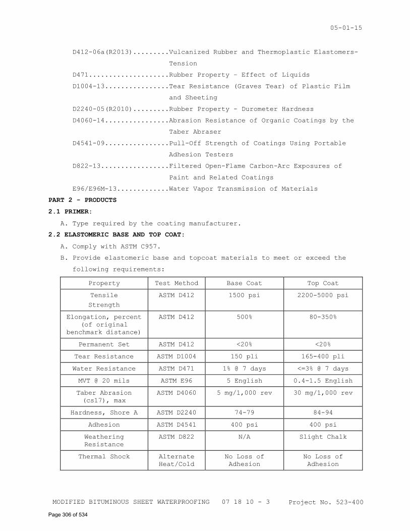
05-01-15
D412-06a(R2013).........Vulcanized Rubber and Thermoplastic Elastomers-
Tension
D471....................Rubber Property – Effect of Liquids
D1004-13................Tear Resistance (Graves Tear) of Plastic Film
and Sheeting
D2240-05(R2010).........Rubber Property - Durometer Hardness
D4060-14................Abrasion Resistance of Organic Coatings by the
Taber Abraser
D4541-09................Pull-Off Strength of Coatings Using Portable
Adhesion Testers
D822-13.................Filtered Open-Flame Carbon-Arc Exposures of
Paint and Related Coatings
E96/E96M-13.............Water Vapor Transmission of Materials
PART 2 - PRODUCTS
2.1 PRIMER:
A. Type required by the coating manufacturer.
2.2 ELASTOMERIC BASE AND TOP COAT:
A. Comply with ASTM C957.
B. Provide elastomeric base and topcoat materials to meet or exceed the
following requirements:
Property Test Method Base Coat Top Coat
Tensile
Strength
ASTM D412 1500 psi 2200-5000 psi
Elongation, percent
(of original
benchmark distance)
ASTM D412 500% 80-350%
Permanent Set ASTM D412 <20% <20%
Tear Resistance ASTM D1004 150 pli 165-400 pli
Water Resistance ASTM D471 1% @ 7 days <=3% @ 7 days
MVT @ 20 mils ASTM E96 5 English 0.4-1.5 English
Taber Abrasion
(cs17), max
ASTM D4060 5 mg/1,000 rev 30 mg/1,000 rev
Hardness, Shore A ASTM D2240 74-79 84-94
Adhesion ASTM D4541 400 psi 400 psi
Weathering
Resistance
ASTM D822 N/A Slight Chalk
Thermal Shock Alternate
Heat/Cold
No Loss of
Adhesion
No Loss of
Adhesion
Project No. 523-400 MODIFIED BITUMINOUS SHEET WATERPROOFING 07 18 10 - 3
Page 306 of 534
05-01-15
2.3 AGGREGATE:
A. Thoroughly washed, clean, medium-grained sharp indigenous stone
granules, graded between 1 mm (.04 inch) and 4 mm (.16 inch) in size,
and having a hardness of 6.5 or greater on the Moh's scale.
2.4 FLASHING/SEALANTS:
A. Flashing Tape: Minimum thickness of 30 mils.
B. Liquid Flashing: per manufacturer.
C. Sealants: per manufacturer.
PART 3 - EXECUTION
3.1 SURFACE PREPARATION:
A. Conduct pre-application inspections surfaces to receive coatings with
authorized manufacturer’s representative.
B. Inspect all joints to ensure there is no deteriorated sealant or
adhesion loss in the joints. Repair all deficient sealant.
C. Shot Blasting: Mechanically prepare surface by shot blasting to
industry standard surface texture (ICRI's CSP3-4) without causing
additional surface defects in deck surface. Shot blasting does not
remove deep penetrating oils, grease, tar or asphalt stains. Proper
cleaning procedures should be followed to insure proper bonding of the
deck coating.
D. Cracks and Cold Joints: Visible hairline cracks (up to 1/16" in width)
in concrete and cold joints shall be cleaned, primed as required and
treated with liquid flashing a minimum distance of 2" on each side of
crack to yield a total thickness of 30 dry mils. Large cracks (over
1/16" in width) shall be routed and sealed with sealant. Sealant shall
be applied to inside area of crack only, not applied to deck surface.
Detail sealed cracks with liquid flashing a distance of 2" on each side
of crack to yield a total thickness of 30 dry mils.
E. Control Joints: Seal secondary control joints with sealant. Sealant
shall be applied to inside area of joint only, not applied to deck
surface. Detail sealed joints with liquid flashing a distance of 2" on
each side of joint to yield a total thickness of 30 dry mils.
F. Flashing Tape: Install flashing tape where indicated on the drawings
prior to the application of elastomeric coating.
G. Surface Condition: Surface shall be clean and dry prior to coating.
H. Fill holes, depressions and cracks with fillers compatible with the
coating material and recommended by the coating manufacturer.
Project No. 523-400 MODIFIED BITUMINOUS SHEET WATERPROOFING 07 18 10 - 4
Page 307 of 534
05-01-15
I. Subsurface imperfections that telegraph through the finish coating
surface are not acceptable.
3.2 WORK COORDINATION:
A. To provide a watertight installation, coordinate this work with
flashing and drains required to be installed before the coating work
begins and be completed after the coating is in place.
3.3 APPLICATION:
A. Prime surfaces to receive elastomeric waterproofing materials as
recommended by the product manufacturer.
B. Where horizontal surfaces intersect vertical surfaces, provide a
sealant type fillet as recommended by the manufacturer.
C. Apply elastomeric base coat at a rate that will ensure a dry film
thickness of not less than that indicated on the drawings.
D. Uniformly disperse aggregate topping at the rate required by the
manufacturer; inter-bond and vulcanize granules within the fluid
elastomeric topping in accordance with manufacturer's instructions.
E. Apply elastomeric top coat at a rate which will ensure a dry film
thickness for the top coat and a total combined dry film thickness for
the base and top coats as indicated on the drawings.
F. Complete the base to a uniform established line as shown.
3.4 CLEANING:
A. Remove smears of elastomeric material from other work.
3.5 PROTECTION:
A. Protect the finished coating from traffic until the coating cures and
afterward until final acceptance.
- - - E N D - - -
Project No. 523-400 MODIFIED BITUMINOUS SHEET WATERPROOFING 07 18 10 - 5
Page 308 of 534
06-01-12
THERMAL INSULATION 07 21 13 - 1 Project No. 523-400
SECTION 07 21 13
THERMAL INSULATION
PART 1 - GENERAL
1.1 DESCRIPTION:
A. This section specifies thermal insulation for buildings.
1.2 RELATED WORK
A. Not applicable.
B. Not applicable.
C. Insulation in connection with roofing and waterproofing: Section 07 22
00, ROOF AND DECK INSULATION.
D. Safing insulation: Section 07 84 00, FIRESTOPPING.
1.3 SUBMITTALS:
A. Submit in accordance with Section 01 33 23, SHOP DRAWINGS, PRODUCT
DATA, AND SAMPLES.
B. Manufacturer's Literature and Data:
1. Insulation, each type used
C. Certificates: Stating the type, thickness and "R" value (thermal
resistance) of the insulation to be installed.
1.4 STORAGE AND HANDLING:
A. Store insulation materials in weathertight enclosure.
B. Protect insulation from damage from handling, weather and construction
operations before, during, and after installation.
1.5 APPLICABLE PUBLICATIONS:
A. The publications listed below form a part of this specification to the
extent referenced. The publications are referenced in the text by basic
designation only.
B. American Society for Testing and Materials (ASTM):
C578-10.................Rigid, Cellular Polystyrene Thermal Insulation
PART 2 - PRODUCTS
2.1 INSULATION – GENERAL:
A. Where thermal resistance ("R" value) is specified or shown for
insulation, the thickness shown on the drawings is nominal. Use only
insulation with actual thickness that is not less than that required to
provide the thermal resistance specified.
B. Where "R" value is not specified for insulation, use the thickness
shown on the drawings.
C. Not applicable.
Page 309 of 534
06-01-12
THERMAL INSULATION 07 21 13 - 2 Project No. 523-400
D. Insulation Products shall comply with following minimum content
standards for recovered materials:
Material Type Percent by Weight
Rigid foam 9 percent recovered material
The minimum-content standards are based on the weight (not the volume)
of the material in the insulating core only.
2.2 MASONRY CAVITY WALL INSULATION:
Not Applicable
2.3 PERIMETER AND UNDER-SLAB INSULATION IN CONTACT WITH SOIL:
A. Polystyrene Board: ASTM C578, Type IV, V, VI, VII, or IX where covered
by soil or concrete.
2.4 FIRE-RESISTANT THERMAL INSULATION:
A. Spray-Applied Insulation: A total system of recycled cellulose
fibers, chemical treatment, adhesive binding system and spray-on
application method, conforming to the following:
1. Flame/Smoke Properties: ASTM E-84/U.L. 723, Tested at a minimum of
5" thickness Class 1, Class A, Flame Spread 5, Smoke Development 5.
2. Product: K-13 by International Cellulose Corporation or equal.
3. R-Value: Approximately 3.8 per inch.
4. Application: Insulation at the underside of precast parking deck
system at utility rooms.
PART 3 - EXECUTION
3.1 INSTALLATION - GENERAL
A. Not applicable.
B. Install rigid insulating units with joints close and flush, in regular
courses and with cross joints broken.
3.2 MASONRY CAVITY WALLS:
Not Applicable
3.3 PERIMETER AND UNDER-SLAB INSULATION:
A. Not applicable.
B. Horizontal insulation under concrete floor slab:
1. Lay insulation boards and blocks horizontally on level, compacted
and drained fill.
2. Extend insulation as shown.
Page 310 of 534
06-01-12
THERMAL INSULATION 07 21 13 - 3 Project No. 523-400
3.4 FIRE-RESISTANT AND THERMAL INSULATION:
A. Apply spray-applied insulation according to manufacturer's written
instructions to a thickness of 3 inches. Do not apply insulation until
installation of pipes, ducts, conduits, wiring, and electrical outlets
in walls is completed and electrical boxes, and other items not
indicated to receive insulation are masked.
- - - E N D - - -
Page 311 of 534
10-10
ROOF AND DECK INSULATION 07 22 00 - 1 Project No. 523-400
SECTION 07 22 00
ROOF AND DECK INSULATION
PART 1 - GENERAL
1.1 DESCRIPTION
A. Roof and deck insulation, and cover board on new construction ready to
receive roofing or waterproofing membrane.
1.2 RELATED WORK
A. Not applicable.
B. Not applicable.
C. Wood cants, blocking, and edge strips: Section 06 10 00, ROUGH
CARPENTRY.
D. Perimeter, rigid, and batt or blanket insulation not part of roofing
system: Section 07 21 13, THERMAL INSULATION.
E. Sheet metal components and wind uplift requirements for roof-edge
design: Section 07 60 00, FLASHING AND SHEET METAL.
1.3 APPLICABLE PUBLICATIONS
A. Publications listed below form a part of this specification to the
extent referenced. Publications are referenced in the text by the basic
designation only. Editions of applicable publications current on date
of issue of bidding documents apply unless otherwise indicated.
B. ASTM International (ASTM):
C208-08.................Cellulosic Fiber Insulating Board
C1289-10................Faced Rigid Cellular Polyisocyanurate Thermal
Insulation Board
D41-05..................Asphalt Primer Used in Roofing, Dampproofing,
and Waterproofing
E84-09..................Standard Test Method for Surface Burning
Characteristics of Building Material
F1667-05................Driven Fasteners: Nails, Spikes, and Staples
C. FM Approvals: RoofNav Approved Roofing Assemblies and Products.
4450-89.................Approved Standard for Class 1 Insulated Steel
Deck Roofs
4470-10.................Approved Standard for Class 1 Roof Coverings
D. National Roofing Contractors Association: Roofing and Waterproofing
Manual
E. Underwriters Laboratories, Inc. (UL): Fire Resistance Directory (2009)
Page 312 of 534
10-10
ROOF AND DECK INSULATION 07 22 00 - 2 Project No. 523-400
1.4 PERFORMANCE REQUIREMENTS
A. Thermal Performance: Provide roof insulation meeting minimum overall
average R-value of 33, with minimum R-value at any location of 10.
B. FM Approvals: Provide roof insulation complying with requirements in
FM Approvals 4450 and 4470 as part of specified roofing system, listed
in FM Approvals "RoofNav" as part of roofing system meeting
Fire/Windstorm Classification in Division 07 roofing section.
1.5 QUALITY CONTROL
A. Requirements of Division 07 roofing section for qualifications of
roofing system insulation Installer; Work of this Section shall be
performed by same Installer.
B. Requirements of Division 07 roofing section for inspection of Work of
this Section and qualifications of Inspector.
C. Unless specified otherwise, comply with the recommendations of the NRCA
"Roofing and Waterproofing Manual" applicable to insulation for
storage, handling, and application.
D. Requirements of roofing system uplift pressure design for specified
roofing system.
E. Requirements of applicable FM Approval for specified roofing system
insulation attachment.
1.6 SUBMITTALS
A. Submit in accordance with Section 01 33 23, SHOP DRAWINGS, PRODUCT
DATA, AND SAMPLES.
B. Product Data:
1. Not applicable.
2. Roofing cement, each type.
3. Roof insulation, each type.
4. Not applicable.
5. Cover board, each type.
6. Fastening requirements.
7. Insulation span data for flutes of metal decks.
C. Not applicable.
D. Shop Drawings: Include plans, sections, details, and attachments.
1. Nailers, cants, and terminations.
2. Layout of insulation showing slopes, tapers, penetration, and edge
conditions.
E. Samples:
Page 313 of 534
10-10
ROOF AND DECK INSULATION 07 22 00 - 3 Project No. 523-400
1. Roof insulation, each type.
2. Nails and fasteners, each type.
F. Certificates:
1. Indicating type, thermal conductance, and minimum and average
thickness of insulation.
2. Indicating materials and method of application of insulation system
meet the requirements of FM Approvals for specified roofing system.
G. Laboratory Test Reports: Thermal values of insulation products.
H. Layout of tapered roof system showing units required.
I. Documentation of supervisors' and inspectors' qualifications.
1.7 DELIVERY, STORAGE AND MARKING
A. Comply with the recommendations of the NRCA "Roofing and Waterproofing
Manual" applicable to built-up roofing for storage, handling and
installation requirements.
1.8 QUALITY ASSURANCE:
A. Roof insulation on combustible or steel decks shall have a flame spread
rating not greater than 75 and a smoke developed rating not greater
than 150, exclusive of covering, when tested in accordance with ASTM
E84, or shall have successfully passed FM Approvals 4450.
1. Insulation bearing the UL label and listed in the UL Building
Materials Directory as meeting the flame spread and smoke developed
ratings will be accepted in-lieu-of copies of test reports.
2. Compliance with flame spread and smoke developed ratings will not be
required when insulation has been tested as part of a roof
construction assembly of the particular type used for this project
and the construction is listed as fire-classified in the UL Building
Materials Directory or listed as Class I roof deck construction in
the FM Approvals "RoofNav."
3. Insulation tested as part of a roof construction assembly shall bear
UL or FM labels attesting to the ratings specified herein.
PART 2 - PRODUCTS
2.1 ADHESIVE MATERIALS
A. Adhesive Materials, General: Adhesive and sealant materials
recommended by roofing system manufacturer for intended use, identical
to materials utilized in approved listed roofing system, and compatible
with roofing membrane.
Page 314 of 534
10-10
ROOF AND DECK INSULATION 07 22 00 - 4 Project No. 523-400
1. Liquid-type adhesive materials shall comply with VOC limits of
authorities having jurisdiction.
2. Adhesives and sealants that are not on the exterior side of weather
barrier shall comply with the following limits for VOC content when
calculated according to 40 CFR 59, Subpart D (EPA Method 24):
a. Plastic Foam Adhesives: 50 g/L.
b. Multipurpose Construction Adhesives: 70 g/L.
c. Fiberglass Adhesives: 80 g/L.
d. Contact Adhesives: 80 g/L.
e. Other Adhesives: 250 g/L.
f. Nonmembrane Roof Sealants: 300 g/L.
g. Sealant Primers for Nonporous Substrates: 250 g/L.
h. Sealant Primers for Porous Substrates: 775 g/L.
B. Primer: ASTM D41.
2.2 ROOF AND DECK INSULATION
A. Roof and Deck Insulation, General: Preformed roof insulation boards
approved by roofing manufacturer and listed as component of FM
Approvals-approved roofing system.
B. Polyisocyanurate Board Insulation: ASTM C1289, Type II, Class 1, Grade
2, felt or glass-fiber mat facer on both major surfaces.
C. Not applicable.
D. Not applicable.
E. Not applicable.
F. Tapered Roof Insulation System:
1. Fabricate of mineral fiberboard, polyisocyanurate, perlite board, or
cellular glass. Use only one insulation material for tapered
sections. Use only factory-tapered insulation.
2. Cut to provide high and low points with crickets and slopes as
shown.
3. Minimum thickness of tapered sections; 38 mm (1-1/2 inch).
4. Minimum slope 1:48 (1/4 inch per 12 inches).
2.3 INSULATION ACCESSORIES
A. Not applicable.
B. Cants and Tapered Edge Strips:
1. Not applicable.
2. Insulation Cant Strips: ASTM C208, Type II, Grade 1, cellulosic-
fiber insulation board.
Page 315 of 534
10-10
ROOF AND DECK INSULATION 07 22 00 - 5 Project No. 523-400
C. Not applicable.
D. Not applicable.
E. Cover Board:
1. Not applicable.
2. Not applicable.
3. Cellulosic-fiber insulation board, ASTM C208, Type II, Grade 2, 13
mm (1/2 inch) thick.
2.4 FASTENERS
A. Fasteners: Factory-coated steel fasteners and metal or plastic plates
complying with FM Approvals 4470, designed for fastening substrate
board to roof deck.
B. Staples and Nails: ASTM F1667. Type as designated for item anchored and
for substrate.
PART 3 - EXECUTION
3.1 EXAMINATION
A. Comply with requirements of Division 07 roofing section.
3.2 PREPARATION
A. Comply with requirements of Division 07 roofing section.
3.3 SUBSTRATE BOARD INSTALLATION
Not Applicable
3.4 VAPOR RETARDER INSTALLATION
Not Applicable
3.5 RIGID INSULATION INSTALLATION
A. Insulation Installation, General:
1. Install roof insulation in accordance with roofing system
manufacturer's written instructions.
2. Install roof insulation in accordance with requirements of FM
Approval's Listing for specified roofing system.
3. Not applicable.
4. Cant Strips: Install preformed insulation cant strips at junctures
of roofing system with vertical construction.
B. Insulation Thickness:
1. Thickness of roof insulation shown on drawings is nominal. Actual
thickness shall provide the average thermal resistance "R" value of
not less than that specified in Performance Requirements Article.
Page 316 of 534
10-10
ROOF AND DECK INSULATION 07 22 00 - 6 Project No. 523-400
2. Insulation on Metal Decks: Provide minimum thickness of insulation
for metal decks recommended by the insulation manufacturer to span
rib opening (flute size) of metal deck used. Support edges of
insulation on metal deck ribs.
3. When thickness of insulation to be used is more or less than that
shown on the drawings, make adjustments in the alignment and
location of roof drains, flashing, gravel stops, fascias and similar
items at no additional cost to the Government.
4. Where tapered insulation is used, the thickness of the insulation at
high points and roof edges shall be as shown on the drawings; the
thickness at the low point (drains) shall be not less than 38 mm
(1-1/2 inches).
5. Use not less than two layers of insulation when insulation is 68 mm
(2.7 inch) or more in thickness unless specified otherwise. Stagger
joints minimum 150 mm (6 inches).
C. Lay insulating units with close joints, in regular courses and with
cross joints broken. When laid in more than one layer, break joints of
succeeding layers of roof insulation with those in preceding layer.
D. Not applicable.
E. Not applicable.
F. Cut to fit tight against blocking or penetrations.
G. Cover all insulation installed on the same day; comply with temporary
protection requirements of Division 07 roofing section.
H. Installation Method:
1. Not applicable.
2. Mechanically Fastened Insulation:
a. Fasten insulation in accordance with FM Approval's "RoofNav"
requirement in Division 07 roofing section.
b. Fasten insulation to resist uplift pressures specified in
Division 07 roofing section.
3. Not applicable.
4. Cover Board: Install cover boards over insulation with long joints
in continuous straight lines with staggered end joints. Offset
cover board joints from insulation joints minimum 150 mm (6 inches).
Fasten cover boards according to "Mechanically Fastened Insulation"
requirements.
- - - E N D - - -
Page 317 of 534
10-11
EPDM ROOFING 07 53 23 - 1 Project No. 523-400
SECTION 07 53 23
ETHYLENE-PROPYLENE-DIENE-MONOMER ROOFING
PART 1 GENERAL
1.1 DESCRIPTION
A. Ethylene Propylene Diene Monomer (EPDM) sheet roofing adhered to roof
deck.
1.2 RELATED WORK
A. Treated wood framing, blocking, and nailers: Section 06 10 00, ROUGH
CARPENTRY.
B. Roof Insulation: Section 07 22 00, ROOF AND DECK INSULATION.
C. Metal cap flashings, copings, fascias, and expansion joints: Section 07
60 00, FLASHING AND SHEET METAL.
1.3 QUALITY ASSURANCE
A. Approved applicator by the membrane roofing system manufacturer, and
certified by the manufacturer as having the necessary expertise to
install the specific system.
B. Pre-Roofing Meeting:
1. Upon completion of roof deck installation and prior to any roofing
application, hold a pre-roofing meeting arranged by the Contractor
and attended by the Roofing Inspector, Material Manufacturers
Technical Representative, Roofing Applicator, Contractor, and
Resident Engineer,
2. Discuss specific expectations and responsibilities, construction
procedures, specification requirements, application, environmental
conditions, job and surface readiness, material storage, and
protection.
3. Inspect roof deck at this time to:
a. Verify that work of other trades which penetrates roof deck is
completed.
b. Determine adequacy of deck anchorage, presence of foreign
material, moisture and unlevel surfaces, or other conditions that
would prevent application of roofing system from commencing or
cause a roof failure.
c. Examine samples and installation instructions of manufacturer.
d. Perform pull out test of fasteners (See paragraph 3.2).
1.4 SUBMITTALS
A. Submit in accordance with Section 01 33 23, SHOP DRAWINGS, PRODUCT DATA,
AND SAMPLES.
B. Applicators approval certification by manufacturer.
C. Shop Drawings:
Page 318 of 534
10-11
EPDM ROOFING 07 53 23 - 2 Project No. 523-400
1. Sheet membrane layout.
2. Fastener pattern, layout, and spacing requirements.
3. Termination details.
D. Manufacturers installation instructions revised for project.
E. Samples:
1. Sheet membrane: One 150 mm (6 inch) square piece.
2. Sheet flashing: One 150 mm (6 inch) square piece.
3. Fasteners: Two, each type.
1.5 DELIVERY, STORAGE AND HANDLING
A. Deliver, store, and handle materials as specified by manufacturer.
B. Store volatile materials separate from other materials with separation
to prevent fire from damaging the work, or other materials.
1.6 WARRANTY
Roofing work subject to the terms of the Construction Contract Article
“Warranty of Construction”, except extend the warranty period to five
years.
1.7 APPLICABLE PUBLICATIONS
A. Publications listed below form a part of this specification to the
extent referenced. Publications are referenced in the text by the basic
designation only.
B. American Society for Testing and Materials (ASTM):
A167-99(R2009)..........Stainless and Heat-Resisting Chromium-Nickel
Steel Plate, Sheet and Strip
B209-07.................Aluminum and Aluminum-Alloy Sheet and Plate
D2240-05(R2010).........Rubber Property - Durometer Hardness
D4637-10................EPDM Sheet Used in Single-Ply Roof Membrane
E96-10..................Water Vapor Transmission of Materials
E108-10.................Fire Tests of Roof Coverings
G21-09..................Resistance of Synthetic Polymeric Materials to
Fungi
C. National Roofing Contractors Association (NRCA):
Fifth Edition - 05......The NRCA Roofing and Waterproofing Manual.
D. Federal Specifications (Fed. Spec.)
FF-S-107C(2)............Screws, Tapping and Drive
FF-S-111D(1)............Screw, Wood
E. Factory Mutual Engineering and Research Corporation (FM):
Annual Issue............Approval Guide Building Materials
F. Underwriters Laboratories, Inc (UL):
Annual Issue............Building Materials Directory
Annual Issue............Fire Resistance Directory
G. Warnock Hersey (WH):
Page 319 of 534
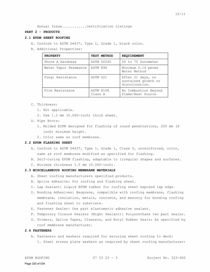
10-11
EPDM ROOFING 07 53 23 - 3 Project No. 523-400
Annual Issue............Certification Listings
PART 2 - PRODUCTS
2.1 EPDM SHEET ROOFING
A. Conform to ASTM D4637, Type I, Grade 1, black color.
B. Additional Properties:
PROPERTY TEST METHOD REQUIREMENT
Shore A Hardness ASTM D2240 55 to 75 Durometer
Water Vapor Permeance ASTM E96 Minimum 0.14 perms
Water Method
Fungi Resistance ASTM G21 After 21 days, no
sustained growth or
discoloration.
Fire Resistance ASTM E108
Class A
No Combustion Beyond
Flame/Heat Source
C. Thickness:
1. Not applicable.
2. Use 1.5 mm (0.060-inch) thick sheet.
D. Pipe Boots:
1. Molded EDPM designed for flashing of round penetrations, 200 mm (8
inch) minimum height.
2. Color same as roof membrane.
2.2 EPDM FLASHING SHEET
A. Conform to ASTM D4637, Type I, Grade 1, Class U, unreinforced, color,
same as roof membrane modified as specified for flashing.
B. Self-curing EPDM flashing, adaptable to irregular shapes and surfaces.
C. Minimum thickness 1.5 mm (0.060-inch).
2.3 MISCELLANEOUS ROOFING MEMBRANE MATERIALS
A. Sheet roofing manufacturers specified products.
B. Splice Adhesive: For roofing and flashing sheet.
C. Lap Sealant: Liquid EPDM rubber for roofing sheet exposed lap edge.
D. Bonding Adhesives: Neoprene, compatible with roofing membrane, flashing
membrane, insulation, metals, concrete, and masonry for bonding roofing
and flashing sheet to substrate.
E. Fastener Sealer: One part elastomeric adhesive sealant.
F. Temporary Closure Sealers (Night Sealant): Polyurethane two part sealer.
G. Primers, Splice Tapes, Cleaners, and Butyl Rubber Seals: As specified by
roof membrane manufacturer.
2.4 FASTENERS
A. Fasteners and washers required for securing sheet roofing to deck:
1. Steel stress plate washers as required by sheet roofing manufacturer:
Page 320 of 534
10-11
EPDM ROOFING 07 53 23 - 4 Project No. 523-400
a. Coated against corrosion.
b. Separate or attached to fastener.
c. Approximately 50 mm (2 inch) diameter or 40 mm x 65 mm (1-1/2 by
2-1/2 inches) rectangular plate with rounded corners, minimum
thickness 0.6 mm (0.023-inch).
2. Fastening strip or batten strip for securing roof membrane to deck:
a. Stainless steel strip: ASTM A167 type 302 or 304, minimum 0.5 mm
(0.018-inch) thick.
b. Aluminum strip: ASTM B209, minimum 2.4 mm (0.094-inch) thick.
c. Rounded corners on strips.
d. Form strips 38 mm (1-1/2 inches) wide, 3000 mm (10 feet) maximum
length with 6 mm x 10 mm (1/4 by 3/8 inch) punched slotted holes
at 100 mm (4 inch) centers; centered on width of strip. Punch
holes 2 mm (1/16 inch) larger than fastener shank when shank is
larger than 5 mm (3/16 inch).
3. Steel decks: Screws; Fed Spec FF-S-107, hardened nylon screw or steel
screw coated to resist corrosion, self drilling, anti-backout thread
design. Minimum pullout resistance of 135 Kg (300 pounds), minimum
thread penetration of 13 mm (1/2 inch).
4. Not applicable.
5. Not applicable.
6. Wood:
a. Screws; Fed. Spec. FF-S-111, Type I, Style 2.5, coated to resist
corrosion, length to provide 19 mm (3/4 inch) minimum penetration.
b. Nails: Barbed shank, galvanized.
7. Washers: Neoprene backed metal washer 28 mm (1-1/8 inch) minimum
diameter.
8. To Sheet Metal: Self tapping screw; Fed. Spec. FF-S-107, 2 mm (No.
14), sheet metal screw, minimum thread penetration of 6 mm (1/4
inch); stainless steel.
B. Pipe Compression Clamp or Drawband:
1. Stainless steel or cadmium plated steel drawband.
2. Worm drive clamp device.
C. Surface mounted base flashing clamp strip:
1. Stainless steel strip, ASTM A167, type 302 or 304, dead soft temper,
minimum 0.5 mm (0.018-inch) thick.
2. Aluminum strip: ASTM B209 24 mm (.094-inch) thick.
3. For exposed location, form strips with 6 mm (1/4 inch) wide top edge
bent out 45 degrees (for sealant) from 40 mm (1-1/2 inch) wide
material; 2400 mm (8 feet) maximum length with slotted 6 mm x 10 mm
Page 321 of 534
10-11
EPDM ROOFING 07 53 23 - 5 Project No. 523-400
(1/4 by 3/8-inch) holes punched at 200 mm (8 inch) centers, centered
between bend and bottom edges.
4. For locations covered by cap flashings, form strips 30 mm (1-1/4
inch) wide, 2400 mm (8 feet) maximum length with slotted holes 6 mm x
10 mm (1/4 by 3/8 inch) punched at 200 mm (8 inch) centers, centered
on strip width.
D. Fasteners and washers required for securing pavers together with straps
and to walls or other anchorage.
1. Straps for securing pavers together:
a. Stainless steel strap: ASTM A167, type 302 or 304, minimum 0.46 mm
(0.018 inch) thick.
b. Aluminum strap: ASTM B209, minimum 2.39 mm (0.094 inch) thick.
c. Rounded corners on straps.
d. Form straps 38 mm 91-1/2 inches) wide, 3 m (10 feet) maximum
length with 6 by 10 mm (1/4 by 3/8 inch) punched slotted holes at
100 mm (4 inch centers centered on width of strap. Punch hole size
2 mm (1/16 inch) larger than fastener shank when shank is thicker
than 5 mm (3/16 inch).
2.5 VAPOR RETARDER OR SEPARATION SHEETS
Not Applicable
2.6 FLEXIBLE TUBING
Not Applicable
2.7 WALKWAY PADS
Not Applicable
2.8 PROTECTION MAT OR SEPARATION SHEETS
Not Applicable
2.9 BALLAST AND PAVERS
Not Applicable
PART 3 - EXECUTION
3.1 GENERAL
A. Do not apply if deck will be used for subsequent work platform, storage
of materials, or staging or scaffolding will be erected thereon unless
protection provided to distribute loads less than one-half compression
resistance of roofing system materials.
1. Curbs, blocking, edge strips, and other components to which roofing
and base flashing is attached in place ready to receive insulation
and, roofing.
2. Coordinate roof operation with sheet metal work and roof insulation
work so that insulation and flashing are installed concurrently to
permit continuous roofing operations.
Page 322 of 534
10-11
EPDM ROOFING 07 53 23 - 6 Project No. 523-400
3. Complete installation of flashing, insulation, and roofing in the
same day except for the area where temporary protection is required
when work is stopped.
B. Phased construction is not permitted. The complete installation of
roofing system is required in the same day except for area where
temporary protection is required when work is stopped. Complete
installation includes pavers and ballast for ballasted systems.
C. Dry out surfaces, including the flutes of metal deck, that become wet
from any cause during progress of the work before roofing work is
resumed.
D. Apply materials only to dry substrates.
E. Except for temporary protection specified, do not apply materials during
damp or rainy weather, during excessive wind conditions, nor while
moisture (dew, snow, fog, ice, or frost) is present in any amount in or
on the materials.
1. Do not apply materials to substrate having temperature of 4°C (40
degrees F) or less, or when materials applied with the roof require
higher application temperature.
2. Do not apply materials when the temperature is below 4°C (40 degrees
F).
F. Temporary Protection:
1. Install temporary protection consisting of a temporary seal and water
cut-offs at the end of each day's work and when work is halted for an
indefinite period or work is stopped when precipitation is imminent.
2. Temporarily seal exposed surfaces of insulation within the roofing
membrane.
3. Do not leave insulation surfaces or edges exposed.
4. Use polyethylene film or building paper to separate roof sheet from
bituminous materials.
5. Apply the temporary seal and water cut off by extending the roof
membrane beyond the insulation and securely embedding the edge of the
roof membrane in 6 mm (1/4 inch) thick by 50 mm (2 inches) wide strip
of temporary closure sealant (night sealant) and weight edge with
sandbags, to prevent displacement; space sandbags not over 2400 mm (8
foot) centers. Check daily to insure temporary seal remains
watertight. Reseal open areas and weight down.
6. Before the work resumes, cut off and discard portions of the roof
membrane in contact with roof cement or bituminous materials.
a. Cut not less than 150 mm (6 inches) back from bituminous coated
edges or surfaces.
b. Remove temporary polyethylene film or building paper.
Page 323 of 534
10-11
EPDM ROOFING 07 53 23 - 7 Project No. 523-400
7. Remove and discard sandbags contaminated with bituminous products.
8. For roof areas that are to remain intact and that are subject to foot
traffic and damage, provide temporary wood walkways with notches in
sleepers to permit free drainage.
9. Provide 2 mm (6 mil) polyethylene sheeting or building paper cover
over roofing membrane under temporary wood walkways and adjacent
areas. Round all edges and corners of wood bearing on roof surface.
3.2 PREPARATION
A. Test pull out resistance of fasteners in deck in the presence of the
Resident Engineer before starting roofing work. Tests are not required
for wood.
1. Test applicable fastener type in applicable deck.
2. Install fasteners through a sample of the insulation, if any is to be
used, into the structural deck.
3. Test the pull out resistance with a pull out tester.
4. Test one fastener in each deck level and one for every 230 m² (2500
square feet) of deck type and level.
5. Test at locations designated by Resident Engineer.
6. Do not proceed with the roofing work if the pull out resistance of
the fasteners is less than specified.
7. Test results:
a. Repeat tests using other type fasteners or use additional
fasteners to stay within the pullout load resistance criteria.
B. Remove dirt, debris, and surface moisture. Cover or fill voids greater
than 6 mm (1/4 inch) wide to provide solid support for roof membrane.
C. Install separation sheet over bituminous material on deck surface
lapping edges and ends 150 mm (6 inches) or as recommended by roof
membrane manufacturer.
1. Do not install of separation sheet beyond what can be covered by
roofing membrane each day.
2. Use polyethylene, or building paper, that will be compatible with
seaming method.
3. Insure separation sheet completely isolates bituminous materials from
EPDM roofing membrane.
4. Turn up at penetrations, or other surfaces where bituminous materials
occur, to cover bituminous product.
5. Turn down over edges of blocking at perimeters to cover blocking.
3.3 INSTALLATION OF ROOFING AND FLASHING
A. Do not allow the membrane to come in contact with surfaces contaminated
with asphalt, coal tar, oil, grease, or other substances which are not
compatible with EPDM roofing membrane.
Page 324 of 534
10-11
EPDM ROOFING 07 53 23 - 8 Project No. 523-400
B. If possible, install the membrane so the sheets run perpendicular to the
long dimension of the insulation boards.
C. If possible, start at the low point of the roof and work towards the
high point. Lap the sheets so the flow of water is not against the edges
of the sheet. Coordinate with roof insulation installation.
D. Position the membrane so it is free of buckles and wrinkles.
E. Roll sheet out on deck; inspect for defects as sheet is being rolled out
and remove defective areas:
1. Allow 30 minutes for relaxing before proceeding.
2. Lap edges and ends of sheets 75 mm (3 inches) or more as recommended
by the manufacturer. Clean lap surfaces as specified by manufacturer.
3. Adhesively splice laps. Apply pressure as required. Seam strength of
laps as required by ASTM D4637.
4. Check seams to ensure continuous adhesion and correct defects.
5. Finish edges of laps with a continuous beveled bead of lap sealant to
sheet edges to provide smooth transition as specified by
manufacturer.
6. Finish seams as the membrane is being installed (same day).
7. Anchor perimeter to deck or wall as specified.
F. Membrane Perimeter Anchorage:
1. Install batten strip or steel stress plate with fasteners at the
perimeter of each roof level, curb flashing, expansion joints and
similar penetrations as indicated in accordance with membrane
manufacturer's instructions on top of roof membrane to wall or deck.
2. Mechanically fastened as follows:
a. Top of mechanical fastener set flush with top surface of the
nailing strip or stress plate.
b. Space mechanical fasteners a maximum 300 mm (12 inches) on center.
c. Start 25 mm (1 inch) from the end of the nailing strip when used.
d. When strip is cut round edge and corners before installing.
e. Set fasteners in lap sealant and cover fastener head with fastener
sealer including batten strip or stress plate.
f. Stop fastening strip where the use of the nailing strip interferes
with the flow of the surface water, separate by a 150 mm (6 inch)
space, then start again.
g. After mechanically fastening cover and seal with a 225 mm (9 inch)
wide strip of flashing sheet. Use splice adhesive on all laps and
finish edge with sealant as specified.
h. At gravel stops turn the membrane down over the front edge of the
blocking, cant, or the nailer to below blocking. Secure the
Page 325 of 534
10-11
EPDM ROOFING 07 53 23 - 9 Project No. 523-400
membrane to the vertical portion of the nailer; with fasteners
spaced not over 150 mm (6 inches) on centers.
i. At parapet walls intersecting building walls and curbs, secure the
membrane to the structural deck with fasteners 150 mm (6 inches)
on center or as shown in NRCA manual (Fifth Edition)
G. Adhered System:
1. Apply bonding adhesive in quantities required by roof membrane
manufacturer.
2. Fold sheet back on itself, clean and coat the bottom side of the
membrane and the top of the deck with adhesive. Do not coat the lap
joint area.
3. After adhesive has set according to adhesive manufacturer's
application instruction, roll the membrane into the adhesive in
manner that minimizes voids and wrinkles.
4. Repeat for other half of sheet. Cut voids and wrinkles to lay flat
and clean for repair patch over cut area.
H. Not applicable.
J. Flashing Roof Drains:
1. Install roof drain flashing as recommended by the membrane
manufacturer, generally as follows:
a. Coordinate to set the metal drain flashing in asphalt roof cement,
holding cement back from the edge of the metal flange.
b. Do not allow the roof cement to come in contact with the EPDM roof
membrane.
c. Adhere the EPDM roof membrane to the metal flashing with the
membrane manufacturer's recommended bonding adhesive.
2. Turn down the metal drain flashing and EPDM roof membrane into the
drain body and install clamping ring and stainer.
M. Installing EPDM Base Flashing and Pipe Flashing:
1. Install EPDM flashing membranes to pipes, walls or curbs to a height
not less than 200 mm (8 inches) above roof surfaces and 100 mm (4
inches) on roof membranes. Install in accordance with NRCA manual:
a. Adhere flashing to pipe, wall or curb with bonding adhesive.
b. Form inside and outside corners of EPDM flashing membrane in
accordance with NRCA manual (Fifth Edition). Form pipe flashing in
accordance with NRCA manual (Fifth Edition).
c. Lap ends not less than 100 mm (4 inches).
d. Adhesively splice flashing membranes together and flashing
membranes to roof membranes. Finish exposed edges with sealant as
specified.
Page 326 of 534
10-11
EPDM ROOFING 07 53 23 - 10 Project No. 523-400
2. Anchor top of flashing to walls or curbs with fasteners spaced not
over 150 mm (6 inches) on center. Use surface mounted fastening strip
with sealant on ducts. Use pipe clamps on pipes or other round
penetrations.
3. Apply sealant to top edge of flashing.
N. Not applicable.
O. Repairs to membrane and flashings:
1. Remove sections of EPDM sheet roofing or flashing that is creased
wrinkled or fishmouthed.
2. Cover removed areas, cuts and damaged areas with a patch extending
100 mm (4 inches) beyond damaged, cut, or removed area. Adhesively
splice to roof membrane or flashing. Finish edge of lap with sealant
as specified.
3.4 INSTALLATION OF BALLAST SYSTEM AND PAVERS
Not Applicable
3.5 WALKWAY PADS
Not Applicable
3.6 FIELD QUALITY CONTROL
A. Examine and probe seams in the membrane and flashing in the presence of
the Resident Engineer and Membrane Manufacturer's Inspector.
B. Probe the edges of welded seams with a blunt tipped instrument. Use
sufficient hand pressure to detect marginal bonds, voids, skips, and
fishmouths.
C. Cut 100 mm (4 inch) wide by 300 mm (12 inch) long samples through the
seams where directed by the Resident Engineer.
1. Cut one sample for every 450 m (1500 linear feet) of seams.
2. Cut the samples perpendicular to the longitudinal direction of the
seams.
3. Failure of the samples to maintain the standard of quality within a
reasonable tolerance of the approved samples will be cause for
rejection of the work.
D. Repair areas of welded seams where samples have been taken or marginal
bond voids or skips occur.
E. Repair fishmouths and wrinkles by cutting to lay flat and installing
patch over cut area extending 100 mm (4 inches) beyond cut.
3.7 TEMPORARY ROOF
A. Install temporary roof when sequences of work or weather does not permit
installation of a completed permanent roof system or roof would be
subject to phasing of roof work, construction traffic, scaffolds, and
work over roof area.
Page 327 of 534
10-11
EPDM ROOFING 07 53 23 - 11 Project No. 523-400
B. Use of 1.15 mm (0.045-inch) thick non-reinforced EPDM membrane or other
temporary membrane as approved.
C. Install not less than 6 mm (1/4 inch) thick plywood underlayment over
steel decks before installing temporary roof.
D. Secure membrane to deck with mechanical fasteners or temporary ballast
not exceeding deck dead load capacity.
E. Repair cuts, tears, and punctures with patches to keep system
watertight.
F. Install permanent roof system within one year.
- - - E N D - - -
Page 328 of 534
12-01-13
FLASHING AND SHEET METAL 07 60 00 - 1 Project No. 523-400
SECTION 07 60 00
FLASHING AND SHEET METAL
PART 1 - GENERAL
1.1 DESCRIPTION
Formed sheet metal work for wall and roof flashing, roof edge metal,
fasciae are specified in this section.
1.2 RELATED WORK
A. Not applicable.
B. Not applicable.
C. Not applicable.
D. Joint Sealants: Section 07 92 00, JOINT SEALANTS.
E. Color of factory coated exterior architectural metal and anodized
aluminum items: Section 09 06 00, SCHEDULE FOR FINISHES.
F. Not applicable.
G. Not applicable.
H. Not applicable.
I. Flashing of Roof Drains: Section 22 14 00, FACILITY STORM DRAINAGE.
1.3 APPLICABLE PUBLICATIONS
A. Publications listed below form a part of this specification to the
extent referenced. Publications are referenced in the text by the basic
designation only. Editions of applicable publications current on date
of issue of bidding documents apply unless otherwise indicated.
B. Aluminum Association (AA):
AA-C22A42...............Chemically etched medium matte, with integrally
colored anodic coating, Class I Architectural,
0.7 mils thick
C. American National Standards Institute/Single-Ply Roofing Institute
(ANSI/SPRI):
ANSI/SPRI ES-1-03.......Wind Design Standard for Edge Systems Used with
Low Slope Roofing Systems
D. ASTM International (ASTM):
A653/A653M-11...........Steel Sheet Zinc-Coated (Galvanized) or Zinc
Alloy Coated (Galvanized) by the Hot- Dip
Process
B209-10.................Aluminum and Aluminum-Alloy Sheet and Plate
Page 329 of 534
12-01-13
FLASHING AND SHEET METAL 07 60 00 - 2 Project No. 523-400
D1187-97(R2011).........Asphalt Base Emulsions for Use as Protective
Coatings for Metal
E. Sheet Metal and Air Conditioning Contractors National Association
(SMACNA): Architectural Sheet Metal Manual.
F. National Association of Architectural Metal Manufacturers (NAAMM):
AMP 500-06..............Metal Finishes Manual
G. Federal Specification (Fed. Spec):
A-A-1925A...............Shield, Expansion; (Nail Anchors)
UU-B-790A...............Building Paper, Vegetable Fiber
H. International Code Commission (ICC): International Building Code,
Current Edition
1.4 PERFORMANCE REQUIREMENTS
A. Wind Uplift Forces: Resist the following forces per FM Approvals 1-49:
1. Not applicable.
2. Not applicable.
3. Wind Zone 2: 1.48 to 2.15 kPa (31 to 45 lbf/sq. ft.): 4.31-kPa
(90-lbf/sq. ft.) perimeter uplift force, 5.74-kPa (120-lbf/sq. ft.)
corner uplift force, and 2.15-kPa (45-lbf/sq. ft.) outward force.
4. Not applicable.
B. Wind Design Standard: Fabricate and install roof-edge flashings tested
per ANSI/SPRI ES-1 to resist design pressure indicated on Drawings.
1.5 SUBMITTALS
A. Submit in accordance with Section 01 33 23, SHOP DRAWINGS, PRODUCT
DATA, AND SAMPLES.
B. Shop Drawings: For all specified items, including:
1. Flashings
2. Not applicable
3. Gravel Stop-Fascia
C. Manufacturer's Literature and Data: For all specified items.
D. Certificates: Indicating compliance with specified finishing
requirements, from applicator and contractor.
PART 2 - PRODUCTS
2.1 FLASHING AND SHEET METAL MATERIALS
A. Not applicable.
B. Not applicable.
Page 330 of 534
12-01-13
FLASHING AND SHEET METAL 07 60 00 - 3 Project No. 523-400
C. Not applicable.
D. Not applicable.
E. Not applicable.
F. Aluminum Sheet: ASTM B209, alloy 3003-H14 except alloy used for color
anodized aluminum shall be as required to produce specified color.
Alloy required to produce specified color shall have the same
structural properties as alloy 3003-H14.
G. Galvanized Sheet: ASTM, A653.
2.2 FLASHING ACCESSORIES
A. Not applicable.
B. Rosin Paper: Fed-Spec. UU-B-790, Type I, Grade D, Style 1b, Rosin-sized
sheathing paper, weighing approximately 3 Kg/10 m²( 6 lbs/100 sf).
C. Bituminous Paint: ASTM D1187, Type I.
D. Fasteners:
1. Use stainless steel for aluminum alloy. Use galvanized steel or
stainless steel for galvanized steel.
2. Nails:
a. Minimum diameter for copper nails: 3 mm (0.109 inch).
b. Minimum diameter for aluminum nails 3 mm (0.105 inch).
c. Minimum diameter for stainless steel nails: 2 mm (0.095 inch) and
annular threaded.
d. Length to provide not less than 22 mm (7/8 inch) penetration into
anchorage.
3. Rivets: Not less than 3 mm (1/8 inch) diameter.
4. Expansion Shields: Fed Spec A-A-1925A.
E. Sealant: As specified in Section 07 92 00, JOINT SEALANTS for exterior
locations.
F. Not applicable.
G. Roof Cement: ASTM D4586.
2.3 SHEET METAL THICKNESS
A. Except as otherwise shown or specified use thickness or weight of sheet
metal as follows:
B. Concealed Locations (Built into Construction):
1. Galvanized steel: 0.5 mm (0.021 inch) thick.
C. Not applicable.
D. Thickness of aluminum or galvanized steel is specified with each item.
Page 331 of 534
12-01-13
FLASHING AND SHEET METAL 07 60 00 - 4 Project No. 523-400
2.4 FABRICATION, GENERAL
A. Jointing:
1. Not applicable.
2. Not applicable.
3. Joints shall conform to following requirements:
a. Flat-lock joints shall finish not less than 19 mm (3/4 inch)
wide.
b. Lap joints subject to stress shall finish not less than 25 mm
(one inch) wide and shall be soldered and riveted.
c. Unsoldered lap joints shall finish not less than 100 mm (4
inches) wide.
4. Flat and lap joints shall be made in direction of flow.
B. Not applicable.
C. Cleats:
1. Fabricate cleats to secure flashings and sheet metal work over 300
mm (12 inches) wide and where specified.
2. Provide cleats for maximum spacing of 300 mm (12 inch) centers
unless specified otherwise.
3. Form cleats of same metal and weights or thickness as the sheet
metal being installed unless specified otherwise.
4. Fabricate cleats from 50 mm (2 inch) wide strip. Form end with not
less than 19 mm (3/4 inch) wide loose lock to item for anchorage.
Form other end of length to receive nails free of item to be
anchored and end edge to be folded over and cover nail heads.
D. Edge Strips or Continuous Cleats:
1. Fabricate continuous edge strips where shown and specified to secure
loose edges of the sheet metal work.
2. Except as otherwise specified, fabricate edge strips or minimum 1.25
mm (0.050 inch) thick aluminum.
3. Use material compatible with sheet metal to be secured by the edge
strip.
4. Fabricate in 3000 mm (10 feet) maximum lengths with not less than 19
mm (3/4 inch) loose lock into metal secured by edge strip.
5. Fabricate Strips for fascia anchorage to extend below the supporting
wood construction to form a drip and to allow the flashing to be
hooked over the lower edge at least 19 mm (3/4-inch).
Page 332 of 534

12-01-13
FLASHING AND SHEET METAL 07 60 00 - 5 Project No. 523-400
6. Fabricate anchor edge maximum width of 75 mm (3 inches) or of
sufficient width to provide adequate bearing area to insure a rigid
installation using 1.6 mm (0.0625 inch) thick aluminum.
E. Drips:
1. Form drips at lower edge of sheet metal counter-flashings (cap
flashings), fascias, gravel stops, wall copings, by folding edge
back 13 mm (1/2 inch) and bending out 45 degrees from vertical to
carry water away from the wall.
2. Form drip to provide hook to engage cleat or edge strip for
fastening for not less than 19 mm (3/4 inch) loose lock where shown.
F. Edges:
1. Edges of flashings concealed in masonry joints opposite drain side
shall be turned up 6 mm (1/4 inch) to form dam, unless otherwise
specified or shown otherwise.
2. Finish exposed edges of flashing with a 6 mm (1/4 inch) hem formed
by folding edge of flashing back on itself when not hooked to edge
strip or cleat. Use 6 mm (1/4 inch) minimum penetration beyond wall
face with drip for through-wall flashing exposed edge.
3. All metal roof edges shall meet requirements of IBC, current
edition.
G. Metal Options:
1. Where options are permitted for different metals use only one metal
throughout.
2. Stainless steel may be used in concealed locations for fasteners of
other metals exposed to view.
2.5 FINISHES
A. Use same finish on adjacent metal or components and exposed metal
surfaces unless specified or shown otherwise.
B. In accordance with NAAMM Metal Finishes Manual AMP 500, unless
otherwise specified.
C. Finish exposed metal surfaces as follows, unless specified otherwise:
1. Not applicable.
2. Not applicable.
3. Aluminum:
a. Not applicable.
b. Colored Finish: AA-C22A42 (anodized) or AA-C22A44
(electrolytically deposited metallic compound) medium matte,
Page 333 of 534
12-01-13
FLASHING AND SHEET METAL 07 60 00 - 6 Project No. 523-400
integrally colored coating, Class 1 Architectural, 18 mm (0.7
mils) thick. Dyes will not be accepted. Medium bronze.
2.6 THROUGH-WALL FLASHINGS
A. Not applicable.
B. Not applicable.
C. Not applicable.
D. For Flashing at Architectural Precast Concrete Panels or Stone Panels.
1. Use plan flat sheet of stainless steel.
2. Form exposed portions with drip as specified or receiver.
E. Window Sill Flashing:
1. Use aluminum.
2. Fabricate flashing at ends with folded corners to turn up 5 mm (3/16
inch) in first vertical masonry joint beyond masonry opening.
3. Turn up back edge as shown.
4. Form exposed portion with drip as specified or receiver.
2.7 BASE FLASHING
Not Applicable
2.8 COUNTERFLASHING (CAP FLASHING OR HOODS)
Not Applicable
2.9 GRAVEL STOPS
A. General:
1. Fabricate in lengths not less than 2400 mm (8 feet) long and maximum
of 3000 mm (10 feet).
2. Fabricate internal and external corners as one-piece with legs not
less than 600 mm (2 feet) or more than 1200 mm (4 feet) long.
3. Fabricate roof flange not less than 100 mm (4 inches) wide.
4. Fabricate top edge to extend above roof not less than 25 mm (one
inch) for embedded gravel aggregate and not less than 100 mm (4
inches) for loose laid ballast.
5. Fabricate lower edge outward at an angle of 45 degrees to form drip
and as fascia or as counter flashing as shown:
a. Fabricate of one-piece material of suitable width for fascia
height of 250 mm (10 inch) maximum or counterflashing lap of not
less than 100 mm (4 inch) over base flashing.
b. Fabricate bottom edge of formed fascia to receive edge strip.
Page 334 of 534
12-01-13
FLASHING AND SHEET METAL 07 60 00 - 7 Project No. 523-400
c. When fascia bottom edge forms counter flashing over roofing lap
roofing not less than 150 mm (6 inches).
B. Formed Flat Sheet Metal Gravel Stops and Fascia:
1. Fabricate as shown of 1.25 mm (0.050 inch) thick aluminum.
2. When fascia exceeds 150 mm (6 inches) in depth, form one or more
horizontal stops not less than 13 mm (1/2 inch) high in the fascia.
3. Fabricate as two-piece fascia when fascia depth exceeds 250 mm (10
inches).
4. At joint between ends of sheets, provide a concealed clip soldered
or welded near one end of each sheet to hold the adjoining sheet in
lapped position. The clip shall be approximately 100 mm (4 inches)
wide and shall be the full depth of the fascia less 25 mm (one inch)
at top and bottom. Clip shall be of the same thickness as the
fascia.
5. Provide edge strip as specified with lower hooked edge bent outward
at an angle of 45 degrees.
2.10 BITUMEN STOPS
Not Applicable
2.11 HANGING GUTTERS
Not Applicable
2.12 CONDUCTORS (DOWNSPOUTS)
Not Applicable
2.13 SPLASHPANS
Not Applicable
2.14 REGLETS
Not Applicable
2.15 INSULATED EXPANSION JOINT COVERS
Not Applicable
2.16 ENGINE EXHAUST PIPE OR FLUE OR STACK FLASHING
Not Applicable
2.17 SCUPPERS
Not Applicable
Page 335 of 534
12-01-13
FLASHING AND SHEET METAL 07 60 00 - 8 Project No. 523-400
2.18 GOOSENECK ROOF VENTILATORS
Not Applicable
PART 3 - EXECUTION
3.1 INSTALLATION
A. General:
1. Install flashing and sheet metal items as shown in Sheet Metal and
Air Conditioning Contractors National Association, Inc.,
publication, ARCHITECTURAL SHEET METAL MANUAL, except as otherwise
shown or specified.
2. Apply Sealant as specified in Section 07 92 00, JOINT SEALANTS.
3. Apply sheet metal and other flashing material to surfaces which are
smooth, sound, clean, dry and free from defects that might affect
the application.
4. Remove projections which would puncture the materials and fill holes
and depressions with material compatible with the substrate. Cover
holes or cracks in wood wider than 6 mm (1/4 inch) with sheet metal
compatible with the roofing and flashing material used.
5. Coordinate with masonry work for the application of a skim coat of
mortar to surfaces of unit masonry to receive flashing material
before the application of flashing.
6. Apply a layer of 7 Kg (15 pound) saturated felt followed by a layer
of rosin paper to wood surfaces to be covered with copper. Lap each
ply 50 mm (2 inch) with the slope and nail with large headed copper
nails.
7. Confine direct nailing of sheet metal to strips 300 mm (12 inch) or
less wide. Nail flashing along one edge only. Space nail not over
100 mm (4 inches) on center unless specified otherwise.
8. Install bolts, rivets, and screws where indicated, specified, or
required in accordance with the SMACNA Sheet Metal Manual. Space
rivets at 75 mm (3 inch) on centers in two rows in a staggered
position. Use neoprene washers under fastener heads when fastener
head is exposed.
9. Coordinate with roofing work for the installation of metal base
flashings and other metal items having roof flanges for anchorage
and watertight installation.
Page 336 of 534
12-01-13
FLASHING AND SHEET METAL 07 60 00 - 9 Project No. 523-400
10. Nail continuous cleats on 75 mm (3 inch) on centers in two rows in a
staggered position.
11. Nail individual cleats with two nails and bend end tab over nail
heads. Lock other end of cleat into hemmed edge.
12. Install flashings in conjunction with other trades so that flashings
are inserted in other materials and joined together to provide a
water tight installation.
13. Where required to prevent galvanic action between dissimilar metal
isolate the contact areas of dissimilar metal with sheet lead,
waterproof building paper, or a coat of bituminous paint.
14. Isolate aluminum in contact with dissimilar metals others than
stainless steel, white bronze or other metal compatible with
aluminum by:
a. Paint dissimilar metal with a prime coat of zinc-chromate or
other suitable primer, followed by two coats of aluminum paint.
b. Paint dissimilar metal with a coat of bituminous paint.
c. Apply an approved caulking material between aluminum and
dissimilar metal.
15. Paint aluminum in contact with or built into mortar, concrete,
plaster, or other masonry materials with a coat of bituminous paint.
16. Paint aluminum in contact with absorptive materials that may become
repeatedly wet with two coats of bituminous paint or two coats of
aluminum paint.
3.2 THROUGH-WALL FLASHING
A. General:
1. Install continuous through-wall flashing between top of concrete
foundation walls and bottom of masonry building walls; at top of
concrete floors; under masonry, concrete, or stone copings and
elsewhere as shown.
2. Where exposed portions are used as a counterflashings, lap base
flashings at least 100 mm (4 inches)and use thickness of metal as
specified for exposed locations.
3. Exposed edge of flashing may be formed as a receiver for two piece
counter flashing as specified.
4. Terminate exterior edge beyond face of wall approximately 6 mm (1/4
inch) with drip edge where not part of counter flashing.
Page 337 of 534
12-01-13
FLASHING AND SHEET METAL 07 60 00 - 10 Project No. 523-400
5. Turn back edge up 6 mm (1/4 inch) unless noted otherwise where
flashing terminates in mortar joint or hollow masonry unit joint.
6. Terminate interior raised edge in masonry backup unit approximately
38 mm (1 1/2 inch) into unit unless shown otherwise.
7. Under copings terminate both edges beyond face of wall approximately
6 mm (1/4 inch) with drip edge.
8. Lap end joints at least two corrugations, but not less than 100 mm
(4 inches). Seal laps with sealant.
9. Where dowels, reinforcing bars and fastening devices penetrate
flashing, seal penetration with sealing compound. Sealing compound
is specified in Section 07 92 00, JOINT SEALANTS.
10. Coordinate with other work to set in a bed of mortar above and below
flashing so that total thickness of the two layers of mortar and
flashing are same as regular mortar joint.
11. Where ends of flashing terminate turn ends up 25 mm (1 inch) and
fold corners to form dam extending to wall face in vertical mortar
or veneer joint.
12. Turn flashing up not less than 200 mm (8 inch) between masonry or
behind exterior veneer.
13. When flashing terminates in reglet extend flashing full depth into
reglet and secure with lead or plastic wedges spaced 150 mm (6 inch)
on center.
14. Continue flashing around columns:
a. Where flashing cannot be inserted in column reglet hold flashing
vertical leg against column.
b. Counterflash top edge with 75 mm (3 inch) wide strip of saturated
cotton unless shown otherwise. Secure cotton strip with roof
cement to column. Lap base flashing with cotton strip 38 mm (1
1/2 inch).
B. Flashing at Top of Concrete Foundation Walls Where concrete is exposed.
Turn up not less than 200 mm (8 inch) high and into masonry backup
mortar joint or reglet in concrete backup as specified.
C. Not applicable.
D. Not applicable.
E. Not applicable.
F. Not applicable.
G. Window Sill Flashing:
Page 338 of 534
12-01-13
FLASHING AND SHEET METAL 07 60 00 - 11 Project No. 523-400
1. Install flashing to extend not less than 100 mm (4 inch) beyond ends
of sill into vertical joint of masonry or veneer.
2. Turn back edge up to terminate under window frame.
3. Turn ends up 25 mm (one inch) and fold corners to form dam and
extend to face of wall.
H. Not applicable.
I. Flashing at Masonry, Stone, or Precast Concrete Copings:
1. Install flashing with drips on both wall faces unless shown
otherwise.
2. Form penetration openings to fit tight against dowel or other item
with edge turned up. Seal penetrations with sealant.
3.3 BASE FLASHING
Not Applicable
3.4 COUNTERFLASHING (CAP FLASHING OR HOODS)
Not Applicable
3.5 REGLETS
Not Applicable
3.6 GRAVEL STOPS
A. General:
1. Install gravel stops and fascias with allowance for expansion at
each joint; minimum of 6 mm (1/4 inch).
2. Extend roof flange of gravel stop and splice plates not less than
four inches out over roofing and nail or screw to wood nailers.
Space fasteners on 75 mm (3 inch) centers in staggered pattern.
3. Install continuous cleat for fascia drip edge. Secure with fasteners
as close to lower edge as possible on 75 mm (3 inch) centers.
4. Where ends of gravel stops and fascias abut a vertical wall, provide
a watertight, flashed and sealant filled joint.
5. Set flange in roof cement when installed over built-up roofing.
6. Edge securement for low-slope roofs: Low-slope membrane roof systems
metal edge securement, except gutters, shall be designed in
accordance with ANSI/SPRI ES-1, except the basic wind speed shall be
determined from Figure 1609, of IBC 2003.
B. Sheet metal gravel stops and fascia:
1. Install with end joints of splice plates sheets lapped three inches.
Page 339 of 534
12-01-13
FLASHING AND SHEET METAL 07 60 00 - 12 Project No. 523-400
2. Hook the lower edge of fascia into a continuous edge strip.
3. Lock top section to bottom section for two piece fascia.
- - - E N D - - -
Page 340 of 534
10-11
FIRESTOPPING 07 84 00 - 1 Project No. 523-400
SECTION 07 84 00
FIRESTOPPING
PART 1 GENERAL
1.1 DESCRIPTION
A. Closures of openings in walls, floors, and roof decks against
penetration of flame, heat, and smoke or gases in fire resistant rated
construction.
B. Closure of openings in walls against penetration of gases or smoke in
smoke partitions.
1.2 RELATED WORK
A. Not applicable.
B. Not applicable.
C. Sealants and application: Section 07 92 00, JOINT SEALANTS.
1.3 SUBMITTALS
A. Submit in accordance with Section 01 33 23, SHOP DRAWINGS, PRODUCT
DATA, AND SAMPLES.
B. Manufacturers literature, data, and installation instructions for types
of firestopping and smoke stopping used.
C. List of FM, UL, or WH classification number of systems installed.
D. Certified laboratory test reports for ASTM E814 tests for systems not
listed by FM, UL, or WH proposed for use.
1.4 DELIVERY AND STORAGE
A. Deliver materials in their original unopened containers with
manufacturer’s name and product identification.
B. Store in a location providing protection from damage and exposure to
the elements.
1.5 WARRANTY
Firestopping work subject to the terms of the Construction Contract
Article “Warranty of Construction”, except extend the warranty period
to five years.
1.6 QUALITY ASSURANCE
FM, UL, or WH or other approved laboratory tested products will be
acceptable.
1.7 APPLICABLE PUBLICATIONS
A. Publications listed below form a part of this specification to the
extent referenced. Publications are referenced in the text by the basic
designation only.
B. American Society for Testing and Materials (ASTM):
Page 341 of 534
10-11
FIRESTOPPING 07 84 00 - 2 Project No. 523-400
E84-10..................Surface Burning Characteristics of Building
Materials
E814-11.................Fire Tests of Through-Penetration Fire Stops
C. Factory Mutual Engineering and Research Corporation (FM):
Annual Issue Approval Guide Building Materials
D. Underwriters Laboratories, Inc. (UL):
Annual Issue Building Materials Directory
Annual Issue Fire Resistance Directory
1479-10.................Fire Tests of Through-Penetration Firestops
E. Warnock Hersey (WH):
Annual Issue Certification Listings
PART 2 - PRODUCTS
2.1 FIRESTOP SYSTEMS
A. Use either factory built (Firestop Devices) or field erected (through-
Penetration Firestop Systems) to form a specific building system
maintaining required integrity of the fire barrier and stop the passage
of gases or smoke.
B. Through-penetration firestop systems and firestop devices tested in
accordance with ASTM E814 or UL 1479 using the "F" or "T" rating to
maintain the same rating and integrity as the fire barrier being
sealed. "T" ratings are not required for penetrations smaller than or
equal to 100 mm (4 in) nominal pipe or 0.01 m2 (16 sq. in.) in overall
cross sectional area.
C. Products requiring heat activation to seal an opening by its
intumescence shall exhibit a demonstrated ability to function as
designed to maintain the fire barrier.
D. Firestop sealants used for firestopping or smoke sealing shall have
following properties:
1. Contain no flammable or toxic solvents.
2. Have no dangerous or flammable out gassing during the drying or
curing of products.
3. Water-resistant after drying or curing and unaffected by high
humidity, condensation or transient water exposure.
4. When used in exposed areas, shall be capable of being sanded and
finished with similar surface treatments as used on the surrounding
wall or floor surface.
Page 342 of 534
10-11
FIRESTOPPING 07 84 00 - 3 Project No. 523-400
E. Firestopping system or devices used for penetrations by glass pipe,
plastic pipe or conduits, unenclosed cables, or other non-metallic
materials shall have following properties:
1. Classified for use with the particular type of penetrating material
used.
2. Penetrations containing loose electrical cables, computer data
cables, and communications cables protected using firestopping
systems that allow unrestricted cable changes without damage to the
seal.
3. Intumescent products which would expand to seal the opening and act
as fire, smoke, toxic fumes, and, water sealant.
F. Maximum flame spread of 25 and smoke development of 50 when tested in
accordance with ASTM E84.
G. FM, UL, or WH rated or tested by an approved laboratory in accordance
with ASTM E814.
H. Materials to be asbestos free.
2.2 SMOKE STOPPING IN SMOKE PARTITIONS
A. Use silicone sealant in smoke partitions as specified in Section 07 92
00, JOINT SEALANTS.
B. Use mineral fiber filler and bond breaker behind sealant.
C. Sealants shall have a maximum flame spread of 25 and smoke developed of
50 when tested in accordance with E84.
D. When used in exposed areas capable of being sanded and finished with
similar surface treatments as used on the surrounding wall or floor
surface.
PART 3 - EXECUTION
3.1 EXAMINATION
Submit product data and installation instructions, as required by
article, submittals, after an on site examination of areas to receive
firestopping.
3.2 PREPARATION
A. Remove dirt, grease, oil, loose materials, or other substances that
prevent adherence and bonding or application of the firestopping or
smoke stopping materials.
B. Remove insulation on insulated pipe for a distance of 150 mm (six
inches) on either side of the fire rated assembly prior to applying the
firestopping materials unless the firestopping materials are tested and
approved for use on insulated pipes.
Page 343 of 534
10-11
FIRESTOPPING 07 84 00 - 4 Project No. 523-400
3.3 INSTALLATION
A. Do not begin work until the specified material data and installation
instructions of the proposed firestopping systems have been submitted
and approved.
B. Install firestopping systems with smoke stopping in accordance with FM,
UL, WH, or other approved system details and installation instructions.
C. Install smoke stopping seals in smoke partitions.
3.4 CLEAN-UP AND ACCEPTANCE OF WORK
A. As work on each floor is completed, remove materials, litter, and
debris.
B. Do not move materials and equipment to the next-scheduled work area
until completed work is inspected and accepted by the Resident
Engineer.
C. Clean up spills of liquid type materials.
- - - E N D - - -
Page 344 of 534
12-11
JOINT SEALANTS 07 92 00 - 1 Project No. 523-400
SECTION 07 92 00
JOINT SEALANTS
PART 1 - GENERAL
1.1 DESCRIPTION:
Section covers all sealant and caulking materials and their
application, wherever required for complete installation of building
materials or systems.
1.2 RELATED WORK:
A. Installation of concrete joint sealants: Section 07 92 33, CONCRETE
JOINT SEALANTS.
B. Sealing of site work concrete paving: Section 32 05 23, CEMENT AND
CONCRETE FOR EXTERIOR IMPROVEMENTS.
C. Masonry control and expansion joint: Section 04 20 00, UNIT MASONRY.
D. Firestopping penetrations: Section 07 84 00, FIRESTOPPING.
E. Glazing: Section 08 80 00, GLAZING.
F. Glazed aluminum curtain wall: Section 08 44 13, GLAZED ALUMINUM CURTAIN
WALLS.
G. Not applicable.
H. Mechanical Work: Section 21 05 11, COMMON WORK RESULTS FOR FIRE
SUPPRESSION, Section 22 05 11, COMMON WORK RESULTS FOR PLUMBING,
Section 23 05 11, COMMON WORK RESULTS FOR HVAC AND STEAM GENERATION.
1.3 QUALITY CONTROL:
A. Installer Qualifications: An experienced installer who has specialized
in installing joint sealants similar in material, design, and extent to
those indicated for this Project and whose work has resulted in joint-
sealant installations with a record of successful in-service
performance.
B. Source Limitations: Obtain each type of joint sealant through one
source from a single manufacturer.
C. Product Testing: Obtain test results from a qualified testing agency
based on testing current sealant formulations within a 12-month period.
1. Testing Agency Qualifications: An independent testing agency
qualified according to ASTM C1021.
2. Test elastomeric joint sealants for compliance with requirements
specified by reference to ASTM C920, and where applicable, to other
standard test methods.
3. Test elastomeric joint sealants according to SWRI’s Sealant
Validation Program for compliance with requirements specified by
Page 345 of 534
12-11
JOINT SEALANTS 07 92 00 - 2 Project No. 523-400
reference to ASTM C920 for adhesion and cohesion under cyclic
movement, adhesion-in peel, and indentation hardness.
4. Test other joint sealants for compliance with requirements indicated
by referencing standard specifications and test methods.
D. Not applicable.
E. VOC: Acrylic latex and Silicon sealants shall have less than 50g/l VOC
content.
1.4 SUBMITTALS:
A. Submit in accordance with Section 01 33 23, SHOP DRAWINGS, PRODUCT
DATA, AND SAMPLES.
B. Manufacturer's installation instructions for each product used.
C. Cured samples of exposed sealants for each color where required to
match adjacent material.
D. Manufacturer's Literature and Data:
1. Caulking compound
2. Primers
3. Sealing compound, each type, including compatibility when different
sealants are in contact with each other.
1.5 PROJECT CONDITIONS:
A. Environmental Limitations:
1. Do not proceed with installation of joint sealants under following
conditions:
a. When ambient and substrate temperature conditions are outside
limits permitted by joint sealant manufacturer or are below 4.4 C
(40 F).
b. When joint substrates are wet.
B. Joint-Width Conditions:
1. Do not proceed with installation of joint sealants where joint
widths are less than those allowed by joint sealant manufacturer for
applications indicated.
C. Joint-Substrate Conditions:
1. Do not proceed with installation of joint sealants until
contaminants capable of interfering with adhesion are removed from
joint substrates.
1.6 DELIVERY, HANDLING, AND STORAGE:
A. Deliver materials in manufacturers' original unopened containers, with
brand names, date of manufacture, shelf life, and material designation
clearly marked thereon.
Page 346 of 534
12-11
JOINT SEALANTS 07 92 00 - 3 Project No. 523-400
B. Carefully handle and store to prevent inclusion of foreign materials.
C. Do not subject to sustained temperatures exceeding 32 C (90 F) or less
than 5 C (40 F).
1.7 DEFINITIONS:
A. Definitions of terms in accordance with ASTM C717 and as specified.
B. Back-up Rod: A type of sealant backing.
C. Bond Breakers: A type of sealant backing.
D. Filler: A sealant backing used behind a back-up rod.
1.8 WARRANTY:
A. Warranty exterior sealing against leaks, adhesion, and cohesive
failure, and subject to the Construction Contract terms of "Warranty of Construction", except that warranty period shall be extended to two years.
B. General Warranty: Special warranty specified in this Article shall not
deprive Government of other rights Government may have under other
provisions of Contract Documents and shall be in addition to, and run
concurrent with, other warranties made by Contractor under requirements
of Contract Documents.
1.9 APPLICABLE PUBLICATIONS:
A. Publications listed below form a part of this specification to extent
referenced. Publications are referenced in text by basic designation
only.
B. American Society for Testing and Materials (ASTM):
C612-10.................Mineral Fiber Block and Board Thermal
Insulation.
C834-10.................Latex Sealants.
C920-10.................Elastomeric Joint Sealants.
D1056-07................Specification for Flexible Cellular Materials—
Sponge or Expanded Rubber.
C. Sealant, Waterproofing and Restoration Institute (SWRI).
The Professionals’ Guide
PART 2 - PRODUCTS
2.1 SEALANTS:
A. S-1:
1. ASTM C920, polyurethane or polysulfide.
2. Type M.
3. Class 25.
4. Grade NS.
5. Shore A hardness of 20-40
Page 347 of 534
12-11
JOINT SEALANTS 07 92 00 - 4 Project No. 523-400
B. Not applicable.
C. Not applicable.
D. Not applicable.
E. Not applicable.
F. S-6:
1. ASTM C920, silicone, neutral cure.
2. Type S.
3. Class: Joint movement range of plus 100 percent to minus 50 percent.
4. Grade NS.
5. Shore A hardness of 15-20.
6. Minimum elongation of 1200 percent.
2.2 CAULKING COMPOUND:
A. C-1: ASTM C834, acrylic latex.
B. C-2: One component acoustical caulking, non drying, non hardening,
synthetic rubber.
2.3 COLOR:
A. Sealants used with exposed masonry shall match color of mortar joints.
B. Sealants used with unpainted concrete shall match color of adjacent
concrete.
C. Color of sealants for other locations shall be light gray or aluminum,
unless specified otherwise.
D. Caulking shall be light gray or white, unless specified otherwise.
2.4 JOINT SEALANT BACKING:
A. General: Provide sealant backings of material and type that are
nonstaining; are compatible with joint substrates, sealants, primers,
and other joint fillers; and are approved for applications indicated by
sealant manufacturer based on field experience and laboratory testing.
B. Cylindrical Sealant Backings: ASTM C1330, of type indicated below and
of size and density to control sealant depth and otherwise contribute
to producing optimum sealant performance:
1. Type C: Closed-cell material with a surface skin.
C. Elastomeric Tubing Sealant Backings: Neoprene, butyl, EPDM, or silicone
tubing complying with ASTM D1056, nonabsorbent to water and gas, and
capable of remaining resilient at temperatures down to minus 32 C
(minus 26 F). Provide products with low compression set and of size and
shape to provide a secondary seal, to control sealant depth, and
otherwise contribute to optimum sealant performance.
Page 348 of 534
12-11
JOINT SEALANTS 07 92 00 - 5 Project No. 523-400
D. Bond-Breaker Tape: Polyethylene tape or other plastic tape recommended
by sealant manufacturer for preventing sealant from adhering to rigid,
inflexible joint-filler materials or joint surfaces at back of joint
where such adhesion would result in sealant failure. Provide self-
adhesive tape where applicable.
2.5 FILLER:
A. Mineral fiber board: ASTM C612, Class 1.
B. Thickness same as joint width.
C. Depth to fill void completely behind back-up rod.
2.6 PRIMER:
A. As recommended by manufacturer of caulking or sealant material.
B. Stain free type.
2.7 CLEANERS-NON POUROUS SURFACES:
Chemical cleaners acceptable to manufacturer of sealants and sealant
backing material, free of oily residues and other substances capable of
staining or harming joint substrates and adjacent non-porous surfaces
and formulated to promote adhesion of sealant and substrates.
PART 3 - EXECUTION
3.1 INSPECTION:
A. Inspect substrate surface for bond breaker contamination and unsound
materials at adherent faces of sealant.
B. Coordinate for repair and resolution of unsound substrate materials.
C. Inspect for uniform joint widths and that dimensions are within
tolerance established by sealant manufacturer.
3.2 PREPARATIONS:
A. Prepare joints in accordance with manufacturer's instructions and SWRI.
B. Clean surfaces of joint to receive caulking or sealants leaving joint
dry to the touch, free from frost, moisture, grease, oil, wax, lacquer
paint, or other foreign matter that would tend to destroy or impair
adhesion.
1. Clean porous joint substrate surfaces by brushing, grinding, blast
cleaning, mechanical abrading, or a combination of these methods to
produce a clean, sound substrate capable of developing optimum bond
with joint sealants.
2. Remove loose particles remaining from above cleaning operations by
vacuuming or blowing out joints with oil-free compressed air. Porous
joint surfaces include the following:
a. Concrete.
Page 349 of 534
12-11
JOINT SEALANTS 07 92 00 - 6 Project No. 523-400
b. Masonry.
c. Unglazed surfaces of ceramic tile.
3. Remove laitance and form-release agents from concrete.
4. Clean nonporous surfaces with chemical cleaners or other means that
do not stain, harm substrates, or leave residues capable of
interfering with adhesion of joint sealants.
a. Metal.
b. Glass.
c. Porcelain enamel.
d. Glazed surfaces of ceramic tile.
C. Do not cut or damage joint edges.
D. Apply masking tape to face of surfaces adjacent to joints before
applying primers, caulking, or sealing compounds.
1. Do not leave gaps between ends of sealant backings.
2. Do not stretch, twist, puncture, or tear sealant backings.
3. Remove absorbent sealant backings that have become wet before
sealant application and replace them with dry materials.
E. Apply primer to sides of joints wherever required by compound
manufacturer's printed instructions.
1. Apply primer prior to installation of back-up rod or bond breaker
tape.
2. Use brush or other approved means that will reach all parts of
joints.
F. Take all necessary steps to prevent three sided adhesion of sealants.
3.3 BACKING INSTALLATION:
A. Install back-up material, to form joints enclosed on three sides as
required for specified depth of sealant.
B. Where deep joints occur, install filler to fill space behind the back-
up rod and position the rod at proper depth.
C. Cut fillers installed to proper depth for installation of back-up
rod and sealants.
D. Install back-up rod, without puncturing the material, to a uniform
depth, within plus or minus 3 mm (1/8 inch) for sealant depths
specified.
E. Where space for back-up rod does not exist, install bond breaker tape
strip at bottom (or back) of joint so sealant bonds only to two
opposing surfaces.
F. Take all necessary steps to prevent three sided adhesion of sealants.
Page 350 of 534
12-11
JOINT SEALANTS 07 92 00 - 7 Project No. 523-400
3.4 SEALANT DEPTHS AND GEOMETRY:
A. At widths up to 6 mm (1/4 inch), sealant depth equal to width.
B. At widths over 6 mm (1/4 inch), sealant depth 1/2 of width up to 13 mm
(1/2 inch) maximum depth at center of joint with sealant thickness at
center of joint approximately 1/2 of depth at adhesion surface.
3.5 INSTALLATION:
A. General:
1. Apply sealants and caulking only when ambient temperature is between
5 C and 38 C (40 and 100 F).
2. Do not use polysulfide base sealants where sealant may be exposed to
fumes from bituminous materials, or where water vapor in continuous
contact with cementitious materials may be present.
3. Do not use sealant type listed by manufacture as not suitable for
use in locations specified.
4. Apply caulking and sealing compound in accordance with
manufacturer's printed instructions.
5. Avoid dropping or smearing compound on adjacent surfaces.
6. Fill joints solidly with compound and finish compound smooth.
7. Tool joints to concave surface unless shown or specified otherwise.
8. Finish paving or floor joints flush unless joint is otherwise
detailed.
9. Apply compounds with nozzle size to fit joint width.
10. Test sealants for compatibility with each other and substrate. Use
only compatible sealant.
B. For application of sealants, follow requirements of ASTM C1193 unless
specified otherwise.
C. Where gypsum board partitions are of sound rated, fire rated, or smoke
barrier construction, follow requirements of ASTM C919 only to seal all
cut-outs and intersections with the adjoining construction unless
specified otherwise.
1. Apply a 6 mm (1/4 inch) minimum bead of sealant each side of runners
(tracks), including those used at partition intersections with
dissimilar wall construction.
2. Coordinate with application of gypsum board to install sealant
immediately prior to application of gypsum board.
3. Partition intersections: Seal edges of face layer of gypsum board
abutting intersecting partitions, before taping and finishing or
application of veneer plaster-joint reinforcing.
Page 351 of 534
12-11
JOINT SEALANTS 07 92 00 - 8 Project No. 523-400
4. Openings: Apply a 6 mm (1/4 inch) bead of sealant around all cut-
outs to seal openings of electrical boxes, ducts, pipes and similar
penetrations. To seal electrical boxes, seal sides and backs.
5. Control Joints: Before control joints are installed, apply sealant
in back of control joint to reduce flanking path for sound through
control joint.
3.6 FIELD QUALITY CONTROL:
Not Applicable
3.7 CLEANING:
A. Fresh compound accidentally smeared on adjoining surfaces: Scrape off
immediately and rub clean with a solvent as recommended by the caulking
or sealant manufacturer.
B. After filling and finishing joints, remove masking tape.
C. Leave adjacent surfaces in a clean and unstained condition.
3.8 LOCATIONS:
A. Exterior Building Joints, Horizontal and Vertical:
1. Metal to Metal: Type S-1, S-2
2. Metal to Masonry or Concrete: Type S-1
3. Masonry to Masonry or Concrete: Type S-1
4. Concrete to Concrete: Type S-1
5. Not applicable.
6. Threshold Setting Bed: Type S-1
7. Masonry Expansion and Control Joints: Type S-6
B. Metal Flashings:
1. Flashings to Wall: Type S-6
2. Metal to Metal: Type S-6
C. Not applicable.
D. Not applicable.
E. Not applicable.
F. Interior Caulking:
1. Typical Narrow Joint 6 mm, (1/4 inch) or less at Walls and Adjacent
Components: Types C-1 and C-2.
2. Perimeter of Doors, Windows, Access Panels which Adjoin Concrete or
Masonry Surfaces: Types C-1 and C-2.
3. Joints at Masonry Walls and Columns, Piers, Concrete Walls or
Exterior Walls: Types C-1 and C-2.
- - - E N D - - -
Page 352 of 534
12-11
07 92 33 - 1
SECTION 07 92 33
CONCRETE JOINT SEALANTS
PART 1 - GENERAL
1.1 DESCRIPTION:
A. Section covers all sealant materials and their application, wherever
required for complete installation of building materials or systems.
Including but not limited to:
1. Exterior Joints in the following horizontal traffic bearing
surfaces:
a. Construction joints in cast-in-place concrete.
b. Control joints in cast-in-place concrete slabs on grade,
slabs, and topping slabs.
c. Joints between precast concrete units.
d. Perimeter of all floor drains.
2. Exterior joints in the following vertical and horizontal non-traffic
surfaces:
a. Construction joints in cast-in-place concrete.
b. Control joints in cast-in-place concrete slabs on grade,
slabs, and topping slabs.
c. Joints between precast concrete units.
d. Cove Joints at intersection of horizontal and vertical
concrete members.
e. Joints between precast and cast-in-place concrete.
f. Vertical and horizontal joints between precast beams and
columns at tiers exposed directly to weather.
1.2 RELATED WORK:
A. Installation of typical joint sealants: Section 07 92 00, JOINT
SEALANTS.
B. Sealing of site work concrete paving: Section 32 05 23, CEMENT AND
CONCRETE FOR EXTERIOR IMPROVEMENTS.
C. Masonry control and expansion joint: Section 04 20 00, UNIT MASONRY.
D. Joints in horizontal precast members: Section 03 41 33 PRECAST
STRUCTURAL PRETENSIONED CONCRETE.
E. Sealing of joints in cast-in-place concrete slabs: Section 03 30 00
CAST-IN-PLACE CONCRETE.
1.3 QUALITY CONTROL:
A. Installer Qualifications: An experienced installer who has specialized
in installing joint sealants similar in material, design, and extent to
Project No. 523-400 CONCRETE JOINT SEALANTS
Page 353 of 534
12-11
07 92 33 - 2
those indicated for this Project and whose work has resulted in joint-
sealant installations with a record of successful in-service
performance. Provide proof of a minimum of 5 similar project in the
past three (3) years.
B. Source Limitations: Obtain each type of joint sealant through one
source from a single manufacturer.
C. Product Testing: Obtain test results from a qualified testing agency
based on testing current sealant formulations within a 12-month period.
1. Testing Agency Qualifications: An independent testing agency
qualified according to ASTM C1021.
2. Test elastomeric joint sealants for compliance with requirements
specified by reference to ASTM C920, and where applicable, to other
standard test methods.
3. Test elastomeric joint sealants according to SWRI’s Sealant
Validation Program for compliance with requirements specified by
reference to ASTM C920 for adhesion and cohesion under cyclic
movement, adhesion-in peel, and indentation hardness.
4. Test other joint sealants for compliance with requirements indicated
by referencing standard specifications and test methods.
D. Preconstruction Field-Adhesion Testing: Before installing elastomeric
sealants, field test their adhesion to joint substrates in accordance
with sealant manufacturer’s recommendations:
1. Locate test joints where indicated or, if not indicated, as directed
by Contracting Officer.
2. Conduct field tests for each application indicated below:
a. Each type of elastomeric sealant and joint substrate indicated.
b. Each type of non-elastomeric sealant and joint substrate
indicated.
3. Notify Resident Engineer seven days in advance of dates and times
when test joints will be erected.
4. Arrange for tests to take place with joint sealant manufacturer’s
technical representative present.
E. VOC: Acrylic latex and Silicon sealants shall have less than 50g/l VOC
content.
F. Mockups: Before installing joint sealants, apply elastomeric sealants
as follows to verify selections made under sample Submittals and to
demonstrate aesthetic effects and qualities of materials and execution:
CONCRETE JOINT SEALANTS Project No. 523-400
Page 354 of 534
12-11
07 92 33 - 3
1. Joints in mockups of assemblies specified in other Sections that are
indicated to receive elastomeric joint sealants, which are specified
by reference to this section.
1.4 SUBMITTALS:
A. Unless otherwise specified, submittals required in this section shall
be submitted for review. Submittals shall be prepared and submitted in
accordance with Division 1.
B. Submittals not reviewed by the General Contractor prior to submission
to the Engineer will not be reviewed. Include on the submittal
statement or stamp of approval by Contractor, representing that the
Contractor has seen and examined the submittal and that all
requirements listed in this Section and Division 1 have been complied
with.
C. Product Data: Submit producer’s or manufacturer’s specifications and
installation instructions for the following products. Include
laboratory test reports and other data to show compliance with
specifications (including specified standards).
1. Joint Sealant Material.
2. Backer Rod.
3. Certification by joint sealant product plus the primers and cleaners
required for sealant installation comply with local regulations
controlling use of volatile organic compounds.
4. Warranty.
5. Applicator’s qualifications.
1.5 PROJECT CONDITIONS:
A. Environmental Limitations:
1. Do not proceed with installation of joint sealants under following
conditions:
a. When ambient and substrate temperature conditions are outside
limits permitted by joint sealant manufacturer or are below 4.4 C
(40 F).
b. When joint substrates are wet.
B. Joint-Width Conditions:
1. Do not proceed with installation of joint sealants where joint
widths are less or more than those allowed by joint sealant
manufacturer for applications indicated.
C. Joint-Substrate Conditions:
CONCRETE JOINT SEALANTS Project No. 523-400
Page 355 of 534

12-11
07 92 33 - 4
1. Do not proceed with installation of joint sealants until
contaminants capable of interfering with adhesion are removed from
joint substrates.
1.6 DELIVERY, HANDLING, AND STORAGE:
A. Deliver materials in manufacturers' original unopened containers, with
brand names, date of manufacture, shelf life, and material designation
clearly marked thereon.
B. Carefully handle and store to prevent inclusion of foreign materials.
C. Do not subject to sustained temperatures exceeding 32 C (90 F) or less
than 5 C (40 F).
1.7 DEFINITIONS:
A. Definitions of terms in accordance with ASTM C717 and as specified.
B. Back-up Rod: A type of sealant backing.
C. Bond Breakers: A type of sealant backing.
D. Filler: A sealant backing used behind a back-up rod.
1.8 WARRANTY:
A. Warranty exterior sealing against leaks, adhesion, and cohesive
failure, and subject to the Construction Contract terms of "Warranty of
Construction", except that warranty period shall be extended to two years.
B. General Warranty: Special warranty specified in this Article shall not
deprive Government of other rights Government may have under other
provisions of Contract Documents and shall be in addition to, and run
concurrent with, other warranties made by Contractor under requirements
of Contract Documents.
1.9 APPLICABLE PUBLICATIONS:
A. Publications listed below form a part of this specification to extent
referenced. Publications are referenced in text by basic designation
only.
B. American Society for Testing and Materials (ASTM):
C717-10.................Standard Terminology of Building Seals and
Sealants.
C920-10.................Elastomeric Joint Sealants.
C1021-08................Laboratories Engaged in Testing of Building
Sealants.
C1193-09................Standard Guide for Use of Joint Sealants.
C1330-02 (R2007)........Cylindrical Sealant Backing for Use with Cold
Liquid Applied Sealants.
CONCRETE JOINT SEALANTS Project No. 523-400
Page 356 of 534
12-11
07 92 33 - 5
D1056-07................Specification for Flexible Cellular Materials—
Sponge or Expanded Rubber.
E84-09..................Surface Burning Characteristics of Building
Materials.
C. Sealant, Waterproofing and Restoration Institute (SWRI).
The Professionals’ Guide
D. Sealant, Waterproofing and Restoration Institute (SWRI).
Applying Liquid Sealants.
D. American Concrete Institute (ACI):
ACI 504 (latest)........Guide to Sealing Joints in Concrete Structures
PART 2 - PRODUCTS
2.1 SEALANTS:
A. S-100:
1. ASTM C920, polyurethane or polysulfide.
2. Type M.
3. Class 25.
4. Grade NS.
5. Shore A hardness of 20-40
B. S-101: Joints in CIP Slabs and Toppings.
1. ASTM C920 polyurethane.
2. Type S.
3. Class 25,joint movement range of plus or minus 25 percent.
4. Grade P.
5. Shore A hardness of 35 to 50.
C. S-102: Joints in Precast Units.
1. ASTM C920, fuel resistant polyurethane.
2. Type M, Grade NS.
3. Class 25, joint movement range of plus or minus 50 percent.
4. Grade P/NS.
5. Shore A hardness of 25 to 50.
2.2 COLOR:
A. Sealants used with exposed masonry shall match color of mortar joints.
B. Sealants used with unpainted concrete shall match color of adjacent
concrete.
C. Color of sealants for other locations shall be light gray or aluminum,
unless specified otherwise.
D. Caulking shall be light gray or white, unless specified otherwise.
CONCRETE JOINT SEALANTS Project No. 523-400
Page 357 of 534
12-11
07 92 33 - 6
2.3 JOINT SEALANT BACKING:
A. General: Provide sealant backings of material and type that are
nonstaining; are compatible with joint substrates, sealants, primers,
and other joint fillers; and are approved for applications indicated by
sealant manufacturer based on field experience and laboratory testing.
B. Cylindrical Sealant Backings: ASTM C1330, of type indicated below and
of size and density to control sealant depth and otherwise contribute
to producing optimum sealant performance:
1. Type C: Closed-cell material with a surface skin.
C. Elastomeric Tubing Sealant Backings: Neoprene, butyl, EPDM, or silicone
tubing complying with ASTM D1056, nonabsorbent to water and gas, and
capable of remaining resilient at temperatures down to minus 32 C
(minus 26 F). Provide products with low compression set and of size and
shape to provide a secondary seal, to control sealant depth, and
otherwise contribute to optimum sealant performance.
D. Bond-Breaker Tape: Polyethylene tape or other plastic tape recommended
by sealant manufacturer for preventing sealant from adhering to rigid,
inflexible joint-filler materials or joint surfaces at back of joint
where such adhesion would result in sealant failure. Provide self-
adhesive tape where applicable.
2.4 FILLER:
A. Mineral fiber board: ASTM C612, Class 1.
B. Thickness same as joint width.
C. Depth to fill void completely behind back-up rod.
2.5 PRIMER:
A. As recommended by manufacturer of caulking or sealant material.
B. Stain free type.
2.6 CLEANERS-NON POUROUS SURFACES:
Chemical cleaners acceptable to manufacturer of sealants and sealant
backing material, free of oily residues and other substances capable of
staining or harming joint substrates and adjacent non-porous surfaces
and formulated to promote adhesion of sealant and substrates.
PART 3 - EXECUTION
3.1 INSPECTION:
A. Inspect substrate surface for bond breaker contamination and unsound
materials at adherent faces of sealant.
B. Coordinate for repair and resolution of unsound substrate materials.
CONCRETE JOINT SEALANTS Project No. 523-400
Page 358 of 534
12-11
07 92 33 - 7
C. Inspect for uniform joint widths and that dimensions are within
tolerance established by sealant manufacturer.
3.2 PREPARATIONS:
A. Prepare joints in accordance with manufacturer's instructions and SWRI.
B. Clean surfaces of joint to receive caulking or sealants leaving joint
dry to the touch, free from frost, moisture, grease, oil, wax, lacquer
paint, or other foreign matter that would tend to destroy or impair
adhesion.
1. Clean porous joint substrate surfaces by brushing, grinding, blast
cleaning, mechanical abrading, or a combination of these methods to
produce a clean, sound substrate capable of developing optimum bond
with joint sealants.
2. Remove loose particles remaining from above cleaning operations by
vacuuming or blowing out joints with oil-free compressed air. Porous
joint surfaces include the following:
a. Concrete.
3. Remove laitance and form-release agents from concrete.
C. Do not cut or damage joint edges.
D. Apply masking tape to face of surfaces adjacent to joints before
applying primers, caulking, or sealing compounds.
1. Do not leave gaps between ends of sealant backings.
2. Do not stretch, twist, puncture, or tear sealant backings.
3. Remove absorbent sealant backings that have become wet before
sealant application and replace them with dry materials.
E. Apply primer to sides of joints wherever required by compound
manufacturer's printed instructions.
1. Apply primer prior to installation of back-up rod or bond breaker
tape.
2. Use brush or other approved means that will reach all parts of
joints.
F. Take all necessary steps to prevent three sided adhesion of sealants.
3.3 BACKING INSTALLATION:
A. Install back-up material, to form joints enclosed on three sides as
required for specified depth of sealant.
B. Where deep joints occur, install filler to fill space behind the back-
up rod and position the rod at proper depth.
C. Cut fillers installed to proper depth for installation of
back-up rod and sealants.
CONCRETE JOINT SEALANTS CONCRETE JOINT SEALANTS CONCRETE JOINT SEALANTS CONCRETE JOINT SEALANTS CONCRETE JOINT SEALANTS
CONCRETE JOINT SEALANTS
CONCRETE JOINT SEALANTS
Project No. 523-400
Project No. 523-400
Project No. 523-400
Page 359 of 534
12-11
07 92 33 - 8
D. Install back-up rod, without puncturing the material, to a uniform
depth, within plus or minus 3 mm (1/8 inch) for sealant depths
specified.
E. Where space for back-up rod does not exist, install bond breaker tape
strip at bottom (or back) of joint so sealant bonds only to two
opposing surfaces.
F. Take all necessary steps to prevent three sided adhesion of sealants.
3.4 SEALANT DEPTHS AND GEOMETRY:
A. At widths up to 6 mm (1/4 inch), sealant depth equal to width.
B. At widths over 6 mm (1/4 inch), sealant depth 1/2 of width up to 13 mm
(1/2 inch) maximum depth at center of joint with sealant thickness at
center of joint approximately 1/2 of depth at adhesion surface.
3.5 INSTALLATION:
A. General:
1. Apply sealants only when ambient temperature is between
5 C and 38 C (40 and 100 F).
2. Do not use polysulfide base sealants where sealant may be exposed to
fumes from bituminous materials, or where water vapor in continuous
contact with cementitious materials may be present.
3. Do not use sealant type listed by manufacture as not suitable for
use in locations specified.
4. Apply sealing compound in accordance with manufacturer's printed
instructions.
5. Avoid dropping or smearing compound on adjacent surfaces.
6. Fill joints solidly with compound and finish compound smooth.
7. Tool joints to concave surface unless shown or specified otherwise.
8. Finish floor joints 1/8” minimum below floor unless joint is
otherwise detailed.
9. Apply compounds with nozzle size to fit joint width.
10. Test sealants for compatibility with each other and substrate. Use
only compatible sealant.
B. For application of sealants, follow requirements of ASTM C1193 unless
specified otherwise.
3.6 FIELD QUALITY CONTROL:
A. Field-Adhesion Testing: Field-test joint-sealant adhesion to joint
substrates as recommended by sealant manufacturer:
1. Extent of Testing: Test completed elastomeric sealant joints as
follows:
CONCRETE JOINT SEALANTS
CONCRETE JOINT SEALANTS
Project No. 523-400
Project No. 523-400
Page 360 of 534
12-11
07 92 33 - 9
a. Perform 10 tests for first 300 m (1000 feet) of joint length for
each type of elastomeric sealant and joint substrate.
b. Perform one test for each 300 m (1000 feet) of joint length
thereafter or one test per each floor per elevation.
B. Inspect joints for complete fill, for absence of voids, and for joint
configuration complying with specified requirements. Record results in
a field adhesion test log.
C. Inspect tested joints and report on following:
1. Whether sealants in joints connected to pulled-out portion failed to
adhere to joint substrates or tore cohesively. Include data on pull
distance used to test each type of product and joint substrate.
2. Compare these results to determine if adhesion passes sealant
manufacturer’s field-adhesion hand-pull test criteria.
3. Whether sealants filled joint cavities and are free from voids.
4. Whether sealant dimensions and configurations comply with specified
requirements.
D. Record test results in a field adhesion test log. Include dates when
sealants were installed, names of persons who installed sealants, test
dates, test locations, whether joints were primed, adhesion results and
percent elongations, sealant fill, sealant configuration, and sealant
dimensions.
E. Repair sealants pulled from test area by applying new sealants
following same procedures used to originally seal joints. Ensure that
original sealant surfaces are clean and new sealant contacts original
sealant.
F. Evaluation of Field-Test Results: Sealants not evidencing adhesive
failure from testing or noncompliance with other indicated
requirements, will be considered satisfactory. Remove sealants that
fail to adhere to joint substrates during testing or to comply with
other requirements. Retest failed applications until test results prove
sealants comply with indicated requirements.
3.7 CLEANING:
A. Fresh compound accidentally smeared on adjoining surfaces: Scrape off
immediately and rub clean with a solvent as recommended by the caulking
or sealant manufacturer.
B. After filling and finishing joints, remove masking tape.
C. Leave adjacent surfaces in a clean and unstained condition.
CONCRETE JOINT SEALANTS Project No. 523-400
Page 361 of 534
12-11
07 92 33 - 10
3.8 LOCATIONS:
A. Exterior Building Joints, Horizontal and Vertical:
1. Precast Units: Type S-100
B. Horizontal Traffic Joints:
1. Precast Units in Garage/Parking Decks: Type S-101.
2. CIP Joints in Garage/Parking Decks: Type S-102
- - - E N D - - -
CONCRETE JOINT SEALANTS Project No. 523-400
Page 362 of 534
01-01-13
HOLLOW METAL DOORS AND FRAMES 08 11 13 - 1 Project No. 523-400
SECTION 08 11 13
HOLLOW METAL DOORS AND FRAMES
PART 1 - GENERAL
1.1 DESCRIPTION
A. This section specifies steel doors, steel frames and related
components.
B. Terms relating to steel doors and frames as defined in ANSI A123.1 and
as specified.
1.2 RELATED WORK
A. Not applicable.
B. Aluminum frames entrance work: Section 08 41 13, ALUMINUM-FRAMED
ENTRANCES AND STOREFRONTS.
C. Not applicable.
D. Not applicable.
E. Not applicable.
F. Door Hardware: Section 08 71 00, DOOR HARDWARE.
G. Glazing and ballistic rated glazing: Section 08 80 00, GLAZING.
H. Not applicable.
I. Not applicable.
J. Not applicable.
K. Not applicable.
L. Not applicable.
M. Card readers and biometric devices: Section 28 13 00, ACCESS CONTROL.
1.3 TESTING
An independent testing laboratory shall perform testing.
1.4 SUBMITTALS
A. Submit in accordance with Section 01 33 23, SHOP DRAWINGS, PRODUCT
DATA, AND SAMPLES.
B. Manufacturers Literature and Data:
1. Fire rated doors and frames, showing conformance with NFPA 80 and
Underwriters Laboratory, Inc., or Intertek Testing Services or
Factory Mutual fire rating requirements.
2. Sound rated doors, including test report from Testing Laboratory.
1.5 SHIPMENT
A. Prior to shipment label each door and frame to show location, size,
door swing and other pertinent information.
B. Fasten temporary steel spreaders across the bottom of each door frame.
Page 363 of 534
01-01-13
HOLLOW METAL DOORS AND FRAMES 08 11 13 - 2 Project No. 523-400
1.6 STORAGE AND HANDLING
A. Store doors and frames at the site under cover.
B. Protect from rust and damage during storage and erection until
completion.
1.7 APPLICABLE PUBLICATIONS
A. Publications listed below form a part of this specification to the
extent referenced. Publications are referenced in the text by the basic
designation only.
B. Door and Hardware Institute (DHI):
A115 Series.............Steel Door and Frame Preparation for Hardware,
Series A115.1 through A115.17 (Dates Vary)
C. Steel Door Institute (SDI):
113-01 (R2006)..........Thermal Transmittance of Steel Door and Frame
Assemblies
128-09..................Acoustical Performance for Steel Door and Frame
Assemblies
D. American National Standard Institute:
A250.8-2003 (R2008).....Specifications for Standard Steel Doors and
Frames
E. American Society for Testing and Materials (ASTM):
A167-99(R2009)..........Stainless and Heat-Resisting Chromium-Nickel
Steel Plate, Sheet, and Strip
A568/568-M-11...........Steel, Sheet, Carbon, and High-Strength, Low-
alloy, Hot-Rolled and Cold-Rolled
A1008-10................Steel, sheet, Cold-Rolled, Carbon, Structural,
High Strength Low Alloy and High Strength Low
Alloy with Improved Formability
F. The National Association Architectural Metal Manufactures (NAAMM):
Metal Finishes Manual (AMP 500-06)
G. National Fire Protection Association (NFPA):
80-13...................Fire Doors and Fire Windows
H. Underwriters Laboratories, Inc. (UL):
Fire Resistance Directory
I. Intertek Testing Services (ITS):
Certifications Listings…Latest Edition
J. Factory Mutual System (FM):
Approval Guide
Page 364 of 534
01-01-13
HOLLOW METAL DOORS AND FRAMES 08 11 13 - 3 Project No. 523-400
PART 2 - PRODUCTS
2.1 MATERIALS
A. Not applicable.
B. Sheet Steel: ASTM A1008, cold-rolled for panels (face sheets) of doors.
C. Anchors, Fastenings and Accessories: Fastenings anchors, clips
connecting members and sleeves from zinc coated steel.
D. Not applicable.
E. Not applicable.
F. Not applicable.
G. Prime Paint: Paint that meets or exceeds the requirements of A250.8.
2.2 FABRICATION GENERAL
A. GENERAL:
1. Follow ANSI A250.8 for fabrication of standard steel doors, except
as specified otherwise. Doors to receive hardware specified in
Section 08 71 00, DOOR HARDWARE. Tolerances as per ANSI A250.8.
Thickness, 44 mm (1-3/4 inches), unless otherwise shown.
2. Close top edge of exterior doors flush and seal to prevent water
intrusion.
3. When vertical steel stiffeners are used for core construction, fill
spaces between stiffeners with mineral fiber insulation.
B. Not applicable.
C. Heavy Duty Doors: ANSI A250.8, Level 2, Full flush seamless design of
size and design shown. Core construction types b, c, e, or f, for
exterior doors.
D. Not applicable.
E. Not applicable.
F. Fire Rated Doors (Labeled):
1. Conform to NFPA 80 when tested by Underwriters Laboratories, Inc.,
Inchcape Testing Services, or Factory Mutual for the class of door
or door opening shown.
2. Fire rated labels of metal, with raised or incised markings of
approving laboratory shall be permanently attached to doors.
3. Close top and vertical edges of doors flush. Vertical edges shall be
seamless. Apply steel astragal to the meeting stile of the active
leaf of pairs of fire rated doors, except where vertical rod exit
devices are specified for both leaves swinging in the same
direction.
Page 365 of 534
01-01-13
HOLLOW METAL DOORS AND FRAMES 08 11 13 - 4 Project No. 523-400
4. Construct fire rated doors in stairwell enclosures for maximum
transmitted temperature rise of 230 C (450 F) above ambient
temperature at end of 30 minutes of fire exposure when tested in
accordance with ASTM E152.
2.3 METAL FRAMES
A. General:
1. ANSI A250.8, 1.3 mm (0.053 inch) thick sheet steel, types and styles
as shown or scheduled.
2. Frames for exterior doors: Fabricate from 1.7 mm (0.067 inch) thick
galvanized steel conforming to ASTM A525.
3. Frames for labeled fire rated doors.
a. Comply with NFPA 80. Test by Underwriters Laboratories, Inc.,
Inchcape Testing Services, or Factory Mutual.
b. Fire rated labels of approving laboratory permanently attached to
frames as evidence of conformance with these requirements.
Provide labels of metal or engraved stamp, with raised or incised
markings.
4. Knocked-down frames are not acceptable.
B. Reinforcement and Covers:
1. ANSI A250.8 for, minimum thickness of steel reinforcement welded to
back of frames.
2. Provide mortar guards securely fastened to back of hardware
reinforcements except on lead-lined frames.
C. Not applicable.
D. Not applicable.
E. Not applicable.
F. Frame Anchors:
1. Floor anchors:
a. Where floor fills occur, provide extension type floor anchors to
compensate for depth of fill.
b. At bottom of jamb use 1.3 mm (0.053 inch) thick steel clip angles
welded to jamb and drilled to receive two 6 mm (1/4 inch) floor
bolts. Use 50 mm x 50 mm (2 inch by 2 inch) 9 mm by (3/8 inch)
clip angle for lead lined frames, drilled for 9 mm (3/8 inch)
floor bolts.
c. Where mullions occur, provide 2.3 mm (0.093 inch) thick steel
channel anchors, drilled for two 6 mm (1/4 inch) floor bolts and
frame anchor screws.
Page 366 of 534
01-01-13
HOLLOW METAL DOORS AND FRAMES 08 11 13 - 5 Project No. 523-400
d. Where sill sections occur, provide continuous 1 mm (0.042 inch)
thick steel rough bucks drilled for 6 mm (1/4 inch) floor bolts
and frame anchor screws. Space floor bolts at 50 mm (24 inches)
on center.
2. Jamb anchors:
a. Locate anchors on jambs near top and bottom of each frame, and at
intermediate points not over 600 mm (24 inches) apart, except for
fire rated frames space anchors as required by labeling
authority.
b. Form jamb anchors of not less than 1 mm (0.042 inch) thick steel
unless otherwise specified.
c. Anchors set in masonry: Use adjustable anchors designed for
friction fit against the frame and for extension into the masonry
not less than 250 mm (10 inches). Use one of following type:
1) Wire loop type of 5 mm (3/16 inch) diameter wire.
2) T-shape or strap and stirrup type of corrugated or perforated
sheet steel.
2.4 TRANSOM PANELS
Not Applicable
2.5 LOUVERS
Not Applicable
2.6 SHOP PAINTING
ANSI A250.8.
PART 3 - EXECUTION
3.1 INSTALLATION
A. Plumb, align and brace frames securely until permanent anchors are set.
1. Use triangular bracing near each corner on both sides of frames with
temporary wood spreaders at midpoint.
2. Use wood spreaders at bottom of frame if the shipping spreader is
removed.
3. Protect frame from accidental abuse.
4. Where construction will permit concealment, leave the shipping
spreaders in place after installation, otherwise remove the
spreaders after the frames are set and anchored.
5. Remove wood spreaders and braces only after the walls are built and
jamb anchors are secured.
B. Floor Anchors:
Page 367 of 534
01-01-13
HOLLOW METAL DOORS AND FRAMES 08 11 13 - 6 Project No. 523-400
1. Anchor the bottom of door frames to floor with two 6 mm (1/4 inch)
diameter expansion bolts. Use 9 mm (3/8 inch) bolts on lead lined
frames.
2. Power actuated drive pins may be used to secure frame anchors to
concrete floors.
C. Jamb Anchors:
1. Anchors in masonry walls: Embed anchors in mortar. Fill space
between frame and masonry wall with grout or mortar as walls are
built.
2. Coat frame back with a bituminous coating prior to lining of grout
filling in masonry walls.
3. Secure anchors to sides of studs with two fasteners through anchor
tabs. Use steel drill screws to steel studs.
4. Frames set in prepared openings of masonry or concrete: Expansion
bolt to wall with 6 mm (1/4 inch) expansion bolts through spacers.
Where subframes or rough bucks are used, 6 mm (1/4 inch) expansion
bolts on 600 mm (24 inch) centers or power activated drive pins 600
mm (24 inches) on centers. Secure two piece frames to subframe or
rough buck with machine screws on both faces.
D. Install anchors for labeled fire rated doors to provide rating as
required.
3.2 INSTALLATION OF DOORS AND APPLICATION OF HARDWARE
Install doors and hardware as specified in Section 08 71 00, DOOR
HARDWARE.
- - - E N D - - -
Page 368 of 534
10-11
ALUMINUM-FRAMED ENTRANCES 08 41 13 - 1 Project No. 523-400
AND STOREFRONTS
SECTION 08 41 13
ALUMINUM-FRAMED ENTRANCES AND STOREFRONTS
PART 1 - GENERAL
1.1 DESCRIPTION:
This section specifies aluminum entrance work including hung doors and
other components to make a complete assembly.
1.2 RELATED WORK:
A. Glass and Glazing: Section 08 80 00, GLAZING.
B. Hardware: Section 08 71 00, DOOR HARDWARE.
C. Not applicable.
D. Texture and color of finish: Section 09 06 00, SCHEDULE FOR FINISHES.
1.3 SUBMITTALS:
A. Submit in accordance with Section 01 33 23, SHOP DRAWINGS, PRODUCT
DATA, AND SAMPLES.
B. Shop Drawings: (1/2 full scale) showing construction, anchorage,
reinforcement, and installation details.
C. Manufacturer’s Literature and Data:
1. Doors, each type.
2. Entrance and Storefront construction.
D. Samples:
1. Not applicable.
2. Two samples of anodized aluminum of each color showing finish and
maximum shade range.
E. Manufacturer's Certificates:
1. Stating that aluminum has been given specified thickness of
anodizing.
2. Indicating manufacturer's qualifications specified.
1.4 QUALITY ASSURANCE:
A. Approval by Contracting Officer is required of products of proposed
manufacturer, or supplier, and will be based upon submission by
Contractor certification.
B. Certify manufacturer regularly and presently manufactures aluminum
entrances and storefronts as one of their principal products.
1.5 DELIVERY, STORAGE AND HANDLING:
A. Deliver aluminum entrance and storefront material to the site in
packages or containers; labeled for identification with the
manufacturer's name, brand and contents.
Page 369 of 534
10-11
ALUMINUM-FRAMED ENTRANCES 08 41 13 - 2 Project No. 523-400
AND STOREFRONTS
B. Store aluminum entrance and storefront material in weather-tight and
dry storage facility.
C. Protect from damage from handling, weather and construction operations
before, during and after installation.
1.6 APPLICABLE PUBLICATIONS:
A. The publications listed below form a part of this specification to the
extent referenced. The publications are referenced in the text by the
basic designation only.
B. American Society for Testing and Materials (ASTM):
B209-07.................Aluminum and Aluminum-Alloy Sheet and Plate
B221-08.................Aluminum and Aluminum-Alloy Extruded Bars,
Rods, Wire, Shapes, and Tubes
F468-10.................Nonferrous Bolts, Hex Cap Screws, and Studs for
General Use
F593-02(R2008)..........Stainless Steel Bolts, Hex Cap Screws, and
Studs
C. National Association of Architectural Metal Manufacturers (NAAMM):
AMP 500 Series..........Metal Finishes Manual
D. American Architectural Manufacturer's Association (AAMA):
2604-10.................High Performance Organic Coatings on
Architectural Aluminum Extrusions and Panels
E. American Welding Society (AWS):
D1.2-08.................Structural Welding Code Aluminum
1.7 PERFORMANCE REQUIREMENTS:
A. Shapes and thickness of framing members shall be sufficient to
withstand a design wind load of not less than 1.4 kilopascals (30
pounds per square foot) of supported area with a deflection of not more
than 1/175 times the length of the member and a safety factor of not
less than 1.65 (applied to overall load failure of the unit). Provide
glazing beads, moldings, and trim of not less than 1.25 mm (0.050 inch)
nominal thickness.
B. Air Infiltration: When tested in accordance with ASTM E 283, air
infiltration shall not exceed 2.63 x 10-50 cm per square meter (0.06
cubic feet per minute per square foot) of fixed area at a test pressure
of 0.30 kPa (6.24 pounds per square foot) 80 kilometers (50 mile) per
hour wind.
Page 370 of 534
10-11
ALUMINUM-FRAMED ENTRANCES 08 41 13 - 3 Project No. 523-400
AND STOREFRONTS
C. Water Penetration: When tested in accordance with ASTM E 331, there
shall be no water penetration at a pressure of 0.38 kPa (8 pounds per
square foot) of fixed area.
PART 2 - PRODUCTS
2.1 MATERIALS:
A. Aluminum, ASTM B209 and B221:
1. Alloy 6063 temper T5 for doors and door frames.
2. Not applicable.
3. For color anodized finish, use aluminum alloy as required to produce
specified color.
B. Not applicable.
C. Fasteners:
1. Aluminum: ASTM F468, Alloy 2024.
2. Stainless Steel: ASTM F593, Alloy Groups 1, 2 and 3.
2.2 FABRICATION:
A. Fabricate doors, of extruded aluminum sections not less than 3 mm
(0.125 inch) thick. Fabricate glazing beads of aluminum not less than
1.0 mm (0.050 inch) thick.
B. Accurately form metal parts and accurately fit and rigidly assemble
joints, except those joints designed to accommodate movement. Seal
joints to prevent leakage of both air and water.
C. Make welds in aluminum in accordance with the recommended practice AWA
D1.2. Use electrodes and methods recommended by the manufacturers of
the metals and alloys being welded. Make welds behind finished surfaces
so as to cause no distortion or discoloration of the exposed side.
Clean welded joints of welding flux and dress exposed and contact
surfaces.
D. Make provisions in doors and frames to receive the specified hardware
and accessories. Coordinate schedule and template for hardware
specified under Section 08 71 00, DOOR HARDWARE. Where concealed
closers or other mechanisms are required, provide the necessary space,
cutouts, and reinforcement for secure fastening.
E. Fit and assemble the work at the manufacturer's plant. Mark work that
cannot be permanently plant-assembled to assure proper assembly in the
field.
2.3 PROTECTION OF ALUMINUM:
A. Isolate aluminum from contact with dissimilar metals other than
stainless steel, white bronze, or zinc by any of the following:
Page 371 of 534
10-11
ALUMINUM-FRAMED ENTRANCES 08 41 13 - 4 Project No. 523-400
AND STOREFRONTS
1. Coat the dissimilar metal with two coats of heavy-bodied alkali
resistant bituminous paint.
2. Place caulking compound, or non-absorptive tape, or gasket between
the aluminum and the dissimilar metal.
3. Paint aluminum in contact with mortar, concrete and plaster, with a
coat of aluminum paint primer.
2.4 FRAMES:
A. Fabricate doors, frames, mullions, transoms, frames for fixed glass and
similar members from extruded aluminum not less than 3 mm (0.125 inch)
thick.
B. Provide integral stops and glass rebates and applied snap-on type trim.
C. Use concealed screws, bolts and other fasteners. Secure cover boxes to
frames in back of all lock strike cutouts.
D. Fabricate framework with thermal breaks in frames where insulating
glass is scheduled and specified under Section 08 80 00, GLAZING.
2.5 STILE AND RAIL DOORS:
A. Nominal 45 mm (1-3/4 inch) thick, with stile and head rail 90 mm (3-1/2
inches) wide, and bottom rail 250 mm (10 inches) wide.
B. Bevel single-acting doors 3 mm (1/8 inch) at lock, hinge and meeting
stile edges. Provide clearances of 2 mm (1/16 inch) at hinge stiles, 3
mm (1/8 inch) at lock stiles and top rails, and 5 mm (3/16 inch) at
floors and thresholds. Form glass rebates integrally with stiles and
rails. Glazing beads may be formed integrally with stiles and rails or
applied type secured with fasteners at 150 mm (six inches) on centers.
C. Construct doors with a system of welded joints or interlocking dovetail
joints between stiles and rails. Clamp door together through top and
bottom rails with 9 mm (3/8 inch) primed steel rod extending into the
stiles, and having a self-locking nut and washer at each end. Reinforce
stiles and rails to prevent door distortion when tie rods are
tightened. Provide a compensating spring-type washer under each nut to
take up any stresses that may develop. Construct joints between rails
and stiles to remain rigid and tight when door is operated.
D. Weather-stripping: Provide removable, woven pile type (silicone-
treated) weather-stripping attached to aluminum or vinyl holder. Make
slots for applying weather-stripping integral with doors and door frame
stops. Apply continuous weather-stripping to heads, jambs, bottom, and
meeting stiles of doors and frames. Install weather-stripping so doors
can swing freely and close positively.
Page 372 of 534
10-11
ALUMINUM-FRAMED ENTRANCES 08 41 13 - 5 Project No. 523-400
AND STOREFRONTS
2.6 FLUSH PANEL DOORS:
Not Applicable
2.7 REINFORCEMENT FOR BUILDERS HARDWARE:
A. Fabricate from stainless steel plates.
B. Hinge and pivot reinforcing: 4.55 mm (0.1793 inch) thick.
C. Reinforcing for lock face, flush bolts, concealed holders, concealed or
surface mounted closers: 2.66 mm (0.1046 inch) thick.
D. Reinforcing for all other surface mounted hardware: 1.5 mm (0.0598
inch) thick.
2.8 COLUMN COVERS AND TRIM
A. Fabricate column covers and trim shown from 1.5 mm (0.0625 inch) thick
sheet aluminum of longest available lengths.
B. Use concealed fasteners.
C. Provide aluminum stiffener and other supporting members shown or as
required to maintain the integrity of the components.
2.9 FINISH
A. In accordance with NAAMM AMP 500 series.
B. Anodized Aluminum:
1. Not applicable.
2. Color Finish: Chemically etched medium matte, with integrally
colored anodic coating, Class I Architectural, 7 mils thick. More
than 50 percent variation of the maximum shade range approved will
not be accepted in a single component or in adjacent components,
stiles, and rails on a continuous series. Medium bronze.
PART 3 - EXECUTION
3.1 INSTALLATION:
A. Allowable Installation Tolerances: Install work plumb and true, in
alignment and in relation to lines and grades shown. Variation of 3 mm
(1/8 inch) in 2400 mm (eight feet), non-accumulative, is maximum
permissible for plumb, level, warp, bow and alignment.
B. Anchor aluminum frames to adjoining construction at heads, jambs and
bottom and to steel supports, and bracing. Anchor frames with stainless
steel or aluminum countersunk flathead, expansion bolts or machine
screws, as applicable. Use aluminum clips for internal connections of
adjoining frame sections.
C. Where work is installed within masonry or concrete openings, place no
parts other than built-in anchors and provision for operating devices
Page 373 of 534
10-11
ALUMINUM-FRAMED ENTRANCES 08 41 13 - 6 Project No. 523-400
AND STOREFRONTS
located in the floor, until after the masonry or concrete work is
completed.
D. Install hardware specified under Section 08 71 00, DOOR HARDWARE.
3.2 ADJUSTING:
After installation of entrance and storefront work is completed, adjust
and lubricate operating mechanisms to insure proper performance.
3.3 PROTECTION, CLEANING AND REPAIRING:
Remove all mastic smears and other unsightly marks, and repair any
damaged or disfiguration of the work. Protect the installed work
against damage or abuse.
- - - E N D - - -
Page 374 of 534
10-11
GLAZED ALUMINUM CURTAIN WALLS 08 44 13 - 1 Project No. 523-400
SECTION 08 44 13
GLAZED ALUMINUM CURTAIN WALLS
PART 1 - GENERAL
1.1 DESCRIPTION
A. Section specifies glazed aluminum curtain wall system.
1. Thermally isolated, pressure equalized on interior.
2. Type: Stick system to include following:
a. Glass, Insulated Metal Panels and Glass Spandrel Panels.
b. Integral reinforcing.
c. Closures, trim, subsills and flashings.
d. Column covers.
e. Fasteners, anchors, and related reinforcement.
1.2 RELATED WORK
A. Not applicable.
B. Not applicable.
C. Not applicable.
D. Sheet metal flashing and trim: Section 07 60 00, FLASHING AND SHEET
METAL.
a. Joint sealants: Section 07 92 00, JOINT SEALANTS.
E. Aluminum and glass hinged entry doors and storefront construction:
Section 08 41 13, ALUMINUM-FRAMED ENTRANCES AND STOREFRONTS.
1.3 QUALITY ASSURANCE
A. Qualifications:
1. Approval is required of products or service of proposed manufacturer,
suppliers and installers, and will be based upon submission by
Contractor of certification that:
a. Manufacturers Qualifications: Manufacturer with five (5) years
continuous documented experience in design, and fabrication of
glazed aluminum curtain wall systems of type and size required for
that project.
b. Installer: Manufacturer approved in writing. Continuously
installed glazed aluminum curtain walls systems for previous five
(5) years.
c. Manufacturer shall provide technical field representation at
project site, as a minimum, at start of project, during middle,
towards end of project, and during field testing of field mockup
panel.
d. Testing Laboratory: Contractor retained. Engage an AAMA accredited
commercial testing laboratory to perform tests specified. Submit
information regarding testing laboratory’s facilities and
Page 375 of 534
10-11
GLAZED ALUMINUM CURTAIN WALLS 08 44 13 - 2 Project No. 523-400
qualifications of technical personnel to perform testing specified
in this section.
e. Product Options: Information on Drawings and in Specifications
establishes requirements for aesthetic effects and performance
characteristics of glazed aluminum curtain wall system. Aesthetic
effects are indicated by dimensions, arrangements, alignment, and
profiles of components and assemblies as they relate to
sightlines, one another, and adjoining construction. Performance
characteristics are indicated by criteria subject to verification
by one or more methods including preconstruction testing, field
testing, or in-service performance.
1) Do not modify intended aesthetic effects. If modifications are
proposed, submit comprehensive explanatory data for review.
f. Qualification of Welders:
1) Welding shall be performed by certified welders qualified in
accordance with AWS D1.2, using procedures, materials, and
equipment of the type required for this work.
B. Not applicable.
C. Pre-Installation Conference
1. Prior to starting installation of glazed curtain wall system schedule
conference with Contracting Officer to ensure following:
a. Clear understanding of drawings and specifications.
b. Onsite inspection and acceptance of structural and pertinent
structural details relating to curtain wall system.
c. Coordination of work of various trades involved in providing
system. Conference shall be attended by Contractor; personnel
directly responsible for installation of curtain wall system,
flashing and sheet metal work, firestopping system and curtain
wall manufacturer and their Technical Field Representatives.
Conflicts shall be resolved and confirmed in writing.
1.4 SUBMITTALS
A. In accordance with Section 01 33 23, SHOP DRAWINGS, PRODUCT DATA, AND
SAMPLES.
B. Manufacturer's Literature and Product Data:
1. Manufacturer’s standard details and fabrication methods.
2. Data on finishing, components, and accessories.
3. Instructions: Submit descriptive literature, detail specifications,
available performance test data and instructions for installation,
and adjustments.
4. Recommendations for maintenance and cleaning of exterior surfaces.
C. Shop Drawings:
Page 376 of 534
10-11
GLAZED ALUMINUM CURTAIN WALLS 08 44 13 - 3 Project No. 523-400
1. Show elevations of glazed curtain wall system at 1:50 (1/4 inch)
scale, metal gages, details of construction, methods of anchorage,
glazing details, and details of installation.
2. Submit for curtain wall system, accessories. Tentative approval of
drawings shall be received before fabrication of mock-up. Final
approval of drawings shall be deferred pending approval of mock-up
and accessories. Drawings shall indicate in detail all system parts
including elevations, full size sections, framing, jointing, panels,
types and thickness of metal anchorage details, flashing and coping
details, field connections, weep and drainage system, finishes,
sealing methods, glazing, glass sizes and details, firestopping
insulation materials, and erection details.
3. Not applicable.
4. Operation and Maintenance Manuals
a. Submit cleaning and maintenance instructions.
D. Samples:
1. Submit pairs of samples of each specified color and finish on 300 mm
(12-inch) long section by width of each tubular, or extruded shape
section or 300 mm by 300 mm (12-inch by 12-inch) wide sections of
sheet shapes.
2. Submit corner section of framing members showing fasteners, panels,
glazing methods, glazing materials, and weather-stripping. Submit one
sample minimum 300 mm by 300 mm (12 inches by 12 inches). In lieu of
submitting separate samples for corner section, intermediate section,
and panel, one composite sample incorporating all components and
features listed may be submitted.
3. Where normal color variations are anticipated, include 2 or more
units in set indicating extreme limits of color variations.
E. Glass:
1. Specified in Section 08 80 00, GLAZING.
F. Quality Control Submittals:
1. Design Data:
a. Submit structural and thermal calculations for complete wall
assembly. Structural calculations and design shop drawings shall
be signed and sealed by a structural engineer registered in state
in which project is to be located.
2. Factory Test Reports:
a. Test Reports: Provide certified test reports, for each of
following listed tests, from a qualified independent testing
laboratory showing that glazed aluminum curtain wall system
assembly has been tested in accordance with specified test
Page 377 of 534
10-11
GLAZED ALUMINUM CURTAIN WALLS 08 44 13 - 4 Project No. 523-400
procedures and complies with performance characteristics as
indicated by manufacturer’s testing procedures. Manufacturer shall
submit appropriate testing numbers for specific tests indicated
below.
1) Deflection and structural tests.
2) Water penetration tests.
3) Air infiltration tests.
4) Delamination tests.
5) Thermal conductance tests.
6) Submit factory tests required except that where a curtain wall
system or component of similar type, size, and design as
specified for this project has been previously tested within
last year, under conditions specified herein, resulting test
reports may be submitted in lieu of listed testing.
G. Manufacturer's Certificates:
1. Submit Certificates of Compliance, with specification requirements,
for the following:
a. Metal extrusions.
b. Metal accessories.
c. Stating that aluminum has been given specified thickness of
anodizing or organic coating finish.
d. Indicating manufacturer’s and installer’s meet qualifications as
specified.
e. Submit list of equivalent size installations, for both
manufacturer and installer, which have had satisfactory and
efficient operation.
H. Manufacturer’s Field Reports:
1. Submit field reports of manufacturer’s field representative
observations of curtain wall installation indicating observations
made during inspection at beginning of project, during middle of
installation and at conclusion of project. Indicate any directions
given Contractor for corrective action.
1.5 DELIVERY, STORAGE AND HANDLING
A. Refer to AAMA CW 10 for care and handling of architectural aluminum from
shop to site.
B. Prior to packaging for shipment from factory, mark wall components to
correspond with shop and erection drawings and their placement location
and erection.
C. Prior to shipment from factory, place knocked-down lineal members in
cardboard containers and cover finished surfaces of members with
protective covering of adhesive paper, waterproof tape, or strippable
Page 378 of 534
10-11
GLAZED ALUMINUM CURTAIN WALLS 08 44 13 - 5 Project No. 523-400
plastic. Do not cover metal surfaces that will be in contact with
sealants after installation.
D. Inspect materials delivered to site for damage; unload and store with
ventilation, free from heavy dust, not subject to combustion products or
sources of water, and shall permit easy access for inspection and
handling. Sealing and caulking compounds, including handling, shall be
in accordance with requirements of Section 07 92 00 JOINT SEALANTS.
1.6 PROJECT CONDITIONS
Field Measurements: Where glazed aluminum curtain wall systems are
indicated to fit to other construction, verify dimensions of other
construction by field measurements before fabrication and indicate
measurements on Shop Drawings. Coordinate fabrication schedule with
construction progress to avoid delaying Work.
1.7 APPLICABLE PUBLICATIONS
A. Publications listed below form a part of this specification to extent
referenced. Publications are referred to in text by basic designation
only.
B. American Architectural Manufacturers Association (AAMA):
MCWM-1-89...............Metal Curtain Wall Manual
CW 10-04................Care and Handling of Architectural Aluminum from
Shop to Site
CWG 1-89................Installation of Aluminum Curtain Walls
TIR A11-04..............Maximum Allowable Deflection of Framing Systems
for Building Cladding Components of Design Wind
Loads
503-08..................Field Testing of Metal Storefronts, Curtain
walls and Sloped Glazing Systems
C. American Society for Testing and Materials (ASTM):
A36/A36M-08.............Structural Steel
A193-10.................Alloy-Steel and Stainless Steel Bolting
Materials for High Temperature Service
A307-10.................Carbon Steel Bolts and Studs, 60,000 PSI Tensile
Strength
B209-10.................Aluminum and Aluminum Alloy Sheet and Plate
B221/B221M-08...........Aluminum and Aluminum Alloy Extruded Bars, Rods,
Wire, Shapes and Tubes
B316/B316M-10...........Aluminum and Aluminum Alloy Rivet and Cold-
Heading, Wire, and Rods
D1037-06................Evaluating the Properties of Wood-Base Fibers
and Particle Panel Materials
Page 379 of 534
10-11
GLAZED ALUMINUM CURTAIN WALLS 08 44 13 - 6 Project No. 523-400
E330-02(R2010)..........Structural Performance of Exterior Windows,
Curtain Walls, and Doors by Uniform Static Air
Pressure Difference
E783-02(R2010)..........Test Method for Field Measurement of Air Leakage
Through Installed Exterior Windows and Doors.
D. Federal Specifications (FS):
TT-P-645B-90............Primer, Paint, Zinc-Molybdate, Alkyd Type
E. Military Specifications (MIL):
MIL-C-18480.............(Rev. B) Coating Compound, Bituminous Solvent,
Coal Tar Base
F. National Association of Architectural Metal Manufacturers (NAAMM):
500 Series (2006).......Metal Finishes Manual.
G. Steel Structures Painting Council (SSPC)
Paint 25-97 (2004)......Red Iron Oxide Raw Linseed Oil and Alkyd Primer
(Without Lead and Chromate Pigments
1.8 WARRANTY
A.Submit manufacturer’s written warranty for materials, installation and
weathertightness, and subject to the Construction Contract terms of
“Warranty of Construction”, except that warranty period shall be extended
to five (5) years from date of final acceptance of project by Government.
PART 2 - PRODUCTS
2.1 SYSTEM DESCRIPTION
A. Design Requirements:
1. Curtain Wall System: Tubular aluminum sections with thermal break
condition self-supporting framing, factory prefinished, vision glass,
glass, insulated metal panel, spandrel infill, and louvers; related
flashings, anchorage and attachment devices.
2. System Assembly: Site assembled.
3. No curtain wall framing member shall deflect, in a direction normal
to plane of wall, more than 1/175 of its clear span or 20 mm (3/4
inch), whichever is less, when designed in accordance with
requirements of TIR A11 and tested in accordance with ASTM E330. No
framing member shall have a permanent deformation in excess of 0.2
percent of its clear span when tested in accordance with ASTM E330
for a minimum test period of 10 seconds at 1.5 times design wind
pressures indicated as part of structural drawing wind load
requirements. No glass breakage, damage to fasteners, hardware or
accessories shall be permitted due to deformation stated above:
a. Provide system complete with framing, mullions, trim, fasteners,
anchors, accessories, concealed auxiliary members, and attachment
Page 380 of 534
10-11
GLAZED ALUMINUM CURTAIN WALLS 08 44 13 - 7 Project No. 523-400
devices for securing wall to structure as specified or indicated.
Unless noted otherwise, comply with MCWM-1.
b. Curtain wall system components shall be furnished by one
manufacturer or fabricator; however, all components need not be
products of same manufacturer.
c. Fully coordinate system accessories directly incorporated, and
adjacent to contiguous related work and insure materials
compatibility, deflection limitations, thermal movements, and
clearances and tolerances as indicated or specified.
d. Provide system with adequate allowances for expansion and
contraction of components and fastenings to prevent buckling
damage, joint seal failure, glass breakage, undue stress on
fastenings or other detrimental effects. For design purposes, base
provisions for thermal movement on assumed ambient temperature
range of from -18 degrees C to 49 degrees C (0 degrees F to 120
degrees F).
e. Provide wall system to accommodate tolerances in building frame
and other contiguous work as indicated or specified.
B. Manufacturer’s Professional Engineer Qualifications: A professional
engineer who is legally qualified to practice in jurisdiction where
Project is located and who is experienced in providing engineering
services of kind indicated. Engineering services are defined as those
performed for installations of curtain walls that are similar to those
indicated for this Project in material, design, and extent.
C. Performance Requirements:
1. System shall meet or exceed all performance requirements specified.
2. Curtain wall components shall have been tested in accordance with
requirements below and shall meet performance requirements specified:
3. System Design: Design and size components to withstand dead loads and
live loads caused by positive and negative wind loads acting normal
to plane of wall as calculated in accordance with ASCE 7-Minimum
Design Loads for Buildings and Other Structures.
4. Seismic Loads: Design and size components to withstand seismic loads
and sway displacement as calculated in accordance with VA Seismic
Design Requirements H-18-8.
5. Water Penetration:
a. No water penetration shall occur when wall is tested in accordance
with ASTM E331 at a differential static test pressure of 20
percent of inward acting design wind pressure as indicated on
structural drawings, but not less than 479 Pa (10 psf).
Page 381 of 534
10-11
GLAZED ALUMINUM CURTAIN WALLS 08 44 13 - 8 Project No. 523-400
b. Make provision in wall construction for adequate drainage to
outside of water leakage or condensation that occurs within outer
face of wall. Leave drainage and weep openings in members and wall
open during test.
6. Air Infiltration: Test glazed aluminum curtain wall system according
to AAMA 503, which requires testing according to ASTM E783
a. Static-Air-Differential: 75 Pa (1.57 lbf/sq. ft.) minimum.
b. Air Leakage: 0.03 L/s per sq. m (0.06 cfm/sq ft) of surface
maximum.
7. Deflections Test: ASTM E330, Procedure B:
a. No member shall deflect in a direction parallel to plane of wall,
when carrying its full design load, more than an amount which will
reduce edge cover or glass bite below 75 percent of design
dimension. No member after deflection under full design load,
shall have a clearance between itself and top of panel, glass,
sash, or other part immediately below it less than 3 mm (1/8
inch); clearance between member and an operable window or door
shall be minimum 1.5 mm (1/16 inch).
8. Delamination Test:
a. Adhesively bonded metal-faced spandrel panels shall show no
evidence of delamination, warpage or other deterioration or damage
when subjected to the six "Accelerated Aging Cycles" specified in
ASTM D1037.
2.2 MATERIALS
A. Extruded Aluminum Framing Members: ASTM B221M; 6063-T5 extruded aluminum
for non-structural components or 6063-T6 extruded aluminum for
structural members; temper and alloy as recommended by manufacturer.
B. Sheet Aluminum: ASTM B209M; 6065-T5 temper and alloy as recommended by
manufacturer.
1. Formed flashing and closures: Minimum 1.58 mm (0.062 inch) thick
aluminum, in finish as selected.
2. Extruded sill members: Minimum 1.58 mm (0.062 inch) thick aluminum,
in finish as selected.
C. Steel Sections: ASTM A36M.
D. Primer: TS TT-P-645; red, for shop application and field touch-up.
E. Fasteners:
1. For Exterior Cap Retainers: ASTM A193 B8 300 series, stainless steel
screws.
2. For Framework Connections: ASTM B211M 2024-T4 aluminum, ASTM A193 B8
300 series, stainless steel, and ASTM B316 aluminum rivets, as
required by connection.
Page 382 of 534
10-11
GLAZED ALUMINUM CURTAIN WALLS 08 44 13 - 9 Project No. 523-400
3. For Anchoring Glazed Aluminum Curtain Wall to Support Structure: ASTM
A307 zinc plated steel fasteners.
F. Shims: Metal or plastic.
G. Joint Sealants and Accessories:
1. In accordance with requirements specified in Section 07 92 00, JOINT
SEALANTS.
2. Structural Flush Glazed Joints: High performance silicone sealant
applied in accordance with manufacturer's recommendations.
3. Non-structural Flush Glazed Joints and Weather Seal Joints: Silicone
sealants applied in accordance with manufacturer's recommendations.
H. Glazing Materials:
1. As specified under Section 08 80 00, GLAZING.
2. Glazing Gaskets:
a. Exterior: Continuous EPDM gaskets at each glass and spandrel
panel.
3. Glass Sizes and Clearances:
a. Accommodate up to 25 mm (1 inch) glazing.
b. Sizes indicated are nominal. Verify actual sizes required by
measuring frames. Coordinate dimensions for glass and glass
holding members to meet applicable minimum clearances as
recommended by glass manufacturer. Do not nip glass to remove
flares or to reduce oversized dimensions. All cutting shall occur
in factory.
4. Glass Setting Materials:
a. Provide head bead and drive wedge required for glass installation to suit curtain wall system in accordance with manufacture’s
recommendations.
I. Louvers:
1. As specified under Section 08 90 00, LOUVERS AND VENTS.
J. Louver Screening:
1. As specified under Section 08 90 00, LOUVERS AND VENTS.
2.3 FABRICATION
A. Curtain wall components shall be of materials and thickness indicated or
specified. Details indicated are representative of required design and
profiles. Maintain sightlines indicated on drawings. Unless specifically
indicated or specified otherwise, methods of fabrication and assembly
shall be at discretion of curtain wall manufacturer. Perform fitting and
assembling of components in shop to maximum extent practicable.
Anchorage devices shall permit adjustment in three directions. There
shall be no exposed fasteners.
Page 383 of 534
10-11
GLAZED ALUMINUM CURTAIN WALLS 08 44 13 - 10 Project No. 523-400
B. Joints: Joints exceeding +1.5 mm (+1/16") shall be mechanically
fastened.
C. Ventilation and Drainage: Direct water leakage to exterior by means of
concealed drainage system and weeps. Flashings and other materials used
internally shall be nonstaining, noncorrosive, and nonbleeding.
D. Protection and Treatment of Metals:
1. Remove from metal surfaces lubricants used in fabrication and clean
off other extraneous material before leaving shop.
2. Provide protection against galvanic action wherever dissimilar metals
are in contact, except in case of aluminum in permanent contact with
galvanized steel, zinc, stainless steel, or relatively small areas of
white bronze. Paint contact surfaces with one coat bituminous paint
conforming to MIL-C-18480 or apply appropriate caulking material or
nonabsorptive, noncorrosive, and nonstaining tape or gasket between
contact surfaces.
E. Metal sills and Closures: Fabricate accessories, spandrel panels, trim
closures of sizes and shapes indicated from similar materials and finish
as specified for wall system.
F. Concealed Interior Mullion Reinforcing: ASTM A36M steel shapes as
required for strength and mullion size limitations, hot dip galvanized
after fabrication in accordance with ASTM A123.
G. Metal Spandrel Panels (Glazing Type B): Manufacturer's standard
laminated aluminum-faced panels of thickness indicated, flat with no
deviations in plane exceeding 1.5 mm in 600 mm (1/16 inch in 24 inches)
or 3 mm (1/8 inch) over entire panel. Provide with edge flanges:
1. Face Sheets: 0.6 mm (0.024-inch) minimum thickness finished to match
system framing.
a. Texture: Smooth.
2. Concealed Back Sheets: Aluminum or galvanized steel in manufacturer's
standard thickness.
3. Panel Core Material: Rigid, closed-cell, polyisocyanurate thermal
insulation: R-Value: R6.
2.4 PROTECTION
A. Provide protection for aluminum against galvanic action, wherever
dissimilar materials are in contact, by painting contact surfaces of
dissimilar material with a heavy coat of bituminous paint (complete
coverage), or by separating contact surfaces with a preformed neoprene
tape having pressure sensitive adhesive coating on one side.
2.5 COLUMN COVERS AND TRIM (GLAZING TYPE D)
A. Fabricate column covers and trim shown from 1.5 mm (0.0625 inch) thick
sheet aluminum of longest available lengths.
Page 384 of 534
10-11
GLAZED ALUMINUM CURTAIN WALLS 08 44 13 - 11 Project No. 523-400
B. Use concealed fasteners.
C. Provide aluminum stiffener and other supporting members shown or as
required to maintain the integrity of the components.
2.6 METAL FINISHES
A. In accordance with NAAMM AMP500 series.
B. Anodized Aluminum:
1. AA-C22A44 Chemically etched medium matte with electrolytically
deposited metallic compound, integrally colored coating Class 1
Architectural, 0.7-mil thick finish. Dyes will not be accepted. //
a. Medium bronze.
C. Not applicable.
D. Shop and Touch-Up Primer for Steel Components: SSPC Paint 25 red oxide.
E. Touch-Up Primer for galvanized Steel Surfaces: SSPC Paint 20 zinc rich.
F. Concealed Steel Items: Galvanized in accordance with ASTM A123 to 610
gm/sq m 2.0 oz/sq ft. Primed with iron oxide paint.
G. Apply one coat of bituminous paint to concealed aluminum and steel
surfaces in contact with cementitious or dissimilar materials.
PART 3 - EXECUTION
3.1 EXAMINATION
A. Prior to installation of glazed curtain wall system, arrange for
representative(s) of manufacturer to examine structure and substrate to
determine that they are properly prepared, and ready to receive glazed
curtain wall work included herein.
B. Verifying Conditions and Adjacent Surfaces: After establishment of lines
and grades and prior to system installation examine supporting
structural elements. Verify governing dimensions, including floor
elevations, floor to floor heights, minimum clearances between curtain
wall and structural frames, and other permissible dimensional tolerances
in building frame.
3.2 PREPARATION
A. Take field dimensions and examine condition of substrates, supports, and
other conditions under which work of this section is to be performed to
verify that work may properly commence. Do not proceed with installation
until unsatisfactory conditions have been corrected.
B. Contact between aluminum and dissimilar metals shall receive a
protective coating of asphaltic paint for prevention of electrolytic
action and corrosion.
3.3 INSTALLATION
A. Installation and erection of glazed curtain wall system and all
components shall be in accordance with written directions of curtain
Page 385 of 534
10-11
GLAZED ALUMINUM CURTAIN WALLS 08 44 13 - 12 Project No. 523-400
wall manufacturer. Match profiles, sizes, and spacing indicated on
approved shop drawings.
B. Bench Marks and Reference Points: Establish and permanently mark bench
marks for elevations and building line offsets for alignment at
convenient points on each floor level. Should any error or discrepancy
be discovered in location of marks, stop erection work in that area
until discrepancies have been corrected.
C. Ensure that drainage system operates properly in accord with AAMA 501
procedures.
D. Do not proceed with structural silicone work when metal temperature is
below 0 degrees C (32 degrees F).
E. Isolate between aluminum and dissimilar metals with protective coating
or plastic strip to prevent electrolytic corrosion.
F. Install glazed aluminum curtain wall system so as to maintain a
virtually flat face cap, with no visible bowing.
G. Install entire system so that fasteners are not visible.
H. Tolerances:
1. Maximum variation from plane or location shown on approved shop
drawings: 3 mm per 3600 mm (1/8 inch per 12 feet) of length up to not
more than 13 mm (1/2 inch) in any total length.
2. Maximum offset from true alignment between two identical members
abutting end to end in line: 0.8 mm (1/32 inch).
3. Sealant Space Between Curtain Wall Mullion and Adjacent Construction:
Maximum of 19 mm (3/4 inch) and minimum of 6 mm (1/4 inch).
I. Not applicable.
J. Joint Sealants:
1. Joint Sealants: Shall be in accordance with requirements of Section
07 92 00, JOINT SEALANTS.
2. Surfaces to be primed and sealed shall be clean, dry to touch, free
from frost, moisture, grease, oil, wax, lacquer, paint, or other
foreign matter. Enclose joints on three sides. Clean out grooves to
proper depth. Joint dimensions shall conform to approved detail
drawings with a tolerance of plus 3 mm (1/8 inch). Do not apply
compound unless ambient temperature is between 5 and 35 degrees C (40
and 90 degrees F). Clean out loose particles and mortar just before
sealing. Remove protective coatings or coverings from surfaces in
contact with sealants before applying sealants or tapes. Solvents
used to remove coatings shall be of type that leave no residue on
metals.
3. Match approved sample. Force compound into grooves with sufficient
pressure to fill grooves solidly. Sealing compound shall be uniformly
Page 386 of 534
10-11
GLAZED ALUMINUM CURTAIN WALLS 08 44 13 - 13 Project No. 523-400
smooth and free of wrinkles and, unless indicated otherwise, shall be
tooled and left sufficiently convex to result in a flush joint when
dry. Do not trim edges of sealing material after joints are tooled.
Mix only amount of multi-component sealant which can be installed
within four hours, but at no time shall this amount exceed 19 liters
(5 gallons).
4. Apply primer to masonry, concrete, wood, and other surfaces as
recommended by sealant manufacturer. Do not apply primer to surfaces
which will be exposed after caulking is completed.
5. Tightly pack backing in bottom of joints which are over 13 mm (1/2
inch) in depth with specified backing material to depth indicated or
specified. Roll backing material of hose or rod stock into joints to
prevent lengthwise stretching.
6. Install bond preventive material at back or bottom of joint cavities
in which no backstop material is required, covering full width and
length of joint cavities.
7. Remove compound smears from surfaces of materials adjacent to sealed
joints as work progresses. Use masking tape on each side of joint
where texture of adjacent material will be difficult to clean. Remove
masking tape immediately after filling joint. Scrape off fresh
compound from adjacent surfaces immediately and rub clean with
approved solvent. Upon completion of caulking and sealing, remove
remaining smears, stains, and other soiling, and leave work in clean
neat condition.
K. Glass:
1. Refer to Section 08 80 00, GLAZING, and drawing for glass types.
Install in accordance with manufacturer's recommendations as modified
herein.
2. Before installing glass, inspect sash and frames to receive glass for
defects such as dimensional variations, glass clearances, open
joints, or other conditions that will prevent satisfactory glass
installation. Do not proceed with installation until defects have
been corrected.
3. Clean sealing surfaces at perimeter of glass and sealing surfaces of
rebates and stop beads before applying glazing compound, sealing
compound, glazing tape, or gaskets. Use only approved solvents and
cleaning agents recommended by compound or gasket manufacturer. All
sashes shall be designed for outside glazing. Provide continuous snap
in glazing beads to suit glass as specified.
4. Insulating and tempered glass, and glass of other types that exceed
100 united inches in size: Provide void space at head and jamb to
Page 387 of 534
10-11
GLAZED ALUMINUM CURTAIN WALLS 08 44 13 - 14 Project No. 523-400
allow glass to expand or move without exuding sealant. Perimeter
frames and ventilator sections shall have glazing rebates providing
an unobstructed glazing surface 19 mm (3/4 inch) in height. Glazing
rebate surfaces must be sloped to shed water.
5. Provide adequate means to weep incidental water and condensation away
from sealed edges of insulated glass units and out of wall system.
Weeping of lock-strip gaskets should be in accordance with
recommendation of glass manufacturer.
3.4 ADJUSTING
A. Adjust doors to provide a tight fit at contact points and operate
easily.
B. Adjust weather-stripping to make even contact with surfaces.
C. Adjust operating hardware and moving parts.
3.5 CLEANING
A. Install curtain wall frame and associated metal to avoid soiling or
smudging finish.
B. Clean metal surfaces promptly after installation, exercising care to
avoid damage to coatings.
C. Remove excess glazing and sealant compounds, dirt, and other substances.
D. Follow recommendations of manufacturer in selection of cleaning agents.
Do not use cleaning agents containing ammonia or other compounds that
might damage finished metal surfaces.
E. Replace cracked, broken, and defective glass with new glass at no
additional cost to Government. Just prior to final acceptance of curtain
wall system clean glass surfaces on both sides, remove labels, paint
spots, compounds, and other defacements, and clean metal fixed panels.
Remove and replace components that cannot be cleaned successfully.
3.6 FIELD QUALITY CONTROL
Not Applicable
3.7 DEMONSTRATION, TESTING, AND ACCEPTANCE
Not Applicable
3.8 PROTECTION
A. After installation, protect windows, and other exposed surfaces from
disfiguration, contamination, contact with harmful materials, and from
other construction hazards that will interfere with their operation, or
damage their appearance or finish. Protection methods shall be in
accordance with recommendations of product manufacturers or of
respective trade association. Remove paper or tape factory applied
protection immediately after installation. Clean surfaces of mortar,
plaster, paint, smears of sealants, and other foreign matter to present
Page 388 of 534
10-11
GLAZED ALUMINUM CURTAIN WALLS 08 44 13 - 15 Project No. 523-400
neat appearance and prevent fouling of operation. In addition, wash with
a stiff fiber brush, soap and water, and thoroughly rinse. Where
surfaces become stained or discolored, clean or restore finish in
accordance with recommendations of product manufacturer or respective
trade association.
- - - END - - -
Page 389 of 534
12-01-13
DOOR HARDWARE 08 71 00 - 1 Project No. 523-400
SECTION 08 71 00
DOOR HARDWARE
PART 1 - GENERAL
1.1 DESCRIPTION
A. Door hardware and related items necessary for complete installation and
operation of doors.
1.2 RELATED WORK
A. Caulking: Section 07 92 00 JOINT SEALANTS.
B. Application of Hardware: Section 08 11 13, HOLLOW METAL DOORS AND
FRAMES.
C. Finishes: Section 09 06 00, SCHEDULE FOR FINISHES.
D. Painting: Section 09 91 00, PAINTING.
E. Card Readers: Section 28 13 00, PHYSICAL ACCESS CONTROL SYSTEMS.
F. Electrical: Division 26, ELECTRICAL.
1.3 GENERAL
A. All hardware shall comply with UFAS, (Uniform Federal Accessible
Standards) unless specified otherwise.
B. Provide rated door hardware assemblies where required by most current
version of the International Building Code (IBC).
C. Hardware for Labeled Fire Doors and Exit Doors: Conform to requirements
of NFPA 80 for labeled fire doors and to NFPA 101 for exit doors, as
well as to other requirements specified. Provide hardware listed by UL,
except where heavier materials, large size, or better grades are
specified herein under paragraph HARDWARE SETS. In lieu of UL labeling
and listing, test reports from a nationally recognized testing agency
may be submitted showing that hardware has been tested in accordance
with UL test methods and that it conforms to NFPA requirements.
D. Hardware for application on metal and wood doors and frames shall be
made to standard templates. Furnish templates to the fabricator of
these items in sufficient time so as not to delay the construction.
E. The following items shall be of the same manufacturer, except as
otherwise specified:
1. Mortise locksets.
2. Hinges for hollow metal and wood doors.
3. Surface applied overhead door closers.
4. Exit devices.
Page 390 of 534
12-01-13
DOOR HARDWARE 08 71 00 - 2 Project No. 523-400
1.4 WARRANTY
A. Automatic door operators shall be subject to the terms of the Construction
Contract terms "Warrenty of Construction", except that the Warranty period
shall be two years in lieu of one year for all items except as noted below:
1. Locks, latchsets, and panic hardware: 5 years.
2. Door closers and continuous hinges: 10 years.
1.5 MAINTENANCE MANUALS
A. In accordance with Section 01 00 00, GENERAL REQUIREMENTS Article
titled "INSTRUCTIONS", furnish maintenance manuals and instructions on
all door hardware. Provide installation instructions with the submittal
documentation.
1.6 SUBMITTALS
A. Submittals shall be in accordance with Section 01 33 23, SHOP DRAWINGS,
PRODUCT DATA AND SAMPLES. Submit 6 copies of the schedule per Section
01 33 23. Submit 2 final copies of the final approved schedules to VAMC
Locksmith as record copies (VISN Locksmith if the VAMC does not have a
locksmith).
B. Hardware Schedule: Prepare and submit hardware schedule in the
following form:
Hardware
Item
Quantity Size Reference
Publication
Type No.
Finish Mfr.
Name
and
Catalog
No.
Key
Control
Symbols
UL Mark
(if
fire
rated
and
listed)
ANSI/BHMA
Finish
Designation
C. Samples and Manufacturers' Literature:
1. Samples: All hardware items (proposed for the project) that have not
been previously approved by Builders Hardware Manufacturers
Association shall be submitted for approval. Tag and mark all items
with manufacturer's name, catalog number and project number.
2. Samples are not required for hardware listed in the specifications
by manufacturer's catalog number, if the contractor proposes to use
the manufacturer's product specified.
D. Certificate of Compliance and Test Reports: Submit certificates that
hardware conforms to the requirements specified herein. Certificates
Page 391 of 534
12-01-13
DOOR HARDWARE 08 71 00 - 3 Project No. 523-400
shall be accompanied by copies of reports as referenced. The testing
shall have been conducted either in the manufacturer's plant and
certified by an independent testing laboratory or conducted in an
independent laboratory, within four years of submittal of reports for
approval.
1.7 DELIVERY AND MARKING
A. Deliver items of hardware to job site in their original containers,
complete with necessary appurtenances including screws, keys, and
instructions. Tag one of each different item of hardware and deliver to
Resident Engineer for reference purposes. Tag shall identify items by
Project Specification number and manufacturer's catalog number. These
items shall remain on file in Resident Engineer's office until all
other similar items have been installed in project, at which time the
Resident Engineer will deliver items on file to Contractor for
installation in predetermined locations on the project.
1.8 PREINSTALLATION MEETING
A. Convene a preinstallation meeting not less than 30 days before start of
installation of door hardware. Require attendance of parties directly
affecting work of this section, including Contractor and Installer,
Architect, Project Engineer and VA Locksmith, Hardware Consultant, and
Hardware Manufacturer’s Representative. Review the following:
1. Inspection of door hardware.
2. Job and surface readiness.
3. Coordination with other work.
4. Protection of hardware surfaces.
5. Substrate surface protection.
6. Installation.
7. Adjusting.
8. Repair.
9. Field quality control.
10. Cleaning.
1.9 INSTRUCTIONS
A. Hardware Set Symbols on Drawings: Except for protective plates, door
stops, mutes, thresholds and the like specified herein, hardware
requirements for each door are indicated on drawings by symbols.
Symbols for hardware sets consist of letters (e.g., "HW") followed by a
number. Each number designates a set of hardware items applicable to a
door type.
Page 392 of 534
12-01-13
DOOR HARDWARE 08 71 00 - 4 Project No. 523-400
B. Keying: A new Great Grandmaster key shall be established for this
project. The key system shall be small format (Best size and profile)
removable core type as previously described. The key blanks shall be
protected by a utility patent with a minimum seven years remaining on
the patent from the start of construction, and protected by contract-
controlled distribution. The manufacturer shall furnish code pattern
listings in both paper and electronic formats so keys may be reproduced
by code; provide electronic format in file type required by project’s
key control software. The manufacturer shall design the new key system
with the capacity to rekey the existing system and also provide for 25
percent expansion capability beyond this requirement. Submit a keying
chart for approval showing proposed keying layout and listing expansion
capacity.
1. Keying information will be furnished to the Contractor by the
Resident Engineer.
2. Supply information regarding key control of cylinder locks to
manufacturers of equipment having cylinder type locks. Notify
Resident Engineer immediately when and to whom keys or keying
information is supplied. Return all such keys to the Resident
Engineer.
1.10 APPLICABLE PUBLICATIONS
A. The publications listed below form a part of this specification to the
extent referenced. The publications are referenced in the text by the
basic designation only. In text, hardware items are referred to by
series, types, etc., listed in such specifications and standards,
except as otherwise specified.
B. American Society for Testing and Materials (ASTM):
E883-04.................Padlocks
C. American National Standards Institute/Builders Hardware Manufacturers
Association (ANSI/BHMA):
A156.1-06...............Butts and Hinges
A156.2-03...............Bored and Pre-assembled Locks and Latches
A156.3-08...............Exit Devices, Coordinators, and Auto Flush
Bolts
A156.4-08...............Door Controls (Closers)
A156.5-01...............Auxiliary Locks and Associated Products
A156.6-05...............Architectural Door Trim
A156.8-05...............Door Controls-Overhead Stops and Holders
Page 393 of 534
12-01-13
DOOR HARDWARE 08 71 00 - 5 Project No. 523-400
A156.13-05..............Mortise Locks and Latches Series 1000
A156.16-08..............Auxiliary Hardware
A156.18-06..............Materials and Finishes
A156.21-09..............Thresholds
A156.22-05..............Door Gasketing and Edge Seal Systems
A156.26-06..............Continuous Hinges
A156.31-07 .............Electric Strikes and Frame Mounted Actuators
D. National Fire Protection Association (NFPA):
80-10...................Fire Doors and Fire Windows
101-09..................Life Safety Code
E. Underwriters Laboratories, Inc. (UL):
Building Materials Directory (2008)
PART 2 - PRODUCTS
2.1 BUTT HINGES
A. ANSI A156.1. Provide only three-knuckle hinges, except five-knuckle
where the required hinge type is not available in a three-knuckle
version (e.g., some types of swing-clear hinges). The following types
of butt hinges shall be used for the types of doors listed, except
where otherwise specified:
1. Exterior Doors: Type A2112/A5112 for doors 900 mm (3 feet) wide or
less and Type A2111/A5111 for doors over 900 mm (3 feet) wide.
Hinges for exterior outswing doors shall have non-removable pins.
Hinges for exterior fire-rated doors shall be of stainless steel
material.
B. Provide quantity and size of hinges per door leaf as follows:
1. Doors up to 1210 mm (4 feet) high: 2 hinges.
2. Doors 1210 mm (4 feet) to 2260 mm (7 feet 5 inches) high: 3 hinges
minimum.
3. Doors greater than 2260 mm (7 feet 5 inches) high: 4 hinges.
4. Doors up to 900 mm (3 feet) wide, standard weight: 114 mm x 114 mm
(4-1/2 inches x 4-1/2 inches) hinges.
5. Doors over 900 mm (3 feet) to 1065 mm (3 feet 6 inches) wide,
standard weight: 127 mm x 114 mm (5 inches x 4-1/2 inches).
6. Doors over 1065 mm (3 feet 6 inches) to 1210 mm (4 feet), heavy
weight: 127 mm x 114 mm (5 inches x 4-1/2 inches).
7. Provide heavy-weight hinges where specified.
8. At doors weighing 330 kg (150 lbs.) or more, furnish 127 mm (5
inch) high hinges.
Page 394 of 534
12-01-13
DOOR HARDWARE 08 71 00 - 6 Project No. 523-400
2.2 CONTINUOUS HINGES
A. ANSI/BHMA A156.26, Grade 1-600.
1. Listed under Category N in BHMA's "Certified Product Directory."
B. General: Minimum 0.120-inch- (3.0-mm-) thick, hinge leaves with
minimum overall width of 4 inches (102 mm); fabricated to full height
of door and frame and to template screw locations; with components
finished after milling and drilling are complete
C. Continuous, Barrel-Type Hinges: Hinge with knuckles formed around a
Teflon-coated 6.35mm (0.25-inch) minimum diameter pin that extends
entire length of hinge.
1. Base Metal for Exterior Hinges: Stainless steel.
2. Not applicable.
3. Not applicable.
4. Provide with non-removable pin (hospital tip option) at lockable
outswing doors.
5. Where required to clear adjacent casing, trim, and wall conditions
and allow full door swing, provide wide throw hinges of minimum
width required.
6. Provide with manufacturer’s cut-outs for separate mortised power
transfers and/or mortised automatic door bottoms where they occur.
2.3 DOOR CLOSING DEVICES
A. Closing devices shall be products of one manufacturer for each type
specified.
2.4 OVERHEAD CLOSERS
A. Conform to ANSI A156.4, Grade 1.
B. Closers shall conform to the following:
1. The closer shall have minimum 50 percent adjustable closing force
over minimum value for that closer and have adjustable hydraulic
back check effective between 60 degrees and 85 degrees of door
opening.
2. Where specified, closer shall have hold-open feature.
3. Size Requirements: Provide multi-size closers, sizes 1 through 6,
except where multi-size closer is not available for the required
application.
4. Material of closer body shall be forged or cast.
5. Arm and brackets for closers shall be steel, malleable iron or high
strength ductile cast iron.
Page 395 of 534
12-01-13
DOOR HARDWARE 08 71 00 - 7 Project No. 523-400
6. Where closers are exposed to the exterior or are mounted in rooms
that experience high humidity, provide closer body and arm assembly
of stainless steel material.
7. Closers shall have full size metal cover; plastic covers will not be
accepted.
8. Closers shall have adjustable hydraulic back-check, separate valves
for closing and latching speed, adjustable back-check positioning
valve, and adjustable delayed action valve.
9. Provide closers with any accessories required for the mounting
application, including (but not limited to) drop plates, special
soffit plates, spacers for heavy-duty parallel arm fifth screws,
bull-nose or other regular arm brackets, longer or shorter arm
assemblies, and special factory templating. Provide special arms,
drop plates, and templating as needed to allow mounting at doors
with overhead stops and/or holders.
10. Closer arms or backcheck valve shall not be used to stop the door
from overswing, except in applications where a separate wall, floor,
or overhead stop cannot be used.
11. Provide parallel arm closers with heavy duty rigid arm.
12. Where closers are to be installed on the push side of the door,
provide parallel arm type except where conditions require use of top
jamb arm.
13. Provide all surface closers with the same body attachment screw
pattern for ease of replacement and maintenance.
14. All closers shall have a 1 ½” (38mm) minimum piston diameter.
2.5 FLOOR CLOSERS AND FLOOR PIVOT SETS
Not Applicable
2.6 DOOR STOPS
A. Conform to ANSI A156.16.
B. Provide door stops wherever an opened door or any item of hardware
thereon would strike a wall, column, equipment or other parts of
building construction. For concrete, masonry or quarry tile
construction, use lead expansion shields for mounting door stops.
C. Where cylindrical locks with turn pieces or pushbuttons occur, equip
wall bumpers Type L02251 (rubber pads having concave face) to receive
turn piece or button.
D. Provide floor stops (Type L02141 or L02161 in office areas; Type L02121
x 3 screws into floor elsewhere. Wall bumpers, where used, must be
Page 396 of 534
12-01-13
DOOR HARDWARE 08 71 00 - 8 Project No. 523-400
installed to impact the trim or the door within the leading half of its
width. Floor stops, where used, must be installed within 4-inches of
the wall face and impact the door within the leading half of its width.
E. Where drywall partitions occur, use floor stops, Type L02141 or L02161
in office areas, Type L02121 elsewhere.
F. Provide stop Type L02011, as applicable for exterior doors. At
outswing doors where stop can be installed in concrete, provide stop
mated to concrete anchor set in 76mm (3-inch) core-drilled hole and
filled with quick-setting cement.
G. Omit stops where floor mounted door holders are required and where
automatic operated doors occur.
H. Provide appropriate roller bumper for each set of doors (except where
closet doors occur) where two doors would interfere with each other in
swinging.
I. Provide appropriate door mounted stop on doors in individual toilets
where floor or wall mounted stops cannot be used.
J. Provide overhead surface applied stop Type C02541, ANSI A156.8 on
patient toilet doors in bedrooms where toilet door could come in
contact with the bedroom door.
K. Provide door stops on doors where combination closer magnetic holders
are specified, except where wall stops cannot be used or where floor
stops cannot be installed within 4-inches of the wall.
L. Where the specified wall or floor stop cannot be used, provide
concealed overhead stops (surface-mounted where concealed cannot be
used).
2.7 OVERHEAD DOOR STOPS AND HOLDERS
A. Conform to ANSI Standard A156.8. Overhead holders shall be of sizes
recommended by holder manufacturer for each width of door. Set overhead
holders for 110 degree opening, unless limited by building construction
or equipment. Provide Grade 1 overhead concealed slide type: stop-only
at rated doors and security doors, hold-open type with exposed hold-
open on/off control at all other doors requiring overhead door stops.
2.8 FLOOR DOOR HOLDERS
Not Applicable
2.9 LOCKS AND LATCHES
A. Conform to ANSI A156.2. Locks and latches for doors 45 mm (1-3/4 inch)
thick or over shall have beveled fronts. Lock cylinders shall have not
less than six pins. Cylinders for all locksets shall be removable core
Page 397 of 534
12-01-13
DOOR HARDWARE 08 71 00 - 9 Project No. 523-400
type. Cylinders shall be furnished with construction removable cores
and construction master keys. Cylinder shall be removable by special
key or tool. Construct all cores so that they will be interchangeable
into the core housings of all mortise locks, rim locks, cylindrical
locks, and any other type lock included in the Great Grand Master Key
System. Disassembly of lever or lockset shall not be required to remove
core from lockset. All locksets or latches on double doors with fire
label shall have latch bolt with 19 mm (3/4 inch) throw, unless shorter
throw allowed by the door manufacturer’s fire label. Provide temporary
keying device or construction core of allow opening and closing during
construction and prior to the installation of final cores.
B. In addition to above requirements, locks and latches shall comply with
following requirements:
1. Mortise Lock and Latch Sets: Conform to ANSI/BHMA A156.13. Mortise
locksets shall be series 1000, minimum Grade 2. All locksets and
latchsets, except on designated doors in Psychiatric (Mental Health)
areas, shall have lever handles fabricated from cast stainless
steel. All locks and latchsets shall be furnished with 122.55 mm
(4-7/8-inch) curved lip strike and wrought box. At outswing pairs
with overlapping astragals, provide flat lip strip with 21mm (7/8-
inch) lip-to-center dimension. Lock function F02 shall be furnished
with emergency tools/keys for emergency entrance. All lock cases
installed on lead lined doors shall be lead lined before applying
final hardware finish. Furnish armored fronts for all mortise locks.
Where mortise locks are installed in high-humidity locations or
where exposed to the exterior on both sides of the opening, provide
non-ferrous mortise lock case.
2.10 PUSH-BUTTON COMBINATION LOCKS
Not Applicable
2.11 ELECTROMAGNETIC LOCKS
Not Applicable
2.12 ELECTRIC STRIKES
A. ANSI/ BHMA A156.31 Grade 1.
B. General: Use fail-secure electric strikes at fire-rated doors.
Page 398 of 534
12-01-13
DOOR HARDWARE 08 71 00 - 10 Project No. 523-400
2.13 KEYS
A. Stamp all keys with change number and key set symbol. Furnish keys in
quantities as follows:
Locks/Keys Quantity
Cylinder locks 2 keys each
Cylinder lock change key
blanks
100 each different key way
Master-keyed sets 6 keys each
Grand Master sets 6 keys each
Great Grand Master set 5 keys
Control key 2 keys
2.14 KEY CABINET
A. ANSI Standard A156.5. Provide key cabinet made of cold rolled, 1.2 mm
(0.0478 inch) thick furniture steel electro-welded. Doors shall have
"no sag" continuous brass-pin piano type hinge and be equipped with
chrome plated locking door handles, hook cam and mechanical pushbutton
door lock. Key Cabinet and Key Control System shall accommodate all
keys for this project plus 25 percent. Provide minimum number of
multiple cabinets where a single cabinet of largest size will not
accommodate the required number of keys.
B. Key tags shall consist of two sets: Permanent self-locking and loan key
snaphook type with tag colors as follows: Red fiber marker of the
permanent self-locking type approximately 32 mm (1-1/4 inch) in
diameter engraved with the legend "FILE KEY MUST NOT BE LOANED." Also
furnish for each hook a white cloverleaf key marker with snap-hooks
engraved with the legend "LOAN KEY."
C. The manufacturer of the lock cylinders and locks shall attach a key tag
to keys of each lock cylinder and shall mark thereon the respective
item number and key change number. Provide each group of keys in a key
gathering envelope (supplied by Key Cabinet Manufacturer) in which the
lock manufacturer shall include the following information: Item number,
key change number and door number. The contractor shall furnish the Key
Cabinet Manufacturer the hardware and keying schedules and change keys.
D. The Key Cabinet Manufacturer shall set up a three-way cross index
system, including master keys, listing the keys alphabetically, the
hooks numerically and the key changes numerically on different colored
index cards. Index cards shall be typewritten and inserted in a durable
Page 399 of 534
12-01-13
DOOR HARDWARE 08 71 00 - 11 Project No. 523-400
binder. Attach the keys to the two sets of numbered tags supplied with
the cabinet. (The permanent tag and the loan key tag). Instruct the
owner in proper use of the system. Install cabinet as directed by the
Resident Engineer.
2.15 ARMOR PLATES, KICK PLATES, MOP PLATES AND DOOR EDGING
A. Conform to ANSI Standard A156.6.
B. Provide protective plates as specified below:
1. Kick plates, mop plates of metal, Type J100 series.
2. Provide kick plates and mop plates where specified. Kick plates
shall be 254 mm (10 inches) or 305 mm (12 inches) high. Mop plates
shall be 152 mm (6 inches) high. Both kick and mop plates shall be
minimum 1.27 mm (0.050 inches) thick. Provide kick and mop plates
beveled on all 4 edges (B4E). On push side of doors where jamb stop
extends to floor, make kick plates 38 mm (1-1/2 inches) less than
width of door, except pairs of metal doors which shall have plates
25 mm (1 inch) less than width of each door. Extend all other kick
and mop plates to within 6 mm (1/4 inch) of each edge of doors. Kick
and mop plates shall butt astragals. For jamb stop requirements, see
specification sections pertaining to door frames.
3. Kick plates and/or mop plates are not required on following door
sides:
a. Armor plate side of doors;
b. Exterior side of exterior doors;
c. Closet side of closet doors;
d. Both sides of aluminum entrance doors.
4. Not applicable.
5. Where louver or grille occurs in lower portion of doors, substitute
stretcher plate and kick plate in place of armor plate. Size of
stretcher plate and kick plate shall be 254 mm (10 inches) high.
2.16 EXIT DEVICES
A. Conform to ANSI Standard A156.3. Exit devices shall be Grade 1; type
and function are specified in hardware sets. Provide flush with
finished floor strikes for vertical rod exit devices in interior of
building. Trim shall have cast satin stainless steel lever handles of
design similar to locksets, unless otherwise specified. Provide key
cylinders for keyed operating trim and, where specified, cylinder
dogging.
B. Not applicable.
Page 400 of 534
12-01-13
DOOR HARDWARE 08 71 00 - 12 Project No. 523-400
C. Not applicable.
D. Not applicable.
E. At non-rated openings with panic hardware, provide panic hardware with
key cylinder dogging feature.
F. Exit devices for fire doors shall comply with Underwriters
Laboratories, Inc., requirements for Fire Exit Hardware. Submit proof
of compliance.
2.17 FLUSH BOLTS (LEVER EXTENSION)
Not Applicable
2.18 FLUSH BOLTS (AUTOMATIC)
Not Applicable
2.19 DOOR PULLS WITH PLATES
A. Conform to ANSI A156.6. Pull Type J401, 152 mm (6 inches) high by 19 mm
(3/4 inches) diameter with plate Type J302, 90 mm by 350 mm (3-1/2
inches by 14 inches), unless otherwise specified. Provide pull with
projection of 70 mm (2 3/4 inches) and a clearance of 51 mm (2 inches).
2.20 PUSH BARS
A. Conform to ANSI A156.6. Metal, Push Type J501, 760 mm (30 inches) wide
by 19 mm (3/4 inches) diameter. Provide bar with projection of 70 mm (2
3/4 inches) and a clearance of 51 mm (2 inches).
2.21 COMBINATION PUSH AND PULL PLATES
Not Applicable
2.22 COORDINATORS
Not Applicable
2.23 THRESHOLDS
A. Conform to ANSI A156.21, mill finish extruded aluminum, except as
otherwise specified. In existing construction, thresholds shall be
installed in a bed of sealant with ¼-20 stainless steel machine screws
and expansion shields. In new construction, embed aluminum anchors
coated with epoxy in concrete to secure thresholds. Furnish thresholds
for the full width of the openings.
B. For thresholds at elevators entrances see other sections of
specifications.
C. At exterior doors and any interior doors exposed to moisture, provide
threshold with non-slip abrasive finish.
D. Provide with miter returns where threshold extends more than 12 mm (0.5
inch) from fame face.
Page 401 of 534
12-01-13
DOOR HARDWARE 08 71 00 - 13 Project No. 523-400
2.24 AUTOMATIC DOOR BOTTOM SEAL AND RUBBER GASKET FOR LIGHT PROOF OR SOUND
CONTROL DOORS
Not Applicable
2.25 WEATHERSTRIPS (FOR EXTERIOR DOORS)
A. Conform to ANSI A156.22. Air leakage shall not to exceed 0.50 CFM per
foot of crack length (0.000774m3/s/m).
2.26 MISCELLANEOUS HARDWARE
A. Not applicable.
B. Not applicable.
C. Mutes: Conform to ANSI A156.16. Provide door mutes or door silencers
Type L03011 or L03021, depending on frame material, of white or light
gray color, on each steel or wood door frame, except at fire-rated
frames, lead-lined frames and frames for sound-resistant, lightproof
and electromagnetically shielded doors. Furnish 3 mutes for single
doors and 2 mutes for each pair of doors, except double-acting doors.
Provide 4 mutes or silencers for frames for each Dutch type door.
Provide 2 mutes for each edge of sliding door which would contact door
frame.
2.27 PADLOCKS FOR VARIOUS DOORS, GATES AND HATCHES
A. ASTM E883, size 50 mm (2 inch) wide chain; furnish extended shackles as
required by job conditions. Provide padlocks, with key cylinders, for
each door in following areas as noted.
B. Key padlocks as follows:
1. Wire Fence Gates for Snow Removal: Engineer's set, except as
otherwise specified.
2.28 THERMOSTATIC TEMPERATURE CONTROL VALVE CABINETS
Not Applicable
2.29 HINGED WIRE GUARDS (FOR WINDOWS, DOORS AND TRANSOMS) AND WIRE PARTITION
DOORS
Not Applicable
2.30 FINISHES
A. Exposed surfaces of hardware shall have ANSI A156.18, finishes as
specified below. Finishes on all hinges, pivots, closers, thresholds,
etc., shall be as specified below under "Miscellaneous Finishes." For
field painting (final coat) of ferrous hardware, see Section 09 91 00,
PAINTING.
B. 626 or 630: All surfaces on exterior and interior of buildings, except
where other finishes are specified.
Page 402 of 534
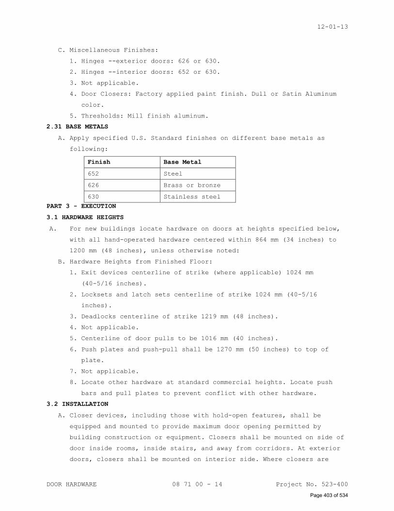
12-01-13
DOOR HARDWARE 08 71 00 - 14 Project No. 523-400
C. Miscellaneous Finishes:
1. Hinges --exterior doors: 626 or 630.
2. Hinges --interior doors: 652 or 630.
3. Not applicable.
4. Door Closers: Factory applied paint finish. Dull or Satin Aluminum
color.
5. Thresholds: Mill finish aluminum.
2.31 BASE METALS
A. Apply specified U.S. Standard finishes on different base metals as
following:
Finish Base Metal
652 Steel
626 Brass or bronze
630 Stainless steel
PART 3 - EXECUTION
3.1 HARDWARE HEIGHTS
A. For new buildings locate hardware on doors at heights specified below,
with all hand-operated hardware centered within 864 mm (34 inches) to
1200 mm (48 inches), unless otherwise noted:
B. Hardware Heights from Finished Floor:
1. Exit devices centerline of strike (where applicable) 1024 mm
(40-5/16 inches).
2. Locksets and latch sets centerline of strike 1024 mm (40-5/16
inches).
3. Deadlocks centerline of strike 1219 mm (48 inches).
4. Not applicable.
5. Centerline of door pulls to be 1016 mm (40 inches).
6. Push plates and push-pull shall be 1270 mm (50 inches) to top of
plate.
7. Not applicable.
8. Locate other hardware at standard commercial heights. Locate push
bars and pull plates to prevent conflict with other hardware.
3.2 INSTALLATION
A. Closer devices, including those with hold-open features, shall be
equipped and mounted to provide maximum door opening permitted by
building construction or equipment. Closers shall be mounted on side of
door inside rooms, inside stairs, and away from corridors. At exterior
doors, closers shall be mounted on interior side. Where closers are
Page 403 of 534
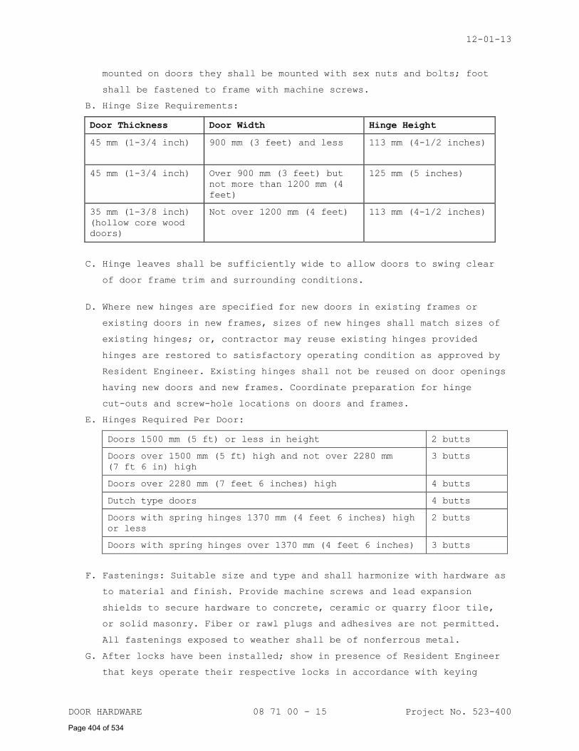
12-01-13
DOOR HARDWARE 08 71 00 - 15 Project No. 523-400
mounted on doors they shall be mounted with sex nuts and bolts; foot
shall be fastened to frame with machine screws.
B. Hinge Size Requirements:
Door Thickness Door Width Hinge Height
45 mm (1-3/4 inch) 900 mm (3 feet) and less 113 mm (4-1/2 inches)
45 mm (1-3/4 inch) Over 900 mm (3 feet) but
not more than 1200 mm (4
feet)
125 mm (5 inches)
35 mm (1-3/8 inch)
(hollow core wood
doors)
Not over 1200 mm (4 feet) 113 mm (4-1/2 inches)
C. Hinge leaves shall be sufficiently wide to allow doors to swing clear
of door frame trim and surrounding conditions.
D. Where new hinges are specified for new doors in existing frames or
existing doors in new frames, sizes of new hinges shall match sizes of
existing hinges; or, contractor may reuse existing hinges provided
hinges are restored to satisfactory operating condition as approved by
Resident Engineer. Existing hinges shall not be reused on door openings
having new doors and new frames. Coordinate preparation for hinge
cut-outs and screw-hole locations on doors and frames.
E. Hinges Required Per Door:
Doors 1500 mm (5 ft) or less in height 2 butts
Doors over 1500 mm (5 ft) high and not over 2280 mm
(7 ft 6 in) high
3 butts
Doors over 2280 mm (7 feet 6 inches) high 4 butts
Dutch type doors 4 butts
Doors with spring hinges 1370 mm (4 feet 6 inches) high
or less
2 butts
Doors with spring hinges over 1370 mm (4 feet 6 inches) 3 butts
F. Fastenings: Suitable size and type and shall harmonize with hardware as
to material and finish. Provide machine screws and lead expansion
shields to secure hardware to concrete, ceramic or quarry floor tile,
or solid masonry. Fiber or rawl plugs and adhesives are not permitted.
All fastenings exposed to weather shall be of nonferrous metal.
G. After locks have been installed; show in presence of Resident Engineer
that keys operate their respective locks in accordance with keying
Page 404 of 534
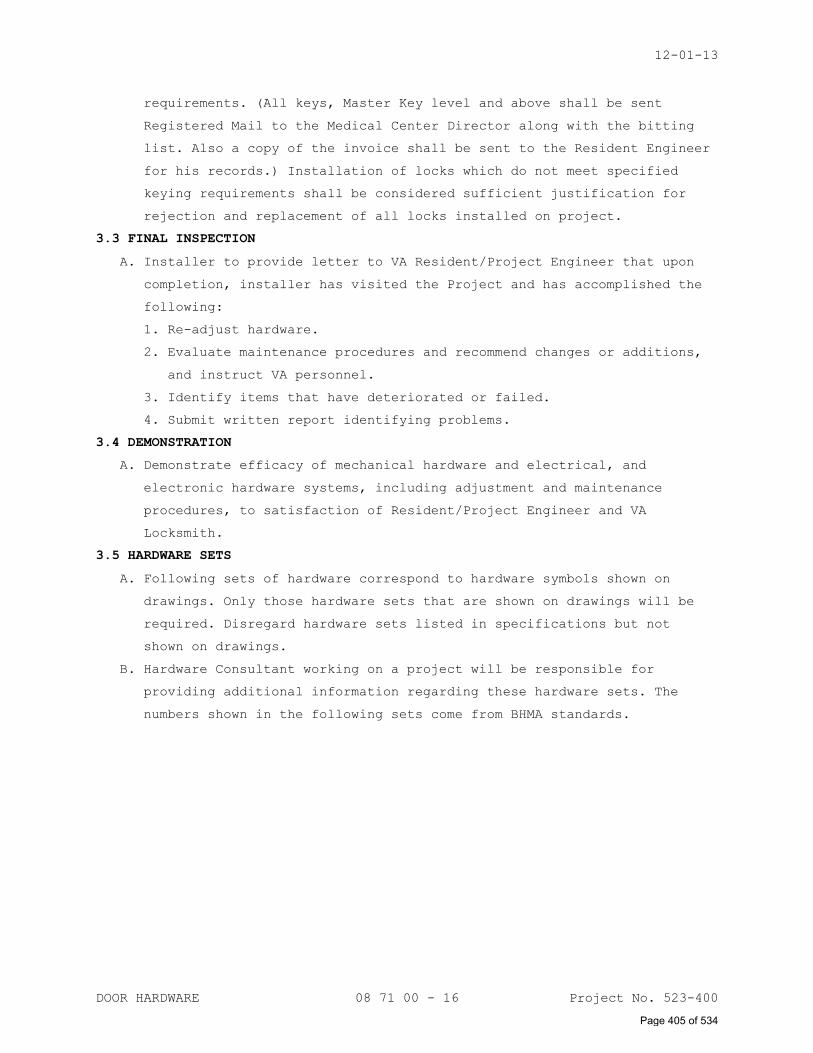
12-01-13
DOOR HARDWARE 08 71 00 - 16 Project No. 523-400
requirements. (All keys, Master Key level and above shall be sent
Registered Mail to the Medical Center Director along with the bitting
list. Also a copy of the invoice shall be sent to the Resident Engineer
for his records.) Installation of locks which do not meet specified
keying requirements shall be considered sufficient justification for
rejection and replacement of all locks installed on project.
3.3 FINAL INSPECTION
A. Installer to provide letter to VA Resident/Project Engineer that upon
completion, installer has visited the Project and has accomplished the
following:
1. Re-adjust hardware.
2. Evaluate maintenance procedures and recommend changes or additions,
and instruct VA personnel.
3. Identify items that have deteriorated or failed.
4. Submit written report identifying problems.
3.4 DEMONSTRATION
A. Demonstrate efficacy of mechanical hardware and electrical, and
electronic hardware systems, including adjustment and maintenance
procedures, to satisfaction of Resident/Project Engineer and VA
Locksmith.
3.5 HARDWARE SETS
A. Following sets of hardware correspond to hardware symbols shown on
drawings. Only those hardware sets that are shown on drawings will be
required. Disregard hardware sets listed in specifications but not
shown on drawings.
B. Hardware Consultant working on a project will be responsible for
providing additional information regarding these hardware sets. The
numbers shown in the following sets come from BHMA standards.
Page 405 of 534
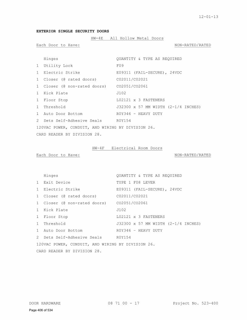
12-01-13
DOOR HARDWARE 08 71 00 - 17 Project No. 523-400
EXTERIOR SINGLE SECURITY DOORS
HW-4E All Hollow Metal Doors
Each Door to Have: NON-RATED/RATED
Hinges QUANTITY & TYPE AS REQUIRED
1 Utility Lock F09
1 Electric Strike E09311 (FAIL-SECURE), 24VDC
1 Closer (@ rated doors) C02011/C02021
1 Closer (@ non-rated doors) CO2051/CO2061
1 Kick Plate J102
1 Floor Stop L02121 x 3 FASTENERS
1 Threshold J32300 x 57 MM WIDTH (2-1/4 INCHES)
1 Auto Door Bottom R0Y346 – HEAVY DUTY
2 Sets Self-Adhesive Seals R0Y154
120VAC POWER, CONDUIT, AND WIRING BY DIVISION 26.
CARD READER BY DIVISION 28.
HW-4F Electrical Room Doors
Each Door to Have: NON-RATED/RATED
Hinges QUANTITY & TYPE AS REQUIRED
1 Exit Device TYPE 1 F08 LEVER
1 Electric Strike E09311 (FAIL-SECURE), 24VDC
1 Closer (@ rated doors) C02011/C02021
1 Closer (@ non-rated doors) CO2051/CO2061
1 Kick Plate J102
1 Floor Stop L02121 x 3 FASTENERS
1 Threshold J32300 x 57 MM WIDTH (2-1/4 INCHES)
1 Auto Door Bottom R0Y346 – HEAVY DUTY
2 Sets Self-Adhesive Seals R0Y154
120VAC POWER, CONDUIT, AND WIRING BY DIVISION 26.
CARD READER BY DIVISION 28.
Page 406 of 534
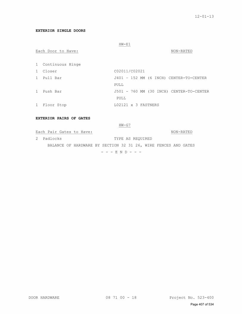
12-01-13
DOOR HARDWARE 08 71 00 - 18 Project No. 523-400
EXTERIOR SINGLE DOORS
HW-E1
Each Door to Have: NON-RATED
1 Continuous Hinge
1 Closer C02011/C02021
1 Pull Bar J401 – 152 MM (6 INCH) CENTER-TO-CENTER
PULL
1 Push Bar J501 – 760 MM (30 INCH) CENTER-TO-CENTER
PULL
1 Floor Stop L02121 x 3 FASTNERS
EXTERIOR PAIRS OF GATES
HW-G7
Each Pair Gates to Have: NON-RATED
2 Padlocks TYPE AS REQUIRED
BALANCE OF HARDWARE BY SECTION 32 31 26, WIRE FENCES AND GATES
- - - E N D - - -
Page 407 of 534
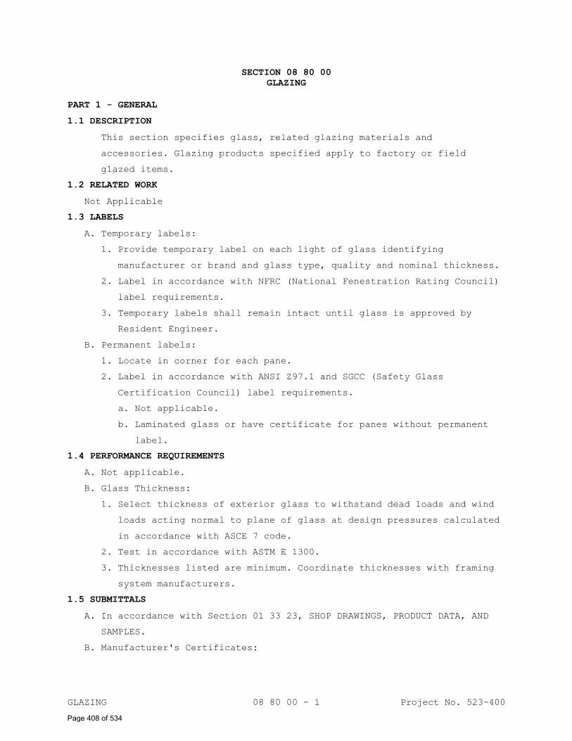
GLAZING 08 80 00 - 1 Project No. 523-400
SECTION 08 80 00
GLAZING
PART 1 - GENERAL
1.1 DESCRIPTION
This section specifies glass, related glazing materials and
accessories. Glazing products specified apply to factory or field
glazed items.
1.2 RELATED WORK
Not Applicable
1.3 LABELS
A. Temporary labels:
1. Provide temporary label on each light of glass identifying
manufacturer or brand and glass type, quality and nominal thickness.
2. Label in accordance with NFRC (National Fenestration Rating Council)
label requirements.
3. Temporary labels shall remain intact until glass is approved by
Resident Engineer.
B. Permanent labels:
1. Locate in corner for each pane.
2. Label in accordance with ANSI Z97.1 and SGCC (Safety Glass
Certification Council) label requirements.
a. Not applicable.
b. Laminated glass or have certificate for panes without permanent
label.
1.4 PERFORMANCE REQUIREMENTS
A. Not applicable.
B. Glass Thickness:
1. Select thickness of exterior glass to withstand dead loads and wind
loads acting normal to plane of glass at design pressures calculated
in accordance with ASCE 7 code.
2. Test in accordance with ASTM E 1300.
3. Thicknesses listed are minimum. Coordinate thicknesses with framing
system manufacturers.
1.5 SUBMITTALS
A. In accordance with Section 01 33 23, SHOP DRAWINGS, PRODUCT DATA, AND
SAMPLES.
B. Manufacturer's Certificates:
Page 408 of 534

05-01-14
GLAZING 08 80 00 - 2 Project No. 523-400
1. Certificates stating that wire glass, meets requirements for safety
glazing material as specified in ANSI Z97.1.
C. Warranty: Submit written guaranty, conforming to General Requirements
requirements, and to “Warranty of Construction” Article in this
Section.
D. Manufacturer's Literature and Data:
1. Glass, each kind required.
E. Not applicable.
1.6 DELIVERY, STORAGE AND HANDLING
A. Delivery: Schedule delivery to coincide with glazing schedules so
minimum handling of crates is required. Do not open crates except as
required for inspection for shipping damage.
B. Storage: Store cases according to printed instructions on case, in
areas least subject to traffic or falling objects. Keep storage area
clean and dry.
C. Handling: Unpack cases following printed instructions on case. Stack
individual windows on edge leaned slightly against upright supports
with separators between each.
1.7 PROJECT CONDITIONS
Field Measurements: Field measure openings before ordering tempered
glass products. Be responsible for proper fit of field measured
products.
1.8 WARRANTY
A. Warranty: Conform to the Construction Contract terms of "Warranty of Construction", except extend warranty period for the following:
1. Not applicable.
2. Insulating glass units to remain sealed for 10 years.
3. Laminated glass units to remain laminated for 5 years.
1.9 APPLICABLE PUBLICATIONS
A. Publications listed below form a part of this specification to extent
referenced. Publications are referenced in text by basic designation
only.
B. American National Standards Institute (ANSI):
Z97.1-09................Safety Glazing Material Used in
Building - Safety Performance Specifications
and Methods of Test.
C. American Society for Testing and Materials (ASTM):
Page 409 of 534
05-01-14
GLAZING 08 80 00 - 3 Project No. 523-400
C864-05.................Dense Elastomeric Compression Seal Gaskets,
Setting Blocks, and Spacers
C920-11.................Elastomeric Joint Sealants
C1036-06................Flat Glass
D. Safety Glazing Certification Council (SGCC) 2012:
Certified Products Directory (Issued Semi-Annually).
E. Glass Association of North America (GANA):
Glazing Manual (Latest Edition)
Sealant Manual (2009)
F. American Society of Civil Engineers (ASCE):
ASCE 7-10...............Wind Load Provisions
PART 2 - PRODUCT
2.1 GLASS
A. Use thickness stated unless specified otherwise in assemblies.
B. Clear Glass:
1. ASTM C1036, Type I, Class 1, Quality q3.
2. Thickness, 6 mm (1/4 inch).
2.2 HEAT-TREATED GLASS
Not Applicable
2.3 COATED GLASS
Not Applicable
2.4 PLASTIC
Not Applicable
2.5 LAMINATED GLASS
A. Two or more lites of glass bonded with an interlayer material for use
in building glazing
B. Not applicable.
C. Not applicable.
D. Use min. 0.75 mm (0.030 inch) thick interlayer for vertical glazing
where 1.5 mm (0.060 inch) interlayer is not otherwise shown or
required.
2.6 LAMINATED GLAZING ASSEMBLIES
A. Clear Glazing:
1. Both panes clear glass ASTM C1036, Type I, Class 1, Quality q3.
2. Thickness: Each pane, 3 mm (1/8 inch) thick.
2.7 BULLET RESISTIVE ASSEMBLY
Not Applicable
Page 410 of 534
05-01-14
GLAZING 08 80 00 - 4 Project No. 523-400
2.8 GLASS CLAD POLYCARBONATE SECURITY GLAZING ASSEMBLY
Not Applicable
2.9 INSULATING GLASS UNITS
Not Applicable
2.10 FIRE RESISTANT GLASS WITHOUT WIRE MESH
Not Applicable
2.11 INSULATING PLASTIC SHEETS
Not Applicable
2.12 GLAZING ACCESSORIES
A. As required to supplement the accessories provided with the items to be
glazed and to provide a complete installation. Ferrous metal
accessories exposed in the finished work shall have a finish that will
not corrode or stain while in service.
B. Setting Blocks: ASTM C864:
1. Channel shape; having 6 mm (1/4 inch) internal depth.
2. Shore a hardness of 80 to 90 Durometer.
3. Block lengths: 50 mm (two inches) except 100 to 150 mm (four to six
inches) for insulating glass.
4. Block width: Approximately 1.6 mm (1/16 inch) less than the full
width of the rabbet.
5. Block thickness: Minimum 4.8 mm (3/16 inch). Thickness sized for
rabbet depth as required.
C. Spacers: ASTM C864:
1. Channel shape having a 6 mm (1/4 inch) internal depth.
2. Flanges not less 2.4 mm (3/32 inch) thick and web 3 mm (1/8 inch)
thick.
3. Lengths: One to 25 to 76 mm (one to three inches).
4. Shore a hardness of 40 to 50 Durometer.
D. Not applicable.
E. Not applicable.
F. Not applicable.
G. Not applicable.
H. Glazing Gaskets: ASTM C864:
1. Firm dense wedge shape for locking in sash.
2. Soft, closed cell with locking key for sash key.
3. Flanges may terminate above the glazing-beads or terminate flush
with top of beads.
I. Not applicable.
Page 411 of 534
05-01-14
GLAZING 08 80 00 - 5 Project No. 523-400
J. Glazing Sealants: ASTM C920, silicone neutral cure:
1. Type S.
2. Class 25
3. Grade NS.
4. Shore A hardness of 25 to 30 Durometer.
K. Not applicable.
L. Neoprene or EPDM Glazing Gasket: ASTM C864.
1. Channel shape; flanges may terminate above the glazing channel or
flush with the top of the channel.
2. Designed for dry glazing.
M. Color:
1. Color of glazing compounds, gaskets, and sealants used for aluminum
color frames shall match color of the finished aluminum and be
nonstaining.
2. Color of other glazing compounds, gaskets, and sealants which will
be exposed in the finished work and unpainted shall be black, gray,
or neutral color.
PART 3 - EXECUTION
3.1 EXAMINATION
A. Verification of Conditions:
1. Examine openings for glass and glazing units; determine they are
proper size; plumb; square; and level before installation is
started.
2. Verify that glazing openings conform with details, dimensions and
tolerances indicated on manufacturer’s approved shop drawings.
B. Advise Contractor of conditions which may adversely affect glass and
glazing unit installation, prior to commencement of installation: Do
not proceed with installation until unsatisfactory conditions have been
corrected.
C. Verify that wash down of adjacent masonry is completed prior to
erection of glass and glazing units to prevent damage to glass and
glazing units by cleaning materials.
3.2 PREPARATION
A. For sealant glazing, prepare glazing surfaces in accordance with GANA-
02 Sealant Manual.
B. Determine glazing unit size and edge clearances by measuring the actual
unit to receive the glazing.
Page 412 of 534
05-01-14
GLAZING 08 80 00 - 6 Project No. 523-400
C. Shop fabricate and cut glass with smooth, straight edges of full size
required by openings to provide GANA recommended edge clearances.
D. Verify that components used are compatible.
E. Clean and dry glazing surfaces.
F. Prime surfaces scheduled to receive sealants, as determined by
preconstruction sealant-substrate testing.
3.3 INSTALLATION - GENERAL
A. Install in accordance with GANA-01 Glazing Manual and GANA-02 Sealant
Manual unless specified otherwise.
B. Glaze in accordance with recommendations of glazing and framing
manufacturers, and as required to meet the Performance Test
Requirements specified in other applicable sections of specifications.
C. Set glazing without bending, twisting, or forcing of units.
D. Do not allow glass to rest on or contact any framing member.
E. Glaze doors, in a securely fixed or closed and locked position, until
sealant, glazing compound, or putty has thoroughly set.
F. Not applicable.
G. Not applicable.
H. Not applicable.
I. Not applicable.
J. Laminated Glass:
1. Tape edges to seal interlayer and protect from glazing sealants.
2. Do not use putty or glazing compounds.
3.4 INSTALLATION - DRY METHOD (TAPE AND GASKET SPLINE GLAZING)
A. Cut glazing spline to length; install on glazing pane. Seal corners by
butting and sealing junctions with butyl sealant.
B. Place setting blocks at 1/3 points with edge block no more than 150 mm
(6 inches) from corners.
C. Rest glazing on setting blocks and push against fixed stop with
sufficient pressure to attain full contact.
D. Install removable stops without displacing glazing spline. Exert
pressure for full continuous contact.
E. Do not exceed edge pressures stipulated by glass manufacturers for
installing glass lites.
F. Trim protruding tape edge.
3.5 INSTALLATION - WET/DRY METHOD (PREFORMED TAPE AND SEALANT)
Not Applicable
Page 413 of 534
05-01-14
GLAZING 08 80 00 - 7 Project No. 523-400
3.6 INSTALLATION - WET METHOD (SEALANT AND SEALANT)
Not Applicable
3.7 INSTALLATION - EXTERIOR BUTT GLAZED METHOD (SEALANT ONLY)
Not Applicable
3.8 INSTALLATION - INTERIOR WET/DRY METHOD (TAPE AND SEALANT)
Not Applicable
3.9 INSTALLATION - INTERIOR WET METHOD (COMPOUND AND COMPOUND)
Not Applicable
3.10 INSTALLATION - REGLAZING HISTORIC FRAMING
Not Applicable
3.11 REPLACEMENT AND CLEANING
A. Clean new glass surfaces removing temporary labels, paint spots, and
defacement after approval by Resident Engineer.
B. Replace cracked, broken, and imperfect glass, or glass which has been
installed improperly.
C. Leave glass, putty, and other setting material in clean, whole, and
acceptable condition.
3.12 PROTECTION
Protect finished surfaces from damage during erection, and after
completion of work. Strippable plastic coatings on colored anodized
finish are not acceptable.
3.13 GLAZING SCHEDULE
A. Not applicable.
B. Not applicable.
C. Not applicable.
D. Not applicable.
E. Not applicable.
F. Laminated Glass (Glass Type A): Install as specified in doors,
observation windows and interior pane of dual glazed windows where
indicated.
- - - E N D - - -
Page 414 of 534
10-11
LOUVERS AND VENTS 08 90 00 - 1 Project No. 523-400
SECTION 08 90 00
LOUVERS AND VENTS
PART 1 - GENERAL
1.1 DESCRIPTION
This section specifies fixed wall louvers.
1.2 RELATED WORK
A. Not applicable.
B. Color of finish: Section 09 06 00, SCHEDULE FOR FINISHESS.
1.3 SUBMITTALS
A. Submit in accordance with Section 01 33 23, SHOP DRAWINGS, PRODUCT DATA,
AND SAMPLES.
B. Shop Drawings:
Each type, showing material, finish, size of members, method of
assembly, and installation and anchorage details.
C. Manufacturer's Literature and Data:
Each type of louver and vent.
1.4 APPLICABLE PUBLICATIONS
A. The publications listed below form a part of this specification to the
extent referenced. The publications are referenced in the text by the
basic designation only.
B. The Master Painters Institute (MPI):
Approved Product List – September 2011
C. American Society for Testing and Materials (ASTM):
B209/B209M-03(R2007)....Aluminum and Aluminum Alloy, Sheet and Plate
B221-08.................Aluminum and Aluminum Alloy Extruded Bars, Rods,
Wire, Shapes, and Tubes
B221M-07................Aluminum and Aluminum Alloy Extruded Bars, Rods,
Wire Shapes, and Tubes
D. National Association of Architectural Metal Manufacturers (NAAMM):
AMP 500-06..............Metal Finishes Manual
E. Air Movement and Control Association, Inc. (AMCA):
500-L-07................Testing Louvers
PART 2 - PRODUCTS
2.1 MATERIALS
A. Aluminum, Extruded: ASTM B221/B221M.
B. Not applicable.
C. Not applicable.
D. Aluminum, Plate and Sheet: ASTM B209/B209M.
E. Fasteners: Fasteners for securing louvers and wall vents to adjoining
construction, except as otherwise specified or shown, shall be toggle or
Page 415 of 534
10-11
LOUVERS AND VENTS 08 90 00 - 2 Project No. 523-400
expansion bolts, of size and type as required for each specific type of
installation and service condition.
1. Where type, size, or spacing of fasteners is not shown or specified,
submit shop drawings showing proposed fasteners, and method of
installation.
2. Fasteners for louvers, louver frames, and wire guards shall be of
stainless steel or aluminum.
2.2 EXTERIOR WALL LOUVERS
A. General:
1. Provide fixed type louvers of size and design shown.
2. Heads, sills and jamb sections shall have formed caulking slots or be
designed to retain caulking. Head sections shall have exterior drip
lip, and sill sections an integral water stop.
3. Furnish louvers with sill extension or separate sill as shown.
4. Frame shall be mechanically fastened or welded construction with
welds dressed smooth and flush.
B. Performance Characteristics:
1. Weather louvers shall have a minimum of 50 percent free area and
shall pass (900 fpm) free area velocity at a pressure drop not
exceeding (0.1 inch) water gage and carry not more than (0.01 ounces)
of water per m² (square foot) of free area for 15 minutes when tested
per AMCA Standard 500-L.
2. Louvers shall bear AMCA certified rating seals for air performance
and water penetration ratings.
C. Aluminum Louvers:
1. General: Frames, blades, sills and mullions (sliding interlocking
type); 2 mm (0.081-inch) thick extruded aluminum. Blades shall be
drainable type and have reinforcing bosses.
2. Louvers, fixed: Make frame sizes 13 mm (1/2-inch) smaller than
openings. Single louvers frames shall not exceed 1700 mm (66 inches)
wide. When openings exceed 1700 mm (66 inches), provide twin louvers
separated by mullion members.
2.3 CLOSURE ANGLES AND CLOSURE PLATES
A. Fabricate from 2 mm (0.074-inch) thick stainless steel or aluminum.
B. Provide continuous closure angles and closure plates on inside head,
jambs and sill of exterior wall louvers.
C. Secure angles and plates to louver frames with screws, and to masonry or
concrete with fasteners as specified.
2.4 WIRE GUARDS
A. Provide wire guards on outside of all exterior louvers, except on
exhaust air louvers.
Page 416 of 534
10-11
LOUVERS AND VENTS 08 90 00 - 3 Project No. 523-400
B. Fabricate frames from 2 mm (0.081-inch) thick extruded or sheet aluminum
designed to retain wire mesh.
C. Wire mesh shall be woven from not less than 1.6 mm (0.063-inch) diameter
aluminum wire in 13 mm (1/2-inch) square mesh.
D. Miter corners and join by concealed corner clips or locks extending
about 57 mm (2-1/4 inches) into rails and stiles. Equip wire guards over
four feet in height with a mid-rail constructed as specified for frame
components.
E. Fasten frames to outside of louvers with aluminum or stainless steel
devices designed to allow removal and replacement without damage to the
wire guard or the louver.
2.5 EXTERIOR DOOR LOUVERS
Not Applicable
2.6 INTERIOR DOOR LOUVERS
Not Applicable
2.7 WALL VENTS
Not Applicable
2.8 AIR INTAKE VENTS
Not Applicable
2.9 BRICK VENTS
Not Applicable
2.10 FINISH
A. In accordance with NAAMM Metal Finishes Manual: AMP 500-505
B. Aluminum Louvers:
1. Anodized finish
a. Not applicable.
b. Not applicable.
c. AA-C22A42 Chemically etched medium matte, with integrally colored
anodic coating, Class I Architectural, 0.7 mils thick.
NOTE: AA-C22A44 Chemically etched medium matte, with
electronically deposited metallic compound, Class I
Architectural, 0.7 mils thick may be provided as an option
for AA-C22A42 color anodic coating. Dyes will not be
accepted.
2.11 PROTECTION
A. Provide protection for aluminum against galvanic action wherever
dissimilar materials are in contact, by painting the contact surfaces of
the dissimilar material with a heavy coat of bituminous paint (complete
coverage), or by separating the contact surfaces with a performed
Page 417 of 534
10-11
LOUVERS AND VENTS 08 90 00 - 4 Project No. 523-400
synthetic rubber tape having pressure sensitive adhesive coating on one
side.
B. Isolate the aluminum from plaster, concrete and masonry by coating
aluminum with zinc-chromate primer.
C. Protect finished surfaces from damage during fabrication, erection, and
after completion of the work.
PART 3 - EXECUTION
3.1 INSTALLATION
A. Set work accurately, in alignment and where shown. Items shall be plumb,
level, free of rack and twist, and set parallel or perpendicular as
required to line and plane of surface.
B. Furnish setting drawings and instructions for installation of anchors
and for the positioning of items having anchors to be built into masonry
construction. Provide temporary bracing for such items until masonry is
set.
C. Provide anchoring devices and fasteners as shown and as necessary for
securing louvers to building construction as specified. Power actuated
drive pins may be used, except for removal items and where members would
be deformed or substrate damaged by their use.
D. Generally, set wall louvers in masonry walls during progress of the
work. If wall louvers are not delivered to job in time for installation
in prepared openings, make provision for later installation. Set in
cast-in-place concrete in prepared openings.
3.2 CLEANING AND ADJUSTING
A. After installation, all exposed prefinished and plated items and all
items fabricated from stainless steel and aluminum shall be cleaned as
recommended by the manufacturer and protected from damage until
completion of the project.
- - - E N D - - -
Page 418 of 534

10-11
09 06 00 - i
SECTION 09 06 00
SCHEDULE FOR FINISHES
SECTION 09 06 00-SCHEDULE FOR FINISHES
VAMC:
Location:
Project no. and Name:
Submission
Date:
LOUVERS AND VENTS
SCHEDULE OF FINISHES Project No. 523-400
Page 419 of 534
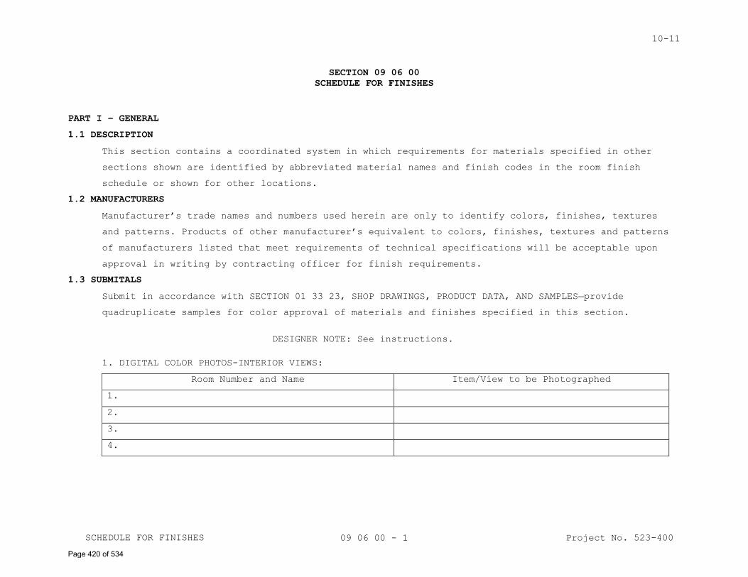
10-11
09 06 00 - 1
SECTION 09 06 00
SCHEDULE FOR FINISHES
PART I – GENERAL
1.1 DESCRIPTION
This section contains a coordinated system in which requirements for materials specified in other
sections shown are identified by abbreviated material names and finish codes in the room finish
schedule or shown for other locations.
1.2 MANUFACTURERS
Manufacturer’s trade names and numbers used herein are only to identify colors, finishes, textures
and patterns. Products of other manufacturer’s equivalent to colors, finishes, textures and patterns
of manufacturers listed that meet requirements of technical specifications will be acceptable upon
approval in writing by contracting officer for finish requirements.
1.3 SUBMITALS
Submit in accordance with SECTION 01 33 23, SHOP DRAWINGS, PRODUCT DATA, AND SAMPLES provide
quadruplicate samples for color approval of materials and finishes specified in this section.
DESIGNER NOTE: See instructions.
1. DIGITAL COLOR PHOTOS-INTERIOR VIEWS:
Room Number and Name Item/View to be Photographed
1.
2.
3.
4.
Project No. 523-400 SCHEDULE FOR FINISHES
Page 420 of 534
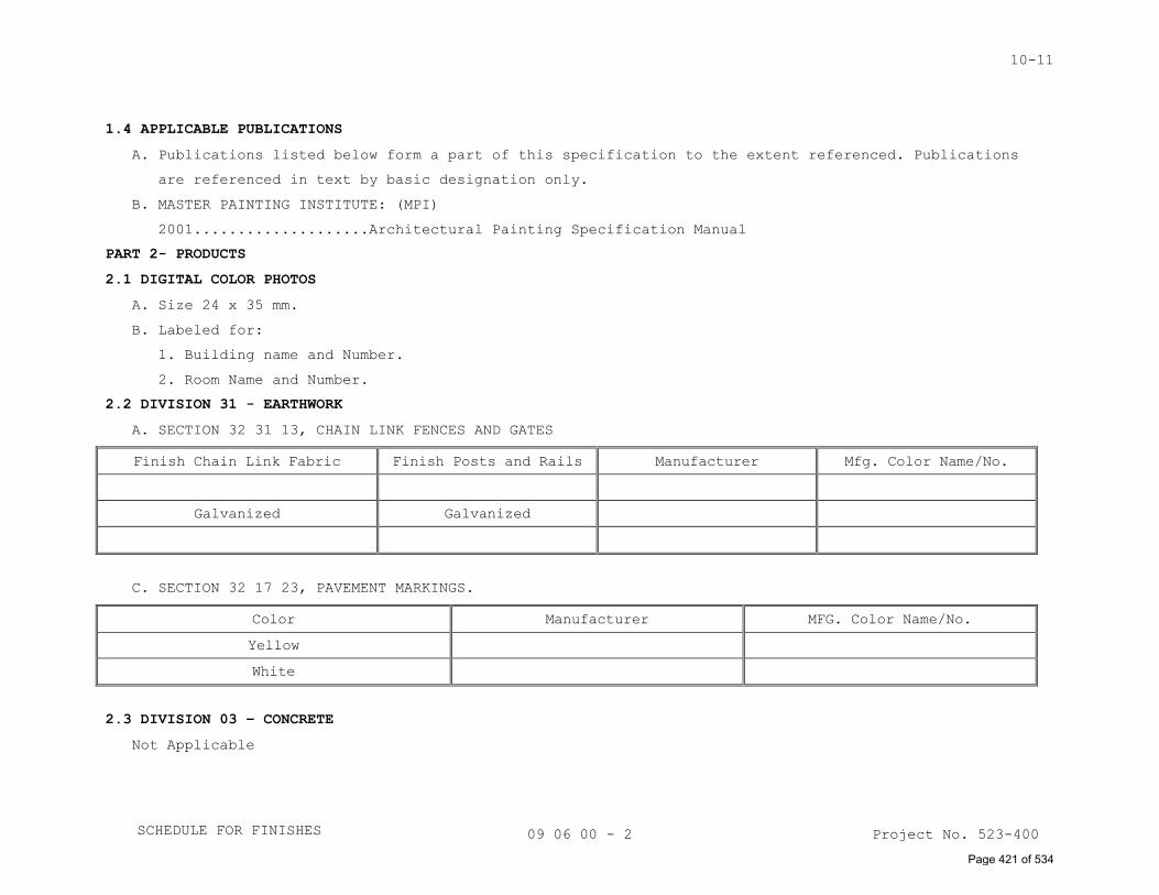
10-11
09 06 00 - 2
1.4 APPLICABLE PUBLICATIONS
A. Publications listed below form a part of this specification to the extent referenced. Publications
are referenced in text by basic designation only.
B. MASTER PAINTING INSTITUTE: (MPI)
2001....................Architectural Painting Specification Manual
PART 2- PRODUCTS
2.1 DIGITAL COLOR PHOTOS
A. Size 24 x 35 mm.
B. Labeled for:
1. Building name and Number.
2. Room Name and Number.
2.2 DIVISION 31 - EARTHWORK
A. SECTION 32 31 13, CHAIN LINK FENCES AND GATES
Finish Chain Link Fabric Finish Posts and Rails Manufacturer Mfg. Color Name/No.
Galvanized Galvanized
C. SECTION 32 17 23, PAVEMENT MARKINGS.
Color Manufacturer MFG. Color Name/No.
Yellow
White
2.3 DIVISION 03 – CONCRETE
Not Applicable
Project No. 523-400
Project No. 523-400
Project No. 523-400 SCHEDULE FOR FINISHES
Page 421 of 534
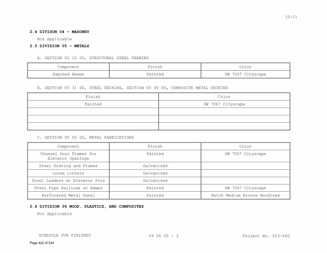
10-11
09 06 00 - 3
2.4 DIVISON 04 – MASONRY
Not Applicable
2.5 DIVISION 05 – METALS
A. SECTION 05 12 00, STRUCTURAL STEEL FRAMING
Component Finish Color
Exposed Beams Painted SW 7067 Cityscape
B. SECTION 05 31 00, STEEL DECKING, SECTION 05 36 00, COMPOSITE METAL DECKING
Finish Color
Painted SW 7067 Cityscape
C. SECTION 05 50 00, METAL FABRICATIONS
Component Finish Color
Channel Door Frames for
Elevator Openings
Painted SW 7067 Cityscape
Steel Grating and Frames Galvanized
Loose Lintels Galvanized
Steel Ladders at Elevator Pits Galvanized
Steel Pipe Railings at Ramps Painted SW 7067 Cityscape
Perforated Metal Panel Painted Match Medium Bronze Anodized
2.6 DIVISION 06 WOOD, PLASTICS, AND COMPOSITES
Not Applicable
Project No. 523-400 SCHEDULE FOR FINISHES
Page 422 of 534
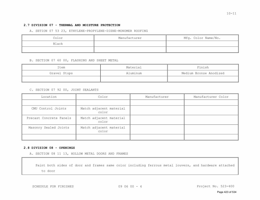
10-11
09 06 00 - 4
2.7 DIVISION 07 - THERMAL AND MOISTURE PROTECTION
A. SETION 07 53 23, ETHYLENE-PROPYLENE-DIENE-MONOMER ROOFING
Color Manufacturer Mfg. Color Name/No.
Black
B. SECTION 07 60 00, FLASHING AND SHEET METAL
Item Material Finish
Gravel Stops Aluminum Medium Bronze Anodized
C. SECTION 07 92 00, JOINT SEALANTS
Location Color Manufacturer Manufacturer Color
CMU Control Joints Match adjacent material
color
Precast Concrete Panels Match adjacent material
color
Masonry Sealed Joints Match adjacent material
color
2.8 DIVISION 08 - OPENINGS
A. SECTION 08 11 13, HOLLOW METAL DOORS AND FRAMES
Paint both sides of door and frames same color including ferrous metal louvers, and hardware attached
to door
Project No. 523-400 SCHEDULE FOR FINISHES
Page 423 of 534
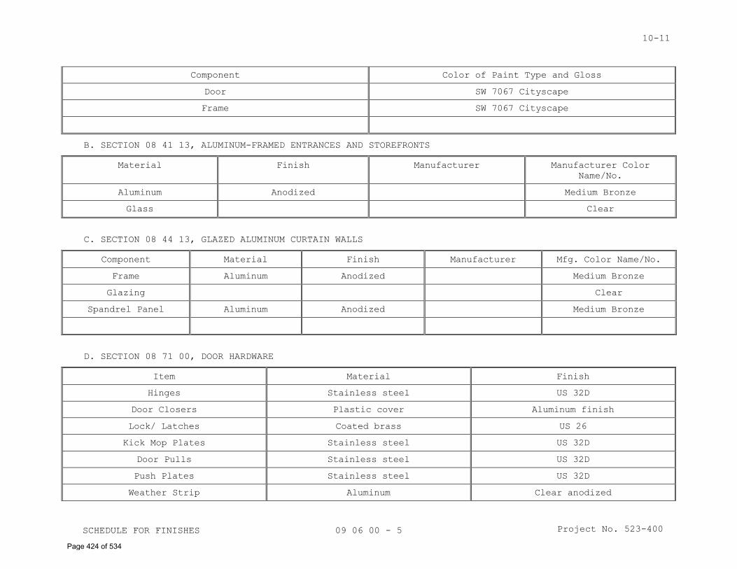
10-11
09 06 00 - 5
Component Color of Paint Type and Gloss
Door SW 7067 Cityscape
Frame SW 7067 Cityscape
B. SECTION 08 41 13, ALUMINUM-FRAMED ENTRANCES AND STOREFRONTS
Material Finish Manufacturer Manufacturer Color
Name/No.
Aluminum Anodized Medium Bronze
Glass Clear
C. SECTION 08 44 13, GLAZED ALUMINUM CURTAIN WALLS
Component Material Finish Manufacturer Mfg. Color Name/No.
Frame Aluminum Anodized Medium Bronze
Glazing Clear
Spandrel Panel Aluminum Anodized Medium Bronze
D. SECTION 08 71 00, DOOR HARDWARE
Item Material Finish
Hinges Stainless steel US 32D
Door Closers Plastic cover Aluminum finish
Lock/ Latches Coated brass US 26
Kick Mop Plates Stainless steel US 32D
Door Pulls Stainless steel US 32D
Push Plates Stainless steel US 32D
Weather Strip Aluminum Clear anodized
Project No. 523-400 SCHEDULE FOR FINISHES
Page 424 of 534
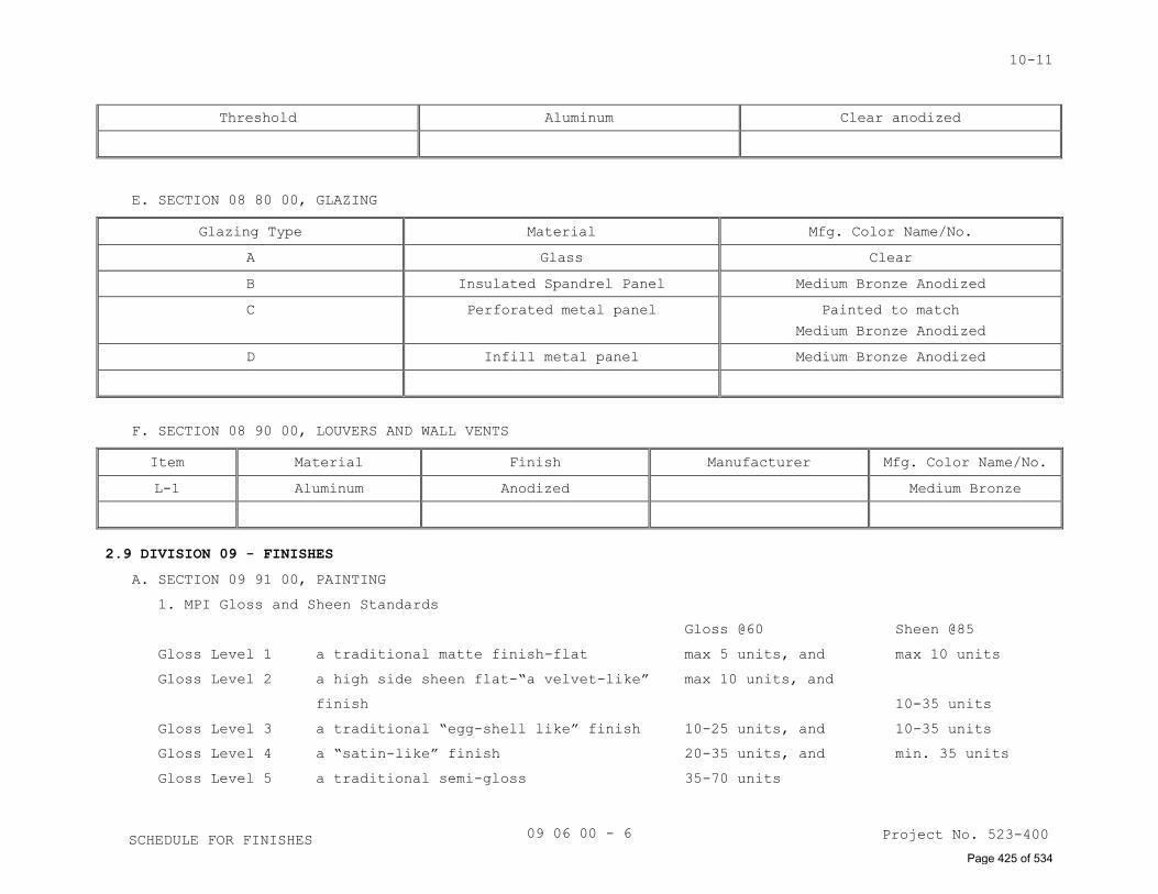
10-11
09 06 00 - 6
Threshold Aluminum Clear anodized
E. SECTION 08 80 00, GLAZING
Glazing Type Material Mfg. Color Name/No.
A Glass Clear
B Insulated Spandrel Panel Medium Bronze Anodized
C Perforated metal panel Painted to match
Medium Bronze Anodized
D Infill metal panel Medium Bronze Anodized
F. SECTION 08 90 00, LOUVERS AND WALL VENTS
Item Material Finish Manufacturer Mfg. Color Name/No.
L-1 Aluminum Anodized Medium Bronze
2.9 DIVISION 09 - FINISHES
A. SECTION 09 91 00, PAINTING
1. MPI Gloss and Sheen Standards
Gloss @60 Sheen @85
Gloss Level 1 a traditional matte finish-flat max 5 units, and max 10 units
Gloss Level 2 a high side sheen flat-“a velvet-like” max 10 units, and
finish 10-35 units
Gloss Level 3 a traditional “egg-shell like” finish 10-25 units, and 10-35 units
Gloss Level 4 a “satin-like” finish 20-35 units, and min. 35 units
Gloss Level 5 a traditional semi-gloss 35-70 units
Project No. 523-400 SCHEDULE FOR FINISHES Page 425 of 534
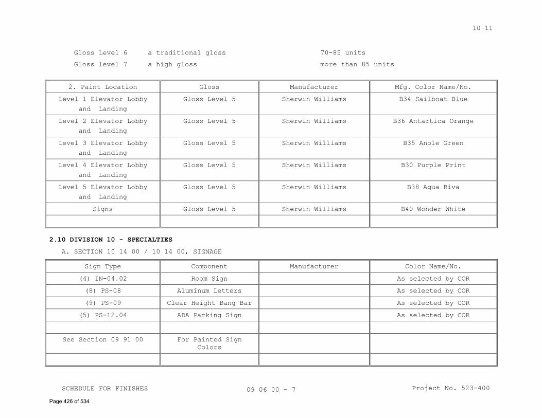
10-11
09 06 00 - 7
Gloss Level 6 a traditional gloss 70-85 units
Gloss level 7 a high gloss more than 85 units
2. Paint Location Gloss Manufacturer Mfg. Color Name/No.
Level 1 Elevator Lobby
and Landing
Gloss Level 5 Sherwin Williams B34 Sailboat Blue
Level 2 Elevator Lobby
and Landing
Gloss Level 5 Sherwin Williams B36 Antartica Orange
Level 3 Elevator Lobby
and Landing
Gloss Level 5 Sherwin Williams B35 Anole Green
Level 4 Elevator Lobby
and Landing
Gloss Level 5 Sherwin Williams B30 Purple Print
Level 5 Elevator Lobby
and Landing
Gloss Level 5 Sherwin Williams B38 Aqua Riva
Signs Gloss Level 5 Sherwin Williams B40 Wonder White
2.10 DIVISION 10 - SPECIALTIES
A. SECTION 10 14 00 / 10 14 00, SIGNAGE
Sign Type Component Manufacturer Color Name/No.
(4) IN-04.02 Room Sign As selected by COR
(8) PS-08 Aluminum Letters As selected by COR
(9) PS-09 Clear Height Bang Bar As selected by COR
(5) PS-12.04 ADA Parking Sign As selected by COR
See Section 09 91 00 For Painted Sign
Colors
Project No. 523-400
SCHEDULE FOR FINISHES
SCHEDULE FOR FINISHES
Page 426 of 534
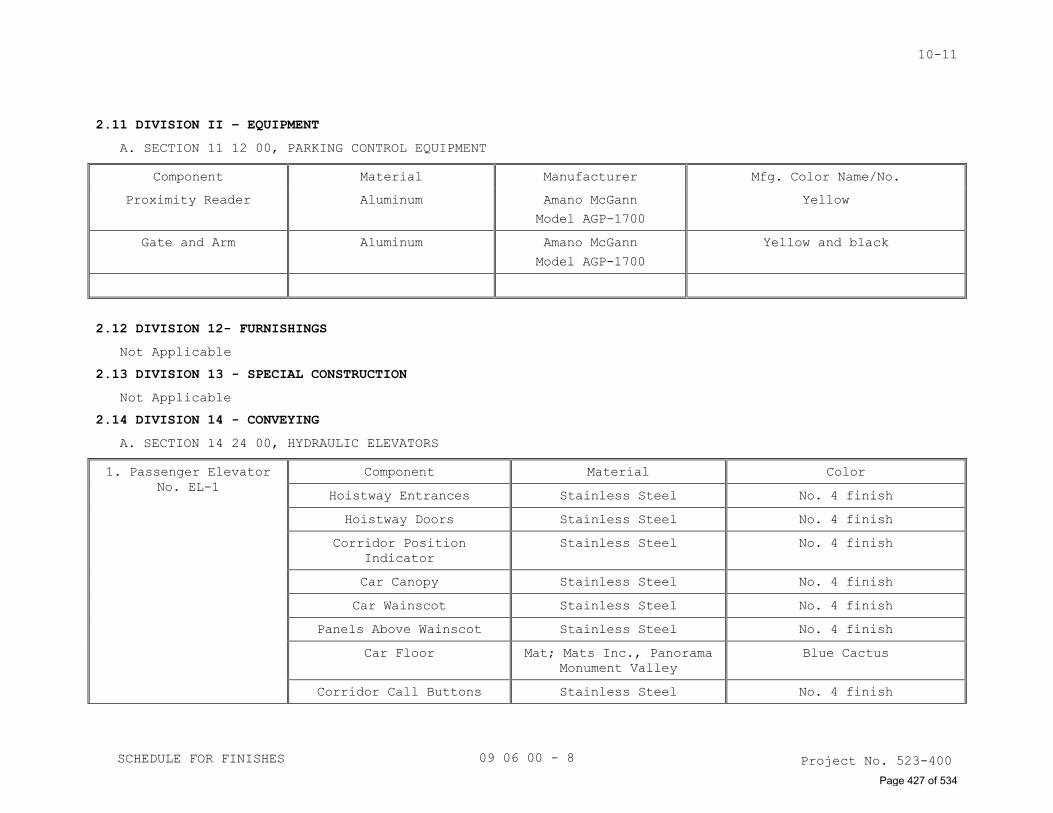
10-11
09 06 00 - 8
2.11 DIVISION II – EQUIPMENT
A. SECTION 11 12 00, PARKING CONTROL EQUIPMENT
Component Material Manufacturer Mfg. Color Name/No.
Proximity Reader Aluminum Amano McGann
Model AGP-1700
Yellow
Gate and Arm Aluminum Amano McGann
Model AGP-1700
Yellow and black
2.12 DIVISION 12- FURNISHINGS
Not Applicable
2.13 DIVISION 13 - SPECIAL CONSTRUCTION
Not Applicable
2.14 DIVISION 14 - CONVEYING
A. SECTION 14 24 00, HYDRAULIC ELEVATORS
1. Passenger Elevator
No. EL-1
Component Material Color
Hoistway Entrances Stainless Steel No. 4 finish
Hoistway Doors Stainless Steel No. 4 finish
Corridor Position
Indicator
Stainless Steel No. 4 finish
Car Canopy Stainless Steel No. 4 finish
Car Wainscot Stainless Steel No. 4 finish
Panels Above Wainscot Stainless Steel No. 4 finish
Car Floor Mat; Mats Inc., Panorama
Monument Valley
Blue Cactus
Corridor Call Buttons Stainless Steel No. 4 finish
Project No. 523-400
Project No. 523-400
Project No. 523-400
SCHEDULE FOR FINISHES
SCHEDULE FOR FINISHES
Page 427 of 534
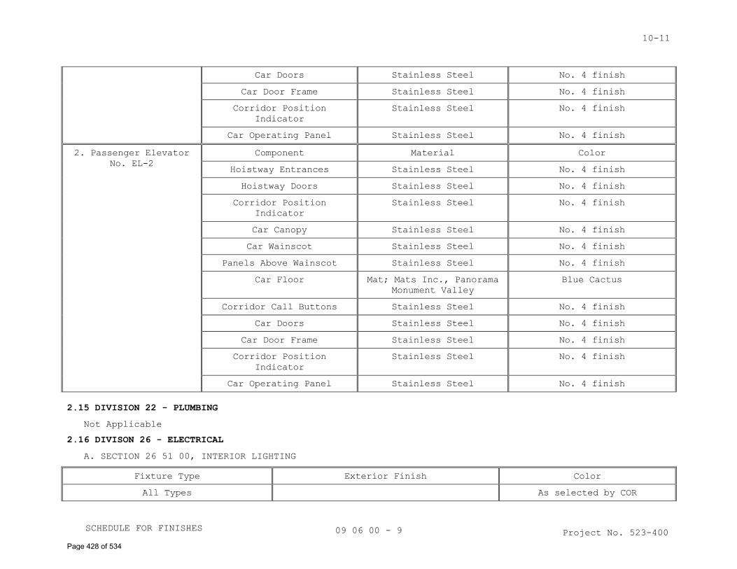
10-11
09 06 00 - 9
Car Doors Stainless Steel No. 4 finish
Car Door Frame Stainless Steel No. 4 finish
Corridor Position
Indicator
Stainless Steel No. 4 finish
Car Operating Panel Stainless Steel No. 4 finish
2. Passenger Elevator
No. EL-2
Component Material Color
Hoistway Entrances Stainless Steel No. 4 finish
Hoistway Doors Stainless Steel No. 4 finish
Corridor Position
Indicator
Stainless Steel No. 4 finish
Car Canopy Stainless Steel No. 4 finish
Car Wainscot Stainless Steel No. 4 finish
Panels Above Wainscot Stainless Steel No. 4 finish
Car Floor Mat; Mats Inc., Panorama
Monument Valley
Blue Cactus
Corridor Call Buttons Stainless Steel No. 4 finish
Car Doors Stainless Steel No. 4 finish
Car Door Frame Stainless Steel No. 4 finish
Corridor Position
Indicator
Stainless Steel No. 4 finish
Car Operating Panel Stainless Steel No. 4 finish
2.15 DIVISION 22 - PLUMBING
Not Applicable
2.16 DIVISON 26 - ELECTRICAL
A. SECTION 26 51 00, INTERIOR LIGHTING
Fixture Type Exterior Finish Color
All Types As selected by COR
Project No. 523-400 SCHEDULE FOR FINISHES
Page 428 of 534
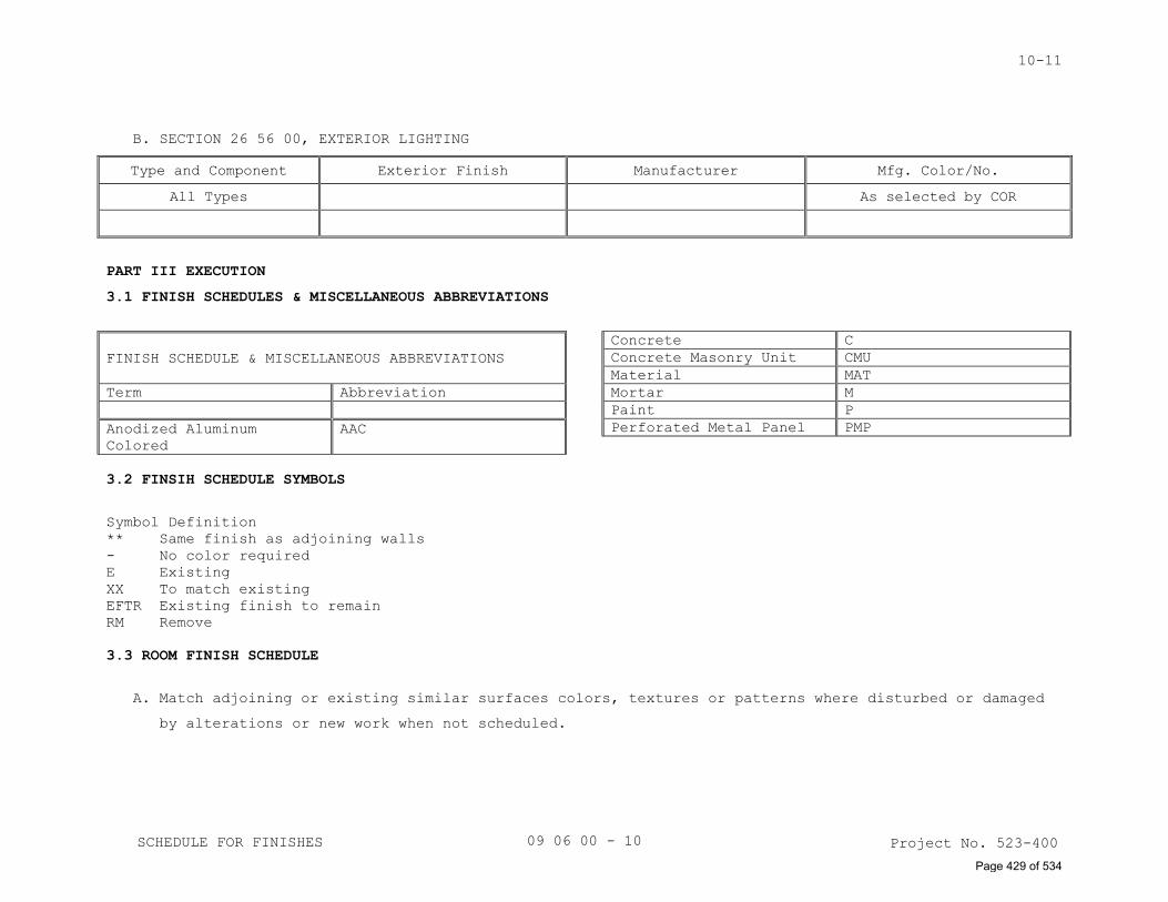
10-11
09 06 00 - 10
B. SECTION 26 56 00, EXTERIOR LIGHTING
Type and Component Exterior Finish Manufacturer Mfg. Color/No.
All Types As selected by COR
PART III EXECUTION
3.1 FINISH SCHEDULES & MISCELLANEOUS ABBREVIATIONS
FINISH SCHEDULE & MISCELLANEOUS ABBREVIATIONS
Term Abbreviation
Anodized Aluminum
Colored
AAC
Concrete C
Concrete Masonry Unit CMU
Material MAT
Mortar M
Paint P
Perforated Metal Panel PMP
3.2 FINSIH SCHEDULE SYMBOLS
Symbol Definition
** Same finish as adjoining walls
- No color required
E Existing
XX To match existing
EFTR Existing finish to remain
RM Remove
3.3 ROOM FINISH SCHEDULE
A. Match adjoining or existing similar surfaces colors, textures or patterns where disturbed or damaged
by alterations or new work when not scheduled.
Project No. 523-400 SCHEDULE FOR FINISHES
Page 429 of 534
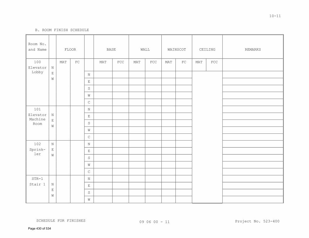
10-11
09 06 00 - 11
B. ROOM FINISH SCHEDULE
Room No.
and Name FLOOR BASE WALL WAINSCOT CEILING REMARKS
100
Elevator
Lobby
N
E
W
MAT FC MAT FCC MAT FCC MAT FC MAT FCC
N
E
S
W
C
101
Elevator
Machine
Room
N
E
W
N
E
S
W
C
102
Sprink-
ler
N
E
W
N
E
S
W
C
STR-1
Stair 1 N
E
W
N
E
S
W
Project No. 523-400 SCHEDULE FOR FINISHES
Page 430 of 534
10-11
09 06 00 - 12
C
103
Elec.
N
E
W
N
E
S
W
C
104
Emer.
Elec.
N
E
W
N
E
S
W
C
201
I.T.
N
E
W
N
E
S
W
C
202
I.T.
Security
N
E
W
N
E
S
W
C
N
E
W
N
E
S
W
C
Project No. 523-400
SCHEDULE FOR FINISHES
SCHEDULE FOR FINISHES
Page 431 of 534
10-11
09 06 00 - 13
N
E
W
N
E
S
W
C
N
E
W
N
E
S
W
C
N
E
W
N
E
S
W
C
N
E
W
N
E
S
W
C
--- E N D---
Project No. 523-400
Project No. 523-400 SCHEDULE FOR FINISHES
Page 432 of 534
10-01-14
NON-STRUCTURAL METAL FRAMING 09 22 16 - 1 Project No. 523-400
SECTION 09 22 16
NON-STRUCTURAL METAL FRAMING
PART 1 - GENERAL
1.1 DESCRIPTION
This section specifies steel studs wall systems, or furred framing,
wall furring, fasteners, and accessories for the screw attachment of
gypsum board, plaster bases or other building boards.
1.2 RELATED WORK
A. Soffit framing: Section 05 40 00, COLD-FORMED METAL FRAMING.
1.3 TERMINOLOGY
A. Description of terms shall be in accordance with ASTM C754, ASTM C11,
ASTM C841 and as specified.
B. Underside of Structure Overhead: In spaces where steel trusses or bar
joists are shown, the underside of structure overhead shall be the
underside of the floor or roof construction supported by beams,
trusses, or bar joists. In interstitial spaces with walk-on floors the
underside of the walk-on floor is the underside of structure overhead.
C. Thickness of steel specified is the minimum bare (uncoated) steel
thickness.
1.4 SUBMITTALS
A. Submit in accordance with Section 01 33 23, SHOP DRAWINGS, PRODUCT
DATA, AND SAMPLES.
B. Manufacturer's Literature and Data:
1. Studs, runners and accessories.
2. Hanger inserts.
3. Channels (Rolled steel).
4. Furring channels.
5. Screws, clips and other fasteners.
C. Shop Drawings:
1. Not applicable.
2. Typical metal stud and furring construction system including details
around openings and corner details.
D. Test Results: Fire rating test designation, each fire rating required
for each assembly.
1.5 DELIVERY, IDENTIFICATION, HANDLING AND STORAGE
In accordance with the requirements of ASTM C754.
Page 433 of 534
10-01-14
NON-STRUCTURAL METAL FRAMING 09 22 16 - 2 Project No. 523-400
1.6 APPLICABLE PUBLICATIONS
A. The publications listed below form a part of this specification to the
extent referenced. The publications are referenced in the text by the
basic designation only.
B. American Society For Testing And Materials (ASTM)
A653/653M-11............Specification for Steel Sheet, Zinc Coated
(Galvanized) or Zinc-Iron Alloy-Coated
(Galvannealed) by Hot-Dip Process.
C645-09.................Non-Structural Steel Framing Members
C754-11.................Installation of Steel Framing Members to
Receive Screw-Attached Gypsum Panel Products
C841-03(R2008)..........Installation of Interior Lathing and Furring
PART 2 - PRODUCTS
2.1 PROTECTIVE COATING
Galvanize steel studs, runners (track), rigid (hat section) furring
channels, "Z" shaped furring channels, and resilient furring channels,
with coating designation of G-60 minimum, per ASTM A653.
2.2 STEEL STUDS AND RUNNERS (TRACK)
A. ASTM C645, modified for thickness specified and sizes as shown.
1. Use ASTM A653/A653M steel, 0.8 mm (0.0329-inch) thick bare metal (33
mil).
2. Runners same thickness as studs.
B. Provide not less than two cutouts in web of each stud, approximately
300 mm (12 inches) from each end, and intermediate cutouts on
approximately 600 mm (24-inch) centers.
C. Doubled studs for openings and studs for supporting concrete
backer-board.
D. Studs 3600 mm (12 feet) or less in length shall be in one piece.
2.3 FURRING CHANNELS
A. Not applicable.
B. Not applicable.
C. "Z" Furring Channels:
1. Not less than 0.45 mm (0.0179-inch)-thick bare metal, with 32 mm
(1-1/4 inch) and 19 mm (3/4-inch) flanges.
2. Web furring depth to suit thickness of insulation with slotted
perforations.
2.4 FASTENERS, CLIPS, AND OTHER METAL ACCESSORIES
A. ASTM C754, except as otherwise specified.
Page 434 of 534
10-01-14
NON-STRUCTURAL METAL FRAMING 09 22 16 - 3 Project No. 523-400
B. Not applicable.
C. Fasteners for steel studs thicker than 0.84 mm (0.033-inch) thick. Use
ASTM C954 steel drill screws of size and type recommended by the
manufacturer of the material being fastened.
D. Clips: ASTM C841 (paragraph 6.11), manufacturer’s standard items.
Clips used in lieu of tie wire shall have holding power equivalent to
that provided by the tie wire for the specific application.
E. Concrete ceiling hanger inserts (anchorage for hanger wire and hanger
straps): Steel, zinc-coated (galvanized), manufacturers standard items,
designed to support twice the hanger loads imposed and the type of
hanger used.
F. Not applicable.
G. Attachments for Wall Furring:
1. Manufacturers standard items fabricated from zinc-coated
(galvanized) steel sheet.
2. For concrete or masonry walls: Metal slots with adjustable inserts
or adjustable wall furring brackets. Spacers may be fabricated from 1
mm (0.0396-inch) thick galvanized steel with corrugated edges.
H. Power Actuated Fasteners: Type and size as recommended by the
manufacturer of the material being fastened.
2.5 SUSPENDED CEILING SYSTEM FOR GYPSUM BOARD (OPTION)
Not Applicable
PART 3 - EXECUTION
3.1 INSTALLATION CRITERIA
Not Applicable
3.2 INSTALLING STUDS
A. Install studs in accordance with ASTM C754, except as otherwise shown
or specified.
B. Space studs not more than 610 mm (24 inches) on center.
C. Cut studs 6 mm to 9 mm (1/4 to 3/8-inch) less than floor to underside
of structure overhead when extended to underside of structure overhead.
D. Where studs are shown to terminate above suspended ceilings, provide
bracing as shown or extend studs to underside of structure overhead.
E. Extend studs to underside of structure overhead for fire, rated
partitions, smoke partitions, shafts, and sound rated partitions and
insulated exterior wall furring.
F. Not applicable.
G. Openings:
Page 435 of 534
10-01-14
NON-STRUCTURAL METAL FRAMING 09 22 16 - 4 Project No. 523-400
1. Frame jambs of openings in stud partitions and furring with two
studs placed back to back or as shown.
2. Fasten back to back studs together with 9 mm (3/8-inch) long Type S
pan head screws at not less than 600 mm (two feet) on center,
staggered along webs.
3. Studs fastened flange to flange shall have splice plates on both
sides approximately 50 X 75 mm (2 by 3 inches) screwed to each stud
with two screws in each stud. Locate splice plates at 600 mm (24
inches) on center between runner tracks.
H. Fastening Studs:
1. Fasten studs located adjacent to partition intersections, corners
and studs at jambs of openings to flange of runner tracks with two
screws through each end of each stud and flange of runner.
2. Do not fasten studs to top runner track when studs extend to
underside of structure overhead.
I. Chase Wall Partitions:
1. Locate cross braces for chase wall partitions to permit the
installation of pipes, conduits, carriers and similar items.
2. Use studs or runners as cross bracing not less than 63 mm (2-1/2
inches wide).
J. Form building seismic or expansion joints with double studs back to
back spaced 75 mm (three inches) apart plus the width of the seismic or
expansion joint.
3.3 INSTALLING WALL FURRING FOR FINISH APPLIED TO ONE SIDE ONLY
A. In accordance with ASTM C754, or ASTM C841 except as otherwise
specified or shown.
B. Wall furring-Stud System:
1. Framed with 63 mm (2-1/2 inch) or narrower studs, 600 mm (24 inches)
on center.
2. Brace as specified in ASTM C754 for Wall Furring-Stud System or
brace with sections or runners or studs placed horizontally at not
less than three foot vertical intervals on side without finish.
3. Securely fasten braces to each stud with two Type S pan head screws
at each bearing.
C. Direct attachment to masonry or concrete; rigid channels or "Z"
channels:
1. Install rigid (hat section) furring channels at 600 mm (24 inches)
on center, horizontally or vertically.
Page 436 of 534
10-01-14
NON-STRUCTURAL METAL FRAMING 09 22 16 - 5 Project No. 523-400
2. Install "Z" furring channels vertically spaced not more than 600 mm
(24 inches) on center.
3. At corners where rigid furring channels are positioned horizontally,
provide mitered joints in furring channels.
4. Ends of spliced furring channels shall be nested not less than
200 mm (8 inches).
5. Fasten furring channels to walls with power-actuated drive pins or
hardened steel concrete nails. Where channels are spliced, provide
two fasteners in each flange.
6. Locate furring channels at interior and exterior corners in
accordance with wall finish material manufacturers printed erection
instructions. Locate "Z" channels within 100 mm (4 inches) of
corner.
D. Installing Wall Furring-Bracket System: Space furring channels not more
than 400 mm (16 inches) on center.
3.4 INSTALLING SUPPORTS REQUIRED BY OTHER TRADES
A. Provide for attachment and support of electrical outlets, plumbing,
laboratory or heating fixtures, recessed type plumbing fixture
accessories, access panel frames, wall bumpers, wood seats, toilet
stall partitions, dressing booth partitions, urinal screens,
chalkboards, tackboards, wall-hung casework, handrail brackets,
recessed fire extinguisher cabinets and other items like auto door
buttons and auto door operators supported by stud construction.
B. Provide additional studs where required. Install metal backing plates,
or special metal shapes as required, securely fastened to metal studs.
3.5 INSTALLING SHAFT WALL SYSTEM
Not Applicable
3.6 INSTALLING FURRED AND SUSPENDED CEILINGS OR SOFFITS
Not Applicable
3.7 TOLERANCES
A. Fastening surface for application of subsequent materials shall not
vary more than 3 mm (1/8-inch) from the layout line.
B. Plumb and align vertical members within 3 mm (1/8-inch.)
C. Level or align ceilings within 3 mm (1/8-inch.)
- - - E N D - - -
Page 437 of 534
11-01-14
GYPSUM BOARD 09 29 00 - 1 Project No. 523-400
SECTION 09 29 00
GYPSUM BOARD
PART 1 - GENERAL
1.1 DESCRIPTION
This section specifies installation and finishing of gypsum board.
1.2 RELATED WORK
A. Installation of steel framing members for walls, partitions, furring,
soffits, and ceilings: Section 05 40 00, COLD-FORMED METAL FRAMING, and
Section 09 22 16, NON-STRUCTURAL METAL FRAMING.
1.3 TERMINOLOGY
A. Definitions and description of terms shall be in accordance with ASTM
C11, C840, and as specified.
B. Underside of Structure Overhead: In spaces where steel trusses or bar
joists are shown, the underside of structure overhead shall be the
underside of the floor or roof construction supported by the trusses or
bar joists.
C. "Yoked": Gypsum board cut out for opening with no joint at the opening
(along door jamb or above the door).
1.4 SUBMITTALS
A. Submit in accordance with Section 01 33 23, SHOP DRAWINGS, PRODUCT
DATA, AND SAMPLES.
B. Manufacturer's Literature and Data:
1. Cornerbead and edge trim.
2. Finishing materials.
3. Not applicable.
4. Gypsum board, each type.
C. Shop Drawings:
1. Typical gypsum board installation, showing corner details, edge trim
details and the like.
D. Samples:
1. Cornerbead.
2. Edge trim.
E. Not applicable.
1. Fire rating test, each fire rating required for each assembly.
2. Sound rating test.
F. Certificates: Certify that gypsum board types, gypsum backing board
types, cementitious backer units, and joint treating materials do not
contain asbestos material.
Page 438 of 534
11-01-14
GYPSUM BOARD 09 29 00 - 2 Project No. 523-400
1.5 DELIVERY, IDENTIFICATION, HANDLING AND STORAGE
In accordance with the requirements of ASTM C840.
1.6 ENVIRONMENTAL CONDITIONS
In accordance with the requirements of ASTM C840.
1.7 APPLICABLE PUBLICATIONS
A. The publications listed below form a part of this specification to the
extent referenced. The publications are referenced in the text by the
basic designation only.
B. American Society for Testing And Materials (ASTM):
C475-02.................Joint Compound and Joint Tape for Finishing
Gypsum Board
C840-08.................Application and Finishing of Gypsum Board
C1002-07................Steel Self-Piercing Tapping Screws for the
Application of Gypsum Panel Products or Metal
Plaster Bases to Wood Studs or Steel Studs
C1047-05................Accessories for Gypsum Wallboard and Gypsum
Veneer Base
C1396-06................Gypsum Board
PART 2 - PRODUCTS
2.1 GYPSUM BOARD
A. Gypsum Board: ASTM C1396, Type X, 16 mm (5/8 inch) thick unless shown
otherwise. Shall contain a minimum of 20 percent recycled gypsum.
B. Not applicable.
C. Not applicable.
D. Gypsum cores shall contain maximum percentage of post-industrial
recycled gypsum content available in the area (a minimum of 95 percent
post-industrial recycled gypsum content). Paper facings shall contain
100 percent post-consumer recycled paper content.
2.2 GYPSUM SHEATHING BOARD
A. ASTM C1396, Type X, water-resistant core, 16 mm (5/8 inch) thick.
2.3 ACCESSORIES
A. ASTM C1047, except form of 0.39 mm (0.015 inch) thick zinc coated steel
sheet or rigid PVC plastic.
B. Flanges not less than 22 mm (7/8 inch) wide with punchouts or
deformations as required to provide compound bond.
2.4 FASTENERS
A. ASTM C1002 and ASTM C840, except as otherwise specified.
B. ASTM C954, for steel studs thicker than 0.04 mm (0.33 inch).
Page 439 of 534
11-01-14
GYPSUM BOARD 09 29 00 - 3 Project No. 523-400
C. Select screws of size and type recommended by the manufacturer of the
material being fastened.
D. Not applicable.
E. Clips: Zinc-coated (galvanized) steel; gypsum board manufacturer's
standard items.
2.5 FINISHING MATERIALS AND LAMINATING ADHESIVE
ASTM C475 and ASTM C840. Free of antifreeze, vinyl adhesives,
preservatives, biocides and other VOC. Adhesive shall contain a maximum
VOC content of 50 g/l.
PART 3 - EXECUTION
3.1 GYPSUM BOARD HEIGHTS
A. Extend all layers of gypsum board from floor to underside of structure
overhead on following partitions and furring:
1. Not applicable.
2. One side of partitions or furring:
a. Inside of exterior wall furring or stud construction.
b. Room side of room without suspended ceilings.
3.2 INSTALLING GYPSUM BOARD
A. Coordinate installation of gypsum board with other trades and related
work.
B. Install gypsum board in accordance with ASTM C840, except as otherwise
specified.
C. Not applicable.
D. Use gypsum boards in maximum practical lengths to minimize number of
end joints.
E. Bring gypsum board into contact, but do not force into place.
F. Not applicable.
G. Walls (Except Shaft Walls):
1. When gypsum board is installed parallel to framing members, space
fasteners 300 mm (12 inches) on center in field of the board, and
200 mm (8 inches) on center along edges.
2. When gypsum board is installed perpendicular to framing members,
space fasteners 300 mm (12 inches) on center in field and along
edges.
3. Stagger screws on abutting edges or ends.
4. For single-ply construction, apply gypsum board with long dimension
either parallel or perpendicular to framing members as required to
Page 440 of 534
11-01-14
GYPSUM BOARD 09 29 00 - 4 Project No. 523-400
minimize number of joints except gypsum board shall be applied
vertically over "Z" furring channels.
5. Not applicable.
6. Not applicable.
7. No offset in exposed face of walls and partitions will be permitted
because of single-ply and two-ply or three-ply application
requirements.
H. Not applicable.
I. Electrical and Telecommunications Boxes:
1. Seal annular spaces between electrical and telecommunications
receptacle boxes and gypsum board partitions.
J. Accessories:
1. Set accessories plumb, level and true to line, neatly mitered at
corners and intersections, and securely attach to supporting
surfaces as specified.
2. Install in one piece, without the limits of the longest commercially
available lengths.
3. Corner Beads:
a. Install at all vertical and horizontal external corners and where
shown.
b. Use screws only. Do not use crimping tool.
4. Edge Trim (casings Beads):
a. At both sides of expansion and control joints unless shown
otherwise.
b. Where gypsum board terminates against dissimilar materials and at
perimeter of openings, except where covered by flanges, casings
or permanently built-in equipment.
c. Where gypsum board surfaces of non-load bearing assemblies abut
load bearing members.
d. Where shown.
3.3 INSTALLING GYPSUM SHEATHING
A. Install in accordance with ASTM C840, except as otherwise specified or
shown.
B. Use screws of sufficient length to secure sheathing to framing.
C. Space screws 9 mm (3/8 inch) from ends and edges of sheathing and 200
mm (8 inches) on center. Space screws a maximum of 200 mm (8 inches) on
center on intermediate framing members.
Page 441 of 534
11-01-14
GYPSUM BOARD 09 29 00 - 5 Project No. 523-400
D. Apply 600 mm by 2400 mm (2 foot by 8 foot) sheathing boards
horizontally with tongue edge up.
E. Apply 1200 mm by 2400 mm or 2700 mm (4 ft. by 8 ft. or 9 foot) gypsum
sheathing boards with edges over framing.
3.4 CAVITY SHAFT WALL
Not Applicable
3.5 FINISHING OF GYPSUM BOARD
A. Finish joints, edges, corners, and fastener heads in accordance with
ASTM C840. Use Level 4 finish for al finished areas open to public
view.
B. Before proceeding with installation of finishing materials, assure the
following:
1. Gypsum board is fastened and held close to framing or furring.
2. Fastening heads in gypsum board are slightly below surface in dimple
formed by driving tool.
C. Finish joints, fasteners, and all openings, including openings around
penetrations, on that part of the gypsum board extending above
suspended ceilings to seal surface of non decorated gypsum board
construction. After the installation of hanger rods, hanger wires,
supports, equipment, conduits, piping and similar work, seal remaining
openings and maintain the integrity of the construction. Sanding is not
required of non decorated surfaces.
3.6 REPAIRS
A. After taping and finishing has been completed, and before decoration,
repair all damaged and defective work, including nondecorated surfaces.
B. Patch holes or openings 13 mm (1/2 inch) or less in diameter, or
equivalent size, with a setting type finishing compound or patching
plaster.
C. Repair holes or openings over 13 mm (1/2 inch) diameter, or equivalent
size, with 16 mm (5/8 inch) thick gypsum board secured in such a manner
as to provide solid substrate equivalent to undamaged surface.
- - - E N D - - -
Page 442 of 534
03-11
RESILIENT TILE FLOORING 09 65 19 - 1 Project No. 523-400
SECTION 09 65 19
RESILIENT TILE FLOORING
PART 1 - GENERAL
1.1 DESCRIPTION
This section specifies the installation of rubber tile flooring and
accessories.
1.2 RELATED WORK
A. Color and pattern and location in room finish schedule: Section 09 06
00, SCHEDULE FOR FINISHES.
1.3 SUBMITTALS
A. Submit in accordance with Section 01 33 23, SHOP DRAWINGS, PRODUCT DATA,
AND SAMPLES.
B. Manufacturer's Literature and Data:
1. Description of each product.
2. Resilient material manufacturer’s recommendations for adhesives, and
primers.
3. Application and installation instructions.
C. Samples:
1. Tile: 100 mm by 100 mm (4 inches by 4 inches) for each type, pattern
and color.
1.4 DELIVERY
A. Deliver materials to the site in original sealed packages or containers,
clearly marked with the manufacturer's name or brand, type and color,
production run number and date of manufacture.
B. Materials from containers which have been distorted, damaged or opened
prior to installation will be rejected.
1.5 STORAGE
A. Store materials in weathertight and dry storage facility.
B. Protect from damage from handling, water, and temperature.
PART 2 - PRODUCTS
2.1 GENERAL
A. Furnish product type, materials of the same production run and meeting
following criteria.
B. Use adhesives and primers recommended by the floor resilient material
manufacturer.
2.2 VINYL COMPOSITION TILE
Not Applicable
2.3 SOLID VINYL-TILE
Not Applicable
Page 443 of 534
03-11
RESILIENT TILE FLOORING 09 65 19 - 2 Project No. 523-400
2.4 RUBBER TILE
A. Recycled rubber tile, consisting of a blend of recycled rubber tiles
with EPDM colored granules, 950 mm (38 inches) square, 6 mm (1/4 inch)
thick.
B. Color and pattern uniformly distributed throughout tile.
2.5 ADHESIVES
A. Comply with applicable regulations regarding toxic and hazardous
materials Green Seal (GS-36) for commercial adhesive.
B. Use low-VOC adhesive during installation. Water based is preferred over
solvent based adhesives.
2.6 PRIMER (FOR CONCRETE SUBFLOORS)
Not Applicable
2.7 LEVELING COMPOUND (FOR CONCRETE FLOORS)
Not Applicable
2.8 POLISH AND CLEANERS
Not Applicable
2.9 EDGE STRIPS
Not Applicable
2.10 SCREWS
Not Applicable
2.11 FEATURE STRIPS
Not Applicable
PART 3 - EXECUTION
3.1 PROJECT CONDITIONS
A. Maintain temperature of materials a minimum of 22 C (70 F,) for 48
hours before installation.
B. Maintain temperature of rooms where work occurs between 21 C and 27 C
(70 F and 80 F), for at least 48 hours, before, during and after
installation.
C. Do not install flooring until building is permanently enclosed and wet
construction in or near areas to receive tile materials is complete, dry
and cured.
3.2 SUBFLOOR PREPARATION
A. Use leveling and patching compounds as recommended by flooring
manufacturer for filling small cracks, holes and depressions and
leveling sub-floors.
3.3 INSTALLATION
A. Install in accordance with manufacturer's instructions for application
and installation unless specified otherwise.
Page 444 of 534
03-11
RESILIENT TILE FLOORING 09 65 19 - 3 Project No. 523-400
B. Mix tile from at least two containers. An apparent line either of shades
or pattern variance will not be accepted.
C. Tile Layout:
1. If layout is not shown on drawings, lay tile symmetrically about
center of room or space with joints aligned.
2. No tile shall be less than 150 mm (6 inches) and of equal width at
walls.
3. Place tile pattern in the same direction; do not alternate tiles.
D. Trim tiles to touch for the length of intersections at pipes and
vertical projections, seal joints at pipes with waterproof cement.
E. Application:
1. Apply adhesive uniformly with no bare spots.
2. Roll tile floor with a minimum 45 kg (100 pound) roller. No
exceptions.
3. The Resident Engineer may have test tiles removed to check for non-
uniform adhesion, spotty adhesive coverage, and ease of removal.
3.4 CLEANING AND PROTECTION
A. Clean adhesive marks on exposed surfaces during the application of
resilient materials before the adhesive sets. Exposed adhesive is not
acceptable.
B. Keep traffic off resilient material for a minimum 72 hours after
installation.
C. Clean materials in the following order:
1. For the first two weeks sweep and damp mopped only.
2. After two weeks, scrub resilient materials with a minimum amount of
water and a mild detergent. Leave surface clean and free of detergent
residue.
D. When construction traffic occurs over tile, cover resilient materials
with reinforced kraft paper properly secured and maintained until
removal is directed by Resident Engineer. At entrances and where wheeled
vehicles or carts are used, cover tile with plywood, hardboard, or
particle board over paper, secured and maintained until removal is
directed by Resident Engineer.
E. When protective materials are removed and immediately prior to
acceptance, replace any damage tile and re-clean resilient materials.
- - - E N D - - -
Page 445 of 534
07-01-13
PAINTING 09 91 00 - 1 Project No. 523-400
SECTION 09 91 00
PAINTING
PART 1-GENERAL
1.1 DESCRIPTION
A. Section specifies field painting.
B. Section specifies prime coats which may be applied in shop under other
sections.
C. Painting includes shellacs, stains, varnishes, coatings specified, and
striping or markers and identity markings.
1.2 RELATED WORK
A. Shop prime painting of steel and ferrous metals: Division 05 - METALS,
Division 08 - OPENINGS, Division 10 - SPECIALTIES,EQUIPMENT, Division 14
– CONVEYING EQUIPMENT, Division 21 – FIRE SUPPRESSION, Division 22 -
PLUMBING, Division 23 – HEATING, VENTILATION AND AIR-CONDITIONING,
Division 26 - ELECTRICAL, Division 27 - COMMUNICATIONS, and Division 28
– ELECTRONIC SAFETY AND SECURITY sections.
B. Not applicable.
C. Type of Finish, Color, and Gloss Level of Finish Coat: Section 09 06 00,
SCHEDULE FOR FINISHES.
D. Not applicable.
E. Not applicable.
F. Asphalt and concrete pavement marking: Section 32 17 23, PAVEMENT
MARKINGS.
1.3 SUBMITTALS
A. Submit in accordance with Section 01 33 23, SHOP DRAWINGS, PRODUCT DATA,
AND SAMPLES.
B. Manufacturer's Literature and Data:
Before work is started, or sample panels are prepared, submit
manufacturer's literature, the current Master Painters Institute (MPI)
"Approved Product List" indicating brand label, product name and product
code as of the date of contract award, will be used to determine
compliance with the submittal requirements of this specification. The
Contractor may choose to use subsequent MPI "Approved Product List",
however, only one list may be used for the entire contract and each
coating system is to be from a single manufacturer. All coats on a
particular substrate must be from a single manufacturer. No variation from
the MPI "Approved Product List" where applicable is acceptable.
Page 446 of 534
07-01-13
PAINTING 09 91 00 - 2 Project No. 523-400
C. Sample Panels:
1. After painters' materials have been approved and before work is started
submit sample panels showing each type of finish and color specified.
2. Panels to show color: Composition board, 100 by 250 by 3 mm (4 inch by
10 inch by 1/8 inch).
3. Panel to show transparent finishes: Wood of same species and grain
pattern as wood approved for use, 100 by 250 by 3 mm (4 inch by 10 inch
face by 1/4 inch) thick minimum, and where both flat and edge grain
will be exposed, 250 mm (10 inches) long by sufficient size, 50 by 50
mm (2 by 2 inch) minimum or actual wood member to show complete finish.
4. Attach labels to panel stating the following:
a. Federal Specification Number or manufacturers name and product
number of paints used.
b. Specification code number specified in Section 09 06 00, SCHEDULE
FOR FINISHES.
c. Product type and color.
d. Name of project.
5. Strips showing not less than 50 mm (2 inch) wide strips of undercoats
and 100 mm (4 inch) wide strip of finish coat.
D. Sample of identity markers if used.
E. Manufacturers' Certificates indicating compliance with specified
requirements:
1. Manufacturer's paint substituted for Federal Specification paints meets
or exceeds performance of paint specified.
2. High temperature aluminum paint.
3. Epoxy coating.
4. Intumescent clear coating or fire retardant paint.
5. Plastic floor coating.
1.4 DELIVERY AND STORAGE
A. Deliver materials to site in manufacturer's sealed container marked to
show following:
1. Name of manufacturer.
2. Product type.
3. Batch number.
4. Instructions for use.
5. Safety precautions.
B. In addition to manufacturer's label, provide a label legibly printed as
following:
1. Federal Specification Number, where applicable, and name of material.
2. Surface upon which material is to be applied.
3. If paint or other coating, state coat types; prime, body or finish.
Page 447 of 534
07-01-13
PAINTING 09 91 00 - 3 Project No. 523-400
C. Maintain space for storage, and handling of painting materials and
equipment in a neat and orderly condition to prevent spontaneous
combustion from occurring or igniting adjacent items.
D. Store materials at site at least 24 hours before using, at a temperature
between 18 and 30 degrees C (65 and 85 degrees F).
1.5 MOCK-UP PANEL
Not Applicable
1.6 APPLICABLE PUBLICATIONS
A. Publications listed below form a part of this specification to the extent
referenced. Publications are referenced in the text by basic designation
only.
B. American Conference of Governmental Industrial Hygienists (ACGIH):
ACGIH TLV-BKLT-2012.....Threshold Limit Values (TLV) for Chemical
Substances and Physical Agents and Biological
Exposure Indices (BEIs)
ACGIH TLV-DOC-2012......Documentation of Threshold Limit Values and
Biological Exposure Indices, (Seventh Edition)
C. American National Standards Institute (ANSI):
A13.1-07................Scheme for the Identification of Piping Systems
D. American Society for Testing and Materials (ASTM):
D260-86..........Boiled Linseed Oil
E. Commercial Item Description (CID):
A-A-1555................Water Paint, Powder (Cementitious, White and
Colors) (WPC) (cancelled)
A-A-3120................Paint, For Swimming Pools (RF) (cancelled)
F. Federal Specifications (Fed Spec):
TT-P-1411A..............Paint, Copolymer-Resin, Cementitious (For
Waterproofing Concrete and Masonry Walls) (CEP)
G. Master Painters Institute (MPI):
No. 4-12................Interior/ Exterior Latex Block Filler
No. 10-12...............Exterior Latex, Flat (AE)
No. 11-12...............Exterior Latex, Semi-Gloss (AE)
No. 18-12...............Organic Zinc Rich Primer
No. 45-12...............Interior Primer Sealer
No. 47-12...............Interior Alkyd, Semi-Gloss, MPI Gloss Level 5 (AK)
No. 50-12...............Interior Latex Primer Sealer
No. 94-12...............Exterior Alkyd, Semi-Gloss (EO)
No. 134-12..............Waterborne Galvanized Primer
No. 135-12..............Non-Cementitious Galvanized Primer
Page 448 of 534
07-01-13
PAINTING 09 91 00 - 4 Project No. 523-400
No. 138-12..............Interior High Performance Latex, MPI Gloss Level 2
(LF)
H. Steel Structures Painting Council (SSPC):
SSPC SP 1-04 (R2004)....Solvent Cleaning
PART 2 - PRODUCTS
2.1 MATERIALS
A. Cementitious Paint (CEP): TT-P-1411A [Paint, Copolymer-Resin, Cementitious
(CEP)], Type 1 for exterior use, Type II for interior use.
B. Not applicable.
C. Plastic Tape:
1. Pigmented vinyl plastic film in colors as specified in Section 09 06
00, SCHEDULE FOR FINISHES or specified.
2. Pressure sensitive adhesive back.
3. Widths as shown.
D. Identity markers options:
1. Pressure sensitive vinyl markers.
2. Snap-on coil plastic markers.
E. Interior/Exterior Latex Block Filler: MPI 4.
F. Exterior Latex, Flat (AE): MPI 10.
G. Exterior Latex, Semi-Gloss (AE): MPI 11.
H. Organic Zinc rich Coating (HR): MPI 18.
I. Interior Primer Sealer: MPI 45.
J. Interior Enamel Undercoat: MPI 47.
K. Interior Latex Primer Sealer: MPI 50.
L. Exterior Alkyd, Semi-Gloss (EO): MPI 94.
M. Waterborne Galvanized Primer: MPI 134.
N. Non-Cementitious Galvanized Primer: MPI 135.
O. Interior High Performance Latex, MPI Gloss Level 2(LF): MPI 138.
2.2 PAINT PROPERTIES
A. Use ready-mixed (including colors), except two component epoxies,
polyurethanes, polyesters, paints having metallic powders packaged
separately and paints requiring specified additives.
B. Where no requirements are given in the referenced specifications for
primers, use primers with pigment and vehicle, compatible with substrate
and finish coats specified.
2.3 REGULATORY REQUIREMENTS/QUALITY ASSURANCE
A. Paint materials shall conform to the restrictions of the local
Environmental and Toxic Control jurisdiction.
Page 449 of 534
07-01-13
PAINTING 09 91 00 - 5 Project No. 523-400
1. Volatile Organic Compounds (VOC): VOC content of paint materials shall
not exceed 10g/l for interior latex paints/primers and 50g/l for
exterior latex paints and primers.
2. Lead-Base Paint:
a. Comply with Section 410 of the Lead-Based Paint Poisoning Prevention
Act, as amended, and with implementing regulations promulgated by
Secretary of Housing and Urban Development.
b. Regulations concerning prohibition against use of lead-based paint
in federal and federally assisted construction, or rehabilitation of
residential structures are set forth in Subpart F, Title 24, Code of
Federal Regulations, Department of Housing and Urban Development.
3. Asbestos: Materials shall not contain asbestos.
4. Chromate, Cadmium, Mercury, and Silica: Materials shall not contain
zinc-chromate, strontium-chromate, Cadmium, mercury or mercury
compounds or free crystalline silica.
5. Human Carcinogens: Materials shall not contain any of the ACGIH-BKLT
and ACGHI-DOC confirmed or suspected human carcinogens.
6. Use high performance acrylic paints in place of alkyd paints, where
possible.
7. VOC content for solvent-based paints shall not exceed 250g/l and shall
not be formulated with more than one percent aromatic hydro carbons by
weight.
PART 3 - EXECUTION
3.1 JOB CONDITIONS
A. Safety: Observe required safety regulations and manufacturer's warning and
instructions for storage, handling and application of painting materials.
1. Take necessary precautions to protect personnel and property from
hazards due to falls, injuries, toxic fumes, fire, explosion, or other
harm.
2. Deposit soiled cleaning rags and waste materials in metal containers
approved for that purpose. Dispose of such items off the site at end of
each days work.
B. Atmospheric and Surface Conditions:
1. Do not apply coating when air or substrate conditions are:
a. Less than 3 degrees C (5 degrees F) above dew point.
b. Below 10 degrees C (50 degrees F) or over 35 degrees C (95 degrees
F), unless specifically pre-approved by the Contracting Officer and
the product manufacturer. Under no circumstances shall application
conditions exceed manufacturer recommendations.
Page 450 of 534
07-01-13
PAINTING 09 91 00 - 6 Project No. 523-400
2. Maintain interior temperatures until paint dries hard.
3. Do no exterior painting when it is windy and dusty.
4. Do not paint in direct sunlight or on surfaces that the sun will soon
warm.
5. Apply only on clean, dry and frost free surfaces except as follows:
a. Apply water thinned acrylic and cementitious paints to damp (not
wet) surfaces where allowed by manufacturer's printed instructions.
b. Dampened with a fine mist of water on hot dry days concrete and
masonry surfaces to which water thinned acrylic and cementitious
paints are applied to prevent excessive suction and to cool surface.
3.2 SURFACE PREPARATION
A. Method of surface preparation is optional, provided results of finish
painting produce solid even color and texture specified with no overlays.
B. General:
1. Remove prefinished items not to be painted such as lighting fixtures,
escutcheon plates, hardware, trim, and similar items for reinstallation
after paint is dried.
2. Remove items for reinstallation and complete painting of such items and
adjacent areas when item or adjacent surface is not accessible or
finish is different.
3. See other sections of specifications for specified surface conditions
and prime coat.
4. Clean surfaces for painting with materials and methods compatible with
substrate and specified finish. Remove any residue remaining from
cleaning agents used. Do not use solvents, acid, or steam on concrete
and masonry.
C. Not applicable.
D. Ferrous Metals:
1. Remove oil, grease, soil, drawing and cutting compounds, flux and other
detrimental foreign matter in accordance with SSPC-SP 1 (Solvent
Cleaning).
2. Remove loose mill scale, rust, and paint, by hand or power tool
cleaning, as defined in SSPC-SP 2 (Hand Tool Cleaning) and SSPC-SP 3
(Power Tool Cleaning). Exception: where high temperature aluminum paint
is used, prepare surface in accordance with paint manufacturer's
instructions.
3. Fill dents, holes and similar voids and depressions in flat exposed
surfaces of hollow steel doors and frames, access panels, roll-up steel
doors and similar items specified to have semi-gloss or gloss finish
with TT-F-322D (Filler, Two-Component Type, For Dents, Small Holes and
Blow-Holes). Finish flush with adjacent surfaces.
Page 451 of 534
07-01-13
PAINTING 09 91 00 - 7 Project No. 523-400
a. This includes flat head countersunk screws used for permanent
anchors.
b. Do not fill screws of item intended for removal such as glazing
beads.
4. Spot prime abraded and damaged areas in shop prime coat which expose
bare metal with same type of paint used for prime coat. Feather edge of
spot prime to produce smooth finish coat.
5. Spot prime abraded and damaged areas which expose bare metal of factory
finished items with paint as recommended by manufacturer of item.
E. Zinc-Coated (Galvanized) Metal Surfaces Specified Painted:
1. Clean surfaces to remove grease, oil and other deterrents to paint
adhesion in accordance with SSPC-SP 1 (Solvent Cleaning).
2. Spot coat abraded and damaged areas of zinc-coating which expose base
metal on hot-dip zinc-coated items with MPI 18 (Organic Zinc Rich
Coating). Prime or spot prime with MPI 134 (Waterborne Galvanized
Primer) or MPI 135 (Non- Cementitious Galvanized Primer) depending on
finish coat compatibility.
F. Masonry and Concrete:
1. Clean and remove dust, dirt, oil, grease efflorescence, form release
agents, laitance, and other deterrents to paint adhesion.
2. Use emulsion type cleaning agents to remove oil, grease, paint and
similar products. Use of solvents, acid, or steam is not permitted.
3. Remove loose mortar in masonry work.
4. Replace mortar and fill open joints, holes, cracks and depressions with
new mortar specified in Section 04 05 13, MASONRY MORTARING Section 04
05 16, MASONRY GROUTING. Do not fill weep holes. Finish to match
adjacent surfaces.
5. Not applicable.
6. Repair broken and spalled concrete edges with concrete patching
compound to match adjacent surfaces as specified in CONCRETE Sections.
Remove projections to level of adjacent surface by grinding or similar
methods.
G. Gypsum Board:
1. Remove efflorescence, loose and chalking plaster or finishing
materials.
2. Remove dust, dirt, and other deterrents to paint adhesion.
3. Fill holes, cracks, and other depressions with CID-A-A-1272A [Plaster,
Gypsum (Spackling Compound) finished flush with adjacent surface, with
texture to match texture of adjacent surface. Patch holes over 25 mm
(1-inch) in diameter as specified in Section for plaster or gypsum
board.
Page 452 of 534
07-01-13
PAINTING 09 91 00 - 8 Project No. 523-400
3.3 PAINT PREPARATION
A. Thoroughly mix painting materials to ensure uniformity of color, complete
dispersion of pigment and uniform composition.
B. Do not thin unless necessary for application and when finish paint is used
for body and prime coats. Use materials and quantities for thinning as
specified in manufacturer's printed instructions.
C. Remove paint skins, then strain paint through commercial paint strainer to
remove lumps and other particles.
D. Mix two component and two part paint and those requiring additives in such
a manner as to uniformly blend as specified in manufacturer's printed
instructions unless specified otherwise.
E. For tinting required to produce exact shades specified, use color pigment
recommended by the paint manufacturer.
3.4 APPLICATION
A. Start of surface preparation or painting will be construed as acceptance
of the surface as satisfactory for the application of materials.
B. Unless otherwise specified, apply paint in three coats; prime, body, and
finish. When two coats applied to prime coat are the same, first coat
applied over primer is body coat and second coat is finish coat.
C. Apply each coat evenly and cover substrate completely.
D. Allow not less than 48 hours between application of succeeding coats,
except as allowed by manufacturer's printed instructions, and approved by
Resident Engineer.
E. Finish surfaces to show solid even color, free from runs, lumps,
brushmarks, laps, holidays, or other defects.
F. Apply by brush, roller or spray, except as otherwise specified.
G. Do not spray paint in existing occupied spaces unless approved by Resident
Engineer, except in spaces sealed from existing occupied spaces.
1. Apply painting materials specifically required by manufacturer to be
applied by spraying.
2. In areas, where paint is applied by spray, mask or enclose with
polyethylene, or similar air tight material with edges and seams
continuously sealed including items specified in WORK NOT PAINTED,
motors, controls, telephone, and electrical equipment, fronts of
sterilizes and other recessed equipment and similar prefinished items.
I. Do not paint in closed position operable items such as access doors and
panels, window sashes, overhead doors, and similar items except overhead
roll-up doors and shutters.
3.5 PRIME PAINTING
A. After surface preparation prime surfaces before application of body and
finish coats, except as otherwise specified.
Page 453 of 534
07-01-13
PAINTING 09 91 00 - 9 Project No. 523-400
B. Spot prime and apply body coat to damaged and abraded painted surfaces
before applying succeeding coats.
C. Additional field applied prime coats over shop or factory applied prime
coats are not required except for exterior exposed steel apply an
additional prime coat.
D. Prime rebates for stop and face glazing of wood, and for face glazing of
steel.
E. Not Applicable.
F. Metals except boilers, incinerator stacks, and engine exhaust pipes:
1. Steel and iron: MPI 134 (Waterborne Galvanized Primer).
2. Zinc-coated steel and iron: MPI 134 (Waterborne Galvanized Primer).
G. Gypsum Board:
1. Exterior Surfaces scheduled to have MPI 10 (Exterior Latex, Flat
(AE))Use MPI 10 (Exterior Latex, Flat (AE)).
2. Interior Primer: MPI 50(Interior Latex Primer Sealer).
H. Not applicable.
I. Concrete Masonry Units except glazed or integrally colored and decorative
units:
1. MPI 4 (Block Filler) on interior surfaces.
2. Prime exterior surface as specified for exterior finishes.
3.6 EXTERIOR FINISHES
A. Apply following finish coats where specified in Section 09 06 00, SCHEDULE
FOR FINISHES.
B. Not applicable.
C. Steel and Ferrous Metal:
1. Two coats of MPI 94 (Exterior Alkyd, Semi-Gloss (EO).
D. Not applicable.
E. Concrete Masonry Units and Concrete:
1. General:
a. Where specified in Section 09 06 00, SCHEDULE FOR FINISHES or shown.
b. Mix as specified in manufacturer's printed directions.
c. Do not mix more paint at one time than can be used within four hours
after mixing. Discard paint that has started to set.
d. Dampen warm surfaces above 24 degrees C (75 degrees F) with fine
mist of water before application of paint. Do not leave free water
on surface.
e. Cure paint with a fine mist of water as specified in manufacturer's
printed instructions.
2. Use two coats of TT-P-1411 (Paint, Co-polymer-Resin, Cementitious
(CEP)), unless specified otherwise.
F. Exterior Gypsum Sheathing (Soffits):
Page 454 of 534
07-01-13
PAINTING 09 91 00 - 10 Project No. 523-400
1. Two coats MPI 10 (Exterior Latex, Flat (AE)) over primer.
3.7 INTERIOR FINISHES
A. Apply following finish coats over prime coats in spaces or on surfaces
specified in Section 09 06 00, SCHEDULE FOR FINISHES.
B. Metal Work:
1. Apply to exposed surfaces.
2. Omit body and finish coats on surfaces concealed after installation
except electrical conduit containing conductors over 600 volts.
3. Ferrous Metal, Galvanized Metal, and Other Metals Scheduled:
a. Apply two coats of MPI 47 (Interior Alkyd, Semi-Gloss (AK)) unless
specified otherwise.
C. Gypsum Board:
1. One coat of MPI 45 (Interior Primer Sealer).
2. Two coats of MPI 138 (Interior High Performance Latex, MPI Gloss Level
2 (LF)).
D. Not applicable.
E. Masonry and Concrete Walls:
1. Over MPI 4 (Interior/Exterior Latex Block Filler) on CMU surfaces.
2. Not applicable..
3. Two coats of MPI 138 (Interior High Performance Latex, MPI Gloss Level
2 (LF)).
F. Not applicable.
3.8 REFINISHING EXISTING PAINTED SURFACES
Not Applicable
3.9 PAINT COLOR
A. Color and gloss of finish coats is specified in Section 09 06 00, SCHEDULE
FOR FINISHES.
B. For additional requirements regarding color see section 3.8 REFINISHING
EXISTING PAINTED SURFACE and 3.10 MECHANICAL AND ELECTRICAL FIELD PAINTING SCHEDULE.
C. Coat Colors:
1. Color of priming coat: Lighter than body coat.
2. Color of body coat: Lighter than finish coat.
3. Color prime and body coats to not show through the finish coat and to
mask surface imperfections or contrasts.
D. Painting, Caulking, Closures, and Fillers Adjacent to Casework:
1. Paint to match color of casework where casework has a paint finish.
2. Paint to match color of wall where casework is stainless steel, plastic
laminate, or varnished wood.
Page 455 of 534
07-01-13
PAINTING 09 91 00 - 11 Project No. 523-400
3.10 MECHANICAL AND ELECTRICAL WORK FIELD PAINTING SCHEDULE
A. Field painting of mechanical and electrical consists of cleaning,
touching-up abraded shop prime coats, and applying prime, body and finish
coats to materials and equipment if not factory finished in space
scheduled to be finished.
B. In spaces not scheduled to be finish painted in Section 09 06 00, SCHEDULE
FOR FINISHES paint as specified under paragraph H, colors.
C. Paint various systems specified in Division 21 – FIRE SUPPRESSION,
Division 22 - PLUMBING, Division 23 – HEATING, VENTILATION AND AIR-
CONDITIONING, Division 26 - ELECTRICAL, Division 27 - COMMUNICATIONS,
and Division 28 – ELECTRONIC SAFETY AND SECURITY.
Division 21 – FIRE SUPPRESSION, Division 22 - PLUMBING, Division 23 –
HEATING, VENTILATION AND AIR-CONDITIONING, Division 26 - ELECTRICAL,
Division 27 - COMMUNICATIONS, and Division 28 – ELECTRONIC SAFETY AND
SECURITY.
D. Paint after tests have been completed.
E. Omit prime coat from factory prime-coated items.
F. Finish painting of mechanical and electrical equipment is not required
when located in interstitial spaces, above suspended ceilings, in
concealed areas such as pipe and electric closets, pipe basements, pipe
tunnels, trenches, attics, roof spaces, shafts and furred spaces except on
electrical conduit containing feeders 600 volts or more.
G. Omit field painting of items specified in paragraph, Building and
Structural WORK NOT PAINTED.
H. Color:
1. Paint items having no color specified in Section 09 06 00, SCHEDULE FOR
FINISHES to match surrounding surfaces.
2. Paint colors as specified in Section 09 06 00, SCHEDULE FOR FINISHES
except for following:
a. White ....................Exterior unfinished surfaces of enameled
plumbing fixtures. Insulation coverings on breeching and uptake
inside boiler house, drums and drum-heads, oil heaters, condensate
tanks and condensate piping.
b. Gray: ......................Heating, ventilating, air conditioning
and refrigeration equipment (except as required to match surrounding
surfaces), and water and sewage treatment equipment and sewage
ejection equipment.
c. Aluminum Color: Ferrous metal on outside of boilers and in
connection with boiler settings including supporting doors and door
frames and fuel oil burning equipment, and steam generation system
(bare piping, fittings, hangers, supports, valves, traps and
miscellaneous iron work in contact with pipe).
Page 456 of 534

07-01-13
PAINTING 09 91 00 - 12 Project No. 523-400
d. Federal Safety Red: Exposed fire protection piping hydrants, post
indicators, electrical conducts containing fire alarm control
wiring, and fire alarm equipment.
e. Federal Safety Orange: .Entire lengths of electrical conduits
containing feeders 600 volts or more.
f. Color to match brickwork sheet metal covering on breeching outside
of exterior wall of boiler house.
I. Apply paint systems on properly prepared and primed surface as follows:
1. Exterior Locations:
a. Apply two coats of MPI 94 (Exterior Alkyd, Semi-gloss (EO)) to the
following ferrous metal items:
Vent and exhaust pipes with temperatures under 94 degrees C
(200 degrees F), roof drains, fire hydrants, post indicators, yard
hydrants, exposed piping and similar items.
b. Apply two coats of MPI 11 (Exterior Latex, Semi Gloss (AE) to the
following metal items:
Galvanized and zinc-copper alloy metal.
2. Interior Locations:
a. Apply two coats of MPI 47 (Interior Alkyd, Semi-Gloss (AK)) to
following items:
1) Metal under 94 degrees C (200 degrees F) of items such as bare
piping, fittings, hangers and supports.
2) Equipment and systems such as hinged covers and frames for
control cabinets and boxes, cast-iron radiators, electric
conduits and panel boards.
3) Heating, ventilating, air conditioning, plumbing equipment, and
machinery having shop prime coat and not factory finished.
b. Not applicable..
c. Not applicable.
d. Not applicable.
e. Paint electrical conduits containing cables rated 600 volts or more
using two coats of MPI 94 (Exterior Alkyd, Semi-gloss (EO)) in the
Federal Safety Orange color in exposed and concealed spaces full
length of conduit.
3. Other exposed locations:
a. Not applicable.
b. Cloth jackets of insulation of ducts and pipes in connection with
plumbing, air conditioning, ventilating refrigeration and heating
systems: One coat of MPI 50 (Interior Latex Primer Sealer) and one
coat of MPI 10 (Exterior Latex, Flat (AE).
Page 457 of 534
07-01-13
PAINTING 09 91 00 - 13 Project No. 523-400
3.11 BUILDING AND STRUCTURAL WORK FIELD PAINTING
A. Painting and finishing of interior and exterior work except as specified
under paragraph 3.11 B.
1. Painting and finishing of new work including colors and gloss of finish
selected is specified in Finish Schedule, Section 09 06 00, SCHEDULE
FOR FINISHES.
2. Painting of disturbed, damaged and repaired or patched surfaces when
entire space is not scheduled for complete repainting or refinishing.
3. Painting of ferrous metal and galvanized metal.
4. Not applicable.
5. Identity painting and safety painting.
B. Building and Structural Work not Painted:
1. Prefinished items:
a. Elevator entrances and cabs and similar items specified factory
finished under other sections.
2. Finished surfaces:
a. Hardware except ferrous metal.
b. Anodized aluminum, stainless steel, chromium plating, copper, and
brass, except as otherwise specified.
c. Signs, fixtures, and other similar items integrally finished.
3. Concealed surfaces:
a. Inside elevator shafts, except as otherwise specified.
b. Inside walls or other spaces behind access doors or panels.
c. Surfaces concealed behind permanently installed casework and
equipment.
4. Moving and operating parts:
a. Shafts, chains, gears, mechanical and electrical operators,
linkages, and sprinkler heads, and sensing devices.
b. Tracks for overhead or coiling doors, shutters, and grilles.
5. Labels:
a. Code required label, such as Underwriters Laboratories Inc.,
Inchcape Testing Services, Inc., or Factory Mutual Research
Corporation.
b. Identification plates, instruction plates, performance rating, and
nomenclature.
6. Galvanized metal:
a. Exterior chain link fence and gates, corrugated metal areaways, and
gratings.
7. Not applicable.
8. Gaskets.
Page 458 of 534
07-01-13
PAINTING 09 91 00 - 14 Project No. 523-400
9. Concrete curbs, gutters, pavements, retaining walls, exterior exposed
foundations walls and interior walls in pipe basements.
10. Not applicable.
11. Structural steel encased in concrete, masonry, or other enclosure.
12. Not applicable.
13. Ceilings, walls, columns in interstitial spaces.
14. Ceilings, walls, and columns in pipe basements.
3.12 IDENTITY PAINTING SCHEDULE
A. Identify designated service in accordance with ANSI A13.1, unless
specified otherwise, on exposed piping, piping above removable ceilings,
piping in accessible pipe spaces, interstitial spaces, and piping behind
access panels.
1. Legend may be identified using 2.1 G options or by stencil
applications.
2. Apply legends adjacent to changes in direction, on branches, where
pipes pass through walls or floors, adjacent to operating accessories
such as valves, regulators, strainers and cleanouts a minimum of 12 000
mm (40 feet) apart on straight runs of piping. Identification next to
plumbing fixtures is not required.
3. Locate Legends clearly visible from operating position.
4. Use arrow to indicate direction of flow.
5. Identify pipe contents with sufficient additional details such as
temperature, pressure, and contents to identify possible hazard. Insert
working pressure shown on drawings where asterisk appears for High,
Medium, and Low Pressure designations as follows:
a. High Pressure - 414 kPa (60 psig) and above.
b. Medium Pressure - 104 to 413 kPa (15 to 59 psig).
c. Low Pressure - 103 kPa (14 psig) and below.
d. Add Fuel oil grade numbers.
6. Legend name in full or in abbreviated form as follows:
COLOR OF COLOR OF COLOR OF LEGEND
PIPING EXPOSED PIPING BACKGROUND LETTERS BBREVIATIONS
Blow-off Yellow Black Blow-off
Boiler Feedwater Yellow Black Blr Feed
A/C Condenser Water Supply Green White A/C Cond Wtr Sup
A/C Condenser Water Return Green White A/C Cond Wtr Ret
Chilled Water Supply Green White Ch. Wtr Sup
Chilled Water Return Green White Ch. Wtr Ret
Page 459 of 534
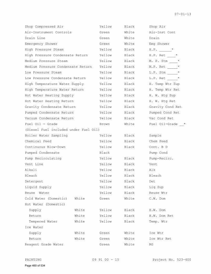
07-01-13
PAINTING 09 91 00 - 15 Project No. 523-400
Shop Compressed Air Yellow Black Shop Air
Air-Instrument Controls Green White Air-Inst Cont
Drain Line Green White Drain
Emergency Shower Green White Emg Shower
High Pressure Steam Yellow Black H.P. ______*
High Pressure Condensate Return Yellow Black H.P. Ret ____*
Medium Pressure Steam Yellow Black M. P. Stm ____*
Medium Pressure Condensate Return Yellow Black M.P. Ret _____*
Low Pressure Steam Yellow Black L.P. Stm _____*
Low Pressure Condensate Return Yellow Black L.P. Ret _____*
High Temperature Water Supply Yellow Black H. Temp Wtr Sup
High Temperature Water Return Yellow Black H. Temp Wtr Ret
Hot Water Heating Supply Yellow Black H. W. Htg Sup
Hot Water Heating Return Yellow Black H. W. Htg Ret
Gravity Condensate Return Yellow Black Gravity Cond Ret
Pumped Condensate Return Yellow Black Pumped Cond Ret
Vacuum Condensate Return Yellow Black Vac Cond Ret
Fuel Oil - Grade Brown White Fuel Oil-Grade __*
(Diesel Fuel included under Fuel Oil)
Boiler Water Sampling Yellow Black Sample
Chemical Feed Yellow Black Chem Feed
Continuous Blow-Down Yellow Black Cont. B D
Pumped Condensate Black Pump Cond
Pump Recirculating Yellow Black Pump-Recirc.
Vent Line Yellow Black Vent
Alkali Yellow Black Alk
Bleach Yellow Black Bleach
Detergent Yellow Black Det
Liquid Supply Yellow Black Liq Sup
Reuse Water Yellow Black Reuse Wtr
Cold Water (Domestic) White Green White C.W. Dom
Hot Water (Domestic)
Supply White Yellow Black H.W. Dom
Return White Yellow Black H.W. Dom Ret
Tempered Water White Yellow Black Temp. Wtr
Ice Water
Supply White Green White Ice Wtr
Return White Green White Ice Wtr Ret
Reagent Grade Water Green White RG
Page 460 of 534
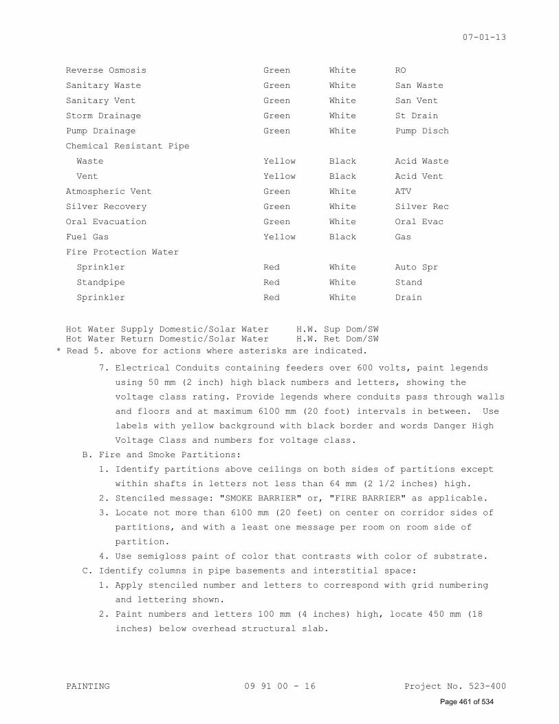
07-01-13
PAINTING 09 91 00 - 16 Project No. 523-400
Reverse Osmosis Green White RO
Sanitary Waste Green White San Waste
Sanitary Vent Green White San Vent
Storm Drainage Green White St Drain
Pump Drainage Green White Pump Disch
Chemical Resistant Pipe
Waste Yellow Black Acid Waste
Vent Yellow Black Acid Vent
Atmospheric Vent Green White ATV
Silver Recovery Green White Silver Rec
Oral Evacuation Green White Oral Evac
Fuel Gas Yellow Black Gas
Fire Protection Water
Sprinkler Red White Auto Spr
Standpipe Red White Stand
Sprinkler Red White Drain
Hot Water Supply Domestic/Solar Water H.W. Sup Dom/SW
Hot Water Return Domestic/Solar Water H.W. Ret Dom/SW
7. Electrical Conduits containing feeders over 600 volts, paint legends
using 50 mm (2 inch) high black numbers and letters, showing the
voltage class rating. Provide legends where conduits pass through walls
and floors and at maximum 6100 mm (20 foot) intervals in between. Use
labels with yellow background with black border and words Danger High
Voltage Class and numbers for voltage class.
B. Fire and Smoke Partitions:
1. Identify partitions above ceilings on both sides of partitions except
within shafts in letters not less than 64 mm (2 1/2 inches) high.
2. Stenciled message: "SMOKE BARRIER" or, "FIRE BARRIER" as applicable.
3. Locate not more than 6100 mm (20 feet) on center on corridor sides of
partitions, and with a least one message per room on room side of
partition.
4. Use semigloss paint of color that contrasts with color of substrate.
C. Identify columns in pipe basements and interstitial space:
1. Apply stenciled number and letters to correspond with grid numbering
and lettering shown.
2. Paint numbers and letters 100 mm (4 inches) high, locate 450 mm (18
inches) below overhead structural slab.
* Read 5. above for actions where asterisks are indicated.
Page 461 of 534
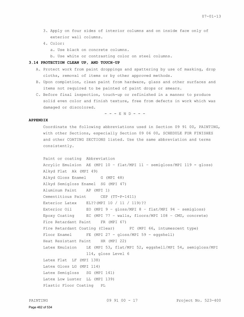
07-01-13
PAINTING 09 91 00 - 17 Project No. 523-400
3. Apply on four sides of interior columns and on inside face only of
exterior wall columns.
4. Color:
a. Use black on concrete columns.
b. Use white or contrasting color on steel columns.
3.14 PROTECTION CLEAN UP, AND TOUCH-UP
A. Protect work from paint droppings and spattering by use of masking, drop
cloths, removal of items or by other approved methods.
B. Upon completion, clean paint from hardware, glass and other surfaces and
items not required to be painted of paint drops or smears.
C. Before final inspection, touch-up or refinished in a manner to produce
solid even color and finish texture, free from defects in work which was
damaged or discolored.
- - - E N D - - -
APPENDIX
Coordinate the following abbreviations used in Section 09 91 00, PAINTING,
with other Sections, especially Section 09 06 00, SCHEDULE FOR FINISHES
and other COATING SECTIONS listed. Use the same abbreviation and terms
consistently.
Paint or coating Abbreviation
Acrylic Emulsion AE (MPI 10 – flat/MPI 11 – semigloss/MPI 119 - gloss)
Alkyd Flat Ak (MPI 49)
Alkyd Gloss Enamel G (MPI 48)
Alkyd Semigloss Enamel SG (MPI 47)
Aluminum Paint AP (MPI 1)
Cementitious Paint CEP (TT-P-1411)
Exterior Latex EL??(MPI 10 / 11 / 119)??
Exterior Oil EO (MPI 9 – gloss/MPI 8 – flat/MPI 94 – semigloss)
Epoxy Coating EC (MPI 77 – walls, floors/MPI 108 – CMU, concrete)
Fire Retardant Paint FR (MPI 67)
Fire Retardant Coating (Clear) FC (MPI 66, intumescent type)
Floor Enamel FE (MPI 27 – gloss/MPI 59 – eggshell)
Heat Resistant Paint HR (MPI 22)
Latex Emulsion LE (MPI 53, flat/MPI 52, eggshell/MPI 54, semigloss/MPI
114, gloss Level 6
Latex Flat LF (MPI 138)
Latex Gloss LG (MPI 114)
Latex Semigloss SG (MPI 141)
Latex Low Luster LL (MPI 139)
Plastic Floor Coating PL
Page 462 of 534
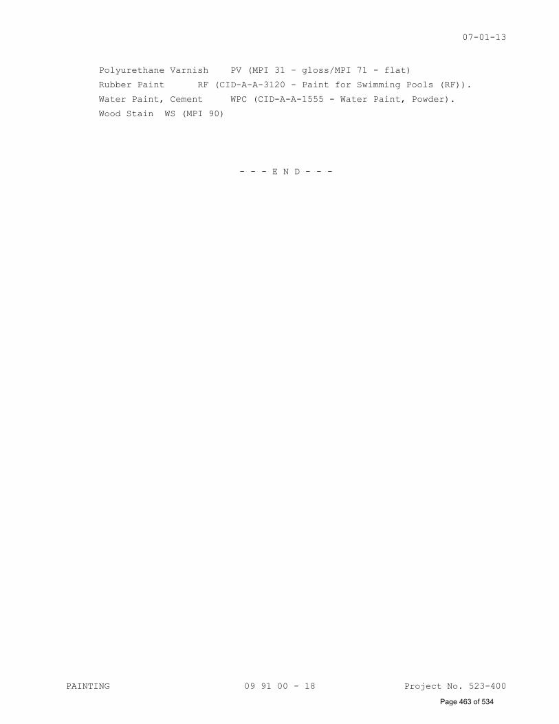
07-01-13
PAINTING 09 91 00 - 18 Project No. 523-400
Polyurethane Varnish PV (MPI 31 – gloss/MPI 71 - flat)
Rubber Paint RF (CID-A-A-3120 - Paint for Swimming Pools (RF)).
Water Paint, Cement WPC (CID-A-A-1555 - Water Paint, Powder).
Wood Stain WS (MPI 90)
- - - E N D - - -
Page 463 of 534
11-11
SIGNAGE 10 14 00 - 1 Project No. 523-400
SECTION 10 14 00
SIGNAGE
PART 1 - GENERAL
1.1 DESCRIPTION
A. This section specifies interior signage for room numbers, directional
signs and code required signs.
B. This section also specifies exterior parking and traffic signs.
1.2 RELATED WORK
A. Not applicable.
B. Lighted EXIT signs for egress purposes are specified under Division 26,
ELECTRICAL.
C. Not applicable.
D. Color Finish: Section 09 06 00, SCHEDULE FOR FINISHES.
1.3 MANUFACTURER'S QUALIFICATIONS
Sign manufacturer shall provide evidence that they regularly and
presently manufactures signs similar to those specified in this section
as one of their principal products.
1.4 SUBMITTALS
A. Submit in accordance with Section 01 33 23, SHOP DRAWINGS, PRODUCT DATA
AND SAMPLES.
B. Samples: Sign panels and frames, with letters and symbols, each type.
Submit 2 sets. One set of samples will be retained by Resident Engineer,
other returned to Contractor.
1. Sign Panel, 200 mm x 250 mm (8 inches x 10 inches), with letters.
2. Color samples of each color, 150 mm x 150 mm (6 inches x 6 inches.
Show anticipated range of color and texture.
3. Sample of typeface, arrow and symbols in a typical full size layout.
C. Manufacturer's Literature:
1. Showing the methods and procedures proposed for the concealed
anchorage of the signage system to each surface type.
2. Manufacturer’s printed specifications, anchorage details,
installation and maintenance instructions.
D. Samples: Sign location plan, showing location, type and total number of
signs required.
E. Shop Drawings: Scaled for manufacture and fabrication of sign types.
Identify materials, show joints, welds, anchorage, accessory items,
mounting and finishes.
F. Full size layout patterns for dimensional letters.
Page 464 of 534
11-11
SIGNAGE 10 14 00 - 2 Project No. 523-400
1.5 DELIVERY AND STORAGE
A. Deliver materials to job in manufacturer's original sealed containers
with brand name marked thereon. Protect materials from damage.
B. Package to prevent damage or deterioration during shipment, handling,
storage and installation. Maintain protective covering in place and in
good repair until removal is necessary.
C. Deliver signs only when the site and mounting services are ready for
installation work to proceed.
D. Store products in dry condition inside enclosed facilities.
1.6 APPLICABLE PUBLICATIONS
A. The publications listed below form a part of this specification to the
extent referenced. The publications are referenced in the text by the
basic designation only.
B. American Society for Testing and Materials (ASTM):
B209-07.................Aluminum and Aluminum-Alloy Sheet and Plate
B221-08.................Aluminum and Aluminum-Alloy Extruded Bars, Rods,
Wire, Shapes, and tubes.
C. Federal Specifications (Fed Spec):
MIL-PRF-8184F...........Plastic Sheet, Acrylic, Modified.
A-A-59502...............Plastic Sheet, Polycarbonate
1.7 MINIMUM SIGN REQUIREMENTS
A. Permanent Rooms and Spaces:
1. Tactile and Braille Characters, raised minimum 0.793 mm (1/32 in).
Characters shall be accompanied by Grade 2 Braille.
2. Type Styles: Characters shall be uppercase, Helvetica Medium,
Helvetica Medium Condensed and Helvetica Regular.
3. Character Height: Minimum 16 mm (5/8 in) high, Maximum 50 mm (2 in).
4. Symbols (Pictograms): Equivalent written description shall be placed
directly below symbol, outside of symbol's background field. Border
dimensions of symbol background shall be minimum 150 mm (6 in) high.
5. Finish and Contrast: Characters and background shall be eggshell,
matte or other non-glare finish with adequate contrast with
background.
6. Mounting Location and Height: As shown. Mounted on wall adjacent to
the latch side of the door and to avoid door swing and protruding
objects.
B. Overhead Signs:
1. Type Styles: As shown. Characters shall have a width-to-height ratio
between 3:5 and 1:1. Characters shall have a stroke width-to-height
ratio of between 1:5 and 1:10.
Page 465 of 534
11-11
SIGNAGE 10 14 00 - 3 Project No. 523-400
2. Character Height: minimum 75 mm (3 in) high for overhead signs. As
shown, for directional signs.
3. Finish and Contrast: Same as for signs of permanent rooms and spaces.
4. Mounting Location and Height: As shown.
1.8 COLORS AND FINISHES:
Section 09 06 00, SCHEDULE FOR FINSIHES.
PART 2 - PRODUCTS
2.1 GENERAL
A. Signs of type, size and design shown on the drawings and as specified.
B. Signs complete with lettering, framing and related components for a
complete installation.
C. Provide graphics items as completed units produced by a single
manufacturer, including necessary mounting accessories, fittings and
fastenings.
D. Do not scale drawings for dimensions. Contractor to verify and be
responsible for all dimensions and conditions shown by these drawings.
Resident Engineer to be notified of any discrepancy in drawing, in field
directions or conditions, and/or of any changes required for all such
construction details.
E. The Sign Contractor, by commencing work of this section, assumes overall
responsibility, as part of his warranty of work, to assure that
assemblies, components and parts shown or required within the work of
the section, comply with the Contract Documents. The Contractor shall
further warrant: That all components, specified or required to
satisfactorily complete the installation are compatible with each other
and with conditions of installations.
2.2 PRODUCTS
A. Aluminum:
1. Sheet and Plate: ASTM B209.
2. Extrusions and Tubing: ASTM B221.
B. Cast Acrylic Sheet: MIL-PRF-8184F; Type II, class 1, Water white non-
glare optically clear. Matt finish water white clear acrylic shall not
be acceptable.
C. Polycarbonate: A-A-59502; Type I, class 1.
D. Vinyl: 0.1 mm thick machine cut, having a pressure sensitive adhesive
and integral colors.
F. Concrete Post Footings: See Section 03 30 00, CAST-IN-PLACE CONCRETE,
Cast-in-place Concrete.
Page 466 of 534
11-11
SIGNAGE 10 14 00 - 4 Project No. 523-400
2.3 SIGN STANDARDS
A. Topography:
1. Type Style: Helvetica Medium and Helvetica Medium Condensed. Initial
caps or all caps as indicated in Sign Message Schedule.
2. Arrow: See graphic standards in drawings.
3. Letter spacing: See graphic standards on drawings.
4. Letter spacing: See graphic standards on drawings.
5. All text, arrows, and symbols to be provided in size, colors,
typefaces and letter spacing shown. Text shall be a true, clean,
accurate reproduction of typeface(s) shown. Text shown in drawings
are for layout purposes only; final text for signs is listed in Sign
Message Schedule.
B. Project Colors and Finishes: See Section 09 06 00, SCHEDULE FOR
FINISHES.
2.4 INTERIOR SIGN TYPES
A. General:
1. The interior sign system is comprised of sign types families that are
identified by a letter and number which identify a particular group
of signs. An additional number identifies a specific type of sign
within that family.
a. IN indicates a component construction based sign.
B. Not Applicable.
C. Not applicable.
D. Not applicable.
E. Sign Type Family 04:
1. All text and graphics are to be first surface applied vinyl letters.
2.4 PARKING STRUCTURE SIGN TYPES
A. General:
1. PS indicates a parking structure sign.
a. The parking structure sign system shall be comprised of sign type
families that are identified by two numbers which identify a
particular sign type family. An additional number identifies a
specific type of sign within that sign family. A letter designates
a specific sign configuration, version and/or layout for graphics.
B. Sign Type PS-08:
1. Shall be 10 inch high, cast aluminum dimensional letters.
a. Letters to be 1 inch thick and constructed for projected mounting.
b. Finish: As selected by COR.
C. Sign Type PS-09.01:
1. Shall be Clearance Height Bang Bar.
a. 6 inch diameter PVC tubing.
Page 467 of 534
11-11
SIGNAGE 10 14 00 - 5 Project No. 523-400
b. Surface applied vinyl graphics.
c. Black text on yellow background with black stripes.
d. Ceiling mounted signs required mounting hardware on the sign that
allows for sign disconnection, removal and reinstallation and
reconnection.
D. Sign Type PS-12.04:
1. Shall be handicap parking stall.
a. Post mounted option.
b. Sign Face: Aluminum sheet, 1’-6” high by 1’-0” wide.
c. Surface applied reflective vinyl graphics. Message layout A.
d. Top of sign to be 6 foot high.
2.5 FABRICATION
A. Design components to allow for expansion and contraction for a minimum
material temperature range of 56 °C (100 °F), without causing buckling,
excessive opening of joints or over stressing of adhesives, welds and
fasteners.
B. Form work to required shapes and sizes, with true curve lines and
angles. Provide necessary rebates, lugs and brackets for assembly of
units. Use concealed fasteners whenever and wherever possible.
C. Shop fabricate so far as practicable. Joints fastened flush to conceal
reinforcement, or welded where thickness or section permits.
D. Contact surfaces of connected members be true. Assembled so joints will
be tight and practically unnoticeable, without use of filling compound.
E. Signs shall have fine, even texture and be flat and sound. Lines and
miters sharp, arises unbroken, profiles accurate and ornament true to
pattern. Plane surfaces be smooth flat and without oil-canning, free of
rack and twist. Maximum variation from plane of surface plus or minus
0.3 mm (0.015 inches). Restore texture to filed or cut areas.
F. Level or straighten wrought work. Members shall have sharp lines and
angles and smooth su1rfaces.
G. Extruded members to be free from extrusion marks. Square turns and
corners sharp, curves true.
H. Drill holes for bolts and screws. Conceal fastenings where possible.
Exposed ends and edges mill smooth, with corners slightly rounded. Form
joints exposed to weather to exclude water.
I. Finish hollow signs with matching material on all faces, tops, bottoms
and ends. Edge joints tightly mitered to give appearance of solid
material.
J. All painted surfaces properly primed. Finish coating of paint to have
complete coverage with no light or thin applications allowing substrate
or primer to show. Finished surface smooth, free of scratches, gouges,
Page 468 of 534
11-11
SIGNAGE 10 14 00 - 6 Project No. 523-400
drips, bubbles, thickness variations, foreign matter and other
imperfections.
K. Not Applicable.
L. Pre-assemble items in shop to greatest extent possible to minimize field
splicing and assembly. Disassemble units only as necessary for shipping
and handling limitations. Clearly mark units for re-assembly and
coordinated installation.
M. No signs are to be manufactured until final sign message schedule and
location review has been completed by the Resident Engineer & forwarded
to contractor.
PART 3 - EXECUTION
3.1 INSTALLATION
A. Protect products against damage during field handling and installation.
Protect adjacent existing and newly placed construction, landscaping and
finishes as necessary to prevent damage during installation. Paint and
touch up any exposed fasteners and connecting hardware to match color
and finish of surrounding surface.
B. Mount signs in proper alignment, level and plumb according to the sign
location plan and the dimensions given on elevation and sign location
drawings. Where otherwise not dimensioned, signs shall be installed
where best suited to provide a consistent appearance throughout the
project. When exact position, angle, height or location is in doubt,
contact Resident Engineer for clarification.
C. Contractor shall be responsible for all signs that are damaged, lost or
stolen while materials are on the job site and up until the completion
and final acceptance of the job.
D. Remove or correct signs or installation work Resident Engineer
determines as unsafe or as an unsafe condition.
E. At completion of sign installation, clean exposed sign surfaces. Clean
and repair any adjoining surfaces and landscaping that became soiled or
damaged as a result of installation of signs.
F. Locate signs as shown on the Sign Location Plans.
G. Not applicable.
H. Contractor will be responsible for verifying that behind each sign
location there are no utility lines that will be affected by
installation of signs. Any damage during installation of signs to
utilities will be the sole responsibility of the Contractor to correct
and repair.
I. Furnish inserts and anchoring devices which must be set in concrete or
other material for installation of signs. Provide setting drawings,
Page 469 of 534

11-11
SIGNAGE 10 14 00 - 7 Project No. 523-400
templates, instructions and directions for installation of anchorage
devices which may involve other trades.
- - - END - - -
Page 470 of 534
08-01-14
FIRE EXTINGUISHER CABINETS 10 44 13 - 1 Project No. 523-400
SECTION 10 44 13
FIRE EXTINGUISHER CABINETS
PART 1 - GENERAL
1.1 DESCRIPTION
This section covers recessed fire extinguisher cabinets.
1.2 RELATED WORK
Not Applicable
1.3 SUBMITTALS
A. Submit in accordance with Section 01 33 23, SHOP DRAWINGS, PRODUCT
DATA, AND SAMPLES.
B. Manufacturer's Literature and Data: Fire extinguisher cabinet including
installation instruction and rough opening required.
1.4 APPLICATION PUBLICATIONS
A. The publications listed below form a part of this specification to the
extent referenced. The publications are referenced in the text by the
basic designation only.
B. American Society of Testing and Materials (ASTM):
D4802-10................Poly (Methyl Methacrylate) Acrylic Plastic
Sheet
PART 2 - PRODUCTS
2.1 FIRE EXTINGUISHER CABINET
Surface-mounted type with flat trim of size and design shown.
2.2 FABRICATION
A. Form body of cabinet from 0.9 mm (0.0359 inch) thick sheet steel.
B. Fabricate door and trim from 1.2 mm (0.0478 inch) thick sheet steel
with all face joints fully welded and ground smooth.
1. Glaze doors with 6 mm (1/4 inch) thick ASTM D4802, clear acrylic
sheet, Category B-1, Finish 1.
2. Design doors to open 180 degrees.
3. Provide continuous hinge, pull handle, and adjustable roller catch.
2.3 FINISH
A. Finish interior of cabinet body with baked-on semigloss white enamel.
B. Finish door, frame with manufacturer's standard baked-on prime coat
suitable for field painting.
PART 3 - EXECUTION
A. Install fire extinguisher cabinets in prepared openings and secure in
accordance with manufacturer's instructions.
Page 471 of 534
08-01-14
FIRE EXTINGUISHER CABINETS 10 44 13 - 2 Project No. 523-400
B. Install cabinet so that bottom of cabinet is 914 mm (36 inches) above
finished floor.
- - - E N D - - -
Page 472 of 534
11-11
PARKING CONTROL EQUIPMENT 11 12 00 - 1 Project No. 523-400
SECTION 11 12 00
PARKING CONTROL EQUIPMENT
PART 1 GENERAL:
1.1 DESCRIPTION:
A. Section Includes:
1. Automatic Barrier Gates.
2. Vehicle Detectors.
3. Card Control Units.
1.2 RELATED WORK:
A. Conduit placement for equipment: Section 26 05 33, RACEWAY AND BOXES
FOR ELECTRICAL SYSTEMS
B. Electrical characteristics and wiring connections: Section 26 27 26,
WIRING DEVICES.
1.3 QUALITY CONTROL:
A. Qualifications:
1. Approval by Contracting Officer is required of products or service
of proposed manufacturer, suppliers, and installers, and will be
based upon submission by Contractor of certification that:
a. Installer: Approved by manufacturer of materials and has
technical qualifications, experience, trained personnel and
facilities to install specified items.
b. Manufacturer's product submitted has been in satisfactory
operation, on three installations similar and equivalent in size
to this project, for three years. Submit list of installations.
2. Maintenance Proximity: Installer shall maintain a place of business
with maintenance facilities not more than two (2) hours normal
travel time from project site.
3. UL and NEMA Compliance: Provide internal electrical components
required as part of parking control equipment that are listed by UL
and comply with applicable NEMA standards.
4. Single-Source Responsibility: Obtain parking control equipment from
one source and from a single manufacturer.
1.4 SUBMITTALS:
A. In accordance with Section 01 33 23, SHOP DRAWINGS, PRODUCT DATA, AND
SAMPLES, submit following:
1. Manufacturer's Literature and Data:
Page 473 of 534
11-11
PARKING CONTROL EQUIPMENT 11 12 00 - 2 Project No. 523-400
a. Description of parking control equipment material and accessories
to be provided.
b. Provide data on operating equipment, characteristics and
limitations, and operating temperature ranges.
2. Shop Drawings and Certificates: Indicate plan layout of equipment
access lanes, mounting bolt dimensions, conduit and outlet
locations, power requirements, and conformation of building
electrical requirements. Provide Contractor with mounting bolt
template in time for installation.
3. Wiring Diagrams: Detailing wiring for parking control equipment
operator, signal, and control systems differentiating clearly
between manufacturer-installed wiring and field-installed wiring.
a. Show locations of connections to electrical service provided as a
unit of work under other Divisions.
4. Maintenance Data: For parking control equipment components for
inclusion in Operating and Maintenance Manuals, include the
following:
a. Maintenance Instructions: Provide manufacturer’s instructions for
maintenance of parking control equipment.
1) Include recommended methods and frequency for maintaining
equipment in optimum operating condition under anticipated
traffic and use conditions.
2) Include precautions against materials and methods that may be
detrimental to finishes and performance.
3) Lubrication Schedule and Information: Provide lubrication and
periodic maintenance requirement schedules including parts
list and parts numbers.
5. Operation Data: Provide operating data for operating equipment,
including clock timer, changing security access code, and any other
pertinent information required for Government operation.
6. Certificates: Quality Control Certificate Submittals and lists
specified in paragraph, QUALIFICATIONS.
B. In accordance with Section 01 00 00, GENERAL REQUIREMENTS, submit
following at project closeout: Guaranty.
C. In accordance with Section 01 00 00, GENERAL REQUIREMENTS, submit
following at project closeout:
1. Project Record Documents: Record actual locations of concealed
conduit and vehicle detection activators.
Page 474 of 534
11-11
PARKING CONTROL EQUIPMENT 11 12 00 - 3 Project No. 523-400
1.5 REGULATORY REQUIREMENTS:
A. Conform to NFPA code for fire/ambulance emergency vehicle access.
B. Products Requiring Electrical Connection: Listed and classified by UL
as suitable for purpose specified and indicated.
1.6 PROJECT CONDITIONS:
A. Coordinate placement of conduit, accessories, and power wiring to
operating equipment.
B. Sequence installation to ensure utility connections are achieved in an
orderly and expeditious manner.
1.7 DELIVERY, STORAGE AND HANDLING:
A. Deliver materials to site in original sealed packages or containers;
labeled for identification with manufacturer's name and brand.
B. Store materials in weathertight and dry storage facility. Protect from
damage due to handling, weather, and construction operations before,
during and after installation.
1.8 APPLICABLE PUBLICATIONS:
A. Publications listed below form a part of this specification to extent
referenced. Publications are referenced in text by basic designation
only.
B. American Society for Testing Materials (ASTM):
A153/A153M-09...........Standard Specification for Zinc Coating (Hot-
Dip) on Iron and Steel Hardware.
A500-10.................Standard Specification for Cold-Formed Welded
and Seamless Carbon Steel Structural Tubing in
Rounds and Shapes.
A653/A653M-10...........Standard Specification for Steel Sheet, Zinc-
Coated (Galvanized) by the Hot-Dip Process,
Structural (Physical) Quality.
C. National Electrical Manufacturers Association (NEMA):
MG 1-09(R2010)..........Motors and Generators.
D. National Fire Protection Association (NFPA):
70-11...................National Electrical Code.
E. Underwriters Laboratories Inc. (UL):
Electrical Appliance and Utilization Equipment Directory.
1.9 SYSTEM DESCRIPTION:
A. Parking Control System: Automatic operation at entrance and automatic
operation at exit.
Page 475 of 534
11-11
PARKING CONTROL EQUIPMENT 11 12 00 - 4 Project No. 523-400
B. Design: Protect against interference or damage by lightning or other
electrical influence; include fuse, over-voltage protection, flash-over
protection, and line filter.
C. Entry – Automatic Gate Arm Control: Electrically operated upon
insertion of coded card. Activate automatic arm reversing switch if an
obstacle is sensed in downward motion. Loop Detection shall close the
gate once a vehicle has cleared the gate area.
D. Exit – Automatic Gate Arm Control: Electrically operated upon detection
of vehicle by sensing loop buried in pavement. Activate automatic arm
reversing switch if an obstacle is sensed in the downward motion.
1.10 SCHEDULING:NOT USED
1.11 WARRANTY
A. Submit manufacturer's written warranty for materials and installation.
Warranty shall be for one year.
1. Warranty: Cover keeping equipment operational.
2. Final Acceptance: Requirement for final acceptance shall be
continued acceptable use of parking control equipment without a
breakdown or stoppage for a period of fifteen (15) calendar days
after final acceptance of project by Government.
PART 2 PRODUCTS
2.1 MATERIALS:
A. Iron and Steel Hardware: ASTM A153; Zinc coating (hot-dip) on iron and
steel hardware.
B. Steel: ASTM A653/A653M; Galvanized to G90.
C. Structural tubing in rounds and shapes: A500; Cold-Formed Welded and
Seamless Carbon Steel Structural Tubing in Rounds and Shapes.
D. Wood: Clear fir or cedar.
2.2 AUTOMATIC GATE:
A. Provide UL approved automatic barrier gate parking access-control
system.
B. Cabinet: 1.9 mm, ( 0.075 inch) minimum cold-rolled steel sheet
cabinet, welded and weather tight seams, reinforced internally with
welded steel angle framing, thermally insulated to permit heater to
maintain cabinet temperature to equipment operating minimum, flush
access doors and panels, tamper proof hardware, weather tight gaskets,
master keyed locks; furnish two (2) keys for each gate, keyed alike.
Conceal mounting bolts inside units:
Page 476 of 534
11-11
PARKING CONTROL EQUIPMENT 11 12 00 - 5 Project No. 523-400
1. Finish cabinet, interior and exterior, with manufacturer’s standard
white baked enamel finish over primer system.
C. Arm Control: Mechanism to raise and lower arm by instant reversing
electric motor, enclosed speed reducer operated by self-contained,
plug-in replaceable controller. Design mechanism with slip clutch to
prevent breakage if arm is forced, and to permit manual operation if
required. Arm movement to stop and start at reduced speed. Components
of zinc coated steel.
D. Electrical Components: Self-contained, plug-in, replaceable components.
Include wiring for control units, zinc plated connection box, grounded
convenience outlet, switch for automatic or manual operation, switch to
disconnect power unit, thermostatically controlled minimum 250 Watt
heater strip with control switch and preset thermostat, and thermal
protection disconnect for motor.
2.3 ELECTRICAL CHARACTERISTICS AND COMPONENTS:
A. Electrical Characteristics:
1. Provide 115 volts AC, single phase, 60 Hz.
2. Refer to Section 26 27 26, WIRING DEVICES: Electrical connections.
B. Motor: Instant reversing motor for operation of gate arm. Refer to
Section 26 29 21, DISCONNECT SWITCHES.
C. Controls: Transmit power to gate arm drive shaft through a harmonic
acting crank and connecting rod. Fabricate cranks, rod, and drive shaft
of galvanized solid bar steel.
D. Wiring Terminations: Provide terminal lugs to match branch circuit
conductor quantities, sizes, and materials indicated. Enclose terminal
lugs in terminal box sized to NFPA 70.
E. Disconnect Switch: Factory mount disconnect switch in control panel.
2.4 ARM AND SUPPORT:
A. Gate Arm: Fabricate gate arm of nominal 25 mm (1 inch) thick, length as
indicated, of Wood, one piece arm, articulating arm with internal
counterbalance, with safety rubber bottom edge and automatic instant
reversing arm mechanism that stops downward motion of gates if arm
strikes an object, and returning arm immediately to upward position.
Equip mechanism with a 0 to 60 second variable time reset device.
1. Finish with manufacturer’s standard coating system with black
diagonal stripes on traffic side face.
Page 477 of 534
11-11
PARKING CONTROL EQUIPMENT 11 12 00 - 6 Project No. 523-400
B. Arm Clamp: Cast metal, quick change clamp and hub bracket, to permit
rapid replacement of arm without fitting or drilling. Provide breakaway
feature to ensure clean break if arm is struck.
C. End support post required for gate arm of 4.3 m (14 feet) or longer.
D. End Support Post: 50 mm ( 2 inch) square, round or steel tubular
section; 1940 mm ( 37 inches) high, 3.4 mm, (0.135 inch) minimum wall
thickness; with alignment bracket, closed cap and baseplate.
E. Padlocking Feature: To lock gate arm in either open or closed position,
if required.
2.5 CARD CONTROL:
A. General: Provide pedestal mounted card control units to activate
barrier gates.
B. Control Unit: To activate gate arm by insertion of coded card; Card
access system shall be provided by the electrical contractor as a stand
alone, general building PAC system and not part of the gate access
control system.
C. Cabinet: 1.9 mm (0.075 inch) minimum welded cold-rolled steel sheet,
weather tight seams; thermally insulated to permit heater to maintain
cabinet temperature to equipment operating minimum, flush access doors
and panels, tamper proof flush mounted lock hardware and two (2) keys
to operate access panel, weather tight gaskets. Conceal mounting bolts
inside units.
1. Mount housing on a 50 mm (2 inch) square steel tube pedestal with a
curved top to receive housing, and a trim plate to cover anchor
bolts.
2. Finish interior and exterior of cabinet with manufacturer’s standard
baked enamel finish over primer.
2.6 VEHICLE DETECTION:
A. Vehicle Detection: For use in temperature range of -40 to 71 C; ((-40
to 160) F) to consist of detector unit in conjunction with sensing
loop to activate barrier gate when vehicle enters or exits to reclose
the gate following a gate opening with card access.
B. Loop Wire: 14 gage, XHWN or THWN copper; loop size of 1 200 X 1 800 mm.
((48 X 72) inches.)
C. Loop Groove Fill: Same material as pavement.
D. Treadle Plate: Stainless steel, 3300 X 1800 mm size, (12 X 72 inches;
to consist of weatherproof sensor detector to activate barrier gate
Page 478 of 534
11-11
PARKING CONTROL EQUIPMENT 11 12 00 - 7 Project No. 523-400
when vehicle enters or exits to reclose the gate following a card
access opening.
2.7 FINISHES:
A. Gate Arm: Two coat enamel with reflective black and yellow diagonal
stripes both sides of arm.
B. Gate Posts and Cabinets: Baked enamel on steel, color as selected by
the owner.
PART 3 EXECUTION
3.1 EXAMINATION:
A. Verification of existing conditions before starting work:
1. Prior to beginning installation, examine areas to receive parking
control equipment. Verify that critical dimensions are correct and
that conditions are acceptable:
a. Do not proceed with installation of parking control equipment
until unsatisfactory conditions have been corrected.
B. Verify that anchor bolts, are ready to receive work and dimensions are
as indicated on shop drawings.
C. Verify that electric power is available and of correct characteristics.
3.2 PREPARATION
Provide templates for anchor bolts and other items encased in concrete
or below finished surfaces in sufficient time so as not to delay work.
3.3 INSTALLATION
A. Install parking control system and components in accordance with
manufacturer’s instructions and placement drawings.
B. Cut grooves in pavement surface, install vehicle detection loops and
lead-in wires, and fill grooves with loop filler.
C. Install internal electrical wiring, conduit, junction boxes,
transformers, circuit breakers, and auxiliary components required.
3.4 ADJUSTING
A. Prior to final acceptance of project adjust system components for
smooth operation.
B. Fit and adjust hardware for ease of operation.
1. Lubricate hardware and other moving parts.
2. Readjust parking control system and components at completion of
project.
Page 479 of 534
11-11
PARKING CONTROL EQUIPMENT 11 12 00 - 8 Project No. 523-400
3.5 CLEANING
A. Clean metal surfaces promptly after installation, exercising care to
avoid damage to coatings. Touch up damaged shop-applied finishes as
required to restore damaged areas.
B. Follow recommendations of manufacturer in selection of cleaning agents.
Do not use cleaning agents containing ammonia or other compounds that
might damage finished metal surfaces.
3.6 FIELD QUALITY CONTROL
A. Tests:
1. Test operating functions in accordance with manufacturer’s printed
checklist.
2. Correct defects revealed by tests. Retest corrected areas until
functions are operating properly.
3.7 DEMONSTRATION, TESTING AND ACCEPTANCE
A. Instruct Owner’s personnel in proper operation and maintenance of
parking control equipment. Train personnel in procedures to follow in
event of operational failures or malfunctions.
B. Acceptance: At completion of project, and as a condition of acceptance,
parking control equipment and systems shall be operated for a period of
15 consecutive calendar days without breakdown.
3.8 PROTECTION:
A. Protect parking control equipment finished surfaces from damage during
erection, and after completion of work until final inspection and
acceptance.
- - - END - - -
Page 480 of 534
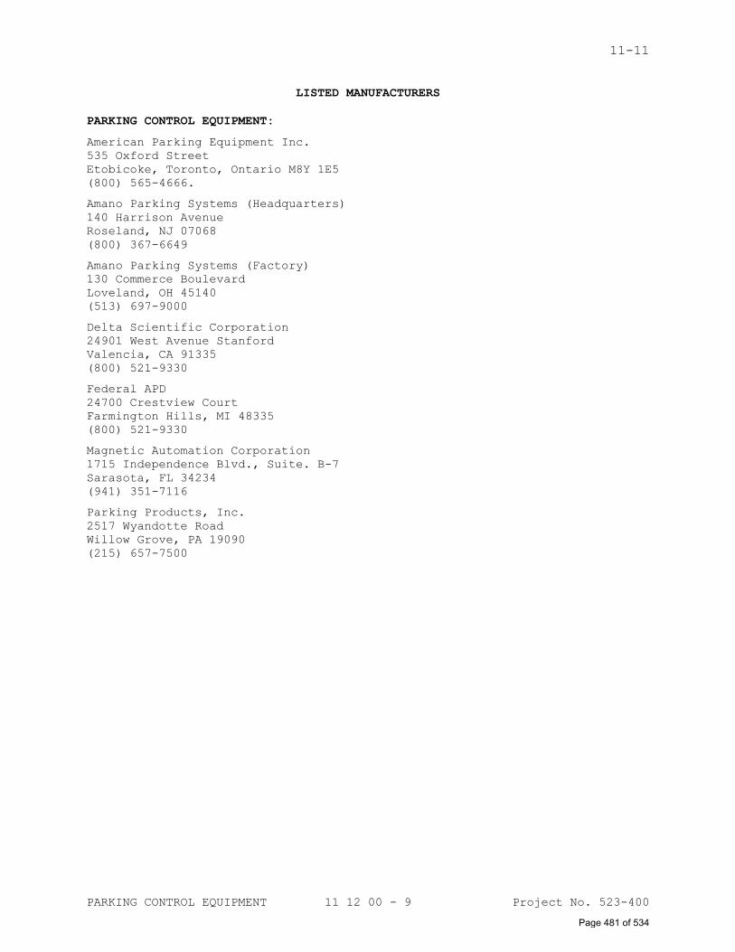
11-11
PARKING CONTROL EQUIPMENT 11 12 00 - 9 Project No. 523-400
LISTED MANUFACTURERS
PARKING CONTROL EQUIPMENT:
American Parking Equipment Inc.
535 Oxford Street
Etobicoke, Toronto, Ontario M8Y 1E5
(800) 565-4666.
Amano Parking Systems (Headquarters)
140 Harrison Avenue
Roseland, NJ 07068
(800) 367-6649
Amano Parking Systems (Factory)
130 Commerce Boulevard
Loveland, OH 45140
(513) 697-9000
Delta Scientific Corporation
24901 West Avenue Stanford
Valencia, CA 91335
(800) 521-9330
Federal APD
24700 Crestview Court
Farmington Hills, MI 48335
(800) 521-9330
Magnetic Automation Corporation
1715 Independence Blvd., Suite. B-7
Sarasota, FL 34234
(941) 351-7116
Parking Products, Inc.
2517 Wyandotte Road
Willow Grove, PA 19090
(215) 657-7500
Page 481 of 534
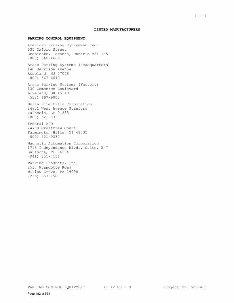
11-11
PARKING CONTROL EQUIPMENT 11 12 00 - 9 Project No. 523-400
LISTED MANUFACTURERS
PARKING CONTROL EQUIPMENT:
American Parking Equipment Inc.
535 Oxford Street
Etobicoke, Toronto, Ontario M8Y 1E5
(800) 565-4666.
Amano Parking Systems (Headquarters)
140 Harrison Avenue
Roseland, NJ 07068
(800) 367-6649
Amano Parking Systems (Factory)
130 Commerce Boulevard
Loveland, OH 45140
(513) 697-9000
Delta Scientific Corporation
24901 West Avenue Stanford
Valencia, CA 91335
(800) 521-9330
Federal APD
24700 Crestview Court
Farmington Hills, MI 48335
(800) 521-9330
Magnetic Automation Corporation
1715 Independence Blvd., Suite. B-7
Sarasota, FL 34234
(941) 351-7116
Parking Products, Inc.
2517 Wyandotte Road
Willow Grove, PA 19090
(215) 657-7500
Page 482 of 534
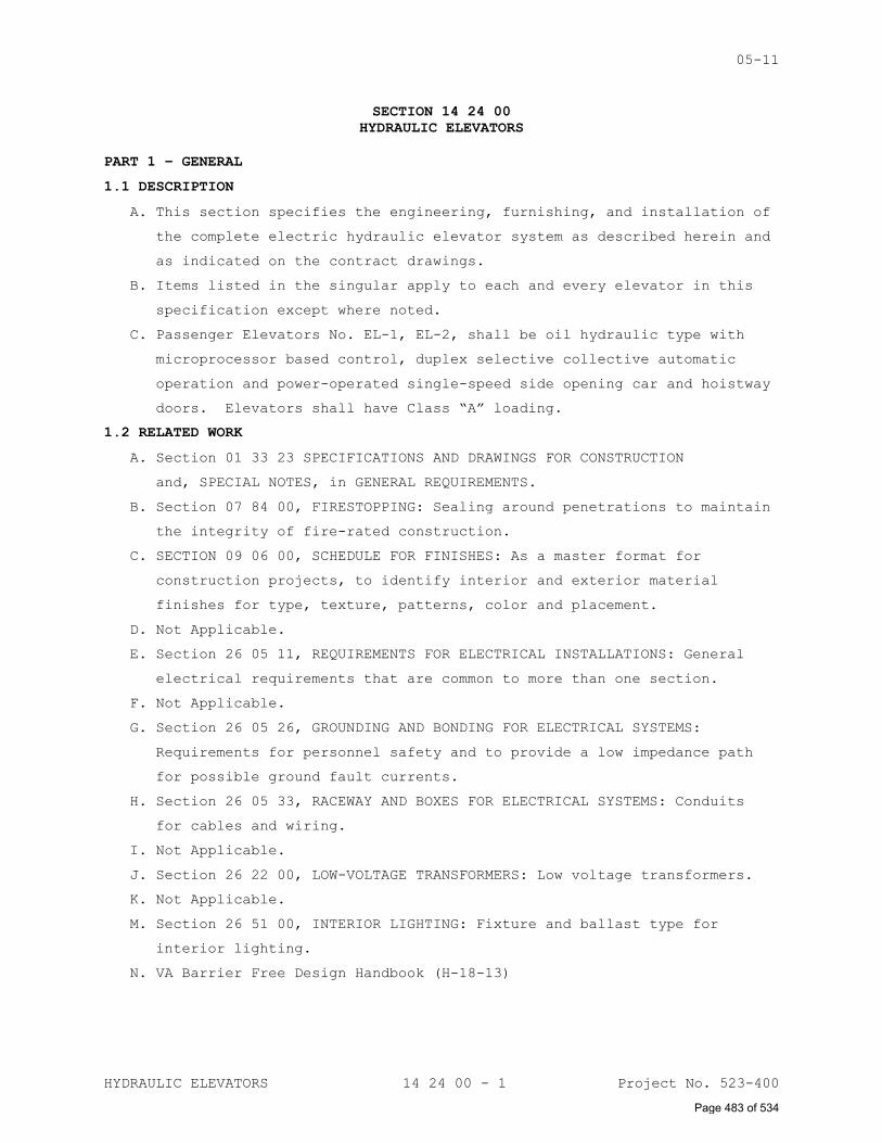
05-11
HYDRAULIC ELEVATORS 14 24 00 - 1 Project No. 523-400
SECTION 14 24 00
HYDRAULIC ELEVATORS
PART 1 – GENERAL
1.1 DESCRIPTION
A. This section specifies the engineering, furnishing, and installation of
the complete electric hydraulic elevator system as described herein and
as indicated on the contract drawings.
B. Items listed in the singular apply to each and every elevator in this
specification except where noted.
C. Passenger Elevators No. EL-1, EL-2, shall be oil hydraulic type with
microprocessor based control, duplex selective collective automatic
operation and power-operated single-speed side opening car and hoistway
doors. Elevators shall have Class “A” loading.
1.2 RELATED WORK
A. Section 01 33 23 SPECIFICATIONS AND DRAWINGS FOR CONSTRUCTION
and, SPECIAL NOTES, in GENERAL REQUIREMENTS.
B. Section 07 84 00, FIRESTOPPING: Sealing around penetrations to maintain
the integrity of fire-rated construction.
C. SECTION 09 06 00, SCHEDULE FOR FINISHES: As a master format for
construction projects, to identify interior and exterior material
finishes for type, texture, patterns, color and placement.
D. Not Applicable.
E. Section 26 05 11, REQUIREMENTS FOR ELECTRICAL INSTALLATIONS: General
electrical requirements that are common to more than one section.
F. Not Applicable.
G. Section 26 05 26, GROUNDING AND BONDING FOR ELECTRICAL SYSTEMS:
Requirements for personnel safety and to provide a low impedance path
for possible ground fault currents.
H. Section 26 05 33, RACEWAY AND BOXES FOR ELECTRICAL SYSTEMS: Conduits
for cables and wiring.
I. Not Applicable.
J. Section 26 22 00, LOW-VOLTAGE TRANSFORMERS: Low voltage transformers.
K. Not Applicable.
M. Section 26 51 00, INTERIOR LIGHTING: Fixture and ballast type for
interior lighting.
N. VA Barrier Free Design Handbook (H-18-13)
Page 483 of 534
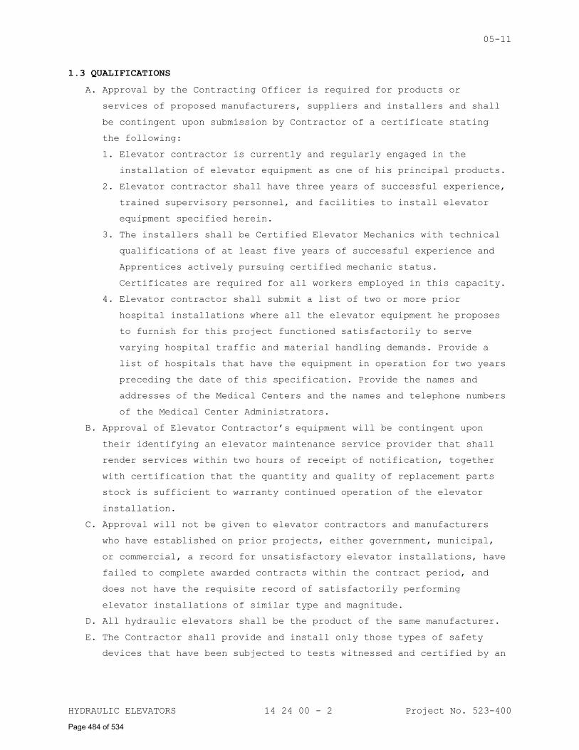
05-11
HYDRAULIC ELEVATORS 14 24 00 - 2 Project No. 523-400
1.3 QUALIFICATIONS
A. Approval by the Contracting Officer is required for products or
services of proposed manufacturers, suppliers and installers and shall
be contingent upon submission by Contractor of a certificate stating
the following:
1. Elevator contractor is currently and regularly engaged in the
installation of elevator equipment as one of his principal products.
2. Elevator contractor shall have three years of successful experience,
trained supervisory personnel, and facilities to install elevator
equipment specified herein.
3. The installers shall be Certified Elevator Mechanics with technical
qualifications of at least five years of successful experience and
Apprentices actively pursuing certified mechanic status.
Certificates are required for all workers employed in this capacity.
4. Elevator contractor shall submit a list of two or more prior
hospital installations where all the elevator equipment he proposes
to furnish for this project functioned satisfactorily to serve
varying hospital traffic and material handling demands. Provide a
list of hospitals that have the equipment in operation for two years
preceding the date of this specification. Provide the names and
addresses of the Medical Centers and the names and telephone numbers
of the Medical Center Administrators.
B. Approval of Elevator Contractor’s equipment will be contingent upon
their identifying an elevator maintenance service provider that shall
render services within two hours of receipt of notification, together
with certification that the quantity and quality of replacement parts
stock is sufficient to warranty continued operation of the elevator
installation.
C. Approval will not be given to elevator contractors and manufacturers
who have established on prior projects, either government, municipal,
or commercial, a record for unsatisfactory elevator installations, have
failed to complete awarded contracts within the contract period, and
does not have the requisite record of satisfactorily performing
elevator installations of similar type and magnitude.
D. All hydraulic elevators shall be the product of the same manufacturer.
E. The Contractor shall provide and install only those types of safety
devices that have been subjected to tests witnessed and certified by an
Page 484 of 534
05-11
HYDRAULIC ELEVATORS 14 24 00 - 3 Project No. 523-400
independent professional testing laboratory that is not a subsidiary of
the firm that manufactures supplies or installs the equipment.
F. Welding at the project site shall be made by welders and welding
operators who have previously qualified by test as prescribed in
American Welding Society Publications AWS Dl.1 to perform the type of
work required. VAMC shall require welding certificates be submitted
for all workers employed in this capacity. A welding or hot work permit
is required for each day and shall be obtained from the COTR of safety
department. Request permit one day in advance.
1.4 APPLICABLE PUBLICATIONS
A. The publications listed below form a part of this specification.
Elevator installation shall meet the requirements of the latest
editions published and adopted by the United States Department of
Veterans Affairs on the date contract is signed.
B. Federal Specifications (Fed. Spec.):
J-C-30B.................Cable and Wire, Electrical (Power, Fixed
Installation)
W-C-596F................Connector, Plug, Electrical; Connector,
Receptacle, Electrical
W-F-406E................Fittings for Cable, Power, Electrical and
Conduit, Metal, Flexible
HH-I-558C...............Insulation, Blankets, Thermal (Mineral Fiber,
Industrial Type)
W-F-408E................Fittings for Conduit, Metal, Rigid (Thick- Wall
and Thin-wall (EMT) Type)
RR-W-410................Wire Rope and Strand
TT-E-489J...............Enamel, Alkyd, Gloss, Low VOC Content
QQ-S-766 ...............Steel, Stainless and Heat Resisting, Alloys,
Plate, Sheet and Strip
C. International Building Code (IBC)
D. American Society of Mechanical Engineers (ASME):
A17.1...................Safety Code for Elevators and Escalators
A17.2...................Inspectors Manual for Electric Elevators and
Escalators
E. National Fire Protection Association:
NFPA 13..........Standard for the Installation of Sprinkler Systems
NFPA 70..........National Electrical Code (NEC)
NFPA 72..........National Fire Alarm and Signaling Code
Page 485 of 534
05-11
HYDRAULIC ELEVATORS 14 24 00 - 4 Project No. 523-400
NFPA 101.........Life Safety Code
NFPA 252.........Fire Test of Door Assemblies
F. American Society for Testing and Materials (ASTM):
A1008/A1008M-09.........Steel, Sheet, Cold Rolled, Carbon, Structural,
High-Strength Low-Alloy and High Strength Low-
Alloy with Improved Farability
E1042-02................Acoustically Absorptive Materials Applied by
Trowel or Spray
G. Manufacturer's Standardization Society of the Valve and Fittings
Industry (MSS):
SP-58...................Pipe Hangers and Supports
H. Society of Automotive Engineers, Inc. (SAE)
J517-91..................Hydraulic Hose, Standard
I. Gages:
For Sheet and Plate: U.S. Standard (USS)
For Wires: American Wire Gauge (AWG)
J. American Welding Society (AWS):
D1.1....................Structured Welding Code – Steel
K. National Electrical Manufacturers Association (NEMA):
LD-3....................High-Pressure Decorative Laminates
L. Underwriter's Laboratories (UL):
486A....................Safety Wire Connectors for Copper Conductors
797.....................Safety Electrical Metallic Tubing
M. Institute of Electrical and Electronic Engineers (IEEE)
N. Regulatory Standards:
Uniform Federal Accessibility Standards
Americans with Disabilities Act
1.5 SUBMITTALS
A. Submit in accordance with Specification Section 01 33 23, SHOP
DRAWINGS, PRODUCT DATA, and SAMPLES.
B. Before execution of work, furnish information to evidence full
compliance with contract requirements for proposed items. Such
information shall include, as required: Manufacturer's Name, Trade
Names, Model or Catalog Number, Nameplate Data (size, capacity, and
rating) and corresponding specification reference (Federal or project
specification number and paragraph). All submitted drawings and related
elevator material shall be forwarded to the Contracting Officer.
C. Shop Drawings:
Page 486 of 534
05-11
HYDRAULIC ELEVATORS 14 24 00 - 5 Project No. 523-400
1. Complete scaled and dimensioned layout in plan and section view
showing the arrangement of equipment and all details of each and
every elevator unit specified including:
a. Complete layout showing location of storage tank/pump assembly,
controller, piping layout, outside diameter of cylinder/plunger
assembly, size of car platform, car frame members, and support
assembly.
b. Car, guide rails, brackets, buffers, and other components located
in hoistway.
c. Rail bracket spacing and maximum vertical forces on guide rails
in accordance with ASME A17.1 Section 2.23 and Section 8.4.8 for
Seismic Risk Zone 2 or greater.
d. Reactions at points of supports and buffer impact loads.
e. Weights of principal parts.
f. Top and bottom clearances and over travel of the car.
g. Location of shunt trip circuit breaker, switchboard panel, light
switch, and feeder extension points in the machine room.
2. Drawings of hoistway entrances and doors showing details of
construction and method of fastening to the structural members of
the building.
a. If drywall construction is used to enclose hoistway, submit
details of interface fastenings between entrance frames and
drywall.
b. Sill details including sill support.
D. Samples:
1. One each of stainless steel, 75 mm x 125 mm (3 in. x 5 in.).
2. Not applicable.
3. Not applicable.
4. Not applicable.
5. One each car and hoistway Braille plate sample.
6. One each car and hall button sample.
7. One each car and hall lantern/position indicator sample.
8. One each wall and ceiling material finish sample.
9. One each car lighting sample.
10. No other samples of materials specified shall be submitted unless
specifically requested after submission of manufacturer's name. If
additional samples are furnished pursuant to request, adjustment in
Page 487 of 534
05-11
HYDRAULIC ELEVATORS 14 24 00 - 6 Project No. 523-400
contract price and time will be made as provided in Section 01 00
00, GENERAL REQUIREMENTS.
E. Name of manufacturer, type or style designation, and applicable data of
the following equipment shall be shown on the elevator layouts:
1. Storage tank/pump assembly.
2. Pump and motor, HP and RPM rating, Voltage, Starting and Full Load
Ampere, Number of phases, and Gallons per minute.
3. Controller.
4. Starters and Overload Current Protection Devices.
5. Car Safety Device; Rupture Valve and Manual Shut Off Valves.
6. Electric Door Operator; HP rating and RPM of motor.
7. Hoistway Door Interlocks.
8. Car Buffers; maximum and minimum rated load, maximum rated striking
speed and stroke.
9. Cab Ventilation Unit; HP rating and CFM rating.
F. Complete construction drawings of elevator car enclosure, showing
dimensioned details of construction, fastenings to platform, car
lighting, ventilation, ceiling framing, top exits, and location of car
equipment.
G. Complete dimensioned detail of vibration isolating foundations for
storage tank/pump assembly.
H. Dimensioned drawings showing details of:
1. All signal and operating fixtures.
2. Car slide guides/roller guides.
3. Hoistway door tracks, hangers, and sills.
4. Door operator, infrared curtain units.
I. Cuts or drawings showing details of controllers and supervisory panels.
J. Furnish certificates as required under: Paragraph "QUALIFICATIONS".
1.6 WIRING DIAGRAMS
A. Provide three complete sets of field wiring and straight line wiring
diagrams showing all electrical circuits in the hoistway, machine room
and fixtures. Install one set coated with an approved plastic sealer
and mounted in the elevator machine room as directed by the Resident
Engineer.
B. In the event field modifications are necessary during installation,
diagrams shall be revised to include all corrections made prior to and
during the final inspection. Corrected diagrams shall be delivered to
the Resident Engineer within 30 days of final acceptance.
Page 488 of 534
05-11
HYDRAULIC ELEVATORS 14 24 00 - 7 Project No. 523-400
C. Provide the following information relating to the specific type of
microprocessor controls installed:
1. Owner's information manual, containing job specific data on major
components, maintenance, and adjustment.
2. System logic description.
3. Complete wiring diagrams needed for field troubleshooting,
adjustment, repair and replacement of components. Diagrams shall be
base diagrams, containing all changes and additions made to the
equipment during the design and construction period.
1.7 ADDITIONAL EQUIPMENT
A. Additional equipment required to operate the specified equipment
manufactured and supplied for this installation shall be furnished and
installed by the contractor. The cost of the equipment shall be
included in the base bid.
B. Special equipment not required by specification, which would improve
the operation, may be installed in conjunction with the specified
equipment by the contractor at his option at no additional cost to the
Government, provided prior approval is obtained from the Contracting
Officer’s Technical Representative.
1.8 TOOL CABINET
A. Provide a metal parts/tool cabinet, having two shelves and hinged
doors. Cabinet size shall be 1220 mm (48 in.) high, 762 mm (30 in.)
wide, and 457 mm (18 in.) deep.
1.9 PERFORMANCE STANDARDS
A. The elevators shall be capable of meeting the highest standards of the
industry and specifically the following:
1. Contract speed is high speed in either direction of travel with
rated capacity load in the elevator. Speed variation under all load
conditions, regardless of direction of travel, shall not vary more
than five (5) percent.
2. The controlled rate of change of acceleration and retardation of the
car shall not exceed 0.1G per second and the maximum acceleration
and retardation shall not exceed 0.2G per second.
Page 489 of 534
05-11
HYDRAULIC ELEVATORS 14 24 00 - 8 Project No. 523-400
3. Starting, stopping, and leveling shall be smooth and comfortable
without appreciable steps of acceleration and deceleration.
B. The door operator shall open the car door and hoistway door
simultaneously at 2.5-feet per second and close at 1-foot per second.
C. Pressure: Fluid system components shall be designed and factory tested
for 500 psi operating pressure.
D. Floor level stopping accuracy shall be within 3 mm (1/8 in.) above or
below the floor, regardless of load condition.
E. Noise and Vibration Isolation: All elevator equipment including their
supports and fastenings to the building, shall be mechanically and
electrically isolated from the building structure to minimize
objectionable noise and vibration transmission to car, building
structure, or adjacent occupied areas of building.
F. Sound Isolation: Noise level relating to elevator equipment operation
in machine room shall not exceed 80 dBA. All dBA readings shall be
taken three (3) feet off the floor and three (3) feet from equipment.
G. Airborne Noise: Measured noise level of elevator equipment during
operation shall not exceed 50 dBA in elevator lobbies and 60 dBA inside
car under any condition including door operation and car ventilation
exhaust blower on its highest speed.
1.10 WARRANTY
A. Submit all labor and materials furnished in connection with elevator
system and installation. The one year Warranty shall commence after
final inspection, completion of performance test, and upon full
acceptance of the installation.
B. During warranty period if a device is not functioning properly or in
accordance with specification requirements, or if in the opinion of the
Contracting Officer’s Technical Representative, excessive maintenance
and attention must be employed to keep device operational, device shall
be removed and a new device meeting all requirements shall be installed
as part of work until satisfactory operation of installation is
obtained.
Page 490 of 534
05-11
HYDRAULIC ELEVATORS 14 24 00 - 9 Project No. 523-400
PART 2 - PRODUCTS
2.1 MATERIALS
A. Where stainless steel is specified, it shall be corrosion resisting
steel complying with Fed. Spec. QQ-S-766, Class 302 or 304, Condition A
with Number 4 finish on exposed surfaces. Stainless steel shall have
the grain of belting in the direction of the longest dimension and
surfaces shall be smooth and without waves. During installation all
stainless steel surfaces shall be protected with a suitable material.
B. Where cold rolled steel is specified, it shall be low-carbon steel
rolled to stretcher leveled standard flatness, complying with ASTM
A109.
2.2 MANUFACTURED PRODUCTS
A. Materials, devices and equipment furnished shall be of current
production by manufacturers regularly engaged in the manufacture of
such items. Items not meeting this requirement, but meet technical
specifications which can be established through reliable test reports
or physical examination of representative samples, will be considered.
B. When two or more devices of the same class of materials or equipment
are required, these units shall be products of one manufacturer.
C. Manufacturers of equipment assemblies which include components made by
others shall assume complete responsibility for the final assembled
unit.
1. Individual components of assembled units shall be products of the
same manufacturers.
2. Parts which are alike shall be the product of a single manufacturer.
3. Components shall be compatible with each other and with the total
assembly for the intended service.
D. Motor nameplates shall state manufacturers’ name, rated horsepower,
speed, volts, amperes and other characteristics required by NEMA
Standards and shall be securely attached to the item of equipment in a
conspicuous location.
E. The elevator equipment, including controllers, door operators, and
supervisory system shall be non-proprietary, the product of
manufacturers of established reputation, provided such items are
capably engineered and produced under coordinated specifications to
ensure compatibility with the total operating system. Mixing of
manufactures related to a single system or group of components shall be
identified in the submittals.
Page 491 of 534
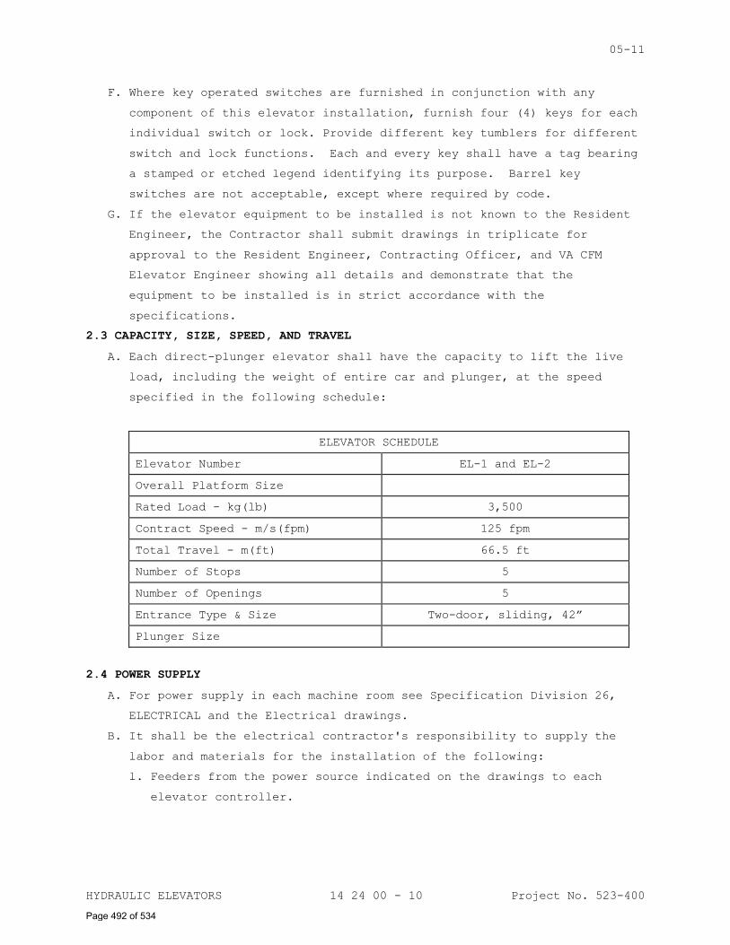
05-11
HYDRAULIC ELEVATORS 14 24 00 - 10 Project No. 523-400
F. Where key operated switches are furnished in conjunction with any
component of this elevator installation, furnish four (4) keys for each
individual switch or lock. Provide different key tumblers for different
switch and lock functions. Each and every key shall have a tag bearing
a stamped or etched legend identifying its purpose. Barrel key
switches are not acceptable, except where required by code.
G. If the elevator equipment to be installed is not known to the Resident
Engineer, the Contractor shall submit drawings in triplicate for
approval to the Resident Engineer, Contracting Officer, and VA CFM
Elevator Engineer showing all details and demonstrate that the
equipment to be installed is in strict accordance with the
specifications.
2.3 CAPACITY, SIZE, SPEED, AND TRAVEL
A. Each direct-plunger elevator shall have the capacity to lift the live
load, including the weight of entire car and plunger, at the speed
specified in the following schedule:
ELEVATOR SCHEDULE
Elevator Number EL-1 and EL-2
Overall Platform Size
Rated Load - kg(lb) 3,500
Contract Speed - m/s(fpm) 125 fpm
Total Travel - m(ft) 66.5 ft
Number of Stops 5
Number of Openings 5
Entrance Type & Size Two-door, sliding, 42”
Plunger Size
2.4 POWER SUPPLY
A. For power supply in each machine room see Specification Division 26,
ELECTRICAL and the Electrical drawings.
B. It shall be the electrical contractor's responsibility to supply the
labor and materials for the installation of the following:
l. Feeders from the power source indicated on the drawings to each
elevator controller.
Page 492 of 534
05-11
HYDRAULIC ELEVATORS 14 24 00 - 11 Project No. 523-400
2. Shunt Trip Circuit Breaker for each controller shall be located
inside machine room at the strike side of the machine room door and
lockable in the “Off” position.
3. Provide Surge Suppressors to protect the elevator equipment.
C. Power for auxiliary operation of elevator as specified shall be
available from auxiliary power generator, including wiring connection
to the elevator control system.
2.5 CONDUIT AND WIREWAY
A. Unless otherwise specified or approved, install electrical conductors,
except traveling cable connections to the car, in rigid zinc-coated
steel or aluminum conduit, electrical metallic tubing or metal
wireways. Rigid conduit smaller than 3/4 inch or electrical metallic
tubing smaller than 1/2 inch electrical trade size shall not be used.
All raceways completely embedded in concrete slabs, walls, or floor
fill shall be rigid steel conduit. Wireway (duct) shall be used in the
hoistway and to the controller and between similar apparatus in the
elevator machine room. Fully protect self-supporting connections, where
approved, from abrasion or other mechanical injury. Flexible metal
conduit not less than 3/8 inch electrical trade size may be used, not
exceeding 18 inches in length unsupported, for short connections
between risers and limit switches, interlocks, and for other
applications permitted by NEC.
B. All conduit terminating in steel cabinets, junction boxes, wireways,
switch boxes, outlet boxes and similar locations shall have approved
insulation bushings. Install a steel lock nut under the bushings if
they are constructed completely of insulating materials. Protect the
conductors at ends of conduits not terminating in steel cabinets or
boxes by terminal fittings having an insulated opening for the
conductors.
C. Rigid conduit and EMT fittings using set screws or indentations as a
means of attachment shall not be used. All fittings shall be steel or
malleable iron.
D. Connect motors or other items subject to movement, vibration or removal
to the conduit or EMT systems with flexible, steel conduits.
2.6 CONDUCTORS
A. Unless otherwise specified, conductors, excluding the traveling cables,
shall be stranded or solid coated annealed copper in accordance with
Federal Specification J-C-30B for Type RHW or THW. Where 16 and 18 AWG
Page 493 of 534
05-11
HYDRAULIC ELEVATORS 14 24 00 - 12 Project No. 523-400
are permitted by NEC, single conductors or multiple conductor cables in
accordance with Federal Specification J-C-580 for Type TF may be used
provided the insulation of single conductor cable and outer jacket of
multiple conductor cable is flame retardant and moisture resistant.
Multiple conductor cable shall have color or number coding for each
conductor. Conductors for control boards shall be in accordance with
NEC. Joints or splices are not permitted in wiring except at outlets.
Tap connectors may be used in wireways provided they meet all UL
requirements.
B. Provide all necessary conduit and wiring between machine room and
hoistway.
C. All wiring must test free from short circuits or ground faults.
Insulation resistance between individual external conductors and
between conductors and ground shall be a minimum of one megohm.
D. Where size of conductors is not given, voltage and amperes shall not
exceed limits prescribed by NEC.
E. Provide equipment grounding. Ground the conduits, supports, controller
enclosure, motor, platform and car frame, and all other non-current
conducting metal enclosures for electrical equipment in accordance with
NEC. The ground wires shall be copper, green insulated and sized as
required by NEC. Bond the grounding wires to all junction boxes,
cabinets, and wire raceways.
F. Terminal connections for all conductors used for external wiring
between various items of elevator equipment shall be solderless
pressure wire connectors in accordance with Federal Specification W-S-
610. The Elevator Contractor may, at his option, make these terminal
connections on 10 gauge or smaller conductors with approved terminal
eyelets set on the conductor with a special setting tool, or with an
approved pressure type terminal block. Terminal blocks using pierce-
through serrated washers are not acceptable.
2.7 TRAVELING CABLES
A. All conductors to the car shall consist of flexible traveling cables
conforming to the requirements of NEC. Traveling cables shall run from
the junction box on the car directly to the controller. Junction boxes
on the car shall be equipped with terminal blocks. Terminal blocks
having pressure wire connectors of the clamp type that meet UL 486A
requirements for stranded wire may be used in lieu of terminal eyelet
connections. Terminal blocks shall have permanent indelible identifying
Page 494 of 534
05-11
HYDRAULIC ELEVATORS 14 24 00 - 13 Project No. 523-400
numbers for each connection. Cables shall be securely anchored to avoid
strain on individual terminal connections. Flame and moisture resistant
outer covering must remain intact between junction boxes. Abrupt
bending, twisting and distortion of the cables shall not be permitted.
B. Provide spare conductors equal to 10 percent of the total number of
conductors furnished, but not less than 5 spare conductors in each
traveling cable.
C. Provide shielded wires for the auto dial telephone system within the
traveling cable. Add 5 pair shielded wires for card reader, 2 RG-6/U
coaxial CCTV cables, and 2 pair 14 gauge wires for CCTV power as
needed.
D. If traveling cables come into contact with the hoistway or elevator due
to sway or change in position, provide shields or pads to the elevator
and hoistway to prevent damage to the traveling cables.
E. Hardware cloth wide may be installed from the hoistway suspension point
downward to the elevator pit to prevent traveling cables from rubbing
or chafing. Hardware cloth shall be securely fastened and tensioned to
prevent buckling. Hardware cloth is not required when traveling cable
is hung against a flat wall.
2.8 CONTROLLER AND SUPERVISORY PANEL
A. UL/CSA Labeled Controller: Mount all assemblies, power supplies,
chassis switches, and relays on a self-supporting steel frame.
Completely enclose the equipment and provide a mean to control the
temperature. Solid state components shall be designed to operate
between 32 to 104 degrees Fahrenheit, humidity non-condensing up to 85
percent.
B. All controller switches and relays shall have contacts of design and
material to insure maximum conductivity, long life and reliable
operation without overheating or excessive wear, and shall provide a
wiping action to prevent sticking due to fusion. Switches carrying
highly inductive currents shall be provided with arc shields or
suppressors.
C. Where time delay relays are used in the circuits, they shall be of
acceptable design, adjustable, reliable, and consistent such as
condenser timing or electronic timing circuits.
D. Properly identify each device on all panels by name, letter, or
standard symbol which shall be neatly stencil painted or decaled in an
indelible and legible manner. Identification markings shall be
Page 495 of 534
05-11
HYDRAULIC ELEVATORS 14 24 00 - 14 Project No. 523-400
coordinated with identical markings used on wiring diagrams. The ampere
rating shall be marked adjacent to all fuse holders. All spare
conductors to controller and supervisory panel shall be neatly formed,
laced, and identified.
2.9 MICROPROCESSOR CONTROL SYSTEM
A. Provide a microprocessor based system with absolute position/speed
feedback encoded tape and electronic motor starter to control the pump
motor and signal functions in accordance with these specifications.
Across the line and wye-delta starters are not acceptable. Complete
details of the components and printed circuit boards, together with a
complete operational description, shall be submitted for approval.
1. All controllers shall be non-proprietary.
2. Proprietary tools shall not be necessary for adjusting, maintenance,
repair, and testing of equipment.
3. Controller manufacturer shall provide factory training, engineering
and technical support, including all manuals and wiring diagrams to
the VA Medical Center’s designated Elevator Maintenance Service
Provider.
4. Replacement parts shall be shipped overnight within 48 hours of an
order being received.
B. All controller assemblies shall provide smooth, step-less acceleration
and deceleration of the elevator, automatically and irrespective of the
load in the car. All control equipment shall be enclosed in a metal
cabinet with lockable, hinged door(s) and shall be provided with a
means of ventilation. All non-conducting metal parts in the machine
room shall be grounded in accordance with NEC. Cabinet shall be
securely attached to the building structure.
C. Circuit boards for the control of each and every elevator system;
dispatching, signals, door operation and special operation shall be
installed in a NEMA Type 1 General Purpose Enclosure. Circuit boards
shall be moisture resistant, non-corrosive, non-conductive, fabricated
of non-combustible material and adequate thickness to support the
components mounted thereon. Mounting racks shall be spaced to prevent
accidental contact between individual circuit boards and modules.
D. Modules shall be of the type that plug into pre-wired mounting racks.
Field wiring or alteration shall not be necessary in order to replace
defective modules.
Page 496 of 534
05-11
HYDRAULIC ELEVATORS 14 24 00 - 15 Project No. 523-400
E. Each device, module and fuse (with volt and ampere rating) shall be
identified by name, letter or standard symbol in an approved indelible
and legible manner on the device or panel. Coordinate identification
markings with identical markings on wiring diagrams.
F. The electrical connections between the printed circuit boards (modules)
and the circuit connectors incorporated in the mounting racks shall be
made through individual tabs which shall be an integral part of each
module. The tabs shall be nickel-gold plated or other approved metal
of equal electrical characteristics. Modules shall be keyed or notched
to prevent insertion of the modules in the inverted position.
G. Light emitting diodes (LED) shall be for visual monitoring of
individual modules.
H. Components shall have interlocking circuits to assure fail-safe
operation and to prevent elevator movement should a component
malfunction.
I. Method of wire wrapping from point to point with connections on the
mounting racks shall be submitted for approval.
J. Field wiring changes required during construction shall be made only to
the mounting rack connection points and not to the individual module
circuitry or components. If it is necessary to alter individual
modules they shall be returned to the factory where design changes
shall be made and module design records changed so correct replacement
units will be available.
K. All logic symbols and circuitry designations shall be in accordance
with ASME and NEC Standards.
L. Solid state components shall be designed to operate within a
temperature range of 32 to 104 degrees Fahrenheit, humidity non-
condensing up to 85 percent.
M. Wiring connections for operating circuits and for external control
circuits shall be brought to terminal blocks mounted in an accessible
location within the controller cabinet. Terminal blocks using pierce
through serrated washers shall not be used.
2.10A AUXILIARY POWER OPERATION
A. The control system for Elevators EL-1 and EL-2 shall provide for the
operation of at least one car per elevator bank on auxiliary power upon
failure of the normal power supply.
B. Auxiliary power supply, its starting means, transfer switch for
transfer of elevator supply from normal to auxiliary power, two pair of
Page 497 of 534
05-11
HYDRAULIC ELEVATORS 14 24 00 - 16 Project No. 523-400
conductors in a conduit from an auxiliary contact on the transfer
switch (open or close contacts as required by Controller Manufacturer)
to terminals in the group elevator controller and other related work
shall be provided by the Electrical Contractor.
C. Auxiliary equipment on elevator controllers, wiring between associated
elevator controllers and wiring between elevator controllers and remote
selector panel as required to permit the elevators to operate as
detailed, shall be provided by the Elevator Contractor.
D. Upon loss of normal power supply there shall be a delay before
transferring to auxiliary power of 10 seconds minimum to 45 seconds
maximum, the delay shall be accomplished through an adjustable timing
device. Following this adjustable delay the associated elevators shall
function as follows:
1. Not applicable.
2. Selector switch, Manual operation:
a. Selector switch shall be mechanically and electrically
interlocked to prevent the selection of more than one elevator
from operating on auxiliary power.
b. The selector switch shall have positions marked with the number
of each elevator controlled. It shall also have a position marked
"Automatic". When the selector switch is set to the automatic
position, the medical emergency service car, shall operate on
auxiliary power operation, or if none, the last car arriving at
the designated floor and be capable of functioning under all
design features.
c. Change in selection of elevators shall be by means of the
selection switch and shall occur only when the previous selected
elevator is stopped at the designated floor.
d. The selector switch shall be locked out of operation when the
system is in the normal mode of operation.
e. Locate the selector switch above the hall push button station at
the designated level in a NEMA 1B flush type enclosure furnished
with a brushed finish stainless steel hinged door and frame. The
door shall contain a tumbler type lock furnished with four keys.
The enclosure faceplate shall be identified "Auxiliary Power
Control" with 13 mm (1/2 in.) engraved letters filled with black
paint.
Page 498 of 534
05-11
HYDRAULIC ELEVATORS 14 24 00 - 17 Project No. 523-400
3. The inside of the selector panel shall be brushed finish stainless
steel with each device identified with 3 mm (1/8 in.) engraving
filled with black paint. The panel shall contain:
a. Selector switches for selecting the elevators shall be toggle
type or rotary key switch.
b. Pilot lights to indicate normal mode of operation, auxiliary
power service available, and which elevator or elevators in each
group is connected to auxiliary service.
c. A lamp test circuit consisting of a momentary contact push button
to test all pilot lights in the circuit.
d. Provide a permanently mounted, easy to read, instruction plate
which shall include operating instructions for auxiliary power
service and instructions for lamp test circuits.
E. Prior to the return of normal power an adjustable timed circuit shall
be activated that will cause all cars to remain at a floor if already
there or stop and remain at the next floor if in flight. Actual
transfer of power from auxiliary power to normal building power shall
take place after all cars are stopped at a floor with their doors open.
F. Car lighting circuits shall be connected to the auxiliary power panel.
2.10B EMERGENCY RESCUE OPERATION
A. Provide a power source to send the elevator to the lowest landing by
activating the down valves. After the elevator has leveled at the
lowest landing, provide power to open the car and hoistway doors
automatically. After a predetermined time the car and hoistway doors
shall close. Power shall stay applied to the door open button so the
doors can be opened from the inside of the elevator. The elevator shall
remain shut down at the bottom landing until normal power is restored.
Install a sign on the controller indicating that the power is applied
to the down valve and door operator during loss of normal power.
2.11A TWO-STOP AUTOMATIC OPERATION
Not Applicable
2.11B SINGLE CAR SELECTIVE COLLECTIVE AUTOMATIC OPERATION
Not Applicable
2.11C DUPLEX SELECTIVE COLLECTIVE AUTOMATIC OPERATION
A. Provide duplex selective collective automatic operation, for passenger
elevators EL-1 and EL-2.
B. Operate elevators from push buttons inside the cars and located at each
floor between elevators. When cars are available, park one car at main
Page 499 of 534
05-11
HYDRAULIC ELEVATORS 14 24 00 - 18 Project No. 523-400
floor (home car) and the other car at last call (free car). Respond to
car calls and hall calls above main floor using the “free” car. Once a
car has started, respond to registered calls in the direction of travel
and in the order the floors are reached. Do not reverse the car
direction until all car calls have been answered, or until all hall
calls ahead of the car and corresponding to the direction of car travel
have been answered.
Slow and stop elevators automatically at floors corresponding to
registered calls in the order in which they are approached in each
direction of travel. As slowdown is initiated, automatically cancel
hall call and car call. Hold car at arrival floor an adjustable time
interval to allow passenger transfer.
When the “free” car is clearing calls, the “home” car to shall respond
to the following:
1. Calls registered on “home” car push buttons.
2. Up hall calls registered below “free” car.
3. Up or down calls registered above “free” car while “free” car is
traveling down.
4. Hall calls when “free” car is delayed in its normal operation for a
predetermined period.
C. When both cars are clearing calls, stop only one car in response to any
registered hall call. Return the first car to clear its calls to the
main floor. Should last service required bring both cars to the main
floor, the first arriving car becomes the “free” car. Illuminate floor
push button to indicate call registration. Extinguish light when call
is answered.
D. If a landing call button is operated while the car and hoistway doors
are closing at that floor, the call shall be registered for the next
available elevator. Calls registered shall be canceled if closing doors
are reopened by means of "DOOR OPEN" button or infrared curtain unit.
E. When an elevator is delayed for a predetermined time interval or shuts
down after it receives a start signal, the system shall automatically
permit the remaining car in the group to respond to hall calls and to
be dispatched in normal manner. When cause of delay is corrected, car
shall automatically resume normal operation unless it has been manually
removed from the system.
F. Auxiliary Landing Call Operation: In the event of landing call button
circuit failure, elevators are to service each floor in both directions
Page 500 of 534
05-11
HYDRAULIC ELEVATORS 14 24 00 - 19 Project No. 523-400
in a predetermined pattern without registration of a call within
elevators. Provide illuminated signal in each controller to indicate
that emergency dispatch operation is in effect. Restoration of the
landing call button system shall cause normal operation to resume.
G. Car lights and fan in the elevator shall not shut off when elevator is
idle. Arrange circuits so that power to outlets on top and bottom of
car shall not be interrupted.
2.11D GROUP SELECTIVE COLECTIVE AUTOMATIC OPERATION
Not Applicable
2.11E MACHINE ROOM MONITOR (CCTV): GROUP OPERATION
A. Install a monitor in the machine room located in the Group Dispatch
Operation Cabinet. Provide separate cabinets for the passenger
elevator group and for the service elevator group. Provide one
keyboard for each terminal.
B. The CCTV shall contain indicators to provide the following information:
1. The floor where each elevator is currently located.
2. The direction that each elevator is currently traveling or is
scheduled to travel.
3. The location and direction of currently registered hall calls.
4. Elevators that are currently out of service.
5. Elevators that are currently bypassing hall calls.
6. Elevators that are currently engaged in passenger transfers.
7. Operations program under which entire group is currently operating.
8. Zone divisions of the entire group.
9. Door positions.
10. Status indication for cars on independent service, car top
inspection, stop switch activated, alarm activated, fire service,
and earthquake protection activated, etc.
C. The maintenance terminal shall be suitable for all troubleshooting
procedures related to the specific type microprocessor installed on
this project.
2.12 FIREFIGHTERS’ SERVICE
A. Provide Firefighters’ Service as per ASME A17.1 Section 2.27.
B. Smoke Detectors:
1. Smoke detection devices that are designated for actuation of
Elevator Phase I "FIRE SERVICE" response shall be provided in each
elevator lobby, top of hoistway, and machine room.
Page 501 of 534
05-11
HYDRAULIC ELEVATORS 14 24 00 - 20 Project No. 523-400
a. Elevator lobby smoke detectors shall activate only the elevators
sharing the corresponding or common lobby.
b. Top of hoistway smoke detectors shall activate fire recall and
the top of hoistway motorized vent.
c. Elevator or group of elevators serving separate isolated areas of
the same floor shall have an independent smoke detection system.
d. Machine room smoke detectors shall activate fire recall for each
and every elevator with equipment located in that machine room.
e. Hoistway ventilation to be located at the top of hoistway for
elevators that penetrate more than three floors meeting the
requirements of ASME A17.1 Section 2.1.4 and IBC Section 3004.
The vent shall stay closed under power. When the top of hoistway
smoke detector is activated, the power is removed from the vent
and the vent shall open. When the smoke detector is reset, the
vent shall close by power.
2.13 MEDICAL EMERGENCY SERVICE
Not Applicable
2.14 SEISMIC REQUIREMENTS
A. Meet the requirements of ASME A17.1 Section 8.4, Elevator Safety
Requirements for Seismic Risk Zone 2 or greater and VA Seismic Design
Manual H-18-8.
B. Support and maintain pump unit, controller, rails, rail brackets,
conduit, buffers, piping, scavenger pumps and jack unit assembly in
place as to effectively prevent any part from sliding, rotating or
overturning or jumping under conditions imposed by seismic forces not
less than that required to produce an acceleration of gravity
horizontally and 1/2 gravity vertically acting simultaneously. Design
the total system to continue operation without interruption under
specified seismic acceleration, as outlined in H-18-8.
C. Support all vertical conduits and duct systems within the hoistway at
points above the center of gravity of riser. Provide lateral guides at
regular intervals.
D. Provide hydraulic equipment mounted on vibration isolators with seismic
restraints.
E. Bolt pump unit and controller to the floor and provide sway braces at
top. Secure all electrical components within the panels to the panel
frame. Fit doors and hinged panels with positive locking latches.
Page 502 of 534
05-11
HYDRAULIC ELEVATORS 14 24 00 - 21 Project No. 523-400
F. Car guide rail brackets and rail clip bolts shall be guarded against
snagging on the side of the rail adjacent to the point of suspension of
the traveling cables.
G. Provide car guide rails with at least one intermediate bracket between
brackets located at each floor so that bracket spacing does not exceed
2400 mm (8 ft). If intermediate brackets cannot be installed because of
lack of structural support, reinforce rails with 225 mm (9 in.) channel
or approved equal backing.
H. Guide rails shall not be less than 22.5 kg/m (15 lb/ft).
I. The stresses in parts of structural members made of steel shall not
exceed 88 percent of the minimum elastic strength of the material used
in the fastenings.
J. Provide car enclosure ceiling panels and fluorescent tubes with
latching devices that shall restrain the panels and fluorescent tubes.
Devices shall be readily removable for cleaning or replacing panels and
re-lamping.
K. Submittals are required for all equipment anchors, supports, restraints
and detectors. Submittals shall include weight, dimensions, center of
gravity, standard connections, calculations, manufacturer's
recommendations, behavior problems (vibration, thermal, expansion,
etc.,) so that design can be properly reviewed.
2.15 PUMP UNIT ASSEMBLY
A. Completely integrate the pump unit for the control of the elevator and
self-contain in a unit fabricated of structural steel. The unit shall
consist of a hydraulic fluid pump driven by an induction motor together
with oil control valves, piping, etc. Enclose unit on four open sides
of the power unit frame with not less than 16 gauge steel removable
panel sections. Provide a minimum 50 mm (2 in.) air space between the
top of the panels and bottom of tank. Line panels on the interior side
with one-inch rigid acoustical insulation board.
B. Control valves shall be electronically controlled. Hydraulic fluid flow
shall be controlled to insure speed variation of not more than five (5)
percent under all load conditions.
C. Hydraulic system working pressure shall not exceed 500 psi under any
load condition.
D. Pump shall be positive displacement, rotary screw type, specifically
designed for hydraulic elevator service, having a steady discharge
without pulsation to give smooth and quiet operation. Pump output shall
Page 503 of 534
05-11
HYDRAULIC ELEVATORS 14 24 00 - 22 Project No. 523-400
be capable of lifting elevator car with rated capacity, with a speed
variation of no more than five (5) percent between no load and full
load. Pump shall operate under flooded suction in an accurately
machined case with the clearance required to assure maximum efficiency.
Hydraulic fluid by-pass shall discharge directly into storage tank.
E. Motor shall be squirrel-cage, drip proof, ball bearing, and induction
type, with a synchronous speed not in excess of 1800 RPM. Design motor
specifically for elevator service, not to exceed nameplate full load
current by more than 10% and be continuously rated 120 starts per hour
without exceeding a rise of 40 degrees C. Include closed transition SCR
soft start.
F. Connect motor and pump with multiple V-belt. Size belts and sheaves for
duty involved and design to prevent any metallic contact between motor
and pump shaft. Provide isolation units of rubber in shear to prevent
transmission of pump and motor vibration to the building. Install
expanded metal sheave guard that can be easily removed for servicing
and inspection.
G. Hydraulic equipment may be installed within the oil storage tank if
applicable for elevator size, speed, and duty rating.
H. Design motor, pump, tank, and piping to accommodate future travel, if
specified.
2.16 HYDRAULIC SYSTEM
A. Construct the storage tank of sheet steel, welded construction, and a
steel cover with suitable means for filling, a minimum one-inch
protected vent opening, an overflow connection, and a valve drain
connection. Tank shall act as a storage tank only, and sized to pass
through machine room door as shown on drawings. Provide marked gauge to
monitor hydraulic fluid level. Tank shall be of capacity to hold volume
of hydraulic fluid required to lift elevator to top terminal landing,
plus a reserve of not less than ten gallons. Provide a baffle in the
bottom of the tank to prevent entry of any sediment or foreign
particles into hydraulic system. Baffle shall also minimize aeration of
hydraulic fluid. Permissible minimum hydraulic fluid level shall be
clearly indicated. Hydraulic fluid shall be of good grade to assure
free flow when cool, and have minimum flash point of 400 degrees F.
Provide initial supply of hydraulic fluid for operation of elevator.
1. Thermostatically control the viscosity of the hydraulic fluid with
thermal cooling unit and temperature thermostat to maintain the
Page 504 of 534
05-11
HYDRAULIC ELEVATORS 14 24 00 - 23 Project No. 523-400
fluid temperature in the reservoir, pump and valves at a constant
operating viscosity.
2. Provide a data plate on the tank framing indicating the
characteristics of the hydraulic fluid used.
B. Furnish and install connections between the storage tank, pump,
muffler, operating valves, and cylinder complete with necessary valves,
pipe supports, and fittings. All connections between the discharge side
of the pump, check valve, muffler, cylinder, lowering valves shall be
of schedule 40 steel with threaded, flanged, or welded mechanical
couplings. Size of pipe and couplings between cylinder and pumping unit
shall be such that fluid pressure loss is limited to 10 percent.
C. Do not subject valves, piping, and fittings to working pressure greater
than those recommended by the manufacturer.
D. Support all horizontal piping. Place hangers or supports within 305 mm
(12 in.) on each side of every change of direction of pipe line and
space supports not over 3.0 meters (10 ft) apart. Secure vertical runs
properly with iron clamps at sufficiently close intervals to carry
weight of pipe and contents. Provide supports under pipe to floor.
1. Provide all piping from machine room to hoistway, including
necessary supports or hangers. If remote piping is underground or in
damp inaccessible areas, install hydraulic piping thru PVC sleeve
pipe.
E. Install pipe sleeves where pipes pass through walls or floors. Set
sleeves during construction. After installation of piping, equip the
sleeves with snug fitting inner liner of either glass or mineral wool
insulation.
F. Install blowout-proof, non-hammering, oil-hydraulic muffler in the
hydraulic fluid supply pressure line near power unit in machine room.
Design muffler to reduce to a minimum any pulsation or noises that may
be transmitted through the hydraulic fluid into the hoistway.
G. Arrange control valves to operate so hydraulic fluid flow will be
controlled in positive and gradual manner to insure smooth starting and
stopping of elevator.
H. Provide safety check valve between cylinder and pump connection which
will hold elevator with specified load at any point when pump stops or
pressure drops below minimum operating levels.
I. Provide an automatic shut-off valve in the oil supply line at the
cylinder inlet. Weld pipe protruding from cylinder at inlet and thread
Page 505 of 534
05-11
HYDRAULIC ELEVATORS 14 24 00 - 24 Project No. 523-400
to receive shut-off valve. Activate the automatic shut-off valve when
there is more than a ten percent increase in high speed in the down
direction. When activated, this device shall immediately stop the
descent of the elevator, and hold the elevator until it is lowered by
use of the manual lowering feature of the valve. Arrange the manual
lowering feature of the automatic shut-off valve to limit the maximum
descending speed of the elevator to 15 fpm. The exposed adjustments of
the automatic shut-off valve shall have their means of adjustment
sealed after being set to their correct position.
J. Provide external tank shut-off valve to isolate hydraulic fluid during
maintenance operations.
K. Provide all pump relief and other auxiliary valves to comply with the
requirements of the ASME A17.1 Section 3.19 and to insure smooth, safe,
and satisfactory operation of elevator.
L. Furnish and adjust by-pass and relief valve in accordance with ASME
A17.1 Rule 3.19.4.2.
M. Install check valve to hold the elevator car with rated load at any
point when the pump stops.
N. Provide shut-off valves in the pit near the cylinder and in the machine
room capable of withstanding 150 percent of design operating pressure.
Each manual valve shall have an attached handle.
0. Conveniently locate the manual lowering valve, easily accessible, and
properly identified with a red arrow and not concealed within the
storage tank. Mark the operating handle in red.
P. Provide a low oil control feature which shall shut off the motor and
pump and return the elevator to the lowest landing. Upon reaching the
lowest landing, doors will open automatically allowing passengers to
leave the car. Then doors shall close. All control buttons, except the
door open button, shall be made ineffective.
Q. Provide oil-tight drip pan for assembled pumping unit, including
storage tank. Pan shall be not less than 16 gauge sheet steel, with
one-inch sides.
R. The entire hydraulic system, including muffler, shall be tested to
withstand a pressure equal to twice the calculated working pressure.
Submit certification that test has been performed.
2.17 HYDRAULIC PLUNGER ASSEMBLY
A. Design cylinder and plunger in accordance with ASME A17.1. It shall be
of sufficient size to lift gross load the height specified. Factory
Page 506 of 534
05-11
HYDRAULIC ELEVATORS 14 24 00 - 25 Project No. 523-400
test at a pressure equal to twice the calculated working pressure, for
strength and to insure freedom from leakage. Provide bottom of cylinder
head with internal guide bearing and top of cylinder head with
removable packing gland. Packing gland shall permit ready replacement
of packing. Victaulic type packing gland head will not be permitted.
1. Provide a bleeder valve located below the cylinder flange to release
air or other gases from the system.
2. Equip cylinder with drip ring below the packing gland to collect
leakage of hydraulic fluid.
3. Bolt the cylinder mounting brackets to continuous footing channels
that also support the rails and buffers.
B. Install a flexible tubing scavenger line with an electrically operated
pump between the piston drip ring and oil storage tank. Scavenger line,
pump and strainers shall operate independently of hydraulic fluid
pressure. Equip scavenger pump with a water float designed to prevent
operation of the pump should the pit flood and designed to be manually
reset. Strap the pump and reservoir to the pit channels.
C. Plunger shall be heavy seamless steel tubing, turned smooth and true to
within plus or minus .38 mm (0.015 in.) tolerance and no diameter
change greater than .07 mm (0.003in.) per-inch of length. Grind the
plunger surface to a fine polish finish, 12 micro-inches or finer.
Where plunger is multi-piece construction, machine the joints to assure
perfectly matching surfaces. No tool marks shall be visible.
1. Secure plunger to underside of platform supporting beams with
fastenings capable of supporting four times the weight of the
plunger. The platen plate shall incorporate piston car vibration
isolator as herein specified.
2. Provide a stop ring welded or screwed to the bottom of plunger that
shall prevent the plunger from leaving its cylinder. For plunger
units that include future travel, locate the stop ring to permit
only the actual travel and required runby.
3. Isolate plunger head from the platen plate to prevent corrosion or
electrolysis.
4. Carefully protect plunger and replace if gouged, nicked or scored.
5. If conditions beneath the pit floor are not adequate to support the
total loading of the elevator, install reinforcing members in the
pit floor.
Page 507 of 534
05-11
HYDRAULIC ELEVATORS 14 24 00 - 26 Project No. 523-400
D. Before installation, clean entire cylinder wall of all traces of oil,
grease, moisture, dirt and scale.
2.18 HYDRAULIC CYLINDER CASING
A. The casing shall be iron or steel not less than 0.375-inch thick, at
least 15.2 mm (6 in.) larger in diameter than the cylinder. The
Elevator Contractor shall demonstrate to the Resident Engineer that the
casing has been accurately set, positioned, and plumbed to accept the
plunger assembly. Close the bottom with a minimum of 15.2 mm (6 in.) of
concrete.
B. Provide PVC casing liner to fit inside steel casing. Fabricate from
schedule 80 PVC pipe with watertight bottom and a top flange gasket to
seal plunger flange and form a complete, watertight, electrically non-
conductive encasement of the entire unit.
C. Provide suitable well hole to accommodate casing. Coordinate the
drilling of well hole and setting of the cylinder with construction of
concrete pit. Provide watertight joint between the casing and the pit
floor at bottom of pit.
D. Base bid on drilling hole in dirt, sand, rock, gravel, loam, boulders,
hardpan, water, or other obstacles. Include the removal of all dirt and
debris.
2.19 CAR BUFFERS
A. Provide a minimum of two spring buffers for each elevator that meet the
requirements of ASME A17.1 Section 3.22. Securely fasten buffers and
supports to the pit channels and in the alignment with striker plates
on elevator. Ever installed buffer shall have a permanently attached
metal plate indicating its stroke and load rating. Buffer anchorage
shall not puncture pit waterproofing.
B. Design and install buffers to provide minimum car runby required by
ASME A17.1 Rule 3.4.2.
C. Furnish pipe stanchions and struts as required to properly support the
buffer.
2.20 CAR GUIDES
A. Install on car frame four adjustable roller guides, each assembled on a
substantial metal base, to permit individual self-alignment to the
guide rails.
B. Not applicable.
C. Roller Guides:
Page 508 of 534
05-11
HYDRAULIC ELEVATORS 14 24 00 - 27 Project No. 523-400
1. Each guide shall be of an approved type consisting of not less than
three (3) wheels, each with a durable, resilient oil-resistant
material tire rotating on ball bearings having sealed-in
lubrication. Assemble rollers on a substantial metal base and mount
to provide continuous spring pressure contact of all wheels with the
corresponding rail surfaces under all conditions of loading and
operation. The wheels shall be of ample diameter and shall run on
three-machine finished dry rail surfaces. Secure the roller guides
at top and bottom on each side of car frame. All mounting bolts
shall be fitted with nuts, flat washers, split lock washers and if
required, beveled washers.
2. Provide sheet metal guards to protect wheels on top of car.
3. Minimum diameter of car rollers shall be 150 mm (6 in.) unless the
six wheel roller type is used. The entire elevator car shall be
properly balanced to equalize pressure on all guide rollers. Cars
shall be balanced in post-wise and front-to-back directions. Test
for this balanced condition shall be witnessed at time of final
inspection.
D. Equip car with an auxiliary guiding device for each guide shoe which
shall prevent the car from leaving the rails in the event that the
normal guides are fractured. These auxiliary guides shall not, during
normal operation, touch the guiding surfaces of the rails. Fabricate
the auxiliary guides from hot rolled steel plate and mount between the
normal guide shoes and the car frames. The auxiliary guides may be an
extension of the normal guide shoe mounting plate if that plate is
fabricated from hot rolled steel. The portion of the auxiliary guide
which shall come in contact with the rail guiding surfaces in the event
of loss of the normal guides shall be lined with an approved bearing
material to minimize damage to the rail guiding surfaces.
2.21 GUIDE RAILS, SUPPORTS, AND FASTENINGS
A. Guide rails shall conform to ASME A17.1 Section 2.23.
B. Guide rails for car shall be planed steel T-sections and weigh 27.5
kg/m (18.5 lb/ft).
C. Securely fasten guide rails to the brackets or other supports by heavy
duty steel rail clips.
D. Provide necessary car rail brackets of sufficient size and design to
secure substantial rigidity to prevent spreading or distortion of rails
under any condition.
Page 509 of 534
05-11
HYDRAULIC ELEVATORS 14 24 00 - 28 Project No. 523-400
1. Slotted or oversized holes shall be fitted with flat washers and
shall conform to ASME A17.1 Rule 2.23.10.3.
2. Where fastenings are over 4.2 m (14 ft) apart, rails shall be
reinforced with 228 mm (9 in.) channel or approved equal backing to
secure the rigidity required.
E. Rail joints and fishplates shall be in accordance with ASME A17.1 Rule
2.23.7. Rail joints shall not interfere with clamps and brackets.
Design rail alignment shims to remain in place if fastenings become
loose.
F. Guide rails shall extend from channels on pit floor to within 76 mm (3
in.) of the underside of the concrete slab or grating at top of
hoistway with a maximum deviation of 3.2 mm (1/8 in.) from plumb in all
directions. Provide a minimum of 19 mm (3/4 in.) clearance between
bottom of rails and top of pit channels.
G. Guide rail anchorages in pit shall be made in a manner that will not
reduce effectiveness of the pit waterproofing.
H. In the event inserts or bond blocks are required for the attachment of
guide rails, the Contractor shall furnish such inserts or bond blocks
and shall install them in the forms before the concrete is poured. Use
inserts or bond blocks only in concrete or block work where steel
framing is not available for support of guide rails. Expansion-type
bolting for guide rail brackets will not be permitted.
I. Guide rails shall be clean and free of any signs of rust, grease, or
abrasion before final inspection. Paint the shank and base of the T-
section with two field coats of manufacturer’s standard enamel.
2.22 NORMAL AND FINAL TERMINAL STOPPING DEVICES
A. Normal and final terminal stopping devices shall conform to ASME A17.1
Section 2.25.
B. Mount terminal slowdown switches and direction limit switches on the
elevator or in hoistway to reduce speed and bring car to an automatic
stop at the terminal landings.
1. Switches shall function with any load up to and including 100
percent of rated elevator capacity at any speed obtained in normal
operation.
2. Switches, when opened, shall permit operation of elevator in reverse
direction of travel.
C. Mount final terminal stopping switches in the hoistway.
Page 510 of 534
05-11
HYDRAULIC ELEVATORS 14 24 00 - 29 Project No. 523-400
1. Switches shall be positively opened should the car travel beyond the
terminal direction limit switches.
2. Switches shall be independent of other stopping devices.
3. Switches, when opened, shall remove power from pump motor and
control valves preventing operation of car in either direction.
D. After final stopping switches have been adjusted, through bolt switches
to guide rail.
2.23 CROSSHEAD DATA PLATE AND CODE DATA PLATE
A. Permanently attach a non-corrosive metal Data Plate to car crosshead.
Data plate shall bear information required by ASME A17.1 Section 2.16.3
and 2.20.2.1.
B. Permanently attach a Code Data Plate, in plain view, to the controller,
ASME A17.1 Section 8.9.
2.24 WORKMAN’S LIGHTS AND OUTLETS
A. Provide duplex GFCI protected type receptacles and lamp, with guards on
top of elevator car and beneath platform.
B. The receptacles shall be in accordance with Fed. Spec. W-C-596 for Type
D7, 2-pole, 3-wire grounded type rated for 15 amperes and 125 volts.
2.25 TOP-OF-CAR OPERATING DEVICE
A. Provide a cartop operating device that meets the requirements of ASME
A17.1 Section 2.26.
B. The device shall be activated by a toggle switch mounted in the device.
The switch shall be clearly marked "INSPECTION" and "NORMAL" on the
faceplate, with 6 mm (1/4 in.) letters.
C. Movement of the elevator shall be accomplished by the continuous
pressure on a direction button and a safety button.
D. Provide an emergency stop toggle type switch.
E. Provide permanent identification for the operation of all components in
the device.
F. The device shall be permanently attached to the elevator crosshead on
the side of the elevator nearest to the hoistway doors used for
accessing the top of the car.
2.26 CAR LEVELING DEVICE
A. Car shall be equipped with a two-way leveling device to automatically
bring the car to within 3 mm (1/8 in.) of exact level with the landing
for which a stop is initiated regardless of load in car or direction.
B. If the car stops short or travels beyond the floor, the leveling
device, within its zone shall automatically correct this condition and
Page 511 of 534
05-11
HYDRAULIC ELEVATORS 14 24 00 - 30 Project No. 523-400
maintain the car within 3 mm (1/8 in.) of level with the floor landing
regardless of the load carried.
C. Provide encoded steel tape, steel tape with magnets or steel vanes with
magnetic switches. Submit design for approval.
2.27 EMERGENCY STOP SWITCHES
A. Provide an emergency stop switch for each top-of-car device, pit,
machine spaces, service panel and firefighters’ control panel inside
the elevator. Mount stop switches in the pit adjacent to pit access
door, at top of the pit ladder 1220 mm (48 in.) above the bottom
landing sill and 1220 mm (48 in.) above the pit floor adjacent to the
pit ladder.
B. Each stop switch shall be red in color and shall have "STOP" and "RUN"
positions legibly and indelibly identified.
2.28 MAIN CAR OPERATING PANEL
A. Locate the main car operating panel in the car enclosure on the front
return panel for passenger/service elevators and the front of the side
wall for freight elevators. The top floor car call push button shall
not be more than 1220 mm (48 in.) above the finished floor. Car call
push buttons and indicator lights shall be round with a minimum
diameter of 25 mm (1 in.), LED white light illuminated.
B. One piece front faceplate, with edges beveled 15 degrees, shall have
the firefighters’ service panel recessed into the upper section and the
service operation panel recessed into the lower section, fitted with
hinged doors. Doors shall have concealed hinges, be in the same front
plane as the faceplate and fitted with cylinder type key operated
locks. Secure the faceplate with stainless steel tamperproof screws.
C. All terminology on the main car operating panel shall be raised or
engraved. Use 6 mm (1/4 in.) letters to identify all devices in upper
section of the main car operating panel. The handicapped markings with
contrasting background shall be recessed .030 inch in the faceplate,
square or rectangular in shape, with the finished face of the 12 mm
(1/2 in.) numerals and markings flush with the faceplates. Surface
mounted plates are not acceptable.
D. The upper section shall contain the following items in order listed
from top to bottom:
1. Engrave elevator number, 25 mm (1 in.) high with black paint for
contrast.
Page 512 of 534
05-11
HYDRAULIC ELEVATORS 14 24 00 - 31 Project No. 523-400
2. Engrave capacity plate information with black paint for contrast
with freight loading class and number of passengers allowed.
3. Emergency car lighting system consisting of a rechargeable battery,
charger, controls, and LED illuminated light fixture. The system
shall automatically provide emergency light in the car upon failure
or interruption of the normal car lighting service, and function
irrespective of the position of the light control switch in the car.
The system shall be capable of maintaining a minimum illumination of
1.0 foot-candle when measured 1220 mm (48 in.)above the car floor
and approximately 305 mm (12 in.) in front of the car operating
panel, for not less than four (4) hours.
4. LED illuminated digital car position indicator with direction
arrows. Digital display floor numbers and direction arrows shall be
a minimum of 50mm (2 in.) high.
5. Firefighters’ Emergency Operation Panel shall conform to the
requirements of ASME A17.1 Section 2.27. Firefighters’ Panel shall
be 1676 mm (66 in.) minimum to 1830 mm (72 in.) maximum to the top
of the panel above finished floor.
6. Firefighters’ Emergency Indicator Light shall be round with a
minimum diameter of 25 mm (1 in.).
7. Not applicable.
8. Independent Service switch, see Section 2.30 for detailed
description.
9. Provide a Door Hold button on the faceplate next to the independent
service key switch. It shall have “DOOR HOLD” indelibly marked on
the button. Button shall light when activated. When activated, the
door shall stay open for a maximum of one minute. To override door
hold timer, push a car call button or door close button. Door Hold
button is not ADA required and Braille is not needed.
10. Complete set of round car call push buttons, minimum diameter of 25
mm (1 in.), and LED white light illuminated, corresponding to the
floors served. Car call buttons shall be legibly and indelibly
identified by a floor number and/or letter not less than 12mm (1/2
in.) high in the face of the call button. Stack buttons in a single
vertical column for low rise buildings up to six floors with front
openings only.
11. Door Open and Door Close buttons shall be located below the car call
buttons. They shall have “OPEN” and “CLOSE” legibly and indelibly
Page 513 of 534
05-11
HYDRAULIC ELEVATORS 14 24 00 - 32 Project No. 523-400
identified by letters in the face of the respective button. The Door
Open button shall be located closest to the door jamb as required by
ADA.
12. Red Emergency Alarm button that shall be located below the car
operating buttons. Mount the emergency alarm button not lower than
890 mm (35 in.) above the finished floor. It shall be connected to
audible signaling devices as required by A17.1 Rule 2.27.1.2.
Provide audible signaling devices including the necessary wiring.
13. Emergency Help push button shall activate two way communications by
Auto Dial telephone system as required by ASME A17.1 Rule
2.27.1.1.3. Help button shall be LED white light illuminated and
flash when call is acknowledged. Legibly and indelibly label the
button “HELP” in the face of the button with 12 mm (1/2 in.) high
letters.
14. Provide a corresponding Braille plate on the left side of each
button. The handicapped markings with contrasting background shall
be recessed .030 inch in the faceplate, square or rectangular in
shape, with the finished face of the 12 mm (1/2 in.) numerals and
markings flush with the faceplates. Surface mounted plates are not
acceptable.
E. The service operation panel, in the lower section shall contain the
following items:
1. Light switch labeled “LIGHTS” for controlling interior car lighting
with its two positions marked “ON” and “OFF”.
2. Inspection switch that will disconnect normal operation and activate
hoistway access switches at terminal landings. Switch shall be
labeled “INSPECTION” with its two positions marked “ON” and “OFF”.
3. Three position switch labeled “FAN” with its positions marked
“HIGH”, “LOW” and “OFF” for controlling car ventilating blower.
4. Two position, spring return, toggle switch or push button to test
the emergency light and alarm device. It shall be labeled “TEST
EMERGENCY LIGHT AND ALARM”.
2.29 AUXILIARY CAR OPERATING PANEL
Not Applicable
2.30 INDEPENDENT SERVICE
A. Provide a legibly and indelibly labeled "INDEPENDENT SERVICE", two-
position key operated switch on the face of the main car operating
panel that shall have its positions marked "ON" and "OFF". When the
Page 514 of 534
05-11
HYDRAULIC ELEVATORS 14 24 00 - 33 Project No. 523-400
switch is in the "ON" position, the car shall respond only to calls
registered on its car dispatch buttons and shall bypass all calls
registered on landing push buttons. The car shall start when a car call
is registered, car call button or door close button is pressed, car and
hoistway doors are closed, and interlock circuits are made. When switch
is returned to "OFF" position, normal service shall be resumed.
2.31 CAR POSITION INDICATOR
A. Provide an alpha-numeric digital car position indicator in the main car
operating panel, consisting of numerals and arrows not less than 50 mm
(2 in.) high, to indicate position of car and direction of car travel.
Locate position indicator at the top of the main car operating panel,
illuminated by light emitting diodes.
2.32 AUDIO VOICE SYSTEM
A. Provide digitized audio voice system activated by stopping at a floor.
Audio voice shall announce floor designations, direction of travel, and
special announcements. The voice announcement system shall be a natural
sounding human voice that receives messages and shall comply with ADA
requirements for audible car position indicators. The voice announcer
shall have two separate volume controls, one for the floor designations
and direction of travel, and another for special announcements. The
voice announcer shall have a full range loud speaker, located on top of
the cab. The audio voice unit shall contain the number of ports
necessary to accommodate the number of floors, direction messages, and
special announcements. Install voice announcer per manufacturer’s
recommendations and instructions. The voice announcer units shall be
the product of a manufacturer of established reputation. Provide
manufacturer literature and list of voice messages.
1. Fire Service Message
2. Medical Emergency Service Message
3. “Please do not block doors.”
4. Provide special messages as directed by Resident Engineer.
2.33 AUTO DIAL TELEPHONE SYSTEM
A. Furnish and install a complete ADA compliant intercommunication system.
B. Provide a two-way communication device in the car with automatic
dialing, tracking and recall features with shielded wiring to car
controller in machine room. Provide dialer with automatic rollover
capability with minimum two numbers.
Page 515 of 534
05-11
HYDRAULIC ELEVATORS 14 24 00 - 34 Project No. 523-400
C. “HELP” button shall illuminate and flash when call is acknowledged.
Button shall match floor push button design.
D. Provide “HELP” button tactile symbol engraved signage and Braille
adjacent to button mounted integral with car operating panels.
E. The auto dial system shall be located in the auxiliary car operating
panel. The speaker and unit shall be mounted on the backside of the
perforated stainless steel plate cover.
F. Each elevator shall have an individual phone number.
G. If the operator ends the call, the phone shall be able to redial
immediately.
2.34 CORRIDOR OPERATING DEVICE FACEPLATES
A. Fabricate faceplates for elevator operating and signal devices from not
less than 3 mm (1/8 in.) thick flat stainless steel with all edges
beveled 15 degrees. Install all faceplates flush with surface on which
they are mounted.
B. Corridor push button faceplates shall be at least 127 mm (5 in.) wide
by 305 mm (12 in.) high. The centerline of the landing push buttons
shall be 1067 mm (42 in.) above the corridor floor.
C. Elevator Corridor Call Station Pictograph shall be engraved in the
faceplate.
D. Fasten all car and corridor operating device and signal device
faceplates with stainless steel tamperproof screws.
E. Design corridor push button faceplates so that pressure on push buttons
shall be independent of pressure on push button contacts.
F. Engraved legends in faceplates shall have lettering 6 mm (1/4 in.) high
filled with black paint.
G. Provide a corresponding Braille plate on the left side of each button.
The handicapped markings with contrasting background shall be recessed
.030 inch in the faceplate, square or rectangular in shape, with the
finished face of the 12 mm (1/2 in.) numerals and markings flush with
the faceplates. Surface mounted plates are not acceptable.
2.35 CORRIDOR OPERATING DEVICES
A. Provide one riser of landing call buttons located as shown on contract
drawings.
B. Fixtures for intermediate landings shall contain "UP" and "DOWN"
buttons. Fixtures for terminal landings shall contain a single "UP" or
"DOWN" button.
Page 516 of 534
05-11
HYDRAULIC ELEVATORS 14 24 00 - 35 Project No. 523-400
C. Each button shall contain an integral registration LED white light
which shall illuminate upon registration of a call and shall extinguish
when that call is answered.
D. The direction of each button shall be legibly and indelibly identified
by arrows not less than 12 mm (1/2 in.) high in the face of each
button.
E. Two or more risers of landing call buttons, if specified, shall be
cross-connected so that either "UP" or "DOWN" buttons at a floor shall
be capable of registering a call to that floor for the entire elevator
group. Registration of a landing call shall illuminate "UP" or "DOWN"
buttons simultaneously, and upon satisfaction of that call, both
buttons shall be extinguished simultaneously.
F. Landing push buttons shall not re-open the doors while the car and
hoistway doors are closing at that floor, the call shall be registered
for the next available elevator. Calls registered shall be canceled if
closing doors are re-opened by means of "DOOR OPEN" button or infrared
curtain unit.
2.36 CORRIDOR LANTERN/POSITION INDICATOR
A. Provide each car with combination corridor lantern/position indicator
digital display mounted over the hoistway entrances at each and every
floor. Provide each terminal landing with "UP" or "DOWN", minimum 64 mm
(2 1/2 in.) high digital arrow lanterns and each intermediate landing
with "UP" and "DOWN" digital arrow lanterns. Each lens shall be LED
illuminated of proper intensity, so shielded to illuminate individual
lens only. The lenses in each lantern shall be illuminated green to
indicate "UP" travel and red to indicate "DOWN" travel. Lanterns shall
signal in advance of car arrival at the landing indicating the
direction of travel whether or not corridor button has been operated at
that floor. Hall calls shall receive immediate assignment to individual
cars and hall lantern shall sound and illuminate. Corridor lanterns
shall not be illuminated when a car passes a floor without stopping.
Each lantern shall be equipped with a clearly audible electronic chime
which shall sound once for "UPWARD" bound car and twice for "DOWNWARD"
bound car. Audible signal shall not sound when a car passes the floor
without stopping. Provide adjustable sound level on audible signal. Car
riding lanterns are not acceptable.
B. Provide alpha-numeric digital position indicators directly over
hoistway landing entranceways between the arrival lanterns at each and
Page 517 of 534
05-11
HYDRAULIC ELEVATORS 14 24 00 - 36 Project No. 523-400
every floor. Indicator faceplate shall be stainless steel. Numerals
shall be not less than 50 mm (2 in.) high with direction arrows. Cover
plates shall be readily removable for re-lamping. The appropriate
direction arrow shall be illuminated during entire travel of car in
corresponding direction.
C. Provide LED illumination in each compartment to indicate the position
and direction the car is traveling by illuminating the proper alpha-
numeric symbol. When the car is standing at a landing without direction
established, arrows shall not be illuminated.
2.37 HOISTWAY ACCESS SWITCHES
A. Provide hoistway access switches for elevator at top terminal landing
to permit access to top of car, and at bottom terminal landing to
permit access to pit. Elevators with side slide doors, mount the access
key switch 1830 mm (6 ft) above the corridor floor in the wall next to
the strike jamb. Exposed portions of each access switch or its
faceplate shall have legible, indelible legends to indicate "UP",
"DOWN", and "OFF" positions. Submit design and location of access
switches for approval. Each access switch shall be a constant pressure
cylinder type lock having not less than five pins or five stainless
steel disc combination with key removable only when switch is in the
"OFF" position. Lock shall not be operable by any other key which will
operate any other lock or device used for any other purpose in the VA
Medical Center. When the car is moved down from the top terminal
landing, limit the zone of travel to a distance not greater than the
top of the crosshead level with the top floor.
B. Provide emergency access for all hoistway entrances, keyways for
passenger and service elevators and locked door release system (key
access) for freight elevators.
2.38 HOISTWAY ENTRANCES: PASSENGER ELEVATORS
A. Provide entrances of metal construction using cold rolled steel. Door
frames shall be constructed of stainless steel. Complete entrances with
sills, hanger supports, hangers, tracks, angle struts, unit frames,
door panels, fascia plates, toe guards, hardware, bumpers, sight
guards, and wall anchors.
B. Provide one piece extruded aluminum sills with non-slip wearing
surface, grooved for door guides and recessed for fascia plates. Sills
shall have overall height of not less than 19 mm (3/4 in.) set true,
straight, and level, with hoistway edges plumb over each other, and top
Page 518 of 534
05-11
HYDRAULIC ELEVATORS 14 24 00 - 37 Project No. 523-400
surfaces flush with finished floor. Grout the sills full length after
installation.
C. Construct hanger supports of not less than 4.5 mm (3/16 in.) thick
steel plate, and bolted to strut angles.
D. Structural steel angles 76 mm x 76 mm x 9 mm (3 in. x 3 in. x 3/8 in.)
or 127 mm x 127 mm x 13 mm (5 in. x 5 in. x 1/2 in.), as required,
shall extend from top of sill to bottom of floor beam above, and shall
be securely fastened at maximum 457 mm (18 in.) on center and at each
end with two bolts.
E. Provide jambs and head soffits, of not less than 14-gauge stainless
steel, for entrances. Jambs and head soffits shall be bolted or welded
construction, and provided with three anchors each side. Side jambs
shall be curved type. Radius of curvature shall be 89 mm (3 1/2 in.).
Head jamb shall be square type, and shall overhang corridor face of
side jambs by 6 mm (1/4 in.). Rigidly fasten jambs and head soffits to
building structure. Provide jambs with protective covering. After
installation, protect jambs and head soffits to prevent damage to
finish during construction. Solidly grout jambs.
F. Provide 14-gauge sheet steel fascia plates in hoistway to extend
vertically from head of hanger support housing to sill above. Plates
shall be the same width as the door opening of elevator and adequately
reinforced to prevent waves and buckles. Below bottom terminal landing
and over upper terminal landing provide shear guards beveled back to
and fastened to the wall.
G. Provide hoistway entrance with flush two speed side slide hoistway
doors for Elevators EL-1 and EL-2. Door panels shall be not less than
16-gauge stainless steel, flush type construction, and not less than 32
mm (1 1/4 in.) thick. Wrap stainless steel around the leading and
trailing edges of the door panel. Top and bottom of door panels shall
have continuous stiffener channels welded in place. Reinforcement of
the door panels shall be approximately 1.0 mm (0.04 in.) in thickness
and of the hat section type. At bottom of each and every panel, provide
two removable laminated phenolic gibs or other approved material guides
and a separate fire gib. Reinforce each door panel for hangers,
interlock mechanism, drive assembly, and closer. One door panel for
each entrance shall bear a BOCA label, Underwriters' label, or in lieu
of this, labels from other accredited test laboratories may be
furnished provided they are based on fire test reports and factory
Page 519 of 534
05-11
HYDRAULIC ELEVATORS 14 24 00 - 38 Project No. 523-400
inspection procedures acceptable to the COTR. Fasten sight guard of 14-
gauge stainless steel, extending full height of panel, to leading edge
of fast speed panel of two-speed doors.
H. Provide hangers for hoistway door panels and provide relating devices
to transmit motion from one door panel to the other. Fasten the hangers
to the door sections. Provide reinforcements at the point of
attachment. The hanger shall have provisions for vertical and lateral
adjustments. Hang doors on two-point suspension hangers having sealed
ball-bearing sheaves not less than 76 mm (3 in.) in diameter, with
rubber or non-metallic sound-reducing tires mounted on malleable iron
or steel brackets. The hanger sheaves shall operate at a relatively low
rotational speed, and shall roll on a high-carbon, cold-rolled or drawn
steel track shaped to permit free movement of sheaves without regard to
vertical adjustment of sheave, bracket or housing. Beneath the track
and each hanger sheave, provide a hardened steel up-thrust roller
capable of withstanding a vertical thrust equal to the carrying
capacity of adjacent upper sheave. The up-thrust shall have fine
vertical adjustments, and the face of the roller shaped so as to permit
free movement of the hanger sheave. The up-thrust roller shall have
ball or roller bearings. Provide the hanger sheaves with steel fire
stops to prevent disengagement from tracks.
I. Do not use hangers that are constructed integrally with the door
panels.
J. Provide raised numerals on cast, rear mounted plates for all openings.
Numerals shall be a minimum of 50 mm (2 in.) high, located on each side
of entrance frame, with centerline of 1524 mm (5 ft) above the landing
sill. The number plates shall contain Braille.
K. Provide unique car number on every elevator entrance at designated main
fire service floor level, minimum 76 mm (3 in.) in height.
2.39 ELECTRIC INTERLOCKS
A. Equip each hoistway door with an interlock, functioning as hoistway
unit system, to prevent operation of car until all hoistway doors are
locked in closed position. Hoistway door interlocks shall not be
accepted unless they meet the requirements of ASME A17.1 Section 2.12.
B. Equip car doors with electric contact that prevents operation of car
until doors are closed unless car is operating in leveling zone or
hoistway access switch is used. Locate door contact to prevent its
Page 520 of 534
05-11
HYDRAULIC ELEVATORS 14 24 00 - 39 Project No. 523-400
being tampered with from inside of car. Car door contact shall not be
accepted unless it meets the requirements of ASME A17.1 Section 2.12.
C. Wiring installed from the hoistway riser to each door interlock shall
be NEC type SF-2, or equivalent.
1. Type SF-2 cable terminations in the interlock housing shall be
sleeved with glass braid fillers or equivalent.
D. Provide devices, either mechanical or electrical, that shall prevent
operation of the elevator in event of damaged or defective door
equipment that has permitted an independent car or hoistway door panel
to remain in the "unclosed" and "unlocked" position.
2.40 CAR FRAME: PASSENGER/SERVICE ELEVATORS
A. Car frame shall conform to the requirements of ASME A17.1 Section 2.15,
constructed of steel plates and structural shapes securely riveted,
bolted, or welded together. Iron casting shall not be permitted. The
entire assembly shall be rugged construction, and amply braced to
withstand unequal loading of platform. Car frame members shall be
constructed to relieve the car enclosure of all strains. Balance car
front to back and side to side. Provide balancing weights and frames,
properly located, to achieve the required true balance.
B. Provide a bonding wire between frame and plunger.
2.41 CAR PLATFORM: PASSENGER/SERVICE ELEVATORS
A. Construct the car platform to comply with all the requirements of ASME
A17.1 Section 2.15.5. The platform shall be designed to withstand the
forces developed under the loading conditions specified. Provide car
entrances with extruded aluminum sill or better with machined or
extruded guide grooves. Cover underside and all exposed edges of wood
filled platform with sheet metal of not less than 27-gauge, with all
exposed joints and edges folded under. Fire resistant paint is not
acceptable. Platform shall have flexible composition flooring not less
than 3 mm (1/8 in.) thick. For color, see Section 09 06 00, SCHEDULE
FOR FINISHES. Adhesive material shall be type recommended by
manufacturer of flooring. Lay flooring flush with threshold plate and
base.
B. Provide a platform guard (toe guard) that meets the requirements of
ASME A17.1 Section 2.15.9, of not less than 12-guage sheet-steel on the
entrance side, extend 76 mm (3 in.) beyond each side of entrance jamb.
Securely brace platform guard to car platform, and bevel bottom edge at
a 60-75 degree angle from horizontal. Install platform in the hoistway,
Page 521 of 534
05-11
HYDRAULIC ELEVATORS 14 24 00 - 40 Project No. 523-400
so that the clearance between front edge and landing threshold shall
not exceed 32 mm (1 1/4 in.).
C. Isolate the platform from the car frame by approved rubber pads or
other equally effective means.
D. Provide adjustable diagonal brace rods to hold platform firmly within
car suspension frame.
E. Provide a bonding wire between frame and platform.
2.42 CAR ENCLOSURE: PASSENGER/SERVICE ELEVATORS
A. Car enclosure shall have a dome height inside the cab of 2440 mm (8
ft).
B. Securely fasten car enclosure to platform by through bolts located at
intervals of not more than 457 mm (18 in.) running through an angle at
the base of panels to underside of platform. Provide 6 mm (1/4 in.)
bolts with nuts and lock washers.
C. Car enclosure base shall be of 14-gauge stainless steel, 152 mm (6 in.)
high. Provide straight type base at front return sides. Vertical face
of base at sides and rear shall be flush with, or recessed behind the
wainscot directly above the base. There shall be no exposed fastenings
in base. Provide natural ventilation openings divided equally between
the bottom and top of the car enclosure that shall provide a minimum
3.5 percent of the inside car floor area.
D. Construct canopy of not less than 12-gauge steel.
E. Car top railings shall meet the requirements of ASME A17.1 Rules
2.14.1.7 and 2.10.2.
F. Front return wall panel, entrance columns, rear corner columns,
entrance head-jamb and transom shall be 14-gauge stainless steel full
height of car. Side and rear walls from top of base to top of panel
shall be constructed of 14-gauge cold rolled steel. Side and rear walls
up to 1220 mm (48 in.) above finished floor shall be covered with
stainless steel. Side and rear walls from 1220 (48 in.) to the ceiling
shall be covered with stainless steel. Apply directly to the cab walls
or to 13 mm (1/2 in.) plywood/particle board that meets requirements of
ASTM E 84, UL 723, or CAN/ULC-S102.2, whichever is applicable. Submit a
method of fastening plywood/particle board to steel walls. It shall be
flush with the face of the bottom section of the stainless steel..
Color is specified in Section 09 06 00, SCHEDULE FOR FINISHES, Interior
shall be flush panel construction with angles welded on exterior to
insure adequate rigidity. Coat exterior of panels with mastic sound
Page 522 of 534
05-11
HYDRAULIC ELEVATORS 14 24 00 - 41 Project No. 523-400
insulation material approximately 2.5 mm (3/32 in.) thick followed by a
prime coat of paint. Mastic material shall conform to ASTM E1042.
1. Smooth and flush all joints with no ragged or broken edges. Plastic
laminate shall comply with NEMA LD-3, textured finish, general
purpose type, grade designation GP 50, and 0.050 in. thickness,
except with a minimum wear resistance of 1200 cycles, and backer
sheet, grade designation BK 20, and 0.020 in. thickness.
G. Provide a hinged top emergency exit cover. Exit shall be unobstructed
when open and shall have mechanical stops on the cover. Provide a code
approved exit switch to prevent operation of the elevator when the
emergency exit is open.
H. Provide duplex, GFCI protected type receptacle in car. Locate flush-
mounted receptacle on the centerline of the main car operating panel,
150 mm (6 in.) above the car floor.
I. Lighting for passenger elevators:
1. Provide aluminum hanging ceiling frame. Construct frame of 1/8 in. x
1 1/2 in. x 1 1/2 in. “T” and “L” sections, divide ceiling into six
panels.
2. Provide fluorescent or LED illuminated car light fixtures above the
ceiling panels. See Specification 265100, Interior Lighting for
fixture and ballast type. Maintain a minimum light level of 50-foot
candles at 914 mm (36 in.) above the finished floor.
J. Lighting for service elevators:
1. Provide car lighting with indirect fluorescent or LED lamps mounted
in lighting coves along each side of the cab ceiling, front to
back.See Specification 265100, Interior Lighting for fixture and
ballast type. Maintain a minimum light level of 50-foot candles at
914 mm (36 in.) above the finished floor.
2. Equip the lighting cove with asymmetrical reflectors having specular
ALZAK (or equal) finish. Maintain a minimum light level of 50-foot
candles 914 mm (36 in.) above finished floor at the car operating
panels.
3. Enclose the entire vertical space between the light trough outer
edge and the cab canopy with approved opaque white or clear lumicite
sheeting. Install the lumicite sheeting so that it is removable for
cleaning and re-lamping.
K. Provide a blower unit arranged to exhaust through an opening in the
canopy. Provide a stainless or chrome plated fan grill around the
Page 523 of 534
05-11
HYDRAULIC ELEVATORS 14 24 00 - 42 Project No. 523-400
opening. Provide 2-speed fan, capable of rated free delivery air
displacement of approximately 380 and 700 cfm at respective speeds.
Mount fan on top of car with rubber isolation to prevent transmission
of vibration to car structure. Provide screening over intake and
exhaust end of blower. Provide a 3-position switch to control the unit
in service panel.
L. Provide car enclosure with two sets of stainless steel handrails.
1. 75 mm (3 in.) wide x 9 mm (3/8 in.) thick flatstock located with
centerlines 750 mm and 1050 mm (30 in. and 42 in.) above the car
floor.
2. Locate handrails approximately 38 mm (1 1/2 in.) from cab wall.
Install handrails on two side and rear walls. Curve ends of
handrails to walls. Conceal all handrail fastenings. Handrails shall
be removable from inside the car enclosure.
M. Provide car entrance with single speed side opening horizontal sliding
car doors, of same type as hoistway doors for Elevators EL-1 and EL-2.
Construct door panels to be flush hollow metal construction, not less
than 32 mm (1 1/4 in.) thick, consisting of one continuous piece 16-
gauge stainless steel on car side face, leading and trailing edges.
Separate two plates by a sound-deadening material, and reinforce by
steel shapes welded to the plates at frequent intervals. Reinforce
panels as required for installation of hangers, power-operating and
door-opening devices. Hang doors on two-point suspension hangers having
sealed ball-bearing sheaves not less than 76 mm (3 in.) in diameter,
with rubber or non-metallic sound-reducing tires. Equip hangers with
adjustable ball-bearing rollers to take upward thrust of panels.
Upthrust rollers shall be capable of being locked in position after
adjustment to a maximum of .38 mm (1/64 in.) clearance. Provide two
laminated phenolic gibs on each door panel. Gibs shall be replaceable
without removal of door panel. Provide door drive assembly, restrictor,
gate switch, header, track, arms, and all related door hardware.
2.43 POWER DOOR OPERATORS: PASSENGER/SERVICE ELEVATORS
A. Provide a high-speed heavy duty door operator to automatically open the
car and hoistway doors simultaneously when the car is level with the
floor, and automatically close the doors simultaneously at the
expiration of the door-open time. Provide solid-state door control with
closed loop circuitry to constantly monitor and automatically adjust
door operation based upon velocity, position, and motor current. Motor
Page 524 of 534
05-11
HYDRAULIC ELEVATORS 14 24 00 - 43 Project No. 523-400
shall be of the high-internal resistance type, capable of withstanding
high currents resulting from stall without damage to the motor. The
door operator shall be capable of opening a car door and hoistway door
simultaneously, at a speed of .762 m (2.5 ft) per second. The closing
speed of the doors shall be .3 m (1 ft) per second. A reversal of
direction of the doors from the closing to opening operation, whether
initiated by obstruction of the infrared curtain or the door "OPEN"
button, shall be accomplished within 38 mm (1.5 in.) maximum of door
movement. Emphasis is placed on obtaining quiet interlock and door
operation; smooth, fast, dynamic braking for door reversals, stopping
of the door reversal, and stopping of the doors at extremes of travel.
Construct all levers and drive arms operating the doors, of heavy steel
members, and all pivot points shall have ball or roller bearings.
Auxiliary automatic door closers required under ASME A17.1 Section
2.11.3 shall be torsion spring type or spring loaded sill mounted type.
B. Design the door operator so that in case of interruption or failure of
the electric power from any cause, it shall permit emergency manual
operation of the car door and hoistway door from within the car, only
in the door zone. Out of door zone, doors are restricted to 100 mm (4
in.) opening.
1. It shall not be possible for the doors to open by power unless the
elevator is within the leveling zone.
2. Provide infrared curtain unit. The device shall cause the car and
hoistway doors to reverse automatically to the fully-open position
should the unit be actuated while the doors are closing. Unit shall
function at all times when the doors are not closed, irrespective of
all other operating features. The leading edge of the unit shall
have an approved black finish.
C. Should the doors be prevented from closing for more than a
predetermined adjustable interval of 20 to 60 seconds by operation of
the curtain unit, the doors shall stay open, the audio voice message
and a buzzer located on the car shall sound only on automatic
operation. Do not provide door nudging.
1. If an obstruction of the doors should not activate the photo-
electric door control device and prevent the doors from closing for
more than a predetermined adjustable interval of 15 to 30 seconds,
the doors shall reverse to the fully open position and remain open
until the “Door Close” button re-establishes the closing cycle.
Page 525 of 534
05-11
HYDRAULIC ELEVATORS 14 24 00 - 44 Project No. 523-400
D. Provide door "OPEN" and "CLOSE" buttons. When the door "OPEN" button is
pressed and held, the doors, if in the open position, shall remain open
and if the doors are closing, they shall stop, reverse and re-open.
Momentary pressure of the door "CLOSE" button shall initiate the
closing of the doors prior to the expiration of the normal door open
time.
PART 3 – EXECUTION
3.1 PREPARATION
A. Examine work of other trades on which the work of this Section depends.
Report defects to the Resident Engineer in writing which may affect the
work of this trade or equipment operation dimensions from site for
preparation of shop drawings.
B. Ensure that shafts and openings for moving equipment are plumb, level
and in line, and that pit is to proper depth, waterproofed and drained
with necessary access doors, ladder and guard.
C. Ensure that machine room is properly illuminated, heated and
ventilated, and equipment, foundations, beams correctly located
complete with floor and access stairs and door.
D. Before fabrication, take necessary job site measurements, and verify
where work is governed by other trades. Check measurement of space for
equipment, and means of access for installation and operation. Obtain
dimensions from site for preparation of shop drawings.
E. Ensure the following preparatory work, provided under other sections of
the specification has been provided. If the Elevator Contractor
requires changes in size or location of trolley beams, or their
supports, trap doors, etc., to accomplish their work, he must make
arrangements, subject to approval of the Contracting officer and
include cost in their bid. Where applicable, locate controller near and
visible to its respective hydraulic pump unit. Work required prior to
the completion of the elevator installation:
1. Supply of electric feeder wires to the terminals of the elevator
control panel, including circuit breaker.
2. Provide light and GFCI outlets in the elevator pit and machine room.
3. Furnish electric power for testing and adjusting elevator equipment.
4. Furnish circuit breaker panel in machine room for car and hoistway
lights and receptacles.
5. Supply power for cab lighting and ventilation from an emergency
power panel specified in Division 26, ELECTRICAL.
Page 526 of 534
05-11
HYDRAULIC ELEVATORS 14 24 00 - 45 Project No. 523-400
6. Machine room enclosed and protected from moisture, with self
closing, self locking door and access stairs.
7. Provide fire extinguisher in machine room.
F. Supply for installation, inserts, anchors, bearing plates, brackets,
supports and bracing including all setting templates and diagrams for
placement.
3.2 SPACE CONDITIONS
A. Attention is called to overhead clearance, pit clearances, overall
space in machine room, and construction conditions at building site in
connection with elevator work. Addition or revision of space
requirements, or construction changes that may be required for the
complete installation of the elevators must be arranged for and
obtained by the Contractor, subject to approval by Resident Engineer.
Include cost of changes in bid that become a part of the contract.
Provide proper, code legal installation of equipment, including all
construction, accessories and devices in connecting with elevator,
mechanical and electrical work specified.
B. Where concrete beams, floor slabs or other building construction
protrude more than 50 mm (2 in.) into hoistway; bevel all top surfaces
of projections to an angle of 75 degrees with the horizontal.
3.3 INSTALLATION
A. Perform work with competent Certified Elevator Mechanics and
Apprentices skilled in this work and under the direct supervision of
the Elevator Contractor’s experienced foreman.
B. Set hoistway entrances in alignment with car openings, and true with
plumb sill lines.
C. Erect hoistway sills, headers and frames prior to erection of rough
walls and doors. Erect fascias and toe guards after rough walls are
finished.
D. Install machinery, guides, controls, car and all equipment and
accessories in accordance with manufacturer's instructions, applicable
codes and standards.
E. Isolate and dampen machine vibration with properly sized sound-reducing
anti-vibration pads.
F. Grout sills and hoistway entrance frames.
Page 527 of 534
05-11
HYDRAULIC ELEVATORS 14 24 00 - 46 Project No. 523-400
3.4 ARRANGEMENT OF EQUIPMENT
A. Clearance around elevator, mechanical and electrical equipment shall
comply with applicable provisions of NEC. Arrange equipment in machine
room so that major equipment components can be removed for repair or
replacement without dismantling or removing other equipment in the same
machine room. Locate controller near and visible to its respective
hydraulic pump unit.
3.5 WORKMANSHIP AND PROTECTION
A. Installations shall be performed by Certified Elevator Mechanics and
Apprentices to best possible industry standards. Details of the
installation shall be mechanically and electrically correct. Materials
and equipment shall be new and without imperfections.
B. Recesses, cutouts, slots, holes, patching, grouting, refinishing to
accommodate installation of equipment shall be included in the
Contractor's work. All new holes in concrete shall be core drilled.
C. Structural members shall not be cut or altered. Work in place that is
damaged or defaced shall be restored equal to original condition.
D. Finished work shall be straight, plumb, level, and square with smooth
surfaces and lines. All machinery and equipment shall be protected
against dirt, water, or mechanical injury. At final completion, all
work shall be thoroughly cleaned and delivered in perfect unblemished
condition.
E. Sleeves for conduit and other small holes shall project 50 mm (2 in.)
above concrete slabs.
F. Exposed gears, sprockets, and sheaves shall be guarded from accidental
contact in accordance with ASME A17.1 Section 2.10.
3.6 CLEANING
A. Clean machine room and equipment.
B. Perform hoistway clean down.
C. Prior to final acceptance, remove protective covering from finished or
ornamental surfaces. Clean and polish surfaces with regard to type of
material.
3.7 PAINTING AND FINISHING
A. Hydraulic pump assembly shall be factory painted with manufacturer's
standard finish and color.
B. Controllers, car frames and platforms, beams, rails and buffers, except
their machined surfaces, cams, brackets and all other uncoated ferrous
Page 528 of 534
05-11
HYDRAULIC ELEVATORS 14 24 00 - 47 Project No. 523-400
metal items shall be painted one factory priming coat or approved
equal.
C. Upon completion of installation and prior to final inspection, all
equipment shall be thoroughly cleaned of grease, oil, cement, plaster
and other debris. All equipment, except that otherwise specified as to
architectural finish, shall then be given two coats of paint of
approved color, conforming to manufacturer's standard.
D. Stencil or apply decal floor designations not less than 100 mm (4 in.)
high on hoistway doors, fascias or walls within door restrictor areas
as required by ASME A17.1 Rule 2.29.2. The color of paint used shall
contrast with the color of the surfaces to which it is applied.
E. Elevator pump units, controllers, main line shunt trip circuit
breakers, bolster channels, and cross heads of cars shall be identified
by 100 mm (4 in.) high numerals and letters located as directed.
Numerals shall contrast with surrounding color and shall be stenciled
or decaled.
F. Hoistway Entrances of Passenger, and Service Elevators:
1. Door panels shall be parkerized or given equivalent rust resistant
treatment and a factory finish of one coat of baked-on primer and
one factory finish coat of baked-on enamel.
2. Fascia plates, top and bottom shear guards, dust covers, hanger
covers, and other metalwork, including built-in or hidden work and
structural metal, (except stainless steel entrance frames and
surfaces to receive baked enamel finish) shall be given one approved
prime coat in the shop, and one field coat of paint of approved
color.
G. Hoistway Entrances of Freight Elevators:
1. Metal surfaces of doors and frames shall receive shop prime coat.
2. Finish painting, after installation, shall be one coat of paint of
approved color. For color, see Section 09 06 00, SCHEDULE FOR
FINISHES.
H. Elevator Cabs for Passenger and Service Elevators:
1. Interior and exterior steel surfaces shall be parkerized or given
equivalent rust resistant treatment before finish is applied.
2. Interior steel surfaces shall be factory finished with one coat of
baked on enamel or proxylin lacquer. For color, see Section 09 06
00, SCHEDULE FOR FINISHES.
Page 529 of 534
05-11
HYDRAULIC ELEVATORS 14 24 00 - 48 Project No. 523-400
3. Give exterior faces of car doors one finish coat of paint of medium
gray color.
3.8 PRE-TESTS AND TESTS
A. Pre-test the elevators and related equipment in the presence of the
Resident Engineer or his authorized representative for proper operation
before requesting final inspection. Conduct final inspection at other
than normal working hours, if required by Resident Engineer.
1. Procedure outlined in the Inspectors Manual for Hydraulic Elevators,
ASME A17.2 shall apply.
a. Final test shall be conducted in the presence of and witnessed by
an ASME QEI-1 Certified Elevator Inspector.
b. Government shall furnish electric power including necessary
current for starting, testing, and operating machinery of each
elevator.
2. Contractor shall furnish the following test instruments and
materials on-site and at the designated time of inspection: properly
marked test weights, oil pressure gauge, voltmeter, amp probe,
thermometers, direct reading tachometer, megohm meter, vibration
meter, sound meter, light meter, stop watch, and a means of two-way
communication.
3. If during the inspection process the Inspector determines the need,
the following instruments shall be available within a four-hour
period: Megohm meter, vibration meter, sound meter, and a light
meter.
B. Inspection of workmanship, equipment furnished, and installation for
compliance with specification.
C. Full-Load Run Test: Elevators shall be tested for a period of one hour
continuous run with full contract load in the car. The test run shall
consist of the elevator stopping at all floors, in either direction of
travel, for not less than five or more than ten seconds per floor.
D. Speed Test: The actual speed of the elevator shall be determined in
both directions of travel with full contract load and no load in the
elevator. Speed shall be determined by certified tachometer. The actual
measured speed of the elevator with all loads in either direction shall
be within five (5) percent of specified rated speed. Full speed runs
shall be quiet and free from vibration and sway.
E. Temperature Rise Test: The temperature rise of the pump motor shall be
determined during the full load test run. Temperatures shall be
Page 530 of 534
05-11
HYDRAULIC ELEVATORS 14 24 00 - 49 Project No. 523-400
measured by the use of thermometers. Under these conditions, the
temperature rise of the equipment shall not exceed 50 degrees
Centigrade above ambient temperature. Test shall start when all machine
room equipment is within 5 degrees Centigrade of the ambient
temperature. Other tests for heat runs on motors shall be performed as
prescribed by the Institute of Electrical and Electronic Engineers.
F. Car Leveling Test: Elevator car leveling devices shall be tested for
accuracy of leveling at all floors with no load in car and with
contract load in car in both directions of travel. Accuracy of floor
level shall be within plus or minus 3 mm (1/8 in.) of level with any
landing floor for which the stop has been initiated regardless of load
in car or direction of travel. The car leveling device shall
automatically correct over travel as well as under travel and shall
maintain the car floor within plus or minus 3 mm (1/8 in.) of level
with the landing floor regardless of change in load.
G. Insulation Resistance Test: The elevator's complete wiring system shall
be free from short circuits and ground faults and the insulation
resistance of the system shall be determined by use of megohm meter, at
the discretion of the Elevator Inspector conducting the test.
H. Safety Devices Tests: Safety devices shall be tested as required by
ASME A17.1 Section 8.10.
I. Overload Devices: Test all overload current protection devices in the
system at final inspection.
J. Limit Stops:
1. The position of the car when stopped by each of the normal limit
stops with no load and with contract load in the car shall be
accurately measured.
2. Final position of the elevator relative to the terminal landings
shall be determined when the elevator has been stopped by the final
limits. The lower limit stop shall be made with contract load in the
elevator. Elevator shall be operated at inspection speed for both
tests. Normal limit stopping devices shall be inoperative for the
tests.
K. Working Pressure: Verify working pressure of the hydraulic system by
pressure gauge placed in the system line. Take readings with no load
and full load in car.
L. Test automatic shut-off valve for proper operation.
Page 531 of 534
05-11
HYDRAULIC ELEVATORS 14 24 00 - 50 Project No. 523-400
M. Setting of Car Door Contacts: The position of the car door at which the
elevator may be started shall be measured. The distance from full
closure shall not exceed that required by ASME A17.1. The test shall be
made with the hoistway doors closed or the hoistway door contact
inoperative.
N. Setting of Interlocks: The position of the hoistway door at which the
elevator may be started shall be measured and shall not exceed ASME
A17.1 requirements.
O. Operating and Signal System: The elevator shall be operated by the
operating devices provided and the operation signals and automatic
floor leveling shall function in accordance with requirements
specified. Starting, stopping and leveling shall be smooth and
comfortable without appreciable steps of acceleration or deceleration.
P. Performance of the Elevator supervisory system shall be witnessed and
approved by the representative of the Resident Engineer.
Q. Evidence of malfunction in any tested system or parts of equipment that
occurs during the testing shall be corrected, repaired, or replaced at
no additional cost to the Government, and the test repeated.
R. If equipment fails test requirements and a re-inspection is required,
the Contractor shall be responsible for the cost of re-inspection;
salaries, transportation expenses, and per-diem expenses incurred by
the representative of the Resident Engineer.
3.9 INSTRUCTION OF VA PERSONNEL
A. Provide competent instruction to VA personnel regarding the operation
of equipment and accessories installed under this contract, for a
period equal to one eight hour work day. Instruction shall commence
after completion of all work and at the time and place directed by the
Resident Engineer.
B. Written instructions in triplicate relative to care, adjustments and
operation of all equipment and accessories shall be furnished and
delivered to the Resident Engineer in independently bound folders. DVD
recordings will also be acceptable. Written instructions shall include
correct and legible wiring diagrams, nomenclature sheet of all
electrical apparatus including location of each device, complete and
comprehensive sequence of operation, complete replacement parts list
with descriptive literature, and identification and diagrammatic cuts
of equipment and parts. Information shall also include electrical
operation characteristics of all circuits, relays, timers, and
Page 532 of 534
05-11
HYDRAULIC ELEVATORS 14 24 00 - 51 Project No. 523-400
electronic devices, as well as R.P.M. values and related
characteristics for all rotating equipment.
C. Provide supplementary instruction for any new equipment that may become
necessary because of changes, modifications or replacement of equipment
or operation under requirements of paragraph entitled "Warranty of
Construction".
Page 533 of 534

05-11
HYDRAULIC ELEVATORS 14 24 00 - 52 Project No. 523-400
- - - E N D - - -
Page 534 of 534