book 2 of 2 - va vendor portal
TRANSCRIPT
VA SPECIFICATIONS FOR EXPAND CRITICAL CARE BED CAPACITY FOR CENTRAL ARKANSAS VETERANS HEALTHCARE SYSTEM AT LITTLE ROCK, AR
BOOK 2 OF 2 PROPERTY OF DEPARTMENT OF VETERANS AFFAIRS Within 10 days after date of opening bids return this specification (together with drawings) postage prepaid to Contracting Officer (90C), Central Arkansas Veterans Healthcare System, Bldg. 41, 2200 Fort Roots Drive, North Little Rock, AR 72114-1706
06-08
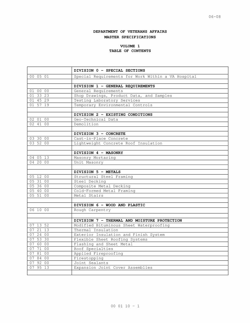
DEPARTMENT OF VETERANS AFFAIRS MASTER SPECIFICATIONS
VOLUME 1 TABLE OF CONTENTS
DIVISION 0 - SPECIAL SECTIONS 00 05 01 Special Requirements for Work Within a VA Hospital DIVISION 1 - GENERAL REQUIREMENTS 01 00 00 General Requirements 01 33 23 Shop Drawings, Product Data, and Samples 01 45 29 Testing Laboratory Services 01 57 19 Temporary Environmental Controls DIVISION 2 – EXISTING CONDITIONS 02 01 00 Geo-Technical Data 02 41 00 Demolition DIVISION 3 – CONCRETE 03 30 00 Cast-in-Place Concrete 03 52 00 Lightweight Concrete Roof Insulation DIVISION 4 – MASONRY 04 05 13 Masonry Mortaring 04 20 00 Unit Masonry DIVISION 5 – METALS 05 12 00 Structural Steel Framing 05 31 00 Steel Decking 05 36 00 Composite Metal Decking 05 40 00 Cold-Formed Metal Framing 05 51 00 Metal Stairs DIVISION 6 - WOOD AND PLASTIC 06 10 00 Rough Carpentry DIVISION 7 - THERMAL AND MOISTURE PROTECTION 07 13 52 Modified Bituminous Sheet Waterproofing 07 21 13 Thermal Insulation 07 24 00 Exterior Insulation and Finish System 07 53 30 Flexible Sheet Roofing Systems 07 60 00 Flashing and Sheet Metal 07 71 00 Roof Specialties 07 81 00 Applied Fireproofing 07 84 00 Firestopping 07 92 00 Joint Sealants 07 95 13 Expansion Joint Cover Assemblies
00 01 10 - 1
06-08
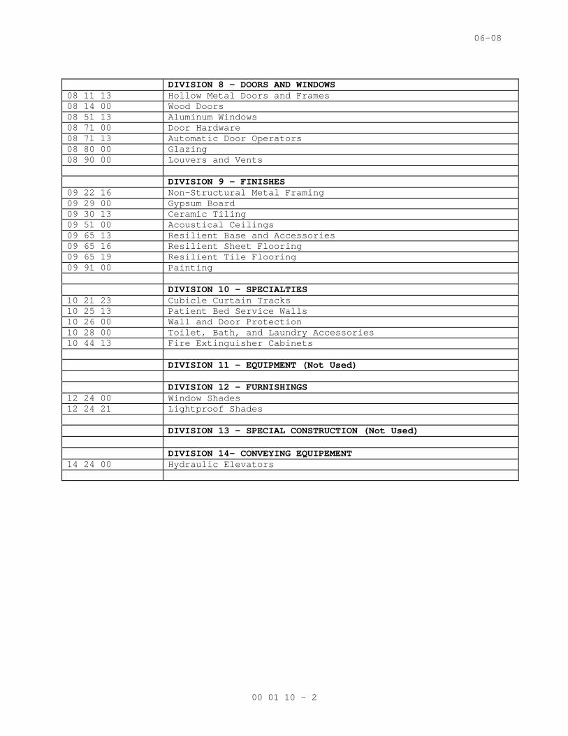
DIVISION 8 - DOORS AND WINDOWS 08 11 13 Hollow Metal Doors and Frames 08 14 00 Wood Doors 08 51 13 Aluminum Windows 08 71 00 Door Hardware 08 71 13 Automatic Door Operators 08 80 00 Glazing 08 90 00 Louvers and Vents DIVISION 9 – FINISHES 09 22 16 Non-Structural Metal Framing 09 29 00 Gypsum Board 09 30 13 Ceramic Tiling 09 51 00 Acoustical Ceilings 09 65 13 Resilient Base and Accessories 09 65 16 Resilient Sheet Flooring 09 65 19 Resilient Tile Flooring 09 91 00 Painting DIVISION 10 – SPECIALTIES 10 21 23 Cubicle Curtain Tracks 10 25 13 Patient Bed Service Walls 10 26 00 Wall and Door Protection 10 28 00 Toilet, Bath, and Laundry Accessories 10 44 13 Fire Extinguisher Cabinets DIVISION 11 – EQUIPMENT (Not Used) DIVISION 12 – FURNISHINGS 12 24 00 Window Shades 12 24 21 Lightproof Shades DIVISION 13 - SPECIAL CONSTRUCTION (Not Used) DIVISION 14– CONVEYING EQUIPEMENT 14 24 00 Hydraulic Elevators
00 01 10 - 2
06-08
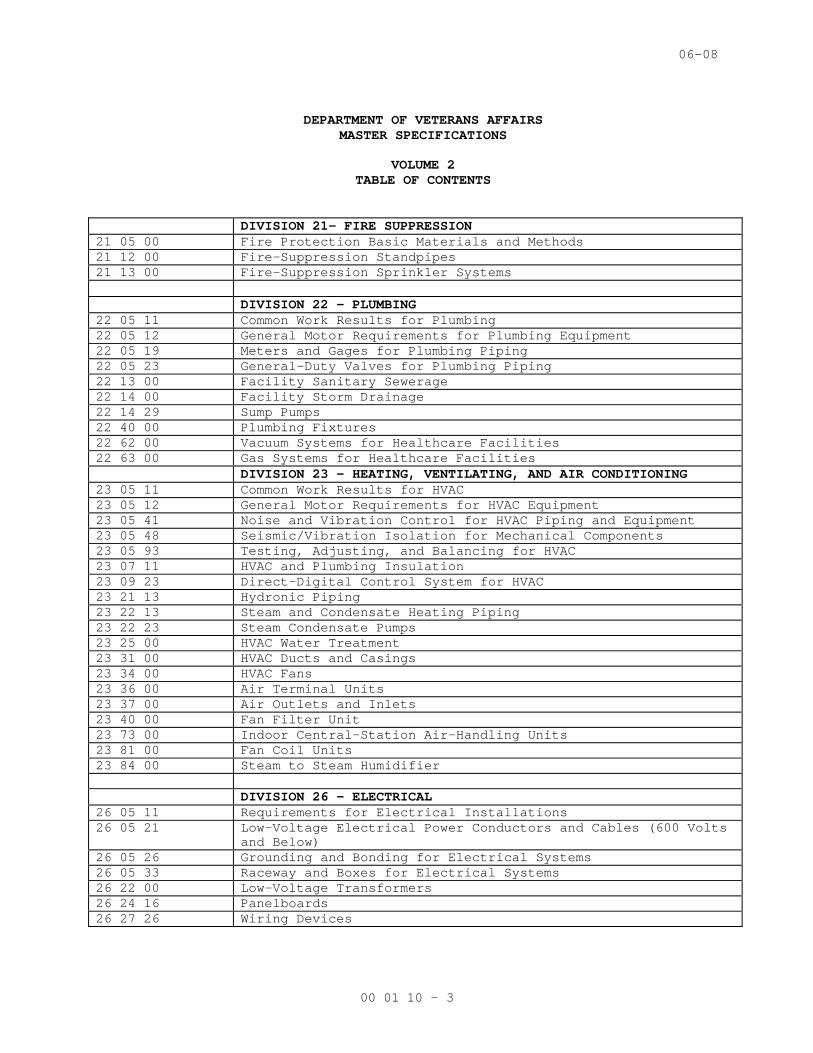
DEPARTMENT OF VETERANS AFFAIRS MASTER SPECIFICATIONS VOLUME 2
TABLE OF CONTENTS
DIVISION 21- FIRE SUPPRESSION 21 05 00 Fire Protection Basic Materials and Methods 21 12 00 Fire-Suppression Standpipes 21 13 00 Fire-Suppression Sprinkler Systems DIVISION 22 – PLUMBING 22 05 11 Common Work Results for Plumbing 22 05 12 General Motor Requirements for Plumbing Equipment 22 05 19 Meters and Gages for Plumbing Piping 22 05 23 General-Duty Valves for Plumbing Piping 22 13 00 Facility Sanitary Sewerage 22 14 00 Facility Storm Drainage 22 14 29 Sump Pumps 22 40 00 Plumbing Fixtures 22 62 00 Vacuum Systems for Healthcare Facilities 22 63 00 Gas Systems for Healthcare Facilities DIVISION 23 – HEATING, VENTILATING, AND AIR CONDITIONING 23 05 11 Common Work Results for HVAC 23 05 12 General Motor Requirements for HVAC Equipment 23 05 41 Noise and Vibration Control for HVAC Piping and Equipment 23 05 48 Seismic/Vibration Isolation for Mechanical Components 23 05 93 Testing, Adjusting, and Balancing for HVAC 23 07 11 HVAC and Plumbing Insulation 23 09 23 Direct-Digital Control System for HVAC 23 21 13 Hydronic Piping 23 22 13 Steam and Condensate Heating Piping 23 22 23 Steam Condensate Pumps 23 25 00 HVAC Water Treatment 23 31 00 HVAC Ducts and Casings 23 34 00 HVAC Fans 23 36 00 Air Terminal Units 23 37 00 Air Outlets and Inlets 23 40 00 Fan Filter Unit 23 73 00 Indoor Central-Station Air-Handling Units 23 81 00 Fan Coil Units 23 84 00 Steam to Steam Humidifier DIVISION 26 – ELECTRICAL 26 05 11 Requirements for Electrical Installations 26 05 21 Low-Voltage Electrical Power Conductors and Cables (600 Volts
and Below) 26 05 26 Grounding and Bonding for Electrical Systems 26 05 33 Raceway and Boxes for Electrical Systems 26 22 00 Low-Voltage Transformers 26 24 16 Panelboards 26 27 26 Wiring Devices
00 01 10 - 3
06-08
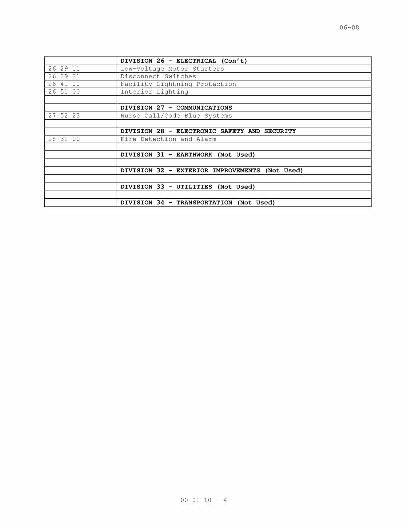
DIVISION 26 – ELECTRICAL (Con’t) 26 29 11 Low-Voltage Motor Starters 26 29 21 Disconnect Switches 26 41 00 Facility Lightning Protection 26 51 00 Interior Lighting DIVISION 27 – COMMUNICATIONS 27 52 23 Nurse Call/Code Blue Systems DIVISION 28 – ELECTRONIC SAFETY AND SECURITY 28 31 00 Fire Detection and Alarm DIVISION 31 – EARTHWORK (Not Used) DIVISION 32 – EXTERIOR IMPROVEMENTS (Not Used) DIVISION 33 – UTILITIES (Not Used) DIVISION 34 – TRANSPORTATION (Not Used)
00 01 10 - 4
05-08M
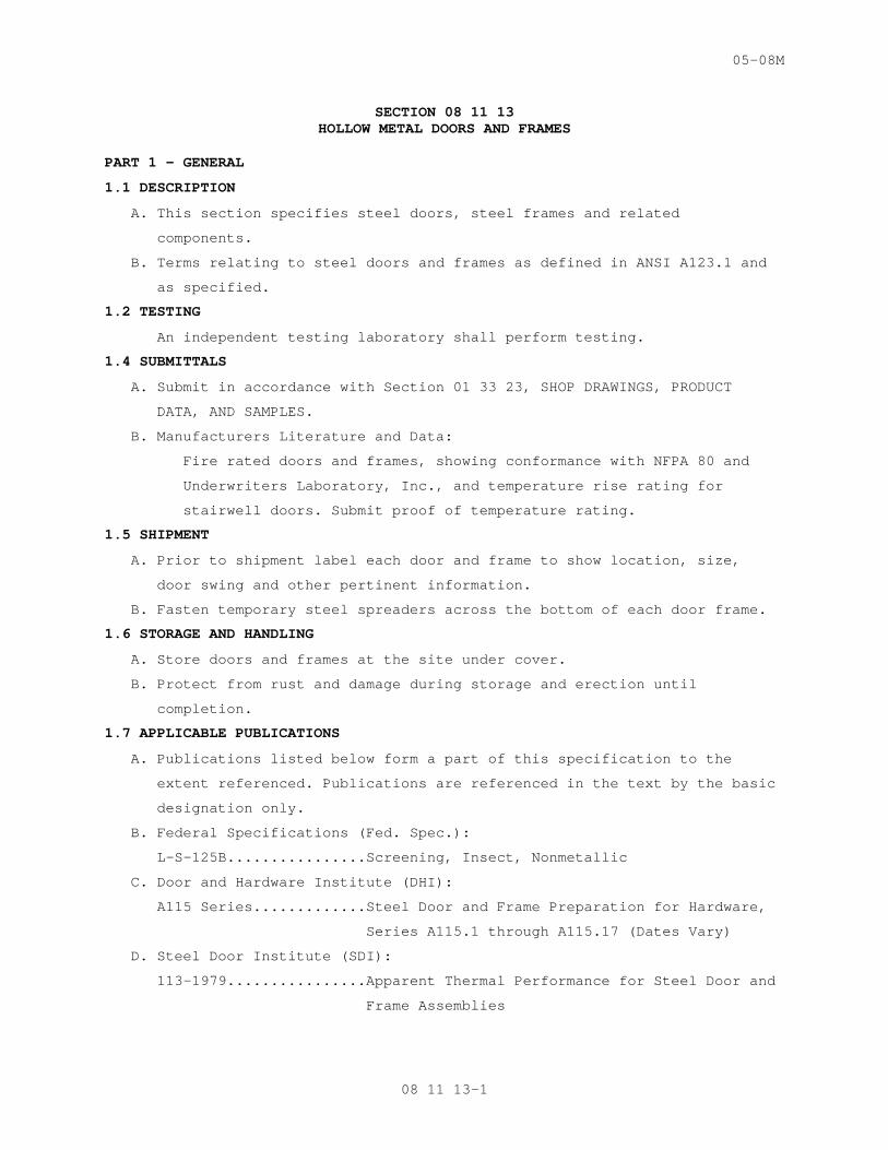
SECTION 08 11 13 HOLLOW METAL DOORS AND FRAMES
PART 1 - GENERAL
1.1 DESCRIPTION
A. This section specifies steel doors, steel frames and related
components.
B. Terms relating to steel doors and frames as defined in ANSI A123.1 and
as specified.
1.2 TESTING
An independent testing laboratory shall perform testing.
1.4 SUBMITTALS
A. Submit in accordance with Section 01 33 23, SHOP DRAWINGS, PRODUCT
DATA, AND SAMPLES.
B. Manufacturers Literature and Data:
Fire rated doors and frames, showing conformance with NFPA 80 and
Underwriters Laboratory, Inc., and temperature rise rating for
stairwell doors. Submit proof of temperature rating.
1.5 SHIPMENT
A. Prior to shipment label each door and frame to show location, size,
door swing and other pertinent information.
B. Fasten temporary steel spreaders across the bottom of each door frame.
1.6 STORAGE AND HANDLING
A. Store doors and frames at the site under cover.
B. Protect from rust and damage during storage and erection until
completion.
1.7 APPLICABLE PUBLICATIONS
A. Publications listed below form a part of this specification to the
extent referenced. Publications are referenced in the text by the basic
designation only.
B. Federal Specifications (Fed. Spec.):
L-S-125B................Screening, Insect, Nonmetallic
C. Door and Hardware Institute (DHI):
A115 Series.............Steel Door and Frame Preparation for Hardware,
Series A115.1 through A115.17 (Dates Vary)
D. Steel Door Institute (SDI):
113-1979................Apparent Thermal Performance for Steel Door and
Frame Assemblies
08 11 13-1
05-08M
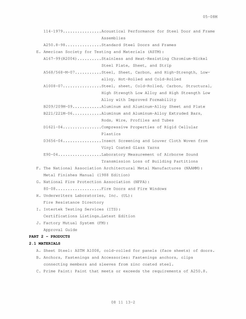
114-1979................Acoustical Performance for Steel Door and Frame
Assemblies
A250.8-98...............Standard Steel Doors and Frames
E. American Society for Testing and Materials (ASTM):
A167-99(R2004)..........Stainless and Heat-Resisting Chromium-Nickel
Steel Plate, Sheet, and Strip
A568/568-M-07...........Steel, Sheet, Carbon, and High-Strength, Low-
alloy, Hot-Rolled and Cold-Rolled
A1008-07................Steel, sheet, Cold-Rolled, Carbon, Structural,
High Strength Low Alloy and High Strength Low
Alloy with Improved Formability
B209/209M-09............Aluminum and Aluminum-Alloy Sheet and Plate
B221/221M-06............Aluminum and Aluminum-Alloy Extruded Bars,
Rods, Wire, Profiles and Tubes
D1621-04................Compressive Properties of Rigid Cellular
Plastics
D3656-04................Insect Screening and Louver Cloth Woven from
Vinyl Coated Glass Yarns
E90-04..................Laboratory Measurement of Airborne Sound
Transmission Loss of Building Partitions
F. The National Association Architectural Metal Manufactures (NAAMM):
Metal Finishes Manual (1988 Edition)
G. National Fire Protection Association (NFPA):
80-08...................Fire Doors and Fire Windows
H. Underwriters Laboratories, Inc. (UL):
Fire Resistance Directory
I. Intertek Testing Services (ITS):
Certifications Listings…Latest Edition
J. Factory Mutual System (FM):
Approval Guide
PART 2 - PRODUCTS
2.1 MATERIALS
A. Sheet Steel: ASTM A1008, cold-rolled for panels (face sheets) of doors.
B. Anchors, Fastenings and Accessories: Fastenings anchors, clips
connecting members and sleeves from zinc coated steel.
C. Prime Paint: Paint that meets or exceeds the requirements of A250.8.
08 11 13-2
05-08M
2.2 FABRICATION GENERAL
A. GENERAL:
1. Follow SDI A250.8 for fabrication of standard steel doors, except as
specified otherwise. Doors to receive hardware specified in Section
08 71 00, DOOR HARDWARE. Tolerances as per SDI A250.8. Thickness, 44
mm (1-3/4 inches), unless otherwise shown.
2. Close top edge of exterior doors flush and seal to prevent water
intrusion.
3. When vertical steel stiffeners are used for core construction, fill
spaces between stiffeners with mineral fiber insulation.
B. Heavy Duty Doors: SDI A250.8, Level 2, Model 2 of size and design
shown. Core construction types a, d, or f, for interior doors, and,
types b, c, e, or f, for exterior doors.
C. General:
1. SDI A250.8, 1.3 mm (0.053 inch) thick sheet steel, types and styles
as shown or scheduled.
2. Frames for exterior doors: Fabricate from 1.7 mm (0.067 inch) thick
galvanized steel conforming to ASTM A525.
3. Frames for labeled fire rated doors // and windows //.
4. Frames for doors specified to have automatic door operators;
Security doors (Type 36); service window: minimum 1.7 mm (0.067
inch) thick.
5. Knocked-down frames are not acceptable.
D. Reinforcement and Covers:
1. SDI A250.8 for, minimum thickness of steel reinforcement welded to
back of frames.
2. Provide mortar guards securely fastened to back of hardware
reinforcements except on lead-lined frames.
3. Where concealed door closers are installed within the head of the
door frames, prepare frames for closers and provide 1 mm (0.042
inch) thick steel removable stop sections for access to concealed
face plates and control valves, except when cover plates are
furnished with closer.
E. Glazed Openings:
a. Integral stop on exterior, corridor, or secure side of door.
b. Design rabbet width and depth to receive glazing material or panel
shown or specified.
08 11 13-3
05-08M
F. Frame Anchors:
1. Floor anchors:
a. Where floor fills occur, provide extension type floor anchors to
compensate for depth of fill.
b. At bottom of jamb use 1.3 mm (0.053 inch) thick steel clip angles
welded to jamb and drilled to receive two 6 mm (1/4 inch) floor
bolts. Use 50 mm x 50 mm (2 inch by 2 inch) 9 mm by (3/8 inch)
clip angle for lead lined frames, drilled for 9 mm (3/8 inch)
floor bolts.
c. Where mullions occur, provide 2.3 mm (0.093 inch) thick steel
channel anchors, drilled for two 6 mm (1/4 inch) floor bolts and
frame anchor screws.
d. Where sill sections occur, provide continuous 1 mm (0.042 inch)
thick steel rough bucks drilled for 6 mm (1/4 inch) floor bolts
and frame anchor screws. Space floor bolts at 50 mm (24 inches)
on center.
2. Jamb anchors:
a. Locate anchors on jambs near top and bottom of each frame, and at
intermediate points not over 600 mm (24 inches) apart, // except
for fire rated frames space anchors as required by labeling
authority //.
b. Form jamb anchors of not less than 1 mm (0.042 inch) thick steel
unless otherwise specified.
c. Anchors for stud partitions: Either weld to frame or use lock-in
snap-in type. Provide tabs for securing anchor to the sides of
the studs.
2.3 SHOP PAINTING
SDI A250.8.
PART 3 - EXECUTION
3.1 INSTALLATION
A. Plumb, align and brace frames securely until permanent anchors are set.
1. Use triangular bracing near each corner on both sides of frames with
temporary wood spreaders at midpoint.
2. Use wood spreaders at bottom of frame if the shipping spreader is
removed.
3. Protect frame from accidental abuse.
08 11 13-4
05-08M
4. Where construction will permit concealment, leave the shipping
spreaders in place after installation, otherwise remove the
spreaders after the frames are set and anchored.
5. Remove wood spreaders and braces only after the walls are built and
jamb anchors are secured.
B. Floor Anchors:
1. Anchor the bottom of door frames to floor with two 6 mm (1/4 inch)
diameter expansion bolts. Use 9 mm (3/8 inch) bolts on lead lined
frames.
2. Power actuated drive pins may be used to secure frame anchors to
concrete floors.
C. Jamb Anchors:
1. Anchors in masonry walls: Embed anchors in mortar. Fill space
between frame and masonry wall with grout or mortar as walls are
built.
2. Coat frame back with a bituminous coating prior to lining of grout
filling in masonry walls.
3. Secure anchors to sides of studs with two fasteners through anchor
tabs. Use steel drill screws to steel studs.
D. Install anchors for labeled fire rated doors to provide rating as
required.
3.2 INSTALLATION OF DOORS AND APPLICATION OF HARDWARE
Install doors and hardware as specified in Sections Section 08 11 13,
HOLLOW METAL DOORS AND FRAMES, Section 08 14 00, WOOD DOORS and Section
08 71 00, DOOR HARDWARE.
- - - E N D - - -
08 11 13-5
10-07M
SECTION 08 14 00 INTERIOR WOOD DOORS
PART 1 - GENERAL
1.1 DESCRIPTION
A. This section specifies interior flush doors with prefinish, prefit
option.
B. Section includes fire rated doors, and smoke doors.
1.2 RELATED WORK
A. Metal door frames: Section 08 11 13, HOLLOW METAL DOORS AND FRAMES.
B. Door hardware including hardware location (height): Section 08 71 00,
DOOR HARDWARE.
C. Installation of doors and hardware: Section 08 11 13, HOLLOW METAL
DOORS AND FRAMES, Section 08 14 00, WOOD DOORS, or Section 08 71 00,
DOOR HARDWARE.
1.3 SUBMITTALS
A. Submit in accordance with Section 01 33 23, SHOP DRAWINGS, PRODUCT
DATA, AND SAMPLES.
B. Samples:
Veneer sample 200 mm (8 inch) by 275 mm (11 inch) by 6 mm (1/4 inch)
showing specified wood species sanded to receive a transparent finish.
Factory finish veneer sample where the prefinished option is accepted.
C. Shop Drawings:
1. Show every door in project and schedule location in building.
2. Indicate type, grade, finish and size.
3. Provide information concerning specific requirements not included in
the manufacturer's literature and data submittal.
1.4 WARRANTY
A. Doors are subject to terms of Article titled “Warranty of Construction”
of Section, 00 72 00, GENERAL CONDITIONS, except that warranty shall be
as follows:
1. For interior doors, manufacturer’s warranty for lifetime of original
installation.
1.5 DELIVERY AND STORAGE
A. Factory seal doors and accessories in minimum of 6 mill polyethylene
bags or cardboard packages which shall remain unbroken during delivery
and storage.
B. Store in accordance with WDMA I.S.1-A, J-1 Job Site Information.
C. Label package for door opening where used.
08 14 00-1
10-07M
1.6 APPLICABLE PUBLICATIONS
Publications listed below form a part of this specification to extent
referenced. Publications are referenced in text by basic designation
only.
B. Window and Door Manufacturers Association (WDMA):
I.S.1-A-04..............Architectural Wood Flush Doors
I.S.4-00................Water-Repellent Preservative Non-Pressure
Treatment for Millwork
I.S.6-97................Wood Stile and Rail Doors
I.S.6-A-01..............Architectural Stile and Rail Doors
TM-5-90.................Test Method to Determine the Split Resistance
of Stile Edges of Wood Doors
TM-6-88.................Adhesive Bond Durability Test Method
TM-7-90.................Cycle-Slam Test Method
TM-8-90.................Hinge Loading Resistance Test Method
TM-10-90................Screw Holding Test Method
C. National Fire Protection Association (NFPA):
80-99...................Fire Doors and Windows
252-03..................Fire Tests of Door Assemblies
D. ASTM International (ASTM):
E90-00..................Fire Tests of Door Assemblies
PART 2 - PRODUCTS
2.1 FLUSH DOORS
A. General:
1. Meet requirements of WDMA I.S.1-A, Extra Heavy Duty.
2. Adhesive: Type II
3. Thickness: 45 mm (1-3/4 inches) unless otherwise shown or specified.
B. Face Veneer:
1. In accordance with NWWDA I.S.1-A.
2. One species throughout the project unless scheduled or otherwise
shown.
3. For transparent finishes: Premium Grade. rotary cut.
a. A grade face veneer standard optional.
b. AA grade face veneer
c. Match face veneers for doors for uniform effect of color and
grain at joints.
d. Door edges shall be same species as door face veneer except maple
may be used for stile face veneer on birch doors.
08 14 00-2
10-07M
e. In existing buildings, where doors are required to have
transparent finish, use wood species and grade of face veneers to
match adjacent existing doors.
C. Wood for stops, louvers, muntins and moldings of flush doors required
to have transparent finish:
1. Solid Wood of same species as face veneer, except maple may be used
on birch doors.
2. Glazing:
a. On non-labeled doors use applied wood stops nailed tight on room
side and attached on opposite side with flathead, countersunk
wood screws, spaced approximately 125 mm (5 inches) on centers.
b. Use stainless steel or dull chrome plated brass screws for
exterior doors.
D. Stiles and Rails:
Option for wood stiles and rails:
Composite material having screw withdrawal force greater than
minimum performance level value when tested in accordance with
WDMA TM-10.
E. Fire rated wood doors:
1. Fire Performance Rating:
a. “B” label, 1-1/2 hours.
b. “C” label, 3/4 hour.
2. Labels:
a. Doors shall conform to the requirements of ASTM E2074, or NFPA
252, and, carry an identifying label from a qualified testing and
inspection agency for class of door or opening shown designating
fire performance rating.
b. Metal labels with raised or incised markings.
3. Performance Criteria for Stiles of doors utilizing standard mortise
leaf hinges:
a. Hinge Loading: WDMA TM-8. Average of 10 test samples for Extra
Heavy Duty doors.
b. Direct screw withdrawal: WDMA TM-10 for Extra Heavy Duty doors.
Average of 10 test samples using a steel, fully threaded #12 wood
screw.
c. Cycle Slam: 1,000,000 cycles with no loose hinge screws or other
visible signs of failure when tested in accordance with WDMA TM-
7.
08 14 00-3
10-07M
4. Additional Hardware Reinforcement:
a. Provide fire rated doors with hardware reinforcement blocking.
b. Size of lock blocks as required to secure hardware specified.
c. Top, bottom and intermediate rail blocks shall measure not less
than 125 mm (five inches) minimum by full core width.
d. Reinforcement blocking in compliance with manufacturer's labeling
requirements.
e. Mineral material similar to core is not acceptable.
5. Other Core Components: Manufacturer's standard as allowed by the
labeling requirements.
6. Provide steel frame approved for use in labeled doors for vision
panels.
7. Provide steel astragal on pair of doors.
F. Smoke Barrier Doors:
1. For glazed openings use steel frames approved for use in labeled
doors.
2. Provide a steel astragal on one leaf of pairs of doors, including
double egress doors.
2.2 PREFINISH, PREFIT OPTION
A. Flush doors may be factory machined to receive hardware, bevels,
undercuts, cutouts, accessories and fitting for frame.
B. Factory fitting to conform to specification for shop and field fitting,
including factory application of sealer to edge and routings.
C. Flush doors to receive transparent finish (in addition to being prefit)
shall be factory finished as follows:
1. WDMA I.S.1A Section F-3 specification for System TR-4, Conversion
Varnish or System TR-5, Catalyzed Vinyl.
2.3 IDENTIFICATION MARK:
A. On top edge of door.
B. Either a stamp, brand or other indelible mark, giving manufacturer’s
name, door’s trade name, construction of door, code date of manufacture
and quality.
C. Accompanied by either of the following additional requirements:
1. An identification mark or a separate certification including name of
inspection organization.
2. Identification of standards for door, including glue type.
3. Identification of veneer and quality certification.
4. Identification of preservative treatment for stile and rail doors.
08 14 00-4
10-07M
2.4 SEALING:
Give top and bottom edge of doors two coats of catalyzed polyurethane
or water resistant sealer before sealing in shipping containers.
PART 3 - EXECUTION
3.1 DOOR PREPARATION
A. Field, shop or factory preparation: Do not violate the qualified
testing and inspection agency label requirements for fire rated doors.
B. Clearances between Doors and Frames and Floors:
1. Maximum 3 mm (1/8 inch) clearance at the jambs, heads, and meeting
stiles, and a 19 mm (3/4 inch) clearance at bottom, except as
otherwise specified.
2. Maximum clearance at bottom of sound rated doors, light-proofed
doors, doors to operating rooms, and doors designated to be fitted
with mechanical seal: 10 mm (3/8 inch).
C. Provide cutouts for special details required and specified.
D. Rout doors for hardware using templates and location heights specified
in Section, 08 71 00 DOOR HARDWARE.
E. Fit doors to frame, bevel lock edge of doors 3 mm (1/8 inch) for each
50 mm (two inches) of door thickness // undercut where shown. //
F. Immediately after fitting and cutting of doors for hardware, seal cut
edges of doors with two coats of water resistant sealer.
G. Finish surfaces, including both faces, top and bottom and edges of the
doors smooth to touch.
H. Apply a steel astragal on the opposite side of active door on pairs of
fire rated doors.
I. Apply a steel astragal to meeting style of active leaf of pair of doors
or double egress smoke doors.
3.2 INSTALLATION OF DOORS APPLICATION OF HARDWARE
Install doors and hardware as specified in Section, INSTALLATION OF
DOORS AND HARDWARE.
3.3 DOOR PROTECTION
A. As door installation is completed, place polyethylene bag or cardboard
shipping container over door and tape in place.
B. Provide protective covering over knobs and handles in addition to
covering door.
C. Maintain covering in good condition until removal is approved by
Resident Engineer.
- - - E N D - - -
08 14 00-5
03-08M
SECTION 08 51 13 ALUMINUM WINDOWS
PART 1 - GENERAL
1.1 DESCRIPTION
A. Aluminum windows of type and size shown, complete with hardware,
related components and accessories.
B. Type: Fixed
1.2 DEFINITIONS
A. Accessories: Mullions, staff beads, casings, closures, trim, moldings,
panning systems, sub-sills, clips anchors, fasteners, weather-
stripping, insect screens and other necessary components required for
fabrication and installation of window units.
B. Uncontrolled Water: Water not drained to the exterior, or water
appearing on the room side of the window.
1.3 RELATED WORK
Glazing: Section 08 80 00, GLAZING.
1.4 DELIVERY, STORAGE AND HANDLING
A. Protect windows from damage during handling and construction operations
before, during and after installation.
B. Store windows under cover, setting upright.
C. Do not stack windows flat.
D. Do not lay building materials or equipment on windows.
1.5 QUALITY ASSURANCE
A. Approval by contracting officer is required of products or service of
proposed manufacturers and installers.
B. Approval will be based on submission of certification by Contractor
that:
1. Manufacturer regularly and presently manufactures the specified
windows as one of its principal products.
2. Installer has technical qualifications, experience, trained
personnel and facilities to install specified items.
C. Provide each type of window produced from one source of manufacture.
D. Quality Certified Labels or certificate:
1. Architectural Aluminum Manufacturers Association, "AAMA label"
affixed to each window indicating compliance with specification.
2. Certificates in lieu of label with copy of recent test report (not
more than 4 years old) from an independent testing laboratory and
certificate signed by window manufacturer stating that windows
08 51 13 - 1
03-08M
provided comply with specified requirements and AAMA 101/I.S.2 for
type of window specified.
1.6 SUBMITTAL
A. Submit in accordance with Section 01 33 23, SHOP DRAWINGS, PRODUCT
DATA, AND SAMPLES.
B. Shop Drawings:
1. Minimum of 1/2 full scale types of windows on project.
2. Identifying parts of window units by name and kind of metal or
material, show construction, installation and anchorages.
3. Include glazing details and standards for factory glazed units.
C. Manufacturer's Literature and Data:
Window.
D. Certificates:
1. Certificates as specified in paragraph QUALITY ASSURANCE.
2. Indicating manufacturers and installers qualifications.
3. Manufacturer's Certification that windows delivered to project are
identical to windows tested.
E. Test Reports:
Copies of test reports as specified in paragraph QUALITY ASSURANCE.
F. Samples: Provide 150 mm (six-inch) length samples showing finishes,
specified.
1.7 WARRANTY
Warrant windows against malfunctions due to defects in thermal breaks,
hardware, materials and workmanship, subject to the terms of Article
WARRANTY OF CONSTRUCTION of Section 00 72 00, GENERAL CONDITIONS,
except provide 10 year warranty period.
1.8 APPLICABLE PUBLICATIONS
A. Publications listed below form a part of this specification to extent
referenced. Publications are referenced in text by basic designation
only.
B. American Society of Heating, Refrigerating and Air Conditioning
Engineers (ASHRAE)
90.1-04.................Energy Standard of Buildings
C. American Architectural Manufacturers Association (AAMA):
101/I.S.2/A440-05.......Windows, Doors, and Unit Skylights
505-98..................Dry Shrinkage and Composite Performance Thermal
Cycling Test Procedures
08 51 13 - 2
03-08M
2605-05.................Superior Performing Organic Coatings on
Architectural Aluminum Extrusions and Panels
TIR-A8-04...............Structural Performance of Poured and Debridged
Framing Systems
D. American Society for Testing and Materials (ASTM):
A653/A653M-07...........Steel Sheet, Zinc Coated (Galvanized), Zinc-
Iron Alloy-Coated (Galvannealed) by the Hot-dip
Process
E 90-04.................Test Method for Laboratory Measurement of
Airborne Sound Transmission Loss of Building
Partitions
E. National Fenestration Rating Council (NFRC):
NFRC 100-04.............Determining Fenestration Product U-Factors
NFRC 200-04.............Determining Fenestration Product Solar Heat
Gain Coefficient and Visible Transmittance at
Normal Incidence
F. National Association of Architectural Metal Manufacturers (NAAMM):
AMP 500 Series..........Metal Finishes Manual
PART 2- PRODUCTS
2.1 MATERIALS
A. Aluminum Extrusions; Sheet and Plate: AAMA 101/I.S.2.
B. Sheet Steel, Galvanized: ASTM A653; G90 galvanized coating.
C. Weather-strips: AAMA 101/I.S.2; except leaf type weather-stripping is
not permitted.
2.2 THERMAL PERFORMANCE
A. Thermal Transmittance: Maximum U value class for insulating glass
windows: 50 (U=0.50).
C. Solar Heat Gain Coefficient (SHGC): SHGC shall comply with State or
local energy code requirement.
2.3 FABRICATION
A. Fabrication to exceed or meet requirements of Physical Load Tests, Air
Infiltration Test, and Water Resistance Test of AAMA 101/I.S.2.
B. Glazing:
1. Factory or field glazing optional.
2. Glaze in accordance with Section 08 80 00, GLAZING.
3. Windows reglazable without dismantling sash framing.
4. Design rabbet to suit glass thickness and glazing method specified.
5. Glaze from interior except where not accessible.
08 51 13 - 3
03-08M
6. Provide removable fin type glazing beads.
C. Trim:
1. Trim includes casings, closures, and panning.
2. Fabricate to shapes shown of aluminum not less than 1.6 mm (0.062
inch) thick
3. Extruded or formed sections, straight, true, and smooth on exposed
surfaces.
4. Exposed external corners mitered and internal corners coped; fitted
with hairline joints.
5. Reinforce 1.6 mm (0.062 inch) thick members with not less than 3 mm
(1/8-inch) thick aluminum.
6. Except for strap anchors, provide reinforcing for fastening near
ends and at intervals not more than 305 mm (12 inches) between ends.
7. Design to allow unrestricted expansion and contraction of members
and window frames.
8. Secure to window frames with machine screws or expansion rivets.
9. Exposed screws, fasteners or pop rivets are not acceptable on
exterior of the casing or trim cover system.
D. Thermal-Break Construction:
1. Manufacturer’s Standard.
2. Low conductance thermal barrier.
3. Capable of structurally holding sash in position and together.
4. All Thermal Break Assemblies (Pour & Debridge, Insulbar or others)
shall be tested as per AAMA TIR A8 and AAMA 505 for Dry Shrinkage
and Composite Performance.
5. Location of thermal barrier and design of window shall be such that,
in closed position, outside air shall not come in direct contact
with interior frame of the window.
E. Mullions: AAMA 101.
F. Subsills and Stools:
1. Fabricate to shapes shown of not less than 2 mm (0.080 inch) thick
extruded aluminum.
2. One piece full length of opening with concealed anchors.
3. Sills turned up back edge not less than 6 mm (1/4 inch). Front edge
provide with drip.
4. Sill back edge behind face of window frame. Do not extend to
interior surface or bridge thermal breaks.
5. Do not perforate for anchorage, clip screws, or other requirements.
08 51 13 - 4
03-08M
2.4 FIXED WINDOWS
A. AMMA 101/I.S.2; Type HC25.
B. AAMA certified product to the AAMA 101/I.S.2. - 97 standard.
2.5 FINISH
A. In accordance with NAAMM AMP 500 series.
B. Finish exposed aluminum surfaces as follows:
1. Anodized Aluminum:
a. Finish in accordance with AMP 501 letters and numbers.
b. Colored anodized Finish: AA-C22A42 (anodized) or AA-C22A44
(electrolytically deposited metallic compound) medium matte,
integrally colored coating, Class 1 Architectural, 0.7 mils
thick. Match finish of existing windows.
1) Dyes not accepted.
2) Coated Aluminum:
3) Variation of more than 50 percent of maximum shade range
approved will not be accepted in a single window or in
adjacent windows and mullions on a continuous series.
a) AMP 501 and 505.
b) Fluorocarbon Finish: AAMA 2605, superior performing organic
coating.
c) Steel: AMP 504.
d) Stainless steel: AMP 503.
1. Concealed: 2B or 2D.
2. Exposed: No. 4 unless specified otherwise.
E. Hardware: Finish hardware exposed when window is in the closed
position: Match window color.
PART 3 - EXECUTION
3.1 PROTECTION (DISSIMILAR MATERIALS): AAMA 101/I.S.2.
3.2 INSTALLATION, GENERAL
A. Install window units in accordance with manufacturer's specifications
and recommendations for installation of window units, hardware,
operators and other components of work.
B. Where type, size or spacing of fastenings for securing window
accessories or equipment to building construction is not shown or
specified, use expansion or toggle bolts or screws, as best suited to
construction material.
1. Provide bolts or screws minimum 6 mm (1/4-inch) in diameter.
2. Sized and spaced to resist the tensile and shear loads imposed.
08 51 13 - 5
03-08M
3. Do not use exposed fasteners on exterior, except when unavoidable
for application of hardware.
4. Provide non-magnetic stainless steel Phillips flat-head machine
screws for exposed fasteners, where required, or special tamper-
proof fasteners.
5. Locate fasteners to not disturb the thermal break construction of
windows.
C. Set windows plumb, level, true, and in alignment; without warp or rack
of frames or sash.
D. Anchor windows on four sides with anchor clips or fin trim.
1. Do not allow anchor clips to bridge thermal breaks.
2. Use separate clips for each side of thermal breaks.
3. Make connections to allow for thermal and other movements.
4. Do not allow building load to bear on windows.
5. Use manufacturer's standard clips at corners and not over 600 mm (24
inches) on center.
6. Where fin trim anchorage is shown build into adjacent construction,
anchoring at corners and not over 600 mm (24 inches) on center.
E. Sills and Stools:
1. Set in bed of mortar or other compound to fully support, true to
line shown.
2. Do not extend sill to inside window surface or past thermal break.
3. Leave space for sealants at ends and to window frame unless shown
otherwise.
3.3 MULLIONS CLOSURES, TRIM, AND PANNING
A. Cut mullion full height of opening and anchor directly to window frame
on each side.
B. Closures, Trim, and Panning: External corners mitered and internal
corners coped, fitted with hairline, tightly closed joints.
C. Secure to concrete or solid masonry with expansion bolts, expansion
rivets, split shank drive bolts, or powder actuated drive pins.
D. Toggle bolt to hollow masonry units. Screwed to wood or metal.
E. Fasten except for strap anchors, near ends and corners and at intervals
not more than 300 mm (12 inches) between.
F. Seal units following installation to provide weathertight system.
08 51 13 - 6
03-08M
3.4 ADJUST AND CLEAN
A. Adjust ventilating sash and hardware to provide tight fit at contact
points, and at weather-stripping for smooth operation and weathertight
closure.
B. Clean aluminum surfaces promptly after installation of windows,
exercising care to avoid damage to protective coatings and finishes.
C. Remove excess glazing and sealant compounds, dirt, and other
substances.
D. Lubricate hardware and moving parts.
E. Clean glass promptly after installation of windows. Remove glazing and
sealant compound, dirt and other substances.
F. Except when a window is being adjusted or tested, keep locked in the
closed position during the progress of work on the project.
- - - E N D - - -
08 51 13 - 7
SECTION 087100
DOOR HARDWARE
PART 1 - GENERAL
1.1 CONDITIONS
A. The general conditions, supplementary general conditions, and all
contract documents are a part of this division of the specifications
and all provisions contained herein. Submission of proposal implies
that the bidder is fully familiar with all requirements of said
documents.
1.2 SCOPE
A. The finish hardware supplier shall furnish all necessary items for
completion of this project, as specified in paragraph 3.05, hardware
sets, or as necessary to complete this building excepting the items
specifically excluded.
1.3 WORK NOT INCLUDED
A. Window hardware
B. Folding partition hardware
C. Toilet partition hardware
D. Overhead door hardware (except cylinders or padlocks)
E. Aluminum door hardware (except cylinders)
F. Cabinet and millwork hardware
1.4 QUALITY ASSURANCE
A. The hardware supplier shall submit six (6) typewritten hardware
schedules to the architect through the general contractor for approval.
Each schedule shall contain the door index listing or opening on the
project and the hardware for said opening. Each item of hardware
listed is to be clearly identified by manufacturer, manufacturer's
number and finish.
B. The architect retains the authority to approve or reject any schedule
based upon his knowledge of the suppliers experience and capabilities,
the general quality of the products submitted and compliance with the
specifications.
C. If requested, the supplier shall provide working samples of any items
he proposes to substitute. Samples will be returned to the jobsite for
installation.
D. The hardware supplier shall forward template information to all related
trades within ten (10) days after receipt of approved hardware
087100 - 1
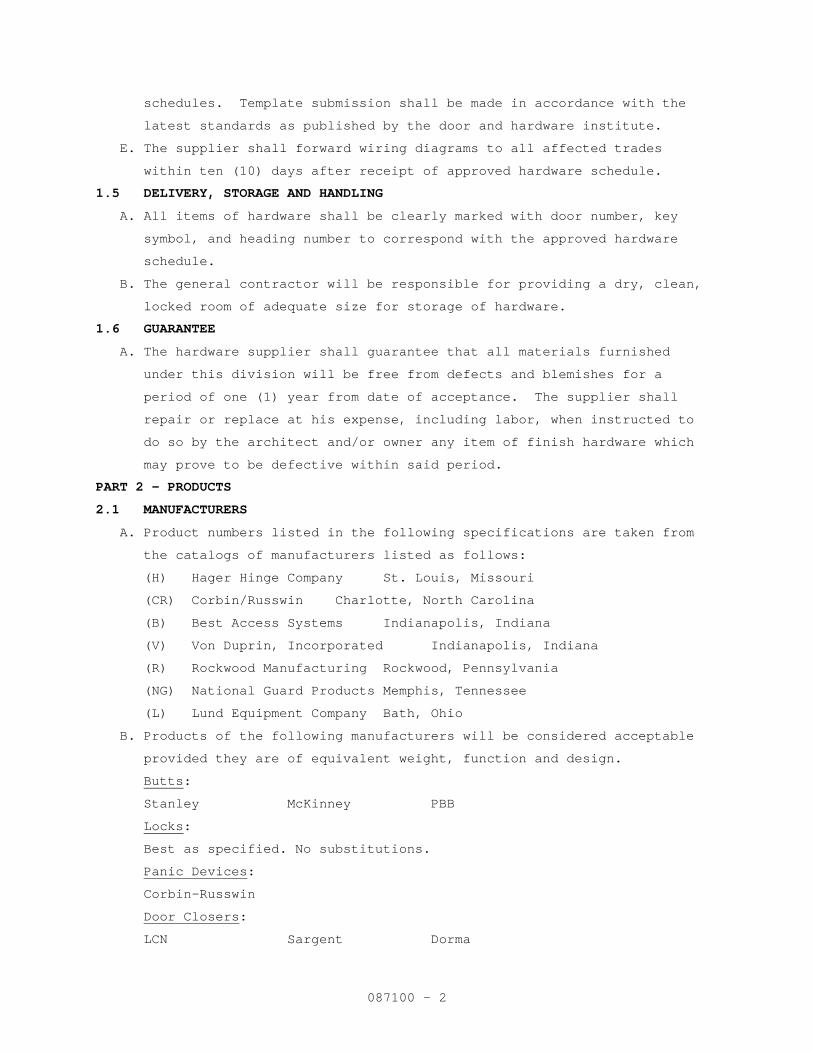
schedules. Template submission shall be made in accordance with the
latest standards as published by the door and hardware institute.
E. The supplier shall forward wiring diagrams to all affected trades
within ten (10) days after receipt of approved hardware schedule.
1.5 DELIVERY, STORAGE AND HANDLING
A. All items of hardware shall be clearly marked with door number, key
symbol, and heading number to correspond with the approved hardware
schedule.
B. The general contractor will be responsible for providing a dry, clean,
locked room of adequate size for storage of hardware.
1.6 GUARANTEE
A. The hardware supplier shall guarantee that all materials furnished
under this division will be free from defects and blemishes for a
period of one (1) year from date of acceptance. The supplier shall
repair or replace at his expense, including labor, when instructed to
do so by the architect and/or owner any item of finish hardware which
may prove to be defective within said period.
PART 2 - PRODUCTS
2.1 MANUFACTURERS
A. Product numbers listed in the following specifications are taken from
the catalogs of manufacturers listed as follows:
(H) Hager Hinge Company St. Louis, Missouri
(CR) Corbin/Russwin Charlotte, North Carolina
(B) Best Access Systems Indianapolis, Indiana
(V) Von Duprin, Incorporated Indianapolis, Indiana
(R) Rockwood Manufacturing Rockwood, Pennsylvania
(NG) National Guard Products Memphis, Tennessee
(L) Lund Equipment Company Bath, Ohio
B. Products of the following manufacturers will be considered acceptable
provided they are of equivalent weight, function and design.
Butts:
Stanley McKinney PBB
Locks:
Best as specified. No substitutions.
Panic Devices:
Corbin-Russwin
Door Closers:
LCN Sargent Dorma
087100 - 2
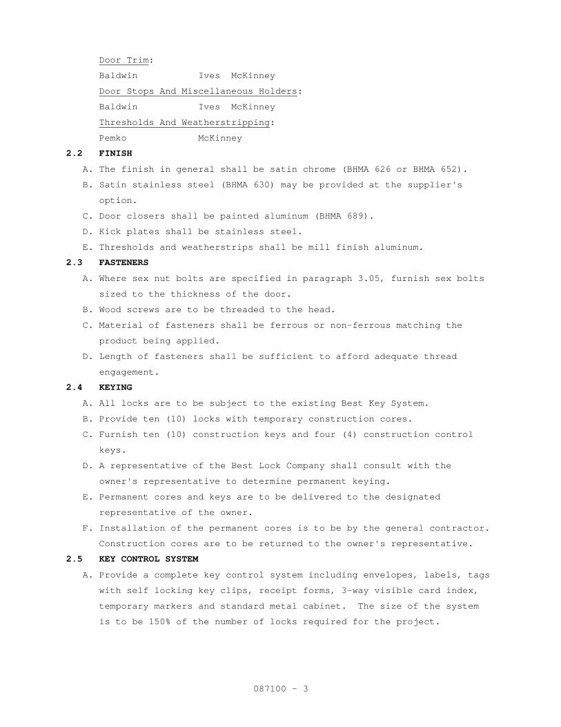
Door Trim:
Baldwin Ives McKinney
Door Stops And Miscellaneous Holders:
Baldwin Ives McKinney
Thresholds And Weatherstripping:
Pemko McKinney
2.2 FINISH
A. The finish in general shall be satin chrome (BHMA 626 or BHMA 652).
B. Satin stainless steel (BHMA 630) may be provided at the supplier's
option.
C. Door closers shall be painted aluminum (BHMA 689).
D. Kick plates shall be stainless steel.
E. Thresholds and weatherstrips shall be mill finish aluminum.
2.3 FASTENERS
A. Where sex nut bolts are specified in paragraph 3.05, furnish sex bolts
sized to the thickness of the door.
B. Wood screws are to be threaded to the head.
C. Material of fasteners shall be ferrous or non-ferrous matching the
product being applied.
D. Length of fasteners shall be sufficient to afford adequate thread
engagement.
2.4 KEYING
A. All locks are to be subject to the existing Best Key System.
B. Provide ten (10) locks with temporary construction cores.
C. Furnish ten (10) construction keys and four (4) construction control
keys.
D. A representative of the Best Lock Company shall consult with the
owner's representative to determine permanent keying.
E. Permanent cores and keys are to be delivered to the designated
representative of the owner.
F. Installation of the permanent cores is to be by the general contractor.
Construction cores are to be returned to the owner's representative.
2.5 KEY CONTROL SYSTEM
A. Provide a complete key control system including envelopes, labels, tags
with self locking key clips, receipt forms, 3-way visible card index,
temporary markers and standard metal cabinet. The size of the system
is to be 150% of the number of locks required for the project.
087100 - 3
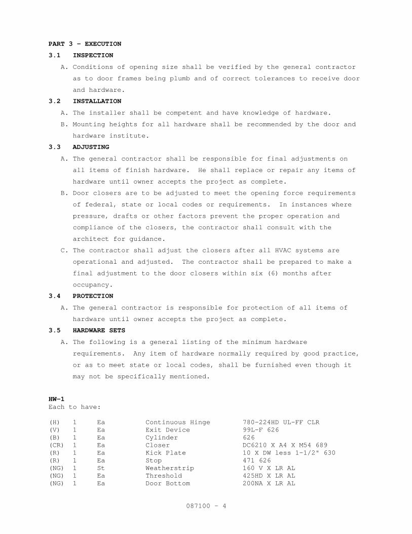
PART 3 - EXECUTION
3.1 INSPECTION
A. Conditions of opening size shall be verified by the general contractor
as to door frames being plumb and of correct tolerances to receive door
and hardware.
3.2 INSTALLATION
A. The installer shall be competent and have knowledge of hardware.
B. Mounting heights for all hardware shall be recommended by the door and
hardware institute.
3.3 ADJUSTING
A. The general contractor shall be responsible for final adjustments on
all items of finish hardware. He shall replace or repair any items of
hardware until owner accepts the project as complete.
B. Door closers are to be adjusted to meet the opening force requirements
of federal, state or local codes or requirements. In instances where
pressure, drafts or other factors prevent the proper operation and
compliance of the closers, the contractor shall consult with the
architect for guidance.
C. The contractor shall adjust the closers after all HVAC systems are
operational and adjusted. The contractor shall be prepared to make a
final adjustment to the door closers within six (6) months after
occupancy.
3.4 PROTECTION
A. The general contractor is responsible for protection of all items of
hardware until owner accepts the project as complete.
3.5 HARDWARE SETS
A. The following is a general listing of the minimum hardware
requirements. Any item of hardware normally required by good practice,
or as to meet state or local codes, shall be furnished even though it
may not be specifically mentioned.
HW-1 Each to have: (H) 1 Ea Continuous Hinge 780-224HD UL-FF CLR (V) 1 Ea Exit Device 99L-F 626 (B) 1 Ea Cylinder 626 (CR) 1 Ea Closer DC6210 X A4 X M54 689 (R) 1 Ea Kick Plate 10 X DW less 1-1/2" 630 (R) 1 Ea Stop 471 626 (NG) 1 St Weatherstrip 160 V X LR AL (NG) 1 Ea Threshold 425HD X LR AL (NG) 1 Ea Door Bottom 200NA X LR AL
087100 - 4
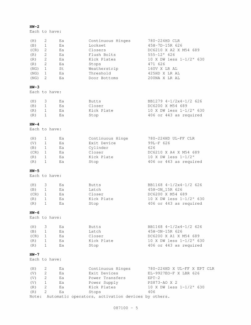
HW-2 Each to have: (H) 2 Ea Continuous Hinges 780-224HD CLR (B) 1 Ea Lockset 45H-7D-15R 626 (CR) 2 Ea Closers DC6210 X A2 X M54 689 (R) 2 Ea Flush Bolts 555-12" 626 (R) 2 Ea Kick Plates 10 X DW less 1-1/2" 630 (R) 2 Ea Stops 471 626 (NG) 1 St Weatherstrip 160V X LR AL (NG) 1 Ea Threshold 425HD X LR AL (NG) 2 Ea Door Bottoms 200NA X LR AL HW-3 Each to have: (H) 3 Ea Butts BB1279 4-1/2x4-1/2 626 (B) 1 Ea Closer DC6200 X M54 689 (R) 1 Ea Kick Plate 10 X DW less 1-1/2" 630 (R) 1 Ea Stop 406 or 443 as required HW-4 Each to have: (H) 1 Ea Continuous Hinge 780-224HD UL-FF CLR (V) 1 Ea Exit Device 99L-F 626 (B) 1 Ea Cylinder 626 (CR) 1 Ea Closer DC6210 X A4 X M54 689 (R) 1 Ea Kick Plate 10 X DW less 1-1/2" (R) 1 Ea Stop 406 or 443 as required HW-5 Each to have: (H) 3 Ea Butts BB1168 4-1/2x4-1/2 626 (B) 1 Ea Latch 45H-ON_15R 626 (CR) 1 Ea Closer DC6200 X M54 689 (R) 1 Ea Kick Plate 10 X DW less 1-1/2" 630 (R) 1 Ea Stop 406 or 443 as required HW-6 Each to have: (H) 3 Ea Butts BB1168 4-1/2x4-1/2 626 (B) 1 Ea Latch 45H-ON-15R 626 (CR) 1 Ea Closer DC6200 X A1 X M54 689 (R) 1 Ea Kick Plate 10 X DW less 1-1/2" 630 (R) 1 Ea Stop 406 or 443 as required HW-7 Each to have: (H) 2 Ea Continuous Hinges 780-224HD X UL-FF X EPT CLR (V) 2 Ea Exit Devices EL-9927EO-F X LBR 626 (V) 2 Ea Power Transfers EPT-2 (V) 1 Ea Power Supply PS873-AO X 2 (R) 2 Ea Kick Plates 10 X DW less 1-1/2" 630 (R) 2 Ea Stops 406 Note: Automatic operators, activation devices by others.
087100 - 5
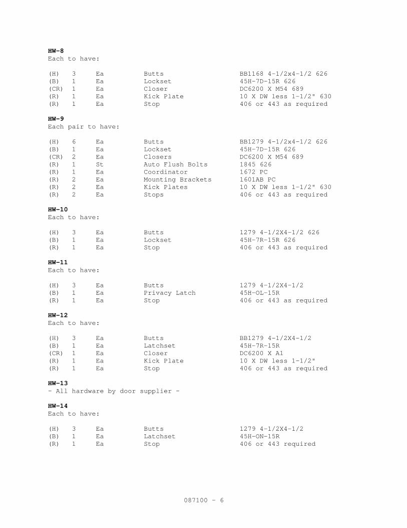
HW-8 Each to have: (H) 3 Ea Butts BB1168 4-1/2x4-1/2 626 (B) 1 Ea Lockset 45H-7D-15R 626 (CR) 1 Ea Closer DC6200 X M54 689 (R) 1 Ea Kick Plate 10 X DW less 1-1/2" 630 (R) 1 Ea Stop 406 or 443 as required HW-9 Each pair to have: (H) 6 Ea Butts BB1279 4-1/2x4-1/2 626 (B) 1 Ea Lockset 45H-7D-15R 626 (CR) 2 Ea Closers DC6200 X M54 689 (R) 1 St Auto Flush Bolts 1845 626 (R) 1 Ea Coordinator 1672 PC (R) 2 Ea Mounting Brackets 1601AB PC (R) 2 Ea Kick Plates 10 X DW less 1-1/2" 630 (R) 2 Ea Stops 406 or 443 as required HW-10 Each to have: (H) 3 Ea Butts 1279 4-1/2X4-1/2 626 (B) 1 Ea Lockset 45H-7R-15R 626 (R) 1 Ea Stop 406 or 443 as required HW-11 Each to have: (H) 3 Ea Butts 1279 4-1/2X4-1/2 (B) 1 Ea Privacy Latch 45H-OL-15R (R) 1 Ea Stop 406 or 443 as required HW-12 Each to have: (H) 3 Ea Butts BB1279 4-1/2X4-1/2 (B) 1 Ea Latchset 45H-7R-15R (CR) 1 Ea Closer DC6200 X A1 (R) 1 Ea Kick Plate 10 X DW less 1-1/2" (R) 1 Ea Stop 406 or 443 as required HW-13 - All hardware by door supplier - HW-14 Each to have: (H) 3 Ea Butts 1279 4-1/2X4-1/2 (B) 1 Ea Latchset 45H-ON-15R (R) 1 Ea Stop 406 or 443 required
087100 - 6
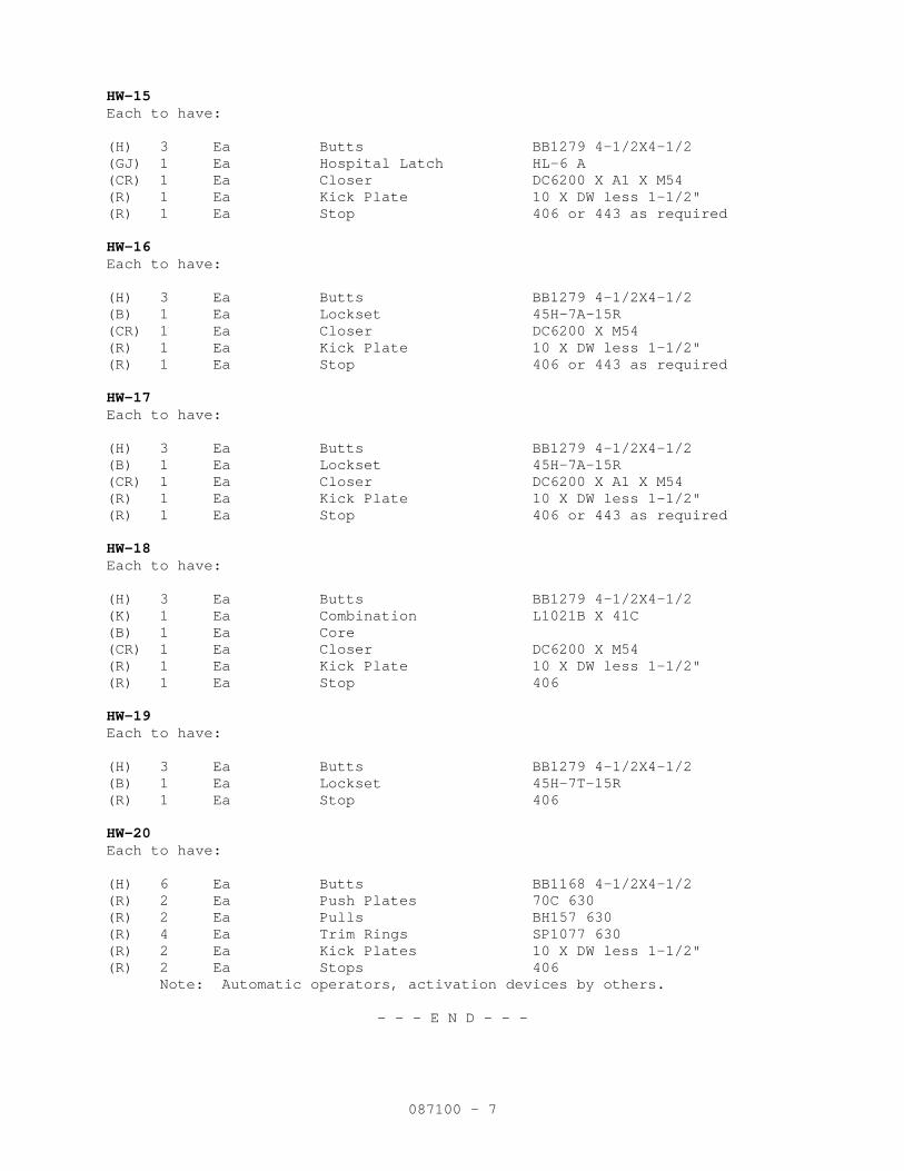
HW-15 Each to have: (H) 3 Ea Butts BB1279 4-1/2X4-1/2 (GJ) 1 Ea Hospital Latch HL-6 A (CR) 1 Ea Closer DC6200 X A1 X M54 (R) 1 Ea Kick Plate 10 X DW less 1-1/2" (R) 1 Ea Stop 406 or 443 as required HW-16 Each to have: (H) 3 Ea Butts BB1279 4-1/2X4-1/2 (B) 1 Ea Lockset 45H-7A-15R (CR) 1 Ea Closer DC6200 X M54 (R) 1 Ea Kick Plate 10 X DW less 1-1/2" (R) 1 Ea Stop 406 or 443 as required HW-17 Each to have: (H) 3 Ea Butts BB1279 4-1/2X4-1/2 (B) 1 Ea Lockset 45H-7A-15R (CR) 1 Ea Closer DC6200 X A1 X M54 (R) 1 Ea Kick Plate 10 X DW less 1-1/2" (R) 1 Ea Stop 406 or 443 as required HW-18 Each to have: (H) 3 Ea Butts BB1279 4-1/2X4-1/2 (K) 1 Ea Combination L1021B X 41C (B) 1 Ea Core (CR) 1 Ea Closer DC6200 X M54 (R) 1 Ea Kick Plate 10 X DW less 1-1/2" (R) 1 Ea Stop 406 HW-19 Each to have: (H) 3 Ea Butts BB1279 4-1/2X4-1/2 (B) 1 Ea Lockset 45H-7T-15R (R) 1 Ea Stop 406 HW-20 Each to have: (H) 6 Ea Butts BB1168 4-1/2X4-1/2 (R) 2 Ea Push Plates 70C 630 (R) 2 Ea Pulls BH157 630 (R) 4 Ea Trim Rings SP1077 630 (R) 2 Ea Kick Plates 10 X DW less 1-1/2" (R) 2 Ea Stops 406 Note: Automatic operators, activation devices by others.
- - - E N D - - -
087100 - 7
01-08M
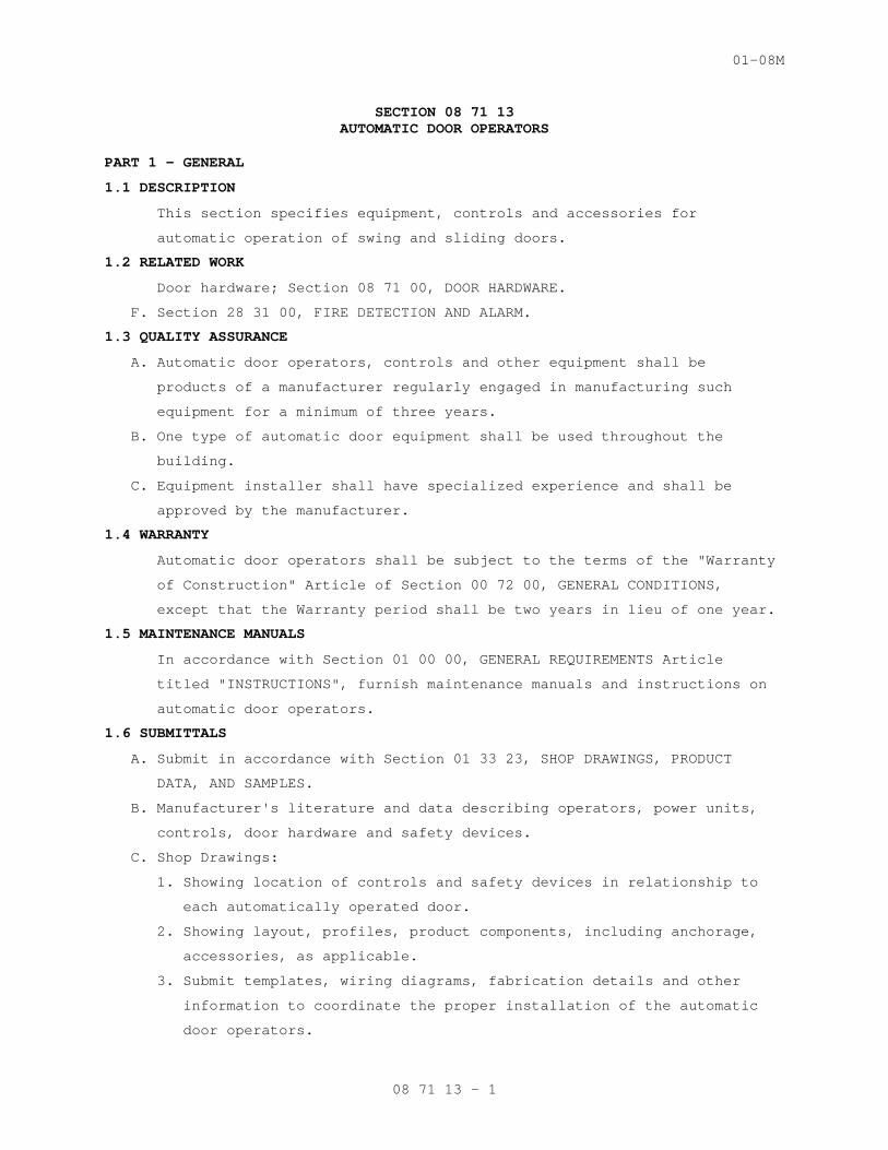
SECTION 08 71 13 AUTOMATIC DOOR OPERATORS
PART 1 - GENERAL
1.1 DESCRIPTION
This section specifies equipment, controls and accessories for
automatic operation of swing and sliding doors.
1.2 RELATED WORK
Door hardware; Section 08 71 00, DOOR HARDWARE.
F. Section 28 31 00, FIRE DETECTION AND ALARM.
1.3 QUALITY ASSURANCE
A. Automatic door operators, controls and other equipment shall be
products of a manufacturer regularly engaged in manufacturing such
equipment for a minimum of three years.
B. One type of automatic door equipment shall be used throughout the
building.
C. Equipment installer shall have specialized experience and shall be
approved by the manufacturer.
1.4 WARRANTY
Automatic door operators shall be subject to the terms of the "Warranty
of Construction" Article of Section 00 72 00, GENERAL CONDITIONS,
except that the Warranty period shall be two years in lieu of one year.
1.5 MAINTENANCE MANUALS
In accordance with Section 01 00 00, GENERAL REQUIREMENTS Article
titled "INSTRUCTIONS", furnish maintenance manuals and instructions on
automatic door operators.
1.6 SUBMITTALS
A. Submit in accordance with Section 01 33 23, SHOP DRAWINGS, PRODUCT
DATA, AND SAMPLES.
B. Manufacturer's literature and data describing operators, power units,
controls, door hardware and safety devices.
C. Shop Drawings:
1. Showing location of controls and safety devices in relationship to
each automatically operated door.
2. Showing layout, profiles, product components, including anchorage,
accessories, as applicable.
3. Submit templates, wiring diagrams, fabrication details and other
information to coordinate the proper installation of the automatic
door operators.
08 71 13 - 1
01-08M
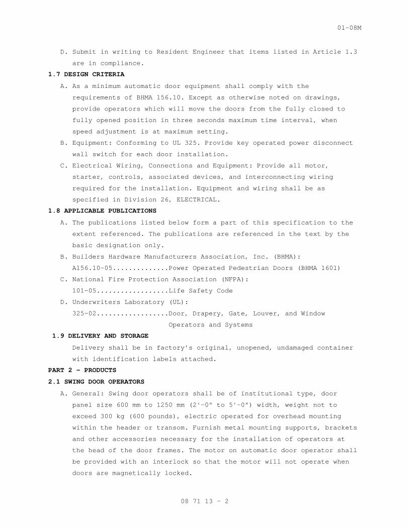
D. Submit in writing to Resident Engineer that items listed in Article 1.3
are in compliance.
1.7 DESIGN CRITERIA
A. As a minimum automatic door equipment shall comply with the
requirements of BHMA 156.10. Except as otherwise noted on drawings,
provide operators which will move the doors from the fully closed to
fully opened position in three seconds maximum time interval, when
speed adjustment is at maximum setting.
B. Equipment: Conforming to UL 325. Provide key operated power disconnect
wall switch for each door installation.
C. Electrical Wiring, Connections and Equipment: Provide all motor,
starter, controls, associated devices, and interconnecting wiring
required for the installation. Equipment and wiring shall be as
specified in Division 26, ELECTRICAL.
1.8 APPLICABLE PUBLICATIONS
A. The publications listed below form a part of this specification to the
extent referenced. The publications are referenced in the text by the
basic designation only.
B. Builders Hardware Manufacturers Association, Inc. (BHMA):
A156.10-05..............Power Operated Pedestrian Doors (BHMA 1601)
C. National Fire Protection Association (NFPA):
101-05..................Life Safety Code
D. Underwriters Laboratory (UL):
325-02..................Door, Drapery, Gate, Louver, and Window
Operators and Systems
1.9 DELIVERY AND STORAGE
Delivery shall be in factory’s original, unopened, undamaged container
with identification labels attached.
PART 2 - PRODUCTS
2.1 SWING DOOR OPERATORS
A. General: Swing door operators shall be of institutional type, door
panel size 600 mm to 1250 mm (2'-0" to 5'-0") width, weight not to
exceed 300 kg (600 pounds), electric operated for overhead mounting
within the header or transom. Furnish metal mounting supports, brackets
and other accessories necessary for the installation of operators at
the head of the door frames. The motor on automatic door operator shall
be provided with an interlock so that the motor will not operate when
doors are magnetically locked.
08 71 13 - 2
01-08M
B. Operators shall have checking mechanism providing cushioning action at
last part of door travel, in both opening and closing cycle. Operators
shall be capable of recycling doors instantaneously to full open
position from any point in the closing cycle when control switch is
activated. Operators shall, when automatic power is interrupted or
shut-off, permit doors to easily open manually without damage to
automatic operator system.
C. Operator, enclosed in housing, shall open door by energizing motor and
shall stop by electrically reducing voltage and stalling motor against
mechanical stop. Door shall close by means of spring energy, and close
force shall be controlled by gear system and motor being used as
dynamic break without power. System shall operate as manual door
control in event of power failure. Opening and closing speeds shall be
adjustable:
1. Operator Housing: Housing shall be a minimum of 112 mm (4-1/2
inches) wide by 140 mm (5.5 inches) high aluminum extrusions with
enclosed end caps for application to 100 mm (4 inches) and larger
frame systems. All structural sections shall have a minimum
thickness of 3.2 mm (0.125 inch) and be fabricated of a minimum of
6063-T5 aluminum alloy.
2. Power Operator: Completely assembled and sealed unit which shall
include gear drive transmission, mechanical spring and bearings, all
located in aluminum case and filled with special lubricant for
extreme temperature conditions. A minimum 1/8 Hp "DC" shunt-wound
permanent magnet motor with sealed ball bearings shall be attached
to transmission system. Complete unit shall be rubber mounted with
provisions for easy maintenance and replacement, without removing
door from pivots or frame.
3. Connecting hardware shall have drive arm attached to door with a pin
linkage rotating in a self-lubricating bearing. Door shall not pivot
on shaft of operator.
4. Electrical Control: Operator shall have a self contained electrical
control unit, including necessary transformers, relays, rectifiers,
and other electronic components for proper operation and switching
of power operator. All connecting harnesses shall have interlocking
plugs.
08 71 13 - 3
01-08M
2.2 MICROPRCESSOR CONTROLS
A. The system shall include a multi-function microprocessor control
providing adjustable hold open time (1–30 seconds), LED indications for
sensor input signals and operator status and power assist close
options. Control shall be capable of receiving activation signals from
any device with normally open dry contact output. All activation modes
shall provide fully adjustable opening speed:
1. With push-to-operate function enabled, the control shall provide a
means of initiating a self-start activation circuit by slightly
pushing the door open at any point in the door swing.
2. Power assist shall provide a two second impulse in the close
direction to overcome restrictions with locking devices of pressure
differentials, allowing the unit to operate in standard time delay
mode, and permitting the door to close from the full open position
after the hold time is satisfied.
B. The door shall be held open by low voltage applied to the continuous
duty motor. The control shall include an adjustable safety circuit that
monitors door operation and stops the opening direction of the door if
an obstruction is sensed. The motor shall include a recycle feature
that reopens the door if an obstruction is sensed at any point during
the closing cycle. The control shall include a standard three position
toggle switch with functions for ON, OFF, and HOLD OPEN.
2.3 POWER UNITS
Each power unit shall be self-contained, electric operated and
independent of the door operator. Capacity and size of power circuits
shall be in accordance with automatic door operator manufacturer's
specifications and Division 26 – ELECTRICAL.
2.4 DOOR CONTROLS
A. Opening and closing actions of doors shall be actuated by controls and
safety devices specified, and conform to ANSI 156.10. Controls shall
cause doors to open instantly when control device is actuated; hold
doors in open positions; then, cause doors to close, unless safety
device or reactivated control interrupts operation.
B. Manual Controls:
Push Plate Wall Switch: Recess type, cast aluminum or stainless
steel push plate minimum 100 mm by 100 mm (four-inch by four-inch),
with 13 mm (l/2-inch) high letters "To Operate Door--Push" engraved
on face of plate.
08 71 13 - 4
01-08M
C. Motion Detector: The motion detector may be surface mounted or
concealed, to provide a signal to actuate the door operator, and
monitor the immediate zone, to detect intrusion by persons, carts or
similar objects. The zone which the detector monitors shall be 1500 mm
(five feet) deep and 1500 mm (five feet) across, plus or minus 150 mm
(six inches) on all dimensions. The maximum response time shall be no
less than 25 milliseconds. Unit shall be designed to operate on 24
volts AC. The control shall not be affected by cleaning material,
solvents, dust, dirt and outdoor weather conditions.
2.5 SAFETY DEVICES
A. General: Area over which doors swing or slide shall be a safety section
and anyone standing in path of door's movement shall be protected by a
safety device, except where push controls are shown.
B. Each swing door shall have installed on the pull side a presence sensor
to detect any person standing in the door swing path and prevent the
door from opening.
C. Time delay switches shall be adjustable between 3 to 60 seconds and
shall control closing cycle of doors.
D. Decals with sign "In" or "Do Not Enter" shall be installed on both
faces of each door where shown.
PART 3 - EXECUTION
3.1 INSTALLATION
A. Coordinate installation of equipment with other related work. Manual
controls and power disconnect switches shall be recessed or semi-flush
mounted in partitions. Secure operator components to adjacent
construction with suitable fastenings. Conceal conduits, piping, and
electric equipment, in finish work.
B. Install power units in locations shown. Where units are to be mounted
on walls, provide metal supports or shelves for the units. All
equipment, including time delay switches, shall be accessible for
maintenance and adjustment.
C. Operators shall be adjusted and must function properly for the type o£
traffic (pedestrians, carts, stretchers and wheelchairs) expected to
pass through doors. Each door leaf of pairs of doors shall open and
close in synchronization. On pairs of doors, operators shall allow
either door to be opened manually without the other door opening.
D. Install controls at positions shown and make them convenient for
particular traffic expected to pass through openings. Maximum height of
08 71 13 - 5
01-08M
push plate wall switches from finished floors shall be 40 inches unless
otherwise approved by the Resident Engineer.
3.2 INSTRUCTIONS
A. Following the installation and final adjustments of the door operators,
the installer shall fully instruct VA personnel for 2 hours on the
operating, servicing and safety requirements for the swing and sliding
automatic door operators.
B. Coordinate instruction to VA personnel with Resident Engineer.
- - - E N D - - -
08 71 13 - 6
02-08M
SECTION 08 80 00 GLAZING
PART 1 - GENERAL
1.1 DESCRIPTION
This section specifies glass, related glazing materials and
accessories. Glazing products specified apply to factory or field
glazed items.
1.2 RELATED WORK
A. Factory glazed by manufacturer in Section 08 51 13, ALUMINUM WINDOWS.
1.3 LABELS
A. Temporary labels:
1. Provide temporary label on each light of glass identifying
manufacturer or brand and glass type, quality and nominal thickness.
2. Label in accordance with NFRC (National Fenestration Rating Council)
label requirements.
3. Temporary labels shall remain intact until glass is approved by
Resident Engineer.
B. Permanent labels:
1. Locate in corner for each pane.
2. Label in accordance with ANSI Z97.1 and SGCC (Safety Glass
Certification Council) label requirements.
a. Tempered glass.
1.4 PERFORMANCE REQUIREMENTS
A. Building Enclosure Vapor Retarder and Air Barrier:
1. Utilize the inner pane of multiple pane sealed units for the
continuity of the air barrier and vapor retarder seal.
2. Maintain a continuous air barrier and vapor retarder throughout the
glazed assembly from glass pane to heel bead of glazing sealant.
B. Glass Thickness:
1. Select thickness of exterior glass to withstand dead loads and wind
loads acting normal to plane of glass at design pressures calculated
in accordance with applicable code.
2. Limit glass deflection to 1/200 or flexure limit of glass, whichever
is less, with full recovery of glazing materials.
3. Test in accordance with ASTM E 330.
4. Thicknesses listed are minimum. Coordinate thicknesses with framing
system manufacturers.
08 80 00-1
02-08M
1.5 SUBMITTALS
A. In accordance with Section 01 33 23, SHOP DRAWINGS, PRODUCT DATA, AND
SAMPLES.
B. Manufacturer's Certificates:
1. Certificates stating that wire glass, meets requirements for safety
glazing material as specified in ANSI Z97.1.
2. Certificate on shading coefficient.
3. Certificate on "R" value when value is specified.
4. Certificate test reports confirming compliance’s with specified
bullet resistive rating.
C. Warranty: Submit written guaranty, conforming to General Condition
requirements, and to “Warranty of Construction” Article in this
Section.
D. Manufacturer's Literature and Data:
1. Glass, each kind required.
2. Insulating glass units.
3. Elastic compound for metal sash glazing.
4. Glazing cushion.
5. Sealing compound.
E. Samples:
Size: 150 mm by 150 mm (6 inches by 6 inches).
F. Preconstruction Adhesion and Compatibility Test Report: Submit glazing
sealant manufacturer’s test report indicating glazing sealants were
tested for adhesion to glass and glazing channel substrates and for
compatibility with glass and other glazing materials.
1.6 DELIVERY, STORAGE AND HANDLING
A. Delivery: Schedule delivery to coincide with glazing schedules so
minimum handling of crates is required. Do not open crates except as
required for inspection for shipping damage.
B. Storage: Store cases according to printed instructions on case, in
areas least subject to traffic or falling objects. Keep storage area
clean and dry.
C. Handling: Unpack cases following printed instructions on case. Stack
individual windows on edge leaned slightly against upright supports
with separators between each.
1. Protect sealed-air-space insulating glazing units from exposure to
abnormal pressure changes, as could result from substantial changes
in altitude during delivery by air freight. Provide temporary
08 80 00-2
02-08M
breather tubes which do not nullify applicable warranties on
hermetic seals.
2. Temporary protections: The glass front and polycarbonate/Noviflex
back of glazing shall be temporarily protected with compatible,
peelable, heat-resistant film which will be peeled for inspections
and re-applied and finally removed after doors and windows are
installed at destination. Since many adhesives will attack
polycarbonate, the film used on exposed polycarbonate surfaces shall
be approved and applied by manufacturer.
3. Edge protection: To cushion and protect glass clad, polycarbonate,
and Noviflex edges from contamination or foreign matter, the four
edges shall be sealed the depth of glazing with continuous standard-
thickness Santoprene tape. Alternatively, continuous channel shaped
extrusion of Santoprene shall be used, with flanges extending into
face sides of glazing.
4. Protect "Constant Temperature" units including every unit where
glass sheet is directly laminated to or directly sealed with metal-
tube type spacer bar to polycarbonate sheet, from exposures to
ambient temperatures outside the range of 16 to 24 C, during the
fabricating, handling, shipping, storing, installation, and
subsequent protection of glazing.
1.7 PROJECT CONDITIONS
Field Measurements: Field measure openings before ordering tempered
glass products. Be responsible for proper fit of field measured
products.
1.8 WARRANTY
A. Warranty: Conform to terms of "Warranty of Construction" Article in
Section 00 72 00, GENERAL CONDITIONS, except extend warranty period for
the following:
Insulating glass units to remain sealed for 10 years.
1.9 APPLICABLE PUBLICATIONS
A. Publications listed below form a part of this specification to extent
referenced. Publications are referenced in text by basic designation
only.
B. American National Standards Institute (ANSI):
Z97.1-04................Safety Glazing Material Used in Building -
Safety Performance Specifications and Methods
of Test.
08 80 00-3
02-08M
C. American Society for Testing and Materials (ASTM):
C1363-05................Thermal Performance of Building Assemblies, by
Means of A Hot Box Apparatus
C542-05.................Lock-Strip Gaskets.
C716-06.................Installing Lock-Strip Gaskets and Infill
Glazing Materials.
C864-05.................Dense Elastomeric Compression Seal Gaskets,
Setting Blocks, and Spacers.
C920-05.................Elastomeric Joint Sealants.
C1036-06................Flat Glass.
C1048-04................Heat-Treated Flat Glass-Kind HS, Kind FT Coated
and Uncoated Glass.
C1172-03................Laminated Architectural Flat Glass.
C1349-04................Architectural Flat Glass Clad Polycarbonate.
D635-06.................Rate of Burning and/or Extent and Time of
Burning of Self-Supporting Plastic in a
Horizontal Position.
D4802-07................Poly (Methyl Methacrylate) Acrylic Plastic
Sheet.
E84-01..................Surface Burning Characteristics of Building
Materials.
E330-02.................Structural Performance of Exterior Windows,
Curtain Walls, and Doors by Uniform Static Air
Pressure Difference.
E774-97.................Sealed Insulating Glass Units
D. Commercial Item Description (CID):
A-A-59502...............Plastic Sheet, Polycarbonate
E. Code of Federal Regulations (CFR):
16 CFR 1201 - Safety Standard for Architectural Glazing Materials;
1977, with 1984 Revision.
F. National Fire Protection Association (NFPA):
80-06...................Fire Doors and Windows.
G. National Fenestration Rating Council (NFRC):
Certified Products Directory (Latest Edition).
H. Safety Glazing Certification Council (SGCC):
Certified Products Directory (Issued Semi-Annually).
I. Underwriters Laboratories, Inc. (UL):
752-05..................Bullet-Resisting Equipment.
08 80 00-4
02-08M
PART 2 - PRODUCT
2.1 GLASS
A. Use thickness stated unless specified otherwise in assemblies.
B. G-1, Clear Glass:
1. ASTM C1036, Type I, Class 1, Quality q3
2. Thickness, 1/4 inch.
C. G-2, Clear Wire Glass:
1. ASTM C1036, Type II, Class 1, Form 1, Quality q8, Mesh m1 or m2.
2. Thickness, 1/4 inch.
D. G-3, Clear Tempered Glass
1. ASTM C1048, Kind FT, Condition A, type I, lass 1, Quality q3.
2. Thickness: 1/4- inch.
E. G-4, Tinted Glass:
1. ASTM C1036, Type I, Class 3, Quality q3.
2. Thickness,1/4 inch.
2.2 INSULATING GLASS UNITS
A. Provide factory fabricated, hermetically sealed glass unit consisting
of two panes of glass separated by a dehydrated air space.
B. Assemble units using glass types specified:
C. Sealed Edge Units (SEU):
1. Conform to ASTM E774, Class C performance requirements.
2. Air Space not less than ¼ inch) wide.
3. R value not less than 1.65.
D. G-35, SEU Tinted Glass and Clear Glass:
1. Exterior pane: G-4.
2. Interior pane: G-1.
2.3 GLAZING ACCESSORIES
A. As required to supplement the accessories provided with the items to be
glazed and to provide a complete installation. Ferrous metal
08 80 00-5
02-08M
accessories exposed in the finished work shall have a finish that will
not corrode or stain while in service.
B. Setting Blocks: ASTM C864:
1. Channel shape; having 6 mm (1/4 inch) internal depth.
2. Shore a hardness of 80 to 90 Durometer.
3. Block lengths: 50 mm (two inches) except 100 to 150 mm (four to six
inches) for insulating glass.
4. Block width: Approximately 1.6 mm (1/16 inch) less than the full
width of the rabbet.
5. Block thickness: Minimum 4.8 mm (3/16 inch). Thickness sized for
rabbet depth as required.
C. Spacers: ASTM C864:
1. Channel shape having a 6 mm (1/4 inch) internal depth.
2. Flanges not less 2.4 mm (3/32 inch) thick and web 3 mm (1/8 inch)
thick.
3. Lengths: One to 25 to 76 mm (one to three inches).
4. Shore a hardness of 40 to 50 Durometer.
D. Sealing Tapes:
1. Semi-solid polymeric based material exhibiting pressure-sensitive
adhesion and withstanding exposure to sunlight, moisture, heat,
cold, and aging.
2. Shape, size and degree of softness and strength suitable for use in
glazing application to prevent water infiltration.
E. Glazing Clips: Galvanized steel spring wire designed to hold glass in
position in rabbeted sash without stops.
F. Glazing Gaskets: ASTM C864:
1. Firm dense wedge shape for locking in sash.
2. Soft, closed cell with locking key for sash key.
3. Flanges may terminate above the glazing-beads or terminate flush
with top of beads.
G. Lock-Strip Glazing Gaskets: ASTM C542, shape, size, and mounting as
indicated.
H. Glazing Sealants: ASTM C920, silicone neutral cure:
1. Type S.
2. Class 25
3. Grade NS.
4. Shore A hardness of 25 to 30 Durometer.
08 80 00-6
02-08M
I. Color:
1. Color of glazing compounds, gaskets, and sealants used for aluminum
color frames shall match color of the finished aluminum and be
nonstaining.
2. Color of other glazing compounds, gaskets, and sealants which will
be exposed in the finished work and unpainted shall be black, gray,
or neutral color.
PART 3 - EXECUTION
3.1 EXAMINATION
A. Verification of Conditions:
1. Examine openings for glass and glazing units; determine they are
proper size; plumb; square; and level before installation is
started.
2. Verify that glazing openings conform with details, dimensions and
tolerances indicated on manufacturer’s approved shop drawings.
B. Advise Contractor of conditions which may adversely affect glass and
glazing unit installation, prior to commencement of installation.
1. Do not proceed with installation until unsatisfactory conditions
have been corrected.
C. Verify that wash down of adjacent masonry is completed prior to
erection of glass and glazing units to prevent damage to glass and
glazing units by cleaning materials.
3.2 PREPARATION
A. For sealant glazing, prepare glazing surfaces in accordance with GANA-
02 Sealant Manual.
B. Determine glazing unit size and edge clearances by measuring the actual
unit to receive the glazing.
C. Shop fabricate and cut glass with smooth, straight edges of full size
required by openings to provide GANA recommended edge clearances.
D. Verify that components used are compatible.
E. Clean and dry glazing surfaces.
F. Prime surfaces scheduled to receive sealants, as determined by
preconstruction sealant-substrate testing.
3.3 INSTALLATION - GENERAL
A. Install in accordance with GANA-01 Glazing Manual and GANA-02 Sealant
Manual unless specified otherwise.
08 80 00-7
02-08M
B. Glaze in accordance with recommendations of glazing and framing
manufacturers, and as required to meet the Performance Test
Requirements specified in other applicable sections of specifications.
C. Set glazing without bending, twisting, or forcing of units.
D. Do not allow glass to rest on or contact any framing member.
E. Glaze doors and operable sash, in a securely fixed or closed and locked
position, until sealant, glazing compound, or putty has thoroughly set.
F. Tempered Glass: Install with roller distortions in horizontal position
unless otherwise directed.
G. Insulating Glass Units:
1. Glaze in compliance with glass manufacturer's written instructions.
2. When glazing gaskets are used, they shall be of sufficient size and
depth to cover glass seal or metal channel frame completely.
3. Do not use putty or glazing compounds.
4. Do not grind, nip, cut, or otherwise alter edges and corners of
fused glass units after shipping from factory.
5. Install with tape or gunnable sealant in wood sash.
H. Fire Resistant Glass:
1. Wire glass: Glaze in accordance with NFPA 80.
3.4 REPLACEMENT AND CLEANING
A. Clean new glass surfaces removing temporary labels, paint spots, and
defacement after approval by Resident Engineer.
B. Replace cracked, broken, and imperfect glass, or glass which has been
installed improperly.
C. Leave glass, putty, and other setting material in clean, whole, and
acceptable condition.
3.5 PROTECTION
Protect finished surfaces from damage during erection, and after
completion of work. Strippable plastic coatings on colored anodized
finish are not acceptable.
3.5 GLAZING SCHEDULE
A. Fire Resistant Glass – G-2: Install clear wire glass in interior fire
rated or labeled doors and windows.
B. Tempered Glass – G-3:
1. Install in full and half glazed doors unless indicated otherwise.
2. Install in in door sidelights adjacent to doors
08 80 00-8
02-08M
C. Clear Glass – G-1: Interior doors and other locations: 3/16 inch
thick, except where other glass is specified.
E. Tinted Glass - G-4: Install in insulating glass SEU Units.
F. Insulating Glass – G-5 (G-4 + G-1):
1. Install SEU tinted glass and clear glass in aluminum framing.
- - - E N D - - -
08 80 00-9
01-08M
SECTION 08 90 00 LOUVERS AND VENTS
PART 1 - GENERAL
1.1 DESCRIPTION
This section specifies fixed and operable wall louvers, door louvers and
wall vents.
1.2 SUBMITTALS
A. Submit in accordance with Section 01 33 23, SHOP DRAWINGS, PRODUCT DATA,
AND SAMPLES.
B. Shop Drawings:
Each type, showing material, finish, size of members, operating devices,
method of assembly, and installation and anchorage details.
C. Manufacturer's Literature and Data:
Each type of louver and vent.
1.3 APPLICABLE PUBLICATIONS
A. The publications listed below form a part of this specification to the
extent referenced. The publications are referenced in the text by the
basic designation only.
B. The Master Painters Institute (MPI):
Approved Product List – November 2007
C. American Society for Testing and Materials (ASTM):
A167-99(R2004)..........Stainless and Heat-Resisting Chromium - Nickel
Steel Plate, Sheet, and Strip
A1008/A1008M REV A-07...Steel, Sheet, Carbon, Cold Rolled, Structural,
and High Strength Low-Alloy with Improved
Formability
B209/B209M-07...........Aluminum and Aluminum Alloy, Sheet and Plate
B221-06.................Aluminum and Aluminum Alloy Extruded Bars, Rods,
Wire, Shapes, and Tubes
B221M-07................Aluminum and Aluminum Alloy Extruded Bars, Rods,
Wire Shapes, and Tubes
D. National Association of Architectural Metal Manufacturers (NAAMM):
AMP 500-505 (1988)......Metal Finishes Manual
E. National Fire Protection Association (NFPA):
90A-02..................Installation of Air Conditioning and Ventilating
Systems
G. American Architectural Manufacturers Association (AAMA):
605-98..................High Performance Organic Coatings on
Architectural Extrusions and Panels
08 90 00 - 1
01-08M
H. Air Movement and Control Association, Inc. (AMCA):
500-L-99................Testing Louvers
PART 2 - PRODUCTS
2.1 MATERIALS
A. Aluminum, Extruded: ASTM B221/B221M.
B. Aluminum, Plate and Sheet: ASTM B209/B209M.
C. Fasteners: Fasteners for securing louvers and wall vents to adjoining
construction, except as otherwise specified or shown, shall be toggle or
expansion bolts, of size and type as required for each specific type of
installation and service condition.
1. Where type, size, or spacing of fasteners is not shown or specified,
submit shop drawings showing proposed fasteners, and method of
installation.
2. Fasteners for louvers, louver frames, and wire guards shall be of
stainless steel or aluminum.
D. Inorganic Zinc Primer: MPI No. 19.
2.2 EXTERIOR WALL LOUVERS
A. General:
1. Provide fixed type louvers of size and design shown.
2. Heads, sills and jamb sections shall have formed caulking slots or be
designed to retain caulking. Head sections shall have exterior drip
lip, and sill sections an integral water stop.
3. Furnish louvers with sill extension or separate sill as shown.
4. Frame shall be mechanically fastened or welded construction with
welds dressed smooth and flush.
B. Performance Characteristics:
Louvers shall bear AMCA certified rating seals for air performance and
water penetration ratings.
C. Aluminum Louvers:
1. General: Frames, blades, sills and mullions; 2 mm (0.081-inch) thick
extruded aluminum. Blades shall be drainable type and have
reinforcing bosses.
2. Louvers, fixed: Make frame sizes 13 mm (1/2-inch) smaller than
openings. Single louvers frames shall not exceed 1700 mm (66 inches)
wide. When openings exceed 1700 mm (66 inches), provide twin louvers
separated by mullion members.
2.3 CLOSURE ANGLES AND CLOSURE PLATES
A. Fabricate from 2 mm (0.074-inch) thick stainless steel or aluminum.
B. Provide continuous closure angles and closure plates on inside head,
jambs and sill of exterior wall louvers.
08 90 00 - 2
01-08M
C. Secure angles and plates to louver frames with screws, and to masonry or
concrete with fasteners as specified.
2.4 WIRE GUARDS
A. Provide wire guards on outside of all exterior louvers, except on
exhaust air louvers.
B. Fabricate frames from 2 mm (0.081-inch) thick extruded or sheet aluminum
designed to retain wire mesh.
C. Wire mesh shall be woven from not less than 1.6 mm (0.063-inch) diameter
aluminum wire.
D. Miter corners and join by concealed corner clips or locks extending
about 57 mm (2-1/4 inches) into rails and stiles. Equip wire guards over
four feet in height with a mid-rail constructed as specified for frame
components.
E. Fasten frames to outside of louvers with aluminum or stainless steel
devices designed to allow removal and replacement without damage to the
wire guard or the louver.
2.5 AIR INTAKE VENTS
A. Fabricate exterior louvered wall ventilators for fresh air intake for
air conditioning units from extruded aluminum, ASTM B221. Form with
integral horizontal louvers and frame, with drip extending beyond face
of wall and integral water stops.
B. Provide aluminum closures where shown for inside face of dummy vents.
C. Provide 0.8 m (0.032-inch) thick aluminum sleeves in cavity walls where
required.
2.6 FINISH
A. In accordance with NAAMM Metal Finishes Manual: AMP 500-505
B. Aluminum Louvers Air Intake Vents Wire Guards:
Anodized finish AA-C22A42 Chemically etched medium matte, with
integrally colored anodic coating, Class I Architectural, 0.7 mils
thick.
2.7 PROTECTION
A. Provide protection for aluminum against galvanic action wherever
dissimilar materials are in contact, by painting the contact surfaces of
the dissimilar material with a heavy coat of bituminous paint (complete
coverage), or by separating the contact surfaces with a performed
synthetic rubber tape having pressure sensitive adhesive coating on one
side.
B. Isolate the aluminum from plaster, concrete and masonry by coating
aluminum with zinc-chromate primer.
08 90 00 - 3
01-08M
C. Protect finished surfaces from damage during fabrication, erection, and
after completion of the work. Strippable plastic coating on colored
anodized finish is not approved.
PART 3 - EXECUTION
3.1 INSTALLATION
A. Set work accurately, in alignment and where shown. Items shall be plumb,
level, free of rack and twist, and set parallel or perpendicular as
required to line and plane of surface.
B. Furnish setting drawings and instructions for installation of anchors
and for the positioning of items having anchors to be built into masonry
construction. Provide temporary bracing for such items until masonry is
set.
C. Provide anchoring devices and fasteners as shown and as necessary for
securing louvers to building construction as specified. Power actuated
drive pins may be used, except for removal items and where members would
be deformed or substrate damaged by their use.
D. Generally, set wall louvers in masonry walls during progress of the
work. If wall louvers are not delivered to job in time for installation
in prepared openings, make provision for later installation. Set in
cast-in-place concrete in prepared openings.
3.2 CLEANING AND ADJUSTING
A. After installation, all exposed prefinished and plated items and all
items fabricated from stainless steel and aluminum shall be cleaned as
recommended by the manufacturer and protected from damage until
completion of the project.
B. All movable parts, including hardware, shall be cleaned and adjusted to
operate as designed without binding or deformation of the members, so as
to be centered in the opening of frame, and where applicable, to have
all contact surfaces fit tight and even without forcing or warping the
components
- - - E N D - - -
08 90 00 - 4
10-07M
SECTION 09 22 16 NON-STRUCTURAL METAL FRAMING
PART 1 - GENERAL
1.1 DESCRIPTION
This section specifies steel studs wall systems, shaft wall systems,
ceiling or soffit suspended or furred framing, wall furring, fasteners,
and accessories for the screw attachment of gypsum board, plaster bases
or other building boards.
1.2 RELATED WORK
A. Load bearing framing: Section 05 40 00, COLD-FORMED METAL FRAMING.
B. Ceiling suspension systems for acoustical tile or panels and lay in
gypsum board panels: Section 09 51 00, ACOUSTICAL CEILINGS// Section 09
29 00, GYPSUM BOARD.
1.3 TERMINOLOGY
A. Description of terms shall be in accordance with ASTM C754, ASTM C11,
ASTM C841 and as specified.
B. Underside of Structure Overhead: In spaces where steel trusses or bar
joists are shown, the underside of structure overhead shall be the
underside of the floor or roof construction supported by beams, trusses,
or bar joists. In interstitial spaces with walk-on floors the underside
of the walk-on floor is the underside of structure overhead.
C. Thickness of steel specified is the minimum bare (uncoated) steel
thickness.
1.4 SUBMITTALS
A. Submit in accordance with Section 01 33 23, SHOP DRAWINGS, PRODUCT DATA,
AND SAMPLES.
B. Manufacturer's Literature and Data:
1. Studs, runners and accessories.
2. Hanger inserts.
3. Channels (Rolled steel).
4. Furring channels.
5. Screws, clips and other fasteners.
C. Shop Drawings:
1. Typical ceiling suspension system.
2. Typical metal stud and furring construction system including details
around openings and corner details.
3. Typical shaft wall assembly
4. Typical fire rated assembly and column fireproofing showing details
of construction same as that used in fire rating test.
09 22 16 - 1

10-07M
D. Test Results: Fire rating test designation, each fire rating required
for each assembly.
1.5 DELIVERY, IDENTIFICATION, HANDLING AND STORAGE
In accordance with the requirements of ASTM C754.
1.6 APPLICABLE PUBLICATIONS
A. The publications listed below form a part of this specification to the
extent referenced. The publications are referenced in the text by the
basic designation only.
B. American Society For Testing And Materials (ASTM)
A123-02.................Zinc (Hot-dip Galvanized) Coatings on Iron and
Steel Products
A653/A653M-07...........Steel Sheet, Zinc-Coated (Galvanized) or Zinc-
Iron Alloy Coated (Galvannealed) by the Hot-Dip
Process
A641-03.................Zinc-Coated (Galvanized) Carbon Steel Wire
C11-07..................Terminology Relating to Gypsum and Related
Building Materials and Systems
C635-04.................Manufacture, Performance, and Testing of Metal
Suspension System for Acoustical Tile and Lay-in
Panel Ceilings
C636-06.................Installation of Metal Ceiling Suspension Systems
for Acoustical Tile and Lay-in Panels
C645-07.................Non-Structural Steel Framing Members
C754-04.................Installation of Steel Framing Members to Receive
Screw-Attached Gypsum Panel Products
C841-03.................Installation of Interior Lathing and Furring
C954-04.................Steel Drill Screws for the Application of Gypsum
Panel Products or Metal Plaster Bases to Steel
Studs from 0.033 in. (0.84 mm) to 0.112 in.
(2.84 mm) in Thickness
C1002-04................Steel Self-Piercing Tapping Screws for the
Application of Gypsum Panel Products or Metal
Plaster Bases to Wood Studs or Steel Studs
E580-06.................Application of Ceiling Suspension Systems for
Acoustical Tile and Lay-in Panels in Areas
Requiring Moderate Seismic Restraint.
09 22 16 - 2
10-07M
PART 2 - PRODUCTS
2.1 PROTECTIVE COATING
Galvanize steel studs, runners (track), rigid (hat section) furring
channels, "Z" shaped furring channels, and resilient furring channels,
with coating designation of G-60 minimum, per ASTM 123.
2.2 STEEL STUDS AND RUNNERS (TRACK)
A. ASTM C645, modified for thickness specified and sizes and shown.
1. Use ASTM A525 steel, 0.9 mm (0.0359-inch) thick bare metal (20
gauge).
2. Runners same thickness as studs.
B. Provide not less than two cutouts in web of each stud, approximately 300
mm (12 inches) from each end, and intermediate cutouts on approximately
600 mm (24-inch) centers.
C. Doubled studs for openings and studs for supporting concrete
backer-board.
D. Shaft Wall Framing:
1. Conform to rated wall construction.
2. C-H Studs.
3. E Studs.
4. J Runners.
5. Steel Jamb-Strut.
2.3 FURRING CHANNELS
A. Rigid furring channels (hat shape): ASTM C645.
B. Resilient furring channels:
1. Not less than 0.45 mm (0.0179-inch) thick bare metal.
2. Semi-hat shape, only one flange for anchorage with channel web leg
slotted on anchorage side, channel web leg on other side stiffens
fastener surface but shall not contact anchorage surface other
channel leg is attached to.
C. "Z" Furring Channels:
1. Not less than 0.45 mm (0.0179-inch)-thick bare metal, with 32 mm
(1-1/4 inch) and 19 mm (3/4-inch) flanges.
2. Web furring depth to suit thickness of insulation with slotted
perforations.
D. Rolled Steel Channels: ASTM C754, cold rolled; or, ASTM C841, cold
rolled.
2.4 FASTENERS, CLIPS, AND OTHER METAL ACCESSORIES
A. ASTM C754, except as otherwise specified.
B. For fire rated construction: Type and size same as used in fire rating
test.
09 22 16 - 3
10-07M
C. Fasteners for steel studs thicker than 0.84 mm (0.033-inch) thick. Use
ASTM C954 steel drill screws of size and type recommended by the
manufacturer of the material being fastened.
D. Clips: ASTM C841 (paragraph 6.11), manufacturer’s standard items. Clips
used in lieu of tie wire shall have holding power equivalent to that
provided by the tie wire for the specific application.
E. Concrete ceiling hanger inserts (anchorage for hanger wire and hanger
straps): Steel, zinc-coated (galvanized), manufacturers standard items,
designed to support twice the hanger loads imposed and the type of
hanger used.
F. Tie Wire and Hanger Wire:
1. ASTM A641, soft temper, Class 1 coating.
2. Gage (diameter) as specified in ASTM C754 or ASTM C841.
G. Attachments for Wall Furring:
1. Manufacturers standard items fabricated from zinc-coated (galvanized)
steel sheet.
2. For concrete or masonry walls: Metal slots with adjustable inserts or
adjustable wall furring brackets. Spacers may be fabricated from 1 mm
(0.0396-inch) thick galvanized steel with corrugated edges.
H. Power Actuated Fasteners: Type and size as recommended by the
manufacturer of the material being fastened.
2.5 SUSPENDED CEILING SYSTEM FOR GYPSUM BOARD (OPTION)
A. Conform to ASTM C635, heavy duty, with not less than 35 mm (1-3/8 inch)
wide knurled capped flange face designed for screw attachment of gypsum
board.
B. Wall track channel with 35 mm (1-3/8 inch) wide flange.
PART 3 - EXECUTION
3.1 INSTALLATION CRITERIA
A. Where fire rated construction is required for walls, partitions,
columns, beams and floor-ceiling assemblies, the construction shall be
same as that used in fire rating test.
B. Construction requirements for fire rated assemblies and materials shall
be as shown and specified, the provisions of the Scope paragraph (1.2)
of ASTM C754 and ASTM C841 regarding details of construction shall not
apply.
3.2 INSTALLING STUDS
A. Install studs in accordance with ASTM C754, except as otherwise shown or
specified.
B. Space studs not more than 16-inches on center.
09 22 16 - 4
10-07M
C. Cut studs 6 mm to 9 mm (1/4 to 3/8-inch) less than floor to underside of
structure overhead when extended to underside of structure overhead.
D. Where studs are shown to terminate above suspended ceilings, provide
bracing as shown or extend studs to underside of structure overhead.
E. Extend studs to underside of structure overhead for fire, rated
partitions, smoke partitions, shafts, and sound rated partitions.
F. Openings:
1. Frame jambs of openings in stud partitions and furring with two studs
placed back to back or as shown.
2. Fasten back to back studs together with 9 mm (3/8-inch) long Type S
pan head screws at not less than 600 mm (two feet) on center,
staggered along webs.
3. Studs fastened flange to flange shall have splice plates on both
sides approximately 50 X 75 mm (2 by 3 inches) screwed to each stud
with two screws in each stud. Locate splice plates at 600 mm (24
inches) on center between runner tracks.
G. Fastening Studs:
1. Fasten studs located adjacent to partition intersections, corners and
studs at jambs of openings to flange of runner tracks with two screws
through each end of each stud and flange of runner.
2. Do not fasten studs to top runner track when studs extend to
underside of structure overhead.
H. Chase Wall Partitions:
1. Locate cross braces for chase wall partitions to permit the
installation of pipes, conduits, carriers and similar items.
2. Use studs or runners as cross bracing not less than 63 mm (2-1/2
inches wide).
I. Form building seismic or expansion joints with double studs back to back
spaced 75 mm (three inches) apart plus the width of the seismic or
expansion joint.
J. Form control joint, with double studs spaced 13 mm (1/2-inch) apart.
3.3 INSTALLING WALL FURRING FOR FINISH APPLIED TO ONE SIDE ONLY
A. In accordance with ASTM C754, or ASTM C841 except as otherwise specified
or shown.
B. Wall furring-Stud System:
1. Framed with 63 mm (2-1/2 inch) or narrower studs, 600 mm (24 inches)
on center.
2. Brace as specified in ASTM C754 for Wall Furring-Stud System or brace
with sections or runners or studs placed horizontally at not less
than three foot vertical intervals on side without finish.
09 22 16 - 5
10-07M
3. Securely fasten braces to each stud with two Type S pan head screws
at each bearing.
C. Direct attachment to masonry or concrete; rigid channels or "Z"
channels:
1. Install rigid (hat section) furring channels at 600 mm (24 inches) on
center, horizontally or vertically.
2. Install "Z" furring channels vertically spaced not more than 600 mm
(24 inches) on center.
3. At corners where rigid furring channels are positioned horizontally,
provide mitered joints in furring channels.
4. Ends of spliced furring channels shall be nested not less than 200 mm
(8 inches).
5. Fasten furring channels to walls with power-actuated drive pins or
hardened steel concrete nails. Where channels are spliced, provide
two fasteners in each flange.
6. Locate furring channels at interior and exterior corners in
accordance with wall finish material manufacturers printed erection
instructions. Locate "Z" channels within 100 mm (4 inches) of corner.
D. Installing Wall Furring-Bracket System: Space furring channels not more
than 400 mm (16 inches) on center.
3.4 INSTALLING SUPPORTS REQUIRED BY OTHER TRADES
A. Provide for attachment and support of electrical outlets, plumbing,
laboratory or heating fixtures, recessed type plumbing fixture
accessories, access panel frames, wall bumpers, wood seats, toilet stall
partitions, dressing booth partitions, urinal screens, chalkboards,
tackboards, wall-hung casework, handrail brackets, recessed fire
extinguisher cabinets and other items like auto door buttons and auto
door operators supported by stud construction.
B. Provide additional studs where required. Install metal backing plates,
or special metal shapes as required, securely fastened to metal studs.
3.5 INSTALLING SHAFT WALL SYSTEM
A. Position J runners at floor and ceiling with the short leg toward finish
side of wall. Securely attach runners to structural supports with power
driven fasteners at both ends and 600 mm (24 inches) on center.
B. After liner panels have been erected, cut C-H studs and E studs, from 9
mm (3/8-inch) to not more than 13 mm (1/2-inch) less than
floor-to-ceiling height. Install C-H studs between liner panels with
liner panels inserted in the groove.
C. Install full-length steel E studs over shaft wall line at intersections,
corners, hinged door jambs, columns, and both sides of closure panels.
09 22 16 - 6
10-07M
D. Suitably frame all openings to maintain structural support for wall:
1. Provide necessary liner fillers and shims to conform to label frame
requirements.
2. Frame openings cut within a liner panel with E studs around
perimeter.
3. Frame openings with vertical E studs at jambs, horizontal J runner at
head and sill.
E. Elevator Shafts:
1. Frame elevator door frames with 0.87 mm (0.0341-inch) thick J strut
or J stud jambs having 75 mm (three-inch) long legs on the shaft
side.
2. Protrusions including fasteners other than flange of shaft wall
framing system or offsets from vertical alignments more than 3 mm
(1/8-inch) are not permitted unless shown.
3. Align shaft walls for plumb vertical flush alignment from top to
bottom of shaft.
3.6 INSTALLING FURRED AND SUSPENDED CEILINGS OR SOFFITS
A. Install furred and suspended ceilings or soffits in accordance with ASTM
C754 or ASTM C841 except as otherwise specified or shown for screw
attached gypsum board ceilings and for plaster ceilings or soffits.
1. Space framing at 400 mm (16-inch) centers for metal lath anchorage.
2. Space framing at 600 mm (24-inch) centers for gypsum board anchorage.
B. New exposed concrete slabs:
1. Use metal inserts required for attachment and support of hangers or
hanger wires with tied wire loops for embedding in concrete.
2. Furnish for installation under Division 3, CONCRETE.
3. Suspended ceilings under concrete rib construction shall have runner
channels at right angles to ribs and be supported from ribs with
hangers at ends and at 1200 mm (48-inch) maximum intervals along
channels. Stagger hangers at alternate channels.
C. Concrete slabs on steel decking composite construction:
1. Use pull down tabs when available.
2. Use power activated fasteners when direct attachment to structural
framing can not be accomplished.
D. Where bar joists or beams are more than 1200 mm (48 inches) apart,
provide intermediate hangers so that spacing between supports does not
exceed 1200 mm (48 inches). Use clips, bolts, or wire ties for direct
attachment to steel framing.
E. Installing suspended ceiling system for gypsum board (ASTM C635 Option):
1. Install only for ceilings to receive screw attached gypsum board.
09 22 16 - 7
10-07M
2. Install in accordance with ASTM C636.
a. Install main runners spaced 1200 mm (48 inches) on center.
b. Install 1200 mm (four foot) tees not over 600 mm (24 inches) on
center; locate for edge support of gypsum board.
c. Install wall track channel at perimeter.
3.7 TOLERANCES
A. Fastening surface for application of subsequent materials shall not vary
more than 3 mm (1/8-inch) from the layout line.
B. Plumb and align vertical members within 3 mm (1/8-inch.)
C. Level or align ceilings within 3 mm (1/8-inch.)
- - - E N D - - -
09 22 16 - 8
02-08M
SECTION 09 29 00 GYPSUM BOARD
PART 1 - GENERAL
1.1 DESCRIPTION
This section specifies installation and finishing of gypsum board.
1.2 RELATED WORK
A. Installation of steel framing members for walls, partitions, furring,
soffits, and ceilings: Section 05 40 00, COLD-FORMED METAL FRAMING, and
Section 09 22 16, NON-STRUCTURAL METAL FRAMING.
B. Acoustical Sealants: Section 07 92 00, JOINT SEALANTS.
1.3 TERMINOLOGY
A. Definitions and description of terms shall be in accordance with ASTM
C11, C840, and as specified.
B. Underside of Structure Overhead: In spaces where steel trusses or bar
joists are shown, the underside of structure overhead shall be the
underside of the floor or roof construction supported by the trusses or
bar joists.
C. "Yoked": Gypsum board cut out for opening with no joint at the opening
(along door jamb or above the door).
1.4 SUBMITTALS
A. Submit in accordance with Section 01 33 23, SHOP DRAWINGS, PRODUCT DATA,
AND SAMPLES.
B. Manufacturer's Literature and Data:
1. Cornerbead and edge trim.
2. Finishing materials.
3. Laminating adhesive.
4. Gypsum board, each type.
C. Shop Drawings:
1. Typical gypsum board installation, showing corner details, edge trim
details and the like.
2. Typical sound rated assembly, showing treatment at perimeter of
partitions and penetrations at gypsum board.
3. Typical shaft wall assembly.
4. Typical fire rated assembly and column fireproofing, indicating
details of construction same as that used in fire rating test.
D. Samples:
1. Cornerbead.
2. Edge trim.
3. Control joints.
09 29 00 - 1
02-08M
E. Test Results:
1. Fire rating test, each fire rating required for each assembly.
2. Sound rating test.
1.5 DELIVERY, IDENTIFICATION, HANDLING AND STORAGE
In accordance with the requirements of ASTM C840.
1.6 ENVIRONMENTAL CONDITIONS
In accordance with the requirements of ASTM C840.
1.7 APPLICABLE PUBLICATIONS
A. The publications listed below form a part of this specification to the
extent referenced. The publications are referenced in the text by the
basic designation only.
B. American Society for Testing And Materials (ASTM):
C11-07..................Terminology Relating to Gypsum and Related
Building Materials and Systems
C475-02.................Joint Compound and Joint Tape for Finishing
Gypsum Board
C840-07.................Application and Finishing of Gypsum Board
C954-07.................Steel Drill Screws for the Application of Gypsum
Board or Metal Plaster Bases to Steel Stud from
0.033 in. (0.84mm) to 0.112 in. (2.84mm) in
thickness
C1002-07................Steel Self-Piercing Tapping Screws for the
Application of Gypsum Panel Products or Metal
Plaster Bases to Wood Studs or Steel Studs
C1047-05................Accessories for Gypsum Wallboard and Gypsum
Veneer Base
C1177-06................Glass Mat Gypsum Substrate for Use as Sheathing
C1396-06................Gypsum Board
E84-07..................Surface Burning Characteristics of Building
Materials
E497-99.................Installing Sound Isolating Lightweight
Partitions
C. Underwriters Laboratories Inc. (UL):
Latest Edition..........Fire Resistance Directory
D. Inchcape Testing Services (ITS):
Latest Editions.........Certification Listings
PART 2 - PRODUCTS
2.1 GYPSUM BOARD
A. Gypsum Board: ASTM C1396, Type X, 16 mm (5/8 inch) thick unless shown
otherwise. Shall contain a minimum of 20 percent recycled gypsum.
09 29 00 - 2
02-08M
B. Coreboard or Shaft Wall Liner Panels.
1. ASTM C1396, Type X.
2. Coreboard for shaft walls 300, 400, 600 mm (12, 16, or 24 inches)
wide by required lengths 25 mm (one inch) thick with paper faces
treated to resist moisture.
C. Water Resistant Gypsum Backing Board: ASTM C620, Type X, 16 mm (5/8
inch) thick.
D. Gypsum cores shall contain a minimum of 95 percent post industrial
recycled gypsum content. Paper facings shall contain 100 percent post-
consumer recycled paper content.
2.2 EXTERIOR GYPSUM SHEATHING BOARD
Dens Glass Gold (or equal) with a synthetic wrap such as Tyvek, ASTM E 1667
(or equal)
2.3 ACCESSORIES
A. ASTM C1047, except form of 0.39 mm (0.015 inch) thick zinc coated steel
sheet or rigid PVC plastic.
B. Flanges not less than 22 mm (7/8 inch) wide with punchouts or
deformations as required to provide compound bond.
2.4 FASTENERS
A. ASTM C1002 and ASTM C840, except as otherwise specified.
B. ASTM C954, for steel studs thicker than 0.04 mm (0.33 inch).
C. Select screws of size and type recommended by the manufacturer of the
material being fastened.
D. For fire rated construction, type and size same as used in fire rating
test.
E. Clips: Zinc-coated (galvanized) steel; gypsum board manufacturer's
standard items.
2.5 FINISHING MATERIALS AND LAMINATING ADHESIVE
ASTM C475 and ASTM C840. Free of antifreeze, vinyl adhesives,
preservatives, biocides and other VOC. Adhesive shall contain a maximum
VOC content of 50 g/l.
PART 3 - EXECUTION
3.1 GYPSUM BOARD HEIGHTS
A. Extend all layers of gypsum board from floor to underside of structure
overhead on following partitions and furring:
1. Two sides of partitions:
a. Fire rated partitions.
b. Smoke partitions.
c. Sound rated partitions.
09 29 00 - 3
02-08M
d. Full height partitions shown (FHP).
2. One side of partitions or furring:
a. Inside of exterior wall furring or stud construction.
b. Room side of room without suspended ceilings.
c. Furring for pipes and duct shafts, except where fire rated shaft
wall construction is shown.
B. In locations other than those specified, extend gypsum board from floor
to heights as follows:
1. Not less than 100 mm (4 inches) above suspended acoustical ceilings.
2. At ceiling of suspended gypsum board ceilings.
3. At existing ceilings.
3.2 INSTALLING GYPSUM BOARD
A. Coordinate installation of gypsum board with other trades and related
work.
B. Install gypsum board in accordance with ASTM C840, except as otherwise
specified.
C. Use gypsum boards in maximum practical lengths to minimize number of end
joints.
D. Bring gypsum board into contact, but do not force into place.
E. Ceilings:
1. For single-ply construction, use perpendicular application.
2. For two-ply assembles:
a. Use perpendicular application.
b. Apply face ply of gypsum board so that joints of face ply do not
occur at joints of base ply with joints over framing members.
F. Walls (Except Shaft Walls):
1. When gypsum board is installed parallel to framing members, space
fasteners 300 mm (12 inches) on center in field of the board, and 200
mm (8 inches) on center along edges.
2. When gypsum board is installed perpendicular to framing members,
space fasteners 300 mm (12 inches) on center in field and along
edges.
3. Stagger screws on abutting edges or ends.
4. For single-ply construction, apply gypsum board with long dimension
either parallel or perpendicular to framing members as required to
minimize number of joints except gypsum board shall be applied
vertically over "Z" furring channels.
5. For two-ply gypsum board assemblies, apply base ply of gypsum board
to assure minimum number of joints in face layer. Apply face ply of
09 29 00 - 4
02-08M
wallboard to base ply so that joints of face ply do not occur at
joints of base ply with joints over framing members.
6. For three-ply gypsum board assemblies, apply plies in same manner as
for two-ply assemblies, except that heads of fasteners need only be
driven flush with surface for first and second plies. Apply third ply
of wallboard in same manner as second ply of two-ply assembly, except
use fasteners of sufficient length enough to have the same
penetration into framing members as required for two-ply assemblies.
7. No offset in exposed face of walls and partitions will be permitted
because of single-ply and two-ply or three-ply application
requirements.
8. Control Joints ASTM C840 and as follows:
a. Locate at both side jambs of openings if gypsum board is not
"yoked". Use one system throughout.
b. Not required for wall lengths less than 9000 mm (30 feet).
c. Extend control joints the full height of the wall or length of
soffit/ceiling membrane.
G. Acoustical or Sound Rated Partitions, Fire and Smoke Partitions:
1. Cut gypsum board for a space approximately 3 mm to 6 mm (1/8 to 1/4
inch) wide around partition perimeter.
2. Coordinate for application of caulking or sealants to space prior to
taping and finishing.
3. Follow ASTM E497 for sound rated partitions. STC minimum values as
shown.
H. Accessories:
1. Set accessories plumb, level and true to line, neatly mitered at
corners and intersections, and securely attach to supporting surfaces
as specified.
2. Install in one piece, without the limits of the longest commercially
available lengths.
3. Corner Beads:
a. Install at all vertical and horizontal external corners and where
shown.
b. Use screws only. Do not use crimping tool.
4. Edge Trim (casings Beads):
a. At both sides of expansion and control joints unless shown
otherwise.
b. Where gypsum board terminates against dissimilar materials and at
perimeter of openings, except where covered by flanges, casings or
permanently built-in equipment.
09 29 00 - 5
02-08M
c. Where gypsum board surfaces of non-load bearing assemblies abut
load bearing members.
d. Where shown.
3.3 INSTALLING GYPSUM SHEATHING
A. Install in accordance with ASTM C840, except as otherwise specified or
shown.
B. Use screws of sufficient length to secure sheathing to framing.
C. Space screws 9 mm (3/8 inch) from ends and edges of sheathing and 200 mm
(8 inches) on center. Space screws a maximum of 200 mm (8 inches) on
center on intermediate framing members.
D. Apply 600 mm by 2400 mm (2 foot by 8 foot) sheathing boards horizontally
with tongue edge up.
E. Apply 1200 mm by 2400 mm or 2700 mm (4 ft. by 8 ft. or 9 foot) gypsum
sheathing boards vertically with edges over framing.
3.4 CAVITY SHAFT WALL
A. Coordinate assembly with Section 09 22 16, NON-STRUCTURAL METAL FRAMING,
for erection of framing and gypsum board.
B. Cut coreboard (liner) panels 25 mm (one inch) less than floor-to-ceiling
height, and erect vertically between J-runners on shaft side.
1. Where shaft walls exceed 4300 mm (14 feet) in height, position panel
end joints within upper and lower third points of wall.
2. Stagger joints top and bottom in adjacent panels.
3. After erection of J-struts of opening frames, fasten panels to J-
struts with screws of sufficient length to secure to framing
staggered from those in base, spaced 300 mm (12 inches) on center.
D. Gypsum Board:
1. Two hour wall:
a. Erect base layer (backing board) vertically on finish side of wall
with end joints staggered. Fasten base layer panels to studs with
25 mm (one inch) long screws, spaced 600 mm (24 inches) on center.
b. Use laminating adhesive between plies in accordance with UL or FM
if required by fire test.
c. Apply face layer of gypsum board required by fire test vertically
over base layer with joints staggered and attach with screws of
sufficient length to secure to framing staggered from those in
base, spaced 300 mm (12 inches) on center.
2. One hour wall with one layer on finish side of wall: Apply face layer
of gypsum board vertically. Attach to studs with screws of sufficient
length to secure to framing, spaced 300 mm (12 inches) on center in
field and along edges.
09 29 00 - 6
02-08M
3. Where coreboard is covered with face layer of gypsum board, stagger
joints of face layer from those in the coreboard base.
E. Treat joints, corners, and fasteners in face layer as specified for
finishing of gypsum board.
F. Elevator Shafts:
1. Protrusions including fasteners other than flange of shaft wall
framing system or offsets from vertical alignments more than 3 mm
(1/8-inch) are not permitted unless shown.
2. Align shaft walls for plumb vertical flush alignment from top to
bottom of shaft.
3.5 FINISHING OF GYPSUM BOARD
A. Finish joints, edges, corners, and fastener heads in accordance with
ASTM C840. Use Level 5 finish for al finished areas open to public view.
B. Before proceeding with installation of finishing materials, assure the
following:
1. Gypsum board is fastened and held close to framing or furring.
2. Fastening heads in gypsum board are slightly below surface in dimple
formed by driving tool.
C. Finish joints, fasteners, and all openings, including openings around
penetrations, on that part of the gypsum board extending above suspended
ceilings to seal surface of non decorated smoke barrier, fire rated and
sound rated gypsum board construction. After the installation of hanger
rods, hanger wires, supports, equipment, conduits, piping and similar
work, seal remaining openings and maintain the integrity of the smoke
barrier, fire rated and sound rated construction. Sanding is not
required of non decorated surfaces.
3.6 REPAIRS
A. After taping and finishing has been completed, and before decoration,
repair all damaged and defective work, including nondecorated surfaces.
B. Patch holes or openings 13 mm (1/2 inch) or less in diameter, or
equivalent size, with a setting type finishing compound or patching
plaster.
C. Repair holes or openings over 13 mm (1/2 inch) diameter, or equivalent
size, with 16 mm (5/8 inch) thick gypsum board secured in such a manner
as to provide solid substrate equivalent to undamaged surface.
D. Tape and refinish scratched, abraded or damaged finish surfaces
including cracks and joints in non decorated surface to provide smoke
tight construction fire protection equivalent to the fire rated
construction.
09 29 00 - 7

02-08M
- - - E N D - - -
09 29 00 - 8
01-08M
SECTION 09 30 13 CERAMIC TILING
PART 1 - GENERAL
1.1 DESCRIPTION
This section specifies ceramic and quarry tile, marble thresholds and
window stools, terrazzo divider strips, waterproofing membranes for
thin-set applications, crack isolation membranes, tile backer board.
1.2 SUBMITTALS
A. Submit in accordance with Section 01 33 23, SHOP DRAWINGS, PRODUCT DATA,
AND SAMPLES.
B. Samples:
1. Base tile, each type, each color, each size.
2. Mosaic floor tile panels, 225 mm by 225 mm (9 inches by 9 inches),
each type, color, size and pattern.
3. Paver tile, each size, type, color and pattern.
4. Quarry tile, each type, color, and size.
5. Porcelain tile, each type, color, patterns and size.
6. Wall (or wainscot) tile, each color, size and pattern.
7. Trim shapes, bullnose cap and cove including bullnose cap and base
pieces at internal and external corners of vertical surfaces, each
type, color, and size.
8. Therapeutic pool tile, panels 300 mm (12 inches) square, each type,
size, color, typical lettering and special shapes.
C. Product Data:
1. Ceramic tile, marked to show each type, size, and shape required.
2. Chemical resistant mortar and grout (Epoxy and Furan).
3. Cementitious backer unit.
4. Dry-set Portland cement mortar and grout.
5. Divider strip.
6. Elastomeric membrane and bond coat.
7. Reinforcing tape.
8. Leveling compound.
9. Latex-Portland cement mortar and grout.
10. Commercial Portland cement grout.
11. Organic adhesive.
12. Slip resistant tile.
13. Waterproofing isolation membrane.
14. Fasteners.
D. Certification:
1. Master grade, ANSI A137.1.
09 30 13 - 1
01-08M
2. Manufacturer's certificates indicating that the following materials
comply with specification requirements:
a. Chemical resistant mortar and grout (epoxy and furan).
b. Modified epoxy emulsion.
c. Commercial Portland cement grout.
d. Cementitious backer unit.
e. Dry-set Portland cement mortar and grout.
f. Elastomeric membrane and bond coat.
g. Reinforcing tape.
h. Latex-Portland cement mortar and grout.
i. Leveling compound.
j. Organic adhesive.
k. Waterproof isolation membrane.
l. Factory mounted tile suitability for application in wet area
specified under 2.1, A, 3 with list of successful in-service
performance locations.
1.4 DELIVERY AND STORAGE
A. Deliver materials in containers with labels legible and intact and
grade-seals unbroken.
B. Store material to prevent damage or contamination.
1.5 APPLICABLE PUBLICATIONS
A. Publications listed below form a part of this specification to the
extent referenced. Publications are referenced in text by basic
designation only.
B. American National Standards Institute (ANSI):
A10.20-05...............Safety Requirements for Ceramic Tile, Terrazzo,
and Marble Works
A108.1A-05..............Installation of Ceramic Tile in the Wet-Set
Method with Portland Cement Mortar
A108.1B-05..............Installation of Ceramic Tile on a Cured Portland
Cement Mortar Setting Bed with dry-Set or latex-
Portland Cement Mortar
A108.1C-05..............Contractors Option; Installation of Ceramic Tile
in the Wet-Set method with Portland Cement
Mortar or Installation of Ceramic Tile on a
Cured Portland Cement Mortar Setting Bed with
Dry-Set or Latex-Portland Cement Mortar
A108.4-05...............Installation of Ceramic Tile with Organic
Adhesives or Water Cleanable Tile Setting Epoxy
Adhesives
09 30 13 - 2
01-08M
A108.5-05...............Installation of Ceramic Tile with Dry-Set
Portland Cement Mortar or Latex-Portland Cement
Mortar
A108.6-05...............Installation of Ceramic Tile with Chemical
Resistant, Water Cleanable Tile-Setting and
Grouting Epoxy
A108.8-05...............Installation of Ceramic Tile with Chemical
Resistant Furan Resin Mortar and Grout
A108.10-05..............Installation of Grout in Tilework
A108.11-05..............Interior Installation of Cementitious Backer
Units
A108.13-05..............Installation of Load Bearing, Bonded, Waterproof
Membranes for Thin-Set Ceramic Tile and
Dimension Stone
A118.1-05...............Dry-Set Portland Cement Mortar
A118.3-05...............Chemical Resistant, Water Cleanable Tile-Setting
Epoxy and Water Cleanable Tile-Setting and
Grouting Epoxy Adhesive
A118.4-05...............Latex-Portland Cement Mortar
A118.5-05...............Chemical Resistant Furan Mortars and Grouts for
Tile Installation
A118.6-05...............Standard Cement Grouts for Tile Installation
A118.9-05...............Cementitious Backer Units
A118.10-05..............Load Bearing, Bonded, Waterproof Membranes for
Thin-Set Ceramic Tile and Dimension Stone
Installation
A136.1-05...............Organic Adhesives for Installation of Ceramic
Tile
A137.1-88...............Ceramic Tile
C. American Society For Testing And Materials (ASTM): A185-07.................Steel Welded Wire Fabric, Plain, for Concrete
Reinforcing
C109/C109M-07...........Standard Test Method for Compressive Strength of
Hydraulic Cement Mortars (Using 2 inch. or [50-
mm] Cube Specimens)
C241-90 (R2005).........Abrasion Resistance of Stone Subjected to Foot
Traffic
C348-02.................Standard Test Method for Flexural Strength of
Hydraulic-Cement Mortars
09 30 13 - 3
01-08M
C627-93(R2007)..........Evaluating Ceramic Floor Tile Installation
Systems Using the Robinson-Type Floor Tester
C954-07.................Steel Drill Screws for the Application of Gypsum
Board on Metal Plaster Base to Steel Studs from
0.033 in (0.84 mm) to 0.112 in (2.84 mm) in
thickness
C979-05.................Pigments for Integrally Colored Concrete
C1002-07................Steel Self-Piercing Tapping Screws for the
Application of Panel Products
C1027-99(R2004).........Determining “Visible Abrasion Resistance on
Glazed Ceramic Tile”
C1028-07................Determining the Static Coefficient of Friction
of Ceramic Tile and Other Like Surfaces by the
Horizontal Dynamometer Pull Meter Method
C1127-01................Standard Guide for Use of High Solids Content,
Cold Liquid-Applied Elastomeric Waterproofing
Membrane with an Integral Wearing Surface
C1178/C1178M-06.........Standard Specification for Coated Glass Mat
Water-Resistant Gypsum Backing Panel
D4397-02................Standard Specification for Polyethylene Sheeting
for Construction, Industrial and Agricultural
Applications
D5109-99(R2004).........Standard Test Methods for Copper-Clad
Thermosetting Laminates for Printed Wiring
Boards
D. Marble Institute of America (MIA): Design Manual III-2007
E. Tile Council of America, Inc. (TCA):
2007....................Handbook for Ceramic Tile Installation
PART 2 - PRODUCTS
2.1 TILE
A. Comply with ANSI A137.1, Standard Grade, except as modified:
1. Inspection procedures listed under the Appendix of ANSI A137.1.
2. Abrasion Resistance Classification:
a. Tested in accordance with values listed in Table 1, ASTM C 1027.
b. Class V, 12000 revolutions for floors in Corridors, Kitchens,
Storage including Refrigerated Rooms
c. Class IV, 6000 revolutions for remaining areas.
3. Slip Resistant Tile for Floors:
a. Coefficient of friction, when tested in accordance with ASTM
C1028, required for level of performance:
09 30 13 - 4
01-08M
1) Not less than 0.7 (wet condition) for bathing areas.
2) Not less than 0.8 on ramps for wet and dry conditions.
3) Not less than 0.6, except 0.8 on ramps as stated above, for wet
and dry conditions for other areas.
b. Tile Having Abrasive Grains:
1. Unglazed Ceramic Mosaic Tile: Abrasive grains throughout body
of the tile.
2. Quarry Tile: Abrasive grains uniformly embedded in face at rate
of approximately 7.5 percent of surface area.
c. Porcelain Paver Tile: Matte surface finish.
4. Mosaic tile may be mounted or joined together by a resinous bonding
material along tile edges.
5. Do not use back mounted tiles in showers unless certified by
manufacturer as noted in paragraph 1.3.D.
B. Unglazed Ceramic Mosaic Tile: Nominal 6 mm (1/4 inch) thick with cushion
edges.
D. Glazed Wall Tile: Cushion edges, glazing.
F. Trim Shapes:
1. Conform to applicable requirements of adjoining floor and wall tile.
2. Use slip resistant trim shapes for horizontal surfaces of showers.
3. Use trim shapes sizes conforming to size of adjoining field wall
tile.
4. Internal and External Corners:
a. Square internal and external corner joints are not acceptable.
b. External corners including edges: Use bullnose shapes.
c. Internal corners: Use cove shapes.
d. Base to floor internal corners: Use special shapes providing
integral cove vertical and horizontal joint.
e. Base to floor external corners: Use special shapes providing
bullnose vertical edge with integral cove horizontal joint. Use
stop at bottom of openings having bullnose return to wall.
f. Wall top edge internal corners: Use special shapes providing
integral cove vertical joint with bullnose top edge.
g. Wall top edge external corners: Use special shapes providing
bullnose vertical and horizontal joint edge.
h. For unglazed ceramic mosaic and glazed wall tile installed in
Portland cement mortar setting bed, use cove and bullnose shapes
as applicable. When ceramic mosaic wall and base tile is required,
use C Series cove and bullnose shapes.
09 30 13 - 5
01-08M
i. For unglazed ceramic mosaic and glazed wall tile installed in
dry-set Portland cement mortar, latex-Portland cement mortar, and
organic adhesive (thin set methods), use cove and surface bullnose
shapes as applicable.
j. For quarry tile work, use cove and bullnose shapes as applicable.
2.2 CEMENTITIOUS BACKER UNITS
A. Use in showers or wet areas.
B. ANSI A118.9.
C. Use Cementitious backer units in maximum available lengths.
D. Backer unit meet or exceed the following additional physical properties:
Property Test Method Value
Water absorption ASTM C948 Less than 20 percent by weight
2.3 JOINT MATERIALS FOR CEMENTITIOUS BACKER UNITS
A. Reinforcing Tape: Vinyl coated woven glass fiber mesh tape, open weave,
50 mm (2 inches) wide. Tape with pressure sensitive adhesive backing
will not be permitted.
B. Tape Embedding Material: Latex-Portland cement mortar complying with
ANSI A118.4.
C. Joint material, including reinforcing tape, and tape embedding material,
shall be as specifically recommended by the backer unit manufacturer.
2.4 FASTENERS
A. Screws for Cementitious Backer Units.
1. Standard screws for gypsum board are not acceptable.
2. Minimum 11 mm (7/16 inch) diameter head, corrosion resistant coated,
with washers.
3. ASTM C954 for steel 1 mm (0.033 inch) thick.
4. ASTM C1002 for wood.
B. Washers: Galvanized steel, 13 mm (1/2 inch) minimum diameter.
2.5 GLASS MAT WATER RESISTANT GYPSUM BACKER BOARD
Confirm to ASTM C1178/C1178M, Optional System for Cementious Backer Units.
2.6 SETTING MATERIALS OR BOND COATS
A. Conform to TCA Handbook for Ceramic Tile Installation.
B. Portland Cement Mortar: ANSI A108.1.
C. Latex-Portland Cement Mortar: ANSI A118.4.
1. For wall applications, provide non-sagging, latex-Portland cement
mortar complying with ANSI A118.4.
2. Prepackaged Dry-Mortar Mix: Factory-prepared mixture of Portland
cement; dry, redispersible, ethylene vinyl acetate additive; and
09 30 13 - 6
01-08M
other ingredients to which only water needs to be added at Project
site.
D. Dry-Set Portland Cement Mortar: ANSI A118.1. For wall applications,
provide non-sagging, latex-Portland cement mortar complying with ANSI
A118.4.
E. Organic Adhesives: ANSI A136.1, Type 1.
F. Chemical-Resistant Bond Coat:
1. Epoxy Resin Type: ANSI A118.3.
2. Furan Resin Type: ANSI A118.5.
2.7 GROUTING MATERIALS
A. Coloring Pigments:
1. Pure mineral pigments, limeproof and nonfading, complying with ASTM
C979.
2. Add coloring pigments to grout by the manufacturer.
3. Job colored grout is not acceptable.
4. Use is required in Commercial Portland Cement Grout, Dry-Set Grout,
and Latex-Portland Cement Grout.
B. Commercial Portland Cement Grout: ANSI A118.6 color as specified.
2.8 PATCHING AND LEVELING COMPOUND
A. Portland cement base, polymer-modified, self-leveling compound,
manufactured specifically for resurfacing and leveling concrete floors.
Products containing gypsum are not acceptable.
B. Shall have minimum following physical properties:
1. Compressive strength - 25 MPa (3500 psig) per ASTM C109/C109M.
2. Flexural strength - 7 MPa (1000 psig) per ASTM C348 (28 day value).
C. Capable of being applied in layers up to 38 mm (1-1/2 inches) thick
without fillers and up to 100 mm (four inches) thick with fillers, being
brought to a feather edge, and being trowelled to a smooth finish.
D. Primers, fillers, and reinforcement as required by manufacturer for
application and substrate condition.
E. Ready for use in 48 hours after application.
2.9 MARBLE
A. Soundness Classification in accordance with MIA Design Manual III
Groups.
B. Thresholds:
1. Group A, Minimum abrasive hardness (Ha) of 10.0 per ASTM C241.
2. Honed finish on exposed faces.
3. One piece full width of door opening. Notch thresholds to match
profile of door jambs.
C. Window Stools:
09 30 13 - 7
01-08M
1. Group A or B.
2. Polished finish on exposed faces.
3. Size and thickness as shown.
2.10 WATER
Clean, potable and free from salts and other injurious elements to
mortar and grout materials.
2.11 CLEANING COMPOUNDS
A. Specifically designed for cleaning masonry and concrete and which will
not prevent bond of subsequent tile setting materials including patching
and leveling compounds and elastomeric waterproofing membrane and coat.
B. Materials containing acid or caustic material not acceptable.
PART 3 - EXECUTION
3.1 ENVIRONMENTAL REQUIREMENTS
A. Maintain ambient temperature of work areas at not less than 16 degree C
(60 degrees F), without interruption, for not less than 24 hours before
installation and not less than three days after installation.
B. Maintain higher temperatures for a longer period of time where required
by manufacturer's recommendation and ANSI Specifications for
installation.
C. Do not install tile when the temperature is above 38 degrees C (100
degrees F).
D. Do not install materials when the temperature of the substrate is below
16 degrees C (60 degrees F).
E. Do not allow temperature to fall below 10 degrees C (50 degrees F) after
fourth day of completion of tile work.
3.2 ALLOWABLE TOLERANCE
A. Variation in plane of sub-floor, including concrete fills leveling
compounds and mortar beds:
1. Not more than 1 in 500 (1/4 inch in 10 feet) from required elevation
where Portland cement mortar setting bed is used.
2. Not more than 1 in 1000 (1/8 inch in 10 feet) where dry-set Portland
cement, and latex-Portland cement mortar setting beds and chemical-
resistant bond coats are used.
B. Variation in Plane of Wall Surfaces:
1. Not more than 1 in 400 (1/4 inch in eight feet) from required plane
where Portland cement mortar setting bed is used.
2. Not more than 1 in 800 (1/8 inch in eight feet) where dry-set or
latex-Portland cement mortar or organic adhesive setting materials is
used.
09 30 13 - 8
01-08M
3.3 SURFACE PREPARATION
A. Cleaning New Concrete or Masonry:
1. Chip out loose material, clean off all oil, grease dirt, adhesives,
curing compounds, and other deterrents to bonding by mechanical
method, or by using products specifically designed for cleaning
concrete and masonry.
2. Use self-contained power blast cleaning systems to remove curing
compounds and steel trowel finish from concrete slabs where ceramic
tile will be installed directly on concrete surface with thin-set
materials.
3. Steam cleaning or the use of acids and solvents for cleaning will not
be permitted.
B. Patching and Leveling:
1. Mix and apply patching and leveling compound in accordance with
manufacturer's instructions.
2. Fill holes and cracks and align concrete floors that are out of
required plane with patching and leveling compound.
a. Thickness of compound as required to bring finish tile system to
elevation shown.
b. Float finish.
c. At substrate expansion, isolation, and other moving joints, allow
joint of same width to continue through underlayment.
3. Apply patching and leveling compound to concrete and masonry wall
surfaces that are out of required plane.
4. Apply leveling coats of material compatible with wall surface and
tile setting material to wall surfaces, other than concrete and
masonry that are out of required plane.
C. Additional preparation of concrete floors for tile set with epoxy, or
furan-resin shall be in accordance with the manufacturer's printed
instructions.
3.4 CEMENTITIOUS BACKER UNITS
A. Remove polyethylene wrapping from cementitious backer units and separate
to allow for air circulation. Allow moisture content of backer units to
dry down to a maximum of 35 percent before applying joint treatment and
tile.
B. Install in accordance with ANSI A108.11 except as specified otherwise.
C. Install units horizontally or vertically to minimize joints with end
joints over framing members. Units with rounded edges; face rounded edge
away from studs to form a V joint for joint treatment.
09 30 13 - 9
01-08M
D. Secure cementitious backer units to each framing member with screws
spaced not more than 200 mm (eight inches) on center and not closer than
13 mm (1/2 inch) from the edge of the backer unit or as recommended by
backer unit manufacturer. Install screws so that the screw heads are
flush with the surface of the backer unit.
E. Where backer unit joins shower pans or waterproofing, lap backer unit
over turned up waterproof system. Install fasteners only through top
one-inch of turned up waterproof systems.
F. Do not install joint treatment for seven days after installation of
cementitious backer unit.
G. Joint Treatment:
1. Fill horizontal and vertical joints and corners with latex-Portland
cement mortar. Apply fiberglass tape over joints and corners and
embed with same mortar.
2. Leave 6 mm (1/4 inch) space for sealant at lips of tubs, sinks, or
other plumbing receptors.
3.5 MARBLE
A. Secure thresholds and stools in position with minimum of two stainless
steel dowels.
B. Set in dry-set Portland cement mortar or latex-Portland cement mortar
bond coat.
C. Set threshold to finish 12mm (1/2 inch) above ceramic tile floor unless
shown otherwise, with bevel edge joint top flush with adjacent floor
similar to TCA detail TR611-02.
3.6 CERAMIC TILE - GENERAL
A. Comply with ANSI A108 series of tile installation standards in
"Specifications for Installation of Ceramic Tile" applicable to methods
of installation.
B. Comply with TCA Installation Guidelines
3.7 MOVEMENT JOINTS
A. Prepare tile expansion, isolation, construction and contraction joints
for installation of sealant. Refer to Section 07 92 00, JOINT SEALANTS.
B. TCA details EJ 171-02.
C. At expansion joints, rake out joint full depth of tile and setting bed
and mortar bed. Do not cut waterproof or isolation membrane.
D. Rake out grout at joints between tile, tub, service sink, at toe of
base, and where shown not less than 6 mm (1/4 inch) deep.
3.8 CLEANING
A. Thoroughly sponge and wash tile. Polish glazed surfaces with clean dry
cloths.
09 30 13 - 10
01-08M
B. Methods and materials used shall not damage or impair appearance of tile
surfaces.
C. The use of acid or acid cleaners on glazed tile surfaces is prohibited.
D. Clean tile grouted with epoxy, furan and commercial Portland cement
grout and tile set in elastomeric bond coat as recommended by the
manufacturer of the grout and bond coat.
3.9 PROTECTION
A. Keep traffic off tile floor, until grout and setting material is firmly
set and cured.
B. Where traffic occurs over tile floor, cover tile floor with not less
than 9 mm (3/8 inch) thick plywood, wood particle board, or hardboard
securely taped in place. Do not remove protective cover until time for
final inspection. Clean tile of any tape, adhesive and stains.
- - - E N D - - -
09 30 13 - 11
11-07M
SECTION 09 51 00 ACOUSTICAL CEILINGS
PART 1- GENERAL
1.1 DESCRIPTION
A. Metal ceiling suspension system for acoustical ceilings.
B. Acoustical units.
1.2 SUBMITTAL
A. Submit in accordance with Section 01 33 23, SHOP DRAWINGS, PRODUCT DATA,
AND SAMPLES.
B. Samples:
1. Acoustical units, each type, with label indicating conformance to
specification requirements, including units specified to match
existing.
2. Colored markers for units providing access.
C. Manufacturer's Literature and Data:
1. Ceiling suspension system, each type, showing complete details of
installation.
2. Acoustical units, each type
D. Manufacturer's Certificates: Acoustical units, each type, in accordance
with specification requirements.
1.3 DEFINITIONS
A. Standard definitions as defined in ASTM C634.
B. Terminology as defined in ASTM E1264.
1.4 APPLICABLE PUBLICATIONS
A. Publications listed below form a part of this specification to extent
referenced. Publications are referenced in the text by basic
designation only.
B. American Society for Testing and Materials (ASTM):
A641/A641M-03...........Zinc-coated (Galvanized) Carbon Steel Wire
A653/A653M-07...........Steel Sheet, Zinc-Coated (Galvanized) or Zinc-
Iron Alloy-coated (Galvannealed) by the Hot-Dip
Process
C423-07.................Sound Absorption and Sound Absorption
Coefficients by the Reverberation Room Method
C634-02 (E2007).........Standard Terminology Relating to Environmental
Acoustics
C635-04.................Metal Suspension Systems for Acoustical Tile and
Lay-in Panel Ceilings
09 51 00 - 1
11-07M
C636-06.................Installation of Metal Ceiling Suspension Systems
for Acoustical Tile and Lay-in Panels
E84-07..................Surface Burning Characteristics of Building
Materials
E119-07.................Fire Tests of Building Construction and
Materials
E413-04.................Classification for Rating Sound Insulation.
E580-06.................Application of Ceiling Suspension Systems for
Acoustical Tile and Lay-in Panels in Areas
Requiring Seismic Restraint
E1264-(R2005)...........Classification for Acoustical Ceiling Products
PART 2- PRODUCTS
2.1 METAL SUSPENSION SYSTEM
A. ASTM C635, heavy-duty system, except as otherwise specified.
1. Ceiling suspension system members may be fabricated from either of
the following unless specified otherwise.
a. Galvanized cold-rolled steel, bonderized.
b. Extruded aluminum.
c. Fire resistant plastic (glass fiber) having a flame spread and
smoke developed rating of not more than 25 when tested in
accordance with ASTM E84.
2. Use same construction for cross runners as main runners. Use of
lighter-duty sections for cross runners is not acceptable.
B. Exposed grid suspension system for support of lay-in panels:
1. Exposed grid width not less than 22 mm (7/8 inch) with not less than
8 mm (5/16 inch) panel bearing surface.
2. Fabricate wall molding and other special molding from the same
material with same exposed width and finish as the exposed grid
members.
2.2 PERIMETER SEAL
A. Vinyl, polyethylene or polyurethane open cell sponge material having
density of 1.3 plus or minus 10 percent, compression set less than 10
percent with pressure sensitive adhesive coating on one side.
B. Thickness as required to fill voids between back of wall molding and
finish wall.
C. Not less than 9 mm (3/8 inch) wide strip.
2.3 WIRE
A. ASTM A641.
B. For wire hangers: Minimum diameter 2.68 mm (0.1055 inch).
C. For bracing wires: Minimum diameter 3.43 mm (0.1350 inch).
09 51 00 - 2
11-07M
2.4 ANCHORS AND INSERTS
A. Use anchors or inserts to support twice the loads imposed by hangers
attached thereto.
B. Hanger Inserts:
1. Fabricate inserts from steel, zinc-coated (galvanized after
fabrication).
2. Flush ceiling insert type:
a. Designed to provide a shell covered opening over a wire loop to
permit attachment of hangers and keep concrete out of insert
recess.
b. Insert opening inside shell approximately 16 mm (5/8 inch) wide by
9 mm (3/8 inch) high over top of wire.
c. Wire 5 mm (3/16 inch) diameter with length to provide positive
hooked anchorage in concrete.
C. Clips:
1. Galvanized steel.
2. Designed to clamp to steel beam or bar joists, or secure framing
member together.
3. Designed to rigidly secure framing members together.
4. Designed to sustain twice the loads imposed by hangers or items
supported.
D. Tile Splines: ASTM C635.
2.5 ACOUSTICAL UNITS
A. General:
1. ASTM E1264, weighing 3.6 kg/m2 (3/4 psf) minimum for mineral fiber
panels or tile.
2. Class A Flame Spread: ASTM 84
3. Minimum NRC (Noise Reduction Coefficient): 0.55 unless specified
otherwise: ASTM C423.
4. Minimum CAC (Ceiling Attenuation Class): 40-44 range unless specified
otherwise: ASTM E413.
5. Manufacturers standard finish, minimum Light Reflectance (LR)
coefficient of 0.75 on the exposed surfaces.
6. Lay-in panels: Sizes as shown, with square edges.
2.6 ACCESS IDENTIFICATION
A. Markers:
1. Use colored markers with pressure sensitive adhesive on one side.
2. Make colored markers of paper of plastic, 6 to 9 mm (1/4 to 3/8 inch)
in diameter.
B. Use markers of the same diameter throughout building.
09 51 00 - 3
11-07M
C. Color Code: Use following color markers for service identification:
Color...................Service
Red.....................Sprinkler System: Valves and Controls
Green...................Domestic Water: Valves and Controls
Yellow..................Chilled Water and Heating Water
Orange..................Ductwork: Fire Dampers
Blue....................Ductwork: Dampers and Controls
Black...................Gas: Laboratory, Medical, Air and Vacuum
PART 3 EXECUTION
3.1 CEILING TREATMENT
A. Treatment of ceilings shall include sides and soffits of ceiling beams,
furred work 600 mm (24 inches) wide and over, and vertical surfaces at
changes in ceiling heights unless otherwise shown. Install acoustic
tiles after wet finishes have been installed and solvents have cured.
B. Lay out acoustical units symmetrically about center lines of each room
or space unless shown otherwise on reflected ceiling plan.
C. Moldings:
1. Install metal wall molding at perimeter of room, column, or edge at
vertical surfaces.
2. Install special shaped molding at changes in ceiling heights and at
other breaks in ceiling construction to support acoustical units and
to conceal their edges.
D. Perimeter Seal:
1. Install perimeter seal between vertical leg of wall molding and
finish wall, partition, and other vertical surfaces.
2. Install perimeter seal to finish flush with exposed faces of
horizontal legs of wall molding.
E. Existing ceiling:
1. Where extension of existing ceilings occur, match existing.
2. Where acoustical units are salvaged and reinstalled or joined, use
salvaged units within a space. Do not mix new and salvaged units
within a space which results in contrast between old and new acoustic
units.
3. Comply with specifications for new acoustical units for new units
required to match appearance of existing units.
3.2 CEILING SUSPENSION SYSTEM INSTALLATION
A. General:
1. Install metal suspension system for acoustical tile and lay-in panels
in accordance with ASTM C636, except as specified otherwise.
09 51 00 - 4
11-07M
2. Use direct or indirect hung suspension system or combination thereof
as defined in ASTM C635.
3. Support a maximum area of 1.48 m2 (16 sf) of ceiling per hanger.
4. Prevent deflection in excess of 1/360 of span of cross runner and
main runner.
5. Provide extra hangers, minimum of one hanger at each corner of each
item of mechanical, electrical and miscellaneous equipment supported
by ceiling suspension system not having separate support or hangers.
6. Provide not less than 100 mm (4 inch) clearance from the exposed face
of the acoustical units to the underside of ducts, pipe, conduit,
secondary suspension channels, concrete beams or joists; and steel
beam or bar joist unless furred system is shown,
7. Use main runners not less than 1200 mm (48 inches) in length.
8. Install hanger wires vertically. Angled wires are not acceptable
except for seismic restraint bracing wires.
B. Anchorage to Structure:
1. Concrete:
a. Install hanger inserts and wire loops required for support of
hanger wire in concrete forms before concrete is placed. Install
hanger wires with looped ends through steel deck if steel deck
does not have attachment device.
b. Use eye pins or threaded studs with screw-on eyes in existing or
already placed concrete structures to support hanger wire. Install
in sides of concrete beams or joists at mid height.
2. Steel:
a. When steel framing does not permit installation of hanger wires at
spacing required, install carrying channels for attachment of
hanger wires.
(1) Size and space carrying channels to insure that the maximum
deflection specified will not be exceeded.
(2) Attach hangers to steel carrying channels, spaced four feet on
center, unless area supported or deflection exceeds the amount
specified.
b. Attach carrying channels to the bottom flange of steel beams
spaced not 1200 mm (4 feet) on center before fire proofing is
installed. Weld or use steel clips to attach to beam to develop
full strength of carrying channel.
c. Attach hangers to bottom chord of bar joists or to carrying
channels installed between the bar joists when hanger spacing
prevents anchorage to joist. Rest carrying channels on top of the
09 51 00 - 5
11-07M
bottom chord of the bar joists, and securely wire tie or clip to
joist.
B. Direct Hung Suspension System:
1. As illustrated in ASTM C635.
2. Support main runners by hanger wires attached directly to the
structure overhead.
3. Maximum spacing of hangers, 1200 mm (4 feet) on centers unless
interference occurs by mechanical systems. Use indirect hung
suspension system where not possible to maintain hanger spacing.
C. Indirect Hung Suspension System:
1. As illustrated in ASTM C635.
2. Space carrying channels for indirect hung suspension system not more
than 1200 mm (4 feet) on center. Space hangers for carrying channels
not more than 2400 mm (8 feet) on center or for carrying channels
less than 1200 mm (4 feet) or center so as to insure that specified
requirements are not exceeded.
3. Support main runners by specially designed clips attached to carrying
channels.
3.3 ACOUSTICAL UNIT INSTALLATION
A. Cut acoustic units for perimeter borders and penetrations to fit tight
against penetration for joint not concealed by molding.
B. Install lay-in acoustic panels in exposed grid with not less than 6 mm
(1/4 inch) bearing at edges on supports.
1. Install tile to lay level and in full contact with exposed grid.
2. Replace cracked, broken, stained, dirty, or tile not cut for minimum
bearing.
C. Markers:
1. Install markers of color code specified to identify the various
concealed piping, mechanical, and plumbing systems.
2. Attach colored markers to exposed grid on opposite sides of the units
providing access.
3. Attach marker on exposed ceiling surface of upward access acoustical
unit.
3.5 CLEAN-UP AND COMPLETION
A. Replace damaged, discolored, dirty, cracked and broken acoustical units.
B. Leave finished work free from defects.
- - - E N D - - -
09 51 00 - 6
04-08M
SECTION 09 65 13 RESILIENT BASE AND ACCESSORIES
PART 1 - GENERAL
1.1 DESCRIPTION
This section specifies the installation of vinyl or rubber base and
resilient stair treads with sheet rubber flooring on landings.
1.2 RELATED WORK
Integral base with sheet flooring: Section 09 65 16, RESILIENT SHEET
FLOORING.
1.3 SUBMITTALS
A. Submit in accordance with Section 01 33 23, SHOP DRAWINGS, PRODUCT DATA,
AND SAMPLES.
B. Manufacturer's Literature and Data:
1. Description of each product.
2. Base and stair material manufacturer's recommendations for adhesives.
3. Application and installation instructions.
C. Samples:
1. Base: 150 mm (6 inches) long, each type and color.
2. Resilient Stair Treads: 150 mm (6 inches) long.
3. Sheet Rubber Flooring: 300 mm (12 inches) square.
4. Adhesive: Literature indicating each type.
1.4 DELIVERY
A. Deliver materials to the site in original sealed packages or containers,
clearly marked with the manufacturer's name or brand, type and color,
production run number and date of manufacture.
B. Materials from containers which have been distorted, damaged or opened
prior to installation will be rejected.
1.5 STORAGE
A. Store materials in weather tight and dry storage facility.
B. Protect material from damage by handling and construction operations
before, during, and after installation.
1.6 APPLICABLE PUBLICATIONS
A. The publication listed below form a part of this specification to the
extent referenced. The publications are referenced in the text by the
basic designation only.
B. American Society for Testing and Materials (ASTM):
F1344-04................Rubber Floor Tile
F1859-04................Rubber Sheet Floor Covering without Backing
F1860-04................Rubber Sheet Floor Covering with Backing
09 65 13 - 1
04-08M
F1861-02................Resilient Wall Base
C. Federal Specifications (Fed. Spec.):
RR-T-650E...............Treads, Metallic and Non-Metallic, Nonskid
PART 2 - PRODUCTS
2.1 GENERAL
Use only products by the same manufacturer and from the same production
run.
2.2 RESILIENT BASE
A. ASTM F1861, 3 mm (1/8 inch) thick, 100 mm (4 inches) high, Type TP
Rubber, Thermoplastics, Group 2-layered with molded top. Style B-cove.
B. Where carpet occurs, use Style A-straight.
C. Use only one type of base throughout.
2.3 RESILIENT TREADS
A. Fed. Spec. RR-T-650, Composition A, Type 2, 5 mm (3/16 inch) thick on
wear surface tapering to 3 mm (1/8 inch) thick at riser end.
B. Nosing shape to conform to sub-tread nosing shape.
2.4 SHEET RUBBER FLOORING
A. ASTM F1344, F1859 or F1860, 900 mm (36 inches) wide, 3 mm (1/8 inch)
thick, smooth face, material by the same manufacturer as the rubber
treads, color and pattern to match treads.
B. Use for stair landings.
C. Use rubber flooring made with a minimum of 90% consumer rubber where
possible.
2.5 PRIMER (FOR CONCRETE FLOORS)
As recommended by the adhesive and tile manufacturer.
2.6 LEVELING COMPOUND (FOR CONCRETE FLOORS)
Provide products with latex or polyvinyl acetate resins in the mix.
2.7 ADHESIVES
A. Use products recommended by the material manufacturer for the conditions
of use.
B. Use low-VOC adhesive during installation. Water based adhesive with low
VOC is preferred over solvent based adhesive.
PART 3 - EXECUTION
3.1 PROJECT CONDITIONS
A. Maintain temperature of materials above 21o C (70 °F), for 48 hours
before installation.
B. Maintain temperature of rooms where work occurs, between 21o C and 27o C
(70oF and 80oF) for at least 48 hours, before, during, and after
installation.
09 65 13 - 2
04-08M
C. Do not install materials until building is permanently enclosed and wet
construction is complete, dry, and cured.
3.2 INSTALLATION REQUIREMENTS
A. The respective manufacturer's instructions for application and
installation will be considered for use when approved by the Resident
Engineer.
B. Submit proposed installation deviation from this specification to the
Resident Engineer indicating the differences in the method of
installation.
C. The Resident Engineer reserves the right to have test portions of
material installation removed to check for non-uniform adhesion and
spotty adhesive coverage.
3.3 PREPARATION
A. Examine surfaces on which material is to be installed.
B. Fill cracks, pits, and dents with leveling compound.
C. Level to 3 mm (1/8 inch) maximum variations.
D. Do not use adhesive for leveling or filling.
E. Grind, sand, or cut away protrusions; grind high spots.
F. Clean substrate area of oil, grease, dust, paint, and deleterious
substances.
G. Substrate area dry and cured. Perform manufacturer’s recommended bond
and moisture test.
H. Preparation of existing installation:
1. Remove existing base and stair treads including adhesive.
2. Do not use solvents to remove adhesives.
3. Prepare substrate as specified.
3.4 BASE INSTALLATION
A. Location:
1. Unless otherwise specified or shown, where base is scheduled, install
base over toe space of base of casework, lockers, laboratory,
pharmacy furniture island cabinets and where other equipment occurs.
2. Extend base scheduled for room into adjacent closet, alcoves, and
around columns.
B. Application:
1. Apply adhesive uniformly with no bare spots.
2. Set base with joints aligned and butted to touch for entire height.
3. Before starting installation, layout base material to provide the
minimum number of joints with no strip less than 600 mm (24 inches)
length.
a. Short pieces to save material will not be permitted.
09 65 13 - 3
04-08M
b. Locate joints as remote from corners as the material lengths or
the wall configuration will permit.
C. Form corners and end stops as follows:
1. Score back of outside corner.
2. Score face of inside corner and notch cove.
D. Roll base for complete adhesion.
3.5 STAIR TREAD INSTALLATION
A. Prepare surfaces to receive the treads in accordance with applicable
portions of paragraph, preparation.
B. Layout of Treads.
1. No joints will be accepted in treads.,
2. Set full treads on intermediate and floor landings.
C. Application:
1. Apply adhesive uniformly with no bare spots.
2. Roll and pound treads to assure adhesion.
3.6 SHEET RUBBER INSTALLATION.
A. Prepare surfaces to receive sheet rubber in accordance with applicable
portions of paragraph, preparation.
B. Layout of Sheet Rubber:
1. Use minimum number of joints compatible with material direction and
symmetrical joint location.
2. Where sheet rubber intersect vertical stair members, other sheets,
stair treads, and other resilient materials at the floor landings,
material shall touch for the entire length within 5 mils (0.005
inch).
3. Install sheet rubber on floors and intermediate landings where
resilient stair treads are installed; center joint with other
flooring material under doors.
C. Application:
1. Apply adhesive uniformly with no bare spots.
2. Roll sheet rubber to assure adhesion.
3.7 CLEANING AND PROTECTION
A. Clean all exposed surfaces of base and adjoining areas of adhesive
spatter before it sets.
B. Keep traffic off resilient material for at least 72 hours after
installation.
C. Clean and polish materials in the following order:
1. After two weeks, scrub resilient base, sheet rubber and treads
materials with a minimum amount of water and a mild detergent. Leave
09 65 13 - 4
04-08M
surfaces clean and free of detergent residue. Polish resilient base
to a gloss finish.
2. Do not polish tread and sheet rubber materials.
D. When construction traffic is anticipated, cover tread materials with
reinforced kraft paper and plywood or hardboard properly secured and
maintained until removal is directed by the Resident Engineer.
E. Where protective materials are removed and immediately prior to
acceptance, replace damaged materials and re-clean resilient materials.
Damaged materials are defined as having cuts, gouges, scrapes or tears
and not fully adhered.
- - - E N D - - -
09 65 13 - 5
10-07M
SECTION 09 65 16 RESILIENT SHEET FLOORING
PART 1 - GENERAL
1.1 DESCRIPTION
A. This Section specifies the installation of sheet flooring with backing
and integral cove base.
B. Grades of resilient sheet vinyl floor covering without backing having
vinyl plastic wearlayer with backing.
C. Installation of sheet flooring including following:
1. Heat welded seams.
2. Integral cove base: Installed at intersection of floor and vertical
surfaces.
1.2 RELATED WORK
A. Concrete floors: Section 03 30 00, CAST-IN-PLACE CONCRETE.
1.3 QUALITY CONTROL-QUALIFICATIONS:
A. The Contracting Officer shall approve products or service of proposed
manufacturer, suppliers, and installers, and the Contractor shall submit
certification that:
1. Heat welded seaming is manufacturer's prescribed method of
installation.
2. Installer is approved by manufacturer of materials and has technical
qualifications, experience, trained personnel, and facilities to
install specified items.
3. Manufacturer's product submitted has been in satisfactory operation,
on three installations similar and equivalent in size to this project
for three years. Submit list of installations.
B. The sheet vinyl floor coverings shall meet fire performance
characteristics as determined by testing products, per ASTM test method,
indicated below by Underwriters Laboratories, Inc. (UL) or another
recognized testing and inspecting agency acceptable to authorities
having jurisdiction.
1. Critical Radiant Flux: 0.45 watts per sq. cm or more, Class I, per
ASTM E648.
2. Smoke Density: Less than 450 per ASTM E662.
C. The floor covering manufacturer shall certify that products supplied for
installation comply with local regulations controlling use of volatile
organic compounds (VOC’s).
1.4 SUBMITTALS
A. In accordance with Section 01 33 23, SHOP DRAWINGS, PRODUCT DATA, AND
SAMPLES, submit following:
09 65 16 - 1
10-07M
B. Manufacturer's Literature and Data:
1. Description of resilient material and accessories to be provided.
2. Resilient material manufacturer's recommendations for adhesives, weld
rods, sealants, and underlayment.
3. Application and installation instructions.
C. Samples:
1. Sheet material, 38 mm by 300 mm (1-1/2 inch by 12 inch), of each
color and pattern with a welded seam using proposed welding rod //
300 mm (12 inches) square for each type, pattern and color//.
2. Cap strip and fillet strip, 300 mm (12 inches) for integral base.
3. Shop Drawings and Certificates: Layout of joints showing patterns
where joints are expressed, and type and location of obscure type
joints. Indicate orientation of directional patterns.
4. Certificates: Quality Control Certificate Submittals and lists
specified in paragraph, QUALIFICATIONS.
5. Edge strips: 150 mm (6 inches) long each type.
6. Adhesive, underlayment and primer: Pint container, each type.
1.5 PROJECT CONDITIONS
A. Maintain temperature of floor materials and room, where work occurs,
above 18 ° C (65 °F) and below 38 °C (100 °F) for 48 hours before, during
and for 48 hours after installation. After above period, room
temperature shall not fall below 13 °C (55 °F).
B. Construction in or near areas to receive flooring work shall be
complete, dry and cured. Do not install resilient flooring over slabs
until they have been cured and are sufficiently dry to achieve a bond
with adhesive. Follow flooring manufacturers recommendations for bond
and moisture testing.
C. Building shall be permanently enclosed. Schedule construction so that
floor receives no construction traffic when completed.
1.6 DELIVERY, STORAGE AND HANDLING
A. Deliver materials to site in original sealed packages or containers;
labeled for identification with manufacturer's name and brand.
B. Deliver sheet flooring full width roll, completely enclosed in factory
wrap, clearly marked with the manufacturer's number, type and color,
production run number and manufacture date.
C. Store materials in weathertight and dry storage facility. Protect from
damage due to handling, weather, and construction operations before,
during and after installation. Store sheet flooring on end with ambient
temperatures maintained as recommended by manufacturer.
09 65 16 - 2
10-07M
D. Store sheet flooring on end.
E. Move sheet vinyl floor coverings and installation accessories into
spaces where they will be installed at least 48 hours in advance of
installation.
1.7 APPLICABLE PUBLICATIONS
A. Publications listed below form a part of this specification to extent
referenced. Publications are referenced in text by basic designation
only.
B. American Society For Testing Materials (ASTM):
E648-06.................Critical Radiant Flux of Floor-Covering Systems
Using a Radiant Energy Source.
E662-06.................Specific Optical Density of Smoke Generated by
Solid Materials.
E1907-06................Evaluating Moisture Conditions of Concrete
Floors to Receive Resilient Floor Coverings
F710-05.................Practice for Preparing Concrete Floors and Other
Monolithic Floors to Receive Resilient Flooring.
F1303-04................Sheet Vinyl Floor Covering with Backing.
F1913-04................Sheet Vinyl Flooring without Backing
C. Resilient Floor Covering Institute (RFCI):
Recommended Work Practices for Removal of Resilient Floor Coverings.
1.9 SCHEDULING
Interior finish work such as plastering, drywall finishing, concrete,
terrazzo, ceiling work, and painting work shall be complete and dry
before installation. Mechanical, electrical, and other work above
ceiling line shall be completed. Heating, ventilating, and air
conditioning systems shall be installed and operating in order to
maintain temperature and humidity requirements.
1.10 GUARANTY:
Submit written guaranty, in accordance with General Condition
requirements except that guarantee period shall be extended to include
two (2) years.
PART 2 - PRODUCTS
2.1 SHEET VINYL FLOOR COVERINGS
A. Sheet Vinyl Floor Coverings: Smooth face, minimum thickness nominal
2 mm (0.08 inch). Sheet flooring shall conform to ASTM F1913 and
material requirements specified in ASTM F1303, Type II, Grade 1, backing
classification not applicable. Foam backed sheet flooring is not
acceptable.
09 65 16 - 3
10-07M
B. Size: Provide maximum size sheet vinyl material produced by manufacturer
to provide minimum number of joints. Minimum size width acceptable -
1200 mm (48 inches).
C. Each color and pattern of sheet flooring shall be of same production
run.
2.2 WELDING ROD:
Product of floor covering manufacturer in color shall match field color
of sheet vinyl covering.
2.3 APPLICATION MATERIALS AND ACCESSORIES
A. Floor and Base Adhesive: Type recommended by sheet flooring material
manufacturer for conditions of use.
B. Mastic Underlayment (for concrete floors): Provide products with latex
or polyvinyl acetate resins in mix. Condition to be corrected shall
determine type of underlayment selected for use.
C. Base Accessories:
1. Fillet Strip: 19 mm (3/4 inch) radius fillet strip compatible with
resilient sheet material.
2. Cap Strip: Extruded flanged zero edge vinyl reducer strip
approximately 25 mm (one inch) exposed height with 13 mm (1/2 inch)
flange.
2.4 SHEET FLOORING
A. ASTM F1303, Type II, Grade 1, except for backing requirements. Foam
backed sheet flooring is not acceptable.
B. Minimum nominal thickness 2 mm (0.08 inch); 1800 mm (6 ft) minimum
width.
C. Critical Radiant Flux: 0.45 watts per sq.cm or more, class I, per ASTM
E648.
D. Smoke density: less than 450 per ASTM E662.
E. Color and pattern of sheet flooring of the same production run.
2.5 ADHESIVES
Water resistant type recommended by the sheet flooring manufacturer for
the conditions of use.
2.6 BASE CAP STRIP AND COVE STRIP
A. Extruded vinyl compatible with the sheet flooring.
B. Cap strip "J" shape with feathered edge flange approximately 25 mm (one
inch) wide; top designed to receive sheet flooring with 13 mm (1/2 inch)
flange lapping top of flooring
C. Cove strip 70 mm (2-3/4 inch) radius.
09 65 16 - 4
10-07M
2.7 LEVELING COMPOUND (FOR CONCRETE FLOORS)
Provide cementitious products with latex or polyvinyl acetate resins in
the mix.
2.8 PRIMER (FOR CONCRETE SUBFLOORS)
As recommended by the adhesive or sheet flooring manufacturer.
2.9 EDGE STRIPS
A. Extruded aluminum, mill finish, mechanically cleaned.
B. 28 mm (1-l/8 inch) wide, 6 mm (1/4 inch) thick, bevel one edge to 3 mm
(1/8 inch) thick.
C. Drill and counter sink edge strips for flat head screws. Space holes
near ends and approximately 225 mm (9 inches) on center in between.
2.10 SEALANT
A. As specified in Section 07 92 00, JOINT SEALANTS.
B. Compatible with sheet flooring.
PART 3 - EXECUTION
3.1 PROJECT CONDITIONS
A. Maintain temperature of sheet flooring above 36 °C (65 °F), for 48 hours
before installation.
B. Maintain temperature of rooms where sheet flooring work occurs above
36 °C (65 °F), for 48 hours, before installation and during
installation.
C. After installation, maintain temperature at or above 36 °C (65 °F.)
D. Building is permanently enclosed.
E. Wet construction in or near areas to receive sheet flooring is complete,
dry and cured.
3.2 SUBFLOOR PREPARATION
A. Concrete Subfloors: Verify that concrete slabs comply with ASTM F710.
1. Installer shall examine surfaces on which resilient sheet flooring is
to be installed, and shall advise Contractor, in writing, of areas
which are unacceptable for installation of flooring material.
Installer shall advise Contractor which methods are to be used to
correct conditions that will impair proper installation. Installation
shall not proceed until unsatisfactory conditions have been
corrected.
2. Slab substrates dry, free of curing compounds, sealers, hardeners,
and other materials which would interfere with bonding of adhesive.
Determine adhesion and dryness characteristics by performing bond and
09 65 16 - 5
10-07M
moisture tests recommended by Resilient Floor Covering Institute
recommendations in manual RFCI-MRP.
B. Broom or vacuum clean substrates to be covered by sheet vinyl floor
coverings immediately before installation. Following cleaning, examine
substrates to determine if there is visually any evidence of moisture,
alkaline salts, carbonation, or dust.
C. Primer: If recommended by flooring manufacturer, prior to application of
adhesive, apply concrete slab primer in accordance with manufacturer’s
directions.
D. Correct conditions which will impair proper installation, including
trowel marks, pits, dents, protrusions, cracks or joints.
E. Fill cracks, joints, depressions, and other irregularities in concrete
with leveling compound.
1. Do not use adhesive for filling or leveling purposes.
2. Do not use leveling compound to correct imperfections which can be
corrected by spot grinding.
3. Trowel to smooth surface free of trowel marks, pits, dents,
protrusions, cracks or joint lines.
F. Clean floor of oil, paint, dust and deleterious substances. Leave floor
dry and cured free of residue from existing curing or cleaning agents.
G. Concrete Subfloor Testing:
Determine adhesion and dryness of the floor by bond and moisture tests
as recommended by RFCI manual MPR.
3.2 INSTALLATION OF FLOORING
A. Install work in strict compliance with manufacturer's instructions and
approved layout drawings.
B. Maintain uniformity of sheet vinyl floor covering direction and avoid
cross seams.
C. Arrange for a minimum number of seams and place them in inconspicuous
and low traffic areas, but in no case less than 150 mm (6 inches) away
from parallel joints in flooring substrates.
D. Match edges of resilient floor coverings for color shading and pattern
at seams.
E. Where resilient sheet flooring abuts other flooring material floors
shall finish level.
F. Extend sheet vinyl floor coverings into toe spaces, door reveals,
closets, and similar openings.
G. Inform the Resident Engineer of conflicts between this section and the
manufacturer's instructions or recommendations for auxiliary materials,
or installation methods, before proceeding.
09 65 16 - 6
10-07M
H. Install sheet in full coverage adhesives.
1. Air pockets or loose edges will not be accepted.
2. Trim sheet materials to touch in the length of intersection at pipes
and vertical projections; seal joints at pipe with waterproof cement
or sealant.
I. Keep joints to a minimum; avoid small filler pieces or strips.
J. Follow manufacturer’s recommendations for seams at butt joints. Do not
leave any open joints that would be readily visible from a standing
position.
K. Follow manufacturer’s recommendations regarding pattern match, if
applicable.
L. Installation of Edge Strips:
1. Locate edge strips under center lines of doors unless otherwise
indicated.
2. Set aluminum strips in adhesive, anchor with lead anchors and
stainless steel Phillips screws.
M. Integral Cove Base Installation:
1. Set preformed fillet strip to receive base.
2. Install the base with adhesive, terminate expose edge with the cap
strip.
3. Form internal and external corners to the geometric shape generated
by the cove at either straight or radius corners.
4. Solvent weld joints as specified for the flooring. Seal cap strip to
wall with an adhesive type sealant.
5. Unless otherwise specified or shown where sheet flooring is
scheduled, provide integral base at intersection of floor and
vertical surfaces. Provide sheet flooring and base scheduled for room
on floors and walls under and behind areas where casework, laboratory
and pharmacy furniture and other equipment occurs, except where
mounted in wall recesses.
3.3 INSTALLATION OF INTEGRAL COVED BASE
A. Set preformed cove to receive base. Install base material with adhesive
and terminate exposed edge with cap strip. Integral base shall be 100 mm
(4 inches).
B. Internal and external corners shall be formed to geometric shape
generated by cove at either square or radius corners.
3.4 WELDING
A. Heat weld all joints of flooring and base using equipment and procedures
recommended by flooring manufacturer.
09 65 16 - 7
10-07M
B. Welding shall consist of routing joint, inserting a welding rod into
routed space, and terminally fusing into a homogeneous joint.
C. Upon completion of welding, surface across joint shall finish flush,
free from voids, and recessed or raised areas.
D. Fusion of Material: Joint shall be fused a minimum of 65 percent through
thickness of material, and after welding shall meet specified
characteristics for flooring.
3.5 CLEANING
A. Clean small adhesive marks during application of sheet flooring and base
before adhesive sets, excessive adhesive smearing will not be accepted.
B. Remove visible adhesive and other surface blemishes using methods and
cleaner recommended by floor covering manufacturers.
C. Clean and polish materials per flooring manufacturer’s written
recommendations.
D. Vacuum floor thoroughly.
E. Do not wash floor until after period recommended by floor covering
manufacturer and then prepare in accordance with manufacturer’s
recommendations.
F. Upon completion, Resident Engineer shall inspect floor and base to
ascertain that work was done in accordance with manufacturer's printed
instructions.
G. Perform initial maintenance according to flooring manufacturer’s written
recommendations.
3.6 PROTECTION:
A. Protect installed flooring as recommended by flooring manufacturer
against damage from rolling loads, other trades, or placement of
fixtures and furnishings.
B. Keep traffic off sheet flooring for 24 hours after installation.
C. Where construction traffic is anticipated, cover sheet flooring with
reinforced kraft paper properly secured and maintained until removal is
authorized by the Resident Engineer.
D. Where protective materials are removed and immediately prior to
acceptance, repair any damage, re-clean sheet flooring, lightly re-apply
polish and buff floor.
- - - E N D - - -
09 65 16 - 8
04-08M
SECTION 09 65 19 RESILIENT TILE FLOORING
PART 1 - GENERAL
1.1 DESCRIPTION
This section specifies the installation of solid vinyl tile flooring,
vinyl composition tile flooring, rubber tile flooring, and accessories.
1.2 RELATED WORK
Resilient Base: Section 09 65 13, RESILIENT BASE AND ACCESSORIES.
1.3 SUBMITTALS
A. Submit in accordance with Section 01 33 23, SHOP DRAWINGS, PRODUCT DATA,
AND SAMPLES.
B. Manufacturer's Literature and Data:
1. Description of each product.
2. Resilient material manufacturers recommendations for adhesives,
underlayment, primers and polish.
3. Application and installation instructions.
C. Samples:
1. Tile: 300 mm by 300 mm (12 inches by 12 inches) for each type,
pattern and color.
2. Edge Strips: 150 mm (6 inches) long, each type.
3. Feature Strips: 150 mm (6 inches) long.
D. Shop Drawings:
1. Layout of patterns shown on the drawings and in Section 09 06 00,
SCHEDULE FOR FINISHES.
2. Edge strip locations showing types and detail cross sections.
E. Test Reports:
1. Abrasion resistance: Depth of wear for each tile type and color and
volume loss of tile, certified by independent laboratory.
2. Tested per ASTM F510.
1.4 DELIVERY
A. Deliver materials to the site in original sealed packages or containers,
clearly marked with the manufacturer's name or brand, type and color,
production run number and date of manufacture.
B. Materials from containers which have been distorted, damaged or opened
prior to installation will be rejected.
1.5 STORAGE
A. Store materials in weathertight and dry storage facility.
B. Protect from damage from handling, water, and temperature.
09 65 19 - 1
04-08M
1.6 APPLICABLE PUBLICATIONS
A. The publications listed below form a part of this specification to the
extent referenced. The publications are referenced in the text by the
basic designation only.
B. American Society for Testing and Materials (ASTM):
D4078-02................Water Emulsion Floor Finish
E648-08.................Critical Radiant Flux of Floor Covering Systems
Using a Radiant Energy Source
E662-06.................Specific Optical Density of Smoke Generated by
Solid Materials
E1155-96 (R2008)........Determining Floor Flatness and Floor Levelness
Numbers
F510-93 (R 2004)........Resistance to Abrasion of Resilient Floor
Coverings Using an Abrader with a Grit Feed
Method
F710-08.................Preparing Concrete Floors to Receive Resilient
Flooring
F1066-04................Vinyl Composition Floor Tile
F1344-04................Rubber Floor Tile
F1700-04................Solid Vinyl Floor Tile
C. Resilient Floor Covering Institute (RFCI):
IP #2...................Installation Practice for Vinyl Composition Tile
(VCT)
D. Federal Specifications (Fed. Spec.): SS-T-312................Tile Floor: Asphalt, Rubber, Vinyl and Vinyl
Composition
PART 2 - PRODUCTS
2.1 GENERAL
A. Furnish product type, materials of the same production run and meeting
following criteria.
B. Use adhesives, underlayment, primers and polish recommended by the floor
resilient material manufacturer.
C. Critical Radiant Flux: 0.45 watts per sq. cm or more, Class I, per ASTM
E 648.
D. Smoke density: Less than 450 per ASTM E662.
2.2 VINYL COMPOSITION TILE
A. ASTM F1066, Composition 1, Class I (solid color), 300 mm (12 inches)
square, 3 mm (1/8 inch) thick.
B. Color and pattern uniformly distributed throughout thickness.
09 65 19 - 2
04-08M
2.3 ADHESIVES
A. Comply with applicable regulations regarding toxic and hazardous
materials Green Seal (GS-36) for commercial adhesive.
B. Use low-VOC adhesive during installation. Water based is preferred over
solvent based adhesives.
2.4 PRIMER (FOR CONCRETE SUBFLOORS)
As recommended by the adhesive and tile manufacturer.
2.5 LEVELING COMPOUND (FOR CONCRETE FLOORS)
A. Provide cementitious products with latex or polyvinyl acetate resins in
the mix.
B. Determine the type of underlayment selected for use by the condition to
be corrected.
2.6 POLISH AND CLEANERS
A. Cleaners RFCI CL-1.
B. Polish: ASTM D4078.
2.7 EDGE STRIPS
A. 28 mm (1-1/8 inch) wide unless shown otherwise.
B. Bevel from maximum thickness to minimum thickness for flush joint unless
shown otherwise.
C. Extruded aluminum, mill finish, mechanically cleaned:
1. Drill and counter sink edge strip for flat head screws.
2. Space holes near ends and approximately 225 mm (9 inches) on center
between.
D. Resilient Edge Strip or Reducer Strip: Fed. Specs. SS-T-312, Solid
vinyl.
2.8 SCREWS
Stainless steel flat head screw.
PART 3 - EXECUTION
3.1 PROJECT CONDITIONS
A. Maintain temperature of materials a minimum of 22 °C (70 °F,) for 48
hours before installation.
B. Maintain temperature of rooms where work occurs between 21 °C and 27 °C
(70 °F and 80 °F), for at least 48 hours, before, during and after
installation.
C. Do not install flooring until building is permanently enclosed and wet
construction in or near areas to receive tile materials is complete, dry
and cured.
09 65 19 - 3
04-08M
3.2 SUBFLOOR PREPARATION
A. Verify that concrete slabs comply with ASTM F710. At existing slabs,
determine levelness by F-number method in accordance with ASTM E1155.
Overall value shall not exceed as follows:
FF30/FL20
B. Correct conditions which will impair proper installation.
C. Fill cracks, joints and other irregularities in concrete with leveling
compound:
1. Do not use adhesive for filling or leveling purposes.
2. Do not use leveling compound to correct imperfections which can be
corrected by spot grinding.
3. Trowel to smooth surface free of trowel marks, pits, dents,
protrusions, cracks or joints.
D. Clean floor of oil, paint, dust, and deleterious substances: Leave floor
dry and cured free of residue from existing curing or cleaning agents.
E. Concrete Subfloor Testing:
Determine Adhesion and dryness of the floor by bond and moisture tests
as recommended by RFCI manual MRP.
F. Perform additional subfloor preparation to obtain satisfactory adherence
of flooring if subfloor test patches allows easy removal of tile.
G. Prime the concrete subfloor if the primer will seal slab conditions that
would inhibit bonding, or if priming is recommended by the tile or
adhesive manufacturers.
H. Preparation of existing installation shall include the removal of
existing resilient floor and existing adhesive. Do not use solvents to
remove adhesives.
3.3 INSTALLATION
A. Install in accordance with manufacturer's instructions for application
and installation unless specified otherwise.
B. Mix tile from at least two containers. An apparent line either of shades
or pattern variance will not be accepted.
C. Tile Layout:
1. If layout is not shown on drawings, lay tile symmetrically about
center of room or space with joints aligned.
2. No tile shall be less than 150 mm (6 inches) and of equal width at
walls.
3. Place tile pattern in the same direction; do not alternate tiles.
D. Trim tiles to touch for the length of intersections at pipes and
vertical projections, seal joints at pipes with waterproof cement.
E. Application:
09 65 19 - 4
04-08M
1. Apply adhesive uniformly with no bare spots.
a. Conform to RFC1-TM-6 for joint tightness and for corner
intersection unless layout pattern shows random corner
intersection.
b. More than 5 percent of the joints not touching will not be
accepted.
2. Roll tile floor with a minimum 45 kg (100 pound) roller. No
exceptions.
3. The Resident Engineer may have test tiles removed to check for non-
uniform adhesion, spotty adhesive coverage, and ease of removal.
Install new tile for broken removed tile.
F. Installation of Edge Strips:
1. Locate edge strips under center line of doors unless otherwise shown.
2. Set resilient edge strips in adhesive. Anchor metal edge strips with
anchors and screws specified.
3. Where tile edge is exposed, butt edge strip to touch along tile edge.
4. Where thin set ceramic tile abuts resilient tile, set edge strip
against floor file and against the ceramic tile edge.
3.4 CLEANING AND PROTECTION
A. Clean adhesive marks on exposed surfaces during the application of
resilient materials before the adhesive sets. Exposed adhesive is not
acceptable.
B. Keep traffic off resilient material for a minimum 72 hours after
installation.
C. Clean and polish materials in the following order:
1. For the first two weeks sweep and damp mopped only.
2. After two weeks, scrub resilient materials with a minimum amount of
water and a mild detergent. Leave surface clean and free of detergent
residue.
3. Apply polish to the floors in accordance with the polish
manufacturer's instructions.
D. When construction traffic occurs over tile, cover resilient materials
with reinforced kraft paper properly secured and maintained until
removal is directed by Resident Engineer. At entrances and where wheeled
vehicles or carts are used, cover tile with plywood, hardboard, or
particle board over paper, secured and maintained until removal is
directed by Resident Engineer.
E. When protective materials are removed and immediately prior to
acceptance, replace any damage tile, re-clean resilient materials,
lightly re-apply polish and buff floors.
09 65 19 - 5
04-08M
3.6 LOCATION
A. Unless otherwise specified or shown, install tile flooring, on floor
under areas where casework, laboratory and pharmacy furniture and other
equipment occurs, except where mounted in wall recesses.
B. Extend tile flooring for room into adjacent closets and alcoves.
- - - E N D - - -
09 65 19 - 6
04-08M
SECTION 09 91 00 PAINTING
PART 1-GENERAL
1.1 DESCRIPTION
A. Section specifies field painting.
B. Painting includes shellacs, stains, varnishes, coatings specified, and
striping or markers and identity markings.
1.2 SUBMITTALS
A. Submit in accordance with Section 01 33 23, SHOP DRAWINGS, PRODUCT DATA,
AND SAMPLES.
B. Manufacturer's Literature and Data:
Before work is started, or sample panels are prepared, submit
manufacturer's literature, the current Master Painters Institute (MPI)
"Approved Product List" indicating brand label, product name and product
code as of the date of contract award, will be used to determine
compliance with the submittal requirements of this specification. The
Contractor may choose to use subsequent MPI "Approved Product List",
however, only one list may be used for the entire contract and each
coating system is to be from a single manufacturer. All coats on a
particular substrate must be from a single manufacturer. No variation from
the MPI "Approved Product List" where applicable is acceptable.
C. Sample Panels:
1. After painters' materials have been approved and before work is started
submit sample panels showing each type of finish and color specified.
2. Panels to show color: Composition board, 100 by 250 by 3 mm (4 inch by
10 inch by 1/8 inch).
3. Panel to show transparent finishes: Wood of same species and grain
pattern as wood approved for use, 100 by 250 by 3 mm (4 inch by 10 inch
face by 1/4 inch) thick minimum, and where both flat and edge grain
will be exposed, 250 mm (10 inches) long by sufficient size, 50 by 50
mm (2 by 2 inch) minimum or actual wood member to show complete finish.
4. Attach labels to panel stating the following:
a. Federal Specification Number or manufacturers name and product
number of paints used.
b. Specification code number specified in Section 09 06 00, SCHEDULE
FOR FINISHES.
c. Product type and color.
d. Name of project.
5. Strips showing not less than 50 mm (2 inch) wide strips of undercoats
and 100 mm (4 inch) wide strip of finish coat.
09 91 00 - 1
04-08M
D. Sample of identity markers if used.
E. Manufacturers' Certificates indicating compliance with specified
requirements:
1. Manufacturer's paint substituted for Federal Specification paints meets
or exceeds performance of paint specified.
2. High temperature aluminum paint.
3. Epoxy coating.
4. Intumescent clear coating or fire retardant paint.
5. Plastic floor coating.
1.3 DELIVERY AND STORAGE
A. Deliver materials to site in manufacturer's sealed container marked to
show following:
1. Name of manufacturer.
2. Product type.
3. Batch number.
4. Instructions for use.
5. Safety precautions.
B. In addition to manufacturer's label, provide a label legibly printed as
following:
1. Federal Specification Number, where applicable, and name of material.
2. Surface upon which material is to be applied.
3. If paint or other coating, state coat types; prime, body or finish.
C. Maintain space for storage, and handling of painting materials and
equipment in a neat and orderly condition to prevent spontaneous
combustion from occurring or igniting adjacent items.
D. Store materials at site at least 24 hours before using, at a temperature
between 18 and 30 degrees C (65 and 85 degrees F).
1.4 APPLICABLE PUBLICATIONS
A. Publications listed below form a part of this specification to the extent
referenced. Publications are referenced in the text by basic designation
only.
B. American Conference of Governmental Industrial Hygienists (ACGIH):
ACGIH TLV-BKLT-1992.....Threshold Limit Values (TLV) for Chemical
Substances and Physical Agents and Biological
Exposure Indices (BEIs)
ACGIH TLV-DOC...........Documentation of Threshold Limit Values and
Biological Exposure Indices, (Sixth Edition)
C. American National Standards Institute (ANSI):
A13.1-96................Scheme for the Identification of Piping Systems
D. American Society for Testing and Materials (ASTM):
09 91 00 - 2
04-08M
D260-86..........Boiled Linseed Oil
E. Commercial Item Description (CID):
A-A-1555................Water Paint, Powder (Cementitious, White and
Colors) (WPC) (cancelled)
A-A-3120................Paint, For Swimming Pools (RF) (cancelled)
F. Federal Specifications (Fed Spec):
TT-P-1411A..............Paint, Copolymer-Resin, Cementitious (For
Waterproofing Concrete and Masonry Walls) (CEP)
G. Master Painters Institute (MPI):
No. 1-06................Aluminum Paint (AP)
No. 4-06................Interior/ Exterior Latex Block Filler
No. 5-06................Exterior Alkyd Wood Primer
No. 7-06................Exterior Oil Wood Primer
No. 8-06................Exterior Alkyd, Flat MPI Gloss Level 1 (EO)
No. 9-06................Exterior Alkyd Enamel MPI Gloss Level 6 (EO)
No. 10-06...............Exterior Latex, Flat (AE)
No. 11-06...............Exterior Latex, Semi-Gloss (AE)
No. 18-06...............Organic Zinc Rich Primer
No. 22-06...............Aluminum Paint, High Heat (up to 590% - 1100F)
(HR)
No. 26-06...............Cementitious Galvanized Metal Primer
No. 27-06...............Exterior / Interior Alkyd Floor Enamel, Gloss (FE)
No. 31-06...............Polyurethane, Moisture Cured, Clear Gloss (PV)
No. 36-06...............Knot Sealer
No. 43-06...............Interior Satin Latex, MPI Gloss Level 4
No. 44-06...............Interior Low Sheen Latex, MPI Gloss Level 2
No. 45-06...............Interior Primer Sealer
No. 46-06...............Interior Enamel Undercoat
No. 47-06...............Interior Alkyd, Semi-Gloss, MPI Gloss Level 5 (AK)
No. 48-06...............Interior Alkyd, Gloss, MPI Gloss Level 6 (AK)
No. 49-06...............Interior Alkyd, Flat, MPI Gloss Level 1 (AK)
No. 50-06...............Interior Latex Primer Sealer
No. 51-06...............Interior Alkyd, Eggshell, MPI Gloss Level 3
No. 52-06...............Interior Latex, MPI Gloss Level 3 (LE)
No. 53-06...............Interior Latex, Flat, MPI Gloss Level 1 (LE)
No. 54-06...............Interior Latex, Semi-Gloss, MPI Gloss Level 5 (LE)
No. 59-06...............Interior/Exterior Alkyd Porch & Floor Enamel, Low
Gloss (FE)
No. 60-06...............Interior/Exterior Latex Porch & Floor Paint, Low
Gloss
09 91 00 - 3
04-08M
No. 66-06...............Interior Alkyd Fire Retardant, Clear Top-Coat (ULC
Approved) (FC)
No. 67-06...............Interior Latex Fire Retardant, Top-Coat (ULC
Approved) (FR)
No. 68-06...............Interior/ Exterior Latex Porch & Floor Paint,
Gloss
No. 71-06...............Polyurethane, Moisture Cured, Clear, Flat (PV)
No. 74-06...............Interior Alkyd Varnish, Semi-Gloss
No. 77-06...............Epoxy Cold Cured, Gloss (EC)
No. 79-06...............Marine Alkyd Metal Primer
No. 90-06...............Interior Wood Stain, Semi-Transparent (WS)
No. 91-06...............Wood Filler Paste
No. 94-06...............Exterior Alkyd, Semi-Gloss (EO)
No. 95-06...............Fast Drying Metal Primer
No. 98-06...............High Build Epoxy Coating
No. 101-06..............Epoxy Anti-Corrosive Metal Primer
No. 108-06..............High Build Epoxy Coating, Low Gloss (EC)
No. 114-06..............Interior Latex, Gloss (LE) and (LG)
No. 119-06..............Exterior Latex, High Gloss (acrylic) (AE)
No. 135-06..............Non-Cementitious Galvanized Primer
No. 138-06..............Interior High Performance Latex, MPI Gloss Level 2
(LF)
No. 139-06..............Interior High Performance Latex, MPI Gloss Level 3
(LL)
No. 140-06..............Interior High Performance Latex, MPI Gloss Level 4
No. 141-06..............Interior High Performance Latex (SG) MPI Gloss
Level 5
H. Steel Structures Painting Council (SSPC):
SSPC SP 1-00 (R2004)....Solvent Cleaning
SSPC SP 2-00 (R2004)....Hand Tool Cleaning
SSPC SP 3-00 (R2004)....Power Tool Cleaning
PART 2 - PRODUCTS
2.1 PAINT PROPERTIES
A. Use ready-mixed (including colors), except two component epoxies,
polyurethanes, polyesters, paints having metallic powders packaged
separately and paints requiring specified additives.
B. Where no requirements are given in the referenced specifications for
primers, use primers with pigment and vehicle, compatible with substrate
and finish coats specified.
09 91 00 - 4
04-08M
2.2 REGULATORY REQUIREMENTS/QUALITY ASSURANCE
A. Paint materials shall conform to the restrictions of the local
Environmental and Toxic Control jurisdiction.
1. Volatile Organic Compounds (VOC): VOC content of paint materials shall
not exceed 10g/l for interior latex paints/primers and 50g/l for
exterior latex paints and primers.
2. Lead-Base Paint:
a. Comply with Section 410 of the Lead-Based Paint Poisoning Prevention
Act, as amended, and with implementing regulations promulgated by
Secretary of Housing and Urban Development.
b. Regulations concerning prohibition against use of lead-based paint
in federal and federally assisted construction, or rehabilitation of
residential structures are set forth in Subpart F, Title 24, Code of
Federal Regulations, Department of Housing and Urban Development.
c. For lead-paint removal, see Section 02 83 33.13, LEAD-BASED PAINT
REMOVAL AND DISPOSAL.
3. Asbestos: Materials shall not contain asbestos.
4. Chromate, Cadmium, Mercury, and Silica: Materials shall not contain
zinc-chromate, strontium-chromate, Cadmium, mercury or mercury
compounds or free crystalline silica.
5. Human Carcinogens: Materials shall not contain any of the ACGIH-BKLT
and ACGHI-DOC confirmed or suspected human carcinogens.
6. Use high performance acrylic paints in place of alkyd paints, where
possible.
7. VOC content for solvent-based paints shall not exceed 250g/l and shall
not be formulated with more than one percent aromatic hydro carbons by
weight.
PART 3 - EXECUTION
3.1 JOB CONDITIONS
A. Safety: Observe required safety regulations and manufacturer's warning and
instructions for storage, handling and application of painting materials.
1. Take necessary precautions to protect personnel and property from
hazards due to falls, injuries, toxic fumes, fire, explosion, or other
harm.
2. Deposit soiled cleaning rags and waste materials in metal containers
approved for that purpose. Dispose of such items off the site at end of
each days work.
B. Atmospheric and Surface Conditions:
1. Do not apply coating when air or substrate conditions are:
a. Less than 3 degrees C (5 degrees F) above dew point.
09 91 00 - 5
04-08M
b. Below 10 degrees C (50 degrees F) or over 35 degrees C (95 degrees
F), unless specifically pre-approved by the Contracting Officer and
the product manufacturer. Under no circumstances shall application
conditions exceed manufacturer recommendations.
2. Maintain interior temperatures until paint dries hard.
3. Do no exterior painting when it is windy and dusty.
4. Do not paint in direct sunlight or on surfaces that the sun will soon
warm.
5. Apply only on clean, dry and frost free surfaces except as follows:
a. Apply water thinned acrylic and cementitious paints to damp (not
wet) surfaces where allowed by manufacturer's printed instructions.
b. Dampened with a fine mist of water on hot dry days concrete and
masonry surfaces to which water thinned acrylic and cementitious
paints are applied to prevent excessive suction and to cool surface.
6. Varnishing:
a. Apply in clean areas and in still air.
b. Before varnishing vacuum and dust area.
c. Immediately before varnishing wipe down surfaces with a tack rag.
3.2 SURFACE PREPARATION
A. Method of surface preparation is optional, provided results of finish
painting produce solid even color and texture specified with no overlays.
B. General:
1. Remove prefinished items not to be painted such as lighting fixtures,
escutcheon plates, hardware, trim, and similar items for reinstallation
after paint is dried.
2. Remove items for reinstallation and complete painting of such items and
adjacent areas when item or adjacent surface is not accessible or
finish is different.
3. See other sections of specifications for specified surface conditions
and prime coat.
4. Clean surfaces for painting with materials and methods compatible with
substrate and specified finish. Remove any residue remaining from
cleaning agents used. Do not use solvents, acid, or steam on concrete
and masonry.
C. Ferrous Metals:
1. Remove oil, grease, soil, drawing and cutting compounds, flux and other
detrimental foreign matter in accordance with SSPC-SP 1 (Solvent
Cleaning).
2. Remove loose mill scale, rust, and paint, by hand or power tool
cleaning, as defined in SSPC-SP 2 (Hand Tool Cleaning) and SSPC-SP 3
09 91 00 - 6
04-08M
(Power Tool Cleaning). Exception: where high temperature aluminum paint
is used, prepare surface in accordance with paint manufacturer's
instructions.
3. Fill dents, holes and similar voids and depressions in flat exposed
surfaces of hollow steel doors and frames, access panels, roll-up steel
doors and similar items specified to have semi-gloss or gloss finish
with TT-F-322D (Filler, Two-Component Type, For Dents, Small Holes and
Blow-Holes). Finish flush with adjacent surfaces.
a. This includes flat head countersunk screws used for permanent
anchors.
b. Do not fill screws of item intended for removal such as glazing
beads.
4. Spot prime abraded and damaged areas in shop prime coat which expose
bare metal with same type of paint used for prime coat. Feather edge of
spot prime to produce smooth finish coat.
5. Spot prime abraded and damaged areas which expose bare metal of factory
finished items with paint as recommended by manufacturer of item.
D. Zinc-Coated (Galvanized) Metal Surfaces Specified Painted:
1. Clean surfaces to remove grease, oil and other deterrents to paint
adhesion in accordance with SSPC-SP 1 (Solvent Cleaning).
2. Spot coat abraded and damaged areas of zinc-coating which expose base
metal on hot-dip zinc-coated items with MPI 18 (Organic Zinc Rich
Coating). Prime or spot prime with MPI 134 (Waterborne Galvanized
Primer) or MPI 135 (Non- Cementitious Galvanized Primer) depending on
finish coat compatibility.
G. Gypsum Board:
1. Remove efflorescence, loose and chalking plaster or finishing
materials.
2. Remove dust, dirt, and other deterrents to paint adhesion.
3. Fill holes, cracks, and other depressions with CID-A-A-1272A [Plaster,
Gypsum (Spackling Compound) finished flush with adjacent surface, with
texture to match texture of adjacent surface. Patch holes over 25 mm
(1-inch) in diameter as specified in Section for plaster or gypsum
board.
3.3 PAINT PREPARATION
A. Thoroughly mix painting materials to ensure uniformity of color, complete
dispersion of pigment and uniform composition.
B. Do not thin unless necessary for application and when finish paint is used
for body and prime coats. Use materials and quantities for thinning as
specified in manufacturer's printed instructions.
09 91 00 - 7
04-08M
C. Remove paint skins, then strain paint through commercial paint strainer to
remove lumps and other particles.
D. Mix two component and two part paint and those requiring additives in such
a manner as to uniformly blend as specified in manufacturer's printed
instructions unless specified otherwise.
E. For tinting required to produce exact shades specified, use color pigment
recommended by the paint manufacturer.
3.4 APPLICATION
A. Start of surface preparation or painting will be construed as acceptance
of the surface as satisfactory for the application of materials.
B. Unless otherwise specified, apply paint in three coats; prime, body, and
finish. When two coats applied to prime coat are the same, first coat
applied over primer is body coat and second coat is finish coat.
C. Apply each coat evenly and cover substrate completely.
D. Allow not less than 48 hours between application of succeeding coats,
except as allowed by manufacturer's printed instructions, and approved by
Resident Engineer.
E. Finish surfaces to show solid even color, free from runs, lumps,
brushmarks, laps, holidays, or other defects.
F. Apply by brush, roller or spray, except as otherwise specified.
G. Do not spray paint in existing occupied spaces unless approved by Resident
Engineer, except in spaces sealed from existing occupied spaces.
1. Apply painting materials specifically required by manufacturer to be
applied by spraying.
2. In areas, where paint is applied by spray, mask or enclose with
polyethylene, or similar air tight material with edges and seams
continuously sealed including items specified in WORK NOT PAINTED,
motors, controls, telephone, and electrical equipment, fronts of
sterilizes and other recessed equipment and similar prefinished items.
I. Do not paint in closed position operable items such as access doors and
panels, window sashes, overhead doors, and similar items except overhead
roll-up doors and shutters.
3.5 PRIME PAINTING
A. After surface preparation prime surfaces before application of body and
finish coats, except as otherwise specified.
B. Spot prime and apply body coat to damaged and abraded painted surfaces
before applying succeeding coats.
C. Additional field applied prime coats over shop or factory applied prime
coats are not required except for exterior exposed steel apply an
additional prime coat.
09 91 00 - 8
04-08M
D. Prime rebates for stop and face glazing of wood, and for face glazing of
steel.
3.6 EXTERIOR FINISHES
A. Apply following finish coats.
B. Steel and Ferrous Metal:
1. Two coats of MPI 8 (Exterior Alkyd, Flat (EO)) on exposed surfaces,
except on surfaces over 94 degrees C (200 degrees F).
3.7 INTERIOR FINISHES
A. Apply following finish coats over prime coats in spaces or on surfaces as
indicated.
B. Metal Work:
1. Apply to exposed surfaces.
2. Ferrous Metal, Galvanized Metal, and Other Metals Scheduled:
Apply two coats of MPI 47 (Interior Alkyd, Semi-Gloss (AK)) unless
specified otherwise.
C. Gypsum Board:
One coat of MPI 45 (Interior Primer Sealer) plus one coat of MPI 139
(Interior High Performance Latex, MPI Gloss level 3 (LL)).
D. Wood:
1. Sanding:
a. Use 220-grit sandpaper.
b. Sand sealers and varnish between coats.
c. Sand enough to scarify surface to assure good adhesion of subsequent
coats, to level roughly applied sealer and varnish, and to knock off
"whiskers" of any raised grain as well as dust particles.
09 91 00 - 9
04-08M
2. Sealers:
a. Apply sealers specified except sealer may be omitted where
pigmented, penetrating, or wiping stains containing resins are used.
b. Allow manufacturer's recommended drying time before sanding, but not
less than 24 hours or 36 hours in damp or muggy weather.
c. Sand as specified.
3. Transparent Finishes on Wood Except Floors.
b. Stain Finish:
1) One coat of MPI 90 (Interior Wood Stain, Semi-Transparent (WS)).
2) Use wood stain of type and color required to achieve finish
specified. Do not use varnish type stains.
3) One coat of sealer as written in 2.1 E.
4) Two coats of MPI 71 (Polyurethane, Moisture Cured, Clear Flat
(PV).
3.8 REFINISHING EXISTING PAINTED SURFACES
A. Clean, patch and repair existing surfaces as specified under surface
preparation.
B. Remove and reinstall items as specified under surface preparation.
C. Remove existing finishes or apply separation coats to prevent non
compatible coatings from having contact.
D. Patched or Replaced Areas in Surfaces and Components: Apply spot prime and
body coats as specified for new work to repaired areas or replaced
components.
E. Except where scheduled for complete painting apply finish coat over plane
surface to nearest break in plane, such as corner, reveal, or frame.
F. Refinish areas as specified for new work to match adjoining work unless
specified or scheduled otherwise.
G. Sand or dull glossy surfaces prior to painting.
H. Sand existing coatings to a feather edge so that transition between new
and existing finish will not show in finished work.
3.9 PAINT COLOR
A. Coat Colors:
1. Color of priming coat: Lighter than body coat.
2. Color of body coat: Lighter than finish coat.
3. Color prime and body coats to not show through the finish coat and to
mask surface imperfections or contrasts.
D. Painting, Caulking, Closures, and Fillers Adjacent to Casework:
1. Paint to match color of casework where casework has a paint finish.
2. Paint to match color of wall where casework is stainless steel, plastic
laminate, or varnished wood.
09 91 00 - 10
04-08M
3.10 IDENTITY PAINTING SCHEDULE
Fire and Smoke Partitions:
1. Identify partitions above ceilings on both sides of partitions except
within shafts in letters not less than 64 mm (2 1/2 inches) high.
2. Stenciled message: "SMOKE PARTITION" or, "FIRE PARTITION" as
applicable.
3. Locate not more than 6100 mm (20 feet) on center on corridor sides of
partitions, and with a least one message per room on room side of
partition.
4. Use semigloss paint of color that contrasts with color of substrate.
3.11 PROTECTION CLEAN UP, AND TOUCH-UP
A. Protect work from paint droppings and spattering by use of masking, drop
cloths, removal of items or by other approved methods.
B. Upon completion, clean paint from hardware, glass and other surfaces and
items not required to be painted of paint drops or smears.
C. Before final inspection, touch-up or refinished in a manner to produce
solid even color and finish texture, free from defects in work which was
damaged or discolored.
- - - E N D - - -
09 91 00 - 11
02-08M
SECTION 10 21 23 CUBICLE CURTAIN TRACKS
PART 1 - GENERAL
1.1 DESCRIPTION
This section specifies cubicle curtain track (C.C.T.).
1.2 SUBMITTALS
A. Submit in accordance with Section 01 33 23, SHOP DRAWINGS, PRODUCT DATA,
AND SAMPLES.
B. Samples:
1. One 300 mm (12 inch) long piece of cubicle curtain track with carrier
access and end stop.
2. One clip anchor for fastening track to grid system of acoustical
ceilings.
C. Shop Drawings: Showing layout of tracks and method of anchorage.
D. Manufacturer's Literature and Data:
Cubicle curtain track.
1.4 DELIVERY, STORAGE AND HANDLING
A. Deliver material in original package marked to identify the contents,
brand name, and the name of the manufacturer or supplier.
B. Store in dry and protected location. Store so as to not bend or warp the
tracks.
C. Do not open packages until contents are needed for installation, unless
verification inspection is required.
1.5 APPLICABLE PUBLICATIONS
A. The publications listed below form a part of this specification to the
extent referenced. The publications are referenced in the text by the
basic designation only.
B. American Society for Testing and Materials (ASTM):
B221-06.................Aluminum and Aluminum-Alloy Extruded Bars, Rods,
Wire, Shapes, and Tubes.
B456-03.................Electrodeposited Coatings for Copper Plus Nickel
Plus Chromium and Nickel Plus Chromium
C. The National Association of Architectural Metal Manufacturers (NAAMM):
AMP 500 Series..........Metal Finishes Manual
PART 2 - PRODUCTS
2.1 CUBICLE CURTAIN TRACKS
A. Surface mounted:
10 21 23 - 1
02-08M
Channel Tracks (Surface Mounted Type): Extruded aluminum, ASTM B221,
alloy 6063, temper T5 or T6, channel shaped, with smooth inside raceway
for curtain carriers.
B. Curtain Carriers: Nylon or delrin carriers, with either nylon or delrin
wheels on metal, delrin, or nylon axles. Equip each carrier with either
stainless steel, chromium plated brass or steel hooks with swivel, or
nickel chromium plated brass or stainless steel bead chain and hook
assembly, or delrin carriers may have moulded on delrin hooks. Hook for
bead chain may be the same material and finish as the bead chain or may
be chromium plated steel. Provide 2.2 carriers for every 300 mm
(onefoot) of each section of each track length, plus one additional
carrier.
C. End Stop Connectors, Ceiling Flanges and Other Accessories: Fabricate
from the same material with the same finish as the tracks or from nylon.
D. Hangers and Fittings: Fabricate from the same material with the same
finish as the tracks. Hangers may be round or square for channel tracks
and round for tubular tracks. Design fittings to be compatible with
design of tracks and to safely transmit the track load to the hangers.
E. At end of each section of track, make provision for insertion and
removal of carriers. Design to prevent accidental removal of carrier.
Any operating mechanism shall be removable with common tools.
2.2 FASTENERS
A. Exposed Fasteners, Screws and Bolts: Stainless steel or chromium/nickel
plated brass.
B. Concealed Fasteners, Screws and Bolts: Hot-dip galvanized (except in
high moisture areas use stainless steel).
C. Metal Clips: Anchor curtain tracks to exposed grid of lay-in acoustical
tile ceilings, with concealed metal (butterfly) type or two piece snap
locking type ceiling clip of high strength spring steel. When it is not
possible to install the metal ceiling clip, the cubicle curtain track
may be screwed to the ceiling grid.
2.3 FINISHES
Aluminum: Chemically etched medium matte, with clear anodic coating, Class
II Architectural, 0.4 mils thick.
2.5 FABRICATION
A. Weld and grind smooth joints of fabricated components.
B. Form tracks and bends of lengths that will produce the minimum number of
joints. Make track sections up to 4800 mm (16 feet) without joints. Form
corner bend on a 300 mm (12 inch) radius.
10 21 23 - 2
02-08M
C. Provide steel anchor plates, supports, and anchors for securing
components to building construction.
D. Form flat surface without distortion.
E. Shop assemble components and package complete with anchors and fittings.
PART 3 - EXECUTION
3.1 INSTALLATION
A. Install tracks after finish painting and ceiling finishing operations
are complete.
B. Install track level and hangers plumb and securely anchor to the ceiling
to form a rigid installation.
C. Anchor surface mounted curtain tracks directly to exposed grid of lay-in
acoustical tile ceilings with suitable fasteners, spaced approximately
600 mm (24 inches) on center.
D. Anchor surface mounted curtain tracks to concrete, plaster and gypsum
board ceilings with a minimum of 3 mm (1/8-inch) diameter fastenings or
concealed clips spaced not more than 900 mm (three feet) on center.
E. Securely fasten end stop caps to prevent their being forced out by the
striking weight of carriers.
3.2 ACCEPTANCE
A. Track shall be installed neat, rigid, plumb, level and true, and
securely anchored to the overhead construction.
B. Carrier units shall operate smoothly and easily over the full range of
travel.
- - - E N D - - -
10 21 23 - 3
10-07M
SECTION 10 25 13 PATIENT BED SERVICE WALLS
PART 1 – GENERAL
1.1 DESCRIPTION
This section specifies the furnishing, installation and connection of
the patient wall systems both horizontal and vertical. Patient wall
systems are also referred to as prefabricated bedside patient units or
PBPUs.
1.2 RELATED WORK
A. Section 09 06 00, SCHEDULE FOR FINISHES: Color and finishes of the
patient wall units.
B. Section 22 62 00, VACUUM SYSTEMS FOR LABORATORY AND HEALTHCARE
FACILITIES and Section 22 63 00, GAS SYSTEMS FOR LABORATORY AND
HEALTHCARE FACILITIES: Requirements for air, oxygen and vacuum outlets
in the patient wall units.
C. Section 26 05 11, REQUIREMENTS FOR ELECTRICAL INSTALLATIONS: General
electrical requirements that are common to more than one section of
Division 26.
D. Section 26 05 33, RACEWAY AND BOXES FOR ELECTRICAL SYSTEMS: Raceways and
outlet boxes for wiring.
E. Section 26 05 21, LOW-VOLTAGE ELECTRICAL POWER CONDUCTORS AND CABLES
(600 VOLTS AND BELOW): Cables and wiring.
F. Section 26 27 26, WIRING DEVICES: Wiring devices to be installed in the
patient wall units.
G. Section 26 24 16, PANELBOARDS: Panelboard requirements for patient wall
units with a panelboard.
H. Section 26 05 26, GROUNDING AND BONDING FOR ELECTRICAL SYSTEMS:
Requirements for personnel safety and to provide a low impedance path to
ground for possible ground currents.
I. Section 26 51 00, INTERIOR LIGHTING: Lighting fixture requirements when
installed in or connected to the patient wall units.
J. Section 27 52 23, NURSE CALL/CODE BLUE SYSTEMS: Nurse Call and Code One
requirements for installation in the patient wall units.
1.3 SUBMITTALS
A. In accordance with Section 26 05 11, REQUIREMENTS FOR ELECTRICAL
INSTALLATIONS, submit the following:
B. Shop Drawings:
1. Sufficient information, clearly presented, shall be included to
determine compliance with drawings and specifications.
10 25 13 - 1
10-07M
2. Include electrical ratings, dimensions, mounting details, front view,
side view, equipment and device arrangement, wiring diagrams,
material, and connection diagrams.
3. Determine final layout of each style of patient wall system at this
stage. Provide configuration drawings showing all possible device
(nurse call, medical gases, electrical receptacles and switches,
etc.) locations to the Resident Engineer. The Resident Engineer will
provide by return of submittal the desired configuration of each
style of patient wall system. Limit the number and type of devices
allowed for each style of unit to the number and type of devices
specified for that style below.
C. Manuals: Two weeks prior to the final inspection, deliver four copies of
the following to the Resident Engineer.
1. Complete maintenance and operating manuals including wiring diagrams,
technical data sheets, and information for ordering replacement
parts:
a. Include complete "As installed" diagrams which indicate all items
of equipment, their interconnecting wiring and interconnecting
piping.
b. Include complete diagrams of the internal wiring for each of the
items of equipment, including "As installed" revisions of the
diagrams.
c. Identify terminals on the wiring diagrams to facilitate
installation, maintenance and operation.
D. Certifications: Two weeks prior to the final inspection, deliver four
copies of the following certifications to the Resident Engineer:
1. Certification by the manufacturer that the equipment conforms to the
requirements of the drawings and specifications.
2. Certification by the Contractor that the equipment has been properly
installed, adjusted, and tested in accordance with the manufacturers
recommendations.
1.4 APPLICABLE PUBLICATIONS:
A. Publications listed below (including amendments, addenda, revisions,
supplements and errata) form a part of this specification to the extent
referenced. Publications are referenced in text by the basic designation
only.
B. National Fire Protection Association (NFPA):
70-02...................National Electrical Code (NEC)
99-02...................Health Care Facilities
C. Underwriters Laboratories, Inc. (UL):
10 25 13 - 2
10-07M
UL listed in product category SECTIONS AND UNITS (QQXX). This standard
used to investigate listed products in this category is NFPA 70 (NEC).
PART 2 - PRODUCTS
2.1 EQUIPMENT AND MANUFACTURER
AMICO Regal Series Recessed Flatwall as manufacturer by AMICO Corporation,
85 Fulton Way, Richmond Hill , ON, L4B 2N4 CANADA. No Substitutions will
be allowed.
2.2 MATERIALS AND CONSTRUCTION
A. Enclosure shall be constructed of extruded, anodized aluminum alloy
sections to provide a modular unit with integrated accessory rails for
equipment management.
B. The Regal Series Recessed Flatwall shall be 14 3/8” x 71” [365.13mm x
1803.40mm] at the Back box. The Regal Recessed Flatwalls can be single
sided or back to back and come equipped with a stud assembly.
C. Each Recessed Flatwall shall contain electrical conduit to enclose
electrical wiring for each type of power (critical, normal & low
voltage/communication).
D. All med gas piping shall be hard-piped and brazed to a single point of
connection. Med gas pipes will terminate above the ceiling line.
E. All Fascia panels (aluminum and laminated) shall be removable for access
for easy installation and maintenance of headwall services.
F. Integrated Accessory Rails: The Recessed Flatwall System has two (2)
accessory channels. The accessory channels are clear etched anodized or
powder coated alumimum.
G. Fascia: Single piece laminated aluminum.
H. Medical Gas Outlets: AMICO Corporation, DISS connection type, Console
Style.
I. Each Regal Series Recessed Flatwall Shall Contain:
1. 1 x Console style AMICO Oxygen Outlets
2. 1 x Console style AMICO Vacuum Outlet
2.2 UTILITY CONNECTIONS
A. Medical Gas Manifold: Medical gas distribution shall be supplied by pipe
drops to the single point connection above the unit as indicated on the
drawing. All Medical Gas Outlets and piping shall be brazed and tested
in accordance with NFPA 99c. All Medical Gas piping shall be Type L
copper pipe. Each outlet, piping and manifold shall pass a 24 hour
standing pressure test.
B. Electrical Wiring: Wire for standard and critical branch power circuits
shall be #10 or #12 (as specified) type THHN stranded copper wire, 600
volt, with heat resistant thermo-plastic insulation for hot (black) and
10 25 13 - 3
10-07M
neutral (white). Grounds shall be #10 type R THHN stranded copper wire
(green). All ground conductors shall be installed in conduit.
C. Grounding and Bonding: All ground conductors shall be installed in
conduit. Each power receptacle shall have a ground conductor connected
to a grounding screw.
D. Low Voltage Data Provisions: Shall be connected to device junction box
via conduit or raceway. AMICO Corporation shall include pull cord
extending from junction box to service provision. Telephone Nurse Call
patient station device shall be furnished, installed and wired by Low
Voltage contractor.
E. Electrical Receptacles: Shall be Hubble Hospital Grade 15 or 20 amp, 120
or 277 volt, U.L listed and marked Hospital Grade. AMICO Corporation
shall furnish and install receptacles with wiring required, as shown on
submittal shop drawings. All receptacles shall be Hubble hospital grade
receptacles. Electrical contractor shall insure compatibility of plug
on accessory equipment to be used with these devices:
F. Duplex receptacles shall be NEMA style 5-15R or 5-20R, color Ivory for
use on normal power circuits, and color Red for use on critical branch
power circuits.
PART 3 - EXECUTION
3.1 INSTALLATION:
A. Installation shall be in accordance with NFPA 70 (NEC), NFPA 99, and as
shown on the drawings.
B. Compressed Air, Oxygen and Vacuum System Equipment:
1. Install and test the equipment and piping system in accordance with
the drawings and Section 22 62 00, VACUUM SYSTEMS FOR LABORATORY AND
HEALTHCARE FACILITIES and Section 22 63 00, GAS SYSTEMS FOR
LABORATORY AND HEALTHCARE FACILITIES.
2. Install and make connections as required for a complete and
operational patient wall system for each unit.
- - - E N D - - -
10 25 13 - 4
03-08M
SECTION 10 26 00 WALL AND DOOR PROTECTION
PART 1 - GENERAL
1.1 DESCRIPTION
This section specifies handrails and corner guards.
1.2 SUBMITTALS
A. Submit in accordance with Section 01 33 23, SHOP DRAWINGS, PRODUCT DATA,
AND SAMPLES.
B. Shop Drawings: Show design and installation details.
C. Manufacturer's Literature and Data:
1. Handrails.
2. Corner Guards.
D. Test Report: Showing that resilient material complies with specified
fire and safety code requirements.
1.3 DELIVERY AND STORAGE
A. Deliver materials to the site in original sealed packages or containers
marked with the name and brand, or trademark of the manufacturer.
B. Protect from damage from handling and construction operations before,
during and after installation.
C. Store in a dry environment of approximately 21° C (70 degrees F) for at
least 48 hours prior to installation.
1.4 APPLICABLE PUBLICATIONS
A. Publications listed below form a part of this specification to extent
referenced. Publications are referenced in text by basic designation
only.
B. American Society for Testing and Materials (ASTM):
A167-99(R2004)..........Stainless and Heat-Resisting Chromium-Nickel
Steel Plate, Sheet, and Strip
B221-07.................Aluminum and Aluminum-Alloy Extruded Bars, Rods,
Wire, Shapes, and Tubes
D256-06.................Impact Resistance of Plastics
D635-06.................Rate of Burning and/or Extent and Time of
Burning of Self-Supporting Plastics in a
Horizontal Position
E84-07..................Surface Burning Characteristics of Building
Materials
C. The National Association of Architectural Metal Manufacturers (NAAMM):
AMP 500 Series..........Metal Finishes Manual
D. National Fire Protection Association (NFPA):
10 26 00 - 1
03-08M
80-06...................Standard for Fire Doors and Windows
E. Society of American Automotive Engineers (SAE):
J 1545-05...............Instrumental Color Difference Measurement for
Exterior Finishes.
F. Underwriters Laboratories Inc. (UL):
Annual Issue............Building Materials Directory
PART 2 - PRODUCTS
2.1 MATERIALS
A. Stainless Steel: ASTM A167, Type 302B.
B. Aluminum Extruded: ASTM B221, Alloy 6063, Temper T5 or T6. Aluminum
alloy used for colored anodizing coating shall be as required to produce
specified color.
C. Resilient Material:
1. Extruded and injection molded acrylic vinyl or extruded polyvinyl
chloride meeting following requirements:
a. Minimum impact resistance of 1197 ps (25 ft lbs per sq.ft) when
tested in accordance with ASTM D256 (Izod impact, ft.lbs. per inch
notch).
b. Class 1 fire rating when tested in accordance with ASTM E84,
having a maximum flame spread of 25 and a smoke developed rating
of 450 or less.
c. Rated self extinguishing when tested in accordance with ASTM D635.
d. Material shall be labeled and tested by Underwriters Laboratories
or other approved independent testing laboratory.
e. Integral color with all colored components matched in accordance
with SAE J 1545 to within plus or minus 1.0 on the CIE-LCH scales.
f. Same finish on exposed surfaces.
2.2 CORNER GUARDS
A. Resilient, Shock-Absorbing Corner Guards: Surface mounted type of 30 mm
(1-1/4 inch radius).
1. Snap-on corner guard formed from resilient material, minimum 2 mm
(0.078-inch) thick, free floating on a continuous 1.6 mm (0.063-inch)
thick extruded aluminum retainer.
2. Provide factory fabricated end closure caps at top and bottom of
surface mounted corner guards.
2.3 WALL GUARDS AND HANDRAILS
A. Resilient Handrails:
1. Handrails: Match existing handrails adjacent to the unit on the
second floor.
10 26 00 - 2
03-08M
2. Provide handrails and wall guards (crash rails) with prefabricated
and closure caps, inside and outside corners, concealed splices,
cushions, mounting hardware and other accessories as required. End
caps and corners shall be field adjustable to assure close alignment
with handrails. Screw or bolt closure caps to aluminum retainer.
2.4 FASTENERS AND ANCHORS
A. Provide fasteners and anchors as required for each specific type of
installation.
B. Where type, size, spacing or method of fastening is not shown or
specified, submit shop drawings showing proposed installation details.
2.5 FINISH
A. In accordance with NAAMM AMP 500 series.
B. Aluminum:
1. Exposed aluminum: AAC22A31 chemically etched medium matte, with
clear anodic coating, Class II Architectural, 0.4 mil thick.
2. Concealed aluminum: Mill finish as fabricated, uniform in color and
free from surface blemishes.
C. Stainless Steel: NAAMM finish Number 4.
D. Resilient Material: Embossed texture and color in accordance with SAE J
1545.
PART 3 - INSTALLATION
3.1 RESILIENT CORNER GUARDS
Install corner guards on walls in accordance with manufacturer's
instructions.
3.2 RESILIENT HANDRAIL
Secure guards to walls with mounting cushions brackets and fasteners in
accordance with manufacturer's details and instructions.
- - - E N D - - -
10 26 00 - 3
02-08M
SECTION 10 28 00 TOILET, BATH, AND LAUNDRY ACCESSORIES
PART 1 - GENERAL
1.1 DESCRIPTION
A. This section specifies manufactured items usually used in dressing
rooms, toilets, baths, locker rooms and at sinks in related spaces.
B. Items Specified:
1. Paper towel dispenser.
2. Toilet tissue dispenser.
3. Grab Bars: (10800-1.DWG).
4. Shower curtain rods: (10800-2.DWG) and (10800-3.DWG).
5. Clothes hooks, robe or coat.
6. Towel bars.
7. Metal framed mirror: (10800-7.DWG).
8. Soap dishes.
9. Mop racks.
1.2 SUBMITTALS
A. Submit in accordance with Section 01 33 23, SHOP DRAWINGS, PRODUCT DATA,
AND SAMPLES.
B. Shop Drawings:
1. Each product specified.
2. Paper towel dispenser.
3. Metal framed mirrors, fillers, and design and installation of units
when installed on ceramic tile wainscots and offset surfaces.
4. Shower Curtain rods, showing required length for each location.
5. Grab bars, showing design and each different type of anchorage.
6. Show material and finish, size of members, and details of
construction, installation and anchorage of mop racks.
C. Samples:
1. One of each type of accessory specified.
2. After approval, samples may be used in the work.
D. Manufacturer's Literature and Data:
1. All accessories specified.
2. Show type of material, gages or metal thickness in inches, finishes,
and when required, capacity of accessories.
3. Show working operations of spindle for toilet tissue dispensers.
4. Mop racks.
10 28 00 - 1
02-08M
E. Manufacturer's Certificates:
1. Attesting that soap dispensers are fabricated of material that will
not be affected by liquid soap or aseptic detergents, Phisohex and
solutions containing hexachlorophene.
2. Anodized finish as specified.
1.3 QUALITY ASSURANCE
A. Each product shall meet, as a minimum, the requirements specified, and
shall be a standard commercial product of a manufacturer regularly
presently manufacturing items of type specified.
B. Each accessory type shall be the same and be made by the same
manufacturer.
C. Each accessory shall be assembled to the greatest extent possible before
delivery to the site.
D. Include additional features, which are not specifically prohibited by
this specification, but which are a part of the manufacturer's standard
commercial product.
1.4 PACKAGING AND DELIVERY
A. Pack accessories individually to protect finish.
B. Deliver accessories to the project only when installation work in rooms
is ready to receive them.
C. Deliver inserts and rough-in frames to site at appropriate time for
building-in.
D. Deliver products to site in sealed packages of containers; labeled for
identification with manufacturer's name, brand, and contents.
1.5 STORAGE
A. Store products in weathertight and dry storage facility.
B. Protect from damage from handling, weather and construction operations
before, during and after installation in accordance with manufacturer's
instructions.
1.6 APPLICABLE PUBLICATIONS
A. Publications listed below form a part of this specification to the
extent referenced. Publications are referenced in the text by the basic
designation only.
B. American Society for Testing and Materials (ASTM):
A167-99(R2004)..........Stainless and Heat-Resisting Chromium-Nickel
Steel Plate, Sheet and Strip.
A176-99(R2004)..........Stainless and Heat-Resisting Chromium Steel
Plate, Sheet, and Strip
A269-07.................Seamless and Welded Austenitic Stainless Steel
Tubing for General Service
10 28 00 - 2
02-08M
A312/A312M-06...........Seamless and Welded Austenitic Stainless Steel
Pipes
A653/A653M-07...........Steel Sheet, Zinc-Coated (Galvanized) or Zinc-
Iron Alloy-Coated (Galvannealed) by the Hot-Dip
Process
B221-06.................Aluminum and Aluminum-Alloy Extruded Bars, Rods,
Wire, Shapes, and Tubes
B456-03.................Electrodeposited Coatings of Copper Plus Nickel
Plus Chromium and Nickel Plus Chromium
C1036-06................Flat Glass
C1048-04................Heat-Treated Flat Glass-Kind HS, Kind FT Coated
and Uncoated Glass
D635-06.................Rate of Burning and/or Extent and Time of
Burning of Self Supporting Plastics in a
Horizontal Position
F446-85 (R2004).........Consumer Safety Specification for Grab Bars and
Accessories Installed in the Bathing Area.
A269-07.................Seamless and Welded Austenitic Stainless Steel
Tubing for General Service
D3453-01................Flexible Cellular Materials - Urethane for
Furniture and Automotive Cushioning, Bedding,
and Similar Applications
D3690-02................Vinyl-Coated and Urethane-Coated Upholstery
Fabrics
C. The National Association of Architectural Metal Manufacturers (NAAMM):
AMP 500 Series..........Metal Finishes Manual
AMP 500-505-88..........Metal Finishes Manual and Finishes for Stainless
Steel
D. American Welding Society (AWS):
D10.4-86 (R2000)........Welding Austenitic Chromium-Nickel Stainless
Steel Piping and Tubing
E. Federal Specifications (Fed. Specs.):
A-A-3002................Mirrors, Glass
FF-S-107C (2)...........Screw, Tapping and Drive
FF-S-107C...............Screw, Tapping and Drive.
WW-P-541E(1)............Plumbing Fixtures (Accessories, Land Use) Detail
Specification
PART 2 - PRODUCTS
2.1 MATERIALS
A. Aluminum: ASTM B221, alloy 6063-T5 and alloy 6463-T5.
10 28 00 - 3
02-08M
B. Stainless Steel:
1. Plate or sheet: ASTM A167, Type 302, 304, or 304L, except ASTM A176
where Type 430 is specified, 0.0299-inch thick unless otherwise
specified.
2. Tube: ASTM A269, Alloy Type 302, 304, or 304L.
C. Stainless Steel Tubing: ASTM A269, Grade 304 or 304L, seamless or
welded.
D. Stainless Steel Pipe: ASTM A312; Grade TP 304 or TP 304L.
E. Steel Sheet: ASTM A653, zinc-coated (galvanized) coating designation
G90.
F. Glass:
1. ASTM C1036, Type 1, Class 1, Quality q2, for mirrors, and for mirror
doors in medicine cabinets.
2. ASTM C1036, Type 1 Class 1 Quality q3, for shelves in medicine
cabinets.
3. ASTM C1048, Kind FT, Condition A, Type 1, Class 1 (use in Mental
Health and Behavior Nursing Unit Psychiatric Patient Areas and
Security Examination Rooms where mirrors and glass are specified).
G. Foam Rubber: ASTM D3453, Grade BD, Type 2.
H. Vinyl Covering: ASTM D3690, Vinyl coated fabric, Class A.
I. Plywood: PS1, Grade CD.
2.2 FASTENERS
A. Exposed Fasteners: Stainless steel or chromium plated brass, finish to
match adjacent surface.
B. Concealed Fasteners: Steel, hot-dip galvanized (except in high moisture
areas such as showers or bath tubs use stainless steel).
C. Toggle Bolts: For use in hollow masonry or frame construction.
D. Hex bolts: For through bolting on thin panels.
E. Expansion Shields: Lead or plastic as recommended by accessory
manufacturer for component and substrate for use in solid masonry or
concrete.
F. Screws:
1. ASME B18.6.4.
2. Fed Spec. FF-S-107, Stainless steel Type A.
G. Adhesive: As recommended by manufacturer for products to be joined.
2.3 FINISH
A. In accordance with NAAMM AMP 500 series.
B. Anodized Aluminum:
1. AA-C22A41 Chemically etched medium matte, with clear anodic coating,
Class I Architectural, 0.7-mil thick.
10 28 00 - 4
02-08M
2.4 FABRICATION - GENERAL
A. Welding, AWS D10.4.
B. Grind dress, and finish welded joints to match finish of adjacent
surface.
C. Form exposed surfaces from one sheet of stock, free of joints.
D. Provide steel anchors and components required for secure installation.
E. Form flat surfaces without distortion. Keep exposed surfaces free from
scratches and dents. Reinforce doors to prevent warp or twist.
F. Isolate aluminum from dissimilar metals and from contact with building
materials as required to prevent electrolysis and corrosion.
G. Hot-dip galvanized steel, except stainless steel, anchors and fastening
devices.
H. Shop assemble accessories and package with all components, anchors,
fittings, fasteners and keys.
I. Key items alike.
J. Provide templates and rough-in measurements as required.
K. Round and deburr edges of sheets to remove sharp edges.
2.5 PAPER TOWEL DISPENSERS
A. Surface mounted type with sloping top.
B. Dispensing capacity for 300 sheets of any type of paper toweling.
C. Fabricate of stainless steel.
D. Provide door with continuous hinge at bottom, and either spring tension
cam lock or tumbler lock, keyed alike, at top and a refill sight slot in
front.
2.6 TOILET TISSUE DISPENSERS
A. Double roll surface mounted type.
B. Mount on continuous backplate.
C. Removable spindle ABS plastic or chrome plated plastic.
D. Wood rollers are not acceptable.
2.7 GRAB BARS
A. Fed. Spec WW-P-541/8B, Type IV, bars, surface mounted, Class 2, grab
bars and ASTM F446.
B. Fabricate of either stainless steel or nylon coated steel, except use
only one type throughout the project:
1. Stainless steel: Grab bars, flanges, mounting plates, supports,
screws, bolts, and exposed nuts and washers.
2. Nylon Coated Steel: Grab bars and flanges complete with mounting
plates and fasteners.
C. Concealed mount.
D. Bars:
10 28 00 - 5
02-08M
1. Fabricate from 38 mm (1-1/2 inch) outside diameter tubing.
a. Stainless steel, minimum 1.2 mm (0.0478 inch) thick.
b. Nylon coated bars, minimum 1.5 mm (0.0598 inch) thick.
2. Fabricate in one continuous piece with ends turned toward walls,
except swing up and where grab bars are shown continuous around three
sides of showers, bars may be fabricated in two sections, with
concealed slip joint between.
3. Continuous weld intermediate support to the grab bar.
E. Flange for Concealed Mounting:
1. Minimum of 2.65 mm (0.1046 inch) thick, approximately 75 mm (3 inch)
diameter by 13 mm (1/2 inch) deep, with provisions for not less than
three set screws for securing flange to back plate.
2. Insert grab bar through center of the flange and continuously weld
perimeter of grab bar flush to back side of flange.
F. Flange for Exposed Mounting:
1. Minimum 5 mm (3/16 inch) thick, approximately 75 mm (3 inch)
diameter.
2. Insert grab bar through flange and continuously weld perimeter of
grab bar flush to backside of flange.
G. In lieu of providing flange for concealed mounting, and back plate as
specified, grab rail may be secured by being welded to a back plate and
be covered with flange.
H. Back Plates:
1. Minimum 2.65 mm (0.1046 inch) thick metal.
2. Fabricate in one piece, approximately 6 mm (1/4 inch) deep, with
diameter sized to fit flange. Provide slotted holes to accommodate
anchor bolts.
2.8 SHOWER CURTAIN RODS
A. Stainless steel tubing, ASTM A569, minimum 1.27 mm (0.050 inch) wall
thickness, 32 mm (1 1/4 inch) outside diameter.
B. Flanges, stainless steel rings, 66 mm (2 5/8 inch) minimum outside
diameter, with 2 holes opposite each other for 6 mm (1/4 inch) stainless
steel fastening bolts. Provide a set screw within the curvature of each
flange for securing the rod.
2.9 CLOTHES HOOKS-ROBE OR COAT
A. Fabricate hook units either of chromium plated brass with a satin
finish, or stainless steel, using 6 mm (1/4 inch) minimum thick stock,
with edges and corners rounded smooth to the thickness of the metal, or
3 mm (1/8 inch) minimum radius.
10 28 00 - 6
02-08M
B. Fabricate each unit as a double hook on a single shaft, integral with or
permanently fastened to the wall flange, provided with concealed
fastenings.
2.10 TOWEL BARS
A. Fed. Spec. WW-P-541/8B, Type IV, Bar, Surface mounted; Class 1, towel.
B. Either stainless steel, or chromium plated copper alloy.
C. Bar Length: 450 and 600 mm (18 and 24 inches) as shown.
D. Finish of brackets or supports same as bar.
2.11 METAL FRAMED MIRRORS
A. Fed. Spec. A-A-3002 metal frame; chromium finished steel.
B. Mirror Glass:
1. Minimum 6 mm (1/4 inch) thick.
2. Set mirror in a protective vinyl glazing tape.
3. Use tempered glass for mirrors in Mental Health and Behavioral
Nursing units.
C. Frames:
1. Channel or angle shaped section with face of frame not less than 9 mm
(3/8 inch) wide. Fabricate with square corners.
2. Use either 0.9 mm (0.0359 inch) thick stainless steel, chrome
finished steel, or extruded aluminum, with clear anodized finish 0.4
mils thick.
3. Filler:
a. Where mirrors are mounted on walls having ceramic tile wainscots
not flush with wall above, provide fillers at void between back of
mirror and wall surface.
b. Fabricate fillers from same material and finish as the mirror
frame, contoured to conceal the void behind the mirror at sides
and top.
D. Back Plate:
1. Fabricate backplate for concealed wall hanging of either zinc-coated,
or cadmium plated 0.9 mm (0.036 inch) thick sheet steel, die cut to
fit face of mirror frame, and furnish with theft resistant concealed
wall fastenings.
2. Use set screw type theft resistant concealed fastening system for
mounting mirrors.
E. Mounting Bracket:
1. Designed to support mirror tight to wall.
2. Designed to retain mirror with concealed set screw fastenings.
2.12 SOAP DISHES
A. Fed. Spec. WW-P-541/8B, Type VI, Holder.
10 28 00 - 7
02-08M
B. Class 1, Surface Mounted:
1. One piece with provisions for exposed fasteners.
2. Fabricate from chromium plated brass approximately 115 by 95 mm (4
1/2 by 3-3/4 inches) overall size with drainage openings at bottom.
C. Class 2, Recessed:
1. One piece seamless shell and flange with provisions for concealed
fasteners.
2. Fabricate from either chromium plated brass, or 0.8 mm (0.0329 inch)
thick stainless steel.
3. Form surface of soap tray with raised ridges or patterned dimples to
provide gripping surface for soap bar, or provide flush soap tray
with a retaining lip. Plastic soap trays or tray inserts are not
acceptable.
2.13 MOP RACKS
A. Minimum 1.0M (40 inches) long with five holders.
B. Clamps:
1. Minimum of 1.3 mm (0.050-inch) thick stainless steel bracket
retaining channel with a hard rubber serrated cam; pivot mounted to
channel.
2. Clamps to hold handles from 13 mm (1/2-inch) minimum to 32 mm (1-1/4
inch) maximum diameter.
C. Support:
1. Minimum of 1 mm (0.0375 inch) thick stainless steel hat shape channel
to hold clamps away from wall as shown.
2. Drill wall flange for 3 mm (1/8 inch) fasteners above and below clamp
locations.
D. Secure clamps to support with oval head machine screws or rivets into
continuous reinforcing back of clamps.
E. Finish on stainless Steel: AMP 503-No. 4.
PART 3 - EXECUTION
3.1 PREPARATION
A. Before starting work notify Resident Engineer in writing of any
conflicts detrimental to installation or operation of units.
B. Verify with the Resident Engineer the exact location of accessories.
3.2 INSTALLATION
A. Set work accurately, in alignment and where shown. Items shall be plumb,
level, free of rack and twist, and set parallel or perpendicular as
required to line and plane of surface.
B. Toggle bolt to steel anchorage plates in frame partitions or hollow
masonry.
10 28 00 - 8
02-08M
C. Install accessories in accordance with the manufacturer's printed
instructions and ASTM F446.
D. Install accessories plumb and level and securely anchor to substrate.
E. Install accessories in a manner that will permit the accessory to
function as designed and allow for servicing as required without
hampering or hindering the performance of other devices.
F. Position and install dispensers, and other devices in countertops, clear
of drawers, permitting ample clearance below countertop between devices,
and ready access for maintenance as needed.
G. Align mirrors, dispensers and other accessories even and level, when
installed in battery.
H. Install accessories to prevent striking by other moving, items or
interference with accessibility.
3.3 SCHEDULE OF ACCESSORIES
Refer to the Drawings.
3.4 CLEANING
After installation, clean as recommended by the manufacturer and protect
from damage until completion of the project.
- - - E N D - - -
10 28 00 - 9
10-07M
SECTION 10 44 13 FIRE EXTINGUISHER CABINETS
PART 1 - GENERAL
1.1 DESCRIPTION
This section covers recessed fire extinguisher cabinets.
1.2 SUBMITTALS
A. Submit in accordance with Section 01 33 23, SHOP DRAWINGS, PRODUCT DATA,
AND SAMPLES.
B. Manufacturer's Literature and Data: Fire extinguisher cabinet including
installation instruction and rough opening required.
1.3 APPLICATION PUBLICATIONS
A. The publications listed below form a part of this specification to the
extent referenced. The publications are referenced in the text by the
basic designation only.
B. American Society of Testing and Materials (ASTM):
D4802-02................Poly (Methyl Methacrylate) Acrylic Plastic Sheet
PART 2 - PRODUCTS
2.1 FIRE EXTINGUISHER CABINET
Recessed type with flat trim of size and design shown.
2.2 FABRICATION
A. Form body of cabinet from 0.9 mm (0.0359 inch) thick sheet steel.
B. Fabricate door and trim from 1.2 mm (0.0478 inch) thick sheet steel with
all face joints fully welded and ground smooth.
1. Glaze doors with 6 mm (1/4 inch) thick ASTM D4802, clear acrylic
sheet, Category B-1, Finish 1.
2. Design doors to open 180 degrees.
3. Provide continuous hinge, pull handle, and adjustable roller catch.
2.3 FINISH
A. Finish interior of cabinet body with baked-on semigloss white enamel.
B. Finish door, frame with manufacturer's standard baked-on prime coat
suitable for field painting.
PART 3 - EXECUTION
A. Install fire extinguisher cabinets in prepared openings and secure in
accordance with manufacturer's instructions.
B. Install cabinet so that bottom of cabinet is 975 mm (39 inches) above
finished floor.
- - - E N D - - -
10 44 13 - 1
02-08M
SECTION 12 24 00 WINDOW SHADES
PART 1 - GENERAL
1.1 DESCRIPTION
Venetian blinds are specified in this section. Window shades shall be
furnished complete, including brackets, fittings and hardware.
1.2 QUALITY CONTROL
Manufacturer's Qualification: Venetian blind and vertical blind
manufacturer shall provide evidence that the manufacture of blinds are a
major product, and that the blinds have performed satisfactorily on
similar installations.
1.3 SUBMITTALS
A. Submit in accordance with Section 01 33 23, SHOP DRAWINGS, PRODUCT DATA,
AND SAMPLES.
B. Samples:
1. Venetian blind slats, 300 mm (12 inches) long, including cord and
tape, showing color and finish.
C. Manufacturer's literature and data; showing details of construction and
hardware for:
Venetian blinds
1.4 APPLICABLE PUBLICATIONS
A. The publications listed below form a part of this specification to the
extent referenced. The publications are referenced to in the text by the
basic designation only.
B. Federal Specifications (Fed. Spec.):
AA-V-00200B.............Venetian Blinds, Shade, Roller, Window, Roller,
Slat, Cord, and Accessories
C. American Society for Testing and Materials (ASTM):
A167-99 (R2004).........Stainless and heat-Resisting Chromium-Nickel
Steel Plate, Sheet and Strip
B221/B221M-07...........Aluminum-Alloy Extruded Bars, Rods, Wire,
Shapes, and Tubes
D635-06.................Rate of Burning and/or Extent and Time of
Burning of Self-Supporting Plastics in a
Horizontal Position
D648-07.................Deflection Temperature of Plastics Under
Flexural Load in the Edgewise Position
12 24 00 - 1
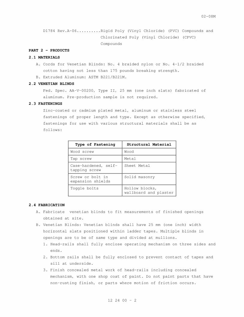
02-08M
D1784 Rev.A-06..........Rigid Poly (Vinyl Chloride) (PVC) Compounds and
Chlorinated Poly (Vinyl Chloride) (CPVC)
Compounds
PART 2 - PRODUCTS
2.1 MATERIALS
A. Cords for Venetian Blinds: No. 4 braided nylon or No. 4-1/2 braided
cotton having not less than 175 pounds breaking strength.
B. Extruded Aluminum: ASTM B221/B221M.
2.2 VENETIAN BLINDS
Fed. Spec. AA-V-00200, Type II, 25 mm (one inch slats) fabricated of
aluminum. Pre-production sample is not required.
2.3 FASTENINGS
Zinc-coated or cadmium plated metal, aluminum or stainless steel
fastenings of proper length and type. Except as otherwise specified,
fastenings for use with various structural materials shall be as
follows:
Type of Fastening Structural Material
Wood screw Wood
Tap screw Metal
Case-hardened, self-tapping screw
Sheet Metal
Screw or bolt in expansion shields
Solid masonry
Toggle bolts Hollow blocks, wallboard and plaster
2.4 FABRICATION
A. Fabricate venetian blinds to fit measurements of finished openings
obtained at site.
B. Venetian Blinds: Venetian blinds shall have 25 mm (one inch) width
horizontal slats positioned within ladder tapes. Multiple blinds in
openings are to be of same type and divided at mullions.
1. Head-rails shall fully enclose operating mechanism on three sides and
ends.
2. Bottom rails shall be fully enclosed to prevent contact of tapes and
sill at underside.
3. Finish concealed metal work of head-rails including concealed
mechanism, with one shop coat of paint. Do not paint parts that have
non-rusting finish, or parts where motion of friction occurs.
12 24 00 - 2
02-08M
PART 3 - EXECUTION
3.1 INSTALLATION
A. Venetian Blinds: Support blinds in level position by brackets and
intermediate supports that will permit easy removal and replacement of
units without damage to blind, or adjacent surfaces. Provide at least
two fasteners for each bracket or other support.
1. Install blinds between jambs on window openings with steel trim.
Mount brackets on trim reveal, flush with face of trim and secure
with steel screws.
2. Provide one brush (for each 1 to 50 blind) of an approved type,
- - - E N D - - -
12 24 00 - 3
02-08M
SECTION 12 24 21 LIGHTPROOF SHADES
PART 1 - GENERAL
1.1 DESCRIPTION
Provide lightproof shades where indicated.
1.2 RELATED WORK
SECTION 12 24 00, WINDOW SHADES.
1.3 SUBMITTALS
A. In accordance with Section 01 33 23, SHOP DRAWINGS, PRODUCT DATA, AND
SAMPLES, furnish the following:
B. Manufacturers' Literature and Data: Showing details of construction and
hardware for Lightproof Shades.
1.4 APPLICABLE PUBLICATIONS
A. The publications listed below form a part of this specification to the
extent referenced. The publications are referenced in the text by the
basic designation only.
B. Federal Specifications (Fed. Spec.):
A-A-59517...............Cloth, Coated or Laminated, Polyvinylchloride
(Artificial Leather)
PART 2 - PRODUCTS
2.1 MATERIALS
A. Shade Cloth: Fabricate for a crackproof and fadeproof material that will
remain soft and pliable at all times under temperature changes. Shade
cloth shall conform to fire resistant requirement of Fed. Spec. A-A-
59517, and shall be same color on both sides.
B. Cords for Shades: No. 4 braided nylon, or No. 4 1/2 braided cotton
having not less than 80 Kg (175 pounds) breaking strength.
C. Fastenings: Zinc-coated or cadmium plated metal, aluminum or stainless
steel fastenings of proper length and type. Except as otherwise
specified, fastenings for use with various structural materials shall be
as follows:
Type of Fastening Structural Material
Wood screw Wood
Tap Screw Metal
Case-hardened, self-tapping screw
Solid masonry Sheet metal
Toggle bolts Hollow blocks, wallboard plaster
12 24 21 - 1
02-08M
2.2 SHADES ENCLOSED IN WINDOWS
Shades inside of windows panes shall be used at Mental Health and
Behavioral Nursing Units. There shall be no cords or ropes attached and
curtains shall not be used. Hardware should be flush with the walls so
that it can’t be used to secure a nose. Hardware should also be tamper
proof to prevent removal for use as a weapon or for self harm.
2.3 FABRICATION
A. Lightproof shades shall be metal head housing, deep side guides, sill
light lock members, continuous metal jamb and head anchor section,
operating bars, and shall be complete with roller assembly, one piece
lightproof shade cloth, and metal disappearing type horizontal braces
(two each shade).
B. Light traps shall be shop fabricated, and shall consist of a head box to
house the shade roller, and steel channels U-shape in cross section to
serve as guides for the shade along the sides, and to receive the bottom
edge of the shade along the sill. Make light trap of sheet steel having
a minimum thickness of 0.38 mm (0.015). Legs of the U-shaped channels
shall be, not less than 45 mm (1-3/4 inches) long and separated by
minimum distance that will permit free operation of the shade. Edges of
light trap coming into contact with the shade cloth shall be rounded or
beaded. Exposed face of the head box shall be hinged, or removable for
access to the shade roller. Design entire assembly to prevent light from
entering the room when the shade is drawn. Interior or unexposed
surfaces of the light trap shall have a finish coat of flat black
enamel. Exposed portions of the light trap shall have a factory applied
pyroxylin lacquer, or baked on enamel finish in color to match adjoining
wood or metal work.
C. Rollers shall be of aluminum or stainless steel of sufficient diameter
to support the shade, and provided with spindles, bearings and coil
springs. Provide rollers with a groove and metal spline with aluminum,
or stainless steel machine screws spaced not over nine inches on
centers, for attaching the shade cloth.
D. Shades not finished with a selvage shall have vertical edges bound or
hemmed to prevent raveling. Sewing shall be double or triple stitched,
using a high-grade thread. Make needle holes lightproof by applying a
suitable filler.
E. Stiffen the shade by transverse steel bars of size and weight to hold
the shade in the channel guides. Space bars approximately 450 mm (18
inches) on centers and conceal in pockets in the shade. Fit bottom edge
12 24 21 - 2
02-08M
of the shade with a steel operating bar designed to engage the sill
channel of the light trap. Paint bars with flat black enamel.
F. Cords: Fit operating bar with pull cord.
PART 3 - EXECUTION
3.1 INSTALLATION
Install lightproof shades level at a height that will permit proper
operation of the shades, and prevent outside light from infiltrating
into the room. Light traps shall be closely fitted to the adjacent
construction, and the connection shall be rigid and light-tight. Shades
shall not be installed until after the room painting and finishing
operations are complete.
- E N D - -
12 24 21 - 3
SECTION 142400
HYDRAULIC ELEVATORS
PART 1 - GENERAL
1.1 SUMMARY
A. This Section includes hydraulic service elevators.
1.2 SUBMITTALS
A. Product Data: Include capacities, sizes, performances,
operations, safety features, finishes, and similar information.
B. Shop Drawings: Show plans, elevations, sections, and large-scale
details indicating service at each landing, machine room layout,
coordination with building structure, relationships with other
construction, and locations of equipment and signals. Indicate
variations from specified requirements, maximum dynamic and
static loads imposed on building structure at points of support,
and maximum and average power demands.
C. Samples: For exposed finishes.
D. Manufacturer Certificates: Signed by elevator manufacturer
certifying that hoistway, pit, and machine room layout and
dimensions, as shown on Drawings, and electrical service, as
shown and specified, are adequate for elevator system being
provided.
E. Operation and maintenance data.
F. Inspection and Acceptance Certificates and Operating Permits: As
required by authorities having jurisdiction for normal,
unrestricted elevator use.
1.3 QUALITY ASSURANCE
Accessibility Requirements: Comply with Section 4.10 in the U.S.
Architectural & Transportation Barriers Compliance Board's "Americans
with Disabilities Act (ADA), Accessibility Guidelines for Buildings and
Facilities (ADAAG)."
1.4 WARRANTY
Special Manufacturer's Warranty: Manufacturer's standard form in which
manufacturer agrees to repair, restore, or replace defective elevator
work within specified warranty period.
Warranty Period: One year from date of Substantial Completion.
1.5 MAINTENANCE SERVICE
A. Initial Maintenance Service: Beginning at Substantial
Completion, provide one year's full maintenance service by
skilled employees of elevator Installer. Include monthly
preventive maintenance, repair or replacement of worn or
defective components, lubrication, cleaning, and adjusting as
required for proper elevator operation at rated speed and
capacity.
PART 2 - PRODUCTS
2.1 MANUFACTURERS
A. Available Manufacturers: Subject to compliance with
requirements, manufacturers offering products that may be
incorporated into the Work include, but are not limited to, the
following:
B. Manufacturers: Subject to compliance with requirements, provide
products by one of the following:
1. KONE Inc.
2. Otis Elevator Co. (Basis of Design)
3. Schindler Elevator Corp.
4. ThyssenKrupp Elevator.
2.2 SYSTEMS AND COMPONENTS
A. General: Provide manufacturer's standard elevator systems,
including standard components published by manufacturer as
included in standard preengineered elevator systems and as
required for complete system.
B. Pump Units: Positive-displacement type with a maximum of 10
percent variation between no load and full load and with minimum
pulsations. Provide either of the following:
1. Pump mounted on oil tank with vibration isolation mounts.
Enclose pump in prime-painted steel enclosure lined with 1-
inch- (25-mm-) thick, glass-fiber insulation board.
2. Submersible pump, suspended inside oil tank from vibration
isolation mounts.
3. Provide motor with solid-state starting.
C. Hydraulic Silencers: Provide hydraulic silencer containing
pulsation-absorbing material in a blowout-proof housing at pump
unit.
D. Hydraulic Fluid: Elevator manufacturer's standard fluid with
additives as needed to prevent oxidation of fluid, corrosion of
cylinder and other components, and other adverse effects.
142400 - 2
E. Protective Cylinder Casing: PVC or HDPE pipe casing complying
with ASME A17.1, of sufficient size to provide not less than 1-
inch (25-mm) clearance from cylinder and extending above pit
floor. Provide means to monitor casing effectiveness to comply
with ASME A17.1.
F. Guides: Provide either roller guides or sliding guides at top
and bottom of car and counterweight frames. If sliding guides
are used, provide guide-rail lubricators or polymer-coated,
nonlubricated guides.
2.3 OPERATION SYSTEMS
A. General: Provide manufacturer's standard microprocessor
operation system for each elevator as required to provide type of
operation system indicated.
B. Single-Car Auxiliary Operations:
1. Battery-Powered Lowering: When power fails, car is lowered
to the lowest floor, opens its doors, and shuts down.
System includes rechargeable battery and automatic
recharging system. If the elevator will not be powered by
the building’s emergency generator, then include a battery
lowering feature.
2.4 DOOR REOPENING DEVICES
A. Infrared Array: Provide door reopening devices with uniform
array of 36 or more microprocessor-controlled, infrared light
beams projecting across car entrance. Interruption of one or
more of the light beams shall cause doors to stop and reopen.
B. Nudging Feature: After car doors are prevented from closing for
predetermined adjustable time, a loud buzzer shall sound and
doors shall begin to close at reduced kinetic energy.
2.5 FINISH MATERIALS
A. Cold-Rolled Steel Sheet: ASTM A 1008/A 1008M, commercial steel,
Type B, exposed.
B. Hot-Rolled Steel Sheet: ASTM A 1011/A 1011M, commercial steel,
Type B, pickled.
C. Stainless-Steel Sheet: ASTM A 240/A 240M, Type 304.
D. Stainless-Steel Bars: ASTM A 276, Type 304.
E. Stainless-Steel Tubing: ASTM A 554, Grade MT 304.
F. Aluminum Extrusions: ASTM B 221 (ASTM B 221M), Alloy 6063.
142400 - 3
G. Plastic Laminate: High-pressure type complying with NEMA LD 3,
Type HGS or HGL.
2.6 CAR ENCLOSURES
A. General: Provide enameled-steel car enclosures to receive
removable wall panels, with car roof, access doors, power door
operators, and ventilation.
1. Provide standard railings complying with ASME A17.1 on car
tops where required by ASME A17.1.
2. Stainless-Steel Wall Panels: Flush, hollow-metal
construction.
3. Stainless-Steel Doors: Flush, hollow-metal construction.
4. Sills: Extruded aluminum, with grooved surface, 1/4 inch
(6.4 mm) thick.
5. Luminous Ceiling: Fluorescent light fixtures and ceiling
panels of translucent acrylic or other permanent rigid
plastic.
2.7 HOISTWAY ENTRANCES
A. General: Provide manufacturer's standard horizontal-sliding,
door-and-frame hoistway entrances complete with track systems,
hardware, sills, and accessories. Where gypsum board wall
construction is indicated, provide self-supporting frames with
reinforced head sections.
B. Materials and Fabrication: Provide manufacturer's standards, but
not less than the following:
1. Stainless-Steel Frames: Formed from stainless-steel sheet.
2. Stainless-Steel Doors: Flush, hollow-metal construction.
3. Sills: Extruded aluminum, with grooved surface, 1/4 inch
(6.4 mm) thick.
4. Nonshrink, Nonmetallic Grout: Factory-packaged,
nonstaining, noncorrosive, nongaseous grout complying with
ASTM C 1107.
2.8 SIGNAL EQUIPMENT
A. General: Provide hall-call and car-call buttons that light when
activated and remain lit until call has been fulfilled.
Fabricate lighted elements LEDs.
B. Car Control Stations: Provide manufacturer's standard car
control stations. Mount in return panel adjacent to car door,
unless otherwise indicated.
142400 - 4
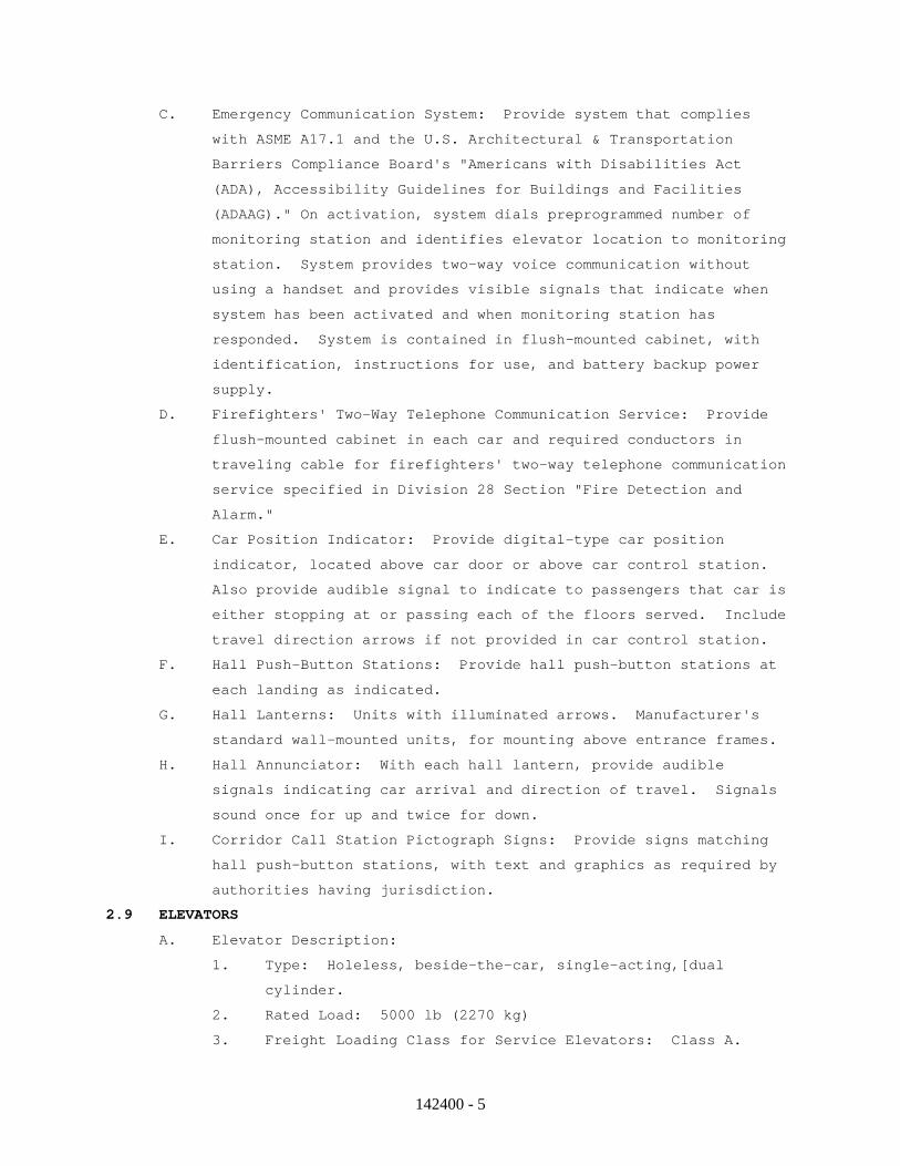
C. Emergency Communication System: Provide system that complies
with ASME A17.1 and the U.S. Architectural & Transportation
Barriers Compliance Board's "Americans with Disabilities Act
(ADA), Accessibility Guidelines for Buildings and Facilities
(ADAAG)." On activation, system dials preprogrammed number of
monitoring station and identifies elevator location to monitoring
station. System provides two-way voice communication without
using a handset and provides visible signals that indicate when
system has been activated and when monitoring station has
responded. System is contained in flush-mounted cabinet, with
identification, instructions for use, and battery backup power
supply.
D. Firefighters' Two-Way Telephone Communication Service: Provide
flush-mounted cabinet in each car and required conductors in
traveling cable for firefighters' two-way telephone communication
service specified in Division 28 Section "Fire Detection and
Alarm."
E. Car Position Indicator: Provide digital-type car position
indicator, located above car door or above car control station.
Also provide audible signal to indicate to passengers that car is
either stopping at or passing each of the floors served. Include
travel direction arrows if not provided in car control station.
F. Hall Push-Button Stations: Provide hall push-button stations at
each landing as indicated.
G. Hall Lanterns: Units with illuminated arrows. Manufacturer's
standard wall-mounted units, for mounting above entrance frames.
H. Hall Annunciator: With each hall lantern, provide audible
signals indicating car arrival and direction of travel. Signals
sound once for up and twice for down.
I. Corridor Call Station Pictograph Signs: Provide signs matching
hall push-button stations, with text and graphics as required by
authorities having jurisdiction.
2.9 ELEVATORS
A. Elevator Description:
1. Type: Holeless, beside-the-car, single-acting,[dual
cylinder.
2. Rated Load: 5000 lb (2270 kg)
3. Freight Loading Class for Service Elevators: Class A.
142400 - 5
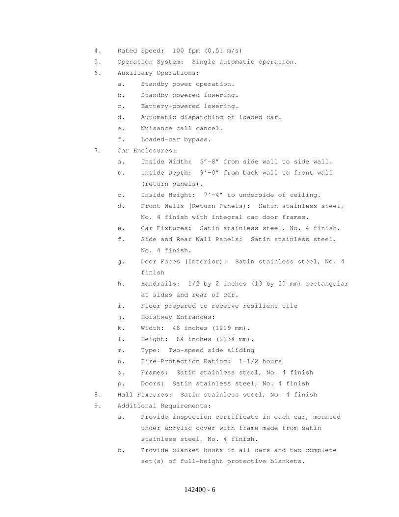
4. Rated Speed: 100 fpm (0.51 m/s)
5. Operation System: Single automatic operation.
6. Auxiliary Operations:
a. Standby power operation.
b. Standby-powered lowering.
c. Battery-powered lowering.
d. Automatic dispatching of loaded car.
e. Nuisance call cancel.
f. Loaded-car bypass.
7. Car Enclosures:
a. Inside Width: 5”-8” from side wall to side wall.
b. Inside Depth: 9’-0” from back wall to front wall
(return panels).
c. Inside Height: 7’-4” to underside of ceiling.
d. Front Walls (Return Panels): Satin stainless steel,
No. 4 finish with integral car door frames.
e. Car Fixtures: Satin stainless steel, No. 4 finish.
f. Side and Rear Wall Panels: Satin stainless steel,
No. 4 finish.
g. Door Faces (Interior): Satin stainless steel, No. 4
finish
h. Handrails: 1/2 by 2 inches (13 by 50 mm) rectangular
at sides and rear of car.
i. Floor prepared to receive resilient tile
j. Hoistway Entrances:
k. Width: 48 inches (1219 mm).
l. Height: 84 inches (2134 mm).
m. Type: Two-speed side sliding
n. Fire-Protection Rating: 1-1/2 hours
o. Frames: Satin stainless steel, No. 4 finish
p. Doors: Satin stainless steel, No. 4 finish
8. Hall Fixtures: Satin stainless steel, No. 4 finish
9. Additional Requirements:
a. Provide inspection certificate in each car, mounted
under acrylic cover with frame made from satin
stainless steel, No. 4 finish.
b. Provide blanket hooks in all cars and two complete
set(s) of full-height protective blankets.
142400 - 6
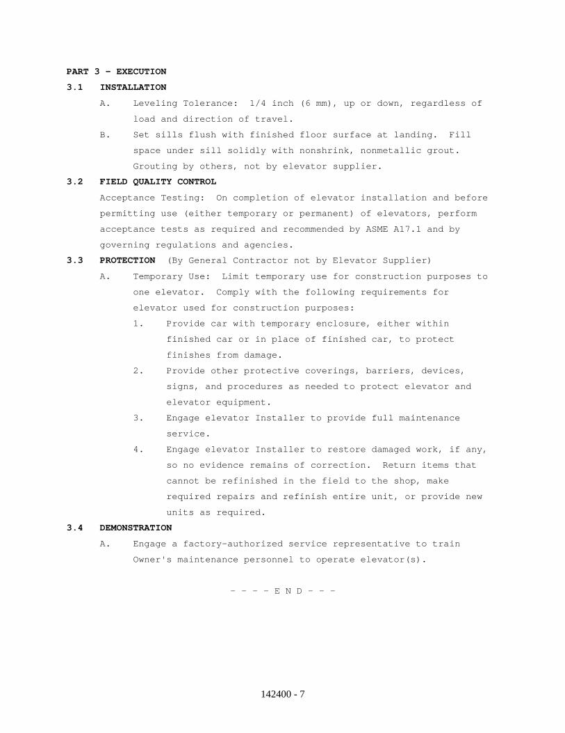
PART 3 - EXECUTION
3.1 INSTALLATION
A. Leveling Tolerance: 1/4 inch (6 mm), up or down, regardless of
load and direction of travel.
B. Set sills flush with finished floor surface at landing. Fill
space under sill solidly with nonshrink, nonmetallic grout.
Grouting by others, not by elevator supplier.
3.2 FIELD QUALITY CONTROL
Acceptance Testing: On completion of elevator installation and before
permitting use (either temporary or permanent) of elevators, perform
acceptance tests as required and recommended by ASME A17.1 and by
governing regulations and agencies.
3.3 PROTECTION (By General Contractor not by Elevator Supplier)
A. Temporary Use: Limit temporary use for construction purposes to
one elevator. Comply with the following requirements for
elevator used for construction purposes:
1. Provide car with temporary enclosure, either within
finished car or in place of finished car, to protect
finishes from damage.
2. Provide other protective coverings, barriers, devices,
signs, and procedures as needed to protect elevator and
elevator equipment.
3. Engage elevator Installer to provide full maintenance
service.
4. Engage elevator Installer to restore damaged work, if any,
so no evidence remains of correction. Return items that
cannot be refinished in the field to the shop, make
required repairs and refinish entire unit, or provide new
units as required.
3.4 DEMONSTRATION
A. Engage a factory-authorized service representative to train
Owner's maintenance personnel to operate elevator(s).
- - - - E N D - - -
142400 - 7
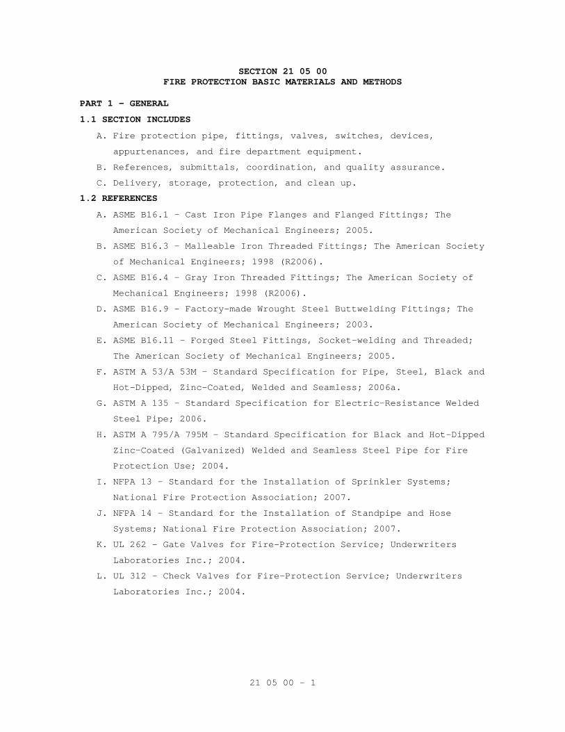
21 05 00 - 1
SECTION 21 05 00 FIRE PROTECTION BASIC MATERIALS AND METHODS
PART 1 - GENERAL
1.1 SECTION INCLUDES
A. Fire protection pipe, fittings, valves, switches, devices,
appurtenances, and fire department equipment.
B. References, submittals, coordination, and quality assurance.
C. Delivery, storage, protection, and clean up.
1.2 REFERENCES
A. ASME B16.1 - Cast Iron Pipe Flanges and Flanged Fittings; The
American Society of Mechanical Engineers; 2005.
B. ASME B16.3 - Malleable Iron Threaded Fittings; The American Society
of Mechanical Engineers; 1998 (R2006).
C. ASME B16.4 - Gray Iron Threaded Fittings; The American Society of
Mechanical Engineers; 1998 (R2006).
D. ASME B16.9 - Factory-made Wrought Steel Buttwelding Fittings; The
American Society of Mechanical Engineers; 2003.
E. ASME B16.11 - Forged Steel Fittings, Socket-welding and Threaded;
The American Society of Mechanical Engineers; 2005.
F. ASTM A 53/A 53M - Standard Specification for Pipe, Steel, Black and
Hot-Dipped, Zinc-Coated, Welded and Seamless; 2006a.
G. ASTM A 135 - Standard Specification for Electric-Resistance Welded
Steel Pipe; 2006.
H. ASTM A 795/A 795M - Standard Specification for Black and Hot-Dipped
Zinc-Coated (Galvanized) Welded and Seamless Steel Pipe for Fire
Protection Use; 2004.
I. NFPA 13 - Standard for the Installation of Sprinkler Systems;
National Fire Protection Association; 2007.
J. NFPA 14 - Standard for the Installation of Standpipe and Hose
Systems; National Fire Protection Association; 2007.
K. UL 262 - Gate Valves for Fire-Protection Service; Underwriters
Laboratories Inc.; 2004.
L. UL 312 - Check Valves for Fire-Protection Service; Underwriters
Laboratories Inc.; 2004.
21 05 00 - 2
1.3 SUBMITTALS
A. Submit shop drawings on all equipment, hydraulic calculations and
detailed drawings on the proposed system to the Architect through
the general contractor and to the local authority having
jurisdiction for approval. Partial submittals are not acceptable.
B. Submit plans and hydraulic calculations as per the requirements of
NFPA 13. The sprinkler contractor shall be required to receive
reviewed and approved drawings from all AHJ prior to commencing
fabrication or installation.
1.4 COORDINATION:
All work shall be designed and installed in accordance with the
local utility company requirements. All work shall be coordinated
with other trade work to eliminated rework by any tradesman.
Contractor shall submit plans and specifications to all AHJ and
receive approval prior to installation. Failure to receive
approval prior to installation, see quality assurance section.
1.5 QUALITY ASSURANCE
A. All work shall be done in accordance with Owner's insurance
carrier's requirements, NFPA and all applicable local and state
codes and ordinances. In the event that a code conflict occurs,
the most stringent requirement shall apply. The sprinkler system
designer shall have obtained NICET Level 3 certification in fire
sprinkler design prior to designing the system(s). The contractor
shall be licensed to perform fire protection work with in state of
Arkansas as per the requirements of the Arkansas Fire Protection
Licensing Board. Equipment specified herein shall be as noted or
equivalent. The sprinkler Contractor shall coordinate with other
trades on the job in locating the sprinkler system in relation to
lights, steel framing, building HVAC system, etc. The Contractor
shall, after completion of the work, make any corrections to the
system as required for approval by the insurance carrier, the
Engineer and the local authority having jurisdiction. In order to
expedite sprinkler system design and upon mutual agreement, TME may
assist sprinkler contractor in the development of "working plans".
However, the sprinkler contractor shall satisfy all code,
fabrication, coordination, and AHJ requirements.
21 05 00 - 3
1.6 DELIVERY, STORAGE, AND PROTECTION
A. Deliver and store valves in shipping containers, with labeling in
place.
B. Provide temporary protective coating on cast iron and steel valves.
C. The Fire Protections Contractor shall be completely responsible to
provide all fire protection equipment installed by this contract in
new condition on the date of substantial completion as set by the
owner or his agent. Any equipment not found to be in new condition
shall be replaced by this contractor at no expense to the owner.
PART 2 PRODUCTS
2.1 GENERAL SYSTEM AND PRODUCT REQUIREMENTS
A. Sprinkler Systems: Conform work to NFPA 13.
B. Standpipe and Hose Systems: Conform to NFPA 14.
C. Welding Materials and Procedures: Conform to ASME Code. NFPA 24,
and all AHJ.
2.2 ABOVE GROUND PIPING AND FITTINGS
A. Above ground fire protection wet piping shall be Schedule 10 roll
grooved black steel meeting all NFPA 13 and Factory Mutual
requirements or Schedule 40 threaded or groove black steel meeting
all NFPA 13 and Factory Mutual requirements. All pipe end
preparations shall meet the requirements of NFPA 13.
B. Flange fittings shall be standard class 125 cast iron. Groove
fittings and couplings shall be UL/FM approved for 300 PSI working
pressure. No groove fitting that has a "short" take out nor the
accompanying coupling, will be acceptable. No press-fit or sock it
type fittings will be acceptable. All groove fittings to be of the
same manufacturer. Installer is cautioned to NOT mismatch groove
material. Welded outlets on piping shall comply the requirements
of ANSI B1.20.1; ASTM A-53, Grades A or B, Type E. Welded outlets
to be UL listed, FM approved for use conforming to NFPA. NOTE:
The outlet type used shall match the pipe type installed. For
example, a Schedule 40 branch shall connect via a Schedule 40
welded outlet, however, the pipe being welded may be Schedule 10 or
Schedule 40. Segment welded fittings are not acceptable.
21 05 00 - 4
2.3 PIPE HANGERS AND SUPPORTS
A. Hangers for steel pipe sizes 1/2 to 4 inches: adjustable swivel,
split ring.
B. Vertical Support: Steel riser clamp.
C. Floor Support: Cast iron adjustable pipe saddle, lock nut, nipple,
floor flange, and concrete pier or steel support.
D. Copper Pipe Support: Carbon steel ring, adjustable, copper plated.
E. Contractor is cautioned to consider hanger locations when system
pressure exceeds 100 PSI.
F. This building is in Category C seismic zone which requires seismic
bracing for fire protection.
2.4 VALVES AND APPURTENANCES
A. Gate Valve (above grade): Valves 2" and smaller shall be made of
the best grade brass of screwed pattern, solid wedge disc, outside,
screw and yoke, screwed bonnet and malleable iron wheel, Nibco T-
104-O 175 lb. non-shock or approved equivalent.
B. Flange End O. S. & Y. Gate Valves: Valves 2-1/2 " and larger shall
be cast iron body, cast iron wheel, bolted bonnet, outside screw-
and-yoke, solid wedge disk, parallel seat, Nibco F-607-OTS 175 lb.
non-shock or approved equivalent. All valves shall have UL/FM
approval stamped on valve.
C. Groove End Butterfly Valves: Valves shall be equivalent to Tyco
Fire Products Model BFV-1 with built in tamper switch. Maximum
working pressure 300 PSI, UL/FM/ULC approved, and ductile iron body
having epoxy coating. Ductile iron disk, disk seal of grade EPDM
type E encapsulated rubber conforming to ASTM D-2000. Both upper
stem, lower plug, and stem to be stainless steel.
D. Groove End Check Valves: Valves shall be equivalent to Tyco Fire
Products Model CV-1F. Maximum working pressure 300 PSI, UL/FM/ULC
approved, ductile iron body and cap with stainless steel clapper.
E. Screw Check Valves: Valves 2" and smaller shall be UL/FM approved
made of brass, screwed pattern, horizontal swing, Y-pattern,
renewable composition disc, equivalent to Nibco KT-403-W, 200 lb.
WOG non-shock.
F. Flange End Check Valves: Valves 2-1/2" and larger shall be UL/FM
approved horizontal swing, iron body, bronze trim, bolted bonnet,
bronze disc, flanged ends, equivalent to Nibco F-968-B, 250 lb non-
shock.
21 05 00 - 5
G. Globe Valves and Angle Valves: Valves shall be UL/FM approved made
of brass, screwed pattern, EPDM type W disk, screwed bonnet, and
aluminum wheel, Nibco KT-211-W-UL or KT-67HL 175 lb. WOG non-shock
or approved equivalent.
2.5 FIRE DEPARTMENT EQUIPMENT
A. Fire Department Valve: Angle Valve, Potter-Roemer, Inc. Fig. 4065
2-1/2" rough brass with cap and chain. Hose connection shall match
responding fire department requirements.
2.6 SWITCHES AND DEVICES
A. OS&Y Tamper Switches: Switches equivalent to System Sensor Model
OS&Y 2. 2 sets of SPDT (form C) contacts; 10.0A @ 125/250 VAC; 2.5A
@ 6/12/24 VDC. Operating temperature range 32 F to 120 F.
B. Flow Switches: Switches equivalent to System Sensor WFD series. 2
sets of SPDT (form C) 10.0A, ½ HP @ 125/250 VAC; 2.5A @ 6/12/24
VDC. Operating temperature range 32 F to 120 F.
C. Test and Drain: Test and drain equivalent to AGF Model 10000.
UL/FM/ULC approved device, which shall be piped to suitable drain
pipe.
D. Riser Manifold: Riser manifold equivalent to Tyco Fire Products Fig
513, 513D, 513R. Working pressure is 175 PSI equipped with; water
flow switch, ball valve, test and drain, valve with properly sized
test orifice, and sight glass. Provide operational pressure relief
valve for grid system installation.
PART 3 EXECUTION
3.1 PREPARATION
A. Ream pipe and tube ends. Remove burrs.
B. Remove scale and foreign material, from inside and outside, before
assembly.
C. Install fire protection system in accordance to OSHA, NFPA, local
codes regulations, and manufacturer’s recommendations. Refer to
the drawings for a description of areas to be sprinklered and types
of hazard. All fire protection piping shall be designed and
installed after coordination with all other trades that may
conflict with sprinkler routing. Coordinate location of sprinkler
heads with Architect's reflected ceiling plan, lighting layout, and
HVAC diffuser layout. In exterior vestibules, other outside
entrance areas, and exterior type stairwells, install dry type
sprinklers.
21 05 00 - 6
3.2 INSTALLATION
A. Install sprinkler system and service main piping, hangers, and
supports in accordance with NFPA 13.
B. Install standpipe piping, hangers, and supports in accordance with
NFPA 14.
C. Route piping in orderly manner, plumb, and parallel to building
structure. Maintain gradient.
D. Install piping to conserve building space, to not interfere with
use of space and other work.
E. Group piping whenever practical at common elevations.
F. Sleeve pipes passing through fire walls, and floors, which are not
core drilled.
G. Install piping to allow for expansion and contraction without
stressing pipe, joints, or connected equipment.
H. Interface all electrical signaling devices with the fire alarm
system.
1. Tamper switches (alarm, trouble)
2. Flow switches (alarm, fire)
3.3 PIPE, HANGERS, AND SUPPORT
A. Install hangers to provide minimum 1/2 inch space between finished
covering and adjacent work.
B. Use hangers with minimum vertical adjustment. Design hangers for
pipe movement without disengagement of supported pipe.
C. Support vertical piping at every floor. Support riser piping
independently of connected horizontal piping.
D. Where several pipes can be installed in parallel and at same
elevation, provide multiple or trapeze hangers.
E. Prime coat exposed to view steel hangers and supports.
F. Slope piping and arrange systems to drain at low points. Use
eccentric reducers to maintain top of pipe level.
G. Prepare pipe, fittings, supports, and accessories for finish
painting. Where pipe support members are welded to structural
building framing, scrape, brush clean, and apply one coat of zinc
rich primer to welding.
H. Do not penetrate building structural members unless indicated or
otherwise given written properly executed directive.
21 05 00 - 7
I. Provide sleeves when penetrating footings, below grade floors, and
below grade walls. Seal pipe and sleeve penetrations to achieve
fire resistance equivalent to fire separation required. Provide
link seal gasket at all outside penetrations.
J. When installing more than one piping system material, ensure system
components are compatible and joined to ensure the integrity of the
system. Provide necessary joining fittings. Ensure flanges,
union, and couplings for servicing are consistently provided.
K. Install valves with stems upright or horizontal, not inverted.
Remove protective coatings prior to installation.
L. Provide valves for shut-off or isolating service.
M. Provide drain valves at main shut-off valves, low points of piping
and apparatus.
3.4 FIRESTOPPING:
All pipe penetrations of rated partitions shall be properly caulked
with fire caulking including sidewall sprinkler heads penetrating
such partitions.
3.5 SPARE PARTS/SIGNAGE
A. Provide and install all required signage on sprinkler system
equipment, pipe, control valves, devices, and auxiliary drain
valves as per NFPA #13.
B. Provide system tag at each system control valve. Each tag to be
self-indicative of the area controlled by that valve.
C. Provide appropriate count sprinkler head cabinet with proportionate
number of sprinklers and at least one sprinkler wrench for each
type sprinkler installed on site. Locate the head cabinet as per
owner's directive.
3.6 CLEANUP
A. Special care shall be taken at all times but especially during
"finish out" stage while using the pipe cutting/threading machine.
Provide protection below power machine to prevent drips and spills
of cutting oil.
B. All exposed finished surfaces shall be wiped clean of smudges,
fingerprints, etc.
C. Sprinkler contractor is specifically responsible for removal of all
debris created as a direct or indirect result of his portion of the
construction project.
21 05 00 - 8
3.7 CLOSE OUT:
Before application for final payment is requested the contractor is
to provide all requirements set forth by the General Conditions of
the Specifications and deliver to the engineer of record (TME,
Inc.) the following:
A. 1 full set of "AS BUILT" drawings. Provide "DBX As Built Drawings"
cabinet, size D, by Space Age Electronics. Field locate cabinet
adjacent to fire riser.
B. 1 full set of Operating and Maintenance Manuals.
C. 1 full set of applicable and executed test certificates for each
system.
D. 1 full set of electronic files (.dwg format) containing all fire
protection shop drawings used in the performance of the contract.
These files shall match the "AS BUILT" drawings stated in Section A
above.
E. On site training of owner specified personnel shall be coordinated
through the General Contractor. Training session(s) shall be
provided in order to familiarize the owner with the various
operations of the systems installed. The sprinkler contractor
shall direct and illustrate to the owner the function of the
various sprinkler valves in his facility. The sprinkler contractor
is to show the owner the location of all control valves and drain
valves as well as illustrate these valves specifically. Upon
completion of the training session the sprinkler contractor shall
provide a letter to the owner for his signature containing the
content of the training session. This letter shall be forwarded to
the engineer of record (TME, Inc.).
- - - E N D - - -
21 12 00 - 1
SECTION 21 12 00 FIRE-SUPPRESSION STANDPIPES
PART 1 GENERAL
1.1 SECTION INCLUDES
A. Standpipe system hose valves.
1.2 REFERENCES
A. FM P7825 - Approval Guide; Factory Mutual Research Corporation;
current edition.
B. NFPA 14 - Standard for the Installation of Standpipe and Hose
Systems; National Fire Protection Association; 2007.
C. UL (FPED) - Fire Protection Equipment Directory; Underwriters
Laboratories Inc.; current edition.
1.3 PRE-INSTALLATION MEETING
A. Convene one week before starting work of this section.
1.4 DELIVERY, STORAGE, AND HANDLING
A. Deliver and store products in shipping packaging until
installation.
B. Protect doors and other equipment from breakage or damage through
proper staging or storage between time of rough in and finish out
of project
PART 2 PRODUCTS
2.1 FIRE HOSE VALVES
A. Class I Fire Department Valve: Potter-Roemer, Inc. Fig. 4065 2-
1/2" fire department valve rough brass finish with 2-1/2" x 1-1/2"
reducer with cap and chain. Hose connection shall match responding
fire department requirements.
B. Manufacturer: Potter-Roemer
C. Other Acceptable Manufacturers:
1. Guardian
2. Croker
PART 3 EXECUTION
3.1 INSTALLATION
A. Install in accordance with manufacturer's instructions.
B. Install in accordance with NFPA 14.
21 12 00 - 2
C. Where the static pressure at a hose connection exceeds 175 psi
(12.1 bar), an approved pressure-regulating device shall be
provided to limit static and residual pressures at the outlet of
the hose connection to 100 psi (6.9 bar) for 1-1/2-in. (38.1-mm)
hose connections available for occupant use and 175 psi (12.1 bar)
for other hose connections. The pressure on the inlet side of the
pressure-regulating device shall not exceed the device’s rated
working pressure.
D. Flush entire system of foreign matter.
3.2 FIELD QUALITY CONTROL
A. Test entire system in accordance with NFPA 14.
B. Test shall be witnessed by Fire Marshall.
- - - E N D - - -
21 13 00 - 1
SECTION 21 13 00 FIRE-SUPPRESSION SPRINKLER SYSTEMS
PART 1 GENERAL
1.1 SECTION INCLUDES
A. Wet-pipe sprinkler system.
B. System design, installation, and certification.
1.2 RELATED SECTIONS
A. Section 210500 - Common Work Results for Fire Suppression.
1.3 REFERENCES
A. FM P7825 - Approval Guide; Factory Mutual Research Corporation;
current edition.
B. NFPA 13 - Standard for the Installation of Sprinkler Systems;
National Fire Protection Association; 2007.
C. UL (FPED) - Fire Protection Equipment Directory; Underwriters
Laboratories Inc.; current edition.
1.4 PROJECT RECORD DOCUMENTS
A. As-built drawings: Record actual locations of sprinklers and
deviations of piping from shop drawings clearly indicating all
drain and test locations.
B. Manufacturer's Certificate: Certify that system has been tested
and meets or exceeds code requirements.
C. Operation and Maintenance Data: Include components of system,
servicing requirements, record drawings, inspection data,
replacement part numbers and availability, and location and numbers
of service depot.
D. Electronic files: Provide a full set of electronic files in .dwg
format containing all fire protection shop drawings used in the
performance of the contract. These files shall match the "AS-
BUILT" drawings stated in Section A above.
1.5 PRE-INSTALLATION MEETING
A. Convene not less than one week before starting work of this
section.
1.6 DELIVERY, STORAGE, AND PROTECTION
A. Store products in shipping containers and maintain in place until
installation.
B. Make sure that the sprinklers are not subjected to temperatures in
access of the maximum recommended ambient temperature as per NFPA
and the manufacturer.
21 13 00 - 2
C. Replace all sprinklers that have been subjected to too high
temperature or have come into contact with corrosive fumes prior to
installation.
1.07 EXTRA MATERIALS
A. Provide extra sprinklers of type and size matching those installed,
in quantity required by referenced NFPA standard.
B. Provide suitable wrenches for each sprinkler type.
C. Install metal sprinkler cabinet(s) in location(s) designated by
owner.
PART 2 PRODUCTS
2.1 SPRINKLERS
A. All sprinklers for Light Hazard and all standard spray sprinklers
for Ordinary Hazard shall be quick response.
B. All sprinklers placed in finished ceiling shall be white finish
with white recessed escutcheons, unless otherwise noted on the fire
protection plans.
C. All sprinklers shall be UL approved for the designed location and
use.
D. Temperature ratings of sprinklers based on distances from heat
sources shall comply with the specific table in NFPA 13. It is NOT
acceptable to provide higher "rated" sprinklers throughout a room,
compartment, or area unless specifically required to do so by NFPA
13.
E. Sprinkler head locations for 2' x 2 and 2' x 4' (or similar)
acoustical tile lay in ceiling panel shall be installed at the
centerline of the tile. NOTE: This is a requirement for "return
bends" to be installed to hit specific locations. See plan for
areas or rooms which apply. This requirement is not in force for
non-public small rooms such as toilets, janitor closets, storage
rooms, kitchens, or the like. In these rooms, sprinklers shall be
installed at no closer than 6" to ceiling tee bars.
21 13 00 - 3
F. Flexible sprinkler drops: Flexible stainless hose assemblies and a
bracketing system that connect sprinkler heads to the branch lines
as manufactured by FlexHead Industries. Each FlexHead unit comes
with a mounting bracket and a 1-piece, leak tested sprinkler drop.
The mounting bracket is compatible with any suspended or gypsum
board ceiling system. All FlexHead commercial sprinkler
connections are Factory Mutual (FM) approved and UL listed and are
manufactured in an FM/UL audited facility. The bracket system is
made from galvanized sheet metal and is approved and compatible for
use with light, medium and heavy load grids (ASTM C635, C636) or
gypsum board ceiling systems. These flexible connections may be
required for seismic, ease of installation, tenant flexibility,
owner, or specific sprinkler location requirements.
G. Sealing Sprinkler: Reliable Model G4 and G4FR “Sealing” Concealed
Automatic Sprinklers shall be installed in locations indicated on
the drawings. This sprinkler provides fire protection in dust free
environments while offering an attractive appearance and adjustment
for easy installation. These “Sealing” Concealer are standard
response sprinklers. This assembly is recessed into the ceiling
and concealed by a flat gasketed cover plate. Refer to Reliable
Bulletin 123.
H. Provide compatible sprinkler head guards for all pendent and
upright sprinklers when the sprinkler deflector is installed below
7' AFF.
I. Acceptable sprinkler manufacturers:
1. Viking
2. Reliable
3. Tyco Fire Products
J. In areas of corrosive atmosphere, provide lead coated or wax coated
sprinklers to prevent premature decay of the sprinkler head. The
escutcheon plates for these type areas shall be made of plastic.
PART 3 DESIGN CRITERIA
3.1 The design, materials, equipment, installation, inspection, and
testing of the automatic sprinkler system shall be in accordance
with the provisions of NFPA 13. EXCEPTION: All sprinkler
hydraulically calculated sprinkler systems shall be incorporated in
a 10 PSI safety factor.
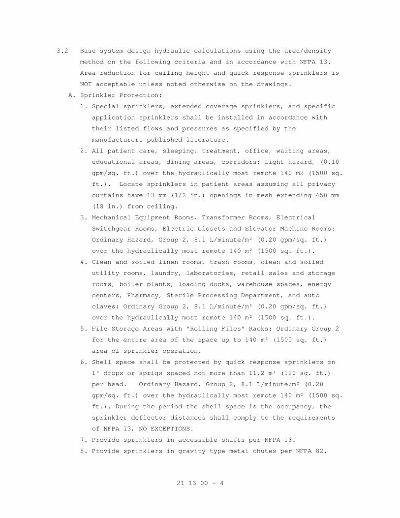
21 13 00 - 4
3.2 Base system design hydraulic calculations using the area/density
method on the following criteria and in accordance with NFPA 13.
Area reduction for ceiling height and quick response sprinklers is
NOT acceptable unless noted otherwise on the drawings.
A. Sprinkler Protection:
1. Special sprinklers, extended coverage sprinklers, and specific
application sprinklers shall be installed in accordance with
their listed flows and pressures as specified by the
manufacturers published literature.
2. All patient care, sleeping, treatment, office, waiting areas,
educational areas, dining areas, corridors: Light hazard, (0.10
gpm/sq. ft.) over the hydraulically most remote 140 m2 (1500 sq.
ft.). Locate sprinklers in patient areas assuming all privacy
curtains have 13 mm (1/2 in.) openings in mesh extending 450 mm
(18 in.) from ceiling.
3. Mechanical Equipment Rooms, Transformer Rooms, Electrical
Switchgear Rooms, Electric Closets and Elevator Machine Rooms:
Ordinary Hazard, Group 2, 8.1 L/minute/m² (0.20 gpm/sq. ft.)
over the hydraulically most remote 140 m² (1500 sq. ft.).
4. Clean and soiled linen rooms, trash rooms, clean and soiled
utility rooms, laundry, laboratories, retail sales and storage
rooms, boiler plants, loading docks, warehouse spaces, energy
centers, Pharmacy, Sterile Processing Department, and auto
claves: Ordinary Group 2, 8.1 L/minute/m² (0.20 gpm/sq. ft.)
over the hydraulically most remote 140 m² (1500 sq. ft.).
5. File Storage Areas with "Rolling Files" Racks: Ordinary Group 2
for the entire area of the space up to 140 m² (1500 sq. ft.)
area of sprinkler operation.
6. Shell space shall be protected by quick response sprinklers on
1" drops or sprigs spaced not more than 11.2 m² (120 sq. ft.)
per head. Ordinary Hazard, Group 2, 8.1 L/minute/m² (0.20
gpm/sq. ft.) over the hydraulically most remote 140 m² (1500 sq.
ft.). During the period the shell space is the occupancy, the
sprinkler deflector distances shall comply to the requirements
of NFPA 13, NO EXCEPTIONS.
7. Provide sprinklers in accessible shafts per NFPA 13.
8. Provide sprinklers in gravity type metal chutes per NFPA 82.
21 13 00 - 5
3.3 HOSE WATER ALLOWANCE:
A. Light hazard; provide 100 GPM inside hose PLUS 00 GPM outside hose.
B. Ordinary hazard; provide 100 GPM inside hose PLUS 150 GPM outside
hose.
PART 4 EXECUTION
4.1 INSTALLATION
A. Install in accordance with referenced NFPA standard.
B. Install equipment in accordance with manufacturer's instructions.
C. For each sprinkler zone provide a control valve, check valve with
gage, flow switch, self-contained test and drain assembly and
pressure gage.
D. Place pipe runs to minimize obstruction to other work.
E. Place piping in concealed spaces above finished ceilings.
F. Flush entire piping system of foreign matter.
G. Hydrostatically test entire system.
H. Hydrostatic test to be witnessed by responding fire department.
4.2 INTERFACE WITH OTHER PRODUCTS
A. Ensure required devices are installed and connected as required to
the fire alarm system.
B. Coordinate the power requirements of any device provided by the
Fire Protection Contractor with the electrical or fire alarm
contractor. The Fire Protection Contractor assumes all costs
associated with his failure to properly coordinate with the power
supply contractor.
- - - E N D - - -
22 05 11 - 1
SECTION 22 05 11 COMMON WORK RESULTS FOR PLUMBING
PART 1 - GENERAL
1.1 DESCRIPTION
A. The requirements of this Section apply to all sections of Division 22.
B. Definitions:
1. Exposed: Piping and equipment exposed to view in finished rooms.
2. Option or optional: Contractor's choice of an alternate material or
method.
1.2 RELATED WORK
A. Section 01 00 00, GENERAL REQUIREMENTS.
B. Section 01 33 23, SHOP DRAWINGS, PRODUCT DATA, AND SAMPLES.
C. Excavation and Backfill: Section 31 20 00, EARTH MOVING.
D. Concrete and Grout: Section 03 30 00, CAST-IN-PLACE CONCRETE.
E. Building Components for Attachment of Hangers: Section 05 31 00, STEEL
DECKING.
F. Section 07 84 00, FIRESTOPPING.
G. Flashing for Wall and Roof Penetrations: Section 07 60 00, FLASHING AND
SHEET METAL.
H. Section 07 92 00, JOINT SEALANTS.
I. Section 09 91 00, PAINTING.
J. Section 23 05 48, SEISMIC/VIBRATION ISOLATION FOR MECHANICAL COMPONENTS.
K. Section 23 07 11, HVAC AND PLUMBING INSULATION.
L. Section 26 05 11, REQUIREMENTS FOR ELECTRICAL INSTALLATIONS
M. Section 22 05 12, GENERAL MOTOR REQUIREMENTS FOR PLUMBING EQUIPMENT.
N. Section 26 29 11, LOW-VOLTAGE MOTOR STARTERS.
1.3 QUALITY ASSURANCE
A. Products Criteria:
1. Standard Products: Material and equipment shall be the standard
products of a manufacturer regularly engaged in the manufacture of
the products for at least 3 years. However, digital electronics
devices, software and systems such as controls, instruments, computer
work station, shall be the current generation of technology and basic
design that has a proven satisfactory service record of at least
three years. See other specification sections for any exceptions.
22 05 11 - 2
2. Equipment Service: There shall be permanent service organizations,
authorized and trained by manufacturers of the equipment supplied,
located within 100 miles of the project. These organizations shall
come to the site and provide acceptable service to restore operations
within four hours of receipt of notification by phone, e-mail or fax
in event of an emergency, such as the shut-down of equipment; or
within 24 hours in a non-emergency. Submit names, mail and e-mail
addresses and phone numbers of service organizations providing
service under these conditions for (as applicable to the project):
pumps, critical instrumentation, computer workstation and
programming.
3. All items furnished shall be free from defects that would adversely
affect the performance, maintainability and appearance of individual
components and overall assembly.
4. Conform to codes and standards as required by the specifications.
Conform to local codes, if required by local authorities such as the
natural gas supplier, if the local codes are more stringent then
those specified. Refer any conflicts to the Resident Engineer
(RE)/Contracting Officers Technical Representative (COTR).
5. Multiple Units: When two or more units of materials or equipment of
the same type or class are required, these units shall be products of
one manufacturer.
6. Assembled Units: Manufacturers of equipment assemblies, which use
components made by others, assume complete responsibility for the
final assembled product.
7. Nameplates: Nameplate bearing manufacturer's name or identifiable
trademark shall be securely affixed in a conspicuous place on
equipment, or name or trademark cast integrally with equipment,
stamped or otherwise permanently marked on each item of equipment.
8. Asbestos products or equipment or materials containing asbestos shall
not be used.
B. Welding: Before any welding is performed, contractor shall submit a
certificate certifying that welders comply with the following
requirements:
1. Qualify welding processes and operators for piping according to ASME
"Boiler and Pressure Vessel Code", Section IX, "Welding and Brazing
Qualifications".
2. Comply with provisions of ASME B31 series "Code for Pressure Piping".
22 05 11 - 3
3. Certify that each welder has passed American Welding Society (AWS)
qualification tests for the welding processes involved, and that
certification is current.
C. Manufacturer's Recommendations: Where installation procedures or any
part thereof are required to be in accordance with the recommendations
of the manufacturer of the material being installed, printed copies of
these recommendations shall be furnished to the Resident Engineer prior
to installation. Installation of the item will not be allowed to proceed
until the recommendations are received. Failure to furnish these
recommendations can be cause for rejection of the material.
D. Execution (Installation, Construction) Quality:
1. Apply and install all items in accordance with manufacturer's written
instructions. Refer conflicts between the manufacturer's instructions
and the contract drawings and specifications to the RE/COTR for
resolution. Provide written hard copies or computer files of
manufacturer’s installation instructions to the RE/COTR at least two
weeks prior to commencing installation of any item.
2. All items that require access, such as for operating, cleaning,
servicing, maintenance, and calibration, shall be easily and safely
accessible by persons standing at floor level, or standing on
permanent platforms, without the use of portable ladders. Examples of
these items include, but are not limited to: all types of valves,
filters and strainers, transmitters, control devices. Prior to
commencing installation work, refer conflicts between this
requirement and contract drawings to the RE/COTR for resolution.
3. Provide complete layout drawings required by Paragraph, SUBMITTALS.
Do not commence construction work on any system until the layout
drawings have been approved.
E. Extended Guarantee Period Services:
1. Qualifications: All service technicians assigned to perform work
under this contract shall be qualified and factory trained by the
Original Equipment Manufacturer (O.E.M.). Each technician shall have
at least three years experience of working on comparable systems and
shall be a full time employee of the contractor. The contractor shall
furnish, for the Department of Veterans Affairs (VA) review and
approval, resumes of all service technicians scheduled to service the
equipment and systems. The resume shall include details of
experience, training, and educational qualifications and performance
evaluations.
22 05 11 - 4
2. Replacement Parts: The contractor shall be equipped with all
replacement parts of all equipment and systems to be serviced and the
manufacturer's standard service and repair procedures. All
replacement parts shall be brand new and of current design. The
replacement parts shall be O.E.M. items. Obsolete or refurbished
parts are unacceptable. "Approved Equal" parts must have prior
approval of the Contracting Officer. Contractor shall furnish
evidence of guaranteed supply of parts for the life of the system.
3. Service Supplies: The services shall include, without any additional
cost to the government, all replacement parts, special tools and
equipment, and consumable materials, that is, lubrication oil,
grease, and cleaning materials, as required. The requirement of UL
listing, where applicable, shall not be voided by any replacement
parts, components, software, or modifications provided by the
contractor.
4. Scheduled and Emergency Call Service: The service shall include a
scheduled monthly visit to perform systematic examination of
equipment and/or systems and a 7 day, 24 hours call back service for
emergency service. The emergency service is defined as a situation
created by a breakdown or malfunction of any equipment or system
warranting urgent attention. A qualified service representative shall
respond to the VA request for emergency service within two hours and
assess the problem either by telephone or remote diagnostic
capability. If the emergency situation cannot be rectified by the VA
personnel, on site emergency service shall be provided by sending a
qualified service representative within 24 hours. For the rural
locations of the VA medical centers, situated over 200 miles from the
contractor's established service depot, the maximum response time of
48 hours shall be acceptable. The emergency service shall be limited
to adjustments and repairs specifically required to protect the
safety of the equipment for which the emergency service was required
to be performed.
5. Licensing: The contractor shall be licensed to perform the contracted
services. The contractor shall furnish details of all applicable
local and state licensing requirements to VA as a part of the
qualification requirements. The licenses shall be current, valid
through the term of the contract and in the name of the contractor.
22 05 11 - 5
6. Documentation Requirements: The contractor shall maintain a separate
log for each item of equipment and each system covered under the
extended guarantee period service contract with the VA Medical Center
(VAMC) Engineering Service. The log shall list dates and times of all
scheduled and emergency calls. Each emergency call shall be described
with details of the nature and causes of emergency, steps taken to
rectify the situations, and specific recommendations to avoid such
conditions in the future.
7. Reports: The contractor shall provide a quarterly report for the
first year and twice a year for the remainder of the guarantee period
for all equipment and systems serviced under the extended guarantee
period contract. The report shall clearly and concisely describe the
services rendered, parts replaced, and repairs performed. The report
shall prescribe anticipated future needs of the equipment and systems
for preventive and predictive maintenance.
8. Quality Program: The contractor shall provide a description of the
quality management and control program. The description shall include
a tangible proof the existence of such program, names of at least
three customers who have participated in the program, and specific
information showing the applicability of program to the project.
9. Training: During each scheduled service visit, the contractor shall
actively involve the VAMC maintenance personnel in performing
scheduled service and associated activities. The practical training
during the scheduled service visits shall include parting oral and
written instructions, for each specific task of the servicing
contract, to the VAMC maintenance personnel who shall operate the
hardware and software in accordance with the intent of the design and
under direct supervision of the service contractor's qualified
service technician. At the end of the first year of the service
contract, the contractor shall obtain a certificate from the VAMC
Engineering Service confirming completion of training to the
authorized VA representatives.
10. Classroom Training: Provide list and costs of available classroom
training courses offered by contractor or O.E.M.
F. Plumbing Systems: NAPHCC National Standard Plumbing Code.
1.4 SUBMITTALS
A. Submit in accordance with Section 01 33 23, SHOP DRAWINGS, PRODUCT DATA,
AND SAMPLES.
22 05 11 - 6
B. Information and material submitted under this section shall be marked
"SUBMITTED UNDER SECTION 22 05 11, COMNON WORK RESULTS FOR PLUMBING",
with applicable "Group" number.
C. Contractor shall make all necessary field measurements and
investigations to assure that the equipment and assemblies will meet
contract requirements.
D. If equipment is submitted which differs in arrangement from that shown,
provide drawings that show the rearrangement of all associated systems.
Approval will be given only if all features of the equipment and
associated systems, including accessibility, are equivalent to that
required by the contract.
E. Prior to submitting shop drawings for approval, contractor shall certify
in writing that manufacturers of all major items of equipment have each
reviewed drawings and specifications, and have jointly coordinated and
properly integrated their equipment and controls to provide a complete
and efficient installation.
F. Upon request by Government, provide lists of previous installations for
selected items of equipment. Include contact persons who will serve as
references, with telephone numbers and e-mail addresses.
G. Manufacturer's Literature and Data: Submit under the pertinent section
rather than under this section.
1. Submit electric motor data and variable speed drive data with the
driven equipment.
2. Equipment and materials identification.
3. Fire-stopping materials.
4. Hangers, inserts, supports and bracing. Provide load calculations for
variable spring and constant support hangers.
5. Wall, floor, and ceiling plates.
H. Coordination Drawings: Submit complete consolidated and coordinated
layout drawings for all new systems, and for existing systems that are
in the same areas. The drawings shall include plan views, elevations and
sections of all systems and shall be on a scale of not less than 1:32
(3/8-inch equal to one foot). Clearly identify and dimension the
proposed locations of the principal items of equipment. The drawings
shall clearly show the proposed location and adequate clearance for all
equipment, piping, pumps, valves and other items. Show the access means
for all items requiring access for operations and maintenance. Do not
install equipment foundations, equipment or piping until layout drawings
have been approved. Provide detailed layout drawings of all piping
systems. In addition provide details of the following.
22 05 11 - 7
1. Mechanical equipment rooms.
2. Interstitial space.
3. Hangers, inserts, supports, and bracing.
4. Pipe sleeves.
5. Equipment penetrations of floors, walls, ceilings, or roofs.
I. Maintenance Data and Operating Instructions:
1. Maintenance and operating manuals for systems and equipment.
2. Provide a listing of recommended replacement parts for keeping in
stock supply, including sources of supply, for equipment. Include in
the listing belts for equipment: Belt manufacturer, model number,
size and style, and distinguished whether of multiple belt sets.
1.5 DELIVERY, STORAGE AND HANDLING
A. Protection of Equipment:
1. Equipment and material placed on the job site shall remain in the
custody of the Contractor until phased acceptance, whether or not the
Government has reimbursed the Contractor for the equipment and
material. The Contractor is solely responsible for the protection of
such equipment and material against any damage.
2. Place damaged equipment in first class, new operating condition; or,
replace same as determined and directed by the RE/COTR. Such repair
or replacement shall be at no additional cost to the Government.
3. Protect interiors of new equipment and piping systems against entry
of foreign matter. Clean both inside and outside before painting or
placing equipment in operation.
4. Existing equipment and piping being worked on by the Contractor shall
be under the custody and responsibility of the Contractor and shall
be protected as required for new work.
B. Cleanliness of Piping and Equipment Systems:
1. Exercise care in storage and handling of equipment and piping
material to be incorporated in the work. Remove debris arising from
cutting, threading and welding of piping.
2. Piping systems shall be flushed, blown or pigged as necessary to
deliver clean systems.
3. Clean interior of all tanks prior to delivery for beneficial use by
the Government.
4. Contractor shall be fully responsible for all costs, damage, and
delay arising from failure to provide clean systems.
22 05 11 - 8
1.6 APPLICABLE PUBLICATIONS
A. The publications listed below form a part of this specification to the
extent referenced. The publications are referenced in the text by the
basic designation only.
22 05 11 - 9
B. American Society of Mechanical Engineers (ASME):
Boiler and Pressure Vessel Code (BPVC):
SEC IX-98...............Qualifications Standard for Welding and Brazing
Procedures, Welders, Brazers, and Welding and
Brazing Operators
C. American Society for Testing and Materials (ASTM):
A36/A36M-2001...........Carbon Structural Steel
A575-96.................Steel Bars, Carbon, Merchant Quality, M-Grades R
(2002)
E84-2003................Standard Test Method for Burning Characteristics
of Building Materials
E119-2000...............Standard Test Method for Fire Tests of Building
Construction and Materials
D. Manufacturers Standardization Society (MSS) of the Valve and Fittings
Industry, Inc:
SP-58-93................Pipe Hangers and Supports-Materials, Design and
Manufacture
SP 69-2003..............Pipe Hangers and Supports-Selection and
Application
E. National Electrical Manufacturers Association (NEMA):
MG1-2003, Rev. 1-2004...Motors and Generators
F. National Association of Plumbing - Heating - Cooling Contractors
(NAPHCC):
1996....................National Standard Plumbing Code
PART 2 - PRODUCTS
2.1 FACTORY-ASSEMBLED PRODUCTS
A. Provide maximum standardization of components to reduce spare part
requirements.
B. Manufacturers of equipment assemblies that include components made by
others shall assume complete responsibility for final assembled unit.
1. All components of an assembled unit need not be products of same
manufacturer.
2. Constituent parts that are alike shall be products of a single
manufacturer.
3. Components shall be compatible with each other and with the total
assembly for intended service.
4. Contractor shall guarantee performance of assemblies of components,
and shall repair or replace elements of the assemblies as required to
deliver specified performance of the complete assembly.
22 05 11 - 10
C. Components of equipment shall bear manufacturer's name and trademark,
model number, serial number and performance data on a name plate
securely affixed in a conspicuous place, or cast integral with, stamped
or otherwise permanently marked upon the components of the equipment.
D. Major items of equipment, which serve the same function, must be the
same make and model. Exceptions will be permitted if performance
requirements cannot be met.
2.2 COMPATIBILITY OF RELATED EQUIPMENT
Equipment and materials installed shall be compatible in all respects
with other items being furnished and with existing items so that the
result will be a complete and fully operational plant that conforms to
contract requirements.
2.3 SAFETY GUARDS
Pump shafts and couplings shall be fully guarded by a sheet steel guard,
covering coupling and shaft but not bearings. Material shall be minimum
16-gage sheet steel; ends shall be braked and drilled and attached to
pump base with minimum of four 6 mm (1/4-inch) bolts. Reinforce guard as
necessary to prevent side play forcing guard onto couplings.
2.4 LIFTING ATTACHMENTS
Provide equipment with suitable lifting attachments to enable equipment
to be lifted in its normal position. Lifting attachments shall withstand
any handling conditions that might be encountered, without bending or
distortion of shape, such as rapid lowering and braking of load.
2.5 ELECTRIC MOTORS, MOTOR CONTROL, CONTROL WIRING
A. All material and equipment furnished and installation methods shall
conform to the requirements of Section 22 05 12, GENERAL MOTOR
REQUIREMENTS FOR PLUMBING EQUIPMENT; Section 26 29 11, LOW-VOLTAGE MOTOR
STARTERS; and, Section 26 05 21, LOW-VOLTAGE ELECTRICAL POWER CONDUCTORS
AND CABLES (600 VOLTS AND BELOW). Provide all electrical wiring,
conduit, and devices necessary for the proper connection, protection and
operation of the systems. Provide special energy efficient motors as
scheduled. Unless otherwise specified for a particular application use
electric motors with the following requirements.
B. Special Requirements:
1. Where motor power requirements of equipment furnished deviate from
power shown on plans, provide electrical service designed under the
requirements of NFPA 70 without additional time or cost to the
Government.
22 05 11 - 11
2. Assemblies of motors, starters, controls, and interlocks on factory
assembled and wired devices shall be in accordance with the
requirements of this specification.
3. Wire and cable materials specified in the electrical division of the
specifications shall be modified as follows:
a. Wiring material located where temperatures can exceed 71 degrees C
(160 degrees F) shall be stranded copper with Teflon FEP
insulation with jacket. This includes wiring on the boilers.
b. Other wiring at boilers and to control panels shall be NFPA 70
designation THWN.
c. Provide shielded conductors or wiring in separate conduits for all
instrumentation and control systems where recommended by
manufacturer of equipment.
4. Select motor sizes so that the motors do not operate into the service
factor at maximum required loads on the driven equipment. Motors on
pumps shall be sized for non-overloading at all points on the pump
performance curves.
5. Motors utilized with variable frequency drives shall be rated
“inverter-ready” per NEMA Standard, MG1, Part 31.4.4.2.
C. Motor Efficiency and Power Factor: All motors, when specified as “high
efficiency” by the project specifications on driven equipment, shall
conform to efficiency and power factor requirements in Section 22 05 12,
GENERAL MOTOR REQUIREMENTS FOR PLUMBING EQUIPMENT, with no consideration
of annual service hours. Motor manufacturers generally define these
efficiency requirements as “NEMA premium efficient” and the requirements
generally exceed those of the Energy Policy Act of 1992 (EPACT). Motors
not specified as “high efficiency” shall comply with EPACT.
D. Single-phase Motors: Capacitor-start type for hard starting
applications. Motors for centrifugal fans and pumps may be split phase
or permanent split capacitor (PSC).
E. Poly-phase Motors: NEMA Design B, Squirrel cage, induction type. Each
two-speed motor shall have two separate windings. Provide a time- delay
(20 seconds minimum) relay for switching from high to low speed.
F. Rating: Continuous duty at 100 percent capacity in an ambient
temperature of 40 degrees centigrade (104 degrees F); minimum horsepower
as shown on drawings; maximum horsepower in normal operation not to
exceed nameplate rating without service factor.
G. Insulation Resistance: Not less than one-half meg-ohm between stator
conductors and frame, to be determined at the time of final inspection.
22 05 11 - 12
2.6 VARIABLE SPEED MOTOR CONTROLLERS
A. Refer to Section 26 05 11, REQUIREMENTS FOR ELECTRICAL INSTALLATIONS and
Section 26 29 11, LOW-VOLTAGE MOTOR STARTERS for specifications.
B. The combination of controller and motor shall be provided by the
respective pump manufacturer, and shall be rated for 100 percent output
performance. Multiple units of the same class of equipment, i.e. pumps,
shall be product of a single manufacturer.
C. Motors shall be energy efficient type and be approved by the motor
controller manufacturer. The controller-motor combination shall be
guaranteed to provide full motor nameplate horsepower in variable
frequency operation. Both driving and driven motor/fan sheaves shall be
fixed pitch.
D. Controller shall not add any current or voltage transients to the input
AC power distribution system, DDC controls, sensitive medical equipment,
etc., nor shall be affected from other devices on the AC power system.
2.7 EQUIPMENT AND MATERIALS IDENTIFICATION
A. Use symbols, nomenclature and equipment numbers specified, shown on the
drawings and shown in the maintenance manuals. In addition, provide bar
code identification nameplate for all equipment which will allow the
equipment identification code to be scanned into the system for
maintenance and inventory tracking. Identification for piping is
specified in Section 09 91 00, PAINTING.
B. Interior (Indoor) Equipment: Engraved nameplates, with letters not less
than 48 mm (3/16-inch) high of brass with black-filled letters, or rigid
black plastic with white letters specified in Section 09 91 00, PAINTING
permanently fastened to the equipment. Identify unit components such as
coils, filters, fans, etc.
C. Exterior (Outdoor) Equipment: Brass nameplates, with engraved black
filled letters, not less than 48 mm (3/16-inch) high riveted or bolted
to the equipment.
D. Control Items: Label all temperature and humidity sensors, controllers
and control dampers. Identify and label each item as they appear on the
control diagrams.
E. Valve Tags and Lists:
1. Plumbing: Provide for all valves (Fixture stops not included).
2. Valve tags: Engraved black filled numbers and letters not less than
13 mm (1/2-inch) high for number designation, and not less than 6.4
mm (1/4-inch) for service designation on 19 gage 38 mm (1-1/2 inches)
round brass disc, attached with brass "S" hook or brass chain.
22 05 11 - 13
3. Valve lists: Typed or printed plastic coated card(s), sized 216
mm(8-1/2 inches) by 280 mm (11 inches) showing tag number, valve
function and area of control, for each service or system. Punch
sheets for a 3-ring notebook.
4. Provide detailed plan for each floor of the building indicating the
location and valve number for each valve. Identify location of each
valve with a color coded thumb tack in ceiling.
2.8 FIRESTOPPING
Section 07 84 00, FIRESTOPPING specifies an effective barrier against
the spread of fire, smoke and gases where penetrations occur for piping.
Refer to Section 23 07 11, HVAC AND PLUMBING INSULATION, for firestop
pipe insulation.
2.9 GALVANIZED REPAIR COMPOUND
Mil. Spec. DOD-P-21035B, paint form.
2.10 PIPE AND EQUIPMENT SUPPORTS AND RESTRAINTS
A. In lieu of the paragraph which follows, suspended equipment support and
restraints may be designed and installed in accordance with the National
Uniform Seismic Installation Guidelines (NUSIG), most current edition.
Submittals based on either the NUSIG guidelines or the following
paragraphs of this Section shall be stamped and signed by a professional
engineer registered in a state where the project is located. Support of
suspended equipment over 227 kg (500 pounds) shall be submitted for
approval of the Resident Engineer in all cases. See paragraph 2.8.M for
lateral force design requirements.
B. Type Numbers Specified: MSS SP-58. For selection and application refer
to MSS SP-69. Refer to Section 05 50 00, METAL FABRICATIONS, for
miscellaneous metal support materials and prime coat painting.
C. For Attachment to Concrete Construction:
1. Concrete insert: Type 18, MSS SP-58.
2. Self-drilling expansion shields and machine bolt expansion anchors:
Permitted in concrete not less than 102 mm (four inches) thick when
approved by the Resident Engineer for each job condition.
3. Power-driven fasteners: Permitted in existing concrete or masonry not
less than 102 mm (four inches) thick when approved by the Resident
Engineer for each job condition.
D. For Attachment to Steel Construction: MSS SP-58.
1. Welded attachment: Type 22.
2. Beam clamps: Types 20, 21, 28 or 29. Type 23 C-clamp may be used for
individual copper tubing up to 23mm (7/8-inch) outside diameter.
22 05 11 - 14
E. Attachment to Metal Pan or Deck: As required for materials specified in
Section 05 31 00, STEEL DECKING.
F. For Attachment to Wood Construction: Wood screws or lag bolts.
G. Hanger Rods: Hot-rolled steel, ASTM A36 or A575 for allowable load
listed in MSS SP-58. For piping, provide adjustment means for
controlling level or slope. Types 13 or 15 turn-buckles shall provide 38
mm (1-1/2 inches) minimum of adjustment and incorporate locknuts.
All-thread rods are acceptable.
H. Multiple (Trapeze) Hangers: Galvanized, cold formed, lipped steel
channel horizontal member, not less than 41mm by 41mm (1-5/8 inches by
1-5/8 inches), 2.7 mm (No. 12 gage), designed to accept special spring
held, hardened steel nuts. Not permitted for steam supply and condensate
piping.
1. Allowable hanger load: Manufacturers rating less 91kg (200 pounds).
2. Guide individual pipes on the horizontal member of every other
trapeze hanger with 6 mm (1/4-inch) U-bolt fabricated from steel rod.
Provide Type 40 insulation shield, secured by two 13mm (1/2-inch)
galvanized steel bands, or preinsulated calcium silicate shield for
insulated piping at each hanger.
I. Pipe Hangers and Supports: (MSS SP-58), use hangers sized to encircle
insulation on insulated piping. Refer to Section 23 07 11, HVAC, AND
PLUMBING INSULATION for insulation thickness. To protect insulation,
provide Type 39 saddles for roller type supports or preinsulated calcium
silicate shields. Provide Type 40 insulation shield or preinsulated
calcium silicate shield at all other types of supports and hangers
including those for preinsulated piping.
1. General Types (MSS SP-58):
a. Standard clevis hanger: Type 1; provide locknut.
b. Riser clamps: Type 8.
c. Wall brackets: Types 31, 32 or 33.
d. Roller supports: Type 41, 43, 44 and 46.
e. Saddle support: Type 36, 37 or 38.
f. Turnbuckle: Types 13 or 15. preinsulate
g. U-bolt clamp: Type 24.
h. Copper Tube:
1) Hangers, clamps and other support material in contact with
tubing shall be painted with copper colored epoxy paint,
plastic coated or taped with non adhesive isolation tape to
prevent electrolysis.
22 05 11 - 15
2) For vertical runs use epoxy painted or plastic coated riser
clamps.
3) For supporting tube to strut: Provide epoxy painted pipe straps
for copper tube or plastic inserted vibration isolation clamps.
4) Insulated Lines: Provide pre-insulated calcium silicate shields
sized for copper tube.
2. Plumbing Piping (Other Than General Types):
a. Horizontal piping: Type 1, 5, 7, 9, and 10.
b. Chrome plated piping: Chrome plated supports.
c. Hangers and supports in pipe chase: Prefabricated system ABS
self-extinguishing material, not subject to electrolytic action,
to hold piping, prevent vibration and compensate for all static
and operational conditions.
d. Blocking, stays and bracing: Angle iron or preformed metal channel
shapes, 1.3 mm (18 gage) minimum.
J. Pre-insulated Calcium Silicate Shields:
1. Provide 360 degree water resistant high density 965 kPa (140 psi)
compressive strength calcium silicate shields encased in galvanized
metal.
2. Pre-insulated calcium silicate shields to be installed at the point
of support during erection.
3. Shield thickness shall match the pipe insulation.
4. The type of shield is selected by the temperature of the pipe, the
load it must carry, and the type of support it will be used with.
a. Shields for supporting chilled or cold water shall have insulation
that extends a minimum of 1 inch past the sheet metal. Provide for
an adequate vapor barrier in chilled lines.
b. The pre-insulated calcium silicate shield shall support the
maximum allowable water filled span as indicated in MSS-SP 69. To
support the load, the shields may have one or more of the
following features: structural inserts 4138 kPa (600 psi)
compressive strength, an extra bottom metal shield, or formed
structural steel (ASTM A36) wear plates welded to the bottom sheet
metal jacket.
5. Shields may be used on steel clevis hanger type supports, roller supports or flat surfaces.
K. Seismic Restraint of Piping: Refer to Section 23 05 48,
SEISMIC/VIBRATION ISOLATION FOR MECHANICAL COMPONENTS.
22 05 11 - 16
2.11 PIPE PENETRATIONS
A. Install sleeves during construction for other than blocked out floor
openings for risers in mechanical bays.
B. To prevent accidental liquid spills from passing to a lower level,
provide the following:
1. For sleeves: Extend sleeve 25 mm (one inch) above finished floor and
provide sealant for watertight joint.
2. For blocked out floor openings: Provide 40 mm (1-1/2 inch) angle set
in silicone adhesive around opening.
3. For drilled penetrations: Provide 40 mm (1-1/2 inch) angle ring or
square set in silicone adhesive around penetration.
C. Penetrations are not allowed through beams or ribs, but may be installed
in concrete beam flanges. Any deviation from these requirements must
receive prior approval of Resident Engineer.
D. Sheet Metal, Plastic, or Moisture-resistant Fiber Sleeves: Provide for
pipe passing through floors, interior walls, and partitions, unless
brass or steel pipe sleeves are specifically called for below.
E. Cast Iron or Zinc Coated Pipe Sleeves: Provide for pipe passing through
exterior walls below grade. Make space between sleeve and pipe
watertight with a modular or link rubber seal. Seal shall be applied at
both ends of sleeve.
F. Galvanized Steel or an alternate Black Iron Pipe with asphalt coating
Sleeves: Provide for pipe passing through concrete beam flanges, except
where brass pipe sleeves are called for. Provide sleeve for pipe passing
through floor of mechanical rooms, laundry work rooms, and animal rooms
above basement. Except in mechanical rooms, connect sleeve with floor
plate.
G. Brass Pipe Sleeves: Provide for pipe passing through quarry tile,
terrazzo or ceramic tile floors. Connect sleeve with floor plate.
H. Sleeves are not required for wall hydrants for fire department
connections or in drywall construction.
I. Sleeve Clearance: Sleeve through floors, walls, partitions, and beam
flanges shall be one inch greater in diameter than external diameter of
pipe. Sleeve for pipe with insulation shall be large enough to
accommodate the insulation. Interior openings shall be caulked tight
with fire stopping material and sealant to prevent the spread of fire,
smoke, and gases.
J. Sealant and Adhesives: Shall be as specified in Section 07 92 00, JOINT
SEALANTS.
22 05 11 - 17
2.12 TOOLS AND LUBRICANTS
A. Furnish, and turn over to the Resident Engineer, special tools not
readily available commercially, that are required for disassembly or
adjustment of equipment and machinery furnished.
B. Grease Guns with Attachments for Applicable Fittings: One for each type
of grease required for each motor or other equipment.
C. Tool Containers: Hardwood or metal, permanently identified for in tended
service and mounted, or located, where directed by the Resident
Engineer.
D. Lubricants: A minimum of 0.95 L (one quart) of oil, and 0.45 kg (one
pound) of grease, of equipment manufacturer's recommended grade and
type, in unopened containers and properly identified as to use for each
different application.
2.13 WALL, FLOOR AND CEILING PLATES
A. Material and Type: Chrome plated brass or chrome plated steel, one piece
or split type with concealed hinge, with set screw for fastening to
pipe, or sleeve. Use plates that fit tight around pipes, cover openings
around pipes and cover the entire pipe sleeve projection.
B. Thickness: Not less than 2.4 mm (3/32-inch) for floor plates. For wall
and ceiling plates, not less than 0.64 mm (0.025-inch) for up to 80 mm
(3-inch pipe), 0.89 mm (0.035-inch) for larger pipe.
C. Locations: Use where pipe penetrates floors, walls and ceilings in
exposed locations, in finished areas only. Use also where insulation
ends on exposed water supply pipe drop from overhead. Provide a
watertight joint in spaces where brass or steel pipe sleeves are
specified.
2.14 ASBESTOS
Materials containing asbestos are not permitted.
PART 3 - EXECUTION
3.1 ARRANGEMENT AND INSTALLATION OF EQUIPMENT AND PIPING
A. Coordinate location of piping, sleeves, inserts, hangers, and equipment,
access provisions, and work of all trades. Locate piping, sleeves,
inserts, hangers, and equipment clear of windows, doors, openings, light
outlets, and other services and utilities. Prepare equipment layout
drawings to coordinate proper location and personnel access of all
facilities. Submit the drawings for review as required by Part 1.
Follow manufacturer's published recommendations for installation methods
not otherwise specified.
B. Operating Personnel Access and Observation Provisions: Select and
arrange all equipment and systems to provide clear view and easy access,
22 05 11 - 18
without use of portable ladders, for maintenance and operation of all
devices including, but not limited to: all equipment items, valves,
filters, strainers, transmitters, sensors, control devices. All gages
and indicators shall be clearly visible by personnel standing on the
floor or on permanent platforms. Do not reduce or change maintenance and
operating space and access provisions that are shown on the drawings.
C. Equipment and Piping Support: Coordinate structural systems necessary
for pipe and equipment support with pipe and equipment locations to
permit proper installation.
D. Location of pipe sleeves, trenches and chases shall be accurately
coordinated with equipment and piping locations.
E. Cutting Holes:
1. Cut holes through concrete and masonry by rotary core drill.
Pneumatic hammer, impact electric, and hand or manual hammer type
drill will not be allowed, except as permitted by RE/COTR where
working area space is limited.
2. Locate holes to avoid interference with structural members such as
beams or grade beams. Holes shall be laid out in advance and drilling
done only after approval by RE/COTR. If the Contractor considers it
necessary to drill through structural members, this matter shall be
referred to RE/COTR for approval.
3. Do not penetrate membrane waterproofing.
F. Interconnection of Instrumentation or Control Devices: Generally,
electrical and pneumatic interconnections are not shown but must be
provided.
G. Minor Piping: Generally, small diameter pipe runs from drips and drains,
water cooling, and other service are not shown but must be provided.
H. Protection and Cleaning:
1. Equipment and materials shall be carefully handled, properly stored,
and adequately protected to prevent damage before and during
installation, in accordance with the manufacturer's recommendations
and as approved by the Resident Engineer. Damaged or defective items
in the opinion of the Resident Engineer shall be replaced.
2. Protect all finished parts of equipment, such as shafts and bearings
where accessible, from rust prior to operation by means of protective
grease coating and wrapping. Close pipe openings with caps or plugs
during installation. Tightly cover and protect fixtures and equipment
against dirt, water chemical, or mechanical injury. At completion of
all work thoroughly clean fixtures, exposed materials and equipment.
22 05 11 - 19
I. Concrete and Grout: Use concrete and shrink compensating grout 25 MPa
(3000 psi) minimum, specified in Section 03 30 00, CAST-IN-PLACE
CONCRETE.
J. Install gages, thermometers, valves and other devices with due regard
for ease in reading or operating and maintaining said devices. Locate
and position thermometers and gages to be easily read by operator or
staff standing on floor or walkway provided. Servicing shall not require
dismantling adjacent equipment or pipe work.
22 05 11 - 20
K. Electrical and Pneumatic Interconnection of Controls and Instruments:
This generally not shown but must be provided. This includes
interconnections of sensors, transmitters, transducers, control devices,
control and instrumentation panels, instruments and computer
workstations. Comply with NFPA-70.
L. Work in Existing Building:
1. Perform as specified in Article, OPERATIONS AND STORAGE AREAS,
Article, ALTERATIONS, and Article, RESTORATION of the Section 01 00
00, GENERAL REQUIREMENTS for relocation of existing equipment,
alterations and restoration of existing building(s).
2. As specified in Section 01 00 00, GENERAL REQUIREMENTS, Article,
OPERATIONS AND STORAGE AREAS, make alterations to existing service
piping at times that will least interfere with normal operation of
the facility.
3. Cut required openings through existing masonry and reinforced
concrete using diamond core drills. Use of pneumatic hammer type
drills, impact type electric drills, and hand or manual hammer type
drills, will be permitted only with approval of the Resident
Engineer. Locate openings that will least effect structural slabs,
columns, ribs or beams. Refer to the Resident Engineer for
determination of proper design for openings through structural
sections and opening layouts approval, prior to cutting or drilling
into structure. After Resident Engineer's approval, carefully cut
opening through construction no larger than absolutely necessary for
the required installation.
M. Work in Animal Research Areas: Seal all pipe penetrations with silicone
sealant to prevent entrance of insects.
N. Switchgear Drip Protection: Every effort shall be made to eliminate the
installation of pipe above electrical and telephone switchgear. If this
is not possible, encase pipe in a second pipe with a minimum of joints.
O. Inaccessible Equipment:
1. Where the Government determines that the Contractor has installed
equipment not conveniently accessible for operation and maintenance,
equipment shall be removed and reinstalled or remedial action
performed as directed at no additional cost to the Government.
2. The term "conveniently accessible" is defined as capable of being
reached without the use of ladders, or without climbing or crawling
under or over obstacles such as motors, fans, pumps, belt guards,
transformers, high voltage lines, piping, and ductwork.
22 05 11 - 21
3.2 TEMPORARY PIPING AND EQUIPMENT
A. Continuity of operation of existing facilities will generally require
temporary installation or relocation of equipment and piping.
B. The Contractor shall provide all required facilities in accordance with
the requirements of phased construction and maintenance of service. All
piping and equipment shall be properly supported, sloped to drain,
operate without excessive stress, and shall be insulated where injury
can occur to personnel by contact with operating facilities. The
requirements of Para. 3.1 apply.
C. Temporary facilities and piping shall be completely removed and any
openings in structures sealed. Provide necessary blind flanges and caps
to seal open piping remaining in service.
3.3 RIGGING
A. Design is based on application of available equipment. Openings in
building structures are planned to accommodate design scheme.
B. Alternative methods of equipment delivery may be offered by Contractor
and will be considered by Government under specified restrictions of
phasing and maintenance of service as well as structural integrity of
the building.
C. Close all openings in the building when not required for rigging
operations to maintain proper environment in the facility for Government
operation and maintenance of service.
D. Contractor shall provide all facilities required to deliver specified
equipment and place on foundations. Attachments to structures for
rigging purposes and support of equipment on structures shall be
Contractor's full responsibility. Upon request, the Government will
check structure adequacy and advise Contractor of recommended
restrictions.
E. Contractor shall check all clearances, weight limitations and shall
offer a rigging plan designed by a Registered Professional Engineer. All
modifications to structures, including reinforcement thereof, shall be
at Contractor's cost, time and responsibility.
F. Rigging plan and methods shall be referred to RE/COTR for evaluation
prior to actual work.
3.4 PIPE AND EQUIPMENT SUPPORTS
A. Where hanger spacing does not correspond with joist or rib spacing, use
structural steel channels secured directly to joist and rib structure
that will correspond to the required hanger spacing, and then suspend
the equipment and piping from the channels. Drill or burn holes in
structural steel only with the prior approval of the Resident Engineer.
22 05 11 - 22
B. Use of chain, wire or strap hangers; wood for blocking, stays and
bracing; or, hangers suspended from piping above will not be permitted.
Replace or thoroughly clean rusty products and paint with zinc primer.
C. Use hanger rods that are straight and vertical. Turnbuckles for vertical
adjustments may be omitted where limited space prevents use. Provide a
minimum of 15 mm (1/2-inch) clearance between pipe or piping covering
and adjacent work.
D. Plumbing horizontal and vertical pipe supports, refer to the NAPHCC
National Standard Plumbing Code.
E. Overhead Supports:
1. The basic structural system of the building is designed to sustain
the loads imposed by equipment and piping to be supported overhead.
2. Provide steel structural members, in addition to those shown, of
adequate capability to support the imposed loads, located in
accordance with the final approved layout of equipment and piping.
3. Tubing and capillary systems shall be supported in channel troughs.
F. Floor Supports:
1. Provide concrete bases, concrete anchor blocks and pedestals, and
structural steel systems for support of equipment and piping. Anchor
and dowel concrete bases and structural systems to resist forces
under operating and seismic conditions (if applicable) without
excessive displacement or structural failure.
2. Do not locate or install bases and supports until equipment mounted
thereon has been approved. Size bases to match equipment mounted
thereon plus 50 mm (2 inch) excess on all edges. Refer to structural
drawings. Bases shall be neatly finished and smoothed, shall have
chamfered edges at the top, and shall be suitable for painting.
3. All equipment shall be shimmed, leveled, firmly anchored, and grouted
with epoxy grout. Anchor bolts shall be placed in sleeves, anchored
to the bases. Fill the annular space between sleeves and bolts with a
granular material to permit alignment and realignment.
4. For seismic anchoring, refer to Section 23 05 48, SEISMIC/VIBRATION ISOLATION FOR MECHANICAL COMPONENTS.
3.5 LUBRICATION
A. Lubricate all devices requiring lubrication prior to initial operation.
Field-check all devices for proper lubrication.
22 05 11 - 23
B. Equip all devices with required lubrication fittings or devices. Provide
a minimum of one liter (one quart) of oil and 0.5 kg (one pound) of
grease of manufacturer's recommended grade and type for each different
application; also provide 12 grease sticks for lubricated plug valves.
Deliver all materials to RE/COTR in unopened containers that are
properly identified as to application.
C. Provide a separate grease gun with attachments for applicable fittings
for each type of grease applied.
D. All lubrication points shall be accessible without disassembling
equipment, except to remove access plates.
3.6 MECHANICAL DEMOLITION
A. Rigging access, other than indicated on the drawings, shall be provided
by the Contractor after approval for structural integrity by the
RE/COTR. Such access shall be provided without additional cost or time
to the Government. Where work is in an operating plant, provide approved
protection from dust and debris at all times for the safety of plant
personnel and maintenance of plant operation and environment of the
plant.
B. In an operating plant, maintain the operation, cleanliness and safety.
Government personnel will be carrying on their normal duties of
operating, cleaning and maintaining equipment and plant operation.
Confine the work to the immediate area concerned; maintain cleanliness
and wet down demolished materials to eliminate dust. Do not permit
debris to accumulate in the area to the detriment of plant operation.
Perform all flame cutting to maintain the fire safety integrity of this
plant. Adequate fire extinguishing facilities shall be available at all
times. Perform all work in accordance with recognized fire protection
standards. Inspection will be made by personnel of the VA Medical
Center, and Contractor shall follow all directives of the RE or COTR
with regard to rigging, safety, fire safety, and maintenance of
operations.
22 05 11 - 24
C. Completely remove all piping, wiring, conduit, and other devices
associated with the equipment not to be re-used in the new work. This
includes all pipe, valves, fittings, insulation, and all hangers
including the top connection and any fastenings to building structural
systems. Seal all openings, after removal of equipment, pipes, ducts,
and other penetrations in roof, walls, floors, in an approved manner and
in accordance with plans and specifications where specifically covered.
Structural integrity of the building system shall be maintained.
Reference shall also be made to the drawings and specifications of the
other disciplines in the project for additional facilities to be
demolished or handled.
D. All valves including gate, globe, ball, butterfly and check, all
pressure gages and thermometers with wells shall remain Government
property and shall be removed and delivered to RE/COTR and stored as
directed. The Contractor shall remove all other material and equipment,
devices and demolition debris under these plans and specifications. Such
material shall be removed from Government property expeditiously and
shall not be allowed to accumulate.
3.7 CLEANING AND PAINTING
A. Prior to final inspection and acceptance of the plant and facilities for
beneficial use by the Government, the plant facilities, equipment and
systems shall be thoroughly cleaned and painted. Refer to Section 09 91
00, PAINTING.
B. In addition, the following special conditions apply:
1. Cleaning shall be thorough. Use solvents, cleaning materials and methods recommended by the manufacturers for the specific tasks.
Remove all rust prior to painting and from surfaces to remain
unpainted. Repair scratches, scuffs, and abrasions prior to applying
prime and finish coats.
2. Material And Equipment Not To Be Painted Includes: a. Motors, controllers, control switches, and safety switches.
b. Control and interlock devices.
c. Regulators.
d. Pressure reducing valves.
e. Control valves and thermostatic elements.
f. Lubrication devices and grease fittings.
g. Copper, brass, aluminum, stainless steel and bronze surfaces.
h. Valve stems and rotating shafts.
i. Pressure gauges and thermometers.
j. Glass.
22 05 11 - 25
k. Name plates.
3. Control and instrument panels shall be cleaned, damaged surfaces
repaired, and shall be touched-up with matching paint obtained from
panel manufacturer.
4. Pumps, motors, steel and cast iron bases, and coupling guards shall
be cleaned, and shall be touched-up with the same color as utilized
by the pump manufacturer
5. Temporary Facilities: Apply paint to surfaces that do not have
existing finish coats.
6. Final result shall be smooth, even-colored, even-textured factory
finish on all items. Completely repaint the entire piece of
equipment if necessary to achieve this.
3.8 IDENTIFICATION SIGNS
A. Provide laminated plastic signs, with engraved lettering not less than
5 mm (3/16-inch) high, designating functions, for all equipment,
switches, motor controllers, relays, meters, control devices, including
automatic control valves. Nomenclature and identification symbols shall
correspond to that used in maintenance manual, and in diagrams specified
elsewhere. Attach by chain, adhesive, or screws.
B. Factory Built Equipment: Metal plate, securely attached, with name and
address of manufacturer, serial number, model number, size, performance.
C. Pipe Identification: Refer to Section 09 91 00, PAINTING.
3.9 STARTUP AND TEMPORARY OPERATION
Start up equipment as described in equipment specifications. Verify that
vibration is within specified tolerance prior to extended operation.
Temporary use of equipment is specified in Section 01 00 00, GENERAL
REQUIREMENTS, Article, TEMPORARY USE OF MECHANICAL AND ELECTRICAL
EQUIPMENT.
3.10 OPERATING AND PERFORMANCE TESTS
A. Prior to the final inspection, perform required tests as specified in
Section 01 00 00, GENERAL REQUIREMENTS, Article, TESTS and submit the
test reports and records to the Resident Engineer.
B. Should evidence of malfunction in any tested system, or piece of
equipment or component part thereof, occur during or as a result of
tests, make proper corrections, repairs or replacements, and repeat
tests at no additional cost to the Government.
C. When completion of certain work or system occurs at a time when final
control settings and adjustments cannot be properly made to make
performance tests, then make performance tests for heating systems and
22 05 11 - 26
for cooling systems respectively during first actual seasonal use of
respective systems following completion of work.
3.9 OPERATION AND MAINTENANCE MANUALS
A. Provide four bound copies. Deliver to RE/COTR not less than 30 days
prior to completion of a phase or final inspection.
B. Include all new and temporary equipment and all elements of each
assembly.
C. Data sheet on each device listing model, size, capacity, pressure,
speed, horsepower, impeller size, other data.
D. Manufacturer’s installation, maintenance, repair, and operation
instructions for each device. Include assembly drawings and parts lists.
Include operating precautions and reasons for precautions.
E. Lubrication instructions including type and quantity of lubricant.
F. Schematic diagrams and wiring diagrams of all control systems corrected
to include all field modifications.
G. Set points of all interlock devices. H. Trouble-shooting guide for control systems.
I. Operation of the combustion control system.
J. Emergency procedures.
3.10 INSTRUCTIONS TO VA PERSONNEL
Provide in accordance with Article, INSTRUCTIONS, of Section 01 00 00,
GENERAL REQUIREMENTS.
- - - E N D - - -
22 05 12 - 1
SECTION 22 05 12 GENERAL MOTOR REQUIREMENTS FOR PLUMBING EQUIPMENT
PART 1 - GENERAL
1.1 DESCRIPTION:
This section specifies the furnishing, installation and connection of
motors for plumbing equipment.
1.2 RELATED WORK:
A. Section 26 05 11, REQUIREMENTS FOR ELECTRICAL INSTALLATIONS: General
electrical requirements that are common to more than one Section of
Division 26.
B. Section 26 29 11, LOW-VOLTAGE MOTOR STARTERS: Starters, control and
protection for motors.
C. Other sections specifying motor driven equipment in Division22.
1.3 SUBMITTALS:
A. In accordance with Section 26 05 11, REQUIREMENTS FOR ELECTRICAL
INSTALLATIONS, submit the following:
B. Shop Drawings:
1. Sufficient information, clearly presented, shall be included to
determine compliance with drawings and specifications.
2. Include electrical ratings, dimensions, mounting details, materials,
horsepower, RPM, enclosure, starting characteristics, torque
characteristics, code letter, full load and locked rotor current,
service factor, and lubrication method.
C. Manuals:
1. Submit simultaneously with the shop drawings, companion copies of
complete maintenance and operating manuals, including technical data
sheets and application data.
D. Certification: Two weeks prior to final inspection, unless otherwise
noted, submit four copies of the following certification to the Resident
Engineer:
1. Certification that the motors have been properly applied, installed,
adjusted, lubricated, and tested.
1.4 APPLICABLE PUBLICATIONS:
A. Publications listed below (including amendments, addenda, revisions,
supplements and errata) form a part of this specification to the extent
referenced. Publications are referenced in the text by designation only.
B. National Electrical Manufacturers Association (NEMA):
MG 1-98.................Motors and Generators
22 05 12 - 2
MG 2-01.................Safety Standard and Guide for Selection,
Installation and Use of Electric Motors and
Generators
C. National Fire Protection Association (NFPA):
70-02...................National Electrical Code (NEC)
PART 2 - PRODUCTS
2.1 MOTORS:
A. For alternating current, fractional and integral horsepower motors, NEMA
Publications MG 1 and MG 2 shall apply.
B. Voltage ratings shall be as follows:
1. Single phase:
a. Motors connected to 120-volt systems: 115 volts.
b. Motors connected to 208-volt systems: 200 volts.
c. Motors connected to 240 volt or 480 volt systems: 230/460 volts,
dual connection.
2. Three phase:
a. Motors connected to 208-volt systems: 200 volts.
b. Motors, less than 74.6 kW (100 HP), connected to 240 volt or 480
volt systems: 230/460 volts, dual connection.
c. Motors, 74.6 kW (100 HP) or larger, connected to 240-volt systems:
230 volts.
d. Motors, 74.6 kW (100 HP) or larger, connected to 480-volt systems:
460 volts.
e. Motors connected to high voltage systems: Shall conform to NEMA
Standards for connection to the nominal system voltage shown on
the drawings.
C. Number of phases shall be as follows:
1. Motors, less than 373 W (1/2 HP): Single phase.
2. Motors, 373 W (1/2 HP) and larger: 3 phase.
3. Exceptions:
a. Hermetically sealed motors.
b. Motors for equipment assemblies, less than 746 W (one HP), may be
single phase provided the manufacturer of the proposed assemblies
cannot supply the assemblies with three phase motors.
D. Horsepower ratings shall be adequate for operating the connected loads
continuously in the prevailing ambient temperatures in areas where the
motors are installed, without exceeding the NEMA standard temperature
rises for the motor insulation.
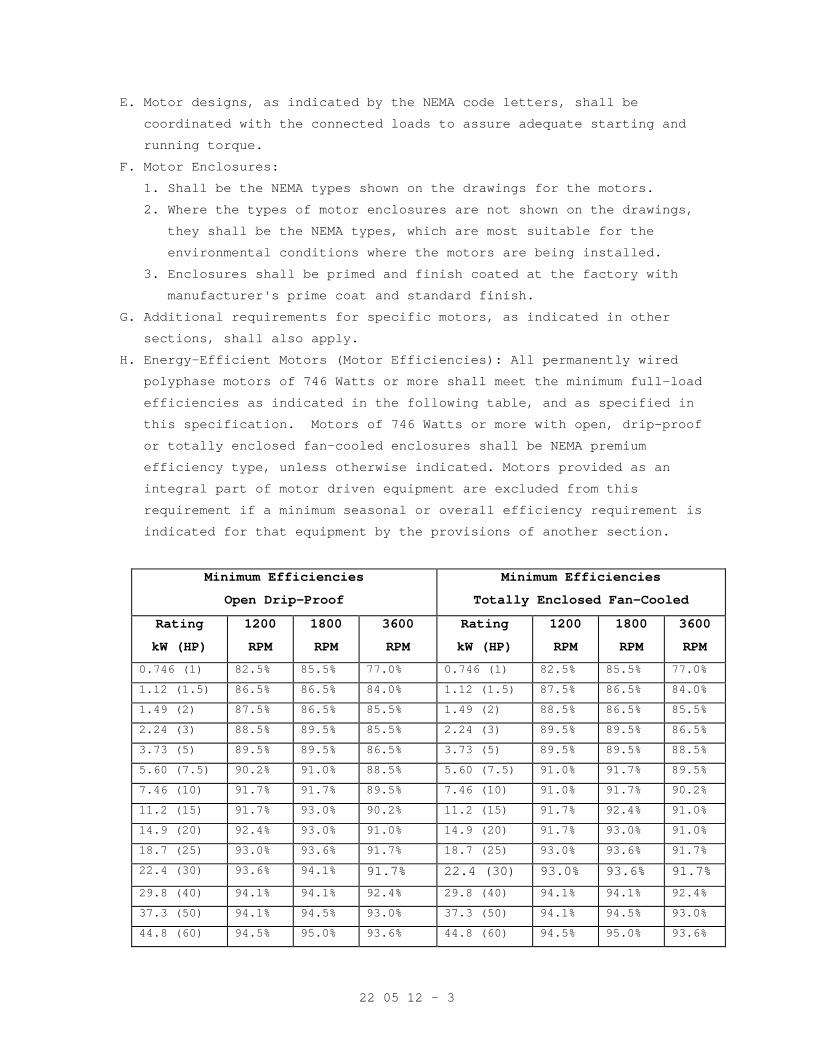
22 05 12 - 3
E. Motor designs, as indicated by the NEMA code letters, shall be
coordinated with the connected loads to assure adequate starting and
running torque.
F. Motor Enclosures:
1. Shall be the NEMA types shown on the drawings for the motors.
2. Where the types of motor enclosures are not shown on the drawings,
they shall be the NEMA types, which are most suitable for the
environmental conditions where the motors are being installed.
3. Enclosures shall be primed and finish coated at the factory with
manufacturer's prime coat and standard finish.
G. Additional requirements for specific motors, as indicated in other
sections, shall also apply.
H. Energy-Efficient Motors (Motor Efficiencies): All permanently wired
polyphase motors of 746 Watts or more shall meet the minimum full-load
efficiencies as indicated in the following table, and as specified in
this specification. Motors of 746 Watts or more with open, drip-proof
or totally enclosed fan-cooled enclosures shall be NEMA premium
efficiency type, unless otherwise indicated. Motors provided as an
integral part of motor driven equipment are excluded from this
requirement if a minimum seasonal or overall efficiency requirement is
indicated for that equipment by the provisions of another section.
Minimum Efficiencies
Open Drip-Proof
Minimum Efficiencies
Totally Enclosed Fan-Cooled
Rating
kW (HP)
1200
RPM
1800
RPM
3600
RPM
Rating
kW (HP)
1200
RPM
1800
RPM
3600
RPM
0.746 (1) 82.5% 85.5% 77.0% 0.746 (1) 82.5% 85.5% 77.0%
1.12 (1.5) 86.5% 86.5% 84.0% 1.12 (1.5) 87.5% 86.5% 84.0%
1.49 (2) 87.5% 86.5% 85.5% 1.49 (2) 88.5% 86.5% 85.5%
2.24 (3) 88.5% 89.5% 85.5% 2.24 (3) 89.5% 89.5% 86.5%
3.73 (5) 89.5% 89.5% 86.5% 3.73 (5) 89.5% 89.5% 88.5%
5.60 (7.5) 90.2% 91.0% 88.5% 5.60 (7.5) 91.0% 91.7% 89.5%
7.46 (10) 91.7% 91.7% 89.5% 7.46 (10) 91.0% 91.7% 90.2%
11.2 (15) 91.7% 93.0% 90.2% 11.2 (15) 91.7% 92.4% 91.0%
14.9 (20) 92.4% 93.0% 91.0% 14.9 (20) 91.7% 93.0% 91.0%
18.7 (25) 93.0% 93.6% 91.7% 18.7 (25) 93.0% 93.6% 91.7%
22.4 (30) 93.6% 94.1% 91.7% 22.4 (30) 93.0% 93.6% 91.7%
29.8 (40) 94.1% 94.1% 92.4% 29.8 (40) 94.1% 94.1% 92.4%
37.3 (50) 94.1% 94.5% 93.0% 37.3 (50) 94.1% 94.5% 93.0%
44.8 (60) 94.5% 95.0% 93.6% 44.8 (60) 94.5% 95.0% 93.6%
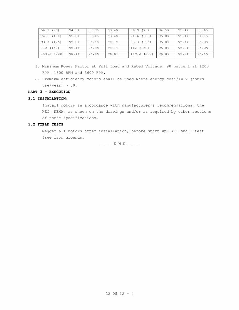
22 05 12 - 4
56.9 (75) 94.5% 95.0% 93.6% 56.9 (75) 94.5% 95.4% 93.6%
74.6 (100) 95.0% 95.4% 93.6% 74.6 (100) 95.0% 95.4% 94.1%
93.3 (125) 95.0% 95.4% 94.1% 93.3 (125) 95.0% 95.4% 95.0%
112 (150) 95.4% 95.8% 94.1% 112 (150) 95.8% 95.8% 95.0%
149.2 (200) 95.4% 95.8% 95.0% 149.2 (200) 95.8% 96.2% 95.4%
I. Minimum Power Factor at Full Load and Rated Voltage: 90 percent at 1200
RPM, 1800 RPM and 3600 RPM.
J. Premium efficiency motors shall be used where energy cost/kW x (hours
use/year) > 50.
PART 3 - EXECUTION
3.1 INSTALLATION:
Install motors in accordance with manufacturer’s recommendations, the
NEC, NEMA, as shown on the drawings and/or as required by other sections
of these specifications.
3.2 FIELD TESTS
Megger all motors after installation, before start-up. All shall test
free from grounds.
- - - E N D - - -
22 05 19 - 1
SECTION 22 05 19 METERS AND GAGES FOR PLUMBING PIPING
PART 1 - GENERAL
1.1 DESCRIPTION
Pressure gages.
1.2 RELATED WORK
Section 22 05 11, COMMON WORK RESULTS FOR PLUMBING.
1.3 SUBMITTALS
A. Submit in accordance with Section 01 33 23, SHOP DRAWINGS, PRODUCT
DATA, AND SAMPLES.
B. Manufacturer's Literature and Data:
1. Pressure Gages.
1.4 APPLICABLE PUBLICATIONS
A. The publications listed below form a part of this specification to the
extent referenced. The publications are referenced in the text by the
basic designation only.
B. American National Standards Institute (ANSI):
American Society of Mechanical Engineers (ASME): (Copyrighted Society)
B40.1-01................Gauges-Pressure Indicating Dial Type-Elastic
C. National Association of Plumbing - Heating - Cooling Contractors
(PHCC):
National Standard Plumbing Code - 1996
PART 2 - PRODUCTS
2.1 PRESSURE GAGES FOR WATER AND SEWAGE USAGE
A. ANSI B40.1 all metal case 114 mm (4-1/2 inches) diameter, bottom
connected throughout, graduated as required for service, and identity
labeled. Range shall be 1375 kPa (0 to psi) gauge.
PART 3 - EXECUTION
3.1 INSTALLATION
A. General: Comply with the PHCC National Standard Plumbing Code and
manufacturers’ recommendations.
- - - E N D - - -
22 05 23 - 1
SECTION 22 05 23 GENERAL-DUTY VALVES FOR PLUMBING PIPING
PART 1 - GENERAL
1.1 DESCRIPTION
A. General-duty valves for domestic water and sewer systems.
1.2 RELATED WORK
A. Section 22 05 11, COMMON WORK RESULTS FOR PLUMBING.
1.3 SUBMITTALS
A. Submit in accordance with Section 01 33 23, SHOP DRAWINGS, PRODUCT
DATA, AND SAMPLES.
B. Manufacturer's Literature and Data:
1. Valves.
2. Backflow Preventers.
3. Pressure Reducing Valves.
4. All items listed in Part 2 - Products.
1.4 APPLICABLE PUBLICATIONS
A. The publications listed below form a part of this specification to the
extent referenced. The publications are referenced in the text by the
basic designation only.
B. American Society for Testing and Materials (ASTM):
A536-84(R1999) E1.......Ductile Iron Castings
C. National Association of Plumbing - Heating - Cooling Contractors
(PHCC):
National Standard Plumbing Code - 1996
D. Manufacturers Standardization Society of the Valve and Fittings
Industry, Inc. (MSS):
SP-70-98................Cast Iron Gate Valves, Flanged and Threaded
Ends.
SP-72-99................Ball Valves With Flanged or Butt Welding For
General Purpose
SP-80-03................Bronze Gate, Globe, Angle and Check Valves.
SP-110-96...............Ball Valve Threaded, Socket Welding, Solder
Joint, Grooved and Flared Ends
E. American Society of Sanitary Engineers (ASSE):
1013-99.................Reduced Pressure Principle Backflow Preventers
1015-99.................Double Check Backflow Prevention Assembly
22 05 23 - 2
PART 2 - PRODUCTS
2.1 VALVES
A. Asbestos packing is prohibited.
B. Shut-off:
1. Cold, Hot and Recirculating Hot Water:
a. Fifty millimeter (2 inches) and smaller:
1) Ball, Mss SP-72, SP-110, Type II, Class 125, Style 1, three
piece or double union end construction, full ported, full
flow, with solder end connections, 2750 kPa (400 psi) WOG,
MSS-SP-67.
b. Less than 100 mm (4 inches): Butterfly, iron body, aluminum
bronze disc, 416 stainless steel stem, EPDM seat, wafer design,
lever operator to six 150 mm (6 inch )size, , 1375 kPa (200
pound) WOG, Fed. Spec WW-V-1967.
c. One hundred millimeters (4 inches) and larger:
1) Gate, MSS-SP-70, wedge disc, class 125, cast iron body with
bronze trim, flanged, gear operated and crank for 200 mm (8
inches) and above.
2) Grooved end butterfly valves with ductile iron body and disc
core ASTM A536. Disc rubber coated with compatible material
for intended service, maximum working pressure 2050 kPa (300
pounds psi) grooved ends for connection with mechanical
grooved couplings.
2. Reagent Grade Water: Shall be ball type of same material as used for
pipe.
C. Balancing:
1. Hot Water Recirculating, 50 mm (2 inches) and smaller: Combination
type, calibrated, bronze with bronze disc, equipped with readout
valves with integral check valve, indexing position pointer and
calibrated name plate, internal EPT 0-ring seals and factory molded
insulating enclosures.
2. Larger than 50 mm (2 inches): Combination balancing and shut-off,
non-lubricated eccentric plug type with cast iron or semi-steel
body, electroless nickel plated cast iron plug, with resilient
facing suitable for continuous water service up to 80 °C (180 °F),
bronze bearings, 1200 kPa (175 pound) WOG rating and an adjustable
open position memory stop and lever.
22 05 23 - 3
D. Check:
1. Less than 100 mm (3 inches) and smaller): Bronze body and trim,
swing type, MSS-SP-80, 850 kPa (125 pound) WSP.
2. Larger than 100 mm (4 inches and larger):
a. Iron body, bronze trim, swing type, vertical or horizontal
installation, flange connections, 1375 kPa (200 pound) WOG.
b. Ductile iron (ASTM A536) or malleable iron (ASTM A47) body,
stainless steel or aluminum bronze trim, dual disc, spring
loaded, non-slamming design with grooved ends for connection with
mechanical grooved couplings. Consult manufacturer for
appropriate elastomeric seal for intended service. Maximum
working pressure 3450 kPa (500 pounds psi), depending on size.
E. Globe:
1. Eighty millimeters (3 inches) or smaller: Bronze body and bonnet,
MSS-SP-80, 850 kPa (125 pound) WSP. Disk shall be free to swivel on
the stem. Composition seating surface disk construction may be
substituted for all metal disk construction. Packing shall be a
woven non-asbestos material, impregnated with not less than 25
percent, by weight, tetrafluoroethylene resin.
2. Larger than 80 mm (3 inches): Similar to above, except with cast
iron body and bronze trim.
2.2 WATER PRESSURE REDUCING VALVE AND CONNECTIONS
A. Single-seated, for dead end service for 200 to 850 kPa (30 to 125
pounds) range on low pressure side. Composition diaphragm and stainless
steel springs, bronze body with threaded connections for sizes 15 to 55
mm (1/2 to 2 inch), cast iron or semi-steel body with brass or bronze
trimmings and flanged connections for sizes 15 to 50 mm (2-1/2 to 4
inch).
B. Operation: Diaphragm and spring to act directly on valve stem.
Delivered pressure shall vary not more than one kPa for each 10 kPa
(one pound for each 10 pounds) variation on inlet pressure.
C. Setting: Entering water pressure, discharge pressure, capacity, size,
and related measurements shall be as shown on the drawings.
D. Connections Valves and Strainers: Install shut off valve on each side
of reducing valve and full sized bypass with globe valve. Install
strainer on inlet side of, and same size as pressure reducing valve.
Install pressure gage on low pressure side of line.
22 05 23 - 4
2.3 BACKWATER VALVE
Flap type, hinged or pivoted, with revolving disc. Cast iron body with
cleanout of sufficient size to permit removal of interior parts. Hinge,
pivot, disc and seat shall be nonferrous metal. Normal position of disc
shall be slightly open. Extend the cleanout to the finished floor and
fit with threaded countersunk plug. Provide clamping device wherever
the cleanout extends through the membrane waterproofing.
2.4 BACKFLOW PREVENTERS
A. Provide a backflow prevention device at any point in the plumbing
system where the potable water supply comes in contact with a potential
source of contamination. Device shall be certified by the American
Society of Sanitary Engineers. Listed below is a partial list of
connection to the potable water system which shall be protected against
backflow or back siphonage.
B. Reduced Pressure Backflow Preventer: ASSE 1013.
1. Dialysis, Deionized or Reverse Osmosis Water Systems.
2. Water make-up to heating systems, cooling tower, chilled water
system, and generators.
C. Pressure Type: ASSE 1020
1. Water make-up to heating systems, cooling tower, chilled water
system, and generators.
D. Atmospheric Vacuum Breaker: ASSE 1001
1. Hose bibs and sinks w/threaded outlets.
2. Disposers.
3. Showers (telephone type).
E. Double Check Detector Backflow Prevention Assembly: Fire service. ASSE
1015.
PART 3 - EXECUTION
3.1 INSTALLATION
A. General: Comply with the PHCC National Standard Plumbing Code and the
following:
1. Install valves with stem in horizontal position whenever possible.
All valves shall be easily accessible. Install valve in each water
connection to fixture.
2. Install union and shut-off valve on pressure piping at connections
to equipment.
3. Backflow prevention device shall be installed in an accessible
location, 5 (five) feet above finish floor.

22 05 23 - 5
- - E N D - - -
22 13 00 - 1
SECTION 22 13 00 FACILITY SANITARY SEWERAGE
PART 1 - GENERAL
1.1 DESCRIPTION
Sanitary sewerage systems, including piping, equipment and all
necessary accessories as designated in this section.
1.2 RELATED WORK
A. Penetrations in rated enclosures: Section 07 84 00, FIRESTOPPING.
B. Preparation and finish painting and identification of piping systems:
Section 09 91 00, PAINTING.
C. Section 22 05 11, COMMON WORK RESULTS FOR PLUMBING.
D. Pipe Insulation: Section 23 07 11, HVAC AND PLUMBING INSULATION.
1.3 SUBMITTALS
A. Submit in accordance with Section 01 33 23, SHOP DRAWINGS, PRODUCT
DATA, AND SAMPLES.
B. Manufacturer's Literature and Data:
1. Piping.
2. Floor Drains.
3. Cleanouts.
4. All items listed in Part 2 - Products.
C. Detailed shop drawing of clamping device and extensions when required
in connection with the waterproofing membrane or the floor drain.
1.4 APPLICABLE PUBLICATIONS
A. The publications listed below form a part of this specification to the
extent referenced. The publications are referenced in the text by the
basic designation only.
B. American National Standards Institute (ANSI):
American Society of Mechanical Engineers (ASME): (Copyrighted Society)
A112.1.1M-91............Floor Drains ANSI/ASME
A13.1-96................Scheme for Identification of Piping Systems
B16.3-98................Malleable Iron Threaded Fittings ANSI/ASME
B16.4-98................Cast Iron Threaded Fittings Classes 125 and 250
ANSI/ASME
B16.12-98...............Cast Iron Threaded Drainage Fittings ANSI/ASME
B16.15-85(R 1994).......Cast Bronze Threaded Fittings ANSI/ASME
Element ANSI/ASME
22 13 00 - 2
C. American Society for Testing and Materials (ASTM):
A47-99..................Ferritic Malleable Iron Castings Revision 1989
A53-02..................Pipe, Steel, Black And Hot-Dipped, Zinc-coated
Welded and Seamless
A74-03..................Cast Iron Soil Pipe and Fittings
A183-83(R1998)..........Carbon Steel Track Bolts and Nuts
A536-84(R1999) E1.......Ductile Iron Castings
B32-03..................Solder Metal
B75-99(Rev A)...........Seamless Copper Tube
B306-02.................Copper Drainage Tube (DWV)
B584-00.................Copper Alloy Sand Castings for General
Applications Revision A
C564-03.................Rubber Gaskets for Cast Iron Soil Pipe and
Fittings
D. National Association of Plumbing - Heating - Cooling Contractors
(PHCC):
National Standard Plumbing Code - 1996
E. Cast Iron Soil Pipe Institute (CISPI):
301-04..................Hubless Cast Iron Soil and Fittings
F. International Association of Plumbing and Mechanical Officials (IAPMO):
Uniform Plumbing Code - 2000
IS6-93..................Installation Standard
G. American Society of Sanitary Engineers (ASSE):
1018-01.................Performance for trap seal primer valve-water
supply fed
H. Factory Mutual (FM):
a. Coupling Used in Hubless Cast Iron Systems for Drains, Waste and
Vent Systems.
I. Plumbing and Drainage Institute (PDI):
PDI WH-201..............Water Hammer Arrestor
PART 2 - PRODUCTS
2.1 SANITARY PIPING
A. Cast Iron Soil Pipe and Fittings: Used for pipe buried in or in contact
with earth and for extension of pipe to a distance of approximately
1500 mm (5 feet) outside of building walls and interior waste and vent
piping above grade. Pipe shall be bell and spigot, modified hub, or
plain end (no-hub) as required by selected jointing method:
1. Material, (Pipe and Fittings): ASTM A74, C1SP1-301, Service Class.
22 13 00 - 3
2. Joints: Provide any one of the following types to suit pipe
furnished.
a. Double seal, compression-type molded neoprene gasket. Gaskets
shall suit class of pipe being jointed.
b. Mechanical: Meet the requirements and criteria for pressure,
leak, deflection, and shear tests as outlined in Factory Mutual
No. 1680 for Class 1 couplings.
1) Stainless steel clamp type coupling of elastomeric sealing
sleeve, ASTM C564 and a Series 300 stainless steel shield and
clamp assembly. Sealing sleeve with center-stop to prevent
contact between pipes/fittings being joined shall be marked
ASTM C564.
2) Cast Iron coupling with neoprene gasket and stainless steel
bolts and nuts.
c. Mechanical Grooved Couplings: Shall consist of ductile iron (ASTM
A536, Grade 65-45-12), or malleable iron (ASTM A47, Grade 32510)
housings, a pressure responsive elastomeric gasket (ASTM D2000),
and steel track head bolts. Shall be for use on pipe and fittings
grooved to the manufacturer's specifications. Couplings and
fittings to be of the same manufacturer.
d. Adapters: Where service weight pipe is connected to extra heavy
pipe and extra heavy fittings of chair carriers, provide adapters
or similar system to make tight, leakproof joints.
B. Steel Pipe and Fittings: May be used for vent piping above grade.
1. Pipe Galvanized: ASTM A53, standard weight.
2. Fittings:
a. Soil, Waste and Drain Piping: Cast iron, ANSI B16.12, threaded,
galvanized.
b. Sanitary and Exhaust Vent Piping: Malleable iron, ANSI B16.3, or
cast iron, ANSI B16.4. All piping shall be of the same kind.
Couplings of vent piping may be standard couplings furnished with
pipe.
c. Unions: Tucker connection or equivalent type throughout.
22 13 00 - 4
d. Mechanical Grooved Couplings: Shall consist of ductile iron (ASTM
A536, Grade 65-45-12), or malleable iron (ASTM A47, Grade 32510)
housings, a pressure responsive elastomeric gasket (ASTM D2000),
and steel track head bolts. Shall be for use on pipe and fittings
grooved to the manufacturer's specifications. Couplings and
fittings to be of the same manufacturer.
C. Copper Tube, (DWV): May be used for piping above ground, except for
urinal drains.
1. Tube: ASTM B306.
2. Fittings:
a. Solder type.
b. Grooved fittings, 50 to 150 mm (2 to 6 inch) wrought copper
conforming to ASTM B75 C12200, 125 to 150 mm (5 to 6 inch) bronze
casting conforming to ASTM B584, CDA 844(81-3-7-9). Mechanical
grooved couplings, ductile iron, ASTM A536 (Grade 65-45-12), or
malleable iron, ASTM A47 (Grade 32510) housings, with EPDM
gasket, steel track head bolts, ASTM A183, coated with copper
colored alkyd enamel.
3. Joints: ASTM B32, 50/50, special alloy, lead free. Solder using non-
corrosive flux.
2.2 EXPOSED WASTE PIPING
A. Finished Room: Use full iron pipe size chrome plated brass piping for
exposed waste piping connecting fixtures, casework, cabinets, equipment
and reagent racks when not concealed by apron including those furnished
by the Government or specified in other sections.
1. Pipe: Fed. Spec. WW-P-351, standard weight.
2. Fittings: ANSI B16.15 cast bronze threaded fittings with chrome
finish, (125 and 250).
3. Nipples: ASTM B 687, Chromium-plated.
4. Unions: Brass or Bronze with chrome finish. Unions 65 mm (2-1/2
inches) and larger shall be flange type with approved gaskets.
B. Unfinished Rooms, Mechanical Rooms and Kitchens: Chrome-plated brass
piping is not required. Paint piping systems as specified in Section 09
91 00, PAINTING.
22 13 00 - 5
2.3 CLEANOUTS
A. Same size as the pipe, up to 100 mm (4 inches); not less than 100 mm (4
inches) for larger pipe. Cleanouts shall be easily accessible and shall
be gastight and watertight. Provide a minimum clearance of 600 mm (24
inches) for the rodding.
B. In Floors: Floor cleanouts shall have cast iron body and frame with
square adjustable scoriated secured nickel bronze top. Unit shall be
vertically adjustable for a minimum of 50 mm (2 inches). When a
waterproof membrane is used in the floor system, provide clamping
collars on the cleanouts. Cleanouts shall consist of "Y" fittings and 3
mm (1/8 inch) bends with brass or bronze screw plugs. Cleanouts in the
resilient tile floors, quarry tile and ceramic tile floors shall be
provided with square top covers recessed for tile insertion. In the
carpeted areas, provide carpet cleanout markers. Provide two way
cleanouts where indicated on drawings.
C. Provide cleanouts at or near the base of the vertical stacks with the
cleanout plug located approximately 600 mm (24 inches) above the floor.
If there are no fixtures installed on the lowest floor, the cleanout
shall be installed at the base of the stack. Extend the cleanouts to
the wall access cover. Cleanout shall consist of sanitary tees. Furnish
nickel-bronze square frame and stainless steel cover with minimum
opening of 150 by 150 mm (6 by 6 inches) at each wall cleanout. Where
the piping is concealed, a fixture trap or a fixture with integral
trap, readily removable without disturbing concealed roughing work,
shall be accepted as a cleanout equivalent providing the opening to be
used as a cleanout opening is the size required by the NPHCC National
Standard Plumbing Code.
D. In horizontal runs above grade, cleanouts shall consist of cast brass
tapered screw plug in fitting or caulked/no hub cast iron ferrule.
Plain end (no-hub) piping in interstitial space or above ceiling may
use plain end (no-hub) blind plug and clamp.
22 13 00 - 6
2.4 TRAPS
Provide on all sanitary branch waste connections from fixtures or
equipment not provided with traps. Exposed brass shall be polished
brass chromium plated with nipple and set screw escutcheons. Concealed
traps may be rough cast brass or same material as pipe connected to.
Slip joints not permitted on sewer side of trap. Traps shall correspond
to fittings on cast iron soil pipe or steel pipe respectively, and size
shall be as required by connected service or fixture.
2.5 TRAP PRIMERS
A. Trap Primer: Hydraulic.
1. Fifteen millimeter (1/2 inch) Inlet/fifteen millimeter (1/2 inch)
Outlet fully automatic, all brass trap primer valve, activated by a
drop in building water pressure, no adjustment required. Model for
one (1) to four (4) traps with distribution unit, may be located
anywhere in an active cold water line, as indicated on the drawings
or as required by code. ASSE Standard 1018. Omit distribution unit
when serving a single trap.
2.6 WATERPROOFING
A. Provide at points where pipes pass through membrane waterproofed floors
or walls in contact with earth.
B. Floors: Provide cast iron stack sleeve with flashing device and a
underdeck clamp. After stack is passed through sleeve, provide a
waterproofed caulked joint at top hub.
C. Walls: See detail shown on drawings.
2.7 DIELECTRIC FITTINGS
Provide dielectric couplings or unions between ferrous and non-ferrous
pipe.
PART 3 - EXECUTION
3.1 INSTALLATION
A. General: Comply with the PHCC National Standard Plumbing Code and the
following:
1. Install branch piping for waste from the respective piping systems
and connect to all fixtures, valves, cocks, outlets, casework,
cabinets and equipment, including those furnished by the Government
or specified in other sections.
2. Pipe shall be round and straight. Cutting shall be done with proper
tools. Pipe, except for plastic and glass, shall be reamed to full
size after cutting.
22 13 00 - 7
3. All pipe runs shall be laid out to avoid interference with other
work.
4. Install valves with stem in horizontal position whenever possible.
All valves shall be easily accessible. Install valve in each water
connection to fixture.
5. All gravity waste drain lines inside the building with vertical
drops over 6 m (20 feet) shall be provided with joint restraint on
the vertical drop and horizontal offset or branch below the vertical
drop. Joint restraint shall be accomplished by threaded, soldered,
lead and oakum or grooved joints or a combination of pipe clamps and
tie-rods as detailed in NFPA 24. Vertical joint restraint shall be
provided from the fitting at the bottom of the vertical drop through
every joint up to the riser clamp at the floor penetration of the
floor above. Horizontal joint restraint shall be provided from the
same fitting at the bottom of the vertical drop through every joint
on the horizontal offset or branch for a minimum of 18 m (60 feet)
or to anchoring point from the building structure. Joint restraint
below ground shall be accomplished by thrust blocks detailed in NFPA
24.
6. Pipe Hangers, Supports and Accessories:
a. All piping shall be supported per of the National Standard
Plumbing Code, Chapter No. 8.
b. Shop Painting and Plating: Hangers, supports, rods, inserts and
accessories used for Pipe supports shall be shop coated with red
lead or zinc Chromate primer paint. Electroplated copper hanger
rods, hangers and accessories may be used with copper tubing.
c. Floor, Wall and Ceiling Plates, Supports, Hangers:
1) Solid or split unplated cast iron.
2) All plates shall be provided with set screws.
3) Pipe Hangers: Height adjustable clevis type.
4) Adjustable Floor Rests and Base Flanges: Steel.
5) Concrete Inserts: "Universal" or continuous slotted type.
6) Hanger Rods: Mild, low carbon steel, fully threaded or
Threaded at each end with two removable nuts at each end for
positioning rod and hanger and locking each in place.
7) Riser Clamps: Malleable iron or steel.
8) Rollers: Cast iron.
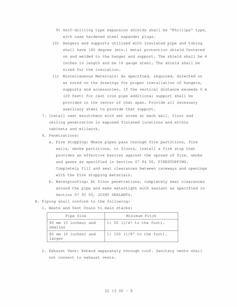
22 13 00 - 8
9) Self-drilling type expansion shields shall be "Phillips" type,
with case hardened steel expander plugs.
10) Hangers and supports utilized with insulated pipe and tubing
shall have 180 degree (min.) metal protection shield Centered
on and welded to the hanger and support. The shield shall be 4
inches in length and be 16 gauge steel. The shield shall be
sized for the insulation.
11) Miscellaneous Materials: As specified, required, directed or
as noted on the drawings for proper installation of hangers,
supports and accessories. If the vertical distance exceeds 6 m
(20 feet) for cast iron pipe additional support shall be
provided in the center of that span. Provide all necessary
auxiliary steel to provide that support.
7. Install cast escutcheon with set screw at each wall, floor and
ceiling penetration in exposed finished locations and within
cabinets and millwork.
8. Penetrations:
a. Fire Stopping: Where pipes pass through fire partitions, fire
walls, smoke partitions, or floors, install a fire stop that
provides an effective barrier against the spread of fire, smoke
and gases as specified in Section 07 84 00, FIRESTOPPING.
Completely fill and seal clearances between raceways and openings
with the fire stopping materials.
b. Waterproofing: At floor penetrations, completely seal clearances
around the pipe and make watertight with sealant as specified in
Section 07 92 00, JOINT SEALANTS.
B. Piping shall conform to the following:
1. Waste and Vent Drain to main stacks:
Pipe Size Minimum Pitch
80 mm (3 inches) and smaller
1: 50 (1/4" to the foot).
80 mm (4 inches) and larger
1: 100 (1/8" to the foot).
2. Exhaust Vent: Extend separately through roof. Sanitary vents shall
not connect to exhaust vents.
22 13 00 - 9
3.2 TESTS
A. General: Test system either in its entirety or in sections.
B. Waste Systems: Conduct before trenches are backfilled or fixtures are
connected. Conduct water test or air test, as directed.
1. Water Test: If entire system is tested, tightly close all openings
in pipes except highest opening, and fill system with water to point
of overflow. If system is tested in sections, tightly plug each
opening except highest opening of section under test, fill each
section with water and test with at least a 3 m (10 foot) head of
water. In testing successive sections, test at least upper 3 m (10
feet) of next preceding section so that each joint or pipe except
upper most 3 m (10 feet) of system has been submitted to a test of
at least a 3 m (10 foot) head of water. Keep water in system, or in
portion under test, for at least 15 minutes before inspection
starts. System shall then be tight at all joints.
2. Air Test: Maintain air pressure of 35 kPa (5 psi) gage for at least
15 minutes without leakage. Use force pump and mercury column gage.
3. Final Tests: Either one of the following tests may be used.
a. Smoke Test: After fixtures are permanently connected and traps
are filled with water, fill entire drainage and vent systems with
smoke under pressure of 1.3 kPa (one inch of water) with a smoke
machine. Chemical smoke is prohibited.
b. Peppermint Test: Introduce (two ounces) of peppermint into each
line or stack.
- - - E N D - - -
22 14 00 - 1
SECTION 22 14 00 FACILITY STORM DRAINAGE
PART 1 - GENERAL
1.1 DESCRIPTION
Storm drainage systems, including piping and all necessary accessories
as designated in this section.
1.2 RELATED WORK
A. Penetrations in rated enclosures: Section 07 84 00, FIRESTOPPING.
B. Preparation and finish painting and identification of piping systems:
Section 09 91 00, PAINTING.
C. Section 22 05 11, COMMON WORK RESULTS FOR PLUMBING.
D. Pipe Insulation: Section 23 07 11, HVAC AND PLUMBING INSULATION.
1.3 SUBMITTALS
A. Submit in accordance with Section 01 33 23, SHOP DRAWINGS, PRODUCT
DATA, AND SAMPLES.
B. Manufacturer's Literature and Data:
1. Piping.
2. Roof Drains.
3. Cleanouts.
4. All items listed in Part 2 - Products.
C. Detailed shop drawing of clamping device and extensions when required
in connection with the waterproofing membrane.
1.4 APPLICABLE PUBLICATIONS
A. The publications listed below form a part of this specification to the
extent referenced. The publications are referenced in the text by the
basic designation only.
B. Federal Specifications (Fed. Spec.):
A-A-59617...............Unions, Brass or Bronze Threaded, Pipe
Connections and Solder-Joint Tube Connections
C. American National Standards Institute (ANSI):
American Society of Mechanical Engineers (ASME): (Copyrighted Society)
A13.1-96................Scheme for Identification of Piping Systems
B16.3-98................Malleable Iron Threaded Fittings ANSI/ASME
B16.9-01................Factory-Made Wrought Steel Buttwelding Fittings
ANSI/ASME
B16.11-01...............Forged Steel Fittings, Socket-Welding and
Threaded ANSI/ASME
B16.12-98...............Cast Iron Threaded Drainage Fittings ANSI/ASME
22 14 00 - 2
B16.15-85(R 1994).......Cast Bronze Threaded Fittings ANSI/ASME
B16.18-01...............Cast Copper Alloy Solder-Joint Pressure
Fittings ANSI/ASME
B16.22-01...............Wrought Copper and Copper Alloy Solder Joint
Pressure Fittings ANSI/ASME
D. American Society for Testing and Materials (ASTM):
A47-99..................Ferritic Malleable Iron Castings Revision 1989
A53-02..................Pipe, Steel, Black And Hot-Dipped, Zinc-coated
Welded and Seamless
A74-03..................Cast Iron Soil Pipe and Fittings
A183-83(R1998)..........Carbon Steel Track Bolts and Nuts
A312-03.................Seamless and Welded Austenitic Stainless Steel
Pipe
A536-84(R1999) E1.......Ductile Iron Castings
A733-03.................Welded and Seamless Carbon Steel and Austenitic
Stainless Steel Pipe Nipples
B32-03..................Solder Metal
B61-02..................Steam or Bronze Castings
B62-02..................Composition Bronze or Ounce Metal Castings
B75-99(Rev A)...........Seamless Copper Tube
B88-03..................Seamless Copper Water Tube
B306-02.................Copper Drainage Tube (DWV)
B584-00.................Copper Alloy Sand Castings for General
Applications Revision A
B687-99.................Brass, Copper, and Chromium-Plated Pipe Nipples
C564-03.................Rubber Gaskets for Cast Iron Soil Pipe and
Fittings
D4101-03b Propylene Plastic Injection and Extrusion
Materials
E. American Welding Society (AWS):
A5.8-92.................Filler Metals for Brazing
F. National Association of Plumbing - Heating - Cooling Contractors
(PHCC):
National Standard Plumbing Code - 1996
G. Cast Iron Soil Pipe Institute (CISPI):
301-04..................Hubless Cast Iron Soil and Fittings
22 14 00 - 3
H. International Association of Plumbing and Mechanical Officials (IAPMO):
Uniform Plumbing Code - 2000
IS6-93..................Installation Standard
I. Manufacturers Standardization Society of the Valve and Fittings
Industry, Inc. (MSS):
SP-72-99................Ball Valves With Flanged or Butt Welding For
General Purpose
SP-110-96...............Ball Valve Threaded, Socket Welding, Solder
Joint, Grooved and Flared Ends
J. Factory Mutual (FM):
a. Coupling Used in Hubless Cast Iron Systems for Drains, Waste and
Vent Systems.
PART 2 - PRODUCTS
2.1 STORM WATER DRAIN AND VENT PIPING
A. Cast Iron Soil Pipe and Fittings: Used for pipe buried in or in contact
with earth and for extension of pipe to a distance of approximately
1500 mm (5 feet) outside of building walls and interior waste and vent
piping above grade. Pipe shall be bell and spigot, modified hub, or
plain end (no-hub) as required by selected jointing method:
1. Material, (Pipe and Fittings): ASTM A74, C1SP1-301, Service Class.
2. Joints: Provide any one of the following types to suit pipe
furnished.
a. Lead and oakum and caulked by hand.
b. Double seal, compression-type molded neoprene gasket. Gaskets
shall suit class of pipe being jointed.
c. Mechanical: Meet the requirements and criteria for pressure,
leak, deflection and shear tests as outlined in Factory Mutual
No. 1680 for Class 1 couplings.
1) Stainless steel clamp type coupling of elastomeric sealing
sleeve, ASTM C564 and a Series 300 stainless steel shield and
clamp assembly. Sealing sleeve with center-stop to prevent
contact between pipes/fittings being joined shall be marked
ASTM C564.
2) Cast Iron coupling with neoprene gasket and stainless steel
bolts and nuts.
22 14 00 - 4
d. Mechanical Grooved Couplings: Shall consist of ductile iron (ASTM
A536, Grade 65-45-12), or malleable iron (ASTM A47, Grade 32510)
housings, a pressure responsive elastomeric gasket (ASTM D2000),
and steel track head bolts. Shall be for use on pipe and fittings
grooved to the manufacturer's specifications. Couplings and
fittings to be of the same manufacturer.
e. Adapters: Where service weight pipe is connected to extra heavy
pipe and extra heavy fittings of chair carriers, provide adapters
or similar system to make tight, leakproof joints.
B. Steel Pipe and Fittings: May be used for vent piping and storm water
piping above grade.
1. Pipe Galvanized: ASTM A53, standard weight.
2. Fittings:
a. Drain Piping: Cast iron, ANSI B16.12, threaded, galvanized.
c. Unions: Tucker connection or equivalent type throughout.
d. Mechanical Grooved Couplings: Shall consist of ductile iron (ASTM
A536, Grade 65-45-12), or malleable iron (ASTM A47, Grade 32510)
housings, a pressure responsive elastomeric gasket (ASTM D2000),
and steel track head bolts. Shall be for use on pipe and fittings
grooved to the manufacturer's specifications. Couplings and
fittings to be of the same manufacturer.
C. Copper Tube, (DWV): May be used for piping above ground.
1. Tube: ASTM B306.
2. Fittings:
a. Solder type.
b. Grooved fittings, 50 to 150 mm (2 to 6 inch) wrought copper
conforming to ASTM B75 C12200, 125 to 150 mm (5 to 6 inch) bronze
casting conforming to ASTM B584, CDA 844(81-3-7-9). Mechanical
grooved couplings, ductile iron, ASTM A536 (Grade 65-45-12), or
malleable iron, ASTM A47 (Grade 32510) housings, with EPDM
gasket, steel track head bolts, ASTM A183, coated with copper
colored alkyd enamel.
3. Joints: ASTM B32, 50/50, special alloy, lead free. Solder using
non-corrosive flux.
22 14 00 - 5
2.2 CLEANOUTS
A. Same size as the pipe, up to 100 mm (4 inches); not less than 100 mm (4
inches) for larger pipe. Cleanouts for chemical waste drain pipe shall
be of same material as the pipe. Cleanouts shall be easily accessible
and shall be gastight and watertight. Provide a minimum clearance of
600 mm (24 inches) for the rodding.
B. In Floors: Floor cleanouts shall have cast iron body and frame with
square adjustable scoriated secured nickel bronze top. Unit shall be
vertically adjustable for a minimum of 50 mm (2 inches). When a
waterproof membrane is used in the floor system, provide clamping
collars on the cleanouts. Cleanouts shall consist of "Y" fittings and 3
mm (1/8 inch) bends with brass or bronze screw plugs. Cleanouts in the
resilient tile floors, quarry tile and ceramic tile floors shall be
provided with square top covers recessed for tile insertion. In the
carpeted areas, provide carpet cleanout markers. Provide two way
cleanouts where indicated on drawings.
C. Provide cleanouts at or near the base of the vertical stacks with the
cleanout plug located approximately 600 mm (24 inches) above the floor.
If there are no fixtures installed on the lowest floor, the cleanout
shall be installed at the base of the stack. Extend the cleanouts to
the wall access cover. Cleanout shall consist of sanitary tees. Furnish
nickel-bronze square frame and stainless steel cover with minimum
opening of 150 by 150 mm (6 by 6 inches) at each wall cleanout. Where
the piping is concealed, a fixture trap or a fixture with integral
trap, readily removable without disturbing concealed roughing work,
shall be accepted as a cleanout equivalent providing the opening to be
used as a cleanout opening is the size required by the NPHCC National
Standard Plumbing Code.
D. In horizontal runs above grade, cleanouts shall consist of cast brass
tapered screw plug in fitting or caulked/no hub cast iron ferrule.
Plain end (no-hub) piping in interstitial space or above ceiling may
use plain end (no-hub) blind plug and clamp.

22 14 00 - 6
2.3 ROOF DRAINS AND CONNECTIONS
A. Roof Drains: Cast iron with clamping device for making watertight
connection. Free openings through strainer shall be twice area of drain
outlet. For roof drains not installed in connection with a waterproof
membrane, provide a soft copper membrane 300 mm (12 inches) in diameter
greater than outside diameter of drain collar. Provide an integral
gravel stop for drains installed on roofs having built-up roofing
covered with gravel or slag. Provide integral no-hub, soil pipe gasket
or threaded outlet connection.
1. Flat Roofs: Beehive or dome shaped strainer with integral flange not
less than 300 mm (12 inches) in diameter. For insulated roofs,
provide a roof drain with an adjustable drainage collar, which can
be raised or lowered to meet required insulation heights, sump
receiver and deck clamp. Bottom section shall serve as roof drain
during construction before insulation is installed.
2. Canopy Roofs: Beehive or dome shaped strainer with the integral
flange not larger than 200 mm (8 inches) in diameter. For insulated
roof provide a roof drain with an adjustable drainage collar, which
can be raised or lowered to meet the required insulation heights,
sump receiver and deck clamp. Bottom section shall serve as roof
drain during construction before insulation is installed.
3. Protective Roof Membrane Insulation Assembly: Perforated stainless
steel extension filter, non-puncturing clamp ring, large sump with
extra wide roof flange and deck clamp.
a. Non-pedestrian Roofs: Large polypropylene or aluminum locking
dome.
b. Pedestrian Roof: Bronze promenade top 350 mm (14 inches) square,
set in square secured frame support collar.
B. Expansion Joints: Heavy cast iron with cast brass or copper expansion
sleeve having smooth bearing surface working freely against a packing
ring held in place and under pressure of a bolted gland ring, forming a
water and air tight flexible joint. Asbestos packing is prohibited.
C. Interior Downspouts: Provide an expansion joint, specified above, at
top of run on straight, vertical runs of downspout piping 12 m (40
feet) long or more.
D. Downspout Nozzle: The nozzle fitting shall be of brass, unfinished,
with internal pipe thread for connection to downspout.
22 14 00 - 7
2.4 WATERPROOFING
A. Provide at points where pipes pass through membrane waterproofed floors
or walls in contact with earth.
B. Floors: Provide cast iron stack sleeve with flashing device and a
underdeck clamp. After stack is passed through sleeve, provide a
waterproofed caulked joint at top hub.
C. Walls: See detail shown on drawings.
PART 3 - EXECUTION
3.1 INSTALLATION
A. General: Comply with the PHCC National Standard Plumbing Code and the
following:
1. Install branch piping from the piping system and connect to all
fixtures, valves, cocks, outlets, casework, cabinets and equipment,
including those furnished by the Government or specified in other
sections.
2. Pipe shall be round and straight. Cutting shall be done with proper
tools. Pipe, except for plastic and glass, shall be reamed to full
size after cutting.
3. All pipe runs shall be laid out to avoid interference with other
work.
4. Install union and shut-off valve on pressure piping at connections
to equipment.
5. All gravity waste drain lines inside the building with vertical
drops over 6 m (20 feet) shall be provided with joint restraint on
the vertical drop and horizontal offset or branch below the vertical
drop. Joint restraint shall be accomplished by threaded, soldered,
lead and oakum or grooved joints or a combination of pipe clamps and
tie-rods as detailed in NFPA 24. Vertical joint restraint shall be
provided from the fitting at the bottom of the vertical drop through
every joint up to the riser clamp at the floor penetration of the
floor above. Horizontal joint restraint shall be provided from the
same fitting at the bottom of the vertical drop through every joint
on the horizontal offset or branch for a minimum of 18 m (60 feet)
or to anchoring point from the building structure. Joint restraint
below ground shall be accomplished by thrust blocks detailed in NFPA
24.
22 14 00 - 8
6. Pipe Hangers, Supports And Accessories:
a. All piping shall be supported per of the National Standard
Plumbing Code, Chapter No. 8.
b. Shop Painting and Plating: Hangers, supports, rods, inserts and
accessories used for Pipe supports shall be shop coated with red
lead or zinc Chromate primer paint. Electroplated copper hanger
rods, hangers and accessories may be used with copper tubing.
c. Floor, Wall and Ceiling Plates, Supports, Hangers:
1) Solid or split unplated cast iron.
2) All plates shall be provided with set screws.
3) Pipe Hangers: Height adjustable clevis type.
4) Adjustable Floor Rests and Base Flanges: Steel.
5) Concrete Inserts: "Universal" or continuous slotted type.
6) Hanger Rods: Mild, low carbon steel, fully threaded or
Threaded at each end with two removable nuts at each end for
positioning rod and hanger and locking each in place.
7) Riser Clamps: Malleable iron or steel.
8) Rollers: Cast iron.
9) Self-drilling type expansion shields shall be "Phillips" type,
with case hardened steel expander plugs.
10) Hangers and supports utilized with insulated pipe and tubing
shall have 180 degree (min.) metal protection shield Centered
on and welded to the hanger and support. The shield shall be 4
inches in length and be 16 gauge steel. The shield shall be
sized for the insulation.
11) Miscellaneous Materials: As specified, required, directed or
as noted on the drawings for proper installation of hangers,
supports and accessories. If the vertical distance exceeds 6 m
(20 feet) for cast iron pipe additional support shall be
provided in the center of that span. Provide all necessary
auxiliary steel to provide that support.
7. Install cast escutcheon with set screw at each wall, floor and
ceiling penetration in exposed finished locations and within
cabinets and millwork.
22 14 00 - 9
8. Penetrations:
a. Fire Stopping: Where pipes pass through fire partitions, fire
walls, smoke partitions, or floors, install a fire stop that
provides an effective barrier against the spread of fire, smoke
and gases as specified in Section 07 84 00, FIRESTOPPING.
Completely fill and seal clearances between raceways and openings
with the fire stopping materials.
b. Waterproofing: At floor penetrations, completely seal clearances
around the pipe and make watertight with sealant as specified in
Section 07 92 00, JOINT SEALANTS.
B. Piping shall conform to the following:
1. Storm Water Drain and Vent Drain to main stacks:
Pipe Size Minimum Pitch
80 mm (3 inches) and smaller
1: 50 (1/4" to the foot).
80 mm (4 inches) and larger
1: 100 (1/8" to the foot).
2. Exhaust Vent: Extend separately through roof. Sanitary vents shall
not connect to exhaust vents.
3.2 TESTS
A. General: Test system either in its entirety or in sections.
B. Storm Water Drain: Conduct before trenches are backfilled or fixtures
are connected. Conduct water test or air test, as directed.
1. Water Test: If entire system is tested, tightly close all openings
in pipes except highest opening, and fill system with water to point
of overflow. If system is tested in sections, tightly plug each
opening except highest opening of section under test, fill each
section with water and test with at least a 3 m (10 foot) head of
water. In testing successive sections, test at least upper 3 m (10
feet) of next preceding section so that each joint or pipe except
upper most 3 m (10 feet) of system has been submitted to a test of
at least a 3 m (10 foot) head of water. Keep water in system, or in
portion under test, for at least 15 minutes before inspection
starts. System shall then be tight at all joints.
2. Air Test: Maintain air pressure of 35 kPa (5 psi) gage for at least
15 minutes without leakage. Use force pump and mercury column gage.
22 14 00 - 10
3. Final Tests: Either one of the following tests may be used.
a. Smoke Test: After fixtures are permanently connected and traps
are filled with water, fill entire drainage and vent systems with
smoke under pressure of 1.3 kPa (one inch of water) with a smoke
machine. Chemical smoke is prohibited.
b. Peppermint Test: Introduce (two ounces) of peppermint into each
line or stack.
- - - E N D - - -
22 14 29 - 1
SECTION 22 14 29 SUMP PUMPS
PART 1 - GENERAL
1.1 DESCRIPTION
Sump pumps.
1.2 RELATED WORK
A. Section 22 05 11, COMMON WORK RESULTS FOR PLUMBING.
B. Section 22 05 12, GENERAL MOTOR REQUIREMENTS FOR PLUMBING EQUIPMENT.
1.3 SUBMITTALS
A. Submit in accordance with Section 01 33 23, SHOP DRAWINGS, PRODUCT DATA,
AND SAMPLES.
B. Manufacturer's Literature and Data:
1. Pump:
a. Manufacturer and model.
b. Operating speed.
c. Capacity.
d. Characteristic performance curves.
2. Motor:
a. Manufacturer.
b. Speed.
c. Current Characteristics and W (HP).
d. Efficiency.
C. Certified copies of all the factory and construction site test data
sheets and reports.
D. Complete operating and maintenance manuals including wiring diagrams,
technical data sheets and information for ordering replaceable parts:
1. Include complete connection which indicates all components of the
system.
2. Include complete diagrams of the internal wiring for each item of
equipment.
3. Diagrams shall have their terminals identified to facilitate
installation, operation and maintenance.
1.5 APPLICABLE PUBLICATIONS
A. The publications listed below form a part of this specification to the
extent referenced. The publications are referenced in the text by the
basic designation only.
22 14 29 - 2
B. National Electrical Manufacturers Association (NEMA):
ICS6-93 (R2001).........Industrial Control and Systems Enclosures
250-03..................Enclosures for Electrical Equipment (1000 Volts
Maximum)
C. Underwriters' Laboratories, Inc. (UL):
508-99 (R2002)..........Safety Industrial Control Equipment
PART 2 - PRODUCTS
2.1 SUMP PUMP
A. Centrifugal, vertical, submersible, designed for 93 degrees C (200
degrees F) maximum hot water service. Driver shall be electric motor.
Support shall be substantial rigid type. Provide perforated, nonferrous
suction trainer. Systems may include one, two, or more pumps with
alternator as required by conditions:
1. Pump housings may be cast iron, bronze, or stainless steel. Cast iron
housings for submersible pumps shall be epoxy coated.
B. Impeller: Brass or bronze.
C. Shaft: Bronze, stainless steel or other approved corrosion-resisting
metal.
D. Bearings: As required to hold shaft alignment, anti-friction type for
thrust. For vertical sump pumps, if bearings for shaft in sump require
lubrication, provide a method to lubricate bearings without opening the
sump or removing the pump.
E. Characteristics: Head capacity characteristics shall not permit
overloading at any point of the curve.
F. Motor: Maximum 40 degrees C ambient temperature rise, completely
enclosed, voltage and phase as shown in schedule on Electrical drawings
conforming to NEMA 250 Type 4. Motor capacity to operate pump without
overloading the motor. Refer to Section 22 05 12, GENERAL MOTOR
REQUIREMENTS FOR PLUMBING EQUIPMENT.
22 14 29 - 3
G. Automatic Control and Level Alarm: Furnish a control panel in a Nema 1
enclosure for indoors or in a Nema 4X enclosure for outdoors. The
controls shall be suitable for operation with the electrical
characteristics listed on the Electrical drawings. The control panel
shall have a level control system with switches to start and stop pumps
automatically, and to activate a high water alarm. The level control
system will include sensors in the sump that detect the level of the
liquid. The sensors may be float type switches, ultrasonic level
sensors, transducers, or other appropriate equipment. The high water
alarm shall have a red beacon light at the control panel and a buzzer,
horn, or bell. The alarm shall have a silencing switch. Provide
auxiliary contacts for remote alarming to the Energy Control Center
(ECC). The circuitry of the control panel shall include:
-power switch to turn on/off the automatic control mechanism
-HOA switches to manually override automatic control mechanism
-run lights to indicate when pumps are powered up
-level status lights to indicate when water in sump has reached the
predetermined on/off and alarm levels
-magnetic motor contactors
-disconnect/breaker for each pump
-automatic motor overload protection
1. Sensors that detect the level of water in the sump shall be so
arranged as to allow the accumulation of enough volume of liquid
below the normal on level that the pump will run for a minimum cycle
of one minute. Sensors shall be located to activate the alarm
adequately before the water level rises to the inlet pipe.
2. Provide two separate power supplies to the control panel, one for the
control/alarm circuitry and one for power to the pump motors. Each
power supply is to be fed from its own breaker so that if a pump
overload trips a breaker, the alarm system will still function. Each
power supply is to be wired in its own conduit.
3. Wiring from the sump to the control panel shall have separate
conduits for the pump power and for the sensor switches. All conduits
are to be sealed at the basin and at the control panel to prevent the
intrusion of moisture and of flammable and/or corrosive gases.
H. Sump: Sump shall be sized to allow an adequate volume of water to
accumulate for a minimum one minute cycle of pump operation.
22 14 29 - 4
I. Provide a check valve and gate valve in the discharge of each pump.
Where a submersible pump is installed, drill a 3/16” diameter vent hole
in the piping below the check valve beneath the cover of the sump, to
expel any air entrapped beneath the check valve.
J. Removal/Disconnect System: In a system utilizing a submersible pump,
where sump depth, pump size, or other conditions make removal of the
pump unusually difficult or unsafe, a removal/disconnect system shall be
provided. The system will consist of a discharge fitting mounted on
vertical guide rails attached to the sump. The pump shall be fitted with
an adapter fitting that easily connects to/disconnects from the
discharge fitting as the pump is raised from or lowered into the sump.
The discharge piping will connect to the discharge fitting so that it is
not necessary to disconnect any piping in order to remove the pump.
Where the sump depth is greater than five feet or other conditions exist
to make the removal of the pump difficult or hazardous, the system shall
include a rail guided quick disconnect apparatus to allow the pump to be
pulled up out of the sump without workers entering the sump and without
disconnecting the piping.
PART 3 - EXECUTION
3.1 TEST
A. Make tests as recommended by product manufacturer and listed standards
and under actual or simulated operating conditions and prove full
compliance with design and specified requirements. Tests of the various
items of equipment shall be performed simultaneously with the system of
which each item is an integral part.
B. When any defects are detected, correct defects and repeat test.
- - - E N D - - -
22 40 00 - 1
SECTION 22 40 00 PLUMBING FIXTURES
PART 1 - GENERAL
1.1 DESCRIPTION
Plumbing fixtures, associated trim and fittings necessary to make a
complete installation from wall or floor connections to rough piping,
and certain accessories.
1.2 RELATED WORK
A. Sealing between fixtures and other finish surfaces: Section 07 92 00,
JOINT SEALANTS.
B. Section 22 05 11, COMMON WORK RESULTS FOR PLUMBING.
1.3 SUBMITTALS
A. Submit in accordance with Section 01 33 23, SHOP DRAWINGS, PRODUCT DATA,
AND SAMPLES.
B. Submit plumbing fixture information in an assembled brochure, showing
cuts and full detailed description of each fixture.
1.4 APPLICABLE PUBLICATIONS
A. The publications listed below form a part of this specification to the
extent referenced. The publications are referenced in the text by the
basic designation only.
B. American National Standard Institute (ANSI):
The American Society of Mechanical Engineers (ASME):
A112.6.1M-02(R2008).....Floor Affixed Supports for Off-the-Floor
Plumbing Fixtures for Public Use
A112.19.1M-04...........Enameled Cast Iron Plumbing fixtures
A112.19.2M-03(R2008)....Vitreous China Plumbing Fixtures
A112.19.3-2001(R2008)...Stainless Steel Plumbing fixtures (Designed for
Residential Use)
C. American Society for Testing and Materials (ASTM):
A276-2003...............Stainless and Heat-Resisting Steel Bars and
Shapes
D. National Association of Architectural Metal Manufacturers (NAAMM): NAAMM
AMP 500-505
Metal Finishes Manual (1988)
E. American Society of Sanitary Engineers (ASSE):
1016-05.................Performance Requirements for Individual
Thermostatic, Pressure Balancing and Combination
Pressure Balancing and Thermostatic Control
Valves for Individual Fixture Fittings
22 40 00 - 2
F. National Sanitation Foundation (NSF)/American National Standards
Institute (ANSI):
61-03...................Drinking Water System Components-Health Effects
G. American with Disabilities Act(A.D.A) Section 4-19.4 Exposed Pipes and
Surfaces
PART 2 - PRODUCTS
2.1 FIXTURES
A. See fixture schedule on plans for types of fixtures required.
2.2 STAINLESS STEEL
A. Corrosion-resistant Steel (CRS):
1. Plate, Sheet and Strip: CRS flat products shall conform to chemical
composition requirements of any 300 series steel specified in ASTM
A276.
2. Finish: Exposed surfaces shall have standard polish (ground and
polished) equal to NAAMM finish Number 4.
B. Die-cast zinc alloy products are prohibited.
2.3 STOPS
A. Provide lock-shield loose key or screw driver pattern angle stops,
straight stops or stops integral with faucet, with each compression type
faucet whether specifically called for or not, including sinks in wood
and metal casework, laboratory furniture and pharmacy furniture. Locate
stops centrally above or below fixture in accessible location.
B. Furnish keys for lock shield stops to Resident Engineer.
C. Supply from stops not integral with faucet shall be chrome plated copper
flexible tubing or flexible stainless steel with inner core of non-toxic
polymer.
D. Supply pipe from wall to valve stop shall be rigid threaded IPS copper
alloy pipe, i.e. red brass pipe nipple.
E. Psychiatric Area: Provide stainless steel drain guard for all lavatories
not installed in casework.
2.4 ESCUTCHEONS
Heavy type, chrome plated, with set screws. Provide for piping serving
plumbing fixtures and at each wall, ceiling and floor penetrations in
exposed finished locations and within cabinets and millwork.
2.5 LAMINAR FLOW CONTROL DEVICE
A. Smooth, bright stainless steel or satin finish, chrome plated metal
laminar flow device shall provide non-aeration, clear, coherent laminar
flow that will not splash in basin. Device shall also have a flow
control restrictor and have vandal resistant housing.
22 40 00 - 3
B. Flow Control Restrictor:
1. Capable of restricting flow from 95 to 110 mL/s (1.5 to 1.7 gpm) for
lavatories; 125 to 140 mL/s (2.0 to 2.2 gpm) for sinks P-505 through
P-520, P-524 and P-528; and 170 to 190 mL/s (2.75 to 3.0 gpm) for
dietary food preparation and rinse sinks.
2. Compensates for pressure fluctuation maintaining flow rate specified
above within 10 percent between 170 and 550 kPa (25 and 80 psi).
3. Operates by expansion and contraction, eliminates mineral/sediment
build-up with self-clearing action, and is capable of easy manual
cleaning.
C. Device manufactured by OMNI Products, Inc. or equal.
2.6 CARRIERS
A. ASME/ANSI A112.6.1M, with adjustable gasket faceplate chair carriers for
wall hung closets with auxiliary anchor foot assembly, hanger rod
support feet, and rear anchor tie down.
B. ASME/ANSI A112.6.1M, lavatory, chair carrier for thin wall construction.
All lavatory chair carriers shall be capable of supporting the lavatory
with a 250-pound vertical load applied at the front of the fixture.
C. Where water closets, lavatories or sinks are installed back-to-back and
carriers are specified, provide one carrier to serve both fixtures in
lieu of individual carriers. The drainage fitting of the back to back
carrier shall be so constructed that it prevents the discharge from one
fixture from flowing into the opposite fixture.
PART 3 - EXECUTION
3.1 INSTALLATION
A. Fixture Setting: Opening between fixture and floor and wall finish shall
be sealed as specified under Section 07 92 00, JOINT SEALANTS.
B. Supports and Fastening: Secure all fixtures, equipment and trimmings to
partitions, walls and related finish surfaces. Exposed heads of bolts
and nuts in finished rooms shall be hexagonal, polished chrome plated
brass with rounded tops.
C. Through Bolts: Free standing marble and metal stud partitions.
D. Toggle Bolts: For hollow masonry units, finished or unfinished.
E. Expansion Bolts: For brick or concrete or other solid masonry. Shall be
6 mm (1/4-inch) diameter bolts, and to extend at least 75 mm (3-inches)
into masonry and be fitted with loose tubing or sleeves extending into
masonry. Wood plugs, fiber plugs, lead or other soft metal shields are
prohibited.
22 40 00 - 4
F. Power Set Fasteners: May be used for concrete walls, shall be 6 mm (1/4-
inch) threaded studs, and shall extend at least 35 mm (1-1/4 inches)
into wall.
G. Tightly cover and protect fixtures and equipment against dirt, water and
chemical or mechanical injury.
H. Where water closet waste pipe has to be offset due to beam interference,
provide correct and additional piping necessary to eliminate relocation
of water closet.
I. Do not use aerators on lavatories and sinks.
3.2 CLEANING
At completion of all work, fixtures, exposed materials and equipment
shall be thoroughly cleaned.
- - - E N D - - -
22 62 00 - 1
SECTION 22 62 00 VACUUM SYSTEMS FOR HEALTHCARE FACILITIES
PART 1 - GENERAL
1.1 DESCRIPTION
A. Healthcare Vacuum Systems: Consisting of vacuum services; complete,
ready for operation, including all necessary piping, fittings, valves,
cabinets, station outlets and inlets, rough-ins, ceiling services,
gages, alarms including low voltage wiring, vacuum pumps, electric
motors and starters, receivers, and all necessary parts, accessories,
connections and equipment. Match existing station inlet terminal
connections.
B. Vacuum system alarm wiring from equipment to alarm panels.
1.2 RELATED WORK
A. Sealing around pipe penetrations to maintain the integrity of time rated
construction: Section 07 84 00, FIRESTOPPING.
B. Sealing around pipe penetrations through the floor to prevent moisture
migration: Section 07 92 00, JOINT SEALANTS.
C. General requirements and items common to more than one section of
Division 22: Section 22 05 11, COMMON WORK RESULTS FOR PLUMBING.
D. Alarm interface with ECC. Section 23 09 23, DIRECT-DIGITAL CONTROL
SYSTEM FOR HVAC.
E. Conduit: Section 26 05 33, RACEWAY AND BOXES FOR ELECTRICAL SYSTEMS.
F. Control wiring: Section 26 05 21, LOW-VOLTAGE ELECTRICAL POWER
CONDUCTORS AND CABLES (600 VOLTS AND BELOW).
G. Electrical wiring and accessories: Section 26 27 26, WIRING DEVICES.
H. Electric motors: Section 22 05 12, GENERAL MOTOR REQUIREMENTS FOR
PLUMBING EQUIPMENT.
I. Motor starters: Section 26 29 11, LOW-VOLTAGE MOTOR STARTERS.
J. Prefabricated bedside patient units: Section 10 25 13, PATIENT BED
SERVICE WALLS.
K. Healthcare Gases and Vacuum Alarms: Section 22 63 00, GAS SYSTEMS FOR
HEALTHCARE FACILITIES.
L. Healthcare Gas Piping and Equipment: Section 22 63 00, GAS SYSTEMS FOR
HEALTHCARE FACILITIES.
1.3 QUALITY ASSURANCE
A. Materials and Installation: In accordance with NFPA 99 2005, and as
specified.
22 62 00 - 2
B. Equipment Installer: Show technical qualifications and previous
experience in installing medical gas equipment on three similar
projects. Submit names and addresses of referenced projects.
C. Equipment Supplier: Show evidence of equivalent product installed at
three installations similar to this project that has been in
satisfactory and efficient operation for three years. Submit names and
addresses where the product is installed.
D. Medical Gas System Testing Organization: The testing shall be conducted
by a party technically competent and experienced in the field of medical
gas pipeline testing. Such testing shall be performed by a party other
than the installing contractor.
E. Provide names of three projects where testing of vacuum systems has been
performed by the testing agency. Include the name of the project, names
of such persons at that project who supervised the work for the project
owner, or who accepted the report for the project owner, and a written
statement that the projects listed required work of similar scope to
that set forth in this specification.
F. Submit the testing agency's detailed procedure which will be followed in
the testing of this project. Include details of the testing sequence,
procedures for cross connection tests, outlet function tests, alarm
tests, purity tests, etc., as required by this specification. For purity
test procedures, include data on test methods, types of equipment to be
used, calibration sources and method references.
G. Certification: Provide documentation prior to submitting request for
final inspection to include all test results, the names of individuals
performing work for the testing agency on this project, detailed
procedures followed for all tests, and a certification that all results
of tests were within limits allowed by this specification.
H. Installing contractor shall maintain as-built drawings of each completed
phases for verification; and, shall provide the complete set at the time
of final systems certification testing, for certification by the Third
Party Testing Company. As-built drawings are to be provided, and a copy
of them on Auto-Cad version (R-14 or later) provided on compact disk.
Should the installing contractor engage the testing company to provide
as-built or any portion thereof, it shall not be deemed a conflict of
interest or breach of the ‘third party testing company’ requirement.
1.4 SUBMITTALS
A. Submit as one package in accordance with Section 01 33 23, SHOP
DRAWINGS, PRODUCT DATA, AND SAMPLES.
22 62 00 - 3
B. Manufacturer's Literature and Data:
1. Piping.
2. Valves.
3. Inlet and outlet cocks
4. Valve cabinets.
5. Gages.
6. Station inlets, and rough-in assemblies.
7. Alarm controls and panels.
8. Vacuum switches.
9. Vacuum bottle brackets.
10. Vacuum pump systems (Provide certified pump test data at
start-up):
a. Pumps: Manufacturer and model.
b. Pump performance curves.
c. Pump operating speed (RPM).
d. Capacity: Free air exhaust from 65 and 80 kPa (19 and 24 inches
Hg.) gage vacuum (L/s) (SCFM).
e. Capacity: Expanded air capacity at 65 and 80 kPa (19 and 24 inches
Hg.) gage vacuum (L/s) (SCFM).
f. Type of bearing in pump.
g. Type of lubrication.
h. Type and adjustment of drive.
i. Electric motors: Manufacturer, frame and type.
j. Speed of motors (RPM).
k. Current characteristics and horsepower of motors.
l. Receiver capacity and rating.
m. Silencers: Manufacturer, type and model.
C. Station Inlets: Submit letter from manufacturer stating that inlets are
designed and manufactured to comply with NFPA 99. Inlet shall bear label
of approval as an assembly, of Underwriters Laboratories, Inc., or
Associated Factory Mutual Research Corporation. In lieu of above labels,
certificate may be submitted by a nationally recognized independent
testing laboratory, satisfactory to the Contracting Officer, certifying
that materials, appliances and assemblies conform to published
standards, including methods of tests, of above organizations.
D. Certification: The completed systems have been installed, tested, purged
and analyzed in accordance with the requirements of this specification.
22 62 00 - 4
1.5 TRAINING
A. Furnish the services of a competent instructor for not less than two
four-hour periods for instructing personnel in the operation and
maintenance of the vacuum systems, on the dates requested by COTR.
B. Coordinate with other requirements specified in Section 01 00 00,
GENERAL REQUIREMENTS.
1.6 APPLICABLE PUBLICATIONS
The publications listed below form a part of this specification to the
extent referenced. The publications are referenced in the test by the
basic designation only.
A. American National Standards Institute (ANSI):
A13.1-96................Scheme for Identification of Piping Systems
B16.22-01...............Wrought Copper and Bronze Solder-Joint Pressure
Fittings
B40.1-98................ Pressure Gauges and Gauge Attachments
B. American Society for Testing and Materials (ASTM):
B819-00.................Standard Specification for Seamless Copper Tube
for Medical Gas Systems
C. American Society of Mechanical Engineers (ASME):
Section IX-04...........Welding and Brazing Qualifications
D. American Welding Society (AWS):
AWS A5.8-92.............Brazing Filler Metal
AWS B2.2-91.............Standard for Brazing Procedure and Performance
Qualification (Modified per NFPA 99)
E. Compressed Gas Association (CGA):
P-9-92..................Inert Gases Argon, Nitrogen and Helium
F. National Electrical Manufacturers Association (NEMA):
ICS-6-01................Industrial Controls and Systems Enclosures
G. National Fire Protection Association (NFPA):
99-99...................Health Care Facilities
H. United States Pharmacopoeia XXI/National Formulary XVI (USP/NF)
I. Manufacturing Standardization Society (MSS):
MSS-SP-72-99............Ball Valves With Flanged or Butt Welding For
General Purpose
MSS-SP-110-96...........Ball Valve Threaded, Socket Welding, Solder
Joint, Grooved and Flared Ends
MSS-SP-73-03............Brazing Joints for Copper and Copper Alloy
Solder Pressure Fittings
22 62 00 - 5
PART 2 - PRODUCTS
2.1 PIPING
A. Copper Tubing: Type "K" or "L", ASTM B819, seamless copper tube, hard
drawn temper, with wrought copper fittings conforming to ANSI B16.22 or
brazing fittings complying with MSS SP-73. Size designated reflecting
nominal inside diameter. All tubing and fittings shall be labeled
"ACR/OXY", "OXY", "OXY/MED", "ACR/MED", or "MED".
B. Brazing Alloy: AWS A5.8, Classification BCuP, greater than 537 °C (1000
°F) melting temperature. Flux is strictly prohibited for
copper-to-copper connections.
C. Screw Joints: Polytetrafluoroethylene (teflon) tape.
D. Galvanized Steel: Use only for discharge from vacuum producer.
1. Pipe: ASTM A53, standard weight.
2. Fittings:
a. Flexible groove, malleable iron, ASTM A47, or ductile iron, ASTM
A536.
b. Malleable iron screwed, ANSI B16.3.
E. Memory metal couplings having temperature and pressure rating not less
than that of a brazed joint shall be permitted.
F. Apply piping identification labels shall be done at time of installation
in accordance with current NFPA. Supplementary color identification
shall be in accordance with CGA Pamphlet C-9.
G. Special Fittings: The following special fittings shall be permitted to
be used in lieu of brazed joints:
1. Memory-metal couplings having temperature and pressure ratings joints
not less than that of a brazed joint.
2. Listed or approved metallic gas tube fittings that, when made up,
provide a permanent joint having the mechanical, thermal, and sealing
integrity of a brazed joint.
3. Dielectric fittings where required by the manufacturer of special
medical equipment to electrically isolate the equipment from the
piping distribution system.
4. Axially swaged, elastic strain preload fittings providing metal to
metal seal having pressure and temperature ratings not less than that
of a brazed joint and when complete are permanent and non-separable.
22 62 00 - 6
2.2 EXPOSED HEALTHCARE VACUUM PIPING
A. Finished Room: Use full iron pipe size chrome plated brass piping for
exposed healthcare vacuum piping connecting fixtures, casework,
cabinets, equipment and reagent racks when not concealed by apron
including those furnished by the Government or specified in other
sections.
1. Pipe: Fed. Spec. WW-P-351, standard weight.
2. Fittings: ANSI B16.15 cast bronze threaded fittings with chrome
finish, (125 and 250).
3. Nipples: ASTM B 687, Chromium-plated.
4. Unions: Mss SP-72, SP-110, Brass or Bronze with chrome finish. Unions
65 mm (2-1/2 inches) and larger shall be flange type with approved
gaskets.
5. Valves: Mss SP-72, SP-110, Brass or bronze with chrome finish.
2.3 VALVES
A. Ball: In-line, other than zone valves in cabinets.
1. Seventy five millimeter (2 1/2 inches) and smaller: Bronze/ brass
body, Fed. Spec. MSS SP72 & SP 110 , Type II, Class 150, Style 1,
with tubing extensions for brazed connections, full ported,
three-piece or double union end connections, teflon seat seals, full
flow, 4125 kPa ( 600 psi) WOG minimum working pressure, with locking
type handle. An acceptable manufacturer that meets the specification:
Jomar model S-100.
2. Eighty to one hundred millimeter (3-4 inches): Bronze/ brass body,
Fed. Spec. MSS SP72 & SP 110, Type II, Class 150, Style 1 with
tubing extensions brazed to flanges, full ported, three piece, double
seal, teflon seals, full flow, 4125 kPa (600 psi) WOG minimum
working pressure, with locking type handle.
B. Check:
1. Eighty millimeter (3 inches) and smaller: brass and Bronze body,
straight through design for minimum pressure drop, spring loaded,
self aligning with teflon cone seat, vibration free, silent
operation, supplied NPT female threads at each end with flow
direction arrow permanently cast into, 2750 kPa (400 psi) WOG minimum
working pressure.
2. One hundred millimeter (4 inches) and larger: Iron body, bronze trim,
swing type, vertical or horizontal installation, flange connection,
1025 kPa (150 psi) WSP.
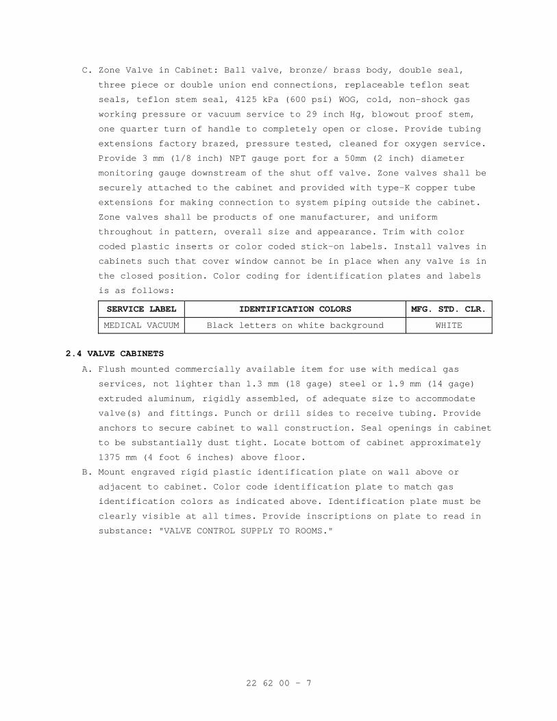
22 62 00 - 7
C. Zone Valve in Cabinet: Ball valve, bronze/ brass body, double seal,
three piece or double union end connections, replaceable teflon seat
seals, teflon stem seal, 4125 kPa (600 psi) WOG, cold, non-shock gas
working pressure or vacuum service to 29 inch Hg, blowout proof stem,
one quarter turn of handle to completely open or close. Provide tubing
extensions factory brazed, pressure tested, cleaned for oxygen service.
Provide 3 mm (1/8 inch) NPT gauge port for a 50mm (2 inch) diameter
monitoring gauge downstream of the shut off valve. Zone valves shall be
securely attached to the cabinet and provided with type-K copper tube
extensions for making connection to system piping outside the cabinet.
Zone valves shall be products of one manufacturer, and uniform
throughout in pattern, overall size and appearance. Trim with color
coded plastic inserts or color coded stick-on labels. Install valves in
cabinets such that cover window cannot be in place when any valve is in
the closed position. Color coding for identification plates and labels
is as follows:
SERVICE LABEL IDENTIFICATION COLORS MFG. STD. CLR.
MEDICAL VACUUM Black letters on white background WHITE
2.4 VALVE CABINETS
A. Flush mounted commercially available item for use with medical gas
services, not lighter than 1.3 mm (18 gage) steel or 1.9 mm (14 gage)
extruded aluminum, rigidly assembled, of adequate size to accommodate
valve(s) and fittings. Punch or drill sides to receive tubing. Provide
anchors to secure cabinet to wall construction. Seal openings in cabinet
to be substantially dust tight. Locate bottom of cabinet approximately
1375 mm (4 foot 6 inches) above floor.
B. Mount engraved rigid plastic identification plate on wall above or
adjacent to cabinet. Color code identification plate to match gas
identification colors as indicated above. Identification plate must be
clearly visible at all times. Provide inscriptions on plate to read in
substance: "VALVE CONTROL SUPPLY TO ROOMS."
22 62 00 - 8
C. Cover plate: Fabricate from 1.3 mm (18 gage) sheet metal with satin
chromed finish, extruded anodized aluminum, or .85 mm (22 gage)
stainless steel. Provide cover window of replaceable plastic, with a
corrosion resistant device or lever secured to window for emergency
window removal. Permanently paint or stencil on window: "FOR EMERGENCY
SHUT-OFF VALVES ONLY, SHUT-OFF VALVES FOR PIPED GASES", or equivalent
wording. Configure such that it is not possible to install window with
any valve in the closed position. Each valve shall have gauge upstream
of valve inside valve box.
D. Cabinets and isolation valves shall be located and piped as shown, and
at a minimum, so as to allow the isolation of each smoke compartment
separately. No cabinet shall serve more than one smoke compartment.
2.5 GAGES
A. Vacuum Gages:
1. For vacuum line use adjacent to source equipment: ANSI B40.1, vacuum
gage, size 115 mm (4-1/2 inches), gage for air, accurate to within
two percent, with metal case. Range shall be 0-100 kPa (0-30 inches
Hg). Dial graduations and figures shall be black on a white
background, or white on a black background. Label for vacuum service.
Install with gage cock. Provide compound gages for Vacuum system.
2. For vacuum service upstream of main shutoff valve: Provide 40 mm
(1-1/2 inch) diameter gage with steel case, bourdon tube and brass
movement, dial range 0-100 kPa (0-30 inches Hg). Provide compound
gages for Vacuum system.
2.6 STATION INLETS
A. For designated service, consisting of a quick coupler and inlet supply
tube. Provide coupler that is non-interchangeable with other services,
and leak proof under three times normal working pressure. Equip each
station inlet with an automatic valve to conform with NFPA 99. Place
valves in the assembly to provide easy access after installation for
servicing and replacement, and to facilitate line blow-out, purging, and
testing. Fasten each inlet securely to rough-in to prevent floating and
provide each with a capped stub length of 6 mm (1/4-inch) (10 mm outside
diameter) (3/8-inch outside diameter) tubing for connection to supply.
Label stub tubing for appropriate service. Rough-in kits and test plugs
for Prefabricated Bedside Patient Units (PBPU) are furnished under this
specification but installed by manufacturer of PBPUs before initial test
specified herein. Install completion kits (valve body and face plate)
for the remainder of required tests.
22 62 00 - 9
2.7 STATION INLET ROUGH-IN
A. Flush mounted, protected against corrosion. Anchor rough-in securely to
unit or wall construction.
B. Modular Cover Plate: Die cast plate, two-piece .85 mm (22 gage)
stainless steel or 1.6 mm (16 gage) chromium plated metal, secured to
rough-in with stainless steel or chromium plated countersunk screws.
C. Cover Plate for Prefabricated Bedside Patient Units (PBPU): One-piece
with construction and material as indicated for modular cover plate.
D. Provide permanent, metal or plastic, identification plates securely
fastened at each inlet opening, with inscription for appropriate service
using color coded letters and background. Metal plates shall have
letters embossed on baked-on enamel background. Color coding for
identification plates is as follows:
SERVICE LABEL IDENTIFICATION PLATE COLORS
MEDICAL VACUUM Black letters on white background
2.8 CEILING SERVICES
A. Column accessories: Equip each utility column with flush type quick
coupler vacuum service station inlets as specified under Article,
STATION INLETS. Provide the following inlets, mounted on the utility
column: three medical vacuum and one anesthesia evacuation.
2.9 VACUUM SWITCHES
General purpose, contact or mercury type, allowing both high and low set
points, with contact type provided with a protective dust cover;
adjustable range set by inside or outside adjustment; switches activate
when indicated by alarm requirements. Use one orifice nipple (or DISS
demand check valve) for each sensor switch.
2.10 VACUUM BOTTLE BRACKET
Single, plate of one piece, .85 mm (22 gage) stainless steel or 1.6 mm
(16 gage) chromium plated metal or aluminum, finish matching cover of
adjoining vacuum inlet; keepers of same material as plate and anchored
securely. Provide bracket and plastic vacuum bottle holder for each
vacuum wall inlet.
2.11 VACUUM PUMP SYSTEMS
A. General: All components factory packaged (prewired and pre-piped) tank
mounted. Package piping shall be type K or L copper tubing with brazed
joints per current NFPA. Provide discharge separator/silencer.
B. Pumps: Multiplex such that design load is provided with the largest
single unit out of service.
22 62 00 - 10
1. Flooded oil rotary vane type, with filtered total oil recirculation,
capable of providing a maximum vacuum level of 95 Pa (28 inches Hg.),
air cooled, thermally protected with shut-down relay, automatically
lubricated, with oil back pressure or differential pressure alarm and
gage, rated for continuous duty, 24 hours per day, seven days per
week. Drip lube pumps are not acceptable.
C. Motor and Starter: Maximum 40 °C ambient temperature rise, drip proof
type motor, ball bearings, for operation with current, voltage, phase
and cycle specified in Section 22 05 12, GENERAL MOTOR REQUIREMENTS FOR
PLUMBING EQUIPMENT. Motor shall be of such capacity that brake
horsepower required by driver equipment at normal rated capacity will
not exceed nameplate rating of the motor. Provide each motor with
automatic, fully enclosed, magnetic starter of type specified in Section
26 29 11, LOW-VOLTAGE MOTOR STARTERS.
D. Controls:
1. Automatic: Adjustable, vacuum operated, automatic, electric switch to
start and stop motor at receiver vacuum indicated. Provide heavy duty
alternator, automatic, operating on a timed basis, to alternate the
pumps by time forced alternation.
2. Control panel: Housed in a NEMA ICS-6, Type 12, listed, dust proof
enclosure; prewired to include all specified electrical, electronic
and electropneumatic devices. Include wiring diagrams and operating
descriptions in the cabinet. Include the following:
a. Circuit breakers for each control and motor circuit.
b. Hand-off-automatic selector switch for each pump.
c. Hour meter for each pump.
d. Control circuit transformers.
e. One magnetic motor starter for each pump.
f. Provide panel with external visual (lights, red for running, green
for off) and audible (horn/buzzer) signals. The signals provided
include:
1) Pump in operation (visual only).
2) Thermal overload shutdown (visual and audible).
3) Oil discharge filter differential pressure or back pressure
alarm (visual), with contacts for external signal. Wire to
master alarm panel.
4) Cancel button, which will silence an audible alarm, reactivate
should a second alarm occur while the horn is silenced, and
reset automatically upon correction of the original signal.
22 62 00 - 11
E. Receiver Tank: Welded galvanized steel, in compliance with ASME Section
VIII, 850 kPa (125 psi) working pressure stamped and certified. Equip
with vacuum gage and gage glass. Receiver shall be of sufficient
capacity to ensure practical on/off operation of pumps.
F. Bio-Hazard Safety Statement: "BIOHAZARD CAUTION: Fluid and waste
material inside vacuum pipelines and vacuum equipment may be
contaminated with blood and other potentially infectious material.
Construction and service personnel should use PERSONAL PROTECTIVE
EQUIPMENT and practice UNIVERSAL PRECAUTIONS when opening or servicing
vacuum systems."
PART 3 - EXECUTION
3.1 INSTALLATION
A. In accordance with current NFPA.
B. Install cast escutcheon with set screw at each wall, floor and ceiling
penetration in exposed finished locations and within cabinets and
millwork.
C. Keep open ends of tube capped or plugged at all times or otherwise
sealed until final assembly.
D. Cut piping square and accurately with a tube cutter (sawing not
permitted) to measurements determined at place of installation. Ream
tube to remove burrs, being careful not to expand tube, and so no chips
of copper remain in the tube. Work into place without springing or
forcing. Bottom tube in socket so there are no gaps between tube and
fitting. Exercise care in handling equipment and tools used in cutting
or reaming of tube to prevent oil or grease being introduced into
tubing. Where contamination has occurred, material is no longer suitable
for oxygen service.
E. Spacing of hangers: Current NFPA.
F. Rigidly support valves and other equipment to prevent strain on tube or
joints.
G. While being brazed, joints shall be continuously purged with oil free
nitrogen. The flow of purged gas shall be maintained until joint is cool
to touch.
H. Do not bend tubing. Use fittings.
I. Support ceiling column assembly from heavy sub-mounting castings
furnished with the unit as part of roughing-in. Anchor with 15 mm
(1/2-inch) diameter bolts attached to angle iron frame supported from
structural ceiling, unless otherwise indicated.
22 62 00 - 12
J. Provide two 25 mm (1 inch) minimum conduits from ceiling column assembly
to adjacent corridor, one for mass spectrometer tubing and wiring and
one for monitor wiring, for connection to signal cabling network.
K. Install pressure and vacuum switches, transmitter and gauges to be
easily accessed, and provide access panel where installed above plaster
ceiling. Install pressure switch and sensors with orifice nipple between
the pipe line and switches/sensors.
L. Apply pipe labeling during installation process and not after
installation is completed. Size of legend letters shall be in accordance
with ANSI A13.1.
M. After initial leakage testing is completed, allow piping to remain
pressurized with testing gas until testing agency performs final tests.
N. Penetrations:
1. Fire Stopping: Where pipes pass through fire partitions, fire walls,
smoked partitions, or floors, install a fire stop that provides an
effective barrier against the spread of fire, smoke and gases as
specified in Section 07 84 00, FIRESTOPPING, with intumescent
materials only. Completely fill and seal clearances between raceways
and openings with the fire stopping material.
2. Waterproofing: At floor penetrations, completely seal clearances
around the pipe and make watertight with sealant as specified in
Section 07 92 00, JOINT SEALANTS.
O. Provide 40mm (1 1/2 inch) diameter line vacuum gage downstream of zone
valve in cabinets.
P. Provide zone valves in cabinets where indicated and outside each
Operating Room and a minimum one zone valve assembly for each 18 outlet
set.
3.2 TESTS
A. Initial Tests: Blow down, and high and low pressure leakage tests as
required by current NFPA with documentation.
B. Medical gas testing agency shall perform the following:
1. Perform and document all cross connection tests, labeling
verification, supply system operation, and valve and alarm operation
tests as required by, and in accordance with, current NFPA and the
procedures set forth in pre-qualification documentation.
2. Verify that the systems, as installed, meet or exceed the
requirements of current NFPA, this specification, and that the
systems operate as required.
22 62 00 - 13
3. Piping purge test: For each positive pressure gas system, verify
cleanliness of piping system. Filter a minimum of 35 cubic feet (1000
liters) of gas through a clean white 0.45 micron filter at a minimum
velocity of 3.5 scfm (100 Lpm). Filter shall show no discoloration,
and shall accrue no more than 0.1 mg of matter. Test each zone at the
outlet most remote from the source. Perform test with the use of an
inert gas as described in CGA P-9.
4. Inlet flow test:
a. Test all inlets for flow. Perform test with the use of an inert
gas as described in CGA P-9.
b. Needle valve vacuum inlets must draw no less than 1.0 scfm with
adjacent inlet flowing, at a dynamic inlet pressure of 12-inches
Hg, and a static vacuum of 15-inches Hg.
c. Vacuum inlets must draw no less than 85 Lpm (3.0 scfm) with
adjacent inlet flowing, at a dynamic inlet pressure of 40 kPa
(12-inches Hg), and a static vacuum of 50 kPa (15-inches Hg).
- - - E N D - - -
22 63 00 - 1
SECTION 22 63 00 GAS SYSTEMS FOR HEALTHCARE FACILITIES
PART 1 - GENERAL
1.1 DESCRIPTION
A. Central Healthcare Gas Systems: Consisting of oxygen, nitrous oxide,
nitrogen, and compressed air services; complete, ready for operation,
including all necessary piping, fittings, valves, cabinets, station
outlets, rough-ins, ceiling services, gages, alarms including low
voltage wiring, nitrogen control panels, cylinder manifolds, air
compressors, electric motors and starters, air dryers, filters, pressure
regulators, dew point, carbon monoxide monitors and all necessary parts,
accessories, connections and equipment. Match existing station outlet
and inlet terminal connections.
B. Oxygen System: Ready for connection to outside bulk supply tank, but not
including tank.
C. Healthcare gas system alarm wiring from equipment to alarm panels.
1.2 RELATED WORK
A. Sealing around pipe penetrations to maintain the integrity of time rated
construction: Section 07 84 00, FIRESTOPPING.
B. Sealing around pipe penetrations through the floor to prevent moisture
migration: Section 07 92 00, JOINT SEALANTS.
C. General requirements and items common to more than one section of
Division 22. Section 22 05 11, COMMON WORK RESULTS FOR PLUMBING.
E. Alarm interface with ECC. Section 23 09 23, DIRECT-DIGITAL CONTROL
SYSTEM FOR HVAC.
F. Conduit: Section 26 05 33, RACEWAY AND BOXES FOR ELECTRICAL SYSTEMS.
G. Control wiring: Section 26 05 21, LOW-VOLTAGE ELECTRICAL POWER
CONDUCTORS AND CABLES (600 VOLTS AND BELOW).
H. Electrical wiring and accessories: Section 26 27 26, WIRING DEVICES.
I. Electric motors: Section 22 05 12, GENERAL MOTOR REQUIREMENTS FOR
PLUMBING EQUIPMENT.
J. Motor starters: Section 26 29 11, LOW-VOLTAGE MOTOR STARTERS.
K. Prefabricated bedside patient units: Section 10 25 13, PATIENT BED
SERVICE WALLS.
L. Vacuum Piping and Equipment: Section 22 62 00, VACUUM SYSTEMS FOR
HEALTHCARE FACILITIES
1.3 QUALITY ASSURANCE
A. Materials and Installation: In accordance with NFPA 99, and as
specified.
22 63 00 - 2
B. Equipment Installer: Show technical qualifications and previous
experience in installing laboratory and healthcare equipment on three
similar projects. Submit names and addresses of referenced projects.
C. Equipment Supplier: Show evidence of equivalent product installed at
three installations similar to this project that has been in
satisfactory and efficient operation for three years. Submit names and
addresses where the product is installed.
D. Healthcare System Testing Organization: The testing shall be conducted
by a party technically competent and experienced in the field of
laboratory and healthcare pipeline testing. Such testing shall be
performed by a party other than the installing contractor.
E. Provide names of three projects where testing of medical or laboratory
gases systems has been performed by the testing agency. Include the name
of the project, names of such persons at that project who supervised the
work for the project owner, or who accepted the report for the project
owner, and a written statement that the projects listed required work of
similar scope to that set forth in this specification.
F. Submit the testing agency's detailed procedure which will be followed in
the testing of this project. Include details of the testing sequence,
procedures for cross connection tests, outlet function tests, alarm
tests, purity tests, etc., as required by this specification. For purity
test procedures, include data on test methods, types of equipment to be
used, calibration sources and method references.
G. Certification: Provide documentation prior to submitting request for
final inspection to include all test results, the names of individuals
performing work for the testing agency on this project, detailed
procedures followed for all tests, and a certification that all results
of tests were within limits allowed by this specification.
H. Installing contractor shall maintain as-built drawings of each completed
phases for verification; and, shall provide the complete set at the time
of final systems certification testing, for certification by the Third
Party Testing Company. As-built drawings are to be provided, and a copy
of them on Auto-Cad version (R-14 or later) provided on compact disk.
Should the installing contractor engage the testing company to provide
as-built or any portion thereof, it shall not be deemed a conflict of
interest or breach of the ‘third party testing company’ requirement.
1.4 SUBMITTALS
A. Submit as one package in accordance with Section 01 33 23, SHOP
DRAWINGS, PRODUCT DATA, AND SAMPLES.
22 63 00 - 3
B. Manufacturer's Literature and Data:
1. Piping.
2. Valves.
3. Inlet and outlet cocks
4. Valve cabinets.
5. Gages.
6. Station outlets and rough-in assemblies.
7. Alarm controls and panels.
8. Pressure Switches.
C. Station Outlets: Submit letter from manufacturer stating that outlets
are designed and manufactured to comply with NFPA 99. Outlet shall bear
label of approval as an assembly, of Underwriters Laboratories, Inc., or
Associated Factory Mutual Research Corporation. In lieu of above labels,
certificate may be submitted by a nationally recognized independent
testing laboratory, satisfactory to the Contracting Officer, certifying
that materials, appliances and assemblies conform to published
standards, including methods of tests, of above organizations.
D. Certification: The completed systems have been installed, tested, purged
and analyzed in accordance with the requirements of this specification.
1.5 TRAINING
A. Furnish the services of a competent instructor for not less than two
four-hour periods for instructing personnel in the operation and
maintenance of the laboratory and healthcare gas systems, on the dates
requested by COTR.
B. Coordinate with other requirements specified in Section 01 00 00,
GENERAL REQUIREMENTS.
1.6 APPLICABLE PUBLICATIONS
A. The publications listed below form a part of this specification to the
extent referenced. The publications are referenced in the test by the
basic designation only.
B. American Society for Testing and Materials (ASTM):
B819-(R2006)............Seamless Copper Tube for Medical Gas Systems
C. American Society of Mechanical Engineers (ASME):
A13.1-07................Scheme for Identification of Piping Systems
B16.22-01(R2005)........Wrought Copper and Bronze Solder-Joint Pressure
Fittings
B40.100-98..............Pressure Gauges and Gauge Attachments
Boiler and Pressure Vessel Code -
Section VIII-07.........Pressure Vessels, Division I
Section IX-07...........Welding and Brazing Qualifications
22 63 00 - 4
D. American Welding Society (AWS):
AWS A5.8-04.............Brazing Filler Metal
AWS B2.2-91.............Standard for Brazing Procedure and Performance
Qualification (Modified per NFPA 99)
E. Compressed Gas Association (CGA):
C-9-04..................Standard Color Marking of Compressed Gas
Cylinders
G-4.1-04................Cleaning Equipment for Oxygen Service
P-9-01..................Inert Gases Argon, Nitrogen and Helium
V-1-05..................Standard for Compressed Gas Cylinder Valve
Outlet and Inlet Connections
F. National Electrical Manufacturers Association (NEMA):
ICS-6-93(R2006).........Industrial Controls and Systems Enclosures
G. National Fire Protection Association (NFPA):
99-05...................Health Care Facilities
H. United States Pharmacopoeia XXI/National Formulary XVI (USP/NF)
I. Manufacturing Standardization Society (MSS):
MSS-SP-72-99............Ball Valves With Flanged or Butt Welding For
General Purpose
MSS-SP-110-96...........Ball Valve Threaded, Socket Welding, Solder
Joint, Grooved and Flared Ends
MSS-SP-73-03............Brazing Joints for Copper and Copper Alloy
Solder Pressure Fittings
PART 2 - PRODUCTS
2.1 PIPING
A. Copper Tubing: Type "K" or "L", ASTM B819, seamless copper tube, hard
drawn temper, with wrought copper fittings conforming to ASME B16.22 or
brazing fittings complying with MSS SP-73. Size designated reflecting
nominal inside diameter. All tubing and fittings shall be labeled
"ACR/OXY", "OXY", "OXY/MED", "ACR/MED", or "MED".
B. Brazing Alloy: AWS A5.8, Classification BCuP, greater than 537 °C (1000
°F) melting temperature. Flux is strictly prohibited for
copper-to-copper connections.
C. Screw Joints: Polytetrafluoroethylene (teflon) tape.
D. Memory metal couplings having temperature and pressure rating not less
than that of a brazed joint shall be permitted.
E. Apply piping identification labels shall be done at time of installation
in accordance with current NFPA. Supplementary color identification
shall be in accordance with CGA Pamphlet C-9.
22 63 00 - 5
F. Special Fittings: The following special fittings shall be permitted to
be used in lieu of brazed joints:
1. Memory-metal couplings having temperature and pressure ratings joints
not less than that of a brazed joint.
2. Listed or approved metallic gas tube fittings that, when made up,
provide a permanent joint having the mechanical, thermal, and sealing
integrity of a brazed joint.
3. Dielectric fittings where required by the manufacturer of special
medical equipment to electrically isolate the equipment from the
piping distribution system.
4. Axially swaged, elastic strain preload fittings providing metal to
metal seal having pressure and temperature ratings not less than that
of a brazed joint and when complete are permanent and non-separable.
2.2 EXPOSED LABORATORY AND HEALTHCARE GASES PIPING
A. Finished Room: Use full iron pipe size chrome plated brass piping for
exposed laboratory and healthcare gas piping connecting fixtures,
casework, cabinets, equipment and reagent racks when not concealed by
apron including those furnished by the Government or specified in other
sections.
1. Pipe: Fed. Spec. WW-P-351, standard weight.
2. Fittings: ASME B16.15 cast bronze threaded fittings with chrome
finish, (125 and 250).
3. Nipples: ASTM B 687, Chromium-plated.
4. Unions: Mss SP-72, SP-110, Brass or Bronze with chrome finish. Unions
65 mm (2-1/2 inches) and larger shall be flange type with approved
gaskets.
5. Valves: Mss SP-72, SP-110, Brass or bronze with chrome finish.
2.3 VALVES
A. Ball: In-line, other than zone valves in cabinets:
1. Seventy five millimeter (2 1/2 inches) and smaller: Bronze/ brass
body, Fed. Spec. MSS SP72 & SP 110 , Type II, Class 150, Style 1,
with tubing extensions for brazed connections, full ported,
three-piece or double union end connections, teflon seat seals, full
flow, 4125 kPa ( 600 psi) WOG minimum working pressure, with locking
type handle and cleaned for oxygen service. An acceptable
manufacturer that meets the specification: Jomar model S-100.
22 63 00 - 6
2. Eighty to one hundred millimeter (3-4 inches): Bronze/ brass body,
Fed. Spec. MSS SP72 & SP 110, Type II, Class 150, Style 1 with
tubing extensions brazed to flanges, full ported, three piece, double
seal, teflon seals, full flow, 4125 kPa (600 psi) WOG minimum
working pressure, with locking type handle, and cleaned for oxygen
service.
B. Check:
1. Eighty millimeter (3 inches) and smaller: brass and Bronze body,
straight through design for minimum pressure drop, spring loaded,
self aligning with teflon cone seat, vibration free, silent
operation, supplied NPT female threads at each end with flow
direction arrow permanently cast into, cleaned for oxygen use, 2750
kPa (400 psi) WOG minimum working pressure.
2. One hundred millimeter (4 inches) and larger: Iron body, bronze trim,
swing type, vertical or horizontal installation, flange connection,
1025 kPa (150 psi) WSP.
C. Zone Valve in Cabinet: Ball valve, bronze/ brass body, double seal,
three piece or double union end connections, replaceable teflon seat
seals, teflon stem seal, 4125 kPa (600 psi) WOG, cold, non-shock gas
working pressure service to 29 inch Hg, cleaned for oxygen service,
blowout proof stem, one quarter turn of handle to completely open or
close. Provide tubing extensions factory brazed, pressure tested,
cleaned for oxygen service. Provide 3 mm (1/8 inch) NPT gauge port for a
50mm (2 inch) diameter monitoring gauge downstream of the shut off
valve. Zone valves shall be securely attached to the cabinet and
provided with type-K copper tube extensions for making connection to
system piping outside the cabinet. Zone valves shall be products of one
manufacturer, and uniform throughout in pattern, overall size and
appearance. Trim with color coded plastic inserts or color coded
stick-on labels. Install valves in cabinets such that cover window
cannot be in place when any valve is in the closed position. Color
coding for identification plates and labels is as follows:
SERVICE LABEL IDENTIFICATION COLORS MFG. STD. CLR.
OXYGEN White letters on green background GREEN
MEDICAL AIR Black or white letters on yellow background
YELLOW
22 63 00 - 7
2.4 VALVE CABINETS
A. Flush mounted commercially available item for use with laboratory and
healthcare services, not lighter than 1.3 mm (18 gage) steel or 1.9 mm
(14 gage) extruded aluminum, rigidly assembled, of adequate size to
accommodate valve(s) and fittings. Punch or drill sides to receive
tubing. Provide anchors to secure cabinet to wall construction. Seal
openings in cabinet to be substantially dust tight. Locate bottom of
cabinet approximately 1375 mm (4 foot 6 inches) above floor.
B. Mount engraved rigid plastic identification plate on wall above or
adjacent to cabinet. Color code identification plate to match gas
identification colors as indicated above. Identification plate must be
clearly visible at all times. Provide inscriptions on plate to read in
substance: "VALVE CONTROL SUPPLY TO ROOMS."
C. Cover plate: Fabricate from 1.3 mm (18 gage) sheet metal with satin
chromed finish, extruded anodized aluminum, or .85 mm (22 gage)
stainless steel. Provide cover window of replaceable plastic, with a
corrosion resistant device or lever secured to window for emergency
window removal. Permanently paint or stencil on window: "FOR EMERGENCY
SHUT-OFF VALVES ONLY, SHUT-OFF VALVES FOR PIPED GASES", or equivalent
wording. Configure such that it is not possible to install window with
any valve in the closed position. Each valve shall have gauge upstream
of valve inside valve box.
D. Cabinets and isolation valves shall be located and piped as shown, and
at a minimum, so as to allow the isolation of each smoke compartment
separately. No cabinet shall serve more than one smoke compartment.
2.5 GAGES
A. Pressure Gages: Includes gages temporarily supplied for testing
purposes.
1. For line pressure use adjacent to source equipment: ASME B40.1,
pressure gage, single, size 115 mm (4-1/2 inches), for compressed
air, nitrogen and oxygen, accurate to within two percent, with metal
case. Range shall be two times operating pressure. Dial graduations
and figures shall be black on a white background, or white on a black
background. Gage shall be cleaned for oxygen use, labeled for
appropriate service, and marked "USE NO OIL". Install with gage cock.
2. For all services downstream of main shutoff valve: Manufactured
expressly for oxygen use but labeled for appropriate service and
marked "USE NO OIL", 40 mm (1-1/2 inch) diameter gage with dial range
1-690 kPa (1-100 psi) for air service.
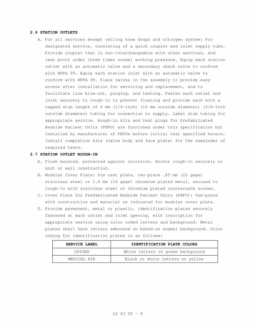
22 63 00 - 8
2.6 STATION OUTLETS
A. For all services except ceiling hose drops and nitrogen system: For
designated service, consisting of a quick coupler and inlet supply tube.
Provide coupler that is non-interchangeable with other services, and
leak proof under three times normal working pressure. Equip each station
outlet with an automatic valve and a secondary check valve to conform
with NFPA 99. Equip each station inlet with an automatic valve to
conform with NFPA 99. Place valves in the assembly to provide easy
access after installation for servicing and replacement, and to
facilitate line blow-out, purging, and testing. Fasten each outlet and
inlet securely to rough-in to prevent floating and provide each with a
capped stub length of 6 mm (1/4-inch) (10 mm outside diameter) (3/8-inch
outside diameter) tubing for connection to supply. Label stub tubing for
appropriate service. Rough-in kits and test plugs for Prefabricated
Bedside Patient Units (PBPU) are furnished under this specification but
installed by manufacturer of PBPUs before initial test specified herein.
Install completion kits (valve body and face plate) for the remainder of
required tests.
2.7 STATION OUTLET ROUGH-IN
A. Flush mounted, protected against corrosion. Anchor rough-in securely to
unit or wall construction.
B. Modular Cover Plate: Die cast plate, two-piece .85 mm (22 gage)
stainless steel or 1.6 mm (16 gage) chromium plated metal, secured to
rough-in with stainless steel or chromium plated countersunk screws.
C. Cover Plate for Prefabricated Bedside Patient Units (PBPU): One-piece
with construction and material as indicated for modular cover plate.
D. Provide permanent, metal or plastic, identification plates securely
fastened at each outlet and inlet opening, with inscription for
appropriate service using color coded letters and background. Metal
plates shall have letters embossed on baked-on enamel background. Color
coding for identification plates is as follows:
SERVICE LABEL IDENTIFICATION PLATE COLORS
OXYGEN White letters on green background
MEDICAL AIR Black or white letters on yellow
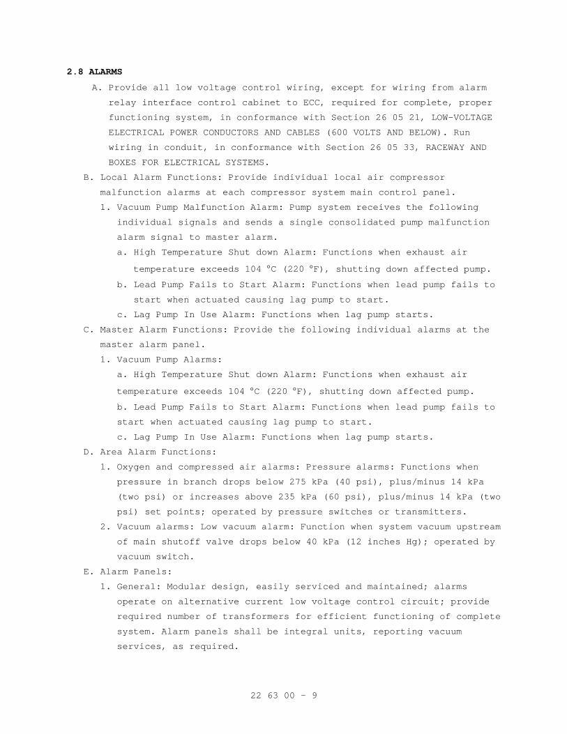
22 63 00 - 9
2.8 ALARMS
A. Provide all low voltage control wiring, except for wiring from alarm
relay interface control cabinet to ECC, required for complete, proper
functioning system, in conformance with Section 26 05 21, LOW-VOLTAGE
ELECTRICAL POWER CONDUCTORS AND CABLES (600 VOLTS AND BELOW). Run
wiring in conduit, in conformance with Section 26 05 33, RACEWAY AND
BOXES FOR ELECTRICAL SYSTEMS.
B. Local Alarm Functions: Provide individual local air compressor
malfunction alarms at each compressor system main control panel.
1. Vacuum Pump Malfunction Alarm: Pump system receives the following
individual signals and sends a single consolidated pump malfunction
alarm signal to master alarm.
a. High Temperature Shut down Alarm: Functions when exhaust air
temperature exceeds 104 °C (220 °F), shutting down affected pump.
b. Lead Pump Fails to Start Alarm: Functions when lead pump fails to
start when actuated causing lag pump to start.
c. Lag Pump In Use Alarm: Functions when lag pump starts.
C. Master Alarm Functions: Provide the following individual alarms at the
master alarm panel.
1. Vacuum Pump Alarms:
a. High Temperature Shut down Alarm: Functions when exhaust air
temperature exceeds 104 °C (220 °F), shutting down affected pump.
b. Lead Pump Fails to Start Alarm: Functions when lead pump fails to
start when actuated causing lag pump to start.
c. Lag Pump In Use Alarm: Functions when lag pump starts.
D. Area Alarm Functions:
1. Oxygen and compressed air alarms: Pressure alarms: Functions when
pressure in branch drops below 275 kPa (40 psi), plus/minus 14 kPa
(two psi) or increases above 235 kPa (60 psi), plus/minus 14 kPa (two
psi) set points; operated by pressure switches or transmitters.
2. Vacuum alarms: Low vacuum alarm: Function when system vacuum upstream
of main shutoff valve drops below 40 kPa (12 inches Hg); operated by
vacuum switch.
E. Alarm Panels:
1. General: Modular design, easily serviced and maintained; alarms
operate on alternative current low voltage control circuit; provide
required number of transformers for efficient functioning of complete
system. Alarm panels shall be integral units, reporting vacuum
services, as required.
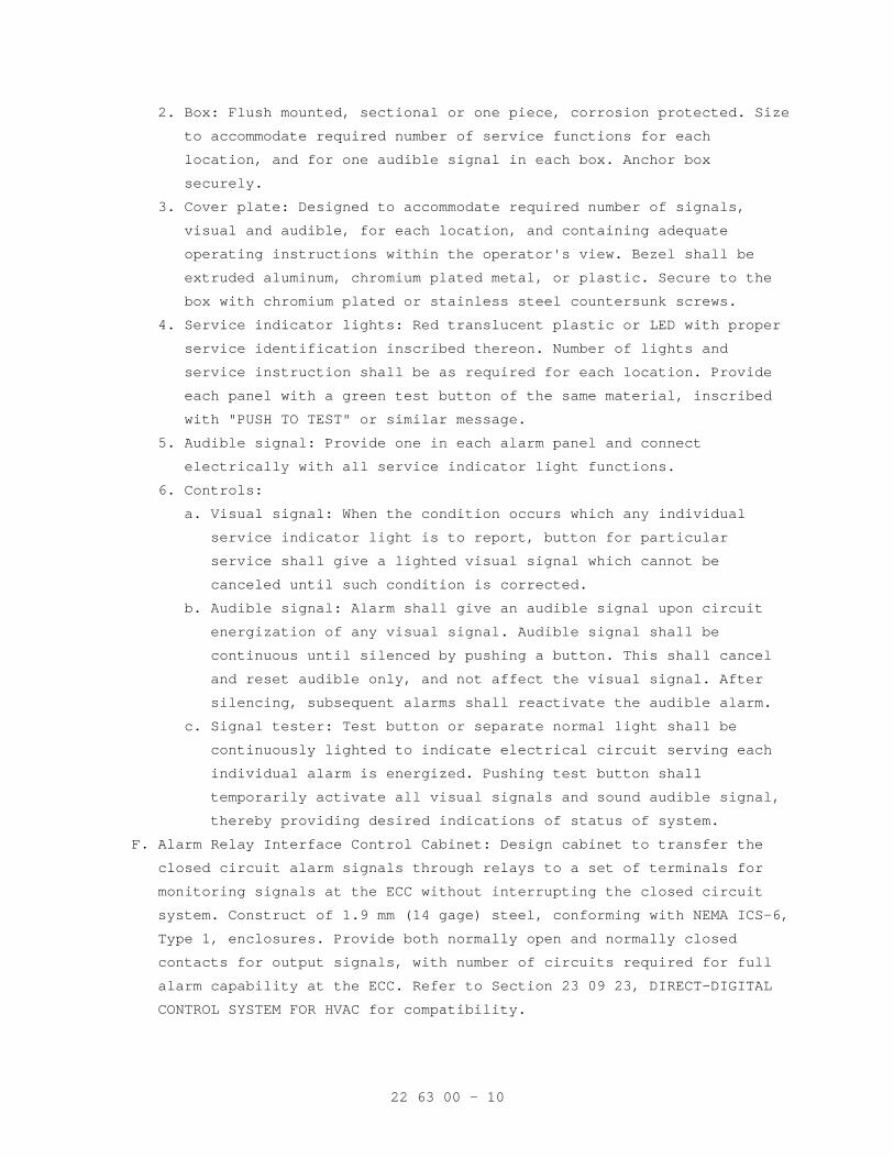
22 63 00 - 10
2. Box: Flush mounted, sectional or one piece, corrosion protected. Size
to accommodate required number of service functions for each
location, and for one audible signal in each box. Anchor box
securely.
3. Cover plate: Designed to accommodate required number of signals,
visual and audible, for each location, and containing adequate
operating instructions within the operator's view. Bezel shall be
extruded aluminum, chromium plated metal, or plastic. Secure to the
box with chromium plated or stainless steel countersunk screws.
4. Service indicator lights: Red translucent plastic or LED with proper
service identification inscribed thereon. Number of lights and
service instruction shall be as required for each location. Provide
each panel with a green test button of the same material, inscribed
with "PUSH TO TEST" or similar message.
5. Audible signal: Provide one in each alarm panel and connect
electrically with all service indicator light functions.
6. Controls:
a. Visual signal: When the condition occurs which any individual
service indicator light is to report, button for particular
service shall give a lighted visual signal which cannot be
canceled until such condition is corrected.
b. Audible signal: Alarm shall give an audible signal upon circuit
energization of any visual signal. Audible signal shall be
continuous until silenced by pushing a button. This shall cancel
and reset audible only, and not affect the visual signal. After
silencing, subsequent alarms shall reactivate the audible alarm.
c. Signal tester: Test button or separate normal light shall be
continuously lighted to indicate electrical circuit serving each
individual alarm is energized. Pushing test button shall
temporarily activate all visual signals and sound audible signal,
thereby providing desired indications of status of system.
F. Alarm Relay Interface Control Cabinet: Design cabinet to transfer the
closed circuit alarm signals through relays to a set of terminals for
monitoring signals at the ECC without interrupting the closed circuit
system. Construct of 1.9 mm (14 gage) steel, conforming with NEMA ICS-6,
Type 1, enclosures. Provide both normally open and normally closed
contacts for output signals, with number of circuits required for full
alarm capability at the ECC. Refer to Section 23 09 23, DIRECT-DIGITAL
CONTROL SYSTEM FOR HVAC for compatibility.
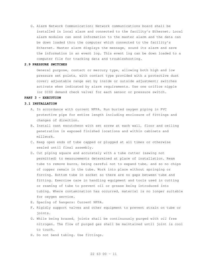
22 63 00 - 11
G. Alarm Network Communication: Network communications board shall be
installed in local alarm and connected to the facility’s Ethernet. Local
alarm modules can send information to the master alarm and the data can
be down loaded thru the computer which connected to the facility’s
Ethernet. Master alarm displays the message, sound its alarm and save
the information in an event log. This event log can be down loaded to a
computer file for tracking data and troubleshooting.
2.9 PRESSURE SWITCHES
General purpose, contact or mercury type, allowing both high and low
pressure set points, with contact type provided with a protective dust
cover; adjustable range set by inside or outside adjustment; switches
activate when indicated by alarm requirements. Use one orifice nipple
(or DISS demand check valve) for each sensor or pressure switch.
PART 3 - EXECUTION
3.1 INSTALLATION
A. In accordance with current NFPA. Run buried oxygen piping in PVC
protective pipe for entire length including enclosure of fittings and
changes of direction.
B. Install cast escutcheon with set screw at each wall, floor and ceiling
penetration in exposed finished locations and within cabinets and
millwork.
C. Keep open ends of tube capped or plugged at all times or otherwise
sealed until final assembly.
D. Cut piping square and accurately with a tube cutter (sawing not
permitted) to measurements determined at place of installation. Ream
tube to remove burrs, being careful not to expand tube, and so no chips
of copper remain in the tube. Work into place without springing or
forcing. Bottom tube in socket so there are no gaps between tube and
fitting. Exercise care in handling equipment and tools used in cutting
or reaming of tube to prevent oil or grease being introduced into
tubing. Where contamination has occurred, material is no longer suitable
for oxygen service.
E. Spacing of hangers: Current NFPA.
F. Rigidly support valves and other equipment to prevent strain on tube or
joints.
G. While being brazed, joints shall be continuously purged with oil free
nitrogen. The flow of purged gas shall be maintained until joint is cool
to touch.
H. Do not bend tubing. Use fittings.
22 63 00 - 12
I. Support ceiling column assembly from heavy sub-mounting castings
furnished with the unit as part of roughing-in. Anchor with 15 mm
(1/2-inch) diameter bolts attached to angle iron frame supported from
structural ceiling, unless otherwise indicated.
J. Provide two 25 mm (1 inch) minimum conduits from ceiling column assembly
to adjacent corridor, one for mass spectrometer tubing and wiring and
one for monitor wiring, for connection to signal cabling network.
K. Install pressure switches, transmitter and gauges to be easily accessed,
and provide access panel where installed above plaster ceiling. Install
pressure switch and sensors with orifice nipple between the pipe line
and switches/sensors.
L. Apply pipe labeling during installation process and not after
installation is completed. Size of legend letters shall be in accordance
with ANSI A13.1.
M. Pipe compressor intake to a source of clean ambient air as indicated in
current NFPA.
N. After initial leakage testing is completed, allow piping to remain
pressurized with testing gas until testing agency performs final tests.
O. Penetrations:
1. Fire Stopping: Where pipes pass through fire partitions, fire walls,
smoked partitions, or floors, install a fire stop that provides an
effective barrier against the spread of fire, smoke and gases as
specified in Section 07 84 00, FIRESTOPPING, with intumescent
materials only. Completely fill and seal clearances between raceways
and openings with the fire stopping material.
2. Waterproofing: At floor penetrations, completely seal clearances
around the pipe and make watertight with sealant as specified in
Section 07 92 00, JOINT SEALANTS.
P. Provide 40mm (1 1/2 inch) diameter line pressure gage downstream of zone
valve in cabinets.
Q. Provide zone valves in cabinets where indicated and outside each
Operating Room and a minimum one zone valve assembly for each 18 outlet
set.
3.2 TESTS
A. Initial Tests: Blow down, and high and low pressure leakage tests as
required by current NFPA with documentation.
22 63 00 - 13
B. Healthcare testing agency shall perform the following:
1. Perform and document all cross connection tests, labeling
verification, supply system operation, and valve and alarm operation
tests as required by, and in accordance with, current NFPA and the
procedures set forth in pre-qualification documentation.
2. Verify that the systems, as installed, meet or exceed the
requirements of current NFPA, this specification, and that the
systems operate as required.
3. Piping purge test: For each positive pressure gas system, verify
cleanliness of piping system. Filter a minimum of 35 cubic feet (1000
liters) of gas through a clean white 0.45 micron filter at a minimum
velocity of 3.5 scfm (100 Lpm). Filter shall show no discoloration,
and shall accrue no more than 0.1 mg of matter. Test each zone at the
outlet most remote from the source. Perform test with the use of an
inert gas as described in CGA P-9.
4. Piping purity test: For each positive pressure system, verify purity
of piping system. Test each zone at the most remote outlet for dew
point, carbon monoxide, total hydrocarbons (as methane), and
halogenated hydrocarbons, and compare with source gas. The two tests
must in no case exceed variation as specified in Paragraph, Maximum
Allowable Variation. Perform test with the use of an inert gas as
described in CGA P-9.
5. Outlet and inlet flow test:
a. Test all outlets for flow. Perform test with the use of an inert
gas as described in CGA P-9.
b. Oxygen, nitrous oxide and air outlets must deliver 100 Lpm (3.5
scfm) with a pressure drop of no more than 35 kPa (5 psi), and
static pressure of 350 kPa (50 psi).
c. Needle valve air outlets must deliver 1.5 scfm with a pressure
drop of no more than five psi, and static pressure of 50 psi.
6. Source Contamination Test: Analyze each pressure gas source for
concentration of contaminants, by volume. Take samples for air system
test at the intake and at a point immediately downstream of the final
filter outlet. The compared tests must in no case exceed variation as
specified in Paragraph, Maximum Allowable Variation.
7. Analysis Test:
a. Analyze each pressure gas source and outlet for concentration of
gas, by volume.
b. Make analysis with instruments designed to measure the specific
gas dispensed.
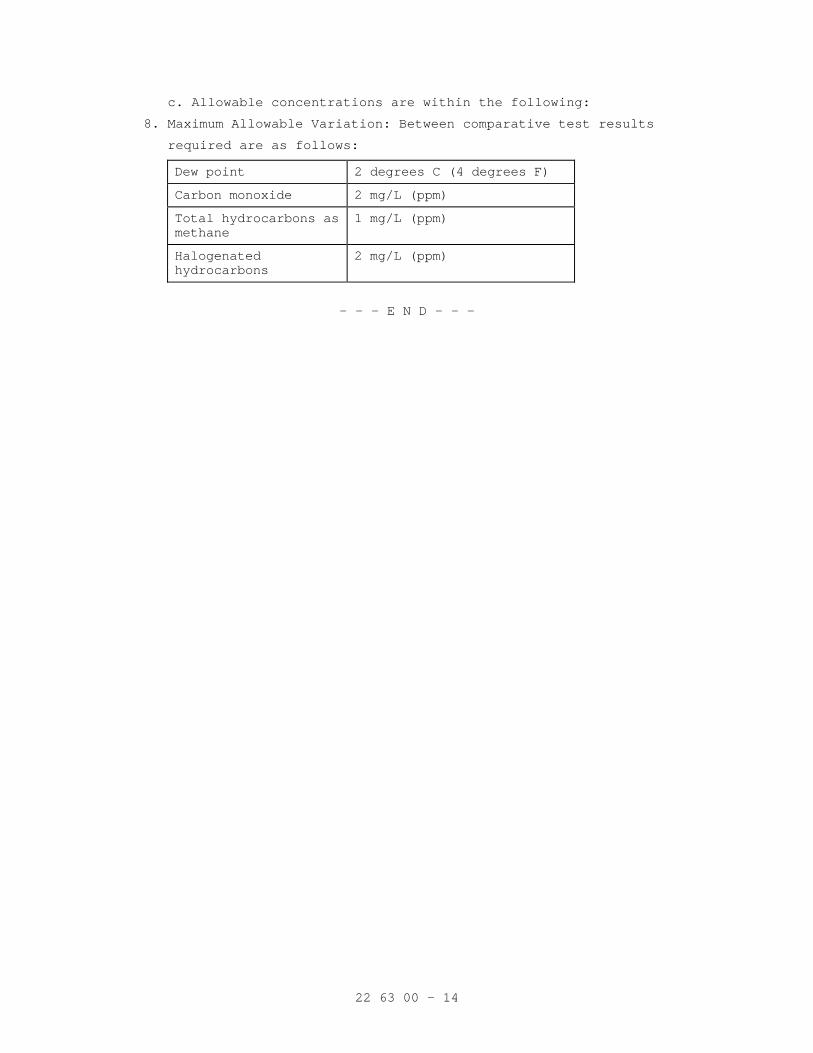
22 63 00 - 14
c. Allowable concentrations are within the following:
8. Maximum Allowable Variation: Between comparative test results
required are as follows:
Dew point 2 degrees C (4 degrees F)
Carbon monoxide 2 mg/L (ppm)
Total hydrocarbons as methane
1 mg/L (ppm)
Halogenated hydrocarbons
2 mg/L (ppm)
- - - E N D - - -
23 05 11 - 1
SECTION 23 05 11 COMMON WORK RESULTS FOR HVAC EQUIPMENT
PART 1 - GENERAL
1.1 DESCRIPTION
A. The requirements of this Section apply to all sections of Division 23.
B. Definitions:
1. Exposed: Piping, ductwork, and equipment exposed to view in finished
rooms.
2. Option or optional: Contractor's choice of an alternate material or
method.
3. RE: Resident Engineer
4. COTR: Contracting Officer’s Technical Representative.
1.2 RELATED WORK
A. Section 01 00 00, GENERAL REQUIREMENTS. B. Section 01 33 23, SHOP DRAWINGS, PRODUCT DATA, AND SAMPLES. C. Excavation and Backfill: Section 31 20 00, EARTH MOVING.
D. Concrete and Grout: Section 03 30 00, CAST-IN-PLACE CONCRETE.
E. Building Components for Attachment of Hangers: Section 05 31 00, STEEL
DECKING.
F. Section 07 84 00, FIRESTOPPING.
G. Flashing for Wall and Roof Penetrations: Section 07 60 00, FLASHING AND
SHEET METAL.
H. Section 07 92 00, JOINT SEALANTS.
I. Section 09 91 00, PAINTING.
J. Section 23 05 48, SEISMI/VIBRATION ISOLATION FOR MECHANICAL COMPONENTS.
K. Section 26 05 11, REQUIREMENTS FOR ELECTRICAL INSTALLATIONS
L. Section 26 29 11, LOW-VOLTAGE MOTOR STARTERS.
1.3 QUALITY ASSURANCE
A. Mechanical, electrical and associated systems shall be safe, reliable,
efficient, durable, easily and safely operable and maintainable, easily
and safely accessible, and in compliance with applicable codes as
specified. The systems shall be comprised of high quality institutional-
class and industrial-class products of manufacturers that are
experienced specialists in the required product lines. All construction
firms and personnel shall be experienced and qualified specialists in
industrial and institutional HVAC, as applicable.
B. Flow Rate Tolerance for HVAC Equipment: Section 23 05 93, TESTING,
ADJUSTING, AND BALANCING FOR HVAC.
23 05 11 - 2
C. Equipment Vibration Tolerance:
1. Refer to Section 23 05 41, NOISE AND VIBRATION CONTROL FOR HVAC
PIPING AND EQUIPMENT. Equipment shall be factory-balanced to this
tolerance and re-balanced on site, as necessary.
2. After HVAC air balance work is completed and permanent drive sheaves
are in place, perform field mechanical balancing and adjustments
required to meet the specified vibration tolerance.
D. Products Criteria:
1. Standard Products: Material and equipment shall be the standard
products of a manufacturer regularly engaged in the manufacture of
the products for at least 3 years. The design, model and size of each
item shall have been in satisfactory and efficient operation on at
least three installations for approximately three years. However,
digital electronics devices, software and systems such as controls,
instruments, shall be the current generation of technology and basic
design that has a proven satisfactory service record of at least
three years. See other specification sections for any exceptions.
2. All items furnished shall be free from defects that would adversely
affect the performance, maintainability and appearance of individual
components and overall assembly.
4. Conform to codes and standards as required by the specifications.
Conform to local codes, if required by local authorities, if the
local codes are more stringent then those specified. Refer any
conflicts to the Resident Engineer (RE)/Contracting Officers
Technical Representative (COTR).
5. Multiple Units: When two or more units of materials or equipment of
the same type or class are required, these units shall be products of
one manufacturer.
6. Assembled Units: Manufacturers of equipment assemblies, which use
components made by others, assume complete responsibility for the
final assembled product.
7. Nameplates: Nameplate bearing manufacturer's name or identifiable
trademark shall be securely affixed in a conspicuous place on
equipment, or name or trademark cast integrally with equipment,
stamped or otherwise permanently marked on each item of equipment.
8. Asbestos products or equipment or materials containing asbestos shall
not be used.
23 05 11 - 3
E. Equipment Service Organizations:
1. HVAC: Products and systems shall be supported by service
organizations that maintain a complete inventory of repair parts and
are located reasonably close to the site.
F. HVAC Mechanical Systems Welding: Before any welding is performed,
contractor shall submit a certificate certifying that welders comply
with the following requirements:
1. Qualify welding processes and operators for piping according to ASME
"Boiler and Pressure Vessel Code", Section IX, "Welding and Brazing
Qualifications".
2. Comply with provisions of ASME B31 series "Code for Pressure Piping".
3. Certify that each welder has passed American Welding Society (AWS)
qualification tests for the welding processes involved, and that
certification is current.
G. Execution (Installation, Construction) Quality:
1. Apply and install all items in accordance with manufacturer's written
instructions. Refer conflicts between the manufacturer's instructions
and the contract drawings and specifications to the RE/COTR for
resolution. Provide written hard copies or computer files of
manufacturer’s installation instructions to the RE/COTR at least two
weeks prior to commencing installation of any item. Installation of
the item will not be allowed to proceed until the recommendations are
received. Failure to furnish these recommendations is a cause for
rejection of the material.
2. All items that require access, such as for operating, cleaning,
servicing, maintenance, and calibration, shall be easily and safely
accessible by persons standing at floor level, or standing on
permanent platforms, without the use of portable ladders. Examples of
these items include, but are not limited to: all types of valves,
filters and strainers, transmitters, control devices. Prior to
commencing installation work, refer conflicts between this
requirement and contract drawings to the RE/COTR for resolution.
3. Provide complete layout drawings required by Paragraph, SUBMITTALS.
Do not commence construction work on any system until the layout
drawings have been approved.
1.4 SUBMITTALS
A. Submit in accordance with Section 01 33 23, SHOP DRAWINGS, PRODUCT DATA,
AND SAMPLES, and with requirements in the individual specification
sections.
23 05 11 - 4
B. Contractor shall make all necessary field measurements and
investigations to assure that the equipment and assemblies will meet
contract requirements.
C. If equipment is submitted which differs in arrangement from that shown,
provide drawings that show the rearrangement of all associated systems.
Approval will be given only if all features of the equipment and
associated systems, including accessibility, are equivalent to that
required by the contract.
D. Prior to submitting shop drawings for approval, contractor shall certify
in writing that manufacturers of all major items of equipment have each
reviewed drawings and specifications, and have jointly coordinated and
properly integrated their equipment and controls to provide a complete
and efficient installation.
E. Upon request by Government, provide lists of previous installations for
selected items of equipment. Include contact persons who will serve as
references, with telephone numbers and e-mail addresses.
F. Submittals and shop drawings for interdependent items, containing
applicable descriptive information, shall be furnished together and
complete in a group. Coordinate and properly integrate materials and
equipment in each group to provide a completely compatible and efficient
installation. Final review and approvals will be made only by groups.
I. Samples: Samples will not be required, except for insulation or where
materials offered differ from specification requirements. Samples shall
be accompanied by full description of characteristics different from
specification. The Government, at the Government’s expense, will perform
evaluation and testing if necessary. The Contractor may submit samples
of additional material at the Contractor's option; however, if
additional samples of materials are submitted later, pursuant to
Government request, adjustment in contract price and time will be made
as provided under Article CHANGES of Section 00 72 00, GENERAL
CONDITIONS.
J. Layout Drawings:
1. Submit complete consolidated and coordinated layout drawings for all
new systems, and for existing systems that are in the same areas.
23 05 11 - 5
2. The drawings shall include plan views, elevations and sections of all
systems and shall be on a scale of not less than 1:32 (3/8-inch equal
to one foot). Clearly identify and dimension the proposed locations
of the principal items of equipment. The drawings shall clearly show
locations and adequate clearance for all equipment, piping, valves,
control panels and other items. Show the access means for all items
requiring access for operations and maintenance. Provide detailed
layout drawings of all piping and duct systems.
3. Do not install equipment foundations, equipment or piping until
layout drawings have been approved.
4. In addition, for HVAC systems, provide details of the following:
a. Mechanical equipment rooms.
b. Interstitial space.
c. Hangers, inserts, supports, and bracing.
d. Pipe sleeves.
e. Duct or equipment penetrations of floors, walls, ceilings, or
roofs.
K. Manufacturer's Literature and Data: Submit under the pertinent section
rather than under this section.
1. Submit belt drive with the driven equipment. Submit selection data
for specific drives when requested by the Resident Engineer.
2. Submit electric motor data and variable speed drive data with the
driven equipment.
3. Equipment and materials identification.
4. Fire-stopping materials.
5. Hangers, inserts, supports and bracing. Provide load calculations for
variable spring and constant support hangers.
6. Wall, floor, and ceiling plates.
L. HVAC Maintenance Data and Operating Instructions:
1. Maintenance and operating manuals in accordance with Section 01 00
00, GENERAL REQUIREMENTS, Article, INSTRUCTIONS, for systems and
equipment.
2. Provide a listing of recommended replacement parts for keeping in
stock supply, including sources of supply, for equipment. Include in
the listing belts for equipment: Belt manufacturer, model number,
size and style, and distinguished whether of multiple belt sets.
M. Provide copies of approved HVAC equipment submittals to the Testing,
Adjusting and Balancing Subcontractor.
23 05 11 - 6
1.5 APPLICABLE PUBLICATIONS
A. The publications listed below form a part of this specification to the
extent referenced. The publications are referenced in the text by the
basic designation only.
B. Air Conditioning and Refrigeration Institute (ARI):
430-99..................Central Station Air-Handling Units
C. American National Standard Institute (ANSI):
B31.1-2004..............Power Piping
D. Rubber Manufacturers Association (ANSI/RMA):
IP-20-2007..............Drives Using Classical V-Belts and Sheaves
IP-21-1991(1997)........Drives Using Double-V (Hexagonal) Belts
IP-22-2007..............Drives Using Narrow V-Belts and Sheaves
E. Air Movement and Control Association (AMCA):
410-96..................Recommended Safety Practices for Air Moving
Devices
F. American Society of Mechanical Engineers (ASME):
Boiler and Pressure Vessel Code (BPVC):
Section IX-2007.........Welding and Brazing Qualifications
Code for Pressure Piping:
B31.1-2004..............Power Piping, with Amendments
G. American Society for Testing and Materials (ASTM):
A36/A36M-05.............Carbon Structural Steel
A575-96(2002)...........Steel Bars, Carbon, Merchant Quality, M-Grades R
(2002)
E84-07..................Standard Test Method for Burning Characteristics
of Building Materials
E119-07.................Standard Test Method for Fire Tests of Building
Construction and Materials
H. Manufacturers Standardization Society (MSS) of the Valve and Fittings
Industry, Inc:
SP-58-2002..............Pipe Hangers and Supports-Materials, Design and
Manufacture
SP 69-2003..............Pipe Hangers and Supports-Selection and
Application
SP 127-2001.............Bracing for Piping Systems, Seismic – Wind –
Dynamic, Design, Selection, Application
J. National Electrical Manufacturers Association (NEMA):
MG-1-2006...............Motors and Generators
K. National Fire Protection Association (NFPA):
70-08...................National Electrical Code
23 05 11 - 7
90A-02..................Installation of Air Conditioning and Ventilating
Systems
101-06..................Life Safety Code
1.6 DELIVERY, STORAGE AND HANDLING
A. Protection of Equipment:
1. Equipment and material placed on the job site shall remain in the
custody of the Contractor until phased acceptance, whether or not the
Government has reimbursed the Contractor for the equipment and
material. The Contractor is solely responsible for the protection of
such equipment and material against any damage.
2. Place damaged equipment in first class, new operating condition; or,
replace same as determined and directed by the RE/COTR. Such repair
or replacement shall be at no additional cost to the Government.
3. Protect interiors of new equipment and piping systems against entry
of foreign matter. Clean both inside and outside before painting or
placing equipment in operation.
4. Existing equipment and piping being worked on by the Contractor shall
be under the custody and responsibility of the Contractor and shall
be protected as required for new work.
B. Cleanliness of Piping and Equipment Systems:
1. Exercise care in storage and handling of equipment and piping
material to be incorporated in the work. Remove debris arising from
cutting, threading and welding of piping.
2. Piping systems shall be flushed, blown or pigged as necessary to
deliver clean systems.
3. Clean interior of all tanks prior to delivery for beneficial use by
the Government.
4. Contractor shall be fully responsible for all costs, damage, and
delay arising from failure to provide clean systems.
PART 2 - PRODUCTS
2.1 FACTORY-ASSEMBLED PRODUCTS
A. Provide maximum standardization of components to reduce spare part
requirements.
B. Manufacturers of equipment assemblies that include components made by
others shall assume complete responsibility for final assembled unit.
1. All components of an assembled unit need not be products of same
manufacturer.
2. Constituent parts that are alike shall be products of a single
manufacturer.
23 05 11 - 8
3. Components shall be compatible with each other and with the total
assembly for intended service.
4. Contractor shall guarantee performance of assemblies of components,
and shall repair or replace elements of the assemblies as required to
deliver specified performance of the complete assembly.
C. Components of equipment shall bear manufacturer's name and trademark,
model number, serial number and performance data on a name plate
securely affixed in a conspicuous place, or cast integral with, stamped
or otherwise permanently marked upon the components of the equipment.
D. Major items of equipment, which serve the same function, must be the
same make and model. Exceptions will be permitted if performance
requirements cannot be met.
2.2 COMPATIBILITY OF RELATED EQUIPMENT
Equipment and materials installed shall be compatible in all respects
with other items being furnished and with existing items so that the
result will be a complete and fully operational plant that conforms to
contract requirements.
2.3 BELT DRIVES
A. Type: ANSI/RMA standard V-belts with proper motor pulley and driven
sheave. Belts shall be constructed of reinforced cord and rubber.
B. Dimensions, rating and selection standards: ANSI/RMA IP-20 and IP-21.
C. Minimum Horsepower Rating: Motor horsepower plus recommended ANSI/RMA
service factor (not less than 20 percent) in addition to the ANSI/RMA
allowances for pitch diameter, center distance, and arc of contact.
D. Maximum Speed: 25 m/s (5000 feet per minute).
E. Adjustment Provisions: For alignment and ANSI/RMA standard allowances
for installation and take-up.
F. Drives may utilize a single V-Belt (any cross section) when it is the
manufacturer's standard.
G. Multiple Belts: Matched to ANSI/RMA specified limits by measurement on a
belt measuring fixture. Seal matched sets together to prevent mixing or
partial loss of sets. Replacement, when necessary, shall be an entire
set of new matched belts.
H. Sheaves and Pulleys:
1. Material: Pressed steel, or close grained cast iron.
2. Bore: Fixed or bushing type for securing to shaft with keys.
3. Balanced: Statically and dynamically.
4. Groove spacing for driving and driven pulleys shall be the same.
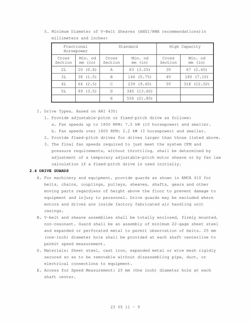
23 05 11 - 9
5. Minimum Diameter of V-Belt Sheaves (ANSI/RMA recommendations)in
millimeters and inches:
Fractional Horsepower
Standard High Capacity
Cross Section
Min. od mm (in)
Cross Section
Min. od mm (in)
Cross Section
Min. od mm (in)
2L 20 (0.8) A 83 (3.25) 3V 67 (2.65)
3L 38 (1.5) B 146 (5.75) 4V 180 (7.10)
4L 64 (2.5) C 239 (9.40) 5V 318 (12.50)
5L 89 (3.5) D 345 (13.60)
E 554 (21.80)
I. Drive Types, Based on ARI 435:
1. Provide adjustable-pitch or fixed-pitch drive as follows:
a. Fan speeds up to 1800 RPM: 7.5 kW (10 horsepower) and smaller.
b. Fan speeds over 1800 RPM: 2.2 kW (3 horsepower) and smaller.
2. Provide fixed-pitch drives for drives larger than those listed above.
3. The final fan speeds required to just meet the system CFM and
pressure requirements, without throttling, shall be determined by
adjustment of a temporary adjustable-pitch motor sheave or by fan law
calculation if a fixed-pitch drive is used initially.
2.4 DRIVE GUARDS
A. For machinery and equipment, provide guards as shown in AMCA 410 for
belts, chains, couplings, pulleys, sheaves, shafts, gears and other
moving parts regardless of height above the floor to prevent damage to
equipment and injury to personnel. Drive guards may be excluded where
motors and drives are inside factory fabricated air handling unit
casings.
B. V-belt and sheave assemblies shall be totally enclosed, firmly mounted,
non-resonant. Guard shall be an assembly of minimum 22-gage sheet steel
and expanded or perforated metal to permit observation of belts. 25 mm
(one-inch) diameter hole shall be provided at each shaft centerline to
permit speed measurement.
D. Materials: Sheet steel, cast iron, expanded metal or wire mesh rigidly
secured so as to be removable without disassembling pipe, duct, or
electrical connections to equipment.
E. Access for Speed Measurement: 25 mm (One inch) diameter hole at each
shaft center.
23 05 11 - 10
2.5 LIFTING ATTACHMENTS
Provide equipment with suitable lifting attachments to enable equipment
to be lifted in its normal position. Lifting attachments shall withstand
any handling conditions that might be encountered, without bending or
distortion of shape, such as rapid lowering and braking of load.
2.6 ELECTRIC MOTORS
A. All material and equipment furnished and installation methods shall
conform to the requirements of Section 23 05 12, GENERAL MOTOR
REQUIREMENTS FOR HVAC EQUIPMENT; Section 26 29 11, LOW-VOLTAGE MOTOR
STARTERS; and, Section 26 05 21, LOW-VOLTAGE ELECTRICAL POWER CONDUCTORS
AND CABLES (600 VOLTS AND BELOW). Provide all electrical wiring,
conduit, and devices necessary for the proper connection, protection and
operation of the systems. Provide special energy efficient motors as
scheduled. Unless otherwise specified for a particular application use
electric motors with the following requirements.
B. Single-phase Motors: Capacitor-start type for hard starting
applications. Motors for centrifugal fans may be split phase or
permanent split capacitor (PSC).
C. Poly-phase Motors: NEMA Design B, Squirrel cage, induction type. Each
two-speed motor shall have two separate windings. Provide a time- delay
(20 seconds minimum) relay for switching from high to low speed.
D. Rating: Continuous duty at 100 percent capacity in an ambient
temperature of 40 degrees centigrade (104 degrees F); minimum horsepower
as shown on drawings; maximum horsepower in normal operation not to
exceed nameplate rating without service factor.
E. Special Requirements:
1. Where motor power requirements of equipment furnished deviate from
power shown on plans, provide electrical service designed under the
requirements of NFPA 70 without additional time or cost to the
Government.
2. Assemblies of motors, starters, controls, and interlocks on factory
assembled and wired devices shall be in accordance with the
requirements of this specification.
3. Wire and cable materials specified in the electrical division of the
specifications shall be modified as follows:
a. Wiring material located where temperatures can exceed 71 degrees C
(160 degrees F) shall be stranded copper with Teflon FEP
insulation with jacket. This includes wiring on the boilers.
b. Other wiring at boilers and to control panels shall be NFPA 70
designation THWN.
23 05 11 - 11
c. Provide shielded conductors or wiring in separate conduits for all
instrumentation and control systems where recommended by
manufacturer of equipment.
4. Select motor sizes so that the motors do not operate into the service
factor at maximum required loads on the driven equipment. Motors on
pumps shall be sized for non-overloading at all points on the pump
performance curves.
5. Motors utilized with variable frequency drives shall be rated
“inverter-ready” per NEMA Standard, MG1, Part 31.4.4.2. Provide
motor shaft grounding apparatus that will protect bearings from
damage from stray currents.
F. Motor Efficiency and Power Factor: All motors, when specified as “high
efficiency” by the project specifications on driven equipment, shall
conform to efficiency and power factor requirements in Section 23 05 12,
GENERAL MOTOR REQUIREMENTS FOR HVAC EQUIPMENT, with no consideration of
annual service hours. Motor manufacturers generally define these
efficiency requirements as “NEMA premium efficient” and the requirements
generally exceed those of the Energy Policy Act of 1992 (EPACT). Motors
not specified as “high efficiency” shall comply with EPACT.
G. Insulation Resistance: Not less than one-half meg-ohm between stator
conductors and frame, to be determined at the time of final inspection.
2.7 VARIABLE SPEED MOTOR CONTROLLERS
A. Refer to Section 26 05 11, REQUIREMENTS FOR ELECTRICAL INSTALLATIONS and
Section 26 29 11, LOW-VOLTAGE MOTOR STARTERS for specifications.
B. The combination of controller and motor shall be provided by the
manufacturer of the driven equipment, fans, and shall be rated for 100
percent output performance. Multiple units of the same class of
equipment, i.e. air handlers, fans, pumps, shall be product of a single
manufacturer.
C. Motors shall be energy efficient type and be approved by the motor
controller manufacturer. The controller-motor combination shall be
guaranteed to provide full motor nameplate horsepower in variable
frequency operation. Both driving and driven motor/fan sheaves shall be
fixed pitch.
D. Controller shall not add any current or voltage transients to the input
AC power distribution system, DDC controls, sensitive medical equipment,
etc., nor shall be affected from other devices on the AC power system.
23 05 11 - 12
2.8 EQUIPMENT AND MATERIALS IDENTIFICATION
A. Use symbols, nomenclature and equipment numbers specified, shown on the
drawings and shown in the maintenance manuals. In addition, provide bar
code identification nameplate for all equipment which will allow the
equipment identification code to be scanned into the system for
maintenance and inventory tracking. Identification for piping is
specified in Section 09 91 00, PAINTING.
B. Interior (Indoor) Equipment: Engraved nameplates, with letters not less
than 48 mm (3/16-inch) high of brass with black-filled letters, or rigid
black plastic with white letters specified in Section 09 91 00, PAINTING
permanently fastened to the equipment. Identify unit components such as
coils, filters, fans, etc.
C. Exterior (Outdoor) Equipment: Brass nameplates, with engraved black
filled letters, not less than 48 mm (3/16-inch) high riveted or bolted
to the equipment.
D. Control Items: Label all temperature and humidity sensors, controllers
and control dampers. Identify and label each item as they appear on the
control diagrams.
E. Valve Tags and Lists:
1. Valve tags: Engraved black filled numbers and letters not less than
13 mm (1/2-inch) high for number designation, and not less than 6.4
mm(1/4-inch) for service designation on 19 gage 38 mm (1-1/2 inches)
round brass disc, attached with brass "S" hook or brass chain.
3. Valve lists: Typed or printed plastic coated card(s), sized 216
mm(8-1/2 inches) by 280 mm (11 inches) showing tag number, valve
function and area of control, for each service or system. Punch
sheets for a 3-ring notebook.
4. Provide detailed plan for each floor of the building indicating the
location and valve number for each valve. Identify location of each
valve with a color coded thumb tack in ceiling.
2.9 FIRESTOPPING
Section 07 84 00, FIRESTOPPING specifies an effective barrier against
the spread of fire, smoke and gases where penetrations occur for piping
and ductwork. Refer to Section 23 07 11, HVAC AND PLUMBING INSULATION,
for firestop pipe and duct insulation.
2.10 GALVANIZED REPAIR COMPOUND
Mil. Spec. DOD-P-21035B, paint form.
2.11 HVAC PIPE AND EQUIPMENT SUPPORTS AND RESTRAINTS
A. Vibration Isolators: Refer to Section 23 05 41, NOISE AND VIBRATION
CONTROL FOR HVAC PIPING AND EQUIPMENT.
23 05 11 - 13
B. Supports for Roof Mounted Items:
1. Equipment: Equipment rails shall be galvanized steel, minimum 1.3 mm
(18 gauge), with integral baseplate, continuous welded corner seams,
factory installed 50 mm by 100 mm (2 by 4) treated wood nailer, 1.3
mm (18 gauge) galvanized steel counter flashing cap with screws,
built-in cant strip, (except for gypsum or tectum deck), minimum
height 280 mm (11 inches). For surface insulated roof deck, provide
raised cant strip to start at the upper surface of the insulation.
2. Pipe/duct pedestals: Provide a galvanized Unistrut channel welded to
U-shaped mounting brackets which are secured to side of rail with
galvanized lag bolts.
D. Pipe Supports: Comply with MSS SP-58. Type Numbers specified refer to
this standard. For selection and application comply with MSS SP-69.
E. Attachment to Steel Building Construction:
1. Welded attachment: MSS SP-58, Type 22.
2. Beam clamps: MSS SP-58, Types 20, 21, 28 or 29. Type 23 C-clamp may
be used for individual copper tubing up to 23mm (7/8-inch) outside
diameter.
F. Attachment to Metal Pan or Deck: As required for materials specified in
Section 05 31 00, STEEL DECKING.
G. Hanger Rods: Hot-rolled steel, ASTM A36 or A575 for allowable load
listed in MSS SP-58. For piping, provide adjustment means for
controlling level or slope. Types 13 or 15 turn-buckles shall provide 38
mm (1-1/2 inches) minimum of adjustment and incorporate locknuts.
All-thread rods are acceptable.
H. Hangers Supporting Multiple Pipes (Trapeze Hangers): Galvanized, cold
formed, lipped steel channel horizontal member, not less than 41 mm by
41 mm (1-5/8 inches by 1-5/8 inches), 2.7 mm (No. 12 gage), designed to
accept special spring held, hardened steel nuts. Not permitted for steam
supply and condensate piping.
1. Allowable hanger load: Manufacturers rating less 91kg (200 pounds).
2. Guide individual pipes on the horizontal member of every other
trapeze hanger with 6 mm (1/4-inch) U-bolt fabricated from steel rod.
Provide Type 40 insulation shield, secured by two 13mm (1/2-inch)
galvanized steel bands, or preinsulated calcium silicate shield for
insulated piping at each hanger.
23 05 11 - 14
I. Supports for Piping Systems:
1. Select hangers sized to encircle insulation on insulated piping.
Refer to Section 23 07 11, HVAC AND PLUMBING INSULATION for
insulation thickness. To protect insulation, provide Type 39 saddles
for roller type supports or preinsulated calcium silicate shields.
Provide Type 40 insulation shield or preinsulated calcium silicate
shield at all other types of supports and hangers including those for
preinsulated piping.
2. Piping Systems except High and Medium Pressure Steam (MSS SP-58):
a. Standard clevis hanger: Type 1; provide locknut.
b. Riser clamps: Type 8.
c. Wall brackets: Types 31, 32 or 33.
d. Roller supports: Type 41, 43, 44 and 46.
e. Saddle support: Type 36, 37 or 38.
f. Turnbuckle: Types 13 or 15. Preinsulate.
g. U-bolt clamp: Type 24.
h. Copper Tube:
1) Hangers, clamps and other support material in contact with
tubing shall be painted with copper colored epoxy paint,
plastic coated or taped with non adhesive isolation tape to
prevent electrolysis.
2) For vertical runs use epoxy painted or plastic coated riser
clamps.
3) For supporting tube to strut: Provide epoxy painted pipe straps
for copper tube or plastic inserted vibration isolation clamps.
4) Insulated Lines: Provide pre-insulated calcium silicate shields
sized for copper tube.
3. High and Medium Pressure Steam (MSS SP-58):
a. Provide eye rod or Type 17 eye nut near the upper attachment.
b. Piping 50 mm (2 inches) and larger: Type 43 roller hanger. For
roller hangers requiring seismic bracing provide a Type 1 clevis
hanger with Type 41 roller attached by flat side bars.
c. Piping with Vertical Expansion and Contraction:
1) Movement up to 20 mm (3/4-inch): Type 51 or 52 variable spring
unit with integral turn buckle and load indicator.
2) Movement more than 20 mm (3/4-inch): Type 54 or 55 constant
support unit with integral adjusting nut, turn buckle and
travel position indicator.
23 05 11 - 15
J. Pre-insulated Calcium Silicate Shields:
1. Provide 360 degree water resistant high density 965 kPa (140 psi)
compressive strength calcium silicate shields encased in galvanized
metal.
2. Pre-insulated calcium silicate shields to be installed at the point
of support during erection.
3. Shield thickness shall match the pipe insulation.
4. The type of shield is selected by the temperature of the pipe, the
load it must carry, and the type of support it will be used with.
a. Shields for supporting chilled or cold water shall have insulation
that extends a minimum of 1 inch past the sheet metal. Provide for
an adequate vapor barrier in chilled lines.
b. The pre-insulated calcium silicate shield shall support the
maximum allowable water filled span as indicated in MSS-SP 69. To
support the load, the shields may have one or more of the
following features: structural inserts 4138 kPa (600 psi)
compressive strength, an extra bottom metal shield, or formed
structural steel (ASTM A36) wear plates welded to the bottom sheet
metal jacket.
5. Shields may be used on steel clevis hanger type supports, roller supports or flat surfaces.
K. Seismic Restraint of Piping and Ductwork: Refer to Section 23 05 48,
SEISMIC/VIBRATION ISOLATION FOR MECHANICAL COMPONENTS. Comply with MSS
SP-127.
2.12 PIPE PENETRATIONS
A. Install sleeves during construction for other than blocked out floor
openings for risers in mechanical bays.
B. To prevent accidental liquid spills from passing to a lower level,
provide the following:
1. For sleeves: Extend sleeve 25 mm (one inch) above finished floor and
provide sealant for watertight joint.
2. For blocked out floor openings: Provide 40 mm (1-1/2 inch) angle set
in silicone adhesive around opening.
3. For drilled penetrations: Provide 40 mm (1-1/2 inch) angle ring or
square set in silicone adhesive around penetration.
C. Penetrations are not allowed through beams or ribs, but may be installed
in concrete beam flanges. Any deviation from these requirements must
receive prior approval of Resident Engineer.
23 05 11 - 16
D. Sheet Metal, Plastic, or Moisture-resistant Fiber Sleeves: Provide for
pipe passing through floors, interior walls, and partitions, unless
brass or steel pipe sleeves are specifically called for below.
E. Cast Iron or Zinc Coated Pipe Sleeves: Provide for pipe passing through
exterior walls below grade. Make space between sleeve and pipe
watertight with a modular or link rubber seal. Seal shall be applied at
both ends of sleeve.
F. Galvanized Steel or an alternate Black Iron Pipe with asphalt coating
Sleeves: Provide for pipe passing through concrete beam flanges, except
where brass pipe sleeves are called for. Provide sleeve for pipe passing
through floor of mechanical rooms, laundry work rooms, and animal rooms
above basement. Except in mechanical rooms, connect sleeve with floor
plate.
G. Brass Pipe Sleeves: Provide for pipe passing through quarry tile,
terrazzo or ceramic tile floors. Connect sleeve with floor plate.
H. Sleeves are not required for wall hydrants for fire department
connections or in drywall construction.
I. Sleeve Clearance: Sleeve through floors, walls, partitions, and beam
flanges shall be one inch greater in diameter than external diameter of
pipe. Sleeve for pipe with insulation shall be large enough to
accommodate the insulation. Interior openings shall be caulked tight
with fire stopping material and sealant to prevent the spread of fire,
smoke, and gases.
J. Sealant and Adhesives: Shall be as specified in Section 07 92 00, JOINT
SEALANTS.
2.13 SPECIAL TOOLS AND LUBRICANTS
A. Furnish, and turn over to the RE/COTR, special tools not readily
available commercially, that are required for disassembly or adjustment
of equipment and machinery furnished.
B. Grease Guns with Attachments for Applicable Fittings: One for each type
of grease required for each motor or other equipment.
C. Tool Containers: Hardwood or metal, permanently identified for in tended
service and mounted, or located, where directed by the Resident
Engineer.
D. Lubricants: A minimum of 0.95 L (one quart) of oil, and 0.45 kg (one
pound) of grease, of equipment manufacturer's recommended grade and
type, in unopened containers and properly identified as to use for each
different application.
23 05 11 - 17
2.14 WALL, FLOOR AND CEILING PLATES
A. Material and Type: Chrome plated brass or chrome plated steel, one piece
or split type with concealed hinge, with set screw for fastening to
pipe, or sleeve. Use plates that fit tight around pipes, cover openings
around pipes and cover the entire pipe sleeve projection.
B. Thickness: Not less than 2.4 mm (3/32-inch) for floor plates. For wall
and ceiling plates, not less than 0.64 mm (0.025-inch) for up to 80 mm
(3-inch pipe), 0.89 mm (0.035-inch) for larger pipe.
C. Locations: Use where pipe penetrates floors, walls and ceilings in
exposed locations, in finished areas only. Use also where insulation
ends on exposed water supply pipe drop from overhead. Provide a
watertight joint in spaces where brass or steel pipe sleeves are
specified.
2.15 ASBESTOS
Materials containing asbestos are not permitted.
PART 3 - EXECUTION
3.1 ARRANGEMENT AND INSTALLATION OF EQUIPMENT AND PIPING
A. Coordinate location of piping, sleeves, inserts, hangers, ductwork and
equipment. Locate piping, sleeves, inserts, hangers, ductwork and
equipment clear of windows, doors, openings, light outlets, and other
services and utilities. Prepare equipment layout drawings to coordinate
proper location and personnel access of all facilities. Submit the
drawings for review as required by Part 1. Follow manufacturer's
published recommendations for installation methods not otherwise
specified.
B. Operating Personnel Access and Observation Provisions: Select and
arrange all equipment and systems to provide clear view and easy access,
without use of portable ladders, for maintenance and operation of all
devices including, but not limited to: all equipment items, valves,
filters, strainers, transmitters, sensors, control devices. All gages
and indicators shall be clearly visible by personnel standing on the
floor or on permanent platforms. Do not reduce or change maintenance and
operating space and access provisions that are shown on the drawings.
C. Equipment and Piping Support: Coordinate structural systems necessary
for pipe and equipment support with pipe and equipment locations to
permit proper installation.
D. Location of pipe sleeves, trenches and chases shall be accurately
coordinated with equipment and piping locations.
E. Cutting Holes:

23 05 11 - 18
1. Cut holes through concrete and masonry by rotary core drill.
Pneumatic hammer, impact electric, and hand or manual hammer type
drill will not be allowed, except as permitted by RE/COTR where
working area space is limited.
23 05 11 - 19
2. Locate holes to avoid interference with structural members such as
beams or grade beams. Holes shall be laid out in advance and drilling
done only after approval by RE/COTR. If the Contractor considers it
necessary to drill through structural members, this matter shall be
referred to RE/COTR for approval.
3. Do not penetrate membrane waterproofing.
F. Interconnection of Instrumentation or Control Devices: Generally,
electrical and pneumatic interconnections are not shown but must be
provided.
G. Minor Piping: Generally, small diameter pipe runs from drips and drains,
water cooling, and other service are not shown but must be provided.
H. Electrical and Pneumatic Interconnection of Controls and Instruments:
This generally not shown but must be provided. This includes
interconnections of sensors, transmitters, transducers, control devices,
control and instrumentation panels, instruments and computer
workstations. Comply with NFPA-70.
I. Protection and Cleaning:
1. Equipment and materials shall be carefully handled, properly stored,
and adequately protected to prevent damage before and during
installation, in accordance with the manufacturer's recommendations
and as approved by the Resident Engineer. Damaged or defective items
in the opinion of the Resident Engineer shall be replaced.
2. Protect all finished parts of equipment, such as shafts and bearings
where accessible, from rust prior to operation by means of protective
grease coating and wrapping. Close pipe openings with caps or plugs
during installation. Tightly cover and protect fixtures and equipment
against dirt, water chemical, or mechanical injury. At completion of
all work thoroughly clean fixtures, exposed materials and equipment.
J. Concrete and Grout: Use concrete and shrink compensating grout 25 MPa
(3000 psi) minimum, specified in Section 03 30 00, CAST-IN-PLACE
CONCRETE.
K. Install gages, thermometers, valves and other devices with due regard
for ease in reading or operating and maintaining said devices. Locate
and position thermometers and gages to be easily read by operator or
staff standing on floor or walkway provided. Servicing shall not require
dismantling adjacent equipment or pipe work.
L. Install steam piping expansion joints as per manufacturer’s
recommendations.
23 05 11 - 20
M. Work in Existing Building:
1. Perform as specified in Article, OPERATIONS AND STORAGE AREAS,
Article, ALTERATIONS, and Article, RESTORATION of the Section 01 00
00, GENERAL REQUIREMENTS for relocation of existing equipment,
alterations and restoration of existing building(s).
2. As specified in Section 01 00 00, GENERAL REQUIREMENTS, Article,
OPERATIONS AND STORAGE AREAS, make alterations to existing service
piping at times that will least interfere with normal operation of
the facility.
3. Cut required openings through existing masonry and reinforced
concrete using diamond core drills. Use of pneumatic hammer type
drills, impact type electric drills, and hand or manual hammer type
drills, will be permitted only with approval of the Resident
Engineer. Locate openings that will least effect structural slabs,
columns, ribs or beams. Refer to the Resident Engineer for
determination of proper design for openings through structural
sections and opening layouts approval, prior to cutting or drilling
into structure. After Resident Engineer's approval, carefully cut
opening through construction no larger than absolutely necessary for
the required installation.
N. Work in Animal Research Areas: Seal all pipe and duct penetrations with
silicone sealant to prevent entrance of insects.
O. Switchgear Drip Protection: Every effort shall be made to eliminate the
installation of pipe above electrical and telephone switchgear. If this
is not possible, encase pipe in a second pipe with a minimum of joints.
P. Inaccessible Equipment:
1. Where the Government determines that the Contractor has installed
equipment not conveniently accessible for operation and maintenance,
equipment shall be removed and reinstalled or remedial action
performed as directed at no additional cost to the Government.
2. The term "conveniently accessible" is defined as capable of being
reached without the use of ladders, or without climbing or crawling
under or over obstacles such as motors, fans, pumps, belt guards,
transformers, high voltage lines, piping, and ductwork.
3.2 TEMPORARY PIPING AND EQUIPMENT
A. Continuity of operation of existing facilities will generally require
temporary installation or relocation of equipment and piping.
23 05 11 - 21
B. The Contractor shall provide all required facilities in accordance with
the requirements of phased construction and maintenance of service. All
piping and equipment shall be properly supported, sloped to drain,
operate without excessive stress, and shall be insulated where injury
can occur to personnel by contact with operating facilities. The
requirements of Para. 3.1 apply.
C. Temporary facilities and piping shall be completely removed and any
openings in structures sealed. Provide necessary blind flanges and caps
to seal open piping remaining in service.
3.3 RIGGING
A. Design is based on application of available equipment. Openings in
building structures are planned to accommodate design scheme.
B. Alternative methods of equipment delivery may be offered by Contractor
and will be considered by Government under specified restrictions of
phasing and maintenance of service as well as structural integrity of
the building.
C. Close all openings in the building when not required for rigging
operations to maintain proper environment in the facility for Government
operation and maintenance of service.
D. Contractor shall provide all facilities required to deliver specified
equipment and place on foundations. Attachments to structures for
rigging purposes and support of equipment on structures shall be
Contractor's full responsibility. Upon request, the Government will
check structure adequacy and advise Contractor of recommended
restrictions.
E. Contractor shall check all clearances, weight limitations and shall
offer a rigging plan designed by a Registered Professional Engineer. All
modifications to structures, including reinforcement thereof, shall be
at Contractor's cost, time and responsibility.
F. Rigging plan and methods shall be referred to RE/COTR for evaluation
prior to actual work.
G. Restore building to original condition upon completion of rigging work.
3.4 PIPE AND EQUIPMENT SUPPORTS
A. Where hanger spacing does not correspond with joist or rib spacing, use
structural steel channels secured directly to joist and rib structure
that will correspond to the required hanger spacing, and then suspend
the equipment and piping from the channels. Drill or burn holes in
structural steel only with the prior approval of the RE/COTR.
23 05 11 - 22
B. Use of chain, wire or strap hangers; wood for blocking, stays and
bracing; or, hangers suspended from piping above will not be permitted.
Replace or thoroughly clean rusty products and paint with zinc primer.
C. Use hanger rods that are straight and vertical. Turnbuckles for vertical
adjustments may be omitted where limited space prevents use. Provide a
minimum of 15 mm (1/2-inch) clearance between pipe or piping covering
and adjacent work.
D. HVAC Horizontal Pipe Support Spacing: Refer to MSS SP-69. Provide
additional supports at valves, strainers, in-line pumps and other heavy
components. Provide a support within one foot of each elbow.
E. HVAC Vertical Pipe Supports:
1. Up to 150 mm (6-inch pipe), 9 m (30 feet) long, bolt riser clamps to
the pipe below couplings, or welded to the pipe and rests supports
securely on the building structure.
2. Vertical pipe larger than the foregoing, support on base elbows or
tees, or substantial pipe legs extending to the building structure.
F. Overhead Supports:
1. The basic structural system of the building is designed to sustain
the loads imposed by equipment and piping to be supported overhead.
2. Provide steel structural members, in addition to those shown, of
adequate capability to support the imposed loads, located in
accordance with the final approved layout of equipment and piping.
3. Tubing and capillary systems shall be supported in channel troughs.
G. Floor Supports:
1. Provide concrete bases, concrete anchor blocks and pedestals, and
structural steel systems for support of equipment and piping. Anchor
and dowel concrete bases and structural systems to resist forces
under operating and seismic conditions (if applicable) without
excessive displacement or structural failure.
2. Do not locate or install bases and supports until equipment mounted
thereon has been approved. Size bases to match equipment mounted
thereon plus 50 mm (2 inch) excess on all edges. Refer to structural
drawings. Bases shall be neatly finished and smoothed, shall have
chamfered edges at the top, and shall be suitable for painting.
3. All equipment shall be shimmed, leveled, firmly anchored, and grouted
with epoxy grout. Anchor bolts shall be placed in sleeves, anchored
to the bases. Fill the annular space between sleeves and bolts with a
granular material to permit alignment and realignment.
4. For seismic anchoring, refer to Section 23 05 48, SEISMIC/VIBRATION ISOLATION FOR MECHANICAL COMPONENTS.
23 05 11 - 23
3.5 MECHANICAL DEMOLITION
A. Rigging access, other than indicated on the drawings, shall be provided
by the Contractor after approval for structural integrity by the
RE/COTR. Such access shall be provided without additional cost or time
to the Government. Where work is in an operating facility, provide
approved protection from dust and debris at all times for the safety of
facility personnel and maintenance of facility operation and environment
of the facility.
B. In an operating facility, maintain the operation, cleanliness and
safety. Government personnel will be carrying on their normal duties of
operating, cleaning and maintaining equipment and facility operation.
Confine the work to the immediate area concerned; maintain cleanliness
and wet down demolished materials to eliminate dust. Do not permit
debris to accumulate in the area to the detriment of facility operation.
Perform all flame cutting to maintain the fire safety integrity of this
plant. Adequate fire extinguishing facilities shall be available at all
times. Perform all work in accordance with recognized fire protection
standards. Inspection will be made by personnel of the VA Medical
Center, and Contractor shall follow all directives of the RE or COTR
with regard to rigging, safety, fire safety, and maintenance of
operations.
C. Completely remove all piping, wiring, conduit, and other devices
associated with the equipment not to be re-used in the new work. This
includes all pipe, valves, fittings, insulation, and all hangers
including the top connection and any fastenings to building structural
systems. Seal all openings, after removal of equipment, pipes, ducts,
and other penetrations in roof, walls, floors, in an approved manner and
in accordance with plans and specifications where specifically covered.
Structural integrity of the building system shall be maintained.
Reference shall also be made to the drawings and specifications of the
other disciplines in the project for additional facilities to be
demolished or handled.
D. All valves including gate, globe, ball, butterfly and check, all
pressure gages and thermometers with wells shall remain Government
property and shall be removed and delivered to RE/COTR and stored as
directed. The Contractor shall remove all other material and equipment,
devices and demolition debris under these plans and specifications. Such
material shall be removed from Government property expeditiously and
shall not be allowed to accumulate.
23 05 11 - 24
3.6 CLEANING AND PAINTING
A. Prior to final inspection and acceptance of the plant and facilities for
beneficial use by the Government, the plant facilities, equipment and
systems shall be thoroughly cleaned and painted. Refer to Section 09 91
00, PAINTING.
B. In addition, the following special conditions apply:
1. Cleaning shall be thorough. Use solvents, cleaning materials and methods recommended by the manufacturers for the specific tasks.
Remove all rust prior to painting and from surfaces to remain
unpainted. Repair scratches, scuffs, and abrasions prior to applying
prime and finish coats.
2. Material And Equipment Not To Be Painted Includes: a. Motors, controllers, control switches, and safety switches.
b. Control and interlock devices.
c. Regulators.
d. Pressure reducing valves.
e. Control valves and thermostatic elements.
f. Lubrication devices and grease fittings.
g. Copper, brass, aluminum, stainless steel and bronze surfaces.
h. Valve stems and rotating shafts.
i. Pressure gauges and thermometers.
j. Glass.
k. Name plates.
3. Control and instrument panels shall be cleaned, damaged surfaces
repaired, and shall be touched-up with matching paint obtained from
panel manufacturer.
4. Motors, steel and cast iron bases, and coupling guards shall be
cleaned, and shall be touched-up with the same color as utilized by
the pump manufacturer
5. Temporary Facilities: Apply paint to surfaces that do not have
existing finish coats.
6. Paint shall withstand the following temperatures without peeling or
discoloration:
a. Condensate -- 38 degrees C (100 degrees F) on insulation jacket
surface and 120 degrees C (250 degrees F) on metal pipe surface.
b. Steam -- 52 degrees C (125 degrees F) on insulation jacket surface
and 190 degrees C (375 degrees F) on metal pipe surface.
7. Final result shall be smooth, even-colored, even-textured factory
finish on all items. Completely repaint the entire piece of
equipment if necessary to achieve this.
23 05 11 - 25
3.7 IDENTIFICATION SIGNS
A. Provide laminated plastic signs, with engraved lettering not less than
5 mm (3/16-inch) high, designating functions, for all equipment,
switches, motor controllers, relays, meters, control devices, including
automatic control valves. Nomenclature and identification symbols shall
correspond to that used in maintenance manual, and in diagrams specified
elsewhere. Attach by chain, adhesive, or screws.
B. Factory Built Equipment: Metal plate, securely attached, with name and
address of manufacturer, serial number, model number, size, performance.
E. Pipe Identification: Refer to Section 09 91 00, PAINTING.
3.8 MOTOR AND DRIVE ALIGNMENT
A. Belt Drive: Set driving and driven shafts parallel and align so that the
corresponding grooves are in the same plane.
B. Direct-connect Drive: Securely mount motor in accurate alignment so that
shafts are free from both angular and parallel misalignment when both
motor and driven machine are operating at normal temperatures.
3.9 LUBRICATION
A. Lubricate all devices requiring lubrication prior to initial operation.
Field-check all devices for proper lubrication.
B. Equip all devices with required lubrication fittings or devices. Provide
a minimum of one liter (one quart) of oil and 0.5 kg (one pound) of
grease of manufacturer's recommended grade and type for each different
application; also provide 12 grease sticks for lubricated plug valves.
Deliver all materials to RE/COTR in unopened containers that are
properly identified as to application.
C. Provide a separate grease gun with attachments for applicable fittings
for each type of grease applied.
D. All lubrication points shall be accessible without disassembling
equipment, except to remove access plates.
3.10 STARTUP AND TEMPORARY OPERATION
Start up equipment as described in equipment specifications. Verify that
vibration is within specified tolerance prior to extended operation.
Temporary use of equipment is specified in Section 01 00 00, GENERAL
REQUIREMENTS, Article, TEMPORARY USE OF MECHANICAL AND ELECTRICAL
EQUIPMENT.
3.11 OPERATING AND PERFORMANCE TESTS
A. Prior to the final inspection, perform required tests as specified in
Section 01 00 00, GENERAL REQUIREMENTS, Article, TESTS, and submit the
test reports and records to the RE/COTR.
23 05 11 - 26
B. Should evidence of malfunction in any tested system, or piece of
equipment or component part thereof, occur during or as a result of
tests, make proper corrections, repairs or replacements, and repeat
tests at no additional cost to the Government.
C. When completion of certain work or system occurs at a time when final
control settings and adjustments cannot be properly made to make
performance tests, then make performance tests for heating systems and
for cooling systems respectively during first actual seasonal use of
respective systems following completion of work.
3.12 INSTRUCTIONS TO VA PERSONNEL
Provide in accordance with Article, INSTRUCTIONS, of Section 01 00 00,
GENERAL REQUIREMENTS.
- - - E N D - - -
23 05 12 - 1
SECTION 23 05 12 GENERAL MOTOR REQUIREMENTS FOR HVAC EQUIPMENT
PART 1 - GENERAL
1.1 DESCRIPTION:
This section specifies the furnishing, installation and connection of
motors for HVAC equipment.
1.2 RELATED WORK:
A. Section 26 05 11, REQUIREMENTS FOR ELECTRICAL INSTALLATIONS: General
electrical requirements that are common to more than one Section of
Division 26.
B. Section 26 29 11, LOW-VOLTAGE MOTOR STARTERS: Starters, control and
protection for motors.
C. Other sections specifying motor driven equipment in Division 23.
1.3 SUBMITTALS:
A. In accordance with Section 26 05 11, REQUIREMENTS FOR ELECTRICAL
INSTALLATIONS, submit the following:
B. Shop Drawings:
1. Sufficient information, clearly presented, shall be included to
determine compliance with drawings and specifications.
2. Include electrical ratings, dimensions, mounting details, materials,
horsepower, RPM, enclosure, starting characteristics, torque
characteristics, code letter, full load and locked rotor current,
service factor, and lubrication method.
C. Manuals:
1. Submit simultaneously with the shop drawings, companion copies of
complete maintenance and operating manuals, including technical data
sheets and application data.
D. Certification: Two weeks prior to final inspection, unless otherwise
noted, submit four copies of the following certification to the Resident
Engineer:
1. Certification that the motors have been properly applied, installed,
adjusted, lubricated, and tested.
1.4 APPLICABLE PUBLICATIONS:
A. Publications listed below (including amendments, addenda, revisions,
supplements and errata) form a part of this specification to the extent
referenced. Publications are referenced in the text by designation only.
B. National Electrical Manufacturers Association (NEMA):
MG 1-98.................Motors and Generators
23 05 12 - 2
MG 2-01.................Safety Standard and Guide for Selection,
Installation and Use of Electric Motors and
Generators
C. National Fire Protection Association (NFPA):
70-02...................National Electrical Code (NEC)
PART 2 - PRODUCTS
2.1 MOTORS:
A. For alternating current, fractional and integral horsepower motors, NEMA
Publications MG 1 and MG 2 shall apply.
B. Voltage ratings shall be as follows:
1. Single phase:
a. Motors connected to 120-volt systems: 115 volts.
b. Motors connected to 208-volt systems: 200 volts.
c. Motors connected to 240 volt or 480 volt systems: 230/460 volts,
dual connection.
2. Three phase:
a. Motors connected to 208-volt systems: 200 volts.
b. Motors, less than 74.6 kW (100 HP), connected to 240 volt or 480
volt systems: 230/460 volts, dual connection.
c. Motors, 74.6 kW (100 HP) or larger, connected to 240-volt systems:
230 volts.
d. Motors, 74.6 kW (100 HP) or larger, connected to 480-volt systems:
460 volts.
e. Motors connected to high voltage systems: Shall conform to NEMA
Standards for connection to the nominal system voltage shown on
the drawings.
C. Horsepower ratings shall be adequate for operating the connected loads
continuously in the prevailing ambient temperatures in areas where the
motors are installed, without exceeding the NEMA standard temperature
rises for the motor insulation.
D. Motor designs, as indicated by the NEMA code letters, shall be
coordinated with the connected loads to assure adequate starting and
running torque.
E. Motor Enclosures:
1. Shall be the NEMA types shown on the drawings for the motors.
2. Where the types of motor enclosures are not shown on the drawings,
they shall be the NEMA types, which are most suitable for the
environmental conditions where the motors are being installed.
3. Enclosures shall be primed and finish coated at the factory with
manufacturer's prime coat and standard finish.
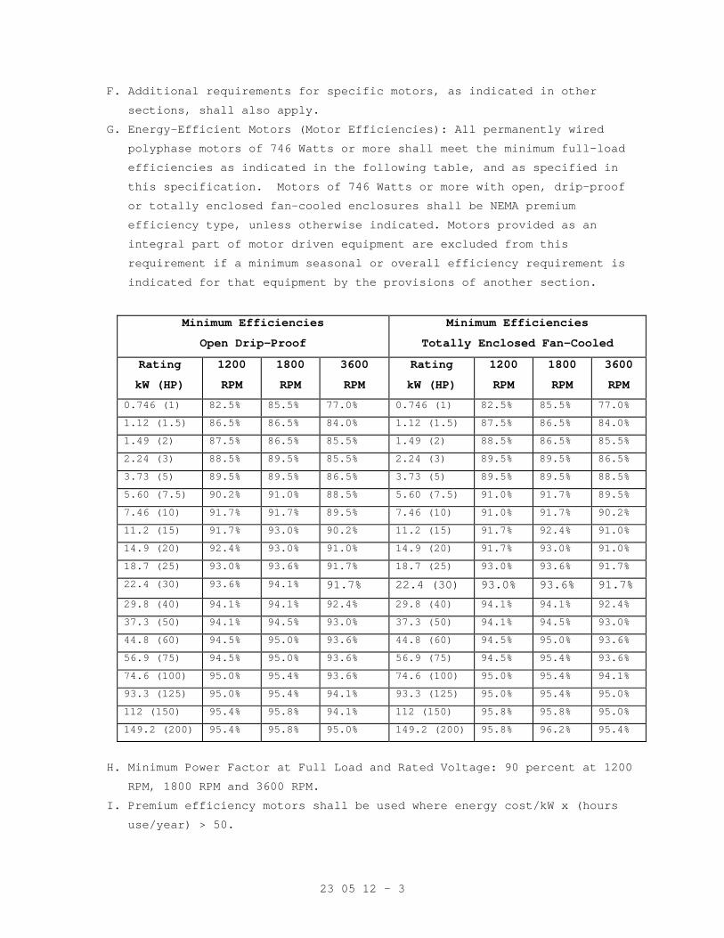
23 05 12 - 3
F. Additional requirements for specific motors, as indicated in other
sections, shall also apply.
G. Energy-Efficient Motors (Motor Efficiencies): All permanently wired
polyphase motors of 746 Watts or more shall meet the minimum full-load
efficiencies as indicated in the following table, and as specified in
this specification. Motors of 746 Watts or more with open, drip-proof
or totally enclosed fan-cooled enclosures shall be NEMA premium
efficiency type, unless otherwise indicated. Motors provided as an
integral part of motor driven equipment are excluded from this
requirement if a minimum seasonal or overall efficiency requirement is
indicated for that equipment by the provisions of another section.
Minimum Efficiencies
Open Drip-Proof
Minimum Efficiencies
Totally Enclosed Fan-Cooled
Rating
kW (HP)
1200
RPM
1800
RPM
3600
RPM
Rating
kW (HP)
1200
RPM
1800
RPM
3600
RPM
0.746 (1) 82.5% 85.5% 77.0% 0.746 (1) 82.5% 85.5% 77.0%
1.12 (1.5) 86.5% 86.5% 84.0% 1.12 (1.5) 87.5% 86.5% 84.0%
1.49 (2) 87.5% 86.5% 85.5% 1.49 (2) 88.5% 86.5% 85.5%
2.24 (3) 88.5% 89.5% 85.5% 2.24 (3) 89.5% 89.5% 86.5%
3.73 (5) 89.5% 89.5% 86.5% 3.73 (5) 89.5% 89.5% 88.5%
5.60 (7.5) 90.2% 91.0% 88.5% 5.60 (7.5) 91.0% 91.7% 89.5%
7.46 (10) 91.7% 91.7% 89.5% 7.46 (10) 91.0% 91.7% 90.2%
11.2 (15) 91.7% 93.0% 90.2% 11.2 (15) 91.7% 92.4% 91.0%
14.9 (20) 92.4% 93.0% 91.0% 14.9 (20) 91.7% 93.0% 91.0%
18.7 (25) 93.0% 93.6% 91.7% 18.7 (25) 93.0% 93.6% 91.7%
22.4 (30) 93.6% 94.1% 91.7% 22.4 (30) 93.0% 93.6% 91.7%
29.8 (40) 94.1% 94.1% 92.4% 29.8 (40) 94.1% 94.1% 92.4%
37.3 (50) 94.1% 94.5% 93.0% 37.3 (50) 94.1% 94.5% 93.0%
44.8 (60) 94.5% 95.0% 93.6% 44.8 (60) 94.5% 95.0% 93.6%
56.9 (75) 94.5% 95.0% 93.6% 56.9 (75) 94.5% 95.4% 93.6%
74.6 (100) 95.0% 95.4% 93.6% 74.6 (100) 95.0% 95.4% 94.1%
93.3 (125) 95.0% 95.4% 94.1% 93.3 (125) 95.0% 95.4% 95.0%
112 (150) 95.4% 95.8% 94.1% 112 (150) 95.8% 95.8% 95.0%
149.2 (200) 95.4% 95.8% 95.0% 149.2 (200) 95.8% 96.2% 95.4%
H. Minimum Power Factor at Full Load and Rated Voltage: 90 percent at 1200
RPM, 1800 RPM and 3600 RPM.
I. Premium efficiency motors shall be used where energy cost/kW x (hours
use/year) > 50.
23 05 12 - 4
PART 3 - EXECUTION
3.1 INSTALLATION:
Install motors in accordance with manufacturer’s recommendations, the
NEC, NEMA, as shown on the drawings and/or as required by other sections
of these specifications.
3.2 FIELD TESTS
Megger all motors after installation, before start-up. All shall test
free from grounds.
- - - E N D - - -
23 05 41 - 1
SECTION 23 05 41 NOISE AND VIBRATION CONTROL FOR HVAC PIPING AND EQUIPMENT
PART 1 - GENERAL
1.1 DESCRIPTION
Noise criteria, seismic restraints for equipment, vibration tolerance
and vibration isolation for HVAC and plumbing work.
1.2 RELATED WORK
A. Section 03 30 00, CAST-IN-PLACE CONCRETE: Requirements for concrete
inertia bases.
B. Section 23 05 48, SEISMIC/VIBRATION ISOLATION FOR MECHANICAL
COMPONENTS: Seismic requirements for non-structural equipment
C. Section 23 05 11, COMMON WORK RESULTS FOR HVAC: General mechanical
requirements and items, which are common to more than one section of
Division 23.
D. Section 23 22 13, STEAM AND CONDENSATE HEATING PIPING: Requirements for
flexible pipe connectors to reciprocating and rotating mechanical
equipment.
E. Section 23 73 00, INDOOR CENTRAL-STATION AIR-HANDLING UNITS:
Requirements for optional Air Handling Unit internal vibration
isolation.
F. Section 23 31 00, HVAC DUCTS AND CASINGS: requirements for flexible
duct connectors, sound attenuators and sound absorbing duct lining.
G. SECTION 23 05 93, TESTING, ADJUSTING, AND BALANCING FOR HVAC:
requirements for sound and vibration tests.
1.3 QUALITY ASSURANCE
A. Refer to article, QUALITY ASSURANCE in specification Section 23 05 11,
COMMON WORK RESULTS FOR HVAC.
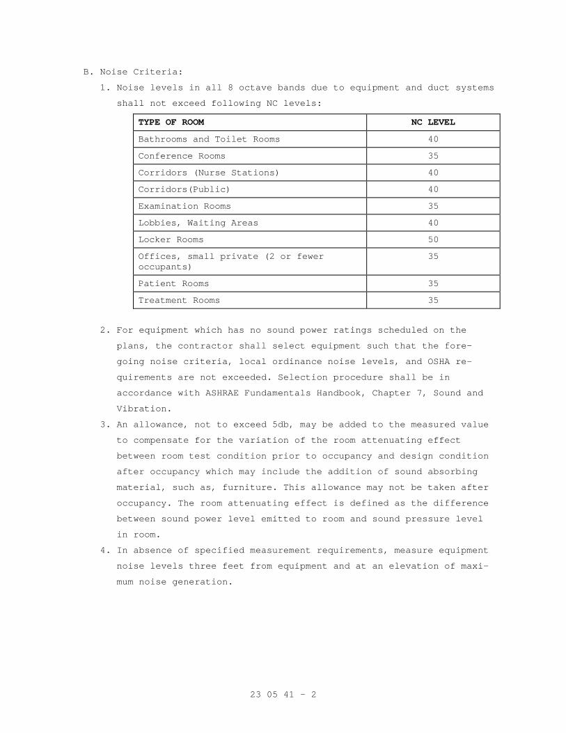
23 05 41 - 2
B. Noise Criteria:
1. Noise levels in all 8 octave bands due to equipment and duct systems
shall not exceed following NC levels:
TYPE OF ROOM NC LEVEL
Bathrooms and Toilet Rooms 40
Conference Rooms 35
Corridors (Nurse Stations) 40
Corridors(Public) 40
Examination Rooms 35
Lobbies, Waiting Areas 40
Locker Rooms 50
Offices, small private (2 or fewer occupants)
35
Patient Rooms 35
Treatment Rooms 35
2. For equipment which has no sound power ratings scheduled on the
plans, the contractor shall select equipment such that the fore-
going noise criteria, local ordinance noise levels, and OSHA re-
quirements are not exceeded. Selection procedure shall be in
accordance with ASHRAE Fundamentals Handbook, Chapter 7, Sound and
Vibration.
3. An allowance, not to exceed 5db, may be added to the measured value
to compensate for the variation of the room attenuating effect
between room test condition prior to occupancy and design condition
after occupancy which may include the addition of sound absorbing
material, such as, furniture. This allowance may not be taken after
occupancy. The room attenuating effect is defined as the difference
between sound power level emitted to room and sound pressure level
in room.
4. In absence of specified measurement requirements, measure equipment
noise levels three feet from equipment and at an elevation of maxi-
mum noise generation.
23 05 41 - 3
C. Seismic Restraint Requirements:
1. Equipment:
a. All mechanical equipment not supported with isolators external to
the unit shall be securely anchored to the structure. Such
mechanical equipment shall be properly supported to resist a
horizontal force of 50 percent of the weight of the equipment
furnished.
b. All mechanical equipment mounted on vibration isolators shall be
provided with seismic restraints capable of resisting a
horizontal force of 100 percent of the weight of the equipment
furnished.
2. Piping: Refer to specification Section 23 05 11, COMMON WORK RESULTS
FOR HVAC.
3. Ductwork: Refer to specification Section 23 31 00, HVAC DUCTS AND
CASINGS.
D. Allowable Vibration Tolerances for Rotating, Non-reciprocating Equip-
ment: Not to exceed a self-excited vibration maximum velocity of 5 mm
per second (0.20 inch per second) RMS, filter in, when measured with a
vibration meter on bearing caps of machine in vertical, horizontal and
axial directions or measured at equipment mounting feet if bearings are
concealed. Measurements for internally isolated fans and motors may be
made at the mounting feet.
1.4 SUBMITTALS
A. Submit in accordance with specification Section 01 33 23, SHOP
DRAWINGS, PRODUCT DATA, AND SAMPLES.
B. Manufacturer's Literature and Data:
1. Vibration isolators:
a. Floor mountings
b. Hangers
c. Snubbers
d. Thrust restraints
2. Bases.
3. Seismic restraint provisions and bolting.
4. Acoustical enclosures.
C. Isolator manufacturer shall furnish with submittal load calculations
for selection of isolators, including supplemental bases, based on
lowest operating speed of equipment supported.
23 05 41 - 4
D. Seismic Requirements: Submittals are required for all equipment an-
chors, supports and seismic restraints. Submittals shall include
weights, dimensions, standard connections, and manufacturer's
certification that all specified equipment will withstand seismic
Lateral Force requirements as shown on drawings,
1.5 APPLICABLE PUBLICATIONS
A. The publications listed below form a part of this specification to the
extent referenced. The publications are referenced in the text by the
basic designation only.
B. American Society of Heating, Refrigerating and Air-Conditioning
Engineers, Inc. (ASHRAE):
2005....................Fundamentals Handbook, Chapter 7, Sound and
Vibration
C. American Society for Testing and Materials (ASTM):
A123/A123M-02...........Standard Specification for Zinc (Hot-Dip
Galvanized) Coatings on Iron and Steel Products
A307-04.................Standard Specification for Carbon Steel Bolts
and Studs, 60,000 PSI Tensile Strength
D2240-05................Standard Test Method for Rubber Property -
Durometer Hardness
D. Manufacturers Standardization (MSS):
SP-58-02................Pipe Hangers and Supports-Materials, Design and
Manufacture
E. Occupational Safety and Health Administration (OSHA):
29 CFR 1910.95..........Occupational Noise Exposure
PART 2 - PRODUCTS
2.1 GENERAL REQUIREMENTS
A. Type of isolator, base, and minimum static deflection shall be as
required for each specific equipment application as recommended by
isolator or equipment manufacturer but subject to minimum requirements
indicated herein and in the schedule on the drawings.
B. Elastometric Isolators shall comply with ASTM D2240 and be oil
resistant neoprene with a maximum stiffness of 60 durometer and have a
straight-line deflection curve.
C. Exposure to weather: Isolators, including springs, exposed to weather
shall be hot dip galvanized after fabrication. Hot-dip zinc coating
shall not be less than 609 grams per square meter (two ounces per
square foot) by weight complying with ASTM A123.
23 05 41 - 5
D. Uniform Loading: Select and locate isolators to produce uniform loading
and deflection even when equipment weight is not evenly distributed.
E. Color code isolators by type and size for easy identification of
capacity.
2.2 SEISMIC RESTRAINT REQUIREMENTS FOR EQUIPMENTS
A. Bolt pad mounted equipment, without vibration isolators, to the floor
or other support using ASTM A307 standard bolting material.
B. Floor mounted equipment, with vibration Isolators: Type SS. Where Type
N isolators are used provide channel frame base horizontal restraints
bolted to the floor, or other support, on all sides of the equipment
Size and material required for the base shall be as recommended by the
isolator manufacturer.
C. On all sided of suspended equipment, provide bracing for rigid supports
and provide restraints for resiliently supported equipment. The slack
cable restraint method, Mason Industries, or equal, is acceptable.
2.3 VIBRATION ISOLATORS
A. Floor Mountings:
1. Double Deflection Neoprene (Type N): Shall include neoprene covered
steel support plated (top and bottom), friction pads, and necessary
bolt holes.
2. Captive Spring Mount for Seismic Restraint (Type SS):
a. Design mounts to resiliently resist seismic forces in all direc-
tions. Snubbing shall take place in all modes with adjustment to
limit upward, downward, and horizontal travel to a maximum of 6
mm (1/4-inch) before contacting snubbers. Mountings shall have a
minimum rating of one G coefficient of gravity as calculated and
certified by a registered structural engineer.
b. All mountings shall have leveling bolts that must be rigidly
bolted to the equipment. Spring diameters shall be no less than
0.8 of the compressed height of the spring at rated load. Springs
shall have a minimum additional travel to solid equal to 50
percent of the rated deflection. Mountings shall have ports for
spring inspection. Provide an all directional neoprene cushion
collar around the equipment bolt.
23 05 41 - 6
3. Spring Isolators with Vertical Limit Stops (Type SP): Similar to
spring isolators noted above, except include a vertical limit stop
to limit upward travel if weight is removed and also to reduce
movement and spring extension due to wind loads. Provide clearance
around restraining bolts to prevent mechanical short circuiting.
Isolators shall have a minimum seismic rating of one G.
4. Seismic Pad (Type DS): Pads shall be felt, cork neoprene waffle,
neoprene and cork sandwich, neoprene and fiberglass, neoprene and
steel waffle, or reinforced duck and neoprene, with steel top plate
and drilled for an anchor bolt. Washers and bushings shall be
reinforced duck and neoprene. Size pads for a maximum load of 345
kPa (50 pounds per square inch).
B. Hangers: Shall be combination neoprene and springs unless otherwise
noted and shall allow for expansion of pipe.
1. Combination Neoprene and Spring (Type H): Vibration hanger shall
contain a spring and double deflection neoprene element in series.
Spring shall have a diameter not less than 0.8 of compressed oper-
ating spring height. Spring shall have a minimum additional travel
of 50 percent between design height and solid height. Spring shall
permit a 15 degree angular misalignment without rubbing on hanger
box.
2. Spring Position Hanger (Type HP): Similar to combination neoprene
and spring hanger except hanger shall hold piping at a fixed
elevation during installation and include a secondary adjustment
feature to transfer load to spring while maintaining same position.
3. Neoprene (Type HN): Vibration hanger shall contain a double
deflection type neoprene isolation element. Hanger rod shall be
separated from contact with hanger bracket by a neoprene grommet.
4. Spring (Type HS): Vibration hanger shall contain a coiled steel
spring in series with a neoprene grommet. Spring shall have a
diameter not less than 0.8 of compressed operating spring height.
Spring shall have a minimum additional travel of 50 percent between
design height and solid height. Spring shall permit a 15 degree
angular misalignment without rubbing on hanger box.
5. Hanger supports for piping 50 mm (2 inches) and larger shall have a
pointer and scale deflection indicator.
23 05 41 - 7
C. Snubbers: Each spring mounted base shall have a minimum of four all-
directional or eight two directional (two per side) seismic snubbers
that are double acting. Elastomeric materials shall be shock absorbent
neoprene bridge quality bearing pads, maximum 60 durometer, replaceable
and have a minimum thickness of 6 mm (1/4 inch). Air gap between hard
and resilient material shall be not less than 3 mm (1/8 inch) nor more
than 6 mm (1/4 inch). Restraints shall be capable of withstanding
design load without permanent deformation.
D. Thrust Restraints (Type THR): Restraints shall provide a spring element
contained in a steel frame with neoprene pads at each end attachment.
Restraints shall have factory preset thrust and be field adjustable to
allow a maximum movement of 6 mm (1/4 inch) when the fan starts and
stops. Restraint assemblies shall include rods, angle brackets and
other hardware for field installation.
2.4 BASES
A. Rails (Type R): Design rails with isolator brackets to reduce mounting
height of equipment and cradle machines having legs or bases that do
not require a complete supplementary base. To assure adequate
stiffness, height of members shall be a minimum of 1/12 of longest base
dimension but not less than 100 mm (4 inches). Where rails are used
with neoprene mounts for small fans or close coupled pumps, extend
rails to compensate overhang of housing.
B. Integral Structural Steel Base (Type B): Design base with isolator
brackets to reduce mounting height of equipment which require a
complete supplementary rigid base. To assure adequate stiffness, height
of members shall be a minimum of 1/12 of longest base dimension, but
not less than 100 mm (four inches).
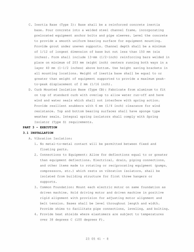
23 05 41 - 8
C. Inertia Base (Type I): Base shall be a reinforced concrete inertia
base. Pour concrete into a welded steel channel frame, incorporating
prelocated equipment anchor bolts and pipe sleeves. Level the concrete
to provide a smooth uniform bearing surface for equipment mounting.
Provide grout under uneven supports. Channel depth shall be a minimum
of 1/12 of longest dimension of base but not less than 150 mm (six
inches). Form shall include 13-mm (1/2-inch) reinforcing bars welded in
place on minimum of 203 mm (eight inch) centers running both ways in a
layer 40 mm (1-1/2 inches) above bottom. Use height saving brackets in
all mounting locations. Weight of inertia base shall be equal to or
greater than weight of equipment supported to provide a maximum peak-
to-peak displacement of 2 mm (1/16 inch).
D. Curb Mounted Isolation Base (Type CB): Fabricate from aluminum to fit
on top of standard curb with overlap to allow water run-off and have
wind and water seals which shall not interfere with spring action.
Provide resilient snubbers with 6 mm (1/4 inch) clearance for wind
resistance. Top and bottom bearing surfaces shall have sponge type
weather seals. Integral spring isolators shall comply with Spring
Isolator (Type S) requirements.
PART 3 - EXECUTION
3.1 INSTALLATION
A. Vibration Isolation:
1. No metal-to-metal contact will be permitted between fixed and
floating parts.
2. Connections to Equipment: Allow for deflections equal to or greater
than equipment deflections. Electrical, drain, piping connections,
and other items made to rotating or reciprocating equipment (pumps,
compressors, etc.) which rests on vibration isolators, shall be
isolated from building structure for first three hangers or
supports.
3. Common Foundation: Mount each electric motor on same foundation as
driven machine. Hold driving motor and driven machine in positive
rigid alignment with provision for adjusting motor alignment and
belt tension. Bases shall be level throughout length and width.
Provide shims to facilitate pipe connections, leveling, and bolting.
4. Provide heat shields where elastomers are subject to temperatures
over 38 degrees C (l00 degrees F).
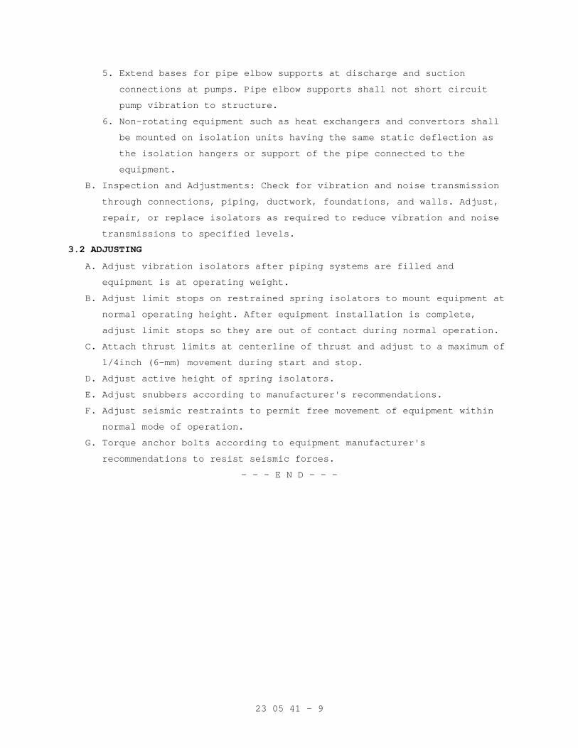
23 05 41 - 9
5. Extend bases for pipe elbow supports at discharge and suction
connections at pumps. Pipe elbow supports shall not short circuit
pump vibration to structure.
6. Non-rotating equipment such as heat exchangers and convertors shall
be mounted on isolation units having the same static deflection as
the isolation hangers or support of the pipe connected to the
equipment.
B. Inspection and Adjustments: Check for vibration and noise transmission
through connections, piping, ductwork, foundations, and walls. Adjust,
repair, or replace isolators as required to reduce vibration and noise
transmissions to specified levels.
3.2 ADJUSTING
A. Adjust vibration isolators after piping systems are filled and
equipment is at operating weight.
B. Adjust limit stops on restrained spring isolators to mount equipment at
normal operating height. After equipment installation is complete,
adjust limit stops so they are out of contact during normal operation.
C. Attach thrust limits at centerline of thrust and adjust to a maximum of
1/4inch (6-mm) movement during start and stop.
D. Adjust active height of spring isolators.
E. Adjust snubbers according to manufacturer's recommendations.
F. Adjust seismic restraints to permit free movement of equipment within
normal mode of operation.
G. Torque anchor bolts according to equipment manufacturer's
recommendations to resist seismic forces.
- - - E N D - - -
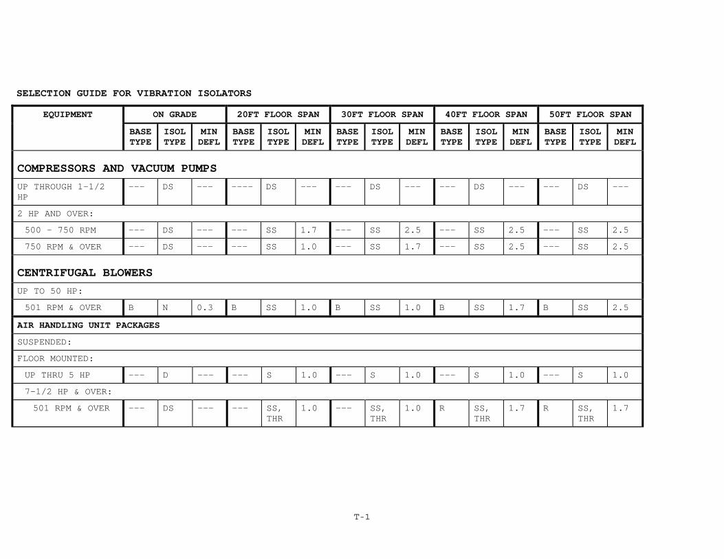
T-1
SELECTION GUIDE FOR VIBRATION ISOLATORS
EQUIPMENT ON GRADE 20FT FLOOR SPAN 30FT FLOOR SPAN 40FT FLOOR SPAN 50FT FLOOR SPAN
BASE TYPE
ISOL TYPE
MIN DEFL
BASE TYPE
ISOL TYPE
MIN DEFL
BASE TYPE
ISOL TYPE
MIN DEFL
BASE TYPE
ISOL TYPE
MIN DEFL
BASE TYPE
ISOL TYPE
MIN DEFL
COMPRESSORS AND VACUUM PUMPS UP THROUGH 1-1/2 HP
--- DS --- ---- DS --- --- DS --- --- DS --- --- DS ---
2 HP AND OVER:
500 - 750 RPM --- DS --- --- SS 1.7 --- SS 2.5 --- SS 2.5 --- SS 2.5
750 RPM & OVER --- DS --- --- SS 1.0 --- SS 1.7 --- SS 2.5 --- SS 2.5
CENTRIFUGAL BLOWERS UP TO 50 HP:
501 RPM & OVER B N 0.3 B SS 1.0 B SS 1.0 B SS 1.7 B SS 2.5
AIR HANDLING UNIT PACKAGES
SUSPENDED:
FLOOR MOUNTED:
UP THRU 5 HP --- D --- --- S 1.0 --- S 1.0 --- S 1.0 --- S 1.0
7-1/2 HP & OVER:
501 RPM & OVER --- DS --- --- SS, THR
1.0 --- SS, THR
1.0 R SS, THR
1.7 R SS, THR
1.7
23 05 48 - 1
SECTION 23 05 48 SEISMIC/VIBRATION ISOLATION FOR MECHANICAL COMPONENTS
PART 1 - GENERAL
1.1 DESCRIPTION
A. Intent:
1. All mechanical equipment, piping and ductwork as noted on the
equipment schedule or in the specification shall be mounted on
vibration isolators to prevent the transmission of vibration and
mechanically transmitted sound to the building structure. Vibration
isolators shall be selected in accordance with the weight
distribution so as to produce reasonably uniform deflections.
2. All isolators and isolation materials shall be of the same
manufacturer and shall be certified by the manufacturer.
3. It is the intent of the seismic portion of this specification to
keep all mechanical and electrical building system components in
place during a seismic event.
4. All such systems must be installed in strict accordance with seismic
codes, component manufacturer's and building construction standards.
Whenever a conflict occurs between the manufacturers or construction
standards, the most stringent shall apply.
5. This specification is considered to be minimum requirements for
seismic consideration and is not intended as a substitute for
legislated, more stringent, national, state or local construction
requirements (i.e. California Title 24, California OSHPD, Canadian
Building Codes, or other requirements).
6. Any variance or non-compliance with these specification requirements
shall be corrected by the contractor in an approved manner.
7. Seismic restraints shall be designed in accordance with seismic
force levels as detailed in section 1.06.
B. The work in this section includes, but is not limited to the following:
1. Vibration isolation for piping, ductwork and equipment.
2. Equipment isolation bases.
3. Flexible piping connections.
4. Seismic restraints for isolated equipment.
5. Seismic restraints for non-isolated equipment.
6. Certification of seismic restraint designs and installation
supervision.
7. Certification of seismic attachment of housekeeping pads.
23 05 48 - 2
8. All mechanical and electrical systems. Equipment buried underground
is excluded but entry of services through the foundation wall is
included. Equipment referred to below is typical. (Equipment not
listed is still included in this specification).
a. Air Distribution Boxes
b. Air Handling Units
c. Ductwork
d. Fans (all types)
e. Heat Exchangers
f. Piping
g. Tanks (all types)
h. Variable Frequency Drives
C. Definitions
1. Life Safety Systems:
a. All systems involved with fire protection including sprinkler
piping, fire pumps, jockey pumps, fire pump control panels,
service water supply piping, water tanks, fire dampers and smoke
exhaust systems.
b. All systems involved with and/or connected to emergency power
supply including all generators, transfer switches, transformers
and all flowpaths to fire protection and/or emergency lighting
systems.
c. All medical and life support systems.
d. Fresh air relief systems on emergency control sequence including
air handlers, conduit, duct, dampers, etc.
2. Positive Attachment: A positive attachment is defined as a cast-in
anchor, a drill-in wedge anchor, a double-sided beam clamp loaded
perpendicular to a beam, or a welded or bolted connection to
structure. Single sided SCB type beam clamps for support rods of
overhead piping, ductwork, fire protection, electrical conduit, bus
duct, or cable trays, or any other equipment are not acceptable on
this project as seismic attachment points.
3. Transverse Bracing: Restraint(s) applied to limit motion
perpendicular to the centerline of the pipe, duct or conduit.
4. Longitudinal Bracing: Restraint(s) applied to limit motion parallel
to the centerline of the pipe, duct or conduit.
23 05 48 - 3
1.2 SUBMITTAL DATA REQUIREMENTS
A. The manufacturer of vibration isolation and seismic restraints shall
provide submittals for products as follows:
1. Descriptive Data:
a. Catalog cuts or data sheets on vibration isolators and specific
restraints detailing compliance with the specification.
b. Detailed schedules of flexible and rigidly mounted equipment,
showing vibration isolators and seismic restraints by referencing
numbered descriptive drawings.
2. Shop Drawings:
a. Submit fabrication details for equipment bases including
dimensions, structural member sizes and support point locations.
b. Provide all details of suspension and support for ceiling
suspended equipment.
c. Where walls, floors, slabs or supplementary steel work are used
for seismic restraint locations, details of acceptable attachment
methods for ducts, conduit and pipe must be included and approved
before the condition is accepted for installation. Restraint
manufacturers' submittals must include spacing, static loads and
seismic loads at all attachment and support points.
d. Provide specific details of seismic restraints and anchors;
include number, size and locations for each piece of equipment.
e. Piping and duct restraint locations shall be field documented
during construction. Shop drawings of floor plan layouts shall
be prepared indicating actual field conditions and restraint
locations shall be clearly identified. Calculations, by a
registered professional engineer, and restraint details shall be
submitted to the project engineer for approval.
3. Seismic Certification and Analysis:
a. Seismic restraint calculations must be provided for all
connections of equipment to the structure. Calculations must be
stamped by a registered professional engineer with at least five
years of seismic design experience, licensed in the state of the
job location.
23 05 48 - 4
b. All restraining devices shall have a preapproval number from
California OSHPD or some other recognized government agency
showing maximum restraint ratings. Preapprovals based on
independent testing are preferred to preapprovals based on
calculations. Where preapproved devices are not available,
submittals based on independent testing are preferred.
Calculations (including the combining of tensile and shear
loadings) to support seismic restraint designs must be stamped by
a registered professional engineer with at least five years of
seismic design experience and licensed in the state of the job
location. Testing and calculations must include shear and tensile
loads as well as one test or analysis at 45 to the weakest mode.
c. Analysis must indicate calculated dead loads, static seismic
loads and capacity of materials utilized for connections to
equipment and structure. Analysis must detail anchoring methods,
bolt diameter, embedment and/or welded length. All seismic
restraint devices shall be designed to accept, without failure,
the forces detailed in Paragraph 1.06 acting through the
equipment center of gravity. Overturning moments may exceed
forces at ground level.
1.3 CODE AND STANDARDS REQUIREMENTS
A. Typical Applicable codes and Standards:
1. The Arkansas Fire Prevention Code 2002, based on the International
Building Code 2000.
2. Sheet Metal and Air Conditioning Contractors National Association's
“Seismic Restraint Manual Guidelines for Mechanical Systems - Second
Edition”.
3. National Uniform Seismic Installation Guidelines.
4. NFPA 5000 - The Building Construction and Safety Code.
1.4 MANUFACTURER'S RESPONSIBILITY
A. Manufacturer of vibration isolation and seismic control equipment shall
have the following responsibilities:
1. Determine vibration isolation and seismic restraint sizes and
locations.
2. Provide vibration isolation and seismic restraints as scheduled or
specified.
3. Provide calculations and materials if required for restraint of
unisolated equipment.
23 05 48 - 5
4. Provide installation instructions, drawings and trained field
supervision to insure proper installation and performance.
1.5 RELATED WORK
A. Housekeeping Pads:
1. Housekeeping pad reinforcement and monolithic pad attachment to the
structure details and design shall be prepared by the restraint
vendor if not already indicated on the drawings.
2. Housekeeping pads shall be coordinated with restraint vendor and
sized to provide a minimum edge distance of ten (10) bolt diameters
all around the outermost anchor bolt to allow development of full
drill-in wedge anchor ratings. If cast-in anchors are to be used,
the housekeeping pads shall be sized to accommodate the ACI
requirements for bolt coverage and embedment.
B. Supplementary Support Steel: Contractor shall supply supplementary
support steel for all equipment, piping, ductwork, etc. including roof-
mounted equipment, as required or specified.
C. Attachments: Contractor shall supply restraint attachment plates cast
into housekeeping pads, concrete inserts, double-sided beam clamps,
etc. in accordance with the requirements of the vibration vendor's
calculations.
1.6 SEISMIC FORCE LEVELS
A. The following are used to determine the “G” force levels used on this
project based on the codes listed in Section 1.03.
1. Component amplification factor (ap) for each type of component are
as follows:
a. High Deformability Pipe = 1.0
b. Rigidly Mounted Equipment and Limited Deformability Pipe = 1.0
c. Vibration Isolated Equipment and Pipe, Pressure Vessels = 2.5
d. Low Deformability Pipe = 1.0
2. Component Response Modification Factor (Rp) for each component are
as follows:
a. High Deformability Pipe = 3.5
b. Rigidly Mounted Equipment and Limited Deformability Pipe = 2.5
c. Vibration Isolated Equipment and Pipe, Pressure Vessels = 2.5
d. Low Deformability Pipe = 1.25
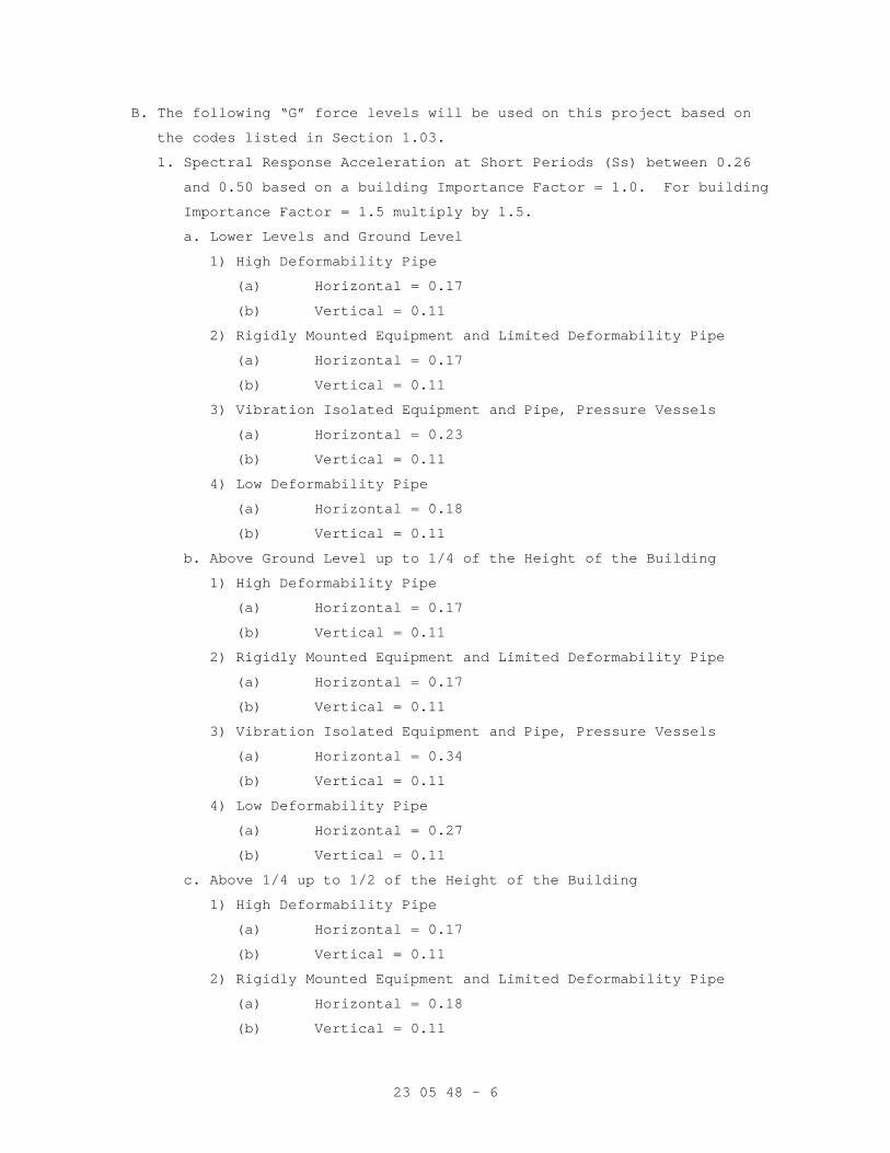
23 05 48 - 6
B. The following “G” force levels will be used on this project based on
the codes listed in Section 1.03.
1. Spectral Response Acceleration at Short Periods (Ss) between 0.26
and 0.50 based on a building Importance Factor = 1.0. For building
Importance Factor = 1.5 multiply by 1.5.
a. Lower Levels and Ground Level
1) High Deformability Pipe
(a) Horizontal = 0.17
(b) Vertical = 0.11
2) Rigidly Mounted Equipment and Limited Deformability Pipe
(a) Horizontal = 0.17
(b) Vertical = 0.11
3) Vibration Isolated Equipment and Pipe, Pressure Vessels
(a) Horizontal = 0.23
(b) Vertical = 0.11
4) Low Deformability Pipe
(a) Horizontal = 0.18
(b) Vertical = 0.11
b. Above Ground Level up to 1/4 of the Height of the Building
1) High Deformability Pipe
(a) Horizontal = 0.17
(b) Vertical = 0.11
2) Rigidly Mounted Equipment and Limited Deformability Pipe
(a) Horizontal = 0.17
(b) Vertical = 0.11
3) Vibration Isolated Equipment and Pipe, Pressure Vessels
(a) Horizontal = 0.34
(b) Vertical = 0.11
4) Low Deformability Pipe
(a) Horizontal = 0.27
(b) Vertical = 0.11
c. Above 1/4 up to 1/2 of the Height of the Building
1) High Deformability Pipe
(a) Horizontal = 0.17
(b) Vertical = 0.11
2) Rigidly Mounted Equipment and Limited Deformability Pipe
(a) Horizontal = 0.18
(b) Vertical = 0.11
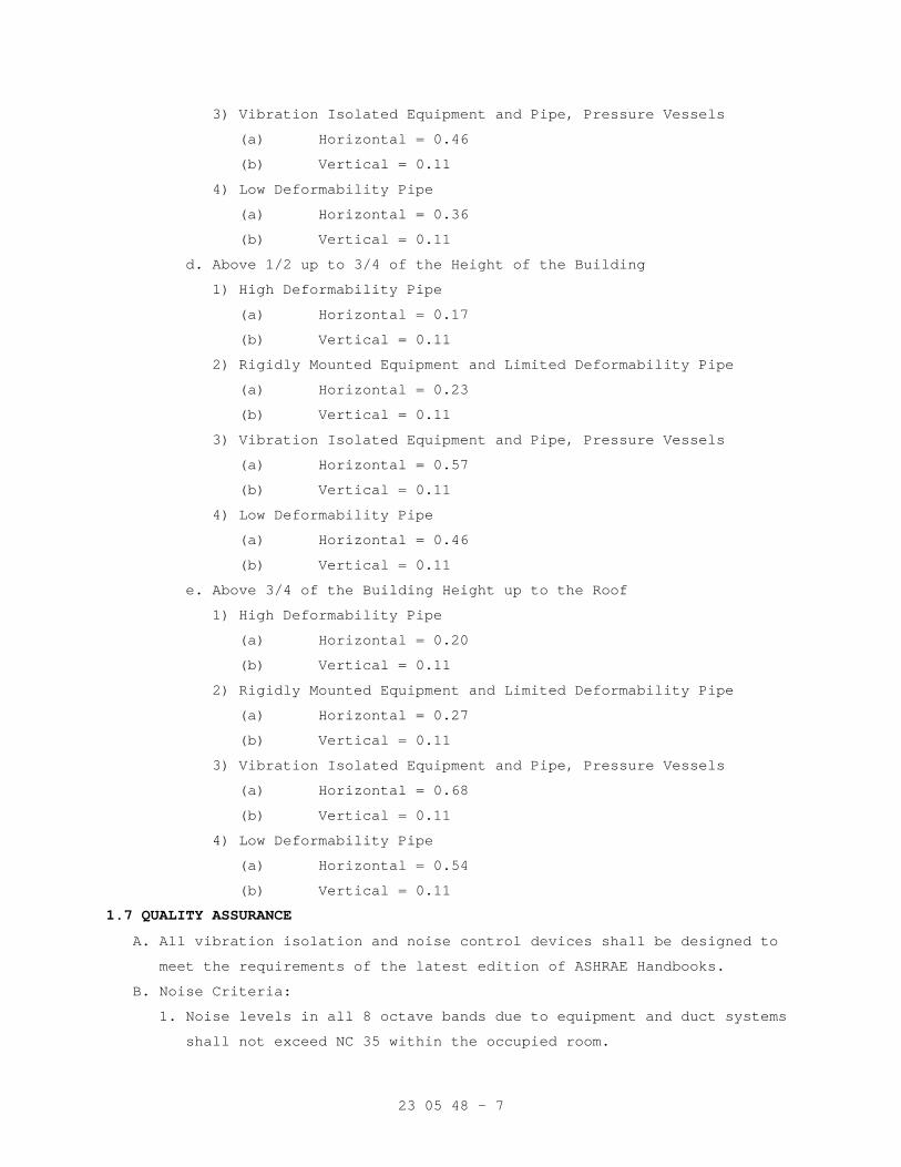
23 05 48 - 7
3) Vibration Isolated Equipment and Pipe, Pressure Vessels
(a) Horizontal = 0.46
(b) Vertical = 0.11
4) Low Deformability Pipe
(a) Horizontal = 0.36
(b) Vertical = 0.11
d. Above 1/2 up to 3/4 of the Height of the Building
1) High Deformability Pipe
(a) Horizontal = 0.17
(b) Vertical = 0.11
2) Rigidly Mounted Equipment and Limited Deformability Pipe
(a) Horizontal = 0.23
(b) Vertical = 0.11
3) Vibration Isolated Equipment and Pipe, Pressure Vessels
(a) Horizontal = 0.57
(b) Vertical = 0.11
4) Low Deformability Pipe
(a) Horizontal = 0.46
(b) Vertical = 0.11
e. Above 3/4 of the Building Height up to the Roof
1) High Deformability Pipe
(a) Horizontal = 0.20
(b) Vertical = 0.11
2) Rigidly Mounted Equipment and Limited Deformability Pipe
(a) Horizontal = 0.27
(b) Vertical = 0.11
3) Vibration Isolated Equipment and Pipe, Pressure Vessels
(a) Horizontal = 0.68
(b) Vertical = 0.11
4) Low Deformability Pipe
(a) Horizontal = 0.54
(b) Vertical = 0.11
1.7 QUALITY ASSURANCE
A. All vibration isolation and noise control devices shall be designed to
meet the requirements of the latest edition of ASHRAE Handbooks.
B. Noise Criteria:
1. Noise levels in all 8 octave bands due to equipment and duct systems
shall not exceed NC 35 within the occupied room.
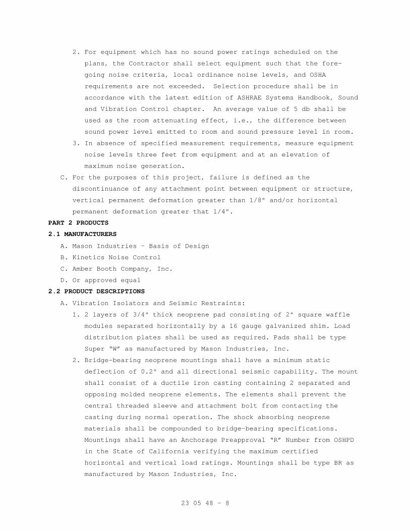
23 05 48 - 8
2. For equipment which has no sound power ratings scheduled on the
plans, the Contractor shall select equipment such that the fore-
going noise criteria, local ordinance noise levels, and OSHA
requirements are not exceeded. Selection procedure shall be in
accordance with the latest edition of ASHRAE Systems Handbook, Sound
and Vibration Control chapter. An average value of 5 db shall be
used as the room attenuating effect, i.e., the difference between
sound power level emitted to room and sound pressure level in room.
3. In absence of specified measurement requirements, measure equipment
noise levels three feet from equipment and at an elevation of
maximum noise generation.
C. For the purposes of this project, failure is defined as the
discontinuance of any attachment point between equipment or structure,
vertical permanent deformation greater than 1/8" and/or horizontal
permanent deformation greater that 1/4".
PART 2 PRODUCTS
2.1 MANUFACTURERS
A. Mason Industries - Basis of Design
B. Kinetics Noise Control
C. Amber Booth Company, Inc.
D. Or approved equal
2.2 PRODUCT DESCRIPTIONS
A. Vibration Isolators and Seismic Restraints:
1. 2 layers of 3/4" thick neoprene pad consisting of 2" square waffle
modules separated horizontally by a 16 gauge galvanized shim. Load
distribution plates shall be used as required. Pads shall be type
Super “W” as manufactured by Mason Industries, Inc.
2. Bridge-bearing neoprene mountings shall have a minimum static
deflection of 0.2" and all directional seismic capability. The mount
shall consist of a ductile iron casting containing 2 separated and
opposing molded neoprene elements. The elements shall prevent the
central threaded sleeve and attachment bolt from contacting the
casting during normal operation. The shock absorbing neoprene
materials shall be compounded to bridge-bearing specifications.
Mountings shall have an Anchorage Preapproval “R” Number from OSHPD
in the State of California verifying the maximum certified
horizontal and vertical load ratings. Mountings shall be type BR as
manufactured by Mason Industries, Inc.
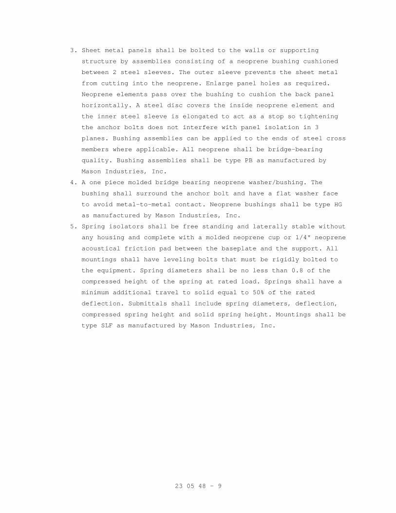
23 05 48 - 9
3. Sheet metal panels shall be bolted to the walls or supporting
structure by assemblies consisting of a neoprene bushing cushioned
between 2 steel sleeves. The outer sleeve prevents the sheet metal
from cutting into the neoprene. Enlarge panel holes as required.
Neoprene elements pass over the bushing to cushion the back panel
horizontally. A steel disc covers the inside neoprene element and
the inner steel sleeve is elongated to act as a stop so tightening
the anchor bolts does not interfere with panel isolation in 3
planes. Bushing assemblies can be applied to the ends of steel cross
members where applicable. All neoprene shall be bridge-bearing
quality. Bushing assemblies shall be type PB as manufactured by
Mason Industries, Inc.
4. A one piece molded bridge bearing neoprene washer/bushing. The
bushing shall surround the anchor bolt and have a flat washer face
to avoid metal-to-metal contact. Neoprene bushings shall be type HG
as manufactured by Mason Industries, Inc.
5. Spring isolators shall be free standing and laterally stable without
any housing and complete with a molded neoprene cup or 1/4" neoprene
acoustical friction pad between the baseplate and the support. All
mountings shall have leveling bolts that must be rigidly bolted to
the equipment. Spring diameters shall be no less than 0.8 of the
compressed height of the spring at rated load. Springs shall have a
minimum additional travel to solid equal to 50% of the rated
deflection. Submittals shall include spring diameters, deflection,
compressed spring height and solid spring height. Mountings shall be
type SLF as manufactured by Mason Industries, Inc.
23 05 48 - 10
6. Restrained spring mountings shall have an SLF mounting as described
in Specification 5, within a rigid housing that includes vertical
limit stops to prevent spring extension when weight is removed. The
housing shall serve as blocking during erection. Installed and
operating heights are equal. A minimum clearance of 1/2" shall be
maintained around restraining bolts and between the housing and the
spring so as not to interfere with the spring action. Restraining
Bolts shall have a neoprene bushing between the bolt and the
housing. Limit stops shall be out of contact during normal
operation. Since housings will be bolted or welded in position there
must be an internal isolation pad. Housing shall be designed to
resist all seismic forces. Mountings shall have Anchorage
Preapproval “R” Number from OSHPD in the State of California
certifying the maximum certified horizontal and vertical load
ratings. Mountings shall be type SLR or SLRS as manufactured by
Mason Industries, Inc.
7. Spring mountings as in specification 5 built into a ductile iron or
steel housing to provide all directional seismic snubbing. The
snubber shall be adjustable vertically and allow a maximum of 1/4"
travel in all directions before contacting the resilient snubbing
collars. Mountings shall have an Anchorage Preapproval “R” number
from OSHPD in the State of California verifying the maximum
certified horizontal and vertical load ratings. Mountings shall be
type SSLFH as manufactured by Mason Industries, Inc.
8. Air Springs shall be manufactured with upper and lower steel
sections connected by a replaceable flexible nylon reinforced
neoprene element. Air spring configuration shall be multiple bellows
to achieve a maximum natural frequency of 3 Hz. Air Springs shall be
designed for a burst pressure that is a minimum of three times the
published maximum operating pressure. All air spring systems shall
be connected to either the building control air or a supplementary
air supply and equipped with three leveling valves to maintain
leveling within plus or minus 1/8". Submittals shall include natural
frequency, load and damping tests. Air Springs shall be type MT and
leveling valves type LV as manufactured by Mason Industries, Inc.
23 05 48 - 11
9. Restrained air spring mountings shall have an MT air spring as
described in Specification 8, within a rigid housing that includes
vertical limit stops to prevent air spring extension when weight is
removed. The housing shall serve as blocking during erection. A
steel spacer shall be removed after adjustment. Installed and
operating heights are equal. A minimum clearance of 1/2" shall be
maintained around restraining bolts and between the housing and the
air spring so as not to interfere with the air spring action. Limit
stops shall be out of contact during normal operation. Housing shall
be designed to resist all seismic forces. Mountings shall be type
SLR-MT as manufactured by Mason Industries, Inc.
10. Hangers shall consist of rigid steel frames containing minimum 1-
1/4" thick neoprene elements at the top and a steel spring with
general characteristics as in specification 5 seated in a steel
washer reinforced neoprene cup on the bottom. The neoprene element
and the cup shall have neoprene bushings projecting through the
steel box. To maintain stability the boxes shall not be articulated
as clevis hangers nor the neoprene element stacked on top of the
spring. Spring diameters and hanger box lower hole sizes shall be
large enough to permit the hanger rod to swing through a 30 degree
arc from side to side before contacting the rod bushing and short
circuiting the spring. Submittals shall include a hanger drawing
showing the 30 degree capability. Hangers shall be type 30N as
manufactured by Mason Industries, Inc.
11. Hangers shall be as described in 10, but they shall be supplied
with a combination rubber and steel rebound washer as the seismic
upstop for suspended piping, ductwork, and equipment. Rubber
thickness shall be a minimum of 1/4". Submittals shall include a
drawing of the hanger showing the installation of the rebound
washer. Hangers shall be type RW30N as manufactured by Mason
Industries, Inc.
23 05 48 - 12
12. Hangers shall be as described in 10, but they shall be
precompressed and locked at the rated deflection by means of a
resilient seismic upstop to keep the piping or equipment at a fixed
elevation during installation. The hangers shall be designed with a
release mechanism to free the spring after the installation is
complete and the hanger is subjected to its full load. Deflection
shall be clearly indicated by means of a scale. Submittals shall
include a drawing of the hanger showing the 30 degree capability.
Hangers shall be type PC30N as manufactured by Mason Industries,
Inc.
13. Seismic Cable Restraints shall consist of galvanized steel
aircraft cables sized to resist seismic loads with a minimum safety
factor of two and arranged to provide all-directional restraint.
Cables must be prestretched to achieve a certified minimum modulus
of elasticity. Cable end connections shall be steel assemblies that
swivel to final installation angle and utilize two clamping bolts to
provide proper cable engagement. Cables must not be allowed to bend
across sharp edges. Cable assemblies shall have an Anchorage
Preapproval “R” Number from OSHPD in the State of California
verifying the maximum certified load ratings. Cable assemblies shall
be type SCB at the ceiling and at the clevis bolt, SCBH between the
hanger rod nut and the clevis or SCBV if clamped to a beam, all as
manufactured by Mason Industries, Inc.
14. Seismic solid braces shall consist of steel angles or channels to
resist seismic loads with a minimum safety factor of 2 and arranged
to provide all directional restraint. Seismic solid brace end
connectors shall be steel assemblies that swivel to the final
installation angle and utilize 2 through bolts to provide proper
attachment. Seismic solid brace assembly shall have Anchorage
Preapproval “R” Number from OSHPD in the State of California
verifying the maximum certified load ratings. Solid seismic brace
assemblies shall be type SSB, SSBS or SSRF as manufactured by Mason
Industries, Inc.
a. Note: Specifications 12-14 apply to trapeze as well as clevis
hanger locations. At trapeze anchor locations piping must be
shackled to the trapeze. Specifications apply to hanging
equipment as well.
23 05 48 - 13
15. Steel angles, sized to prevent buckling, shall be clamped to pipe
or equipment rods utilizing a minimum of three ductile iron clamps
at each restraint location when required. Welding of support rods is
not acceptable. Rod clamp assemblies shall have an Anchorage
Preapproval “R” Number from OSHPD in the State of California. Rod
clamp assemblies shall be type SRC or UC as manufactured by Mason
Industries, Inc.
16. Pipe clevis cross bolt braces are required in all restraint
locations. They shall be special purpose preformed channels deep
enough to be held in place by bolts passing over the cross bolt.
Clevis cross braces shall have an Anchorage Preapproval “R” Number
from OSHPD in the State of California. Clevis cross brace shall be
type CCB as manufactured by Mason Industries, Inc.
17. All-directional seismic snubbers shall consist of interlocking
steel members restrained by a one-piece molded neoprene bushing of
bridge bearing neoprene. Bushing shall be replaceable and a minimum
of 1/4" thick. Rated loadings shall not exceed 1000 psi. A minimum
air gap of 1/8" shall be incorporated in the snubber design in all
directions before contact is made between the rigid and resilient
surfaces. Snubber end caps shall be removable to allow inspection of
internal clearances. Neoprene bushings shall be rotated to insure no
short circuits exist before systems are activated. Snubbers shall
have an Anchorage Preapproval “R” Number from OSHPD in the State of
California verifying the maximum certified horizontal and vertical
load ratings. Snubber shall be type Z-1225 as manufactured by Mason
Industries, Inc.
23 05 48 - 14
18. All directional seismic snubbers shall consist of interlocking
steel members restrained by shock absorbent rubber materials
compounded to bridge bearing specifications. Elastomeric materials
shall be replaceable and a minimum of 3/4" thick. Rated loadings
shall not exceed 1000 psi. Snubbers shall be manufactured with an
air gap between hard and resilient material of not less than 1/8"
nor more that 1/4". Snubbers shall be installed with factory set
clearances. The capacity of the seismic snubber at 3/8" deflection
shall be equal or greater than the load assigned to the mounting
grouping controlled by the snubber multiplied by the applicable” G”
force. Submittals shall include the load deflection curves up to
1/2" deflection in the x, y and z planes. Snubbers shall have an
Anchorage Preapproval “R” Number from OSHPD in the State of
California verifying the maximum certified horizontal and vertical
load ratings. Snubbers shall be type Z-1011 as manufactured by Mason
Industries, Inc.
19. Stud wedge anchors shall be manufactured from full diameter wire,
not from undersized wire that is “rolled up” to create the thread.
The stud anchor shall also have a safety shoulder which fully
supports the wedge ring under load. The stud anchors shall have an
evaluation report number from the I.C.B.O Evaluation Service, Inc.
verifying its allowable loads. Drill-in stud wedge anchors shall be
type SAS as manufactured by Mason Industries, Inc.
20. Female wedge anchors are preferred in floor locations so
isolators or equipment can be slid into place after the anchors are
installed. Anchors shall be manufactured from full diameter wire,
and shall have a safety shoulder to fully support the wedge ring
under load. Female wedge anchors shall have an evaluation report
number from the I.C.B.O. Evaluation Service, Inc. verifying to its
allowable loads. Drill-in female wedge anchors shall be type SAB as
manufactured by Mason Industries, Inc.
23 05 48 - 15
21. Vibration isolation manufacturer shall furnish integral
structural steel bases. Rectangular bases are preferred for all
equipment. Centrifugal refrigeration machines and pump bases may be
T or L shaped where space is a problem. Pump bases for split case
pump shall include supports for suction and discharge elbows. All
perimeter members shall be steel beams with a minimum depth equal to
1/10 of the longest dimension of the base. Base depth need not
exceed 14" provided that the deflection and misalignment is kept
within acceptable limits as determined by the manufacturer. Height
saving brackets shall be employed in all mounting locations to
provide a base clearance of 1". Bases shall be type WF as
manufactured by Mason Industries, Inc.
22. Vibration isolation manufacturer shall furnish rectangular steel
concrete pouring forms for floating and inertia foundations. Bases
for split case pumps shall be large enough to provide for suction
and discharge elbows. Bases shall be a minimum of 1/12 of the
longest dimension of the base but not less than 6". The base depth
need not exceed 12" unless specifically recommended by the base
manufacturer for mass or rigidity. Forms shall include minimum
concrete reinforcing consisting of 1/2" bars welded in place on 6"
centers running both ways in a layer 1-1/2" above the bottom. Forms
shall be furnished with steel templates to hold the anchor bolts
sleeves and anchors while concrete is being poured. Height saving
brackets shall be employed in all mounting locations to maintain a
1" clearance below the base. Wooden formed bases leaving a concrete
rather then a steel finish are not acceptable. Base shall be type
BMK or K as manufactured by Mason Industries, Inc.
23 05 48 - 16
23. Curb mounted rooftop equipment shall be mounted on spring
isolation curbs. The lower member shall consist of a sheet metal or
structural steel sections containing adjustable and removable steel
springs that support the upper floating section. The upper frame
must provide continuous support for the equipment and must be
captive so as to resiliently resist wind and seismic forces. All
directional neoprene snubber bushings shall be a minimum of 1/4"
thick. Steel springs shall be laterally stable and rest on 1/4"
thick neoprene acoustical pads. Hardware must be plated and the
springs provided with a rust resistant finish. The curbs
waterproofing shall consist of a continuous flexible flashing nailed
over the lower curbs waterproofing. All spring locations shall have
accessibility to adjust springs. Lower curbs shall have provision
for 2" of insulation. The roof curbs shall be built to seismically
contain the rooftop unit. The unit must be solidly fastened to the
top floating rail, and the lower section anchored to the roof
structure. Curb shall have Anchorage Preapproval “R” Number from
OSHPD in the State of California attesting to the maximum certified
horizontal and vertical load ratings. Curb shall be type SRSC or
RMSS as manufactured by Mason Industries, Inc.
24. Curb mounted rooftop equipment shall be mounted on top of Rigid
Seismic Roof curbs. Curb sections shall be designed by an Engineer
licensed in the state where the project is, and shall be either
structural steel channels or 12-gauge sheet metal. Field assembled
joints are to include a minimum of 2 rows of 3 bolts at each
connection. Curb to have a factory installed wood nailer. The
Rooftop unit must be fastened to the curb and the curb fastened to
the structure to resist both seismic and wind forces. Submittal
shall include calculations by a professional engineer licensed in
the state, and the engineer shall have a minimum of 5 years
experience in seismic applications. Curb details and unit connection
to curb details shall be included. Curbs shall be type RRC as
manufactured by Mason Industries, Inc. Curb shall match slope of the
supporting structure.
23 05 48 - 17
25. Flexible spherical expansion joints shall employ peroxide cured
EPDM in the covers, liners and Kevlar tire cord frictioning. Any
substitutions must have equal or superior physical and chemical
characteristics. Solid steel rings shall be used within the raised
face rubber flanged ends to prevent pullout. Flexible cable bead
wire is not acceptable. Sizes 2" and larger shall have 2 spheres
reinforced with a ductile iron external ring between spheres.
Flanges shall be split ductile iron or steel with hooked or similar
interlocks. Sizes 16" to 24” may be single sphere. Sizes 3/4” to 1-
1/2” may have threaded 2 piece bolted flange assemblies, 1 sphere
and cable retention. Connectors shall be rated at 250 psi up to 170
F with a uniform drop in allowable pressure to 215 psi at 250 F in
sizes through 14". 16" through 24" single sphere minimum ratings are
180 psi at 170 F and 150 psi at 250 F. Higher rated connectors may
be used to accommodate service conditions. All expansion joints must
be factory tested to 150% of rated pressure for 12 minutes before
shipment.
Safety factors to burst and flange pullout shall be a minimum of
3/1. Concentric reducers to the above ratings may be substituted for
equal ended expansion joints. Expansion joints shall be installed in
piping gaps equal to the length of the expansion joints under
pressure. Control rods need only be used in unanchored piping
locations where the manufacturer determines the installation exceeds
the pressure requirement without control rods. If control rods are
used, they must have 1/2” thick Neoprene washer bushings large
enough in diameter to take the thrust at 1000 psi maximum on the
washer area. Submittals shall include two test reports by
independent consultants showing minimum reductions of 20 DB in
vibration accelerations and 10 DB in sound pressure levels at
typical blade passage frequencies on this or a similar product by
the same manufacturer. All expansion joints shall be installed on
the equipment side of the shut off valves. Expansion joints shall be
type SAFEFLEX SFDEJ, SFEJ, SFDCR or SFU and Control Rods CR as
manufactured by Mason Industries, Inc.
23 05 48 - 18
26. Flexible stainless steel hose shall have stainless steel braid
and carbon steel fittings. Sizes 3" and larger shall be flanged.
Smaller sizes shall have male nipples. Minimum lengths shall be as
tabulated:
Flanged 3" x 14" 6" x 20" 12" x 28" 4" x 15" 8" x 22" 14" x 30" 5" x 19" 10" x 26" 16" x 32"
Male Nipples 1/2" x 9" 1-1/4" x 12" 2" x 14" 3/4" x 10" 1-1/2" x 13" 2-1/2" x 18" 1" x 11"
Hoses shall be installed on the equipment side of the shut-off
valves horizontally and parallel to the equipment shafts wherever
possible. Hoses shall be type BSS as manufactured by Mason
Industries, Inc.
27. All-directional acoustical pipe anchor, consisting of 2 sizes of
steel tubing separated by a minimum 1/2" thick 60 durometer
neoprene. Vertical restraint shall be provided by similar material
arranged to prevent vertical travel in either direction. Allowable
loads on the isolation material should not exceed 500 psi and the
design shall be balanced for equal resistance in any direction. All-
directional anchors shall be type ADA as manufactured by Mason
Industries, Inc.
28. Pipe guides shall consist of a telescopic arrangement of two
sizes of steel tubing separated by a minimum 1/2" thickness of 60
durometer neoprene. The height of the guides shall be preset with a
shear pin to allow vertical motion due to pipe expansion or
contraction. Shear pin shall be removable and reinsertable to allow
for selection of pipe movement. Guides shall be capable of +/-5/8"
motion, or to meet location requirements. Pipe guides shall be type
VSG as manufactured by Mason Industries, Inc.
23 05 48 - 19
29. Split Wall Seals consist of 2 bolted pipe halves with minimum
3/4" thick neoprene sponge bonded to the inner faces. The seal shall
be tightened around the pipe to eliminate clearance between the
inner sponge face and the piping. Concrete may be packed around the
seal to make it integral with the floor, wall or ceiling if the seal
is not already in place around the pipe prior to the construction of
the building member. Seals shall project a minimum of 1" past either
face of the wall. Where temperatures exceed 240 F, 10# density
fiberglass may be used in lieu of the sponge. Seals shall be type
SWS as manufactured by Mason Industries, Inc.
30. The horizontal thrust restraint shall consist of a spring element
in series with a neoprene molded cup as described in specification 5
with the same deflection as specified for the mountings or hangers.
The spring element shall be designed so it can be preset for thrust
at the factory and adjusted in the field to allow for a maximum of
1/4" (6 mm) movement at start and stop. The assembly shall be
furnished with 1 rod and angle brackets for attachment to both the
equipment and the ductwork or the equipment and the structure.
Horizontal restraints shall be attached at the centerline of thrust
and symmetrical on either side of the unit. Horizontal thrust
restraints shall be type WBI/WBD as manufactured by Mason
Industries, Inc.
31. Housekeeping pad anchors shall consist of a ductile iron casting
that is tapered and hexagonal, smaller at its base than at its top.
The upper portion shall have holes for rebar to pass through. The
anchor shall be continuously threaded from top to bottom for the
attachment of soleplates. Housekeeping pad anchors shall be attached
to the structural slab using a stud wedge anchor. Housekeeping pad
anchors shall be type HPA and stud wedge anchor shall be type SAS
both as manufactured by Mason Industries, Inc.
PART 3 EXECUTION
3.1 GENERAL
A. All vibration isolators and seismic restraint systems must be installed
in strict accordance with the manufacturers written instructions and
all certified submittal data.
B. Installation of vibration isolators and seismic restraints must not
cause any change of position of equipment, piping or ductwork resulting
in stresses or misalignment.
23 05 48 - 20
C. No rigid connections between equipment and the building structure shall
be made that degrades the noise and vibration control system herein
specified.
D. The contractor shall not install any equipment, piping, duct or
conduit, which makes rigid connections with the building unless
isolation is not specified. “Building” includes, but is not limited to,
slabs, beams, columns, studs and walls.
E. Coordinate work with other trades to avoid rigid contact with the
building.
F. Any conflicts with other trades, which will result in rigid contact
with equipment or piping due to inadequate space or other unforeseen
conditions, should be brought to the Architects/Engineers attention
prior to installation. Corrective work necessitated by conflicts after
installation shall be at the responsible contractor's expense.
G. Bring to the Architects/Engineers attention any discrepancies between
the specifications and the field conditions or changes required due to
specific equipment selection, prior to installation. Corrective work
necessitated by discrepancies after installation shall be at the
responsible contractor's expense.
H. Correct, at no additional cost, all installations, which are deemed
defective in workmanship and materials at the contractor's expense.
I. Overstressing of the building structure must not occur because of
overhead support of equipment. Contractor must submit loads to the
structural engineer of record for approval. Generally bracing may occur
from:
1. Flanges of structural beams.
2. Upper truss cords in bar joist construction.
3. Cast in place inserts or wedge type drill-in concrete anchors.
J. Product specification 13 cable restraints shall be installed slightly
slack to avoid short circuiting the isolated suspended equipment,
piping or conduit.
K. Product specification 13 cable assemblies are installed taut on non-
isolated systems. Product specification 14 seismic solid braces may be
used in place of cables on rigidly attached systems only.
L. At locations where product specification 13 or 14 restraints are
located, the support rods must be braced when necessary to accept
compressive loads with specification 14 braces.
23 05 48 - 21
M. At locations where product specification 13 cable restraints are
installed on support rods with spring isolators, the spring isolation
hangers must be product specification type 11.
N. At all locations where product specification 13 or 14 restraints are
attached to pipe clevis, the clevis cross bolt must be reinforced with
product specification type 16 braces.
O. Drill-in concrete anchors for ceiling and wall installation shall be
product specification type 19, and product specification type 20 female
wedge type for floor mounted equipment.
P. Vibration isolation manufacturer shall furnish integral structural
steel bases as required. Independent steel rails are not permitted on
this project.
Q. Hand built elastomeric expansion joints may be used when pipe sizes
exceed 24" or specified movements exceed product specification 25
capabilities.
R. Where piping passes through walls, floors or ceilings the vibration
isolation manufacturer shall provide product specification 29 wall
seals.
S. Air handling equipment and centrifugal fans shall be protected against
excessive displacement which results from high air thrust in relation
to the equipment weight. Horizontal thrust restraint shall be product
specification type 30.
T. Locate isolation hangers as near to the overhead support structure as
possible.
U. All fire protection piping shall be braced in accordance with NFPA 13
and 14.
V. All mechanical equipment shall be vibration isolated and seismically
restrained as per the schedules in part 4 of this specification.
W. All fire protection equipment is considered life safety equipment and
shall be seismically restrained using the seismic force levels for life
safety equipment in table 1.06-1, if higher levels are shown.
X. Contractor shall make provisions for attachments of seismic restraints
with all required equipment.
23 05 48 - 22
3.2 VIBRATION ISOLATION AND SEISMIC RESTRAINT OF PIPING
A. Horizontal Pipe Isolation: The first 4 pipe hangers in the main lines
near the mechanical equipment shall be as described in product
specification 12. Brace hanger rods with SRC clamps product
specification 15. Horizontal runs in all other locations throughout the
building shall be isolated by hangers as described in product
specification 10 and 11. Floor supported piping shall rest on isolators
as described in product specification 6. Heat exchangers and expansion
tanks are considered part of the piping run. The first three isolators
from the isolated equipment will have the same static deflection as
specified for the mountings under the connected equipment. If piping is
connected to equipment located in basements and hangs from ceilings
under occupied spaces the first three hangers shall have 0.75"
deflection for pipe sizes up to and including 3", 1-1/2" deflection for
pipe sizes up to and including 6", and 2-1/2" deflection thereafter.
Hangers shall be located as close to the overhead structure as
practical. Hanger locations that also have seismic restraints attached
must have type RW Rebound Washers to limit uplift. Where piping
connects to mechanical equipment install product specification 25
expansion joints or product specification 26 stainless hoses if 25 is
not suitable for the service.
B. Riser isolation: Risers shall be suspended from product specification
11 hangers or supported by product specification 5 mountings, anchored
with product specification 27 anchors, and guided with product
specification 28 sliding guides. Steel springs shall be a minimum of
0.75" except in those expansion locations where additional deflection
is required to limit load changes to +/-25% of the initial load.
Submittals must include riser diagrams and calculations showing
anticipated expansion and contraction at each support point, initial
and final loads on the building structure, spring deflection changes
and seismic loads. Submittal data shall include certification that the
riser system has been examined for excessive stresses and that none
will exist in the proposed design.
C. Seismic Restraint of Piping:
1. Seismically restrain all piping listed as a, b, or c below. Use
product specification 13 cables if isolated. Product specification
13 or 14 restraints may be used on unisolated piping.
23 05 48 - 23
a. Fuel oil piping, gas piping, medical gas piping, and compressed
air piping that is 1" I.D. or larger.
b. Piping located in boiler rooms, mechanical equipment rooms, and
refrigeration equipment rooms that is 1-1/4" I.D. and larger.
c. All other piping 2-1/2" diameter and larger.
2. Transverse piping restraints shall be at 40' maximum spacing for all
pipe sizes, except where lesser spacing is required to limit
anchorage loads.
3. Longitudinal restraints shall be at 80' maximum spacing for all pipe
sizes, except where lesser spacing is required to limit anchorage
loads.
4. Where thermal expansion is a consideration, guides and anchors may
be used as transverse and longitudinal restraints provided they have
a capacity equal to or greater than the restraint loads in addition
to the loads induced by expansion or contraction.
5. For fuel oil and all gas piping transverse restraints must be at 20'
maximum and longitudinal restraints at 40' maximum spacing.
6. Transverse restraint for one pipe section may also act as a
longitudinal restraint for a pipe section of the same size connected
perpendicular to it if the restraint is installed within 24" of the
elbow or TEE or combined stresses are within allowable limits at
longer distances.
7. Hold down clamps must be used to attach pipe to all trapeze members
before applying restraints in a manner similar to clevis supports.
8. Branch lines may not be used to restrain main lines.
9. Cast iron pipe of all types, glass pipe and any other pipes joined
with a four band shield and clamp assembly in areas with Ss of 0.35
or greater shall be braced as in sections 3.02.C.2 and 3. For areas
with Ss less than 0.35, 2 band clamps may be used with a reduced
spacing of 1/2 of those listed in sections 3.02.C.2 and 3.
10. Connection to the structure must be made with a non-friction
connection (i.e. no “C” clamps).
11. Hanger locations that also have seismic restraints attached must
have Product specification 11 type RW Rebound Washers.
12. Piping which crosses building expansion joints shall be anchored
on each side of the expansion joint. Ball joints or braided hose
assemblies shall be employed to allow the specified movement of the
building without affecting the integrity of the piping system.
23 05 48 - 24
D. Pipe Exclusions:
1. Gas piping less than 1" inside diameter.
2. Piping in boiler and mechanical rooms less than 1-1/4" inside
diameter.
3. All other piping less than 2-1/2" inside diameter.
4. All piping suspended by clevis hangers where the distance from the
top of the pipe to the suspension point is 12" or less.
5. All trapezed piping where the distance from the suspension point to
the trapeze member is 12" or less.
6. If any suspension location in the run exceeds the above, the entire
run must be braced.
3.3 VIBRATION ISOLATION AND SEISMIC RESTRAINT OF DUCTWORK
A. Vibration isolation of ductwork:
1. All discharge runs for a distance of 50' from the connected
equipment shall be isolated from the building structure by means of
product specification 10 hangers or product specification 5 floor
isolators. Spring deflection shall be a minimum of 0.75".
2. All duct runs having air velocity of 1000 fpm or more shall be
isolated from the building structure by product specification 12
hangers or 5 floor supports. Spring deflection shall be a minimum of
0.75".
B. Seismic restraint of ductwork:
1. Seismically restrain all ductwork with product specification 13 or
14 restraints as listed below:
a. Restrain rectangular ducts with cross sectional area of 6 sq. ft.
or larger.
b. Restrain round ducts with diameters of 28" or larger.
c. Restrain flat oval ducts the same as rectangular ducts of the
same nominal size.
2. Transverse restraints shall occur at 30' intervals or at both ends
of the duct run if less than the specified interval. Transverse
restraints shall be installed at each duct turn and at each end of a
duct run.
23 05 48 - 25
3. Longitudinal restraints shall occur at 60' intervals with at least 1
restraint per duct run. Transverse restraints for one duct section
may also act as a longitudinal restraint for a duct section
connected perpendicular to it if the restraints are installed within
4' of the intersection of the ducts and if the restraints are sized
for the larger duct. Duct joints shall conform to SMACNA duct
construction standards.
4. The ductwork must be reinforced at the restraint locations.
Reinforcement shall consist of an additional angle on top of the
ductwork that is attached to the support hanger rods. Ductwork is to
be attached to both upper angle and lower trapeze.
5. A group of ducts may be combined in a larger frame so that the
combined weights and dimensions of the ducts are less than or equal
to the maximum weight and dimensions of the duct for which bracing
details are selected.
6. Walls, including gypsum board non bearing partitions, which have
ducts running through them may replace a typical transverse brace.
Provide channel framing around ducts and solid blocking between the
duct and frame.
7. Connection to the structure must be made with a non-friction
connection (i.e. no “C” clamps).
8. Hanger locations that also have seismic restraints attached must
have product specification 11 type RW Rebound Washers.
C. Ductwork Exclusions:
1. Rectangular and square and ducts that are less than 6 square feet in
cross sectional area.
2. Oval ducts that are less than 6 square feet in cross sectional area
based on nominal size.
3. Round duct less than 28" in diameter.
4. All trapezed ductwork where the distance from the suspension point
to the trapeze member is 12" or less.
5. Ductwork hung with straps where the top of the duct is 12" or less
from the suspension point and the strap has 2 #10 sheet metal screws
within 2" of the top of the duct.
6. If any suspension location in the run exceeds the above, the entire
run must be braced.
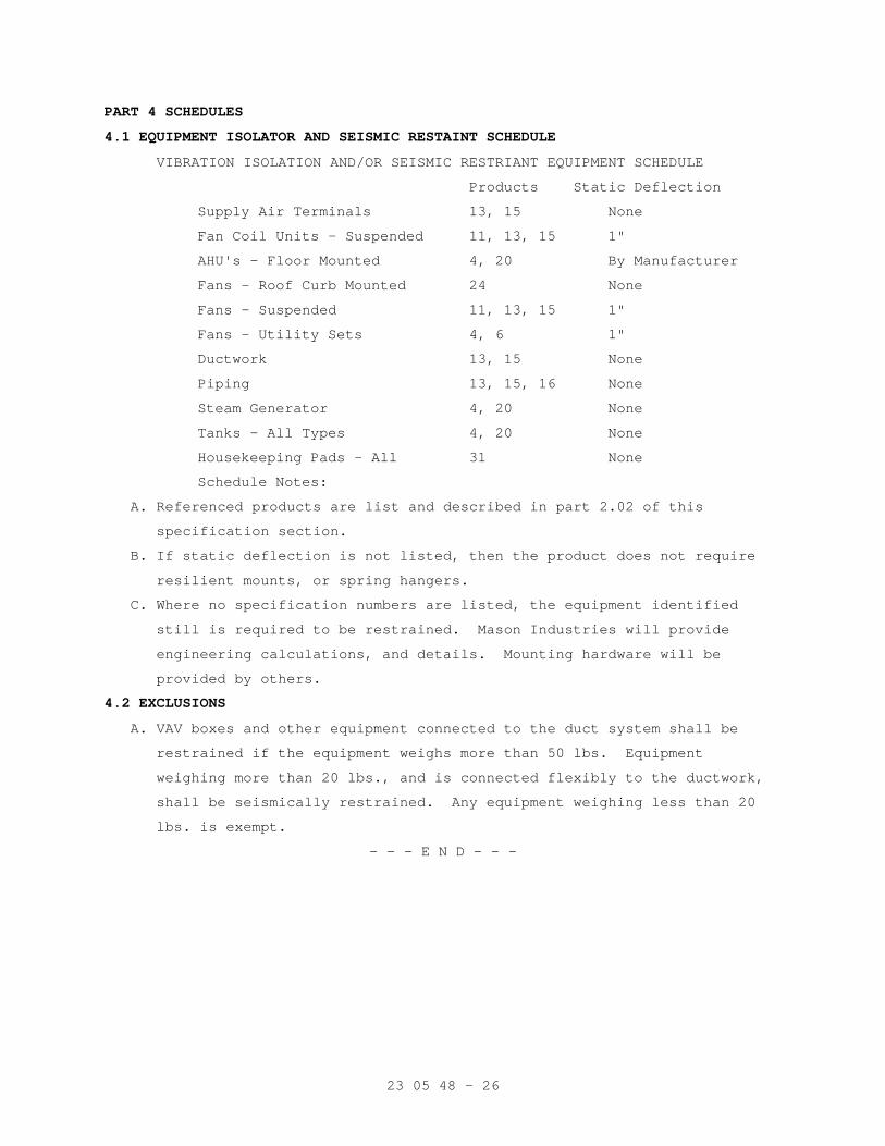
23 05 48 - 26
PART 4 SCHEDULES
4.1 EQUIPMENT ISOLATOR AND SEISMIC RESTAINT SCHEDULE
VIBRATION ISOLATION AND/OR SEISMIC RESTRIANT EQUIPMENT SCHEDULE
Products Static Deflection
Supply Air Terminals 13, 15 None
Fan Coil Units - Suspended 11, 13, 15 1"
AHU's - Floor Mounted 4, 20 By Manufacturer
Fans - Roof Curb Mounted 24 None
Fans - Suspended 11, 13, 15 1"
Fans - Utility Sets 4, 6 1"
Ductwork 13, 15 None
Piping 13, 15, 16 None
Steam Generator 4, 20 None
Tanks - All Types 4, 20 None
Housekeeping Pads - All 31 None
Schedule Notes:
A. Referenced products are list and described in part 2.02 of this
specification section.
B. If static deflection is not listed, then the product does not require
resilient mounts, or spring hangers.
C. Where no specification numbers are listed, the equipment identified
still is required to be restrained. Mason Industries will provide
engineering calculations, and details. Mounting hardware will be
provided by others.
4.2 EXCLUSIONS
A. VAV boxes and other equipment connected to the duct system shall be
restrained if the equipment weighs more than 50 lbs. Equipment
weighing more than 20 lbs., and is connected flexibly to the ductwork,
shall be seismically restrained. Any equipment weighing less than 20
lbs. is exempt.
- - - E N D - - -
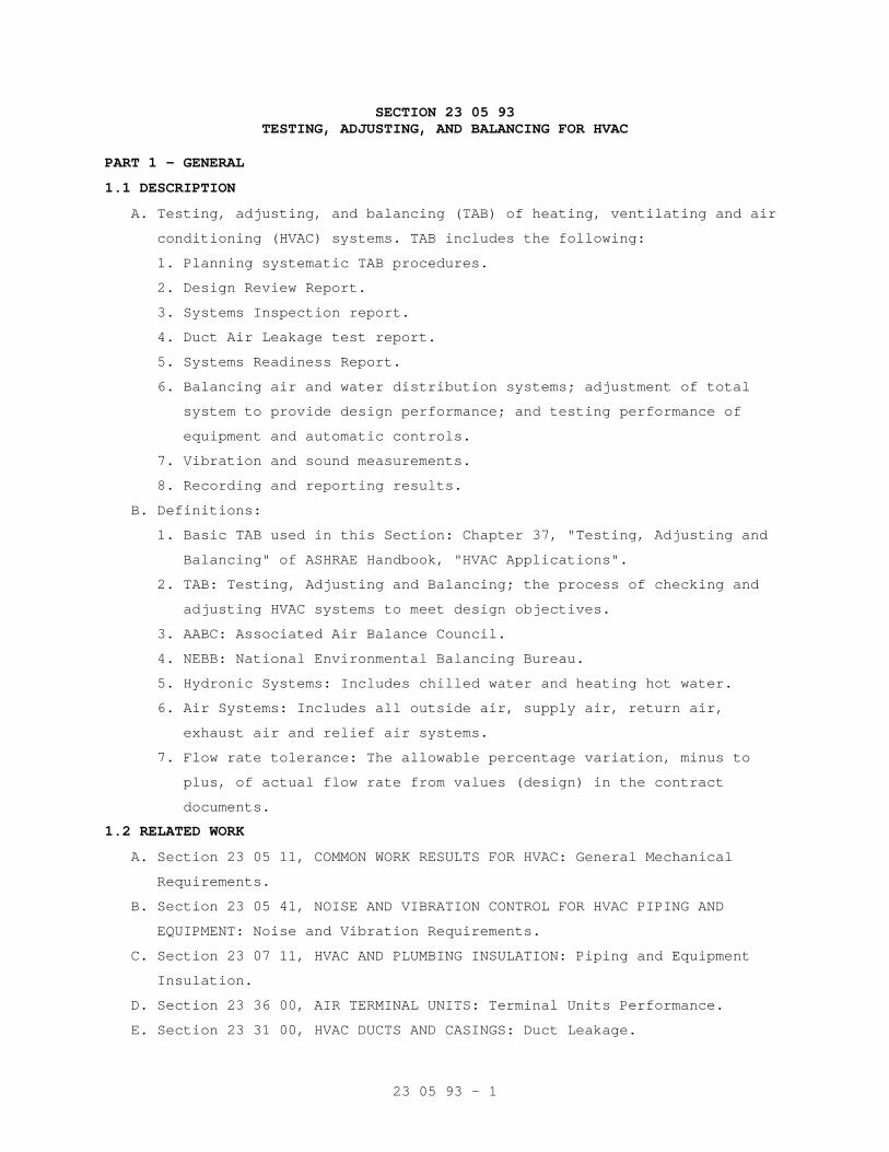
23 05 93 - 1
SECTION 23 05 93 TESTING, ADJUSTING, AND BALANCING FOR HVAC
PART 1 - GENERAL
1.1 DESCRIPTION
A. Testing, adjusting, and balancing (TAB) of heating, ventilating and air
conditioning (HVAC) systems. TAB includes the following:
1. Planning systematic TAB procedures.
2. Design Review Report.
3. Systems Inspection report.
4. Duct Air Leakage test report.
5. Systems Readiness Report.
6. Balancing air and water distribution systems; adjustment of total
system to provide design performance; and testing performance of
equipment and automatic controls.
7. Vibration and sound measurements.
8. Recording and reporting results.
B. Definitions:
1. Basic TAB used in this Section: Chapter 37, "Testing, Adjusting and
Balancing" of ASHRAE Handbook, "HVAC Applications".
2. TAB: Testing, Adjusting and Balancing; the process of checking and
adjusting HVAC systems to meet design objectives.
3. AABC: Associated Air Balance Council.
4. NEBB: National Environmental Balancing Bureau.
5. Hydronic Systems: Includes chilled water and heating hot water.
6. Air Systems: Includes all outside air, supply air, return air,
exhaust air and relief air systems.
7. Flow rate tolerance: The allowable percentage variation, minus to
plus, of actual flow rate from values (design) in the contract
documents.
1.2 RELATED WORK
A. Section 23 05 11, COMMON WORK RESULTS FOR HVAC: General Mechanical
Requirements.
B. Section 23 05 41, NOISE AND VIBRATION CONTROL FOR HVAC PIPING AND
EQUIPMENT: Noise and Vibration Requirements.
C. Section 23 07 11, HVAC AND PLUMBING INSULATION: Piping and Equipment
Insulation.
D. Section 23 36 00, AIR TERMINAL UNITS: Terminal Units Performance.
E. Section 23 31 00, HVAC DUCTS AND CASINGS: Duct Leakage.
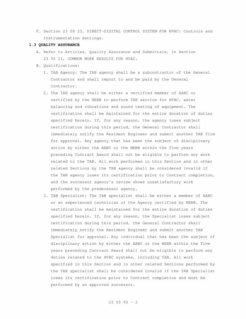
23 05 93 - 2
F. Section 23 09 23, DIRECT-DIGITAL CONTROL SYSTEM FOR HVAC: Controls and
Instrumentation Settings.
1.3 QUALITY ASSURANCE
A. Refer to Articles, Quality Assurance and Submittals, in Section
23 05 11, COMMON WORK RESULTS FOR HVAC.
B. Qualifications:
1. TAB Agency: The TAB agency shall be a subcontractor of the General
Contractor and shall report to and be paid by the General
Contractor.
2. The TAB agency shall be either a certified member of AABC or
certified by the NEBB to perform TAB service for HVAC, water
balancing and vibrations and sound testing of equipment. The
certification shall be maintained for the entire duration of duties
specified herein. If, for any reason, the agency loses subject
certification during this period, the General Contractor shall
immediately notify the Resident Engineer and submit another TAB firm
for approval. Any agency that has been the subject of disciplinary
action by either the AABC or the NEBB within the five years
preceding Contract Award shall not be eligible to perform any work
related to the TAB. All work performed in this Section and in other
related Sections by the TAB agency shall be considered invalid if
the TAB agency loses its certification prior to Contract completion,
and the successor agency’s review shows unsatisfactory work
performed by the predecessor agency.
3. TAB Specialist: The TAB specialist shall be either a member of AABC
or an experienced technician of the Agency certified by NEBB. The
certification shall be maintained for the entire duration of duties
specified herein. If, for any reason, the Specialist loses subject
certification during this period, the General Contractor shall
immediately notify the Resident Engineer and submit another TAB
Specialist for approval. Any individual that has been the subject of
disciplinary action by either the AABC or the NEBB within the five
years preceding Contract Award shall not be eligible to perform any
duties related to the HVAC systems, including TAB. All work
specified in this Section and in other related Sections performed by
the TAB specialist shall be considered invalid if the TAB Specialist
loses its certification prior to Contract completion and must be
performed by an approved successor.
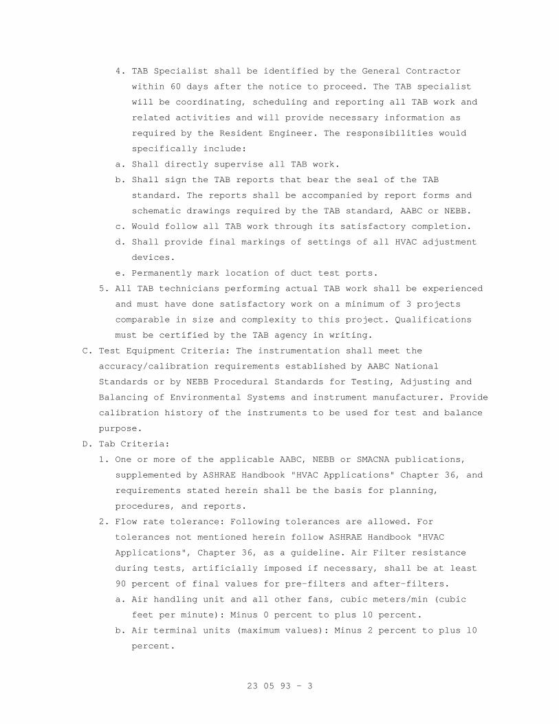
23 05 93 - 3
4. TAB Specialist shall be identified by the General Contractor
within 60 days after the notice to proceed. The TAB specialist
will be coordinating, scheduling and reporting all TAB work and
related activities and will provide necessary information as
required by the Resident Engineer. The responsibilities would
specifically include:
a. Shall directly supervise all TAB work.
b. Shall sign the TAB reports that bear the seal of the TAB
standard. The reports shall be accompanied by report forms and
schematic drawings required by the TAB standard, AABC or NEBB.
c. Would follow all TAB work through its satisfactory completion.
d. Shall provide final markings of settings of all HVAC adjustment
devices.
e. Permanently mark location of duct test ports.
5. All TAB technicians performing actual TAB work shall be experienced
and must have done satisfactory work on a minimum of 3 projects
comparable in size and complexity to this project. Qualifications
must be certified by the TAB agency in writing.
C. Test Equipment Criteria: The instrumentation shall meet the
accuracy/calibration requirements established by AABC National
Standards or by NEBB Procedural Standards for Testing, Adjusting and
Balancing of Environmental Systems and instrument manufacturer. Provide
calibration history of the instruments to be used for test and balance
purpose.
D. Tab Criteria:
1. One or more of the applicable AABC, NEBB or SMACNA publications,
supplemented by ASHRAE Handbook "HVAC Applications" Chapter 36, and
requirements stated herein shall be the basis for planning,
procedures, and reports.
2. Flow rate tolerance: Following tolerances are allowed. For
tolerances not mentioned herein follow ASHRAE Handbook "HVAC
Applications", Chapter 36, as a guideline. Air Filter resistance
during tests, artificially imposed if necessary, shall be at least
90 percent of final values for pre-filters and after-filters.
a. Air handling unit and all other fans, cubic meters/min (cubic
feet per minute): Minus 0 percent to plus l0 percent.
b. Air terminal units (maximum values): Minus 2 percent to plus l0
percent.
23 05 93 - 4
c. Minimum outside air: 0 percent to plus 10 percent.
d. Individual room air outlets and inlets, and air flow rates not
mentioned above: Minus 2 percent to plus l0 percent except if the
air to a space is 100 CFM or less the tolerance would be 0 to
plus 5 percent.
e. Hot water coils: Minus 5 percent to plus 5 percent.
f. Chilled water coils: 0 percent to plus 5 percent.
3. Systems shall be adjusted for energy efficient operation as
described in PART 3.
4. Typical TAB procedures and results shall be demonstrated to the
Resident Engineer for one air distribution system (including all
fans, three terminal units, three rooms) and one hydronic system
(three coils) as follows:
a. When field TAB work begins.
b. During each partial final inspection and the final inspection for
the project if requested by VA.
1.4 SUBMITTALS
A. Submit in accordance with Section 01 33 23, SHOP DRAWINGS, PRODUCT
DATA, AND SAMPLES.
B. Submit names and qualifications of TAB agency and TAB specialists
within 60 days after the notice to proceed. Submit information on three
recently completed projects and a list of proposed test equipment.
C. For use by the Resident Engineer staff, submit one complete set of
applicable AABC or NEBB publications that will be the basis of TAB
work.
D. Submit Following for Review and Approval:
1. Design Review Report within 90 days after the system layout on air
and water side is completed by the Contractor.
2. Systems inspection report on equipment and installation for
conformance with design.
3. Duct Air Leakage Test Report.
4. Systems Readiness Report.
5. Intermediate and Final TAB reports covering flow balance and
adjustments, performance tests, vibration tests and sound tests.
6. Include in final reports uncorrected installation deficiencies noted
during TAB and applicable explanatory comments on test results that
differ from design requirements.
23 05 93 - 5
E. Prior to request for Final or Partial Final inspection, submit
completed Test and Balance report for the area.
1.5 APPLICABLE PUBLICATIONS
A. The following publications form a part of this specification to the
extent indicated by the reference thereto. In text the publications are
referenced to by the acronym of the organization.
B. American Society of Heating, Refrigerating and Air Conditioning
Engineers, Inc. (ASHRAE):
2003....................HVAC Applications ASHRAE Handbook, Chapter 37,
Testing, Adjusting, and Balancing and Chapter
47, Sound and Vibration Control
C. Associated Air Balance Council (AABC):
2002....................AABC National Standards for Total System
Balance
D. National Environmental Balancing Bureau (NEBB):
7th Edition 2005 ........Procedural Standards for Testing, Adjusting,
Balancing of Environmental Systems
1st Edition 1994 ........Procedural Standards for the Measurement and
Assessment of Sound and Vibration
2nd Edition 1999 ........Procedural Standards for Building Systems
Commissioning
E. Sheet Metal and Air Conditioning Contractors National Association
(SMACNA):
3rd Edition 2002 ........HVAC SYSTEMS-Testing, Adjusting and Balancing
PART 2 - PRODUCTS
2.1 PLUGS
Provide plastic plugs to seal holes drilled in ductwork for test
purposes.
2.2 INSULATION REPAIR MATERIAL
See Section 23 07 11, HVAC AND PLUMBING INSULATION. Provide for repair
of insulation removed or damaged for TAB work.
PART 3 - EXECUTION
3.1 GENERAL
A. Refer to TAB Criteria in Article, Quality Assurance.
B. Obtain applicable contract documents and copies of approved submittals
for HVAC equipment and automatic control systems.
23 05 93 - 6
3.2 DESIGN REVIEW REPORT
The TAB Specialist shall review the Contract Plans and specifications
and advise the Resident Engineer of any design deficiencies that would
prevent the HVAC systems from effectively operating in accordance with
the sequence of operation specified or prevent the effective and
accurate TAB of the system. The TAB Specialist shall provide a report
individually listing each deficiency and the corresponding proposed
corrective action necessary for proper system operation.
3.3 SYSTEMS INSPECTION REPORT
A. Inspect equipment and installation for conformance with design.
B. The inspection and report is to be done after air distribution
equipment is on site and duct installation has begun, but well in
advance of performance testing and balancing work. The purpose of the
inspection is to identify and report deviations from design and ensure
that systems will be ready for TAB at the appropriate time.
C. Reports: Follow check list format developed by AABC, NEBB or SMACNA,
supplemented by narrative comments, with emphasis on air handling units
and fans. Check for conformance with submittals. Verify that diffuser
and register sizes are correct. Check air terminal unit installation
including their duct sizes and routing.
3.4 DUCT AIR LEAKAGE TEST REPORT
See paragraphs "Duct leakage Tests and Repairs" in Section 23 31 00,
HVAC DUCTS AND CASINGS for TAB agency’s role and responsibilities in
witnessing, recording and reporting of deficiencies.
3.5 SYSTEM READINESS REPORT
A. Inspect each System to ensure that it is complete including
installation and operation of controls.
B. Verify that all items such as ductwork piping, ports, terminals,
connectors, etc., that is required for TAB are installed. Provide a
report to the Resident Engineer.
3.6 TAB REPORTS
A. Submit an intermediate report for 50 percent of systems and equipment
tested and balanced to establish satisfactory test results.
B. The TAB contractor shall provide raw data immediately in writing to the
Resident Engineer if there is a problem in achieving intended results
before submitting a formal report.
23 05 93 - 7
C. If over 20 percent of readings in the intermediate report fall outside
the acceptable range, the TAB report shall be considered invalid and
all contract TAB work shall be repeated and re-submitted for approval.
D. Do not proceed with the remaining systems until intermediate report is
approved by the Resident Engineer.
3.7 TAB PROCEDURES
A. Tab shall be performed in accordance with the requirement of the
Standard under which TAB agency is certified by either AABC or NEBB.
B. General: During TAB all related system components shall be in full
operation. Fan and pump rotation, motor loads and equipment vibration
shall be checked and corrected as necessary before proceeding with TAB.
Set controls and/or block off parts of distribution systems to simulate
design operation of variable volume air or water systems for test and
balance work.
C. Coordinate TAB procedures with any phased construction completion
requirements for the project. Provide TAB reports for each phase of the
project prior to partial final inspections of each phase of the
project.
D. Allow sufficient time in construction schedule for TAB and submission
of all reports for an organized and timely correction of deficiencies.
E. Air Balance and Equipment Test: Include air handling units, fans,
terminal units, fan coil units, and room diffusers/outlets/inlets.
1. Artificially load air filters by partial blanking to produce air
pressure drop of at least 90 percent of the design final pressure
drop.
2. Adjust fan speeds to provide design air flow. V-belt drives,
including fixed pitch pulley requirements, are specified in Section
23 05 11, COMMON WORK RESULTS FOR HVAC.
3. Test and balance systems in all specified modes of operation,
including variable volume, economizer, and fire emergency modes.
Verify that dampers and other controls function properly.
4. Variable air volume (VAV) systems:
a. Coordinate TAB, including system volumetric controls, with
Section 23 09 23, DIRECT-DIGITAL CONTROL SYSTEM FOR HVAC.
23 05 93 - 8
b. Section 23 36 00, AIR TERMINAL UNITS, specifies that maximum and
minimum flow rates for air terminal units (ATU) be factory set.
Check and readjust ATU flow rates if necessary. Balance air
distribution from ATU on full cooling maximum scheduled cubic
meters per minute (cubic feet per minute). Reset room thermostats
and check ATU operation from maximum to minimum cooling, to the
heating mode, and back to cooling. Record and report the heating
coil leaving air temperature when the ATU is in the maximum
heating mode.
5. Record final measurements for air handling equipment performance
data sheets.
F. Water Balance and Equipment Test: Include coils:
1. Adjust flow rates for equipment. Set coils to values on equipment
submittals, if different from values on contract drawings.
2. Primary-secondary (variable volume) systems: Coordinate TAB with
Section 23 09 23, DIRECT-DIGITAL CONTROL SYSTEM FOR HVAC. Balance
systems at design water flow and then verify that variable flow
controls function properly.
3. Record final measurements for hydronic equipment on performance data
sheets. Include entering and leaving water temperatures for heating
and cooling coils. Include entering and leaving air temperatures
(DB/WB for cooling coils) for air handling units and reheat coils.
Make air and water temperature measurements at the same time.
3.8 VIBRATION TESTING
A. Furnish instruments and perform vibration measurements as specified in
Section 23 05 41, NOISE AND VIBRATION CONTROL FOR HVAC PIPING AND
EQUIPMENT. Field vibration balancing is specified in Section 23 05 11,
COMMON WORK RESULTS FOR HVAC. Provide measurements for all rotating
HVAC equipment of 373 watts (1/2 horsepower) and larger, including fans
and motors.
B. Record initial measurements for each unit of equipment on test forms
and submit a report to the Resident Engineer. Where vibration readings
exceed the allowable tolerance Contractor shall be directed to correct
the problem. The TAB agency shall verify that the corrections are done
and submit a final report to the Resident Engineer.
23 05 93 - 9
3.9 SOUND TESTING
A. Perform and record required sound measurements in accordance with
Paragraph, QUALITY ASSURANCE in Section 23 05 41, NOISE AND VIBRATION
CONTROL FOR HVAC PIPING AND EQUIPMENT.
1. Take readings in rooms, approximately fifteen (15) percent of all
rooms. The Resident Engineer may designate the specific rooms to be
tested.
B. Take measurements with a calibrated sound level meter and octave band
analyzer of the accuracy required by AABC or NEBB.
C. Sound reference levels, formulas and coefficients shall be according to
ASHRAE Handbook, "HVAC Applications", Chapter 46, SOUND AND VIBRATION
CONTROL.
D. Determine compliance with specifications as follows:
1. When sound pressure levels are specified, including the NC Criteria
in Section 23 05 41, NOISE AND VIBRATION CONTROL FOR HVAC PIPING AND
EQUIPMENT:
a. Reduce the background noise as much as possible by shutting off
unrelated audible equipment.
b. Measure octave band sound pressure levels with specified
equipment "off."
c. Measure octave band sound pressure levels with specified
equipment "on."
d. Use the DIFFERENCE in corresponding readings to determine the
sound pressure due to equipment.
DIFFERENCE: 0 1 2 3 4 5 to 9 10 or More
FACTOR: 10 7 4 3 2 1 0
Sound pressure level due to equipment equals sound pressure level
with equipment "on" minus FACTOR.
e. Plot octave bands of sound pressure level due to equipment for
typical rooms on a graph which also shows noise criteria (NC)
curves.
2. When sound power levels are specified:
a. Perform steps 1.a. thru 1.d., as above.
b. For indoor equipment: Determine room attenuating effect, i.e.,
difference between sound power level and sound pressure level.
Determined sound power level will be the sum of sound pressure
level due to equipment plus the room attenuating effect.
23 05 93 - 10
c. For outdoor equipment: Use directivity factor and distance from
noise source to determine distance factor, i.e., difference
between sound power level and sound pressure level. Measured
sound power level will be the sum of sound pressure level due to
equipment plus the distance factor. Use 30 feet for sound level
location.
3. Where sound pressure levels are specified in terms of dB(A), measure
sound levels using the "A" scale of meter. Single value readings
will be used instead of octave band analysis.
E. Where measured sound levels exceed specified level, the installing
contractor or equipment manufacturer shall take remedial action
approved by the Resident Engineer and the necessary sound tests shall
be repeated.
3.10 MARKING OF SETTINGS
Following approval of Tab final Report, the setting of all HVAC
adjustment devices including valves, splitters and dampers shall be
permanently marked by the TAB Specialist so that adjustment can be
restored if disturbed at any time. Style and colors used for markings
shall be coordinated with the Resident Engineer.
3.11 IDENTIFICATION OF TEST PORTS
The TAB Specialist shall permanently and legibly identify the location
points of duct test ports. If the ductwork has exterior insulation, the
identification shall be made on the exterior side of the insulation.
All penetrations through ductwork and ductwork insulation shall be
sealed to prevent air leaks and maintain integrity of vapor barrier.
- - - E N D - - -
23 07 11 - 1
SECTION 23 07 11 HVAC AND PLUMBING INSULATION
PART 1 - GENERAL
1.1 DESCRIPTION
A. Field applied insulation for thermal efficiency and condensation
control for
1. HVAC piping, ductwork and equipment.
2. Plumbing piping and equipment.
B. Definitions
1. ASJ: All service jacket, white finish facing or jacket.
2. Air conditioned space: Space having air temperature and/or humidity
controlled by mechanical equipment.
3. Cold: Equipment, ductwork or piping handling media at design
temperature of 16 degrees C (60 degrees F) or below.
4. Concealed: Ductwork and piping above ceilings and in chases, and
pipe spaces.
5. Exposed: Piping, ductwork, and equipment exposed to view in finished
areas including mechanical, Electrical equipment rooms or exposed to
outdoor weather. Shafts and chases are not considered finished
areas.
6. FSK: Foil-scrim-kraft facing.
7. Hot: HVAC Ductwork handling air at design temperature above 16
degrees C (60 degrees F);HVAC and plumbing equipment or piping
handling media above 41 degrees C (105 degrees F).
8. Density: kg/m3 - kilograms per cubic meter (Pcf - pounds per cubic
foot).
9. Runouts: Branch pipe connections up to 25-mm (one-inch) nominal size
to fan coil units or reheat coils for terminal units.
10. Thermal conductance: Heat flow rate through materials.
a. Flat surface: Watt per square meter (BTU per hour per square
foot).
b. Pipe or Cylinder: Watt per square meter (BTU per hour per linear
foot).
11. Thermal Conductivity (k): Watt per meter, per degree C (BTU per
inch thickness, per hour, per square foot, per degree F temperature
difference).
12. HPS: High pressure steam (415 kPa [60 psig] and above).
13. HPR: High pressure steam condensate return.
23 07 11 - 2
14. LPS: Low pressure steam (103 kPa [15 psig] and below).
15. LPR: Low pressure steam condensate gravity return.
16. PC: Pumped condensate.
17. HWH: Hot water heating supply.
18. HWHR: Hot water heating return.
19. CW: Cold water.
20. HW: Hot water.
21. CH: Chilled water supply.
22. CHR: Chilled water return.
1.2 RELATED WORK
A. Section 07 84 00, FIRESTOPPING: Mineral fiber and bond breaker behind
sealant.
B. Section 23 05 11, COMMON WORK RESULTS FOR HVAC: General mechanical
requirements and items, which are common to more than one section of
Division 23.
C. Section 22 05 19, METERS AND GAGES FOR PLUMBING PIPING and Section 22
05 23, GENERAL-DUTY VALVES FOR PLUMBING PIPING: Hot and cold water
piping.
D. Section 23 21 13, HYDRONIC PIPING and Section 23 22 13, STEAM AND
CONDENSATE HEATING PIPING: Piping and equipment.
E. Section 23 21 13, HYDRONIC PIPING: Chilled water piping.
F. Section 23 31 00, HVAC DUCTS AND CASINGS: Ductwork, plenum and
fittings.
1.3 QUALITY ASSURANCE
A. Refer to article QUALITY ASSURANCE, in Section 23 05 11, COMMON WORK
RESULTS FOR HVAC.
B. Criteria:
1. Comply with NFPA 90A, particularly paragraphs 4.3.3.1 through
4.3.3.6, 4.3.10.2.6, and 5.4.6.4, parts of which are quoted as
follows:
4.3.3.1 Pipe insulation and coverings, duct coverings, duct linings, vapor retarder facings, adhesives, fasteners, tapes, and supplementary materials added to air ducts, plenums, panels, and duct silencers used in duct systems, unless otherwise provided for in 4.3.3.1.2 or 4.3.3.1.3, shall have, in the form in which they are used, a maximum flame spread index of 25 without evidence of continued progressive combustion and a maximum smoke developed index of 50 when tested in accordance with NFPA 255, Standard Method of Test of Surface Burning Characteristics of Building Materials.
23 07 11 - 3
4.3.3.1.1 Where these products are to be applied with adhesives, they shall be tested with such adhesives applied, or the adhesives used shall have a maximum flame spread index of 25 and a maximum smoke developed index of 50 when in the final dry state. (See 4.2.4.2.)
4.3.3.1.2 The flame spread and smoke developed index requirements of 4.3.3.1.1 shall not apply to air duct weatherproof coverings where they are located entirely outside of a building, do not penetrate a wall or roof, and do not create an exposure hazard.
4.3.3.1.3 Smoke detectors required by 6.4.4 shall not be required to meet flame spread index or smoke developed index requirements.
4.3.3.2 Closure systems for use with rigid and flexible air ducts tested in accordance with UL 181, Standard for Safety Factory-Made Air Ducts and Air Connectors, shall have been tested, listed, and used in accordance with the conditions of their listings, in accordance with one of the following:
(1) UL 181A, Standard for Safety Closure Systems for Use with Rigid Air Ducts and Air Connectors
(2) UL 181B, Standard for Safety Closure Systems for Use with Flexible Air Ducts and Air Connectors
4.3.3.3 Air duct, panel, and plenum coverings and linings, and pipe insulation and coverings shall not flame, glow, smolder, or smoke when tested in accordance with a similar test for pipe covering, ASTM C 411, Standard Test Method for Hot-Surface Performance of High-Temperature Thermal Insulation, at the temperature to which they are exposed in service.
4.3.3.3.1 In no case shall the test temperature be below 121°C (250°F).
4.3.3.4 Air duct coverings shall not extend through walls or floors that are required to be fire stopped or required to have a fire resistance rating, unless such coverings meet the requirements of 5.4.6.4.
4.3.3.5* Air duct linings shall be interrupted at fire dampers to prevent interference with the operation of devices.
4.3.3.6 Air duct coverings shall not be installed so as to conceal or prevent the use of any service opening.
4.3.10.2.6 Materials exposed to the airflow shall be noncombustible or limited combustible and have a maximum smoke developed index of 50 or comply with the following.
4.3.10.2.6.1 Electrical wires and cables and optical fiber cables shall be listed as noncombustible or limited combustible and have a maximum smoke developed index of 50 or shall be listed as having a maximum peak optical density of 0.5 or less, an average optical density of 0.15 or less, and a maximum flame spread distance of 1.5 m (5 ft) or less when tested in accordance with NFPA 262, Standard Method of Test for Flame Travel and Smoke of Wires and Cables for Use in Air-Handling Spaces.
23 07 11 - 4
4.3.10.2.6.3 Nonferrous fire sprinkler piping shall be listed as having a maximum peak optical density of 0.5 or less, an average optical density of 0.15 or less, and a maximum flame spread distance of 1.5 m (5 ft) or less when tested in accordance with UL 1887, Standard for Safety Fire Test of Plastic Sprinkler Pipe for Visible Flame and Smoke Characteristics.
4.3.10.2.6.4 Optical-fiber and communication raceways shall be listed as having a maximum peak optical density of 0.5 or less, an average optical density of 0.15 or less, and a maximum flame spread distance of 1.5 m (5 ft) or less when tested in accordance with UL 2024, Standard for Safety Optical-Fiber Cable Raceway.
4.3.10.2.6.5 Loudspeakers and recessed lighting fixtures, including their assemblies and accessories, shall be permitted in the ceiling cavity plenum where listed as having a maximum peak optical density of 0.5 or less, an average optical density of 0.15 or less, and a peak heat release rate of 100 kW or less when tested in accordance with UL 2043, Standard for Safety Fire Test for Heat and Visible Smoke Release for Discrete Products and Their Accessories Installed in Air-Handling Spaces.
4.3.10.2.6.6 Supplementary materials for air distribution systems shall be permitted when complying with the provisions of 4.3.3.
4.3.10.2.6.7 Smoke detectors shall not be required to meet the provisions of this section.
5.4.6.4 Where air ducts pass through walls, floors, or partitions that are required to have a fire resistance rating and where fire dampers are not required, the opening in the construction around the air duct shall be as follows:
(1) Not exceeding a 25.4 mm (1 in.) average clearance on all sides
(2) Filled solid with an approved material capable of preventing the passage of flame and hot gases sufficient to ignite cotton waste when subjected to the time-temperature fire conditions required for fire barrier penetration as specified in NFPA 251, Standard Methods of Tests of Fire Endurance of Building Construction and Materials
2. Test methods: ASTM E84, UL 723, or NFPA 255.
3. Specified k factors are at 24 degrees C (75 degrees F) mean
temperature unless stated otherwise. Where optional thermal
insulation material is used, select thickness to provide thermal
conductance no greater than that for the specified material. For
pipe, use insulation manufacturer's published heat flow tables. For
domestic hot water supply and return, run out insulation and
condensation control insulation, no thickness adjustment need be
made.
23 07 11 - 5
4. All materials shall be compatible and suitable for service
temperature, and shall not contribute to corrosion or otherwise
attack surface to which applied in either the wet or dry state.
C. Every package or standard container of insulation or accessories
delivered to the job site for use must have a manufacturer's stamp or
label giving the name of the manufacturer and description of the
material.
1.4 SUBMITTALS
A. Submit in accordance with Section 01 33 23, SHOP DRAWINGS, PRODUCT
DATA, AND SAMPLES.
B. Shop Drawings:
1. All information, clearly presented, shall be included to determine
compliance with drawings and specifications and ASTM, federal and
military specifications.
a. Insulation materials: Specify each type used and state surface
burning characteristics.
b. Insulation facings and jackets: Each type used. Make it clear
that white finish will be furnished for exposed ductwork, casings
and equipment.
c. Insulation accessory materials: Each type used.
d. Manufacturer's installation and fitting fabrication instructions
for flexible unicellular insulation.
e. Make reference to applicable specification paragraph numbers for
coordination.
C. Samples:
1. Each type of insulation: Minimum size 100 mm (4 inches) square for
board/block/ blanket; 150 mm (6 inches) long, full diameter for
round types.
2. Each type of facing and jacket: Minimum size 100 mm (4 inches
square).
3. Each accessory material: Minimum 120 ML (4 ounce) liquid container
or 120 gram (4 ounce) dry weight for adhesives/cement/mastic.
1.5 STORAGE AND HANDLING OF MATERIAL
Store materials in clean and dry environment, pipe covering jackets
shall be clean and unmarred. Place adhesives in original containers.
Maintain ambient temperatures and conditions as required by printed
instructions of manufacturers of adhesives, mastics and finishing
cements.
23 07 11 - 6
1.6 APPLICABLE PUBLICATIONS
A. The publications listed below form a part of this specification to the
extent referenced. The publications are referenced in the text by basic
designation only.
B. Federal Specifications (Fed. Spec.):
L-P-535E (2)-91.........Plastic Sheet (Sheeting): Plastic Strip; Poly
(Vinyl Chloride) and Poly (Vinyl Chloride -
Vinyl Acetate), Rigid.
C. Military Specifications (Mil. Spec.):
MIL-A-3316C (2)-90......Adhesives, Fire-Resistant, Thermal Insulation
MIL-A-24179A (1)-87.....Adhesive, Flexible Unicellular-Plastic
Thermal Insulation
MIL-C-19565C (1)-88.....Coating Compounds, Thermal Insulation, Fire-and
Water-Resistant, Vapor-Barrier
MIL-C-20079H-87.........Cloth, Glass; Tape, Textile Glass; and Thread,
Glass and Wire-Reinforced Glass
D. American Society for Testing and Materials (ASTM):
A167-99.................Standard Specification for Stainless and
Heat-Resisting Chromium-Nickel Steel Plate,
Sheet, and Strip
B209-04.................Standard Specification for Aluminum and
Aluminum-Alloy Sheet and Plate
C411-97.................Standard test method for Hot-Surface
Performance of High-Temperature Thermal
Insulation
C449-00.................Standard Specification for Mineral Fiber
Hydraulic-Setting Thermal Insulating and
Finishing Cement
C533-04.................Standard Specification for Calcium Silicate
Block and Pipe Thermal Insulation
C534-05.................Standard Specification for Preformed Flexible
Elastomeric Cellular Thermal Insulation in
Sheet and Tubular Form
C547-06.................Standard Specification for Mineral Fiber pipe
Insulation
C552-03.................Standard Specification for Cellular Glass
Thermal Insulation
23 07 11 - 7
C553-02.................Standard Specification for Mineral Fiber
Blanket Thermal Insulation for Commercial and
Industrial Applications
C585-90.................Standard Practice for Inner and Outer Diameters
of Rigid Thermal Insulation for Nominal Sizes
of Pipe and Tubing (NPS System) R (1998)
C612-04.................Standard Specification for Mineral Fiber Block
and Board Thermal Insulation
C1126-04................Standard Specification for Faced or Unfaced
Rigid Cellular Phenolic Thermal Insulation
C1136-06................Standard Specification for Flexible, Low
Permeance Vapor Retarders for Thermal
Insulation
D1668-97a (2006)........Standard Specification for Glass Fabrics (Woven
and Treated) for Roofing and Waterproofing
E84-06..................Standard Test Method for Surface Burning
Characteristics of Building
Materials
E119-05a................Standard Test Method for Fire Tests of Building
Construction and Materials
E. National Fire Protection Association (NFPA):
90A-02..................Installation of Air Conditioning and
Ventilating Systems
101-06..................Life Safety Code
251-06..................Standard methods of Tests of Fire Endurance of
Building Construction Materials
255-06..................Standard Method of tests of Surface Burning
Characteristics of Building Materials
F. Underwriters Laboratories, Inc (UL):
723.....................UL Standard for Safety Test for Surface Burning
Characteristics of Building Materials with
Revision of 08/03
G. Manufacturer’s Standardization Society of the Valve and Fitting
Industry (MSS):
SP58-2002...............Pipe Hangers and Supports Materials, Design,
and Manufacture
23 07 11 - 8
PART 2 - PRODUCTS
2.1 MINERAL FIBER
A. ASTM C612 (Board, Block), Class 1 or 2, k = 0.037 Watt per meter, per
degree C (0.26), external insulation for temperatures up to 204 degrees
C (400 degrees F).
B. ASTM C553 (Blanket, Flexible) Type I, Class B-5, Density 32 kg/m3 (2
pcf), k = 0.04 (0.27), for use at temperatures up to 204 degrees C (400
degrees F)
C. ASTM C547 (Pipe Fitting Insulation and Preformed Pipe Insulation),
Class 1, k = 0.037 (0.26) for use at temperatures 230 degrees C (450
degrees F).
2.2 MINERAL WOOL OR REFRACTORY FIBER
A. Comply with Standard ASTM C612, Class 3, 450 degrees C (850 degrees F).
2.3 RIGID CELLULAR PHENOLIC FOAM
A. Preformed (molded) pipe insulation, ASTM C1126, type III, grade 1, k =
0.021(0.15), for temperatures up to 121 degrees C (250 degrees F) with
vapor retarder and all service jacket with polyvinyl chloride premolded
fitting covering.
B. Equipment and Duct Insulation, ASTM C 1126, type II, grade 1, k = 0.021
(0.15), for temperatures up to 121 degrees C (250 degrees F) with rigid
cellular phenolic insulation and covering, vapor retarder and all
service jacket.
2.4 CELLULAR GLASS CLOSED-CELL
A. Comply with Standard ASTM C177, C518, density 120 kg/m3 (7.5 pcf)
nominal, k = 0.033 (0.29) at 0 degrees C (75 degrees F).
B. Pipe insulation for temperatures up to 200 degrees C (400 degrees F).
2.5 POLYISOCYANURATE CLOSED-CELL RIGID
A. Preformed (fabricated) pipe insulation, ASTM C591, type IV,
K=0.027(0.19), for use at temperatures up to 149 degree C (300 degree
F) with factory applied PVDC or all service jacket vapor retarder with
polyvinyl chloride premolded fitting covers.
B. Equipment and duct insulation, ASTM C 591,type IV, K=0.027(0.19), for
use at temperatures up to 149 degrees C (300 degrees F) with PVDC or
all service jacket vapor retarder jacket.
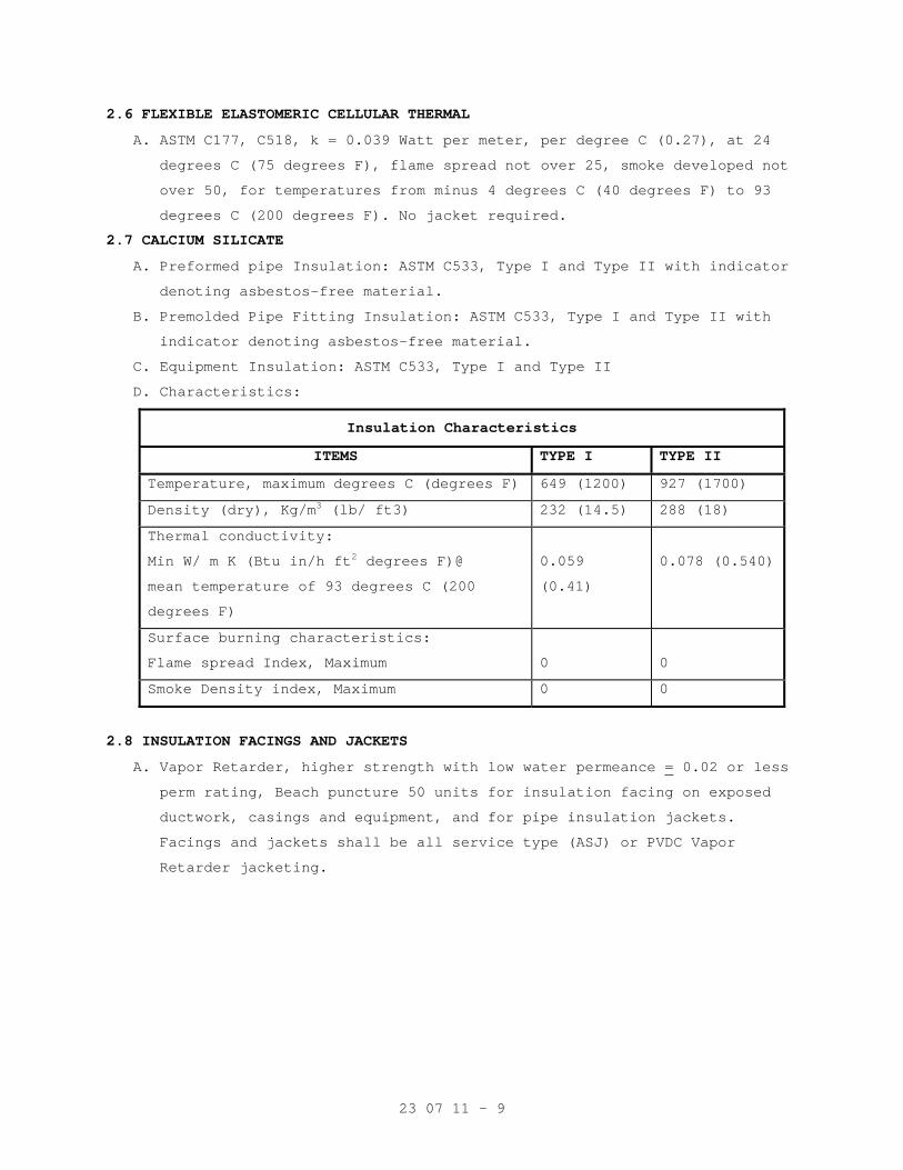
23 07 11 - 9
2.6 FLEXIBLE ELASTOMERIC CELLULAR THERMAL
A. ASTM C177, C518, k = 0.039 Watt per meter, per degree C (0.27), at 24
degrees C (75 degrees F), flame spread not over 25, smoke developed not
over 50, for temperatures from minus 4 degrees C (40 degrees F) to 93
degrees C (200 degrees F). No jacket required.
2.7 CALCIUM SILICATE
A. Preformed pipe Insulation: ASTM C533, Type I and Type II with indicator
denoting asbestos-free material.
B. Premolded Pipe Fitting Insulation: ASTM C533, Type I and Type II with
indicator denoting asbestos-free material.
C. Equipment Insulation: ASTM C533, Type I and Type II
D. Characteristics:
Insulation Characteristics
ITEMS TYPE I TYPE II
Temperature, maximum degrees C (degrees F) 649 (1200) 927 (1700)
Density (dry), Kg/m3 (lb/ ft3) 232 (14.5) 288 (18)
Thermal conductivity:
Min W/ m K (Btu in/h ft2 degrees F)@
mean temperature of 93 degrees C (200
degrees F)
0.059
(0.41)
0.078 (0.540)
Surface burning characteristics:
Flame spread Index, Maximum
0
0
Smoke Density index, Maximum 0 0
2.8 INSULATION FACINGS AND JACKETS
A. Vapor Retarder, higher strength with low water permeance = 0.02 or less
perm rating, Beach puncture 50 units for insulation facing on exposed
ductwork, casings and equipment, and for pipe insulation jackets.
Facings and jackets shall be all service type (ASJ) or PVDC Vapor
Retarder jacketing.
23 07 11 - 10
B. ASJ jacket shall be white kraft bonded to 0.025 mm (1 mil) thick
aluminum foil, fiberglass reinforced, with pressure sensitive adhesive
closure. Comply with ASTM C1136. Beach puncture 5 units, Suitable for
painting without sizing. Jackets shall have minimum 40 mm (1-1/2 inch)
lap on longitudinal joints and minimum 100 mm (4 inch) butt strip on
end joints. Butt strip material shall be same as the jacket. Lap and
butt strips shall be self-sealing type with factory-applied pressure
sensitive adhesive.
C. Vapor Retarder medium strength with low water vapor permeance of 0.02
or less perm rating), Beach puncture 25 units: Foil-Scrim-Kraft (FSK)
or PVDC vapor retarder jacketing type for concealed ductwork and
equipment.
D. Glass Cloth Jackets: Presized, minimum 0.18 kg per square meter (7.8
ounces per square yard), 2000 kPa (300 psig) bursting strength with
integral vapor retarder where required or specified. Weather proof if
utilized for outside service.
E. Factory composite materials may be used provided that they have been
tested and certified by the manufacturer.
F. Pipe fitting insulation covering (jackets): Fitting covering shall be
premolded to match shape of fitting and shall be polyvinyl chloride
(PVC) conforming to Fed Spec L-P-335, composition A, Type II Grade GU,
and Type III, minimum thickness 0.7 mm (0.03 inches). Provide color
matching vapor retarder pressure sensitive tape.
G. Aluminum Jacket-Piping systems and circular breeching and stacks: ASTM
B209, 3003 alloy, H-14 temper, 0.6 mm (0.023 inch) minimum thickness
with locking longitudinal joints. Jackets for elbows, tees and other
fittings shall be factory-fabricated to match shape of fitting and of
0.6 mm (0.024) inch minimum thickness aluminum. Fittings shall be of
same construction as straight run jackets but need not be of the same
alloy. Factory-fabricated stainless steel bands shall be installed on
all circumferential joints. Bands shall be 20 mm (0.75 inch) wide on
450 mm (18 inch) centers. System shall be weatherproof if utilized for
outside service.
H. Aluminum jacket-Rectangular breeching: ASTM B209, 3003 alloy, H-14
temper, 0.5 mm (0.020 inches) thick with 32 mm (1-1/4 inch)
corrugations or 0.8 mm (0.032 inches) thick with no corrugations.
System shall be weatherproof if used for outside service.
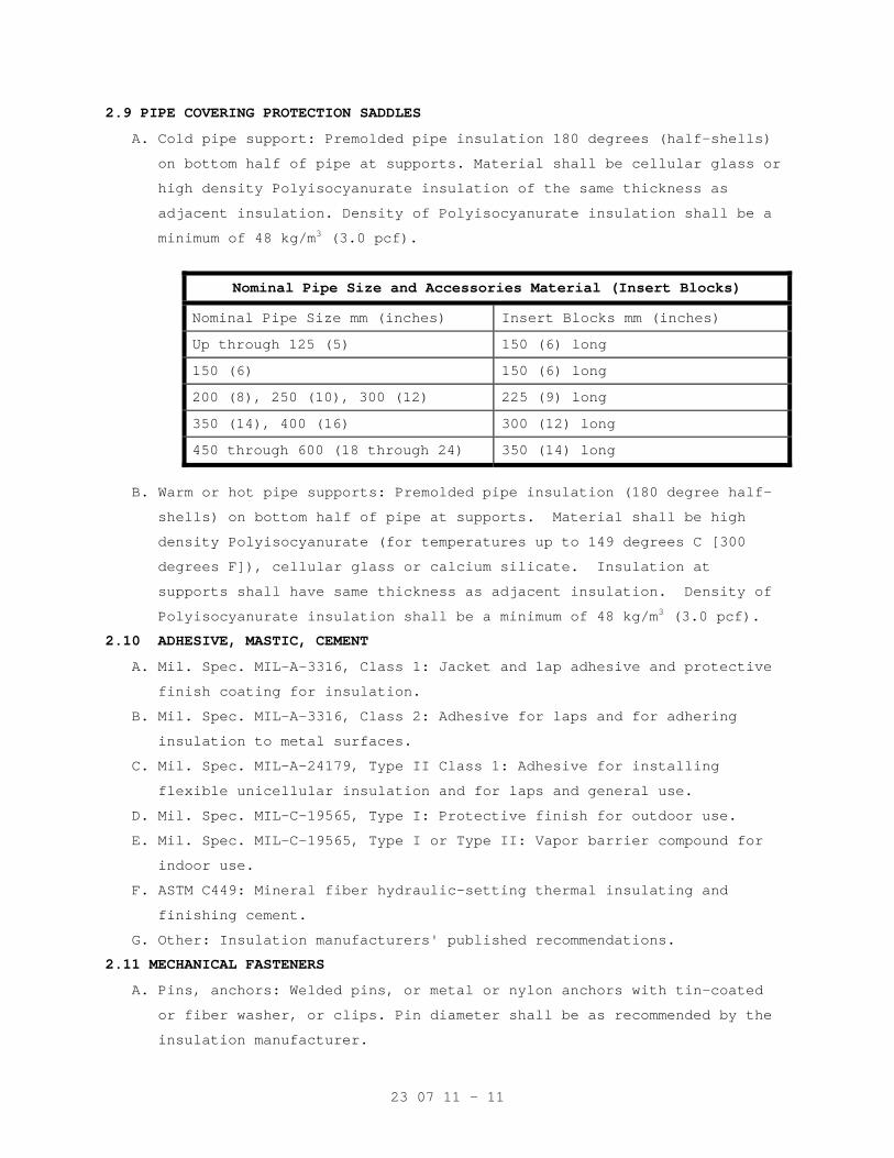
23 07 11 - 11
2.9 PIPE COVERING PROTECTION SADDLES
A. Cold pipe support: Premolded pipe insulation 180 degrees (half-shells)
on bottom half of pipe at supports. Material shall be cellular glass or
high density Polyisocyanurate insulation of the same thickness as
adjacent insulation. Density of Polyisocyanurate insulation shall be a
minimum of 48 kg/m3 (3.0 pcf).
Nominal Pipe Size and Accessories Material (Insert Blocks)
Nominal Pipe Size mm (inches) Insert Blocks mm (inches)
Up through 125 (5) 150 (6) long
150 (6) 150 (6) long
200 (8), 250 (10), 300 (12) 225 (9) long
350 (14), 400 (16) 300 (12) long
450 through 600 (18 through 24) 350 (14) long
B. Warm or hot pipe supports: Premolded pipe insulation (180 degree half-
shells) on bottom half of pipe at supports. Material shall be high
density Polyisocyanurate (for temperatures up to 149 degrees C [300
degrees F]), cellular glass or calcium silicate. Insulation at
supports shall have same thickness as adjacent insulation. Density of
Polyisocyanurate insulation shall be a minimum of 48 kg/m3 (3.0 pcf).
2.10 ADHESIVE, MASTIC, CEMENT
A. Mil. Spec. MIL-A-3316, Class 1: Jacket and lap adhesive and protective
finish coating for insulation.
B. Mil. Spec. MIL-A-3316, Class 2: Adhesive for laps and for adhering
insulation to metal surfaces.
C. Mil. Spec. MIL-A-24179, Type II Class 1: Adhesive for installing
flexible unicellular insulation and for laps and general use.
D. Mil. Spec. MIL-C-19565, Type I: Protective finish for outdoor use.
E. Mil. Spec. MIL-C-19565, Type I or Type II: Vapor barrier compound for
indoor use.
F. ASTM C449: Mineral fiber hydraulic-setting thermal insulating and
finishing cement.
G. Other: Insulation manufacturers' published recommendations.
2.11 MECHANICAL FASTENERS
A. Pins, anchors: Welded pins, or metal or nylon anchors with tin-coated
or fiber washer, or clips. Pin diameter shall be as recommended by the
insulation manufacturer.
23 07 11 - 12
B. Staples: Outward clinching monel or stainless steel.
C. Wire: 1.3 mm thick (18 gage) soft annealed galvanized or 1.9 mm (14
gage) copper clad steel or nickel copper alloy.
D. Bands: 20 mm (3/4 inch) nominal width, brass, galvanized steel,
aluminum or stainless steel.
2.12 REINFORCEMENT AND FINISHES
A. Glass fabric, open weave: ASTM D1668, Type III (resin treated) and Type
I (asphalt treated).
B. Glass fiber fitting tape: Mil. Spec MIL-C-20079, Type II, Class 1.
C. Tape for Flexible Elastomeric Cellular Insulation: As recommended by
the insulation manufacturer.
D. Hexagonal wire netting: 25 mm (one inch) mesh, 0.85 mm thick (22 gage)
galvanized steel.
E. Corner beads: 50 mm (2 inch) by 50 mm (2 inch), 0.55 mm thick (26 gage)
galvanized steel; or, 25 mm (1 inch) by 25 mm (1 inch), 0.47 mm thick
(28 gage) aluminum angle adhered to 50 mm (2 inch) by 50 mm (2 inch)
Kraft paper.
F. PVC fitting cover: Fed. Spec L-P-535, Composition A, 11-86 Type II,
Grade GU, with Form B Mineral Fiber insert, for media temperature 4
degrees C (40 degrees F) to 121 degrees C (250 degrees F). Below 4
degrees C (40 degrees F) and above 121 degrees C (250 degrees F).
Provide double layer insert. Provide color matching vapor barrier
pressure sensitive tape.
2.13 FIRESTOPPING MATERIAL
Other than pipe and duct insulation, refer to Section 07 84 00
FIRESTOPPING.
2.14 FLAME AND SMOKE
Unless shown otherwise all assembled systems shall meet flame spread 25
and smoke developed 50 rating as developed under ASTM, NFPA and UL
standards and specifications. See paragraph 1.3 "Quality Assurance".
2.15 STEAM SPECIALITY REMOVABLE BLANKET INSULATION
For steam equipment and valves requiring frequent removal for
maintenance, including steam valves, PRV and stream traps, provide
custom fabricated pads.
A. Removable Pad Materials
1. Silicone impregnated fiberglass Falenc, Lenco, or equal, Alph 2025-
1805.
2. Needled fiberglass Matt, BCF Industries, Alpha, Temp-mat1.
23 07 11 - 13
3. Securements-Velco not allowed 55-0 ring and strapping.
PART 3 - EXECUTION
3.1 GENERAL REQUIREMENTS
A. Required pressure tests of duct and piping joints and connections shall
be completed and the work approved by the Resident Engineer for
application of insulation. Surface shall be clean and dry with all
foreign materials, such as dirt, oil, loose scale and rust removed.
B. Except for specific exceptions, insulate entire specified equipment,
piping (pipe, fittings, valves, accessories), and duct systems.
Insulate each pipe and duct individually. Do not use scrap pieces of
insulation where a full length section will fit.
C. Insulation materials shall be installed in a first class manner with
smooth and even surfaces, with jackets and facings drawn tight and
smoothly cemented down at all laps. Insulation shall be continuous
through all sleeves and openings, except at fire dampers and duct
heaters (NFPA 90A). Vapor retarders shall be continuous and
uninterrupted throughout systems with operating temperature 16 degrees
C (60 degrees F) and below. Lap and seal vapor barrier over ends and
exposed edges of insulation. Anchors, supports and other metal
projections through insulation on cold surfaces shall be insulated and
vapor sealed for a minimum length of 150 mm (6 inches).
D. Install vapor stops at all insulation terminations on either side of
valves, pumps and equipment and particularly in straight lengths of
pipe insulation.
E. Insulation on hot piping and equipment shall be terminated square at
items not to be insulated, access openings and nameplates. Cover all
exposed raw insulation with white sealer or jacket material.
F. Protect all insulations outside of buildings with aluminum jacket using
lock joint or other approved system for a continuous weather tight
system. Access doors and other items requiring maintenance or access
shall be removable and sealable.
G. HVAC work not to be insulated:
1. Relief air ducts (Economizer cycle exhaust air).
2. Exhaust air ducts and plenums.
3. Equipment: Flash tanks, steam condensate pumps.
23 07 11 - 14
4. In hot piping: Unions, flexible connectors, control valves, PRVs,
safety valves and discharge vent piping, vacuum breakers,
thermostatic vent valves, steam traps 20 mm (3/4 inch) and smaller,
exposed piping through floor for convectors and radiators. Insulate
piping to within approximately 75 mm (3 inches) of uninsulated
items.
H. Plumbing work not to be insulated:
1. Piping and valves of fire protection system.
2. Chromium plated brass piping.
3. Water piping in contact with earth.
4. Piping in pipe basement serving wall hydrants.
5. Small horizontal cold water branch runs in partitions to individual
fixtures may be without insulation for maximum distance of 900 mm (3
feet).
6. Distilled water piping.
I. Apply insulation materials subject to the manufacturer's recommended
temperature limits. Apply adhesives, mastic and coatings at the
manufacturer's recommended minimum coverage.
J. Elbows, flanges and other fittings shall be insulated with the same
material as is used on the pipe straights. The elbow/ fitting
insulation shall be field-fabricated, mitered or factory prefabricated
to the necessary size and shape to fit on the elbow/ fitting. Use of
polyurethane spray-foam to fill a PVC elbow jacket is prohibited on
cold applications.
K. Firestop Pipe and Duct insulation:
1. Provide firestopping insulation at fire and smoke barriers through
penetrations. Fire stopping insulation shall be UL listed as defines
in Section 07 84 00, FIRESTOPPING.
2. Pipe and duct penetrations requiring fire stop insulation including,
but not limited to the following:
a. Pipe risers through floors
b. Pipe or duct chase walls and floors
c. Smoke partitions
d. Fire partitions
L. Provide metal jackets over insulation as follows:
a. All ducts exposed to outdoor weather.
b. A 50 mm (2 inch) overlap is required at longitudinal and
circumferential joints.
23 07 11 - 15
3.2 INSULATION INSTALLATION
A. Mineral Fiber Board:
1. Faced board: Apply board on pins spaced not more than 300 mm (12
inches) on center each way, and not less than 75 mm (3 inches) from
each edge of board. In addition to pins, apply insulation bonding
adhesive to entire underside of horizontal metal surfaces. Butt
insulation edges tightly and seal all joints with laps and butt
strips. After applying speed clips cut pins off flush and apply
vapor seal patches over clips.
2. Plain board:
a. Insulation shall be scored, beveled or mitered to provide tight
joints and be secured to equipment with bands spaced 225 mm (9
inches) on center for irregular surfaces or with pins and clips
on flat surfaces. Use corner beads to protect edges of
insulation.
b. For hot equipment: Stretch 25 mm (1 inch) mesh wire, with edges
wire laced together, over insulation and finish with insulating
and finishing cement applied in one coat, 6 mm (1/4 inch) thick,
trowel led to a smooth finish.
c. For cold equipment: Apply meshed glass fabric in a tack coat 1.5
to 1.7 square meter per liter (60 to 70 square feet per gallon)
of vapor mastic and finish with mastic at 0.3 to 0.4 square meter
per liter (12 to 15 square feet per gallon) over the entire
fabric surface.
3. Exposed, unlined ductwork and equipment in unfinished areas,
mechanical rooms:
a. 50 mm (2 inch) thick insulation faced with ASJ (white all service
jacket): Supply air duct and afterfilter housing.
b. 40 mm (1-1/2 inch) thick insulation faced with ASJ: Return air
duct, mixed air plenums and prefilter housing.
c. Outside air intake ducts: 25 mm (one inch) thick insulation faced
with ASJ.
4. Hot equipment: 40 mm (1-1/2 inch) thick insulation faced with ASJ.
a. Convertors, air separators, steam condensate pump receivers.
b. Reheat coil casing and separation chambers on steam humidifiers
located above ceilings.
c. Domestic water heaters and hot water storage tanks (not factory
insulated).
23 07 11 - 16
B. Flexible Mineral Fiber Blanket:
1. Adhere insulation to metal with 100 mm (4 inch) wide strips of
insulation bonding adhesive at 200 mm (8 inches) on center all
around duct. Additionally secure insulation to bottom of ducts
exceeding 600 mm (24 inches) in width with pins welded or adhered on
450 mm (18 inch) centers. Secure washers on pins. Butt insulation
edges and seal joints with laps and butt strips. Staples may be used
to assist in securing insulation. Seal all vapor retarder
penetrations with mastic. Sagging duct insulation will not be
acceptable. Install firestop duct insulation where required.
2. Supply air ductwork to be insulated includes main and branch ducts
from AHU discharge to room supply outlets, and the bodies of ceiling
outlets to prevent condensation. Insulate coil casings and damper
frames. To prevent condensation insulate trapeze type supports and
angle iron hangers for flat oval ducts that are in direct contact
with metal duct.
3. Concealed supply air ductwork.
a. Above ceilings: 50 mm (2 inch) thick insulation faced with FSK.
4. Concealed return air duct above ceilings, unconditioned areas, and
in chases with external wall or containing steam piping; 40 mm (1-
1/2 inch) thick, insulation faced with FSK. Concealed return air
ductwork in other locations need not be insulated.
C. Molded Mineral Fiber Pipe and Tubing Covering:
1. Fit insulation to pipe or duct, aligning longitudinal joints. Seal
longitudinal joint laps and circumferential butt strips by rubbing
hard with a nylon sealing tool to assure a positive seal. Staples
may be used to assist in securing insulation. Seal all vapor
retarder penetrations on cold piping with a generous application of
vapor barrier mastic. Provide inserts and install with metal
insulation shields at outside pipe supports. Install freeze
protection insulation over heating cable.
2. Contractor's options for fitting, flange and valve insulation:
a. Insulating and finishing cement for sizes less than 100 mm (4
inches) operating at surface temperature of 16 degrees C (61
degrees F) or more.
23 07 11 - 17
b. Factory premolded, one piece PVC covers with mineral fiber, (Form
B), inserts. Provide two insert layers for pipe temperatures
below 4 degrees C (40 degrees F), or above 121 degrees C (250
degrees F). Secure first layer of insulation with twine. Seal
seam edges with vapor barrier mastic and secure with fitting
tape.
c. Factory molded, ASTM C547 or field mitered sections, joined with
adhesive or wired in place. For hot piping finish with a
smoothing coat of finishing cement. For cold fittings, 16 degrees
C (60 degrees F) or less, vapor seal with a layer of glass
fitting tape imbedded between two 2 mm (1/16 inch) coats of vapor
barrier mastic.
d. Fitting tape shall extend over the adjacent pipe insulation and
overlap on itself at least 50 mm (2 inches).
3. Nominal thickness in millimeters and inches specified in table
below, for piping above ground:
Nominal Thickness of Molded Mineral Fiber Insulation
Nominal Pipe Size, millimeters (inches):
25
(1) & below
32- 75 (1-1/4- 3)
100-150
(4-6)
200
(8) and above
a. 122-177 degrees C (251-350 F) (HPS)
50 (2.0) 65 (2.5) 90 (3.5)
90 (3.5)
b. 100-121 degrees C HPR (212-250 degrees F) (Vent piping from PRV safety valves, condensate receivers, and flash tanks)
25 (1.0) 50 (2.0) 50 (2.0)
50 (2.0)
c. 38-99 degrees C (100-211 degrees F) (LPR, PC, HWH, HWHR)
25 (1.0) 40 (1.5) 50 (2.0)
50 (2.0)
1. Runouts to fan coil units
15 (0.5) - - -
2. Runouts to air terminal unit reheat coils
15 (0.5) - - -
d. Domestic hot water supply and return
15 (0.5) 20(0.75) 25 (1.0)
40 (1.5)
D. Rigid Cellular Phenolic Foam:
1. Rigid closed cell phenolic insulation may be provided for piping,
ductwork and equipment for temperatures up to 121 degrees C (250
degrees F).
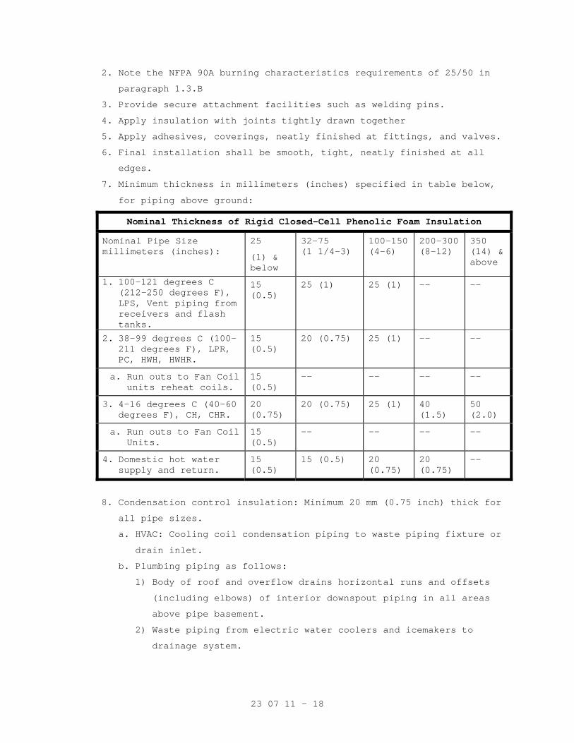
23 07 11 - 18
2. Note the NFPA 90A burning characteristics requirements of 25/50 in
paragraph 1.3.B
3. Provide secure attachment facilities such as welding pins.
4. Apply insulation with joints tightly drawn together
5. Apply adhesives, coverings, neatly finished at fittings, and valves.
6. Final installation shall be smooth, tight, neatly finished at all
edges.
7. Minimum thickness in millimeters (inches) specified in table below,
for piping above ground:
Nominal Thickness of Rigid Closed-Cell Phenolic Foam Insulation
Nominal Pipe Size millimeters (inches):
25
(1) & below
32-75 (1 1/4-3)
100-150 (4-6)
200-300 (8-12)
350 (14) & above
1. 100-121 degrees C (212-250 degrees F), LPS, Vent piping from receivers and flash tanks.
15 (0.5)
25 (1) 25 (1) -- --
2. 38-99 degrees C (100-211 degrees F), LPR, PC, HWH, HWHR.
15 (0.5)
20 (0.75) 25 (1) -- --
a. Run outs to Fan Coil units reheat coils.
15 (0.5)
-- -- -- --
3. 4-16 degrees C (40-60 degrees F), CH, CHR.
20 (0.75)
20 (0.75) 25 (1) 40 (1.5)
50 (2.0)
a. Run outs to Fan Coil Units.
15 (0.5)
-- -- -- --
4. Domestic hot water supply and return.
15 (0.5)
15 (0.5) 20 (0.75)
20 (0.75)
--
8. Condensation control insulation: Minimum 20 mm (0.75 inch) thick for
all pipe sizes.
a. HVAC: Cooling coil condensation piping to waste piping fixture or
drain inlet.
b. Plumbing piping as follows:
1) Body of roof and overflow drains horizontal runs and offsets
(including elbows) of interior downspout piping in all areas
above pipe basement.
2) Waste piping from electric water coolers and icemakers to
drainage system.
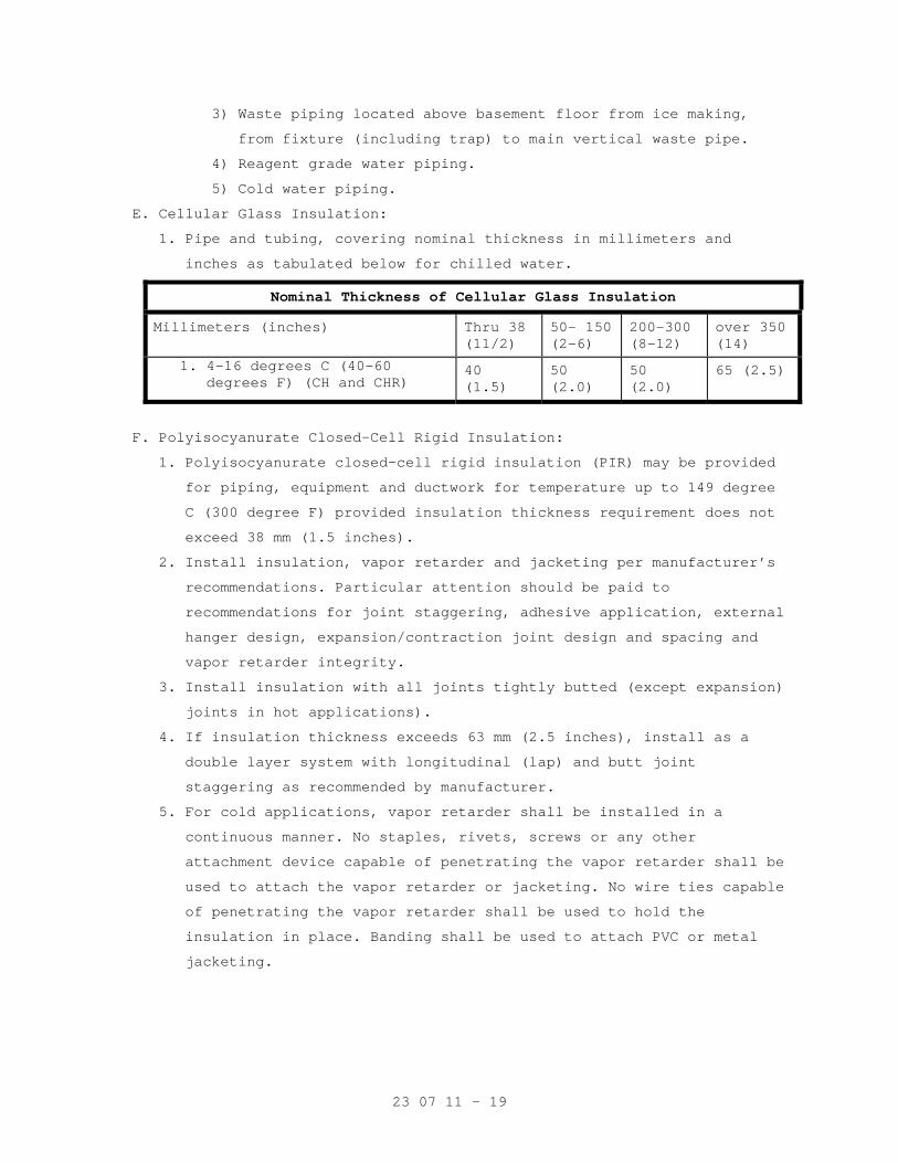
23 07 11 - 19
3) Waste piping located above basement floor from ice making,
from fixture (including trap) to main vertical waste pipe.
4) Reagent grade water piping.
5) Cold water piping.
E. Cellular Glass Insulation:
1. Pipe and tubing, covering nominal thickness in millimeters and
inches as tabulated below for chilled water.
Nominal Thickness of Cellular Glass Insulation
Millimeters (inches) Thru 38 (11/2)
50- 150(2-6)
200-300 (8-12)
over 350 (14)
1. 4-16 degrees C (40-60 degrees F) (CH and CHR)
40 (1.5)
50 (2.0)
50 (2.0)
65 (2.5)
F. Polyisocyanurate Closed-Cell Rigid Insulation:
1. Polyisocyanurate closed-cell rigid insulation (PIR) may be provided
for piping, equipment and ductwork for temperature up to 149 degree
C (300 degree F) provided insulation thickness requirement does not
exceed 38 mm (1.5 inches).
2. Install insulation, vapor retarder and jacketing per manufacturer’s
recommendations. Particular attention should be paid to
recommendations for joint staggering, adhesive application, external
hanger design, expansion/contraction joint design and spacing and
vapor retarder integrity.
3. Install insulation with all joints tightly butted (except expansion)
joints in hot applications).
4. If insulation thickness exceeds 63 mm (2.5 inches), install as a
double layer system with longitudinal (lap) and butt joint
staggering as recommended by manufacturer.
5. For cold applications, vapor retarder shall be installed in a
continuous manner. No staples, rivets, screws or any other
attachment device capable of penetrating the vapor retarder shall be
used to attach the vapor retarder or jacketing. No wire ties capable
of penetrating the vapor retarder shall be used to hold the
insulation in place. Banding shall be used to attach PVC or metal
jacketing.
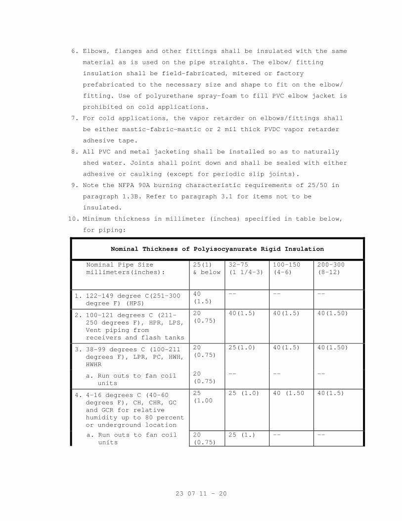
23 07 11 - 20
6. Elbows, flanges and other fittings shall be insulated with the same
material as is used on the pipe straights. The elbow/ fitting
insulation shall be field-fabricated, mitered or factory
prefabricated to the necessary size and shape to fit on the elbow/
fitting. Use of polyurethane spray-foam to fill PVC elbow jacket is
prohibited on cold applications.
7. For cold applications, the vapor retarder on elbows/fittings shall
be either mastic-fabric-mastic or 2 mil thick PVDC vapor retarder
adhesive tape.
8. All PVC and metal jacketing shall be installed so as to naturally
shed water. Joints shall point down and shall be sealed with either
adhesive or caulking (except for periodic slip joints).
9. Note the NFPA 90A burning characteristic requirements of 25/50 in
paragraph 1.3B. Refer to paragraph 3.1 for items not to be
insulated.
10. Minimum thickness in millimeter (inches) specified in table below,
for piping:
Nominal Thickness of Polyisocyanurate Rigid Insulation
Nominal Pipe Size millimeters(inches):
25(1) & below
32-75 (1 1/4-3)
100-150 (4-6)
200-300 (8-12)
1. 122-149 degree C(251-300 degree F) (HPS)
40 (1.5)
-- -- --
2. 100-121 degrees C (211-250 degrees F), HPR, LPS, Vent piping from receivers and flash tanks
20 (0.75)
40(1.5) 40(1.5) 40(1.50)
3. 38-99 degrees C (100-211 degrees F), LPR, PC, HWH, HWHR
20 (0.75)
25(1.0) 40(1.5) 40(1.50)
a. Run outs to fan coil units
20 (0.75)
-- -- --
4. 4-16 degrees C (40-60 degrees F), CH, CHR, GC and GCR for relative humidity up to 80 percent or underground location
25 (1.00
25 (1.0) 40 (1.50 40(1.5)
a. Run outs to fan coil units
20 (0.75)
25 (1.) -- --
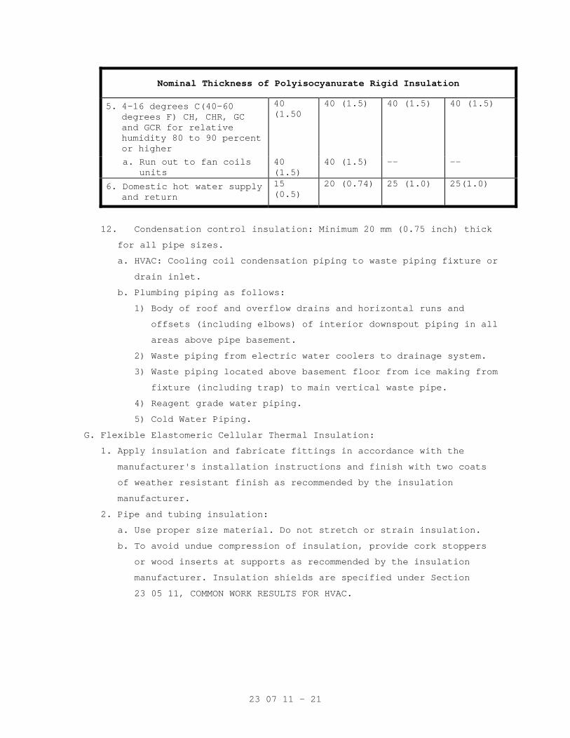
23 07 11 - 21
Nominal Thickness of Polyisocyanurate Rigid Insulation
5. 4-16 degrees C(40-60 degrees F) CH, CHR, GC and GCR for relative humidity 80 to 90 percent or higher
40 (1.50
40 (1.5) 40 (1.5) 40 (1.5)
a. Run out to fan coils units
40 (1.5)
40 (1.5) -- --
6. Domestic hot water supply and return
15 (0.5)
20 (0.74) 25 (1.0) 25(1.0)
12. Condensation control insulation: Minimum 20 mm (0.75 inch) thick
for all pipe sizes.
a. HVAC: Cooling coil condensation piping to waste piping fixture or
drain inlet.
b. Plumbing piping as follows:
1) Body of roof and overflow drains and horizontal runs and
offsets (including elbows) of interior downspout piping in all
areas above pipe basement.
2) Waste piping from electric water coolers to drainage system.
3) Waste piping located above basement floor from ice making from
fixture (including trap) to main vertical waste pipe.
4) Reagent grade water piping.
5) Cold Water Piping.
G. Flexible Elastomeric Cellular Thermal Insulation:
1. Apply insulation and fabricate fittings in accordance with the
manufacturer's installation instructions and finish with two coats
of weather resistant finish as recommended by the insulation
manufacturer.
2. Pipe and tubing insulation:
a. Use proper size material. Do not stretch or strain insulation.
b. To avoid undue compression of insulation, provide cork stoppers
or wood inserts at supports as recommended by the insulation
manufacturer. Insulation shields are specified under Section
23 05 11, COMMON WORK RESULTS FOR HVAC.
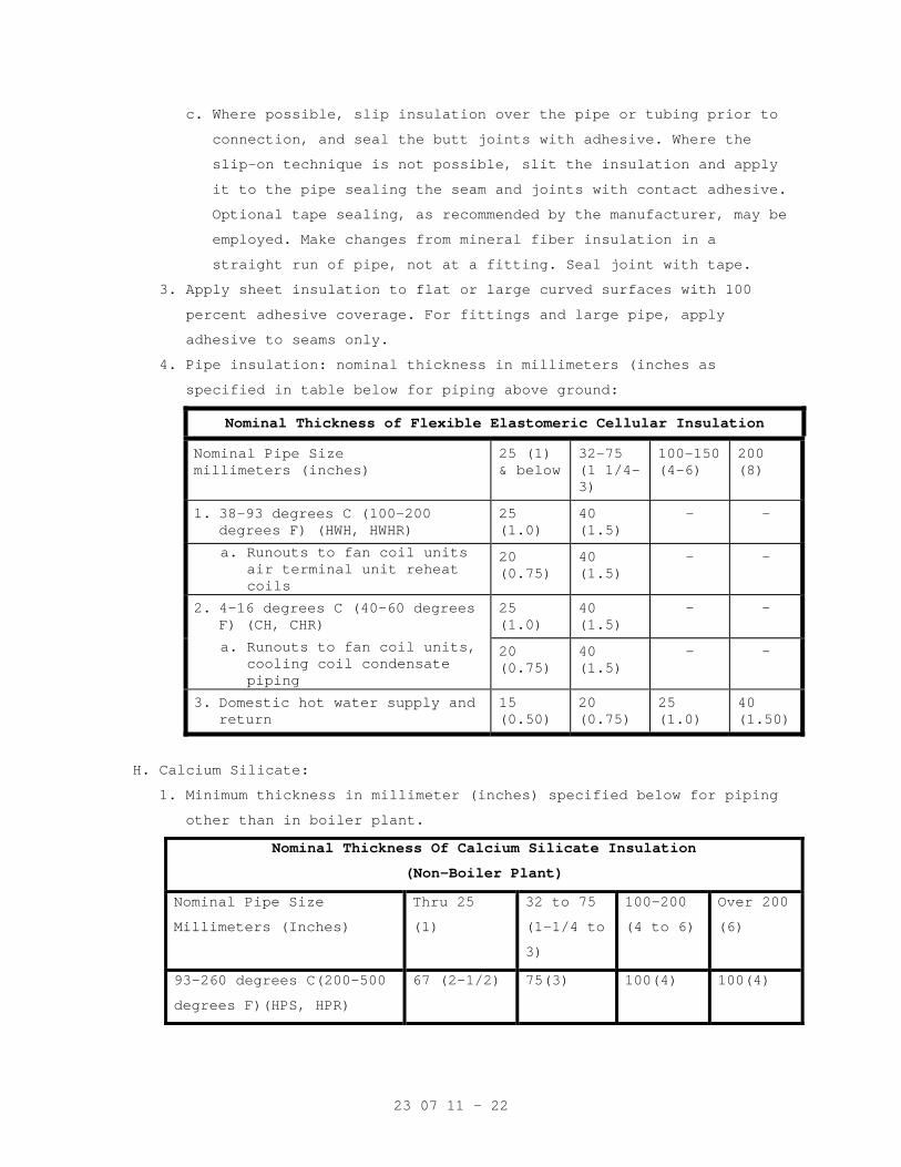
23 07 11 - 22
c. Where possible, slip insulation over the pipe or tubing prior to
connection, and seal the butt joints with adhesive. Where the
slip-on technique is not possible, slit the insulation and apply
it to the pipe sealing the seam and joints with contact adhesive.
Optional tape sealing, as recommended by the manufacturer, may be
employed. Make changes from mineral fiber insulation in a
straight run of pipe, not at a fitting. Seal joint with tape.
3. Apply sheet insulation to flat or large curved surfaces with 100
percent adhesive coverage. For fittings and large pipe, apply
adhesive to seams only.
4. Pipe insulation: nominal thickness in millimeters (inches as
specified in table below for piping above ground:
Nominal Thickness of Flexible Elastomeric Cellular Insulation
Nominal Pipe Size millimeters (inches)
25 (1) & below
32-75 (1 1/4-3)
100-150 (4-6)
200 (8)
1. 38-93 degrees C (100-200 degrees F) (HWH, HWHR)
25 (1.0)
40 (1.5)
- -
a. Runouts to fan coil units air terminal unit reheat coils
20 (0.75)
40 (1.5)
- -
2. 4-16 degrees C (40-60 degrees F) (CH, CHR)
25 (1.0)
40 (1.5)
- -
a. Runouts to fan coil units, cooling coil condensate piping
20 (0.75)
40 (1.5)
- -
3. Domestic hot water supply and return
15 (0.50)
20 (0.75)
25 (1.0)
40 (1.50)
H. Calcium Silicate:
1. Minimum thickness in millimeter (inches) specified below for piping
other than in boiler plant.
Nominal Thickness Of Calcium Silicate Insulation
(Non-Boiler Plant)
Nominal Pipe Size
Millimeters (Inches)
Thru 25
(1)
32 to 75
(1-1/4 to
3)
100-200
(4 to 6)
Over 200
(6)
93-260 degrees C(200-500
degrees F)(HPS, HPR)
67 (2-1/2) 75(3) 100(4) 100(4)
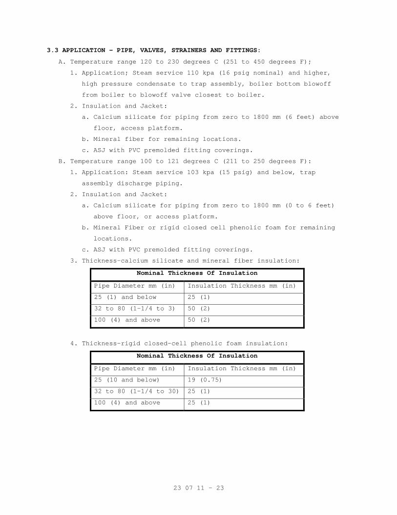
23 07 11 - 23
3.3 APPLICATION – PIPE, VALVES, STRAINERS AND FITTINGS:
A. Temperature range 120 to 230 degrees C (251 to 450 degrees F);
1. Application; Steam service 110 kpa (16 psig nominal) and higher,
high pressure condensate to trap assembly, boiler bottom blowoff
from boiler to blowoff valve closest to boiler.
2. Insulation and Jacket:
a. Calcium silicate for piping from zero to 1800 mm (6 feet) above
floor, access platform.
b. Mineral fiber for remaining locations.
c. ASJ with PVC premolded fitting coverings.
B. Temperature range 100 to 121 degrees C (211 to 250 degrees F):
1. Application: Steam service 103 kpa (15 psig) and below, trap
assembly discharge piping.
2. Insulation and Jacket:
a. Calcium silicate for piping from zero to 1800 mm (0 to 6 feet)
above floor, or access platform.
b. Mineral Fiber or rigid closed cell phenolic foam for remaining
locations.
c. ASJ with PVC premolded fitting coverings.
3. Thickness-calcium silicate and mineral fiber insulation:
Nominal Thickness Of Insulation
Pipe Diameter mm (in) Insulation Thickness mm (in)
25 (1) and below 25 (1)
32 to 80 (1-1/4 to 3) 50 (2)
100 (4) and above 50 (2)
4. Thickness-rigid closed-cell phenolic foam insulation:
Nominal Thickness Of Insulation
Pipe Diameter mm (in) Insulation Thickness mm (in)
25 (10 and below) 19 (0.75)
32 to 80 (1-1/4 to 30) 25 (1)
100 (4) and above 25 (1)
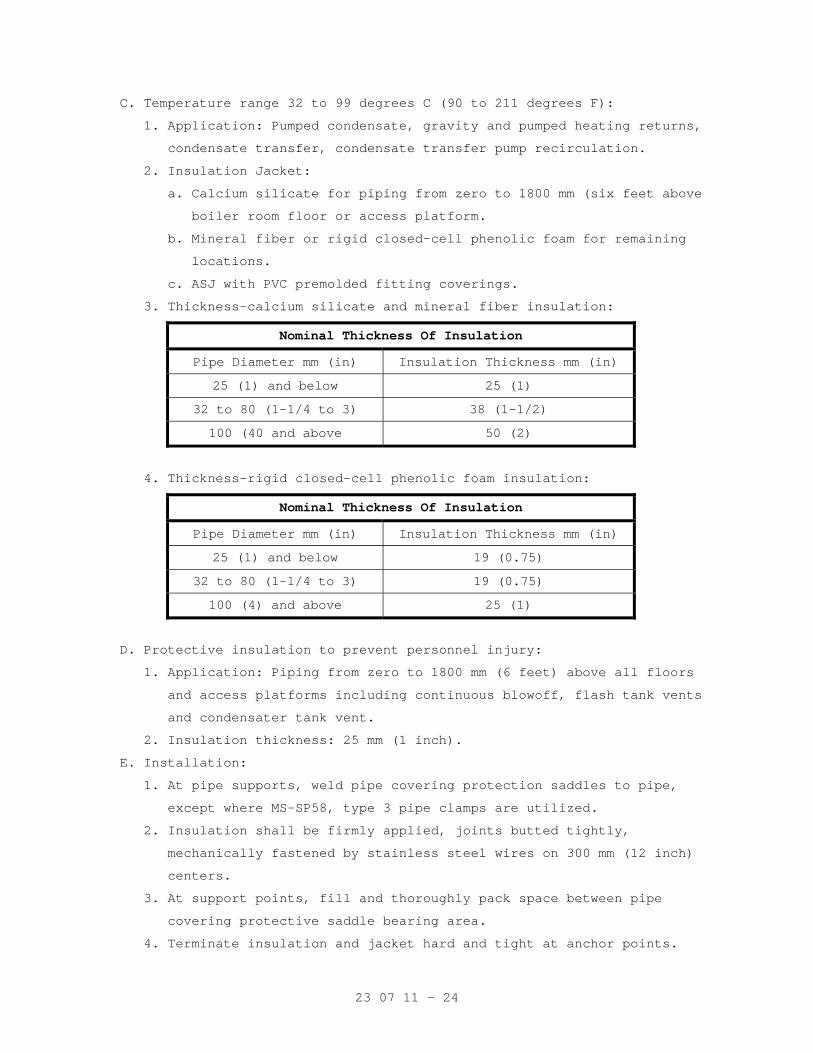
23 07 11 - 24
C. Temperature range 32 to 99 degrees C (90 to 211 degrees F):
1. Application: Pumped condensate, gravity and pumped heating returns,
condensate transfer, condensate transfer pump recirculation.
2. Insulation Jacket:
a. Calcium silicate for piping from zero to 1800 mm (six feet above
boiler room floor or access platform.
b. Mineral fiber or rigid closed-cell phenolic foam for remaining
locations.
c. ASJ with PVC premolded fitting coverings.
3. Thickness-calcium silicate and mineral fiber insulation:
Nominal Thickness Of Insulation
Pipe Diameter mm (in) Insulation Thickness mm (in)
25 (1) and below 25 (1)
32 to 80 (1-1/4 to 3) 38 (1-1/2)
100 (40 and above 50 (2)
4. Thickness-rigid closed-cell phenolic foam insulation:
Nominal Thickness Of Insulation
Pipe Diameter mm (in) Insulation Thickness mm (in)
25 (1) and below 19 (0.75)
32 to 80 (1-1/4 to 3) 19 (0.75)
100 (4) and above 25 (1)
D. Protective insulation to prevent personnel injury:
1. Application: Piping from zero to 1800 mm (6 feet) above all floors
and access platforms including continuous blowoff, flash tank vents
and condensater tank vent.
2. Insulation thickness: 25 mm (1 inch).
E. Installation:
1. At pipe supports, weld pipe covering protection saddles to pipe,
except where MS-SP58, type 3 pipe clamps are utilized.
2. Insulation shall be firmly applied, joints butted tightly,
mechanically fastened by stainless steel wires on 300 mm (12 inch)
centers.
3. At support points, fill and thoroughly pack space between pipe
covering protective saddle bearing area.
4. Terminate insulation and jacket hard and tight at anchor points.
23 07 11 - 25
5. Terminate insulation at piping facilities not insulated with a 45
degree chamfered section of insulating and finishing cement covered
with jacket.
6. On calcium silicate, mineral fiber and rigid closed-cell phenolic
foam systems, insulated flanged fittings, strainers and valves with
sections of pipe insulation cut, fitted and arranged neatly and
firmly wired in place. Fill all cracks, voids and coat outer surface
with insulating cement. Install jacket. Provide similar construction
on welded and threaded fittings on calcium silicate systems or use
premolded fitting insulation.
7. On mineral fiber systems, insulate welded and threaded fittings more
than 50 mm (2 inches) in diameter with compressed blanket insulation
(minimum 2/1) and finish with jacket or PVC cover.
8. Insulate fittings 50 mm (2 inches) and smaller with mastic finishing
material and cover with jacket.
9. Insulate valve bonnet upto valve side of bonnet flange to permit
bonnet flange removal without disturbing insulation.
10. Install jacket smooth, tight and neatly finish all edges. Over wrap
ASJ butt strips by 50 percent. Secure aluminum jacket with stainless
steel bands 300 mm (12 inches) on center or aluminum screws on 200
mm (4 inch) centers.
11. Do not insulate basket removal flanges on strainers.
- - - E N D - - -
23 09 23 - 1
SECTION 23 09 23 DIRECT-DIGITAL CONTROL SYSTEM FOR HVAC
PART 1 - GENERAL
1.1 SCOPE
A. General: The control system shall be as indicated on the drawings and
described in the specifications, and consist of a peer-to-peer network
of building digital control panels and existing operator workstation
herein called the Energy Management System (EMS).
B. Direct Digital Control (DDC) technology shall be used to provide the
functions necessary for control of systems defined for control on this
project.
C. The control system shall be designed such that each mechanical system
will operate under stand-alone control. As such, in the event of a
network communication failure, or the loss of other controllers, the
control system shall continue to independently operate the unaffected
equipment.
D. Communication between the building digital control panels and existing
workstation(s) shall be over a high-speed Ethernet network. All nodes
on this network shall be peers. A modem and network communications
card shall be provided for remote access to the system.
E. All control devices shown on the control diagrams are furnished by the
ATC Contractor unless otherwise noted or specified.
F. All components required to accomplish the sequences of operation shown
on the control diagrams, described in the specification, or as required
for a properly operating system shall be provided by the ATC Contractor
unless otherwise noted, shown, or specified.
1.2 APPROVED TEMPERATURE CONTROL CONTRACTORS
A. Approved Control System Manufacturers:
Manufacturer Name Product
Siemens Apogee
1.3 CODES AND STANDARDS:
Work, materials and equipment shall comply with the rules and
regulations of all codes and ordinances of local, state and federal
authorities. As a minimum, the installation shall comply with the
current editions in effect 30 days prior to receipt of bids of the
following codes:
23 09 23 - 2
A. National Electric Code (NEC)
B. International Building Code (IBC)
C. International Mechanical Code (IMC)
D. Underwriters Laboratories: Products shall be UL-916-PAZX listed.
E. ANSI/ASHRAE Standard 135-2004 (BACnet)
F. ANSI/EIA/CEA-709.1 (LONtalk)
1.4 COORDINATION
A. EMS and System Integration:
1. EMS Communication Protocols: Match the existing for inclusion in the
existing Siemens Apogee EMS currently installed in the facility.
2. EMS Integration: The ATC Contractor shall be responsible for the
integration of all controllers or gateways shown on the control
diagrams and/or as specified with HVAC equipment and other systems,
into the EMS. All hardware, wiring, software, and programming
required to receive communication from equipment controller,
gateway, and other systems shall be furnished and installed by the
ATC Contractor.
3. All points available through the controllers and gateways shall be
mapped through to the EMS Network such that this information is
available at the EMS operator workstation.
4. HVAC Equipment: Where indicated on the control diagrams or
specified, the HVAC equipment supplier shall be responsible for
providing a BACnet or LON interface for the HVAC equipment to
communicate with the EMS.
5. Other Systems: Where indicated on the control diagrams or specified,
the system equipment supplier(s) shall be responsible for providing
BACnet or LON interfaces to communicate with the EMS. Examples of
other systems include, but are not limited to, switchgear monitoring
systems, lighting systems, and domestic booster system.
6. Communication cabling from HVAC equipment or other systems
controllers or gateways, to the EMS shall be furnished and installed
by the ATC Contractor.
7. EMS network (LAN and Trunk) cabling shall be furnished and installed
by the ATC Contractor.
23 09 23 - 3
B. Air Handling Units:
1. Air handling units shall be furnished with outside air and return
air dampers. Damper actuators shall be furnished and installed by
the ATC Contractor.
2. Filters shall be furnished with magnehelic air gauges.
3. Air handling unit isolation smoke dampers shall be furnished with
factory mounted electric actuators with integral end switches.
Control wiring to close isolation smoke dampers when air handling
unit stops shall be furnished and installed by the ATC Contractor.
4. Interlock wiring from isolation smoke damper end switches for air
handling unit safety shutdown shall be furnished and installed by
the ATC Contractor.
5. Programmable fire alarm relay, wiring to close isolation smoke
damper from fire alarm system, and power wiring to isolation smoke
damper actuator shall be furnished and installed by the Fire Alarm
Contractor.
6. Programmable fire alarm relay for AHU shutdown and fire alarm wiring
from fire alarm panel to programmable fire alarm relay shall be
furnished and installed by the Fire Alarm Contractor. Control
wiring from fire alarm relay to air handling unit control panel
shall be furnished and installed by the ATC Contractor.
7. Duct mounted smoke detectors shall be furnished and installed by the
Fire Alarm Contractor.
8. Air handling units shall be furnished with airflow measuring
stations installed in the outside air intakes of the units. The
airflow stations shall provide a proportional output velocity signal
(2-10Vdc) for use by the ATC Contractor in measuring the outside
airflow entering the unit. Wiring from airflow station to EMS shall
be furnished and installed by the ATC Contractor.
9. Humidifiers shall be capable accepting a modulating (0-10Vdc or 4-
20mA) signal from the EMS to modulate humidifier capacity.
Installation of humidity transmitters, high limits, control wiring
and other associated devices shall be the responsibility of the ATC
Contractor.
10. Heating water and chilled water control valves shall be furnished
by the ATC Contractor and installed in piping by the Mechanical
Contractor.
23 09 23 - 4
C. Single Duct Supply Air Terminals:
1. Single duct supply air terminals are specified in Section 23 36 00.
Terminals shall be furnished with dampers and averaging velocity
pressure sensors.
2. Controls and actuators for terminal dampers shall be furnished and
installed by the ATC Contractor.
3. Power wiring (120V) for supply air terminals shall be furnished and
installed by the Electrical Contractor.
4. Control transformers, enclosures, and 24 VAC power wiring to
controllers shall be furnished and installed by the ATC Contractor.
5. Control valves for supply air terminal reheat coils shall be
furnished by the ATC Contractor and installed in piping by the
Mechanical Contractor.
6. Capped tees in the pneumatic tubing at the averaging velocity sensor
shall be furnished and installed by the ATC Contractor.
D. Exhaust Air Terminals:
1. Exhaust air terminals are specified in Section 23 36 00. Exhaust
air terminals shall be furnished with dampers and orifice plate
velocity pressure sensors.
2. Controls and actuators for terminal dampers shall be furnished and
installed by the ATC Contractor.
3. Power wiring (120V) for isolation room control panels shall be
furnished and installed by the Electrical Contractor.
4. Control transformers, enclosures, and 24 VAC power wiring to
controllers shall be furnished and installed by the ATC Contractor.
5. Capped tees in the pneumatic tubing at the airflow measuring device
shall be furnished and installed by the ATC Contractor.
6. Room pressure monitors shall be furnished and installed by the ATC
Contractor. Power wiring for room pressure monitors shall be
furnished and installed by the Electrical Contractor.
E. Chilled Water System
1. Sensors and brass wells for temperature sensors shall be furnished
by the ATC Contractor. Brass wells shall be installed in piping by
the Mechanical Contractor. Refer to control diagrams for location
and quantities of sensors and brass wells.
23 09 23 - 5
2. Differential pressure sensors shall be furnished and installed by
the ATC Contractor. Taps in piping and isolation valves for
pressure sensors are furnished and installed in piping by Mechanical
Contractor.
F. Control Dampers and Actuators:
1. Control dampers are specified in Section 23 33 00. Control damper
actuators shall be furnished and installed by the ATC Contractor.
2. Refer to drawings for quantities, sizes, and locations of control
dampers.
G. Power Wiring:
1. Power wiring required for the automatic temperature control system
shall be furnished and installed by the ATC Contractor unless
otherwise noted on the drawings or in the specifications.
2. Control transformers for 24 VAC power are furnished, installed, and
wired by the ATC Contractor unless otherwise noted on the drawings
or in the specifications.
3. Power wiring to the EMS Control Panels shall be furnished and
installed by the Electrical Contractor.
4. Power wiring to the field equipment panels shall be furnished and
installed by the Electrical Contractor.
5. Power wiring to damper actuators and control valves shall be
furnished and installed by the ATC Contractor.
H. Exhaust Fans:
1. Fans shall be furnished with motorized dampers and electric
actuators. Control wiring to dampers shall be furnished and
installed by the ATC Contractor.
2. Power wiring to variable frequency drives and from variable
frequency drives to the motors shall be furnished and installed by
the Electrical Contractor.
I. Fan Coil Units (120V/1 Phase):
1. Power wiring for controllers shall be furnished and installed by the
Electrical Contractor.
2. Control transformers, enclosures, and 24 VAC power wiring to
controllers shall be furnished and installed by the ATC Contractor.
3. Moisture sensors shall be furnished and installed by the ATC
Contractor in the auxiliary drain pans of units. Refer to drawings
for locations and quantities.
4. Units shall be furnished with multi-speed fan contactors.
23 09 23 - 6
5. Chilled water and/or heating water control valves for units shall be
furnished by the ATC Contractor. Valves shall be installed in
piping by the Mechanical Contractor.
6. Control and interlock wiring for units shall be furnished and
installed by the ATC Contractor.
J. Heating Water System:
1. Sensors and brass wells for temperature sensors shall be furnished
by the ATC Contractor. Brass wells shall be installed in piping by
the Mechanical Contractor. Refer to control diagrams for location
and quantities of sensors and brass wells.
2. Heating water control valves shall be furnished by the ATC
Contractor. Valves shall be installed in piping by the Mechanical
Contractor. Refer to control diagrams for location and quantities
of control valves.
3. Differential pressure sensors shall be furnished and installed by
the ATC Contractor. Taps in piping and isolation valves for
pressure sensors are furnished and installed in piping by Mechanical
Contractor.
K. Variable Frequency Drives:
1. Variable frequency shall be furnished by the ATC Contractor.
2. Control and interlock wiring for variable frequency drives shall be
furnished and installed by the ATC Contractor.
3. Power wiring for variable frequency drives shall be furnished and
installed by the Electrical Contractor.
4. Variable frequency drives shall be installed by the Electrical
Contractor.
L. Smoke Dampers:
1. Smoke dampers and actuators are specified in Section 23 33 00.
2. Remote smoke dampers shall be furnished with electric spring return
to closed position actuators with integral damper end switches.
3. Power wring (120V) for smoke dampers shall be furnished and
installed by the Electrical Contractor.
4. Control wiring for smoke dampers shall be furnished and installed by
the Electrical Contractor.
23 09 23 - 7
M. Motor Starters:
1. Motor starters shall be furnished and installed by the Electrical
Contractor.
2. Motor starters shall be furnished with 120VAC control transformers,
Hand-Off-Automatic switches, and auxiliary contacts.
3. Power wiring to motor starter and from motor starter to motor shall
be furnished and installed by the Electrical Contractor.
4. Control and interlock wiring for motor starter to accomplish the
sequence of operations indicated on the control drawings shall be
furnished and installed by the ATC Contractor.
N. Fire Alarm System:
1. The fire alarm system including the panel, duct mounted smoke
detectors, programmable relays, and associated wiring shall be
furnished and installed by the Electrical Contractor.
2. The fire alarm system shall be furnished with programmable relays
for status indication to the automatic temperature control system
for safety shutdown of the HVAC systems.
3. The Fire Alarm Contractor shall mount and program the relays such
that its normally closed contacts open in the event of an alarm
condition.
4. The Fire Alarm Contractor shall locate the programmable relays in
the same room as the HVAC system to be controlled.
O. Steam System:
1. An steam to steam generator with self contained controls shall be
furnished by the equipment supplier and installed by the Mechanical
Contractor.
2. Power wiring to the steam to steam generator shall be furnished and
installed by the Electrical Contractor.
3. Steam pressure transmitters shall be furnished and installed by the
ATC Contractor.
4. Taps in piping and manual isolation valves for steam pressure
transmitters shall be furnished and installed by the Mechanical
Contractor.
P. Radiant Heat Panels:
1. Radiant heat panels shall be furnished and installed by the
Mechanical Contractor.
2. Power wiring to the radiant heat panels shall be furnished and
installed by the Electrical Contractor.
23 09 23 - 8
3. Control and interlock wiring to the radiant heat panels shall be
furnished and installed by the ATC Contractor.
1.5 QUALITY ASSURANCE:
A. Materials and equipment shall be the products of manufacturers
regularly engaged in the production and installation of temperature
control systems. Materials and equipment shall be the manufacturer's
latest standard design that complies with the specifications.
B. System Installer Qualifications:
1. The Installer shall have an established working relationship with
the control system manufacturer of not less than 3 years.
2. The Installer shall have successfully completed factory training
classes on the control system. The Installer shall include in the
control system submittals a copy of the certification of completed
training.
3. The Installer shall have an office within 50 miles of the project
site and provide 24 hour response in the event of a customer call.
C. All electronic equipment shall conform to the requirements of FCC
Regulations, Part 15, Section 15, governing radio frequency and
electromagnetic interference and shall be so labeled.
D. All system components shall be designed to be fault tolerant.
Components shall operate in a satisfactory manner and without damage at
plus 10% to minus 15% rated voltage and plus 3% to minus 3% line
frequency. All inputs and outputs shall be equipped with static,
transient, and short-circuit protection.
1.6 SUBMITTALS
A. General: Submittal documents shall include the following information:
catalog data sheets, written sequences of operation, valve schedules,
damper schedules, system flow diagrams, wiring diagrams, bill of
materials, program flow charts, and point lists. All information
pertaining to a specific item of equipment or system shall be located
on a single drawing to the extent practical.
B. Catalog Data Sheets: Data sheets shall be clearly marked so as to
indicate the specific characteristics of the equipment and devices to
be furnished. Data sheets shall be marked with the appropriate
equipment designations consistent with the diagrams and bill of
materials.
23 09 23 - 9
C. Diagrams: All wiring shall be numbered on the control diagrams to
match the actual wire tags used in the field. Diagrams shall include
the relevant sections of all packaged equipment control panels such
that the exact nature of the interface between the panels and the
temperature control system is indicated. Each device shall have a
unique designation. The source (panel number and circuit number) of
all power connections to the temperature control system shall be
indicated.
D. Sequences of Operation: Sequences of operation shall include
references to the specific devices involved in the execution of the
sequence including panel inputs and outputs, transducers, relays,
valves, dampers, etc.
PART 2 PRODUCTS
2.1 COMMUNICATIONS NETWORK
A. This project shall be comprised of an EMS network utilizing high-speed
communications between Building Controllers and PC Workstations. The
controls Contractor shall provide all communication media, connectors,
repeaters, hubs, and routers necessary for the EMS system internetwork.
B. Sub-networks (EMS Trunk) shall be used for communications between
Building Controllers, Custom Application Controllers, Application
Specific Controllers, and other system controllers.
D. All Building Controllers shall have a communications port for
connections with the operator interfaces.
E. Remote operator interface via a 56K baud modem shall allow for
communication with any and all controllers on this network as described
in the following paragraph.
F. Communications services over the internet work shall result in operator
interface and value passing that is transparent to the internet work
architecture as follows:
1. Connection of an operator interface device to any one building
controller on the internet work will allow the operator to interface
with all other building controllers as if that interface were
directly connected to the other controllers. Data, status
information, reports, system software, custom programs, etc., for
all building controllers shall be available for viewing and editing
from any one building controller on the internet work.
23 09 23 - 10
2. All database values (i.e., points, software variable, custom program
variables) of any one building controller shall be readable by any
other building controller on the internet work. This value passing
shall be automatically performed by a controller when a reference to
a point name not located in that controller is entered into the
controller's database.
G. The time clocks in all controllers shall be automatically synchronized
daily.
2.2 FIELD EQUIPMENT
A. Field Equipment Panels:
1. All control components not required by function to be remotely
located such as sensing devices and valves shall be installed in
metal enclosure approved for the environment.
2. Enclosures shall be lockable with a hinged front door.
3. All wiring terminations shall be made at numbered terminal blocks.
4. Engraved nameplates shall be installed at all devices.
B. Damper Actuators:
1. Air Terminal Damper Actuators: Actuators shall be of the 24 VAC
incremental type with a minimum torque of 35 lb-in. Actuators shall
maintain last position on a power failure.
2. Electronic Damper Actuators: Actuators shall be of the 24 VAC for
designed for modulating, two position, or incremental operation
appropriate for the application shown on the control drawings.
3. Actuators will have minimum torque as required to provide smooth
operation of the dampers under loaded conditions. Actuators on
dampers in contact with outside air and sequenced with dampers in
contact with outside air shall have spring return.
4. Multiple damper actuators shall be used on large dampers or dampers
with high close-off requirements. Control supplier is responsible
for proper selection of size and quantity to match application.
C. Control Relays: Relays shall be Square D or approved equal with coil
voltages, contact arrangements, and contact ratings suitable for the
application.
D. Sensors:
1. Current Sensors: Current sensors for motor status indication shall
be of the microprocessor based type. Sensors shall output a 4-20 mA
or 0-10Vdc signal that is proportional to motor current.
23 09 23 - 11
2. Thermostats: Thermostats shall be enclosed in a durable plastic case
with base plate and ventilation openings. Thermostats shall be
complete with thermistor type sensor, manual override button,
digital temperature indication for setpoint and space temperature,
setpoint adjustment, and terminal jack for connection to portable
operator's terminal. Sensor range shall be 55/95 deg. F. Sensor
accuracy shall be plus or minus 0.5 deg. F. Setpoint accuracy shall
be plus or minus 1.0 deg. F.
3. Duct Mounted Averaging Temperature Sensors: Duct averaging
temperature sensors shall be furnished where indicated on control
drawings. Averaging sensors shall be 1 linear foot in length for
every 1 square foot of duct cross-sectional area. Averaging
sensors shall be installed such that each square foot of duct cross-
sectional area is covered by the averaging element. Sensors shall be
thermistor or platinum RTD type. Sensor range shall be as required
for the application. Sensor accuracy shall be plus or minus 0.5 F.
4. Duct Mounted Temperature Sensors: Sensors shall be thermistor or
platinum RTD type. Sensors shall be suitable for application and
environment. Sensor range shall be as required for the application.
Sensor accuracy shall be plus or minus 0.5 deg. F.
5. Pipe Mounted Temperature Sensors: Sensors shall be installed in
brass temperature wells. Sensors shall be thermistor or platinum
RTD type. Sensor range shall be as required for the application.
Sensor accuracy shall be plus or minus 0.1 deg. F.
6. Duct Static Pressure Sensors: Duct static pressure sensors shall
have a range suitable for the application. Sensor accuracy shall be
plus or minus 0.01 inches water column (w.c.). Sensor shall have an
integral LCD readout for continuous display of current value.
Sensors shall be located in the field equipment panels or as
directed by the Engineer.
7. Differential Air Pressure Sensors: Differential air pressure
sensors shall have a range suitable for the application. Sensor
shall have an integral LCD readout for continuous display of current
value. Sensor locations shall be where indicated on the drawings or
as directed by the Engineer. Sensor accuracy shall be plus or minus
1% of range. Sensor shall be temperature compensated with auto zero
function.
23 09 23 - 12
8. Duct Mounted Humidity Sensors: Sensors accuracy shall be plus or
minus 3% RH with a range of 20/95% RH. Where used for comparative
enthalpy or wet bulb calculations the sensor accuracy shall be 1%
with a range of 20/95%.
9. Outside Air Humidity Sensors: Outside air humidity sensors accuracy
shall be plus or minus 1% RH with a range of 20/95% RH.
10. Strap-On Temperature Sensors: Strap-on temperature sensors shall
be used for domestic hot water return temperature sensing
applications only where temperature wells are impractical to
install. Sensor accuracy shall be plus or minus 0.5 deg of media
temperature. Install to piping with thermal compound to enhance
conductivity of heat to sensor.
11. Room Pressure Monitor/Sensor:
a. Room pressure monitor shall display room pressure on the front
panel with a resolution of 0.001 inches of water column and
provide proportional output to the EMS proportional to the room
pressure.
b. Room pressure monitor shall have a range of plus or minus 1.0
inches of water column and an accuracy of reading and alarm of
plus or minus 1.0% of full scale.
c. The same instrument to shall be used to monitor positive or
negative room pressures.
d. A red and a green LED shall be provided as a visual alert of the
current status of the room. The pressure at which the lights
change state shall be adjusted from the front panel.
e. The room pressure monitor shall be provided with a SPDT alarm
relay to signal EMS if pressure is out of normal condition.
f. The room pressure monitor shall be provided with 3 analog output
signals, 0 to 5Vdc, 0 to 10Vdc, and 4 to 20 mA. These analog
outputs shall be proportional to the room pressure.
g. All electrical and mechanical components shall be housed in a
polycarbonate NEMA type 13 (IEC529, IP65) enclosure with a clear,
gasketed, polycarbonate cover for easy viewing of display and
room status.
h. Operating temperature and humidity range is 32 F to 120 F and 10%
to 90% R.H.
23 09 23 - 13
12. Room Pressure Annunciator:
a. Annunciator shall provide a visual and audible warning of an
alarm condition.
b. Annunciator shall be located as shown on the drawings.
c. The annunciator operates in conjunction with the Room Pressure
Monitor.
d. A green LED shall indicate normal conditions. Absence of the
green LED and flashing red LED with audible alarm shall indicate
and alarm condition.
e. An alarm silence/acknowledge pushbutton shall be provided to
silence the alarm while the red LED continues to flash.
f. The red LED and the alarm shall be off when the condition returns
to normal; the green LED shall return to steady on when normal
conditions return.
13. Moisture Sensors: Moisture sensors shall be designed to detect
the presence of condensate and other liquid overflow in auxiliary
drain pans that are normally dry. Upon sensing moisture the sensor
shall stop the system and send an alarm the EMS. The sensor shall
be solid state with hydrophilic pad, integral feet, stainless steel
sensor array, epoxy encapsulated electronics, and double throw
relays. Switch shall be equal to Wet Switch WS-1.
E. Static Pressure Sensing Lines: Static pressure sensing lines shall be
3/8 inch poly tubing installed in 1/2” minimum EMT conduit or hard
copper with sweat fittings.
F. Switches:
1. Current Switches:
a. Current switches for motor status indication shall be of the
microprocessor based type.
b. Switches shall be capable of detecting between normal and
abnormal loads (self-calibrating).
c. Current switches shall be Veris Industries Hawkeye or approved
equal.
d. Current switches used in variable frequency drive applications
shall be specific for the application.
2. Differential Pressure Switches: Differential pressure switches
shall be used to provide dirty filter alarm indication. Setpoints
shall be adjustable.
23 09 23 - 14
3. High Static Pressure Switches:
a. A high static pressure switch with adjustable setpoint shall be
installed in the discharge ductwork of each air handling unit.
b. Switches shall have two sets of normally closed dry contact
outputs (fan safety and digital input) with a manual pushbutton
reset.
4. Low Limit Temperature Switches:
a. Low temperature limit switches shall be installed as shown on the
control drawings.
b. Sensing elements shall have 1 foot of element length per 2 square
foot of cross-sectional area of duct. Sensing elements shall
respond to the lowest temperature sensed by any one foot section.
c. Switches shall have two normally closed dry contact outputs (fan
safety and digital input) with a manual reset pushbutton.
d. Low limit sensing shall be installed such that the entire cross-
sectional area is covered by the sensing element. Multiple low
limit temperature switches shall be used as required to protect
the system from low temperature conditions.
G. Transformers:
1. Class 2 Power Limited: Control transformers used for terminal units
and fan coil unit controls shall be UL listed, Class 2 current-
limiting type, or shall be furnished with over-current protection in
both primary and secondary circuits for Class 2 service.
2. Control Transformers: Control transformers that do not meet the
Class 2 power limited section of NEC, shall be provided with fuses
installed in the primary and secondary circuits as indicated on the
drawings.
H. Control Valves:
1. Control valves shall be two-way or three-way blending type with
equal percentage characteristic as indicated on the Drawings.
2. Control valves of the two-way type shall have a minimum shutoff
rating of 50 psig or 1.5 times system bead as required by the
application maximum.
3. Valves shall be sized for a maximum water pressure drop of 3 psig.
4. Valve types, body material, and pressure rating shall be suitable
for the application.
23 09 23 - 15
5. Valve stems shall be polished stainless steel. Valve trim shall be
polished stainless steel or brass. Valve packing shall be spring-
loaded and self-adjusting Teflon.
6. Actuators for valves shall be modulating, floating (tri-state), or
two-position (on/off) to meet the application as shown on the
control drawings.
7. Fail safe where required, shall require spring return.
8. Control valves used for isolation of equipment shall be pipe line
size with actuators sized to close off against pump head.
9. Control valves used for isolation or greater than 6 inches shall be
butterfly type with actuators sized for application.
10. Refer to control diagrams for quantity and location of control
valves.
11. Equipment room natural gas shut-off valve shall be suitable for the
application.
I. Capped tees: Capped tees in pneumatic tubing at supply and exhaust air
terminal air flow measuring devices shall be fabricated using brass
tees, short section of polytubing, and a brass cap.
J. Occupancy Sensor: Sensors shall be ceiling mounted using passive
infrared technology and two level lens to sense when room is occupied.
Sensor shall have adjustable time delay and shall be capable of 180
degree detection for up to 900 square feet. Sensor shall provide
contact closure for integration into EMS.
2.3 ENERGY MANAGEMENT SYSTEM (EMS) OPERATOR INTERFACE
A. PC workstation(s) are existing Siemens Apogee to be revised.
B. System Software:
1. Operating System: Operating system is existing Siemens Apogee.
2. System Graphics: Graphics will be added to the existing Siemens
Apogee system.
3. Custom Graphics: Custom graphic files shall be created with the use
of commonly available graphics packages. The graphics generation
package shall create and modify graphics that are saved in industry
standard formats such as BMP, GIF and JPEG.
2.4 BUILDING CONTROLLERS
A. General: Provide Building Controllers as shown on the control diagrams
and as required for proper operation of the EMS. Each of these panels
shall meet the following requirements.
23 09 23 - 16
1. The EMS shall be composed of one or more independent, standalone,
microprocessor based Building Controllers to manage the global
strategies described in System software section.
2. The Building Controller shall have sufficient memory to support its
operating system, database, and programming requirements.
3. The controller shall provide a communications port for connection of
the Portable Operators Terminal.
4. The operating system of the Controller shall manage the input and
output communications signals to allow distributed controllers to
share real and virtual point information and allow central
monitoring and alarms.
5. Controllers that perform scheduling shall have a real time clock.
6. Data shall be shared between networked Building Controllers.
7. The Building Controller shall utilize industry recognized open
standard protocols for communication to unit controllers.
8. The Building Controller shall continually check the status of its
processor and memory circuits. If an abnormal operation is
detected, the controller shall assume a predetermined failure mode,
generate an alarm notification, create a retrievable file of the
state of all applicable memory locations at the time of the failure,
and automatically reset the Building Controller to return to a
normal operating mode.
B. Environment: Controller hardware shall be suitable for the anticipated
ambient conditions. Controller used in conditioned ambient shall be
mounted in an enclosure, and shall be rated for operation at 32 F to
120 F and 0 to 95% RH non-condensing.
C. Serviceability: Provide diagnostic LEDs for power, communications, and
processor. The Building Controller shall have a display on the main
board that indicates the current operating mode of the controller. All
wiring connections shall be made to field removable, modular terminal
strips or to a termination card connected by a ribbon cable. The
primary logic board shall be removable without disconnecting field
wiring.
D. Memory: The Building Controller shall maintain all BIOS and
programming information in the event of a power loss for at least 72
hours.
23 09 23 - 17
E. Immunity to Power and Noise: Controller shall be able to operate at
90% to 110% of nominal voltage rating and shall perform an orderly
shut-down below 80% nominal voltage.
F. Building Controller Operator Display: Each building controller shall
include an operator display allowing the user to perform basic daily
operations tasks on the building automation system. At a minimum this
operator display shall:
1. Be installed on the building controller and require no additional
power source.
2. Consist of a one-quarter VGA touch screen with 320 X 240-pixel
resolution. The brightness and the contrast of the backlit touch
screen shall be adjustable to allow for easy reading of information
on the screen.
3. Be capable of having unique user identification and passwords that
can be programmed to limit access to the system and operator
functions.
4. Display the current state of an input/output point and equipment
controller connected to the system.
5. Give the operator the ability to override the current state of an
output point or HVAC equipment controller connected to the building
controller.
6. Allow the operator to modify the start and stop times of any time-
of-day schedule within the system.
7. Provide a visual indication that a system alarm exists and allow for
an optional audible alarm annunciation.
8. Provide the ability to view and acknowledge alarms that are
annunciated at that building controller.
9. Allow the operator to view custom graphical displays with dynamic
status information.
10. Automatically update displayed system information every 10
seconds.
2.5 APPLICATION SPECIFIC DDC CONTROLLERS
A. General: Application specific controllers (ASC) are microprocessor-
based DDC controllers, which through hardware or firmware design are
dedicated to control a specific piece of equipment. ASC shall be
customized for the equipment served to accomplish the sequence of
operation shown on the control drawings.

23 09 23 - 18
1. Each ASC shall be capable of stand-alone operation and shall
continue to provide control functions without being connected to the
network.
2. Each ASC will contain sufficient I/O capacity to control the target
system.
B. Environment: The hardware shall be suitable for the anticipated
ambient conditions.
1. Controller used in conditioned ambient spaces shall be mounted in
NEMA 1 type rated enclosures. Controllers located where not to be
disturbed by building activity, may be provided with plenum-rated
enclosures and non-enclosed wiring connections for plenum cabling.
All controllers shall be rated for operation at 32 F to 120 F and 0
to 95% RH non-condensing.
2. Controllers used outdoors and/or in wet ambient shall be mounted
within NEMA 4 type waterproof enclosures, and shall be rated for
operation at -40 F to 155 F and 0 to 95% RH non-condensing.
C. Serviceability: Provide diagnostic LEDs for power and communications.
All wiring connections shall be clearly labeled and made to be field
removable.
D. Memory: The Application Specific Controller shall maintain all BIOS
and programming information in the event of a power loss for at least
90 days.
E. Immunity to Power and Noise: Controller shall be able to operate at
90% to 110% of nominal voltage rating and shall perform an orderly
shutdown below 80%.
F. Transformer: Power supply for the ASC must be rated at minimum of 125%
of ASC power consumption, and shall be fused or current limiting type.
G. Application specific controllers shall communicate on the existing EMS
Trunk.
H. Application specific controllers shall capable of use on fan coil
units, air terminal units, and other systems as applicable.
2.6 CUSTOM APPLICATION DDC CONTROLLERS
A. General: Provide Custom Application Controllers where required to meet
sequence of operation as shown on control drawings. Each of these
panels shall meet the following requirements.
1. The Controller shall have sufficient memory to support its operating
system, database, and programming requirements.
2. Controllers that perform scheduling shall have a real time clock.
23 09 23 - 19
3. The operating system of the Controller shall manage the input and
output communications signals to allow distributed controllers to
share real and virtual point information and allow central
monitoring and alarms.
4. The Controller shall continually check the status of its processor
and memory circuits. If an abnormal operation is detected, the
controller shall assume a predetermined failure mode, and generate
an alarm notification.
B. Environment: Controller hardware shall be suitable for the anticipated
ambient conditions.
1. Controller used in conditioned ambient shall be mounted in NEMA 1
type enclosures, and shall be rated for operation at 32 F to 120 F
and 0 to 95% RH non-condensing.
2. Controllers used outdoors and/or in wet ambient shall be mounted
within NEMA 4 type waterproof enclosures, and shall be rated for
operation at -40 F to 155 F and 0 to 95% RH non-condensing.
C. A local operator interface shall be provided at for each custom
application controller. The operator interface shall be provided for
interrogating and editing data. A system security password shall be
available to prevent unauthorized use of the keypad and display.
D. Serviceability: Provide diagnostic LEDs for power, communications, and
processor. All low voltage wiring connections shall be made such that
the controller electronics can be removed and/or replaced without
disconnection of field termination wiring.
E. Memory: The Controller shall maintain all BIOS and programming
information in the event of a power loss for at least 72 hours.
F. Immunity to Power and Noise: Controller shall be able to operate at
90% to 110% of nominal voltage rating and shall perform an orderly
shutdown below 80% nominal voltage.
G. Custom application controllers shall communicate on the existing EMS
Trunk using BACnet or LonTalk protocol to match the EMS.
2.7 VARIABLE FREQUENCY DRIVES:
A. Acceptable Manufacturers: Drives shall be as manufactured by ABB.
B. Locations: Variable frequency drives shall be provided for the
equipment indicated on the Drawings.
C. Type: Drives shall be variable torque PWM type.
23 09 23 - 20
D. Submittals: Include front and side views of enclosures with overall
dimensions, weights, conduit entrance locations, and nameplate legends.
Provide catalog sheets indicating voltage, controller size, and
ratings. Include complete wiring diagrams.
E. Enclosure: Drive enclosures shall be NEMA 1 with a hinged lockable
door. Provide integral fused disconnect switch or circuit breaker on
the line side.
F. Extra Materials: Provide 2 of each air filter required. Provide 3 of
each fuse size and type.
G. Mechanical Room Environment: Drives shall be suitable for installation
in a mechanical room environment (0 - 104 F and 0 - 90% RH non-
condensing).
H. Operator Keypad and Display: Each drive shall be furnished with a
keypad and display. Keypad must be removable. Keypad must utilize a
minimum of 12 membrane keys with tactile feel. Display to be a minimum
of 16 characters per line by 2 lines. Display shall be back lit with
adjustable contrast. Keypad shall allow the drive to be manually
started and stopped. Keypad shall allow the adjustment of all setpoints
and parameters. Keypad shall allow the output frequency to be manually
controlled. Keypad and display shall allow the indication of output
frequency, diagnostic messages, output voltage, output current, motor
data, setpoints, and control parameters.
I. Diagnostics: Each drive shall be equipped for self-diagnostic
operation including reference speed command, heat sink temperature, bus
voltage, bus current, PWM frequency, I/O command status, software
version, and control settings.
J. EMS Interface: Each drive shall be equipped with an interface card for
direct connection to the EMS. Interface shall allow direct
communication between the drive and the EMS. Interface shall as a
minimum provide the following functions: start/stop, run status, and
alarm status.
K. Speed Control: The output frequency of each drive shall be controlled
by a 4-20 mA current signal or 0-10 VDC voltage signal from the DDC
panel.
L. Ratings:
1. Rated Input Voltage: 480 volts, three phase, 60 Hertz
2. Motor Nameplate Voltage: 460 volts, three phase, 60 Hertz
23 09 23 - 21
3. Displacement Power Factor: Between 1.0 and 0.95, lagging, over
entire range of operating speed and load.
4. Minimum Efficiency at Full Load: 96%
M. Control Wiring: Each drive shall be equipped with a 115 VAC control
transformer with fuses. Drive shall be configured and equipped for an
automatic restart after a power failure. Each drive shall be equipped
with safety interlock and status contacts. Safety interlock terminals
shall allow starting under both the automatic and manual modes of
operation.
N. Input Line Reactance: Each drive shall be equipped with input and
output line reactance. Power line noise shall be limited to a voltage
distortion factor and line notch depth as defined in IEEE Standard 519-
1981, Guide for Harmonic Control and Reactive Compensation of Static
Power Converters. Drives shall not emit either conducted or radiated
RFI in excess of the limitations set forth in the FCC Rules and
Regulations, Part 15, Subpart J.
2.8 INPUT/OUTPUT INTERFACE
A. Hard-wired inputs and outputs may tie into the system through Building,
Custom, or Application Specific Controllers.
B. All input points and output points shall be protected such that
shorting of the point to itself, another point, or ground will cause no
damage to the controller. All input and output points shall be
protected from voltage up to 24V of any duration, such that contact
with this voltage will cause no damage to the controller.
C. Binary inputs shall allow the monitoring of on/off signals from remote
devices. The binary inputs shall provide a wetting current of at least
12 mA to be compatible with commonly available control devices.
D. Pulse Accumulation Input Points: This type of point shall conform to
all the requirements of Binary Input points, and also accept up to 3
pulses per second for pulse accumulation, and shall be protected
against effects of contact bounce and noise.
E. Analog inputs shall allow the monitoring of low voltage (0-10 Vdc),
current (4-20 ma), or resistance signals (thermistor, RTD). Analog
inputs shall be compatible with, and field configurable to commonly
available sensing devices.
23 09 23 - 22
F. Binary outputs shall provide for on/off operation. Terminal unit and
zone control applications may use 2 outputs for drive-open, drive-close
(tri-state) modulating control. Binary outputs on custom application
controllers shall have 3-mode (on/off/auto) program override control
from the panel with output status lights.
G. Analog outputs shall provide a modulating signal for the control of end
devices. Outputs shall provide either a 0-10 Vdc or a 4-20 ma signal
as required to provide proper control of the output device. Analog
outputs on custom application controllers shall have a 2-mode
(auto/manual) program override control, with manual output adjustment
over 0-100% of range.
PART 3 - EXECUTION
3.1 EXAMINATION
A. The entire set of drawings shall be thoroughly examined for control
device and equipment locations, and any discrepancies, conflicts, or
omissions shall be reported to the Architect/Engineer for resolution
before rough-in work is started.
B. The Contractor shall inspect the site to verify that equipment is
installable as shown, and any discrepancies, conflicts, or omissions
shall be reported to the Architect/Engineer for resolution before
rough-in work is started.
3.2 PROTECTION
A. The Contractor shall protect all work and material from damage by
his/her work or workers, and shall be liable for all damage thus
caused.
B. The Contractor shall be responsible for his/her work and equipment
until finally inspected, tested, and accepted. The Contractor shall
protect his/her work against theft or damage, and shall carefully store
material and equipment received on site that is not immediately
installed. The Contractor shall close all open ends of work with
temporary covers or plugs during storage and construction to prevent
entry of foreign objects.
3.3 GENERAL WORKMANSHIP
A. Install equipment, piping, wiring/conduit parallel to building lines
(i.e. horizontal, vertical, and parallel to walls) wherever possible.
B. Provide sufficient slack and flexible connections to allow for
vibration of piping and equipment.
23 09 23 - 23
C. Install all equipment in readily accessible location as defined by
chapter 1 article 100 part A of the NEC. Control panels shall be
attached to structural walls unless mounted in equipment enclosure
specifically designed for that purpose. Panels shall be mounted to
allow for unobstructed access for service.
D. Verify integrity of all wiring to ensure continuity and freedom from
shorts and grounds.
E. All equipment, installation, and wiring shall comply with acceptable
industry specifications and standards for performance, reliability, and
compatibility and be executed in strict adherence to local codes and
standard practices.
3.4 FIELD QUALITY CONTROL
A. All work, materials and equipment shall comply with the rules and
regulations of applicable local, state, and federal codes and
ordinances.
B. The Contractor shall continually monitor the field installation for
code compliance and quality of workmanship. All visible piping and or
wiring runs shall be installed parallel to building lines and properly
supported.
C. The Contractor shall arrange for field inspections by local and/or
state authorities having jurisdiction over the work.
3.5 WIRING
A. All control and interlock wiring shall comply with the national and
local electrical codes and the electrical division of these
specifications.
B. Where Class 2 wires are in concealed and accessible locations including
ceiling return air plenums, approved cables not in raceway may be used
provided that:
1. Circuits meet National Electric Code Class 2 (current limited)
requirements.
2. Low voltage power circuits shall be sub fused when required to meet
Class 2 current limit.
3. All cables shall be UL listed for application, i.e., cables used in
ceiling plenums shall be UL listed specifically for that purpose.
C. Do not install Class 2 wiring in conduit containing Class 1 wiring.
Boxes and panels containing high voltage may not be used for low
voltage wiring except for the purpose of interfacing the two (e.g.
relays and transformers).
23 09 23 - 24
D. Where class 2 wiring is installed without conduit or raceway, wiring
shall be run parallel along a surface or perpendicular to it, and
bundled, using approved wire ties at no greater than 10 ft. intervals.
Such bundled cable shall be fastened to the structure, using bridle
rings or hooks for cable management, at 5 ft. intervals or more often
to achieve a neat and workmanlike result.
E. All wire-to-device or wire-to-wire connections shall be made at a
terminal blocks or terminal strip. All wiring within enclosures shall
be neatly bundled and anchored to permit access and prevent restriction
to devices and terminals. No wire nuts will be used on this project.
F. Maximum allowable voltage for control wiring shall be 120V. If only
higher voltages are available, the Control System Contractor shall
provide step down transformers.
G. All wiring shall be installed as continuous lengths, where possible.
Any required splices shall be made only within an approved junction box
or other approved protective device.
H. Install plenum wiring in sleeves where it passes through walls and
floors. Maintain fire rating at all penetrations in accordance with
other sections of this specification and local codes.
I. Size of conduit and size and type of wire shall be the design
responsibility of the Control System Contractor, in keeping with the
manufacturer's recommendation and National Electric Code.
J. Thermostats and space sensors shall be installed concealed junction
boxes properly supported by the wall framing.
K. Wiring and/or cabling for thermostats and space sensors shall be
installed in EMT raceway, concealed in building walls from space sensor
junction box to above ceiling level (stub up).
L. Control and status relays are to be located in designated enclosures
only. These relays may also be located within packaged equipment
control panel enclosures. These relays shall not be located within
Class 1 starter enclosures.
M. Follow manufacturer's installation recommendations for all
communication and network cabling. Network or communication cabling
shall be run separately from other wiring.
N. This Contractor shall terminate all control and/or interlock wiring and
shall maintain updated (as-built) wiring diagrams with terminations
identified at the job site.
23 09 23 - 25
O. Flexible metal conduits and liquid tight, flexible metal conduits shall
not exceed 3' in length and shall be supported at each end. Flexible
metal conduit less than 1/2" electrical trade size shall not be used.
In areas exposed to moisture, including chiller and boiler rooms,
liquid tight, flexible metal conduits shall be used.
P. Control wiring shall be numbered at all terminations in accordance with
the submitted diagrams. All wiring labels shall be made by a labeling
machine with black ink on white label background within two (2) inches
of termination point.
Q. Control wiring in mechanical rooms, exterior to the building, and where
exposed to damage in the normal course of building operations, shall be
installed in raceway in accordance with the electrical division.
R. ATC Contractor shall provide an engraved nametag on the ceiling grid
(T-bar) with the TEC designation for reference of maintenance
personnel.
3.6 INSTALLATION OF SENSORS
A. Install sensors in accordance with the manufacturer's recommendations.
B. Mount sensors rigidly and adequate for the environment within which the
sensor operates.
C. Space sensors shall be installed on concealed junction boxes properly
supported by the wall framing.
D. Wiring and/or cabling for all space sensors shall be installed on EMT
raceway, concealed in building walls from junction box to above ceiling
level (stub up).
E. All wires attached to sensors shall be air sealed in their conduits or
in the wall to stop air transmitted from other areas affecting sensor
readings.
F. Install duct static pressure tap with tube end facing directly down-
stream of air flow.
G. Sensors used in mixing plenums, and hot and cold decks shall be of the
averaging type. Averaging sensors shall be installed in a serpentine
manner horizontally across duct. Each bend shall be supported with a
capillary clip.
H. Averaging sensors shall be installed such that each 2 square foot of
cross-sectional area is covered by 1 linear foot of averaging element.
I. All pipe mounted temperature sensors shall be installed in wells.
Install all liquid temperature sensors with heat conducting fluid in
thermal wells.
23 09 23 - 26
3.7 ACTUATORS
A. Mount and link control damper actuators per manufacturer's
instructions.
B. To compress seals when spring return actuators are used on normally
closed dampers, power actuator to approximately 5° open position,
manually close the damper, and then tighten the linkage.
C. Check operation of damper/actuator combination to confirm that actuator
modulates damper smoothly throughout stroke to both open and closed
positions.
D. Valves: Actuators shall be mounted on valves with adapters approved by
the actuator manufacturer. Actuators and adapters shall be mounted
following manufacturer's recommendations.
E. All power wiring for actuators is by the ATC Contractor.
3.8 AIR FILTER GAGE(S)
A. Mount filter gage(s) on outside of insulated equipment enclosure.
Install filter gage(s) in a location accessible to view from the
finished floor. Install filter gage(s) per manufacturer's
recommendations.
3.9 IDENTIFICATION OF HARDWARE AND WIRING
A. All wiring and cabling, including that within factory fabricated
panels, shall be labeled at each end within 2" of termination with a
cable identifier and other descriptive information.
B. Permanently label or code each point of field terminal strips to show
the instrument or item served.
C. Identify control panels with minimum 1/2” letters on nameplates.
D. Identify all other control components with permanent labels.
Identifiers shall match record documents. All plug-in components shall
be labeled such that removal of the component does not remove the
label.
3.10 CONTROLLERS
A. Provide a separate Controller for each major piece of HVAC equipment.
A custom application controller may control more than one system
provided that all points associated with that system are assigned to
the same controller. Points used for control loop reset such as
outside air or space temperature are exempt from this requirement.
23 09 23 - 27
B. Building Controllers and Custom Application Controllers shall be
selected to provide a minimum of 10% spare I/O point capacity for each
point type found at each location. If input points are not universal,
10% of each type is required.
3.11 PROGRAMMING
A. Provide sufficient internal memory for the specified control sequences
and trend logging. There shall be a minimum of 25% of available memory
free for future use.
B. Point Naming: System point names shall be modular in design, allowing
easy operator interface without the use of a written point index. Point
naming shall be coordinated with and approved by the owner to match the
existing system.
C. Software Programming: Provide programming for the system as written in
the specifications and adhere to the sequence strategies provided. All
other system programming necessary for the operation of the system but
not specified in this document shall also be provided by the ATC
Contractor. Imbed into any custom-written control programs sufficient
comment statements or inherent flow diagrams to clearly describe each
section of the program. The comment statements shall reflect the
language used in the sequence of operations.
D. Operator Interface:
1. The ATC Contractor shall provide all the labor necessary to install,
initialize, start-up, and trouble-shoot all operator interface
software and their functions as described in this section. This
includes any operating system software, the operator interface
database, and any third party software installation and integration
required for successful operation of the operator interface.
2. As part of this execution phase, the ATC Contractor will perform a
complete test of the operator interface. Tests shall be made in the
presence of the Owner or Owner's representative.
E. Graphic Displays:
1. The ATC Contractor shall develop and implement color graphic
displays for the following equipment and systems.
a. Building with links to graphic displays for service yard, each
floor level, roof, and energy consumption.
b. Each building floor level with links to graphic displays for each
mechanical room and electrical room, each supply air terminal,
each fan coil unit, and each airborne infectious isolation room.
23 09 23 - 28
c. Fire alarm system (indicating status of AC-1 smoke status,
programmable relays, and smoke dampers).
d. Roof level with links to graphic displays for each exhaust fan.
e. Each supply air terminal.
f. Each airborne infectious isolation room with link to graphic
displays for exhaust fan and room pressure monitor.
g. Each room pressure monitor.
h. Each supply air terminal.
i. Each fan coil unit.
j. Each exhaust fan (indicating all information available through
EMS interface).
k. Each air handling unit supply fan (indicating all information
available through VFD EMS interface).
l. Relief fan (indicating all information available through VFD EMS
interface).
m. Air handling unit AC-1 with links to graphic displays for the
supply fan.
2. Each graphic display shall indicate the current status of the
associated points and equipment.
3. Each color graphic display shall have a schematic background that
accurately indicates the location of equipment, valves, dampers,
sensors, etc.
4. Each graphic display shall have a link to the building graphic
display (home page).
5. Each graphic display shall have a link to the sequence of operation
for the associated equipment and systems.
6. Each graphic display shall indicate the current outside air
temperature and relative humidity.
7. Each air handling unit graphic display shall have a link to a
listing indicating the identification number, room served, air flow,
terminal damper position, and discharge air temperature of each
supply air terminal served by that air handling unit. Listing shall
also indicate the sum of the air flows measured at the air terminals
and the sum of the air flows measured at the air handling unit
supply fans.
8. Specific content and arrangement of graphic displays shall be
coordinated with Owner and Engineer.
23 09 23 - 29
F. Alarms: The ATC Contractor shall develop and implement warning and
alarm setpoints and messages for all systems. Warning and alarm
messages shall be coordinated with Owner and Engineer. Critical alarms
as designated by the Owner shall be forwarded to maintenance personnel
by telephone or pager.
G. Air Terminal Calibration: The ATC Contractor shall develop and
implement a program that provides for the automatic calibration of all
air terminal controllers at staggered intervals every 24 hours.
H. Demonstration: A complete demonstration and readout of the
capabilities of the monitoring and control system shall be performed.
The Contractor shall dedicate a minimum of 8 hours on-site with the
Owner and his representatives for a complete functional demonstration
of all the system requirements. This demonstration constitutes a joint
acceptance inspection, and permits acceptance of the delivered system
for on-line operation.
3.12 TESTING, ADJUSTING, AND BALANCING ASSISTANCE:
A. The ATC Contractor shall provide a technician, employed by the control
supplier, familiar with this project and the control system installed
to assist the Testing, Adjusting, and Balancing (TAB) Contractor in
adjustments to the control systems.
B. The ATC Contractor shall make the technician available for 80 on-site
hours during normal project working hours to assist the TAB Contractor
in the testing, adjusting, and balancing process at no cost to the TAB
Contractor.
C. The TAB Contractor shall coordinate the schedule for the TAB work with
the ATC Contractor a minimum of 2 weeks in advance of the need for the
technician.
3.13 TESTING:
When the installation of the system is complete, the Contractor shall
execute the following field tests: verify transmission media
operation, calibrate all temperature sensors, verify local control and
stand-alone operation, and verify proper operation of each control
point. The Contractor shall also provide to the Engineer for review
and approval trend data each 30 minutes for a 72 hour period for all
points served by the automatic temperature control system installed
under this Contract. Data shall be provided in Microsoft Excel and PDF
format on CD-Rom.
23 09 23 - 30
3.14 GUARANTEE:
The Contractor shall provide all services, materials, and equipment
necessary for the successful operation of the control system for a
period of 1 year after substantial completion. Work shall include all
scheduled maintenance requirements including adjustments, diagnostics,
software updates, and calibration. Scheduled maintenance shall be
performed during a minimum of 4 quarterly visits. Response time to the
site for unscheduled maintenance shall be not more than 24 hours. The
ATC Contractor shall furnish and install all software updates released
within the warranty period.
3.15 RECORD DRAWINGS:
The Contractor shall maintain accurate record drawings of the work. A
copy of the record drawings (control diagrams and sequences of
operation) shall be laminated and mounted at each EMS panel.
3.16 ON SITE TRAINING:
The Contractor shall fully instruct the Owner's maintenance personnel
in the proper operation and maintenance of the installed equipment and
systems. Training times shall be scheduled in advance with the Owner.
A. Training to include a walk-through of the project to inspect control
components installed as part of this contract including the building
controller(s), application specific controller(s), custom application
controller(s), and field equipment.
B. The Controls Contractor shall review the control diagrams specific to
the project, catalogue date, and maintenance manuals with the Owner.
C. The instructor(s) shall be factory-trained instructors experienced in
presenting this material.
3.17 MECHANICAL ROOM ACCESS:
The ATC Contractor shall furnish and install EMS network access outlets
in Mechanical Room 3001 and Mechanical Room 3063 such that the Owner
can access the EMS using a laptop computer and on Ethernet cable.
Functionality shall be equivalent to that available at the operator
workstation.
PART 4 - SEQUENCES OF OPERATION
4.1 SEQUENCES OF OPERATION:
Sequences OF operation for each item of equipment and system are
indicated on the Drawings.
- - - E N D - - -
23 21 13-1
SECTION 23 21 13 HYDRONIC PIPING
PART 1 - GENERAL
1.1 DESCRIPTION
A. Water piping to connect HVAC equipment, including the following:
1. Chilled water, heating hot water, and drain piping.
1.2 RELATED WORK
A. Section 01 00 00, GENERAL REQUIREMENTS.
B. Section 01 33 23, SHOP DRAWINGS, PRODUCT DATA, AND SAMPLES.
C. Section 31 20 00, EARTH MOVING: Excavation and backfill.
D. Section 03 30 00, CAST-IN-PLACE CONCRETE.
E. Section 07 13 52, MODIFIED BITUMINOUS SHEET WATERPROOFING.
F. Section 33 10 00, WATER UTILITIES: Underground piping.
G. Section 23 05 48, SEISMIC/VIBRATION ISOLATION FOR MECHANICAL
COMPONENTS: Seismic restraints for piping.
H. Section 23 05 11, COMMON WORK RESULTS FOR HVAC: General mechanical
requirements and items, which are common to more than one section of
Division 23.
I. Section 23 07 11, HVAC AND PLUMBING INSULATION: Piping insulation.
J. Section 23 25 00, HVAC WATER TREATMENT: Water treatment for open and
closed systems.
K. Section 23 09 23, DIRECT-DIGITAL CONTROL SYSTEM FOR HVAC: Temperature
and pressure sensors and valve operators.
1.3 QUALITY ASSURANCE
A. Section 23 05 11, COMMON WORK RESULTS FOR HVAC, which includes welding
qualifications.
B. Design Working Pressure for Preinsulated Chilled Water Piping: 861 kPa
(125 psig).
C. Submit prior to welding of steel piping a certificate of Welder’s
certification. The certificate shall be current and not more than one
year old.
D. Manufacturers Training Service: The Contractor shall obtain the
services of an independent trained representative of the preinsulated
chilled water pipe system manufacturer to instruct contractor's work
force in installation procedures for all preinsulated, prefabricated
systems.
23 21 13-2
1.4 SUBMITTALS
A. Submit in accordance with Section 01 33 23, SHOP DRAWINGS, PRODUCT
DATA, AND SAMPLES.
B. Manufacturer's Literature and Data:
1. Pipe and equipment supports. Submit calculations for variable spring
and constant support hangers.
2. Pipe and tubing, with specification, class or type, and schedule.
3. Pipe fittings, including miscellaneous adapters and special
fittings.
4. Flanges, gaskets and bolting.
5. Valves of all types.
6. Strainers.
7. Flexible connectors for water service.
8. Pipe alignment guides.
9. Expansion joints.
10. Expansion compensators.
11. All specified hydronic system components.
12. Gages.
13. Thermometers and test wells.
14. Seismic bracing details for piping.
15. Factory preinsulated piping components and installation
instructions.
C. Manufacturer's certified data report, Form No. U-1, for ASME pressure
vessels:
1. Flash tanks.
D. Submit prior to welding of steel piping a certificate of Welder’s
certification. The certificate shall be current and not more than one
year old.
E. Coordination Drawings: Refer to Article, SUBMITTALS of Section 23 05
11, COMMON WORK RESULTS FOR HVAC.
F. As-Built Piping Diagrams: Provide drawing as follows for chilled water,
condenser water, and heating hot water system and other piping systems
and equipment. .
1. One wall-mounted stick file with complete set of prints. Mount stick
file in the chiller plant or control room along with control diagram
stick file.
2. One complete set of reproducible drawings.
23 21 13-3
3. One complete set of drawings in electronic format (Autocad or other
approved format).
1.5 APPLICABLE PUBLICATIONS
A. The publications listed below form a part of this specification to the
extent referenced. The publications are referenced in the text by the
basic designation only.
B. American Society of Mechanical Engineers (ASME):
B1.20.1-83..............Pipe Threads, General Purpose (Inch)
B16.1-98................Cast Iron Pipe Flanges and Flanged Fittings
B16.3-98................Malleable Iron Threaded Fittings
B16.4-98................Gray Iron Threaded Fittings
B16.5-03................Pipe Flanges and Flanged Fittings
B16.9-03................Factory-Made Wrought Buttwelding Fittings
B16.11-05...............Forged Fittings, Socket-Welding and Threaded
B16.14-91...............Ferrous Pipe Plugs, Bushings, and Locknuts with
Pipe Threads
B16.22-01...............Wrought Copper and Copper Alloy Solder-Joint
Pressure Fittings
B16.23-02...............Cast Copper Alloy Solder Joint Drainage
Fittings
B16.24-01...............Cast Copper Alloy Pipe Flanges and Flanged
Fittings, Class 150, 300, 400, 600, 900, 1500
and 2500
B16.39-98...............Malleable Iron Threaded Pipe Unions, Classes
150, 250, and 300
B16.42-98...............Ductile Iron Pipe Flanges and Flanged Fittings:
Classes 150 and 300
B31.1-01................Power Piping
B31.9-04................Building Services Piping
B40.100-05..............Pressure Gauges and Gauge Attachments
C. American National Standards Institute, Inc. (ANSI):
B16.1 00................Cast Iron Pipe Flanges and Flanged Fittings,
Class 25, 125 and 250
B16.3 00................Malleable Iron Threaded Fittings Classes 150
and 300
B16.5 03................Pipe Flanges and Flanged Fittings NPS ½ through
NPS 24
B16.9 03................Factory Made Wrought Butt Welding Fittings
23 21 13-4
B16.11 01...............Forged Fittings, Socket Welding and Threaded
B16.14 91...............Ferrous Pipe Plugs, Bushings and Locknuts with
Pipe Threads
B16.18-01...............Cast Copper Alloy Solder joint Pressure
fittings
B16.22 00...............Wrought Copper and Bronze Solder Joint Pressure
Fittings
B16.24 01...............Cast Copper Alloy Pipe Fittings and Flanged
Fittings: Class 150, 300, 400, 600, 900, 1500
and 2500
B31.1 01................Power Piping
D. American Society for Testing and Materials (ASTM):
A47/A47M-99 (2004)......Ferritic Malleable Iron Castings
A53/A53M-06.............Standard Specification for Pipe, Steel, Black
and Hot-Dipped, Zinc-Coated, Welded and
Seamless
A106/A106M-06...........Standard Specification for Seamless Carbon
Steel Pipe for High-Temperature Service
A126-04.................Standard Specification for Gray Iron Castings
for Valves, Flanges, and Pipe Fittings
A181/A181M-01...........Standard Specification for Carbon Steel
Forgings, for General-Purpose Piping
A183-03 ................ Standard Specification for Carbon Steel Track
Bolts and Nuts
A216/A216M-04 .......... Standard Specification for Steel Castings,
Carbon, Suitable for Fusion Welding, for High
Temperature Service
A234/A234M 04 .......... Piping Fittings of Wrought Carbon Steel and
Alloy Steel for Moderate and High Temperature
Service
A307-04 ................ Standard Specification for Carbon Steel Bolts
and Studs, 60,000 PSI Tensile Strength
A536-84 (2004) ......... Standard Specification for Ductile Iron Castings
A 615/A 615M-04 ........ Deformed and Plain Carbon Steel Bars for
Concrete Reinforcement
A653/A 653M-04 ......... Steel Sheet, Zinc-Coated (Galvanized) or Zinc-
Iron Alloy Coated (Galvannealed) By the Hot-Dip
Process
23 21 13-5
B32-04 ................. Standard Specification for Solder Metal
B61-02 ................. Standard Specification for Steam or Valve Bronze
Castings
B62-02 ................. Standard Specification for Composition Bronze or
Ounce Metal Castings
B88-03 ................. Standard Specification for Seamless Copper Water
Tube
B209 04 ................ Aluminum and Aluminum Alloy Sheet and Plate
C177 97 ............... Standard Test Method for Steady State Heat Flux
Measurements and Thermal Transmission Properties
by Means of the Guarded Hot Plate Apparatus
C478-03 ................ Precast Reinforced Concrete Manhole Sections
C533 03 ................ Calcium Silicate Block and Pipe Thermal
Insulation
C552 03 ................ Cellular Glass Thermal Insulation
D 3350-02 ............. Polyethylene Plastics Pipe and Fittings
Materials
C591-01 ................ Unfaced Preformed Rigid Cellular
Polyisocyanurate Thermal Insulation
F477-02 ................ Elastomeric Seals Gaskets) for Joining Plastic
Pipe
E. American Water Works Association (AWWA):
C110/03.................Ductile Iron and Grey Iron Fittings for Water
C203 00.................Coal Tar Protective Coatings and Linings for
Steel Water Pipe Lines Enamel and Tape Hot
Applied
F. American Welding Society (AWS):
A5.8/A5.8M-04...........Specification for Filler Metals for Brazing and
Braze Welding
B2.1-02.................Standard Welding Procedure Specification
G. Copper Development Association, Inc. (CDA):
CDA A4015-95............Copper Tube Handbook
H. Expansion Joint Manufacturer’s Association, Inc. (EJMA):
EMJA-2003...............Expansion Joint Manufacturer’s Association
Standards, Eighth Edition
I. Manufacturers Standardization Society (MSS) of the Valve and Fitting
Industry, Inc.:
SP-67-02a...............Butterfly Valves
23 21 13-6
SP-70-06................Gray Iron Gate Valves, Flanged and Threaded
Ends
SP-71-05................Gray Iron Swing Check Valves, Flanged and
Threaded Ends
SP-72-99................Ball Valves with Flanged or Butt-Welding Ends
for General Service
SP-78-05................Cast Iron Plug Valves, Flanged and Threaded
Ends
SP-80-03................Bronze Gate, Globe, Angle and Check Valves
SP-85-02................Cast Iron Globe and Angle Valves, Flanged and
Threaded Ends
J. National Sanitation Foundation (NSF):
14 03...................Plastic Piping System Components and Related
Materials
K. Sheet Metal and Air Conditioning Contractors National Association
(SMACNA):
HVAC Duct Construction Standards, 2nd Edition 1997
PART 2 - PRODUCTS
2.1 PIPE AND EQUIPMENT SUPPORTS, PIPE SLEEVES, AND WALL AND CEILING PLATES
Provide in accordance with Section 23 05 11, COMMON WORK RESULTS FOR
HVAC.
2.2 PIPE AND TUBING
A. Chilled Water (above ground), Heating Hot Water, and Vent Piping:
1. Steel: ASTM A53 Grade B, seamless or ERW, Schedule 40.
2. Copper water tube option: ASTM B88, Type K or L, hard drawn.
B. Cooling Coil Condensate Drain Piping:
1. From air handling units: Copper water tube, ASTM B88, Type M, or
schedule 80 flame retardant polypropylene plastic.
2. From fan coil or other terminal units: Copper water tube, ASTM B88,
Type L for runouts and Type M for mains.
C. Pipe supports, including insulation shields, for above ground piping:
Section 23 05 11, COMMON WORK RESULTS FOR HVAC.
2.3 FITTINGS FOR STEEL PIPE
A. 65 mm (2-1/2 inches) and Larger: Welded or flanged joints. Mechanical
couplings and fittings are optional for water piping only.
1. Butt welding fittings: ASME B16.9 with same wall thickness as
connecting piping. Elbows shall be long radius type, unless
otherwise noted.
23 21 13-7
2. Welding flanges and bolting: ASME B16.5:
a. Water service: Weld neck or slip-on, plain face, with 6 mm (1/8
inch) thick full face neoprene gasket suitable for 104 degrees C
(220 degrees F).
1) Contractor's option: Convoluted, cold formed 150 pound steel
flanges, with teflon gaskets, may be used for water service.
b. Flange bolting: Carbon steel machine bolts or studs and nuts,
ASTM A307, Grade B.
B. 50 mm (2 inches) and Smaller: Screwed or welded. Mechanical couplings
are optional for water piping only.
1. Butt welding: ASME B16.9 with same wall thickness as connecting
piping.
2. Forged steel, socket welding or threaded: ASME B16.11.
3. Screwed: 150 pound malleable iron, ASME B16.3. 125 pound cast iron,
ASME B16.4, may be used in lieu of malleable iron. Bushing reduction
of a single pipe size, or use of close nipples, is not acceptable.
4. Unions: ASME B16.39.
5. Water hose connection adapter: Brass, pipe thread to 20 mm (3/4
inch) garden hose thread, with hose cap nut.
C. Welded Branch and Tap Connections: Forged steel weldolets, or
branchlets and threadolets may be used for branch connections up to one
pipe size smaller than the main. Forged steel half-couplings, ASME
B16.11 may be used for drain, vent and gage connections.
D. Mechanical Pipe Couplings and Fittings: May be used, with cut or roll
grooved pipe, in water service up to 110 degrees C (230 degrees F) in
lieu of welded, screwed or flanged connections.
1. Grooved mechanical couplings: Malleable iron, ASTM A47 or ductile
iron, ASTM A536, fabricated in two or more parts, securely held
together by two or more track-head, square, or oval-neck bolts, ASTM
A183.
2. Gaskets: Rubber product recommended by the coupling manufacturer for
the intended service.
3. Grooved end fittings: Malleable iron, ASTM A47; ductile iron, ASTM
A536; or steel, ASTM A53 or A106, designed to accept grooved
mechanical couplings. Tap-in type branch connections are acceptable.
23 21 13-8
2.4 FITTINGS FOR COPPER TUBING
A. Solder Joint:
1. Joints shall be made up in accordance with recommended practices of
the materials applied. Apply 95/5 tin and antimony on all copper
piping.
2. Mechanically formed tee connection in water and drain piping: Form
mechanically extracted collars in a continuous operation by drilling
pilot hole and drawing out tube surface to form collar, having a
height of not less than three times the thickness of tube wall.
Adjustable collaring device shall insure proper tolerance and
complete uniformity of the joint. Notch and dimple joining branch
tube in a single process to provide free flow where the branch tube
penetrates the fitting.
B. Bronze Flanges and Flanged Fittings: ASME B16.24.
2.5 DIELECTRIC FITTINGS
A. Provide where copper tubing and ferrous metal pipe are joined.
B. 50 mm (2 inches) and Smaller: Threaded dielectric union, ASME B16.39.
C. 65 mm (2 1/2 inches) and Larger: Flange union with dielectric gasket
and bolt sleeves, ASME B16.42.
D. Temperature Rating, 99 degrees C (210 degrees F).
2.6 SCREWED JOINTS
A. Pipe Thread: ANSI B1.20.
B. Lubricant or Sealant: Oil and graphite or other compound approved for
the intended service.
2.7 VALVES
A. Asbestos packing is not acceptable.
B. All valves of the same type shall be products of a single manufacturer.
Provide gate and globe valves with packing that can be replaced with
the valve under full working pressure.
C. Provide chain operators for valves 100 mm (4 inches) and larger when
the centerline is located 2400 mm (8 feet) or more above the floor or
operating platform.
D. Gate Valves:
1. 50 mm (2 inches) and smaller: MSS-SP80, Bronze, 1034 kPa (150 lb.),
wedge disc, rising stem, union bonnet.
2. 65 mm (2 1/2 inches) and larger: Flanged, outside screw and yoke.
a. MSS-SP 70, iron body, bronze mounted, 861 kPa (125 psig) wedge
disc.
23 21 13-9
E. Globe, Angle and Swing Check Valves:
1. 50 mm (2 inches) and smaller: MSS-SP 80, bronze, 1034 kPa (150 lb.)
Globe and angle valves shall be union bonnet with metal plug type
disc.
2. 65 mm (2 1/2 inches) and larger: 861 kPa (125 psig), flanged, iron
body, bronze trim, MSS-SP-85 for globe valves and MSS-SP-71 for
check valves.
F. Non-Slam or Silent Check Valve: Spring loaded double disc swing check
or internally guided flat disc lift type check for bubble tight
shut-off. Provide where check valves are shown in chilled water and hot
water piping. Check valves incorporating a balancing feature may be
used.
1. Body: Cast iron, ASTM A126, Class B, or steel, ASTM A216, Class WCB,
or ductile iron, ASTM 536, flanged, grooved, or wafer type.
2. Seat, disc and spring: 18-8 stainless steel, or bronze, ASTM B62.
Seats may be elastomer material.
G. Butterfly Valves: May be used in lieu of gate valves in water service
except for direct buried pipe. Provide stem extension to allow 50 mm (2
inches) of pipe insulation without interfering with valve operation.
1. MSS-SP 67, flange lug type (for end of line service) or grooved end
rated 1205 kPa (175 psig) working pressure at 93 degrees C (200
degrees F).
a. Body: Cast iron, ASTM A126, Class B. Malleable iron, ASTM A47
electro-plated, or ductile iron, ASTM A536, Grade 65-45-12
electro-plated.
b. Trim: Bronze, aluminum bronze, or 300 series stainless steel
disc, bronze bearings, 316 stainless steel shaft and
manufacturer's recommended resilient seat. Resilient seat shall
be field replaceable, and fully line the body to completely
isolate the body from the product. A phosphate coated steel shaft
or stem is acceptable, if the stem is completely isolated from
the product.
c. Actuators: Field interchangeable. Valves for balancing service
shall have adjustable memory stop to limit open position.
1) Valves 150 mm (6 inches) and smaller: Lever actuator with
minimum of seven locking positions, except where chain wheel
is required.
23 21 13-10
2) Valves 200 mm (8 inches) and larger: Enclosed worm gear with
handwheel, and where required, chain-wheel operator.
H. Ball Valves: Brass or bronze body with chrome-plated ball with full
port and Teflon seat at 4140 kPa (600 psig) working pressure rating.
Screwed or solder connections. Provide stem extension to allow
operation without interfering with pipe insulation.
I. Water Flow Balancing Valves: For flow regulation and shut-off. Valves
shall be line size rather than reduced to control valve size and be one
of the following types.
1. Butterfly valve as specified herein with memory stop.
2. Eccentric plug valve: Iron body, bronze or nickel-plated iron plug,
bronze bearings, adjustable memory stop, operating lever, rated 861
kPa (125 psig) and 121 degrees C (250 degrees F).
J. Circuit Setter Valve: A dual purpose flow balancing valve and
adjustable flow meter, with bronze or cast iron body, calibrated
position pointer, valved pressure taps or quick disconnects with
integral check valves and preformed polyurethane insulating enclosure.
Provide a readout kit including flow meter, readout probes, hoses, flow
charts or calculator, and carrying case.
K. Automatic Balancing Control Valves: Factory calibrated to maintain
constant flow (plus or minus five percent) over system pressure
fluctuations of at least 10 times the minimum required for control.
Provide standard pressure taps and four sets of capacity charts. Valves
shall be line size and be one of the following designs:
1. Gray iron (ASTM A126) or brass body rated 1205 kPa (175 psig) at 93
degrees C (200 degrees F), with stainless steel piston and spring.
2. Brass or ferrous body designed for 2067 kPa (300 psig) service at
121 degrees C (250 degrees F), with corrosion resistant, tamper
proof, self-cleaning piston/spring assembly that is easily removable
for inspection or replacement.
3. Combination assemblies containing ball type shut-off valves, unions,
flow regulators, strainers with blowdown valves and pressure
temperature ports shall be acceptable.
2.8 STRAINERS
A. Basket or Y Type. Tee type is acceptable for water service.
B. Screens: Bronze, monel metal or 18-8 stainless steel, free area not
less than 2-1/2 times pipe area, with perforations as follows: 1.1
mm (0.045 inch) diameter perforations.
23 21 13-11
2. 100 mm (4 inches) and larger: 3.2 mm (0.125 inch) diameter
perforations.
C. Suction Diffusers: Specified in Section 23 21 23, HYDRONIC PUMPS.
2.9 FLEXIBLE CONNECTORS FOR WATER SERVICE
A. Flanged Spool Connector:
1. Single arch or multiple arch type. Tube and cover shall be
constructed of chlorobutyl elastomer with full faced integral
flanges to provide a tight seal without gaskets. Connectors shall be
internally reinforced with high strength synthetic fibers
impregnated with rubber or synthetic compounds as recommended by
connector manufacturer, and steel reinforcing rings.
2. Working pressures and temperatures shall be as follows:
a. Connector sizes 50 mm to 100 mm (2 inches to 4 inches), 1137 kPa
(165psig) at 121 degrees C (250 degrees F).
b. Connector sizes 125 mm to 300 mm (5 inches to 12 inches), 965 kPa
(140 psig) at 121 degrees C (250 degrees F).
3. Provide ductile iron retaining rings and control units.
B. Mechanical Pipe Couplings:
See other fittings specified under Part 2, PRODUCTS.
2.10 EXPANSION JOINTS
A. Factory built devices, inserted in the pipe lines, designed to absorb
axial cyclical pipe movement which results from thermal expansion and
contraction. This includes factory-built or field-fabricated guides
located along the pipe lines to restrain lateral pipe motion and direct
the axial pipe movement into the expansion joints.
B. Manufacturing Quality Assurance: Conform to Expansion Joints
Manufacturers Association Standards.
C. Bellows - Internally Pressurized Type:
1. Multiple corrugations of Type 304 or Type A240-321 stainless steel.
2. Internal stainless steel sleeve entire length of bellows.
3. External cast iron equalizing rings for services exceeding 340 kPa
(50 psig).
4. Welded ends.
5. Design shall conform to standards of EJMA and ASME B31.1.
6. External tie rods designed to withstand pressure thrust force upon
anchor failure if one or both anchors for the joint are at change in
direction of pipeline.
7. Integral external cover.
23 21 13-12
D. Bellows - Externally Pressurized Type:
1. Multiple corrugations of Type 304 stainless steel.
2. Internal and external guide integral with joint.
3. Design for external pressurization of bellows to eliminate squirm.
4. Welded ends.
5. Conform to the standards of EJMA and ASME B31.1.
6. Threaded connection at bottom, 25 mm (one inch) minimum, for drain
or drip point.
7. Integral external cover and internal sleeve.
E. Expansion Compensators:
1. Corrugated bellows, externally pressurized, stainless steel or
bronze.
2. Internal guides and anti-torque devices.
3. Threaded ends.
4. External shroud.
5. Conform to standards of EJMA.
F. Expansion Joint Identification: Provide stamped brass or stainless
steel nameplate on each expansion joint listing the manufacturer, the
allowable movement, flow direction, design pressure and temperature,
date of manufacture, and identifying the expansion joint by the
identification number on the contract drawings.
I. Guides: Provide factory-built guides along the pipe line to permit
axial movement only and to restrain lateral and angular movement.
Guides must be designed to withstand a minimum of 15 percent of the
axial force which will be imposed on the expansion joints and anchors.
Field-built guides may be used if detailed on the contract drawings.
2.11 GAGES, PRESSURE AND COMPOUND
A. ASME B40.100, Accuracy Grade 1A, (pressure, vacuum, or compound for
air, oil or water), initial mid-scale accuracy 1 percent of scale
(Qualify grade), metal or phenolic case, 115 mm (4-1/2 inches) in
diameter, 6 mm (1/4 inch) NPT bottom connection, white dial with black
graduations and pointer, clear glass or acrylic plastic window,
suitable for board mounting. Provide red "set hand" to indicate normal
working pressure.
B. Provide brass lever handle union cock. Provide brass/bronze pressure
snubber for gages in water service.
C. Range of Gages: Provide range equal to at least 130 percent of normal
operating range.
23 21 13-13
1. For condenser water suction (compound): Minus 100 kPa (30 inches Hg)
to plus 700 kPa (100 psig).
2.12 PRESSURE/TEMPERATURE TEST PROVISIONS
A. Pete's Plug: 6 mm (1/4 inch) MPT by 75 mm (3 inches) long, brass body
and cap, with retained safety cap, nordel self-closing valve cores,
permanently installed in piping where shown, or in lieu of pressure
gage test connections shown on the drawings.
B. Provide one each of the following test items to the Resident Engineer:
1. 6 mm (1/4 inch) FPT by 3 mm (1/8 inch) diameter stainless steel
pressure gage adapter probe for extra long test plug. PETE'S 500 XL
is an example.
2. 90 mm (3-1/2 inch) diameter, one percent accuracy, compound gage, ,
–—100 kPa (30 inches) Hg to 700 kPa (100 psig) range.
3. 0 - 104 degrees C (220 degrees F) pocket thermometer one-half degree
accuracy, 25 mm (one inch) dial, 125 mm (5 inch) long stainless
steel stem, plastic case.
2.13 THERMOMETERS
A. Mercury or organic liquid filled type, red or blue column, clear
plastic window, with 150 mm (6 inch) brass stem, straight, fixed or
adjustable angle as required for each in reading.
B. Case: Chrome plated brass or aluminum with enamel finish.
C. Scale: Not less than 225 mm (9 inches), range as described below, two
degree graduations.
D. Separable Socket (Well): Brass, extension neck type to clear pipe
insulation.
E. Scale ranges may be slightly greater than shown to meet manufacturer's
standard. Required ranges in degrees C (F):
Chilled Water 0 to 38 degrees C (32-100 degrees F)
Hot Water -1 to 116 degrees C (30 to 240 degrees F).
2.14 FIRESTOPPING MATERIAL
Refer to Section 23 05 11, COMMON WORK RESULTS FOR HVAC.
2.15 VACUUM AND AIR RELIEF VALVES
Vacuum and air relief valves shall be iron body with bronze trim, and
stainless steel floats.
23 21 13-14
2.16 REINFORCING STEEL
Reinforcing steel shall be deformed bars, ASTM 615, Grade 40, unless
otherwise noted.
PART 3 - EXECUTION
3.1 GENERAL
A. The drawings show the general arrangement of pipe and equipment but do
not show all required fittings and offsets that may be necessary to
connect pipes to equipment, fan-coils, coils, etc., and to coordinate
with other trades. Provide all necessary fittings, offsets and pipe
runs based on field measurements and at no additional cost to the
government. Coordinate with other trades for space available and
relative location of HVAC equipment and accessories to be connected on
ceiling grid. Pipe location on the drawings shall be altered by
contractor where necessary to avoid interferences and clearance
difficulties.
B. Store materials to avoid excessive exposure to weather or foreign
materials. Keep inside of piping relatively clean during installation
and protect open ends when work is not in progress.
C. Support piping securely. Refer to PART 3, Section 23 05 11, COMMON WORK
RESULTS FOR HVAC. Install other heat exchangers at height sufficient to
provide gravity flow of condensate to the flash tank and condensate
pump.
D. Install piping generally parallel to walls and column center lines,
unless shown otherwise on the drawings. Space piping, including
insulation, to provide 25 mm (one inch) minimum clearance between
adjacent piping or other surface. Unless shown otherwise, slope drain
piping down in the direction of flow not less than 25 mm (one inch) in
12 m (40 feet). Provide eccentric reducers to keep bottom of sloped
piping flat.
E. Locate and orient valves to permit proper operation and access for
maintenance of packing, seat and disc. Generally locate valve stems in
overhead piping in horizontal position. Provide a union adjacent to one
end of all threaded end valves. Control valves usually require reducers
to connect to pipe sizes shown on the drawing. Install butterfly valves
with the valve open as recommended by the manufacturer to prevent
binding of the disc in the seat.
23 21 13-15
F. Offset equipment connections to allow valving off for maintenance and
repair with minimal removal of piping. Provide flexibility in equipment
connections and branch line take-offs with 3-elbow swing joints where
noted on the drawings.
G. Tee water piping runouts or branches into the side of mains or other
branches. Avoid bull-head tees, which are two return lines entering
opposite ends of a tee and exiting out the common side.
H. Provide manual air vent at all piping system high points and drain
valves at all low points.
I. Connect piping to equipment as shown on the drawings. Install
components furnished by others such as:
1. Water treatment pot feeders and condenser water treatment systems.
2. Flow elements (orifice unions), control valve bodies, flow switches,
pressure taps with valve, and wells for sensors.
J. Thermometer Wells: In pipes 65 mm (2-1/2 inches) and smaller increase
the pipe size to provide free area equal to the upstream pipe area.
K. Firestopping: Fill openings around uninsulated piping penetrating
floors or fire walls, with firestop material. For firestopping
insulated piping refer to Section 23 07 11, HVAC AND PLUMBING
INSULATION.
L. Where copper piping is connected to steel piping, provide dielectric
connections.
3.2 PIPE JOINTS
A. Welded: Beveling, spacing and other details shall conform to ASME B31.1
and AWS B2.1. See Welder’s qualification requirements under "Quality
Assurance" in Section 23 05 11, COMMON WORK RESULTS FOR HVAC.
B. Screwed: Threads shall conform to ASME B1.20; joint compound shall be
applied to male threads only and joints made up so no more than three
threads show. Coat exposed threads on steel pipe with joint compound,
or red lead paint for corrosion protection.
C. Mechanical Joint: Pipe grooving shall be in accordance with joint
manufacturer's specifications. Lubricate gasket exterior including
lips, pipe ends and housing interiors to prevent pinching the gasket
during installation. Lubricant shall be as recommended by coupling
manufacturer.
D. 125 Pound Cast Iron Flange (Plain Face): Mating flange shall have
raised face, if any, removed to avoid overstressing the cast iron
flange.
23 21 13-16
E. Solvent Welded Joints: As recommended by the manufacturer.
3.3 EXPANSION JOINTS (BELLOWS AND SLIP TYPE)
A. Anchors and Guides: Provide type, quantity and spacing as recommended
by manufacturer of expansion joint and as shown. A professional
engineer shall verify in writing that anchors and guides are properly
designed for forces and moments which will be imposed.
B. Cold Set: Provide setting of joint travel at installation as
recommended by the manufacturer for the ambient temperature during the
installation.
C. Preparation for Service: Remove all apparatus provided to restrain
joint during shipping or installation. Representative of manufacturer
shall visit the site and verify that installation is proper.
D. Access: Expansion joints must be located in readily accessible space.
Locate joints to permit access without removing piping or other
devices. Allow clear space to permit replacement of joints and to
permit access to devices for inspection of all surfaces and for adding
packing.
3.4 SEISMIC BRACING ABOVEGROUND PIPING
Provide in accordance with Section 23 05 48, SEISMIC/VIBRATION
ISOLATION FOR MECHANICAL COMPONENTS.
3.5 LEAK TESTING ABOVEGROUND PIPING
A. Inspect all joints and connections for leaks and workmanship and make
corrections as necessary, to the satisfaction of the Resident Engineer.
Tests may be either of those below, or a combination, as approved by
the Resident Engineer.
B. An operating test at design pressure, and for hot systems, design
maximum temperature.
C. A hydrostatic test at 1.5 times design pressure. For water systems the
design maximum pressure would usually be the static head, or expansion
tank maximum pressure, plus pump head. Factory tested equipment
(convertors, exchangers, coils, etc.) need not be field tested. Isolate
equipment where necessary to avoid excessive pressure on mechanical
seals and safety devices.
23 21 13-17
3.6 FLUSHING AND CLEANING PIPING SYSTEMS
A. Water Piping: Clean systems as recommended by the suppliers of
chemicals specified in Section 23 25 00, HVAC WATER TREATMENT.
1. Initial flushing: Remove loose dirt, mill scale, metal chips, weld
beads, rust, and like deleterious substances without damage to any
system component. Provide temporary piping or hose to bypass coils,
control valves, exchangers and other factory cleaned equipment
unless acceptable means of protection are provided and subsequent
inspection of hide-out areas takes place. Isolate or protect clean
system components, including pumps and pressure vessels, and remove
any component which may be damaged. Open all valves, drains, vents
and strainers at all system levels. Remove plugs, caps, spool
pieces, and components to facilitate early debris discharge from
system. Sectionalize system to obtain debris carrying velocity of
1.8 m/S (6 feet per second), if possible. Connect dead-end supply
and return headers as necessary. Flush bottoms of risers. Install
temporary strainers where necessary to protect down-stream
equipment. Supply and remove flushing water and drainage by various
type hose, temporary and permanent piping and Contractor's booster
pumps. Flush until clean as approved by the Resident Engineer.
2. Cleaning: Using products supplied in Section 23 25 00, HVAC WATER
TREATMENT, circulate systems at normal temperature to remove
adherent organic soil, hydrocarbons, flux, pipe mill varnish, pipe
joint compounds, iron oxide, and like deleterious substances not
removed by flushing, without chemical or mechanical damage to any
system component. Removal of tightly adherent mill scale is not
required. Keep isolated equipment which is "clean" and where
dead-end debris accumulation cannot occur. Sectionalize system if
possible, to circulate at velocities not less than 1.8 m/S (6 feet
per second). Circulate each section for not less than four hours.
Blow-down all strainers, or remove and clean as frequently as
necessary. Drain and prepare for final flushing.
3. Final Flushing: Return systems to conditions required by initial
flushing after all cleaning solution has been displaced by clean
make-up. Flush all dead ends and isolated clean equipment. Gently
operate all valves to dislodge any debris in valve body by
throttling velocity. Flush for not less than one hour.
23 21 13-18
3.7 WATER TREATMENT
A. Close and fill system as soon as possible after final flushing to
minimize corrosion.
B. Charge systems with chemicals specified in Section 23 25 00, HVAC WATER
TREATMENT.
C. Utilize this activity, by arrangement with the Resident Engineer, for
instructing VA operating personnel.
3.8 OPERATING AND PERFORMANCE TEST AND INSTRUCTION
A. Refer to PART 3, Section 23 05 11, COMMON WORK RESULTS FOR HVAC.
B. Adjust red set hand on pressure gages to normal working pressure.
- - - E N D - - -
23 22 13 - 1
SECTION 23 22 13 STEAM AND CONDENSATE HEATING PIPING
PART 1 - GENERAL
1.1 DESCRIPTION
A. Steam, condensate and vent piping inside buildings.
1.2 RELATED WORK
A. Seismic restraints for piping: Section 23 05 48, SEISMIC/VIBRATION
ISOLATION FOR MECHANICAL COMPONENTS.
B. General mechanical requirements and items, which are common to more than
one section of Division 23: Section 23 05 11, COMMON WORK RESULTS FOR
HVAC.
C. Pumps: Section 23 22 23, STEAM CONDENSATE PUMPS.
D. Piping insulation: Section 23 07 11, HVAC AND PLUMBING INSULATION.
E. Water treatment for open and closed systems: Section 23 25 00, HVAC
WATER TREATMENT.
F. Temperature and pressure sensors and valve operators: Section 23 09 23,
DIRECT-DIGITAL CONTROL SYSTEM FOR HVAC.
1.3 QUALITY ASSURANCE
Section 23 05 11, COMMON WORK RESULTS FOR HVAC, which includes welding
qualifications.
1.4 SUBMITTALS
A. Submit in accordance with Section 01 33 23, SHOP DRAWINGS, PRODUCT DATA,
AND SAMPLES.
B. Manufacturer's Literature and Data:
1. Pipe and equipment supports. Submit calculations for variable spring
and constant support hangers.
2. Pipe and tubing, with specification, class or type, and schedule.
3. Pipe fittings, including miscellaneous adapters and special fittings.
4. Flanges, gaskets and bolting.
5. Valves of all types.
6. Strainers.
7. Flexible connectors.
8. Pipe alignment guides.
9. Expansion joints.
10. Expansion compensators.
11. Flexible ball joints: Catalog sheets, performance charts,
schematic drawings, specifications and installation instructions.
12. All specified steam system components.
13. Gages.
23 22 13 - 2
14. Thermometers and test wells.
15. Seismic bracing details for piping.
C. Manufacturer's certified data report, Form No. U-1, for ASME pressure
vessels:
1. Flash tanks.
D. Coordination Drawings: Refer to Article, SUBMITTALS of Section 23 05 11,
COMMON WORK RESULTS FOR HVAC.
E. As-Built Piping Diagrams: Provide drawing as follows for steam and steam
condensate piping and other central plant equipment.
1. One wall-mounted stick file for prints. Mount stick file in the
chiller plant or adjacent control room along with control diagram
stick file.
2. One set of reproducible drawings.
1.5 APPLICABLE PUBLICATIONS
A. The publications listed below form a part of this specification to the
extent referenced. The publications are referenced in the text by the
basic designation only.
B. American National Institute Standard (ANSI):
B1.20.1-01..............Pipe Threads, General Purpose (Inch)
C. American Society of Mechanical Engineers (ASME):
B16.1-98................Cast Iron Pipe Flanges and Flanged Fittings
B16.3-98................Malleable Iron Threaded Fittings
B16.4-98................Gray Iron Threaded Fittings
B16.9-01................Factory-Made Wrought Buttwelding Fittings
B16.11-02...............Forged Fittings, Socket-Welding and Threaded
B16.14-91...............Ferrous Pipe Plugs, Bushings, and Locknuts with
Pipe Threads
B16.22-98...............Wrought Copper and Copper Alloy Solder-Joint
Pressure Fittings
B16.23-92...............Cast Copper Alloy Solder Joint Drainage Fittings
B16.24-01...............Cast Copper Alloy Pipe Flanges and Flanged
Fittings, Class 150, 300, 400, 600, 900, 1500
and 2500
B16.39-98...............Malleable Iron Threaded Pipe Unions, Classes
150, 250, and 300
B31.1-01................Power Piping
B31.9-96................Building Services Piping
B40.100-98..............Pressure Gauges and Gauge Attachments
Boiler and Pressure Vessel Code: SEC VIII D1-2001, Pressure Vessels,
Division 1
23 22 13 - 3
D. American Society for Testing and Materials (ASTM):
A47-99..................Ferritic Malleable Iron Castings
A53-01..................Pipe, Steel, Black and Hot-Dipped, Zinc-Coated,
Welded and Seamless
A106-99.................Seamless Carbon Steel Pipe for High-Temperature
Service
A126-01.................Standard Specification for Gray Iron Castings
for Valves, Flanges, and Pipe Fittings
A181-01.................Carbon Steel Forgings, for General-Purpose
Piping
A183-98 ................ Carbon Steel Track Bolts and Nuts
A216-98 ................ Standard Specification for Steel Castings,
Carbon, Suitable for Fusion Welding, for High
Temperature Service
A285-01 ................ Pressure Vessel Plates, Carbon Steel, Low-and-
Intermediate-Tensile Strength
A307-00 ................ Carbon Steel Bolts and Studs, 60,000 PSI Tensile
Strength
A516-01 ................ Pressure Vessel Plates, Carbon Steel, for
Moderate-and- Lower Temperature Service
A536-99 ................ Standard Specification for Ductile Iron Castings
B32-00 ................. Solder Metal
B61-93 ................. Steam or Valve Bronze Castings
B62-93 ................. Composition Bronze or Ounce Metal Castings
B88-99 ................. Seamless Copper Water Tube
E. American Welding Society (AWS):
A5.8-92.................Filler Metals for Brazing and Braze Welding
B2.1-00.................Welding Procedure and Performance Qualifications
F. Manufacturers Standardization Society (MSS) of the Valve and Fitting
Industry, Inc.:
SP-67-95................Butterfly Valves
SP-70-98................Cast Iron Gate Valves, Flanged and Threaded Ends
SP-71-97................Gray Iron Swing Check Valves, Flanged and
Threaded Ends
SP-72-99................Ball Valves with Flanged or Butt-Welding Ends
for General Service
SP-78-98................Cast Iron Plug Valves, Flanged and Threaded Ends
SP-80-97................Bronze Gate, Globe, Angle and Check Valves
SP-85-94................Cast Iron Globe and Angle Valves, Flanged and
Threaded Ends
23 22 13 - 4
G. Military Specifications (Mil. Spec.):
MIL-S-901D-1989.........Shock Tests, H.I. (High Impact) Shipboard
Machinery, Equipment, and Systems
H. National Board of Boiler and Pressure Vessel Inspectors (NB): Relieving
Capacities of Safety Valves and Relief Valves
PART 2 - PRODUCTS
2.1 PIPE AND EQUIPMENT SUPPORTS, PIPE SLEEVES, AND WALL AND CEILING PLATES
Provide in accordance with Section 23 05 11, COMMON WORK RESULTS FOR
HVAC.
2.2 PIPE AND TUBING
A. Steam Piping: Steel, ASTM A53, Grade B, seamless or ERW; A106 Grade B,
Seamless; Schedule 40.
B. Steam Condensate Piping:
1. Concealed above ceiling, in wall or chase: Copper water tube ASTM
B88, Type K, hard drawn.
2. All other locations: Copper water tube ASTM B88, Type K, hard drawn;
or steel, ASTM A53, Grade B, Seamless or ERW, or A106 Grade B
Seamless, Schedule 80.
2.3 FITTINGS FOR STEEL PIPE
A. 65 mm (2-1/2 inches) and Larger: Welded or flanged joints. Mechanical
couplings and fittings are optional for water piping only.
1. Butt welding fittings: ASME B16.9 with same wall thickness as
connecting piping. Elbows shall be long radius type, unless otherwise
noted.
2. Welding flanges and bolting: ASME B16.5:
a. Steam service: Weld neck or slip-on, raised face, with
non-asbestos gasket. Non-asbestos gasket shall either be stainless
steel spiral wound strip with flexible graphite filler or
compressed inorganic fiber with nitrile binder rated for saturated
and superheated steam service 750 degrees F and 1500 psi.
c. Flange bolting: Carbon steel machine bolts or studs and nuts, ASTM
A307, Grade B.
B. 50 mm (2 inches) and Smaller: Screwed or welded.
1. Butt welding: ASME B16.9 with same wall thickness as connecting
piping.
2. Forged steel, socket welding or threaded: ASME B16.11.
23 22 13 - 5
3. Screwed: 150 pound malleable iron, ASME B16.3. 125 pound cast iron,
ASME B16.4, may be used in lieu of malleable iron, except for steam
and steam condensate piping. Provide 300 pound malleable iron, ASME
B16.3 for steam and steam condensate piping. Cast iron fittings are
piping is not acceptable for steam and steam condensate piping.
Bushing reduction of a single pipe size, or use of close nipples, is
not acceptable.
4. Unions: ASME B16.39.
5. Steam line drip station and strainer quick-couple blowdown hose
connection: Straight through, plug and socket, screw or cam locking
type for 15 mm (1/2 inch) ID hose. No integral shut-off is required.
C. Welded Branch and Tap Connections: Forged steel weldolets, or branchlets
and thredolets may be used for branch connections up to one pipe size
smaller than the main. Forged steel half-couplings, ASME B16.11 may be
used for drain, vent and gage connections.
2.4 FITTINGS FOR COPPER TUBING
A. Solder Joint:
1. Joints shall be made up in accordance with recommended practices of
the materials applied. Apply 95/5 tin and antimony on all copper
piping.
B. Bronze Flanges and Flanged Fittings: ASME B16.24.
2.5 DIELECTRIC FITTINGS
A. Provide where copper tubing and ferrous metal pipe are joined.
B. 50 mm (2 inches) and Smaller: Threaded dielectric union, ASME B16.39.
C. 65 mm (2 1/2 inches) and Larger: Flange union with dielectric gasket and
bolt sleeves, ASME B16.42.
D. Temperature Rating, 121 degrees C (250 degrees F) for steam condensate
and as required for steam service.
2.6 SCREWED JOINTS
A. Pipe Thread: ANSI B1.20.
B. Lubricant or Sealant: Oil and graphite or other compound approved for
the intended service.
2.7 VALVES
A. Asbestos packing is not acceptable.
B. All valves of the same type shall be products of a single manufacturer.
Provide gate and globe valves with packing that can be replaced with the
valve under full working pressure.
C. Provide chain operators for valves 100 mm (4 inches) and larger when the
centerline is located 2400 mm (8 feet) or more above the floor or
operating platform.
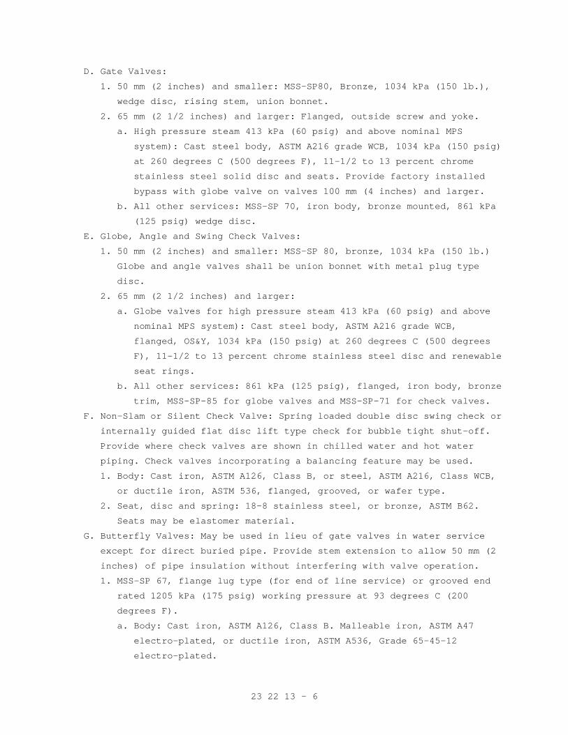
23 22 13 - 6
D. Gate Valves:
1. 50 mm (2 inches) and smaller: MSS-SP80, Bronze, 1034 kPa (150 lb.),
wedge disc, rising stem, union bonnet.
2. 65 mm (2 1/2 inches) and larger: Flanged, outside screw and yoke.
a. High pressure steam 413 kPa (60 psig) and above nominal MPS
system): Cast steel body, ASTM A216 grade WCB, 1034 kPa (150 psig)
at 260 degrees C (500 degrees F), 11-1/2 to 13 percent chrome
stainless steel solid disc and seats. Provide factory installed
bypass with globe valve on valves 100 mm (4 inches) and larger.
b. All other services: MSS-SP 70, iron body, bronze mounted, 861 kPa
(125 psig) wedge disc.
E. Globe, Angle and Swing Check Valves:
1. 50 mm (2 inches) and smaller: MSS-SP 80, bronze, 1034 kPa (150 lb.)
Globe and angle valves shall be union bonnet with metal plug type
disc.
2. 65 mm (2 1/2 inches) and larger:
a. Globe valves for high pressure steam 413 kPa (60 psig) and above
nominal MPS system): Cast steel body, ASTM A216 grade WCB,
flanged, OS&Y, 1034 kPa (150 psig) at 260 degrees C (500 degrees
F), 11-1/2 to 13 percent chrome stainless steel disc and renewable
seat rings.
b. All other services: 861 kPa (125 psig), flanged, iron body, bronze
trim, MSS-SP-85 for globe valves and MSS-SP-71 for check valves.
F. Non-Slam or Silent Check Valve: Spring loaded double disc swing check or
internally guided flat disc lift type check for bubble tight shut-off.
Provide where check valves are shown in chilled water and hot water
piping. Check valves incorporating a balancing feature may be used.
1. Body: Cast iron, ASTM A126, Class B, or steel, ASTM A216, Class WCB,
or ductile iron, ASTM 536, flanged, grooved, or wafer type.
2. Seat, disc and spring: 18-8 stainless steel, or bronze, ASTM B62.
Seats may be elastomer material.
G. Butterfly Valves: May be used in lieu of gate valves in water service
except for direct buried pipe. Provide stem extension to allow 50 mm (2
inches) of pipe insulation without interfering with valve operation.
1. MSS-SP 67, flange lug type (for end of line service) or grooved end
rated 1205 kPa (175 psig) working pressure at 93 degrees C (200
degrees F).
a. Body: Cast iron, ASTM A126, Class B. Malleable iron, ASTM A47
electro-plated, or ductile iron, ASTM A536, Grade 65-45-12
electro-plated.
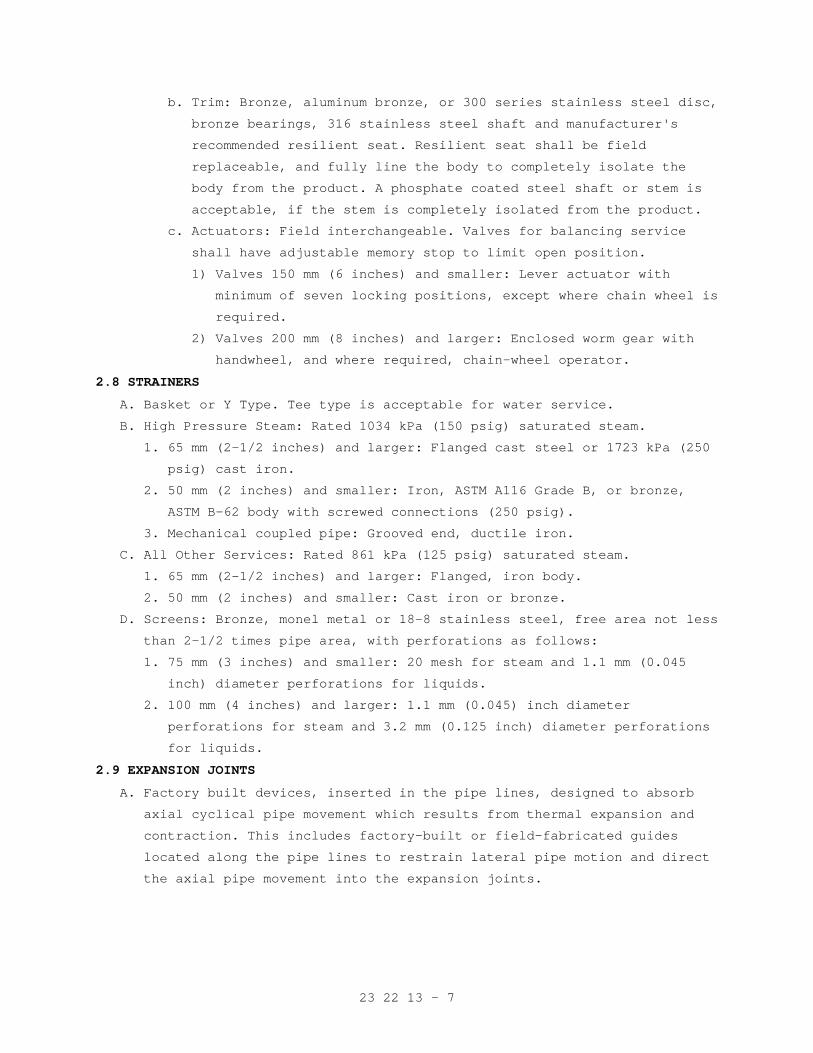
23 22 13 - 7
b. Trim: Bronze, aluminum bronze, or 300 series stainless steel disc,
bronze bearings, 316 stainless steel shaft and manufacturer's
recommended resilient seat. Resilient seat shall be field
replaceable, and fully line the body to completely isolate the
body from the product. A phosphate coated steel shaft or stem is
acceptable, if the stem is completely isolated from the product.
c. Actuators: Field interchangeable. Valves for balancing service
shall have adjustable memory stop to limit open position.
1) Valves 150 mm (6 inches) and smaller: Lever actuator with
minimum of seven locking positions, except where chain wheel is
required.
2) Valves 200 mm (8 inches) and larger: Enclosed worm gear with
handwheel, and where required, chain-wheel operator.
2.8 STRAINERS
A. Basket or Y Type. Tee type is acceptable for water service.
B. High Pressure Steam: Rated 1034 kPa (150 psig) saturated steam.
1. 65 mm (2-1/2 inches) and larger: Flanged cast steel or 1723 kPa (250
psig) cast iron.
2. 50 mm (2 inches) and smaller: Iron, ASTM A116 Grade B, or bronze,
ASTM B-62 body with screwed connections (250 psig).
3. Mechanical coupled pipe: Grooved end, ductile iron.
C. All Other Services: Rated 861 kPa (125 psig) saturated steam.
1. 65 mm (2-1/2 inches) and larger: Flanged, iron body.
2. 50 mm (2 inches) and smaller: Cast iron or bronze.
D. Screens: Bronze, monel metal or 18-8 stainless steel, free area not less
than 2-1/2 times pipe area, with perforations as follows:
1. 75 mm (3 inches) and smaller: 20 mesh for steam and 1.1 mm (0.045
inch) diameter perforations for liquids.
2. 100 mm (4 inches) and larger: 1.1 mm (0.045) inch diameter
perforations for steam and 3.2 mm (0.125 inch) diameter perforations
for liquids.
2.9 EXPANSION JOINTS
A. Factory built devices, inserted in the pipe lines, designed to absorb
axial cyclical pipe movement which results from thermal expansion and
contraction. This includes factory-built or field-fabricated guides
located along the pipe lines to restrain lateral pipe motion and direct
the axial pipe movement into the expansion joints.
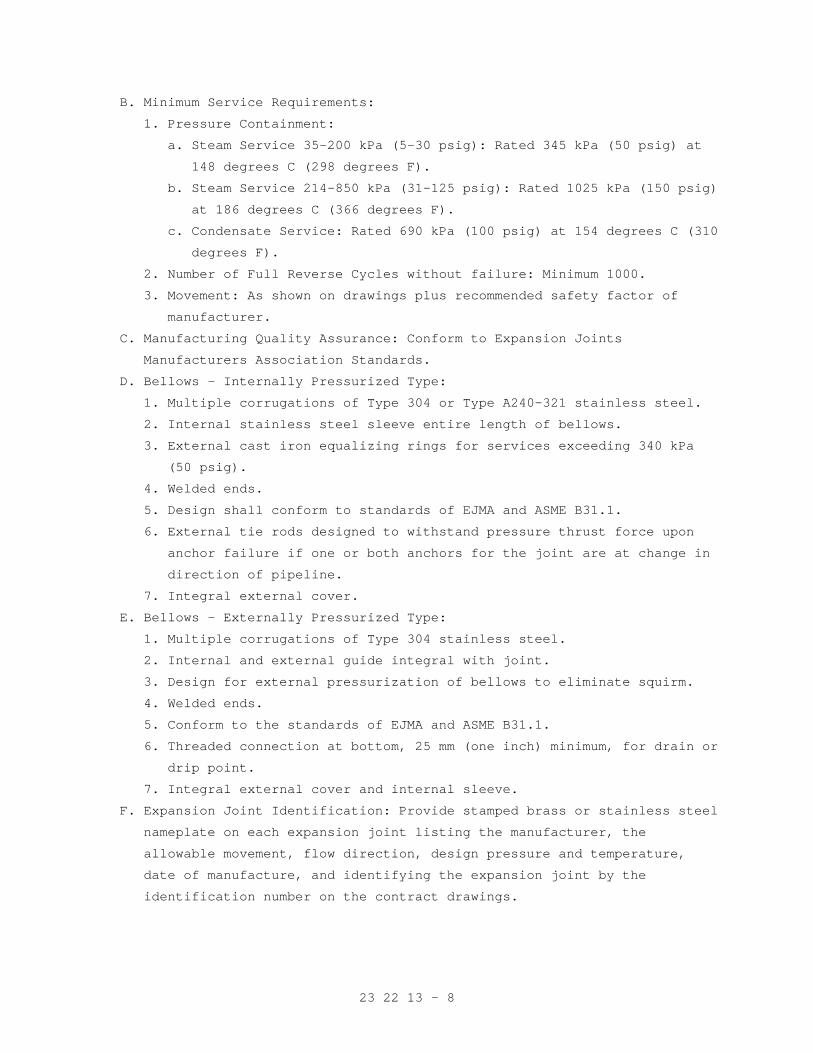
23 22 13 - 8
B. Minimum Service Requirements:
1. Pressure Containment:
a. Steam Service 35-200 kPa (5-30 psig): Rated 345 kPa (50 psig) at
148 degrees C (298 degrees F).
b. Steam Service 214-850 kPa (31-125 psig): Rated 1025 kPa (150 psig)
at 186 degrees C (366 degrees F).
c. Condensate Service: Rated 690 kPa (100 psig) at 154 degrees C (310
degrees F).
2. Number of Full Reverse Cycles without failure: Minimum 1000.
3. Movement: As shown on drawings plus recommended safety factor of
manufacturer.
C. Manufacturing Quality Assurance: Conform to Expansion Joints
Manufacturers Association Standards.
D. Bellows - Internally Pressurized Type:
1. Multiple corrugations of Type 304 or Type A240-321 stainless steel.
2. Internal stainless steel sleeve entire length of bellows.
3. External cast iron equalizing rings for services exceeding 340 kPa
(50 psig).
4. Welded ends.
5. Design shall conform to standards of EJMA and ASME B31.1.
6. External tie rods designed to withstand pressure thrust force upon
anchor failure if one or both anchors for the joint are at change in
direction of pipeline.
7. Integral external cover.
E. Bellows - Externally Pressurized Type:
1. Multiple corrugations of Type 304 stainless steel.
2. Internal and external guide integral with joint.
3. Design for external pressurization of bellows to eliminate squirm.
4. Welded ends.
5. Conform to the standards of EJMA and ASME B31.1.
6. Threaded connection at bottom, 25 mm (one inch) minimum, for drain or
drip point.
7. Integral external cover and internal sleeve.
F. Expansion Joint Identification: Provide stamped brass or stainless steel
nameplate on each expansion joint listing the manufacturer, the
allowable movement, flow direction, design pressure and temperature,
date of manufacture, and identifying the expansion joint by the
identification number on the contract drawings.
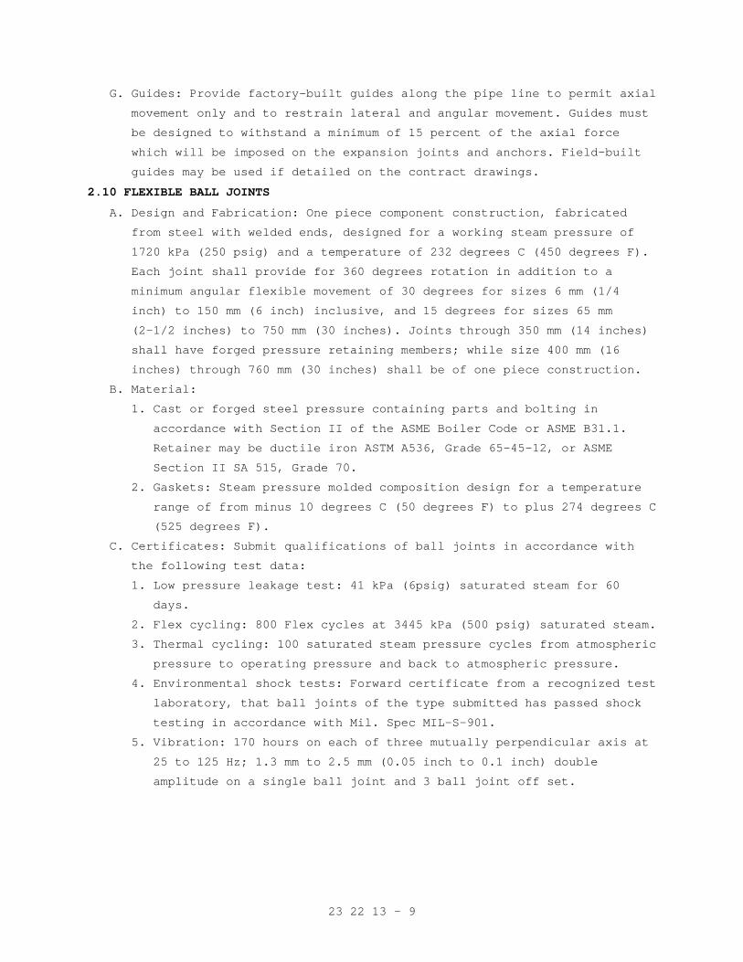
23 22 13 - 9
G. Guides: Provide factory-built guides along the pipe line to permit axial
movement only and to restrain lateral and angular movement. Guides must
be designed to withstand a minimum of 15 percent of the axial force
which will be imposed on the expansion joints and anchors. Field-built
guides may be used if detailed on the contract drawings.
2.10 FLEXIBLE BALL JOINTS
A. Design and Fabrication: One piece component construction, fabricated
from steel with welded ends, designed for a working steam pressure of
1720 kPa (250 psig) and a temperature of 232 degrees C (450 degrees F).
Each joint shall provide for 360 degrees rotation in addition to a
minimum angular flexible movement of 30 degrees for sizes 6 mm (1/4
inch) to 150 mm (6 inch) inclusive, and 15 degrees for sizes 65 mm
(2-1/2 inches) to 750 mm (30 inches). Joints through 350 mm (14 inches)
shall have forged pressure retaining members; while size 400 mm (16
inches) through 760 mm (30 inches) shall be of one piece construction.
B. Material:
1. Cast or forged steel pressure containing parts and bolting in
accordance with Section II of the ASME Boiler Code or ASME B31.1.
Retainer may be ductile iron ASTM A536, Grade 65-45-12, or ASME
Section II SA 515, Grade 70.
2. Gaskets: Steam pressure molded composition design for a temperature
range of from minus 10 degrees C (50 degrees F) to plus 274 degrees C
(525 degrees F).
C. Certificates: Submit qualifications of ball joints in accordance with
the following test data:
1. Low pressure leakage test: 41 kPa (6psig) saturated steam for 60
days.
2. Flex cycling: 800 Flex cycles at 3445 kPa (500 psig) saturated steam.
3. Thermal cycling: 100 saturated steam pressure cycles from atmospheric
pressure to operating pressure and back to atmospheric pressure.
4. Environmental shock tests: Forward certificate from a recognized test
laboratory, that ball joints of the type submitted has passed shock
testing in accordance with Mil. Spec MIL-S-901.
5. Vibration: 170 hours on each of three mutually perpendicular axis at
25 to 125 Hz; 1.3 mm to 2.5 mm (0.05 inch to 0.1 inch) double
amplitude on a single ball joint and 3 ball joint off set.
23 22 13 - 10
2.11 STEAM SYSTEM COMPONENTS
A. Steam Pressure Reducing Valves in PRV Stations:
1. Type: Single-seated, diaphragm operated, spring-loaded, external or
internal steam pilot-controlled, normally closed, adjustable set
pressure. Pilot shall sense controlled pressure downstream of main
valve.
2. Service: Provide controlled reduced pressure to steam piping systems.
3. Pressure control shall be smooth and continuous with maximum drop of
10 percent. Maximum flow capability of each valve shall not exceed
capacity of downstream safety valve(s).
4. Main valve and pilot valve shall have replaceable valve plug and seat
of stainless steel, monel, or similar durable material.
a. Pressure rating for high pressure steam: Not less than 1034 kPa
(150 psig) saturated steam.
b. Connections: Flanged for valves 65 mm (2-1/2 inches) and larger;
flanged or threaded ends for smaller valves.
5. Select pressure reducing valves to develop less than 85 dbA at 1500
mm (5 feet) elevation above adjacent floor, and 1500 mm (5 feet)
distance in any direction. Inlet and outlet piping for steam pressure
reducing valves shall be Schedule 80 minimum for required distance to
achieve required levels or sound attenuators shall be applied.
6. Pneumatically controlled valve: May be furnished in lieu of
steam-operation. All specification requirements for steam operated
valves apply. Valves shall close on failure of air supply.
B. Safety Valves and Accessories: Comply with ASME Boiler and Pressure
Vessel Code, Section VIII. Capacities shall be certified by National
Board of Boiler and Pressure Vessel Inspectors, maximum accumulation 10
percent. Provide lifting lever. Provide drip pan elbow where shown.
C. Flash Tanks: Horizontal or vertical vortex type, constructed of copper
bearing steel, ASTM A516 or ASTM A285, for a steam working pressure of
861 kPa (125 psig) to comply with ASME Code for Unfired Pressure Vessels
and stamped with "U" symbol. Perforated pipe inside tank shall be ASTM
A53 Grade B, Seamless or ERW, or A106 Grade B Seamless, Schedule 80.
Corrosion allowance of 1.6 mm (1/16 inch) may be provided in lieu of the
copper bearing requirement. Provide data Form No. U-1.
D. Steam Trap: Each type of trap shall be the product of a single
manufacturer. Provide trap sets at all low points and at 61 m (200 feet)
intervals on the horizontal main lines.
23 22 13 - 11
1. Floats and linkages shall provide sufficient force to open trap valve
over full operating pressure range available to the system. Unless
otherwise indicated on the drawings, traps shall be sized for
capacities indicated at minimum pressure drop as follows:
a. For equipment with modulating control valve: 1.7 kPa (1/4 psig),
based on a condensate leg of 300 mm (12 inches) at the trap inlet
and gravity flow to the receiver.
b. For main line drip trap sets and other trap sets at steam
pressure: Up to 70 percent of design differential pressure.
Condensate may be lifted to the return line.
2. Trap bodies: Bronze, cast iron, or semi-steel, constructed to permit
ease of removal and servicing working parts without disturbing
connecting piping. For systems without relief valve traps shall be
rated for the pressure upstream of the PRV supplying the system.
3. Balanced pressure thermostatic elements: Phosphor bronze, stainless
steel or monel metal.
4. Valves and seats: Suitable hardened corrosion resistant alloy.
5. Mechanism: Brass, stainless steel or corrosion resistant alloy.
6. Floats: Stainless steel.
7. Inverted bucket traps: Provide bi-metallic thermostatic element for
rapid release of non-condensables.
E. Thermostatic Air Vent (Steam): Brass or iron body, balanced pressure
bellows, stainless steel (renewable) valve and seat, rated 861 kPa (125
psig) working pressure, 20 mm (3/4 inch) screwed connections. Air vents
shall be balanced pressure type that responds to steam
pressure-temperature curve and vents air at any pressure.
F. Steam Humidifiers: Steam separator type that discharges steam into the
air stream through a steam jacketed distribution manifold or dispersion
tube. Humidifiers shall be complete with Y-type steam supply strainer;
modulating, normally closed steam control valve; normally closed
condensate temperature switch; and manufacturer's standard steam trap.
1. Steam separator: Stainless steel or cast iron.
2. Distribution manifold: Stainless steel, composed of dispersion pipe
and surrounding steam jacket, manifold shall span the width of duct
or air handler, and shall be multiple manifold type under any of the
following conditions:
a. Duct section height exceeds 900 mm (36 inches).
b. Duct air velocity exceeds 5.1 m/s (1000 feet per minute).
c. If within 900 mm (3 feet) upstream of fan, damper or prefilter.
d. If within 3000 mm (10 feet) upstream of afterfilter.
23 22 13 - 12
2.12 GAGES, PRESSURE AND COMPOUND
A. ASME B40.1, Accuracy Grade 1A, (pressure, vacuum, or compound), initial
mid-scale accuracy 1 percent of scale (Qualify grade), metal or phenolic
case, 115 mm (4-1/2 inches) in diameter, 6 mm (1/4 inch) NPT bottom
connection, white dial with black graduations and pointer, clear glass
or acrylic plastic window, suitable for board mounting. Provide red "set
hand" to indicate normal working pressure.
B. Provide brass, lever handle union cock. Provide brass/bronze pressure
snubber for gages in water service. Provide brass pigtail syphon for
steam gages.
C. Range of Gages: For services not listed provide range equal to at least
130 percent of normal operating range:
Low pressure steam to 103 kPa(15 psig)
0 to 207 kPa (30 psig).
Medium pressure steam nominal 413 kPa (60 psig)
0 to 689 kPa (100 psig).
2.13 PRESSURE/TEMPERATURE TEST PROVISIONS
A. Pete's Plug: 6 mm (1/4 inch) MPT by 75 mm (3 inches) long, brass body
and cap, with retained safety cap, nordel self-closing valve cores,
permanently installed in piping where shown, or in lieu of pressure gage
test connections shown on the drawings.
B. Provide one each of the following test items to the Resident Engineer:
1. 6 mm (1/4 inch) FPT by 3 mm (1/8 inch) diameter stainless steel
pressure gage adapter probe for extra long test plug. PETE'S 500 XL
is an example.
2. 90 mm (3-1/2 inch) diameter, one percent accuracy, compound gage, ,
762 mm (30 inches) Hg to 689 kPa (100 psig) range.
3. 0 - 104 degrees C (220 degrees F) pocket thermometer one-half degree
accuracy, 25 mm (one inch) dial, 125 mm (5 inch) long stainless steel
stem, plastic case.
2.14 FIRESTOPPING MATERIAL
Refer to Section 23 05 11, COMMON WORK RESULTS FOR HVAC.
23 22 13 - 13
PART 3 - EXECUTION
3.1 GENERAL
A. The drawings show the general arrangement of pipe and equipment but do
not show all required fittings and offsets that may be necessary to
connect pipes to equipment, fan-coils, coils, radiators, etc., and to
coordinate with other trades. Provide all necessary fittings, offsets
and pipe runs based on field measurements and at no additional cost to
the government. Coordinate with other trades for space available and
relative location of HVAC equipment and accessories to be connected on
ceiling grid. Pipe location on the drawings shall be altered by
contractor where necessary to avoid interferences and clearance
difficulties.
B. Store materials to avoid excessive exposure to weather or foreign
materials. Keep inside of piping relatively clean during installation
and protect open ends when work is not in progress.
C. Support piping securely. Refer to PART 3, Section 23 05 11, COMMON WORK
RESULTS FOR HVAC. Install convertors and other heat exchangers at height
sufficient to provide gravity flow of condensate to the flash tank and
condensate pump.
D. Install piping generally parallel to walls and column center lines,
unless shown otherwise on the drawings. Space piping, including
insulation, to provide 25 mm (one inch) minimum clearance between
adjacent piping or other surface. Unless shown otherwise, slope steam,
condensate and drain piping down in the direction of flow not less than
25 mm (one inch) in 12 m (40 feet). Provide eccentric reducers to keep
bottom of sloped piping flat.
E. Locate and orient valves to permit proper operation and access for
maintenance of packing, seat and disc. Generally locate valve stems in
overhead piping in horizontal position. Provide a union adjacent to one
end of all threaded end valves. Control valves usually require reducers
to connect to pipe sizes shown on the drawing. Install butterfly valves
with the valve open as recommended by the manufacturer to prevent
binding of the disc in the seat.
F. Offset equipment connections to allow valving off for maintenance and
repair with minimal removal of piping. Provide flexibility in equipment
connections and branch line take-offs with 3-elbow swing joints where
noted on the drawings.
G. Tee water piping runouts or branches into the side of mains or other
branches. Avoid bull-head tees, which are two return lines entering
opposite ends of a tee and exiting out the common side.
23 22 13 - 14
H. Connect piping to equipment as shown on the drawings. Install components
furnished by others such as:
1. Flow elements (orifice unions), control valve bodies, flow switches,
pressure taps with valve, and wells for sensors.
I. Firestopping: Fill openings around uninsulated piping penetrating floors
or fire walls, with firestop material. For firestopping insulated piping
refer to Section 23 07 11, HVAC AND PLUMBING INSULATION.
J. Where copper piping is connected to steel piping, provide dielectric
connections.
3.2 PIPE JOINTS
A. Welded: Beveling, spacing and other details shall conform to ASME B31.1
and AWS B2.1. See Welder’s qualification requirements under "Quality
Assurance" in Section 23 05 11, COMMON WORK RESULTS FOR HVAC.
B. Screwed: Threads shall conform to ASME B1.20; joint compound shall be
applied to male threads only and joints made up so no more than three
threads show. Coat exposed threads on steel pipe with joint compound, or
red lead paint for corrosion protection.
C. 125 Pound Cast Iron Flange (Plain Face): Mating flange shall have raised
face, if any, removed to avoid overstressing the cast iron flange.
D. Solvent Welded Joints: As recommended by the manufacturer.
3.3 EXPANSION JOINTS (BELLOWS AND SLIP TYPE)
A. Anchors and Guides: Provide type, quantity and spacing as recommended by
manufacturer of expansion joint and as shown. A professional engineer
shall verify in writing that anchors and guides are properly designed
for forces and moments which will be imposed.
B. Cold Set: Provide setting of joint travel at installation as recommended
by the manufacturer for the ambient temperature during the installation.
C. Preparation for Service: Remove all apparatus provided to restrain joint
during shipping or installation. Representative of manufacturer shall
visit the site and verify that installation is proper.
D. Access: Expansion joints must be located in readily accessible space.
Locate joints to permit access without removing piping or other devices.
Allow clear space to permit replacement of joints and to permit access
to devices for inspection of all surfaces and for adding packing.
3.4 STEAM TRAP PIPING
Install to permit gravity flow to the trap. Provide gravity flow (avoid
lifting condensate) from the trap where modulating control valves are
used. Support traps weighing over 11 kg (25 pounds) independently of
connecting piping.
23 22 13 - 15
3.5 SEISMIC BRACING
Provide is accordance with Section 23 05 48, SEISMIC/VIBRATION ISOLATION
FOR MECHANICAL COMPONENTS.
3.6 LEAK TESTING
A. Inspect all joints and connections for leaks and workmanship and make
corrections as necessary, to the satisfaction of the Resident Engineer.
Tests may be either of those below, or a combination, as approved by the
Resident Engineer.
B. An operating test at design pressure, and for hot systems, design
maximum temperature.
C. A hydrostatic test at 1.5 times design pressure. For water systems the
design maximum pressure would usually be the static head, or expansion
tank maximum pressure, plus pump head. Factory tested equipment
(convertors, exchangers, coils, etc.) need not be field tested. Avoid
excessive pressure on mechanical seals and safety devices.
3.7 FLUSHING AND CLEANING PIPING SYSTEMS
A. Steam, Condensate and Vent Piping: No flushing or chemical cleaning
required. Accomplish cleaning by pulling all strainer screens and
cleaning all scale/dirt legs during start-up operation.
3.8 WATER TREATMENT
A. Close and fill system as soon as possible after final flushing to
minimize corrosion.
B. Charge systems with chemicals specified in Section 23 25 00, HVAC WATER
TREATMENT.
C. Utilize this activity, by arrangement with the Resident Engineer, for
instructing VA operating personnel.
3.9 OPERATING AND PERFORMANCE TEST AND INSTRUCTION
A. Refer to PART 3, Section 23 05 11, COMMON WORK RESULTS FOR HVAC.
B. Adjust red set hand on pressure gages to normal working pressure.
- - - E N D - - -
23 22 23 - 1
SECTION 23 22 23 STEAM CONDENSATE PUMPS
PART 1 - GENERAL
1.1 DESCRIPTION
A. Steam condensate pumps for Heating, Ventilating and Air Conditioning.
B. Definitions:
1. Capacity: Liters per second (L/s) (Gallons per minute (GPM)) of the
fluid pumped.
2. Head: Total dynamic head in kPa (feet) of the fluid pumped.
3. Flat head-capacity curve: Where the shutoff head is less than 1.16
times the head at the best efficiency point.
1.2 RELATED WORK
A. Section 01 00 00, GENERAL REQUIREMENTS.
B. Section 01 33 23, SHOP DRAWINGS, PRODUCT DATA, AND SAMPLES.
C. Section 23 05 48, SEISMIC/VIBRATION ISOLATION FOR MECHANICAL
COMPONENTS.
D. Section 23 05 11, COMMON WORK RESULTS FOR HVAC.
E. Section 23 05 41, NOISE AND VIBRATION CONTROL FOR HVAC PIPING AND
EQUIPMENT.
F. Section 23 22 13, STEAM AND CONDENSATE HEATING PIPING.
G. Section 23 05 12, GENERAL MOTOR REQUIREMENTS FOR HVAC EQUIPMENT.
H. Section 26 29 11, LOW-VOLTAGE MOTOR STARTERS.
1.3 QUALITY ASSURANCE
A. Refer to Paragraph, QUALITY ASSURANCE in Section 23 05 11, COMMON WORK
RESULTS FOR HVAC.
B. Design Criteria:
1. Pumps design and manufacturer shall conform to Hydraulic Institute
Standards.
2. Pump sizes, capacities, pressures, operating characteristics and
efficiency shall be as scheduled.
3. Head-capacity curves shall slope up to maximum head at shut-off.
Curves shall be relatively flat for closed systems. Select pumps
near the midrange of the curve, so the design capacity falls to the
left of the best efficiency point, to allow a cushion for the usual
drift to the right in operation, without approaching the pump curve
end point and possible cavitation and unstable operation. Select
pumps for open systems so that required net positive suction head
(NPSHR) does not exceed the net positive head available (NPSHA).
23 22 23 - 2
4. The head for pumps submitted for pumping through condensers and
through chilled water coils and evaporators shall be increased, if
necessary, to match the equipment approved for the project.
5. Pump Driver: Furnish with pump. Size shall be non-overloading at any
point on the head-capacity curve including one pump operation in a
parallel or series pumping installation.
6. Provide all pumps with motors, impellers, drive assemblies,
bearings, coupling guard and other accessories specified. Statically
and dynamically balance all rotating parts.
7. Furnish each pump and motor with a nameplate giving the
manufacturers name, serial number of pump, capacity in GPM and head
in feet at design condition, horsepower, voltage, frequency, speed
and full load current and motor efficiency.
8. Test all pumps before shipment. The manufacturer shall certify all
pump ratings.
9. After completion of balancing, provide replacement of impellers or
trim impellers to provide specified flow at actual pumping head, as
installed.
10. Furnish one spare seal and casing gasket for each pump to the
Resident Engineer.
C. Allowable Vibration Tolerance for Pump Units: Section 23 05 41, NOISE
AND VIBRATION CONTROL FOR HVAC PIPING AND EQUIPMENT.
1.4 SUBMITTALS
A. Submit in accordance with Section 01 33 23, SHOP DRAWINGS, PRODUCT
DATA, AND SAMPLES.
B. Manufacturer's Literature and Data:
1. Pumps and accessories.
2. Motors and drives.
3. Variable speed motor controllers.
C. Manufacturer's installation, maintenance and operating instructions, in
accordance with Section 23 05 11, COMMON WORK RESULTS FOR HVAC.
D. Characteristic Curves: Head-capacity, efficiency-capacity, brake
horsepower-capacity, and NPSHR-capacity for each pump and for combined
pumps in parallel or series service. Identify pump and show fluid
pumped, specific gravity, pump speed and curves plotted from zero flow
to maximum for the impeller being furnished and at least the maximum
diameter impeller that can be used with the casing.
23 22 23 - 3
1.5 APPLICABLE PUBLICATIONS
A. The publications listed below form a part of this specification to the
extent referenced. The publications are referenced in the text by the
basic designation only:
B. American Iron and Steel Institute (AISI):
AISI 1045...............Cold Drawn Carbon Steel Bar, Type 1045
AISI 416................Type 416 Stainless Steel
C. American National Standards Institute (ANSI):
ANSI B15.1-00...........Safety Standard for Mechanical Power
Transmission Apparatus
ANSI B16.1-00...........Cast Iron Pipe Flanges and Flanged Fittings,
Class 25, 125, 250 and 800
D. American Society for Testing and Materials (ASTM):
A48-98..................Gray Iron Castings
B62-02..................Composition Bronze or Ounce Metal Castings
E. Maintenance and Operating Manuals in accordance with Section 01 00 00,
GENERAL REQUIREMENTS.
PART 2 - PRODUCTS
2.1 CONDENSATE PUMP, PAD-MOUNTED
A. General: Factory assembled unit consisting of vented receiver tank,
motor-driven pumps, interconnecting piping and wiring, motor controls
(including starters, if necessary) and accessories, designed to
receive, store, and pump steam condensate.
B. Receiver Tank: Cast iron or galvanized steel, with threaded openings
for connection of piping and accessories and facilities for mounting
float switches. Receivers for simplex pumps shall include all
facilities for future mounting of additional pump and controls.
C. Furnish seals for condensate pump with a minimum temperature rating of
392 degrees C (250 degrees F).
D. Centrifugal Pumps: Bronze fitted with mechanical shaft seals.
1. Designed to allow removal of rotating elements without disturbing
connecting piping or pump casing mounting.
2. Shafts: Stainless steel, AISI Type 416 or alloy steel with bronze
shaft sleeves.
3. Bearings: Regreaseable ball or roller type.
4. Casing wearing rings: Bronze.
E. Motors: Refer to Section 23 05 12, GENERAL MOTOR REQUIREMENTS FOR HVAC
EQUIPMENT.
23 22 23 - 4
F. Pump Operation:
1. Float Switches: NEMA 1, mounted on receiver tank, to start and stop
pumps in response to changes in the water level in the receiver and
adjustable to permit the controlled water levels to be changed.
Floats and connecting rods shall be copper, bronze or stainless
steel.
2. Alternator: Provide for duplex units to automatically start the
second pump when the first pump fails in keeping the receiver water
level from rising and to alternate the order of starting the pumps.
For units 0.25 kW (1/3 horsepower) and smaller, the alternator may
be the mechanical type for use in lieu of float switches.
G. Control Cabinet for 3 Phase (0.37 kW (1/2 hp) and larger) Units: NEMA
1, UL approved, factory wired, enclosing all controls, with indicating
lights, manual switches and resets mounted on the outside of the panel.
Attach cabinet to the pump set with rigid steel framework, unless
remote mounting is noted on the pump schedule.
1. Motor starters: Magnetic contact types with circuit breakers or
combination fusible disconnect switches. Provide low voltage control
circuits (120 volt maximum) and "hand-off-automatic" (H-O-A)
switches for each pump.
2. Indicating lights for each pump: Green to show that power is on, red
to show that the pump is running.
H. Electric Wiring: Suitable for 93 degrees C (200 degrees F) service;
enclosed in liquid-tight flexible metal conduit where located outside
of control cabinet.
I. Receiver Accessories:
1. Thermometer: 34-216 degrees C (100 - 420 degrees F), mounted below
minimum water level.
2. Water level gage glass: Brass with gage cocks which automatically
stop the flow of water when the glass is broken. Provide drain on
the lower gage cock and protection rods for the glass.
PART 3 - EXECUTION
3.1 INSTALLATION
A. Follow manufacturer's written instructions for pump mounting and
start-up. Access/ Service space around pumps shall not be less than
minimum space recommended by pumps manufacturer.
23 22 23 - 5
B. Support piping adjacent to pump such that no weight is carried on pump
casing. First 3 hangers for each pipe shall be spring and neoprene
type.
C. Sequence of installation for base-mounted pumps:
1. Level and shim the unit base and grout to the concrete pad.
2. Shim the driver and realign the pump and driver. Correct axial,
angular or parallel misalignment of the shafts.
3. Connect properly aligned and independently supported piping.
4. Recheck alignment.
D. Pad-mounted Condensate Pump: Level, shim, bolt, and grout the unit base
onto the concrete pad.
E. Provide drains for bases and seals for base mounted pumps, piped to and
discharging into floor drains.
F. Coordinate location of thermometer and pressure gauges as per Section
23 22 13, STEAM AND CONDENSATE HEATING PIPING.
3.2 START-UP
A. Verify that the piping system has been flushed, cleaned and filled.
B. Lubricate pumps before start-up.
C. Prime the pump, vent all air from the casing and verify that the
rotation is correct. To avoid damage to mechanical seals, never start
or run the pump in dry condition.
D. Verify that correct size heaters-motor over-load devices are installed
for each pump controller unit.
E. Perform field mechanical balancing if necessary to meet specified
vibration tolerance.
- - - E N D - - -
23 25 00 - 1
SECTION 23 25 00 HVAC WATER TREATMENT
PART 1 - GENERAL
1.1 DESCRIPTION
A. This section specifies cleaning and treatment of circulating HVAC water
systems, including the following.
1. Cleaning compounds.
2. Chemical treatment for closed loop heat transfer systems.
3. Chemical treatment for open loop systems.
1.2 RELATED WORK
A. Test requirements and instructions on use of equipment/system: Section
01 00 00, GENERAL REQUIREMENTS.
B. General mechanical requirements and items, which are common to more
than one section of Division 23: Section 23 05 11, COMMON WORK RESULTS
FOR HVAC.
C. Piping and valves: Section 23 21 13, HYDRONIC PIPING and Section
23 22 13, STEAM AND CONDENSATE HEATING PIPING.
1.3 QUALITY ASSURANCE
A. Refer to paragraph, QUALITY ASSURANCE in Section 23 05 11, COMMON WORK
RESULTS FOR HVAC.
1.4 SUBMITTALS
A. Submit in accordance with Section 01 33 23, SHOP DRAWINGS, PRODUCT
DATA, AND SAMPLES.
B. Manufacturer's Literature and Data including:
1. Cleaning compounds and recommended procedures for their use.
2. Chemical treatment for closed systems, including installation and
operating instructions.
3. Chemical treatment for open loop systems, including installation and
operating instructions.
C. Water analysis verification.
D. Materials Safety Data Sheet for all proposed chemical compounds, based
on U.S. Department of Labor Form No. L5B-005-4.
E. Maintenance and operating instructions in accordance with Section
01 00 00, GENERAL REQUIREMENTS.
1.5 APPLICABLE PUBLICATIONS
A. The publication listed below form a part of this specification to the
extent referenced. The publications are referenced in the text by the
basic designation only.
23 25 00 - 2
B. National Fire Protection Association (NFPA):
70-05...................National Electric Code (NEC)
PART 2 - PRODUCTS
2.1 CLEANING COMPOUNDS
A. Alkaline phosphate or non-phosphate detergent/surfactant/specific to
remove organic soil, hydrocarbons, flux, pipe mill varnish, pipe
compounds, iron oxide, and like deleterious substances, with or without
inhibitor, suitable for system wetted metals without deleterious
effects.
B. All chemicals to be acceptable for discharge to sanitary sewer.
C. Refer to Section 23 21 13, HYDRONIC PIPING and Section 23 22 13, STEAM
AND CONDENSATE HEATING PIPING, PART 3, for flushing and cleaning
procedures.
2.2 EQUIPMENT AND MATERIALS IDENTIFICATION
Refer to Section 23 05 11, COMMON WORK RESULTS FOR HVAC.
PART 3 - EXECUTION
3.1 INSTALLATION
A. Delivery and Storage: Deliver all chemicals in manufacturer's sealed
shipping containers. Store in designated space and protect from
deleterious exposure and hazardous spills.
B. Before adding cleaning chemical to the closed system, all air handling
coils and fan coil units should be isolated by closing the inlet and
outlet valves and opening the bypass valves. This is done to prevent
dirt and solids from lodging the coils.
C. Do not valve in or operate system pumps until after system has been
cleaned.
D. After chemical cleaning is satisfactorily completed, open the inlet and
outlet valves to each coil and close the by-pass valves. Also, clean
all strainers.
E. Perform tests and report results in accordance with Section 01 00 00,
GENERAL REQUIREMENTS.
F. After cleaning is complete, and water PH is acceptable to manufacturer
of water treatment chemical, add manufacturer-recommended amount of
chemicals to systems.
G. Instruct VA personnel in system maintenance and operation in accordance
with Section 01 00 00, GENERAL REQUIREMENTS.
- - - E N D - - -
23 31 00 - 1
SECTION 23 31 00 HVAC DUCTS AND CASINGS
PART 1 - GENERAL
1.1 DESCRIPTION
A. Ductwork and accessories for HVAC including the following:
1. Supply air, return air, outside air, exhaust, and relief systems.
2. Exhaust duct with HEPA filters for Negative Pressure Isolation Room.
B. Definitions:
1. SMACNA Standards as used in this specification means the HVAC Duct
Construction Standards, Metal and Flexible.
2. Seal or Sealing: Use of liquid or mastic sealant, with or without
compatible tape overlay, or gasketing of flanged joints, to keep air
leakage at duct joints, seams and connections to an acceptable
minimum.
3. Duct Pressure Classification: SMACNA HVAC Duct Construction
Standards, Metal and Flexible.
4. Exposed Duct: Exposed to view in a finished room, exposed to weather.
1.2 RELATED WORK
A. Fire Stopping Material: Section 07 84 00, FIRESTOPPING.
B. Outdoor and Exhaust Louvers: Section 08 90 00, LOUVERS AND VENTS.
C. Seismic Reinforcing: Section 23 05 48, SEISMIC/VIBRATION ISOLATION FOR
MECHANICAL COMPONENTS.
D. General Mechanical Requirements: Section 23 05 11, COMMON WORK RESULTS
FOR HVAC AND STEAM GENERATION.
E. Noise Level Requirements: Section 23 05 41, NOISE AND VIBRATION CONTROL
FOR HVAC PIPING AND EQUIPMENT.
F. Duct Insulation: Section 23 07 11, HVAC AND PLUMBING INSULATION
G. Plumbing Connections: Section 22 11 00, FACILITY WATER DISTRIBUTION
H. Air Flow Control Valves and Terminal Units: Section 23 36 00, AIR
TERMINAL UNITS.
I. Duct Mounted Coils: Section 23 82 16, AIR COILS.
J. Supply Air Fans: Section 23 73 00, INDOOR CENTRAL-STATION AIR-HANDLING
UNITS.
K. Return Air and Exhaust Air Fans: Section 23 34 00, HVAC FANS.
L. Duct Mounted Instrumentation: Section 23 09 23, DIRECT-DIGITAL CONTROL
SYSTEM FOR HVAC.
M. Testing and Balancing of Air Flows: Section 23 05 93, TESTING,
ADJUSTING, AND BALANCING FOR HVAC.
N. Smoke Detectors: Section 28 31 00, FIRE DETECTION AND ALARM.
23 31 00 - 2
1.3 QUALITY ASSURANCE
A. Refer to article, QUALITY ASSURANCE, in Section 23 05 11, COMMON WORK
RESULTS FOR HVAC.
B. Fire Safety Code: Comply with NFPA 90A.
C. Duct System Construction and Installation: Referenced SMACNA Standards
are the minimum acceptable quality.
D. Duct Sealing, Air Leakage Criteria, and Air Leakage Tests: Ducts shall
be sealed as per duct sealing requirements of SMACNA HVAC Air Duct
Leakage Test Manual for duct pressure classes shown on the drawings.
E. Duct accessories exposed to the air stream, such as dampers of all types
(except smoke dampers) and access openings, shall be of the same
material as the duct or provide at least the same level of corrosion
resistance.
1.4 SUBMITTALS
A. Submit in accordance with Section 01 33 23, SHOP DRAWINGS, PRODUCT DATA,
AND SAMPLES.
B. Manufacturer's Literature and Data:
1. Rectangular ducts:
a. Schedules of duct systems, materials and selected SMACNA
construction alternatives for joints, sealing, gage and
reinforcement.
b. Duct liner.
c. Sealants and gaskets.
d. Access doors.
2. Round and flat oval duct construction details:
a. Manufacturer's details for duct fittings.
b. Duct liner.
c. Sealants and gaskets.
d. Access sections.
e. Installation instructions.
3. Volume dampers, back draft dampers.
4. Upper hanger attachments.
5. Fire dampers, fire doors, and smoke dampers with installation
instructions.
6. Flexible ducts and clamps, with manufacturer's installation
instructions.
7. Flexible connections.
8. Instrument test fittings.
9. Details and design analysis of alternate or optional duct systems.
23 31 00 - 3
C. Coordination Drawings: Refer to article, SUBMITTALS, in Section 23 05
11, COMMON WORK RESULTS FOR HVAC.
1.5 APPLICABLE PUBLICATIONS
A. The publications listed below form a part of this specification to the
extent referenced. The publications are referenced in the text by the
basic designation only.
B. Air Moving and Conditioning Association (AMCA):
500D-98.................Laboratory Method of Testing Dampers for Rating
500L-99.................Laboratory Method of Testing Louvers for Rating
C. American Society of Civil Engineers (ASCE):
ASCE7-98................Minimum Design Loads for Buildings and Other
Structures
D. American Society for Testing and Materials (ASTM):
A167-99.................Standard Specification for Stainless and
Heat-Resisting Chromium-Nickel Steel Plate,
Sheet and Strip
A653-01.................Standard Specification for Steel Sheet,
Zinc-Coated (Galvanized) or Zinc-Iron Alloy
coated (Galvannealed) by the Hot-Dip process
A1011-02................Standard Specification for Steel Sheet and Strip
Hot rolled Carbon structural, High-Strength Low-
Alloy and High Strength Low-Alloy with Improved
Formability
B209-01.................Standard Specification for Aluminum and
Aluminum-Alloy Sheet and Plate
C1071-00................Standard Specification for Fibrous Glass Duct
Lining Insulation (Thermal and Sound Absorbing
Material)
E84-01..................Standard Test Method for Surface Burning
Characteristics of Building Materials
E. National Fire Protection Association (NFPA):
90A-99..................Standard for the Installation of Air
Conditioning and Ventilating Systems
F. Sheet Metal and Air Conditioning Contractors National Association
(SMACNA):
2nd Edition – 1995......HVAC Duct Construction Standards, Metal and
Flexible
1st Edition, 1985.......HVAC Air Duct Leakage Test Manual
23 31 00 - 4
G. Underwriters Laboratories, Inc. (UL):
33-93...................UL Standard for Safety Heat Responsive Links for
Fire Protection Service
181-96..................UL Standard for Safety Factory-Made Air Ducts
and Connectors
555-02 .................Fire Dampers
555S-02 ................Smoke Dampers
PART 2 - PRODUCTS
2.1 DUCT MATERIALS AND SEALANTS
A. General: Except for systems specified otherwise, construct ducts,
casings, and accessories of galvanized sheet steel, ASTM A527, coating
G90; or, aluminum sheet, ASTM B209, alloy 1100, 3003 or 5052.
B. Specified Corrosion Resistant Systems: Stainless steel sheet, ASTM A167,
Class 302 or 304, Condition A (annealed) Finish No. 4 for exposed ducts
and Finish No. 2B for concealed duct or ducts located in mechanical
rooms.
C. Joint Sealing: Refer to SMACNA HVAC Duct Construction Standards,
paragraph S1.9.
1. Sealant: Elastomeric compound, gun or brush grade, maximum 25 flame
spread and 50 smoke developed (dry state) compounded specifically for
sealing ductwork as recommended by the manufacturer. Generally
provide liquid sealant, with or without compatible tape, for low
clearance slip joints and heavy, permanently elastic, mastic type
where clearances are larger. Oil base caulking and glazing compounds
are not acceptable because they do not retain elasticity and bond.
2. Tape: Use only tape specifically designated by the sealant
manufacturer and apply only over wet sealant. Pressure sensitive tape
shall not be used on bare metal or on dry sealant.
3. Gaskets in Flanged Joints: Soft neoprene.
D. Approved factory made joints such as DUCTMATE SYSTEM may be used.
2.2 DUCT CONSTRUCTION AND INSTALLATION
A. Follow SMACNA HVAC Duct Construction Standards.
B. Duct Pressure Class: 2 inch, 3 inch, 4 inch W.G.
C. Seal Class: As shown on the drawings and in accordance with SMACNA HVAC
Air Duct Leakage Test Manual.
23 31 00 - 5
D. Wet Air Exhaust Ducts and Accessories: Ducts for cage washers shall be
1.3 mm (18 gage) stainless steel made liquid tight with continuous
external weld for all seams and joints. Provide neoprene gaskets at
flanged connections. Where ducts are not self draining back to the
equipment, provide low point drain pocket with copper drain pipe to
sanitary sewer. Provide access door in side of duct at drain pockets.
E. Duct for Negative Pressure Up to 750 Pa (3 inch W.G.): Provide for
exhaust duct between HEPA filters and exhaust fan inlet including
systems for Negative Isolation Room exhaust.
1. Round Duct: Galvanized steel, spiral lock seam construction with
standard slip joints.
2. Rectangular Duct: Galvanized steel, minimum 1.0 mm (20 gage),
Pittsburgh lock seam, companion angle joints 32 mm by 3.2 mm (1-1/4
by 1/8 inch) minimum at not more than 2.4 m (8 feet) spacing.
DUCTMATE SYSTEM or equal manufactured joints are acceptable in lieu
of companion angles.
F. Round and Flat Oval Ducts: Furnish duct and fittings made by the same
manufacturer to insure good fit of slip joints. When submitted and
approved in advance, round and flat oval duct, with size converted on
the basis of equal pressure drop, may be furnished in lieu of
rectangular duct design shown on the drawings.
1. Elbows: Diameters 80 through 200 mm (3 through 8 inches) shall be two
sections die stamped, all others shall be gored construction, maximum
18 degree angle, with all seams continuously welded or standing seam.
Coat galvanized areas of fittings damaged by welding with corrosion
resistant aluminum paint or galvanized repair compound.
2. Provide bell mouth, conical tees or taps, laterals, reducers, and
other low loss fittings as shown in SMACNA HVAC Duct Construction
Standards.
3. Ribbed Duct Option: Lighter gage round/oval duct and fittings may be
furnished provided certified tests indicating that the rigidity and
performance is equivalent to SMACNA standard gage ducts are
submitted.
a. Ducts: Manufacturer's published standard gage, G90 coating, spiral
lock seam construction with an intermediate standing rib.
b. Fittings: May be manufacturer's standard as shown in published
catalogs, fabricated by spot welding and bonding with neoprene
base cement or machine formed seam in lieu of continuous welded
seams.
23 31 00 - 6
4. Provide flat side reinforcement of oval ducts as recommended by the
manufacturer and SMACNA HVAC Duct Construction Standard S3.13.
Because of high pressure loss, do not use internal tie-rod
reinforcement unless approved by the Resident Engineer.
G. Casings and Plenums: Construct in accordance with SMACNA HVAC Duct
Construction Standards Section 6, including curbs, access doors, pipe
penetrations, eliminators and drain pans. Access doors shall be hollow
metal, insulated, with latches and door pulls, 500 mm (20 inches) wide
by 1200 - 1350 mm (48 - 54 inches) high. Provide view port in the doors
where shown. Provide drain for outside air louver plenum. Outside air
plenum shall have exterior insulation. Drain piping shall be routed to
the nearest floor drain.
H. Volume Dampers: Single blade or opposed blade, multi-louver type as
detailed in SMACNA Standards. Refer to SMACNA Detail Figure 2-12 for
Single Blade and Figure 2.13 for Multi-blade Volume Dampers.
I. Duct Hangers and Supports: Refer to SMACNA Standards Section IV. Avoid
use of trapeze hangers for round duct.
2.3 DUCT ACCESS DOORS, PANELS AND SECTIONS
A. Provide access doors, sized and located for maintenance work, upstream,
in the following locations:
1. Each duct mounted coil and humidifier.
2. Each fire damper (for link service), smoke damper and automatic
control damper.
3. Each duct mounted smoke detector.
B. Openings shall be as large as feasible in small ducts, 300 mm by 300 mm
(12 inch by 12 inch) minimum where possible. Access sections in
insulated ducts shall be double-wall, insulated. Transparent
shatterproof covers are preferred for uninsulated ducts.
1. For rectangular ducts: Refer to SMACNA HVAC Duct Construction
Standards (Figure 2-12).
2. For round and flat oval duct: Refer to SMACNA HVAC duct Construction
Standards (Figure 2-11).
2.4 FIRE DAMPERS
A. Galvanized steel, interlocking blade type, UL listing and label, 1-1/2
hour rating, 70 degrees C (160 degrees F) fusible line, 100 percent free
opening with no part of the blade stack or damper frame in the air
stream.
B. Fire dampers in wet air exhaust shall be of stainless steel
construction, all others may be galvanized steel.
23 31 00 - 7
1. The damper frame may be of design and length as to function as the
mounting sleeve, thus eliminating the need for a separate sleeve, as
allowed by UL 555. Otherwise provide sleeves and mounting angles,
minimum 1.9 mm (14 gage), required to provide installation equivalent
to the damper manufacturer's UL test installation.
2. Submit manufacturer's installation instructions conforming to UL
rating test.
3. Combination fire and smoke dampers: Multi-louver or curtain type
units meeting all requirements of both dampers shall be used where
shown and may be used at the Contractor's option where applicable.
2.5 SMOKE DAMPERS
A. Maximum air velocity, through free area of open damper, and pressure
loss: Low pressure and medium pressure duct (supply, return, exhaust,
outside air): 450 m/min (1500 fpm). Maximum static pressure loss: 32 Pa
(0.13 inch W.G.).
B. Maximum air leakage, closed damper: 0.32 cubic meters /min/square meter
(4.0 CFM per square foot) at 750 Pa (3 inch W.G.) differential pressure.
C. Minimum requirements for dampers:
1. Shall comply with requirements of Table 6-1 of UL 555S, except for
the Fire Endurance and Hose Stream Test.
2. Frame: Galvanized steel channel with side, top and bottom stops or
seals.
3. Blades: Galvanized steel, parallel type preferably, 300 mm (12 inch)
maximum width, edges sealed with neoprene, rubber or felt, if
required to meet minimum leakage. Airfoil (streamlined) type for
minimum noise generation and pressure drop are preferred for duct
mounted dampers.
4. Shafts: Galvanized steel.
5. Bearings: Nylon, bronze sleeve or ball type.
6. Hardware: Zinc plated.
7. Operation: Automatic open/close. No smoke damper that requires manual
reset or link replacement after actuation is acceptable. See drawings
for required control operation.
D. Motor operator (actuator): Provide pneumatic or electric as required by
the automatic control system, externally mounted on stand-offs to allow
complete insulation coverage.
23 31 00 - 8
2.6 FLEXIBLE AIR DUCT CONNECTORS
A. General: Factory fabricated, complying with NFPA 90A for connectors not
passing through floors of buildings. Flexible ducts shall not penetrate
any fire or smoke barrier which is required to have a fire resistance
rating of one hour or more. Flexible duct length shall not exceed 1.5 m
(5 feet). Provide insulated acoustical air duct connectors in supply air
duct systems and elsewhere as shown.
B. Flexible ducts shall be listed by Underwriters Laboratories, Inc.,
complying with UL 181. Ducts larger than 200 mm (8 inches) in diameter
shall be Class 1. Ducts 200 mm (8 inches) in diameter and smaller may be
Class 1 or Class 2.
C. Insulated Flexible Air Duct: Factory made including mineral fiber
insulation with maximum C factor of 0.25 at 24 degrees C (75 degrees F)
mean temperature, encased with a low permeability moisture barrier outer
jacket, having a puncture resistance of not less than 50 Beach Units.
Acoustic insertion loss shall not be less than 3 dB per 300 mm (foot) of
straight duct, at 500 Hz, based on 150 mm (6 inch) duct, of 750 m/min
(2500 fpm).
D. Application Criteria:
1. Temperature range: -18 to 93 degrees C (0 to 200 degrees F) internal.
2. Maximum working velocity: 1200 m/min (4000 feet per minute).
3. Minimum working pressure, inches of water gage: 2500 Pa (10 inches)
positive, 500 Pa (2 inches) negative.
E. Duct Clamps: 100 percent nylon strap, 80 kg (175 pounds) minimum loop
tensile strength manufactured for this purpose or stainless steel strap
with cadmium plated worm gear tightening device. Apply clamps with
sealant and as approved for UL 181, Class 1 installation.
2.7 FLEXIBLE CONNECTIONS
Where duct connections are made to fans and air handling units, install
a non-combustible flexible connection of 822 g (29 ounce) neoprene
coated fiberglass fabric approximately 150 mm (6 inches) wide. For
connections exposed to sun and weather provide hypalon coating in lieu
of neoprene. Burning characteristics shall conform to NFPA 90A. Securely
fasten flexible connections to round ducts with stainless steel or
zinc-coated iron draw bands with worm gear fastener. For rectangular
connections, crimp fabric to sheet metal and fasten sheet metal to ducts
by screws 50 mm (2 inches) on center. Fabric shall not be stressed other
than by air pressure. Allow at least 25 mm (one inch) slack to insure
that no vibration is transmitted.
23 31 00 - 9
2.8 PREFABRICATED ROOF CURBS
Galvanized steel or extruded aluminum 300 mm (12 inches) above finish
roof service, continuous welded corner seams, treated wood nailer, 40 mm
(1-1/2 inch) thick, 48 kg/cubic meter (3 pound/cubic feet) density rigid
mineral fiberboard insulation with metal liner, built-in cant strip
(except for gypsum or tectum decks). For surface insulated roof deck,
provide raised cant strip (recessed mounting flange) to start at the
upper surface of the insulation. Curbs shall be constructed for pitched
roof or ridge mounting as required to keep top of curb level.
2.9 FIRESTOPPING MATERIAL
Refer to Section 07 84 00, FIRESTOPPING.
2.10 SEISMIC RESTRAINT FOR DUCTWORK
Refer to Section 23 05 48, SEISMIC/VIBRATION ISOLATION FOR MECHANICAL
COMPONENTS.
2.11 THERMOMETER (AIR)
Refer to Section 23 09 23, DIRECT-DIGITAL CONTROL SYSTEM FOR HVAC.
2.12 INSTRUMENT TEST FITTINGS
A. Manufactured type with a minimum 50 mm (two inch) length for insulated
duct, and a minimum 25 mm (one inch) length for duct not insulated. Test
hole shall have a flat gasket for rectangular ducts and a concave gasket
for round ducts at the base, and a screw cap to prevent air leakage.
B. Provide instrument test holes at each duct or casing mounted temperature
sensor or transmitter, and at entering and leaving side of each heating
coil, cooling coil, and heat recovery unit.
2.13 AIR FLOW CONTROL VALVES (AFCV)
Refer to Section 23 36 00: AIR TERMINAL UNITS.
PART 3 - EXECUTION
3.1 INSTALLATION
A. Comply with provisions of Section 23 05 11, COMMON WORK RESULTS FOR
HVAC, particularly regarding coordination with other trades and work in
existing buildings.
23 31 00 - 10
B. Fabricate and install ductwork and accessories in accordance with
referenced SMACNA Standards:
1. Drawings show the general layout of ductwork and accessories but do
not show all required fittings and offsets that may be necessary to
connect ducts to equipment, boxes, diffusers, grilles, etc., and to
coordinate with other trades. Fabricate ductwork based on field
measurements. Provide all necessary fittings and offsets at no
additional cost to the government. Coordinate with other trades for
space available and relative location of HVAC equipment and
accessories on ceiling grid. Duct sizes on the drawings are inside
dimensions which shall be altered by Contractor to other dimensions
with the same air handling characteristics where necessary to avoid
interferences and clearance difficulties.
2. Provide duct transitions, offsets and connections to dampers, coils,
and other equipment in accordance with SMACNA Standards, Section II.
Provide streamliner, when an obstruction cannot be avoided and must
be taken in by a duct. Repair galvanized areas with galvanizing
repair compound.
3. Provide bolted construction and tie-rod reinforcement in accordance
with SMACNA Standards.
4. Construct casings, eliminators, and pipe penetrations in accordance
with SMACNA Standards, Chapter 6. Design casing access doors to swing
against air pressure so that pressure helps to maintain a tight seal.
C. Install duct hangers and supports in accordance with SMACNA Standards,
Chapter 4.
D. Install fire dampers in accordance with the manufacturer's instructions
to conform to the installation used for the rating test.
E. Seal openings around duct penetrations of floors and fire rated
partitions with fire stop material as required by NFPA 90A.
F. Flexible duct installation: Refer to SMACNA Standards, Chapter 3. Ducts
shall be continuous, single pieces not over 1.5 m (5 feet) long (NFPA
90A), as straight and short as feasible, adequately supported.
Centerline radius of bends shall be not less than two duct diameters.
Make connections with clamps as recommended by SMACNA. Clamp per SMACNA
with one clamp on the core duct and one on the insulation jacket.
Flexible ducts shall not penetrate floors, or any chase or partition
designated as a fire or smoke barrier, including corridor partitions
fire rated one hour or two hour. Support ducts SMACNA Standards.
23 31 00 - 11
G. Where diffusers, registers and grilles cannot be installed to avoid
seeing inside the duct, paint the inside of the duct with flat black
paint to reduce visibility.
H. Control Damper Installation:
1. Provide necessary blank-off plates required to install dampers that
are smaller than duct size. Provide necessary transitions required to
install dampers larger than duct size.
2. Assemble multiple sections dampers with required interconnecting
linkage and extend required number of shafts through duct for
external mounting of damper motors.
3. Provide necessary sheet metal baffle plates to eliminate
stratification and provide air volumes specified. Locate baffles by
experimentation, and affix and seal permanently in place, only after
stratification problem has been eliminated.
4. Install all damper control/adjustment devices on stand-offs to allow
complete coverage of insulation.
I. Air Flow Measuring Devices (AFMD): Install units with minimum straight
run distances, upstream and downstream as recommended by the
manufacturer.
J. Low Pressure Duct Liner: Install in accordance with SMACNA, Duct Liner
Application Standard.
K. Protection and Cleaning: Adequately protect equipment and materials
against physical damage. Place equipment in first class operating
condition, or return to source of supply for repair or replacement, as
determined by Resident Engineer. Protect equipment and ducts during
construction against entry of foreign matter to the inside and clean
both inside and outside before operation and painting. When new ducts
are connected to existing ductwork, clean both new and existing ductwork
by mopping and vacuum cleaning inside and outside before operation.
3.2 DUCT LEAKAGE TESTS AND REPAIR
A. Leak testing company shall be independent of the sheet metal company
employed by General Contractor.
B. Ductwork leak test shall be performed for the entire air distribution
supply, return, exhaust system Section by Section including fans, coils
and filter Section designated as static pressure class 750 Pa (3 inch
W.G.) and above. All supply ductwork less than 500 Pa (3 inch W.G) shall
also be tested where there is no air terminal units employed in the
system.
23 31 00 - 12
C. Test procedure, apparatus and report shall conform to SMACNA Leakage
Test manual. The maximum leakage rate allowed is 4 percent of the design
air flow rate.
D. All ductwork shall be leak tested first before enclosed in a shaft or
covered in other inaccessible areas.
E. All tests shall be performed in the presence of the Resident Engineer
and the Test and Balance agency. The Test and Balance agency shall
measure and record duct leakage and report to the Resident Engineer and
identify leakage source with excessive leakage.
F. If any portion of the duct system tested fails to meet the permissible
leakage level, the Contractor shall rectify sealing of ductwork to bring
it into compliance and shall retest it until acceptable leakage is
demonstrated to the Resident Engineer.
G. All tests and necessary repairs shall be completed prior to insulation
or concealment of ductwork.
H. Make sure all openings used for testing flow and temperatures by TAB
Contractor are sealed properly.
3.3 TESTING, ADJUSTING AND BALANCING (TAB)
Refer to Section 23 05 93, TESTING, ADJUSTING, AND BALANCING FOR HVAC.
3.4 OPERATING AND PERFORMANCE TESTS
Refer to Section 23 05 11, COMMON WORK RESULTS FOR HVAC.
- - - E N D - - -
23 34 00 - 1
SECTION 23 34 00 HVAC FANS
PART 1 - GENERAL
1.1 DESCRIPTION
A. Fans for heating, ventilating and air conditioning.
B. Product Definitions: AMCA Publication 99, Standard l-66.
1.2 RELATED WORK
A. Section 01 00 00, GENERAL REQUIREMENTS.
B. Section 01 33 23, SHOP DRAWINGS, PRODUCT DATA, AND SAMPLES.
C. Section 23 05 48, SEISMIC/VIBRATION ISOLATION FOR MECHANICAL COMPONENTS.
D. Section 23 05 11, COMMON WORK RESULTS FOR HVAC.
E. Section 23 05 41, NOISE AND VIBRATION CONTROL FOR HVAC PIPING AND
EQUIPMENT.
F. Section 26 29 11, LOW-VOLTAGE MOTOR STARTERS.
G. Section 23 05 12, GENERAL MOTOR REQUIREMENTS FOR HVAC EQUIPMENT.
H. Section 23 73 00, INDOOR CENTRAL-STATION AIR-HANDLING UNITS.
I. Section 23 05 93, TESTING, ADJUSTING, AND BALANCING FOR HVAC.
1.3 QUALITY ASSURANCE
A. Refer to paragraph, QUALITY ASSURANCE, in Section 23 05 11, COMMON WORK
RESULTS FOR HVAC.
B. Fans and power ventilators shall be listed in the current edition of
AMCA 26l, and shall bear the AMCA performance seal.
C. Operating Limits for Centrifugal Fans: AMCA 99 (Class I, II, and III).
D. Fans and power ventilators shall comply with the following standards:
l. Testing and Rating: AMCA 2l0.
2. Sound Rating: AMCA 300.
E. Vibration Tolerance for Fans and Power Ventilators: Section 23 05 41,
NOISE AND VIBRATION CONTROL FOR HVAC PIPING AND EQUIPMENT.
F. Performance Criteria:
l. The fan schedule shows cubic meters per minute (CFM) and design
static pressure. Scheduled fan motors, 0.37 kW (l/2 horsepower) and
larger, are sized for design cubic meters per minute (CFM) at ll0
percent design static pressure, but not to exceed 185 Pa (3/4-inch)
additional pressure.
2. Provide fans and motors capable of stable operation at design
conditions and at ll0 percent pressure as stated above.
23 34 00 - 2
3. Lower than design pressure drop of approved individual components may
allow use of a smaller fan motor and still provide the safety factor.
When submitted as a deviation a smaller motor may be approved in the
interest of energy conservation. The contractor shall be responsible
for making necessary changes to the electrical system.
4. Select fan operating point as follows:
a. Forward curved and axial fans: Right hand side of peak pressure
point.
b. Airfoil, backward inclined or tubular: Near the peak of static
efficiency.
G. Safety Criteria: Provide manufacturer's standard screen on fan inlet and
discharge where exposed to operating and maintenance personnel.
H. Corrosion Protection:
1. Except for fans in fume hood exhaust service, all steel shall be
mill-galvanized, or phosphatized and coated with minimum two coats,
corrosion resistant enamel paint. Manufacturers paint and paint
system shall meet the minimum specifications of: ASTM D1735 water
fog; ASTM B117 salt spray; ASTM D3359 adhesion; and ASTM G152 and
G153 for carbon arc light apparatus for exposure of non-metallic
material.
1.4 SUBMITTALS
A. Submit in accordance with Section 01 33 23, SHOP DRAWINGS, PRODUCT DATA,
AND SAMPLES.
B. Manufacturers Literature and Data:
l. Fan sections, motors and drives.
2. Centrifugal fans, motors, drives, accessories and coatings.
a. In-line centrifugal fans.
b. Tubular Centrifugal Fans.
c. Utility fans and vent sets.
3. Prefabricated roof curbs.
4. Power roof ventilators.
C. Certified Sound power levels for each fan.
D. Motor ratings types, electrical characteristics and accessories.
E. Roof curbs.
F. Belt guards.
G. Maintenance and Operating manuals in accordance with Section 01 00 00,
GENERAL REQUIREMENTS.
23 34 00 - 3
H. Certified fan performance curves for each fan showing cubic meters per
minute (CFM) versus static pressure, efficiency, and horsepower for
design point of operation and at ll0 percent of design static pressure.
Include product application data to indicate the effect of capacity
control devices such as inlet vane dampers on flow, pressure and kW
(horsepower).
1.5 APPLICABLE PUBLICATIONS
A. The publications listed below form a part of this specification to the
extent referenced. The publications are referenced in the text by the
basic designation only.
B. Anti-Friction Bearing Manufacturers Association, Inc. (AFBMA):
9-00....................Load Ratings and Fatigue Life for Ball Bearings
C. Air Movement and Control Association International, Inc. (AMCA):
99-86...................Standards Handbook
2l0-01..................Laboratory Methods of Testing Fans for
Aerodynamic Performance Rating
26l-98..................Directory of Products Licensed to bear the AMCA
Certified Ratings Seal - Published Annually
300-96..................Reverberant Room Method for Sound Testing of
Fans
D. American Society for Testing and Materials (ASTM):
B117-03.................Standard Practice for Operating Salt Spray (Fog)
Apparatus
D1735-02................Standard Practice for Testing Water Resistance
of Coatings Using Water Fog Apparatus
D3359-02................Standard Test Methods for Measuring Adhesion by
Tape Test
G152-01.................Standard Practice for Operating Open Flame
Carbon Arc Light Apparatus for Exposure of Non-
Metallic Materials
G153-01.................Standard Practice for Operating Enclosed Carbon
Arc Light Apparatus for Exposure of Non-Metallic
Materials
E. National Fire Protection Association (NFPA):
NFPA 96-02..............Standard for Ventilation Control and Fire
Protection of Commercial Cooking Operations
F. Underwriters Laboratories, Inc. (UL):
181-96..................Factory Made Air Ducts and Air Connectors
23 34 00 - 4
PART 2 - PRODUCTS
2.1 FAN SECTION (CABINET FAN)
Refer to specification Section 23 73 00, INDOOR CENTRAL-STATION AIR-
HANDLING UNITS.
2.2 CENTRIFUGAL FANS
A. Standards and Performance Criteria: Refer to Paragraph, QUALITY
ASSURANCE. Record factory vibration test results on the fan or furnish
to the Contractor.
B. Fan arrangement, unless noted or approved otherwise:
l. SWSl fans: Arrangement l, 9, or l0.
C. Construction: Wheel diameters and outlet areas shall be in accordance
with AMCA standards.
l. Housing: Low carbon steel, arc welded throughout, braced and
supported by structural channel or angle iron to prevent vibration or
pulsation, flanged outlet, inlet fully streamlined. Provide lifting
clips, and casing drain. Provide manufacturer's standard access door.
Provide 12.5 mm (1/2") wire mesh screens for fan inlets without duct
connections.
2. Wheel: Steel plate with die formed blades welded or riveted in place,
factory balanced statically and dynamically.
3. Shaft: Designed to operate at no more than 70 percent of the first
critical speed at the top of the speed range of the fans class.
4. Bearings: Heavy duty ball or roller type sized to produce a Bl0 life
of not less than 40,000 hours, and an average fatigue life of 200,000
hours. Extend filled lubrication tubes for interior bearings or
ducted units to outside of housing.
5. Belts: Oil resistant, non-sparking and non-static. Furnish one
additional complete set of belts for each belt-driven fan.
6. Belt Drives: Factory installed with final alignment belt adjustment
made after installation.
7. Motors and Fan Wheel Pulleys: Adjustable pitch for use with motors
through 15HP, fixed pitch for use with motors larger than 15HP.
Select pulleys, so that pitch adjustment is at the middle of the
adjustment range at fan design conditions.
8. Motor, adjustable motor base, drive and guard: Furnish from factory
with fan. Refer to Section 23 05 11, COMMON WORK RESULTS FOR HVAC
for specifications. Provide protective sheet metal enclosure for fans
located outdoors.
23 34 00 - 5
9. Furnish variable speed fan motor controllers where shown on the
drawings. Refer to Section 23 05 11, COMMON WORK RESULTS FOR HVAC
for controller/motor combination requirements.
10. Provide with motorized damper.
D. In-line Centrifugal Fans: In addition to the requirements of paragraphs
A and C, provide inlet and outlet flanges, bolted access door and
arrangement l, 4 or 9 supports as required.
E. Utility Fans, Vent Sets and Small Capacity Fans: Class l design, arc
welded housing, spun intake cone. Applicable construction specification,
paragraphs A and C, for centrifugal fans shall apply for wheel diameters
300 mm (l2 inches) and larger. Requirement for AMCA seal is waived for
wheel diameters less than 300 mm (l2 inches) and housings may be cast
iron.
2.3 PREFABRICATED ROOF CURBS
A. Construction: Galvanized steel, with continuous welded corner seams, two
inch wall thickness, treated wood nailer, 38 mm (l-l/2 inch) thick, 48
kg per cubic meter (3 pound) density rigid mineral fiberboard insulation
with metal liner, built-in cant strip, (except for gypsum or tectum
decks). For surface insulated roof deck provide raised cant strip to
start at the upper surface of the insulation. Curbs shall be built for
pitched roof or ridge mounting as required to keep top of curb level.
B. Curb Height: 300 mm (l2 inches) above finished roof.
PART 3 - EXECUTION
3.1 INSTALLATION
A. Install fan, motor and drive in accordance with manufacturer's
instructions.
B. Align fan and motor sheaves to allow belts to run true and straight.
C. Bolt equipment to curbs with galvanized lag bolts.
D. Install vibration control devices as shown on drawings and specified in
Section 23 05 41, NOISE AND VIBRATION CONTROL FOR HVAC PIPING AND
EQUIPMENT.
3.2 PRE-OPERATION MAINTENANCE
A. Lubricate bearings, pulleys, belts and other moving parts with
manufacturer recommended lubricants.
B. Rotate impeller by hand and check for shifting during shipment and check
all bolts, collars, and other parts for tightness.
C. Clean fan interiors to remove foreign material and construction dirt and
dust.
23 34 00 - 6
3.3 START-UP AND INSTRUCTIONS
A. Verify proper operation of motor, drive system and fan wheel.
B. Check vibration and correct as necessary for air balance work.
C. After air balancing is complete and permanent sheaves are in place
perform necessary field mechanical balancing to meet vibration tolerance
in Section 23 05 41, NOISE AND VIBRATION CONTROL FOR HVAC PIPING AND
EQUIPMENT.
- - - E N D - - -
23 36 00 - 1
SECTION 23 36 00 AIR TERMINAL UNITS
PART 1 - GENERAL
1.1 DESCRIPTION
Air terminal units.
1.2 RELATED WORK
A. Section 23 05 48, SEISMIC/VIBRATION ISOLATION FOR MECHANICAL
COMPONENTS: Seismic restraints for equipment.
B. Section 23 05 11, COMMON WORK RESULTS FOR HVAC: General mechanical
requirements and items, which are common to more than one section of
Division 23.
C. Section 23 05 41, NOISE AND VIBRATION CONTROL FOR HVAC PIPING AND
EQUIPMENT: Noise requirements.
D. Section 23 31 00, HVAC DUCTS AND CASINGS: Ducts and flexible
connectors.
E. Section 23 09 23, DIRECT-DIGITAL CONTROL SYSTEM FOR HVAC: Valve
operators.
F. Section 23 05 93, TESTING, ADJUSTING, AND BALANCING FOR HVAC: Flow
rates adjusting and balancing.
1.3 QUALITY ASSURANCE
Refer to Paragraph, QUALITY ASSURANCE, in Section 23 05 11, COMMON WORK
RESULTS FOR HVAC.
1.4 SUBMITTALS
A. Submit in accordance with Section 01 33 23, SHOP DRAWINGS, PRODUCT
DATA, AND SAMPLES.
B. Manufacturer's Literature and Data:
1. Air Terminal Units: Submit test data.
C. Samples: Provide one typical air terminal unit for approval by the
Resident Engineer. This unit will be returned to the Contractor after
all similar units have been shipped and deemed acceptable at the job
site.
D. Certificates:
1. Compliance with paragraph, QUALITY ASSURANCE.
2. Compliance with specified standards.
E. Operation and Maintenance Manuals: Submit in accordance with paragraph,
INSTRUCTIONS, in Section 01 00 00, GENERAL REQUIREMENTS.
23 36 00 - 2
1.5 APPLICABLE PUBLICATIONS
A. The publications listed below form a part of this specification to the
extent referenced. The publications are referenced in the text by the
basic designation only.
B. Air Conditioning and Refrigeration Institute (ARI):
880-98..................Air Terminals
C. National Fire Protection Association (NFPA):
90A-02..................Standard for the Installation of Air
Conditioning and Ventilating Systems
70-05...................National Electrical Code
D. Underwriters Laboratories, Inc. (UL):
181-05..................Standard for Factory-Made Air Ducts and Air
Connectors
1995-05.................Heating and Cooling Equipment
1.6 GUARANTY
In accordance with Section 00 72 00, GENERAL CONDITIONS.
PART 2 - PRODUCTS
2.1 AIR TERMINAL UNITS (BOXES)
A. General: Factory built, pressure independent units, factory set-field
adjustable air flow rate, suitable for single duct applications, as
indicated. Clearly show on each unit the unit number and factory set
air volumes corresponding to the contract drawings. Section 23 05 93,
TESTING, ADJUSTING, AND BALANCING FOR HVAC work assume factory set air
volumes. Coordinate flow controller sequence and damper operation
details with the drawings and Section 23 09 23, DIRECT-DIGITAL CONTROL
SYSTEM FOR HVAC.
B. Rating and Performance Certification: ARI Industry Standard 880.
1. Maximum pressure drop: As shown on the drawings.
2. Maximum room sound levels: Not to exceed criteria stated in Section
23 05 41, NOISE AND VIBRATION CONTROL FOR HVAC PIPING AND EQUIPMENT
unless shown otherwise on drawings. Provide terminal sound
attenuators where necessary to comply with the noise criteria. Sound
tests and correction of deficiencies is specified in Section 23 05
93, TESTING, ADJUSTING, AND BALANCING FOR HVAC.
C. Casing: Unit casing shall be constructed of galvanized steel not
lighter than 0.85 mm (22 gauge) or aluminum sheet not lighter than 1 mm
(0.040 IN). Casing of units serving surgery area shall be of aluminum.
Provide hanger brackets for attachment of supports.
23 36 00 - 3
1. Lining material: Suitable to provide required acoustic performance,
thermal insulation and prevent sweating. Meet the requirements of
NFPA 90A and comply with UL 181 for erosion. Insulation shall
consist of 13mm (1/2 IN) thick non-porous foil faced rigid
fiberglass insulation of 4-lb/cu.ft, secured by full length
galvanized steel z-strips which enclose and seal all edges. Tape
and adhesives shall not be used. Comply with UL Standard l8l for
erosion. Surfaces, including all edges, shall be faced with
perforated metal or coated so that the air stream will not detach
material. No lining material is permitted in the boxes serving
surgery areas.
2. Access panels (or doors): Provide panels large enough for
inspection, adjustment and maintenance without disconnecting ducts,
and for cleaning heating coils attached to unit, even if there are
no moving parts. Panels shall be insulated to same standards as the
rest of the casing and shall be secured and gasketed airtight. It
shall require no tool other than a screwdriver to remove.
3. Total leakage from casing: Not to exceed 2 percent of the nominal
capacity of the unit when subjected to a static pressure of 747 pa
(3 IN WG), with all outlets sealed shut and inlets fully open.
4. Octopus connector: Factory installed, lined air distribution
terminal. Provide where flexible duct connections are shown on the
drawings connected directly to terminals. Provide butterfly-
balancing damper, with locking means in connectors with more than
one outlet. No lining material is permitted in connectors serving
surgery areas.
D. Construct dampers and other internal devices of corrosion resisting
materials which do not require lubrication or other periodic
maintenance. The dampers and other internal or external devices for
boxes serving surgery area shall be of stainless steel or aluminum:
1. Damper Leakage: Not greater than 2 percent of maximum rated
capacity, when closed against inlet static pressure of 1kPa (4-inch
WG).
E. Provide multi-point velocity pressure sensors with external pressure
taps.
1. Provide direct reading air flow rate table pasted to box.
F. Provide static pressure tubes.
23 36 00 - 4
G. Factory calibrate air terminal units to air flow rate indicated. All
settings including maximum and minimum air flow shall be field
adjustable.
H. Heating coils for air terminal units: ARI certified, continuous plate
or spiral fin type, leak tested at 2070 kPa (300 PSI).
1. Capacity: As indicated, based on scheduled entering water
temperature.
2. Headers: Copper or Brass.
3. Fins: Aluminum, maximum 315 fins per meter (8 fins per IN).
4. Tubes: Copper, arrange for counter-flow of heating water.
5. Water velocity: 2.4 m/s (8 FPS) maximum with head loss not greater
than indicated.
6. Provide vent and drain connection at high and low point,
respectively of each coil.
7. Coils shall be guaranteed to drain.
PART 3 - EXECUTION
3.1 INSTALLATION
A. Work shall be installed as shown and according to the manufacturer’s
diagrams and recommendations.
B. Handle and install units in accordance with manufacturer's written
instructions.
C. Support units rigidly so they remain stationary at all times.
Cross-bracing or other means of stiffening shall be provided as
necessary. Method of support shall be such that distortion and
malfunction of units cannot occur.
D. Locate air terminal units to provide a straight section of inlet duct
for proper functioning of volume controls.
3.2 OPERATIONAL TEST
Refer to Section 23 05 11, COMMON WORK RESULTS FOR HVAC.
- - - E N D - - -
23 37 00 - 1
SECTION 23 37 00 AIR OUTLETS AND INLETS
PART 1 - GENERAL
1.1 DESCRIPTION
A. Air outlets and inlets.
1.2 RELATED WORK
A. Outdoor and Exhaust Louvers: Section 08 90 00, LOUVERS AND VENTS.
B. Seismic Reinforcing: Section 23 05 48, SEISMIC/VIBRATION ISOLATION FOR
MECHANICAL COMPONENTS.
C. General Mechanical Requirements: Section 23 05 11, COMMON WORK RESULTS
FOR HVAC.
D. Noise Level Requirements: Section 23 05 41, NOISE AND VIBRATION CONTROL
FOR HVAC PIPING AND EQUIPMENT.
E. Testing and Balancing of Air Flows: Section 23 05 93, TESTING,
ADJUSTING, AND BALANCING FOR HVAC.
1.3 QUALITY ASSURANCE
A. Refer to article, QUALITY ASSURANCE, in Section 23 05 11, COMMON WORK
RESULTS FOR HVAC.
B. Fire Safety Code: Comply with NFPA 90A.
1.4 SUBMITTALS
A. Submit in accordance with Section 01 33 23, SHOP DRAWINGS, PRODUCT DATA,
AND SAMPLES.
B. Manufacturer's Literature and Data:
1. Air intake/exhaust hoods.
2. Perforated distribution plates.
3. Diffusers, registers, grilles and accessories.
C. Coordination Drawings: Refer to article, SUBMITTALS, in Section 23 05
11, COMMON WORK RESULTS FOR HVAC.
1.5 APPLICABLE PUBLICATIONS
A. The publications listed below form a part of this specification to the
extent referenced. The publications are referenced in the text by the
basic designation only.
B. Air Diffusion Council Test Code:
1062 GRD-84.............Certification, Rating, and Test Manual 4th
Edition
C. American Society of Civil Engineers (ASCE):
ASCE7-98................Minimum Design Loads for Buildings and Other
Structures
23 37 00 - 2
D. American Society for Testing and Materials (ASTM):
A167-99.................Standard Specification for Stainless and
Heat-Resisting Chromium-Nickel Steel Plate,
Sheet and Strip
A653-01.................Standard Specification for Steel Sheet,
Zinc-Coated (Galvanized) or Zinc-Iron Alloy
coated (Galvannealed) by the Hot-Dip process
A1011-02................Standard Specification for Steel Sheet and Strip
Hot rolled Carbon structural, High-Strength Low-
Alloy and High Strength Low-Alloy with Improved
Formability
B209-01.................Standard Specification for Aluminum and
Aluminum-Alloy Sheet and Plate
E84-01..................Standard Test Method for Surface Burning
Characteristics of Building Materials
E. National Fire Protection Association (NFPA):
90A-99..................Standard for the Installation of Air
Conditioning and Ventilating Systems
F. Underwriters Laboratories, Inc. (UL):
33-93...................UL Standard for Safety Heat Responsive Links for
Fire Protection Service
PART 2 - PRODUCTS
2.1 EQUIPMENT SUPPORTS
Refer to Section 21 05 11, COMMON WORK RESULTS FOR FIRE SUPPRESSION,
Section 22 05 11, COMMON WORK RESULTS FOR PLUMBING, and Section 23 05 11,
COMMON WORK RESULTS FOR HVAC.
2.2 AIR OUTLETS AND INLETS
A. Materials:
1. Steel or aluminum. Provide manufacturer's standard gasket.
2. Exposed Fastenings: The same material as the respective inlet or
outlet. Fasteners for aluminum may be stainless steel.
3. Contractor shall review all ceiling drawings and details and provide
all ceiling mounted devices with appropriate dimensions and trim for
the specific locations.
B. Performance Test Data: In accordance with Air Diffusion Council Code
1062GRD. Refer to Section 23 05 41, NOISE AND VIBRATION CONTROL FOR HVAC
PIPING AND EQUIPMENT for NC criteria.
23 37 00 - 3
C. Air Supply Outlets:
1. Ceiling Diffusers: Suitable for surface mounting, exposed T-bar or
special tile ceilings, off-white finish, square or round neck
connection as shown on the drawings. Provide plaster frame for units
in plaster ceilings.
a. Square, louver, fully adjustable pattern: Round neck, surface
mounting unless shown otherwise on the drawings. Provide
equalizing or control grid and volume control damper.
b. Louver face type: Square or rectangular, removable core for 1, 2,
3, or 4 way directional pattern. Provide equalizing or control
grid and opposed blade damper.
c. Perforated face type: Manual adjustment for one-, two-, three-, or
four-way horizontal air distribution pattern without change of air
volume or pressure. Provide equalizing or control grid and opposed
blade over overlapping blade damper. Perforated face diffusers for
VAV systems shall have the pattern controller on the inner face,
rather than in the neck and designed to discharge air horizontally
at the ceiling maintaining a Coanda effect.
2. Registers: Double deflection type with horizontal face bars and
opposed blade damper with removable key operator.
a. Margin: Flat, 30 mm (1-1/4 inches) wide.
b. Bar spacing: 20 mm (3/4 inch) maximum.
c. Finish: Off white baked enamel for ceiling mounted units. Wall
units shall have a prime coat for field painting, or shall be
extruded with manufacturer's standard finish.
3. Grilles: Same as registers but without the opposed blade damper.
D. Return and Exhaust Registers and Grilles: Provide opposed blade damper
without removable key operator for registers.
1. Finish: Off-white baked enamel for ceiling mounted units. Wall units
shall have a prime coat for field painting, or shall be extruded
aluminum with manufacturer's standard aluminum finish.
2. Standard Type: Fixed horizontal face bars set at 30 to 45 degrees,
approximately 30 mm (1-1/4 inch) margin.
3. Perforated Face Type: To match supply units.
4. Grid Core Type: 13 mm by 13 mm (1/2 inch by 1/2 inch) core with 30 mm
(1-1/4 inch) margin.
23 37 00 - 4
E. Return and other type Air Registers in Psychiatric Rooms: Return,
exhaust, transfer and relief air registers shall be security type, steel
with perforated faceplate, flat surface margin, wall sleeve, opposed
blade damper and back mounting flanges. Faceplate shall be 14 gage
(minimum) with 15x15 mm holes on 5 mm (1/2 by 1/2 inch holes on 3/16
inch) spacing and a minimum free area of 45 percent. Wall sleeve shall
be 1.4 mm) 14 gage (minimum).
PART 3 - EXECUTION
3.1 INSTALLATION
A. Comply with provisions of Section 23 05 11, COMMON WORK RESULTS FOR
HVAC, particularly regarding coordination with other trades and work in
existing buildings.
B. Protection and Cleaning: Adequately protect equipment and materials
against physical damage. Place equipment in first class operating
condition, or return to source of supply for repair or replacement, as
determined by Resident Engineer. Protect equipment during construction
against entry of foreign matter to the inside and clean both inside and
outside before operation and painting.
3.2 TESTING, ADJUSTING AND BALANCING (TAB)
Refer to Section 23 05 93, TESTING, ADJUSTING, AND BALANCING FOR HVAC.
3.3 OPERATING AND PERFORMANCE TESTS
Refer to Section 23 05 11, COMMON WORK RESULTS FOR HVAC.
- - - E N D - - -
23 40 00 - 1
SECTION 23 40 00 FAN FILTER UNIT
PART 1 - GENERAL
1.1 DESCRIPTION
A. Fan filter units for Isolation Room exhaust.
1.2 RELATED WORK
A. Section 23 05 48, SEISMIC/VIBRATION ISOLATION FOR MECHANICAL COMPONENTS
B. Section 23 37 00, AIR OUTLETS AND INLETS
C. Section 23 09 23, DIRECT-DIGITAL CONTROL SYSTEM FOR HVAC
1.3 QUALITY ASSURANCE
A. AFBMA Standards: Load Ratings and Fatigue Life for Ball Bearings.
Bearings must have an L10 life of not less than 200,000 hours.
B. AMCA Standards: Comply with Air Movement and Control Association (AMCA)
standards as applicable to testing and rating fans (AMCA 300), air
moving devices (AMCA 301).
C. ASHRAE Standards: Comply with ASHRAE Standard 52-2-1999 as applicable
to air filter efficiencies.
D. NEMA (& IEEE) Compliance: Provide electric motors which meet the
scheduled full load efficiency, as indicated on the drawings, per NEMA
Standard MG1-12.53a, based on dynamometer testing per IEEE 12 Method B.
E. NEMA (& UL) Compliance: Provide electric motors and products which have
been listed and labeled by Underwriters Laboratories (UL) and comply
with NEMA standards.
F. TEMA Standard Compliance: Construct and install heat transfer units in
accordance with “Standards of the Tubular Exchanger Manufacturers
Association”.
G. UL Compliance: Comply with UL Standard 900 as applicable to listing of
air filters. Comply with UL 984 - Safety Standards for Hermetic Motor
Compressors.
H. All electronic equipment shall conform to the requirements of FCC
Regulations, Part 15, Section 15, governing radio frequency and
electromagnetic interference and shall be so labeled.
1.4 SUBMITTALS
A. Submit in accordance with Section 01 33 23, SHOP DRAWINGS, PRODUCT DATA,
AND SAMPLES.
23 40 00 - 2
B. General: Submit manufacturer's technical product data, including rated
capacities of selected model clearly indicated (including fan curves,
tabular data etc.), weights and loadings (shipping, installed, and
operating where applicable), construction materials furnished (including
gages and finishes), required clearances, location and size of field
connections, motor electrical characteristics and accessories. Clearly
differentiate between portions of wiring that are factory installed and
portions to be field installed. Indicate equipment and connections
required for a complete system. Submit suggested structural steel
support, including dimensions, sizes and locations for mounting bolt
holes. Include weight distribution drawings showing point loadings.
C. Provide data as described above for the following equipment and also
equipment not listed below but shown on mechanical equipment schedules
drawings:
1. Fan Filter Unit
D. Any substitutions of specified HVAC equipment to be installed in a
mechanical room will require revised plan and elevation drawings of each
mechanical room where substitutions occur, in a scale not less than 1/4”
= 1' 0”. Drawings shall indicate equipment sizes, clearances and
elevations, of ALL equipment (substituted and non-substituted). Failure
to furnish revised mechanical room drawings with the substituted
equipment submittal will result in rejection of the submission and no
additional contract time will be allowed for delay of this cause.
E. Shop Drawings: Submit manufacturer's assembly-type shop drawings
indicating dimensions, weight loadings, required clearances, methods of
assembly of components, construction details, and field connection
details.
F. Wiring Diagrams: Submit ladder-type wiring diagrams for electrically
operated accessories. Clearly differentiate between portions of wiring
that are factory-installed and portions to be field-installed.
G. Electric Motors: All equipment specified with premium efficiency motors
shall include data sheets, with equipment submittals, on motors. Data
sheets shall include manufacture/model number of motor including
statement motor complies with NEMA standard MG1 part 31.40.4.2.
H. Maintenance Data: Submit maintenance data, including lubrication
instructions, filter replacement, motor and drive replacement, and spare
parts lists for each equipment item, including “trouble - shooting”
maintenance guide. Include this data and product data in maintenance
manual; in accordance with requirements of Division 1.
23 40 00 - 3
1.5 DELIVERY, STORAGE, AND HANDLING
A. Deliver HVAC equipment with factory-installed shipping skids and lifting
lugs; pack components in factory-fabricated protective containers.
Factory assemble entire unit, where practical. For shipping,
disassemble into as large as practical sub-assemblies so that minimum
amount of field work is required for re-assembly.
B. Store HVAC equipment in clean dry place and protect from weather and
construction traffic. Handle HVAC equipment carefully to avoid damage
to components, enclosures, and finish. Leave factory shipping covers in
place until installation. Do not install damaged components; replace
and return damaged components to equipment manufacturer.
C. Comply with manufacturer's installation instructions for rigging,
unloading and transporting units.
PART 2 - PRODUCTS
2.1 FAN FILTER UNIT
A. General
1. Units shall be self-contained bag-in/bag-out including primary filter
section, prefilter section and blower assembly. Air filters shall be
manufactured by the same manufacturer as the unit.
2. Dimensions and cfm performance shall be as noted on drawings.
B. Construction
1. Filter housing shall be side-access bag-in/bag-out type manufactured
from 14-gauge and 11-gauge T-304 stainless steel. Housing design and
filter arrangement shall allow air to enter and exit the housing
without changing directions. The housing shall accommodate standard
size filters that do not require any special attachments or devices
to function properly in the housing. All pressure retaining joints
and seams shall be continuously welded with no porosities. Joints and
seams requiring intermittent welds, such as reinforcement members,
shall be intermittently welded. Housing shall be free of burrs and
sharp edges. All weld joints and seams that are a portion of any
gasket setting surface, (duct connection flanges and filter sealing
surfaces), shall be ground smooth and flush with adjacent base
metals. All welded joints and seams shall be wire brushed to remove
heat discoloration.

23 40 00 - 4
2. Primary and prefilter housing sections shall have a bagging ring
around the filter access port that is sealed by a gasketed filter
access door. The filter access door gasket shall be silicone and
shall be replaceable. The bagging ring shall have 2 continuous formed
raised ridges to secure the PVC change-out bag. The bagging ring
shall be hemmed on the outer edge to prevent the change-out bag from
tearing.
3. Ancillary hardware including filter clamping mechanism, door handles,
door studs and labels shall be 300 series stainless steel. The
threaded pivot blocks in the filter clamping mechanisms shall be of
brass construction. Filter access door knobs shall be cast aluminum
and designed to prevent galling of threads.
4. A filter clamping mechanism shall be operated by means of a standard
wrench from outside the housing. The mechanism penetration through
the housing wall shall be sealed airtight. The clamping mechanism
shall be on the clean side of the filter and be removable. The
mechanism shall include two pressure channel assemblies with eight
springs per filter and exert a minimum filter sealing force of 1,400
pounds per full width filter and 1050 pounds per half width filter.
The force shall be applied as an even, uniform load along at least
80% of the top and bottom of each filter outer frame. Multi-wide
housing shall be equipped with a filter removal rod to pull the
filters to the change-out position. The removal rod shall operate
from the inside the of filter change out bag.
5. One Camfil Farr manufactured PVC change-out bag shall be furnished
with each filter access port. Change-out bags shall be 8-mil. thick
with a yellow translucent, non-sticking, matte finish. It shall
include a 1/4" diameter elastic shock cord hemmed into the opening of
the bag so when stretched around the housing bagging ring flange, a
secure fit is created. The bag shall include three integral glove
ports to assist in filter change-out. One nylon security strap shall
be included per filter access port to prevent the bag from sliding
off the bagging flange during the change-out process. Design of
components shall be such that all change-out operations shall be
within the bag so there is a barrier between the worker and the
filter at all times.
6. Blower assembly shall include motor and be sized to produce
approximately 4" static pressure at design flow. Blower motor shall
be (direct, belt) drive.
23 40 00 - 5
7. Prefilters shall be 2” deep medium efficiency ASHRAE pleated panels
consisting of cotton and synthetic media, media support grid, and
enclosing frame.
8. Primary air filters shall be HEPA grade (standard, high capacity) air
filters with waterproof micro glass fiber media, corrugated aluminum
separators, urethane sealant, enclosing frame and sealing gasket. The
filter enclosing frame shall be of 16-gauge steel, with a zinc
aluminum alloy finish, and shall be bonded to the media pack to form
a rugged and durable enclosure. The filter shall be assembled without
the use of fasteners to ensure no frame penetrations. Overall
dimensional tolerance shall be correct within -1/8”, +0”, and square
within 1/8”. A poured-in-place seamless sealing gasket shall be
included on the upstream side of the enclosing frame to form a
positive seal upon installation.
9. Discharge damper actuator is specified in Section 15900.
C. Performance
1. All welding procedures, welders, and welder operators shall be
qualified in accordance with ASME Boiler and Pressure Vessel Code,
Section IX. All production welds shall be visually inspected by
qualified personnel, per Camfil Farr standard procedure number CFW-
10001, Visual Inspection of Welds, which incorporates the workmanship
acceptance criteria described in Section 5 and 6 of AWS D9.1-1990,
Specification for Welding of Sheet Metal.
2. The filter housing shall be manufactured under a published Quality
Assurance Program, including the basic requirements of ASME NQA-1.
The filter housing shall be factory tested for filter fit, flatness
of filter sealing surface and operation of filter clamping mechanism.
The filter sealing surface and the complete assembly pressure
boundary shall be leak tested by the pressure decay method as defined
in ASME N510-1995 Reaffirmed, Testing of Nuclear Air Cleaning
Systems, paragraphs 6 and 7. The filter sealing surface shall be
tested at +10" water gage and have a maximum leak rate of 0.0005 cfm
per cubic foot of housing volume. The overall system pressure
boundary shall be leak tested at +15" water gage and have a maximum
leak rate of 0.0005 cfm per cubic foot of housing volume.
3. The housing shall be capable of withstanding a negative or positive
pressure of 15" w.g.
4. Filter bags shall be capable of operating to temperature extremes of
0 F to 150 F.
23 40 00 - 6
5. The primary filter shall be (standard, high) capacity and have a
tested efficiency of 99.97% when evaluated according to IEST
Recommended Practice. Initial resistance to airflow shall not exceed
(1.0”, 1.35”) w.g. at (1100, 2000) cfm.
6. Magnehelic gauges shall be provided for all filter sections.
7. The prefilter shall have a Minimum Efficiency Reporting Value of MERV
8 when evaluated under the guidelines of ASHRAE Standard 52.2-1999.
Initial resistance to airflow shall not exceed 0.28” w.g. at an
airflow of 500 fpm. The filter shall be classified by Underwriters
Laboratories as UL Class 2.
8. Manufacturer shall provide evidence of facility certification to ISO
9001:2000.
9. Unit shall be manufactured by Camfil Farr.
PART 3 - EXECUTION
3.1 INSPECTION:
Examine areas and conditions under which HVAC equipment shall be
installed. Do not proceed with work until unsatisfactory conditions
have been corrected.
3.2 INSTALLATION (GENERAL):
Install HVAC equipment where indicated, in accordance with equipment
manufacturer's installation instructions, and with recognized industry
practices, to insure that equipment complies with requirements and
serves intended purposes. Install HVAC equipment with recommended
clearances provided for service and maintenance.
3.3 ELECTRICAL CONNECTIONS:
Ensure that HVAC equipment and components are wired properly, with
rotation in direction indicated and intended for proper performance.
Furnish to Electrical Installer, manufacturer's wiring diagram and
electrical requirements for installation of field-wiring required for
equipment (including control panels); not work of this section.
3.4 FIELD QUALITY CONTROL:
Upon completion of installation of HVAC equipment, and after motors have
been energized with normal power source, test equipment to demonstrate
compliance with requirements. Where possible, field correct
malfunctioning equipment, then retest to demonstrate compliance.
Replace equipment which cannot be satisfactorily corrected.
3.5 INSTALLATION OF FAN EQUIPMENT
A. Coordinate with other work, including construction of insulated
equipment enclosure, structural and electrical work as necessary to
provide a complete built-up system.
23 40 00 - 7
B. Install fan on vibration isolation bases, complying with Section 23 05
48, SEISMIC/VIBRATION ISOLATION FOR MECHANICAL COMPONENTS.
3.6 INSTALLATION OF FANS
A. Coordinate with other work, including ductwork, floor construction,
roof, wall, ceiling, and electrical work as necessary to interface
installation of air handling equipment with other work.
B. Hang units from structure, where required, using threaded rods and
building attachments, secure rods to unit hanger attachments. Adjust
hangers so unit is plumb and level. Install vibration isolation devices
as furnished with the unit or specified in Section 15200.
C. Install all accessories, shipped loose such as roof curbs, speed
controls, motorized dampers, shutters, vibration isolators, etc.
D. Do not operate units for any purpose, temporary or permanent, until
ductwork is clean, bearings lubricated, and fan has been test run under
observation.
E. Electrical: Furnish electrical field-wiring diagrams to Electrical
Contractor for power wiring of fan motor and motorized damper.
3.7 INSTALLATION OF FILTERS
A. Coordinate with other work, including construction of insulated
equipment enclosure and structural work as necessary to provide a
complete built-up system.
B. Locate each filter unit accurately in position indicated, in relation to
other work. Position unit with sufficient clearance for normal service
and maintenance. Anchor filter holding frames securely. Provide a
minimum 1" width flashing strip around the perimeter of the holding
frame bank to prevent air bypass and support frames. Install with
gasket on downstream side of filter frame on supply ductwork to prevent
passage of unfiltered air.
C. Comply with applicable portions of ANSI/NFPA 70, 90A and B, pertaining
to installation of air filters.
D. Install air filter gage pressure taps upstream and downstream of filters
to indicate air pressure drop through the air filter. Mount filter
gages on outside of insulated equipment enclosure, in an accessible
position.
23 40 00 - 8
3.8 EXTRA STOCK
A. Provide 2 spare sets of belts for each different size or type required
for the exhaust fans.
B. Filters used during construction shall be replaced for testing and
balancing. The airhandler shall be furnished with clean filters at
acceptance of project. Spare filters shall be turned over to the Owner.
- - E N D - - -
23 73 00 - 1
SECTION 23 73 00 INDOOR CENTRAL-STATION AIR-HANDLING UNITS
PART 1 - GENERAL
1.1 DESCRIPTION
A. Air handling units including integral components specified herein.
B. Definitions: Air Handling Unit (AHU): A factory fabricated assembly
consisting of fan, coils, filters, and other necessary equipment to
perform one or more of the following functions of circulating, cleaning,
heating, cooling, humidifying, dehumidifying, and mixing of air. Design
capacities of units shall be as scheduled on the drawings.
1.2 RELATED WORK
A. Seismic restraints for equipment: Section 23 05 48, SEISMIC/VIBRATION
ISOLATION FOR MECHANICAL COMPONENTS.
B. General mechanical requirements and items, which are common to more than
one section of Division 23: Section 23 05 11, COMMON WORK RESULTS FOR
HVAC.
C. Sound and vibration requirements: Section 23 05 41, NOISE AND VIBRATION
CONTROL FOR HVAC PIPING AND EQUIPMENT.
D. Piping and duct insulation: Section 23 07 11, HVAC AND PLUMBING
INSULATION.
E. Piping and valves: Section 23 21 13 / 23 22 13, HYDRONIC PIPING / STEAM
AND CONDENSATE HEATING PIPING.
F. Heating and cooling coils and pressure requirements: Section 23 82 16,
AIR COILS.
G. Return and exhaust fans: Section 23 34 00, HVAC FANS.
H. Requirements for flexible duct connectors, sound attenuators and sound
absorbing duct lining, and air leakage: Section 23 31 00, HVAC DUCTS AND
CASINGS.
I. Air filters and filters' efficiency: Section 23 40 00, HVAC AIR CLEANING
DEVICES.
J. HVAC controls: Section 23 09 23, DIRECT-DIGITAL CONTROL SYSTEM FOR HVAC.
K. Testing, adjusting and balancing of air and water flows: Section 23 05
93, TESTING, ADJUSTING, AND BALANCING FOR HVAC.
L. Types of motors: Section 23 05 12, GENERAL MOTOR REQUIREMENTS FOR HVAC
EQUIPMENT.
M. Types of motor starters: Section 26 29 11, LOW-VOLTAGE MOTOR STARTERS.
1.3 QUALITY ASSURANCE
A. Refer to Article, Quality Assurance, in Section 23 05 11, COMMON WORK
RESULTS FOR HVAC.
23 73 00 - 2
B. Air Handling Units Certification: Certify air-handling units in
accordance with ARI 430.
C. Heating, Cooling, and Air Handling Capacity and Performance Standards:
ARI 430, ARI 410, ASHRAE 51, and AMCA 210.
D. Performance Criteria:
1. The fan schedule indicates design cubic meter per minute (cubic feet
per minute) and design static pressure. Scheduled fan motors, 375
watts (1/2 horsepower) and larger, are sized for the maximum of
design cubic meter per minute (cubic feet per minute) at 110 percent
design static pressure, but not to exceed 187 Pa (3/4 inch water
gage) additional pressure.
2. Fans and motors shall be capable of stable operation at design
conditions cubic meters per minute (cubic feet per minute) and 110
percent pressure as stated above.
3. Lower than design pressure drop of approved individual components may
allow use of a smaller fan motor and still provide the safety factor.
When submitted as a deviation, a smaller motor may be approved in the
interest of energy conservation. Such a deviation shall not qualify
for any value engineering incentive claim or reward.
4. Select fan operating point to right hand side of peak static pressure
point and near the peak of static efficiency.
5. Operating Limits: AMCA 99.
E. Units shall be constructed by a manufacturer who has been manufacturing
air handling units for at least five (5) years.
F. Units shall be shipped in one (1) piece where possible and in shrink
wrapping to protect the unit from dirt, moisture and /or road salt.
Shipping splits can be provided as required for installation. Lifting
lugs will be supplied on each side of the split to facilitate rigging
and joining of segments.
1.4. SUBMITTALS:
A. The contractor shall, in accordance with Section 01 33 23, SHOP
DRAWINGS, PRODUCT DATA, AND SAMPLES, furnish a complete submission for
all air handling units covered in the project. The submission shall
include all information listed below. Partial and incomplete submissions
shall be rejected without reviews.
23 73 00 - 3
B. Manufacturer's Literature and Data:
1. Submittals for AHUs shall include fans, drives, motors, coils, mixing
box with outside/return air dampers, filter housings, and all other
related accessories. The contractor shall provide custom drawings
showing total air handling unit assembly including dimensions,
operating weight, access sections, diffusion plates, flexible
connections, door swings, controls penetrations, electrical
disconnect, lights, duplex receptacles, switches, wiring, utility
connection points, unit support system, vibration isolators, drain
pan, pressure drops through each component (filter, coil etc) and
rigging points. Submittal drawings of section or component only, will
not be acceptable. Contractor shall also submit performance data
including performance test results, charts, curves or certified
computer selection data; data sheets; fabrication and insulation
details; and the number of pieces that each unit will have to be
broken into to meet shipping and job site rigging requirements. This
data shall be submitted in hard copies and in electronic version
compatible to AutoCAD version used by the VA at the time of
submission.
2. Submit sound power levels in each octave band for fan and at entrance
and discharge of AHUs at scheduled conditions. Include sound
attenuator capacities and itemized internal component attenuation.
Internal lining of supply air ductwork with sound absorbing material
is not permitted. In absence of sound power ratings refer to Section
23 05 41, NOISE AND VIBRATION CONTROL FOR HVAC PIPING AND EQUIPMENT.
3. Provide fan curves showing cubic meters per minute (cubic feet per
minute), static pressure, efficiency, and horsepower for design point
of operation and at maximum design cubic meters per minute (cubic
feet per minute) and 110 percent of design static pressure.
4. Submit total fan static pressure, external static pressure, for AHU
including total, inlet and discharge pressures, and itemized
specified internal losses and unspecified internal losses. Refer to
air handling unit schedule on drawings.
C. Maintenance and operating manuals in accordance with Section 01 00 00,
GENERAL REQUIREMENTS. Include instructions for lubrication, filter
replacement, motor and drive replacement, spare part lists, and wiring
diagrams.
D. Submit written test procedures two weeks prior to factory testing.
Submit written results of factory tests for approval prior to shipping.
23 73 00 - 4
1.5 APPLICABLE PUBLICATIONS
A. The publications listed below form a part of this specification to the
extent referenced. The publications are referenced in the text by the
basic designation only.
B. Air-Conditioning and Refrigeration Institute (ARI):
260-01..................Sound Rating of Ducted Air Moving and
Conditioning Equipment
410-01..................Standard for Forced-Circulation Air-Heating and
Air-Cooling Coils
430-89..................Standard for Central Station Air Handling Units
ARI-DCAACP..............Directory of Certified Applied Air Conditioning
Products
C. Air Moving and Conditioning Association (AMCA):
210-00..................Laboratory Methods of Testing Fans for Rating
D. Anti-Friction Bearing Manufacturer's Association, Inc. (AFBMA):
9-90....................Load Ratings and Fatigue life for Ball Bearings
E. American Society of Heating, Refrigerating and Air Conditioning
Engineers (ASHRAE):
51-01...................Standard, Laboratory Methods of Testing Fans for
Rating
F. American Society for Testing and Materials (ASTM):
A653/653M-02............Standard Specification for Steel Sheet, Zinc-
Coated (Galvanized) or Zinc-Iron Alloy-Coated
(Galvannealed) by the Hot-Dip Process
B117-97.................Salt Spray (Fog) Testing
C1071-00................Thermal and Acoustical Insulation (Mineral
Fiber, Duct Lining Material)
D1654-00................Standard Method for Evaluation of Painted or
Coated Specimens Subjected to Corrosive
Environments
D1735-97................Water Resistance of Coatings Using Water Fog
Apparatus
D3359-95................Standard Test Methods for Measuring Adhesion by
Tape Test
E84-01..................Surface Burning Characteristics of Building
Materials
G. Anti-Friction Bearing Manufacturer's Association, Inc. (AFBMA):
9-90....................Load Ratings and Fatigue life for Ball Bearings
23 73 00 - 5
H. Military Specifications (Mil. Spec.):
DOD-P-21035A-77.........Paint, High Zinc Dust Content, Galvanizing
Repair
I. National Fire Protection Association (NFPA):
90A-99..................Installation of Air Conditioning and Ventilating
Systems
PART 2 - PRODUCTS
2.1 AIR HANDLING UNITS
A. General:
1. AHUs shall be entirely of double wall galvanized steel construction.
Casing is specified in paragraph 2.1.C. Foil face lining is not an
acceptable substitute for double wall construction. Galvanizing shall
be hot dipped conforming to ASTM A525 and shall provide a minimum of
0.275 kg of zinc per square meter (0.90 oz. of zinc per square foot)
(G90).
2. The contractor and the AHU manufacturer shall be responsible for
insuring that the unit will not exceed the allocated space shown on
the drawings, including required clearances for service and future
overhaul or removal of unit components. All structural, piping,
wiring, and ductwork alterations of units, which are dimensionally
different than those specified, shall be the responsibility of the
contractor at no additional cost to the government.
3. AHUs shall be fully assembled by the manufacturer in the factory in
accordance with the arrangement shown on the drawings. The unit shall
be assembled into the largest sections possible subject to shipping
and rigging restrictions. The correct fit of all components and
casing sections shall be verified in the factory for all units prior
to shipment. All units shall be fully assembled, tested and then
split to accommodate shipment and job site rigging. On units not
shipped fully assembled, the manufacturer shall tag each section and
include air flow direction to facilitate assembly at the job site.
Lifting lugs or shipping skids shall be provided for each section to
allow for field rigging and final placement of unit.
23 73 00 - 6
4. The AHU manufacturer shall provide the necessary gasketing, caulking,
and all screws, nuts, and bolts required for assembly. The
manufacturer shall provide a local representative at the job site to
supervise the assembly and to assure the units are assembled to meet
manufacturer's recommendations and requirements noted on the
drawings. Provide documentation that this representative has provided
this service on similar jobs to the Contracting Officer. If a local
representative cannot be provided, the manufacturer shall provide a
factory representative.
5. Gaskets: All door and casing and panel gaskets and gaskets between
air handling unit components, if joined in the field, shall be high
quality which seal air tight and retain their structural integrity
and sealing capability after repeated assembly and disassembly of
bolted panels and opening and closing of hinged components. Bolted
sections may use a more permanent gasketing method provided they are
not disassembled.
6. Structural Rigidity: Provide structural reinforcement when required
by span or loading so that the deflection of the assembled structure
shall not exceed 1/200 of the span based on a differential static
pressure of 1991 Pa (8 inches water gage) or higher.
B. Base:
1. Provide a heavy duty steel base for supporting all AHU major
components. Bases shall be constructed of wide-flange steel I-beams,
channels, or minimum 6 inch high 3.5 mm (10 gauge) steel base rails.
Welded or bolted cross members shall be provided as required for
lateral stability. Contractor shall provide supplemental steel
supports as required to obtain proper operation heights for cooling
coil condensate drain trap and steam coil condensate return trap as
shown on drawings.
2. AHUs shall be completely self supporting for installation on concrete
housekeeping pad.
3. The AHU bases not constructed of galvanized material shall be
cleaned, primed with a rust inhibiting primer, and finished with rust
inhibiting exterior enamel.
23 73 00 - 7
C. Casing (including wall, floor and roof):
1. General: AHU casing shall be entirely double wall insulated panels,
integral of or attached to a structural frame. Construction shall be
such that removal of any panel shall not affect the structural
integrity of the unit. Casing finished shall meet ASTM B117 125-hour
or better salt-spray test (5 percent solution). All casing and panel
sections shall be tightly butted and gasketed. No gaps of double wall
construction will be allowed where panels bolt to air handling unit
structural member. Structural members, not covered by the double wall
panels, shall have equivalent insulated double wall construction.
2. Double wall galvanized steel panels shall be minimum 51 mm (2 inches)
thick, constructed of minimum 1.3 mm (18 gauge) outer skin and 1.0 mm
(20 gauge) solid or perforated inner skin. Perforated panels (inner
skin) are not allowed in cooling coil sections, floors, door panels
and where solid sheet is required to avoid air bypass.
3. Blank-Off: Provide where required to insure no air bypass between
sections, through perforated panels or around coils or filters.
Blank-Off shall be installed at each component of the air handling
unit and also at the internal panels to prevent recirculation of the
air through perforated panels. Seal any holes where bypass occurs.
4. Insulation: High density, insulation shall be encased in double-wall
casing between exterior and interior panels such that no insulation
can erode to the air stream. Insulation shall be 50 mm (2 inch)
thick, 24 kg/m3 and (1.5 lb/ft3) with a thermal conductivity R of
approximately 13.8 W/m.K (8.0 BTU/hr-ft2 OF). Air handling units with
less than 50 mm (2 inch) of insulation in any part of the walls,
floor, roof or drain pan shall not be acceptable. The insulation
shall comply with NFPA 90-A for the flame and smoke generation
requirements. Also, refer to specification Section 23 07 11, HVAC,
AND PLUMBING INSULATION.
5. Condensation through metal connections between inner and outer panels
shall be kept to an absolute minimum.
6. Casing panels shall be secured to the support structure with
stainless steel or zinc-chromate plated screws and gaskets installed
around the panel perimeter. Panels shall be completely removable to
allow removal of fan, coils, and other internal components for future
maintenance, repair, or modifications. Welded exterior panels are not
acceptable.
23 73 00 - 8
7. Access Doors: Provide in each access section and where shown on
drawings. Doors shall be a minimum of 50 mm (2 inches) thick with
same double wall construction as the unit casing. Doors shall be a
minimum of 600 mm (24 inches) wide, unless shown of different size on
drawings, and shall be the full casing height up to a maximum of 1850
mm (6 feet). Doors shall be gasketed, hinged, and latched to provide
an airtight seal. The access doors for fan section, mixing box, coil
section shall include a minimum 150 mm x 150 mm (6 inch x 6 inch)
double thickness, with air space between the glass panes tightly
sealed, reinforced glass or Plexiglas window in a gasketed frame.
a. Hinges: Manufacturers standard, designed for door size, weight and
pressure classifications. Hinges shall hold door completely rigid
with minimum 45 kg (100 pound) weight hung on latch side of door.
b. Latches: Non-corrosive alloy construction, with operating levers
for positive cam action, operable from either inside or outside.
Doors that do not open against unit operating pressure shall allow
the door to ajar and then require approximately 0.785 radian (45
degrees) further movement of the handle for complete opening.
Latch shall be capable of restraining explosive opening of door
with a force not less than 1991 Pa (8 inches water gage).
c. Gaskets: Neoprene, continuous around door, positioned for direct
compression with no sliding action between the door and gasket.
Secure with high quality mastic to eliminate possibility of gasket
slipping or coming loose.
8. Provide sealed sleeves, metal or plastic escutcheons or grommets for
penetrations through casing for power and temperature control wiring
and pneumatic tubing. Coordinate with electrical and temperature
control subcontractors for number and location of penetrations.
Coordinate lights, switches, and duplex receptacles and disconnect
switch location and mounting. All penetrations and equipment mounting
may be provided in the factory or in the field. All field
penetrations shall be performed neatly by drilling or saw cutting. No
cutting by torches will be allowed. Neatly seal all openings
airtight.
23 73 00 - 9
D. Floor:
1. Unit floor shall be level without offset space or gap and designed to
support a minimum of 488 kg/square meter (100 pounds per square foot)
distributed load without permanent deformation or crushing of
internal insulation. Provide adequate structural base members beneath
floor in service access sections to support typical service foot
traffic and to prevent damage to unit floor or internal insulation.
Unit floors in casing sections, which may contain water or
condensate, shall be watertight with drain pan.
E. Condensate Drain Pan: Drain pan shall be designed to extend entire
length of cooling coils including headers and return bends. Depth of
drain pan shall be at least 43 mm (1.7 inches) and shall handle all
condensate without overflowing. Drain pan shall be of double wall
construction of 304 stainless steel and have a minimum of 50 mm (2 inch)
insulation, and shall be sloped to drain. Drain pan shall be continuous
metal or welded watertight. No mastic sealing of joints exposed to water
will be permitted. Drain pan shall be placed on top of casing floor or
integrated into casing floor assembly. Drain pan shall be pitched in all
directions to drain line.
1. An intermediate condensate drip pan shall be provided on stacked
cooling coils and shall be constructed of 304 stainless steel with
copper downspouts factory piped to main condensate pan. Use of
intermediate condensate drain channel on upper casing of lower coil
is permissible provided it is readily cleanable. Design of
intermediate condensate drain shall prevent upper coil condensate
from flowing across face of lower coil.
2. Drain pan shall be piped to the exterior of the unit. Drain pan shall
be readily cleanable.
3. Installation, including frame, shall be designed and sealed to
prevent blow-by.
F. Diffuser Section: Furnish a diffuser segment with perforated diffuser
plate immediately downstream of supply fan to assure uniform
distribution of leaving air across the face of the downstream cooling
coil and filters to create uniform velocity profiles across the entire
opening. Bolt or weld diffuser plate to a sturdy steel support frame so
that it remains rigid. Manufacturer shall include any diffuser section
pressure loss in excess of diffuser plate and this value shall be
included in unspecified internal losses when selecting fan.
23 73 00 - 10
G. Fans Sections:
1. Fans shall be minimum Class II construction, double width, double
inlet centrifugal, air foil or backward inclined or forward curved
type as indicated on drawings, factory balanced and rated in
accordance with AMCA 210 or ASHRAE 51. Provide self-aligning, pillow
block, regreasable ball-type bearings selected for a B (10) life of
not less than 40,000 hours and an L(50) average fatigue life of
200,000 hours per AFBMA Standard 9. Extend bearing grease lines to
motor and drive side of fan section. Fan shall be located in
airstream to assure proper air flow.
2. Allowable vibration tolerances for fan shall not exceed a self-
excited vibration maximum velocity of 0.005 m/s (0.20 inch per
second) RMS, filter in, when measured with a vibration meter on
bearing caps of machine in vertical, horizontal and axial directions
or measured at equipment mounting feet if bearings are concealed.
After field installation, compliance to this requirement shall be
demonstrated with field test in accordance with Section 23 05 41,
NOISE AND VIBRATION CONTROL FOR HVAC PIPING AND EQUIPMENT and Section
23 05 93, TESTING, ADJUSTING, AND BALANCING FOR HVAC.
H. Fan Motor, Drive and Mounting Assembly:
1. Provide internally vibration isolated fan, motor and drive, mounted
on a common integral bolted or welded structural steel base with
adjustable motor slide rail with locking device. Provide vibration
isolators and flexible duct connections at fan discharge to
completely isolate fan assembly. Refer to Section 23 05 41, NOISE AND
VIBRATION CONTROL FOR HVAC PIPING AND EQUIPMENT, for additional
requirements.
2. Fan Motor and Drive: Motors shall be energy efficient type with
efficiencies as shown on drawings and suitable for use in variable
frequency drive applications on AHUs where this type of drive is
indicated. Refer to Section 23 05 11, COMMON WORK RESULTS FOR HVAC,
for additional motor and drive specifications. Where variable speed
drives are required they shall be compatible with fan and motor.
Refer to Specification Section 26 29 11, LOW-VOLTAGE MOTOR STARTERS.
3. Fan drive and belts shall be factory mounted with final alignment and
belt adjustment to be made by the Contractor after installation.
Drive and belts shall be as specified in Section 23 05 11, COMMON
WORK RESULTS FOR HVAC. Provide additional drive(s) if required during
balancing, to achieve desired airflow.
23 73 00 - 11
I. Mixing Boxes: Mixing box shall consist of casing and outdoor air and
return air dampers in opposed blade arrangement with damper linkage for
automatic operation. Coordinate damper operator with Section 23 09 23,
DIRECT-DIGITAL CONTROL SYSTEM FOR HVAC. Dampers shall be of ultra-low
leak design with metal compressible bronze jamb seals and extruded vinyl
edge seals on all blades. Blades shall rotate on stainless steel sleeve
bearings or bronze bushings. Leakage rate shall not exceed 1.6 cubic
meters/min/square meter (5 cfm per square foot) at 250 Pa (1 inch water
gage) and 2.8 cubic meters/min/square meter (9 cfm per square foot) at
995 Pa (4 inches water gage).
J. Filter Section: Refer to Section 23 40 00, HVAC AIR CLEANING DEVICES,
for filter requirements.
1. Filters including one complete set for temporary use at site shall be
provided independent of the AHU. The AHU manufacturer shall install
filter housings and racks in filter section compatible with filters
furnished. The AHU manufacturer shall be responsible for furnishing
temporary filters (pre-filters and after-filters, as shown on
drawings) required for AHU testing.
2. Factory-fabricated filter section shall be of the same construction
and finish as the AHU casing including filter racks and hinged double
wall access doors. Filter housings shall be constructed in accordance
with side service or holding frame housing requirements in Section 23
40 00, HVAC AIR CLEANING DEVICES.
K. Coils: Coils shall be mounted on hot dipped galvanized steel supports to
assure proper anchoring of coil and future maintenance. Coils shall be
face or side removable for future replacement thru the access doors or
removable panels. Each coil shall be removable without disturbing
adjacent coil. Cooling coils shall be designed and installed to insure
no condensate carry over. Provide factory installed extended supply,
return, drain and vent piping connections. Refer to Drawings and Section
23 82 16, AIR COILS for additional coil requirements.
1. Water Coils.
2. Integral Face and Bypass Steam Coils: Provide integral vertical face
and bypass dampers.
L. Discharge Section: Provide aerodynamically designed framed discharge
openings or spun bellmouth fittings to minimize pressure loss.
23 73 00 - 12
M. Electrical and Lighting: Wiring and equipment specifications shall
conform to Division 26, ELECTRICAL.
1. Vapor-proof lights using cast aluminum base style with glass globe
and cast aluminum guard shall be installed in access sections for
fan, mixing box, and any section over 300mm (12 inch) wide. A switch
shall control the lights in each compartment with pilot light mounted
outside the respective compartment access door. Wiring between
switches and lights shall be factory installed. All wiring shall run
in neatly installed electrical conduits and terminate in a junction
box for field connection to the building system. Provide single point
115 volt - one phase connection at junction box.
2. Install compatible 100 watt bulb in each light fixture.
3. Provide a convenience duplex receptacle next to the light switch.
4. Disconnect switch and power wiring: Provide factory or field mounted
disconnect switch. Coordinate with Division 26, ELECTRICAL.
PART 3 - EXECUTION
3.1 INSTALLATION
A. Install air handling unit in conformance with ARI 435.
B. Assemble air handling unit components following manufacturer's instruc-
tions for handling, testing and operation. Repair damaged galvanized
areas with paint in accordance with Military Spec. DOD-P-21035. Repair
painted units by touch up of all scratches with finish paint material.
Vacuum the interior of air handling units clean prior to operation.
C. Install seismic restraints for roof top units. Refer to specification
Section 23 05 48, SEISMIC/VIBRATION ISOLATION FOR MECHANICAL COMPONENTS.
D. Leakage and test requirements for air handling units shall be the same
as specified for ductwork in Specification Section 23 31 00, HVAC DUCTS
AND CASINGS except leakage shall not exceed Leakage Class (CL) 12 listed
in SMACNA HVAC Air Duct Leakage Test Manual when tested at 1.5 times the
design static pressure. Repair casing air leaks that can be heard or
felt during normal operation and to meet test requirements.
E. Perform field mechanical (vibration) balancing in accordance with
Section 23 05 41, NOISE AND VIBRATION CONTROL FOR HVAC PIPING AND
EQUIPMENT.
F. Seal and/or fill all openings between the casing and AHU components and
utility connections to prevent air leakage or bypass.
3.2 STARTUP SERVICES
A. A factory-trained service representative of the manufacturer shall
supervise the unit startup and application specific calibration of
control components.

23 73 00 - 13
B. The air handling unit shall not be operated for any purpose, temporary
or permanent, until ductwork is clean, filters are in place, bearings
are lubricated and fan has been test run under observation.
C. After the air handling unit is installed and tested, provide startup and
operating instructions to VA personnel.
- - - E N D - - -
23 81 00 - 1
SECTION 23 81 00 FAN COIL UNITS
PART 1 - GENERAL
1.1 DESCRIPTION
A. Fan coil units.
1.2 RELATED WORK
A. Section 23 05 48, SEISMIC/VIBRATION ISOLATION FOR MECHANICAL COMPONENTS
B. Section 23 37 00, AIR OUTLETS AND INLETS
C. Section 23 09 23, DIRECT-DIGITAL CONTROL SYSTEM FOR HVAC
1.3 QUALITY ASSURANCE
A. AMCA Standards: Comply with Air Movement and Control Association (AMCA)
standards as applicable to testing and rating fans (AMCA 300), air
moving devices (AMCA 301).
B. ASHRAE Standards: Comply with ASHRAE Standard 52-2-1999 as applicable
to air filter efficiencies.
C. ASTM (& UL) Compliance: Thermal insulation for equipment shall have the
following maximum UL Fire Resistance Ratings, per ASTM Standard E84,
unless otherwise specified:
1. Flame Spread: 25
2. Fuel Contributed: 50
3. Smoke Developed: 0
D. NEMA (& IEEE) Compliance: Provide electric motors which meet the
scheduled full load efficiency, as indicated on the drawings, per NEMA
Standard MG1-12.53a, based on dynamometer testing per IEEE 12 Method B.
E. NEMA (& UL) Compliance: Provide electric motors and products which have
been listed and labeled by Underwriters Laboratories (UL) and comply
with NEMA standards.
F. TEMA Standard Compliance: Construct and install heat transfer units in
accordance with “Standards of the Tubular Exchanger Manufacturers
Association”.
G. UL Compliance: Comply with UL Standard 900 as applicable to listing of
air filters. Comply with UL 984 - Safety Standards for Hermetic Motor
Compressors.
H. All electronic equipment shall conform to the requirements of FCC
Regulations, Part 15, Section 15, governing radio frequency and
electromagnetic interference and shall be so labeled.
1.4 SUBMITTALS
A. Submit in accordance with Section 01 33 23, SHOP DRAWINGS, PRODUCT DATA,
AND SAMPLES.
23 81 00 - 2
B. General: Submit manufacturer's technical product data, including rated
capacities of selected model clearly indicated (including tabular data
etc.), weights and loadings (shipping, installed, and operating where
applicable), construction materials furnished (including gages and
finishes), required clearances, location and size of field connections,
motor electrical characteristics and accessories. Clearly differentiate
between portions of wiring that are factory installed and portions to be
field installed. Indicate equipment, piping, and connections required
for a complete system. Submit suggested structural steel support,
including dimensions, sizes and locations for mounting bolt holes.
Include weight distribution drawings showing point loadings.
C. Provide data as described above for the following equipment and also
equipment not listed below but shown on mechanical equipment schedules
drawings:
1. Fan Coil Units
D. Any substitutions of specified HVAC equipment to be installed in a
mechanical room will require revised plan and elevation drawings of each
mechanical room where substitutions occur, in a scale not less than 1/4”
= 1' 0”. Drawings shall indicate equipment sizes, clearances and
elevations, of ALL equipment (substituted and non-substituted). Failure
to furnish revised mechanical room drawings with the substituted
equipment submittal will result in rejection of the submission and no
additional contract time will be allowed for delay of this cause.
E. Shop Drawings: Submit manufacturer's assembly-type shop drawings
indicating dimensions, weight loadings, required clearances, methods of
assembly of components, construction details, and field connection
details.
F. Wiring Diagrams: Submit ladder-type wiring diagrams for electrically
operated accessories. Clearly differentiate between portions of wiring
that are factory-installed and portions to be field-installed.
G. Electric Motors: All equipment specified with premium efficiency motors
shall include data sheets, with equipment submittals, on motors. Data
sheets shall include manufacture/model number of motor including
statement motor complies with NEMA standard MG1 part 31.40.4.2.
H. Maintenance Data: Submit maintenance data, including lubrication
instructions, filter replacement, motor and drive replacement, and spare
parts lists for each equipment item, including “trouble - shooting”
maintenance guide. Include this data and product data in maintenance
manual; in accordance with requirements of Division 1.
23 81 00 - 3
1.5 DELIVERY, STORAGE, AND HANDLING
A. Deliver HVAC equipment with factory-installed shipping skids and lifting
lugs; pack components in factory-fabricated protective containers.
Factory assemble entire unit, where practical. For shipping,
disassemble into as large as practical sub-assemblies so that minimum
amount of field work is required for re-assembly.
B. Store HVAC equipment in clean dry place and protect from weather and
construction traffic. Handle HVAC equipment carefully to avoid damage
to components, enclosures, and finish. Leave factory shipping covers in
place until installation. Do not install damaged components; replace
and return damaged components to equipment manufacturer.
C. Comply with manufacturer's installation instructions for rigging,
unloading and transporting units.
PART 2 - PRODUCTS
2.1 FAN COIL UNITS
A. Furnish and install as shown on the plans and described in the
specifications, fan coil units of types, sizes and capacities not less
than the data scheduled on the drawings. Fan coil units shall have
capacities certified under Industry Room Fan Coil Air Conditioner
Certification Program in accordance with ARI Standard 440. All units
shall be Underwriters Laboratory labeled and approved.
B. Horizontal concealed units shall include chassis, coil(s), drain pans
with insulating liner, auxiliary drain pan, fan wheel(s), fan
housing(s), and motor. The chassis shall be the structural frame and
shall be constructed of 18 gauge galvanized steel. Unit shall be
acoustically and thermally insulated with closed cell insulation.
C. All cabinet parts and exposed recessed panels shall be cleaned,
bonderized, phosphatized, and painted. Finish shall meet ASTM B117
specifications (salt spray test). Color shall be selected by Owner.
D. Fan wheels shall be aluminum, centrifugal forward-curved and double
width. Fan wheels and housings shall be corrosion resistant. Fan
housings shall be constructed of formed sheet metal.
E. Motors shall be permanent split capacitor type and shall be run tested
in assembled units. Motors shall have integral thermal overload
protection and shall be permanently lubricated. Motors shall be capable
of starting at 78% of rated voltage and operating at 90% of rated
voltage on all speed settings. Motors shall be operated at 10% over
voltage without undue magnetic noise and with a temperature rise by the
winding resistance method not exceeding 50 C at full speed and 55 C at
reduced speeds.
23 81 00 - 4
F. All water coils shall be burst tested at 450 psig (air) and leak tested
at 300 psig (air under water). Maximum main coil working pressure shall
be 300 psig. Maximum entering water temperature shall be 200 F. Tubes
and U-bends shall be 3/8” OD copper. Fins shall be aluminum and shall
be mechanically bonded to the copper tubes. Connections shall be
expanded to accept 3/8” OD copper tubing. Cooling coils shall have 3
rows and heating coils 1 row. Maximum fins spacing shall not exceed 144
fins per foot.
G. Filters shall be concealed from sight and removable without displacing
front panels and without additional tools. Filters shall be one-inch
pleated media throwaway.
PART 3 - EXECUTION
3.1 INSPECTION:
Examine areas and conditions under which HVAC equipment shall be
installed. Do not proceed with work until unsatisfactory conditions
have been corrected.
3.2 INSTALLATION (GENERAL):
Install HVAC equipment where indicated, in accordance with equipment
manufacturer's installation instructions, and with recognized industry
practices, to insure that equipment complies with requirements and
serves intended purposes. Install HVAC equipment with recommended
clearances provided for service and maintenance.
3.3 ELECTRICAL CONNECTIONS:
Ensure that HVAC equipment and components are wired properly, with
rotation in direction indicated and intended for proper performance.
Furnish to Electrical Installer, manufacturer's wiring diagram and
electrical requirements for installation of field-wiring required for
equipment (including control panels); not work of this section.
3.4 FIELD QUALITY CONTROL:
Upon completion of installation of HVAC equipment, and after motors have
been energized with normal power source, test equipment to demonstrate
compliance with requirements. Where possible, field correct
malfunctioning equipment, then retest to demonstrate compliance.
Replace equipment which cannot be satisfactorily corrected.
3.5 INSTALLATION OF FAN COIL UNITS
A. Coordinate the footprint of the unit with architectural, structural and
electric components. Coordinate requirements for furr-in and/or floor
penetrations with other trades.
23 81 00 - 5
B. Hang units from structure, where required, using threaded rods and
building attachments, secure rods to unit hanger attachments. Adjust
hangers so unit is plumb and level and humidity condensate shall drain
properly.
C. Coordinate the footprint of the new unit with existing pipe connections
and penetrations through the floor, and existing electrical conduit.
Coordinate new piping furr-in and/or floor penetrations with new unit.
D. Provide for each water coil, water supply and return connection,
strainer, isolation valves, automatic temperature control valve,
balancing cocks, as indicated on the drawings. Install piping to allow
service and maintenance.
E. Connect humidity condensate drain and route condensate piping to floor
drain or as otherwise indicated on the drawings. Trap shall be
adequately sized to properly drain condensate.
3.6 EXTRA STOCK
A. Provide 2 spare sets of belts for each different size or type required
for the exhaust fans.
B. Filters used during construction shall be replaced for testing and
balancing. The airhandler shall be furnished with clean filters at
acceptance of project. Spare filters shall be turned over to the Owner.
- - E N D - - -
23 84 00 - 1
SECTION 23 84 00 STEAM TO STEAM HUMIDIFIER
PART 1 - GENERAL
1.1 DESCRIPTION
A. Steam to steam humidifier.
1.2 RELATED WORK
A. Section 23 05 48, SEISMIC/VIBRATION ISOLATION FOR MECHANICAL COMPONENTS
B. Section 23 37 00, AIR OUTLETS AND INLETS
C. Section 23 09 23, DIRECT-DIGITAL CONTROL SYSTEM FOR HVAC
1.3 QUALITY ASSURANCE
A. ASTM (& UL) Compliance: Thermal insulation for equipment shall have the
following maximum UL Fire Resistance Ratings, per ASTM Standard E84,
unless otherwise specified:
1. Flame Spread: 25
2. Fuel Contributed: 50
3. Smoke Developed: 0
B. TEMA Standard Compliance: Construct and install heat transfer units in
accordance with “Standards of the Tubular Exchanger Manufacturers
Association”.
C. All electronic equipment shall conform to the requirements of FCC
Regulations, Part 15, Section 15, governing radio frequency and
electromagnetic interference and shall be so labeled.
1.4 SUBMITTALS
A. Submit in accordance with Section 01 33 23, SHOP DRAWINGS, PRODUCT DATA,
AND SAMPLES.
B. General: Submit manufacturer's technical product data, including rated
capacities of selected model clearly indicated (including tabular data
etc.), weights and loadings (shipping, installed, and operating where
applicable), construction materials furnished (including gages and
finishes), required clearances, location and size of field connections,
and accessories. Clearly differentiate between portions of wiring that
are factory installed and portions to be field installed. Indicate
equipment, piping, and connections required for a complete system.
Submit suggested structural steel support, including dimensions, sizes
and locations for mounting bolt holes. Include weight distribution
drawings showing point loadings.
C. Provide data as described above for the following equipment and also
equipment not listed below but shown on mechanical equipment schedules
drawings:
1. Steam to Steam Humidifier
23 84 00 - 2
D. Any substitutions of specified HVAC equipment to be installed in a
mechanical room will require revised plan and elevation drawings of each
mechanical room where substitutions occur, in a scale not less than 1/4”
= 1' 0”. Drawings shall indicate equipment sizes, clearances and
elevations, of ALL equipment (substituted and non-substituted). Failure
to furnish revised mechanical room drawings with the substituted
equipment submittal will result in rejection of the submission and no
additional contract time will be allowed for delay of this cause.
E. Shop Drawings: Submit manufacturer's assembly-type shop drawings
indicating dimensions, weight loadings, required clearances, methods of
assembly of components, construction details, and field connection
details.
F. Wiring Diagrams: Submit ladder-type wiring diagrams for electrically
operated accessories. Clearly differentiate between portions of wiring
that are factory-installed and portions to be field-installed.
G. Maintenance Data: Submit maintenance data, including lubrication
instructions, filter replacement, motor and drive replacement, and spare
parts lists for each equipment item, including “trouble - shooting”
maintenance guide. Include this data and product data in maintenance
manual; in accordance with requirements of Division 1.
1.5 DELIVERY, STORAGE, AND HANDLING
A. Deliver HVAC equipment with factory-installed shipping skids and lifting
lugs; pack components in factory-fabricated protective containers.
Factory assemble entire unit, where practical. For shipping,
disassemble into as large as practical sub-assemblies so that minimum
amount of field work is required for re-assembly.
B. Store HVAC equipment in clean dry place and protect from weather and
construction traffic. Handle HVAC equipment carefully to avoid damage
to components, enclosures, and finish. Leave factory shipping covers in
place until installation. Do not install damaged components; replace
and return damaged components to equipment manufacturer.
C. Comply with manufacturer's installation instructions for rigging,
unloading and transporting units.
PART 2 - PRODUCTS
2.1 STEAM TO STEAM HUMIDIFIER
A. Humidifier shall use steam from a boiler to create steam for
humidification through the use of a heat exchanger.
B. The humidifier shall be UL/CUL-listed and CE approved.
C. Tank and cover shall be 14-gauge stainless steel with Heli-arc welded
seams.
23 84 00 - 3
D. Heat exchanger and headers shall be nickel-coated tubular copper,
TEFLON-coated tubular stainless steel, or 316 stainless steel.
E. A modulating steam valve, mounted on the steam supply to the heat
exchanger, shall be a normally closed modulating type with modified
linear flow characteristics, stainless steel trim, and electronic
actuator.
F. A float and thermostat trap shall be provided.
G. Control cabinet shall be a NEMA 12 (IP52) enclosure.
H. The humidifier shall contain the following operational and maintenance
features:
1. Water makeup valve control
2. Auto-drain flush
3. End-of-season drain
4. Low water cutoff
5. Modulating steam control
6. Surface skimmer
7. Removable cover
8. Removable cleanout plate
I. A microprocessor-based controller shall be provided and be capable of
steam modulation of humidifier output, as well as control of all fill
and drain functions.
J. A keypad shall be provided to serve as the human interface to the
controller. The keypad shall be capable of monitoring and/or
controlling the following parameters:
1. Relative humidity (RH) set-point and actual conditions in the space
(from humidistat or humidity transmitter).
2. Relative humidity (RH) set-point and actual conditions in the duct
for variable air volume applications.
3. Relative humidity (RH) high limit set-point and actual conditions.
4. Total system demand in percent of total humidifier capacity.
5. Auto drain/flush frequency interval and duration.
6. End-of-season drain status.
7. System fault indicator.
8. High limit and air flow proving circuit condition.
9. Throttling range adjustment.
10. “Time until service” message.
23 84 00 - 4
K. Dispersion tube shall be constructed of 304 stainless steel, provide
proportional distribution of steam across the entire duct width, be
jacketed by steam at supply pressure, and have 2 rows of thermal-resin
tubelets with calibrated orifices. A 2-piece escutcheon plate shall be
provided to seal dispersion tube duct penetration.
L. Accessories:
1. Remote keypad
2. 2-position humidistat for on-off control
3. Modulating electronic control valve
4. Vane type or static pressure type air flow proving switch
5. Freeze-protection aquastat
6. Duct high limit humidistat
7. VAV control package
8. Cold snap offset sensor
9. Factory-mounted control cabinet
10. Humidifier insulation
11. Support legs
12. Wall brackets
M. The Steam-to-Steam humidifier shall be supported with a warranty that
ensures that product will be free from defects in material and
workmanship for a period of 2 years after installation or 27 months from
shipment.
PART 3 - EXECUTION
3.1 INSPECTION:
Examine areas and conditions under which HVAC equipment shall be
installed. Do not proceed with work until unsatisfactory conditions
have been corrected.
3.2 INSTALLATION (GENERAL):
Install HVAC equipment where indicated, in accordance with equipment
manufacturer's installation instructions, and with recognized industry
practices, to insure that equipment complies with requirements and
serves intended purposes. Install HVAC equipment with recommended
clearances provided for service and maintenance.
3.3 ELECTRICAL CONNECTIONS:
Ensure that HVAC equipment and components are wired properly, with
rotation in direction indicated and intended for proper performance.
Furnish to Electrical Installer, manufacturer's wiring diagram and
electrical requirements for installation of field-wiring required for
equipment (including control panels); not work of this section.
23 84 00 - 5
3.4 FIELD QUALITY CONTROL:
Upon completion of installation of HVAC equipment, and after motors have
been energized with normal power source, test equipment to demonstrate
compliance with requirements. Where possible, field correct
malfunctioning equipment, then retest to demonstrate compliance.
Replace equipment which cannot be satisfactorily corrected.
3.5 INSTALLATION OF STEAM INJECTION HUMIDIFIER (DUCT MOUNTED)
A. Provide for each steam humidifier, steam supply and return connections,
strainer, isolation valves and steam trap as indicated on the drawings.
Allow clearance for maintenance and service.
B. Humidifiers shall be installed in accordance with the manufacturer's
instructions. The contractor shall install humidifiers as directed by
the manufacturer such that equipment, ductwork or control devices shall
not be wetted by steam.
C. Seal dispersion tube/header penetrations in ductwork.
- - E N D - - -
26 05 11 - 1
SECTION 26 05 11 REQUIREMENTS FOR ELECTRICAL INSTALLATIONS
PART 1 - GENERAL
1.1 DESCRIPTION
A. This Section 26 05 11, REQUIREMENTS FOR ELECTRICAL INSTALLATIONS,
applies to all sections of Division 26.
B. Furnish and install electrical wiring, systems, equipment and
accessories in accordance with the specifications and drawings.
Capacities and ratings of motors, transformers, cable, switchboards,
switchgear, panelboards, motor control centers, and other items and
arrangements for the specified items are shown on drawings.
C. Electrical service entrance equipment (arrangements for temporary and
permanent connections to the power company's system) shall conform to
the power company's requirements. Coordinate fuses, circuit breakers and
relays with the power company's system, and obtain power company
approval for sizes and settings of these devices.
D. Wiring ampacities specified or shown on the drawings are based on copper
conductors, with the conduit and raceways accordingly sized. Aluminum
conductors are prohibited.
1.2 MINIMUM REQUIREMENTS
A. References to the National Electrical Code (NEC), Underwriters
Laboratories, Inc. (UL) and National Fire Protection Association (NFPA)
are minimum installation requirement standards.
B. Drawings and other specification sections shall govern in those
instances where requirements are greater than those specified in the
above standards.
1.3 TEST STANDARDS
A. All materials and equipment shall be listed, labeled or certified by a
nationally recognized testing laboratory to meet Underwriters
Laboratories, Inc., standards where test standards have been
established. Equipment and materials which are not covered by UL
Standards will be accepted provided equipment and material is listed,
labeled, certified or otherwise determined to meet safety requirements
of a nationally recognized testing laboratory. Equipment of a class
which no nationally recognized testing laboratory accepts, certifies,
lists, labels, or determines to be safe, will be considered if inspected
or tested in accordance with national industrial standards, such as
NEMA, or ANSI. Evidence of compliance shall include certified test
reports and definitive shop drawings.
26 05 11 - 2
B. Definitions:
1. Listed; equipment or device of a kind mentioned which:
a. Is published by a nationally recognized laboratory which makes
periodic inspection of production of such equipment.
b. States that such equipment meets nationally recognized standards
or has been tested and found safe for use in a specified manner.
2. Labeled; equipment or device is when:
a. It embodies a valid label, symbol, or other identifying mark of a
nationally recognized testing laboratory such as Underwriters
Laboratories, Inc.
b. The laboratory makes periodic inspections of the production of
such equipment.
c. The labeling indicates compliance with nationally recognized
standards or tests to determine safe use in a specified manner.
3. Certified; equipment or product is which:
a. Has been tested and found by a nationally recognized testing
laboratory to meet nationally recognized standards or to be safe
for use in a specified manner.
b. Production of equipment or product is periodically inspected by a
nationally recognized testing laboratory.
c. Bears a label, tag, or other record of certification.
4. Nationally recognized testing laboratory; laboratory which is
approved, in accordance with OSHA regulations, by the Secretary of
Labor.
1.4 QUALIFICATIONS (PRODUCTS AND SERVICES)
A. Manufacturers Qualifications: The manufacturer shall regularly and
presently produce, as one of the manufacturer's principal products, the
equipment and material specified for this project, and shall have
manufactured the item for at least three years.
B. Product Qualification:
1. Manufacturer's product shall have been in satisfactory operation, on
three installations of similar size and type as this project, for
approximately three years.
2. The Government reserves the right to require the Contractor to submit
a list of installations where the products have been in operation
before approval.
C. Service Qualifications: There shall be a permanent service organization
maintained or trained by the manufacturer which will render satisfactory
service to this installation within four hours of receipt of
26 05 11 - 3
notification that service is needed. Submit name and address of service
organizations.
1.5 MANUFACTURED PRODUCTS
A. Materials and equipment furnished shall be of current production by
manufacturers regularly engaged in the manufacture of such items, for
which replacement parts shall be available.
B. When more than one unit of the same class of equipment is required, such
units shall be the product of a single manufacturer.
C. Equipment Assemblies and Components:
1. Components of an assembled unit need not be products of the same
manufacturer.
2. Manufacturers of equipment assemblies, which include components made
by others, shall assume complete responsibility for the final
assembled unit.
3. Components shall be compatible with each other and with the total
assembly for the intended service.
4. Constituent parts which are similar shall be the product of a single
manufacturer.
D. Factory wiring shall be identified on the equipment being furnished and
on all wiring diagrams.
E. When Factory Testing Is Specified:
1. The Government shall have the option of witnessing factory tests. The
contractor shall notify the VA through the Resident Engineer a
minimum of 15 working days prior to the manufacturers making the
factory tests.
2. Four copies of certified test reports containing all test data shall
be furnished to the Resident Engineer prior to final inspection and
not more than 90 days after completion of the tests.
3. When equipment fails to meet factory test and re-inspection is
required, the contractor shall be liable for all additional expenses,
including expenses of the Government.
1.6 EQUIPMENT REQUIREMENTS
Where variations from the contract requirements are requested in
accordance with Section 01 33 23, SHOP DRAWINGS, PRODUCT DATA, AND
SAMPLES, the connecting work and related components shall include, but
not be limited to additions or changes to branch circuits, circuit
protective devices, conduits, wire, feeders, controls, panels and
installation methods.
26 05 11 - 4
1.7 EQUIPMENT PROTECTION
A. Equipment and materials shall be protected during shipment and storage
against physical damage, dirt, moisture, cold and rain:
1. During installation, enclosures, equipment, controls, controllers,
circuit protective devices, and other like items, shall be protected
against entry of foreign matter; and be vacuum cleaned both inside
and outside before testing and operating and repainting if required.
2. Damaged equipment shall be, as determined by the Resident Engineer,
placed in first class operating condition or be returned to the
source of supply for repair or replacement.
3. Painted surfaces shall be protected with factory installed removable
heavy kraft paper, sheet vinyl or equal.
4. Damaged paint on equipment and materials shall be refinished with the
same quality of paint and workmanship as used by the manufacturer so
repaired areas are not obvious.
1.8 WORK PERFORMANCE
A. All electrical work must comply with the requirements of NFPA 70 (NEC),
NFPA 70B, NFPA 70E, OSHA Part 1910 subpart J, OSHA Part 1910 subpart S
and OSHA Part 1910 subpart K in addition to other references required by
contract.
B. Job site safety and worker safety is the responsibility of the
contractor.
C. Electrical work shall be accomplished with all affected circuits or
equipment de-energized. When an electrical outage cannot be accomplished
in this manner for the required work, the following requirements are
mandatory:
1. Electricians must use full protective equipment (i.e., certified and
tested insulating material to cover exposed energized electrical
components, certified and tested insulated tools, etc.) while working
on energized systems in accordance with NFPA 70E.
2. Electricians must wear personal protective equipment while working on
energized systems in accordance with NFPA 70E.
3. Before initiating any work, a job specific work plan must be
developed by the contractor with a peer review conducted and
documented by the Resident Engineer and Medical Center staff. The
work plan must include procedures to be used on and near the live
electrical equipment, barriers to be installed, safety equipment to
be used and exit pathways.
4. Work on energized circuits or equipment cannot begin until prior
written approval is obtained from the Director of the Medical Center.
26 05 11 - 5
D. For work on existing stations, arrange, phase and perform work to assure
electrical service for other buildings at all times. Refer to Article
OPERATIONS AND STORAGE AREAS under Section 01 00 00, GENERAL
REQUIREMENTS.
E. New work shall be installed and connected to existing work neatly and
carefully. Disturbed or damaged work shall be replaced or repaired to
its prior conditions, as required by Section 01 00 00, GENERAL
REQUIREMENTS.
F. Coordinate location of equipment and conduit with other trades to
minimize interferences.
1.9 EQUIPMENT INSTALLATION AND REQUIREMENTS
A. Equipment location shall be as close as practical to locations shown on
the drawings.
B. Working spaces shall not be less than specified in the NEC for all
voltages specified.
C. Inaccessible Equipment:
1. Where the Government determines that the Contractor has installed
equipment not conveniently accessible for operation and maintenance,
the equipment shall be removed and reinstalled as directed at no
additional cost to the Government.
2. "Conveniently accessible" is defined as being capable of being
reached without the use of ladders, or without climbing or crawling
under or over obstacles such as, but not limited to, motors, pumps,
belt guards, transformers, piping, ductwork, conduit and raceways.
1.10 EQUIPMENT IDENTIFICATION
A. In addition to the requirements of the NEC, install an identification
sign which clearly indicates information required for use and
maintenance of items such as panelboards, cabinets, motor controllers
(starters), safety switches, separately enclosed circuit breakers,
individual breakers and controllers in switchboards, switchgear and
motor control assemblies, control devices and other significant
equipment.
B. Nameplates shall be laminated black phenolic resin with a white core
with engraved lettering, a minimum of 6 mm (1/4 inch) high. Secure
nameplates with screws. Nameplates that are furnished by manufacturer as
a standard catalog item, or where other method of identification is
herein specified, are exceptions.
1.11 SUBMITTALS
A. Submit in accordance with Section 01 33 23, SHOP DRAWINGS, PRODUCT DATA,
AND SAMPLES.
26 05 11 - 6
B. The Government's approval shall be obtained for all equipment and
material before delivery to the job site. Delivery, storage or
installation of equipment or material which has not had prior approval
will not be permitted at the job site.
C. All submittals shall include adequate descriptive literature, catalog
cuts, shop drawings and other data necessary for the Government to
ascertain that the proposed equipment and materials comply with
specification requirements. Catalog cuts submitted for approval shall
be legible and clearly identify equipment being submitted.
D. Submittals for individual systems and equipment assemblies which consist
of more than one item or component shall be made for the system or
assembly as a whole. Partial submittals will not be considered for
approval.
1. Mark the submittals, "SUBMITTED UNDER SECTION__________________".
2. Submittals shall be marked to show specification reference including
the section and paragraph numbers.
3. Submit each section separately.
E. The submittals shall include the following:
1. Information that confirms compliance with contract requirements.
Include the manufacturer's name, model or catalog numbers, catalog
information, technical data sheets, shop drawings, pictures,
nameplate data and test reports as required.
2. Submittals are required for all equipment anchors and supports.
Submittals shall include weights, dimensions, center of gravity,
standard connections, manufacturer's recommendations and behavior
problems (e.g., vibration, thermal expansion,) associated with
equipment or piping so that the proposed installation can be properly
reviewed.
3. Elementary and interconnection wiring diagrams for communication and
signal systems, control system and equipment assemblies. All terminal
points and wiring shall be identified on wiring diagrams.
4. Parts list which shall include those replacement parts recommended by
the equipment manufacturer, quantity of parts, current price and
availability of each part.
26 05 11 - 7
F. Manuals: Submit in accordance with Section 01 00 00, GENERAL
REQUIREMENTS.
1. Maintenance and Operation Manuals: Submit as required for systems and
equipment specified in the technical sections. Furnish four copies,
bound in hardback binders, (manufacturer's standard binders) or an
approved equivalent. Furnish one complete manual as specified in the
technical section but in no case later than prior to performance of
systems or equipment test, and furnish the remaining manuals prior to
contract completion.
2. Inscribe the following identification on the cover: the words
"MAINTENANCE AND OPERATION MANUAL," the name and location of the
system, equipment, building, name of Contractor, and contract number.
Include in the manual the names, addresses, and telephone numbers of
each subcontractor installing the system or equipment and the local
representatives for the system or equipment.
3. Provide a "Table of Contents" and assemble the manual to conform to
the table of contents, with tab sheets placed before instructions
covering the subject. The instructions shall be legible and easily
read, with large sheets of drawings folded in.
4. The manuals shall include:
a. Internal and interconnecting wiring and control diagrams with data
to explain detailed operation and control of the equipment.
b. A control sequence describing start-up, operation, and shutdown.
c. Description of the function of each principal item of equipment.
d. Installation and maintenance instructions.
e. Safety precautions.
f. Diagrams and illustrations.
g. Testing methods.
h. Performance data.
i. Lubrication schedule including type, grade, temperature range, and
frequency.
j. Pictorial "exploded" parts list with part numbers. Emphasis shall
be placed on the use of special tools and instruments. The list
shall indicate sources of supply, recommended spare parts, and
name of servicing organization.
k. Appendix; list qualified permanent servicing organizations for
support of the equipment, including addresses and certified
qualifications.
G. Approvals will be based on complete submission of manuals together with
shop drawings.
26 05 11 - 8
H. After approval and prior to installation, furnish the Resident Engineer
with one sample of each of the following:
1. A 300 mm (12 inch) length of each type and size of wire and cable
along with the tag from the coils of reels from which the samples
were taken.
2. Each type of conduit coupling, bushing and termination fitting.
3. Conduit hangers, clamps and supports.
4. Duct sealing compound.
5. Each type of receptacle, toggle switch, outlet box, manual motor
starter, device plate, engraved nameplate, wire and cable splicing
and terminating material and single pole molded case circuit breaker.
6. Each type of light fixture specified in Section 26 51 00, INTERIOR
LIGHTING or shown on the drawings.
1.12 SINGULAR NUMBER
Where any device or part of equipment is referred to in these
specifications in the singular number (e.g., "the switch"), this
reference shall be deemed to apply to as many such devices as are
required to complete the installation as shown on the drawings.
1.13 TRAINING
A. Training shall be provided in accordance with Article, INSTRUCTIONS, of
Section 01 00 00, GENERAL REQUIREMENTS.
B. Training shall be provided for the particular equipment or system as
required in each associated specification.
C. A training schedule shall be developed and submitted by the contractor
and approved by the Resident Engineer at least 30 days prior to the
planned training.
- - - E N D - - -
26 05 21 - 1
SECTION 26 05 21 LOW-VOLTAGE ELECTRICAL POWER CONDUCTORS AND CABLES (600 VOLTS AND BELOW)
PART 1 - GENERAL
1.1 DESCRIPTION
This section specifies the furnishing, installation, and connection of
the low voltage power and lighting wiring.
1.2 RELATED WORK
A. Excavation and backfill for cables that are installed in conduit:
Section 31 20 00, EARTH MOVING.
B. Sealing around penetrations to maintain the integrity of time rated
construction: Section 07 84 00, FIRESTOPPING.
C. General electrical requirements that are common to more than one section
in Division 26: Section 26 05 11, REQUIREMENTS FOR ELECTRICAL
INSTALLATIONS.
D. Conduits for cables and wiring: Section 26 05 33, RACEWAY AND BOXES FOR
ELECTRICAL SYSTEMS.
E. Requirements for personnel safety and to provide a low impedance path
for possible ground fault currents: Section 26 05 26, GROUNDING AND
BONDING FOR ELECTRICAL SYSTEMS.
1.3 SUBMITTALS
A. In accordance with Section 01 33 23, SHOP DRAWINGS, PRODUCT DATA, AND
SAMPLES, furnish the following:
1. Manufacturer's Literature and Data: Showing each cable type and
rating.
2. Certificates: Two weeks prior to final inspection, deliver to the
Resident Engineer four copies of the certification that the material
is in accordance with the drawings and specifications and has been
properly installed.
1.4 APPLICABLE PUBLICATIONS
A. Publications listed below (including amendments, addenda, revisions,
supplements and errata) form a part of this specification to the extent
referenced. Publications are reference in the text by the basic
designation only.
B. American Society of Testing Material (ASTM):
D2301-04................Standard Specification for Vinyl Chloride
Plastic Pressure Sensitive Electrical Insulating
Tape
26 05 21 - 2
C. Federal Specifications (Fed. Spec.):
A-A-59544-00............Cable and Wire, Electrical (Power, Fixed
Installation)
C. National Fire Protection Association (NFPA):
70-05...................National Electrical Code (NEC)
D. Underwriters Laboratories, Inc. (UL):
44-02...................Thermoset-Insulated Wires and Cables
83-03...................Thermoplastic-Insulated Wires and Cables
467-01..................Electrical Grounding and Bonding Equipment
486A-01.................Wire Connectors and Soldering Lugs for Use with
Copper Conductors
486C-02.................Splicing Wire Connectors
486D-02.................Insulated Wire Connector Systems for Underground
Use or in Damp or Wet Locations
486E-00.................Equipment Wiring Terminals for Use with Aluminum
and/or Copper Conductors
493-01..................Thermoplastic-Insulated Underground Feeder and
Branch Circuit Cable
514B-02.................Fittings for Cable and Conduit
1479-03.................Fire Tests of Through-Penetration Fire Stops
PART 2 - PRODUCTS
2.1 CABLE AND WIRE (POWER AND LIGHTING)
A. Cable and Wire shall be in accordance with Fed. Spec. A-A-59544, except
as hereinafter specified.
B. Single Conductor:
1. Shall be annealed copper.
2. Shall be stranded for sizes No. 8 AWG and larger, solid for sizes No.
10 AWG and smaller.
3. Shall be minimum size No. 12 AWG, except where smaller sizes are
allowed herein.
C. Insulation:
1. THW, XHHW, or dual rated THHN-THWN shall be in accordance with UL 44,
and 83.
2. Direct burial: UF or USE shall be in accordance with UL 493.
3. Isolated power system wiring: Type XHHW with a dielectric constant of
3.5 or less.
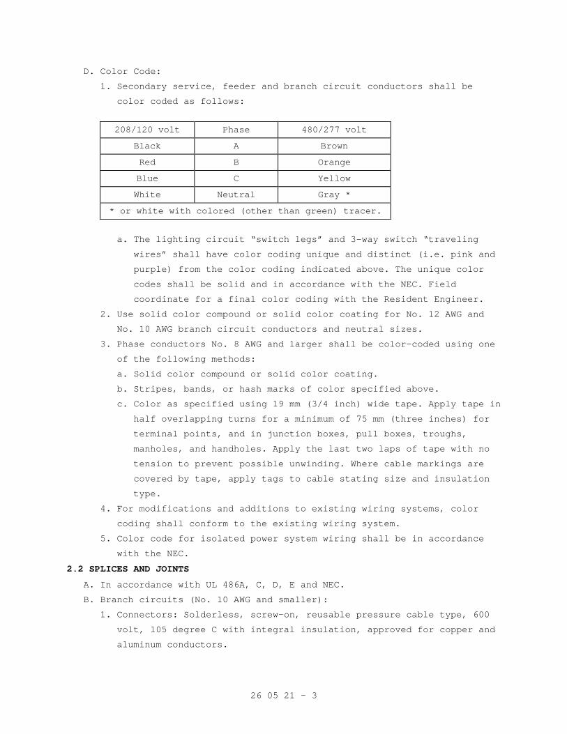
26 05 21 - 3
D. Color Code:
1. Secondary service, feeder and branch circuit conductors shall be
color coded as follows:
208/120 volt Phase 480/277 volt
Black A Brown
Red B Orange
Blue C Yellow
White Neutral Gray *
* or white with colored (other than green) tracer.
a. The lighting circuit “switch legs” and 3-way switch “traveling
wires” shall have color coding unique and distinct (i.e. pink and
purple) from the color coding indicated above. The unique color
codes shall be solid and in accordance with the NEC. Field
coordinate for a final color coding with the Resident Engineer.
2. Use solid color compound or solid color coating for No. 12 AWG and
No. 10 AWG branch circuit conductors and neutral sizes.
3. Phase conductors No. 8 AWG and larger shall be color-coded using one
of the following methods:
a. Solid color compound or solid color coating.
b. Stripes, bands, or hash marks of color specified above.
c. Color as specified using 19 mm (3/4 inch) wide tape. Apply tape in
half overlapping turns for a minimum of 75 mm (three inches) for
terminal points, and in junction boxes, pull boxes, troughs,
manholes, and handholes. Apply the last two laps of tape with no
tension to prevent possible unwinding. Where cable markings are
covered by tape, apply tags to cable stating size and insulation
type.
4. For modifications and additions to existing wiring systems, color
coding shall conform to the existing wiring system.
5. Color code for isolated power system wiring shall be in accordance
with the NEC.
2.2 SPLICES AND JOINTS
A. In accordance with UL 486A, C, D, E and NEC.
B. Branch circuits (No. 10 AWG and smaller):
1. Connectors: Solderless, screw-on, reusable pressure cable type, 600
volt, 105 degree C with integral insulation, approved for copper and
aluminum conductors.
26 05 21 - 4
2. The integral insulator shall have a skirt to completely cover the
stripped wires.
3. The number, size, and combination of conductors, as listed on the
manufacturers packaging shall be strictly complied with.
C. Feeder Circuits:
1. Connectors shall be indent, hex screw, or bolt clamp-type of high
conductivity and corrosion-resistant material.
2. Field installed compression connectors for cable sizes 250 kcmil and
larger shall have not less than two clamping elements or compression
indents per wire.
3. Insulate splices and joints with materials approved for the
particular use, location, voltage, and temperature. Insulate with not
less than that of the conductor level that is being joined.
4. Plastic electrical insulating tape: ASTM D2304 shall apply, flame
retardant, cold and weather resistant.
2.3 CONTROL WIRING
A. Unless otherwise specified in other sections of these specifications,
control wiring shall be as specified for power and lighting wiring,
except the minimum size shall be not less than No. 14 AWG.
B. Control wiring shall be large enough so that the voltage drop under
inrush conditions does not adversely affect operation of the controls.
2.4 WIRE LUBRICATING COMPOUND
A. Suitable for the wire insulation and conduit it is used with, and shall
not harden or become adhesive.
B. Shall not be used on wire for isolated type electrical power systems.
2.5 FIREPROOFING TAPE
A. The tape shall consist of a flexible, conformable fabric of organic
composition coated one side with flame-retardant elastomer.
B. The tape shall be self-extinguishing and shall not support combustion.
It shall be arc-proof and fireproof.
C. The tape shall not deteriorate when subjected to water, gases, salt
water, sewage, or fungus and be resistant to sunlight and ultraviolet
light.
D. The finished application shall withstand a 200-ampere arc for not less
than 30 seconds.
E. Securing tape: Glass cloth electrical tape not less than 0.18 mm
(7 mils) thick, and 19 mm (3/4 inch) wide.
2.6 WARNING TAPE
A. The tape shall be standard, 76 mm (3 inch) wide, 4-Mil polyethylene detectable type.
26 05 21 - 5
B. The tape shall be red with black letters indicating “CAUTION BURIED ELECTRIC LINE BELOW”.
PART 3 - EXECUTION
3.1 INSTALLATION, GENERAL
A. Install in accordance with the NEC, and as specified.
B. Install all wiring in raceway systems, except where direct burial or HCF
Type AC cables are used.
C. Splice cables and wires only in outlet boxes, junction boxes, pull
boxes, manholes, or handholes.
D. Wires of different systems (i.e. 120V, 277V) shall not be installed in
the same conduit or junction box system.
E. Install cable supports for all vertical feeders in accordance with the
NEC. Provide split wedge type which firmly clamps each individual cable
and tightens due to cable weight.
F. For panelboards, cabinets, wireways, switches, and equipment assemblies,
neatly form, train, and tie the cables in individual circuits.
G. Seal cable and wire entering a building from underground, between the
wire and conduit where the cable exits the conduit, with a non-hardening
approved compound.
H. Wire Pulling:
1. Provide installation equipment that will prevent the cutting or
abrasion of insulation during pulling of cables.
2. Use ropes made of nonmetallic material for pulling feeders.
3. Attach pulling lines for feeders by means of either woven basket
grips or pulling eyes attached directly to the conductors, as
approved by the Resident Engineer.
4. Pull in multiple cables together in a single conduit.
I. No more than (3) single-phase branch circuits shall be installed in any
one conduit.
J. The wires shall be derated in accordance with NEC Article 310. Neutral
wires, under conditions defined by the NEC, shall be considered current-
carrying conductors.
3.3 SPLICE INSTALLATION
A. Splices and terminations shall be mechanically and electrically secure.
B. Where the Government determines that unsatisfactory splices or
terminations have been installed, remove the devices and install
approved devices at no additional cost to the Government.
26 05 21 - 6
3.5 CONTROL AND SIGNAL WIRING INSTALLATION
A. Unless otherwise specified in other sections, install wiring and connect
to equipment/devices to perform the required functions as shown and
specified.
B. Except where otherwise required, install a separate power supply circuit
for each system so that malfunctions in any system will not affect other
systems.
C. Where separate power supply circuits are not shown, connect the systems
to the nearest panelboards of suitable voltages, which are intended to
supply such systems and have suitable spare circuit breakers or space
for installation.
D. Install a red warning indicator on the handle of the branch circuit
breaker for the power supply circuit for each system to prevent
accidental de-energizing of the systems.
E. System voltages shall be 120 volts or lower where shown on the drawings
or as required by the NEC.
3.6 CONTROL AND SIGNAL SYSTEM IDENTIFICATION
A. Install a permanent wire marker on each wire at each termination.
B. Identifying numbers and letters on the wire markers shall correspond to
those on the wiring diagrams used for installing the systems.
C. Wire markers shall retain their markings after cleaning.
D. In each manhole and handhole, install embossed brass tags to identify
the system served and function.
3.7 FEEDER IDENTIFICATION
A. In each interior pulbox and junction box, install metal tags on each
circuit cables and wires to clearly designate their circuit
identification and voltage.
B. In each manhole and handhole, provide tags of the embossed brass type,
showing the cable type and voltage rating. Attach the tags to the cables
with slip-free plastic cable lacing units.
3.8 EXISITNG WIRING
Unless specifically indicated on the plans, existing wiring shall not be
reused for the new installation. Only wiring that conforms to the
specifications and applicable codes may be reused. If existing wiring
does not meet these requirements, existing wiring may not be reused and
new wires shall be installed.
26 05 21 - 7
3.9 FIELD TESTING
A. Feeders and branch circuits shall have their insulation tested after
installation and before connection to utilization devices such as
fixtures, motors, or appliances.
B. Tests shall be performed by megger and conductors shall test free from
short-circuits and grounds.
C. Test conductor phase-to-phase and phase-to-ground.
D. The Contractor shall furnish the instruments, materials, and labor for
these tests.
- - - E N D - - -
26 05 26 - 1
SECTION 26 05 26 GROUNDING AND BONDING FOR ELECTRICAL SYSTEMS
PART 1 - GENERAL
1.1 DESCRIPTION
A. This section specifies general grounding and bonding requirements of
electrical equipment operations and to provide a low impedance path for
possible ground fault currents.
B. “Grounding electrode system” refers to all electrodes required by NEC,
as well as including made, supplementary, lightning protection system
grounding electrodes.
C. The terms “connect” and “bond” are used interchangeably in this
specification and have the same meaning.
1.2 RELATED WORK
A. Section 26 05 11, REQUIREMENTS FOR ELECTRICAL INSTALLATIONS: General
electrical requirements and items that are common to more than one
section of Division 26.
B. Section 26 05 21, LOW-VOLTAGE ELECTRICAL POWER CONDUCTORS AND CABLES
(600 VOLTS AND BELOW): Low Voltage power and lighting wiring.
C. Section 26 41 00, FACILITY LIGHTNING PROTECTION: Requirements for a
lightning protection system.
1.3 SUBMITTALS
A. Submit in accordance with Section 26 05 11, REQUIREMENTS FOR ELECTRICAL
INSTALLATIONS.
B. Shop Drawings:
1. Sufficient information, clearly presented, shall be included to
determine compliance with drawings and specifications.
2. Include the location of system grounding electrode connections and
the routing of aboveground and underground grounding electrode
conductors.
C. Test Reports: Provide certified test reports of ground resistance.
D. Certifications: Two weeks prior to final inspection, submit four copies
of the following to the Resident Engineer:
1. Certification that the materials and installation is in accordance
with the drawings and specifications.
2. Certification, by the Contractor, that the complete installation has
been properly installed and tested.
26 05 26 - 2
1.4 APPLICABLE PUBLICATIONS
Publications listed below (including amendments, addenda, revisions,
supplements, and errata) form a part of this specification to the
extent referenced. Publications are referenced in the text by the basic
designation only.
A. American Society for Testing and Materials (ASTM):
B1-2001.................Standard Specification for Hard-Drawn Copper
Wire
B8-2004.................Standard Specification for Concentric-Lay-
Stranded Copper Conductors, Hard, Medium-Hard,
or Soft
B. Institute of Electrical and Electronics Engineers, Inc. (IEEE):
81-1983.................IEEE Guide for Measuring Earth Resistivity,
Ground Impedance, and Earth Surface Potentials
of a Ground System
C. National Fire Protection Association (NFPA):
70-2005.................National Electrical Code (NEC)
99-2005.................Health Care Facilities
D. Underwriters Laboratories, Inc. (UL):
44-2005 ................Thermoset-Insulated Wires and Cables
83-2003 ................Thermoplastic-Insulated Wires and Cables
467-2004 ...............Grounding and Bonding Equipment
486A-486B-2003 .........Wire Connectors
PART 2 - PRODUCTS
2.1 GROUNDING AND BONDING CONDUCTORS
A. Equipment grounding conductors shall be UL 83 insulated stranded
copper, except that sizes 6 mm² (10 AWG) and smaller shall be solid
copper. Insulation color shall be continuous green for all equipment
grounding conductors, except that wire sizes 25 mm² (4 AWG) and larger
shall be permitted to be identified per NEC.
B. Bonding conductors shall be ASTM B8 bare stranded copper, except that
sizes 6 mm² (10 AWG) and smaller shall be ASTM B1 solid bare copper
wire.
C. Isolated Power System: Type XHHW-2 insulation with a dielectric
constant of 3.5 or less.
D. Electrical System Grounding: Conductor sizes shall not be less than
what is shown on the drawings and not less than required by the NEC,
whichever is greater.
26 05 26 - 3
2.2 GROUND RODS
A. Copper clad steel, 19 mm (3/4-inch) diameter by 3000 mm (10 feet) long,
conforming to UL 467.
B. Quantity of rods shall be as required to obtain the specified ground
resistance.
2.3 SPLICES AND TERMINATION COMPONENTS
Components shall meet or exceed UL 467 and be clearly marked with the
manufacturer, catalog number, and permitted conductor size(s).
2.4 GROUND CONNECTIONS
A. Below Grade: Exothermic-welded type connectors.
B. Above Grade:
1. Bonding Jumpers: compression type connectors, using zinc-plated
fasteners and external tooth lockwashers.
2. Ground Busbars: Two-hole compression type lugs using tin-plated
copper or copper alloy bolts and nuts.
3. Rack and Cabinet Ground Bars: one-hole compression-type lugs using
zinc-plated or copper alloy fasteners.
2.5 EQUIPMENT RACK AND CABINET GROUND BARS
Provide solid copper ground bars designed for mounting on the framework
of open or cabinet-enclosed equipment racks with minimum dimensions of
4 mm thick by 19 mm wide (3/8 inch x ¾ inch).
2.6 GROUND TERMINAL BLOCKS
At any equipment mounting location (e.g. backboards and hinged cover
enclosures) where rack-type ground bars cannot be mounted, provide
screw lug-type terminal blocks.
2.7 SPLICE CASE GROUND ACCESSORIES
Splice case grounding and bonding accessories shall be supplied by the
splice case manufacturer when available. Otherwise, use 16 mm² (6 AWG)
insulated ground wire with shield bonding connectors.
PART 3 - EXECUTION
3.1 GENERAL
A. Ground in accordance with the NEC, as shown on drawings, and as
hereinafter specified.
B. System Grounding:
1. Secondary service neutrals: Ground at the supply side of the
secondary disconnecting means and at the related transformers.
2. Separately derived systems (transformers downstream from the service
entrance): Ground the secondary neutral.
26 05 26 - 4
3. Isolation transformers and isolated power systems shall not be
system grounded.
C. Equipment Grounding: Metallic structures (including ductwork and
building steel), enclosures, raceways, junction boxes, outlet boxes,
cabinets, machine frames, and other conductive items in close proximity
with electrical circuits shall be bonded and grounded.
D. Special Grounding: For patient care area electrical power system
grounding, conform to NFPA 99, and NEC.
3.2 INACCESSIBLE GROUNDING CONNECTIONS
Make grounding connections, which are buried or otherwise normally
inaccessible (except connections for which periodic testing access is
required) by exothermic weld.
3.3 SECONDARY EQUIPMENT AND CIRCUITS
A. Main Bonding Jumper: Bond the secondary service neutral to the ground
bus in the service equipment.
B. Metallic Piping, Building Steel, and Supplemental Electrode(s):
1. Provide a grounding electrode conductor sized per NEC between the
service equipment ground bus and all metallic water and gas pipe
systems, building steel, and supplemental or made electrodes. Jumper
insulating joints in the metallic piping. All connections to
electrodes shall be made with fittings that conform to UL 467.
2. Provide a supplemental ground electrode and bond to the grounding
electrode system.
C. Service Disconnect (Separate Individual Enclosure): Provide a ground
bar bolted to the enclosure with lugs for connecting the various
grounding conductors.
D. Switchgear, Switchboards, Unit Substations, and Motor Control Centers:
1. Connect the various feeder equipment grounding conductors to the
ground bus in the enclosure with suitable pressure connectors.
2. For service entrance equipment, connect the grounding electrode
conductor to the ground bus.
3. Connect metallic conduits, which terminate without mechanical
connection to the housing, by grounding bushings and grounding
conductor to the equipment ground bus.
E. Transformers:
1. Exterior: Exterior transformers supplying interior service equipment
shall have the neutral grounded at the transformer secondary.
Provide a grounding electrode at the transformer.
26 05 26 - 5
2. Separately derived systems (transformers downstream from service
equipment): Ground the secondary neutral at the transformer. Provide
a grounding electrode conductor from the transformer to the nearest
component of the grounding electrode system.
F. Conduit Systems:
1. Ground all metallic conduit systems. All metallic conduit systems
shall contain an equipment grounding conductor.
2. Non-metallic conduit systems shall contain an equipment grounding
conductor, except that non-metallic feeder conduits which carry a
grounded conductor from exterior transformers to interior or
building-mounted service entrance equipment need not contain an
equipment grounding conductor.
3. Conduit containing only a grounding conductor, and which is provided
for mechanical protection of the conductor, shall be bonded to that
conductor at the entrance and exit from the conduit.
G. Feeders and Branch Circuits: Install equipment grounding conductors
with all feeders and power and lighting branch circuits.
H. Boxes, Cabinets, Enclosures, and Panelboards:
1. Bond the equipment grounding conductor to each pullbox, junction
box, outlet box, device box, cabinets, and other enclosures through
which the conductor passes (except for special grounding systems for
intensive care units and other critical units shown).
2. Provide lugs in each box and enclosure for equipment grounding
conductor termination.
3. Provide ground bars in panelboards, bolted to the housing, with
sufficient lugs to terminate the equipment grounding conductors.
I. Motors and Starters: Provide lugs in motor terminal box and starter
housing or motor control center compartment to terminate equipment
grounding conductors.
J. Receptacles shall not be grounded through their mounting screws. Ground
with a jumper from the receptacle green ground terminal to the device
box ground screw and the branch circuit equipment grounding conductor.
K. Ground lighting fixtures to the equipment grounding conductor of the
wiring system when the green ground is provided; otherwise, ground the
fixtures through the conduit systems. Fixtures connected with flexible
conduit shall have a green ground wire included with the power wires
from the fixture through the flexible conduit to the first outlet box.
26 05 26 - 6
L. Fixed electrical appliances and equipment shall be provided with a
ground lug for termination of the equipment grounding conductor.
M. Panelboard Bonding: The equipment grounding terminal buses of the
normal and essential branch circuit panelboards serving the same
individual patient vicinity shall be bonded together with an insulated
continuous copper conductor not less than 16 mm² (10 AWG). These
conductors shall be installed in rigid metal conduit.
3.4 CORROSION INHIBITORS
When making ground and ground bonding connections, apply a corrosion
inhibitor to all contact surfaces. Use corrosion inhibitor appropriate
for protecting a connection between the metals used.
3.5 CONDUCTIVE PIPING
A. Bond all conductive piping systems, interior and exterior, to the
building to the grounding electrode system. Bonding connections shall
be made as close as practical to the equipment ground bus.
B. In operating rooms and at intensive care and coronary care type beds,
bond the gases and suction piping, at the outlets, directly to the room
or patient ground bus.
3.6 LIGHTNING PROTECTION SYSTEM
Bond the lightning protection system to the electrical grounding
electrode system.
3.7 ELECTRICAL ROOM GROUNDING
Building Earth Ground Busbars: Provide ground busbar hardware at each
electrical room and connect to pigtail extensions of the building
grounding ring.
3.8 WIREWAY GROUNDING
A. Ground and Bond Metallic Wireway Systems as follows:
1. Bond the metallic structures of wireway to provide 100 percent
electrical continuity throughout the wireway system by connecting a
16 mm² (6 AWG) bonding jumper at all intermediate metallic
enclosures and across all section junctions.
2. Install insulated 16 mm² (6 AWG) bonding jumpers between the wireway
system bonded as required in paragraph 1 above, and the closest
building ground at each end and approximately every 16 meters (50
feet).
3. Use insulated 16 mm² (6 AWG) bonding jumpers to ground or bond
metallic wireway at each end at all intermediate metallic enclosures
and cross all section junctions.
26 05 26 - 7
4. Use insulated 16 mm² (6 AWG) bonding jumpers to ground cable tray to
column-mounted building ground plates (pads) at each end and
approximately every 15 meters.
3.9 GROUND RESISTANCE
A. Grounding system resistance to ground shall not exceed 5 ohms. Make
necessary modifications or additions to the grounding electrode system
for compliance without additional cost to the Government. Final tests
shall assure that this requirement is met.
B. Resistance of the grounding electrode system shall be measured using a
four-terminal fall-of-potential method as defined in IEEE 81. Ground
resistance measurements shall be made before the electrical
distribution system is energized and shall be made in normally dry
conditions not less than 48 hours after the last rainfall. Resistance
measurements of separate grounding electrode systems shall be made
before the systems are bonded together below grade. The combined
resistance of separate systems may be used to meet the required
resistance, but the specified number of electrodes must still be
provided.
C. Services at power company interface points shall comply with the power
company ground resistance requirements.
D. Below-grade connections shall be visually inspected by the Resident
Engineer prior to backfilling. The Contractor shall notify the Resident
Engineer 24 hours before the connections are ready for inspection.
3.10 GROUND ROD INSTALLATION
A. Drive each rod vertically in the earth, not less than 3000 mm (10 feet)
in depth.
B. Where permanently concealed ground connections are required, make the
connections by the exothermic process to form solid metal joints. Make
accessible ground connections with mechanical pressure type ground
connectors.
C. Where rock prevents the driving of vertical ground rods, install angled
ground rods or grounding electrodes in horizontal trenches to achieve
the specified resistance.
- - - E N D - - -
26 05 33 - 1
SECTION 26 05 33 RACEWAY AND BOXES FOR ELECTRICAL SYSTEMS
PART 1 - GENERAL
1.1 DESCRIPTION
A. This section specifies the furnishing, installation, and connection of
conduit, fittings, and boxes to form complete, coordinated, grounded
raceway systems. Raceways are required for all wiring unless shown or
specified otherwise.
B. Definitions: The term conduit, as used in this specification, shall mean
any or all of the raceway types specified.
1.2 RELATED WORK
A. Bedding of conduits: Section 31 20 00, EARTH MOVING.
B. Mounting board for telephone closets: Section 06 10 00, ROUGH CARPENTRY.
C. Sealing around penetrations to maintain the integrity of fire rated
construction: Section 07 84 00, FIRESTOPPING.
D. Fabrications for the deflection of water away from the building envelope
at penetrations: Section 07 60 00, FLASHING AND SHEET METAL.
E. Sealing around conduit penetrations through the building envelope to
prevent moisture migration into the building: Section 07 92 00, JOINT
SEALANTS.
F. Identification and painting of conduit and other devices: Section 09 91
00, PAINTING.
G. General electrical requirements and items that is common to more than
one section of Division 26: Section 26 05 11, REQUIREMENTS FOR
ELECTRICAL INSTALLATIONS.
H. Requirements for personnel safety and to provide a low impedance path
for possible ground fault currents: Section 26 05 26, GROUNDING AND
BONDING FOR ELECTRICAL SYSTEMS.
1.3 SUBMITTALS
In accordance with Section 01 33 23, SHOP DRAWINGS, PRODUCT DATA, AND
SAMPLES, furnish the following:
A. Shop Drawings:
1. Size and location of main feeders;
2. Size and location of panels and pull boxes
3. Layout of required conduit penetrations through structural elements.
4. The specific item proposed and its area of application shall be
identified on the catalog cuts.
26 05 33 - 2
B. Certification: Prior to final inspection, deliver to the Resident
Engineer four copies of the certification that the material is in
accordance with the drawings and specifications and has been properly
installed.
1.4 APPLICABLE PUBLICATIONS
A. Publications listed below (including amendments, addenda, revisions,
supplements and errata) form a part of this specification to the extent
referenced. Publications are referenced in the text by the basic
designation only.
B. National Fire Protection Association (NFPA):
70-05...................National Electrical Code (NEC)
C. Underwriters Laboratories, Inc. (UL):
1-03....................Flexible Metal Conduit
5-01....................Surface Metal Raceway and Fittings
6-03....................Rigid Metal Conduit
50-03...................Enclosures for Electrical Equipment
360-03..................Liquid-Tight Flexible Steel Conduit
467-01..................Grounding and Bonding Equipment
514A-01.................Metallic Outlet Boxes
514B-02.................Fittings for Cable and Conduit
514C-05.................Nonmetallic Outlet Boxes, Flush-Device Boxes and
Covers
651-02..................Schedule 40 and 80 Rigid PVC Conduit
651A-03.................Type EB and A Rigid PVC Conduit and HDPE Conduit
797-03..................Electrical Metallic Tubing
1242-00.................Intermediate Metal Conduit
D. National Electrical Manufacturers Association (NEMA):
TC-3-04.................PVC Fittings for Use with Rigid PVC Conduit and
Tubing
FB1-03..................Fittings, Cast Metal Boxes and Conduit Bodies
for Conduit, Electrical Metallic Tubing and
Cable
PART 2 - PRODUCTS
2.1 MATERIAL
A. Conduit Size: In accordance with the NEC, but not less than 19 mm
(3/4 inch) unless otherwise shown. Where permitted by the NEC, 13 mm
(1/2 inch) flexible conduit may be used for tap connections to recessed
lighting fixtures.
26 05 33 - 3
B. Conduit:
1. Rigid galvanized steel: Shall Conform to UL 6, ANSI C80.1.
2. Rigid aluminum: Shall Conform to UL 6A, ANSI C80.5.
3. Rigid intermediate steel conduit (IMC): Shall Conform to UL 1242,
ANSI C80.6.
4. Electrical metallic tubing (EMT): Shall Conform to UL 797, ANSI
C80.3. Maximum size not to exceed 105 mm (4 inch) and shall be
permitted only with cable rated 600 volts or less.
5. Flexible galvanized steel conduit: Shall Conform to UL 1.
6. Liquid-tight flexible metal conduit: Shall Conform to UL 360.
7. Direct burial plastic conduit: Shall conform to UL 651 and UL 651A,
heavy wall PVC or high density polyethylene (PE).
8. Surface metal raceway: Shall Conform to UL 5.
C. Conduit Fittings:
1. Rigid steel and IMC conduit fittings:
a. Fittings shall meet the requirements of UL 514B and ANSI/ NEMA
FB1.
a. Standard threaded couplings, locknuts, bushings, and elbows: Only
steel or malleable iron materials are acceptable. Integral
retractable type IMC couplings are also acceptable.
b. Locknuts: Bonding type with sharp edges for digging into the metal
wall of an enclosure.
c. Bushings: Metallic insulating type, consisting of an insulating
insert molded or locked into the metallic body of the fitting.
Bushings made entirely of metal or nonmetallic material are not
permitted.
d. Erickson (union-type) and set screw type couplings: Approved for
use in concrete are permitted for use to complete a conduit run
where conduit is installed in concrete. Use set screws of case
hardened steel with hex head and cup point to firmly seat in
conduit wall for positive ground. Tightening of set screws with
pliers is prohibited.
e. Sealing fittings: Threaded cast iron type. Use continuous drain
type sealing fittings to prevent passage of water vapor. In
concealed work, install fittings in flush steel boxes with blank
cover plates having the same finishes as that of other electrical
plates in the room.
26 05 33 - 4
2. Rigid aluminum conduit fittings:
a. Standard threaded couplings, locknuts, bushings, and elbows:
Malleable iron, steel or aluminum alloy materials; Zinc or cadmium
plate iron or steel fittings. Aluminum fittings containing more
than 0.4 percent copper are prohibited.
b. Locknuts and bushings: As specified for rigid steel and IMC
conduit.
c. Set screw fittings: Not permitted for use with aluminum conduit.
3. Electrical metallic tubing fittings:
a. Fittings shall meet the requirements of UL 514B and ANSI/ NEMA
FB1.
b. Only steel or malleable iron materials are acceptable.
c. Couplings and connectors: Concrete tight and rain tight, with
connectors having insulated throats. Use gland and ring
compression type couplings and connectors for conduit sizes 50 mm
(2 inches) and smaller. Use set screw type couplings with four set
screws each for conduit sizes over 50 mm (2 inches). Use set
screws of case-hardened steel with hex head and cup point to
firmly seat in wall of conduit for positive grounding.
d. Indent type connectors or couplings are prohibited.
e. Die-cast or pressure-cast zinc-alloy fittings or fittings made of
"pot metal" are prohibited.
4. Flexible steel conduit fittings:
a. Conform to UL 514B. Only steel or malleable iron materials are
acceptable.
b. Clamp type, with insulated throat.
5. Liquid-tight flexible metal conduit fittings:
a. Fittings shall meet the requirements of UL 514B and ANSI/ NEMA
FB1.
b. Only steel or malleable iron materials are acceptable.
c. Fittings must incorporate a threaded grounding cone, a steel or
plastic compression ring, and a gland for tightening. Connectors
shall have insulated throats.
6. Direct burial plastic conduit fittings:
a. Fittings shall meet the requirements of UL 514C and NEMA TC3.
b. As recommended by the conduit manufacturer.
7. Surface metal raceway fittings: As recommended by the raceway
manufacturer.
26 05 33 - 5
8. Expansion and deflection couplings:
a. Conform to UL 467 and UL 514B.
b. Accommodate, 19 mm (0.75 inch) deflection, expansion, or
contraction in any direction, and allow 30 degree angular
deflections.
c. Include internal flexible metal braid sized to guarantee conduit
ground continuity and fault currents in accordance with UL 467,
and the NEC code tables for ground conductors.
d. Jacket: Flexible, corrosion-resistant, watertight, moisture and
heat resistant molded rubber material with stainless steel jacket
clamps.
D. Conduit Supports:
1. Parts and hardware: Zinc-coat or provide equivalent corrosion
protection.
2. Individual Conduit Hangers: Designed for the purpose, having a
pre-assembled closure bolt and nut, and provisions for receiving a
hanger rod.
3. Multiple conduit (trapeze) hangers: Not less than 38 mm by 38 mm
(1-1/2 by 1-1/2 inch), 12 gage steel, cold formed, lipped channels;
with not less than 9 mm (3/8 inch) diameter steel hanger rods.
4. Solid Masonry and Concrete Anchors: Self-drilling expansion shields,
or machine bolt expansion.
E. Outlet, Junction, and Pull Boxes:
1. UL-50 and UL-514A.
2. Cast metal where required by the NEC or shown, and equipped with
rustproof boxes.
3. Sheet metal boxes: Galvanized steel, except where otherwise shown.
4. Flush mounted wall or ceiling boxes shall be installed with raised
covers so that front face of raised cover is flush with the wall.
Surface mounted wall or ceiling boxes shall be installed with surface
style flat or raised covers.
F. Wireways: Equip with hinged covers, except where removable covers are shown.
G. Warning Tape: Standard, 4-Mil polyethylene 76 mm (3 inch) wide tape
detectable type, red with black letters, and imprinted with “CAUTION
BURIED ELECTRIC LINE BELOW”.
26 05 33 - 6
PART 3 - EXECUTION
3.1 PENETRATIONS
A. Cutting or Holes:
1. Locate holes in advance where they are proposed in the structural
sections such as ribs or beams. Obtain the approval of the Resident
Engineer prior to drilling through structural sections.
2. Cut holes through concrete and masonry in new and existing structures
with a diamond core drill or concrete saw. Pneumatic hammer, impact
electric, hand or manual hammer type drills are not allowed, except
where permitted by the Resident Engineer as required by limited
working space.
B. Fire Stop: Where conduits, wireways, and other electrical raceways pass
through fire partitions, fire walls, smoke partitions, or floors,
install a fire stop that provides an effective barrier against the
spread of fire, smoke and gases as specified in Section 07 84 00,
FIRESTOPPING, with rock wool fiber or silicone foam sealant only.
Completely fill and seal clearances between raceways and openings with
the fire stop material.
C. Waterproofing: At floor, exterior wall, and roof conduit penetrations,
completely seal clearances around the conduit and make watertight as
specified in Section 07 92 00, JOINT SEALANTS.
3.2 INSTALLATION, GENERAL
A. In accordance with UL, NEC, as shown, and as hereinafter specified.
B. Essential (Emergency) raceway systems shall be entirely independent of
other raceway systems, except where specifically "accepted" by NEC
Article 517.
C. Install conduit as follows:
1. In complete runs before pulling in cables or wires.
2. Flattened, dented, or deformed conduit is not permitted. Remove and
replace the damaged conduits with new undamaged material.
3. Assure conduit installation does not encroach into the ceiling height
head room, walkways, or doorways.
4. Cut square with a hacksaw, ream, remove burrs, and draw up tight.
5. Mechanically and electrically continuous.
6. Independently support conduit at 8’0” on center. Do not use other
supports i.e., (suspended ceilings, suspended ceiling supporting
members, lighting fixtures, conduits, mechanical piping, or
mechanical ducts).
7. Support within 300 mm (1 foot) of changes of direction, and within
300 mm (1 foot) of each enclosure to which connected.
26 05 33 - 7
8. Close ends of empty conduit with plugs or caps at the rough-in stage
to prevent entry of debris, until wires are pulled in.
9. Conduit installations under fume and vent hoods are prohibited.
10. Secure conduits to cabinets, junction boxes, pull boxes and outlet
boxes with bonding type locknuts. For rigid and IMC conduit
installations, provide a locknut on the inside of the enclosure, made
up wrench tight. Do not make conduit connections to junction box
covers.
11. Flashing of penetrations of the roof membrane is specified in Section
07 60 00, FLASHING AND SHEET METAL.
12. Do not use aluminum conduits in wet locations.
13. Unless otherwise indicated on the drawings or specified herein, all
conduits shall be installed concealed within finished walls, floors
and ceilings.
D. Conduit Bends:
1. Make bends with standard conduit bending machines.
2. Conduit hickey may be used for slight offsets, and for straightening
stubbed out conduits.
3. Bending of conduits with a pipe tee or vise is prohibited.
E. Layout and Homeruns:
1. Install conduit with wiring, including homeruns, as shown.
2. Deviations: Make only where necessary to avoid interferences and only
after drawings showing the proposed deviations have been submitted
approved by the Resident Engineer.
3.3 CONCEALED WORK INSTALLATION
A. In Concrete:
1. Conduit: Rigid steel, IMC or EMT. Do not install EMT in concrete
slabs that are in contact with soil, gravel or vapor barriers.
2. Align and run conduit in direct lines.
3. Install conduit through concrete beams only when the following
occurs:
a. Where shown on the structural drawings.
b. As approved by the Resident Engineer prior to construction, and
after submittal of drawing showing location, size, and position of
each penetration.
4. Installation of conduit in concrete that is less than 75 mm (3
inches) thick is prohibited.
a. Conduit outside diameter larger than 1/3 of the slab thickness is
prohibited.
26 05 33 - 8
b. Space between conduits in slabs: Approximately six conduit
diameters apart, except one conduit diameter at conduit crossings.
c. Install conduits approximately in the center of the slab so that
there will be a minimum of 19 mm (3/4 inch) of concrete around the
conduits.
5. Make couplings and connections watertight. Use thread compounds that
are UL approved conductive type to insure low resistance ground
continuity through the conduits. Tightening set screws with pliers is
prohibited.
B. Furred or Suspended Ceilings and in Walls:
1. Conduit for conductors above 600 volts:
a. Rigid steel or rigid aluminum.
b. Aluminum conduit mixed indiscriminately with other types in the
same system is prohibited.
2. Conduit for conductors 600 volts and below:
a. Rigid steel, IMC, rigid aluminum, or EMT. Different type conduits
mixed indiscriminately in the same system is prohibited.
3. Align and run conduit parallel or perpendicular to the building
lines.
4. Connect recessed lighting fixtures to conduit runs with maximum 1800
mm (six feet) of flexible metal conduit extending from a junction box
to the fixture.
5. Tightening set screws with pliers is prohibited.
3.4 EXPOSED WORK INSTALLATION
A. Unless otherwise indicated on the drawings, exposed conduit is only
permitted in mechanical and electrical rooms.
B. Conduit for conductors above 600 volts:
1. Rigid steel or rigid aluminum.
2. Aluminum conduit mixed indiscriminately with other types in the same
system is prohibited.
C. Conduit for Conductors 600 volts and below:
1. Rigid steel, IMC, rigid aluminum, or EMT. Different type of conduits
mixed indiscriminately in the system is prohibited.
D. Align and run conduit parallel or perpendicular to the building lines.
E. Install horizontal runs close to the ceiling or beams and secure with
conduit straps.
F. Support horizontal or vertical runs at not over 2400 mm (eight foot)
intervals.
G. Surface metal raceways: Use only where shown.
26 05 33 - 9
H. Painting:
1. Paint exposed conduit as specified in Section 09 91 00, PAINTING.
2. Paint all conduits containing cables rated over 600 volts safety
orange. Refer to Section 09 91 00, PAINTING for preparation, paint
type, and exact color. In addition, paint legends, using 50 mm (two
inch) high black numerals and letters, showing the cable voltage
rating. Provide legends where conduits pass through walls and floors
and at maximum 6000 mm (20 foot) intervals in between.
3.5 DIRECT BURIAL INSTALLATION
A. Exterior routing of Lighting Systems and Other Branch circuits (600 Volt
and Less, and 1500 mm (5 feet) from the buildings):
1. Conduit: Thick wall PVC or high density PE, unless otherwise shown.
2. Mark conduit at uniform intervals to show the kind of material,
direct burial type, and the UL approval label.
3. Install conduit fittings and terminations as recommended by the
conduit manufacturer.
4. Tops of conduits shall be as follows unless otherwise shown:
a. Not less than 600 mm (24 inches) below finished grade.
b. Not less than 750 mm (30 inches) below road and other paved
surfaces.
5. Work with extreme care near existing ducts, conduits, cables, and
other utilities to avoid damaging them.
6. Excavation for conduit bedding and back-filling of trenches is
specified in Section 31 20 00, EARTH MOVING.
a. Cut the trenches neatly and uniformly.
b. Do not kink the conduits.
7. Seal conduits, including spare conduits, at building entrances and at
outdoor terminations for equipment with a suitable compound that
prevents the entrance of moisture and gases.
8. Where metal conduit is shown, install threaded heavy wall rigid steel
galvanized conduit or type A20 rigid steel galvanized conduit coated
with .5 mm (20 mil) bonded PVC, or rigid steel or IMC, PVC coated or
standard coated with bituminous asphaltic compound.
9. Warning tape shall be continuously placed 300 mm (12 inches) above
conduits or electric lines.
26 05 33 - 10
B. Exterior routing of lighting systems and other branch circuits (600
volts and less-under buildings slab on grade to 1500 mm (5 feet) from
the building):
1. Pre-coated rigid galvanized steel conduit.
3.6 HAZARDOUS LOCATIONS
A. Use rigid steel conduit only, notwithstanding requirements otherwise
specified in this or other sections of these specifications.
B. Install UL approved sealing fittings, that prevent passage of explosive
vapors, in hazardous areas equipped with explosive proof lighting
fixtures, switches, and receptacles, as required by the NEC.
3.7 WET OR DAMP LOCATIONS
A. Unless otherwise shown, use conduits of rigid steel or IMC.
B. Provide sealing fittings, to prevent passage of water vapor, where
conduits pass from warm to cold locations, i.e., (refrigerated spaces,
constant temperature rooms, air conditioned spaces building exterior
walls, roofs) or similar spaces.
C. Unless otherwise shown, use rigid steel or IMC conduit within 1500 mm (5
feet) of the exterior and below concrete building slabs in contact with
soil, gravel, or vapor barriers. Conduit shall include an outer factory
coating of .5 mm (20 mil) bonded PVC or field coat with asphaltum before
installation. After installation, completely coat damaged areas of
coating.
3.8 MOTORS AND VIBRATING EQUIPMENT
A. Use flexible metal conduit for connections to motors and other
electrical equipment subject to movement, vibration, misalignment,
cramped quarters, or noise transmission.
B. Provide liquid-tight flexible metal conduit for installation in exterior
locations, moisture or humidity laden atmosphere, corrosive atmosphere,
water or spray wash-down operations, inside (air stream) of HVAC units,
and locations subject to seepage or dripping of oil, grease or water.
Provide a green ground wire with flexible metal conduit.
3.9 EXPANSION JOINTS
A. Conduits 75 mm (3 inches) and larger, that are secured to the building
structure on opposite sides of a building expansion joint, require
expansion and deflection couplings. Install the couplings in accordance
with the manufacturer's recommendations.
26 05 33 - 11
B. Provide conduits smaller than 75 mm (3 inches) with junction boxes on
both sides of the expansion joint. Connect conduits to junction boxes
with sufficient slack of flexible conduit to produce 125 mm (5 inch)
vertical drop midway between the ends. Flexible conduit shall have a
copper green ground bonding jumper installed. In lieu of this flexible
conduit, expansion and deflection couplings as specified above for 375
mm (15 inches) and larger conduits are acceptable.
C. Install expansion and deflection couplings where shown.
D. Seismic Areas: In seismic areas, provide conduits rigidly secured to the
building structure on opposite sides of a building expansion joint with
junction boxes on both sides of the joint. Connect conduits to junction
boxes with 375 mm (15 inches) of slack flexible conduit. Flexible
conduit shall have a copper green ground bonding jumper installed.
3.10 CONDUIT SUPPORTS, INSTALLATION
A. Safe working load shall not exceed 1/4 of proof test load of fastening
devices.
B. Use pipe straps or individual conduit hangers for supporting individual
conduits. Maximum distance between supports is 2.5 m (8 foot) on center.
C. Support multiple conduit runs with trapeze hangers. Use trapeze hangers
that are designed to support a load equal to or greater than the sum of
the weights of the conduits, wires, hanger itself, and 90 kg (200
pounds). Attach each conduit with U-bolts or other approved fasteners.
D. Support conduit independently of junction boxes, pull boxes, fixtures,
suspended ceiling T-bars, angle supports, and similar items.
E. Fasteners and Supports in Solid Masonry and Concrete:
1. New Construction: Use steel or malleable iron concrete inserts set in
place prior to placing the concrete.
2. Existing Construction:
a. Steel expansion anchors not less than 6 mm (1/4 inch) bolt size
and not less than 28 mm (1-1/8 inch) embedment.
b. Power set fasteners not less than 6 mm (1/4 inch) diameter with
depth of penetration not less than 75 mm (3 inches).
c. Use vibration and shock resistant anchors and fasteners for
attaching to concrete ceilings.
F. Hollow Masonry: Toggle bolts are permitted.
G. Bolts supported only by plaster or gypsum wallboard are not acceptable.
H. Metal Structures: Use machine screw fasteners or other devices
specifically designed and approved for the application.
26 05 33 - 12
I. Attachment by wood plugs, rawl plug, plastic, lead or soft metal
anchors, or wood blocking and bolts supported only by plaster is
prohibited.
J. Chain, wire, or perforated strap shall not be used to support or fasten
conduit.
K. Spring steel type supports or fasteners are prohibited for all uses
except: Horizontal and vertical supports/fasteners within walls.
L. Vertical Supports: Vertical conduit runs shall have riser clamps and
supports in accordance with the NEC and as shown. Provide supports for
cable and wire with fittings that include internal wedges and retaining
collars.
3.11 BOX INSTALLATION
A. Boxes for Concealed Conduits:
1. Flush mounted.
2. Provide raised covers for boxes to suit the wall or ceiling,
construction and finish.
B. In addition to boxes shown, install additional boxes where needed to
prevent damage to cables and wires during pulling in operations.
C. Remove only knockouts as required and plug unused openings. Use threaded
plugs for cast metal boxes and snap-in metal covers for sheet metal
boxes.
D. Outlet boxes in the same wall mounted back-to-back are prohibited. A
minimum 600 mm (24 inch), center-to-center lateral spacing shall be
maintained between boxes.)
E. Minimum size of outlet boxes for ground fault interrupter (GFI)
receptacles is 100 mm (4 inches) square by 55 mm (2-1/8 inches) deep,
with device covers for the wall material and thickness involved.
F. Stencil or install phenolic nameplates on covers of the boxes identified
on riser diagrams; for example "SIG-FA JB No. 1".
G. On all Branch Circuit junction box covers, identify the circuits with
black marker.
- - - E N D - - -
26 22 00 - 1
SECTION 26 22 00 LOW-VOLTAGE TRANSFORMERS
PART 1 – GENERAL
1.1 DESCRIPTION
This section specifies the furnishing, installation and connection of
the dry type general-purpose transformers.
1.2 RELATED WORK
A. Section 26 05 11, REQUIREMENTS FOR ELECTRICAL INSTALLATIONS: General
electrical requirements and items that are common to more than one
section of Division 26.
B. Section 26 05 33, RACEWAY AND BOXES FOR ELECTRICAL SYSTEMS: Conduits and
outlet boxes.
C. Section 26 05 21, LOW-VOLTAGE ELECTRICAL POWER CONDUCTORS AND CABLES
(600 VOLTS AND BELOW): Cables and wiring.
D. Section 26 05 26, GROUNDING AND BONDING FOR ELECTRICAL SYSTEMS:
Requirements for personnel safety and to provide a low impedance path
for possible ground fault currents.
1.3 SUBMITTALS
A. In accordance with Section 26 05 11, REQUIREMENTS FOR ELECTRICAL
INSTALLATIONS, submit the following:
B. Shop Drawings:
1. Sufficient information, clearly presented, shall be included to
determine compliance with drawings and specifications.
2. Include electrical ratings, impedance, dimensions, weight, mounting
details, decibel rating, terminations, temperature rise, no load and
full load losses, and connection diagrams.
3. Complete nameplate data including manufacturer’s name and catalog
number.
C. Manuals:
1. Submit, simultaneously with the shop drawings, companion copies of
complete maintenance and operating manuals including technical data
sheets and wiring diagrams.
2. If changes have been made to the originally submitted maintenance and
operating manuals, then two weeks prior to final inspection submit
four copies of updated maintenance and operating manuals to the
Resident Engineer.
26 22 00 - 2
D. Certifications: Two weeks prior to the final inspection, submit four
copies of the following to the Resident Engineer:
1. Certification by the manufacturer that the transformers conform to
the requirements of the drawings and specifications.
2. Certification that the equipment has been properly installed and
tested.
1.4 APPLICABLE PUBLICATIONS
A. Publications listed below (including amendments, addenda, revisions,
supplements and errata) form a part of this specification to the extent
referenced. Publications are referenced in the text by designation only.
B. National Fire Protection Association (NFPA):
70-05...................National Electrical Code (NEC)
C. National Electrical Manufacturers Association (NEMA):
ST 20-97................Dry-Type Transformers for General Applications
PART 2 - PRODUCTS
2.1 GENERAL PURPOSE DRY TYPE TRANSFORMERS
A. Unless otherwise specified, dry type transformers shall be in accordance
with NEMA, NEC and as shown on the drawings. Transformers shall be UL
listed or labeled.
B. Dry type transformers shall have the following features:
1. Self-cooled by natural convection, isolating windings, indoor, dry
type. Autotransformers will not be accepted.
2. Rating and winding connections shall be as shown on the drawings. 3. Transformers shall have copper windings. 4. Ratings shown on the drawings are for continuous-duty without the use
of cooling fans.
5. Insulation systems:
a. Transformers 30 KVA and larger: UL rated 220 degrees C system
having an average maximum rise by resistance of 150 degrees C in a
maximum ambient of 40 degrees C.
b. Transformers below 30 KVA: Same as for 30 KVA and larger or UL
rated 185 degrees C system having an average maximum rise by
resistance of 115 degrees C in a maximum ambient of 40 degrees C.
6. Core and coil assemblies:
a. Rigidly braced to withstand the stresses caused by short circuit
currents and rough handling during shipment.
b. Cores shall be grain oriented, non-aging, and silicon steel.
c. Coils shall be continuous windings without splices except for
taps.
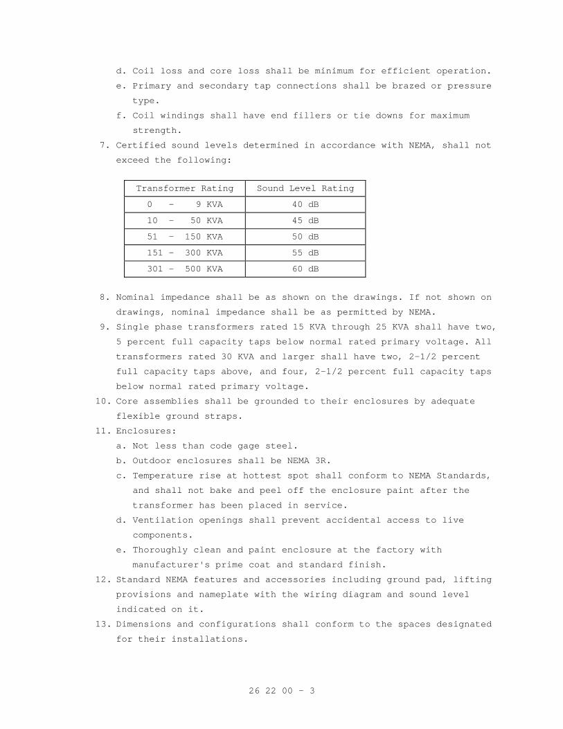
26 22 00 - 3
d. Coil loss and core loss shall be minimum for efficient operation.
e. Primary and secondary tap connections shall be brazed or pressure
type.
f. Coil windings shall have end fillers or tie downs for maximum
strength.
7. Certified sound levels determined in accordance with NEMA, shall not
exceed the following:
Transformer Rating Sound Level Rating
0 - 9 KVA 40 dB
10 - 50 KVA 45 dB
51 - 150 KVA 50 dB
151 - 300 KVA 55 dB
301 - 500 KVA 60 dB
8. Nominal impedance shall be as shown on the drawings. If not shown on
drawings, nominal impedance shall be as permitted by NEMA.
9. Single phase transformers rated 15 KVA through 25 KVA shall have two,
5 percent full capacity taps below normal rated primary voltage. All
transformers rated 30 KVA and larger shall have two, 2-1/2 percent
full capacity taps above, and four, 2-1/2 percent full capacity taps
below normal rated primary voltage.
10. Core assemblies shall be grounded to their enclosures by adequate
flexible ground straps.
11. Enclosures:
a. Not less than code gage steel. b. Outdoor enclosures shall be NEMA 3R. c. Temperature rise at hottest spot shall conform to NEMA Standards,
and shall not bake and peel off the enclosure paint after the
transformer has been placed in service.
d. Ventilation openings shall prevent accidental access to live
components.
e. Thoroughly clean and paint enclosure at the factory with
manufacturer's prime coat and standard finish.
12. Standard NEMA features and accessories including ground pad, lifting
provisions and nameplate with the wiring diagram and sound level
indicated on it.
13. Dimensions and configurations shall conform to the spaces designated
for their installations.
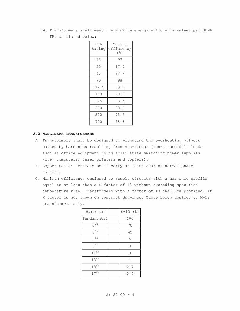
26 22 00 - 4
14. Transformers shall meet the minimum energy efficiency values per NEMA
TP1 as listed below:
kVA Rating
Output efficiency
(%)
15 97
30 97.5
45 97.7
75 98
112.5 98.2
150 98.3
225 98.5
300 98.6
500 98.7
750 98.8
2.2 NONLINEAR TRANSFORMERS
A. Transformers shall be designed to withstand the overheating effects caused by harmonics resulting from non-linear (non-sinusoidal) loads
such as office equipment using solid-state switching power supplies
(i.e. computers, laser printers and copiers).
B. Copper coils’ neutrals shall carry at least 200% of normal phase current.
C. Minimum efficiency designed to supply circuits with a harmonic profile equal to or less than a K factor of 13 without exceeding specified
temperature rise. Transformers with K factor of 13 shall be provided, if
K factor is not shown on contract drawings. Table below applies to K-13
transformers only.
Harmonic K-13 (%)
Fundamental 100
3rd 70
5th 42
7th 5
9th 3
11th 3
13th 1
15th 0.7
17th 0.6
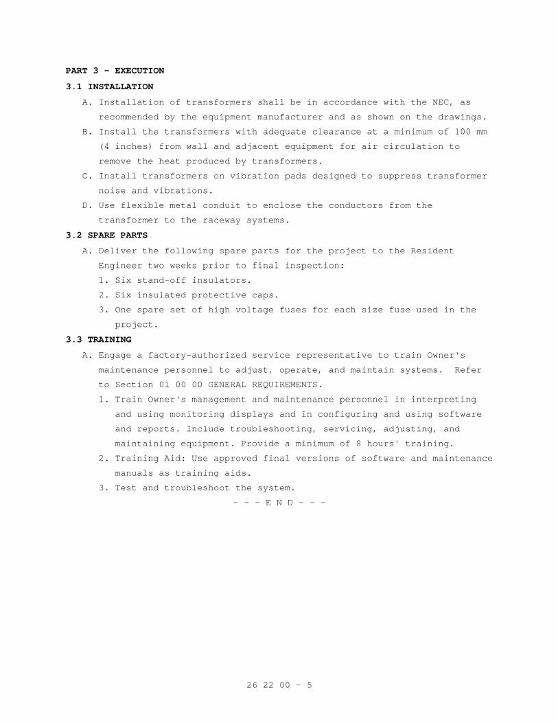
26 22 00 - 5
PART 3 - EXECUTION
3.1 INSTALLATION
A. Installation of transformers shall be in accordance with the NEC, as
recommended by the equipment manufacturer and as shown on the drawings.
B. Install the transformers with adequate clearance at a minimum of 100 mm
(4 inches) from wall and adjacent equipment for air circulation to
remove the heat produced by transformers.
C. Install transformers on vibration pads designed to suppress transformer
noise and vibrations.
D. Use flexible metal conduit to enclose the conductors from the
transformer to the raceway systems.
3.2 SPARE PARTS
A. Deliver the following spare parts for the project to the Resident
Engineer two weeks prior to final inspection:
1. Six stand-off insulators.
2. Six insulated protective caps.
3. One spare set of high voltage fuses for each size fuse used in the
project.
3.3 TRAINING
A. Engage a factory-authorized service representative to train Owner's
maintenance personnel to adjust, operate, and maintain systems. Refer
to Section 01 00 00 GENERAL REQUIREMENTS.
1. Train Owner's management and maintenance personnel in interpreting
and using monitoring displays and in configuring and using software
and reports. Include troubleshooting, servicing, adjusting, and
maintaining equipment. Provide a minimum of 8 hours' training.
2. Training Aid: Use approved final versions of software and maintenance
manuals as training aids.
3. Test and troubleshoot the system.
- - - E N D - - -
26 24 16 - 1
SECTION 26 24 16 PANELBOARDS
PART 1 - GENERAL
1.1 DESCRIPTION
This section specifies the furnishing, installation and connection of
panelboards.
1.2 RELATED WORK
A. Section 26 05 11, REQUIREMENTS FOR ELECTRICAL INSTALLATIONS: General
electrical requirements and items that are common to more than one
Section of Division 26.
B. Section 26 05 33, RACEWAY AND BOXES FOR ELECTRICAL SYSTEMS: Conduits
and outlet boxes.
C. Section 26 05 21, LOW-VOLTAGE ELECTRICAL POWER CONDUCTORS AND CABLES
(600 VOLTS AND BELOW): Cables and wiring.
D. Section 26 05 26, GROUNDING AND BONDING FOR ELECTRICAL SYSTEMS:
Requirements for personnel safety and to provide a low impedance path
for possible ground fault currents.
1.3 SUBMITTALS
A. Submit in accordance with Section 26 05 11, REQUIREMENTS FOR ELECTRICAL
INSTALLATIONS.
B. Shop Drawings:
1. Sufficient information, clearly presented, shall be included to
determine compliance with drawings and specifications.
2. Include electrical ratings, dimensions, mounting details, materials,
wiring diagrams accessories and weights of equipment. Complete
nameplate data including manufacturer’s name and catalog number.
C. Certification: Two weeks prior to final inspection, submit four copies
of the following to the Resident Engineer:
1. Certification that the material is in accordance with the drawings
and specifications has been properly installed, and that the loads
are balanced.
1.4 APPLICABLE PUBLICATIONS
Publications listed below (including amendments, addenda, revisions,
supplements and errata) form a part of this specification to the extent
referenced. Publications are referenced in the text by the basic
designation only.
A. National Electrical Manufacturers Association (NEMA):
PB-1-2006...............Panelboards
26 24 16 - 2
AB-1-2002...............Molded Case Circuit Breakers, Molded Case
Switches and Circuit Breaker Enclosures
B. National Fire Protection Association (NFPA):
70-2005 ................National Electrical Code (NEC)
70E-2004................Standard for Electrical Life Safety in the
Workplace
C. Underwriters Laboratories, Inc. (UL):
50-2003.................Enclosures for Electrical Equipment
67-2003.................Panel boards
489-2006................Molded Case Circuit Breakers and Circuit
Breaker Enclosures
PART 2 - PRODUCTS
2.1 PANELBOARDS
A. Panelboards shall be in accordance with UL, NEMA, NEC, and as shown on
the drawings.
B. Panelboards shall be standard manufactured products. All components of
the panelboards shall be the product and assembly of the same
manufacturer. All similar units of all panelboards to be of the same
manufacturer.
C. All panelboards shall be hinged “door in door” type with:
1. Interior hinged door with hand operated latch or latches as required
to provide access to circuit breaker operating handles only, not to
energized ports.
2. Outer hinged door shall be securely mounted to the panelboard box
with factory bolts, screws, clips or other fasteners requiring a
tool for entry, hand operated latches are not acceptable.
3. Push inner and outer doors shall open left to right.
D. All panelboards shall be completely factory assembled with molded case
circuit breakers. Include one-piece removable, inner dead front cover
independent of the panelboard cover.
E. Panelboards shall have main breaker or main lugs, bus size, voltage,
phase, top or bottom feed, and flush or surface mounting as scheduled
on the drawings.
F. Panelboards shall conform to NEMA PB-1, NEMA AB-1 and UL 67 and have
the following features:
1. Nonreduced size copper or aluminum bus bars, complete with current
ratings as shown on the panel schedules connection straps bolted
together and rigidly supported on molded insulators.
26 24 16 - 3
2. Bus bar connections to the branch circuit breakers shall be the
“distributed phase” or “phase sequence” type. Single-phase, three-
wire panelboard busing shall be such that when any two adjacent
single-pole breakers are connected to opposite phases, two-pole
breakers can be installed in any location. Three-phase, four-wire
busing shall be such that when any three adjacent single-pole
breakers are individually connected to each of the three different
phases, two-or three-pole breakers can be installed at any location.
Current-carrying parts of the bus assembly shall be plated. Mains
ratings shall be as shown.
3. Mechanical lugs furnished with panelboards shall be cast, stamped or
machined metal alloys of sizes suitable for the conductors indicated
to be connected thereto.
4. Neutral bus shall be 100% rated, mounted on insulated supports.
5. Grounding bus bar equipped with screws or lugs for the connection of
grounding wires.
6. Buses braced for the available short circuit current, but not less
than 22,000 amperes symmetrical for 120/208 volt and 120/240 volt
panelboards, and 14,000 amperes symmetrical for 277/480-volt
panelboards.
7. Branch circuit panels shall have buses fabricated for bolt-on type
circuit breakers.
8. Protective devices shall be designed so that they can be easily
replaced.
9. Where designated on panel schedule "spaces", include all necessary
bussing, device support and connections. Provide blank cover for
each space.
10. In two section panelboards, the main bus in each section shall be
full size. The first section shall be furnished with subfeed lugs
on the line side of main lugs only, or through-feed lugs for main
breaker type panels, and with cable connections to the second
section. Panelboard sections with tapped bus or crossover bus are
not acceptable.
11. Series rated panelboards are not permitted.
26 24 16 - 4
2.2 CABINETS AND TRIMS
A. Cabinets:
1. Provide galvanized steel cabinets to house panelboards. Cabinets for
outdoor panels shall be factory primed and suitably treated with a
corrosion-resisting paint finish meeting UL 50 and UL 67.
2. Cabinet enclosure shall not have ventilating openings.
3. Cabinets for panelboards may be of one-piece formed steel or of
formed sheet steel with end and side panels welded, riveted, or
bolted as required.
2.3 MOLDED CASE CIRCUIT BREAKERS FOR PANELBOARDS
A. Breakers shall be UL 489 listed and labeled, in accordance with the
NEC, as shown on the drawings, and as specified.
B. Circuit breakers in panelboards shall be bolt on type on phase bus bar
or branch circuit bar.
1. Molded case circuit breakers for lighting and appliance branch
circuit panelboards shall have minimum interrupting rating as
indicated but not less than:
a. 120/208 Volt Panelboard: 22,000 amperes symmetrical.
b. 120/240 Volt Panelboard: 22,000 amperes symmetrical.
c. 277/480 Volt Panelboard: 14,000 amperes symmetrical.
2. Molded case circuit breakers shall have automatic, trip free,
non-adjustable, inverse time, and instantaneous magnetic trips for
100-ampere frame or less. Magnetic trip shall be adjustable from 3X
to 10X for breakers with 600 ampere frames and higher. Factory
setting shall be HI, unless otherwise noted.
C. Breaker features shall be as follows:
1. A rugged, integral housing of molded insulating material.
2. Silver alloy contacts.
3. Arc quenchers and phase barriers for each pole.
4. Quick-make, quick-break, operating mechanisms.
5. A trip element for each pole, thermal magnetic type with long time
delay and instantaneous characteristics, a common trip bar for all
poles and a single operator.
6. Electrically and mechanically trip free.
7. An operating handle which indicates ON, TRIPPED, and OFF positions.
a. Line connections shall be bolted.
26 24 16 - 5
b. Interrupting rating shall not be less than the maximum short
circuit current available at the line terminals as indicated on
the drawings.
8. An overload on one pole of a multipole breaker shall automatically
cause all the poles of the breaker to open.
9. Shunt trips shall be provided where indicated
10. For circuit breakers being added to existing panelboards, coordinate
the breaker type with existing panelboards. Modify the panel
directory.
2.4 SEPARATELY ENCLOSED MOLDED CASE CIRCUIT BREAKERS
A. Where separately enclosed molded case circuit breakers are shown on the
drawings, provide circuit breakers in accordance with the applicable
requirements of those specified for panelboards.
B. Enclosures are to be of the NEMA types shown on the drawings. Where the
types are not shown, they are to be the NEMA type most suitable for the
environmental conditions where the breakers are being installed.
PART 3 - EXECUTION
3.1 INSTALLATION
A. Installation shall be in accordance with the Manufacturer’s
instructions, the NEC, as shown on the drawings, and as specified.
B. Locate panelboards so that the present and future conduits can be
conveniently connected. Coordinate the sizes of cabinets with
designated closet space.
C. In accordance with Section 09 91 00, PAINTING, paint the panelboard
system voltage, and feeder sizes as shown on the riser diagram in 1
inch block lettering on the inside cover of the cabinet door. Paint the
words "LIFE SAFETY BRANCH", "CRITICAL BRANCH", or "EQUIPMENT SYSTEM" as
applicable and the panel designation in one inch block letters on the
outside of the cabinet doors.
D. Install a typewritten schedule of circuits in each panelboard after
being submitted to and approved by the Resident Engineer. Schedules,
after approval, shall be typed on the panel directory cards and
installed in the appropriate panelboards, incorporating all applicable
contract changes pertaining to that schedule. Include the room numbers
and items served on the cards.
26 24 16 - 6
E. Mount the panelboard fully aligned and such that the maximum height of
the top circuit breaker above finished floor shall not exceed 1980 mm
(78 inches). For panelboards that are too high, mount panelboard so
that the bottom of the cabinets will not be less than 150 mm (6 inches)
above the finished floor.
F. For panelboards located in areas accessible to the public, paint the
exposed surfaces of the trims, doors, and boxes with finishes to match
surrounding surfaces after the panelboards have been installed.
G. Directory-card information shall be typewritten to indicate outlets,
lights, devices, and equipment controlled and final room numbers served
by each circuit and shall be mounted in holders behind protective
covering.
H. Where new panels are to be installed in existing backboxes, backboxes
shall have rust and scale removed from inside. Paint inside of
backboxes with rust preventive paint before the new panel interior is
installed. Provide new trim and doors for these panels. Covers shall
fit tight to the box with no gaps between the cover and the box.
I. Provide ARC flash identification per NFPA 70E.
- - - E N D - - -
26 27 26 - 1
SECTION 26 27 26 WIRING DEVICES
PART 1 - GENERAL
1.1 DESCRIPTION
This section specifies the furnishing, installation and connection of
wiring devices.
1.2 RELATED WORK
A. Section 26 05 11, REQUIREMENTS FOR ELECTRICAL INSTALLATIONS: General
electrical requirements that are common to more than one section of
Division 26.
B. Section 26 05 33, RACEWAY AND BOXES FOR ELECTRICAL SYSTEMS: Conduits and
outlets boxes.
C. Section 26 05 21, LOW-VOLTAGE ELECTRICAL POWER CONDUCTORS AND CABLES
(600 VOLTS AND BELOW): Cables and wiring.
D. Section 26 05 26, GROUNDING AND BONDING FOR ELECTRICAL SYSTEMS:
Requirements for personnel safety and to provide a low impedance path to
ground for possible ground fault currents.
1.3 SUBMITTALS
A. In accordance with Section 26 05 11, REQUIREMENTS FOR ELECTRICAL
INSTALLATIONS, submit the following:
B. Shop Drawings:
1. Sufficient information, clearly presented, shall be included to
determine compliance with drawings and specifications.
2. Include electrical ratings, dimensions, mounting details,
construction materials, grade and termination information.
C. Manuals: Two weeks prior to final inspection, deliver four copies of the
following to the Resident Engineer: Technical data sheets and
information for ordering replacement units.
D. Certifications: Two weeks prior to final inspection, submit four copies
of the following to the Resident Engineer: Certification by the
Contractor that the devices comply with the drawings and specifications,
and have been properly installed, aligned, and tested.
1.4 APPLICABLE PUBLICATIONS
A. Publications listed below (including amendments, addenda, revisions,
supplements and errata) form a part of this specification to the extent
referenced. Publications are referenced in the text by basic designation
only.
B. National Fire Protection Association (NFPA):
70-02...................National Electrical Code (NEC)
26 27 26 - 2
C. National Electrical Manufacturers Association (NEMA):
WD 1-99.................General Color Requirements for Wiring Devices
WD 6-02 ................Wiring Devices – Dimensional Requirements
D. Underwriter’s Laboratories, Inc. (UL):
5-96....................Surface Metal Raceways and Fittings
20-00...................General-Use Snap Switches
231-98..................Power Outlets
467-93..................Grounding and Bonding Equipment
498-01..................Attachment Plugs and Receptacles
943-03..................Ground-Fault Circuit-Interrupters
PART 2 - PRODUCTS
2.1 RECEPTACLES
A. Manufacturers: Lutron ‘Decora’ or Engineer Pre-Approved Equivalent.
B. General: All receptacles shall be listed by Underwriters Laboratories,
Inc., as hospital grade (green dot identification) and conform to NEMA
WD 1. (EXCEPTION - Receptacle types which have no listing as hospital
grade but are listed by UL in their respective categories or receptacles
indicated on the drawings as “not hospital grade”).
1. Mounting straps shall be plated steel, with break-off plaster ears
and shall include a self-grounding feature. Terminal screws shall be
brass, brass plated or a copper alloy metal.
2. Receptacles shall have provisions for back wiring with separate metal
clamp type terminals (four min.) and side wiring from four captively
held binding screws.
C. Duplex receptacles shall be single phase, 20 ampere, 120 volts, 2-pole,
3-wire, and conform to the NEMA 5-20R configuration in NEMA WD 6. The
duplex type shall have break-off feature for two-circuit operation. The
ungrounded pole of each receptacle shall be provided with a separate
terminal.
1. Bodies shall be ivory in color.
2. Switched duplex receptacles shall be wired so that only the top
receptacle is switched. The remaining receptacle shall be unswitched.
3. Duplex Receptacles on Emergency Circuit:
a. Bodies shall be red in color. Wall plates shall be red with the
word "EMERGENCY" engraved in 6 mm, (1/4 inch) white letters.
b. In rooms without emergency powered general lighting, the emergency
receptacles shall be of the self-illuminated type.
26 27 26 - 3
4. Ground Fault Interrupter Duplex Receptacles: Shall be an integral
unit suitable for mounting in a standard outlet box.
a. Ground fault interrupter shall be hospital grade and consist of a
differential current transformer, solid state sensing circuitry
and a circuit interrupter switch. It shall be rated for operation
on a 60 Hz, 120 volt, 20-ampere branch circuit. Device shall have
nominal sensitivity to ground leakage current of five milliamperes
and shall function to interrupt the current supply for any value
of ground leakage current above five milliamperes (+ or – 1
milliamp) on the load side of the device. Device shall have a
minimum nominal tripping time of 1/30th of a second. Devices shall
meet UL 943.
5. Safety Type Duplex Receptacles:
a. Bodies shall be gray in color.
b. Shall be hospital grade, as above with the following additional
requirements.
1) Shall permit current to flow only while a standard plug is in
the proper position in the receptacle.
2) Screws exposed while the wall plates are in place shall be the
tamperproof type.
c. Shall be installed in the following locations:
1) Psychiatric rooms and wards, O.T. areas, PMR areas and other
locations where psychiatric patients are not under constant
supervision.
2) Housekeeping quarters, buildings, waiting areas and lobbies
where children might be present.
6. Isolated Ground Type Duplex Receptacles:
a. Bodies shall be orange in color.
b. Shall be hospital grade and UL listed as “Isolated Ground”.
7. Duplex Receptacles (not hospital grade): Shall be the same as
hospital grade duplex receptacles except for the "hospital grade"
listing and as follows.
a. Bodies shall be brown phenolic compound supported by a plated
steel mounting strap having plaster ears.
b. Shall be NEMA WD 1 heavy duty type.
D. Receptacles; 20, 30 and 50 ampere, 250 volts: Shall be complete with
appropriate cord grip plug. Devices shall meet UL 231.
26 27 26 - 4
E. Weatherproof Receptacles: Shall consist of a duplex receptacle, mounted
in box with a gasketed, weatherproof, cast metal cover plate and cap
over each receptacle opening. The cap shall be permanently attached to
the cover plate by a spring-hinged flap. The weatherproof integrity
shall not be affected when heavy duty specification or hospital grade
attachment plug caps are inserted. Cover plates on outlet boxes mounted
flush in the wall shall be gasketed to the wall in a watertight manner.
F. Lamp Receptacles for Outlet Box Mounting:
1. For use on standard 75 mm (3 inch) and 100 mm (4 inch) outlet boxes.
2. Keyless, porcelain body and skirt supporting a medium screw shell
socket, and integral 3-wire grounding receptacle shall have screw
terminals and a minimum rating of 600 watts.
3. Porcelain neck shall have shade holder groove.
2.2 TOGGLE SWITCHES AND DIMMERS
A. Manufacturers: Lutron ‘Decora’ or Engineer Pre-Approved Equivalent.
B. Toggle switches shall be totally enclosed tumbler type with bodies of
phenolic compound. Toggle handles shall be ivory in color unless
otherwise specified. The rocker type switch is not acceptable and will
not be approved.
1. Switches installed in hazardous areas shall be explosion proof type
in accordance with the NEC and as shown on the drawings.
2. Shall be single unit toggle, butt contact, quiet AC type, heavy-duty
general-purpose use with an integral self grounding mounting strap
with break-off plasters ears and provisions for back wiring with
separate metal wiring clamps and side wiring with captively held
binding screws.
3. Shall be color coded for current rating, listed by Underwriters
Laboratories, Inc., and meet the requirements of NEMA WD 1,
Heavy-Duty and UL 20.
4. Ratings:
a. 120 volt circuits: 20 amperes at 120-277 volts AC.
b. 277 volt circuits: 20 amperes at 120-277 volts AC.
5. The switches shall be mounted on the striker plate side of doors.
6. Incorporate barriers between switches with multigang outlet boxes
where required by the NEC.
7. Switches connected to isolated type electrical power systems shall be
double pole.
8. All toggle switches shall be of the same manufacturer.
26 27 26 - 5
C. Dimmers: Incandescent modular dimming systems.
1. Incandescent dimming system shall be 2000 watt modular type, with
capability for "slaving" larger loads from the "master". System shall
have capability of adding additional "slaves", controlled from the
original basic dimmer "master". All units shall track with "master".
Control units shall be single-phase manual control as shown on the
drawings. Dimmers shall have low and intensity adjustment and
built-in transient voltage protection and fused on the load side. All
remote mounted units shall be completely enclosed in integral metal
housing. "Master", "Slaves" and controls shall be of the same
manufacturer. All dimmers shall be listed by Underwriters
Laboratories, Inc.
D. Dimmers: Incandescent lamp loads. Wall-mounted incandescent dimmers
shall be specification grade with capability of raising and lowering the
lighting from completely off at extreme counter-clockwise rotation, to
full intensity. Dimmers shall include an “off” position. Dimmers shall
maintain full load rating even when two or more units are installed
adjacent to one another. All wall-mounted dimmers shall be of the same
manufacturer.
E. Dimmers: Fluorescent lamp loads. Wall-mounted fluorescent lamp dimmers
shall be specification grade with large control knob and shall be
capable of raising and lowering the lighting from completely off at
extreme counter-clockwise rotation, to full intensity. Dimmers shall
include an “off” position. Dimmers shall have low end intensity
adjustment and maintain full load rating even when two or more units are
installed adjacent to one another. All wall-mounted dimmers shall be of
the same manufacturer. Dimming ballast shall be provided for each F32
rapid start lamp or pair of lamps. Dimmers shall have adequate capacity
for the load served and the environment in which installed.
2.3 WALL PLATES
A. Wall plates for switches and receptacles shall be type 302 stainless
steeL. Oversize plates are not acceptable.
B. Color shall be ivory unless otherwise specified.
C. Standard NEMA design, so that products of different manufacturers will
be interchangeable. Dimensions for openings in wall plates shall be
accordance with NEMA WD1.
D. For receptacles or switches mounted adjacent to each other, wall plates
shall be common for each group of receptacles or switches.
E. In psychiatric areas, wall plates shall have tamperproof screws and
beveled edges.
26 27 26 - 6
F. Wall plates for data, telephone or other communication outlets shall be
as specified in the associated specification.
2.4 SURFACE MULTIPLE-OUTLET ASSEMBLIES
A. Assemblies shall conform to the requirements of NFPA 70 and UL 5.
B. Shall have the following features:
1. Enclosures:
a. Thickness of steel shall be not less than 1 mm (0.040 inch) steel
for base and cover. Nominal dimension shall be 40 by 70 mm (1-1/2 by
2-3/4 inches) with inside cross sectional area not less than 2250
square mm (3.5 square inches). The enclosures shall be thoroughly
cleaned, phosphatized and painted at the factory with primer and the
manufacturer's standard baked enamel or lacquer finish.
2. Receptacles shall be duplex, hospital grade. See paragraph
'RECEPTACLES' in this section. Device cover plates shall be the
manufacturer's standard corrosion resistant finish and shall not
exceed the dimensions of the enclosure.
3. Unless otherwise shown on drawings, spacing of the receptacles along
the strip shall be 600 mm (24 inches) on centers.
4. Wires within the assemblies shall be not less than No. 12 AWG copper,
with 600 volt ratings.
5. Installation fittings shall be designed for the strips being
installed including bends, offsets, device brackets, inside
couplings, wire clips, and elbows.
6. Bond the strips to the conduit systems for their branch supply
circuits.
PART 3 - EXECUTION
3.1 INSTALLATION
A. Installation shall be in accordance with the NEC and as shown as on the
drawings.
B. Ground terminal of each receptacle shall be bonded to the outlet box
with an approved green bonding jumper, and also connected to the green
equipment grounding conductor.
- - - E N D - - -
26 29 11 - 1
SECTION 26 29 11 LOW-VOLTAGE MOTOR STARTERS
PART 1 - GENERAL
1.1 DESCRIPTION
All motor starters and motor control stations including installation and
connection (whether furnished with the equipment specified in other
Divisions or otherwise) shall meet these specifications.
1.2 RELATED WORK
A. Other sections which specify motor driven equipment, except elevator
motor controllers.
B. Section 26 05 11, REQUIREMENTS FOR ELECTRICAL INSTALLATIONS: General
electrical requirements and items that are common to more than one
Section of Division 26.
C. Section 26 05 26, GROUNDING AND BONDING FOR ELECTRICAL SYSTEMS:
Requirements for personnel safety and to provide a low impedance path
for possible ground fault currents.
1.3 SUBMITTALS
Submit in accordance with Section 26 05 11, REQUIREMENTS FOR ELECTRICAL
INSTALLATIONS:
A. Shop Drawings:
1. Sufficient information, clearly presented, shall be included to
determine compliance with drawings and specifications.
2. Include electrical ratings, dimensions, weights, mounting details,
materials, running over current protection, size of enclosure, over
current protection, wiring diagrams, starting characteristics,
interlocking and accessories.
B. Manuals:
1. Submit, simultaneously with the shop drawings, companion copies of
complete maintenance and operating manuals, including technical data
sheets, wiring diagrams and information for ordering replacement
parts.
a. Wiring diagrams shall have their terminals identified to
facilitate installation, maintenance and operation.
b. Wiring diagrams shall indicate internal wiring for each item of
equipment and interconnections between the items of equipment.
c. Elementary schematic diagrams shall be provided for clarity of
operation.
26 29 11 - 2
2. Two weeks prior to the project final inspection, submit four copies
of the final updated maintenance and operating manual to the Resident
Engineer. (Update manual to include any information necessitated by
shop drawing approval).
C. Certification: Two weeks prior to final inspection, unless otherwise
noted, submit four copies of the following certifications to the
Resident Engineer:
1. Certification by the manufacturer that the controllers have passed
the factory 24-hour operational test. (This certification must be
furnished to the Resident Engineer prior to shipping the controller
to the job site.)
2. Certification by the manufacturer that high voltage motor
controller(s) conforms to the requirements of the drawings and
specifications. (This certification must be furnished to the Resident
Engineer prior to shipping the controller to the job site.).
3. Certification that the equipment has been properly installed,
adjusted, and tested.
1.4 APPLICABLE PUBLICATIONS
A. Publications listed below (including amendments, addenda, revisions,
supplements and errata) form a part of this specification to the extent
referenced. Publications are referenced in the text by basic designation
only.
B. Institute of Electrical and Electronic Engineers (IEEE):
519-92..................Recommended Practices and Requirements for
Harmonic Control in Electrical Power Systems
C37.90.1-02.............Standard Surge Withstand Capability (SWC) Tests
for Protective Relays and Relay Systems
C. National Electrical Manufacturers Association (NEMA):
ICS 1-00................Industrial Control and Systems General
Requirements
ICS 1.1-03..............Safety Guidelines for the Application,
Installation and Maintenance of Solid State
Control
ICS 2-00................Industrial Control and Systems, Controllers,
Contactors and Overload Relays Rated 600 Volts
DC
ICS 6-01................Industrial Control and Systems Enclosures
ICS 7-00................Industrial Control and Systems Adjustable-Speed
Drives
26 29 11 - 3
ICS 7.1-00..............Safety Standards for Construction and Guide for
Selection, Installation and Operation of
Adjustable-Speed Drive Systems
D. National Fire Protection Association (NFPA):
70-02...................National Electrical Code (NEC)
E. Underwriters Laboratories Inc. (UL):
508-99..................Industrial Control Equipment
PART 2 - PRODUCTS
2.1 MOTOR STARTERS, GENERAL
A. Motor starters shall be in accordance with the requirements of the IEEE,
NEC, NEMA (ICS 1, ICS 1.1, ICS 2, ICS 6, ICS 7 and ICS 7.1) and UL.
B. Shall have the following features:
1. Separately enclosed unless part of another assembly.
2. Circuit breakers and safety switches within the motor controller
enclosures shall have external operating handles with lock-open
padlocking provisions and shall indicate the ON and OFF positions.
3. Motor control circuits:
a. Shall operate at not more than 120 volts.
b. Shall be grounded except as follows:
1) Where isolated control circuits are shown.
2) Where manufacturers of equipment assemblies recommend that the
control circuits be isolated.
c. Incorporate a separate, heavy duty, control transformer within
each motor controller enclosure to provide the control voltage for
each motor operating over 120 volts.
d. Incorporate over current protection for both primary and secondary
windings of the control power transformers in accordance with the
NEC.
4. Overload current protective devices:
a. Overload relay (thermal or induction type.
b. One for each pole.
c. Manual reset on the door of each motor controller enclosure.
d. Correctly sized for the associated motor's rated full load
current.
e. Check every motor controller after installation and verify that
correct sizes of protective devices have been installed.
f. Deliver four copies of a summarized list to the Resident Engineer,
which indicates and adequately identifies every motor controller
installed. Include the catalog numbers for the correct sizes of
protective devices for the motor controllers.
26 29 11 - 4
5. Hand-Off-Automatic (H-O-A) switch is required unless specifically
stated on the drawings as not required for a particular starter. H-O-
A switch is not required for manual motor starters.
6. Incorporate into each control circuit a 120-volt, solid state time
delay relay (ON delay), minimum adjustable range from 0.3 to 10
minutes, with transient protection. Time delay relay is not required
where H-O-A switch is not required.
7. Auxiliary contacts, pilot lights, pushbuttons and other devices and
accessories as shown on the drawings or otherwise required.
8. Enclosures:
a. Shall be the NEMA types shown on the drawings for the motor
controllers.
b. Shall be the NEMA types which are the most suitable for the
environmental conditions where the motor controllers are being
installed.
c. Doors mechanically interlocked to prevent opening unless the
breaker or switch within the enclosure is open. Provision for
padlock must be provided.
d. Enclosures shall be primed and finish coated at the factory with
the manufacturer’s prime coat and standard finish.
C. Motor controllers incorporated with equipment assemblies shall also be
designed for the specific requirements of the assemblies.
D. Additional requirements for specific motor controllers, as indicated in
other sections, shall also apply.
E. Provide a disconnecting means or safety switch near and within sight of
each motor. Provide all wiring and conduit required to facilitate a
complete and code complied installation.
F. Refer to paragraph, MOTOR CONTROL STATIONS, in this section for
additional requirements.
2.2 MANUAL MOTOR STARTERS
A. Shall be in accordance with applicable requirements of 2.1 above.
B. Manual motor starters.
1. Starters shall be AC, general-purpose Class A, manually operated type
with full voltage controller for induction motors, rated in
horsepower.
2. Units shall include overload and low voltage protection, red pilot
light, NO auxiliary contact and toggle operator.
C. Fractional horsepower manual motor starters.
1. Starters shall be AC, general-purpose Class A, manually operated with
full voltage controller for fractional horsepower induction motors.
26 29 11 - 5
2. Units shall include thermal overload protection, red pilot light and
toggle operator.
D. Motor starting switches.
1. Switches shall be AC, general-purpose Class A, manually operated type
with full voltage controller for fractional horsepower induction
motors.
2. Units shall include thermal overload protection, red pilot light low
voltage protection, auxiliary contact and toggle operator.
2.3 MAGNETIC MOTOR STARTERS
A. Shall be in accordance with applicable requirements of 2.1 above.
B. Starters shall be AC, general-purpose, Class A magnetic controllers for
induction motors rated in horsepower. Minimum size 0.
C. Where combination motor starters are used, combine starter with
protective or disconnect device in a common enclosure.
D. Provide phase loss protection for each starter, with contacts to de-
energize the starter upon loss of any phase.
2.4 REDUCED VOLTAGE MOTOR CONTROLLERS
A. Shall be in accordance with applicable portions of 2.1 above.
B. Shall be installed where shown for motors on the contract drawings.
C. Shall be the type shown on the drawings or included in Section 22 62 00,
VACUUM SYSTEMS FOR HEALTHCARE FACILITIES and Section 22 63 00, GAS
SYSTEMS FOR HEALTHCARE FACILITIES.
D. Shall have closed circuit transition for the types which can incorporate
such transition.
E. Shall limit inrush currents to not more than 70 percent of the locked
rotor currents.
F. Provide phase loss protection for each starter, with contacts to de-
energize the starter upon loss of any phase.
2.5 HIGH VOLTAGE MOTOR CONTROLLERS
A. Shall be in accordance with applicable portions of 2.1 above.
B. Shall have the following additional features:
1. Metal enclosed, free-standing, air break, reduced voltage, primary
reactor, drawout type combined with fused disconnect switch.
2. Shall include the following components:
a. Three pole, air break, drawout type, start contactor.
b. Three pole, air break, drawout type, run contactor. Primary
reactor with taps for 50, 65 and 80 percent of line voltage.
d. Definite time transfer relay.
e. Three current limiting, power type fuses.
f. Control power transformer, protected with current limiting fuses.
26 29 11 - 6
g. Three current transformers and over current protective devices.
h. Zero-sequence current transformers and associated devices for
ground fault protection.
i. Under voltage protection.
j. Protection against single phasing.
k. Stator thermal protection.
l. Indicating type ammeter and selector switch.
m. Red and green indicating lights.
3. A separate enclosure for each motor controller.
4. Shall be isolated by an externally operated mechanism. The secondary
of the control power transformer shall also be opened by that device.
5. Suitable and adequate compartments and barriers for high voltage
components. Isolate the power bus from the normally accessible
compartments.
6. High voltage line receptacles shall be shuttered automatically when
conductors are in the disconnected position and the disconnection
shall be clearly indicated.
7. Interlocks shall include prevention of the following:
a. Inadvertent operation of the isolating mechanism under load.
b. Opening of the high voltage compartment before the controller is
isolated.
c. Closing of the line contactor while the door is open.
8. Current and potential transformers for operating remote recording
watt-hour and demand meters and the indicating meters at the motor
controller.
9. Lock-open padlocking provisions.
10. Furnish accessories as recommended by the manufacturer of the motor
controllers to facilitate convenient operation and maintenance of the
controllers.
C. Interrupting ratings shall be not less than the maximum short circuit
currents available where the controllers are being installed or as
indicated on the drawings.
2.6 VARIABLE SPEED MOTOR CONTROLLERS
A. Shall be in accordance with applicable portions of 2.1 above.
26 29 11 - 7
B. Shall be solid state, micro processor-based with adjustable frequency
and voltage, three phase output capable of driving standard NEMA B
design, three phase alternating current induction motors at full rated
speed. The drives shall utilize a full wave bridge design incorporating
diode rectifier circuitry with pulse width modulation (PWM). Other
control techniques are not acceptable. Silicon controlled rectifiers
(SCR) shall not be used in the rectifying circuitry. The drives shall be
designed to be used on variable torque loads and shall be capable of
providing sufficient torque to allow the motor to break away from rest
upon first application of power.
C. Shall be rated for input power of 208 or 480 volts, three phase, 60 Hz.
Unit shall be capable of operating within voltage parameters of plus 10
to minus 10 percent of line voltage, and be suitably rated for the full
load amps of the maximum watts (HP) within its class.
D. Each controller shall be factory tested at maximum watts (HP), rated
full load current and at an ambient temperature of 40 degrees C for a
period of not less than 24 hours. If a component fails, it shall be
replaced and the test restarted for the full time period. A certified
copy of the factory Test Report shall be furnished to the Resident
Engineer prior to shipping the controller to the job site.
E. Controllers shall have the following features:
1. Isolated power for control circuits.
2. Manually re-settable motor overload protection for each phase.
3. Adjustable current limiting circuitry to provide soft motor starting.
Maximum starting current shall not exceed 200 percent of motor full
load current.
4. Independent acceleration and deceleration time adjustment, manually
adjustable from 2 to 30 seconds. (Set timers to the equipment
manufacturer's recommended time in the above range.)
5. Provide 4 to 20 ma current follower circuitry for interface with
mechanical sensor devices.
6. Automatic frequency adjustment from 20 Hz to 60 Hz.
7. Provide circuitry to initiate an orderly shutdown when any of the
conditions listed below occur. The controller shall not be damaged by
any of these electrical disturbances and shall automatically restart
when the conditions are corrected:
a. Incorrect phase sequence.
b. Single phasing.
c. Over voltage in excess of 10 percent.
d. Under voltage in excess of 10 percent.
26 29 11 - 8
e. Running over current above 110 percent (shall not automatically
reset for this condition.)
f. Instantaneous overcurrent above 150 percent (shall not
automatically reset for this condition).
g. Surge voltage in excess of 1000 volts.
h. Short duration power outages of 12 cycles or less (i.e.,
distribution line switching, generator testing, and automatic
transfer switch operations).
8. Provide automatic shutdown on receipt of a power transfer warning
signal from an automatic transfer switch. Controller shall
automatically restart motor after the power transfer.
F. Minimum efficiency shall be 95 percent at 100 percent speed and
85percent at 50 percent speed.
G. The displacement power factor of the controller shall not be less than
95 percent under any speed or load condition.
H. Controllers shall include a door interlocked fused safety disconnect
switch or door interlocked circuit breaker switch which will disconnect
all input power.
I. Include a by-pass starter with circuitry to protect and isolate the
variable speed controller. When the variable speed controller is in the
by-pass mode, the solid-state components shall be isolated from the
power supply on both the line and motor side.
J. The following accessories are to be door mounted:
1. AC Power on light.
2. Ammeter (RMS motor current).
3. HAND-OFF-AUTOMATIC switch.
4. Manual speed control in HAND mode.
5. System protection lights indicating that the system has shutdown and
will not automatically restart.
6. System protection light indicating that the system has shutdown but
will restart when conditions return to normal.
7. Manual variable speed controller by-pass switch.
8. Diagnostic shutdown indicator lights for each shutdown condition.
9. Provide two N.O. and two N.C. dry contacts rated 120 volts, 10
amperes, 60 HZ for remote indication of the following:
a. System shutdown with auto restart.
b. System shutdown without auto restart.
C. System running.
26 29 11 - 9
10. Incorporate into each control circuit a 120-volt, time delay relay
(ON delay), adjustable from 0.3-10 minutes, with transient
protection. Provide transformer/s for the control circuit/s.
11. Controller shall not add any current or voltage transients to the
input AC power distribution system nor shall transients from other
devices on the AC power distribution system affect the controller.
Controllers shall be protected to comply with IEEE C37.90.1 and
UL-508. Line noise and harmonic voltage distortion shall not exceed
the values allowed by IEEE 519. Include Harmonic filter within the
enclosure of the VFD.
2.7 MOTOR CONTROL STATIONS
A. Shall have the following features:
1. Designed for suitably fulfilling the specific control functions for
which each station is being installed.
2. Coordinate the use of momentary contacts and maintained contacts with
the complete motor control systems to insure safety for people and
equipment.
3. Each station shall have two pilot lights behind red and green jewels
and a circuit to its motor controller. Connect the lamps so they will
be energized as follows:
a. Red while the motor is running.
b. Green while the motor is stopped.
4. Where two or more stations are mounted adjacent to each other,
install a common wall plate, except where the designs of the stations
make such common plates impracticable.
5. Identify each station with a permanently attached individual
nameplate, of laminated black phenolic resin with a white core and
engraved lettering not less than 6 mm (1/4-inch) high. Identify the
motor by its number or other designation and indicate the function
fulfilled by the motor.
B. Components of Motor Control Circuits:
1. Shall also be designed and arranged so that accidental faulting or
grounding of the control conductors will not be able to start the
motors.
2. Use of locking type STOP pushbuttons or switches, which cause motors
to restart automatically when the pushbuttons or switches are
released, will not be permitted.
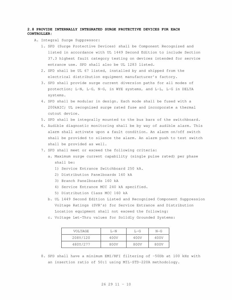
26 29 11 - 10
2.8 PROVIDE INTERNALLY INTEGRATED SURGE PROTECTIVE DEVICES FOR EACH CONTROLLER:
A. Integral Surge Suppressor:
1. SPD (Surge Protective Devices) shall be Component Recognized and
listed in accordance with UL 1449 Second Edition to include Section
37.3 highest fault category testing on devices intended for service
entrance use. SPD shall also be UL 1283 listed.
2. SPD shall be UL 67 listed, installed by and shipped from the
electrical distribution equipment manufacturer’s factory.
3. SPD shall provide surge current diversion paths for all modes of
protection; L-N, L-G, N-G, in WYE systems, and L-L, L-G in DELTA
systems.
4. SPD shall be modular in design. Each mode shall be fused with a
200kAIC; UL recognized surge rated fuse and incorporate a thermal
cutout device.
5. SPD shall be integrally mounted to the bus bars of the switchboard.
6. Audible diagnostic monitoring shall be by way of audible alarm. This
alarm shall activate upon a fault condition. An alarm on/off switch
shall be provided to silence the alarm. An alarm push to test switch
shall be provided as well.
7. SPD shall meet or exceed the following criteria:
a. Maximum surge current capability (single pulse rated) per phase
shall be:
1) Service Entrance Switchboard 250 kA.
2) Distribution Panelboards 160 kA
3) Branch Panelboards 160 kA
4) Service Entrance MCC 240 kA specified.
5) Distribution Class MCC 160 kA
b. UL 1449 Second Edition Listed and Recognized Component Suppression
Voltage Ratings (SVR’s) for Service Entrance and Distribution
Location equipment shall not exceed the following:
c. Voltage Let-Thru values for Solidly Grounded Systems:
VOLTAGE L-N L-G N-G
208Y/120 400V 400V 400V
480Y/277 800V 800V 800V
8. SPD shall have a minimum EMI/RFI filtering of –50Db at 100 kHz with
an insertion ratio of 50:1 using MIL-STD-220A methodology.
26 29 11 - 11
9. SPD shall have the following diagnostic features: transient counter,
status lights on each phase, and one set of 1 NO and 1 NC auxiliary
dry contacts for alarming.
10. SPD shall have a warranty for a period of five years, incorporating
unlimited replacements of suppressor parts if transients destroy them
during the warranty period. Warranty shall be the responsibility of
the electrical distribution equipment manufacturer and shall be
supported by their respective field service division.
PART 3 - EXECUTION
3.1 INSTALLATION
A. Install motor control equipment in accordance with manufacturer’s
recommendations, the NEC, NEMA and as shown on the drawings.
B. Install Variable Speed Motor Controllers in accordance with
manufacturers recommendations, the NEC, as shown on the drawings and in
accordance with NEMA ICS 7.1.C.
C. Furnish and install heater elements in motor starters to match the
installed motor characteristics.
3.2 SPARE PARTS
Two weeks prior to the final inspection, provide one complete set of
spare fuses (including heater elements) for each starter/controller
installed on this project.
- - - E N D - - -
26 29 21 - 1
SECTION 26 29 21 DISCONNECT SWITCHES
PART 1 - GENERAL
1.1 DESCRIPTION
This section specifies the furnishing, installation and connection of
low voltage disconnect switches.
1.2 RELATED WORK
A. General electrical requirements and items that is common to more than
one section of Division 26: Section 26 05 11, REQUIREMENTS FOR
ELECTRICAL INSTALLATIONS.
B. Conduits for cables and wiring: Section 26 05 33, RACEWAY AND BOXES FOR
ELECTRICAL SYSTEMS.
C. Cables and wiring: Section 26 05 21, LOW-VOLTAGE ELECTRICAL POWER
CONDUCTORS AND CABLES (600 VOLTS AND BELOW.
D. Motor rated toggle switches: Section 26 29 11, LOW-VOLTAGE MOTOR
STARTERS.
E. Requirements for personnel safety and to provide a low impedance path
for possible ground faults: Section 26 05 26, GROUNDING AND BONDING FOR
ELECTRICAL SYSTEMS.
1.3 SUBMITTALS
A. Submit in accordance with Section 26 05 11, REQUIREMENTS FOR ELECTRICAL
INSTALLATIONS.
B. Shop Drawings:
1. Include sufficient information, clearly presented to determine
compliance with drawings and specifications.
2. Include electrical ratings, dimensions, mounting details, materials,
enclosure types, fuse type and class.
3. Show the specific switch and fuse proposed for each specific piece of
equipment or circuit.
C. Manuals:
1. Provide complete maintenance and operating manuals for disconnect
switches, including technical data sheets, wiring diagrams, and
information for ordering replacement parts. Deliver four copies to
the Resident Engineer two weeks prior to final inspection.
2. Identify terminals on wiring diagrams to facilitate maintenance and
operation.
3. Wiring diagrams shall indicate internal wiring and any interlocking.
26 29 21 - 2
D. Certification: Two weeks prior to final inspection, deliver to the
Resident Engineer four copies of the certification that the equipment
has been properly installed, adjusted, and tested.
1.4 APPLICABLE PUBLICATIONS
A. Publications listed below (including amendments, addenda, revisions,
supplements and errata) form a part of this specification to the extent
referenced. Publications are referenced in the text by the basic
designation only.
B. National Electrical Manufacturers Association (NEMA):
KS l-01.................Enclosed and Miscellaneous Distribution
Equipment Switches (600 Volts Maximum)
C. National Fire Protection Association (NFPA):
70-05...................National Electrical Code (NEC)
D. Underwriters Laboratories, Inc. (UL):
98-98...................Enclosed and Dead-Front Switches
198C-89.................High-Interrupting-Capacity Fuses, Current
Limiting Types
198E-94.................Class R Fuses
977-99..................Fused Power-Circuit Devices
PART 2 - PRODUCTS
2.1 LOW VOLTAGE FUSIBLE SWITCHES RATED 600 AMPERES AND LESS
A. Shall be quick-make, quick-break type in accordance with UL 98, NEMA KS
1 and NEC.
B. Shall have a minimum duty rating, NEMA classification General Duty (GD)
for 240 volts and NEMA classification Heavy Duty (HD) for 277/480 volts.
C. Shall be horsepower rated.
D. Shall have the following features:
1. Switch mechanism shall be the quick-make, quick-break type.
2. Copper blades, visible in the OFF position.
3. An arc chute for each pole.
4. External operating handle shall indicate ON and OFF position and
shall have lock-open padlocking provisions.
5. Mechanical interlock shall permit opening of the door only when the
switch is in the OFF position, defeatable by a special tool to permit
inspection.
6. Fuse holders for the sizes and types of fuses specified.
7. Electrically operated switches shall only be installed where shown on
the drawings.
8. Solid neutral for each switch being installed in a circuit which
includes a neutral conductor.
26 29 21 - 3
9. Ground Lugs: One for each ground conductor.
10. Enclosures:
a. Shall be the NEMA types shown on the drawings for the switches.
b. Where the types of switch enclosures are not shown, they shall be
the NEMA types which are most suitable for the environmental
conditions where the switches are being installed. Unless
otherwise indicated on the plans, all outdoor switches shall be
NEMA 3R.
c. Shall be finished with manufacturer’s standard gray baked enamel
paint over pretreated steel (for the type of enclosure required).
2.2 LOW VOLTAGE UNFUSED SWITCHES RATED 600 AMPERES AND LESS
Shall be the same as Low Voltage Fusible Switches Rated 600 Amperes and
Less, but no fuses.
2.3 LOW VOLTAGE FUSIBLE SWITCHES RATED OVER 600 AMPERES TO 1200 AMPERES
Shall be the same as Low Voltage Fusible Switches Rated 600 Amperes and
Less, except for the minimum duty rating which shall be NEMA
classification Heavy Duty (HD). These switches shall also be horsepower
rated.
2.4 MOTOR RATED TOGGLE SWITCHES
Refer to Section 26 29 11, LOW-VOLTAGE MOTOR STARTERS for motor rated
toggle switches.
2.5 IDENTIFICATION SIGNS
A. Install nameplate identification signs on each disconnect switch to
identify the equipment controlled.
B. Nameplates shall be laminated black phenolic resin with a white core,
with engraved lettering, a minimum of 6 mm (1/4-inch) high. Secure
nameplates with screws.
PART 3 - EXECUTION
3.1 INSTALLATION
A. Install disconnect switches in accordance with the NEC and as shown on
the drawings.
B. Fusible disconnect switches shall be furnished complete with fuses.
3.2 SPARE PARTS
Two weeks prior to the final inspection, furnish one complete set of
spare fuses for each fusible disconnect switch installed on the project.
Deliver the spare fuses to the Resident Engineer.
- - - E N D - - -
26 41 00 - 1
SECTION 26 41 00 FACILITY LIGHTNING PROTECTION
PART 1 - GENERAL
1.1 DESCRIPTION
This section specifies the furnishing and installation of a complete
master labeled lightning protection system, complying with NFPA 780, UL
96 and UL 96A.
1.2 RELATED WORK
A. Section 26 05 11, REQUIREMENTS FOR ELECTRICAL INSTALLATIONS: General
electrical requirements that are common to more than one section of
Division 26.
B. Section 26 05 26, GROUNDING AND BONDING FOR ELECTRICAL SYSTEMS:
Requirements for personnel safety and to provide a low impedance path to
ground for possible ground faults.
1.3 SUBMITTALS
A. In accordance with Section 26 05 11, REQUIREMENTS FOR ELECTRICAL
INSTALLATIONS, submit the following:
B. Shop Drawings:
1. Isometric and plan views showing layout and connections to the
required metal surfaces.
2. Show the methods of mounting the system to the adjacent construction.
C. Qualifications: Submit proof that the installer of the lightning
protection system has had suitable and adequate experience installing
other lightning protection systems, and is capable of installing the
system as recommended by the manufacturer of the equipment.
D. Certification: Two weeks prior to final inspection, submit four copies
of the following certifications to the Resident Engineer:
1. Certification that the lightning protection system has been properly installed and tested.
2. Certification that the lightning protection system has been inspected by a UL representative and has been approved by UL without
variation.
1.4 APPLICABLE PUBLICATIONS
A. Publications listed below (including amendments, addenda, revisions,
supplements, and errata) form a part of this specification to the extent
referenced. Publications are referenced in the text by designation only.
B. National Fire Protection Association (NFPA):
70-02...................National Electrical Code (NEC)
26 41 00 - 2
780-00..................Standard for the Installation of Lightning
Protection Systems
C. Underwriters Laboratories, Inc. (UL):
96-94...................Lightning Protection Components
96A-01..................Installation Requirements for Lightning
Protection Systems
PART 2 - PRODUCTS
2.1 MATERIALS
A. Attach master labels "A" or "B" to each item by its manufacturer as
evidence that the materials have been manufactured in conformance with
the UL Standards for master label lightning protection materials.
B. In additional to conformance to UL 96, the component material
requirements are as follows:
1. Conductors: Electrical grade copper.
2. Air terminals: Solid copper, not less than 9 mm (3/8 inch) diameter,
with sharp nickel-plated points.
3. Ground rods: Copper clad steel, not less than 13 mm (1/2 inch)
diameter by 2400 mm (8 feet) long.
4. Ground plates: Solid copper, not less than 2 mm (1/16 inch) thick.
5. Tubing: Stiff copper or brass.
C. Anchors and fasteners: Bolt type which are most suitable for the
specific anchor and fastener installations.
PART 3 - EXECUTION
3.1 INSTALLATION
A. Install the conductors as inconspicuously as practical and with the
proper bends.
B. Install the vertical conductors within the concealed cavity of exterior
walls. Run the conductors to the exterior at elevations below the
finished grade and make the ground connections to the earth outside of
the building or stack perimeter.
C. Make connections of dissimilar metal with bimetallic type fittings to
prevent electrolytic action.
D. Use the exothermic welding type connections that form solid metal joints
in the main vertical and horizontal conductors, and for connections that
are not exposed in the finish work.
E. Protect copper conductors with stiff copper or brass tubing, which
enclose the conductors from the top to the bottom of the tubing, between
300 mm (one foot) below and 2100 mm (seven feet) above the finished
grade.
26 41 00 - 3
F. Sheath copper conductors, which pass over cast stone, cut stone,
architectural concrete and masonry surfaces, with not less than a 2 mm
(1/16 inch) thickness of lead to prevent staining of the exterior finish
surfaces.
G. For the earth connections, install ground rods and ground plates, and
the conductor connections to them and the main water pipes in the
presence of the Resident Engineer. For the conductors located outside of
the building or stack, install the conductors not less than 600 mm (two
feet) below the finished grade.
H. For structural steel buildings, connect the steel framework of the
buildings to the main water pipe near the water system entrance to the
building.
I. Connect exterior metal surfaces, located within 900 mm (three feet) of
the lightning protection system conductors, to the lightning protection
system conductors to prevent flashovers.
J. Grounding: Test the ground resistance to earth by standard methods and
conform to the ground resistance requirements specified in Section 26 05
26, GROUNDING AND BONDING FOR ELECTRICAL SYSTEMS.
K. Where shown, use the structural steel framework or reinforcing steel as
the main conductor:
1. Weld or bond the non-electrically-continuous sections together and
make them electrically continuous.
2. Verify the electrical continuity by measuring the ground resistances
to earth at the ground level, at the top of the building or stack,
and at intermediate points with a sensitive ohmmeter. Compare the
resistance readings.
3. Connect the air terminals together with an exterior conductor
connected to the structural steel framework at not more than 18000 mm
(60 foot) intervals.
4. Install ground connections to earth at not more than 18000 mm (60
foot) intervals around the perimeter of the building.
5. Weld or braze bonding plates, not less than 200 mm (eight inches)
square, to cleaned sections of the steel and connect the conductors
to the plates.
6. Do not pierce the structural steel in any manner. Connections to the
structural steel shall conform to UL Publication No. 96A.
L. For smoke stacks, the following additional requirements shall apply:
1. Extend air terminals from approximately 900 mm (three feet) below the
top of the smoke stacks to approximately 900 mm (three feet) above
the top of the stacks.
26 41 00 - 4
2. Securely seat and rivet the vertical conductors into bronze cable
connectors. Cross-connect the vertical conductors at approximately
the midpoint between the top and bottom of the smoke stacks.
M. For obstruction lights, the following additional requirements shall
apply:
1. Extend air terminals 300 mm (one foot) above the top of the light
fixtures and securely clamp to the light fixture supports.
2. Install 600 volt class lightning arresters. Connect the arresters to
the lightning circuit conductors at suitable locations, and ground
and bond them to the lightning protection system.
N. When the lightning protection systems have been installed, have the
systems inspected by a UL representative. Obtain and install a UL
numbered master label "C" for each of the lightning protection systems
at the location directed by the UL representative and the Resident
Engineer.
O. Where the drawings show the new lightning protection system connected to
an existing lightning protection system without a UL master label, the
new portion of the lightning system still requires inspection and labels
as specified above for new work.
- - - E N D - - -
26 51 00 - 1
SECTION 26 51 00 INTERIOR LIGHTING
PART 1 - GENERAL
1.1 DESCRIPTION
This section specifies the furnishing, installation and connection of
the interior lighting systems.
1.2 RELATED WORK
A. Section 26 05 11, REQUIREMENTS FOR ELECTRICAL INSTALLATIONS: General
requirements that are common to more than one section of Division 26.
B. Section 26 05 21, LOW-VOLTAGE ELECTRICAL POWER CONDUCTORS AND CABLES
(600 VOLTS AND BELOW): Cables and wiring.
C. Section 26 27 26, WIRING DEVICES: Wiring devices used as part of the
lighting systems.
D. Section 26 05 26, GROUNDING AND BONDING FOR ELECTRICAL SYSTEMS:
Requirements for personnel safety and to provide a low impedance path to
ground for possible ground fault currents.
1.3 QUALITY ASSURANCE
A. Refer to Paragraph, QUALIFICATIONS, in Section 26 05 11, REQUIREMENTS
FOR ELECTRICAL INSTALLATIONS.
1.4 SUBMITTALS
A. In accordance with Section 26 05 11, REQUIREMENTS FOR ELECTRICAL
INSTALLATIONS, submit the following:
B. Shop Drawings:
1. Sufficient information, clearly presented, shall be included to
determine compliance with drawings and specifications.
2. Include electrical ratings, dimensions, mounting details, materials,
required clearances, terminations, wiring and connection diagrams,
photometric data, ballasts, lenses, louvers, lamps, and controls.
3. When catalog data and/or shop drawings for fluorescent fixtures are
submitted for approval, photometric data from an independent testing
laboratory shall be included with the submittal, indicating average
brightness and efficiency of the fixture, as specified in
specification or as shown on the drawings. Coefficient of utilization
data will not be considered a suitable substitute.
C. Manuals:
1. Submit, simultaneously with the shop drawings companion copies of complete maintenance and operating manuals including technical data
sheets, and information for ordering replacement parts.
26 51 00 - 2
2. Two weeks prior to the final inspection, submit four copies of the final updated maintenance and operating manuals, including any
changes, to the Resident Engineer.
D. Certifications:
1. Two weeks prior to final inspection, submit four copies of the
following certifications to the Resident Engineer:
a. Certification by the Contractor that the equipment has been
properly installed, adjusted, and tested.
b. Include with shop drawings, certification from the manufacturers
that all electronic high-frequency ballasts meet the transient
protection required by IEEE C62.41, Cat. A. Include with initial
shop drawing submittal.
1.5 APPLICABLE PUBLICATIONS
A. Publications listed below (including amendments, addenda, revisions,
supplements, and errata) form a part of this specification to the extent
referenced. Publications are referenced in the text by designation only.
B. American National Standards Institute (ANSI):
C78.1-91................Fluorescent Lamps - Rapid-Start Types -
Dimensional and Electrical Characteristics
C78.2-91................Fluorescent Lamps - Preheat-Start Types -
Dimensional and Electrical Characteristics
C78.3-91................Fluorescent Lamps - Instart Start and Cold-
Cathode Types - Dimensional and Electrical
Characteristics
C78.376-91..............Chromaticity of Fluorescent Lamps (ANSI/NEMA
C78/376-96)
C. Certified Ballast Manufacturers Association (CBM):
Requirements for Ballast Certification
D. Institute of Electrical and Electronic Engineers (IEEE):
C62.41-91...............Recommended Practice on Surge Voltage in Low
Voltage AC Power Circuits
E. National Fire Protection Association (NFPA):
70-02...................National Electrical Code (NEC)
101-00..................Life Safety Code
F. National Electrical Manufacturer's Association (NEMA)
C82.1-97................Ballasts for Fluorescent Lamps - Specifications
C82.2-02................Method of Measurement of Fluorescent Lamp
Ballasts
C82.4-02................Ballasts for High-Intensity-Discharge and Low-
Pressure Sodium Lamps
26 51 00 - 3
C82.11-02...............High Frequency Fluorescent Lamp Ballasts
G. Underwriters Laboratories, Inc. (UL):
496-96..................Edison-Base Lampholders
542-99..................Lampholders, Starters, and Starter Holders for
Fluorescent Lamps
844-95..................Electric Lighting Fixtures for Use in Hazardous
(Classified) Locations
924-95..................Emergency Lighting and Power Equipment
935-01..................Fluorescent-Lamp Ballasts
1029-94.................High-Intensity-Discharge Lamp Ballasts
1598-00.................Luminaires
H. Federal Communications Commission (FCC):
Code of Federal Regulations (CFR), Title 47, Part 18
PART 2 - PRODUCTS
2.1 LIGHTING FIXTURES (LUMINAIRES)
A. Shall be in accordance with NFPA 70, UL 1598 and shall be as shown on
drawings and as specified.
B. Sheet Metal:
1. Shall be formed to prevent warping and sagging. Housing, trim and
lens frame shall be true, straight (unless intentionally curved) and
parallel to each other as designed.
2. Wireways and fittings shall be free of burrs and sharp edges and
shall accommodate internal and branch circuit wiring without damage
to the wiring.
3. Where lighting fixtures are detailed with minimum 20 gauge housing,
minimum 22 gauge housings will be acceptable provided they have
strengthening embossed rib and break formations, which give the
equivalent rigidity of a 20 gauge housing.
4. When installed, any exposed fixture housing surface, trim frame, door
frame and lens frame shall be free of light leaks; lens doors shall
close in a light tight manner.
5. Hinged door closure frames shall operate smoothly without binding
when the fixture is in the installed position, and latches shall
function easily by finger action without the use of tools.
C. Ballasts shall be serviceable while the fixture is in its normally
installed position, and shall not be mounted to removable reflectors or
wireway covers unless so specified.
26 51 00 - 4
D. Lamp Sockets:
1. Fluorescent: Lampholder contacts shall be the biting edge type or
phosphorous-bronze with silver flash contact surface type and shall
conform to the applicable requirements of UL 542. Contacts for
recessed double contact lampholders and for slimline lampholders
shall be silver plated. Lampholders for bi-pin lamps, with the
exception of those for "U" type lamps, shall be of the telescoping
compression type, or of the single slot entry type requiring a
one-quarter turn of the lamp after insertion.
2. Incandescent: Shall have porcelain enclosures and conform to the
applicable requirements of UL 496.
3. High Intensity Discharge (H.I.D.): Shall have porcelain enclosures.
E. Recessed incandescent fixtures mounted in an insulated ceiling shall be
listed for use in insulated ceilings.
F. Fluorescent fixtures with louvers or light transmitting panels shall
have hinges, latches and safety catches to facilitate safe, convenient
cleaning and relamping. Vapor tight fixtures shall have pressure
clamping devices in lieu of the latches.
G. Mechanical Safety: Lighting fixture closures (lens doors, trim frame,
hinged housings, etc.) shall be retained in a secure manner by captive
screws, chains, captive hinges or fasteners such that they cannot be
accidentally dislodged during normal operation or routine maintenance.
H. Metal Finishes:
1. The manufacturer shall apply his standard finish (unless otherwise
specified) over a corrosion resistant primer, after cleaning to free
the metal surfaces of rust, grease, dirt and other deposits. Edges of
pre-finished sheet metal exposed during forming, stamping or shearing
processes shall be finished in a similar corrosion resistant manner
to match the adjacent surface(s). Fixture finish shall be free of
stains or evidence of rusting, blistering, or flaking.
2. Interior light reflecting finishes shall be white with not less than
85 percent reflectances, except where otherwise shown on the drawing.
3. Exterior finishes shall be as shown on the drawings.
I. Provide all lighting fixtures with a specific means for grounding their
metallic wireways and housings to an equipment grounding conductor.
J. Light Transmitting Components for Fluorescent Fixtures:
1. Shall be 100 percent virgin acrylic plastic or water white, annealed,
crystal glass.
26 51 00 - 5
2. Flat lens panels shall have not less than 3.2 mm (1/8 inch) of
average thickness. The average thickness shall be determined by
adding the maximum thickness to the minimum unpenetrated thickness
and dividing the sum by 2.
3. Unless otherwise specified, lenses, diffusers and louvers shall be
retained firmly in a metal frame by clips or clamping ring in such a
manner as to allow expansion and contraction of the lens without
distortion or cracking.
K. Lighting Fixtures in Hazardous Areas: Fixtures shall be suitable for
installation in flammable atmospheres (Class and Group) as defined in
NFPA 70 and shall comply with UL 844.
L. Compact fluorescent fixtures shall be manufactured specifically for
compact fluorescent lamps with ballasts integral to the fixture.
Assemblies designed to retrofit incandescent fixtures are prohibited
except when specifically indicated for renovation of existing fixtures.
Fixtures shall be designed for lamps as specified.
2.2 FLUORESCENT LAMP BALLASTS
A. Where applicable, fluorescent lamps and ballasts shall comply with the
National Energy Policy Act of 1992.
B. Ballasts shall comply with NEMA 82.1, 82.2 and 82.11, NFPA 70, and UL
935 unless otherwise specified.
C. Lamp types F32T8 and F32T8/U shall be operated by electronic, high
frequency ballasts. All other fluorescent lamp types shall be operated
by the standard energy saving electromagnetic core-and-coil ballasts.
For these applications, the lamps shall be operated by core-and-coil
ballasts where specifically required on the drawings as "core-and-coil".
D. Electronic high-frequency ballasts:
1. Ballasts shall operate the lamps at a frequency between 20 and 60 KHz
from an input frequency of 60Hz.
2. Ballast package:
a. Size: The ballast case shall be sized to be physically inter-
changeable with standard core-and-coil ballasts and suitable for
standard mounting in new or existing lighting fixtures.
b. Case marking: Mark the ballast to indicate the required supply
voltage, frequency, RMS current, current surge during starting,
input watts, and power factor at the design center voltage, open
circuit voltage, crest factor and efficacy.
26 51 00 - 6
3. Performance:
a. Light output:
1) At the design voltage, the light output shall be at least equal
to that obtained by a core-and-coil ballasted system meeting
ANSI, NEMA and CBM standards. The comparison test shall be
measured in the same fixture at 25 degrees C (plus or minus one
degree) ambient room temperature.
2) Tests shall be made in fixtures designed only for the number of
lamps being tested.
3) For other applications (higher ambients, etc.) the tests should
be operated with equivalent lamp wall temperatures plus or
minus 4 degrees C.
b. Efficacy: The efficacy of the high-frequency, electronically
ballasted system shall be at least 15 percent greater than the
equivalent CBM core-and-coil ballasted system (see "Light output"
above).
c. Starting: The ballast shall be capable of starting and maintaining
operation of lamps at an ambient temperature of 10 degrees C (50
degree F) or more for an input voltage of plus or minus 10 percent
about the center design voltage unless otherwise indicated. The
ballast shall never be started in the instant start mode at any
temperature.
d. Operation:
1) The ballast shall safely and reliably operate in a room ambient
temperature from 10 degrees C (50 degree F) to 40 degrees C
(105 degree F).
2) The light output shall not vary by more than plus or minus 5
percent for a plus or minus 10 percent variation of the input
voltage about the center design voltage. Light output shall
remain constant for a plus or minus 5 percent variation of the
input voltage.
3) The ballast shall operate the lamps in a manner that will not
adversely curtail the normal life of the lamp.
e. Transient protection: The ballast shall comply with IEEE C62.41,
Cat. A.
f. Flicker: The flicker shall be less than 5 percent and without
visible flicker.
g. Noise: The audible noise levels should be equivalent to or better
than the Class A rating of CBM certified ballasts.
26 51 00 - 7
h. Electromagnetic Interference (EMI) and Radio Frequency
Interference (RFI): The EMI and RFI limits shall meet the
requirements of the Federal Communications Commission Rules and
Regulations (CFR 47 Part 18).
i. Rated life: The ballast shall have a rated life of 10 years or
30,000 hours (based on a 10 hour day).
j. The two-lamp ballast shall safely operate two F32T8 RS, 32- watt
lamps or two F32T8/U lamps. The single lamp ballast shall safely
operate one F32T8 RS, 32-watt lamp or one F32T8/U lamp.
k. Power factor: Not less than 95 percent.
l. Reliability:
1) Labels: Ballasts must be labeled or listed by UL and CBM/ETL.
2) Submit, simultaneously with shop drawings, a certified test
report by an independent testing laboratory showing that the
electronic ballasts meet or exceed all the performance
requirements in this specification.
m. Total harmonic distortion (THD) shall be less than 10 percent.
E. Core-and-coil ballasts (for lamps other than F32T8 and F32T8/U or where
shown on drawings as "core-and-coil"):
1. Shall be rapid starting type.
2. Shall comply with NEMA 82.1 and UL 935.
3. Shall be UL Class P with automatic-resetting, internal, thermal
protection.
4. Shall be CBM/ETL certified.
5. Power factor shall be not less than 95 percent. Capacitors in
ballasts shall not contain PCB (Polychlorinated Biphenyl) fluids or
other fluids recognized as hazardous when discharged into the
environment.
6. Sound ratings shall be Class A or better, except for ballast sizes
which are not available with Class A ratings, as standard products
from any manufacturer. Ballasts which are not available with Class A
ratings shall have the quietest ratings available.
26 51 00 - 8
7. Where core-and-coil ballasts are specified or detailed in lieu of the
normally required electronic high-frequency types, two lamp ballasts
shall be energy-saving type, UL listed to operate F40T12 rapid start
lamps for both standard 40 watt lamps and the reduced wattage 35/34
watts energy-saving lamps. Lamp output shall be within 5 percent of
nominal rating. When operating energy-saving lamps, the input watts
to the ballast shall not exceed 78 watts at 120 V.A.C. or 79 watts at
277 V.A.C. Energy-saving type ballasts should not be used in ambient
temperatures below manufacturer's recommendations.
F. Ballasts for lighting fixtures controlled by dimming devices shall be
the electronic, high frequency type as specified herein, equipped for
dimming and conform to the recommendations of the manufacturer of the
associated dimming devices to assure satisfactory operation of the
lighting system.
G. All ballasts serving straight or "U" type lamps shall be mounted by four
non-turning studs (or captive bolts) equipped with lock washers and nuts
or locking type nuts, or by four thread cutting (TC) sheet metal screws
which are firmly secured against the fixture body (or wireway) to
maximize dissipation of heat and minimize noise. Exception: electronic
high-frequency ballasts may be mounted at a minimum of two points, one
at each end of unit.
H. Ballasts shall be serviceable while the fixture is in its normally
installed position, and shall not be mounted to removable reflectors or
wireway covers unless so specified.
I. To facilitate multi-level lamp switching, lamps within fixture shall be
wired with the outermost lamp at both sides of the fixture on the same
ballast, the next inward pair on another ballast and so on to the
innermost lamp (or pair of lamps). Within a given room, each switch
shall uniformly control the same corresponding lamp (or lamp pairs) in
all fixture units that are being controlled.
J. Where three-lamp fixtures are indicated, unless switching arrangements
dictate otherwise, utilize a common two-lamp ballast to operate the
center lamp in pairs of adjacent units that are mounted in a continuous
row. The ballast fixture and slave-lamp fixture shall be factory wired
with leads or plug devices to facilitate this circuiting. Individually
mounted fixtures and the odd fixture in a row shall utilize a
single-lamp ballast for operation of the center lamp.
26 51 00 - 9
2.3 BALLASTS FOR HIGH INTENSITY DISCHARGE FIXTURES:
A. Shall comply with NEMA 82.4 and UL 1029.
B. Shall have individual overcurrent protection sized in accordance with
the manufacturer's recommendations.
C. Shall have integral thermal protection where the fixture is recessed in
an interior ceiling.
D. Shall be the constant wattage, high power factor type or the reactor
high power factor type. Capacitors shall not contain PCB
(Polychlorinated Biphenyl) fluids or other fluids recognized as
hazardous when discharged into the environment.
E. Shall have not less than Class B sound ratings for interior fixtures,
when available. Ballasts which are not available with Class B ratings
shall be of the next standard rating.
2.4 LAMPS
A. Fluorescent Lamps:
1. Rapid start fluorescent lamps shall comply with ANSI C78.1; preheat-
start type shall comply with ANSI C78.2; and instant-start and cold-
cathode lamps shall comply with ANSI C78.3.
2. Chromacity of fluorescent lamps shall comply with ANSI C78.376.
3. The lamps shall include the F32T8, F32T8/U 32 watt energy saving type
and EPACT approved F40T12 type if specifically required by contract
drawings for special applications.
4. Except as indicated below, lamps shall be energy saving type, have a
color temperature between 3500 and 4100°K, a Color Rendering Index
(CRI) of not less than 75, and an initial lumen output not less than
2800. "U" tube lamps shall have the same color temperature and CRI
limits as the above.
a. In utility areas (Electrical, Communication and Mechanical)
Service rooms and closets), maintenance closets and non-medical
storage spaces, utilize energy saving light-white lamps.
b. In areas with ambient temperatures below 60 degrees use the 40
watt version of the lamp above.
c. Over the beds in Intensive Care, Coronary Care, Recovery, Life
Support, and Observation and Treatment areas; Electromyographic,
Autopsy (Necropsy), Surgery, and certain dental rooms
(Examination, Oral Hygiene, Oral Surgery, Recovery, Labs,
Treatment, and X-Ray) use color corrected lamps having a CRI of 90
or above and a correlated color temperature between 5000 and
6000°K.
26 51 00 - 10
d. Other areas as indicated on the drawings.
B. Incandescent lamps shall be the general service, inside frosted type
rated 130 volts except where otherwise shown on the drawings.
C. High Intensity Discharge Lamps:
1. Mercury vapor lamps shall be ANSI type "DX". Lamps in open or
louvered fixtures mounted less than 4500 mm (15 feet) above the
finished floor (or grade) shall be of the safety type in which the
arc will automatically extinguish if the outer glass envelope becomes
broken.
2. Multi-vapor lamps shall be as defined on the detail drawings.
3. High pressure sodium lamps shall be as defined on the detail
drawings.
D. Compact Fluorescent Lamps: Shall be 3500°K, 10,000 hours average rated
life, and as follows:
1. T4, twin tube, rated as indicated.
2. T4, double twin tube rated as indicated.
2.5 OCCUPANT SENSOR LIGHTING CONTROL SYSTEMS
A. General: An dual technology sensor shall be utilized to control the
"On-Off" actuation of fluorescent or incandescent lighting loads. It
shall provide control of an isolated set of contacts on exposure to a
perceived change in environmental conditions indicating the presence or
absence of one or more persons. It shall maintain the contacts closed in
the presence of continued changes (due to human presence) at similar
intensity and rate. It shall open the contacts at a nominal time after
the changes cease.
B. Passive Sensor System: Sensor(s) shall react to changes of radiated
infrared energy, indicating the activity of one or more human bodies in
the area covered:
1. Range of detection: The sensor(s) shall provide effective coverage of
a room, sensing the presence of one or more people in the room in
order to turn the lights on. The ceiling mounted sensor's area of
coverage shall be approximately a 4200 mm (14 feet) diameter circle
at 1800 mm (6 feet) away. Provide sufficient units to give full
coverage as measured 750 mm (30 inches) above the floor. A
field-of-view adjustment feature shall be provided to allow
orientation to various room operating conditions.
26 51 00 - 11
2. Sensor placement: Locate the sensor(s) in accordance with the
manufacturer's recommendations to maximize energy savings by avoiding
nuisance activation due to sudden temperature or air flow changes.
Locate the units within 1800 mm (6 feet) horizontally of work
stations or major points of activity, including the center of room
entrance doors.
C. Active Sensor System: Sensor(s) shall react to reflective changes to
generated ultrasonic radiation (crystal controlled, 24 to 42kHz),
indicating the activity of one or more persons in the area covered.
1. Range of detection: On ceilings below 3600 mm (twelve feet) in
height, a single direction sensor shall cover approximately a 9 x 9 m
(30 feet x 30 feet) area; a two directional unit a 18 x 9 m (60 feet
x 30 feet) area; and a two-way corridor unit a total distance of 27 m
(90 feet). The sensors shall be equipped with a concealed but
accessible sensitivity control to tune the unit to specific room
conditions.
2. Sensor placement: Locate the sensor(s) in accordance with the
manufacturer's recommendations to maximize energy savings by avoiding
nuisance activation due to predictable non-human motion activities.
Give particular attention to work station or major areas of activity
and the coverage of room entrance doors.
D. Timing/Function: Shall not be user adjustable. Lighting shall remain on
with one or more persons within the covered area. The system shall be
factory set to maintain lights on for a minimum of 8 minutes and not
longer than 12 minutes after the area of coverage is vacated. For
testing purposes, there shall be a means to change the pre-set time
delay to 30 seconds or less.
E. Control Unit: The system shall have a switching relay(s) capable of
switching the fluorescent or incandescent loads as required. Contacts
shall be rated at a minimum of 15 Amps at voltages to 277, with expected
cycles of operation in excess of 100K. Power derived from a current
limiting 24 volt transformer shall power the system and the unit must be
packaged for installation on a standard 200 mm x 200 mm (4 inch x 4
inch) NEMA box enclosure. The unit shall be wired through a conventional
wall switch to provide an over-ride system "Off" and active "Off-On"
functioning.
F. Field Wiring: The wiring between the control unit and sensor(s) shall be
an insulated multi-conductor, #22 gauge Poly Vinyl Chloride (PVC)
jacketed cable.
26 51 00 - 12
2.6 REMOTE CONTROL SWITCHING FOR INDOOR LIGHTING SYSTEMS
A. Shall be rated for continuous-duty service.
B. Electric contacts shall be precious metal surface.
C. Magnetic contactors and relays shall be electrically-operated and
mechanically-held.
D. Characteristics of the components and the total resistances of the
circuits throughout the systems shall be such that the systems will
operate satisfactorily in every respect while the branch circuit power
supply voltage to each system is within a 105-130 volt range at 60 Hz.
E. Wall switches shall be the momentary contact type suitable for mounting
in a single gang outlet box space and compatible with the standard
design wall plates as specified.
F. Where shown on the drawings, incorporate the components in panelboards
behind separate doors and mount them on sound absorbing materials.
G. Install circuit breaker or fuse protection for the control circuits.
H. Low voltage remote control system shall be DC type, operating at not
greater than 30 volts, and meeting the requirements for Class 2 circuits
in Article 725 of the NEC.
2.7 RADIO-INTERFERENCE-FREE FLUORESCENT FIXTURES
A. Shall be specially designed for suppressing radio-frequency energy
produced within the fixtures. The Rules and Regulations of FCC (CFR 47,
Part 18) shall apply.
B. Lenses shall have a light-transparent layer of metal permanently bonded
to them, and in positive contact with the steel housing or equal to
prevent the radio-frequency interferences from passing through the
lenses. The effective light transmittance of the lenses shall be not
less than 75 percent.
C. Install line filters within the body of the fixtures and wired in series
with the supply circuit conductors to eliminate the transmission of
radio frequency energy into the supply circuit.
2.8 FLUORESCENT BEDLIGHT FIXTURES
A. Requirements:
1. Fixed or movable arms are not acceptable.
2. Exposed surfaces shall remain cool to the touch.
3. Major portion of the light shall be directed upwards and outwards
through lenses. Balance of the light shall be directed downwards
through lenses to produce low brightness surfaces with minimum
contrast as viewed by the patients from their normal viewing angles
in bed.
26 51 00 - 13
4. Shall provide not less than 110 lx (10 footcandles) (average) of
general room illumination measured 750 mm (30 inches) above the
floor.
5. Shall provide 330 lx (30 footcandles) on the reading surfaces for the
patients while in a normal prone or normal sit-up position in bed.
B. Provide 4-position, pull cord switch on the fluorescent bedlight within
easy reach of the patient while in a normal prone position in bed. The
switches shall enable the patient to control the upward and downward
portion of the light separately and simultaneously, to include an off
position, except in single bed rooms where the switch shall enable the
patient to energize and de-energize the downward light only. In the
single bed rooms, provide a 2-position pull cord switch for "on-off"
control of the downward lamps.
C. Bedlight fixtures shall be rated for 120 volt operation.
2.9 X-RAY FILM ILLUMINATORS
A. Shall be the high-intensity type, flush-mounted in the walls. Multiples
of the basic unit may be combined in a common housing.
B. Shall have the following features:
1. Fluorescent lighting, designed to provide uniform diffusion of the
light.
2. Box dimensions approximately 525 mm (21 inches) high, 350 mm (14
inches) wide and 100 mm (4 inches) deep.
3. Frame shall be satin chrome-plated brass or stainless steel and shall
extend approximately 40 mm (1-1/2 inches) from the edges of the box.
4. Viewing glass shall be the heat resistant, borosilicate type or 100
percent virgin acrylic plastic and not less than 3 mm (1/8 inch)
thick.
5. Viewing glass shall have adequate dimensions so the films will not
overlap the frame and will be positioned with respect to the light
source for even illumination without shadows.
6. An ON-OFF switch.
7. Power supply voltage shall be 120 volts, 60 Hz.
C. Fluorescent lamps shall be the cool-white, rapid-start type.
D. Ballast shall be low leakage type with leakage not exceeding 30
microamperes.
2.10 EXIT LIGHT FIXTURES
A. Exit light fixtures shall meet applicable requirements of NFPA 101 and
UL 924.
B. Housing and Canopy:
1. Shall be made of cast or extruded aluminum, or rolled steel.
26 51 00 - 14
2. Optional steel housing shall be a minimum 20 gauge thick or
equivalent strength aluminum.
3. Steel housing shall have baked enamel over corrosion resistant, matte
black or ivory white primer.
C. Door frame shall be cast or extruded aluminum, and hinged with latch.
D. Finish shall be satin or fine-grain brushed aluminum.
E. There shall be no radioactive material used in the fixtures.
F. Fixtures:
1. Inscription panels shall be cast or stamped aluminum a minimum of
2.25 mm (0.090 inch) thick, stenciled with 150 mm (6 inch) high
letters, baked with red color stable plastic or fiberglass. Lamps
shall be luminous red Light Emitting Diodes (LED) mounted in center
of letters on red color stable plastic or fiberglass. The LED shall
be rated minimum 25 years life; maximum of 3.5 watts for single face
and 7 watts for double-faced fixtures that do not use diffuser panels
in front of the LEDs. LED exit light fixtures that use diffuser
panels shall require a maximum of 1.0 watt per fixture for single or
double face fixtures.
2. Double-Faced Fixtures: Provide double-faced fixtures where required
or as shown on drawings.
3. Directional Arrows: Provide directional arrows as part of the
inscription panel where required or as shown on drawings. Directional
arrows shall be the "chevron-type" of similar size and width as the
letters and meet the requirements of NFPA 101.
G. Voltages: Fixtures shall be wired for 277-volt operation.
PART 3 - EXECUTION
3.1 INSTALLATION
A. Installation shall be in accordance with the NEC, manufacturer's
instructions and as shown on the drawings or specified.
B. Align, mount and level the lighting fixtures uniformly.
C. Avoid interference with and provide clearance for equipment. Where the
indicated locations for the lighting fixtures conflict with the
locations for equipment, change the locations for the lighting fixtures
by the minimum distances necessary as approved by the Resident Engineer.
D. For suspended lighting fixtures, the mounting heights shall provide the
clearances between the bottoms of the fixtures and the finished floors
as shown on the drawings.
E. Fluorescent bed light fixtures shall be attached to the studs in the
walls. Attachment to gypsum board only is not acceptable.
26 51 00 - 15
F. Lighting Fixture Supports:
1. Shall provide support for all of the fixtures. Supports may be
anchored to channels of the ceiling construction, to the structural
slab or to structural members within a partition, or above a
suspended ceiling.
2. Shall maintain the fixture positions after cleaning and relamping.
3. Shall support the lighting fixtures without causing the ceiling or
partition to deflect.
4. Hardware for recessed lighting fixtures:
a. All fixture mounting devices connecting fixtures to the ceiling
system or building structure shall have a capacity for a
horizontal force of 100 percent of the fixture weight and a
vertical force of 400 percent of the fixture weight.
b. Mounting devices shall clamp the fixture to the ceiling system
structure (main grid runners or fixture framing cross runners) at
four points in such a manner as to resist spreading of these
supporting members. Each support point device shall utilize a
screw or approved hardware to "lock" the fixture housing to the
ceiling system, restraining the fixture from movement in any
direction relative to the ceiling. The screw (size No. 10 minimum)
or approved hardware shall pass through the ceiling member (T-bar,
channel or spline), or it may extend over the inside of the flange
of the channel (or spline) that faces away from the fixture, in a
manner that prevents any fixture movement.
c. In addition to the above, the following is required for fixtures
exceeding 9 kg (20 pounds) in weight. Note: Ceiling types are
defined in ASTM Standard C635-69.
1) Where fixtures mounted in "Intermediate" and "Heavy Duty"
ceilings weigh between 9 kg and 25 kg (20 pounds and 56 pounds)
provide two 12 gauge safety hangers hung slack between diagonal
corners of the fixture and the building structure.
2) Where fixtures weigh over 25 kg (56 pounds) they shall be
independently supported from the building structure by approved
hangers. Two-way angular bracing of hangers shall be provided
to prevent lateral motion.
d. Where ceiling cross runners are installed for support of lighting
fixtures, they must have a carrying capacity equal to that of the
main ceiling runners and be rigidly secured to the main runners.
26 51 00 - 16
5. Surface mounted lighting fixtures:
a. Fixtures shall be bolted against the ceiling independent of the
outlet box at four points spaced near the corners of each unit.
The bolts (or stud-clips) shall be minimum 6 mm (1/4-20) bolt,
secured to main ceiling runners and/or secured to cross runners.
Non-turning studs may be attached to the main ceiling runners and
cross runners with special non-friction clip devices designed for
the purpose, provided they bolt through the runner, or are also
secured to the building structure by 12 gauge safety hangers.
Studs or bolts securing fixtures weighing in excess of 25 kg (56
pounds) shall be supported directly from the building structure.
b. Where ceiling cross runners are installed for support of lighting
fixtures they must have a carrying capacity equal to that of the
main ceiling runners and be rigidly secured to the main runners.
c. Fixtures less than 6.8 kg (15 pounds) in weight and occupying less
than 600 mm x 600 mm (two square feet) of ceiling area may, (when
designed for the purpose) be supported directly from the outlet
box when all the following conditions are met.
1) Screws attaching the fixture to the outlet box pass through
round holes (not key-hole slots) in the fixture body.
2) The outlet box is attached to a main ceiling runner (or cross
runner) with approved hardware.
3) The outlet box is supported vertically from the building
structure.
d. Fixtures mounted in open construction shall be secured directly to
the building structure with approved bolting and clamping devices.
6. Single or double pendent-mounted lighting fixtures:
a. Each stem shall be supported by an approved outlet box, mounted
swivel joint and canopy which holds the stem captive and provides
spring load (or approved equivalent) dampening of fixture
oscillations. Outlet box shall be supported vertically from the
building structure.
7. Outlet boxes for support of lighting fixtures (where permitted) shall
be secured directly to the building structure with approved devices
or supported vertically in a hung ceiling from the building structure
with a nine gauge wire hanger, and be secured by an approved device
to a main ceiling runner or cross runner to prevent any horizontal
movement relative to the ceiling.
26 51 00 - 17
G. Furnish and install the specified lamps for all lighting fixtures
installed and all existing lighting fixtures reinstalled under this
project.
H. Coordinate between the electrical and ceiling trades to ascertain that
approved lighting fixtures are furnished in the proper sizes and
installed with the proper devices (hangers, clips, trim frames,
flanges), to match the ceiling system being installed.
I. Bond lighting fixtures and metal accessories to the grounding system as
specified in Section 26 05 26, GROUNDING AND BONDING FOR ELECTRICAL
SYSTEMS.
J. At completion of project, relamp all fixtures which have failed/burned-
out lamps. Clean all fixtures, lenses, diffusers and louvers that have
accumulated dust/dirt during construction.
- - - E N D - - -
27 52 23-1
SECTION 27 52 23 NURSE CALL/CODE BLUE SYSTEMS
PART 1 - GENERAL
1.1 DESCRIPTION
A. This document specifies the furnishing, installing, and testing of a
complete and operating Visual only, and Code Blue Nurse Call here-in-
after referred to as “the System”, and associated equipment to be
installed in the VA Medical Center, here-in-after referred to as “the
Facility”. The System shall be microprocessor based and include, but
not be limited to: central terminal assemblies; nurse control master
station; psychiatric, bedside patient, staff, staff/duty, duty, and
emergency stations; dome lights; combiners, traps and filters; audio
distribution amplifiers; uninterruptible power supplies (UPS); conduit,
cable duct, and/or cable tray; and necessary passive devices such as,
cable, wire, and connectors, cordsets, push-buttons, pillow speakers,
and specialized bed connection outlets and connector cables.
B. The System shall be delivered free of engineering, manufacturing,
installation, and operating defects. It shall be engineered and
installed for ease of operation, maintenance, and testing.
C. The total System shall be designed and installed so that the
installation, interfacing, integration, combining, and/or consolidation
of equipment actually employed does not produce any undesirable visual
or aural effects such as signal distortions, noise pulses, glitches,
audio or video hum bars, transients, ghosting, etc.
D. The System is defined as an Emergency Critical Care Communication
System and, the Code One (Blue) System is defined as an Emergency
Critical Care Life Support Communication System by the National Fire
Protection Association (NFPA). Therefore, its installation and
operation shall adhere to all appropriate National and/or Government
Local Life Safety and/or Support Codes, whichever are the more
stringent for this Facility. Additionally, the original equipment
manufacturer's (OEM) recommendations and guidelines shall be followed.
The OEM and Contractor shall ensure that all management, sales,
engineering, and installation personnel have read and understand the
requirements of this specification before the System is designed,
engineered, delivered, and provided.
27 52 23-2
E. The VA Project Manager (PM) and/or if delegated Resident Engineer (RE)
are the approving authority for all contractual and operational changes
to the System. The Contractor is cautioned to obtain in writing,
approvals for System changes relating to the published contract
specifications and drawings, from the PM and/or the RE before
proceeding with any proposed change.
F. Equipment Standards and Product Testing:
1. All equipment and materials (other than specific nurse call or code
one (blue) equipment items) used in providing the System shall be
listed, labeled and certified by UL or a nationally recognized
testing laboratory where such standards have been established for
the utilized items. Such listing and labeling shall warrant that the
equipment has been tested in accordance with, and conforms to the
specified standards.
2. The provided active and passive nurse call and code one (blue)
equipment required by the system design and approved technical
submittal must conform with each UL standard in effect for the
equipment, as of the date the technical submittal (or the date when
the RE approved system equipment necessary to be replaced) was
technically reviewed and approved by the VA. Where a UL standard is
in existence for equipment to be used in completion of this
contract, a test must be conducted to certify the equipment meet the
published UL standard. This test must be conducted by UL that makes
periodic inspections of the production of nurse call equipment. The
Contractor’s technical submittal shall include UL certification
and/or documents supplied by the testing laboratory that indicate
each piece of equipment to be furnished conforms to UL standards,
where such standards exist:
3. Each item of equipment to be provided under this contract must bear
the approved UL seal or the seal of the testing laboratory that
warrants the equipment has been tested in accordance with, and
conforms to the specified standards.
4. At a minimum, the entire system shall meet or exceed UL 1069
Standard and be listed so in UL’s published literature. The
Contractor shall provide a copy of the entire UL 1069 published
listing as a part of the technical submittal.
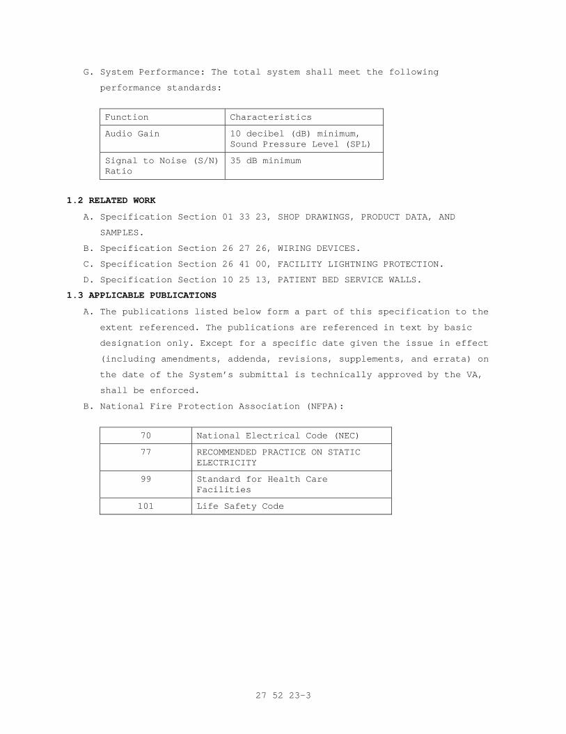
27 52 23-3
G. System Performance: The total system shall meet the following
performance standards:
Function Characteristics
Audio Gain 10 decibel (dB) minimum, Sound Pressure Level (SPL)
Signal to Noise (S/N) Ratio
35 dB minimum
1.2 RELATED WORK
A. Specification Section 01 33 23, SHOP DRAWINGS, PRODUCT DATA, AND
SAMPLES.
B. Specification Section 26 27 26, WIRING DEVICES.
C. Specification Section 26 41 00, FACILITY LIGHTNING PROTECTION.
D. Specification Section 10 25 13, PATIENT BED SERVICE WALLS.
1.3 APPLICABLE PUBLICATIONS
A. The publications listed below form a part of this specification to the
extent referenced. The publications are referenced in text by basic
designation only. Except for a specific date given the issue in effect
(including amendments, addenda, revisions, supplements, and errata) on
the date of the System’s submittal is technically approved by the VA,
shall be enforced.
B. National Fire Protection Association (NFPA):
70 National Electrical Code (NEC)
77 RECOMMENDED PRACTICE ON STATIC ELECTRICITY
99 Standard for Health Care Facilities
101 Life Safety Code
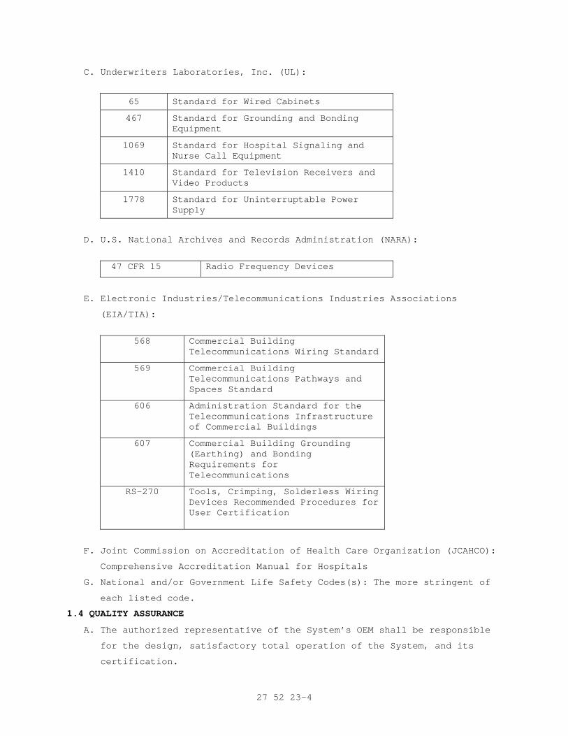
27 52 23-4
C. Underwriters Laboratories, Inc. (UL):
65 Standard for Wired Cabinets
467 Standard for Grounding and Bonding Equipment
1069 Standard for Hospital Signaling and Nurse Call Equipment
1410 Standard for Television Receivers and Video Products
1778 Standard for Uninterruptable Power Supply
D. U.S. National Archives and Records Administration (NARA):
47 CFR 15 Radio Frequency Devices
E. Electronic Industries/Telecommunications Industries Associations
(EIA/TIA):
568 Commercial Building
Telecommunications Wiring Standard
569 Commercial Building Telecommunications Pathways and Spaces Standard
606 Administration Standard for the Telecommunications Infrastructure of Commercial Buildings
607 Commercial Building Grounding (Earthing) and Bonding Requirements for Telecommunications
RS-270 Tools, Crimping, Solderless Wiring Devices Recommended Procedures for User Certification
F. Joint Commission on Accreditation of Health Care Organization (JCAHCO):
Comprehensive Accreditation Manual for Hospitals
G. National and/or Government Life Safety Codes(s): The more stringent of
each listed code.
1.4 QUALITY ASSURANCE
A. The authorized representative of the System’s OEM shall be responsible
for the design, satisfactory total operation of the System, and its
certification.
27 52 23-5
B. The OEM shall meet the minimum requirements identified in paragraph
2.1.A. Additionally, the OEM shall have had experience with three or
more installations of systems of comparable size and complexity as
regards to coordinating, engineering, testing, certifying, supervising,
training, and documentation. Each of these installations shall have
been in successful operation for at least three years after final
acceptance by the user. These installations shall be provided as a part
of the submittal identified in paragraph 1.5.
C. The System Contractor shall submit certified documentation that they
have been an authorized distributor and service organization for the
OEM for a minimum of three (3) years. The System Contractor shall be
authorized by the OEM to certify and warranty the installed equipment.
In addition, the OEM and System Contractor shall accept complete
responsibility for the design, installation, certification, operation,
and physical support for the System. This documentation, along with the
System Contractor and OEM certifications must be provided in writing as
part of the Contractor’s Technical submittal.
D. The Contractor’s Communications Technicians assigned to the System
shall be fully trained, qualified, and certified by the OEM on the
engineering, installation, operation, and testing of the System. The
Contractor shall provide formal written evidence of current OEM
certification(s) for the installer(s) as a part of the submittal or to
the RE before being allowed to commence work on the System.
1.5 SUBMITTALS
A. Provide submittals in accordance with Specification Section 01 33 23,
SHOP DRAWINGS, PRODUCT DATA, AND SAMPLES. The RE shall retain one copy
for review and approval.
1. If the submittal is approved the RE shall retain one copy for
Official Records and return three (3) copies to the Contractor.
2. If the submittal is disapproved, three (3) copies will be returned
to the Contractor with written explanation attached indicating the
areas the submittal deviated from the System specifications. The RE
shall retain one copy for Official Records.
B. Documents: The submittal shall be separated into sections for each sub-
system and shall contain the following:
1. Title page to include:
a. Facility name
a. VA Project Name
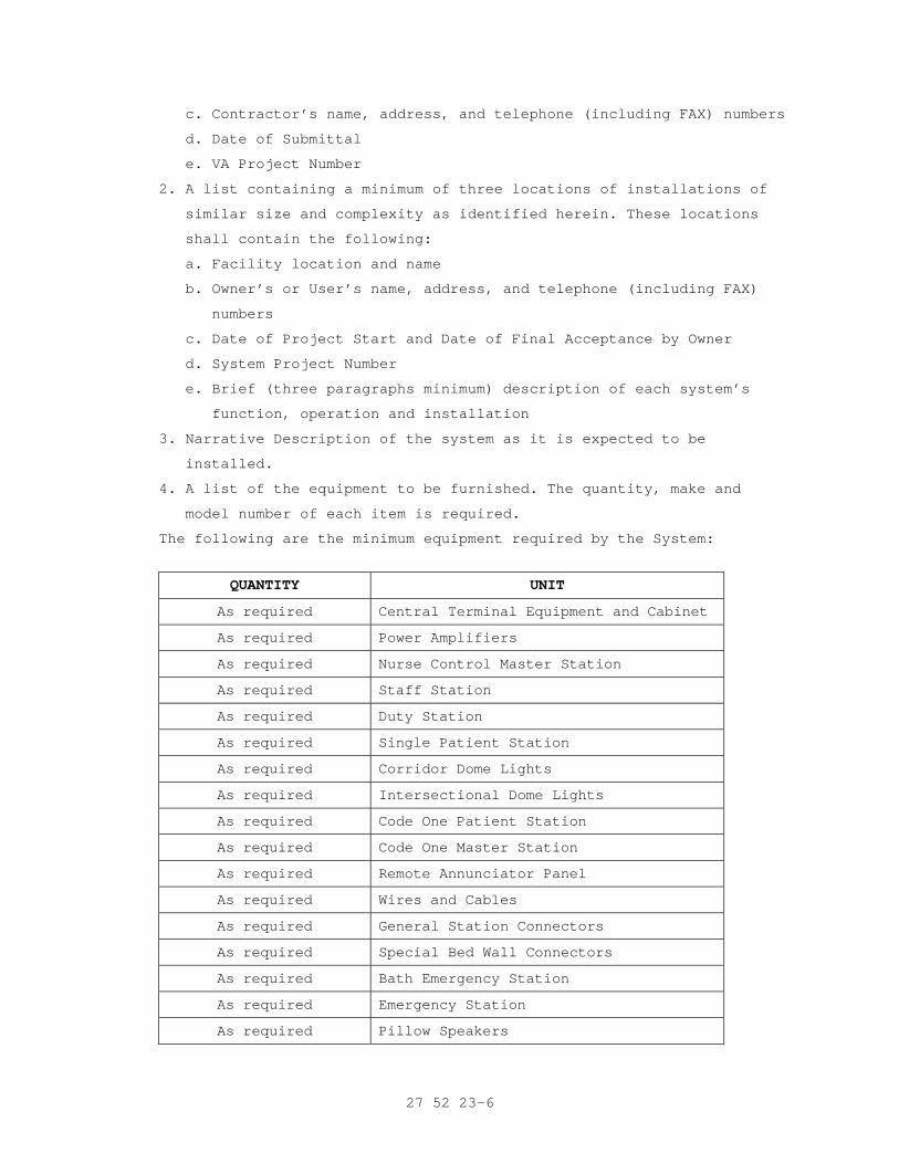
27 52 23-6
c. Contractor’s name, address, and telephone (including FAX) numbers
d. Date of Submittal
e. VA Project Number
2. A list containing a minimum of three locations of installations of
similar size and complexity as identified herein. These locations
shall contain the following:
a. Facility location and name
b. Owner’s or User’s name, address, and telephone (including FAX)
numbers
c. Date of Project Start and Date of Final Acceptance by Owner
d. System Project Number
e. Brief (three paragraphs minimum) description of each system’s
function, operation and installation
3. Narrative Description of the system as it is expected to be
installed.
4. A list of the equipment to be furnished. The quantity, make and
model number of each item is required.
The following are the minimum equipment required by the System:
QUANTITY UNIT
As required Central Terminal Equipment and Cabinet
As required Power Amplifiers
As required Nurse Control Master Station
As required Staff Station
As required Duty Station
As required Single Patient Station
As required Corridor Dome Lights
As required Intersectional Dome Lights
As required Code One Patient Station
As required Code One Master Station
As required Remote Annunciator Panel
As required Wires and Cables
As required General Station Connectors
As required Special Bed Wall Connectors
As required Bath Emergency Station
As required Emergency Station
As required Pillow Speakers
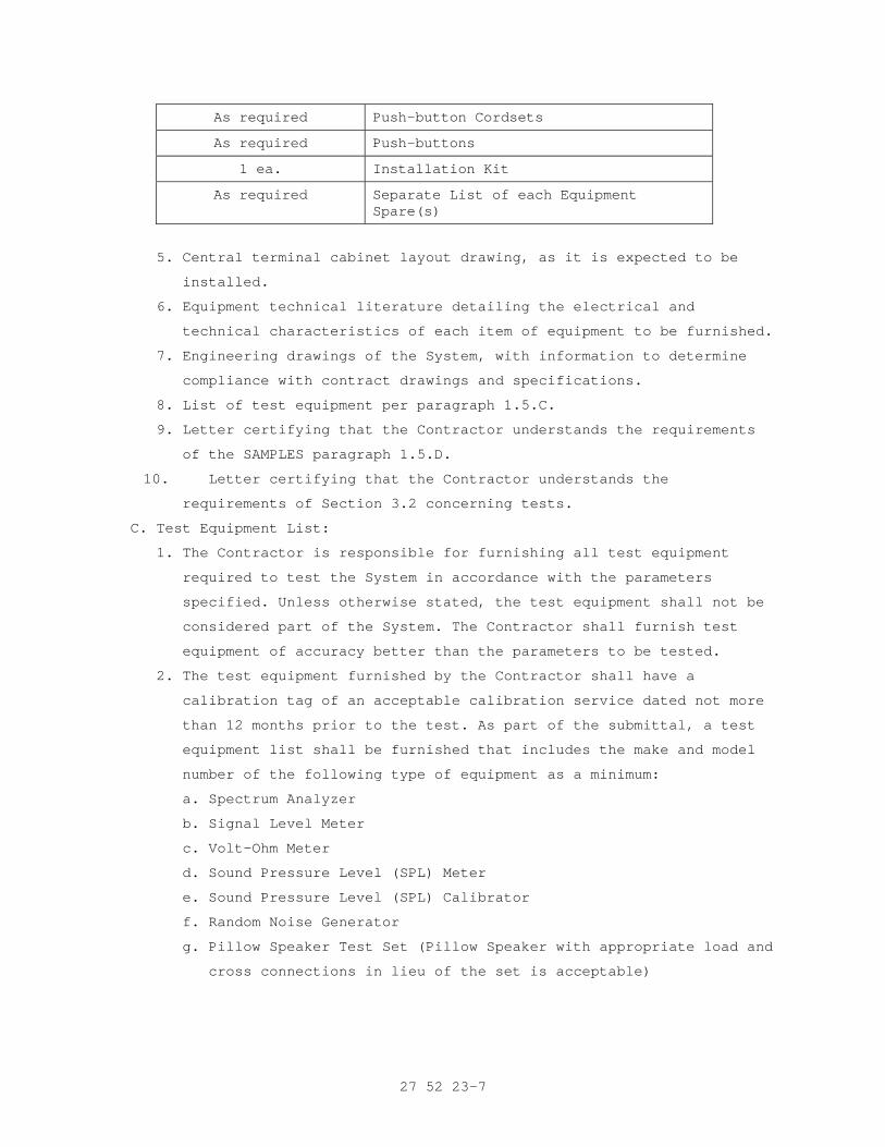
27 52 23-7
As required Push-button Cordsets
As required Push-buttons
1 ea. Installation Kit
As required Separate List of each Equipment Spare(s)
5. Central terminal cabinet layout drawing, as it is expected to be
installed.
6. Equipment technical literature detailing the electrical and
technical characteristics of each item of equipment to be furnished.
7. Engineering drawings of the System, with information to determine
compliance with contract drawings and specifications.
8. List of test equipment per paragraph 1.5.C.
9. Letter certifying that the Contractor understands the requirements
of the SAMPLES paragraph 1.5.D.
10. Letter certifying that the Contractor understands the
requirements of Section 3.2 concerning tests.
C. Test Equipment List:
1. The Contractor is responsible for furnishing all test equipment
required to test the System in accordance with the parameters
specified. Unless otherwise stated, the test equipment shall not be
considered part of the System. The Contractor shall furnish test
equipment of accuracy better than the parameters to be tested.
2. The test equipment furnished by the Contractor shall have a
calibration tag of an acceptable calibration service dated not more
than 12 months prior to the test. As part of the submittal, a test
equipment list shall be furnished that includes the make and model
number of the following type of equipment as a minimum:
a. Spectrum Analyzer
b. Signal Level Meter
c. Volt-Ohm Meter
d. Sound Pressure Level (SPL) Meter
e. Sound Pressure Level (SPL) Calibrator
f. Random Noise Generator
g. Pillow Speaker Test Set (Pillow Speaker with appropriate load and
cross connections in lieu of the set is acceptable)
27 52 23-8
D. Certifications
1. Submit written certification from the OEM indicating that the
proposed supervisor of the installation and the proposed provider of
the contract maintenance are authorized representatives of the OEM.
Include the individual's exact name and address and OEM credentials
in the certification.
2. Submit written certification from the OEM that the wiring and
connection diagrams meet National and/or Government Life Safety
Guidelines, NFPA, NEC, UL 1066, this specification, and JCAHCO
requirements and the instructions, requirements, recommendations,
and guidance set forth by the OEM for the proper performance of the
System as described herein. The VA will not approve any submittal
without this certification.
3. Preacceptance Certification: This certification shall be made in
accordance with the test procedure paragraph 3.2.B.
E. Equipment Manuals: Ten (10) working days prior to the scheduled
acceptance test, the Contractor shall deliver four (4) complete sets of
commercial operation and maintenance manuals for each item of equipment
furnished as part of the System to the RE. The manuals shall detail the
theory of operation and shall include narrative descriptions, pictorial
illustrations, block and schematic diagrams, and parts list.
F. Record Wiring Diagrams:
1. Ten (10) working days prior to the acceptance test, the Contractor
shall four (4) complete sets of the record wiring diagrams of the
System to the RE. The diagrams shall show all inputs and outputs of
electronic and passive equipment correctly identified according to
the markers installed on the interconnecting cables, equipment and
room/area locations.
2. The record wiring diagrams shall be in hard copy and two compact
disk (CD) copies properly formatted to match the Facility's current
operating version of Computer Aided Drafting (AutoCAD) system. The
RE shall verify and inform the Contractor of the current version of
AutoCAD being used by the Facility.
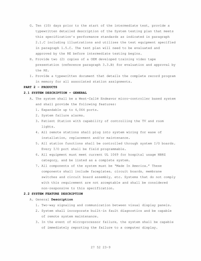
27 52 23-9
G. Ten (10) days prior to the start of the intermediate test, provide a
typewritten detailed description of the System testing plan that meets
this specification’s performance standards as indicated in paragraph
2.1.C including illustrations and utilizes the test equipment specified
in paragraph 1.5.C. The test plan will need to be evaluated and
approved by the RE before intermediate testing begins.
H. Provide two (2) copies of a OEM developed training video tape
presentation (reference paragraph 3.3.B) for evaluation and approval by
the RE.
I. Provide a typewritten document that details the complete record program
in memory for all associated station assignments.
PART 2 - PRODUCTS
2.1 SYSTEM DESCRIPTION - GENERAL
A. The system shall be a West-Call® Endeavor micro-controller based system
and shall provide the following features:
1. Expandable up to 4,064 ports.
2. System failure alarms.
3. Patient Station with capability of controlling the TV and room
lights.
4. All remote stations shall plug into system wiring for ease of
installation, replacement and/or maintenance.
5. All station functions shall be controlled through system I/O boards.
Every I/O port shall be field programmable.
6. All equipment must meet current UL 1069 for hospital usage NBRZ
category, and be listed as a complete system.
7. All components of the system must be “Made In America.” These
components shall include faceplates, circuit boards, membrane
switches and circuit board assembly, etc. Systems that do not comply
with this requirement are not acceptable and shall be considered
non-responsive to this specification.
2.2 SYSTEM FEATURE DESCRIPTION
A. General Description
1. Two-way signaling and communication between visual display panels.
2. System shall incorporate built-in fault diagnostics and be capable
of remote system maintenance.
3. In the event of microprocessor failure, the system shall be capable
of immediately reporting the failure to a computer display.
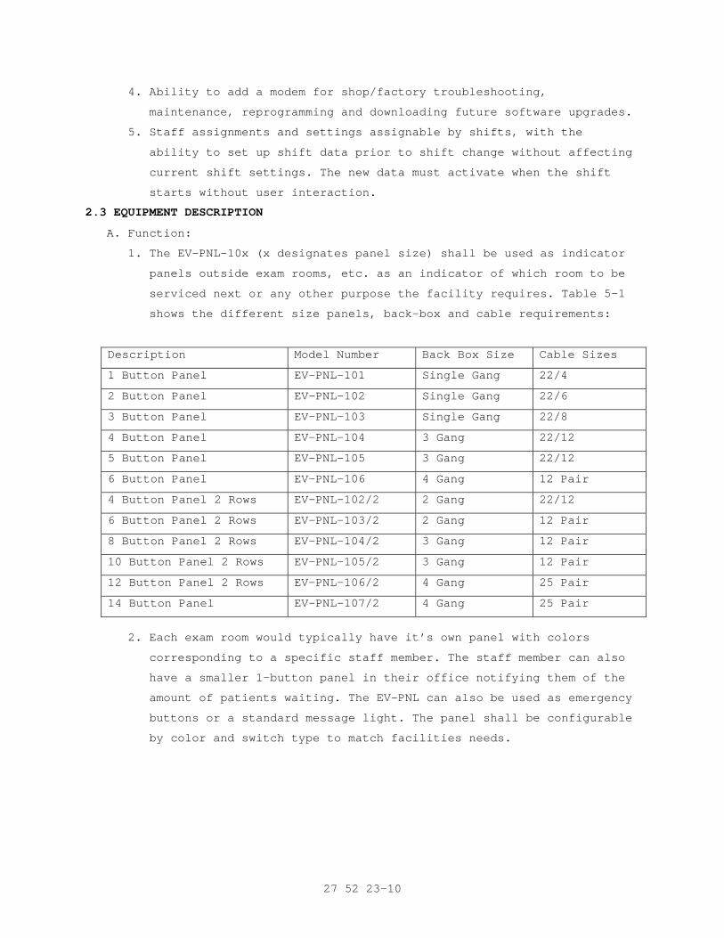
27 52 23-10
4. Ability to add a modem for shop/factory troubleshooting,
maintenance, reprogramming and downloading future software upgrades.
5. Staff assignments and settings assignable by shifts, with the
ability to set up shift data prior to shift change without affecting
current shift settings. The new data must activate when the shift
starts without user interaction.
2.3 EQUIPMENT DESCRIPTION
A. Function:
1. The EV-PNL-10x (x designates panel size) shall be used as indicator
panels outside exam rooms, etc. as an indicator of which room to be
serviced next or any other purpose the facility requires. Table 5-1
shows the different size panels, back-box and cable requirements:
Description Model Number Back Box Size Cable Sizes
1 Button Panel EV-PNL-101 Single Gang 22/4
2 Button Panel EV-PNL-102 Single Gang 22/6
3 Button Panel EV-PNL-103 Single Gang 22/8
4 Button Panel EV-PNL-104 3 Gang 22/12
5 Button Panel EV-PNL-105 3 Gang 22/12
6 Button Panel EV-PNL-106 4 Gang 12 Pair
4 Button Panel 2 Rows EV-PNL-102/2 2 Gang 22/12
6 Button Panel 2 Rows EV-PNL-103/2 2 Gang 12 Pair
8 Button Panel 2 Rows EV-PNL-104/2 3 Gang 12 Pair
10 Button Panel 2 Rows EV-PNL-105/2 3 Gang 12 Pair
12 Button Panel 2 Rows EV-PNL-106/2 4 Gang 25 Pair
14 Button Panel EV-PNL-107/2 4 Gang 25 Pair
2. Each exam room would typically have it’s own panel with colors
corresponding to a specific staff member. The staff member can also
have a smaller 1-button panel in their office notifying them of the
amount of patients waiting. The EV-PNL can also be used as emergency
buttons or a standard message light. The panel shall be configurable
by color and switch type to match facilities needs.
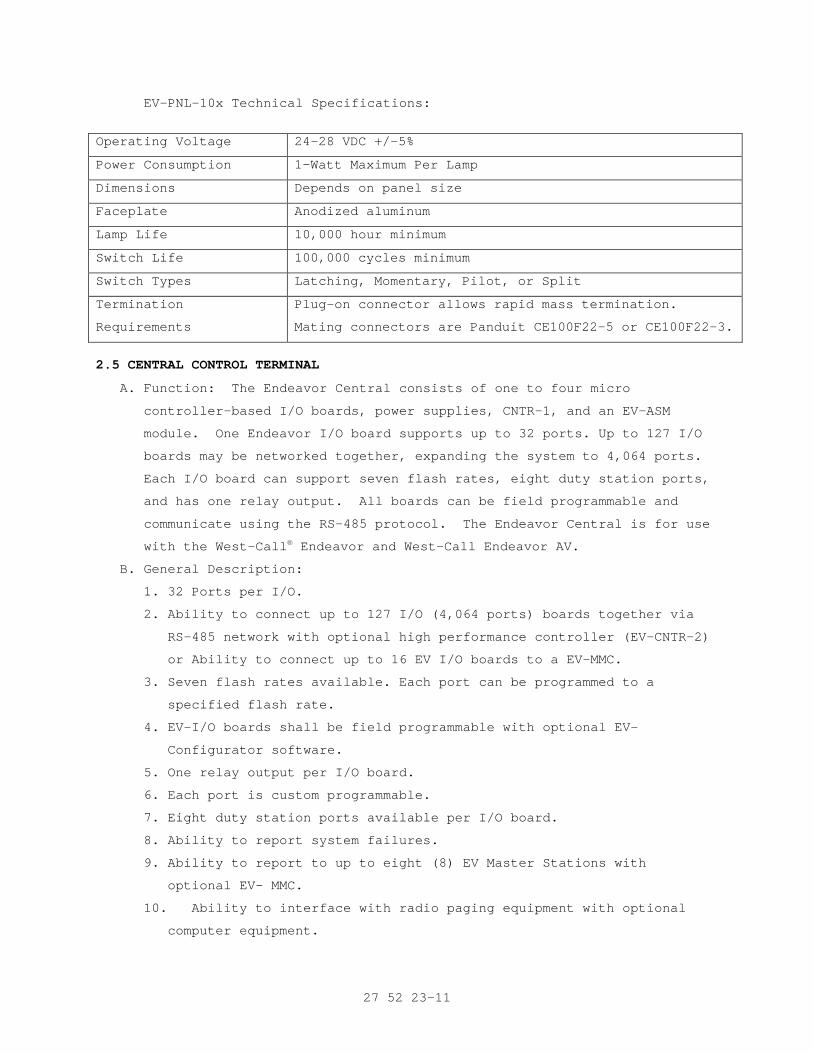
27 52 23-11
EV-PNL-10x Technical Specifications:
Operating Voltage 24-28 VDC +/-5%
Power Consumption 1-Watt Maximum Per Lamp
Dimensions Depends on panel size
Faceplate Anodized aluminum
Lamp Life 10,000 hour minimum
Switch Life 100,000 cycles minimum
Switch Types Latching, Momentary, Pilot, or Split
Termination
Requirements
Plug-on connector allows rapid mass termination.
Mating connectors are Panduit CE100F22-5 or CE100F22-3.
2.5 CENTRAL CONTROL TERMINAL
A. Function: The Endeavor Central consists of one to four micro
controller-based I/O boards, power supplies, CNTR-1, and an EV-ASM
module. One Endeavor I/O board supports up to 32 ports. Up to 127 I/O
boards may be networked together, expanding the system to 4,064 ports.
Each I/O board can support seven flash rates, eight duty station ports,
and has one relay output. All boards can be field programmable and
communicate using the RS-485 protocol. The Endeavor Central is for use
with the West-Call® Endeavor and West-Call Endeavor AV.
B. General Description:
1. 32 Ports per I/O.
2. Ability to connect up to 127 I/O (4,064 ports) boards together via
RS-485 network with optional high performance controller (EV-CNTR-2)
or Ability to connect up to 16 EV I/O boards to a EV-MMC.
3. Seven flash rates available. Each port can be programmed to a
specified flash rate.
4. EV-I/O boards shall be field programmable with optional EV-
Configurator software.
5. One relay output per I/O board.
6. Each port is custom programmable.
7. Eight duty station ports available per I/O board.
8. Ability to report system failures.
9. Ability to report to up to eight (8) EV Master Stations with
optional EV- MMC.
10. Ability to interface with radio paging equipment with optional
computer equipment.
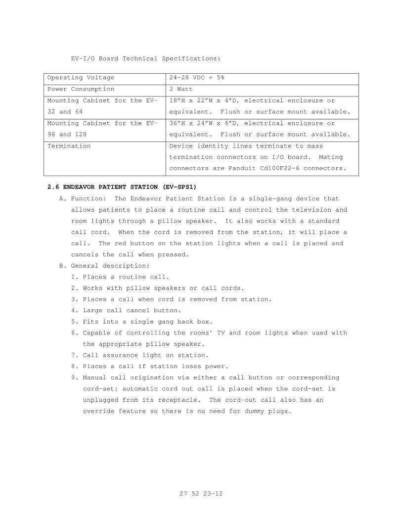
27 52 23-12
EV-I/O Board Technical Specifications:
Operating Voltage 24-28 VDC + 5%
Power Consumption 2 Watt
Mounting Cabinet for the EV-
32 and 64
18”H x 22”W x 4”D, electrical enclosure or
equivalent. Flush or surface mount available.
Mounting Cabinet for the EV-
96 and 128
36”H x 24”W x 6”D, electrical enclosure or
equivalent. Flush or surface mount available.
Termination Device identity lines terminate to mass
termination connectors on I/O board. Mating
connectors are Panduit Cd100F22-6 connectors.
2.6 ENDEAVOR PATIENT STATION (EV-SPS1)
A. Function: The Endeavor Patient Station is a single-gang device that
allows patients to place a routine call and control the television and
room lights through a pillow speaker. It also works with a standard
call cord. When the cord is removed from the station, it will place a
call. The red button on the station lights when a call is placed and
cancels the call when pressed.
B. General description:
1. Places a routine call.
2. Works with pillow speakers or call cords.
3. Places a call when cord is removed from station.
4. Large call cancel button.
5. Fits into a single gang back box.
6. Capable of controlling the rooms’ TV and room lights when used with
the appropriate pillow speaker.
7. Call assurance light on station.
8. Places a call if station loses power.
9. Manual call origination via either a call button or corresponding
cord-set; automatic cord out call is placed when the cord-set is
unplugged from its receptacle. The cord-out call also has an
override feature so there is no need for dummy plugs.
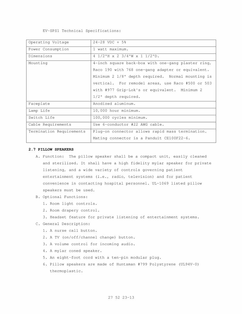
27 52 23-13
EV-SPS1 Technical Specifications:
Operating Voltage 24-28 VDC + 5%
Power Consumption 1 watt maximum.
Dimensions 4 1/2"H x 2 3/4"W x 1 1/2"D.
Mounting 4-inch square back-box with one-gang plaster ring,
Raco 190 with 768 one-gang adapter or equivalent.
Minimum 2 1/8" depth required. Normal mounting is
vertical. For remodel areas, use Raco #500 or 503
with #977 Grip-Lok's or equivalent. Minimum 2
1/2" depth required.
Faceplate Anodized aluminum.
Lamp Life 10,000 hour minimum.
Switch Life 100,000 cycles minimum.
Cable Requirements Use 6-conductor #22 AWG cable.
Termination Requirements Plug-on connector allows rapid mass termination.
Mating connector is a Panduit CE100F22-6.
2.7 PILLOW SPEAKERS
A. Function: The pillow speaker shall be a compact unit, easily cleaned
and sterilized. It shall have a high fidelity mylar speaker for private
listening, and a wide variety of controls governing patient
entertainment systems (i.e., radio, television) and for patient
convenience in contacting hospital personnel. UL-1069 listed pillow
speakers must be used.
B. Optional Functions:
1. Room light controls.
2. Room drapery control.
3. Headset feature for private listening of entertainment systems.
C. General Description:
1. A nurse call button.
2. A TV (on/off/channel change) button.
3. A volume control for incoming audio.
4. A mylar coned speaker.
5. An eight-foot cord with a ten-pin modular plug.
6. Pillow speakers are made of Huntsman #799 Polystyrene (UL94V-0)
thermoplastic.
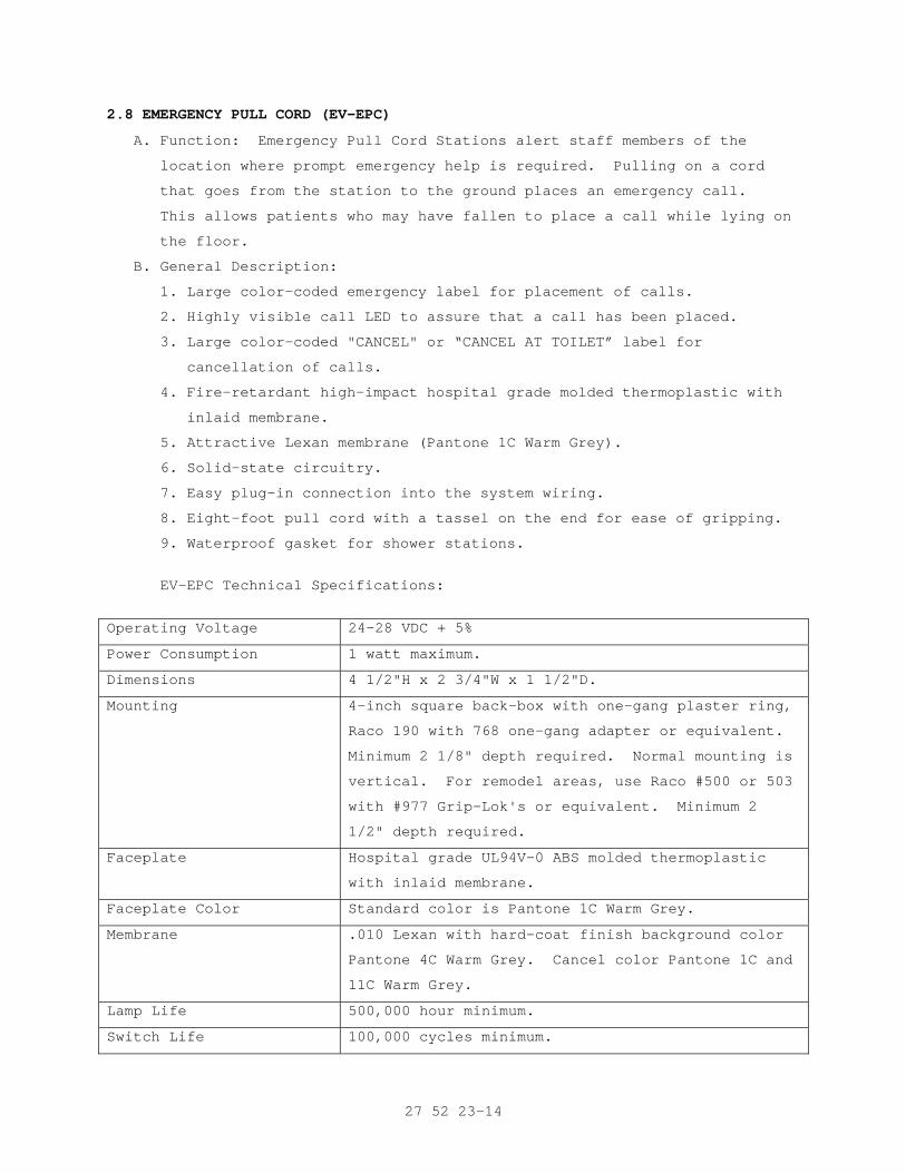
27 52 23-14
2.8 EMERGENCY PULL CORD (EV-EPC)
A. Function: Emergency Pull Cord Stations alert staff members of the
location where prompt emergency help is required. Pulling on a cord
that goes from the station to the ground places an emergency call.
This allows patients who may have fallen to place a call while lying on
the floor.
B. General Description:
1. Large color-coded emergency label for placement of calls.
2. Highly visible call LED to assure that a call has been placed.
3. Large color-coded "CANCEL" or “CANCEL AT TOILET” label for
cancellation of calls.
4. Fire-retardant high-impact hospital grade molded thermoplastic with
inlaid membrane.
5. Attractive Lexan membrane (Pantone 1C Warm Grey).
6. Solid-state circuitry.
7. Easy plug-in connection into the system wiring.
8. Eight-foot pull cord with a tassel on the end for ease of gripping.
9. Waterproof gasket for shower stations.
EV-EPC Technical Specifications:
Operating Voltage 24-28 VDC + 5%
Power Consumption 1 watt maximum.
Dimensions 4 1/2"H x 2 3/4"W x 1 1/2"D.
Mounting 4-inch square back-box with one-gang plaster ring,
Raco 190 with 768 one-gang adapter or equivalent.
Minimum 2 1/8" depth required. Normal mounting is
vertical. For remodel areas, use Raco #500 or 503
with #977 Grip-Lok's or equivalent. Minimum 2
1/2" depth required.
Faceplate Hospital grade UL94V-0 ABS molded thermoplastic
with inlaid membrane.
Faceplate Color Standard color is Pantone 1C Warm Grey.
Membrane .010 Lexan with hard-coat finish background color
Pantone 4C Warm Grey. Cancel color Pantone 1C and
11C Warm Grey.
Lamp Life 500,000 hour minimum.
Switch Life 100,000 cycles minimum.
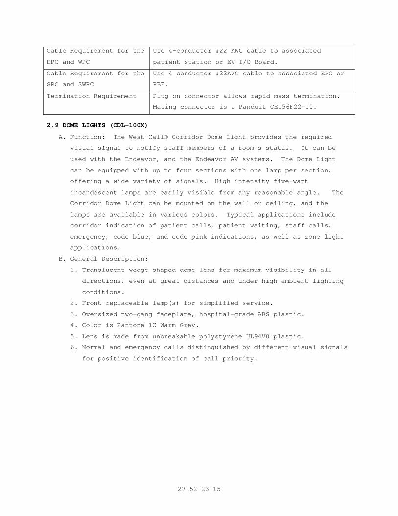
27 52 23-15
Cable Requirement for the
EPC and WPC
Use 4-conductor #22 AWG cable to associated
patient station or EV-I/O Board.
Cable Requirement for the
SPC and SWPC
Use 4 conductor #22AWG cable to associated EPC or
PBE.
Termination Requirement Plug-on connector allows rapid mass termination.
Mating connector is a Panduit CE156F22-10.
2.9 DOME LIGHTS (CDL-100X)
A. Function: The West-Call® Corridor Dome Light provides the required
visual signal to notify staff members of a room's status. It can be
used with the Endeavor, and the Endeavor AV systems. The Dome Light
can be equipped with up to four sections with one lamp per section,
offering a wide variety of signals. High intensity five-watt
incandescent lamps are easily visible from any reasonable angle. The
Corridor Dome Light can be mounted on the wall or ceiling, and the
lamps are available in various colors. Typical applications include
corridor indication of patient calls, patient waiting, staff calls,
emergency, code blue, and code pink indications, as well as zone light
applications.
B. General Description:
1. Translucent wedge-shaped dome lens for maximum visibility in all
directions, even at great distances and under high ambient lighting
conditions.
2. Front-replaceable lamp(s) for simplified service.
3. Oversized two-gang faceplate, hospital-grade ABS plastic.
4. Color is Pantone 1C Warm Grey.
5. Lens is made from unbreakable polystyrene UL94V0 plastic.
6. Normal and emergency calls distinguished by different visual signals
for positive identification of call priority.
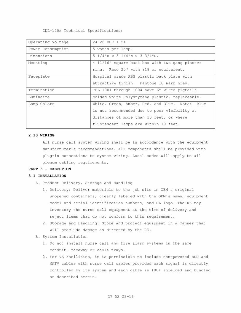
27 52 23-16
CDL-100x Technical Specifications:
Operating Voltage 24-28 VDC + 5%
Power Consumption 5 watts per lamp.
Dimensions 5 1/4"H x 5 1/4"W x 3 3/4"D.
Mounting 4 11/16" square back-box with two-gang plaster
ring. Raco 257 with 818 or equivalent.
Faceplate Hospital grade ABS plastic back plate with
attractive finish. Pantone 1C Warm Grey.
Termination CDL-1001 through 1004 have 6" wired pigtails.
Luminaire Molded white Polystyrene plastic, replaceable.
Lamp Colors White, Green, Amber, Red, and Blue. Note: Blue
is not recommended due to poor visibility at
distances of more than 10 feet, or where
fluorescent lamps are within 10 feet.
2.10 WIRING
All nurse call system wiring shall be in accordance with the equipment
manufacturer’s recommendations. All components shall be provided with
plug-in connections to system wiring. Local codes will apply to all
plenum cabling requirements.
PART 3 - EXECUTION
3.1 INSTALLATION
A. Product Delivery, Storage and Handling
1. Delivery: Deliver materials to the job site in OEM's original
unopened containers, clearly labeled with the OEM's name, equipment
model and serial identification numbers, and UL logo. The RE may
inventory the nurse call equipment at the time of delivery and
reject items that do not conform to this requirement.
2. Storage and Handling: Store and protect equipment in a manner that
will preclude damage as directed by the RE.
B. System Installation
1. Do not install nurse call and fire alarm systems in the same
conduit, raceway or cable trays.
2. For VA Facilities, it is permissible to include non-powered RED and
MATV cables with nurse call cables provided each signal is directly
controlled by its system and each cable is 100% shielded and bundled
as described herein.
27 52 23-17
3. The Contractor shall provide suitable filters, traps and pads for
minimizing interference and for balancing the amplifiers and
distribution system(s). Items used for balancing and minimizing
interference shall be able to pass audio, data and control signals
in the speeds and frequency bands selected, in the directions
specified, with low loss, and high isolation and with minimum delay
of the system poling or subcarrier frequency(s).
4. Back up power supplies (e.g., batteries, UPS) shall be installed in
the central equipment cabinet or in a separate metal cabinet
equipped with a hinged door and lock. If a separate cabinet is
installed, it shall be provided adjacent to the central equipment
cabinet. Where the backup power supply is already self-contained in
a housing, the unit can be mounted adjacent to the respective
equipment cabinet. In all cases, backup power supplies must be
permanently mounted. Each UPS and/or backup power supply shall be
provided with full electrical supervision as described herein.
5. When prefabricated bedside units (PBPU) are used in the System, the
Contractor shall contact the RE who in turn will contact the PBPU
OEM to obtain proper authorizations and written certifications to
attach system components to the PBPU in locations where standard
PBPU access, port knockouts or routes have not been provided.
Additionally, if the patient pillow speaker or cordset hanger does
not have a standard place or mode of attachment to the PBPU, the
Contractor shall obtain the aforementioned guidance from the PBPU
OEM for attaching the hanger. Under no circumstance shall the
Contractor modify, drill, punch, or proceed with installation of the
System in PBPU’s without the required approvals.
6. In those areas where special beds are to be used, such as Hill Rom,
Striker, etc., and the communications connected to the PBPU or to
the headwall, the PBPU, nurse call, and the bed OEMs shall be
contacted by the RE to secure the proper authorizations and guidance
for interfacing the bed’s communications systems with the System.
7. All passive equipment shall be connected according to the OEM's
specifications to insure correct termination, isolation, impedance
match, and signal level balance at each speaker.
8. Install all equipment for each location specified herein and as
identified on the drawings.
27 52 23-18
9. All trunk, distribution and interconnecting lines shall be
terminated in a suitable manner to facilitate future expansion of
the System by adding center terminal equipment only.
10. All vertical and horizontal lines shall be terminated so that
subsequent expansion for additional audio channels shall require
modifications of the System central terminal equipment only.
11. Terminating resistors shall be used to terminate all unused
branches, outlets, unused equipment ports of the System and shall be
devices designed for the purpose of terminating audio cables
carrying audio signals in nurse call systems.
B. Conduit and Signal Ducts:
1. Conduit:
a. The Contractor shall employ the latest installation practices and
materials. The minimum conduit size shall be 25 mm (1 inch) in
diameter for primary signal distribution and 19 mm (3/4 inch) for
remote connections (i.e. dome lights, emergency station, TV
control, RED control, etc.).
b. All cables shall be installed in separate conduit and/or signal
ducts (exception from the separate conduit requirement to allow
nurse call cables to be installed in partitioned cable tray with
RED and MATV cables, shall be granted in writing by the RE if
requested.) The mixing of nurse call and fire alarm cables and/or
systems is not authorized and will not be approved. (See caution
identified in paragraph 3-1b.3.e.).
c. Conduit fill shall not exceed 40 percent.
d. Cable runs shall be splice free between conduit junction and
interface boxes and equipment locations.
2. Signal Duct, Cable Duct, or Cable Tray:
a. The Contractor shall use existing signal duct, cable duct and/or
cable tray, when identified and approved by the RE.
b. Approved signal and/or cable duct shall be a minimum size of 100
mm x 100 mm (4 inch x 4 inch) inside diameter with removable tops
or sides, as appropriate. Protective sleeves, guides, or barriers
are required on all sharp corners, openings, anchors, bolts, or
screw ends, junction, interface and connection points.
27 52 23-19
c. Approved cable tray shall be fully covered, mechanically and
physically partitioned for multiple electronic circuit use, and
UL certified and labeled for use with telecommunication circuits
and/or systems. The RE shall approve width and height dimensions.
d. Do not pull wire or cable through any box, fitting or enclosure
where change of approved conduit, cable tray, signal, or cable
duct alignment or direction occurs. Ensure the proper bend radius
is maintained for each wire or cable as specified by it's OEM.
e. Employ temporary guides, sheaves, rollers, and other necessary
items to protect the wire or cable from excess tension or
damaging bending during installation. Abrasion to wire or cable
jackets is not acceptable and will not be allowed. Replace all
cables whose jackets has been abraded the discovery of any
abraded and/or damaged cables during the proof of performance
test shall be grounds for declaring the entire system
unacceptable and the termination of the proof of performance
test. Completely cover edges of wire or cable passing through
holes in chassis, cabinets or racks, enclosures, pull or junction
boxes, conduit, etc., with plastic or nylon grommetting.
f. All cable junctions and taps shall be accessible. Do not install
junction blocks, multi distribution connections or other
distribution equipment (active or passive) items inside signal
ducts. Use a 150 mm x 150 mm x 100 mm (6 inch x 6 inch x 4 inch)
minimum covered junction box attached to the signal duct fixed
side for distribution system passive equipment installation.
Ensure all equipment and connection assembly junctions are
accessible.
C. Distribution System Signal Wires and Cables
1. Wires and cables shall be provided in the same manner and use like
construction practices as Fire Protective and other Emergency
Systems that are identified and outlined in NFPA 101, Life Safety
Code, Chapters 7, 12, and/or 13, NFPA 70, National Electrical Code,
Chapter 7, Special Conditions. The wires and cables shall be able to
withstand adverse environmental conditions location without
deterioration. Wires and cables shall enter each equipment
enclosure, console, cabinet, or rack in such a manner that all doors
or access panels can be opened and closed without removal or
disruption of the cables.
27 52 23-20
2. Routing and Interconnection:
a. Wires or cables routed between consoles, cabinets, racks, and
other equipment shall be installed in an approved conduit, signal
duct, cable duct, or cable tray that is secured to building
structure.
b. Wires and cables shall be insulated to prevent contact with
signal or current carrying conductors and be 100% shielded. Wires
or cables used in assembling consoles, panels, equipment cabinets
and racks shall be formed into harnesses that are bundled and
tied. Harnessed wires or cables shall be combed straight, formed
and dressed in either a vertical or horizontal relationship to
equipment, controls, components or terminations.
c. Harnesses with intertwined members are not acceptable. Each wire
or cable that breaks out from a harness for connection or
termination shall have been tied off at that harness or bundle
point, and provided with a neatly formed service loop.
d. Wires and cables shall be grouped according to service (i.e.: AC,
grounds, signal, DC, control, etc.). DC, control and signal
cables may be included with any group. Wires and cables shall be
neatly formed and shall not change position in the group
throughout the conduit run. Wires and cables in approved signal
duct, conduit, cable ducts, or cable trays shall be neatly
formed, bundled and tied off in 600 mm to 900 mm (24 to 36 inch)
lengths and shall not change position in the group throughout the
run. Concealed splices are not allowed.
e. Separate, organize, bundle, and route wires or cables to restrict
channel crosstalk or feedback oscillation inside any enclosure.
Looking at any enclosure from the rear (wall mounted enclosures,
junction, pull or interface boxes from the front), locate AC
power, DC, and speaker wires or cables on the left; coaxial,
control, microphone, and line level audio and data wires or
cables, on the right. This installation shall be accomplished
with ties and/or fasteners that will not damage or distort the
wires or cables. Limit spacing between tied off points to a
maximum of 150 mm (6 inches).
27 52 23-21
f. Distribution cables shall be installed and fastened without
causing sharp bends or rubbing of the cables against sharp edges.
Cables shall be fastened with hardware that will not damage or
distort them.
g. Cables shall be labeled with permanent markers at the terminals
of the electronic and passive equipment and at each junction
point in the System. The lettering on the cables shall correspond
with the lettering on the record diagrams.
h. Completely test all of the cables after installation and replace
any defective cables.
i. Provide system input and output polarity as recommended by the
OEM. Insure each color coded wire or cable is connected and
terminated to maintain system polarity to be at least the same
quality of professional audio systems. Reflect all color codes,
wire and cable terminations on the System’s record drawings as
required herein.
D. Outlet Boxes, Back Boxes, and Face Plates
1. Outlet Boxes: Signal, power, interface, connection, distribution,
and junction boxes shall be provided as required by the system
design, on-site inspection, and review of the contract drawings.
2. Back Boxes: Back boxes shall be provided as directed by the OEM as
required by the approved system design, on-site inspection, and
review of the contract drawings.
3. Face Plates (or Cover Plates): Face plates shall be of a standard
type, stainless steel, anodized aluminum or UL approved cycolac
plastic construction and provided by the Contractor for each
identified system location. Connectors and jacks appearing on the
face plate shall be clearly and permanently marked.
E. Connectors: Circuits, transmission lines and signal extensions shall
have continuity, correct connection, and polarity. Polarity shall be
maintained between all points in the System.
1. Wires:
a. Wire ends shall be neatly formed and where insulation has been
cut, heat shrink tubing shall be employed to secure the
insulation on each wire. Tape of any type is not acceptable and
will not be approved.
27 52 23-22
b. Audio spade lugs shall be installed on each wire (including spare
or unused) end and connect to screw terminals of appropriate size
barrier strips. AC barrier strips shall be provided with a
protective cover to prevent accidental contact with wires
carrying live AC current. Wiring blocks are approved for signal,
not AC wires. Wire Nut or "Scotch Lock" connectors are not
acceptable for signal wire installation.
2. Cables: Each connector shall be designed for the specific size cable
being used and installed with the OEM's approved installation tool.
Typical system cable connectors include; but, are not limited to:
Audio spade lug, wiring block, wirewrap, etc.
F. AC Power: AC power wiring shall be run separately from signal cable.
G. Grounding:
1. General: The Contractor shall ground all Contractor installed
equipment to eliminate all shock hazard and to minimize, to the
maximum extent possible, all ground loops, common mode returns,
noise pickup, crosstalk, etc. The total ground resistance shall be
0.1 Ohm or less:
a. Under no conditions shall the AC neutral, either in a power panel
or in a receptacle outlet, be used for system control, subcarrier
or audio reference ground.
b. The use of conduit, signal duct, or cable trays as system or
electrical ground is not acceptable and will not be permitted.
These items may be used only for the dissipation of internally
generated static charges [not to be confused with externally
generated lightning] that may be applied or generated outside the
mechanical and/or physical confines of the System to earth
ground. The discovery of improper system grounding shall be
grounds to declare the System unacceptable and the termination of
all system acceptance testing.
3. Cabinet Buss: A common ground buss of at least #10 AWG solid copper
wire shall extend throughout each equipment cabinet and be connected
to the system ground. Provide a separate isolated ground connection
from each equipment cabinet ground buss to the system ground. Do not
tie equipment ground busses together.
27 52 23-23
4. Equipment: Equipment shall be bonded to the cabinet ground bus with
copper braid equivalent to at least #12 AWG. Self grounding
equipment enclosures, racks or cabinets, that provides OEM certified
functional ground connections through physical contact with
installed equipment, are acceptable alternates.
5. Cable Shields: Cable shields shall be bonded to the cabinet ground
buss with #12 AWG minimum stranded copper wire at only one end of
the cable run. Cable shields shall be insulated from each other,
face plates, equipment racks, consoles, enclosures or cabinets;
except, at the system common ground point. Coaxial and audio cables,
shall have one ground connection at the source; in all cases, cable
shield ground connections shall be kept to a minimum.
H. Equipment Assembly:
1. Cabinets:
a. Each enclosure shall be: floor or wall mounted with standard
knockout holes for conduit connection or cable entrance; provide
for ventilation of the equipment; have front and rear locking
doors (except wall mounted cabinets that require only a front
locking door); power outlet strip(s) and bulkhead connector
panel(s).
b. Each cabinet shall be equipped with a quiet fan and nondisposable
air filter.
c. Enclosures shall be installed plumb and square. Each shall be
permanently attached to the building structure and held firmly in
place as approved by the RE.
d. Signal equipment, patch or bulkhead connector panels (i.e.:
audio, data, control, etc.) shall be connected so that output for
from each source, device or system component shall enter the
panel at the top row of jacks, beginning left to right as viewed
from the front, which will be called "input". Each connection to
a load, device or system component shall exit the panel at the
bottom row of jacks, beginning left to right as viewed from the
front, which will be called "output".
I. Labeling: Abbreviations may be used as long as they are symbol(s) or
acronyms designated for the System or equipment by accepted industry
standards and each abbreviation is used on the appropriate system and
sub-system "record” drawing.
27 52 23-24
1. Cable and Wires (Hereinafter referred to as "Cable"): The Contractor
shall install labels on all cables at each side of all connections.
The labeling shall be permanent, with contrasting identification
alpha or numeric, identifying each cable according to the System "as
record" drawings. Labels shall be installed adjacent to each
mechanical connector, pull box or break in the cable run.
2. Equipment: The Main Nurse Call Control Panel, amplifying, control,
switching, and routing equipment inputs and outputs shall be
permanently labeled with contrasting plastic laminate or bakelite
material. System equipment shall be permanently labeled on the face
of the unit corresponding to its source. Remote control equipment
shall be labeled according to the unit or system being controlled.
Equipment labels shall be permanently affixed to the equipment with
metal screws, permanent mounting devices or cement.
3. AC Power: The AC Power Panel Directory shall identify which
equipment console, cabinet or enclosure that it serves. Each
equipment console, cabinet or enclosure shall be labeled to identify
which AC power panel provides power to it. These labels shall be
permanently affixed to the equipment with metal screws, permanent
mounting devices or cement.
4. Conduit, Cable Duct, and/or Cable Tray: The Contractor shall label
all conduit, duct, and tray, including utilized GFE, with permanent
marking devices or spray painted stenciling a minimum every 3 meters
10 feet) identifying it as the System. Also, each enclosure shall be
labeled according to this standard.
3.2 PROOF OF PERFORMANCE TESTS
A. Intermediate Testing:
1. After completion of the installation of a central control cabinet
and equipment, nurse control master station, local and remote
enunciation stations (code one [blue] systems only), the first ward
(maximum of two wards), and prior to any further work, this portion
of the System must be pretested, inspected, and certified. Each item
of installed equipment shall be checked to ensure appropriate UL
certification labels are affixed, NFPA, Life Safety, and JCAHCO
guidelines are followed, and proper installation practices are
followed. The intermediate test shall include a full operational
test.
27 52 23-25
2. The inspection and test will be conducted by a factory-certified
representative and witnessed by a Government Representative. The
results of the inspection will be officially recorded by the
Government Representative and maintained on file by the RE, until
completion of the entire project. The results will be compared to
the Acceptance Test results. An identical inspection may be
conducted between the 65 - 80% point of the system construction
phase, at the direction of the RE.
B. Pretesting:
1. Upon completing installation of the System, the Contractor shall
align, balance, and completely pretest the entire system under full
operating conditions.
2. Pretesting Procedure:
a. During the System pretest the Contractor shall verify (utilizing
approved spectrum analyzer and test equipment) that the System is
fully operational and meets all the System performance
requirements of this standard.
b. The Contractor shall pretest and verify that all system functions
and specification requirements are met and operational, no
unwanted aural effects, such as signal distortion, noise pulses,
glitches, audio hum, poling noise, etc. are present. At a
minimum, each of the following locations shall be fully
pretested:
1) Central Control Cabinets
2) Nurse Control Stations
3) Patient Stations
4) Staff Stations
5) Local and Remote Enunciation Panels (code one [blue] only)
6) All Networked locations
7) System interface locations (i.e. two way radio, PA, etc.)
8) System trouble reporting
9) System supervision
10) UPS operation
3. The Contractor shall provide four (4) copies of the recorded system
pretest measurements and the written certification that the System
is ready for the formal acceptance test shall be submitted to the
RE.
27 52 23-26
C. Acceptance Test:
1. After the System has been pretested and the Contractor has submitted
the pretest results and certification to the RE, then the Contractor
shall schedule an acceptance test date and give the RE 30 days
written notice prior to the date the acceptance test is expected to
begin. The System shall be tested in the presence of a Government
Representative and an OEM certified representative. The System shall
be tested utilizing the approved test equipment to certify proof of
performance and Life Safety compliance. The test shall verify that
the total System meets all the requirements of this specification.
The notification of the acceptance test shall include the expected
length (in time) of the test.
2. The acceptance test shall be performed on a "go-no-go" basis. Only
those operator adjustments required to show proof of performance
shall be allowed. The test shall demonstrate and verify that the
installed System does comply with all requirements of this
specification under operating conditions. The System shall be rated
as either acceptable or unacceptable at the conclusion of the test.
Failure of any part of the System that precludes completion of
system testing, and which cannot be repaired in four (4) hours,
shall be cause for terminating the acceptance test of the System.
Repeated failures that result in a cumulative time of eight (8)
hours to effect repairs, shall cause the entire System to be
declared unacceptable. Retesting of the entire System shall be
rescheduled at the convenience of the Government.
D. Acceptance Test Procedure:
1. Physical and Mechanical Inspection:
a. The Government Representative will tour all major areas where the
System is and all sub-systems are completely and properly
installed to insure they are operationally ready for proof of
performance testing. A system inventory including available spare
parts will be taken at this time. Each item of installed
equipment shall be checked to ensure appropriate UL certification
labels are affixed.
b. The System diagrams, record drawings, equipment manuals, Auto CAD
Disks, intermediate, and pretest results shall be formally
inventoried and reviewed.
27 52 23-27
c. Failure of the System to meet the installation requirements of
this specification shall be grounds for terminating all testing.
2. Operational Test:
a. After the Physical and Mechanical Inspection, the central
terminating and nurse call master control equipment shall be
checked to verify that it meets all performance requirements
outlined herein. A spectrum analyzer and sound level meter may be
utilized to accomplish this requirement.
b. Following the central equipment test, a pillow speaker (or on
board speaker) shall be connected to the central terminating and
nurse call master control equipment’s output tap to ensure there
are no signal distortions such as intermodulation, data noise,
popping sounds, erratic system functions, on any function.
c. The distribution system shall be checked at each interface,
junction, and distribution point, first, middle, and last
intersectional, room, and bed dome light in each leg to verify
that the nurse call distribution system meets all system
performance standards.
d. Each MATV outlet that is controlled by a nurse call pillow
speaker shall be functionally tested at the same time utilizing
the Contractor’s approved hospital grade TV receiver and TV
remote control cable.
e. The RED system and volume stepper switches shall be checked to
insure proper operation of the pillow speaker, the volume stepper
and the RED system.
f. Additionally, each installed emergency, patient, staff, duty,
panic station, intersectional, room, and bed dome light, power
supply, code one, and remote annunciator panels shall be checked
insuring they meet the requirements of this specification.
g. Once these tests have been completed, each installed sub-system
function shall be tested as a unified, functioning and fully
operating system. The typical functions are: nurse follower,
three levels of emergency signaling (i.e. flashing red emergency,
flashing white patient emergency, flashing white or combination
lights for staff emergency, separate flashing code blue), minimum
of ten minutes of UPS operation, memory saving, minimum of ten
station audio paging, canceling emergency calls at each
originating station only, and storage and prioritizing of calls.
27 52 23-28
h. Individual Item Test: The Government Representative will select
individual items of equipment for detailed proof of performance
testing until 100% of the System has been tested and found to
meet the contents of this specification. Each item shall meet or
exceed the minimum requirements of this document.
3. Test Conclusion:
a. At the conclusion of the Acceptance Test, using the generated
punch list (or discrepancy list) the VA and the Contractor shall
jointly agree to the results of the test, and reschedule testing
on deficiencies and shortages with the RE. Any retesting to
comply with these specifications will be done at the Contractor's
expense.
b. If the System is declared unacceptable without conditions, all
rescheduled testing expenses will be born by the Contractor.
3.3 TRAINING
A. Furnish the services of a factory-trained engineer or technician for
four eight-hour periods to instruct the Facility’s maintenance
personnel. Instruction shall include corrective and preventive
maintenance of the nurse call equipment. Training shall be accomplished
before the VA can accept the System. Additionally, training will be
scheduled at the convenience of the Facility’s, Chief Engineering
Service.
B. Furnish the services of a representative of the nurse call and code one
OEM, familiar with the functions and operation of the equipment, for
two eight-hour periods to train nursing personnel. Instructions shall
be provided for staff personnel in each ward where new nurse call and
code one (blue) equipment is provided under this contract. When
multiple wards are involved, classes will be grouped. Periods of
training shall be coordinated with the Chief of Nursing Service for the
Facility to ensure all nursing shifts receive the required training.
Each session shall include instructions utilizing a factory prepared
and RE approved vertical - horizontal system (VHS) format video tape
presentation and "hands-on" operation of the nurse call and code blue
equipment on a hospital ward. The tape presentation shall be sufficient
in detail to stand-alone as a training aid for initial utilization and
familiarization of the System. Additionally, the Contractor shall
provide two (2) copies of the video presentation to the Chief of
Nursing Service.
27 52 23-29
3.4 GUARANTEE PERIOD OF SERVICE
A. Contractor’s Responsibility:
1. The Contractor shall guarantee that all provided material and
equipment will be free from defects, workmanship and will remain so
for a period of one year from date of final acceptance of the System
by the VA. The Contractor shall provide OEM’s equipment warranty
documents, to the RE (or Facility Contracting Officer if the
Facility has taken procession of the building), that certifies each
item of equipment installed conforms to OEM published
specifications.
2. The Contractor's maintenance personnel shall have the ability to
contact the Contractor and OEM for emergency maintenance and
logistic assistance, remote diagnostic testing, and assistance in
resolving technical problems at any time. This contact capability
shall be provided by the Contractor and OEM at no additional cost to
the VA.
3. All Contractor maintenance and supervisor personnel shall be fully
qualified by the OEM and must provide two (2) copies of current and
qualified OEM training certificates and OEM certification upon
request.
4. Additionally, the Contractor shall accomplish the following minimum
requirements during the one year guaranty period.
B. Response Time During the One Year Guaranty Period:
1. The RE or Facility Contracting Officer is the Contractor’s reporting
and contact official for nurse call system trouble calls, during the
guaranty period.
2. A standard work week is considered 8:00 A.M. to 5:00 P.M., Monday
through Friday exclusive of Federal Holidays.
3. The Contractor shall respond and correct on-site trouble calls,
during the standard work week to:
a. A routine trouble call within one working day of its report. A
routine trouble is considered a trouble which causes a pillow
speaker or cordset, master nurse control station, patient
station, emergency station, or dome light to be inoperable.
b. An emergency trouble call within four hours of its report. An
emergency trouble is considered a trouble which causes a
sub-system (ward), distribution point, terminal cabinet, or code
one system to be inoperable at anytime.
27 52 23-30
4. If a nurse call and/or code blue component failure cannot be
corrected within four hours (exclusive of the standard work time
limits), the Contractor shall be responsible for providing alternate
nurse call equipment. The alternate equipment/system shall be
operational within a maximum of four hours after the four hour
trouble shooting time and restore the effected location operation to
meet the System performance standards. If any sub-system or major
system trouble cannot be corrected within one working day, the
Contractor shall furnish and install compatible substitute equipment
returning the System or sub-system to full operational capability,
as described herein, until repairs are complete.
5. Routine trouble calls in critical emergency health care facilities
(i.e., cardiac arrest, intensive care units, etc.) shall also be
deemed as an emergency trouble call. The RE or Facility Contracting
Officer shall notify the Contractor of this type of trouble call.
C. Required On-Site Visits During the One Year Guaranty Period
1. The Contractor shall visit, on-site, for a minimum of eight hours,
once every 12 weeks, during the guaranty period, to perform system
preventive maintenance, equipment cleaning, and operational
adjustments to maintain the System according the descriptions
identified in this document.
2. The Contractor shall arrange all Facility visits with the RE or
Facility Contracting Officer prior to performing the required
maintenance visits.
3. Preventive maintenance shall be performed by the Contractor in
accordance with the OEM's recommended practice and service intervals
during non-busy time agreed to by the RE or Facility Contracting
Officer and Contractor.
4. The preventive maintenance schedule, functions and reports shall be
provided to and approved by the RE or Facility Contracting Officer.
5. The Contractor shall provide the RE or Facility Contracting Officer
a type written report itemizing each deficiency found and the
corrective action performed during each required visit or official
reported trouble call. The Contractor shall provide the RE with
sample copies of these reports for review and approval at the
beginning of the Acceptance Test. The following reports are the
minimum required:
27 52 23-31
a. The Contractor shall provide a monthly summary all equipment and
sub-systems serviced during this guarantee period to RE or
Facility Contracting Officer by the fifth working day after the
end of each month. The report shall clearly and concisely
describe the services rendered, parts replaced and repairs
performed. The report shall prescribe anticipated future needs of
the equipment and systems for preventive and predictive
maintenance.
b. The Contractor shall maintain a separate log entry for each item
of equipment and each sub-system of the System. The log shall
list dates and times of all scheduled, routine, and emergency
calls. Each emergency call shall be described with details of the
nature and causes of emergency steps taken to rectify the
situation and specific recommendations to avoid such conditions
in the future.
6. The RE or Facility Contracting Officer shall convey to the Facility
Engineering Officer, two (2) copies of actual reports for
evaluation.
a. The RE or Facility Contracting Officer shall ensure a copy of
these reports is entered into the System’s official acquisition
documents.
b. The Facility Chief Engineer shall ensure a copy of these reports
is entered into the System’s official technical record documents.
D. Work Not Included: Maintenance and repair service shall not include the
performance of any work due to improper use; accidents; other vendor,
contractor, or owner tampering or negligence, for which the Contractor
is not directly responsible and does not control. The Contractor shall
immediately notify the RE or Facility Contracting Officer in writing
upon the discovery of these incidents. The RE or Facility Contracting
Officer will investigate all reported incidents and render findings
concerning any Contractor's responsibility.
- - - END - - -
28 31 00 - 1
SECTION 28 31 00 FIRE DETECTION AND ALARM
PART 1 - GENERAL
1.1 DESCRIPTION
A. This section of the specifications includes the furnishing,
installation, and connection of the fire alarm equipment to form a
complete coordinated system ready for operation. It shall include, but
not be limited to, alarm initiating devices, alarm notification
appliances, control units, fire safety control devices, annunciators,
power supplies, and wiring as shown on the drawings and specified.
B. Fire alarm systems shall comply with requirements of NFPA 72 unless
variations to NFPA 72 are specifically identified within these contract
documents by the following notation: "variation". The design, system
layout, document submittal preparation, and supervision of installation
and testing shall be provided by a technician that is certified NICET
level III or a registered fire protection engineer. The NICET certified
technician shall be on site for the supervision and testing of the
system. Factory engineers from the equipment manufacturer, thoroughly
familiar and knowledgeable with all equipment utilized, shall provide
additional technical support at the site as required by the Contracting
Officer or his authorized representative. Installers shall have a
minimum of two years experience installing fire alarm systems.
C. Fire alarm signals:
1. The new expansion shall have an automatic digitized voice fire alarm
signal with emergency manual voice override to notify occupants to
evacuate. The digitized voice message shall identify the area of the
building (smoke zone) from which the alarm was initiated.
D. Alarm signals (by device), supervisory signals (by device) and system
trouble signals (by device not reporting) shall be distinctly
transmitted to the main fire alarm system control unit located in the
security office.
1.2 SCOPE
A. A new fire alarm system shall be designed and installed in accordance
with the specifications and drawings. Device location and wiring runs
shown on the drawings are for reference only unless specifically
dimensioned. Actual locations shall be in accordance with NFPA 72 and
this specification.
28 31 00 - 2
B. Basic Performance:
1. Alarm and trouble signals from each building fire alarm control panel
shall be digitally encoded by UL listed electronic devices onto a
multiplexed communication system.
2. Response time between alarm initiation (contact closure) and
recording at the main fire alarm control unit (appearance on
alphanumeric read out) shall not exceed five (5) seconds.
3. The signaling line circuits (SLC) between building fire alarm control
units shall be wired Style 7 in accordance with NFPA 72. Isolation
shall be provided so that no more than one building can be lost due
to a short circuit fault.
4. Initiating device circuits (IDC) shall be wired Style C in accordance
with NFPA 72.
5. Signaling line circuits (SLC) within buildings shall be wired Style 4
in accordance with NFPA 72. Individual signaling line circuits shall
be limited to covering 22,500 square feet of floor space or 3 floors
whichever is less.
6. Notification appliance circuits (NAC) shall be wired Style Y in
accordance with NFPA 72.
1.3 RELATED WORK
A. Section 01 00 00, GENERAL REQUIREMENTS: Restoration of existing
surfaces.
B. Section 01 33 23, SHOP DRAWINGS, PRODUCT DATA, AND SAMPLES: Procedures
for submittals.
C. Section 07 84 00, FIRESTOPPING: Fire proofing wall penetrations.
D. Section 08 71 00, DOOR HARDWARE: Combination Closer-Holders.
E. Section 09 91 00, PAINTING: Painting for equipment and existing
surfaces.
F. Section 26 05 11, REQUIREMENTS FOR ELECTRICAL INSTALLATIONS: General
electrical requirements for items which are common to other Division 26
sections.
G. Section 26 05 33, RACEWAY AND BOXES FOR ELECTRICAL SYSTEMS: Conduits and
boxes for cables/wiring.
H. Section 26 05 21, LOW-VOLTAGE ELECTRICAL POWER CONDUCTORS AND CABLES
(600 VOLTS AND BELOW: Cables/wiring.
1.4 SUBMITTALS
A. General: Submit 4 copies and 1 reproducible in accordance with Section
01 33 23, SHOP DRAWINGS, PRODUCT DATA, AND SAMPLES, and Section 26 05
11, REQUIREMENTS FOR ELECTRICAL INSTALLATIONS.
28 31 00 - 3
B. Drawings:
1. Prepare drawings using AutoCAD software and include all contractors
information. Layering shall be by VA criteria as provided by the
Contracting Officer’s Technical Representative (COTR). Bid drawing
files on AutoCAD will be provided to the Contractor at the pre-
construction meeting. The contractor shall be responsible for
verifying all critical dimensions shown on the drawings provided by
VA.
2. Floor plans: Provide locations of all devices (with device number at
each addressable device corresponding to control unit programming),
appliances, panels, equipment, junction/terminal cabinets/boxes,
risers, electrical power connections, individual circuits and raceway
routing, system zoning; number, size, and type of raceways and
conductors in each raceway; conduit fill calculations with cross
section area percent fill for each type and size of conductor and
raceway. Only those devices connected and incorporated into the final
system shall be on these floor plans. Do not show any removed devices
on the floor plans. Show all interfaces for all fire safety
functions.
3. Riser diagrams: Provide, for the entire system, the number, size and
type of riser raceways and conductors in each riser raceway and
number of each type device per floor and zone. Show door holder
interface, elevator control interface, HVAC shutdown interface, fire
extinguishing system interface, and all other fire safety interfaces.
Show wiring Styles on the riser diagram for all circuits. Provide
diagrams both on a per building and campus wide basis.
4. Detailed wiring diagrams: Provide for control panels, modules, power
supplies, electrical power connections, auxiliary relays and
annunciators showing termination identifications, size and type
conductors, circuit boards, LED lamps, indicators, adjustable
controls, switches, ribbon connectors, wiring harnesses, terminal
strips and connectors, spare zones/circuits. Diagrams shall be drawn
to a scale sufficient to show spatial relationships between
components, enclosures and equipment configuration.
5. Two weeks prior to final inspection, the Contractor shall deliver to
the COTR one (1) set of reproducible, as-built drawings, two blueline
copies and one (1) set of the as-built drawing computer files
(using AutoCAD). As-built drawings (floor plans) shall show all new
and existing conduit used for the fire alarm system.
28 31 00 - 4
C. Manuals:
1. Submit simultaneously with the shop drawings, companion copies of
complete maintenance and operating manuals including technical data
sheets for all items used in the system, power requirements, device
wiring diagrams, dimensions, and information for ordering replacement
parts.
a. Wiring diagrams shall have their terminals identified to
facilitate installation, operation, expansion and maintenance.
b. Wiring diagrams shall indicate internal wiring for each item of
equipment and the interconnections between the items of equipment.
c. Include complete listing of all software used and installation and
operation instructions including the input/output matrix chart.
d. Provide a clear and concise description of operation that gives,
in detail, the information required to properly operate, inspect,
test and maintain the equipment and system. Provide all
manufacturer's installation limitations including but not limited
to circuit length limitations.
e. Complete listing of all digitized voice messages.
f. Provide standby battery calculations under normal operating and
alarm modes. Battery calculations shall include the magnets for
holding the doors open for one minute.
g. Include information indicating who will provide emergency service
and perform post contract maintenance.
h. Provide a replacement parts list with current prices. Include a
list of recommended spare parts, tools, and instruments for
testing and maintenance purposes.
i. A computerized preventive maintenance schedule for all equipment.
The schedule shall be provided on disk in a computer format
acceptable to the VAMC and shall describe the protocol for
preventive maintenance of all equipment. The schedule shall
include the required times for systematic examination, adjustment
and cleaning of all equipment. A print out of the schedule shall
also be provided in the manual. Provide the disk in a pocket
within the manual.
j. Furnish manuals in 3 ring loose-leaf binder or manufacturer's
standard binder.
k. A print out for all devices proposed on each signaling line
circuit with spare capacity indicated.
28 31 00 - 5
2. Two weeks prior to final inspection, deliver four copies of the final
updated maintenance and operating manual to the COTR.
a. The manual shall be updated to include any information
necessitated by the maintenance and operating manual approval.
b. Complete "As installed" wiring and schematic diagrams shall be
included that shows all items of equipment and their
interconnecting wiring. Show all final terminal identifications.
c. Complete listing of all programming information, including all
control events per device including an updated input/output
matrix.
d. Certificate of Installation as required by NFPA 72 for each
building. The certificate shall identify any variations from the
National Fire Alarm Code.
e. Certificate from equipment manufacturer assuring compliance with
all manufacturers installation requirements and satisfactory
system operation.
D. Certifications:
1. Together with the shop drawing submittal, submit the technician's
NICET level III fire alarm certification as well as certification
from the control unit manufacturer that the proposed performer of
contract maintenance is an authorized representative of the major
equipment manufacturer. Include in the certification the names and
addresses of the proposed supervisor of installation and the proposed
performer of contract maintenance. Also include the name and title of
the manufacturer’s representative who makes the certification.
2. Together with the shop drawing submittal, submit a certification from
either the control unit manufacturer or the manufacturer of each
component (e.g., smoke detector) that the components being furnished
are compatible with the control unit.
3. Together with the shop drawing submittal, submit a certification from
the major equipment manufacturer that the wiring and connection
diagrams meet this specification, UL and NFPA 72 requirements.
1.5 WARRANTY
All work performed and all material and equipment furnished under this
contract shall be free from defects and shall remain so for a period of
five (5) years from the date of acceptance of the entire installation by
the Contracting Officer.
28 31 00 - 6
1.6 GUARANTY PERIOD SERVICES
A. Complete inspection, testing, maintenance and repair service for the
fire alarm system shall be provided by a factory trained authorized
representative of the manufacturer of the major equipment for a period
of five years from the date of acceptance of the entire installation by
the Contracting Officer.
B. Contractor shall provide all necessary test equipment, parts and labor
to perform required inspection, testing, maintenance and repair.
C. All inspection, testing, maintenance and permanent records required by
NFPA 72, and recommended by the equipment manufacturer shall be provided
by the contractor. Work shall include operation of sprinkler system
alarm and supervisory devices as well as all reused existing equipment
connected to the fire alarm system. It shall include all interfaced
equipment including but not limited to elevators and HVAC shutdown.
D. Maintenance and testing shall be performed in accordance with NFPA 72. A
computerized preventive maintenance schedule shall be provided and shall
describe the protocol for preventive maintenance of equipment. The
schedule shall include a systematic examination, adjustment and cleaning
of all equipment.
E. Non-included Work: Repair service shall not include the performance of
any work due to improper use, accidents, or negligence for which the
contractor is not responsible.
F. Service and emergency personnel shall report to the Engineering Office
or their authorized representative upon arrival at the hospital and
again upon the completion of the required work. A copy of the work
ticket containing a complete description of the work performed and parts
replaced shall be provided to the VA Contracting Officer or his
authorized representative.
G. Emergency Service:
1. Warranty Period Service: Service other than the preventative
maintenance, inspection, and testing required by NFPA 72 shall be
considered emergency call-back service and covered under the warranty
of the installation during the first year of the warranty period,
unless the required service is a result of abuse or misuse by the
Government. Written notification shall not be required for emergency
warranty period service and the contractor shall respond as outlined
in the following sections on Normal and Overtime Emergency Call-Back
Service. Warranty period service can be required during normal or
overtime emergency call-back service time periods at the discretion
of the Contracting Officer or his authorized representative.
28 31 00 - 7
2. Normal and overtime emergency call-back service shall consist of an
on-site response within two hours of notification of a system
trouble.
3. Normal emergency call-back service times are between the hours of
7:30 a.m. and 4:00 p.m., Monday through Friday, exclusive of federal
holidays. Service performed during all other times shall be
considered to be overtime emergency call-back service. The cost of
all normal emergency call-back service for years 2 through 5 shall be
included in the cost of this contract.
4. Overtime emergency call-back service shall be provided for the system
when requested by the Government. The cost of the first 40 manhours
per year of overtime call-back service during years 2 through 5 of
this contract shall be provided under this contract. Payment for
overtime emergency call-back service in excess of the 40 man hours
per year requirement will be handled through separate purchase
orders. The method of calculating overtime emergency call-back hours
is based on actual time spent on site and does not include travel
time.
H. The contractor shall maintain a log at each fire alarm control unit. The
log shall list the date and time of all examinations and trouble calls,
condition of the system, and name of the technician. Each trouble call
shall be fully described, including the nature of the trouble, necessary
correction performed, and parts replaced.
I. In the event that VA modifies the fire alarm system post-Acceptance but
during the five year Guaranty Period Service period, Contractor shall be
required to verify that the system, as newly modified or added, is
consistent with the manufacturer's requirements; any verification
performed will be equitably adjusted under the Changes clause. The post-
Acceptance modification or addition to the fire alarm system shall not
void the continuing requirements under this contract set forth in the
Guarantee Period Service provision for the fire alarm system as modified
or added. The contract will be equitably adjusted under the Changes
clause for such additional performance.
1.7 APPLICABLE PUBLICATIONS
A. The publications listed below (including amendments, addenda, revisions,
supplements and errata) form a part of this specification to the extent
referenced. The publications are referenced in text by the basic
designation only.
28 31 00 - 8
B. National Fire Protection Association (NFPA):
70-2005.................National Electrical Code (NEC).
72-2002.................National Fire Alarm Code.
90A-2002................Installation of Air Conditioning and Ventilating
Systems.
101-2003................Life Safety Code
C. Underwriters Laboratories, Inc. (UL):
2000-2000...............Fire Protection Equipment Directory
D. Factory Mutual Research Corp (FM): Approval Guide, 2005 Edition
E. American National Standards Institute (ANSI):
S3.41-1996..............Audible Emergency Evacuation Signal
F. International Code Council, International Building Code (IBC) 2003
Edition
PART 2 - PRODUCTS
2.1 EQUIPMENT AND MATERIALS, GENERAL
A. All equipment and components shall be new and the manufacturer's current
model. All equipment shall be tested and listed by Underwriters
Laboratories, Inc. or Factory Mutual Research Corporation for use as
part of a fire alarm system. The authorized representative of the
manufacturer of the major equipment shall certify that the installation
complies with all manufacturer's requirements and that satisfactory
total system operation has been achieved.
2.2 CONDUIT, BOXES, AND WIRE
A. Conduit shall be in accordance with Section 26 05 33, RACEWAY AND BOXES
FOR ELECTRICAL SYSTEMS and as follows:
1. All new and reused conduit shall be installed in accordance with NFPA
70.
2. Conduit fill shall not exceed 40 percent of interior cross sectional
area.
3. All new conduit shall be 19 mm (3/4 inch) minimum.
B. Wire:
1. Wiring shall be in accordance with NEC article 760, Section 26 05 21,
LOW-VOLTAGE ELECTRICAL POWER CONDUCTORS AND CABLES (600 VOLTS AND
BELOW), and as recommended by the manufacturer of the fire alarm
system. All wires shall be color coded. Number and size of conductors
shall be as recommended by the fire alarm system manufacturer, but
not less than 16 AWG for initiating device circuits and 14 AWG for
notification device circuits.
28 31 00 - 9
2. Addressable circuits and wiring used for the multiplex communication
loop shall be twisted and shielded unless specifically excepted by
the fire alarm equipment manufacturer in writing.
3. Any fire alarm system wiring that extends outside of a building shall
have additional power surge protection to protect equipment from
physical damage and false signals due to lightning, voltage and
current induced transients. Protection devices shall be shown on the
submittal drawings and shall be UL listed or in accordance with
written manufacturer's requirements.
4. All wire or cable used in underground conduits including those in
concrete shall be listed for wet locations.
C. Terminal Boxes, Junction Boxes, and Cabinets:
1. Shall be galvanized steel in accordance with UL requirements.
2. All new and reused boxes shall be sized and installed in accordance
with NFPA 70.
3. New and existing covers shall be repainted red in accordance with
Section 09 91 00, PAINTING and shall be identified with white
markings as "FA" for junction boxes and as "FIRE ALARM SYSTEM" for
cabinets and terminal boxes. Lettering shall be a minimum of 19 mm
(3/4 inch) high.
4. Terminal boxes and cabinets shall have a volume 50 percent greater
than required by the NFPA 70. Minimum sized wire shall be considered
as 14 AWG for calculation purposes.
5. Terminal boxes and cabinets shall have identified pressure type
terminal strips and shall be located at the base of each riser.
Terminal strips shall be labeled as specified or as approved by the
COTR.
2.3 FIRE ALARM CONTROL UNIT
A. General:
1. Each building shall be provided with a fire alarm control unit and
shall operate as a supervised zoned fire alarm system.
2. Each power source shall be supervised from the other source for loss
of power.
3. All circuits shall be monitored for integrity.
4. Visually and audibly annunciate any trouble condition including, but
not limited to main power failure, grounds and system wiring
derangement.
5. Transmit digital alarm information to the main fire alarm control
unit.
B. Enclosure:
28 31 00 - 10
1. The control unit shall be housed in a cabinet suitable for both
recessed and surface mounting. Cabinet and front shall be corrosion
protected, given a rust-resistant prime coat, and manufacturer's
standard finish.
2. Cabinet shall contain all necessary relays, terminals, lamps, and
legend plates to provide control for the system.
C. Power Supply:
1. The control unit shall derive its normal power from a 120 volt, 60 Hz
dedicated supply connected to the emergency power system. Standby
power shall be provided by a 24 volt DC battery as hereinafter
specified. The normal power shall be transformed, rectified,
coordinated, and interfaced with the standby battery and charger.
2. The door holder power shall be arranged so that momentary or
sustained loss of main operating power shall not cause the release of
any door.
3. Power supply for smoke detectors shall be taken from the fire alarm
control unit.
4. Provide protectors to protect the fire alarm equipment from damage
due to lightning or voltage and current transients.
5. Provide new separate and direct ground lines to the outside to
protect the equipment from unwanted grounds.
D. Circuit Supervision: Each alarm initiating device circuit, signaling
line circuit, and notification appliance circuit, shall be supervised
against the occurrence of a break or ground fault condition in the field
wiring. These conditions shall cause a trouble signal to sound in the
control unit until manually silenced by an off switch.
E. Supervisory Devices: All sprinkler system valves, standpipe control
valves, post indicator valves (PIV), and main gate valves shall be
supervised for off-normal position. Closing a valve shall sound a
supervisory signal at the control unit until silenced by an off switch.
The specific location of all closed valves shall be identified at the
control unit. Valve operation shall not cause an alarm signal. Low air
pressure switches and duct detectors shall be monitored as supervisory
signals. The power supply to the elevator shunt trip breaker shall be
monitored by the fire alarm system as a supervisory signal.
F. Trouble signals:
1. Arrange the trouble signals for automatic reset (non-latching).
2. System trouble switch off and on lamps shall be visible through the
control unit door.
28 31 00 - 11
G. Function Switches: Provide the following switches in addition to any
other switches required for the system:
1. Alarm Off Switch: Shall disconnect power to alarm notification
circuits on the local building alarm system. A system trouble signal
shall be activated when switch is in the off position.
2. Trouble Silence Switch: Shall silence the trouble signal whenever the
trouble silence switch is operated. This switch shall not reset the
trouble signal.
3. Reset Switch: Shall reset the system after an alarm, provided the
initiating device has been reset. The system shall lock in alarm
until reset.
4. Lamp Test Switch: A test switch or other approved convenient means
shall be provided to test the indicator lamps.
5. Drill Switch: Shall activate all notification devices without
tripping the remote alarm transmitter. This switch is required only
for general evacuation systems specified herein.
6. Door Holder By-Pass Switch: Shall prevent doors from releasing during
fire alarm tests. A system trouble alarm shall be energized when
switch is in the abnormal position.
7. Elevator recall By-Pass Switch: Shall prevent the elevators from
recalling upon operation of any of the devices installed to perform
that function. A system trouble alarm shall be energized when the
switch is in the abnormal position.
8. HVAC/Smoke Damper By-Pass: Provide a means to disable HVAC fans from
shutting down and/or smoke dampers from closing upon operation of an
initiating device designed to interconnect with these devices.
H. Remote Transmissions:
1. Provide capability and equipment for transmission of alarm,
supervisory and trouble signals to the main fire alarm control unit.
2. Transmitters shall be compatible with the systems and equipment they
are connected to such as timing, operation and other required
features.
I. Remote Control Capability: Each building fire alarm control unit shall
be installed and programmed so that each must be reset locally after an
alarm, before the main fire alarm control unit can be reset. After the
local building fire alarm control unit has been reset, then the all
system acknowledge, reset, silence or disabling functions can be
operated by the main fire alarm control unit
J. System Expansion: Design the control units and enclosures so that the
system can be expanded in the future (to include the addition of twenty
28 31 00 - 12
percent more alarm initiating, alarm notification and door holder
circuits) without disruption or replacement of the existing control unit
and secondary power supply.
2.4 STANDBY POWER SUPPLY
A. Uninterrupted Power Supply (UPS):
1. The UPS system shall be comprised of a static inverter, a precision
battery float charger, and sealed maintenance free batteries.
2. Under normal operating conditions, the load shall be filtered through
a ferroresonant transformer.
3. When normal AC power fails, the inverter shall supply AC power to the
transformer from the battery source. There shall be no break in
output of the system during transfer of the system from normal to
battery supply or back to normal.
4. Batteries shall be sealed, gel cell type.
5. UPS system shall be sized to operate the central processor, CRT,
printer, and all other directly connected equipment for five minutes
upon a normal AC power failure.
B. Batteries:
1. Battery shall be of the sealed, maintenance free type, 24-volt
nominal.
2. Battery shall have sufficient capacity to power the fire alarm system
for not less than twenty-four hours plus five minutes of alarm to an
end voltage of 1.14 volts per cell, upon a normal AC power failure.
3. Battery racks shall be steel with an alkali-resistant finish.
Batteries shall be secured in seismic areas 2B, 3, or 4 as defined by
the Uniform Building Code.
C. Battery Charger:
1. Shall be completely automatic, with constant potential charger
maintaining the battery fully charged under all service conditions.
Charger shall operate from a 120-volt, 60 hertz emergency power
source.
2. Shall be rated for fully charging a completely discharged battery
within 48 hours while simultaneously supplying any loads connected to
the battery.
3. Shall have protection to prevent discharge through the charger.
4. Shall have protection for overloads and short circuits on both AC and
DC sides.
5. A trouble condition shall actuate the fire alarm trouble signal.
6. Charger shall have automatic AC line voltage regulation, automatic
current-limiting features, and adjustable voltage controls.
28 31 00 - 13
2.5 ALARM NOTIFICATION APPLIANCES
A. Strobes:
1. Xenon flash tube type minimum 15 candela in toilet rooms and 75
candela in all other areas with a flash rate of 1 HZ. Strobes shall
be synchronized where required by the National Fire Alarm Code (NFPA
72).
2. Backplate shall be red with 13 mm (1/2 inch) permanent red letters.
Lettering to read "Fire", be oriented on the wall or ceiling
properly, and be visible from all viewing directions.
3. Each strobe circuit shall have a minimum of twenty (20) percent spare
capacity.
4. Strobes may be combined with the audible notification appliances
specified herein.
B. Fire Alarm Horns:
1. Shall be electric, utilizing solid state electronic technology
operating on a nominal 24 VDC.
2. Shall be a minimum nominal rating of 80 dBA at ten feet.
3. Mount on removable adapter plates on conduit boxes.
4. Horns located outdoors shall be of weatherproof type with metal
housing and protective grille.
5. Each horn circuit shall have a minimum of twenty (20) percent spare
capacity.
2.6 ALARM INITIATING DEVICES
A. Manual Fire Alarm Stations:
1. Shall be non-breakglass, address reporting type.
2. Station front shall be constructed of a durable material such as cast
or extruded metal or high impact plastic. Stations shall be
semi-flush type.
3. Stations shall be of single action pull down type with suitable
operating instructions provided on front in raised or depressed
letters, and clearly labeled "FIRE".
4. Operating handles shall be constructed of a durable material. On
operation, the lever shall lock in alarm position and remain so until
reset. A key shall be required to gain front access for resetting,
or conducting tests and drills.
5. Unless otherwise specified, all exposed parts shall be red in color
and have a smooth, hard, durable finish.
28 31 00 - 14
B. Smoke Detectors:
1. Smoke detectors shall be UL listed for use with the fire alarm
control unit being furnished.
2. Smoke detectors shall be addressable type complying with applicable
UL Standards for system type detectors. Smoke detectors shall be
installed in accordance with the manufacturer's recommendations and
NFPA 72.
3. Detectors shall have an indication lamp to denote an alarm condition.
Provide remote indicator lamps and identification plates where
detectors are concealed from view. Locate the remote indicator lamps
and identification plates flush mounted on walls so they can be
observed from a normal standing position.
4. All spot type and duct type detectors installed shall be of the
photoelectric type.
5. Photoelectric detectors shall be factory calibrated and readily field
adjustable. The sensitivity of any photoelectric detector shall be
factory set at 3.0 plus or minus 0.25 percent obscuration per foot.
6. Detectors shall provide a visual trouble indication if they drift out
of sensitivity range or fail internal diagnostics. Detectors shall
also provide visual indication of sensitivity level upon testing.
Detectors, along with the fire alarm control units shall be UL listed
for testing the sensitivity of the detectors.
C. Heat Detectors:
1. Heat detectors shall be of the addressable restorable rate
compensated fixed-temperature spot type.
2. Detectors shall have a minimum smooth ceiling rating of 2500 square
feet.
3. Ordinary temperature (135 degrees F) heat detectors shall be utilized
in elevator mechanical rooms. Intermediate temperature rated (200
degrees F) heat detectors shall be utilized in all other areas.
4. Provide a remote indicator lamp, key test station and identification
nameplate (e.g. “Heat Detector - Elevator P- ) for each
elevator group. Locate key test station in plain view on elevator
machine room wall.
D. Water Flow and Pressure Switches:
1. Wet pipe water flow switches and dry pipe alarm pressure switches for
sprinkler systems shall be connected to the fire alarm system by way
of an address reporting interface device.
28 31 00 - 15
2. All new water flow switches shall be of a single manufacturer and
series and non-accumulative retard type. Connect all switches shown
on the approved shop drawings.
3. All new switches shall have an alarm transmission delay time that is
conveniently adjustable from 0 to 60 seconds. Initial settings shall
be 30-45 seconds. Timing shall be recorded and documented during
testing.
2.7 SUPERVISORY DEVICES
A. Duct Smoke Detectors:
1. Duct smoke detectors shall be provided and connected by way of an
address reporting interface device. Detectors shall be provided with
an approved duct housing mounted exterior to the duct, and shall have
perforated sampling tubes extending across the full width of the duct
(wall to wall). Detector placement shall be such that there is
uniform airflow in the cross section of the duct.
2. Interlocking with fans shall be provided in accordance with NFPA 90A
and as specified hereinafter under Part 3.2, "TYPICAL OPERATION".
3. Provide remote indicator lamps, key test stations and identification
nameplates (e.g. "DUCT SMOKE DETECTOR AHU-X") for all duct detectors.
Locate key test stations in plain view on walls or ceilings so that
they can be observed and operated from a normal standing position.
B. Sprinkler and Standpipe System Supervisory Switches:
1. Each sprinkler system water supply control valve, riser valve or zone
control valve, and each standpipe system riser control valve shall be
equipped with a supervisory switch. Standpipe hose valves, and test
and drain valves shall not be equipped with supervisory switches.
2. Valve supervisory switches shall be connected to the fire alarm
system by way of address reporting interface device. Connect tamper
switches for all control valves shown on the approved shop drawings.
3. The mechanism shall be contained in a weatherproof die-cast aluminum
housing that shall provide a 19 mm (3/4 inch) tapped conduit entrance
and incorporate the necessary facilities for attachment to the
valves.
4. The entire installed assembly shall be tamper-proof and arranged to
cause a switch operation if the housing cover is removed or if the
unit is removed from its mounting.
5. Where dry-pipe sprinkler systems are installed, high and low air
pressure switches shall be provided and monitored by way of an
address reporting interface devices.
28 31 00 - 16
2.8 ADDRESS REPORTING INTERFACE DEVICE
A. Shall have unique addresses that reports directly to the building fire
alarm panel.
B. Shall be configurable to monitor normally open or normally closed
devices for both alarm and trouble conditions.
C. Shall have terminal designations clearly differentiating between the
circuit to which they are reporting from and the device that they are
monitoring.
D. Shall be UL listed for fire alarm use and compatibility with the panel
to which they are connected.
E. Shall be mounted in weatherproof housings if mounted exterior to a
building.
2.9 SMOKE BARRIER DOOR CONTROL
A. Electromagnetic Door Holders:
1. New Door Holders shall be standard wall mounted electromagnetic type.
In locations where doors do not come in contact with the wall when in
the full open position, an extension post shall be added to the door
bracket.
2. Operation shall be by 24 volt DC supplied from a battery located at
the fire alarm control unit. Door holders shall be coordinated as to
voltage, ampere drain, and voltage drop with the battery, battery
charger, wiring and fire alarm system for operation as specified.
B. A maximum of twelve door holders shall be provided for each circuit.
Door holders shall be wired to allow releasing doors by smoke zone.
C. Door holder control circuits shall be electrically supervised.
D. Smoke detectors shall not be incorporated as an integral part of door
holders.
E. Where combination holder-closer units are required to match existing,
these devices are furnished and installed as per Section 08 71 00, DOOR
HARDWARE. Connection and wiring shall be as herein specified.
2.10 UTILITY LOCKS AND KEYS:
A. All key operated test switches, control units, annunciator panels and
lockable cabinets shall be provided with a single standardized utility
lock and key.
B. Key-operated manual fire alarm stations shall have a single standardized
lock and key separate from the control equipment.
C. All keys shall be delivered to the COTR.
28 31 00 - 17
2.11 SPARE AND REPLACEMENT PARTS
A. Provide spare and replacement parts as follows:
1. Manual pull stations - 1
2. Heat detectors - 2 of each type
3. Fire alarm strobes - 5
4. Smoke detectors - 20
5. Control equipment keys - 25
6. Monitor modules - 3
7. Control modules - 3
B. Spare and replacement parts shall be in original packaging and submitted
to the COTR.
C. Provide to the VA, all hardware, software, programming tools, license
and documentation necessary to permanently modify the fire alarm system
on site. The minimum level of modification includes addition and
deletion of devices, circuits, zones and changes to system description,
system operation, and digitized evacuation and instructional messages.
2.12 INSTRUCTION CHART:
Provide a typeset printed or typewritten instruction card mounted behind
a Lexan plastic or glass cover in a stainless steel or aluminum frame
with a backplate. Install the frame in a conspicuous location observable
from each control unit where operations are performed. The card shall
show those steps to be taken by an operator when a signal is received
under all conditions, normal, alarm, supervisory, and trouble. Provide
an additional copy with the binder for the input output matrix for the
sequence of operation. The instructions shall be approved by the COTR
before being posted.
PART 3 - EXECUTION
3.1 INSTALLATION:
A. Installation shall be in accordance with NFPA 70, 72, 90A, and 101 as
shown on the drawings, and as recommended by the major equipment
manufacturer. Fire alarm wiring shall be installed in conduit. All
conduit and wire shall be installed in accordance with Section 26 05 33,
RACEWAY AND BOXES FOR ELECTRICAL SYSTEMS , Section 26 05 21, LOW-VOLTAGE
ELECTRICAL POWER CONDUCTORS AND CABLES (600 VOLTS AND BELOW), and all
penetrations of smoke and fire barriers shall be protected as required
by Section 07 84 00, FIRESTOPPING.
B. All new conduits, junction boxes, conduit supports and hangers shall be
concealed in finished areas and may be exposed in unfinished areas. All
existing accessible fire alarm conduit not reused shall be removed.
28 31 00 - 18
C. All new or reused exposed conduit shall be painted in accordance with
Section 09 91 00, PAINTING to match surrounding finished areas and red
in unfinished areas.
D. Existing devices that are reused shall be properly mounted and
installed. Where devices are installed on existing shallow backboxes,
extension rings of the same material, color and texture of the new fire
alarm devices shall be used. Mounting surfaces shall be cut and patched
in accordance with Section 01 00 00, GENERAL REQUIREMENTS, Restoration,
and be re-painted in accordance with Section 09 91 00, PAINTING as
necessary to match existing.
E. All fire detection and alarm system devices, control units and remote
annunciators shall be flush mounted when located in finished areas and
may be surface mounted when located in unfinished areas. Exact locations
to be approved by the COTR.
F. Strobes shall be flush wall mounted 2,000 mm (80 inches) above the floor
or 150 mm (6 inches) below ceiling, whichever is lower. Locate and mount
to maintain a minimum 900 mm (36 inches) clearance from side
obstructions.
G. Manual pull stations shall be installed not less than 1050 mm (42
inches) or more than 1200 mm (48 inches) from finished floor to bottom
of device and within 1500 mm (60 inches) of a stairway or an exit door.
H. Where possible, locate water flow and pressure switches a minimum of 300
mm (12 inches) from a fitting that changes the direction of the flow and
a minimum of 900 mm (36 inches) from a valve.
I. Mount valve tamper switches so as not to interfere with the normal
operation of the valve and adjust to operate within two revolutions
toward the closed position of the valve control, or when the stem has
moved no more than one-fifth of the distance from its normal position.
J. Connect combination closer-holders installed under Section 08 71 00,
DOOR HARDWARE.
3.2 TYPICAL OPERATION
A. Activation of any manual pull station, water flow or pressure switch,
heat detector, or smoke detector shall cause the following operations to
occur:
1. Continuously sound a temporal pattern general alarm and flash all
strobes in the building in alarm until reset at the local fire alarm
control unit in Buildings.
2. Release only the magnetic door holders on the floor from which alarm
was initiated after the alert signal.
28 31 00 - 19
3. Transmit a separate alarm signal, via the main fire alarm control
unit to the fire department.
4. Unlock the electrically locked exit doors within the zone of alarm.
B. Heat detectors in elevator machine rooms shall, in addition to the above
functions, disconnect all power to all elevators served by that machine
room after a time delay. The time delay shall be programmed within the
fire alarm system programming and be equal to the time it takes for the
car to travel from the highest to the lowest level, plus 10 seconds.
C. Smoke detectors in the primary elevator lobbies of Buildings indicate
the buildings where there is Phase I elevator recall shall, in addition
to the above functions, return all elevators in the bank to the
secondary floor.
D. Smoke detectors in the remaining elevator lobbies, elevator machine
room, or top of hoistway shall, in addition to the above functions,
return all elevators in the bank to the primary floor.
E. Operation of a smoke detector at a corridor door used for automatic
closing shall also release only the magnetic door holders on that floor.
Operation of a smoke detector at a shutter used for automatic closing
shall also release only the shutters on that floor.
F. Operation of duct smoke detectors shall cause a system supervisory
condition and shut down the ventilation system and close the associated
smoke dampers as appropriate.
G. Operation of any sprinkler or standpipe system valve supervisory switch,
high/low air pressure switch, or fire pump alarm switch shall cause a
system supervisory condition.
3.3 TESTS
A. Provide the service of a NICET level III, competent, factory-trained
engineer or technician authorized by the manufacturer of the fire alarm
equipment to technically supervise and participate during all of the
adjustments and tests for the system. Make all adjustments and tests in
the presence of the COTR.
B. When the systems have been completed and prior to the scheduling of the
final inspection, furnish testing equipment and perform the following
tests in the presence of the COTR. When any defects are detected, make
repairs or install replacement components, and repeat the tests until
such time that the complete fire alarm systems meets all contract
requirements. After the system has passed the initial test and been
approved by the COTR, the contractor may request a final inspection.
28 31 00 - 20
1. Before energizing the cables and wires, check for correct connections
and test for short circuits, ground faults, continuity, and
insulation.
2. Test the insulation on all installed cable and wiring by standard
methods as recommended by the equipment manufacturer.
3. Run water through all flow switches. Check time delay on water flow
switches. Submit a report listing all water flow switch operations
and their retard time in seconds.
4. Open each alarm initiating and notification circuit to see if trouble
signal actuates.
5. Ground each alarm initiation and notification circuit and verify
response of trouble signals.
3.4 FINAL INSPECTION AND ACCEPTANCE
A. Prior to final acceptance a minimum 30 day "burn-in" period shall be
provided. The purpose shall be to allow equipment to stabilize and
potential installation and software problems and equipment malfunctions
to be identified and corrected. During this diagnostic period, all
system operations and malfunctions shall be recorded. Final acceptance
will be made upon successful completion of the "burn-in" period and
where the last 14 days is without a system or equipment malfunction.
B. At the final inspection a factory trained representative of the
manufacturer of the major equipment shall repeat the tests in Article
3.3 TESTS and those required by NFPA 72. In addition the representative
shall demonstrate that the systems function properly in every respect.
The demonstration shall be made in the presence of a VA representative.
3.5 INSTRUCTION
A. The manufacturer's authorized representative shall provide instruction
and training to the VA as follows:
1. Six one-hour sessions to engineering staff, security police and
central attendant personnel for simple operation of the system. Two
sessions at the start of installation, two sessions at the completion
of installation and two sessions 3 months after the completion of
installation.
2. Four two-hour sessions to engineering staff for detailed operation of
the system. Two sessions at the completion of installation and two
sessions 3 months after the completion of installation.
3. Three eight-hour sessions to electrical technicians for maintaining,
programming, modifying, and repairing the system at the completion of
installation and one eight-hour refresher session 3 months after the
completion of installation.

28 31 00 - 21
28 31 00 - 22
B. The Contractor and/or the Systems Manufacturer's representative shall
provide a typewritten "Sequence of Operation" including a trouble
shooting guide of the entire system for submittal to the VA. The
sequence of operation will be shown for each input in the system in a
matrix format and provided in a loose leaf binder. When reading the
sequence of operation, the reader will be able to quickly and easily
determine what output will occur upon activation of any input in the
system. The INPUT/OUTPUT matrix format shall be as shown in Appendix A
to NFPA 72.
C. Furnish the services of a competent instructor for instructing personnel
in the programming requirements necessary for system expansion. Such
programming shall include addition or deletion of devices, zones,
indicating circuits and printer/display text.
- - - END - - -