volume 2 vendor manuals) vendor man
TRANSCRIPT

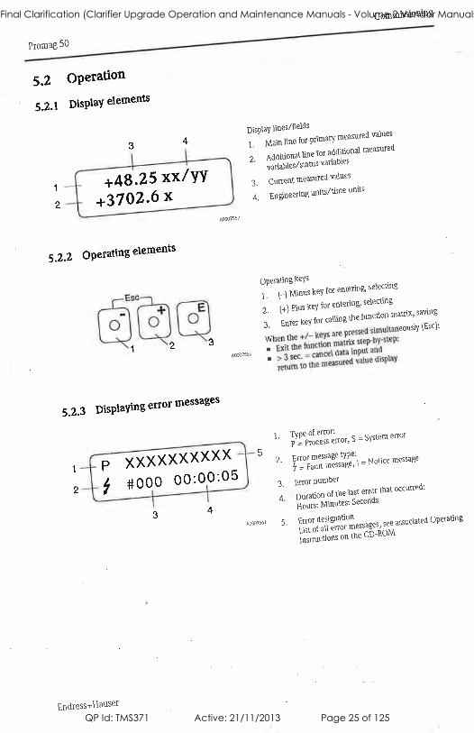
Operation &
Maintenance Manuals
Volume 2
Fernvale Clarifier Upgrade
Fernvale STP ST48 Final Clarification (Clarifier Upgrade Operation and Maintenance Manuals - Volume 2 Vendor Manuals) Vendor Manual
QP Id: TMS371 Active: 21/11/2013 Page 1 of 125

Contents
Section Description
Instrumentation Endress & Hauser
Flowmeter
IFM Pressure Sensor
Royce DO Analyser
Electrical Orbis Timeswitch
Indicators
Ekotech Siting Glass
Wika Pressure Gauge
Valves Challenger PRV161
Challenger PRV160
Pump
Roto Pump
Fernvale STP ST48 Final Clarification (Clarifier Upgrade Operation and Maintenance Manuals - Volume 2 Vendor Manuals) Vendor Manual
QP Id: TMS371 Active: 21/11/2013 Page 2 of 125

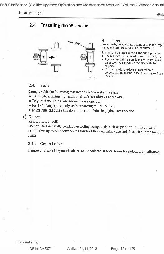
Instrumentation
Fernvale STP ST48 Final Clarification (Clarifier Upgrade Operation and Maintenance Manuals - Volume 2 Vendor Manuals) Vendor Manual
QP Id: TMS371 Active: 21/11/2013 Page 3 of 125

Fernvale STP ST48 Final Clarification (Clarifier Upgrade Operation and Maintenance Manuals - Volume 2 Vendor Manuals) Vendor Manual
QP Id: TMS371 Active: 21/11/2013 Page 4 of 125

Fernvale STP ST48 Final Clarification (Clarifier Upgrade Operation and Maintenance Manuals - Volume 2 Vendor Manuals) Vendor Manual
QP Id: TMS371 Active: 21/11/2013 Page 5 of 125

Fernvale STP ST48 Final Clarification (Clarifier Upgrade Operation and Maintenance Manuals - Volume 2 Vendor Manuals) Vendor Manual
QP Id: TMS371 Active: 21/11/2013 Page 6 of 125
Fernvale STP ST48 Final Clarification (Clarifier Upgrade Operation and Maintenance Manuals - Volume 2 Vendor Manuals) Vendor Manual
QP Id: TMS371 Active: 21/11/2013 Page 7 of 125
Fernvale STP ST48 Final Clarification (Clarifier Upgrade Operation and Maintenance Manuals - Volume 2 Vendor Manuals) Vendor Manual
QP Id: TMS371 Active: 21/11/2013 Page 8 of 125
Fernvale STP ST48 Final Clarification (Clarifier Upgrade Operation and Maintenance Manuals - Volume 2 Vendor Manuals) Vendor Manual
QP Id: TMS371 Active: 21/11/2013 Page 9 of 125
Fernvale STP ST48 Final Clarification (Clarifier Upgrade Operation and Maintenance Manuals - Volume 2 Vendor Manuals) Vendor Manual
QP Id: TMS371 Active: 21/11/2013 Page 10 of 125
Fernvale STP ST48 Final Clarification (Clarifier Upgrade Operation and Maintenance Manuals - Volume 2 Vendor Manuals) Vendor Manual
QP Id: TMS371 Active: 21/11/2013 Page 11 of 125
Fernvale STP ST48 Final Clarification (Clarifier Upgrade Operation and Maintenance Manuals - Volume 2 Vendor Manuals) Vendor Manual
QP Id: TMS371 Active: 21/11/2013 Page 12 of 125
Fernvale STP ST48 Final Clarification (Clarifier Upgrade Operation and Maintenance Manuals - Volume 2 Vendor Manuals) Vendor Manual
QP Id: TMS371 Active: 21/11/2013 Page 13 of 125
Fernvale STP ST48 Final Clarification (Clarifier Upgrade Operation and Maintenance Manuals - Volume 2 Vendor Manuals) Vendor Manual
QP Id: TMS371 Active: 21/11/2013 Page 14 of 125
Fernvale STP ST48 Final Clarification (Clarifier Upgrade Operation and Maintenance Manuals - Volume 2 Vendor Manuals) Vendor Manual
QP Id: TMS371 Active: 21/11/2013 Page 15 of 125
Fernvale STP ST48 Final Clarification (Clarifier Upgrade Operation and Maintenance Manuals - Volume 2 Vendor Manuals) Vendor Manual
QP Id: TMS371 Active: 21/11/2013 Page 16 of 125
Fernvale STP ST48 Final Clarification (Clarifier Upgrade Operation and Maintenance Manuals - Volume 2 Vendor Manuals) Vendor Manual
QP Id: TMS371 Active: 21/11/2013 Page 17 of 125
Fernvale STP ST48 Final Clarification (Clarifier Upgrade Operation and Maintenance Manuals - Volume 2 Vendor Manuals) Vendor Manual
QP Id: TMS371 Active: 21/11/2013 Page 18 of 125

Fernvale STP ST48 Final Clarification (Clarifier Upgrade Operation and Maintenance Manuals - Volume 2 Vendor Manuals) Vendor Manual
QP Id: TMS371 Active: 21/11/2013 Page 19 of 125
Fernvale STP ST48 Final Clarification (Clarifier Upgrade Operation and Maintenance Manuals - Volume 2 Vendor Manuals) Vendor Manual
QP Id: TMS371 Active: 21/11/2013 Page 20 of 125
Fernvale STP ST48 Final Clarification (Clarifier Upgrade Operation and Maintenance Manuals - Volume 2 Vendor Manuals) Vendor Manual
QP Id: TMS371 Active: 21/11/2013 Page 21 of 125
Fernvale STP ST48 Final Clarification (Clarifier Upgrade Operation and Maintenance Manuals - Volume 2 Vendor Manuals) Vendor Manual
QP Id: TMS371 Active: 21/11/2013 Page 22 of 125

Fernvale STP ST48 Final Clarification (Clarifier Upgrade Operation and Maintenance Manuals - Volume 2 Vendor Manuals) Vendor Manual
QP Id: TMS371 Active: 21/11/2013 Page 23 of 125
Fernvale STP ST48 Final Clarification (Clarifier Upgrade Operation and Maintenance Manuals - Volume 2 Vendor Manuals) Vendor Manual
QP Id: TMS371 Active: 21/11/2013 Page 24 of 125
Fernvale STP ST48 Final Clarification (Clarifier Upgrade Operation and Maintenance Manuals - Volume 2 Vendor Manuals) Vendor Manual
QP Id: TMS371 Active: 21/11/2013 Page 25 of 125
Fernvale STP ST48 Final Clarification (Clarifier Upgrade Operation and Maintenance Manuals - Volume 2 Vendor Manuals) Vendor Manual
QP Id: TMS371 Active: 21/11/2013 Page 26 of 125

Fernvale STP ST48 Final Clarification (Clarifier Upgrade Operation and Maintenance Manuals - Volume 2 Vendor Manuals) Vendor Manual
QP Id: TMS371 Active: 21/11/2013 Page 27 of 125

Fernvale STP ST48 Final Clarification (Clarifier Upgrade Operation and Maintenance Manuals - Volume 2 Vendor Manuals) Vendor Manual
QP Id: TMS371 Active: 21/11/2013 Page 28 of 125
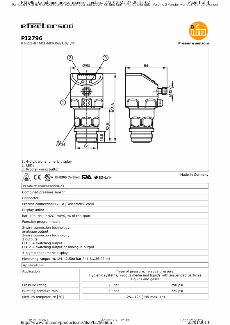
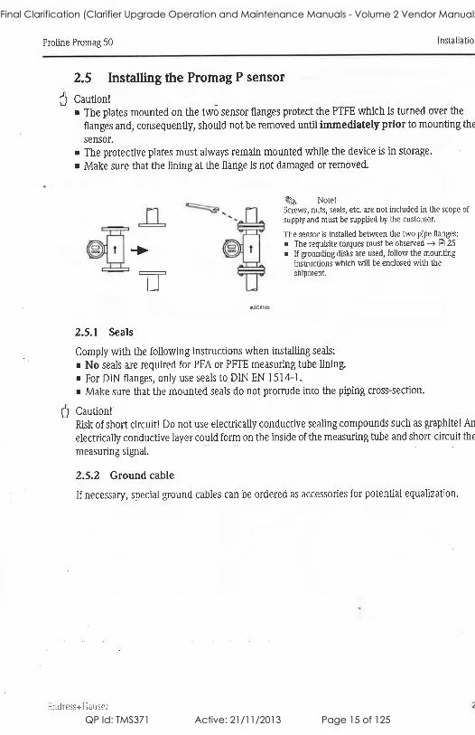
PI2796PI-2.5-REA01-MFRKG/US/ /P Pressure sensors
1: 4-digit alphanumeric display 2: LEDs
3: Programming button
Made in Germany
Product characteristics
Combined pressure sensor
Connector
Process connection: G 1 A / Aseptoflex Vario
Display units:
bar, kPa, psi, inH2O, mWS, % of the span
Function programmable
2-wire connection technology:
analogue output 3-wire connection technology:
2 outputs OUT1 = switching output
OUT2 = switching output or analogue output
4-digit alphanumeric display
Measuring range: -0.124...2.500 bar / -1.8...36.27 psi
Application
Application Type of pressure: relative pressure
Hygienic systems, viscous media and liquids with suspended particles Liquids and gases
Pressure rating 20 bar 290 psi
Bursting pressure min. 50 bar 725 psi
Medium temperature [°C] -25...125 (145 max. 1h)
Page 1 of 4PI2796 - Combined pressure sensor - eclass: 27201302 / 27-20-13-02
23/01/2013http://www.ifm.com/products/aus/ds/PI2796.htm
Fernvale STP ST48 Final Clarification (Clarifier Upgrade Operation and Maintenance Manuals - Volume 2 Vendor Manuals) Vendor Manual
QP Id: TMS371 Active: 21/11/2013 Page 29 of 125
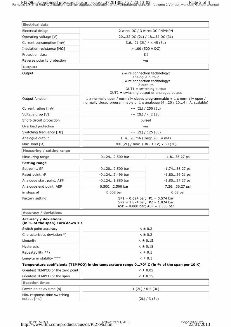
Electrical data
Electrical design 2 wires DC / 3 wires DC PNP/NPN
Operating voltage [V] 20...32 DC (2L) / 18...32 DC (3L)
Current consumption [mA] 3.6...21 (2L) / < 45 (3L)
Insulation resistance [MΩ] > 100 (500 V DC)
Protection class III
Reverse polarity protection yes
Outputs
Output 2-wire connection technology:
analogue output 3-wire connection technology:
2 outputs OUT1 = switching output
OUT2 = switching output or analogue output
Output function 1 x normally open / normally closed programmable + 1 x normally open /
normally closed programmable or 1 x analogue (4...20 / 20...4 mA, scalable)
Current rating [mA] --- (2L) / 250 (3L)
Voltage drop [V] --- (2L) / < 2 (3L)
Short-circuit protection pulsed
Overload protection yes
Switching frequency [Hz] --- (2L) / 125 (3L)
Analogue output I: 4...20 mA (Ineg: 20...4 mA)
Max. load [Ω] 300 (2L) / max. (Ub - 10 V) x 50 (3L)
Measuring / setting range
Measuring range -0.124...2.500 bar -1.8...36.27 psi
Setting range
Set point, SP -0.120...2.500 bar -1.74...36.27 psi
Reset point, rP -0.124...2.496 bar -1.80...36.21 psi
Analogue start point, ASP -0.124...1.880 bar -1.80...27.27 psi
Analogue end point, AEP 0.500...2.500 bar 7.26...36.27 psi
in steps of 0.002 bar 0.03 psi
Factory setting SP1 = 0.624 bar; rP1 = 0.574 bar
SP2 = 1.874 bar; rP2 = 1.824 bar ASP = 0.000 bar; AEP = 2.500 bar
Accuracy / deviations
Accuracy / deviations (in % of the span) Turn down 1:1
Switch point accuracy < ± 0.2
Characteristics deviation *) < ± 0.2
Linearity < ± 0.15
Hysteresis < ± 0.15
Repeatability **) < ± 0.1
Long-term stability ***) < ± 0.1
Temperature coefficients (TEMPCO) in the temperature range 0...70° C (in % of the span per 10 K)
Greatest TEMPCO of the zero point < ± 0.05
Greatest TEMPCO of the span < ± 0.15
Reaction times
Power-on delay time [s] 1 (2L) / 0.5 (3L)
Min. response time switching
output [ms] --- (2L) / 3 (3L)
Page 2 of 4PI2796 - Combined pressure sensor - eclass: 27201302 / 27-20-13-02
23/01/2013http://www.ifm.com/products/aus/ds/PI2796.htm
Fernvale STP ST48 Final Clarification (Clarifier Upgrade Operation and Maintenance Manuals - Volume 2 Vendor Manuals) Vendor Manual
QP Id: TMS371 Active: 21/11/2013 Page 30 of 125
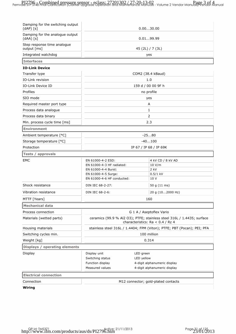
Damping for the switching output
(dAP) [s] 0.00...30.00
Damping for the analogue output (dAA) [s] 0.01...99.99
Step response time analogue output [ms] 45 (2L) / 7 (3L)
Integrated watchdog yes
Interfaces
IO-Link Device
Transfer type COM2 (38.4 kBaud)
IO-Link revision 1.0
IO-Link Device ID 159 d / 00 00 9F h
Profiles no profile
SIO mode yes
Required master port type A
Process data analogue 1
Process data binary 2
Min. process cycle time [ms] 2.3
Environment
Ambient temperature [°C] -25...80
Storage temperature [°C] -40...100
Protection IP 67 / IP 68 / IP 69K
Tests / approvals
EMC EN 61000-4-2 ESD: 4 kV CD / 8 kV AD
EN 61000-4-3 HF radiated: 10 V/m
EN 61000-4-4 Burst: 2 kV
EN 61000-4-5 Surge: 0.5/1 kV
EN 61000-4-6 HF conducted: 10 V
Shock resistance DIN IEC 68-2-27: 50 g (11 ms)
Vibration resistance DIN IEC 68-2-6: 20 g (10...2000 Hz)
MTTF [Years] 160
Mechanical data
Process connection G 1 A / Aseptoflex Vario
Materials (wetted parts) ceramics (99.9 % Al2 O3); PTFE; stainless steel 316L / 1.4435; surface characteristics: Ra < 0.4 / Rz 4
Housing materials stainless steel 316L / 1.4404; FPM (Viton); PTFE; PBT (Pocan); PEI; PFA
Switching cycles min. 100 million
Weight [kg] 0.314
Displays / operating elements
Display Display unit LED green
Switching status LED yellow
Function display 4-digit alphanumeric display
Measured values 4-digit alphanumeric display
Electrical connection
Connection M12 connector; gold-plated contacts
Wiring
Page 3 of 4PI2796 - Combined pressure sensor - eclass: 27201302 / 27-20-13-02
23/01/2013http://www.ifm.com/products/aus/ds/PI2796.htm
Fernvale STP ST48 Final Clarification (Clarifier Upgrade Operation and Maintenance Manuals - Volume 2 Vendor Manuals) Vendor Manual
QP Id: TMS371 Active: 21/11/2013 Page 31 of 125
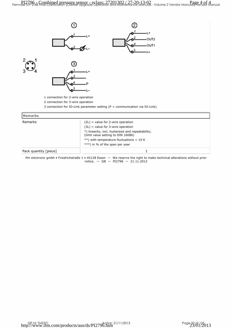
1 connection for 2-wire operation
2 connection for 3-wire operation
3 connection for IO-Link parameter setting (P = communication via IO-Link)
Remarks
Remarks (2L) = value for 2-wire operation
(3L) = value for 3-wire operation
*) linearity, incl. hysteresis and repeatability;
(limit value setting to DIN 16086)
**) with temperature fluctuations < 10 K
***) in % of the span per year
Pack quantity [piece] 1
ifm electronic gmbh • Friedrichstraße 1 • 45128 Essen — We reserve the right to make technical alterations without prior
notice. — GB — PI2796 — 21.11.2012
Page 4 of 4PI2796 - Combined pressure sensor - eclass: 27201302 / 27-20-13-02
23/01/2013http://www.ifm.com/products/aus/ds/PI2796.htm
Fernvale STP ST48 Final Clarification (Clarifier Upgrade Operation and Maintenance Manuals - Volume 2 Vendor Manuals) Vendor Manual
QP Id: TMS371 Active: 21/11/2013 Page 32 of 125

Operating instructions Electronic pressure sensor
PI27xx
7049
24/0
0
01/2
011
UK
Fernvale STP ST48 Final Clarification (Clarifier Upgrade Operation and Maintenance Manuals - Volume 2 Vendor Manuals) Vendor Manual
QP Id: TMS371 Active: 21/11/2013 Page 33 of 125
2
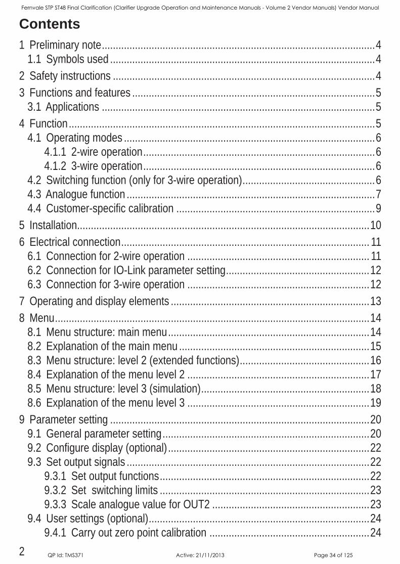
Contents1 Preliminary note 4
11 Symbols used 42 Safety instructions 43 Functions and features 5
31 Applications 54 Function 5
41 Operating modes 6411 2-wire operation 6412 3-wire operation 6
42 Switching function (only for 3-wire operation) 643 Analogue function 744 Customer-specific calibration 9
5 Installation106 Electrical connection 11
61 Connection for 2-wire operation 1162 Connection for IO-Link parameter setting 1263 Connection for 3-wire operation 12
7 Operating and display elements 138 Menu 14
81 Menu structure: main menu 1482 Explanation of the main menu 1583 Menu structure: level 2 (extended functions) 1684 Explanation of the menu level 2 1785 Menu structure: level 3 (simulation) 1886 Explanation of the menu level 3 19
9 Parameter setting 2091 General parameter setting 2092 Configure display (optional) 2293 Set output signals 22
931 Set output functions 22932 Set switching limits 23933 Scale analogue value for OUT2 23
94 User settings (optional) 24941 Carry out zero point calibration 24
Fernvale STP ST48 Final Clarification (Clarifier Upgrade Operation and Maintenance Manuals - Volume 2 Vendor Manuals) Vendor Manual
QP Id: TMS371 Active: 21/11/2013 Page 34 of 125
3
UK
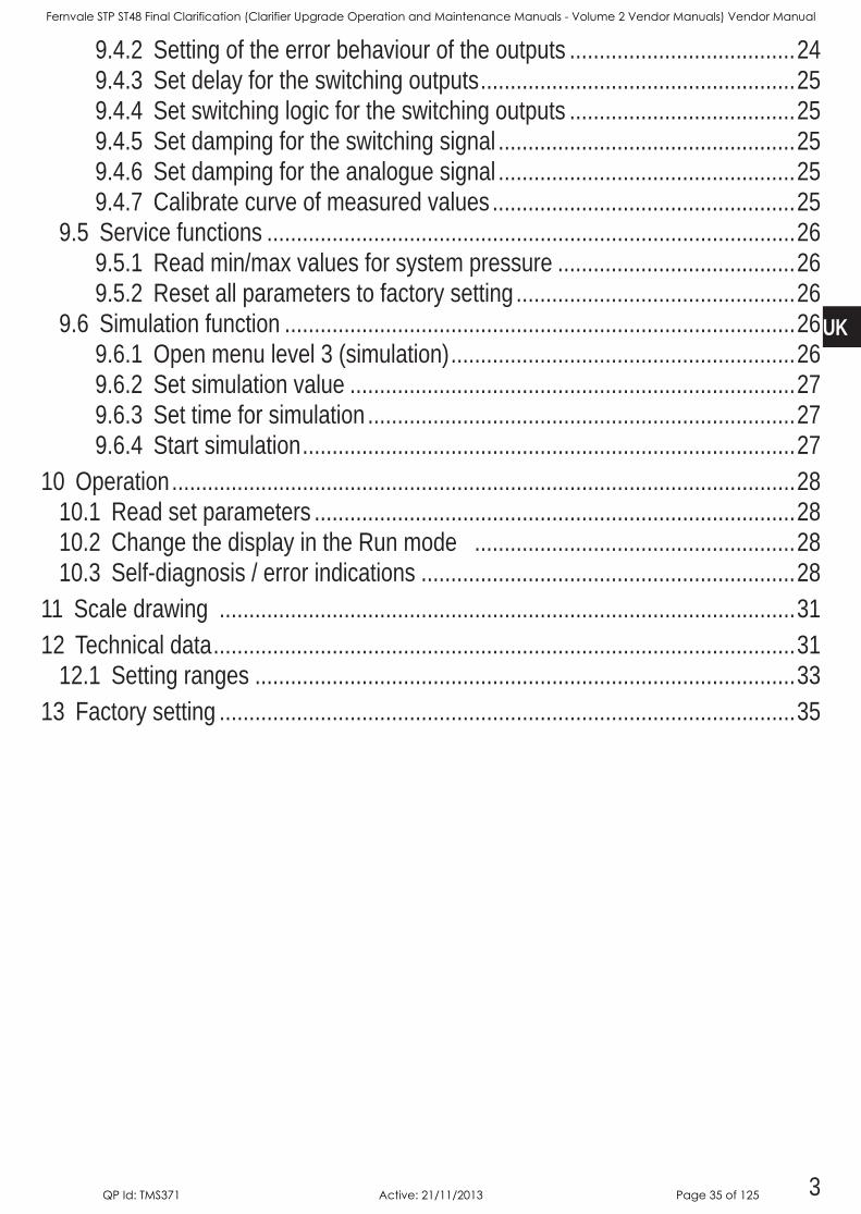
942 Setting of the error behaviour of the outputs 24943 Set delay for the switching outputs 25944 Set switching logic for the switching outputs 25945 Set damping for the switching signal 25946 Set damping for the analogue signal 25947 Calibrate curve of measured values 25
95 Service functions 26951 Read min/max values for system pressure 26952 Reset all parameters to factory setting 26
96 Simulation function 26961 Open menu level 3 (simulation) 26962 Set simulation value 27963 Set time for simulation 27964 Start simulation 27
10 Operation 28101 Read set parameters 28102 Change the display in the Run mode 28103 Self-diagnosis / error indications 28
11 Scale drawing 3112 Technical data 31
121 Setting ranges 3313 Factory setting 35
Fernvale STP ST48 Final Clarification (Clarifier Upgrade Operation and Maintenance Manuals - Volume 2 Vendor Manuals) Vendor Manual
QP Id: TMS371 Active: 21/11/2013 Page 35 of 125

4
1 Preliminary note1.1 Symbols used
Instructions> Reaction, result[…] Designation of pushbuttons, buttons or indications→ Cross-reference
Important note Non-compliance can result in malfunction or interferenceInformation Supplementary note
2 Safety instructions• Please read this document prior to set-up of the unit Ensure that the product is
suitable for your application without any restrictions • If the operating instructions or the technical data are not adhered to, personal
injury and/or damage to property can occur • Checkthecompatibilityoftheproductmaterials(→chapter12Technicaldata)
with the media to be measured in all applicationsFor the scope of validity cULus: The device shall be supplied from an isolating transformer having a secondary Listed fuse rated either a) max 5 amps for voltages 0~20 Vrms (0~283 Vp) or b) 100/Vp for voltages of 20~30 Vrms (283~424 Vp)The Sensor shall be connected only by using any R/C (CYJV2) cord, having suitable ratings
Fernvale STP ST48 Final Clarification (Clarifier Upgrade Operation and Maintenance Manuals - Volume 2 Vendor Manuals) Vendor Manual
QP Id: TMS371 Active: 21/11/2013 Page 36 of 125
5
UK
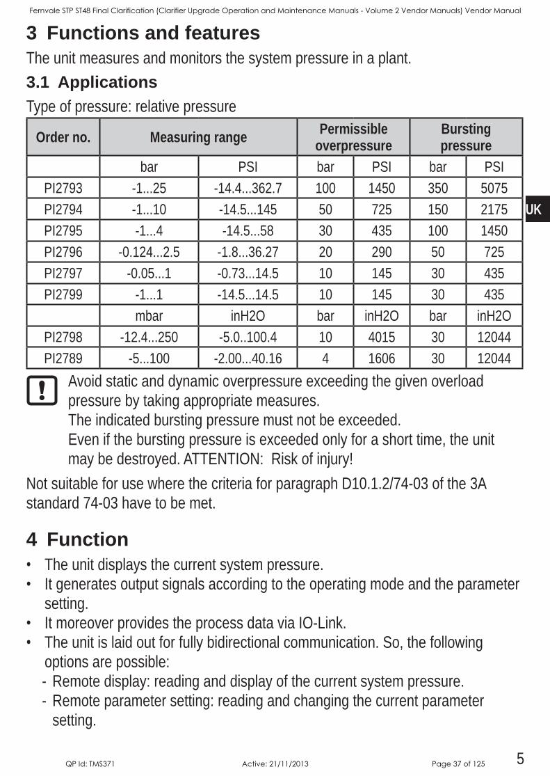
3 Functions and featuresThe unit measures and monitors the system pressure in a plant3.1 ApplicationsType of pressure: relative pressure
Order no. Measuring range Permissible overpressure
Bursting pressure
bar PSI bar PSI bar PSIPI2793 -125 -1443627 100 1450 350 5075PI2794 -110 -145145 50 725 150 2175PI2795 -14 -14558 30 435 100 1450PI2796 -012425 -183627 20 290 50 725PI2797 -0051 -073145 10 145 30 435PI2799 -11 -145145 10 145 30 435
mbar inH2O bar inH2O bar inH2OPI2798 -124250 -501004 10 4015 30 12044PI2789 -5100 -2004016 4 1606 30 12044
Avoid static and dynamic overpressure exceeding the given overload pressure by taking appropriate measuresThe indicated bursting pressure must not be exceededEven if the bursting pressure is exceeded only for a short time, the unit may be destroyed ATTENTION: Risk of injury!
Not suitable for use where the criteria for paragraph D1012/74-03 of the 3A standard 74-03 have to be met
4 Function• The unit displays the current system pressure• It generates output signals according to the operating mode and the parameter
setting• It moreover provides the process data via IO-Link• The unit is laid out for fully bidirectional communication So, the following
options are possible: - Remote display: reading and display of the current system pressure - Remote parameter setting: reading and changing the current parameter setting
Fernvale STP ST48 Final Clarification (Clarifier Upgrade Operation and Maintenance Manuals - Volume 2 Vendor Manuals) Vendor Manual
QP Id: TMS371 Active: 21/11/2013 Page 37 of 125
6
- Using the FDT service program ifm Container, the current parameter settings can be stored and transferred to other units of the same type
The program library of the available DTM objects can be found at wwwifmcom →Service→Download.Device-specific parameter lists for IO-Link parameter setting are available at: wwwifmcom
4.1 Operating modesTheoperatingmodeisdefinedbythewiring(→6Electricalconnection)andautomatically recognised4.1.1 2-wire operationOUT2 (pin 2) analogue signal proportional to pressure 4…20 mA or 204 mA
4.1.2 3-wire operation
OUT1 (pin 4) •switching signal for system pressure limit value•communication via IO-Link
OUT2 (pin 2)3 options:•switching signal for system pressure limit value•analogue signal proportional to pressure 420 mA•analogue signal proportional to pressure 204 mA
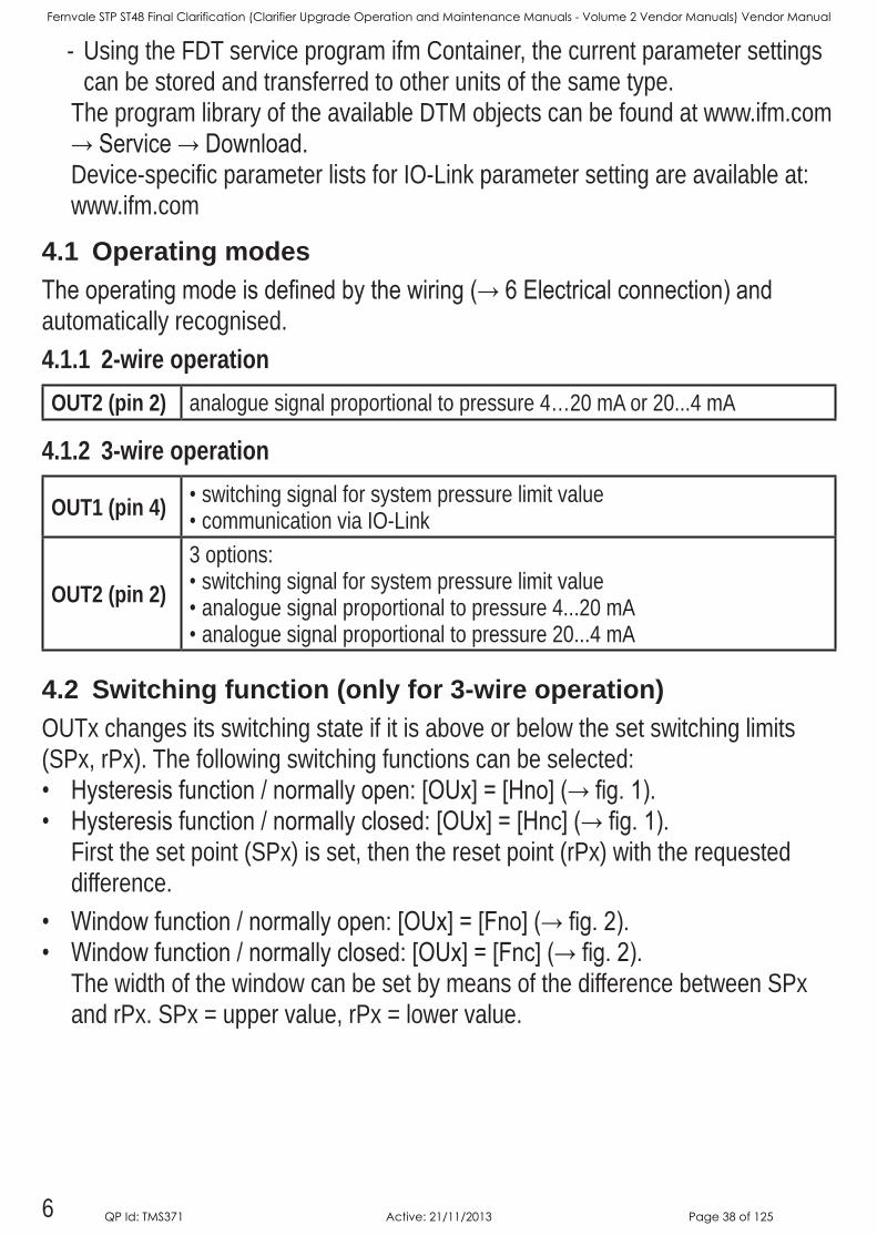
4.2 Switching function (only for 3-wire operation)OUTx changes its switching state if it is above or below the set switching limits (SPx, rPx) The following switching functions can be selected:• Hysteresisfunction/normallyopen:[OUx]=[Hno](→fig.1).• Hysteresisfunction/normallyclosed:[OUx]=[Hnc](→fig.1).
First the set point (SPx) is set, then the reset point (rPx) with the requested difference
• Windowfunction/normallyopen:[OUx]=[Fno](→fig.2).• Windowfunction/normallyclosed:[OUx]=[Fnc](→fig.2).
The width of the window can be set by means of the difference between SPx and rPx SPx = upper value, rPx = lower value
Fernvale STP ST48 Final Clarification (Clarifier Upgrade Operation and Maintenance Manuals - Volume 2 Vendor Manuals) Vendor Manual
QP Id: TMS371 Active: 21/11/2013 Page 38 of 125
7
UK
1 2
P = system pressure; HY = hysteresis; FE = window
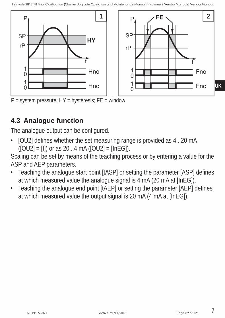
4.3 Analogue functionThe analogue output can be configured• [OU2] defines whether the set measuring range is provided as 420 mA
([OU2] = [I]) or as 204 mA ([OU2] = [InEG])Scaling can be set by means of the teaching process or by entering a value for the ASP and AEP parameters• Teaching the analogue start point [tASP] or setting the parameter [ASP] defines
at which measured value the analogue signal is 4 mA (20 mA at [InEG])• Teaching the analogue end point [tAEP] or setting the parameter [AEP] defines
at which measured value the output signal is 20 mA (4 mA at [InEG])
Fernvale STP ST48 Final Clarification (Clarifier Upgrade Operation and Maintenance Manuals - Volume 2 Vendor Manuals) Vendor Manual
QP Id: TMS371 Active: 21/11/2013 Page 39 of 125
8
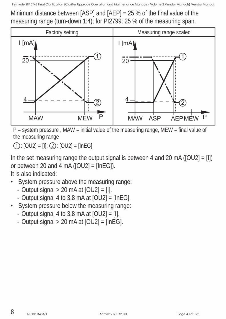
Minimum distance between [ASP] and [AEP] = 25 % of the final value of the measuring range (turn-down 1:4); for PI2799: 25 % of the measuring span
Factory setting Measuring range scaled
P = system pressure , MAW = initial value of the measuring range, MEW = final value of the measuring range1 : [OU2] = [I]; 2 : [OU2] = [InEG]
In the set measuring range the output signal is between 4 and 20 mA ([OU2] = [I]) or between 20 and 4 mA ([OU2] = [InEG])It is also indicated:• System pressure above the measuring range:
- Output signal > 20 mA at [OU2] = [I] - Output signal 4 to 38 mA at [OU2] = [InEG]
• System pressure below the measuring range: - Output signal 4 to 38 mA at [OU2] = [I] - Output signal > 20 mA at [OU2] = [InEG]
Fernvale STP ST48 Final Clarification (Clarifier Upgrade Operation and Maintenance Manuals - Volume 2 Vendor Manuals) Vendor Manual
QP Id: TMS371 Active: 21/11/2013 Page 40 of 125

9
UK
4.4 Customer-specific calibrationThe customer-specific calibration changes the curve of measured values comparedtotherealmeasuredvalues(shifting/changeofthegradient;→9.4.6[CAL]) • Two calibration points can be defined (CP1, CP2) The two points are
independent of each other• Thetwocalibrationpointsmustbewithinthescaledmeasuringrange(→4.3
Pressure monitoring / analogue function)• The zero point calibration [COF] influences the calibration of the curve of
measuredvalues.Recommendation:set[COF]to0(→9.4.1[COF]),thencalibrate the curve of measured values
Afterachangethecalibrationcanberesettofactorysetting(→9.5.2[rES]).
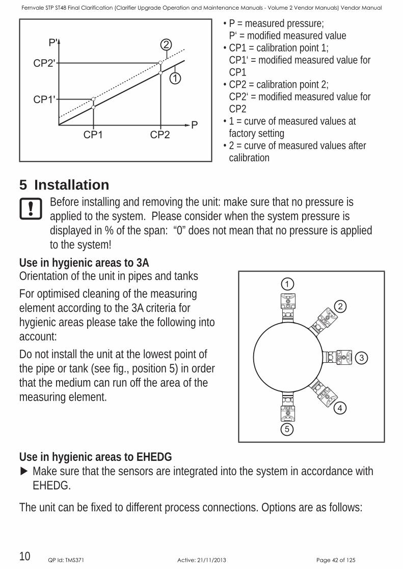
•P = measured pressure;
P‘ = modified measured value•CP1 = calibration point 1;
CP1‘ = modified measured value for CP1
•CP2 = calibration point 2;•1 = curve of measured values at
factory setting•2 = curve of measured values after
calibration
•P = measured pressure;
P‘ = modified measured value•CP1 = calibration point 1;
CP2 = calibration point 2; CP2‘ = modified measured value for CP2
•1 = curve of measured values at factory setting
•2 = curve of measured values after calibration
Fernvale STP ST48 Final Clarification (Clarifier Upgrade Operation and Maintenance Manuals - Volume 2 Vendor Manuals) Vendor Manual
QP Id: TMS371 Active: 21/11/2013 Page 41 of 125
10
•P = measured pressure; P‘ = modified measured value
•CP1 = calibration point 1; CP1‘ = modified measured value for CP1
•CP2 = calibration point 2; CP2‘ = modified measured value for CP2
•1 = curve of measured values at factory setting
•2 = curve of measured values after calibration
5 InstallationBefore installing and removing the unit: make sure that no pressure is applied to the system Please consider when the system pressure is displayed in % of the span: “0” does not mean that no pressure is applied to the system!
Use in hygienic areas to 3A Orientation of the unit in pipes and tanksFor optimised cleaning of the measuring element according to the 3A criteria for hygienic areas please take the following into account:Do not install the unit at the lowest point of the pipe or tank (see fig, position 5) in order that the medium can run off the area of the measuring element
Use in hygienic areas to EHEDG Make sure that the sensors are integrated into the system in accordance with EHEDG
The unit can be fixed to different process connections Options are as follows:
Fernvale STP ST48 Final Clarification (Clarifier Upgrade Operation and Maintenance Manuals - Volume 2 Vendor Manuals) Vendor Manual
QP Id: TMS371 Active: 21/11/2013 Page 42 of 125

11
UK
1 Installation using an adapter with sealing ring (order no. E332xx / E333xx)The adapters are supplied with EPDM O-ring (order no E30054) More sealing rings are available as accessories: FKM O-ring (order no E30123); PEEK sealing ring (order no E30124) Concerninginstallation→Installationinstructionsattachedtotheadapter.
2 Installation using an adapter with metal-to-metal sealOrder no E337xx / E338xxConcerninginstallation→Installationinstructionsattachedtotheadapter.
3 Installation using a welding adapter•Order no E30122•Order no E30130; adapter with leakage portThe adapters are supplied with EPDM O-ring (order no E30054) More sealing rings are available as accessories: FKM O-ring, order no E30123Concerninginstallation→Installationinstructionsattachedtotheadapter.
4 Installation to G 1 flangeThe sealing ring on the sensor is used as process sealThe upper sealing area on the process connection must be flush with the tapped hole and have a surface characteristic of min Rz 63
Grease the sensor thread with a suitable paste Insert the unit into the process connection Tighten it using a spanner Tightening torque: 35 Nm
6 Electrical connectionThe unit must be connected by a qualified electricianThe national and international regulations for the installation of electrical equipment must be adhered toVoltage supply according to EN 50178, SELV, PELV
Disconnect power Connect the unit as follows:
6.1 Connection for 2-wire operation
Fernvale STP ST48 Final Clarification (Clarifier Upgrade Operation and Maintenance Manuals - Volume 2 Vendor Manuals) Vendor Manual
QP Id: TMS371 Active: 21/11/2013 Page 43 of 125
12
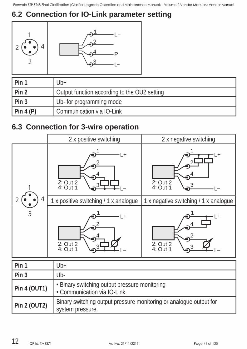
6.2 Connection for IO-Link parameter setting
4
1
3
2L+
L
P
Pin 1 Ub+Pin 2 Output function according to the OU2 setting Pin 3 Ub- for programming modePin 4 (P) Communication via IO-Link
6.3 Connection for 3-wire operation2 x positive switching 2 x negative switching
4
L
L+2
1
3Out 1Out 2
4:2:
4
L
L+2
1
3Out 1Out 2
4:2:
1 x positive switching / 1 x analogue 1 x negative switching / 1 x analogue
4
1
3
2L+
LOut 1Out 2
4:2:
2
1
3
4L+
LOut 1Out 2
4:2:
Pin 1 Ub+Pin 3 Ub-
Pin 4 (OUT1) •Binary switching output pressure monitoring•Communication via IO-Link
Pin 2 (OUT2) Binary switching output pressure monitoring or analogue output for system pressure
Fernvale STP ST48 Final Clarification (Clarifier Upgrade Operation and Maintenance Manuals - Volume 2 Vendor Manuals) Vendor Manual
QP Id: TMS371 Active: 21/11/2013 Page 44 of 125

13
UK
7 Operating and display elements
10
9
11
Mode/Enter Set
1 2 3 4 5 6 7 8
1 to 8: Indicator LEDs - LED 1 to LED 5 = system pressure in the specified unit of measurement - LED 6 = System pressure in % of the set scaling of the analogue output if [OU2] is configured as analogue outputSystem pressure in % of the final value of the measuring range if [OU2] is configured as switching output
- LED 7 = switching status OUT2 (lights if output 2 is switched) - LED 8 = switching status OUT1 (lights if output 1 is switched)
9: Alphanumeric display, 4 digits - Display of the current system pressure - Indication of the parameters and parameter values
10: Set pushbutton - Setting of the parameter values (scrolling by holding pressed; incrementally by pressing once)
11: Mode/Enter button - Selection of the parameters and acknowledgement of the parameter values
Fernvale STP ST48 Final Clarification (Clarifier Upgrade Operation and Maintenance Manuals - Volume 2 Vendor Manuals) Vendor Manual
QP Id: TMS371 Active: 21/11/2013 Page 45 of 125
14
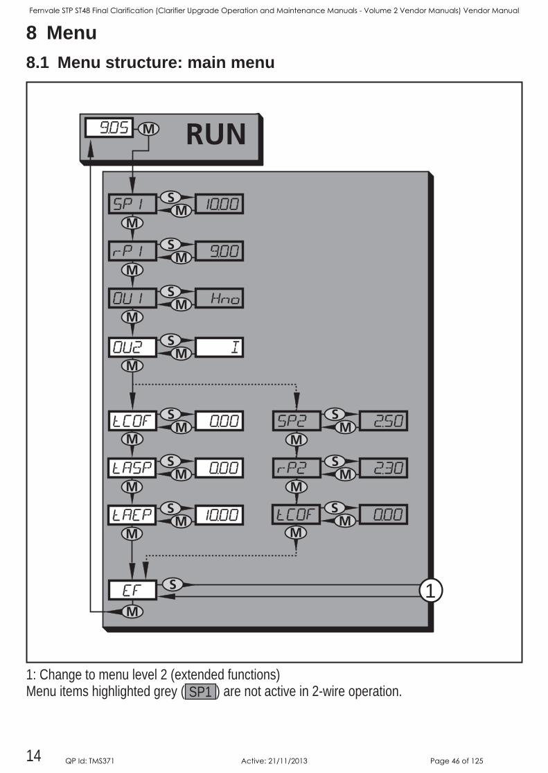
8 Menu8.1 Menu structure: main menu
RUN
S
MM
S
MM
S
MM
S
MS
MS
M
M1
MM
S
MM
S
M
MM
S
MM
S
M
MS
M
1: Change to menu level 2 (extended functions) Menu items highlighted grey ( SP1 ) are not active in 2-wire operation
Fernvale STP ST48 Final Clarification (Clarifier Upgrade Operation and Maintenance Manuals - Volume 2 Vendor Manuals) Vendor Manual
QP Id: TMS371 Active: 21/11/2013 Page 46 of 125
15
UK
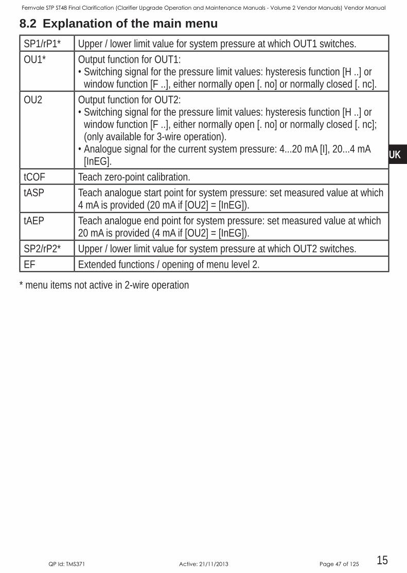
8.2 Explanation of the main menuSP1/rP1* Upper / lower limit value for system pressure at which OUT1 switchesOU1* Output function for OUT1:
•Switching signal for the pressure limit values: hysteresis function [H ] or window function [F ], either normally open [ no] or normally closed [ nc]
OU2 Output function for OUT2:•Switching signal for the pressure limit values: hysteresis function [H ] or
window function [F ], either normally open [ no] or normally closed [ nc]; (only available for 3-wire operation)
•Analogue signal for the current system pressure: 420 mA [I], 204 mA [InEG]
tCOF Teach zero-point calibrationtASP Teach analogue start point for system pressure: set measured value at which
4 mA is provided (20 mA if [OU2] = [InEG])tAEP Teach analogue end point for system pressure: set measured value at which
20 mA is provided (4 mA if [OU2] = [InEG])SP2/rP2* Upper / lower limit value for system pressure at which OUT2 switchesEF Extended functions / opening of menu level 2
* menu items not active in 2-wire operation
Fernvale STP ST48 Final Clarification (Clarifier Upgrade Operation and Maintenance Manuals - Volume 2 Vendor Manuals) Vendor Manual
QP Id: TMS371 Active: 21/11/2013 Page 47 of 125
16
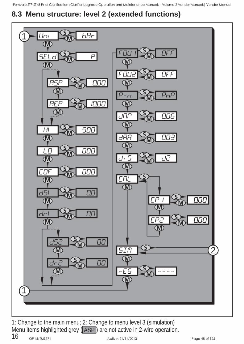
8.3 Menu structure: level 2 (extended functions)
MM
S
MM
S
MM
S
MM
S
MM
S
MS
MM
S
MM
S
MM
S
1
1
M
MM
S
MM
S
MS
MS
MS
MS
M
M
M
M
M
MS
M
MS
M
MS
M
M
MS
MS
M
S 2
S
M
1: Change to the main menu; 2: Change to menu level 3 (simulation)Menu items highlighted grey ( ASP ) are not active in 2-wire operation
Fernvale STP ST48 Final Clarification (Clarifier Upgrade Operation and Maintenance Manuals - Volume 2 Vendor Manuals) Vendor Manual
QP Id: TMS371 Active: 21/11/2013 Page 48 of 125
17
UK
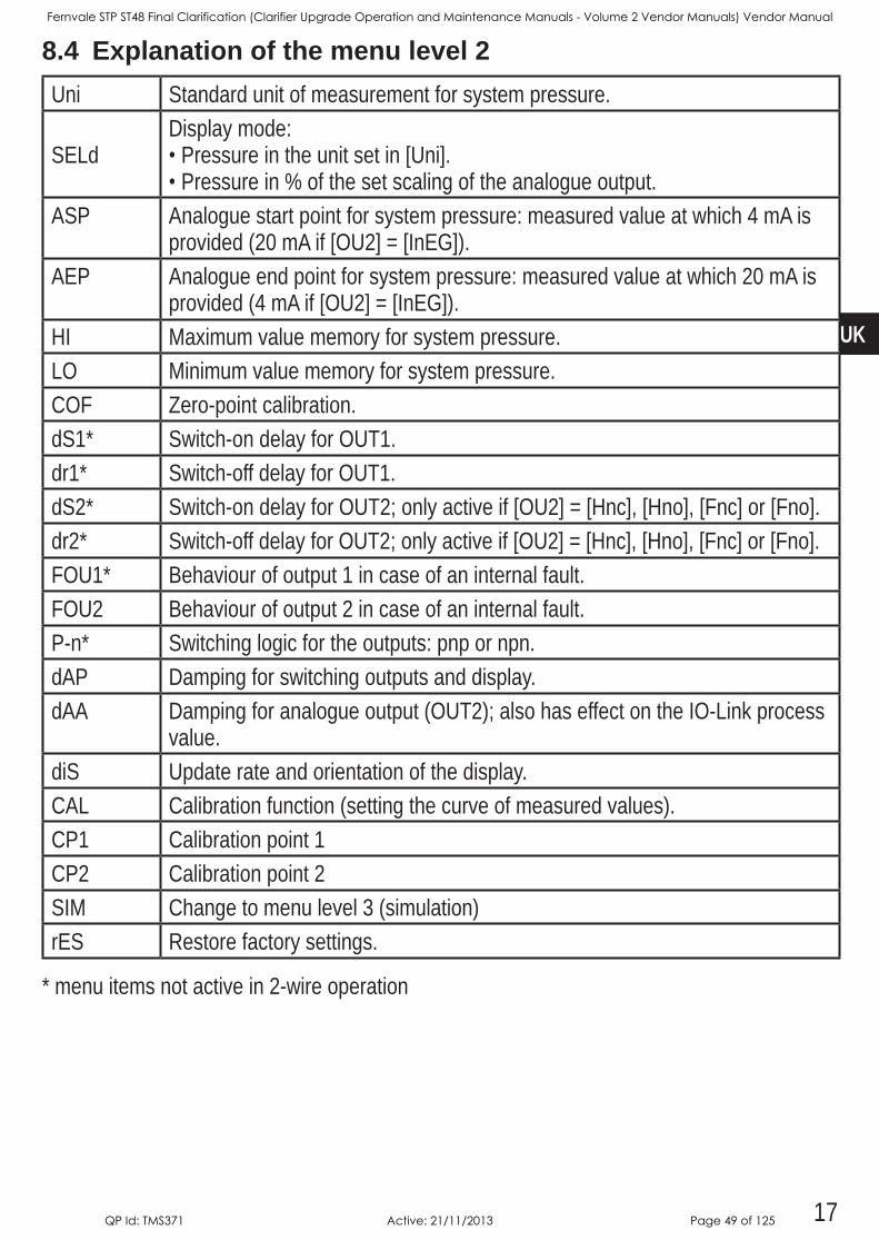
8.4 Explanation of the menu level 2Uni Standard unit of measurement for system pressure
SELdDisplay mode:•Pressure in the unit set in [Uni]•Pressure in % of the set scaling of the analogue output
ASP Analogue start point for system pressure: measured value at which 4 mA is provided (20 mA if [OU2] = [InEG])
AEP Analogue end point for system pressure: measured value at which 20 mA is provided (4 mA if [OU2] = [InEG])
HI Maximum value memory for system pressureLO Minimum value memory for system pressureCOF Zero-point calibrationdS1* Switch-on delay for OUT1dr1* Switch-off delay for OUT1dS2* Switch-on delay for OUT2; only active if [OU2] = [Hnc], [Hno], [Fnc] or [Fno]dr2* Switch-off delay for OUT2; only active if [OU2] = [Hnc], [Hno], [Fnc] or [Fno]FOU1* Behaviour of output 1 in case of an internal faultFOU2 Behaviour of output 2 in case of an internal faultP-n* Switching logic for the outputs: pnp or npndAP Damping for switching outputs and displaydAA Damping for analogue output (OUT2); also has effect on the IO-Link process
valuediS Update rate and orientation of the displayCAL Calibration function (setting the curve of measured values)CP1 Calibration point 1CP2 Calibration point 2SIM Change to menu level 3 (simulation)rES Restore factory settings
* menu items not active in 2-wire operation
Fernvale STP ST48 Final Clarification (Clarifier Upgrade Operation and Maintenance Manuals - Volume 2 Vendor Manuals) Vendor Manual
QP Id: TMS371 Active: 21/11/2013 Page 49 of 125
18
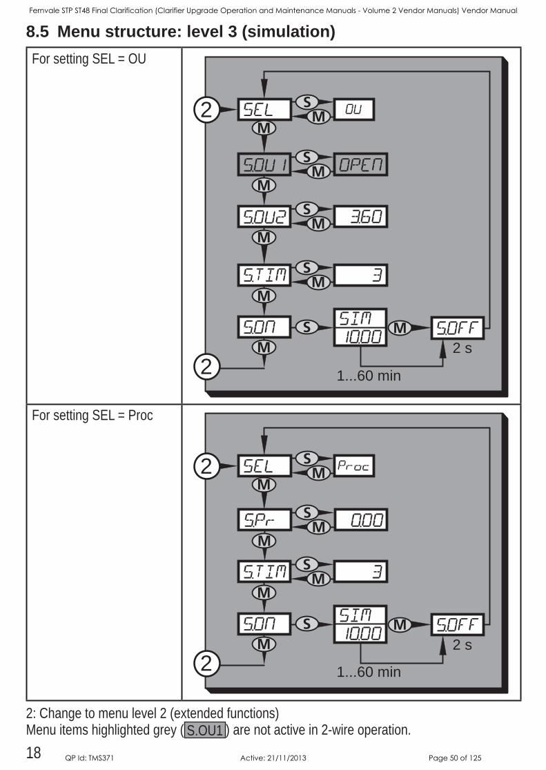
8.5 Menu structure: level 3 (simulation)For setting SEL = OU
2
2 MS
MM
S
MM
S
MM
S
MSM 2 s
1...60 min
M
For setting SEL = Proc
2
2 MS
MM
S
MM
S
MSM 2 s
1...60 min
M
2: Change to menu level 2 (extended functions)Menu items highlighted grey ( SOU1 ) are not active in 2-wire operation
Fernvale STP ST48 Final Clarification (Clarifier Upgrade Operation and Maintenance Manuals - Volume 2 Vendor Manuals) Vendor Manual
QP Id: TMS371 Active: 21/11/2013 Page 50 of 125
19
UK
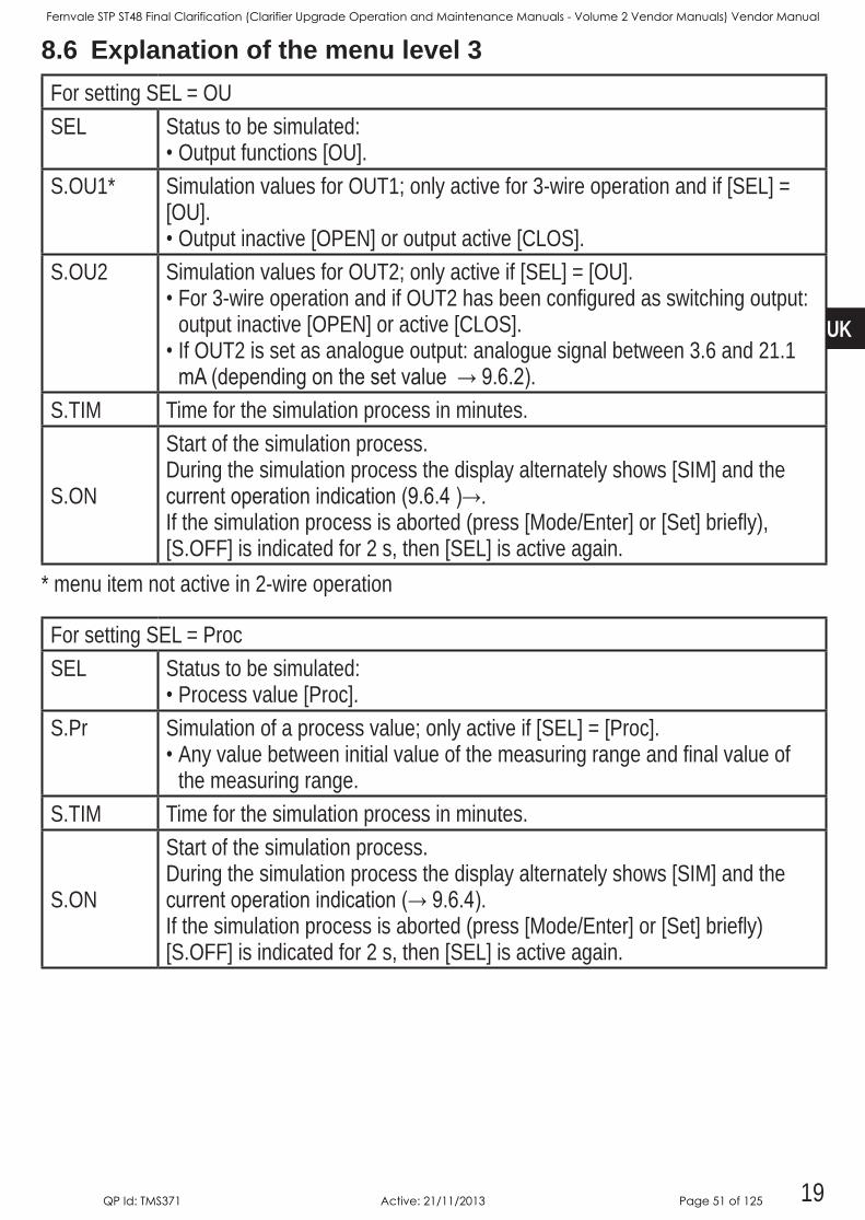
8.6 Explanation of the menu level 3For setting SEL = OUSEL Status to be simulated:
•Output functions [OU]SOU1* Simulation values for OUT1; only active for 3-wire operation and if [SEL] =
[OU]•Output inactive [OPEN] or output active [CLOS]
SOU2 Simulation values for OUT2; only active if [SEL] = [OU]•For 3-wire operation and if OUT2 has been configured as switching output:
output inactive [OPEN] or active [CLOS]•If OUT2 is set as analogue output: analogue signal between 36 and 211 mA(dependingonthesetvalue→9.6.2).
STIM Time for the simulation process in minutes
SON
Start of the simulation processDuring the simulation process the display alternately shows [SIM] and the currentoperationindication(9.6.4)→.If the simulation process is aborted (press [Mode/Enter] or [Set] briefly), [SOFF] is indicated for 2 s, then [SEL] is active again
* menu item not active in 2-wire operation
For setting SEL = ProcSEL Status to be simulated:
•Process value [Proc]SPr Simulation of a process value; only active if [SEL] = [Proc]
•Any value between initial value of the measuring range and final value of the measuring range
STIM Time for the simulation process in minutes
SON
Start of the simulation processDuring the simulation process the display alternately shows [SIM] and the currentoperationindication(→9.6.4).If the simulation process is aborted (press [Mode/Enter] or [Set] briefly) [SOFF] is indicated for 2 s, then [SEL] is active again
Fernvale STP ST48 Final Clarification (Clarifier Upgrade Operation and Maintenance Manuals - Volume 2 Vendor Manuals) Vendor Manual
QP Id: TMS371 Active: 21/11/2013 Page 51 of 125
20
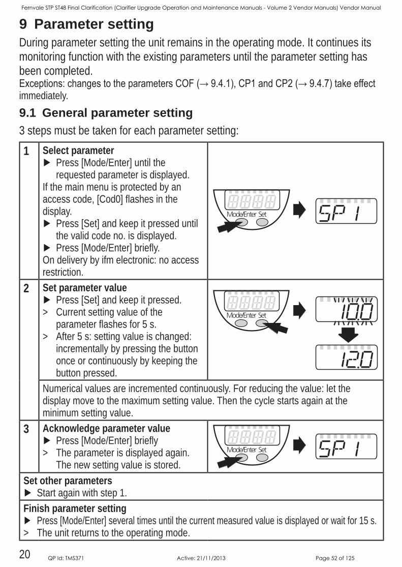
9 Parameter settingDuring parameter setting the unit remains in the operating mode It continues its monitoring function with the existing parameters until the parameter setting has been completedExceptions:changestotheparametersCOF(→9.4.1),CP1andCP2(→9.4.7)takeeffectimmediately9.1 General parameter setting3 steps must be taken for each parameter setting:
1 Select parameter Press [Mode/Enter] until the requested parameter is displayed
If the main menu is protected by an access code, [Cod0] flashes in the display
Press [Set] and keep it pressed until the valid code no is displayed
Press [Mode/Enter] brieflyOn delivery by ifm electronic: no access restriction
2 Set parameter value Press [Set] and keep it pressed
> Current setting value of the parameter flashes for 5 s
> After 5 s: setting value is changed: incrementally by pressing the button once or continuously by keeping the button pressed
Numerical values are incremented continuously For reducing the value: let the display move to the maximum setting value Then the cycle starts again at the minimum setting value
3 Acknowledge parameter value Press [Mode/Enter] briefly
> The parameter is displayed again The new setting value is stored
Set other parameters Start again with step 1
Finish parameter setting Press [Mode/Enter] several times until the current measured value is displayed or wait for 15 s
> The unit returns to the operating mode
Fernvale STP ST48 Final Clarification (Clarifier Upgrade Operation and Maintenance Manuals - Volume 2 Vendor Manuals) Vendor Manual
QP Id: TMS371 Active: 21/11/2013 Page 52 of 125
21
UK
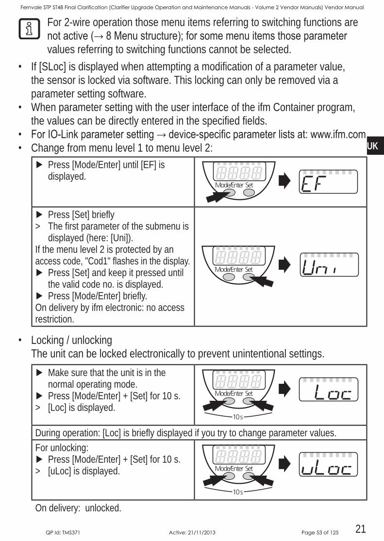
For 2-wire operation those menu items referring to switching functions are notactive(→8Menustructure);forsomemenuitemsthoseparametervalues referring to switching functions cannot be selected
• If [SLoc] is displayed when attempting a modification of a parameter value, the sensor is locked via software This locking can only be removed via a parameter setting software
• When parameter setting with the user interface of the ifm Container program, the values can be directly entered in the specified fields
• ForIO-Linkparametersetting→device-specificparameterlistsat:www.ifm.com• Change from menu level 1 to menu level 2:
Press [Mode/Enter] until [EF] is displayed
Press [Set] briefly > The first parameter of the submenu is
displayed (here: [Uni])If the menu level 2 is protected by an access code, "Cod1" flashes in the display
Press [Set] and keep it pressed until the valid code no is displayed
Press [Mode/Enter] brieflyOn delivery by ifm electronic: no access restriction
• Locking / unlockingThe unit can be locked electronically to prevent unintentional settings
Make sure that the unit is in the normal operating mode
Press [Mode/Enter] + [Set] for 10 s > [Loc] is displayed
During operation: [Loc] is briefly displayed if you try to change parameter valuesFor unlocking:
Press [Mode/Enter] + [Set] for 10 s > [uLoc] is displayed
On delivery: unlocked
Fernvale STP ST48 Final Clarification (Clarifier Upgrade Operation and Maintenance Manuals - Volume 2 Vendor Manuals) Vendor Manual
QP Id: TMS371 Active: 21/11/2013 Page 53 of 125
22
• Timeout:If no button is pressed for 15 s during parameter setting, the unit returns to the operating mode with unchanged values
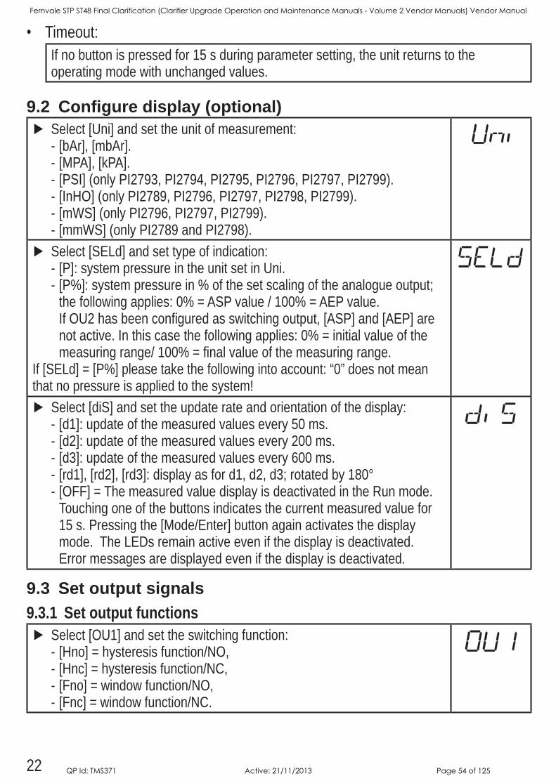
9.2 Configure display (optional) Select [Uni] and set the unit of measurement:
- [bAr], [mbAr] - [MPA], [kPA] - [PSI] (only PI2793, PI2794, PI2795, PI2796, PI2797, PI2799) - [InHO] (only PI2789, PI2796, PI2797, PI2798, PI2799) - [mWS] (only PI2796, PI2797, PI2799) - [mmWS] (only PI2789 and PI2798)
Select [SELd] and set type of indication: - [P]: system pressure in the unit set in Uni - [P%]: system pressure in % of the set scaling of the analogue output; the following applies: 0% = ASP value / 100% = AEP valueIf OU2 has been configured as switching output, [ASP] and [AEP] are not active In this case the following applies: 0% = initial value of the measuring range/ 100% = final value of the measuring range
If [SELd] = [P%] please take the following into account: “0” does not mean that no pressure is applied to the system!
Select [diS] and set the update rate and orientation of the display: - [d1]: update of the measured values every 50 ms - [d2]: update of the measured values every 200 ms - [d3]: update of the measured values every 600 ms - [rd1], [rd2], [rd3]: display as for d1, d2, d3; rotated by 180° - [OFF] = The measured value display is deactivated in the Run mode Touching one of the buttons indicates the current measured value for 15 s Pressing the [Mode/Enter] button again activates the display mode The LEDs remain active even if the display is deactivatedError messages are displayed even if the display is deactivated
9.3 Set output signals9.3.1 Set output functions
Select [OU1] and set the switching function: - [Hno] = hysteresis function/NO, - [Hnc] = hysteresis function/NC, - [Fno] = window function/NO, - [Fnc] = window function/NC
Fernvale STP ST48 Final Clarification (Clarifier Upgrade Operation and Maintenance Manuals - Volume 2 Vendor Manuals) Vendor Manual
QP Id: TMS371 Active: 21/11/2013 Page 54 of 125
23
UK
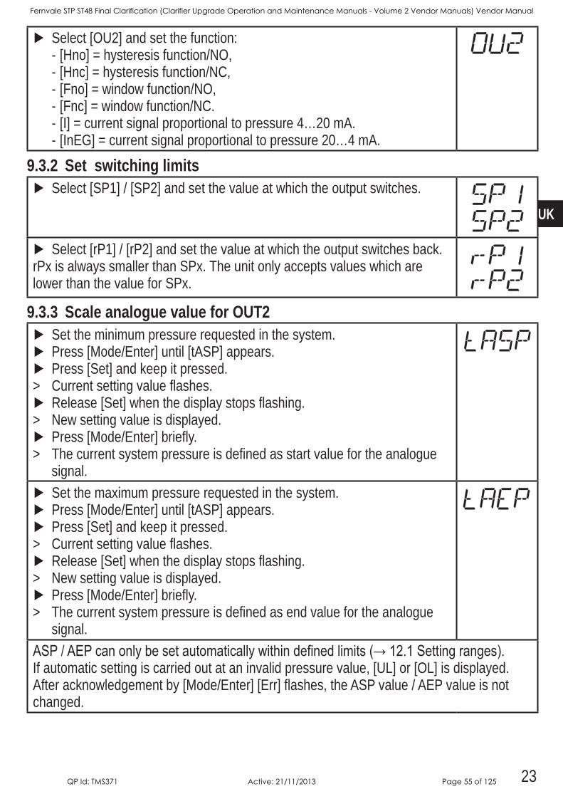
Select [OU2] and set the function: - [Hno] = hysteresis function/NO, - [Hnc] = hysteresis function/NC, - [Fno] = window function/NO, - [Fnc] = window function/NC - [I] = current signal proportional to pressure 4…20 mA - [InEG] = current signal proportional to pressure 20…4 mA
9.3.2 Set switching limits Select [SP1] / [SP2] and set the value at which the output switches
Select [rP1] / [rP2] and set the value at which the output switches backrPx is always smaller than SPx The unit only accepts values which are lower than the value for SPx
9.3.3 Scale analogue value for OUT2 Set the minimum pressure requested in the system Press [Mode/Enter] until [tASP] appears Press [Set] and keep it pressed
> Current setting value flashes Release [Set] when the display stops flashing
> New setting value is displayed Press [Mode/Enter] briefly
> The current system pressure is defined as start value for the analogue signal
Set the maximum pressure requested in the system Press [Mode/Enter] until [tASP] appears Press [Set] and keep it pressed
> Current setting value flashes Release [Set] when the display stops flashing
> New setting value is displayed Press [Mode/Enter] briefly
> The current system pressure is defined as end value for the analogue signal
ASP/AEPcanonlybesetautomaticallywithindefinedlimits(→12.1Settingranges).If automatic setting is carried out at an invalid pressure value, [UL] or [OL] is displayed After acknowledgement by [Mode/Enter] [Err] flashes, the ASP value / AEP value is not changed
Fernvale STP ST48 Final Clarification (Clarifier Upgrade Operation and Maintenance Manuals - Volume 2 Vendor Manuals) Vendor Manual
QP Id: TMS371 Active: 21/11/2013 Page 55 of 125
24
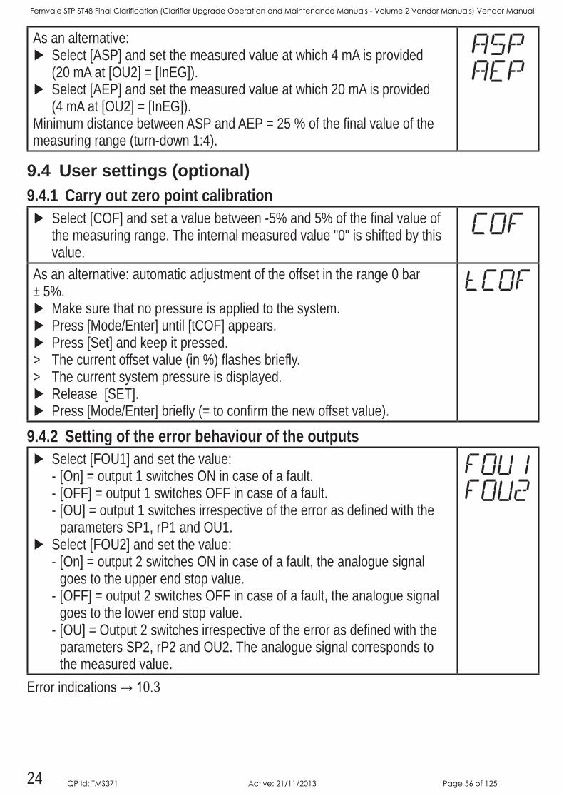
As an alternative: Select [ASP] and set the measured value at which 4 mA is provided (20 mA at [OU2] = [InEG])
Select [AEP] and set the measured value at which 20 mA is provided (4 mA at [OU2] = [InEG])
Minimum distance between ASP and AEP = 25 % of the final value of the measuring range (turn-down 1:4)
9.4 User settings (optional)9.4.1 Carry out zero point calibration
Select [COF] and set a value between -5% and 5% of the final value of the measuring range The internal measured value "0" is shifted by this value
As an alternative: automatic adjustment of the offset in the range 0 bar ± 5%
Make sure that no pressure is applied to the system Press [Mode/Enter] until [tCOF] appears Press [Set] and keep it pressed
> The current offset value (in %) flashes briefly > The current system pressure is displayed Release [SET] Press [Mode/Enter] briefly (= to confirm the new offset value)
9.4.2 Setting of the error behaviour of the outputs Select [FOU1] and set the value:
- [On] = output 1 switches ON in case of a fault - [OFF] = output 1 switches OFF in case of a fault - [OU] = output 1 switches irrespective of the error as defined with the parameters SP1, rP1 and OU1
Select [FOU2] and set the value: - [On] = output 2 switches ON in case of a fault, the analogue signal goes to the upper end stop value
- [OFF] = output 2 switches OFF in case of a fault, the analogue signal goes to the lower end stop value
- [OU] = Output 2 switches irrespective of the error as defined with the parameters SP2, rP2 and OU2 The analogue signal corresponds to the measured value
Errorindications→10.3
Fernvale STP ST48 Final Clarification (Clarifier Upgrade Operation and Maintenance Manuals - Volume 2 Vendor Manuals) Vendor Manual
QP Id: TMS371 Active: 21/11/2013 Page 56 of 125
25
UK
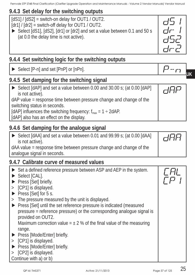
9.4.3 Set delay for the switching outputs[dS1] / [dS2] = switch-on delay for OUT1 / OUT2[dr1] / [dr2] = switch-off delay for OUT1 / OUT2
Select [dS1], [dS2], [dr1] or [dr2] and set a value between 01 and 50 s (at 00 the delay time is not active)
9.4.4 Set switching logic for the switching outputs Select [P-n] and set [PnP] or [nPn]
9.4.5 Set damping for the switching signal Select [dAP] and set a value between 000 and 3000 s; (at 000 [dAP] is not active)
dAP value = response time between pressure change and change of the switching status in seconds[dAP] influences the switching frequency: fmax = 1 ÷ 2dAP[dAP] also has an effect on the display
9.4.6 Set damping for the analogue signal Select [dAA] and set a value between 001 and 9999 s; (at 000 [dAA] is not active)
dAA value = response time between pressure change and change of the analogue signal in seconds
9.4.7 Calibrate curve of measured values Set a defined reference pressure between ASP and AEP in the system Select [CAL] Press [Set] briefly
> [CP1] is displayed Press [Set] for 5 s
> The pressure measured by the unit is displayed Press [Set] until the set reference pressure is indicated (measured pressure = reference pressure) or the corresponding analogue signal is provided on OUT2 Maximum correction value = ± 2 % of the final value of the measuring range
Press [Mode/Enter] briefly > [CP1] is displayed Press [Mode/Enter] briefly
> [CP2] is displayedContinue with a) or b)
Fernvale STP ST48 Final Clarification (Clarifier Upgrade Operation and Maintenance Manuals - Volume 2 Vendor Manuals) Vendor Manual
QP Id: TMS371 Active: 21/11/2013 Page 57 of 125

26
a) Finish calibration: Press [Mode/Enter] briefly
> [CAL] is displayed b) Change a 2nd point on the curve of measured values
Set a second defined reference pressure in the systemMinimum distance between the calibration points CP1 and CP2 = 5 % of the final value of the measuring range
Press [Set] for 5 s > The pressure measured by the unit is displayed Press [Set] until the set reference pressure is indicated (measured pressure = reference pressure) or the corresponding analogue signal is provided on OUT2Maximum correction value = ± 2 % of the final value of the measuring range
Press [Mode/Enter] briefly > [CP2] is displayed Press [Mode/Enter] briefly
> [CAL] is displayed, the process is finished
9.5 Service functions9.5.1 Read min/max values for system pressure
Select [HI] or [LO] and press [Set] briefly[HI] = maximum value, [LO] = minimum valueDelete memory:
Select [HI] or [LO] Press [Set] and keep it pressed until [----] is displayed Press [Mode/Enter] briefly
9.5.2 Reset all parameters to factory setting Select [rES] Press [Set] and keep it pressed until [----] is displayed Press [Mode/Enter] briefly
It is recommended to take down your own settings in the table before carryingoutareset(→13Factorysetting).
9.6 Simulation function9.6.1 Open menu level 3 (simulation)
Select [EF] and press [Set] briefly (= to open menu level 2) Select [SIM] and press [Set] briefly (= to open menu level 3)
> [SEL] is displayed
Fernvale STP ST48 Final Clarification (Clarifier Upgrade Operation and Maintenance Manuals - Volume 2 Vendor Manuals) Vendor Manual
QP Id: TMS371 Active: 21/11/2013 Page 58 of 125
27
UK
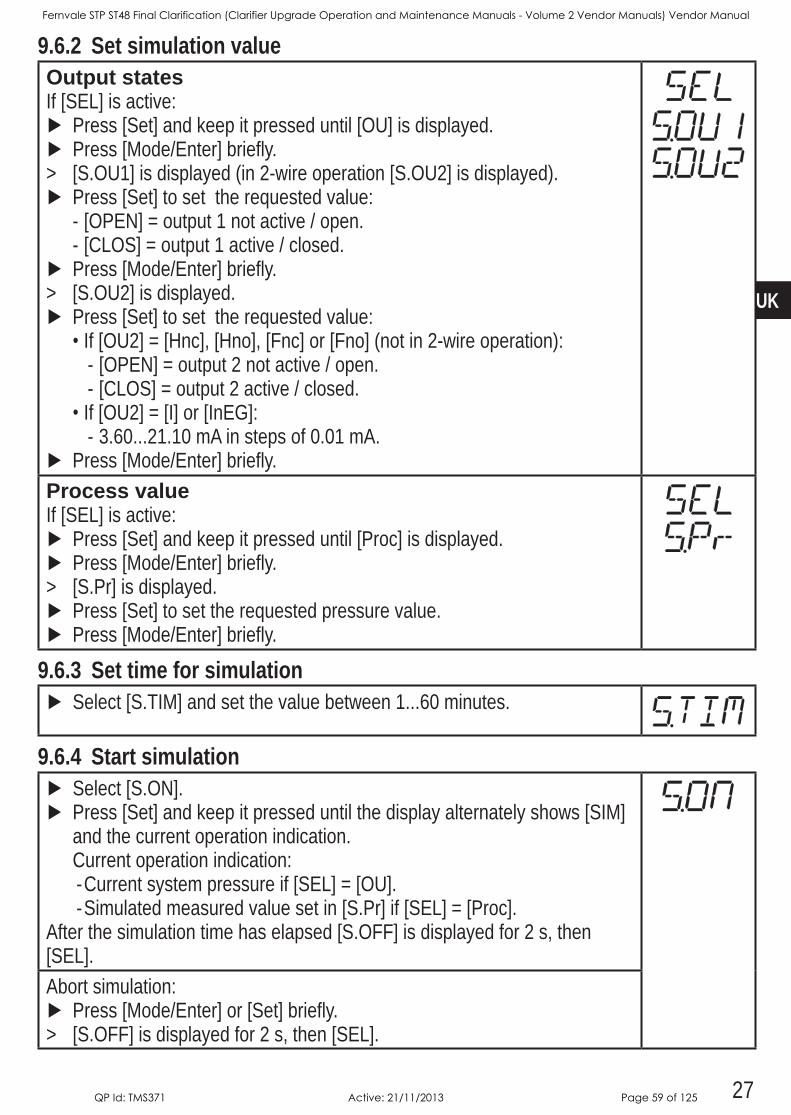
9.6.2 Set simulation valueOutput statesIf [SEL] is active:
Press [Set] and keep it pressed until [OU] is displayed Press [Mode/Enter] briefly
> [SOU1] is displayed (in 2-wire operation [SOU2] is displayed) Press [Set] to set the requested value:
- [OPEN] = output 1 not active / open - [CLOS] = output 1 active / closed
Press [Mode/Enter] briefly > [SOU2] is displayed Press [Set] to set the requested value:•If [OU2] = [Hnc], [Hno], [Fnc] or [Fno] (not in 2-wire operation):
- [OPEN] = output 2 not active / open - [CLOS] = output 2 active / closed
•If [OU2] = [I] or [InEG]: - 3602110 mA in steps of 001 mA
Press [Mode/Enter] brieflyProcess valueIf [SEL] is active:
Press [Set] and keep it pressed until [Proc] is displayed Press [Mode/Enter] briefly
> [SPr] is displayed Press [Set] to set the requested pressure value Press [Mode/Enter] briefly
9.6.3 Set time for simulation Select [STIM] and set the value between 160 minutes
9.6.4 Start simulation Select [SON] Press [Set] and keep it pressed until the display alternately shows [SIM] and the current operation indicationCurrent operation indication: -Current system pressure if [SEL] = [OU] -Simulated measured value set in [SPr] if [SEL] = [Proc]
After the simulation time has elapsed [SOFF] is displayed for 2 s, then [SEL]Abort simulation:
Press [Mode/Enter] or [Set] briefly > [SOFF] is displayed for 2 s, then [SEL]
Fernvale STP ST48 Final Clarification (Clarifier Upgrade Operation and Maintenance Manuals - Volume 2 Vendor Manuals) Vendor Manual
QP Id: TMS371 Active: 21/11/2013 Page 59 of 125
28
10 OperationAfter power on, the unit is in the Run mode (= normal operating mode) It carries out its measurement and evaluation functions and provides output signals according to the set parametersOperatingindicators→Chapter7Operatinganddisplayelements.
10.1 Read set parameters Press [Mode/Enter] until the requested parameter is displayed Press [Set] briefly
> The unit displays the corresponding parameter value for approx 15 s After another 15 s the parameter is displayed again, then the unit returns to the Run mode
10.2 Change the display in the Run mode Press [Set] briefly in the Run mode
> The unit indicates the current measured value in the selected type of indication for approx 15 s: - System pressure in the unit set in Uni - System pressure in % of the set scaling of the analogue output if [OU2] is configured as analogue output
- System pressure in % of the final value of the measuring range if [OU2] is configured as switching output
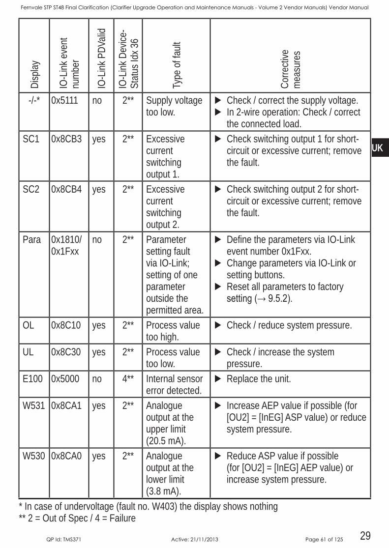
10.3 Self-diagnosis / error indicationsThe unit has many self-diagnostic options• It monitors itself automatically during operation• It indicates warnings and faults via IO-Link and via display (even if the display
is deactivated)• If a fault is found, the outputs are set according to the set parameters FOU1
andFOU2(→9.4.2).
Fernvale STP ST48 Final Clarification (Clarifier Upgrade Operation and Maintenance Manuals - Volume 2 Vendor Manuals) Vendor Manual
QP Id: TMS371 Active: 21/11/2013 Page 60 of 125
29
UK
Disp
lay
IO-L
ink e
vent
nu
mbe
r
IO-L
ink P
DVali
d
IO-L
ink D
evice
-St
atus
Idx 3
6
Type
of f
ault
Corre
ctive
m
easu
res
-/-* 0x5111 no 2** Supply voltage too low
Check / correct the supply voltage In 2-wire operation: Check / correct the connected load
SC1 0x8CB3 yes 2** Excessive current switching output 1
Check switching output 1 for short-circuit or excessive current; remove the fault
SC2 0x8CB4 yes 2** Excessive current switching output 2
Check switching output 2 for short-circuit or excessive current; remove the fault
Para 0x1810/ 0x1Fxx
no 2** Parameter setting fault via IO-Link; setting of one parameter outside the permitted area
Define the parameters via IO-Link event number 0x1Fxx
Change parameters via IO-Link or setting buttons
Reset all parameters to factory setting(→9.5.2).
OL 0x8C10 yes 2** Process value too high
Check / reduce system pressure
UL 0x8C30 yes 2** Process value too low
Check / increase the system pressure
E100 0x5000 no 4** Internal sensor error detected
Replace the unit
W531 0x8CA1 yes 2** Analogue output at the upper limit (205 mA)
Increase AEP value if possible (for [OU2] = [InEG] ASP value) or reduce system pressure
W530 0x8CA0 yes 2** Analogue output at the lower limit (38 mA)
Reduce ASP value if possible (for [OU2] = [InEG] AEP value) or increase system pressure
* In case of undervoltage (fault no W403) the display shows nothing ** 2 = Out of Spec / 4 = Failure
Fernvale STP ST48 Final Clarification (Clarifier Upgrade Operation and Maintenance Manuals - Volume 2 Vendor Manuals) Vendor Manual
QP Id: TMS371 Active: 21/11/2013 Page 61 of 125
30
Disp
lay
IO-L
ink e
vent
nu
mbe
r
IO-L
ink P
DVali
d
IO-L
ink D
evice
-St
atus
Idx 3
6
Type
of f
ault
Corre
ctive
m
easu
res
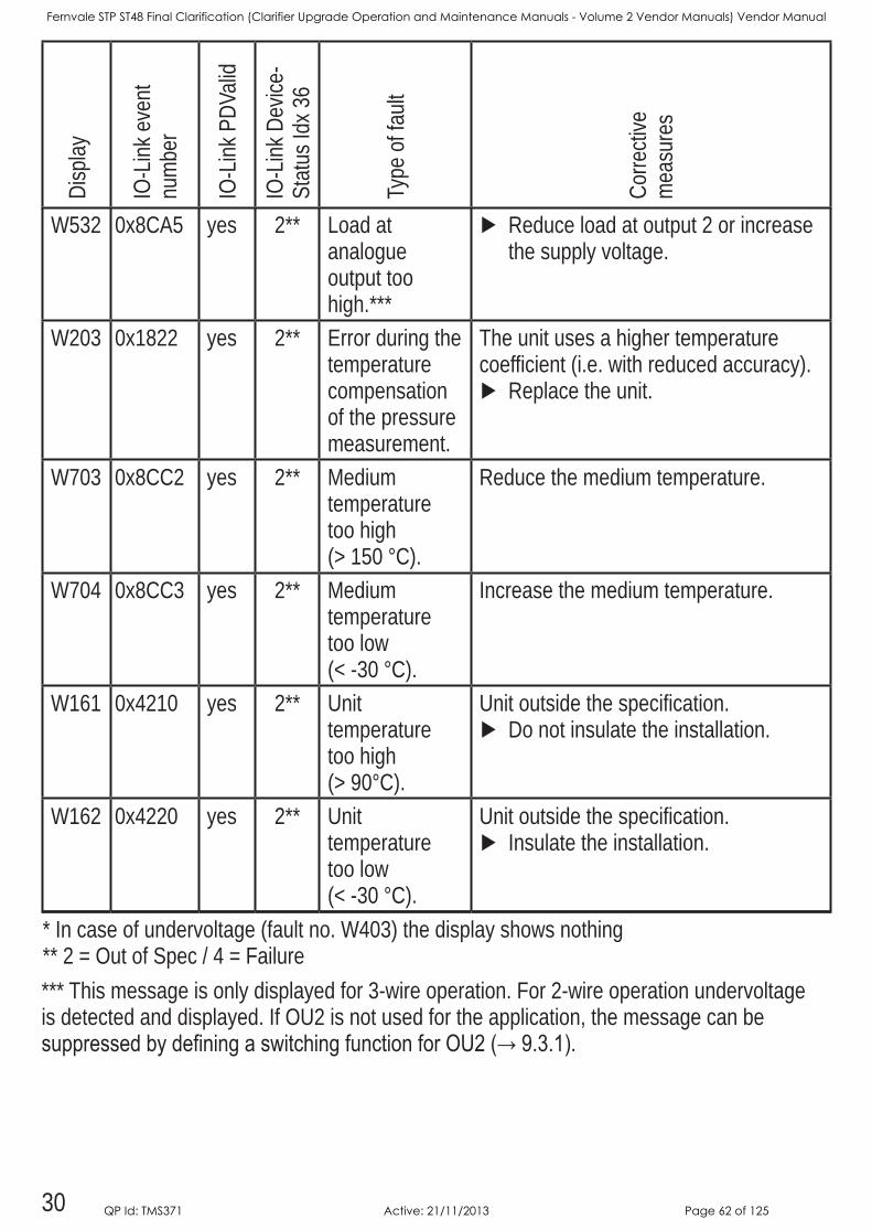
W532 0x8CA5 yes 2** Load at analogue output too high***
Reduce load at output 2 or increase the supply voltage
W203 0x1822 yes 2** Error during the temperature compensation of the pressure measurement
The unit uses a higher temperature coefficient (ie with reduced accuracy)
Replace the unit
W703 0x8CC2 yes 2** Medium temperature too high (> 150 °C)
Reduce the medium temperature
W704 0x8CC3 yes 2** Medium temperature too low (< -30 °C)
Increase the medium temperature
W161 0x4210 yes 2** Unit temperature too high (> 90°C)
Unit outside the specification Do not insulate the installation
W162 0x4220 yes 2** Unit temperature too low (< -30 °C)
Unit outside the specification Insulate the installation
* In case of undervoltage (fault no W403) the display shows nothing ** 2 = Out of Spec / 4 = Failure*** This message is only displayed for 3-wire operation For 2-wire operation undervoltage is detected and displayed If OU2 is not used for the application, the message can be suppressedbydefiningaswitchingfunctionforOU2(→9.3.1).
Fernvale STP ST48 Final Clarification (Clarifier Upgrade Operation and Maintenance Manuals - Volume 2 Vendor Manuals) Vendor Manual
QP Id: TMS371 Active: 21/11/2013 Page 62 of 125
31
UK
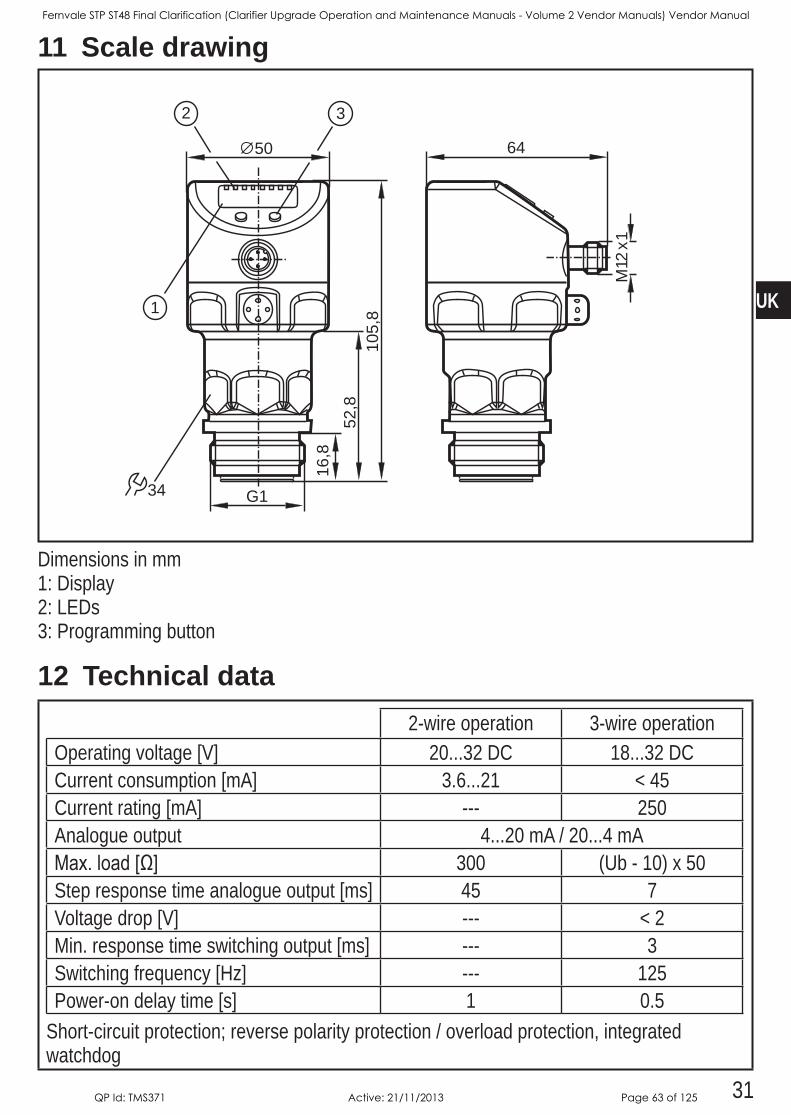
11 Scale drawing
16,8
G1
64
M12
x1
105,
852
,8
50
34
1
2 3
Dimensions in mm1: Display2: LEDs3: Programming button
12 Technical data2-wire operation 3-wire operation
Operating voltage [V] 2032 DC 1832 DCCurrent consumption [mA] 3621 < 45 Current rating [mA] --- 250Analogue output 420 mA / 204 mAMax.load[Ω] 300 (Ub - 10) x 50Step response time analogue output [ms] 45 7Voltage drop [V] --- < 2Min response time switching output [ms] --- 3Switching frequency [Hz] --- 125Power-on delay time [s] 1 05
Short-circuit protection; reverse polarity protection / overload protection, integrated watchdog
Fernvale STP ST48 Final Clarification (Clarifier Upgrade Operation and Maintenance Manuals - Volume 2 Vendor Manuals) Vendor Manual
QP Id: TMS371 Active: 21/11/2013 Page 63 of 125
32
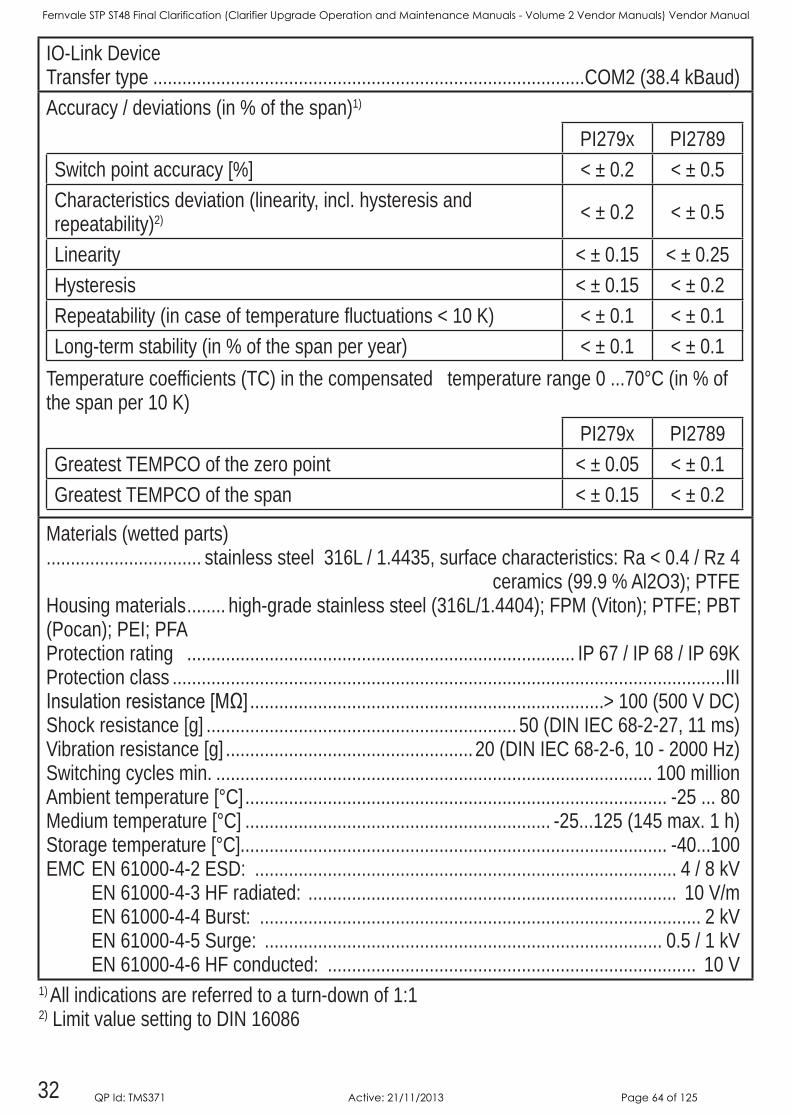
IO-Link Device Transfer type COM2 (384 kBaud)Accuracy / deviations (in % of the span)1)
PI279x PI2789Switch point accuracy [%] < ± 02 < ± 05Characteristics deviation (linearity, incl hysteresis and repeatability)2) < ± 02 < ± 05
Linearity < ± 015 < ± 025Hysteresis < ± 015 < ± 02Repeatability (in case of temperature fluctuations < 10 K) < ± 01 < ± 01Long-term stability (in % of the span per year) < ± 01 < ± 01
Temperature coefficients (TC) in the compensated temperature range 0 70°C (in % of the span per 10 K)
PI279x PI2789Greatest TEMPCO of the zero point < ± 005 < ± 01Greatest TEMPCO of the span < ± 015 < ± 02
Materials (wetted parts) stainless steel 316L / 14435, surface characteristics: Ra < 04 / Rz 4 ceramics (999 % Al2O3); PTFE Housing materials high-grade stainless steel (316L/14404); FPM (Viton); PTFE; PBT (Pocan); PEI; PFAProtection rating IP 67 / IP 68 / IP 69KProtection class IIIInsulationresistance[MΩ] > 100 (500 V DC)Shock resistance [g] 50 (DIN IEC 68-2-27, 11 ms)Vibration resistance [g] 20 (DIN IEC 68-2-6, 10 - 2000 Hz)Switching cycles min 100 millionAmbient temperature [°C] -25 80Medium temperature [°C] -25125 (145 max 1 h)Storage temperature [°C] -40100 EMC EN 61000-4-2 ESD: 4 / 8 kV EN 61000-4-3 HF radiated: 10 V/m EN 61000-4-4 Burst: 2 kV EN 61000-4-5 Surge: 05 / 1 kV EN 61000-4-6 HF conducted: 10 V
1) All indications are referred to a turn-down of 1:12) Limit value setting to DIN 16086
Fernvale STP ST48 Final Clarification (Clarifier Upgrade Operation and Maintenance Manuals - Volume 2 Vendor Manuals) Vendor Manual
QP Id: TMS371 Active: 21/11/2013 Page 64 of 125
33
UK
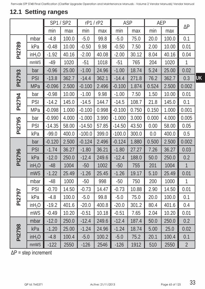
12.1 Setting rangesSP1 / SP2 rP1 / rP2 ASP AEP
ΔPmin max min max min max min max
PI27
89
mbar -48 1000 -50 998 -50 750 200 1000 01kPa -048 1000 -050 998 -050 750 200 1000 001
inH2O -192 4016 -200 4008 -200 3012 804 4016 004mmWS -49 1020 -51 1018 -51 765 204 1020 1
PI27
93 bar -096 2500 -100 2496 -100 1874 524 2500 002PSI -138 3627 -144 3621 -144 2718 762 3627 03MPa -0096 2500 -0100 2496 -0100 1874 0524 2500 0002
PI27
94 bar -098 1000 -100 998 -100 750 150 1000 001PSI -142 1450 -145 1447 -145 1087 218 1450 01MPa -0098 1000 -0100 0998 -0100 0750 0150 1000 0001
PI27
95 bar -0990 4000 -1000 3990 -1000 3000 0000 4000 0005PSI -1435 5800 -1450 5785 -1450 4350 000 5800 005kPa -990 4000 -1000 3990 -1000 3000 00 4000 05
PI27
96
bar -0120 2500 -0124 2496 -0124 1880 0500 2500 0002PSI -174 3627 -180 3621 -180 2727 726 3627 003kPa -120 2500 -124 2496 -124 1880 500 2500 02
inH2O -48 1004 -50 1002 -50 755 201 1004 1mWS -122 2549 -126 2545 -126 1917 510 2549 001
PI27
97
mbar -48 1000 -50 998 -50 750 200 1000 1PSI -070 1450 -073 1447 -073 1088 290 1450 001kPa -48 1000 -50 998 -50 750 200 1000 01
inH2O -192 4016 -200 4008 -200 3012 804 4016 04mWS -049 1020 -051 1018 -051 765 204 1020 001
PI27
98
mbar -120 2500 -124 2496 -124 1874 500 2500 02kPa -120 2500 -124 2496 -124 1874 500 250 002
inH2O -48 1004 -50 1002 -50 752 201 1004 01mmWS -122 2550 -126 2546 -126 1912 510 2550 2
ΔP=stepincrement
Fernvale STP ST48 Final Clarification (Clarifier Upgrade Operation and Maintenance Manuals - Volume 2 Vendor Manuals) Vendor Manual
QP Id: TMS371 Active: 21/11/2013 Page 65 of 125
34
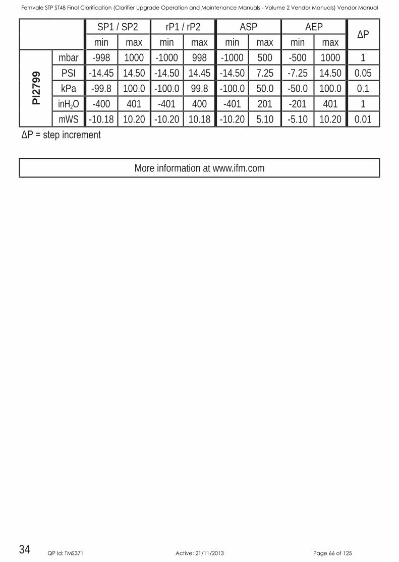
SP1 / SP2 rP1 / rP2 ASP AEPΔP
min max min max min max min maxPI
2799
mbar -998 1000 -1000 998 -1000 500 -500 1000 1PSI -1445 1450 -1450 1445 -1450 725 -725 1450 005kPa -998 1000 -1000 998 -1000 500 -500 1000 01
inH2O -400 401 -401 400 -401 201 -201 401 1mWS -1018 1020 -1020 1018 -1020 510 -510 1020 001
ΔP=stepincrement
More information at wwwifmcom
Fernvale STP ST48 Final Clarification (Clarifier Upgrade Operation and Maintenance Manuals - Volume 2 Vendor Manuals) Vendor Manual
QP Id: TMS371 Active: 21/11/2013 Page 66 of 125
35
UK
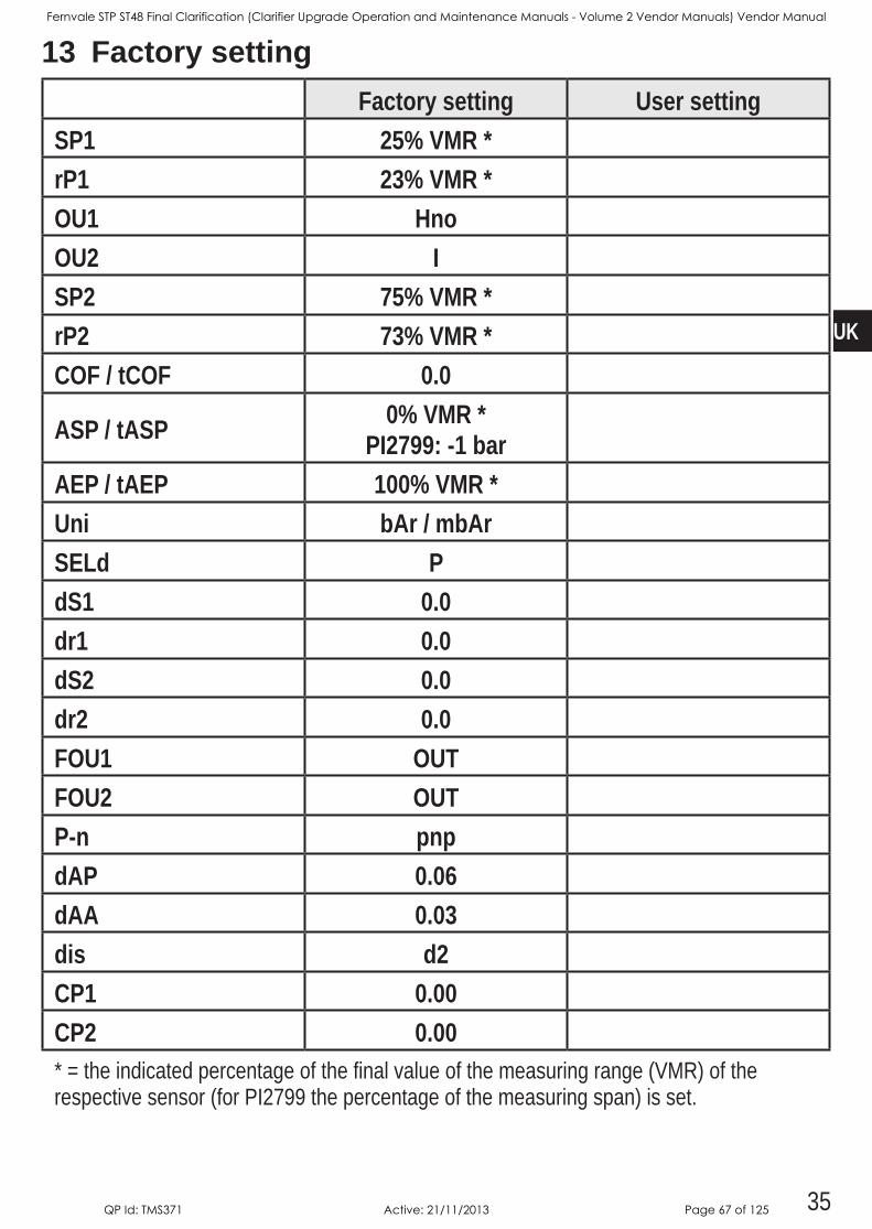
13 Factory settingFactory setting User setting
SP1 25% VMR *rP1 23% VMR *OU1 HnoOU2 ISP2 75% VMR *rP2 73% VMR *COF / tCOF 0.0
ASP / tASP 0% VMR *PI2799: -1 bar
AEP / tAEP 100% VMR *Uni bAr / mbArSELd PdS1 0.0dr1 0.0dS2 0.0dr2 0.0FOU1 OUTFOU2 OUTP-n pnpdAP 0.06dAA 0.03dis d2CP1 0.00CP2 0.00* = the indicated percentage of the final value of the measuring range (VMR) of the respective sensor (for PI2799 the percentage of the measuring span) is set
Fernvale STP ST48 Final Clarification (Clarifier Upgrade Operation and Maintenance Manuals - Volume 2 Vendor Manuals) Vendor Manual
QP Id: TMS371 Active: 21/11/2013 Page 67 of 125

MXD75 MULTI PARAMETER ANALYSER
EASY OPERATION GUIDE FOR CALIBRATING ROYCE
DISSOLVED OXYGEN SENSORS 1. Remove DO Probe from Process. 2. Place Sensor down at angle shown.
3. Inspect Sensor tip and ensure membrane is intact and not torn.
4. If membrane is damaged, remove sensor and replace membrane, re-‐charge sensor with gel (You Tube search “roycewater” for video on recharging Royce DO Sensor).
Fernvale STP ST48 Final Clarification (Clarifier Upgrade Operation and Maintenance Manuals - Volume 2 Vendor Manuals) Vendor Manual
QP Id: TMS371 Active: 21/11/2013 Page 68 of 125
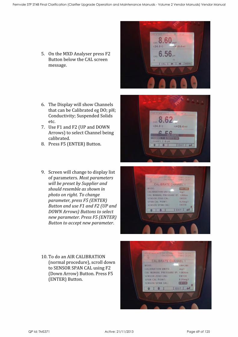
5. On the MXD Analyser press F2 Button below the CAL screen message.
6. The Display will show Channels that can be Calibrated eg DO; pH; Conductivity; Suspended Solids etc.
7. Use F1 and F2 (UP and DOWN Arrows) to select Channel being calibrated.
8. Press F5 (ENTER) Button.
9. Screen will change to display list of parameters. Most parameters will be preset by Supplier and should resemble as shown in photo on right. To change parameter, press F5 (ENTER) Button and use F1 and F2 (UP and DOWN Arrows) Buttons to select new parameter. Press F5 (ENTER) Button to accept new parameter.
10. To do an AIR CALIBRATION (normal procedure), scroll down to SENSOR SPAN CAL using F2 (Down Arrow) Button. Press F5 (ENTER) Button.
Fernvale STP ST48 Final Clarification (Clarifier Upgrade Operation and Maintenance Manuals - Volume 2 Vendor Manuals) Vendor Manual
QP Id: TMS371 Active: 21/11/2013 Page 69 of 125
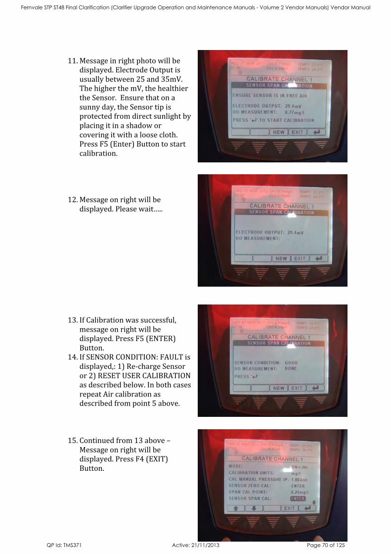
11. Message in right photo will be
displayed. Electrode Output is usually between 25 and 35mV. The higher the mV, the healthier the Sensor. Ensure that on a sunny day, the Sensor tip is protected from direct sunlight by placing it in a shadow or covering it with a loose cloth. Press F5 (Enter) Button to start calibration.
12. Message on right will be displayed. Please wait…..
13. If Calibration was successful, message on right will be displayed. Press F5 (ENTER) Button.
14. If SENSOR CONDITION: FAULT is displayed,: 1) Re-‐charge Sensor or 2) RESET USER CALIBRATION as described below. In both cases repeat Air calibration as described from point 5 above.
15. Continued from 13 above – Message on right will be displayed. Press F4 (EXIT) Button.
Fernvale STP ST48 Final Clarification (Clarifier Upgrade Operation and Maintenance Manuals - Volume 2 Vendor Manuals) Vendor Manual
QP Id: TMS371 Active: 21/11/2013 Page 70 of 125
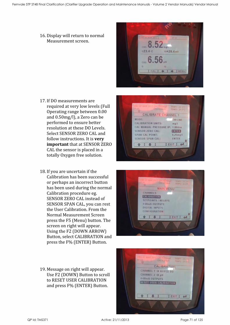
16. Display will return to normal
Measurement screen.
17. If DO measurements are required at very low levels (Full Operating range between 0.00 and 0.50mg/l), a Zero can be performed to ensure better resolution at these DO Levels. Select SENSOR ZERO CAL and follow instructions. It is very important that at SENSOR ZERO CAL the sensor is placed in a totally Oxygen free solution.
18. If you are uncertain if the Calibration has been successful or perhaps an incorrect button has been used during the normal Calibration procedure eg. SENSOR ZERO CAL instead of SENSOR SPAN CAL, you can rest the User Calibration. From the Normal Measurement Screen press the F5 (Menu) button. The screen on right will appear. Using the F2 (DOWN ARROW) Button, select CALIBRATION and press the F% (ENTER) Button.
19. Message on right will appear. Use F2 (DOWN) Button to scroll to RESET USER CALIBRATION and press F% (ENTER) Button.
Fernvale STP ST48 Final Clarification (Clarifier Upgrade Operation and Maintenance Manuals - Volume 2 Vendor Manuals) Vendor Manual
QP Id: TMS371 Active: 21/11/2013 Page 71 of 125
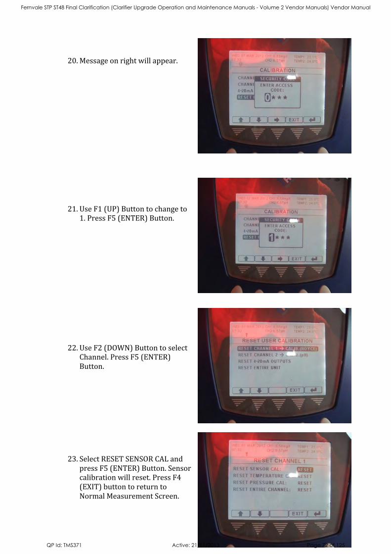
20. Message on right will appear.
21. Use F1 (UP) Button to change to 1. Press F5 (ENTER) Button.
22. Use F2 (DOWN) Button to select Channel. Press F5 (ENTER) Button.
23. Select RESET SENSOR CAL and press F5 (ENTER) Button. Sensor calibration will reset. Press F4 (EXIT) button to return to Normal Measurement Screen.
Fernvale STP ST48 Final Clarification (Clarifier Upgrade Operation and Maintenance Manuals - Volume 2 Vendor Manuals) Vendor Manual
QP Id: TMS371 Active: 21/11/2013 Page 72 of 125
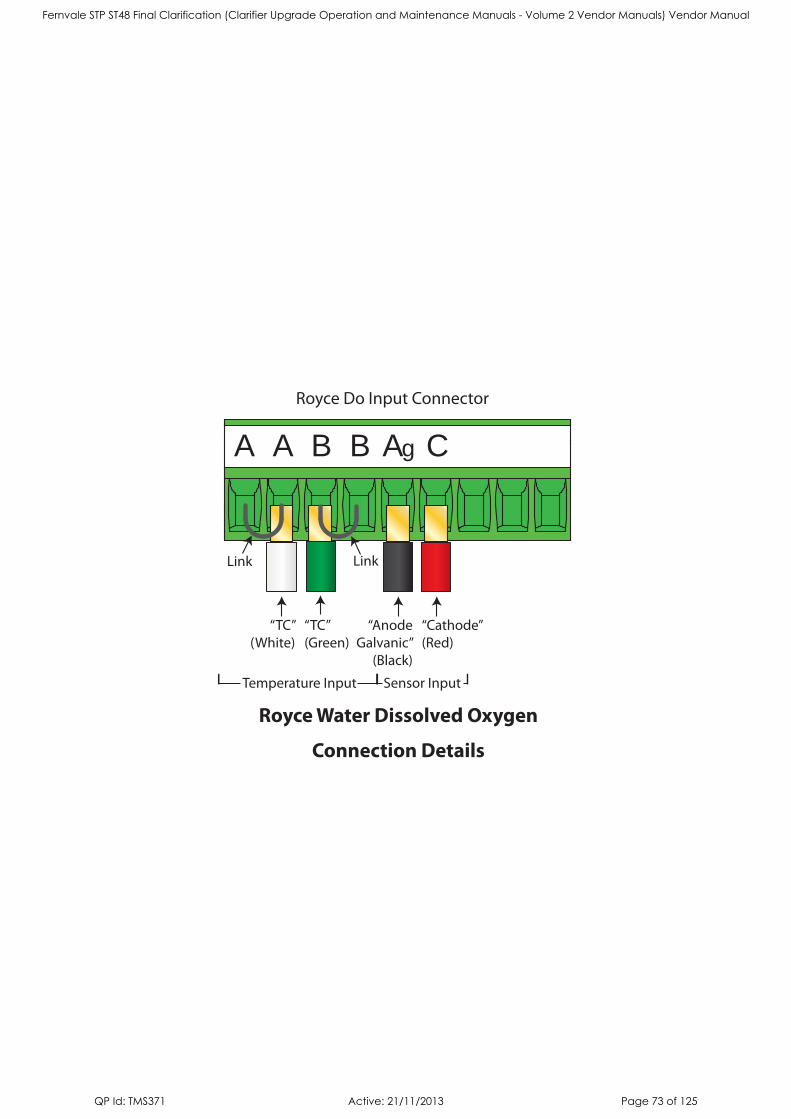
Link
“TC”(White)
“TC”(Green)
“Cathode”(Red)
“AnodeGalvanic”
(Black)
Royce Water Dissolved Oxygen
Connection Details
Royce Do Input Connector
Link
Ag CA A B B
Temperature Input Sensor Input
Fernvale STP ST48 Final Clarification (Clarifier Upgrade Operation and Maintenance Manuals - Volume 2 Vendor Manuals) Vendor Manual
QP Id: TMS371 Active: 21/11/2013 Page 73 of 125

Fernvale STP ST48 Final Clarification (Clarifier Upgrade Operation and Maintenance Manuals - Volume 2 Vendor Manuals) Vendor Manual
QP Id: TMS371 Active: 21/11/2013 Page 74 of 125
Fernvale STP ST48 Final Clarification (Clarifier Upgrade Operation and Maintenance Manuals - Volume 2 Vendor Manuals) Vendor Manual
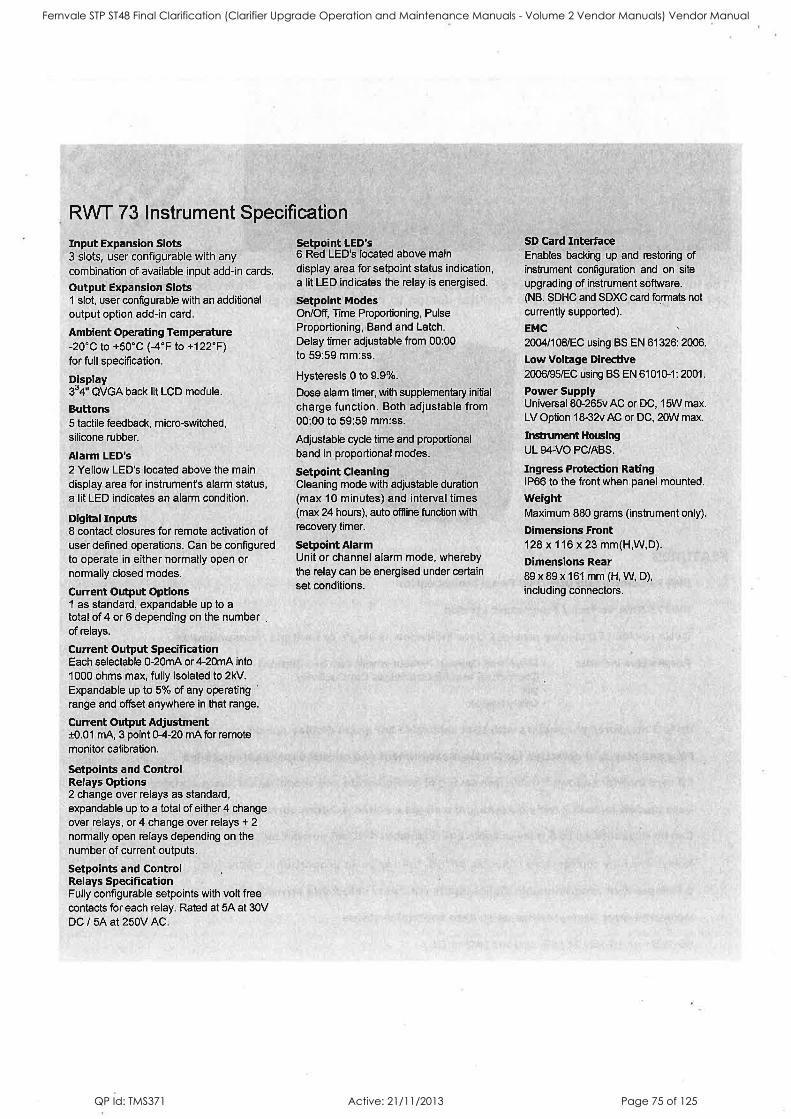
QP Id: TMS371 Active: 21/11/2013 Page 75 of 125
Fernvale STP ST48 Final Clarification (Clarifier Upgrade Operation and Maintenance Manuals - Volume 2 Vendor Manuals) Vendor Manual
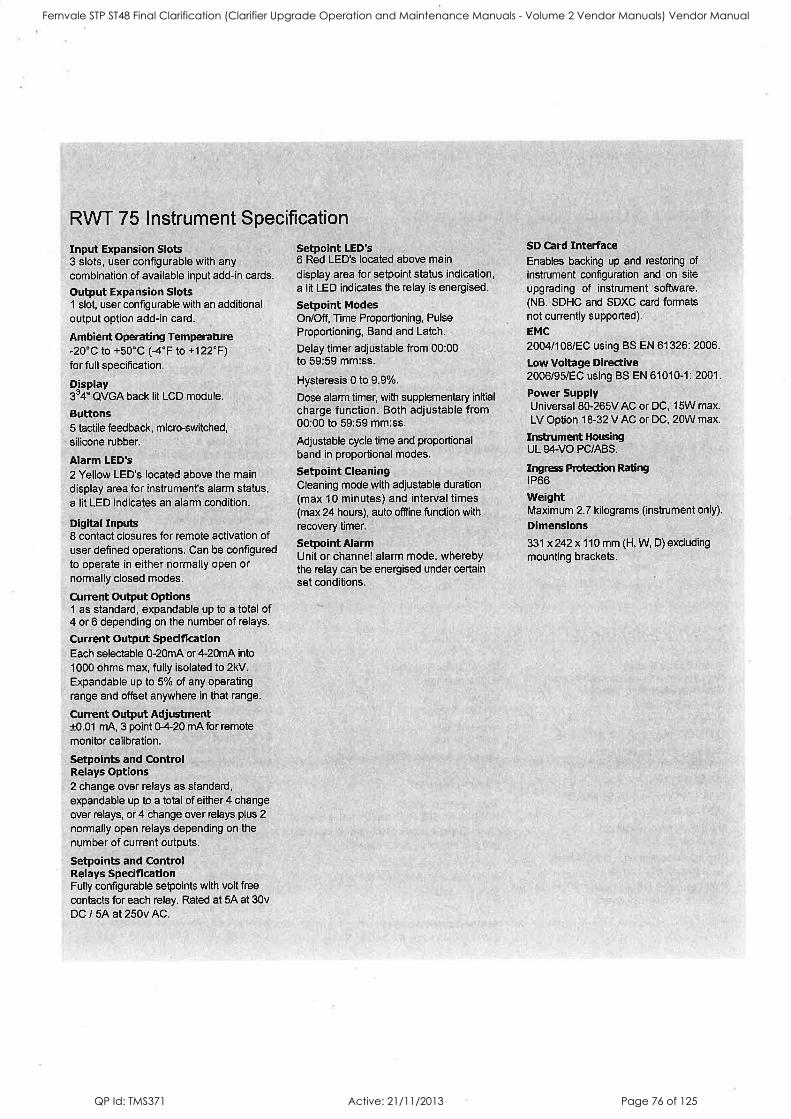
QP Id: TMS371 Active: 21/11/2013 Page 76 of 125
Fernvale STP ST48 Final Clarification (Clarifier Upgrade Operation and Maintenance Manuals - Volume 2 Vendor Manuals) Vendor Manual
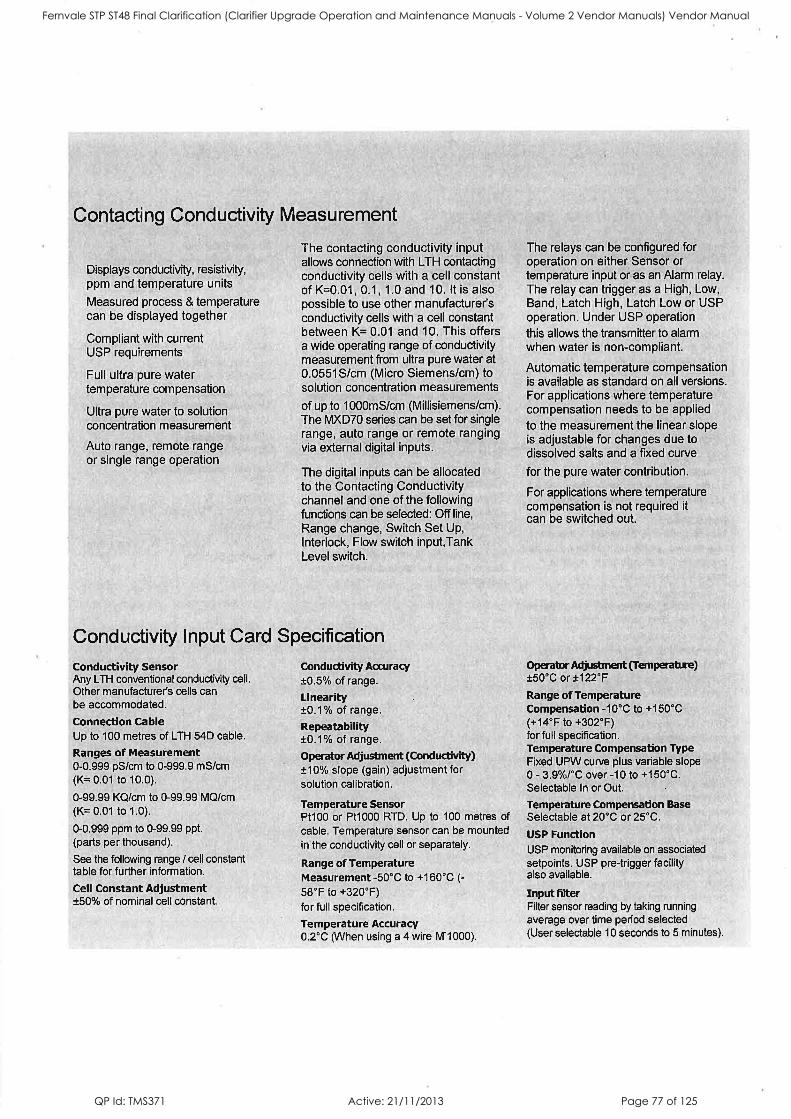
QP Id: TMS371 Active: 21/11/2013 Page 77 of 125
Fernvale STP ST48 Final Clarification (Clarifier Upgrade Operation and Maintenance Manuals - Volume 2 Vendor Manuals) Vendor Manual
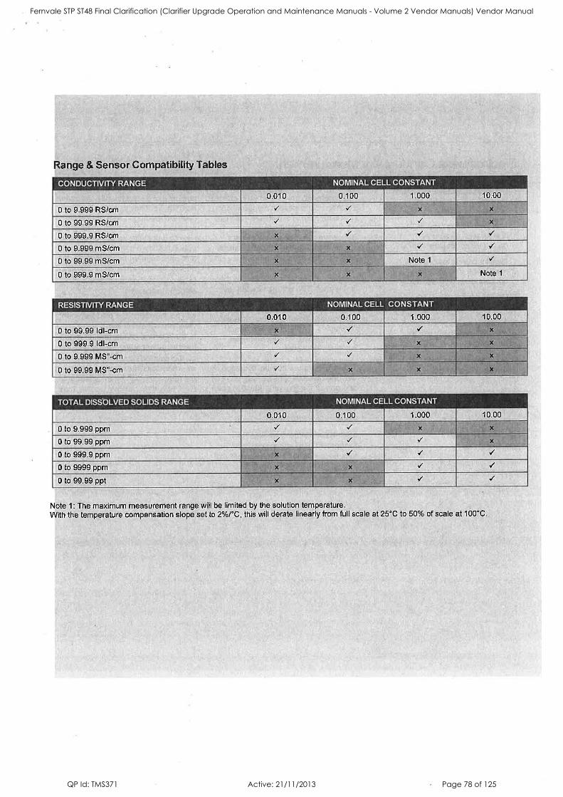
QP Id: TMS371 Active: 21/11/2013 Page 78 of 125
Fernvale STP ST48 Final Clarification (Clarifier Upgrade Operation and Maintenance Manuals - Volume 2 Vendor Manuals) Vendor Manual
QP Id: TMS371 Active: 21/11/2013 Page 79 of 125
Fernvale STP ST48 Final Clarification (Clarifier Upgrade Operation and Maintenance Manuals - Volume 2 Vendor Manuals) Vendor Manual
QP Id: TMS371 Active: 21/11/2013 Page 80 of 125
Fernvale STP ST48 Final Clarification (Clarifier Upgrade Operation and Maintenance Manuals - Volume 2 Vendor Manuals) Vendor Manual
QP Id: TMS371 Active: 21/11/2013 Page 81 of 125
Fernvale STP ST48 Final Clarification (Clarifier Upgrade Operation and Maintenance Manuals - Volume 2 Vendor Manuals) Vendor Manual
QP Id: TMS371 Active: 21/11/2013 Page 82 of 125
Fernvale STP ST48 Final Clarification (Clarifier Upgrade Operation and Maintenance Manuals - Volume 2 Vendor Manuals) Vendor Manual
QP Id: TMS371 Active: 21/11/2013 Page 83 of 125
Fernvale STP ST48 Final Clarification (Clarifier Upgrade Operation and Maintenance Manuals - Volume 2 Vendor Manuals) Vendor Manual
QP Id: TMS371 Active: 21/11/2013 Page 84 of 125
Fernvale STP ST48 Final Clarification (Clarifier Upgrade Operation and Maintenance Manuals - Volume 2 Vendor Manuals) Vendor Manual
QP Id: TMS371 Active: 21/11/2013 Page 85 of 125

Royce Parts Per MillionDissolved Oxygen Systems
Fernvale STP ST48 Final Clarification (Clarifier Upgrade Operation and Maintenance Manuals - Volume 2 Vendor Manuals) Vendor Manual
QP Id: TMS371 Active: 21/11/2013 Page 86 of 125

Maintenance Free Dissolved Oxygen Control System
The Royce line of PPM level dissolved oxygen (DO) analyzers is the largest, most varied line in the world. Features like microprocessor-based intelligent electronics, with a choice of rugged, patented self-cleaning sensors, or maintenance free disposable cartridge sensors, make the totally waterproof Royce line of PPM DO analyzers the best available – anywhere.
The Royce Models 9110 & 9120 are designed to offer the latest Royce Dissolved Oxygen design technology in an affordable package. They also have the capacity to provide advanced features found in other Royce Models and incorporate the latest Modbus communications (Profibus DP is optional). The 9110 is Single Channel and the 9120 is Dual Channel. Both can use the Royce Model 99 (Standard) cartridge DO sensor and the Model 95 rechargeable DO sensor. Air and water jet cleaning are optionally available.
The Royce Models 9210 & 9220 analyzers incorporate the same technological advances as the Models 9110 and 9120. They also have the capacity to provide the advanced features found in other Royce Models and incorporate the latest Modbus communications (Profibus DP is optional). The 9210 is Single Channel & the 9220 is Dual Channel. Both use the exclusive Royce Model 96 Electro-Chemical Self-Cleaning sensor. Air and water jet cleaning are optionally available.
The Model 9200 Continuous DO analyzer provides the ultimate level of monitoring accuracy and aeration control available anywhere in the world. The analyzer is provided standard with everything available on the Model 9210/9220. It also offers menu directing setup and trend graphing on the display, simultaneous DO and temperature readout on the display, standard automatic sensor membrane self-cleaning, digital AND analog outputs, a sensor output voltage mode, and four programmable setpoint relays. Used with the Model 96A DO sensor, the Model 9200 has become the benchmark analyzer for the DO monitoring & blower control market in the 21st century.
The Model 9200/96A system, completed the 2002 Instrument Testing Association’s (ITA) comparative DO test with outstanding results. Test results are available. Contact Royce Technologies for more information.
MODEL 9110/9120/9210/9220 ANALYZER MODEL 9200 ANALYZER
2
Fernvale STP ST48 Final Clarification (Clarifier Upgrade Operation and Maintenance Manuals - Volume 2 Vendor Manuals) Vendor Manual
QP Id: TMS371 Active: 21/11/2013 Page 87 of 125
3
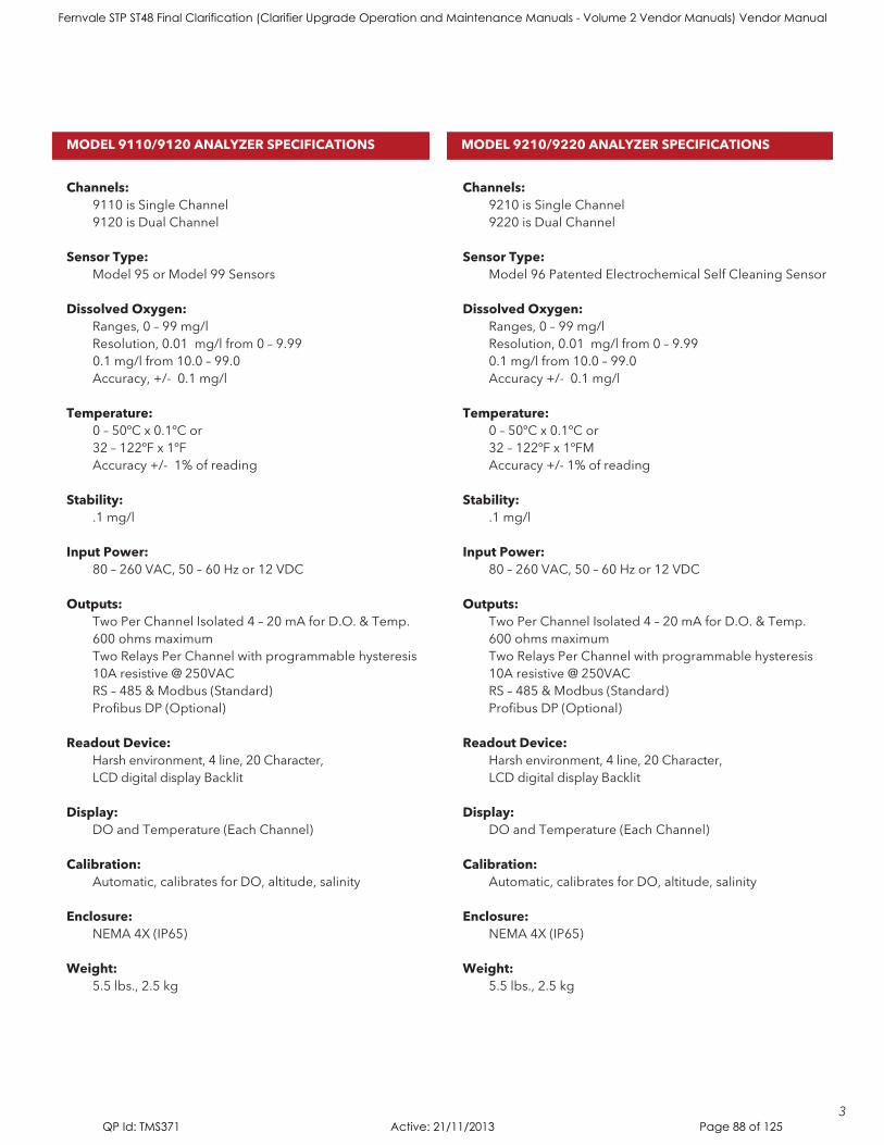
Channels: 9110 is Single Channel 9120 is Dual Channel
Sensor Type: Model 95 or Model 99 Sensors
Dissolved Oxygen: Ranges, 0 – 99 mg/l Resolution, 0.01 mg/l from 0 – 9.99 0.1 mg/l from 10.0 – 99.0 Accuracy, +/- 0.1 mg/l
Temperature: 0 – 50ºC x 0.1ºC or 32 – 122ºF x 1ºF Accuracy +/- 1% of reading
Stability: .1 mg/l
Input Power: 80 – 260 VAC, 50 – 60 Hz or 12 VDC
Outputs: Two Per Channel Isolated 4 – 20 mA for D.O. & Temp. 600 ohms maximum Two Relays Per Channel with programmable hysteresis 10A resistive @ 250VAC RS – 485 & Modbus (Standard) Profibus DP (Optional)
Readout Device: Harsh environment, 4 line, 20 Character, LCD digital display Backlit
Display: DO and Temperature (Each Channel)
Calibration: Automatic, calibrates for DO, altitude, salinity
Enclosure: NEMA 4X (IP65)
Weight: 5.5 lbs., 2.5 kg
Channels: 9210 is Single Channel 9220 is Dual Channel
Sensor Type: Model 96 Patented Electrochemical Self Cleaning Sensor
Dissolved Oxygen: Ranges, 0 – 99 mg/l Resolution, 0.01 mg/l from 0 – 9.99 0.1 mg/l from 10.0 – 99.0 Accuracy +/- 0.1 mg/l
Temperature: 0 – 50ºC x 0.1ºC or 32 – 122ºF x 1ºFM Accuracy +/- 1% of reading
Stability: .1 mg/l
Input Power: 80 – 260 VAC, 50 – 60 Hz or 12 VDC
Outputs: Two Per Channel Isolated 4 – 20 mA for D.O. & Temp. 600 ohms maximum Two Relays Per Channel with programmable hysteresis 10A resistive @ 250VAC RS – 485 & Modbus (Standard) Profibus DP (Optional)
Readout Device: Harsh environment, 4 line, 20 Character, LCD digital display Backlit
Display: DO and Temperature (Each Channel)
Calibration: Automatic, calibrates for DO, altitude, salinity
Enclosure: NEMA 4X (IP65)
Weight: 5.5 lbs., 2.5 kg
MODEL 9110/9120 ANALYZER SPECIFICATIONS MODEL 9210/9220 ANALYZER SPECIFICATIONS
Fernvale STP ST48 Final Clarification (Clarifier Upgrade Operation and Maintenance Manuals - Volume 2 Vendor Manuals) Vendor Manual
QP Id: TMS371 Active: 21/11/2013 Page 88 of 125

MODEL 9200 ANALYZER
4
Model 9200 Analyzer
Dissolved oxygen: Ranges, 0 – 99.9 mg/l (PPM) 0 – 100% Saturation Resolution, 0.01 mg/l 1% Saturation Accuracy, ± 0.1 mg/l or 1% Saturation
Temperature – selectable: 0 – 50ºC x .1ºC or 23 – 122ºF x 1ºF Accuracy +/- 0.2º C Compensation ± 1% of reading
Stability: .1mg/l
Input Power: Switch Selectable 115/230 VAC, 50/60 Hz
Readout Device: Harsh environment, 2.5” x 4.5” graphical LCD digital display
Outputs: One Isolated 4 – 20 mA Output for DO One Isolated 4 – 20 mA Output for Temperature One RS-485 digital, isolated 4 Standard setpoint relays with programmable hysteresis All relays are Form C rated 250 VAC at 6 Amps resistive
Display: DO, temperature, relay status, trend graph and programming menus
Calibration: Automatic, one step push button calibrates for DO, altitude, salinity
Enclosure: NEMA 4X (IP65)
Weight: 8.7 lbs., 3.95 kgm
• Microprocessorbasedelectronics
• Range0–99.9PPMand%Saturation0–99.9%
• Simplecalibrationwith“helpscreen”prompts
• Automatictemperature,altitude,salinitycompensation
• IndividualDOandtemperatureoutputs
• 4programmablerelays
• Onestep,pushbuttoncalibration
• Electronicselfdiagnosticsforsensorandanalyzer
• Electrochemicalselfcleaningsensor(Standard)
• Standard24hourtrendgraph
• Backlitdisplay
FEATURES SPECIFICATIONS
Electrochemical Sensor CleaningThis patented feature provides an automatic cleaning function for the DO sensor membrane. Cleaning occurs on a timed basis programmed into the Model 9200 by the operator. This cleaning process discourages growth on the membrane allowing maintenance-free operation for up to six months, (depending upon the sensor operating environment). A Model 96A sensor is required for operation of this standard feature on Model 9200/9210/9220 analyzers.
Time Delay ControlIn applications where the simple set point relay method of aeration control is inappropriate, the Model 9200 analyzer relays may be programmed to pulse at predetermined intervals when setpoints are exceeded. This is often used with positional control systems for weirs, gates, etc. It is a standard feature on the Model 9200 analyzer.
Fernvale STP ST48 Final Clarification (Clarifier Upgrade Operation and Maintenance Manuals - Volume 2 Vendor Manuals) Vendor Manual
QP Id: TMS371 Active: 21/11/2013 Page 89 of 125
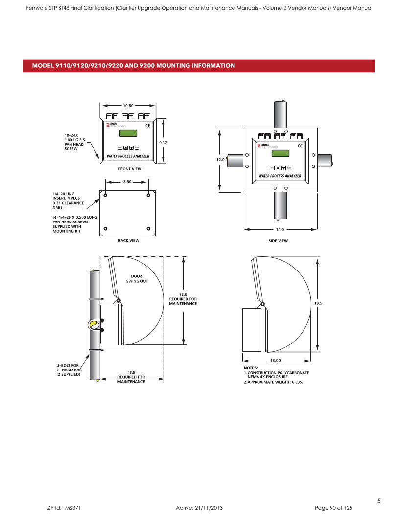
18.5REQUIRED FORMAINTENANCE
DOOR SWING OUT
13.5REQUIRED FORMAINTENANCE
U–BOLT FOR2” HAND RAIL(2 SUPPLIED)
14.0
12.0
TECHNOLOGIES
MENU ENTER
WATER PROCESS ANALYZER
WATER PROCESS ANALYZER
1/4–20 UNCINSERT, 4 PLCS0.31 CLEARANCE DRILL
(4) 1/4–20 X 0.500 LONG PAN HEAD SCREWS SUPPLIED WITH MOUNTING KIT
BACK VIEW
FRONT VIEW
9.37
8.30
10.50TECHNOLOGIES
MENU ENTER
10–24X1.00 LG S.S.PAN HEAD SCREW
SIDE VIEW
18.5
13.00
NOTES:1. CONSTRUCTION POLYCARBONATE NEMA 4X ENCLOSURE2. APPROXIMATE WEIGHT: 6 LBS.
WATER PROCESS ANALYZER
10.50
5
MODEL 9110/9120/9210/9220 AND 9200 MOUNTING INFORMATION
Fernvale STP ST48 Final Clarification (Clarifier Upgrade Operation and Maintenance Manuals - Volume 2 Vendor Manuals) Vendor Manual
QP Id: TMS371 Active: 21/11/2013 Page 90 of 125

1-1/2” PVC PIPESUPPLIED BYCUSTOMER
ROYCE DELUXEHANDRAIL BRACKET
SENSORADAPTER
MODEL 95A/96ASENSOR
CABLE TO ANALYZEROR JUNCTION BOX
Series 90 DO SensorsFEATURES
The Royce Models 95A and 96A Sensors are the latest sensor developments in the field of continuous DO monitoring and control. The small silhouette, and rugged construction of the Models 95A/96A create a unique sensor for the rough applications found in the wastewater treatment, ground water, aquaculture, and oceanographic industries, Both sensors contain precision internal circuitry and use the proven galvanic method of measurement.
The Model 96A Sensor is unique in that it incorporates a dual cathode, dual anode system which gives it the ability to perform the Royce patented electrochemical self cleaning function when used in conjunction with the Model 9200/9210/9220 Analyzers.
The Model 95A is a rugged rechargeable sensor that comes supplied with membranes and KCL gel solution with a system purchase that should last for five years with normal use. The Model 99 offers the convenience of a maintenance-free disposable sensor cartridge.
The Model 95A and 99A Sensors were specifically developed for the Model 9110/9120 continuous monitoring analyzer.
The trim, reliable mounting bracket assembly employed with the Royce line of Series 90 DO Sensors is simple to install and allows for easy access to the sensor for quick maintenance. A narrow profile sensor/collar arrangement allows for a standard PVC pipe installation from any standard rail. This configuration dramatically reduces the potential of rag fouling.
• Platinumcathode,leadanode
• Automatictemperaturecompensating
• Canbeeasilyrebuiltinthefield
• Nospecialtoolsrequired
• Patented electrochemical self-cleaning available
(Model 96A only)
• Jet-cleaningavailable
Measuring principal: Galvanic
Cathode/Anode material: Platinum/Coiled Pure Lead
Electrolyte: Potassium Chloride gel
Repeatability: ± 1% (at constant temperature)
Response time: Using 1 mil membrane - PPM 99% of actual, from air calibration < 30 seconds
Temperature accuracy: ± .2ºC
Sample flow requirements: 0.4 feet per second with 1 mil membrane
SPECIFICATIONS
6
Fernvale STP ST48 Final Clarification (Clarifier Upgrade Operation and Maintenance Manuals - Volume 2 Vendor Manuals) Vendor Manual
QP Id: TMS371 Active: 21/11/2013 Page 91 of 125

•Economicalinitialprice
•RuggedNoncorrosiveconstruction
•Longlivedcartridge
•Galvanicinoperation
•Temperaturecompensated
•1or2milmembranesavailable
•Jet-cleaningavailable
Cathode type and material: Galvanic – Platinum
Anode material: Coiled lead wire
Electrolyte: Potassium Chloride gel
Repeatability: ± 1% (at constant temperature)
Response time: Using 1 mil membrane – PPM 99% of actual, from air calibration in 60 seconds
Temperature accuracy: ± .2ºC
Sample flow requirements: 0.4 feet per second with 1 mil membrane
Dimensions: 1.2” Dia. x 5.8” long
Weight: (w/25 cable) .5 lbs., 22 kgm
The Model 99 replaceable Dissolved Oxygen Cartridge was specifically designed to answer the needs of plants that did not want to recharge sensors. It utilizes the same proven technology and basic design criteria found in all the Royce sensors. Rugged, easy to use, quick changing and with all the accuracy and reliability users have come to trust in Royce Technologies.
3/4” STAINLESS STEEL OR GALVANIZED PVC
(CUSTOMER FURNISHED)
PROBE PIPE MOUNTINGBRACKET KIT
SENSOR CABLE TO ANALYZER ORJUNCTION BOX
QUICK-RELEASELOCKING PIN
2” DIAMETERHANDRAIL CLAMPS
314 STAINLESS STEEL(ROYCE SUPPLIED)
3/4” PVC COUPLING(CUSTOMER FURNISHED)
MODEL 99 CARTRIDGE DISSOLVED OXYGEN SENSOR
SENSOR MOUNTING
FEATURES
SENSOR SPECIFICATIONS
Model 99 Replaceable Cartridge DO Sensor
7
Fernvale STP ST48 Final Clarification (Clarifier Upgrade Operation and Maintenance Manuals - Volume 2 Vendor Manuals) Vendor Manual
QP Id: TMS371 Active: 21/11/2013 Page 92 of 125
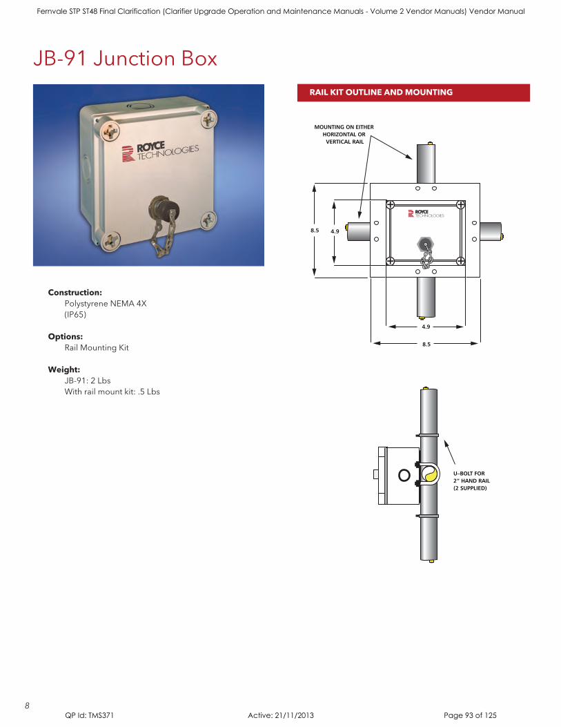
Construction: Polystyrene NEMA 4X (IP65)
Options: Rail Mounting Kit
Weight: JB-91:2Lbs With rail mount kit: .5 Lbs
8.5
4.9
8.5 4.9
U–BOLT FOR2” HAND RAIL(2 SUPPLIED)
MOUNTING ON EITHER HORIZONTAL OR VERTICAL RAIL
TECHNOLOGIES
JB-91JunctionBoxRAIL KIT OUTLINE AND MOUNTING
8
Fernvale STP ST48 Final Clarification (Clarifier Upgrade Operation and Maintenance Manuals - Volume 2 Vendor Manuals) Vendor Manual
QP Id: TMS371 Active: 21/11/2013 Page 93 of 125

JB-91JunctionBox
SENSOR MOUNTING
Type: Air Compressor, Light, Noncontinuous duty
Pressure supplied: 40 to 60 PSIG
Temperature limits: 0 to 50ºC
Enclosure: NEMA 4X, 14”W x 12”H x 6”D
Input power: 115/230 VAC, 60/50 Hz
Weight: 23 pounds (10,4 kgms) 26 pounds (11.8 kgms) with rail kit
Options: Heater (Recommended for -10ºC) Rail Mounting Kit
COMPRESSOR SPECIFICATIONS
“JetClean”SensorMembraneCleaningSystem
9
Fernvale STP ST48 Final Clarification (Clarifier Upgrade Operation and Maintenance Manuals - Volume 2 Vendor Manuals) Vendor Manual
QP Id: TMS371 Active: 21/11/2013 Page 94 of 125
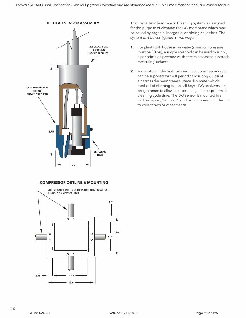
MOUNT PANEL WITH 2 U-BOLTS ON HORIZONTAL RAIL,1 U-BOLT ON VERTICAL RAIL
15.6
13.73
3.3
8.75
2.38
11.91
15.0
9.75
1.52
JET CLEAN HEADCOUPLING
(ROYCE SUPPLIED)
JET CLEAN HEAD
1/4” COMPRESSIONFITTING
(ROYCE SUPPLIED)
TheRoyceJet-CleansensorCleaningSystemisdesignedfor the purpose of cleaning the DO membrane which may be soiled by organic, inorganic, or biological debris. The system can be configured in two ways:
1. For plants with house air or water (minimum pressure must be 30 psi), a simple solenoid can be used to supply a periodic high pressure wash stream across the electrode measuring surface;
2. A miniature industrial, rail mounted, compressor system can be supplied that will periodically supply 65 psi of air across the membrane surface. No mater which method of cleaning is used all Royce DO analyzers are programmed to allow the user to adjust their preferred cleaning cycle time. The DO sensor is mounted in a moldedepoxy“jethead”whichiscontoured in order not to collect rags or other debris.
JET HEAD SENSOR ASSEMBLY
COMPRESSOR OUTLINE & MOUNTING
10
Fernvale STP ST48 Final Clarification (Clarifier Upgrade Operation and Maintenance Manuals - Volume 2 Vendor Manuals) Vendor Manual
QP Id: TMS371 Active: 21/11/2013 Page 95 of 125

151 Graham RoadPO Box 9010College Station, Texas 77842-9010
(979) 690-1711(800) 653-1711 USA/CanadaFAX (979) 690-0440
www.roycetechnologies.comE-mail: [email protected]
Publication 37600612
MEASUREMENT TECHNOLOGIES BY ROYCE
Dissolved Oxygen Monitoring and Control• SingleandMulti-channelAnalyzers
• BioreactorandLagoonSystems
Total Suspended Solids Monitoring and Control• PortableAnalyzers
• SingleandMulti-channelAnalyzers
• Solidsdensity
Interface Level analyzers• Primary,SecondaryandThickenerAnalyzers
Royce, a Xylem brand, provides high quality monitoring and control instrumentation and sensors specifically designed for municipal and industrial wastewater treatment applications. Recognized throughout the wastewater treatment industry as experts in the biological wastewater treatment process.
Fernvale STP ST48 Final Clarification (Clarifier Upgrade Operation and Maintenance Manuals - Volume 2 Vendor Manuals) Vendor Manual
QP Id: TMS371 Active: 21/11/2013 Page 96 of 125

Electrical
Fernvale STP ST48 Final Clarification (Clarifier Upgrade Operation and Maintenance Manuals - Volume 2 Vendor Manuals) Vendor Manual
QP Id: TMS371 Active: 21/11/2013 Page 97 of 125
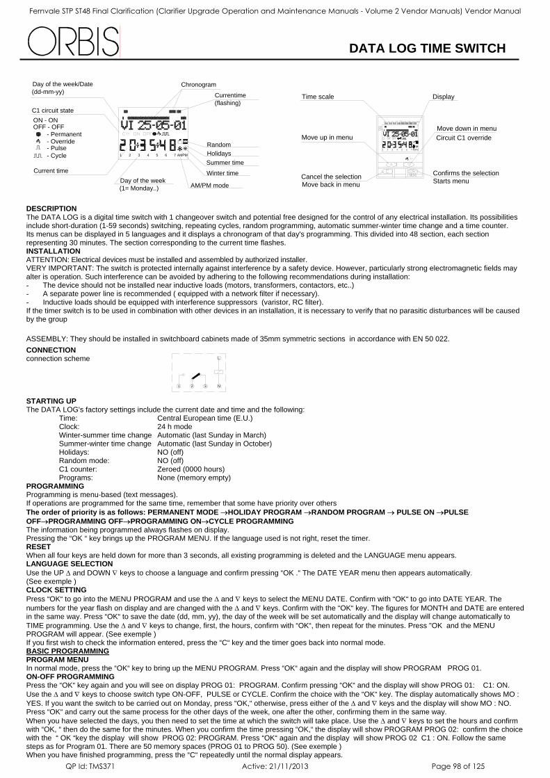
DATA LOG TIME SWITCH
DESCRIPTION The DATA LOG is a digital time switch with 1 changeover switch and potential free designed for the control of any electrical installation. Its possibilities include short-duration (1-59 seconds) switching, repeating cycles, random programming, automatic summer-winter time change and a time counter. Its menus can be displayed in 5 languages and it displays a chronogram of that day's programming. This divided into 48 section, each section representing 30 minutes. The section corresponding to the current time flashes. INSTALLATION
ATTENTION: Electrical devices must be installed and assembled by authorized installer. VERY IMPORTANT: The switch is protected internally against interference by a safety device. However, particularly strong electromagnetic fields may alter is operation. Such interference can be avoided by adhering to the following recommendations during installation: - The device should not be installed near inductive loads (motors, transformers, contactors, etc..) - A separate power line is recommended ( equipped with a network filter if necessary). - Inductive loads should be equipped with interference suppressors (varistor, RC filter). If the timer switch is to be used in combination with other devices in an installation, it is necessary to verify that no parasitic disturbances will be caused by the group
ASSEMBLY: They should be installed in switchboard cabinets made of 35mm symmetric sections in accordance with EN 50 022. CONNECTION connection scheme STARTING UP The DATA LOG's factory settings include the current date and time and the following:
Time: Central European time (E.U.) Clock: 24 h mode Winter-summer time change Automatic (last Sunday in March) Summer-winter time change Automatic (last Sunday in October) Holidays: NO (off) Random mode: NO (off) C1 counter: Zeroed (0000 hours) Programs: None (memory empty)
PROGRAMMING Programming is menu-based (text messages). If operations are programmed for the same time, remember that some have priority over others The order of priority is as follows: PERMANENT MODE →HOLIDAY PROGRAM →RANDOM PROGRAM → PULSE ON →PULSE
OFF→PROGRAMMING OFF→PROGRAMMING ON→CYCLE PROGRAMMING The information being programmed always flashes on display. Pressing the “OK “ key brings up the PROGRAM MENU. If the language used is not right, reset the timer. RESET When all four keys are held down for more than 3 seconds, all existing programming is deleted and the LANGUAGE menu appears. LANGUAGE SELECTION
Use the UP ∆ and DOWN ∇ keys to choose a language and confirm pressing “OK .“ The DATE YEAR menu then appears automatically. (See exemple ) CLOCK SETTING
Press “OK“ to go into the MENU PROGRAM and use the ∆ and ∇ keys to select the MENU DATE. Confirm with “OK“ to go into DATE YEAR. The numbers for the year flash on display and are changed with the ∆ and ∇ keys. Confirm with the “OK“ key. The figures for MONTH and DATE are entered in the same way. Press “OK“ to save the date (dd, mm, yy), the day of the week will be set automatically and the display will change automatically to TIME programming. Use the ∆ and ∇ keys to change, first, the hours, confirm with “OK“, then repeat for the minutes. Press "OK and the MENU PROGRAM will appear. (See exemple ) If you first wish to check the information entered, press the “C“ key and the timer goes back into normal mode. BASIC PROGRAMMING PROGRAM MENU In normal mode, press the “OK“ key to bring up the MENU PROGRAM. Press “OK“ again and the display will show PROGRAM PROG 01. ON-OFF PROGRAMMING Press the “OK“ key again and you will see on display PROG 01: PROGRAM. Confirm pressing “OK“ and the display will show PROG 01: C1: ON. Use the ∆ and ∇ keys to choose switch type ON-OFF, PULSE or CYCLE. Confirm the choice with the “OK“ key. The display automatically shows MO : YES. If you want the switch to be carried out on Monday, press “OK,“ otherwise, press either of the ∆ and ∇ keys and the display will show MO : NO. Press “OK“ and carry out the same process for the other days of the week, one after the other, confirming them in the same way. When you have selected the days, you then need to set the time at which the switch will take place. Use the ∆ and ∇ keys to set the hours and confirm with “OK, “ then do the same for the minutes. When you confirm the time pressing “OK,“ the display will show PROGRAM PROG 02: confirm the choice with the “ OK “key the display will show PROG 02: PROGRAM. Press “OK“ again and the display will show PROG 02 C1 : ON. Follow the same steps as for Program 01. There are 50 memory spaces (PROG 01 to PROG 50). (See exemple ) When you have finished programming, press the “C“ repeatedly until the normal display appears.
ON - ON
Current time
- Pulse- Cycle
- Override- Permanent
OFF - OFF
C1 circuit state
Day of the week/Date(dd-mm-yy)
Day of the week (1= Monday..) AM/PM mode
Chronogram
1 2 3 4 5 6 7 AMPM Holidays
Winter time
Summer time
Random
Currentime (flashing)
Move back in menuCancel the selection
Move up in menu
Time scale
Starts menuConfirms the selection
Circuit C1 overrideMove down in menu
Display
1 2 3 4 5 6 7 PMAM
1 2 3 N
L
Fernvale STP ST48 Final Clarification (Clarifier Upgrade Operation and Maintenance Manuals - Volume 2 Vendor Manuals) Vendor Manual
QP Id: TMS371 Active: 21/11/2013 Page 98 of 125
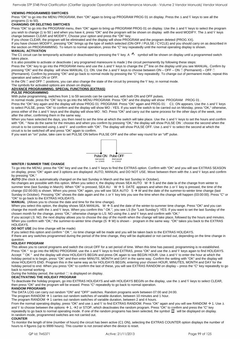
VIEWING PROGRAMMED SWITCHES
Press “OK“ to go into the MENU PROGRAM, then “OK“ again to bring up PROGRAM PROG 01 on display. Press the ∆ and ∇ keys to see all the programs (1 to 50). CHANGING OR DELETING SWITCHES
Press “OK“ to go into the PROGRAM menu, then “OK“ again to bring up PROGRAM PROG 01 on display. Use the ∆ and ∇ keys to select the program you wish to change (1 to 50 ) and when you have it, press “OK“ and the program will be shown on display with the word MODIFY. The ∆ and ∇ keys change between CLEAR and MODIFY, Choose your option and press the “OK“ key. If you chose CLEAR, the program will be eliminated and the display will show PROGRAM and the program deleted (PROG XX). If you have chosen MODIFY, pressing “OK“ brings up the type of switch selected (ON-OFF / PULSE / CYCLE) and you should carry on as described in the section on PROGRAMMING. To return to normal operation, press the “C“ key repeatedly until the normal operating display is shown. MANUAL ACTIVATION
The C1 circuit can be temporarily activated or deactivated by pressing the ∇ key. A symbol will be shown on display until a programmed switch takes place. It is also possible to activate or deactivate ( any programed maneouvre is made ) the circuit permanently by following these steps: Press the “OK“ key to go into the PROGRAM menu and use the ∆ and ∇ keys to change the 2nd line on the display until you see MANUAL. Confirm by pressing “OK“ and the display will show MANUAL C1: ON. Use the ∆ and ∇ keys to choose between ON – OFF – ON (Permanent) – OFF (Permanent). Confirm by pressing “OK“ and go back to normal mode by pressing the “C“ key repeatedly. To change out of permanent mode, repeat this operation and select ON or OFF. In the ON and OFF positions, you can also change the state of the circuit by pressing the ∇ key, in normal mode. The symbols for activated options are shown on display. ADVANCE PROGRAMMING. SPECIAL FUNCTIONS (EXTRAS) PULSE PROGRAMMING With pulse programming, switches from 1 to 59 seconds can be carried out, with both ON and OFF pulses. In normal mode, press the “OK“ key to go into the MENU PROGRAM. Press “OK“ and the display will show: PROGRAM PROG 01 . Press the “OK“ key again and the display will show PROG 01: PROGRAM. Press “OK“ again and PROG 01: C1: ON appears. Use the ∆ and ∇ keys to select PULSE, press “OK“ to confirm and the display will show MO : YES. If you want the switch to be carried out on Monday, press “OK,“ otherwise, press either of the ∆ and ∇ keys and the display will show MO : NO. Press “OK“ and carry out the same process for the other days of the week, one after the other, confirming them in the same way. When you have selected the days, you then need to set the time at which the switch will take place. Use the ∆ and ∇ keys to set the hours and confirm with “OK. “ Now do the same for the minutes and when you confirm by pressing “OK,“ the display will show PULSE ON : choose the second when the circuit is to be connected using ∆ and ∇ and confirm with “OK“. The display will show PULSE OFF. Use ∆ and ∇ to select the second at which the circuit is to be switched off and press “OK“ again to confirm. If you want an "on" pulse, take care to set PULSE ON before PULSE OFF and the other way round for an "off" pulse. WINTER / SUMMER TIME CHANGE To go into the MENU, press the “OK“ key and use the ∆ and ∇ keys to find the EXTRAS option. Confirm with “OK“ and you will see EXTRAS SEASON on display, press “OK“ again and 3 options are displayed: AUTO, MANUAL and DO NOT USE. Move between them with the ∆ and ∇ keys and confirm by pressing “OK.“ AUTO (the clock is automatically changed on the last Sunday in March and the last Sunday in October). No changes are possible with this option. When you select it, the display shows SEA AUTO W S and the date la of the change from winter to summer time (last Sunday in March). When “OK“ is pressed, SEA AU W S DATE appears and when the ∆ or ∇ key is pressed, the time of the change (02:00:00) is shown. When you press “OK“ again, you will see SEA AUTO S W and the date of the summer-to-winter time change (last Sunday in October). Pressing “OK“ shows the date again and the ∆ or ∇ key lets you see the time when the change will happen (03:00:00). Press “C” or “OK“ to go back to the EXTRAS HOLIDAYS. MANUAL (Allows you to choose the date and time for the time change). When you select this option, the display shows SEA MANUAL W S and the date of the winter-to-summer time change. Press “OK“ and you can change the month with the ∆ and ∇ keys. When you confirm this “ OK ”, you see LS (for "Last Sunday“): YES. If you want to set the last Sunday of the chosen month for the change, press “OK,“ otherwise change to LS: NO using the ∆ and ∇ keys and confirm with “OK.“ If you accept LS: NO, the next display allows you to choose the day of the month when the change will take place, followed by the hours and minutes. When you confirm with “OK,“ the summer-to-winter time change (S W) is shown - program in the same way. “OK“ takes you back to the EXTRAS HOLIDAYS. DO NOT USE (no time change will be made) If you select this option and confirm “ OK “, no time change will be made and you will be taken back to the EXTRAS HOLIDAYS. If there are any switches programmed during the period of the time change, they will be duplicated or not carried out, depending on the time change in question. HOLIDAY PROGRAM This allows you to cancel programs and switch the circuit OFF for a set period of time. When this time has passed, programming is re-established. Press “OK “ to go into the MENU PROGRAM, use the ∆ and ∇ keys to find EXTRAS, press “OK“ and use the ∆ and ∇ keys again to find HOLIDAYS. Accept ¨” OK “ and the display will show HOLIDAYS BEGIN and press OK again to see BEGIN HOUR. Use ∆ and ∇ to enter the hour at which the holiday period is to begin, press “OK“ and then enter MINUTE, MONTH and DAY in the same way. Confirm the setting with “OK“ and the display will show HOLIDAYS END. Program this in the same way as for HOLIDAYS BEGIN, entering your chosen HOUR, MINUTES, MONTH and DAY for the holiday period to end. When you press “OK“ to confirm the last of these, you will see EXTRAS RANDOM on display – press the “C“ key repeatedly to go back to normal working. During the holiday period, the symbol is displayed on display. DEACTIVATING THE HOLIDAY PROGRAM
To deactivate the holiday program, go into EXTRAS HOLIDAYS and with HOLIDAYS BEGIN on the display, use the ∆ and ∇ keys to select CLEAR, then press “OK“ and the program will be erased. Press “C“ repeatedly to go back to normal operation. RANDOM PROGRAMS The DATA LOG can carry out random "ON" and "OFF" switches. Random programs work between 07:00 and 24:00. The program RANDOM 1 carries out random switches of variable duration, between 10 minutes and 1 hour. The program RANDOM 1 carries out random switches of variable duration, between 2 and 4 hours. From the normal operating display, press “OK“ and use ∆ and ∇ to find EXTRAS RANDOM. Press “OK“ again and you will see RANDOM 1. Use ∆ and ∇ to choose between the options 1, 2 or STOP, which deactivates the random program. Press “OK“ to confirm and press the “C“ key repeatedly to go back to normal operating mode. If one of the random programs has been selected, the symbol will be displayed on display. In random mode, programmed switches are not carried out. COUNTER To monitor the length of time (number of hours) the circuit has been active (C1 ON), selecting the EXTRAS COUNTER option displays the number of hours to 4 figures (up to 9999 hours). This counter is not zeroed when the device is reset.
i.e.- 12:04:32(finish second)
Pulse OFFPulse ONi.e.- 12:04:05(start second)
Fernvale STP ST48 Final Clarification (Clarifier Upgrade Operation and Maintenance Manuals - Volume 2 Vendor Manuals) Vendor Manual
QP Id: TMS371 Active: 21/11/2013 Page 99 of 125
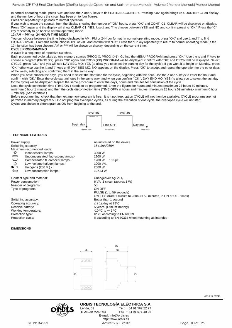
In normal operating mode, press “OK“ and use the ∆ and ∇ keys to find EXTRAS COUNTER. Pressing “OK“ again brings up COUNTER C1 on display and the number of hours the circuit has been on to four figures. Press “C“ repeatedly to go back to normal operation. If you wish to erase the counter, from the display showing the number of "ON" hours, press “OK“ and CONT C1 CLEAR will be displayed on display. Press “OK“ again and the display will show CLEAR C1 YES. Use ∆ and ∇ to choose between YES and NO and confirm pressing “OK“. Press the “C“ key repeatedly to go back to normal operating mode. 12 (AM – PM) or 24-HOUR TIME MODE
You can choose between the time being displayed in AM : PM or 24-hour format. In normal operating mode, press “OK“ and use ∆ and ∇ to find EXTRAS 12/24H. From this menu, choose 12H or 24H and confirm with “OK“. Press the “C“ key repeatedly to return to normal operating mode. If the 12h function has been chosen, AM or PM will be shown on display, depending on the current time. CYCLE PROGRAMMING A cycle is a sequence of repetitive switches. Each programmed cycle takes up two memory spaces (PROG X, PROG X+1). Go into the MENU PROGRAM and press “OK.“ Use the ∆ and ∇ keys to choose a program (PROG XX), press “OK“ again and PROG (XX) PROGRAM will be displayed. Confirm with “OK“ and C1:ON will be displayed. Select CYCLE, press “OK,“ and you will see DAY BEG MO: YES (to allow you to select the starting day for the cycle). If you want it to begin on Monday, press “OK,“ otherwise use the ∆ and ∇ keys until DAY BEG MO: NO appears on the display. Press “OK“ to accept and repeat the operation for the other days of the week, selecting and confirming them in the same way. When you have chosen the days, you need to select the start time for the cycle, beginning with the hour. Use the ∆ and ∇ keys to enter the hour and confirm with “OK.“ Enter the cycle start minutes in the same way, and when you confirm “ OK “, DAY END MO: YES (to allow you to select the last day for the cycle) will be displayed. Repeat the same procedure to enter the days, hours and minutes for conclusion of the cycle. Next, the cycle connection time (TIME ON ) needs to be programmed. Enter the figures for hours and minutes (maximum 23 hours 59 minutes.- minimum 0 hour 1 minute) and then the cycle disconnection time (TIME OFF) in hours and minutes (maximum 23 hours 59 minutes.- minimum 0 hour 1 minute). (See exemple ) Before programming, check that the next memory program is free. It is it not free, option CYCLE will not then be available. CYCLE programs are not permited in memory program 50. Do not program averlaped cycles, as during the execution of one cycle, the overlaped cycle will not start. Cycles are shown in chronogram as ON from begining to the end.
TECHNICAL FEATURES Power supply : As indicated on the device Switching capacity : 16 (10)A/250V Maximum recomended loads: Incandescent lamps.- 3000 W. Uncompensated fluorescent lamps.- 1200 W. Compensated fluorescent lamps.- 1200 W. 150 µF. Low- voltage halogen lamps.- 1000 VA. Halogens (230 V.).- 2500 W. Low-consumption lamps.- 10X23 W.
Contact type and material: Changeover AgSnO2 Power consumption: 6 VA 1 circuit (approx.1 W) Number of programs: 50 Type of programs: ON OFF PULSE (1 to 59 seconds)
CYCLES (from 1 minute to 23hours 59 minutes, in ON or OFF times) Switching accuracy: Better than 1 second Operating accuracy: ≤ ± 1s/day at 23ºC Reserve battery: 5 years. (Lithium Battery) Working temperature: -10 ºC to +45 ºC Protection type: IP 20 according to EN 60529 Protection class: II according to EN 60335 when mounting as intended DIMENSIONS
A016.17.51249
ORBIS TECNOLOGÍA ELÉCTRICA S.A.
Lérida, 61 Tel.: + 34 91 567 22 77 E-28020 MADRID Fax + 34 91 571 40 06
E-mail: [email protected] http://www.orbis.es
1h10min. ON
Time ON
Day end
Time ON
Monday 9:00h
Begin day 2h20min. OFF
Time OFFFriday 13:00h
35
88 45
60
65
Fernvale STP ST48 Final Clarification (Clarifier Upgrade Operation and Maintenance Manuals - Volume 2 Vendor Manuals) Vendor Manual
QP Id: TMS371 Active: 21/11/2013 Page 100 of 125
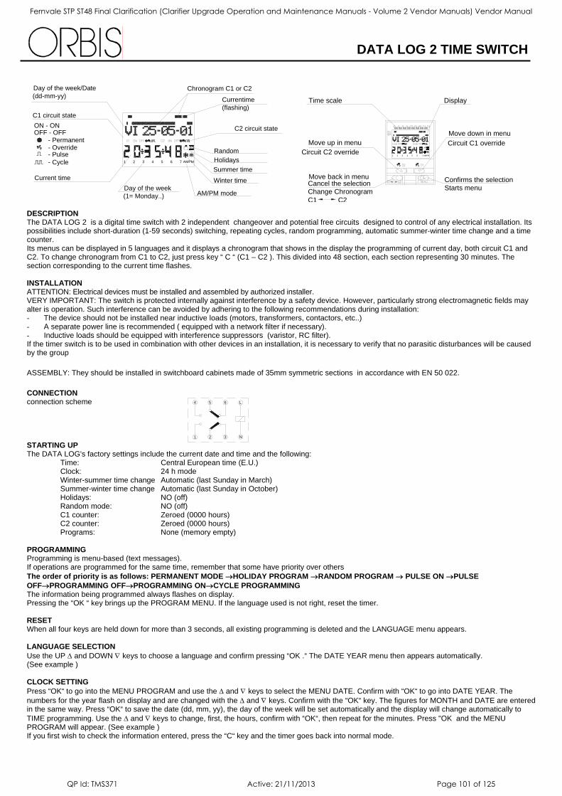
DATA LOG 2 TIME SWITCH
DESCRIPTION The DATA LOG 2 is a digital time switch with 2 independent changeover and potential free circuits designed to control of any electrical installation. Its possibilities include short-duration (1-59 seconds) switching, repeating cycles, random programming, automatic summer-winter time change and a time counter. Its menus can be displayed in 5 languages and it displays a chronogram that shows in the display the programming of current day, both circuit C1 and C2. To change chronogram from C1 to C2, just press key “ C “ (C1 – C2 ). This divided into 48 section, each section representing 30 minutes. The section corresponding to the current time flashes. INSTALLATION
ATTENTION: Electrical devices must be installed and assembled by authorized installer. VERY IMPORTANT: The switch is protected internally against interference by a safety device. However, particularly strong electromagnetic fields may alter is operation. Such interference can be avoided by adhering to the following recommendations during installation: - The device should not be installed near inductive loads (motors, transformers, contactors, etc..) - A separate power line is recommended ( equipped with a network filter if necessary). - Inductive loads should be equipped with interference suppressors (varistor, RC filter). If the timer switch is to be used in combination with other devices in an installation, it is necessary to verify that no parasitic disturbances will be caused by the group
ASSEMBLY: They should be installed in switchboard cabinets made of 35mm symmetric sections in accordance with EN 50 022. CONNECTION connection scheme STARTING UP The DATA LOG's factory settings include the current date and time and the following:
Time: Central European time (E.U.) Clock: 24 h mode Winter-summer time change Automatic (last Sunday in March) Summer-winter time change Automatic (last Sunday in October) Holidays: NO (off) Random mode: NO (off) C1 counter: Zeroed (0000 hours) C2 counter: Zeroed (0000 hours) Programs: None (memory empty)
PROGRAMMING Programming is menu-based (text messages). If operations are programmed for the same time, remember that some have priority over others The order of priority is as follows: PERMANENT MODE →HOLIDAY PROGRAM →RANDOM PROGRAM → PULSE ON →PULSE
OFF→PROGRAMMING OFF→PROGRAMMING ON→CYCLE PROGRAMMING The information being programmed always flashes on display. Pressing the “OK “ key brings up the PROGRAM MENU. If the language used is not right, reset the timer. RESET When all four keys are held down for more than 3 seconds, all existing programming is deleted and the LANGUAGE menu appears. LANGUAGE SELECTION
Use the UP ∆ and DOWN ∇ keys to choose a language and confirm pressing “OK .“ The DATE YEAR menu then appears automatically. (See example ) CLOCK SETTING
Press “OK“ to go into the MENU PROGRAM and use the ∆ and ∇ keys to select the MENU DATE. Confirm with “OK“ to go into DATE YEAR. The numbers for the year flash on display and are changed with the ∆ and ∇ keys. Confirm with the “OK“ key. The figures for MONTH and DATE are entered in the same way. Press “OK“ to save the date (dd, mm, yy), the day of the week will be set automatically and the display will change automatically to TIME programming. Use the ∆ and ∇ keys to change, first, the hours, confirm with “OK“, then repeat for the minutes. Press "OK and the MENU PROGRAM will appear. (See example ) If you first wish to check the information entered, press the “C“ key and the timer goes back into normal mode.
ON - ON
Current time
- Pulse- Cycle
- Override- Permanent
OFF - OFF
C1 circuit state
Day of the week/Date(dd-mm-yy)
Day of the week (1= Monday..) AM/PM mode
1 2 3 4 5 6 7 AMPM Holidays
Winter timeSummer time
Random
Currentime (flashing)
Chronogram C1 or C2
C2 circuit state
Change ChronogramC1 C2
Cancel the selection
Move up in menu
Time scale
Starts menuConfirms the selection
Circuit C1 overrideMove down in menu
Display
1 2 3 4 5 6 7 PMAMCircuit C2 override
Move back in menu
1 2 3 N
L4 5 6
Fernvale STP ST48 Final Clarification (Clarifier Upgrade Operation and Maintenance Manuals - Volume 2 Vendor Manuals) Vendor Manual
QP Id: TMS371 Active: 21/11/2013 Page 101 of 125
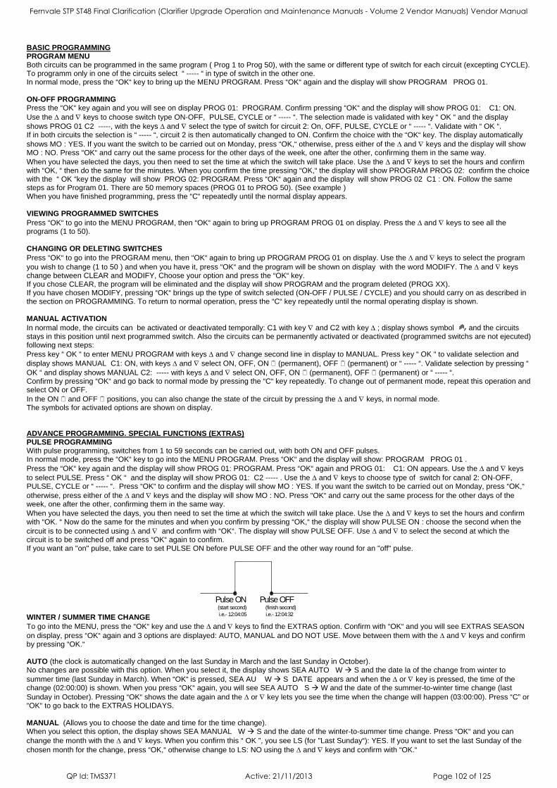
BASIC PROGRAMMING PROGRAM MENU Both circuits can be programmed in the same program ( Prog 1 to Prog 50), with the same or different type of switch for each circuit (excepting CYCLE). To programm only in one of the circuits select “ ----- “ in type of switch in the other one. In normal mode, press the “OK“ key to bring up the MENU PROGRAM. Press “OK“ again and the display will show PROGRAM PROG 01. ON-OFF PROGRAMMING Press the “OK“ key again and you will see on display PROG 01: PROGRAM. Confirm pressing “OK“ and the display will show PROG 01: C1: ON. Use the ∆ and ∇ keys to choose switch type ON-OFF, PULSE, CYCLE or “ ----- “. The selection made is validated with key “ OK “ and the display shows PROG 01 C2 -----, with the keys ∆ and ∇ select the type of switch for circuit 2: On, OFF, PULSE, CYCLE or “ ----- “. Validate with “ OK “. If in both circuits the selection is “ ----- “, circuit 2 is then automatically changed to ON. Confirm the choice with the “OK“ key. The display automatically shows MO : YES. If you want the switch to be carried out on Monday, press “OK,“ otherwise, press either of the ∆ and ∇ keys and the display will show MO : NO. Press “OK“ and carry out the same process for the other days of the week, one after the other, confirming them in the same way. When you have selected the days, you then need to set the time at which the switch will take place. Use the ∆ and ∇ keys to set the hours and confirm with “OK, “ then do the same for the minutes. When you confirm the time pressing “OK,“ the display will show PROGRAM PROG 02: confirm the choice with the “ OK “key the display will show PROG 02: PROGRAM. Press “OK“ again and the display will show PROG 02 C1 : ON. Follow the same steps as for Program 01. There are 50 memory spaces (PROG 01 to PROG 50). (See example ) When you have finished programming, press the “C“ repeatedly until the normal display appears. VIEWING PROGRAMMED SWITCHES
Press “OK“ to go into the MENU PROGRAM, then “OK“ again to bring up PROGRAM PROG 01 on display. Press the ∆ and ∇ keys to see all the programs (1 to 50). CHANGING OR DELETING SWITCHES
Press “OK“ to go into the PROGRAM menu, then “OK“ again to bring up PROGRAM PROG 01 on display. Use the ∆ and ∇ keys to select the program you wish to change (1 to 50 ) and when you have it, press “OK“ and the program will be shown on display with the word MODIFY. The ∆ and ∇ keys change between CLEAR and MODIFY, Choose your option and press the “OK“ key. If you chose CLEAR, the program will be eliminated and the display will show PROGRAM and the program deleted (PROG XX). If you have chosen MODIFY, pressing “OK“ brings up the type of switch selected (ON-OFF / PULSE / CYCLE) and you should carry on as described in the section on PROGRAMMING. To return to normal operation, press the “C“ key repeatedly until the normal operating display is shown. MANUAL ACTIVATION
In normal mode, the circuits can be activated or deactivated temporally: C1 with key ∇ and C2 with key ∆ ; display shows symbol and the circuits stays in this position until next programmed switch. Also the circuits can be permanently activated or deactivated (programmed switchs are not ejecuted) following next steps: Press key “ OK “ to enter MENU PROGRAM with keys ∆ and ∇ change second line in display to MANUAL. Press key “ OK “ to validate selection and display shows MANUAL C1: ON, with keys ∆ and ∇ select ON, OFF, ON (permanent), OFF (permanent) or “ ----- “. Validate selection by pressing “ OK “ and display shows MANUAL C2: ----- with keys ∆ and ∇ select ON, OFF, ON (permanent), OFF (permanent) or “ ----- “. Confirm by pressing “OK“ and go back to normal mode by pressing the “C“ key repeatedly. To change out of permanent mode, repeat this operation and select ON or OFF. In the ON and OFF positions, you can also change the state of the circuit by pressing the ∆ and ∇ keys, in normal mode. The symbols for activated options are shown on display. ADVANCE PROGRAMMING. SPECIAL FUNCTIONS (EXTRAS) PULSE PROGRAMMING With pulse programming, switches from 1 to 59 seconds can be carried out, with both ON and OFF pulses. In normal mode, press the “OK“ key to go into the MENU PROGRAM. Press “OK“ and the display will show: PROGRAM PROG 01 . Press the “OK“ key again and the display will show PROG 01: PROGRAM. Press “OK“ again and PROG 01: C1: ON appears. Use the ∆ and ∇ keys to select PULSE. Press “ OK “ and the display will show PROG 01: C2 ----- . Use the ∆ and ∇ keys to choose type of switch for canal 2: ON-OFF, PULSE, CYCLE or “ ----- “. Press “OK“ to confirm and the display will show MO : YES. If you want the switch to be carried out on Monday, press “OK,“ otherwise, press either of the ∆ and ∇ keys and the display will show MO : NO. Press “OK“ and carry out the same process for the other days of the week, one after the other, confirming them in the same way. When you have selected the days, you then need to set the time at which the switch will take place. Use the ∆ and ∇ keys to set the hours and confirm with “OK. “ Now do the same for the minutes and when you confirm by pressing “OK,“ the display will show PULSE ON : choose the second when the circuit is to be connected using ∆ and ∇ and confirm with “OK“. The display will show PULSE OFF. Use ∆ and ∇ to select the second at which the circuit is to be switched off and press “OK“ again to confirm. If you want an "on" pulse, take care to set PULSE ON before PULSE OFF and the other way round for an "off" pulse. WINTER / SUMMER TIME CHANGE To go into the MENU, press the “OK“ key and use the ∆ and ∇ keys to find the EXTRAS option. Confirm with “OK“ and you will see EXTRAS SEASON on display, press “OK“ again and 3 options are displayed: AUTO, MANUAL and DO NOT USE. Move between them with the ∆ and ∇ keys and confirm by pressing “OK.“ AUTO (the clock is automatically changed on the last Sunday in March and the last Sunday in October). No changes are possible with this option. When you select it, the display shows SEA AUTO W S and the date la of the change from winter to summer time (last Sunday in March). When “OK“ is pressed, SEA AU W S DATE appears and when the ∆ or ∇ key is pressed, the time of the change (02:00:00) is shown. When you press “OK“ again, you will see SEA AUTO S W and the date of the summer-to-winter time change (last Sunday in October). Pressing “OK“ shows the date again and the ∆ or ∇ key lets you see the time when the change will happen (03:00:00). Press “C” or “OK“ to go back to the EXTRAS HOLIDAYS. MANUAL (Allows you to choose the date and time for the time change). When you select this option, the display shows SEA MANUAL W S and the date of the winter-to-summer time change. Press “OK“ and you can change the month with the ∆ and ∇ keys. When you confirm this “ OK ”, you see LS (for "Last Sunday“): YES. If you want to set the last Sunday of the chosen month for the change, press “OK,“ otherwise change to LS: NO using the ∆ and ∇ keys and confirm with “OK.“
i.e.- 12:04:05(start second)
Pulse ONi.e.- 12:04:32(finish second)
Pulse OFF
Fernvale STP ST48 Final Clarification (Clarifier Upgrade Operation and Maintenance Manuals - Volume 2 Vendor Manuals) Vendor Manual
QP Id: TMS371 Active: 21/11/2013 Page 102 of 125
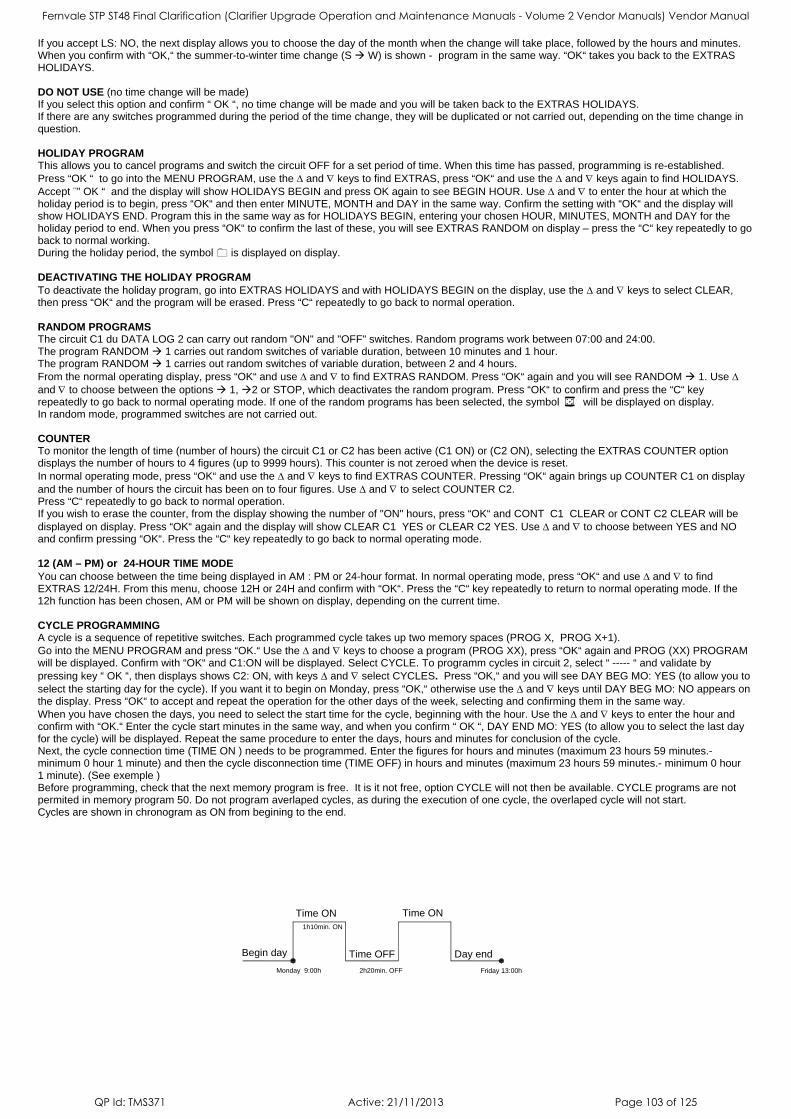
If you accept LS: NO, the next display allows you to choose the day of the month when the change will take place, followed by the hours and minutes. When you confirm with “OK,“ the summer-to-winter time change (S W) is shown - program in the same way. “OK“ takes you back to the EXTRAS HOLIDAYS. DO NOT USE (no time change will be made) If you select this option and confirm “ OK “, no time change will be made and you will be taken back to the EXTRAS HOLIDAYS. If there are any switches programmed during the period of the time change, they will be duplicated or not carried out, depending on the time change in question. HOLIDAY PROGRAM This allows you to cancel programs and switch the circuit OFF for a set period of time. When this time has passed, programming is re-established. Press “OK “ to go into the MENU PROGRAM, use the ∆ and ∇ keys to find EXTRAS, press “OK“ and use the ∆ and ∇ keys again to find HOLIDAYS. Accept ¨” OK “ and the display will show HOLIDAYS BEGIN and press OK again to see BEGIN HOUR. Use ∆ and ∇ to enter the hour at which the holiday period is to begin, press “OK“ and then enter MINUTE, MONTH and DAY in the same way. Confirm the setting with “OK“ and the display will show HOLIDAYS END. Program this in the same way as for HOLIDAYS BEGIN, entering your chosen HOUR, MINUTES, MONTH and DAY for the holiday period to end. When you press “OK“ to confirm the last of these, you will see EXTRAS RANDOM on display – press the “C“ key repeatedly to go back to normal working. During the holiday period, the symbol is displayed on display. DEACTIVATING THE HOLIDAY PROGRAM
To deactivate the holiday program, go into EXTRAS HOLIDAYS and with HOLIDAYS BEGIN on the display, use the ∆ and ∇ keys to select CLEAR, then press “OK“ and the program will be erased. Press “C“ repeatedly to go back to normal operation. RANDOM PROGRAMS The circuit C1 du DATA LOG 2 can carry out random "ON" and "OFF" switches. Random programs work between 07:00 and 24:00. The program RANDOM 1 carries out random switches of variable duration, between 10 minutes and 1 hour. The program RANDOM 1 carries out random switches of variable duration, between 2 and 4 hours. From the normal operating display, press “OK“ and use ∆ and ∇ to find EXTRAS RANDOM. Press “OK“ again and you will see RANDOM 1. Use ∆ and ∇ to choose between the options 1, 2 or STOP, which deactivates the random program. Press “OK“ to confirm and press the “C“ key repeatedly to go back to normal operating mode. If one of the random programs has been selected, the symbol will be displayed on display. In random mode, programmed switches are not carried out. COUNTER To monitor the length of time (number of hours) the circuit C1 or C2 has been active (C1 ON) or (C2 ON), selecting the EXTRAS COUNTER option displays the number of hours to 4 figures (up to 9999 hours). This counter is not zeroed when the device is reset. In normal operating mode, press “OK“ and use the ∆ and ∇ keys to find EXTRAS COUNTER. Pressing “OK“ again brings up COUNTER C1 on display and the number of hours the circuit has been on to four figures. Use ∆ and ∇ to select COUNTER C2. Press “C“ repeatedly to go back to normal operation. If you wish to erase the counter, from the display showing the number of "ON" hours, press “OK“ and CONT C1 CLEAR or CONT C2 CLEAR will be displayed on display. Press “OK“ again and the display will show CLEAR C1 YES or CLEAR C2 YES. Use ∆ and ∇ to choose between YES and NO and confirm pressing “OK“. Press the “C“ key repeatedly to go back to normal operating mode. 12 (AM – PM) or 24-HOUR TIME MODE
You can choose between the time being displayed in AM : PM or 24-hour format. In normal operating mode, press “OK“ and use ∆ and ∇ to find EXTRAS 12/24H. From this menu, choose 12H or 24H and confirm with “OK“. Press the “C“ key repeatedly to return to normal operating mode. If the 12h function has been chosen, AM or PM will be shown on display, depending on the current time. CYCLE PROGRAMMING A cycle is a sequence of repetitive switches. Each programmed cycle takes up two memory spaces (PROG X, PROG X+1). Go into the MENU PROGRAM and press “OK.“ Use the ∆ and ∇ keys to choose a program (PROG XX), press “OK“ again and PROG (XX) PROGRAM will be displayed. Confirm with “OK“ and C1:ON will be displayed. Select CYCLE. To programm cycles in circuit 2, select “ ----- “ and validate by pressing key “ OK “, then displays shows C2: ON, with keys ∆ and ∇ select CYCLES. Press “OK,“ and you will see DAY BEG MO: YES (to allow you to select the starting day for the cycle). If you want it to begin on Monday, press “OK,“ otherwise use the ∆ and ∇ keys until DAY BEG MO: NO appears on the display. Press “OK“ to accept and repeat the operation for the other days of the week, selecting and confirming them in the same way. When you have chosen the days, you need to select the start time for the cycle, beginning with the hour. Use the ∆ and ∇ keys to enter the hour and confirm with “OK.“ Enter the cycle start minutes in the same way, and when you confirm “ OK “, DAY END MO: YES (to allow you to select the last day for the cycle) will be displayed. Repeat the same procedure to enter the days, hours and minutes for conclusion of the cycle. Next, the cycle connection time (TIME ON ) needs to be programmed. Enter the figures for hours and minutes (maximum 23 hours 59 minutes.- minimum 0 hour 1 minute) and then the cycle disconnection time (TIME OFF) in hours and minutes (maximum 23 hours 59 minutes.- minimum 0 hour 1 minute). (See exemple ) Before programming, check that the next memory program is free. It is it not free, option CYCLE will not then be available. CYCLE programs are not permited in memory program 50. Do not program averlaped cycles, as during the execution of one cycle, the overlaped cycle will not start. Cycles are shown in chronogram as ON from begining to the end.
Time OFFBegin day
Time ON
Day end
Time ON
Monday 9:00h
1h10min. ON
2h20min. OFF Friday 13:00h
Fernvale STP ST48 Final Clarification (Clarifier Upgrade Operation and Maintenance Manuals - Volume 2 Vendor Manuals) Vendor Manual
QP Id: TMS371 Active: 21/11/2013 Page 103 of 125
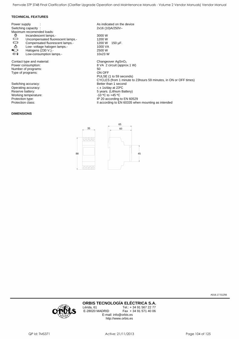
TECHNICAL FEATURES Power supply : As indicated on the device Switching capacity : 2x16 (10)A/250V∼ Maximum recomended loads: Incandescent lamps.- 3000 W Uncompensated fluorescent lamps.- 1200 W Compensated fluorescent lamps.- 1200 W 150 µF. Low- voltage halogen lamps.- 1000 VA Halogens (230 V.).- 2500 W Low-consumption lamps.- 10x23 W
Contact type and material: Changeover AgSnO2 Power consumption: 8 VA 2 circuit (approx.1 W) Number of programs: 50 Type of programs: ON OFF PULSE (1 to 59 seconds)
CYCLES (from 1 minute to 23hours 59 minutes, in ON or OFF times) Switching accuracy: Better than 1 second Operating accuracy: ≤ ± 1s/day at 23ºC Reserve battery: 5 years. (Lithium Battery) Working temperature: -10 ºC to +45 ºC Protection type: IP 20 according to EN 60529 Protection class: II according to EN 60335 when mounting as intended DIMENSIONS
A016.17.51256
ORBIS TECNOLOGÍA ELÉCTRICA S.A.
Lérida, 61 Tel.: + 34 91 567 22 77 E-28020 MADRID Fax + 34 91 571 40 06
E-mail: [email protected] http://www.orbis.es
35
88 45
60
65
Fernvale STP ST48 Final Clarification (Clarifier Upgrade Operation and Maintenance Manuals - Volume 2 Vendor Manuals) Vendor Manual
QP Id: TMS371 Active: 21/11/2013 Page 104 of 125

Indicators
Fernvale STP ST48 Final Clarification (Clarifier Upgrade Operation and Maintenance Manuals - Volume 2 Vendor Manuals) Vendor Manual
QP Id: TMS371 Active: 21/11/2013 Page 105 of 125
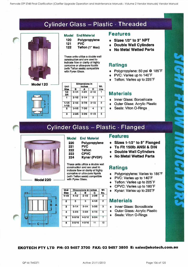
Fernvale STP ST48 Final Clarification (Clarifier Upgrade Operation and Maintenance Manuals - Volume 2 Vendor Manuals) Vendor Manual
QP Id: TMS371 Active: 21/11/2013 Page 106 of 125

Fernvale STP ST48 Final Clarification (Clarifier Upgrade Operation and Maintenance Manuals - Volume 2 Vendor Manuals) Vendor Manual
QP Id: TMS371 Active: 21/11/2013 Page 107 of 125
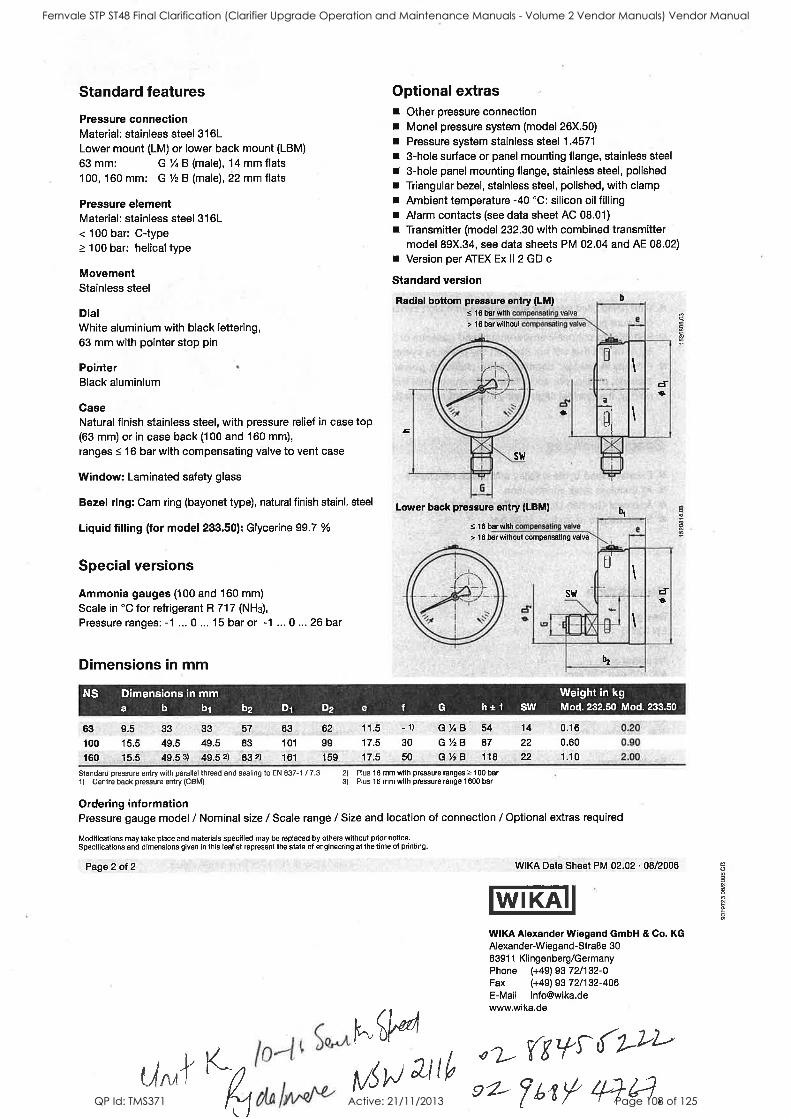
Fernvale STP ST48 Final Clarification (Clarifier Upgrade Operation and Maintenance Manuals - Volume 2 Vendor Manuals) Vendor Manual
QP Id: TMS371 Active: 21/11/2013 Page 108 of 125

Valves
Fernvale STP ST48 Final Clarification (Clarifier Upgrade Operation and Maintenance Manuals - Volume 2 Vendor Manuals) Vendor Manual
QP Id: TMS371 Active: 21/11/2013 Page 109 of 125
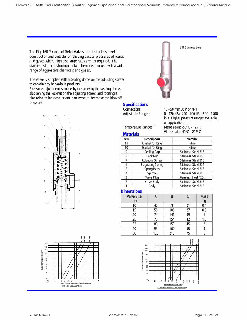
1
8
2
3
4
6
5
C
7
9 1011
B
A
5
10 20
30
40
60
100
200
300
400
600
10
00
BL
OW
-OF
F P
RE
SS
UR
E
kP
a
STANDARD FREE AIR - 10% Accumulation
10
20
30
40
50
100
80
200
300
400
600
CUBIC METRES PER HOUR
32m
m40
mm
50m
m
BL
OW
-OF
F P
RE
SS
UR
E K
PA
LIQUID FLOW (SG1) - LITRES PER SECOND
(WITH 10% ACCUMULATION)
0.0
5
0.1 0.2
0.3
0.4
0.6 1 2 3 4 6
10
10
20
30
40
50
80
100
200
300
400
600
32m
m40
mm
50m
m
The Fig. 160-2 range of Relief Valves are of stainless steel construction and suitable for relieving excess pressures of liquids and gases where high discharge rates are not required. The stainless steel construction makes them ideal for use with a wide range of aggressive chemicals and gases. The valve is supplied with a sealing dome on the adjusting screw to contain any hazardous products Pressure adjustment is made by unscrewing the sealing dome, slackening the locknut on the adjusting screw, and rotating it clockwise to increase or anti-clockwise to decrease the blow off pressure.
Specifications Connections: 10 - 50 mm BSP or NPT Adjustable Ranges: 0 - 120 kPa, 200 - 700 kPa, 500 - 1700
kPa; Higher pressure ranges available on application.
Temperature Ranges:` Nitrile seals: -50°C - 125°C Viton seals: -40°C - 225°C Materials Item Description Material 11 Gasket ‘O’ Ring Nitrile 10 Gasket ‘O’ Ring Nitrile 9 Sealing Cap Stainless Steel 316 8 Lock Nut Stainless Steel 316 7 Adjusting Screw Stainless Steel 316 6 Regulating Spring Stainless Steel 304 5 Spring Pads Stainless Steel 316 4 Spindle Stainless Steel 316 3 Valve Plug Stainless Steel 420c 2 Valve Body Stainless Steel 316 1 Body Stainless Steel 316
316 Stainless Steel
Dimensions Valve Size
mm A
B
C
Mass kg
10 46 78 21 0.4 15 56 106 27 0.5 20 74 141 39 1 25 78 154 42 1.5 32 80 153 45 2 40 93 160 55 3 50 125 215 75 6
Fernvale STP ST48 Final Clarification (Clarifier Upgrade Operation and Maintenance Manuals - Volume 2 Vendor Manuals) Vendor Manual
QP Id: TMS371 Active: 21/11/2013 Page 110 of 125
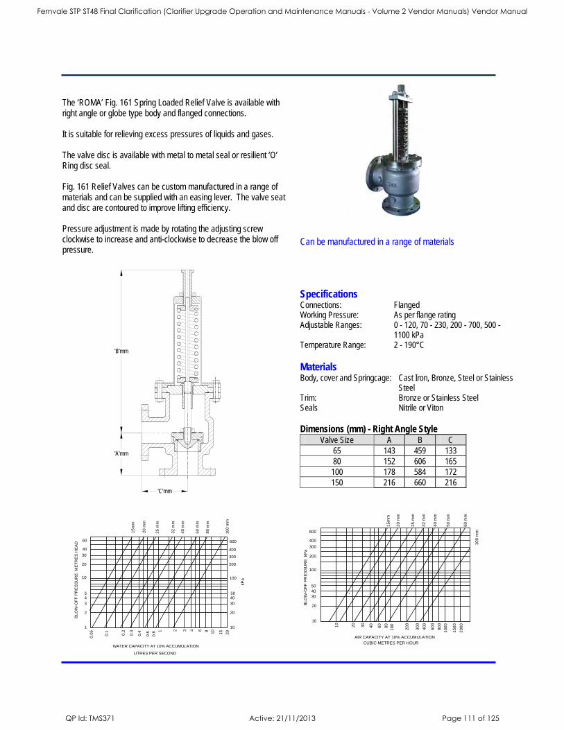
10
20
30
50
100
200
300
400
600
AIR CAPACITY AT 10% ACCUMULATION
CUBIC METRES PER HOUR
10
20
100
20
0
30
0
40
0
60
0
100
0
150
0
200
0
BLO
W-O
FF
PR
ES
SU
RE
kP
a
15m
m
20 m
m
25 m
m
32 m
m
40 m
m
50 m
m
80 m
m
100 m
m
60
80
40
80
0
40
30
1
2
3
45
10
20
30
40
60
10
20
30
4050
WATER CAPACITY AT 10% ACCUMULATION
LITRES PER SECOND
0.0
5
0.1 0.2
0.3 1 2 3 4 6
10
15
20
BL
OW
-OF
F P
RE
SS
UR
E M
ET
RE
S H
EA
D
kP
a
15
mm
20
mm
25 m
m
32 m
m
40 m
m
50 m
m
80 m
m
100 m
m
0.6
0.80.4 8
100
200
300
400
600
The ‘ROMA’ Fig. 161 Spring Loaded Relief Valve is available with right angle or globe type body and flanged connections. It is suitable for relieving excess pressures of liquids and gases. The valve disc is available with metal to metal seal or resilient ‘O’ Ring disc seal. Fig. 161 Relief Valves can be custom manufactured in a range of materials and can be supplied with an easing lever. The valve seat and disc are contoured to improve lifting efficiency. Pressure adjustment is made by rotating the adjusting screw clockwise to increase and anti-clockwise to decrease the blow off pressure.
Materials Body, cover and Springcage: Cast Iron, Bronze, Steel or Stainless
Steel Trim: Bronze or Stainless Steel Seals Nitrile or Viton
Specifications Connections: Flanged Working Pressure: As per flange rating Adjustable Ranges: 0 - 120, 70 - 230, 200 - 700, 500 -
1100 kPa Temperature Range: 2 - 190°C
'B'mm
'A'mm
'C'mm
Can be manufactured in a range of materials
Dimensions (mm) - Right Angle Style Valve Size A B C
65 143 459 133 80 152 606 165
100 178 584 172 150 216 660 216
Fernvale STP ST48 Final Clarification (Clarifier Upgrade Operation and Maintenance Manuals - Volume 2 Vendor Manuals) Vendor Manual
QP Id: TMS371 Active: 21/11/2013 Page 111 of 125

Pump Roto Pump
Fernvale STP ST48 Final Clarification (Clarifier Upgrade Operation and Maintenance Manuals - Volume 2 Vendor Manuals) Vendor Manual
QP Id: TMS371 Active: 21/11/2013 Page 112 of 125
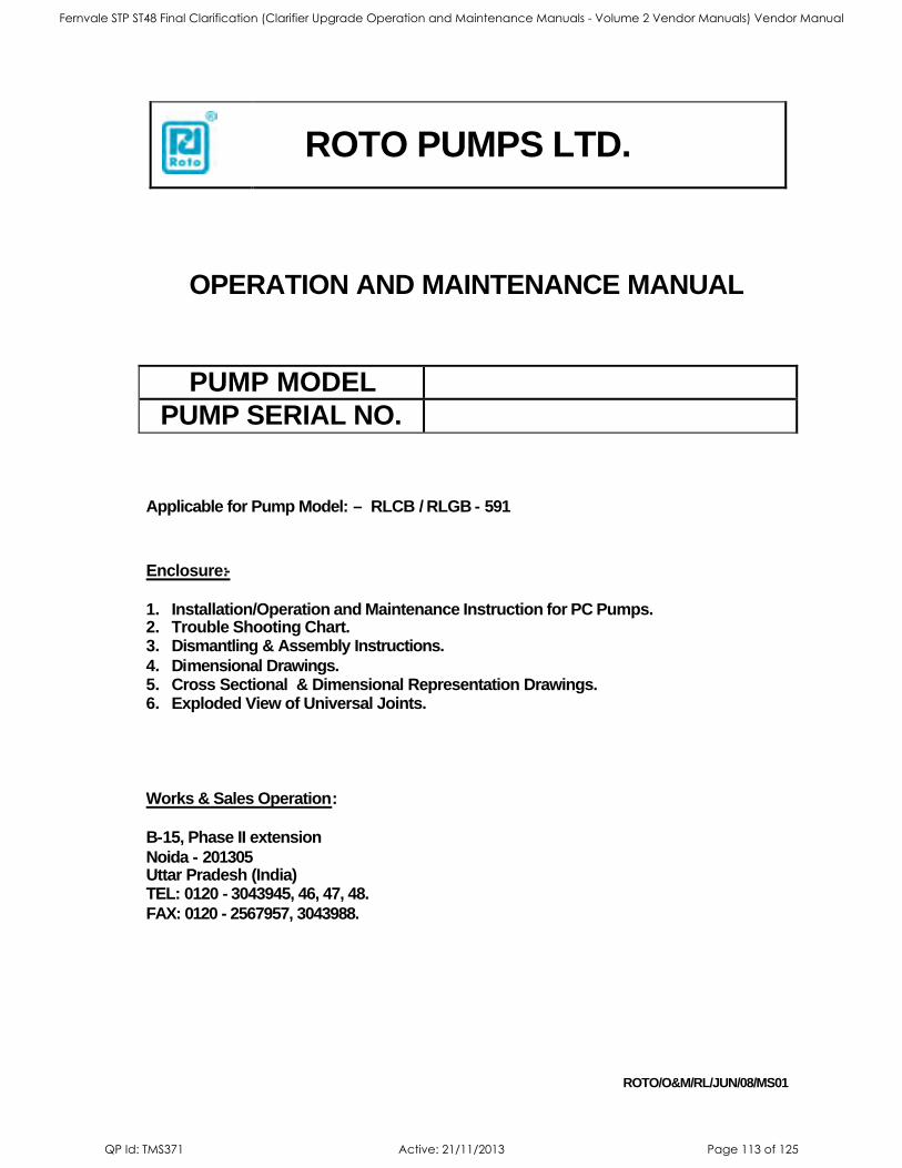
ROTO PUMPS LTD.
ROTO/O&M/RL/JUN/08/MS01
OPERATION AND MAINTENANCE MANUAL
PUMP MODEL
PUMP SERIAL NO.
Applicable for Pump Model: – RLCB / RLGB - 591
Enclosure:-
1. Installation/Operation and Maintenance Instruction for PC Pumps. 2. Trouble Shooting Chart. 3. Dismantling & Assembly Instructions.
4. Dimensional Drawings. 5. Cross Sectional & Dimensional Representation Drawings. 6. Exploded View of Universal Joints.
Works & Sales Operation:
B-15, Phase II extension
Noida - 201305 Uttar Pradesh (India) TEL: 0120 - 3043945, 46, 47, 48.
FAX: 0120 - 2567957, 3043988.
Fernvale STP ST48 Final Clarification (Clarifier Upgrade Operation and Maintenance Manuals - Volume 2 Vendor Manuals) Vendor Manual
QP Id: TMS371 Active: 21/11/2013 Page 113 of 125
INSTALLATION, OPERATION & MAINTENANCE INSTRUCTIONS
FOREWORD
Thank you for your patronage of the Roto Pumps Ltd. We are happy to inform you that your Roto progressive Cavity Pump has been designed, manufactured & tested to give you a long, smooth and trouble-free operation.
To get the best performance form the equipment we request you to carefully study the manual before, during and after installation of the pump. This manual is an essential part of the equipment and should be available
at all times to the plant personal and kept in a safe place in the plant premises. Should you have any doubts or queries, please do not hesitate to contact our nearest dealer or service center.
Our experienced engineers would be happy to offer to you expert advice, should any of the following considerations be overlooked, the safely of personal
and satisfactory operation of the pump may be endangered. GENERAL
1. Adequate ventilation must be provided in order to disperse dangerous vapors when pump is handling harmful or objectionable material.
2. Adequate lighting should be provided to ensure
effective maintenance.
3. Usage with certain products may need a hosing
facility to drain the pump to ease and simplify maintenance.
4. Suitable arrangement should be provided to carry
out gland draining.
5. Adequate space must be provided for dismantling
of the pump as per the dimensional drawing of the pump. (Refer enclosed dimensional drawing.)
STORAGE & HANDLING HANDLING: For safe handling during installation and maintenance the following four points must be taken care of
to avoid any damage to the component or personnel injury: 1. For lifting and assembling, use suitable lifting
tackle and slings, if the pump or any of its component weighs more than 20 kg.
2. The position of slings will depend on specific pump model and mounted accessories
3. If eyebolts are provided, they should be used for
lifting. 4. Experienced personnel should carry out handling.
STORAGE: Following points are advised for storage of
pump and spares. 1. The Pump should be kept in moisture-free area,
preferably, with protective covering. 2. Pump should be kept after draining out the
pumping liquid and preferably after flushing it with water.
3. A small amount of light oil should be injected in the
stuffing box after loosening the gland. For food application pumps, use a compatible vegetable or edible grease.
4. Anti rusting oil or suitable agent must be applied on metallic parts to be stored.
5. Refer manufacturer’s instructions for storage of other items like gearbox, motor etc.
SYSTEM DESIGN AND INSTALLATION SYSTEM DESIGN - At the system design stage, consideration must be given for the provision of filler plugs
and installation of non-return and/or isolating valves. ROTO PUMPS are normally installed in a horizontal position with
base plates mounted on a flat surface, grouted in and bolted,
thus ensuring firm fixing, thereby reducing noise and vibration. After bolting down the base frame, unit should be checked
for correct alignment of the pump to its prime mover. If the pump is mounted in any other way than described above, confirmation of installation must be agreed with
ROTO. ELECTRICAL – Electrical connections should only be made using equipment
suitable for both rating and environment. Normally the ROTO Pump should be installed with starting equipment arranged to give direct on line starting to ensure maximum
starting torque. When the motor is being wired and checked for direction of rotation, ensure that the motor is not coupled with the pump. If any wiring or control device is to be fitted on the electrical equipment they must be set in accordance
with their specific instructions. Protection of all electrical equipment should be ensured for minimum safety requirements as per environment and fluid
being pumped in accordance with applicable safety rules. Earthing points of electrical equipments should be connected when the pump is fitted with electrical drives and it is
essential that these be correctly connected as per the electrical equipment manufacturer’s recommendation
DUTY CONDITIONS Pumps should only be installed on duties for which ROTO has specified materials of construction, fluid, flow rates, pressure, temperature, speed etc. If the duty is changed,
ROTO’S recommendations should be sought immediately in the interest of safety, plant efficiency and pump life. ROTATION
Consult ROTO or its authorized representative if the direction of rotation of pump has to be changed after installation.
GUARDS In the interest of safety of personnel and in compliance with statutory requirement of various countries, the pump pulleys and couplings must be enclosed with proper guards in the
interest of safety of personnel. Specific pumps may have auger feed screws with a wide suction flange. If the pump installation requires that these
cannot be enclosed care must be taken to ensure that personnel cannot gain access while the pump is in operation and emergency stops device must be fitted nearby.
IMPORTANT SAFETY MEASURES DO’S
1. Always fill the pump with fluid and give few turns to provide necessary lubrication before starting
when subject to prolonged stoppage. 2. Always use a pressure relief device on delivery
line for system safety. 3. Use only direct on-line starters for meeting starting
torque requirement of pump. 4. Uncouple pump while motor is being wired and
checked for rotation, to prevent dry running of
pump. 5. Always consult ROTO in case of any change in
operating parameters, like temperature, viscosity, percentage of solids, liquid composition etc,
Fernvale STP ST48 Final Clarification (Clarifier Upgrade Operation and Maintenance Manuals - Volume 2 Vendor Manuals) Vendor Manual
QP Id: TMS371 Active: 21/11/2013 Page 114 of 125
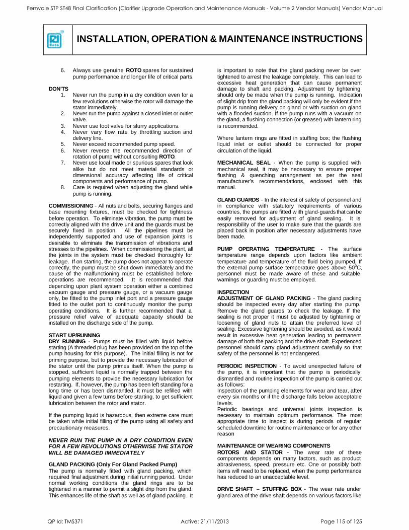
INSTALLATION, OPERATION & MAINTENANCE INSTRUCTIONS
6. Always use genuine ROTO spares for sustained
pump performance and longer life of critical parts.
DON’TS 1. Never run the pump in a dry condition even for a
few revolutions otherwise the rotor will damage the stator immediately.
2. Never run the pump against a closed inlet or outlet valve.
3. Never use foot valve for slurry applications. 4. Never vary flow rate by throttling suction and
delivery line. 5. Never exceed recommended pump speed.
6. Never reverse the recommended direction of rotation of pump without consulting ROTO.
7. Never use local made or spurious spares that look
alike but do not meet material standards or dimensional accuracy affecting life of critical components and performance of pump.
8. Care is required when adjusting the gland while
pump is running. COMMISSIONING - All nuts and bolts, securing flanges and base mounting fixtures, must be checked for tightness
before operation. To eliminate vibration, the pump must be correctly aligned with the drive unit and the guards must be securely fixed in position. All the pipelines must be independently supported and use of expansion joints is
desirable to eliminate the transmission of vibrations and stresses to the pipelines. When commissioning the plant, all the joints in the system must be checked thoroughly for
leakage. If on starting, the pump does not appear to operate correctly, the pump must be shut down immediately and the cause of the malfunctioning must be established before operations are recommenced. It is recommended that
depending upon plant system operation either a combined vacuum gauge and pressure gauge, or a vacuum gauge only, be fitted to the pump inlet port and a pressure gauge fitted to the outlet port to continuously monitor the pump
operating conditions. It is further recommended that a pressure relief valve of adequate capacity should be installed on the discharge side of the pump.
START UP/RUNNING DRY RUNNING - Pumps must be filled with liquid before starting (A threaded plug has been provided on the top of the pump housing for this purpose). The initial filling is not for
priming purpose, but to provide the necessary lubrication of the stator until the pump primes itself. When the pump is stopped, sufficient liquid is normally trapped between the
pumping elements to provide the necessary lubrication for restarting. If, however, the pump has been left standing for a long time or has been dismantled, it must be refilled with liquid and given a few turns before starting, to get sufficient
lubrication between the rotor and stator. If the pumping liquid is hazardous, then extreme care must be taken while initial filling of the pump using all safety and
precautionary measures.
NEVER RUN THE PUMP IN A DRY CONDITION EVEN FOR A FEW REVOLUTIONS OTHERWISE THE STATOR WILL BE DAMAGED IMMEDIATELY GLAND PACKING (Only For Gland Packed Pump)
The pump is normally fitted with gland packing, which required final adjustment during initial running period. Under normal working conditions the gland rings are to be tightened in a manner to permit a slight drip from the gland.
This enhances life of the shaft as well as of gland packing. It
is important to note that the gland packing never be over
tightened to arrest the leakage completely. This can lead to excessive heat generation that can cause permanent damage to shaft and packing. Adjustment by tightening should only be made when the pump is running. Indication
of slight drip from the gland packing will only be evident if the pump is running delivery on gland or with suction on gland with a flooded suction. If the pump runs with a vacuum on the gland, a flushing connection (or greaser) with lantern ring
is recommended. Where lantern rings are fitted in stuffing box; the flushing liquid inlet or outlet should be connected for proper
circulation of the liquid. MECHANICAL SEAL - When the pump is supplied with
mechanical seal, it may be necessary to ensure proper flushing & quenching arrangement as per the seal manufacturer’s recommendations, enclosed with this manual.
GLAND GUARDS - In the interest of safety of personnel and in compliance with statutory requirements of various countries, the pumps are fitted w ith gland-guards that can be
easily removed for adjustment of gland sealing. It is responsibility of the user to make sure that the guards are placed back in position after necessary adjustments have been made.
PUMP OPERATING TEMPERATURE - The surface temperature range depends upon factors like ambient
temperature and temperature of the fluid being pumped. If the external pump surface temperature goes above 500C, personnel must be made aware of these and suitable warnings or guarding must be employed.
INSPECTION ADJUSTMENT OF GLAND PACKING - The gland packing should be inspected every day after starting the pump.
Remove the gland guards to check the leakage. If the sealing is not proper it must be adjusted by tightening or loosening of gland nuts to attain the preferred level of sealing. Excessive tightening should be avoided, as it would
result in excessive heat generation leading to permanent damage of both the packing and the drive shaft. Experienced personnel should carry gland adjustment carefully so that safety of the personnel is not endangered.
PERIODIC INSPECTION - To avoid unexpected failure of the pump, it is important that the pump is periodically
dismantled and routine inspection of the pump is carried out as follows: Inspection of the pumping elements for wear and tear, after every six months or if the discharge falls below acceptable
levels. Periodic bearings and universal joints inspection is necessary to maintain optimum performance. The most appropriate time to inspect is during periods of regular
scheduled downtime for routine maintenance or for any other reason MAINTENANCE OF WEARING COMPONENTS
ROTORS AND STATOR - The wear rate of these components depends on many factors, such as product abrasiveness, speed, pressure etc. One or possibly both
items will need to be replaced, when the pump performance has reduced to an unacceptable level. DRIVE SHAFT – STUFFING BOX - The wear rate under
gland area of the drive shaft depends on various factors like
Fernvale STP ST48 Final Clarification (Clarifier Upgrade Operation and Maintenance Manuals - Volume 2 Vendor Manuals) Vendor Manual
QP Id: TMS371 Active: 21/11/2013 Page 115 of 125
INSTALLATION, OPERATION & MAINTENANCE INSTRUCTIONS
product abrasiveness, extent of tightening of the packing and
speed of the pump. Periodic inspection and maintenance of the gland will maximize the life of the shaft. Replacement of the gland packing or both the gland packing and the drive shaft will be necessary when the shaft sealing becomes
difficult to achieve. UNIVERSAL JOINT - Universal joints should be examined when the pump is dismantled for any reason or for routine
maintenance during periods of regular scheduled equipment down time. The joints should be cleaned and renewed with fresh grease before assembly. Use only recommended grease as per specifications in this
manual. PUMPSET - When a pump unit is dismantled and
reassembled, it has to be ensured that the following steps, as applicable, are covered
1. Correct alignment of pump and driver. 2. Use of appropriate couplings and bushes.
3. Use of appropriate belts and pulleys. EXPLOSIVE PRODUCTS/ HAZARDOUS ATMOSPHERE - In certain instances, the product being pumped may be of a
hazardous nature. In these installations, considerations must be given to provide suitable protection and appropriate warnings to safeguard personnel and plant.
SPECIAL INSTRUCTIONS
ROTATION The pumps are capable of taking rotation in both the
directions but if a change of direction is required, consult ROTO or its authorized agents before doing so. LUBRICATION
UNIVERSAL JOINTS Universal joints should be examined when the pump is
dismantled for any reason or for routine maintenance during periods of regular scheduled equipment down time. Clean the joints and use of the following recommended or equivalent grease. Ensure that Universal Joint Boot Seal
should be packed with 300 gms. of grease.
1. ELF Epexa 00
2. Balmerol Supertec PD-00 3. ESSO liquid grease S 420 4. Fuchs Renosed GFB 5. Total Multis EP200
6. OMEGA 58 alternatively Kuberoil 4UH1 460 (For Food Applications only)
Whenever Boot seal of EPDM materials are recommended
or used, please ensure that only the following Silicone Grease compound is used for such applications.
1. OKS 1140 / 1144 or alternatively UNISILKON
L50/2 NOTE: The above Greases also comply with food
applications.
Fernvale STP ST48 Final Clarification (Clarifier Upgrade Operation and Maintenance Manuals - Volume 2 Vendor Manuals) Vendor Manual
QP Id: TMS371 Active: 21/11/2013 Page 116 of 125
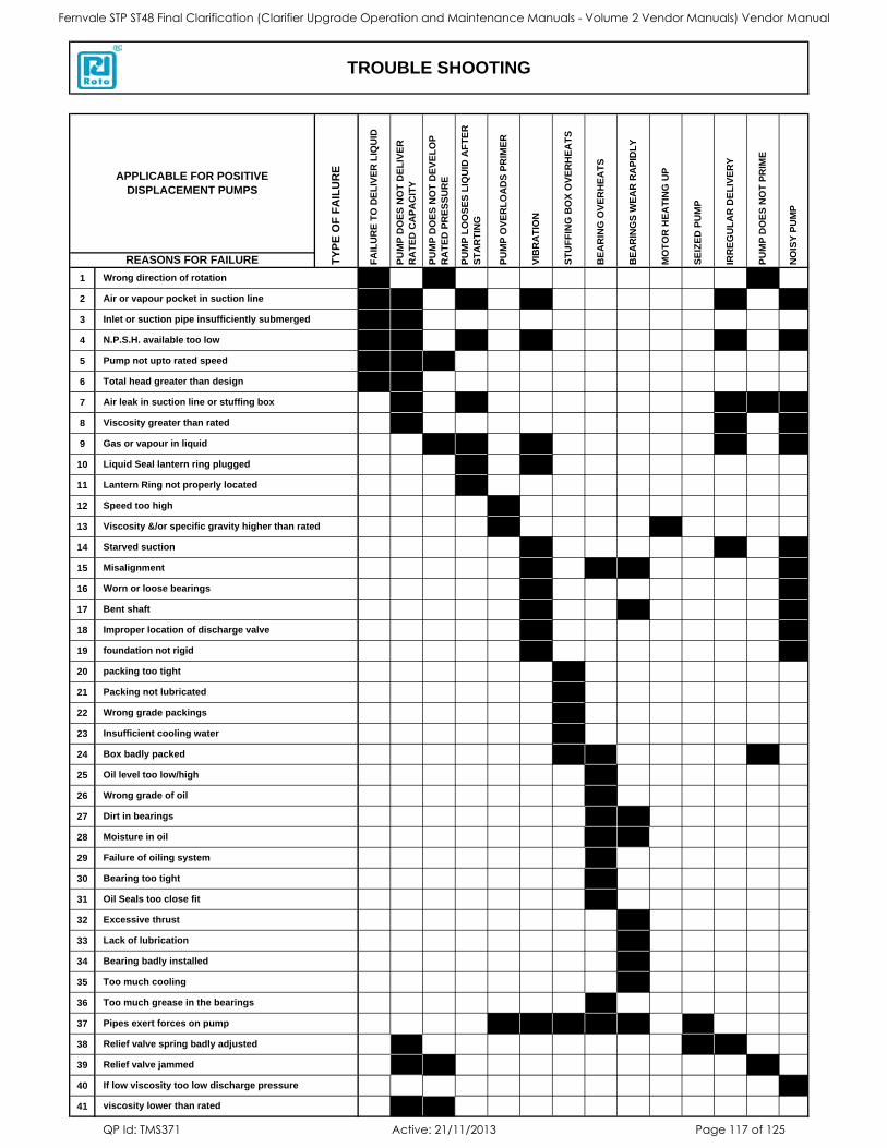
1
2
3
4
5
6
7
8
9
10
11
12
13
14
15
16
17
18
19
20
21
22
23
24
25
26
27
28
29
30
31
32
33
34
35
36
37
38
39
40
41
NO
ISY
PU
MP
BE
AR
ING
S W
EA
R R
AP
IDL
Y
MO
TO
R H
EA
TIN
G U
P
SE
IZE
D P
UM
P
IRR
EG
UL
AR
DE
LIV
ER
Y
VIB
RA
TIO
N
ST
UF
FIN
G B
OX
OV
ER
HE
AT
S
BE
AR
ING
OV
ER
HE
AT
S
PU
MP
DO
ES
NO
T P
RIM
E
Relief valve spring badly adjusted
Relief valve jammed
If low viscosity too low discharge pressure
viscosity lower than rated
Bearing badly installed
Too much cooling
Too much grease in the bearings
Pipes exert forces on pump
Bearing too tight
Oil Seals too close fit
Excessive thrust
Lack of lubrication
Wrong grade of oil
Dirt in bearings
Moisture in oil
Failure of oiling system
Wrong grade packings
Insufficient cooling water
Box badly packed
Oil level too low/high
Improper location of discharge valve
foundation not rigid
packing too tight
Packing not lubricated
Starved suction
Misalignment
Worn or loose bearings
Bent shaft
Liquid Seal lantern ring plugged
Lantern Ring not properly located
Speed too high
Viscosity &/or specific gravity higher than rated
Total head greater than design
Air leak in suction line or stuffing box
Viscosity greater than rated
Gas or vapour in liquid
Air or vapour pocket in suction line
Inlet or suction pipe insufficiently submerged
N.P.S.H. available too low
Pump not upto rated speed
TROUBLE SHOOTING
APPLICABLE FOR POSITIVE
DISPLACEMENT PUMPS
REASONS FOR FAILURE
Wrong direction of rotation
TY
PE
OF
FA
ILU
RE
FA
ILU
RE
TO
DE
LIV
ER
LIQ
UID
PU
MP
DO
ES
NO
T D
EL
IVE
R
RA
TE
D C
AP
AC
ITY
PU
MP
DO
ES
NO
T D
EV
EL
OP
RA
TE
D P
RE
SS
UR
E
PU
MP
LO
OS
ES
LIQ
UID
AF
TE
R
ST
AR
TIN
G
PU
MP
OV
ER
LO
AD
S P
RIM
ER
Fernvale STP ST48 Final Clarification (Clarifier Upgrade Operation and Maintenance Manuals - Volume 2 Vendor Manuals) Vendor Manual
QP Id: TMS371 Active: 21/11/2013 Page 117 of 125
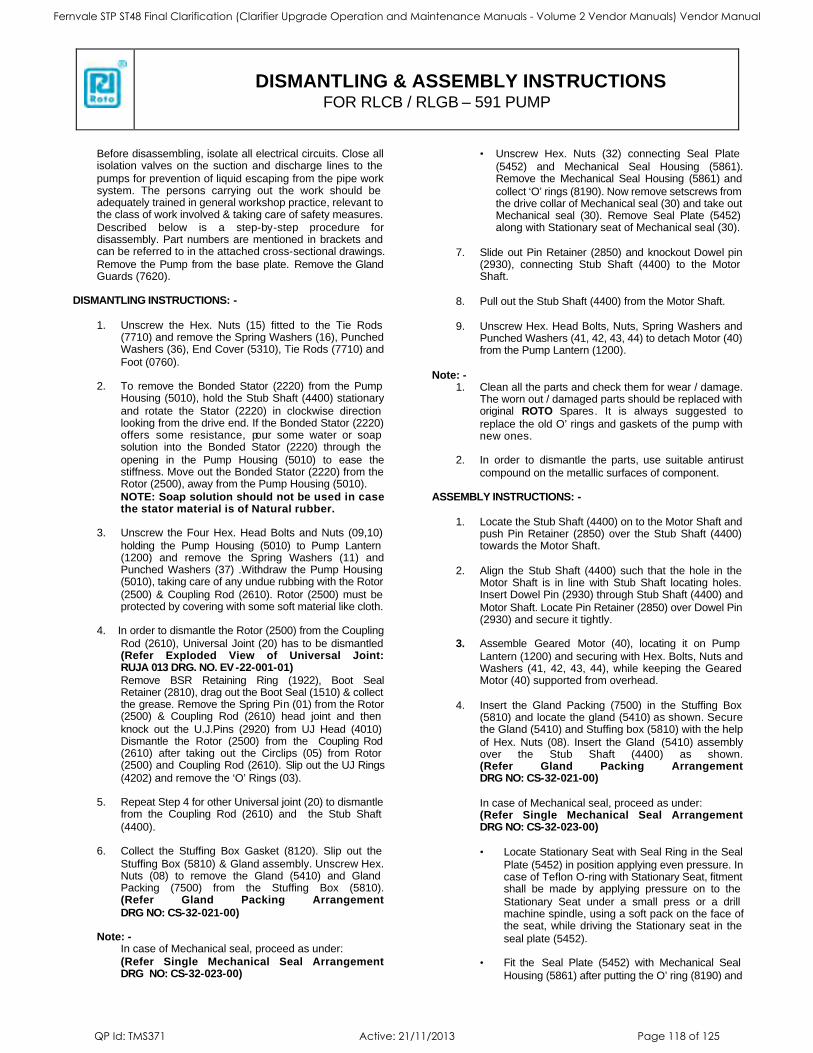
DISMANTLING & ASSEMBLY INSTRUCTIONS
FOR RLCB / RLGB – 591 PUMP
Before disassembling, isolate all electrical circuits. Close all isolation valves on the suction and discharge lines to the
pumps for prevention of liquid escaping from the pipe work system. The persons carrying out the work should be adequately trained in general workshop practice, relevant to the class of work involved & taking care of safety measures.
Described below is a step-by-step procedure for disassembly. Part numbers are mentioned in brackets and can be referred to in the attached cross-sectional drawings.
Remove the Pump from the base plate. Remove the Gland Guards (7620).
DISMANTLING INSTRUCTIONS: -
1. Unscrew the Hex. Nuts (15) fitted to the Tie Rods
(7710) and remove the Spring Washers (16), Punched Washers (36), End Cover (5310), Tie Rods (7710) and
Foot (0760). 2. To remove the Bonded Stator (2220) from the Pump
Housing (5010), hold the Stub Shaft (4400) stationary
and rotate the Stator (2220) in clockwise direction looking from the drive end. If the Bonded Stator (2220) offers some resistance, pour some water or soap solution into the Bonded Stator (2220) through the
opening in the Pump Housing (5010) to ease the stiffness. Move out the Bonded Stator (2220) from the Rotor (2500), away from the Pump Housing (5010).
NOTE: Soap solution should not be used in case the stator material is of Natural rubber.
3. Unscrew the Four Hex. Head Bolts and Nuts (09,10)
holding the Pump Housing (5010) to Pump Lantern (1200) and remove the Spring Washers (11) and Punched Washers (37) .Withdraw the Pump Housing (5010), taking care of any undue rubbing with the Rotor
(2500) & Coupling Rod (2610). Rotor (2500) must be protected by covering with some soft material like cloth.
4. In order to dismantle the Rotor (2500) from the Coupling
Rod (2610), Universal Joint (20) has to be dismantled (Refer Exploded View of Universal Joint: RUJA 013 DRG. NO. EV-22-001-01)
Remove BSR Retaining Ring (1922), Boot Seal Retainer (2810), drag out the Boot Seal (1510) & collect the grease. Remove the Spring Pin (01) from the Rotor (2500) & Coupling Rod (2610) head joint and then
knock out the U.J.Pins (2920) from UJ Head (4010) Dismantle the Rotor (2500) from the Coupling Rod (2610) after taking out the Circlips (05) from Rotor (2500) and Coupling Rod (2610). Slip out the UJ Rings
(4202) and remove the ‘O’ Rings (03).
5. Repeat Step 4 for other Universal joint (20) to dismantle from the Coupling Rod (2610) and the Stub Shaft
(4400). 6. Collect the Stuffing Box Gasket (8120). Slip out the
Stuffing Box (5810) & Gland assembly. Unscrew Hex. Nuts (08) to remove the Gland (5410) and Gland Packing (7500) from the Stuffing Box (5810). (Refer Gland Packing Arrangement
DRG NO: CS-32-021-00)
Note: -
In case of Mechanical seal, proceed as under:
(Refer Single Mechanical Seal Arrangement DRG NO: CS-32-023-00)
• Unscrew Hex. Nuts (32) connecting Seal Plate
(5452) and Mechanical Seal Housing (5861). Remove the Mechanical Seal Housing (5861) and
collect ‘O’ rings (8190). Now remove setscrews from the drive collar of Mechanical seal (30) and take out Mechanical seal (30). Remove Seal Plate (5452) along with Stationary seat of Mechanical seal (30).
7. Slide out Pin Retainer (2850) and knockout Dowel pin
(2930), connecting Stub Shaft (4400) to the Motor Shaft.
8. Pull out the Stub Shaft (4400) from the Motor Shaft.
9. Unscrew Hex. Head Bolts, Nuts, Spring Washers and Punched Washers (41, 42, 43, 44) to detach Motor (40) from the Pump Lantern (1200).
Note: - 1. Clean all the parts and check them for wear / damage.
The worn out / damaged parts should be replaced with original ROTO Spares. It is always suggested to
replace the old O’ rings and gaskets of the pump with new ones.
2. In order to dismantle the parts, use suitable antirust
compound on the metallic surfaces of component. ASSEMBLY INSTRUCTIONS: -
1. Locate the Stub Shaft (4400) on to the Motor Shaft and
push Pin Retainer (2850) over the Stub Shaft (4400) towards the Motor Shaft.
2. Align the Stub Shaft (4400) such that the hole in the
Motor Shaft is in line with Stub Shaft locating holes. Insert Dowel Pin (2930) through Stub Shaft (4400) and
Motor Shaft. Locate Pin Retainer (2850) over Dowel Pin (2930) and secure it tightly.
3. Assemble Geared Motor (40), locating it on Pump
Lantern (1200) and securing with Hex. Bolts, Nuts and Washers (41, 42, 43, 44), while keeping the Geared Motor (40) supported from overhead.
4. Insert the Gland Packing (7500) in the Stuffing Box
(5810) and locate the gland (5410) as shown. Secure the Gland (5410) and Stuffing box (5810) with the help
of Hex. Nuts (08). Insert the Gland (5410) assembly over the Stub Shaft (4400) as shown. (Refer Gland Packing Arrangement DRG NO: CS-32-021-00)
In case of Mechanical seal, proceed as under: (Refer Single Mechanical Seal Arrangement DRG NO: CS-32-023-00)
• Locate Stationary Seat with Seal Ring in the Seal
Plate (5452) in position applying even pressure. In case of Teflon O-ring with Stationary Seat, fitment shall be made by applying pressure on to the
Stationary Seat under a small press or a drill machine spindle, using a soft pack on the face of the seat, while driving the Stationary seat in the
seal plate (5452). • Fit the Seal Plate (5452) with Mechanical Seal
Housing (5861) after putting the O’ ring (8190) and
Fernvale STP ST48 Final Clarification (Clarifier Upgrade Operation and Maintenance Manuals - Volume 2 Vendor Manuals) Vendor Manual
QP Id: TMS371 Active: 21/11/2013 Page 118 of 125
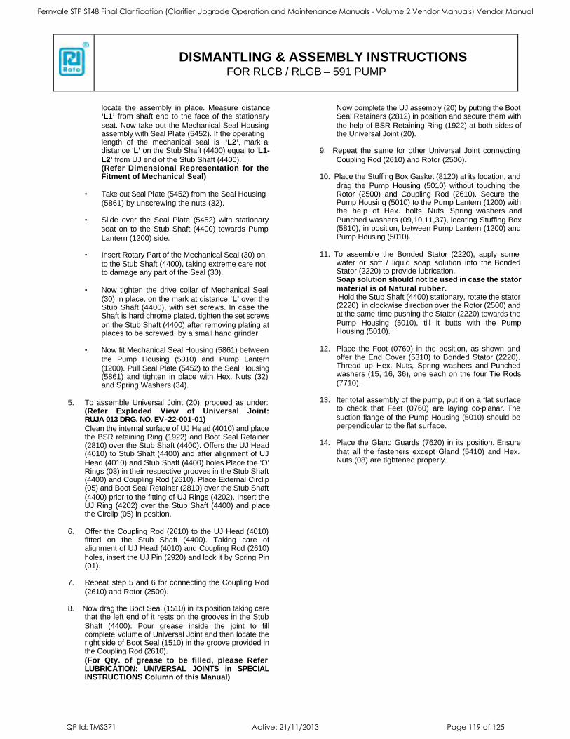
DISMANTLING & ASSEMBLY INSTRUCTIONS
FOR RLCB / RLGB – 591 PUMP
locate the assembly in place. Measure distance ‘L1’ from shaft end to the face of the stationary
seat. Now take out the Mechanical Seal Housing assembly with Seal Plate (5452). If the operating length of the mechanical seal is ‘L2’, mark a distance ‘L’ on the Stub Shaft (4400) equal to ‘L1-
L2’ from UJ end of the Stub Shaft (4400). (Refer Dimensional Representation for the Fitment of Mechanical Seal)
• Take out Seal Plate (5452) from the Seal Housing
(5861) by unscrewing the nuts (32).
• Slide over the Seal Plate (5452) with stationary
seat on to the Stub Shaft (4400) towards Pump
Lantern (1200) side.
• Insert Rotary Part of the Mechanical Seal (30) on
to the Stub Shaft (4400), taking extreme care not to damage any part of the Seal (30).
• Now tighten the drive collar of Mechanical Seal
(30) in place, on the mark at distance ‘L’ over the Stub Shaft (4400), with set screws. In case the Shaft is hard chrome plated, tighten the set screws
on the Stub Shaft (4400) after removing plating at places to be screwed, by a small hand grinder.
• Now fit Mechanical Seal Housing (5861) between
the Pump Housing (5010) and Pump Lantern
(1200). Pull Seal Plate (5452) to the Seal Housing (5861) and tighten in place with Hex. Nuts (32) and Spring Washers (34).
5. To assemble Universal Joint (20), proceed as under: (Refer Exploded View of Universal Joint: RUJA 013 DRG. NO. EV-22-001-01)
Clean the internal surface of UJ Head (4010) and place the BSR retaining Ring (1922) and Boot Seal Retainer (2810) over the Stub Shaft (4400). Offers the UJ Head (4010) to Stub Shaft (4400) and after alignment of UJ
Head (4010) and Stub Shaft (4400) holes.Place the ‘O’ Rings (03) in their respective grooves in the Stub Shaft (4400) and Coupling Rod (2610). Place External Circlip (05) and Boot Seal Retainer (2810) over the Stub Shaft
(4400) prior to the fitting of UJ Rings (4202). Insert the UJ Ring (4202) over the Stub Shaft (4400) and place the Circlip (05) in position.
6. Offer the Coupling Rod (2610) to the UJ Head (4010) fitted on the Stub Shaft (4400). Taking care of alignment of UJ Head (4010) and Coupling Rod (2610)
holes, insert the UJ Pin (2920) and lock it by Spring Pin (01).
7. Repeat step 5 and 6 for connecting the Coupling Rod
(2610) and Rotor (2500).
8. Now drag the Boot Seal (1510) in its position taking care that the left end of it rests on the grooves in the Stub
Shaft (4400). Pour grease inside the joint to fill complete volume of Universal Joint and then locate the right side of Boot Seal (1510) in the groove provided in the Coupling Rod (2610).
(For Qty. of grease to be filled, please Refer LUBRICATION: UNIVERSAL JOINTS in SPECIAL INSTRUCTIONS Column of this Manual)
Now complete the UJ assembly (20) by putting the Boot Seal Retainers (2812) in position and secure them with
the help of BSR Retaining Ring (1922) at both sides of the Universal Joint (20).
9. Repeat the same for other Universal Joint connecting
Coupling Rod (2610) and Rotor (2500).
10. Place the Stuffing Box Gasket (8120) at its location, and
drag the Pump Housing (5010) without touching the Rotor (2500) and Coupling Rod (2610). Secure the Pump Housing (5010) to the Pump Lantern (1200) with the help of Hex. bolts, Nuts, Spring washers and
Punched washers (09,10,11,37), locating Stuffing Box (5810), in position, between Pump Lantern (1200) and Pump Housing (5010).
11. To assemble the Bonded Stator (2220), apply some water or soft / liquid soap solution into the Bonded Stator (2220) to provide lubrication. Soap solution should not be used in case the stator
material is of Natural rubber. Hold the Stub Shaft (4400) stationary, rotate the stator (2220) in clockwise direction over the Rotor (2500) and at the same time pushing the Stator (2220) towards the
Pump Housing (5010), till it butts with the Pump Housing (5010).
12. Place the Foot (0760) in the position, as shown and offer the End Cover (5310) to Bonded Stator (2220). Thread up Hex. Nuts, Spring washers and Punched washers (15, 16, 36), one each on the four Tie Rods
(7710). 13. fter total assembly of the pump, put it on a flat surface
to check that Feet (0760) are laying co-planar. The
suction flange of the Pump Housing (5010) should be perpendicular to the flat surface.
14. Place the Gland Guards (7620) in its position. Ensure
that all the fasteners except Gland (5410) and Hex. Nuts (08) are tightened properly.
Fernvale STP ST48 Final Clarification (Clarifier Upgrade Operation and Maintenance Manuals - Volume 2 Vendor Manuals) Vendor Manual
QP Id: TMS371 Active: 21/11/2013 Page 119 of 125
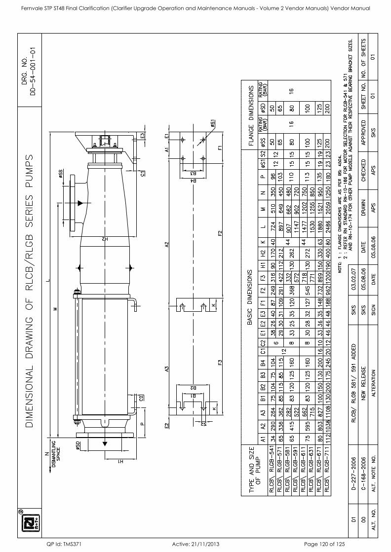
Fernvale STP ST48 Final Clarification (Clarifier Upgrade Operation and Maintenance Manuals - Volume 2 Vendor Manuals) Vendor Manual
QP Id: TMS371 Active: 21/11/2013 Page 120 of 125
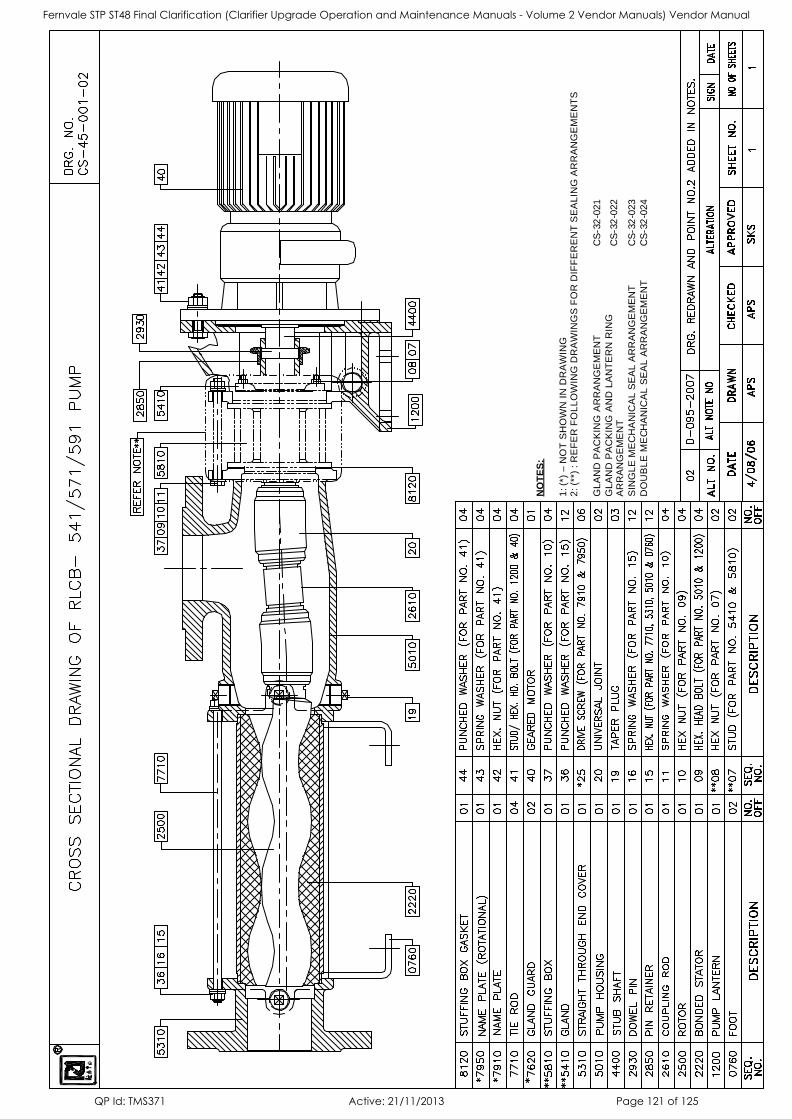
NO
TE
S:
1: (*
) – N
OT
SH
OW
N I
N D
RA
WIN
G
2:
(**)
: R
EF
ER
FO
LL
OW
ING
DR
AW
ING
S F
OR
DIF
FE
RE
NT
SE
AL
ING
AR
RA
NG
EM
EN
TS
GL
AN
D P
AC
KIN
G A
RR
AN
GE
ME
NT
C
S-3
2-0
21
GL
AN
D P
AC
KIN
G A
ND
LA
NT
ER
N R
ING
A
RR
AN
GE
ME
NT
C
S-3
2-0
22
SIN
GL
E M
EC
HA
NIC
AL
SE
AL
AR
RA
NG
EM
EN
T
CS
-32
-023
DO
UB
LE
ME
CH
AN
ICA
L S
EA
L A
RR
AN
GE
ME
NT
C
S-3
2-0
24
Fernvale STP ST48 Final Clarification (Clarifier Upgrade Operation and Maintenance Manuals - Volume 2 Vendor Manuals) Vendor Manual
QP Id: TMS371 Active: 21/11/2013 Page 121 of 125
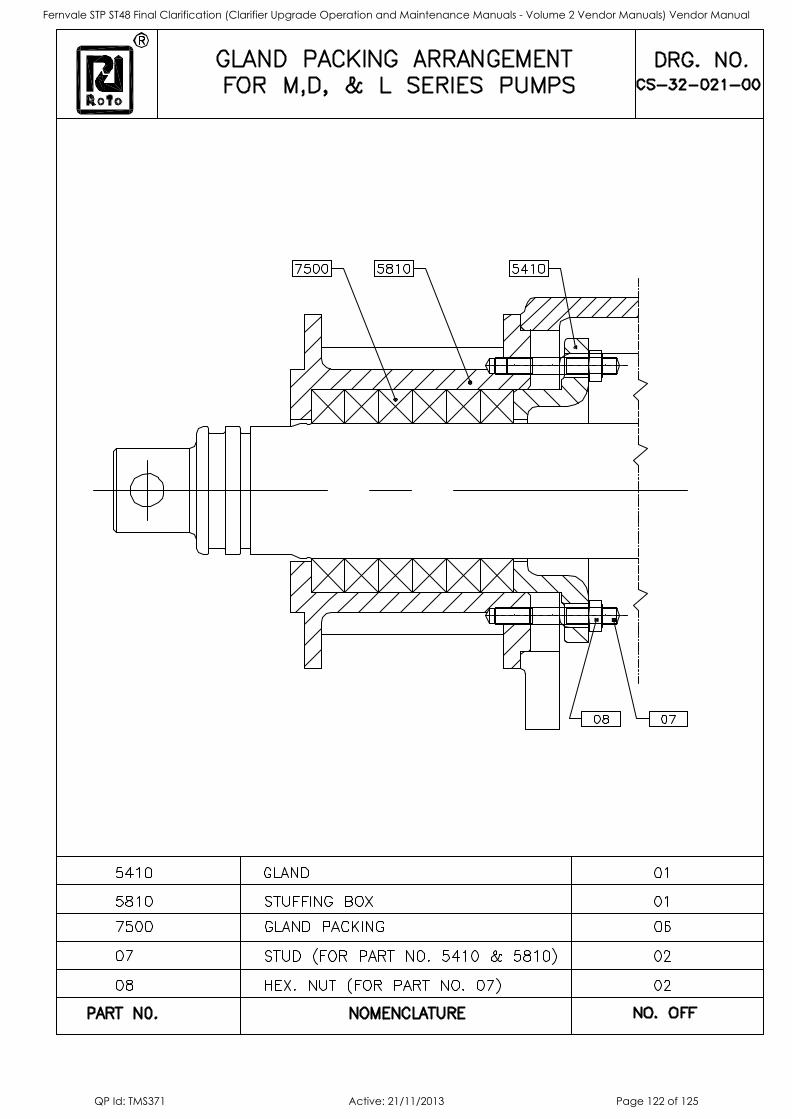
Fernvale STP ST48 Final Clarification (Clarifier Upgrade Operation and Maintenance Manuals - Volume 2 Vendor Manuals) Vendor Manual
QP Id: TMS371 Active: 21/11/2013 Page 122 of 125
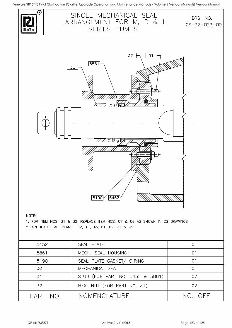
Fernvale STP ST48 Final Clarification (Clarifier Upgrade Operation and Maintenance Manuals - Volume 2 Vendor Manuals) Vendor Manual
QP Id: TMS371 Active: 21/11/2013 Page 123 of 125
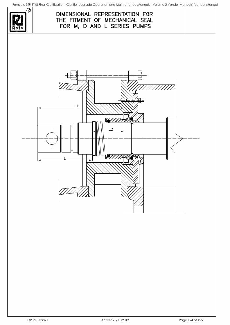
Fernvale STP ST48 Final Clarification (Clarifier Upgrade Operation and Maintenance Manuals - Volume 2 Vendor Manuals) Vendor Manual
QP Id: TMS371 Active: 21/11/2013 Page 124 of 125
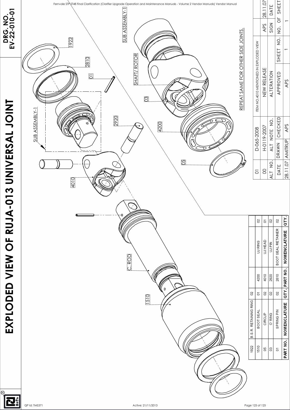
2920
01
1510
2810
1922
C. R
OD
REPE
AT
SAM
E FO
R O
THER
SID
E JO
INTS
.
SUB
ASS
EMBL
Y-1
4010
4200
03
SHA
FT/
ROTO
R
05
SUB
ASS
EMBL
Y-1
DATE
DRAWN
SHEET NO.NO. OF SHEET
R
EXPL
ODE
D VI
EW O
F RU
JA-0
13 U
NIV
ERSA
L JO
INT
DRG
. NO
.EV
-22-
010-
01
ALTERATION
DATE
SIGN
ALT NOTE NO.
ALT NO.
CHECKED
APPROVED
11
00
H-0
119-
2007
N
EW R
ELEA
SE28
.11.
07A
PS
APS
APS
AM
ITRUP
28.1
1.07
01
D-0
65-2
008
I
TEM
NO
.401
0 M
ENTIO
NED
IN E
XPLO
DED
VIE
W
Fernvale STP ST48 Final Clarification (Clarifier Upgrade Operation and Maintenance Manuals - Volume 2 Vendor Manuals) Vendor Manual
QP Id: TMS371 Active: 21/11/2013 Page 125 of 125