laney college theater modernization - vendor
TRANSCRIPT
LANEY COLLEGE THEATER MODERNIZATION
PROJECT MANUAL
900 FALLON STREETOAKLAND, CA 94607
100% SCHEMATIC DESIGNAUGUST 03, 2020
PERALTA COMMUNITY COLLEGE DISTRICT

PERALTA COMMUNITY COLLEGE DISTRICT LANEY COLLEGE THEATER MODERNIZATION OAKLAND, CA
Sections in shaded font not included in this Issue. 100% Schematic Design: 08-03-2020 TABLE OF CONTENTS 200803LCT027/ELS 00 0110 - 1
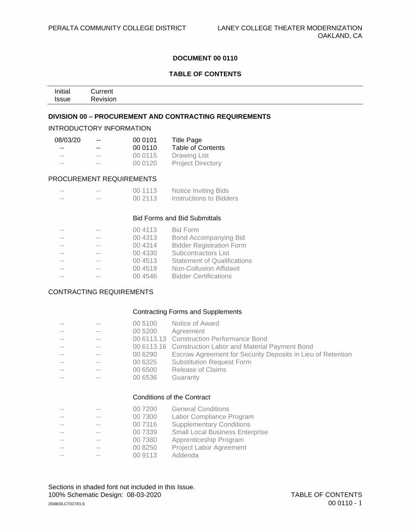
DOCUMENT 00 0110
TABLE OF CONTENTS
Initial Current Issue Revision
DIVISION 00 – PROCUREMENT AND CONTRACTING REQUIREMENTS
INTRODUCTORY INFORMATION
08/03/20 -- 00 0101 Title Page -- -- 00 0110 Table of Contents -- -- 00 0115 Drawing List -- -- 00 0120 Project Directory
PROCUREMENT REQUIREMENTS
-- -- 00 1113 Notice Inviting Bids -- -- 00 2113 Instructions to Bidders
Bid Forms and Bid Submittals
-- -- 00 4113 Bid Form -- -- 00 4313 Bond Accompanying Bid -- -- 00 4314 Bidder Registration Form -- -- 00 4330 Subcontractors List -- -- 00 4513 Statement of Qualifications -- -- 00 4519 Non-Collusion Affidavit -- -- 00 4546 Bidder Certifications
CONTRACTING REQUIREMENTS
Contracting Forms and Supplements
-- -- 00 5100 Notice of Award -- -- 00 5200 Agreement -- -- 00 6113.13 Construction Performance Bond -- -- 00 6113.16 Construction Labor and Material Payment Bond -- -- 00 6290 Escrow Agreement for Security Deposits in Lieu of Retention -- -- 00 6325 Substitution Request Form -- -- 00 6500 Release of Claims -- -- 00 6536 Guaranty
Conditions of the Contract
-- -- 00 7200 General Conditions -- -- 00 7300 Labor Compliance Program -- -- 00 7316 Supplementary Conditions -- -- 00 7339 Small Local Business Enterprise -- -- 00 7380 Apprenticeship Program -- -- 00 8250 Project Labor Agreement -- -- 00 9113 Addenda
LANEY COLLEGE THEATER MODERNIZATION OAKLAND, CA
Initial Current Issue Revision
Sections in shaded font not included in this Issue. 100% Schematic Design: 08-03-2020 TABLE OF CONTENTS 200803LCT027/ELS 00 0110 - 2
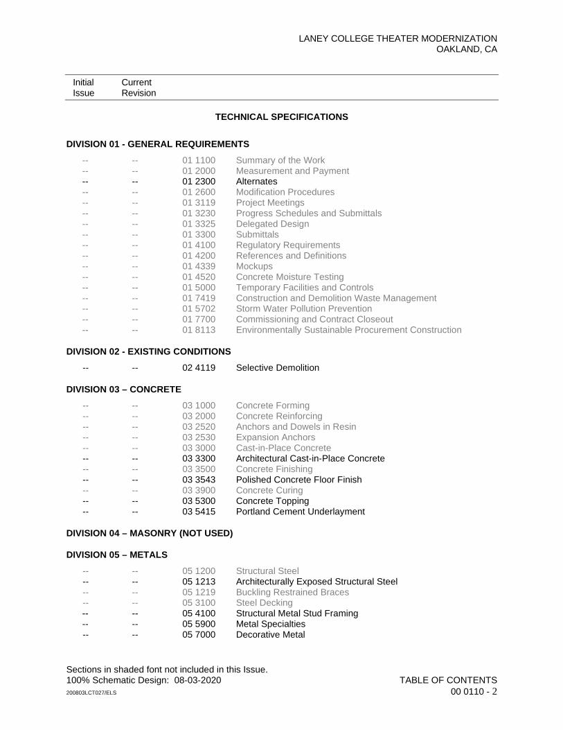
TECHNICAL SPECIFICATIONS
DIVISION 01 - GENERAL REQUIREMENTS
-- -- 01 1100 Summary of the Work -- -- 01 2000 Measurement and Payment -- -- 01 2300 Alternates -- -- 01 2600 Modification Procedures -- -- 01 3119 Project Meetings -- -- 01 3230 Progress Schedules and Submittals -- -- 01 3325 Delegated Design -- -- 01 3300 Submittals -- -- 01 4100 Regulatory Requirements -- -- 01 4200 References and Definitions -- -- 01 4339 Mockups -- -- 01 4520 Concrete Moisture Testing -- -- 01 5000 Temporary Facilities and Controls -- -- 01 7419 Construction and Demolition Waste Management -- -- 01 5702 Storm Water Pollution Prevention -- -- 01 7700 Commissioning and Contract Closeout -- -- 01 8113 Environmentally Sustainable Procurement Construction
DIVISION 02 - EXISTING CONDITIONS
-- -- 02 4119 Selective Demolition
DIVISION 03 – CONCRETE
-- -- 03 1000 Concrete Forming -- -- 03 2000 Concrete Reinforcing -- -- 03 2520 Anchors and Dowels in Resin -- -- 03 2530 Expansion Anchors -- -- 03 3000 Cast-in-Place Concrete -- -- 03 3300 Architectural Cast-in-Place Concrete -- -- 03 3500 Concrete Finishing -- -- 03 3543 Polished Concrete Floor Finish -- -- 03 3900 Concrete Curing -- -- 03 5300 Concrete Topping -- -- 03 5415 Portland Cement Underlayment
DIVISION 04 – MASONRY (NOT USED)
DIVISION 05 – METALS
-- -- 05 1200 Structural Steel -- -- 05 1213 Architecturally Exposed Structural Steel -- -- 05 1219 Buckling Restrained Braces -- -- 05 3100 Steel Decking -- -- 05 4100 Structural Metal Stud Framing -- -- 05 5900 Metal Specialties -- -- 05 7000 Decorative Metal
LANEY COLLEGE THEATER MODERNIZATION OAKLAND, CA
Initial Current Issue Revision
Sections in shaded font not included in this Issue. 100% Schematic Design: 08-03-2020 TABLE OF CONTENTS 200803LCT027/ELS 00 0110 - 3
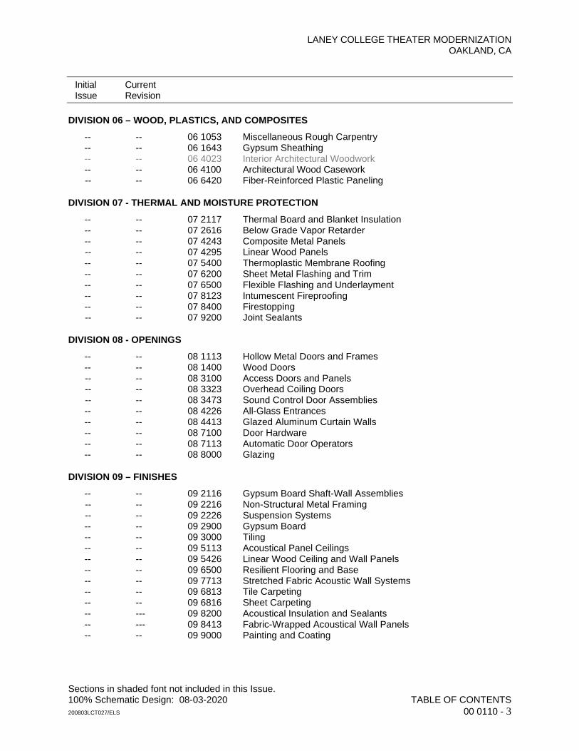
DIVISION 06 – WOOD, PLASTICS, AND COMPOSITES
-- -- 06 1053 Miscellaneous Rough Carpentry -- -- 06 1643 Gypsum Sheathing -- -- 06 4023 Interior Architectural Woodwork -- -- 06 4100 Architectural Wood Casework -- -- 06 6420 Fiber-Reinforced Plastic Paneling
DIVISION 07 - THERMAL AND MOISTURE PROTECTION
-- -- 07 2117 Thermal Board and Blanket Insulation -- -- 07 2616 Below Grade Vapor Retarder -- -- 07 4243 Composite Metal Panels -- -- 07 4295 Linear Wood Panels -- -- 07 5400 Thermoplastic Membrane Roofing -- -- 07 6200 Sheet Metal Flashing and Trim -- -- 07 6500 Flexible Flashing and Underlayment -- -- 07 8123 Intumescent Fireproofing -- -- 07 8400 Firestopping -- -- 07 9200 Joint Sealants
DIVISION 08 - OPENINGS
-- -- 08 1113 Hollow Metal Doors and Frames -- -- 08 1400 Wood Doors -- -- 08 3100 Access Doors and Panels -- -- 08 3323 Overhead Coiling Doors -- -- 08 3473 Sound Control Door Assemblies -- -- 08 4226 All-Glass Entrances -- -- 08 4413 Glazed Aluminum Curtain Walls -- -- 08 7100 Door Hardware -- -- 08 7113 Automatic Door Operators -- -- 08 8000 Glazing
DIVISION 09 – FINISHES
-- -- 09 2116 Gypsum Board Shaft-Wall Assemblies -- -- 09 2216 Non-Structural Metal Framing -- -- 09 2226 Suspension Systems -- -- 09 2900 Gypsum Board -- -- 09 3000 Tiling -- -- 09 5113 Acoustical Panel Ceilings -- -- 09 5426 Linear Wood Ceiling and Wall Panels -- -- 09 6500 Resilient Flooring and Base -- -- 09 7713 Stretched Fabric Acoustic Wall Systems -- -- 09 6813 Tile Carpeting -- -- 09 6816 Sheet Carpeting -- --- 09 8200 Acoustical Insulation and Sealants -- --- 09 8413 Fabric-Wrapped Acoustical Wall Panels -- -- 09 9000 Painting and Coating
LANEY COLLEGE THEATER MODERNIZATION OAKLAND, CA
Initial Current Issue Revision
Sections in shaded font not included in this Issue. 100% Schematic Design: 08-03-2020 TABLE OF CONTENTS 200803LCT027/ELS 00 0110 - 4
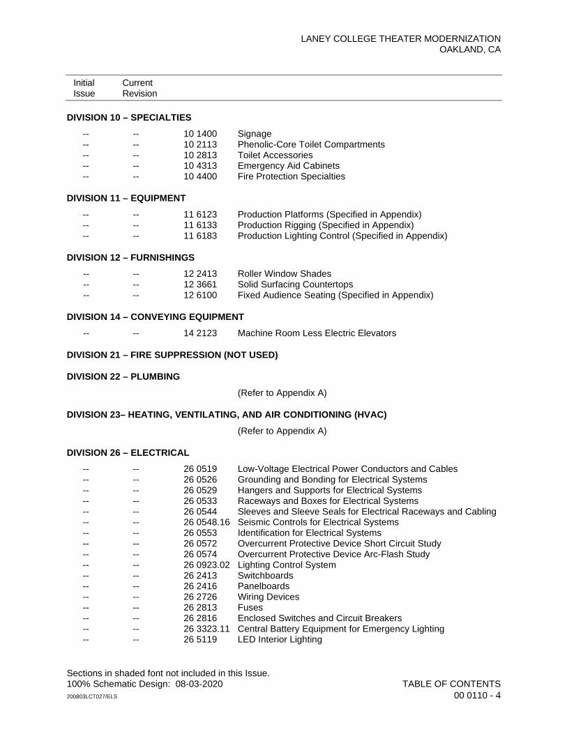
DIVISION 10 – SPECIALTIES
-- -- 10 1400 Signage -- -- 10 2113 Phenolic-Core Toilet Compartments -- -- 10 2813 Toilet Accessories -- -- 10 4313 Emergency Aid Cabinets -- -- 10 4400 Fire Protection Specialties
DIVISION 11 – EQUIPMENT
-- -- 11 6123 Production Platforms (Specified in Appendix) -- -- 11 6133 Production Rigging (Specified in Appendix) -- -- 11 6183 Production Lighting Control (Specified in Appendix)
DIVISION 12 – FURNISHINGS
-- -- 12 2413 Roller Window Shades -- -- 12 3661 Solid Surfacing Countertops -- -- 12 6100 Fixed Audience Seating (Specified in Appendix)
DIVISION 14 – CONVEYING EQUIPMENT
-- -- 14 2123 Machine Room Less Electric Elevators
DIVISION 21 – FIRE SUPPRESSION (NOT USED)
DIVISION 22 – PLUMBING
(Refer to Appendix A)
DIVISION 23– HEATING, VENTILATING, AND AIR CONDITIONING (HVAC)
(Refer to Appendix A)
DIVISION 26 – ELECTRICAL
-- -- 26 0519 Low-Voltage Electrical Power Conductors and Cables -- -- 26 0526 Grounding and Bonding for Electrical Systems -- -- 26 0529 Hangers and Supports for Electrical Systems -- -- 26 0533 Raceways and Boxes for Electrical Systems -- -- 26 0544 Sleeves and Sleeve Seals for Electrical Raceways and Cabling -- -- 26 0548.16 Seismic Controls for Electrical Systems -- -- 26 0553 Identification for Electrical Systems -- -- 26 0572 Overcurrent Protective Device Short Circuit Study -- -- 26 0574 Overcurrent Protective Device Arc-Flash Study -- -- 26 0923.02 Lighting Control System -- -- 26 2413 Switchboards -- -- 26 2416 Panelboards -- -- 26 2726 Wiring Devices -- -- 26 2813 Fuses -- -- 26 2816 Enclosed Switches and Circuit Breakers -- -- 26 3323.11 Central Battery Equipment for Emergency Lighting -- -- 26 5119 LED Interior Lighting
LANEY COLLEGE THEATER MODERNIZATION OAKLAND, CA
Initial Current Issue Revision
Sections in shaded font not included in this Issue. 100% Schematic Design: 08-03-2020 TABLE OF CONTENTS 200803LCT027/ELS 00 0110 - 5
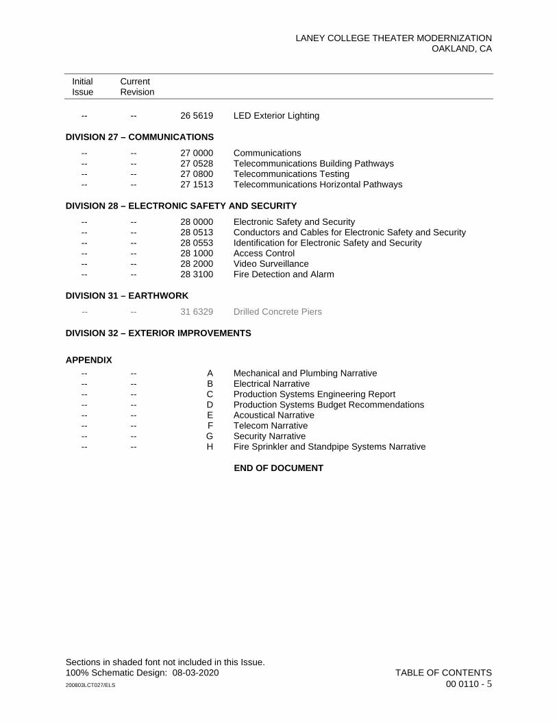
-- -- 26 5619 LED Exterior Lighting
DIVISION 27 – COMMUNICATIONS
-- -- 27 0000 Communications -- -- 27 0528 Telecommunications Building Pathways -- -- 27 0800 Telecommunications Testing -- -- 27 1513 Telecommunications Horizontal Pathways
DIVISION 28 – ELECTRONIC SAFETY AND SECURITY
-- -- 28 0000 Electronic Safety and Security -- -- 28 0513 Conductors and Cables for Electronic Safety and Security -- -- 28 0553 Identification for Electronic Safety and Security -- -- 28 1000 Access Control -- -- 28 2000 Video Surveillance -- -- 28 3100 Fire Detection and Alarm
DIVISION 31 – EARTHWORK
-- -- 31 6329 Drilled Concrete Piers
DIVISION 32 – EXTERIOR IMPROVEMENTS
APPENDIX -- -- A Mechanical and Plumbing Narrative -- -- B Electrical Narrative -- -- C Production Systems Engineering Report -- -- D Production Systems Budget Recommendations -- -- E Acoustical Narrative -- -- F Telecom Narrative -- -- G Security Narrative -- -- H Fire Sprinkler and Standpipe Systems Narrative
END OF DOCUMENT

PERALTA COMMUNITY COLLEGE DISTRICT LANEY COLLEGE THEATER MODERNIZATION OAKLAND, CA
100% Schematic Design: 2020-08-03 ALTERNATES 200730LCT027/ELS 01 2300 - 1
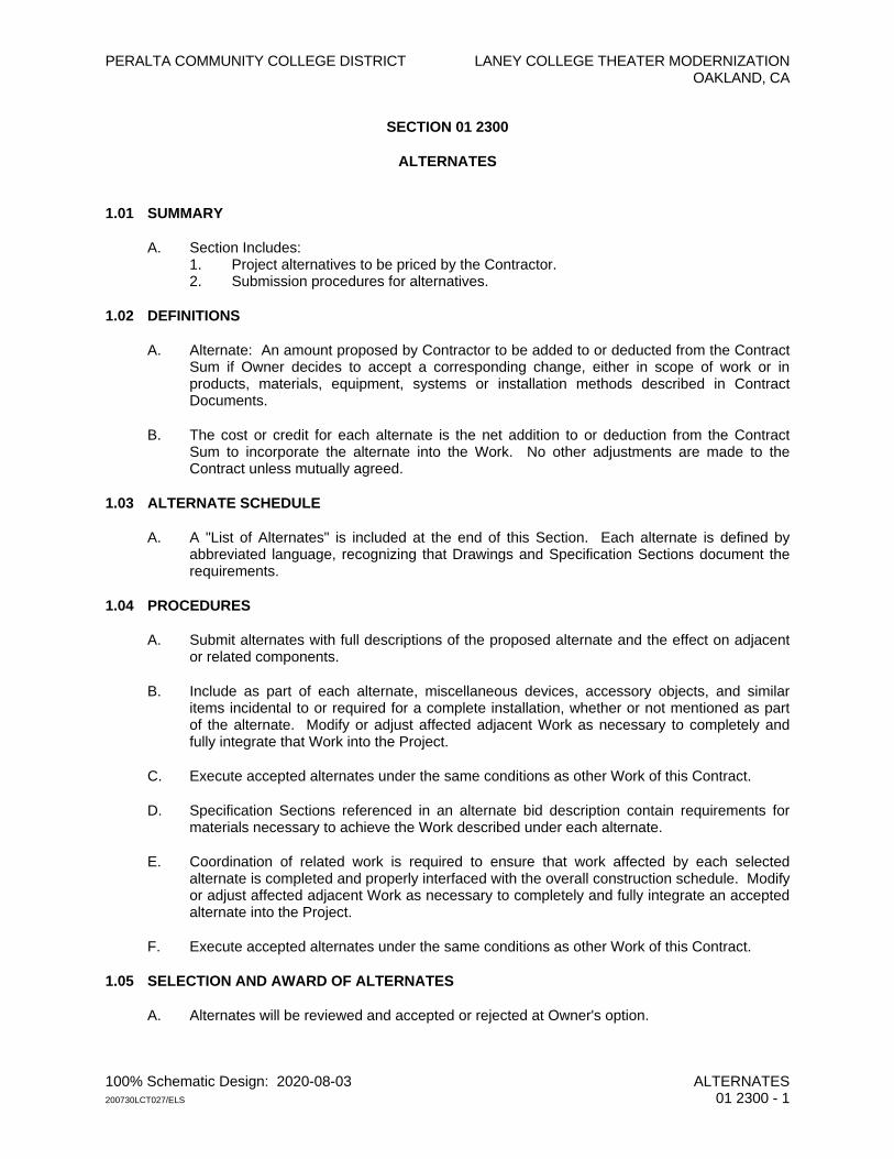
SECTION 01 2300
ALTERNATES
1.01 SUMMARY
A. Section Includes: 1. Project alternatives to be priced by the Contractor. 2. Submission procedures for alternatives.
1.02 DEFINITIONS
A. Alternate: An amount proposed by Contractor to be added to or deducted from the Contract Sum if Owner decides to accept a corresponding change, either in scope of work or in products, materials, equipment, systems or installation methods described in Contract Documents.
B. The cost or credit for each alternate is the net addition to or deduction from the Contract Sum to incorporate the alternate into the Work. No other adjustments are made to the Contract unless mutually agreed.
1.03 ALTERNATE SCHEDULE
A. A "List of Alternates" is included at the end of this Section. Each alternate is defined by abbreviated language, recognizing that Drawings and Specification Sections document the requirements.
1.04 PROCEDURES
A. Submit alternates with full descriptions of the proposed alternate and the effect on adjacent or related components.
B. Include as part of each alternate, miscellaneous devices, accessory objects, and similar items incidental to or required for a complete installation, whether or not mentioned as part of the alternate. Modify or adjust affected adjacent Work as necessary to completely and fully integrate that Work into the Project.
C. Execute accepted alternates under the same conditions as other Work of this Contract.
D. Specification Sections referenced in an alternate bid description contain requirements for materials necessary to achieve the Work described under each alternate.
E. Coordination of related work is required to ensure that work affected by each selected alternate is completed and properly interfaced with the overall construction schedule. Modify or adjust affected adjacent Work as necessary to completely and fully integrate an accepted alternate into the Project.
F. Execute accepted alternates under the same conditions as other Work of this Contract.
1.05 SELECTION AND AWARD OF ALTERNATES
A. Alternates will be reviewed and accepted or rejected at Owner's option.
PERALTA COMMUNITY COLLEGE DISTRICT LANEY COLLEGE THEATER MODERNIZATION OAKLAND, CA
100% Schematic Design: 2020-08-03 ALTERNATES 200730LCT027/ELS 01 2300 - 2
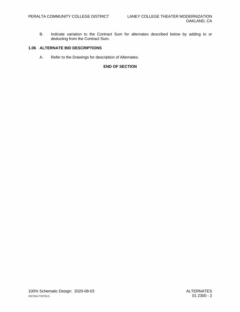
B. Indicate variation to the Contract Sum for alternates described below by adding to or deducting from the Contract Sum.
1.06 ALTERNATE BID DESCRIPTIONS
A. Refer to the Drawings for description of Alternates.
END OF SECTION
PERALTA COMMUNITY COLLEGE DISTRICT LANEY COLLEGE THEATER MODERNIZATION OAKLAND, CA
100% Schematic Design: 2020-08-03 SELECTIVE DEMOLITION 200730LCT027/ELS 02 4119 - 1
SECTION 02 4119
SELECTIVE DEMOLITION
PART 1 - GENERAL
1.01 SUMMARY
A. Section Includes: 1. Demolition of items indicated on the Drawings and required for completion of the
work. 2. Disconnecting, capping or sealing, and removing of utilities. 3. Contractor's Demolition Plan.
1.02 DEFINITIONS
A. Remove: detach items from existing construction and legally dispose of them off-site unless indicated to be removed and salvaged or recycled.
B. Remove and Salvage: Detach items from existing construction and deliver them to Owner as directed.
C. Remove and Reinstall: Detach items from existing construction, prepare them for reuse, and reinstall them where indicated.
D. Existing to Remain: Existing items of construction that are not to be removed and that are not otherwise indicated to be removed, removed and salvaged, or recycled.
1.03 ADMINISTRATIVE REQUIREMENTS
A. Pre-Demolition Meeting: Conduct a pre-demolition meeting at project site before commencing demolition. 1. Inspect and discuss condition of construction to be selectively demolished. 2. Review demolition methods and procedures. 3. Review protection measures for existing construction and building occupants. 4. Report unresolved issues or conflicts to the Architect. 5. Review and finalize Demolition Plan and verify availability of demolition personnel,
equipment, and facilities needed to make progress and avoid delays.
1.04 MATERIALS OWNERSHIP
A. Items of interest or of value to Owner will be removed prior to Contractor commencing demolition.
1.05 ACTION SUBMITTALS
A. Demolition Plan as specified below.
1.06 INFORMATIONAL SUBMITTALS
A. Qualification data for demolition firm if a separate subcontractor will be used.
PERALTA COMMUNITY COLLEGE DISTRICT LANEY COLLEGE THEATER MODERNIZATION OAKLAND, CA
100% Schematic Design: 2020-08-03 SELECTIVE DEMOLITION 200730LCT027/ELS 02 4119 - 2
B. Inventory: After demolition is complete, submit a list of items that have been removed and salvaged, not previously removed by Owner, and that may be of value or of use to the Owner.
1.07 DEMOLITION PLAN
A. The Contractor shall submit a complete Demolition Plan detailing procedures and sequence for removing existing interior improvements and structural elements in a safe and controlled manner to insure stability of the structure at any given time.
B. Thoroughly investigate the condition of portions of the existing Building to be removed before proceeding with the Demolition Plan.
C. The Demolition Plan shall consist of the following: 1. Detailed sequence of demolition and removal work, with starting and ending dates for
each activity. 2. Interruption of utility services. 3. Coordination for shutoff, capping, and continuation of utility services. 4. Details and locations of shields or other protective measures to ensure that occupants
will not be endangered and improvements to remain will not be damaged.
1.08 QUALITY ASSURANCE
A. Demolition Firm Qualifications: An experienced firm that has specialized in demolition work similar in material and extent to that indicated for this Project.
B. Regulatory Requirements: Comply with governing EPA notification regulations before beginning demolition. Comply with hauling and disposal regulations of authorities having jurisdiction.
C. Standards: Comply with ANSI A10.6 and NFPA 241.
1.09 FIELD CONDITIONS
A. Special care shall be exercised to protect existing improvements and other items to remain. 1. Damage or disturbance to existing facilities and items to remain shall be promptly
restored, repaired, or replaced to match existing at no cost to the Owner. 2. If the Contractor has any question as to the extent of demolition or items to remain,
Contractor shall notify the Architect and request a clarification before proceeding.
B. Utility Services: 1. Except where utilities are affected by demolition, maintain existing utilities and protect
against damage during demolition operations. 2. Utilities interfacing with demolition shall be disconnected and sealed before starting
demolition operations.
C. Hazardous Materials: If hazardous materials are encountered, do not disturb and immediately notify Owner’s Representative. Materials determined to be hazardous will be removed by Owner under separate contract.
PART 2 - PRODUCTS (NOT USED)
PERALTA COMMUNITY COLLEGE DISTRICT LANEY COLLEGE THEATER MODERNIZATION OAKLAND, CA
100% Schematic Design: 2020-08-03 SELECTIVE DEMOLITION 200730LCT027/ELS 02 4119 - 3
PART 3 - EXECUTION
3.01 EXAMINATION
A. Survey existing conditions and correlate with requirements indicated to determine extent of additional demolition required.
B. Inventory and record the condition of items to be removed and salvaged.
C. Photographic documentation of existing conditions prior to execution of work under this Contract is not required. This does not, however, relieve the Contractor of the responsibility of restoring and replacing existing improvements to remain, determined by the Owner as damaged by work under this Contract, at no additional expense to Owner.”
3.02 DEMOLITION
A. Existing work to be removed shall, in general, be as indicated on the Drawings and shall include other existing materials and work necessary to install new work indicated and specified.
B. Surfaces to remain, when cut, shall be carefully restored and refinished to provide a continuous, even finish to nearest intersections.
3.03 SALVAGED ITEMS
A. Where required by the Drawings or specified and when so directed to be salvaged and/or reused or refurbished, existing materials shall be removed in the most careful manner possible to avoid damage; and, if damaged, such items shall be restored to conditions satisfactory to the Architect.
3.04 SITE RESTORATION
A. Completely fill voids resulting from demolition operations that will not be required by new construction in conformance with respective Specification Sections and as required to maintain existing Building assembly fire ratings.
3.05 REPAIRS
A. Promptly repair damage to existing improvements to remain.
B. Where repairs to existing surfaces are required, patch to produce surfaces suitable for new materials.
3.06 DISPOSAL OF DEMOLISHED MATERIALS
A. Except for items or materials indicated to be recycled, salvaged, or otherwise indicated to remain Owner's property, remove demolished materials from Project site and legally dispose of them in accordance with in accordance with requirements specified in Section 01 7419, “Construction and Demolition Waste Management.”
END OFSECTION

PERALTA COMMUNITY COLLEGE DISTRICT LANEY COLLEGE THEATER MODERNIZATION OAKLAND, CA
100% Schematic Design: 2020-08-03 ARCHITECTURAL CAST-IN-PLACE CONCRETE 200730LCT027/ELS 03 3300 - 1
SECTION 03 3300
ARCHITECTURAL CAST-IN-PLACE CONCRETE
PART 1 - GENERAL
1.01 SUMMARY
A. Section Includes: Special requirements for exposed exterior and interior formed cast-in-place concrete supplementing the information to be included on the Structural Drawings and in Section 03 3000, “Cast-in-Place Concrete.”
1.02 DEFINITION.
A. Cast-In-Place Architectural Concrete: Concrete that is exposed to view on surfaces of the completed work that requires special concrete materials, formwork, placement, and finishes to obtain specified architectural appearance.
1.03 ACTION SUBMITTALS
A. Product Data: Manufacturers current catalog data and specifications for the following: 1. Mix consolidation admixture. 2. Form ties. 3. Form release agent.
1.04 INFORMATIONAL SUBMITTALS
A. Statement of installer/finisher qualifications for colored architectural concrete if requested by Architect.
1.05 QUALITY ASSURANCE
A. Installer/Finisher Qualifications: An experienced cast-in-place architectural concrete contractor who has specialized experience installing colored architectural concrete, similar in quality level expected for this Project.
B. Except as otherwise specified and indicated on the Drawings, comply with ACI 303.1, “Standard Specification for Cast-In-Place Architectural Concrete,” ACI 303R, “Guide to Cast-In-Place Architectural Concrete.”
C. Mockups: Requirements to be finalized by Architect.
PART 2 - PRODUCTS
2.01 FORMWORK
A. General: 1. Comply with and ACI 347, "Recommended Practice for Concrete Formwork,” for
formwork and other form-facing material requirements. 2. Formwork Surface: Class A and limit concrete surface irregularities designated by
ACI 347R as abrupt or gradual.
PERALTA COMMUNITY COLLEGE DISTRICT LANEY COLLEGE THEATER MODERNIZATION OAKLAND, CA
100% Schematic Design: 2020-08-03 ARCHITECTURAL CAST-IN-PLACE CONCRETE 200730LCT027/ELS 03 3300 - 2
3. Seal joints to prevent leakage of paste using method that will not affect appearance of finished surface.
4. Forms shall not be reused for Architectural Concrete if there is any evidence of surface wear or defect that would impair the quality of the surface.
B. Formwork: To be finalized by Architect.
C. Form Ties: Fiberglass rod ties, tinted to color to match concrete color; “SuperTie” by RJD Industries, Inc. in tensile strength as selected by form designer.
2.02 REINFORCING
A. Materials as approved for structural concrete.
2.03 CONCRETE MATERIALS AND MIX
A. Concrete Design Mix: As approved for structural concrete.
2.04 ACCESSORIES
A. Form-Release Agent: Unitex “Form Tech III” by Dayton Superior.
B. Additional Materials: As approved for structural concrete and specified on the Structural Drawings.
PART 3 - EXECUTION (NOT USED)
END OF SECTION
PERALTA COMMUNITY COLLEGE DISTRICT LANEY COLLEGE THEATER MODERNIZATION OAKLAND, CA
100% Schematic Design: 2020-08-03 POLISHED CONCRETE FLOOR FINISH 200730LCT027/ELS 03 3543 - 1
SECTION 03 3543
POLISHED CONCRETE FLOOR FINISH
PART 1 - GENERAL
1.01 SUMMARY
A. Section Includes: 1. Honed surface treatment for concrete floors. 2. Applied color stain. 3. Liquid-applied sealers and finishers.
1.02 ADMINISTRATIVE REQUIREMENTS
A. Pre-Installation Meeting: Prior to polishing floors and preparing a mockup area, conduct meeting at Project to be attended by Owner, Architect, Contractor, and concrete polisher.
1.03 ACTION SUBMITTALS
A. Product Data: 1. Manufacturer's published data on each finishing product proposed to be used
including information on compatibility of different products and limitations. 2. Concrete Polishing Council aggregate exposure and appearance charts.
1.04 INFORMATIONAL SUBMITTALS
A. Qualifications of polisher.
B. Process and procedures used to achieve appearance of accepted mockup if at variance with this Specification.
C. Minutes of pre-installation meeting.
D. Results of field slip-resistance testing.
1.05 CLOSEOUT SUBMITTALS
A. Data on maintenance and renewal of applied finishes.
1.06 QUALITY ASSURANCE
A. Mockup: Construct mockup area under conditions and lighting similar to those that will be expected during Owner occupancy, with densifier coatings applied.
PART 2 - PRODUCTS
2.01 POLISHED CONCRETE FLOORING
A. Systems and Manufacturers: “The RetroPlate System” by Advanced Floor Products. 888-942-3144, as specified, Induroshine PDS-2” System by W.R. Meadows, or equal.
PERALTA COMMUNITY COLLEGE DISTRICT LANEY COLLEGE THEATER MODERNIZATION OAKLAND, CA
100% Schematic Design: 2020-08-03 POLISHED CONCRETE FLOOR FINISH 200730LCT027/ELS 03 3543 - 2
2.02 DESIGN AND PERFORMANCE CRITERIA
A. Dry or Wet Slip Resistance: 1. After completion of final polishing and cleaning, floor shall be tested using ASTM
E303 Standard Test Method for Measuring Surface Frictional Properties Using the British Pendulum Tester. a. Pendulum Test Value (PTV) shall be 45 or greater under dry and wet
conditions. b. Test results shall be reported in writing.
2. Alternative test method, such as use of a BOT-3000E digital tribometer, if proposed, shall provide results for both wet and dry conditions.
2.03 COATINGS
A. Liquid Densifier: Odorless, non-hazardous, silicate or colloidal silica that penetrates concrete to react with free lime and calcium hydroxide to produce permanent chemical reaction that hardens and densifies concrete surface; “Retro Plate 99,” or equal by system manufacturer.
B. Sealer: Water and stain repellent; “RetroPel” or equal by system manufacturer.
C. Color Stain: "Chromix Admixture" integral concrete coloration by L.M. Scofield Co. or equal non-alkali stain necessary to achieve required colors. 1. Color: To be selected by Architect.
PART 3 - EXECUTION
3.01 POLISHING CONCRETE FLOORS
A. Decorative ground concrete shall be produced by grinding and finishing in accordance with recommendations of polished concrete materials manufacturer to achieve the following Concrete Polishing Association of America (CPAA) finish. 1. Finish Texture, Unless Otherwise Required to Match Accepted Samples: Class B –
fine aggregate. 2. Low Gloss Appearance - Level 2, Satin Honed, with a medium sheen and Image
Clarity value of 10 to 39 and a Haze Index of less than 10. 3. Procedure: Not less than 4 step process with full refinement of each diamond pad up
to 800 grit resin bonded pad with one application of densifier.
G. Apply sealer to polished floor in accordance with manufacturer recommendations and application instructions.
3.02 FIELD QUALITY CONTROL
A. Engage a qualified walkway auditor to perform field testing according to NFSI 101-A to determine if polished concrete floor finish complies with specified static coefficient of friction.
3.03 CLOSEOUT ACTIVITIES
A. Maintenance Training: A CPAA Master Craftsman shall train Owner's designated personnel in proper procedures for maintaining polished concrete floor.
END OF SECTION
PERALTA COMMUNITY COLLEGE DISTRICT LANEY COLLEGE THEATER MODERNIZATION OAKLAND, CA
100% Schematic Design: 2020-08-03 CONCRETE TOPPING 200730LCT027/ELS 03 5300 - 1
SECTION 03 5300
CONCRETE TOPPING
PART 1 - GENERAL
1.01 SUMMARY
A. Section Includes: 1. Concrete topping slabs.
1.02 ADMINISTRATIVE REQUIREMENTS
A. Pre-Installation Meeting: Prior to placing topping, conduct meeting at Project to be attended by Architect, Contractor, concrete topping applicator/finisher to discuss and review the following: 1. Procedures for surface finish work performed by topping applicator. 2. Application of liquid applied products.
1.03 ACTION SUBMITTALS
A. Product Data: Proprietary procedures, materials, and items for admixtures, curing compounds and surface retarder.
B. Samples: Metal band, not less than 12 inches long.
C. Concrete mix design in accordance with ACI 301 and CBC Section 1905.2.
1.04 INFORMATIONAL SUBMITTALS
A. Results of field testing for slip resistance.
B. Statement of installer qualifications if requested by Architect.
C. Minutes of pre-installation meeting.
1.05 QUALITY ASSURANCE
A. Installer Qualifications: Documented experience with concrete topping, of extent and scope similar to that required for this project.
PART 2 - PRODUCTS
2.01 DESIGN AND PERFORMANCE CRITERIA
A. Dry or Wet Slip Resistance: 1. After completion and application of any sealer, concrete topping shalll be tested using
ASTM E303 Standard Test Method for Measuring Surface Frictional Properties Using the British Pendulum Tester. a. Pendulum Test Value (PTV) shall be 45 or greater under dry and wet
conditions.
PERALTA COMMUNITY COLLEGE DISTRICT LANEY COLLEGE THEATER MODERNIZATION OAKLAND, CA
100% Schematic Design: 2020-08-03 CONCRETE TOPPING 200730LCT027/ELS 03 5300 - 2
b. Test results shall be reported in writing. 2. Alternative test method, such as use of a BOT-3000E digital tribometer, if proposed,
shall provide results for both wet and dry conditions.
B. Except where shown to slope to drain, concrete substrate shall provide a minimum overall floor flatness such that depressions in floor between high spots not greater than 1/8 inch when measured below a 10-foot-long straightedge placed anywhere on surface in any direction.
2.02 MATERIALS
A. Concrete: As specified in Section 03 3000, "Cast-In-Place Concrete," for concrete materials.
B. Reinforcement and Reinforcement Accessories: As specified in Section 03 3000, “Cast-in-Place Concrete.”
2.03 MIXES
A. Mix in accordance with requirements of Section 03 3000, "Cast-In-Place Concrete."
B. Recommended Slump: 3 inches, and not over 5 inches.
PART 3 - EXECUTION
3.01 PLACING CONCRETE
A. Place and cure in accordance with requirements on the Drawings, and as specified in Section 03 3000, “Cast-in-Place Concrete”.
B. Follow hot weather placing and curing recommendations of ACI 305 when applicable.
C. Protect installed topping during curing until ready to be sealed. If protective paper is used, do not overlap sections which may affect uniformity of curing.
3.02 INSTALLATION
A. Install concrete in accordance with Section 03 3000, "Cast-in-Place Concrete.” 1. Make slabs flat with maximum variation as specified. 2. Wet screeds not permitted. 3. Slope as indicated.
B. Slab Finishes 1. Conform to requirements of ACI 302.1R. 2. Textures: To be finalized by Architect.
3.03 FIELD QUALITY CONTROL
A. Testing Agency: Owner will engage] a qualified independent testing and inspecting agency to perform compressive strength and installed tolerance tests and inspections.
END OF SECTION
PERALTA COMMUNITY COLLEGE DISTRICT LANEY COLLEGE THEATER MODERNIZATION OAKLAND, CA
100% Schematic Design: 2020-08-03 PORTLAND CEMENT UNDERLAYMENT 200730LCT027/ELS 03 5415 - 1
SECTION 03 5415
PORTLAND CEMENT UNDERLAYMENT
PART 1 - GENERAL
1.01 SUMMARY
A. Section Includes: Liquid-applied, high-strength, fast-setting, non-shrink cement underlayments for patching, filling and leveling existing floors.
1.02 ACTION SUBMITTALS
A. Product Data: Manufacturer's literature describing materials and specifications for mixing, placing, curing, and protecting.
1.03 INFORMATIONAL SUBMITTALS
A. Statement of applicator qualifications for self-leveling underlayment if used on the Project.
PART 2 - PRODUCTS
2.01 MANUFACTURERS
A. Portland Cement Underlayment: Silpro, LLC as specified and the basis of design, Ardex, L.P., Thoro System Products, or equal.
2.02 MATERIALS
A. General: Materials listed below are not necessarily all-inclusive, nor are all materials listed necessarily required to be used.
B. Trowelable Underlayment: Two component, premixed blend of portland cements, graded silica aggregates, and latex modifiers; “Raeco R-50” in pre-blended bag. 1. Compressive Strength: 5,250 psi at 28 days, ASTM C-109. 2. Bond Strength: 1540 psi at 28 days, ASTM C-109. 3. Added Aggregates:
a. For Thickness 1/2-inch to 1 Inch: #8 silica sand at 25 pounds per bag. b. For Thickness 1 Inch and Thicker: 3/8 inch pea gravel at 25 pounds per bag.
C. Self-Leveling Underlayment: Non-structural, premixed blend of cement, graded aggregate, polymers, and control additives capable of being installed to feather edge; “Raeco SLU Superflow." 1. Compressive Strength: 4,200 psi at 28 days, ASTM C-109. 2. Tensile Strength: 750 psi at 28 days, ASTM C-579. 3. Added Aggregate for Thickness 1 Inch and Thicker: 1/4 to 3/8 inch pea gravel at 30
pounds per bag.
D. Topping System: Blend of cement, graded aggregates, fibers, and latex modifiers; “SilproRapid” in pre-blended sacks. 1. Compressive Strength: 8,580 psi at 28 days, ASTM C-109. 2. Flexural Strength: 1200 psi at 28 days, ASTM C-348.
PERALTA COMMUNITY COLLEGE DISTRICT LANEY COLLEGE THEATER MODERNIZATION OAKLAND, CA
100% Schematic Design: 2020-08-03 PORTLAND CEMENT UNDERLAYMENT 200730LCT027/ELS 03 5415 - 2
3. Added Aggregate: a. For Thickness 1/2-inch to 1 Inch: #8 silica sand at 25 pounds per bag. b. For Thickness 1 Inch and Thicker: 1/4 to 3/8 inch pea gravel at 25 pounds per
bag.
E. Primer: Raeco “R-2000” unless otherwise recommended by manufacturer for existing conditions.
F. Water: Clean and potable, free from impurities detrimental to underlayment.
PART 3 - EXECUTION (NOT USED)
END OF SECTION
PERALTA COMMUNITY COLLEGE DISTRICT LANEY COLLEGE THEATER MODERNIZATION OAKLAND, CA
100% Schematic Design: 2020-08-03 ARCHITECTURALLY EXPOSED STRUCTURAL STEEL 200730LCT027/ELS 05 1213 - 1
SECTION 05 1213
ARCHITECTURALLY EXPOSED STRUCTURAL STEEL
PART 1 - GENERAL
1.01 SUMMARY
A. Section Includes: 1. Requirements for preparing and finishing architecturally exposed structural steel
(AESS) supplementing the requirements on the Drawings and specified in Section 05 1200, “Structural Steel.”
2. AESS occurs at locations and items as specified and indicated on the Drawings.
1.02 DEFINITIONS
A. Architecturally Exposed Structural Steel: Structural steel conforming to one of the Categories of Architecturally Exposed Structural Steel or AESS as included in ANSI/AISC 303-16 “Code of Standard Practice for Steel Buildings and Bridges.”
1.03 ACTION SUBMITTALS
A. Shop Drawings: In addition to requirements for shop drawings specified in Section 05 1200, “Structural Steel,” erection plans or elevation drawings shall include the following information: 1. Members considered as AESS. 2. Direction which bolt heads should be oriented for AESS. 3. Clearly indicate which surfaces or edges are exposed and surface preparation being
used. 4. Indicate special tolerances and erection requirements.
B. Samples: Submit for Category 3 AESS to set quality standards for exposed welds, surface preparation, and final surface appearance after shop priming.
1.04 INFORMATIONAL SUBMITTALS
A. Qualification data for erector as specified.
1.05 QUALITY ASSURANCE
A. Qualifications: In addition to requirements specified on the Structural Drawings, and unless otherwise waived by the Architect, installer for AESS shall participate in the AISC Quality Certification Program and shall be designated an AISC-Certified Erector, Category CSE.
PART 2 - PRODUCTS
2.01 DESIGN AND PERFORMANCE CRITERIA
A. Members designated by the Contract Documents as "Architecturally Exposed Structural Steel" (AESS) or "Architecturally Exposed Steel" (AES) shall conform to the following Category requirements of the AESS Matrix included in ANSI/AISC 303-16 “Code of Standard Practice for Steel Buildings and Bridges,” and the additional requirements of this Section.
PERALTA COMMUNITY COLLEGE DISTRICT LANEY COLLEGE THEATER MODERNIZATION OAKLAND, CA
100% Schematic Design: 2020-08-03 ARCHITECTURALLY EXPOSED STRUCTURAL STEEL 200730LCT027/ELS 05 1213 - 2
1. AESS 3: Feature elements viewed at a distance less than 20 feet. The metalwork is intended to be visible to the viewer.
2. In addition, AESS shall comply with I.D. Characteristic 4.4 of the Matrix.
2.02 MATERIALS
A. Steel Members, Bolts, Connectors and Anchors: As specified in Section 05 1200, “Structural Steel.”
B. Shop Primers: As specified under other Sections. Coordinate and verify primer paints will be compatible with finish coatings specified in Section 09 9000, “Painting and Coating.”
2.03 FABRICATION
A. General: 1. Shop-fabricate and assemble AESS to the maximum extent possible. 2. Locate field joints at concealed locations if possible. 3. Detail assemblies to minimize handling and to expedite erection.
B. Fabricate exposed surfaces smooth, square and of surface quality consistent with the approved mockup.
C. In addition to special care used to handle and fabricate AESS, comply with the following: 1. Fabricate with exposed surfaces smooth, square, and free of surface blemishes
including pitting, rust, scale, and roughness. 2. Grind sheared, punched, and flame-cut edges to remove burrs and provide smooth
surfaces and edges.
D. Coping, Blocking, and Joint Gaps: Maintain uniform gaps of 1/8 inch with a tolerance of 1/32 inch.
E. Bolted connections in AESS shall be oriented as shown on the Drawings or, if not shown, as noted on reviewed submittals.
F. Mill marks shall not be exposed to view. If it is not possible to hide mill marks, then the mill marks are to be removed by appropriate length cutting of mill material. If this is not possible, the fabricator shall remove the mill mark, grind, and fill the surface to be consistent with the approved mock up.
G. The matching of abutting cross sections is required.
2.04 SHOP CONNECTIONS
A. Weld Connections: Comply with AWS D1.1/D1.1M and the following: 1. Use weld sizes, fabrication sequence, and equipment for AESS that limit distortions to
allowable tolerances. 2. Remove backing bars or runoff tabs; back-gouge and grind steel smooth. 3. At locations where welding on the far side of an exposed connection occurs, grind
distortions and marking of the steel to a smooth profile aligned with adjacent material. 4. Make fillet welds oversize and grind to uniform profile with smooth face and transition
if required to meet appearance of approved sample.
B. Roughen faying surfaces of slip-critical high strength bolted connections to achieve Class C surface in accordance with the RCSC Specification.
PERALTA COMMUNITY COLLEGE DISTRICT LANEY COLLEGE THEATER MODERNIZATION OAKLAND, CA
100% Schematic Design: 2020-08-03 ARCHITECTURALLY EXPOSED STRUCTURAL STEEL 200730LCT027/ELS 05 1213 - 3
C. Comply with the additional requirements specified on the Structural Drawings.
2.05 SHOP PRIMING
A. Removal soluble salts prior any surface preparation.
B. Surface Preparation for Non-galvanized Steel: Clean surfaces and prepare in accordance with SSPC-SP 6/NACE No. 3, "Commercial Blast Cleaning."
C. Priming: 1. Immediately after surface preparation, apply primer according to manufacturer's
written instructions. 2. Stripe paint corners, crevices, bolts, welds, and sharp edges.
PART 3 - EXECUTION (NOT USED)
END OF SECTION

PERALTA COMMUNITY COLLEGE DISTRICT LANEY COLLEGE THEATER MODERNIZATION OAKLAND, CA
100% Schematic Design: 2020-08-03 STRUCTURAL METAL STUD FRAMING 200730LCT027/ELS 05 4100 - 1
SECTION 05 4100
STRUCTURAL METAL STUD FRAMING
PART 1 - GENERAL
1.01 SUMMARY
A. Section Includes: Delegated design of light-gage, load-bearing steel stud framing system at exterior walls and for all other locations indicated on the Drawings and specified.
1.02 ACTION SUBMITTALS
A. Shop Drawings: 1. Submit for unusual conditions in connection with load-bearing framing construction,
including heavy fixture anchorage and backing systems. 2. Include plans and elevations at not less than 1/4-inch-to-1-foot-0-inch scale and
details at not less than 3-inch-to-1-foot-0-inch scale.
B. Product Data: Manufacturer's specifications and installation instructions for each type of steel stud as may be required to show compliance with these Specifications.
C. Delegated-Design Services: Engineering data for cold-formed metal framing indicated to comply with design loads. Include structural analysis data, signed and sealed by a design engineer responsible for their preparation.
1.03 INFORMATIONAL SUBMITTALS
A. Qualification data for design engineer.
B. Statement of installer qualifications.
C. Certification for each welder.
1.04 QUALITY ASSURANCE
A. Qualifications: 1. Installer: Company specializing in work of this Section with minimum 3 years'
documented experience. 2. Design Engineer: Professional structural or civil engineer registered in the State of
California or shall otherwise be acceptable to governing authorities. a. Design engineer shall be experienced in providing engineering services of the
kind indicated. b. Engineering services are defined as those performed for installations of cold-
formed metal framing that are similar to those indicated for this Project in material, design, and extent.
B. Regulatory Requirements: 1. Comply with fire-resistance ratings as indicated and as required by governing
authorities and codes. 2. Provide materials, accessories, and application procedures listed by an approved
testing agency or tested according to ASTM E119 for the type of construction shown.
PERALTA COMMUNITY COLLEGE DISTRICT LANEY COLLEGE THEATER MODERNIZATION OAKLAND, CA
100% Schematic Design: 2020-08-03 STRUCTURAL METAL STUD FRAMING 200730LCT027/ELS 05 4100 - 2
3. Comply with requirements of California Code of Regulations (CCR), Title 24, Section 2701, for design and identification of cold-formed steel.
4. Framing system shall conform to ICC-ES Report for stud gage and spacing for all wall conditions.
C. Welding: 1. Welders: Qualified in accordance with AWS D1.3 for welding process, position, type
of weld, and type of steel. 2. Comply with applicable provisions of referenced AWS code.
PART 2 - PRODUCTS
2.01 MANUFACTURERS
A. Cold Formed Metal Framing: Cemco, ClarkDietrich Building Systems, SCAFCO Steel Stud Manufacturing Company, Steeler, Inc., or equal.
2.02 PERFORMANCE AND DESIGN REQUIREMENTS
A. Design Requirements: 1. Steel stud systems shall be designed according to the CBC and the American Iron
and Steel Institute (AISI) "North American Specification for the Design of Cold-Formed Steel Structural Members."
2. The design shall be such that the primary structure design is taken into consideration without imposing loads to the primary that the primary was not designed to support.
B. Performance Requirements: Framing design shall conform to the seismic provisions and building drift requirements of CBC and as specified for structural steel.
2.03 MATERIALS
A. General: Thickness or gage identification shall be color coded in accordance with ASTM C955.
B. Sheet Steel: ASTM A1003/A1003M, Structural Grade, Type H, metallic coated, of grade and coating weight as follows: 1. Gage 18 (0.0451 inches): ST33H with minimum yield point of 33,000 psi. 2. Gage 16 (0.0566 inches) and Heavier: ST50H with minimum yield point of 50,000 psi. 3. Coating: G90.
C. Steel Sheet for Vertical Deflection Clips: ASTM A653/A653M, structural steel, zinc coated, of grade and coating as follows: 1. Grade: As required by structural performance. 2. Coating: G90.
2.04 FRAMING COMPONENTS AND ACCESSORIES
A. Studs: Manufacturer’s standard C-shaped studs with punched web, unless otherwise noted. 1. Thickness: As required to meet specified performance criteria but not less than 18
gage. 2. Minimum properties for each stud size shall be as required to meet the specified
performance criteria.
PERALTA COMMUNITY COLLEGE DISTRICT LANEY COLLEGE THEATER MODERNIZATION OAKLAND, CA
100% Schematic Design: 2020-08-03 STRUCTURAL METAL STUD FRAMING 200730LCT027/ELS 05 4100 - 3
B. Floor Tracks: Formed from same gage and grade of steel as used for studs; 1-1/2 inch legs unless otherwise shown or recommended by fabricator.
C. Top Tracks: Formed from 16-gage (minimum 0.0538 inch) steel with 2-inch legs.
D. Cold-Rolled Furring Channels: 1. Base-Metal Thickness: Minimum 0.053-inch (16 gage). 2. Depths:
a. 1-1/2 inches with minimum 1/2-inch wide flanges. b. 3/4 inch with minimum 1/2-inch wide flanges.
E. Partition Stiffeners or Bridging: Unpunched channel shape, formed of 16-gage steel to required dimensions.
F. Fasteners: 1. Expansion Anchors: CBC compliant with a current ICC-ES Report; Hilti Fastening
Systems "Kwik-Bolt TZ," or equal. 2. Power-Actuated Fasteners: Low velocity type, suitable for application indicated;
Ramset Fastening Systems, Hilti Fastening Systems, or equal. 3. Mechanical Fasteners: ASTM C1513, corrosion-resistant-coated, self-drilling, self-
tapping steel drill screws corrosion-resistant-coated meeting requirements of ASTM B633 Type II; Hilti “Kwik HUS-EZ” screw anchors, or equal.
4. Head Style and Drive: a. Typical: Pan-head Phillips. b. Provide low-profile head type beneath sheathing and where required to
accommodate level application of finish materials.
G. Welding Electrodes: AWS low hydrogen, rod number and diameter as selected by the Contractor's Testing Agency.
H. Bracing: Provide cross diagonal 3-inch-wide-x-14-gage straps, welded as required for frame stability and to resist seismic and lateral loads.
I. Side Clips: 12-gage galvanized type; Dale/Incor “VSC-1.”
J. Touch-up Primer for Galvanized Surfaces: SSPC Paint 20 zinc rich; Z.R.C. Cold Galvanizing Compound by ZRC Worldwide, International Protective Coatings, or equal.
PART 3 - EXECUTION
3.01 FIELD QUALITY CONTROL
A. Tolerances: Install cold-formed metal framing as shown within the allowable tolerances: 1. Plumbness of Studs: 1/8 inch in 10 feet. 2. Stud Spacing: plus or minus 1/8 inch.
B. The Owner's Testing Agency will: 1. Provide inspection of welding, including prior fit-up, welding equipment, weld quality,
and welder certification, in accordance with the CBC. 2. Provide inspection during installation as required in order to establish conformity of
work requirements.
END OF SECTION
PERALTA COMMUNITY COLLEGE DISTRICT LANEY COLLEGE THEATER MODERNIZATION OAKLAND, CA
100% Schematic Design: 2020-08-03 STRUCTURAL METAL STUD FRAMING 200730LCT027/ELS 05 4100 - 4
PERALTA COMMUNITY COLLEGE DISTRICT LANEY COLLEGE THEATER MODERNIZATION OAKLAND, CA
100% Schematic Design: 2020-08-03 METAL SPECIALTIES 200730LCT027/ELS 05 5900 - 1
SECTION 05 5900
METAL SPECIALTIES
PART 1 - GENERAL
1.01 SUMMARY
A. Section Includes: 1. The following metal specialties:
a. Access ladders. b. Supports for elevator entrances, rails, and hoist beams. c. Steel framing supports for decorative metal items, as applicable. d. Steel bar gratings at sumps and other locations. e. Steel pipe railings. f. Cast abrasive warning strips at metal stairs. g. Miscellaneous concealed framing and supports including miscellaneous
concealed metal framing and supports not included under other Sections. 2. Shop-applied priming and finishes. 3. Hot-dip galvanizing.
1.02 ACTION SUBMITTALS
A. Shop Drawings: Large-scale drawings for fabrication and erection of assemblies not completely shown by manufacturer's product data.
B. Product Data: Manufacturer's specifications for manufactured products including shop-applied coatings and exposed hardware.
C. Delegated-Design: Engineering data for railings and guardrails provided under this Section verifying compliance with specified criteria. Include structural analysis data, signed and sealed by a design engineer responsible for their preparation.
1.03 INFORMATIONAL SUBMITTALS
A. Certification for each welder.
B. Completed “Procedure Qualification Record” (PQR) and “Welding Procedures Specification” (WPS) forms for the welds to be performed under this Specification in accordance with AWS D1.1.
1.04 QUALITY ASSURANCE
A. Design Engineer in Responsible Charge, if Required: A professional engineer with experience in providing engineering services of the kind required and lawfully eligible in the State of California to seal the design in accordance with State law.
B. Welding: 1. Qualifications: Certified and qualified in accordance with AWS D1.1. 2. Procedures and operations shall comply with AWS "Standard for Welding Procedure
and Performance Qualifications," B2.1. 3. Comply with AWS publication "Welding Zinc Coated Steel" for galvanized products.
PERALTA COMMUNITY COLLEGE DISTRICT LANEY COLLEGE THEATER MODERNIZATION OAKLAND, CA
100% Schematic Design: 2020-08-03 METAL SPECIALTIES 200730LCT027/ELS 05 5900 - 2
PART 2 - PRODUCTS
2.01 DESIGN AND PERFORMANCE REQUIREMENTS
A. Industry Standards: 1. Comply with "Metal Rail Manual" of National Ornamental and Miscellaneous Metals
Association (NOMMA). 2. Comply with "Pipe Railing Manual" of National Association of Architectural Metal
Manufacturers (NAAMM).
B. Structural Performance for Ladders: 1. For lengths up to 10 feet, ladders including attachments shall support two loads of 250
pounds each concentrated between any two consecutive attachments. 2. For each 10 feet additional length or fraction thereof, ladders including attachments
shall support an additional concentrated load of 250 pounds. 3. Each step or rung in each ladder shall support a single concentrated load of 250
pounds minimum.
C. Design exterior items to be watertight and to drain properly.
D. Structural Performance of Railings and Guardrails: 1. General: In engineering steel railings to withstand structural loads indicated,
determine allowable design working stresses of railing materials based on 72 percent of minimum yield strength.
2. Handrails shall Resist the Following: a. Uniform load of 50 pounds per lineal foot applied in any direction. b. Concentrated load of 200 pounds applied in any direction.
3. Uniform and concentrated loads need not be assumed to act concurrently.
E. Allow for thermal movement resulting from 100 degrees F change (range) in ambient temperatures.
2.02 METAL MATERIALS
A. Standard Structural Steel Shapes, Bars and Plates: ASTM A36.
B. Miscellaneous Steel Items: ASTM A283, grade optional.
C. Steel Tubing: ASTM A500 welded or seamless, grade as required for proper strength except where used structurally tubing shall have a strength of not less than Fy = 46 ksi.
D. Steel Pipe: ASTM A53, Type E or S, Grade B for structural pipe; Grade A or Type F for railings where bending is required.
2.03 OTHER MATERIALS AND COMPONENTS
A. Fasteners: Provide type, grade, and class required for the particular use. 1. Provide zinc-coated fasteners with galvanizing complying with ASTM A153 for exterior
use or where built into exterior walls. 2. Fastenings exposed to public access shall be designed to alleviate vandalism and
theft.
B. Welding: 1. Electrodes: In accordance with AWS Code.
PERALTA COMMUNITY COLLEGE DISTRICT LANEY COLLEGE THEATER MODERNIZATION OAKLAND, CA
100% Schematic Design: 2020-08-03 METAL SPECIALTIES 200730LCT027/ELS 05 5900 - 3
2. Welding Filler Metal for Carbon Steel: AWS A5.1 or A5.5 E70XX for SMAW welding process, AWS A5.18 ER70S-X for GMAW welding process, AWS A5.17 or A5.23 F7X-EXXX for SAW welding process, and AWS A5.20 E7XT-X for FCAW welding process.
C. Non-Metallic, Non-Shrink Grout: Premixed, conforming to ASTM C1107, with minimum compressive strength of 5000-psi at 28-days.
2.04 GALVANIZING
A. Provide zinc coating for items exposed to exterior atmosphere, shown on the Drawings, or specified to be galvanized using the hot-dip process after fabrication in accordance with ASTM A385.
2.05 PROTECTIVE COATINGS
A. Products: 1. Galvanizing-Repair Paint: Minimum 82 percent zinc-dust-content paint for
regalvanizing welds in galvanized steel. 2. Shop Primers for Ferrous Metal:
a. Interior: Modified alkyd; Tnemec Series "FD88 Azeron," or equal, applied to 1.5 to 2.5 mils DFT.
b. Exterior – Not Galvanized: Inorganic, zinc-rich: "Tneme-Zinc 90-97," or equal, applied to 2.0 to 3.5 mils DFT.
c. Exterior - Galvanized: Low VOC polyamidoamine epoxy’ Tnemec “L69,” or equal applied at 2.0 to 3 mils DFT.
3. Field-Applied Finish Paints: As specified in Section 09 9000, “Painting and Coating.”
B. Preparation of Galvanized Surfaces for Priming: SSPC No. 1 and additional recommendations included in the AGA document “Suggested Specification for Preparing Hot Dip Galvanized Surfaces for Painting.”
C. Shop Priming: In accordance with the following surface preparation and SSPC PA1, “Shop, Field, and Maintenance Painting.” 1. Galvanized Surfaces: As specified. 2. Concealed Items: SSPC-SP No 3, “Power Tool Cleaning.” 3. Exposed Items: SSPC-SP No. 6/NCACE No. 3 “Commercial Blast Cleaning.”
2.06 FABRICATED ITEMS
A. Elevator Pit Ladder: Comply with ANSI A14.3, meet Cal-OSHA Standards CCR Title 8, "Elevator Safety Orders," and the following unless otherwise shown. 1. Top rung shall be level with sill of access door. 2. Side rails shall extend 42-inches above sill of access door.
B. Metal Grating at Sumps: Steel, nominal 1 inch x 3/16 inch bearing bars at 1-3/16 inch centers with 1/2 inch square cross bars, welded at 4 inches centers, galvanized.
C. Miscellaneous Framing and Supports: Provide as required to complete the Work
PART 3 - EXECUTION (NOT USED)
END OF SECTION

PERALTA COMMUNITY COLLEGE DISTRICT LANEY COLLEGE THEATER MODERNIZATION OAKLAND, CA
100% Schematic Design: 2020-08-03 DECORATIVE METAL 200730LCT027/ELS 05 7000 - 1
SECTION 05 7000
DECORATIVE METAL
PART 1 - GENERAL
1.01 SUMMARY
A. Section Includes: The following decorative metal items: 1. Steel handrails and guardrails not provided by stair manufacturer. 2. Gates. 3. Shop-applied finishes. 4. Additional decorative metal work as shown on the Drawings and not specified under
other Sections.
1.02 ACTION SUBMITTALS
A. Shop Drawings: Large-scale drawings for fabrication and erection of custom fabrications not included as part of shop drawings to be submitted under other Sections.
B. Product Data: Manufacturer's specifications for manufactured products including shop-applied coatings.
C. Samples: 1. Exposed metals in selected finishes, 12 inches square or 12 inches long as
applicable. 2. For products involving selection of color, texture, or design including mechanical
finishes. 3. Additional samples as requested by the Architect.
D. Delegated Design: Engineering data for railings and guardrails.
1.03 INFORMATIONAL SUBMITTALS
A. Certification for each welder.
B. Statement of qualifications for fabricators, installers, and welders.
1.04 QUALITY ASSURANCE
A. Mockups: Required decorative metal mockups to be finalized by Architect.
PART 2 - PRODUCTS
2.01 PERFORMANCE AND DESIGN CRITERIA
A. Decorative steel shall be considered Architecturally Exposed Steel (referred to as "AES" or "AESS") and shall conform to Section 10 of the AISC Code of Standard Practice and the additional recommended practices of the Architectural Products Division (AMP) of the National Association of Architectural Metal Manufacturers (NAAMM).
PERALTA COMMUNITY COLLEGE DISTRICT LANEY COLLEGE THEATER MODERNIZATION OAKLAND, CA
100% Schematic Design: 2020-08-03 DECORATIVE METAL 200730LCT027/ELS 05 7000 - 2
B. Sheet metal work shall comply with applicable provisions of the "Architectural Sheet Metal Manual (SMACNA Manual)," as issued by the Sheet Metal and Air Conditioning Contractors' National Association Inc. (SMACNA).
C. Design Loads: Exterior items, including but not limited to canopy assemblies, shall be capable of withstanding dead load plus Code required live load acting inward or outward without failure or permanent distortion.
D. Structural Performance of Railing Assemblies, Handrails, and Guardrails: 1. General: In engineering stainless steel railings to withstand structural loads indicated,
determine allowable design working stresses of railing materials based on 60 percent of minimum yield strength.
2. Handrails and Top Rails of Guards: a. Uniform load of 50 pounds per lineal foot applied in any direction. b. Concentrated load of 200 pounds applied in any direction. c. Uniform and concentrated loads need not be assumed to act concurrently. d. Top Rails shall support minimum 300 lbs. concentrated single point load
applied at any point vertically or horizontally. 3. Infill of Guards:
a. Concentrated load of 50 pounds applied horizontally on an area of 1 square foot.
b. Infill load and other loads need not be assumed to act concurrently.
E. Industry Standards: 1. Comply with "Metal Rail Manual" of National Ornamental and Miscellaneous Metals
Association (NOMMA). 2. Comply with "Pipe Railing Manual" of National Association of Architectural Metal
Manufacturers (NAAMM).
F. Regulatory Requirements: 1. Comply with the Americans with Disabilities Act (ADA). 2. Comply with the CBC.
G. Modifications to designs shown on the Drawings and proposed in order to meet code requirements shall be noted on submittals. Contractor shall work with Architect to arrive at an acceptable design that is sufficiently similar to the designs shown.
2.02 MATERIALS
A. General: Materials for decorative metal items are to be finalized by Architect. Where selected, they shall comply with the following.
B. Steel: 1. Bars and Plates: ASTM A36. 2. Pipe: ASTM A53, Grade B, Schedule 40. 3. Cold-Drawn Tubing: ASTM A500, Grade B.
C. Aluminum: 1. Sheet: ASTM B209. 2. Pipe: Schedule 40. 3. Extrusions: ASTM B221, alloy 6063-T5.
D. Stainless Steel: 1. Alloy: Type 304 at interior, Type 316 at exterior.
PERALTA COMMUNITY COLLEGE DISTRICT LANEY COLLEGE THEATER MODERNIZATION OAKLAND, CA
100% Schematic Design: 2020-08-03 DECORATIVE METAL 200730LCT027/ELS 05 7000 - 3
2. Tubing for Railings and Guardrails: ASTM A554.
E. Glass: As specified and conforming to requirements of Section 08 8000, "Glazing."
2.03 GALVANIZING
A. Hot-dip galvanizing is required for exterior steel. 1. Comply with ASTM A153 for galvanizing of iron and steel hardware. 2. Comply with ASTM A123 for galvanizing of assembled steel products and rolled,
pressed, and forged-steel shapes, plates, bars, and strips 1/8 inch thick and heavier.
B. Surface Preparation Prior to Galvanizing: In accordance with SSPC Specification SP-10, "Near White Blast Cleaning."
2.04 PROTECTIVE PAINT COATINGS
A. Ferrous Metal Coatings: 1. System INT 5.1M-3 and INT 5.2A-5:
a. Surface Preparation: SSPC SP No. 6. b. Shop Primer: Modified alkyd; Tnemec Series "FD88 Azeron" or accepted
equal. c. Finish: As specified in Section 09 9000, "Painting and Coating."
2. System EXT 5.3H-6 - High-Performance Aliphatic Polyurethane Coating on Exterior Galvanized Steel. a. Surface Preparation: SSPC SP No. 1. b. Primer: Shop or field applied, two-component, water-based epoxy tinted as
specified in Section 09 9000, “Painting and Coating,” to match color of topcoat. c. Topcoat: Water-based High-performance aliphatic polyurethane as specified in
Section 09 9000, “Painting and Coating.”
B. Aluminum, Unless Otherwise Specified: 1. Surface Preparation: In accordance with coating manufacturer’s requirements. 2. Finish: Polyester powder coat; Series 38 by Tiger Drylac or equal in custom color to
be selected by Architect.
2.05 MANUFACTURED FABRICATIONS AND COMPONENTS
A. Manufacturers and Products: To be finalized by Architect.
PART 3 - EXECUTION (NOT USED)
END OF SECTION

PERALTA COMMUNITY COLLEGE DISTRICT LANEY COLLEGE THEATER MODERNIZATION OAKLAND, CA
100% Schematic Design: 2020-08-03 MISCELLANEOUS ROUGH CARPENTRY 200730LCT027/ELS 06 1053 - 1
SECTION 06 1053
MISCELLANEOUS ROUGH CARPENTRY
PART 1 - GENERAL
1.01 SUMMARY
A. Section Includes: 1. Exposed plywood backing for utilities. 2. Plywood underlayment at gypsum board. 3. Miscellaneous blocking, backing, and nailers. 4. Wood treatments.
1.02 ACTION SUBMITTALS
A. Product Data: Wood treatment certification and instructions for proper use of each type of treated material.
1.03 INFORMATIONAL SUBMITTALS
A. Wood treatment certification and instructions for proper use of each type of treated material.
1.04 QUALITY ASSURANCE
A. Lumber-grading rules and wood species shall conform to Product Standard PS 20 and "Standard Grading and Dressing Rules No. 16" of the West Coast Lumber Inspection Bureau (WCLIB).
B. Plywood shall conform to requirements of Product Standard PS 1.
C. Rough carpentry shall conform to applicable requirements of the CBC, Chapter 23, unless otherwise noted.
D. Grade Marks: 1. Identify lumber and plywood by official grademark, or provide inspection certificates from
appropriate grading and inspecting agencies. 2. Do not expose faces with grademarks.
PART 2 - PRODUCTS
2.01 MATERIALS
A. Lumber: 1. Dimensions:
a. Specified lumber dimensions are nominal. b. Actual dimensions shall conform to industry standards established by the National
Grading Rule Committee. 2. Moisture Content: Provide S-Dry seasoned lumber at time of permanent closing in of
building for all framing, except, for lumber of 4 inch or greater nominal thickness, provide FOHC lumber.
3. Dressing: Lumber shall be dressed S4S, unless otherwise noted.
PERALTA COMMUNITY COLLEGE DISTRICT LANEY COLLEGE THEATER MODERNIZATION OAKLAND, CA
100% Schematic Design: 2020-08-03 MISCELLANEOUS ROUGH CARPENTRY 200730LCT027/ELS 06 1053 - 2
4. Species: Unless otherwise noted, framing lumber shall be Douglas Fir. 5. Grades: Following lumbers are specified in accordance with WCLIB grade designations.
a. Backing and Furring: 2 inches to 4 inches thick x 2 inches to 4 inches wide, "Standard" or better grade, paragraph 122-b.
B. Plywood: Group 1 species complying with US Product Standard PS 1. 1. Veneer Grade at Exposed Utility Backing: B-D or B-C Exterior or Interior with exterior
glue, five plies for 1/2 inch and thicker. 2. Backing at Gypsum Board, if Required: Douglas Fir, C-D with exterior glue, five plies for
1/2 inch and thicker.
C. Rough Hardware: 1. Screws for attaching wood members and plywood to metal stud walls, partitions and
furring shall be Type S self-drilling, self-tapping, anodized steel drywall screws of required lengths as specified in Section 09 2900, "Gypsum Board."
2. Hot-dip-galvanize items exposed to moisture or weather.
2.02 WOOD TREATMENTS
A. Wood Pressure Treatment: In accordance with AWPA U1 and T1 Standards.
B. Fire-Retardant Pressure Treatment: In accordance with AWPA U1 and T1 Standards. 1. Fire-retardant-treated wood shall have an Underwriters' Laboratories stamp signifying a
FR-S rating certifying a 25 or less flame-spread and smoke-developed value when tested in accordance with ASTM E84.
2. Acceptable Fire-Retardant Pressure Treatment: “Dricon” by Lonza Wood Protection, or equal.
3. After treatment, kiln-dry lumber to maximum 19 percent moisture content and plywood to maximum 15 percent moisture content.
4. Locations of Use: a. Concealed lumber, and plywood except as otherwise specified, shall be fire
retardant treated. b. Exposed back boards for electrical and telephone panels and other equipment shall
be fire retardant treated.
C. Field-Applied Fire-Retardant Paint: Intumescent vinyl acrylic; "Insl-x" FR-110 "Fire Retardant Paint" by Benjamin Moore.
PART 3 - EXECUTION (NOT USED)
END OF SECTION
PERALTA COMMUNITY COLLEGE DISTRICT LANEY COLLEGE THEATER MODERNIZATION OAKLAND, CA
100% Schematic Design: 08-03-2020 GYPSUM SHEATHING 200730LCT027/ELS 06 1643 - 1
SECTION 06 1643
GYPSUM SHEATHING
PART 1 - GENERAL
1.01 SUMMARY
A. Section Includes: 1. Non-structural gypsum wall sheathing.
B. Related Requirements: 1. Structural Metal Stud Framing: Section 05 4100. 2. Gypsum Board: Section 09 2900.
1.02 ACTION SUBMITTALS
A. Product Data: Manufacturer's product data for each product.
PART 2 - PRODUCTS
2.01 MATERIALS
A. Non-Structural Gypsum Sheathing: ASTM C1177, Type X, fiberglass-faced, silicone-impregnated core; Georgia Pacific "DensGlass Fireguard", “Securerock” Firecode Core by United States Gypsum, or accepted equal. 1. Thickness: 5/8 inch. 2. Size: 4 feet x maximum lengths possible; 8 feet minimum. 3. Edge: Square.
2.02 ACCESSORIES
A. Fasteners: Corrosion-resistant conforming to ASTM C954 and requirements of CBC Section 1403.3; USG “Sheathing Type SF,” or equal. 1. Length as recommended by manufacturer for board thickness and substrate. 2. Provide Type specifically designed for attachment to heavy steel gage metal framing.
B. Miscellaneous Items: Furnish components not specified but shown on the Drawings and other items required to complete the installation.
PART 3 - EXECUTION (NOT USED)
END OF SECTION

PERALTA COMMUNITY COLLEGE DISTRICT LANEY COLLEGE THEATER MODERNIZATION OAKLAND, CA
100% Schematic Design: 2020-08-03 ARCHITECTURAL WOOD CASEWORK 200730LCT027/ELS 06 4100 - 1
SECTION 06 4100
ARCHITECTURAL WOOD CASEWORK
PART 1 - GENERAL
1.01 SUMMARY
A. Section Includes: 1. Custom casework for Reception and at other locations where shown. 2. Wood furring, blocking, shims, and hanging strips for installing architectural cabinets
unless concealed within other construction before cabinet installation. 3. Finish hardware for casework.
1.02 DEFINITIONS
A. Unless otherwise specified, exposed, semi-exposed, and concealed surfaces shall conform to the cabinet surface terminology in Section 10 - Casework of the “North American Architectural Woodwork Standards (NAAWS),” published jointly by WI and AWMAC.
1.03 ACTION SUBMITTALS
A. Shop Drawings: Drawn to scale dimensioned plans, elevations, component profiles, and large scale details for each casework item.
B. Product Data: Manufacturer’s published product literature for hardware, MDF, laminates, and shop-applied coatings.
C. Samples: As applicable to the materials selected. 1. Wood Veneer: 16-inch-x-24-inch complete with specified finish. 2. Solid Stock: 16-inch long with stepped finish. 3. Plastic Laminate: 8 inches by 10 inches, for each type, pattern, color, and finish. 4. Additional Items: As requested by Architect.
1.04 INFORMATIONAL SUBMITTALS
A. Certification: Before delivery of casework to jobsite, submit AWI Certified Compliance Program certificates.
B. Fabricator qualifications.
1.05 CLOSEOUT SUBMITTALS
A. Executed warranty.
PART 2 - PRODUCTS
2.01 DESIGN AND PERFORMANCE CRITERIA
A. WI Certified Compliance Program: Casework and the installation thereof for this Project shall be certified by fabricator for compliance to the Contract Documents:
PERALTA COMMUNITY COLLEGE DISTRICT LANEY COLLEGE THEATER MODERNIZATION OAKLAND, CA
100% Schematic Design: 2020-08-03 ARCHITECTURAL WOOD CASEWORK 200730LCT027/ELS 06 4100 - 2
B. Comply with applicable requirements of the referenced NAAWS document (referred to as the "woodworking standard"). Where Contract Documents Show requirements that conflict with or augment the woodworking standard, comply with the most stringent requirements.
2.02 WOOD MATERIALS
A. Wood Veneer: 1. Conform to NAAWS Custom Grade requirements or HPVA Grade "A," whichever is
more restrictive or required for appearance match Architect’s control sample. 2. Species and Cut: To be selected.
B. Solid Stock: 1. Concealed: Species and grade as specified in woodworking standard for casework
construction, unless otherwise indicated. 2. Exposed: Premium Grade to match adjacent wood veneer.
2.03 PANEL MATERIALS
A. Softwood Plywood: Comply with DOC PS 1 of Types, grades, and cores in accordance with the woodworking standard.
B. Medium-Density Fiberboard (MDF): ANSI A208.2, formaldehyde free; “Medite II” by Roseburg, or equal.
C. Thermally-Fused Melamine Panels (TFM): Melamine resin-impregnated decorative paper thermally fused to a formaldehyde free particle board or MDF core. 1. Color: White, unless otherwise shown or selected by Architect.
D. Hardboard: Tempered Grade, conforming to standards of American Hardboard Association or PS-50; use smooth side exposed.
E. Particle Board: Not permitted.
2.04 LAMINATE MATERIALS
A. High-Pressure Plastic Laminate: Conforming to NEMA LD3.1 and ISO 4586 Parts 1 and 2. 1. Horizontal Surfaces: ISO 10/HGS; horizontal, general purpose, standard. 2. Vertical Surfaces: ISO 20/VG; vertical, general purpose. 3. Cabinet Liner: ISO 72/CLS, cabinet liner, standard. 4. Backing Sheet: ISO 91/BKL; backer, light duty.
B. Manufacturers, Colors, and Finishes: To be finalized by Architect.
2.05 HARDWARE
A. General: Comply with requirements of BHMA A156.9, Type 2 (Institutional).
B. Finishes: 1. Exposed Items: Satin stainless steel, 630, complying with ANSI/BHMA A156.18. 2. Concealed Items: Manufacturer's standard finish, complying with applicable product
class of ANSI/BHMA A156.9.
C. Hinges: Totally concealed, self-closing: silent and controlled closing, 170 degree opening; Blum “CLIP top” with “Blumotion,” or equal.
PERALTA COMMUNITY COLLEGE DISTRICT LANEY COLLEGE THEATER MODERNIZATION OAKLAND, CA
100% Schematic Design: 2020-08-03 ARCHITECTURAL WOOD CASEWORK 200730LCT027/ELS 06 4100 - 3
D. Drawer Slides: Side mounted, lift out, full extension, BHMA Certified; Accuride, Knape & Vogt, or equal.
E. Pulls: To be finalized by Architect.
F. Shelf Supports: 1. End Supported - Clips:
a. Designed insertion into 5mm holes or 1/4 inch diameter holes. b. Profile to provide for concealed seismic restraint of shelves.
2. Rear Supported Standards and Brackets: Single slot design with 2 inch vertical slot adjustability, BHMA Grade 2 compliant.
G. Locks: Schlage CL2000 Series cabinet and drawer locks with solid brass 6 pin cylinders, or equal. 1. Locations: As identified by Architect. 2. Cylinders to be keyed into door keying system specified in Section 08 7100, “Door
Hardware.”
H. Base Levelers, if Used: Adjustable plastic foot and base for screwing into bottom of cabinet.
2.06 FABRICATION
A. General: Construction and assembly shall conform to NAAWS Custom Grade.
B. Carcass Construction: Type A frameless.
C. Door and Drawer Front Style: Flush overlay, NAAWS Style A.
D. Wood Veneer: 1. Veneer layup on exposed surfaces shall with grain running vertically unless otherwise
shown. 2. Veneer faces shall be glue spliced. Stitched faces will not be accepted. 3. Veneer matching shall be continuous across doors, drawer fronts, and panels.
2.07 SHOP FINISHING
A. Back Painting: Surfaces which are not exposed to view at any time and abut walls or floor shall be thoroughly back painted before leaving the shop.
B. Plastic Laminate: 1. Exposed exterior surfaces and exposed interior surfaces shall be finished with
specified high-pressure laminate. 2. Semi-exposed interior surfaces shall be finished with specified high-pressure laminate
cabinet liner or thermally-fused melamine panels where shown. 3. Shelving shall be finished with high-pressure laminate, self-edged..
C. Transparent Finish: CAB-acrylic lacquer; Sherwin Williams CCF23 or equal recommended by casework fabricator.
PART 3 - EXECUTION (NOT USED)
END OF SECTION

PERALTA COMMUNITY COLLEGE DISTRICT LANEY COLLEGE THEATER MODERNIZATION OAKLAND, CA
100% Schematic Design: 2020-08-03 FIBER-REINFORCED PLASTIC PANELING 200730LCT027/ELS 06 6420 - 1
SECTION 06 6420
FIBER-REINFORCED PLASTIC PANELING
PART 1 - GENERAL
1.01 SUMMARY
A. Section Includes: Glass-fiber-reinforced plastic (FRP) wall paneling.
1.02 ACTION SUBMITTALS
A. Shop Drawings: 1. Dimensioned plans and elevations, drawn to scale. 2. Large-scale details identifying components used, and indicating method of
attachment.
B. Product Data: Manufacturer's literature describing materials and installation instructions.
C. Verification Samples: 1. FRP panels, 8 inches square, in specified color and texture. 2. Trim pieces, 6 inch lengths.
PART 2 - PRODUCTS
2.01 DESIGN AND PERFORMANCE CRITERIA
A. Materials and installation shall meet USDA/FSIS requirements.
2.02 WALL PANELING
A. Glass-Fiber-Reinforced Plastic (FRP) Wall Panels:; "Glasbord" by Crane Composites, Inc., "Marlite FRP" by US Gypsum Co.; or equal. 1. Size: 48 inches wide x height shown. 2. Thickness: 0.090 inch, minimum. 3. Flame Spread, ASTM E84: Class A. 4. Smoke Developed, ASTM E84: Under 450. 5. Water Absorption: Not over 0.16 percent. 6. Texture: Smooth. 7. Color: White, unless otherwise selected.
B. Trim: Matching PVC moldings for corners, end caps, and division bars.
2.03 OTHER MATERIALS
A. Sealant: Silicone type, as provided by panel manufacturer. Color to match wall panels.
B. Adhesives: VOC compliant, high quality, low odor, non-flammable, water and mold resistant, latex-based as recommended or provided by panel manufacturer.
PERALTA COMMUNITY COLLEGE DISTRICT LANEY COLLEGE THEATER MODERNIZATION OAKLAND, CA
100% Schematic Design: 2020-08-03 FIBER-REINFORCED PLASTIC PANELING 200730LCT027/ELS 06 6420 - 2
C. Provide fasteners, trim, clips, cleaner, and other materials as recommended by panel manufacturer and required for a complete installation.
PART 3 - EXECUTION
3.01 WALL PANELING INSTALLATION
A. Install panels vertically, cut to required height, without horizontal joints. 1. Where used as a wainscot 48-inches or less in height, install horizontally without
vertical joints except where wall length exceeds maximum available panel length. 2. Joints shall be balanced on each wall with each end panel of equal width or length
and not less than one-half full size.
END OF SECTION
PERALTA COMMUNITY COLLEGE DISTRICT LANEY COLLEGE THEATER MODERNIZATION OAKLAND, CA
100% Schematic Design: 2020-08-03 THERMAL BOARD AND BLANKET INSULATION 200730LCT027/ELS 07 2117 - 1
SECTION 07 2117
THERMAL BOARD AND BLANKET INSULATION
PART 1 - GENERAL
1.01 SUMMARY
A. Section Includes: 1. Batt insulation at exterior framed walls. 2. Board insulation at exterior rainscreen systems. 3. Foam insulation at exterior wall crevices and spaces requiring a thermal seal. 4. Thermal break clips and metal girt installation accessories for board insulation.
1.02 ADMINISTRATIVE REQUIREMENTS
A. Coordinate design and spacing of furring and fiberglass clips securing insulation with attachment requirements of respective rainscreen system.
1.03 ACTION SUBMITTALS
A. Product Data: Manufacturer's specifications and installation recommendations for each type of insulation required. 1. Provide Underwriter's Laboratory approval numbers for required fire ratings. 2. Approval of other laboratories is contingent upon acceptance by applicable authorities.
B. Delegated-Design Services: Provide engineering calculations for furring and anchor clips used for securing exterior board insulation and attachment of wall cladding system substantiating the members, spacing, fastening, and details shown on the shop drawing. Calculations shall be signed and sealed by the engineer in responsible charge retained by the Contractor. Engineer shall be a California licensed civil or structural engineer.
1.04 QUALITY ASSURANCE
A. Regulatory Requirements: 1. Insulation shall be certified by manufacturer to comply with state standards for insulating
materials. 2. Insulation shall comply with Flame Spread Rating and Smoke Density requirements of
CBC.
B. Foam insulation shall comply with CBC.
C. Mockups: 1. First area or example of each type of installation shall serve as a mockup for review of
workmanship by Architect. 2. Do not proceed with installation until mockup is approved.
PART 2 - PRODUCTS
A. Unfaced Batts: Stone wool, formaldehyde free; Rockwool “Comfortbatt SS” by Rockwool Group. 1. Insulating Value per Inch of Thickness: Not less than R-3.7.
PERALTA COMMUNITY COLLEGE DISTRICT LANEY COLLEGE THEATER MODERNIZATION OAKLAND, CA
100% Schematic Design: 2020-08-03 THERMAL BOARD AND BLANKET INSULATION 200730LCT027/ELS 07 2117 - 2
2. Fire Performance: a. Surface Burning Characteristics: ASTM E84.
1) Smoke Developed: 0. 2) Flame Spread: 0.
b. Non-Combustible when tested in accordance with ASTM E136. 3. Certification: “GREENGUARD” certified to be formaldehyde free.
2.02 BOARD INSULATION
A. Continuous Board at Exterior Rainscreen Systems: Semi-rigid stone wool batt insulation, formaldehyde free, with a matte black facing, and complying with ASTM C612, Type IVB; “Rockwool Cavityrock Black” by Rockwool Group. 1. Insulating Value per Inch of Thickness: Not less than R-4. 2. Water Absorption: Less than 0.03 percent by volume, maximum in accordance with
ASTM C1104. 3. Fungi Resistance: Passed, when tested in accordance with ASTM C1338. 4. Fire Performance:
a. Surface Burning Characteristics: ASTM E84. 1) Smoke Developed: 25 or less. 2) Flame Spread: 10 or less.
b. Non-Combustible when tested in accordance with ASTM E136. c. NFPA 285 compliant for use in exterior wall systems of this Project.
2.03 ACCESSORIES
A. Sill Sealer: Self-adhesive air and moisture barrier; “Triple Guard Energy Sill Sealer” by Protector Wrap, or equal. 1. String Wires for Batts: Minimum 18 gage galvanized steel wire.
B. Adhesives: Premium type as recommended by insulation manufacturer for insulation and substrates involved; ChemRex, Inc., or equal.
C. Zee Furring: Galvanized steel, ASTM A653/A653M, with G90 coating designation; structural quality.
D. Sub-framing Thermal Spacers: 100 percent pultruded glass fiber and thermoset polyester resin insulation clip; “Cascadia Clip” by Cascadia Windows Inc. 1. Thickness for Top, Base and Web: 3/16 inches nominal. 2. Depth: To match insulation thickness. 3. Spacer Fasteners: High hex head washer head with sharp twin lead threaded design of
heat treated corrosion resistant coated steel; “Master Driller” No. 2 Mini Drill Point with DT2000 coating by Leland Industries Inc. as recommended by spacer manufacturer.
4. Fasteners: 1/4 -14 x length recommended by manufacturer for size of clip.
E. Additional Fastenings, Straps, and Accessories: As acceptable to insulation manufacturer and required to secure insulation in place.
PART 3 - EXECUTION (NOT USED)
END OF SECTION
PERALTA COMMUNITY COLLEGE DISTRICT LANEY COLLEGE THEATER MODERNIZATION OAKLAND, CA
100% Schematic Design: 2020-08-03 BELOW GRADE VAPOR RETARDER 200730LCT027/ELS 07 2616 - 1
SECTION 07 2616
BELOW GRADE VAPOR RETARDER
PART 1 - GENERAL
1.01 SUMMARY
A. Section Includes: Vapor retarder directly under concrete slab-on-grade at enclosed spaces.
1.02 ADMINISTRATIVE REQUIREMENTS
A. Pre-installation Meeting: Prior to installation of vapor retarder and associated work, Contractor, Architect, vapor retarder manufacturer's representative, vapor retarder installer, and formwork installer shall meet at the Project site to coordinate related requirements and subgrade work.
1.03 ACTION SUBMITTALS
A. Product Data: Manufacturer's literature for vapor retarder with test result data indicating conformance with paragraph 8.3 of ASTM E1745. Include third party documentation that all testing was performed on a single production roll in accordance with ASTM E1745 Section 8.1.
1.04 INFORMATIONAL SUBMITTALS
A. Qualifications of installer.
B. Minutes of pre-installation meeting.
PART 2 - PRODUCTS
2.01 MATERIALS
A. Vapor Retarder: 15-mil polyolefin; "Stego Wrap Vapor Barrier -15-MIL" by Stego Industries, “Moistop Ultra 15” by Fortifiber, or equal meeting the following: 1. Performance ratings when tested in accordance with ASTM E1745:
a. Minimum Permeance: ASTM E96; 0.03 or less. b. Water Vapor Retarder: ASTM E1745; meet or exceed Class A. c. Puncture Resistance: ASTM E-1745; 2200 grams.
2. Thickness of Retarder: Not less than 15 mils.
B. Vapor Retarder Tape: 1. Manufacturer’s 4-inch-wide self-adhering type designed to maintain vapor retarder
integrity; “Stego Tape” or equal; 2. Pressure Sensitive Tape at Seams, Perimeters, and in a Grid in Field: Manufacturer’s
6-inch-wide tape for bonding to concrete; Stego Crete Claw Tape” or equal.
PERALTA COMMUNITY COLLEGE DISTRICT LANEY COLLEGE THEATER MODERNIZATION OAKLAND, CA
100% Schematic Design: 2020-08-03 BELOW GRADE VAPOR RETARDER 200730LCT027/ELS 07 2616 - 2
PART 3 - EXECUTION (NOT USED)
END OF SECTION
PERALTA COMMUNITY COLLEGE DISTRICT LANEY COLLEGE THEATER MODERNIZATION OAKLAND, CA
100% Schematic Design: 2020-08-03 COMPOSITE METAL PANELS 200730LCT027/ELS 07 4243 - 1
SECTION 07 4243
COMPOSITE METAL PANELS
PART 1 - GENERAL
1.01 SUMMARY
A. Section Includes: Flat pressure equalized composite metal panel rainscreen system.
1.02 SYSTEM DESCRIPTION
A. Type: Rout and return panel – dry joint system. No visible fasteners.
B. System shall have no telegraphing or fastening on the panel faces or any other compromise of a neat and flat appearance.
C. Assembly shall be water and airtight without reliance on a secondary backup membrane.
1.03 ADMINISTRATIVE REQUIREMENTS
A. Pre-Installation meeting.
1.04 ACTION SUBMITTALS
A. Shop Drawings: Shop drawings for installation.
B. Product Data: Manufacturer's printed literature for panels and accessories.
C. Samples: Metal panel for verification of finish, color, and appearance.
1.05 INFORMATIONAL SUBMITTAL
A. Fabricator/installer qualifications.
B. Certified test reports showing compliance with specified performance characteristics and physical properties.
C. Minutes of pre-installation meeting.
1.06 CLOSEOUT SUBMITTALS
A. Extended warranty.
1.07 QUALITY ASSURANCE
A. Mockups: First installed area shall serve as a mock-up for review and approval by Architect of workmanship, installation, and visual effect.
PERALTA COMMUNITY COLLEGE DISTRICT LANEY COLLEGE THEATER MODERNIZATION OAKLAND, CA
100% Schematic Design: 2020-08-03 COMPOSITE METAL PANELS 200730LCT027/ELS 07 4243 - 2
1.08 WARRANTY
A. Contractor: In addition to its standard warranty/guarantee under the Contract, furnish Owner with a special written 5-year guarantee, countersigned by installer and aluminum panel manufacturer, agreeing to replace aluminum wall panels and flashings which have failed as results of defects in material or workmanship.
B. Manufacturer: 20 years for aluminum coating.
PART 2 - PRODUCTS
2.01 SYSTEM AND MANUFACTURER
A. Wall Panels: “CPS-11000” by California Panel Systems, LP; Elward Systems Corporation, CS Construction Products; Keith Wall Systems Company Ltd.; or accepted equal.
2.02 COMPOSITE ALUMINUM PANELS
A. Panels: Prefabricated sandwich panel with facing permanently bonded to insulation core; "Alucobond Plus” by 3A Composites USA, Inc., 800-626-3365, “Reynobond FR” by Arconic Architectural Products LLC, or equal. 1. Nominal Thickness: 4mm (0.1576 inches). 2. Exterior Face: Aluminum sheet, 0.020 inch (0.5mm) thick, alloy and temper suitable
for application of factory-applied finished as specified below. 3. Interior Face: Unfinished aluminum sheet, 0.020 inch (0.5mm) thick. 4. Core: Fire retardant extruded thermoplastic.
B. Perimeter extrusions shall be factory-finished to match panels.
C. Finish on Exposed Exterior Surfaces: 2-coat, high-performance polyvinylidene fluoride (PVDF) coating meeting or exceeding AAMA 2605; "Duranar" by PPG Industries, or equal as standard with panel manufacturer. 1. Colors: Custom as selected by Architect.
2.03 ACCESSORIES
A. Flashing: 0.0620 inch minimum thickness aluminum sheet finished to match.
B. Fasteners: Non-corrosive and non-corroding and as recommended by panel manufacturer..
C. Gaskets within the panel system shall be in accordance with manufacturer's standards to meet performance requirements.
PART 3 - EXECUTION (NOT USED)
END OF SECTION
PERALTA COMMUNITY COLLEGE DISTRICT LANEY COLLEGE THEATER MODERNIZATION OAKLAND, CA
100% Schematic Design: 2020-08-03 LINEAR WOOD PANELS 200730LCT027/ELS 07 4295 - 1
SECTION 07 4295
LINEAR WOOD PANELS
PART 1 - GENERAL
1.01 SUMMARY
A. Section Includes: 1. Design-Build requirements for field assembled, rear-ventilated rain screen, wood
panel siding and soffit system, with cavity and open joints.
1.02 ADMINISTRATIVE REQUIREMENTS
A. Pre-Installation Meeting: Architect, Contractor, installer, and other trades whose work will affect quality of installation shall meet prior to beginning installation to review and finalize installation methods and procedures.
1.03 ACTION SUBMITTALS
A. Shop Drawings: Prepare for each fit layout showing dimensions, junctions with other work or soffit finishes, interrelation of electrical and other items interfacing with wood panel system.
B. Product Data: Manufacturer's descriptive literature for suspension system, fasteners, wood components, and shop-applied coatings.
C. Samples: Nominal 16-inches wide by 24 inches for system pattern, wood species, and finish.
D. Delegated Design: Seismic and structural design engineering calculations prepared by the engineer in responsible charge retained by the Contractor shall be submitted to demonstrate compliance with CBC and adequacy of system to withstand specified seismic and structural loading. Engineer shall be a California licensed civil or structural engineer.
1.04 INFORMATIONAL SUBMITTALS
A. Certification that wood items meet specified fire-resistance characteristics.
B. Statement of installer qualifications.
1.05 QUALITY ASSURANCE
A. Mockups: First installed area of wall and soffit shall serve as mockup for review and approval by Architect of workmanship, visual effect, and interface with adjoining construction.
PERALTA COMMUNITY COLLEGE DISTRICT LANEY COLLEGE THEATER MODERNIZATION OAKLAND, CA
100% Schematic Design: 2020-08-03 LINEAR WOOD PANELS 200730LCT027/ELS 07 4295 - 2
PART 2 - PRODUCTS
2.01 DESIGN AND PERFORMANCE CRITERIA
A. Wood components shall be fire-retardant treated and shall have an Underwriters' Laboratories stamp signifying a FR-S, NFPA Class A, or Class I rating certifying a 25 or less flame-spread and 25 or less smoke-developed value when tested in accordance with ASTM E84.
2.02 PANEL MATERIALS
A. Wood Grille Soffit Panels: “2000 Linear Wood” Series by 9Wood Inc., or equal. 1. Assembly Style: “2100 Panelized Linear.” 2. Species: Douglas Fir. 3. Member Size: 5/8 inch thick x 4 inches wide. 4. Reveal between Panels, and Gap between Boards: As shown. 5. Edge Profile: Square. 6. Panel Size: As selected by Architect from manufacturer’s standard sizes. 7. Surface Texture: Smooth. 8. Assembly Style: Cross piece backer. 9. Finish: Manufacturer’s standard exterior stained finish, VOC compliant, spray-applied
in shop. a. Color and Gloss Level: To match approved sample.
10. Shop cut penetrations, fixture cut-outs, and custom sizes.
2.03 ADDITIONAL MATERIALS AND ACCESSORIES
A. Support System: Board manufacturer’s zee clips on Zee furring and perimeter closures, hot-dip galvanized.
B. Fasteners: Hot dip galvanized.
C. Provide additional accessories as recommended by manufacturer for conditions of installation.
PART 3 - EXECUTION (NOT USED)
END OF SECTION
PERALTA COMMUNITY COLLEGE DISTRICT LANEY COLLEGE THEATER MODERNIZATION OAKLAND, CA
100% Schematic Design: 2020-08-03 THERMOPLASTIC MEMBRANE ROOFING 200730LCT027/ELS 07 5400 - 1
SECTION 07 5400
THERMOPLASTIC MEMBRANE ROOFING
PART 1 - GENERAL
1.01 SUMMARY
A. Section Includes: 1. Fully adhered, single ply, felt-backed polyvinyl chloride (PVC) sheet roofing. 2. Rigid insulation integral with roofing. 3. Walkway pads.
1.02 ADMINISTRATIVE REQUIREMENTS
A. Pre-installation Meeting: Prior to installation of roofing and associated work, Contractor, Architect, Construction Manager, manufacturer's representative, roofing installer, and other installers whose work may affect quality of roofing shall meet at the Project site to coordinate related requirements and waterproofing work.
1.03 ACTION SUBMITTALS
A. Shop Drawings. Plan of each area to receive roofing showing slopes, drains, roof-mounted equipment, walkway pads, and locations of flashing and termination details.
B. Product Data. Manufacturer's published specifications for products to be used in roofing system and installation instructions
C. Samples: 12-inch square of sheet roofing, in specified color.
1.04 INFORMATIONAL SUBMITTALS
A. Statement of installer qualifications, including certification by roofing system manufacturer that installer is approved, authorized, or licensed by manufacturer to install specified roofing system.
B. Inspection report on completed roofing by representative of roofing system manufacturer.
C. Certificates signed by roofing manufacturer certifying that the roofing system complies with specified performance requirements.
D. Record of pre-installation meeting.
1.05 CLOSEOUT SUBMITTALS
A. Extended guarantee and warranty.
B. Manufacturer's recommendations for proper maintenance of the roofing system including inspection frequencies, penetration addition/modification policies, temporary repairs, and leak call procedures.
PERALTA COMMUNITY COLLEGE DISTRICT LANEY COLLEGE THEATER MODERNIZATION OAKLAND, CA
100% Schematic Design: 2020-08-03 THERMOPLASTIC MEMBRANE ROOFING 200730LCT027/ELS 07 5400 - 2
1.06 GUARANTEE AND WARRANTY
A. Contractor: In addition to its standard guarantee under the Contract, furnish Owner with a special written 5-year guarantee for roofing system, both new and repaired, agreeing to repair or replace roof that leaks water, deteriorates, or otherwise fails to perform as a result of failure of materials or workmanship, at no expense to the Owner.
B. Manufacturer: Furnish Owner with manufacturer’s executed copy of roofing system manufacturer's standard 20-year "Membrane System Warranty," with a no-dollar-limit penal sum.
PART 2 - PRODUCTS
2.01 DESIGN AND PERFORMANCE CRITERIA
A. Roofing system, base flashing, and interface with other materials shall be watertight; shall not permit passage of liquid water; and shall withstand wind loads, thermally induced movement, and exposure to weather without failure.
B. Material Compatibility: Roofing materials shall be compatible with one another and with other specified materials, under conditions of service and installation required.
C. Membrane, base flashings, and component materials shall meet requirements of FM 4450 and FM 4470 as part of a roofing system and shall be listed in FM's "Approval Guide" for Class 1 or noncombustible construction, as applicable.
D. Installed fully adhered system shall meet FM 1-60 Windstorm Classification rating.
E. Exterior Fire-Test Exposure: Class A; ASTM E108, for installation and slopes indicated. Roofing system shall have specified fire-test-response characteristics as determined by testing identical products in accordance with specified test method by UL, FM, or another testing and inspecting agency acceptable to authorities having jurisdiction.
F. Structural, Seismic, and Wind Loads: Except as otherwise specified, conform to loads specified in the CBC and “Minimum Acceptable” requirements of FM Global Property Loss Data Sheet 1-28, “Wind Design,” and FM Global Property Loss Data Sheet 1-29, “Roof Deck Securement and Above-Deck Roof Components.”
G. Membrane shall be “Energy Star” labeled by the Environmental Protection Agency.
2.02 MANUFACTURED SYSTEM
A. Roofing System: Reinforced, single ply, thermoplastic membrane; “Sarnafil G410-Feltback” by Sika Sarnafil, Inc., or equal. Products and system specified, to establish required level of quality and performance, are by Sika Sarnafil, unless otherwise noted.
B. Roof Membrane: Fleece-backed, fabric-reinforced, fully adhered polyvinyl chloride (PVC) sheet conforming to ASTM D4434/D4434M, Type II, Grade 1. 1. Nominal Thickness: 60-mils (1.5mm). 2. Joint Treatment: Manufacturer's standard hot-air weld. 3. Color: To be selected by Architect.
PERALTA COMMUNITY COLLEGE DISTRICT LANEY COLLEGE THEATER MODERNIZATION OAKLAND, CA
100% Schematic Design: 2020-08-03 THERMOPLASTIC MEMBRANE ROOFING 200730LCT027/ELS 07 5400 - 3
2.03 INSULATION AND COVER BOARD
A. Tapered and Non-Tapered Thermal Rigid Board: Extruded-polystyrene board insulation complying with ASTM C578, Type VI, unfaced; “Sarnatherm XPS” or equal acceptable to membrane manufacturer. 1. Thickness: As required to achieve required average insulating value but not less than 1
inch, using LTTR values determined in accordance with ASTM C1289. 2. Compressive Strength: 20 psi minimum, ASTM D1621. 3. Fire Rating: Underwriters Laboratories' listing as required by code for roof deck. 4. Provide tapered insulation at crickets and elsewhere to achieve slopes indicated or
required by roofing manufacturer.
B. Tapered Edge Strips at Drain Sump Transitions: Cellulose-fiber board; ASTM C208, Type II, Grade 2 (unprimed), water-resistant with non-asphaltic binders, chemically treated for deterioration. 1. Minimum Thickness: 1/2-inch. 2. Slope: 1/4-inch per foot. Taper to a feather edge and size to suit application.
C. Substrate Board: Fiberglass-mat faced gypsum fiber roof board with silicone treated core, conforming to ASTM C1278/C1278M and ASTM C1177/C1177M; "Dens-Deck Prime" by Georgia-Pacific, or equal acceptable to roofing membrane manufacturer. 1. Thickness: 1/2-inch.
2.04 OTHER MATERIALS
A. Walkway: Fiberglass reinforced, 96 mil, weldable membrane with a thick textured surface; “Sarnatred.” 1. Nominal Roll Dimensions: 39 inches wide by 32 feet long.
PART 3 - EXECUTION
3.01 FIELD QUALITY CONTROL
A. Upon completion of installation, a representative of roofing membrane manufacturer shall inspect to verify that the membrane system has been installed in accordance with manufacturer's approved specifications and details.
B. Conduct a 72-hour flood test around roof drains according to ASTM D5957 (modified).
END OF SECTION

PERALTA COMMUNITY COLLEGE DISTRICT LANEY COLLEGE THEATER MODERNIZATION OAKLAND, CA
100% Schematic Design: 2020-08-03 SHEET METAL FLASHING AND TRIM 200730LCT027/ELS 07 6200 - 1
SECTION 07 6200
SHEET METAL FLASHING AND TRIM
PART 1 - GENERAL
1.01 SUMMARY
A. Section Includes: 1. Sheet metal for maintaining weather and water resistance of building enclosure, edge
metal, flashing, and trim. 2. Rain drainage including gutters, conductor heads, downspouts and scuppers. 3. Manufactured sheet metal accessories. 4. Sealant work related to sheet metal flashing and trim.
1.02 ADMINISTRATIVE REQUIREMENTS
A. Pre-installation Meeting: Architect, Contractor, and fabricator’s field and office representatives responsible for work under this Section shall meet at the Project site to coordinate and discuss sheet metal practices applicable to this Project.
1.03 ACTION SUBMITTALS
A. Shop Drawings: Fully detailed, large-scale drawings for fabrication and installation layout of sheet metal flashing and trim.
B. Product Data: Manufacturer's catalog cuts for manufactured items.
C. Samples: 6 inch by 12 inch section of typical exposed flashing with shop-applied finish applied in step fashion to show pretreatment and each applied coating.
1.04 CLOSEOUT SUBMITTALS
A. Extended guarantee and warranty.
1.05 GUARANTEE AND WARRANTY
A. Contractor: In addition to its standard guarantee under the Contract, furnish Owner with a written 2-year guarantee agreeing to repair or replace work that fails in materials or workmanship.
B. Manufacturer: Furnish Owner with manufacturer’s 20 year warranty on coating for pre-finished materials.
PART 2 - PRODUCTS
2.01 DESIGN AND PERFORMANCE CRITERIA
A. Industry Standards: 1. Conform to applicable provisions of NRCA Roofing and Waterproofing Manuals.
PERALTA COMMUNITY COLLEGE DISTRICT LANEY COLLEGE THEATER MODERNIZATION OAKLAND, CA
100% Schematic Design: 2020-08-03 SHEET METAL FLASHING AND TRIM 200730LCT027/ELS 07 6200 - 2
2. Conform to applicable provisions of the "Architectural Sheet Metal Manual" of the Sheet Metal and Air Conditioning Contractors' National Association Inc. (SMACNA Manual), except where more stringent requirements are specified or shown.
B. Installed flashing and sheet metalwork shall be weathertight.
C. Sheet metal flashing and trim assemblies as indicated shall withstand wind loads, structural movement, thermally induced movement, and exposure to weather without failure due to defective manufacture, fabrication, installation, or other defects in construction.
D. Completed sheet metal flashing and trim shall not rattle, leak, or loosen, and shall remain watertight.
E. Provide sheet metal flashing and trim that allows for thermal movement resulting from the maximum ambient and surface temperatures expected by preventing buckling, opening of joints, hole elongation, overstressing of components, failure of joint sealants, failure of connections, and other detrimental effects.
2.02 PREFABRICATED ROOF SPECIALTIES
A. Reglets: 24-gage galvanized steel; "Springlok" Flashing System by Fry Reglet Corp, or equal.
B. Parapet Coping System: Galvanized steel anchor/support cleats for capping any parapet wall; “Perma-Tite Coping” by Metal-Era Roof Edge Systems, or equal.
2.03 SHEET METAL
A. Metallic-Coat Steel Sheet: Restricted flatness steel sheet, metallic coated by the hot-dip process and pre-painted by the coil-coating process to comply with ASTM A755/A755M. 1. Zinc-Coated (Galvanized) Steel Sheet: ASTM A653/A653M, Z275 (G90) coating
designation; structural quality. 2. Aluminum-Zinc Alloy-Coated Steel Sheet: ASTM A792/A792M, Class AZM150
coating designation, Grade 275 (Class AZ50 coating designation, Grade 40); structural quality; “Zincalume,” “Galvalume,” or “Zintro-Alum” manufactured under license from BIEC International, Inc., Vancouver, WA.
B. Aluminum: ASTM B209, alloy 3003, 0.032 inch thick, except as otherwise indicated.
C. Stainless Steel Sheets: ASTM A240, 316 Series, type best suited for purpose.
2.04 ACCESSORIES
A. Fasteners: Hot-dip galvanized or 316 series alloy stainless steel.
B. Solder: ASTM B32; grade as recommended by manufacturer of metal sheets for intended use.
C. Sealant Tape: Pressure-sensitive, 100 percent solids, gray polyisobutylene compound.
D. Draw Bands: Type 316 stainless steel sheet with Type 316 stainless steel screw.
PERALTA COMMUNITY COLLEGE DISTRICT LANEY COLLEGE THEATER MODERNIZATION OAKLAND, CA
100% Schematic Design: 2020-08-03 SHEET METAL FLASHING AND TRIM 200730LCT027/ELS 07 6200 - 3
2.05 FABRICATION
A. Shop-fabricate flashing, trim, expansion joints, and similar items to comply with profiles and sizes shown and in accordance with standard details shown in "Architectural Sheet Metal Manual" by SMACNA.
2.06 FINISHING
A. Field-Finished Sheet Metal: Pretreatment and shop-applied primer.
B. Factory Finished Sheet Metal: 1. Coating: High-performance fluoropolymer coating containing minimum 70 percent
polyvinylidene fluoride (PVDF) resin and meeting or exceeding AAMA 2605. 2. Color: To be selected by Architect.
C. All components factory-finished shall be processed in one production lot to ensure color matching.
PART 3 - EXECUTION (NOT USED)
END OF SECTION

PERALTA COMMUNITY COLLEGE DISTRICT LANEY COLLEGE THEATER MODERNIZATION OAKLAND, CA
100% Schematic Design: 2020-08-03 FLEXIBLE FLASHING AND UNDERLAYMENT 200730LCT027/ELS 07 6500 - 1
SECTION 07 6500
FLEXIBLE FLASHING AND UNDERLAYMENT
PART 1 - GENERAL
1.01 SUMMARY
A. Section Includes: 1. Self-adhering membranes at openings, copings, under metal roofing, and other
locations to waterproof the buildings. 2. Air barrier type slip sheet.
1.02 ACTION SUBMITTALS
A. Product Data: Manufacturer's descriptive data for proposed products.
PART 2 - PRODUCTS
2.01 MATERIALS
A. Self-Adhering Sheet Underlayment below Copings and Flashings: 40 mil thick adhesive backed rubberized asphalt sheet; “Grace Ice and Water Shield HT" by GCP Applied Technologies or equal with a service temperature of up to 260 degrees F.
B. Self-Adhering Flashing: 25 mil thick, cross-laminated HDPE with a rubberized asphalt adhesive backing and release paper liner; "Vycor Plus" by GCP Applied Technologies, or equal.
C. Slip Sheet at Copings: Inorganic, high-performance, non-woven, non-perforated, spunbonded polyolefin; DuPont “Tyvek CommercialWrap” and related assembly components, or equal.
PART 3 - EXECUTION (NOT USED)
END OF SECTION

PERALTA COMMUNITY COLLEGE DISTRICT LANEY COLLEGE THEATER MODERNIZATION OAKLAND, CA
100% Schematic Design: 2020-08-03 INTUMESCENT MASTIC FIREPROOFING 200730LCT027/ELS 07 8123 - 1
SECTION 07 8123
INTUMESCENT MASTIC FIREPROOFING
PART 1 - GENERAL
1.01 SUMMARY
A. Section Includes: Thin film, intumescent mastic fireproofing at Architecturally-Exposed Structural Steel (AESS).
1.02 SYSTEM DESCRIPTION
A. Thin film intumescent fireproofing system to provide the resistance ratings for designated interior and exterior structural framing in accordance with approved ITS/Warnock Hersey Design or UL Designs and ratings indicated and required by code.
1.03 ADMINISTRATIVE REQUIREMENTS
A. Pre-application Meeting: Prior to application of the fireproofing, Contractor, Architect, Owner’s Representative, manufacturer’s representative, and fireproofing application at the Project site.
1.04 ACTION SUBMITTALS
A. Product Data: Manufacturer's literature and specifications for fireproofing, sealers, and finish coat. Include literature for primers if applied under this Section.
B. Schedule: List of steel items to be fireproofed with required fire-resistive ratings and using reference grid numbers as noted on the Drawings and indicating the following:
C. Sample: Apply the thin-film fire resistive material to a section of steel representative of the AESS sections to be used on the Project.
1.05 INFORMATIONAL SUBMITTALS
A. Statement of applicator qualifications.
B. Evidence of governing code approvals. Such evidence shall indicate required fireproofing thickness for each member or surface to be fireproofed.
C. Results of field testing and manufacturer's UL or ITS/Warnock-Hersey warranty rating. Submit prior to proceeding with application of sealer and decorative finish coats.
D. Minutes of pre-application meeting.
1.06 QUALITY ASSURANCE
A. Mockup: Apply the thin-film fire resistive material to a section of steel representative of the AESS sections to be used on the Project.
PERALTA COMMUNITY COLLEGE DISTRICT LANEY COLLEGE THEATER MODERNIZATION OAKLAND, CA
100% Schematic Design: 2020-08-03 INTUMESCENT MASTIC FIREPROOFING 200730LCT027/ELS 07 8123 - 2
B. Requirements of Regulatory Agencies: 1. In addition to complying with other legal requirements, comply with Underwriters
Laboratories Inc. (UL) Fire-Resistant Directory or Warnock-Hersey classification for fire-retardant rating required.
2. Obtain prior approval from regulatory agencies for product and thicknesses of fireproofing for the degree of protection indicated.
PART 2 - PRODUCTS
2.01 DESIGN AND PERFORMANCE CRITERIA
A. Assemblies: Provide fireproofing, including auxiliary materials, according to requirements of each fire-resistance design and manufacturer's written instructions.
B. Source Limitations: Obtain fireproofing from a single source.
C. Required fire-resistance ratings of fireproofing shall be verified by testing accordance with ASTM E119 and UL 263 by a qualified testing agency. 1. Identify products with appropriate markings of applicable testing agency. 2. Steel members are to be considered unrestrained unless specifically noted otherwise.
2.02 MATERIALS
A. Fireproofing: VOC compliant, factory-prepared, UL classified, intumescent coating; “Fire Finish CFP-SP WP by Hilti, Inc..
B. Metal Primers: 1. Galvanized Surfaces – Type D: Low VOC, high build, fast drying, polyamide epoxy;
“Macropoxy 646” by Sherwin-Williams or equal approved by fireproofing manufacturer.
2. Non-Galvanized Surfaces – Type E: Low VOC phenolic alkyd metal primer; “Kem Bond HS” by Sherwin-Williams or equal approved by fireproofing manufacturer.
C. Fireproofing Topcoat at Interior Locations: Low VOC silicone alkyd by Sherwin-Williams or equal suitable for application over intumescent coatings and acceptable to fireproofing manufacturer. 1. Color and Gloss Level: Unless otherwise scheduled, to be selected by Architect. 2. Suitable for application over intumescent coatings and of type recommended in writing
by intumescent coating manufacturer.
D. Additional Materials: Provide as necessary for proper installation in compliance with fireproofing manufacturer's printed instructions.
PART 3 - EXECUTION (NOT USED)
END OF SECTION
PERALTA COMMUNITY COLLEGE DISTRICT LANEY COLLEGE THEATER MODERNIZATION OAKLAND, CA
100% Schematic Design: 2020-08-03 FIRESTOPPING 200730LCT027/ELS 07 8400 - 1
SECTION 07 8400
FIRESTOPPING
PART 1 - GENERAL
1.01 SUMMARY
A. Section Includes: 1. Through-penetration firestop systems: 2. Fire-rated joint systems:
1.02 DEFINITIONS
A. Firestopping: A material, or combination of materials, to retain the integrity of time-rated construction by maintaining an effective barrier against the spread of flame, smoke and gases.
B. Other Definitions: Follow CBC.
1.03 ADMINISTRATIVE REQUIREMENTS
A. Coordinate with the Owner on availability of information on existing Building firestopping products and systems.
1.04 ACTION SUBMITTALS
B. Shop Drawings: For job conditions where no clearly defined UL-approved assembly exists, provide an engineering judgment from manufacturer acceptable to local governing authorities and following requirements set forth by the International Firestop Council.
C. Product Data: Manufacturer's specifications and installation instructions for materials and prefabricated devices sufficient for identification at the jobsite. Include certification or certified laboratory test report stating that materials or combination of materials meet ASTM E814 and are classified in UL's Building Materials Directory.
1.05 INFORMATIONAL SUBMITTALS
A. Manufacturer's letter of certification or certified laboratory test report stating that materials or combination of materials meet requirements specified in ASTM E814 and classified as meeting these requirements in UL's Building Materials Directory.
B. UL Certificates of Compliance.
C. Qualification data for installer.
1.06 QUALITY ASSURANCE
A. Regulatory Requirements: 1. Firestopping installation shall meet requirements of Underwriters Laboratories Inc. (UL)
Test UL 1479, "Fire Tests of Through-Penetration Firestops," or ASTM E814 and UL 2079.
PERALTA COMMUNITY COLLEGE DISTRICT LANEY COLLEGE THEATER MODERNIZATION OAKLAND, CA
100% Schematic Design: 2020-08-03 FIRESTOPPING 200730LCT027/ELS 07 8400 - 2
2. Materials shall meet requirements of NFPA 101, "Life Safety Code" and NFPA 70, "National Electrical Code."
C. Mockups: 1. Concealed Locations: Seal one floor, one wall opening, and one fire-rated partition
meeting overhead structure] as selected, under firestopping system manufacturer's supervision, to show completed system and to verify installation method and procedure.
2. Exposed Locations: Prepare and seal a typical penetration to be sealed with foam firestopping.
PART 2 - PRODUCTS
2.01 DESIGN AND PERFORMANCE CRITERIA
A. General: 1. Provide firestopping systems that are produced and installed to resist the spread of fire,
according to requirements indicated, and passage of smoke and other gases. 2. For firestopping exposed to view, provide products with flame-spread values of less than
25 and smoke-developed values of less than 450, as determined per ASTM E84.
B. F-Rated Through-Penetration Firestop Systems: Provide through-penetration firestop systems with F ratings as determined in accordance with ASTM E814 but not less than that equaling or exceeding the fire-resistance rating of the constructions penetrated.
C. T-Rated Through-Penetration Firestop Systems: Provide through-penetration firestop systems with T ratings, in addition to F ratings, as determined in accordance with ASTM E814, where systems protect penetrating items exposed to contact with adjacent materials in occupiable floor areas. L-Rated Systems: W-Rating: Class 1 rating in accordance with water leakage test per UL 1479.
2.02 FIRESTOPPING MATERIALS
A. General: 1. Materials listed below are not necessarily all-inclusive, nor are all materials listed
necessarily required to be used. 2. Although several manufacturers are listed for each type of firestopping and listed
manufacturers also vary for each Type, Contractor shall develop systems for firestopping using approved systems from a single manufacturer unless products for required systems are not available from the selected manufacturer.
B. Job-Mixed Vinyl Compound: Prepackaged vinyl-based powder product for mixing with water at Project site to produce a paintable compound, passing ASTM E136, with flame-spread and smoke-developed ratings of zero per ASTM E84; “USG Firecode Compound” by United States Gypsum Co., or accepted equal.
C. Firestop Mortar: Prepackaged dry mix of inorganic binders, fillers, and lightweight aggregate formulated for mixing with water at Project site to form a nonshrinking, homogenous mortar; Hilti FS 637 “Firestop Mortar," or accepted equal.
D. Non-intumescent Firestop Sealant: One-part, non-hardening, silicone elastomer; Grace Construction Products Hilti CP 601S “Elastomeric Firestop Sealant," or accepted equal.
E. Intumescent Firestop Sealant: Hilti "FS-One," or accepted equal.
PERALTA COMMUNITY COLLEGE DISTRICT LANEY COLLEGE THEATER MODERNIZATION OAKLAND, CA
100% Schematic Design: 2020-08-03 FIRESTOPPING 200730LCT027/ELS 07 8400 - 3
F. Mastic Firestop Sealant: Single component, water based, mastic grade; Rectorseal "Metacaulk 1100" or accepted equal.
G. Firestop Foam: Two-component silicone elastomer; Hilti CP 620 "Fire Foam," or accepted equal.
H. Intumescent Fire Blocks: Hilti "FS-657" or accepted equal (no known equal).
I. Flexible Firestop Spray Coating: Sprayable water-based coating; designed to form a flexible seal over mineral fiber firesafing; Hilti CP 672 "Speed Spray," or accepted equal.
J. Intumescent Putty and Putty Pads (for Use at Electric Boxes): Hilti CP 617 “Firestop Putty Pads" in required lengths and CP 618 “Firestop Putty Sticks," or accepted equal.
K. Intumescent Pipe Wrap: Hilti CP 645, 648E or 648S "Firestop Wrap Strip," or accepted equal.
L. Intumescent Sheet: Self-supporting board or panel. Hilti CP 675T “Firestop Board with Accessories,” or accepted equal.
M. Intumescent Sleeves, Collars, and Plastic Pipe Devices: Shop or field fabricated; heavy gauge galvanized steel with intumescent liner; Hilti CP 643N and 644 “Firestop Collar," or accepted equal.
N. High Temperature Firestop Calk: Single component; The Carborundum Company "FyrePutty, Tremco "FYRE-Shield," or accepted equal.
O. Spray-Applied, Elastomeric, Firestop Joint Sealant: Non-halogenated latex-based sealant at perimeter fire barriers; “SpecSeal Series AS200 Elastomeric Spray” by Specified Technologies, Inc., or equal.
P. Intumescent Pillows/Bags: Not permitted.
2.03 FIRESAFING, ACCESSORIES, AND ADDITIONAL MATERIALS
A. Mineral Fiber Firesafing/Backing Material: 1. Unfaced Mineral Fiber: 4 pcf, suitable for friction fit in voids. Melt point 2000 degrees F
minimum, ASTM C24. Ceramic or cementitious-blend fiber is also approved. Do not use glass fiber.
2. Foil Faced Mineral Fiber: Same as unfaced mineral fiber but with aluminum foil facing on one side.
C. Cast-in Firestop Devices: Hilti CP 680N and CP 682 “Firestop Cast-in Device,” CP 681 “Tub Box Kit,” and “Aerator Adaptor,” or accepted equal.
D. Other Facing and Backing Materials: As recommended by firestopping manufacturer(s). Use fire resistive material where possible.
PART 3 - EXECUTION (NOT USED)
END OF SECTION

PERALTA COMMUNITY COLLEGE DISTRICT LANEY COLLEGE THEATER MODERNIZATION OAKLAND, CA
100% Schematic Design: 2020-08-03 JOINT SEALANTS 200730LCT027/ELS 07 9200 - 1
SECTION 07 9200
JOINT SEALANTS
PART 1 - GENERAL
1.01 SUMMARY
A. Section Includes: 1. Exterior sealants not incorporated or interfacing with exterior façade assemblies and
roofing assemblies specified or provided under other Sections. 2. Interior sealants.
1.02 ACTION SUBMITTALS
A. Product Data: Manufacturer's specifications, recommendations, and installation instructions, including cleaning of joint surfaces, for each sealant material to be used.
B. Samples: Color selection for each product exposed to view; manufacturer's standard bead samples, consisting of strips of actual products showing full range of colors available.
1.03 INFORMATIONAL SUBMITTALS
A. Statement of qualifications for applicator of exterior sealant.
B. Results of field adhesion testing.
1.04 CLOSEOUT SUBMITTALS
A. Extended warranty.
1.05 QUALITY ASSURANCE
A. Material Compatibility: Sealant materials shall be compatible with one another and with other specified and existing materials, under conditions of service and application required.
PART 2 - PRODUCTS
2.01 SEALANT MATERIALS
A. Colors: 1. Concealed Material: Any of manufacturer's standard colors. 2. Exposed Material: Manufacturer's standard colors, as selected by the Architect.
B. Type 1A - Sealant for General Exposed Exterior Use: One part, neutral cure, gun-grade silicone conforming to ASTM C920, Type S, Grade NS, Class 50; “DOWSIL 795 Building Sealant" by The Dow Chemical Company, "SilPruf” by Momentive Performance Materials, or equal.
C. Type 1B - Sealant for Use at Stone, Concrete and Other Porous Surfaces: One part, medium modulus, silicone polymer conforming to ASTM C920, Type S, Grade NS, Class 50 and
PERALTA COMMUNITY COLLEGE DISTRICT LANEY COLLEGE THEATER MODERNIZATION OAKLAND, CA
100% Schematic Design: 2020-08-03 JOINT SEALANTS 200730LCT027/ELS 07 9200 - 2
formulated to reduce or eliminate dirt pickup, surface streaking, and substrate staining; “DOWSIL 756 SMS" by The Dow Chemical Company, "SCS9000 SilPruf NB" by Momentive Performance Materials, or equal.
D. Type 1C - Sealant in Contact with Self-Adhering Underlayment: One part, neutral cure, gun-grade silicone conforming to ASTM C920, Type S, Grade NS, Class 25; “DOWSIL 758 Weather Barrier" by The Dow Chemical Company, or equal.
E. Type 2 - Exposed Sealant at Metal Panels: Single-component, polyurethane conforming to ASTM C920, Type S, Class 25, Grade NS; Sika “Sikaflex 15LM," or equal, acceptable to metal panel manufacturer.
F. Type 3 - Concealed Bedding Conditions: One-part butyl-rubber calk conforming to ASTM C1311, FS TT-S-001657, Type I, and FS TT-C-1796A; Pecora "BC158," or equal.
G. Type 4 - Exterior and Interior Small to Medium Width Horizontal Joints Subject to Pedestrian Traffic: One-part, self-leveling polyurethane conforming to ASTM C920, Class 25, Type S, Grade P; Pecora " NR-201,” or equal.
H. Type 5 - Interior Nonwet Areas: One-component acrylic latex water-based sealant conforming to ASTM C834; “Tremco "Acrylic Latex," or equal.
I. Type 6 - Interior Wet Areas: One-part mildew-resistant silicone rubber conforming to ASTM C920, Type S, Class 25, Grade NS; Dow Corning "786," or equal.
2.02 MISCELLANEOUS SEALANT MATERIALS
A. Paving Joint Backing for Interior Use: Preformed, self-expanding cork complying with ASTM D1752, Type III, or as recommended by paving sealant manufacturer.
B. Fiber Expansion Joint Material for Exterior Use: Preformed cellular fiber complying with ASTM D1751; 1/2 inch thick unless otherwise indicated; "SealTight Fiber Expansion Joint Filler" by W.R. Meadows, or equal.
C. Perimeter Gap Sealant: Gun-dispensed, foam polyurethane or polyisocyanurate type conforming to ASTM C1620; Hilti “CF 810/812,” or equal.
D. Additional Sealant Materials: As specified in other Specification Sections.
2.03 SEALANT ACCESSORIES
A. Joint Primer/Sealer: As recommended by sealant manufacturer for joint surfaces to be primed or sealed.
B. Sealant Backer Rod: Compressible, rod-stock, as recommended for compatibility with sealant by sealant manufacturer and complying with ASTM C1330.
C. Bond-Breaker Tape: Polyethylene tape or other plastic tape recommended by sealant manufacturer. Provide self-adhesive tape where applicable.
PART 3 - EXECUTION (NOT USED)
END OF SECTION
PERALTA COMMUNITY COLLEGE DISTRICT LANEY COLLEGE THEATER MODERNIZATION OAKLAND, CA
100% Schematic Design: 2020-08-03 HOLLOW METAL DOORS AND FRAMES 200730LCT027/ELS 08 1113 - 1
SECTION 08 1113
HOLLOW METAL DOORS AND FRAMES
PART 1 - GENERAL
1.01 SUMMARY
A. Section Includes: 1. Hollow metal doors and frames.
1.02 ACTION SUBMITTALS
A. Shop Drawings: 1. Cover each type of door, frame, and frame condition. 3. Use same reference numbers for details and openings as those indicated on
Drawings.
B. Product Data: Manufacturer's technical data substantiating products comply with specified requirements.
1.03 INFORMATIONAL SUBMITTALS
A. Test Reports for each type of fire-rated hollow metal door and frame assembly if not included as part of product data submittal.
PART 2 - PRODUCTS
2.01 MANUFACTURERS
A. Steel Doors and Frames: Ceco, Curries, Security Metal Products, or equal SDI Certified manufacturer or member of the Hollow Metal Manufacturers Association (HMMA).
2.02 DESIGN AND PERFORMANCE CRITERIA
A. Steel doors and frames shall comply with ANSI A250.8.
B. Fire-Rated Assemblies: Wherever a fire-resistance classification is indicated, provide fire-rated steel doors and frames, investigated and tested as part of a fire door assembly, complete with type of fire door hardware to be used.
C. Fire-Rated, Borrowed-Light Assemblies: Complying with NFPA 80 and listed and labeled by an approved testing and inspecting agency based on testing according to NFPA 257 or UL 9.
2.03 MATERIALS
A. Hot-Rolled Steel Sheets and Strip: Commercial quality carbon steel, pickled and oiled, complying with ASTM A568 and ASTM A1011.
B. Cold-Rolled Steel Sheets: Commercial-quality carbon steel complying with ASTM A568 and A1008, exposed, matte finish, oiled.
PERALTA COMMUNITY COLLEGE DISTRICT LANEY COLLEGE THEATER MODERNIZATION OAKLAND, CA
100% Schematic Design: 2020-08-03 HOLLOW METAL DOORS AND FRAMES 200730LCT027/ELS 08 1113 - 2
C. Galvanized Steel Sheets: Commercial-quality zinc-coated carbon steel complying with ASTM A653 with A60 or G60zinc coating.
D. Supports and Anchors: Not less than 18-gage galvanized sheet steel.
2.04 FABRICATION - GENERAL
A. Conform to requirements of SDI or NAAMM.
2.05 STEEL FRAMES
A. Provide steel frames of the types and styles indicated on the Drawings.
B. Gages: 1. Interior:
a. Frames in Openings 4’-0" or Less in Width: 16 gage unless thicker gage is included in UL test procedure for rated frames.
b. Frames in Openings over 4’-0" Width: 14 gage. 2. Exterior: 14 gage.
2.06 HOLLOW METAL DOORS
A. ANSI/SDI Classification: 1. Exterior: Level 3 and Physical Performance Level A, Model 2, extra heavy-duty
seamless construction. 2. Interior Non-Fire-Rated: Level 3 and Performance Level A, Model 2, seamless
construction. 3. Interior Fire-Rated: Level 3 and Performance Level A, Model 2, seamless construction. 4. Doors shall be insulated, steel stiffened, for a minimum "U" value of 0.24 except where
opening into unconditioned spaces.
2.07 DOOR ACCESSORIES
A. Non-Rated Louvers: Stationary non-vision, inverted-"Y" blade type, 1-inch thick; Model AFDL by Anemostat Door Products, or accepted equal.
B. Rated Louvers: Stationary non-vision blade type, 1-inch thick, with fusible link and operating lever; Model FLDL by Anemostat Door Products, or equal.
2.08 FINISH HARDWARE PREPARATION
A. Comply with ANSI A115, where applicable, and SDI-107.
PART 3 - EXECUTION (NOT USED)
END OF SECTION
PERALTA COMMUNITY COLLEGE DISTRICT LANEY COLLEGE THEATER MODERNIZATION OAKLAND, CA
100% Schematic Design: 2020-08-03 WOOD DOORS 200730LCT027/ELS 08 1400 - 1
SECTION 08 1400
WOOD DOORS
PART 1 - GENERAL
1.01 SUMMARY
A. Section Includes: 1. Wood flush doors. 2. Factory preparation for finish hardware. 3. Factory finishing. 4. Vision light frames.
1.02 ACTION SUBMITTALS
A. Product Data: 1. Manufacturer’s door specifications. 2. Shop-applied primer.
B. Samples: Door construction, 12 inches square minimum, cut from top or bottom corner of door to illustrate core and face veneer.
1.03 INFORMATIONAL SUBMITTALS
A. Quality Standard Compliance Certificates: WI Certified Compliance Program certificates.
B. Sample Warranty.
1.04 CLOSEOUT SUBMITTALS
A. Executed warranty.
1.05 WARRANTY
A. Manufacturer's Warranty for Interior Solid-Core Doors: Lifetime of the original installation.
PART 2 - PRODUCTS
2.01 MANUFACTURERS
A. Flush Wood Doors: “Aspiro Series” | Marshfield-Algoma by Masonite Architectural, V-T Industries, or equal member of WI, AWI or WDMA.
2.02 DESIGN AND PERFORMANCE CRITERIA
A. In addition to requirements specified, doors shall be manufactured in accordance with Section 9 of the "North American Architectural Woodwork Standards (NAAWS),” published jointly by WI, AWI, and AWMAC, and referenced WDMA Standards where noted.
PERALTA COMMUNITY COLLEGE DISTRICT LANEY COLLEGE THEATER MODERNIZATION OAKLAND, CA
100% Schematic Design: 2020-08-03 WOOD DOORS 200730LCT027/ELS 08 1400 - 2
B. Allowable Tolerances for Fabrication of Doors: In accordance with referenced NAAWS standard.
C. Fire-Rated Assemblies: Wherever a fire-resistance classification is indicated, provide fire-rated doors investigated and tested as part of a fire door assembly, complete with type of fire door hardware to be used. 1. Identify each fire-rated door with a label from an approved laboratory indicating
applicable fire rating and other specified requirements. 2. Construct fire-rated doors in accordance with NFPA Standard 252.
D. Smoke- and Draft-Control Door Assemblies: Listed and labeled for smoke and draft control, based on testing according to UL 1784.
2.03 FLUSH WOOD DOORS
A. Door Appearance Grade: 1. Opaque Finish: Custom. 2. Transparent Finish: Premium.
B. Face Veneer: 1. Doors to Receive Opaque Finish: Medium-density overlay (MDO). 2. Doors to Receive Transparent Finish: Hardwood veneer.
a. Species and Cut: To be finalized by Architect.
C. Cross Banding: Hardwood veneer, 1/16-inch thick.
D. Cores: 1. Typical: Solid, 5-ply, type optional with manufacturer in accordance with WDMA
Standard I.S. 1A. 2. Provide mineral core at fire-rated doors if required to meet fire rating.
E. Edge Construction: 1. General:
a. Securely glue edge-bands to core. Top and bottom bands may be secured in place with machine joint.
b. Doweling of vertical to horizontal edge-bands for oversize doors is permitted. 2. Vertical: NAAWS Type D; full length hardwood, 3/4-inch thick minimum after trimming,
Structural Composite Lumber (SCL) backer, with cross band edges covered. 3. Horizontal: SCL, 1-1/4 inch thick minimum after trimming.
F. Thickness: 1-3/4 inch, unless otherwise noted.
2.4 DOOR FABRICATION
A. Conform to requirements of regulatory agencies, reference standards, reviewed shop drawings, and Contract Documents.
B. Performance Duty Levels (WDMA): 1. Typical: Heavy Duty. 2. Restroom and Other High Use Openings: Extra Heavy Duty.
C. Factory-cut openings, insofar as practicable.
D. Prefit and premachine doors.
PERALTA COMMUNITY COLLEGE DISTRICT LANEY COLLEGE THEATER MODERNIZATION OAKLAND, CA
100% Schematic Design: 2020-08-03 WOOD DOORS 200730LCT027/ELS 08 1400 - 3
E. Undercut doors where indicated.
F. Seal raw edges immediately after cutting and fitting, including areas routed for hardware.
G. Provide door clearances in accordance with the WDMA Standard.
2.5 ADDITIONAL REQUIREMENTS FOR FIRE-RATED DOORS
A. General: 1. Provide mineral core if required to meet scheduled fire rating. 2. Doors shall be properly labeled to match their listing properties. 3. Factory fit and machine doors for frame and finish-hardware in accordance with NFPA 80
requirements and dimensions..
B. 20-minute Rated Doors: 1. Pairs shall be rated without requirement for metal edges or astragals. 2. As required by manufacturer to permit positive pressure “S” label per Category H. 3. Vertical edges (stiles) matching face veneers shall be fire treated if required for fire rating.
C. Mineral Core Doors: 1. Stiles shall be manufacturer’s standard edge for improved screw holding (Neutral
Pressure) and as required by manufacturer to meet Positive Pressure Category A (concealed intumescent).
2.6 DOOR ACCESSORIES
A. Vision Light Frames: 20-gage cold-rolled steel; Anemostat “LoPro,” or equal, finished as follows.
2.07 FINISHING
A. General: Finishing shall conform to NAAWS “Premium” Grade requirements.
B. Opaque Finish: Factory primed and shop or field finish painted as specified in Section 09 9000, “Painting and Coating.”
C. Transparent Finish: Catalyzed polyurethane complying with NAAWS System – 11 or WDMA System TR-6. 1. Gloss Level: To match approved sample. 2. Provide factory finishing only; field finishing will not be permitted.
PART 3 - EXECUTION (NOT USED)
END OF SECTION

PERALTA COMMUNITY COLLEGE DISTRICT LANEY COLLEGE THEATER MODERNIZATION OAKLAND, CA
100% Schematic Design: 2020-08-03 ACCESS DOORS AND PANELS 200730LCT027/ELS 08 3100 - 1
SECTION 08 3100
ACCESS DOORS AND PANELS
PART 1 - GENERAL
1.01 SUMMARY
A. Section Includes: 1. Access doors in walls and ceilings.
1.02 ACTION SUBMITTALS
A. Shop Drawings: Indicate locations of required access doors not shown on the Drawings.
B. Product Data: Manufacturer's drawings and printed literature, indicating method of construction, joinery, finishes, size, shape, thickness, and alloy of materials and relationship to adjacent work.
1.03 QUALITY ASSURANCE
A. Fire-Resistance Ratings: Where required, provide access door assembly with panel door, frame, hinge, and latch from manufacturer listed in UL "Classified Building Materials Index" for the rating indicated. Provide UL label on each access door.
B. Size Variations: Obtain Architect's acceptance of manufacturer's standard size units, which may vary slightly from sizes shown, scheduled, or specified in other Divisions.
PART 2 - PRODUCTS
2.01 MANUFACTURERS
A. Metal Access Doors for Walls and Ceilings: Karp Associates Inc. as specified and the basis of design, Milcor Inc., J. L. Industries, Jay R. Smith Manufacturing, or equal.
2.02 DESIGN AND PERFORMANCE CRITERIA
A. Fire-Resistance Ratings: Where required, provide access door assembly with panel door, frame, hinge, and latch from manufacturer listed in UL "Classified Building Materials Index" for the rating indicated. Provide UL label on each access door.
B. Size Variations: Obtain Architect's acceptance of manufacturer's standard size units, which may vary slightly from sizes shown, scheduled, or specified in Divisions 22, 23, 26 and 28.
C. Provided doors and panels with and without lock functions, in locations indicated and to be confirmed by Owner.
2.03 INTERIOR ACCESS DOORS
A. General: 1. Provide attachment devices and fasteners of type required for specific project conditions.
PERALTA COMMUNITY COLLEGE DISTRICT LANEY COLLEGE THEATER MODERNIZATION OAKLAND, CA
100% Schematic Design: 2020-08-03 ACCESS DOORS AND PANELS 200730LCT027/ELS 08 3100 - 2
2. At sound-rated conditions use "fire-rated"-type doors. 3. Products specified in Divisions 22, 23, 26, 27 and 28 that meet the requirements of this
Section are acceptable.
B. Gypsum Board Partitions – Non-rated: Karp Model KDW. 1. Style: Flanged type for flush mounting with concealed frames. 2. Frame: 16-gage galvanized steel, except as otherwise specified. 3. Door: Not lighter than 14-gage galvanized steel, except as otherwise specified. 4. Hinges: Continuous piano type or concealed spring, allowing opening to 175 degrees.
C. Gypsum Board Partitions – Non-rated, Tile or FRP Paneling: Stainless steel; Karp Model DSC-214M, or equal. 1. Trim Style: 3/4-inch wide, flush flange. 2. Frame: 16 gage. 3. Door: Not lighter than 14-gage. 4. Hinges: Continuous piano type or concealed spring, allowing opening to 175 degrees.
D. Gypsum Board Partitions and Ceilings - Rated: Model KRP-350FR and KRP-450FR. 1. Type: Manufacturer's fire-rated access doors with UL "B" Label. 2. Style: Textured 1-inch frame and bead to receive drywall joint compound installed in
sufficient thickness to conceal flange. 3. Frame: 16-gage galvanized steel. 4. Door: 20-gage galvanized steel, insulated sandwich type at ceilings, self-latching. 5. Hinges: Allow opening to 175 degrees, self-closing.
E. Gypsum Board Partition - Rated, Tile or FRP Paneling: Stainless steel; Model KRP-250FR. 1. Type: Manufacturer's fire-rated access doors with UL "B" Label. 2. Style: 1-inch wide trim with welded corners, ground smooth. 3. Frame: 16 gage. 4. Door: 16 gage. 5. Hinges: Allow opening to 175 degrees, self-closing.
F. Locking Devices: 1. Typical Areas: Allen key or screwdriver-operated latch. 2. Areas Accessible to Public or Determined by Owner as Requiring Locking: Key-operated
cylinder lock. a. Provide two keys per lock and key locks alike, unless otherwise scheduled or
directed by the Architect. b. For locks on panels 24 inches in any dimension, provide interior latch mechanism to
allow door to be opened from the inside without a key. c. Coordinate keying with Section 08 7100, “Door Hardware.”
G. Finishes: 1. Typical: Factory-applied rust-resistant prime coat. Doors shall be field finish painted to
match adjacent wall finish. 2. At Locations Intended to Receive Tile and FRP Paneling: Stainless steel, AISI No. 4
satin finish.
PART 3 - EXECUTION (NOT USED)
END OF SECTION
PERALTA COMMUNITY COLLEGE DISTRICT LANEY COLLEGE THEATER MODERNIZATION OAKLAND, CA
100% Schematic Design: 2020-08-03 OVERHEAD COILING DOORS 200730LCT027/ELS 08 3323 - 1
SECTION 08 3323
OVERHEAD COILING DOORS
PART 1 - GENERAL
1.01 SUMMARY
A. Section Includes: 1. Exterior, non-rated, insulated, motor-operated overhead coiling door with integral man
door. 2. Interior, non-rated, insulated, manually-operated overhead coiling door as an
Alternate to an acoustically rated infill partition between Shop and Stage.
C. d
1.02 ACTION SUBMITTALS
A. Shop Drawings: Include elevations, plans, sections and details. Include rough-in dimensions and fabrication and installation details.
B. Product Data: 1. Furnish manufacturer's product data, rough-in diagrams, and installation instructions
for overhead coiling door, components, and shop-applied coatings. 2. Include information on hardware, motor, and controls.
C. Samples: 1. 12-inch length of each slat type and finish. 2. Hardware and Fittings: As requested by the Architect.
1.03 INFORMATIONAL SUBMITTALS
A. Statement of installer qualifications.
1.04 CLOSEOUT SUBMITTALS
A. Specified warranty.
B. Maintenance and Operating Manual: Complete manual describing the materials, devices and procedures to be followed in operating and maintaining overhead coiling door. Include manufacturer's brochures and parts lists describing the actual materials used in the product.
1.05 QUALITY ASSURANCE
A. Installer Qualifications: Documented experience in installation of electrically operated overhead doors; approved in writing by manufacturer.
B. Regulatory Requirements: Products requiring electrical connection shall be listed and classified by Underwriters Laboratories Inc. (UL) or other testing firm acceptable to the authority having jurisdiction as suitable for purpose specified and indicated.
PERALTA COMMUNITY COLLEGE DISTRICT LANEY COLLEGE THEATER MODERNIZATION OAKLAND, CA
100% Schematic Design: 2020-08-03 OVERHEAD COILING DOORS 200730LCT027/ELS 08 3323 - 2
1.06 WARRANTY
A. Manufacturer: Furnish to Owner door manufacturer’s written 2-year warranty, cosigned by Contractor and installer, for overhead coiling doors against all defects in materials and workmanship, including without limitation against failure of factory applied finish.
PART 2 - PRODUCTS
2.01 COILING SERVICE DOORS
A. Manufacturer and Product: Galvanized-steel; “Stormtite” Model 625 by Overhead Door Corp. as specified or equal.
2.02 DESIGN AND PERFORMANCE REQUIREMENTS
A. Design Requirements: 1. Design components to safely withstand a wind-load pressure of 20 pounds per square
foot. Maximum deflection of curtain and guides shall not exceed 1/240 of span. 2. Side guides and anchorage shall be sufficient to retain curtain based on applicable
seismic requirements. 3. Design door for 25 operating cycles per day and lifetime service of 50,000 cycles. 4. Minor differences from specified components will be allowed as approved by the
Architect.
2.03 MATERIALS AND COMPONENTS
A. Curtain Slats: Flat profile, interlocking sections of formed or rolled galvanized-steel sheet, approximately 3 inches high x 7/8 inches deep, separated by insulation; Overhead Door Type F-265I. 1. Slat Face: 20 gage galvanized steel. 2. Slat cavity shall be filled with CFC-free polyurethane insulation with an insulating
value of not less than R-7.7.
B. Side Guides: ASTM A36 hot-rolled steel shapes, 3/16-inch minimum thickness. Steel shall be galvanized at both interior and exterior doors.
C. Foot Pieces (Bottom Bar): Two hot-rolled steel angles. Angles shall be galvanized in accordance with ASTM A123.
D. Brackets: 1/4-inch-thick (minimum) steel plate. Use galvanized steel at both interior and exterior doors.
E. Counterbalance Assembly: As standard with manufacturer to meet specified cycle requirements.
F. Hood: 24-gage galvanized steel with baffle. Provide with intermediate supports.
G. Weather and Sound Seals: Provide doors with vinyl bottom seal, exterior guide seals, and internal hood seal.
H. Locking: To be finalized by Architect.
I. Wall Mounting Condition: Face-of-wall.
PERALTA COMMUNITY COLLEGE DISTRICT LANEY COLLEGE THEATER MODERNIZATION OAKLAND, CA
100% Schematic Design: 2020-08-03 OVERHEAD COILING DOORS 200730LCT027/ELS 08 3323 - 3
J. Swinging Pass Door: Manufacturer’s standard door and frame constructed integrally with the coiling-door assembly.
2.04 PROTECTIVE COATINGS
A. Shop Painting: 1. Door Curtain and Bottom Bar, and Guides: Factory applied thermosetting powder
coating applied with a minimum thickness of 2.0 mils including primer. a. Color: Custom, to be selected by Architect.
2. Hood and Endplate Brackets: Factory applied thermosetting powder coating to match door curtain.
3. Other Components: a. Galvanized Surfaces: Factory-baked-on acrylic primer. b. Non-Galvanized: Shop coat of rust-inhibiting primer.
B. Field Finish Painting: 1. Exposed Shop-Primed Only Items: As specified in Section 09 9000, “Painting and
Coating,” with standard performance coating.
2.05 ELECTRIC DOOR OPERATORS
A. General: 1. Electric door operator assembly of size and capacity recommended and provided by
door manufacturer for door and operation-cycles requirement specified, with electric motor and factory-prewired motor controls, starter, gear-reduction unit, solenoid-operated brake, clutch, control stations, control devices, integral gearing for locking door, and accessories required for proper operation.
2. Comply with NFPA 70. 3. Control equipment complying with NEMA ICS 1, NEMA ICS 2, and NEMA ICS 6, with
NFPA 70 Class 2 control circuit, maximum 24-VAC ac or DC.
B. Motor Voltage: 115/230 VAC, single phase, 60 Hz.
C. Limit Switches: Equip each motorized door with adjustable switches interlocked with motor controls and set to automatically stop door at fully opened and fully closed positions.
D. Obstruction Detection Devices: External entrapment protection consisting of automatic safety sensor capable of protecting full width of door opening. For non-fire-rated doors, activation of device immediately stops and reverses downward door travel.
E. Control Station: Key switch.
PART 3 - EXECUTION (NOT USED)
END OF SECTION

PERALTA COMMUNITY COLLEGE DISTRICT LANEY COLLEGE THEATER MODERNIZATION OAKLAND, CA
100% Schematic Design: 2020-08-03 SOUND CONTROL DOOR ASSEMBLIES 200730LCT027/ELS 08 3473 - 1
SECTION 08 3473
SOUND CONTROL DOOR ASSEMBLIES
PART 1 - GENERAL
1.01 SUMMARY
A. Section Includes: 1. Acoustically rated, sound-retardant interior metal doors as an Alternate to an
acoustically rated infill partition between Shop and Stage.
1.02 ACTION SUBMITTALS
A. Shop Drawings: Show elevations of doors and full-size details showing thickness, profiles, jointing, and assembly of various members, anchorage, supports, and shop-applied wood veneer.
B. Product Data: Manufacturer’s specifications, installation recommendations, and construction details, including fabrication, finishing, hardware, and other components.
C. Samples: Wood veneer to be applied to interior doors complete with proposed finish to verify appearance match with veneer on interior wood doors.
1.03 INFORMATIONAL SUBMITTALS
A. Certification that the required STC rating, in accordance with ASTM E413, complies with ASTM E90 testing procedure as conducted by an approved acoustical products testing laboratory.
B. Manufacturer’s field quality certification letter as specified.
PART 2 - PRODUCTS
2.01 MATERIALS
A. Sound-Reduction Door: "Super Noise-Lock” by IAC Acoustics, 630-270-1790, Noise Barriers, Protective Door Industries, Jamison, or equal. 1. Door Size: As scheduled on Drawings. 2. STC Rating: 55 to achieve minimum NIC 50 once installed. 3. Finish: Manufacturer’s standard primer.
B. Door shall be manufacturer's complete package, including frame, seals at head and jambs, compression seal at door bottom, and cam-lift hinges.
C. Locksets and Levers: As specified in Section 08 7100, “Door Hardware.”
D. Painting: All metallic surfaces and parts shall factory primed in accordance with ANSI A224.1, "Test Procedure and Acceptance Criteria for Primed Painted Steel Surfaces."
PERALTA COMMUNITY COLLEGE DISTRICT LANEY COLLEGE THEATER MODERNIZATION OAKLAND, CA
100% Schematic Design: 2020-08-03 SOUND CONTROL DOOR ASSEMBLIES 200730LCT027/ELS 08 3473 - 2
PART 3 - EXECUTION (NOT USED)
END OF SECTION
PERALTA COMMUNITY COLLEGE DISTRICT LANEY COLLEGE THEATER MODERNIZATION OAKLAND, CA
100% Schematic Design: 2020-08-03 ALL-GLASS ENTRANCES 200730LCT027/ELS 08 4226 - 1
SECTION 08 4226
ALL-GLASS ENTRANCES
PART 1 - GENERAL
1.01 SUMMARY
A. Section Includes: 1. All-glass entry doors. 2. Hardware for all-glass entry doors.
1.02 ACTION SUBMITTALS
A. Shop Drawings: Indicate layouts, elevations, door swing, interior and exterior side, and details.
B. Product Data: Manufacturer’s literature for components used in assemblies including exposed fasteners and fittings, glass, and door hardware. Hardware shall be keyed to specified Hardware Groups.
C. Samples: 1. Fittings and Hardware: As specified in Section 08 7100, “Door Hardware.” 2. Glass: As specified in Section 08 8000, "Glazing."
D. Hardware Schedule: List door numbers, locations, types of doors and frames, hardware group numbers, key symbols, and name of each item and its manufacturer, catalog number, material, and finish.
E. Wiring Information: Provide manufacturers’ wiring information including manufacturers’ door elevation diagrams for electrified hardware based on Door Hardware Institute (DHI) core class “Electrified Architectural Hardware” (DHI class #COR133)..
1.03 INFORMATIONAL SUBMITTALS
A. Statement of installer qualifications.
1.04 CLOSEOUT SUBMITTALS
A. Extended warranty.
1.05 WARRANTY
A. Manufacturer: Furnish Owner with manufacturer's 2-year warranty in which manufacturer agrees to repair or replace components of all-glass door system, including operating hardware that fails in materials or workmanship during the warranty period.
PERALTA COMMUNITY COLLEGE DISTRICT LANEY COLLEGE THEATER MODERNIZATION OAKLAND, CA
100% Schematic Design: 2020-08-03 ALL-GLASS ENTRANCES 200730LCT027/ELS 08 4226 - 2
PART 2 - PRODUCTS
2.01 ALL-GLASS DOORS
A. Manufacturer and System: “Series 1301” by Blumcraft of Pittsburgh, a Division of C.R. Laurence Co., Inc., or equal.
B. Door Style: Full top and bottom rail. 1. Top rail: 3/4 inch (19 mm) high solid. 2. Bottom rail: 3/4 inch (19 mm) high solid. 3. Rail Profile: Square. 4. Exposed Metal and Finish: As specified.
C. Glass: ASTM C1048, Kind FT (fully tempered), Condition A (uncoated surfaces), Type I (transparent), tested for surface and edge compression in accordance with ASTM C1048 and for impact strength in accordance with 16 CFR 1201 for Category II materials. 1. Exposed Edges: Flat polished. 2. Thickness: 1/2 inch unless thicker glass is recommended by manufacturer for size of
door and conditions of installation.
D. Configuration: As shown and scheduled on the Drawings..
E. Provide holes and cutouts in glass to receive hardware, fittings, and accessories prior to tempering glass. Do not cut, drill, or make other alterations to glass after tempering.
2.02 HARDWARE
A. Electronic Locking, Card Access, Finishes, and Additional Hardware Requirements: As specified in Section 08 7100, “Door Hardware.”
2.03 POWER SUPPLIES FOR AUTO OPERATORS
A. Coordinate use of power supplies with door and frame locations. Provide power supplies, relays and battery backup units as part of the overall system in accordance with the manufacturer’s warranty and system requirements.
B. Provide required connections to fire alarm/life safety system.
2.04 PROTECTIVE PAINT COATINGS
A. General: Comply with manufacturer’s preparation and application instructions for coating and NAAMM's "Metal Finishes Manual for Architectural and Metal Products" for recommendations for applying and designating finishes. Manufacturer’s instructions shall govern in event of conflict.
B. Finish on Aluminum: To match adjacent window wall.
PART 3 - EXECUTION (NOT USED)
END OF SECTION
PERALTA COMMUNITY COLLEGE DISTRICT LANEY COLLEGE THEATER MODERNIZATION OAKLAND, CA
100% Schematic Design: 2020-08-03 GLAZED ALUMINUM CURTAIN WALLS 200730LCT027/ELS 08 4413 - 1
SECTION 08 4413
GLAZED ALUMINUM CURTAIN WALLS
PART 1 - GENERAL
1.01 SUMMARY
A. Section Includes: Design-build requirements for stick-framed, field-glazed, aluminum curtain wall framing system.
1.02 ADMINISTRATIVE REQUIREMENTS
A. Pre-Installation Meeting: Contractor shall schedule a job meeting to review curtain wall work prior to installation to review in detail the Specifications, curtain wall design, drainage and flashing details, construction tolerances, interface with adjoining materials, and other related work.
1.03 ACTION SUBMITTALS
A. Shop Drawings: 1. Show elevations, details of each condition at large scale for each section, joint, anchor
assembly, sealant application, and glazing system and as required for proper fabrication, assembly, and installation.
2. Show entrances included as part of curtain wall system.
B. Product Data: Provide component dimensions, describe components within assembly, anchorage and fasteners, glass, internal drainage details, hardware, and other components.
C. Samples: 1. Framing: 12-inch long section of vertical mullion, finished as specified. 2. Glass: As required by Section 08 8000, "Glazing."
D. Delegated Design: Calculations prepared by the engineer in responsible charge, retained by the Contractor, shall be submitted to demonstrate compliance with CBC and specified performance requirements.
1.04 INFORMATIONAL SUBMITTALS
A. Statement of qualifications as specified.
B. Manufacturer’s standard warranty form.
C. Test Reports: Manufacturer's reports from independent testing laboratory verifying conformance with AAMA and ASTM performance requirements specified.
D. Minutes of pre-installation meeting.
1.05 CLOSEOUT SUBMITTALS
A. Extended guarantee and warranties as specified.
PERALTA COMMUNITY COLLEGE DISTRICT LANEY COLLEGE THEATER MODERNIZATION OAKLAND, CA
100% Schematic Design: 2020-08-03 GLAZED ALUMINUM CURTAIN WALLS 200730LCT027/ELS 08 4413 - 2
1.06 QUALITY ASSURANCE
A. Installer Qualifications: 1. Firm shall specialize in the fabrication and installation of curtain wall systems. 2. Firm shall be approved by system manufacturer.
B. Manufacturer’s Field Representative: A technical field representative of the manufacturer shall be at project site, as a minimum, at start, during middle, towards end of curtain wall installation, and during field testing.
C. Visual Mockup: First installed area approved by the Architect shall serve as a mockup for review and approval by Architect of workmanship and visual effect.
1.07 GUARANTEE AND WARRANTY
A. Contractor: In addition to its Standard Guarantee under the Contract, furnish Owner with a written 5-year guarantee, co-signed by curtain wall installing contractor, agreeing to repair or replace work which fails in materials or workmanship.
B. Manufacturer: 1. System: 2 years. 2. Finish: 20 years.
PART 2 - PRODUCTS
2.01 DESIGN AND PERFORMANCE CRITERIA
A. Safety Factor: Unless otherwise specified, design parts and assemblies (including glazing stops, gaskets, adhesives, and sealants) for safety factor not less than 1.65.
B. Design Modifications: Acceptable only to comply with design criteria.
C. Deflection: Under wind load pressure; do not exceed following clear span deflections. 1. Normal to Wall Plane: L/175. 2. Parallel to Wall Plane: Unless otherwise required for seismic drift, 75 percent of
design clearance dimension or 1/8-inch vertically and 3/8-inch horizontally, whichever is less, between members and adjacent glass, panel, or other part immediately adjacent. a. Door Headers: Horizontal members over doors; 1/16-inch.
3. Sealant Interface: Do not exceed dynamic movement capacity of sealant. 4. Design wind pressure shall be calculated in accordance with code using wind speed
required by CBC.
D. Air Infiltration: Limit air infiltration through assembly to less than 0.06 cfm/square foot of wall area, measured at a reference differential pressure across assembly of 6.24-psf pressure differential when tested in accordance with ASTM E283/E283M.
E. Water Leakage: 1. Static Pressure: None, when subjected to laboratory testing in accordance with
ASTM E331 at 15 psf. 2. Dynamic Pressure: None, when subjected to laboratory testing in accordance with
AAMA 501.1 at 15 psf.
PERALTA COMMUNITY COLLEGE DISTRICT LANEY COLLEGE THEATER MODERNIZATION OAKLAND, CA
100% Schematic Design: 2020-08-03 GLAZED ALUMINUM CURTAIN WALLS 200730LCT027/ELS 08 4413 - 3
F. Condensation Resistance of Frame: Condensation Resistance Factor of 80 or better when tested in accordance with AAMA 1503.
G. Expansion/Contraction: System shall provide for expansion and contraction within system components caused by a temperature range of 170 degrees F over a 12-hour period without detrimental effect to system components.
H. Internal Drainage: Drain water entering joints, condensation occurring in glazing channels, or migrating moisture occurring within system to exterior by a weep drainage network.
I. Energy Performance: Glazed aluminum curtain wall and components shall have certified energy performance ratings in accordance with NFRC standards and approved software.
2.02 CURTAIN WALL SYSTEMS AND COMPONENTS
A. Curtain Wall System: Stick-fabricated, thermally broken system; “1600UT (Ultra Thermal) System 1 Curtain Wall System” by Kawneer Company, Inc. as specified and the basis of design, or accepted equal. 1. Mullions:
a. Sightline: 2 inches. b. Depth: To be finalized by Architect..
2. Finish on Exposed Aluminum: As specified. 3. Glazing:
a. Type: Horizontally and vertically captured. b. Glass: 1-inch thick insulating as specified in Section 08 8000, “Glazing.”
B. Perimeter Sealants: Comply with additional requirements specified in Section 07 9200, "Joint Sealants."
C. Reinforcing Members: As selected by manufacturer to provide sufficient strength for system to meet specified design criteria.
2.03 PROTECTIVE COATINGS AND FINISHES
A. Exposed Aluminum: To be finalized by Architect.
B. Finish on curtain wall framing shall be coordinated with other Sections where appearance match is required.
PART 3 - EXECUTION (NOT USED)
END OF SECTION

PERALTA COMMUNITY COLLEGE DISTRICT LANEY COLLEGE THEATER MODERNIZATION OAKLAND, CA
100% Schematic Design: 2020-08-03 DOOR HARDWARE 200730LCT027/ELS 08 7100 - 1
SECTION 08 7100
DOOR HARDWARE
PART 1 - GENERAL
1.01 SUMMARY
A. Section Includes: Finish hardware for doors including requirements for hardware provided by door manufacturers.
1.02 ACTION SUBMITTALS
A. Product Data: Manufacturer's catalog cuts of each specific item of hardware specified.
B. Hardware Schedule: List door numbers, locations, types of doors and frames, hardware group numbers, key symbols, and name of each item and its manufacturer, catalog number, material, and finish.
C. Samples: Full-size operating hardware in specified finish when requested by Architect.
1.03 INFORMATION SUBMITTALS
A. Sample copies of proposed warranties and guarantee.
1.04 CLOSEOUT SUBMITTALS
A. Extended warranties.
B. Keys.
1.05 QUALITY ASSURANCE
A. Door closing devices shall comply with the following maximum opening-force. 1. Interior Hinged Doors: 5 pounds applied perpendicular to door at latch. 2. Exterior Hinged Doors: 5 pounds applied perpendicular to door at latch. 3. Hinged Fire Doors: 8.5 pounds applied perpendicular to door at latch. 4. Multiple Hinged Entry Doors: Exterior entry doorways that are adjacent to power
operated doors and serve the same room can have up to 8.5 pounds of opening force applied perpendicular to door at latch.
B. Thresholds shall be maximum 1/2-inch in height above floor and landing on both sides of openings. Bevel raised thresholds with a slope of not more than 1:2.
1.06 GUARANTEE AND WARRANTIES
A. Contractor: In addition to its Standard Guarantee under the Contract, furnish Owner with an extended 2-year guarantee against defects related to installation of door hardware.
B. Manufacturers: Furnish Owner with the following written manufacturer warranties. 1. Hinges: Life span of Building. 2. Mortise Locksets and Latchsets: 10 years.
PERALTA COMMUNITY COLLEGE DISTRICT LANEY COLLEGE THEATER MODERNIZATION OAKLAND, CA
100% Schematic Design: 2020-08-03 DOOR HARDWARE 200730LCT027/ELS 08 7100 - 2
3. Electromagnetic Locks: 5 years. 4. Exit Devices: 5 years. 5. Manual Closers: 25 years. 6. Electromechanical Door Hardware: 2 years.
PART 2 - PRODUCTS
2.01 MATERIALS
A. General Requirements: 1. The Specifications are intended to cover all doors in the Project and establish a type
and standard of quality, but it is the responsibility of the Contractor to furnish proper hardware for all openings and for a complete installation, whether specified or not.
2. No extra cost will be allowed because of changes or corrections necessary to facilitate the proper installation of any hardware.
3. Templates: All hardware applied to metal doors or jambs shall be made to template and secured by machine screws.
B. Hinges: 1. Type: Five-knuckle. 2. Exterior Out-Swinging: Stainless steel or solid bronze base material with non-
removable pins. 3. Labeled Doors: Steel. 4. Furnish two hinges for doors up to 5 feet high and one additional hinge for each 2-1/2
feet of height or fraction thereof over 5 feet. 5. Provide ball-bearing hinges for doors with closers.
C. Mechanical Locksets and Latchsets: 1. Heavy Duty Cylindrical Locks and Latches: Schlage ND Series, or equal. 2. Extra Heavy-Duty Commercial Mortise Locks: Schlage “L” Series, or equal. 3. Backset: 2-3/4 inches. 4. Lever and Rose Design: To be finalized by Architect. 5. Strikes:
a. Furnish standard strikes with extended lips where required to protect trim from being marred by latch bolt.
b. Verify whether standard or ANSI cutouts are provided in metal frames. c. Provide dust pocket to conceal interior of doorframe.
D. Overhead Door Closers: LCN 4000 Series, Norton, Dorma, or equal.
E. Doorstops: 1. Install doorstops where required to prevent door or hardware from striking an adjacent
wall or obstruction. 2. Floor and Wall Types: To be finalized by Architect. 3. Overhead Type: Provide where required, where scheduled, or where floor or wall
stop cannot be used. 4. Provide carpet risers at carpeted areas.
F. Exit Devices: Comply with ANSI A156.3, function as scheduled. Exit devices shall be UL rated and shall meet requirements of local fire marshal and CBC Section 1008.1.9.
G. Flush Bolts: 12 inches long, at top and bottom of inactive or designated door leaf, except at exit doors; Trimco or equal.
PERALTA COMMUNITY COLLEGE DISTRICT LANEY COLLEGE THEATER MODERNIZATION OAKLAND, CA
100% Schematic Design: 2020-08-03 DOOR HARDWARE 200730LCT027/ELS 08 7100 - 3
1. At exit doors, provide automatic flush bolts on inactive leaves. 2. At doors over 7 feet high, provide longer rods as required.
H. Weatherstripping, Smoke, and Sound Seals: Pemko, or equal.
I. Provide silencers for doors not scheduled to receive weatherstripping, seals, or silencers provided by doorframe manufacturer; three silencers for single doors and two for pairs of doors.
J. Furnish metal thresholds complying with CBC Section 1133B.2.4.1.
K. Keys and Keying: 1. General:
a. Provide temporary cylinders for construction period. b. Upon completion of Work, remove construction key inserts from lock cylinders,
and deliver construction keys and inserts to Owner. 2. Interior Doors and Building Entrances: To be finalized by Architect.
a. Locked doors shall be un-lockable using a card, fob, or iPhone, with manual 6 pin key override. Only maintenance personnel will have the physical keys.
b. Control system shall be centrally located in Maintenance so they can remotely assign access appropriate to each staff member for locks to which that staff member needs access.
c. Central control system shall track which staff member accessed each specific door.
L. Finishes: To be finalized by Architect.
PART 3 - EXECUTION (NOT USED)
END OF SECTION

PERALTA COMMUNITY COLLEGE DISTRICT LANEY COLLEGE THEATER MODERNIZATION OAKLAND, CA
100% Schematic Design: 2020-08-03 AUTOMATIC DOOR OPERATORS 200730LCT027/ELS 08 7113 - 1
SECTION 08 7113
AUTOMATIC DOOR OPERATORS
PART 1 - GENERAL
1.01 SUMMARY
A. Section Includes: 1. Electric, swinging automatic entrances, full energy and low energy with concealed and
surface mounting. 2. Actuating controls and safety sensors at designated doors.
1.02 ACTION SUBMITTALS
A. Hardware Schedule: Clearly indicate specified Hardware Group and manufacturer of each item proposed.
B. Product Data: 1. Illustrations from manufacturer’s catalogs and data in brochure form. 2. Include labeling and listing information in accordance with the CFC and NFPA 80 for
fire rated and smoke-type doors.
C. Samples: Full-size operating hardware in specified finish when requested by Architect.
D. Templates: Provide listing of manufacturer's template numbers for each item of hardware in hardware schedule.
E. Installation Instructions: Provide manufacturer's written installation and adjustment instructions for finish hardware.
1.03 INFORMATIONAL SUBMITTALS
A. Supplier and installer qualifications as specified.
1.04 CLOSEOUT SUBMITTALS
A. Operating and maintenance manual.:
1.05 MAINTENANCE SUBMITTALS
A. Special wrenches and tools applicable to each different or special component.
B. Maintenance tools and accessories supplied by manufacturer.
C. Maintenance Data: Include the following items: 1. Lubrication instructions. 2. Operator maintenance instructions. 3. Capability of servicing by local firm. List name, address and phone number of firm.
PERALTA COMMUNITY COLLEGE DISTRICT LANEY COLLEGE THEATER MODERNIZATION OAKLAND, CA
100% Schematic Design: 2020-08-03 AUTOMATIC DOOR OPERATORS 200730LCT027/ELS 08 7113 - 2
1.06 QUALITY ASSURANCE
A. Operator Device Supplier Qualifications: 1. Specializing in the supply and servicing of institutional and commercial low energy
operator devices and sliding automatic doors; accredited by manufacturers; and having a minimum of 3 years’ documented experience
B. Installer Qualifications and Documentation: 1. Company specializing in installing the products specified in this Section shall have
minimum 10 years’ experience and be a member of the American Association of Automatic Door Manufacturers (AAADM).
2. A completed AAADM compliance form shall be submitted as proof of compliance with current ANSI/BHMA 156.19 American National Standard for power high and low energy operated doors as well as high energy operators.
3. Doors shall be inspected and form shall be signed by an AAADM certified inspector prior to placing doors in operation.
4. Operator Device Installer Qualifications: The installer of assembly shall be trained in the trade of installing and start-up of commercial high or low energy operator devices and sliding automatic doors.
5. For low energy applications, local certified distributor to install operator in accordance with ANSI 156.19, ANSI 117.1, NFPA 101 and local applicable codes.
1.07 WARRANTY
A. Manufacturer: Furnish Owner with manufacturer’s written 2 year extended warranty for automatic door operators against defects in materials and workmanship.
PART 2 - PRODUCTS
2.01 MATERIALS: GENERAL REQUIREMENTS
A. The Specifications are intended to establish a type and standard of quality, but it is the responsibility of the Contractor to furnish proper hardware for all openings and for a complete installation.
2.02 LOW ENERGY AUTOMATIC OPERATOR DEVICES
A. Overhead Surface or Concealed Mounted Devices: UL rated 4000LE/4900LE low energy operators by Horton Manufacturing, or equal.
B. In-Floor Concealed Mounted Devices: La Force Manufacturing or equal able to meet sill/threshold area conditions.
2.03 ADDITIONAL DEVICES
A. Provide required relays and devices as part of the overall system in accordance system requirements and the following: 1. Units shall have relay contact for interfacing products. 2. Door operator shall have input line rating of 120VAC. 3. Unit shall have an internal circuit breaker switch to interrupt input power for servicing. 4. Unit shall be U.L. Listed for automatic closing door. 5. Unit shall be in compliance with the requirements of the Americans with Disabilities
Act (ADA) and ANSI standards A117.1 and A156.19.
PERALTA COMMUNITY COLLEGE DISTRICT LANEY COLLEGE THEATER MODERNIZATION OAKLAND, CA
100% Schematic Design: 2020-08-03 AUTOMATIC DOOR OPERATORS 200730LCT027/ELS 08 7113 - 3
B. Provide adjustment for opening, closing, and checking speeds, as well as length of time door remains open.
C. Provide units that can be utilized as hold open devices (door placed in opened position when device three-way switch is engaged to “hold open” position.
D. Provide Automatic Operators with external “On/Off switch” as part of overall/complete system.
E. Relays, Timer, and Logic Modules Devices: Type required to interface with security components; and shall be assembled, connected, and fully contained within the power supply enclosure; BEA device # BR3, or equal
F. Push Plates, Touch-Activated Automatic Door Controls: Wikk Industries, Inc., Greendale, WI, 877-421-9490, or equal.
G. Safety Sensor Devices: OPTEX Pro-Swing Elite #OA-603BL x OC904C x required relays, or equal.
2.04 POWER SUPPLIES
A. Provide power supplies, relays and battery backup units as part of the overall system in accordance with the manufacturer’s warranty and system requirements.
B. Output shall be filtered and regulated.
C. Relay, timer, and logic modules shall be provided as required for interface to indicated security components; and shall be assembled, connected, and fully contained within the power supply enclosure.
2.05 FINISHES
A. Exposed Items: To be finalized by Architect.
B. Painted finishes: Factory-painted to match adjacent hardware finish, unless specified or scheduled otherwise.
PART 3 - EXECUTION (NOT USED)
END OF SECTION

PERALTA COMMUNITY COLLEGE DISTRICT LANEY COLLEGE THEATER MODERNIZATION OAKLAND, CA
100% Schematic Design: 2020-08-03 GLAZING 200730LCT027/ELS 08 8000 - 1
SECTION 08 8000
GLAZING
PART 1 - GENERAL
1.01 SUMMARY
A. Section Includes: 1. Requirements for glass, and factory and field glazing of doors, storefronts, window,
and curtain walls. 2. Unframed mirrors.
1.02 ACTION SUBMITTALS
A. Shop Drawings: As specified in related sections for systems in which glazing is installed.
B. Product Data: Manufacturer’s literature substantiating that glass and glazing materials comply with specified requirements.
C. Delegated Design: Calculations for exterior glass to demonstrate compliance with applicable codes and specified structural and deflection requirements. Calculations shall be signed and sealed by the engineer in responsible charge retained by the Contractor. Engineer shall be a California licensed civil or structural engineer.
D. Samples: 12 inches square, of each type specified, except clear single-pane units.
1.03 QUALITY ASSURANCE
A. Where safety glass is indicated or required, provide type of products indicated which comply with ANSI Z97.1 and testing requirements of the U.S. Consumer Product Safety Commission "Safety Standard for Architectural Glazing Materials" 16 CFR Part 1201 for Category I materials.
B. Insulating Glass: Certified under IGMA-approved program and meeting CBA Grade requirement when tested in accordance with ASTM E773 and ASTM E774.
C. Mirrors shall meet CPSC or ANSI safety glazing requirements and shall be certified by the Safety Glazing Certification Council (SGCC).
1.04 WARRANTY
A. Insulating Glass: 10 years.
PART 2 - PRODUCTS
2.01 DESIGN AND PERFORMANCE CRITERIA
A. Regulatory Requirements: 1. Comply with CBC Chapter 24, Section 2406.
PERALTA COMMUNITY COLLEGE DISTRICT LANEY COLLEGE THEATER MODERNIZATION OAKLAND, CA
100% Schematic Design: 2020-08-03 GLAZING 200730LCT027/ELS 08 8000 - 2
2. Where safety glass is indicated or required, provide type of products indicated that comply with ANSI Z97.1 and testing requirements of 16 CFR Part 1201 for Category I or II materials, as applicable.
3. Mirrors shall meet CPSC or ANSI safety glazing requirements and shall be certified by the Safety Glazing Certification Council (SGCC).
B. Industry Standards: 1. Comply with applicable provisions of the AAMA "Metal Curtain Wall, Window, Store
Front and Entrance Guide Specifications Manual."
C. Insulating glass to be certified under IGMA-approved program and meet Test Class CBA requirements when tested in accordance with ASTM E773 and ASTM E774.
2.02 GLASS MATERIALS
A. Annealed Float Glass: ASTM C1036, Type I, Class 1, Quality q3 or better.
B. Heat-Strengthened and Tempered Float Glass: ASTM C1036, Type I float glass as specified above and conforming to requirements of ASTM C1048 and as specified. 1. Tempered glass shall meet ANSI Z97.1 test requirements. 2. Glass shall be tempered using the roller hearth method. 3. Heat-strengthened glass shall have surface compression levels between 3500 and
7000 psi.
C. Fire-Rated Glass: UL and WHI listed, visually clear ceramic, with polished surfaces; 1 inch thin profile "SuperLite II XL" as distributed by SAFTIFirst Division of O'Keeffe's Inc., Brisbane, CA, 888-653-3333; or equal.
2.03 GLASS TYPES
A. GL-1: Typical Exterior Vertical Glazing: Specified tempered, low-iron float with a low-E coating; “Solarban 90” with “Starphire” glass by Virtro Architectural Glass, or equal. 1. Thickness:
a. Exterior Light: 1/4-inch (6mm) thick. b. Air Space: 1/2-inch. c. Interior Light: Clear, 1/4-inch (6mm) thick.
2. Performance Requirements: To be determined.
B. GL-2: Specified fire-rated glass.
C. GL-3: Clear, float, 1/4-inch (6mm) thick unless otherwise noted or specified, tempered where noted and required by code.
D. GL-4: Mirror Glass; ASTM C1503, Select quality, 6.0 mm thick. 1. Provide silver coating, copper-protective coating, and 1-mil-thick mirror backing paint. 2. Comply with CS 27.
PART 3 - EXECUTION (NOT USED)
END OF SECTION
PERALTA COMMUNITY COLLEGE DISTRICT LANEY COLLEGE THEATER MODERNIZATION OAKLAND, CA
100% Schematic Design: 2020-08-03 GYPSUM BOARD SHAFT-WALL ASSEMBLIES 200730LCT027/ELS 09 2116 - 1
SECTION 09 2116
GYPSUM BOARD SHAFT-WALL ASSEMBLIES
PART 1 - GENERAL
1.01 SUMMARY
A. Section Includes: Shaft enclosures for both vertical and horizontal conditions.
1.02 DEFINITIONS
A. Gypsum Board Construction Terminology: Refer to ASTM C11 and GA-223 for definitions of terms for gypsum board construction not defined in this Section or in other referenced standards.
1.03 ADMINISTRATIVE REQUIREMENTS
A. Pre-installation Meeting: Prior to start of shaft wall system installation, Contractor, shaft wall installer, and installers of related work requiring openings, chases, frames, access panels support and similar integrated work shall meet at the project site to coordinate layout, potential interference and conflicts, and sequencing requirements for proper integration of the work.
1.04 ACTION SUBMITTALS
A. Product Data: Manufacturer’s literature for each shaft-wall assembly specified.
B. Delegated-Design: Engineering data prepared, signed, and sealed by the design engineer in responsible charge for framing systems to be provided to verify compliance with design loads for field conditions not covered by manufacturer’s product data.
1.05 INFORMATIONAL SUBMITTALS
A. Qualification data for design engineer.
B. Statement of installer qualifications.
C. The following quality assurance reports if not included with Product Data submittal: 1. Fire-test-response reports from a qualified independent testing and inspecting agency
substantiating each shaft-wall assembly's required fire-resistance rating. 2. ICC Evaluation Report, or equal acceptable to authorities having jurisdiction, that
substantiate required fire-resistance rating for each shaft-wall assembly and evidence compliance with CBC.
1.06 QUALITY ASSURANCE
A. Source Limitations: Obtain components for each gypsum board shaft-wall assembly indicated through one source from a single manufacturer.
PERALTA COMMUNITY COLLEGE DISTRICT LANEY COLLEGE THEATER MODERNIZATION OAKLAND, CA
100% Schematic Design: 2020-08-03 GYPSUM BOARD SHAFT-WALL ASSEMBLIES 200730LCT027/ELS 09 2116 - 2
B. Qualifications: 1. Installer: Company specializing in work of this Section with minimum 3 years'
documented experience. 2. Design Engineer: Professional structural or civil engineer registered in the State of
California or shall otherwise be acceptable to governing authorities. a. Design engineer shall be experienced in providing engineering services of the
kind indicated. b. Engineering services are defined as those performed for installations of metal
framing systems similar to those indicated for this Project in material, design, and extent.
PART 2 - PRODUCTS
2.01 MANUFACTURERS
A. Shaft-Wall Assembly: U.S. Gypsum "Cavity Shaft Wall System," National Gypsum, or accepted equal.
2.02 DESIGN AND PERFORMANCE CRITERIA
A. Fire-Resistance-Rated Assemblies: 1. Comply fire-response-tested assemblies indicated by GA File Numbers in GA-600,
"Fire Resistance Design Manual," or design designations in UL's "Fire Resistance Directory" or certification listings of Intertek’s ETL SEMKO Division or other testing and inspecting agency acceptable to authorities having jurisdiction.
2. Fire-resistance ratings shall be determined by testing assemblies for fire response in accordance with ASTM E119.
B. Structural Performance Characteristics: 1. Shaft-wall assemblies shall maintain an airtight and smoke-tight seal without
deflections exceeding limits indicated, bending stresses causing studs to break or to distort, and end-reaction shear causing runners to bend or to shear and studs to become crippled.
2. Deflection Limits: 3. Elevator and Mechanical Shafts: L/240 at 10-psf pressure. 4. Other Locations: L/240 at 5 psf.
2.03 ASSEMBLY MATERIALS
A. Steel Framing: ASTM C645. 1. Protective Coating: ASTM A653/A653M, G40 hot-dip galvanized coating. 2. Studs:
a. Typical: Manufacturer's C-H stud profile for fire-resistance-rated assembly indicated and in width indicated in on the Drawings.
b. At Partitions Over 14’-5” Vertically: Manufacturer’s E-Stud profile, 6 inch wide. c. Thickness: 20 gage.
3. Track (Runner): Manufacturer's standard J-profile track with long-leg length as standard with manufacturer, but at least 2 inches, in depth and gage matching studs.
4. Corner and End Members: Manufacturer's standard profile framing member for use at corners or where assembly terminates at other work, in depth matching studs and in manufacturer's standard thickness not less than stud thickness indicated.
PERALTA COMMUNITY COLLEGE DISTRICT LANEY COLLEGE THEATER MODERNIZATION OAKLAND, CA
100% Schematic Design: 2020-08-03 GYPSUM BOARD SHAFT-WALL ASSEMBLIES 200730LCT027/ELS 09 2116 - 3
B. Gypsum Liner Panels: Manufacturer's proprietary liner panels, 1 inch thick, with enhanced mold and mildew resistance, conforming to physical properties of ASTM C1396/C1396M and with a mold-resistance score of 10 when tested in accordance with ASTM D3273.
C. Gypsum Board: Comply with requirements of Section 09 2900, "Gypsum Board."
2.04 ACCESSORIES
A. Metal Trim: As specified in Section 09 2900, "Gypsum Board" complying with gypsum board shaft-wall assembly manufacturer's written recommendations for application indicated.
B. Joint Treatment Materials: Comply with ASTM C475/C475M, gypsum board shaft-wall assembly manufacturer's written recommendations for applications indicated, and Section 09 2900, "Gypsum Board."
C. Fasteners: 1. Steel drill screws, ASTM C1002, for fastening gypsum board to steel members less
than 0.03-inch thick. 2. Steel drill screws, ASTM C954, for fastening gypsum board to steel members from
0.03 to 0.112 inch thick. 3. Runner (Track): Fasteners of type and of size and material required to withstand
loading conditions imposed on shaft-wall assemblies without exceeding allowable design stress of runners, fasteners, or structural substrates where anchors are embedded.
D. Sealants: 1. Fire-Rated: As specified in Section 07 8400, "Firestopping." 2. Non-Rated Conditions: As specified in Section 09 8200, “Acoustical Insulation and
Sealants.”
E. Provide additional materials that comply with requirements indicated and shaft-wall assembly manufacturer's written recommendations.
PART 3 - EXECUTION (NOT USED)
END OF SECTION

PERALTA COMMUNITY COLLEGE DISTRICT LANEY COLLEGE THEATER MODERNIZATION OAKLAND, CA
100% Schematic Design: 2020-08-03 NON-STRUCTURAL METAL FRAMING 200730LCT027/ELS 09 2216 - 1
SECTION 09 2216
NON-STRUCTURAL METAL FRAMING
PART 1 - GENERAL
1.01 SUMMARY
A. Section Includes: Delegated design of metal framing of nonbearing vertical and horizontal surfaces.
1.02 ACTION SUBMITTALS
A. Product Data: 1. Specifications and installation instructions for each type of steel stud required to show
compliance with specified requirements. 2. Manufactured top track for deflection relief, with UL approval data for each required
condition and fire rating. 3. Manufactured drywall furring system, if used. 4. ICC-ES Report of framing system for stud gage and spacing for all wall conditions.
B. Delegated-Design: Engineering data prepared, signed, and sealed by the design engineer in responsible charge for framing systems to verifying stud gage and conformance with specified design and performance requirements for field conditions not covered by manufacturer’s product data.
1.03 INFORMATIONAL SUBMITTALS
A. Qualification data for design engineer.
1.04 QUALITY ASSURANCE
A. Provide materials, accessories, and application procedures that have been listed by an approved testing agency or tested according to ASTM E119 for type of construction shown.
B. Framing system shall conform to ICC-ES for stud gage and spacing for all wall conditions.
PART 2 - PRODUCTS
2.01 MANUFACTURERS
A. Metal Stud Systems: Cemco, ClarkDietrich Building Systems, Knorr Steel Framing Systems, Steeler, Inc., or equal.
2.02 DESIGN AND PERFORMANCE CRITERIA
A. Sound-Rated Partitions: Install framing to comply with sound-rated assembly indicated. Assembly shall be tested in accordance with ASTM E90 and classified according to ASTM E413 by an independent testing agency.
PERALTA COMMUNITY COLLEGE DISTRICT LANEY COLLEGE THEATER MODERNIZATION OAKLAND, CA
100% Schematic Design: 2020-08-03 NON-STRUCTURAL METAL FRAMING 200730LCT027/ELS 09 2216 - 2
B. Wall Systems: Select steel studs in accordance with the manufacturer's standard load tables and the following design pressures and deflections: 1. Partitions to Receive Tile Extending Over Wainscot Height: L/360 at 10 psf. 2. At Stairs and Vertical Shafts: L/240 at 10 psf. 3. All Other Partitions: L/240 at 5 psf.
C. Joisted ceiling deflection shall be designed to limit deflection to L/360.
2.03 COMPONENTS
A. General: Metal studs, track, and sheet metal furring channels shall comply with ASTM C645.
B. Prefabricated, Steel Studs: 1. Gage and Width: As required to meet indicated criteria and as shown on the Drawings. 2. Shape: Roll-formed channel with punched openings along web and knurled flanges. 3. Finish: Galvanized, minimum G-40 coating meeting ASTM A653 and C955.
C. Joists: 16-gage steel C-shaped section with punched webs and 1-5/8-inch plain or perforated flanges to receive screws, ASTM A568 or A570 Grade 50, galvanized in accordance with ASTM A653 with G-60 coating.
D. Floor and Top Tracks: Cold-formed steel; ASTM A653. 1. Grade to match stud used. 2. Gage: Equal to or heavier than stud used. 3. Width: Acceptable stud manufacturer's regular type or proper width for stud specified. 4. Top Track for Deflection Relief: "SLP-TRK" slotted single track by Dietrich Metal
Framing, or equal.
E. Channels: 1. Cold-Rolled Channels: 16 gage, with factory-applied, rust-resistant paint. 2. Furring Channel, Screwable Type: 25 gage, cold-formed galvanized steel, hat shaped,
7/8 inch deep, with plain or knurled face to receive screws. 3. Resilient Furring Channels: Steel, asymmetric-shaped channel complying with ASTM
C645, with face connected to a single flange by a single slotted leg (web); Dietrich “RCSN,” or equal.
F. Partition Stiffeners or Bridging: Specified cold-rolled channels or stud; manufacturer's standard bridging for approved stud.
G. Partition Strapping: 2-inch-wide metal strap, same gage as studs.
H. Wire: ASTM A641, Class 1 zinc coating, soft temper.
I. Backing Plates: To be shown on the Drawings.
J. Furnish clips, fasteners, anchorage devices, and miscellaneous components as required for completion of installation.
PART 3 - EXECUTION (NOT USED)
END OF SECTION
PERALTA COMMUNITY COLLEGE DISTRICT LANEY COLLEGE THEATER MODERNIZATION OAKLAND, CA
100% Schematic Design: 2020-08-03 SUSPENSION SYSTEMS 200730LCT027/ELS 09 2226 - 1
SECTION 09 2226
SUSPENSION SYSTEMS
PART 1 - GENERAL
1.01 SUMMARY
A. Section Includes: Suspended ceiling framing for the following: 1. Gypsum board. 2. Portland cement plaster soffits.
1.02 ACTION SUBMITTALS
A. Product Data: 1. Manufactured suspension system. 2. Specification information for steel studs used as joist framing.
B. Delegated-Design Services: Engineering data for suspension systems to be provided to verify compliance with design loads. Include structural analysis data signed and sealed by a design engineer responsible for their preparation.
1.03 INFORMATIONAL SUBMITTALS
A. Qualification data for design engineer.
B. Statement of installer qualifications.
C. Certification for each welder.
1.04 QUALITY ASSURANCE
A. Qualifications: 1. Installer: Company specializing in work of this Section with minimum 3 years'
documented experience. 2. Design Engineer: Professional structural or civil engineer registered in the State of
California.
B. Comply with referenced AWS industry standards for welding.
PART 2 - PRODUCTS
2.01 MANUFACTURERS
A. System Components Using Metal Channels: ClarkDietrich Building Systems, Cemco, or equal.
2.02 MANUFACTURED GRID SYSTEM FOR GYPSUM BOARD CEILINGS
A. As an option, standard tied furring and "hat"-channel suspension system using specified components may be substituted with a manufactured system; USG "Drywall Suspension
PERALTA COMMUNITY COLLEGE DISTRICT LANEY COLLEGE THEATER MODERNIZATION OAKLAND, CA
100% Schematic Design: 2020-08-03 SUSPENSION SYSTEMS 200730LCT027/ELS 09 2226 - 2
System," Armstrong “Drywall Grid System,” or equal. Components shall be hot-dip galvanized.
2.03 DESIGN AND PERFORMANCE CRITERIA
A. Ceiling-support system shall limit deflection of finished ceiling to 1/360 of span. 5.
B. Steel framing shall be isolated from building structure to prevent transfer of loading imposed by structural movement where edges of suspended ceilings abut building structure horizontally at ceiling perimeters or penetration of structural elements.
2.04 COMPONENTS
A. General: Gage identification shall be color coded in accordance with ASTM C955.
B. Channels: 1. Cold-Rolled Framing: Minimum 0.053-inch (16-gage) thick steel with factory-applied,
rust-resistant paint. 2. Furring, Screw Type: Minimum 0.0179 inch (25-gage), cold-formed galvanized steel,
hat shaped, 7/8 inch deep, with plain or knurled face to receive screws.
C. Wire: ASTM A641, Class 1 zinc coating, soft temper. Minimum thickness: 1. Hanging Wire: 0.162-inch nominal diameter (8 gage). 2. Bracing Wire: 0.106-inch nominal diameter (12 gage). 3. Tie Wire:
a. Single Strand: 0.062-inch nominal diameter (16 gage). b. Double Strand: 0.048-inch nominal diameter (18 gage).
D. Clips for fastening furring channels to carrying channels shall be standard product of the gypsum board manufacturer intended for this use.
E. Fasteners: ASTM C1002; self-drilling and self-tapping, No. 10 flat pan-head screws.
F. Anchorage Devices: As selected by Contractor and complying with the following. 1. Low-Velocity, Powder-Driven Fasteners: Hilti Fastening Systems, Impex Tool
Corporation, or equal. 2. Expansion Anchors: CBC compliant with a current ICC-ES Report; Hilti Fastening
Systems "Kwik-Bolt TZ," or equal. 3. Machine Bolts, Nuts, and Washers: Low carbon steel standard fasteners, externally
and internally threaded, ASTM A307, with malleable washers. 4. Verify suitability and allowable penetration of anchorage into concrete slabs and
toppings with Architect prior to installation.
G. Welding Electrodes: Comply with requirements of AWS.
H. Compression Struts: Donn "Seismic Compression Post," or equal.
I. Furnish other components as required for installation.
PART 3 - EXECUTION (NOT USED)
END OF SECTION
PERALTA COMMUNITY COLLEGE DISTRICT LANEY COLLEGE THEATER MODERNIZATION OAKLAND, CA
100% Schematic Design: 2020-08-03 GYPSUM BOARD 200730LCT027/ELS 09 2900 - 1
SECTION 09 2900
GYPSUM BOARD
PART 1 - GENERAL
1.01 SUMMARY
A. Section Includes: Gypsum board, including finishing.
1.02 ACTION SUBMITTALS
A. Product Data: Manufacturer's product data for the following system materials. 1. Each type of gypsum board and finishing product. 2. Metal accessories.
1.03 QUALITY ASSURANCE
A. Work shall comply with the applicable requirements of GA publication GA-216 and GA-214.
PART 2 - PRODUCTS
2.01 INTERIOR GYPSUM BOARD
A. Fire Rated Gypsum Board: ASTM C1396/C1396M, Type X, unless more stringent required by code; “Sheetrock Brand Firecode X Panels” by USG, or equal.
B. Fire-Rated Moisture- and Mold-Resistant Board: ASTM C1396/C1396M, Type X, unless more stringent required by code; “Sheetrock Brand Mold Tough Panels Firecode X” by USG, or equal.
C. Fire-Rated Abuse Resistant Gypsum Board: ASTM C1396/C1396M, Type X abuse resistant gypsum board, “Sheetrock Brand Mold Tough AR Firecode X Panels” by USG, or equal.
D. Enhanced Fire-Rated Board, ASTM C1396/C1396M, Type X; “Sheetrock Brand Firecode C Panels” by USG, or equal.
2.02 ACCESSORIES
A. Laminating Adhesive: As recommended by gypsum board manufacturer for laminating gypsum board together in fire-rated construction, VOC compliant.
B. Fasteners: Phillips head with bugle shape, Type S, conforming to ASTM C1002. Use Type W for attachment to wood backing.
C. Concealed Metal Reinforcements and Casing: Electrogalvanized, conforming to ASTM C1047.
D. Joint-Treatment Materials: Comply with ASTM C475/C474M and with manufacturer's recommendations for specific project conditions.
PERALTA COMMUNITY COLLEGE DISTRICT LANEY COLLEGE THEATER MODERNIZATION OAKLAND, CA
100% Schematic Design: 2020-08-03 GYPSUM BOARD 200730LCT027/ELS 09 2900 - 2
E. Miscellaneous Items: Furnish components not specified but shown on the Drawings and other items required to complete the installation.
PART 3 - EXECUTION
3.01 APPLICATION OF GYPSUM BOARD
A. Level of Finishes: In accordance with GA-214 and the following, subject to finalization by the Design-Builder and approval by the Construction Manager. 1. Locations to Receive "Fire-Taping" and at Unexposed Gypsum Board Applications:
Level 1. 2. Wall Surfaces to Receive Tile: Level 3. 3. Ceilings and Wall Surfaces in Lobbies and Other Public Spaces: Level 4. 4. Walls Over 1 Story High: Level 5. 5. All Other Locations: Level 4.
END OF SECTION
PERALTA COMMUNITY COLLEGE DISTRICT LANEY COLLEGE THEATER MODERNIZATION OAKLAND, CA
100% Schematic Design: 2020-08-03 TILING 200730LCT027/ELS 09 3000 - 1
SECTION 09 3000
TILING
PART 1 - GENERAL
1.01 SUMMARY
A. Section Includes: 1. Floor and wall tile. 2. Grouting of tile. 3. Waterproofing and crack-isolation membranes.
1.02 ACTION SUBMITTALS
A. Shop Drawings: Submit for the following: 1. Custom tile patterns and layouts. 2. Widths, details, and locations of expansion, contraction, control, and isolation joints.
B. Product Data: 1. Manufacturer's product literature for all manufactured products. 2. Installation instructions for backer board, trim, and accessories. 3. Installation instructions for manufactured setting and grouting products.
C. Samples for Verification Purposes: 1. Each color, size, and type of tile and grout specified and selected. 2. Samples of each type of edge trim and accessory, 6 inches long, in each color.
1.03 INFORMATIONAL SUBMITTALS
A. Statement of installer qualifications. Include list of completed projects with project names, addresses, and names of architects and owners.
B. Test Reports: Certified laboratory or field tests for slip resistance as specified.
C. Master grade certificates for each shipment, type, and composition of tile, signed by the manufacturer and installer.
1.04 CLOSEOUT SUBMITTALS
A. Extended warranty for setting and grouting products.
1.05 QUALITY ASSURANCE
A. Mockups: Install tile in designated areas for verification of slip-resistance, workmanship, detailing, color, and general appearance.
1.06 WARRANTY
A. Manufacturer: Furnish Owner with the following manufacturer warranties. 1. Setting and Grouting Materials: 5 years. 2. Waterproofing: Not less than 10 years.
PERALTA COMMUNITY COLLEGE DISTRICT LANEY COLLEGE THEATER MODERNIZATION OAKLAND, CA
100% Schematic Design: 2020-08-03 TILING 200730LCT027/ELS 09 3000 - 2
PART 2 - PRODUCTS
2.01 DESIGN AND PERFORMANCE CRITERIA
A. Dry or Wet Slip Resistance: 1. Floor tile shall be tested using ASTM E303 Standard Test Method for Measuring
Surface Frictional Properties Using the British Pendulum Tester. a. Pendulum Test Value (PTV) shall be 45 or greater under dry and wet
conditions. b. Individual tests shall be made for each concrete substrate texture. c. Test results shall be reported in writing.
2. Alternative test method, such as use of a BOT-3000E digital tribometer, if proposed, shall provide results for both wet and dry conditions.
B. Except where more stringent requirements are specified, conform to applicable ANSI Standards as follows: 1. Ceramic Tile: ANSI A137.1 "Standard Grade." 2. Tile Installation Materials: Comply with ANSI standard referenced with products and
materials specified for setting and grouting.
2.02 TILE MATERIALS
A. Wall and Floor Tile: To be selected.
B. Trim Shapes and Bases: 1. Provide cove base, bullnose, returns, trimmers, and other shapes as available for
scheduled tiles to finish installation. 2. Color and finish of trim shapes shall match adjacent tile. Base shall match wall tile or
floor tile as scheduled.
2.03 WATERPROOFING, CRACK ISOLATION, AND UNDERLAYMENT MATERIALS
A. Liquid-Applied Waterproofing and Crack Isolation Membrane: “Hydro Ban” by Laticrete, “Redgard” by Custom Building Products, or equal meeting ANSI A118.12 for crack isolation membranes and ANSI 118.10 for waterproofing membranes.
2.04 SETTING MATERIALS
A. Latex Portland Cement Mortar: ANSI A118.4; “254 Platinum" by Laticrete, "or equal.
B. Medium-Bed Latex Portland Cement Mortar: ANSI A118.4; "220 Marble & Granite” medium bed mortar by Laticrete, or equal.
2.05 GROUTING MATERIALS
A. Epoxy Grout: ANSI A118.3; "SpectraLOCK PRO" by Laticrete, or equal.
B. Grout Colors: As selected by the Architect from manufacturer’s available standard and premium colors.
2.06 OTHER MATERIALS
A. Metal Edge Protection and Transition Strips: Schlüter Systems, or equal, in profiles, material, and finish to be selected by Architect and as required by tile installation.
PERALTA COMMUNITY COLLEGE DISTRICT LANEY COLLEGE THEATER MODERNIZATION OAKLAND, CA
100% Schematic Design: 2020-08-03 TILING 200730LCT027/ELS 09 3000 - 3
B. Sealant: As provided by grout manufacturer and to match color of grout in adjacent joints.
C. Water: Clean and potable.
D. Tile Cleaner: Product specifically acceptable to tile manufacturer and grout manufacturer for application intended and as recommended by National Tile Promotion Federation (NTPF) for Ceramic Tile Institute (CTI).
E. Protective Paper: Nonstaining laminated and reinforced Kraft paper with bituminous or latex binder.
F. Provide primers, levelers, and other products recommended by manufacturers of setting materials or required for a complete installation.
PART 3 - EXECUTION
3.01 INSTALLATION METHODS
A. Wall Tile at Dry Areas - Typical: TCNA Method W243. 1. Thin-set tile over moisture and mold-resistant gypsum board with latex Portland
cement mortar in accordance with ANSI A108.5. 2. Install latex portland cement grout as specified.
B. Floor Tile: TCNA Method F122/F122A. 1. Install waterproofing and crack isolation membrane over concrete turning up wall
minimum 6 inches. 2. Thin-set tiles over membrane in bond coat of latex portland cement mortar in
accordance with ANSI A108.5. Exercise care so as to avoid damage to f membrane. 3. Install epoxy grout as specified.
C. Control, Contraction, Construction, and Isolation Joints: Locate joints, and install in accordance with TCNA Method EJ171
END OF SECTION

PERALTA COMMUNITY COLLEGE DISTRICT LANEY COLLEGE THEATER MODERNIZATION OAKLAND, CA
100% Schematic Design: 2020-08-03 ACOUSTICAL PANEL CEILINGS 200730LCT027/ELS 09 5113 - 1
SECTION 09 5113
ACOUSTICAL PANEL CEILINGS
PART 1 - GENERAL
1.01 SUMMARY
A. Section Includes: 1. Suspended acoustical ceiling panels. 2. Ceiling suspension system.
1.02 ADMINISTRATIVE REQUIREMENTS
A. Coordination: 1. Develop and coordinate locations of work supported by or penetrating through ceiling
with the other Sections involved prior to making shop drawing submittal. In particular, note partitions that are to be installed prior to ceiling installation.
2. Coordinate work with items specified under other Sections.
1.03 ACTION SUBMITTALS
A. Shop Drawings: Include layout, seismic control, and details.
B. Product Data: Manufacturer's catalog cuts for suspension system components and acoustical panels.
C. Samples. 1. Full-size sample of each type of acoustical panel required. 2. 8-inch-long sample of each type of exposed suspension member and trim, showing
profile and finish.
D. Delegated Design: Seismic and structural design engineering calculations prepared by the engineer in responsible charge retained by the Architect shall be submitted to demonstrate compliance with CBC and specified performance requirements.
1.04 MAINTENANCE SUBMITTALS
A. Acoustical Units: Furnish extra material equal to two full cases of the material manufacturer for each acoustical panel product provided on the Project.
B. Suspension System Components: Not required.
1.05 CLOSEOUT SUBMITTALS
A. Extended warranties.
1.06 WARRANTY
A. Manufacturer: Furnish Owner with the following written manufacturer warranties 1. Acoustical Panels: 10 years. 2. Suspension Grid: 10 years.
PERALTA COMMUNITY COLLEGE DISTRICT LANEY COLLEGE THEATER MODERNIZATION OAKLAND, CA
100% Schematic Design: 2020-08-03 ACOUSTICAL PANEL CEILINGS 200730LCT027/ELS 09 5113 - 2
PART 2 - PRODUCTS
2.01 DESIGN AND PERFORMANCE CRITERIA
A. Seismic Requirements: 1. Ceilings shall comply with CBC requirements for seismic bracing of ceiling suspension
system. 2. Ceiling Compression Struts:
a. Provide struts as shown on Drawings and as required by code, placed maximum 12 feet on center in both directions, and within 6 feet of each wall.
b. Bracing system shall be adequate to support nonbearing ceiling-height partitions spaced at 10 feet on center.
B. Fire Performance Characteristics: 1. Surface Burning Characteristics: Provide products complying with ASTM E 1264 for
Class A products and meeting the following when tested in accordance with ASTM E84. a. Flame Spread: 25 or less. b. Smoke Developed: 50 or less.
C. Tolerances: 1. Deflection, ASTM C635: Maximum 1/360 of span. Applies to suspension system
components, hangers, and fastening devices supporting light fixtures, ceiling grilles, and to acoustical panels.
2. Allowable Tolerance of Finished Acoustical Ceiling System: Level within 1/8 inch in 12 feet.
2.02 MANUFACTURERS
A. Acceptable Manufacturers: As listed with individual products.
B. Products of other manufacturers will be considered for substitution, provided that materials match designated products in color, texture, appearance, and performance to Architect's satisfaction.
2.03 SUSPENSION SYSTEMS
A. Comply with ASTM C635.
B. Structural Classification: Heavy-duty.
C. Main and Cross Members: Hot-dip galvanized, cold-rolled steel.
D. Standard Grid Edge Moldings: Hot-dip galvanized, cold-rolled steel, minimum 0.020-inch-thick steel. 1. Typical Profile: Channel or angle, minimum flange width of 15/16 inch. 2. Shadow-Line Profile, if Shown: Equivalent to Armstrong #7873, or equal.
E. Trim at Exposed Ends: Extruded aluminum with factory-applied baked enamel finish; Armstrong “Axiom,” or equal. 1. Height and Profile: As shown. 2. Color: To match ceiling panel, unless otherwise indicated.
F. Splices, End Connections, Clips, and Other Accessories: Hot-dip galvanized steel.
PERALTA COMMUNITY COLLEGE DISTRICT LANEY COLLEGE THEATER MODERNIZATION OAKLAND, CA
100% Schematic Design: 2020-08-03 ACOUSTICAL PANEL CEILINGS 200730LCT027/ELS 09 5113 - 3
1. Hold-Down Clips: Concealed, spring-loaded, fully accessible. 2. Design to provide strong, rigid, lock-type connections preventing movement or
displacement of joined components and permitting disassembly without damage to component parts.
3. Perimeter Seismic Clips: Armstrong “Berc2 Clip” at perimeter, or equal, and in accordance with ICC-ES Evaluation Report.
G. Suspension Wire: ASTM A641, Class 1 zinc coating, soft temper. 1. Hanger Wire: 0.106-inch nominal diameter (12 gage). 2. Bracing Wire: 0.120-inch nominal diameter (10 gage).
H. Attachment Devices: Size for five times design load required by ASTM C635, Table 1, Direct Hung, unless otherwise indicated.
I. Compression Struts: As shown or a manufactured proprietary product equal to Donn "Seismic Compression Post."
J. Hold-Down Clips: Concealed, spring-loaded, fully accessible, as provided by suspension system manufacturer.
K. Finish: 1. Steel components shall be Bonderized and given a coat of rust-inhibitive paint. 2. Exposed surfaces of components shall have factory-applied semi-gloss white enamel
finish, unless otherwise noted. 3. Grid Color: White, unless otherwise specified.
L. Suspension and Grid Types: To be selected.
2.04 ACOUSTICAL PANELS
A. Acoustical Panel Types: To be selected.
PART 3 - EXECUTION
3.01 INSTALLATION
A. Install suspension system, including necessary hangers, grillage, and other supporting hardware in accordance with CBC, ASTM C636 and ASTM E580, manufacturer’s instructions, and as specified. The most stringent requirements shall govern.
END OF SECTION

PERALTA COMMUNITY COLLEGE DISTRICT LANEY COLLEGE THEATER MODERNIZATION OAKLAND, CA
100% Schematic Design: 2020-08-03 LINEAR WOOD CEILING AND WALL PANELS 200730LCT027/ELS 09 5426 - 1
SECTION 09 5426
LINEAR WOOD CEILING AND WALL PANELS
PART 1 - GENERAL
1.01 SUMMARY
A. Section Includes: 1. Clip-on linear wood ceiling panels 2. Panel grille wood wall panels. 3. Black fabric scrim behind ceiling system. 4. Suspension system at ceiling panels.
1.02 ACTION SUBMITTALS
A. Shop Drawings: Prepare for each layout showing dimensions, junctions with other work.:
B. Product Data: Manufacturer's descriptive literature for suspension system, fasteners, scrim, and wood components..
C. Samples: Nominal 12-inches wide by 16 inches for system pattern, wood species, and finish complete with fabric scrim backing.
1.03 INFORMATIONAL SUBMITTALS
A. Certification that wood items meet specified fire-resistance characteristics.
B. Engineering calculations for seismic bracing at wood ceiling system.
C. Statement of installer qualifications.
1.04 QUALITY ASSURANCE
A. Mockups: First installed area of each wall and ceiling panel system as approved by Architect shall serve as mockup for review and approval of workmanship, visual effect, and interface with adjacent construction.
PART 2 - PRODUCTS
2.01 DESIGN AND PERFORMANCE CRITERIA
A. Seismic Requirements: Ceilings shall comply with the CBC requirements.
B. Tolerances: 1. Ceiling Deflection, ASTM C635: Maximum 1/360 of span. Applies to suspension
system components, hangers, wood slats, ceiling-mounted equipment, and fastening devices supporting ceiling-mounted equipment.
2. Allowable Tolerance of Finished Systems: 1/8 inch in 10 feet.
PERALTA COMMUNITY COLLEGE DISTRICT LANEY COLLEGE THEATER MODERNIZATION OAKLAND, CA
100% Schematic Design: 2020-08-03 LINEAR WOOD CEILING AND WALL PANELS 200730LCT027/ELS 09 5426 - 2
C. Ceiling suspension system shall not be visible from eye level of a person standing on the floor. Orient suspension and bracing away from visible edges.
D. Ceiling and wall wood panel components shall be fire-retardant treated and shall have an Underwriters' Laboratories stamp signifying a FR-S, NFPA Class A, or Class I rating certifying a 25 or less flame-spread and 25 or less smoke-developed value when tested in accordance with ASTM E84.
2.02 CEILING SUSPENSION SYSTEM
A. Suspension Grid: Direct-hung, heavy-duty, exposed tee grid, 15/16-inch face; "Prelude XL" by Armstrong or equal supplied by wood ceiling manufacturer. 1. Comply with ASTM C635. 2. Structural Classification: Heavy-duty. 3. Color: Black.
2.03 WOOD CEILING PANELS
A. Product and Manufacturer: To be selected by Architect; Rulon International, 9-Wood, or equal.
2.04 WOOD WALL PANELS
A. Product and Manufacturer: To be selected by Architect; Rulon International, 9-Wood, or equal.
2.05 ADDITIONAL MATERIALS AND ACCESSORIES
A. Reveal Scrim: Black fabric on backside (top) of panels to block view of insulation and plenum space above ceiling; “FR701, Style 2102” by Guilford of Maine, or equal standard with or recommended by panel manufacturer.
B. Mounting Clips, Alignment Strips, and Perimeter Trim: As shown or recommended and provided by system manufacture.
C. Acoustical Backing: Black-faced panel as specified in Section 09 8200 - Acoustical Insulation and Sealants.
PART 3 - EXECUTION (NOT USED)
END OF SECTION
PERALTA COMMUNITY COLLEGE DISTRICT LANEY COLLEGE THEATER MODERNIZATION OAKLAND, CA
100% Schematic Design: 2020-08-03 RESILIENT FLOORING AND BASE 200730LCT027/ELS 09 6500 - 1
SECTION 09 6500
RESILIENT FLOORING AND BASE
PART 1 - GENERAL
1.01 SUMMARY
A. Section Includes: 1. Resilient flooring. 2. Resilient base. 3. Resilient edge trim and accessories.
1.02 ACTION SUBMITTALS
A. Product Data: Manufacturer's technical data for each resilient product required. Include profiles stair treads, resilient edge strips, and reducers.
B. Samples: 1. Flooring: 12 inches square or larger if requested by Architect. 2. Base: 12-inch long by full dimension, in selected color. 3. Accessories: 9 inches long by full dimension.
1.03 MAINTENANCE SUBMITTALS
A. Base: 20 lineal feet.
B. Accessory: Two standard pieces.
C. Flooring: To be finalized.
1.04 CLOSEOUT SUBMITTALS
A. Maintenance data, including list of recommended maintenance products and procedures for each type of resilient material.
B. Manufacturer’s extended product warranties.
1.05 WARRANTIES
A. Manufacturers: Furnish Owner with manufacturer’s standard extended warranties as available for each of the resilient flooring products used on the project.
PART 2 - PRODUCTS
2.01 DESIGN AND PERFORMANCE CRITERIA
A. Flammability of Resilient Flooring: 1. ASTM E662 and NFPA 258 (Smoke Density): Less than 450. 2. ASTM E648 (Floor Radiant Panel Test): 0.45 watts/per square cm or higher.
PERALTA COMMUNITY COLLEGE DISTRICT LANEY COLLEGE THEATER MODERNIZATION OAKLAND, CA
100% Schematic Design: 2020-08-03 RESILIENT FLOORING AND BASE 200730LCT027/ELS 09 6500 - 2
B. Dry or Wet Slip Resistance: 1. Flooring shall be tested, after application of any site finishers, using ASTM E303
Standard Test Method for Measuring Surface Frictional Properties Using the British Pendulum Tester. a. Pendulum Test Value (PTV) shall be 45 or greater under dry and wet
conditions. b. Individual tests shall be made for each concrete substrate texture. c. Test results shall be reported in writing.
2. Alternative test method, such as use of a BOT-3000E digital tribometer, if proposed, shall provide results for both wet and dry conditions.
2.02 RESILIENT MATERIALS
A. Resilient Flooring: To be selected.
B. Resilient Base: Thermoplastic rubber complying with ASTM F1861, Type TP; Roppe, or equal. 1. Provide with premolded matching outside corners from same color run. 2. Lengths: Continuous roll stock only. 3. Height: 4 inches unless otherwise selected or required to match existing. 4. Colors: To be selected by Architect.
2.03 ACCESSORIES
A. Resilient Edge Strips: Molded vinyl in profiles as selected by Architect from manufacturer's standards. Unless otherwise specified, match thickness of abutting flooring material.
B. Adhesives: 1. General: Provide adhesives as recommended by manufacturer of resilient flooring
material for conditions of installation and for each type of flooring. 2. Athletic Tile: Solvent-Free Moisture-Cured Polyurethane; Roppe #635, or equal.
PART 3 - EXECUTION (NOT USED)
END OF SECTION
PERALTA COMMUNITY COLLEGE DISTRICT LANEY COLLEGE THEATER MODERNIZATION OAKLAND, CA
100% Schematic Design: 2020-08-03 TILE CARPETING 200730LCT027/ELS 09 6813 - 1
SECTION 09 6813
TILE CARPETING
PART 1 - GENERAL
1.01 SUMMARY
A. Section Includes: Carpet tile and accessories.
1.02 ACTION SUBMITTALS
A. Shop Drawings: 1. Submit diagrams showing layout of joints. Show drawing scale, floor and building
location, compass direction, colors and patterns for each area, and location and type of edge moldings.
2. Show installation details for: a. Locations where cutouts are required in carpet. b. Edge strips.
B. Product Data: 1. Data on proposed products, describing physical and performance characteristics;
sizes, patterns, colors available, and method of installation. 2. Product literature for each type of installation accessory required. 3. Data on durability, fading, and flame resistance. 4. Information on carpet resistance to soiling and topical coating. 5. Test data to confirm that carpet meets specified performance requirements. 6. Description and explanation of reclamation process.
C. Samples: 1. Tile: Full-size carpet tile of each type and color required. Samples shall be reviewed
at the Project site. 2. Edge Stripping and Separator: 9 inches long of each type.
1.03 INFORMATIONAL SUBMITTALS
A. Installer qualifications.
B. Results of substrate moisture content tests.
C. Sample copy of specified warranty stating obligations, remedies, limitations, and exclusions of warranty.
1.04 CLOSEOUT SUBMITTALS
A. Extended warranties.
B. Maintenance instructions.
C. Extra stock.
PERALTA COMMUNITY COLLEGE DISTRICT LANEY COLLEGE THEATER MODERNIZATION OAKLAND, CA
100% Schematic Design: 2020-08-03 TILE CARPETING 200730LCT027/ELS 09 6813 - 2
1.05 QUALITY ASSURANCE
A. Installer Qualifications: Firm specializing in carpet installation, with not less than 5 years of experience in installation of carpeting similar to that required for this Project.
B. Mockup: First installed area of carpet tile, to include each type of termination, shall serve as a mockup for review by Architect and Owner of installation workmanship, visual effect, and interface with adjacent construction.
1.06 MAINTENANCE
A. Maintenance Instructions: Submit manufacturer's printed instructions for maintenance of installed work, including recommended methods and cleaning frequencies for maintaining optimum conditions of materials under anticipated traffic and exposures.
B. Replacement Materials: After completion of work, deliver not less than 10 percent, to next full carton, of each carpet tile type, color, and pattern installed.
1.07 WARRANTY
A. Contractor: In addition to its standard Contract warranty, furnish Owner with a written 2-year guarantee, co-signed by installing subcontractor, agreeing to repair, replace, or reset carpet tiles that fail in installation within the extended guarantee period.
B. Manufacturers: Furnish Owner with the following manufacturer warranties. 1. Carpet Fiber Manufacturer:
a. Submit carpet fiber manufacturer's warranty against surface pile abrasive wear (fiber loss) in excess of 10 percent for 10 years from date of installation.
b. Submit carpet fiber manufacturer's lifetime antistatic warranty. 2. Carpet Manufacturer:
a. Subfloor Warranty: Submit carpet manufacturer's warranty that backing material will not react adversely with subfloors over which carpet is to be installed including adhesives, concrete, and other chemicals.
b. Latent and Patent Defects: Carpet manufacturer shall warrant carpet tiles against product failure after installation including, but not necessarily limited to tiles not being cut true and square, and pile fuzz.
c. Dimensional instability such as shrinkage, cupping and doming which adversely affect the ability of the tile to lay flat.
d. Delamination. e. Edge ravel.
C. Warranties shall include removal, replacement, and installation of new carpet tile at no cost to Owner.
PART 2 - PRODUCTS
2.01 MANUFACTURERS
A. Carpet Tiles: Manufacturers, Types, Patterns, and Colors; to be selected by Architect.
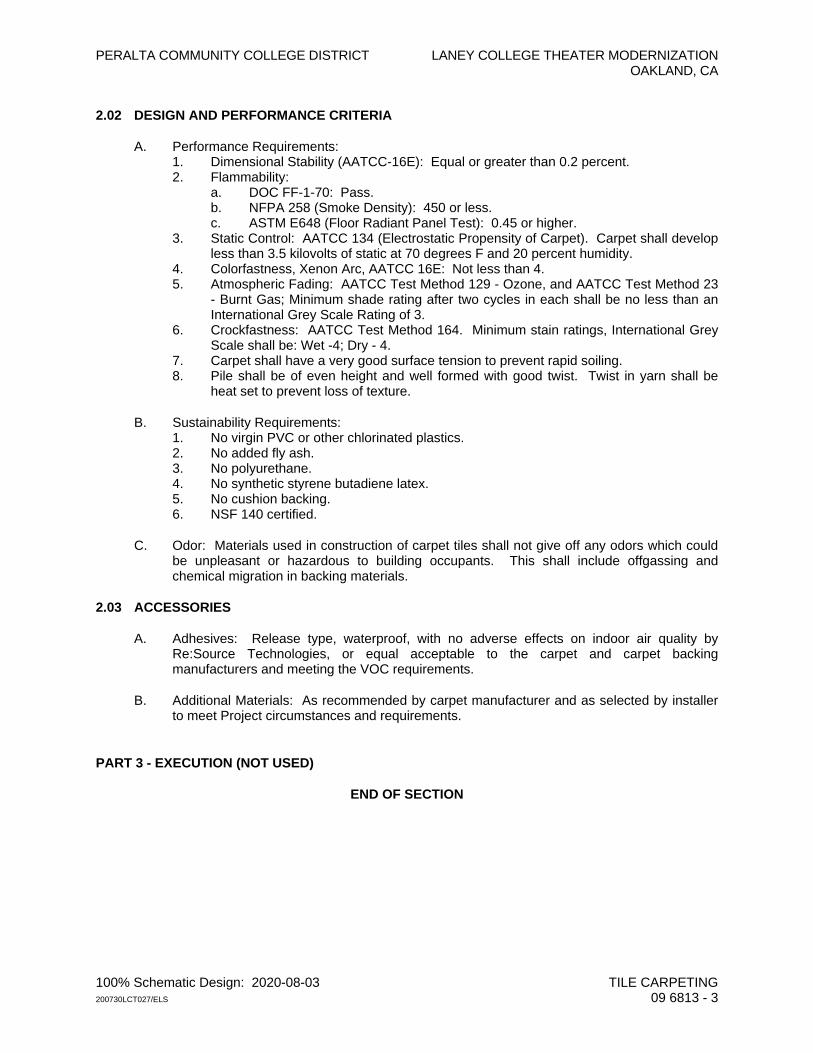
PERALTA COMMUNITY COLLEGE DISTRICT LANEY COLLEGE THEATER MODERNIZATION OAKLAND, CA
100% Schematic Design: 2020-08-03 TILE CARPETING 200730LCT027/ELS 09 6813 - 3
2.02 DESIGN AND PERFORMANCE CRITERIA
A. Performance Requirements: 1. Dimensional Stability (AATCC-16E): Equal or greater than 0.2 percent. 2. Flammability:
a. DOC FF-1-70: Pass. b. NFPA 258 (Smoke Density): 450 or less. c. ASTM E648 (Floor Radiant Panel Test): 0.45 or higher.
3. Static Control: AATCC 134 (Electrostatic Propensity of Carpet). Carpet shall develop less than 3.5 kilovolts of static at 70 degrees F and 20 percent humidity.
4. Colorfastness, Xenon Arc, AATCC 16E: Not less than 4. 5. Atmospheric Fading: AATCC Test Method 129 - Ozone, and AATCC Test Method 23
- Burnt Gas; Minimum shade rating after two cycles in each shall be no less than an International Grey Scale Rating of 3.
6. Crockfastness: AATCC Test Method 164. Minimum stain ratings, International Grey Scale shall be: Wet -4; Dry - 4.
7. Carpet shall have a very good surface tension to prevent rapid soiling. 8. Pile shall be of even height and well formed with good twist. Twist in yarn shall be
heat set to prevent loss of texture.
B. Sustainability Requirements: 1. No virgin PVC or other chlorinated plastics. 2. No added fly ash. 3. No polyurethane. 4. No synthetic styrene butadiene latex. 5. No cushion backing. 6. NSF 140 certified.
C. Odor: Materials used in construction of carpet tiles shall not give off any odors which could be unpleasant or hazardous to building occupants. This shall include offgassing and chemical migration in backing materials.
2.03 ACCESSORIES
A. Adhesives: Release type, waterproof, with no adverse effects on indoor air quality by Re:Source Technologies, or equal acceptable to the carpet and carpet backing manufacturers and meeting the VOC requirements.
B. Additional Materials: As recommended by carpet manufacturer and as selected by installer to meet Project circumstances and requirements.
PART 3 - EXECUTION (NOT USED)
END OF SECTION

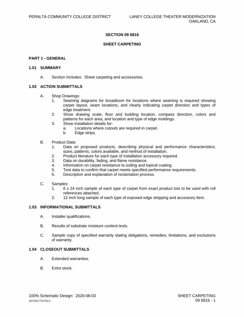
PERALTA COMMUNITY COLLEGE DISTRICT LANEY COLLEGE THEATER MODERNIZATION OAKLAND, CA
100% Schematic Design: 2020-08-03 SHEET CARPETING 200730LCT027/ELS 09 6816 - 1
SECTION 09 6816
SHEET CARPETING
PART 1 - GENERAL
1.01 SUMMARY
A. Section Includes: Sheet carpeting and accessories.
1.02 ACTION SUBMITTALS
A. Shop Drawings: 1. Seaming diagrams for broadloom for locations where seaming is required showing
carpet layout, seam locations, and clearly indicating carpet direction and types of edge treatment.
2. Show drawing scale, floor and building location, compass direction, colors and patterns for each area, and location and type of edge moldings.
3. Show installation details for: a. Locations where cutouts are required in carpet. b. Edge strips.
B. Product Data: 1. Data on proposed products, describing physical and performance characteristics;
sizes, patterns, colors available, and method of installation. 2. Product literature for each type of installation accessory required. 3. Data on durability, fading, and flame resistance. 4. Information on carpet resistance to soiling and topical coating. 5. Test data to confirm that carpet meets specified performance requirements. 6. Description and explanation of reclamation process.
C. Samples: 1. 6 x 24 inch sample of each type of carpet from exact product lots to be used with roll
references attached. 2. 12 inch long sample of each type of exposed edge stripping and accessory item.
1.03 INFORMATIONAL SUBMITTALS
A. Installer qualifications.
B. Results of substrate moisture content tests.
C. Sample copy of specified warranty stating obligations, remedies, limitations, and exclusions of warranty.
1.04 CLOSEOUT SUBMITTALS
A. Extended warranties.
B. Extra stock.
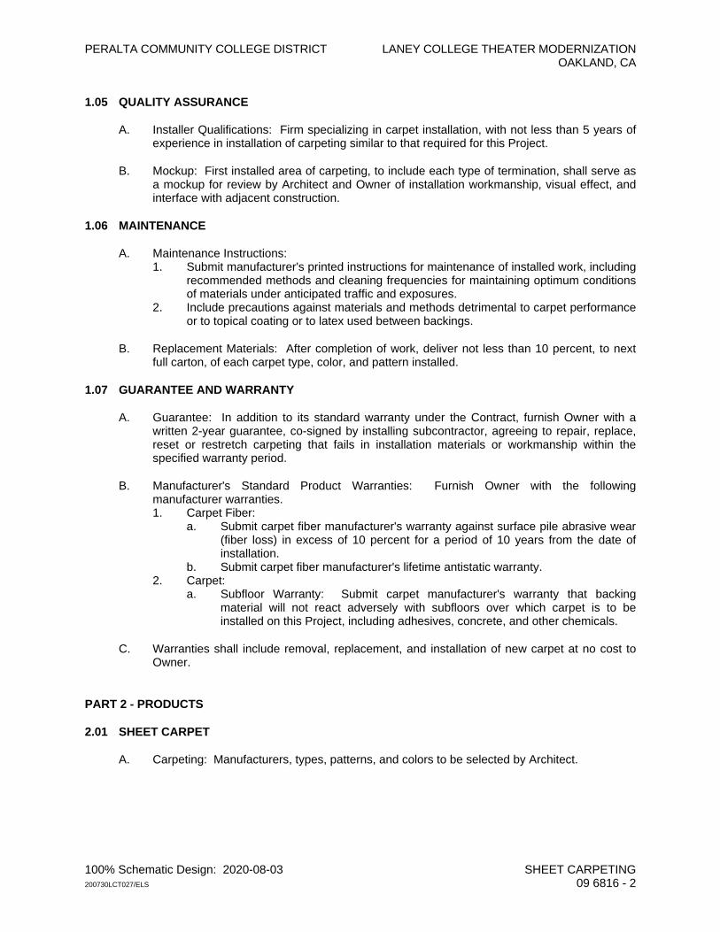
PERALTA COMMUNITY COLLEGE DISTRICT LANEY COLLEGE THEATER MODERNIZATION OAKLAND, CA
100% Schematic Design: 2020-08-03 SHEET CARPETING 200730LCT027/ELS 09 6816 - 2
1.05 QUALITY ASSURANCE
A. Installer Qualifications: Firm specializing in carpet installation, with not less than 5 years of experience in installation of carpeting similar to that required for this Project.
B. Mockup: First installed area of carpeting, to include each type of termination, shall serve as a mockup for review by Architect and Owner of installation workmanship, visual effect, and interface with adjacent construction.
1.06 MAINTENANCE
A. Maintenance Instructions: 1. Submit manufacturer's printed instructions for maintenance of installed work, including
recommended methods and cleaning frequencies for maintaining optimum conditions of materials under anticipated traffic and exposures.
2. Include precautions against materials and methods detrimental to carpet performance or to topical coating or to latex used between backings.
B. Replacement Materials: After completion of work, deliver not less than 10 percent, to next full carton, of each carpet type, color, and pattern installed.
1.07 GUARANTEE AND WARRANTY
A. Guarantee: In addition to its standard warranty under the Contract, furnish Owner with a written 2-year guarantee, co-signed by installing subcontractor, agreeing to repair, replace, reset or restretch carpeting that fails in installation materials or workmanship within the specified warranty period.
B. Manufacturer's Standard Product Warranties: Furnish Owner with the following manufacturer warranties. 1. Carpet Fiber:
a. Submit carpet fiber manufacturer's warranty against surface pile abrasive wear (fiber loss) in excess of 10 percent for a period of 10 years from the date of installation.
b. Submit carpet fiber manufacturer's lifetime antistatic warranty. 2. Carpet:
a. Subfloor Warranty: Submit carpet manufacturer's warranty that backing material will not react adversely with subfloors over which carpet is to be installed on this Project, including adhesives, concrete, and other chemicals.
C. Warranties shall include removal, replacement, and installation of new carpet at no cost to Owner.
PART 2 - PRODUCTS
2.01 SHEET CARPET
A. Carpeting: Manufacturers, types, patterns, and colors to be selected by Architect.
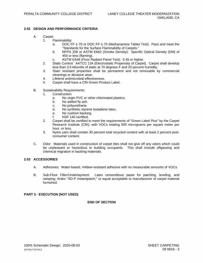
PERALTA COMMUNITY COLLEGE DISTRICT LANEY COLLEGE THEATER MODERNIZATION OAKLAND, CA
100% Schematic Design: 2020-08-03 SHEET CARPETING 200730LCT027/ELS 09 6816 - 3
2.02 DESIGN AND PERFORMANCE CRITERIA
A. Carpet: 1. Flammability:
a. DOC FF-1-70 or DOC FF-1-70 (Methanamine Tablet Test): Pass and meet the "Standards for the Surface Flammability of Carpets."
b. NFPA 258 or ASTM E662 (Smoke Density): Specific Optical Density (DM) of 450 or less (flaming).
c. ASTM E648 (Floor Radiant Panel Test): 0.45 or higher. 2. Static Control: AATCC 134 (Electrostatic Propensity of Carpet). Carpet shall develop
less than 3.5 kilovolts of static at 70 degrees F and 20 percent humidity. 3. Stain resistant properties shall be permanent and not removable by commercial
cleanings or abrasive wear. 4. Lifetime antimicrobial effectiveness. 5. Carpet shall have a CRI Green Product Label.
B. Sustainability Requirements: 1. Construction:
a. No virgin PVC or other chlorinated plastics. b. No added fly ash. c. No polyurethane. d. No synthetic styrene butadiene latex. e. No cushion backing. f. NSF 140 certified.
2. Carpet shall be certified to meet the requirements of “Green Label Plus” by the Carpet Research Institute (CRI), with VOCs totaling 500 micrograms per square meter per hour, or less.
3. Nylon yarn shall contain 30 percent total recycled content with at least 2 percent post-consumer content.
C. Odor: Materials used in construction of carpet tiles shall not give off any odors which could be unpleasant or hazardous to building occupants. This shall include offgassing and chemical migration in backing materials.
2.03 ACCESSORIES
A. Adhesives: Water-based, mildew-resistant adhesive with no measurable amounts of VOCs.
B. Sub-Floor Filler/Underlayment: Latex cementitious paste for patching, leveling, and ramping; Ardex "SD-P Instantpatch," or equal acceptable to manufacturer of carpet material furnished.
PART 3 - EXECUTION (NOT USED)
END OF SECTION

PERALTA COMMUNITY COLLEGE DISTRICT LANEY COLLEGE THEATER MODERNIZATION OAKLAND, CA
100% Schematic Design: 2020-08-03 STRETCHED FABRIC ACOUSTIC WALL SYSTEMS 200730LCT027/ELS 09 7713 - 1
SECTION 09 7713
STRETCHED FABRIC ACOUSTIC WALL SYSTEMS
PART 1 - GENERAL
1.01 SUMMARY
A. Section Includes: 1. Stretched fabric wall covering. 2. Acoustic backing.
1.02 ACTION SUBMITTALS
A. Shop Drawings: 1. Show wall elevations of surfaces to receive stretched fabric covering. Cross-
reference to the Drawings. 2. Show field verified dimensions, directions of pattern, seaming diagrams, hardware,
acoustic backing, system thickness, relationship to penetrations, surface mounted equipment and adjacent perimeter materials, and anchorage to supporting structure.
B. Product Data: Manufacturer's specifications and installation instructions.
C. Samples: 1. Fabrics: 6-inches square for each fabric to be used. 2. 12-inch-square sample showing construction, acoustic backing, seam, and edge
condition.
1.03 INFORMATIONAL SUBMITTALS
A. Certification that products meet specified performance requirements.
B. Certification that installer is approved by system manufacturer.
C. Test results verifying compliance with flammability requirements if not included with product data.
1.04 CLOSEOUT SUBMITTALS
A. Manufacturer's printed maintenance instructions for each type of fabric used.
B. Warranty as specified.
1.05 MAINTENANCE SUBMITTALS
A. Materials: Furnish fabric of that installed for each type, pattern, and color used in the Work, taken from the same "run" as used for the Work.
B. Furnish full-width material.
C. Quantity: As required by Owner.
PERALTA COMMUNITY COLLEGE DISTRICT LANEY COLLEGE THEATER MODERNIZATION OAKLAND, CA
100% Schematic Design: 2020-08-03 STRETCHED FABRIC ACOUSTIC WALL SYSTEMS 200730LCT027/ELS 09 7713 - 2
1.06 QUALITY ASSURANCE
A. Mockup: First 3 or more full height adjacent panel areas shall serve as a mockup for review by Architect of aesthetic effects, mid-joint, and to set quality standards for materials, fabrication, and installation.
1.07 WARRANTY
A. Manufacturer: Furnish Owner with manufacturer’s standard 2-year warranty to repair or replace components of stretch fabric system that fails in performance, materials, or workmanship within specified warranty period.
PART 2 - PRODUCTS
2.01 MANUFACTURER AND SYSTEM
A. System and Manufacturer: Site-built from rigid vinyl extrusions; “AccuSnap” by Accutrack Systems, Inc. as distributed by Marc Lawrence Interiors, Fremont, CA, 510-659-1640, or equal.
2.02 DESIGN AND PERFORMANCE CRITERIA
A. Fire Performance Characteristics: System shall have the following surface-burning characteristics as determined by testing full assemblies (component tests unacceptable) of identical materials and construction in accordance with ASTM E84 by a testing organization acceptable to authorities having jurisdiction. 1. Fire Hazard Classification: Class "A" or "1." 2. Flame Spread: 25 or less. 3. Smoke Developed: 400 or less.
B. Acoustical Performance Characteristics: System shall be installed with an acoustical core, achieving a minimum Noise Reduction Coefficient (NRC) rating as scheduled when mounted in accordance with ASTM C423 Type E400 mounting.
2.03 MATERIALS
A. Fabric Coverings: To be selected by Architect.
B. Acoustical Backing: Composite fiberglass panel with a total thickness of 2 inches. 1. Facing: Impact resistant, high-density mineral fiber board, 22-24 pcf, with a Class A
rating, 1/2 inch thick; "Micore 300" by USG, or equal 2. Backing: Semi-rigid, medium-density fiberglass, 6 to 7 pcf, with a Class A rating,
1-1/2 inches thick; Type 705 Series by Owens Corning, or equal.
C. Adhesive for Mounting Core: VOC compliant and recommended backing manufacturer.
D. Perimeter and Mid-Wall Moldings: System manufacturer's standard rigid PVC moldings, square profile; thickness to align with backing.
PART 3 - EXECUTION (NOT USED)
END OF SECTION
PERALTA COMMUNITY COLLEGE DISTRICT LANEY COLLEGE THEATER MODERNIZATION OAKLAND, CA
100% Schematic Design: 2020-08-03 ACOUSTICAL INSULATION AND SEALANTS 200730LCT027/ELS 09 8200 - 1
SECTION 09 8200
ACOUSTICAL INSULATION AND SEALANTS
PART 1 - GENERAL
1.01 SUMMARY
A. Section Includes: 1. Acoustic batt insulation. 2. Acoustic board insulation. 3. Acoustical sealants and accessories. 4. Sound isolation requirements.
1.02 ACTION SUBMITTALS
A. Product Data: Manufacturer's specifications for each type of insulation and sealant.
B. Samples: Each type of pipe isolation system or product.
PART 2 - PRODUCTS
2.01 ACOUSTICAL BATTS AND BOARDS
A. Sound-Control Batt: Unfaced, friction fit, preformed slag mineral or glass fiber with thermosetting resin binders, formaldehyde-free, conforming to ASTM C665, Type I; “EcoTouch PINK FIBERGLAS” by Owens-Corning, or accepted equal. 1. Thicknesses: Full thickness or cavity, unless otherwise shown. 2. Surface Burning Characteristics: ASTM E84.
a. Smoke Developed: 50 or less. b. Flame Spread: 25 or less.
3. Combustibility: Pass ASTM E136.
B. Semi-Rigid Board - Exposed at Mechanical Rooms: Glass fiber board with black, non-woven mat facing fully bonded to core, conforming to ASTM C612, Class 1A; "CertaPro AcoustaBoard Black" by CertainTeed, “SelectSound” by Owens Corning, or equal. 1. Thickness: 1-1/2 inches, unless otherwise shown. 2. Density: 3.0 pounds per cubic foot. 3. Fungi Resistance: Pass ASTM C1338. 4. Surface Burning Characteristics: UL723.
a. Smoke Developed: 50 or less. b. Flame Spread: 25 or less.
5. Cut edges shall be sealed.
2.02 ADDITIONAL MATERIALS
A. Acoustical Tape: Low-density PVC foam; "Norseal" V-730 Series by Norton Performance Plastics Corp. or equal.
B. Acoustical Sealants:
PERALTA COMMUNITY COLLEGE DISTRICT LANEY COLLEGE THEATER MODERNIZATION OAKLAND, CA
100% Schematic Design: 2020-08-03 ACOUSTICAL INSULATION AND SEALANTS 200730LCT027/ELS 09 8200 - 2
1. Non-Rated Conditions: USG "Sheetrock Acoustical Sealant," Tremco “Acoustical Sealant,” Henry's "Sound Control Sealant" No. 413, or equal conforming to ASTM C919.
2. Fire-Rated Partition Perimeter Conditions: USG "Sheetrock Acoustical Sealant," Jaco “Fire and Draft Sealer,” or equal.
C. Pipe Isolation Systems: Coordinate with Divisions 22, “Plumbing,” and 23, “HVAC.” 1. Do not use pipe isolation systems which utilize a felt insert. 2. Pipes One Inch or Smaller in Diameter: As follows, or equal.
a. “Acousto-Plumb.” b. “Holdrite Silencer” Model #261 (1/2-inch diameter), Model #262 (3/4-inch
diameter), Model #263 (1 inch diameter). 3. Pipes Larger than One Inch in Diameter, and for Hanger Liners: As follows, or equal.
a. Sections of closed cell neoprene sleeves such as AP/Armaflex. b. “Holdrite Silencer” Model #264 (1-1/4 inch diameter), Model #270 (2 inches
wide), Model #271 (2 inches wide). 4. Isolators for Riser Clamps: 1/2-inch thick neoprene pad between the riser clamp and
the floor structure.
D. Electrical Box Treatment: 1. Manufacturer: Lowry’s Inc., Sun Valley, CA, 800-225-8231, or equal.
a. Outlet Box Pads: Polybutene-butyl with inert fillers, minimum 1/8-inch thick; Lowry's "Outlet Box Pads."
b. Sealant: Lowry's "Electrical Box Sealer." 2. See Section 07 8400, "Firestopping," for pads and sealant at fire-rated assemblies.
E. Putty Pads: As specified above for outlet box pads.
F. Sealant Backer Rod: Compressible, rod-stock, polyethylene foam; nongassing, polyethylene-jacketed polyurethane foam; butyl-rubber foam; neoprene foam; or other flexible, permanent, durable, nonabsorptive, closed-cell material as recommended for compatibility with sealant by sealant manufacturer.
G. Miscellaneous Fastenings and Accessories: As acceptable to insulation manufacturer.
PART 3 - EXECUTION (NOT USED)
END OF SECTION
PERALTA COMMUNITY COLLEGE DISTRICT LANEY COLLEGE THEATER MODERNIZATION OAKLAND, CA
100% Schematic Design: 2020-08-03 FABRIC-WRAPPED ACOUSTICAL WALL PANELS 200730LCT027/ELS 09 8413 - 1
SECTION 09 8413
FABRIC-WRAPPED ACOUSTICAL WALL PANELS
PART 1 - GENERAL
1.01 SUMMARY
A. Section Includes: 1. Fabric-wrapped acoustical wall panels
1.02 ADMINISTRATIVE REQUIREMENTS
A. Pre-Installation Meeting: Architect, Contractor, and installer shall meet at project site prior to beginning panel siding installation to review and finalize each layout, penetrating items, and installation methods and procedures.
1.03 ACTION SUBMITTALS
A. Shop Drawings: Elevations of each surface to receive acoustical panels showing layout and joint pattern dimensions as applicable.
B. Product Data: Manufacturer's specifications and installation recommendations.
C. Samples: 12-inch-square sample for each panel type showing fabric, construction, acoustic backing, and edge condition. Submit for each required fabric to be used and each type of core.
1.04 INFORMATIONAL SUBMITTALS
A. Certification that wall panels meet specified performance requirements.
B. Installer qualifications.
1.05 CLOSEOUT SUBMITTALS
A. Manufacturer's printed maintenance instructions for each type of fabric used.
1.06 QUALITY ASSURANCE
A. Installer Qualifications: Verifiable minimum 5 years’ experience installing wall and ceiling panels and acoustical treatment.
B. Single Source: All products under this section shall be supplied by a single manufacturer to ensure consistency in product size and finish.
C. Mockup: First 3 or more adjacent panels installed showing interface with adjacent wall finishes shall serve as a mock-up for review by Architect of workmanship and appearance.
PERALTA COMMUNITY COLLEGE DISTRICT LANEY COLLEGE THEATER MODERNIZATION OAKLAND, CA
100% Schematic Design: 2020-08-03 FABRIC-WRAPPED ACOUSTICAL WALL PANELS 200730LCT027/ELS 09 8413 - 2
1.07 WARRANTY
A. Manufacturers: Furnish Owner with the following extended manufacturer warranties. 1. Fabric-Faced Panels: As available from manufacturer for scheduled product. 2. Adhesive: 3-years against mildew or fungus growth caused by adhesive.
PART 2 - PRODUCTS
2.01 DESIGN AND PERFORMANCE CRIETERIA
A. Acoustical Properties: To be finalized by Architect.
B. Fire Performance Characteristics: Provide wall panels with surface-burning characteristics as determined by testing full assemblies (component tests unacceptable) of identical materials and construction in accordance with ASTM E84 by a testing organization acceptable to authorities having jurisdiction. 1. Fire Hazard Classification: Class "A" or "1." 2. Flame Spread: 25 or less. 3. Smoke Developed: 450 or less.
2.02 ACOUSTICAL WALL PANELS
A. Manufacturer’s and Products: 1. Core: High impact resistant; Decoustics H.I.R. #1, or equal. 2. Fabric Facing: To be finalized by Architect.
B. Accessories: 1. Adhesive: As recommended for each fabric type. 2. Provide panel manufacturer's standard splines, fasteners, and other items as required
for a complete installation.
C. Fabrication: 1. Face Sizes: In accordance with layout shown at each location. Maximum panel width
shall be 48 inches to allow for complete wrapping of fabric at panel ends. 2. Minimum Width of End Panels: One-half unit dimension, unless otherwise shown. 3. Fabricate fabric-wrapped panels to specified profile.
a. Bond fabric to panel face, and return at edges to back of panel. b. Ensure flat, wrinkle-free surfaces, with square edges and corners.
4. Mount installation strips to panel back with chemical hardener.
PART 3 - EXECUTION (NOT USED)
END OF SECTION
PERALTA COMMUNITY COLLEGE DISTRICT LANEY COLLEGE THEATER MODERNIZATION OAKLAND, CA
100% Schematic Design: 2020-08-03 PAINTING AND COATING 200730LCT027/ELS 09 9000 - 1
SECTION 09 9000
PAINTING AND COATING
PART 1 - GENERAL
1.01 SUMMARY
A. Section Includes: Painting and painter's finish on exposed exterior and interior surfaces to complete the finishing of the Work.
1.02 ACTION SUBMITTALS
A. Schedule: Proposed manufacturer’s products grouped by System using same System identification included in these Specifications.
B. Product Data: Manufacturer's technical information for each product scheduled including paint label analysis and application instructions.
C. Color samples.
1.03 INFORMATIONAL SUBMITTALS
A. Statement of applicator qualifications.
1.04 CLOSEOUT SUBMITTALS
A. Listing of each paint used, including manufacturer name, paint type, color name, and color formula.
B. Extra Stock: Not required.
1.05 QUALITY ASSURANCE
A. Field Samples or Mockups: Extent to be finalized by Architect.
PART 2 - PRODUCTS
2.01 MATERIALS
A. Products are specified under "Paint Systems" in Part 3 below and are manufactured by Benjamin Moore, except as otherwise indicated. Equivalent products manufactured by Sherwin-Williams, PPG Architectural Coatings, Dunn-Edwards, Kelly-Moore, Vista, or equal shall be approved by the Architect.
B. Materials selected for coating systems for each type surface shall be the product of a single manufacturer or shall be acceptable to manufacturer of finish coating for system.
C. If more than one quality level of product type is marketed, use material of highest quality.
2.02 COLORS
PERALTA COMMUNITY COLLEGE DISTRICT LANEY COLLEGE THEATER MODERNIZATION OAKLAND, CA
100% Schematic Design: 2020-08-03 PAINTING AND COATING 200730LCT027/ELS 09 9000 - 2
A. Architect will prepare a color schedule with samples for guidance of painter and reserves right to select, allocate, and vary colors on different surfaces throughout building.
B. Colors: To be finalized by Architect.
PART 3 - EXECUTION
3.01 PAINT SYSTEMS
A. Gloss and Sheen Ratings: Paint gloss shall be defined as the sheen rating of applied paint, in accordance with the following limits in conformance with Master Painters Institute, Inc. (MPI) Standards according to ASTM D523. Not all of the Gloss Levels are necessarily scheduled or used on this Project. 1. Gloss Level 1: Matte or Flat; not more than 5 units at 60 degrees and 10 units at 85
degrees. 2. Gloss Level 2: Velvet or Low Sheen; not more than 10 units at 60 degrees and 10 to 35
units at 85 degrees. 3. Gloss Level 3: Eggshell; 10 to 25 units at 60 degrees and 10 to 35 units at 85 degrees. 4. Gloss Level 4: Satin; 20 to 35 units at 60 degrees and not less than 35 units at 85
degrees. 5. Gloss Level 5: Semi-gloss; 35 to 70 units at 60 degrees. 6. Gloss Level 6: Gloss; 70 to 85 units at 60 degrees.
B. Clarification of System Terminology: 1. Interior paint Systems are specified and identified herein by initial letters “INT.” 2. Exterior paint Systems are specified and identified herein by initial letters “EXT.” 3. Initial numbers for each System identify the substrate to be coated. 4. Letter following substrate numbers identify the general finish coat chemistry summarized
as follows:
CODE DESCRIPTION A Standard acrylic B Standard acrylic copolymer D DTM acrylic E Epoxy H Polyester-Acrylic Aliphatic Polyurethane
5. Hyphenated suffix identifies the topcoat gloss levels.
C. Interior Painting Systems:
INT 5.2A-5 Standard Performance Acrylic on Shop-Primed Metal - Gloss Level 5 2 coats “Ultra Spec 500” N539 Zero VOC acrylic copolymer Note: Modify scheduled topcoat if other than specified gloss level is selected by Architect.
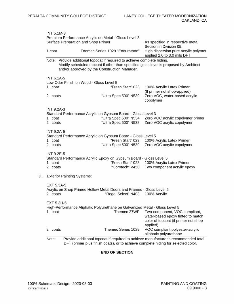
PERALTA COMMUNITY COLLEGE DISTRICT LANEY COLLEGE THEATER MODERNIZATION OAKLAND, CA
100% Schematic Design: 2020-08-03 PAINTING AND COATING 200730LCT027/ELS 09 9000 - 3
INT 5.1M-3 Premium Performance Acrylic on Metal - Gloss Level 3 Surface Preparation and Shop Primer As specified in respective metal
Section in Division 05. 1 coat Tnemec Series 1029 "Enduratone" High dispersion pure acrylic polymer
applied 2.0 to 3.0 mils DFT Note: Provide additional topcoat if required to achieve complete hiding. Modify scheduled topcoat if other than specified gloss level is proposed by Architect
and/or approved by the Construction Manager.
INT 6.1A-5 Low Odor Finish on Wood - Gloss Level 5 1 coat “Fresh Start” 023 100% Acrylic Latex Primer (If primer not shop-applied) 2 coats “Ultra Spec 500” N539 Zero VOC, water-based acrylic
copolymer
INT 9.2A-3 Standard Performance Acrylic on Gypsum Board - Gloss Level 3 1 coat “Ultra Spec 500” N534 Zero VOC acrylic copolymer primer 2 coats “Ultra Spec 500” N538 Zero VOC acrylic copolymer
INT 9.2A-5 Standard Performance Acrylic on Gypsum Board - Gloss Level 5 1 coat “Fresh Start” 023 100% Acrylic Latex Primer 2 coats “Ultra Spec 500” N539 Zero VOC acrylic copolymer
INT 9.2E-5 Standard Performance Acrylic Epoxy on Gypsum Board - Gloss Level 5 1 coat “Fresh Start” 023 100% Acrylic Latex Primer 2 coats “Corotech” V450 Two component acrylic epoxy
D. Exterior Painting Systems:
EXT 5.3A-5 Acrylic on Shop Primed Hollow Metal Doors and Frames - Gloss Level 5 2 coats “Regal Select” N403 100% Acrylic
EXT 5.3H-5 High-Performance Aliphatic Polyurethane on Galvanized Metal - Gloss Level 5 1 coat Tnemec 27WP Two-component, VOC compliant,
water-based epoxy tinted to match color of topcoat (if primer not shop applied)
2 coats Tnemec Series 1029 VOC compliant polyester-acrylic aliphatic polyurethane
Note: Provide additional topcoat if required to achieve manufacturer’s recommended total DFT (primer plus finish coats), or to achieve complete hiding for selected color.
END OF SECTION

PERALTA COMMUNITY COLLEGE DISTRICT LANEY COLLEGE THEATER MODERNIZATION OAKLAND, CA
100% Schematic Design: 2020-08-03 SIGNAGE 200730LCT027/ELS 10 1400 - 1
SECTION 10 1400
SIGNAGE
PART 1 - GENERAL
1.01 SUMMARY
A. Section Includes: General requirements for signage as indicated complete with attachment devices and accessories as required for complete installation including:
1. Code required signage. 2. Interior permanent room identification signage. 3. Glass-mounted signage. 4. Exterior Building signage.
1.02 ACTION SUBMITTALS
A. Shop Drawings: 1. Sign Schedule: 2. Full-scale drawings for each sign indicating materials, lettering layout, and colors. 3. Large-scale drawing and details of custom logo and lettering. Include mounting
details. 4. Building Floor Plans showing signage location, and numbering where applicable,
keyed to Sign Schedule. 5. Font Styles. 18 point graphical example of alphabet and numerical numbers 0
through 9 of signage font style, 18 point scale, and black text on white paper
B. Product Data: Furnish manufacturer's literature and indicate each sign type, style, color, and method of attachment.
C. Samples: 1. Color Verification: 2. Submit one sample of each sign type. 3. Dimensional Letters: Provide one full-size representative samples of each dimensional
letter type required, showing letter style, color, and material finish and method of attachment.
1.03 NFORMATIONAL SUBMITTALS
A. Written Verification of Braille, tactile text and dark to light and light to dark contrasting text and background color approval from Lighthouse for the Blind, San Francisco CA.
1.04 CLOSEOUT
A. Extended warranty.
1.05 WARRANTY
A. Contractor: In addition to its Standard Guarantee under the Contract, furnish to the Owner a written extended 5-year guarantee for signage against all defects in materials and workmanship, including without limitation against yellowing, cracking, crazing, and other visible and performance defects.
PERALTA COMMUNITY COLLEGE DISTRICT LANEY COLLEGE THEATER MODERNIZATION OAKLAND, CA
100% Schematic Design: 2020-08-03 SIGNAGE 200730LCT027/ELS 10 1400 - 2
PART 2 - PRODUCTS
2.01 DESIGN AND PERFORMANCE CRITERIA
A. Regulatory Standards: Except as otherwise specified or shown, signage shall conform to the following: 1. ANSI A-117.1 and the Americans with Disabilities Act (ADA). 2. ATBCB Design Guidelines for Signage in relation to the Americans with Disabilities
Act. 3. California Code of Regulations, Titles 19 and 24. 4. California Grade 2 Braille shall be used whenever Braille symbols are specifically
required. Refer to CBC Section 1117B.5.2. 5. All signage shall conform to CBC Sections 1111, 1115B, and 1117B.5. 6. Uniform Sign Code.
B. Design Criteria: 1. Raised Characters: Section 11B-703.2.
a. Letter Type: Section 11B-703.2.1. 1) Raise characters on signs 1/32-inch minimum. 2) Characters shall be sans serif uppercase characters accompanied by
Grade 2 Braille. b. Character Size: Section 11B-703.2.5.
1) Raised characters shall be a minimum of 5/8-inch and a maximum of 2 inches high.
c. Proportions of Letters and Numbers: Section 11B703.2.4. 1) Characters on signs shall have a width-to-height ratio of between 3:5 and
1:1 and a stroke width-to-height ratio of between 1:5 and 1:10. d. Letters measured to verify compliance must be uppercase.
1) After choosing a typestyle to test, begin by printing the letters I, X, and O at 1 inch high.
2) Place the template’s 1:1 square over the X or O, whichever is narrower. If the character is not wider than 1 inch, nor narrower than the 3:5 rectangle, the proportions are correct.
3) Use the 1:5 rectangle to determine if the stroke of the I is too broad, and the 1:10 rectangle to see if it is too narrow.
4) If the tests are passed, the typestyle is compliant with proportion code. 2. Braille Symbols: Section 11B-703.3.
a. California Contracted Grade 2 Braille with rounded or domed dots shall be used wherever Braille is required. Dots with straight sides and flat tops are not readable for many Braille users and are not acceptable.
b. Space dots 1/10-inch on center in each cell with 2/10-inch space between cells, measured from the second column of dots in the first cell to the first column of dots in the second cell.
c. Raise dots a minimum of 1/40-inch above the background. d. Installation Height: Section 11B-703.4.
3. Pictograms: Section 11B-703.6. a. Field: 6 inch high. Characters and Braille shall not be located in the pictogram
field, Section 11B-703.6.1. b. Text Descriptors: Locate text descriptors directly below the pictogram field.
4. International Symbol of Accessibility: Section 11B-703.7.2.1 and figure 11B- 703.7.2.1.
5. Contrast and Finish of Symbols: Section 11B-703.6.2. a. Contrast between character, symbols and their background must be 70 percent
minimum and have a non-glare finish.
PERALTA COMMUNITY COLLEGE DISTRICT LANEY COLLEGE THEATER MODERNIZATION OAKLAND, CA
100% Schematic Design: 2020-08-03 SIGNAGE 200730LCT027/ELS 10 1400 - 3
6. Mounting Height and Location: Signs with tactile characters shall comply with Section 11B-703.4.
7. Doorways Leading to Sanitary Facilities: Provide signs that comply with applicable requirements of Section 11B-703.7.2.6.
8. Grade Level Exterior Exit Doors: Provide tactile exit signage to comply with Sections 1011.1 and 11B-703.4.2.
2.02 MATERIALS
A. General: To be finalized by Architect.
2.03 GRAPHIC LAYOUTS
A. Text and Layouts: To be finalized by Architect.
PART 3 - EXECUTION (NOT USED)
END OF SECTION

PERALTA COMMUNITY COLLEGE DISTRICT LANEY COLLEGE THEATER MODERNIZATION OAKLAND, CA
100% Schematic Design: 2020-08-03 PHENOLIC-CORE TOILET COMPARTMENTS 200730LCT027/ELS 10 2113 - 1
SECTION 10 2113
PHENOLIC-CORE TOILET COMPARTMENTS
PART 1 - GENERAL
1.01 SUMMARY
A. Section Includes: Toilet partitions and wall-mounted urinal screens constructed of compact laminate (solid phenolic with melamine surfaces).
B. Related Requirements: 1. Miscellaneous Rough Carpentry: 06 1053. 2. Non-Structural Metal Framing: Section 09 2216. 3. Tiling: Section 09 3000. 4. Toilet Accessories: Section 10 2813.
1.02 ACTION SUBMITTALS
A. Shop Drawings: Partition plans, and elevation views, anchorage and mounting details.
B. Product Data: Manufacturer's data sheets for panels and components.
C. Samples: Panel, 6 inches square, in selected colors.
1.03 CLOSEOUT SUBMITTALS
A. Specified warranty.
1.04 QUALITY ASSURANCE
A. Regulatory Requirements: 1. Comply with accessibility requirements of CBC Section 1115B "Bathing and Toilet
Facilities" and ADA “Standards for Accessible Design.” Comply with the most stringent where there is a conflict.
B. Mockups: First installed example of toilet compartment and urinal screen shall serve as a mockup for review and approval.
1.05 WARRANTY
A. Manufacturer: 25 year warranty against failure in materials or workmanship.
PART 2 - PRODUCTS
2.01 TOILET COMPARTMENTS
A. Manufacturer and System: Solid phenolic with matte-finish melamine surfaces; “DuraLine Compact Laminate” with gap-free interlocking privacy option by Bobrick Washroom Equipment Inc. as specified and the basis of design, or equal. 1. Panel Color: To be finalized by Architect.
PERALTA COMMUNITY COLLEGE DISTRICT LANEY COLLEGE THEATER MODERNIZATION OAKLAND, CA
100% Schematic Design: 2020-08-03 PHENOLIC-CORE TOILET COMPARTMENTS 200730LCT027/ELS 10 2113 - 2
2. Edges: Black solid phenolic.
B. Styles: 1. Partitions:
a. Floor-Supported and Overhead-Braced; 1082 Series. b. Floor-to-Ceiling Anchored. 1086 Series.
2. Urinal Screens: Wall supported flat panel; 1085 Series.
2.02 DESIGN AND PERFORMANCE CRITERIA
A. Provide all toilet compartments from a single manufacturer.
B. Partitions shall be vandal resistant and moisture-resistant, designed for heavy use and abuse in institutional washrooms.
2.03 MATERIALS AND COMPONENTS
A. Material for Panels, Pilasters, and Doors: Solid phenolic composite. 1. Minimum finished thickness: 2. Panels: 1/2 inch. 3. Pilasters: 3/4 inch. 4. Doors: 3/4 inch.
B. Pilaster Shoes: Stainless steel.
C. Wall Brackets: Continuous, stainless steel.
D. Hardware and Fittings: Extra-heavy-duty stainless steel equal to Bobrick 1092.67 “Institutional Hardware” or equal. Plated “Zamac” alloy is not acceptable. 1. Hinges: Continuous piano-type, self-closing, gravity-return movement, adjustable. 2. Slide Latch: Combination rubber-faced door strike and keeper. 3. Door Pulls: Outswing-door type on outswinging doors, inswing-door type on
inswinging doors; Bobrick B-1000 312 U-shaped pull. 4. Pulls and latches shall be ADA accessibility compliant. 5. Door Stops: Two 11-gage stainless steel door plates with attached rubber bumpers to
resist door being kicked in or out beyond stile.
E. Coat Hooks: Heavy-duty; Bobrick B-212, mounted 48 inches maximum above finish floor at accessible compartments.
F. Exposed Bolts and Screws: Theft-resistant, one-way heads, stainless steel, pinhead Torx screws.
G. Mounting Brackets: 1. U-channels to secure panels to stiles. 2. Continuous angles brackets to secure stiles to walls and panels to walls.
H. Headrails: 1-inch x 1-5/8-inch minimum, heavy-duty tubular stainless steel or extruded anodized aluminum, satin finish, anti-grip profile, with cast socket-type wall brackets.
PART 3 - EXECUTION (NOT USED)
END OF SECTION
PERALTA COMMUNITY COLLEGE DISTRICT LANEY COLLEGE THEATER MODERNIZATION OAKLAND, CA
100% Schematic Design: 2020-08-03 TOILET ACCESSORIES 200730LCT027/ELS 10 2813 - 1
SECTION 10 2813
TOILET ACCESSORIES
PART 1 - GENERAL
1.01 SUMMARY
A. Section Includes: 1. Toilet accessories. 2. Janitorial accessories.
1.02 ACTION SUBMITTALS
A. Schedule and Shop Drawings: Indicate type, quantities, sizes, and locations for accessories.
B. Product Data: Manufacturer's catalog cuts and data sheets.
C. Samples: Full size for each accessory, if requested. Samples, if submitted, will be returned, and acceptable samples may be used in the work.
1.03 CLOSEOUT SUBMITTALS
A. Maintenance data and operating instructions.
B. Keys required for each type of equipment and lock.
C. Extended warranties as specified.
1.04 QUALITY ASSURANCE
A. Regulatory Requirements: Meet applicable requirements of Americans with Disabilities Act (ADA).
1.05 WARRANTY
A. Manufacturer: Furnish to Owner a manufacturer’s written guarantee for mirrors against silver spoilage and all other defects in materials for 5-years from date of acceptance.
PART 2 - PRODUCTS
2.01 MANUFACTURER
A. Accessories: American Specialties Inc. (ASI) as specified, unless otherwise noted, Bobrick Washroom Equipment Inc., Bradley, or accepted equal.
B. Accessories shall be the product of a single manufacturer, unless otherwise specified.
PERALTA COMMUNITY COLLEGE DISTRICT LANEY COLLEGE THEATER MODERNIZATION OAKLAND, CA
100% Schematic Design: 2020-08-03 TOILET ACCESSORIES 200730LCT027/ELS 10 2813 - 2
2.02 CONTRACTOR FURNISHED AND INSTALLED ACCESSORIES AT RESTROOMS
A. General: 1. Fasteners: Screws, bolts, and other devices of same material as accessory unit and
tamper-and-theft resistant where exposed, and of galvanized steel where concealed. 2. Locked Dispensing Units: Key in accordance with Owner’s existing accessory keying.
Coordinate with Architect. 3. Typical Metal Finish: Satin stainless steel.
B. Grab Bars: Stainless steel; ASI 3700 Series. See Drawings for configurations and dimensions.
C. Additional Accessories: To be finalized by Architect.
2.03 JANITORIAL ACCESSORIES AND ADDITIONAL ITEMS
A. Surface-Mounted Stainless Steel Utility Shelf with Mop/Broom Holders and Hooks: B-239.
B. Pipe Wrap at Exposed Undercounter Plumbing: Flexible vinyl; “Lav-Guard 2" by Truebro Inc., Collierville, TN, 800-340-5969, or accepted equal. 1. Series: As recommended by manufacturer for pipe trap type. 2. Color: White.
PART 3 - EXECUTION (NOT USED)
END OF SECTION
PERALTA COMMUNITY COLLEGE DISTRICT LANEY COLLEGE THEATER MODERNIZATION OAKLAND, CA
100% Schematic Design: 2020-08-03 EMERGENCY AID CABINETS 200730LCT027/ELS 10 4313 - 1
SECTION 10 4313
EMERGENCY AID CABINETS
PART 1 - GENERAL
1.01 SUMMARY
A. Section Includes: 1. Automated external defibrillator (AED) cabinets. 2. Automated external defibrillators (AED's).
1.02 ADMINISTRATIVE REQUIREMENTS
A. Pre-installation Conference: Conduct conference at Project site. Review methods and procedures related to AED cabinets including, but not limited to, mounting locations, installation, and scheduling for installing AEDs.
1.03 ACTION SUBMITTALS
A. Product Data: Manufacturer’s descriptive literature for AED and stock AED cabinet.
B. Samples: 6 by 6 inches for exposed cabinet finish.
1.04 CLOSEOUT SUBMITTALS
A. Maintenance data for AED.
1.05 QUALITY ASSURANCE
A. Electrical Components, Devices, and Accessories: Listed and labeled as defined in NFPA 70, by a qualified testing agency, and marked for intended location and application.
PART 2 - PRODUCTS
2.01 AED CABINET
A. Cabinet Type: Suitable for mounting AED with emergency telephone and alarm and generally matching the existing AED cabinets; Potter Roemer LLC, J. L. Industries, Inc., a Division of Activar Construction Products Group, Larsen's Manufacturing Company, or equal. 1. Model for Basis of Design: To be finalized.
B. Cabinet Box Construction: Non-rated. 1. Interior Size: As required to accommodate the AED and specified features. 2. Cabinet components and equipment shall be accessible, removable and replaceable
with the cabinet door in a 90 degree position. 3. Box and Trim Material: To be finalized. 4. Cabinet box shall be recessed in walls of sufficient depth to suit style of trim.
PERALTA COMMUNITY COLLEGE DISTRICT LANEY COLLEGE THEATER MODERNIZATION OAKLAND, CA
100% Schematic Design: 2020-08-03 EMERGENCY AID CABINETS 200730LCT027/ELS 10 4313 - 2
C. Cabinet Door: 1. Material: To be finalized. 2. Style: Provide limited visibility window. 3. Glazing: Tempered float glass. 4. Hardware: Manufacturer's standard door-operating hardware of proper type for
cabinet type, trim style, and door material and style indicated.
D. Accessories: Identification as standard with manufacturer.
E. Additional Cabinet Features and Accessories: 1. Cabinet Interior Features:
a. Emergency Phone Box. b. Cable Access Box. c. Raceway.
2. Alarm: a. Circuitry board. b. Alarm circuitry. c. Alarm key switch and key. d. Control for visual alarm, audio alarm and relay closures.
2.02 AUTOMATED EXTERNAL DEFIBRILLATOR (AED)
A. Manufacturer and Product: “Heartstart On-Site” (HS1) Defibrillator by Philips, or equal.
PART 3 - EXECUTION (NOT USED)
END OF SECTION
PERALTA COMMUNITY COLLEGE DISTRICT LANEY COLLEGE THEATER MODERNIZATION OAKLAND, CA
100% Schematic Design: 2020-08-03 FIRE PROTECTION SPECIALTIES 200730LCT027/ELS 10 4400 - 1
SECTION 10 4400
FIRE PROTECTION SPECIALTIES
PART 1 - GENERAL
1.01 SUMMARY
A. Section Includes: 1. Fire extinguishers, hangers, and cabinets. 2. Hose valve cabinets.
1.02 ACTION SUBMITTALS
A. Product Data: Manufacturer's specifications and installation instructions for fire extinguishers and cabinets to be used.
1.03 QUALITY ASSURANCE
A. Fabricate and label fire extinguishers to comply with NFPA 10, "Standard for Portable Fire Extinguishers."
B. Fire extinguishers shall be listed and labeled for type, rating, and classification by Factory Mutual (FM) or another independent testing agency acceptable to authorities having jurisdiction and to Owner's insurance company.
C. Meet ADA requirements for mounting height and projection from wall.
PART 2 - PRODUCTS
2.01 EQUIPMENT
A. Fire Extinguishers:. 1. FE-1 – Typical: Multipurpose dry chemical type, 105-pound capacity, UL Rating 4A-
80B:C; Larsen’s MP-510 or equal. 2. FE-2 - Mechanical and Electrical Rooms: Sodium bicarbonate base type, 10-pound
capacity, UL Rating 40B:C; Larsen’s DC-5, or equal. 3. FE-3 - IT MDF and Similar Rooms: Halocarbon type with Dupont “FE-36,” also known
as “CleanGuard” or “Halotron I,” as standard with extinguisher manufacturer and meeting governing regulations, 2-1/2 pound capacity, UL Rating 2B:C.
4. Extinguishers shall be by same manufacturer as fire extinguisher cabinets.
B. Fire Extinguisher Cabinets: As follows with basis of design to be finalized; Larsen's, or equal. 1. Size: To fit specified extinguishers. 2. Design: Recessed, unless otherwise shown. 3. Cabinet Trim: Square profile with return to adjacent wall construction. 4. Door Style: Flush with an acrylic view panel. 5. Latching Device: Zinc-plated pull handle, with self-adjusting roller catch and local
battery-powered alarm." 6. Finish on Door, Trim, and Box: Shop-applied, recoatable, electrostatic white powder
coat.
PERALTA COMMUNITY COLLEGE DISTRICT LANEY COLLEGE THEATER MODERNIZATION OAKLAND, CA
100% Schematic Design: 2020-08-03 FIRE PROTECTION SPECIALTIES 200730LCT027/ELS 10 4400 - 2
C. Mounting Brackets for Surface Mounted Extinguishers in Utility Spaces: As recommended by manufacturer for extinguisher.
PART 3 - EXECUTION (NOT USED)
END OF SECTION
PERALTA COMMUNITY COLLEGE DISTRICT LANEY COLLEGE THEATER MODERNIZATION OAKLAND, CA
100% Schematic Design: 2020-08-03 ROLLER WINDOW SHADES 200730LCT027/ELS 12 2413 - 1
SECTION 12 2413
ROLLER WINDOW SHADES
PART 1 - GENERAL
1.01 SUMMARY
A. Section Includes: 1. Manually operated window shades with blackout shades.
1.02 ACTION SUBMITTALS
A. Shop Drawings: 1. Details supplementing manufacturer’s standard drawings as required to show
anchorage and relationship to adjacent construction. 2. Indicate chain location for manual shades.
B. Shade Schedule: 1. Prepare for each opening using same designations indicated on Drawings. 2. Include details showing each mounting condition, valance if applicable, orientation to
rollers, and operating devices. 3. Show field-measured dimensions of openings scheduled to receive shades.
C. Product Data: Manufacturer's installation instructions, standard detail drawings, and descriptive literature for fabric and shade assemblies.
D. Samples: Minimum 12-inch square of each shade material.
1.03 INFORMATIONAL SUBMITTALS
A. Installer qualifications.
B. Sample copy of each specified warranties stating obligations, remedies, limitations, and exclusions of warranty.
1.04 CLOSEOUT SUBMITTALS
A. Manufacturers’ recommended maintenance procedures for each type of shade, control, and two sets of any special tools.
B. Specified warranties.
1.05 QUALITY ASSURANCE
A. Installer Qualifications: Employee of shade manufacturer or certified in writing by manufacturer as an acceptable installer of shade system.
B. Mockups: 1. Install window shade mockup at one location for each type of shade to show full
operation and appearance.
PERALTA COMMUNITY COLLEGE DISTRICT LANEY COLLEGE THEATER MODERNIZATION OAKLAND, CA
100% Schematic Design: 2020-08-03 ROLLER WINDOW SHADES 200730LCT027/ELS 12 2413 - 2
1.06 WARRANTY
A. Manufacturer: Provide the Owner with the following manufacturer warranties: 1. Tracks, Gear-and-Sprocket Mechanism, and Accessories for Shades: 5 years. 2. Shadecloth: 10 years.
PART 2 - PRODUCTS
2.01 SHADES
A. Manufacturer: MechoShade Systems, LLC, as specified, or equal. 1. Type: Hand chain operated. 2. Configuration: Single shade, top down. 3. Shade Material: “Equinox Blackout.”
a. Colors: To be finalized. 4. Pocket: Extruded aluminum with snap-on type bottom closure. 5. Shade Bands: Construction to include the fabric, the hem weight, hem-pocket, shade
roller tube, and the attachment of the shade band to the roller tube. 6. Factory Finish on Exposed Aluminum: Polyvinylidene fluoride (PVDF) paint system
using "Kynar 500"/"Hylar 5000" resin; custom color.
B. Drive Assembly at Manual Shades: Factory set for size and travel of shades.
C. Chain at Manual Shades: No. 10 stainless steel bead chain formed in a continuous loop. 1. Chain shall have a 90 pound test.
2.02 DESIGN AND PERFORMANCE CRITERIA
A. Drive Assembly: 1. Shall be factory set for size and travel of shades. 2. Shall be adjustable from exterior of shade unit without disassembly of hardware. 3. Shall have a built-in shock absorber system to prevent chain breakage under normal
usage conditions.
B. Removal of shade shall not require disassembly of shade unit.
C. Shade Cloth: 1. Shade cloth shall hang flat, without buckling or distortion. 2. Edge, when trimmed, shall hang straight without raveling. 3. An unguided roller shade cloth shall hang true and straight, without shifting sideways
more than 1/8 inch in either direction due to warp distortion or weave design. 4. Flame Retardance: Shade fabric shall be certified by an independent testing
laboratory to pass NFPA 701 and applicable code requirements.
D. Shades shall have no seams, except where approved in advance in writing by Architect.
E. Each shade shall fully cover the opening where it occurs.
PART 3 - EXECUTION (NOT USED)
END OF SECTION
PERALTA COMMUNITY COLLEGE DISTRICT LANEY COLLEGE THEATER MODERNIZATION OAKLAND, CA
100% Schematic Design: 2020-08-03 SOLID SURFACING COUNTERTOPS 200730LCT027/ELS 12 3661 - 1
SECTION 12 3661
SOLID SURFACING COUNTERTOPS
PART 1 - GENERAL
1.01 SUMMARY
A. Section Includes: Solid quartz and polymer countertops, with matching splashes.
1.02 ACTION SUBMITTALS
A. Shop Drawings: Dimensioned, to-scale plans and elevations showing details of fabrication, seams, edging, lavatory or sink installation, fastener types and locations, sealant, and method of attachment.
B. Product Data: Manufacturer’s descriptive literature and test reports substantiating that solid surfacing meets specified requirements.
C. Samples: 10-inch-square piece of solid surfacing for each pattern and color. Samples shall be fabricated to show counter edge profile.
1.03 INFORMATIONAL SUBMITTALS
A. Fabricator qualifications.
B. Sample copies of proposed warranty.
1.04 CLOSEOUT SUBMITTALS
A. Extended warranty.
B. Manufacturer's recommended care and maintenance recommendations.
1.05 QUALITY ASSURANCE
A. Fabricator Qualifications: Certified by manufacturer of solid surfacing as an acceptable fabricator and installer.
1.06 WARRANTY
A. Manufacturer: Furnish City with manufacturer's extended 10-year warranty against defects in materials, fabrication, and installation. Warranty shall provide material and labor to repair or replace defective materials.
PERALTA COMMUNITY COLLEGE DISTRICT LANEY COLLEGE THEATER MODERNIZATION OAKLAND, CA
100% Schematic Design: 2020-08-03 SOLID SURFACING COUNTERTOPS 200730LCT027/ELS 12 3661 - 2
PART 2 - PRODUCTS
2.01 DESIGN AND PERFORMANCE CRITERIA
A. Flammability: Provide solid surfacing with the following Class A (Class I) surface burning characteristics as determined by testing identical products per UL 723 (ASTM E84) or another testing and inspecting agency acceptable to authorities having jurisdiction: 1. Flame Spread Index: 25 or less. 2. Smoke Developed Index: 450 or less.
B. Standard for Materials and Workmanship: Comply with the applicable requirements of Section 11 - Countertops of the “North American Architectural Woodwork Standards (NAAWS)” published jointly by WI and AWMAC..
2.02 MATERIALS
A. Solid Surfacing: Homogeneous, thermoset, quartz and polymer alloy sheet; “CaesarStone” as distributed by Caesarstone U.S.A., Inc., or equal. 1. Nominal Thickness: 3/4-inch (20 mm). 2. Slabs shall be sized to minimize number of joints in installation. 3. Colors and Additional Product Requirements: To be selected by Architect.
2.03 ACCESSORIES
A. Mounting Adhesive: Structural-grade silicone or epoxy of type recommended by manufacturer for application and conditions of use.
B. Panel Joint Adhesive: Manufacturer's standard two-part epoxy or polyester to create flush, inconspicuous, monolithic, non-porous joints with a chemical bond, and in color to match adjacent solid surfacing. Samples of solid surfacing shall be sent to adhesive material manufacturer if a rematch is required.
C. Perimeter Joint Sealant: Clear silicone, as specified in Section 07 9200, “Joint Sealants.”
D. Substrate Supports: Nominal 2-1/2 inch wide wood strips or 3/4-inch thick continuous Exterior Grade plywood as recommended by manufacturer.
2.04 FABRICATION
A. Comply with applicable requirements of ISSFA-2 of the International Solid Surface Manufacturers Association and printed instructions of manufacturer including those for treating cut edges, sanding, polishing, seaming and layering.
PART 3 - EXECUTION (NOT USED)
END OF SECTION
PERALTA COMMUNITY COLLEGE DISTRICT LANEY COLLEGE THEATER MODERNIZATION OAKLAND, CA
100% Schematic Design: 2020-08-03 MACHINE ROOM-LESS ELECTRIC ELEVATORS 200730LCT027/ELS 14 2123 - 1
SECTION 14 2123
MACHINE ROOM-LESS ELECTRIC ELEVATORS
PART 1 - GENERAL
1.01 SUMMARY
A. Section Includes: Electric gearless machine-room-less passenger elevator with remote controller.
1.02 DEFINITIONS
A. Where a device or a part of equipment is referred to in the singular number, it is intended that such reference shall apply to as many such devices as are required to complete the installation.
B. Terms used in this Section shall have meanings as defined in American National Standards Institute (ANSI) A17.1/ASME A17.1.
1.03 ACTION SUBMITTALS
A. Shop Drawings. 1. Plan and section of hoistway, pit, and machinery space. 2. Details of cab, fixtures, entrances, equipment vibration isolation for proposed
anchoring scheme, and other details. 3. Power requirements. 4. Seismic calculations.
B. Product Data: Manufacturer's catalog cut sheets. 1. Hall and car buttons and position indicators. 2. Independent control switches in locked service cabinet.
C. Samples: 6-inch-square panels and 12-inch lengths of materials and finishes exposed to view. Provide samples of additional materials if specifically requested.
1.04 INFORMATIONAL SUBMITTALS
A. Statement of installer qualifications, including installer's licensing certificate, if requested by Owner’s Representative.
B. Certification for each welder.
1.05 CLOSEOUT SUBMITTALS
A. Maintenance contract, if accepted by Owner.
B. Extended warranty.
C. As Built" drawings, same scale and information as specified for shop drawings.
D. Single-line electrical wiring diagram for elevator system.
PERALTA COMMUNITY COLLEGE DISTRICT LANEY COLLEGE THEATER MODERNIZATION OAKLAND, CA
100% Schematic Design: 2020-08-03 MACHINE ROOM-LESS ELECTRIC ELEVATORS 200730LCT027/ELS 14 2123 - 2
E. Operation Data: Include description of method of operation and control and special features provided. Provide technical information for servicing operating equipment.
F. Maintenance Data: Provide parts catalogs, legible schematic wiring diagrams, one copy of master schematic and lubrication chart.
G. Test and approval certificates issued by jurisdictional authorities.
H. Reports of tests conducted under "Field Quality Control" Article of this Section.
I. Diagnostic Tools: Any specialized tool(s) that may be required to perform diagnostic evaluations, adjustments, and/or parametric software changes and/or test and inspections on any piece of control or monitoring equipment installed.
1.06 WARRANTY
A. Manufacturer: Furnish Owner with a written 2-year labor and materials warranty for entire system.
1.07 MAINTENANCE
A. Furnish full protective maintenance on entire elevator equipment during the first 12 months of Warranty Period. Maintenance shall consist of weekly systematic examination, adjustment or repair or replacement, and lubrication of all elevator components.
B. Provide emergency call-back service, 24 hours per day, 7 days a week, at no additional cost.
C. Continuing Maintenance: Submit monthly cost for continuing full maintenance for a 5-year period after completion of specified Warranty Period.
1.08 QUALITY ASSURANCE
A. Requirements of Regulatory Agencies: 1. California Title 8, State Elevator Safety Order 3041c, and other applicable state and
local codes. 2. "American National Standard Safety Code for Elevators, Dumbwaiters, Escalators,
and Moving Walks," ANSI A17.1. 3. Provide barrier-free access for the physically handicapped as required by California
Code of Regulations (CCR) Title 24, Chapter 5 with amendments, the Americans with Disabilities Act (ADA) requirements and CBC Chapter 31, Sec. 3105 (c). Comply with most restrictive requirements.
PART 2 - PRODUCTS
2.01 ELECTRIC TRACTION ELEVATOR
A. Manufacturer and System: Provide machine room-less traction passenger elevator; “Gen2” from Otis Elevator Company as specified and the basis of design, or equal.
2.02 DESIGN AND PERFORMANCE CRITERIA
A. Design Criteria: 1. Seismic Requirements: Meet requirements of Seismic Zone 4.
PERALTA COMMUNITY COLLEGE DISTRICT LANEY COLLEGE THEATER MODERNIZATION OAKLAND, CA
100% Schematic Design: 2020-08-03 MACHINE ROOM-LESS ELECTRIC ELEVATORS 200730LCT027/ELS 14 2123 - 3
2. Performance: a. Contract Speed: Speed variation under any loading condition in either direction
shall be no more than 5 percent from speed specified. b. Leveling:
1) Within 1/4 inch under any loading condition. 2) Car shall level into floor, and shall not overrun floor and then level back.
B. Sound Control: 1. General: Provide effective sound isolation for all equipment to prevent noise
transmission. Provide all isolated connections with neoprene grommets and washers where bolted connects are used.
C. Control: Microprocessor, with independent service.
D. Operation: Duplex collective.
E. Additional Performance Requirements: 1. One Floor Run: Not over 9 seconds, measured form the time doors reach closed
position until they start to open at the next floor. 2. Door Operating Times, Complete Motion: 3. Open: Not over 2.5 seconds. 4. Close: Not over 2.5 seconds, unless otherwise required by code. 5. Doors shall not rock, chatter, vibrate, slam, or make objectionable noises. 6. Adjust force close (nudging) to gently close doors if obstructed within 20 seconds from
time they reach fully open position. 7. Provide separate adjustments for the time doors remain open after responding to a
hall demand or a call registered in elevator. Time shall be easily adjustable.
F. Mechanical/Electrical: 1. Main Power Supply: Alternating current, 208 volts plus or minus 5 percent of normal,
3 phase, 60 Hz, with a separate equipment grounding conductor. 2. Car Lighting Power Supply: 120 VAC, 60 Hz. 3. Power ventilation with a variable speed, 120 VAC fan..
G. Emergency and Inspection Features: 1. Special emergency service (fire fighters service) as required by governing authorities. 2. Emergency Car Lighting. 3. Key-operated switch at Ground Floor landing call button station to shut down elevator. 4. Key-operated switch in car. 5. Emergency exits, including emergency top exit, interlocked as required by code.
2.03 SYSTEM DESCRIPTION
A. To be finalized by Architect.
2.04 CAB MATERIALS AND FINISHES
A. To be finalized by Architect.
2.05 HOISTWAY ENTRANCES
A. Rating: UL "B" Label.
B. Frames: Square profile, 16 gauge steel.
PERALTA COMMUNITY COLLEGE DISTRICT LANEY COLLEGE THEATER MODERNIZATION OAKLAND, CA
100% Schematic Design: 2020-08-03 MACHINE ROOM-LESS ELECTRIC ELEVATORS 200730LCT027/ELS 14 2123 - 4
C. Doors: Flush solid panels; 16 gage steel.
D. Thresholds: Extruded aluminum with grooved surface.
E. Machine Location: Inside the hoistway mounted on car guide rail.
F. Controller Location: Remote room.
2.06 SIGNAL DEVICES AND FIXTURES
A. Car Operating Panel: Flush-mounted containing the following: 1. Call-registration buttons for each landing with vandal-resistant push buttons. 2. Digital car direction and position indicator. 3. ADA compliant, built-in, flush-mounted, hands-free telephone with trail cables. 4. Emergency stop switch 5. Alarm button 6. Light switch.
B. Hall Stations.
C. Hall Position Indicator.
D. Car Direction Lantern.
E. Push Button Style: Vandal; metallic, impact-resistant, round amber call acceptance light.
F. Fixture cover plates shall be mounted with tamper-resistant screws in same finish as the fixture.
G. Emergency Communication Device: An ADA compliant emergency two way communication device shall be furnished in the car-operating panel.
H. Access key-switch at Main Level entrance jamb.
I. Door Protection: Multi-beam, infrared full screen electronic sensing device projecting across entrance to prevent car and hoistway doors from closing if a light ray is interrupted.
PART 3 - EXECUTION (NOT USED)
END OF SECTION
PERALTA COMMUNITY COLLEGE DISTRICT LANEY COLLEGE THEATER MODERNIZATION OAKLAND, CA
100% Schematic Design: 2020-08-03 LOW-VOLTAGE ELECTRICAL POWER CONDUCTORS AND CABLES
200730LCT027/RIJA 26 0519 - 1
SECTION 26 0519
LOW-VOLTAGE ELECTRICAL POWER CONDUCTORS AND CABLES
PART 1 - GENERAL (NOT USED)
PART 2 - PRODUCTS
2.01 COPPER BUILDING WIRE
A. Description: Flexible, insulated and uninsulated, drawn copper current-carrying conductor with an overall insulation layer or jacket, or both, rated 600 V or less.
B. Manufacturers: Subject to compliance with requirements, available manufacturers offering products that may be incorporated into the Work include, but are not limited to the following:
1. Alpha Wire Company. 2. American Bare Conductor. 3. Belden Inc. 4. Cerro Wire LLC. 5. Encore Wire Corporation. 6. General Cable Technologies Corporation. 7. Okonite Company (The). 8. Service Wire Co. 9. Southwire Company. 10. WESCO.
C. Standards: 1. Listed and labeled as defined in NFPA 70, by a qualified testing agency, and marked for
intended location and use. 2. RoHS compliant. 3. Conductor and Cable Marking: Comply with wire and cable marking according to UL's
"Wire and Cable Marking and Application Guide."
D. Conductors: Copper, complying with ASTM B 3 for bare annealed copper and with ASTM B 8 for stranded conductors.
E. Conductor Insulation: 1. Type NM: Comply with UL 83 and UL 719. 2. Type RHH and Type RHW-2: Comply with UL 44. 3. Type USE-2 and Type SE: Comply with UL 854. 4. Type TC-ER: Comply with NEMA WC 70/ICEA S-95-658 and UL 1277. 5. Type THHN and Type THWN-2: Comply with UL 83. 6. Type THW and Type THW-2: Comply with NEMA WC-70/ICEA S-95-658 and UL 83. 7. Type UF: Comply with UL 83 and UL 493. 8. Type XHHW-2: Comply with UL 44.
PERALTA COMMUNITY COLLEGE DISTRICT LANEY COLLEGE THEATER MODERNIZATION OAKLAND, CA
100% Schematic Design: 2020-08-03 LOW-VOLTAGE ELECTRICAL POWER CONDUCTORS AND CABLES
200730LCT027/RIJA 26 0519 - 2
2.02 ARMORED CABLE, TYPE AC
A. Description: A factory assembly of insulated current-carrying conductors with or without an equipment grounding conductor in an overall metallic sheath.
B. Manufacturers: Subject to compliance with requirements, available manufacturers offering products that may be incorporated into the Work include, but are not limited to the following:
1. Alpha Wire Company. 2. American Bare Conductor. 3. Belden Inc. 4. Cerro Wire LLC. 5. Encore Wire Corporation. 6. General Cable Technologies Corporation. 7. Okonite Company (The). 8. Service Wire Co. 9. Southwire Company. 10. WESCO.
C. Standards:
1. Listed and labeled as defined in NFPA 70, by a qualified testing agency, and marked for intended location and use.
2. RoHS compliant. 3. Comply with UL 4. 4. Conductor and Cable Marking: Comply with wire and cable marking according to UL's
"Wire and Cable Marking and Application Guide."
D. Circuits: 1. Single circuit and multicircuit with color-coded conductors. 2. Power-Limited Fire-Alarm Circuits: Comply with UL 1424.
E. Conductors: Copper, complying with ASTM B 3 for bare annealed copper and with ASTM B 8 for stranded conductors.
F. Ground Conductor: Insulated.
G. Conductor Insulation: Type THHN/THWN-2. Comply with UL 83.
H. Armor: Steel, interlocked.
2.03 CONNECTORS AND SPLICES
A. Description: Factory-fabricated connectors, splices, and lugs of size, ampacity rating, material, type, and class for application and service indicated; listed and labeled as defined in NFPA 70, by a qualified testing agency, and marked for intended location and use.
B. Manufacturers: Subject to compliance with requirements, available manufacturers offering products that may be incorporated into the Work include, but are not limited to the following:
1. 3M Electrical Products. 2. AFC Cable Systems; a part of Atkore International.
PERALTA COMMUNITY COLLEGE DISTRICT LANEY COLLEGE THEATER MODERNIZATION OAKLAND, CA
100% Schematic Design: 2020-08-03 LOW-VOLTAGE ELECTRICAL POWER CONDUCTORS AND CABLES
200730LCT027/RIJA 26 0519 - 3
3. Gardner Bender. 4. Hubbell Power Systems, Inc. 5. Ideal Industries, Inc. 6. ILSCO. 7. NSi Industries LLC. 8. O-Z/Gedney; a brand of Emerson Industrial Automation. 9. Service Wire Co. 10. TE Connectivity Ltd. 11. Thomas & Betts Corporation; A Member of the ABB Group.
C. Jacketed Cable Connectors: For steel and aluminum jacketed cables, zinc die-cast with set screws, designed to connect conductors specified in this Section.
D. Lugs: One piece, seamless, designed to terminate conductors specified in this Section. 1. Material: Copper. 2. Type: Two hole with long barrels. 3. Termination: Crimp.
PART 3 - EXECUTION
(NOT USED)
END OF SECTION

PERALTA COMMUNITY COLLEGE DISTRICT LANEY COLLEGE THEATER MODERNIZATION OAKLAND, CA
100% Schematic Design: 2020-08-03 GROUNDING AND BONDING FOR ELECTRICAL SYSTEMS 200730LCT027/RIJA 26 0526 - 1
SECTION 26 0526
GROUNDING AND BONDING FOR ELECTRICAL SYSTEMS
PART 1 - GENERAL (NOT USED)
PART 2 - PRODUCTS
2.01 SYSTEM DESCRIPTION
A. Electrical Components, Devices, and Accessories: Listed and labeled as defined in NFPA 70, by a qualified testing agency, and marked for intended location and application.
B. Comply with UL 467 for grounding and bonding materials and equipment.
2.02 MANUFACTURERS
A. Manufacturers: Subject to compliance with requirements, available manufacturers offering products that may be incorporated into the Work include, but are not limited to the following:
1. Burndy; Part of Hubbell Electrical Systems. 2. ERICO International Corporation. 3. ILSCO. 4. O-Z/Gedney; a brand of Emerson Industrial Automation. 5. SIEMENS Industry, Inc.; Energy Management Division. 6. Thomas & Betts Corporation; A Member of the ABB Group.
2.03 CONDUCTORS
A. Insulated Conductors: Copper wire or cable insulated for 600 V unless otherwise required by applicable Code or authorities having jurisdiction.
B. Bare Copper Conductors: 1. Solid Conductors: ASTM B 3. 2. Stranded Conductors: ASTM B 8. 3. Tinned Conductors: ASTM B 33. 4. Bonding Conductor: No. 4 or No. 6 AWG, stranded conductor. 5. Bonding Jumper: Copper tape, braided conductors terminated with copper ferrules; 1-5/8
inches (41 mm) wide and 1/16 inch (1.6 mm) thick. 6. Tinned Bonding Jumper: Tinned-copper tape, braided conductors terminated with copper
ferrules; 1-5/8 inches (41 mm) wide and 1/16 inch (1.6 mm) thick.
C. Grounding Bus: Predrilled rectangular bars of annealed copper, 1/4 by 4 inches (6.3 by 100 mm) in cross section, with 9/32-inch (7.14-mm) holes spaced 1-1/8 inches (28 mm) apart. Stand-off insulators for mounting shall comply with UL 891 for use in switchboards, 600 V and shall be Lexan or PVC, impulse tested at 5000 V.
PERALTA COMMUNITY COLLEGE DISTRICT LANEY COLLEGE THEATER MODERNIZATION OAKLAND, CA
100% Schematic Design: 2020-08-03 GROUNDING AND BONDING FOR ELECTRICAL SYSTEMS 200730LCT027/RIJA 26 0526 - 2
2.04 CONNECTORS
A. Listed and labeled by an NRTL acceptable to authorities having jurisdiction for applications in which used and for specific types, sizes, and combinations of conductors and other items connected.
B. Welded Connectors: Exothermic-welding kits of types recommended by kit manufacturer for materials being joined and installation conditions.
C. Bus-Bar Connectors: Mechanical type, cast silicon bronze, solderless compression-type wire terminals, and long-barrel, two-bolt connection to ground bus bar.
D. Beam Clamps: Mechanical type, terminal, ground wire access from four directions, with dual, tin-plated or silicon bronze bolts.
E. Cable-to-Cable Connectors: Compression type, copper or copper alloy.
F. Cable Tray Ground Clamp: Mechanical type, zinc-plated malleable iron.
G. Conduit Hubs: Mechanical type, terminal with threaded hub.
H. Ground Rod Clamps: Mechanical type, copper or copper alloy, terminal with hex head bolt.
I. Ground Rod Clamps: Mechanical type, copper or copper alloy, terminal with hex head bolt.
J. Lay-in Lug Connector: Mechanical type, copper rated for direct burial terminal with set screw.
K. Signal Reference Grid Clamp: Mechanical type, stamped-steel terminal with hex head screw.
L. Straps: Solid copper, cast-bronze clamp. Rated for 600 A.
M. Tower Ground Clamps: Mechanical type, copper or copper alloy, terminal two-piece clamp.
N. U-Bolt Clamps: Mechanical type, copper or copper alloy, terminal listed for direct burial.
O. Water Pipe Clamps: 1. Mechanical type, two pieces with zinc-plated bolts.
a. Material: Die-cast zinc alloy. b. Listed for direct burial.
2. U-bolt type with malleable-iron clamp and copper ground connector rated for direct burial.
2.05 GROUNDING ELECTRODES
A. Ground Rods: Copper-clad steel; 3/4 inch by 10 feet (19 mm by 3 m).
B. Ground Plates: 1/4 inch (6 mm) thick, hot-dip galvanized.
PART 3 - EXECUTION
(NOT USED)
END OF SECTION
PERALTA COMMUNITY COLLEGE DISTRICT LANEY COLLEGE THEATER MODERNIZATION OAKLAND, CA
100% Schematic Design: 2020-08-03 HANGERS AND SUPPORTS FOR ELECTRICAL SYSTEMS 200730LCT027/RIJA 26 0529 - 1
SECTION 26 0529
HANGERS AND SUPPORTS FOR ELECTRICAL SYSTEMS
PART 1 - GENERAL (NOT USED)
PART 2 - PRODUCTS
2.01 PERFORMANCE REQUIREMENTS
A. Delegated Design: Engage a qualified professional engineer, as defined in Section 014000 "Quality Requirements," to design hanger and support system.
B. Seismic Performance: Hangers and supports shall withstand the effects of earthquake motions determined according to ASCE/SEI 7. 1. The term "withstand" means "the supported equipment and systems will remain in place
without separation of any parts when subjected to the seismic forces specified and the supported equipment and systems will be fully operational after the seismic event."
2. Component Importance Factor: 1.5.
2.02 SUPPORT, ANCHORAGE, AND ATTACHMENT COMPONENTS
A. Steel Slotted Support Systems: Preformed steel channels and angles with minimum 13/32-inch- (10-mm-) diameter holes at a maximum of 8 inches (200 mm) o.c. in at least one surface.
1. Manufacturers: Subject to compliance with requirements, available manufacturers offering products that may be incorporated into the Work include, but are not limited to the following:
a. Allied Tube & Conduit; a part of Atkore International. b. B-line, an Eaton business. c. Thomas & Betts Corporation; A Member of the ABB Group. d. Unistrut; Part of Atkore International.
2. Standard: Comply with MFMA-4 factory-fabricated components for field assembly.
3. Material for Channel, Fittings, and Accessories: Galvanized steel. 4. Channel Width: Selected for applicable load criteria. 5. Metallic Coatings: Hot-dip galvanized after fabrication and applied according to MFMA-4.
B. Conduit and Cable Support Devices: Steel and malleable-iron hangers, clamps, and associated fittings, designed for types and sizes of raceway or cable to be supported.
C. Support for Conductors in Vertical Conduit: Factory-fabricated assembly consisting of threaded body and insulating wedging plug or plugs for nonarmored electrical conductors or cables in riser conduits. Plugs shall have number, size, and shape of conductor gripping pieces as required to suit individual conductors or cables supported. Body shall be made of malleable iron.
PERALTA COMMUNITY COLLEGE DISTRICT LANEY COLLEGE THEATER MODERNIZATION OAKLAND, CA
100% Schematic Design: 2020-08-03 HANGERS AND SUPPORTS FOR ELECTRICAL SYSTEMS 200730LCT027/RIJA 26 0529 - 2
D. Structural Steel for Fabricated Supports and Restraints: ASTM A 36/A 36M steel plates, shapes, and bars; black and galvanized.
E. Mounting, Anchoring, and Attachment Components: Items for fastening electrical items or their supports to building surfaces include the following:
1. Mechanical-Expansion Anchors: Insert-wedge-type, zinc-coated steel, for use in hardened portland cement concrete, with tension, shear, and pullout capacities appropriate for supported loads and building materials where used.
a. Manufacturers: Subject to compliance with requirements, available manufacturers offering products that may be incorporated into the Work include, but are not limited to the following:
1) B-line, an Eaton business. 2) Hilti, Inc.
2. Concrete Inserts: Steel or malleable-iron, slotted support system units are similar to MSS Type 18 units and comply with MFMA-4 or MSS SP-58.
3. Clamps for Attachment to Steel Structural Elements: MSS SP-58 units are suitable for attached structural element.
4. Through Bolts: Structural type, hex head, and high strength. Comply with ASTM A 325. 5. Toggle Bolts: All-steel springhead type. 6. Hanger Rods: Threaded steel.
2.03 FABRICATED METAL EQUIPMENT SUPPORT ASSEMBLIES
A. Description: Welded or bolted structural-steel shapes, shop or field fabricated to fit dimensions of supported equipment.
B. Materials: Comply with requirements in Section 05 5000 "Metal Fabrications" for steel shapes and plates.
PART 3 - EXECUTION
(NOT USED)
END OF SECTION
PERALTA COMMUNITY COLLEGE DISTRICT LANEY COLLEGE THEATER MODERNIZATION OAKLAND, CA
100% Schematic Design: 2020-08-03 RACEWAYS AND BOXES FOR ELECTRICAL SYSTEMS 200730LCT027/RIJA 26 0533 - 1
SECTION 26 0533
RACEWAYS AND BOXES FOR ELECTRICAL SYSTEMS
PART 1 - GENERAL
(NOT USED)
PART 2 - PRODUCTS
2.01 METAL CONDUITS AND FITTINGS
A. Metal Conduit: 1. Manufacturers: Subject to compliance with requirements, available manufacturers
offering products that may be incorporated into the Work include, but are not limited to the following: a. AFC Cable Systems; a part of Atkore International. b. Allied Tube & Conduit; a part of Atkore International. c. Calconduit. d. Electri-Flex Company. e. FSR Inc. f. O-Z/Gedney; a brand of Emerson Industrial Automation. g. Patriot Aluminum Products, LLC. h. Thomas & Betts Corporation; A Member of the ABB Group. i. Western Tube and Conduit Corporation. j. Wheatland Tube Company.
2. Listing and Labeling: Listed and labeled as defined in NFPA 70, by a qualified testing agency, and marked for intended location and application.
3. GRC: Comply with ANSI C80.1 and UL 6. 4. IMC: Comply with ANSI C80.6 and UL 1242. 5. PVC-Coated Steel Conduit: PVC-coated rigid steel conduit.
a. Comply with NEMA RN 1. b. Coating Thickness: 0.040 inch (1 mm), minimum.
6. EMT: Comply with ANSI C80.3 and UL 797. 7. FMC: Comply with UL 1; zinc-coated steel. 8. LFMC: Flexible steel conduit with PVC jacket and complying with UL 360.
B. Metal Fittings: 1. Manufacturers: Subject to compliance with requirements, available manufacturers
offering products that may be incorporated into the Work include, but are not limited to the following: a. AFC Cable Systems; a part of Atkore International. b. Allied Tube & Conduit; a part of Atkore International. c. Anamet Electrical, Inc. d. FSR Inc. e. O-Z/Gedney; a brand of Emerson Industrial Automation. f. Thomas & Betts Corporation; A Member of the ABB Group. g. Western Tube and Conduit Corporation. h. Wheatland Tube Company.
2. Comply with NEMA FB 1 and UL 514B. 3. Listing and Labeling: Listed and labeled as defined in NFPA 70, by a qualified testing
agency, and marked for intended location and application.
PERALTA COMMUNITY COLLEGE DISTRICT LANEY COLLEGE THEATER MODERNIZATION OAKLAND, CA
100% Schematic Design: 2020-08-03 RACEWAYS AND BOXES FOR ELECTRICAL SYSTEMS 200730LCT027/RIJA 26 0533 - 2
4. Fittings, General: Listed and labeled for type of conduit, location, and use. 5. Conduit Fittings for Hazardous (Classified) Locations: Comply with UL 1203 and
NFPA 70. 6. Fittings for EMT:
a. Material: Steel. b. Type: Setscrew or compression.
7. Expansion Fittings: PVC or steel to match conduit type, complying with UL 651, rated for environmental conditions where installed, and including flexible external bonding jumper.
8. Coating for Fittings for PVC-Coated Conduit: Minimum thickness of 0.040 inch (1 mm), with overlapping sleeves protecting threaded joints.
C. Joint Compound for IMC, GRC, or ARC: Approved, as defined in NFPA 70, by authorities having jurisdiction for use in conduit assemblies, and compounded for use to lubricate and protect threaded conduit joints from corrosion and to enhance their conductivity.
2.02 NONMETALLIC CONDUITS AND FITTINGS
A. Nonmetallic Conduit: 1. Manufacturers: Subject to compliance with requirements, available manufacturers
offering products that may be incorporated into the Work include, but are not limited to the following: a. AFC Cable Systems; a part of Atkore International. b. Arnco Corporation. c. CANTEX INC. d. Electri-Flex Company. e. RACO; Hubbell. f. Thomas & Betts Corporation; A Member of the ABB Group.
2. Listing and Labeling: Nonmetallic conduit shall be listed and labeled as defined in NFPA 70, by a qualified testing agency, and marked for intended location and application.
3. RNC: Type EPC-40-PVC, complying with NEMA TC 2 and UL 651 unless otherwise indicated.
4. LFNC: Comply with UL 1660. 5. Coilable HDPE: Preassembled with conductors or cables, and complying with
ASTM D 3485. 6. RTRC: Comply with UL 2515A and NEMA TC 14.
B. Nonmetallic Fittings: 1. Manufacturers: Subject to compliance with requirements, available manufacturers
offering products that may be incorporated into the Work include, but are not limited to the following: a. AFC Cable Systems; a part of Atkore International. b. Arnco Corporation. c. CANTEX INC. d. FRE Composites. e. RACO; Hubbell. f. Thomas & Betts Corporation; A Member of the ABB Group.
2. Fittings, General: Listed and labeled for type of conduit, location, and use. 3. Fittings for ENT and RNC: Comply with NEMA TC 3; match to conduit or tubing type and
material. a. Fittings for LFNC: Comply with UL 514B.
4. Solvents and Adhesives: As recommended by conduit manufacturer.
PERALTA COMMUNITY COLLEGE DISTRICT LANEY COLLEGE THEATER MODERNIZATION OAKLAND, CA
100% Schematic Design: 2020-08-03 RACEWAYS AND BOXES FOR ELECTRICAL SYSTEMS 200730LCT027/RIJA 26 0533 - 3
2.03 METAL WIREWAYS AND AUXILIARY GUTTERS
A. Manufacturers: Subject to compliance with requirements, provide products by one of the following: 1. B-line, an Eaton business. 2. Hoffman; a brand of Pentair Equipment Protection. 3. MonoSystems, Inc. 4. Square D.
B. Description: Sheet metal, complying with UL 870 and NEMA 250, Type 3R unless otherwise indicated, and sized according to NFPA 70. 1. Metal wireways installed outdoors shall be listed and labeled as defined in NFPA 70, by a
qualified testing agency, and marked for intended location and application.
C. Fittings and Accessories: Include covers, couplings, offsets, elbows, expansion joints, adapters, hold-down straps, end caps, and other fittings to match and mate with wireways as required for complete system.
D. Wireway Covers: Hinged type unless otherwise indicated.
E. Finish: Manufacturer's standard enamel finish.
2.04 BOXES, ENCLOSURES, AND CABINETS
A. Manufacturers: Subject to compliance with requirements, available manufacturers offering products that may be incorporated into the Work include, but are not limited to the following: 1. Adalet. 2. Crouse-Hinds, an Eaton business. 3. EGS/Appleton Electric. 4. Erickson Electrical Equipment Company. 5. FSR Inc. 6. Hoffman; a brand of Pentair Equipment Protection. 7. Hubbell Incorporated. 8. Hubbell Incorporated; Wiring Device-Kellems. 9. Kraloy. 10. MonoSystems, Inc. 11. Oldcastle Enclosure Solutions. 12. O-Z/Gedney; a brand of Emerson Industrial Automation. 13. RACO; Hubbell. 14. Spring City Electrical Manufacturing Company. 15. Thomas & Betts Corporation; A Member of the ABB Group. 16. Wiremold / Legrand.
B. General Requirements for Boxes, Enclosures, and Cabinets: Boxes, enclosures, and cabinets installed in wet locations shall be listed for use in wet locations.
C. Sheet Metal pressed Outlet and Device Boxes with not welded edges: Comply with NEMA OS 1 and UL 514A.
D. Cast-Metal Outlet and Device Boxes: Comply with NEMA FB 1, ferrous alloy, Type FD, with gasketed cover.
E. Nonmetallic Outlet and Device Boxes: Comply with NEMA OS 2 and UL 514C.
PERALTA COMMUNITY COLLEGE DISTRICT LANEY COLLEGE THEATER MODERNIZATION OAKLAND, CA
100% Schematic Design: 2020-08-03 RACEWAYS AND BOXES FOR ELECTRICAL SYSTEMS 200730LCT027/RIJA 26 0533 - 4
F. Luminaire Outlet Boxes: Nonadjustable, designed for attachment of luminaire weighing 50 lb (23 kg). Outlet boxes designed for attachment of luminaires weighing more than 50 lb (23 kg) shall be listed and marked for the maximum allowable weight.
G. Small Sheet Metal Pull and Junction Boxes: NEMA OS 1.
H. Cast-Metal Access, Pull, and Junction Boxes: Comply with NEMA FB 1 and UL 1773, galvanized, cast iron with gasketed cover.
I. Box extensions used to accommodate new building finishes shall be of same material as recessed box.
J. Device Box Dimensions: 4 inches square by 2-1/8 inches deep (100 mm square by 60 mm deep).
K. Gangable boxes are prohibited.
L. Cabinets: 1. NEMA 250, Type 1, Type 3R, or Type 12 galvanized-steel box with removable interior
panel and removable front, finished inside and out with manufacturer's standard enamel. 2. Hinged door in front cover with flush latch and concealed hinge. 3. Key latch to match panelboards. 4. Metal barriers to separate wiring of different systems and voltage. 5. Accessory feet where required for freestanding equipment.
2.05 HANDHOLES AND BOXES FOR EXTERIOR UNDERGROUND WIRING
A. General Requirements for Handholes and Boxes: 1. Boxes and handholes for use in underground systems shall be designed and identified as
defined in NFPA 70, for intended location and application. 2. Boxes installed in wet areas shall be listed and labeled as defined in NFPA 70, by a
qualified testing agency, and marked for intended location and application.
B. Polymer-Concrete Handholes and Boxes with Polymer-Concrete Cover: Molded of sand and aggregate, bound together with polymer resin, and reinforced with steel, fiberglass, or a combination of the two. 1. Manufacturers: Subject to compliance with requirements, available manufacturers
offering products that may be incorporated into the Work include, but are not limited to the following: a. Armorcast Products Company. b. NewBasis. c. Oldcastle Enclosure Solutions. d. Oldcastle Precast, Inc. e. Quazite: Hubbell Power Systems, Inc.
2. Standard: Comply with SCTE 77. 3. Configuration: Designed for flush burial with open bottom unless otherwise indicated. 4. Cover: Weatherproof, secured by tamper-resistant locking devices and having structural
load rating consistent with enclosure and handhole location. 5. Cover Finish: Nonskid finish shall have a minimum coefficient of friction of 0.50. 6. Cover Legend: Molded lettering, "ELECTRIC.". 7. Conduit Entrance Provisions: Conduit-terminating fittings shall mate with entering ducts
for secure, fixed installation in enclosure wall.
PERALTA COMMUNITY COLLEGE DISTRICT LANEY COLLEGE THEATER MODERNIZATION OAKLAND, CA
100% Schematic Design: 2020-08-03 RACEWAYS AND BOXES FOR ELECTRICAL SYSTEMS 200730LCT027/RIJA 26 0533 - 5
8. Handholes 12 Inches Wide by 24 Inches Long (300 mm Wide by 600 mm Long) and Larger: Have inserts for cable racks and pulling-in irons installed before concrete is poured.
2.06 SOURCE QUALITY CONTROL FOR UNDERGROUND ENCLOSURES
A. Handhole and Pull-Box Prototype Test: Test prototypes of handholes and boxes for compliance with SCTE 77. Strength tests shall be for specified tier ratings of products supplied. 1. Strength tests of complete boxes and covers shall be by either an independent testing
agency or manufacturer. A qualified registered professional engineer shall certify tests by manufacturer.
2. Testing machine pressure gages shall have current calibration certification complying with ISO 9000 and ISO 10012 and traceable to NIST standards.
EXECUTION
(NOT USED)
END OF SECTION

PERALTA COMMUNITY COLLEGE DISTRICT LANEY COLLEGE THEATER MODERNIZATION OAKLAND, CA
100% Schematic Design: 2020-08-03 SLEEVES AND SLEEVE SEALS FOR ELECTRICAL RACEWAY AND CABLING
200730LCT027/RIJA 26 0544 - 1
SECTION 26 0544
SLEEVES AND SLEEVE SEALS FOR ELECTRICAL RACEWAYS AND CABLING
PART 1 - GENERAL
(NOT USED)
PART 2 - PRODUCTS
2.01 SLEEVES
A. Wall Sleeves: 1. Cast-Iron Pipe Sleeves: Cast or fabricated "wall pipe," equivalent to ductile-iron pressure
pipe, with plain ends and integral waterstop unless otherwise indicated.
B. Sleeves for Conduits Penetrating Non-Fire-Rated Gypsum Board Assemblies: Galvanized-steel sheet; 0.0239-inch (0.6-mm) minimum thickness; round tube closed with welded longitudinal joint, with tabs for screw-fastening the sleeve to the board.
C. Sleeves for Rectangular Openings: 1. Material: Galvanized sheet steel. 2. Minimum Metal Thickness:
a. For sleeve cross-section rectangle perimeter less than 50 inches (1270 mm) and with no side larger than 16 inches (400 mm), thickness shall be 0.052 inch (1.3 mm).
b. For sleeve cross-section rectangle perimeter 50 inches (1270 mm) or more and one or more sides larger than 16 inches (400 mm), thickness shall be 0.138 inch (3.5 mm).
2.02 SLEEVE-SEAL SYSTEMS
A. Description: Modular sealing device, designed for field assembly, to fill annular space between sleeve and raceway or cable.
1. Manufacturers: Subject to compliance with requirements, available manufacturers offering products that may be incorporated into the Work include, but are not limited to the following:
a. Advance Products & Systems, Inc. b. Holdrite (Engineered Sleeve Solutions). c. Pipeline Seal and Insulator, Inc.
2. Sealing Elements: EPDM rubber interlocking links shaped to fit surface of pipe. Include type and number required for pipe material and size of pipe.
3. Pressure Plates: Carbon steel. 4. Connecting Bolts and Nuts: Carbon steel, with corrosion-resistant coating, of length
required to secure pressure plates to sealing elements.
PERALTA COMMUNITY COLLEGE DISTRICT LANEY COLLEGE THEATER MODERNIZATION OAKLAND, CA
100% Schematic Design: 2020-08-03 SLEEVES AND SLEEVE SEALS FOR ELECTRICAL RACEWAY AND CABLING
200730LCT027/RIJA 26 0544 - 2
2.03 SLEEVE-SEAL FITTINGS
A. Description: Manufactured plastic, sleeve-type, waterstop assembly made for embedding in concrete slab or wall. Unit shall have plastic or rubber waterstop collar with center opening to match piping OD.
1. Manufacturers: Subject to compliance with requirements, available manufacturers offering products that may be incorporated into the Work include, but are not limited to the following:
a. HOLDRITE.
2.04 SILICONE SEALANTS
A. Silicone Sealants: Single-component, silicone-based, neutral-curing elastomeric sealants of grade indicated below. 1. Grade: Pourable (self-leveling) formulation for openings in floors and other horizontal
surfaces that are not fire rated.
B. Silicone Foams: Multicomponent, silicone-based liquid elastomers that, when mixed, expand and cure in place to produce a flexible, nonshrinking foam.
EXECUTION
(NOT USED)
END OF SECTION
PERALTA COMMUNITY COLLEGE DISTRICT LANEY COLLEGE THEATER MODERNIZATION OAKLAND, CA
100% Schematic Design: 2020-08-03 SEISMIC CONTROLS FOR ELECTRICAL SYSTEMS 200730LCT027/RIJA 26 0548.16 - 1
SECTION 26 0548.16
SEISMIC CONTROLS FOR ELECTRICAL SYSTEMS
PART 1 GENERAL
(NOT USED)
PART 2 PRODUCTS
2.01 PERFORMANCE REQUIREMENTS
A. Wind-Restraint Loading: 1. Basic Wind Speed: Per Structural Engineer or ASCE/SEI 7. 2. Building Classification Category: Per Structural Engineer or ASCE/SEI 7 3. Minimum 10 lb/sq. ft. (48.8 kg/sq. m) multiplied by maximum area of component
projected on vertical plane normal to wind direction and 45 degrees either side of normal.
B. Seismic-Restraint Loading: 1. Site Class as Defined in the IBC: Per Structural Engineer or ASCE/SEI 7 . 2. Assigned Seismic Use Group or Building Category as Defined in the IBC: Per Structural
Engineer or ASCE/SEI 7 . a. Component Importance Factor: [1.0] [1.5] b. Component Response Modification Factor: [1.5] [2.5] [3.5] [5.0] c. Component Amplification Factor: [1.0] [2.5]
2.02 RESTRAINT CHANNEL BRACINGS
A. Manufacturers: Subject to compliance with requirements, available manufacturers offering products that may be incorporated into the Work include, but are not limited to the following:
1. B-line, an Eaton business. 2. Hilti, Inc. 3. Mason Industries, Inc. 4. Unistrut; Part of Atkore International.
B. Description: MFMA-4, shop- or field-fabricated bracing assembly made of slotted steel channels with accessories for attachment to braced component at one end and to building structure at the other end, with other matching components, and with corrosion-resistant coating; rated in tension, compression, and torsion forces.
2.03 RESTRAINT CABLES
A. Manufacturers: Subject to compliance with requirements, available manufacturers offering products that may be incorporated into the Work include, but are not limited to the following:
1. Kinetics Noise Control, Inc. 2. Vibration & Seismic Technologies, LLC. 3. Vibration Mountings & Controls, Inc.
B. Restraint Cables: ASTM A 492 stainless-steel cables. End connections made of steel assemblies with thimbles, brackets, swivel, and bolts designed for restraining cable service; with a minimum of two clamping bolts for cable engagement.
PERALTA COMMUNITY COLLEGE DISTRICT LANEY COLLEGE THEATER MODERNIZATION OAKLAND, CA
100% Schematic Design: 2020-08-03 SEISMIC CONTROLS FOR ELECTRICAL SYSTEMS 200730LCT027/RIJA 26 0548.16 - 2
2.04 SEISMIC-RESTRAINT ACCESSORIES
A. Manufacturers: Subject to compliance with requirements, available manufacturers offering products that may be incorporated into the Work include, but are not limited to the following:
1. B-line, an Eaton business. 2. Kinetics Noise Control, Inc. 3. Mason Industries, Inc.
B. Hanger-Rod Stiffener: Steel tube or steel slotted-support-system sleeve with internally bolted connections to hanger rod.
C. Hinged and Swivel Brace Attachments: Multifunctional steel connectors for attaching hangers to rigid channel bracings and restraint cables.
D. Bushings for Floor-Mounted Equipment Anchor Bolts: Neoprene bushings designed for rigid equipment mountings and matched to type and size of anchor bolts and studs.
E. Bushing Assemblies for Wall-Mounted Equipment Anchorage: Assemblies of neoprene elements and steel sleeves designed for rigid equipment mountings and matched to type and size of attachment devices used.
F. Resilient Isolation Washers and Bushings: One-piece, molded, oil- and water-resistant neoprene, with a flat washer face.
2.05 MECHANICAL ANCHOR BOLTS
A. Manufacturers: Subject to compliance with requirements, available manufacturers offering products that may be incorporated into the Work include, but are not limited to the following:
1. B-line, an Eaton business. 2. Hilti, Inc. 3. Kinetics Noise Control, Inc. 4. Mason Industries, Inc.
B. Mechanical Anchor Bolts: Drilled-in and stud-wedge or female-wedge type in zinc-coated steel for interior applications and stainless steel for exterior applications. Select anchor bolts with strength required for anchor and as tested according to ASTM E 488.
PART 3 EXECUTION
(NOT USED)
END OF SECTION
PERALTA COMMUNITY COLLEGE DISTRICT LANEY COLLEGE THEATER MODERNIZATION OAKLAND, CA
100% Schematic Design: 2020-08-03 IDENTIFICATION FOR ELECTRICAL SYSTEMS 200730LCT027/RIJA 26 0533 - 1
SECTION 26 0553
IDENTIFICATION FOR ELECTRICAL SYSTEMS
PART 1 - GENERAL
(NOT USED)
PART 2 - PRODUCTS
2.01 PERFORMANCE REQUIREMENTS
A. Comply with NFPA 70.
B. Comply with 29 CFR 1910.144 and 29 CFR 1910.145.
C. Comply with ANSI Z535.4 for safety signs and labels.
D. Comply with NFPA 70E and Section 26 0574 "Overcurrent Protective Device Arc-Flash Study" requirements for arc-flash warning labels.
E. Adhesive-attached labeling materials, including label stocks, laminating adhesives, and inks used by label printers, shall comply with UL 969.
F. Thermal Movements: Allow for thermal movements from ambient and surface temperature changes. 1. Temperature Change: 120 deg F (67 deg C), ambient; 180 deg F (100 deg C), material
surfaces.
2.02 COLOR AND LEGEND REQUIREMENTS
A. Raceways and Cables Carrying Circuits at 600 V or Less: 1. Black letters on an orange field. 2. Legend: Indicate voltage and system or service type.
B. Color-Coding for Phase- and Voltage-Level Identification, 600 V or Less: Use colors listed below for ungrounded service feeder and branch-circuit conductors. 1. Color shall be factory applied. 2. Colors for 208/120-V Circuits:
a. Phase A: Black. b. Phase B: Red. c. Phase C: Blue.
3. Colors for 240-V Circuits: a. Phase A: Black. b. Phase B: Red.
4. Color for Neutral: White or gray. 5. Color for Equipment Grounds: Green. 6. Colors for Isolated Grounds: Green with white stripe.
C. Raceways and Cables Carrying Circuits at More Than 600 V: 1. Black letters on an orange field. 2. Legend: "DANGER - CONCEALED HIGH VOLTAGE WIRING."
PERALTA COMMUNITY COLLEGE DISTRICT LANEY COLLEGE THEATER MODERNIZATION OAKLAND, CA
100% Schematic Design: 2020-08-03 IDENTIFICATION FOR ELECTRICAL SYSTEMS 200730LCT027/RIJA 26 0533 - 2
D. Warning Label Colors: 1. Identify system voltage with black letters on an orange background.
E. Warning labels and signs shall include, but are not limited to, the following legends: 1. Multiple Power Source Warning: "DANGER - ELECTRICAL SHOCK HAZARD -
EQUIPMENT HAS MULTIPLE POWER SOURCES." 2. Workspace Clearance Warning: "WARNING - OSHA REGULATION - AREA IN FRONT
OF ELECTRICAL EQUIPMENT MUST BE KEPT CLEAR FOR 36 INCHES (915 MM)."
F. Equipment Identification Labels: 1. Black letters on a white field.
2.03 LABELS
A. Vinyl Wraparound Labels: Preprinted, flexible labels laminated with a clear, weather- and chemical-resistant coating and matching wraparound clear adhesive tape for securing label ends.
1. Manufacturers: Subject to compliance with requirements, available manufacturers offering products that may be incorporated into the Work include, but are not limited to the following:
a. Brady Corporation. b. Panduit Corp. c. Seton Identification Products.
B. Self-Adhesive Wraparound Labels: Preprinted, 3-mil- (0.08-mm-) thick, vinyl flexible label with acrylic pressure-sensitive adhesive.
1. Manufacturers: Subject to compliance with requirements, available manufacturers offering products that may be incorporated into the Work include, but are not limited to the following:
a. Brady Corporation. b. Brother International Corporation. c. Ideal Industries, Inc. d. Panduit Corp. e. Seton Identification Products.
2. Self-Lamination: Clear; UV-, weather- and chemical-resistant; self-laminating, protective shield over the legend. Labels sized such that the clear shield overlaps the entire printed legend.
3. Marker for Labels: Machine-printed, permanent, waterproof, black ink recommended by printer manufacturer.
C. Self-Adhesive Labels: Vinyl, thermal, transfer-printed, 3-mil- (0.08-mm-) thick, multicolor, weather- and UV-resistant, pressure-sensitive adhesive labels, configured for intended use and location. 1. Minimum Nominal Size:
a. 1-1/2 by 6 inches (37 by 150 mm)for raceway and conductors. b. 3-1/2 by 5 inches (76 by 127 mm)for equipment. c. As required by authorities having jurisdiction.
PERALTA COMMUNITY COLLEGE DISTRICT LANEY COLLEGE THEATER MODERNIZATION OAKLAND, CA
100% Schematic Design: 2020-08-03 IDENTIFICATION FOR ELECTRICAL SYSTEMS 200730LCT027/RIJA 26 0533 - 3
2.04 BANDS AND TUBES
A. Snap-around, Color-Coding Bands: Slit, pretensioned, flexible, solid-colored acrylic sleeves, 2 inches (50 mm) long, with diameters sized to suit diameters and that stay in place by gripping action.
1. Manufacturers: Subject to compliance with requirements, available manufacturers offering products that may be incorporated into the Work include, but are not limited to the following:
a. Brady Corporation. b. Marking Services, Inc. c. Panduit Corp.
B. Heat-Shrink Preprinted Tubes: Flame-retardant polyolefin tubes with machine-printed identification labels, sized to suit diameter and shrunk to fit firmly. Full shrink recovery occurs at a maximum of 200 deg F (93 deg C). Comply with UL 224.
1. Manufacturers: Subject to compliance with requirements, available manufacturers offering products that may be incorporated into the Work include, but are not limited to the following:
a. Brady Corporation. b. Panduit Corp.
2.05 TAPES AND STENCILS
A. Self-Adhesive Vinyl Tape: Colored, heavy duty, waterproof, fade resistant; not less than 3 mils (0.08 mm) thick by 1 to 2 inches (25 to 50 mm) wide; compounded for outdoor use.
1. Manufacturers: Subject to compliance with requirements, available manufacturers offering products that may be incorporated into the Work include, but are not limited to the following:
a. Brady Corporation. b. Carlton Industries, LP. c. Marking Services, Inc.
B. Tape and Stencil: 4-inch- (100-mm-) wide black stripes on 10-inch (250-mm) centers placed diagonally over orange background and is 12 inches (300 mm) wide. Stop stripes at legends.
1. Manufacturers: Subject to compliance with requirements, available manufacturers offering products that may be incorporated into the Work include, but are not limited to the following:
a. LEM Products Inc. b. Marking Services, Inc. c. Seton Identification Products.
C. Floor Marking Tape: 2-inch- (50-mm-) wide, 5-mil (0.125-mm) pressure-sensitive vinyl tape, with yellow and black stripes and clear vinyl overlay.
PERALTA COMMUNITY COLLEGE DISTRICT LANEY COLLEGE THEATER MODERNIZATION OAKLAND, CA
100% Schematic Design: 2020-08-03 IDENTIFICATION FOR ELECTRICAL SYSTEMS 200730LCT027/RIJA 26 0533 - 4
1. Manufacturers: Subject to compliance with requirements, available manufacturers offering products that may be incorporated into the Work include, but are not limited to the following:
a. Carlton Industries, LP. b. Seton Identification Products.
D. Underground-Line Warning Tape:
1. Manufacturers: Subject to compliance with requirements, available manufacturers offering products that may be incorporated into the Work include, but are not limited to the following:
a. Brady Corporation. b. Ideal Industries, Inc. c. Marking Services, Inc. d. Seton Identification Products.
2. Tape: a. Recommended by manufacturer for the method of installation and suitable to
identify and locate underground electrical and communications utility lines. b. Printing on tape shall be permanent and shall not be damaged by burial
operations. c. Tape material and ink shall be chemically inert and not subject to degradation
when exposed to acids, alkalis, and other destructive substances commonly found in soils.
3. Color and Printing: a. Comply with ANSI Z535.1, ANSI Z535.2, ANSI Z535.3, ANSI Z535.4, and
ANSI Z535.5. b. Inscriptions for Red-Colored Tapes: "ELECTRIC LINE, HIGH VOLTAGE". c. Inscriptions for Orange-Colored Tapes: "TELEPHONE CABLE, CATV CABLE,
COMMUNICATIONS CABLE, OPTICAL FIBER CABLE". 4. Tag: :
a. Reinforced, detectable three-layer laminate, consisting of a printed pigmented woven scrim, a solid aluminum-foil core, and a clear protective film that allows inspection of the continuity of the conductive core; bright-colored, continuous-printed on one side with the inscription of the utility, compounded for direct-burial service.
b. Width: 3 inches (75 mm). c. Overall Thickness: 8 mils (0.2 mm). d. Foil Core Thickness: 0.35 mil (0.00889 mm). e. Weight: 34 lb/1000 sq. ft. (16.6 kg/100 sq. m). f. Tensile according to ASTM D 882: 300 lbf (1334 N) and 12,500 psi (86.1 MPa).
E. Stenciled Legend: In nonfading, waterproof, black ink or paint. Minimum letter height shall be 1 inch (25 mm).
2.06 TAGS
A. Nonmetallic Preprinted Tags: Polyethylene tags, 0.023 inch (0.58 mm) thick, color-coded for phase and voltage level, with factory printed permanent designations; punched for use with self-locking cable tie fastener.
PERALTA COMMUNITY COLLEGE DISTRICT LANEY COLLEGE THEATER MODERNIZATION OAKLAND, CA
100% Schematic Design: 2020-08-03 IDENTIFICATION FOR ELECTRICAL SYSTEMS 200730LCT027/RIJA 26 0533 - 5
1. Manufacturers: Subject to compliance with requirements, available manufacturers offering products that may be incorporated into the Work include, but are not limited to the following:
a. Brady Corporation. b. Marking Services, Inc. c. Panduit Corp. d. Seton Identification Products.
B. Write-on Tags:
1. Manufacturers: Subject to compliance with requirements, available manufacturers offering products that may be incorporated into the Work include, but are not limited to the following:
a. Carlton Industries, LP. b. Seton Identification Products.
2. Polyester Tags: 0.015 inch (0.38 mm) thick, with corrosion-resistant grommet and cable tie for attachment.
3. Marker for Tags: Permanent, waterproof, black ink marker recommended by tag manufacturer.
4. Marker for Tags: Machine-printed, permanent, waterproof, black ink marker recommended by printer manufacturer.
2.07 SIGNS
A. Baked-Enamel Signs:
1. Manufacturers: Subject to compliance with requirements, available manufacturers offering products that may be incorporated into the Work include, but are not limited to the following:
a. Carlton Industries, LP. b. Marking Services, Inc.
2. Preprinted aluminum signs, [high-intensity reflective, ]punched or drilled for fasteners, with colors, legend, and size required for application.
3. 1/4-inch (6.4-mm) grommets in corners for mounting. 4. Nominal Size: 7 by 10 inches (180 by 250 mm).
B. Laminated Acrylic or Melamine Plastic Signs:
1. Manufacturers: Subject to compliance with requirements, available manufacturers offering products that may be incorporated into the Work include, but are not limited to the following:
a. Brady Corporation. b. Carlton Industries, LP. c. Marking Services, Inc.
2. Engraved legend. 3. Thickness:
a. For signs up to 20 sq. in. (129 sq. cm), minimum 1/16 inch (1.6 mm) thick. b. For signs larger than 20 sq. in. (129 sq. cm), 1/8 inch (3.2 mm) thick.
PERALTA COMMUNITY COLLEGE DISTRICT LANEY COLLEGE THEATER MODERNIZATION OAKLAND, CA
100% Schematic Design: 2020-08-03 IDENTIFICATION FOR ELECTRICAL SYSTEMS 200730LCT027/RIJA 26 0533 - 6
c. Engraved legend with black letters on white face. d. Punched or drilled for mechanical fasteners with 1/4-inch (6.4-mm) grommets in
corners for mounting. e. Framed with mitered acrylic molding and arranged for attachment at applicable
equipment.
2.08 CABLE TIES
A. Manufacturers: Subject to compliance with requirements, available manufacturers offering products that may be incorporated into the Work include, but are not limited to the following:
1. Ideal Industries, Inc. 2. Marking Services, Inc. 3. Panduit Corp.
B. Plenum-Rated Cable Ties: Self-extinguishing, UV stabilized, one piece, and self-locking. 1. Minimum Width: 3/16 inch (5 mm). 2. Tensile Strength at 73 Deg F (23 Deg C) according to ASTM D 638: 7000 psi (48.2 MPa). 3. UL 94 Flame Rating: 94V-0. 4. Temperature Range: Minus 50 to plus 284 deg F (Minus 46 to plus 140 deg C). 5. Color: Black.
2.09 MISCELLANEOUS IDENTIFICATION PRODUCTS
A. Paint: Comply with requirements in painting Sections for paint materials and application requirements. Retain paint system applicable for surface material and location (exterior or interior).
B. Fasteners for Labels and Signs: Self-tapping, stainless-steel screws or stainless-steel machine screws with nuts and flat and lock washers.
EXECUTION
(NOT USED)
END OF SECTION
PERALTA COMMUNITY COLLEGE DISTRICT LANEY COLLEGE THEATER MODERNIZATION OAKLAND, CA
100% Schematic Design: 2020-08-03OVERCURRENT PROTECTIVE DEVICE SHORT-CIRCUIT STUDY 200730LCT027/RIJA 26 0572 - 1
SECTION 26 0572
OVERCURRENT PROTECTIVE DEVICE SHORT-CIRCUIT STUDY
PART 1 GENERAL
(NOT USED)
PART 2 PRODUCTS
2.01 COMPUTER SOFTWARE
A. Manufacturers: Subject to compliance with requirements, provide products by the following:
1. SKM Systems Analysis, Inc.
B. Comply with IEEE 399 and IEEE 551.
C. Analytical features of fault-current-study computer software program shall have the capability to calculate "mandatory," "very desirable," and "desirable" features as listed in IEEE 399.
2.02 SHORT-CIRCUIT STUDY REPORT CONTENTS
A. Executive summary.
B. Study descriptions, purpose, basis, and scope. Include case descriptions, definition of terms, and guide for interpretation of the computer printout.
C. One-line diagram, showing the following: 1. Protective device designations and ampere ratings. 2. Cable size and lengths. 3. Transformer kilovolt ampere (kVA) and voltage ratings. 4. Motor and generator designations and kVA ratings. 5. Switchgear, switchboard, motor-control center, and panelboard designations.
D. Comments and recommendations for system improvements, where needed.
E. Protective Device Evaluation: 1. Evaluate equipment and protective devices and compare to short-circuit ratings. 2. Tabulations of circuit breaker, fuse, and other protective device ratings versus calculated
short-circuit duties. 3. For 600-V overcurrent protective devices, ensure that interrupting ratings are equal to or
higher than calculated 1/2-cycle symmetrical fault current. 4. For devices and equipment rated for asymmetrical fault current, apply multiplication
factors listed in the standards to 1/2-cycle symmetrical fault current. 5. Verify adequacy of phase conductors at maximum three-phase bolted fault currents;
verify adequacy of equipment grounding conductors and grounding electrode conductors at maximum ground-fault currents. Ensure that short-circuit withstand ratings are equal to or higher than calculated 1/2-cycle symmetrical fault current.
F. Short-Circuit Study Input Data: As described in "Power System Data" Article in the Evaluations.
G. Short-Circuit Study Output:
PERALTA COMMUNITY COLLEGE DISTRICT LANEY COLLEGE THEATER MODERNIZATION OAKLAND, CA
100% Schematic Design: 2020-08-03OVERCURRENT PROTECTIVE DEVICE SHORT-CIRCUIT STUDY 200730LCT027/RIJA 26 0572 - 2
1. Low-Voltage Fault Report: Three-phase and unbalanced fault calculations, showing the following for each overcurrent device location: a. Voltage. b. Calculated fault-current magnitude and angle. c. Fault-point X/R ratio. d. Equivalent impedance.
2. Momentary Duty Report: Three-phase and unbalanced fault calculations, showing the following for each overcurrent device location: a. Voltage. b. Calculated symmetrical fault-current magnitude and angle. c. Fault-point X/R ratio. d. Calculated asymmetrical fault currents:
1) Based on fault-point X/R ratio. 2) Based on calculated symmetrical value multiplied by 1.6. 3) Based on calculated symmetrical value multiplied by 2.7.
3. Interrupting Duty Report: Three-phase and unbalanced fault calculations, showing the following for each overcurrent device location: a. Voltage. b. Calculated symmetrical fault-current magnitude and angle. c. Fault-point X/R ratio. d. No AC Decrement (NACD) ratio. e. Equivalent impedance. f. Multiplying factors for 2-, 3-, 5-, and 8-cycle circuit breakers rated on a symmetrical
basis. g. Multiplying factors for 2-, 3-, 5-, and 8-cycle circuit breakers rated on a total basis.
PART 3 EXECUTION
(NOT USED)
END OF SECTION
PERALTA COMMUNITY COLLEGE DISTRICT LANEY COLLEGE THEATER MODERNIZATION OAKLAND, CA
100% Schematic Design: 2020-08-03 OVERCURRENT PROTECTIVE DEVICE ARC-FLASH STUDY 200730LCT027/RIJA 26 0574 - 1
SECTION 26 0574
OVERCURRENT PROTECTIVE DEVICE ARC-FLASH STUDY
PART 1 - GENERAL
(NOT USED)
PART 2 - PRODUCTS
2.01 COMPUTER SOFTWARE DEVELOPERS
A. Manufacturers: Subject to compliance with requirements, provide products by the following:
1. SKM Systems Analysis, Inc.
B. Comply with IEEE 1584 and NFPA 70E.
C. Analytical features of device coordination study computer software program shall have the capability to calculate "mandatory," "very desirable," and "desirable" features as listed in IEEE 399.
2.02 ARC-FLASH STUDY REPORT CONTENT
A. Executive summary.
B. Study descriptions, purpose, basis and scope.
C. One-line diagram, showing the following: 1. Protective device designations and ampere ratings. 2. Cable size and lengths. 3. Transformer kilovolt ampere (kVA) and voltage ratings. 4. Motor and generator designations and kVA ratings. 5. Switchgear, switchboard, motor-control center and panelboard designations.
D. Study Input Data: As described in "Power System Data" Article.
E. Protective Device Coordination Study Report Contents: As specified in "Protective Device Coordination Study Report Contents" Article in Section 260573 "Overcurrent Protective Device Coordination Study."
F. Arc-Flash Study Output: 1. Interrupting Duty Report: Three-phase and unbalanced fault calculations, showing the
following for each overcurrent device location: a. Voltage. b. Calculated symmetrical fault-current magnitude and angle. c. Fault-point X/R ratio. d. No AC Decrement (NACD) ratio. e. Equivalent impedance. f. Multiplying factors for 2-, 3-, 5-, and 8-cycle circuit breakers rated on a symmetrical
basis.
PERALTA COMMUNITY COLLEGE DISTRICT LANEY COLLEGE THEATER MODERNIZATION OAKLAND, CA
100% Schematic Design: 2020-08-03 OVERCURRENT PROTECTIVE DEVICE ARC-FLASH STUDY 200730LCT027/RIJA 26 0574 - 2
g. Multiplying factors for 2-, 3-, 5-, and 8-cycle circuit breakers rated on a total basis.
G. Incident Energy and Flash Protection Boundary Calculations: 1. Arcing fault magnitude. 2. Protective device clearing time. 3. Duration of arc. 4. Arc-flash boundary. 5. Working distance. 6. Incident energy. 7. Hazard risk category. 8. Recommendations for arc-flash energy reduction.
H. Fault study input data, case descriptions, and fault-current calculations including a definition of terms and guide for interpretation of the computer printout.
2.03 ARC-FLASH WARNING LABELS
A. Comply with requirements in Section 26 0553 "Identification for Electrical Systems" for self-adhesive equipment labels. Produce a 3.5-by-5-inch (76-by-127-mm) self-adhesive equipment label for each work location included in the analysis.
B. The label shall have an orange header with the wording, "WARNING, ARC-FLASH HAZARD," and shall include the following information taken directly from the arc-flash hazard analysis: 1. Location designation. 2. Nominal voltage. 3. Flash protection boundary. 4. Hazard risk category. 5. Incident energy. 6. Working distance. 7. Engineering report number, revision number, and issue date.
C. Labels shall be machine printed, with no field-applied markings.
EXECUTION
(NOT USED)
END OF SECTION
PERALTA COMMUNITY COLLEGE DISTRICT LANEY COLLEGE THEATER MODERNIZATION OAKLAND, CA
100% Schematic Design: 2020-08-03 LIGHTING CONTROL SYSTEM 200730LCT027/RIJA 26 0923.02 - 1
SECTION 26 0923.02
LIGHTING CONTROL SYSTEM
PART 1 GENERAL
(NOT USED)
PART 2 PRODUCTS
2.01 SYSTEM DESCRIPTION AND OPERATION
A. The Lighting Control and Automation system as defined under this section covers the following equipment: 1. Digital Occupancy Sensors – Self-configuring, digitally addressable and calibrated
occupancy sensors with LCD display and two-way active infrared (IR) communications. 2. Digital Switches – Self-configuring, digitally addressable pushbutton on/off, dimming, and
scene switches with two-way active infrared (IR) communications. 3. Handheld remotes for personal control – One-button dimming, two-button on/off, or five-
button scene remotes provide control using infrared communications. Remote may be configured in the field to control selected loads or scenes without special tools.
4. Digital Daylighting Sensors – Single-zone closed loop, multi-zone open loop and single-zone dual-loop daylighting sensors with two-way active infrared (IR) communications can provide switching, bi-level, tri-level or dimming control for daylight harvesting.
5. Digital Room Controllers – Self-configuring, digitally addressable one, two or three relay plenum-rated controllers for on/off control. Selected models include 0-10 volt or line voltage forward phase control dimming outputs and integral current monitoring capabilities.
6. Digital Plug-Load Controllers – Self-configuring, digitally addressable, single relay, plenum-rated application-specific controllers. Selected models include integral current monitoring capabilities.
7. Configuration Tools – Handheld remote for room configuration and relay panel programming provides two way infrared (IR) communications to digital devices and allows complete configuration and reconfiguration of the device / room from up to 30 feet away. Unit to have Organic LED display, simple pushbutton interface, and allow bi-directional communication of room variables and occupancy sensor settings. Computer software also customizes room settings.
8. Digital Lighting Management (DLM) local network – Free topology, plug-in wiring system (Cat 5e) for power and data to room devices.
9. Digital Lighting Management (DLM) segment network – Linear topology, BACnet MS/TP network (1.5 twisted pair, shielded,) to connect multiple DLM local networks for centralized control
10. Network Bridge – provides BACnet MS/TP-compliant digital networked communication between rooms, panels and the Segment Manager or building automation system (BAS) and automatically creates BACnet objects representative of connected devices.
11. Segment Manager – provides web browser-based user interface for system control, scheduling, power monitoring, room device parameter administration and reporting.
12. Programming and Configuration software – Optional PC-native application capable of accessing DLM control parameters within a room, for the local network, via a USB adapter, or globally, for many segment networks simultaneously, via BACnet/IP communication.
13. LMCP Digital Lighting Management Relay Panel – provides up to 8, 24, or 48 mechanically latching relays. Relays include a manual override and a single push-on connector for easy installation or removal from the panel. Panel accepts program
PERALTA COMMUNITY COLLEGE DISTRICT LANEY COLLEGE THEATER MODERNIZATION OAKLAND, CA
100% Schematic Design: 2020-08-03 LIGHTING CONTROL SYSTEM 200730LCT027/RIJA 26 0923.02 - 2
changes from handheld configuration tool for date and time, location, holidays, event scheduling, button binding and group programming. Provides BACnet MS/TP-compliant digital networked communication between other lighting controls and/or building automation system (BAS).
14. Emergency Lighting Control Unit (ELCU) – allows a standard lighting control device to control emergency lighting in conjunction with normal lighting in any area within a building
2.02 LIGHTING CONTROL APPLICATIONS
A. Unless relevant provisions of the applicable local Energy Codes are more stringent, provide a minimum application of lighting controls as follows: 1. Space Control Requirements – Provide occupancy/vacancy sensors with Manual- or
Partial-ON functionality in all spaces except applications where hands-free operation is desirable and Automatic-ON occupancy sensors are more appropriate. Provide Manual-ON occupancy/vacancy sensors for any enclosed office, conference room, meeting room, open plan system and training room. For spaces with multiple occupants, or where line-of-sight may be obscured, provide ceiling- or corner-mounted sensors and Manual-ON switches.
2. Multi-Level Lighting – Provide multi-level controls in all spaces except toilet rooms, or applications where variable dimming is used.
3. Task Lighting / Plug Loads – Provide automatic shut off of non essential plug loads and task lighting in all spaces except toilet rooms and storerooms. Provide Automatic-ON of plug loads whenever spaces are occupied. For spaces with multiple occupants a single shut off consistent with the overhead lighting may be used for the area.
4. Daylit Areas – Provide daylight-responsive automatic control in all spaces (conditioned or unconditioned) where daylight contribution is available as defined by relevant local building energy code: a. All luminaires within code-defined daylight zones shall be controlled separately
from luminaires outside of daylit zones. b. Daytime setpoints for total ambient illumination (combined daylight and electric
light) levels that initiate dimming shall be programmed in compliance with relevant local building energy codes.
c. Multiple-leveled switched daylight harvesting controls may be utilized for areas marked on drawings.
d. Provide smooth and continuous daylight dimming for areas marked on drawings. Daylighting control system may be designed to turn off electric lighting when daylight is at or above required lighting levels, only if system functions to turn lamps back on at dimmed level, rather than turning full-on prior to dimming.
2.03 MANUFACTURERS
A. Basis-of-Design Product: Subject to compliance with requirements, provide Watt Stopper DLM or a comparable product by one of the following: 1. Cooper Industries, Inc. 2. Lithonia Lighting; Acuity Brands Lighting, Inc.
2.04 DIGITAL LIGHTING CONTROLS
A. Furnish the Company’s system which accommodates the square-footage coverage requirements for each area controlled, utilizing room controllers, digital occupancy sensors, switches, daylighting sensors and accessories which suit the lighting and electrical system parameters.
PERALTA COMMUNITY COLLEGE DISTRICT LANEY COLLEGE THEATER MODERNIZATION OAKLAND, CA
100% Schematic Design: 2020-08-03 LIGHTING CONTROL SYSTEM 200730LCT027/RIJA 26 0923.02 - 3
2.05 DIGITAL WALL SWITCH OCCUPANCY SENSORS
A. Wallbox mounted passive infrared PIR or dual technology (passive infrared and ultrasonic) digital occupancy sensor with 1 or 2 switch buttons.
B. Digital Occupancy Sensors shall provide scrolling LCD display for digital calibration and electronic documentation. Features include the following: 1. Digital calibration and pushbutton configuration for the following variables:
a. Sensitivity – 0-100% in 10% increments b. Time delay – 1-30 minutes in 1 minute increments c. Test mode – Five second time delay d. Detection technology – PIR, Dual Technology activation and/or re-activation. e. Walk-through mode f. Load parameters including Auto/Manual-ON, blink warning, and daylight
enable/disable when photosensors are included in the DLM local network. 2. Programmable control functionality including:
a. Each sensor may be programmed to control specific loads within a local network. b. Sensor shall be capable of activating one of 16 user-definable lighting scenes. c. Adjustable retrigger time period for manual-on loads. Load will retrigger (turn on)
automatically during the configurable period of time (default 10 seconds) after turning off.
d. On dual technology sensors, independently configurable trigger modes are available for both Normal (NH) and After Hours (AH) time periods. The retrigger mode can be programmed to use the following technologies: 1) Ultrasonic and Passive Infrared 2) Ultrasonic or Passive Infrared 3) Ultrasonic only 4) Passive Infrared only
3. Independently configurable sensitivity settings for passive infrared and ultrasonic technologies (on dual technology sensors) for both Normal (NH) and After Hour (AH) time periods.
4. Two RJ-45 ports for connection to DLM local network. 5. Two-way infrared (IR) transceiver to allow remote programming through handheld
configuration tool and control by remote personal controls. 6. Device Status LEDs including:
a. PIR detection b. Ultrasonic detection c. Configuration mode d. Load binding
7. Assignment of occupancy sensor to a specific load within the room without wiring or special tools.
8. Assignment of local buttons to specific loads within the room without wiring or special tools
9. Manual override of controlled loads. 10. All digital parameter data programmed into an individual wall switch sensor shall be
retained in non-volatile FLASH memory within the wall switch sensor itself. Memory shall have an expected life of no less than 10 years.
C. BACnet object information shall be available for the following objects: 1. Detection state 2. Occupancy sensor time delay 3. Occupancy sensor sensitivity, PIR and Ultrasonic 4. Button state 5. Switch lock control
PERALTA COMMUNITY COLLEGE DISTRICT LANEY COLLEGE THEATER MODERNIZATION OAKLAND, CA
100% Schematic Design: 2020-08-03 LIGHTING CONTROL SYSTEM 200730LCT027/RIJA 26 0923.02 - 4
6. Switch lock status
D. Units shall not have any dip switches or potentiometers for field settings.
E. Multiple occupancy sensors may be installed in a room by simply connecting them to the free topology DLM local network. No additional configuration will be required.
F. Two-button wall switch occupancy sensors, when connected to a single relay dimming room controller, shall operate in the following sequence as a factory default: 1. Left button
a. Press and release - Turn load on b. Press and hold - Raise dimming load
2. Right button a. Press and release - Turn load off b. Press and hold - Lower dimming load
G. Low voltage momentary pushbuttons shall include the following features: 1. Load/Scene Status LED on each switch button with the following characteristics:
a. Bi-level LED b. Dim locator level indicates power to switch c. Bright status level indicates that load or scene is active
2. The following button attributes may be changed or selected using a wireless configuration tool: a. Load and Scene button function may be reconfigured for individual buttons (from
Load to Scene, and vice versa). b. Individual button function may be configured to Toggle, On only or Off only. c. Individual scenes may be locked to prevent unauthorized change. d. Fade Up and Fade Down times for individual scenes may be adjusted from 0
seconds to 18 hours. e. Ramp rate may be adjusted for each dimmer switch. f. Switch buttons may be bound to any load on a room controller and are not load
type dependent; each button may be bound to multiple loads.
H. WattStopper part numbers: LMPW, LMDW. Available in white, light almond, ivory, grey, red and black; compatible with wall plates with decorator opening.
2.06 DIGITAL WALL OR CEILING MOUNTED OCCUPANCY SENSOR
A. Wall or ceiling mounted (to suit installation) passive infrared (PIR), ultrasonic or dual technology digital (passive infrared and ultrasonic) occupancy sensor.
B. Digital Occupancy Sensors shall provide graphic LCD display for digital calibration and electronic documentation. Features include the following: 1. Digital calibration and pushbutton configuration for the following variables:
a. Sensitivity – 0-100% in 10% increments b. Time delay – 1-30 minutes in 1 minute increments c. Test mode – Five second time delay d. Detection technology – PIR, Ultrasonic or Dual Technology activation and/or re-
activation. e. Walk-through mode f. Load parameters including Auto/Manual-ON, blink warning, and daylight
enable/disable when photosensors are included in the DLM local network. 2. Programmable control functionality including:
a. Each sensor may be programmed to control specific loads within a local network.
PERALTA COMMUNITY COLLEGE DISTRICT LANEY COLLEGE THEATER MODERNIZATION OAKLAND, CA
100% Schematic Design: 2020-08-03 LIGHTING CONTROL SYSTEM 200730LCT027/RIJA 26 0923.02 - 5
b. Sensor shall be capable of activating one of 16 user-definable lighting scenes. c. Adjustable retrigger time period for manual-on loads. Load will retrigger (turn on)
automatically within a configurable period of time (default 10 seconds) after turning off.
d. On dual technology sensors, independently configurable trigger modes are available for both Normal (NH) and After Hours (AH) time periods. The retrigger mode can be programmed to use the following technologies: 1) Ultrasonic and Passive Infrared 2) Ultrasonic or Passive Infrared 3) Ultrasonic only 4) Passive Infrared only
3. Independently configurable sensitivity settings for passive infrared and ultrasonic technologies (on dual technology sensors) for both Normal (NH) and After Hour (AH) time periods.
4. One or two RJ-45 port(s) for connection to DLM local network. 5. Two-way infrared (IR) transceiver to allow remote programming through handheld
commissioning tool and control by remote personal controls. 6. Device Status LEDs, which may be disabled for selected applications, including:
a. PIR detection b. Ultrasonic detection c. Configuration mode d. Load binding
7. Assignment of occupancy sensor to a specific load within the room without wiring or special tools.
8. Manual override of controlled loads. 9. All digital parameter data programmed into an individual occupancy sensor shall be
retained in non-volatile FLASH memory within the sensor itself. Memory shall have an expected life of no less than 10 years.
C. BACnet object information shall be available for the following objects: 1. Detection state 2. Occupancy sensor time delay 3. Occupancy sensor sensitivity, PIR and Ultrasonic
D. Units shall not have any dip switches or potentiometers for field settings.
E. Multiple occupancy sensors may be installed in a room by simply connecting them to the free topology DLM local network. No additional configuration will be required.
F. WattStopper product numbers: LMPX, LMDX, LMPC, LMUC, LMDC
2.07 DIGITAL WALL SWITCHES
A. Low voltage momentary pushbutton switches in 1, 2, 3, 4, 5 and 8 button configuration. Wall switches shall include the following features: 1. Two-way infrared (IR) transceiver for use with personal and configuration remote
controls. 2. Removable buttons for field replacement with engraved buttons and/or alternate color
buttons. Button replacement may be completed without removing the switch from the wall.
3. Configuration LED on each switch that blinks to indicate data transmission. 4. Load/Scene Status LED on each switch button with the following characteristics:
a. Bi-level LED b. Dim locator level indicates power to switch
PERALTA COMMUNITY COLLEGE DISTRICT LANEY COLLEGE THEATER MODERNIZATION OAKLAND, CA
100% Schematic Design: 2020-08-03 LIGHTING CONTROL SYSTEM 200730LCT027/RIJA 26 0923.02 - 6
c. Bright status level indicates that load or scene is active 5. Dimming switches shall include seven bi-level LEDs to indicate load levels using 14
steps. 6. Programmable control functionality including:
a. Button priority may be configured to any BACnet priority level, from 1-16, corresponding to networked operation allowing local actions to utilize life safety priority
b. Scene patterns may be saved to any button other than dimming rockers. Once set, buttons may be digitally locked to prevent overwriting of the preset levels.
7. All digital parameter data programmed into an individual wall switch shall be retained in non-volatile FLASH memory within the wall switch itself. Memory shall have an expected life of no less than 10 years.
B. BACnet object information shall be available for the following objects: 1. Button state 2. Switch lock control 3. Switch lock status
C. Two RJ-45 ports for connection to DLM local network.
D. Multiple digital wall switches may be installed in a room by simply connecting them to the free topology DLM local network. No additional configuration shall be required to achieve multi-way switching.
E. The following switch attributes may be changed or selected using a wireless configuration tool: 1. Load and Scene button function may be reconfigured for individual buttons (from Load to
Scene, and vice versa). 2. Individual button function may be configured to Toggle, On only or Off only. 3. Individual scenes may be locked to prevent unauthorized change. 4. Fade Up and Fade Down times for individual scenes may be adjusted from 0 seconds to
18 hours. 5. Ramp rate may be adjusted for each dimmer switch. 6. Switch buttons may be bound to any load on a room controller and are not load type
dependant; each button may be bound to multiple loads.
F. WattStopper product numbers: LMSW-101, LMSW-102, LMSW-103, LMSW-104, LMSW-105, LMSW-108, LMDM-101. Available in white, light almond, ivory, grey, red and black; compatible with wall plates with decorator opening.
2.08 HANDHELD REMOTE CONTROLS
A. Battery-operated handheld devices in 1, 2 and 5 button configurations for remote switching or dimming control. Remote controls shall include the following features: 1. Two-way infrared (IR) transceiver for line of sight communication with DLM local network
within up to 30 feet. 2. LED on each button confirms button press. 3. Load buttons may be bound to any load on a room controller and are not load type
dependant; each button may be bound to multiple loads. 4. Inactivity timeout to save battery life.
B. A wall mount holster and mounting hardware shall be included with each remote control
C. WattStopper part numbers: LMRH-101, LMRH-102, LMRH-105.
PERALTA COMMUNITY COLLEGE DISTRICT LANEY COLLEGE THEATER MODERNIZATION OAKLAND, CA
100% Schematic Design: 2020-08-03 LIGHTING CONTROL SYSTEM 200730LCT027/RIJA 26 0923.02 - 7
2.09 DIGITAL DAYLIGHTING SENSORS
A. Digital daylighting sensors shall work with room controllers to provide automatic switching, bi-level, or tri-level or dimming daylight harvesting capabilities for any load type connected to a room controller. Daylighting sensors shall be interchangeable without the need for rewiring. 1. Closed loop sensors measure the ambient light in the space and control a single lighting
zone. 2. Open loop sensors measure incoming daylight in the space, and are capable of
controlling up to three lighting zones. 3. Dual loop sensors measure both ambient and incoming daylight in the space to insure
that proper light levels are maintained as changes to reflective materials are made in a single zone.
B. Digital daylighting sensors shall include the following features: 1. The sensor’s internal photodiode shall only measure lightwaves within the visible
spectrum. The photodiode’s spectral response curve shall closely match the entire photopic curve. The photodiode shall not measure energy in either the ultraviolet or infrared spectrums. The photocell shall have a sensitivity of less than 5% for any wavelengths less than 400 nanometers or greater than 700 nanometers.
2. Sensor light level range shall be from 1-6,553 footcandles (fc). 3. The capability of ON/OFF, bi-level or tri-level switching, or dimming, for each controlled
zone, depending on the selection of room controller(s) and load binding to room controller(s).
4. For switching daylight harvesting, the photosensor shall provide a field-selectable deadband, or a separation, between the “ON Setpoint” and the “OFF Setpoint” that will prevent the lights from cycling excessively after they turn off.
5. For dimming daylight harvesting, the photosensor shall provide the option, when the daylight contribution is sufficient, of turning lights off or dimming lights to a field-selectable minimum level.
6. Photosensors shall have a digital, independently configurable fade rate for both increasing and decreasing light level in units of percent per second.
7. Photosensors shall provide adjustable cut-off time. Cut-off time is defined by the number of selected minutes the load is at the minimum output before the load turns off. Selectable range between 0-240 minutes including option to never cut-off.
8. Optional wall switch override shall allow occupants to reduce lighting level to increase energy savings or, if permitted by system administrator, raise lighting levels for a selectable period of time or cycle of occupancy.
9. Integral infrared (IR) transceiver for configuration and/or commissioning with a handheld configuration tool, to transmit detected light level to wireless configuration tool, and for communication with personal remote controls.
10. Configuration LED status light on device that blinks to indicate data transmission. 11. Status LED indicates test mode, override mode and load binding. 12. Recessed switch on device to turn controlled load(s) ON and OFF. 13. BACnet object information shall be available for the following daylighting sensor objects,
based on the specific photocell’s settings: a. Light level b. Day and night setpoints c. Off time delay d. On and off setpoints e. Up to three zone setpoints f. Operating mode – on/off, bi-level, tri-level or dimming
14. One RJ-45 port for connection to DLM local network. 15. A choice of accessories to accommodate multiple mounting methods and building
materials. The photosensors may be mounted on a ceiling tile, skylight light well,
PERALTA COMMUNITY COLLEGE DISTRICT LANEY COLLEGE THEATER MODERNIZATION OAKLAND, CA
100% Schematic Design: 2020-08-03 LIGHTING CONTROL SYSTEM 200730LCT027/RIJA 26 0923.02 - 8
suspended lighting fixture or backbox. Standard tube photosensors accommodate mounting materials from 0-0.62” thickness (LMLS-400, LMLS-500). Extended tube photosensors accommodate mounting materials from 0.62”-1.25” thickness (LMLS-400-L, LMLS-500-L). Mounting brackets are compatible with J boxes (LMLS-MB1) and wall mounting (LMLS-MB2). LMLS-600 photosensor to be mounted on included bracket below skylight well.
16. Any load or group of loads in the room can be assigned to a daylighting zone 17. Each load within a daylighting zone can be individually enabled or disabled for discrete
control (load independence). 18. All digital parameter data programmed into a photosensor shall be retained in non-volatile
FLASH memory within the photosensor itself. Memory shall have an expected life of no less than 10 years.
C. Closed loop digital photosensors shall include the following additional features: 1. An internal photodiode that measures light in a 100-degree angle, cutting off the
unwanted light from bright sources outside of this cone. 2. Automatic self-calibration, initiated from the photosensor, a wireless configuration tool or
a PC with appropriate software. 3. Automatically establishes application-specific setpoints following self-calibration. For
switching operation, an adequate deadband between the ON and OFF setpoints shall prevent the lights from cycling; for dimming operation a sliding setpoint control algorithm with separate Day and Night setpoints shall prevent abrupt ramping of loads.
4. WattStopper Product Number: LMLS-400, LMLS-400-L.
D. Open loop digital photosensors shall include the following additional features: 1. An internal photodiode that measures light in a 60-degree angle cutting off the unwanted
light from the interior of the room. 2. Automatically establishes application-specific setpoints following manual calibration using
a wireless configuration tool or a PC with appropriate software. For switching operation, an adequate deadband between the ON and OFF setpoints for each zone shall prevent the lights from cycling; for dimming operation, a proportional control algorithm shall maintain the design lighting level in each zone.
3. Each of the three discrete daylight zones can include any non overlapping group of loads in the room.
4. WattStopper Product Number: LMLS-500, LMLS-500-L.
E. Dual loop digital photosensors shall include the following additional features: 1. Close loop portion of dual loop device must have an internal photodiode that measures
light in a 100 degree angle, cutting off the unwanted light from sources outside of this con 2. Open loop portion of dual loop device must have an internal photodiode that can
measure light in a 60 degree angle, cutting off the unwanted light from the interior of the room.
3. Automatically establishes application-specific set-points following self-calibration. For switching operation, an adequate deadband between the ON and OFF setpoints shall prevent the lights from cycling; for dimming operation a sliding setpoint control algorithm with separate Day and Night setpoints shall prevent abrupt ramping of load.
4. Device must reference closed loop photosensor information as a base line reference. The device must be able to analyze the open loop photosensor information to determine if an adjustment in light levels is required.
5. Device must be able to automatically commission setpoints each night to provide adjustments to electrical lighting based on changes in overall lighting in the space due to changes in reflectance within the space or changes to daylight contribution based on seasonal changes.
PERALTA COMMUNITY COLLEGE DISTRICT LANEY COLLEGE THEATER MODERNIZATION OAKLAND, CA
100% Schematic Design: 2020-08-03 LIGHTING CONTROL SYSTEM 200730LCT027/RIJA 26 0923.02 - 9
6. Device must include extendable mounting arm to properly position sensor within a skylight well.
7. WattStopper product number LMLS-600
2.10 DIGITAL ROOM CONTROLLERS AND PLUG-LOAD CONTROLLERS
A. Digital controllers for lighting and plug loads automatically bind the room loads to the connected devices in the space without commissioning or the use of any tools. Room and plug load controllers shall be provided to match the room lighting and plug load control requirements. The controllers will be simple to install, and will not have dip switches or potentiometers, or require special configuration for standard Plug n’ Go applications. The control units will include the following features: 1. Automatic room configuration to the most energy-efficient sequence of operation based
upon the devices in the room. 2. Simple replacement – Using the default automatic configuration capabilities, a room
controller may be replaced with an off-the-shelf. 3. Multiple room controllers connected together in a local network must automatically
prioritize each room controller, without requiring any configuration or setup, so that loads are sequentially assigned using room controller device ID’s from highest to lowest.
4. Device Status LEDs to indicate: a. Data transmission b. Device has power c. Status for each load d. Configuration status
5. Quick installation features including: a. Standard junction box mounting b. Quick low voltage connections using standard RJ-45 patch cable
6. Based on individual configuration, each load shall be capable of the following behavior on power up following the loss of normal power: a. Turn on to 100% b. Remain off c. Turn on to last level
7. Each load shall be configurable to operate in the following sequences based on occupancy: a. Auto-on/Auto-off (Follow on and off) b. Manual-on/Auto-off (Follow off only)
8. The polarity of each load output shall be reversible, via digital configuration, so that on is off and off is on.
9. BACnet object information shall be available for the following objects: a. Load status b. Electrical current c. Total watts per controller d. Schedule state – normal or after-hours e. Demand response control and cap level f. Room occupancy status g. Total room lighting and plug loads watts h. Total room watts/sq ft i. Force on/off all loads
10. UL 2043 plenum rated 11. Manual override and LED indication for each load 12. Dual voltage (120/277 VAC, 60 Hz), or 347 VAC, 60 Hz (selected models only). 120/277
volt models rated for 20A total load, derating to 16A required for some dimmed loads (forward phase dimming); 347 volt models rated for 15A total load; plug load controllers carry application-specific UL 20 rating for receptacle control.
PERALTA COMMUNITY COLLEGE DISTRICT LANEY COLLEGE THEATER MODERNIZATION OAKLAND, CA
100% Schematic Design: 2020-08-03 LIGHTING CONTROL SYSTEM 200730LCT027/RIJA 26 0923.02 - 10
13. Zero cross circuitry for each load 14. All digital parameter data programmed into an individual room controller or plug load
controller shall be retained in non-volatile FLASH memory within the controller itself. Memory shall have an expected life of no less than 10 years.
B. On/Off Room Controllers shall include: 1. One or two relay configuration 2. Efficient 150 mA switching power supply 3. Three RJ-45 DLM local network ports with integral strain relief and dust cover 4. WattStopper product numbers: LMRC-101, LMRC-102
C. On/Off/Dimming enhanced Room Controllers shall include: 1. Real time current monitoring 2. Multiple relay configurations
a. One, two or three relays (LMRC-21x series) b. One or two relays (LMRC-22x series)
3. Efficient 250 mA switching power supply 4. Four RJ-45 DLM local network ports with integral strain relief and dust cover 5. One dimming output per relay
a. 0-10V Dimming - Where indicated, one 0-10 volt analog output per relay for control of compatible ballasts and LED drivers. The 0-10 volt output shall automatically open upon loss of power to the Room Controller to assure full light output from the controlled lighting. (LMRC-21x series)
b. Line Voltage, Forward Phase Dimming - Where indicated, one forward phase control line voltage dimming output per relay for control of compatible two-wire or three-wire ballasts, LED drivers, MLV, forward phase compatible ELV, neon/cold cathode and incandescent loads. (LMRC-22x series)
c. Each dimming output channel shall have an independently configurable minimum and maximum calibration trim level to set the dimming range to match the true dynamic range of the connected ballast or driver.
d. The LED level indicators on bound dimming switches shall utilize this new maximum and minimum trim.
e. Each dimming output channel shall have an independently configurable minimum and maximum trim level to set the dynamic range of the output within the new 0-100% dimming range defined by the minimum and maximum calibration trim.
f. Calibration and trim levels must be set per output channel. g. Devices that set calibration or trim levels per controller are not acceptable. h. All configuration shall be digital. Devices that set calibration or trim levels per
output channel via trim pots or dip-switches are not acceptable. 6. Each load shall have an independently configurable preset on level for Normal Hours and
After Hours events to allow different dimmed levels to be established at the start of both Normal Hours and After Hours events.
7. Fade rates for dimming loads shall be specific to bound switch buttons, and the load shall maintain a default value for any bound buttons that do not specify a unique value.
8. The following dimming attributes may be changed or selected using a wireless configuration tool: a. Establish preset level for each load from 0-100% b. Set high and low trim for each load c. Set lamp burn in time for each load up to 100 hours
9. Override button for each load provides the following functions: a. Press and release for on/off control b. Press and hold for dimming control
10. WattStopper product numbers: LMRC-211, LRMC-212, LRMC-213, LMRC-221, LMRC-222
PERALTA COMMUNITY COLLEGE DISTRICT LANEY COLLEGE THEATER MODERNIZATION OAKLAND, CA
100% Schematic Design: 2020-08-03 LIGHTING CONTROL SYSTEM 200730LCT027/RIJA 26 0923.02 - 11
2.11 DLM LOCAL NETWORK (Room Network)
A. The DLM local network is a free topology lighting control physical connection and communication protocol designed to control a small area of a building.
B. Features of the DLM local network include: 1. Plug n’ Go® automatic configuration and binding of occupancy sensors, switches and
lighting loads to the most energy-efficient sequence of operation based upon the device attached.
2. Simple replacement of any device in the network with a standard off the shelf unit without requiring commissioning, configuration or setup.
3. Push n’ Learn® configuration to change the automatic configuration, including binding and load parameters without tools, using only the buttons on the digital devices in the local network.
4. Two-way infrared communications for control by handheld remotes, and configuration by a handheld tool including adjusting load parameters, sensor configuration and binding, within a line of sight of up to 30 feet from a sensor, wall switch or IR receiver.
C. Digital room devices connect to the local network using pre-terminated Cat 5e cables with RJ-45 connectors, which provide both data and power to room devices. Systems that utilize RJ-45 patch cords but do not provide serial communication data from individual end devices are not acceptable.
D. If manufacturer’s pre-terminated Cat 5e cables are not used for the installation, the contractor is responsible for testing each cable following installation and supplying manufacturer with test results.
E. WattStopper Product Number: LMRJ-Series
2.12 DLM SEGMENT NETWORK (Room to Room Network)
A. The segment network shall be a linear topology, BACnet-based MS/TP subnet to connect DLM local networks (rooms) and LMCP relay panels for centralized control. 1. Each connected DLM local network shall include a single network bridge (LMBC-300),
and the network bridge is the only room-based device that is connected to the segment network.
2. Network bridges, relay panels and segment managers shall include terminal blocks, with provisions for separate “in” and “out” terminations, for segment network connections.
3. The segment network shall utilize 1.5 twisted pair, shielded, cable supplied by the lighting control manufacturer. The maximum cable run for each segment is 4,000 feet. Conductor-to-conductor capacitance of the twisted pair shall be less than 30 pf/ft and have a characteristic impedance of 120 Ohms.
4. Network signal integrity requires that each conductor and ground wire be correctly terminated at every connected device.
5. Substitution of manufacturer-supplied cable must be pre-approved: Manufacturer will not certify network reliability, and reserves the right to void warranty, if non-approved cable is installed, and if terminations are not completed according to manufacturer’s specific requirements.
6. Segment networks shall be capable of connecting to BACnet-compliant BAS (provided by others) either directly, via MS/TP, or through NB-ROUTERs, via BACnet/IP or BACnet/Ethernet. Systems whose room-connected network infrastructure require gateway devices to provide BACnet data to a BAS are unacceptable.
B. WattStopper Product Number: LM-MSTP, LM-MSTP-DB
PERALTA COMMUNITY COLLEGE DISTRICT LANEY COLLEGE THEATER MODERNIZATION OAKLAND, CA
100% Schematic Design: 2020-08-03 LIGHTING CONTROL SYSTEM 200730LCT027/RIJA 26 0923.02 - 12
2.13 CONFIGURATION TOOLS
A. A wireless configuration tool facilitates optional customization of DLM local networks using two-way infrared communications, while PC software connects to each local network via a USB interface.
B. Features and functionality of the wireless configuration tool shall include but not be limited to: 1. Two-way infrared (IR) communication with DLM IR-enabled devices within a range of
approximately 30 feet. 2. High visibility organic LED (OLED) display, pushbutton user interface and menu-driven
operation. 3. Must be able to read and modify parameters for room controllers, occupancy sensors,
wall switches, daylighting sensors, network bridges and relay panels, and identify room devices by type and serial number.
4. Save up to eight occupancy sensor setting profiles, and apply profiles to selected sensors.
5. Temporarily adjust light level of any load(s) on the local network, and incorporate those levels in scene setting. Set room mode for testing of Normal Hours (NH) and After Hours (AH) parameter settings.
6. Adjust or fine-tune daylighting settings established during auto-configuration, and input light level data to complete configuration of open loop daylighting controls.
7. Set room mode for testing of Normal Hours (NH) and After Hours (AH) parameter settings.
8. Verify status of building level network devices.
C. WattStopper Product Numbers: LMCT-100, LMCI-100/LMCS-100
2.14 NETWORK BRIDGE
A. The network bridge module connects a DLM local network to a BACnet-compliant segment network for communication between rooms, relay panels and a segment manager or BAS. Each local network shall include a network bridge component to provide a connection to the local network room devices. The network bridge shall use industry standard BACnet MS/TP network communication and an optically isolated EIA/TIA RS-485 transceiver. 1. The network bridge shall be provided as a separate module connected on the local
network through an available RJ-45 port. 2. Provide Plug n’ Go operation to automatically discover room devices connected to the
local network and make all device parameters visible to the segment manager via the segment network. No commissioning shall be required for set up of the network bridge on the local network.
3. The network bridge shall automatically create standard BACnet objects for selected room device parameters to allow any BACnet-compliant BAS to include lighting control and power monitoring features as provided by the DLM room devices on each local network. BACnet objects will be created for the addition or replacement of any given in-room DLM device for the installed life of the system. Products requiring that an application-specific point database be loaded to create or map BACnet objects are not acceptable. Systems not capable of providing BACnet data for control devices via a dedicated BACnet Device ID and physical MS/TP termination per room are not acceptable. Standard BACnet objects shall be provided as follows: a. Read/write the normal or after hours schedule state for the room b. Read the detection state of each occupancy sensor c. Read the aggregate occupancy state of the room d. Read/write the On/Off state of loads e. Read/write the dimmed light level of loads
PERALTA COMMUNITY COLLEGE DISTRICT LANEY COLLEGE THEATER MODERNIZATION OAKLAND, CA
100% Schematic Design: 2020-08-03 LIGHTING CONTROL SYSTEM 200730LCT027/RIJA 26 0923.02 - 13
f. Read the button states of switches g. Read total current in amps, and total power in watts through the room controller h. Read/write occupancy sensor time delay, PIR sensitivity and ultrasonic sensitivity
settings i. Activate a preset scene for the room j. Read/write daylight sensor fade time and day and night setpoints k. Read the current light level, in footcandles, from interior and exterior photosensors
and photocells l. Set daylight sensor operating mode m. Read/write wall switch lock status n. Read watts per square foot for the entire controlled room o. Write maximum light level per load for demand response mode p. Read/write activation of demand response mode for the room q. Activate/restore demand response mode for the room
B. WattStopper product numbers: LMBC-300
2.15 SEGMENT MANAGER
A. For networked applications, the Digital Lighting Management system shall include at least one segment manager to manage network communication. It shall be capable of serving up a graphical user interface via a standard web browser utilizing either unencrypted TCP/IP traffic via a configurable port (default is 80) or 256 bit AES encrypted SSL TCP/IP traffic via a configurable port (default is 443).
B. Each segment manager shall have integral support for at least three segment networks. Segment networks may alternately be connected to the segment manger via external routers and switches, using standard Ethernet structured wiring. Each router shall accommodate one segment network. Provide the quantity of routers and switches as shown on the plans.
C. Operational features of the Segment Manager shall include the following: 1. Connection to PC or LAN via standard Ethernet TCP/IP via standard Ethernet TCP/IP
with the option to use SSL encrypted connections for all traffic. 2. Easy to learn and use graphical user interface, compatible with Internet Explorer 8, or
equal browser. Shall not require installation of any lighting control software to an end-user PC.
3. Log in security capable of restricting some users to view-only or other limited operations. 4. Automatic discovery of DLM devices and relay panels on the segment network(s).
Commissioning beyond activation of the discovery function shall not be required to provide communication, monitoring or control of all local networks and lighting control panels.
5. After discovery, all rooms and panels shall be presented in a standard navigation tree format. Selecting a device from the tree will allow the device settings and operational parameters to be viewed and changed by the user.
6. Ability to view and modify room device operational parameters. It shall be possible to set device parameters independently for normal hours and after hours operation including sensor time delays and sensitivities, and load response to sensor including Manual-On or Auto-On.
7. Ability to set up schedules for rooms and panels, view and override current status of panel channels and relays, and assign relays to groups. Schedules shall automatically set controlled zones or areas to either a normal hours or after hours mode of operation. Support for a minimum of 100 unique schedules, each with up to four time events per day. Support for annual schedules, holiday schedules and unique date-bound schedules.
PERALTA COMMUNITY COLLEGE DISTRICT LANEY COLLEGE THEATER MODERNIZATION OAKLAND, CA
100% Schematic Design: 2020-08-03 LIGHTING CONTROL SYSTEM 200730LCT027/RIJA 26 0923.02 - 14
8. Ability to group rooms and loads for common control by schedules, switches or network commands.
9. Ability to monitor connected load current and display power consumption for areas equipped with room controllers incorporating the integral current monitoring feature.
10. Provide capabilities for integration with a BAS via BACnet protocol. At a minimum, the following points shall be available to the BAS via BACnet IP connection to the segment manager: room occupancy state; room schedule mode; room switch lock control; individual occupancy sensor state; room lighting power; room plug-load power; load ON/OFF state; load dimming level; panel channel schedule state; panel relay state; and Segment Manager Group schedule state control.
11. The Segment Manager shall allow access and control of the overall system database via Native Niagara AX FOX connectivity. Systems that must utilize a Tridium Niagara controller in addition to the programming, scheduling and configuration server are not acceptable.
D. Segment Manager shall support multiple DLM rooms as follows: 1. Support up to 120 network bridges and 900 digital in-room devices (LMSM-3E). 2. Support up to 300 network bridges and 2,200 digital in room devices, connected via
network routers and switches (LMSM-6E).
E. WattStopper Product Numbers: LMSM-3E, LMSM-6E, NB-ROUTER, NB-SWITCH, NB-SWITCH-8, NB-SWITCH-16.
2.16 PROGRAMMING, CONFIGURATION AND DOCUMENTATION SOFTWARE
A. PC-native application for optional programming of detailed technician-level parameter information for all DLM products, including all parameters not accessible via BACnet and the handled IR configuration tool. Software must be capable of accessing room-level parameter information locally within the room when connected via the optional LMCI-100 USB programming adapter, or globally for many segment networks simultaneously utilizing standard BACnet/IP communication. 1. Additional parameters exposed through this method include but are not limited to:
a. Occupancy sensor detection LED disable for performance and other aesthetic spaces where blinking LEDs present a distraction.
b. Six occupancy sensor action behaviors for each controlled load, separately configurable for normal hours and after hours modes. Modes include: No Action, Follow Off Only, Follow On Only, Follow On and Off, Follow On Only with Override Time Delay, Follow Off Only with Blink Warn Grace Time, Follow On and Off with Blink Warn Grace Time.
c. Separate fade time adjustments per load for both normal and after hours from 0 - 4 hours.
d. Configurable occupancy sensor re-trigger grace period from 0 - 4 minutes separate for both normal hours and after hours.
e. Separate normal hours and after hours per-load button mode with modes including: Do nothing, on only, off only, on and off.
f. Load control polarity reversal so that on events turn loads off and vice versa. g. Per-load DR (demand response) shed level in units of percent. h. Load output pulse mode in increments of 1second. i. Fade trip point for each load for normal hours and after hours that establishes the
dimmer command level at which a switched load closes its relay to allow for staggered On of switched loads in response to a dimmer.
2. Generation of reports at the whole file, partial file, or room level. Reports include but are not limited to: a. Device list report: All devices in a project listed by type.
PERALTA COMMUNITY COLLEGE DISTRICT LANEY COLLEGE THEATER MODERNIZATION OAKLAND, CA
100% Schematic Design: 2020-08-03 LIGHTING CONTROL SYSTEM 200730LCT027/RIJA 26 0923.02 - 15
b. Load binding report: All load controller bindings showing interaction with sensors, switches, and daylighting.
c. BACnet points report: Per room Device ID report of the valid BACnet points for a given site's BOM.
d. Room summary report: Device manifest for each room, aggregated by common BOM, showing basic sequence of operations.
e. Device parameter report: Per-room lists of all configured parameters accessible via hand held IR programmer for use with O&M documentation.
f. Scene report: All project scene pattern values not left at defaults (i.e. 1 = all loads 100%, 2 = all loads 75%, 3 = all loads 50%, 4 = all loads 25%, 5-16 = same as scene 1).
g. Occupancy sensor report: Basic settings including time delay and sensitivity(ies) for all occupancy sensors.
3. Network-wide programming of parameter data in a spreadsheet-like programming environment including but not limited to the following operations: a. Set, copy/paste an entire project site of sensor time delays. b. Set, copy/paste an entire project site of sensor sensitivity settings. c. Search based on room name and text labels. d. Filter by product type (i.e. LMRC-212) to allow parameter set by product. e. Filter by parameter value to search for product with specific configurations.
4. Network-wide firmware upgrading remotely via the BACnet/IP network. a. Mass firmware update of entire rooms. b. Mass firmware update of specifically selected rooms or areas. c. Mass firmware upgrade of specific products.
B. WattStopper Product Number: LMCS-100, LMCI-100
2.17 LMCP LIGHTING CONTROL PANELS
A. Provide lighting control panels in the locations and capacities as indicated on the plans and schedules. Each panel shall be of modular construction and consist of the following components: 1. Enclosure/Tub shall be NEMA 1, sized to accept an interior with 1 - 8 relays, 1 - 24 relays
and 6 four-pole contactors, or 1 - 48 relays and 6 four-pole contactors. 2. Cover shall be configured for surface or flush wall mounting of the panel as indicated on
the plans. The panel cover shall have a hinged and lockable door with restricted access to line voltage section of the panel.
3. Interior assembly shall be supplied as a factory assembled component specifically designed and listed for field installation. The interior construction shall provide total isolation of high voltage (Class 1) wiring from low voltage (Class 2) wiring within the assembled panel. The interior assembly shall include intelligence boards, power supply, DIN rails for mounting optional Class 2 control devices, and individually replaceable latching type relays. The panel interiors shall include the following features: a. Removable, plug-in terminal blocks with connections for all low voltage
terminations. b. Individual terminal block, override pushbutton, and LED status light for each relay. c. Direct wired switch inputs associated with each relay shall support 2-wire
momentary switches only. d. Digital inputs (four RJ-45 jacks) shall support 1-, 2-, 3-, 4-, and 8-button digital
switches; digital IO modules capable of receiving 0-5V or 0-10V analog photocell inputs; digital IO modules capable of receiving momentary or maintained contact closure inputs or analog sensor inputs; digital daylighting sensors; and digital occupancy sensors. Inputs are divided into two separate digital networks, each capable of supplying 250mA to connected devices.
PERALTA COMMUNITY COLLEGE DISTRICT LANEY COLLEGE THEATER MODERNIZATION OAKLAND, CA
100% Schematic Design: 2020-08-03 LIGHTING CONTROL SYSTEM 200730LCT027/RIJA 26 0923.02 - 16
e. True relay state shall be indicated by the on-board LED and shall be available to external control devices and systems via BACnet.
f. Automatically sequenced operation of relays to reduce impact on the electrical distribution system when large loads are controlled simultaneously.
g. Group and pattern control of relays shall be provided through a simple keypad interface from a handheld IR programmer. Any set of relays can be associated with a group for direct on/off control or pattern (scene) control via a simple programming sequence using the relay override pushbuttons and LED displays for groups 1-8 or a handheld IR programmer for groups 1-99.
h. Relay group status for shall be provided through LED indicators for groups 1-8 and via BACnet for groups 1-99. A solid LED indicates that the last group action called for an ON state and relays in the group are on or in a mixed state.
i. Single-pole latching relays with modular plug-in design. Relays shall provide the following ratings and features: 1) Electrical:
a) 30 amp ballast at 277V b) 20 amp ballast at 347V c) 20amp tungsten at 120V d) 30 amp resistive at 347V e) 1.5 HP motor at 120V f) 14,000 amp short circuit current rating (SCCR) at 347V g) Relays shall be specifically UL 20 listed for control of plug-loads
2) Mechanical: a) Replaceable, ½” KO mounting with removable Class 2 wire harness. b) Actuator on relay housing provides manual override and visual status
indication, accessible from Class 2 section of panel. c) Dual line and load terminals each support two #14 - #12 solid or
stranded conductors. d) Tested to 300,000 mechanical on/off cycles.
4. Isolated low voltage contacts provide for true relay status feedback and pilot light indication.
5. Power supply shall be a multi-voltage transformer assembly with rated power to supply all electronics, occupancy sensors, switches, pilot lights, and photocells as necessary to meet the project requirements. Power supply to have internal over-current protection with automatic reset and metal oxide varistor protection.
6. Where indicated, lighting control panels designated for control of emergency lighting shall be provided with factory installed provision for automatic by pass of relays controlling emergency circuits upon loss of normal power. Panels shall be properly listed and labeled for use on emergency lighting circuits and shall meet the requirements of UL924 and NFPA 70 - Article 700.
7. Integral system clock shall provide scheduling capabilities for panel-only projects without DLM segment networks or BAS control. a. Each panel shall include digital clock capability able to issue system wide
automation commands to up to (11) eleven other panels for a total of (12) twelve networked lighting control panels. The clock shall provide capability for up to 254 independent schedule events per panel for each of the ninety-nine system wide channel groups.
b. The clock capability of each panel shall support the time-based energy saving requirements of applicable local energy codes.
c. The clock module shall provide astronomic capabilities, time delays, blink warning, daylight savings, and holiday functions and will include a battery back up for the clock function and program retention in non-volatile FLASH memory. Clocks that require multiple events to meet local code lighting shut off requirements shall not be allowed.
PERALTA COMMUNITY COLLEGE DISTRICT LANEY COLLEGE THEATER MODERNIZATION OAKLAND, CA
100% Schematic Design: 2020-08-03 LIGHTING CONTROL SYSTEM 200730LCT027/RIJA 26 0923.02 - 17
d. The clock capability of each panel shall operate on a basis of ON/OFF or Normal Hours/After Hours messages to automation groups that implement pre-configured control scenarios. Scenarios shall include: 1) Scheduled ON / OFF 2) Manual ON / Scheduled OFF 3) Astro ON / OFF (or Photo ON / OFF) 4) Astro and Schedule ON / OFF (or Photo and Schedule ON / OFF)
e. The user interface shall be a portable IR handheld remote control capable of programming any panel in the system (LMCT-100)
f. The clock capability of each panel shall employ non-volatile memory and shall retain user programming and time for a minimum of 10 years.
g. Schedules programmed into the clock of any one panel shall be capable of executing panel local schedule or Dark/Light (photocell or Astro) events for that panel in the event that global network communication is lost. Lighting control panels that are not capable of executing events independently of the global network shall not be acceptable.
8. The lighting control panel can operate as a stand-alone system, or can support schedule, group, and photocell control functions, as configured in a Segment Manager controller, via a segment network connection.
9. The lighting control panel shall support digital communications to facilitate the extension of control to include interoperation with building automation systems and other intelligent field devices. Digital communications shall be RS485 MS/TP-based using the BACnet® protocol. a. The panel shall have provision for an individual BACnet device ID and shall
support the full 222 range (0 – 4,193,304). The device ID description property shall be writable via the network to allow unique identification of the lighting control panel on the network.
b. The panel shall support MS/TP MAC addresses in the range of 0 127 and baud rates of 9600k, 38400k, 76800k, and 115.2k bits per second.
c. Lighting control relays shall be controllable as binary output objects in the instance range of 1 64. The state of each relay shall be readable and writable by the BAS via the object present value property.
d. Lighting control relays shall report their true on/off state as binary input objects in the instance range of 1 64.
e. The 99 group Normal Hours/After Hours control objects associated with the panel shall be represented by binary value objects in the instance range of 201 299. The occupancy state of each channel group shall be readable and writable by the BAS via the object present value property. Commanding 1 to a channel group will put all relays associated with the channel into the normal hours mode. Commanding 0 or NULL shall put the relays into the after hours mode.
f. Setup and commissioning of the panel shall not require manufacturer-specific software or a computer. All configuration of the lighting control panel shall be performed using standard BACnet objects or via the handheld IR programming remote. Provide BACnet objects for panel setup and control as follows: 1) Binary output objects in the instance range of 1 64 (one per relay) for
on/off control of relays. 2) Binary value objects in the instance range of 1 99 (one per channel) for
normal hours/after hours schedule control. 3) Binary input objects in the instance range of 1 64 (one per relay) for
reading true on/off state of the relays. 4) Analog value objects in the instance range of 101 199 (one per channel
group) shall assign a blink warn time value to each channel. A value of 5 shall activate the blink warn feature for the channel and set a 5-minute
PERALTA COMMUNITY COLLEGE DISTRICT LANEY COLLEGE THEATER MODERNIZATION OAKLAND, CA
100% Schematic Design: 2020-08-03 LIGHTING CONTROL SYSTEM 200730LCT027/RIJA 26 0923.02 - 18
grace-time period. A value of 250 shall activate the sweep feature for the channel and enable the use of sweep type automatic wall switches.
g. The description property for all objects shall be writable via the network and shall be saved in non-volatile memory within the panel.
h. The BO and BV 1 99 objects shall support BACnet priority array with a relinquish default of off and after hours respectively. Prioritized writes to the channel BV objects shall propagate prioritized control to each member relay in a way analogous to the BACnet Channel object described in addendum aa. (http://www.bacnet.org/Addenda/Add-135-2010aa.pdf)
i. Panel-aggregate control of relay Force Off at priority 2 shall be available via a single BV5 object. Force On at priority 1 shall be available via a single BV4 object.
j. Lockout of all digital switch buttons connected to a given panel shall be command-able via a single BV2 object. The lock status of any connected switch station shall be represented as BV101-196.
10. WattStopper Product Number: LMCP8, LMCP24 or LMCP48
2.18 USER INTERFACE
A. Each lighting control panel system shall be supplied with at least (1) handheld configuration tool (LMCT-100). As a remote programming interface the configuration tool shall allow setup, configuration, and diagnostics of the panel without the need for software or connection of a computer. The user interface shall have the following panel-specific functions as a minimum: 1. Set network parameters including panel device ID, MS/TP MAC address, baud rate and
max master range. 2. Relay Group creation of up to 99 groups. Group creation shall result in programming of
all seven key relay parameters for member relays. The seven parameters are as follows: After-hours Override Time Delay, Normal Hours Override Time Delay, Action on Transition to Normal Hours, Action on Transition to After Hours, Sensor Action During Normal Hours, Sensor Action During After Hours, Blink-Warn Time for After Hours.
3. Program up to 254 separate scheduled events. Events shall occur on seven day intervals with each day selectable as active or inactive, and shall be configurable as to whether the event is active on holidays. Holidays are also defined through the User Interface.
4. Program up to 32 separate Dark/Light events. Events shall have a selectable source as either calculated Astro with delay, or a digital IO module with an integral 0-5V or 0-10V analog photocell. Dark/Light events shall occur on seven day intervals with each day selectable as active or inactive, and shall be configurable as to whether the event is active on holidays.
5. Button binding of digital switches to groups shall be accessible via the handheld IR remote and accomplished from the digital switch station.
6. Programming of panel location information shall be accomplished by the handheld IR remote and include at a minimum LAT, LON, DST zone, and an approximate city/state location.
7. An additional handheld IR remote may optionally be specified to be permanently mounted to the panel interior via a retractable anti-theft lanyard to allow for convenient programming of the panel while assuring that the handheld programmer is always present at that panel. An unlimited number of handheld IR remotes may also be purchased for facilities staff as determined by the end user’s representative.
B. WattStopper Product Number: LMCT-100
PERALTA COMMUNITY COLLEGE DISTRICT LANEY COLLEGE THEATER MODERNIZATION OAKLAND, CA
100% Schematic Design: 2020-08-03 LIGHTING CONTROL SYSTEM 200730LCT027/RIJA 26 0923.02 - 19
2.19 EMERGENCY LIGHTING CONTROL DEVICES
A. Emergency Lighting Control Unit – A UL 924 listed device that monitors a switched circuit providing normal lighting to an area. The unit provides normal ON/OFF control of emergency lighting along with the normal lighting. Upon normal power failure the emergency lighting circuit will close, forcing the emergency lighting ON until normal power is restored. Features include: 1. 120/277 volts, 50/60 Hz, 20 amp ballast rating 2. Push to test button 3. Auxiliary contact for remote test or fire alarm system interface
B. WattStopper Product Numbers: ELCU-100, ELCU-200.
PART 3 EXECUTION
(NOT USED)
END OF SECTION

PERALTA COMMUNITY COLLEGE DISTRICT LANEY COLLEGE THEATER MODERNIZATION OAKLAND, CA
100% Schematic Design: 2020-08-03 SWITCHBOARDS 200730LCT027/RIJA 26 2413 - 1
SECTION 26 2413
SWITCHBOARDS
PART 1 - GENERAL
(NOT USED)
PART 2 - PRODUCTS
2.01 PERFORMANCE REQUIREMENTS
A. Seismic Performance: Switchboards shall withstand the effects of earthquake motions determined according to ASCE/SEI 7. 1. Basis for Certification: Indicate whether withstand certification is based on actual test of
assembled components or on calculation. Shake-table testing shall comply with ICC-ES AC156.
2. The term "withstand" means "the unit will remain in place without separation of any parts from the device when subjected to the seismic forces specified and the unit will be fully operational after the seismic event."
2.02 SWITCHBOARDS
A. Manufacturers: Subject to compliance with requirements, provide products by one of the following:
1. Eaton. 2. General Electric Company. 3. SIEMENS Industry, Inc.; Energy Management Division. 4. Square D; by Schneider Electric.
B. Source Limitations: Obtain switchboards, overcurrent protective devices, components, and accessories from single source from single manufacturer.
C. Product Selection for Restricted Space: Drawings indicate maximum dimensions for switchboards including clearances between switchboards and adjacent surfaces and other items. Comply with indicated maximum dimensions.
D. Electrical Components, Devices, and Accessories: Listed and labeled as defined in NFPA 70, by a qualified testing agency, and marked for intended location and application.
E. Comply with NEMA PB 2.
F. Comply with NFPA 70.
G. Comply with UL 891.
H. Front-Connected, Front-Accessible Switchboards: 1. Main Devices: Panel mounted. 2. Branch Devices: Panel mounted. 3. Sections front and rear aligned.
PERALTA COMMUNITY COLLEGE DISTRICT LANEY COLLEGE THEATER MODERNIZATION OAKLAND, CA
100% Schematic Design: 2020-08-03 SWITCHBOARDS 200730LCT027/RIJA 26 2413 - 2
I. Seismic Requirements: Fabricate and test switchboards according to IEEE 344 to withstand seismic forces defined in Section 26 0548.16 "Seismic Controls for Electrical Systems." 1. Basis for Certification: Indicate whether withstand certification is based on actual test of
assembled components or on calculation. Shake-table testing shall comply with ICC-ES AC156. a. The term "withstand" means "the unit will remain in place without separation of any
parts from the device when subjected to the seismic forces specified and the unit will be fully operational after the seismic event."
J. Indoor Enclosures: Steel, NEMA 250, Type 1.
K. Enclosure Finish for Indoor Units: Factory-applied finish in manufacturer's standard gray finish over a rust-inhibiting primer on treated metal surface.
L. Outdoor Enclosures: Type 3R. 1. Finish: Factory-applied finish in manufacturer's standard color; undersurfaces treated with
corrosion-resistant undercoating. 2. Enclosure: Downward, rearward sloping roof; rear hinged doors for each section, with
provisions for padlocking.
M. Service Entrance Rating: Switchboards intended for use as service entrance equipment shall contain from one to six service disconnecting means with overcurrent protection, a neutral bus with disconnecting link, a grounding electrode conductor terminal, and a main bonding jumper.
N. Bus Transition and Incoming Pull Sections: Matched and aligned with basic switchboard.
O. Removable, Hinged Rear Doors and Compartment Covers: Secured by captive thumb screws, for access to rear interior of switchboard.
P. Hinged Front Panels: Allow access to circuit breaker, metering, accessory, and blank compartments.
Q. Buses and Connections: Three phase, four wire unless otherwise indicated. 1. Provide phase bus arrangement A, B, C from front to back, top to bottom, and left to right
when viewed from the front of the switchboard. 2. Phase- and Neutral-Bus Material: Hard-drawn copper of 98 percent conductivity, silver-
plated. 3. Copper feeder circuit-breaker line connections. 4. Load Terminals: Insulated, rigidly braced, runback bus extensions, of same material as
through buses, equipped with mechanical connectors for outgoing circuit conductors. Provide load terminals for future circuit-breaker positions at full-ampere rating of circuit-breaker position.
5. Ground Bus: 1/4-by-2-inch- (6-by-50-mm-) hard-drawn copper of 98 percent conductivity, equipped with compression connectors for feeder and branch-circuit ground conductors.
6. Main-Phase Buses and Equipment-Ground Buses: Uniform capacity for entire length of switchboard's main and distribution sections. Provide for future extensions from both ends.
7. Disconnect Links: a. Isolate neutral bus from incoming neutral conductors. b. Bond neutral bus to equipment-ground bus for switchboards utilized as service
equipment or separately derived systems. 8. Neutral Buses: 100 percent of the ampacity of phase buses unless otherwise indicated,
equipped with mechanical connectors for outgoing circuit neutral cables. Brace bus extensions for busway feeder neutral bus.
PERALTA COMMUNITY COLLEGE DISTRICT LANEY COLLEGE THEATER MODERNIZATION OAKLAND, CA
100% Schematic Design: 2020-08-03 SWITCHBOARDS 200730LCT027/RIJA 26 2413 - 3
R. Future Devices: Equip compartments with mounting brackets, supports, bus connections, and appurtenances at full rating of circuit-breaker compartment.
S. Fungus Proofing: Permanent fungicidal treatment for overcurrent protective devices and other components including instruments and instrument transformers.
2.03 SURGE PROTECTION DEVICES
A. Manufacturers: Subject to compliance with requirements, provide products by one of the following:
1. Advanced Protection Technologies Inc. (APT). 2. Eaton. 3. General Electric Company. 4. SIEMENS Industry, Inc.; Energy Management Division. 5. Square D; by Schneider Electric.
B. SPDs: Listed and labeled by an NRTL acceptable to authorities having jurisdiction as complying with UL 1449, Type 1.
C. Features and Accessories: 1. Integral disconnect switch. 2. Internal thermal protection that disconnects the SPD before damaging internal
suppressor components. 3. Indicator light display for protection status. 4. Form-C contacts rated at 5 A and 250-V ac, one normally open and one normally closed,
for remote monitoring of protection status. Contacts shall reverse on failure of any surge diversion module or on opening of any current-limiting device. Coordinate with building power monitoring and control system.
5. Surge counter.
D. Peak Surge Current Rating: The minimum single-pulse surge current withstand rating per phase shall not be less than 300 kA. The peak surge current rating shall be the arithmetic sum of the ratings of the individual MOVs in a given mode.
E. Protection modes and UL 1449 VPR for grounded wye circuits with 208Y/120 V, three-phase, four-wire circuits shall not exceed the following: 1. Line to Neutral: 700 V for 208Y/120 V. 2. Line to Ground: 1200 V for 208Y/120 V. 3. Line to Line: 1000 V for 208Y/120 V.
F. SCCR: Equal or exceed 100 kA.
G. Nominal Rating: 20 kA.
2.04 DISCONNECTING AND OVERCURRENT PROTECTIVE DEVICES
A. Molded-Case Circuit Breaker (MCCB): Comply with UL 489, with interrupting capacity to meet available fault currents. 1. Thermal-Magnetic Circuit Breakers: Inverse time-current element for low-level overloads
and instantaneous magnetic trip element for short circuits. Adjustable magnetic trip setting for circuit-breaker frame sizes 250 A and larger.
PERALTA COMMUNITY COLLEGE DISTRICT LANEY COLLEGE THEATER MODERNIZATION OAKLAND, CA
100% Schematic Design: 2020-08-03 SWITCHBOARDS 200730LCT027/RIJA 26 2413 - 4
2. Adjustable Instantaneous-Trip Circuit Breakers: Magnetic trip element with front-mounted, field-adjustable trip setting.
3. Electronic trip circuit breakers with rms sensing; field-replaceable rating plug or field-replicable electronic trip; and the following field-adjustable settings: a. Instantaneous trip. b. Long- and short-time pickup levels. c. Long and short time adjustments. d. Ground-fault pickup level, time delay, and I squared t response.
4. GFCI Circuit Breakers: Single- and double-pole configurations with Class A ground-fault protection (6-mA trip).
5. MCCB Features and Accessories: a. Standard frame sizes, trip ratings, and number of poles. b. Application Listing: Appropriate for application; Type SWD for switching fluorescent
lighting loads; Type HID for feeding fluorescent and high-intensity discharge (HID) lighting circuits.
c. Zone-Selective Interlocking: Integral with electronic trip unit; for interlocking ground-fault protection function.
d. Communication Capability: Circuit-breaker-mounted] [Universal-mounted] Integral communication module with functions and features compatible with power monitoring and control system specified in Section 26 0913 "Electrical Power Monitoring and Control."
e. Shunt Trip: 120-V trip coil energized from separate circuit, set to trip at 55 percent of rated voltage.
f. Undervoltage Trip: Set to operate at 35 to 75 percent of rated voltage without intentional time delay.
g. Auxiliary Contacts: Two SPDT switches with "a" and "b" contacts; "a" contacts mimic circuit-breaker contacts, "b" contacts operate in reverse of circuit-breaker contacts.
B. Bolted-Pressure Contact Switch: Operating mechanism uses rotary-mechanical-bolting action to produce and maintain high clamping pressure on the switch blade after it engages the stationary contacts.
1. Manufacturers: Subject to compliance with requirements, provide products by one of the following:
a. Eaton. b. SIEMENS Industry, Inc.; Energy Management Division. c. Square D.
2. Main-Contact Interrupting Capability: Minimum of 12 times the switch current rating. 3. Operating Mechanism: Manual handle operation to close switch; stores energy in
mechanism for opening and closing. a. Electrical Trip: Operation of lever or push-button trip switch, or trip signal from
ground-fault relay or remote-control device, causes switch to open. 4. Auxiliary Switches: Factory installed, SPDT, with leads connected to terminal block, and
including one set more than quantity required for functional performance indicated. 5. Service-Rated Switches: Labeled for use as service equipment. 6. Ground-Fault Relay: Comply with UL 1053; self-powered type with mechanical ground-
fault indicator, test function, tripping relay with internal memory, and three-phase current transformer/sensor. a. Configuration: Integrally mounted relay and trip unit with adjustable pickup and
time-delay settings, push-to-test feature, and ground-fault indicator.
PERALTA COMMUNITY COLLEGE DISTRICT LANEY COLLEGE THEATER MODERNIZATION OAKLAND, CA
100% Schematic Design: 2020-08-03 SWITCHBOARDS 200730LCT027/RIJA 26 2413 - 5
b. Internal Memory: Integrates the cumulative value of intermittent arcing ground-fault currents and uses the effect to initiate tripping.
c. No-Trip Relay Test: Permits ground-fault simulation test without tripping switch. d. Test Control: Simulates ground fault to test relay and switch (or relay only if "no-
trip" mode is selected). 7. Open-Fuse Trip Device: Arranged to trip switch open if a phase fuse opens.
C. Fused Switch: NEMA KS 1, Type HD; clips to accommodate specified fuses; lockable handle.
D. Fuses are specified in Section 26 2813 "Fuses."
2.05 INSTRUMENTATION
A. Instrument Transformers: NEMA EI 21.1, and the following: 1. Potential Transformers: NEMA EI 21.1; 120 V, 60 Hz, single secondary; disconnecting
type with integral fuse mountings. Burden and accuracy shall be consistent with connected metering and relay devices.
2. Current Transformers: NEMA EI 21.1; 5 A, 60 Hz, secondary; wound type; single secondary winding and secondary shorting device. Burden and accuracy shall be consistent with connected metering and relay devices.
3. Control-Power Transformers: Dry type, mounted in separate compartments for units larger than 3 kVA.
4. Current Transformers for Neutral and Ground-Fault Current Sensing: Connect secondary wiring to ground overcurrent relays, via shorting terminals, to provide selective tripping of main and tie circuit breaker. Coordinate with feeder circuit-breaker, ground-fault protection.
2.06 CONTROL POWER
A. Control Circuits: 120-V ac, supplied through secondary disconnecting devices from control-power transformer.
2.07 ACCESSORY COMPONENTS AND FEATURES
A. Accessory Set: Include tools and miscellaneous items required for overcurrent protective device test, inspection, maintenance, and operation.
B. Portable Test Set: For testing functions of solid-state trip devices without removing from switchboard. Include relay and meter test plugs suitable for testing switchboard meters and switchboard class relays.
C. Mounting Accessories: For anchors, mounting channels, bolts, washers, and other mounting accessories, comply with requirements in Section 26 0548.16 "Seismic Controls for Electrical Systems" or manufacturer's instructions.
2.08 IDENTIFICATION
A. Presentation Media: Painted graphics in color contrasting with background color to represent bus and components, complete with lettered designations.
B. Service Equipment Label: NRTL labeled for use as service equipment for switchboards with one or more service disconnecting and overcurrent protective devices.
PERALTA COMMUNITY COLLEGE DISTRICT LANEY COLLEGE THEATER MODERNIZATION OAKLAND, CA
100% Schematic Design: 2020-08-03 SWITCHBOARDS 200730LCT027/RIJA 26 2413 - 6
EXECUTION
(NOT USED)
END OF SECTION
PERALTA COMMUNITY COLLEGE DISTRICT LANEY COLLEGE THEATER MODERNIZATION OAKLAND, CA
100% Schematic Design: 2020-08-03 PANELBOARDS 200730LCT027/RIJA 26 2416 - 1
SECTION 26 2416
PANELBOARDS
PART 1 - GENERAL
(NOT USED)
PART 2 - PRODUCTS
2.01 PANELBOARDS COMMON REQUIREMENTS
A. Fabricate and test panelboards according to IEEE 344 to withstand seismic forces defined in Section 260548.16 "Seismic Controls for Electrical Systems."
B. Product Selection for Restricted Space: Drawings indicate maximum dimensions for panelboards including clearances between panelboards and adjacent surfaces and other items. Comply with indicated maximum dimensions.
C. Electrical Components, Devices, and Accessories: Listed and labeled as defined in NFPA 70, by a qualified testing agency, and marked for intended location and application.
D. Comply with NEMA PB 1.
E. Comply with NFPA 70.
F. Enclosures: Flush and Surface-mounted, dead-front cabinets. 1. Rated for environmental conditions at installed location.
a. Indoor Dry and Clean Locations: NEMA 250, Type 1. b. Outdoor Locations: NEMA 250, Type 3R. c. Other Wet or Damp Indoor Locations: NEMA 250, Type 4. d. Indoor Locations Subject to Dust, Falling Dirt, and Dripping Noncorrosive Liquids:
NEMA 250, Type 12. 2. Height: 90 inches (2286 mm) to top of trim maximum. 3. Hinged Front Cover: Entire front trim hinged to box and with standard door within hinged
trim cover. Trims shall cover all live parts and shall have no exposed hardware. 4. Skirt for Surface-Mounted Panelboards: Same gage and finish as panelboard front with
flanges for attachment to panelboard, wall, and ceiling or floor. 5. Gutter Extension and Barrier: Same gage and finish as panelboard enclosure; integral
with enclosure body. Arrange to isolate individual panel sections. 6. Finishes:
a. Panels and Trim: Steel and galvanized steel, factory finished immediately after cleaning and pretreating with manufacturer's standard two-coat, baked-on finish consisting of prime coat and thermosetting topcoat.
b. Back Boxes: Same finish as panels and trim. c. Fungus Proofing: Permanent fungicidal treatment for overcurrent protective
devices and other components.
G. Incoming Mains: 1. Location: Convertible between top and bottom. 2. Main Breaker: Main lug interiors up to 400 amperes shall be field convertible to main
breaker.
PERALTA COMMUNITY COLLEGE DISTRICT LANEY COLLEGE THEATER MODERNIZATION OAKLAND, CA
100% Schematic Design: 2020-08-03 PANELBOARDS 200730LCT027/RIJA 26 2416 - 2
H. Phase, Neutral, and Ground Buses: 1. Material: Hard-drawn copper, 98 percent conductivity.
a. Plating shall run entire length of bus. b. Bus shall be fully rated the entire length.
2. Interiors shall be factory assembled into a unit. Replacing switching and protective devices shall not disturb adjacent units or require removing the main bus connectors.
3. Equipment Ground Bus: Adequate for feeder and branch-circuit equipment grounding conductors; bonded to box.
4. Full-Sized Neutral: Equipped with full-capacity bonding strap for service entrance applications. Mount electrically isolated from enclosure. Do not mount neutral bus in gutter.
5. Extra-Capacity Neutral Bus: Neutral bus rated 200 percent of phase bus and listed and labeled by an NRTL acceptable to authority having jurisdiction, as suitable for nonlinear loads in electronic-grade panelboards and others designated on Drawings. Connectors shall be sized for double-sized or parallel conductors as indicated on Drawings. Do not mount neutral bus in gutter.
6. Split Bus: Vertical buses divided into individual vertical sections.
I. Conductor Connectors: Suitable for use with conductor material and sizes. 1. Material: Hard-drawn copper, 98 percent conductivity. 2. Terminations shall allow use of 75 deg C rated conductors without derating. 3. Size: Lugs suitable for indicated conductor sizes, with additional gutter space, if required,
for larger conductors. 4. Main and Neutral Lugs: Mechanical type, with a lug on the neutral bar for each pole in
the panelboard. 5. Ground Lugs and Bus-Configured Terminators: Mechanical type, with a lug on the bar
for each pole in the panelboard. 6. Feed-Through Lugs: Mechanical type, suitable for use with conductor material. Locate at
opposite end of bus from incoming lugs or main device. 7. Subfeed (Double) Lugs: Mechanical type suitable for use with conductor material. Locate
at same end of bus as incoming lugs or main device. 8. Gutter-Tap Lugs: Mechanical type suitable for use with conductor material and with
matching insulating covers. Locate at same end of bus as incoming lugs or main device. 9. Extra-Capacity Neutral Lugs: Rated 200 percent of phase lugs mounted on extra-capacity
neutral bus.
J. NRTL Label: Panelboards shall be labeled by an NRTL acceptable to authority having jurisdiction for use as service equipment with one or more main service disconnecting and overcurrent protective devices. Panelboards shall have meter enclosures, wiring, connections, and other provisions for utility metering. Coordinate with utility company for exact requirements.
K. Future Devices: Panelboards shall have mounting brackets, bus connections, filler plates, and necessary appurtenances required for future installation of devices. 1. Percentage of Future Space Capacity: 50 percent.
L. Panelboard Short-Circuit Current Rating: Fully rated to interrupt symmetrical short-circuit current available at terminals. Assembly listed by an NRTL for 100 percent interrupting capacity. 1. Panelboards and overcurrent protective devices rated 240 V or less shall have short-
circuit ratings calculated in Section 26 0573.13 Short-Circuit Study, but not less than 10,000 A rms symmetrical.
2. Panelboards and overcurrent protective devices rated above 240 V and less than 600 V shall have short-circuit ratings calculated in Section 260573.13 Short-Circuit Study, but not less than 14,000 A rms symmetrical.
PERALTA COMMUNITY COLLEGE DISTRICT LANEY COLLEGE THEATER MODERNIZATION OAKLAND, CA
100% Schematic Design: 2020-08-03 PANELBOARDS 200730LCT027/RIJA 26 2416 - 3
2.02 PERFORMANCE REQUIREMENTS
A. Seismic Performance: Panelboards shall withstand the effects of earthquake motions determined according to ASCE/SEI 7. 1. The term "withstand" means "the unit will remain in place without separation of any parts
from the device when subjected to the seismic forces specified."
B. Surge Suppression: Factory installed as an integral part of indicated panelboards, complying with UL 1449 SPD Type 2.
2.03 POWER PANELBOARDS
A. Manufacturers: Subject to compliance with requirements, provide products by one of the following:
1. Eaton. 2. General Electric Company; GE Energy Management - Electrical Distribution. 3. SIEMENS Industry, Inc.; Energy Management Division. 4. Square D; by Schneider Electric.
B. Panelboards: NEMA PB 1, distribution type.
C. Doors: Secured with vault-type latch with tumbler lock; keyed alike. 1. For doors more than 36 inches (914 mm) high, provide two latches, keyed alike.
D. Mains: Circuit breaker.
E. Branch Overcurrent Protective Devices for Circuit-Breaker Frame Sizes 125 A and Smaller: Bolt-on circuit breakers.
F. Branch Overcurrent Protective Devices for Circuit-Breaker Frame Sizes Larger Than 125 A: Bolt-on circuit breakers.
2.04 LIGHTING AND APPLIANCE BRANCH-CIRCUIT PANELBOARDS
A. Manufacturers: Subject to compliance with requirements, provide products by one of the following:
1. Eaton. 2. General Electric Company; GE Energy Management - Electrical Distribution. 3. SIEMENS Industry, Inc.; Energy Management Division. 4. Square D; by Schneider Electric.
B. Panelboards: NEMA PB 1, lighting and appliance branch-circuit type.
C. Mains: Circuit breaker or lugs only as indicated on schedule.
D. Branch Overcurrent Protective Devices: Bolt-on circuit breakers, replaceable without disturbing adjacent units.
E. Doors: Door-in-door construction with concealed hinges; secured with multipoint latch with tumbler lock; keyed alike. Outer door shall permit full access to the panel interior. Inner door
PERALTA COMMUNITY COLLEGE DISTRICT LANEY COLLEGE THEATER MODERNIZATION OAKLAND, CA
100% Schematic Design: 2020-08-03 PANELBOARDS 200730LCT027/RIJA 26 2416 - 4
shall permit access to breaker operating handles and labeling, but current carrying terminals and bus shall remain concealed.
2.05 DISCONNECTING AND OVERCURRENT PROTECTIVE DEVICES
A. Manufacturers: Subject to compliance with requirements, provide products by one of the following:
1. Eaton. 2. General Electric Company; GE Energy Management - Electrical Distribution. 3. SIEMENS Industry, Inc.; Energy Management Division. 4. Square D; by Schneider Electric.
B. MCCB: Comply with UL 489, with interrupting capacity to meet available fault currents [calculated in Section 26 0573.13 Short-Circuit Study]. 1. Thermal-Magnetic Circuit Breakers:
a. Inverse time-current element for low-level overloads. b. Instantaneous magnetic trip element for short circuits. c. Adjustable magnetic trip setting for circuit-breaker frame sizes 250 A and larger.
2. Adjustable Instantaneous-Trip Circuit Breakers: Magnetic trip element with front-mounted, field-adjustable trip setting.
3. Electronic Trip Circuit Breakers: a. RMS sensing. b. Field-replaceable rating plug or electronic trip. c. Digital display of settings, trip targets, and indicated metering displays. d. Multi-button keypad to access programmable functions and monitored data. e. Ten-event, trip-history log. Each trip event shall be recorded with type, phase, and
magnitude of fault that caused the trip. f. Integral test jack for connection to portable test set or laptop computer. g. Field-Adjustable Settings:
1) Instantaneous trip. 2) Long- and short-time pickup levels. 3) Long and short time adjustments. 4) Ground-fault pickup level, time delay, and I squared T response.
4. GFCI Circuit Breakers: Single- and double-pole configurations with Class A ground-fault protection (6-mA trip).
5. GFEP Circuit Breakers: Class B ground-fault protection (30-mA trip). 6. Arc-Fault Circuit Interrupter Circuit Breakers: Comply with UL 1699; 120/240-V, single-
pole configuration. 7. Subfeed Circuit Breakers: Vertically mounted. 8. MCCB Features and Accessories:
a. Standard frame sizes, trip ratings, and number of poles. b. Breaker handle indicates tripped status. c. UL listed for reverse connection without restrictive line or load ratings. d. Lugs: Mechanical style, suitable for number, size, trip ratings, and conductor
materials. e. Application Listing: Appropriate for application; Type SWD for switching fluorescent
lighting loads; Type HID for feeding fluorescent and HID lighting circuits. f. Ground-Fault Protection: Integrally mounted relay and trip unit with adjustable
pickup and time-delay settings, push-to-test feature, and ground-fault indicator. g. Communication Capability: Integral communication module with functions and
features compatible with power monitoring and control system specified in Section 260913 "Electrical Power Monitoring and Control."
PERALTA COMMUNITY COLLEGE DISTRICT LANEY COLLEGE THEATER MODERNIZATION OAKLAND, CA
100% Schematic Design: 2020-08-03 PANELBOARDS 200730LCT027/RIJA 26 2416 - 5
h. Shunt Trip: 120-V trip coil energized from separate circuit, set to trip at 75 percent of rated voltage.
i. Undervoltage Trip: Set to operate at 35 to 75 percent of rated voltage without intentional time delay.
j. Rating Plugs: Three-pole breakers with ampere ratings greater than 150 amperes shall have interchangeable rating plugs or electronic adjustable trip units.
k. Auxiliary Contacts: Two, SPDT switches with "a" and "b" contacts; "a" contacts mimic circuit-breaker contacts and "b" contacts operate in reverse of circuit-breaker contacts.
l. Alarm Switch: Single-pole, normally open contact that actuates only when circuit breaker trips.
m. Key Interlock Kit: Externally mounted to prohibit circuit-breaker operation; key shall be removable only when circuit breaker is in off position.
n. Zone-Selective Interlocking: Integral with electronic trip unit; for interlocking ground-fault protection function with other upstream or downstream devices.
o. Multipole units enclosed in a single housing with a single handle. p. Handle Padlocking Device: Fixed attachment, for locking circuit-breaker handle in
on or off position. q. Handle Clamp: Loose attachment, for holding circuit-breaker handle in on position.
2.06 IDENTIFICATION
A. Panelboard Label: Manufacturer's name and trademark, voltage, amperage, number of phases, and number of poles shall be located on the interior of the panelboard door.
B. Breaker Labels: Faceplate shall list current rating, UL and IEC certification standards, and AIC rating.
C. Circuit Directory: Directory card inside panelboard door, mounted in metal frame with transparent protective cover. 1. Circuit directory shall identify specific purpose with detail sufficient to distinguish it from
all other circuits.
2.07 ACCESSORY COMPONENTS AND FEATURES
A. Accessory Set: Include tools and miscellaneous items required for overcurrent protective device test, inspection, maintenance, and operation.
B. Portable Test Set: For testing functions of solid-state trip devices without removing from panelboard. Include relay and meter test plugs suitable for testing panelboard meters and switchboard class relays.
EXECUTION
(NOT USED)
END OF SECTION

PERALTA COMMUNITY COLLEGE DISTRICT LANEY COLLEGE THEATER MODERNIZATION OAKLAND, CA
100% Schematic Design: 2020-08-03 WIRING DEVICES 200730LCT027/RIJA 26 2726 - 1
SECTION 26 2726
WIRING DEVICES
PART 1 - GENERAL
(NOT USED)
PART 2 - PRODUCTS
2.01 GENERAL WIRING-DEVICE REQUIREMENTS
A. Wiring Devices, Components, and Accessories: Listed and labeled as defined in NFPA 70, by a qualified testing agency, and marked for intended location and application.
B. Comply with NFPA 70.
C. Devices that are manufactured for use with modular plug-in connectors may be substituted under the following conditions: 1. Connectors shall comply with UL 2459 and shall be made with stranding building wire. 2. Devices shall comply with the requirements in this Section.
D. Devices for Owner-Furnished Equipment: 1. Receptacles: Match plug configurations. 2. Cord and Plug Sets: Match equipment requirements.
E. Source Limitations: Obtain each type of wiring device and associated wall plate from single source from single manufacturer.
2.02 STRAIGHT-BLADE RECEPTACLES
A. Duplex Convenience Receptacles: 125 V, 20 A; comply with NEMA WD 1, NEMA WD 6 Configuration 5-20R, UL 498, and FS W-C-596.
1. Manufacturers: Subject to compliance with requirements, provide products by one of the following:
a. Eaton (Arrow Hart). b. Hubbell Incorporated; Wiring Device-Kellems. c. Leviton Manufacturing Co., Inc. d. Pass & Seymour/Legrand (Pass & Seymour).
B. Tamper-Resistant Convenience Receptacles: 125 V, 20 A; comply with NEMA WD 1, NEMA WD 6 Configuration 5-20R, UL 498, and FS W-C-596.
1. Manufacturers: Subject to compliance with requirements, provide products by one of the following:
a. Eaton (Arrow Hart). b. Hubbell Incorporated; Wiring Device-Kellems. c. Leviton Manufacturing Co., Inc.
PERALTA COMMUNITY COLLEGE DISTRICT LANEY COLLEGE THEATER MODERNIZATION OAKLAND, CA
100% Schematic Design: 2020-08-03 WIRING DEVICES 200730LCT027/RIJA 26 2726 - 2
d. Pass & Seymour/Legrand (Pass & Seymour). e. <Insert manufacturer's name>.
2. Description: Labeled and complying with NFPA 70, "Health Care Facilities" Article, "Pediatric Locations" Section.
2.03 GFCI RECEPTACLES
A. General Description: 1. 125 V, 20 A, straight blade, non-feed-through type. 2. Comply with NEMA WD 1, NEMA WD 6 Configuration 5-20R, UL 498, UL 943 Class A,
and FS W-C-596. 3. Include indicator light that shows when the GFCI has malfunctioned and no longer
provides proper GFCI protection.
B. Duplex GFCI Convenience Receptacles:
1. Manufacturers: Subject to compliance with requirements, provide products by one of the following:
a. Eaton (Arrow Hart). b. Hubbell Incorporated; Wiring Device-Kellems. c. Leviton Manufacturing Co., Inc. d. Pass & Seymour/Legrand (Pass & Seymour). e. <Insert manufacturer's name>.
C. Tamper-Resistant, Duplex GFCI Convenience Receptacles:
1. Manufacturers: Subject to compliance with requirements, provide products by one of the following:
a. Hubbell Incorporated; Wiring Device-Kellems. b. Pass & Seymour/Legrand (Pass & Seymour). c. <Insert manufacturer's name>.
2.04 TOGGLE SWITCHES
A. Comply with NEMA WD 1, UL 20, and FS W-S-896.
B. Switches, 120/277 V, 20 A: 1. Single Pole:
a. Manufacturers: Subject to compliance with requirements, provide products by one of the following:
1) Eaton (Arrow Hart). 2) Hubbell Incorporated; Wiring Device-Kellems. 3) Leviton Manufacturing Co., Inc. 4) Pass & Seymour/Legrand (Pass & Seymour).
2.05 WALL PLATES
A. Single and combination types shall match corresponding wiring devices. 1. Plate-Securing Screws: Metal with head color to match plate finish.
PERALTA COMMUNITY COLLEGE DISTRICT LANEY COLLEGE THEATER MODERNIZATION OAKLAND, CA
100% Schematic Design: 2020-08-03 WIRING DEVICES 200730LCT027/RIJA 26 2726 - 3
2. Material for Finished Spaces: 0.035-inch- (1-mm-) thick, satin-finished, Type 302 stainless steel.
3. Material for Unfinished Spaces: Galvanized steel. 4. Material for Damp Locations: Cast aluminum with spring-loaded lift cover, and listed and
labeled for use in wet and damp locations.
B. Wet-Location, Weatherproof Cover Plates: NEMA 250, complying with Type 3R, weather-resistant, die-cast aluminum with lockable cover.
2.06 FINISHES
A. Device Color: 1. Wiring Devices Connected to Normal Power System: As selected by Architect unless
otherwise indicated or required by NFPA 70 or device listing.
EXECUTION
(NOT USED)
END OF SECTION

PERALTA COMMUNITY COLLEGE DISTRICT LANEY COLLEGE THEATER MODERNIZATION OAKLAND, CA
100% Schematic Design: 2020-08-03 FUSES 200730LCT027/RIJA 26 2813 - 1
SECTION 26 2813
FUSES
PART 1 - GENERAL
(NOT USED)
PART 2 - PRODUCTS
2.01 MANUFACTURERS
A. Manufacturers: Subject to compliance with requirements, provide products by one of the following:
1. Bussmann, an Eaton business. 2. Edison; a brand of Bussmann by Eaton. 3. Littelfuse, Inc. 4. Mersen USA.
B. Source Limitations: Obtain fuses, for use within a specific product or circuit, from single source from single manufacturer.
2.02 CARTRIDGE FUSES
A. Characteristics: NEMA FU 1, current-limiting, nonrenewable cartridge fuses with voltage ratings consistent with circuit voltages. 1. Type RK-1: 600-V, zero- to 600-A rating, 200 kAIC, time delay. 2. Type RK-5: 600-V, zero- to 600-A rating, 200 kAIC, time delay. 3. Type J: 600-V, zero- to 600-A rating, 200 kAIC, time delay.
B. Electrical Components, Devices, and Accessories: Listed and labeled as defined in NFPA 70, by a qualified testing agency, and marked for intended location and application.
C. Comply with NEMA FU 1 for cartridge fuses.
D. Comply with NFPA 70.
E. Coordinate fuse ratings with utilization equipment nameplate limitations of maximum fuse size and with system short-circuit current levels.
2.03 SPARE-FUSE CABINET
A. Characteristics: Wall-mounted steel unit with full-length, recessed piano-hinged door and key-coded cam lock and pull. 1. Size: Adequate for storage of spare fuses specified with 15 percent spare capacity
minimum. 2. Finish: Gray, baked enamel. 3. Identification: "SPARE FUSES" in 1-1/2-inch- (38-mm-) high letters on exterior of door. 4. Fuse Pullers: For each size of fuse, where applicable and available, from fuse
manufacturer.
PERALTA COMMUNITY COLLEGE DISTRICT LANEY COLLEGE THEATER MODERNIZATION OAKLAND, CA
100% Schematic Design: 2020-08-03 FUSES 200730LCT027/RIJA 26 2813 - 2
EXECUTION
(NOT USED)
END OF SECTION
PERALTA COMMUNITY COLLEGE DISTRICT LANEY COLLEGE THEATER MODERNIZATION OAKLAND, CA
100% Schematic Design: 2020-08-03 ENCLOSED SWITCHES AND CIRCUIT BREAKERS 200730LCT027/RIJA 26 2816 - 1
SECTION 26 2816
ENCLOSED SWITCHES AND CIRCUIT BREAKERS
PART 1 - GENERAL
(NOT USED)
PART 2 - PRODUCTS
2.01 PERFORMANCE REQUIREMENTS
A. Seismic Performance: Enclosed switches and circuit breakers shall withstand the effects of earthquake motions determined according to ASCE/SEI 7. 1. The term "withstand" means "the unit will remain in place without separation of any parts
from the device when subjected to the seismic forces specified and the unit will be fully operational after the seismic event."
2.02 GENERAL REQUIREMENTS
A. Source Limitations: Obtain enclosed switches and circuit breakers, overcurrent protective devices, components, and accessories, within same product category, from single manufacturer.
B. Product Selection for Restricted Space: Drawings indicate maximum dimensions for enclosed switches and circuit breakers, including clearances between enclosures, and adjacent surfaces and other items. Comply with indicated maximum dimensions.
C. Electrical Components, Devices, and Accessories: Listed and labeled as defined in NFPA 70, by an NRTL, and marked for intended location and application.
D. Comply with NFPA 70.
2.03 FUSIBLE SWITCHES
A. Manufacturers: Subject to compliance with requirements, provide products by one of the following:
1. ABB Inc. 2. Eaton. 3. General Electric Company. 4. SIEMENS Industry, Inc.; Energy Management Division. 5. Square D; by Schneider Electric.
B. Type HD, Heavy Duty: 1. Single throw. 2. Three pole. 3. 600-V ac. 4. 1200 A and smaller. 5. UL 98 and NEMA KS 1, horsepower rated, with clips or bolt pads to accommodate
specified fuses.
PERALTA COMMUNITY COLLEGE DISTRICT LANEY COLLEGE THEATER MODERNIZATION OAKLAND, CA
100% Schematic Design: 2020-08-03 ENCLOSED SWITCHES AND CIRCUIT BREAKERS 200730LCT027/RIJA 26 2816 - 2
6. Lockable handle with capability to accept three padlocks, and interlocked with cover in closed position.
C. Accessories: 1. Auxiliary Contact Kit: Two NO/NC (Form "C") auxiliary contact(s), arranged to activate
before switch blades open. Contact rating - 240-V ac. 2. Hookstick Handle: Allows use of a hookstick to operate the handle. 3. Lugs: Mechanical type, suitable for number, size, and conductor material. 4. Service-Rated Switches: Labeled for use as service equipment.
2.04 NONFUSIBLE SWITCHES
A. Manufacturers: Subject to compliance with requirements, provide products by one of the following:
1. Eaton. 2. General Electric Company. 3. SIEMENS Industry, Inc.; Energy Management Division. 4. Square D; by Schneider Electric. 5. <Insert manufacturer's name>.
B. Type HD, Heavy Duty, Three Pole, Single Throw, 600-V ac, 1200 A and Smaller: UL 98 and NEMA KS 1, horsepower rated, lockable handle with capability to accept three padlocks, and interlocked with cover in closed position.
C. Type HD, Heavy Duty, Three Pole, Double Throw, 600-V ac, 1200 A and Smaller: UL 98 and NEMA KS 1, horsepower rated, lockable handle with capability to accept three padlocks, and interlocked with cover in closed position.
D. Accessories: 1. Auxiliary Contact Kit: One NO/NC (Form "C") auxiliary contact(s), arranged to activate
before switch blades open. Contact rating - 240-V ac. 2. Hookstick Handle: Allows use of a hookstick to operate the handle. 3. Lugs: Mechanical type, suitable for number, size, and conductor material. 4. Service-Rated Switches: Labeled for use as service equipment.
2.05 SHUNT TRIP SWITCHES
A. Manufacturers: Subject to compliance with requirements, provide products by one of the following:
1. Bussmann, an Eaton business. 2. Littelfuse, Inc. 3. Mersen USA.
B. General Requirements: Comply with ASME A17.1, UL 50, and UL 98, with Class J fuse block and 200-kA interrupting and short-circuit current rating.
C. Type HD, Heavy-Duty, Three Pole, Single-Throw Nonfusible Switch: 600-V ac, amperage as indicated on construction documents. 30 Amp minimum; UL 98 and NEMA KS 1; integral shunt trip mechanism; horsepower rated, lockable handle with capability to accept three padlocks; interlocked with cover in closed position.
PERALTA COMMUNITY COLLEGE DISTRICT LANEY COLLEGE THEATER MODERNIZATION OAKLAND, CA
100% Schematic Design: 2020-08-03 ENCLOSED SWITCHES AND CIRCUIT BREAKERS 200730LCT027/RIJA 26 2816 - 3
D. Control Circuit: 120-V ac; obtained from integral control power transformer, with primary and secondary fuses, with a control power source of enough capacity to operate shunt trip, pilot, indicating and control devices.
E. Accessories: 1. Oiltight key switch for key-to-test function. 2. Mechanically interlocked auxiliary contacts that change state when switch is opened and
closed. 3. Three-pole, double-throw, fire-alarm voltage monitoring relay complying with NFPA 72. 4. Class R Fuse Kit: Provides rejection of other fuse types when Class R fuses are
specified. 5. Auxiliary Contact Kit: Two NO/NC (Form "C") auxiliary contact(s), arranged to activate
before switch blades open. Contact rating - 240-V ac. 6. Hookstick Handle: Allows use of a hookstick to operate the handle. 7. Lugs: Mechanical type, suitable for number, size, and conductor material. 8. Service-Rated Switches: Labeled for use as service equipment.
2.06 MOLDED-CASE CIRCUIT BREAKERS
A. Manufacturers: Subject to compliance with requirements, provide products by one of the following:
1. Eaton. 2. General Electric Company. 3. SIEMENS Industry, Inc.; Energy Management Division. 4. Square D; by Schneider Electric.
B. Circuit breakers shall be constructed using glass-reinforced insulating material. Current carrying components shall be completely isolated from the handle and the accessory mounting area.
C. Circuit breakers shall have a toggle operating mechanism with common tripping of all poles, which provides quick-make, quick-break contact action. The circuit-breaker handle shall be over center, be trip free, and reside in a tripped position between on and off to provide local trip indication. Circuit-breaker escutcheon shall be clearly marked on and off in addition to providing international I/O markings. Equip circuit breaker with a push-to-trip button, located on the face of the circuit breaker to mechanically operate the circuit-breaker tripping mechanism for maintenance and testing purposes.
D. The maximum ampere rating and UL, IEC, or other certification standards with applicable voltage systems and corresponding interrupting ratings shall be clearly marked on face of circuit breaker. Circuit breakers shall be 100 percent rated Series rating is not allowed.
E. MCCBs shall be equipped with a device for locking in the isolated position.
F. Standard: Comply with UL 489 with interrupting capacity to comply with available fault currents.
G. Thermal-Magnetic Circuit Breakers: Inverse time-current thermal element for low-level overloads and instantaneous magnetic trip element for short circuits. Adjustable magnetic trip setting for circuit-breaker frame sizes 250 A and larger.
H. Adjustable, Instantaneous-Trip Circuit Breakers: Magnetic trip element with front-mounted, field-adjustable trip setting.
PERALTA COMMUNITY COLLEGE DISTRICT LANEY COLLEGE THEATER MODERNIZATION OAKLAND, CA
100% Schematic Design: 2020-08-03 ENCLOSED SWITCHES AND CIRCUIT BREAKERS 200730LCT027/RIJA 26 2816 - 4
I. Electronic Trip Circuit Breakers: Field-replaceable rating plug, rms sensing, with the following field-adjustable settings: 1. Instantaneous trip. 2. Long- and short-time pickup levels. 3. Long- and short-time time adjustments. 4. Ground-fault pickup level, time delay, and I-squared t response.
J. Ground-Fault Circuit-Interrupter (GFCI) Circuit Breakers: Single- and two-pole configurations with Class A ground-fault protection (6-mA trip).
K. Ground-Fault Equipment-Protection (GFEP) Circuit Breakers: With Class B ground-fault protection (30-mA trip).
L. Features and Accessories: 1. Standard frame sizes, trip ratings, and number of poles. 2. Lugs: Mechanical type, suitable for number, size, trip ratings, and conductor material. 3. Application Listing: Appropriate for application; Type SWD for switching fluorescent
lighting loads; Type HID for feeding fluorescent and high-intensity discharge lighting circuits.
4. Ground-Fault Protection: Comply with UL 1053; integrally mounted, self-powered type with mechanical ground-fault indicator; relay with adjustable pickup and time-delay settings, push-to-test feature, internal memory, and shunt trip unit; and three-phase, zero-sequence current transformer/sensor.
5. Undervoltage Trip: Set to operate at 35 to 75 percent of rated voltage without intentional time delay.
6. Auxiliary Contacts: Two SPDT switches with "a" and "b" contacts; "a" contacts mimic circuit-breaker contacts, "b" contacts operate in reverse of circuit-breaker contacts.
7. Alarm Switch: One NC contact that operates only when circuit breaker has tripped. 8. Zone-Selective Interlocking: Integral with electronic trip unit; for interlocking ground-fault
protection function. 9. Electrical Operator: Provide remote control for on, off, and reset operations. 10. Accessory Control Power Voltage: Integrally mounted, self-powered; 240-V ac.
2.07 ENCLOSURES
A. Enclosed Switches and Circuit Breakers: UL 489, NEMA KS 1, NEMA 250, and UL 50, to comply with environmental conditions at installed location.
B. Enclosure Finish: The enclosure shall be gray baked enamel paint, electrodeposited on cleaned, phosphatized galvannealed steel (NEMA 250 Types 3R, 12) [copper-free cast aluminum alloy (NEMA 250 Types 7, 9)].
C. Conduit Entry: NEMA 250 Types 4, 4X, and 12 enclosures shall contain no knockouts. NEMA 250 Types 7 and 9 enclosures shall be provided with threaded conduit openings in both endwalls.
D. Operating Mechanism: The circuit-breaker operating handle shall be externally operable with the operating mechanism being an integral part of the box, not the cover. The cover interlock mechanism shall have an externally operated override. The override shall not permanently disable the interlock mechanism, which shall return to the locked position once the override is released. The tool used to override the cover interlock mechanism shall not be required to enter the enclosure in order to override the interlock.
PERALTA COMMUNITY COLLEGE DISTRICT LANEY COLLEGE THEATER MODERNIZATION OAKLAND, CA
100% Schematic Design: 2020-08-03 ENCLOSED SWITCHES AND CIRCUIT BREAKERS 200730LCT027/RIJA 26 2816 - 5
E. Enclosures designated as NEMA 250 Type 4, 4X stainless steel, 12, or 12K shall have a dual cover interlock mechanism to prevent unintentional opening of the enclosure cover when the circuit breaker is ON and to prevent turning the circuit breaker ON when the enclosure cover is open.
F. NEMA 250 Type 7/9 enclosures shall be furnished with a breather and drain kit to allow their use in outdoor and wet location applications.
EXECUTION
(NOT USED)
END OF SECTION

PERALTA COMMUNITY COLLEGE DISTRICT LANEY COLLEGE THEATER MODERNIZATION OAKLAND, CA
100% Schematic Design: 2020-08-03 CENTRAL BATTERY EQUIPMENT FOR EMERGENCY LIGHTING 200730LCT027/RIJA 26 3323.11 - 1
SECTION 26 3323.11
CENTRAL BATTERY EQUIPMENT FOR EMERGENCY LIGHTING
PART 1 - GENERAL (NOT USED)
PART 2 - PRODUCTS
2.01 PERFORMANCE REQUIREMENTS
A. Seismic Performance: Central battery equipment shall withstand the effects of earthquake motions determined according to ASCE/SEI 7. The designated central battery equipment shall be tested and certified by an NRTL as meeting ICC-ES AC 156 test procedure requirements. 1. The term "withstand" means "the unit will remain in place without separation of any parts
from the device when subjected to the seismic forces specified and the unit will be fully operational after the seismic event."
2.02 INTERRUPTIBLE (FAST-TRANSFER) CENTRAL BATTERY EQUIPMENT
A. Manufacturers: Basis of design by Myers Power Products, Inc. Subject to compliance with requirements, provide products by one of the following:
1. Chloride Systems. 2. Controlled Power Company; an Emerson company. 3. Cooper Industries, Inc. 4. Dual-Lite. 5. Emergi-Lite; a Thomas & Betts brand. 6. Lithonia Lighting; Acuity Brands Lighting, Inc. 7. Siltron Emergency Systems. 8. Thomas & Betts Corporation; A Member of the ABB Group.
B. General Requirements for Interruptible (Fast-Transfer) Central Battery Equipment: 1. Electrical Components, Devices, and Accessories: Listed and labeled as defined in
NFPA 70, by a qualified testing agency, and marked for intended location and application.
2. NRTL Compliance: Fabricate and label central battery equipment to comply with UL 924. 3. Comply with the IBC, NFPA 70, and NFPA 101.
C. Performance Requirements: 1. Fast-Transfer Central Battery Equipment: Passive standby (off-line) system.
Automatically sense loss of normal ac supply and use a solid-state static switch to transfer load. Transfer in 2-4 ms or less from normal supply to battery-inverter supply.
2. Automatic Operation: a. Normal Conditions: Supply the load with ac power flowing from normal ac power
input terminals, bypassing inverter, with battery connected in parallel via rectifier/charger output.
b. Abnormal Supply Conditions: If normal ac supply deviates from specified voltage, transfer switch operates and battery supplies constant, regulated ac power through the inverter to the load, with a momentary loss of power to the load.
PERALTA COMMUNITY COLLEGE DISTRICT LANEY COLLEGE THEATER MODERNIZATION OAKLAND, CA
100% Schematic Design: 2020-08-03 CENTRAL BATTERY EQUIPMENT FOR EMERGENCY LIGHTING 200730LCT027/RIJA 26 3323.11 - 2
c. If normal power fails, transfer switch operates and battery supplies constant, regulated ac power through the inverter to the load, with a momentary loss of power to the load.
d. If a fault occurs in system when being supplied by inverter and current flows in excess of the overload rating of inverter, inverter automatically protects itself against damage from overloads and short circuits by shutting down.
e. When normal ac power is restored at input supply terminals of unit, controls automatically retransfer the load back to the normal ac supply, with a momentary loss of power to the load. Rectifier/charger then recharges battery.
f. If normal power failure is prolonged (more than 90 minutes), integral low-voltage battery protective circuit disconnects battery and prevents battery from damage due to deep discharge.
g. If battery becomes discharged, and when normal ac supply is again available, rectifier/charger recharges battery. When battery is fully charged, rectifier/charger automatically shifts to float-charge mode.
h. If battery is disconnected, and normal ac power is available, central battery equipment continues to supply power to the load with no degradation of its regulation of voltage and frequency of output bus.
D. Unit Operating Requirements: 1. Input AC Voltage Tolerance: Plus 10 and minus 15 percent of central battery equipment
input voltage rating. 2. Input Frequency Tolerance: Plus or minus 3 percent of central battery equipment
frequency rating. 3. Synchronizing Slew Rate: 1 Hz per second, maximum. 4. Minimum Off-Line Efficiency: 99 percent at 60 Hz, full load. 5. Minimum Displacement Primary-Side Power Factor: 96 Insert number percent under any
load or operating condition. 6. Ambient Temperature Rating (Other Than Batteries): Not less than 68 deg F (20 deg C)
and not exceeding 86 deg F (30 deg C). 7. Ambient Storage Temperature Rating (Other Than Batteries): Not less than minus 4
deg F (minus 20 deg C) and not exceeding 158 deg F (70 deg C). 8. Ambient Temperature Rating (Batteries): Not less than 32 deg F (0 deg C) and not
exceeding 104 deg F (40 deg C). 9. Ambient Storage Temperature Rating (Batteries): Not less than 0 deg F (minus 18 deg C)
and not exceeding 104 deg F (40 deg C). 10. Humidity Rating: Less than 95 percent (noncondensing). 11. Altitude Rating: Not exceeding 3300 feet (1005 m). 12. Off-Line Overload Capability: 1.5 times the base load current for 60 seconds; minimum
of 1.8 times the base load current for three seconds.
E. Inverter and Controls Logic: Microprocessor based, isolated from all power circuits; provides complete self-diagnostics, periodic automatic testing and reporting; with alarms.
F. Controls and Indication: 1. Status Indication: Door-mounted, labeled LED indicators or digital screen displaying the
following conditions: a. Normal power available. b. Status of system. c. Battery charging status. d. On battery power. e. System fault. f. External fault.
PERALTA COMMUNITY COLLEGE DISTRICT LANEY COLLEGE THEATER MODERNIZATION OAKLAND, CA
100% Schematic Design: 2020-08-03 CENTRAL BATTERY EQUIPMENT FOR EMERGENCY LIGHTING 200730LCT027/RIJA 26 3323.11 - 3
2. Panel-Mounted Operator Station: Manufacturer's standard front-accessible, sealed keypad and plain-English language digital display; allows complete programming, program copying, operating, monitoring, and diagnostic capability. a. Keypad: In addition to required programming and control keys, include the
following: 1) Keys for METER, CONTROL, PROGRAM, and CLEAR modes. 2) Security Access: Provide electronic security access to controls through
identification and password with at least two levels of access: View only; and view, operate, and service.
3) Control Authority: Supports at least three conditions: Off, local manual control at unit and local automatic control at unit.
b. Digital Display: Plain-English language messages on a digital display; provide the following historical logging information and displays: 1) Real-time clock with current time and date. 2) Tests and Events Logs: Record and store up to 50 tests and events.
a) Dates. b) Times. c) Durations. d) Output voltage and currents.
3) Alarm Logs: Record and store up to 50 alarms. a) Dates. b) Times. c) Alarm type.
4) Metering Functions: Display central battery equipment metering parameters including, but not limited to, the following: a) Input and output voltage (V ac) and output current (A ac). b) Battery voltage (V dc) and current (A ac). c) Fault or alarming status (code). d) Power output (VA). e) Inverter load (W). f) Ambient temperature (deg F). g) System run time (cumulative days). h) Inverter run time (cumulative minutes).
5) Alarm Functions: Digital display mounted flush in unit door and connected to display central battery equipment parameters including, but not limited to, the following: a) High/low battery charge voltage. b) High/low input voltage. c) Battery nearing low-voltage condition. d) Battery low voltage. e) High ambient temperature. f) Inverter fault. g) Output fault. h) Output overload.
3. Remote Signal Interfaces: a. Remote Indication Interface: A minimum of one programmable (Form C) dry-circuit
relay output(s) (120-V ac, 2 A) for remote indication of the following: 1) Fault or status indication. 2) On bypass. 3) Low battery. 4) Insert indication.
b. Communications Interface: Factory-installed hardware and software to enable a remote PC to program central battery equipment and monitor and display status and alarms.
PERALTA COMMUNITY COLLEGE DISTRICT LANEY COLLEGE THEATER MODERNIZATION OAKLAND, CA
100% Schematic Design: 2020-08-03 CENTRAL BATTERY EQUIPMENT FOR EMERGENCY LIGHTING 200730LCT027/RIJA 26 3323.11 - 4
1) Communications Ports: RS-232. 2) Network Communications Ports: Ethernet 3) Compliance with ASHRAE 135: Controllers shall support serial MS/TP and
Ethernet IP communications, and shall be able to communicate directly via DDC system for HVAC RS-485 serial networks and Ethernet 10Base-T networks as a native device.
G. Self-Protection and Reliability Features: 1. Input transient protection by means of surge suppressors to provide protection against
damage from supply voltage surges as defined in IEEE C62.45, Category B and C. 2. Integral, programmable, self-diagnostic and self-test circuitry; with alarms and logging. 3. Battery deep-discharge and self-discharge protection; with alarms. 4. Battery self-test circuitry; with alarms and logging.
H. Integral Input Disconnecting Means and OCPD: Thermal-magnetic circuit breaker, complying with UL 489. 1. Integrated Equipment Minimum Short-Circuit Current (Withstand) Rating: As indicated on
plans[ and in compliance with section 260572 Overcurrent Protective Device Short-Circuit Study].
I. Inverter: 1. Description: Solid-state, high-frequency, PWM type, with the following operational
features: a. Automatically regulate output voltage to within plus or minus 3 percent, for all load
ranges and for maximum 25 percent step-load changes; regulation may increase to 8 percent for 100 percent step-load changes.
b. Automatically regulate output frequency to within plus or minus 1 Hz, from no load to full load, at unity power factor, over the operating range of battery voltage.
c. Output Voltage Waveform: Sine wave with maximum 3 percent TDD throughout battery operating-voltage range, for 100 percent linear load.
d. Inverter Overload Capability: 115 percent for 10 minutes; 150 percent surge for 10 seconds.
e. Load Power Factor: 0.5 lead to 0.5 lag. f. Brownout Protection: Produces rated power without draining batteries when input
voltage is down to 75 percent of normal.
J. Rectifier/Battery Charger: 1. Description: Solid state, variable rate, temperature compensated; automatically maintains
batteries in fully charged condition when normal power is available. 2. Maximum Battery Recharge Time from Fully Discharged State: 24 hours. 3. Low-voltage disconnect circuit reduces battery discharge during extended power
outages, monitors battery voltage, and disconnects inverter when battery voltage drops to no less than 85.7 percent of nominal voltage.
K. Batteries: 1. Description: Premium VRLA batteries.
a. Capable of sustaining full-capacity output of inverter unit for minimum of 90 minutes.
2. Battery Disconnect and OCPD: Manufacturer's standard.
L. Maintenance Bypass Systems: 1. Maintenance Bypass Mode: Internal; manual operation only; bypasses central battery
equipment power circuits (inverter and static transfer switch); requires local operator
PERALTA COMMUNITY COLLEGE DISTRICT LANEY COLLEGE THEATER MODERNIZATION OAKLAND, CA
100% Schematic Design: 2020-08-03 CENTRAL BATTERY EQUIPMENT FOR EMERGENCY LIGHTING 200730LCT027/RIJA 26 3323.11 - 5
selection at central battery equipment. Transfer and retransfer shall be make-before-break, without disrupting power to the load or causing system instabilities.
2. Bypass Overload Capability: 1.5 times the base load current.
M. Integral Output Disconnecting Means and OCPD: 1. Multiple-Output OCPDs: Thermal-magnetic circuit breakers, complying with UL 489;
voltage rating matching unit output voltage rating; 20 A, single pole. a. Normally Closed: 2; with trip alarm. b. Normally Open: 2; with trip alarm.
2.03 ENCLOSURES
A. Central Battery Equipment Enclosures: NEMA 250, to comply with environmental conditions at installed location. 1. Dry and Clean Indoor Locations: Type 1 steel cabinets with access to components
through hinged doors with flush tumbler lock and latch. 2. Finish: Manufacturer's standard baked-enamel finish over corrosion-resistant prime
treatment.
2.04 OPTIONAL AND ACCESSORY FEATURES
A. Factory-Installed Options and Accessories: 1. Auto-dialer. 2. Internal fax modem. 3. Audible alarm with silencer switch.
2.05 SOURCE QUALITY CONTROL
A. Testing Agency: Engage a qualified testing agency to evaluate central battery equipment fabricator's quality-control and testing methods.
B. Testing: Test and inspect central battery equipment according to UL 924.
C. Factory Tests: Test and inspect assembled central battery equipment, by a qualified testing agency, according to UL 924. Affix standards organization's label. Include the following: 1. Functional test and demonstration of all functions, controls, indicators, sensors, and
protective devices. 2. Full-load test. 3. Transient-load response test. 4. Overload test. 5. Power failure test.
D. Central battery equipment will be considered defective if it does not pass tests and inspections.
E. Prepare test and inspection reports.
EXECUTION
(NOT USED)
END OF SECTION

PERALTA COMMUNITY COLLEGE DISTRICT LANEY COLLEGE THEATER MODERNIZATION OAKLAND, CA
100% Schematic Design: 2020-08-03 LED INTERIOR LIGHTING 200730LCT027/RIJA 26 5119 - 1
SECTION 26 5119
LED INTERIOR LIGHTING
PART 1 - GENERAL
(NOT USED)
PART 2 - PRODUCTS
2.01 PERFORMANCE REQUIREMENTS
A. Seismic Performance: Luminaires shall withstand the effects of earthquake motions determined according to ASCE 7.
B. Seismic Performance: Luminaires and lamps shall be labeled vibration and shock resistant. 1. The term "withstand" means "the luminaire will remain in place without separation of any
parts when subjected to the seismic forces specified and the luminaire will be fully operational during and after the seismic event."
2.02 LUMINAIRE REQUIREMENTS
A. Electrical Components, Devices, and Accessories: Listed and labeled as defined in NFPA 70, by a qualified testing agency, and marked for intended location and application.
B. Standards: 1. ENERGY STAR certified. 2. California Title 24 compliant. 3. JA8 Compliant for luminaires within residential units 4. UL Listing: Listed for damp location. 5. Recessed luminaires shall comply with NEMA LE 4. 6. User Replaceable Lamps:
a. Bulb shape complying with ANSI C78.79. b. Lamp base complying with ANSI C81.61 or IEC 60061-1.
C. Lamps dimmable from 100 percent to 0 percent of maximum light output.
D. Internal driver.
2.03 MATERIALS
A. Metal Parts: 1. Free of burrs and sharp corners and edges. 2. Sheet metal components shall be steel unless otherwise indicated. 3. Form and support to prevent warping and sagging.
B. Doors, Frames, and Other Internal Access: Smooth operating, free of light leakage under operating conditions, and designed to permit relamping without use of tools. Designed to prevent doors, frames, lenses, diffusers, and other components from falling accidentally during relamping and when secured in operating position.
PERALTA COMMUNITY COLLEGE DISTRICT LANEY COLLEGE THEATER MODERNIZATION OAKLAND, CA
100% Schematic Design: 2020-08-03 LED INTERIOR LIGHTING 200730LCT027/RIJA 26 5119 - 2
C. Factory-Applied Labels: Comply with UL 1598. Include recommended lamps. Locate labels where they will be readily visible to service personnel, but not seen from normal viewing angles when lamps are in place. 1. Label shall include the following lamp characteristics:
a. "USE ONLY" and include specific lamp type. b. Lamp diameter, shape, size, wattage, and coating. c. CCT and CRI for all luminaires.
2.04 METAL FINISHES
A. Variations in finishes are unacceptable in the same piece. Variations in finishes of adjoining components are acceptable if they are within the range of approved Samples and if they can be and are assembled or installed to minimize contrast.
2.05 LUMINAIRE SUPPORT
A. Comply with requirements in Section 260529 "Hangers and Supports for Electrical Systems" for channel and angle iron supports and nonmetallic channel and angle supports.
B. Single-Stem Hangers: 1/2-inch (13-mm) steel tubing with swivel ball fittings and ceiling canopy. Finish same as luminaire.
C. Wires: ASTM A 641/A 641 M, Class 3, soft temper, zinc-coated steel, 12 gage (2.68 mm)
D. Rod Hangers: 3/16-inch (5-mm) minimum diameter, cadmium-plated, threaded steel rod.
E. Hook Hangers: Integrated assembly matched to luminaire, line voltage, and equipment with threaded attachment, cord, and locking-type plug.
EXECUTION (NOT USED)
END OF SECTION
PERALTA COMMUNITY COLLEGE DISTRICT LANEY COLLEGE THEATER MODERNIZATION OAKLAND, CA
100% Schematic Design: 2020-08-03 LED EXTERIOR LIGHTING 200730LCT027/RIJA 26 5619 - 1
SECTION 26 5619 – LED EXTERIOR LIGHTING
PART 1 - GENERAL (NOT USED)
PART 2 - PRODUCTS
2.01 PERFORMANCE REQUIREMENTS
A. Seismic Performance: Luminaires shall withstand the effects of earthquake motions determined according to ASCE/SEI 7.
2.02 LUMINAIRE REQUIREMENTS
A. Electrical Components, Devices, and Accessories: Listed and labeled as defined in NFPA 70, by a qualified testing agency, and marked for intended location and application.
B. NRTL Compliance: Luminaires shall be listed and labeled for indicated class and division of hazard by an NRTL.
C. FM Global Compliance: Luminaires for hazardous locations shall be listed and labeled for indicated class and division of hazard by FM Global.
D. UL Compliance: Comply with UL 1598 and listed for wet location.
E. Lamp base complying with ANSI C81.61 or IEC 60061-1.
F. Bulb shape complying with ANSI C79.1.
G. Lamps dimmable from 100 percent to 0 percent of maximum light output.
H. Internal driver.
I. In-line Fusing: Separate in-line fuse for each luminaire.
J. Lamp Rating: Lamp marked for outdoor use and in enclosed locations.
K. Source Limitations: For luminaires, obtain each color, grade, finish, type, and variety of luminaire from single source with resources to provide products of consistent quality in appearance and physical properties.
2.03 MATERIALS
A. Metal Parts: Free of burrs and sharp corners and edges.
B. Sheet Metal Components: [Corrosion-resistant aluminum] [Stainless steel]. Form and support to prevent warping and sagging.
C. Doors, Frames, and Other Internal Access: Smooth operating, free of light leakage under operating conditions, and designed to permit relamping without use of tools. Designed to prevent doors, frames, lenses, diffusers, and other components from falling accidentally during
PERALTA COMMUNITY COLLEGE DISTRICT LANEY COLLEGE THEATER MODERNIZATION OAKLAND, CA
100% Schematic Design: 2020-08-03 LED EXTERIOR LIGHTING 200730LCT027/RIJA 26 5619 - 2
relamping and when secured in operating position. Doors shall be removable for cleaning or replacing lenses.
D. Reflecting surfaces shall have minimum reflectance as follows unless otherwise indicated: 1. White Surfaces: 85 percent. 2. Specular Surfaces: 83 percent. 3. Diffusing Specular Surfaces: 75 percent.
E. Housings: 1. Rigidly formed, weather- and light-tight enclosure that will not warp, sag, or deform in
use. 2. Provide filter/breather for enclosed luminaires.
F. Factory-Applied Labels: Comply with UL 1598. Include recommended lamps. Labels shall be located where they will be readily visible to service personnel, but not seen from normal viewing angles when lamps are in place. 1. Label shall include the following lamp characteristics:
a. "USE ONLY" and include specific lamp type. b. Lamp diameter, shape, size, wattage and coating. c. CCT and CRI for all luminaires.
2.04 FINISHES
A. Variations in Finishes: Noticeable variations in same piece are unacceptable. Variations in appearance of adjoining components are acceptable if they are within the range of approved Samples and are assembled or installed to minimize contrast.
B. Luminaire Finish: Manufacturer's standard paint applied to factory-assembled and -tested luminaire before shipping. Where indicated, match finish process and color of pole or support materials.
C. Factory-Applied Finish for Aluminum Luminaires: Comply with NAAMM's "Metal Finishes Manual for Architectural and Metal Products" for recommendations for applying and designating finishes. 1. Finish designations prefixed by AA comply with the system established by the Aluminum
Association for designating aluminum finishes. 2. Natural Satin Finish: Provide fine, directional, medium satin polish (AA-M32); buff
complying with AA-M20 requirements; and seal aluminum surfaces with clear, hard-coat wax.
3. Class I, Clear-Anodic Finish: AA-M32C22A41 (Mechanical Finish: Medium satin; Chemical Finish: Etched, medium matte; Anodic Coating: Architectural Class I, clear coating 0.018 mm or thicker) complying with AAMA 611.
4. Class I, Color-Anodic Finish: AA-M32C22A42/A44 (Mechanical Finish: Medium satin; Chemical Finish: Etched, medium matte; Anodic Coating: Architectural Class I, integrally colored or electrolytically deposited color coating 0.018 mm or thicker), complying with AAMA 611.
D. Factory-Applied Finish for Steel Luminaires: Comply with NAAMM's "Metal Finishes Manual for Architectural and Metal Products" for recommendations for applying and designating finishes. 1. Surface Preparation: Clean surfaces to comply with SSPC-SP 1, to remove dirt, oil,
grease, and other contaminants that could impair paint bond. Grind welds and polish surfaces to a smooth, even finish. Remove mill scale and rust, if present, from uncoated steel, complying with SSPC-SP 5/NACE No. 1 or SSPC-SP 8.
PERALTA COMMUNITY COLLEGE DISTRICT LANEY COLLEGE THEATER MODERNIZATION OAKLAND, CA
100% Schematic Design: 2020-08-03 LED EXTERIOR LIGHTING 200730LCT027/RIJA 26 5619 - 3
2. Exterior Surfaces: Manufacturer's standard finish consisting of one or more coats of primer and two finish coats of high-gloss, high-build polyurethane enamel. a. Color: As selected by Architect from manufacturer's full range.
2.05 LUMINAIRE SUPPORT COMPONENTS
A. Comply with requirements in Section 260529 "Hangers and Supports for Electrical Systems" for channel and angle iron supports and nonmetallic channel and angle supports.
EXECUTION
(NOT USED)
END OF SECTION

PERALTA COMMUNITY COLLEGE DISTRICT LANEY COLLEGE THEATER MODERNIZATION OAKLAND, CA
100% Schematic Design: 2020-08-03 COMMUNICATIONS 200730LCT027/Guidepost Solutions LLC 27 0000 - 1
SECTION 27 0000
COMMUNICATIONS
PART 1 - GENERAL
1.01 SUMMARY
A. This Section includes general administrative and procedural requirements for Sections under Division 27, and is intended to supplement, not supersede, Division 1 requirements.
B. The requirements described herein include the following: 1. References 2. Definitions 3. Submittals 4. Quality Assurance 5. Delivery, Storage And Handling 6. Scheduling 7. Warranty 8. Project Management and Coordination Services. 9. Field quality control 10. Project Closeout and Record Documents
1.02 RELATED SECTIONS
A. Consult other Sections, determine the extent and character of related work, and properly coordinate work specified herein with that specified elsewhere to produce a complete and operable installation.
B. General and Supplementary Conditions and general provisions of Contract apply to 27 series Sections.
C. Division 0 and Division 1 of the Project Manual apply to 27 XX XX series Sections. 1. Section 27 05 28 - Telecommunications Building Pathways 2. Section 27 08 00 - Telecommunications Testing 3. Section 27 15 13 - Telecommunications Horizontal Cabling
1.03 REFERENCES
A. Reference to codes, standards, specifications and recommendations of technical societies, trade organizations and governmental agencies shall mean that latest edition of such publications adopted and published prior to submittal of the bid. Consider such codes or standards a part of this Specification as though fully repeated herein.
B. Codes: Perform Work executed under this Section in accordance with applicable requirements of the latest edition of governing codes, rules and regulations including but not limited to the following minimum standards, whether statutory or not: 1. United States Department of Labor (DOL) Regulations (Standards - 29 CFR) 2. Part 1910, “Occupational Safety and Health Standards” 3. National Fire Protection Agency (NFPA) 4. NFPA 70, “National Electrical Code” (NEC). 5. NFPA 75, “Protection of Information Technology Equipment”
PERALTA COMMUNITY COLLEGE DISTRICT LANEY COLLEGE THEATER MODERNIZATION OAKLAND, CA
100% Schematic Design: 2020-08-03 COMMUNICATIONS 200730LCT027/Guidepost Solutions LLC 27 0000 - 2
6. California Code of Regulations (CCR) Title 24, California Building Standards Code Part 2, Basic Building Regulations and Part 3, California Electrical Code (CEC).
7. CBC - International Building Code with CA Amendments 8. CFC - International Fire Code with TX Amendments 9. CMC - Uniform Mechanical Code with TX Amendments 10. National, State and any other binding building and fire codes. 11. FCC Regulations: 12. Standards: Equipment and materials furnished under this Section shall conform to the
following standards where applicable: 13. Underwriter's Laboratories (UL): Applicable listing and ratings, including but not
limited to the following standards: 14. ANSI/TIA/EIA-569-A Commercial Building Standard for Telecommunications
Pathways and Spaces, including the following addenda: 15. Building Industry Consulting Services International (BICSI): 16. Telecommunications Distribution Methods Manual (TDMM) 17. Customer-Owner Outside Plant Design Manual 18. Wireless Design Reference Manual (WDRM) 19. Network Design Reference Manual (NDRM)
C. Make a copy of each document readily available during the course of construction for reference by field personnel.
1.04 DEFINITIONS
A. The Definitions of Division 0 shall apply to the 27 XX XX sections.
B. In addition to those Definitions of Division 0, the following list of terms as used in this Section and Sections 27 XX XX shall be defined as follows:
C. “Connect”: To install required patch cords, equipment cords, cross-connect wire, etc. to complete an electrical or optical circuit.
D. “Cabling”: A combination of cables, wire, cords, and connecting hardware [e.g., cables, conductor terminations, connectors, outlets, patch panels, blocks, and labeling].
E. “Identifier”: A unique code assigned to an element of the telecommunications infrastructure that links it to its corresponding record.
1.05 SYSTEM DESCRIPTION
A. In circumstances where the Specifications and Drawings conflict, the most stringent requirement shall apply. Generally, the Drawings shall govern quantity and the Specifications shall govern quality.
1.06 SUBMITTALS
A. Submit required submittals in accordance with Section 01 25 00.
B. Obtain approval in writing by the Engineer for the Product Data submittals and for the Shop Drawings (as required) prior to release of order for products and equipment, and prior to installation.
C. Product Data Submittal Requirements
PERALTA COMMUNITY COLLEGE DISTRICT LANEY COLLEGE THEATER MODERNIZATION OAKLAND, CA
100% Schematic Design: 2020-08-03 COMMUNICATIONS 200730LCT027/Guidepost Solutions LLC 27 0000 - 3
1. Quantity: Submit quantity of product data submittals as described in Section 01 25 00. In the absence of requirements given, submit nine product data submittals.
2. Format: 3. Content:
D. Shop Drawings Submittal Requirements 1. Quantity: Submit quantity of shop drawings as described in Section 01 25 00. In the
absence of requirements given, submit six sets of shop drawings. 2. Media: Submit shop drawings on media as described in Section 01 25 00. In the
absence of requirements given, submit shop drawings full size on bond or eco-bond. 3. Format: 4. Scaling: 5. Content: 6. Resubmittals: Accompany resubmittals with a cover letter that lists the revisions
made to each drawing in response to Submittal Review Comments. Resubmittals will not be reviewed unless accompanied by this cover letter. Failure to include this cover letter will constitute rejection of the resubmittal package.
E. As-Built Drawings Submittal Requirements 1. Quantity: Submit quantity of as-built drawings as described in Section 01 25 00. In
the absence of requirements given, submit six sets of as-built drawings. 2. Media: Submit shop drawings on media as described in Section 01 25 00. In the
absence of requirements given, submit shop drawings full size on bond or eco-bond. 3. Format:
F. Content: 1. As-Built Drawings shall fully represent actual installed conditions and shall incorporate
revisions made during the course of construction. 2. Floor plans shall show: 3. Enlarged room floor plans scaled at 1/2”=1’-0” showing exact placement of equipment
cabinets/frames, rack bays, and other equipment. Enlarged room overhead plans scaled at 1/2”=1’-0” showing exact placement of overhead cable support devices (e.g., cable basket, cable runway, conduit sleeves, etc.).
4. Wall elevations scaled at 1”=1’-0” showing exact placement of termination hardware (e.g., termination/cross-connect blocks).
5. Installation details.
G. Operation and Maintenance (O & M) Manuals Submittal Requirements 1. Quantity: Submit quantity of O&M Manuals as described in Section 01 25 00. In the
absence of requirements given, submit six product data submittals. 2. Format: 3. Content:
1.07 QUALITY ASSURANCE
A. Manufacturer Qualifications
B. Five continuous years, minimum, design and manufacture of the materials and equipment specified herein.
C. Manufacturer(s) of all products and equipment specified herein shall demonstrate that they have a quality assurance program in place to assure that all of the specifications are met. The program shall include, as a minimum, provisions for: 1. Incoming inspection of raw materials
PERALTA COMMUNITY COLLEGE DISTRICT LANEY COLLEGE THEATER MODERNIZATION OAKLAND, CA
100% Schematic Design: 2020-08-03 COMMUNICATIONS 200730LCT027/Guidepost Solutions LLC 27 0000 - 4
2. In-process inspection and final inspection of the cable product 3. Calibration procedures of all test equipment to be used in the qualifications of the
product 4. Recall procedures in the event that out of calibration equipment is identified. 5. Conformance to certain government standards on quality assurance may be required
for some applications within these specifications. 6. Contractor Qualifications 7. Materials 8. Regulatory Requirements 9. Review of Shop Drawings Prepared by Other Subcontractors: 10. Prepare and maintain a shop drawing review log indicating the following information:
D. Drawings 1. Layout: Follow the general layout shown on the Drawings except where other work
may conflict with the Drawings. 2. Accuracy: Drawings for the Work within this Division are essentially diagrammatic
within the constraints of the symbology applied. 3. The Drawings do not fully represent the entire installation for the Telecommunications
Cabling System. Drawings indicate the general route for the cables and the location of outlets.
4. Complete the details necessary for point-to-point design. This allows the Contractor to achieve desired results applying their own procedures and methods. Submit shop drawings for review prior to installation.
1.08 DELIVERY, STORAGE AND HANDLING
A. Delivery 1. Products shall not be delivered to the site until protected storage space is available. 2. Coordinate delivery of materials with scheduled installation date to allow minimum
storage time at jobsite. 3. Deliver materials in manufacturer's original, unopened, undamaged packaging and
containers with identification labels (name of the manufacturer, product name and number, type, grade, UL classification, etc.) intact.
4. Replace equipment damaged during shipping at no cost to the Owner.
B. Storage and Protection 1. Store materials in clean, dry, ventilated space free from temperature and humidity
conditions (as recommended by manufacturer) and protected from exposure to harmful weather conditions.
2. Comply with manufacturer's requirements for each product. Comply with recommended procedures, precautions or remedies as described in the Material Safety Data Sheets (MSDS) as applicable.
3. Maintain factory wrapping or provide a heavy canvas/plastic cover to protect units from dirt, water, construction debris, and traffic.
4. Storage outdoors covered by rainproof material is not acceptable. 5. Provide heat where required to prevent condensation or temperature related damage.
C. Handling 1. Handle in accordance with manufacturer's written instructions. 2. Damaged equipment shall not be installed. 3. Replace damaged equipment at no cost to the Owner. 4. Handle with care to prevent internal component damage, breakage, denting, and
scoring.
PERALTA COMMUNITY COLLEGE DISTRICT LANEY COLLEGE THEATER MODERNIZATION OAKLAND, CA
100% Schematic Design: 2020-08-03 COMMUNICATIONS 200730LCT027/Guidepost Solutions LLC 27 0000 - 5
1.09 SUBSTITUTIONS 1. Requests for substitutions shall conform to the general requirements and procedure
outlined in Division 1. 2. Where items are noted as "or equal", a product of equivalent function, design, con-
struction, quality and performance will be considered. Include in the substitution request: catalog cuts, product information, and pertinent test data required to substantiate that the product is in fact equivalent to that specified. Only one substitution will be considered for each product specified.
3. Do not provide substitution material, processes or equipment without written authorization from the Engineer.
4. Substitutions shall be equivalent, in the opinion of the Engineer, to the specified product. The burden of proof of such shall rest with the Contractor. When the Engineer in writing accepts a substitution, it is with the understanding that the Contractor guaranteed the substituted product, component, article, or material to be equivalent to the one specified and dimensioned to fit within the construction. Approved substitutions shall not relieve the Contractor of responsibilities for the proper execution of the work, or from any provisions of the Specifications.
5. Manufacturers' names and model numbers used in conjunction with materials, processes or equipment included in the Contract Documents are used to establish standards of quality, utility and appearance. Materials, processes or equipment that, in the opinion of the Owner, are equivalent in quality, utility and appearance will be approved as substitutions to that specified when “or equivalent” follows the manufacturers' names and model number(s).
6. Whenever any material, process or equipment is specified in accordance with a TIA/EIA specification, an ANSI specification, UL rating or other association standard, present an affidavit from the manufacturer certifying that the product complies with the particular standard specification. When requested by the Engineer, submit supporting test data to substantiate compliance at no additional cost.
7. Pay expenses, without additional charge to the Owner, in connection with substitution materials, processes and equipment, including the effect of substitution on self, subcontractor's or other Contractor's work.
1.10 WARRANTY
A. Provide Legrand nCompass premium warranty.
B. Service must be rendered within 4 hours of system failure notification. Note any deviation – exceptions or improvements – to this requirement at the time of bid.
C. Manufacturers of the major system components shall maintain a replacement parts department and provide testing equipment when needed. A complete parts department or stocking distributor shall be located close enough to the job site area to supply replacement parts within a 4-hour period.
D. Warranty installed hardware, under normal use and service, to be free from defects and faulty workmanship during the warranty period. Keep the system in operating condition at no additional material or labor costs to the Owner during the warranty period.
E. The manufacturers shall demonstrate that a quality assurance program is in place to assure that the specifications are met. The program shall include, as a minimum, provisions for: 1. Incoming inspection of raw materials 2. In-process inspection and final inspection of the product 3. Calibration procedures of test equipment to be used in the qualifications of the product 4. Recall procedures in the event that out of calibration equipment is identified.
PERALTA COMMUNITY COLLEGE DISTRICT LANEY COLLEGE THEATER MODERNIZATION OAKLAND, CA
100% Schematic Design: 2020-08-03 COMMUNICATIONS 200730LCT027/Guidepost Solutions LLC 27 0000 - 6
F. Conformance to certain government standards on quality assurance are required for some applications outlined in these specifications.
PART 2 - PRODUCTS
2.01 GENERAL
A. Materials used shall present no environmental or toxicological hazards as defined by current industry standards and shall comply with OSHA and EPA standards, other applicable federal, state, and local laws.
B. Product numbers listed in the 27 XX XX series sections are subject to change by the manufacturer without notification. In the event a product number is invalid or conflicts with the written description, notify the Owner in writing prior to ordering the material and performing any installation work. Provision and installation of the approved changed product will be at no additional cost to the Owner.
PART 3 - EXECUTION
3.01 EXAMINATION
A. Conditions: Verify conditions, provided under other sections, are acceptable for product installation in accordance with manufacturer's instructions.
B. Pathways: Verify that pathways and supporting devices, provided under other sections, are properly and permanently installed, and that temporary supports, devices, etc., have been removed.
C. Field Measurements: Verify dimensions of pathways, including length of pathways. For example, “true tape” the conduits to verify cabling distances.
3.02 FIELD QUALITY CONTROL
A. Staffing: Provide a qualified foreman who is in charge of the Work and who is present at the job site at times Work is being performed. Supervise the work force executing the Work. Perform the installation within the restraints of the construction schedule.
B. Project Management: Coordinate and attend weekly status meetings to review the overall progress and issues to be resolved throughout the course of construction. Prepare and distribute meeting agenda prior to and meeting notes after meetings in a format acceptable to the General Contractor.
C. Scheduling: Prepare an overall construction schedule based on the results of the planning meetings with the General Contractor. Issue schedule to General Contractor for approval. Prepare and issue updated schedules whenever there are modifications.
D. Inspection: Perform inspection after installation. Keep areas of work accessible and notify code authorities, or designated inspectors, of work completion released for inspection. Document completion, and inspection as required.
PERALTA COMMUNITY COLLEGE DISTRICT LANEY COLLEGE THEATER MODERNIZATION OAKLAND, CA
100% Schematic Design: 2020-08-03 COMMUNICATIONS 200730LCT027/Guidepost Solutions LLC 27 0000 - 7
3.03 INSTALLATION
A. Conform to applicable federal, state and local codes, and telephone standards.
B. Attend one pre-construction meeting(s) with the Owner to coordinate the requirements of the communications systems.
C. Coordinate the entire installation with the General Contractor, and their subcontractors, to meet the construction schedule. Include coordination meetings as required to fulfill this requirement.
D. Related Products Installation: Refer to other sections listed in Related Sections paragraph herein for related products installation.
E. Manufacturer's Instructions: 1. Comply with manufacturer's product data, including product technical bulletins,
product catalog installation instructions, and product carton instructions for installation. 2. Maintain jobsite file and comply with Material Safety Data Sheets (MSDS) for each
product delivered to jobsite.
F. Adjusting: 1. Make changes and revisions to the system to optimize operation for final use. 2. Make changes to the system such that any defects in workmanship are corrected and
cables and the associated termination hardware pass the minimum test requirements. 3. Protection: 4. Protect installed products and finish surfaces from damage during delivery and
construction. 5. Provide protective coverings on adjacent surfaces for protection from dust and debris.
3.04 REPAIR/RESTORATION
A. Replace or repair work completed by others that you deface or destroy. Pay the full cost of this repair/replacement.
B. Paint damaged areas to painted surfaces caused by Work.
C. Punch List: 1. Inspect installed work in conjunction with the General Contractor and develop a punch
list for items needing correction. 2. Provide punch list to Owner for review prior to performing punch walk with Owner.
D. Re-Installation: 1. Make changes to adjust the system to optimum operation for final use. Repair the
system such that any defects in workmanship are correct and cables and the associated termination hardware passes the minimum test requirements.
2. Repair defects prior to system acceptance.
E. Cleaning 1. Clean daily. Remove temporary coverings and protection of adjacent work areas.
Remove unused products, debris, spills, or other excess materials. Remove installation equipment.
2. Leave finished work and adjacent surfaces in neat, clean condition with no evidence of damage.
3. Repair or replace damaged installed products.
PERALTA COMMUNITY COLLEGE DISTRICT LANEY COLLEGE THEATER MODERNIZATION OAKLAND, CA
100% Schematic Design: 2020-08-03 COMMUNICATIONS 200730LCT027/Guidepost Solutions LLC 27 0000 - 8
4. Clean installed products in accordance with manufacturer's instructions prior to Owner's acceptance. Legally dispose of debris.
3.05 DEMONSTRATION
A. On completion of the acceptance test, schedule a time convenient with the Owner or Owner’s Representative for instruction in the configuration, operation, and maintenance of the system.
B. Provide 4 hours, minimum, of on-site orientation and training by a factory-trained representative. Document dates and times of training and submit a “sign in” sheet for individuals trained, as part of the close out documentation.
3.06 CERTIFICATION
A. Provide to Owner or Owner’s Representative a written form of acceptance for signature. Corrections must be completed before Owner or Owner’s Representative and Engineer will give acceptance.
3.07 RECORD DRAWINGS
A. Refer to Division 00 for Record Drawings.
END OF SECTION
PERALTA COMMUNITY COLLEGE DISTRICT LANEY COLLEGE THEATER MODERNIZATION OAKLAND, CA
100% Schematic Design: 2020-08-03 TELECOMMUNICATIONS BUILDING PATHWAYS 200730LCT027/Guidepost Solutions LLC 27 0528 - 1
SECTION 27 0528
TELECOMMUNICATIONS BUILDING PATHWAYS
PART 1 - GENERAL
1.01 SUMMARY
A. Section Includes: Telecommunications building pathways.
1.02 RELATED SECTIONS
A. Division 26 – Basic Materials and Methods, Conduit, Cable Tray, Boxes
B. Section 27 00 00 – Communications
C. Section 27 08 00 – Telecommunications Testing
D. Section 27 15 13 – Telecommunications Horizontal Cabling
1.03 REFERENCES
A. Comply with the References requirements of Section 27 00 00.
B. In additional to those codes, standards, etc., list in Section 27 00 00, comply with the latest edition of the following applicable specifications and standards except as otherwise shown or specified:
C. ASTM A 510 Specifications for General Requirements for Wire Rods and Coarse Round Wire, Carbon Steel
D. ASTM B 633 Specifications for Electrodepositing Coatings of Zinc on Iron and Steel, Sections SC2 and SC3.
E. ASTM A 653 Specifications for Steel Sheet, Zinc-Coated (Galvanized) by Hot Dip Process
F. ASTM A 591 Specifications for Electrodepositing Coatings of Zinc on steel wire or sheets.
G. ASTM A 123 Specifications for Zinc (Hot Galvanized) Coatings on Iron and Steel.
1.04 DEFINITIONS
A. Definitions as described in Section 27 00 00 shall apply to this section.
B. “Cable Hanger”: A metal, most often steel, cable support device shaped (section view) similar to the letter J; alternately, a fabric strap. The device is available in different sizes supporting different quantities of cables, and is also available with different attachment hardware to be supported by different methods (e.g., wire support, beam flange clip, etc.).
C. “J-Hook”: Another name for cable hangers.
PERALTA COMMUNITY COLLEGE DISTRICT LANEY COLLEGE THEATER MODERNIZATION OAKLAND, CA
100% Schematic Design: 2020-08-03 TELECOMMUNICATIONS BUILDING PATHWAYS 200730LCT027/Guidepost Solutions LLC 27 0528 - 2
1.05 SYSTEM DESCRIPTION
A. Work Covered Under Other Sections
B. Conduit, pull boxes, device boxes.
C. The Telecommunications Building Pathways consist of the following subsystems: 1. Primary Pathways: Cable Basket, Cable Tray including supports 2. Secondary Pathways: Cable Hangers including supports 3. Surface Raceway
1.06 SUBMITTALS
A. General: Conform to Submittal requirements as described in Section 27 00 00.
B. Quantity: Furnish quantities of each submittal as noted in Section 27 00 00.
C. Submittal Requirements at Start Of Construction: 1. Product Data Submittal 2. Shop Drawings Submittal: Consisting of proposed changes to pathway route plans.
D. Submittal Requirements at Close Out: 1. As-Built Drawings Submittal (can be combined with shop drawings of Section 27 15
13).
1.07 SUBSTITUTIONS
A. Requests for substitutions shall conform to the requirements and procedure in Section 27 00 00.
1.08 QUALITY ASSURANCE
A. Comply with Quality Assurance requirements of Section 27 00 00.
B. NFPA Compliance: Comply with NFPA 70B, “Recommended Practice for Electrical Equipment Maintenance” pertaining to cable tray series of specifications.
1.09 PRODUCT DELIVERY, STORAGE AND HANDLING
A. Comply with Delivery, Storage and Handling requirements of Section 27 00 00.
1.10 WARRANTY
A. Comply with Warranty requirements of Section 27 00 00.
PART 2 - PRODUCTS
2.01 CONDUIT
A. Conduit and back boxes to be provided and installed by the electrical contractor. Coordination required with Division 26 electrical contractor for conduit needs and placement.
PERALTA COMMUNITY COLLEGE DISTRICT LANEY COLLEGE THEATER MODERNIZATION OAKLAND, CA
100% Schematic Design: 2020-08-03 TELECOMMUNICATIONS BUILDING PATHWAYS 200730LCT027/Guidepost Solutions LLC 27 0528 - 3
2.02 CABLE BASKET
A. Application: Suitable for indoor installation to support, store, and manage telecommunications cables, either overhead or mounted vertically on a wall.
B. Description: Cable basket – Use Existing cable basket infrastructure as shown on drawings.
2.03 CABLE HANGERS
A. Application: Suitable for indoor installation within ceiling space for the support of telecommunications cables. Where applicable.
B. Listings: UL 2043, for use in air handling spaces
C. Manufacturers (or variation per installation method), or equal: 1. B-Line #BCH12-W2; hanger for up to 16 cables 2. B-Line #BCH21-W2; hanger for up to 50 cables 3. B-Line #BCH32-W2; hanger for up to 80 cables 4. Erico #CAT12; hanger for up to 16 cables 5. Erico #CAT21; hanger for up to 50 cables 6. Erico #CAT32; hanger for up to 80 cables 7. Panduit #JMJH2-X20; hanger for up to 30 cables 8. Panduit #JMJH2W-X20; hanger for up to 30 cables, wall-mount type
2.04 DROP WIRE
A. Application: Suitable for indoor installation within ceiling space into structure above (e.g., slab and/or deck) for the support of telecommunications support devices.
B. Listings: UL 2043, for use in air handling spaces.
C. Assembly shall be equipped with ceiling clip, pre-mounted fastening pin, plastic washer, and pre-tied wire.
D. Fastening pin shall be 7/8”.
E. Wire shall be 12 gauge.
F. Manufacturer, or equal: 1. Hilti #CC27 X-AL-H22P8T xx ft PT; drop wire assembly, xx foot wire – where “xx” is
the length
PART 3 - EXECUTION
3.01 GENERAL
A. Comply with the Execution requirements of Section 27 00 00.
3.02 EXAMINATION
A. Examine areas to receive overhead hanger/support system prior to the start of work within this section. Notify the General Contractor of conditions that would adversely affect the
PERALTA COMMUNITY COLLEGE DISTRICT LANEY COLLEGE THEATER MODERNIZATION OAKLAND, CA
100% Schematic Design: 2020-08-03 TELECOMMUNICATIONS BUILDING PATHWAYS 200730LCT027/Guidepost Solutions LLC 27 0528 - 4
installation or subsequent utilization of the system. Do not proceed with installation until unsatisfactory conditions are corrected.
B. Installer is responsible for the integrity of the structures to which the system is attached, including their capability of safely accepting the loads imposed as evaluated by a qualified engineer
3.03 INSTALLATION
A. Cable Hangers 1. Install hangers in accordance with recognized industry practices, to ensure that the
installed system complies with requirements of the NEC, and applicable portions of NFPA 70B and NECA’s “Standards of Installation” pertaining to general electrical installation practices.
2. Provide dedicated supports at sixty inches (60”) separation, maximum, per a given route. Supports shall consist of #12 wire or ¼” threaded rod. Suspend wire or rod using components appropriate for the structure – e.g., embedded anchor for the threaded rod. Do not share support (wire/rod) with other trades. Do not support the hanger on ceiling grid support wires. Do not support the hanger from ductwork, piping, or other equipment hangers.
3. Install hangers six inches (6”), minimum, from light fixtures or other EMI source. Install hangers between six inches (6”) and twelve inches (12”) above ceiling grid.
4. Install system at locations indicated on the approved shop drawings. Routes are diagrammatic in nature. Field verify route prior to installation.
5. Provide materials necessary to properly support system from existing building construction per manufacturer’s instructions, and meeting or exceeding recognized industry practices, and as appropriate for this project. Do not support from ductwork, piping, or other equipment hangers.
END OF SECTION
PERALTA COMMUNITY COLLEGE DISTRICT LANEY COLLEGE THEATER MODERNIZATION OAKLAND, CA
100% Schematic Design: 2020-08-03 TELECOMMUNICATIONS TESTING 200730LCT027/Guidepost Solutions LLC 27 0800 - 1
SECTION 27 0800
TELECOMMUNICATIONS TESTING
PART 1 - GENERAL
1.01 SCOPE OF WORK
A. Section Includes: Testing of Telecommunications Horizontal Cabling subsystems.
B. Provide all labor, materials, tools, field-test instruments and equipment required for the complete testing, identification and administration of the work called for in the Contract Documents.
C. In order to conform to the overall project event schedule, the cabling contractor shall survey the work areas and coordinate cabling testing with other applicable trades.
D. In addition to the tests detailed in this document, the contractor shall notify the Owner or the Owner’s representative of any additional tests that are deemed necessary to guarantee a fully functional system. The contractor shall carry out and record any additional measurement results at no additional charge.
E. Related Sections 1. Consult all other Sections and Divisions, determine the extent and character of related
work and properly coordinate work specified herein with that specified elsewhere to completely test a complete and operable system.
2. Section 27 00 00 – Communications 3. Section 27 05 28 – Telecommunications Building Pathways 4. Section 27 15 13 - Telecommunications Horizontal Cabling
1.02 REFERENCES
A. Comply with Section 27 00 00 References requirements.
1.03 DEFINITIONS
A. Refer to Definitions of Sections 270000, 271513, and 270528.
B. In addition, the following list of terms as used in this specification shall be defined as follows: 1. “Adapter” (associated with fiber connectivity): Shall mean a connecting device joining
2 fiber connectors, either like or unlike. 2. “Channel”: Shall mean a testing configuration which includes the Permanent Link and
the line cord (at the workstation), the equipment cord, and, if a full cross connection is implemented, a patch cord and the cross connect termination/connecting apparatus.
3. “Connect”: Shall mean install all required patch cords, equipment cords, cross-connect wire, etc. to complete an electrical or optical circuit.
4. “Cord”: Shall mean a length of cordage having connectors at each end. The term “Cord” shall be synonymous with the term “Jumper”. The cord may be:
5. “Launch Cord”: Shall mean the cord certified for use in fiber optic characterization testing, as described in this section.
6. “OTDR”: Shall mean Optical Time Domain Reflectometer. 7. “Passive Link Segment”: Shall mean the cable, connectors, couplings, and splices
between two fiber optic termination units.
PERALTA COMMUNITY COLLEGE DISTRICT LANEY COLLEGE THEATER MODERNIZATION OAKLAND, CA
100% Schematic Design: 2020-08-03 TELECOMMUNICATIONS TESTING 200730LCT027/Guidepost Solutions LLC 27 0800 - 2
8. “Permanent Link”: Shall mean the ‘permanent’ portion of the Horizontal cabling to each outlet with the test cords de-embedded from the measurements; this includes cable, consolidation point (if used), termination/connecting apparatus in the IDF and the connector at the outlet.
9. “System Cord”: Shall mean the cord used in the operating electrical or optical circuit. 10. “Test Cord”: Shall mean the cord certified for use in testing, as described in this
section.
1.04 SYSTEM DESCRIPTION
A. Work Provided Under Other Sections 1. Refer to Section 27 15 13 for a more complete System Description. 2. Horizontal Cabling
B. Base Bid Work 1. Testing of a completed Telecommunications Cabling System, including: 2. Testing Requirements:
1.05 SUBMITTALS
A. Refer to Submittals of to Section 27 00 00 for procedural, quantity, and format requirements.
B. Preconstruction Submittal Requirements: 1. Testing Procedures Submittal, describing step-by-step procedures used by the field
technicians. 2. Product Submittal, including cut sheets of testing equipment to be used (note all
software/firmware versions as applicable) and certificate of last calibration. 3. Schedule Submittal, consisting of proposed schedule of work. This schedule may be
combined with the schedule developed for 27 XX XX series Sections.
C. Submittal Requirements at Closeout: 1. Record Documents.
D. Submittal Description: Record Documents 1. Test Reports: Record documents submittal shall include test reports showing the
following information: 2. Furnish all test results on USB Drive in their native data format and an exported
Microsoft Excel compatible format.
1.06 QUALITY ASSURANCE
A. Comply with the Quality Assurance requirements of Section 27 00 00.
B. All testing procedures and field-test instruments shall comply with applicable requirements of:
C. ANSI/TIA-1152, Requirements for Field Test Instruments and Measurements for Balanced Twisted-Pair Cabling
D. ANSI/TIA-568-0.D, Generic Telecommunications Cabling for Customer Premises.
E. ANSI/TIA-568-1.D, Commercial Building Telecommunications Cabling Standard
PERALTA COMMUNITY COLLEGE DISTRICT LANEY COLLEGE THEATER MODERNIZATION OAKLAND, CA
100% Schematic Design: 2020-08-03 TELECOMMUNICATIONS TESTING 200730LCT027/Guidepost Solutions LLC 27 0800 - 3
F. ANSI/TIA 568 C.2, Balanced Twisted-Pair Telecommunications Cabling and Components Standards.
G. ANSI/TIA-606-B, Administration Standard for Commercial Telecommunications Infrastructure, including the requirements specified by the customer, unless the customer specifies their own labeling requirements.
H. Trained technicians who have successfully attended an appropriate training program and have obtained a certificate as proof thereof shall execute the tests. These certificates may have been issued by any of the following organizations or an equivalent organization:
I. Manufacturer of the connectors or cable.
J. Manufacturer of the test equipment used for the field certification.
K. Training organizations (e.g., BICSI, A Telecommunications Association headquarters in Tampa, Florida; ACP [Association of Cabling Professionals™] Cabling Business Institute located in Dallas, Texas)
L. The Owner or the Owner’s representative shall be invited to witness and/or review field-testing.
M. The Owner or the Owner’s representative shall be notified of the start date of the testing phase five business days before testing commences.
N. The Owner or the Owner’s representative will select a random sample of five percent of the installed links. The Owner or the Owner’s representative shall test these randomly selected links and the results are to be stored in accordance with Part 3 of this document. The results obtained shall be compared to the data provided by the installation contractor. If more than two percent of the sample results differ in terms of the pass/fail determination, the installation contractor under supervision of the representative shall repeat one hundred percent testing at no cost to the Owner.
1.07 WARRANTY
A. Warrant the validity of the test results. Under no circumstances shall any cable’s test results be substituted for another’s. If a single instance of falsification is confirmed, the Contractor shall be liable for a complete retest of the cabling system at no additional cost to the Owner. This includes the retaining the services of a neutral party to observe all retesting.
PART 2 - PRODUCTS
2.01 GENERAL
A. The manufacturer may change the product numbers listed in this Section at any time, as well as software and firmware versions. In the event this Section contains an invalid product number or conflicts with the written description, or specifies an out-of-date software and/or firmware version, notify the Engineer in writing prior to issuing submittals or field testing.
2.02 CATEGORY 6 HORIZONTAL CABLE TESTER
A. Equipment shall meet TIA/EIA-568B.2 Addendum 1 requirements for Level III accuracy.
PERALTA COMMUNITY COLLEGE DISTRICT LANEY COLLEGE THEATER MODERNIZATION OAKLAND, CA
100% Schematic Design: 2020-08-03 TELECOMMUNICATIONS TESTING 200730LCT027/Guidepost Solutions LLC 27 0800 - 4
B. Test Standards (minimum): TIA Category 6 (per TIA/EIA-568B.2 Addendum 1); ISO/IEC 11801 Class C and D; ISO/IEC 11801-2000 Class C and D, 1000Base-T, 100Base-TX; IEEE 802.3 10Base-T; ANSI TP-PMD; IEEE 802.5
C. Areas of Test Measurement (minimum): Wire Map; Length; Insertion Loss; Near End Crosstalk (NEXT) loss, at both master unit and remote unit; Power Sum NEXT (PSNEXT) loss, at both master unit and remote unit; Equal Level Far End Crosstalk (ELFEXT), at both master unit and remote unit; Power Sum ELFEXT, at both master unit and remote unit; Return Loss (RL), at both master unit and remote unit; Propagation Delay and Delay Skew; Attenuation-to-Crosstalk Ratio (ACR), at both master unit and remote unit; Power Sum ACR (PSACR), at both master unit and remote unit; Characteristic Impedance; DC Loop Resistance.
D. Equipment: Fluke Networks or equal 1. #DSX-5000; “CableAnalyzer” test kit (main unit, remote unit, CAT6 permanent link
adapters, CAT6 channel adapters, accessories), loaded with latest version of firmware.
2. #DTX-1800; “CableAnalyzer” test kit (main unit, remote unit, CAT6 permanent link adapters, CAT6 channel adapters, accessories), loaded with latest version of firmware.
3. #DSX-8000; “CableAnalyzer” test kit (main unit, remote unit, CAT6 permanent link adapters, CAT6 channel adapters, accessories), loaded with latest version of firmware.
4. “LinkWare” reporting and documentation software (version 1.1, or higher)
PART 3 - EXECUTION
3.01 SCHEDULING
A. Prepare a schedule for testing activities based on the schedule developed in Sections 27 XX XX. Update testing schedule when changes in the cabling construction schedule occur.
B. Schedule both the Engineer of Record and a representative of the test equipment manufacturer for a demonstration of testing methods. Execute a demonstration of testing methods with aforementioned parties prior to ‘production’ testing activities. Test reports and acceptance testing will not be accepted without proof of methods demonstration.
3.02 FIELD QUALITY CONTROL
A. Complete testing as delineated below prior to system acceptance.
B. Permanently record all test results and presented in a format acceptable to the Owner or Engineer before system acceptance.
C. Remove and replace with new, at no additional cost to the Owner, any cables or conductors (copper or glass) failing to meet the indicated standards. The Owner will not accept the installation until testing has indicated a 100% availability of all cables and conductors or the Owner has approved any deviation from this requirement.
D. Calibrate test sets and associated equipment per the manufacturers printed instructions at the beginning of each day’s testing and after each battery charge. Fully charge the test sets prior to each day's testing to ensure proper operation.
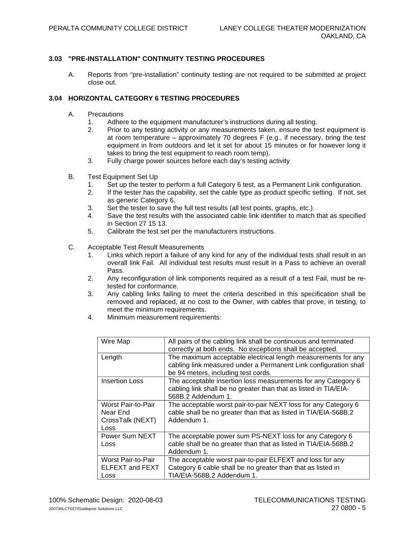
PERALTA COMMUNITY COLLEGE DISTRICT LANEY COLLEGE THEATER MODERNIZATION OAKLAND, CA
100% Schematic Design: 2020-08-03 TELECOMMUNICATIONS TESTING 200730LCT027/Guidepost Solutions LLC 27 0800 - 5
3.03 "PRE-INSTALLATION" CONTINUITY TESTING PROCEDURES
A. Reports from “pre-installation” continuity testing are not required to be submitted at project close out.
3.04 HORIZONTAL CATEGORY 6 TESTING PROCEDURES
A. Precautions 1. Adhere to the equipment manufacturer’s instructions during all testing. 2. Prior to any testing activity or any measurements taken, ensure the test equipment is
at room temperature – approximately 70 degrees F (e.g., if necessary, bring the test equipment in from outdoors and let it set for about 15 minutes or for however long it takes to bring the test equipment to reach room temp).
3. Fully charge power sources before each day’s testing activity
B. Test Equipment Set Up 1. Set up the tester to perform a full Category 6 test, as a Permanent Link configuration. 2. If the tester has the capability, set the cable type as product specific setting. If not, set
as generic Category 6. 3. Set the tester to save the full test results (all test points, graphs, etc.). 4. Save the test results with the associated cable link identifier to match that as specified
in Section 27 15 13. 5. Calibrate the test set per the manufacturers instructions.
C. Acceptable Test Result Measurements 1. Links which report a failure of any kind for any of the individual tests shall result in an
overall link Fail. All individual test results must result in a Pass to achieve an overall Pass.
2. Any reconfiguration of link components required as a result of a test Fail, must be re-tested for conformance.
3. Any cabling links failing to meet the criteria described in this specification shall be removed and replaced, at no cost to the Owner, with cables that prove, in testing, to meet the minimum requirements.
4. Minimum measurement requirements:
Wire Map All pairs of the cabling link shall be continuous and terminated
correctly at both ends. No exceptions shall be accepted. Length The maximum acceptable electrical length measurements for any
cabling link measured under a Permanent Link configuration shall be 94 meters, including test cords.
Insertion Loss The acceptable insertion loss measurements for any Category 6 cabling link shall be no greater than that as listed in TIA/EIA-568B.2 Addendum 1.
Worst Pair-to-Pair Near End CrossTalk (NEXT) Loss
The acceptable worst pair-to-pair NEXT loss for any Category 6 cable shall be no greater than that as listed in TIA/EIA-568B.2 Addendum 1.
Power Sum NEXT Loss
The acceptable power sum PS-NEXT loss for any Category 6 cable shall be no greater than that as listed in TIA/EIA-568B.2 Addendum 1.
Worst Pair-to-Pair ELFEXT and FEXT Loss
The acceptable worst pair-to-pair ELFEXT and loss for any Category 6 cable shall be no greater than that as listed in TIA/EIA-568B.2 Addendum 1.
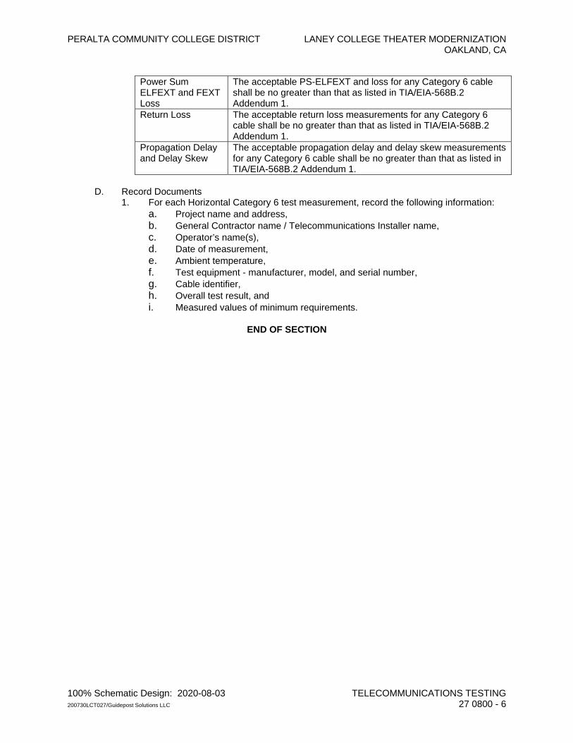
PERALTA COMMUNITY COLLEGE DISTRICT LANEY COLLEGE THEATER MODERNIZATION OAKLAND, CA
100% Schematic Design: 2020-08-03 TELECOMMUNICATIONS TESTING 200730LCT027/Guidepost Solutions LLC 27 0800 - 6
Power Sum ELFEXT and FEXT Loss
The acceptable PS-ELFEXT and loss for any Category 6 cable shall be no greater than that as listed in TIA/EIA-568B.2 Addendum 1.
Return Loss The acceptable return loss measurements for any Category 6 cable shall be no greater than that as listed in TIA/EIA-568B.2 Addendum 1.
Propagation Delay and Delay Skew
The acceptable propagation delay and delay skew measurements for any Category 6 cable shall be no greater than that as listed in TIA/EIA-568B.2 Addendum 1.
D. Record Documents 1. For each Horizontal Category 6 test measurement, record the following information:
a. Project name and address, b. General Contractor name / Telecommunications Installer name, c. Operator’s name(s), d. Date of measurement, e. Ambient temperature, f. Test equipment - manufacturer, model, and serial number, g. Cable identifier, h. Overall test result, and i. Measured values of minimum requirements.
END OF SECTION
PERALTA COMMUNITY COLLEGE DISTRICT LANEY COLLEGE THEATER MODERNIZATION OAKLAND, CA
100% Schematic Design: 2020-08-03 TELECOMMUNICATIONS HORIZONTAL PATHWAYS 200730LCT027/Guidepost Solutions LLC 27 1513 - 1
SECTION 27 1513
TELECOMMUNICATIONS HORIZONTAL PATHWAYS
PART 1 - GENERAL
1.01 SUMMARY
A. Section Includes: 1. Horizontal Cabling (subsystem of Telecommunications Cabling Infrastructure) –
Provide and install network Category 6 cable from field devices to IT/MEP rooms. Field devices include wall jacks.
1.02 RELATED SECTIONS
A. Division 26 – Basic Materials and Methods, Conduit, Cable Tray, Boxes
B. Comply with the Related Sections paragraph of Section 27 00 00.
C. Section 27 05 28 – Telecommunications Building Pathways
D. Section 27 08 00 – Telecommunications Testing
E. Products Furnished and Installed Under Another Section: 1. Conduits, sleeves, and other pathway systems for building distribution. 2. Conduit stubs and device (back) boxes for devices/outlets. 3. Surface raceway – base, cover, and device plates.
1.03 REFERENCES
A. Comply with the References requirements of Section 27 00 00.
1.04 DEFINITIONS
A. Refer to Section 27 00 00 for Definitions.
B. In addition, the following list of terms as used in this specification shall be defined as follows:
C. “CAT6”: Category 6 [F/UTP]
D. “Channel”: End to end transmission path; e.g., the entire portion of the horizontal cabling to each outlet consisting of the Permanent Link, line cord (at the workstation), patch cord, and, if a full cross-connection is implemented, the cross-connect termination/connecting apparatus and equipment cord.
E. “CMP”: Communications Media Plenum, plenum rating; synonymous with “MPP”
F. “CMR”: Communications Media Riser, riser rating; synonymous with “MPR”
G. “FEP”: Fluorinated Ethylene Propylene
PERALTA COMMUNITY COLLEGE DISTRICT LANEY COLLEGE THEATER MODERNIZATION OAKLAND, CA
100% Schematic Design: 2020-08-03 TELECOMMUNICATIONS HORIZONTAL PATHWAYS 200730LCT027/Guidepost Solutions LLC 27 1513 - 2
H. “Permanent Link”: Test configuration for a horizontal cabling link excluding test cords, connections at the ends of the test cords, patch cords, equipment cords, line cords; e.g., the ‘permanent’ portion of the horizontal cabling to each outlet consisting of cable, consolidation point (if used), termination/connecting apparatus in the Telecommunications Room and the connector at the outlet.
I. “PVC”: PolyVinyl Chloride
J. “F/UTP”: Foiled/Unshielded Twisted Pair
1.05 SYSTEM DESCRIPTION
A. Provide engineering, labor, materials, apparatus, tools, equipment, and transportation required to make a complete working telecommunications Horizontal Cabling System installation described in these specifications.
B. Consider horizontal cabling as shown on Drawings to be base bid work, unless otherwise noted.
C. In general, the scope of work includes: 1. Preconstruction Submittals. 2. Horizontal cables, terminations, and outlets. 3. Cable management. 4. Patch cords and cross-connects. 5. Cable identification tags and system labeling. 6. Record Documents. 7. Warranty.
D. The scope of work includes the following items: 1. Provide and install of network drops as identified on “TC” drawings. Areas of work
include: 2. Provide, terminate, and installation of 48 port patch panels in above rooms. 3. Provide and installation of vertical and horizontal cable management in above rooms. 4. Provide and install of patch cords with connectivity in telecommunications racks. 5. Provide, terminate and installation of RJ-45 jacks / outlets as indicated on “TC”
drawings. Outlets shall have white, blue, and green jacks depending on style.
1.06 SUBMITTALS
A. Comply with the Submittals article of Section 27 00 00 for procedural, quantity, and format requirements.
B. Preconstruction Submittal Requirements: 1. Product Data Submittal, indicating conformance with NEC, UL, TIA/EIA listings,
certifications and specifications. 2. Shop Drawings Submittal, consisting of proposed changes to cable routing, or
termination locations/configurations. 3. Typical Outlet Sample, including faceplate, faceplate label, connectors/jacks, port
labels, cables (about 12” sample), and cable label.
C. Closeout Submittal Requirements: 1. As-Built Drawings. 2. Cross-connection records/cut sheets.
PERALTA COMMUNITY COLLEGE DISTRICT LANEY COLLEGE THEATER MODERNIZATION OAKLAND, CA
100% Schematic Design: 2020-08-03 TELECOMMUNICATIONS HORIZONTAL PATHWAYS 200730LCT027/Guidepost Solutions LLC 27 1513 - 3
D. 1. O & M Manuals.
1.07 QUALITY ASSURANCE
A. Comply with the Quality Assurance requirements of Section 27 00 00.
B. Contractor Qualifications 1. In addition to the Contractor Qualifications requirements of Section 27 00 00, the
Telecommunications Installer shall be a Certified Installer, certified by equipment manufacturer and shall be capable of providing an extended warranty.
2. Provide evidence in the bid submission of certification in the manufacturer program. Evidence shall consist of a “Certification of Participation” issued by manufacturer listing the Telecommunications Installer’s company name.
1.08 DELIVERY, STORAGE AND HANDLING
A. Comply with the Delivery, Storage and Handling requirements of Section 27 00 00.
1.09 WARRANTY
A. The telecommunications horizontal cabling system, as specified in this section, shall receive a system warranty. This extended warranty shall cover parts and labor for the duration of the extended warranty. This extended warranty shall also cover electrical performance of cabling system to the specific category per ANSI/TIA/EIA-568-B performance criteria.
PART 2 - PRODUCTS:
2.01 FACEPLATES AND COVER PLATES:
A. Two position faceplate. Single gang. Color: White. Compatible with specified modular connectors.
2.02 CABLE AND WIRE:
A. Plenum rated Category 6 station cable. 4-pair unshielded twisted pair (F/UTP). 23 AWG. Cable to meet the performance characteristics of Category 6 to 500 MHz. UL Listed CMP. Jacket color: Blue.
2.03 PATCH CORD ASSEMBLIES:
A. Fiber Patch Cord: 50/125 micron fiber. Color: Orange. Minimum bandwidth: 500 MHz at both 850nm and 1300nm. Maximum attenuation is 1.00 dB at 1300nm.
B. Category 6 patch cords. Color: Matching color of jack. Patch cable shall be 8 conductor Tangle Free RJ-45 plug-to-plug.
2.04 RACKS AND RUNWAY:
A. Equipment rack: Install new racks as shown on design drawings.
B. Cable runway. Utilize runways and conduit provided by the Division 26 electrical contractor.
PERALTA COMMUNITY COLLEGE DISTRICT LANEY COLLEGE THEATER MODERNIZATION OAKLAND, CA
100% Schematic Design: 2020-08-03 TELECOMMUNICATIONS HORIZONTAL PATHWAYS 200730LCT027/Guidepost Solutions LLC 27 1513 - 4
2.05 CABLE MANAGEMENT:
A. Vertical cable manager. Utilize vertical cable management.
B. Horizontal cable manager. For routing jumpers horizontally while maintaining acceptable bend radii. 2U. Compatible with specified vertical cable manager and equipment rack. Chatsworth 30130-719 or equal.
2.06 TERMINATION HARDWARE:
A. Modular connector (Data). RJ-45 jack inserts exceeding the performance characteristics of Category 6. Compatible with specified faceplates. Color: Blue.
B. Modular connector (Voice). RJ-45 jack inserts exceeding the performance characteristics of Category 6. Compatible with specified faceplates. Color: White
C. Modular connector (WAP). RJ-45 jack inserts exceeding the performance characteristics of Category 6. Compatible with specified faceplates. Color: Green
D. Patch panel. 48-port. 19-inch rack mountable. 2U. Category 6.
2.07 MISCELLANEOUS MATERIAL:
A. Penetration Sealants: Biotherm Biofire, 3M CD25, Nelson Flameseal, Scotch/3M PSS794 or equal.
B. Labels: Brother P-Touch (TM), Panasonic, 3M or equal.
C. Anchors. Wood Surfaces: Wood screws.
D. Anchors. Concrete Surfaces. Non-post-tensioned concrete/slabs: Anchors, self-drilling. powder-driven anchors will not be acceptable unless approved in writing by the Owner and the AHJ.
E. Anchors. Concrete Surfaces. Post-tensioned concrete/slabs where equipment mass is less than to 20 lbm (pounds of mass): Wedge-type concrete inserts; nut/bolt combinations, USS 1/4 inch (minimum); additional support according to weight and listing.
F. Anchors. Concrete Surfaces. Post-tensioned concrete/slabs where equipment mass is greater than 20 lbm: Approved anchor plates according to FSD sealed and signed by a California-licensed structural engineer and the AHJ.
G. Bolts and Anchors: 1/4 inch (minimum) for equipment less than 20 lbm and 3/8 inch diameter (minimum) for all others unless otherwise specifically noted. Tighten fasteners to, and capable of withstanding, thirty ft/lb. torque (minimum); non-powder-actuated.
PERALTA COMMUNITY COLLEGE DISTRICT LANEY COLLEGE THEATER MODERNIZATION OAKLAND, CA
100% Schematic Design: 2020-08-03 TELECOMMUNICATIONS HORIZONTAL PATHWAYS 200730LCT027/Guidepost Solutions LLC 27 1513 - 5
PART 3 - EXECUTION
3.01 GENERAL
A. Comply with the Execution requirements of Section 27 00 00.
B. Install products, components, accessories, hardware, etc., according to the manufacturer’s instructions.
3.02 EXAMINATION
A. Pathways: Prior to installation, verify pathways are complete and ready for cables.
B. Equipment Rooms: Prior to installation, verify equipment rooms are complete and ready for cables.
3.03 INSTALLATION
A. Horizontal Cable 1. Cable runs shall have continuous sheath continuity, homogenous in nature. Splices
are not permitted anywhere. 2. Maintain maximum cable length of 90 meters from the termination in the
Telecommunications Room to the termination at the outlet. 3. A cable bundle shall contain no more than 24 individual cables.
3.04 INSTALLATION
A. Maintain a minimum bend radius of 6 times the cable diameter during and after installation.
B. Maintain pulling tension within manufacturer's limits.
C. Protect cable during installation. Replace cable if damaged during installation.
D. Place cables with no kinks, twists, or impact damage to the sheath.
E. Place and suspend cables in a manner to protect them from physical interference or damage.
F. Routing 1. When routing horizontally within Telecommunications Room, utilize the overhead
cable support. When routing vertically within Telecommunications Room, fasten the cable bundles using approved cable ties to the wall-mounted vertical cable support every 24 inches on center.
2. Route cables a minimum of 6" away from power sources to reduce interference from EMI.
3. When routing cables in areas without primary horizontal pathways, install cables onto secondary pathways or approved support devices, such as cable hangers.
4. Route cables at 90-degree angles, allowing for bending radius along corridors for ease of access. Do not route through an adjacent space if a corridor borders at least one wall of the room.
5. Provide a 10 feet (minimum) sheathed cable slack loop at each end of the run. In the Telecommunications Room, place the slack in the overhead cable support. At the workstation, place cable in ceiling space before the device conduit stub supported from a cable hanger.
PERALTA COMMUNITY COLLEGE DISTRICT LANEY COLLEGE THEATER MODERNIZATION OAKLAND, CA
100% Schematic Design: 2020-08-03 TELECOMMUNICATIONS HORIZONTAL PATHWAYS 200730LCT027/Guidepost Solutions LLC 27 1513 - 6
6. Provide six inches (minimum) of sheathed cable slack behind each workstation outlet faceplate. The slack cable shall be coiled inside the device box, the surface raceway, or within the wall, in accordance with the cabling manufacturer's installation standards.
7. At the equipment bay in the Telecommunications Room where floor-standing racks are used, divide horizontal cables equally between both sides of an equipment rack such that a cable does not travel past the midpoint of the rack prior to termination.
G. Termination 1. Properly (per manufacturer’s instructions and TIA/EIA-568-B standard installation
practices) strain relieve cables at termination points. 2. Terminate pairs on the specified connecting hardware. Perform terminations in
accordance with manufacturer’s instructions and TIA/EIA-568-B standard installation practices.
H. Patch Panels and Horizontal Management Panels 1. Provide discrete patch panels in a quantity to allow termination of data cables served
from respective IDF. 2. Install the discrete patch panels and horizontal management panels in the
configuration as shown on the Drawings. Install panels level.
I. Outlet Faceplates 1. Install faceplates plumb, square, and at the same level as adjacent device faceplates. 2. Patch gaps around faceplates so that faceplate covers the entire opening. 3. For surface raceway, color shall match electrical device and/or cover plate.
J. Outlet Modular Connectors 1. Terminate pairs on the specified modular connector. Perform terminations in
accordance with manufacturer’s instructions and TIA/EIA-568-B standard installation practices.
2. Replace terminations and connectors not passing the required media test.
K. Cords and Crossconnects 1. Coordinate with Owner for cord (workstation, Telecom Room, and other) patching and
crossconnecting requirements. 2. Splices in patch cords and crossconnect wire are prohibited. 3. Record crossconnections in IDFs crossconnection purposes and for record
documents.
3.05 LABELING
A. General Requirements 1. Labeling, identifier assignment, and label colors shall conform to TIA/EIA-606-A
Administration Standard and as approved by Owner’s Representative before installation.
2. Labels shall be permanent with machine-generated text; hand-written labels will not be accepted.
B. Label Formats 1. Horizontal Cable Labels
C. Modular Patch Panel Labels 1. Use modular patch panel labels included in the product packaging. (Approval by the
Owner shall be required for other labels.) 2. Use a label color for the respective field type, per TIA/EIA-606.
PERALTA COMMUNITY COLLEGE DISTRICT LANEY COLLEGE THEATER MODERNIZATION OAKLAND, CA
100% Schematic Design: 2020-08-03 TELECOMMUNICATIONS HORIZONTAL PATHWAYS 200730LCT027/Guidepost Solutions LLC 27 1513 - 7
3. Text Attributes: Black, 3/32” high, minimum, or #10 font size.
D. Outlet Labels 1. Text Attributes: Black, 1/8” high, minimum, or #12 font size. 2. Provide an “Equipment Room Identifier” label at the top of the faceplate with the
serving telecommunication room’s identifier. 3. Provide a “Unique Cable Number” label above each port with the link’s unique cable
number. 4. Identifier AssignmentHorizontal Cables / Cabling Link 5. Assign each cable a unique number, in ascending order beginning with the number 1.
E. Outlet Ports 1. The outlet ports shall be identical to the unique cable number.
F. Modular Patch Panel Ports 1. The modular patch panel ports shall be identical to the unique cable number.
3.06 FINAL INSPECTION
A. Inspect installed products and work in conjunction with the Owner. Develop a punch-list for items needing correction.
B. Issue punch-list to the Owner for review prior to performing punch-list walk.
C. Repair defects prior to system acceptance.
D. Inspect installed products and work in conjunction with the Owner for sign off.
END OF SECTION

PERALTA COMMUNITY COLLEGE DISTRICT LANEY COLLEGE THEATER MODERNIZATION OAKLAND, CA
100% Schematic Design: 2020-08-03 ELECTRONIC SAFETY AND SECURITY 200730LCT027/Guidepost Solutions LLC 28 0000 - 1
SECTION 28 0000
ELECTRONIC SAFETY AND SECURITY
PART 1 - GENERAL
1.01 SUMMARY
A. This Section includes general administrative and procedural requirements for Division 28 Sections, and is intended to supplement, not supersede, the requirements specified in Division 1.
1.02 RELATED SECTIONS
A. General: Consult all other Sections, determine the extent and character of related work, and properly coordinate work specified herein with that specified elsewhere to produce a complete and operable system.
B. Related Sections: 1. Section 28 05 13: Conductors and Cabling for Electronic Security and Safety 2. Section 28 05 53: Identification for Electronic Security and Safety 3. Section 28 10 00: Access Control 4. Section 28 20 00: Video Surveillance
C. General and Supplementary Conditions: Drawings and general provisions of Contract and Division 1 of the Specifications, apply to Division 28 Sections.
1.03 REFERENCES
A. Reference to codes, standards, specifications and recommendations of technical societies, trade organizations and governmental agencies shall mean that latest edition of such publications adopted and published prior to submittal of the bid. Consider such codes or standards a part of this Specification as though fully repeated herein.
B. Codes: Perform work in accordance with all applicable requirements of the latest edition of all governing codes, rules and regulations including but not limited to the following minimum standards, whether statutory or not: 1. National Electric Code (NEC), NFPA 70. 2. California Code of Regulations (CCR) Title 24, California Building Standards Code
Part 2, Basic Building Regulations and Part 3, California Electrical Code (CEC). 3. California Building Code (CBC). 4. California Fire Code (CFC). 5. California Mechanical Code (CMC). 6. National, State and any other binding building and fire codes. 7. FCC Regulations: 8. Underwriter's Laboratories (UL): Applicable listing and ratings. 9. Electronic Industry Association (EIA) testing standards 10. Americans with Disabilities Act (ADA) 11. American Standard Code for Information Interchange (ACSI) 12. American Society for Testing and Materials (ATSM) 13. National Electrical Manufacturers' Association (NEMA) 14. National Fire Protection Association (NFPA)
PERALTA COMMUNITY COLLEGE DISTRICT LANEY COLLEGE THEATER MODERNIZATION OAKLAND, CA
100% Schematic Design: 2020-08-03 ELECTRONIC SAFETY AND SECURITY 200730LCT027/Guidepost Solutions LLC 28 0000 - 2
C. Make a copy of each document readily available during the course of construction for reference by field personnel.
1.04 DEFINITIONS
A. The Definitions of Division 1 shall apply to the Division 28 Sections
B. In addition to those Definitions of Division 1, the following list of terms as used in this specification shall be defined as follows: 1. "Furnish": To purchase, procure, acquire, and deliver complete with related
accessories. 2. "Install": To set in place, join, unite, fasten, link, attach, set up or otherwise connect
together and test before turning over to the Owner, all parts, items, or equipment supplied by contractor. Installation shall be complete and ready for regular operation.
3. "Provide": To furnish, transport, install, erect, connect, test and turn over to the Owner, complete and ready for regular operation.
4. "Connect": To install all required patch cords, equipment cords, cross-connect wire, etc. to complete an electrical or optical circuit.
5. "As directed": As directed or instructed by the Owner, or their authorized representative.
6. "Cabling": A combination of all cables, wire, cords, and connecting hardware [e.g., cables, conductor terminations, connectors, outlets, patch panels, blocks, and labeling].
7. “ACAMS”: Access Control & Alarm Monitoring System 8. “VSS”: Video Surveillance System
1.05 SYSTEM DESCRIPTION
A. Overview 1. Access Control (Section 28 10 00) 2. Video Surveillance (Section 28 20 00)
B. Drawings
1.06 SUBMITTALS
A. General: Submit required submittal(s) in accordance with General Conditions of the Contract, and Division 1 Submittal Procedures.
B. Cover Letter: Include a cover letter stating that the submittal is in full compliance with the requirements of the Contract Documents. List in full the items and data submitted, signed (and stamped, if applicable) by the person who prepared the submittal. Failure to comply with this requirement shall constitute grounds for rejection of submittal.
C. Submittal Description: Product Data 1. General: Product data submittals must be approved by the Owner prior to release of
order for equipment and prior to installation. 2. Quantity: As noted in Division 1. 3. Format: 4. Content:
D. Submittal Description: Shop Drawings 1. General: The Owner must approve shop drawings prior to release of order for
equipment and prior to installation.
PERALTA COMMUNITY COLLEGE DISTRICT LANEY COLLEGE THEATER MODERNIZATION OAKLAND, CA
100% Schematic Design: 2020-08-03 ELECTRONIC SAFETY AND SECURITY 200730LCT027/Guidepost Solutions LLC 28 0000 - 3
2. Quantity & Media: Furnish quantity and on media specified in Division 1. 3. Content: 4. Point-to-Point Diagrams: Include all wiring, points of connection and interconnecting
devices. 5. Block Diagram/Riser Diagram: Show the system components and all conduit and wire
types and sizes between them including all cabling interface between termination hardware.
6. Installation Details: Include installation details for all devices. 7. Seismic Calculations: As part of the shop drawings submittal where applicable, the
manufacturer shall provide anchorage calculations for floor mounted fully loaded distribution frames such that it shall remain attached to the mounting surface after experiencing forces in conformance with Section 2312 "Earthquake Regulations" of the "Uniform Building Code" for Seismic Zone 4 Area, Importance Factor of 1.25. Structural Calculations shall be prepared and signed by a Registered Structural Engineer. Specify proof loads for drilled-in anchors, if used. Seismic calculation shop drawings shall be wet stamped and signed by a registered structural engineer.
8. Calculations:
E. Submittal Description: Labeling Sample 1. Quantity & Media: Furnish quantity indicated in Division 1. 2. Submit two sets of physical product samples for review and comment by Owner prior
to the installation of equipment: 3. Content: 4. Provide panel label 5. Provide cable label on a cut length of cable.
F. Submittal Description: As-Built Drawings 1. Quantity & Media: Submit four sets of Record Drawings. 2. Upon receipt of the Owner’s review comments, make corrections and furnish the
following as-built drawings: 3. Format: 4. Content:
G. Submittal Description: Operation and Maintenance Manuals 1. Quantity: Furnish four O & M Manuals. 2. Format: 3. Content: 4. Hardware Manual which includes: 5. Operator’s Manual which full explains all procedures and instructions for the operation
of the system and includes: 6. Maintenance Manual which includes: 7. Record Drawings Manual: 11”x17” prints of Record Drawings, as described above.
H. Resubmittals: Include a cover letter listing the action taken and revisions made to each product submittal in response to Submittal Review Comments. Resubmittal packages will not be reviewed unless accompanied by this cover letter. Failure to include this cover letter will constitute rejection of the resubmittal package.
I. Submittals must be complete. Owner reserves the right to reject any submittals determined to be incomplete.
PERALTA COMMUNITY COLLEGE DISTRICT LANEY COLLEGE THEATER MODERNIZATION OAKLAND, CA
100% Schematic Design: 2020-08-03 ELECTRONIC SAFETY AND SECURITY 200730LCT027/Guidepost Solutions LLC 28 0000 - 4
1.07 QUALITY ASSURANCE
A. All equipment supplied shall be listed by a nationally recognized test laboratory where applicable.
B. All equipment and accessories to be the product of a manufacturer regularly engaged in its manufacture.
C. All items of a given type shall be the products of the same manufacturer.
D. All items shall be of the latest technology; no discontinued models or products are acceptable.
E. The manufacturer, or their Authorized Representative, shall confirm that within 300 miles of the project site there is an established agency which: 1. Stocks a full compliment of parts 2. Offers service during normal working hours as well as emergency service on all
equipment to be furnished 3. Will supply parts and service without delay and at reasonable cost. 4. Contractor shall be capable of performing service or maintenance work on these
specified or accepted systems. Contractor shall be factory-certified where such certification is available.
1.08 PRODUCT DELIVERY, STORAGE AND HANDLING
A. Delivery 1. Do not deliver products to the site until protected storage space is available.
Coordinate delivery of materials with scheduled installation date to allow minimum storage time at jobsite.
2. Deliver materials in manufacturer's original, unopened, undamaged containers with identification labels (name of the manufacturer, product name, type, grade, UL classification, etc.) intact.
3. Replace materials damaged during shipping at no cost to the Owner.
B. Storage 1. Store materials in clean, dry, ventilated space free from temperature and humidity
conditions (as recommended by manufacturer) and protected from exposure to harmful weather conditions.
2. Comply with manufacturer's requirements for each product. Comply with recommended procedures, precautions or remedies as described in the Material Safety Data Sheets (MSDS) as applicable.
3. Maintain factory wrapping or provide a heavy canvas/plastic cover to protect units from dirt, water, construction debris, and traffic.
4. Storage outdoors covered by rainproof material is not acceptable. 5. Provide heat where required to prevent condensation or temperature related damage.
C. Handling 1. Handle in accordance with manufacturer's written instructions. 2. Damaged equipment shall not be installed. 3. Replace damaged equipment at no cost to the Owner. 4. Handle with care to prevent internal component damage, breakage, denting, and
scoring.
PERALTA COMMUNITY COLLEGE DISTRICT LANEY COLLEGE THEATER MODERNIZATION OAKLAND, CA
100% Schematic Design: 2020-08-03 ELECTRONIC SAFETY AND SECURITY 200730LCT027/Guidepost Solutions LLC 28 0000 - 5
1.09 SUBSTITUTIONS
A. All materials and equipment shall conform to these specifications. No substitute materials may be used, unless previously accepted in writing by the Architect.
B. Manufacturers listed as acceptable are normally engaged in the type of work specified. The listing of equipment part numbers or particular types of systems by specific manufacturers is to establish the performance quality, type, and parameters of the equipment and material specified. The equipment shall be as specified or equal products substituted under provisions of Section 01 25 00.
1.10 WARRANTY
A. Installation, equipment, and all parts and labor are guaranteed by Contractor and manufacturer for one year from written notification of acceptance by the Owner.
B. The installing Contractor shall provide, upon notification of a problem, a field service technician to correct the problem within 24 hours of notification.
C. At least 60 days prior to expiration of guarantee, provide maintenance contract proposals for a second year of service for each system to Owner.
PART 2 - PRODUCTS
2.01 SECURITY SYSTEM PRODUCTS 1. Refer to individual Security System sub-sections for product details.
2.02 SPARE PARTS
A. Prior to completion of the job, provide spare parts to Owner as detailed in each System sub-section.
PART 3 - EXECUTION
3.01 REQUIREMENTS
A. Systems shall be complete and operational in all respects.
B. Provide all conduit, conductors, etc. for all building Systems. All wiring shall be in raceway unless shown otherwise on the drawings.
C. Wiring and conduit shown on drawings represents a minimum requirement. Contractor shall furnish and install all wiring and conduit recommended by submitted system manufacturers for optimum system performance at no additional cost to the Owner.
D. Connect power to Systems as required.
E. All equipment, junction boxes, terminal cans, etc. shall be installed utilizing tamper proof mounting hardware. Provide a minimum of 2 driver bits or hand tools for each type of security fastener provided.
PERALTA COMMUNITY COLLEGE DISTRICT LANEY COLLEGE THEATER MODERNIZATION OAKLAND, CA
100% Schematic Design: 2020-08-03 ELECTRONIC SAFETY AND SECURITY 200730LCT027/Guidepost Solutions LLC 28 0000 - 6
F. Provide seismic restraint for all equipment, including equipment racks, consoles, etc. Refer to Division 16 for seismic restraint requirements.
G. Refer to individual Security System sub-sections for additional installation requirements.
3.02 TRAINING
A. As a part of this contract, provide training as described herein and detailed under each System sub-section.
B. Training shall be by engineers or technicians highly skilled in the systems and certified by manufacturer as qualified to train in the associated systems.
C. Training shall be conducted at dates and times directed by the Owner's representative. Initial training shall be provided for the security director and consultant. Upon their approval, a second training session shall be provided for security officers. An additional training session for officers shall be provided within the first year after system acceptance. Provide specific training sessions for Owner's maintenance personnel. After-hours training shall be provided at no additional cost if requested by the Owner.
D. Verification of completion of training is required by the Owner prior to release of retention compensation.
3.03 PROGRAMMING
A. Provide initial programming for all applicable systems. Programming shall include, but not be limited to: 1. English-language description of each alarm point. 2. Access Control System alarm-based camera call-up.
B. Submit to the Owner’s Representative for Owner's review proposed programming, including device names and descriptions, timings, sequence of operations, sample audio messages, etc.
C. Upon Owner's request, each system shall be reprogrammed by the Building Security Electronic Systems Contractor one time during the warranty period at no additional cost.
3.04 COMMISSIONING, ACCEPTANCE TESTING AND REPORTS
A. There are two distinct types of tests for which the Contractor is responsible: 1. The first type is the Pre-functional Performance Test. These tests ensure that all
equipment, wiring, and systems are installed in accordance with the Specifications, Plans, and Manufacturers’ requirements.
2. The second type of test is the Functional Performance Test. These tests ensure that all equipment and systems operate in accordance with design intent. These are dynamic tests, and test the systems through all possible modes of operation.
B. Provide a written testing plan describing proposed duration and schedule for performing pre-functional performance tests and functional performance tests in spreadsheet format listing each and every device, cable/wire, and software point to be tested. Submit the testing plans for approval prior to commissioning and acceptance testing.
C. Perform systems tests using personnel who have attended a manufacturer's training school for installation and testing of the systems as described above. Perform testing with the test
PERALTA COMMUNITY COLLEGE DISTRICT LANEY COLLEGE THEATER MODERNIZATION OAKLAND, CA
100% Schematic Design: 2020-08-03 ELECTRONIC SAFETY AND SECURITY 200730LCT027/Guidepost Solutions LLC 28 0000 - 7
instruments as required by the manufacturer; testing by means other than the manufacturer's procedures will not be acceptable unless agreed to by the Engineer and manufacturer.
D. Upon completion of the installation of the Security Systems, the contractor shall perform 100% testing and submit pre-functional reports including, but not limited to, the following information in spreadsheet format: 1. A complete list of all equipment installed, including serial numbers of major
components. 2. Certification that all equipment is properly installed and functional, and conforms with
contract Specifications and Plans. 3. Test reports of all inputs and outputs, devices, and equipment. 4. Test technician's name, company, and dates of test.
E. Following review of the Pre-functional test reports by the Engineer, the contractor shall perform a functional test of all Security System equipment in the presence of the Engineer. Test shall include performance tests of each device, switch, control unit, power supply, battery standby unit, monitor panel, controller, printer, and all other equipment and material required by the contract. At a minimum, perform tests to demonstrate that: 1. All systems are free from grounding and open circuits. 2. Each alarm-initiating device consistently functions as specified and produces the
specified alarm actions. 3. An abnormal condition of any circuit or device required to be electrically supervised
will result in activating the specified trouble or tamper alarm signal. 4. Systems operate properly during and while on emergency generator power. 5. Alarm signals are audible at the monitor. 6. The system is operable under specified trouble conditions.
END OF SECTION

PERALTA COMMUNITY COLLEGE DISTRICT LANEY COLLEGE THEATER MODERNIZATION OAKLAND, CA
100% Schematic Design: 2020-08-03 200730LCT027/Guidepost Solutions LLC 28 0513 - 1
SECTION 28 0513
CONDUCTORS AND CABLES FOR ELECTRONIC SAFETY AND SECURITY
PART 1 - GENERAL
1.01 SUMMARY
A. General: Furnish engineering, labor, materials, apparatus, tools, equipment, transportation, temporary construction and special or occasional services as required to make a complete working security system installation, as described in these specifications.
B. Section Includes: 1. Wiring and cable
C. Related Sections: 1. Consult other Divisions; determine the extent and character of related work and
properly coordinate work specified herein with that specified elsewhere to produce a complete and operable system.
2. Section 28 05 53 - Identification for Electronic Safety and Security 3. Section 28 13 00 - Access Control and Alarm Monitoring System 4. Section 28 23 00 - Video Surveillance System
1.02 SUBMITTALS
A. Submit in accordance with the requirements of Section 28 00 00 Electronic Safety and Security Requirements, the following items: 1. Product Data
PART 2 - PRODUCTS
2.01 WIRE AND CABLE
A. General 1. Provide all necessary cable supports and J-Hangers dedicated for security cable 2. Do not share conduits with fire alarm or telecommunications systems. 3. Provide required wire and cable sized to allow for voltage drop on long runs and
effectively shielded as required to allow the routing of 12 & 24V power and video signal cable in the same conduit without interference or signal noise.
4. Cable installed outdoors or in underground conduit must contain a PVC or Polyethylene jacket, flooded to prevent water intrusion.
5. Cables installed outdoors or in underground conduit that transition into the building and run in plenum space to contain a plenum-rated (type CMP) jacket and contain water block material to prevent water intrusion.
6. Cables installed indoors to contain a plenum rated jacket (type CMP). 7. Manufacturers:
2.02 ETHERNET COPPER NETWORK CABLING
A. Category 6 station cable. 4-pair unshielded twisted pair (UTP). 23 AWG. Cable to meet the performance characteristics of Category 6 to 450 MHz. UL Listed CMP. Jacket color: Green. General Cable model Genspeed 6000, or equal.
PERALTA COMMUNITY COLLEGE DISTRICT LANEY COLLEGE THEATER MODERNIZATION OAKLAND, CA
100% Schematic Design: 2020-08-03 200730LCT027/Guidepost Solutions LLC 28 0513 - 2
2.03 CATEGORY 6 HORIZONTAL CABLE TESTER
A. Equipment shall meet TIA/EIA-568B.2 Addendum 1 requirements for Level III accuracy.
B. Test Standards (minimum): TIA Category 6 (per TIA/EIA-568B.2 Addendum 1); ISO/IEC 11801 Class C and D; ISO/IEC 11801-2000 Class C and D, 1000Base-T, 100Base-TX; IEEE 802.3 10Base-T; ANSI TP-PMD; IEEE 802.5.
C. Areas of Test Measurement (minimum): Wire Map; Length; Insertion Loss; Near End Crosstalk (NEXT) loss, at both master unit and remote unit; Power Sum NEXT (PSNEXT) loss, at both master unit and remote unit; Equal Level Far End Crosstalk (ELFEXT), at both master unit and remote unit; Power Sum ELFEXT, at both master unit and remote unit; Return Loss (RL), at both master unit and remote unit; Propagation Delay and Delay Skew; Attenuation-to-Crosstalk Ratio (ACR), at both master unit and remote unit; Power Sum ACR (PSACR), at both master unit and remote unit; Characteristic Impedance; DC Loop Resistance.
D. Equipment: Agilent Technologies 1. #N2600A-100; “WireScope 350” test kit (main unit, remote unit, CAT6 permanent link
probe, CAT6 channel probe, accessories), loaded with firmware version 3.1.1. 2. “ScopeData Pro” reporting and documentation software latest version.
E. Equipment: Fluke Networks 1. #DTX-1200 or #DTX-1800; “DTX CableAnalyzer” test kit (main unit, remote unit,
CAT6 permanent link adapters, CAT6 channel adapters, accessories), loaded with latest version of firmware.
2. #DSP-4300; “CableAnalyzer” test kit (main unit, remote unit, CAT6 permanent link adapters, CAT6 channel adapters, accessories), loaded with firmware version 3.0.4.
3. “LinkWare” reporting and documentation software (version 1.1, or higher)
F. Access Control System 1. Provide plenum rated cable by Westpenn, Belden, Commscope, or equal. 2. Category 6 station cable. 4-pair unshielded twisted pair (UTP). 23 AWG. Cable to
meet the performance characteristics of Category 6 to 450 MHz. UL Listed CMP. Jacket color: Green. General Cable model Genspeed 6000. Power over Ethernet (PoE) connection from network switch to integrated PoE door lock/card reader or access control system edge reader adapter.
3. #18/4 conductor unshielded: door contacts, glass break detectors, rex detectors 4. #16/2 AWG unshielded: low current lock power 5. #16/2 AWG unshielded: Lock power to Exit Device (panic hardware) 6. #18/2 AWG unshielded: Low current relays and card reader power 7. #22/4 OSDP RS-485 (Belden 3107A or equal) 8. #18/8 conductor unshielded: Door Management and Exit Alarms
G. Video Surveillance System 1. Network cable: PoE connection from network switch to IP camera and other devices
requiring communication via the County-wide network. 2. Category 6 station cable. 4-pair unshielded twisted pair (UTP). 23 AWG. Cable to
meet the performance characteristics of Category 6 to 450 MHz. UL Listed CMP. Jacket color: Green. General Cable model Genspeed 6000.
PERALTA COMMUNITY COLLEGE DISTRICT LANEY COLLEGE THEATER MODERNIZATION OAKLAND, CA
100% Schematic Design: 2020-08-03 200730LCT027/Guidepost Solutions LLC 28 0513 - 3
PART 3 - EXECUTION
3.01 INSTALLATION
A. Identify all wire and cable clearly with permanent labels wrapped about the full circumference within one (1) inch of each connection. Indicate the number designated on the associated field or shop drawings or run sheet, as applies. Assign wire or cable designations consistently throughout a given system; i.e., each wire or cable shall carry the same labeled designation over its entire run, regardless of intermediate terminations. Additionally, provide labels where wire and cable first enter and exit from conduit, junction or distribution boxes; labels shall be located within six (6) inches of the point of exit. Labels shall be by Brady, Thomas and Betts, or equal.
B. Secure all wire and cable run vertically in conduit for continuous distances greater than thirty (30) feet at the vertical run terminations. Non coaxial cables shall be secured by screw flange nylon cable ties or similar approved devices, Thomas and Betts or equal. Symmetrical clamping devices with split, circular or other wire conforming, nonmetallic bushings shall be provided for all other cables.
C. All wire and cable shall be continuous and splice free for the entire length of run between designated connections or terminations.
D. Make all connections to screw type barrier strips on panels and with insulated crimp type spade lugs when appropriate. Size all lugs properly to assure high electrical integrity, i.e., low resistance connections.
E. Lace, tie or harness wire or cable as required herein, and in accordance with accepted professional practice. Dress, lace or harness all wire and cable to prevent mechanical stress on electrical connections; no wire or cable shall be supported by a connection point.
F. Wiring for shielding certain conductors from others or routing in separate raceways, shall be as recommended by the manufacturer's current requirements.
G. All wiring shall be installed in a continuous steel conduit system when not located above accessible ceiling and shall be of the size recommended by the equipment supplier.
H. Provide all necessary tie wires.
I. Label all cables at both ends of a run and within all pull and junction boxes using machine generated wrap-around labels.
J. Follow manufacturers recommended guidelines for installation.
3.02 HORIZONTAL CATEGORY 6 TESTING PROCEDURES
A. Precautions 1. Adhere to the equipment manufacturer’s instructions during all testing. 2. Prior to any testing activity or any measurements taken, ensure the test equipment is
at room temperature – approximately 70 degrees F (e.g., if necessary, bring the test equipment in from outdoors and let it set for about 15 minutes or for however long it takes to bring the test equipment to reach room temp).
3. Fully charge power sources before each day’s testing activity
B. Test Equipment Set Up
PERALTA COMMUNITY COLLEGE DISTRICT LANEY COLLEGE THEATER MODERNIZATION OAKLAND, CA
100% Schematic Design: 2020-08-03 200730LCT027/Guidepost Solutions LLC 28 0513 - 4
1. Set up the tester to perform a full Category 6 test, as a Permanent Link configuration. 2. If the tester has the capability, set the cable type as product specific setting. If not, set
as generic Category 6. 3. Set the tester to save the full test results (all test points, graphs, etc.). 4. Save the test results with the associated cable link identifier to match that as
specified. 5. Calibrate the test set per the manufacturer’s instructions.
C. Acceptable Test Result Measurements 1. Links which report a Fail, Fail* or Pass* for any of the individual tests shall result in an
overall link Fail. All individual test results must result in a Pass to achieve an overall Pass.
2. Any reconfiguration of link components required as a result of a test Fail, must be re-tested for conformance.
3. Any cabling links failing to meet the criteria described in this specification shall be removed and replaced, at no cost to the Owner, with cables that prove, in testing, to meet the minimum requirements.
4. Minimum measurement requirements: Wire Map All pairs of the cabling link shall be continuous and terminated
correctly at both ends. No exceptions shall be accepted. Length The maximum acceptable electrical length measurements for any
cabling link measured under a Permanent Link configuration shall be 94 meters, including test cords.
Insertion Loss The acceptable insertion loss measurements for any Category 6 cabling link shall be no greater than that as listed in TIA/EIA-568B.2 Addendum 1.
Worst Pair-to-Pair Near End CrossTalk (NEXT) Loss
The acceptable worst pair-to-pair NEXT loss for any Category 6 cable shall be no greater than that as listed in TIA/EIA-568B.2 Addendum 1.
Power Sum NEXT Loss
The acceptable power sum PS-NEXT loss for any Category 6 cable shall be no greater than that as listed in TIA/EIA-568B.2 Addendum 1.
Worst Pair-to-Pair ELFEXT and FEXT Loss
The acceptable worst pair-to-pair ELFEXT and loss for any Category 6 cable shall be no greater than that as listed in TIA/EIA-568B.2 Addendum 1.
Power Sum ELFEXT and FEXT Loss
The acceptable PS-ELFEXT and loss for any Category 6 cable shall be no greater than that as listed in TIA/EIA-568B.2 Addendum 1.
Return Loss The acceptable return loss measurements for any Category 6 cable shall be no greater than that as listed in TIA/EIA-568B.2 Addendum 1.
Propagation Delay and Delay Skew
The acceptable propagation delay and delay skew measurements for any Category 6 cable shall be no greater than that as listed in TIA/EIA-568B.2 Addendum 1.
D. Record Documents 1. For each Horizontal Category 6 test measurement, record the following information:
END OF SECTION
PERALTA COMMUNITY COLLEGE DISTRICT LANEY COLLEGE THEATER MODERNIZATION OAKLAND, CA
100% Schematic Design: 2020-08-03 IDENTIFICATION FOR ELECTRONIC SAFETY AND SECURITY 200730LCT027/Guidepost Solutions LLC 28 0553 - 1
SECTION 28 0553
IDENTIFICATION FOR ELECTRONIC SAFETY AND SECURITY
PART 1 - GENERAL
1.01 SUMMARY
A. General: Furnish engineering, labor, materials, apparatus, tools, equipment, transportation, temporary construction and special or occasional services as required to make a complete working security system installation, as described in these specifications.
1.02 SECTION INCLUDES
A. Labeling
1.03 RELATED SECTIONS
A. Consult other Divisions, determine the extent and character of related work and properly coordinate work specified herein with that specified elsewhere to produce a complete and operable system.
B. Section 28 00 00 Electronic Safety and Security
C. Section 28 05 13 Conductors for Electronic Safety and Security
D. Section 28 13 00 Access Control
E. Section 28 23 00 Video Surveillance
1.04 SUBMITTALS
A. Submit in accordance with the requirements of Section 28 00 00: Electronic Safety and Security Requirements, the following items: 1. Product Data 2. Label Samples: Submit the following for review and comment prior to the and 3. installation of equipment:
PART 2 - PRODUCTS
2.01 LABELS
A. Phenolic two-tone for exterior mounting on Enclosures. White lettering on black background.
2.02 WIRE AND CABLE LABELS
A. Provide self-laminating adhesive laser labels.
B. Labels shall be machine printable with a laser printer.
C. Text Attributes:
PERALTA COMMUNITY COLLEGE DISTRICT LANEY COLLEGE THEATER MODERNIZATION OAKLAND, CA
100% Schematic Design: 2020-08-03 IDENTIFICATION FOR ELECTRONIC SAFETY AND SECURITY 200730LCT027/Guidepost Solutions LLC 28 0553 - 2
PART 3 - EXECUTION
3.01 INSTALLATION
A. Label all wiring and equipment.
B. Identify wire and cable clearly with permanent labels wrapped about the full circumference within one (1) inch of each connection. Indicate the number designated on the associated field or shop drawings or run sheet, as applies. Assign wire or cable designations consistently throughout a given system; i.e., each wire or cable shall carry the same labeled designation over its entire run, regardless of intermediate terminations. Additionally, provide labels where wire and cable first enter and exit from conduit, junction or distribution boxes; labels shall be located within six (6) inches of the point of exit.
C. Label all cables at both ends of a run and within all pull and junction boxes using machine generated wrap-around labels.
D. Boxes, Panels, and Enclosures
3.02 LABELING
A. General Requirements 1. Physically label all of the security system components. The components include, but
are not limited to, the following: 2. The ends of all cables must be permanently marked with machine-generated or
stenciled (not handwritten) wrap around labels with a self-laminating feature, according to current practice and as approved by Owner before installation.
3. Components, such as racks and patch panels, must be permanently marked with machine-generated labels, according to current practices and as approved by the Owner before installation.
4. Labels shall coincide with device id’s used on the record drawings.
B. Equipment Enclosures 1. Label all Enclosures, alarm monitoring, and powers supply enclosures associated with
the security system with an adhesive backed phenolic label. Use 12 point text. 2. Labels shall be represented in and match the security system record drawings.
C. Security Devices 1. Label all equipment associated with the security system with a permanent machine
generated, laminated, label. Use 12 point text with a clear background. Use white or black lettering depending upon the color of the device.
2. Label device in a concealed location with the system point number and address. 3. Label power supply batteries with the month and year they were installed.
D. Wire and Cable 1. Label all wire and cable associated with the security system with permanent machine
generated, laminated, labels. Use 12 point, black text on a white label. 2. All wire and cable labels shall be clearly visible without the need to remove wire
management or any other obstructions.
E. Cable Label Format 1. Obtain label format document from Owner.
END OF SECTION
PERALTA COMMUNITY COLLEGE DISTRICT LANEY COLLEGE THEATER MODERNIZATION OAKLAND, CA
100% Schematic Design: 2020-08-03 ACCESS CONTROL 200730LCT027/Guidepost Solutions LLC 28 1000 - 1
SECTION 28 1000
ACCESS CONTROL
PART 1 - GENERAL
1.01 SECTION INCLUDES
A. Materials, equipment fabrication, installation, and tests in conformity with applicable codes and authorities having jurisdiction for the following: 1. Expand the existing Access Control System as shown on Drawings. 2. Provide all conduit, raceways, cables, backboxes, card readers, cards, controllers,
alarm contacts, glass break detectors, programming, software, licenses, and upgrades needed to achieve a complete and functional system. Also included are all required power supplies, power filtering, mounts, housings, equipment stand, and interfaces to equipment furnished by others.
3. Configure system to allow access with the presentation of a valid access card. A door contact shall indicate to the system that a door has been opened and closed and a Request to Exit device will indicate egress. The system shall be able to detect a forced or held door and indicate in several ways the open or closed condition of the door. The system shall record and store all events and transactions and provide a means to review an event log that has unlimited storage capacity.
4. Provide new card readers. 5. Provide card reader controllers and other equipment as required. 6. Coordinate system requirements with the Owner’s IT department. 7. Establish system communication with the Access Control System Server and panels
via the Owner’s LAN/WAN network. 8. Provide required interface relays, materials, and cabling to the fire alarm control
panel. 9. Provide installation, testing, adjustment, and initial programming for all equipment. 10. Provide written documentation and instructions for system as installed. 11. Provide training to the Owner in the operation, adjustment, servicing, and repair of this
system.
B. Refer to Section 28 00 00 for Submittal, Substitution, and Warranty requirements.
1.02 RELATED SECTIONS
A. General: Consult all other Sections, determine the extent and character of related work, and properly coordinate work specified herein with that specified elsewhere to produce a complete and operable system.
B. Related Sections: 1. Section 28 05 13 Conductors and Cabling for Electronic Safety and Security 2. Section 28 05 53 Identification for Electronic Safety and Security 3. Section 28 23 00 Video Surveillance
C. General and Supplementary Conditions: Drawings and general provisions of Contract and Division 1 of the Specifications, apply to Division 28 Sections.
PERALTA COMMUNITY COLLEGE DISTRICT LANEY COLLEGE THEATER MODERNIZATION OAKLAND, CA
100% Schematic Design: 2020-08-03 ACCESS CONTROL 200730LCT027/Guidepost Solutions LLC 28 1000 - 2
PART 2 - PRODUCTS
2.01 ACCESS CONTROL PRODUCTS
A. System Specifications 1. Manufacturer’s catalog and system numbers of equipment listed in this specification
indicate type, quality, and functions of the equipment required, and represent the minimum acceptable standards. Provide all compatible parts for the submitted system. Verify accessibility requirements of authorities having jurisdiction.
2. Access control system equipment shall be manufactured by AMAG, no equal. Acceptable manufacturers of related Access Control equipment include HID, Altronix, Life Safety Power, Securitron, Detection Systems, Sentrol, and Designed Security.
B. Client Workstations 1. Install Client workstation software, and client license, on up to 3 Client PC’s as
directed by the Owner. The workstations shall be loaded and configured to communicate to the Security Server or security database via a network connection over the Owner’s LAN/WAN. Coordinate with the Owner and the IT representative for the location of and access to the workstation.
C. Card Readers 1. Card Readers shall be HID SEOS iCLASS SE R40, or HID SEOS iCLASS SE R15,
and shall be manufactured by HID Corporation. The card readers shall meet or exceed the following criteria:
D. Access Control Cards 1. Cards shall be compatible with card readers. Provide a unique, "hot-stamp" serial
number on each card, along with a printed list cross-referencing serial numbers, with internal programming number. Cards shall be HID iCLASS SEOS + Prox smart cards. Coordinate with Owner and HID for specific card number sequencing.
2. Cards shall be printed with custom graphics and verbiage as directed by the Owner. 3. Furnish 50 cards to Owner’s representative. Coordinate Card Sequencing with the
Owner
E. Access Control Panels 1. Access Panel Controllers, I/O boards, and new power supplies for DC locks shall be
provided with battery back-up sufficient to maintain full operation of monitoring functions for a minimum of 4 hours, plus a minimum of 25 lock activations in the event of power failure. Provide complete with input, outputs, and sufficient power for reader-controlled doors shown on drawings.
2. Provide door controllers within Access Control Panel wired and communicating via OSDP.
3. Provide required interfacing relays between Access Control Panel (ACP) outputs and locks being controlled. Install diode noise suppression on all relay coils and lock coils.
4. Provide panel interface modules to support the installation of Power over Ethernet (PoE) card readers and locks required for this project.
5. Provide sufficient input boards to accept all monitored points and an additional 10% spare capacity on the Access Control System.
6. Provide sufficient output boards to accept all outputs and an additional 10% spare capacity on the Access Control System.
7. Provide reed tamper switches on each equipment cabinet. 8. Include input points to connect AC power fail and low battery conditions from power
supplies to Access Control system.
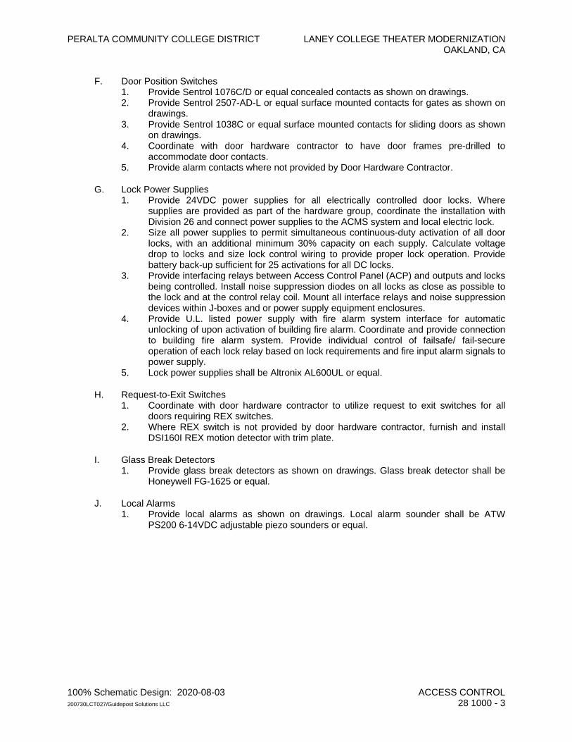
PERALTA COMMUNITY COLLEGE DISTRICT LANEY COLLEGE THEATER MODERNIZATION OAKLAND, CA
100% Schematic Design: 2020-08-03 ACCESS CONTROL 200730LCT027/Guidepost Solutions LLC 28 1000 - 3
F. Door Position Switches 1. Provide Sentrol 1076C/D or equal concealed contacts as shown on drawings. 2. Provide Sentrol 2507-AD-L or equal surface mounted contacts for gates as shown on
drawings. 3. Provide Sentrol 1038C or equal surface mounted contacts for sliding doors as shown
on drawings. 4. Coordinate with door hardware contractor to have door frames pre-drilled to
accommodate door contacts. 5. Provide alarm contacts where not provided by Door Hardware Contractor.
G. Lock Power Supplies 1. Provide 24VDC power supplies for all electrically controlled door locks. Where
supplies are provided as part of the hardware group, coordinate the installation with Division 26 and connect power supplies to the ACMS system and local electric lock.
2. Size all power supplies to permit simultaneous continuous-duty activation of all door locks, with an additional minimum 30% capacity on each supply. Calculate voltage drop to locks and size lock control wiring to provide proper lock operation. Provide battery back-up sufficient for 25 activations for all DC locks.
3. Provide interfacing relays between Access Control Panel (ACP) and outputs and locks being controlled. Install noise suppression diodes on all locks as close as possible to the lock and at the control relay coil. Mount all interface relays and noise suppression devices within J-boxes and or power supply equipment enclosures.
4. Provide U.L. listed power supply with fire alarm system interface for automatic unlocking of upon activation of building fire alarm. Coordinate and provide connection to building fire alarm system. Provide individual control of failsafe/ fail-secure operation of each lock relay based on lock requirements and fire input alarm signals to power supply.
5. Lock power supplies shall be Altronix AL600UL or equal.
H. Request-to-Exit Switches 1. Coordinate with door hardware contractor to utilize request to exit switches for all
doors requiring REX switches. 2. Where REX switch is not provided by door hardware contractor, furnish and install
DSI160I REX motion detector with trim plate.
I. Glass Break Detectors 1. Provide glass break detectors as shown on drawings. Glass break detector shall be
Honeywell FG-1625 or equal.
J. Local Alarms 1. Provide local alarms as shown on drawings. Local alarm sounder shall be ATW
PS200 6-14VDC adjustable piezo sounders or equal.
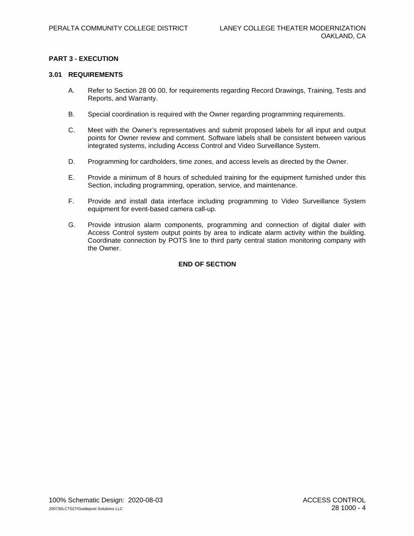
PERALTA COMMUNITY COLLEGE DISTRICT LANEY COLLEGE THEATER MODERNIZATION OAKLAND, CA
100% Schematic Design: 2020-08-03 ACCESS CONTROL 200730LCT027/Guidepost Solutions LLC 28 1000 - 4
PART 3 - EXECUTION
3.01 REQUIREMENTS
A. Refer to Section 28 00 00, for requirements regarding Record Drawings, Training, Tests and Reports, and Warranty.
B. Special coordination is required with the Owner regarding programming requirements.
C. Meet with the Owner’s representatives and submit proposed labels for all input and output points for Owner review and comment. Software labels shall be consistent between various integrated systems, including Access Control and Video Surveillance System.
D. Programming for cardholders, time zones, and access levels as directed by the Owner.
E. Provide a minimum of 8 hours of scheduled training for the equipment furnished under this Section, including programming, operation, service, and maintenance.
F. Provide and install data interface including programming to Video Surveillance System equipment for event-based camera call-up.
G. Provide intrusion alarm components, programming and connection of digital dialer with Access Control system output points by area to indicate alarm activity within the building. Coordinate connection by POTS line to third party central station monitoring company with the Owner.
END OF SECTION
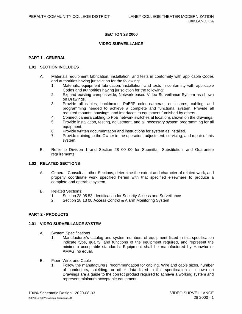
PERALTA COMMUNITY COLLEGE DISTRICT LANEY COLLEGE THEATER MODERNIZATION OAKLAND, CA
100% Schematic Design: 2020-08-03 VIDEO SURVEILLANCE 200730LCT027/Guidepost Solutions LLC 28 2000 - 1
SECTION 28 2000
VIDEO SURVEILLANCE
PART 1 - GENERAL
1.01 SECTION INCLUDES
A. Materials, equipment fabrication, installation, and tests in conformity with applicable Codes and authorities having jurisdiction for the following: 1. Materials, equipment fabrication, installation, and tests in conformity with applicable
Codes and authorities having jurisdiction for the following: 2. Expand existing campus-wide, Network-based Video Surveillance System as shown
on Drawings. 3. Provide all cables, backboxes, PoE/IP color cameras, enclosures, cabling, and
programming needed to achieve a complete and functional system. Provide all required mounts, housings, and interfaces to equipment furnished by others.
4. Connect camera cabling to PoE network switches at locations shown on the drawings. 5. Provide installation, testing, adjustment, and all necessary system programming for all
equipment. 6. Provide written documentation and instructions for system as installed. 7. Provide training to the Owner in the operation, adjustment, servicing, and repair of this
system.
B. Refer to Division 1 and Section 28 00 00 for Submittal, Substitution, and Guarantee requirements.
1.02 RELATED SECTIONS
A. General: Consult all other Sections, determine the extent and character of related work, and properly coordinate work specified herein with that specified elsewhere to produce a complete and operable system.
B. Related Sections: 1. Section 28 05 53 Identification for Security Access and Surveillance 2. Section 28 13 00 Access Control & Alarm Monitoring System
PART 2 - PRODUCTS
2.01 VIDEO SURVEILLANCE SYSTEM
A. System Specifications 1. Manufacturer’s catalog and system numbers of equipment listed in this specification
indicate type, quality, and functions of the equipment required, and represent the minimum acceptable standards. Equipment shall be manufactured by Hanwha or AMAG, no equal.
B. Fiber, Wire, and Cable 1. Follow the manufacturers’ recommendation for cabling. Wire and cable sizes, number
of conductors, shielding, or other data listed in this specification or shown on Drawings are a guide to the correct product required to achieve a working system and represent minimum acceptable equipment.
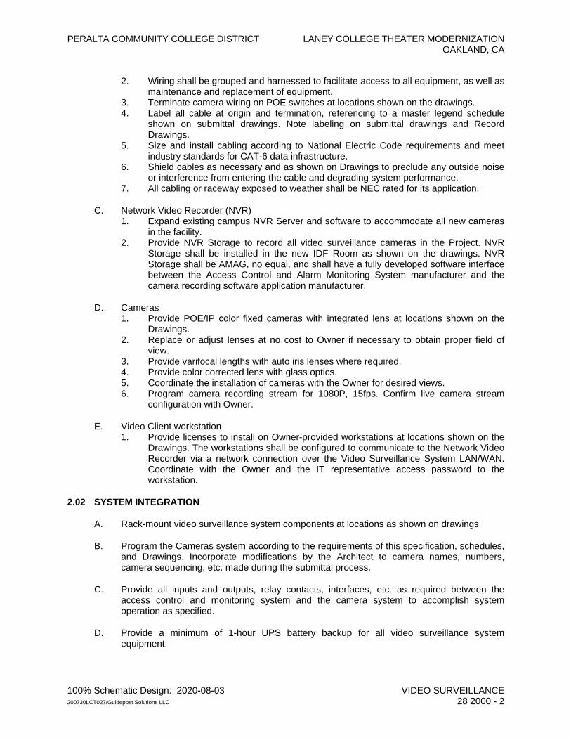
PERALTA COMMUNITY COLLEGE DISTRICT LANEY COLLEGE THEATER MODERNIZATION OAKLAND, CA
100% Schematic Design: 2020-08-03 VIDEO SURVEILLANCE 200730LCT027/Guidepost Solutions LLC 28 2000 - 2
2. Wiring shall be grouped and harnessed to facilitate access to all equipment, as well as maintenance and replacement of equipment.
3. Terminate camera wiring on POE switches at locations shown on the drawings. 4. Label all cable at origin and termination, referencing to a master legend schedule
shown on submittal drawings. Note labeling on submittal drawings and Record Drawings.
5. Size and install cabling according to National Electric Code requirements and meet industry standards for CAT-6 data infrastructure.
6. Shield cables as necessary and as shown on Drawings to preclude any outside noise or interference from entering the cable and degrading system performance.
7. All cabling or raceway exposed to weather shall be NEC rated for its application.
C. Network Video Recorder (NVR) 1. Expand existing campus NVR Server and software to accommodate all new cameras
in the facility. 2. Provide NVR Storage to record all video surveillance cameras in the Project. NVR
Storage shall be installed in the new IDF Room as shown on the drawings. NVR Storage shall be AMAG, no equal, and shall have a fully developed software interface between the Access Control and Alarm Monitoring System manufacturer and the camera recording software application manufacturer.
D. Cameras 1. Provide POE/IP color fixed cameras with integrated lens at locations shown on the
Drawings. 2. Replace or adjust lenses at no cost to Owner if necessary to obtain proper field of
view. 3. Provide varifocal lengths with auto iris lenses where required. 4. Provide color corrected lens with glass optics. 5. Coordinate the installation of cameras with the Owner for desired views. 6. Program camera recording stream for 1080P, 15fps. Confirm live camera stream
configuration with Owner.
E. Video Client workstation 1. Provide licenses to install on Owner-provided workstations at locations shown on the
Drawings. The workstations shall be configured to communicate to the Network Video Recorder via a network connection over the Video Surveillance System LAN/WAN. Coordinate with the Owner and the IT representative access password to the workstation.
2.02 SYSTEM INTEGRATION
A. Rack-mount video surveillance system components at locations as shown on drawings
B. Program the Cameras system according to the requirements of this specification, schedules, and Drawings. Incorporate modifications by the Architect to camera names, numbers, camera sequencing, etc. made during the submittal process.
C. Provide all inputs and outputs, relay contacts, interfaces, etc. as required between the access control and monitoring system and the camera system to accomplish system operation as specified.
D. Provide a minimum of 1-hour UPS battery backup for all video surveillance system equipment.
PERALTA COMMUNITY COLLEGE DISTRICT LANEY COLLEGE THEATER MODERNIZATION OAKLAND, CA
100% Schematic Design: 2020-08-03 VIDEO SURVEILLANCE 200730LCT027/Guidepost Solutions LLC 28 2000 - 3
PART 3 - EXECUTION
3.01 REQUIREMENTS
A. Refer to Section 28 00 00, for requirements regarding As-Built Drawings, Training, Tests and Reports, and Warranty.
B. Provide one indoor fixed camera, one outdoor fixed camera, and one 180 degree multisensory camera as spare parts.
C. Provide one hot-swappable hard drive of compatible manufacturer and size as spare for the Network Video Recorder RAID-6 storage array.
D. Provide a minimum of 8 hours of training for this system.
END OF SECTION

PERALTA COMMUNITY COLLEGE DISTRICT LANEY COLLEGE THEATER MODERNIZATION OAKLAND, CA
100% Schematic Design: 2020-08-03 FIRE DETECTION AND ALARM 200730LCT027/RIJA 28 3100 - 1
SECTION 28 3100
FIRE DETECTION AND ALARM
PART 1 - GENERAL
(NOT USED)
PART 2 - PRODUCTS
2.01 ACCEPTABLE MANUFACTURERS
A. Fire alarm equipment shall be standard products of the Notifier Co., Edwards Systems Technology, Siemens Building Technologies, Inc. Simplex Grinnell, Johnson Controls and Gamewell-FCI, or equal.
B. Catalog and model numbers listed are intended to establish type and quality of equipment and system design as well as operating features required. Deviations from intended functions of specified system are not permitted. Equipment shall not be ordered or installed until such equipment has been reviewed and approved by the Architect.
C. Products specified below are based on Notifier system components. For other manufacturers approved system components, refer to Attachment A.
2.02 FIRE ALARM CONTROL PANEL (FACP) OR NETWORK NODES
A. Furnish Notifier Model No. NFS-320, (CSFM 7165-0028:0243), or NFS2-640 (CSFM 7165-0028:0243), or NFS2-3030 (CSFM 7165-0028:0224) Fire Alarm Control Panels as indicated on drawings.
B. Operator Control:
1. Acknowledge Switch: Activation of control panel acknowledge switch in response to a single new trouble or alarm condition shall silence panel sounding device and change system alarm or trouble LED from flashing to steady-ON. If additional new alarm or trouble conditions exist in system, activation of this switch shall advance display to next alarm or trouble condition that exists, and shall not silence local audible device or change LED to steady until new conditions have been so acknowledged. New alarm conditions shall always be displayed before new trouble conditions. Occurrence of a new alarm or trouble condition shall cause panel to resound, and sequences as described above, shall repeat.
2. Signal (Alarm) Silence Switch: Activation of the signal silence switch shall cause programmed alarm notification appliances and relays to return to the normal condition after an alarm condition. The selection of notification circuits and relays that are silenceable by this switch shall be fully fielded programmable within the confines of applicable standards at the job site. The FACP software shall include silence inhibit and auto-silence timers.
3. Alarm Activate (Drill) Switch: Alarm activate switch shall activate notification appliance circuits. The drill function shall latch until the panel is silenced or reset.
4. System Reset Switch: Activation of the System Reset switch shall cause electronically-latched initiating devices, appliances or software zone, as well as associated output devices and circuits, to return to their normal condition.
5. Lamp Test Switch: Switch shall activate local system LEDs, light each segment of the liquid crystal display and display the panel software revision for service personnel.
6. Hot Button Switch: Hot Button Key switch shall be provided in FACP to disable all output devices for testing or repair of system. Key switch shall silence all horn and strobes, disable PA cutouts, HVAC shutdowns, door closures, and Autonomous PA systems. Key
PERALTA COMMUNITY COLLEGE DISTRICT LANEY COLLEGE THEATER MODERNIZATION OAKLAND, CA
100% Schematic Design: 2020-08-03 FIRE DETECTION AND ALARM 200730LCT027/RIJA 28 3100 - 2
switch shall be password protected to enable function. LED indicator shall illuminate a trouble condition while Hot Button Switch is activated and shall turn off when system is re-enabled.
C. System Capacity and General Operation
1. The control panel or each network node shall provide, or be capable of expansion to 318 intelligent or addressable devices for the NFS-320 or 636 Intelligent or addressable devices for the NFS2-640 and 3180 intelligent, addressable devices for the NFS2-3030.
2. The control panel or each network node shall include Form-C alarm, trouble, supervisory, and security relays rated at a minimum of two amps at 30 VDC. It shall also include four Class B (NFPA Style Y) or Class A (NFPA Style Z) programmable Notifications Appliance Circuits.
3. The control panel or each network node shall support up to two output modules (signal or relay) for a total of ten circuits for the NFS-320 or eight output modules (signal or relay), each with eight circuits for a total of 64 circuits for the NFS2-640. The NFS2-3030 shall support 12 output modules for a total of 96 circuits. Programmable notification appliance circuits shall be class B.
4. The system shall include a full featured operator interface control and annunciation panel that shall include a backlit Liquid Crystal Display (LCD), individual color coded system status LEDs, and an alphanumeric keypad with easy touch rubber keys for the field programming and control of the fire alarm system.
5. The system shall be programmable, configurable, and expandable in the field without the need for special tools, PROM programmers or PC based programmers. It shall not require replacement of memory ICs to facilitate programming changes.
6. The system shall allow the programming of any input to activate any output or group of outputs. The FACP shall support up to 20 logic equations, including “and” “or” and “not”, or timed delay equations to be used for advanced programming. Logic equations shall require the use of a PC with software utility designed for programming.
7. The FACP or each network node shall provide the following features: a. Drift compensation to extend detector accuracy over life. Drift Compensation shall
also include a smoothing feature, allowing transient noise signals to be filtered out. b. Detector Sensitivity tests, meeting requirements of NFPA 72 Chapter seven. c. Maintenance alert, with two levels (maintenance alert or maintenance urgent), to
warn of excessive smoke detector dirt or dust accumulation. d. Nine sensitivity levels for alarm, selected by detector. The alarm level range shall be
0.5 to 2.35 percent per foot for photoelectric detectors and 0.5 to 2.5 percent per foot for ionization detectors. The system shall also support sensitive advance detection laser detectors with an alarm level range of 0.03 percent per foot to one percent per foot. The system shall also include up to nine levels of Pre- alarm, selected by detector, to indicate impending alarms to maintenance personnel.
e. Circuit boards, programming, and interconnecting cables to enable the system to display or print system reports.
f. Alarm verification, with counters and a trouble indication to alert maintenance personnel when a detector enters verification 20 times.
g. PAS pre-signal, meeting NFPA 72 requirements. h. Rapid manual station reporting (less than three seconds) shall meet NFPA 72
Chapter one requirements for activation of notification circuits within ten Seconds of initiating device activation.
i. Periodic detector test, conducted automatically by the software. j. Self optimizing pre-alarm for advance fire warning, which allows each detector to
learn its particular environment and set its pre-alarm level to just above normal peaks.
PERALTA COMMUNITY COLLEGE DISTRICT LANEY COLLEGE THEATER MODERNIZATION OAKLAND, CA
100% Schematic Design: 2020-08-03 FIRE DETECTION AND ALARM 200730LCT027/RIJA 28 3100 - 3
k. Cross zoning with the capability of counting: two detectors in alarm, two software zones in alarm, or one smoke detector and one thermal detector.
l. Walk test, with a check for two detectors set to same address. m. Control-by-time for non-fire operations, with holiday schedules. n. Day or night automatic adjustment of detector sensitivity. o. RS 232 serial port to support a District supplied printer to be used for silent testing
and certification of the system.
8. The FACP shall be capable of coding main panel(s) node notification circuits in temporal code (NFPA 72 A-2-2.2.2).The panel shall also provide a coding option that will synchronize specific strobe lights designed to accept a specific “sync pulse”.
9. Network Communication: a. The network architecture shall be based on a Local Area Network (LAN), a firmware
package that utilizes a peer-to-peer, inherently regenerative communication format and protocol. The protocol shall be based on ARCNET or equivalent non-proprietary protocol.
b. Failure of any node shall not cause failure or communication degradation of any other node or change the network communication protocol among surviving nodes located within distance limitations. A node may be an intelligent Fire Alarm Control Panel (FACP), Network Control Station PC (NCS) or Network Control Annunciator (NCA).
c. Each network node address shall be capable of storing Event Equations which shall be used to activate outputs on one network node from inputs on other network nodes.
D. System Display:
1. Utilize the 640-character display option. The design of the CPU shall provide for a configuration with the 640-character display mounted on the front of the unit in place of the standard 80-character display.
2. The 640-character display shall provide the controls and indicators used by the system operator: The 640 character display shall include the following operator control switches; Acknowledge, Alarm, Silence, Alarm Activate (drill), System Reset and Lamp Test.
3. The display shall annunciate status information and custom alphanumeric labels for intelligent detector, addressable modules, internal panel circuits, and software zones.
4. The 640-character display shall provide ten Light-Emitting-Diodes (LEDs) that indicate the status of the following system parameters: AC Power and Network Communication, Fire Alarm, Pre alarm Warning, Security Alarm, Supervisory Event, System Trouble, Alarm Silence, Disabled Points, CPU failure.
5. The 640-character display shall use ten “soft” keys for screen navigation or to accomplish dedicated programming functions. Full programming access shall require use of a laptop and the proper programming utility. The programming utility shall be provided to the OAR who will forward it to the local maintenance area representative.
6. The system shall support the display of battery charging current and voltage on the LCD display.
E. Network Control Annunciator (NCA-2):
1. When a networked system is installed a network controlled annunciator shall be provided to display system intelligent points. The NCA-2 shall be capable of displaying information for all possible points on the network.
2. The NCA-2 shall include a minimum of 640 characters, backlit by a long life, solid-state LCD display. Additionally, the network display shall include ten soft keys for screen navigation and the ability to scroll events by type. i.e. Fire Alarm, Supervisory Alarm, Trouble, etc.
PERALTA COMMUNITY COLLEGE DISTRICT LANEY COLLEGE THEATER MODERNIZATION OAKLAND, CA
100% Schematic Design: 2020-08-03 FIRE DETECTION AND ALARM 200730LCT027/RIJA 28 3100 - 4
3. The NCA-2 shall have the ability to display up to eight events in order of priority and time of occurrence. Counters shall be provided to indicate the total number of event by type.
4. The NCA-2 shall mount in a Notifier ABS-2DB or equal box; provide the NCA-2 with a key enable or disable switch for the network node fire alarm control panels. The network display may mount in a backbox designed for this use. The network shall support the NCAs.
5. The network control annunciator shall have an event history buffer capable of storing a minimum of 1000 events in nonvolatile memory. Additionally, the NCA-2 shall have a fire alarm history buffer capable of storing a minimum of 200 events in nonvolatile memory.
6. The NCA-2 shall include two EIA-232 ports for UL864 listed printers and CRT’s.
7. The NCA-2 shall include control switches for system wide control of Acknowledge, Signal Silence, System Reset, Drill, and local Lamp Test. A mechanical means, by which the controls switches are locked out, such as a key, shall be provided.
8. The NCA-2 shall include long life LEDs to display Power, Fire Alarm, Pre-Alarm, Security Alarm, System Trouble, Supervisory, Signals, Silenced, Disabled Prints, other (non-fire) Events, and CPU Failure.
9. The NCA-2 shall include a Master Password and up to nine user Passwords. The Master password shall be required to access the programming and alter status menus. Each User password may have different levels of authorization assigned by the Master password. Passwords installed into the NCA-2 shall be made available to the OAR who will forward them to the local maintenance area representative.
10. The NCA-2 shall allow editing of label for points within the network, control on or off of outputs, enable or disable of network points, alter detector sensitivity, clear detector verification counters for any analog addressable detector within the network, clear any history log within the network, change the Time or Date settings, initiate a Walk Test.
11. The NCA-2 shall include a time of day clock.
12. Each NCA-2 shall support 80-character remote display annunciators for displaying network activity. These “Terminal Mode” displays will mimic the activity appearing on the corresponding NCA. There shall be only one annunciator or control system consisting of components manufactured by one manufacturer for the fire alarm system.
F. Signaling Line Circuits (SLC):
1. Each FACP or FACP network node shall support a minimum of one SLC for the NFS-320 for the Notifier NFS2-640 or ten SLC’s for the NFS2-3030. Each SLC interface shall provide power to and communicate with up to 159 intelligent detectors (ionization, photoelectric or thermal) and 159 intelligent modules (monitor or control) for a loop capacity of 318 devices.
2. CPU shall receive analog information from intelligent detectors to be processed to determine whether normal, alarm, pre-alarm, or trouble conditions exist for each detector. The software shall automatically maintain the detector’s desired sensitivity level by adjusting for the effects of environmental factors including the accumulation of dust in each detector. The analog information shall also be used for automatic detectors testing and for the automatic determination of detector maintenance requirements.
G. Enclosures:
1. The control panel shall be housed in a UL-listed cabinet suitable for surface or semi-flush mounting. The cabinet and front shall be corrosion protected, given a rust-resistant prime coat, and manufacturer’s standard finish.
2. The back box and door shall be constructed of 0.030 steel with provisions for electrical conduit connections into the sides and top.

PERALTA COMMUNITY COLLEGE DISTRICT LANEY COLLEGE THEATER MODERNIZATION OAKLAND, CA
100% Schematic Design: 2020-08-03 FIRE DETECTION AND ALARM 200730LCT027/RIJA 28 3100 - 5
3. The supplied door shall include a key lock and shall include glass or other transparent opening for viewing of indicators. For convenience, the door may be site configured for either right or left hand hinging.
H. Power Supply:
1. An off-line switching power supply shall be available for the fire alarm control panel or network node and provide six amps of available power for the NFS2-640, and 4.5 amps for NFS2-3030 and six amps for the NFS-320 for control panel and peripheral devices.
2. Provisions shall be made to allow the audio-visual power to be increased as required by adding modular expansion audio-visual power supplies.
3. Over-current protection shall be provided on power outputs. The power supply shall provide an integral battery charger. Battery arrangement may be configured in the field.
4. The power supply shall continuously monitor field wires for earth ground conditions, and shall have the following LED indicators: a. Ground Fault LED. b. AC Power Fail LED. c. NCA-2 on LED (4).
5. The main power supply shall operate on 120 VAC, 60 Hz, and shall provide power for the FACP or network node(s).
6. The main power supply shall provide a battery charger using dual rate charging techniques for fast battery recharge and be capable of charging batteries up to 60 AH for the NFS-640 and 200 AH for the NFS2-3030.
2.03 REMOTE ANNUNCIATORS
A. A non-networked fire alarm system annunciator is required when there is only one FACP in the system. Provide a Notifier Model LCD-80TM (CSFM7165-0028:0243), or LCD-160 (CSFM7120-0028:0227) alphanumeric display remote annunciator, or equal. A Network annunciator is required for any system that contains more than one fire alarm control panel (FACP) or network node. Provide a Notifier Model NCA-2 (CSFM7165-0028:0224, alphanumeric display remote annunciator, or equal. Display shall be back lit and be furnished with a maximum of 20 characters of 4 lines for the LCD-80, or 80TM and 40 characters on 16 lines for the LCD-160 or NCA-2. Provide the following functions:
1. Control switches for system acknowledge, signal silence and system reset via a touchpad.
2. Time and date display field.
3. Local piezo sounder with alarm or trouble resound.
4. On-line green LED (flashing).
5. Evacuation and drill switches, via a touchpad.
6. Pre-signal hold via a touchpad.
7. System test at control panel and CTR.
B. Following additional features shall be furnished:
1. Device Fire Annunciation.
2. Device Trouble Annunciation.
3. System Operation Annunciation.
4. "Power On" LED.
C. Typewritten operating instructions and a site map shall be posted adjacent to remote annunciator(s). The site map shall be sized and include designations and devices as described in paragraph 3.02 N. of this specification. Project site map shall depict fire alarm devices in the building(s) in which they are installed. The instruction and site map shall be mounted in suitable
PERALTA COMMUNITY COLLEGE DISTRICT LANEY COLLEGE THEATER MODERNIZATION OAKLAND, CA
100% Schematic Design: 2020-08-03 FIRE DETECTION AND ALARM 200730LCT027/RIJA 28 3100 - 6
document frames and attached to the wall with a minimum of two screws each. Contractor’s name and telephone number shall not be placed on either the instruction or the site map.
2.04 POWER SUPPLIES
A. Remote Notification Appliance Circuit (NAC) extender power supplies shall be Notifier No. FCPS-24S6 (CSFM 7315-0028:0225), or equal. Unit shall be furnished with main printed circuit board, transformers, lockable cabinet, and batteries. Unit shall be configured to drive 4 notification appliance circuits. The remote power supplies shall be configured with a monitor module to report trouble conditions to the controlling FACP via an SLC. Triggering of NAC inputs shall be directly controlled from the FACP without the use of addressable control or relay modules.
2.05 PERIPHERAL DEVICES AND EQUIPMENT
A. Manual Stations: Interior Use: Station shall be Notifier, Model No. BNG-1R (CSFM 7150-0028:0003) or equal, addressable semi-flush, non-breakable glass type. Station housing shall be fabricated of die-cast aluminum with reset lock and key. Provide an addressable monitor module Model No. FMM-101(A) (CSFM 7300-0028:0219) for each manual station.
B. Smoke Detectors: Smoke Detectors shall be Notifier Model No. FAPT-851 (CSFM 7272-0028:0206) or equal, addressable smoke detectors. Provide base Model No. B710LP. (CSFM 7300-0028:0173). Detector shall be microprocessor based, using a combination of photoelectric, and thermal sensing technologies. The smoke detector shall have its loop number and electronic address permanently and clearly labeled onto the device base using a p-touch type labeling system. The label shall be visible without removing the detector head.
C. Non-Explosion Proof Automatic Heat Detectors shall be combination rate-of-rise and fixed-temperature type. When fixed-temperature portion is activated, units shall provide visual evidence of such operation (LED). Addressable Heat detectors shall be Notifier Model No. FST-851R (CSFM 7270-0028:0196) or equal. Provide base Model No. B-710LP. (CSFM 7300-0028:0173) The location of the heat detector must be clearly marked below the ceiling and the detector must be readily accessible. The heat detector shall have its electronic address permanently and clearly labeled onto the device and be readily accessible. For spaces where the normal ambient temperature can reach temperatures as high as 150 degrees F. such as in attic spaces, use Notifier FST-851H with base B-710LP. The heat detector shall have its loop number and electronic address permanently and clearly labeled onto the device using a p-touch labeling system. The label shall be visible without removing the detector head.
D. Explosion Proof Automatic heat Detectors: These detectors shall be Thermotech Model 302-EPM-135 (CSFM 7270-0021:0001) or equal; it shall be rated for 135 degree Fahrenheit alarm temperature. Mount the detector on a JL threaded hub cover manufactured by Killark Electric, or equivalent from other owner approved manufacturers. Seals, conduit type, and fittings shall be suitable for the hazardous zone and location where the device will be installed. Provide an appropriate wire protective cover over box and detector. Addressable module(s) associated with this type of devices shall be installed outside of the hazardous area.
E. Weatherproof Automatic heat Detectors: These detectors shall be Thermotech Model 302-ET-135 (CSFM 7270-0021:0001) or equal; it shall be rated for 135 degree Fahrenheit alarm temperature. Detector shall be mounted horizontally in a two gang weatherproof box with cover manufactured by Hubbell/Bell or equivalent from other owner approved manufactures. Install an appropriate wire protective cover over box and detector. Conduit type and fittings shall be suitable for the environment where the device will be installed.
F. Duct Smoke Detectors: Duct smoke detectors shall be Notifier Model No. FSD-751RPL(A) (CSFM 3240-0028:0205) or FSD-751PL(A) (CSFM 3240-0028:0205) or equal, and shall be of solid state photoelectric type and shall operate on light-scattering photodiode principle. The location of the duct detector must be clearly marked below the ceiling and the detector must be readily accessible. The duct smoke detector shall have its electronic address permanently and clearly labeled onto the device. The label shall be visible without removing the detector head.
PERALTA COMMUNITY COLLEGE DISTRICT LANEY COLLEGE THEATER MODERNIZATION OAKLAND, CA
100% Schematic Design: 2020-08-03 FIRE DETECTION AND ALARM 200730LCT027/RIJA 28 3100 - 7
Duct smoke detectors that are already installed as part of packaged ventilation equipment that are not the detector specified above shall be connected to the fire alarm system via a monitor module. The existing power source shall be disconnected and resettable power from the FACP or Remote Power Supply shall be connected in place of the existing power source for fire alarm system resettable power and alarm initiation.
G. Projected Beam Infrared Type Smoke Detectors shall be Notifier Model No. FSB-200S (CSFM 7260-0028:0228), or equal, and shall consist of a transmitter / receiver unit and reflector to be used in accordance with manufacturers recommendations. Each detector shall include six user-selectable sensitivity levels. Alignment shall be achieved with a signal strength meter incorporated into the beam detector. The detector shall feature automatic detection and adjustment to the optimum level for the specific environment. Provide remote test stations with key lock for detectors, Notifier Model RTS-451KEY, or equal, located below ceiling.
H. Linear Heat Detectors: Linear detectors shall be Protectowire Model No, PHSC-190-EPR less messenger wire or PHSC-190-EPR-M with messenger wire (CSFM 7270-0854:0101) or equal linear detectors rated for 150 degree Fahrenheit installed ambient temperature and 190 degree Fahrenheit alarm temperature. Damaged detector due to excessive bending or kinking during installation shall not be accepted. Interface the Protectowire detector with the FACP system via addressable monitor module(s) located on one extreme of the detector and an end of line resistor at the other extreme. End of line resistor shall be readily accessible for testing. Provide appropriate signs indicating the existence of linear heat detectors at the entrances of areas protected with this type of fire detection. Installation shall be done in accordance with applicable codes and standards, and manufacturer’s published installation recommendations.
1. Provide a system that utilizes linear heat detectors in concealed or controlled access areas. The detection wire shall be installed within 20 inches of the underside of the building roof or the above floor as recommended by the manufacturer. In shallow areas install the detection wire within the upper part of the space to be protected. a. One circuit of linear heat detection shall be utilized for areas not exceeding 4,000
square feet above multiple rooms. b. Areas above Gymnasiums and Auditoriums exceeding 4,000 square feet shall be
considered one zone. c. Areas divided by a fire rated wall shall be protected separately and considered an
independent zone.
I. Multi-Criteria Fire Detectors (MS and HS Only) shall be Notifier Model FSC-851(A) IntelliQuad (CSFM 7272-0028:0255) or equal.
1. Multi-Criteria Fire Detectors shall be used on performing stages and surrounding areas of the performing stage where the use of special effect smoke is to be used.
2. Multi-Criteria Fire Detector shall combine four separate sensing elements into one unit: a. Photoelectric chamber shall sense airborne particulate for smoke detection. b. Electrochemical cell technology shall monitor carbon monoxide. c. Infrared sensing shall measure ambient light levels and flame signatures. d. Thermal detection shall monitor temperature.
3. Multi-Criteria Detector shall be capable of generating only one alarm signal from at least two sensors of the four when positively confirming a fire. The sensor output shall be mathematically evaluated to determine when a signal is warranted.
4. Twin LED indicators shall provide 360 degree visibility.
J. Monitor Modules:
1. Monitor module shall be Notifier Model No. FMM-1(A) (CSFM 7300-0028:0219), or equal. Module shall connect a supervised zone of conventional initiating devices, N.O. dry contact devices, including four-wire smoke detectors, to one of SLC loops. Monitor module shall install in a four-inch square by 2 1/8-inch deep electrical box. The module
PERALTA COMMUNITY COLLEGE DISTRICT LANEY COLLEGE THEATER MODERNIZATION OAKLAND, CA
100% Schematic Design: 2020-08-03 FIRE DETECTION AND ALARM 200730LCT027/RIJA 28 3100 - 8
shall have its loop number, electronic address, and function label on the front cover using a P-Touch type or equal labeling system.
2. Monitor module shall provide address-setting means using rotary decimal switches and shall store an internal type of device. An LED shall be provided which shall flash under normal conditions indicating that monitor module is operational and in regular communication with control panel.
K. Control Modules:
1. Control module shall be Notifier Model No. FCM-1 (CSFM 7300-0028:0219), or equal. Module shall be used to connect a conventional indicating appliance or MR type isolation relay to one of the SLC loops. Control module shall install in a standard four-inch square by 2 1/8-inch deep electrical box. Audio or visual or relay power shall be provided by a separate loop from main control panel or from supervised remote power supplies. The module shall have its loop number, electronic address, and function label on the front cover using a p-Touch type or equal labeling system. Provide Air Products PAM-3 Relay Model A77-716B (CSFM 7300-1004:0101) or equal power supervision relay to monitor 24 volt DC power.
2. Control module shall provide address-setting means using rotary decimal switches and shall store an internal identifying code which control panel shall use to identify type of device. An LED shall be provided which shall flash under normal conditions, indicating that control module is operational and in regular communication with control panel.
L. Relay Modules:
1. Relay Module shall be Notifier FRM-1(CSFM 7300-0028:0219) the module shall provide as a minimum one set of form “C” dry contacts and have its loop number, electronic address, and function labeled on the front cover using a P-Touch type labeling system.
2. Provide a buffer relay that is part of the control system if controlled circuit(s) exceeds the voltage or current rating of the relay module.
3. Relays used to interface control of other systems shall be electrically supervised and shall only be wired in a fail-safe mode of function during a power failure.
4. Provide Relay Module at shunt trip breakers for AV electrical system shut down upon alarm.
M. Isolator Modules:
1. Isolator module shall be Notifier, Model No. ISO-X, (CSFM 7165-0028:0243) or equal. Module shall isolate wire-to-wire circuits on an SLC loop in order to limit number of other modules or detectors that are incapacitated by short circuit fault. If a wire-to-wire short occurs, isolator shall automatically open-circuit SLC loop. When short is corrected, isolators shall automatically reconnect isolated section of SLC loop.
2. Isolator module shall not require address setting, although isolators will electrically reduce capacity of loop by two detectors or module addresses. Isolator module will install in a standard 4-inch deep electrical box. It shall include a single LED that shall flash to indicate that isolator is operational and shall illuminate steadily to indicate that a short has been detected and isolated.
N. Horns and Strobes: Horns and strobes shall be products of the same manufacturer. In order to establish a standard of quality, items are specified from the products manufactured by System Sensor, acceptable manufacturers are Honeywell, Wheelock Inc., Gentex or District approved equal. Addressable or multifunction two wire indicating (Audible or Visual) appliances shall not be acceptable.
1. Alarm horns shall be System Sensor Model No. HR (CSFM 7135-1653:0189) or equal, and shall be polarized and operated by 24 VDC. Entire unit shall be red finish. Horn assemblies shall be furnished with separate wire leads for in or out wiring for legs of associated signal circuits. T tapping of signal device conductors to signal circuit
PERALTA COMMUNITY COLLEGE DISTRICT LANEY COLLEGE THEATER MODERNIZATION OAKLAND, CA
100% Schematic Design: 2020-08-03 FIRE DETECTION AND ALARM 200730LCT027/RIJA 28 3100 - 9
conductors is not permitted. Suitable gaskets shall be provided for weatherproof installation. Horns shall provide a minimum sound pressure level of 100 dB at 10 feet. Horns shall be mounted on manufacturer’s recommended outlet boxes. Weatherproof horns shall be Model No. HRK (CSFM 7135-1653:0189); Provide a Model No. BBS-2 back box skirt on indoor surface mount outlet boxes.
2. Horn/strobe shall be wall mounted System Sensor Model No. P4R standard candela output or Model No. P4RH high candela output (CSFM 7135-1653:188); or equal. Horn/strobe shall operate on two separate two wire 24 VDC polarized circuits and shall be provided with a semi-flush mounting plate. Entire unit shall be red finish. Strobe light shall have a clear Lexan lens. The word "FIRE" shall be printed on the two sides of the strobe body. Horn shall provide a minimum sound output of 100 dB at 10 feet. The strobe shall provide a selectable minimum light intensity of 15, 30, 60, 75, 90, 110, 135, 150, or 185 Candela as indicated on Drawings to meet or exceed requirements of CBC, CHAPTER 11B AND ADAAG and UL 1971. Horn/Strobes shall be mounted on manufacturer recommended outlet boxes. Weather proof horn or strobe shall be model No. P4RK or Model No. P4RHK. Provide a model No. BBS-2 back box skirt on indoor surface mounted outlet boxes.
3. Strobe indicating appliances shall be System Sensor Model No. SR standard candela output or Model No. SRH high candela output (CSFM 7125-1653:0186), or equal. Devices shall be UL listed and shall be wall-mounted. Entire unit shall be red finish. Strobe light shall have a clear Lexan lens. The word "FIRE" shall be printed on two sides of the strobe body. Strobes shall meet CBC, CHAPTER 11B AND ADAAG and UL 1971 requirements. The strobe shall provide a selectable minimum light intensity of 15, 30, 60, 75, 90, 110, 135, 150, or 185 Candela as indicated on the Drawings to meet or exceed requirements of CBC, CHAPTER 11B AND ADAAG and UL 1971. Strobes shall be mounted on manufacturer recommended outlet boxes. Weather proof strobe shall be model No. SRK or Model No. SRHK. Provide a model No. BBS-2 back box skirt on indoor outlet boxes.
4. Strobe synchronization modules if required shall be System Sensor Model No. MDL3R (CSFM 7300-1653:0202) or equal, to be installed in conjunction with two or more strobes located in same room or corridor or as indicated on Drawings. (Strobe synchronization modules must be compatible with installed strobes).
O. Electromagnetic Door Holder: Electromagnetic door holders shall be installed on doors as indicated on Drawings or as required. Electromagnetic Doors shall consist of a wall-mounted electromagnet and a door-mounted armature with an adjustable contact plate. Electromagnets shall provide a force of attraction of 35 pounds when energized and less than three pounds residual with power disconnected. Armature contact plates shall provide a horizontal adjustment of 25 degrees. The holding force of Electromagnetic Doors shall be totally electromagnetic and without the use of mechanical linkage or other moving parts. Electromagnetic Door Holders shall normally be energized, and a release shall be accomplished by interrupting the circuit. Door holders shall be Reliable Security Group DH Series (CSFM 3550-1039:0100) or equal. The door holder power supply shall be an Altronix Model AL400ULM (CSFM 7315-1335:0100) for three amp. Output, AL600ULM (CSFM 7315-1335:0100) for six amp output, AL1024ULM (CSFM 7315-1335:0100) for ten amp output. The power supply shall be equipped with a fail safe input trigger circuit and five individually protected outputs. (Electromagnetic Door holders shall not be powered by an FACP or remote NAC power supplies).
P. Bells: System Sensor Model No. SSM-24-10, or equal, with Weather proof back box No. WBB for installation with surface raceway. Bells shall be polarized and operated by 24 VDC. Bell shall be powered from FACP or Remote NAC power supply. When used as a notification appliance to indicate fire sprinkler water flow the bell shall be directly controlled by contacts in the associated flow switch. Addressable relays or control modules shall not be used to supervise sprinkler bells. Bell assemblies shall provide separate wire leads for in or out wiring
PERALTA COMMUNITY COLLEGE DISTRICT LANEY COLLEGE THEATER MODERNIZATION OAKLAND, CA
100% Schematic Design: 2020-08-03 FIRE DETECTION AND ALARM 200730LCT027/RIJA 28 3100 - 10
for legs of associated signal circuits. Bells shall be vibrating type providing a minimum sound pressure level output of 84 - 87 dB at ten feet. Bells shall be ten inches in diameter, finished with baked-on red enamel paint, UL listed for fire alarm installation, and suitable for surface or semi-flush mounting. Provide a sign adjacent to the water flow bell with one inch tall and 3/8 inch stroke white lettering on a bright red background. The sign shall read: “NOTIFY FIRE DEPARTMENT WHEN ALARM SOUNDS”.
Q. Water-flow Switches:
1. Water-flow switches shall be Potter Electric Model No. VSR-F (CSFM 7770-0328:0001) or equal. Vane-type water-flow switches shall be installed on system piping as designated on Drawings or as required. Detectors shall install on clear pipe spans of appropriate nominal size, either a vertical or horizontal run, at least six inches from fittings or valves which may change water direction, flow rate or pipe diameter, and not closer than 24 inches to valves or drains. Detector shall respond to water-flow in specified direction after a preset time delay that is field adjustable. Actuation mechanism shall include a polyethylene vane inserted through a hole in the pipe and connected by a mechanical linkage to delay mechanism. Output shall consist of ten amps (dual SPDT switches form-C contacts). A conduit entrance for standard electrical conduit fittings shall be provided on detectors. Detectors shall be listed by UL for indoor or outdoor installation. No more than 18 inches of seal-tight flex may be used to connect the water flow or tamper switch to the site conduit system at any one location.
2. Sprinkler valve tamper switches shall be System Sensor Model No. OSY2 (CSFM 7770-1653:0118) for use with outside screw-and-yoke valves or System Sensor Model No. PIBV2 (CSFM 7770-1653:0118) for use with post indicating valves or equal. Supervisory switch shall be installed on valves as designated on Drawings or as required. Switches shall be installed to not interfere with normal valve operation and shall be adjusted to operate within two revolutions of valve control or when stem has moved no more than 1/5 of distance from its normal position. Mechanism shall be housed in a weatherproof die cast metal enclosure, also providing a 3/4 inch tapped conduit entrance to incorporate necessary facilities for attachment to valve. Switch mechanism shall be furnished with a minimum rated capacity of ten amps at 125 VAC and 2.5 amps at 24 VAC. Entire installed assembly shall be tamper-resistant. Tamper switches shall be UL listed. No more than 18 inches of seal-tight flex may be used to connect the water flow or tamper switch to the site conduit system at any one location.
R. Universal Digital Alarm Communicator Transmitter shall be Notifier Model No. UDACT (CSFM 7300-0028:0174). The UDACT is an interface for communication of digital information between a fire alarm control panel and a UL-Listed central station.
1. The UDACT shall be compact in size, mounting in a standard module position of the fire alarm control cabinet. Optionally, the UDACT shall have the ability for remote mounting, up to 6000 feet from the fire alarm control panel. The wire connections between the UDACT and the control panel shall be supervised with one pair for power and one pair for multiplexed communication of overall system status.
2. The UDACT shall include connections for dual telephone lines (with voltage detect), per UL or NFPA or FCC requirements. It shall include the ability for split reporting of panel events between up to three different telephone numbers.
3. It shall be completely field programmable from a built in keypad or laptop computer, and shall be capable of transmitting events in multiple formats.
4. Communication shall include vital system status such as: a. Independent Zone (Alarm, trouble, non-alarm, supervisory. b. Independent Addressable Device Status. c. AC (Mains) and Earth Fault. d. System Off Normal.
PERALTA COMMUNITY COLLEGE DISTRICT LANEY COLLEGE THEATER MODERNIZATION OAKLAND, CA
100% Schematic Design: 2020-08-03 FIRE DETECTION AND ALARM 200730LCT027/RIJA 28 3100 - 11
e. 12 and 24 Hour Test Signal. f. Abnormal Test Signal (per UL requirements). g. EIA-485 Communications Failure. h. Phone Line Failure.
5. The UDACT shall support independent zone or point reporting when used in the Contact ID format. This enables the central station to have exact details concerning the origin of the fire or response emergency.
6. The UDACT shall be supplied with two eight conductor, two to six foot long line cords. One end of the cords shall plug into the jacks on the UDACT. The other end of the cords shall plug into industry standard RJ-31X surface mounted telephone jacks. Install jacks in a screw cover box adjacent to the FACP if sufficient space is not available within the FACP, or adjacent fire alarm terminal cabinet. The line cords shall be installed in conduit when it is necessary to locate the jacks remotely from the FACP enclosure. The jacks shall be mounted to the rear of the box. The telephone number for each line shall be labeled on its respective jack.
S. Voice Evacuation System:
1. The Voice Evacuation Control (EVAC) Panel shall be Notifier Model No. NFV-25/50 (CSFM 6911-0028:0229) The self contained control panel shall be equipped with dual 25 watt audio amplifiers each with a single style Y (Class B) supervised 25 V rms output circuit. The EVAC panel shall have the ability to record a minimum of two field-programmable messages of up to 60 seconds total duration with an integral microphone or an external source via an audio input jack. The messages shall be stored digitally onto a non-volatile EEPROM. The message(s) shall be individually field programmable for three, four, six, eight, or indefinite repeat while triggered by the host FACP. Any message being delivered at the time of the trigger circuit(s) reset shall not stop in mid sentence but shall be completed to the end of the message. A tone generator shall be provided capable of emulating a field programmable lead-in or trailing alert tone or an Audible Emergency Evacuation Signal (Temporal Pattern). The EVAC panel shall be capable of electrically supervising in both active and standby conditions, the amplifier outputs, field wiring, message generator, tone generator, microphone and primary or secondary power supplies to an internal trouble relay(s). The trouble relay(s) contacts shall be accessible via a terminal strip and be configured and connected to report internal or external trouble conditions to the host FACP via the trigger circuit or a separate monitor module. The minimum of two trigger circuits shall be individually field-configurable for triggering with a NAC circuit or a supervised dry contact. The control panel shall be equipped with LED indicator lights for Power On, System Trouble, Message Generator Trouble, Tone Generator Trouble, Microphone Trouble, Battery Trouble, Charger Trouble, Ground Fault, Output Circuit Trouble and Amplifier Supervisory. The panel shall be equipped with an internal monitor speaker for reviewing the field recorded messages. The primary power supply shall operate at 120 VAC through a dedicated 20 amp. circuit and shall be capable of charging 18 AH lead acid batteries. Provide two 12 volt batteries that will provide a secondary power source for the same or longer duration than is required by the host FACP. An auxiliary 24 volt DC power output shall be provided for use by an associated addressable control module. The EVAC control panel shall be triggered either directly by the associated FACP with a NAC circuit or by an addressable control module. Provide 3/8 inch minimum P Touch labeling on the window in front of the built in microphone indicating that “THE INTERNAL MICROPHONE IS TO BE USED FOR THE RECORDING OF ANNOUNCEMENTS ONLY. NOT FOR USE BY STAFF OR FIRE DEPARTMENT PERSONNEL.”
2. Ceiling Mounted eight Inch EVAC Speakers shall be Wheelock Model No. S8-70-25 (CSFM 7320-0785:0164) to be mounted in a Model CBB-8 backbox. The speaker assembly shall be supplied with a white 12 inch round metal grill. The 8 inch speaker shall have an impedance of 8 ohms, minimum 9.5 ounce magnet and an attached 25 volt audio
PERALTA COMMUNITY COLLEGE DISTRICT LANEY COLLEGE THEATER MODERNIZATION OAKLAND, CA
100% Schematic Design: 2020-08-03 FIRE DETECTION AND ALARM 200730LCT027/RIJA 28 3100 - 12
line matching transformer with 1/8, 1/4, 1/2, 1, 2, 4 and 8 watt tap settings and DC blocking capacitor. Wattage shall be selectable by the use of a jumper or shunt. Audio levels shall be 75, 78, 81 87, 90 or 93 dba at ten feet. Input or output terminals that will accommodate 12 to 18 AWG wire shall be provided. Speakers orientated in the same direction shall be connected in phase with each other. Multiple speakers in areas such as Auditoriums or Gymnasiums shall be divided into two circuits in a checker board pattern and connected separately to the two audio output circuits.
3. Wall Mount four Inch EVAC Speakers shall be SpectrAlert Model No. SPRV (CSFM 7320-1653:0201) to be mounted on a manufacture recommended outlet box. When mounted on a surface mount outlet box, Provide a Model No. BBS-SP201R surface mount backbox skirt. The speaker assembly shall be supplied with a square high impact red grill. The four inch speaker shall have an attached 25 volt audio line matching transformer with 1/4, 1/2, 1 and 2 watt tap settings and a DC blocking capacitor. Wattage shall be selectable by the use of a jumper or shunt. Audio levels shall be 80, 84, 86 or 89 dba at ten feet. Input or Output terminals that will accommodate 12 to 18 AWG wire shall be provided. Speakers orientated in the same direction shall be connected in phase with each other; but when installed facing opposite directions they shall be connected out of phase.
T. Network Cables or SLC or Annunciator Data or Audio Output Cables: The construction and physical characteristics such as aqua-seal water block, wire gage, insulation and jacket types, etc. shall not be altered. Equivalent cables must be specifically approved and recommended by the manufacturer of the fire alarm system equipment. Substitutions will require review from the Architect or Engineer of Record.
U. The cable types listed below are based and specified on the recommendations of Notifier Fire Alarm Systems. If the submitted fire alarm system requires a different cable configuration with additional conductors, multi-conductor versus twisted pairs, etcetera than is specified above, request a substitution to supply and install the configuration of cables by the make and model of the fire alarm system that is to be installed.
1. Indoor Network and EVAC System Audio Output Circuit(s) applications shall be in conduit or in surface mounted raceway as indicated on drawings: West Penn No. D980, one pair 18 gage solid copper, unshielded, Copolene II insulated and PVC jacketed, or equal.
2. Indoor SLC applications in conduit or in surface mounted raceway where it is indicated on drawings: West Penn No. D990, one pair 16 gage solid copper, unshielded, Copolene II insulated and PVC jacketed, or equal.
3. Indoor Annunciator applications in conduit or in surface mounted raceway where it is indicated on drawings: West Penn No. D975, one pair 18 gage solid copper, shielded, Copolene II insulated and PVC jacketed, or equal.
4. Outdoor or Underground Network Applications: West Penn AQ224, two-conductor 18 gage stranded copper, unshielded, water-blocked construction and PVC insulated, or equal.
5. Outdoor or Underground SLC applications: West Penn AQ225, 2-conductor 16 gage, AQ226, 2 conductor 14 gage, or AQ227, 2 conductor 12 gage stranded copper, unshielded water-blocked construction and PVC insulated, or equal.
6. Outdoor or Underground Annunciator applications: West Penn AQ293, 2 conductors, 18 gage stranded copper, shielded water-blocked construction and PVC insulated, or equal.
V. Protective Covers
1. Provide protective covers for pull stations, smoke and heat detectors, and audible and visual devices located in areas occupied by students that can be subjected to vandalism such as gyms, restrooms, locker and shower rooms, and all hallways and corridors associated with these spaces. Installation of cover must not protrude over current ADA
PERALTA COMMUNITY COLLEGE DISTRICT LANEY COLLEGE THEATER MODERNIZATION OAKLAND, CA
100% Schematic Design: 2020-08-03 FIRE DETECTION AND ALARM 200730LCT027/RIJA 28 3100 - 13
limitations. Tamper-Proof cover shall only serve as protective cover and shall provide no audible local alarm.
EXECUTION
(NOT USED)
END OF SECTION

PERALTA COMMUNITY COLLEGE DISTRICT LANEY COLLEGE THEATER MODERNIZATION OAKLAND, CA
200730LCT027/ELS
APPENDIX A
MECHANICAL AND PLUMBING NARRATIVE
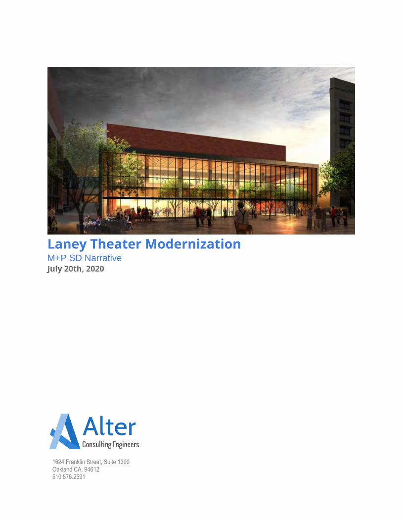
1624 Franklin Street, Suite 1300 Oakland CA, 94612 510.876.2591
Laney Theater Modernization M+P SD Narrative
July 20th, 2020
Laney College – Theater Modernization
Executive Summary Alter Consulting Engineers completed a schematic design of mechanical and plumbing systems for the Laney College Theater Modernization project. The activities include recommendations for the design of envelope systems and design of the renovated HVAC system: with a focus on comfort, resiliency, and energy performance. The existing HVAC infrastructure serving the Laney Theater building has reached the end of its useful life and should be significantly replaced. Thermal comfort and ventilation issues have been reported by the building’s occupants and stakeholders. Any major renovation of the building should include a substantial replacement of the existing HVAC system. Additionally, the building is currently served by a pneumatic control system. Pneumatic control systems rely on compressed air to open and close valves. This type of control system has long been phased out of buildings due to control issues and energy efficiency standards. A pneumatic control system cannot be digitally controlled. Any major renovation of the building should include a substantial replacement of the existing HVAC control system. The project is required to exceed the baseline performance of an equivalent Title 24 2019 baseline renovation project, by 10%. The HVAC system will be relied upon to realized most of those required savings. The specification and efficiency of the HVAC modernizations described below are critical for meeting the project’s Savings by Design goals. Under the 2019 code cycle, lighting power allowances have been significantly reduced, the project will no longer be able to rely on lighting renovations to claim substantial energy savings. Instead the project must rely more heavily on the specification of the HVAC system for energy savings. The project team aspires for construction efficiency and cost-effective sustainable design features. This is a challenge that can be met with collaboration, dedication, and attention to detail by all members of the ownership, design, and construction team.
Laney College – Theater Modernization
Table of Contents ...................................................................................................................................................................................................... 4
Overview ............................................................................................................................................................................. 4
Building Description ................................................................................................................................................................... 4
Building Sustainability ......................................................................................................................................................... 5
Façade Tuning ........................................................................................................................................................................... 5
Local Weather Analysis ............................................................................................................................................................. 6
Envelope Performance .............................................................................................................................................................. 7
Designing for Thermal Comfort .................................................................................................................................................. 8
HVAC Design Criteria.......................................................................................................................................................... 9
Outdoor Design Conditions ........................................................................................................................................................ 9
Indoor Design Conditions ........................................................................................................................................................... 9
Load Calculations ...................................................................................................................................................................... 9
Central System Sizing................................................................................................................................................................ 9
Ventilation .................................................................................................................................................................................. 9
Ductwork Design...................................................................................................................................................................... 10
Air Handling Unit Design .......................................................................................................................................................... 10
Heating and Cooling Design .................................................................................................................................................... 11
Pipe Work Design .................................................................................................................................................................... 12
Pipe Insulation ......................................................................................................................................................................... 12
Access and Maintenance ......................................................................................................................................................... 12
Controllability ........................................................................................................................................................................... 12
HVAC Scope ................................................................................................................................................................ 13
Demolition Scope..................................................................................................................................................................... 13
New Construction Scope ......................................................................................................................................................... 13
Products .................................................................................................................................................................................. 15
Water Systems ........................................................................................................................................................................ 15
Controls ................................................................................................................................................................................... 15
Plumbing Design Criteria ................................................................................................................................................... 16
Water Efficiency ....................................................................................................................................................................... 16
Fixtures .................................................................................................................................................................................... 16
Domestic Hot Water ................................................................................................................................................................. 16
Domestic Cold Water ............................................................................................................................................................... 16
Sanitary Sewer and Venting ..................................................................................................................................................... 16
Condensate ............................................................................................................................................................................. 16
Natural Gas ............................................................................................................................................................................. 16
Fire Protection ......................................................................................................................................................................... 16
Preliminary Equipment List ...................................................................................................................................................... 17
Piping Materials ....................................................................................................................................................................... 17
Fixtures and Connections ........................................................................................................................................................ 17
Accessories ............................................................................................................................................................................. 17
Miscellaneous .......................................................................................................................................................................... 17
Plumbing Scope ........................................................................................................................................................... 18
Demolition Scope of Work ....................................................................................................................................................... 18
New Construction Scope of Work ............................................................................................................................................ 18
Energy Model Detailed Inputs ....................................................................................................................................... 19
Common Model Inputs ............................................................................................................................................................. 19
Baseline, Proposed Comparisons Tables ................................................................................................................................ 19
Laney College – Theater Modernization
Overview The following report has been prepared to summarize the schematic design MEP design and building performance analysis conducted by Alter Consulting Engineers (AlterCE).
Building Description The Laney Theater is a four story performance arts and teaching facility, approximately 56,000 GSF in Oakland, California. The building is owned and operated by Laney Community College (District, College). The ground and second floors are predominantly occupied by a large performance auditorium, which includes: a stage, fly tower, catwalk, control booth, and back stage support spaces. The upper two levels include: several private offices, teaching laboratory spaces, and theatrical / musical rehearsal spaces. The core of the fourth floor is occupied by the building’s mechanical room. This mechanical room houses the buildings two air handling units and four central exhaust fans. The perimeter of the fourth floor is occupied by more teaching and theater support spaces. In addition to the four regularly occupied levels, the building also includes a basement pit / utility room area. These utility rooms include: the building electrical panels, transformers, and elevator machine equipment. The utility rooms on this level are conditioned by a large belt driven transfer fan. This fan exhausts air to the outdoors, cooling the room with make-up transfer air. The basement electrical utility room, and the cooling equipment serving this room have reached the end of their useful life and should be replaced. The building is served by two built-up air handling units (AHU)s each located in the fourth floor mechanical room. Each AHU is dedicated to a different purpose. SF-2, the first AHU, servers the theater space. SF-1, the second AHU, serves the remaining building. The AHUs have been painted based on component. With yellow belt driven centrifugal supply and return fans section, and red cooling coils sections. The cooling coil in these AHUs are supplied chilled water from the campus central plant. Chilled water was not flowing from the plant at time of the site walk. Air is distributed from the AHUs to risers built into the building’s concrete floors, walls, and roof. The new HVAC ductwork will need to be designed to utilize these existing openings. It is difficult to install new penetrations in the existing concrete structure. The buildings regularly occupied spaces have been divided into discrete HVAC control zones. Each zone is provided with a duct-mounted-constant-volume-hydronic-heating-coils and wall mounted thermostats. The thermostats communicate pneumatically with a control valve on an associated heating coil. Modulating the hydronic heating coil control valve open and closed in response to space setpoint temperature. The building is controlled by a central pneumatic controls system. This existing control system includes a pneumatic piping system which is distributed through-out the building. Pneumatic control systems are antiquated and should be replaced as part of any major building renovation project. Significant energy savings are available with more modern control systems. Compressed air leakage in the pneumatic system was observed during the site walk.
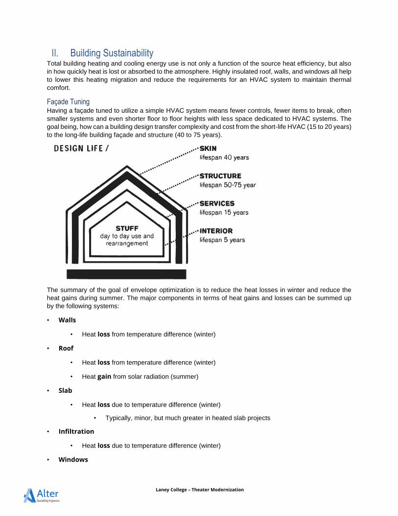
Laney College – Theater Modernization
Building Sustainability Total building heating and cooling energy use is not only a function of the source heat efficiency, but also in how quickly heat is lost or absorbed to the atmosphere. Highly insulated roof, walls, and windows all help to lower this heating migration and reduce the requirements for an HVAC system to maintain thermal comfort.
Façade Tuning Having a façade tuned to utilize a simple HVAC system means fewer controls, fewer items to break, often smaller systems and even shorter floor to floor heights with less space dedicated to HVAC systems. The goal being, how can a building design transfer complexity and cost from the short-life HVAC (15 to 20 years) to the long-life building façade and structure (40 to 75 years).
The summary of the goal of envelope optimization is to reduce the heat losses in winter and reduce the heat gains during summer. The major components in terms of heat gains and losses can be summed up by the following systems:
• Walls
• Heat loss from temperature difference (winter)
• Roof
• Heat loss from temperature difference (winter)
• Heat gain from solar radiation (summer)
• Slab
• Heat loss due to temperature difference (winter)
• Typically, minor, but much greater in heated slab projects
• Infiltration
• Heat loss due to temperature difference (winter)
• Windows
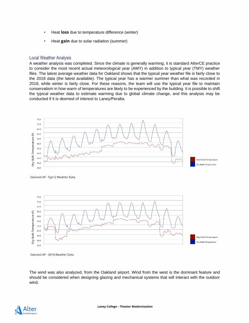
Laney College – Theater Modernization
• Heat loss due to temperature difference (winter)
• Heat gain due to solar radiation (summer)
Local Weather Analysis A weather analysis was completed. Since the climate is generally warming, it is standard AlterCE practice to consider the most recent actual meteorological year (AMY) in addition to typical year (TMY) weather files. The latest average weather data for Oakland shows that the typical year weather file is fairly close to the 2018 data (the latest available). The typical year has a warmer summer than what was recorded in 2018, while winter is fairly close. For these reasons, the team will use the typical year file to maintain conservatism in how warm of temperatures are likely to be experienced by the building. It is possible to shift the typical weather data to estimate warming due to global climate change, and this analysis may be conducted if it is deemed of interest to Laney/Peralta.
The wind was also analyzed, from the Oakland airport. Wind from the west is the dominant feature and should be considered when designing glazing and mechanical systems that will interact with the outdoor wind.
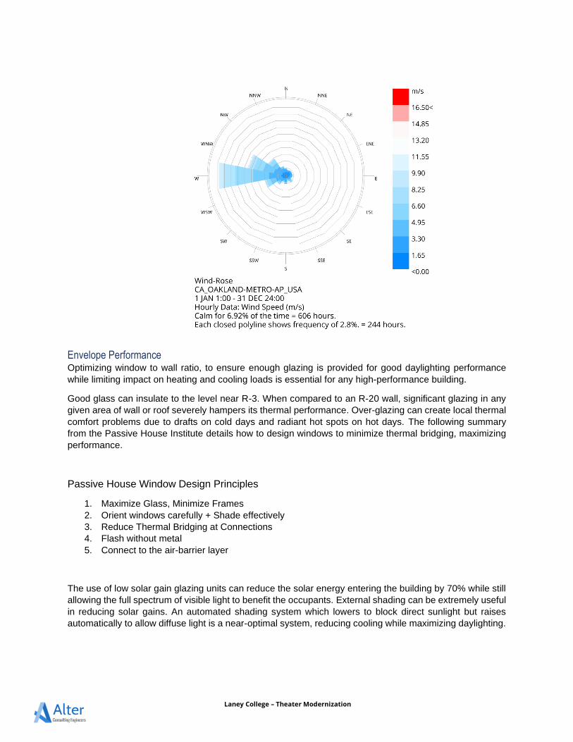
Laney College – Theater Modernization
Envelope Performance Optimizing window to wall ratio, to ensure enough glazing is provided for good daylighting performance while limiting impact on heating and cooling loads is essential for any high-performance building.
Good glass can insulate to the level near R-3. When compared to an R-20 wall, significant glazing in any given area of wall or roof severely hampers its thermal performance. Over-glazing can create local thermal comfort problems due to drafts on cold days and radiant hot spots on hot days. The following summary from the Passive House Institute details how to design windows to minimize thermal bridging, maximizing performance.
Passive House Window Design Principles
1. Maximize Glass, Minimize Frames 2. Orient windows carefully + Shade effectively 3. Reduce Thermal Bridging at Connections 4. Flash without metal 5. Connect to the air-barrier layer
The use of low solar gain glazing units can reduce the solar energy entering the building by 70% while still allowing the full spectrum of visible light to benefit the occupants. External shading can be extremely useful in reducing solar gains. An automated shading system which lowers to block direct sunlight but raises automatically to allow diffuse light is a near-optimal system, reducing cooling while maximizing daylighting.
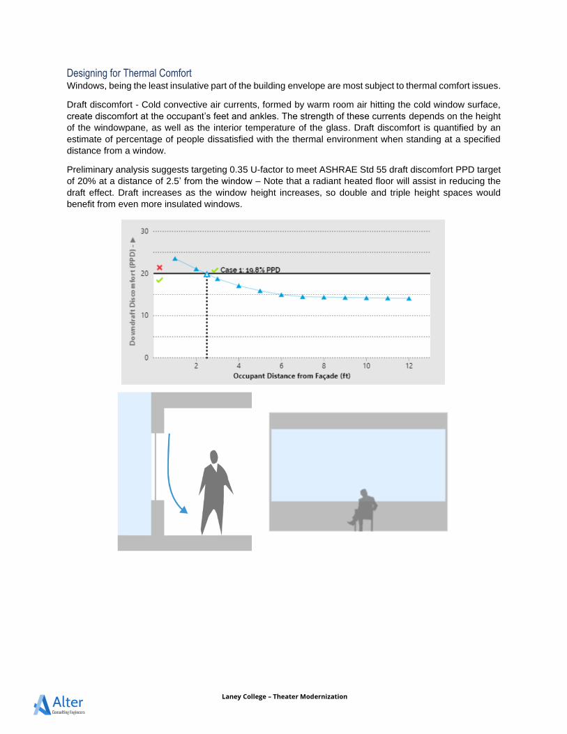
Laney College – Theater Modernization
Designing for Thermal Comfort Windows, being the least insulative part of the building envelope are most subject to thermal comfort issues.
Draft discomfort - Cold convective air currents, formed by warm room air hitting the cold window surface, create discomfort at the occupant’s feet and ankles. The strength of these currents depends on the height of the windowpane, as well as the interior temperature of the glass. Draft discomfort is quantified by an estimate of percentage of people dissatisfied with the thermal environment when standing at a specified distance from a window.
Preliminary analysis suggests targeting 0.35 U-factor to meet ASHRAE Std 55 draft discomfort PPD target of 20% at a distance of 2.5’ from the window – Note that a radiant heated floor will assist in reducing the draft effect. Draft increases as the window height increases, so double and triple height spaces would benefit from even more insulated windows.
Laney College – Theater Modernization
HVAC Design Criteria Outdoor Design Conditions Location: Oakland, California Outdoor Design Conditions:
• Temperatures are based on 2019 Title 24 (0.5% cooling, 99.4% heating) for Oakland, CA. • Summer peak based on monthly 0.5%: 89 F DB; 66 F WB • Winter based on 0.6%: 31 F DB
Using the 0.6% and 0.5% design conditions is industry standard design practice and ensures the HVAC system is not sized based on short duration extreme outdoor air conditions. Instead, the system is sized to operate favorable at far more common outdoor air design conditions.
Indoor Design Conditions The HVAC system is designed to maintain the following conditions in each interior space type.
Space Summer Winter Theater 75°F ± 2 DB 70°F ± 2 DB Office Spaces 75°F ± 2 DB 70°F ± 2 DB Classrooms 75°F ± 2 DB 70°F ± 2 DB IDF Room 80°F ± 2 DB 55°F ± 2 DB Lobby/Circulation 78°F ± 2 DB 70°F ± 2 DB Locker Rooms / Changing 75°F ± 2 DB 70°F ± 2 DB Storage Rooms / MEP Rooms 85°F ± 2 DB 55°F ± 2 DB
Load Calculations Load calculations should be based on the methodology outlined by the ASHRAE Handbook – Fundamentals, Chapter 16, Non-residential Cooling and Heating Load Calculations. Heating load calculations use simple worst-case assumptions: no solar or internal gains, and no heating storage (with all heat losses evaluated instantaneously). Cooling load calculations should follow the heat balance (HB) method. This estimation involves calculating a surface-by-surface conductive, convective and radiative heat balance for each room surface and a convective heat balance for the room air. The HB method contains no arbitrarily set parameters The heat balance (HB) method allows detailed simulation of space temperatures and flows.
Central System Sizing The central system shall be size as indicated by the modeled peak coincidental block load. No safety factor is applied at the central system level. Instead, because equipment is sold in nominal sizes, the capacity of the central system is based on the closest nominal sized piece of equipment available which is capable of meeting the modeled coincidental peak block load.
Ventilation Mechanical ventilation and air filtration will be provided to maintain acceptable indoor air quality. The quantity of outdoor air is based on ventilation rates as required by Title 24 Part 6 and its reference standard ASHRAE 62.1. The proposed systems bring in ventilation air and mix it with recirculated room air, all of which is filtered and conditioned prior to being introduced into the occupied zone. Natural ventilation may be used in conjunction with the fan-based ventilation but will need to be carefully coordinated from an operational
Laney College – Theater Modernization
standpoint, so the mechanical system is not running while natural ventilation is being used. The spaces will be maintained at neutral pressure with respect to the outside. The heat recovery element shall be sized to ensure ventilation supply air to the building is never less than 60 degrees and never greater than 80 degrees. Assume return air temperatures equal to room air temperature plus 5 degree offset. Standard filtration provides for protection of equipment (coils, fans, etc) but does not provide for occupant health. High-efficiency filtration ensures that indoor air quality is also maintained. By increasing the efficiency of the filtration, especially for the smallest particles, dust and common airborne pollutants are greatly reduced. With the right selection and design of the filtration system, the energy required for filtering ventilation air will be controlled to a manageable level.
Ductwork Design The ductwork sizing and space air distribution shall be done in accordance with ASHRAE and SMACNA standards. Ductwork upstream of VAV boxes shall be designed not to exceed 0.07inWC/100ft or 1200 FPM. Ductwork downstream of VAV boxes shall be designed not to exceed 0.05 inWC/100ft or 1000FPM. Where turns and offsets are required, low pressure drop fittings such as 1.5 radius elbows and mitered elbows with turning vanes shall be provided. Single radius elbows and mitered elbows without turning vanes are not permitted. Sheet metal gauges shall be in accordance with SMACNA. Construction of ductwork shall be in accordance with SMACNA 1995-second edition for the appropriate duct pressure classification. Sheet metal shall be galvanized steel.
Air Handling Unit Design Each air handler provided shall be capable of 100% outdoor air economizer through parallel blade low leakage dampers and direct coupled actuators. Size cooling coil for 15 degree chilled water delta T, assuming 55 degree entering chilled water temperature. Face velocity shall not exceed 350 ft/min. Coils density shall not exceed 10 fpi or 8 rows. The total air pressure drop associated with the cooling coil shall not exceed 0.5inWC. Size heating coil for 20 degree heating hot water delta T, assuming 130 degree entering heating hot water temperature. Face velocity shall not exceed 350 ft/min. Coils density shall not exceed 10 fpi or 6 rows. The total air pressure drop associated with the heating coil shall not exceed 0.4inWC. Provide space within AHUs for 12” V-Cell MERV-14 filters and “throw-away” 4” V-Cell MERV-8 filters (for flush out). Pre filters are not required for normal operation. The total air pressure drop associated with the pre and final filters shall not exceed 0.10inWC when clean, or 1.0inWC when dirty. The system shall measure and alarm when filter pressure exceeds 1.0inWC. Indoor air handlers shall be 2-in double wall construction, outdoor air handlers shall be 4-in double wall construction. Where air to air heat recovery is provided, the heat recovery system shall be rated for minimum of 75% sensible heat recovery effectiveness. The unit shall be capable of 100% outdoor air and exhaust air bypass around the heat recovery element. The bypass shall be controlled by a modulating damper. The unit shall be capable of modulating the bypass damper to maintain a constant mixed air condition (bypassing some air around the heat recovery element to control heat recovery rate). The total air pressure drop associated with the entire heat recovery system shall not exceed 0.4inWC on the supply fans and/or 0.4inWC on the return fan.
Laney College – Theater Modernization
Each air handling unit over 10,000 CFM
• Shall be provided with a minimum of (qty.4) supply fans and (qty.4) return fans. • Each fan shall be sized to provided 1/3 of the peak design flow rate. • Each fan shall be provided with a backdraft damper, the damper shall fail closed when a fan fails. • The unit shall maintain continuous, 100% operation, with one fan failed. • Each fan shall be driven by an EC motor. • The unit shall be automatically disable individual supply and return fans to provide stable capacity
down to 10% flow rate conditions. • Heat recovery shall be enable a minimum of 75% sensible effectiveness • Connected to campus BMS (read/write)
Each air handling unit less 10,000 CFM
• Shall be provided with a minimum of (qty.2) supply fans and (qty.2) return fans. • Each fan shall be sized to provided 1/3 of the peak design flow rate. • Each fan shall be provided with a backdraft damper, the damper shall fail closed when a fan fails. • The unit shall maintain continuous, 50% operation, with one fan failed. • Each fan shall be driven by an EC motor. • Heat recovery shall be enable a minimum of 70% sensible effectiveness • Connected to campus BMS (read/write)
Heating and Cooling Design Hot water and chilled water from the Laney College central utility plant (CUP) has been provided to the building for the buildings heating and cooling needs. Hot and chilled water enter the building through a service tunnel located at grade. Heating and cooling water tap off of the existing lines to serve the theater and the adjacent locker room building. These services are not currently separated, a common tap is shared by both buildings. A new tap will be required to separate the locker room’s heating hot water services from the theater building’s hot water services. The system will be changed over under a separate contract. New chilled and hot water flow meters will be required. Flow meters shall be provided with supply and return temperature propose to enable BTU/hr monitoring. Provide flow meters for the Theater Building, chilled water and heating hot water. Isolation valves and drain valves shall be provided where the piping enters the building to allow the building chilled water and hot water piping to be isolated from the campus loop and drained. New secondary chilled water and heating hot water pumps shall be provided to source water from the campus chilled and heating hot water loops. Chilled Water Secondary Pumps
• Qty.2 Pumps • Each sized for 60% design flow rates • Located in fourth floor mechanical room • EC Motors • Connected to campus BMS (read/write)
Heating Hot Water Secondary Pumps
• Qty.2 Pumps • Each sized for 60% design flow rates • Located in utility tunnel • EC Motors • Connected to campus BMS (read/write)
Laney College – Theater Modernization
Pipe Work Design Pipe work shall be installed per ASPE installation requirements. Pipe sizes shall be based sized not to exceed 3 FPS. Valves and fittings shall be low pressure drop, with smooth elbows. Piping shall be valve to accommodate isolation of zones from the central loop effect on the system operation.
Pipe Insulation Pipe shall be insulated in conformance with California’s 2019 Title 24 Part 6. Where insulation is exposed to the outdoors, insulation shall be protected with a weather proof enclosure or insulation shall be itself weather resistant.
Access and Maintenance The heating and cooling system shall be located in a means that allows for adequate service area. This should include a minimum of 4ft in front of electrical panels, and 12” of separation between equipment and exterior or interior walls. Equipment shall be specified in a way which reduces maintenance. This includes: providing fans with direct drive motors; providing outdoor unit coast treatment coatings; specifying equipment made of resilient materials; limiting equipment exposure to the direct sun; and locating equipment low to the ground, where possible. The ventilation system will require regular filter replacement. Filters should be located in a means which enables easy access. If the ventilator is located in a cabinet, provide filters located at the unit. If the ventilator is located in a ceiling or crawlspace, then provide filters at the return air grille and the outdoor air intake louver. Electric heat pumps will generate significant condensate during the winter heating season. If an electric air source heat pump is provide to generate heating, ensure adequate design consideration has been provide to address condensate. Additionally heat pump will be located outdoors and require periodic washdown of condensers coils. The heat pump should be provided with an appropriate coatings for coastal environments and washdown.
Controllability The owner shall have control, through a web terminal with the ability to: read/write, read, and write all points available for any central system provided. Including but not limited to, scheduling, setpoints, bypass control, economizer setpoints, view power use, view heating / cooling demand, fan speed.. Each devices shall be web access enabled and include a simplified web application based control interface. This building will be provided with full DDC controls using Guideline 36 control sequences. CO2 sensors shall be located in spaces with high-density occupancies to allow for demand-controller ventilation. The building automation system will be integrated with the centralized lighting controls, to leverage the lighting occupancy sensors to reduce ventilation and expand space temperature setpoints when spaces are unoccupied.
Laney College – Theater Modernization
HVAC Scope To meet the project scoping items, identified by the project Architect, the project will be required to undertake a major renovation of the buildings HVAC system. The following scope of work has been identified. Please refer to architectural drawings for additional scope clarification.
Demolition Scope 1. Except where identified below and in drawings,
a. Existing ductwork distribution from existing AHU room to existing VAV boxes to remain b. Existing ductwork distribution from existing VAV box to existing air terminals to remain c. Existing hydronic piping distribution to remain
2. Existing basement dinner room exhaust fan 3. Fabrication lab HVAC and associated supply fan 4. Existing air handling units located in the fourth floor mechanical room 5. Existing exhaust fans located in the fourth floor mechanical room 6. Existing ducting in four floor mechanical room as indicated in demo plans 7. All zone level reheat boxes 8. Existing pneumatic control system 9. Existing thermostats 10. Existing process chilled and process hot water flow meters 11. Branch hydronic piping serving adjacent Locker Room building 12. Zone level supply air diffuser and return air grilles serving theater seating area 13. Floor diffuser serving existing lobby area 14. Duct downstream of VAV box in Office 200 15. Zone level ductwork serving balcony 16. Supply and return air terminals in balcony 17. Zone level ductwork serving 3rd floor offices 18. Supply air and return terminals in 3rd floor offices. 19. Zone level ductwork serving the dressing, make-up, and costume rooms. 20. Zone level ductwork serving Green Room 201 21. Zone level ductwork serving TV Studio 306/306a 22. Zone level ductwork serving Media Classroom 319 23. Zone level ductwork serving New TV Studio 24. Zone level ductwork serving Green Room 201 25. Zone level ductwork serving Media Recording 415/413
New Construction Scope 1. Clean and leak test all ductwork (new and existing) 2. Inspect, replace as necessary, and flush clean all hydronic piping (new and existing) 3. New basement Dimmer Room exhaust fan 4. New cabinet mounted AHU to Scene Shop 5. Ductwork serving new Scene Shop 6. Install (qty.2) new air handling units in the fourth floor mechanical room
a. 20,000CFM VAV Supply fan array, each b. 20,000CFM VAV Return fan array, each c. 400 FPM Chilled water cooling coil, each d. Flat plate exhaust heat recovery heat exchanger at 70% effective. Each Sized at less
than 0.5inWC pressure drop e. Heat recovery bypass damper. each f. Enthalpy based air side economizer, at 100% design air flow rate, each g. Isolate all new equipment with spring isolators, each h. Install duct static pressure sensor downstream in existing ductwork, for fan speed control,
each i. Provide duct mounted intake and discharge silencers
Laney College – Theater Modernization
j. Enabled BMS monitoring and command k. Enable Guideline 36 compliant control
7. Install (qty.1) new restroom exhaust fan, to serve existing restrooms a. 5,000CFM Exhaust Fan b. 1.5inWC c. Utility Fan d. Isolate all new equipment with spring isolators, each e. Install airflow measuring station f. Enabled BMS monitoring and command g. Enable Guideline 36 compliant control
8. Install (qty.1) new restroom exhaust fan, to serve new restroom addition a. 1,000CFM Exhaust Fan b. 1.5inWC c. Utility Fan d. Isolate all new equipment with spring isolators, each e. Install airflow measuring station f. Enabled BMS monitoring and command g. Enable Guideline 36 compliant control
9. Ductwork from fourth floor risers to new fourth floor AHUs 10. Ductwork from fourth floor risers to new fourth floor exhaust fans 11. Install all new zone level supply VAV reheat boxes, connect to existing hydronic heating piping 12. Install all new zone level exhaust VAV boxes. Where possible located VAV boxes in mechanical
room, many risers in mechanical room are dedicated to specific zones. 13. New BACnet DDC control system
a. Install new wall thermostats b. Wire new controls system to new VAV reheat boxes, and new AHUs c. Integrate with campus control system d. Install new building level chilled water and heating hot water BTU meter e. Enable Guideline 36 compliant control
14. 4” Theater building Chilled Water Meter, full bore, BMS connection. 15. 4” Theater building Heating Hot Water Meter, full bore, BMS connection. 16. 2” Locker Room Heating Hot Water Meter, full bore, BMS connection. 17. Branch hydronic piping as required to separate Locker Room heating hot water loop from Theater
building heating hot water loop. 18. Displacement zone level supply air diffusers below seating area 19. Reconfigure branch ductwork, below seating area, to inverse supply and return locations in the
theater seating zone. Diffuser below theater seating should supply air, grilles behind theater seating (on wall) should return air. As designed system currently does opposite. Refer to plans.
20. Floor diffusers to serve ventilation to new lobby area 21. Install radiant pex tubing, 5/8” ID. 9”OCC within new topping slab of new entry lobby 22. Route pex tubing in slab to manifold cabinet. 23. Route chilled water and hot water, from local mains to radiant manifold cabinet 24. Duct downstream of VAV box in Office 200 25. Zone level ductwork serving balcony 26. Supply and return air terminals in balcony 27. Zone level ductwork serving 3rd floor offices 28. Supply air and return terminals in 3rd floor offices. 29. Zone level ductwork serving the dressing, make-up, and costume rooms. 30. Zone level ductwork serving Green Room 201 31. Zone level ductwork serving TV Studio 306/306a 32. Zone level ductwork serving Media Classroom 319 33. Zone level ductwork serving New TV Studio 34. Zone level ductwork serving Green Room 201 35. Zone level ductwork serving Media Recording 415/413
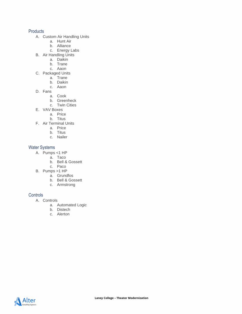
Laney College – Theater Modernization
Products A. Custom Air Handling Units
a. Hunt Air b. Alliance c. Energy Labs
B. Air Handling Units a. Daikin b. Trane c. Aaon
C. Packaged Units a. Trane b. Daikin c. Aaon
D. Fans a. Cook b. Greenheck c. Twin Cities
E. VAV Boxes a. Price b. Titus
F. Air Terminal Units a. Price b. Titus c. Nailer
Water Systems A. Pumps <1 HP
a. Taco b. Bell & Gossett c. Paco
B. Pumps >1 HP a. Grundfos b. Bell & Gossett c. Armstrong
Controls A. Controls
a. Automated Logic b. Distech c. Alerton
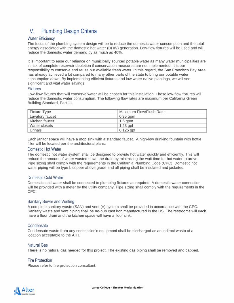
Laney College – Theater Modernization
Plumbing Design Criteria Water Efficiency The focus of the plumbing system design will be to reduce the domestic water consumption and the total energy associated with the domestic hot water (DHW) generation. Low-flow fixtures will be used and will reduce the domestic water demand by as much as 40%. It is important to ease our reliance on municipally sourced potable water as many water municipalities are in risk of complete reservoir depletion if conservation measures are not implemented. It is our responsibility to conserve and reuse our available fresh water. In this regard, the San Francisco Bay Area has already achieved a lot compared to many other parts of the state to bring our potable water consumption down. By implementing efficient fixtures and low water native plantings, we will see significant and vital water savings.
Fixtures Low-flow fixtures that will conserve water will be chosen for this installation. These low-flow fixtures will reduce the domestic water consumption. The following flow rates are maximum per California Green Building Standard, Part 11.
Fixture Type Maximum Flow/Flush Rate Lavatory faucet 0.35 gpm Kitchen faucet 1.5 gpm Water closets 1.28 gpf Urinals 0.125 gpf
Each janitor space will have a mop sink with a standard faucet. A high-low drinking fountain with bottle filler will be located per the architectural plans.
Domestic Hot Water The domestic hot water system shall be designed to provide hot water quickly and efficiently. This will reduce the amount of water wasted down the drain by minimizing the wait time for hot water to arrive. Pipe sizing shall comply with the requirements in the California Plumbing Code (CPC). Domestic hot water piping will be type L copper above grade and all piping shall be insulated and jacketed.
Domestic Cold Water Domestic cold water shall be connected to plumbing fixtures as required. A domestic water connection will be provided with a meter by the utility company. Pipe sizing shall comply with the requirements in the CPC.
Sanitary Sewer and Venting A complete sanitary waste (SAN) and vent (V) system shall be provided in accordance with the CPC. Sanitary waste and vent piping shall be no-hub cast iron manufactured in the US. The restrooms will each have a floor drain and the kitchen space will have a floor sink.
Condensate Condensate waste from any concession’s equipment shall be discharged as an indirect waste at a location acceptable to the AHJ.
Natural Gas There is no natural gas needed for this project. The existing gas piping shall be removed and capped.
Fire Protection Please refer to fire protection consultant.
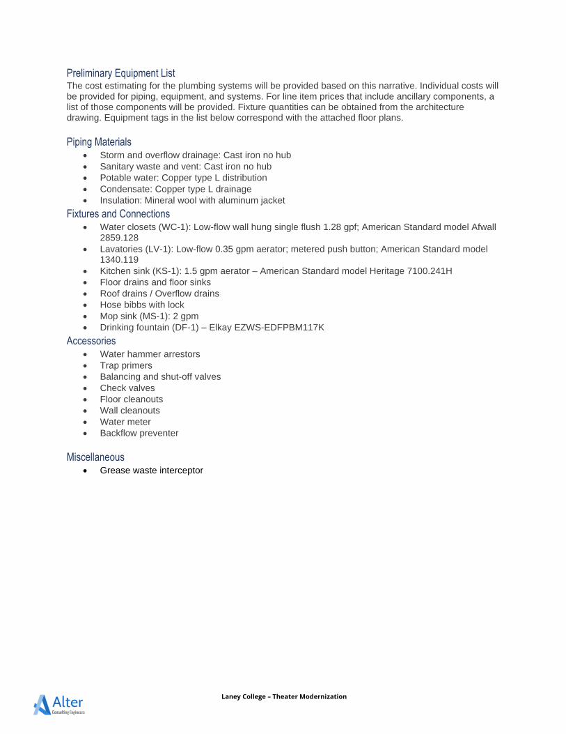
Laney College – Theater Modernization
Preliminary Equipment List The cost estimating for the plumbing systems will be provided based on this narrative. Individual costs will be provided for piping, equipment, and systems. For line item prices that include ancillary components, a list of those components will be provided. Fixture quantities can be obtained from the architecture drawing. Equipment tags in the list below correspond with the attached floor plans.
Piping Materials • Storm and overflow drainage: Cast iron no hub • Sanitary waste and vent: Cast iron no hub • Potable water: Copper type L distribution • Condensate: Copper type L drainage • Insulation: Mineral wool with aluminum jacket
Fixtures and Connections • Water closets (WC-1): Low-flow wall hung single flush 1.28 gpf; American Standard model Afwall
2859.128 • Lavatories (LV-1): Low-flow 0.35 gpm aerator; metered push button; American Standard model
1340.119 • Kitchen sink (KS-1): 1.5 gpm aerator – American Standard model Heritage 7100.241H • Floor drains and floor sinks • Roof drains / Overflow drains • Hose bibbs with lock • Mop sink (MS-1): 2 gpm • Drinking fountain (DF-1) – Elkay EZWS-EDFPBM117K
Accessories • Water hammer arrestors • Trap primers • Balancing and shut-off valves • Check valves • Floor cleanouts • Wall cleanouts • Water meter • Backflow preventer
Miscellaneous • Grease waste interceptor
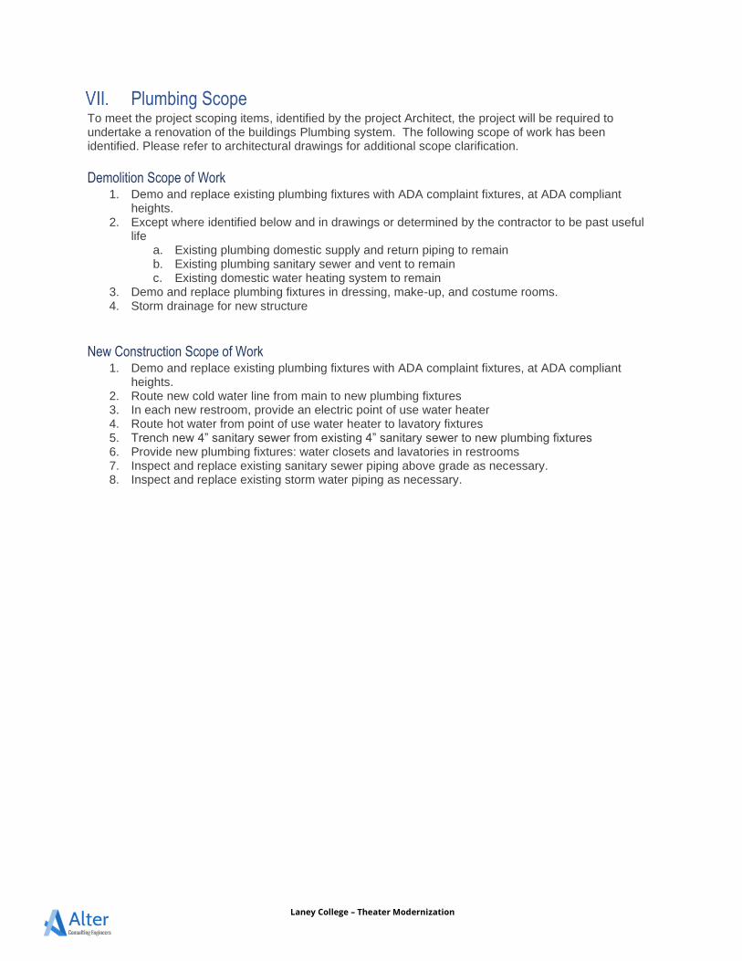
Laney College – Theater Modernization
Plumbing Scope To meet the project scoping items, identified by the project Architect, the project will be required to undertake a renovation of the buildings Plumbing system. The following scope of work has been identified. Please refer to architectural drawings for additional scope clarification.
Demolition Scope of Work 1. Demo and replace existing plumbing fixtures with ADA complaint fixtures, at ADA compliant
heights. 2. Except where identified below and in drawings or determined by the contractor to be past useful
life a. Existing plumbing domestic supply and return piping to remain b. Existing plumbing sanitary sewer and vent to remain c. Existing domestic water heating system to remain
3. Demo and replace plumbing fixtures in dressing, make-up, and costume rooms. 4. Storm drainage for new structure
New Construction Scope of Work 1. Demo and replace existing plumbing fixtures with ADA complaint fixtures, at ADA compliant
heights. 2. Route new cold water line from main to new plumbing fixtures 3. In each new restroom, provide an electric point of use water heater 4. Route hot water from point of use water heater to lavatory fixtures 5. Trench new 4” sanitary sewer from existing 4” sanitary sewer to new plumbing fixtures 6. Provide new plumbing fixtures: water closets and lavatories in restrooms 7. Inspect and replace existing sanitary sewer piping above grade as necessary. 8. Inspect and replace existing storm water piping as necessary.
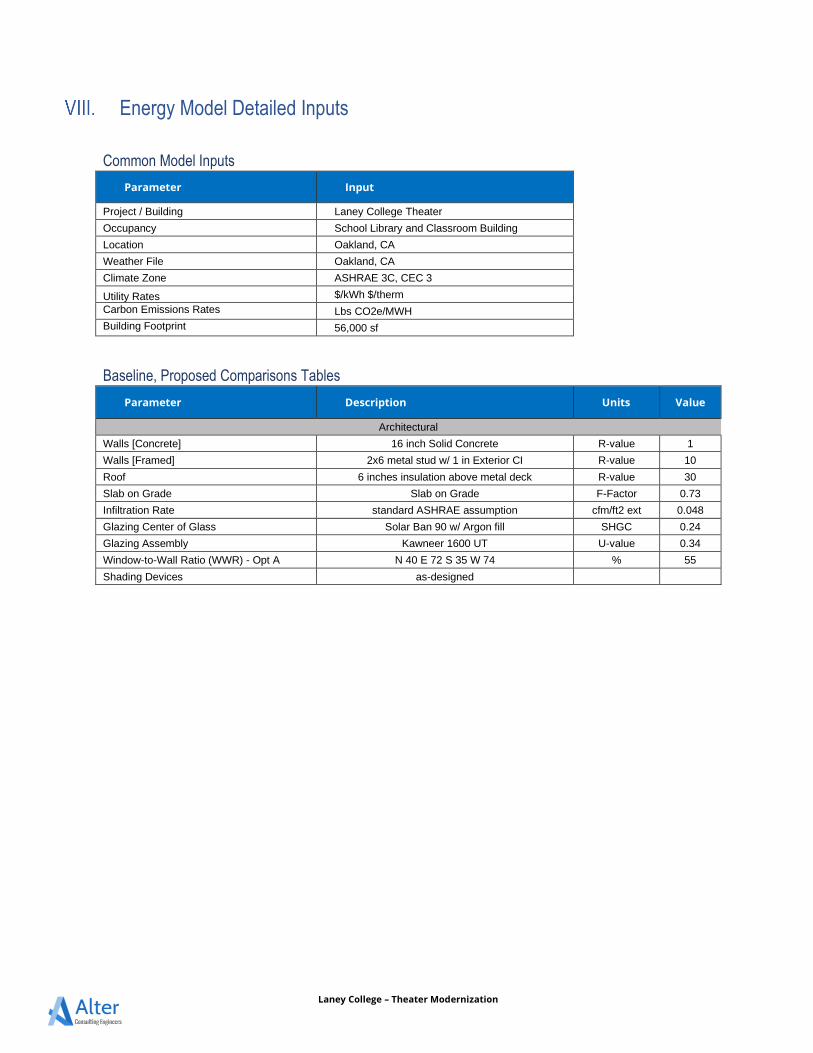
Laney College – Theater Modernization
Energy Model Detailed Inputs
Common Model Inputs
Parameter Input
Project / Building Laney College Theater
Occupancy School Library and Classroom Building
Location Oakland, CA
Weather File Oakland, CA
Climate Zone ASHRAE 3C, CEC 3
Utility Rates $/kWh $/therm Carbon Emissions Rates Lbs CO2e/MWH Building Footprint 56,000 sf
Baseline, Proposed Comparisons Tables
Parameter Description Units Value
Architectural
Walls [Concrete] 16 inch Solid Concrete R-value 1
Walls [Framed] 2x6 metal stud w/ 1 in Exterior CI R-value 10
Roof 6 inches insulation above metal deck R-value 30
Slab on Grade Slab on Grade F-Factor 0.73
Infiltration Rate standard ASHRAE assumption cfm/ft2 ext 0.048
Glazing Center of Glass Solar Ban 90 w/ Argon fill SHGC 0.24
Glazing Assembly Kawneer 1600 UT U-value 0.34
Window-to-Wall Ratio (WWR) - Opt A N 40 E 72 S 35 W 74 % 55
Shading Devices as-designed
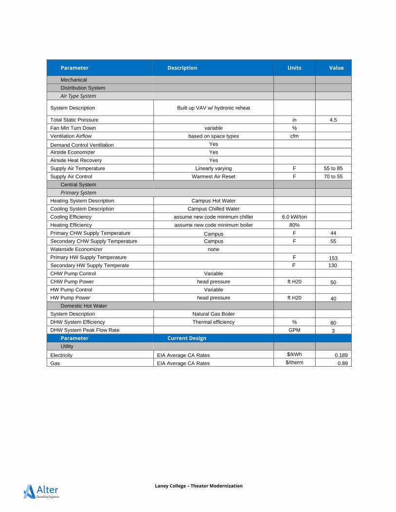
Laney College – Theater Modernization
Parameter Description Units Value
Mechanical
Distribution System
Air Type System
System Description Built up VAV w/ hydronic reheat
Total Static Pressure in 4.5
Fan Min Turn Down variable %
Ventilation Airflow based on space types cfm
Demand Control Ventilation Yes
Airside Economizer Yes
Airside Heat Recovery Yes
Supply Air Temperature Linearly varying F 55 to 85
Supply Air Control Warmest Air Reset F 70 to 55
Central System
Primary System
Heating System Description Campus Hot Water
Cooling System Description Campus Chilled Water
Cooling Efficiency assume new code minimum chiller 6.0 kW/ton
Heating Efficiency assume new code minimum boiler 80%
Primary CHW Supply Temperature Campus F 44
Secondary CHW Supply Temperature Campus F 55
Waterside Economizer none
Primary HW Supply Temperature F 153 Secondary HW Supply Temperate F 130
CHW Pump Control Variable CHW Pump Power head pressure ft H20 50 HW Pump Control Variable HW Pump Power head pressure ft H20 40
Domestic Hot Water
System Description Natural Gas Boiler DHW System Efficiency Thermal efficiency % 80 DHW System Peak Flow Rate GPM 3
Parameter Current Design
Utility
Electricity EIA Average CA Rates $/kWh 0.189
Gas EIA Average CA Rates $/therm 0.89
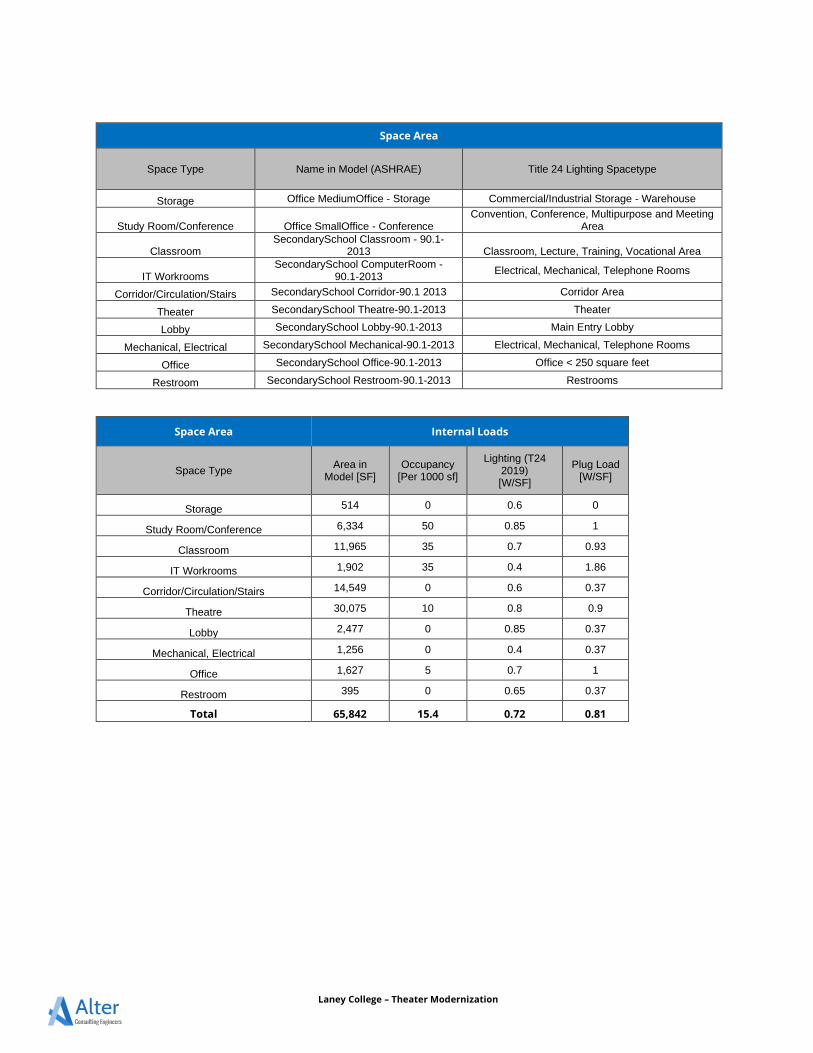
Laney College – Theater Modernization
Space Area
Space Type Name in Model (ASHRAE) Title 24 Lighting Spacetype
Storage Office MediumOffice - Storage Commercial/Industrial Storage - Warehouse
Study Room/Conference Office SmallOffice - Conference Convention, Conference, Multipurpose and Meeting
Area
Classroom SecondarySchool Classroom - 90.1-
2013 Classroom, Lecture, Training, Vocational Area
IT Workrooms SecondarySchool ComputerRoom -
90.1-2013 Electrical, Mechanical, Telephone Rooms
Corridor/Circulation/Stairs SecondarySchool Corridor-90.1 2013 Corridor Area
Theater SecondarySchool Theatre-90.1-2013 Theater
Lobby SecondarySchool Lobby-90.1-2013 Main Entry Lobby
Mechanical, Electrical SecondarySchool Mechanical-90.1-2013 Electrical, Mechanical, Telephone Rooms
Office SecondarySchool Office-90.1-2013 Office < 250 square feet
Restroom SecondarySchool Restroom-90.1-2013 Restrooms
Space Area Internal Loads
Space Type Area in
Model [SF] Occupancy
[Per 1000 sf]
Lighting (T24 2019) [W/SF]
Plug Load [W/SF]
Storage 514 0 0.6 0
Study Room/Conference 6,334 50 0.85 1
Classroom 11,965 35 0.7 0.93
IT Workrooms 1,902 35 0.4 1.86
Corridor/Circulation/Stairs 14,549 0 0.6 0.37
Theatre 30,075 10 0.8 0.9
Lobby 2,477 0 0.85 0.37
Mechanical, Electrical 1,256 0 0.4 0.37
Office 1,627 5 0.7 1
Restroom 395 0 0.65 0.37
Total 65,842 15.4 0.72 0.81
PERALTA COMMUNITY COLLEGE DISTRICT LANEY COLLEGE THEATER MODERNIZATION OAKLAND, CA
200730LCT027/ELS
APPENDIX B
ELECTRICAL NARRATIVE
LANEY COLLEGE THEATRE MODERNIZATIONSCHEMATIC DESIGN PRICING NARRATIVE - ELECTRICAL
RIJA Inc.
1620 Montgomery Street, Suite 250
San Francisco, CA 94111
July 17, 2020
LANEY COLLEGE THEATRE MODERNIZATION – Schematic Design Pricing Narrative
P a g e 1 | 6
1 INTRODUCTION The electrical design will strategically implement a sensible and sustainable electrical system that provides ease of maintenance and
flexibility, while also designed for a modern, digital, and connected learning environment. The unique uses and activities at the Theatre
necessitate flexible spaces, along with flexible electrical systems to allow for frequent reconfiguration of classrooms and capacity for future
modifications. Energy efficiency will be accomplished within the building design through responsive lighting controls, daylight harvesting
elements, plug load control, and sensitivity towards equipment selection.
1.1 Codes & Standards
California Codes
2019 California Building Code (CBC), Volumes #1 and #2 (Part 2, Title 24, CCR).
2019 California Building Code (Part 3, Title 24, CCR).
2019 California Fire Code (CFC) (Part 9, Title 24, CCR).
2019 California Green Code (Part 11, Title 24, CCR).
2019 California Referenced STANDARDS CODE (Part 12, Title 24, CCR).
2019 NFPA 72 National Fire Alarm Code.
2019 ADA Standards for Accessible Design.
2 ELECTRICAL SYSTEM 2.1 Electrical Service
The existing theatre building is being fed from Existing Unit Substation No. 5 located at the transformer room located at the
Stage/Orchestra level. Substation No. 5 is rated at 1500kVA, 12kV-480/277V and was manufactured in 1969. The transformer is
antiquated and should be replaced. In addition to the Theatre building, this unit substation also feeds Building G. For the purposes
of this pricing exercise, provide Add Alternate Line Item Cost for replacement of Unit Substation No. 5 with new, and reconnecting
Building G.
2.2 Building(s) Distribution
The existing electrical distribution equipment (switchboard, transformers, panelboards, etc) is antiquated and past the
manufacturers recommended life. All equipment to be replaced
Dedicated distribution equipment shall be provided for AV and Theatrical Lighting use, see 2.8 Equipment List
Provide dedicated panelboards per floor.
House Lighting, Plugs, Domestic Hot Water, and HVAC shall be disaggregated and served from dedicated panelboards, see 2.8
Equipment List.
Re-use of existing infrastructure (conduits and backboxes) where possible
2.3 Branch Distribution
For areas not affected by work, intercept existing branch circuits and reconnect to new distribution equipment
Branch circuit design will not exceed a maximum of 1,600 volt amperes per 20 ampere, 120 volt circuit for general areas. Branch
circuit design for computer rooms, offices, and administration will not exceed a maximum of 720 volt amperes per 20 ampere, 120
volt circuit. Dedicated circuits will be required for theatre equipment, classrooms, and administration buildings. These equipment
and locations will be determine during the next phase of design.
Motors of 1/2 horsepower and larger will be served at 208 volt service, 3 phase, 3 wire + ground. Motors less than 1/2 horsepower
will be served at 120 volt service, 1 phase, 2 wire + ground. All multi-wire branch circuits will be installed with dedicated neutrals.
Highly loaded, 20-amp, continuous electrical loads, such as circulation-lighting and servers, will have increased wire sizes (i.e.: from
#12 to #10) in order to reduce power loss in the wiring.
Refer to Shalleck Collaborative for additional branch and feeder distribution requirements.
Separate wires in conduit will be provided for each of the following loads:
Mechanical and Plumbing Systems
o 480V, 3 phase, 3 wire + ground, 60 hertz.
o 208V, 1 phase, 2 wire + ground, 60 hertz.
LANEY COLLEGE THEATRE MODERNIZATION – Schematic Design Pricing Narrative
P a g e 2 | 6
o 120V, 1 phase, 2 wire + ground, 60 hertz.
Lighting
o 277V, 1 phase, 2 wire + ground, 60 hertz.
General Purpose Receptacles
o 120V, 1 phase, 2 wire + ground, 60 hertz.
Computer Equipment Areas
o 120V, 1 phase, 2 wire + ground, 60 hertz.
Head-ends for Signal Systems (i.e.: BMS, Security, Fire Alarm, Lighting Controls, etc.)
o 120V, 1 phase, 2 wire + ground, 60 hertz.
2.4 Emergency Power System
Life Safety secondary source of power shall be provided by a lighting inverters strategically located throughout the building. The inverters
can be located in ceiling space, wall mount, or in dedicated closets. We assume UPS power (uninterrupted power source) will be rack
mounted and provided by owner.
Emergency / Life Safety Loads include the following:
Emergency and Egress Lighting
Exit Signs
Fire Alarm
Standby Loads include the following:
Network Rooms
The lighting inverters will be interconnected to the fire alarm system such that under alarm situations, the emergency lighting will turn on
regardless of control state.
2.5 Power Monitoring
A main building meter will be provided at the main switchboard. A multipoint metering system shall be used at the main switchboard. Sub-
meters will be web-enabled and communicate to the building energy management system.
Metering will occur and panelboard level and will be segregated as follows:
HVAC
Domestic Water Systems
Telecommunications
Plug Load
Lighting
Theatrical Loads
In the next phase of the design, we will prepare a submetering diagram and Sub Metering schedule.
2.6 Grounding
A single point grounding system will be established via main ground bus located in the main electrical room. The main ground bus
will function as a connection point for the grounding and bonding systems within the room. There will be a ground bus located in
each secondary electrical room, and shall be connected to the main ground bus.
A minimum of two ground rods will be located in opposite corners of the room and will be outside the main switchboard. The
ground rods will be exothermically connected to the electrical room ground loop.
Separately derived systems will be grounded per CEC requirements.
A telecommunications ground bus will be installed in the telecommunication room. The ground bus will include stainless steel
mounting brackets, an insulator, and a pre-drilled copper bus bar. Isolated ground buses will be provided in distribution equipment
serving telecommunication rooms.
Refer to Shalleck Collaborative for additional grounding requirements
LANEY COLLEGE THEATRE MODERNIZATION – Schematic Design Pricing Narrative
P a g e 3 | 6
2.7 Lighting
Lighting is a key component for maximizing the energy efficiency for the project, security, and providing adequate and safe lighting levels
for anticipated uses. Electric lighting will be designed to decrease energy use while creating a comfortable visual environment for the users.
Several key strategies will be used to accomplish this:
Use of high efficiency light sources and light fixtures wherever possible, featuring LED light sources with 0-10V drivers.
Use of lighting controls to turn off lights when not required. This includes the use of occupancy sensors, whenever possible. Also
where appropriate the use of time switches, astronomic time switches, security sensors, and digital timers.
Refer to plans for additional pricing information
2.8 Lighting Controls
An addressable lighting control system will have the ability for granular control and monitoring of each luminaire and associated
lighting control device, load monitoring, and automatic demand response (ADR) capability. Addressable lighting controls will be
Wattstopper DLM (Digital Lighting Management)
The addressable lighting control system will be controlled via software based controls, residing on a dedicated head-end server,
which allows integration with the building energy management system via BACnet protocol. The lighting control head-end will have
capability of control and monitoring of any space excluding electrical and mechanical rooms in a cluster by area or zone and set
schedules/presets. Each luminaire or group of luminaires will be controlled and monitored by individually addressable drivers
and/or interface devices.
The primary method of controlling interior luminaires while conserving energy in the building will be achieved through the use of
occupancy sensors and manual override switches. Lighting control devices will be integrated into an addressable system. These
devices will be provided in offices, support spaces, and storage rooms. Occupancy sensors will be set to “manual on/auto off” in
offices and conference rooms; “auto on/auto off” for restrooms and support areas.
Emergency lighting will be controlled with other lights.
Occupancy sensors that control emergency egress lighting will be bypassed to provide 100% illumination in the event of normal
power failure.
Daylight harvesting will be designed and specified to reduce energy where natural daylight occurs in abundant and sufficient levels.
Areas receiving sufficient, natural sunlight from glazing, will be equipped with a dimmable lighting system to automatically adjust
the amount of electric light against available and constantly fluctuating daylight. This continuously dimming system consists of
photocells, daylight dimming control modules, and dimmable 0-10VDC electronic drivers for each space.
DMX Control system for the following spaces: Blackbox, Recording Studio, and TV Studio
Include a house lighting control system budget of $7/sqft
Refer to Shalleck Collaborative Documents for additional lighting control requirements
2.9 Electrical Equipment
Refer to Single Line Diagram
2.10 Electrical Equipment
Switchboard - Swithboards will be completely assembled, free standing, with copper bus bars, full neutral bus, and separate copper
ground bus. All bus work will be braced to withstand 65KAIC amperes RMS symmetrical. Short circuit values shall be revisited in
future design phase to determine actual ratings for all equipment. Protective devices will be provided with approved barrier
between sections and extended load terminals. Protective devices will consist of circuit breakers. Circuit breaker selection will utilize
molded case type; be rated for application in their intended enclosure; include solid-state tripping with adjustable long time,
instantaneous, short time, and ground fault. Additional spare branch feeder breakers will be provided for future and spare capacity.
Switchboard will be Eaton Cutler Hammer, Square D, GE, Siemens, or approved.
Panelboards - Panelboards will be triple-split-bus style, have door-in-door construction with minimum 42-poles, and copper bussing,
unless otherwise noted in single line diagram. Transient Voltage Surge Suppressors shall be used on all panelboards feeding all IT
rooms. For pricing purposes, 120/208V panelboard bus work will be braced to withstand 22kAIC amperes RMS symmetrical, and
480/2077V panelboards at 36kAIC. Proposed: Square D, Eaton Cutler Hammer, or approved.
Panelboards (Production Lighting and AV System) – Refer to Shalleck Collaborative Documents
Transformers (Building Power) - Electrical Code inherently requires transformers to be oversized for the load it is serving.
Transformers are inefficient when lightly loaded, which is typical of office applications (less than 20% loading of name plate rating).
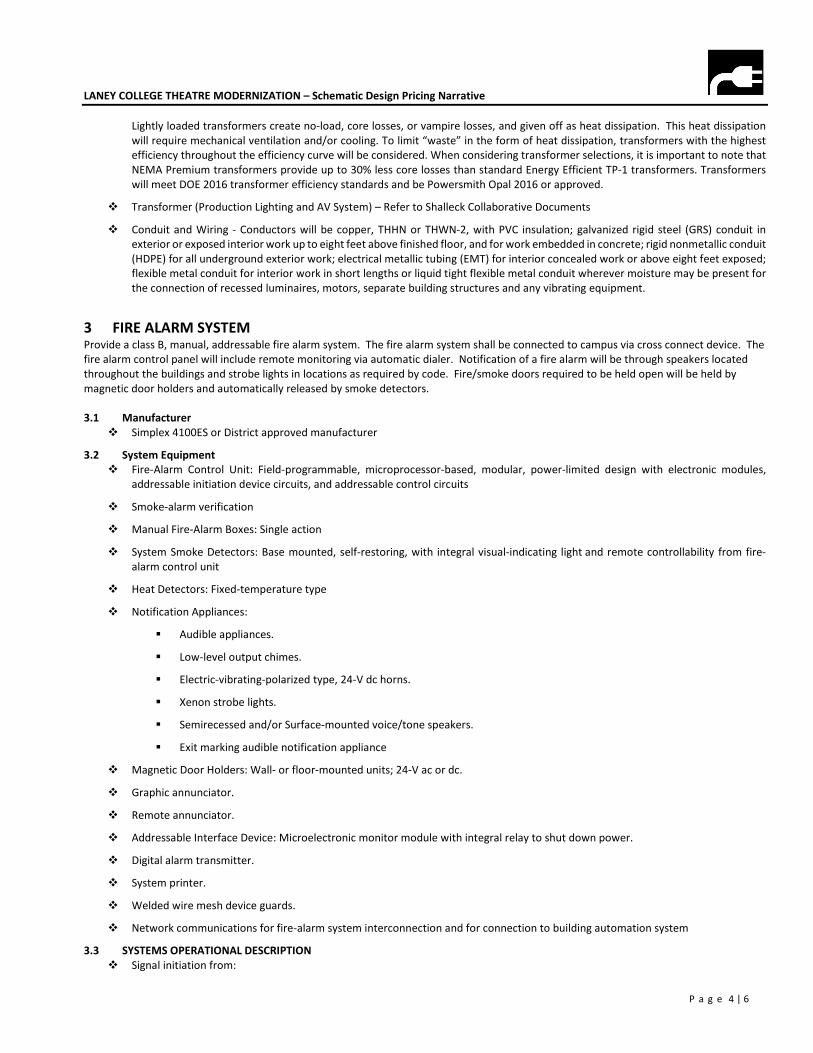
LANEY COLLEGE THEATRE MODERNIZATION – Schematic Design Pricing Narrative
P a g e 4 | 6
Lightly loaded transformers create no-load, core losses, or vampire losses, and given off as heat dissipation. This heat dissipation
will require mechanical ventilation and/or cooling. To limit “waste” in the form of heat dissipation, transformers with the highest
efficiency throughout the efficiency curve will be considered. When considering transformer selections, it is important to note that
NEMA Premium transformers provide up to 30% less core losses than standard Energy Efficient TP-1 transformers. Transformers
will meet DOE 2016 transformer efficiency standards and be Powersmith Opal 2016 or approved.
Transformer (Production Lighting and AV System) – Refer to Shalleck Collaborative Documents
Conduit and Wiring - Conductors will be copper, THHN or THWN-2, with PVC insulation; galvanized rigid steel (GRS) conduit in
exterior or exposed interior work up to eight feet above finished floor, and for work embedded in concrete; rigid nonmetallic conduit
(HDPE) for all underground exterior work; electrical metallic tubing (EMT) for interior concealed work or above eight feet exposed;
flexible metal conduit for interior work in short lengths or liquid tight flexible metal conduit wherever moisture may be present for
the connection of recessed luminaires, motors, separate building structures and any vibrating equipment.
3 FIRE ALARM SYSTEM Provide a class B, manual, addressable fire alarm system. The fire alarm system shall be connected to campus via cross connect device. The
fire alarm control panel will include remote monitoring via automatic dialer. Notification of a fire alarm will be through speakers located
throughout the buildings and strobe lights in locations as required by code. Fire/smoke doors required to be held open will be held by
magnetic door holders and automatically released by smoke detectors.
3.1 Manufacturer
Simplex 4100ES or District approved manufacturer
3.2 System Equipment
Fire-Alarm Control Unit: Field-programmable, microprocessor-based, modular, power-limited design with electronic modules,
addressable initiation device circuits, and addressable control circuits
Smoke-alarm verification
Manual Fire-Alarm Boxes: Single action
System Smoke Detectors: Base mounted, self-restoring, with integral visual-indicating light and remote controllability from fire-
alarm control unit
Heat Detectors: Fixed-temperature type
Notification Appliances:
Audible appliances.
Low-level output chimes.
Electric-vibrating-polarized type, 24-V dc horns.
Xenon strobe lights.
Semirecessed and/or Surface-mounted voice/tone speakers.
Exit marking audible notification appliance
Magnetic Door Holders: Wall- or floor-mounted units; 24-V ac or dc.
Graphic annunciator.
Remote annunciator.
Addressable Interface Device: Microelectronic monitor module with integral relay to shut down power.
Digital alarm transmitter.
System printer.
Welded wire mesh device guards.
Network communications for fire-alarm system interconnection and for connection to building automation system
3.3 SYSTEMS OPERATIONAL DESCRIPTION
Signal initiation from:
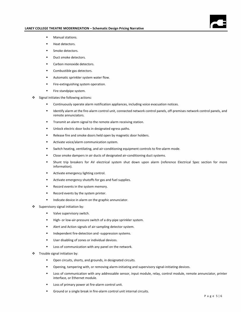
LANEY COLLEGE THEATRE MODERNIZATION – Schematic Design Pricing Narrative
P a g e 5 | 6
Manual stations.
Heat detectors.
Smoke detectors.
Duct smoke detectors.
Carbon monoxide detectors.
Combustible gas detectors.
Automatic sprinkler system water flow.
Fire-extinguishing system operation.
Fire standpipe system.
Signal initiates the following actions:
Continuously operate alarm notification appliances, including voice evacuation notices.
Identify alarm at the fire-alarm control unit, connected network control panels, off-premises network control panels, and
remote annunciators.
Transmit an alarm signal to the remote alarm receiving station.
Unlock electric door locks in designated egress paths.
Release fire and smoke doors held open by magnetic door holders.
Activate voice/alarm communication system.
Switch heating, ventilating, and air-conditioning equipment controls to fire-alarm mode.
Close smoke dampers in air ducts of designated air-conditioning duct systems.
Shunt trip breakers for AV electrical system shut down upon alarm (reference Electrical Spec section for more
information).
Activate emergency lighting control.
Activate emergency shutoffs for gas and fuel supplies.
Record events in the system memory.
Record events by the system printer.
Indicate device in alarm on the graphic annunciator.
Supervisory signal initiation by:
Valve supervisory switch.
High- or low-air-pressure switch of a dry-pipe sprinkler system.
Alert and Action signals of air-sampling detector system.
Independent fire-detection and -suppression systems.
User disabling of zones or individual devices.
Loss of communication with any panel on the network.
Trouble signal initiation by:
Open circuits, shorts, and grounds, in designated circuits.
Opening, tampering with, or removing alarm-initiating and supervisory signal-initiating devices.
Loss of communication with any addressable sensor, input module, relay, control module, remote annunciator, printer
interface, or Ethernet module.
Loss of primary power at fire-alarm control unit.
Ground or a single break in fire-alarm control unit internal circuits.
LANEY COLLEGE THEATRE MODERNIZATION – Schematic Design Pricing Narrative
P a g e 6 | 6
Abnormal ac voltage at fire-alarm control unit.
Break in standby battery circuitry.
Failure of battery charging.
Abnormal position of any switch at the fire-alarm control unit or annunciator.
Voice signal amplifier failure.
Hose cabinet door open.
System Trouble and Supervisory Signal Actions: Initiate notification appliances and annunciate at fire-alarm control unit and remote
annunciators. Record the event on system printer.
PERALTA COMMUNITY COLLEGE DISTRICT LANEY COLLEGE THEATER MODERNIZATION OAKLAND, CA
200730LCT027/ELS
APPENDIX C
PRODUCTION SYSTEMS ENGINEERING REPORT
Laney College Theatre Production Systems Engineering Report July 17, 2020 – 100% Schematic Design
The following report outlines the theatrical production systems’ electrical, mechanical, and structural requirements for the theatre and support space renovation at the Laney College Theatre. Changes from the 50% Schematic Design report are in green.
1. Electrical Engineering Criteria
PRODUCTION LIGHTING SYSTEMS
Scope We will design and specify the production lighting control system equipment and fixtures in dedicated drawings and in Division 11 specifications. The system will be installed in its entirety under Electrical. Our documents will be oriented to show/specify the equipment and devices provided by Division 11 only. The infrastructure for the system such as conduit size and route, wire, back boxes, and all parts of the power systems must be designed by the Electrical Engineer and shown within their documents. We will provide CAD layers of devices and review and coordinate with the electrical documents. For low voltage production control systems, our documents will include point to point diagrams and wire types, but not design or documentation of the Electrical infrastructure as required to complete the installation. Production lighting fixtures are “temporary loads” that are clamped on and changed for each performance. They will be installed by the Owner’s forces or the Div. 11 supplier. Transformer Transformer “PL-1” - Dedicated 120/208VAC 3-phase, K-13
rated transformer, or equivalent HMT model Size: 225 kVA (assuming power factor of 0.9) Feeds: Main Theatre - (1) Production Lighting Relay Panel – “TRP-1”,
(1) 400A Lighting Company Switch Theatre Lab - (1) Production Lighting Relay Panel – “LRP-3”,
(1) 100A Lighting Company Switch Relay Panels Relay panels are to be provided for the production and architectural lighting in the main theater and flex space. These panels may be located in any electrical room and should be planned to limit copper and conduit runs to branch circuits. Common Features: Feeders: Copper, Provide feeders for each panel. Breakers: Must be inside dimmer room. Provide local disconnect if not. Space required: Each panel requires 20”w x 5”d (+3’ clearance) x 6’-0” high.
Rear access not required; run feeders into bottom of panel and branch loads into top. We recommend providing an enclosed gutter, pull box or wireway above panel to land branch conduits, then stub down with large conduits.
Location: Basement Electrical Room
Laney College Theatre July 17, 2020 Production Systems Engineering Report – 100% Schematic Design Page 2 of 15
Inrush Current: We expect a maximum inrush current of 50-60% of max load. Product BOD: ETC Sensor IQ Panel (48 circuit panels) or ETC Echo Panel
(24 circuit panels) Production “TRP-1” (Main Theatre) Relay panel electrical load: 57.6 kW peak anticipated (50% diversity) Fed From: Lighting transformer “PL-1” Breakers: (1) 200A, 120/208VAC, 3-phase. Branch Circuits: (48) for production lighting Architectural “ARP-2” Relay Panel electrical load: 28.8 kW peak anticipated (25% diversity) Actual Electrical load to be confirmed by project
electrical engineer and lighting designer. Fed From: Standard Building Power Breakers: (1) 200A, 120/208VAC 3-phase. Branch Circuits: (48) for Architectural lighting Theatre Lab Panel “LRP-3” Relay panel electrical load: 28.8 kW peak anticipated (50% diversity) Plus Electrical Load anticipated for House Lighting. Actual Electrical load to be confirmed by project
electrical engineer and lighting designer. Fed From: Lighting transformer “PL-1” Breakers: (1) 100A, 120/208VAC, 3-phase. Branch Circuits: (16) for production lighting (8) for Architectural Lighting. Branch Loads Wiring devices: Production lighting wiring devices to be provided under Div. 11
and installed by Electrical. Devices come prewired with labeled terminal strips for branch wiring to the production relay panels. Circuits are numbered at the device with a corresponding relay number. Theatrical Consultant’s drawings will show production lighting device locations, details and circuit numbers. Circuit numbers and/or device numbers should not be repeated on the electrical drawings.
Electrical drawings would show conduit and wire required. Provide 20A full load wiring that limits voltage drop to 3% at 1000w (minimum #10 unless runs are very long). We anticipate a total of approximately (48) branch circuits for production lighting in the main stage and (56) branch circuits for architectural lighting throughout the theatre areas of the building. Production lighting relay modules are 80% rated; wire should be sized for a full 20A load.
Laney College Theatre July 17, 2020 Production Systems Engineering Report – 100% Schematic Design Page 3 of 15
Production Lighting Company Switch - Main Theatre - 400A Temporary device load: 72.0 kW total – 50% simultaneous with “TRP-1” load above. Fed from: Lighting transformer “PL-1”. Feeders: Copper, with neutrals 2x oversized as current carrying
conductor. Device: Provide theatre industry UL listed standard company switch
which includes one 400A, 120/208VAC 3-Ø cam-lock safety connection panel. This would be specified in Div. 26 with products recommended by The SC.
Space required: 30” wide x 12” deep x 48” tall each, mounted 2’-0” a.f.f. Location: Surface mounted at stage side wall. Product: PowerGATE by Lex Products Production Lighting Company Switch - Theatre Lab - 100A Temporary device load: 9.0 kW total – 25% simultaneous with “LRP-3” load above. Fed from: Lighting transformer “PL-1”. Feeders: Copper, with neutrals 2x oversized as current carrying
conductor. Device: Provide theatre industry UL listed standard company switch
which includes one 100A, 120/208VAC 3-Ø pin-and-sleeve connection panel. This would be specified in Div. 26 with products recommended by The SC.
Space required: 10” wide x 10” deep x 14” tall each, mounted 2’-0” a.f.f. Location: Surface mounted at stage side wall. Product: ESL Power Model #3361-00, Pin & Sleeve Company Switch
PRODUCTION RIGGING AND MACHINERY SYSTEMS
Motorized Rigging Systems – Counterweight Assist Motor load: (7) 1.5 HP motors. Motor feed: Standard building power other than transformer “PL-1” Required power: 120/208 VAC, 3-Ø. Control system: Minimal 120V power. Disconnect: Units include on board starters and control. Control devices: The motorized rigging safety and control devices to be
furnished and installed under Div. 11. Devices will come prewired for connection to electrical service. The SC’s drawings will show device locations, details, point-to-point connection and wire type for control systems only. Electrical drawings would show conduit, line voltage wiring, and cross reference Production Systems documents for control wiring required. Provision of wire and complete electrical interconnection and termination by Div. 26.
Device Locations: Main Theatre: (3) Orchestra Shell, (4) Stage Electrics Product: JR Clancy Power Assist
Laney College Theatre July 17, 2020 Production Systems Engineering Report – 100% Schematic Design Page 4 of 15
Motorized Rigging Systems – Apron Lighting Hoist Motor load: (1)2.0 HP motor. Motor feed: Standard building power other than transformer “PL-1” Required power: 208 VAC, 3-Ø. Control system: Minimal 120V power. Disconnect: Units include on board starters and control. Control devices: The motorized rigging safety and control devices to be
furnished and installed under Div. 11. Devices will come prewired for connection to electrical service. The SC’s drawings will show device locations, details, point-to-point connection and wire type for control systems only. Electrical drawings would show conduit, line voltage wiring, and cross reference Production Systems documents for control wiring required. Provision of wire and complete electrical interconnection and termination by Div. 26.
Device Locations: Main Theatre: (1) Stage Lighting Pipe at Apron Product: ETC Prodigy 1500E, or similar by JR Clancy
PRODUCTION AV SYSTEMS
Scope
The Shalleck Collaborative will design and specify the AV system equipment and devices in dedicated drawings and in Division 27 specifications. The system will be installed in its entirety under Div. 27. The Electrical Engineer is responsible for designing and documenting all power related systems including specifying the conduit size and route, back boxes, and all junction boxes etc. The Shalleck Collaborative will provide CAD layers of devices to facilitate the Electrical Engineers documentation and will review and coordinate the AV power systems with the electrical documents.
All power to AV systems must be on a dedicated K-13 rated or HMT-style transformer, combined with an isolated ground system. AV power will be identified with orange outlets throughout the facility.
Isolated Ground Systems
The AV systems isolated ground (IG) system is of paramount importance in providing a clean power source for AV equipment. Care is required to ensure the IG system is designed correctly. We will require a star isolated ground system, meaning that all AV power system grounds ultimately reference the building ground at only one point, typically located in the main electrical service room.
The main branches for the IG system (from main electrical room to branch AV power panels) will be fed with #3/0 AWG insulated ground cable. From these main points, branch load circuits connect to an IG busbar using standard-size (12 or 14 AWG) conductors. In addition, a #3/0 AWG IG conductor must be brought to the AV equipment racks, for termination to an equipment rack busbar, provided by the AV contractor.
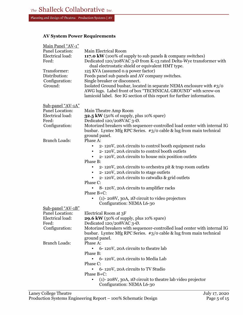
Laney College Theatre July 17, 2020 Production Systems Engineering Report – 100% Schematic Design Page 5 of 15
AV System Power Requirements Main Panel “AV-1” Panel Location: Main Electrical Room Electrical load: 117.0 kW (100% of supply to sub panels & company switches) Feed: Dedicated 120/208VAC 3-Ø from K-13 rated Delta-Wye transformer with
dual electrostatic shield or equivalent HMT type. Transformer: 125 KVA (assumed 0.9 power factor) Distribution: Feeds panel sub panels and AV company switches. Configuration: Single breaker or disconnect. Ground: Isolated Ground busbar, located in separate NEMA enclosure with #3/0
AWG lugs. Label front of box “TECHNICAL GROUND” with screw-on lamicoid label. See IG section of this report for further information.
Sub-panel “AV-1A” Panel Location: Main Theatre Amp Room Electrical load: 32.5 kW (50% of supply, plus 10% spare) Feed: Dedicated 120/208VAC 3-Ø. Configuration: Motorized breakers with sequencer-controlled load center with internal IG
busbar. Lyntec Mfg RPC Series. #3/0 cable & lug from main technical ground panel.
Branch Loads: Phase A:
• 2- 120V, 20A circuits to control booth equipment racks
• 2- 120V, 20A circuits to control booth outlets
• 2- 120V, 20A circuits to house mix position outlets Phase B:
• 2- 120V, 20A circuits to orchestra pit & trap room outlets
• 2- 120V, 20A circuits to stage outlets
• 2- 120V, 20A circuits to catwalks & grid outlets Phase C:
• 8- 120V, 20A circuits to amplifier racks Phase B+C:
• (1)- 208V, 30A, 1Ø circuit to video projectors Configuration: NEMA L6-30
Sub-panel “AV-1B” Panel Location: Electrical Room at 3F Electrical load: 29.6 kW (50% of supply, plus 10% spare) Feed: Dedicated 120/208VAC 3-Ø. Configuration: Motorized breakers with sequencer-controlled load center with internal IG
busbar. Lyntec Mfg RPC Series. #3/0 cable & lug from main technical ground panel.
Branch Loads: Phase A:
• 6- 120V, 20A circuits to theatre lab Phase B:
• 6- 120V, 20A circuits to Media Lab Phase C:
• 6- 120V, 20A circuits to TV Studio Phase B+C:
• (1)- 208V, 30A, 1Ø circuit to theatre lab video projector Configuration: NEMA L6-30
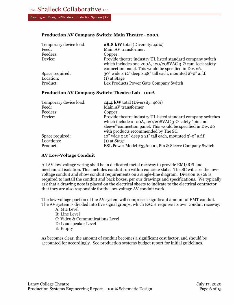
Laney College Theatre July 17, 2020 Production Systems Engineering Report – 100% Schematic Design Page 6 of 15
Production AV Company Switch: Main Theatre - 200A Temporary device load: 28.8 kW total (Diversity: 40%) Feed: Main AV transformer. Feeders: Copper. Device: Provide theatre industry UL listed standard company switch
which includes one 200A, 120/208VAC 3-Ø cam-lock safety connection panel. This would be specified in Div. 26.
Space required: 30” wide x 12” deep x 48” tall each, mounted 2’-0” a.f.f. Location: (1) at Stage Product: Lex Products Power Gate Company Switch Production AV Company Switch: Theatre Lab - 100A Temporary device load: 14.4 kW total (Diversity: 40%) Feed: Main AV transformer Feeders: Copper. Device: Provide theatre industry UL listed standard company switches
which include a 100A, 120/208VAC 3-Ø safety “pin and sleeve” connection panel. This would be specified in Div. 26 with products recommended by The SC.
Space required: 10” wide x 10” deep x 21” tall each, mounted 3’-0” a.f.f. Locations: (1) at Stage Product: ESL Power Model #3361-00, Pin & Sleeve Company Switch AV Low-Voltage Conduit
All AV low-voltage wiring shall be in dedicated metal raceway to provide EMI/RFI and mechanical isolation. This includes conduit run within concrete slabs. The SC will size the low-voltage conduit and show conduit requirements on a single-line diagram. Division 16/26 is required to install the conduit and back boxes, per our drawings and specifications. We typically ask that a drawing note is placed on the electrical sheets to indicate to the electrical contractor that they are also responsible for the low-voltage AV conduit work.
The low-voltage portion of the AV system will comprise a significant amount of EMT conduit. The AV system is divided into five signal groups, which EACH requires its own conduit raceway:
A: Mic Level B: Line Level C: Video & Communications Level D: Loudspeaker Level E: Empty
As becomes clear, the amount of conduit becomes a significant cost factor, and should be accounted for accordingly. See production systems budget report for initial guidelines.
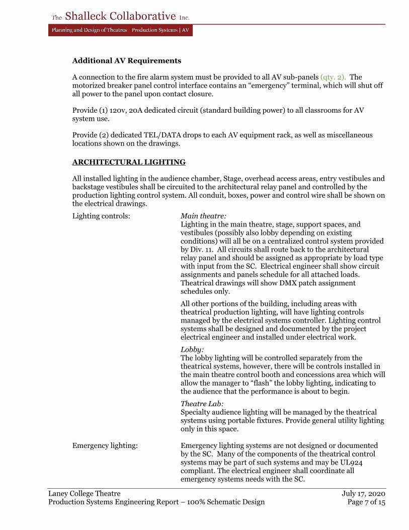
Laney College Theatre July 17, 2020 Production Systems Engineering Report – 100% Schematic Design Page 7 of 15
Additional AV Requirements
A connection to the fire alarm system must be provided to all AV sub-panels (qty. 2). The motorized breaker panel control interface contains an “emergency” terminal, which will shut off all power to the panel upon contact closure.
Provide (1) 120v, 20A dedicated circuit (standard building power) to all classrooms for AV system use.
Provide (2) dedicated TEL/DATA drops to each AV equipment rack, as well as miscellaneous locations shown on the drawings.
ARCHITECTURAL LIGHTING
All installed lighting in the audience chamber, Stage, overhead access areas, entry vestibules and backstage vestibules shall be circuited to the architectural relay panel and controlled by the production lighting control system. All conduit, boxes, power and control wire shall be shown on the electrical drawings.
Lighting controls: Main theatre: Lighting in the main theatre, stage, support spaces, and
vestibules (possibly also lobby depending on existing conditions) will all be on a centralized control system provided by Div. 11. All circuits shall route back to the architectural relay panel and should be assigned as appropriate by load type with input from the SC. Electrical engineer shall show circuit assignments and panels schedule for all attached loads. Theatrical drawings will show DMX patch assignment schedules only.
All other portions of the building, including areas with theatrical production lighting, will have lighting controls managed by the electrical systems controller. Lighting control systems shall be designed and documented by the project electrical engineer and installed under electrical work.
Lobby: The lobby lighting will be controlled separately from the
theatrical systems, however, there will be controls installed in the main theatre control booth and concessions area which will allow the manager to “flash” the lobby lighting, indicating to the audience that the performance is about to begin.
Theatre Lab: Specialty audience lighting will be managed by the theatrical
systems using portable fixtures. Provide general utility lighting only in this space.
Emergency lighting: Emergency lighting systems are not designed or documented
by the SC. Many of the components of the theatrical control systems may be part of such systems and may be UL924 compliant. The electrical engineer shall coordinate all emergency systems needs with the SC.
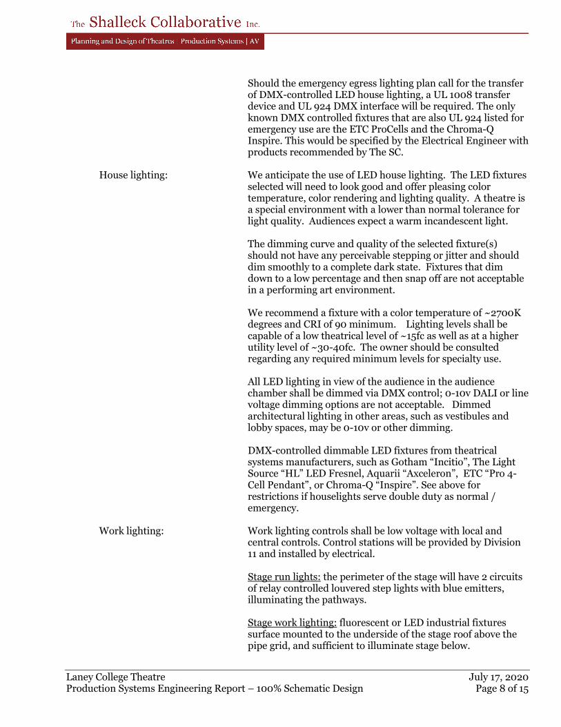
Laney College Theatre July 17, 2020 Production Systems Engineering Report – 100% Schematic Design Page 8 of 15
Should the emergency egress lighting plan call for the transfer
of DMX-controlled LED house lighting, a UL 1008 transfer device and UL 924 DMX interface will be required. The only known DMX controlled fixtures that are also UL 924 listed for emergency use are the ETC ProCells and the Chroma-Q Inspire. This would be specified by the Electrical Engineer with products recommended by The SC.
House lighting: We anticipate the use of LED house lighting. The LED fixtures
selected will need to look good and offer pleasing color temperature, color rendering and lighting quality. A theatre is a special environment with a lower than normal tolerance for light quality. Audiences expect a warm incandescent light.
The dimming curve and quality of the selected fixture(s)
should not have any perceivable stepping or jitter and should dim smoothly to a complete dark state. Fixtures that dim down to a low percentage and then snap off are not acceptable in a performing art environment.
We recommend a fixture with a color temperature of ~2700K
degrees and CRI of 90 minimum. Lighting levels shall be capable of a low theatrical level of ~15fc as well as at a higher utility level of ~30-40fc. The owner should be consulted regarding any required minimum levels for specialty use.
All LED lighting in view of the audience in the audience
chamber shall be dimmed via DMX control; 0-10v DALI or line voltage dimming options are not acceptable. Dimmed architectural lighting in other areas, such as vestibules and lobby spaces, may be 0-10v or other dimming.
DMX-controlled dimmable LED fixtures from theatrical
systems manufacturers, such as Gotham “Incitio”, The Light Source “HL” LED Fresnel, Aquarii “Axceleron”, ETC “Pro 4-Cell Pendant”, or Chroma-Q “Inspire”. See above for restrictions if houselights serve double duty as normal / emergency.
Work lighting: Work lighting controls shall be low voltage with local and
central controls. Control stations will be provided by Division 11 and installed by electrical.
Stage run lights: the perimeter of the stage will have 2 circuits
of relay controlled louvered step lights with blue emitters, illuminating the pathways.
Stage work lighting: fluorescent or LED industrial fixtures
surface mounted to the underside of the stage roof above the pipe grid, and sufficient to illuminate stage below.
Laney College Theatre July 17, 2020 Production Systems Engineering Report – 100% Schematic Design Page 9 of 15
Control/follow spot booths: (3) zones of lighting, Low voltage dimming control on each:
• Primary lighting: recessed fixtures with mini-cube louvers.
• Show condition lighting: low mounted, louvered step lights and recessed dimmable downlights
• Task lighting: black finished track lighting over the counter.
Circulation lighting: Non-audience circulation areas that
immediately connect to the Stage and Audience chamber, such as stairwells, halls and vestibules, shall have two systems of lighting - both controlled via low voltage relay. One system of overhead or wall mounted fluorescent/LED fixtures is for work light and general activity and a second system of dimmable compact fluorescent fixtures with blue filters or LED fixtures, either overhead or louvered step lights is for low lighting levels during performances.
Dressing room lighting: All dressing room lighting should be
3000K and have a high CRI (90+). Make up station lighting: shall be provided at the top and sides
of each makeup mirror station (approx. every 60”), each station shall be individually switched and on a master switch. Provide cages per NEC.
MISC. ELECTRICAL REQUIREMENTS (PROVIDED UNDER ELEC.) Dressing rooms: Dressing stations require plug mold or quad outlets above the
countertop - assume (1) dedicated 20A circuit for every two stations. Per NEC, requirements these outlets are required to be switched at the entry doorways and are to have indicators visible in the adjacent corridor. Provide general purpose power below the countertop at +/-10’-0” o.c.
Exit Signage: Exit signage should not be direct view LED or edge-lit type, as
the lighting spill tends to be problematic. We prefer RED backlit exit fixtures, as they are least visually obtrusive in a dark theatre.
Miscellaneous Power Company Switch - 100A (1 total) Load: 18.0 kW Feed: Standard building power. Feeders: Copper. Device: Provide theatre industry UL listed standard company switches
which include a 100A, 120/208VAC 3-Ø safety “pin and sleeve” connection panel. This would be specified in Div. 16 with products recommended by The SC.
Laney College Theatre July 17, 2020 Production Systems Engineering Report – 100% Schematic Design Page 10 of 15
Space required: 10” wide x 10” deep x 14” tall each, mounted 2’-0” a.f.f. Locations: (1) at Main Theatre stage Product: ESL Power Model #3361-00, Pin & Sleeve Company Switch
2. Mechanical Engineering Criteria PRODUCTION LIGHTING SYSTEMS Production Lighting Fixtures – Main Theatre
Audience chamber load: 12.0 kW average Source location: Technical positions overhead at +/-24’-0” a.f.f. Design temperature: Comfortable Room Temperature Stage area load: 24.0 kW average
Source location: Technical positions overhead at +/-21’-0” a.f.f. Design temperature: 75◦F average Stage air: Air movement shall be planned to minimize the movement of
stage draperies and scenery. There shall be no pressure differential across the Proscenium. Air on stage should either be dropped from above or be supplied from the side and returned at the side(s) in order to provide movement stage sideways across the draperies and scenery.
Production Lighting Fixtures – Theatre Lab
Lighting Fixtures 14.4 kW maximum Source location: Technical positions overhead at +/-12’-0” a.f.f. Design temperature: Normal comfortable room temperature
PRODUCTION AV SYSTEMS
Main/Lab Theatre Amplifier Room: Equipment load: 6.0 kW average for long durations Maximum temperature: 80◦F
TV Studio Equipment Room: Equipment load: 4.0 kW average for long durations Maximum temperature: 80◦F
Recording Studio Equipment Room: Equipment load: 4.0 kW average for long durations Maximum temperature: 80◦F
RELATED ROOMS Main Theatre Control Room
Typical Load: 4.0 kW Maximum temperature: Normal comfortable room temperature. Average Occupancy Load: Six; possible addition of load from AV projector or followspots.
Laney College Theatre July 17, 2020 Production Systems Engineering Report – 100% Schematic Design Page 12 of 15
Dressing Rooms Dressing stations: Assume 0.36 kW per station (60” of counter space) from
vanity lighting, plus room lighting and occupancy load TV Studio Control Room
Typical Load: 4.0 kW Maximum temperature: Normal comfortable room temperature. Average Occupancy Load: Six; possible addition of load from AV projector or followspots.
Recording Studio Control Room
Typical Load: 4.0 kW Maximum temperature: Normal comfortable room temperature. Average Occupancy Load: Six; possible addition of load from AV projector or followspots.
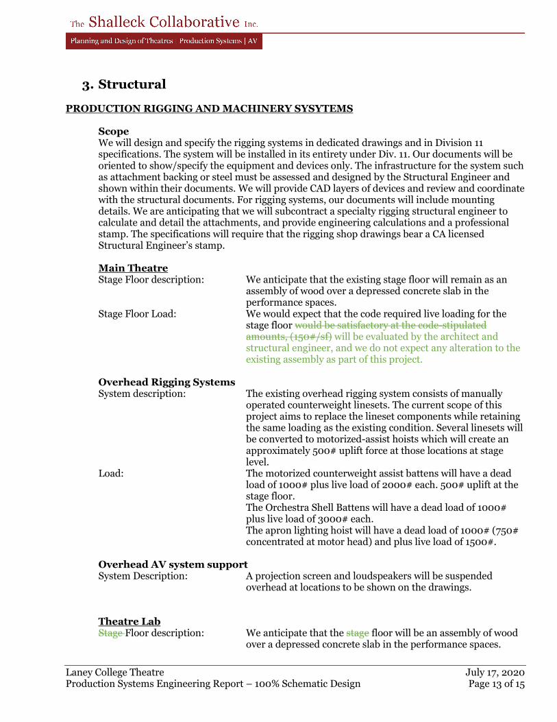
Laney College Theatre July 17, 2020 Production Systems Engineering Report – 100% Schematic Design Page 13 of 15
3. Structural PRODUCTION RIGGING AND MACHINERY SYSYTEMS
Scope We will design and specify the rigging systems in dedicated drawings and in Division 11 specifications. The system will be installed in its entirety under Div. 11. Our documents will be oriented to show/specify the equipment and devices only. The infrastructure for the system such as attachment backing or steel must be assessed and designed by the Structural Engineer and shown within their documents. We will provide CAD layers of devices and review and coordinate with the structural documents. For rigging systems, our documents will include mounting details. We are anticipating that we will subcontract a specialty rigging structural engineer to calculate and detail the attachments, and provide engineering calculations and a professional stamp. The specifications will require that the rigging shop drawings bear a CA licensed Structural Engineer’s stamp. Main Theatre Stage Floor description: We anticipate that the existing stage floor will remain as an
assembly of wood over a depressed concrete slab in the performance spaces.
Stage Floor Load: We would expect that the code required live loading for the stage floor would be satisfactory at the code-stipulated amounts, (150#/sf) will be evaluated by the architect and structural engineer, and we do not expect any alteration to the existing assembly as part of this project.
Overhead Rigging Systems System description: The existing overhead rigging system consists of manually
operated counterweight linesets. The current scope of this project aims to replace the lineset components while retaining the same loading as the existing condition. Several linesets will be converted to motorized-assist hoists which will create an approximately 500# uplift force at those locations at stage level.
Load: The motorized counterweight assist battens will have a dead load of 1000# plus live load of 2000# each. 500# uplift at the stage floor.
The Orchestra Shell Battens will have a dead load of 1000# plus live load of 3000# each.
The apron lighting hoist will have a dead load of 1000# (750# concentrated at motor head) and plus live load of 1500#.
Overhead AV system support System Description: A projection screen and loudspeakers will be suspended
overhead at locations to be shown on the drawings. Theatre Lab Stage Floor description: We anticipate that the stage floor will be an assembly of wood
over a depressed concrete slab in the performance spaces.
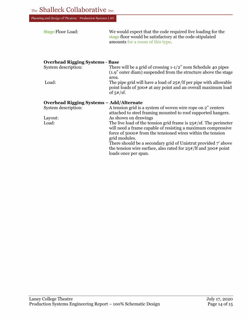
Laney College Theatre July 17, 2020 Production Systems Engineering Report – 100% Schematic Design Page 14 of 15
Stage Floor Load: We would expect that the code required live loading for the stage floor would be satisfactory at the code-stipulated amounts for a room of this type.
Overhead Rigging Systems - Base System description: There will be a grid of crossing 1-1/2” nom Schedule 40 pipes
(1.9” outer diam) suspended from the structure above the stage area.
Load: The pipe grid will have a load of 25#/lf per pipe with allowable point loads of 300# at any point and an overall maximum load of 5#/sf.
Overhead Rigging Systems – Add/Alternate System description: A tension grid is a system of woven wire rope on 2” centers
attached to steel framing mounted to roof supported hangers. Layout: As shown on drawings Load: The live load of the tension grid frame is 25#/sf. The perimeter
will need a frame capable of resisting a maximum compressive force of 5000# from the tensioned wires within the tension grid modules.
There should be a secondary grid of Unistrut provided 7’ above the tension wire surface, also rated for 25#/lf and 300# point loads once per span.
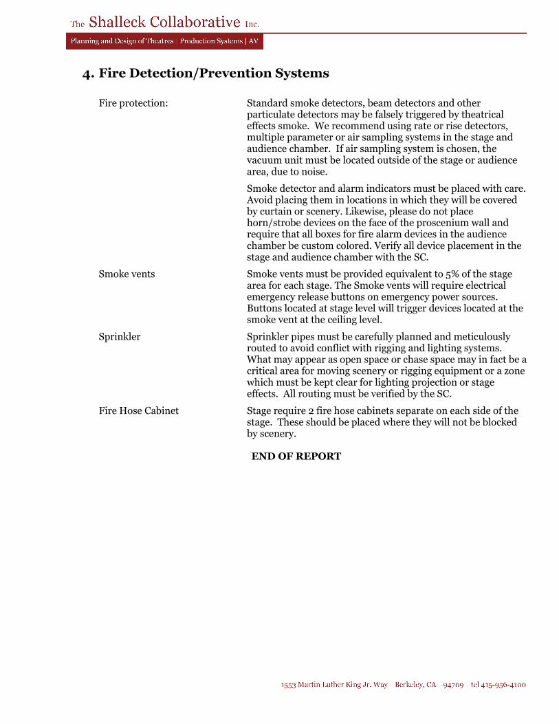
4. Fire Detection/Prevention Systems
Fire protection: Standard smoke detectors, beam detectors and other particulate detectors may be falsely triggered by theatrical effects smoke. We recommend using rate or rise detectors, multiple parameter or air sampling systems in the stage and audience chamber. If air sampling system is chosen, the vacuum unit must be located outside of the stage or audience area, due to noise.
Smoke detector and alarm indicators must be placed with care. Avoid placing them in locations in which they will be covered by curtain or scenery. Likewise, please do not place horn/strobe devices on the face of the proscenium wall and require that all boxes for fire alarm devices in the audience chamber be custom colored. Verify all device placement in the stage and audience chamber with the SC.
Smoke vents Smoke vents must be provided equivalent to 5% of the stage area for each stage. The Smoke vents will require electrical emergency release buttons on emergency power sources. Buttons located at stage level will trigger devices located at the smoke vent at the ceiling level.
Sprinkler Sprinkler pipes must be carefully planned and meticulously routed to avoid conflict with rigging and lighting systems. What may appear as open space or chase space may in fact be a critical area for moving scenery or rigging equipment or a zone which must be kept clear for lighting projection or stage effects. All routing must be verified by the SC.
Fire Hose Cabinet Stage require 2 fire hose cabinets separate on each side of the stage. These should be placed where they will not be blocked by scenery.
END OF REPORT
PERALTA COMMUNITY COLLEGE DISTRICT LANEY COLLEGE THEATER MODERNIZATION OAKLAND, CA
200730LCT027/ELS
APPENDIX D
PRODUCTION SYSTEMS BUDGET RECOMMENDATIONS
TRANSMITTAL / MEMO
Project: Laney College Theatre Modernization Date: 2020-07-17 Via: e-mail Fax:
To: Jeff Zieba, Kim-Van Truong ELS Architecture and Urban Design
Tel:
From: Adam Shalleck, Ian Hunter, Maura LaRiviere Re: Production Systems Budgets – 100SD # of pgs.
including cover: 6
Below are listed the budget recommendations for production systems within the Laney College Theatre Modernization project. It is important to note that not all sections represent a complete and installed cost. In particular, the Cost Estimator(s) who is/are responsible for structural and electrical costs will need to include production systems infrastructure and installation (in the case of electrical) that normally falls under Divisions 5 and 26. The recommendations below are listed in 2020 dollars and do not include General Contractors mark-up and general conditions or overall contingencies. FF&E systems budget allocations are included in these estimates. It is important to consider these budgets, as FF&E equipment will be required for turnkey operation of the facility. FF&E equipment may be procured as part of the base contract OR as owner furnished equipment after the contract is complete. Items changed since the Concept Phase budget are shown in green.
Base Scope
1. Theatre 100 Production Rigging – Lineset Modernizations - Section 11 61 33 $170,000
Deduct $50,000 if Motorized option below is taken. Safety upgrades including replacement of existing rod-style arbors with front-loading arbors, and replacement of any original headblocks or loftblocks which are past their useful lives. New counterweight to match arbor slots. Capstan winch and reinforcement of existing lock rail as necessary for operation. Reuse of existing battens and hardware where feasible. **Assumes re-use of existing stage draperies, if FF&E allowance below is not available. Related Exclusions: Structural support as needed for all rigging elements. Electrical accommodations for capstan winch. Additional FF&E equipment (drapes) as described below. Production Rigging – Motorized Linesets - Section 11 61 33 $170,000 Safety upgrades including replacement of (7) existing rod-style arbors with motor assisted front-loading linesets at the areas of heaviest load or most frequent change of load (fixed electrics, upstage traveller
_______________________________________________________________________ Laney College Theatre Modernization July 17th, 2020 Production Systems Budget Recommendations – 100SD Page 2 of 6
set, orchestra shell ceilings) and addition of 2 manual lineset to infill gaps in rigging wall. Localized control station for each lineset at the lockrail. Reuse of existing battens and hardware where feasible. Related Exclusions: Structural support as needed for all rigging elements. Electrical accommodations including motor disconnects. Additional FF&E equipment (new drapes, orchestra shell ceilings) as described below. Production Rigging – Apron Hoist - Section 11 61 33 $40,000 Motorized hoist mounted over the stage apron, which allows a batten to be lowered to stage level to hang and rough focus the lighting fixtures. Includes dedicated motor controller. Related Exclusions: Structural support as needed for all rigging elements. Electrical accommodations including motor disconnects Production Lighting Control – Section 11 61 83 $135,000 Educational and Performance System allowance to include (48) 20A DMX controlled breakers for production lighting, (48) 20A DMX controlled relays for architectural and work lighting. Allowance for integration of emergency lighting control. Moving light capable computer control console with focus remote; network components, control and circuit wiring devices and stage cable, equipment only. Related Exclusions: Div. 26 work including infrastructure per engineering report, architectural lighting fixtures, emergency lighting/transfer, distribution and control wire, conduit, and complete installation. FF&E equipment (additional lighting fixtures and accessories) as described below. Production Lighting Control – Base Fixture Package - Section 11 61 84 $100,000 LED production lighting fixtures, compatible with new electrical control system. Approximately (30) ellipsoidal spot fixtures, (15) wash fixtures, and (10) cyclorama lights. Lenses and barrels in assorted sizes, prorated by usage. Related Exclusions: Installed system components, as described above for section 11 61 83. Fixed Audience Seating – Section 12 61 00 $135,000 Budget includes (300) fixed, upholstered theatre chairs, installed ($450/chair). Standard finishes with minor customizations. No tablet arms or cupholders. Related Exclusions: Electrical connection for aisle lighting.
Production AV Systems – Section 27 41 16 $350,000 Comprehensive system to include wiring infrastructure, digital mixing console, wireless mics, loudspeaker system, fixed video projection, control system, production intercom, monitoring to all technical areas, mixing in booth and in-house, FM assistive listening. Includes wire, pull and system integration and installation. Include loose AV equipment. **Assumes re-use of recently purchased audio & video equipment. Related Exclusions: Electrical work including all line voltage connections (complete), and providing and installing all low-voltage conduit and backboxes required by the AV system, as well as specialty electrical systems noted in the engineering report.
2. Theatre Lab 319 Rehearsal / Black Box 418 Production Rigging – Pipe Grid– Section 11 61 33 $50,000 $100,000 Mutually exclusive with Tension Grid Alternate system described below. Budget includes 735 2500sqft of pipe grid, (1) manually operated bi-part traveller drape track, and (4) “walk-along” leg drapery tracks, installed.
_______________________________________________________________________ Laney College Theatre Modernization July 17th, 2020 Production Systems Budget Recommendations – 100SD Page 3 of 6
Related Exclusions: Structural accommodations for pipe grid including ceiling isolation from mechanical equipment above. FF&E equipment (drapery) as described below. Production Rigging – Tension Grid Alternate - Section 11 61 33 $120,000 Mutually exclusive with Pipe Grid system described above. Budget includes 735 sqft of tension grid, (1) manually operated bi-part traveller drape track, and (4) “walk-along” leg drapery tracks, installed. Related Exclusions: Structural accommodations for pipe grid including ceiling isolation from mechanical equipment above. FF&E equipment (drapery) as described below. Production Lighting Control – Section 11 61 83 $20,000 Budget includes DMX infrastructure to support LED fixtures and/or portable dimmer sticks. Dimmers, fixtures, and control console are listed below under FF&E allowances. No control of normal use “work lights” in room. Related Exclusions: Electrical accommodations including infrastructure, power receptacles, distribution and control wire, conduit, junction boxes, and complete installation.
Production AV Systems – Section 27 41 16 $150,000 System to include wiring infrastructure, portable audio mixer and playback devices, flexible loudspeaker system, video projection system, production intercom, monitoring to support spaces, FM assistive listening. Standard classroom system. Includes wire, pull and system integration and installation. Related Exclusions: Electrical work including all line voltage connections (complete), and providing and installing all low-voltage conduit and backboxes required by the AV system, as well as specialty electrical systems noted in the engineering report.
3. Relocated Visual Media Lab Rm??? TV Studio 306/306A Pipe Grid and Drape Track– Section 11 61 33 $40,000 Budget includes 500sqft of pipe grid and 70 linear feet of curved perimeter “walk-along” drapery track, installed. **Assumes re-use of existing TV Studio draperies, if FF&E allowance below is not available. Related Exclusions: Structural accommodations for pipe grid including ceiling isolation from mechanical equipment above. FF&E equipment (drapery) as described below. Production Lighting Control – Section 11 61 83 $20,000 Budget includes DMX infrastructure to support LED fixtures and/or portable dimmer sticks. Dimmers, fixtures, and control console are listed below under FF&E allowances. No control of normal use “work lights” in room. Related Exclusions: Electrical accommodations including infrastructure, power receptacles, distribution and control wire, conduit, junction boxes, and complete installation. Production AV Systems – Section 27 41 16 $300,000 Live video capturing & editing equipment including (3) studio video cameras, non-linear editing suite, video mixer & monitoring, multi-track audio mixer & monitoring, teleprompter. Includes wire, pull and system integration and installation. Related Exclusions: Electrical work including all line voltage connections (complete), and providing and installing all low-voltage conduit and backboxes required by the AV system, as well as specialty electrical systems noted in the engineering report.
_______________________________________________________________________ Laney College Theatre Modernization July 17th, 2020 Production Systems Budget Recommendations – 100SD Page 4 of 6
4. Sound Media Lab and Control Media Recording - Control 413/415 Production AV Systems – Section 27 41 16 $150,000 Multi-channel audio recording system with 7.1 surround monitoring system. Includes computer & audio interface, software for recording and playback & musician monitoring system. Includes wire, pull and system integration and installation. Related Exclusions: Electrical work including all line voltage connections (complete), and providing and installing all low-voltage conduit and backboxes required by the AV system, as well as specialty electrical systems noted in the engineering report. AV Systems: Edit Stations – Section 27 41 16 $30,000 Assumes (3) edit stations with computer, audio interface, monitoring and related accessories. Includes wire, pull and system integration and installation. Related Exclusions: Electrical work including all line voltage connections (complete), and providing and installing all low-voltage conduit and backboxes required by the AV system, as well as specialty electrical systems noted in the engineering report. Classroom AV Systems – Section 27 41 16 $15,000 Campus-standard classroom AV system with video display, laptop AV connections, simple control system, audio playback. Wire, pull and system integration and installation. Related Exclusions: Electrical work including all line voltage connections (complete), and providing and installing all low-voltage conduit and backboxes required by the AV system.
5. Media Classroom 319
Classroom AV Systems – Section 27 41 16 $25,000 Campus-standard classroom AV system with video display, laptop AV connections, simple control system, audio playback. Enhanced audio system for media use. Wire, pull and system integration and installation. Related Exclusions: Electrical work including all line voltage connections (complete), and providing and installing all low-voltage conduit and backboxes required by the AV system.
6. Classrooms 425 & 426
Classroom AV Systems – Section 27 41 16 $15,000 / each Campus-standard classroom AV system with video display, laptop AV connections, simple control system, audio playback. Wire, pull and system integration and installation. Related Exclusions: Electrical work including all line voltage connections (complete), and providing and installing all low-voltage conduit and backboxes required by the AV system.
7. Breakout Space Office 200 AV Systems – Section 27 41 16 $10,000/each
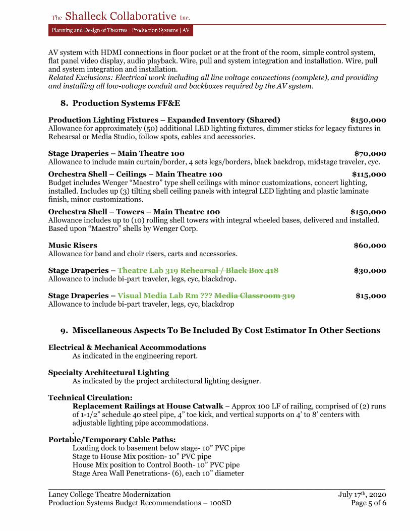
_______________________________________________________________________ Laney College Theatre Modernization July 17th, 2020 Production Systems Budget Recommendations – 100SD Page 5 of 6
AV system with HDMI connections in floor pocket or at the front of the room, simple control system, flat panel video display, audio playback. Wire, pull and system integration and installation. Wire, pull and system integration and installation. Related Exclusions: Electrical work including all line voltage connections (complete), and providing and installing all low-voltage conduit and backboxes required by the AV system.
8. Production Systems FF&E
Production Lighting Fixtures – Expanded Inventory (Shared) $150,000 Allowance for approximately (50) additional LED lighting fixtures, dimmer sticks for legacy fixtures in Rehearsal or Media Studio, follow spots, cables and accessories. Stage Draperies – Main Theatre 100 $70,000 Allowance to include main curtain/border, 4 sets legs/borders, black backdrop, midstage traveler, cyc.
Orchestra Shell – Ceilings – Main Theatre 100 $115,000 Budget includes Wenger “Maestro” type shell ceilings with minor customizations, concert lighting, installed. Includes up (3) tilting shell ceiling panels with integral LED lighting and plastic laminate finish, minor customizations.
Orchestra Shell – Towers – Main Theatre 100 $150,000 Allowance includes up to (10) rolling shell towers with integral wheeled bases, delivered and installed. Based upon “Maestro” shells by Wenger Corp. Music Risers $60,000 Allowance for band and choir risers, carts and accessories. Stage Draperies – Theatre Lab 319 Rehearsal / Black Box 418 $30,000 Allowance to include bi-part traveler, legs, cyc, blackdrop. Stage Draperies – Visual Media Lab Rm ??? Media Classroom 319 $15,000 Allowance to include bi-part traveler, legs, cyc, blackdrop
9. Miscellaneous Aspects To Be Included By Cost Estimator In Other Sections
Electrical & Mechanical Accommodations As indicated in the engineering report. Specialty Architectural Lighting As indicated by the project architectural lighting designer.
Technical Circulation:
Replacement Railings at House Catwalk – Approx 100 LF of railing, comprised of (2) runs of 1-1/2” schedule 40 steel pipe, 4” toe kick, and vertical supports on 4’ to 8’ centers with adjustable lighting pipe accommodations. .
Portable/Temporary Cable Paths: Loading dock to basement below stage- 10” PVC pipe Stage to House Mix position- 10” PVC pipe House Mix position to Control Booth- 10” PVC pipe Stage Area Wall Penetrations- (6), each 10” diameter
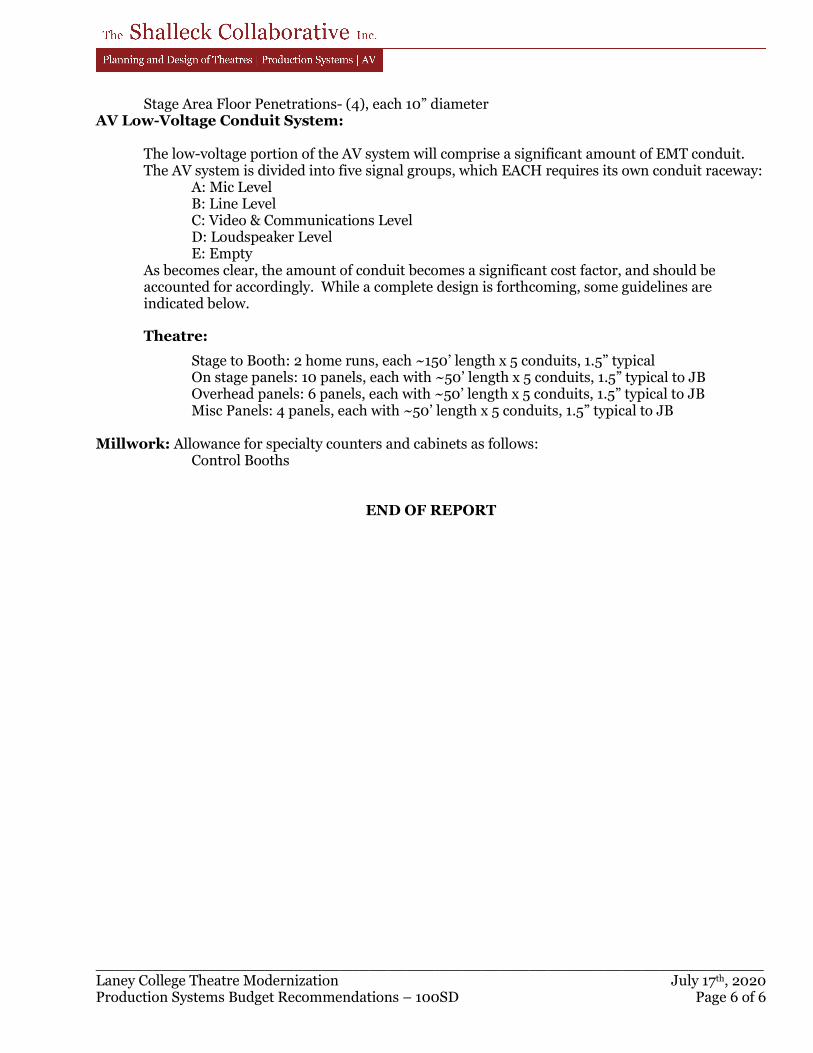
_______________________________________________________________________ Laney College Theatre Modernization July 17th, 2020 Production Systems Budget Recommendations – 100SD Page 6 of 6
Stage Area Floor Penetrations- (4), each 10” diameter AV Low-Voltage Conduit System:
The low-voltage portion of the AV system will comprise a significant amount of EMT conduit. The AV system is divided into five signal groups, which EACH requires its own conduit raceway:
A: Mic Level B: Line Level C: Video & Communications Level D: Loudspeaker Level E: Empty
As becomes clear, the amount of conduit becomes a significant cost factor, and should be accounted for accordingly. While a complete design is forthcoming, some guidelines are indicated below.
Theatre:
Stage to Booth: 2 home runs, each ~150’ length x 5 conduits, 1.5” typical On stage panels: 10 panels, each with ~50’ length x 5 conduits, 1.5” typical to JB Overhead panels: 6 panels, each with ~50’ length x 5 conduits, 1.5” typical to JB Misc Panels: 4 panels, each with ~50’ length x 5 conduits, 1.5” typical to JB Millwork: Allowance for specialty counters and cabinets as follows:
Control Booths
END OF REPORT

PERALTA COMMUNITY COLLEGE DISTRICT LANEY COLLEGE THEATER MODERNIZATION OAKLAND, CA
200730LCT027/ELS
APPENDIX E
ACOUSTICAL NARRATIVE
Laney College Theater Modernization Project Oakland, CA
SCHEMATIC DESIGN ACOUSTICAL NARRATIVE
31 July 2020
Prepared for: Kim-Van Troung
ELS Architecture and Urban Design
2040 Addison Street
Berkeley, CA 94704
Prepared by: Salter
Felipe Tavera – Associate
Jason Duty, PE – Vice President
Salter Project: 20-0175
Laney College Theater Modernization Project
31 July 2020
Schematic Design Acoustical Narrative
Page 2
INTRODUCTION
The purpose of this narrative is to provide preliminary acoustical design standards for the Laney Theater
Modernization Project. The project consists of the renovation of an existing approximately 40,000 square
foot building that serves the Theater, Dance, Music, and Media Departments.
The project includes modifications to a 300-seat proscenium theater, theater support spaces (e.g.,
dressing rooms, scene shop, control booth) and the addition/renovation of a visual media lab, a sound
media lab, a theater lab, a vocal lab, and some office and breakout spaces.
Our recommendations are based on the 9 July 2020 Schematic Design Backgrounds, 15 July 2020
acoustical measurements, our experience with similar projects, and our ongoing coordination with you
and the design team.
We have also recently conducted acoustical measurements in the existing space. The results of the
measurements will be used to provide additional recommendations in a future update to this document.
This report comprises the following sections:
● Section 1: Sound Isolation Between Rooms
● Section 2: Sound-Isolation Details
● Section 3: Rooms Acoustics
● Section 4: MEP System Noise and Vibration Reduction
SECTION 1: SOUND ISOLATION BETWEEN ROOMS
Walls
1. We have developed 5 wall types, as shown in Figures 1 to 5 (and described below). We have assumed
that the framing will be 20-gauge studs or heavier. Unique conditions that require additional
acoustical considerations will be reviewed as the project evolves.
● Wall Type B: Insulated single-stud wall with three total layers of gypsum board that extends
full-height to the underside of the floor above.
● Wall Type C: Insulated single-stud wall with a two layers of gypsum board on each side that
extend full-height to the underside of the floor above.
● Wall Type D: Insulated double-stud wall with two layers of gypsum board on each side that
extends full-height to the underside of the floor above.
● Wall Type F: Insulated double-stud wall with three layers of gypsum board on each side that
extends full-height to the underside of the floor above.
● Wall Type Y: Insulated independent furred wall with two layers of gypsum board that extends
full-height to the underside of the floor above.
Laney College Theater Modernization Project
31 July 2020
Schematic Design Acoustical Narrative
Page 3
2. Provide Wall Type B between circulation the following spaces:
● Classrooms and circulation
● Offices and circulation
● Theater Lab and circulation
3. Provide Wall Type C between the following spaces:
● Classrooms
● Offices and restrooms
● Theater and adjacent vestibule (with a door)
4. Provide Wall Type D between the following spaces:
● Relocated Visual Media Lab and circulation
● Visual Media Control Room and circulation
● Sound Media Lab and circulation
● Sound Media Control Room and circulation
● Possible Vocal Lab and circulation
● Stage and Current Fab Lab
● Theater and adjacent lobbies (without a door or a vestibule)
5. Provide Wall Type F between the following spaces:
● Relocated Visual Media Lab and Restrooms
● Relocated visual Media and Control Room
● Sound Media Lab and Restrooms
● Sound Media Lab and Sound Media Control Room
6. Provide Wall Type Y between the building core and the following spaces:
● Possible Vocal Lab and elevator shaft wall
● Sound media labs and exterior walls
● Theater Lab and elevator shaft wall
● Theater lab and theater
● Office 306 and elevator shaft wall
7. We recommend that vestibules (sound locks) be provided to all entrances to the theater. The walls
between the vestibules and adjacent lobbies should be Wall Type C.
Glazing
8. The drawings do not yet indicate whether any walls would be provided with glazing. Note that glazing
is not recommended in Wall Types D through Y (with a few exceptions). If glazing is to be used in
walls, we recommend that the following glazing types be used:
● With Wall Type B: minimum 1/4-inch thick glass
● With Wall Type C: minimum 1/2-inch laminated glass
Laney College Theater Modernization Project
31 July 2020
Schematic Design Acoustical Narrative
Page 4
9. If a window is required between the Visual Media Lab and adjacent Control Room, or if the existing
window between the Theater Control Room 302 and the Theater is being replaced, the window will
need two laminated panes of glass (similar to Figure 6). It is also possible to purchase “off-the-shelf”
sound-rated window products that could be used at these locations (e.g., Noise Barriers QuietLite,
IAC Noise-Lock).
We recommend that a new window also be provided between the Sound Media Lab and Sound
Media Control Room (if the demising wall is being modified). We can provide more information as the
design progresses.
Doors
10. The following rooms should be provided with gasketed solid-core wood or insulated metal doors (see
Figure 7):
● Classrooms
● Offices
● Enlarged Green Room 201
● Breakout Space 200
● Theater-Vestibule Doors (theatre side; no latches)
● Control room 302
11. The following rooms should be provided with sound-rated door systems. The recommended STC1
rating is shown in parenthesis:
● Theater-Vestibule Doors (circulation side; min STC 43)
● Theater Lab 319 (STC 50)
● Theater Door, if no vestibules are provided (STC 50, no latches)
● Visual Media Lab (STC 50)
● Control Room (STC 50)
● Sound Media Lab (STC 50)
● Sound Media Control Room (STC 50)
● Possible Vocal Lab (STC 50)
● Mechanical 418 (STC 50)
Manufacturers such as IAC Acoustics and Noise Barriers can provide door systems with such STC
ratings.
12. We understand that the Fab Lab will move out and that this space will become the theater scene
shop. We assume concurrent use of the scene shop and stage is desired, therefore large sound-rated
doors would be needed between these two rooms. Allow for minimum STC 53 doors with minimum
1 STC (Sound Transmission Class) – A single-number rating defined in ASTM E90 that quantifies the airborne sound insulating
performance of a partition under laboratory conditions. Increasing STC ratings correspond to improved airborne sound insulation.
Laney College Theater Modernization Project
31 July 2020
Schematic Design Acoustical Narrative
Page 5
4-inch thick door leaves at this location. Once additional information on the expected uses of these
two rooms, we can provide additional information on this.
Floor-Ceiling Assemblies
13. We understand that the existing structure consists of a concrete waffle slab that is several inches
thick. We expect that if a suspended lay-in tile ceiling (minimum CAC2 35; minimum NRC3 0.70) is
provided underneath in enclosed rooms, this assembly would provide sufficient airborne sound
isolation between typical spaces.
14. However, we recommend that upgraded ceiling assemblies be provided in the following spaces:
● Visual Media Studio
● Visual Media Control Room
● Office 306 (under Possible Vocal Lab)
The upgraded ceilings could be spring-isolated gypsum board ceilings (see Figure 8) or tunnel
construction assemblies (similar to Figure 9). We will provide additional input as the design
progresses and the expected uses of these spaces are further defined.
If the ceilings of the Level 4 Sound Media Rooms will be rebuilt, upgraded ceilings should also be
provided (see Figures 8 and 9).
15. The existing finish floors at most spaces in Level 3 and 4 appear to be a form of resilient tiled floors.
We assume that this floor will be replaced at most locations. To address concerns about impact and
footfall noise transfer, we recommend that a 5-mm thick acoustical underlayment be provided under
the new finish floor. A product such as Pliteq RST05 or Ecore EcoSilence 5 would be acoustically
acceptable.
We understand that at some locations, the design is considering removing the existing floors and
leaving the concrete floor exposed. Note that without an acoustical underlayment, footfall noise and
structure borne noise (e.g., dragging of chairs, furniture) would be audible in spaces adjacent and
directly beneath these areas and rooms (especially if the room below does not have a ceiling).
Some impact noise attenuation can be achieved by providing continuous ceilings in the spaces below
these areas or by upgrading such ceilings (e.g., suspended gypsum board, high-CAC ceiling tiles).
However, note that an acoustical underlayment is the most effective acoustical strategy to address
this concern.
Another potential option to maintain a concrete finish would be to provide acoustical underlayments
under “thin” concrete toppings.
2 CAC (Ceiling Attenuation Class) – A single-number rating defined in ASTM E1264 that quantifies the sound insulation
provided by the ceilings in adjacent rooms separated by a wall that does not extend to the structure above.
3 NRC (Noise Reduction Coefficient) – A single-number rating defined in ASTM C423 that quantifies the sound absorbing performance of a material. NRC is calculated by averaging the material’s octave-band sound absorption coefficients in the speech frequency range – i.e., at 250, 500, 1000, and 2000 hertz. An NRC of 1.00 represents 100% absorption (no sound reflections). An updated version of the NRC is SAA (sound absorption average).
Laney College Theater Modernization Project
31 July 2020
Schematic Design Acoustical Narrative
Page 6
We can also discuss other potential options once the new floor finishes are better understood.
16. Our onsite observations indicate that the existing Media Recording 415 and TV Studio 306A appear to
have a form of isolated flooring. We recommend that the following rooms be provided with a similar
isolated floor. If the isolated floors will be rebuilt, we recommend systems such as Figure 10:
● Relocated Visual Media Studio and adjacent control room
● Sound Media Control Room
● Theater Lab
Note that even with the isolated floor, there could be audible noise transfer between the Lobby and
the Level 3 Visual Media Studio and Control room. If this is a concern, administrative measures such
as scheduling around the loudest activities should be implemented. Otherwise, we should discuss
providing a suspended ceiling in the Lobby.
SECTION 2: SOUND-ISOLATION DETAILS
The following recommendations should be incorporated into the project design documents:
1. All constructions with batt insulation is to be considered “sound-rated”.
2. Do not bridge double-stud framing, such as with bracing, pipes, or conduit. For fire-rated double-stud
walls, UL U493 should provide the needed rating without needed cross-bracing.
3. The gypsum board of sound-rated partitions and ceilings should be held back 1/4-inch from all
intersecting structures (such as floors, walls, and ceilings) and penetrations, with the gap caulked
airtight with acoustical sealant. If a fire-rated sealant is needed, consider Pecora AC-20 FTR,
Metacaulk 150+, or an approved equal.
4. Sound-rated walls are to be constructed full-height to the structure above (unless otherwise noted)
and sealed airtight.
5. Junction boxes in plumbing walls or on opposite sides of sound-rated partitions should be separated
by at least 16 inches and one empty stud bay. All sides should be treated with putty pads as shown in
Figure 11. This treatment should be implemented at all junction boxes and receptacles in sound-rated
partitions (e.g., light switches, low-voltage devices, network ports).
6. If 16-inch separation between junction boxes in opposite sides is not possible, add a barrier between
the boxes using a layer of gypsum board or sheet metal between the boxes, as shown in Figure 12.
7. Ideally, surface mounted junction boxes would be provided in the Visual Media and Sound Media
Labs.
8. Recessed fixtures or panels larger than a four-gang box should be enclosed with a layer of gypsum
board (see Figure 13). Recessed fixtures should not be located back-to-back.
9. All penetrations (e.g., ducts, piping, and conduit) in sound-rated constructions should be sealed
airtight with acoustical sealant (see Figures 14 through 19). All wires and cables penetrating
sound-rated partitions should be enclosed in conduit. Cable trays should transition to conduit at
penetrations in sound-rated partitions.
Laney College Theater Modernization Project
31 July 2020
Schematic Design Acoustical Narrative
Page 7
10. Access doors in sound-rated constructions should be equal to fire-rated access doors incorporating
an insulated steel door panel, piano hinge, and silicone bulb seal at the door perimeter. The assembly
should be sealed to the gypsum board with acoustical sealant. Products such as JL Industries Models
BG and LBG STC 47, Babcock-Davis B-ITK-SFB, or Williams Bros. Corp WB-FR Premium could be used.
SECTION 3: ROOM ACOUSTICS
To control reverberation and sound build-up, we recommend that sound-absorptive finishes be
incorporated into the project, as described below. We are glad to discuss acoustical materials to achieve
your desired aesthetic, as the project progresses.
Theater
1. We understand that the interior theater acoustics are deemed to be acceptable. The project will be
replacing the carpeting and a portion of the theater seats in-kind. Carpeting should only be provided
at circulation areas. If this were to change, please let us know so that we can provide additional input.
2. Our onsite measurements indicate that the mid-band reverberation time4 in the theater is 1.6
seconds.
Stage
3. Currently, the stage does not have any sound-absorptive finishes. We recommend allowing for 2-inch
thick black faced insulation to be added to cover approximately 50% of all stage walls.
Theater Vestibules (Sound-Locks)
4. Provide sound absorptive ceilings (minimum NRC of 0.70). In addition, sound-absorptive wall panels
(minimum NRC 0.80) should be provided on all available walls extending from three feet above the
finished floor to at least seven feet.
Lobby
5. We recommend providing sound-absorptive ceiling treatments to approximately 70% of the available
ceiling area. The sound-absorptive treatment should achieve a minimum NRC of 0.80 and be at least
2-inches thick.
Green Room, Breakout Space, Classrooms
6. Provide sound absorptive lay-in tile ceilings (minimum NRC of 0.70; minimum CAC 35). In addition,
sound-absorptive wall panels (minimum NRC 0.80) should be provided on at least two adjacent walls,
4 RT60 (Reverberation Time) – The time it takes for sound to decay 60 dB in a room. Music sounds richer in rooms with long
reverberation times, but speech might be difficult to understand. Conversely, speech is more intelligible in rooms with shorter reverberation times, but music might sound dry.
Laney College Theater Modernization Project
31 July 2020
Schematic Design Acoustical Narrative
Page 8
extending from three feet above the finished floor (chair-back height) to at least seven feet above the
finish floor and the absorptive panels.
Theater Lab
7. Allow for 4-inch thick sound-absorbing wall treatments on one wall, and 2-inch thick panels on at
least two others. Panels should be installed 36-inches AFF to ceiling. A sound-absorptive ceiling
should be provided above the lighting grid (e.g., 2-inch black faced insulation attached to the
underside of the ceiling).
Visual Media Studio and Sound Media Lab
8. Allow for 4-inch thick assembly on each wall and two layers of 2-inch black faced insulation on the
ceiling. Walls could be provided with strut grids to facilitate attachment of equipment, assume
24-inch spacing vertically on all four walls. If a hard infinity cyclorama is planned for the space, it
should be tilted at least 7-degrees from the vertical axis and covered with 24 to 30 oz., 100% fullness,
velour curtains to when it is not in use.
Visual and Sound Media Control Rooms
9. Ideally, these rooms should have a symmetrical layout (i.e., the “left” and “right” side of the rooms
should be identical) to improve the listener response. The inner studs of the recommended wall type
(see Sound Isolation section) could be used to provide a symmetrical room.
2-inch thick sound-absorbing panels (minimum NRC of 1.00) at 36-inches AFF to ceiling, should be
provided on approximately 50% of the walls in combination with a suspended sound-absorbing
ceiling (minimum NRC of 0.80) with an insulation filled cavity at least 16 inches deep.
Theater Control Room
10. Provide sound absorptive ceilings (minimum NRC of 0.80). In addition, sound-absorptive wall panels
(minimum NRC 0.80) should be provided on at least one long wall extending from three feet above
the finished floor to at least seven feet above the finish floor.
Vocal Lab
11. Allow for 4-inch thick sound-absorbing wall treatments on two adjacent walls, and 2-inch thick panels
on the other two. Panels should be installed 36-inches AFF to ceiling. A suspended sound-absorbing
ceiling (minimum NRC of 0.80) with an insulation filled cavity at least 16 inches deep should also be
provided. Alternatively, pre-manufactured rooms could be used instead (e.g., Noise Barriers
QuietMPR or Wenger SoundLok).
Offices, Make-up, Dressing Rooms
12. Provide sound absorptive ceilings with a minimum NRC rating of 0.70.
Laney College Theater Modernization Project
31 July 2020
Schematic Design Acoustical Narrative
Page 9
Mechanical Rooms
13. Provide 2-inch thick black-faced insulation to all available wall and ceilings.
SECTION 4: MEP SYSTEM NOISE AND VIBRATION REDUCTION
The existing mechanical system is comprised of a series of large fans located in the Level 4 Mechanical
room. At this time, we assume that most of the mechanical equipment will be replaced, but will still likely
be located in this room.
General
1. Based on ASHRAE guidelines, we recommend that the noise due to MEP systems be designed to meet
the noise criteria (NC5) for spaces listed in Table 1.
Table 1: Recommended HVAC Noise Criteria
Space Noise Criteria Measured NC
Theater, Stage 20 to 25 30 to 35
Theater, Stage (during elevator operation) 20 to 25 35 to 40
Sound Media Lab, Visual Media Lab, Vocal Lab 20 to 25 N/A
Sound Media Control Room, Visual Media Control Room 25 N/A
Existing Live Room 20 18
Existing Control Room 25 23
Theater Lab 25 to 30 N/A
Huddle Rooms, Lounges 30 N/A
Green Room, Breakout Spaces, Offices 35 37
BOH Theater Support Spaces (dressing rooms, make up) 35 to 40 N/A
Media Check-out, Circulation, Lobbies 40 N/A
Restrooms 45 N/A
2. The project should conform with industry-standard vibration control recommendations contained in
the latest ASHRAE HVAC Applications Handbook.
3. We recommend that unhoused springs be used. Where necessary, separate seismic snubbers should
be used. We also recommend external spring isolation. If internal springs are used, then the housing
should be isolated on neoprene waffle pads. The acoustical vibration isolation must not compromise
seismic code requirements and vice-versa.
4. The isolation devices shall be as follows:
● Unhoused springs shall be equal to Mason SLFH
● Seismic snubbers shall be equal to Mason Z-1225
● Restrained springs shall be equal to Mason SLR 100 Series or SSLFH-X
5 NC (Noise Criteria) – A single-number rating defined by ASHRAE that quantifies a steady-state noise. It is based on a family of
curves that includes noise from 63 Hz to 8,000 Hz. NC is typically used to rate the loudness of HVAC system noise in a room.
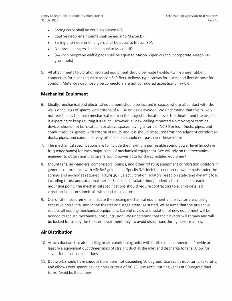
Laney College Theater Modernization Project
31 July 2020
Schematic Design Acoustical Narrative
Page 10
● Spring curbs shall be equal to Mason RSC
● Captive neoprene mounts shall be equal to Mason BR
● Spring-and-neoprene hangers shall be equal to Mason 30N
● Neoprene hangers shall be equal to Mason HD
● 3/4-inch neoprene waffle pads shall be equal to Mason Super W (and incorporate Mason HG
grommets)
5. All attachments to vibration-isolated equipment should be made flexible: twin-sphere rubber
connectors for pipes (equal to Mason Safeflex), bellows-type canvas for ducts, and flexible hose for
conduit. Metal-braided hose pipe connectors are not considered acoustically flexible.
Mechanical Equipment
6. Ideally, mechanical and electrical equipment should be located in spaces where all contact with the
walls or ceilings of spaces with criteria of NC 30 or less is avoided. We understand that this is likely
not feasible, as the main mechanical room in the project tis located over the theater and the project
is expecting to keep utilizing it as such. However, all new ceiling-mounted air-moving or terminal
devices should not be located in or above spaces having criteria of NC 30 or less. Ducts, pipes, and
conduit serving spaces with criteria of NC 25 and less should be routed from the adjacent corridor; all
ducts, pipes, and conduit serving other spaces should not pass over these rooms.
7. The mechanical specifications are to include the maximum permissible sound power level (in octave
frequency bands) for each major piece of mechanical equipment. We will rely on the mechanical
engineer to obtain manufacturer’s sound power data for the scheduled equipment
8. Mount fans, air-handlers, compressors, pumps, and other rotating equipment on vibration isolators in
general conformance with ASHRAE guidelines. Specify 3/4-inch thick neoprene waffle pads under the
springs and anchor as required (Figure 20). Select vibration isolators based on static and dynamic load
including thrust and rotational inertia. Select each isolator independently for the load at each
mounting point. The mechanical specifications should require contractors to submit detailed
vibration isolation submittals with load calculations.
9. Our onsite measurements indicate the existing mechanical equipment and elevator are causing
excessive noise intrusion in the theater and stage areas. As stated, we assume that the project will
replace all existing mechanical equipment. Careful review and isolation of new equipment will be
needed to reduce mechanical noise intrusion. We understand that the elevator will remain and will
be locked for use by the theater department only, to avoid disruptions during performances.
Air Distribution
10. Attach ductwork to air handling or air-conditioning units with flexible duct connectors. Provide at
least five equivalent duct dimensions of straight duct at the inlet and discharge to fans. Allow for
seven-foot silencers near fans.
11. Ductwork should have smooth transitions not exceeding 10 degrees. Use radius duct turns, take-offs,
and elbows over spaces having noise criteria of NC 25. Use airfoil turning vanes at 90-degree duct
turns. Avoid bullhead tees.
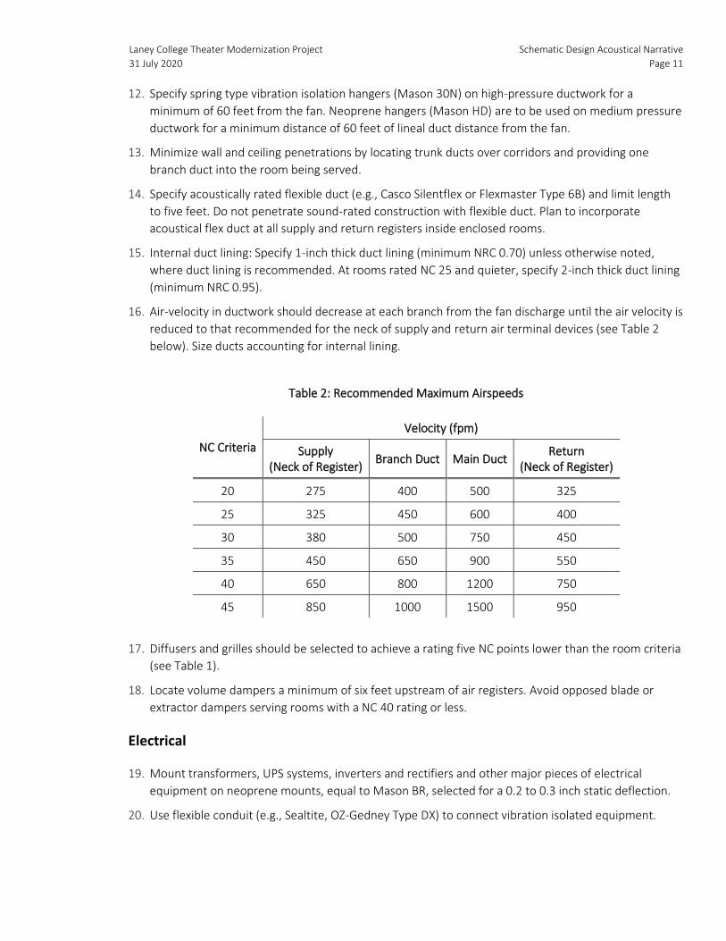
Laney College Theater Modernization Project
31 July 2020
Schematic Design Acoustical Narrative
Page 11
12. Specify spring type vibration isolation hangers (Mason 30N) on high-pressure ductwork for a
minimum of 60 feet from the fan. Neoprene hangers (Mason HD) are to be used on medium pressure
ductwork for a minimum distance of 60 feet of lineal duct distance from the fan.
13. Minimize wall and ceiling penetrations by locating trunk ducts over corridors and providing one
branch duct into the room being served.
14. Specify acoustically rated flexible duct (e.g., Casco Silentflex or Flexmaster Type 6B) and limit length
to five feet. Do not penetrate sound-rated construction with flexible duct. Plan to incorporate
acoustical flex duct at all supply and return registers inside enclosed rooms.
15. Internal duct lining: Specify 1-inch thick duct lining (minimum NRC 0.70) unless otherwise noted,
where duct lining is recommended. At rooms rated NC 25 and quieter, specify 2-inch thick duct lining
(minimum NRC 0.95).
16. Air-velocity in ductwork should decrease at each branch from the fan discharge until the air velocity is
reduced to that recommended for the neck of supply and return air terminal devices (see Table 2
below). Size ducts accounting for internal lining.
Table 2: Recommended Maximum Airspeeds
NC Criteria
Velocity (fpm)
Supply (Neck of Register)
Branch Duct Main Duct Return
(Neck of Register)
20 275 400 500 325
25 325 450 600 400
30 380 500 750 450
35 450 650 900 550
40 650 800 1200 750
45 850 1000 1500 950
17. Diffusers and grilles should be selected to achieve a rating five NC points lower than the room criteria
(see Table 1).
18. Locate volume dampers a minimum of six feet upstream of air registers. Avoid opposed blade or
extractor dampers serving rooms with a NC 40 rating or less.
Electrical
19. Mount transformers, UPS systems, inverters and rectifiers and other major pieces of electrical
equipment on neoprene mounts, equal to Mason BR, selected for a 0.2 to 0.3 inch static deflection.
20. Use flexible conduit (e.g., Sealtite, OZ-Gedney Type DX) to connect vibration isolated equipment.
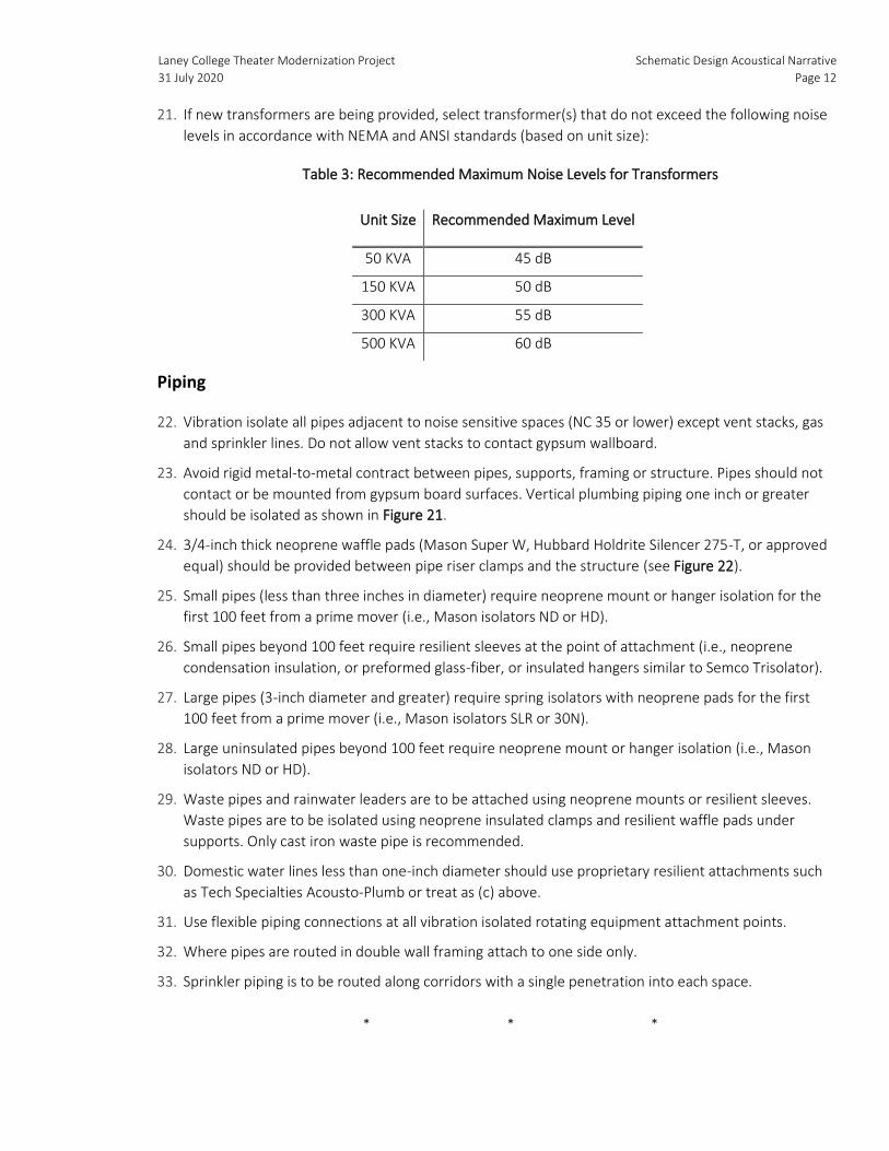
Laney College Theater Modernization Project
31 July 2020
Schematic Design Acoustical Narrative
Page 12
21. If new transformers are being provided, select transformer(s) that do not exceed the following noise
levels in accordance with NEMA and ANSI standards (based on unit size):
Table 3: Recommended Maximum Noise Levels for Transformers
Unit Size Recommended Maximum Level
50 KVA 45 dB
150 KVA 50 dB
300 KVA 55 dB
500 KVA 60 dB
Piping
22. Vibration isolate all pipes adjacent to noise sensitive spaces (NC 35 or lower) except vent stacks, gas
and sprinkler lines. Do not allow vent stacks to contact gypsum wallboard.
23. Avoid rigid metal-to-metal contract between pipes, supports, framing or structure. Pipes should not
contact or be mounted from gypsum board surfaces. Vertical plumbing piping one inch or greater
should be isolated as shown in Figure 21.
24. 3/4-inch thick neoprene waffle pads (Mason Super W, Hubbard Holdrite Silencer 275-T, or approved
equal) should be provided between pipe riser clamps and the structure (see Figure 22).
25. Small pipes (less than three inches in diameter) require neoprene mount or hanger isolation for the
first 100 feet from a prime mover (i.e., Mason isolators ND or HD).
26. Small pipes beyond 100 feet require resilient sleeves at the point of attachment (i.e., neoprene
condensation insulation, or preformed glass-fiber, or insulated hangers similar to Semco Trisolator).
27. Large pipes (3-inch diameter and greater) require spring isolators with neoprene pads for the first
100 feet from a prime mover (i.e., Mason isolators SLR or 30N).
28. Large uninsulated pipes beyond 100 feet require neoprene mount or hanger isolation (i.e., Mason
isolators ND or HD).
29. Waste pipes and rainwater leaders are to be attached using neoprene mounts or resilient sleeves.
Waste pipes are to be isolated using neoprene insulated clamps and resilient waffle pads under
supports. Only cast iron waste pipe is recommended.
30. Domestic water lines less than one-inch diameter should use proprietary resilient attachments such
as Tech Specialties Acousto-Plumb or treat as (c) above.
31. Use flexible piping connections at all vibration isolated rotating equipment attachment points.
32. Where pipes are routed in double wall framing attach to one side only.
33. Sprinkler piping is to be routed along corridors with a single penetration into each space.
* * *
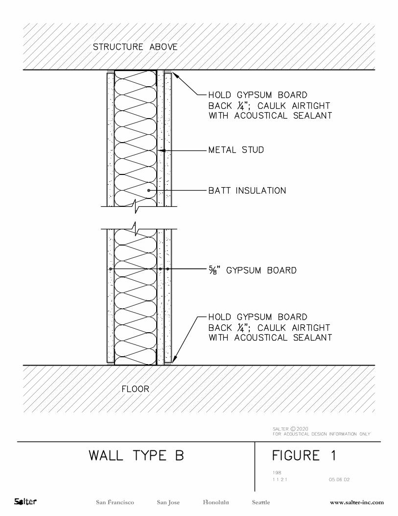
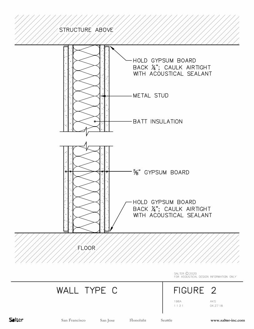
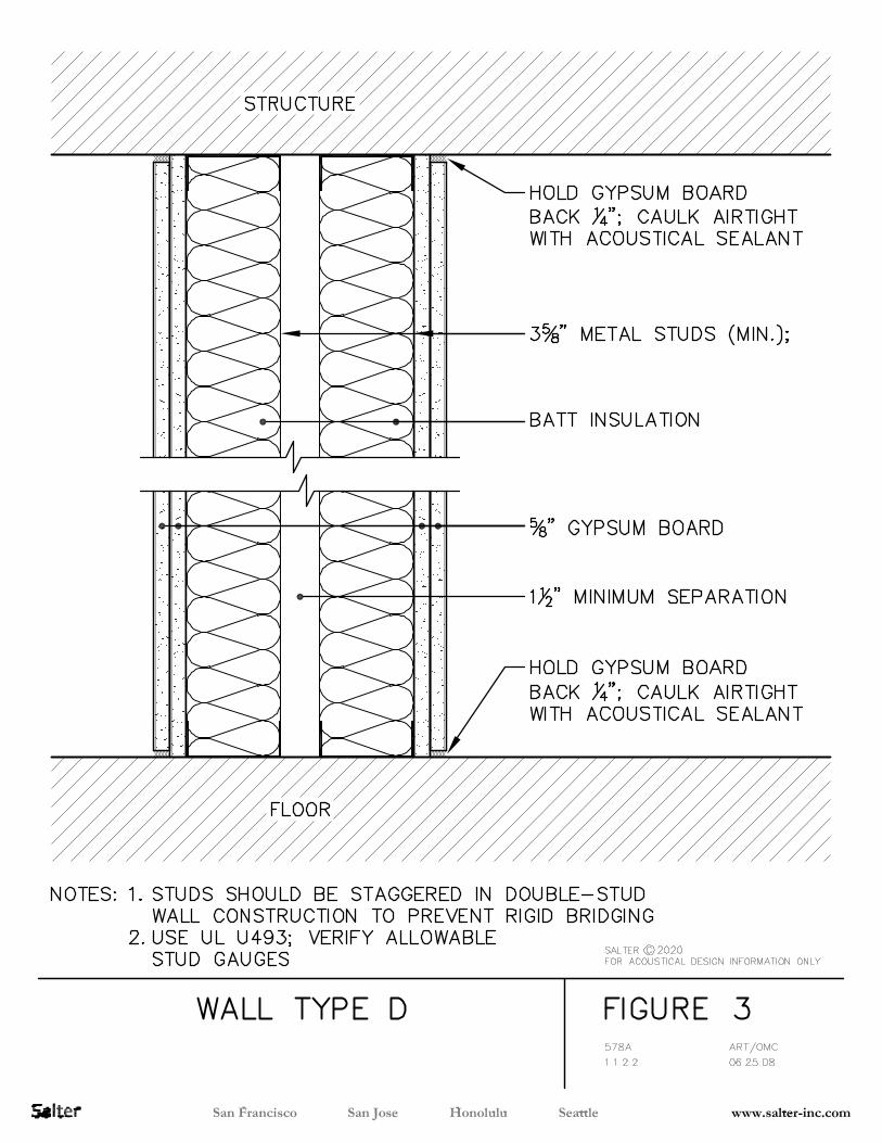
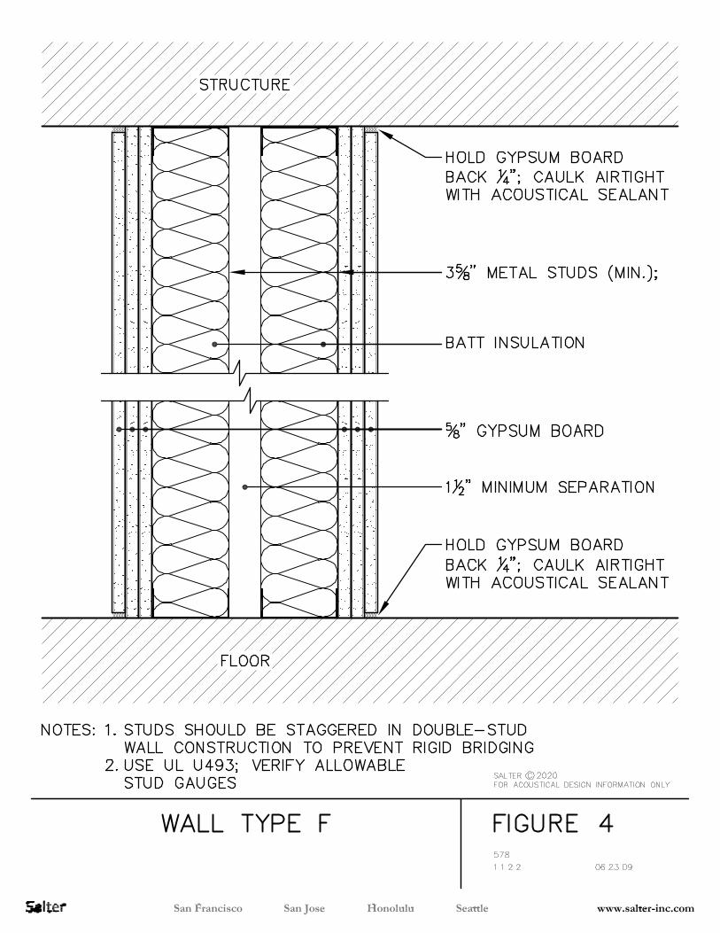
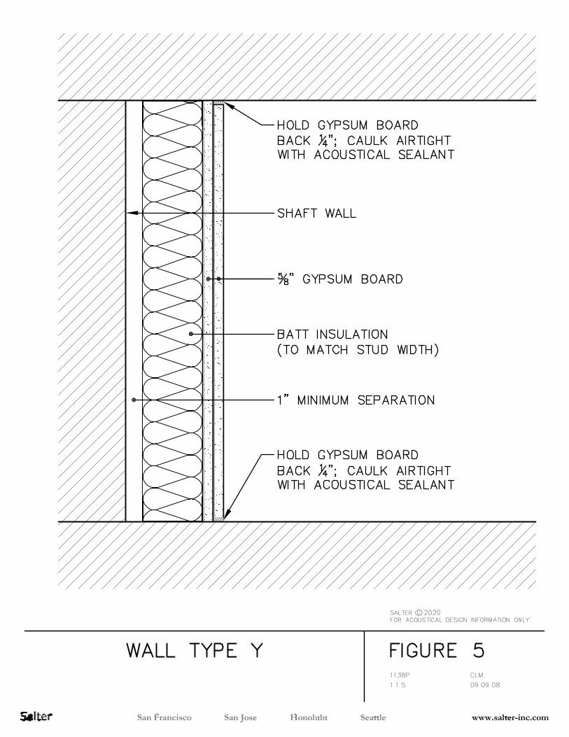
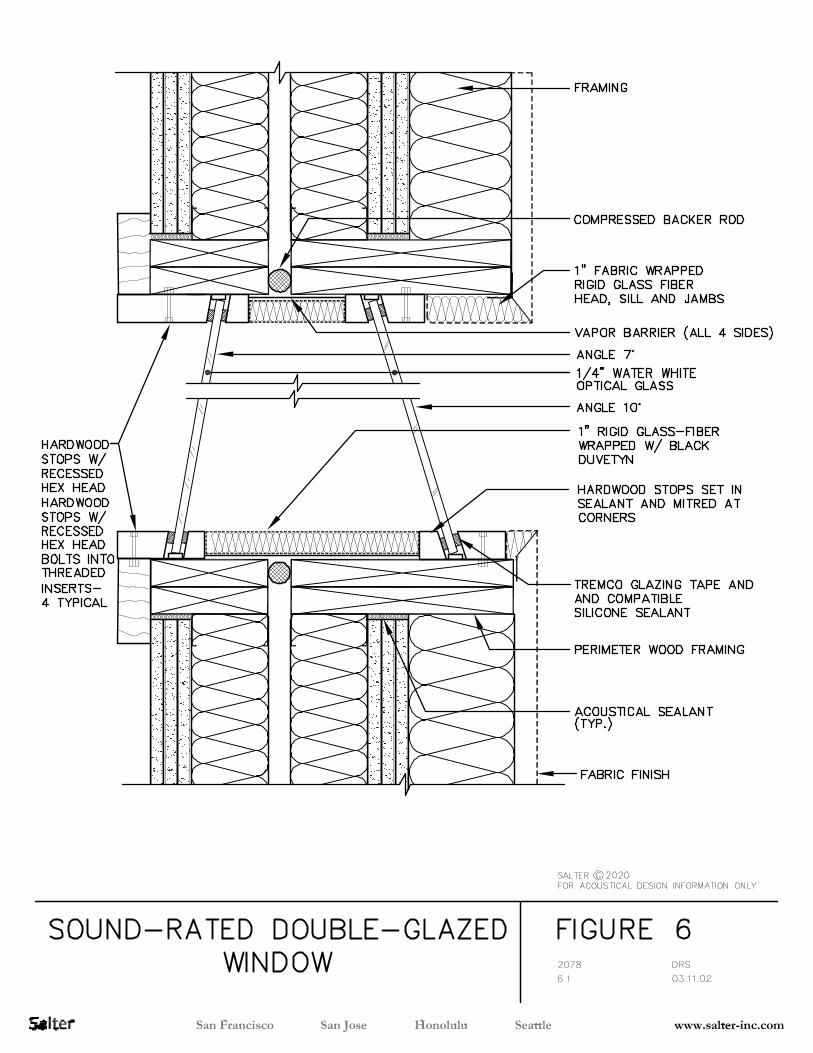
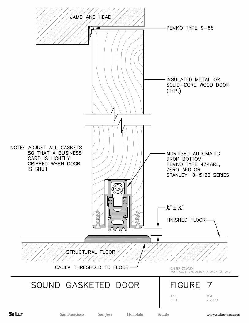
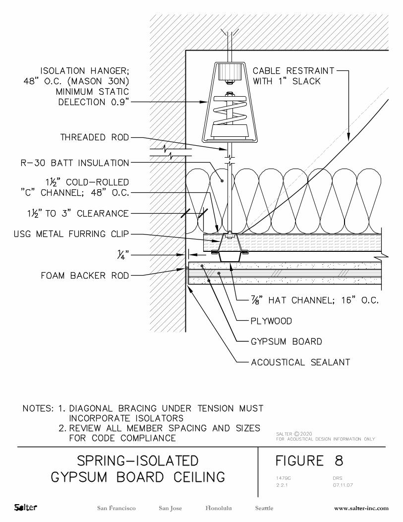
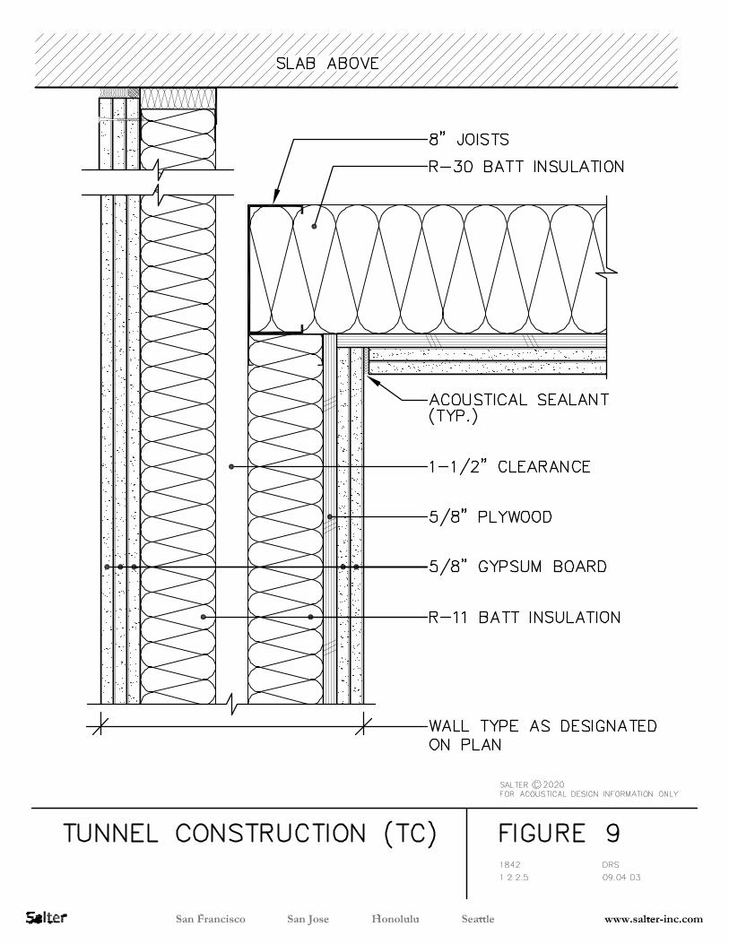
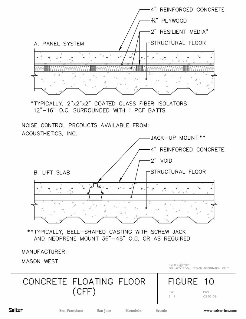
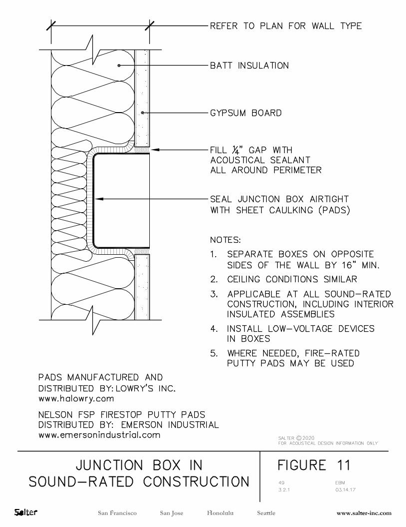

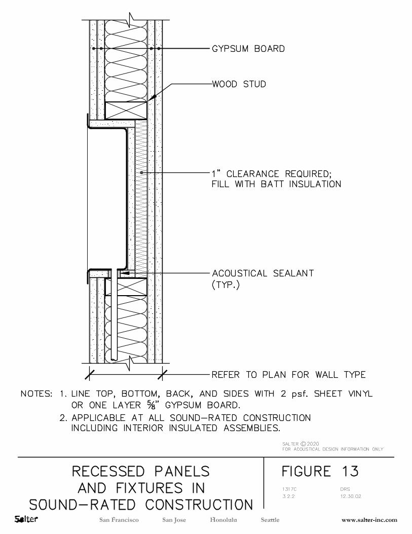
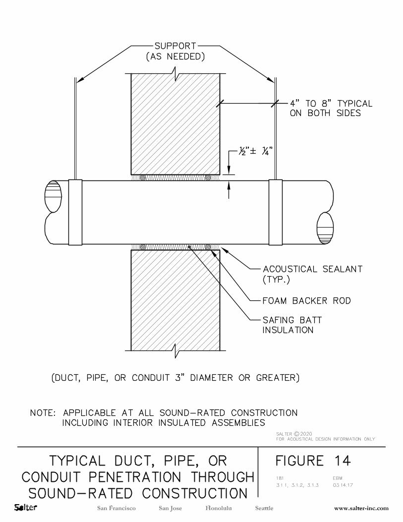
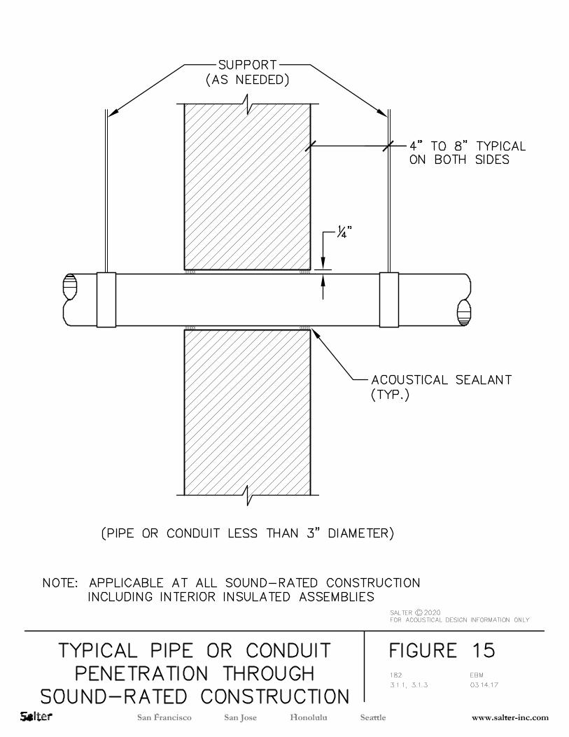
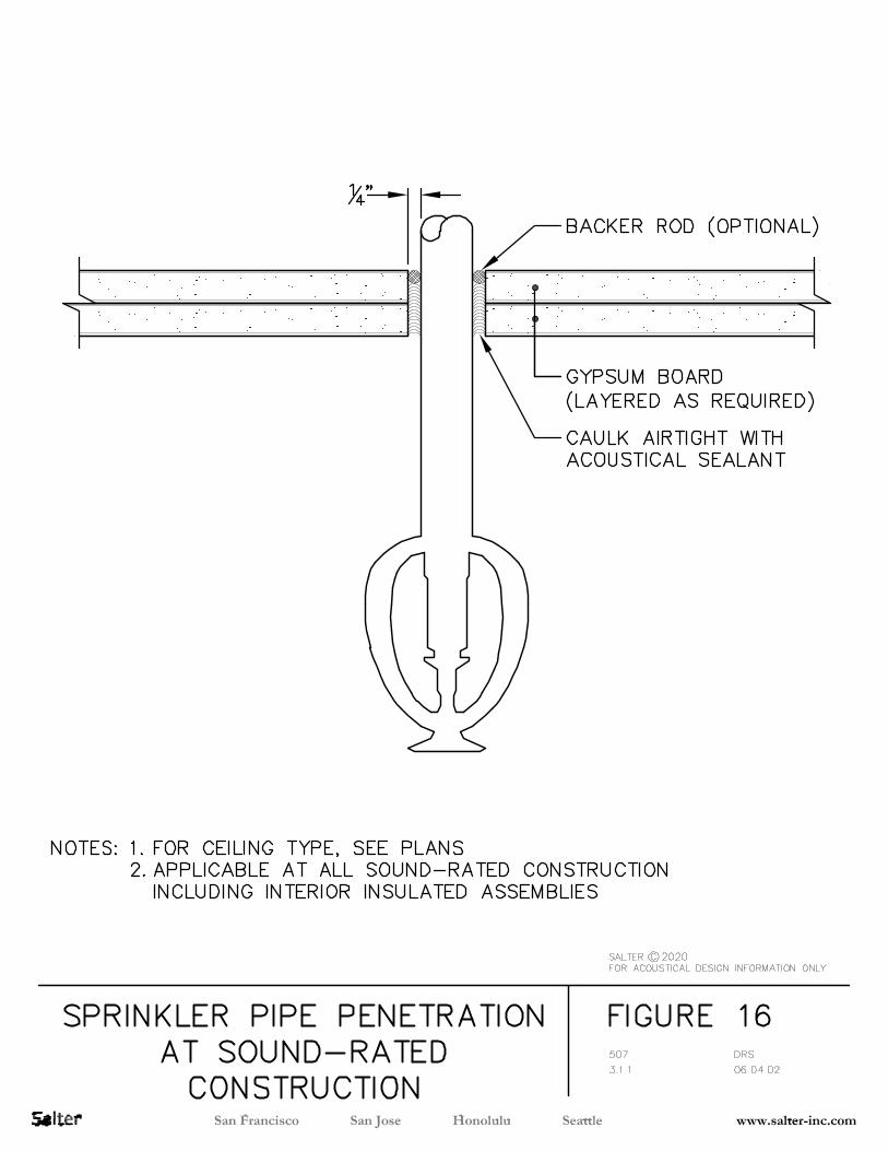
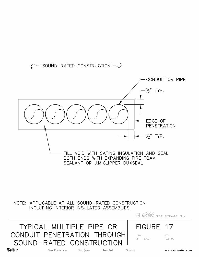
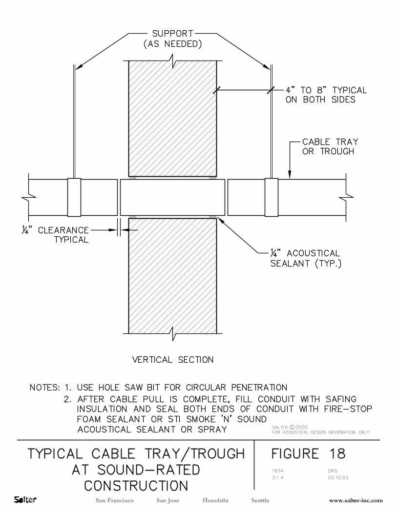
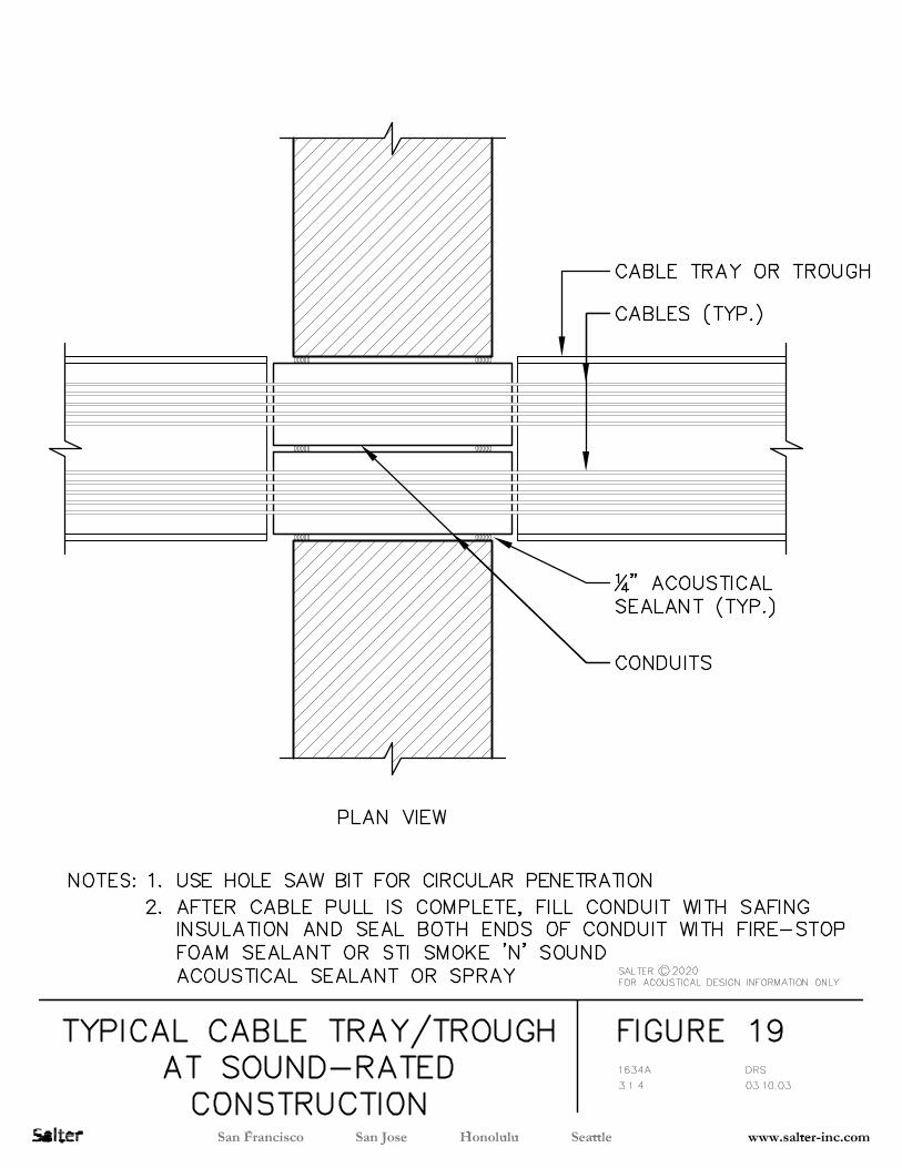
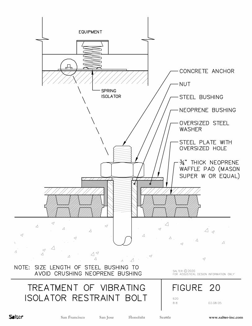
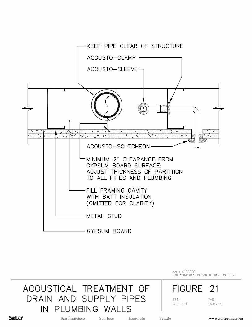
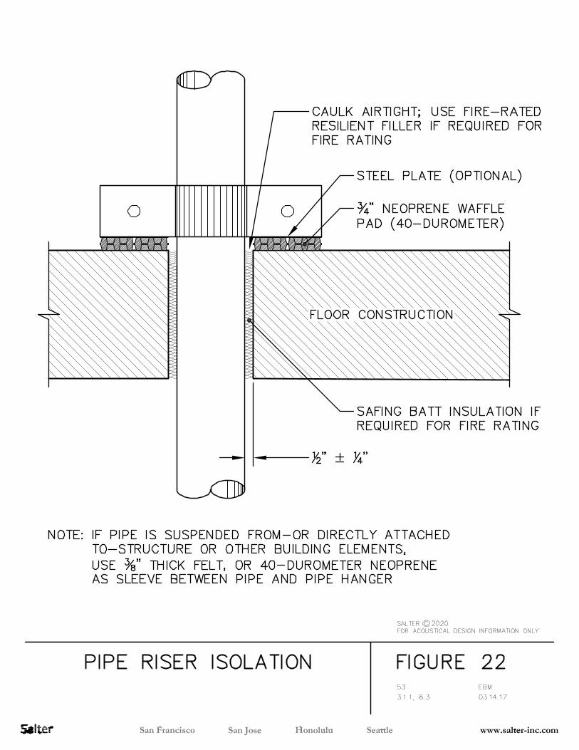

PERALTA COMMUNITY COLLEGE DISTRICT LANEY COLLEGE THEATER MODERNIZATION OAKLAND, CA
200803LCT027/ELS
APPENDIX F
TELECOM NARRATIVE
GUIDEPOST SOLUTIONS, LLC – LANEY COLLEGE THEATER MODERNIZATION – SD TELECOM NARRATIVE
PUBLICATION RECORD Document
Version
Publication Date
Primary Author
Description
V1.0 07/30/2020 Neal Schatmeier 100% SD Submission
I. Introduction and Executive Summary
A. General
1. This Basis of Design Narrative documents the structured cabling and security engineering
system design strategies and principles for the PCCD Theater Modernization at Laney College
project located in Oakland, CA. The project will provide low voltage systems for 5 levels with
programming including a Theater and Stage, a new accessible lobby, extended lobby,
women’s and men’s dressing rooms and lockers, offices, Green room, classrooms, Theater
control room, Production Control, TV Studio, and Media rooms. The Theater Building totals
approximately 40,207 SF. Guidepost Solutions is providing design services for the
Telecommunications riser, consisting of backbone copper and fiber optic cabling for the
building as well as the horizontal cable plant stemming from the Telecommunications Room(s)
to support the different building functions as outlined in this document.
2. Use of this report will assist in design coordination, planning and design development.
II. Telecommunications Systems
The telecommunication system will be designed to include re-use of MDF/Demarc room 115A on Level 1. An
IDF and the pathway feeding the IDF will be tentatively located on Level 3. Location and size of the IDF to
be determined during the DD phase of the project.
The telecommunications and security systems design will be based on the requirements we received from
the PCCD project team in conjunction with industry standards and best practices. The design will consist of
the installation of horizontal and backbone cabling, as well as all associated termination devices, terminations,
and cross connects.
To better quantify and qualify the requirements of the telecommunications systems, this section categorizes
the Telecommunications into subsystems:
Telecommunications Subsystems:
• Inside Building Cable Infrastructure: This subsystem consists of the structured cable plant including
the horizontal cabling to the workstation outlets, inter-cabinet connectivity, and devices such as
CCTV cameras and WAPs; backbone cabling which interconnects the Demarc,
Telecommunications Rooms (MDF, IDF and Entrance Facility), termination hardware, equipment
racks and support accessories.
• Horizontal Cabling Distribution System: This subsystem includes the hardware and cabling required
for implementation of network connectivity to the workstations
GUIDEPOST SOLUTIONS, LLC – LANEY COLLEGE THEATER MODERNIZATION – SD TELECOM NARRATIVE
• Backbone Cabling Distribution System: This subsystem includes the hardware and cabling required
for implementation of backbone connectivity between telecommunication rooms and support
spaces.
• Pathway and Spaces: This subsystem includes the Pathways and spaces including cable tray,
sleeves, and conduits that will be required to support the horizontal cabling routed between the
telecommunication rooms and the workstation outlets.
• Cabling Administration: This subsystem includes a unique identification label for all termination panels
and cabling
• Wireless Data System: This subsystem includes the placement of Access Points that will be
connected to the standard data system via the structured cable plant.
A. Inside Building Cable Infrastructure
The technology infrastructure is comprised of the cable plant and passive hardware that will support
current and future Voice, Data and Wireless systems:
a. All workstations will be supported by uniform cabling distribution with a hierarchical
star topology. It consists of 4-pair unshielded (UTP) 6 CMP cables as part of the base
contract. The cables are home run in a star topology from each
telecommunications outlet to the supporting telecommunication room (IDF/MDF).
The telecommunication room will service all areas within its zone and maintain a 90
meter distance limitation from the workstation outlet to the patch panel.
b. The infrastructure design is vendor-specific. It is intended to support all current and
anticipated telecommunications systems.
c. The components of the infrastructure include workstation/office/WAP/printer
outlets, horizontal cabling, cabinets/racks and termination hardware. The
contractor will furnish and install all fiber and copper patch cords at the workstation
and within the IDF.
d. The design will address the cabling infrastructure from the terminations in the
IDF/MDF to horizontal cables and connectors. The construction documents and
specifications will address proper installation, termination and testing procedures to
ensure total system compliance and certification, to secure a 25-year component
warranty where the manufacturer states that its products will conform to
specification and will be free from defects.
B. Horizontal Cabling Distribution System
1. General
a. The standard outlet requires 4-pair unshielded (UTP) cat 6 CMP cables as part of the
base contract. A detailed configuration of the telecommunications outlets and
horizontal cabling is discussed below.
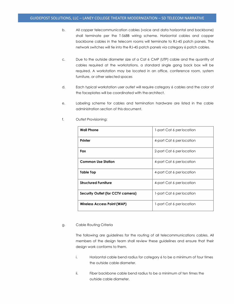
GUIDEPOST SOLUTIONS, LLC – LANEY COLLEGE THEATER MODERNIZATION – SD TELECOM NARRATIVE
b. All copper telecommunication cables (voice and data horizontal and backbone)
shall terminate per the T-568B wiring scheme. Horizontal cables and copper
backbone cables in the telecom rooms will terminate to RJ-45 patch panels. The
network switches will tie into the RJ-45 patch panels via category 6 patch cables.
c. Due to the outside diameter size of a Cat 6 CMP (UTP) cable and the quantity of
cables required at the workstations, a standard single gang back box will be
required. A workstation may be located in an office, conference room, system
furniture, or other selected spaces
d. Each typical workstation user outlet will require category 6 cables and the color of
the faceplates will be coordinated with the architect.
e. Labeling scheme for cables and termination hardware are listed in the cable
administration section of this document.
f. Outlet Provisioning:
Wall Phone 1-port Cat 6 per location
Printer 4-port Cat 6 per location
Fax 2-port Cat 6 per location
Common Use Station 4-port Cat 6 per location
Table Top 4-port Cat 6 per location
Structured Furniture 4-port Cat 6 per location
Security Outlet (for CCTV camera) 1-port Cat 6 per location
Wireless Access Point (WAP) 1-port Cat 6 per location
g. Cable Routing Criteria
The following are guidelines for the routing of all telecommunications cables. All
members of the design team shall review these guidelines and ensure that their
design work conforms to them.
i. Horizontal cable bend radius for category 6 to be a minimum of four times
the outside cable diameter.
ii. Fiber backbone cable bend radius to be a minimum of ten times the
outside cable diameter.
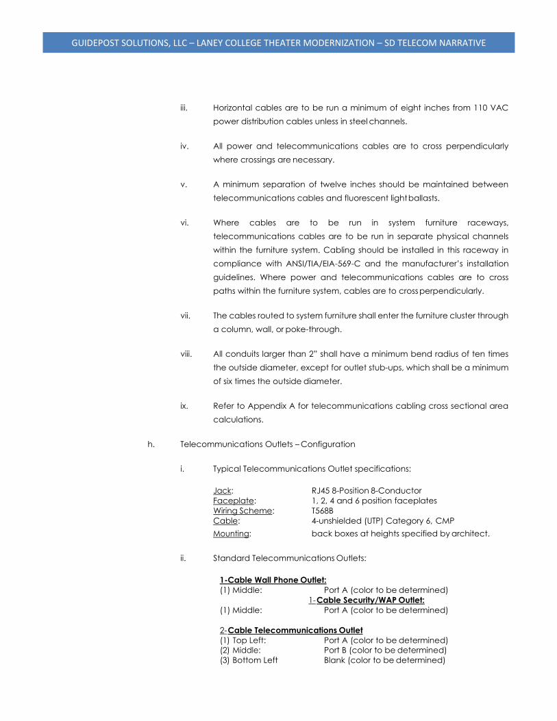
GUIDEPOST SOLUTIONS, LLC – LANEY COLLEGE THEATER MODERNIZATION – SD TELECOM NARRATIVE
iii. Horizontal cables are to be run a minimum of eight inches from 110 VAC
power distribution cables unless in steel channels.
iv. All power and telecommunications cables are to cross perpendicularly
where crossings are necessary.
v. A minimum separation of twelve inches should be maintained between
telecommunications cables and fluorescent light ballasts.
vi. Where cables are to be run in system furniture raceways,
telecommunications cables are to be run in separate physical channels
within the furniture system. Cabling should be installed in this raceway in
compliance with ANSI/TIA/EIA-569-C and the manufacturer’s installation
guidelines. Where power and telecommunications cables are to cross
paths within the furniture system, cables are to cross perpendicularly.
vii. The cables routed to system furniture shall enter the furniture cluster through
a column, wall, or poke-through.
viii. All conduits larger than 2” shall have a minimum bend radius of ten times
the outside diameter, except for outlet stub-ups, which shall be a minimum
of six times the outside diameter.
ix. Refer to Appendix A for telecommunications cabling cross sectional area
calculations.
h. Telecommunications Outlets – Configuration
i. Typical Telecommunications Outlet specifications:
Jack: RJ45 8-Position 8-Conductor
Faceplate: 1, 2, 4 and 6 position faceplates
Wiring Scheme: T568B
Cable: 4-unshielded (UTP) Category 6, CMP
Mounting: back boxes at heights specified by architect.
ii. Standard Telecommunications Outlets:
1-Cable Wall Phone Outlet:
(1) Middle: Port A (color to be determined)
1- Cable Security/WAP Outlet:
(1) Middle: Port A (color to be determined)
2- Cable Telecommunications Outlet
(1) Top Left: Port A (color to be determined)
(2) Middle: Port B (color to be determined)
(3) Bottom Left Blank (color to be determined)
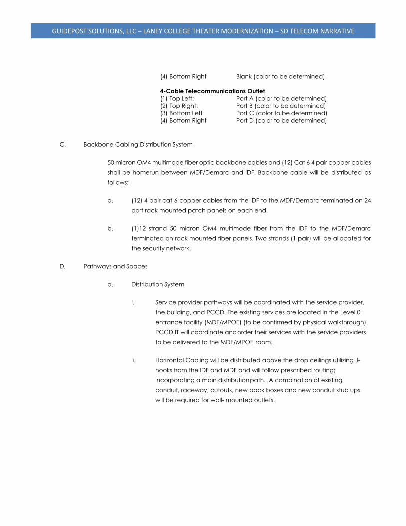
GUIDEPOST SOLUTIONS, LLC – LANEY COLLEGE THEATER MODERNIZATION – SD TELECOM NARRATIVE
(4) Bottom Right Blank (color to be determined)
4-Cable Telecommunications Outlet
(1) Top Left: Port A (color to be determined)
(2) Top Right: Port B (color to be determined)
(3) Bottom Left Port C (color to be determined)
(4) Bottom Right Port D (color to be determined)
C. Backbone Cabling Distribution System
50 micron OM4 multimode fiber optic backbone cables and (12) Cat 6 4 pair copper cables
shall be homerun between MDF/Demarc and IDF. Backbone cable will be distributed as
follows:
a. (12) 4 pair cat 6 copper cables from the IDF to the MDF/Demarc terminated on 24
port rack mounted patch panels on each end.
b. (1)12 strand 50 micron OM4 multimode fiber from the IDF to the MDF/Demarc
terminated on rack mounted fiber panels. Two strands (1 pair) will be allocated for
the security network.
D. Pathways and Spaces
a. Distribution System
i. Service provider pathways will be coordinated with the service provider,
the building, and PCCD. The existing services are located in the Level 0
entrance facility (MDF/MPOE) (to be confirmed by physical walkthrough).
PCCD IT will coordinate and order their services with the service providers
to be delivered to the MDF/MPOE room.
ii. Horizontal Cabling will be distributed above the drop ceilings utilizing J-
hooks from the IDF and MDF and will follow prescribed routing;
incorporating a main distribution path. A combination of existing
conduit, raceway, cutouts, new back boxes and new conduit stub ups
will be required for wall- mounted outlets.
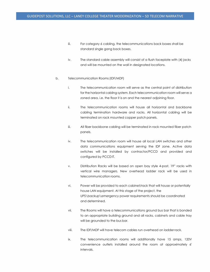
GUIDEPOST SOLUTIONS, LLC – LANEY COLLEGE THEATER MODERNIZATION – SD TELECOM NARRATIVE
iii. For category 6 cabling, the telecommunications back boxes shall be
standard single gang back boxes.
iv. The standard cable assembly will consist of a flush faceplate with (4) jacks
and will be mounted on the wall in designated locations.
b. Telecommunication Rooms (IDF/MDF)
i. The telecommunication room will serve as the central point of distribution
for the horizontal cabling system. Each telecommunication room will serve a
zoned area, i.e. the floor it is on and the nearest adjoining floor.
ii. The telecommunication rooms will house all horizontal and backbone
cabling termination hardware and racks. All horizontal cabling will be
terminated on rack mounted copper patch panels.
iii. All fiber backbone cabling will be terminated in rack mounted fiber patch
panels.
iv. The telecommunication room will house all local LAN switches and other
data communications equipment serving the IDF zone. Active data
switches will be installed by contractor/PCCD and provided and
configured by PCCD IT.
v. Distribution Racks will be based on open bay style 4-post, 19” racks with
vertical wire managers. New overhead ladder rack will be used in
telecommunication rooms.
vi. Power will be provided to each cabinet/rack that will house or potentially
house LAN equipment. At this stage of the project, the
UPS\backup\emergency power requirements should be coordinated
and determined.
vii. The Rooms will have a telecommunications ground bus bar that is bonded
to an appropriate building ground and all racks, cabinets and cable tray
will be grounded to the bus bar.
viii. The IDF/MDF will have telecom cables run overhead on ladder rack.
ix. The telecommunication rooms will additionally have 15 amps, 120V
convenience outlets installed around the room at approximately 6'
intervals.
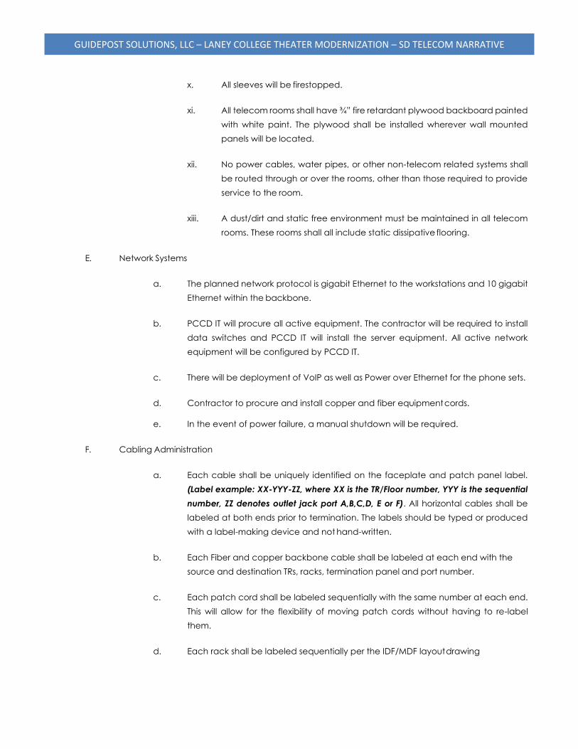
GUIDEPOST SOLUTIONS, LLC – LANEY COLLEGE THEATER MODERNIZATION – SD TELECOM NARRATIVE
x. All sleeves will be firestopped.
xi. All telecom rooms shall have ¾” fire retardant plywood backboard painted
with white paint. The plywood shall be installed wherever wall mounted
panels will be located.
xii. No power cables, water pipes, or other non-telecom related systems shall
be routed through or over the rooms, other than those required to provide
service to the room.
xiii. A dust/dirt and static free environment must be maintained in all telecom
rooms. These rooms shall all include static dissipative flooring.
E. Network Systems
a. The planned network protocol is gigabit Ethernet to the workstations and 10 gigabit
Ethernet within the backbone.
b. PCCD IT will procure all active equipment. The contractor will be required to install
data switches and PCCD IT will install the server equipment. All active network
equipment will be configured by PCCD IT.
c. There will be deployment of VoIP as well as Power over Ethernet for the phone sets.
d. Contractor to procure and install copper and fiber equipment cords.
e. In the event of power failure, a manual shutdown will be required.
F. Cabling Administration
a. Each cable shall be uniquely identified on the faceplate and patch panel label.
(Label example: XX-YYY-ZZ, where XX is the TR/Floor number, YYY is the sequential
number, ZZ denotes outlet jack port A,B,C,D, E or F). All horizontal cables shall be
labeled at both ends prior to termination. The labels should be typed or produced
with a label-making device and not hand-written.
b. Each Fiber and copper backbone cable shall be labeled at each end with the
source and destination TRs, racks, termination panel and port number.
c. Each patch cord shall be labeled sequentially with the same number at each end.
This will allow for the flexibility of moving patch cords without having to re-label
them.
d. Each rack shall be labeled sequentially per the IDF/MDF layout drawing
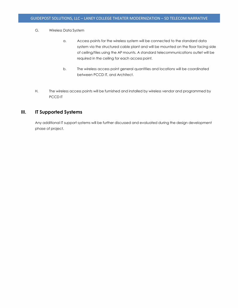
GUIDEPOST SOLUTIONS, LLC – LANEY COLLEGE THEATER MODERNIZATION – SD TELECOM NARRATIVE
G. Wireless Data System
a. Access points for the wireless system will be connected to the standard data
system via the structured cable plant and will be mounted on the floor facing side
of ceiling/tiles using the AP mounts. A standard telecommunications outlet will be
required in the ceiling for each access point.
b. The wireless access point general quantities and locations will be coordinated
between PCCD IT, and Architect.
H. The wireless access points will be furnished and installed by wireless vendor and programmed by
PCCD IT
III. IT Supported Systems
Any additional IT support systems will be further discussed and evaluated during the design development
phase of project.
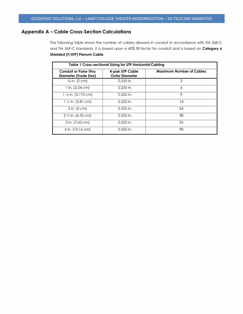
GUIDEPOST SOLUTIONS, LLC – LANEY COLLEGE THEATER MODERNIZATION – SD TELECOM NARRATIVE
Appendix A – Cable Cross-Section Calculations
The following table shows the number of cables allowed in conduit in accordance with TIA 568-C
and TIA 569-C standards. It is based upon a 40% fill factor for conduit and is based on Category 6
Shielded (F/UTP) Plenum Cable.
Table 1 Cross-sectional Sizing for UTP Horizontal Cabling
Conduit or Poke-Thru
Diameter (Trade Size)
4-pair UTP Cable
Outer Diameter
Maximum Number of Cables
¾ in. (2 cm) 0.255 in. 3
1 in. (2.54 cm) 0.255 in. 6
1 ¼ in. (3.175 cm) 0.255 in. 9
1 ½ in. (3.81 cm) 0.255 in. 14
2 in. (5 cm) 0.255 in. 24
2 ½ in. (6.35 cm) 0.255 in. 38
3 in. (7.62 cm) 0.255 in. 55
4 in. (10.16 cm) 0.255 in. 98
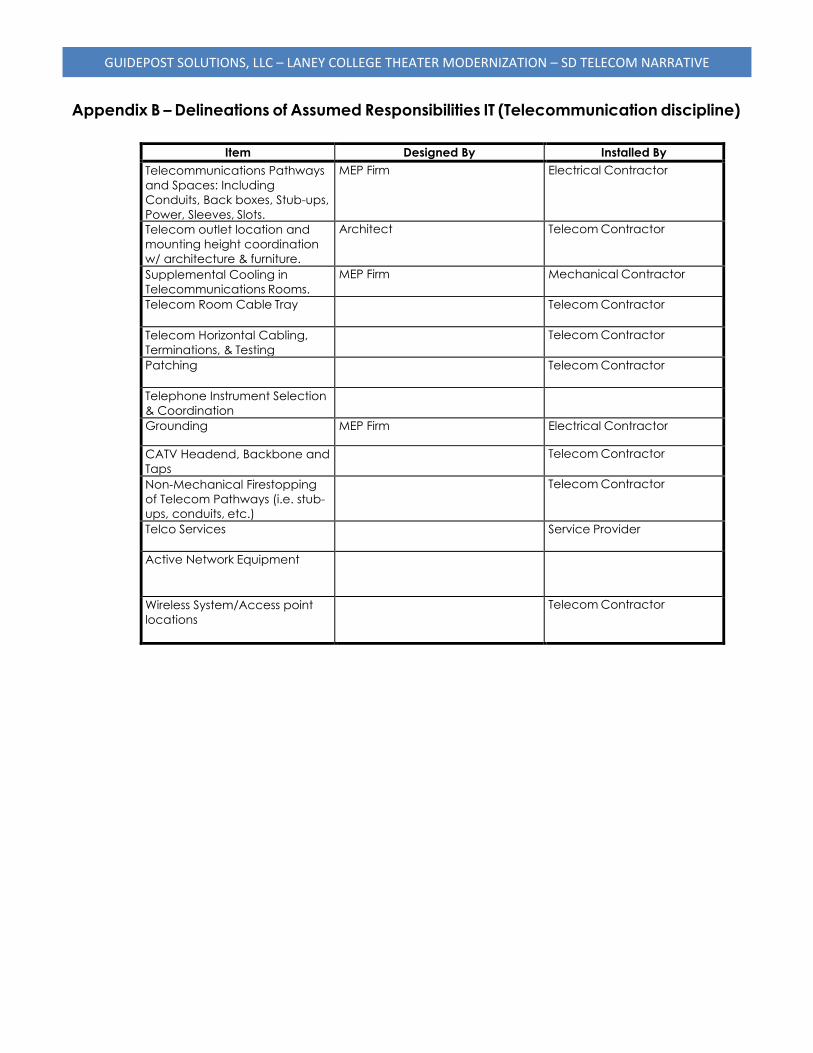
GUIDEPOST SOLUTIONS, LLC – LANEY COLLEGE THEATER MODERNIZATION – SD TELECOM NARRATIVE
Appendix B – Delineations of Assumed Responsibilities IT (Telecommunication discipline)
Item Designed By Installed By
Telecommunications Pathways
and Spaces: Including
Conduits, Back boxes, Stub-ups,
Power, Sleeves, Slots.
MEP Firm Electrical Contractor
Telecom outlet location and
mounting height coordination
w/ architecture & furniture.
Architect Telecom Contractor
Supplemental Cooling in
Telecommunications Rooms.
MEP Firm Mechanical Contractor
Telecom Room Cable Tray Telecom Contractor
Telecom Horizontal Cabling,
Terminations, & Testing
Telecom Contractor
Patching Telecom Contractor
Telephone Instrument Selection
& Coordination
Grounding MEP Firm Electrical Contractor
CATV Headend, Backbone and
Taps
Telecom Contractor
Non-Mechanical Firestopping
of Telecom Pathways (i.e. stub-
ups, conduits, etc.)
Telecom Contractor
Telco Services Service Provider
Active Network Equipment
Wireless System/Access point
locations
Telecom Contractor

PERALTA COMMUNITY COLLEGE DISTRICT LANEY COLLEGE THEATER MODERNIZATION OAKLAND, CA
200803LCT027/ELS
APPENDIX G
SECURITY NARRATIVE
GUIDEPOST SOLUTIONS, LLC – LANEY COLLEGE THEATER MODERNIZATION – SD SECURITY NARRATIVE
PUBLICATION RECORD Document
Version
Publication Date
Primary Author
Description
V1.0 07/28/2020 Drew Dito 100% SD Submission
I. Introduction and Executive Summary
A. General
1. This Basis of Design Narrative documents the security system design strategies and
principles for the Laney College Theater Renovation.
2. Use of this narrative will assist in design coordination, planning and design development.
B. Overall Design Intent
1. Provide a safe and secure environment for all building occupants.
2. Maintain continuous operation of systems in an emergency until building inhabitants can
evacuate to a safer area.
3. Integrate access control, alarm monitoring and video surveillance into a single integrated
security electronics system.
4. Specify products and requirements for a new theater building security system that functions
within existing Laney College systems and procedures.
II. Security Systems
The electronic control equipment and network switches for the Security system will mostly reside in the
stage level IDF room. Security devices on levels 3 or 4 may require control panels or network switches in
the 3rd floor IDF room. All access control and alarm monitoring control panels, access control and video
servers, data storage and security cabling will be provided by the security integrator to comprise a full
turnkey physical security solution. Networking hardware necessary for the security system will be
provided by the Owner’s IT group or the security integrator; to be determined through the early
development of the security design.
GUIDEPOST SOLUTIONS, LLC – LANEY COLLEGE THEATER MODERNIZATION – SD SECURITY NARRATIVE
A. Access Control and Alarm Monitoring Systems (ACAMS)
1. Door Hardening
a. Door hardware to include tamper-resistant hinges and high-security hardware sets.
Locks to be pick resistant and utilize a restricted keyway.
b. Doors utilizing electrified hardware for entry control will use hardware that is rated
as “fail secure” unless otherwise required by code.
c. Provide latch guard hardware on all exterior doors.
d. Provide perimeter doors with hinges on the secured side unless otherwise required
by code.
e. Emergency exit doors shall be equipped with local sounders.
f. Avoid door holders for all perimeter and access-controlled doors.
2. Areas of Protection
a. Provide alarm contacts on all perimeter doors to the theater.
b. Provide glass break detectors for main theater lobby.
c. Provide card readers, alarm contacts, and electrified door hardware with
integrated Request-to-exit (REX) switches on all access controlled entry doors. For
ADA auto operator doors, integrate card reader with ADA auto operator to
disable ADA push plates until a valid card read is presented.
d. Provide card readers, alarm contacts, and electrified door hardware with
integrated Request-to-exit (REX) switches on all IDF room doors.
e. Provide card readers, alarm contacts, and electrified door hardware with
integrated Request-to-exit (REX) switches on all high value rooms that require
access control; to be determined in early development of the security design.
f. Provide emergency help buttons at locations to be determined.
3. Essential System Requirements
a. Access control and Alarm Monitoring system will be a networked system of
controllers serving all access controlled and alarm monitored points. The system
shall also integrate with the Video Surveillance System.
GUIDEPOST SOLUTIONS, LLC – LANEY COLLEGE THEATER MODERNIZATION – SD SECURITY NARRATIVE
b. Security system shall be programmed on a schedule to shunt alarms and allow
free access to the theater during regular hours.
c. Provide Owner training on the ACAMS software operations, maintenance, and
configuration; provide programming of fifty (50) access control badges.
d. All security devices provided in this project shall be purchased with their
appropriate software licenses for use in the access control and video
management software.
e. Access Control Panels will be located in building IDF rooms. Each wall mounted
security equipment location will require one 8’ H x 4’ W sheet of fire treated
plywood, and one 20 amp dedicated emergency power circuit. 36” inches of clear
space must be provided in front of the Access Control Panel for the panel’s door
swing.
f. Access Control Software shall be provided and fully configured on district police
workstations and select district personnel to be determined.
B. Video Surveillance Systems (VSS)
1. Camera Features
a. All interior cameras shall be vandal resistant with features and configuration for
optimal views in low-light conditions.
b. All exterior cameras shall be vandal and environmental resistant and be optimized
for low-light conditions
c. All cameras shall be fixed, panoramic, or multi-sensor cameras and shall be
provided with their manufacturer recommended mounting kit.
2. Areas of Surveillance
a. Overall perimeter views achieved through corner mounted multisensory 360
cameras.
b. Interior lobby views for both the main and North Lobbies.
c. FAB LAB roller door and exterior loading area.
d. Interior IDF Room Doors.
e. Upper Lobby, Lower Lobby, and stair general views.
f. 3rd and 4th Floor corridor cameras capturing entry onto the floor from stairwells and
elevators.
g. Interior cameras within high-value rooms requiring access control, to be determined
in early development of the security design.
GUIDEPOST SOLUTIONS, LLC – LANEY COLLEGE THEATER MODERNIZATION – SD SECURITY NARRATIVE
3. Essential System Requirements
a. The video surveillance system shall fully integrate with the districts current
milestone system and the Access Control and Alarm Monitoring system.
b. All cameras shall be power over ethernet (PoE.)
c. Network Video Recorders shall be provided by security integrator to support all
new Laney Theater cameras.
d. Video recordings shall be stored for 30 days or as required by district policy.
e. VSS shall record a standard 15 fps at 1080P HD resolution when activated
by motion.
f. All security devices provided in this project shall be purchased with their appropriate
software licenses for use in the access control and video management software.
g. Cameras within view of security alarm devices shall be programmed to
call up within the access control system when an alarm event occurs.

PERALTA COMMUNITY COLLEGE DISTRICT LANEY COLLEGE THEATER MODERNIZATION OAKLAND, CA
200803LCT027/ELS
APPENDIX H
FIRE SPRINKLER AND STANDPIPE SYSTEMS NARRATIVE
3498 Clayton Road, Suite 101 (925) 681-2731 Ext. 112 Concord, CA 94519 [email protected] www.hytcorp.com
July 17, 2020
Kim-Van Truong ELS Architecture + Urban Design 2040 Addison Street Berkeley, CA 94704
Subject: Laney College Theater – Modernization Project Schematic Design Narrative Fire Sprinkler and Standpipe Systems
Dear Ms. Truong;
The fire sprinkler and standpipe systems for the Laney College Theater Modernization Project will be designed to comply with the California Code of Regulations, Title 24, Parts 2 and 9, California Building Code and Fire Code, respectively; National Fire Protection Association (NFPA) Standard 13, Standard for the Installation of sprinkler Systems (2016), NFPA 14, Standard for the Installation of Standpipe and Hose Systems (2016), and the requirements of the California Division of the State Architect (DSA).
The new sprinkler and standpipe systems will be served from a new fire service connection to the East Bay Municipal Utility District (EBMUD) water supply system without augmentation (i.e. fire pump) or on-site secondary water source. Although preliminary water supply modeling data from EBMUD has not yet been provided/obtained, we believe that water pressures and flows will be sufficient for adequate support of the proposed fire sprinkler systems, however pipe sizes may be larger-than-typical due to the height of the building.
A Manual Wet Standpipe System will be provided with 2½” fire hose valve connections at each exit stairway, at each of the main floor levels. Where necessary, fire hose valves will be located in wall cabinets.
Fire sprinkler protection will be provided for all occupiable areas of the building (including covered outdoor spaces), and will be hydraulically designed to generally provide Light Hazard protection for most of the spaces. The Stage, Mechanical, Storage and similar spaces will be designed for Ordinary Hazard Occupancies.
To the extent feasible, fire protection piping and appurtenances will be concealed behind finished ceiling surfaces. In areas of the building with exposed concrete “waffle” ceilings, piping and sprinklers will be aligned with the structural elements to reduce the visual impact of the piping system. All fire protection control valves and waterflow switches will be electronically supervised by the building’s fire alarm system.
Fire sprinkler materials and devices will generally consist of the following:
Page 2 July 17, 2020
3498 Clayton Road, Suite 101 (925) 681-2731 Ext. 112 Concord, CA 94519 [email protected] www.hytcorp.com
Fire Sprinklers
Fire sprinklers will be UL Listed Quick Response sprinklers, and will be selected to compliment the architectural features of the building. In general, sprinklers in finished ceilings will be white polyester recessed pendent sprinklers with matching white escutcheons and will be aesthetically located (center of tile or “quarter-point” in suspended ceilings). Areas with exposed structure will be provided with chrome finished upright and/or pendent fire sprinkler protection. Extended coverage and other special purpose sprinklers will be avoided unless demanded by other design considerations.
Stage, Storage and similar spaces where sprinklers may be subject to mechanical damage will be equipped with robust fire sprinkler guards assemblies as manufactured by SprinkGuard (www.sprinkguard.com).
Pipe and Fittings
Fire sprinkler piping 2-inch diameter and smaller will be Schedule 40 black steel pipe in accordance with NFPA 13. Fire sprinkler piping 2½-inch diameter and larger will be Schedule 10 black steel pipe. Other thin-walled piping materials (such as Schedule 5, 7, and threadable thinwalls, etc.) will not be permitted (for longevity and durability purposes). All piping will be specified to be provided with factory-applied antimicrobial coatings to inhibit Microbiologically-Influenced Corrosion (MIC).
Where fire protection piping crosses provided seismic joints, a UL Listed Metraflex Fireloop assembly will be provided to allow for full building differential movement while protecting the integrity and function of the fire protection piping system.
Exterior, exposed piping, fittings, and appurtenances will be galvanized.
For seismic durability and to aid the construction process, sprinklers in finished ceilings will be provided with flexible hose drop/armovers such as Flexhead, Vic-Flex, or similar.
Please let me know if you have any questions or if you require any additional information.
Thank you,
Bret Tresidder, P.E.
Fire Protection Engineer
