viscous sheet retraction - dspace@mit
TRANSCRIPT
Viscous Sheet Retraction
The MIT Faculty has made this article openly available. Please share how this access benefits you. Your story matters.
Citation NIKOS SAVVA and JOHN W. M. BUSH (2009). Viscous sheetretraction. Journal of Fluid Mechanics, 626 , pp 211-240 doi:10.1017/S0022112009005795
As Published http://dx.doi.org/10.1017/s0022112009005795
Publisher Cambridge University Press
Version Final published version
Citable link http://hdl.handle.net/1721.1/58206
Terms of Use Article is made available in accordance with the publisher'spolicy and may be subject to US copyright law. Please refer to thepublisher's site for terms of use.
J. Fluid Mech. (2009), vol. 626, pp. 211–240. c© 2009 Cambridge University Press
doi:10.1017/S0022112009005795 Printed in the United Kingdom
211
Viscous sheet retraction
NIKOS SAVVA† AND JOHN W. M. BUSH‡Department of Mathematics, Massachusetts Institute of Technology,
Cambridge, MA 02139, USA
(Received 11 December 2007 and in revised form 19 November 2008)
We present the results of a combined theoretical and numerical investigation ofthe rim-driven retraction of flat fluid sheets in both planar and circular geometries.Particular attention is given to the influence of the fluid viscosity on the evolutionof the sheet and its bounding rim. In both geometries, after a transient that dependson the sheet viscosity and geometry, the film edge eventually attains the Taylor–Culick speed predicted on the basis of inviscid theory. The emergence of this resultin the viscous limit is rationalized by consideration of both momentum and energyarguments. We first consider the planar geometry considered by Brenner & Gueyffier(Phys. Fluids, vol. 11, 1999, p. 737) and deduce new analytical expressions for thespeed of the film edge at the onset of rupture and the evolution of the maximumfilm thickness for viscous films. In order to consider the expansion of a circular hole,we develop an appropriate lubrication model that predicts the form of the earlystage dynamics of film rupture. Simulations of a broad range of flow parametersconfirm the importance of geometry on the dynamics, verifying the exponential holegrowth reported in early experimental studies. We demonstrate the sensitivity of theinitial retraction speed on the film profile, and so suggest that the anomalous rateof retraction reported in these experiments may be attributed in part to geometricdetails of the puncture process.
1. IntroductionSheet retraction arises in a wide range of physical settings, ranging from fuel
injectors to foams in the food industry to biological membranes (for an overview seede Gennes, Brochart-Wyart & Quere 2003). The disintegration of fluid sheets is ofprimary importance in the context of fluid fragmentation or atomization (Lefebvre1989; Bayvel & Orzechowski 1993; Villermaux 2007). Commonly, such atomizationprocesses involve a cascade from fluid volumes to sheets to filaments to droplets, aroute that depends critically on the dynamics and stability of fluid sheets and theirbounding rims. Depending on the application at hand, film rupture can be eitherdesirable, as in spray formation (e.g. Pomeau & Villermaux 2006), or undesirable, asin curtain coating (e.g. Miyamoto & Katagiri 1997).
The initial observations of soap film rupture were reported by Dupre (1867) andRayleigh (1891). Their studies motivated the experimental work of Ranz (1950), whoobserved that, following puncture, the film recedes under the influence of surfacetension at a constant speed, and that fluid accumulates in a roughly circular rim as
† Present address: Department of Chemical Engineering, Imperial College London, LondonSW7 2AZ, UK.
‡ E-mail address for correspondence: [email protected]
212 N. Savva and J. W. M. Bush
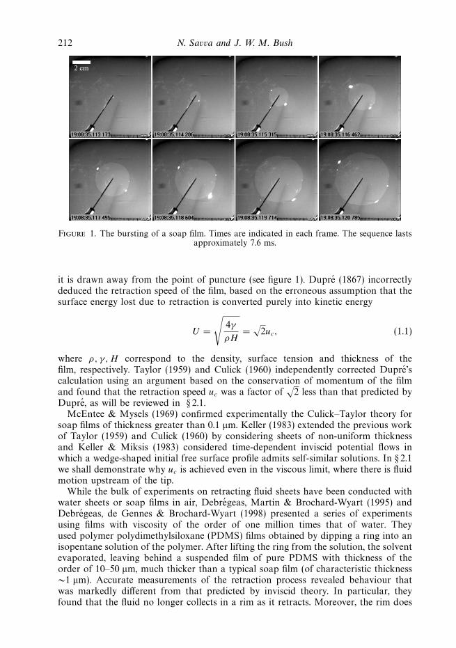
2 cm
Figure 1. The bursting of a soap film. Times are indicated in each frame. The sequence lastsapproximately 7.6 ms.
it is drawn away from the point of puncture (see figure 1). Dupre (1867) incorrectlydeduced the retraction speed of the film, based on the erroneous assumption that thesurface energy lost due to retraction is converted purely into kinetic energy
U =
√4γ
ρH=
√2uc, (1.1)
where ρ, γ, H correspond to the density, surface tension and thickness of thefilm, respectively. Taylor (1959) and Culick (1960) independently corrected Dupre’scalculation using an argument based on the conservation of momentum of the filmand found that the retraction speed uc was a factor of
√2 less than that predicted by
Dupre, as will be reviewed in § 2.1.McEntee & Mysels (1969) confirmed experimentally the Culick–Taylor theory for
soap films of thickness greater than 0.1 μm. Keller (1983) extended the previous workof Taylor (1959) and Culick (1960) by considering sheets of non-uniform thicknessand Keller & Miksis (1983) considered time-dependent inviscid potential flows inwhich a wedge-shaped initial free surface profile admits self-similar solutions. In § 2.1we shall demonstrate why uc is achieved even in the viscous limit, where there is fluidmotion upstream of the tip.
While the bulk of experiments on retracting fluid sheets have been conducted withwater sheets or soap films in air, Debregeas, Martin & Brochard-Wyart (1995) andDebregeas, de Gennes & Brochard-Wyart (1998) presented a series of experimentsusing films with viscosity of the order of one million times that of water. Theyused polymer polydimethylsiloxane (PDMS) films obtained by dipping a ring into anisopentane solution of the polymer. After lifting the ring from the solution, the solventevaporated, leaving behind a suspended film of pure PDMS with thickness of theorder of 10–50 μm, much thicker than a typical soap film (of characteristic thickness∼1 μm). Accurate measurements of the retraction process revealed behaviour thatwas markedly different from that predicted by inviscid theory. In particular, theyfound that the fluid no longer collects in a rim as it retracts. Moreover, the rim does
Viscous sheet retraction 213
not retract at a constant speed; rather, the hole radius grows exponentially as
r0exp(t) = R0 exp
( t
1.4τ
), (1.2)
where τ = μH/2γ, with R0 being the initial hole size and μ the film’s dynamicviscosity. The exponential hole growth was also supported by a simple theoreticalargument, in which surface energy released during retraction was equated to theenergy dissipated through the action of viscosity, that predicted:
r0 (t) = R0 exp( t
2τ
). (1.3)
While Debregeas et al. (1995) did not consider viscoelastic effects in deriving(1.3), they did suggest that the exponential behaviour may be due in part to theviscoelasticity of the films. However, the typical shear rate of the PDMS films wasbelow those at which non-Newtonian behaviour sets in (e.g. Deyrail et al. 2007). In thesubsequent experimental studies of Dalnoki-Veress et al. (1999) and Roth et al. (2005),film rupture was used as a means to measure the viscosity of molten polystyrene filmswith viscosities of the order of 1012 times that of water. Dalnoki-Veress et al. (1999)probed the nonlinear viscoelastic regime, where it was found that the viscous timescale τ decreased markedly with decreasing film thickness. This effect was attributedto the reduction in film viscosity caused by the large shear strain rates caused bythe hole expansion. Roth et al. (2005) found an initial transient regime where theexpansion of the hole was faster than exponential; fitting to the data was achievedby introducing a time-dependent viscosity.
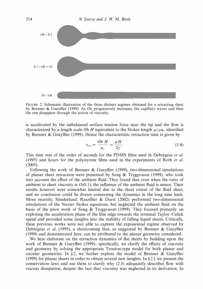
Following the work of Debregeas et al. (1995), Brenner & Gueyffier (1999) studiedthe retraction of a two-dimensional planar sheet numerically using a one-dimensionalTrouton-type lubrication model. They were able to identify three distinct regimesdepending on the Ohnesorge number, defined as
Oh =μ√
2Hργ(1.4)
that expresses the relative importance of viscous resistance to surface tension forces(see figure 2). In the low Oh regime (Oh < 0.1), they found that capillary wavedisturbances are generated ahead of the retracting rim. As the Ohnesorge number isincreased, the capillary waves disappear and the rim diffuses in towards the bulk ofthe sheet. Finally in the high Oh regime (Oh � 10), they found that no rim forms atall, in accord with Debregeas’ observations. In all cases considered, the sheet edgewas found to approach the Culick–Taylor speed in the long time limit.
The retraction time scales are different in the high and low Oh regimes. Sincenumerical simulations indicate that the characteristic speed uc is independent of Oh,the length scale prescribes the characteristic retraction time. Naturally, this lengthscale is a measure of the distance from the tip over which the film is disturbed,and depends on the relative importance of viscosity to surface tension, as quantifiedthrough Oh. In the low Oh regime, the motion is primarily concentrated near thetip, so that the characteristic length scale is prescribed by H . This implies that thecharacteristic time scale is
τinv =H
uc
=
√ρH 3
2γ, (1.5)
which is of the order of microseconds for the soap films in the experiments ofRanz (1950). Conversely, in the viscous, high Oh limit, a larger portion of the film
214 N. Savva and J. W. M. Bush
Oh < 0.1
0.1 < Oh < 10
10 < Oh
Figure 2. Schematic illustration of the three distinct regimes obtained for a retracting sheetby Brenner & Gueyffier (1999). As Oh progressively increases, the capillary waves and thenthe rim disappear through the action of viscosity.
is accelerated by the unbalanced surface tension force near the tip and the flow ischaracterized by a length scale Oh H equivalent to the Stokes length μ/ρuc identifiedby Brenner & Gueyffier (1999). Hence the characteristic retraction time is given by
τvis =Oh H
uc
=μH
2γ. (1.6)
This time was of the order of seconds for the PDMS films used in Debregeas et al.(1995) and hours for the polystyrene films used in the experiments of Roth et al.(2005).
Following the work of Brenner & Gueyffier (1999), two-dimensional simulationsof planar sheet retraction were presented by Song & Tryggvason (1999), who tookinto account the effect of the ambient fluid. They found that even when the ratio ofambient to sheet viscosity is O(0.1), the influence of the ambient fluid is minor. Theirresults however were somewhat limited due to the short extent of the fluid sheet,and no conclusion could be drawn concerning the dynamics in the long time limit.More recently, Sunderhauf, Raszillier & Durst (2002) performed two-dimensionalsimulations of the Navier–Stokes equations, but neglected the ambient fluid on thebasis of the prior work of Song & Tryggvason (1999). They focused primarily onexploring the acceleration phase of the film edge towards the terminal Taylor–Culickspeed and provided some insights into the stability of falling liquid sheets. Critically,these previous works were not able to capture the exponential regime observed byDebregeas et al. (1995), a shortcoming that, as suggested by Brenner & Gueyffier(1999) and demonstrated here, can be attributed to the planar geometry considered.
We here elaborate on the retraction dynamics of flat sheets by building upon thework of Brenner & Gueyffier (1999); specifically, we clarify the effects of viscosityand geometry by solving the appropriate Trouton-type model for both planar andcircular geometries. In § 2, we further explore the model of Brenner & Gueyffier(1999) for planar sheets in order to obtain several new insights. In § 2.1 we present theconservation laws and use them to clarify why (2.3) adequately describes flow withviscous dissipation, despite the fact that viscosity was neglected in its derivation. In
Viscous sheet retraction 215
z
xh(∞, t) = H
x0 (t)
h(x, t)
Figure 3. Planar sheet geometry. The sheet retracts from left to right under the influence ofthe capillary force acting at its edge.
§ 2.2, we calculate an analytic expression for the hole growth during the early stagesof retraction and the maximum film thickness in the high Oh limit. In § 3, we developa new theoretical model that allows us to investigate the expansion of a circularhole for arbitrary Ohnesorge number. By examining the lubrication equations in thehigh Oh limit, we demonstrate that the exponential hole growth in the high Oh limitcan be deduced directly from the lubrication equations, thus providing an alternativederivation to the energy argument of Debregeas et al. (1995). Our model is solvednumerically to elucidate the effects of viscosity, geometry and initial conditions. Weconclude in § 4 with a discussion of the potential importance of three-dimensionaland other effects neglected in our model.
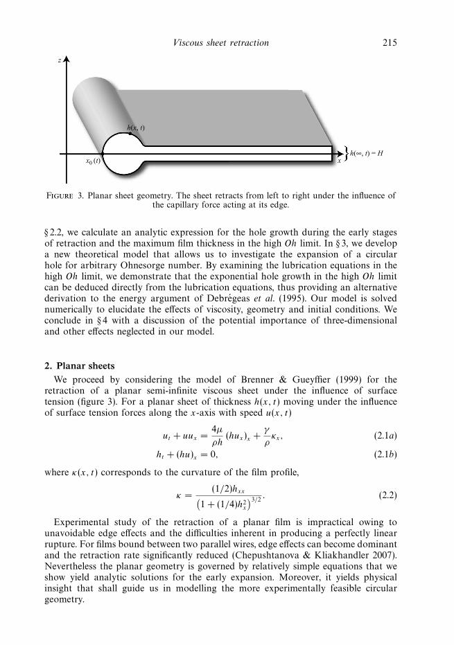
2. Planar sheetsWe proceed by considering the model of Brenner & Gueyffier (1999) for the
retraction of a planar semi-infinite viscous sheet under the influence of surfacetension (figure 3). For a planar sheet of thickness h(x, t) moving under the influenceof surface tension forces along the x-axis with speed u(x, t)
ut + uux =4μ
ρh(hux)x +
γ
ρκx, (2.1a)
ht + (hu)x = 0, (2.1b)
where κ(x, t) corresponds to the curvature of the film profile,
κ =(1/2)hxx(
1 + (1/4)h2x
)3/2. (2.2)
Experimental study of the retraction of a planar film is impractical owing tounavoidable edge effects and the difficulties inherent in producing a perfectly linearrupture. For films bound between two parallel wires, edge effects can become dominantand the retraction rate significantly reduced (Chepushtanova & Kliakhandler 2007).Nevertheless the planar geometry is governed by relatively simple equations that weshow yield analytic solutions for the early expansion. Moreover, it yields physicalinsight that shall guide us in modelling the more experimentally feasible circulargeometry.
216 N. Savva and J. W. M. Bush
uc = δl/δt
δm = ρHδl
H
δl
γ, ρ
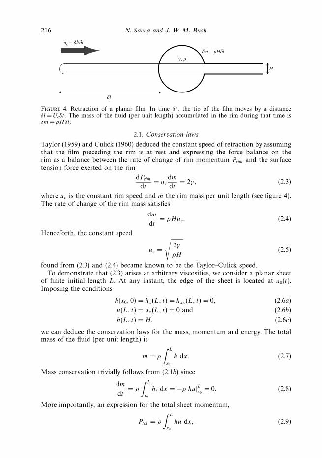
Figure 4. Retraction of a planar film. In time δt, the tip of the film moves by a distanceδl = Ucδt. The mass of the fluid (per unit length) accumulated in the rim during that time isδm= ρHδl.
2.1. Conservation laws
Taylor (1959) and Culick (1960) deduced the constant speed of retraction by assumingthat the film preceding the rim is at rest and expressing the force balance on therim as a balance between the rate of change of rim momentum Prim and the surfacetension force exerted on the rim
dPrim
dt= uc
dm
dt= 2γ, (2.3)
where uc is the constant rim speed and m the rim mass per unit length (see figure 4).The rate of change of the rim mass satisfies
dm
dt= ρHuc. (2.4)
Henceforth, the constant speed
uc =
√2γ
ρH(2.5)
found from (2.3) and (2.4) became known to be the Taylor–Culick speed.To demonstrate that (2.3) arises at arbitrary viscosities, we consider a planar sheet
of finite initial length L. At any instant, the edge of the sheet is located at x0(t).Imposing the conditions
h(x0, 0) = hx(L, t) = hxx(L, t) = 0, (2.6a)
u(L, t) = ux(L, t) = 0 and (2.6b)
h(L, t) = H, (2.6c)
we can deduce the conservation laws for the mass, momentum and energy. The totalmass of the fluid (per unit length) is
m = ρ
∫ L
x0
h dx. (2.7)
Mass conservation trivially follows from (2.1b) since
dm
dt= ρ
∫ L
x0
ht dx = −ρ hu|Lx0= 0. (2.8)
More importantly, an expression for the total sheet momentum,
Ptot = ρ
∫ L
x0
hu dx, (2.9)
Viscous sheet retraction 217
can be found by multiplying (2.1b) by u and (2.1a) by h and adding them together.Thus, we obtain the equation
(ρhu)t +(ρhu2 − 4μhux − γ hκ − 2γ
(1 + 1
4h2
x
)−1/2 )x
= 0. (2.10)
Integrating the first term from x0 to L gives
ρ
∫ L
x0
(hu)t dx =dPtot
dt+ ρu (x0)
2 h (x0) =dPtot
dt. (2.11)
Combining this with the integral of the second term from x0 to L, evaluated by using(2.6), yields
dPtot
dt= 2γ, (2.12)
under the assumption that hx → ∞ as x → x0. Hence, we find that even thoughthe dissipation due to viscosity is not directly described by Taylor’s and Culick’smomentum balance, its inclusion does not alter the veracity of their result. Withthis simple calculation, we see the role of viscosity in the dynamics of retraction: itaffects how the momentum is distributed through the film, but does not affect itsterminal speed uc. As also pointed out in the two-dimensional numerical calculationsof Sunderhauf et al. (2002), in the long time limit, half of the surface energy isconverted to kinetic energy, while the other half is ultimately dissipated through theaction of viscosity.
To obtain the corresponding energy equation, we multiply (2.1b) by u2 and (2.1a)by hu and add them, which yields, after some algebra:(
1
2ρhu2 + 2γ
√1 +
1
4h2
x
)t
+
(1
2ρhu3 − 4μhuux − γ uhκ − (1/2)γ hxht(
1 + (1/4)h2x
)1/2
)x
= −4μhu2x. (2.13)
Integration with respect to x and use of the boundary conditions (2.6) yields
d
dt(Ek + Eγ ) = D, (2.14)
where we identify
Ek =1
2ρ
∫ L
x0
hu2 dx, (2.15)
Eγ = 2γ
∫ L
x0
√1 + 1
4h2
x dx, (2.16)
D = −4μ
∫ L
x0
hu2x dx, (2.17)
as the total kinetic energy, surface energy and viscous dissipation of the sheet,respectively. This approach reveals why Dupre’s original argument of balancingsurface energy lost and kinetic energy gained by the retracting film predicted anincorrect retraction speed. Culick (1960) argued against the prediction of Dupre(1867) on physical grounds, attributing the discrepancy to the energy lost while theundisturbed film accelerates to the constant Taylor–Culick speed. We now see thatthe momentum conservation equation yields the correct expression for uc, since the
218 N. Savva and J. W. M. Bush
viscous forces are internal to the film and so do not contribute to the momentumbudget (2.12).
2.2. Early stages of retraction
We proceed by deducing a new analytic expression that describes the initiation ofsheet retraction in the high Oh limit. Non-dimensionalizing the equations by
t = τvis t∗, x = OhHx∗, h = Hh∗ and u = ucu
∗,
we can write the momentum equation in non-dimensional form as
u∗t∗ + u∗u∗
x∗ =4
h∗ (h∗u∗x∗)x∗ +
1
2Oh−2κ∗
x∗ . (2.18)
If we assume that the fluid sheet consists of a nearly semi-circular cap followed bya straight edge, there occurs a singularity in the curvature at x∗
s = (2Oh)−1, since att∗ = 0 it satisfies
κ∗ =
{−2Oh2 0 � x∗ < (2Oh)−1
0 x∗ > (2Oh)−1 . (2.19)
Therefore, we can approximate κ∗x∗ initially by a delta function
κ∗x∗ = 2Oh2δ(x∗ − x∗
s ). (2.20)
We further assume that during the initial stages of retraction, the film thicknessremains uniform to leading order, x∗
s is small compared to the axial extent of thefilm, the delta-function structure of the curvature gradient κ∗
x∗ is preserved andthe fluid contained in the semi-circular cap moves at the tip speed. By neglecting theconvective term, we thus reduce the problem to
ut = 4uxx + δ (x − xs) , (2.21)
where we have dropped the stars for convenience. These simplifying assumptions areexpected to be strictly valid only in the high Oh regime, where the viscous effectsdominate inertia at the onset and resist the shape change of the fluid film, specificallythe development of a pronounced rim.
The velocity is assumed to be continuous, which allows us to integrate (2.21) fromxs −ε to xs +ε for some small ε > 0. Taking the limit as ε → 0 yields a jump conditionfor ux
[ux] = − 14. (2.22)
Away from the discontinuity at xs (which without loss of generality we set as xs = 0)we are left with the heat equation
ut = 4uxx, x � 0, (2.23)
which we solve subject to the conditions
u(x, 0) = 0, ux(0, t) = − 14, u(x, t) → 0 as x → ∞, (2.24)
the second of which comes from the jump in ux at xs and is obtained when there areno velocity gradients within the fluid cap. The solution to (2.23) can be obtained bythe method of Laplace transforms that yields
u(x, t) =
√t
πexp
(− x2
16t
)− 1
4xerfc
(x
4√
t
). (2.25)
Viscous sheet retraction 219
0.7
0.6
0.5
0.4
u* = u/uc
0.3
0.2
0.1
0.1 0.2 0.3 0.4
Theory u* =
Oh > 100
Oh = 5
Oh = 1
Oh = 0.5
0.5 0.6 0.7 0.8 0.9 1.00
t*π
t* = t/τ vis
√
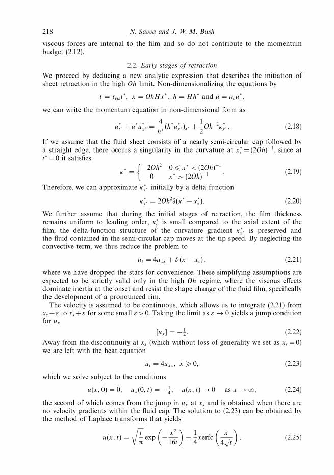
Figure 5. Plot of the tip velocity versus time during the early stages of retraction for differentOhnesorge numbers. The plots for Oh = 100, 500, 1000 and 10000 are indistinguishable. Thedotted curve shows the theoretical result u∗ =
√t∗/π, which is in good agreement with numerics
up to a time t ≈ 0.4τvis , where τvis = μH/2γ .
In dimensional variables, the tip speed and displacement may be expressed as
u(0, t) = uc
√t
πτvis
, x0 =2
3√
π
(t
τvis
)3/2
H. (2.26)
Solving (2.1) together with conditions (2.6) in a similar manner as described inthe Appendix for the axisymmetric case, we show in figure 5 the evolution of thetip speed for various Ohnesorge numbers that verifies the validity of our calculationfor short times. This result supports the suggestion of Brenner & Gueyffier (1999)that the geometry plays an important role in the retraction dynamics. The edge ofa planar film initially recedes with a displacement that scales as t3/2 while in theexperiments reported in Debregeas et al. (1995), Dalnoki-Veress et al. (1999) andRoth et al. (2005), the initial retraction of a circular hole follows an exponential law.
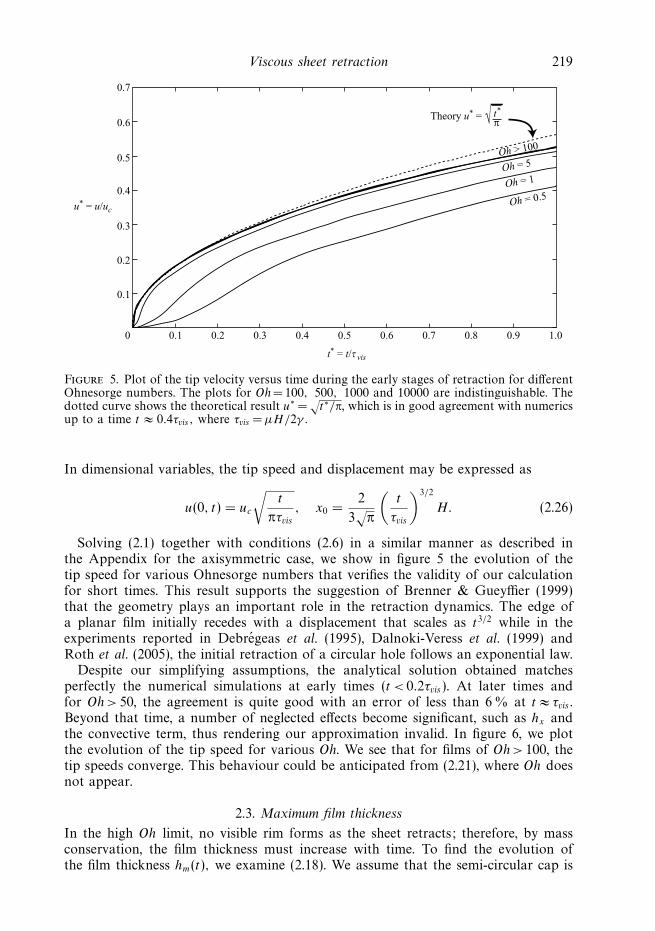
Despite our simplifying assumptions, the analytical solution obtained matchesperfectly the numerical simulations at early times (t < 0.2τvis ). At later times andfor Oh > 50, the agreement is quite good with an error of less than 6 % at t ≈ τvis .Beyond that time, a number of neglected effects become significant, such as hx andthe convective term, thus rendering our approximation invalid. In figure 6, we plotthe evolution of the tip speed for various Oh. We see that for films of Oh > 100, thetip speeds converge. This behaviour could be anticipated from (2.21), where Oh doesnot appear.
2.3. Maximum film thickness
In the high Oh limit, no visible rim forms as the sheet retracts; therefore, by massconservation, the film thickness must increase with time. To find the evolution ofthe film thickness hm(t), we examine (2.18). We assume that the semi-circular cap is
220 N. Savva and J. W. M. Bush
1.0
0.9
0.8
0.7
0.6
0.5
0.4
0.3
0.2
0.1
0 5 10 15 20
Oh = 100, 1000
Oh = 10
Oh = 1
Oh = 0.5
25 30
u* = u/uc
t* = t/τ vis
Figure 6. Velocity of the film edge for different Ohnesorge numbers. In the high Oh limitthe velocity curves become indistinguishable.
preserved at all times. The dimensionless curvature is thus assumed to be
κ∗ =
⎧⎨⎩−2Oh2
h∗m(t)
0 � x∗ < 12h∗
m(t)/Oh
0 x∗ > 12h∗
m(t)/Oh
. (2.27)
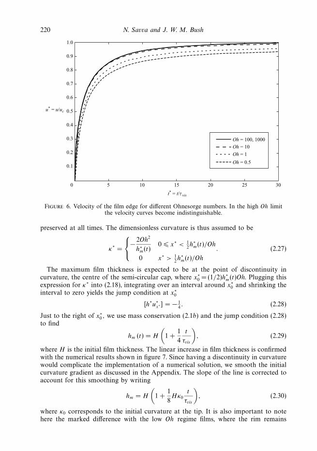
The maximum film thickness is expected to be at the point of discontinuity incurvature, the centre of the semi-circular cap, where x∗
0 = (1/2)h∗m(t)Oh. Plugging this
expression for κ∗ into (2.18), integrating over an interval around x∗0 and shrinking the
interval to zero yields the jump condition at x∗0
[h∗u∗x∗] = − 1
4. (2.28)
Just to the right of x∗0 , we use mass conservation (2.1b) and the jump condition (2.28)
to find
hm (t) = H
(1 +
1
4
t
τvis
), (2.29)
where H is the initial film thickness. The linear increase in film thickness is confirmedwith the numerical results shown in figure 7. Since having a discontinuity in curvaturewould complicate the implementation of a numerical solution, we smooth the initialcurvature gradient as discussed in the Appendix. The slope of the line is corrected toaccount for this smoothing by writing
hm = H
(1 +
1
8Hκ0
t
τvis
), (2.30)
where κ0 corresponds to the initial curvature at the tip. It is also important to notehere the marked difference with the low Oh regime films, where the rim remains
Viscous sheet retraction 221
0 5 10 15 20 25 30
1
2
3
4
5
6
7
8
9Oh = 1000
Oh = 100
Oh = 10
Oh = 1
Oh = 0.5
Theory
u* = hm/H
t* = t/τ vis
Figure 7. Maximum film thickness hm versus time for different Ohnesorge numbers. In thehigh Oh limit, hm grows linearly in time, confirming the theory represented by the dotted linethat corresponds to (2.28). The numerical results (solid curves) at Oh = 0.5, 1.0, 10, 100 and1000 correspond to profiles with κ0 = 2.1.
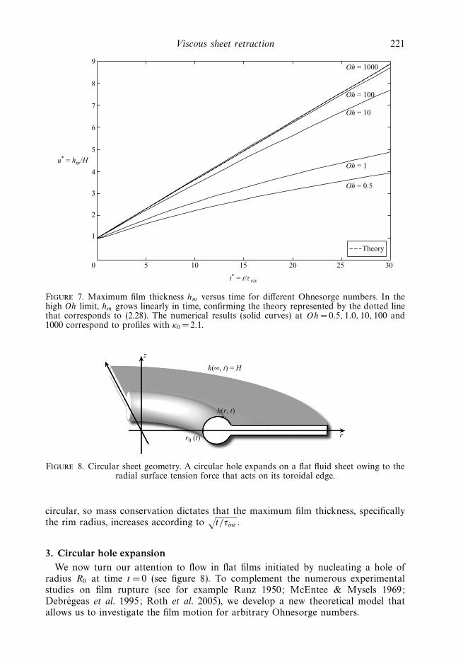
z
rr0 (t)
h(r, t)
h(∞, t) = H
Figure 8. Circular sheet geometry. A circular hole expands on a flat fluid sheet owing to theradial surface tension force that acts on its toroidal edge.
circular, so mass conservation dictates that the maximum film thickness, specificallythe rim radius, increases according to
√t/τinv .
3. Circular hole expansionWe now turn our attention to flow in flat films initiated by nucleating a hole of
radius R0 at time t = 0 (see figure 8). To complement the numerous experimentalstudies on film rupture (see for example Ranz 1950; McEntee & Mysels 1969;Debregeas et al. 1995; Roth et al. 2005), we develop a new theoretical model thatallows us to investigate the film motion for arbitrary Ohnesorge numbers.
222 N. Savva and J. W. M. Bush
Holes in thin films do not necessarily open. In an axisymmetric configuration, theazimuthal curvature contributes a component to the surface tension force that opposeshole expansion. Depending on the initial film shape and hole radius, situations mayarise where the hole will contract and close, and film rupture is averted (Taylor &Michael 1973). We shall henceforth proceed by considering configurations for whichholes expand.
3.1. Derivation of the film equations
We consider the Navier–Stokes equations in cylindrical coordinates (Batchelor 1967)
Ut + UUr + V Uz = −Pr/ρ + ν(Urr + Uzz + Ur/r − U/r2), (3.1)
Vt + UVr + V Vz = −Pz/ρ + ν (Vrr + Vzz + Vr/r) , (3.2)
where U is the radial velocity, V the velocity along the axis and P the fluid pressure.We neglect any azimuthal dependence on the basis of the experiments of Debregeaset al. (1995), who confirmed that the resulting motion is purely radial via particletracking. We also have the continuity equation
(Ur)r + (V r)z = 0, (3.3)
together with the normal and tangential stress boundary conditions at z =h(r, t)/2,respectively,
−P
ρ+ 2ν
[Ur sin2 θ − (Vr + Uz) sin θ cos θ + Vz cos2 θ
]∣∣∣∣z=h/2
=γ
ρκ, (3.4a)
2 (Vz − Ur ) sin θ cos θ + (Vr + Uz) (cos2 θ − sin2 θ)∣∣z=h/2
= 0, (3.4b)
where tan θ = hr/2 is the slope of the interface and κ is the curvature of the boundary:
κ(r, t) =(1/2)hrr(
1 + (1/4)h2r
)3/2+
(1/2)hr
r(1 + (1/4)h2
r
)1/2. (3.5)
Finally the kinematic boundary condition may be written as
ht + U |z=h/2 hr = V |z=h/2 . (3.6)
For a slender sheet, assumed to be symmetric about z =0, we use a Taylor expansionabout z = 0, to write
U (r, z, t) = u(r, t) + u2(r, t)z2 + · · · , (3.7a)
V (r, z, t) = v1(r, t)z + v3(r, t)z3 + · · · , (3.7b)
P (r, z, t) = p(r, t) + p2(r, t)z2 + · · · . (3.7c)
This approach was successfully used in the past to study jet breakup (Eggers &Dupont 1994; Eggers & Brenner 2000). Matching powers of z in (3.3) we find that tothe lowest order in z
v1 = −(
ur +u
r
), (3.8)
v3 = −1
3
(u2r +
u2
r
). (3.9)
Viscous sheet retraction 223
Similarly, (3.1) and (3.2) yield
ut + uur = −pr/ρ + ν(urr + ur/r − u/r2 + 2u2), (3.10)
v1t + uv1r + v21 = −2p2/ρ + ν(v1rr + v1r/r + 6v3). (3.11)
In the long wavelength limit, h � hr we find that to leading order in h the boundaryand kinematic conditions, (3.4a), (3.4b) and (3.6) become, respectively,
−p
ρ=
γ
ρκ − 2νv1, (3.12)
2u2 = −2hr
h(v1 − ur ) − v1r , (3.13)
ht + uhr = v1h. (3.14)
We eliminate v1 in (3.14) using (3.8) to find
ht +1
r(urh)r = 0. (3.15)
Similarly, elimination of u2 and p from (3.10) using (3.12), (3.13) and (3.8) yields
ut + uur =4ν
h
((h
r(ur)r
)r
− uhr
2r
)+
γ
ρκr . (3.16)
Equations (3.15) and (3.16) constitute a system of lubrication equations that describethe retraction of a circular sheet. However this long-wavelength approximation is notvalid everywhere and the equations become singular as we approach the film tip.Similar difficulties arise in various applications of the lubrication approximation;nevertheless, such models perform surprisingly well. For instance, in Eggers &Dupont (1994), the lubrication model yields excellent agreement with experimentalobservations of jet breakup and pendant drop formation.
3.2. Early stages of expansion
We proceed by performing an early-time analysis of the governing equations (3.15)and (3.16) in the high Oh limit, by following the ideas developed in § 2.2 for planarsheets. Introducing the scalings
r = OhHr∗, h = Hh∗, u = ucu∗, R0 = OhHR∗
0 and t = τvis t∗, (3.17)
we write (3.16) in non-dimensional form as
u∗t∗ + u∗u∗
r∗ =4
h∗
[(h∗
r∗ (u∗r∗)r∗
)r∗
− u∗hr∗
2r∗
]+
1
2Oh−2κ∗
r∗ . (3.18)
We assume that initially the rim corresponds to the inner portion of a torus andmatches onto a flat sheet. The film curvature thus becomes
κ∗ =
{2Oh2
(− 1 + r∗
s −r
r
)R∗
0 � r∗ < r∗s
0 r∗ > r∗s
, (3.19)
where r∗s = R∗
0+(1/2)Oh−1 is the point where the rim and the flat sheet meet. Note herethe second term in the expression for the curvature that arises from the axisymmetryof the problem. Dropping the stars for convenience, we find that in the same limitconsidered for early-stage planar sheet retraction (i.e. convective terms negligible, andh constant for r > rs) the same jump condition arises, namely,
[ur ] = − 14. (3.20)
224 N. Savva and J. W. M. Bush
To the right of the jump, h variations are neglected, so we consider
(ur)t = 4
[(ur)rr − (ur)r
r
], (3.21)
which can be solved by separation of variables to yield
u = Aeλ2tK1
(12λr
), (3.22)
where A and λ are constants to be determined and K1 is the modified Bessel functionof the second kind of order 1. Note that the modified Bessel function of the firstkind I1 diverges as r → ∞ and is thus dropped since u → 0 at infinity. Denoting theradius of the punctured hole and its time derivative by r0 and r0, respectively, we takers ≈ r0(t) to obtain
r0 = Aeλ2tK1
(12λr0
)(3.23)
upon application of the boundary condition u(r0, t) = r0(t). To proceed further, wenote that the argument of K1, λr0/2, is small during early stages of retraction. Byretaining only the first-order term in the small argument expansion of K1, we find
r0 =2Aeλ
2t
λr0
, (3.24)
which gives r0(t) = R0eλ2t/2. This allows us to write the sheet speed to the right of the
cap as
u =λ3R2
0
4eλ
2tK1
(1
2λr
). (3.25)
Just to the right of the jump, we calculate the velocity gradient at r = rs ≈ r0 andexpand the derivative of K1 to obtain
ur (r+s ) = −λ2/2 (3.26)
to leading order in r0. Thus far, λ remains unknown and needs to be determinedby the jump condition. Unlike the planar case, there are non-zero velocity gradientswithin the cap when r0 is sufficiently small. Solving for the flow within the cap cannotbe done analytically, but we note that the term hr/h dominates the other terms in(3.18), which thus assumes the form
hr
h
[(ur)r
r− u
2r
]= 0. (3.27)
By requiring the continuity of u(r, t) at r = r0, this equation may be solved for u toyield
u =λ2R
3/20
2r1/2. (3.28)
The velocity gradient at r = r−s is thus
ur (r−s ) = −λ2/4. (3.29)
Using (3.26) and (3.29) in (3.20) we find that λ=1. We therefore conclude that thehole grows exponentially during the early stages of retraction
r0(t) = R0 exp
(t
2τvis
), (3.30)
Viscous sheet retraction 225
as expressed in dimensional variables. Hence the exponential hole growth reportedby Debregeas et al. (1995) need not be attributed to viscoelastic effects; rather, itis a generic feature of circular hole retraction on a viscous sheet. We note thatour approach, based entirely on the lubrication equations, complements the energyargument of Debregeas et al. (1995).
3.3. Simulation results
The governing equations are solved numerically as described in the Appendix. Eventhough we explored a wide range of Oh, particular attention was given to the highOh regime, in order to make comparisons with recently reported experimental work(e.g. Debregeas et al. 1995; Dalnoki-Veress et al. 1999; Roth et al. 2005). The regimesidentified in the work of Brenner & Gueyffier (1999) are also present in the retractionof circular sheets (figure 2). While the differences between the two geometries arenot significant at low Oh, there are striking differences in the retraction dynamics inthe high Oh regime. For the sake of clarity of presentation, we devote § § 3.3.1, 3.3.2and 3.3.3 to discussions of the high (Oh � 10), moderate (0.01 < Oh < 10) and low(Oh < 0.01) Ohnesorge number regimes, respectively.
3.3.1. High Oh simulations
Experiments in the high Oh limit have been limited to fluids with long chainpolymers, specifically PDMS in Debregeas et al. (1995) and molten polystyrene inDalnoki-Veress et al. (1999) and Roth et al. (2005). We proceed by demonstratingthat the essential features of retraction reported are captured by a Newtonian fluiddescription.
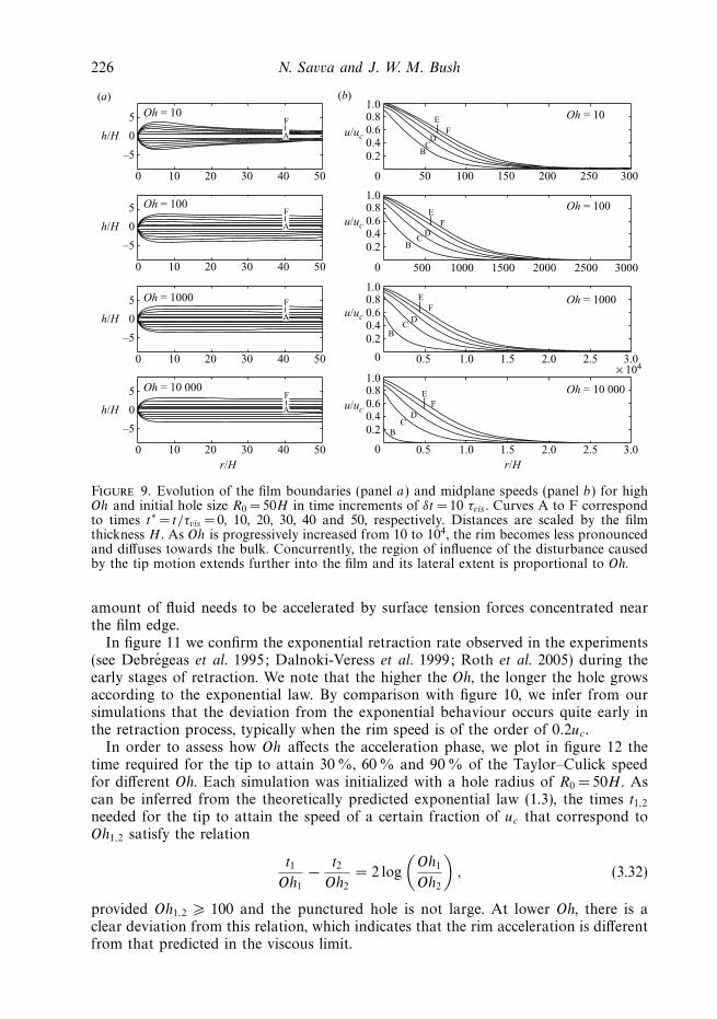
Figure 9 illustrates the evolution of typical film profiles and midplane velocities atvarious Oh. As Oh increases beyond 100, the rim diffuses towards the bulk of thefilm, thus making the film appear to be of uniform thickness. We note that even athigh Oh, the film is slightly thicker near the rim and very gradually thins furtheraway from the tip. It is also important to note that the region of influence of the tipmotion, which grows in time as more fluid is set into motion, is directly proportionalto Oh.
Just as the velocity curves for a planar sheet asymptote to a single curve in thehigh Oh limit (see figure 6), something similar can be said for the circular sheet.However, the initial size of the nucleated hole must now be considered. In particular,having written the momentum equations in non-dimensional form using (3.17) and byassuming that the film profile near the tip is preserved, we can replace the derivativeof the film curvature with the approximate expression
κ∗r∗ ≈ 2Oh2δ
(r − r∗
0
), (3.31)
provided that the azimuthal curvature term in (3.5) is much smaller than the curvatureof the film profile, i.e. H/R0 1. Doing so leaves us with a set of dimensionlessequations that are independent of Oh. Therefore, different simulations will yieldalmost identical results provided that r∗
0 , the dimensionless initial hole radius, is thesame. In other words, curves that have the same ratio HOh/R0 will yield virtuallyindistinguishable self-similar velocity curves, as confirmed by our simulations. Forexample, tip speeds of a simulation with Oh = 104 and R0 = 50H are indistinguishablefrom these with Oh =103 and R0 = 5H .
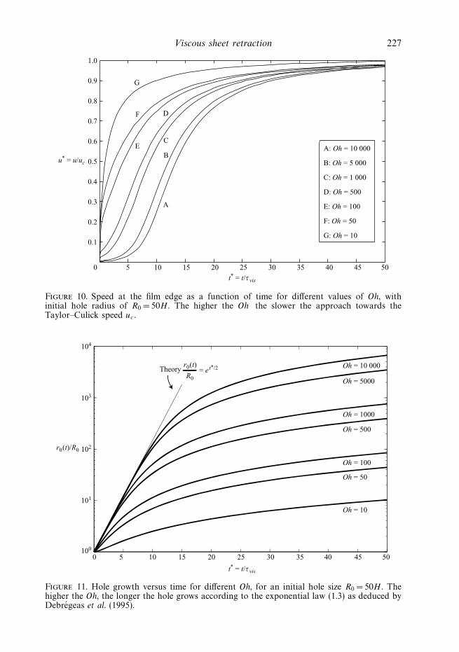
Figure 10 indicates the dependence on Oh of the approach of the sheet tip to theTaylor–Culick speed. High Oh films require substantially more time than low Ohfilms to approach uc. Viscous forces delay the acceleration process, because a larger
226 N. Savva and J. W. M. Bush
5 Oh = 10E
F
E
E
F
F
E
F
D
D
D
D
C
C
C
C
B
B
B
B
Oh = 100
Oh = 1000
Oh = 10 000
Oh = 10
Oh = 100
Oh = 1000
Oh = 10 000
1.00.80.6u/uc
u/uc
u/uc
u/uc
0.40.2
0 50 100 150 200 250 300
500 1000 1500 2000 2500 3000
0.5 1.0 1.5 2.0 2.5 3.0× 10⁴
0.5 1.0 1.5 2.0 2.5 3.0
(a) (b)
0
0 10 20 30 40 50
0 10 20 30 40 50
0 10 20 30 40 50
0 10 20 30 40 50
h/H
–5
5
0h/H
–5
5
0h/H
–5
5
0h/H
r/H r/H
–5
1.00.80.60.40.2
0
1.00.80.60.40.2
0
1.00.80.60.40.2
0
A
F
A
F
A
F
A
F
Figure 9. Evolution of the film boundaries (panel a) and midplane speeds (panel b) for highOh and initial hole size R0 = 50H in time increments of δt =10 τvis . Curves A to F correspondto times t∗ = t/τvis = 0, 10, 20, 30, 40 and 50, respectively. Distances are scaled by the filmthickness H . As Oh is progressively increased from 10 to 104, the rim becomes less pronouncedand diffuses towards the bulk. Concurrently, the region of influence of the disturbance causedby the tip motion extends further into the film and its lateral extent is proportional to Oh.
amount of fluid needs to be accelerated by surface tension forces concentrated nearthe film edge.
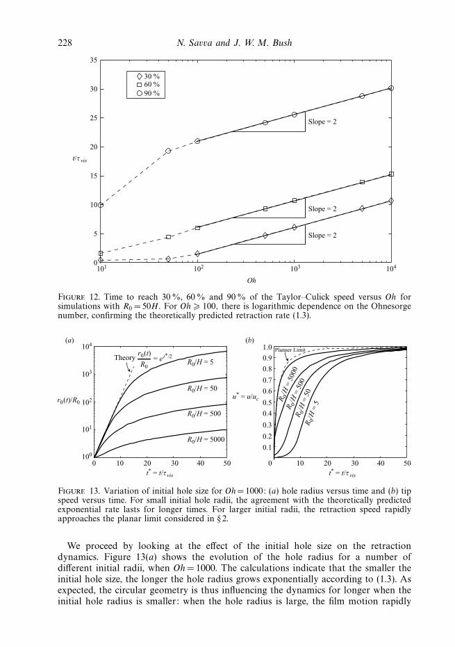
In figure 11 we confirm the exponential retraction rate observed in the experiments(see Debregeas et al. 1995; Dalnoki-Veress et al. 1999; Roth et al. 2005) during theearly stages of retraction. We note that the higher the Oh, the longer the hole growsaccording to the exponential law. By comparison with figure 10, we infer from oursimulations that the deviation from the exponential behaviour occurs quite early inthe retraction process, typically when the rim speed is of the order of 0.2uc.
In order to assess how Oh affects the acceleration phase, we plot in figure 12 thetime required for the tip to attain 30 %, 60 % and 90 % of the Taylor–Culick speedfor different Oh. Each simulation was initialized with a hole radius of R0 = 50H. Ascan be inferred from the theoretically predicted exponential law (1.3), the times t1,2needed for the tip to attain the speed of a certain fraction of uc that correspond toOh1,2 satisfy the relation
t1
Oh1
− t2
Oh2
= 2 log
(Oh1
Oh2
), (3.32)
provided Oh1,2 � 100 and the punctured hole is not large. At lower Oh, there is aclear deviation from this relation, which indicates that the rim acceleration is differentfrom that predicted in the viscous limit.
Viscous sheet retraction 227
1.0
0.9 G
F
E
D
C
B
A
0.8
0.7
0.6
0.5
0.4
0.3
0.2
0.1
5 10 15 20 25 30 35 40
A: Oh = 10 000
B: Oh = 5 000
C: Oh = 1 000
D: Oh = 500
E: Oh = 100
F: Oh = 50
G: Oh = 10
45 500
u* = u/uc
t* = t/τ vis
Figure 10. Speed at the film edge as a function of time for different values of Oh, withinitial hole radius of R0 = 50H. The higher the Oh the slower the approach towards theTaylor–Culick speed uc.
104
103
TheoryOh = 10 000
Oh = 5000
Oh = 1000
Oh = 500
Oh = 100
Oh = 50
Oh = 10
= et*/2
102r0 (t)/R0
101
100
5 10 15 20 25 30 35 40 45 500
r0 (t)
R0
t* = t/τ vis
Figure 11. Hole growth versus time for different Oh, for an initial hole size R0 = 50H . Thehigher the Oh, the longer the hole grows according to the exponential law (1.3) as deduced byDebregeas et al. (1995).
228 N. Savva and J. W. M. Bush
35
30
30 %60 %
90 %
Slope = 2
Slope = 2
Slope = 2
25
20
15
10
101 102 103
Oh
104
5
0
t/τ vis
Figure 12. Time to reach 30 %, 60% and 90 % of the Taylor–Culick speed versus Oh forsimulations with R0 = 50H. For Oh � 100, there is logarithmic dependence on the Ohnesorgenumber, confirming the theoretically predicted retraction rate (1.3).
104(a) (b)
103
102
R0/H = 5
R 0/H
= 5
000
R 0/H
= 5
00R 0
/H =
50
R 0/H
= 5
R0/H = 50
R0/H = 500
R0/H = 5000
101
100
0 10 20 30 40 50
TheoryPlanner Limit
= et*/2
r0 (t)/R0
r0 (t)
R0
0
0.1
0.3
0.2
0.4
0.5
0.6
0.7
0.8
0.9
1.0
10 20 30 40 50
u* = u/uc
t* = t/τ vis t* = t/τ vis
Figure 13. Variation of initial hole size for Oh =1000: (a) hole radius versus time and (b) tipspeed versus time. For small initial hole radii, the agreement with the theoretically predictedexponential rate lasts for longer times. For larger initial radii, the retraction speed rapidlyapproaches the planar limit considered in § 2.
We proceed by looking at the effect of the initial hole size on the retractiondynamics. Figure 13(a) shows the evolution of the hole radius for a number ofdifferent initial radii, when Oh = 1000. The calculations indicate that the smaller theinitial hole size, the longer the hole radius grows exponentially according to (1.3). Asexpected, the circular geometry is thus influencing the dynamics for longer when theinitial hole radius is smaller: when the hole radius is large, the film motion rapidly
Viscous sheet retraction 229
102
101
–0.6
0 0.5 1.0 1.5 2.0
–0.4
–0.2
0H
H
0.2
0.4
0.6
α = 15
α = 3
α = 0
α = 0α = 3
α = 15
100
0 1 2 3 4
Theory
Debregeas et al.
5 6
r0 (t)/R0
t* = t/τ vis
Figure 14. Effect of the initial film profile (as specified by α) on sheet retraction. Hole radiusversus time for Oh= 8 × 10³ and R0 = 40H . The inset shows the corresponding initial filmprofiles in the vicinity of the tip. A more pointed initial film profile retracts faster until its tiprelaxes to a semi-circular cap; thereafter, the film retracts at the theoretically predicted rateshown by the dashed curve, corresponding to (3.30). The dotted line indicates the experimentallyobserved retraction rates reported by Debregeas et al. (1995).
approaches the planar limit considered in § 2 (see figure 13b). Variations in the initialhole radius affect the low Oh films to a lesser extent, mainly due to the shorter timescales involved in the approach to uc.
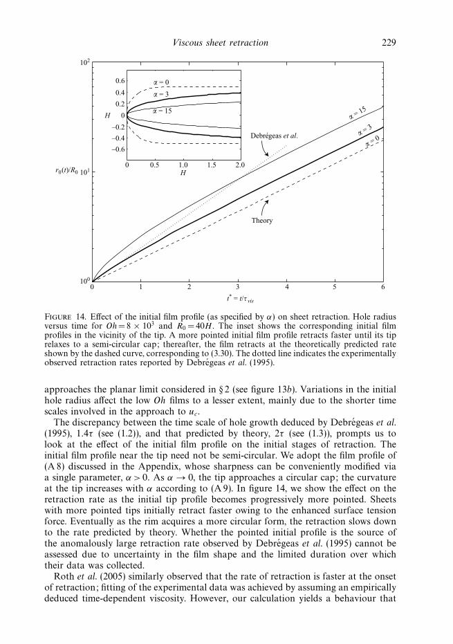
The discrepancy between the time scale of hole growth deduced by Debregeas et al.(1995), 1.4τ (see (1.2)), and that predicted by theory, 2τ (see (1.3)), prompts us tolook at the effect of the initial film profile on the initial stages of retraction. Theinitial film profile near the tip need not be semi-circular. We adopt the film profile of(A 8) discussed in the Appendix, whose sharpness can be conveniently modified viaa single parameter, α > 0. As α → 0, the tip approaches a circular cap; the curvatureat the tip increases with α according to (A 9). In figure 14, we show the effect on theretraction rate as the initial tip profile becomes progressively more pointed. Sheetswith more pointed tips initially retract faster owing to the enhanced surface tensionforce. Eventually as the rim acquires a more circular form, the retraction slows downto the rate predicted by theory. Whether the pointed initial profile is the source ofthe anomalously large retraction rate observed by Debregeas et al. (1995) cannot beassessed due to uncertainty in the film shape and the limited duration over whichtheir data was collected.
Roth et al. (2005) similarly observed that the rate of retraction is faster at the onsetof retraction; fitting of the experimental data was achieved by assuming an empiricallydeduced time-dependent viscosity. However, our calculation yields a behaviour that
230 N. Savva and J. W. M. Bush
2.5
2.0
1.5
ln r0 (t)/R0
1.0
0.5
0.5 1.0 1.5 2.0 2.5 3.0 3.5 4.00
t* = t/τ vis
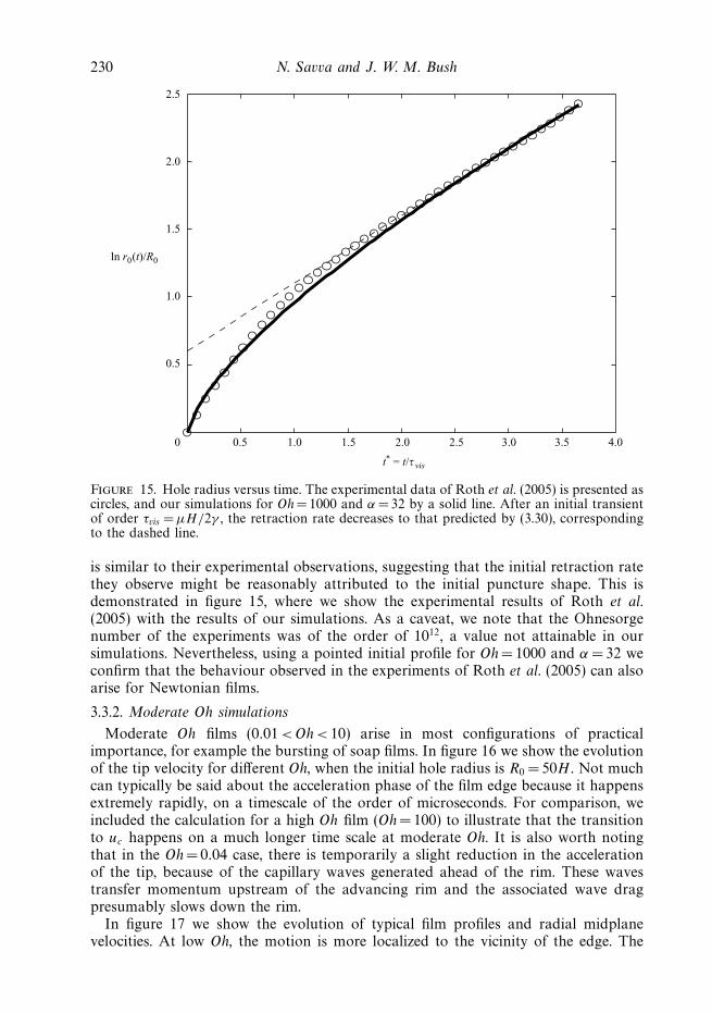
Figure 15. Hole radius versus time. The experimental data of Roth et al. (2005) is presented ascircles, and our simulations for Oh = 1000 and α = 32 by a solid line. After an initial transientof order τvis = μH/2γ , the retraction rate decreases to that predicted by (3.30), correspondingto the dashed line.
is similar to their experimental observations, suggesting that the initial retraction ratethey observe might be reasonably attributed to the initial puncture shape. This isdemonstrated in figure 15, where we show the experimental results of Roth et al.(2005) with the results of our simulations. As a caveat, we note that the Ohnesorgenumber of the experiments was of the order of 1012, a value not attainable in oursimulations. Nevertheless, using a pointed initial profile for Oh = 1000 and α = 32 weconfirm that the behaviour observed in the experiments of Roth et al. (2005) can alsoarise for Newtonian films.
3.3.2. Moderate Oh simulations
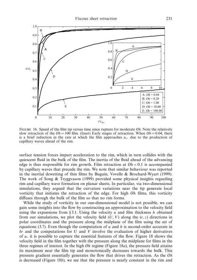
Moderate Oh films (0.01 < Oh < 10) arise in most configurations of practicalimportance, for example the bursting of soap films. In figure 16 we show the evolutionof the tip velocity for different Oh, when the initial hole radius is R0 = 50H . Not muchcan typically be said about the acceleration phase of the film edge because it happensextremely rapidly, on a timescale of the order of microseconds. For comparison, weincluded the calculation for a high Oh film (Oh = 100) to illustrate that the transitionto uc happens on a much longer time scale at moderate Oh. It is also worth notingthat in the Oh = 0.04 case, there is temporarily a slight reduction in the accelerationof the tip, because of the capillary waves generated ahead of the rim. These wavestransfer momentum upstream of the advancing rim and the associated wave dragpresumably slows down the rim.
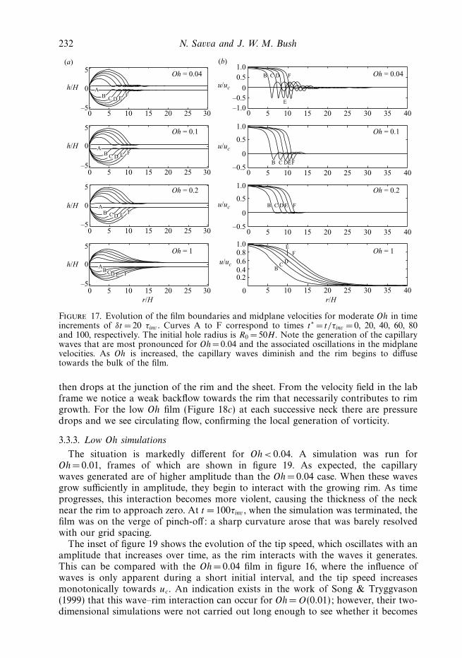
In figure 17 we show the evolution of typical film profiles and radial midplanevelocities. At low Oh, the motion is more localized to the vicinity of the edge. The
Viscous sheet retraction 231
0 10 20 30 40 50 60
t/τinv
70
A: Oh = 0.04
B: Oh = 0.20
C: Oh = 1.00
D: Oh = 10.00
E: Oh = 100.00
80 90 100
0.1
0.2
0.3
0.4
0.5u/uc
0.6
1.0
0.8
0.6
0.4
0.2
2 4 6 8 100
0.7
0.8
0.9
B
BAAA
CC
D
D
E
E
1.0
Figure 16. Speed of the film tip versus time since rupture for moderate Oh. Note the relativelyslow retraction of the Oh = 100 film. (Inset) Early stages of retraction. When Oh =0.04, thereis a brief reduction in the rate at which the film approaches uc, due to the production ofcapillary waves ahead of the rim.
surface tension forces impart acceleration to the rim, which in turn collides with thequiescent fluid in the bulk of the film. The inertia of the fluid ahead of the advancingedge is thus responsible for rim growth. Film retraction at Oh < 0.1 is accompaniedby capillary waves that precede the rim. We note that similar behaviour was reportedin the inertial dewetting of thin films by Buguin, Vovelle & Brochard-Wyart (1999).The work of Song & Tryggvason (1999) provided some physical insights regardingrim and capillary wave formation on planar sheets. In particular, via two-dimensionalsimulations, they argued that the curvature variations near the tip generate localvorticity that initiates the retraction of the edge. For high Oh films, this vorticitydiffuses through the bulk of the film so that no rim forms.
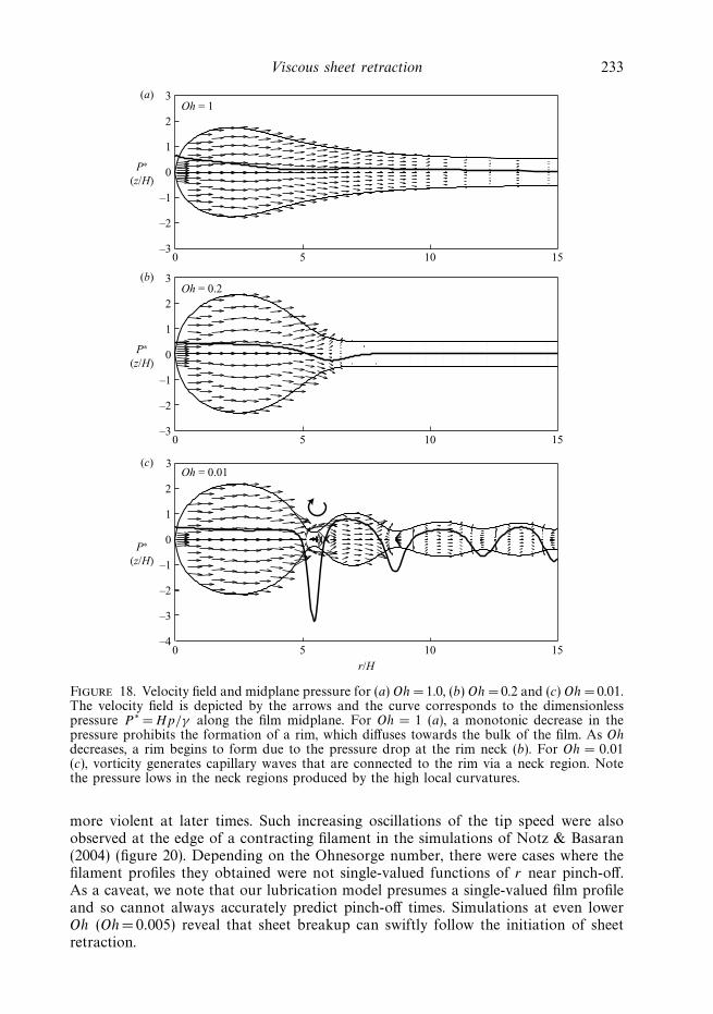
While the study of vorticity in our one-dimensional model is not possible, we cangain some insights into the flow by constructing an approximation to the velocity fieldusing the expansions from § 3.1. Using the velocity u and film thickness h obtainedfrom our simulations, we plot the velocity field (U, V ) along the (r, z) directions inpolar coordinates and the pressure along the midplane of the film using the set ofequations (3.7). Even though the computation of u and h is second-order accurate inδr and the computations for U and V involve the evaluation of higher derivativesof u, it is possible to capture the essential features of the flow. Figure 18 shows thevelocity field in the film together with the pressure along the midplane for films in thethree regimes of interest. In the high Oh regime (Figure 18a), the pressure field attainsits maximum near the film tip and monotonically decreases towards the bulk. Thispressure gradient essentially generates the flow that drives the retraction. As the Ohis decreased (Figure 18b), we see that the pressure is nearly constant in the rim and
232 N. Savva and J. W. M. Bush
5 Oh = 0.04 F
E
F
DCB
B C DEF
B
B
C
C
D
D
E
E
F
F
Oh = 0.1
Oh = 0.2
Oh = 1
Oh = 0.04
Oh = 0.1
Oh = 0.2
Oh = 1
1.0
0.5
0u/uc
u/uc
u/uc
u/uc
–0.5
–1.0
0
0 5 10 15 20 25 30 35 40
5 10 15 20 25 30 35 40
0 5 10 15 20 25 30 35 40
0 5 10 15 20 25 30 35 40
(a) (b)
0
0 5 10 15 20 25 30
0 5 10 15 20 25 30
0 5 10 15 20 25 30
0 5 10 15 20 25 30
h/H
–5
5
0h/H
–5
5
0h/H
–5
5
0h/H
r/H r/H
–5
1.0
0.5
0
–0.5
1.0
0.5
0
–0.5
1.00.8
0.40.6
0.2
A
A
A
ABCD E F
B C D EF
B C D E F
B C D EF
Figure 17. Evolution of the film boundaries and midplane velocities for moderate Oh in timeincrements of δt = 20 τinv . Curves A to F correspond to times t∗ = t/τinv = 0, 20, 40, 60, 80and 100, respectively. The initial hole radius is R0 = 50H. Note the generation of the capillarywaves that are most pronounced for Oh= 0.04 and the associated oscillations in the midplanevelocities. As Oh is increased, the capillary waves diminish and the rim begins to diffusetowards the bulk of the film.
then drops at the junction of the rim and the sheet. From the velocity field in the labframe we notice a weak backflow towards the rim that necessarily contributes to rimgrowth. For the low Oh film (Figure 18c) at each successive neck there are pressuredrops and we see circulating flow, confirming the local generation of vorticity.
3.3.3. Low Oh simulations
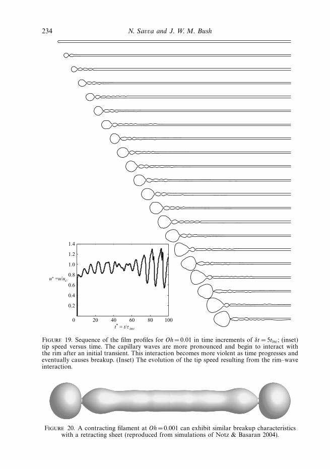
The situation is markedly different for Oh < 0.04. A simulation was run forOh = 0.01, frames of which are shown in figure 19. As expected, the capillarywaves generated are of higher amplitude than the Oh = 0.04 case. When these wavesgrow sufficiently in amplitude, they begin to interact with the growing rim. As timeprogresses, this interaction becomes more violent, causing the thickness of the necknear the rim to approach zero. At t = 100τinv , when the simulation was terminated, thefilm was on the verge of pinch-off: a sharp curvature arose that was barely resolvedwith our grid spacing.
The inset of figure 19 shows the evolution of the tip speed, which oscillates with anamplitude that increases over time, as the rim interacts with the waves it generates.This can be compared with the Oh =0.04 film in figure 16, where the influence ofwaves is only apparent during a short initial interval, and the tip speed increasesmonotonically towards uc. An indication exists in the work of Song & Tryggvason(1999) that this wave–rim interaction can occur for Oh =O(0.01); however, their two-dimensional simulations were not carried out long enough to see whether it becomes
Viscous sheet retraction 233
3(a)
2
1
0P∗
(z/H)–1
–2
–30 5 10 15
Oh = 1
3(b)
2
1
0P∗
(z/H)–1
–2
–30 5 10 15
Oh = 0.2
3(c)
2
1
0P∗
(z/H) –1
–2
–3
–40 5 10 15
Oh = 0.01
r/H
Figure 18. Velocity field and midplane pressure for (a) Oh =1.0, (b) Oh = 0.2 and (c) Oh = 0.01.The velocity field is depicted by the arrows and the curve corresponds to the dimensionlesspressure P ∗ = Hp/γ along the film midplane. For Oh = 1 (a), a monotonic decrease in thepressure prohibits the formation of a rim, which diffuses towards the bulk of the film. As Ohdecreases, a rim begins to form due to the pressure drop at the rim neck (b). For Oh = 0.01(c), vorticity generates capillary waves that are connected to the rim via a neck region. Notethe pressure lows in the neck regions produced by the high local curvatures.
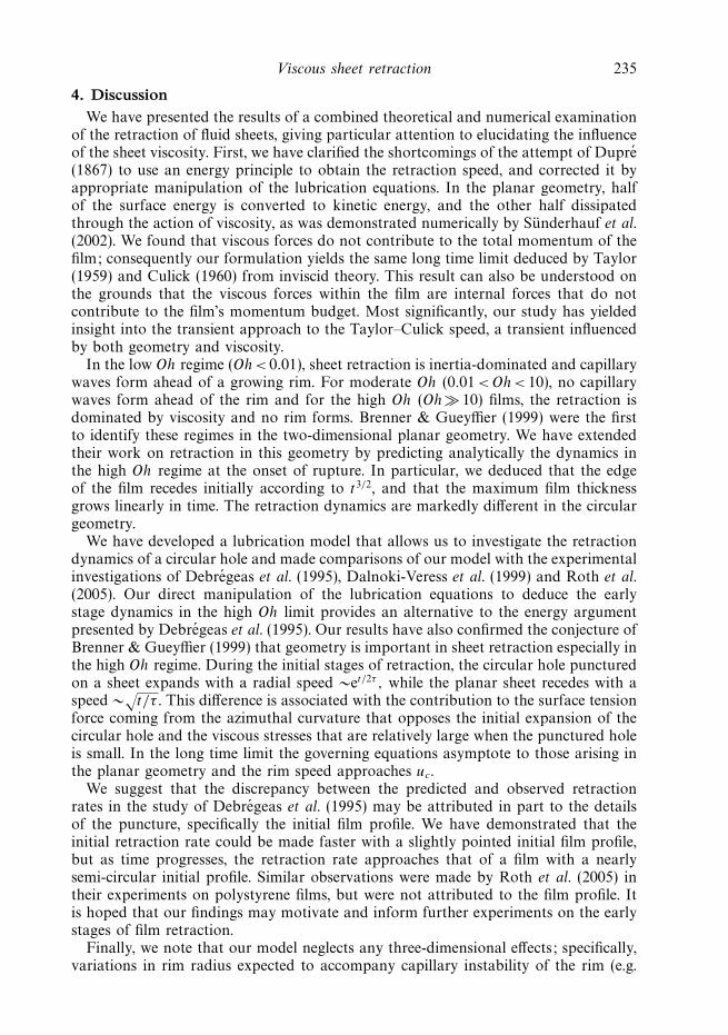
more violent at later times. Such increasing oscillations of the tip speed were alsoobserved at the edge of a contracting filament in the simulations of Notz & Basaran(2004) (figure 20). Depending on the Ohnesorge number, there were cases where thefilament profiles they obtained were not single-valued functions of r near pinch-off.As a caveat, we note that our lubrication model presumes a single-valued film profileand so cannot always accurately predict pinch-off times. Simulations at even lowerOh (Oh = 0.005) reveal that sheet breakup can swiftly follow the initiation of sheetretraction.
234 N. Savva and J. W. M. Bush
1.4
1.2
1.0
0.8
0.6
0.4
0.2
0 20 40 60 80 100
u∗ =u/uc
t* = t/τ inv
Figure 19. Sequence of the film profiles for Oh = 0.01 in time increments of δt = 5tinv; (inset)tip speed versus time. The capillary waves are more pronounced and begin to interact withthe rim after an initial transient. This interaction becomes more violent as time progresses andeventually causes breakup. (Inset) The evolution of the tip speed resulting from the rim–waveinteraction.
Figure 20. A contracting filament at Oh =0.001 can exhibit similar breakup characteristicswith a retracting sheet (reproduced from simulations of Notz & Basaran 2004).
Viscous sheet retraction 235
4. DiscussionWe have presented the results of a combined theoretical and numerical examination
of the retraction of fluid sheets, giving particular attention to elucidating the influenceof the sheet viscosity. First, we have clarified the shortcomings of the attempt of Dupre(1867) to use an energy principle to obtain the retraction speed, and corrected it byappropriate manipulation of the lubrication equations. In the planar geometry, halfof the surface energy is converted to kinetic energy, and the other half dissipatedthrough the action of viscosity, as was demonstrated numerically by Sunderhauf et al.(2002). We found that viscous forces do not contribute to the total momentum of thefilm; consequently our formulation yields the same long time limit deduced by Taylor(1959) and Culick (1960) from inviscid theory. This result can also be understood onthe grounds that the viscous forces within the film are internal forces that do notcontribute to the film’s momentum budget. Most significantly, our study has yieldedinsight into the transient approach to the Taylor–Culick speed, a transient influencedby both geometry and viscosity.
In the low Oh regime (Oh < 0.01), sheet retraction is inertia-dominated and capillarywaves form ahead of a growing rim. For moderate Oh (0.01 < Oh < 10), no capillarywaves form ahead of the rim and for the high Oh (Oh � 10) films, the retraction isdominated by viscosity and no rim forms. Brenner & Gueyffier (1999) were the firstto identify these regimes in the two-dimensional planar geometry. We have extendedtheir work on retraction in this geometry by predicting analytically the dynamics inthe high Oh regime at the onset of rupture. In particular, we deduced that the edgeof the film recedes initially according to t3/2, and that the maximum film thicknessgrows linearly in time. The retraction dynamics are markedly different in the circulargeometry.
We have developed a lubrication model that allows us to investigate the retractiondynamics of a circular hole and made comparisons of our model with the experimentalinvestigations of Debregeas et al. (1995), Dalnoki-Veress et al. (1999) and Roth et al.(2005). Our direct manipulation of the lubrication equations to deduce the earlystage dynamics in the high Oh limit provides an alternative to the energy argumentpresented by Debregeas et al. (1995). Our results have also confirmed the conjecture ofBrenner & Gueyffier (1999) that geometry is important in sheet retraction especially inthe high Oh regime. During the initial stages of retraction, the circular hole puncturedon a sheet expands with a radial speed ∼et/2τ , while the planar sheet recedes with aspeed ∼
√t/τ . This difference is associated with the contribution to the surface tension
force coming from the azimuthal curvature that opposes the initial expansion of thecircular hole and the viscous stresses that are relatively large when the punctured holeis small. In the long time limit the governing equations asymptote to those arising inthe planar geometry and the rim speed approaches uc.
We suggest that the discrepancy between the predicted and observed retractionrates in the study of Debregeas et al. (1995) may be attributed in part to the detailsof the puncture, specifically the initial film profile. We have demonstrated that theinitial retraction rate could be made faster with a slightly pointed initial film profile,but as time progresses, the retraction rate approaches that of a film with a nearlysemi-circular initial profile. Similar observations were made by Roth et al. (2005) intheir experiments on polystyrene films, but were not attributed to the film profile. Itis hoped that our findings may motivate and inform further experiments on the earlystages of film retraction.
Finally, we note that our model neglects any three-dimensional effects; specifically,variations in rim radius expected to accompany capillary instability of the rim (e.g.
236 N. Savva and J. W. M. Bush
McEntee & Mysels 1969; Pandit & Davidson 1990). While rim instability is related tothe Rayleigh–Plateau instability, the physical picture is more complex owing to rimgrowth. For instance in the moderate Oh regime, if a rim of radius R were to pinch
off due to the capillary instability, it would do so after a time τc ∼√
ρR3/2γ , which
can be comparable to the appropriate time scale of retraction, τinv =√
ρH 3/2γ . Thisis especially true at the onset of retraction, where H and R are comparable. Thetendency of the rim growth to suppress the onset of this instability was apparentin the experiments of McEntee & Mysels (1969) and demonstrated in the numericalsimulations (at Oh = 0.1 and 0.03) of Fullana & Zaleski (1999), who suggested thatthe rim will eventually become unstable to perturbations with wavelengths that aretypically a few orders of magnitude larger than the film thickness. The stability ofthe rim is enhanced not only by rim growth, but by the action of viscosity as wasconfirmed in the experiments of Debregeas et al. (1995), Dalnoki-Veress et al. (1999)and Roth et al. (2005). Improved understanding of the rim stability will contribute toour ability to predict drop sizes resulting from film disintegration (see Bush & Hasha2004; Bremond & Villermaux 2006; Roisman, Horvat & Tropea 2006; Villermaux2007).
John W. M. Bush gratefully acknowledges the financial support of the NSF throughCareer Grant CTS-0130465. The authors thank Jens Eggers for a number of valuableexchanges.
Appendix. Numerical methodIn non-dimesionalizing the governing equations (3.15) and (3.16), the time scale is
chosen according to the Ohnesorge number. By selecting the larger time scale of τinv
and τvis , we facilitate the computations since with the same computational cost, wecan integrate the equations further in physical time. Since τvis =Oh τinv , τinv and τvis
are the appropriate time scales for, respectively, Oh < 1 and Oh > 1.Equations (3.15) and (3.16) are rearranged to solve for f = h2, because the slope of
h, which goes like√
r − r0(t) near the tip, becomes infinite there. Doing so avoids thedifficulties in taking the derivatives of h to evaluate the curvature at the tip, whichnow transforms to
κ = 82ffrr − f 2
r(16f + f 2
r
)3/2+
fr
r(16f + f 2
r
)1/2. (A 1)
In their examination of jet breakup, Eggers & Dupont (1994) remedied the difficultyof hr blowing up at the tip by fitting an even quartic polynomial to the jet profilein this region. Our approach is more natural in terms of implementation as thediscretization of the equations is done without resorting to polynomial fits.
Since this is a free boundary problem, where the tip of the film moves, solving thesystem of equations requires the remeshing of the domain at each time step. To avoidthis difficulty, we map the computational domain (r ′, t ′) to the physical (r, t)-planevia the transformation
r =
(1 − r0 (t)
L
)r ′ + r0 (t) , (A 2a)
t = t ′, (A 2b)
where 0 � r ′ � L and L is the radial extent of the film. Under this mapping, theedge of the film is always located at r ′ =0 in the computational domain and r = L
Viscous sheet retraction 237
is mapped to r ′ =L; the free boundary problem is thus transformed into a fixedboundary problem. The derivatives must be transformed accordingly by
∂
∂t=
∂
∂t ′ − 1 − r ′/L
1 − r0 (t) /Lu0 (t)
∂
∂x ′ , (A 3a)
∂
∂x=
1
1 − r0 (t) /L
∂
∂x ′ , (A 3b)
where the tip speed
u0 =dr0
dt. (A 4)
In Eggers’ work, the failure of the lubrication approximation is remedied byneglecting the effect of viscosity near the tip; in the jet breakup problem, the conditionat the jet tip is apparently not critical. Nevertheless, choosing the appropriate tipcondition is crucial here and needs to be addressed more carefully. We see that whenθ = π/2 and f =0, (3.4b) is trivially satisfied no matter what form u2 takes. Hence,we infer u2 by extrapolating over the values of u2 in the interior, found using (3.13).Quadratic extrapolation requires
u2|tip =x1x2 (x2 − x1) u2,3 + x1x3 (x1 − x3) u2,2 + x2x3 (x3 − x2) u2,1
x1x2 (x2 − x1) + x1x3 (x1 − x3) + x2x3 (x3 − x2), (A 5)
where xi = ri − r0 is the (i + 1)th node in the computational grid at which u2 takesthe value u2,i . Substituting θ = π/2 and f =0 in (3.4a) gives
− p
ρ
∣∣∣∣tip
=γ
ρκ − 2νu0r
. (A 6)
Using (A 6) in (3.10), we find that the velocity at the film edge evolves according to
du0
dt=
γ
ρκr + 2ν
(− u0rr
+u0r
r− u0
r2+ u2
)∣∣∣∣tip
. (A 7)
The presence of the viscous term is essential here: its absence causes the hole toexpand at a faster rate.
At the far end of the film (r → ∞), Neumann conditions are used for the thicknessand velocity. As far as the initial film profile is concerned, it is imposed ratherarbitrarily, by using a profile of the form
f ∗ (r∗, 0; α
)= 1 −
(12
− α − r∗ + R∗0 + 1
2
√(1 + 2α)2 + 4(r∗ − R∗
0)(2α + r∗ − R∗0 − 1)
)2
,
(A 8)
where α is a parameter that controls the curvature profile and r∗ � R∗0 . Equation
(A 8) was constructed by perturbing trajectories on the phase plane of a particulardynamical system and essentially represents a smoothing of a semi-circular captogether with a rectangular strip. The smaller we take α, the more pronounced thepeak in the curvature gradient, and the finer the mesh required to resolve the sheetshape. In the numerical computations, we typically used α =1/20 to 1/100. As weincrease α, the tip curvature and its gradient increase according to
κ(r = R0; α) = −2 − 4α, (A 9)
238 N. Savva and J. W. M. Bush
0.5(a)
(b) (c)
0.4 F
A0.3h/H
xx
x
0.20.1
00.2
0.20
–0.5
–1.0
–1.5A F A
E F
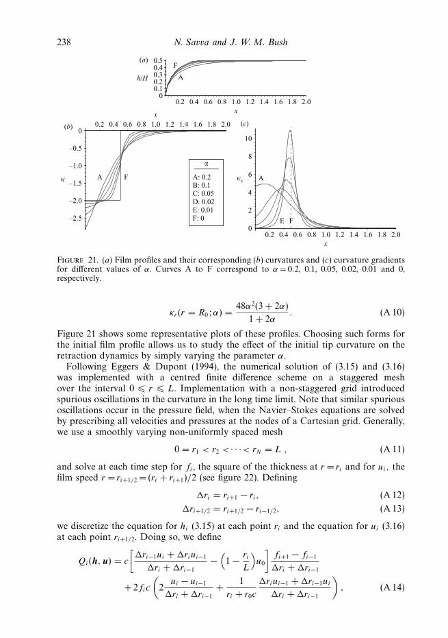
A: 0.2B: 0.1C: 0.05D: 0.02E: 0.01F: 0
κ κx
α
–2.0
–2.5
0.4 0.6 0.8 1.0 1.2 1.4 1.6 1.8 2.0
10
8
6
4
2
00.2 0.4 0.6 0.8 1.0 1.2 1.4 1.6 1.8 2.0
0.4 0.6 0.8 1.0 1.2 1.4 1.6 1.8 2.0
Figure 21. (a) Film profiles and their corresponding (b) curvatures and (c) curvature gradientsfor different values of α. Curves A to F correspond to α = 0.2, 0.1, 0.05, 0.02, 0.01 and 0,respectively.
κr (r = R0; α) =48α2(3 + 2α)
1 + 2α. (A 10)
Figure 21 shows some representative plots of these profiles. Choosing such forms forthe initial film profile allows us to study the effect of the initial tip curvature on theretraction dynamics by simply varying the parameter α.
Following Eggers & Dupont (1994), the numerical solution of (3.15) and (3.16)was implemented with a centred finite difference scheme on a staggered meshover the interval 0 � r � L. Implementation with a non-staggered grid introducedspurious oscillations in the curvature in the long time limit. Note that similar spuriousoscillations occur in the pressure field, when the Navier–Stokes equations are solvedby prescribing all velocities and pressures at the nodes of a Cartesian grid. Generally,we use a smoothly varying non-uniformly spaced mesh
0 = r1 < r2 < · · ·< rN = L , (A 11)
and solve at each time step for fi , the square of the thickness at r = ri and for ui, thefilm speed r = ri+1/2 = (ri + ri+1)/2 (see figure 22). Defining
�ri = ri+1 − ri, (A 12)
�ri+1/2 = ri+1/2 − ri−1/2, (A 13)
we discretize the equation for hi (3.15) at each point ri and the equation for ui (3.16)at each point ri+1/2. Doing so, we define
Qi(h, u) = c
[�ri−1ui + �riui−1
�ri + �ri−1
−(1 − ri
L
)u0
]fi+1 − fi−1
�ri + �ri−1
+ 2fic
(2
ui − ui−1
�ri + �ri−1
+1
ri + r0c
�riui−1 + �ri−1ui
�ri + �ri−1
), (A 14)
Viscous sheet retraction 239
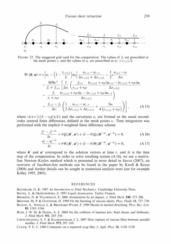
f1
f2 f3
r1 r2 r3
u0
u1 u2 u3 ui–2
ri–1 ri+1 ri+2
fi+1 fi+2
ri
fi–1 fiui–1 ui+1ui
Figure 22. The staggered grid used for the computation. The values of fi are prescribed atthe mesh points ri and the values of ui are prescribed at (ri + ri+1) /2.
Wi (h, u) = c[ui −
(1 − ri+1/2
L
)u0
] ui+1 − ui−1
�ri+3/2 + �ri+1/2
− 1
2cκi+1 − κi
�ri
− 8Ohc2
fi + fi+1
[1
�ri
(fi+1
ri+1 + r0c
(ri+3/2 + r0c)ui+1 − (ri+1/2 + r0c)ui
�ri+3/2
− fi
ri + r0c
(ri+1/2 + r0c)ui − (ri−1/2 + r0c)ui−1
�ri+1/2
)
− fi+1 − fi
�ri
(1
2
ui+1 − ui−1
�ri+3/2 + �ri+1/2
+3ui
4(ri+1/2 + r0c
))]
, (A 15)
where c(t) = 1/(1 − r0(t)/L) and the curvatures κi are formed as the usual second-order centred finite differences, defined at the mesh points ri . Time integration wasperformed with the implicit θ-weighted finite difference scheme
f ti − f t−δt
i
δt+ θQi(h
t , ut ) + (1 − θ)Qi(ht−δt , ut−δt ) = 0, (A 16)
uti − ut−δt
i
δt+ θWi(h
t , ut ) + (1 − θ)Wi(ht−δt , ut−δt ) = 0, (A 17)
where ht and ut correspond to the solution vectors at time t, and δt is the timestep of the computation. In order to solve resulting system (A 16), we use a matrix-free Newton–Krylov method which is presented in more detail in Savva (2007); anoverview of Jacobian-free methods can be found in the paper by Knoll & Keyes(2004) and further details can be sought in numerical analysis texts (see for exampleKelley 1995, 2003).
REFERENCES
Batchelor, G. K. 1967 An Introduction to Fluid Mechanics . Cambridge University Press.
Bayvel, L. & Orzechowski, Z. 1993 Liquid Atomization . Taylor–Francis.
Bremond, N. & Villermaux, E. 2006 Atomization by jet impact. J. Fluid Mech. 549, 273–306.
Brenner, M. P. & Gueyffier, D. 1999 On the bursting of viscous sheets. Phys. Fluids 11, 737–739.
Buguin, A., Vovelle, L. & Brochard-Wyart, F. 1999 Shocks in inertial dewetting. Phys. Rev. Lett.83, 1183–1186.
Bush, J. W. M. & Hasha, A. E. 2004 On the collision of laminar jets: fluid chains and fishbones.J. Fluid Mech. 511, 285–310.
Chepushtanova, S. V. & Kliakhandler, I. L. 2007 Slow rupture of viscous films between parallelneedles. J. Fluid Mech. 573, 297–310.
Culick, F. E. C. 1960 Comments on a ruptured soap film. J. Appl. Phys. 31, 1128–1129.
240 N. Savva and J. W. M. Bush
Dalnoki-Veress, K., Nickel, B. G., Roth, C. & Dutcher, J. R. 1999 Hole formation and growthin freely standing polystyrene films. J. Fluid Mech. 59 (2), 2153–2156.
Debregeas, G., de Gennes, G. P. & Brochard-Wyart, F. 1998 The life and death of viscous “bare”bubbles. Science 279, 1704–1707.
Debregeas, G., Martin, P. & Brochard-Wyart, F. 1995 Viscous bursting of suspended films. Phys.Rev. Lett. 75, 3886–3889.
Deyrail, Y., Mesri, Z. El, Huneault, M., Zeghloul, A. & Bousmina, M. 2007 Analysis ofmorphology development in immiscible newtonian polymer mixtures during shear flow.J. Rheol. 51, 781–797.
Dupre, M. A. 1867 Sixieme memoire sur la theorie mechanique de la chaleur. Ann. Chim. Phys. 4(11), 194–220.
Eggers, J. & Brenner, M. P. 2000 Spinning jets. In Proceedings of the IUTAM Symposium onNonlinear Waves in Multi-Phase Flow (ed. H.-C. Chang), pp. 185–194. Kluwer.
Eggers, J. & Dupont, T. F. 1994 Drop formation in a one-dimensional approximation of theNavier–Stokes equation. J. Fluid Mech. 262, 205–221.
Fullana, G. M. & Zaleski, S. 1999 Stability of a growing rim in a liquid sheet of uniform thickness.Phys. Fluids 11, 952–954.
de Gennes, P. G., Brochart-Wyart, F. & Quere, D. 2003 Capillarity and Wetting Phenomena:Drops, Bubbles, Pearls, Waves . Springer.
Keller, J. B. 1983 Breaking of liquid films and threads. Phys. Fluids 26, 3451–3453.
Keller, J. B. & Miksis, M. J. 1983 Surface tension driven flows. SIAM J. Appl. Math. 43, 268–277.
Kelley, C. T. 1995 Iterative Methods for Linear and Nonlinear Equations . SIAM.
Kelley, C. T. 2003 Solving Nonlinear Equations with Newton’s Method . SIAM.
Knoll, D. A. & Keyes, D. E. 2004 Jacobian-free Newton–Krylov methods: a survey of approachesand applications. J. Comp. Phys. 193, 357–397.
Lefebvre, A. H. 1989 Liquid Atomization . Hemisphere.
McEntee, W. R. & Mysels, K. J. 1969 The bursting of soap films. I. An experimental study. J. Phys.Chem. 73, 3018–3028.
Miyamoto, K. & Katagiri, Y. 1997 Curtain coating. In Liquid Film Coating (ed. S. F. Kistler &P. M. Schweizer), pp. 463–494. Chapman–Hall.
Notz, P. K. & Basaran, O. A. 2004 Dynamics and breakup of contracting filaments. J. Fluid Mech.512, 223–256.
Pandit, A. B. & Davidson, J. F. 1990 Hydrodynamics of the rupture of thin liquid films. J. FluidMech. 212, 11–24.
Pomeau, Y. & Villermaux, E. 2006 Two hundred years of capillarity research. Phys. Today 59,39–44.
Ranz, W. E. 1950 Some experiments on the dynamics of liquid films. J. Appl. Phys. 30, 1950–1955.
Rayleigh, Lord 1891 Some applications of photography. Nature 44, 249–254.
Roisman, I. V., Horvat, K. & Tropea, C. 2006 Spray impact: rim transverse instability initiatingfingering and splash, and description of secondary spray. Phys. Fluids 18, 102104.
Roth, C. B., Deh, B., Nickel, B. G. & Dutcher, J. R. 2005 Evidence of convective constraintrelease during hole growth in freely standing polystyrene films at low temperatures. Phys.Rev. E 72 (2), 021802.
Savva, N. 2007 Viscous fluid sheets. PhD thesis, Massachusetts Institute of Technology.
Song, M. & Tryggvason, G. 1999 The formation of thick borders on an initially stationary fluidsheet. Phys. Fluids 11, 2487–2493.
Sunderhauf, G., Raszillier, H. & Durst, F. 2002 The retraction of the edge of a planar liquidsheet. Phys. Fluids 14, 198–208.
Taylor, G. I. 1959 The dynamics of thin sheets of fluid. III. Disintegration of fluid sheets. Proc. R.Soc. Lond. Ser. A 253, 313–321.
Taylor, G. I. & Michael, D. I. 1973 On making holes in a sheet of fluid. J. Fluid Mech. 58, 625–639.
Villermaux, E. 2007 Fragmentation. Annu. Rev. Fluid Mech. 39, 419–446.