magnetomicrometry - dspace@mit
TRANSCRIPT

Magnetomicrometry
The MIT Faculty has made this article openly available. Please share how this access benefits you. Your story matters.
Citation Taylor, CR, Srinivasan, SS, Yeon, SH, O’Donnell, MK, Roberts, TJ etal. 2021. "Magnetomicrometry." Science Robotics, 6 (57).
As Published 10.1126/SCIROBOTICS.ABG0656
Publisher American Association for the Advancement of Science (AAAS)
Version Author's final manuscript
Citable link https://hdl.handle.net/1721.1/138903
Terms of Use Article is made available in accordance with the publisher'spolicy and may be subject to US copyright law. Please refer to thepublisher's site for terms of use.
This is the author's version of the work. It is posted here by permission of the AAAS for personal use, not for redistribution. The definitive version was published in Science Robotics 6, (2021-08-18), doi: 10.1126/scirobotics.abg0656
1
Magnetomicrometry
C.R. Taylor1 , S.S. Srinivasan1 ,2 , S.H. Yeon1 , M.K. O’Donnell3 , T.J. Roberts3 , H.M. Herr1 ,2*
1MIT Center for Extreme Bionics. 2Harvard Medical School.
3Brown University Department of Ecology and Evolutionary Biology. *Corresponding Author ([email protected])
Abstract We live in an era of wearable sensing, where our movement through the world is continuously monitored by devices. And yet, we lack a portable sensor that can continuously monitor muscle, tendon, and bone motion, allowing us to monitor performance, deliver targeted rehabilitation, and provide intuitive, reflexive control over prostheses and exoskeletons. Here, we introduce a sensing modality, magnetomicrometry, that uses the relative positions of implanted magnetic beads to enable wireless tracking of tissue length changes. We demonstrate real-time muscle length tracking in an in vivo turkey model via chronically implanted magnetic beads, while investigating accuracy, biocompatibility, and long-term implant stability. We anticipate that this tool will lay the groundwork for volitional control over wearable robots via real-time tracking of muscle lengths and speeds. Further, to inform future biomimetic control strategies, magnetomicrometry may also be used in the in vivo tracking of biological tissues to elucidate biomechanical principles of animal and human movement. Introduction Accurate, timely monitoring of user intent is necessary to provide volitional control over a prosthesis, exoskeleton, or other human-machine interface. As a result, substantial work has been undertaken towards developing approaches to measure intent by tracking the nervous, mechanical, and chemical signals generated by peripheral limbs (1–3). Amongst the mechanical parameters measured are muscle length and shortening speed, which must ideally be tracked on a timescale of tens of milliseconds with millimeter resolution to be useful for reflexive control of prostheses and exoskeletons (4, 5). Non-invasive approaches to monitoring user intent, such as surface electromyography (EMG), ultrasound, and mechanomyography, reside outside the body but have poor, unstable signal quality (6, 7) or require substantial mass, power, and computation (5). For example, fluoromicrometry, which uses X-rays for high precision tissue position tracking, is wireless but is limited to short bursts due to ionizing radiation, requires an entire room, and involves substantial processing time (8). And whereas high-density surface EMG is portable and can be sufficiently accurate to decode spinal neural drives (9), signal drift and large artifacts due to skin-electrode impedance variations can be caused by changes in perspiration (10) or by dynamic pressure changes from, for instance, a prosthetic socket (11). In contrast, highly-invasive approaches such as sonomicrometry, electrodes implanted in peripheral nerves, and EMG via implanted muscle electrodes provide improved signal quality but are expensive to implement, require delicate surgery, and are prone to damage or variable performance over time (6, 12). For instance, sonomicrometry uses implanted ultrasound crystals
This is the author's version of the work. It is posted here by permission of the AAAS for personal use, not for redistribution. The definitive version was published in Science Robotics 6, (2021-08-18), doi: 10.1126/scirobotics.abg0656
2
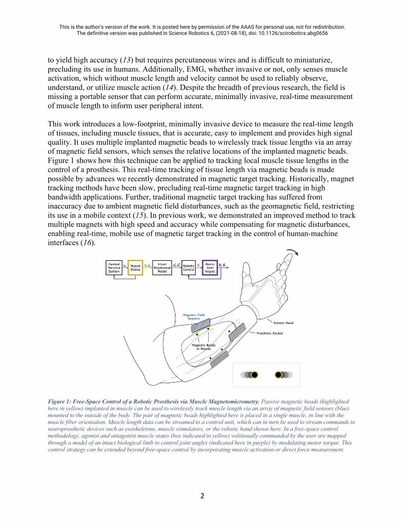
to yield high accuracy (13) but requires percutaneous wires and is difficult to miniaturize, precluding its use in humans. Additionally, EMG, whether invasive or not, only senses muscle activation, which without muscle length and velocity cannot be used to reliably observe, understand, or utilize muscle action (14). Despite the breadth of previous research, the field is missing a portable sensor that can perform accurate, minimally invasive, real-time measurement of muscle length to inform user peripheral intent. This work introduces a low-footprint, minimally invasive device to measure the real-time length of tissues, including muscle tissues, that is accurate, easy to implement and provides high signal quality. It uses multiple implanted magnetic beads to wirelessly track tissue lengths via an array of magnetic field sensors, which senses the relative locations of the implanted magnetic beads. Figure 1 shows how this technique can be applied to tracking local muscle tissue lengths in the control of a prosthesis. This real-time tracking of tissue length via magnetic beads is made possible by advances we recently demonstrated in magnetic target tracking. Historically, magnet tracking methods have been slow, precluding real-time magnetic target tracking in high bandwidth applications. Further, traditional magnetic target tracking has suffered from inaccuracy due to ambient magnetic field disturbances, such as the geomagnetic field, restricting its use in a mobile context (15). In previous work, we demonstrated an improved method to track multiple magnets with high speed and accuracy while compensating for magnetic disturbances, enabling real-time, mobile use of magnetic target tracking in the control of human-machine interfaces (16).
Figure 1: Free-Space Control of a Robotic Prosthesis via Muscle Magnetomicrometry. Passive magnetic beads (highlighted here in yellow) implanted in muscle can be used to wirelessly track muscle length via an array of magnetic field sensors (blue) mounted to the outside of the body. The pair of magnetic beads highlighted here is placed in a single muscle, in line with the muscle fiber orientation. Muscle length data can be streamed to a control unit, which can in turn be used to stream commands to neuroprosthetic devices such as exoskeletons, muscle stimulators, or the robotic hand shown here. In a free-space control methodology, agonist and antagonist muscle states (box indicated in yellow) volitionally commanded by the user are mapped through a model of an intact biological limb to control joint angles (indicated here in purple) by modulating motor torque. This control strategy can be extended beyond free-space control by incorporating muscle activation or direct force measurement.

This is the author's version of the work. It is posted here by permission of the AAAS for personal use, not for redistribution. The definitive version was published in Science Robotics 6, (2021-08-18), doi: 10.1126/scirobotics.abg0656
3
Previously, magnets have been permanently implanted in humans alongside Hall sensors for joint tracking, successfully demonstrating the viability and safety of this approach (17). Because low-frequency magnetic fields are not affected by materials such as silicone, carbon fiber, or the human body, the magnetic field passes undisturbed from the muscles to the sensors as if these other materials are not present. This allows for accurate, transcutaneous, real-time tracking of the unpowered implants. Single implanted magnets can be used to simultaneously monitor multiple muscles via external magnetic field sensors (18, 19). However, the single-magnet-per-muscle approach is limited in various ways. Muscle length can be passively cycled by the motion of a joint, such as when the elbow joint is engaged by a strong handshake from another person, or the muscle can be actively cycled when flexed, such as when holding a glass of water. In a controlled setting, a measurement of axial motion from a single point in the muscle could allow measurement of either the passive or active muscle length change (e.g., for free-space control or force control of a prosthesis), but these two sources of motion would confound one another when both are present. Further, single-magnet axial or radial displacement caused by muscle flexion (i.e., shortening and bulging of the muscle, which are roughly predictive of one another under the assumption of isovolume) would be challenging to measure due to movement of surrounding tissues or pressure from a prosthetic socket. These issues are solved by the use of multiple magnetic beads in each muscle, allowing muscle length to be accurately measured regardless of tendon strain. Using an approach we call magnetomicrometry, a pair of magnetic beads is implanted along the axis of each muscle or along the length of the muscle fascicle. Using externally mounted magnetic field sensor arrays, each magnetic bead pair is tracked wirelessly as outlined in previous work (16). The Euclidean distance between the three-dimensional positions of the beads is used to determine the length of the muscle, so the sensing of muscle length should remain unaffected by movement of the sensors or muscle relative to one another. The magnetic field sensors used for this tracking can be mounted to the skin, affixed to a prosthetic socket, or embedded in clothing, making this approach ideal for use in both stationary and mobile contexts. As shown in Figure 1, one control strategy using magnetomicrometry maps muscle lengths to bionic joint angles through an intact biophysical limb model, providing the user intuitive volitional control over a robotic prosthesis or exoskeletal device. This strategy can be further extended beyond free-space control by incorporating muscle activation or direct musculotendon force measurement. For instance, muscle lengths and speeds from magnetomicrometry could be combined with EMG to calculate the force through a muscle model. In this work, we focus on the salient output of magnetomicrometry: real time measurement of muscle length. We use an in vivo turkey model to implant magnetic bead pairs and validate in situ muscle tracking accuracy against fluoromicrometry. We also monitor long-term magnetic bead positions for migration and examine long-term tissue responses to the implants. These factors (accuracy, long-term viability, and tissue response) are the key factors that need to be investigated to make this approach feasible. We hypothesize that magnetic beads can be used to track muscle length with submillimeter accuracy and that magnetic beads used for this purpose can be permanently implanted in muscle without adverse tissue reactions or migration of the implants. Our validation of the system performance enables alternative device implementations for a variety of biomechanical applications.

This is the author's version of the work. It is posted here by permission of the AAAS for personal use, not for redistribution. The definitive version was published in Science Robotics 6, (2021-08-18), doi: 10.1126/scirobotics.abg0656
4
Results Magnetomicrometry
To verify in vivo tracking accuracy, we implanted magnetic bead pairs into the gastrocnemius muscles in the left and right limbs of four turkeys. We then applied a mechanical frequency sweep to the muscle length and used a magnetic field sensor array to track the length of the muscle via the magnetic bead pair (see Figure 2A and Supplementary Video 1). While performing this tracking in real time, we recorded a 99th-percentile tracking time delay of 2.52 ms (see Supplementary Figure 1). This real-time muscle length data was compared against simultaneously collected fluoromicrometry data (see Figure 2B). The length excursion of the muscle increased toward the end of the frequency sweep, likely due to reflexive muscle contraction that increased the force and extension of series elastic elements. Three repetitions of the frequency sweep were performed for each gastrocnemius muscle of each turkey (see Supplementary Figures 2-5), and the distribution of the absolute differences from each trial was used to determine the accuracy and precision of each trial (see Figure 3). Combining the data from all frequency sweeps, these results demonstrated real-time wireless tracking of muscle with submillimeter accuracy (229 µm mean absolute offset +/- 144 µm), with an average precision of 69 µm. Accounting for noise from fluoromicrometry (58 µm, see Supplementary Figure 6) yielded an adjusted precision for these trials of approximately 37 µm.
Figure 2: Real-Time Muscle Length Tracking. (A) Two magnetic spheres (highlighted in yellow) were implanted in the gastrocnemius muscle (red) in four turkeys. A motor was used to apply a mechanical frequency sweep to the ankle that ranged from 0.7 to 7 Hz, with a spring to provide an opposing force. A laptop computer and a magnetic field sensor array (blue) mounted external to the turkey’s leg were used to track the distance between the magnetic beads in real time. Two X-ray sources (orange, above turkey) and image intensifiers (orange, below turkey) were used to record stereo X-ray video of the magnetic beads. (B) The distance between the magnetic beads as measured by magnetomicrometry (plotted in blue) is shown against the X-ray stereo videofluoroscopy (fluoromicrometry, plotted in orange). The absolute difference between magnetomicrometry and fluoromicrometry is plotted in green. Sample is from the right gastrocnemius of turkey B (see supplementary material for all trial data from all four turkeys).

This is the author's version of the work. It is posted here by permission of the AAAS for personal use, not for redistribution. The definitive version was published in Science Robotics 6, (2021-08-18), doi: 10.1126/scirobotics.abg0656
5
Figure 3: Difference Between Magnetomicrometry and Fluoromicrometry Gastrocnemius Frequency Sweep Measurements, in Micrometers. Histograms show the probability distribution of the difference between magnetomicrometry and fluoromicrometry for each of the four turkeys (turkeys A through D, show from top to bottom alternating between left and right legs), for all trials with each leg. The table shows the offset and standard deviation (SD) for each of the trials, giving a representation of the accuracy and intra-trial precision. Across all trials, the mean absolute offset (MAO) was 229 µm, and the measured precision was 69 µm, root-mean-square (RMS), with an adjusted RMS precision of 37 µm (accounting for the noise from fluoromicrometry). Note that the left gastrocnemius of turkey A was omitted from these trials, as discussed in the results of the migration study.
Biocompatibility
To assess biocompatibility, we harvested tissue samples containing the Parylene-coated magnetic beads at 27 weeks post-implantation. Hematoxylin and eosin (H&E) staining of 5 µm sections of fixed muscle tissue samples demonstrated robust healing of the implantation site, with no apparent effect to neurovascular structures and myocyte health. A thin capsule of collagenous, fibrotic tissue surrounded the magnet in all cases with a thickness of 100 µm +/- 59 µm (across 11 samples – see Figure 4 for a representative sample), suggesting a possible mechanism for enhanced long-term stability of the magnetic beads against migration. No acute inflammatory process, magnet particulates or magnet delamination were evidenced, though turkeys A and D likely had diffuse inflammatory reactions which could have been caused by particles from the implant (see Supplementary Figure 7). Fatty necrosis was present at the margins of the implant, suggesting a localized tissue healing pattern consistent with foreign body integration.

This is the author's version of the work. It is posted here by permission of the AAAS for personal use, not for redistribution. The definitive version was published in Science Robotics 6, (2021-08-18), doi: 10.1126/scirobotics.abg0656
6
Figure 4: Histology for a Single Magnet. This histology image from turkey D shows a cross section of the muscle through the implantation site after removal of the magnet. The fibrous capsule is marked between the two black arrows. The scale bar indicates a distance of 1 mm.
Migration
Long-term implant stability depends on the properties of muscle tissue, the size and coating of the magnets, and the forces that the magnets exert on one another. There is not currently any method for simulating whether force between magnets will cause migration of the magnetic bead pairs through the muscle, so the interaction between muscle tissue properties and the size and coating of the magnets on long-term stability required empirical investigation. We implanted pairs of magnetic beads at various separation distances in the gastrocnemius and iliotibialis cranialis muscles (see Figure 5A) and used computed tomography (CT) scans to determine the separation distances of the magnetic bead pairs over time (Figure 5B). The minimum separation distance for this study was chosen based on the crossover point at which the magnetic beads exert a force on one another equal to the force of gravity at the muscle’s resting length, and the maximum separation distance was dictated by the length of the muscle. The magnetic bead pair that was implanted closest to one another, with an initial separation distance measured at 15.3 mm, underwent migration to a final distance of approximately 3 mm (the diameter of the magnetic beads) within 15 days. The second closest magnetic bead pair, with an initial separation distance measured at 16.7 mm, did not fully migrate, and was measured at a final separation distance of 13.8 mm at conclusion of the study. In contrast, beads at longer separation distances, above 21.5 mm, were resilient to migration at long timescales (n = 13), suggesting that these magnetic beads can be safely implanted with separation distances above 21.5 mm. Notably, the bead pairs at these longer separation distances actually increased in separation distance over the six-month study (increase of 4% +/- 3%), possibly due to the growth of the turkeys over this time period, though small changes in distance for any particular pair of beads could have resulted

This is the author's version of the work. It is posted here by permission of the AAAS for personal use, not for redistribution. The definitive version was published in Science Robotics 6, (2021-08-18), doi: 10.1126/scirobotics.abg0656
7
from changes in passive muscle properties or small variations in positioning the bird for different measurements.
Figure 5: Long-Term Implant Stability of 3mm-Diameter Magnet Pairs Against Migration in Muscle. (A) Pairs of 3mm-diameter magnets were implanted with various separation distances into the gastrocnemius and iliotibialis cranialis muscles of all four turkeys. (B) Separation distances were monitored over time via computed tomography scans. Note that there is a cutoff point at 21.5 mm for the 3-mm-diameter magnets used where magnets should not be implanted any closer to one another to ensure stability against migration.
Discussion Magnetomicrometry
Our study demonstrates that magnetomicrometry is viable in vivo with submillimeter accuracy (~37 µm) and no migration or adverse foreign body reaction. This muscle length tracking technique provides a tool for minimally invasive real-time muscle length and velocity tracking. In these experiments, we compared tracking data against fluoromicrometry with the expectation that its precision would far exceed that of magnetomicrometry. We were surprised to find that this did not appear to be the case. Rather, magnetomicrometry appears to be more precise than fluoromicrometry when the magnetic beads are in close proximity to the magnetic field sensors (see Supplementary Figure 6). Specifically, we note that because we used the standard deviation of the difference between magnetomicrometry and fluoromicrometry as our metric of precision, the precision values reported in Figure 3 are substantially influenced by the noise from the fluoromicrometry measurements, which is compensated for by the adjusted precision at the bottom of the figure. Magnetomicrometry is limited in the depth that the magnetic beads can be implanted and still accurately tracked, due to the sensor noise of the magnetic field sensors (16) (see also Supplementary Figure 6). Additionally, the precision of this method is substantially influenced by the number of sensors (20). Thus, at close range and with additional sensors, it is possible to improve the precision of this method beyond what we have demonstrated here. Conversely, with fewer sensors and when sensing tissues at greater depth, precision will be adversely affected. The size and strength of the magnetic beads also affects the precision, as we demonstrated in previous work (16), presenting a trade-off between implant size and tracking precision. We selected magnetic beads with a diameter of 3 mm and a 96-sensor tracking array in an attempt to minimize implant size while maintaining acceptable tracking accuracy (note, for comparison, 0.5-1 mm diameter beads used for fluoromicrometry (8), 2.5 mm diameter beads used for

This is the author's version of the work. It is posted here by permission of the AAAS for personal use, not for redistribution. The definitive version was published in Science Robotics 6, (2021-08-18), doi: 10.1126/scirobotics.abg0656
8
sonomicrometry (21), and 2 mm by 15 mm length implants used for implantable myoelectric sensors (6)). The frequency sweep data that were collected were obtained via passive cycling of the muscle. Larger excursions are expected under active contraction, further improving the signal-to-noise ratio beyond the results presented here. We note that this technique measures the distance between two magnetic beads implanted in tissue, so the placement of the magnetic beads will affect whether this distance serves as a proxy for the total muscle length, an individual fiber length, or some other combination of muscle factors. The same is true for fluoromicrometry and sonomicrometry. Although it may be possible to achieve precise placement along muscle fibers using a technique such as ultrasound guidance, the effect of the placement technique on this signal merits further investigation. In this study we limited our analysis to the distance between these magnetic beads, but the time derivative of this signal can be used to observe local contraction velocities, and a linear transformation of this signal can be used to determine local tissue strains. Although magnetomicrometry provides a proxy for total muscle length, we emphasize here that a single magnetic bead pair provides only a spatially-local length measurement across the entire muscle volume at any given time, whereas muscles are composed of an elaborate array of spindle muscle fibers that provide spatially-rich length proprioceptive feedback to the nervous system. Though additional magnetic bead pairs could be used to sense the lengths of multiple muscle fibers, migration and sensing noise limitations prevent this technique from being employed in practical use. Thus, this technique is currently limited to macro-scale muscle length measurement. Implantation
Due to their small size, it is possible to implant the magnetic beads percutaneously using a minimally invasive trocar-based injection procedure, similar to standard tantalum bead injection techniques (currently used for ~1 mm diameter tantalum beads). Magnets can be implanted above the threshold distance to prevent migration and pose few biocompatibility concerns. Using the empirically determined magnetic bead separation distance for a given magnetic bead coating, diameter, and magnetic dipole strength, safe magnetic bead separation distance thresholds for magnetic beads of the same coating and diameter with different magnetic dipole strengths can be calculated given assumptions about magnet orientations as well as the assumption that the force between magnets is what causes the initial migration of the magnets (See Supplementary Note 1). Migration due to strong external magnetic fields, such as those generated by an MRI scanner, or due to nearby ferromagnetic materials, such as steel furniture, was not explored as part of this work and thus constitutes an important safety risk requiring empirical investigation. Study Limitations
An offset between the magnetomicrometry and fluoromicrometry measurements existed in each trial that was consistent within the trial but varied from one trial to another. Although the precision (the standard deviation of the difference between the two signals) can be explained by the normally-distributed sensor noise from the magnetic field sensors, the offset (the mean of the difference) cannot be explained in this same way. In order to span the full length of all muscles, the magnetic field sensor array consisted of two independent circuit boards attached to one
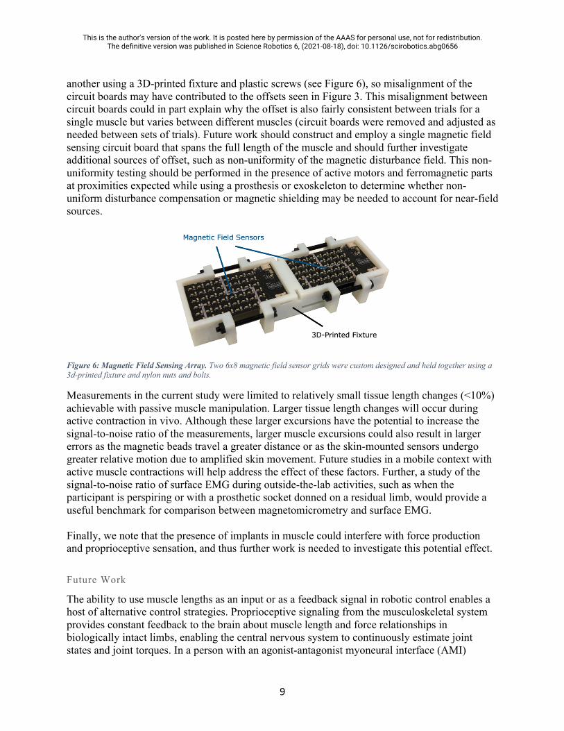
This is the author's version of the work. It is posted here by permission of the AAAS for personal use, not for redistribution. The definitive version was published in Science Robotics 6, (2021-08-18), doi: 10.1126/scirobotics.abg0656
9
another using a 3D-printed fixture and plastic screws (see Figure 6), so misalignment of the circuit boards may have contributed to the offsets seen in Figure 3. This misalignment between circuit boards could in part explain why the offset is also fairly consistent between trials for a single muscle but varies between different muscles (circuit boards were removed and adjusted as needed between sets of trials). Future work should construct and employ a single magnetic field sensing circuit board that spans the full length of the muscle and should further investigate additional sources of offset, such as non-uniformity of the magnetic disturbance field. This non-uniformity testing should be performed in the presence of active motors and ferromagnetic parts at proximities expected while using a prosthesis or exoskeleton to determine whether non-uniform disturbance compensation or magnetic shielding may be needed to account for near-field sources.
Figure 6: Magnetic Field Sensing Array. Two 6x8 magnetic field sensor grids were custom designed and held together using a 3d-printed fixture and nylon nuts and bolts.
Measurements in the current study were limited to relatively small tissue length changes (<10%) achievable with passive muscle manipulation. Larger tissue length changes will occur during active contraction in vivo. Although these larger excursions have the potential to increase the signal-to-noise ratio of the measurements, larger muscle excursions could also result in larger errors as the magnetic beads travel a greater distance or as the skin-mounted sensors undergo greater relative motion due to amplified skin movement. Future studies in a mobile context with active muscle contractions will help address the effect of these factors. Further, a study of the signal-to-noise ratio of surface EMG during outside-the-lab activities, such as when the participant is perspiring or with a prosthetic socket donned on a residual limb, would provide a useful benchmark for comparison between magnetomicrometry and surface EMG. Finally, we note that the presence of implants in muscle could interfere with force production and proprioceptive sensation, and thus further work is needed to investigate this potential effect.
Future Work
The ability to use muscle lengths as an input or as a feedback signal in robotic control enables a host of alternative control strategies. Proprioceptive signaling from the musculoskeletal system provides constant feedback to the brain about muscle length and force relationships in biologically intact limbs, enabling the central nervous system to continuously estimate joint states and joint torques. In a person with an agonist-antagonist myoneural interface (AMI)

This is the author's version of the work. It is posted here by permission of the AAAS for personal use, not for redistribution. The definitive version was published in Science Robotics 6, (2021-08-18), doi: 10.1126/scirobotics.abg0656
10
amputation, which physically connects agonist and antagonist muscle pairs to one another, muscle dynamic relationships in the residual limb are preserved, maintaining this natural proprioceptive feedback (22). This feedback could enable a person with an AMI amputation to intuitively control a robotic prosthesis via muscle state commands. The control diagram of Figure 1 illustrates a biologically-inspired strategy for delivering this control with a free-space paradigm using muscle lengths sensed via magnetomicrometry. To extend beyond free-space control, the intact biophysical model of this control strategy can be augmented by musculotendon force. For the purpose of measuring musculotendon force directly, future work should investigate the application of magnetomicrometry to tendon strain tracking (13, 14), including biocompatibility and attachment strategies. Alternatively, muscle activation can be paired with muscle length and velocity to determine musculotendon force via a biophysical muscle model (23, 24). This muscle activation signal is typically measured via EMG measurements from an electrode at or near the muscle, but the high precision of the results presented here suggests the possibility of direct mechanomyographic measurement via the implanted magnetic beads. Particularly, future work should include the development of an algorithm to sense lateral vibrations of magnetic beads implanted in muscle and the study of how these vibrations relate to activation during isotonic and isometric muscle contractions. Though research has been performed on the acoustic properties of lateral muscle vibrations (25, 26), the physical amplitude of these vibrations requires further investigation, perhaps requiring further improvement in measurement precision via increasing magnetic field sensor density. When this is achieved, it may be possible to simultaneously measure the length, velocity, and force of each muscle via a single pair of implanted magnetic beads, allowing for force, length, and velocity control with a minimum number of sensing elements. In addition to these possible applications, future work should also investigate the potential use of magnetic bead tracking in providing minimally invasive joint state tracking via multiple bone-implanted magnetic beads. Further, the attachment of magnetic beads to tendon may be worth investigating for the sensing of musculotendon force via shear wave elastography (27). Although biological proprioceptive feedback in the context of an AMI amputation could enable highly repeatable muscle state commands for open-loop control of a robotic device via magnetomicrometry (see Figure 1), errors in biophysical modeling and the application of external forces will inevitably lead to mismatch between desired and actual bionic joint states. To address this issue, the inclusion of sensory feedback of bionic joint states to the central nervous system would provide refined dexterity through fully closed-loop control (28, 29). Such a strategy could also be used to compensate for inaccuracies in control when a person equipped with magnetomicrometry has a traditional (non-AMI) amputation, where afferent information from muscle spindles fibers does not convey a natural proprioceptive mapping to the user. These biologically inspired control strategies are also applicable to the control of exoskeletal devices. For instance, the combination of magnetomicrometry and EMG could allow calculation of muscle forces, which could then be augmented as joint torques and impedances by the exoskeleton. Alternatively, magnetomicrometry alone may be able to be used for exoskeletal control. Because of biological tissue compliance and limb inertia, muscle fascicles begin

This is the author's version of the work. It is posted here by permission of the AAAS for personal use, not for redistribution. The definitive version was published in Science Robotics 6, (2021-08-18), doi: 10.1126/scirobotics.abg0656
11
displacing before the joint output, and thus the use of magnetomicrometry to track muscle length changes may be an important control signal for position control of a worn exoskeleton. Further, magnetomicrometry may even be used in future applications for the remote control of robotic devices, control of software for gaming or communication, or the direct control of alternative transportation devices. In the context of neural impairment, magnetomicrometry may be used to correct for inconsistencies between desired and actual muscle lengths, speeds, and forces. Magnetomicrometry can provide artificial proprioceptive signals as feedback to an artificial muscle stimulator to restore natural dynamics in patients with spinal cord injury, stroke, cerebral palsy, and Parkinson’s disease. In addition, these artificial proprioceptive signals may be used as a feedback signal for an exoskeleton to correct for tremors, muscle spasticity, or muscle weakness. Further, this strategy will enable the high-resolution sensing of muscle lengths, speeds, and forces in freely-roaming animals and humans, enabling further development of volitional and reflex models of biological movement. In this way, magnetomicrometry may be important in the further development of biomimetic control algorithms for generalized autonomous robotic control, extending upon the advantages historically seen when using biomimicry in design and control (30). Summary
In this manuscript we present magnetomicrometry, a strategy for measuring in vivo tissue lengths. We show, using a turkey animal model, the real-time wireless measurement of muscle length for oscillations from 0.7 to 7 Hz using pairs of magnetic beads, and demonstrate submillimeter accuracy with 37 µm precision. We further verify the long-term biocompatibility of magnetic beads implanted in muscle and show that multiple magnetic beads implanted in muscle with a sufficient separation distance are stable against migration. Materials and Methods All animal experiments were approved by the Institutional Animal Care and Use Committees at Brown University and the Massachusetts Institute of Technology. Domestic turkeys (adult female broad-breasted white, age 8 months at implantation) were obtained from local breeders and maintained in the Animal Care facility at Brown University on an ad libitum water and poultry feed diet. Four animals were used in this study. Implantation
For surgical implantation of the 3-mm diameter magnetic beads, turkeys were placed on anesthesia under 3-4% isofluorane. During surgical procedures, animals were intubated and actively ventilated, while monitoring oxygen saturation, heart rate, respiratory rate, and body temperature. Surgical sites were prepped by feather removal and a surgical scrub, and all surgeries were performed under sterile conditions. At each insertion site (the distal and proximal ends of the gastrocnemius and iliotibialis cranialis muscles), a 16 gauge needle and a thin pair of surgical scissors were consecutively used to make an insertion channel smaller than the diameter of the magnet. The magnet was then press-fit into the end of a sterile hollow plastic tube, dipped

This is the author's version of the work. It is posted here by permission of the AAAS for personal use, not for redistribution. The definitive version was published in Science Robotics 6, (2021-08-18), doi: 10.1126/scirobotics.abg0656
12
in sterile saline, and inserted into the channel using depth markings on the plastic tube for reference. A sterile wooden rod (longer than the plastic tube) was then guided fully into the bore of the plastic tube and used to gently, but firmly, hold the magnet in place while removing the plastic tube from the muscle. The wooden rod was then removed, and nonmagnetic forceps were used to suture the muscle closed at the insertion site using 6-0 nonabsorbable silk. Skin closure was performed with 4-0 Vicryl absorbable suture followed by Tegaderm (3M) transparent film dressing applied to the skin around the insertion site. Biocompatibility
For biocompatibility, all magnets (3-millimeter-diameter N35 neodymium-iron-boron spherical magnets, initially coated in nickel) were coated in Parylene C (BJA Magnetics, 6.9 µm +/- 0.2 µm). Each magnet’s strength was then measured and recorded, and the magnet was rinsed in 70% ethanol by volume (in distilled water) followed by three rinses with distilled de-ionized water. Each magnet was then sterilized using ethylene oxide, after which they were allowed 48 hours to degas before surgical implantation. After experiments were complete, postmortem tissue samples were taken via dissection of a ~1cm cube section of muscle surrounding each magnet. Samples were fixed in 4% formalin for 24 hours. They were then washed with phosphate-buffered saline for 15 minutes, stored in 75% ethanol, and paraffin-processed. 5 µm sections were obtained at 10 µm increments in both longitudinal and cross-sectional orientations of the tissue. At least 10 sections were analyzed per animal. Tissues were stained with H&E. Distances between magnets and fibrotic capsule thickness were assessed using ImageScope (Leica). Migration
During surgical implantation, magnet pairs were inserted, with the aid of a sterile ruler, at various separation distances between approximately 20 and 70 mm, exposing the various magnetic bead pairs to differing levels of force between the two magnetic beads. Immediately after surgical implantation and at time intervals (multiple weeks) after the implantation, computed tomography (CT) scans (Animage Fidex Veterinary CT Scanner) were used to monitor the distances between the beads. Turkeys were placed on anesthesia under 3-4% isofluorane, and for each leg, the turkey lay prone with the leg of interest flush with, centered on, and parallel to the scanning table, with the foot positioned as cranial and medial to the body as possible. The goal of this anatomical positioning was to replicate muscle length as much as possible from measurement to measurement so that any changes in magnetic bead separation measurements could be attributed to magnetic bead migration and not muscle length variability. Each leg was scanned separately to simplify positioning in the scanner and reduce the possibility of needing to repeat scans. In each CT scan, a reference object (an acrylic bar with magnets press-fit into two measured, pre-drilled holes) was included to ensure consistency in scale. A medical image viewer (Horos) was used to determine the three-dimensional positions of the magnetic beads in each muscle, and these positions were used to calculate the magnetic bead separation distances. Immediately following surgery and throughout the study, all turkeys were provided ample space to move about, and thus muscles experienced ordinary in vivo contraction patterns.

This is the author's version of the work. It is posted here by permission of the AAAS for personal use, not for redistribution. The definitive version was published in Science Robotics 6, (2021-08-18), doi: 10.1126/scirobotics.abg0656
13
Magnetomicrometry
Custom-designed arrays of magnetometers were positioned over the implant sites to track magnet position. Two custom sensing boards, each with 48 LIS3MDL magnetic field sensors (STMicroelectronics) in a 6x8 grid spaced at 4.83 mm, were held together by a 3d-printed fixture (Connex 500, Stratasys) at 60 mm apart from circuit board center to circuit board center, forming a single, 96-magnetic-field-sensor array. Nylon nuts and bolts (McMaster-Carr) were used to secure the circuit boards to the fixture. A custom adapter board was used to connect a Teensy 3.6 microcontroller (PJRC) to the sensing boards using flexible flat cables (Molex), and on-board 4-to-16 line decoders (74HC154BQ, Nexperia) were used to individually enable magnetic field sensors for SPI communication (10 MHz clock). The magnetic field at each of the sensors was measured with a sampling rate of 300 Hz. A full-scale range of 1.6 mT was selected for each of the sensor axes, which allowed each magnet to come within a minimum distance of approximately 11.25 mm of any individual sensor. To minimize onboard magnetic field distortion, all capacitors used (Vishay) were MRI-safe. As in previous work (16), the tracking algorithm was run in real-time on a Macbook Air (13-inch, Early 2014) with 8 GB of RAM and an Intel i7 CPU running at 1.7 GHz. To validate accuracy, magnetomicrometry measurements were compared against simultaneous fluoromicrometry measurements, the current state-of-the-art for relative tissue position measurement. At 12 weeks post-implantation, for each of the legs of each of the four turkeys, the 96-magnetic-field-sensor array was strapped to the outside of the turkey’s leg over the magnetic bead pair in the gastrocnemius muscle. With the turkey anesthetized, an electric motor (Aurora Scientific 310B-LR) was used to apply a mechanical frequency sweep to the turkey’s ankle (10-second exponential chirp from 0.7 to 7 Hz), with a spring (surgical tubing) providing an opposing force. The maximum frequency of 7 Hz was chosen to exceed the maximum bandwidth of 6 Hz expected from muscle) (31). Throughout this frequency sweep of the ankle (and thus, of the passively-cycled gastrocnemius muscle), the magnetic field sensor array was used as described in previous work (16) to track the length of the gastrocnemius muscle using the distance between the magnetic beads in real time. For comparison, the distance between the magnetic beads, which are radio-opaque, was also simultaneously monitored via fluoromicrometry (two intersecting X-ray video streams, with the two X-ray sources positioned above the turkey and the two image intensifiers positioned below – see Supplementary Figure 8). All fluoromicrometry data was post-processed in XMALab (32), whenever possible automating the processing using 25% “threshold offset in percent,” manually performing tracking when reprojection error exceeded one pixel, and without performing any temporal filtering to smooth the data. Time syncing was used to perform initial alignment of the magnetomicrometry and fluoromicrometry curves, but due to inconsistency in the time sync signal from the X-ray system, optimization was used to fine-tune the temporal alignment of the data. All data were kept unfiltered. To confirm the compatibility between magnetomicrometry and fluoromicrometry, two magnets were placed into a 1x10 LEGO plate at various known distances apart from one another while collecting data from each sensing strategy (see Supplementary Figures 6, 9, and 10 and Supplementary Note 2). To evaluate the accuracy of the magnetomicrometry in sensing magnets
This is the author's version of the work. It is posted here by permission of the AAAS for personal use, not for redistribution. The definitive version was published in Science Robotics 6, (2021-08-18), doi: 10.1126/scirobotics.abg0656
14
implanted at various depths, the position of the magnetic field sensor array was adjusted to various sensing heights during these static data collections. To verify that the tracking latency remained low during magnetomicrometry data collection, the time delay was recorded between receipt of raw magnetic field data by the computer and the completion of the tracking algorithm (see Supplementary Figure 1). Data Analysis
The offset for each trial was calculated by taking the mean of the difference between magnetomicrometry and fluoromicrometry, and the precision was calculated by calculating the standard deviation of the difference between magnetomicrometry and fluoromicrometry. The mean absolute offset was calculated by taking the mean of the absolute values of all of the trial offsets. Using the root-mean-square of the fluoromicrometry static precision, we adjusted the precision of our dynamic magnetomicrometry trials by subtracting variances to calculate an adjusted precision. References and Notes 1. T. A. Kung, R. A. Bueno, G. K. Alkhalefah, N. B. Langhals, M. G. Urbanchek, P. S.
Cederna, Innovations in prosthetic interfaces for the upper extremity. Plastic and reconstructive surgery. 132, 1515–1523 (2013).
2. A. Young, T. Kuiken, L. Hargrove, Analysis of using EMG and mechanical sensors to enhance intent recognition in powered lower limb prostheses. Journal of neural engineering. 11, 056021 (2014).
3. T. Pradhan, H. S. Jung, J. H. Jang, T. W. Kim, C. Kang, J. S. Kim, Chemical sensing of neurotransmitters. Chemical Society Reviews. 43, 4684–4713 (2014).
4. T. R. Farrell, R. F. Weir, The optimal controller delay for myoelectric prostheses. IEEE Transactions on neural systems and rehabilitation engineering. 15, 111–118 (2007).
5. N. J. Cronin, C. P. Carty, R. S. Barrett, G. Lichtwark, Automatic tracking of medial gastrocnemius fascicle length during human locomotion. Journal of applied physiology. 111, 1491–1496 (2011).
6. R. F. Weir, P. R. Troyk, G. A. DeMichele, D. A. Kerns, J. F. Schorsch, H. Maas, Implantable myoelectric sensors (IMESs) for intramuscular electromyogram recording. IEEE Transactions on Biomedical Engineering. 56, 159–171 (2008).
7. M. A. Islam, K. Sundaraj, R. B. Ahmad, S. Sundaraj, N. U. Ahamed, M. A. Ali, Cross-talk in mechanomyographic signals from the forearm muscles during sub-maximal to maximal isometric grip force. PLoS one. 9, e96628 (2014).

This is the author's version of the work. It is posted here by permission of the AAAS for personal use, not for redistribution. The definitive version was published in Science Robotics 6, (2021-08-18), doi: 10.1126/scirobotics.abg0656
15
8. A. L. Camp, H. C. Astley, A. M. Horner, T. J. Roberts, E. L. Brainerd, Fluoromicrometry: a method for measuring muscle length dynamics with biplanar videofluoroscopy. Journal of Experimental Zoology Part A: Ecological Genetics and Physiology. 325, 399–408 (2016).
9. D. Farina, I. Vujaklija, M. Sartori, T. Kapelner, F. Negro, N. Jiang, K. Bergmeister, A. Andalib, J. Principe, O. C. Aszmann, Man/machine interface based on the discharge timings of spinal motor neurons after targeted muscle reinnervation. Nature biomedical engineering. 1, 1–12 (2017).
10. P. Cattarello, R. Merletti, in 2016 IEEE International Symposium on Medical Measurements and Applications (MeMeA) (IEEE, 2016), pp. 1–6.
11. J. H. Hong, M. S. Mun, Relationship between socket pressure and EMG of two muscles in trans-femoral stumps during gait. Prosthetics and orthotics international. 29, 59–72 (2005).
12. M. Ortiz-Catalan, B. Håkansson, R. Brånemark, An osseointegrated human-machine gateway for long-term sensory feedback and motor control of artificial limbs. Science translational medicine. 6, 257re6-257re6 (2014).
13. T. J. Roberts, R. L. Marsh, P. G. Weyand, C. R. Taylor, Muscular force in running turkeys: the economy of minimizing work. Science. 275, 1113–1115 (1997).
14. F. E. Zajac, Muscle and tendon: properties, models, scaling, and application to biomechanics and motor control. Critical reviews in biomedical engineering. 17, 359–411 (1989).
15. W. Weitschies, O. Kosch, H. Mönnikes, L. Trahms, Magnetic marker monitoring: an application of biomagnetic measurement instrumentation and principles for the determination of the gastrointestinal behavior of magnetically marked solid dosage forms. Advanced drug delivery reviews. 57, 1210–1222 (2005).
16. C. R. Taylor, H. G. Abramson, H. M. Herr, Low-Latency Tracking of Multiple Permanent Magnets. IEEE Sensors Journal. 19, 11458–11468 (2019).
17. N. Bhadra, P. H. Peckham, M. W. Keith, K. L. Kilgore, F. Montague, M. Gazdik, T. Stage, Implementation of an implantable joint-angle transducer. Journal of rehabilitation research and development. 39, 411–422 (2002).
18. S. Tarantino, F. Clemente, D. Barone, M. Controzzi, C. Cipriani, The myokinetic control interface: tracking implanted magnets as a means for prosthetic control. Scientific reports. 7, 1–11 (2017).
19. S. Milici, M. Gherardini, F. Clemente, F. Masiero, P. Sassu, C. Cipriani, The Myokinetic Control Interface: How Many Magnets Can be Implanted in an Amputated Forearm? Evidence From a Simulated Environment. IEEE Transactions on Neural Systems and Rehabilitation Engineering. 28, 2451–2458 (2020).
This is the author's version of the work. It is posted here by permission of the AAAS for personal use, not for redistribution. The definitive version was published in Science Robotics 6, (2021-08-18), doi: 10.1126/scirobotics.abg0656
16
20. C. Hu, M. Q.-H. Meng, M. Mandal, Efficient magnetic localization and orientation technique for capsule endoscopy. International Journal of Information Acquisition. 2, 23–36 (2005).
21. R. Griffiths, Ultrasound transit time gives direct measurement of muscle fibre length in vivo. Journal of neuroscience methods. 21, 159–165 (1987).
22. S. Srinivasan, M. Carty, P. Calvaresi, T. Clites, B. Maimon, C. Taylor, A. Zorzos, H. Herr, On prosthetic control: A regenerative agonist-antagonist myoneural interface. Science Robotics. 2 (2017).
23. T. S. Buchanan, D. G. Lloyd, K. Manal, T. F. Besier, Neuromusculoskeletal modeling: estimation of muscle forces and joint moments and movements from measurements of neural command. Journal of applied biomechanics. 20, 367–395 (2004).
24. T. A. McMahon, Muscles, reflexes, and locomotion (Princeton University Press, 1984).
25. J. V. Frangioni, T. S. Kwan-Gett, L. E. Dobrunz, T. A. McMahon, The mechanism of low-frequency sound production in muscle. Biophysical journal. 51, 775–783 (1987).
26. J. W. Coburn, T. Housh, J. Cramer, J. Weir, J. Miller, T. Beck, M. Malek, G. Johnson, Mechanomyographic time and frequency domain responses of the vastus medialis muscle during submaximal to maximal isometric and isokinetic muscle actions. Electromyography and clinical neurophysiology. 44, 247–255 (2004).
27. J. A. Martin, S. C. Brandon, E. M. Keuler, J. R. Hermus, A. C. Ehlers, D. J. Segalman, M. S. Allen, D. G. Thelen, Gauging force by tapping tendons. Nature communications. 9, 1–9 (2018).
28. S. Raspopovic, M. Capogrosso, F. M. Petrini, M. Bonizzato, J. Rigosa, G. Di Pino, J. Carpaneto, M. Controzzi, T. Boretius, E. Fernandez, others, Restoring natural sensory feedback in real-time bidirectional hand prostheses. Science translational medicine. 6, 222ra19-222ra19 (2014).
29. K. Li, Y. Fang, Y. Zhou, H. Liu, Non-invasive stimulation-based tactile sensation for upper-extremity prosthesis: a review. IEEE Sensors Journal. 17, 2625–2635 (2017).
30. S. Collins, A. Ruina, R. Tedrake, M. Wisse, Efficient bipedal robots based on passive-dynamic walkers. Science. 307, 1082–1085 (2005).
31. M. Carney, H. M. Herr, Energetic Consequences of Series and Parallel Springs in Lower-Extremity Powered Prostheses (2019).
32. B. J. Knörlein, D. B. Baier, S. M. Gatesy, J. Laurence-Chasen, E. L. Brainerd, Validation of XMALab software for marker-based XROMM. Journal of Experimental Biology. 219, 3701–3711 (2016).

This is the author's version of the work. It is posted here by permission of the AAAS for personal use, not for redistribution. The definitive version was published in Science Robotics 6, (2021-08-18), doi: 10.1126/scirobotics.abg0656
17
Acknowledgements: We thank E. Tavares for her invaluable support with logistics, A. Rutter, J. Petersen, and R. Marsh for their assistance in setting up and operating equipment for the experiments, and B. Brainerd and J. Capano for their generous support on the processing of X-ray data. We also thank B. Mayton and J. Paradiso for helpful advice on hardware and software setup and providing access to critical electronics equipment. We acknowledge H. Specht, L. Duso, and M. Gray for their expert advice on biocompatible coatings. We also acknowledge the contribution of T. Clites in early conversations on the development of the magnetomicrometry concept. All original figure artwork was created by M. Brumett. Funding: This work was funded by the Salah Foundation and the MIT Media Lab Consortia to H.M.H., and by NIH Grant AR055295 and NSF Grant 1832795 to T.J.R.. Author contributions: C.R.T. performed development of the magnetomicrometry strategy, experimental conception and design, surgeries, data collection, analysis, documentation, and writing of the manuscript. S.S.S. contributed to experimental design, assisted in development of the surgical procedure, oversaw the performance of histology, and provided substantial support in drafting and revising the manuscript. S.Y. designed, validated, and oversaw fabrication of the magnetic field sensing embedded system and assisted extensively in the setup of the real-time measurement framework. M.O. performed computed tomography scans, supported development of the final surgical procedure, and contributed to development of and carrying out the experiments. T.J.R. contributed to experimental design, aided in experiment setup and performing experiments, and developed the final surgical procedure. H.M.H. conceived the magnetomicrometry strategy and contributed to the experimental design and writing of the manuscript. Competing interests: C.R.T, S.Y., and H.M.H have filed patents on the magnetomicrometry concept entitled “Method for Neuromechanical And Neuroelectromagnetic Mitigation Of Limb Pathology” (Patent WO2019074950A1) and on implementation strategies for magnetomicrometry entitled “Magnetomicrometric Advances in Robotic Control” (U.S. Pending Patent 63/104942). Data and materials availability: All data for the conclusions in the paper are present in the paper and the Supplementary Materials. Raw magnetomicrometry and fluoromicrometry data and scripts used to generate all of the plots and summary values associated with this data can be accessed at https://www.dropbox.com/sh/a0f6pmm2kquq379/AADknbtwe66AwPLTDeDom_Qza?dl=0.

This is the author's version of the work. It is posted here by permission of the AAAS for personal use, not for redistribution. The definitive version was published in Science Robotics 6, (2021-08-18), doi: 10.1126/scirobotics.abg0656
18
Supplementary Materials Supplementary Note 1
For magnetic beads of a different coating or diameter, the empirical investigation of the magnetic bead should be repeated, noting that changing these parameters modifies friction between the muscle and the implant, as well as the tissue response of the muscle to the implant. As a caution, because the force between magnetic beads is proportional to the inverse fourth power of their separation distance, the beads experience a steep increase in force as the magnetic bead separation distance is reduced, and thus the minimum separation distance threshold should be conservatively chosen and strictly followed, and implantation should only occur according to this threshold while the muscle is at rest. To investigate how magnetic bead separation distance thresholds should be adjusted when using magnetic beads of higher magnetic dipole strength, we first let d be the distance between two spherical magnetic beads with magnetic moments 𝑚! and 𝑚". Assuming the magnetic beads are aligned in orientation (the highest force scenario), the force between the two magnetic beads is given by
F =3µ#2π
𝑚!𝑚"
𝑑$ ,
where µ# is the permeability of free space. An implantation separation distance threshold 𝑑# is empirically determined, above which a magnetic bead pair with the magnetic moment product 𝑚!𝑚" is expected to not migrate. Assuming that the muscle maximally contracts by a factor of c throughout the study duration, the maximum force experienced between the magnetic beads during this empirical determination is given by
F%&' =3µ#2π
𝑚!𝑚"
(𝑐𝑑#)$.
Given two new magnetic beads of the same geometry and coating with new magnetic moments 𝑚!( = a𝑚! and 𝑚"
( = b𝑚", we wish to establish a new separation distance threshold 𝑑#( for these new magnetic beads, assuming that the new magnetic bead pair will undergo an equivalent maximum contraction factor, and assuming that bead migration can be fully described by having exceeded the maximum force. The relationship between the maximum force and this new separation distance threshold is given by
𝐹)*+ =3µ#2π
𝑎𝑚!𝑏𝑚"
(𝑐𝑑#( )$.
Equating these two expressions for 𝐹)*+ gives an updated separation distance threshold
d#( = 5√𝑎𝑏! 7𝑑#.

This is the author's version of the work. It is posted here by permission of the AAAS for personal use, not for redistribution. The definitive version was published in Science Robotics 6, (2021-08-18), doi: 10.1126/scirobotics.abg0656
19
Thus, assuming that the force between magnetic beads is what drives migration, for beads of identical geometry and coating but new magnetic moments, safe implant separation distances for the new magnetic beads can be adopted from previous empirical determination of the safe magnetic bead separation distance by scaling the threshold distance by the fourth root of the product of the magnetic moment scale factors. Supplementary Note 2
To investigate whether fluoromicrometry was causing an offset in the magnetomicrometry signal, magnetomicrometry data were collected in a static tracking condition starting before and finishing after fluoromicrometry data collection. These static measurements were performed with the sensing array at various heights above the magnets and with the magnets at various separation distances. The results demonstrated that the mean of the magnetomicrometry signal deviated at minimum 0.03x and at maximum 1.35x the standard deviation of the noise from before to after the X-ray was turned on and from before the X-ray was turned on to after it was turned off (see Supplementary Figure 10). Thus, it is possible that a portion of the error in the magnetomicrometry signal may have been caused by interference from the X-ray machine (e.g., via heating of the magnetomicrometry sensing board), but further investigation in a future study would be required to verify causality with significance. A deviation at the beginning of these fluoromicrometry measurements can also be observed, likely due to the warm-up of the X-ray machine. For simplicity, the data during this warm-up period was not discarded during the calculation of offsets and precision. Supplementary Figures
Supplementary Figure 1: Time Delay in Tracking Two Magnets with Disturbance Compensation for Magnetomicrometry. The time delay was measured as the time between receipt of the raw data by the computer and completion of the multi-magnet tracking algorithm with magnetic disturbance compensation. This histogram shows the distribution of time delays across all 22 mechanical frequency sweep magnetomicrometry trials. The 99th-percentile time delay was 2.52 ms.
This is the author's version of the work. It is posted here by permission of the AAAS for personal use, not for redistribution. The definitive version was published in Science Robotics 6, (2021-08-18), doi: 10.1126/scirobotics.abg0656
20
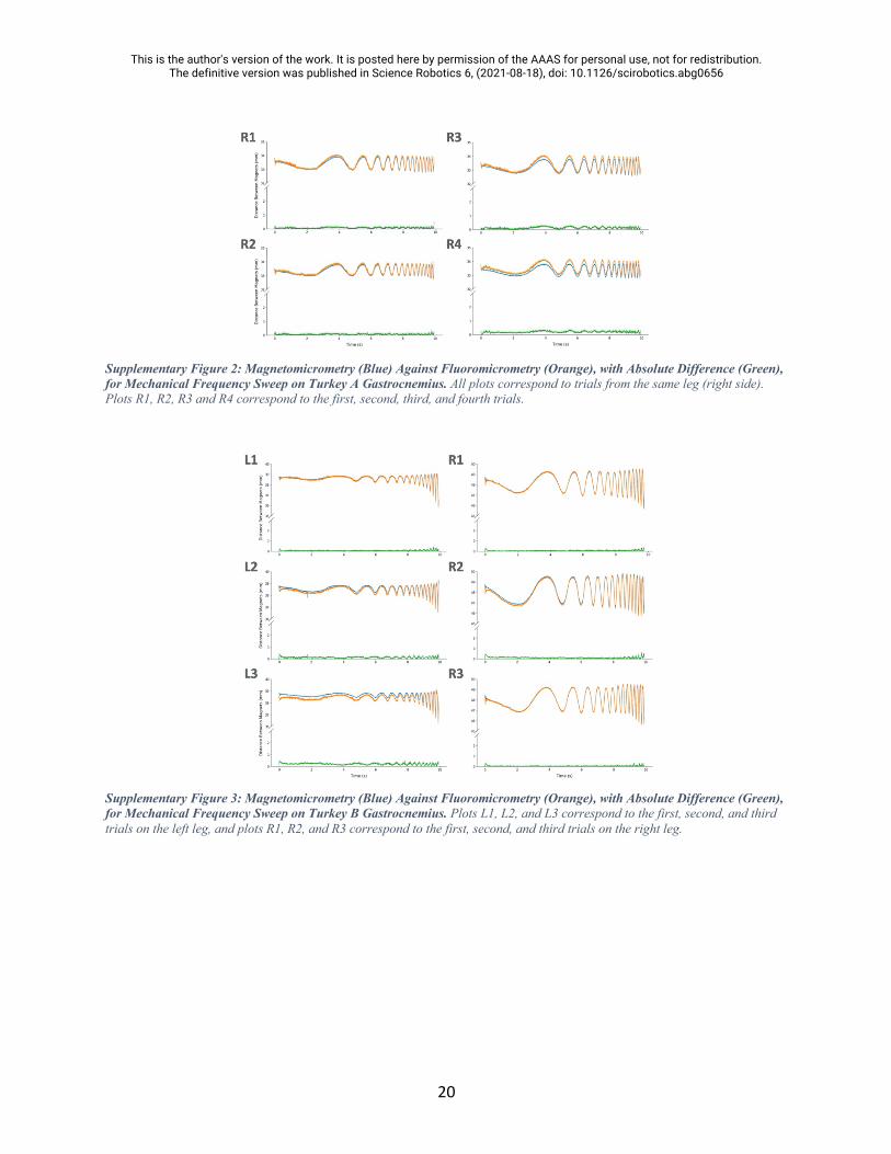
Supplementary Figure 2: Magnetomicrometry (Blue) Against Fluoromicrometry (Orange), with Absolute Difference (Green), for Mechanical Frequency Sweep on Turkey A Gastrocnemius. All plots correspond to trials from the same leg (right side). Plots R1, R2, R3 and R4 correspond to the first, second, third, and fourth trials.
Supplementary Figure 3: Magnetomicrometry (Blue) Against Fluoromicrometry (Orange), with Absolute Difference (Green), for Mechanical Frequency Sweep on Turkey B Gastrocnemius. Plots L1, L2, and L3 correspond to the first, second, and third trials on the left leg, and plots R1, R2, and R3 correspond to the first, second, and third trials on the right leg.

This is the author's version of the work. It is posted here by permission of the AAAS for personal use, not for redistribution. The definitive version was published in Science Robotics 6, (2021-08-18), doi: 10.1126/scirobotics.abg0656
21
Supplementary Figure 4: Magnetomicrometry (Blue) Against Fluoromicrometry (Orange), with Absolute Difference (Green), for Mechanical Frequency Sweep on Turkey C Gastrocnemius. Plots L1, L2, and L3 correspond to the first, second, and third trials on the left leg, and plots R1, R2, and R3 correspond to the first, second, and third trials on the right leg.
Supplementary Figure 5: Magnetomicrometry (Blue) Against Fluoromicrometry (Orange), with Absolute Difference (Green), for Mechanical Frequency Sweep on Turkey D Gastrocnemius. Plots L1, L2, and L3 correspond to the first, second, and third trials on the left leg, and plots R1, R2, and R3 correspond to the first, second, and third trials on the right leg.

This is the author's version of the work. It is posted here by permission of the AAAS for personal use, not for redistribution. The definitive version was published in Science Robotics 6, (2021-08-18), doi: 10.1126/scirobotics.abg0656
22
Supplementary Figure 6: Static Magnetomicrometry Versus Fluoromicrometry (Probability Distributions). Magnetomicrometry (blue) and fluoromicrometry (orange) measurements were taken while magnets were placed at separation distances of approximately 24, 40, 56, and 72 mm in a LEGO block (vertical dashed gray lines in each column), with the sensing array at various heights above the magnets (sensor proximity corresponding to each row shown in the table at right, in millimeters). Magnetomicrometry (MM) and fluoromicrometry (FM) standard deviations and the offset between MM and FM shown in the table at right (units in micrometers), along with the mean absolute offset and FM SD root-mean-square for all data and the MM SD RMS for each sensor proximity. Note that the FM SD RMS (58 µm) was used in calculating the adjusted precision in Figure 3.
Supplementary Figure 7: Histology Section from Turkey A Showing Diffuse Inflammatory Reaction. Turkey A likely had a diffuse inflammatory reaction which could have been caused by particles from the implant. The scale bar indicates a distance of 1 mm. One histological cross section from Turkey D presented similarly.
This is the author's version of the work. It is posted here by permission of the AAAS for personal use, not for redistribution. The definitive version was published in Science Robotics 6, (2021-08-18), doi: 10.1126/scirobotics.abg0656
23
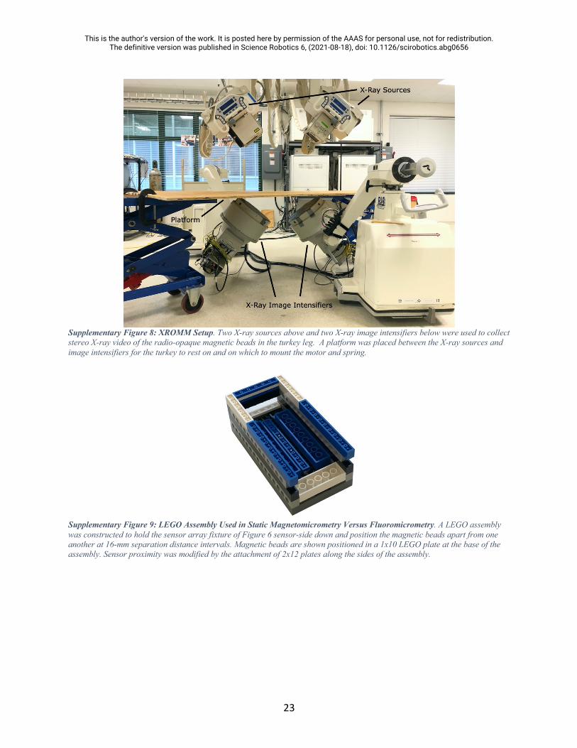
Supplementary Figure 8: XROMM Setup. Two X-ray sources above and two X-ray image intensifiers below were used to collect stereo X-ray video of the radio-opaque magnetic beads in the turkey leg. A platform was placed between the X-ray sources and image intensifiers for the turkey to rest on and on which to mount the motor and spring.
Supplementary Figure 9: LEGO Assembly Used in Static Magnetomicrometry Versus Fluoromicrometry. A LEGO assembly was constructed to hold the sensor array fixture of Figure 6 sensor-side down and position the magnetic beads apart from one another at 16-mm separation distance intervals. Magnetic beads are shown positioned in a 1x10 LEGO plate at the base of the assembly. Sensor proximity was modified by the attachment of 2x12 plates along the sides of the assembly.

This is the author's version of the work. It is posted here by permission of the AAAS for personal use, not for redistribution. The definitive version was published in Science Robotics 6, (2021-08-18), doi: 10.1126/scirobotics.abg0656
24
Supplementary Figure 10: Static Magnetomicrometry Versus Fluoromicrometry (Time-Series). Magnetomicrometry (blue) and fluoromicrometry (orange) measurements were taken while magnets were placed at separation distances of approximately 24, 40, 56, and 72 mm in a LEGO block (horizontal dashed gray lines in each row), with the sensing array at various heights above the magnets. In contrast with Supplementary Figure 6, the vertical axis shows the separation distances, and the different columns correspond to the different sensor proximities (annotated above plots). Magnetomicrometry data is plotted for one second before and one second after the start and end of the fluoromicrometry measurements, respectively. It can be observed from these plots that some of the fluoromicrometry measurements exhibit a warm-up time lasting a small fraction of a second.
Supplementary Video 1: Muscle Frequency Sweep. A mechanical frequency sweep from 0.7 to 7 Hz is applied to the ankle in an anesthetized turkey, and a magnetic field sensor array is used to wirelessly track the length of the muscle in real time via two implanted magnetic beads. The movement of the turkey ankle is shown, with the real-time plot of muscle length overlaid. This supplementary video can be accessed at https://www.dropbox.com/s/hkyf7dhevl9rpff/muscle_frequency_sweep.mov?dl=0.