user manual - samsung display solutions
TRANSCRIPT
User Manual
The color and the appearance may differ depending on the product, and the specifications are subject to change without prior notice to improve the performance.
SH37F
Table of contents
Before Using the Product
Copyright 6
Safety Precautions 7Symbols 7Cleaning 7Storage 8Electricity and Safety 8Installation 9Operation 11
Preparations
Checking the Components 14Components 14
Parts 15Control Panel 15Reverse Side 16Anti-theft Lock 17Remote Control 18Connection Using an IR Stereo Cable (sold separately) 20
Before Installing the Product (Installation Guide) 21Tilting Angle and Rotation 21Ventilation 21
Using the COVER-JACK 23
Installing the Wall Mount 24Installing the Wall Mount 24
Wall Mount Kit Specifications (VESA) 24
Remote Control (RS232C) 25Cable Connection 25Connection 28Control Codes 29
Connecting and Using a Source Device
Before Connecting 38Pre-connection Checkpoints 38
Connecting to a PC 38Connection using the DVI-RGB cable 38Connection using a DVI cable (Digital type) 39Connection Using an HDMI-DVI Cable 39Connection Using an HDMI Cable 40Connection Using an DP Cable 40
Connecting an External Monitor 41
Connecting to a Video Device 42Connection Using an HDMI-DVI Cable 42Connection Using an HDMI Cable 43
Connecting to an Audio System 43
Connecting the LAN Cable 44
Changing the Input source 45Source 45
Using MDC
MDC Program Installation/Uninstallation 46Installation 46Uninstallation 46
Connecting to MDC 47Using MDC via RS-232C (serial data communications standards) 47Using MDC via Ethernet 48
Home feature
Player 50Approving a connected device from the server 51Network Channel 55Local Channel 55Published Content 55Network File 55My Templates 55Available features in the Player page 56Player page Settings menu 57When Content is Running 59File Formats Compatible with Player 61File Formats Compatible with Videowall 66
Schedule 68Available features in the Schedule page 68
Clone Product 70
ID Settings 71
2
Table of contents
Device ID 71PC Connection Cable 71Device ID Auto Set 71
Video Wall 72Apply to 72Video Wall 73
Network Status 74
Picture Mode 75
On/Off Timer 76On Timer 76Off Timer 77Holiday Management 77
Ticker 78
More settings 78
URL Launcher 79
Screen Adjustment
Picture Mode 80
Backlight / Contrast / Brightness / Sharpness / Color / Tint (G/R) 81
Color Temperature 82
White Balance 832 Point 8310 Point 83
Gamma 84
Calibrated Value 84
Advanced Settings 85Dynamic Contrast 86Black Tone 86Flesh Tone 86RGB Only Mode 86Color Space 86Motion Lighting 86
Picture Options 87Color Tone 88Digital Clean View 88MPEG Noise Filter 88HDMI Black Level 89Film Mode 89Dynamic Backlight 89
Picture Size 90Picture Size 90Position 91Zoom/Position 91Resolution 92
Auto Adjustment 93
PC Screen Adjustment 93
Picture Off 94
Reset Picture 94
OnScreen Display
Display Orientation 95Source Content Orientation 95Aspect Ratio 95
Screen Protection 96Auto Protection Time 96Screen Burn Protection 96
Message Display 99Schedule Channel Info 99Source Info 99No Signal Message 99MDC Message 99Download Status Message 99
Menu Language 100
Reset OnScreen Display 100
Sound Adjustment
HDMI Sound 101
Speaker Settings 102Sound Output 102
3
Table of contents
Network
Network Status 103
Network Settings 103Network type 103Network Settings (Wired) 104
Multimedia Device Settings 106
Server Network Settings 106Connect to Server 106MagicInfo Mode 106Server Access 106FTP Mode 106
Device Name 106
System
Accessibility 107Voice Guide 107Menu Transparency 108High Contrast 108Enlarge 108
Setup 109Initial settings (System) 109
Time 110Clock Set 110DST 110Sleep Timer 110Power On Delay 110
Auto Source Switching 111Auto Source Switching 111Primary Source Recovery 111Primary Source 111Secondary Source 111
Power Control 112Auto Power On 112PC Module Power 112Max. Power Saving 112Standby Control 113Power Button 113Network Standby 113
Eco Solution 114Energy Saving 114Eco Sensor 114Screen Lamp Schedule 115No Signal Power Off 115Auto Power Off 115
Temperature Control 116
Device Manager 117Keyboard Settings 117Mouse Settings 118Pointer Settings 119
Play via 120
Change PIN 120
Security 121Safety Lock 121USB Auto Play Lock 121Mobile Connection Lock 121
General 122Smart Security 122BD Wise 123Anynet+ (HDMI-CEC) 124Troubleshooting for Anynet+ 126HDMI Hot Plug 128DivX® Video On Demand 128Game Mode 128
Reset System 129
Support
Software Update 130Update now 130Auto Update 130
Contact Samsung 130
Go to Home 130
Reset All 130
Playing photos, videos and music (Media Play)
Read the following before using media play with a USB device 131Using a USB device 133Playing media content from a PC/mobile device 134
4
Table of contents
Features provided in the media content list page 135Menu items in the media content list page 136
Available buttons and features during photo playback 137
Available buttons and features during video playback 138
Available buttons and features during music playback 139
Supported Subtitle and Media play file formats 140Subtitle 140Supported image resolutions 140Supported music file formats 141Supported Video Formats 141
Troubleshooting Guide
Requirements Before Contacting Samsung Customer Service Center 143Testing the Product 143Checking the Resolution and Frequency 143Check the followings. 144
Q & A 151
Specifications
General 152
Preset Timing Modes 154
Appendix
Responsibility for the Pay Service (Cost to Customers) 156Not a product defect 156A Product damage caused by customer's fault 156Others 156
Optimum Picture Quality and Afterimage Burn-in Prevention 157Optimum Picture Quality 157Prevention of Afterimage Burn-in 157
License 159
Terminology 160
5
6
Before Using the Product
CopyrightThe contents of this manual are subject to change without notice to improve quality.
© 2016 Samsung Electronics
Samsung Electronics owns the copyright for this manual.
Use or reproduction of this manual in parts or entirety without the authorization of Samsung Electronics is prohibited.
Microsoft, Windows are registered trademarks of Microsoft Corporation.
VESA, DPM and DDC are registered trademarks of the Video Electronics Standards Association.
Ownership of all other trademarks is attributed to their due owner.
Chapter 01
7
Safety Precautions
CautionRISK OF ELECTRIC SHOCK DO NOT OPEN
Caution : TO REDUCE THE RISK OF ELECTRIC SHOCK, DO NOT REMOVE COVER. (OR BACK)
THERE ARE NO USER SERVICEABLE PARTS INSIDE.
REFER ALL SERVICING TO QUALIFIED PERSONNEL.
This symbol indicates that high voltage is present inside.
It is dangerous to make any kind of contact with any internal part of this product.
This symbol alerts you that important literature concerning operation and maintenance has been included with this product.
Symbols
WarningA serious or fatal injury may result if instructions are not followed.
CautionPersonal injury or damage to properties may result if instructions are not followed.
Activities marked by this symbol are prohibited.
Instructions marked by this symbol must be followed.
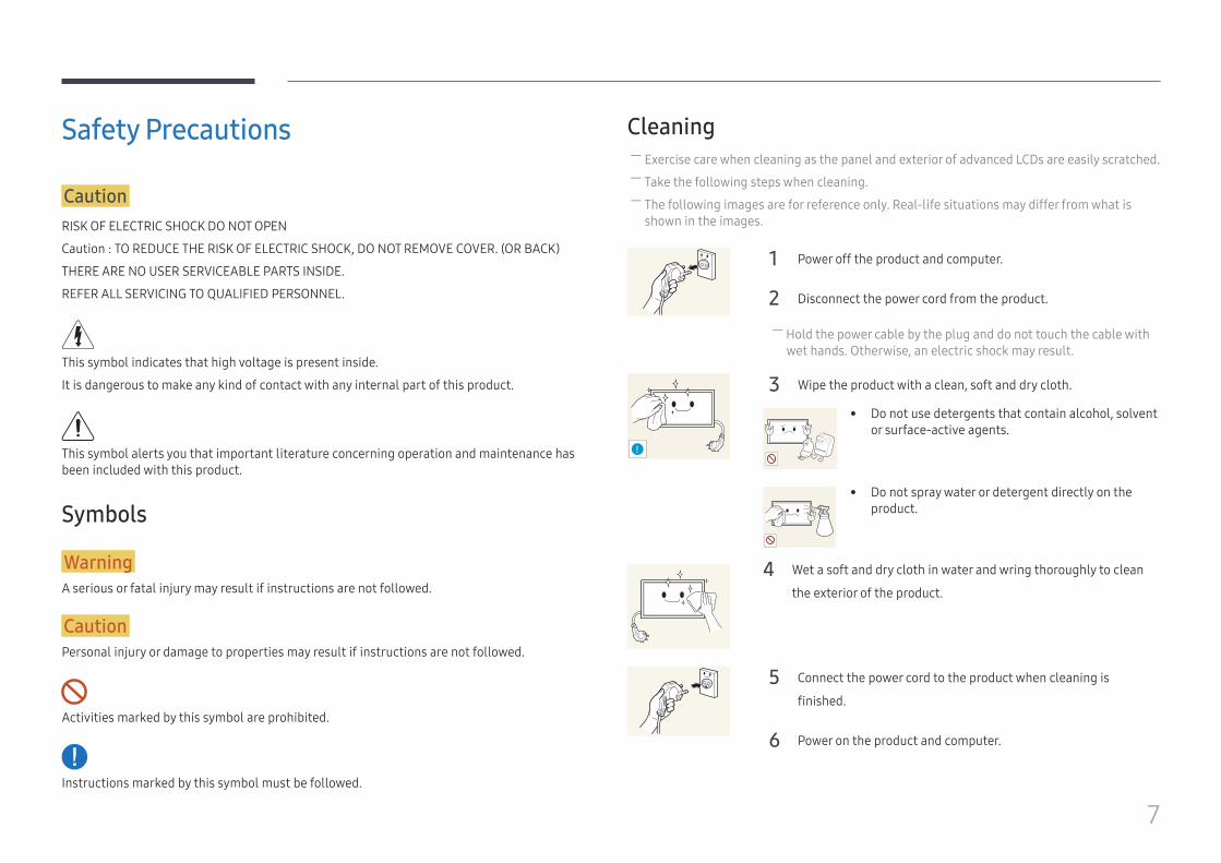
Cleaning ― Exercise care when cleaning as the panel and exterior of advanced LCDs are easily scratched. ― Take the following steps when cleaning. ― The following images are for reference only. Real-life situations may differ from what is shown in the images.
1 Power off the product and computer.
2 Disconnect the power cord from the product.
― Hold the power cable by the plug and do not touch the cable with wet hands. Otherwise, an electric shock may result.
!
3 Wipe the product with a clean, soft and dry cloth.
• Do not use detergents that contain alcohol, solvent or surface-active agents.
• Do not spray water or detergent directly on the product.
4 Wet a soft and dry cloth in water and wring thoroughly to clean
the exterior of the product.
5 Connect the power cord to the product when cleaning is
finished.
6 Power on the product and computer.
8
StorageDue to the characteristics of high-glossy products, using a UV humidifier nearby may create white-colored stains on the product.
― Contact Customer Service Center if the inside of the product needs cleaning (service fee will be charged).
Electricity and Safety ― The following images are for reference only. Real-life situations may differ from what is shown in the images.
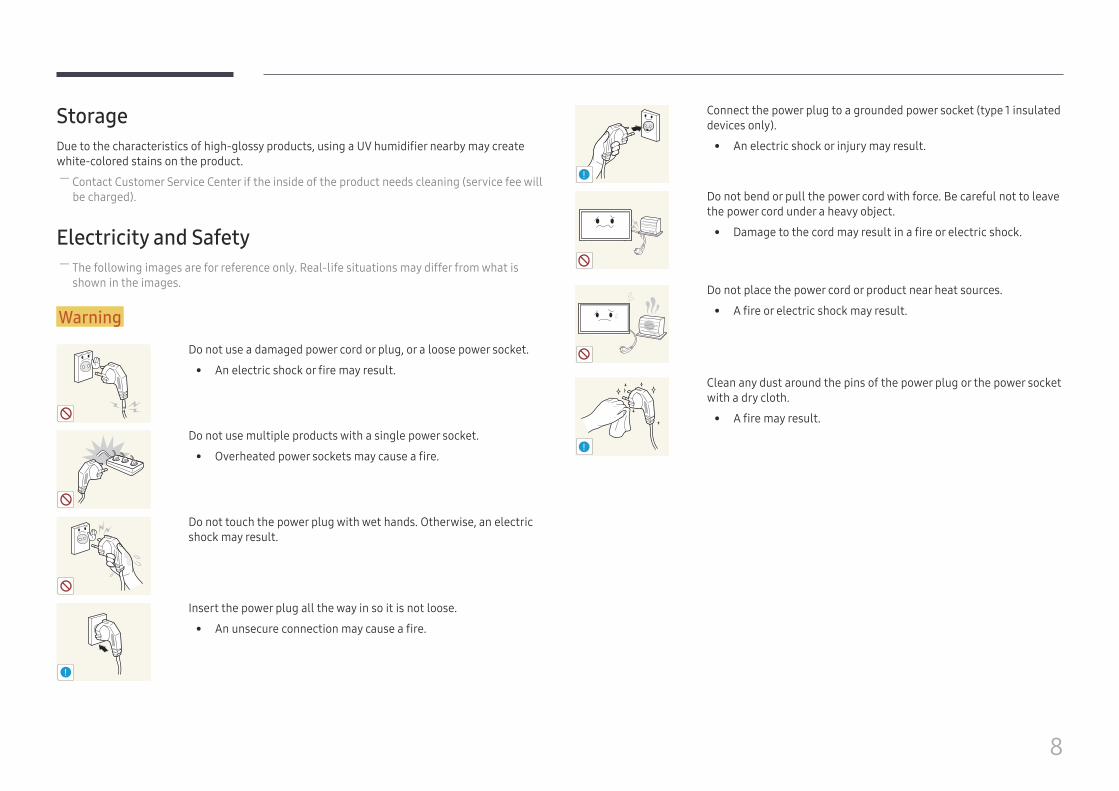
Warning
Do not use a damaged power cord or plug, or a loose power socket.
• An electric shock or fire may result.
Do not use multiple products with a single power socket.
• Overheated power sockets may cause a fire.
Do not touch the power plug with wet hands. Otherwise, an electric shock may result.
!
Insert the power plug all the way in so it is not loose.
• An unsecure connection may cause a fire.
!
Connect the power plug to a grounded power socket (type 1 insulated devices only).
• An electric shock or injury may result.
Do not bend or pull the power cord with force. Be careful not to leave the power cord under a heavy object.
• Damage to the cord may result in a fire or electric shock.
Do not place the power cord or product near heat sources.
• A fire or electric shock may result.
!
Clean any dust around the pins of the power plug or the power socket with a dry cloth.
• A fire may result.
9
Caution
Do not disconnect the power cord while the product is being used.
• The product may become damaged by an electric shock.
!
Only use the power cord provided with your product by Samsung. Do not use the power cord with other products.
• A fire or electric shock may result.
!
Keep the power socket where the power cord is connected unobstructed.
• The power cord must be disconnected to cut off power to the product when an issue occurs.
• Note that the product is not completely powered down by using only the power button on the remote.
!
Hold the plug when disconnecting the power cord from the power socket.
• An electric shock or fire may result.
Installation
Warning
DO NOT PLACE CANDLES, INSECT REPELLANTS OR CIGARETTES ON TOP OF THE PRODUCT. DO NOT INSTALL THE PRODUCT NEAR HEAT SOURCES.
• A fire may result.
!
Have a technician install the wall-mount hanger.
• Installation by an unqualified person can result in an injury.
• Only use approved cabinets.
Do not install the product in poorly ventilated spaces such as a bookcase or closet.
• An increased internal temperature may cause a fire.
!
Install the product at least 10 cm away from the wall to allow ventilation.
• An increased internal temperature may cause a fire.
!
Keep the plastic packaging out of the reach of children.
• Children may suffocate.
10
Do not install the product on an unstable or vibrating surface (insecure shelf, sloped surface, etc.)
• The product may fall and become damaged and/or cause an injury.
• Using the product in an area with excess vibration may damage the product or cause a fire.
!
Do not install the product in a vehicle or a place exposed to dust, moisture (water drips, etc.), oil, or smoke.
• A fire or electric shock may result.
Do not expose the product to direct sunlight, heat, or a hot object such as a stove.
• The product lifespan may be reduced or a fire may result.
Do not install the product within the reach of young children.
• The product may fall and injure children.
• As the front is heavy, install the product on a flat and stable surface.
Edible oil, such as soybean oil, can damage or deform the product. Do not install the product in a kitchen or near a kitchen counter.
Caution
!
Do not drop the product while moving.
• Product failure or personal injury may result.
Do not set down the product on its front.
• The screen may become damaged.
When installing the product on a cabinet or shelf, make sure that the bottom edge of the front of the product is not protruding.
• The product may fall and become damaged and/or cause an injury.
• Install the product only on cabinets or shelves of the right size.
!
Set down the product gently.
• Product failure or personal injury may result.
SAMSUNG
!
Installing the product in an unusual place (a place exposed to a lot of fine dust, chemical substances, extreme temperatures or a significant presence of moisture, or a place where the product will operate continuously for an extended period of time) may seriously affect its performance.
• Be sure to consult Samsung Customer Service Center if you want to install the product at such a place.
11
Operation
Warning
There is a high voltage inside the product. Never disassemble, repair or modify the product yourself.
• A fire or electric shock may result.
• Contact Samsung Customer Service Center for repairs.
!
Before moving the product, turn off the power switch and disconnect the power cable and all other connected cables.
• Damage to the cord may result in a fire or electric shock.
!
If the product generates abnormal sounds, a burning smell or smoke, disconnect the power cord immediately and contact Samsung Customer Service Center.
• An electric shock or fire may result.
Do not let children hang from the product or climb on top of it.
• Children may become injured or seriously harmed.
If the product is dropped or the outer case is damaged, turn off the power switch and disconnect the power cord. Then contact Samsung Customer Service Center.
• Continued use can result in a fire or electric shock.
Do not leave heavy objects or items that children like (toys, sweets, etc.) on top of the product.
• The product or heavy objects may fall as children try to reach for the toys or sweets resulting in a serious injury.
!
During a lightning or thunderstorm, power off the product and remove the power cable.
• A fire or electric shock may result.
!
Do not drop objects on the product or apply impact.
• A fire or electric shock may result.
Do not move the product by pulling the power cord or any cable.
• Product failure, an electric shock or fire may result from a damaged cable.
!GAS
If a gas leakage is found, do not touch the product or power plug. Also, ventilate the area immediately.
• Sparks can cause an explosion or fire.
Do not lift or move the product by pulling the power cord or any cable.
• Product failure, an electric shock or fire may result from a damaged cable.
12
!
Do not use or keep combustible spray or an inflammable substance near the product.
• An explosion or fire may result.
Ensure the vents are not blocked by tablecloths or curtains.
• An increased internal temperature may cause a fire.
100
Do not insert metallic objects (chopsticks, coins, hairpins, etc) or objects that burn easily (paper, matches, etc) into the product (via the vent or input/output ports, etc).
• Be sure to power off the product and disconnect the power cord when water or other foreign substances have entered the product. Then contact Samsung Customer Service Center.
• Product failure, an electric shock or fire may result.
Do not place objects containing liquid (vases, pots, bottles, etc) or metallic objects on top of the product.
• Be sure to power off the product and disconnect the power cord when water or other foreign substances have entered the product. Then contact Samsung Customer Service Center.
• Product failure, an electric shock or fire may result.
Caution
!
Leaving the screen fixed on a stationary image for an extended period of time may cause afterimage burn-in or defective pixels.
• Activate power-saving mode or a moving-picture screen saver if you will not be using the product for an extended period of time.
-_-
!
Disconnect the power cord from the power socket if you do not plan on using the product for an extended period of time (vacation, etc).
• Dust accumulation combined with heat can cause a fire, electric shock or electric leakage.
!
Use the product at the recommended resolution and frequency.
• Your eyesight may deteriorate.
Do not hold the product upside-down or move it by holding the stand.
• The product may fall and become damaged or cause an injury.
!
Looking at the screen too close for an extended period of time can deteriorate your eyesight.
Do not use humidifiers or stoves around the product.
• A fire or electric shock may result.
13
!
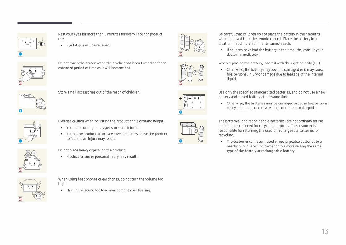
Rest your eyes for more than 5 minutes for every 1 hour of product use.
• Eye fatigue will be relieved.
Do not touch the screen when the product has been turned on for an extended period of time as it will become hot.
!
Store small accessories out of the reach of children.
!
Exercise caution when adjusting the product angle or stand height.
• Your hand or finger may get stuck and injured.
• Tilting the product at an excessive angle may cause the product to fall and an injury may result.
Do not place heavy objects on the product.
• Product failure or personal injury may result.
When using headphones or earphones, do not turn the volume too high.
• Having the sound too loud may damage your hearing.
Be careful that children do not place the battery in their mouths when removed from the remote control. Place the battery in a location that children or infants cannot reach.
• If children have had the battery in their mouths, consult your doctor immediately.
When replacing the battery, insert it with the right polarity (+, -).
• Otherwise, the battery may become damaged or it may cause fire, personal injury or damage due to leakage of the internal liquid.
!
Use only the specified standardized batteries, and do not use a new battery and a used battery at the same time.
• Otherwise, the batteries may be damaged or cause fire, personal injury or damage due to a leakage of the internal liquid.
!
The batteries (and rechargeable batteries) are not ordinary refuse and must be returned for recycling purposes. The customer is responsible for returning the used or rechargeable batteries for recycling.
• The customer can return used or rechargeable batteries to a nearby public recycling center or to a store selling the same type of the battery or rechargeable battery.
14
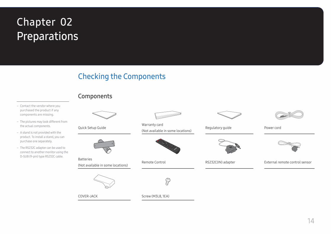
– Contact the vendor where you purchased the product if any components are missing.
– The pictures may look different from the actual components.
– A stand is not provided with the product. To install a stand, you can purchase one separately.
– The RS232C adapter can be used to connect to another monitor using the D-SUB (9-pin) type RS232C cable.
Checking the Components
Components
Quick Setup GuideWarranty card
(Not available in some locations)Regulatory guide Power cord
+
+
-
-
Batteries
(Not available in some locations)Remote Control RS232C(IN) adapter External remote control sensor
COVER-JACK Screw (M3L8, 1EA)
PreparationsChapter 02
15
Parts
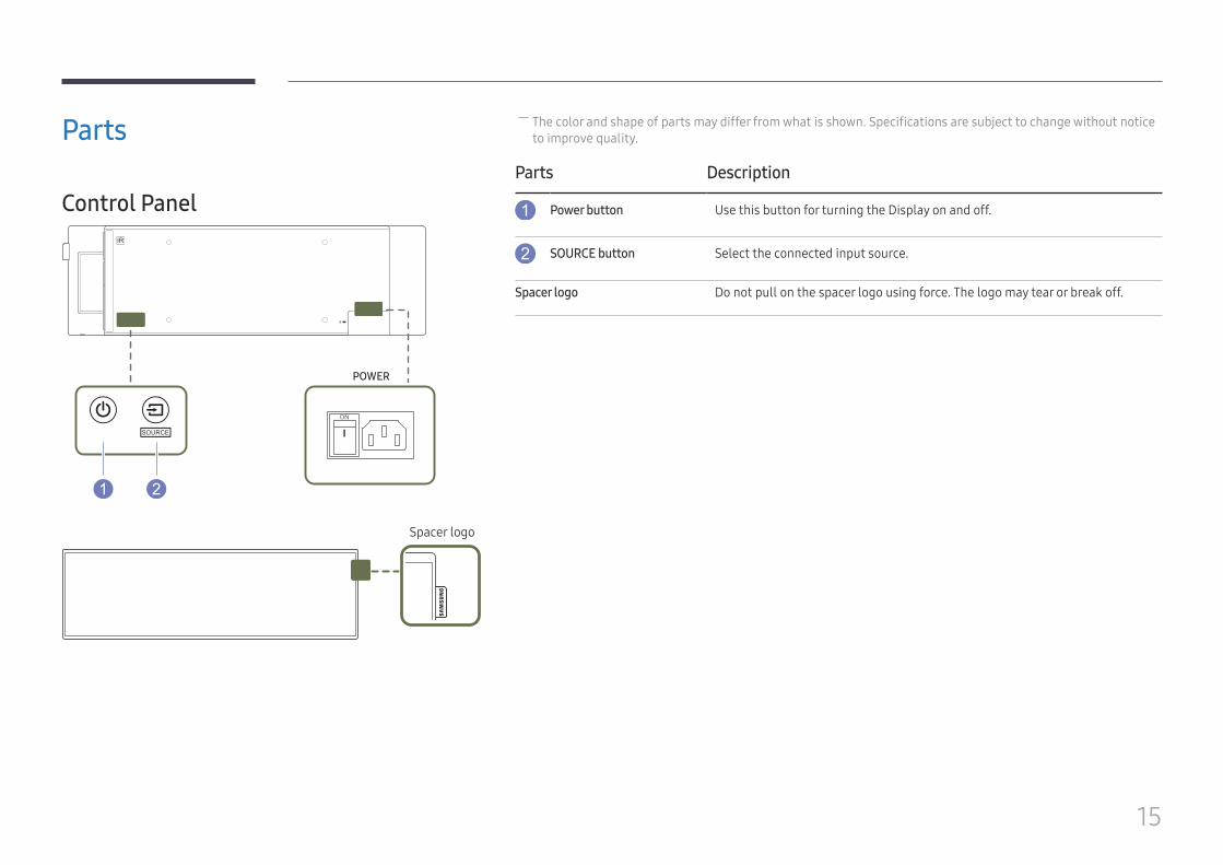
Control Panel
POWER
Spacer logo
― The color and shape of parts may differ from what is shown. Specifications are subject to change without notice to improve quality.
Parts Description
Power button Use this button for turning the Display on and off.
SOURCE button Select the connected input source.
Spacer logo Do not pull on the spacer logo using force. The logo may tear or break off.
16
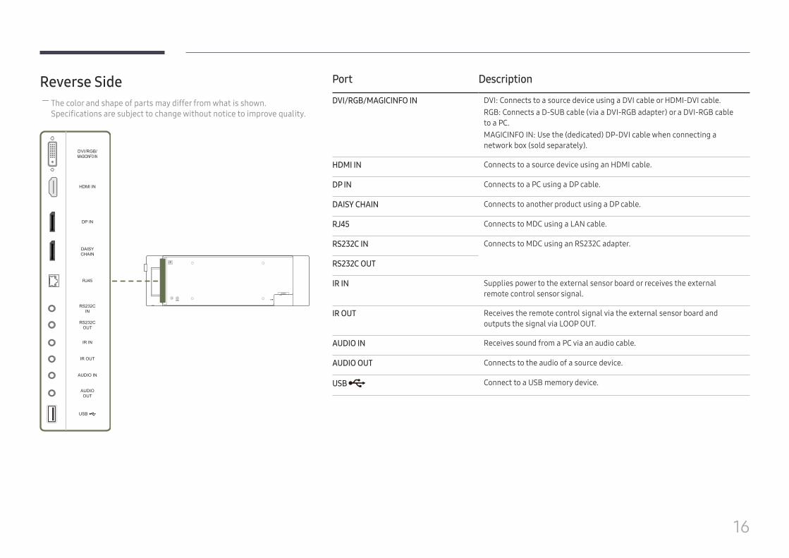
Reverse Side ― The color and shape of parts may differ from what is shown. Specifications are subject to change without notice to improve quality.
RS232CIN
RS232COUT
IR IN
IR OUT
AUDIO IN
AUDIOOUT
HDMI IN
DAISYCHAIN
RJ45
DP IN
USB
Port Description
DVI/RGB/MAGICINFO IN DVI: Connects to a source device using a DVI cable or HDMI-DVI cable.RGB: Connects a D-SUB cable (via a DVI-RGB adapter) or a DVI-RGB cable to a PC.MAGICINFO IN: Use the (dedicated) DP-DVI cable when connecting a network box (sold separately).
HDMI IN Connects to a source device using an HDMI cable.
DP IN Connects to a PC using a DP cable.
DAISY CHAIN Connects to another product using a DP cable.
RJ45 Connects to MDC using a LAN cable.
RS232C IN Connects to MDC using an RS232C adapter.
RS232C OUT
IR IN Supplies power to the external sensor board or receives the external remote control sensor signal.
IR OUT Receives the remote control signal via the external sensor board and outputs the signal via LOOP OUT.
AUDIO IN Receives sound from a PC via an audio cable.
AUDIO OUT Connects to the audio of a source device.
USB Connect to a USB memory device.
17
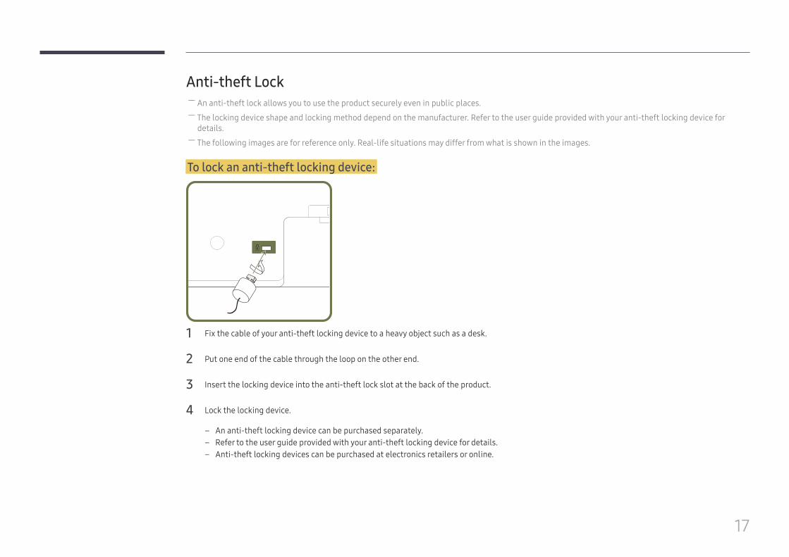
Anti-theft Lock ― An anti-theft lock allows you to use the product securely even in public places. ― The locking device shape and locking method depend on the manufacturer. Refer to the user guide provided with your anti-theft locking device for details.
― The following images are for reference only. Real-life situations may differ from what is shown in the images.
To lock an anti-theft locking device:
1 Fix the cable of your anti-theft locking device to a heavy object such as a desk.
2 Put one end of the cable through the loop on the other end.
3 Insert the locking device into the anti-theft lock slot at the back of the product.
4 Lock the locking device.
– An anti-theft locking device can be purchased separately. – Refer to the user guide provided with your anti-theft locking device for details. – Anti-theft locking devices can be purchased at electronics retailers or online.
18
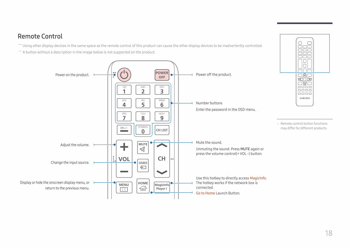
– Remote control button functions may differ for different products.
Remote Control ― Using other display devices in the same space as the remote control of this product can cause the other display devices to be inadvertently controlled. ― A button without a description in the image below is not supported on the product.
HOMEMENU
POWEROFF
VOL CH
MagicInfoPlayer I
.QZ
1ABC
2DEF
3GHI
4JKL
5MNO
6
SYMBOL
0
PRS
7TUV
8WXY
9
MUTE
DEL-/--
SOURCE
CH LIST
Power off the product.
Number buttons
Enter the password in the OSD menu.
Mute the sound.
Unmuting the sound: Press MUTE again or press the volume control(+ VOL -) button.
Go to Home Launch Button.
Display or hide the onscreen display menu, or return to the previous menu.
Power on the product.
Adjust the volume.
Change the input source.
Use this hotkey to directly access MagicInfo. The hotkey works if the network box is connected.
19
TOOLS INFO
SET UNSET LOCK
PC
ADVI
BHDMI
CDP
D
EXITRETURN
IR control
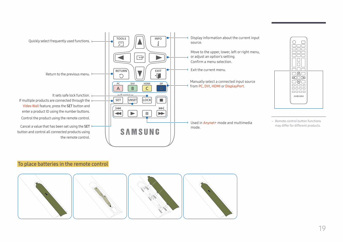
Display information about the current input source.
Move to the upper, lower, left or right menu, or adjust an option's setting.Confirm a menu selection.
Exit the current menu.
Manually select a connected input source from PC, DVI, HDMI or DisplayPort.
Used in Anynet+ mode and multimedia mode.
Quickly select frequently used functions.
Return to the previous menu.
It sets safe lock function.If multiple products are connected through the
Video Wall feature, press the SET button and enter a product ID using the number buttons.
Control the product using the remote control.
Cancel a value that has been set using the SET button and control all connected products using
the remote control.
– Remote control button functions may differ for different products.
To place batteries in the remote control
20
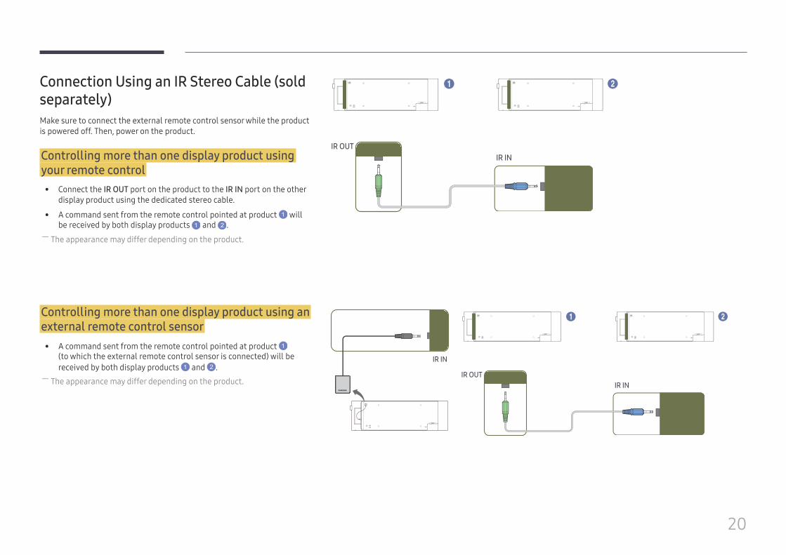
Connection Using an IR Stereo Cable (sold separately)Make sure to connect the external remote control sensor while the product is powered off. Then, power on the product.
Controlling more than one display product using your remote control
• Connect the IR OUT port on the product to the IR IN port on the other display product using the dedicated stereo cable.
• A command sent from the remote control pointed at product 1 will be received by both display products 1 and 2 .
― The appearance may differ depending on the product.
IR OUTIR IN
1 2
Controlling more than one display product using an external remote control sensor
• A command sent from the remote control pointed at product 1 (to which the external remote control sensor is connected) will be received by both display products 1 and 2 .
― The appearance may differ depending on the product.IR OUT
IR IN
IR IN
1 2
21
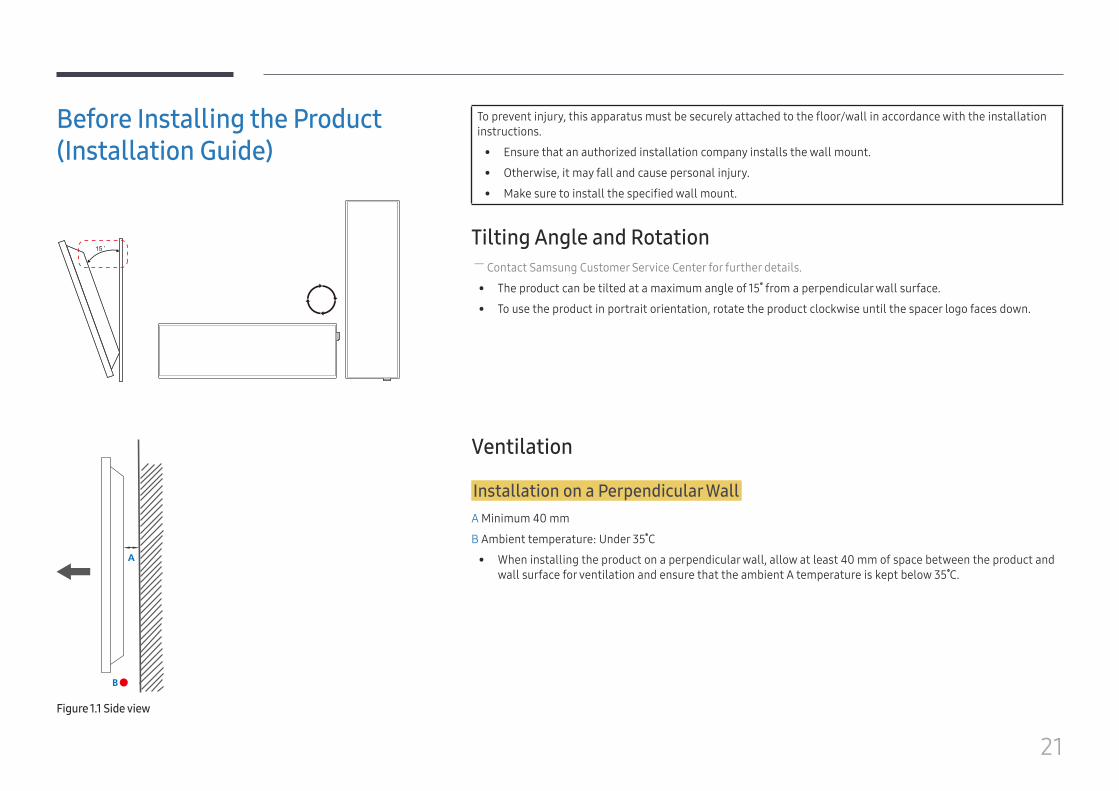
Before Installing the Product (Installation Guide)
15 ˚
To prevent injury, this apparatus must be securely attached to the floor/wall in accordance with the installation instructions.
• Ensure that an authorized installation company installs the wall mount.
• Otherwise, it may fall and cause personal injury.
• Make sure to install the specified wall mount.
Tilting Angle and Rotation ― Contact Samsung Customer Service Center for further details.
• The product can be tilted at a maximum angle of 15 from a perpendicular wall surface.
• To use the product in portrait orientation, rotate the product clockwise until the spacer logo faces down.
A
B
Figure 1.1 Side view
Ventilation
Installation on a Perpendicular WallA Minimum 40 mm
B Ambient temperature: Under 35 C
• When installing the product on a perpendicular wall, allow at least 40 mm of space between the product and wall surface for ventilation and ensure that the ambient A temperature is kept below 35 C.
22
A
B
CE
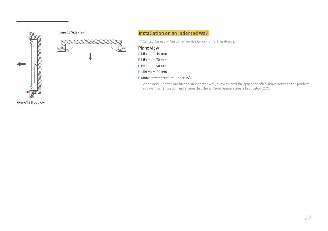
Figure 1.3 Side view
D D
Figure 1.2 Side view
Installation on an Indented Wall ― Contact Samsung Customer Service Center for further details.
Plane viewA Minimum 40 mm
B Minimum 70 mm
C Minimum 50 mm
D Minimum 50 mm
E Ambient temperature: Under 35 C ― When installing the product on an indented wall, allow at least the space specified above between the product and wall for ventilation and ensure that the ambient temperature is kept below 35 C.
23
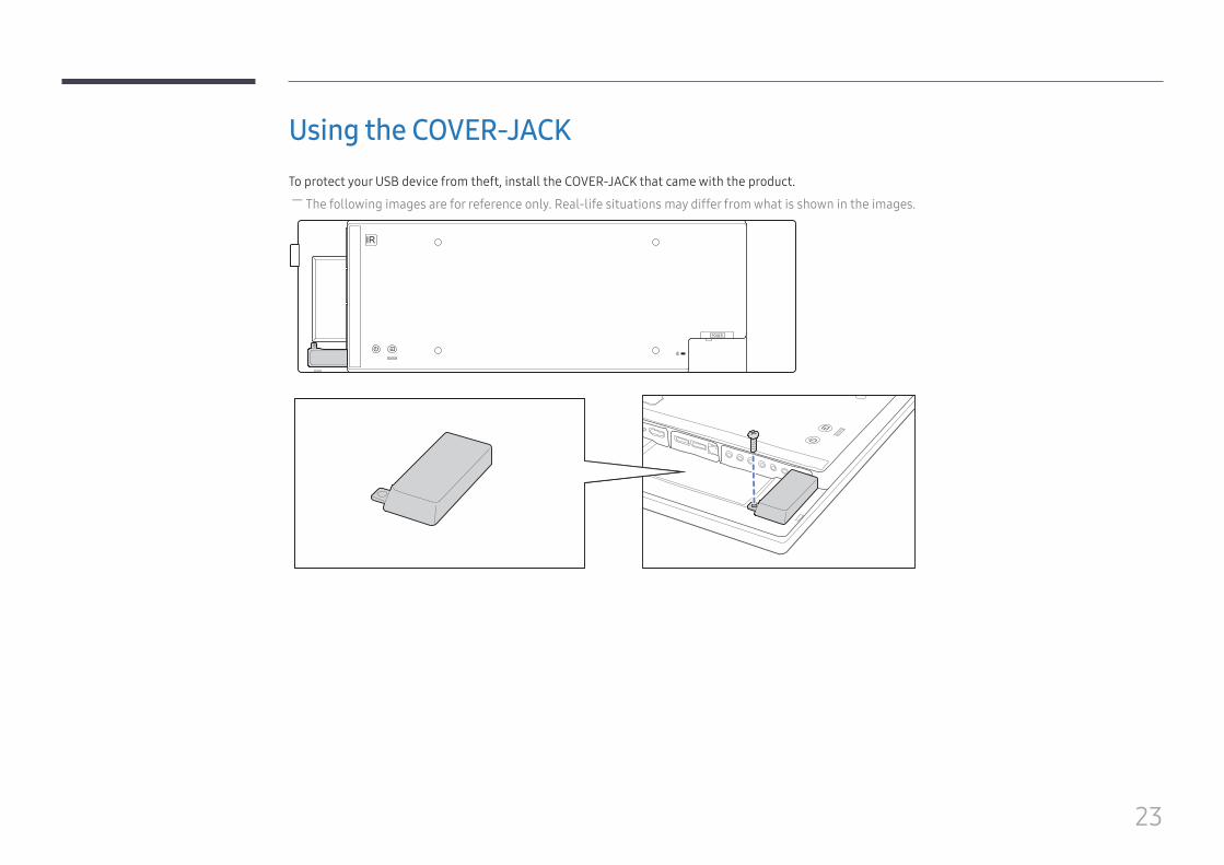
Using the COVER-JACKTo protect your USB device from theft, install the COVER-JACK that came with the product.
― The following images are for reference only. Real-life situations may differ from what is shown in the images.
24
Installing the Wall Mount
Installing the Wall MountThe wall mount kit (sold separately) allows you to mount the product on the wall.
For detailed information on installing the wall mount, see the instructions provided with the wall mount.
We recommend you contact a technician for assistance when installing the wall mount bracket.
Samsung Electronics is not responsible for any damage to the product or injury to yourself or others if you elect to install the wall mount on your own.
• Samsung wall mount kits contain a detailed installation manual and all parts necessary for assembly are provided.
• Do not use screws that are longer than the standard length or do not comply with the VESA standard screw specifications. Screws that are too long may cause damage to the inside of the product.
• For wall mounts that do not comply with the VESA standard screw specifications, the length of the screws may differ depending on the wall mount specifications.
• Do not fasten the screws too firmly. This may damage the product or cause the product to fall, leading to personal injury. Samsung is not liable for these kinds of accidents.
• Samsung is not liable for product damage or personal injury when a non-VESA or non-specified wall mount is used or the consumer fails to follow the product installation instructions.
• Do not mount the product at more than a 15 degree tilt.
• Always have two people mount the product on a wall.
• Standard dimensions for wall mount kits are shown in the table below.
Unit: mm (inches)
Model name VESA screw hole specs (A * B) in millimeters
Standard Screw Quantity
SH37F 400 x 200 (15.7 x 7.9) M8 / L14 - 16 4
― Do not install your Wall Mount Kit while your product is turned on. It may result in personal injury due to electric shock.
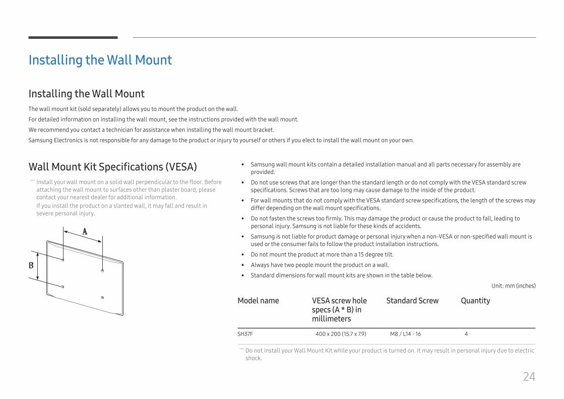
Wall Mount Kit Specifications (VESA) ― Install your wall mount on a solid wall perpendicular to the floor. Before attaching the wall mount to surfaces other than plaster board, please contact your nearest dealer for additional information.If you install the product on a slanted wall, it may fall and result in severe personal injury.
25
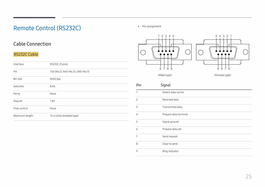
Remote Control (RS232C)
Cable Connection
RS232C Cable
Interface RS232C (9 pins)
Pin TxD (No.2), RxD (No.3), GND (No.5)
Bit rate 9600 bps
Data bits 8 bit
Parity None
Stop bit 1 bit
Flow control None
Maximum length 15 m (only shielded type)
• Pin assignment
1 2 3 4 5
6 7 8 9
5 4 3 2 1
9 8 7 6
<Male type> <Female type>
Pin Signal
1 Detect data carrier
2 Received data
3 Transmitted data
4 Prepare data terminal
5 Signal ground
6 Prepare data set
7 Send request
8 Clear to send
9 Ring indicator
26
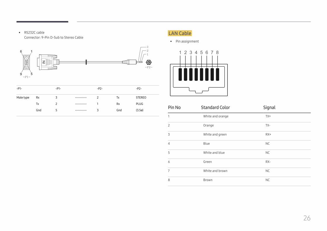
• RS232C cableConnector: 9-Pin D-Sub to Stereo Cable
5
16
9
-P2-
1
2
3
-P1-
-P1- -P1- -P2- -P2-
Male type Rx
Tx
Gnd
3
2
5
----------
----------
----------
2
1
3
Tx
Rx
Gnd
STEREO
PLUG
(3.5ø)
LAN Cable • Pin assignment
1 2 3 4 5 6 7 8
Pin No Standard Color Signal
1 White and orange TX+
2 Orange TX-
3 White and green RX+
4 Blue NC
5 White and blue NC
6 Green RX-
7 White and brown NC
8 Brown NC
27
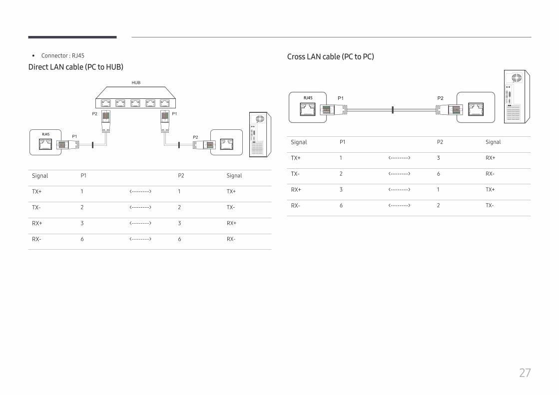
• Connector : RJ45
Direct LAN cable (PC to HUB)
RJ45 RJ45 MDC
HUB
P1
P1P2
P2
Signal P1 P2 Signal
TX+ 1 <--------> 1 TX+
TX- 2 <--------> 2 TX-
RX+ 3 <--------> 3 RX+
RX- 6 <--------> 6 RX-
Cross LAN cable (PC to PC)
RJ45 P1 P2
Signal P1 P2 Signal
TX+ 1 <--------> 3 RX+
TX- 2 <--------> 6 RX-
RX+ 3 <--------> 1 TX+
RX- 6 <--------> 2 TX-
28
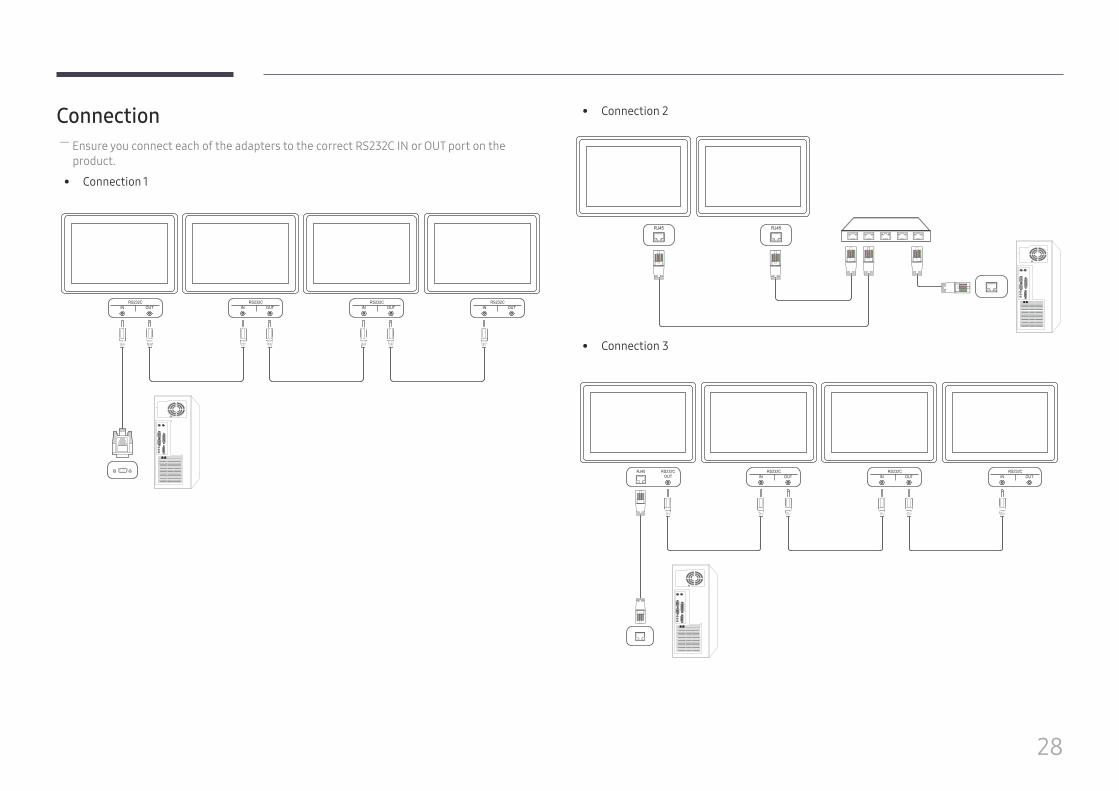
Connection ― Ensure you connect each of the adapters to the correct RS232C IN or OUT port on the product.
• Connection 1
RS232CIN OUT
RS232CIN OUT
RS232CIN OUT
RS232CIN OUT
• Connection 2
RJ45 RJ45
• Connection 3
RS232COUT
RJ45 RS232CIN OUT
RS232CIN OUT
RS232CIN OUT
29
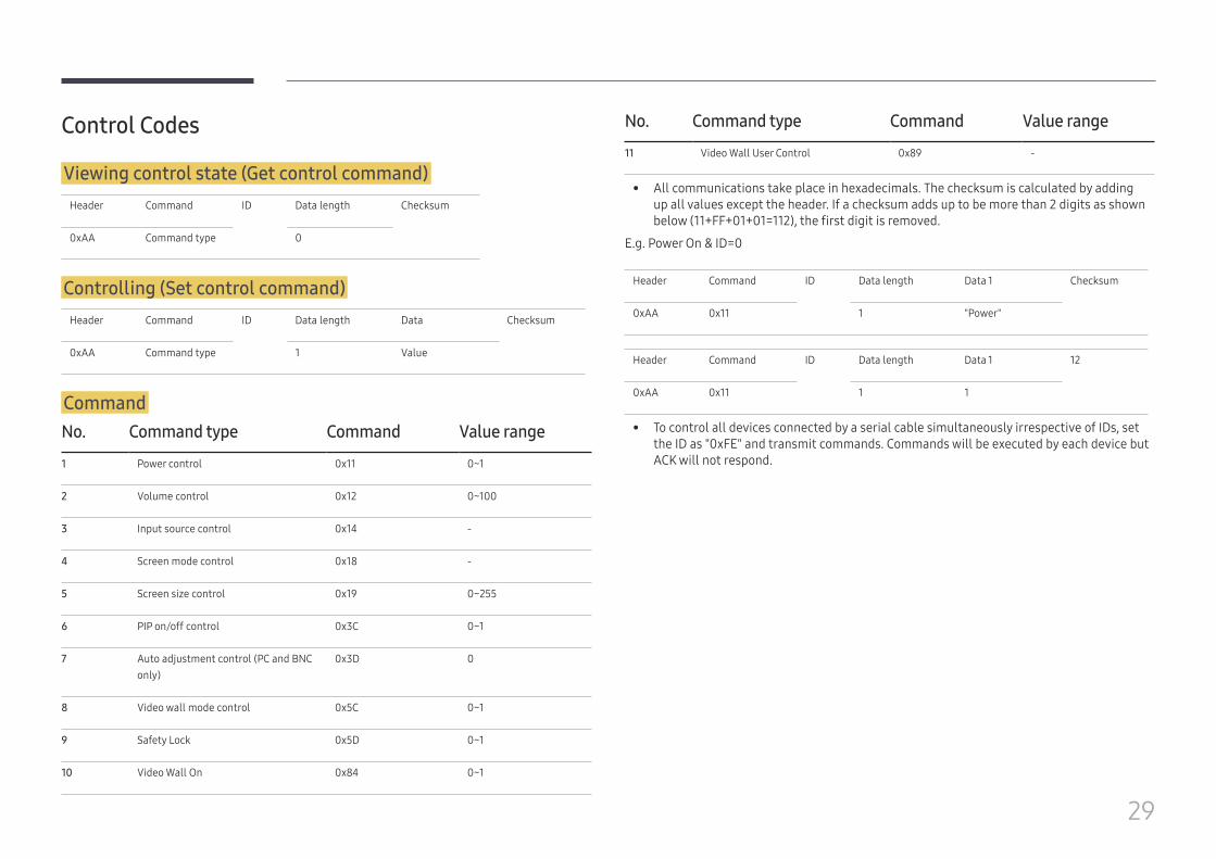
Control Codes
Viewing control state (Get control command)Header Command ID Data length Checksum
0xAA Command type 0
Controlling (Set control command)Header Command ID Data length Data Checksum
0xAA Command type 1 Value
CommandNo. Command type Command Value range
1 Power control 0x11 0~1
2 Volume control 0x12 0~100
3 Input source control 0x14 -
4 Screen mode control 0x18 -
5 Screen size control 0x19 0~255
6 PIP on/off control 0x3C 0~1
7 Auto adjustment control (PC and BNC only)
0x3D 0
8 Video wall mode control 0x5C 0~1
9 Safety Lock 0x5D 0~1
10 Video Wall On 0x84 0~1
No. Command type Command Value range
11 Video Wall User Control 0x89 -
• All communications take place in hexadecimals. The checksum is calculated by adding up all values except the header. If a checksum adds up to be more than 2 digits as shown below (11+FF+01+01=112), the first digit is removed.
E.g. Power On & ID=0
Header Command ID Data length Data 1 Checksum
0xAA 0x11 1 "Power"
Header Command ID Data length Data 1 12
0xAA 0x11 1 1
• To control all devices connected by a serial cable simultaneously irrespective of IDs, set the ID as "0xFE" and transmit commands. Commands will be executed by each device but ACK will not respond.
30
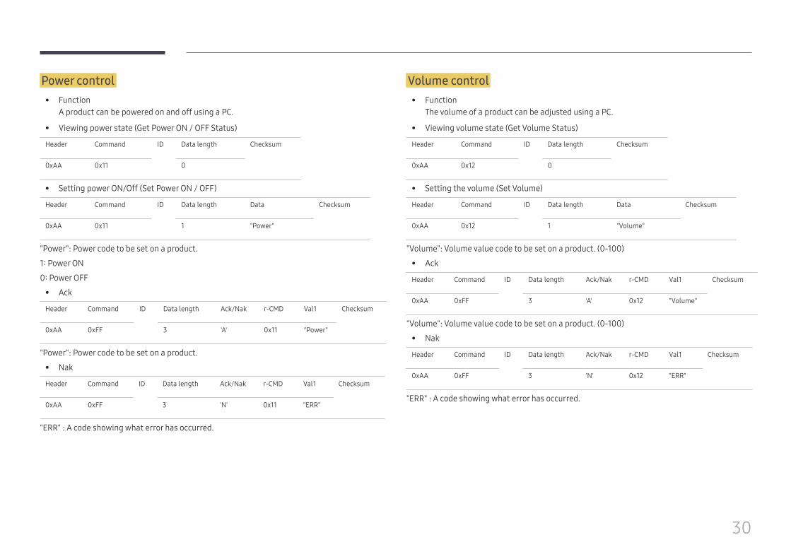
Power control • Function
A product can be powered on and off using a PC.
• Viewing power state (Get Power ON / OFF Status)
Header Command ID Data length Checksum
0xAA 0x11 0
• Setting power ON/Off (Set Power ON / OFF)
Header Command ID Data length Data Checksum
0xAA 0x11 1 "Power"
"Power": Power code to be set on a product.
1: Power ON
0: Power OFF
• Ack
Header Command ID Data length Ack/Nak r-CMD Val1 Checksum
0xAA 0xFF 3 'A' 0x11 "Power"
"Power": Power code to be set on a product.
• Nak
Header Command ID Data length Ack/Nak r-CMD Val1 Checksum
0xAA 0xFF 3 'N' 0x11 "ERR"
"ERR" : A code showing what error has occurred.
Volume control • Function
The volume of a product can be adjusted using a PC.
• Viewing volume state (Get Volume Status)
Header Command ID Data length Checksum
0xAA 0x12 0
• Setting the volume (Set Volume)
Header Command ID Data length Data Checksum
0xAA 0x12 1 "Volume"
"Volume": Volume value code to be set on a product. (0-100)
• Ack
Header Command ID Data length Ack/Nak r-CMD Val1 Checksum
0xAA 0xFF 3 'A' 0x12 "Volume"
"Volume": Volume value code to be set on a product. (0-100)
• Nak
Header Command ID Data length Ack/Nak r-CMD Val1 Checksum
0xAA 0xFF 3 'N' 0x12 "ERR"
"ERR" : A code showing what error has occurred.
31
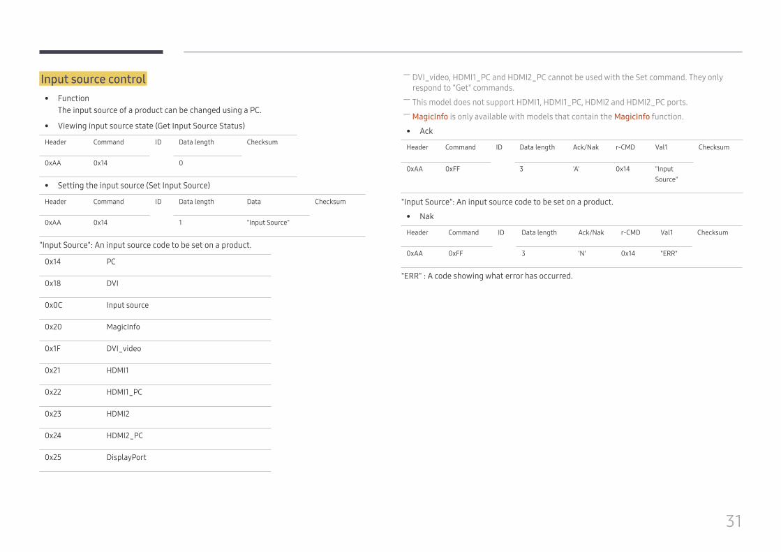
Input source control • Function
The input source of a product can be changed using a PC.
• Viewing input source state (Get Input Source Status)
Header Command ID Data length Checksum
0xAA 0x14 0
• Setting the input source (Set Input Source)
Header Command ID Data length Data Checksum
0xAA 0x14 1 "Input Source"
"Input Source": An input source code to be set on a product.
0x14 PC
0x18 DVI
0x0C Input source
0x20 MagicInfo
0x1F DVI_video
0x21 HDMI1
0x22 HDMI1_PC
0x23 HDMI2
0x24 HDMI2_PC
0x25 DisplayPort
― DVI_video, HDMI1_PC and HDMI2_PC cannot be used with the Set command. They only respond to "Get" commands.
― This model does not support HDMI1, HDMI1_PC, HDMI2 and HDMI2_PC ports. ― MagicInfo is only available with models that contain the MagicInfo function.
• Ack
Header Command ID Data length Ack/Nak r-CMD Val1 Checksum
0xAA 0xFF 3 'A' 0x14 "Input Source"
"Input Source": An input source code to be set on a product.
• Nak
Header Command ID Data length Ack/Nak r-CMD Val1 Checksum
0xAA 0xFF 3 'N' 0x14 "ERR"
"ERR" : A code showing what error has occurred.
32
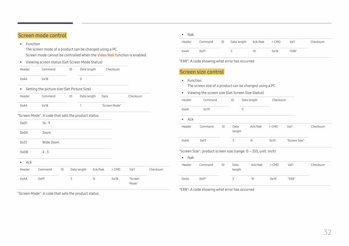
Screen mode control • Function
The screen mode of a product can be changed using a PC.Screen mode cannot be controlled when the Video Wall function is enabled.
• Viewing screen status (Get Screen Mode Status)
Header Command ID Data length Checksum
0xAA 0x18 0
• Setting the picture size (Set Picture Size)
Header Command ID Data length Data Checksum
0xAA 0x18 1 "Screen Mode"
"Screen Mode": A code that sets the product status
0x01 16 : 9
0x04 Zoom
0x31 Wide Zoom
0x0B 4 : 3
• Ack
Header Command ID Data length Ack/Nak r-CMD Val1 Checksum
0xAA 0xFF 3 'A' 0x18 "Screen Mode"
"Screen Mode": A code that sets the product status
• Nak
Header Command ID Data length Ack/Nak r-CMD Val1 Checksum
0xAA 0xFF 3 'N' 0x18 "ERR"
"ERR": A code showing what error has occurred
Screen size control • Function
The screen size of a product can be changed using a PC.
• Viewing the screen size (Get Screen Size Status)
Header Command ID Data length Checksum
0xAA 0x19 0
• Ack
Header Command ID Data length
Ack/Nak r-CMD Val1 Checksum
0xAA 0xFF 3 'A' 0x19 "Screen Size"
"Screen Size": product screen size (range: 0 – 255, unit: inch)
• Nak
Header Command ID Data length
Ack/Nak r-CMD Val1 Checksum
0xAA 0xFF 3 'N' 0x19 "ERR"
"ERR": A code showing what error has occurred
33
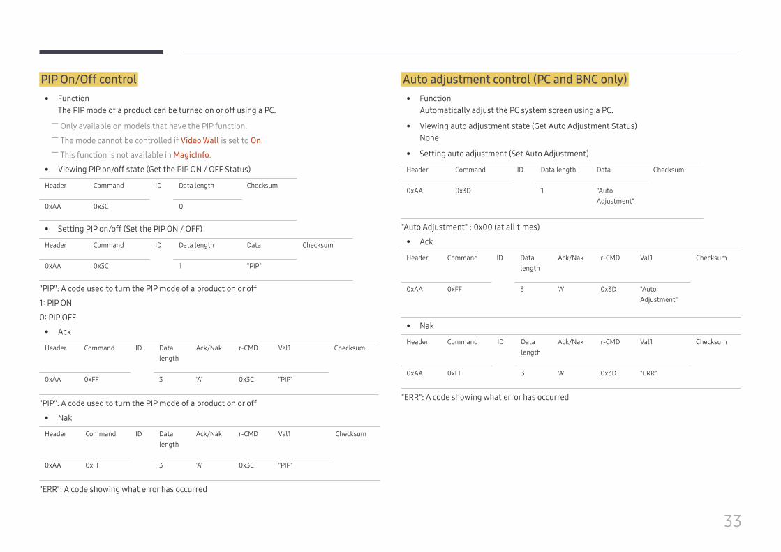
PIP On/Off control • Function
The PIP mode of a product can be turned on or off using a PC. ― Only available on models that have the PIP function. ― The mode cannot be controlled if Video Wall is set to On. ― This function is not available in MagicInfo.
• Viewing PIP on/off state (Get the PIP ON / OFF Status)
Header Command ID Data length Checksum
0xAA 0x3C 0
• Setting PIP on/off (Set the PIP ON / OFF)
Header Command ID Data length Data Checksum
0xAA 0x3C 1 "PIP"
"PIP": A code used to turn the PIP mode of a product on or off
1: PIP ON
0: PIP OFF
• Ack
Header Command ID Data length
Ack/Nak r-CMD Val1 Checksum
0xAA 0xFF 3 'A' 0x3C "PIP"
"PIP": A code used to turn the PIP mode of a product on or off
• Nak
Header Command ID Data length
Ack/Nak r-CMD Val1 Checksum
0xAA 0xFF 3 'A' 0x3C "PIP"
"ERR": A code showing what error has occurred
Auto adjustment control (PC and BNC only) • Function
Automatically adjust the PC system screen using a PC.
• Viewing auto adjustment state (Get Auto Adjustment Status)None
• Setting auto adjustment (Set Auto Adjustment)
Header Command ID Data length Data Checksum
0xAA 0x3D 1 "Auto Adjustment"
"Auto Adjustment" : 0x00 (at all times)
• Ack
Header Command ID Data length
Ack/Nak r-CMD Val1 Checksum
0xAA 0xFF 3 'A' 0x3D "Auto Adjustment"
• Nak
Header Command ID Data length
Ack/Nak r-CMD Val1 Checksum
0xAA 0xFF 3 'A' 0x3D "ERR"
"ERR": A code showing what error has occurred
34
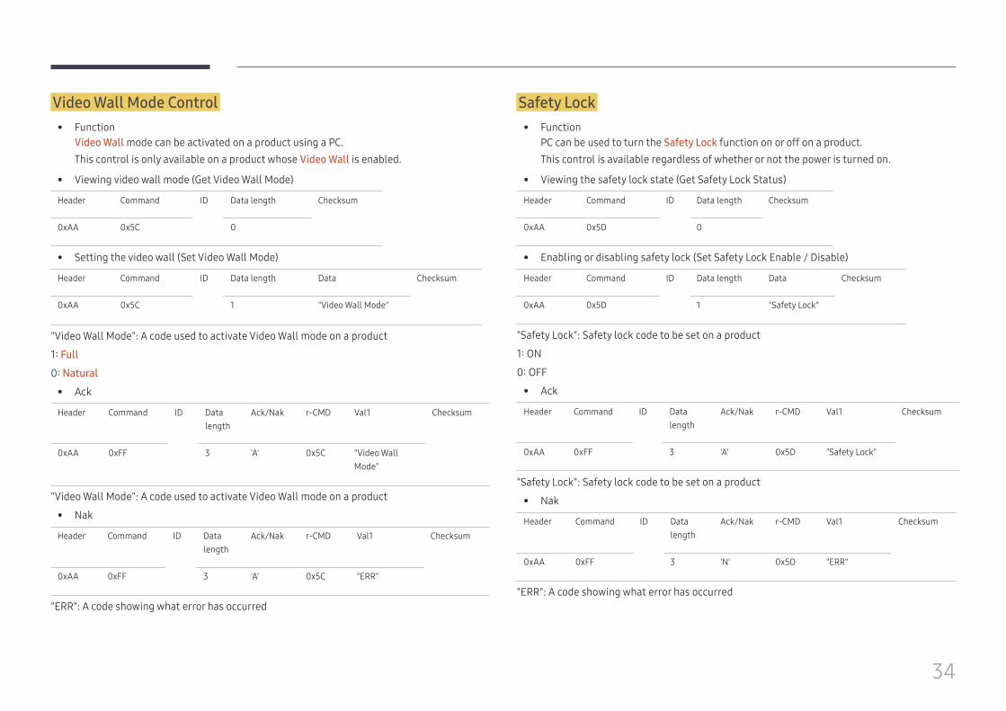
Video Wall Mode Control • Function
Video Wall mode can be activated on a product using a PC.This control is only available on a product whose Video Wall is enabled.
• Viewing video wall mode (Get Video Wall Mode)
Header Command ID Data length Checksum
0xAA 0x5C 0
• Setting the video wall (Set Video Wall Mode)
Header Command ID Data length Data Checksum
0xAA 0x5C 1 "Video Wall Mode"
"Video Wall Mode": A code used to activate Video Wall mode on a product
1: Full
0: Natural
• Ack
Header Command ID Data length
Ack/Nak r-CMD Val1 Checksum
0xAA 0xFF 3 'A' 0x5C "Video Wall Mode"
"Video Wall Mode": A code used to activate Video Wall mode on a product
• Nak
Header Command ID Data length
Ack/Nak r-CMD Val1 Checksum
0xAA 0xFF 3 'A' 0x5C "ERR"
"ERR": A code showing what error has occurred
Safety Lock • Function
PC can be used to turn the Safety Lock function on or off on a product.This control is available regardless of whether or not the power is turned on.
• Viewing the safety lock state (Get Safety Lock Status)
Header Command ID Data length Checksum
0xAA 0x5D 0
• Enabling or disabling safety lock (Set Safety Lock Enable / Disable)
Header Command ID Data length Data Checksum
0xAA 0x5D 1 "Safety Lock"
"Safety Lock": Safety lock code to be set on a product
1: ON
0: OFF
• Ack
Header Command ID Data length
Ack/Nak r-CMD Val1 Checksum
0xAA 0xFF 3 'A' 0x5D "Safety Lock"
"Safety Lock": Safety lock code to be set on a product
• Nak
Header Command ID Data length
Ack/Nak r-CMD Val1 Checksum
0xAA 0xFF 3 'N' 0x5D "ERR"
"ERR": A code showing what error has occurred
35
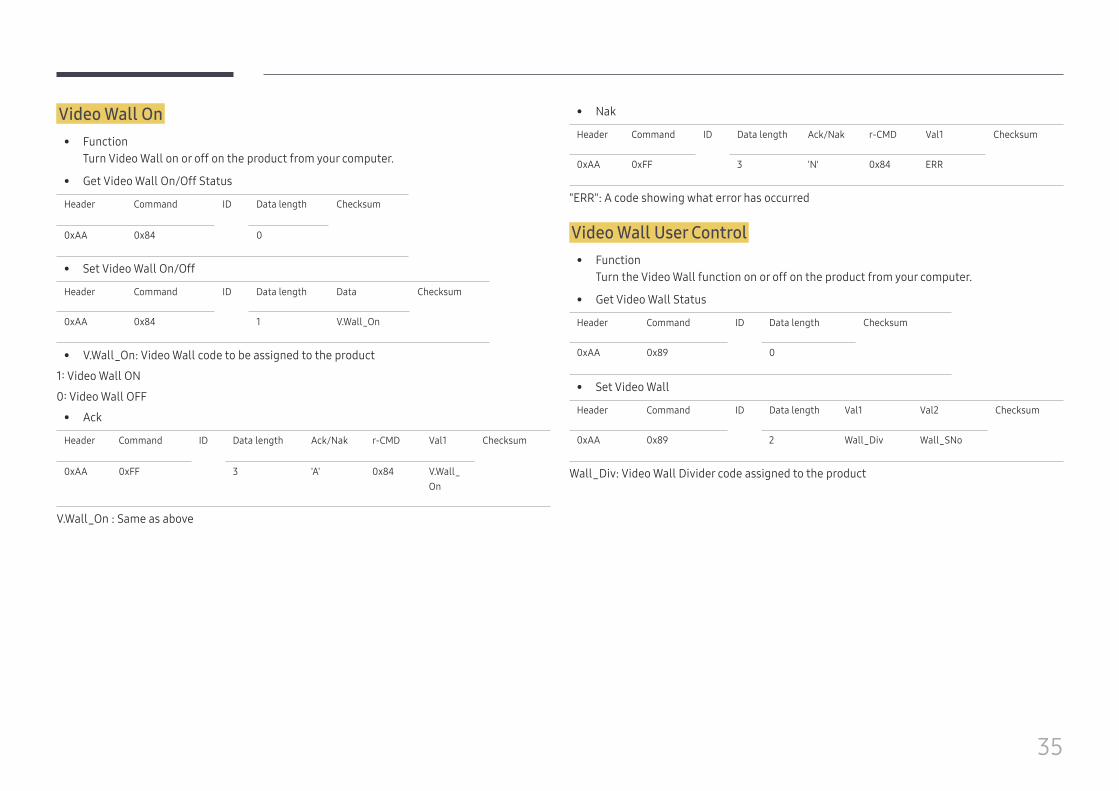
Video Wall On • Function
Turn Video Wall on or off on the product from your computer.
• Get Video Wall On/Off Status
Header Command ID Data length Checksum
0xAA 0x84 0
• Set Video Wall On/Off
Header Command ID Data length Data Checksum
0xAA 0x84 1 V.Wall_On
• V.Wall_On: Video Wall code to be assigned to the product
1: Video Wall ON
0: Video Wall OFF
• Ack
Header Command ID Data length Ack/Nak r-CMD Val1 Checksum
0xAA 0xFF 3 'A' 0x84 V.Wall_On
V.Wall_On : Same as above
• Nak
Header Command ID Data length Ack/Nak r-CMD Val1 Checksum
0xAA 0xFF 3 'N' 0x84 ERR
"ERR": A code showing what error has occurred
Video Wall User Control • Function
Turn the Video Wall function on or off on the product from your computer.
• Get Video Wall Status
Header Command ID Data length Checksum
0xAA 0x89 0
• Set Video Wall
Header Command ID Data length Val1 Val2 Checksum
0xAA 0x89 2 Wall_Div Wall_SNo
Wall_Div: Video Wall Divider code assigned to the product
36
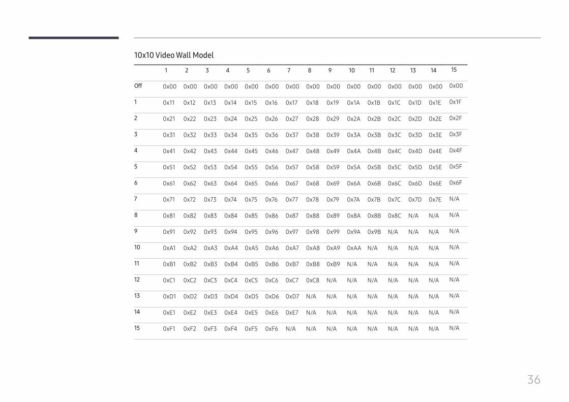
10x10 Video Wall Model
1 2 3 4 5 6 7 8 9 10 11 12 13 14 15
Off 0x00 0x00 0x00 0x00 0x00 0x00 0x00 0x00 0x00 0x00 0x00 0x00 0x00 0x00 0x00
1 0x11 0x12 0x13 0x14 0x15 0x16 0x17 0x18 0x19 0x1A 0x1B 0x1C 0x1D 0x1E 0x1F
2 0x21 0x22 0x23 0x24 0x25 0x26 0x27 0x28 0x29 0x2A 0x2B 0x2C 0x2D 0x2E 0x2F
3 0x31 0x32 0x33 0x34 0x35 0x36 0x37 0x38 0x39 0x3A 0x3B 0x3C 0x3D 0x3E 0x3F
4 0x41 0x42 0x43 0x44 0x45 0x46 0x47 0x48 0x49 0x4A 0x4B 0x4C 0x4D 0x4E 0x4F
5 0x51 0x52 0x53 0x54 0x55 0x56 0x57 0x58 0x59 0x5A 0x5B 0x5C 0x5D 0x5E 0x5F
6 0x61 0x62 0x63 0x64 0x65 0x66 0x67 0x68 0x69 0x6A 0x6B 0x6C 0x6D 0x6E 0x6F
7 0x71 0x72 0x73 0x74 0x75 0x76 0x77 0x78 0x79 0x7A 0x7B 0x7C 0x7D 0x7E N/A
8 0x81 0x82 0x83 0x84 0x85 0x86 0x87 0x88 0x89 0x8A 0x8B 0x8C N/A N/A N/A
9 0x91 0x92 0x93 0x94 0x95 0x96 0x97 0x98 0x99 0x9A 0x9B N/A N/A N/A N/A
10 0xA1 0xA2 0xA3 0xA4 0xA5 0xA6 0xA7 0xA8 0xA9 0xAA N/A N/A N/A N/A N/A
11 0xB1 0xB2 0xB3 0xB4 0xB5 0xB6 0xB7 0xB8 0xB9 N/A N/A N/A N/A N/A N/A
12 0xC1 0xC2 0xC3 0xC4 0xC5 0xC6 0xC7 0xC8 N/A N/A N/A N/A N/A N/A N/A
13 0xD1 0xD2 0xD3 0xD4 0xD5 0xD6 0xD7 N/A N/A N/A N/A N/A N/A N/A N/A
14 0xE1 0xE2 0xE3 0xE4 0xE5 0xE6 0xE7 N/A N/A N/A N/A N/A N/A N/A N/A
15 0xF1 0xF2 0xF3 0xF4 0xF5 0xF6 N/A N/A N/A N/A N/A N/A N/A N/A N/A
37
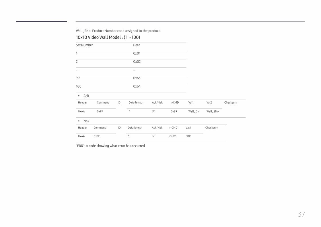
Wall_SNo: Product Number code assigned to the product
10x10 Video Wall Model : ( 1 ~ 100)Set Number Data
1 0x01
2 0x02
... ...
99 0x63
100 0x64
• Ack
Header Command ID Data length Ack/Nak r-CMD Val1 Val2 Checksum
0xAA 0xFF 4 'A' 0x89 Wall_Div Wall_SNo
• Nak
Header Command ID Data length Ack/Nak r-CMD Val1 Checksum
0xAA 0xFF 3 'N' 0x89 ERR
"ERR": A code showing what error has occurred
38
Connecting and Using a Source Device
Before Connecting
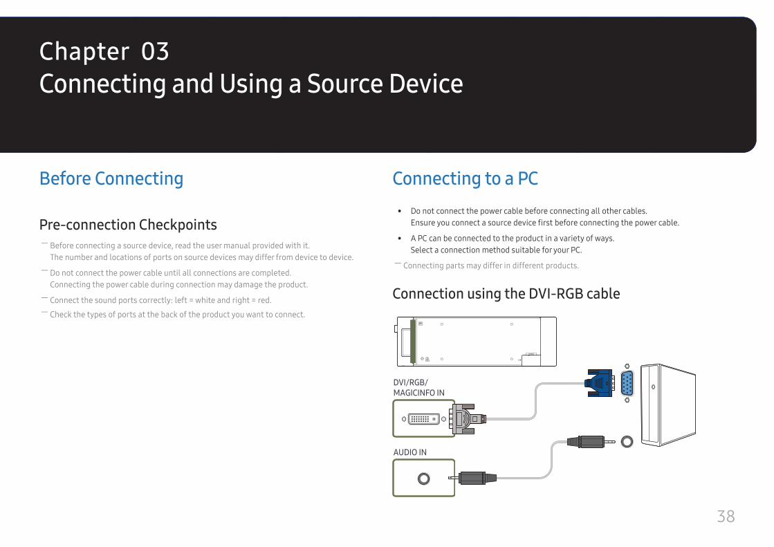
Pre-connection Checkpoints ― Before connecting a source device, read the user manual provided with it.The number and locations of ports on source devices may differ from device to device.
― Do not connect the power cable until all connections are completed.Connecting the power cable during connection may damage the product.
― Connect the sound ports correctly: left = white and right = red. ― Check the types of ports at the back of the product you want to connect.
Connecting to a PC • Do not connect the power cable before connecting all other cables.
Ensure you connect a source device first before connecting the power cable.
• A PC can be connected to the product in a variety of ways.Select a connection method suitable for your PC.
― Connecting parts may differ in different products.
Connection using the DVI-RGB cable
DVI/RGB/MAGICINFO IN
AUDIO IN
Chapter 03
39
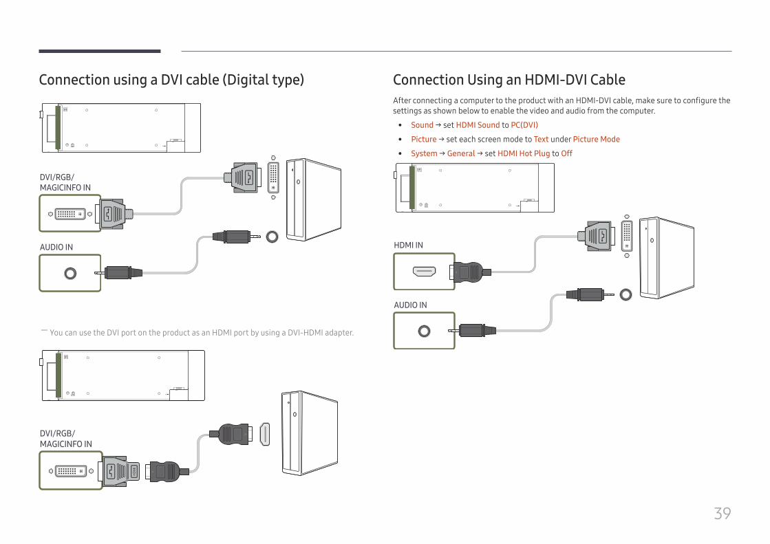
Connection using a DVI cable (Digital type)
DVI/RGB/MAGICINFO IN
AUDIO IN
― You can use the DVI port on the product as an HDMI port by using a DVI-HDMI adapter.
DVI/RGB/MAGICINFO IN
HD
MI
Connection Using an HDMI-DVI CableAfter connecting a computer to the product with an HDMI-DVI cable, make sure to configure the settings as shown below to enable the video and audio from the computer.
• Sound → set HDMI Sound to PC(DVI)
• Picture → set each screen mode to Text under Picture Mode
• System → General → set HDMI Hot Plug to Off
HDMI IN
AUDIO IN
40
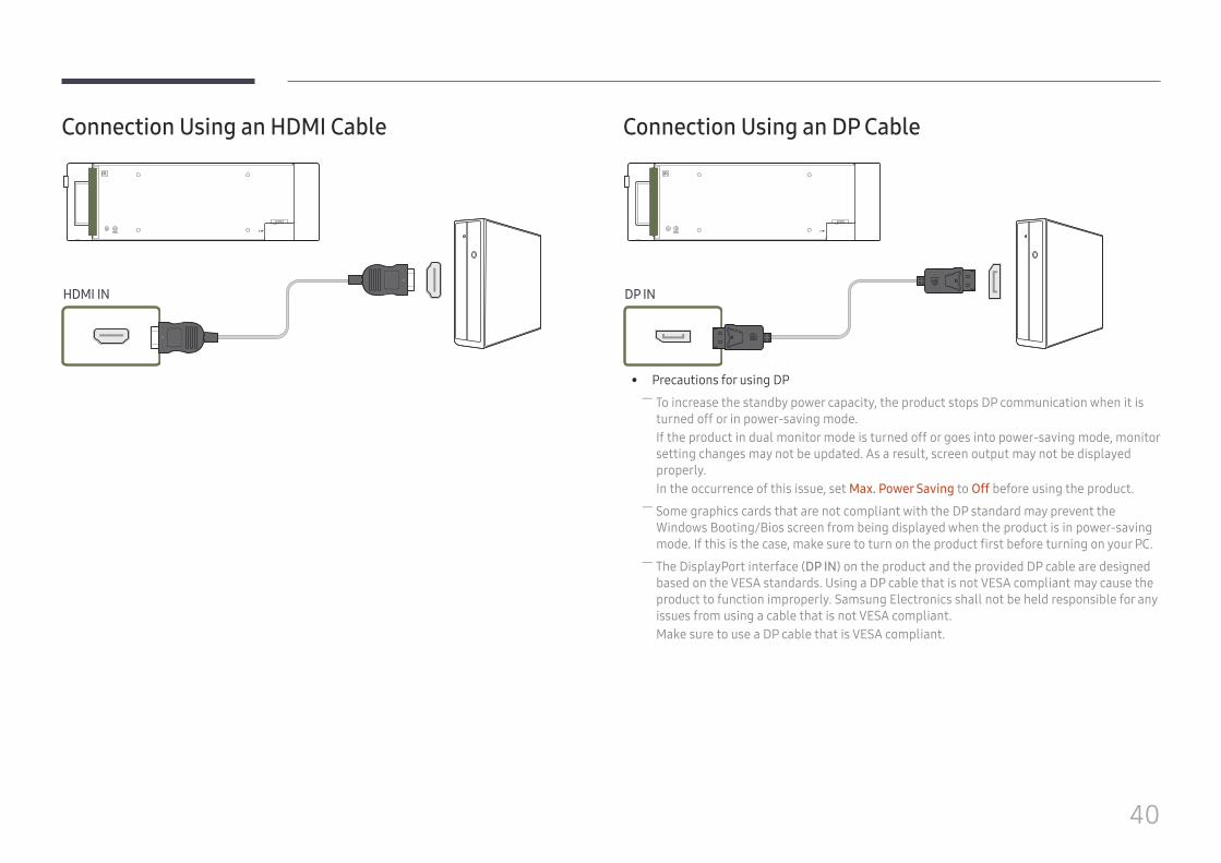
Connection Using an HDMI Cable
HDMI IN
Connection Using an DP Cable
DP IN
• Precautions for using DP ― To increase the standby power capacity, the product stops DP communication when it is turned off or in power-saving mode.If the product in dual monitor mode is turned off or goes into power-saving mode, monitor setting changes may not be updated. As a result, screen output may not be displayed properly.In the occurrence of this issue, set Max. Power Saving to Off before using the product.
― Some graphics cards that are not compliant with the DP standard may prevent the Windows Booting/Bios screen from being displayed when the product is in power-saving mode. If this is the case, make sure to turn on the product first before turning on your PC.
― The DisplayPort interface (DP IN) on the product and the provided DP cable are designed based on the VESA standards. Using a DP cable that is not VESA compliant may cause the product to function improperly. Samsung Electronics shall not be held responsible for any issues from using a cable that is not VESA compliant.Make sure to use a DP cable that is VESA compliant.
41
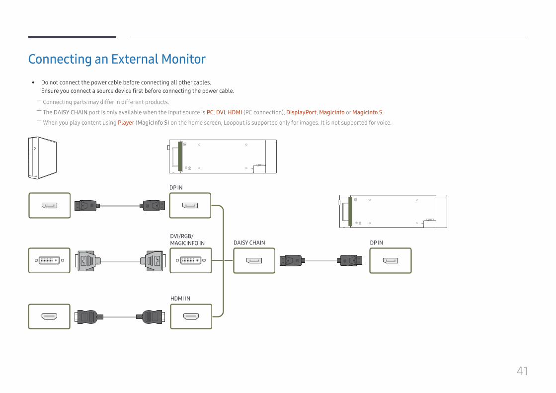
Connecting an External Monitor • Do not connect the power cable before connecting all other cables.
Ensure you connect a source device first before connecting the power cable. ― Connecting parts may differ in different products. ― The DAISY CHAIN port is only available when the input source is PC, DVI, HDMI (PC connection), DisplayPort, MagicInfo or MagicInfo S. ― When you play content using Player (MagicInfo S) on the home screen, Loopout is supported only for images. It is not supported for voice.
DP IN
DP INDAISY CHAINDVI/RGB/MAGICINFO IN
HDMI IN
42
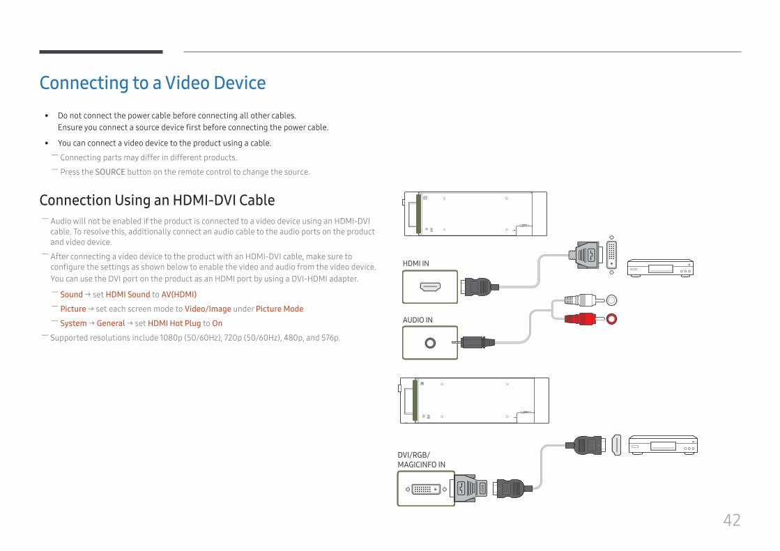
Connecting to a Video Device • Do not connect the power cable before connecting all other cables.
Ensure you connect a source device first before connecting the power cable.
• You can connect a video device to the product using a cable. ― Connecting parts may differ in different products. ― Press the SOURCE button on the remote control to change the source.
Connection Using an HDMI-DVI Cable ― Audio will not be enabled if the product is connected to a video device using an HDMI-DVI cable. To resolve this, additionally connect an audio cable to the audio ports on the product and video device.
― After connecting a video device to the product with an HDMI-DVI cable, make sure to configure the settings as shown below to enable the video and audio from the video device.You can use the DVI port on the product as an HDMI port by using a DVI-HDMI adapter.
― Sound → set HDMI Sound to AV(HDMI) ― Picture → set each screen mode to Video/Image under Picture Mode ― System → General → set HDMI Hot Plug to On
― Supported resolutions include 1080p (50/60Hz), 720p (50/60Hz), 480p, and 576p.
HDMI IN
AUDIO IN
HD
MI
DVI/RGB/MAGICINFO IN
43
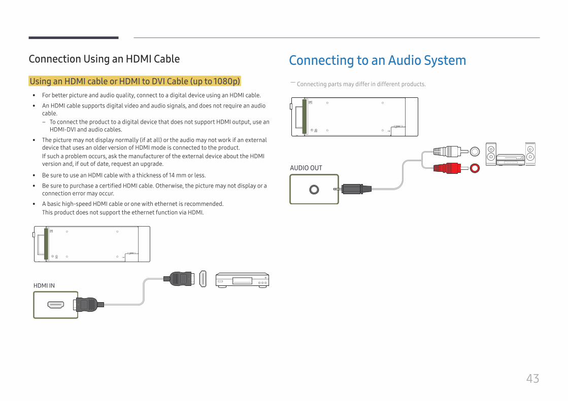
Connection Using an HDMI Cable
Using an HDMI cable or HDMI to DVI Cable (up to 1080p) • For better picture and audio quality, connect to a digital device using an HDMI cable.
• An HDMI cable supports digital video and audio signals, and does not require an audio cable.
– To connect the product to a digital device that does not support HDMI output, use an HDMI-DVI and audio cables.
• The picture may not display normally (if at all) or the audio may not work if an external device that uses an older version of HDMI mode is connected to the product. If such a problem occurs, ask the manufacturer of the external device about the HDMI version and, if out of date, request an upgrade.
• Be sure to use an HDMI cable with a thickness of 14 mm or less.
• Be sure to purchase a certified HDMI cable. Otherwise, the picture may not display or a connection error may occur.
• A basic high-speed HDMI cable or one with ethernet is recommended.This product does not support the ethernet function via HDMI.
HDMI IN
Connecting to an Audio System ― Connecting parts may differ in different products.
AUDIO OUT
44
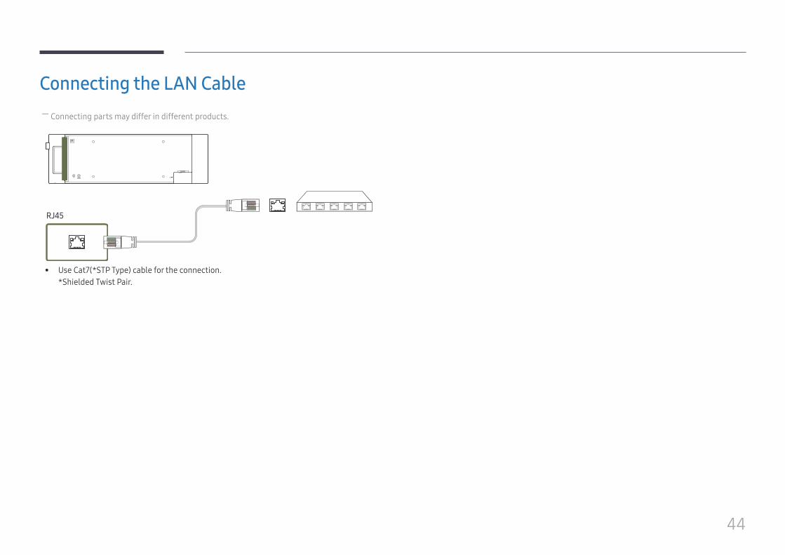
Connecting the LAN Cable ― Connecting parts may differ in different products.
RJ45
• Use Cat7(*STP Type) cable for the connection. *Shielded Twist Pair.
45
Changing the Input source
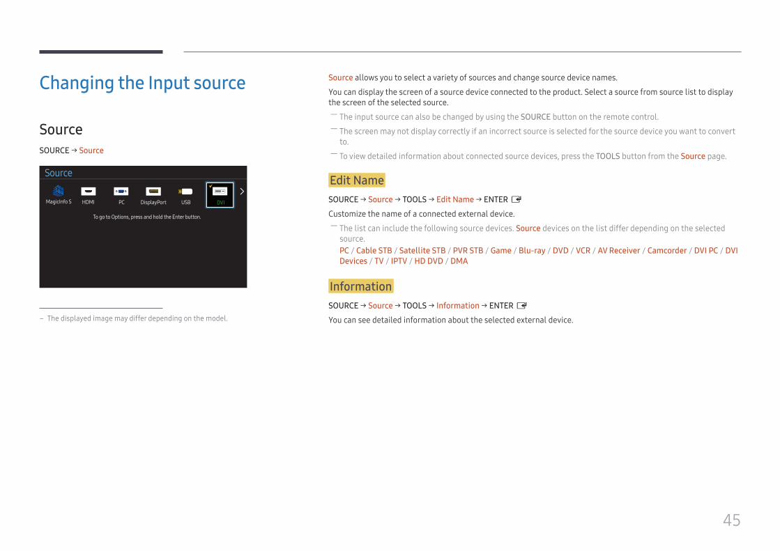
SourceSOURCE → Source
Source
MagicInfo S HDMI PC USBDisplayPort DVI
To go to Options, press and hold the Enter button.
– The displayed image may differ depending on the model.
Source allows you to select a variety of sources and change source device names.
You can display the screen of a source device connected to the product. Select a source from source list to display the screen of the selected source.
― The input source can also be changed by using the SOURCE button on the remote control. ― The screen may not display correctly if an incorrect source is selected for the source device you want to convert to.
― To view detailed information about connected source devices, press the TOOLS button from the Source page.
Edit NameSOURCE → Source → TOOLS → Edit Name → ENTER E
Customize the name of a connected external device. ― The list can include the following source devices. Source devices on the list differ depending on the selected source.PC / Cable STB / Satellite STB / PVR STB / Game / Blu-ray / DVD / VCR / AV Receiver / Camcorder / DVI PC / DVI Devices / TV / IPTV / HD DVD / DMA
InformationSOURCE → Source → TOOLS → Information → ENTER E
You can see detailed information about the selected external device.
46
Using MDC
MDC Program Installation/Uninstallation
Installation ― MDC installation can be affected by the graphics card, mother board and network conditions.
1 Click the MDC Unified installation program.
2 Select a language for installation. Next, click "OK".
3 When the "Welcome to the InstallShield Wizard for MDC_Unified" screen appears, click
"Next".
4 In the "License Agreement" window displayed, select "I accept the terms in the license
agreement" and click "Next".
5 In the displayed "Customer Information" window, fill out all the information fields and
click "Next".
6 In the displayed "Destination Folder" window, select the directory path you want to
install the program in and click "Next".
― If the directory path is not specified, the program will be installed in the default directory path.
7 In the displayed "Ready to Install the Program" window, check the directory path to
install the program in and click "Install".
8 Installation progress will be displayed.
9 Click "Finish" in the displayed "InstallShield Wizard Complete" window.
― Select "Launch MDC Unified" and click "Finish" to run the MDC program immediately.
10 The MDC Unified shortcut icon will be created on the desktop after installation.
― The MDC execution icon may not be displayed depending on the PC system or product specifications.
― Press F5 if the execution icon is not displayed.
Uninstallation1 Select Settings > Control Panel on the Start menu and double-click Add/Delete Program.
2 Select MDC Unified from the list and click Change/Remove.
Multiple display control "MDC" is an application that allows you to easily control multiple display devices simultaneously using a PC.
- For details on how to use the MDC program, refer to Help after installing the program. The MDC program is available on the website.
Chapter 04
47
Connecting to MDC
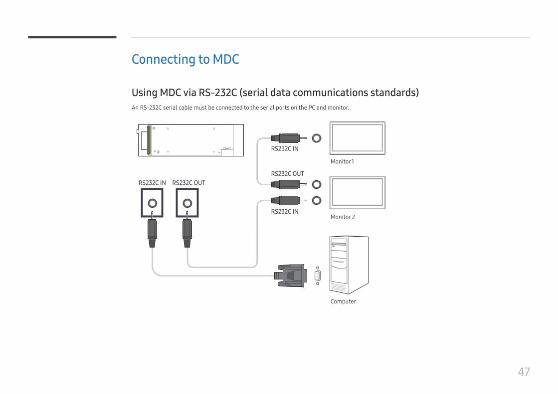
Using MDC via RS-232C (serial data communications standards)An RS-232C serial cable must be connected to the serial ports on the PC and monitor.
RS232C IN RS232C OUT
RS232C IN
RS232C IN
RS232C OUT
Monitor 1
Monitor 2
Computer
48
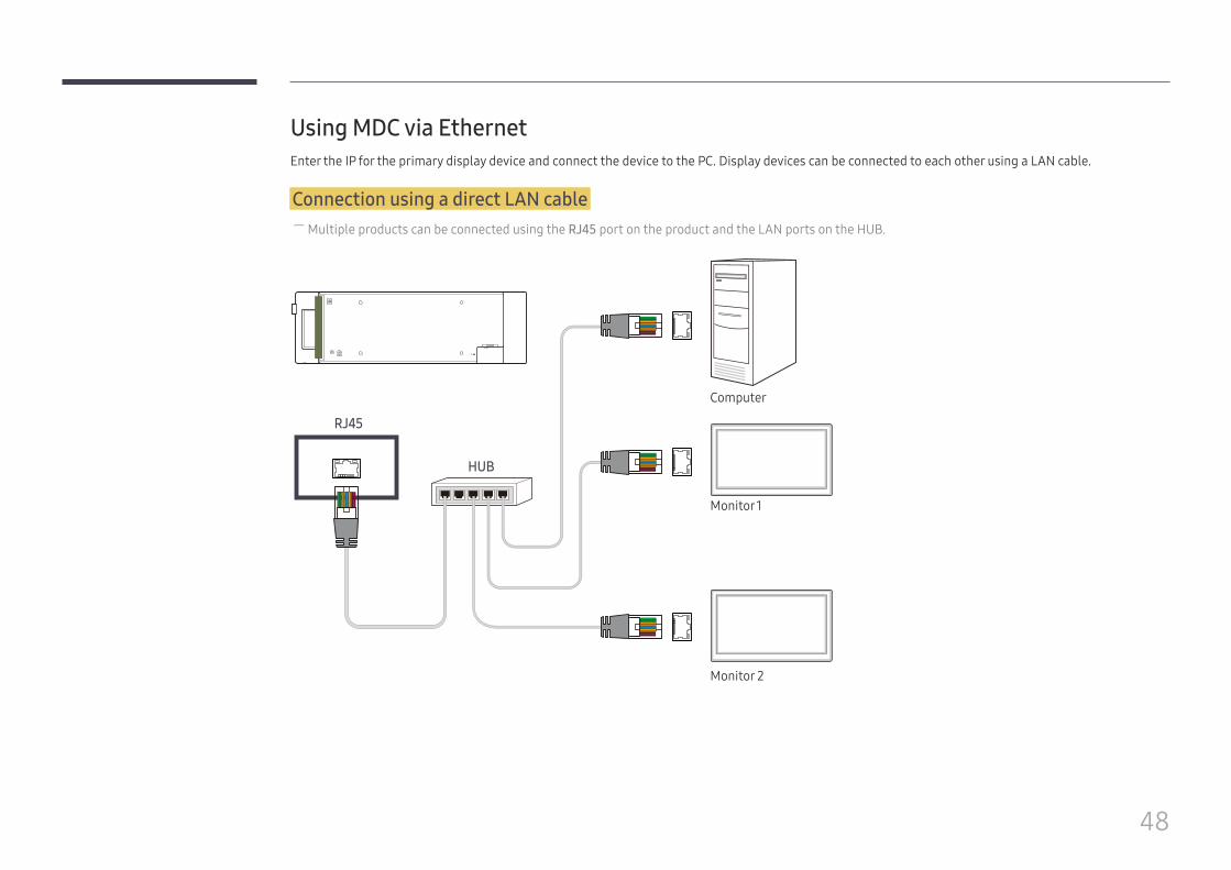
Using MDC via EthernetEnter the IP for the primary display device and connect the device to the PC. Display devices can be connected to each other using a LAN cable.
Connection using a direct LAN cable ― Multiple products can be connected using the RJ45 port on the product and the LAN ports on the HUB.
RJ45
HUB
Monitor 1
Monitor 2
Computer
49
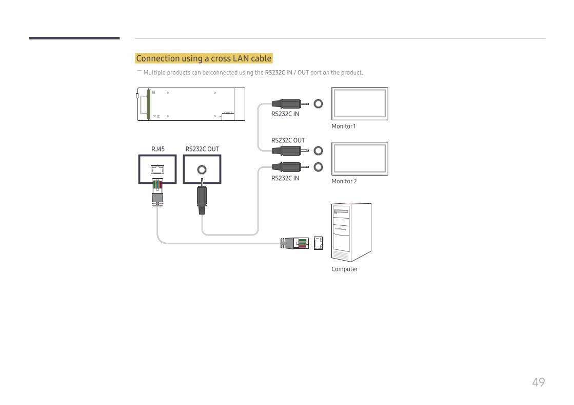
Connection using a cross LAN cable ― Multiple products can be connected using the RS232C IN / OUT port on the product.
Monitor 1
Monitor 2
Computer
RS232C OUTRS232C OUT
RJ45
RS232C IN
RS232C IN
50
Home feature
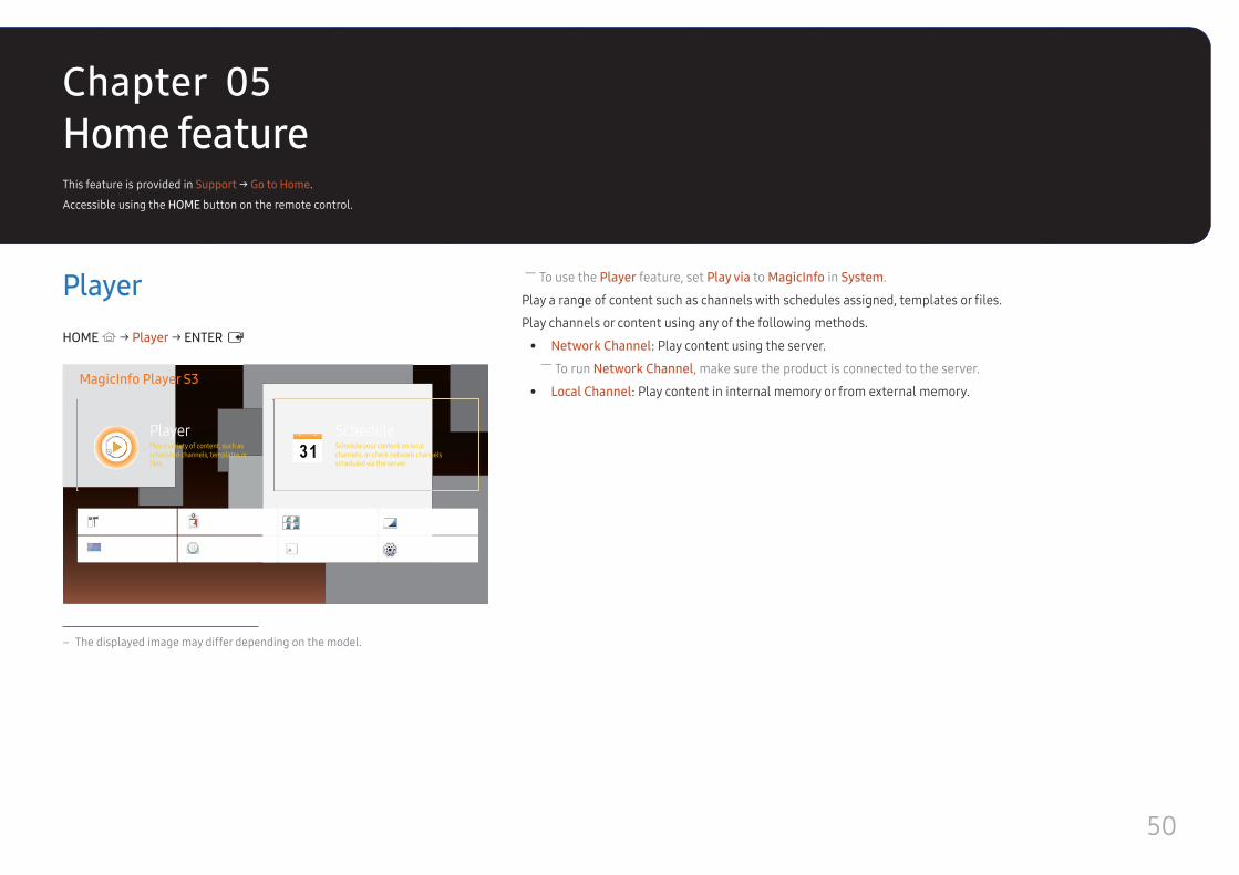
― To use the Player feature, set Play via to MagicInfo in System.
Play a range of content such as channels with schedules assigned, templates or files.
Play channels or content using any of the following methods.
• Network Channel: Play content using the server. ― To run Network Channel, make sure the product is connected to the server.
• Local Channel: Play content in internal memory or from external memory.
PlayerHOME → Player → ENTER E
MagicInfo Player S3
PlayerPlay a variety of content, such as scheduled channels, templates or files.
Schedule your content on local channels, or check network channels scheduled via the server.
Clone Product
Picture Mode
ID Settings
On/Off Timer
Video Wall
Ticker
Network Status
More settings
Schedule
– The displayed image may differ depending on the model.
This feature is provided in Support → Go to Home.
Accessible using the HOME button on the remote control.
Chapter 05
51
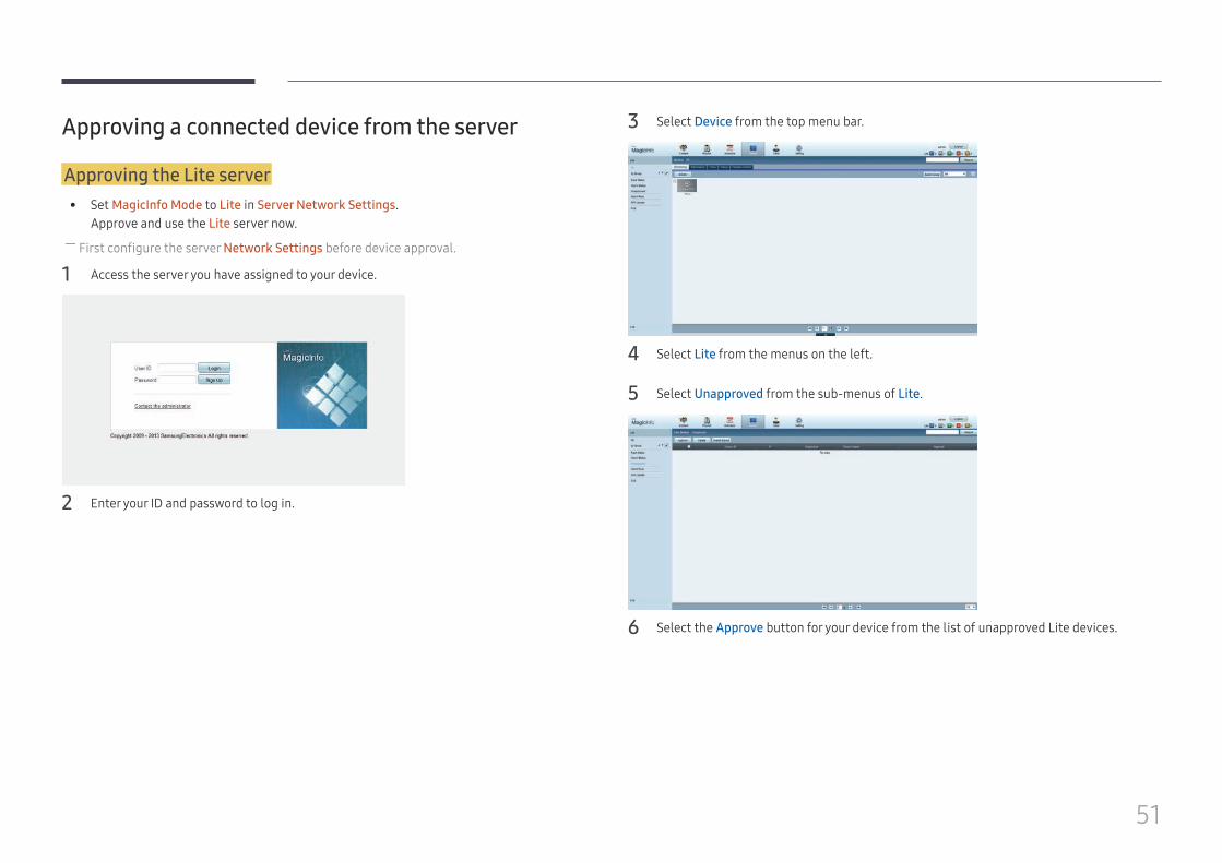
Approving a connected device from the server
Approving the Lite server • Set MagicInfo Mode to Lite in Server Network Settings.
Approve and use the Lite server now. ― First configure the server Network Settings before device approval.
1 Access the server you have assigned to your device.
2 Enter your ID and password to log in.
3 Select Device from the top menu bar.
4 Select Lite from the menus on the left.
5 Select Unapproved from the sub-menus of Lite.
6 Select the Approve button for your device from the list of unapproved Lite devices.
52
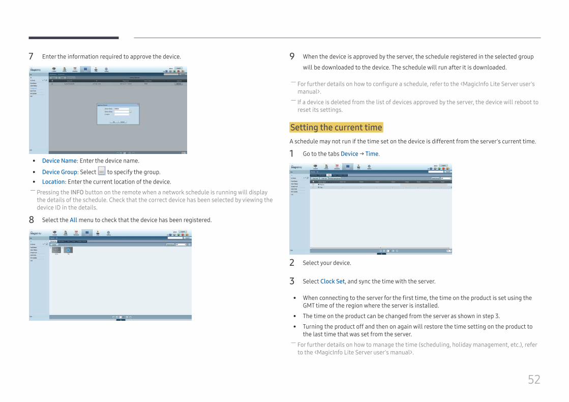
7 Enter the information required to approve the device.
• Device Name: Enter the device name.
• Device Group: Select to specify the group. • Location: Enter the current location of the device. ― Pressing the INFO button on the remote when a network schedule is running will display the details of the schedule. Check that the correct device has been selected by viewing the device ID in the details.
8 Select the All menu to check that the device has been registered.
9 When the device is approved by the server, the schedule registered in the selected group
will be downloaded to the device. The schedule will run after it is downloaded.
― For further details on how to configure a schedule, refer to the <MagicInfo Lite Server user's manual>.
― If a device is deleted from the list of devices approved by the server, the device will reboot to reset its settings.
Setting the current timeA schedule may not run if the time set on the device is different from the server's current time.
1 Go to the tabs Device → Time.
2 Select your device.
3 Select Clock Set, and sync the time with the server.
• When connecting to the server for the first time, the time on the product is set using the GMT time of the region where the server is installed.
• The time on the product can be changed from the server as shown in step 3.
• Turning the product off and then on again will restore the time setting on the product to the last time that was set from the server.
― For further details on how to manage the time (scheduling, holiday management, etc.), refer to the <MagicInfo Lite Server user's manual>.
53
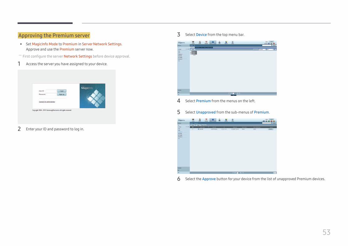
Approving the Premium server • Set MagicInfo Mode to Premium in Server Network Settings.
Approve and use the Premium server now. ― First configure the server Network Settings before device approval.
1 Access the server you have assigned to your device.
2 Enter your ID and password to log in.
3 Select Device from the top menu bar.
4 Select Premium from the menus on the left.
5 Select Unapproved from the sub-menus of Premium.
6 Select the Approve button for your device from the list of unapproved Premium devices.
54
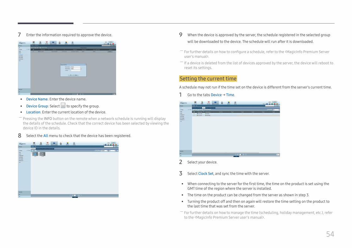
7 Enter the information required to approve the device.
• Device Name: Enter the device name.
• Device Group: Select to specify the group. • Location: Enter the current location of the device. ― Pressing the INFO button on the remote when a network schedule is running will display the details of the schedule. Check that the correct device has been selected by viewing the device ID in the details.
8 Select the All menu to check that the device has been registered.
9 When the device is approved by the server, the schedule registered in the selected group
will be downloaded to the device. The schedule will run after it is downloaded.
― For further details on how to configure a schedule, refer to the <MagicInfo Premium Server user's manual>.
― If a device is deleted from the list of devices approved by the server, the device will reboot to reset its settings.
Setting the current timeA schedule may not run if the time set on the device is different from the server's current time.
1 Go to the tabs Device → Time.
2 Select your device.
3 Select Clock Set, and sync the time with the server.
• When connecting to the server for the first time, the time on the product is set using the GMT time of the region where the server is installed.
• The time on the product can be changed from the server as shown in step 3.
• Turning the product off and then on again will restore the time setting on the product to the last time that was set from the server.
― For further details on how to manage the time (scheduling, holiday management, etc.), refer to the <MagicInfo Premium Server user's manual>.
55
Network ChannelPlay content, templates and schedules configured on the server.
• You can view whether the server is connected (approval) in the Player menu screen.To view whether the server is connected when a Network Channel is running, press INFO on the remote.
1 Select Network Channel from the Player menu.
― The No channel. message appears if no channel has been registered in Network Channel.
2 Network Channel will run.
Local ChannelPlay a schedule or channel that was configured in the product.
1 Select Local Channel from the Player menu.
― The No channel. message appears if no channel has been registered in Local Channel.
2 Local Channel will run.
Published ContentPlay a template stored on a connected USB device.
― The Published Content feature appears only when a USB device containing templates is connected. ― Play scheduled content.
Network FileContent files included in schedules that have been downloaded through MagicInfo Server are displayed.
My TemplatesPlay a template in My Templates stored in the internal memory of the product.
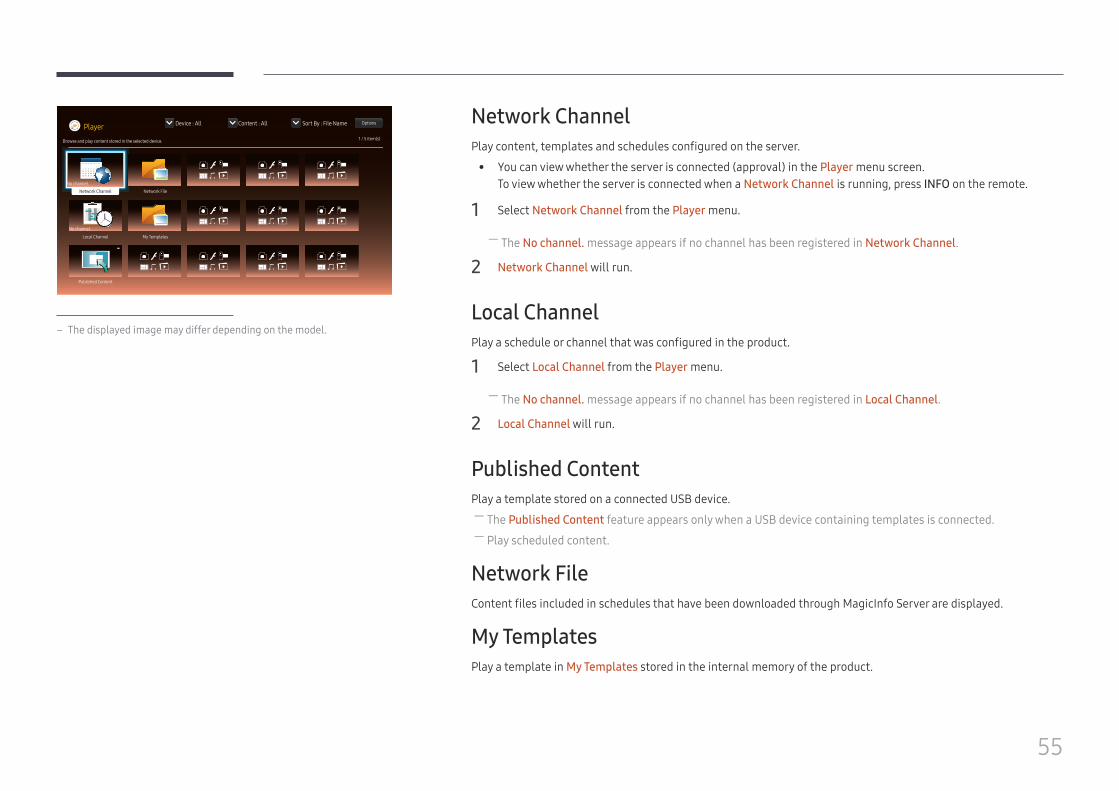
Player Device : All Content : All Sort By : File Name Options
1 / 5 item(s)Browse and play content stored in the selected device.
No channel.
Network Channel
Local Channel
Network File
My Templates
Published Content
No channel.
– The displayed image may differ depending on the model.
56
Available features in the Player pageThe Player list page provides the following features.
• DeviceSelect either Internal or USB to search for a desired device list.
– All / Internal / USB
• ContentSelect a content type as criterion to search for a desired content list.
– All / Video / Image / PDF / Flash / Office / My Templates
• Sort BySpecify the content sort criterion.
– File name / Recently Played
• Options
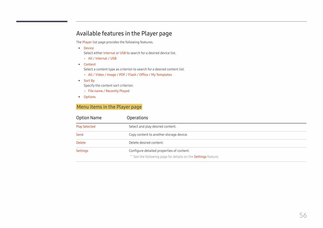
Menu items in the Player page
Option Name Operations
Play Selected Select and play desired content.
Send Copy content to another storage device.
Delete Delete desired content.
Settings Configure detailed properties of content. ― See the following page for details on the Settings feature.
57
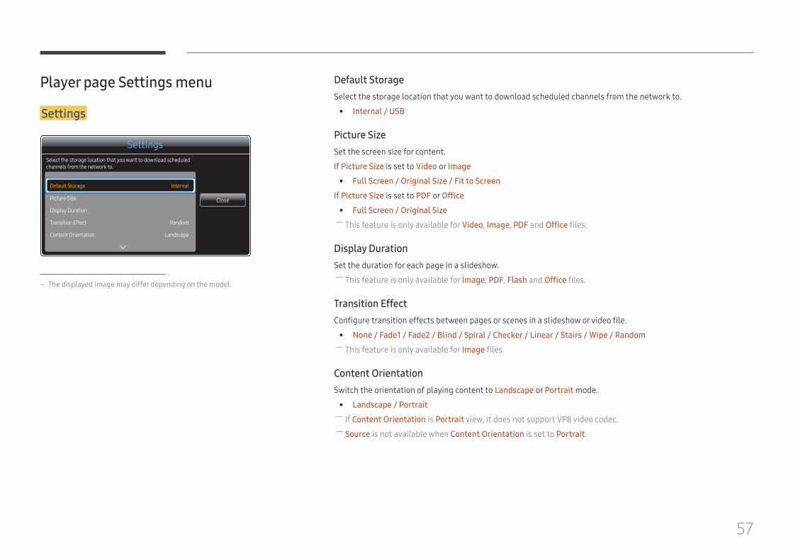
Player page Settings menu
Settings
Settings
Default Storage
Picture Size
Display Duration
Transition Effect
Content Orientation
Internal
Random
Landscape
Select the storage location that you want to download scheduled channels from the network to.
Close
– The displayed image may differ depending on the model.
Default StorageSelect the storage location that you want to download scheduled channels from the network to.
• Internal / USB
Picture SizeSet the screen size for content.
If Picture Size is set to Video or Image
• Full Screen / Original Size / Fit to Screen
If Picture Size is set to PDF or Office
• Full Screen / Original Size ― This feature is only available for Video, Image, PDF and Office files.
Display DurationSet the duration for each page in a slideshow.
― This feature is only available for Image, PDF, Flash and Office files.
Transition EffectConfigure transition effects between pages or scenes in a slideshow or video file.
• None / Fade1 / Fade2 / Blind / Spiral / Checker / Linear / Stairs / Wipe / Random ― This feature is only available for Image files.
Content OrientationSwitch the orientation of playing content to Landscape or Portrait mode.
• Landscape / Portrait ― If Content Orientation is Portrait view, it does not support VP8 video codec. ― Source is not available when Content Orientation is set to Portrait.
58
Default ContentThis default content will be displayed if you run a channel while no programs are scheduled on the channel.
• None
Safely RemoveSafely removes USB memory
ResetRestore all the values under Settings to the default when the product was purchased.
59
When Content is Running
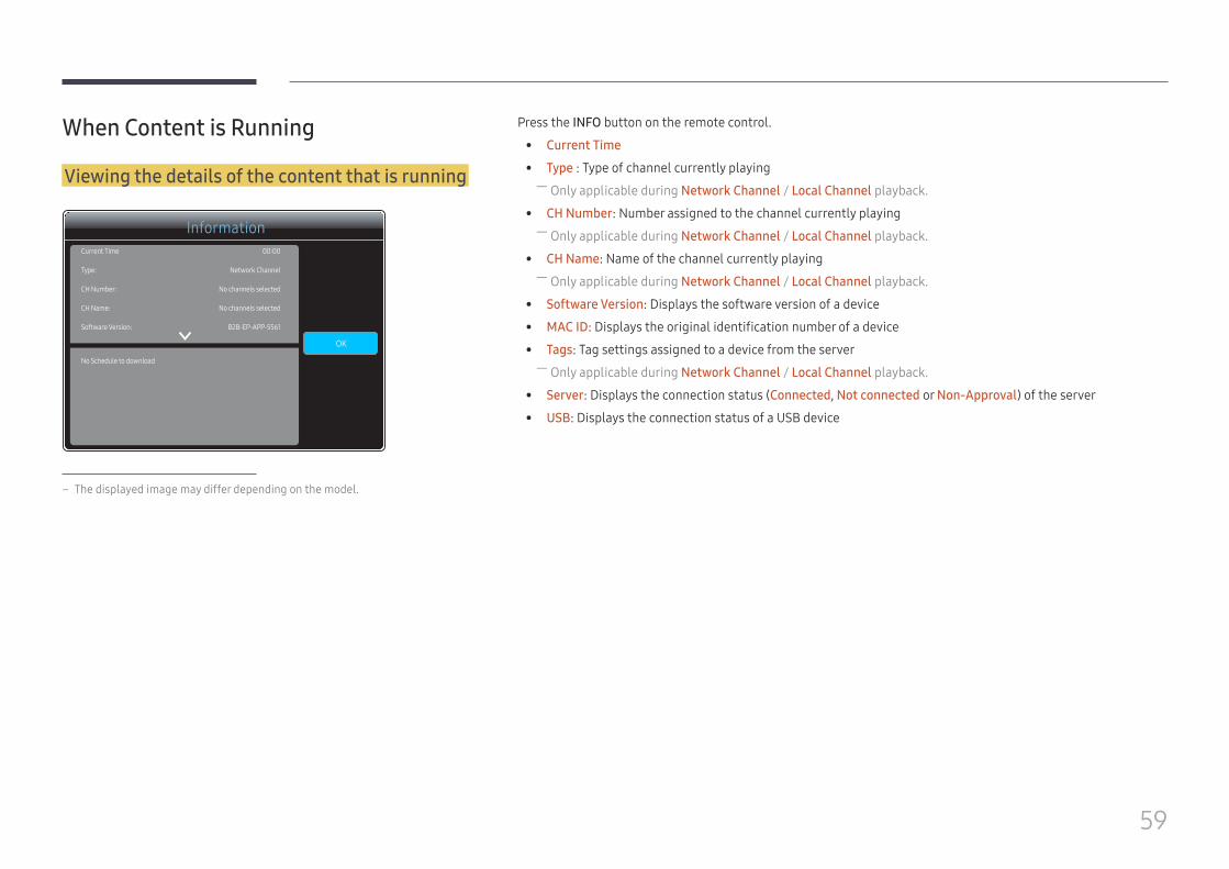
Viewing the details of the content that is running
InformationCurrent Time
Type:
CH Number:
CH Name:
Software Version:
No Schedule to download
00:00
Network Channel
No channels selected
No channels selected
B2B-EP-APP-5561
OK
– The displayed image may differ depending on the model.
Press the INFO button on the remote control.
• Current Time
• Type : Type of channel currently playing ― Only applicable during Network Channel / Local Channel playback.
• CH Number: Number assigned to the channel currently playing ― Only applicable during Network Channel / Local Channel playback.
• CH Name: Name of the channel currently playing ― Only applicable during Network Channel / Local Channel playback.
• Software Version: Displays the software version of a device
• MAC ID: Displays the original identification number of a device
• Tags: Tag settings assigned to a device from the server ― Only applicable during Network Channel / Local Channel playback.
• Server: Displays the connection status (Connected, Not connected or Non-Approval) of the server
• USB: Displays the connection status of a USB device
60
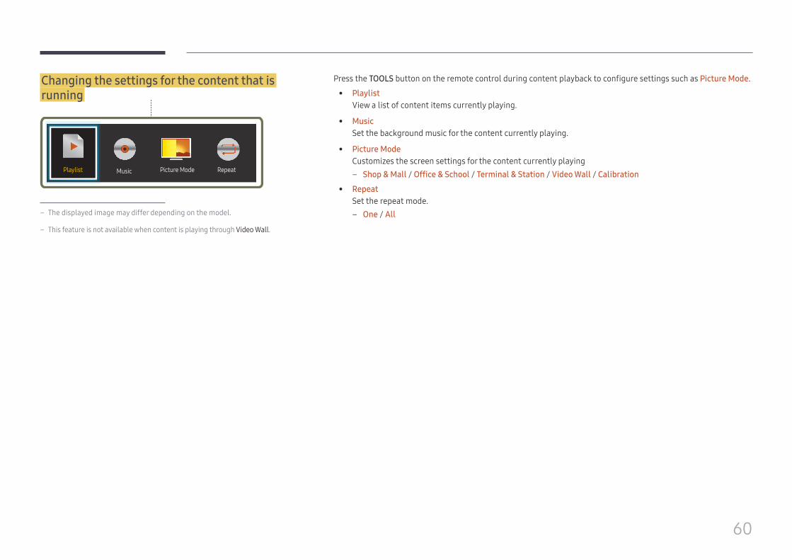
Changing the settings for the content that is running
MusicPlaylist Picture Mode Repeat
– The displayed image may differ depending on the model.
– This feature is not available when content is playing through Video Wall.
Press the TOOLS button on the remote control during content playback to configure settings such as Picture Mode.
• PlaylistView a list of content items currently playing.
• MusicSet the background music for the content currently playing.
• Picture ModeCustomizes the screen settings for the content currently playing
– Shop & Mall / Office & School / Terminal & Station / Video Wall / Calibration
• RepeatSet the repeat mode.
– One / All
61
File Formats Compatible with Player • Supported file systems include FAT32 and NTFS.
• A file with a vertical and horizontal resolution larger than the maximum resolution cannot be played.Check the vertical and horizontal resolution of the file.
• Check the supported video and audio Codec types and Versions.
• Check the supported file versions. – Flash player 11.0 and older and Flash Air 3.0 and older versions are supported. – PowerPoint version up to 97 – 2007 is supported
• Only the last USB device that was connected is recognized.
Network Schedule Multiframe
Playback restrictions • A maximum of two video files (Video) can be played simultaneously.
• For video files with vertical dimensions of 1080p or larger, only one file can be played at a time.
• The maximum number of 4096 x 4096-dimension image files that can be played simultaneously from a media slide is four.
• More than one Flash file cannot be played.
• If an input source element is included, only one video file or media slide can be played simultaneously.
• In a combination of "video files + Flash files + input source elements," supported combinations of different content files that can simultaneously play are as follows:
– Video + Flash – Video + input source element – Flash + input source element
• For Office files (PPT and Word files) and PDF files, only one file type is supported at a time.
• LFD(.lfd) files are not supported.
Sound output restrictions • More than one sound output cannot be used.
• Playback priority: Flash file > network BGM > local BGM > video file in the main frame selected by the user ― Network BGM: Settings can be configured in step 1 when creating a server schedule. ― Local BGM: BGM settings can be configured using the tools displayed after the TOOLS button is pressed during Player playback.
― User-selected main frame: Main frame settings can be configured in step 2 when creating a server schedule.
Template files and LFD(.lfd) files
Restrictions • Ensure a distributed folder (content / schedules) exists in Internal / USB memory.
Playback restrictions • A maximum of two video (Video) files can be played.
• More than one Flash file cannot be played.
• For Office files (PPT and Word files) and PDF files, only one file type is supported at a time.
• Multiple videos (Video) cannot be played on a single display of a video wall simultaneously.
Sound output restrictions • More than one sound output cannot be used.
• Playback priority: Flash file > network BGM > local BGM > video file in the main frame selected by the user
62
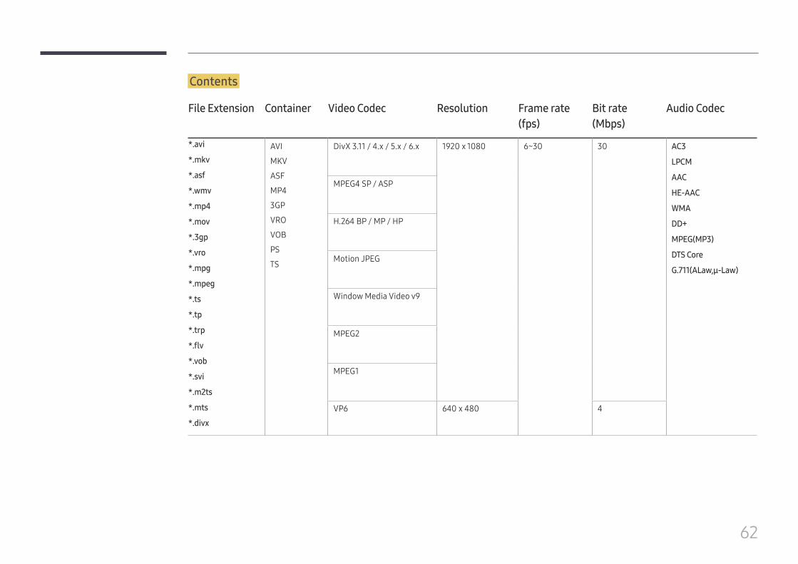
Contents
File Extension Container Video Codec Resolution Frame rate(fps)
Bit rate(Mbps)
Audio Codec
*.avi
*.mkv
*.asf
*.wmv
*.mp4
*.mov
*.3gp
*.vro
*.mpg
*.mpeg
*.ts
*.tp
*.trp
*.flv
*.vob
*.svi
*.m2ts
*.mts
*.divx
AVI
MKV
ASF
MP4
3GP
VRO
VOB
PS
TS
DivX 3.11 / 4.x / 5.x / 6.x 1920 x 1080 6~30 30 AC3
LPCM
AAC
HE-AAC
WMA
DD+
MPEG(MP3)
DTS Core
G.711(ALaw,μ-Law)
MPEG4 SP / ASP
H.264 BP / MP / HP
Motion JPEG
Window Media Video v9
MPEG2
MPEG1
VP6 640 x 480 4
63
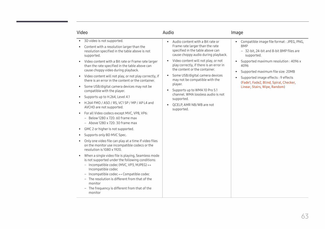
Video Audio Image
• 3D video is not supported.
• Content with a resolution larger than the resolution specified in the table above is not supported.
• Video content with a Bit rate or Frame rate larger than the rate specified in the table above can cause choppy video during playback.
• Video content will not play, or not play correctly, if there is an error in the content or the container.
• Some USB/digital camera devices may not be compatible with the player.
• Supports up to H.264, Level 4.1
• H.264 FMO / ASO / RS, VC1 SP / MP / AP L4 and AVCHD are not supported.
• For all Video codecs except MVC, VP8, VP6: – Below 1280 x 720: 60 frame max – Above 1280 x 720: 30 frame max
• GMC 2 or higher is not supported.
• Supports only BD MVC Spec.
• Only one video file can play at a time if video files on the monitor use incompatible codecs or the resolution is 1080 x 1920.
• When a single video file is playing, Seamless mode is not supported under the following conditions:
– Incompatible codec (MVC, VP3, MJPEG) ↔ Incompatible codec
– Incompatible codec ↔ Compatible codec – The resolution is different from that of the
monitor – The frequency is different from that of the
monitor
• Audio content with a Bit rate or Frame rate larger than the rate specified in the table above can cause choppy audio during playback.
• Video content will not play, or not play correctly, if there is an error in the content or the container.
• Some USB/digital camera devices may not be compatible with the player.
• Supports up to WMA 10 Pro 5.1 channel. WMA lossless audio is not supported.
• QCELP, AMR NB/WB are not supported.
• Compatible image file format : JPEG, PNG, BMP
– 32-bit, 24-bit and 8-bit BMP files are supported.
• Supported maximum resolution : 4096 x 4096
• Supported maximum file size: 20MB
• Supported image effects : 9 effects(Fade1, Fade2, Blind, Spiral, Checker, Linear, Stairs, Wipe, Random)
64
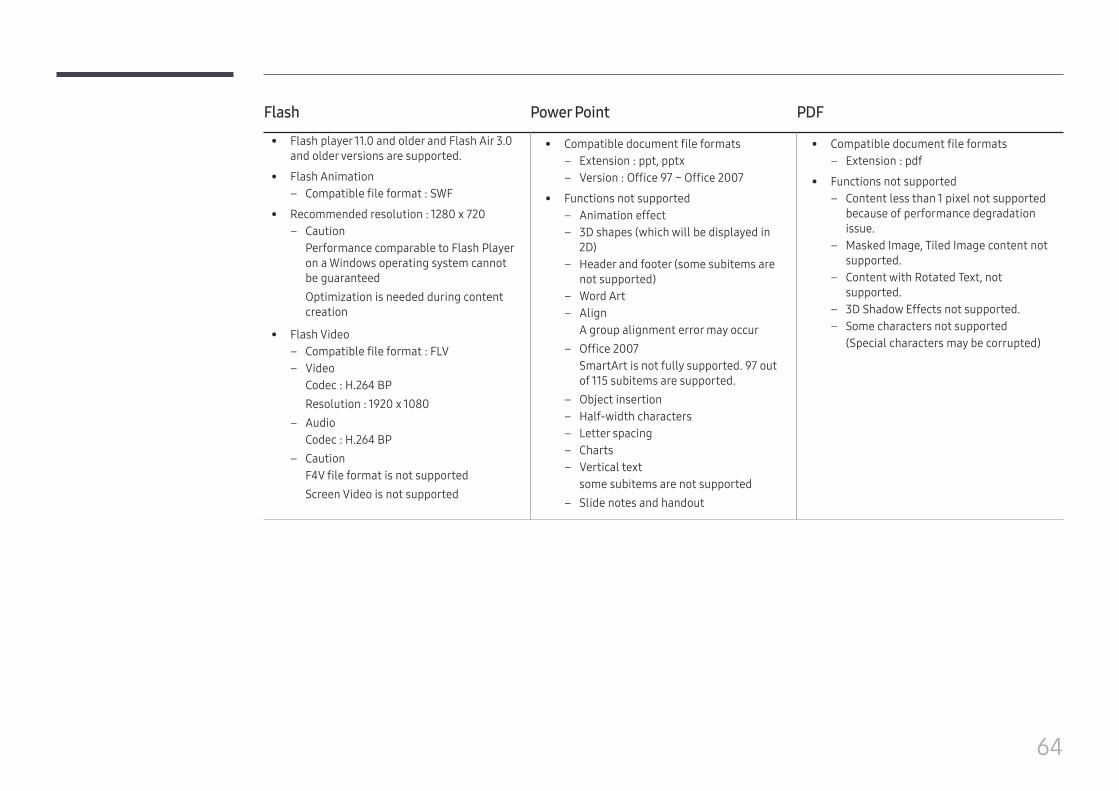
Flash Power Point PDF
• Flash player 11.0 and older and Flash Air 3.0 and older versions are supported.
• Flash Animation – Compatible file format : SWF
• Recommended resolution : 1280 x 720 – Caution
Performance comparable to Flash Player on a Windows operating system cannot be guaranteedOptimization is needed during content creation
• Flash Video – Compatible file format : FLV – Video
Codec : H.264 BPResolution : 1920 x 1080
– AudioCodec : H.264 BP
– CautionF4V file format is not supportedScreen Video is not supported
• Compatible document file formats – Extension : ppt, pptx – Version : Office 97 ~ Office 2007
• Functions not supported – Animation effect – 3D shapes (which will be displayed in
2D) – Header and footer (some subitems are
not supported) – Word Art – Align
A group alignment error may occur – Office 2007
SmartArt is not fully supported. 97 out of 115 subitems are supported.
– Object insertion – Half-width characters – Letter spacing – Charts – Vertical text
some subitems are not supported – Slide notes and handout
• Compatible document file formats – Extension : pdf
• Functions not supported – Content less than 1 pixel not supported
because of performance degradation issue.
– Masked Image, Tiled Image content not supported.
– Content with Rotated Text, not supported.
– 3D Shadow Effects not supported. – Some characters not supported
(Special characters may be corrupted)
65
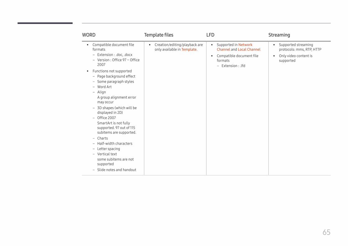
WORD Template files LFD Streaming
• Compatible document file formats
– Extension : .doc, .docx – Version : Office 97 ~ Office
2007
• Functions not supported – Page background effect – Some paragraph styles – Word Art – Align
A group alignment error may occur
– 3D shapes (which will be displayed in 2D)
– Office 2007SmartArt is not fully supported. 97 out of 115 subitems are supported.
– Charts – Half-width characters – Letter spacing – Vertical text
some subitems are not supported
– Slide notes and handout
• Creation/editing/playback are only available in Template.
• Supported in Network Channel and Local Channel
• Compatible document file formats
– Extension : .lfd
• Supported streaming protocols: mms, RTP, HTTP
• Only video content is supported
66
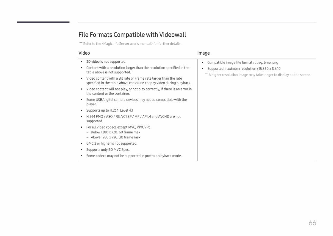
File Formats Compatible with Videowall ― Refer to the <MagicInfo Server user's manual> for further details.
Video Image
• 3D video is not supported.
• Content with a resolution larger than the resolution specified in the table above is not supported.
• Video content with a Bit rate or Frame rate larger than the rate specified in the table above can cause choppy video during playback.
• Video content will not play, or not play correctly, if there is an error in the content or the container.
• Some USB/digital camera devices may not be compatible with the player.
• Supports up to H.264, Level 4.1
• H.264 FMO / ASO / RS, VC1 SP / MP / AP L4 and AVCHD are not supported.
• For all Video codecs except MVC, VP8, VP6: – Below 1280 x 720: 60 frame max – Above 1280 x 720: 30 frame max
• GMC 2 or higher is not supported.
• Supports only BD MVC Spec.
• Some codecs may not be supported in portrait playback mode.
• Compatible image file format : Jpeg, bmp, png
• Supported maximum resolution : 15,360 x 8,640 ― A higher resolution image may take longer to display on the screen.
67
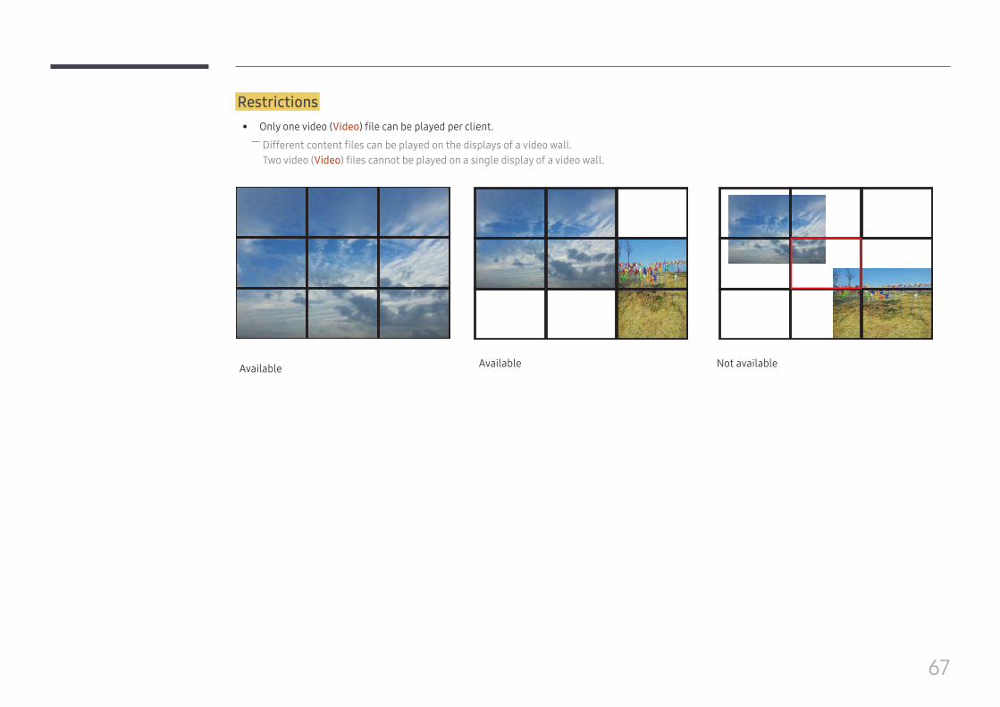
Restrictions • Only one video (Video) file can be played per client.
― Different content files can be played on the displays of a video wall.Two video (Video) files cannot be played on a single display of a video wall.
Available Available Not available
68
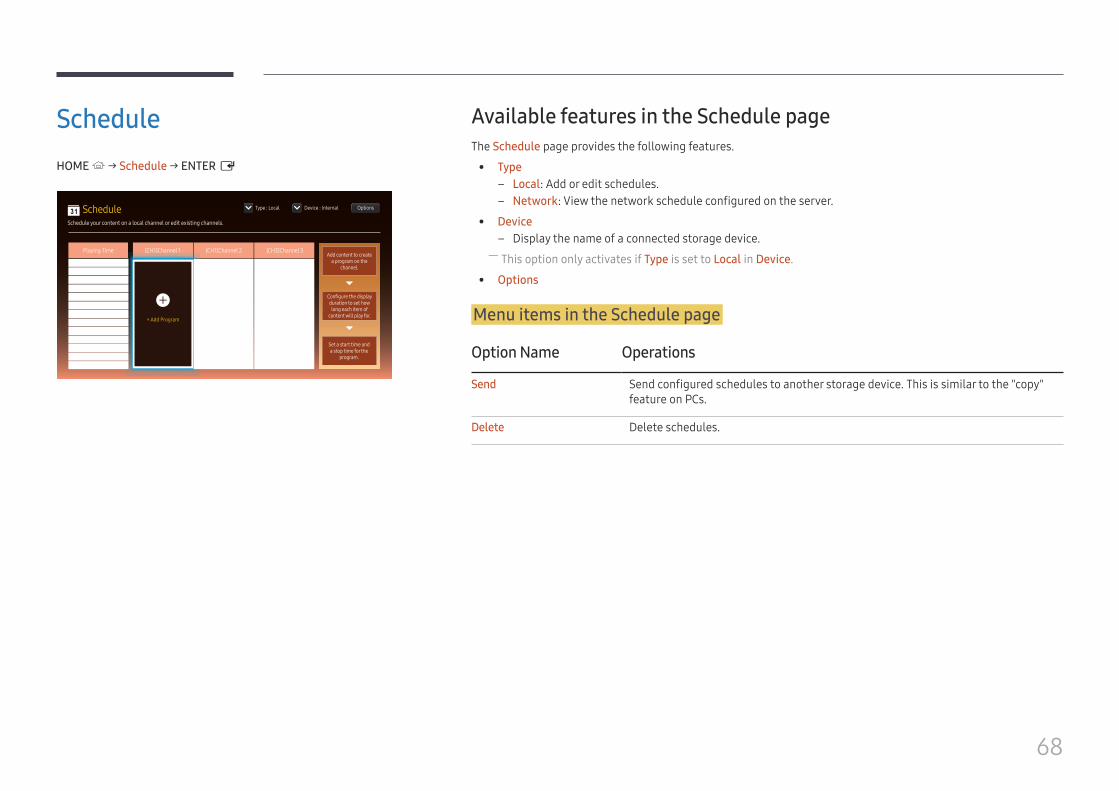
ScheduleHOME → Schedule → ENTER E
00:00
00:30
01:00
01:30
02:00
02:30
03:00
03:30
04:00
04:30
05:00
05:30
06:00
Add content to create a program on the
channel.
Configure the display duration to set how long each item of
content will play for.
Set a start time and a stop time for the
program.
Playing Time [CH1]Channel 1 [CH1]Channel 2 [CH3]Channel 3
OptionsType : Local Device : Internal
Schedule your content on a local channel or edit existing channels.
Schedule
+ Add Program Schedule your content on CH 2.
Schedule your content on CH 3.
Available features in the Schedule pageThe Schedule page provides the following features.
• Type – Local: Add or edit schedules. – Network: View the network schedule configured on the server.
• Device – Display the name of a connected storage device.
― This option only activates if Type is set to Local in Device.
• Options
Menu items in the Schedule page
Option Name Operations
Send Send configured schedules to another storage device. This is similar to the "copy" feature on PCs.
Delete Delete schedules.
69
Configuring channel schedulesPlay media content such as videos, photos and music at a desired time.
1 Select a channel to configure.
2 Select video, music and photo content you want to apply to the channel schedule.
3 Set the time to play the schedule. (Start Time ~ Stop Time)
4 Change the channel schedule name, and then select a destination folder to save to.
5 Press the Save button.
― Only applicable when Type is set to Local.
Editing a channel schedule.Change settings for a configured channel schedule such as content, the duration and the schedule name.
1 Select a channel to edit.
2 Select video, photo or music content to edit in the channel schedule.
– Deleting content: Place the cursor over the desired content and then press the E button to delete it. – Move to the far right end of the content list. Click the + button to add content or change the playback order of content items.
3 Set the time to play the schedule. (Start Time ~ Stop Time)
4 Change the channel schedule name, and then select a destination folder to save to.
5 Press the Save button.
― Only applicable when Type is set to Local.
70
Clone ProductHOME → Clone Product → ENTER E
Clone Product
– The displayed image may differ depending on the model.
Export the product settings to a USB device or load the settings via a USB device.
This option is useful when assigning the same settings to several products.
When USB does not contain a duplicate file
1 Connect the USB device to a USB port. Run the Clone Product function.
2 The No cloning file found on the external storage device. Export this device's settings to the external storage
device? message appears.
When USB contains a duplicate file
1 Connect the USB device to a USB port. Run the Clone Product function.
2 The Settings file found on the external storage device. Please select an option. message appears.
Run the Import from External Storage or Export to External Storage function. – Import from External Storage: Copy settings saved on an external storage device to the product. – Export to External Storage: Copy settings on the product to an external storage device.
― After configuration is complete, the product is rebooted automatically.
71
ID SettingsHOME → ID Settings → ENTER E
ID Settings
– The displayed image may differ depending on the model.
Assign an ID to a set.
Device IDEnter the ID number of the product connected to the input cable for input signal reception. (Range: 0~224)
― Press u/d to select a number, and press E. ― Enter the number you want using the number buttons on the remote control.
PC Connection CableSelect a method to connect to MDC to receive the MDC signal.
• RS232C cableCommunicate with MDC via the RS232C-stereo cable.
• RJ45(LAN) cableCommunicate with MDC via the RJ45 cable.
Device ID Auto Set ― Assign ID number automatically for all connected products.
72
Video WallHOME → Video Wall → ENTER E
Video Wall
– The displayed image may differ depending on the model.
Customize the layout of multiple displays that are connected to form a video wall.
In addition, display part of a whole picture or repeat the same picture on each of the connected multiple displays.
To display multiple images, refer to MDC Help or the MagicInfo user guide. Some models may not support the MagicInfo function.
Apply to • Current Source (screen output from a device connected to Source): Configure videowall features for the screen
output from an external device connected to the product.
• MagicInfo Player S: Configure videowall features for content saved in the product or content saved on a USB memory or SD card.
Restrictions ― Playback may be initially choppy if video files of different resolutions play successively (i.e., 1280x720 content plays after 1920x1080 content) or an image file and a video file play one after the other.
Video Image
• Supported resolution – 1920 x 1080 @ 24p/30p – 1280 x 720 @ 24p/30p/60p
• HEVC and 3D images are not supported.
• Compatible image file format: Jpeg, png, bmp
• Supported maximum resolution – jpeg: 15360 x 8640 – png: 4096 x 4096 – bmp: 4096 x 4096
73
Video WallYou can activate or deactivate Video Wall.
To organize a video wall, select On.
• Off / On
Horizontal x VerticalThis feature automatically splits a videowall display based on a videowall matrix configuration.
Enter the videowall matrix.
The videowall display is split based on the configured matrix. The number of vertical or horizontal display devices can be set within the range 1 and 15. ― A videowall display can be split into a maximum of 225 screens. ― The Horizontal x Vertical option is only enabled when Video Wall is set to On.
Screen PositionTo rearrange split screens, adjust the number for each product in the matrix using the Screen Position feature.
Selecting Screen Position will display the videowall matrix with the numbers assigned to the products that form the videowall.
To rearrange products, use the direction buttons on the remote control to move a product to another desired number. Press the E button.
• All Displays: Assign screen positions to All displays. Then, you don't need to set up video wall for individual displays.
• Current Displays: Only Assign screen position for this first display. ― Screen Position can be set up with a maximum of 15x15 split screens (225 devices). If connected using DP Loopout mode, the maximum number of devices changes to 100.
― The Screen Position option is only enabled when Video Wall is set to On. ― To use the function, make sure Horizontal x Vertical is configured.
FormatSelect how to display images on the videowall display.
• Full: Display images in full screen with no margin.
• Natural: Display images in the original aspect ratio without enlarging or reducing the size. ― The Format option is only enabled when Video Wall is set to On.
74
Check the current network and Internet connection.Network StatusHOME → Network Status → ENTER E
Network Status
– The displayed image may differ depending on the model.
75
Picture ModeHOME → Picture Mode → ENTER E
Picture Mode
– The displayed image may differ depending on the model.
Select a picture mode (Picture Mode) suitable for the environment where the product will be used.
Video/Image mode improves the picture quality of the video device. Text mode improves the picture quality of the computer.
• Shop & MallSuitable for shopping malls.
– Select either Video/Image or Text depending on the picture mode.
• Office & SchoolSuitable for offices and schools.
– Select either Video/Image or Text depending on the picture mode.
• Terminal & StationSuitable for bus terminals and train stations.
– Select either Video/Image or Text depending on the picture mode.
• Video WallSuitable for environments where videowall display are used.
– Select either Video/Image or Text depending on the picture mode.
• CalibrationIn this mode, the brightness, color, gamma and uniformity settings customized using the color calibration program Advanced Color Management are applied.
– To apply the Calibration mode properly, make sure you configure the picture quality settings, such as brightness, color, gamma and uniformity, using the color calibration program Advanced Color Management.
– To download the Advanced Color Management program, visit www.samsung.com/displaysolutions.
• BD WiseProvides the optimal picture quality for Samsung DVD, Blu-ray and Home Theater products which support BD Wise. When BD Wise is turned On, the picture mode is automatically changed to the optimal resolution.
– Available when you connect Samsung products that support BD Wise through an HDMI cable to the product.
– The BD Wise function is enabled only when a source device with the BD Wise function is connected.
76
On/Off TimerHOME → On/Off Timer → ENTER E
On/Off Timer
– The displayed image may differ depending on the model.
― You must set Clock Set before you can use this feature.
On TimerSet On Timer so that your product turns on automatically at a time and on a day of your choosing.
The power is turned on with the specified volume or input source.
On Timer: Set the on timer by making a selection from one of the seven options. Ensure you set the current time first.
(On Timer 1 ~ On Timer 7)
• Setup: Select Off, Once, Everyday, Mon~Fri, Mon~Sat, Sat~Sun or Manual.If you select Manual, you can choose the days you want On Timer to turn on your product.
– The check mark indicates days you’ve selected.
• Time: Set the hour and minute. Use the number buttons or the up and down arrow keys to enter numbers. Use the left and right arrow buttons to change entry fields.
• Volume: Set the desired volume level. Use the left and right arrow buttons to change the volume level.
• Source: Select the input source of your choice.
• Content (when the Source is set to Internal/USB): From the USB device or internal memory device, select a folder containing content you want to play when the product turns on. Content can include music, photo or video files. ― This function is available only when a USB device is connected.
― If there is no music file on the USB device or you don’t select a folder containing a music file, the Timer function does not operate correctly.
― If there is only one photo file in the USB, the Slide Show will not play. ― If a folder name is too long, the folder cannot be selected. ― Each USB you use is assigned its own folder. When using more than one of the same type of USB, make sure the folders assigned to each USB have different names.
― We recommend that you use a USB memory stick and a multi card reader when using On Timer. ― The On Timer function may not work with USB devices with a built-in battery, MP3 players, or PMPs made by some manufacturers because the product can take too long to recognize these devices.
77
Off TimerSet the off timer (Off Timer) by making a selection from one of the seven options. (Off Timer 1 ~ Off Timer 7)
• Setup: Select Off, Once, Everyday, Mon~Fri, Mon~Sat, Sat~Sun or Manual.If you select Manual, you can choose the days you want Off Timer to turn off your product.
– The check mark indicates days you’ve selected.
• Time: Set the hour and minute. Use the number buttons or the up and down arrow keys to enter numbers. Use the left and right arrow buttons to change entry fields.
Holiday ManagementTimer will be disabled during a period specified as a holiday.
• Add Holiday: Specify the period you want to add as a holiday.Select the start and end dates of the holiday you want to add using the u/d buttons, and click the Save button.The period will be added to the list of holidays.
– Start: Set the start date of the holiday. – End: Set the end date of the holiday.
― Delete: Delete selected items from the list of holidays. ― Edit: Select a holiday item and then change the date.
• Set Applied Timer: Set the On Timer and Off Timer to not activate on public holidays. – Press E to select the On Timer and Off Timer settings you do not want to activate. – The selected On Timer and Off Timer will not activate.
78
TickerHOME → Ticker → ENTER E
Ticker
– The displayed image may differ depending on the model.
Input text while a video or image is displayed and display the text on the screen.
• Off / On
• Message: Enter a message to display on the screen.
• Time: Set the Start Time and End Time to display a Message.
• Font Options: Specify the text font and color for the message.
• Position: Select an orientation to display a Message.
• Scroll: Specify the scroll Direction and Speed for the message.
• Preview: Preview configured caption settings.
More settingsHOME → More settings → ENTER E
More settings
– The displayed image may differ depending on the model.
The picture settings menu appears.
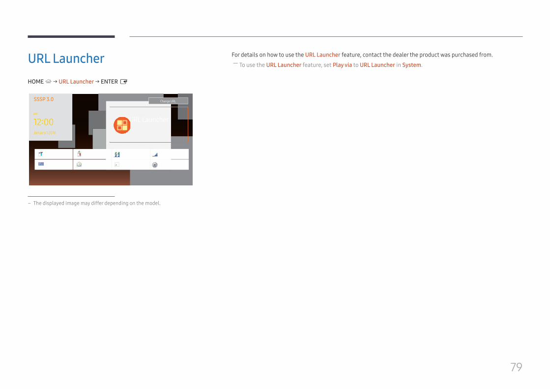
79
URL LauncherHOME → URL Launcher → ENTER E
SSSP 3.0
URL Launcher12:00
Change URL
pm
January 1 2016
Clone Product
Picture Mode
ID Settings
On/Off Timer
Video Wall
Ticker
Network Status
More settings
– The displayed image may differ depending on the model.
For details on how to use the URL Launcher feature, contact the dealer the product was purchased from. ― To use the URL Launcher feature, set Play via to URL Launcher in System.
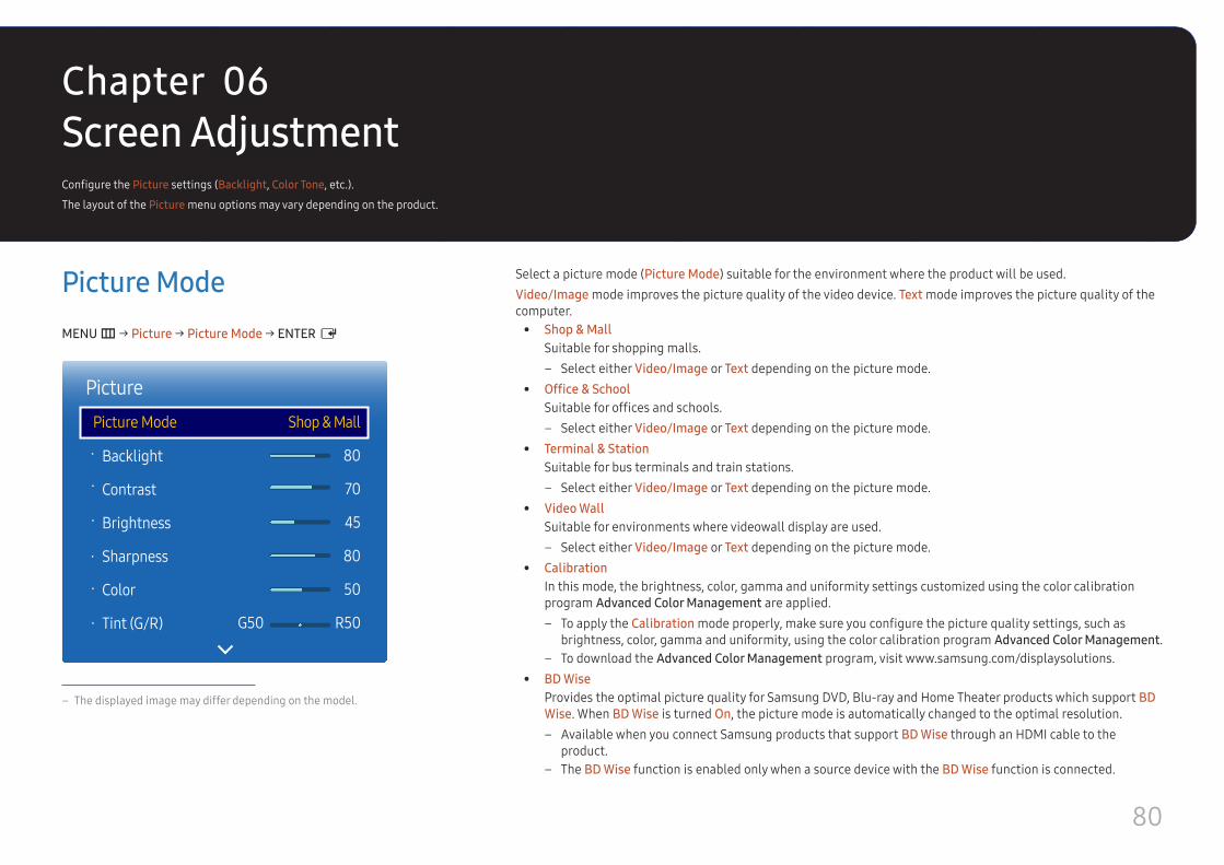
80
Screen AdjustmentConfigure the Picture settings (Backlight, Color Tone, etc.).
The layout of the Picture menu options may vary depending on the product.
Picture ModeMENU m → Picture → Picture Mode → ENTER E
·
·
·
·
·
·
PicturePicture Mode
Backlight
Contrast
Brightness
Sharpness
Color
Tint (G/R)
Shop & Mall
80
70
45
80
50
G50 R50
– The displayed image may differ depending on the model.
Select a picture mode (Picture Mode) suitable for the environment where the product will be used.Video/Image mode improves the picture quality of the video device. Text mode improves the picture quality of the computer.
• Shop & MallSuitable for shopping malls.
– Select either Video/Image or Text depending on the picture mode. • Office & School
Suitable for offices and schools. – Select either Video/Image or Text depending on the picture mode.
• Terminal & StationSuitable for bus terminals and train stations.
– Select either Video/Image or Text depending on the picture mode. • Video Wall
Suitable for environments where videowall display are used. – Select either Video/Image or Text depending on the picture mode.
• CalibrationIn this mode, the brightness, color, gamma and uniformity settings customized using the color calibration program Advanced Color Management are applied.
– To apply the Calibration mode properly, make sure you configure the picture quality settings, such as brightness, color, gamma and uniformity, using the color calibration program Advanced Color Management.
– To download the Advanced Color Management program, visit www.samsung.com/displaysolutions. • BD Wise
Provides the optimal picture quality for Samsung DVD, Blu-ray and Home Theater products which support BD Wise. When BD Wise is turned On, the picture mode is automatically changed to the optimal resolution.
– Available when you connect Samsung products that support BD Wise through an HDMI cable to the product.
– The BD Wise function is enabled only when a source device with the BD Wise function is connected.
Chapter 06
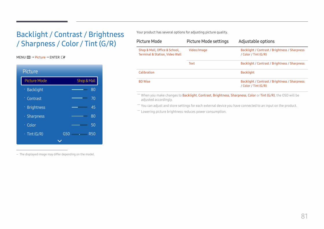
81
Backlight / Contrast / Brightness / Sharpness / Color / Tint (G/R)MENU m → Picture → ENTER E
·
·
·
·
·
·
PicturePicture Mode
Backlight
Contrast
Brightness
Sharpness
Color
Tint (G/R)
Shop & Mall
80
70
45
80
50
G50 R50
– The displayed image may differ depending on the model.
Your product has several options for adjusting picture quality.
Picture Mode Picture Mode settings Adjustable options
Shop & Mall, Office & School, Terminal & Station, Video Wall
Video/Image Backlight / Contrast / Brightness / Sharpness / Color / Tint (G/R)
Text Backlight / Contrast / Brightness / Sharpness
Calibration Backlight
BD Wise Backlight / Contrast / Brightness / Sharpness / Color / Tint (G/R)
― When you make changes to Backlight, Contrast, Brightness, Sharpness, Color or Tint (G/R), the OSD will be adjusted accordingly.
― You can adjust and store settings for each external device you have connected to an input on the product. ― Lowering picture brightness reduces power consumption.

82
Color TemperatureMENU m → Picture → Color Temperature → ENTER E
Picture
Color Temperature 16000K
– The displayed image may differ depending on the model.
Adjust the color temperature (Red / Green / Blue). (Range: 2800K–16000K) ― Enabled when Color Tone is set to Off. ― Color Temperature is disabled if Picture Mode is set to Calibration or BD Wise.
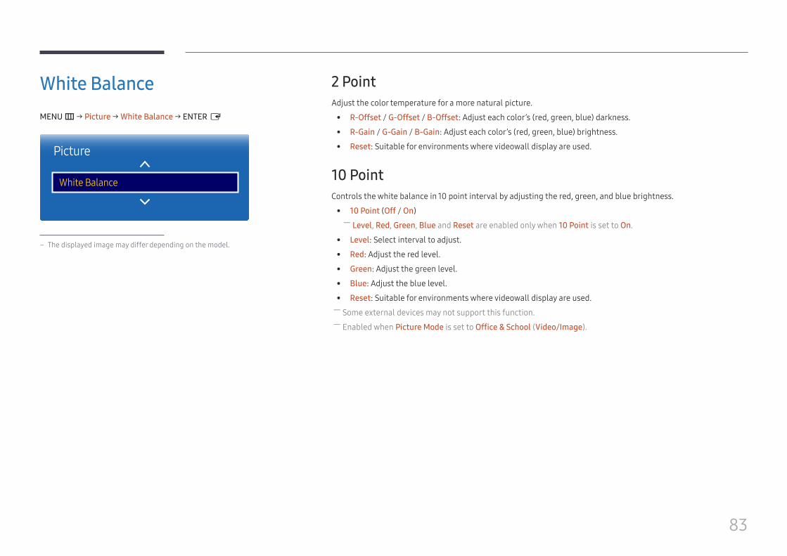
83
White BalanceMENU m → Picture → White Balance → ENTER E
Picture
White Balance
– The displayed image may differ depending on the model.
2 PointAdjust the color temperature for a more natural picture.
• R-Offset / G-Offset / B-Offset: Adjust each color’s (red, green, blue) darkness.
• R-Gain / G-Gain / B-Gain: Adjust each color’s (red, green, blue) brightness.
• Reset: Suitable for environments where videowall display are used.
10 PointControls the white balance in 10 point interval by adjusting the red, green, and blue brightness.
• 10 Point (Off / On) ― Level, Red, Green, Blue and Reset are enabled only when 10 Point is set to On.
• Level: Select interval to adjust.
• Red: Adjust the red level.
• Green: Adjust the green level.
• Blue: Adjust the blue level.
• Reset: Suitable for environments where videowall display are used. ― Some external devices may not support this function. ― Enabled when Picture Mode is set to Office & School (Video/Image).
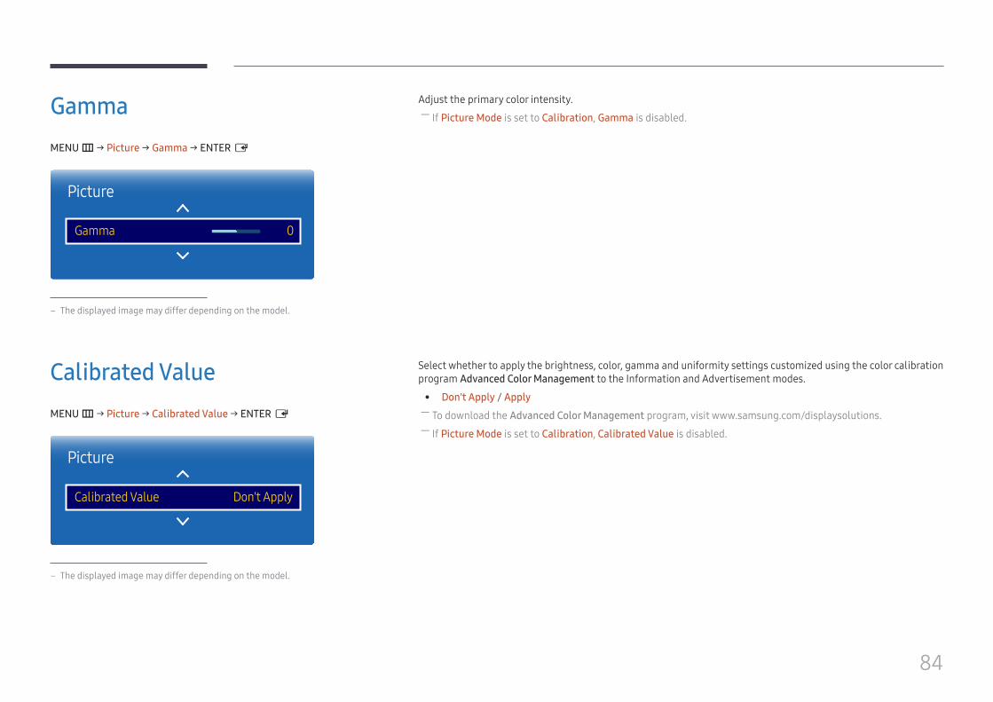
84
GammaMENU m → Picture → Gamma → ENTER E
Picture
Gamma 0
– The displayed image may differ depending on the model.
Adjust the primary color intensity. ― If Picture Mode is set to Calibration, Gamma is disabled.
Calibrated ValueMENU m → Picture → Calibrated Value → ENTER E
Picture
Calibrated Value Don't Apply
– The displayed image may differ depending on the model.
Select whether to apply the brightness, color, gamma and uniformity settings customized using the color calibration program Advanced Color Management to the Information and Advertisement modes.
• Don't Apply / Apply ― To download the Advanced Color Management program, visit www.samsung.com/displaysolutions. ― If Picture Mode is set to Calibration, Calibrated Value is disabled.
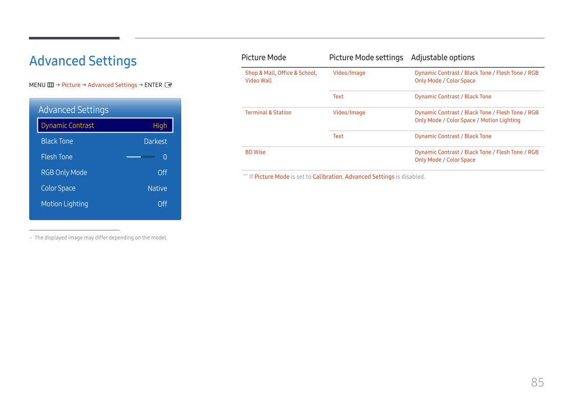
85
Advanced SettingsMENU m → Picture → Advanced Settings → ENTER E
Advanced SettingsDynamic Contrast
Black Tone
Flesh Tone
RGB Only Mode
Color Space
Motion Lighting
High
Darkest
0
Off
Native
Off
– The displayed image may differ depending on the model.
Picture Mode Picture Mode settings Adjustable options
Shop & Mall, Office & School, Video Wall
Video/Image Dynamic Contrast / Black Tone / Flesh Tone / RGB Only Mode / Color Space
Text Dynamic Contrast / Black Tone
Terminal & Station Video/Image Dynamic Contrast / Black Tone / Flesh Tone / RGB Only Mode / Color Space / Motion Lighting
Text Dynamic Contrast / Black Tone
BD Wise Dynamic Contrast / Black Tone / Flesh Tone / RGB Only Mode / Color Space
― If Picture Mode is set to Calibration, Advanced Settings is disabled.
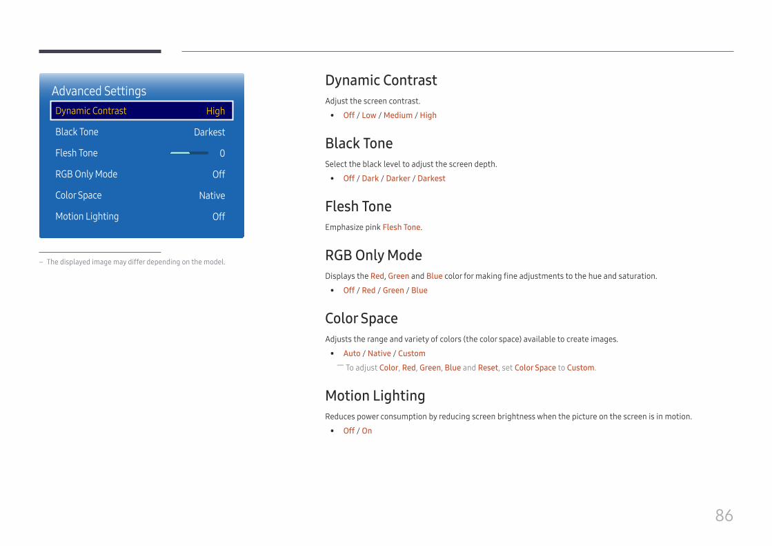
86
Advanced SettingsDynamic Contrast
Black Tone
Flesh Tone
RGB Only Mode
Color Space
Motion Lighting
High
Darkest
0
Off
Native
Off
– The displayed image may differ depending on the model.
Dynamic ContrastAdjust the screen contrast.
• Off / Low / Medium / High
Black ToneSelect the black level to adjust the screen depth.
• Off / Dark / Darker / Darkest
Flesh ToneEmphasize pink Flesh Tone.
RGB Only ModeDisplays the Red, Green and Blue color for making fine adjustments to the hue and saturation.
• Off / Red / Green / Blue
Color SpaceAdjusts the range and variety of colors (the color space) available to create images.
• Auto / Native / Custom ― To adjust Color, Red, Green, Blue and Reset, set Color Space to Custom.
Motion LightingReduces power consumption by reducing screen brightness when the picture on the screen is in motion.
• Off / On

87
Picture OptionsMENU m → Picture → Picture Options → ENTER E
Picture OptionsColor Tone
Digital Clean View
MPEG Noise Filter
HDMI Black Level
Film Mode
Dynamic Backlight
Off
Off
Off
Low
Off
Off
– The displayed image may differ depending on the model.
Picture Mode Picture Mode settings Adjustable options
Shop & Mall, Office & School, Terminal & Station, Video Wall
Video/Image Color Tone / Digital Clean View / MPEG Noise Filter / HDMI Black Level / Film Mode / Dynamic Backlight
Text Color Tone / HDMI Black Level / Dynamic Backlight
Calibration HDMI Black Level / Dynamic Backlight
BD Wise Color Tone / Digital Clean View / MPEG Noise Filter / HDMI Black Level / Film Mode / Dynamic Backlight
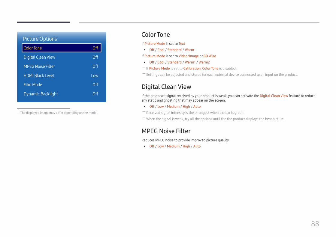
88
Picture OptionsColor Tone
Digital Clean View
MPEG Noise Filter
HDMI Black Level
Film Mode
Dynamic Backlight
Off
Off
Off
Low
Off
Off
– The displayed image may differ depending on the model.
Color ToneIf Picture Mode is set to Text
• Off / Cool / Standard / Warm
If Picture Mode is set to Video/Image or BD Wise
• Off / Cool / Standard / Warm1 / Warm2 ― If Picture Mode is set to Calibration, Color Tone is disabled. ― Settings can be adjusted and stored for each external device connected to an input on the product.
Digital Clean ViewIf the broadcast signal received by your product is weak, you can activate the Digital Clean View feature to reduce any static and ghosting that may appear on the screen.
• Off / Low / Medium / High / Auto ― Received signal intensity is the strongest when the bar is green. ― When the signal is weak, try all the options until the the product displays the best picture.
MPEG Noise FilterReduces MPEG noise to provide improved picture quality.
• Off / Low / Medium / High / Auto
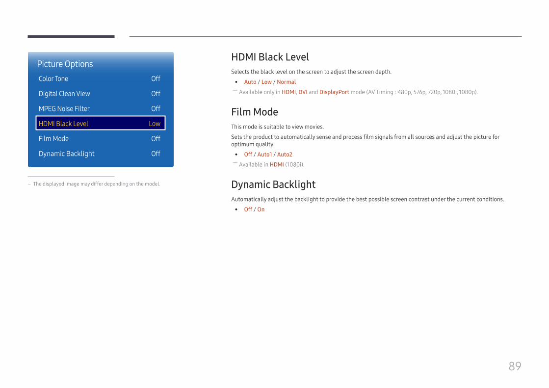
89
Picture OptionsColor Tone
Digital Clean View
MPEG Noise Filter
HDMI Black Level
Film Mode
Dynamic Backlight
Off
Off
Off
Low
Off
Off
– The displayed image may differ depending on the model.
HDMI Black LevelSelects the black level on the screen to adjust the screen depth.
• Auto / Low / Normal ― Available only in HDMI, DVI and DisplayPort mode (AV Timing : 480p, 576p, 720p, 1080i, 1080p).
Film ModeThis mode is suitable to view movies.
Sets the product to automatically sense and process film signals from all sources and adjust the picture for optimum quality.
• Off / Auto1 / Auto2 ― Available in HDMI (1080i).
Dynamic BacklightAutomatically adjust the backlight to provide the best possible screen contrast under the current conditions.
• Off / On

90
Picture SizeMENU m → Picture → Picture Size → ENTER E
·
Picture SizePicture Size 16:9
Position
Resolution Off
– The displayed image may differ depending on the model.
choose size and aspect ratio picture displayed on screen.
Picture Size ― Different screen adjustment options are displayed depending on the current input source.
• 16:9: Sets the picture to 16:9 wide mode.
• Zoom1: Use for moderate magnification. Cuts off the top and sides.
• Zoom2: Use for a stronger magnification.
• 4:3: Sets the picture to basic (4:3) mode. ― Do not set your product to 4:3 format for a long time.The borders displayed on the left and right, or top and bottom of the screen may cause image retention (screen burn) which is not covered by the warranty.
• Screen Fit: Displays the full image without any cut-off when HDMI (720p / 1080i / 1080p) signals are inputted.
• Custom: Changes the resolution to suit the user's preferences.
• Original Ratio: If the input source is PC, DVI, HDMI (PC connection), DisplayPort, the video will display in the original aspect ratio.
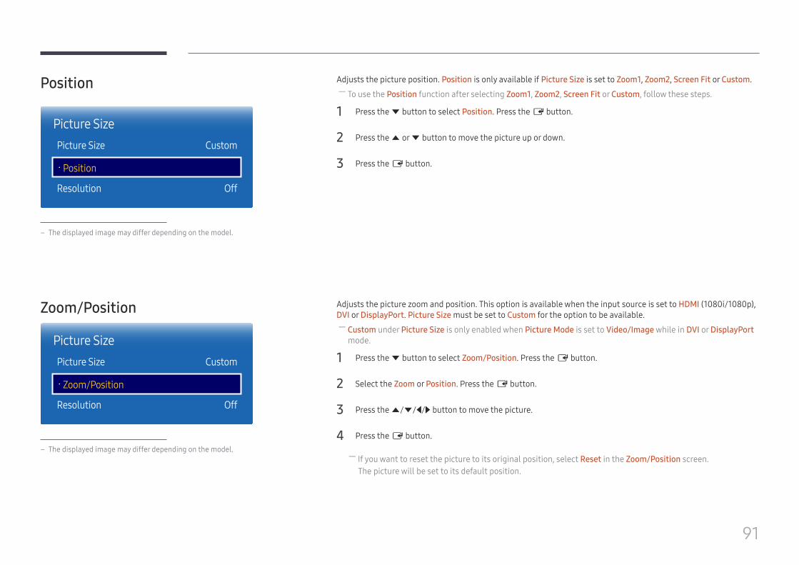
91
Position
·
Picture SizePicture Size Custom
Position
Resolution Off
– The displayed image may differ depending on the model.
Adjusts the picture position. Position is only available if Picture Size is set to Zoom1, Zoom2, Screen Fit or Custom. ― To use the Position function after selecting Zoom1, Zoom2, Screen Fit or Custom, follow these steps.
1 Press the d button to select Position. Press the E button.
2 Press the u or d button to move the picture up or down.
3 Press the E button.
Zoom/Position
·
Picture SizePicture Size Custom
Zoom/Position
Resolution Off
– The displayed image may differ depending on the model.
Adjusts the picture zoom and position. This option is available when the input source is set to HDMI (1080i/1080p), DVI or DisplayPort. Picture Size must be set to Custom for the option to be available.
― Custom under Picture Size is only enabled when Picture Mode is set to Video/Image while in DVI or DisplayPort mode.
1 Press the d button to select Zoom/Position. Press the E button.
2 Select the Zoom or Position. Press the E button.
3 Press the u/d/l/r button to move the picture.
4 Press the E button.
― If you want to reset the picture to its original position, select Reset in the Zoom/Position screen.The picture will be set to its default position.
92
ResolutionIf the picture is not normal even when the resolution of the graphics card is one of the following, you can optimize the picture quality by selecting the same resolution for the product as the PC using this menu.
Available resolutions: Off / 1024x768 / 1280x768 / 1360x768 / 1366x768
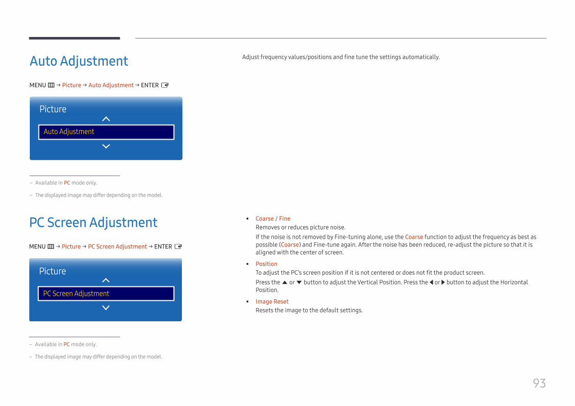
93
Auto AdjustmentMENU m → Picture → Auto Adjustment → ENTER E
Picture
Auto Adjustment
– Available in PC mode only.
– The displayed image may differ depending on the model.
Adjust frequency values/positions and fine tune the settings automatically.
PC Screen AdjustmentMENU m → Picture → PC Screen Adjustment → ENTER E
Picture
PC Screen Adjustment
– Available in PC mode only.
– The displayed image may differ depending on the model.
• Coarse / FineRemoves or reduces picture noise.If the noise is not removed by Fine-tuning alone, use the Coarse function to adjust the frequency as best as possible (Coarse) and Fine-tune again. After the noise has been reduced, re-adjust the picture so that it is aligned with the center of screen.
• PositionTo adjust the PC’s screen position if it is not centered or does not fit the product screen.Press the u or d button to adjust the Vertical Position. Press the l or r button to adjust the Horizontal Position.
• Image ResetResets the image to the default settings.
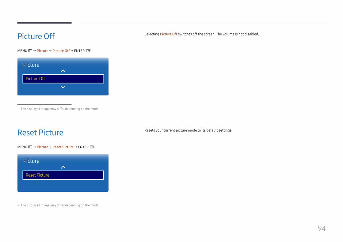
94
Picture OffMENU m → Picture → Picture Off → ENTER E
Picture
Picture Off
– The displayed image may differ depending on the model.
Selecting Picture Off switches off the screen. The volume is not disabled.
Reset PictureMENU m → Picture → Reset Picture → ENTER E
Picture
Reset Picture
– The displayed image may differ depending on the model.
Resets your current picture mode to its default settings.
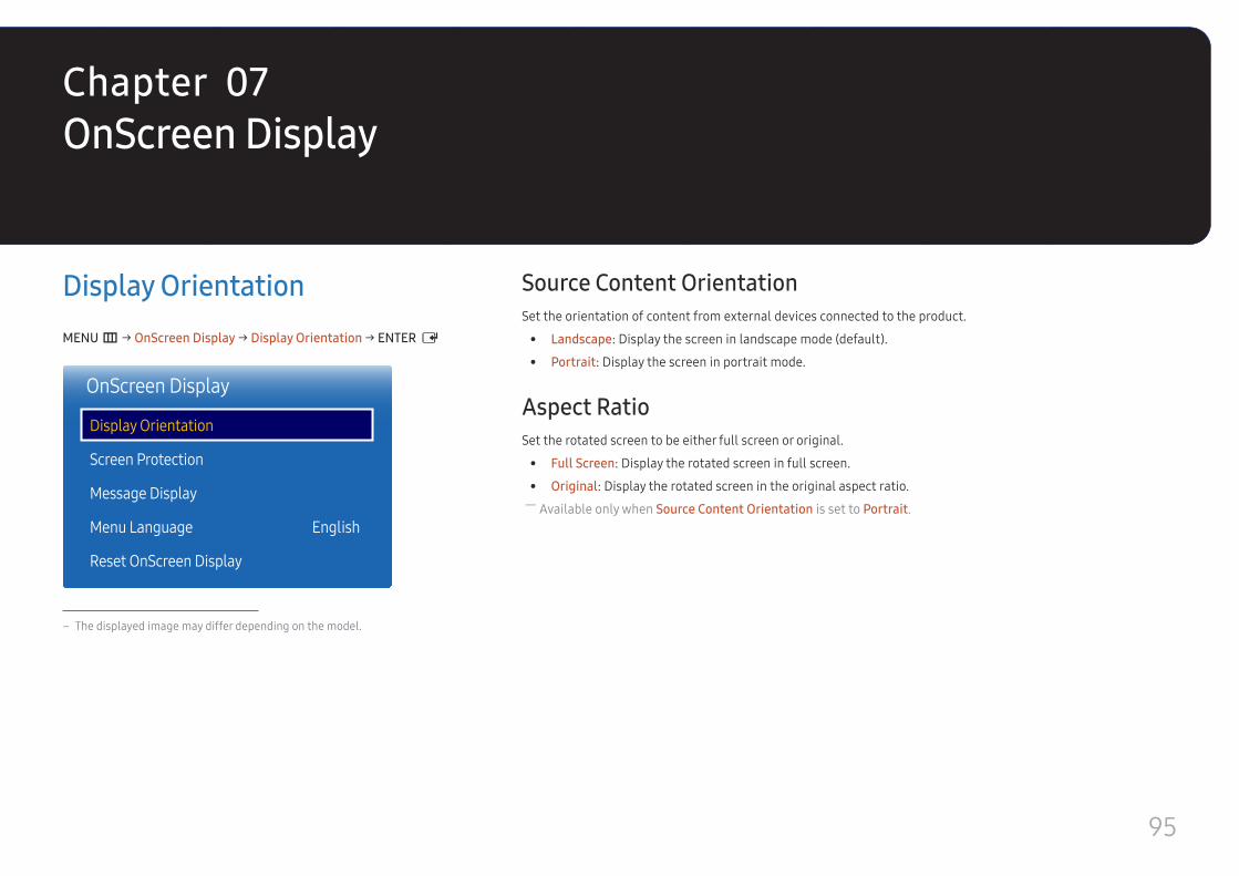
95
OnScreen Display
Display OrientationMENU m → OnScreen Display → Display Orientation → ENTER E
OnScreen Display
Display Orientation
Screen Protection
Message Display
Menu Language
Reset OnScreen Display
English
– The displayed image may differ depending on the model.
Source Content OrientationSet the orientation of content from external devices connected to the product.
• Landscape: Display the screen in landscape mode (default).
• Portrait: Display the screen in portrait mode.
Aspect RatioSet the rotated screen to be either full screen or original.
• Full Screen: Display the rotated screen in full screen.
• Original: Display the rotated screen in the original aspect ratio. ― Available only when Source Content Orientation is set to Portrait.
Chapter 07
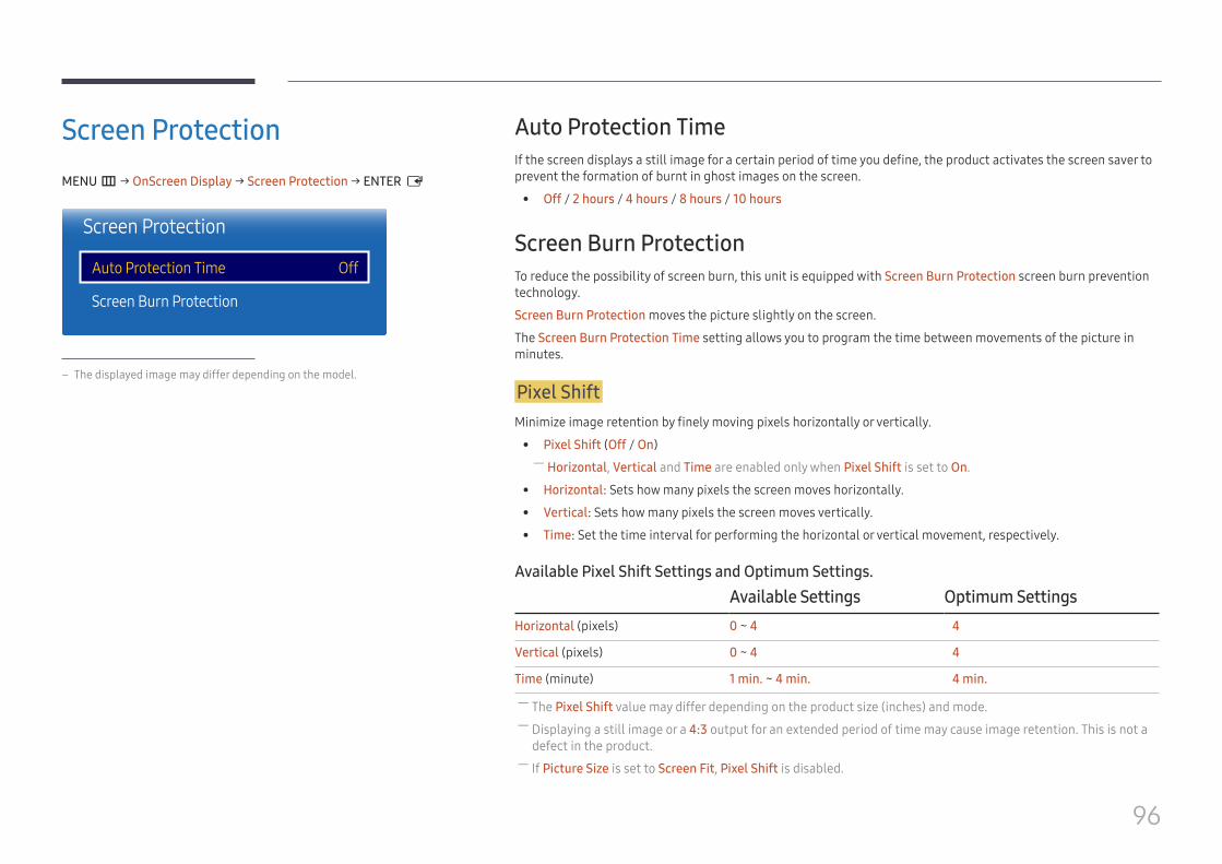
96
Screen ProtectionMENU m → OnScreen Display → Screen Protection → ENTER E
Screen Protection
Auto Protection Time
Screen Burn Protection
Off
– The displayed image may differ depending on the model.
Auto Protection TimeIf the screen displays a still image for a certain period of time you define, the product activates the screen saver to prevent the formation of burnt in ghost images on the screen.
• Off / 2 hours / 4 hours / 8 hours / 10 hours
Screen Burn ProtectionTo reduce the possibility of screen burn, this unit is equipped with Screen Burn Protection screen burn prevention technology.
Screen Burn Protection moves the picture slightly on the screen.
The Screen Burn Protection Time setting allows you to program the time between movements of the picture in minutes.
Pixel ShiftMinimize image retention by finely moving pixels horizontally or vertically.
• Pixel Shift (Off / On) ― Horizontal, Vertical and Time are enabled only when Pixel Shift is set to On.
• Horizontal: Sets how many pixels the screen moves horizontally.
• Vertical: Sets how many pixels the screen moves vertically.
• Time: Set the time interval for performing the horizontal or vertical movement, respectively.
Available Pixel Shift Settings and Optimum Settings.Available Settings Optimum Settings
Horizontal (pixels) 0 ~ 4 4
Vertical (pixels) 0 ~ 4 4
Time (minute) 1 min. ~ 4 min. 4 min.
― The Pixel Shift value may differ depending on the product size (inches) and mode. ― Displaying a still image or a 4:3 output for an extended period of time may cause image retention. This is not a defect in the product.
― If Picture Size is set to Screen Fit, Pixel Shift is disabled.
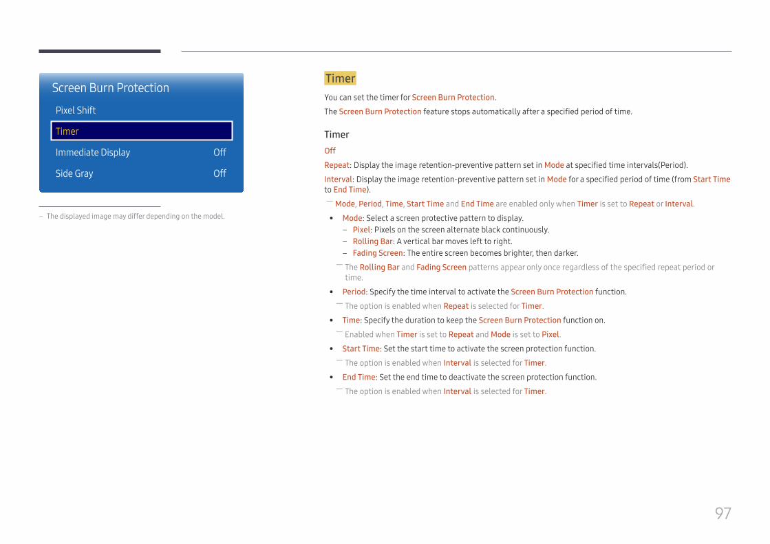
97
Screen Burn Protection
Pixel Shift
Timer
Immediate Display
Side Gray
Off
Off
– The displayed image may differ depending on the model.
TimerYou can set the timer for Screen Burn Protection.
The Screen Burn Protection feature stops automatically after a specified period of time.
TimerOff
Repeat: Display the image retention-preventive pattern set in Mode at specified time intervals(Period).
Interval: Display the image retention-preventive pattern set in Mode for a specified period of time (from Start Time to End Time).
― Mode, Period, Time, Start Time and End Time are enabled only when Timer is set to Repeat or Interval.
• Mode: Select a screen protective pattern to display. – Pixel: Pixels on the screen alternate black continuously. – Rolling Bar: A vertical bar moves left to right. – Fading Screen: The entire screen becomes brighter, then darker.
― The Rolling Bar and Fading Screen patterns appear only once regardless of the specified repeat period or time.
• Period: Specify the time interval to activate the Screen Burn Protection function. ― The option is enabled when Repeat is selected for Timer.
• Time: Specify the duration to keep the Screen Burn Protection function on. ― Enabled when Timer is set to Repeat and Mode is set to Pixel.
• Start Time: Set the start time to activate the screen protection function. ― The option is enabled when Interval is selected for Timer.
• End Time: Set the end time to deactivate the screen protection function. ― The option is enabled when Interval is selected for Timer.
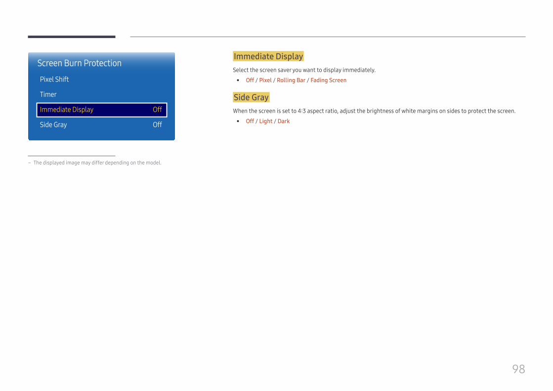
98
Screen Burn Protection
Pixel Shift
Timer
Immediate Display
Side Gray
Off
Off
– The displayed image may differ depending on the model.
Immediate DisplaySelect the screen saver you want to display immediately.
• Off / Pixel / Rolling Bar / Fading Screen
Side GrayWhen the screen is set to 4:3 aspect ratio, adjust the brightness of white margins on sides to protect the screen.
• Off / Light / Dark
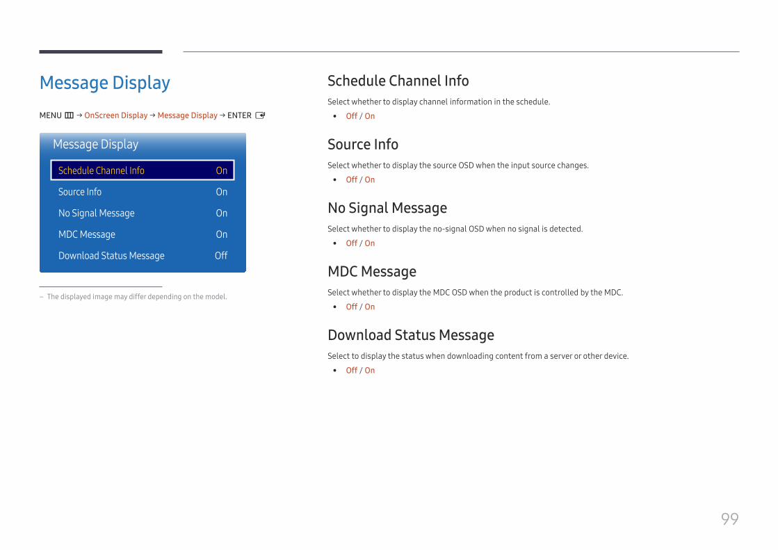
99
Message DisplayMENU m → OnScreen Display → Message Display → ENTER E
Message Display
Schedule Channel Info
Source Info
No Signal Message
MDC Message
Download Status Message
On
On
On
On
Off
– The displayed image may differ depending on the model.
Schedule Channel InfoSelect whether to display channel information in the schedule.
• Off / On
Source InfoSelect whether to display the source OSD when the input source changes.
• Off / On
No Signal MessageSelect whether to display the no-signal OSD when no signal is detected.
• Off / On
MDC MessageSelect whether to display the MDC OSD when the product is controlled by the MDC.
• Off / On
Download Status MessageSelect to display the status when downloading content from a server or other device.
• Off / On
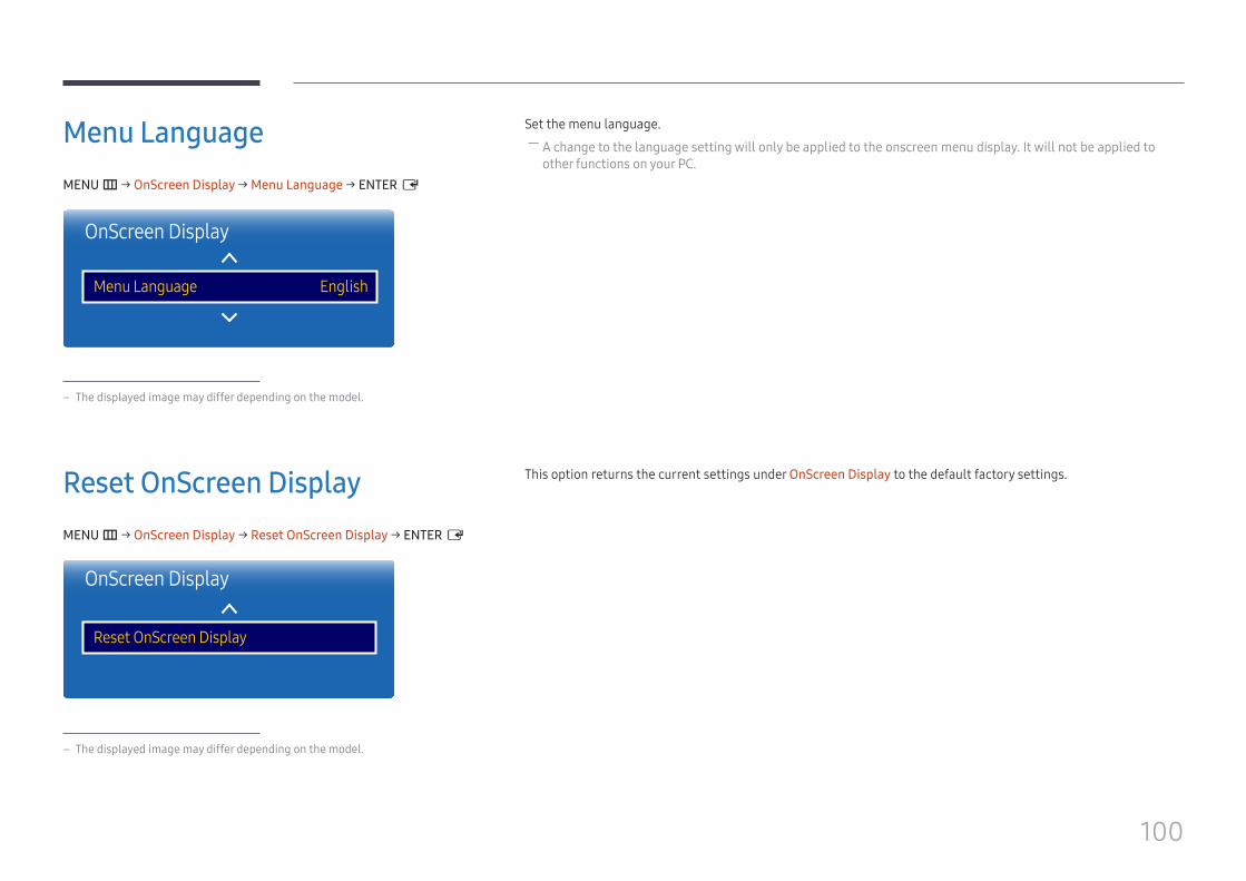
100
Menu LanguageMENU m → OnScreen Display → Menu Language → ENTER E
OnScreen Display
Menu Language English
– The displayed image may differ depending on the model.
Set the menu language. ― A change to the language setting will only be applied to the onscreen menu display. It will not be applied to other functions on your PC.
Reset OnScreen DisplayMENU m → OnScreen Display → Reset OnScreen Display → ENTER E
OnScreen Display
Reset OnScreen Display
– The displayed image may differ depending on the model.
This option returns the current settings under OnScreen Display to the default factory settings.
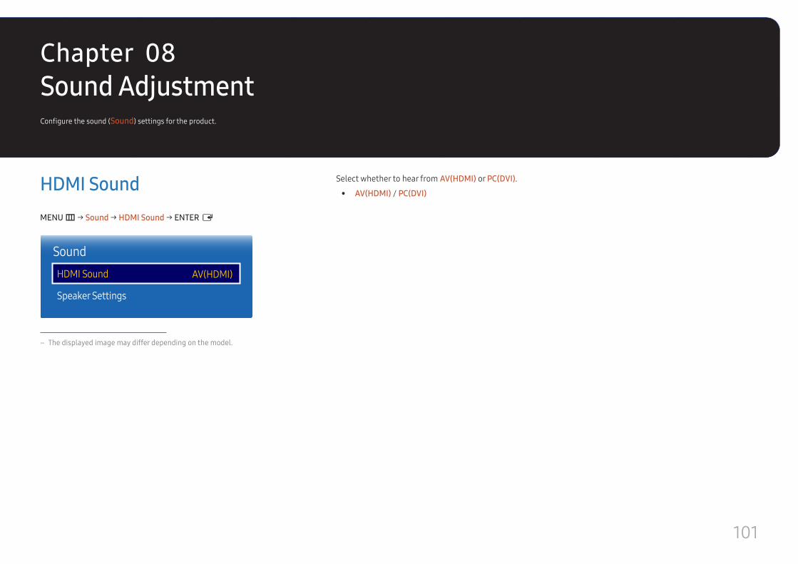
101
Sound AdjustmentConfigure the sound (Sound) settings for the product.
HDMI SoundMENU m → Sound → HDMI Sound → ENTER E
SoundHDMI Sound
Speaker Settings
AV(HDMI)
– The displayed image may differ depending on the model.
Select whether to hear from AV(HDMI) or PC(DVI).
• AV(HDMI) / PC(DVI)
Chapter 08

102
Speaker SettingsMENU m → Sound → Speaker Settings → ENTER E
Sound
Speaker Settings
– The displayed image may differ depending on the model.
Sound Output • External / Receiver ― If there is no video signal, both the products speakers and the external speakers will be mute.
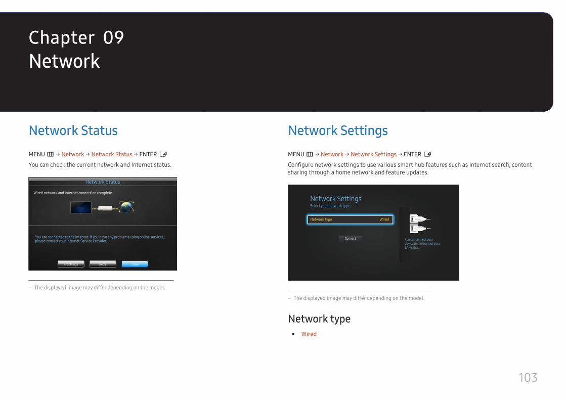
103
Network
Network StatusMENU m → Network → Network Status → ENTER E
You can check the current network and Internet status.
Network Status
Wired network and Internet connection complete.
You are connected to the Internet. If you have any problems using online services, please contact your Internet Service Provider.
CloseRetryIP Settings
– The displayed image may differ depending on the model.
Network SettingsMENU m → Network → Network Settings → ENTER E
Configure network settings to use various smart hub features such as Internet search, content sharing through a home network and feature updates.
Network SettingsSelect your network type.
Network type Wired
Connect You can connect your device to the Internet via a LAN cable.
– The displayed image may differ depending on the model.
Network type • Wired
Chapter 09
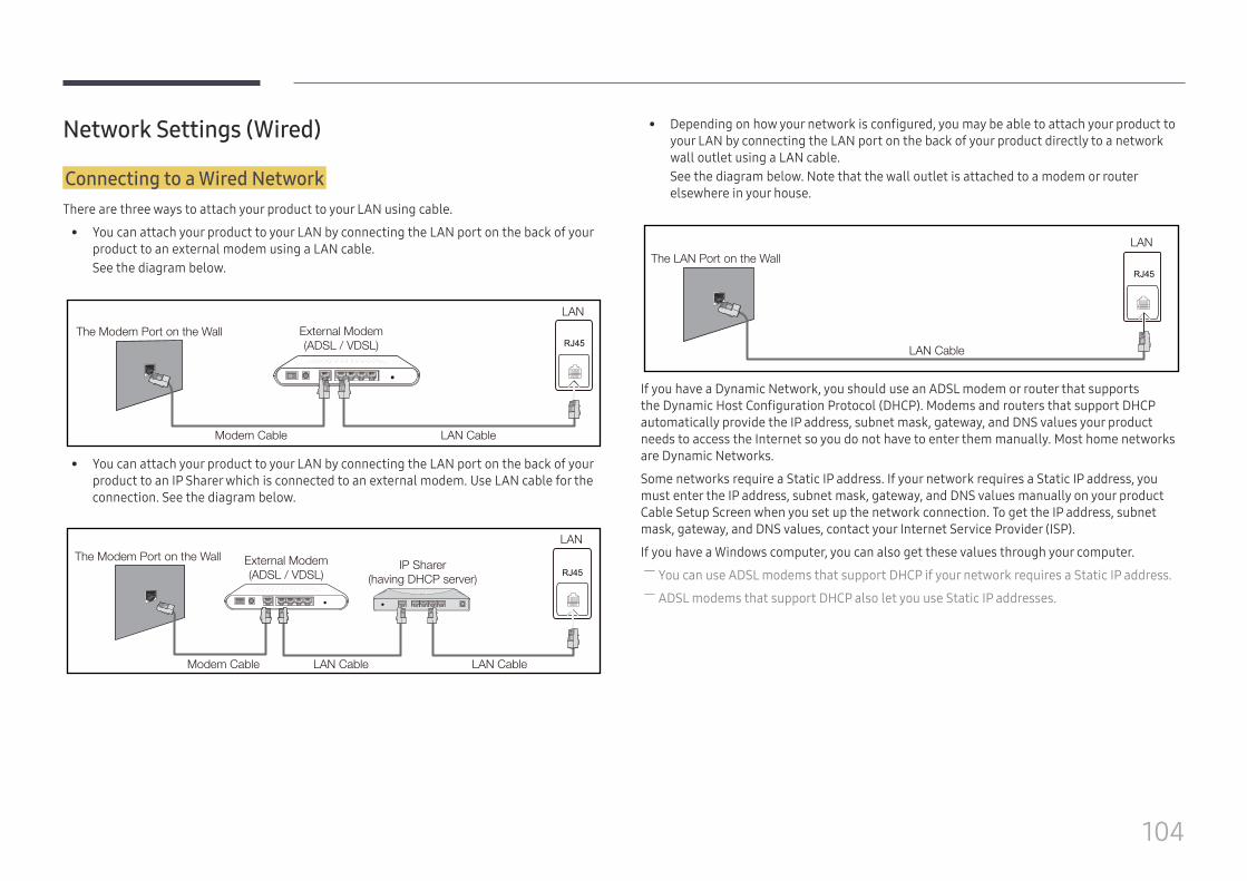
104
Network Settings (Wired)
Connecting to a Wired NetworkThere are three ways to attach your product to your LAN using cable.
• You can attach your product to your LAN by connecting the LAN port on the back of your product to an external modem using a LAN cable.See the diagram below.
RJ45The Modem Port on the Wall External Modem
(ADSL / VDSL)
Modem Cable LAN Cable
LAN
• You can attach your product to your LAN by connecting the LAN port on the back of your product to an IP Sharer which is connected to an external modem. Use LAN cable for the connection. See the diagram below.
The Modem Port on the Wall External Modem(ADSL / VDSL)
IP Sharer(having DHCP server)
LAN
Modem Cable LAN Cable LAN Cable
RJ45
• Depending on how your network is configured, you may be able to attach your product to your LAN by connecting the LAN port on the back of your product directly to a network wall outlet using a LAN cable. See the diagram below. Note that the wall outlet is attached to a modem or router elsewhere in your house.
The LAN Port on the WallLAN
LAN Cable
RJ45
If you have a Dynamic Network, you should use an ADSL modem or router that supports the Dynamic Host Configuration Protocol (DHCP). Modems and routers that support DHCP automatically provide the IP address, subnet mask, gateway, and DNS values your product needs to access the Internet so you do not have to enter them manually. Most home networks are Dynamic Networks.
Some networks require a Static IP address. If your network requires a Static IP address, you must enter the IP address, subnet mask, gateway, and DNS values manually on your product Cable Setup Screen when you set up the network connection. To get the IP address, subnet mask, gateway, and DNS values, contact your Internet Service Provider (ISP).
If you have a Windows computer, you can also get these values through your computer. ― You can use ADSL modems that support DHCP if your network requires a Static IP address. ― ADSL modems that support DHCP also let you use Static IP addresses.
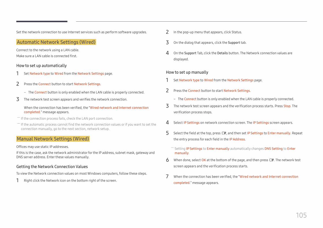
105
Set the network connection to use Internet services such as perform software upgrades.
Automatic Network Settings (Wired)Connect to the network using a LAN cable.
Make sure a LAN cable is connected first.
How to set up automatically
1 Set Network type to Wired from the Network Settings page.
2 Press the Connect button to start Network Settings.
– The Connect button is only enabled when the LAN cable is properly connected.
3 The network test screen appears and verifies the network connection.
When the connection has been verified, the “Wired network and Internet connection completed.” message appears.
― If the connection process fails, check the LAN port connection. ― If the automatic process cannot find the network connection values or if you want to set the connection manually, go to the next section, network setup.
Manual Network Settings (Wired)Offices may use static IP addresses.
If this is the case, ask the network administrator for the IP address, subnet mask, gateway and DNS server address. Enter these values manually.
Getting the Network Connection ValuesTo view the Network connection values on most Windows computers, follow these steps.
1 Right click the Network icon on the bottom right of the screen.
2 In the pop-up menu that appears, click Status.
3 On the dialog that appears, click the Support tab.
4 On the Support Tab, click the Details button. The Network connection values are
displayed.
How to set up manually
1 Set Network type to Wired from the Network Settings page.
2 Press the Connect button to start Network Settings.
– The Connect button is only enabled when the LAN cable is properly connected.
3 The network test screen appears and the verification process starts. Press Stop. The
verification process stops.
4 Select IP Settings on network connection screen. The IP Settings screen appears.
5 Select the field at the top, press E, and then set IP Settings to Enter manually. Repeat
the entry process for each field in the IP Address.
― Setting IP Settings to Enter manually automatically changes DNS Setting to Enter manually.
6 When done, select OK at the bottom of the page, and then press E. The network test
screen appears and the verification process starts.
7 When the connection has been verified, the “Wired network and Internet connection
completed.” message appears.
106
Multimedia Device SettingsMENU m → Network → Multimedia Device Settings → ENTER E
Allow other devices such as smart phones and tablets on your network, to share content with your product.
Server Network SettingsMENU m → Network → Server Network Settings → ENTER E
Connect to ServerTo run Player connect to a network.
• Server Address / SSL / Port ― If the SSL option is enabled, the server is configured to use https and data transfer is encrypted.
― Enter the server IP address and port number. Use 7001 as the port number. (If unable to connect to the server using port number 7001, check with your server administrator to find the correct port number and then change the port number.)
MagicInfo ModeSelect the appropriate MagicInfo Mode depending on the environment where you are using the product.
• Lite / Premium
Server AccessSelect a method to connect the server network.
• Allow / Deny
FTP ModeSpecify the FTP operating mode.
• Active / Passive
Device NameMENU m → Network → Device Name → ENTER E
Select or enter a device name.
This name can be shown on network remote controls over the network.
• User Input / [Signage]Display 1 ~ 6
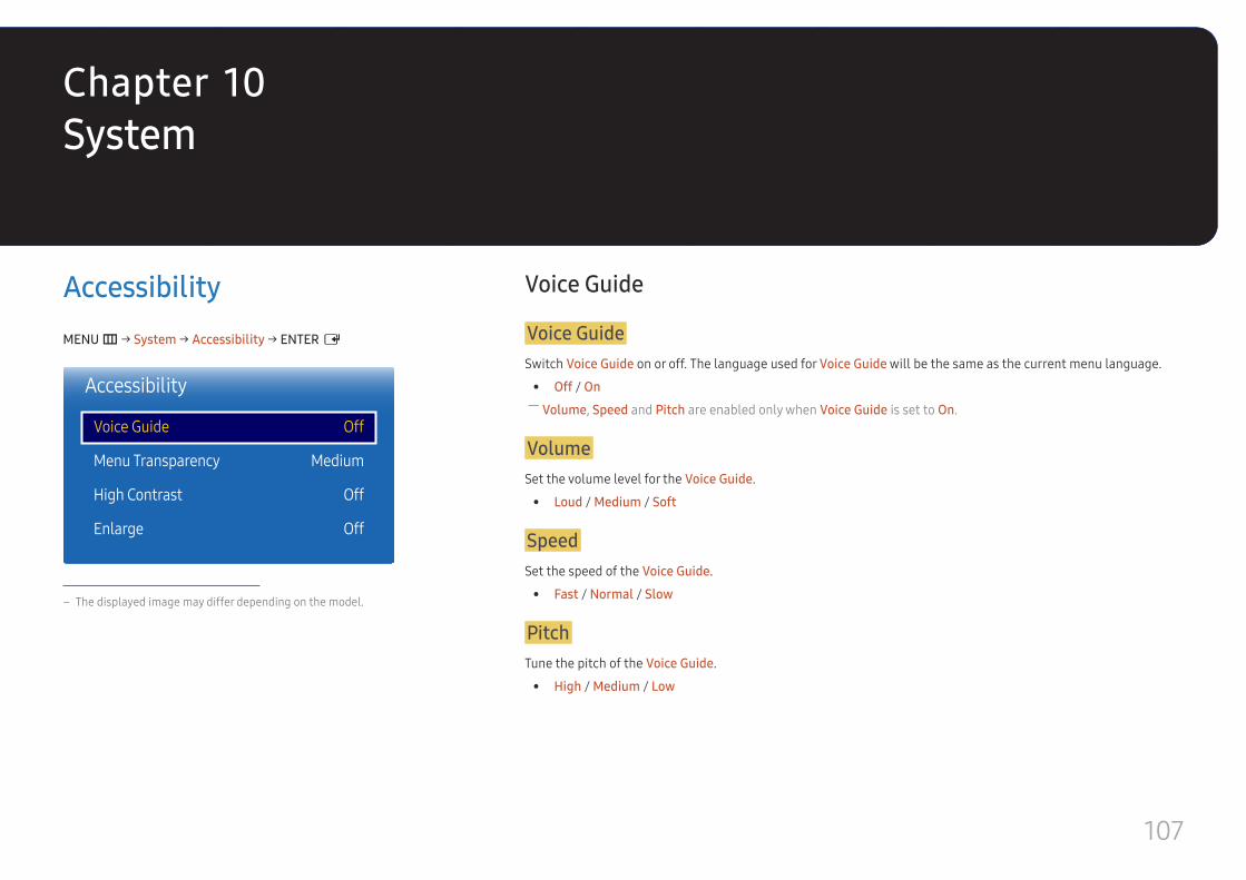
107
System
AccessibilityMENU m → System → Accessibility → ENTER E
Accessibility
Voice Guide
Menu Transparency
High Contrast
Enlarge
Off
Medium
Off
Off
– The displayed image may differ depending on the model.
Voice Guide
Voice GuideSwitch Voice Guide on or off. The language used for Voice Guide will be the same as the current menu language.
• Off / On ― Volume, Speed and Pitch are enabled only when Voice Guide is set to On.
VolumeSet the volume level for the Voice Guide.
• Loud / Medium / Soft
SpeedSet the speed of the Voice Guide.
• Fast / Normal / Slow
PitchTune the pitch of the Voice Guide.
• High / Medium / Low
Chapter 10
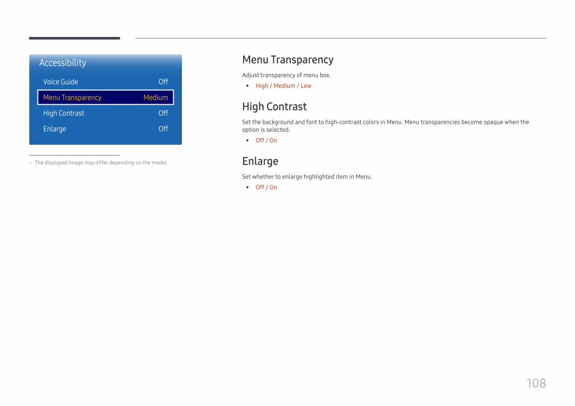
108
Accessibility
Voice Guide
Menu Transparency
High Contrast
Enlarge
Off
Medium
Off
Off
– The displayed image may differ depending on the model.
Menu TransparencyAdjust transparency of menu box.
• High / Medium / Low
High ContrastSet the background and font to high-contrast colors in Menu. Menu transparencies become opaque when the option is selected.
• Off / On
EnlargeSet whether to enlarge highlighted item in Menu.
• Off / On
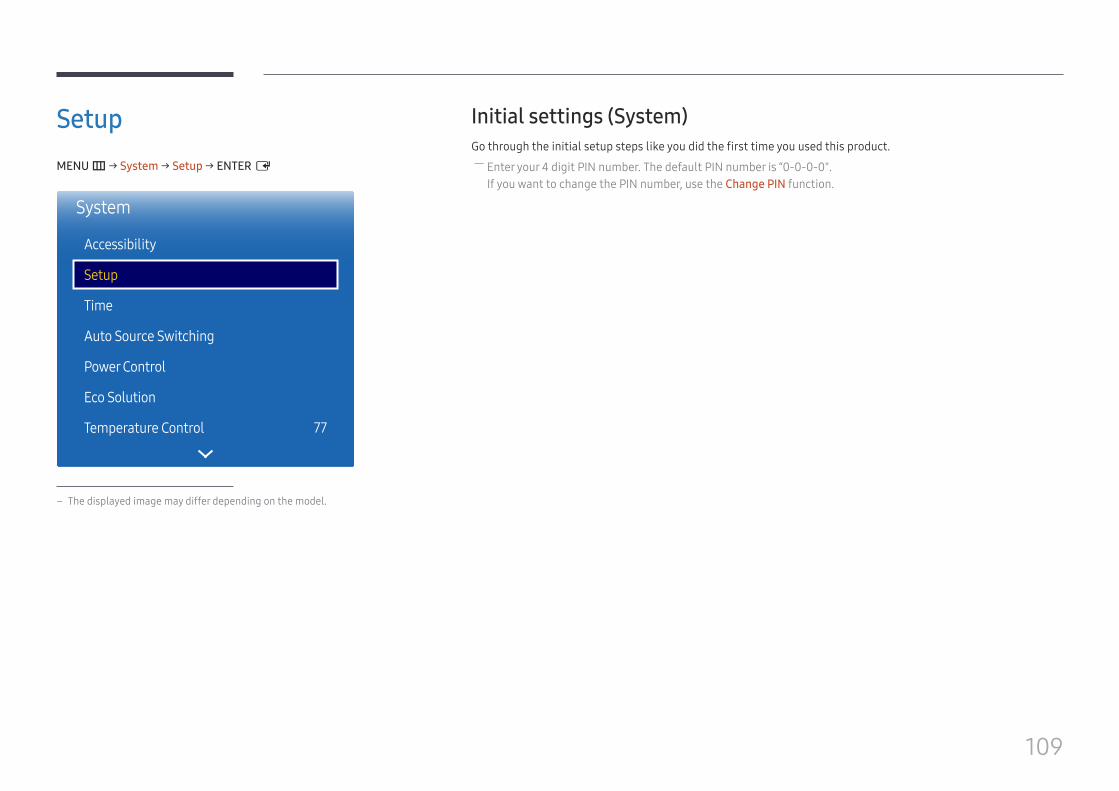
109
SetupMENU m → System → Setup → ENTER E
System
Accessibility
Setup
Time
Auto Source Switching
Power Control
Eco Solution
Temperature Control 77
– The displayed image may differ depending on the model.
Initial settings (System)Go through the initial setup steps like you did the first time you used this product.
― Enter your 4 digit PIN number. The default PIN number is “0-0-0-0". If you want to change the PIN number, use the Change PIN function.
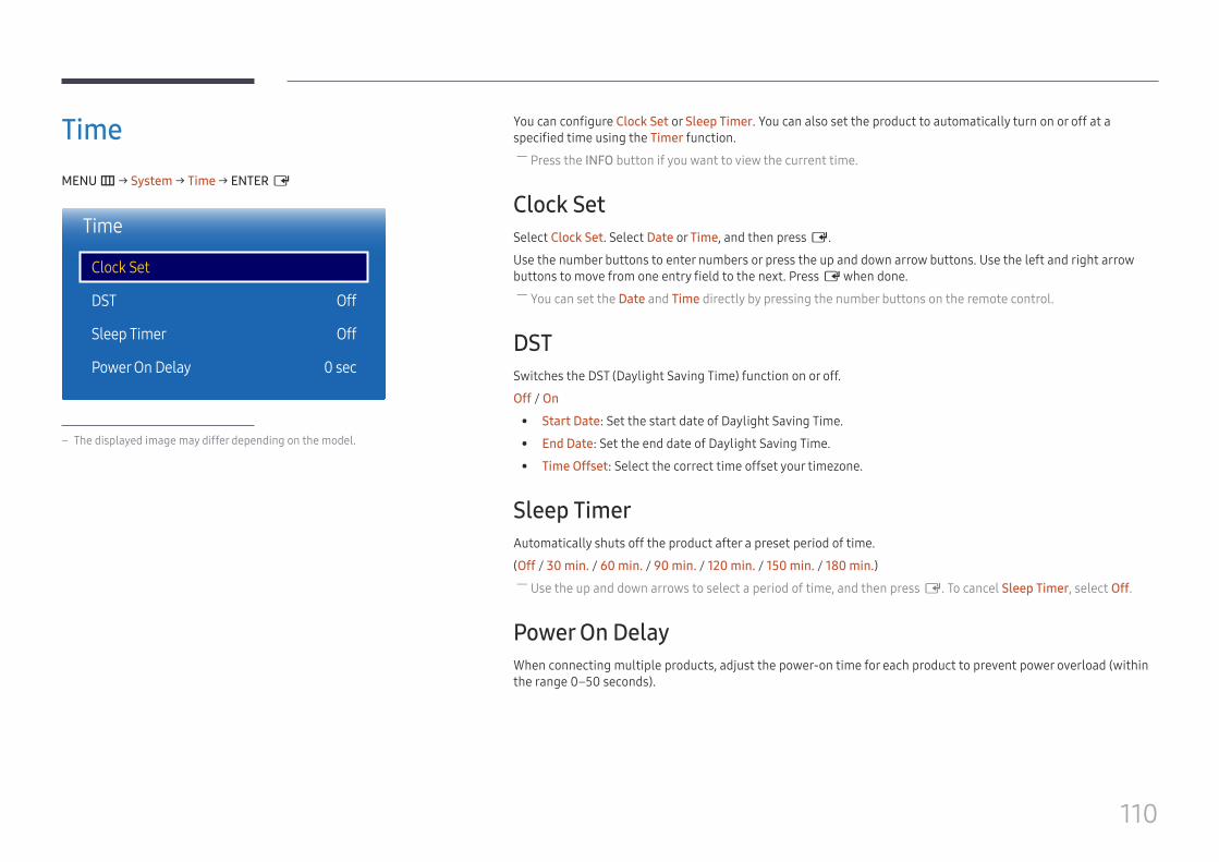
110
TimeMENU m → System → Time → ENTER E
Time
Clock Set
DST
Sleep Timer
Power On Delay
Off
Off
0 sec
– The displayed image may differ depending on the model.
You can configure Clock Set or Sleep Timer. You can also set the product to automatically turn on or off at a specified time using the Timer function.
― Press the INFO button if you want to view the current time.
Clock SetSelect Clock Set. Select Date or Time, and then press E.
Use the number buttons to enter numbers or press the up and down arrow buttons. Use the left and right arrow buttons to move from one entry field to the next. Press E when done.
― You can set the Date and Time directly by pressing the number buttons on the remote control.
DSTSwitches the DST (Daylight Saving Time) function on or off.
Off / On
• Start Date: Set the start date of Daylight Saving Time.
• End Date: Set the end date of Daylight Saving Time.
• Time Offset: Select the correct time offset your timezone.
Sleep TimerAutomatically shuts off the product after a preset period of time.
(Off / 30 min. / 60 min. / 90 min. / 120 min. / 150 min. / 180 min.) ― Use the up and down arrows to select a period of time, and then press E. To cancel Sleep Timer, select Off.
Power On DelayWhen connecting multiple products, adjust the power-on time for each product to prevent power overload (within the range 0–50 seconds).
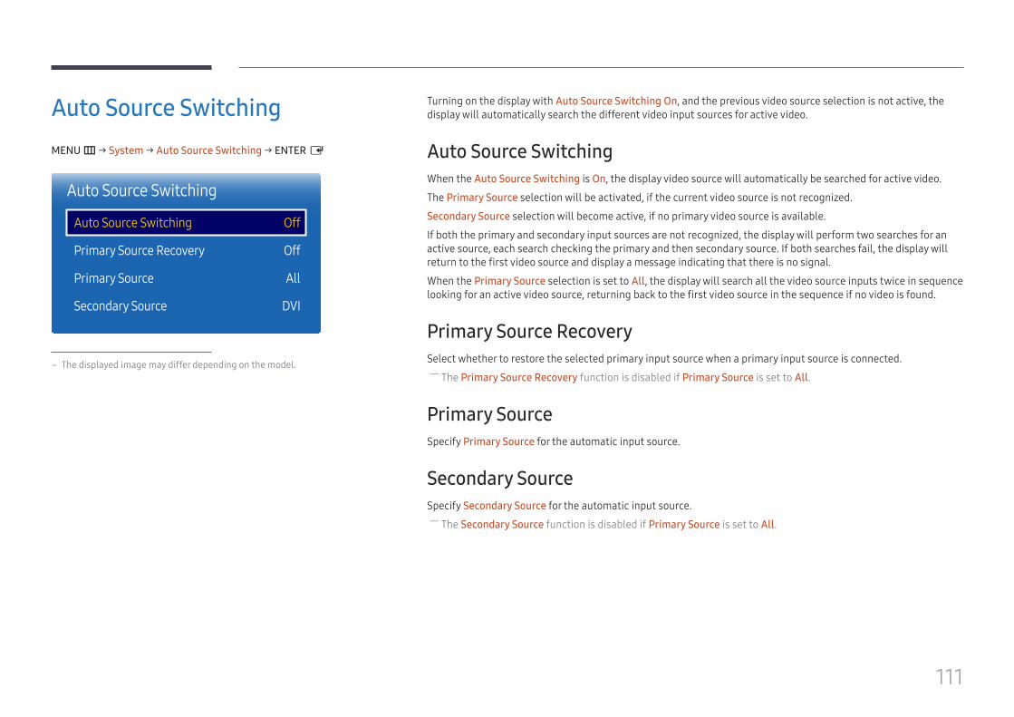
111
Turning on the display with Auto Source Switching On, and the previous video source selection is not active, the display will automatically search the different video input sources for active video.
Auto Source SwitchingWhen the Auto Source Switching is On, the display video source will automatically be searched for active video.
The Primary Source selection will be activated, if the current video source is not recognized.
Secondary Source selection will become active, if no primary video source is available.
If both the primary and secondary input sources are not recognized, the display will perform two searches for an active source, each search checking the primary and then secondary source. If both searches fail, the display will return to the first video source and display a message indicating that there is no signal.
When the Primary Source selection is set to All, the display will search all the video source inputs twice in sequence looking for an active video source, returning back to the first video source in the sequence if no video is found.
Primary Source RecoverySelect whether to restore the selected primary input source when a primary input source is connected.
― The Primary Source Recovery function is disabled if Primary Source is set to All.
Primary SourceSpecify Primary Source for the automatic input source.
Secondary SourceSpecify Secondary Source for the automatic input source.
― The Secondary Source function is disabled if Primary Source is set to All.
Auto Source SwitchingMENU m → System → Auto Source Switching → ENTER E
끄기
Auto Source Switching
Auto Source Switching
Primary Source Recovery
Primary Source
Secondary Source
Off
Off
All
DVI
– The displayed image may differ depending on the model.
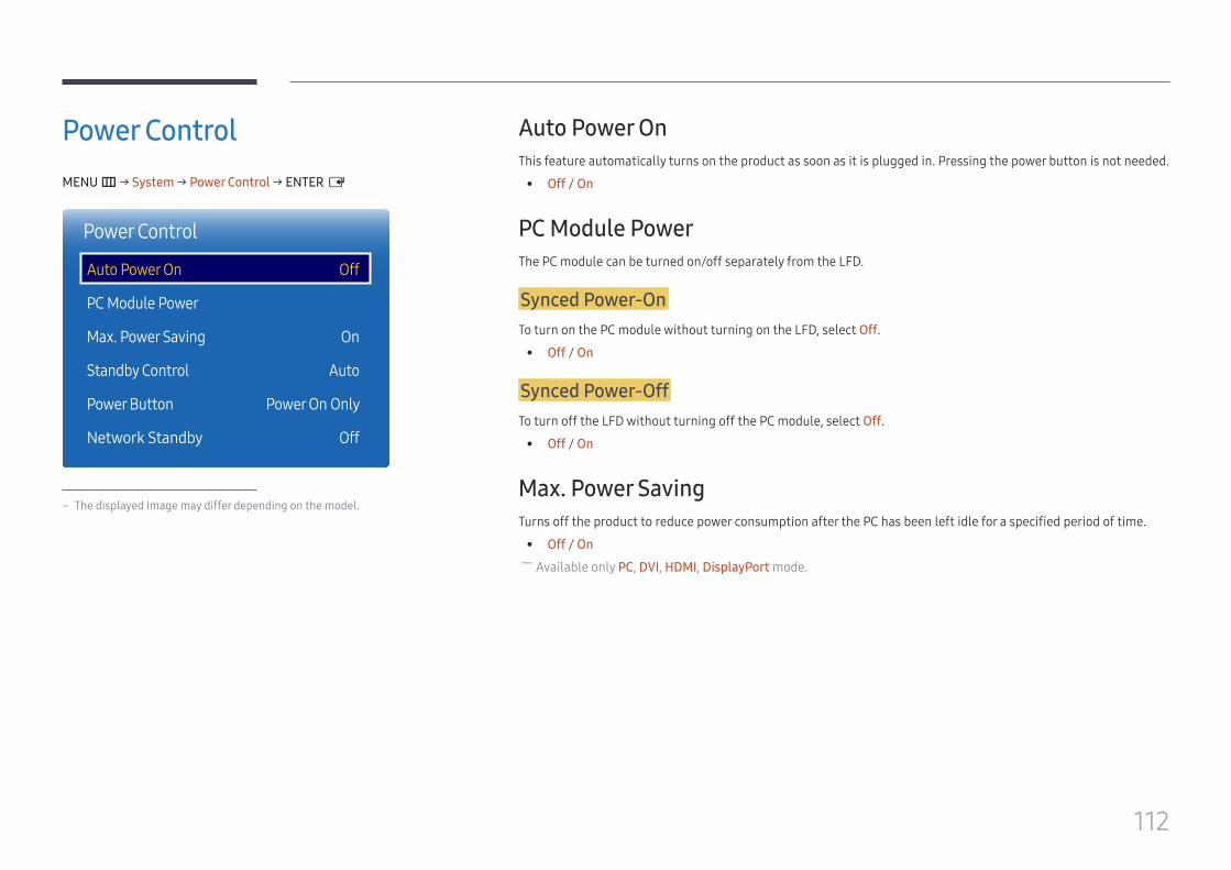
112
Power ControlMENU m → System → Power Control → ENTER E
Power Control
Auto Power On
PC Module Power
Max. Power Saving
Standby Control
Power Button
Network Standby
Off
On
Auto
Power On Only
Off
– The displayed image may differ depending on the model.
Auto Power OnThis feature automatically turns on the product as soon as it is plugged in. Pressing the power button is not needed.
• Off / On
PC Module PowerThe PC module can be turned on/off separately from the LFD.
Synced Power-OnTo turn on the PC module without turning on the LFD, select Off.
• Off / On
Synced Power-OffTo turn off the LFD without turning off the PC module, select Off.
• Off / On
Max. Power SavingTurns off the product to reduce power consumption after the PC has been left idle for a specified period of time.
• Off / On ― Available only PC, DVI, HDMI, DisplayPort mode.
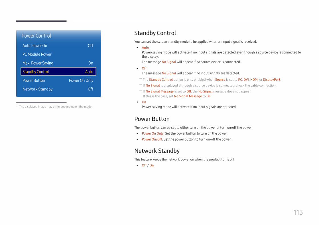
113
Standby ControlYou can set the screen standby mode to be applied when an input signal is received.
• AutoPower-saving mode will activate if no input signals are detected even though a source device is connected to the display.The message No Signal will appear if no source device is connected.
• OffThe message No Signal will appear if no input signals are detected. ― The Standby Control option is only enabled when Source is set to PC, DVI, HDMI or DisplayPort. ― If No Signal is displayed although a source device is connected, check the cable connection. ― If No Signal Message is set to Off, the No Signal message does not appear.If this is the case, set No Signal Message to On.
• OnPower-saving mode will activate if no input signals are detected.
Power ButtonThe power button can be set to either turn on the power or turn on/off the power.
• Power On Only: Set the power button to turn on the power.
• Power On/Off: Set the power button to turn on/off the power.
Network StandbyThis feature keeps the network power on when the product turns off.
• Off / On
Power Control
Auto Power On
PC Module Power
Max. Power Saving
Standby Control
Power Button
Network Standby
Off
On
Auto
Power On Only
Off
– The displayed image may differ depending on the model.
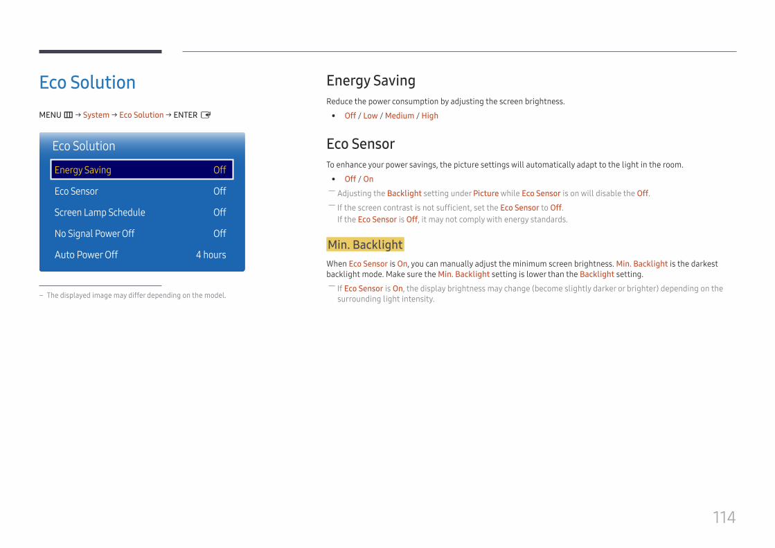
114
Eco SolutionMENU m → System → Eco Solution → ENTER E
Eco Solution
Energy Saving
Eco Sensor
Screen Lamp Schedule
No Signal Power Off
Auto Power Off
Off
Off
Off
Off
4 hours
– The displayed image may differ depending on the model.
Energy SavingReduce the power consumption by adjusting the screen brightness.
• Off / Low / Medium / High
Eco SensorTo enhance your power savings, the picture settings will automatically adapt to the light in the room.
• Off / On ― Adjusting the Backlight setting under Picture while Eco Sensor is on will disable the Off. ― If the screen contrast is not sufficient, set the Eco Sensor to Off.If the Eco Sensor is Off, it may not comply with energy standards.
Min. BacklightWhen Eco Sensor is On, you can manually adjust the minimum screen brightness. Min. Backlight is the darkest backlight mode. Make sure the Min. Backlight setting is lower than the Backlight setting.
― If Eco Sensor is On, the display brightness may change (become slightly darker or brighter) depending on the surrounding light intensity.
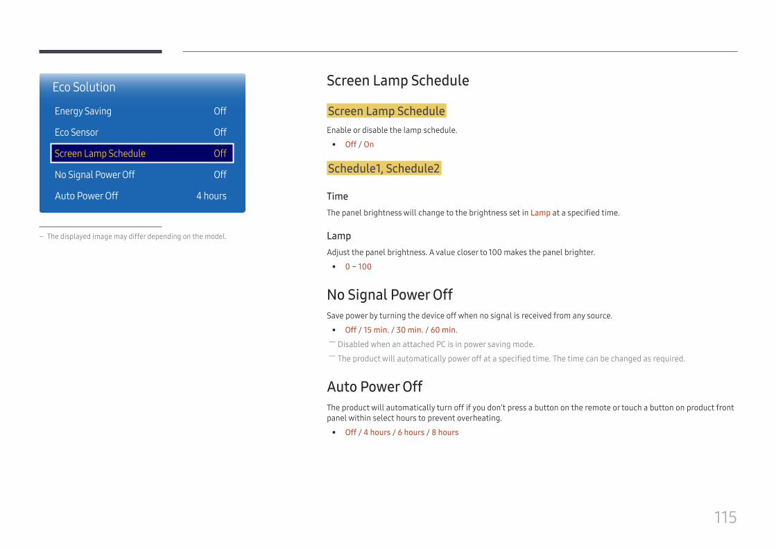
115
Eco Solution
Energy Saving
Eco Sensor
Screen Lamp Schedule
No Signal Power Off
Auto Power Off
Off
Off
Off
Off
4 hours
– The displayed image may differ depending on the model.
Screen Lamp Schedule
Screen Lamp ScheduleEnable or disable the lamp schedule.
• Off / On
Schedule1, Schedule2
TimeThe panel brightness will change to the brightness set in Lamp at a specified time.
LampAdjust the panel brightness. A value closer to 100 makes the panel brighter.
• 0 ~ 100
No Signal Power Off Save power by turning the device off when no signal is received from any source.
• Off / 15 min. / 30 min. / 60 min. ― Disabled when an attached PC is in power saving mode. ― The product will automatically power off at a specified time. The time can be changed as required.
Auto Power OffThe product will automatically turn off if you don’t press a button on the remote or touch a button on product front panel within select hours to prevent overheating.
• Off / 4 hours / 6 hours / 8 hours

116
Temperature ControlMENU m → System → Temperature Control → ENTER E
System
Temperature Control 77
– The displayed image may differ depending on the model.
This function detects the internal temperature of the product. You can specify the temperature range that is acceptable.
The default temperature is set to 77 C.
The recommended operating temperature for this product is 75 to 80 C (based on an ambient temperature of 40 C). ― The screen will become darker if the current temperature exceeds the specified temperature limit. If the temperature continues to rise, the product will power off to prevent overheating.
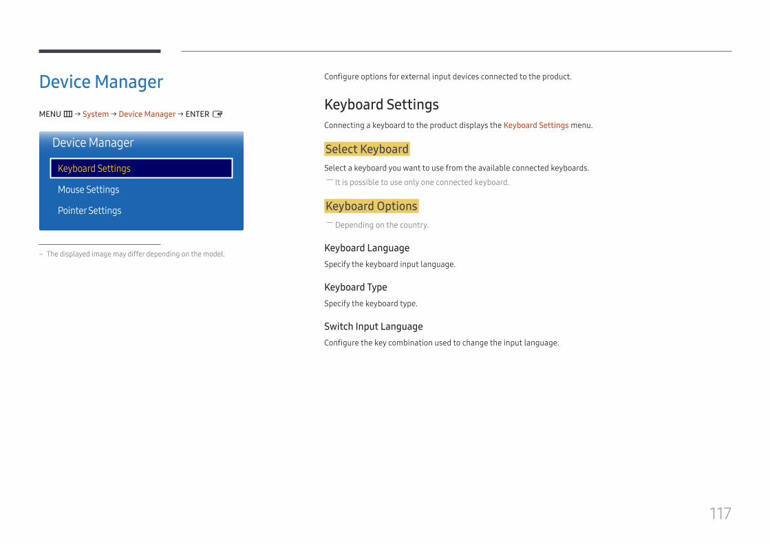
117
Device ManagerMENU m → System → Device Manager → ENTER E
Device Manager
Keyboard Settings
Mouse Settings
Pointer Settings
– The displayed image may differ depending on the model.
Configure options for external input devices connected to the product.
Keyboard SettingsConnecting a keyboard to the product displays the Keyboard Settings menu.
Select KeyboardSelect a keyboard you want to use from the available connected keyboards.
― It is possible to use only one connected keyboard.
Keyboard Options ― Depending on the country.
Keyboard LanguageSpecify the keyboard input language.
Keyboard TypeSpecify the keyboard type.
Switch Input LanguageConfigure the key combination used to change the input language.
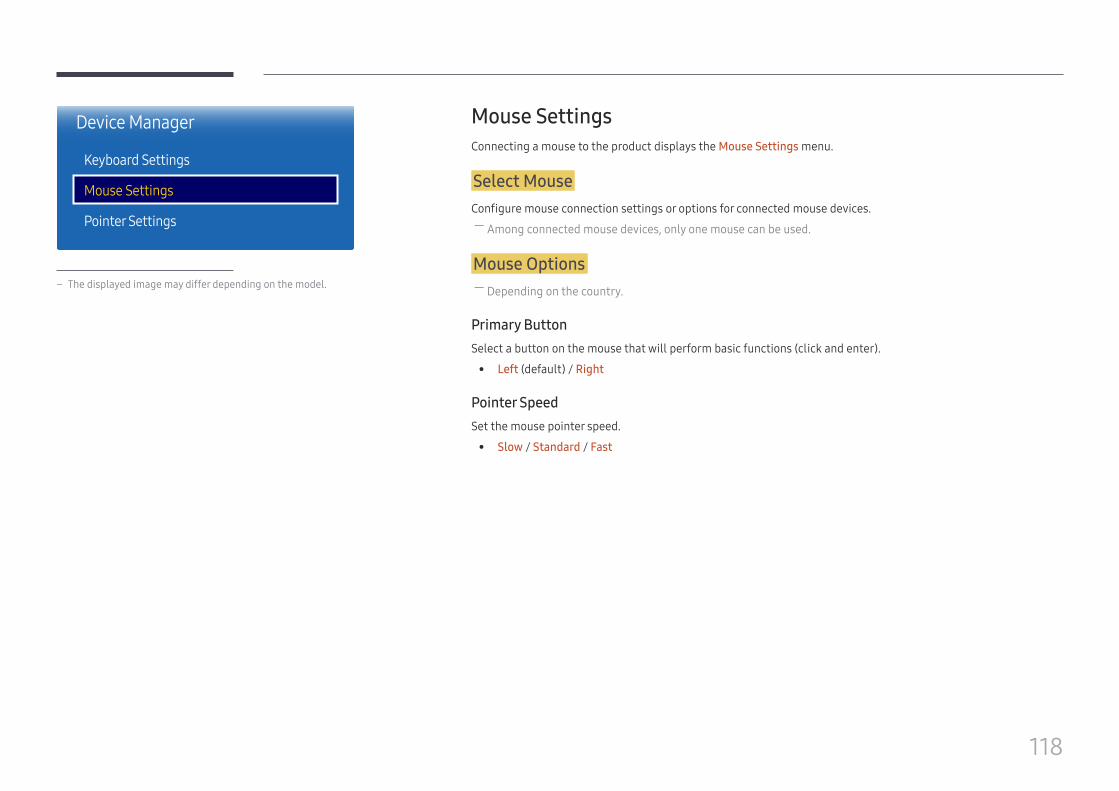
118
Mouse SettingsConnecting a mouse to the product displays the Mouse Settings menu.
Select MouseConfigure mouse connection settings or options for connected mouse devices.
― Among connected mouse devices, only one mouse can be used.
Mouse Options ― Depending on the country.
Primary ButtonSelect a button on the mouse that will perform basic functions (click and enter).
• Left (default) / Right
Pointer SpeedSet the mouse pointer speed.
• Slow / Standard / Fast
Device Manager
Keyboard Settings
Mouse Settings
Pointer Settings
– The displayed image may differ depending on the model.
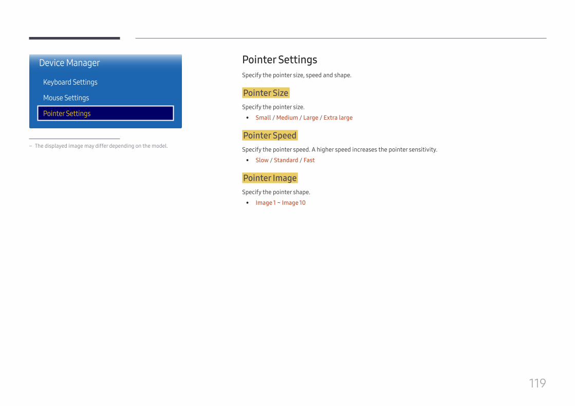
119
Device Manager
Keyboard Settings
Mouse Settings
Pointer Settings
– The displayed image may differ depending on the model.
Pointer SettingsSpecify the pointer size, speed and shape.
Pointer SizeSpecify the pointer size.
• Small / Medium / Large / Extra large
Pointer SpeedSpecify the pointer speed. A higher speed increases the pointer sensitivity.
• Slow / Standard / Fast
Pointer ImageSpecify the pointer shape.
• Image 1 ~ Image 10
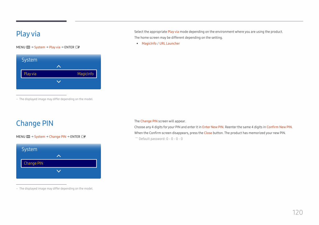
120
Play viaMENU m → System → Play via → ENTER E
System
Play via MagicInfo
– The displayed image may differ depending on the model.
Select the appropriate Play via mode depending on the environment where you are using the product.
The home screen may be different depending on the setting.
• MagicInfo / URL Launcher
Change PINMENU m → System → Change PIN → ENTER E
System
Change PIN
– The displayed image may differ depending on the model.
The Change PIN screen will appear.
Choose any 4 digits for your PIN and enter it in Enter New PIN. Reenter the same 4 digits in Confirm New PIN.
When the Confirm screen disappears, press the Close button. The product has memorized your new PIN. ― Default password: 0 - 0 - 0 - 0
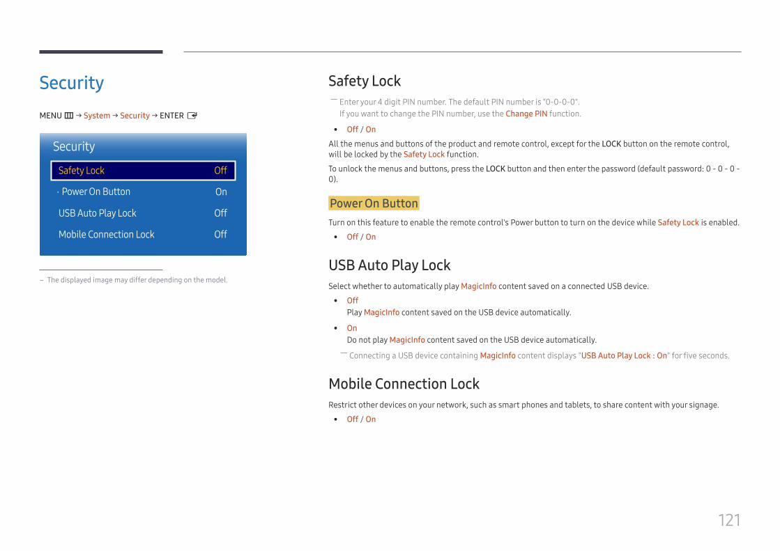
121
SecurityMENU m → System → Security → ENTER E
·
Security
Safety Lock
Power On Button
USB Auto Play Lock
Mobile Connection Lock
Off
On
Off
Off
– The displayed image may differ depending on the model.
Safety Lock ― Enter your 4 digit PIN number. The default PIN number is “0-0-0-0".If you want to change the PIN number, use the Change PIN function.
• Off / On
All the menus and buttons of the product and remote control, except for the LOCK button on the remote control, will be locked by the Safety Lock function.
To unlock the menus and buttons, press the LOCK button and then enter the password (default password: 0 - 0 - 0 - 0).
Power On ButtonTurn on this feature to enable the remote control's Power button to turn on the device while Safety Lock is enabled.
• Off / On
USB Auto Play LockSelect whether to automatically play MagicInfo content saved on a connected USB device.
• OffPlay MagicInfo content saved on the USB device automatically.
• OnDo not play MagicInfo content saved on the USB device automatically. ― Connecting a USB device containing MagicInfo content displays "USB Auto Play Lock : On" for five seconds.
Mobile Connection LockRestrict other devices on your network, such as smart phones and tablets, to share content with your signage.
• Off / On
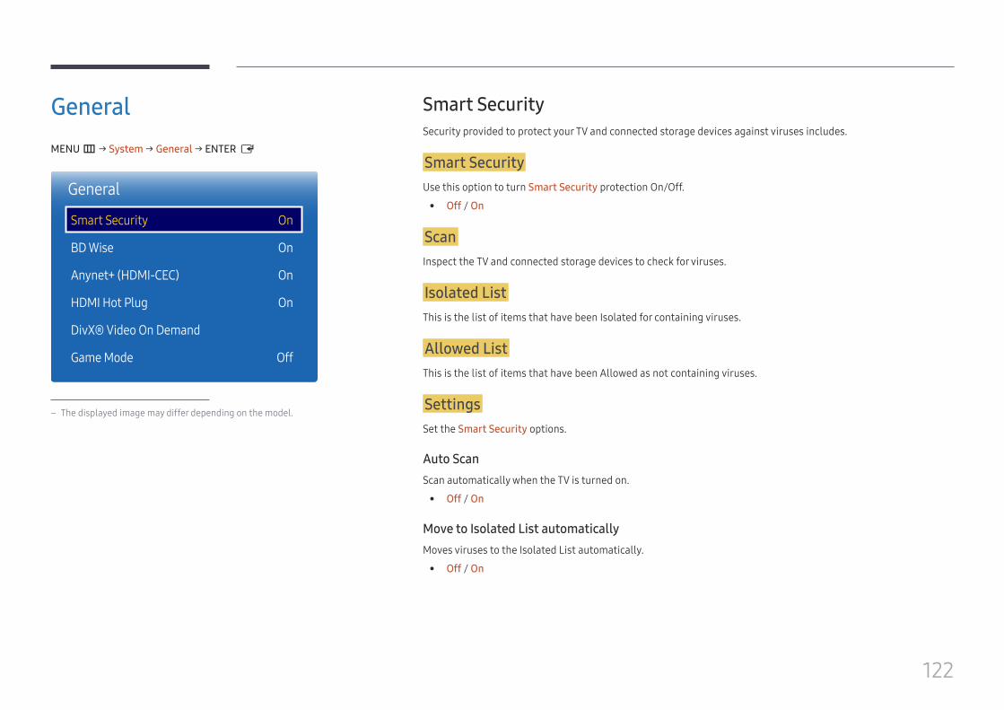
122
GeneralMENU m → System → General → ENTER E
General
Smart Security
BD Wise
Anynet+ (HDMI-CEC)
HDMI Hot Plug
DivX® Video On Demand
Game Mode
On
On
On
On
Off
– The displayed image may differ depending on the model.
Smart SecuritySecurity provided to protect your TV and connected storage devices against viruses includes.
Smart SecurityUse this option to turn Smart Security protection On/Off.
• Off / On
ScanInspect the TV and connected storage devices to check for viruses.
Isolated ListThis is the list of items that have been Isolated for containing viruses.
Allowed ListThis is the list of items that have been Allowed as not containing viruses.
SettingsSet the Smart Security options.
Auto ScanScan automatically when the TV is turned on.
• Off / On
Move to Isolated List automaticallyMoves viruses to the Isolated List automatically.
• Off / On
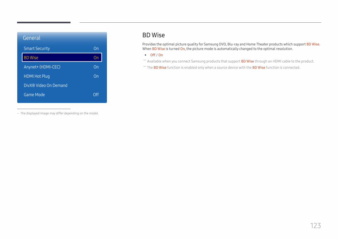
123
BD WiseProvides the optimal picture quality for Samsung DVD, Blu-ray and Home Theater products which support BD Wise. When BD Wise is turned On, the picture mode is automatically changed to the optimal resolution.
• Off / On ― Available when you connect Samsung products that support BD Wise through an HDMI cable to the product. ― The BD Wise function is enabled only when a source device with the BD Wise function is connected.
General
Smart Security
BD Wise
Anynet+ (HDMI-CEC)
HDMI Hot Plug
DivX® Video On Demand
Game Mode
On
On
On
On
Off
– The displayed image may differ depending on the model.
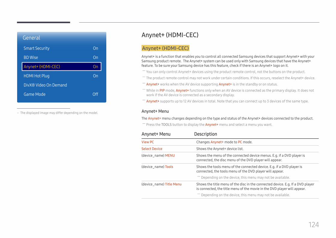
124
Anynet+ (HDMI-CEC)
Anynet+ (HDMI-CEC)Anynet+ is a function that enables you to control all connected Samsung devices that support Anynet+ with your Samsung product remote. The Anynet+ system can be used only with Samsung devices that have the Anynet+ feature. To be sure your Samsung device has this feature, check if there is an Anynet+ logo on it.
― You can only control Anynet+ devices using the product remote control, not the buttons on the product. ― The product remote control may not work under certain conditions. If this occurs, reselect the Anynet+ device. ― Anynet+ works when the AV device supporting Anynet+ is in the standby or on status. ― While in PIP mode, Anynet+ functions only when an AV device is connected as the primary display. It does not work if the AV device is connected as a secondary display.
― Anynet+ supports up to 12 AV devices in total. Note that you can connect up to 3 devices of the same type.
Anynet+ MenuThe Anynet+ menu changes depending on the type and status of the Anynet+ devices connected to the product.
― Press the TOOLS button to display the Anynet+ menu and select a menu you want.
Anynet+ Menu DescriptionView PC Changes Anynet+ mode to PC mode.
Select Device Shows the Anynet+ device list.
(device_name) MENU Shows the menu of the connected device menus. E.g. if a DVD player is connected, the disc menu of the DVD player will appear.
(device_name) Tools Shows the tools menu of the connected device. E.g. if a DVD player is connected, the tools menu of the DVD player will appear.
― Depending on the device, this menu may not be available.
(device_name) Title Menu Shows the title menu of the disc in the connected device. E.g. If a DVD player is connected, the title menu of the movie in the DVD player will appear.
― Depending on the device, this menu may not be available.
General
Smart Security
BD Wise
Anynet+ (HDMI-CEC)
HDMI Hot Plug
DivX® Video On Demand
Game Mode
On
On
On
On
Off
– The displayed image may differ depending on the model.
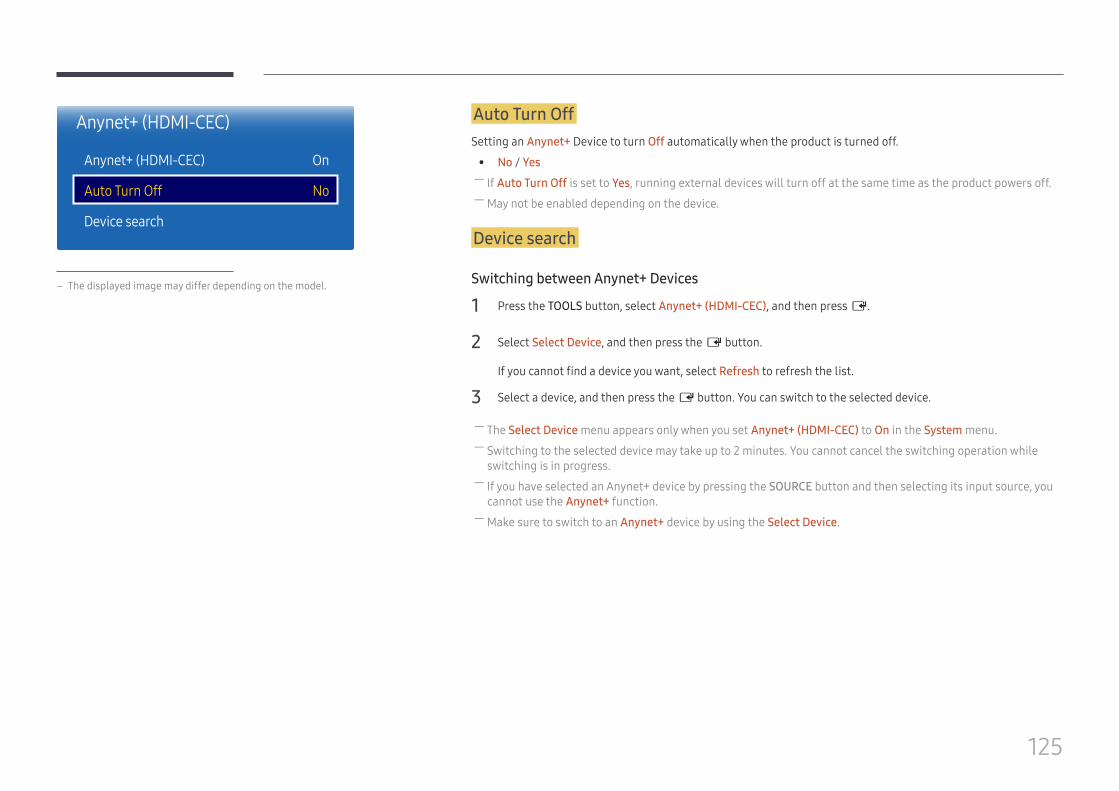
125
Auto Turn OffSetting an Anynet+ Device to turn Off automatically when the product is turned off.
• No / Yes ― If Auto Turn Off is set to Yes, running external devices will turn off at the same time as the product powers off. ― May not be enabled depending on the device.
Device search
Switching between Anynet+ Devices
1 Press the TOOLS button, select Anynet+ (HDMI-CEC), and then press E.
2 Select Select Device, and then press the E button.
If you cannot find a device you want, select Refresh to refresh the list.
3 Select a device, and then press the E button. You can switch to the selected device.
― The Select Device menu appears only when you set Anynet+ (HDMI-CEC) to On in the System menu. ― Switching to the selected device may take up to 2 minutes. You cannot cancel the switching operation while switching is in progress.
― If you have selected an Anynet+ device by pressing the SOURCE button and then selecting its input source, you cannot use the Anynet+ function.
― Make sure to switch to an Anynet+ device by using the Select Device.
Anynet+ (HDMI-CEC)
Anynet+ (HDMI-CEC)
Auto Turn Off
Device search
On
No
– The displayed image may differ depending on the model.
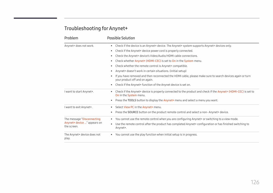
126
Troubleshooting for Anynet+
Problem Possible Solution
Anynet+ does not work. • Check if the device is an Anynet+ device. The Anynet+ system supports Anynet+ devices only.
• Check if the Anynet+ device power cord is properly connected.
• Check the Anynet+ device’s Video/Audio/HDMI cable connections.
• Check whether Anynet+ (HDMI-CEC) is set to On in the System menu.
• Check whether the remote control is Anynet+ compatible.
• Anynet+ doesn’t work in certain situations. (initial setup)
• If you have removed and then reconnected the HDMI cable, please make sure to search devices again or turn your product off and on again.
• Check if the Anynet+ function of the Anynet device is set on.
I want to start Anynet+. • Check if the Anynet+ device is properly connected to the product and check if the Anynet+ (HDMI-CEC) is set to On in the System menu.
• Press the TOOLS button to display the Anynet+ menu and select a menu you want.
I want to exit Anynet+. • Select View PC in the Anynet+ menu.
• Press the SOURCE button on the product remote control and select a non- Anynet+ device.
The message “Disconnecting Anynet+ device ...” appears on the screen.
• You cannot use the remote control when you are configuring Anynet+ or switching to a view mode.
• Use the remote control after the product has completed Anynet+ configuration or has finished switching to Anynet+.
The Anynet+ device does not play.
• You cannot use the play function when initial setup is in progress.
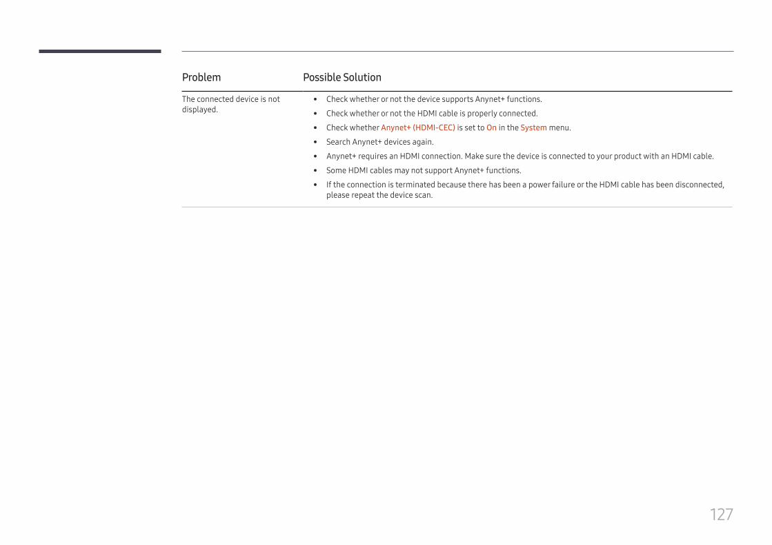
127
Problem Possible Solution
The connected device is not displayed.
• Check whether or not the device supports Anynet+ functions.
• Check whether or not the HDMI cable is properly connected.
• Check whether Anynet+ (HDMI-CEC) is set to On in the System menu.
• Search Anynet+ devices again.
• Anynet+ requires an HDMI connection. Make sure the device is connected to your product with an HDMI cable.
• Some HDMI cables may not support Anynet+ functions.
• If the connection is terminated because there has been a power failure or the HDMI cable has been disconnected, please repeat the device scan.
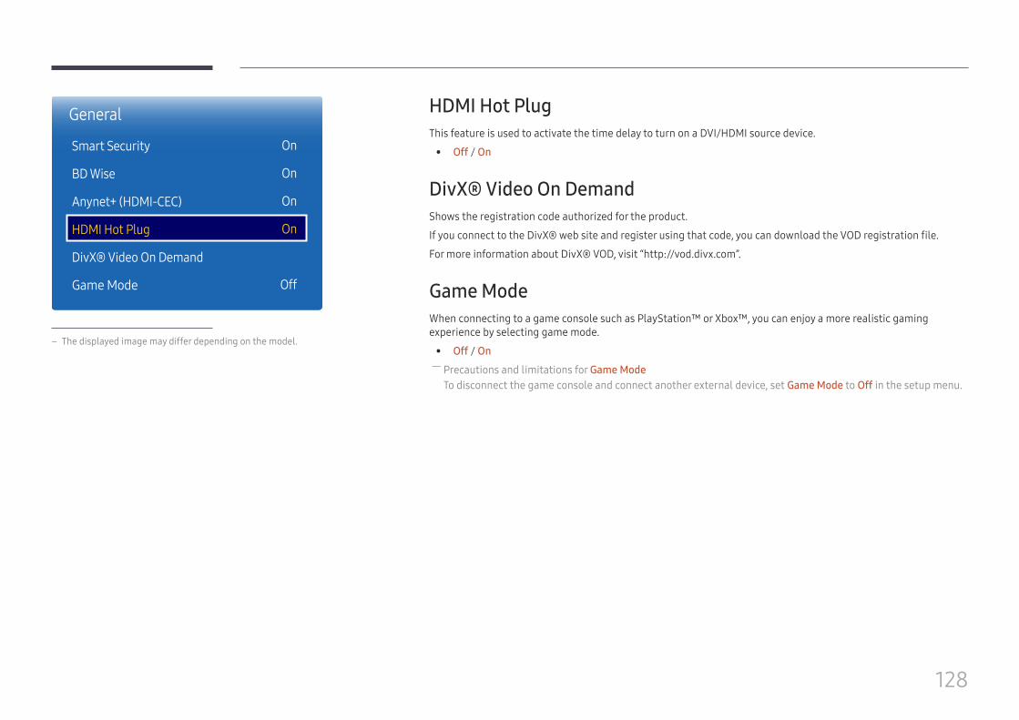
128
HDMI Hot PlugThis feature is used to activate the time delay to turn on a DVI/HDMI source device.
• Off / On
DivX® Video On DemandShows the registration code authorized for the product.
If you connect to the DivX® web site and register using that code, you can download the VOD registration file.
For more information about DivX® VOD, visit “http://vod.divx.com”.
Game ModeWhen connecting to a game console such as PlayStation™ or Xbox™, you can enjoy a more realistic gaming experience by selecting game mode.
• Off / On ― Precautions and limitations for Game ModeTo disconnect the game console and connect another external device, set Game Mode to Off in the setup menu.
General
Smart Security
BD Wise
Anynet+ (HDMI-CEC)
HDMI Hot Plug
DivX® Video On Demand
Game Mode
On
On
On
On
Off
– The displayed image may differ depending on the model.

129
Reset SystemMENU m → System → Reset System → ENTER E
System
Reset System
– The displayed image may differ depending on the model.
This option returns the current settings under system to the default factory settings.
130
Support
Software UpdateMENU m → Support → Software Update → ENTER E
The Software Update menu lets you upgrade your product software to the latest version. ― Be careful not to turn off the power until the upgrade is complete. The product will turn off and on automatically after completing the software upgrade.
― When you upgrade software, all video and audio settings you have made will return to their default settings. We advise you to write down your settings so that you can easily reset them after the upgrade.
Update nowUpdate the software to the latest version.
― Current version: This is the software version already installed in the product.
Auto UpdateThis feature automatically updates the product when not in use.
• Off / On
Contact SamsungMENU m → Support → Contact Samsung → ENTER E
View this information when your product does not work properly or when you want to upgrade the software.
You can find information regarding our call centers and how to download products and software.
― Contact Samsung and find the product Model Code and Software Version.
Go to HomeAccessible using the HOME button on the remote control.
MENU m → Support → Go to Home → ENTER E
Go to Home to play a variety of content from a memory device or a connected network.
Reset AllMENU m → Support → Reset All → ENTER E
This option returns all the current settings for a display to the default factory settings.
Chapter 11
131
Playing photos, videos and music (Media Play)
Play photos, videos or music saved on a storage device.
Play a variety of content using the following methods.
• Using a USB device: Play media content such as videos, photos and music from a USB device.
• Connecting a storage device: Play media content saved on a storage device such as a smartphone, camera, PC or cloud service.
Read the following before using media play with a USB device
Caution • Before connecting a USB device to the product, back up files to ensure your data is not damaged or lost.
Samsung Electronics is not liable for any damage or loss of data.
• Do not remove a USB device while it is loading.
• If a USB device is connected using a USB extension cable, the USB device may not be recognized or files saved on the device may not be able to be read.
• If the product does not recognize a connected USB device, the files on the USB device may be corrupted or may not be able to be played.If this occurs, connect the USB device to the PC to format the device, then make sure the device is connected properly.
• USB HDD greater than 2TB is not supported.
Enjoy videos, photos, music files saved on a USB Mass Storage Class (MSC) device.
Chapter 12
132
Compatible devices with media play • Some USB digital cameras, smartphones and audio devices may not be compatible with the product.
• Media play is only compatible with USB MSC devices.
• MSC device refers to a Mass Storage Class Bulk-Only Transport device. Examples of MSC devices include Thumb drives, Flash card readers and USB HDDs. (USB hubs are not supported.) These MSC devices must be connected directly to a USB port on the product.
• If more than one Picture Transfer Protocol (PTP) device is connected, only one will work at a time.
• If multiple MSC devices are connected, some devices may not be recognized. USB devices that require high power (higher than 500mA or 5V) may not be supported.
• If an overheating warning message appears when a USB device is connected or used, the USB device may not be recognized or function properly.
• The screensaver activates if the product is left idle for a period of time specified in Auto Protection Time.
• Power-saving mode on some external hard disk drives may automatically deactivate after connecting to the product.
File system and formats • Media play may not function properly with unlicensed multimedia files.
• Media Transfer Protocol (MTP) is not supported.
• Supported file systems include FAT16, FAT32 and NTFS (read only).
• Media play supports the sequential JPEG format.It does not support the progressive JPEG format.
• Images with a higher resolution take longer to be displayed on the screen.
• The maximum JPEG resolution supported is 15360x8640 pixels.
• If a file is incompatible or corrupted, a message Not Supported File Format. appears.
• When sorting files in folder view mode, a maximum of 1000 files can be displayed in each folder.
• If a USB device contains 8000 files and folders or more, some files and folders may not open.
• DRM MP3 files downloaded from websites that charge a fee cannot be played. Digital Rights Management (DRM) refers to a system for protecting the copyrights of data circulated via the Internet or other digital media by enabling secure distribution and/or disabling illegal distribution of the data.
133
Using a USB device
Connecting a USB device
1 Turn on your product.
2 Connect a USB device containing photo, music and/or movie files to the USB port on the back or side panel of the product.
3 The Player page automatically appears as soon as a USB device connects to the product.
― If only one USB device is connected, files saved on the USB device are displayed automatically. ― To view content saved on a USB device, connect the USB device to a USB port on the product.
Removing a USB device
Removing a USB device from Source
1 Press SOURCE on the remote control. Alternatively, go to Source using the OSD menu.
SOURCE → Source
2 Select USB from Source, and then press the TOOLS button on the remote control. The Options menu is displayed.
3 Select Disconnect USB Device and wait until the USB device is disconnected. The USB device is disconnected.
It is recommended to use a USB HDD that has a power adapter.
It is recommended to remove a USB device using the Disconnect USB Device function.
134
Playing media content from a PC/mobile device
Approving a PC/mobile device connectionPlay photos, videos or music saved on a PC or mobile device.
To play media content from a PC or mobile device on the product, the connection with the PC or mobile device must be approved.
1 Press SOURCE on the remote control. Alternatively, go to Source using the OSD menu.
SOURCE → Source
2 Select Network from Source. The Network Device menu appears.
3 Select Options from the screen, and then select Multimedia Device Settings. A list of devices connected to the product will appear.
4 Select a device and approve the device connection. Playback is only available on devices that are permitted to connect.
― Sending a media content playback request from a PC or mobile device displays a prompt asking if connection with the product is permitted. Conveniently connect the devices using the prompt.
― For details on how to configure a network, refer to the section Network Settings. ― Ensure the product and PC are connected to the same network subnet. All IP addresses are made up of four parts separated by dots.(E.g. IP address 111.222.333.444) The product should have the same IP address as the PC, except for the fourth part of the address, if they are connected to the same subnet. (E.g. 111.222.333.***)
135
Features provided in the media content list pageSOURCE → Source → USB
The media content list page on a storage device provides the following features.
• Sort byRearrange the media content list under the selected file format in a desired view mode.
– This menu item is not available if Filter is set to All.
• FilterAmong Photos, Videos and Music content saved on a storage device, view content files under a desired file format only.
• Options – This menu item is not available if Filter is set to All.
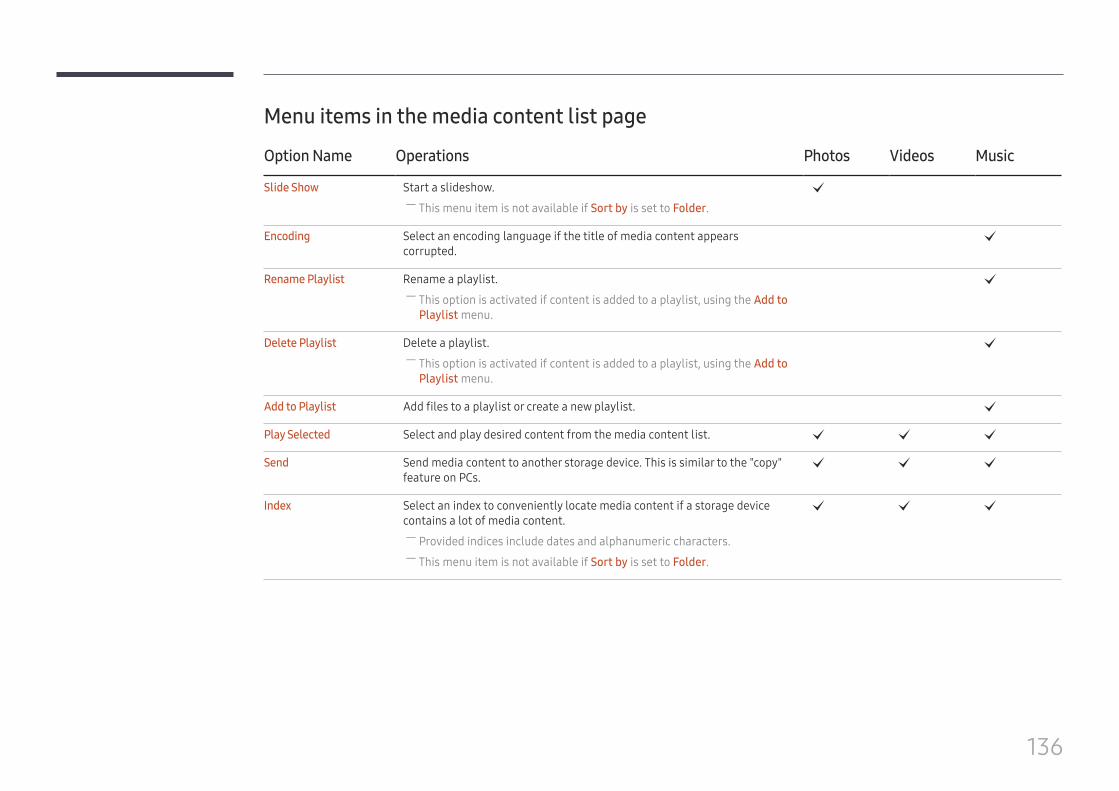
136
Menu items in the media content list page
Option Name Operations Photos Videos Music
Slide Show Start a slideshow. ― This menu item is not available if Sort by is set to Folder.
c
Encoding Select an encoding language if the title of media content appears corrupted.
c
Rename Playlist Rename a playlist. ― This option is activated if content is added to a playlist, using the Add to Playlist menu.
c
Delete Playlist Delete a playlist. ― This option is activated if content is added to a playlist, using the Add to Playlist menu.
c
Add to Playlist Add files to a playlist or create a new playlist. c
Play Selected Select and play desired content from the media content list. c c c
Send Send media content to another storage device. This is similar to the "copy" feature on PCs.
c c c
Index Select an index to conveniently locate media content if a storage device contains a lot of media content.
― Provided indices include dates and alphanumeric characters. ― This menu item is not available if Sort by is set to Folder.
c c c

137
Available buttons and features during photo playbackPressing the E or TOOLS button displays the following buttons. The RETURN button makes the buttons disappear.
• Pause / PlayStart or stop a slideshow. Using a slideshow, it is possible to play all photos in a folder.
• Previous / NextView the previous or next photo.
• Settings
Option Name Operations
Slideshow Settings Speed: Change the slideshow speed.
Effects: Apply transition effects between photos.
Rotate Rotate photos.
Zoom Zoom in on photos up to 4x.
Picture Mode Change the Picture Mode.
Background Music Play background music while viewing photos. ― Make sure a music file is saved on the same device. ― The mini player is displayed while background music (Background Music) is playing. Using the mini player, pause the music currently playing or change to another music.
― Previous BGM track / Pause BGM / Play BGM / Next BGM track
Select Speakers Select a speaker that will output the background music (Background Music). ― This menu item is only available when background music (Background Music) is playing.
Send Send open photos to another storage device. This is similar to the "copy" feature on PCs.
Information View information about a file.
– Pressing the INFO button while a device name is selected will display information about the selected device.
– Pressing the INFO button while a file is selected will display information about the selected file.
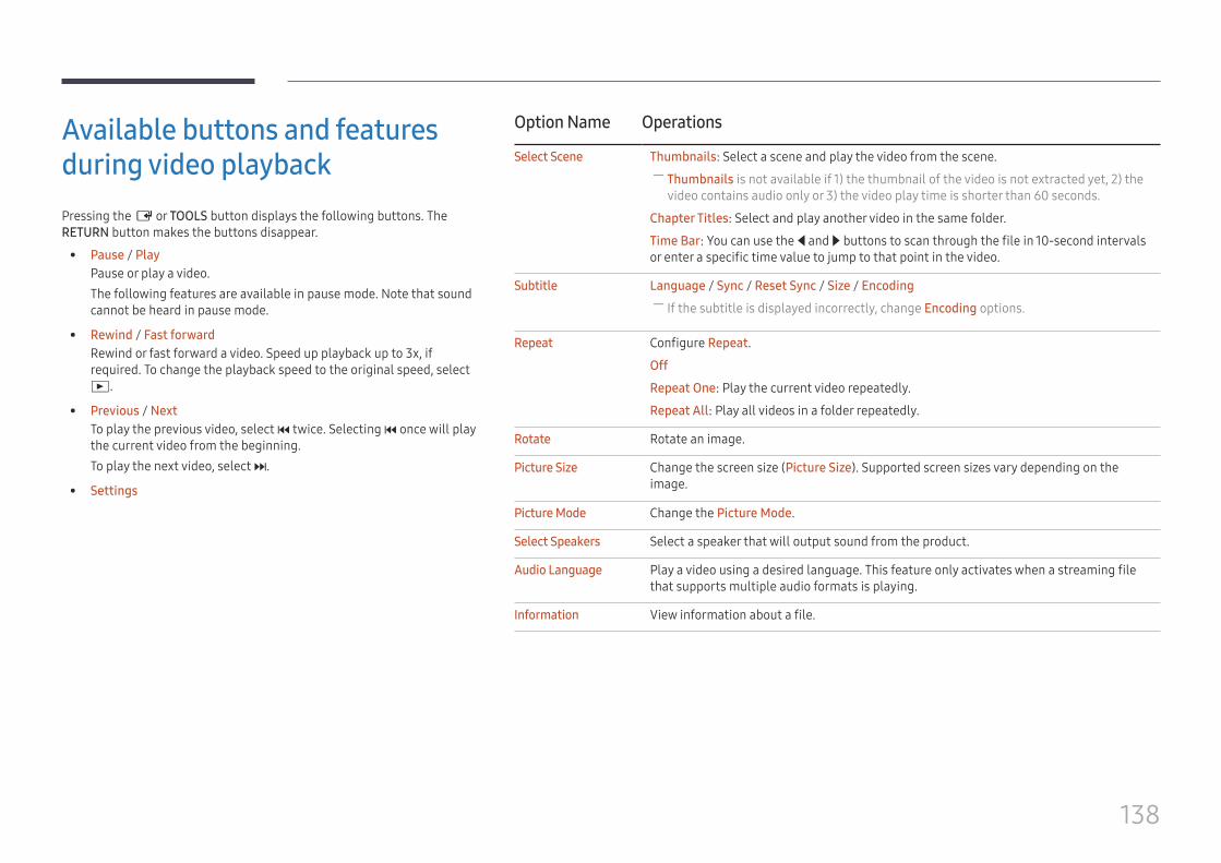
138
Available buttons and features during video playbackPressing the E or TOOLS button displays the following buttons. The RETURN button makes the buttons disappear.
• Pause / PlayPause or play a video.The following features are available in pause mode. Note that sound cannot be heard in pause mode.
• Rewind / Fast forwardRewind or fast forward a video. Speed up playback up to 3x, if required. To change the playback speed to the original speed, select ∂.
• Previous / NextTo play the previous video, select twice. Selecting once will play the current video from the beginning.To play the next video, select ‚.
• Settings
Option Name Operations
Select Scene Thumbnails: Select a scene and play the video from the scene. ― Thumbnails is not available if 1) the thumbnail of the video is not extracted yet, 2) the video contains audio only or 3) the video play time is shorter than 60 seconds.
Chapter Titles: Select and play another video in the same folder.
Time Bar: You can use the l and r buttons to scan through the file in 10-second intervals or enter a specific time value to jump to that point in the video.
Subtitle Language / Sync / Reset Sync / Size / Encoding ― If the subtitle is displayed incorrectly, change Encoding options.
Repeat Configure Repeat.
Off
Repeat One: Play the current video repeatedly.
Repeat All: Play all videos in a folder repeatedly.
Rotate Rotate an image.
Picture Size Change the screen size (Picture Size). Supported screen sizes vary depending on the image.
Picture Mode Change the Picture Mode.
Select Speakers Select a speaker that will output sound from the product.
Audio Language Play a video using a desired language. This feature only activates when a streaming file that supports multiple audio formats is playing.
Information View information about a file.
139
Available buttons and features during music playback • Pause / Play
Pause or play music.
• Rewind / Fast forwardRewind or fast forward music. Speed up playback up to 3x, if required. To play the previous music file, select ∂ twice.
• Previous / NextTo play the previous music file, select twice. Selecting once will play the current music from the beginning.To play the next music file, select ‚.
• RepeatConfigure Repeat mode. Repeat One plays the current music file repeatedly. Repeat All plays all files in a folder repeatedly.
• ShuffleEnable or disable shuffle playback mode.
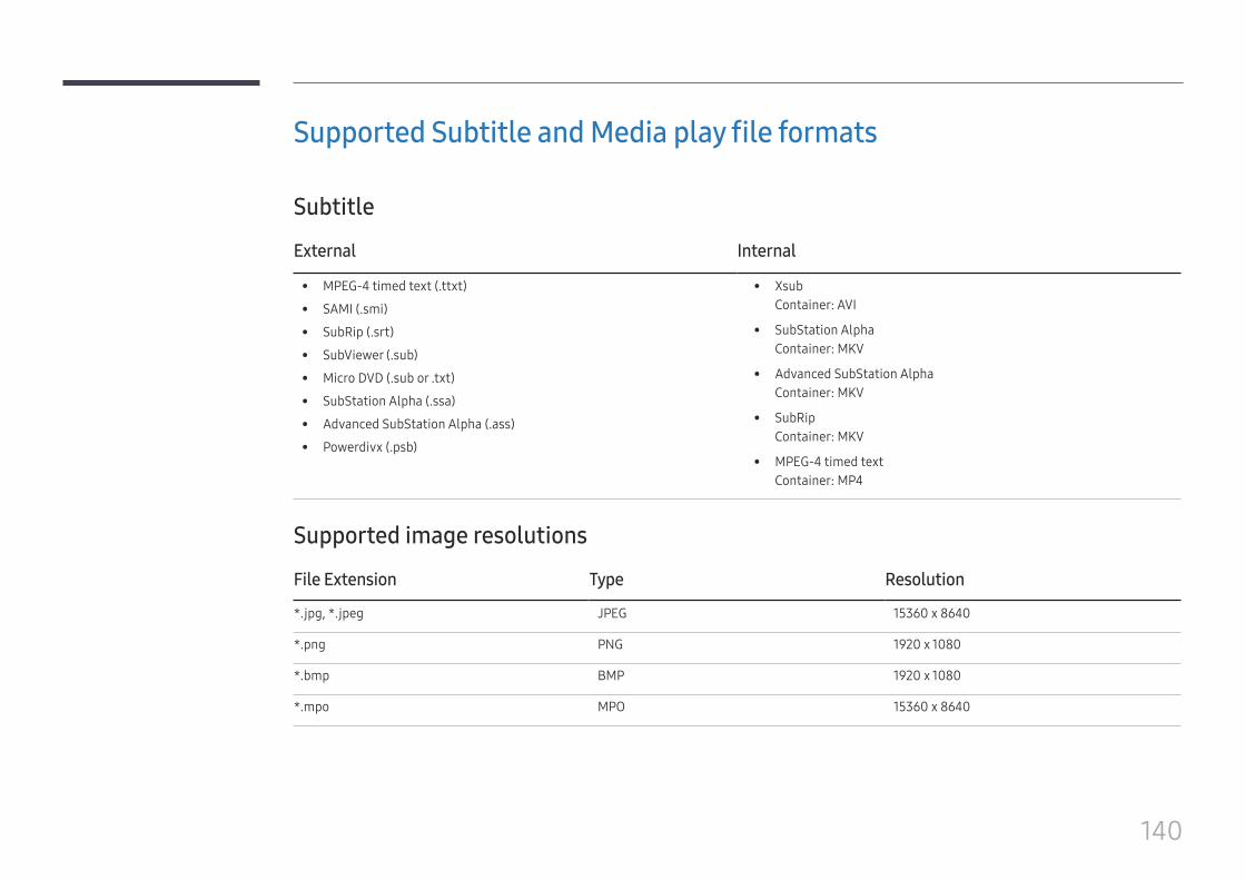
140
Supported Subtitle and Media play file formats
Subtitle
External Internal
• MPEG-4 timed text (.ttxt)
• SAMI (.smi)
• SubRip (.srt)
• SubViewer (.sub)
• Micro DVD (.sub or .txt)
• SubStation Alpha (.ssa)
• Advanced SubStation Alpha (.ass)
• Powerdivx (.psb)
• XsubContainer: AVI
• SubStation AlphaContainer: MKV
• Advanced SubStation AlphaContainer: MKV
• SubRipContainer: MKV
• MPEG-4 timed textContainer: MP4
Supported image resolutions
File Extension Type Resolution
*.jpg, *.jpeg JPEG 15360 x 8640
*.png PNG 1920 x 1080
*.bmp BMP 1920 x 1080
*.mpo MPO 15360 x 8640
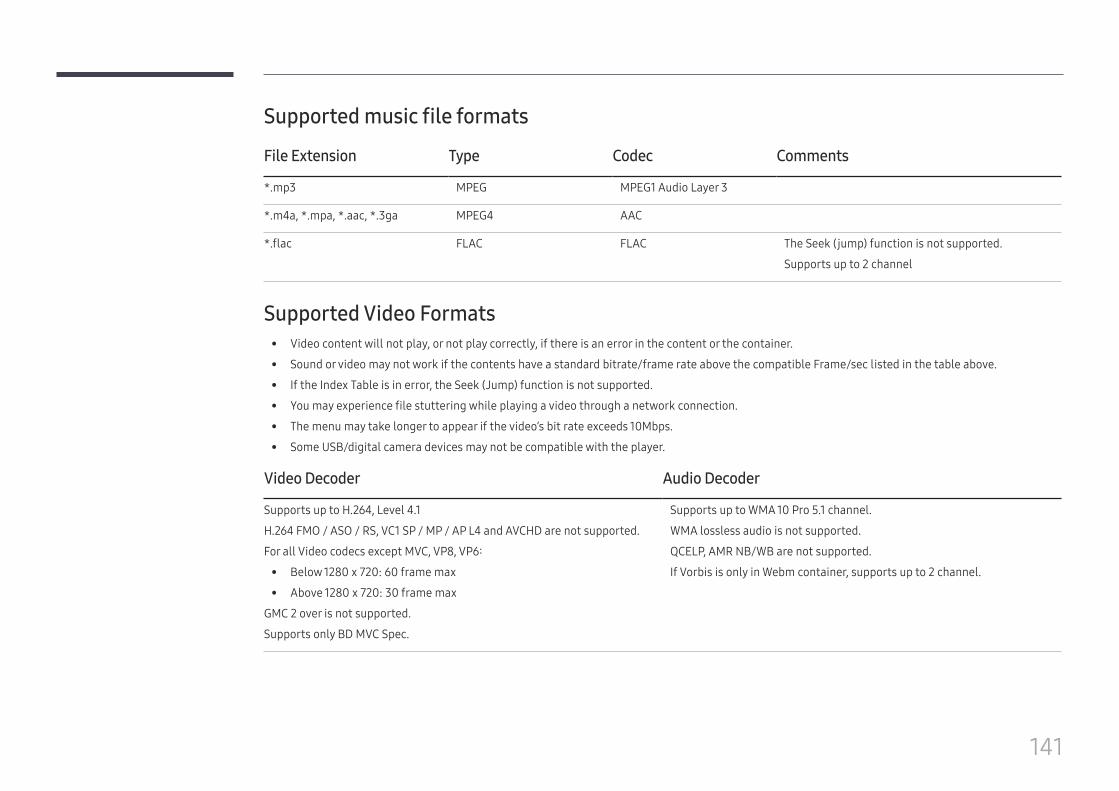
141
Supported music file formats
File Extension Type Codec Comments
*.mp3 MPEG MPEG1 Audio Layer 3
*.m4a, *.mpa, *.aac, *.3ga MPEG4 AAC
*.flac FLAC FLAC The Seek (jump) function is not supported.
Supports up to 2 channel
Supported Video Formats • Video content will not play, or not play correctly, if there is an error in the content or the container.
• Sound or video may not work if the contents have a standard bitrate/frame rate above the compatible Frame/sec listed in the table above.
• If the Index Table is in error, the Seek (Jump) function is not supported.
• You may experience file stuttering while playing a video through a network connection.
• The menu may take longer to appear if the video’s bit rate exceeds 10Mbps.
• Some USB/digital camera devices may not be compatible with the player.
Video Decoder Audio Decoder
Supports up to H.264, Level 4.1
H.264 FMO / ASO / RS, VC1 SP / MP / AP L4 and AVCHD are not supported.
For all Video codecs except MVC, VP8, VP6:
• Below 1280 x 720: 60 frame max
• Above 1280 x 720: 30 frame max
GMC 2 over is not supported.
Supports only BD MVC Spec.
Supports up to WMA 10 Pro 5.1 channel.
WMA lossless audio is not supported.
QCELP, AMR NB/WB are not supported.
If Vorbis is only in Webm container, supports up to 2 channel.
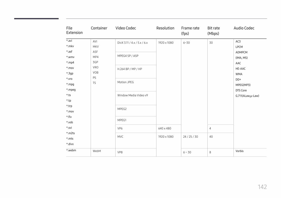
142
File Extension
Container Video Codec Resolution Frame rate(fps)
Bit rate(Mbps)
Audio Codec
*.avi
*.mkv
*.asf
*.wmv
*.mp4
*.mov
*.3gp
*.vro
*.mpg
*.mpeg
*.ts
*.tp
*.trp
*.mov
*.flv
*.vob
*.svi
*.m2ts
*.mts
*.divx
AVI
MKV
ASF
MP4
3GP
VRO
VOB
PS
TS
DivX 3.11 / 4.x / 5.x / 6.x 1920 x 1080 6~30 30 AC3
LPCM
ADMPCM
(IMA, MS)
AAC
HE-AAC
WMA
DD+
MPEG(MP3)
DTS Core
G.711(ALaw,μ-Law)
MPEG4 SP / ASP
H.264 BP / MP / HP
Motion JPEG
Window Media Video v9
MPEG2
MPEG1
VP6 640 x 480 4
MVC 1920 x 1080 24 / 25 / 30 40
*.webm WebM VP8 6 ~ 30 8 Vorbis
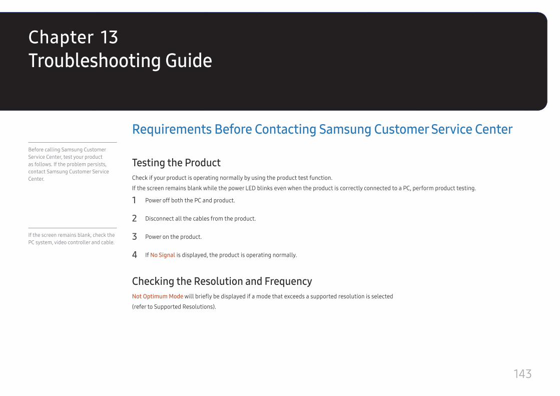
143
Troubleshooting Guide
Requirements Before Contacting Samsung Customer Service Center
Testing the ProductCheck if your product is operating normally by using the product test function.
If the screen remains blank while the power LED blinks even when the product is correctly connected to a PC, perform product testing.
1 Power off both the PC and product.
2 Disconnect all the cables from the product.
3 Power on the product.
4 If No Signal is displayed, the product is operating normally.
Checking the Resolution and FrequencyNot Optimum Mode will briefly be displayed if a mode that exceeds a supported resolution is selected
(refer to Supported Resolutions).
Before calling Samsung Customer Service Center, test your product as follows. If the problem persists, contact Samsung Customer Service Center.
If the screen remains blank, check the PC system, video controller and cable.
Chapter 13
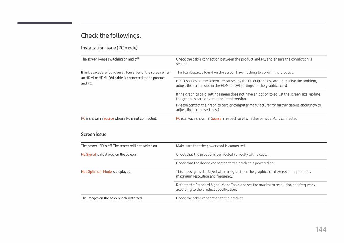
144
Check the followings.
Installation issue (PC mode)
The screen keeps switching on and off. Check the cable connection between the product and PC, and ensure the connection is secure.
Blank spaces are found on all four sides of the screen when an HDMI or HDMI-DVI cable is connected to the product and PC.
The blank spaces found on the screen have nothing to do with the product.
Blank spaces on the screen are caused by the PC or graphics card. To resolve the problem, adjust the screen size in the HDMI or DVI settings for the graphics card.
If the graphics card settings menu does not have an option to adjust the screen size, update the graphics card driver to the latest version.
(Please contact the graphics card or computer manufacturer for further details about how to adjust the screen settings.)
PC is shown in Source when a PC is not connected. PC is always shown in Source irrespective of whether or not a PC is connected.
Screen issue
The power LED is off. The screen will not switch on. Make sure that the power cord is connected.
No Signal is displayed on the screen. Check that the product is connected correctly with a cable.
Check that the device connected to the product is powered on.
Not Optimum Mode is displayed. This message is displayed when a signal from the graphics card exceeds the product's maximum resolution and frequency.
Refer to the Standard Signal Mode Table and set the maximum resolution and frequency according to the product specifications.
The images on the screen look distorted. Check the cable connection to the product
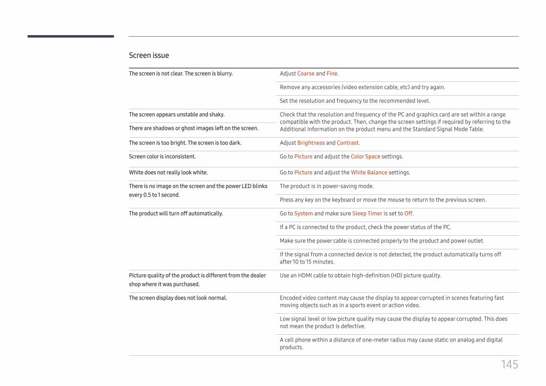
145
Screen issue
The screen is not clear. The screen is blurry. Adjust Coarse and Fine.
Remove any accessories (video extension cable, etc) and try again.
Set the resolution and frequency to the recommended level.
The screen appears unstable and shaky. Check that the resolution and frequency of the PC and graphics card are set within a range compatible with the product. Then, change the screen settings if required by referring to the Additional Information on the product menu and the Standard Signal Mode Table.There are shadows or ghost images left on the screen.
The screen is too bright. The screen is too dark. Adjust Brightness and Contrast.
Screen color is inconsistent. Go to Picture and adjust the Color Space settings.
White does not really look white. Go to Picture and adjust the White Balance settings.
There is no image on the screen and the power LED blinks every 0.5 to 1 second.
The product is in power-saving mode.
Press any key on the keyboard or move the mouse to return to the previous screen.
The product will turn off automatically. Go to System and make sure Sleep Timer is set to Off.
If a PC is connected to the product, check the power status of the PC.
Make sure the power cable is connected properly to the product and power outlet.
If the signal from a connected device is not detected, the product automatically turns off after 10 to 15 minutes.
Picture quality of the product is different from the dealer shop where it was purchased.
Use an HDMI cable to obtain high-definition (HD) picture quality.
The screen display does not look normal. Encoded video content may cause the display to appear corrupted in scenes featuring fast moving objects such as in a sports event or action video.
Low signal level or low picture quality may cause the display to appear corrupted. This does not mean the product is defective.
A cell phone within a distance of one-meter radius may cause static on analog and digital products.
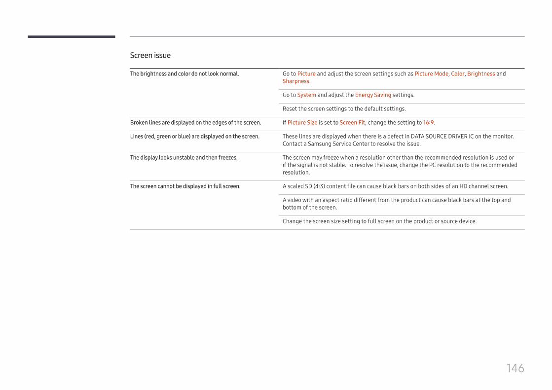
146
Screen issue
The brightness and color do not look normal. Go to Picture and adjust the screen settings such as Picture Mode, Color, Brightness and Sharpness.
Go to System and adjust the Energy Saving settings.
Reset the screen settings to the default settings.
Broken lines are displayed on the edges of the screen. If Picture Size is set to Screen Fit, change the setting to 16:9.
Lines (red, green or blue) are displayed on the screen. These lines are displayed when there is a defect in DATA SOURCE DRIVER IC on the monitor. Contact a Samsung Service Center to resolve the issue.
The display looks unstable and then freezes. The screen may freeze when a resolution other than the recommended resolution is used or if the signal is not stable. To resolve the issue, change the PC resolution to the recommended resolution.
The screen cannot be displayed in full screen. A scaled SD (4:3) content file can cause black bars on both sides of an HD channel screen.
A video with an aspect ratio different from the product can cause black bars at the top and bottom of the screen.
Change the screen size setting to full screen on the product or source device.
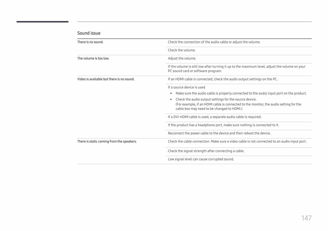
147
Sound issue
There is no sound. Check the connection of the audio cable or adjust the volume.
Check the volume.
The volume is too low. Adjust the volume.
If the volume is still low after turning it up to the maximum level, adjust the volume on your PC sound card or software program.
Video is available but there is no sound. If an HDMI cable is connected, check the audio output settings on the PC.
If a source device is used
• Make sure the audio cable is properly connected to the audio input port on the product.
• Check the audio output settings for the source device.(For example, if an HDMI cable is connected to the monitor, the audio setting for the cable box may need to be changed to HDMI.)
If a DVI-HDMI cable is used, a separate audio cable is required.
If the product has a headphone port, make sure nothing is connected to it.
Reconnect the power cable to the device and then reboot the device.
There is static coming from the speakers. Check the cable connection. Make sure a video cable is not connected to an audio input port.
Check the signal strength after connecting a cable.
Low signal level can cause corrupted sound.
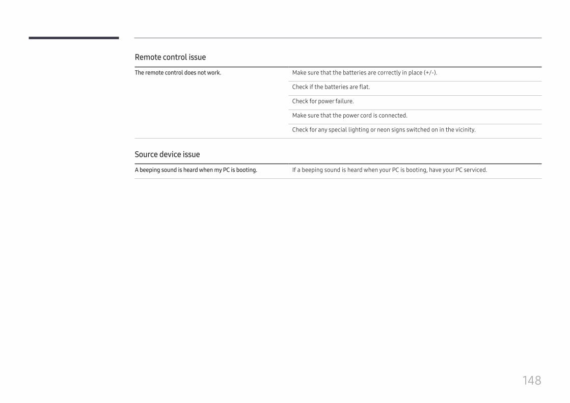
148
Remote control issue
The remote control does not work. Make sure that the batteries are correctly in place (+/-).
Check if the batteries are flat.
Check for power failure.
Make sure that the power cord is connected.
Check for any special lighting or neon signs switched on in the vicinity.
Source device issue
A beeping sound is heard when my PC is booting. If a beeping sound is heard when your PC is booting, have your PC serviced.
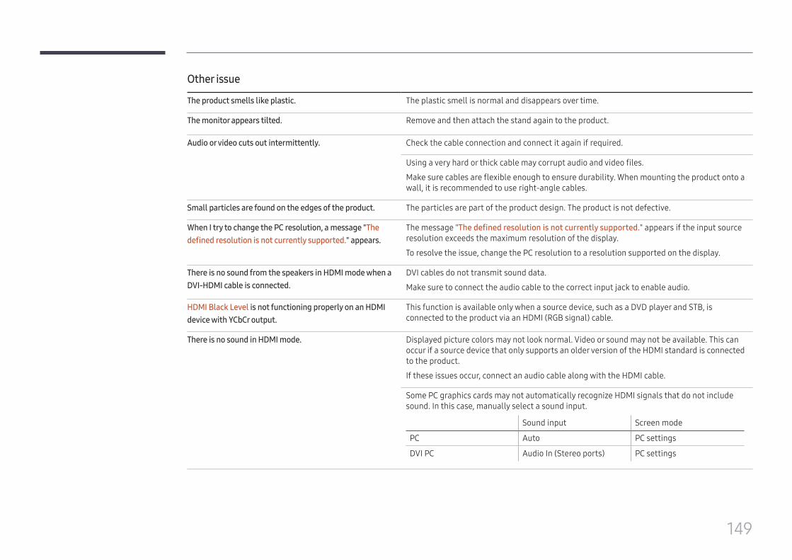
149
Other issue
The product smells like plastic. The plastic smell is normal and disappears over time.
The monitor appears tilted. Remove and then attach the stand again to the product.
Audio or video cuts out intermittently. Check the cable connection and connect it again if required.
Using a very hard or thick cable may corrupt audio and video files.
Make sure cables are flexible enough to ensure durability. When mounting the product onto a wall, it is recommended to use right-angle cables.
Small particles are found on the edges of the product. The particles are part of the product design. The product is not defective.
When I try to change the PC resolution, a message "The defined resolution is not currently supported." appears.
The message "The defined resolution is not currently supported." appears if the input source resolution exceeds the maximum resolution of the display.
To resolve the issue, change the PC resolution to a resolution supported on the display.
There is no sound from the speakers in HDMI mode when a DVI-HDMI cable is connected.
DVI cables do not transmit sound data.
Make sure to connect the audio cable to the correct input jack to enable audio.
HDMI Black Level is not functioning properly on an HDMI device with YCbCr output.
This function is available only when a source device, such as a DVD player and STB, is connected to the product via an HDMI (RGB signal) cable.
There is no sound in HDMI mode. Displayed picture colors may not look normal. Video or sound may not be available. This can occur if a source device that only supports an older version of the HDMI standard is connected to the product.
If these issues occur, connect an audio cable along with the HDMI cable.
Some PC graphics cards may not automatically recognize HDMI signals that do not include sound. In this case, manually select a sound input.
Sound input Screen mode
PC Auto PC settings
DVI PC Audio In (Stereo ports) PC settings
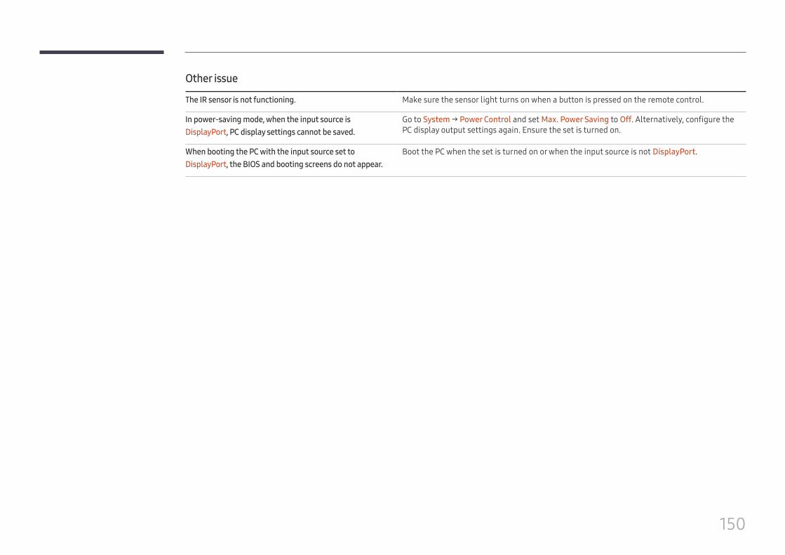
150
Other issue
The IR sensor is not functioning. Make sure the sensor light turns on when a button is pressed on the remote control.
In power-saving mode, when the input source is DisplayPort, PC display settings cannot be saved.
Go to System → Power Control and set Max. Power Saving to Off. Alternatively, configure the PC display output settings again. Ensure the set is turned on.
When booting the PC with the input source set to DisplayPort, the BIOS and booting screens do not appear.
Boot the PC when the set is turned on or when the input source is not DisplayPort.
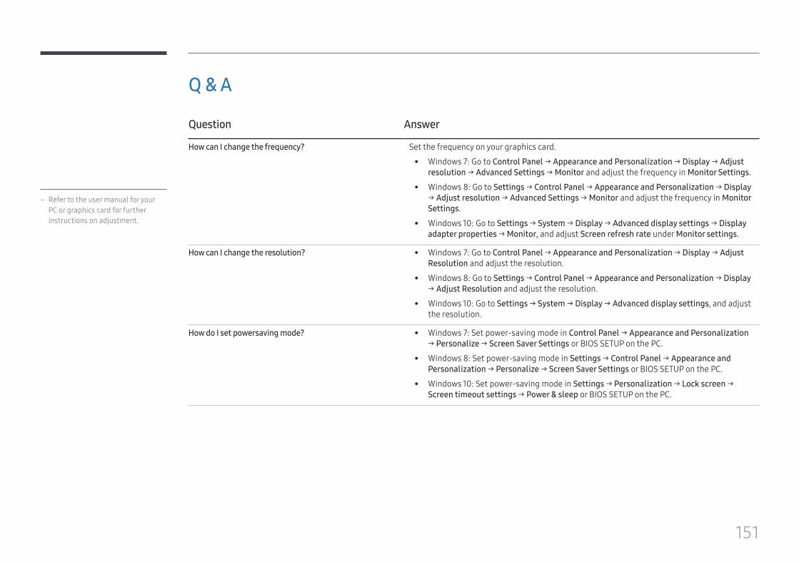
151
Q & A
Question Answer
How can I change the frequency? Set the frequency on your graphics card.
• Windows 7: Go to Control Panel → Appearance and Personalization → Display → Adjust resolution → Advanced Settings → Monitor and adjust the frequency in Monitor Settings.
• Windows 8: Go to Settings → Control Panel → Appearance and Personalization → Display → Adjust resolution → Advanced Settings → Monitor and adjust the frequency in Monitor Settings.
• Windows 10: Go to Settings → System → Display → Advanced display settings → Display adapter properties → Monitor, and adjust Screen refresh rate under Monitor settings.
How can I change the resolution? • Windows 7: Go to Control Panel → Appearance and Personalization → Display → Adjust Resolution and adjust the resolution.
• Windows 8: Go to Settings → Control Panel → Appearance and Personalization → Display → Adjust Resolution and adjust the resolution.
• Windows 10: Go to Settings → System → Display → Advanced display settings, and adjust the resolution.
How do I set powersaving mode? • Windows 7: Set power-saving mode in Control Panel → Appearance and Personalization → Personalize → Screen Saver Settings or BIOS SETUP on the PC.
• Windows 8: Set power-saving mode in Settings → Control Panel → Appearance and Personalization → Personalize → Screen Saver Settings or BIOS SETUP on the PC.
• Windows 10: Set power-saving mode in Settings → Personalization → Lock screen → Screen timeout settings → Power & sleep or BIOS SETUP on the PC.
– Refer to the user manual for your PC or graphics card for further instructions on adjustment.
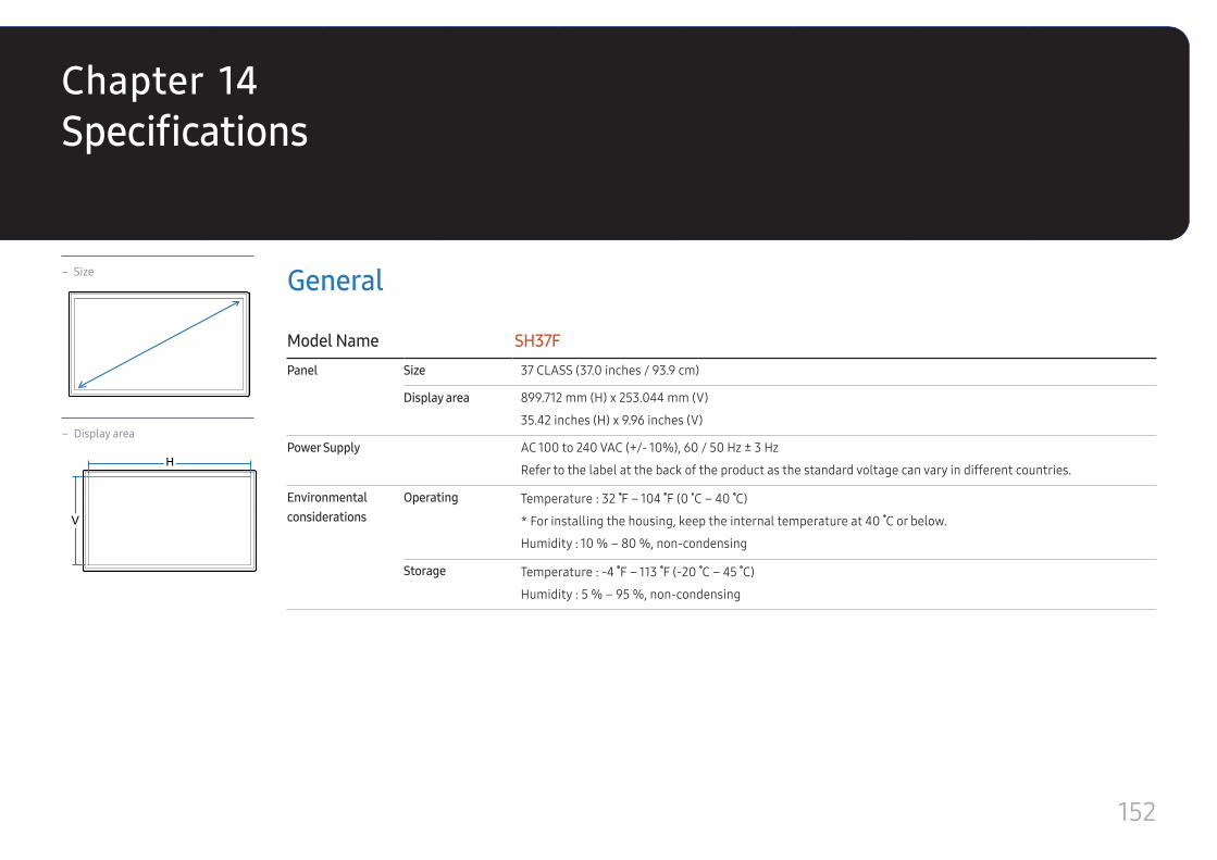
152
Specifications
– Size
– Display area
H
V
General
Model Name SH37FPanel Size 37 CLASS (37.0 inches / 93.9 cm)
Display area 899.712 mm (H) x 253.044 mm (V)
35.42 inches (H) x 9.96 inches (V)
Power Supply AC 100 to 240 VAC (+/- 10%), 60 / 50 Hz ± 3 Hz
Refer to the label at the back of the product as the standard voltage can vary in different countries.
Environmental considerations
Operating Temperature : 32 F – 104 F (0 C – 40 C)
* For installing the housing, keep the internal temperature at 40 C or below.
Humidity : 10 % – 80 %, non-condensing
Storage Temperature : -4 F – 113 F (-20 C – 45 C)
Humidity : 5 % – 95 %, non-condensing
Chapter 14
153
― Plug-and-PlayThis monitor can be installed and used with any Plug-and-Play compatible systems. Two-way data exchange between the monitor and PC system optimizes the monitor settings. Monitor installation takes place automatically. However, you can customize the installation settings if desired.
― Due to the nature of the manufacturing of this product, approximately 1 pixel per million (1ppm) may appear brighter or darker on the panel. This does not affect product performance.
― This is a class A product. In a domestic environment this product may cause radio interference in which case the user may be required to take adequate measures.
― For detailed device specifications, visit the Samsung Electronics website.
(USA only)
Dispose unwanted electronics through an approved recycler.
To find the nearest recycling location, go to our website: www.samsung.com/recyclingdirect or call, (877) 278 - 0799
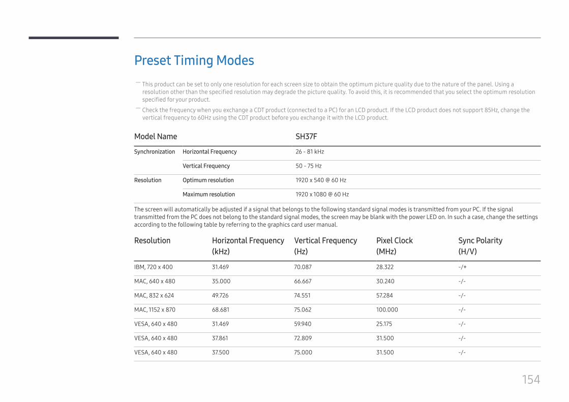
154
Preset Timing Modes ― This product can be set to only one resolution for each screen size to obtain the optimum picture quality due to the nature of the panel. Using a resolution other than the specified resolution may degrade the picture quality. To avoid this, it is recommended that you select the optimum resolution specified for your product.
― Check the frequency when you exchange a CDT product (connected to a PC) for an LCD product. If the LCD product does not support 85Hz, change the vertical frequency to 60Hz using the CDT product before you exchange it with the LCD product.
Model Name SH37F
Synchronization Horizontal Frequency 26 - 81 kHz
Vertical Frequency 50 - 75 Hz
Resolution Optimum resolution 1920 x 540 @ 60 Hz
Maximum resolution 1920 x 1080 @ 60 Hz
The screen will automatically be adjusted if a signal that belongs to the following standard signal modes is transmitted from your PC. If the signal transmitted from the PC does not belong to the standard signal modes, the screen may be blank with the power LED on. In such a case, change the settings according to the following table by referring to the graphics card user manual.
Resolution Horizontal Frequency(kHz)
Vertical Frequency(Hz)
Pixel Clock(MHz)
Sync Polarity(H/V)
IBM, 720 x 400 31.469 70.087 28.322 -/+
MAC, 640 x 480 35.000 66.667 30.240 -/-
MAC, 832 x 624 49.726 74.551 57.284 -/-
MAC, 1152 x 870 68.681 75.062 100.000 -/-
VESA, 640 x 480 31.469 59.940 25.175 -/-
VESA, 640 x 480 37.861 72.809 31.500 -/-
VESA, 640 x 480 37.500 75.000 31.500 -/-
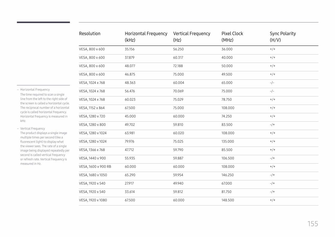
155
Resolution Horizontal Frequency(kHz)
Vertical Frequency(Hz)
Pixel Clock(MHz)
Sync Polarity(H/V)
VESA, 800 x 600 35.156 56.250 36.000 +/+
VESA, 800 x 600 37.879 60.317 40.000 +/+
VESA, 800 x 600 48.077 72.188 50.000 +/+
VESA, 800 x 600 46.875 75.000 49.500 +/+
VESA, 1024 x 768 48.363 60.004 65.000 -/-
VESA, 1024 x 768 56.476 70.069 75.000 -/-
VESA, 1024 x 768 60.023 75.029 78.750 +/+
VESA, 1152 x 864 67.500 75.000 108.000 +/+
VESA, 1280 x 720 45.000 60.000 74.250 +/+
VESA, 1280 x 800 49.702 59.810 83.500 -/+
VESA, 1280 x 1024 63.981 60.020 108.000 +/+
VESA, 1280 x 1024 79.976 75.025 135.000 +/+
VESA, 1366 x 768 47.712 59.790 85.500 +/+
VESA, 1440 x 900 55.935 59.887 106.500 -/+
VESA, 1600 x 900 RB 60.000 60.000 108.000 +/+
VESA, 1680 x 1050 65.290 59.954 146.250 -/+
VESA, 1920 x 540 27.917 49.940 67.000 -/+
VESA, 1920 x 540 33.614 59.812 81.750 -/+
VESA, 1920 x 1080 67.500 60.000 148.500 +/+
– Horizontal FrequencyThe time required to scan a single line from the left to the right side of the screen is called a horizontal cycle. The reciprocal number of a horizontal cycle is called horizontal frequency. Horizontal frequency is measured in kHz.
– Vertical FrequencyThe product displays a single image multiple times per second (like a fluorescent light) to display what the viewer sees. The rate of a single image being displayed repeatedly per second is called vertical frequency or refresh rate. Vertical frequency is measured in Hz.
156
Appendix
Responsibility for the Pay Service (Cost to Customers)
― When the service is requested, in spite of in warranty, we may charge you for a visit from a service technician in the following cases.
Not a product defectCleaning of the product, Adjustment, Explanation, Re-installation and etc.
• If a service technician gives instructions on how to use product or simply adjusts options without disassembling product.
• If a defect is caused by external environmental factors (Internet, Antenna, Wired Signal, etc.)
• If a product is reinstalled or devices are connected additionally after installing the purchased product for the first time.
• If a product is reinstalled to move to a different spot or to move to a different house.
• If customer requests instructions on how to use because of another company's product.
• If customer requests instructions on how to use the network or another company's program.
• If customer requests software installation and setup for the product.
• If a service technician removes/cleans dusts or foreign materials inside of the product.
• If customer requests an installation additionally after purchasing a product through home-shopping or online.
A Product damage caused by customer's faultProduct damage caused by customer's mishandling or wrong repair
If a product damage is caused by;
• External impact or drop.
• Use of supplies or separatly sold product unspecified by Samsung.
• Repair from a person besides an engineer of outsourcing service company or partner of Samsung Electronics Co., Ltd.
• Remodeling or repairing the product by customer.
• Using it with incorrect voltage or non-authorized electrical connections.
• Not following the "cautions" in User Manual.
Others • If product fails by natural disaster. (lightning, fire, earthquake, flood damage, etc)
• If consumable components are all used up. (Battery, Toner, Fluorescent lights, Head, Vibrator, Lamp, Filter, Ribbon, etc.)
― If customer requests a service in case the product has no defect, service fee may be charged. So please read User Manual first.
Chapter 15
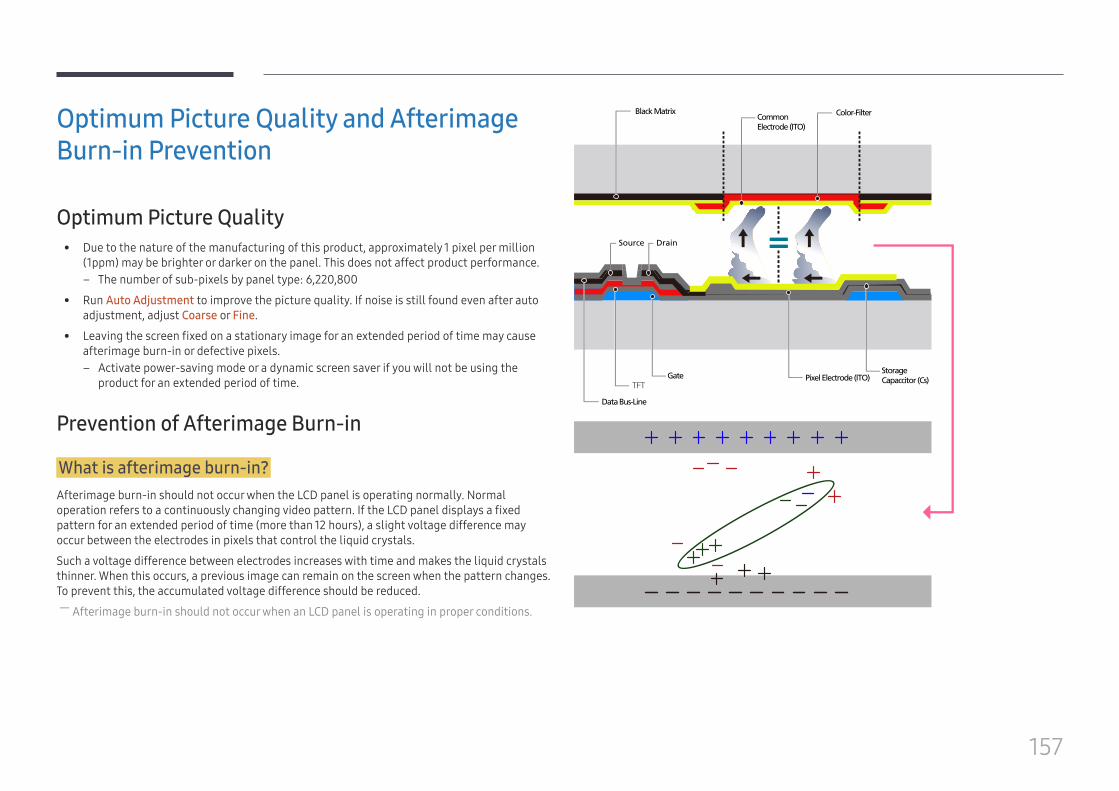
157
Optimum Picture Quality and Afterimage Burn-in Prevention
Optimum Picture Quality • Due to the nature of the manufacturing of this product, approximately 1 pixel per million
(1ppm) may be brighter or darker on the panel. This does not affect product performance. – The number of sub-pixels by panel type: 6,220,800
• Run Auto Adjustment to improve the picture quality. If noise is still found even after auto adjustment, adjust Coarse or Fine.
• Leaving the screen fixed on a stationary image for an extended period of time may cause afterimage burn-in or defective pixels.
– Activate power-saving mode or a dynamic screen saver if you will not be using the product for an extended period of time.
Prevention of Afterimage Burn-in
What is afterimage burn-in?Afterimage burn-in should not occur when the LCD panel is operating normally. Normal operation refers to a continuously changing video pattern. If the LCD panel displays a fixed pattern for an extended period of time (more than 12 hours), a slight voltage difference may occur between the electrodes in pixels that control the liquid crystals.
Such a voltage difference between electrodes increases with time and makes the liquid crystals thinner. When this occurs, a previous image can remain on the screen when the pattern changes. To prevent this, the accumulated voltage difference should be reduced.
― Afterimage burn-in should not occur when an LCD panel is operating in proper conditions.
Black Matrix
Source Drain
Data Bus-Line
TFTGate Pixel Electrode (ITO)
Storage Capaccitor (Cs)
Color-FilterCommon Electrode (ITO)
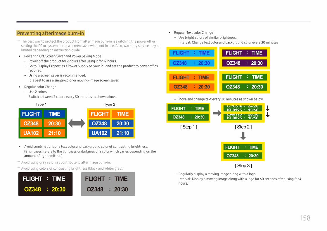
158
Preventing afterimage burn-in ― The best way to protect the product from afterimage burn-in is switching the power off or setting the PC or system to run a screen saver when not in use. Also, Warranty service may be limited depending on instruction guide.
• Powering Off, Screen Saver and Power Saving Mode – Power off the product for 2 hours after using it for 12 hours. – Go to Display Properties > Power Supply on your PC and set the product to power off as
required. – Using a screen saver is recommended.
It is best to use a single-color or moving-image screen saver.
• Regular color Change – Use 2 colors
Switch between 2 colors every 30 minutes as shown above.
FLIGHT FLIGHTTIME TIME
OZ348
UA102 21:10
20:30OZ348
UA102 21:10
20:30
Type 1 Type 2
• Avoid combinations of a text color and background color of contrasting brightness.(Brightness: refers to the lightness or darkness of a color which varies depending on the amount of light emitted.)
― Avoid using gray as it may contribute to afterimage burn-in. ― Avoid using colors of contrasting brightness (black and white; gray).
FLIGHT TIME
OZ348 20:30
:
:FLIGHT TIME
OZ348 20:30
:
:
• Regular Text color Change – Use bright colors of similar brightness.
Interval: Change text color and background color every 30 minutes
FLIGHT TIME
OZ348 20:30
:
:
FLIGHT TIME
OZ348 20:30
:
:
FLIGHT TIME
OZ348 20:30
:
:
FLIGHT TIME
OZ348 20:30
:
:
– Move and change text every 30 minutes as shown below.
FLIGHT TIME
OZ348 20:30
:
:
[ Step 3 ]
[ Step 2 ]
FLIGHT TIME
OZ348
:
:
[ Step 1 ]
20:30
– Regularly display a moving image along with a logo.Interval: Display a moving image along with a logo for 60 seconds after using for 4 hours.
159
License
Manufactured under license from Dolby Laboratories.
Dolby and the double-D symbol are trademarks of Dolby Laboratories.
Ⓡ
Manufactured under a license from U.S. Patent No’s: 5,956,674, 5,974,380, 5,978,762, 6,487,535, 6,226,616, 7,212,872, 7,003,467, 7,272,567, 7,668,723, 7,392,195, 7,930,184, 7,333,929 and 7,548,853. DTS, the Symbol, and DTS and the Symbol together are registered trademarks & DTS Premium Sound is a trademark of DTS, Inc. ©2012 DTS, Inc. All Rights Reserved.
Ⓡ
Manufactured under a license from U.S. Patent No’s: 6,285,767, 8,027,477, 5,319,713, 5,333,201, 5,638,452, 5,771,295, 5,970,152, 5,912,976, 7,200,236, 7,492,907, 8,050,434, 7,720,240, 7,031,474, 7,907,736 and 7,764,802. DTS, the Symbol, and DTS and the Symbol together are registered trademarks & DTS Studio Sound is a trademark of DTS, Inc. ©2012 DTS, Inc. All Rights Reserved.
The terms HDMI and HDMI High-Definition Multimedia Interface, and the HDMI Logo are trademarks or registered trademarks of HDMI Licensing LLC in the United States and other countries.
DivX Certified® to play DivX® video up to HD 1080p, including premium content.
DivX®, DivX Certified® and associated logos are trademarks of DivX, LLC and are used under license.
This DivX Certified® device has passed rigorous testing to ensure it plays DivX® video.
To play purchased DivX movies, first register your device at vod.divx.com. Find your registration code in the DivX VOD section of your device setup menu.
Covered by one or more of the following U.S. patents: 7,295,673; 7,460,668; 7,515,710; 8,656,183; 8,731,369; RE45,052.
Open Source Licence Notice
In the case of using open source software, Open Source Licences are available on the product menu. Open Source Licence Notice is written only English.
For information on the Open Source Licence Notice, contact the Samsung Customer Center or send email to [email protected].
160
Terminology
480i / 480p / 720p / 1080i / 1080p____ Each of the scanning rates above refers to the number of effective scanning lines that decides the screen resolution. The scanning rate may be indicated in i (interlaced) or p (progressive), depending on the scanning method.- ScanningScanning refers to a process of sending pixels that form an image progressively. A larger number of pixels will deliver a clearer and more vivid picture.- ProgressiveIn progressive scan mode, all lines of pixels are scanned one by one (progressively) on the screen.- InterlacedIn interlaced scan mode, every other line of pixels is scanned from top to bottom first and then the remaining lines of pixels (that were not scanned) are scanned.
Non-interlace Mode and Interlace Mode____ Non-interlace mode (progressive scan) displays a horizontal line from the top to the bottom of a screen progressively. Interlace mode displays the odd number lines first and the even number lines next. Non-interlace mode is mainly used in monitors as it produces screen clarity and interlace mode is mainly used in TVs.
Dot Pitch____ The screen consist of red, green and blue dots. A shorter distance between the dots produces a higher resolution. Dot pitch refers to the distance between the shortest distance between dots of the same color. Dot pitch is measured in millimeters.
Vertical Frequency____ The product displays a single image many times per second (like a fluorescent light that flickers) to display an image for a viewer to see. The rate of a single image being displayed repeatedly per second is called vertical frequency or refresh rate. Vertical frequency is measured in Hz.E.g. 60Hz refers to a single image being displayed 60 times in one second.
Horizontal Frequency____ The time required to scan a single line from the left to the right side of the screen is called a horizontal cycle. The reciprocal number of a horizontal cycle is called horizontal frequency. Horizontal frequency is measured in kHz.
Source____ Input source refers to a video source device connected to the product such as a camcorder or video or DVD player.
Plug & Play____ Plug & Play is a function that allows the automatic exchange of information between a monitor and PC to produce an optimum display environment. The product uses VESA DDC (international standard) to execute Plug & Play.
Resolution____ Resolution is the number of horizontal dots (pixels) and vertical dots (pixels) that form a screen. It represents the level of display detail. A higher resolution enables more data to be displayed on the screen and is useful to perform multiple tasks simultaneously.E.g. A resolution of 1920 X 1080 consists of 1,920 horizontal pixels (horizontal resolution) and 1,080 vertical pixels (vertical resolution).
DVD (Digital Versatile Disc)____ DVD refers to a CD-sized mass storage disk where you can save multimedia (audio, video or game) applications using MPEG-2 video compression technology.
HDMI (High Definition Multimedia Interface)____ It is an interface that can be connected to a digital audio source as well as a high-definition video source by using a single cable without compression.
Multiple Display Control (MDC)____ MDC (Multiple Display Control) is an application that allows multiple display devices to be controlled simultaneously using a PC. Communication between a PC and monitor takes place using RS232C (serial data transmission) and RJ45 (LAN) cables.