product catalogue - samsung
TRANSCRIPT

ProductCatalogueCommercial
2021
Highlights for 2021
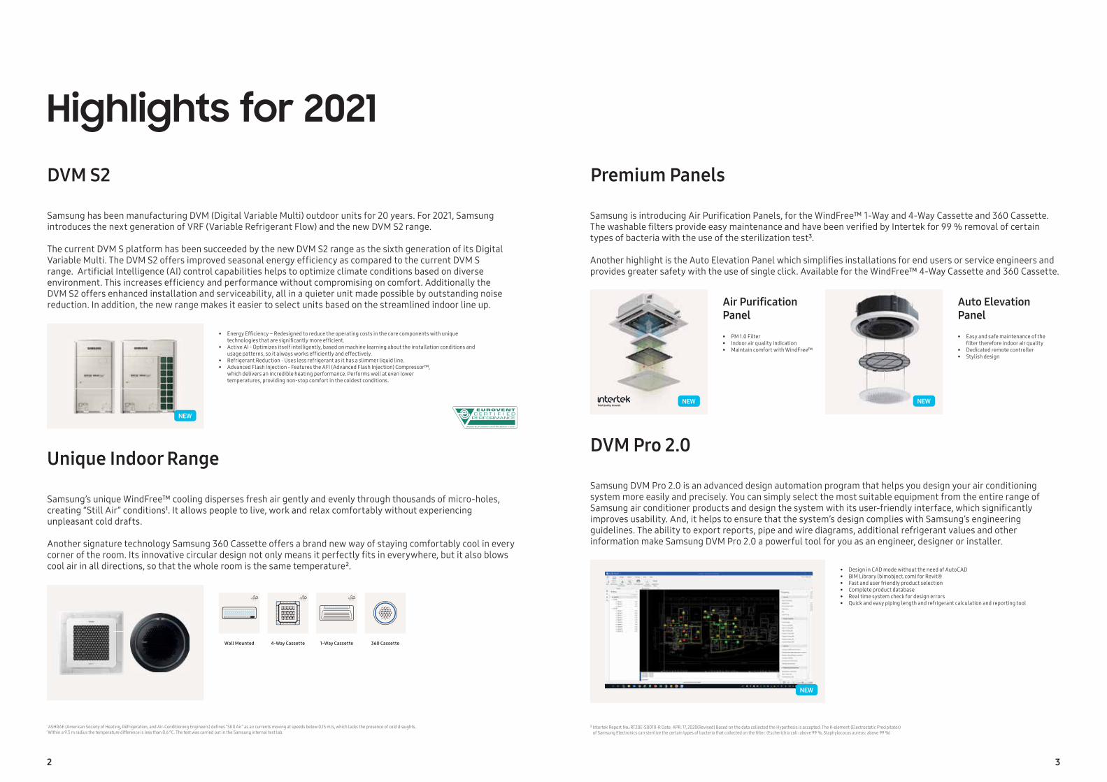
Samsung has been manufacturing DVM (Digital Variable Multi) outdoor units for 20 years. For 2021, Samsung introduces the next generation of VRF (Variable Refrigerant Flow) and the new DVM S2 range.
The current DVM S platform has been succeeded by the new DVM S2 range as the sixth generation of its DigitalVariable Multi. The DVM S2 offers improved seasonal energy effi ciency as compared to the current DVM S range. Artifi cial Intelligence (AI) control capabilities helps to optimize climate conditions based on diverse environment. This increases effi ciency and performance without compromising on comfort. Additionally the DVM S2 offers enhanced installation and serviceability, all in a quieter unit made possible by outstanding noise reduction. In addition, the new range makes it easier to select units based on the streamlined indoor line up.
Samsung’s unique WindFree™ cooling disperses fresh air gently and evenly through thousands of micro-holes, creating “Still Air” conditions¹. It allows people to live, work and relax comfortably without experiencing unpleasant cold drafts.
Another signature technology Samsung 360 Cassette offers a brand new way of staying comfortably cool in every corner of the room. Its innovative circular design not only means it perfectly fi ts in everywhere, but it also blows cool air in all directions, so that the whole room is the same temperature².
Samsung DVM Pro 2.0 is an advanced design automation program that helps you design your air conditioning system more easily and precisely. You can simply select the most suitable equipment from the entire range of Samsung air conditioner products and design the system with its user-friendly interface, which signifi cantly improves usability. And, it helps to ensure that the system’s design complies with Samsung’s engineering guidelines. The ability to export reports, pipe and wire diagrams, additional refrigerant values and other information make Samsung DVM Pro 2.0 a powerful tool for you as an engineer, designer or installer.
Samsung is introducing Air Purifi cation Panels, for the WindFree™ 1-Way and 4-Way Cassette and 360 Cassette. The washable fi lters provide easy maintenance and have been verifi ed by Intertek for 99 % removal of certain types of bacteria with the use of the sterilization test³.
Another highlight is the Auto Elevation Panel which simplifi es installations for end users or service engineers and provides greater safety with the use of single click. Available for the WindFree™ 4-Way Cassette and 360 Cassette.
DVM S2 Premium Panels
DVM Pro 2.0Unique Indoor Range
• Energy Effi ciency – Redesigned to reduce the operating costs in the core components with unique technologies that are signifi cantly more effi cient.• Active AI - Optimizes itself intelligently, based on machine learning about the installation conditions and usage patterns, so it always works effi ciently and effectively.• Refrigerant Reduction - Uses less refrigerant as it has a slimmer liquid line.• Advanced Flash Injection - Features the AFI (Advanced Flash Injection) Compressor™, which delivers an incredible heating performance. Performs well at even lower temperatures, providing non-stop comfort in the coldest conditions.
• PM 1.0 Filter• Indoor air quality indication• Maintain comfort with WindFree™
• Easy and safe maintenance of the fi lter therefore indoor air quality• Dedicated remote controller• Stylish design
• Design in CAD mode without the need of AutoCAD • BIM Library (bimobject.com) for Revit® • Fast and user friendly product selection • Complete product database • Real time system check for design errors • Quick and easy piping length and refrigerant calculation and reporting tool
¹ ASHRAE (American Society of Heating, Refrigeration, and Air-Conditioning Engineers) defi nes “Still Air” as air currents moving at speeds below 0.15 m/s, which lacks the presence of cold draughts.² Within a 9.3 m radius the temperature difference is less than 0.6 °C. The test was carried out in the Samsung internal test lab.
NEW
NEW
³ Intertek Report No.:RT20E-S0010-R Date: APR. 17, 2020(Revised) Based on the data collected the Hypothesis is accepted: The K-element (Electrostatic Precipitator) of Samsung Electronics can sterilize the certain types of bacteria that collected on the fi lter. (Escherichia coli: above 99 %, Staphylococus aureus: above 99 %)
Air Purifi cation Panel
Auto Elevation Panel
Wall Mounted 4-Way Cassette 1-Way Cassette 360 Cassette
NEW NEW
2 3
Product overview
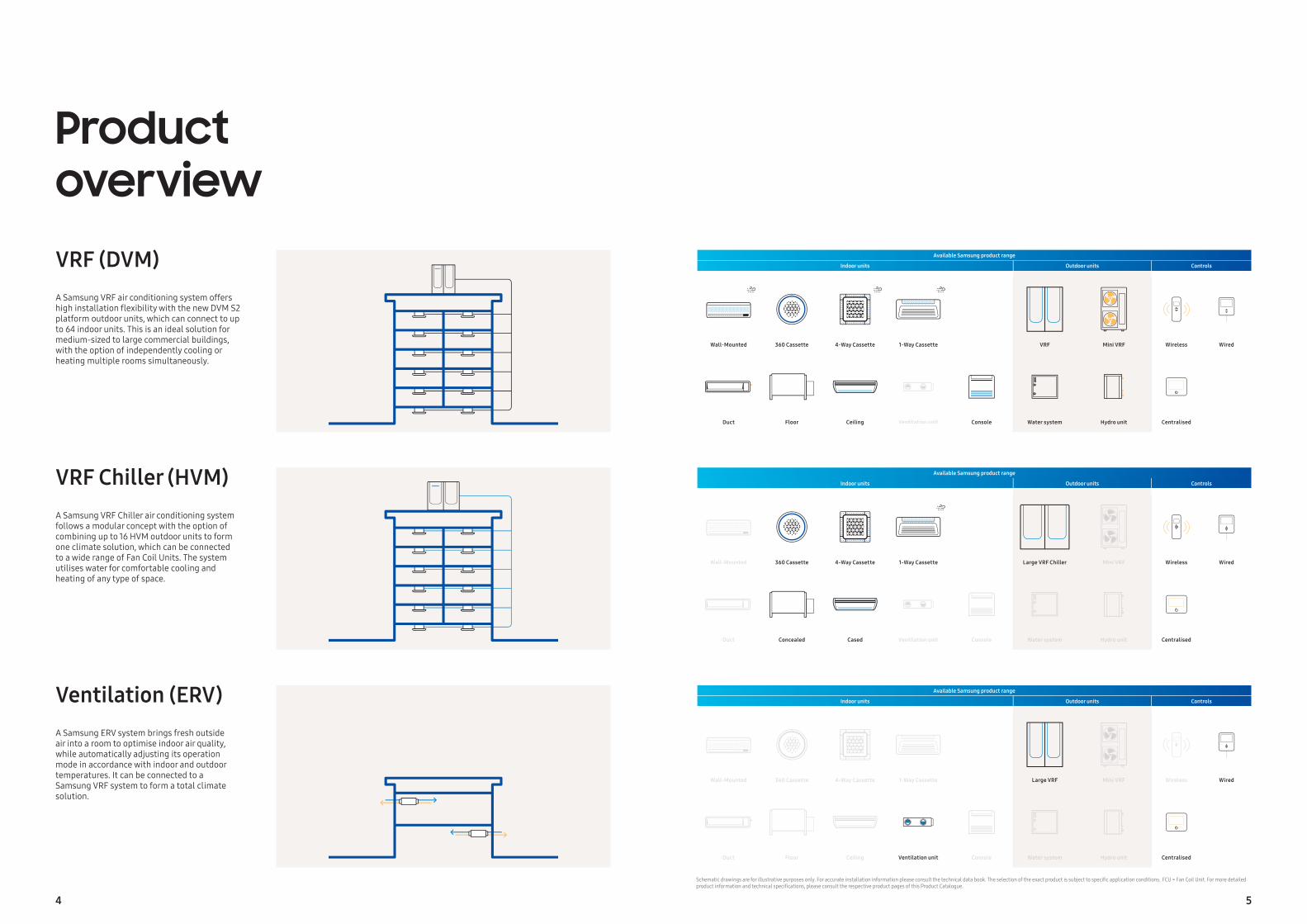
A Samsung VRF air conditioning system offers high installation fl exibility with the new DVM S2 platform outdoor units, which can connect to up to 64 indoor units. This is an ideal solution for medium-sized to large commercial buildings, with the option of independently cooling or heating multiple rooms simultaneously.
A Samsung VRF Chiller air conditioning system follows a modular concept with the option of combining up to 16 HVM outdoor units to form one climate solution, which can be connected to a wide range of Fan Coil Units. The system utilises water for comfortable cooling and heating of any type of space.
A Samsung ERV system brings fresh outside air into a room to optimise indoor air quality, while automatically adjusting its operation mode in accordance with indoor and outdoor temperatures. It can be connected to a Samsung VRF system to form a total climate solution.
VRF (DVM)
VRF Chiller (HVM)
Ventilation (ERV)
Schematic drawings are for illustrative purposes only. For accurate installation information please consult the technical data book. The selection of the exact product is subject to specifi c application conditions. FCU = Fan Coil Unit. For more detailed product information and technical specifi cations, please consult the respective product pages of this Product Catalogue.
Available Samsung product range
Indoor units Outdoor units Controls
Wall-Mounted 360 Cassette 4-Way Cassette 1-Way Cassette VRF Mini VRF Wireless Wired
Duct Floor Ceiling Ventilation unit Console Water system Hydro unit Centralised
Available Samsung product range
Indoor units Outdoor units Controls
Wall-Mounted 360 Cassette 4-Way Cassette 1-Way Cassette Large VRF Chiller Mini VRF Wireless Wired
Duct Concealed Cased Ventilation unit Console Water system Hydro unit Centralised
Available Samsung product range
Indoor units Outdoor units Controls
Wall-Mounted 360 Cassette 4-Way Cassette 1-Way Cassette Large VRF Mini VRF Wireless Wired
Duct Floor Ceiling Ventilation unit Console Water system Hydro unit Centralised
4 5
Table of contentsIntroductionSamsung Climate Solutions at a glanceSamsung reference projects in the spotlightRegulations and standardsCertifications
Innovations in detailDVM S2 NEW DVM S Eco DVM S WaterHeat Recovery for DVMHVM ChillerLSP Slim Duct NEW
MSP/HSP Duct S NEW
WindFree™ DeluxeWindFree™ 4-Way Cassette UNIQUE
WindFree™ 1-Way Cassette UNIQUE
360 Cassette UNIQUE
ERV (Plus)Air Handling Unit (AHU) Kitb.IoT
VRF (DVM)Line-up outdoorLine-up indoorSelection guideNomenclatureDVM S Eco Heat Pump DVM S2 Essential Heat Pump (2-Pipe)DVM S2 Standard Heat Pump (2-Pipe)DVM S2 High EER Heat Pump (2-Pipe)DVM S Eco Heat Recovery DVM S2 High EER Heat Recovery (3-Pipe)DVM S WaterWindFree™ 4-Way 600 x 600 Cassette UNIQUE
WindFree™ 4-Way Cassette UNIQUE
WindFree™ 1-Way Cassette UNIQUE
360 Cassette UNIQUE
LSP Duct MSP Duct HSP DuctConsoleFloor/CeilingBig Ceiling
Concealed Floor-StandingConcealed Floor-Standing High Static PressurePackaged Floor-StandingBoracay Wall-Mounted (EEV included and EEV excluded) WindFree™ Deluxe (EEV included and EEV excluded)Max Wall-MountedHydro UnitMode Control Unit (MCU)AHU Kit for Outdoor Unit
VRF Chiller (HVM)Line-up outdoorLine-up indoorSelection guideNomenclatureHVM ChillerWindFree™ 1-Way Cassette FCU4-Way Cassette FCU360 Cassette FCUConcealed FCUCased FCU
Ventilation (ERV)ERVERV Plus for DVM SOAP Duct for DVM S
ControlsLine-upSelection guideFeatures and dimensional drawings
AccessoriesLine-up
Design and supportSamsung Climate Solutions Partner PortalSamsung DVM Pro 2.0 NEW
Samsung HVM Selection ToolSamsung specialist design supportSamsung Climate Solutions Academy
This document may either contain preliminary values or may lack some values that were not yet available at the time of creation. To obtain the latest information, please consult the Samsung Climate Solutions Partner Portal at partnerhub.samsung.com/climate or contact your Samsung representative.
7
Intr
oduc
tion
6
Technicalsupport
Spareparts
Marketingplatforms
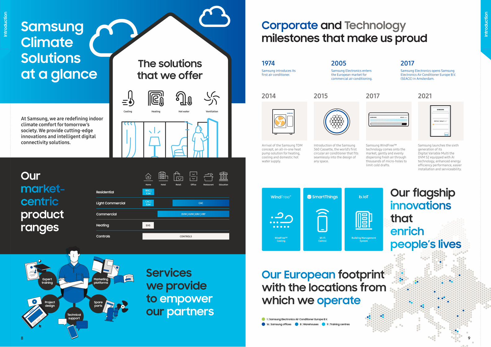
1 | Samsung Electronics Air Conditioner Europe B.V.
16 | Samsung offices 8 | Warehouses 9 | Training centres
Project design
Experttraining
Ourmarket-centricproductranges
Our European footprintwith the locations from which we operate
Corporate and Technologymilestones that make us proud
The solutions that we offer
At Samsung, we are redefi ning indoor climate comfort for tomorrow’s society. We provide cutting-edge innovations and intelligent digital connectivity solutions.
Samsung ClimateSolutions at a glance
Heating Hot water VentilationCooling
Controls
Heating
Light Commercial
Commercial
Residential RAC | FJM
EHS
CAC | FJM CAC
DVM | HVM | ERV | VRF
CONTROLS
Serviceswe provideto empowerour partners
WindFree™Cooling
Wi-FiControl
Building Management System
Our flagship innovations that enrich people’s lives
Home Offi ceRetail EducationHotel Restaurant
1974 2005 2017Samsung introduces itsfi rst air conditioner.
Samsung Electronics entersthe European market for commercial air conditioning.
Samsung Electronics opens Samsung Electronics Air Conditioner Europe B.V. (SEACE) in Amsterdam.
2014 2015 2017 2021
Arrival of the Samsung TDM concept, an all-in-one heat pump solution for heating, cooling and domestic hot water supply.
Introduction of the Samsung 360 Cassette, the world’s fi rst circular air conditioner that fi ts seamlessly into the design of any space.
Samsung WindFree™ technology comes onto the market, gently and evenly dispersing fresh air through thousands of micro-holes to limit cold drafts.
Samsung launches the sixth generation of its Digital Variable Multi the DVM S2 equipped with AI technology, enhanced energy effi ciency performance, easier installation and serviceability.
8 9
Intr
oduc
tion
Intr
oduc
tion
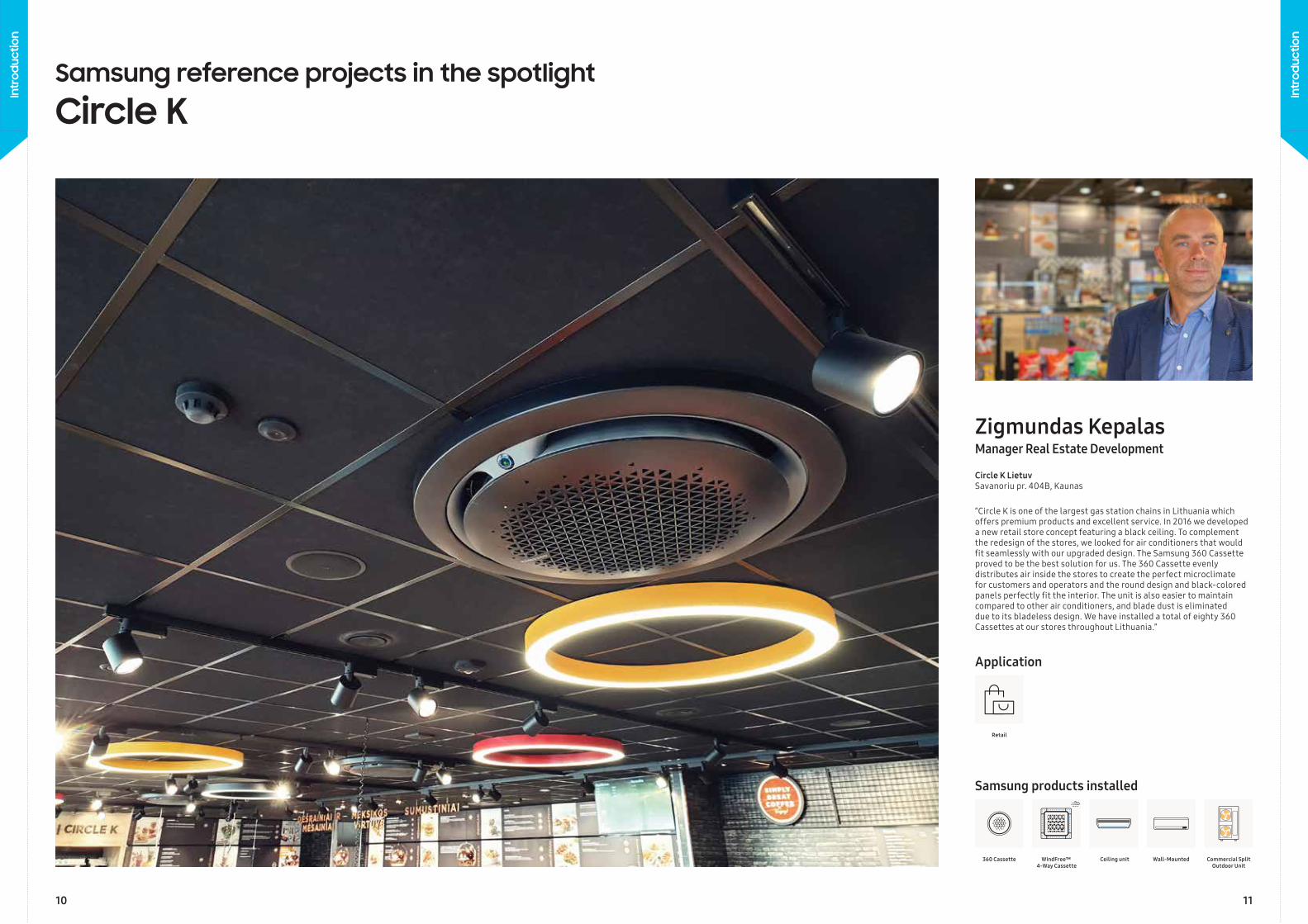
Samsung reference projects in the spotlight
Circle K
“Circle K is one of the largest gas station chains in Lithuania which offers premium products and excellent service. In 2016 we developed a new retail store concept featuring a black ceiling. To complement the redesign of the stores, we looked for air conditioners that would fi t seamlessly with our upgraded design. The Samsung 360 Cassette proved to be the best solution for us. The 360 Cassette evenly distributes air inside the stores to create the perfect microclimate for customers and operators and the round design and black-colored panels perfectly fi t the interior. The unit is also easier to maintain compared to other air conditioners, and blade dust is eliminated due to its bladeless design. We have installed a total of eighty 360 Cassettes at our stores throughout Lithuania.”
Circle K LietuvSavanoriu pr. 404B, Kaunas
WindFree™ 4-Way Cassette
Retail
Wall-MountedCeiling unit Commercial Split Outdoor Unit
Samsung products installed
Application
Manager Real Estate DevelopmentZigmundas Kepalas
360 Cassette
10 11
Intr
oduc
tion
Intr
oduc
tion
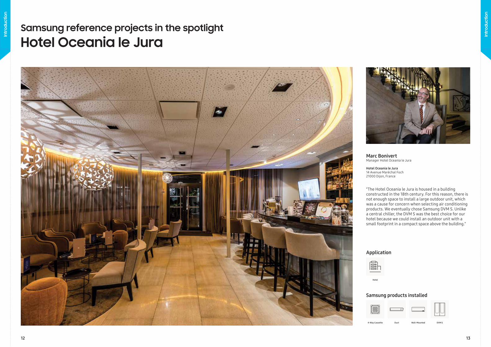
“The Hotel Oceania le Jura is housed in a building constructed in the 18th century. For this reason, there is not enough space to install a large outdoor unit, which was a cause for concern when selecting air conditioning products. We eventually chose Samsung DVM S. Unlike a central chiller, the DVM S was the best choice for our hotel because we could install an outdoor unit with a small footprint in a compact space above the building.”
Marc BonivertManager Hotel Oceania le Jura
Hotel Oceania le Jura14 Avenue Maréchal Foch21000 Dijon, France
4-Way Cassette
Hotel
Wall-MountedDuct DVM S
Samsung products installed
Application
Samsung reference projects in the spotlight
Hotel Oceania le Jura
12 13
Intr
oduc
tion
Intr
oduc
tion
Samsung strives to provide customers with new eco-friendly experiences and lead the way to a sustainable future for the global community through innovative and eco-friendly products and technology. We monitor applicable environmental standards and laws and regulations in the context of our climate solutions operations. Samsung also conducts environmental improvement activities across all product development, production, distribution, use and disposal phases.
The Ecodesign Directive for Energy Related Products (ErP) aims to raise awareness about the energy efficiency of products, while stimulating manufacturers to make their products more energy efficient from the design phase. The Directive is applicable to a broad range of cooling and heating products, which have been divided into different lots.
LOT 10 was implemented on 1 January 2013 and covers air conditioners with a capacity less than 12 kW, typically residential or light commercial systems. It requires manufacturers to provide highly visible
information regarding energy efficiency, including an energy label. LOT 1 and 2 took effect on 26 September 2015 and include residential air to water heat pumps for space heating and hot water production respectively (< 400 kW). It is mandatory to provide energy labels for products with a capacity less than 70 kW. On 1 January 2018, LOT 21 came into force. LOT 21 covers commercial cooling and heating products with a capacity greater than 12 kW. It does not require manufacturers to publish energy labels, but energy performance data should be made available online.
Ecodesign
LOTS 1/2 LOT 10 LOT 21
In effect since 26 September 2015 1 January 2013 1 January 2018
Applicable products
A2W heat pumps < 400 kW
Air conditioners < 12 kW
Air conditioners > 12 kW
Energy labelrequired
Samsungproduct range
EHS RAC | FJM | CAC CAC | DVM | HVM
Regulations and standards
Effective since 31 May 2017, the European EN378 standard provides guidance for companies who design, install, operate and maintain air conditioners, heat pumps and similar systems that use refrigerants. Based on the access characteristics of occupied spaces into which a refrigerant could leak, and an assessment of the refrigerant’s toxicity and flammability, refrigerant charge limits are set and safety measures are prescribed to mitigate risk in the possible event of a refrigerant leakage.
Access categories range from general access areas, such as hotels, restaurants and shopping areas, to more restricted supervised and authorised areas.
The location of refrigerant systems follows a classification of four classes, where VRF systems are typically defined as Class II, either located in a machine room or in the open air. Subject to the available ventilation in rooms, additional measures may be needed such as mechanical ventilation or detectors.
Samsung offers specialist support to professionals in the design of cooling and heating installations. Please contact your Samsung representative to enquire about support in aligning your project design with the requirements of the EN378 standard.
EN378 standard
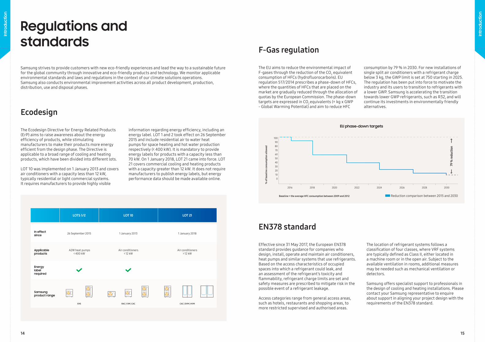
The EU aims to reduce the environmental impact of F-gases through the reduction of the CO2 equivalent consumption of HFCs (hydrofluorocarbons). EU regulation 517/2014 prescribes a phase-down of HFCs, where the quantities of HFCs that are placed on the market are gradually reduced through the allocation of quotas by the European Commission. The phase-down targets are expressed in CO2 equivalents (= kg x GWP - Global Warming Potential) and aim to reduce HFC
consumption by 79 % in 2030. For new installations of single split air conditioners with a refrigerant charge below 3 kg, the GWP limit is set at 750 starting in 2025. The regulation has been put into force to motivate the industry and its users to transition to refrigerants with a lower GWP. Samsung is accelerating the transition towards lower GWP refrigerants, such as R32, and will continue its investments in environmentally friendly alternatives.
F-Gas regulation
79 %
redu
ctio
n
EU phase-down targets
Reduction comparison between 2015 and 2030
% o
f bas
elin
e co
nsum
ptio
n al
low
ed
Baseline = the average HFC consumption between 2009 and 2012
100 9080706050403020100
2016 2018 2020 2022 20262024 2028 2030
14 15
Intr
oduc
tion
Intr
oduc
tion
Samsung adheres to the WEEE (Waste Electrical and Electronic Equipment) Directive. This Directive applies to the principles of extended producer responsibility. It stipulates the safe collection, treatment, recycling and environmentally sound disposal of all electrical and electronic equipment. By working with collective recycling schemes in each EU member state Samsung co-fi nances the take-back and recycling of electronic products.
Samsung has been giving new life to used batteries by funding collection, treatment and recycling by local battery recycling organisations.
Samsung works together with recycling schemes and governmental organisations to collect, separate and reuse all packaging materials at various points in the distribution chain. Many materials can be recycled into new products and recycling helps to save natural resources. Recycling packaging helps to reuse valuable raw materials and to reduce the overall impact on the environment.
WEEE: Electronic Waste
Batteries
Packaging
17
Intr
oduc
tion
Intr
oduc
tion
16 17
Certif ications
Intertek is a leading Total Quality Assurance provider to industries worldwide verifying air quality¹. To deliver credibility, Intertek maintains extensive global accreditations and recognitions for testing and certification services. Working with Intertek helps showcase and maintain products’ safety and performance attributes. Intertek’s expertise in regulatory standards and certifications keeps you ahead of changes and challenges.
Intertek offers certification programmes that achieve market entry into a variety of global destinations, programmes for a more eco-friendly environment and also programmes to verify social accountability compliance for both manufacturers and suppliers.
Samsung's Tri-Care Filter, Air Purification Panels for WindFree™ Pure PM 1.0, WindFree™ 1-Way Cassette, WindFree™ 4-Way Cassette and 360 Cassette have been verified by Intertek.
Eurovent is globally known for its quality mark ‘Eurovent CertifiedPerformance’ which certifies performance ratings of air-conditioningand refrigeration products according to European and internationalstandards. The ‘Eurovent Certified Performance’ mark indicates thatthe prescribed quality requirement has been fulfilled and should notrequire the need to be proven after the customer’s decision and afterthe manufacturer’s production process.
Eurovent is an accredited third-party certification body. It buildscustomer confidence by leveling the competitive playing field for allmanufacturers and by increasing the integrity and accuracy of theindustrial performance ratings. Thus providing trustworthy servicesto the entire ecosystem.
Samsung air conditioning products ranging from the Single Split (RAC), Multi Split (FJM), Commercial Split (CAC), Variable Refrigerant Flow (VRF) and Eco Heating System (EHS) line-up in the ‘Air–to–Water’ (A2W) heat pump category are all Eurovent certified.
To check the ongoing validity of the Eurovent certified products fromSamsung, please visit: www.eurovent-certification.com
Intertek
Eurovent
1 Our products have not been tested for their effects on the COVID-19 virus. Therefore, we do not make or give any express or implied claims or guarantees with regard to COVID-19.
18
Intr
oduc
tion
Intr
oduc
tion
19
The 7th Generation of IGBTMulti-serration FanEnlarged Heat Exchanger Enlarged Heat Exchanger
36.2% 23.7%Transfer
AreaTransfer
Area
LargeSerration
SmallSerration
Outdoorunit
The firstbranch
of indoor units
Normal Pipe Slimmer Pipe
Degree of D
SH
Outdoor Temperature
ConventionalControl
OptimalDSH Control
Triple Profi le Scroll Dual Magnet Motor
Optimal Discharge Superheat (DSH) Control
Triple Profi le Scroll with Dual Magnet Motor
Flash Injection Technology
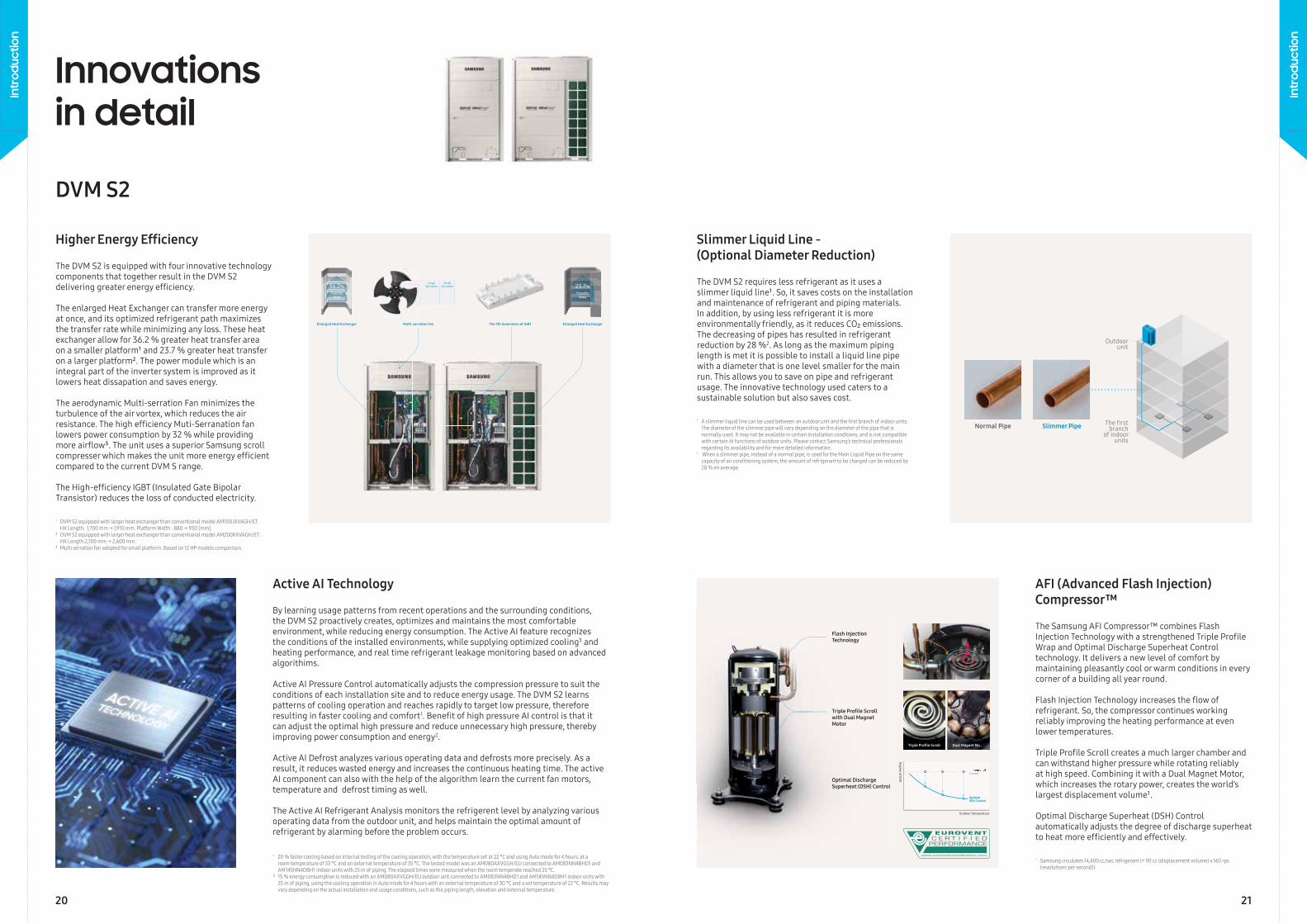
The DVM S2 is equipped with four innovative technology components that together result in the DVM S2 delivering greater energy effi ciency.
The enlarged Heat Exchanger can transfer more energy at once, and its optimized refrigerant path maximizes the transfer rate while minimizing any loss. These heat exchanger allow for 36.2 % greater heat transfer area on a smaller platform¹ and 23.7 % greater heat transfer on a larger platform². The power module which is an integral part of the inverter system is improved as it lowers heat dissapation and saves energy.
The aerodynamic Multi-serration Fan minimizes the turbulence of the air vortex, which reduces the air resistance. The high effi ciency Muti-Serranation fan lowers power consumption by 32 % while providing more airfl ow³. The unit uses a superior Samsung scroll compresser which makes the unit more energy effi cient compared to the current DVM S range.
The High-effi ciency IGBT (Insulated Gate Bipolar Transistor) reduces the loss of conducted electricity.
The DVM S2 requires less refrigerant as it uses a slimmer liquid line¹. So, it saves costs on the installation and maintenance of refrigerant and piping materials. In addition, by using less refrigerant it is more environmentally friendly, as it reduces CO₂ emissions.The decreasing of pipes has resulted in refrigerant reduction by 28 %2. As long as the maximum piping length is met it is possible to install a liquid line pipe with a diameter that is one level smaller for the main run. This allows you to save on pipe and refrigerant usage. The innovative technology used caters to a sustainable solution but also saves cost.
The Samsung AFI Compressor™ combines Flash Injection Technology with a strengthened Triple Profi le Wrap and Optimal Discharge Superheat Control technology. It delivers a new level of comfort by maintaining pleasantly cool or warm conditions in every corner of a building all year round.
Flash Injection Technology increases the fl ow of refrigerant. So, the compressor continues working reliably improving the heating performance at even lower temperatures.
Triple Profi le Scroll creates a much larger chamber and can withstand higher pressure while rotating reliably at high speed. Combining it with a Dual Magnet Motor, which increases the rotary power, creates the world’s largest displacement volume¹.
Optimal Discharge Superheat (DSH) Control automatically adjusts the degree of discharge superheat to heat more effi ciently and effectively.
Innovations in detail
1 DVM S2 equipped with larger heat exchanger than conventional model AM100JXVAGH/ET. HX Length: 1,700 mm → 1,910 mm. Platform Width : 880 → 930 [mm].² DVM S2 equipped with larger heat exchanger than conventional model AM200KXVAGH/ET. HX Length:2,100 mm → 2,600 mm. ³ Multi serration fan adopted for small platform. Based on 12 HP models comparison.
1 A slimmer liquid line can be used between an outdoor unit and the fi rst branch of indoor units. The diameter of the slimmer pipe will vary depending on the diameter of the pipe that is normally used. It may not be available in certain installation conditions, and is not compatible with certain AI functions of outdoor units. Please contact Samsung’s technical professionals regarding its availability and for more detailed information.2 When a slimmer pipe, instead of a normal pipe, is used for the Main Liquid Pipe on the same capacity of air conditioning system, the amount of refrigerant to be charged can be reduced by 28 % on average.
1 Samsung circulates 14,400 cc/sec refrigerant (= 90 cc (displacement volume) x 160 rps (revolutions per second)).
DVM S2
Higher Energy Effi ciency Slimmer Liquid Line -(Optional Diameter Reduction)
AFI (Advanced Flash Injection) Compressor™
By learning usage patterns from recent operations and the surrounding conditions, the DVM S2 proactively creates, optimizes and maintains the most comfortable environment, while reducing energy consumption. The Active AI feature recognizes the conditions of the installed environments, while supplying optimized cooling¹ and heating performance, and real time refrigerant leakage monitoring based on advanced algorithims.
Active AI Pressure Control automatically adjusts the compression pressure to suit the conditions of each installation site and to reduce energy usage. The DVM S2 learns patterns of cooling operation and reaches rapidly to target low pressure, therefore resulting in faster cooling and comfort1. Benefi t of high pressure AI control is that it can adjust the optimal high pressure and reduce unnecessary high pressure, thereby improving power consumption and energy2.
Active AI Defrost analyzes various operating data and defrosts more precisely. As a result, it reduces wasted energy and increases the continuous heating time. The active AI component can also with the help of the algorithm learn the current fan motors, temperature and defrost timing as well.
The Active AI Refrigerant Analysis monitors the refrigerent level by analyzing various operating data from the outdoor unit, and helps maintain the optimal amount of refrigerant by alarming before the problem occurs.
1 20 % faster cooling based on internal testing of the cooling operation, with the temperature set at 22 °C and using Auto mode for 4 hours, at a room temperature of 33 °C and an external temperature of 35 °C. The tested model was an AM080AXVGGH/EU connected to AM083NN4BHD1 and AM145NN4DBH1 indoor units with 25 m of piping. The elapsed times were measured when the room temperate reached 25 °C.² 15 % energy consumption is reduced with an AM080AXVGGH/EU outdoor unit connected to AM083NN4BHD1 and AM145NN4DBH1 indoor units with 25 m of piping, using the cooling operation in Auto mode for 4 hours with an external temperature of 30 °C and a set temperature of 22 °C. Results may vary depending on the actual installation and usage conditions, such as the piping length, elevation and external temperature.
Active AI Technology
20 21
Intr
oduc
tion
Intr
oduc
tion
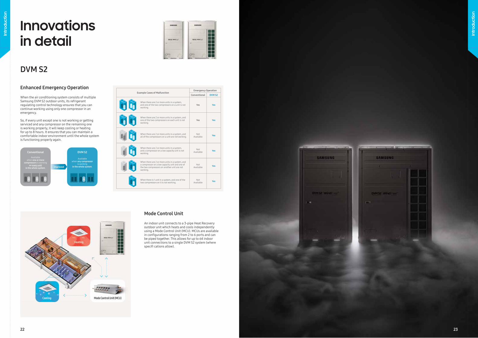
When the air conditioning system consists of multiple Samsung DVM S2 outdoor units, its refrigerant regulating control technology ensures that you can continue working using only one compressor in an emergency.
So, if every unit except one is not working or getting serviced and any compressor on the remaining one is working properly, it will keep cooling or heating for up to 8 hours. It ensures that you can maintain a comfortable indoor environment until the whole system is functioning properly again.
Innovations in detail
DVM S2
Enhanced Emergency Operation
An indoor unit connects to a 3-pipe Heat Recoveryoutdoor unit which heats and cools independentlyusing a Mode Control Unit (MCU). MCUs are availablein confi gurations ranging from 2 to 6 ports and canbe piped together. This allows for up to 64 indoorunit connections to a single DVM S2 system (wherespecifi cations allow).
Mode Control Unit
22
Intr
oduc
tion
Intr
oduc
tion
23
Improved
Conventional
ON ON ON ON
DVM S2
Available when any compressor
is working in the whole system.
Available when one or more
compressors is working on every unit
in the whole system.
Example Cases of MalfunctionEmergency Operation
Conventional DVM S2
When there are 2 or more units in a system, and one of the two compressors on a unit is not working.
Yes Yes
When there are 2 or more units in a system, and one of the two compressors on each unit is not working.
Yes Yes
When there are 2 or more units in a system, and all of the compressors on a unit are not working.
Not Available Yes
When there are 2 or more units in a system, and a compressor on a low capacity unit is not working.
Not Available Yes
When there are 2 or more units in a system, and a compressor on a low capacity unit and one of the two compressors on another unit are not working.
Not Available Yes
When there is 1 unit in a system, and one of the two compressors on it is not working.
Not Available Yes
3-Step Quiet Mode
7:00 14:00 20:00 8:00
Temperature
Environmental Load
OperatingCurve 1 Step
2 Step
3 Step
3 dB(A)5 dB(A)
7 dB(A)
6 HP
6 HP
+ =
8 HP 14 HP
14 HP12 HP10 HP8 HP
MAX 14 HP
Innovations in detail
DVM S Eco
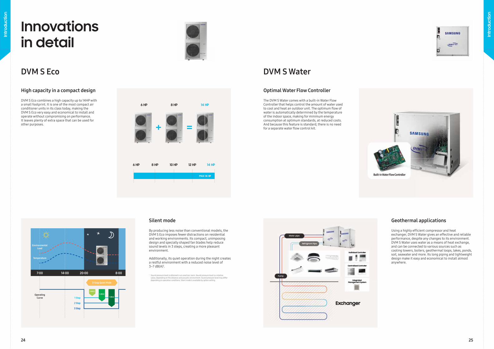
By producing less noise than conventional models, the DVM S Eco imposes fewer distractions on residential and working environments. Its compact, unimposing design and specially shaped fan blades help reduce sound levels in 3 steps, creating a more pleasant environment.
Additionally, its quiet operation during the night creates a restful environment with a reduced noise level of 3–7 dB(A)1.
DVM S Eco combines a high capacity up to 14HP with a small footprint. It is one of the most compact air conditioner units in its class today, making theDVM S Eco very easy and economical to install and operate without compromising on performance.It leaves plenty of extra space that can be used forother purposes.
High capacity in a compact design
Silent mode
Using a highly effi cient compressor and heat exchanger, DVM S Water gives an effective and reliable performance, despite any changes to its environment. DVM S Water uses water as a means of heat exchange, and can be connected to various sources such as cooling towers, boilers, geothermal loops, lakes, ponds, soil, seawater and more. Its long piping and lightweight design make it easy and economical to install almost anywhere.
DVM S Water
The DVM S Water comes with a built-in Water Flow Controller that helps control the amount of water used to cool and heat an outdoor unit. The optimum fl ow of water is automatically determined by the temperature of the indoor space, making for minimum energy consumption at optimum standards, at reduced costs. And because this feature is standard, there is no need for a separate water fl ow control kit.
Optimal Water Flow Controller
Geothermal applications
1 Sound pressure level is obtained in an anechoic room. Sound pressure level is a relative value, depending on the distance and acoustic environment. Sound pressure level may differ depending on operation conditions. Silent mode is available by option setting.
24 25
Intr
oduc
tion
Intr
oduc
tion
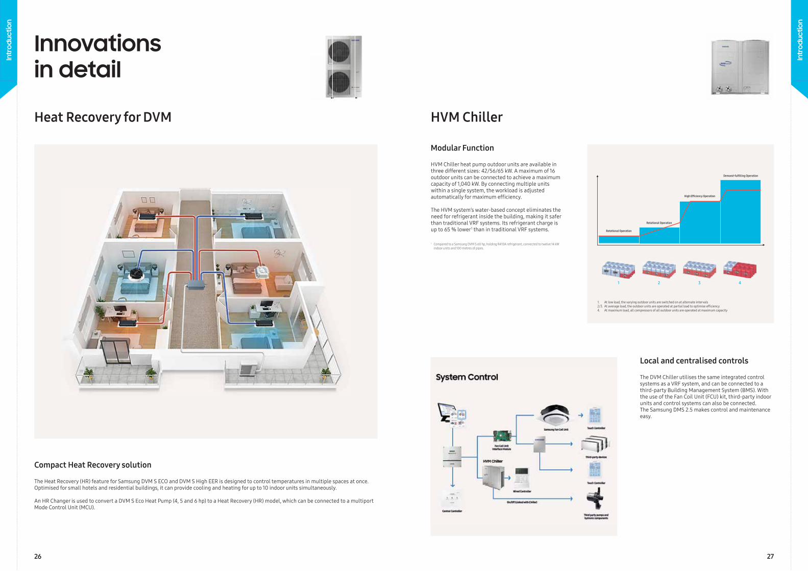
Rotational Operation
Rotational Operation
High Efficiency Operation
Demand-fulfilling Operation
1 2 3 4
1. At low load, the varying outdoor units are switched on at alternate intervals2/3. At average load, the outdoor units are operated at partial load to optimise effi ciency4. At maximum load, all compressors of all outdoor units are operated at maximum capacity
Innovations in detail
Heat Recovery for DVM
The Heat Recovery (HR) feature for Samsung DVM S ECO and DVM S High EER is designed to control temperatures in multiple spaces at once. Optimised for small hotels and residential buildings, it can provide cooling and heating for up to 10 indoor units simultaneously.
An HR Changer is used to convert a DVM S Eco Heat Pump (4, 5 and 6 hp) to a Heat Recovery (HR) model, which can be connected to a multiport Mode Control Unit (MCU).
Compact Heat Recovery solution
The DVM Chiller utilises the same integrated control systems as a VRF system, and can be connected to a third-party Building Management System (BMS). With the use of the Fan Coil Unit (FCU) kit, third-party indoor units and control systems can also be connected.The Samsung DMS 2.5 makes control and maintenance easy.
HVM Chiller
HVM Chiller heat pump outdoor units are available in three different sizes: 42/56/65 kW. A maximum of 16 outdoor units can be connected to achieve a maximum capacity of 1,040 kW. By connecting multiple units within a single system, the workload is adjusted automatically for maximum effi ciency.
The HVM system’s water-based concept eliminates the need for refrigerant inside the building, making it safer than traditional VRF systems. Its refrigerant charge is up to 65 % lower 1 than in traditional VRF systems.
Modular Function
Local and centralised controls
1 Compared to a Samsung DVM S 60 hp, holding R410A refrigerant, connected to twelve 14 kW indoor units and 100 metres of pipes.
26 27
Intr
oduc
tion
Intr
oduc
tion
Innovations in detail
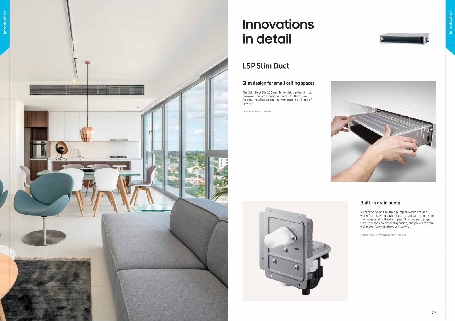
A check valve on the drain pump prevents drained water from fl owing back into the drain pan, minimising the water level in the drain pan. This modern design feature means no water stagnation, and prevents drain water overfl owing into your interiors.
LSP Slim Duct
The Slim Duct S is 200 mm in height, making it much narrower than conventional products. This allows for easy installation and maintenance in all kinds of spaces.1
Slim design for small ceiling spaces
Built-in drain pump1
1 Based on the AM017~071*NLD*H/EU
1 Based on models AM***KNLDEH/EU, AM***MNLD*H/EU
28 29
Intr
oduc
tion
Intr
oduc
tion
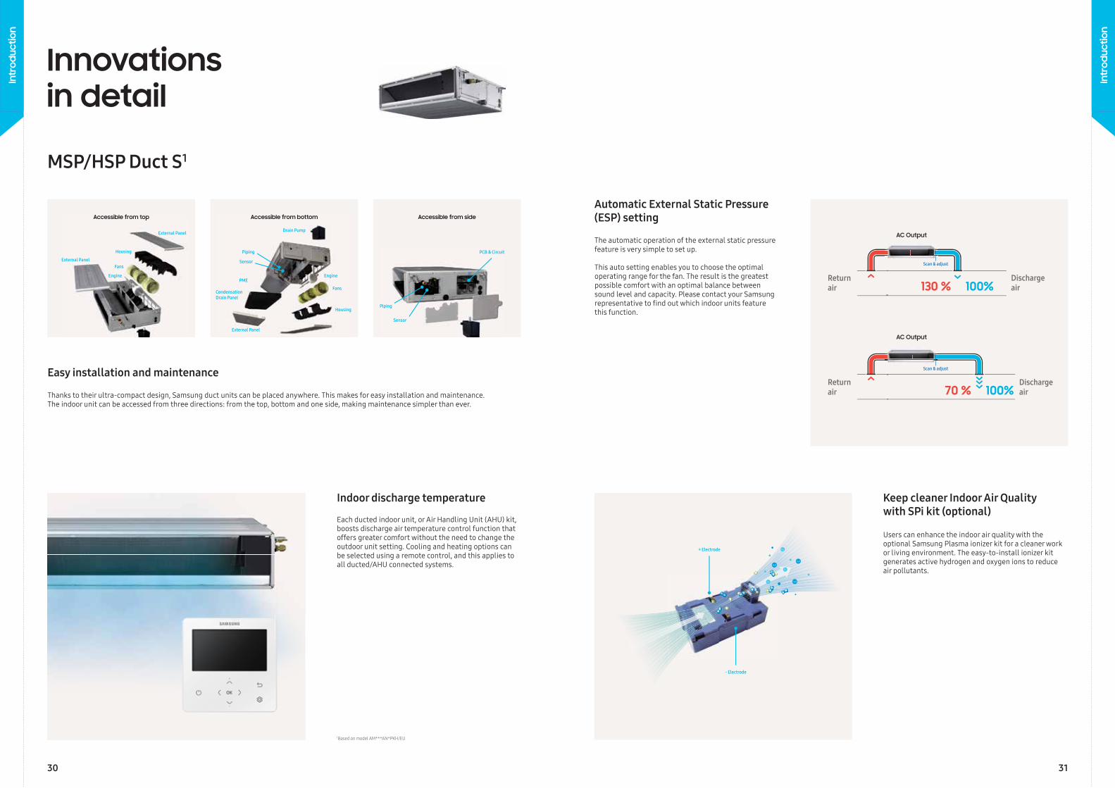
Accessible from top
External Panel
External Panel
External Panel
Drain Pump
Condensation Drain Panel
Engine Engine
Sensor
Sensor
Housing
Housing
Piping
Piping
PCB & Circuit
Fans
Fans
PME
Accessible from bottom Accessible from side
Return air
Discharge air
Return air
Discharge air
Scan & adjust
Scan & adjust
OOOOOOOOOOOOOOOOOOOOOOOOOOOOOOOOOOO
HHHHHHHHHHHHHHHHHHHHH
OOOOOOOOOOOOOOOHHHHHHHHHHHHH
OOOOOOOOOOOOOO OOOOOOOOOOOOOOHHHHHHHHHHHHH
OOOOOOOOOOOOOOOOOO HHHHHH
OO
OOOOOOO
OOOOOOOOOOOOOOOOOOOOOOOOOOOOOOOO
H₂O
H₂O
H₂O
O₂
O₂
O₂
HHHHHHH
HHHH
HHHHHHHHHHHHHHHHHHHHH
HHHHHHHHHHHHHHHHHHHHH
+ Electrode
- Electrode
Thanks to their ultra-compact design, Samsung duct units can be placed anywhere. This makes for easy installation and maintenance.The indoor unit can be accessed from three directions: from the top, bottom and one side, making maintenance simpler than ever.
Easy installation and maintenance
Innovations in detail
MSP/HSP Duct S1
Users can enhance the indoor air quality with the optional Samsung Plasma ionizer kit for a cleaner work or living environment. The easy-to-install ionizer kit generates active hydrogen and oxygen ions to reduce air pollutants.
Each ducted indoor unit, or Air Handling Unit (AHU) kit, boosts discharge air temperature control function that offers greater comfort without the need to change the outdoor unit setting. Cooling and heating options can be selected using a remote control, and this applies to all ducted/AHU connected systems.
The automatic operation of the external static pressure feature is very simple to set up.
This auto setting enables you to choose the optimal operating range for the fan. The result is the greatest possible comfort with an optimal balance between sound level and capacity. Please contact your Samsung representative to fi nd out which indoor units feature this function.
Automatic External Static Pressure (ESP) setting
Keep cleaner Indoor Air Qualitywith SPi kit (optional)
Indoor discharge temperature
1 Based on model AM***AN*PKH/EU
30 31
Intr
oduc
tion
Intr
oduc
tion
Tem
pera
ture
(°C)
Time (min)
Step 1
Step 2Step 1 Step 3
Step 2 Step 3
FastCooling
WindFree™Cooling
DehumidificationMode
Set temperature (°C)
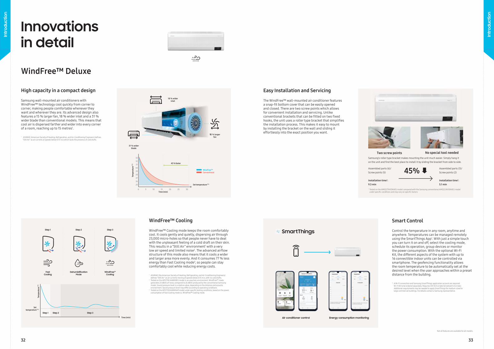
15 % larger fan
18 % wider inlet
Tem
pera
ture
(°C)
Time (min)
43 % faster
WindFree™ Conventional
31 % wider blade
15 % larger
Set temperature (°C)
0 5 10 15 20 25 30
333231302928272625
WindFree™ Deluxe
Innovations in detail
WindFree™ Cooling mode keeps the room comfortably cool. It cools gently and quietly, dispersing air through 23,000 micro-holes so that people never have to deal with the unpleasant feeling of a cold draft on their skin. This results in a “Still Air” environment1 with a very low air speed and limited noise2. The advanced airfl ow structure of this mode also means that it cools a wider and larger area more evenly. And it consumes 77 % less energy than Fast Cooling mode3, so people can stay comfortably cool while reducing energy costs.
Samsung wall-mounted air conditioners with WindFree™ technology cool quickly from corner to corner, making people comfortable whenever they want and wherever they are. Its advanced design also features a 15 % larger fan, 18 % wider inlet and a 31 % wider blade than conventional models. This means that cool air is dispersed farther and wider into every corner of a room, reaching up to 15 metres1.
High capacity in a compact design
WindFree™ Cooling
1 ASHRAE (the American Society of Heating, Refrigerating, and Air-Conditioning Engineers) defi nes “Still Air” as air currents moving at speeds below 0.15 m/s, with no cold drafts.2 Tested on the AR12TXCAAWKNEU model in an anechoic environment. WindFree™ mode generates 23 dB(A) of noise, compared to 26 dB(A) produced by the conventional Samsung model. Sound pressure level is a relative value, depending on the distance and acoustic environment. Sound pressure level may differ according to operating conditions. 3 Tested on the AR12TVEAAWKNAP model under specifi c testing conditions, based on the power consumption of Fast Cooling mode vs. WindFree™ Cooling mode.
1 ASHRAE (American Society of Heating, Refrigeration, and Air-Conditioning Engineers) defi nes “Still Air” as air currents at speeds below 0.15 m/s which lacks the presence of cold drafts.
The WindFree™ wall-mounted air conditioner features a snap-fi t bottom cover that can be easily opened and closed. There are two screw points which allows for convenient installation and servicing. Unlike conventional brackets that can be fi tted on two fi xed hooks, the unit uses a roller type bracket that simplifi es the installation process. This makes it easy to mount by installing the bracket on the wall and sliding it effortlessly into the exact position you want.
Control the temperature in any room, anytime and anywhere. Temperatures can be managed remotely using the SmartThings App1. With just a simple touch you can turn it on and off, select the cooling mode, schedule its operation, group devices or monitor the power consumption. With the optional Wi-Fi Kit, the different aspects of the system with up to 16 connectible indoor units can be controlled via smartphone. The geofencing functionality allows the room temperature to be automatically set at the desired level when the user approaches within a preset distance from the building.
¹ A Wi-Fi connection and Samsung SmartThings application account are required. Wi-Fi Kit to be ordered separately. Requires iOS 10.0 or later & Android 5.0 or later. Additional requirements may be needed to apply SmartThings for medium-sized to large commercial buildings. For details contact a Samsung representative.
Easy Installation and Servicing
Smart Control
Energy consumption monitoringAir conditioner control
Two screw points No special tool neededSamsung’s roller type bracket makes mounting the unit much easier. Simply hang iton the unit and fi nd the best place to install it by sliding the bracket from side to side.
Assembled parts (6)/Screw points (5)
Installation time1:9.3 min
Assembled parts (3)/Screw points (2)
Installation time1:5.1 min
45%
1 Tested on the AM022TNVDKHEU model compared with the Samsung conventional AM022JNVDKHEU model under specifi c conditions and may vary on specifi c factors
Not all features are available for all models.
32 33
Intr
oduc
tion
Intr
oduc
tion
WindFree™ 4-Way Cassette
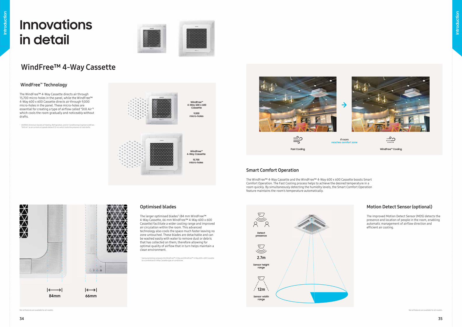
The WindFree™ 4-Way Cassette directs air through 15,700 micro-holes in the panel, while the WindFree™ 4-Way 600 x 600 Cassette directs air through 9,000 micro-holes in the panel. These micro-holes areessential for creating a type of airfl ow called “Still Air”¹ which cools the room gradually and noticeably without drafts.
The larger optimised blades¹ (84 mm WindFree™4-Way Cassette, 66 mm WindFree™ 4-Way 600 x 600 Cassette) facilitate a wider cooling range and improved air circulation within the room. This advancedtechnology also cools the space much faster leaving no zone untouched. These blades are detachable and can be washed easily with water to remove dust or debris that has collected on them, therefore allowing for optimal quality of airfl ow that in turn helps maintain aclean environment.
1 ASHRAE (American Society of Heating, Refrigeration, and Air-Conditioning Engineers) defi nes “Still Air” as air currents at speeds below 0.15 m/s which lacks the presence of cold drafts.
¹ Samsung testing compares the WindFree™ 4-Way and WindFree™ 4-Way 600 x 600 Cassette to a conventional 4-Way Cassette type air conditioner.
WindFree™ Technology
Optimised blades
Innovations in detail
Image placeholder Segnaposto immagine Platzhalter fuer BildZástupný symbol obrázkuPlaatsaanduiding voor afbeeldingenBillede pladsholderMarcador de posición de la imagen
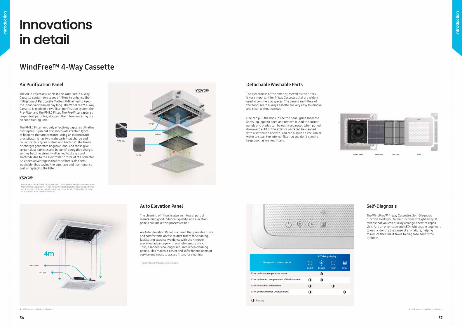
Fast Cooling
Sensor height range
Detect presence
Sensor width range
If room reaches comfort zone
The WindFree™ 4-Way Cassette and the WindFree™ 4-Way 600 x 600 Cassette boosts Smart Comfort Operation. The Fast Cooling process helps to achieve the desired temperature in a room quickly. By simultaneously detecting the humidity levels, the Smart Comfort Operation feature maintains the room’s temperature automatically.
The improved Motion Detect Sensor (MDS) detects thepresence and location of people in the room, enablingautomatic management of airfl ow direction andeffi cient air cooling.
Smart Comfort Operation
Motion Detect Sensor (optional)
Not all features are available for all models.
WindFree™ 4-Way Cassette
15,700 micro-holes
WindFree™ 4-Way 600 x 600
Cassette
9,000 micro-holes
Not all features are available for all models.
WindFree™ Cooling
34 35
Intr
oduc
tion
Intr
oduc
tion
The Air Purifi cation Panels in the WindFree™ 4-Way Cassette contain two types of fi lters to enhance the mitigation of Particulate Matter (PM), aimed to keep the indoor air clean all day long. The WindFree™ 4-Way Cassette is made of a two fi lter purifi cation system the Pre-Filter and the PM1.0 Filter. The Pre-Filter captures larger dust particles, stopping them from entering the air conditioning unit.
The PM1.0 Filter¹ not only effectively captures ultrafi ne dust upto 0.3 μm but also inactivates certain types of bacteria that are captured, using an electrostatic precipitator. It has two main parts that charge and collect certain types of dust and bacteria¹. The brush discharger generates negative ions. And these give certain dust particles and bacteria¹ a negative charge, so they become strongly attached to the ground electrode due to the electrostatic force of the collector. An added advantage is that this fi lter is also semi washable, thus saving the purchase and maintenance cost of replacing the fi lter.
The cleaning of fi lters is also an integral part of maintaining good indoor air quality, and elevation panels can make this process easier.
An Auto Elevation Panel is a panel that provides quick and comfortable access to dust fi lters for cleaning, facilitating extra convenience with the 4 metre1
elevation advantage with a single remote click. Thus, a ladder is no longer required when cleaning panels. This makes it easier and safer for end users or service engineers to access fi lters for cleaning.
1 May vary based on the actual usage conditions.
Air Purifi cation Panel
Auto Elevation Panel
Innovations in detail
WindFree™ 4-Way Cassette
The cleanliness of the exterior, as well as the fi lters, is very important for 4-Way Cassettes that are widely used in commercial spaces. The panels and fi lters of the WindFree™ 4-Way Cassette are very easy to remove and clean without screws.
One can pull the hook inside the panel grille (near the Samsung logo) to open and remove it. And the corner panels and blades can be easily separated when pulled downwards. All of the exterior parts can be cleaned with a soft brush or cloth. You can also use a vacuum or water to clean the internal fi lter, so you don’t need to keep purchasing new fi lters.
The WindFree™ 4-Way Cassette’s Self-Diagnosis function alerts you to malfunctions straight away. It means that you can quickly arrange a service repair visit. And an error code and LED light enable engineers to easily identify the cause of any failure, helping to reduce the time it takes to diagnose and fi x the problem.
Detachable Washable Parts
Self-Diagnosis
4m
Pre-Filter
PM1.0 Filter
PM1.0 Filter
Collector
Charger
Pre-Filter
Examples of relevant errors
LED-lamp display
On/Off Defrost Timer Filter
Error on indoor temperature sensor
Error on heat exchanger sensor of the indoor unit
Error on outdoor unit sensors
Error on MDS (Motion Detect Sensor)
Blinking
PM1.0 Filter Pre- Filter GrilleBlade & Panels
1 Intertek Report No.: RT20E-S0010-R Date: APR. 17, 2020 (Revised) Based on the data collected the Hypothesis is accepted:The K-element (Electrostatic Precipitator) of Samsung Electronics can sterilize the certain types of bacteria that collected on the fi lter. (Escherichia coli : above 99 %, Staphylococcus aureus : above 99 %)
Not all features are available for all models. Not all features are available for all models.
36 37
Intr
oduc
tion
Intr
oduc
tion
WindFree™ 1-Way Cassette
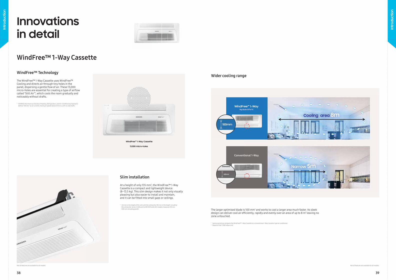
13,000 micro-holes
The WindFree™ 1-Way Cassette uses WindFree™ Cooling and directs air through tiny holes in the panel, dispersing a gentle fl ow of air. These 13,000 micro-holes are essential for creating a type of airfl ow called “Still Air”1, which cools the room gradually and noticeably without drafts.
At a height of only 135 mm1, the WindFree™ 1-Way Cassette is a compact and lightweight device (8–13.5 kg). This slim design makes it not only visually pleasing but also easier to install and maintain, and it can be fi tted into small gaps or ceilings.
¹ 135 mm is the height of the unit until the ceiling tile. 145 mm is the height including the ceiling tile. Up to 2.5 kW and 3.6 kW (FJM and CAC) models measures 135 mm (180 mm including panel).
WindFree™ Technology
Slim installation
Innovations in detail
WindFree™ 1-Way Cassette
¹ ASHRAE (the American Society of Heating, Refrigeration, and Air-Conditioning Engineers) defi nes “Still Air” as air currents moving at speeds below 0.15 m/s, with no cold drafts.
The larger optimised blade is 100 mm1 and works to cool a larger area much faster. Its sleek design can deliver cool air effi ciently, rapidly and evenly over an area of up to 8 m2 leaving no zone untouched.
Wider cooling range
1 Samsung testing compares the WindFree™ 1-Way Cassette to a conventional 1-Way Cassette-type air conditioner.2 Based on the 7.1 kW indoor unit.
Not all features are available for all models. Not all features are available for all models.
38 39
Intr
oduc
tion
Intr
oduc
tion
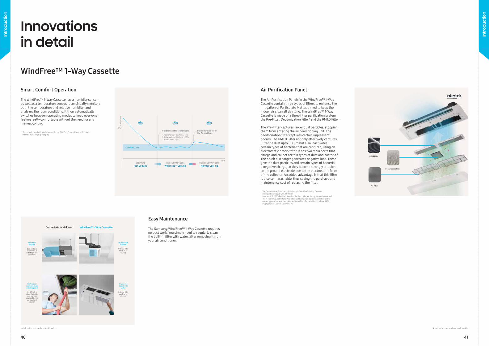
The WindFree™ 1-Way Cassette has a humidity sensor as well as a temperature sensor. It continually monitors both the temperature and relative humidity¹ and analyzes the room conditions. It then automatically switches between operating modes to keep everyone feeling really comfortable without the need for any manual control.
The Samsung WindFree™ 1-Way Cassette requires no duct work. You simply need to regularly clean the built-in fi lter with water, after removing it fromyour air conditioner.
1 The humidity level will only be shown during WindFree™ operation and Dry Mode via the SmartThings app display.
Smart Comfort Operation
Easy Maintenance
BeginningFast Cooling
Comfort Zone
Inside Comfort ZoneWindFreeTM Cooling
Outside Comfort ZoneNormal Cooling
Time
Room Tem
p.
(°C)If a room moves out ofthe Comfort Zone
If a room is in the Comfort Zone
1. Room Temp. ≤ Set Temp. - 2℃2. Relative humidity level ≤ 60%3. Room Temp. ≤ 26℃
Innovations in detail
WindFree™ 1-Way Cassette
The Air Purifi cation Panels in the WindFree™ 1-Way Cassette contain three types of fi lters to enhance the mitigation of Particulate Matter, aimed to keep the indoor air clean all day long. The WindFree™ 1-Way Cassette is made of a three fi lter purifi cation system the Pre-Filter, Deodorization Filter¹ and the PM1.0 Filter.
The Pre-Filter captures larger dust particles, stopping them from entering the air conditioning unit. The deodorization fi lter captures certain unpleasant odours. The PM1.0 Filter not only effectively captures ultrafi ne dust upto 0.3 μm but also inactivates certain types of bacteria that are captured, using an electrostatic precipitator. It has two main parts that charge and collect certain types of dust and bacteria.² The brush discharger generates negative ions. These give the dust particles and certain types of bacteria a negative charge, so they become strongly attached to the ground electrode due to the electrostatic force of the collector. An added advantage is that this fi lter is also semi washable, thus saving the purchase and maintenance cost of replacing the fi lter.
Air Purifi cation Panel
PM1.0 Filter
Deodorization Filter
Pre-Filter
No duct workrequired
Duct workrequired
Anyone can clean it with
water
Professionalcleaning serviceor tool required
Only the fi lter needs to be
cleaned
Dust particlesaccumulate in
both fi lters andduct work
Only the fi lter needs to be
cleaned
It is diffi cult to clean the inside
duct work, so you need to hire
a professional cleaner
Ducted Airconditioner WindFree™ 1-Way Cassette
Not all features are available for all models.
1 The Deodorization Filter can only be found in WindFree™ 1-Way Cassette.2 Intertek Report No.: RT20E-S0010-R
Date: APR. 17, 2020 (Revised) Based on the data collected the Hypothesis is accepted: The K-element (Electrostatic Precipitator) of Samsung Electronics can sterilize the certain types of bacteria that collected on the fi lter.(Escherichia coli : above 99 %, Staphylococcus aureus : above 99 %)
Not all features are available for all models.
40 41
Intr
oduc
tion
Intr
oduc
tion
Innovations in detail
Conventional 4-Way Cassette
Samsung 360 CassetteSamsung
360 Cassette
Spot OperatingInnercircle
Ice Bluedot
Middlecircle
Yellow Green dot
Outercircle
Blue dot(blinking)
Sequentialcircles
Red dot(blinking)
Mid FilterWide ErrorSwing Error
360 Cassette
Innovations in detail
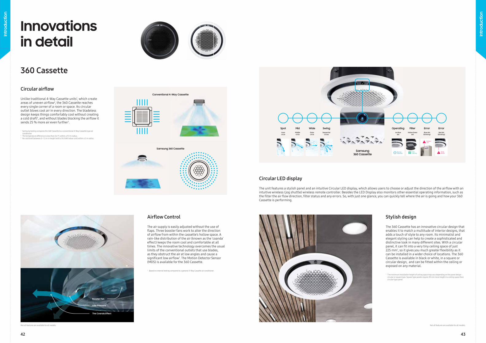
Unlike traditional 4-Way Cassette units1, which create areas of uneven airfl ow2, the 360 Cassette reaches every single corner of a room or space. Its circular outlet blows cool air in every direction. The bladeless design keeps things comfortably cool without creating a cold draft3, and without blades blocking the airfl ow it sends 25 % more air even further1.
The air supply is easily adjusted without the use of fl aps. Three booster fans work to alter the direction of airfl ow from within the cassette’s hollow space. A rain-like distribution of the air (known as the ‘coanda’ effect) keeps the room cool and comfortable at all times. The innovative technology overcomes the usual limits of the conventional outlets that use blades, as they obstruct the air at low angles and cause a signifi cant low airfl ow1. The Motion Detector Sensor (MDS) is available for the 360 Cassette.
The 360 Cassette has an innovative circular design that enables it to match a multitude of interior designs, that adds a touch of style to any room. Its minimalist and elegant styling can help to create a sophisticated and distinctive look in many different sites. With a circular panel, it can fi t into a very tiny ceiling space of just 225 mm1, so it gives you much greater fl exibility as it can be installed in a wider choice of locations. The 360 Cassette is available in black or white, in a square or circular design, and can be fi tted within the ceiling or exposed on any material.
1 Samsung testing compares the 360 Cassette to a conventional 4-Way Cassette type air conditioner.2 The temperature difference is less than 0.6 °C within a 9.3 m radius.3 No cold draft between 0–1.5 m in height (with a 14.0 kW indoor unit) within a 5 m radius.
1 Based on internal testing compared to a general 4-Way Cassette air conditioner. 1 T he minimum installation height of ceiling space may vary depending on the panel design - circular or square type. Square type panels require 30 mm more height in a ceiling space than circular type panel.
Circular airfl ow
Airfl ow Control Stylish design
The unit features a stylish panel and an intuitive Circular LED display, which allows users to choose or adjust the direction of the airfl ow with an intuitive wireless (jog shuttle) wireless remote controller. Besides the LED Display also monitors other essential operating information, such as the fi lter the air fl ow direction, fi lter status and any errors. So, with just one glance, you can quickly tell where the air is going and how your 360 Cassette is performing.
Circular LED display
Booster Fan
Low Pressure
The Coanda Effect
Not all features are available for all models. Not all features are available for all models.
42 43
Intr
oduc
tion
Intr
oduc
tion
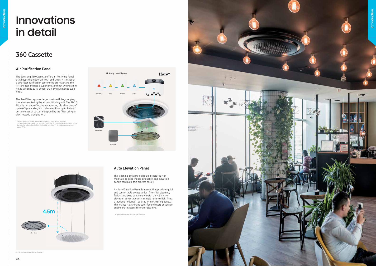
The Samsung 360 Cassette offers an Purifying Panel that keeps the indoor air fresh and clean. It is made of a two fi lter purifi cation system the pre-fi lter and the PM1.0 Filter and has a superior fi lter mesh with 0.5 mm holes, which is 20 % denser than a vinyl chloride type fi lter.
The Pre-Filter captures larger dust particles, stopping them from entering the air conditioning unit. The PM1.0 Filter is not only effective at capturing ultrafi ne dust of up to 0.3 μm in size, but it also sterilizes up to 99 % of certain types of bacteria1 trapped by the fi lter using an electrostatic precipitator1.
Air Purifi cation Panel
Innovations in detail
360 Cassette
The cleaning of fi lters is also an integral part of maintaining good indoor air quality, and elevation panels can make this process easier.
An Auto Elevation Panel is a panel that provides quick and comfortable access to dust fi lters for cleaning, facilitating extra convenience with the 4.5 metre¹ elevation advantage with a single remote click. Thus, a ladder is no longer required when cleaning panels. This makes it easier and safer for end users or service engineers to access fi lters for cleaning.
1 May vary based on the actual usage conditions.
Auto Elevation Panel
Very Poor Poor Moderate Good
Air Purity Level Display
4.5m
PM1.0 Filter
Pre-Filter
Pre-Filter
¹ Verifi ed by Intertek, Report Number RT20E-S0010-R, Issue Date:17 April 2020 . The K-element (Electrostatic Precipitator) of Samsung Electronics can sterilize certain types of bacteria that collected on the fi lter (Escherichia coli: above 99 %, Staphylococcus aureus: above 99 %).
Not all features are available for all models.
44 45
Intr
oduc
tion
Intr
oduc
tion
Communication F1, F2
EEV Control
Eva_out Sensor
RoomSensor
Eva inSensor
AHU Controller
Fan Feedback
Supply Air
Sensor
Fresh AirReturn AirExhaust Air
Gas pipe
Liquid Pipe
EEV Kit
AHU Fan Control
Outdoor unit
Return Air
Indoor
Dust & CO₂
Heat RecoveredFresh Air
Fresh Air
Dust & CO₂
Supply Air
Outdoor Air
Outdoor
Exhaust Air
Heat Exchanger
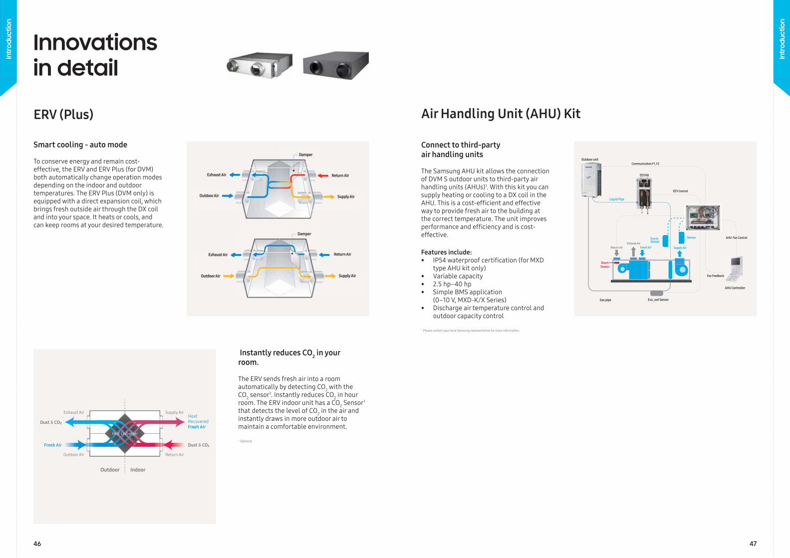
The ERV sends fresh air into a room automatically by detecting CO2 with the CO2 sensor1. Instantly reduces CO2 in hour room. The ERV indoor unit has a CO2 Sensor1
that detects the level of CO2 in the air and instantly draws in more outdoor air to maintain a comfortable environment.
1 Optional
ERV (Plus)
To conserve energy and remain cost-effective, the ERV and ERV Plus (for DVM) both automatically change operation modes depending on the indoor and outdoor temperatures. The ERV Plus (DVM only) is equipped with a direct expansion coil, which brings fresh outside air through the DX coil and into your space. It heats or cools, and can keep rooms at your desired temperature.
Smart cooling - auto mode
Instantly reduces CO2 in your room.
Innovations in detail
Air Handling Unit (AHU) Kit
The Samsung AHU kit allows the connection of DVM S outdoor units to third-party air handling units (AHUs) 1. With this kit you can supply heating or cooling to a DX coil in the AHU. This is a cost-effi cient and effective way to provide fresh air to the building at the correct temperature. The unit improves performance and effi ciency and is cost-effective.
Features include:• IP54 waterproof certifi cation (for MXD
type AHU kit only) • Variable capacity• 2.5 hp–40 hp• Simple BMS application
(0–10 V, MXD-K/X Series)• Discharge air temperature control and
outdoor capacity control
1 Please contact your local Samsung representative for more information.
Connect to third-party air handling units
46 47
Intr
oduc
tion
Intr
oduc
tion
Wireless Network
Security
Energy Management
HVAC Light
3rd Party Service
Faciltiies / Sensors
DMS 2.5 IoT
Third Party System
Wired Wireless
Client (Web User)
BACnetTCP / IP
Samsung VRF
Smart Controller Smart Controller
HVAC
CCTV
Beacon
Wearable
Temperature/Humidity Sensor
DMS 2.5
VRF
Lighting
Lighting Power
Sensor
Photovoltaic
ESS
MechanicalEquipment
Security
Electric Power
Field Device
AP
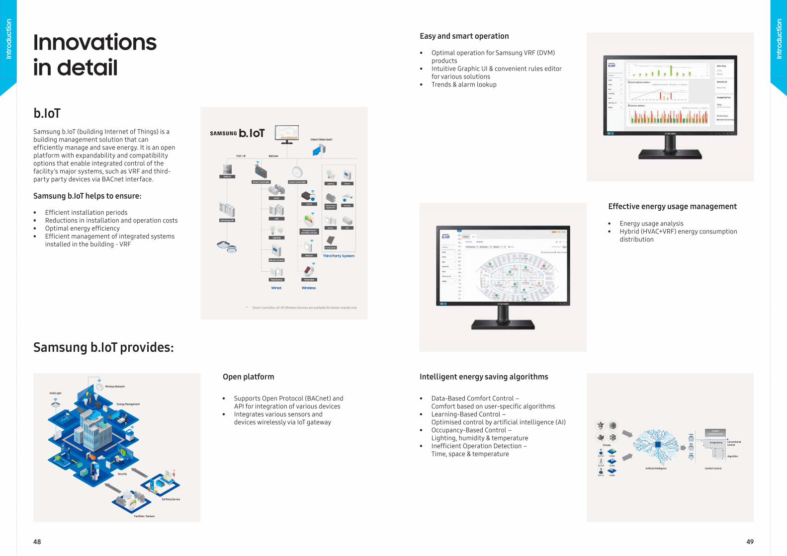
Open platform
• Supports Open Protocol (BACnet) and API for integration of various devices
• Integrates various sensors and devices wirelessly via IoT gateway
Innovations in detail
* Smart Controller, IoT AP, Wireless Devices are available for Korean market only
b.IoT
Samsung b.IoT provides:
Samsung b.IoT (building Internet of Things) is a building management solution that can effi ciently manage and save energy. It is an open platform with expandability and compatibility options that enable integrated control of the facility’s major systems, such as VRF and third-party party devices via BACnet interface.
Samsung b.IoT helps to ensure:
• Effi cient installation periods• Reductions in installation and operation costs• Optimal energy effi ciency • Effi cient management of integrated systems
installed in the building - VRF
Climate
Artificial Intelligence 0.6~0.9
0.3~0.7
1.2 Met
0.8~1.2 1.6 Met
1.0 Met
Comfort Control
ConventionalControl
Algorithm
ComfortSatisfaction 90%
Energy Saving
High
Mid
Low
Intelligent energy saving algorithms
• Data-Based Comfort Control – Comfort based on user-specifi c algorithms
• Learning-Based Control – Optimised control by artifi cial intelligence (AI)
• Occupancy-Based Control – Lighting, humidity & temperature
• Ineffi cient Operation Detection – Time, space & temperature
Effective energy usage management
• Energy usage analysis• Hybrid (HVAC+VRF) energy consumption
distribution
Easy and smart operation
• Optimal operation for Samsung VRF (DVM) products
• Intuitive Graphic UI & convenient rules editor for various solutions
• Trends & alarm lookup
48 49
Intr
oduc
tion
Intr
oduc
tion
VRF
51
VRF
50
Intr
oduc
tion
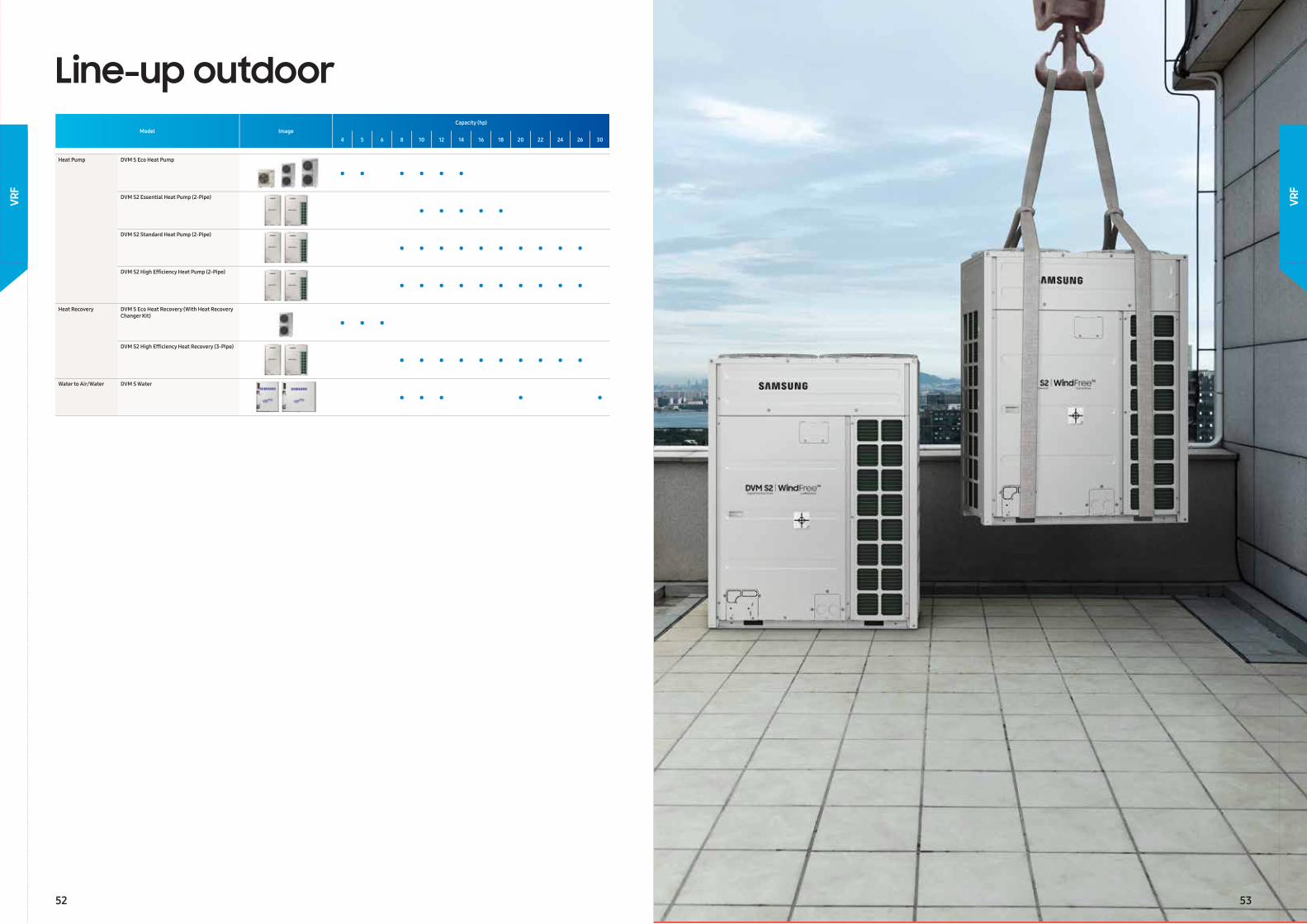
Line-up outdoorModel Image
Capacity (hp)
4 5 6 8 10 12 14 16 18 20 22 24 26 30
Heat Pump DVM S Eco Heat Pump
• • • • • •
DVM S2 Essential Heat Pump (2-Pipe)
• • • • •
DVM S2 Standard Heat Pump (2-Pipe)
• • • • • • • • • •
DVM S2 High Effi ciency Heat Pump (2-Pipe)
• • • • • • • • • •
Heat Recovery DVM S Eco Heat Recovery (With Heat Recovery Changer Kit)
• • •
DVM S2 High Effi ciency Heat Recovery (3-Pipe)
• • • • • • • • • •
Water to Air/Water DVM S Water
• • • • •
52 53
VRF
VRF
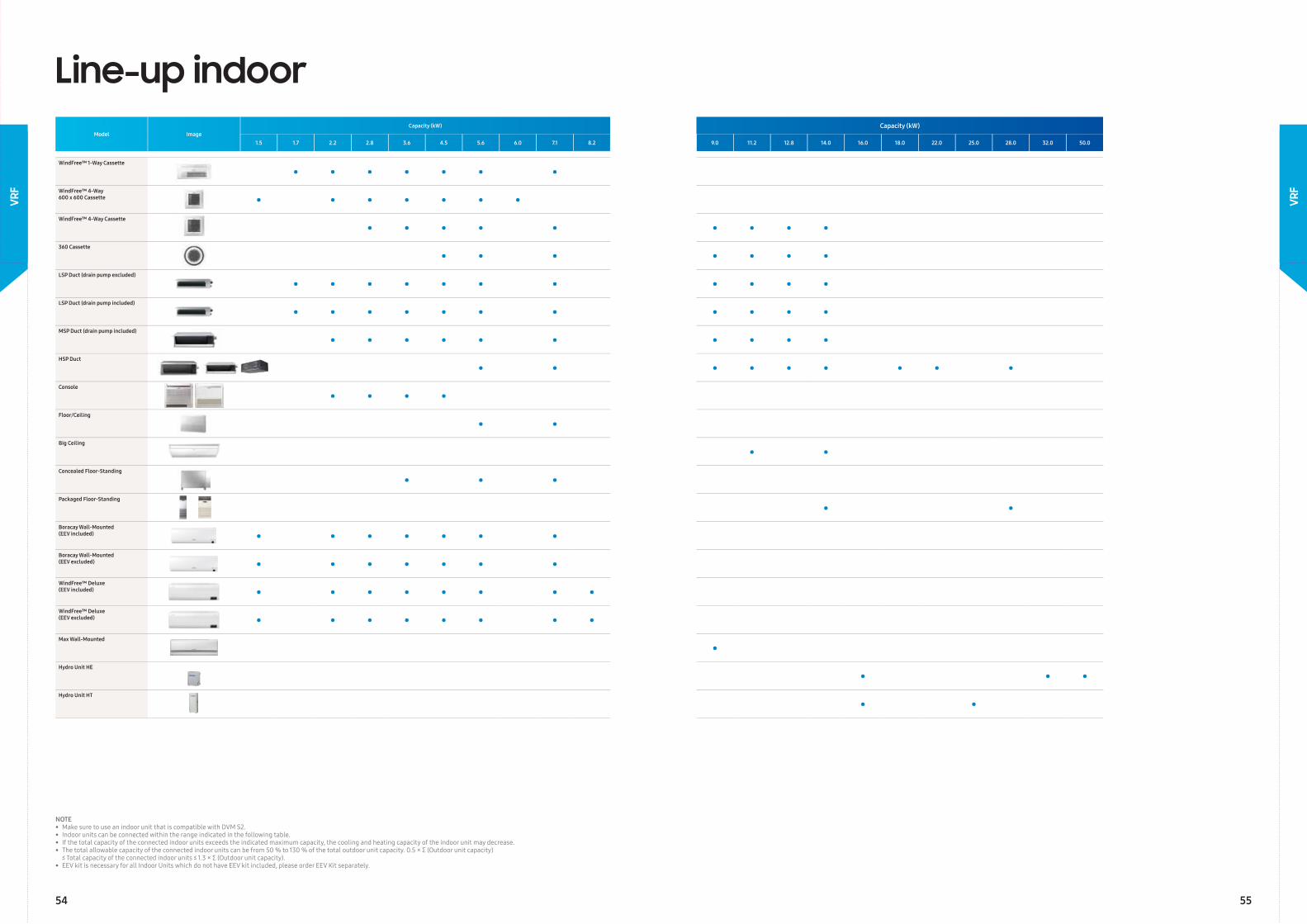
Line-up indoorModel Image
Capacity (kW) Capacity (kW)
1.5 1.7 2.2 2.8 3.6 4.5 5.6 6.0 7.1 8.2 9.0 11.2 12.8 14.0 16.0 18.0 22.0 25.0 28.0 32.0 50.0
WindFree™ 1-Way Cassette
• • • • • • •WindFree™ 4-Way600 x 600 Cassette • • • • • • •WindFree™ 4-Way Cassette
• • • • • • • • •360 Cassette
• • • • • • •LSP Duct (drain pump excluded)
• • • • • • • • • • •LSP Duct (drain pump included)
• • • • • • • • • • •MSP Duct (drain pump included)
• • • • • • • • • •HSP Duct
• • • • • • • • •
Console
• • • •Floor/Ceiling
• •Big Ceiling
• • Concealed Floor-Standing
• • • Packaged Floor-Standing
• •Boracay Wall-Mounted (EEV included) • • • • • • •Boracay Wall-Mounted (EEV excluded) • • • • • • •WindFree™ Deluxe (EEV included) • • • • • • • •WindFree™ Deluxe (EEV excluded) • • • • • • • •Max Wall-Mounted
•Hydro Unit HE
• • •Hydro Unit HT
• •
NOTE• Make sure to use an indoor unit that is compatible with DVM S2.• Indoor units can be connected within the range indicated in the following table.• If the total capacity of the connected indoor units exceeds the indicated maximum capacity, the cooling and heating capacity of the indoor unit may decrease.• The total allowable capacity of the connected indoor units can be from 50 % to 130 % of the total outdoor unit capacity. 0.5 × Σ (Outdoor unit capacity) ≤ Total capacity of the connected indoor units ≤ 1.3 × Σ (Outdoor unit capacity).• EEV kit is necessary for all Indoor Units which do not have EEV kit included, please order EEV Kit separately.
54 55
VRF
VRF
VRF
VRF
5756
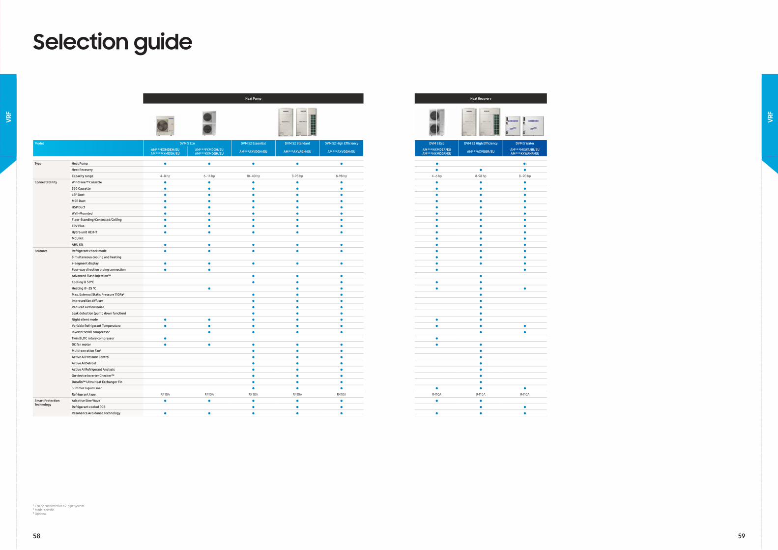
Selection guide
Heat Pump Heat Recovery
Model DVM S Eco DVM S2 Essential DVM S2 Standard DVM S2 High Effi ciency DVM S Eco DVM S2 High Effi ciency DVM S Water
AM***KXMDEH/EUAM***MXMDEH/EU
AM***FXMDGH/EUAM***KXMDGH/EU AM***AXVDGH/EU AM***AXVAGH/EU AM***AXVGGH/EU AM***NXMDER/EU
AM***NXMDGR/EU AM***AXVGGR/EU AM***MXWANR/EUAM***KXWANR/EU
Type Heat Pump • • • • • •1 •1
Heat Recovery • • •Capacity range 4–8 hp 6–14 hp 10–40 hp 8-98 hp 8-98 hp 4–6 hp 8-98 hp 8–90 hp
Connectablility WindFree™ Cassette • • • • • • • •360 Cassette • • • • • • • •LSP Duct • • • • • • • •MSP Duct • • • • • • • •HSP Duct • • • • • • • •Wall-Mounted • • • • • • • •Floor-Standing/Concealed/Ceiling • • • • • • • •ERV Plus • • • • • • • •Hydro unit HE/HT • • • • • • • •MCU Kit • • •AHU Kit • • • • • • • •
Features Refrigerant check mode • • • • • • • •Simultaneous cooling and heating • • •7-Segment display • • • • • • • •Four-way direction piping connection • • • •Advanced Flash Injection™ • • • •Cooling @ 50°C • • • • •Heating @ -25 °C • • • • • •Max. External Static Pressure 110Pa² • • • •Improved fan diffuser • • • •Reduced air fl ow noise • • • •Leak detection (pump down function) • • • •Night silent mode • • • • • • •Variable Refrigerant Temperature • • • • • • • •Inverter scroll compressor • • • • • •Twin BLDC rotary compressor • •DC fan motor • • • • • • •Multi-serration Fan2 • • • •Active AI Pressure Control • • • •Active AI Defrost • • • •Active AI Refrigerant Analysis • • • •On-device Inverter Checker™ • • • •Durafi n™ Ultra Heat Exchanger Fin • • • •Slimmer Liquid Line3 • • • • • •Refrigerant type R410A R410A R410A R410A R410A R410A R410A R410A
Smart Protection Technology
Adaptive Sine Wave • • • • • • •Refrigerant cooled PCB • • • • •Resonance Avoidance Technology • • • • • • • •
¹ Can be connected as a 2-pipe system.² Model specifi c.³ Optional.
58 59
VRF
VRF
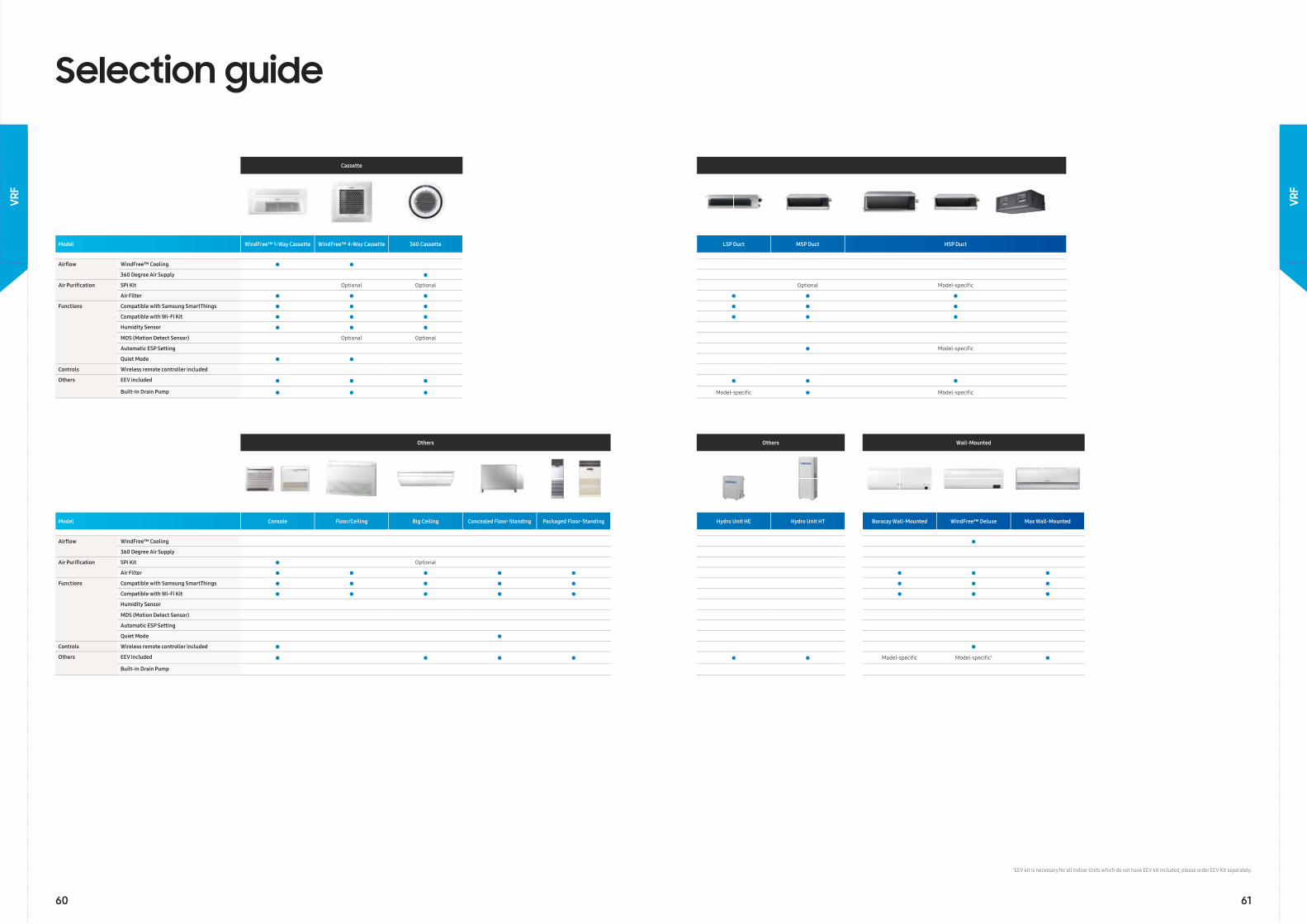
Selection guide
Others Others Wall-Mounted
Model Console Floor/Ceiling Big Ceiling Concealed Floor-Standing Packaged Floor-Standing Hydro Unit HE Hydro Unit HT Boracay Wall-Mounted WindFree™ Deluxe Max Wall-Mounted
Airfl ow WindFree™ Cooling •360 Degree Air Supply
Air Purifi cation SPi Kit • Optional
Air Filter • • • • • • • •Functions Compatible with Samsung SmartThings • • • • • • • •
Compatible with Wi-Fi Kit • • • • • • • •Humidity Sensor
MDS (Motion Detect Sensor)
Automatic ESP Setting
Quiet Mode •Controls Wireless remote controller included • •Others EEV included • • • • • • Model-specifi c Model-specifi c1 •
Built-In Drain Pump
1 EEV kit is necessary for all Indoor Units which do not have EEV kit included, please order EEV Kit separately.
Cassette
Model WindFree™ 1-Way Cassette WindFree™ 4-Way Cassette 360 Cassette LSP Duct MSP Duct HSP Duct
Airfl ow WindFree™ Cooling • •360 Degree Air Supply •
Air Purifi cation SPi Kit Optional Optional Optional Model-specifi c
Air Filter • • • • • •Functions Compatible with Samsung SmartThings • • • • • •
Compatible with Wi-Fi Kit • • • • • •Humidity Sensor • • •MDS (Motion Detect Sensor) Optional Optional
Automatic ESP Setting • Model-specifi c
Quiet Mode • •Controls Wireless remote controller included
Others EEV included • • • • • •Built-In Drain Pump • • • Model-specifi c • Model-specifi c
60 61
VRF
VRF
62
VRF
VRF
63
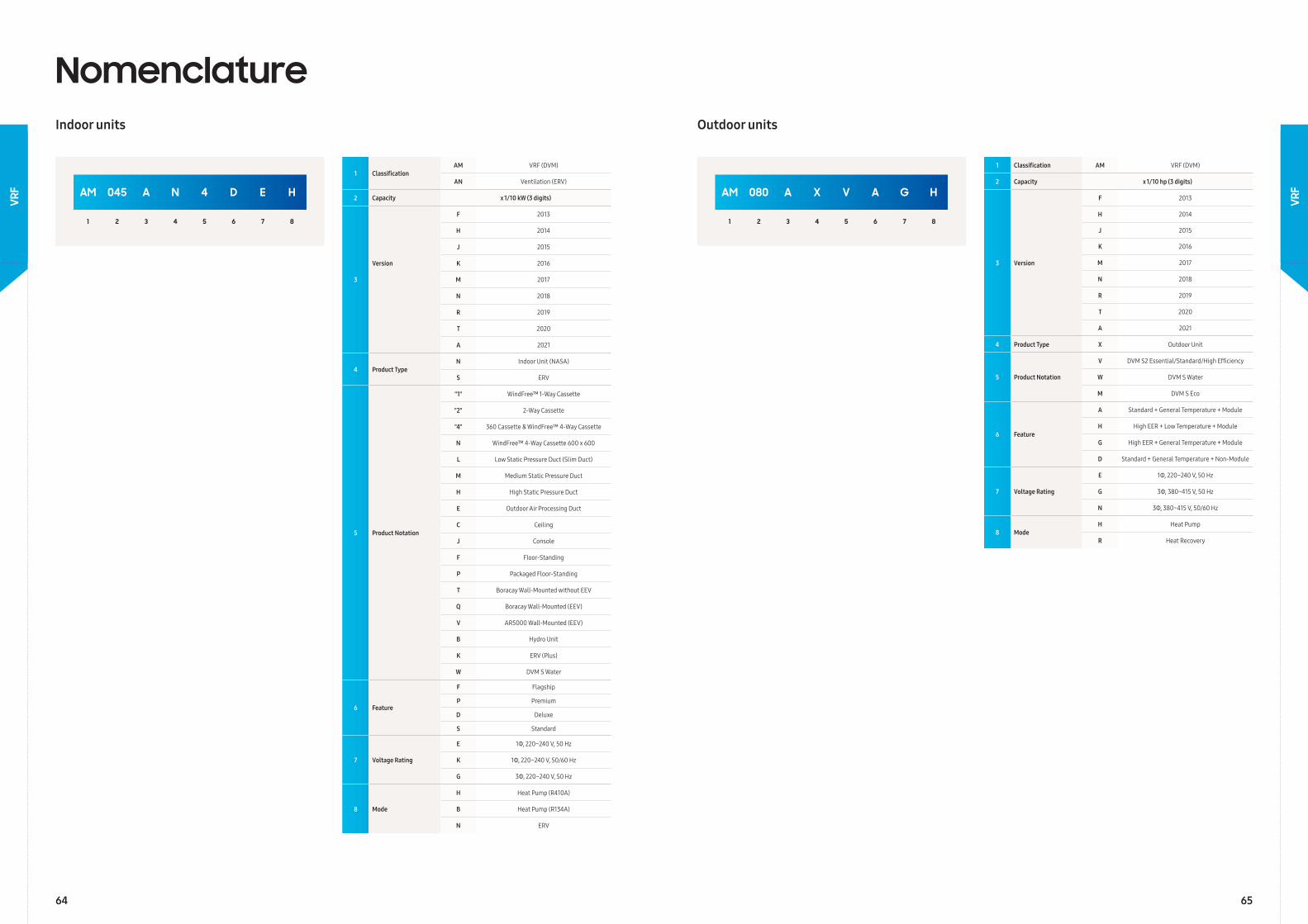
AM 045 A N 4 D E H
1 2 3 4 5 6 7 8
1 ClassificationAM VRF (DVM)
AN Ventilation (ERV)
2 Capacity x 1/10 kW (3 digits)
3
Version
F 2013
H 2014
J 2015
K 2016
M 2017
N 2018
R 2019
T 2020
A 2021
4 Product TypeN Indoor Unit (NASA)
S ERV
5 Product Notation
"1" WindFree™ 1-Way Cassette
"2" 2-Way Cassette
"4" 360 Cassette & WindFree™ 4-Way Cassette
N WindFree™ 4-Way Cassette 600 x 600
L Low Static Pressure Duct (Slim Duct)
M Medium Static Pressure Duct
H High Static Pressure Duct
E Outdoor Air Processing Duct
C Ceiling
J Console
F Floor-Standing
P Packaged Floor-Standing
T Boracay Wall-Mounted without EEV
Q Boracay Wall-Mounted (EEV)
V AR5000 Wall-Mounted (EEV)
B Hydro Unit
K ERV (Plus)
W DVM S Water
6 Feature
F Flagship
P Premium
D Deluxe
S Standard
7 Voltage Rating
E 1Φ, 220~240 V, 50 Hz
K 1Φ, 220~240 V, 50/60 Hz
G 3Φ, 220~240 V, 50 Hz
8 Mode
H Heat Pump (R410A)
B Heat Pump (R134A)
N ERV
AM 080 A X V A G H
1 2 3 4 5 6 7 8
1 Classification AM VRF (DVM)
2 Capacity x 1/10 hp (3 digits)
3 Version
F 2013
H 2014
J 2015
K 2016
M 2017
N 2018
R 2019
T 2020
A 2021
4 Product Type X Outdoor Unit
5 Product Notation
V DVM S2 Essential/Standard/High Efficiency
W DVM S Water
M DVM S Eco
6 Feature
A Standard + General Temperature + Module
H High EER + Low Temperature + Module
G High EER + General Temperature + Module
D Standard + General Temperature + Non-Module
7 Voltage Rating
E 1Φ, 220~240 V, 50 Hz
G 3Φ, 380~415 V, 50 Hz
N 3Φ, 380~415 V, 50/60 Hz
8 ModeH Heat Pump
R Heat Recovery
NomenclatureIndoor units Outdoor units
64 65
VRF
VRF
Model AM040KXMDEH/EU AM050KXMDEH/EU AM080MXMDGH/EU AM080FXMDGH/EU AM100KXMDGH/EU AM120KXMDGH/EU AM140KXMDGH/EU
Power Supply Φ, #, V, Hz 1Φ, 2, 220–240 V, 50 Hz 1Φ, 2, 220–240 V, 50 Hz 3Φ, 4, 380–415 V, 50 Hz 3Φ, 4, 380–415 V, 50 Hz 3Φ, 4, 380–415 V, 50 Hz 3Φ, 4, 380–415 V, 50 Hz 3Φ, 4, 380–415 V, 50 Hz
Performance hp hp 4 5 8 8 10 12 14
Capacity Cooling kW 12.1 14.0 22.4 22.4 28.0 33.5 40.0
Heating kW 12.1 14.0 22.4 25.0 31.5 37.5 45.0
Maximum number of connectable indoor units ea 6.0 8.0 13.0 13.0 18.0 21.0 26.0
Total capacity of the connected indoor units Min. kW 5.6 7.0 11.2 11.2 14.0 16.8 20.0
Max. kW 15.7 18.2 29.1 29.1 36.4 43.6 52.0
Power Power Input Cooling kW 3.60 4.00 6.90 5.72 7.29 8.77 10.59
Heating kW 2.90 3.40 5.80 4.88 6.74 7.81 9.88
Current Input Cooling A 17.50 19.50 11.70 9.66 11.51 13.74 16.48
Heating A 14.00 16.50 9.50 8.24 10.58 12.23 15.55
Current Minimum SSC value MVA - - 3.4 3.4 4.6 5.1 5.9
MCA A 24.0 27.0 18.4 18.0 21.5 23.5 32.0
MFA A 32 40 25 25 30 30 40
Energy Effi ciency 1 EER (Nominal Cooling) W/W 3.36 3.50 3.25 3.92 3.84 3.82 3.78
COP (Nominal Heating) W/W 4.17 4.12 3.86 5.12 4.67 4.79 4.55
SEER W/W 7.25 6.71 7.46 9.22 7.09 6.94 6.83
Compressor Type - Twin BLDC Rotary Twin BLDC Rotary Twin BLDC Rotary Inverter Scroll Inverter Scroll Inverter Scroll Inverter Scroll
Output kW × n 4.12 x 1 4.12 x 1 4.92 x 1 4.96 x 1 5.18 x 1 6.39 x 1 6.76 x 1
Oil Type - PVE PVE PVE PVE PVE PVE PVE
Initial Charge cc 1,700 1,700 1,700 2,800 2,300 2,300 2,300
Fan Type & Discharge direction - Propeller Propeller Propeller Propeller Propeller Propeller Propeller
- Horizontal Horizontal Horizontal Horizontal Horizontal Horizontal Horizontal
Number of Fans ea 1 1 2 2 2 2 2
Airfl ow Rate m³/min 64 70 135 135 165 166 180
l/s 1067 1167 2250 2250 2750 2766.67 3000
External Static Pressure Max. mmAq 3.00 3.00 3.00 3.00 3.00 3.00 3.00
Pa 29.40 29.40 29.40 29.40 29.40 29.40 29.40
Fan Motor Model - BLDC Motor BLDC Motor BLDC Motor BLDC Motor BLDC Motor BLDC Motor BLDC Motor
Output x n W 125 x 1 139 x 1 139 x 2 139 x 2 244 x 2 244 x 2 244 x 2
Piping Connections Liquid Pipe ø, mm 9.52 9.52 9.52 9.52 9.52 12.7 12.7
ø, inch 3/8 3/8 3/8 3/8 3/8 1/2 1/2
Gas Pipe ø, mm 15.88 15.88 19.05 19.05 22.22 28.58 28.58
ø, inch 5/8 5/8 3/4 3/4 7/8 1 1/8 1 1/8
Piping length (ODU-IDU)3 Max. (Equiv.) m 50 (65) 50 (65) 100 (130) 100 (130) 160 (185) 160 (185) 160 (185)
Piping length (1st Branch - IDU)3 Max. m 40 40 40 40 40 40 40
Total piping length (System) Max. m 150 150 300 300 300 300 300
Level Difference (Outdoor in highest position) Max. m 30 30 30 30 50 50 50
Level Difference (Indoor in highest position) Max. m 25 25 30 30 40 40 40
Level Difference (IDU-IDU)3 Max. m 15 15 30 30 50 50 50
Wiring Connections Communication Min. mm² 0.75 0.75 0.75 0.75 0.75 0.75 0.75
Remark - F1, F2 F1, F2 F1, F2 F1, F2 F1, F2 F1, F2 F1, F2
Refrigerant Type R410A(Fluorinated greenhouse gas, GWP=2,088) R410A(Fluorinated greenhouse gas, GWP=2,088)
Factory Charging kg / tCO2e 2.00/4.18 2.50/5.22 3.70/7.73 3.70/7.73 3.70/7.73 4.30/8.98 4.80/10.02
Sound Sound Pressure2 Cooling dB(A) 52 55 59 56 58 59 62
Heating dB(A) 54 57 59 58 60 61 64
Sound Power dB(A) 73 75 77 74 74 76 79
External Dimensions Net Weight kg 79.0 83.5 115.0 135.0 145.0 155.0 162.0
Net Dimensions (W x H x D) mm 940 x 998 x 330 940 x 998 x 330 940 x 1,420 x 330 940 x 1,420 x 330 940 x 1,630 x 460 940 x 1,630 x 460 940 x 1,630 x 460
Operating Temperature Range
Cooling ℃ -5.0~48.0 -5.0~48.0 -5.0~48.0 -5.0~48.0 -5.0~52.0 -5.0~52.0 -5.0~52.0
Heating ℃ -20.0~24.0 -20.0~24.0 -20.0~24.0 -20.0~24.0 -25.0~24.0 -25.0~24.0 -25.0~24.0
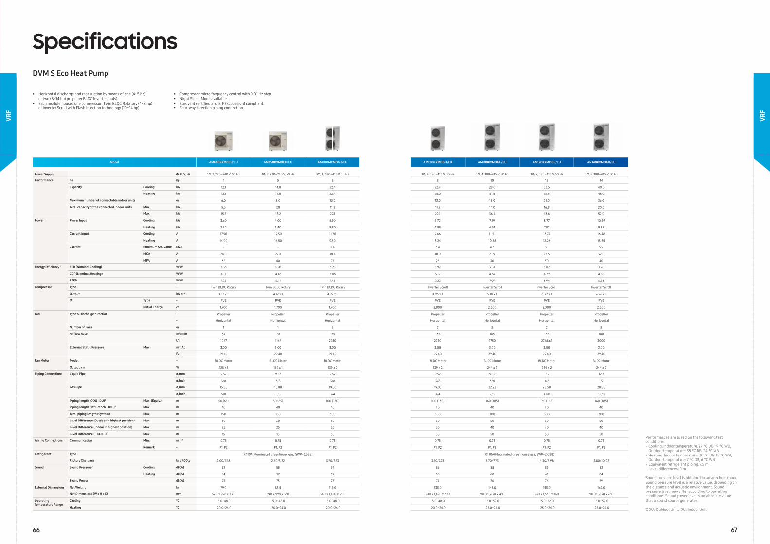
SpecificationsDVM S Eco Heat Pump
• Horizontal discharge and rear suction by means of one (4~5 hp) or two (8~14 hp) propeller BLDC Inverter fan(s).• Each module houses one compressor: Twin BLDC Rotatory (4~8 hp) or Inverter Scroll with Flash Injection technology (10~14 hp).
• Compressor micro frequency control with 0.01 Hz step.• Night Silent Mode available.• Eurovent certifi ed and ErP (Ecodesign) compliant.• Four-way direction piping connection.
1 Performances are based on the following test conditions:- Cooling: Indoor temperature: 27 °C DB, 19 °C WB, Outdoor temperature: 35 °C DB, 24 °C WB - Heating: Indoor temperature: 20 °C DB, 15 °C WB, Outdoor temperature: 7 °C DB, 6 °C WB- Equivalent refrigerant piping: 7.5 m, Level differences: 0 m
2 Sound pressure level is obtained in an anechoic room. Sound pressure level is a relative value, depending on the distance and acoustic environment. Sound pressure level may differ according to operating conditions. Sound power level is an absolute value that a sound source generates.
3ODU: Outdoor Unit, IDU: Indoor Unit
66 67
VRF
VRF
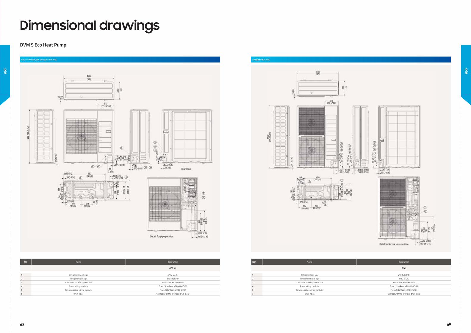
Dimensional drawingsDVM S Eco Heat Pump
NO Name Description
4/5 hp
1 Refrigerant liquid pipe ø9.52 (ø3/8)
2 Refrigerant gas pipe ø15.88 (ø5/8)
3 Knock-out hole for pipe intake Front/Side/Rear/Bottom
4 Power wiring conduits Front/Side/Rear, ø34.00 (ø1 3/8)
5 Communication wiring conduits Front/Side/Rear, ø22.00 (ø7/8)
6 Drain holes Connect with the provided drain plug.
AM040KXMDEH/EU, AM050KXMDEH/EU AM080∗XMDGH/EU
NO Name Description
8 hp
1 Refrigerant gas pipe ø19.05 (ø3/4)
2 Refrigerant liquid pipe ø9.52 (ø3/8)
3 Knock-out hole for pipe intake Front/Side/Rear/Bottom
4 Power wiring conduits Front/Side/Rear, ø34.00 (ø1 3/8)
5 Communication wiring conduits Front/Side/Rear, ø22.00 (ø7/8)
6 Drain holes Connect with the provided drain plug.
68 69
VRF
VRF
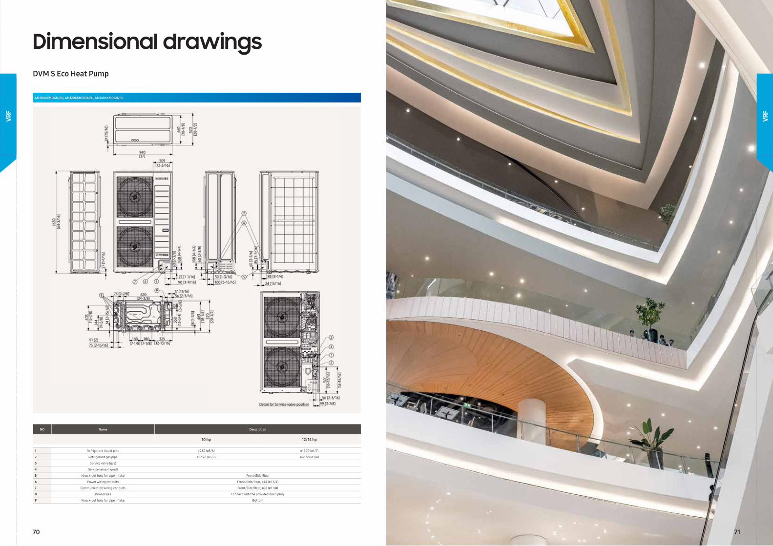
AM100KXMDGH/EU, AM120KXMDGH/EU, AM140KXMDGH/EU
NO Name Description
10 hp 12/14 hp
1 Refrigerant liquid pipe ø9.52 (ø3/8) ø12.70 (ø1/2)
2 Refrigerant gas pipe ø22.28 (ø5/8) ø28.58 (ø3/4)
3 Service valve (gas)
4 Service valve (liquid)
5 Knock-out hole for pipe intake Front/Side/Rear
6 Power wiring conduits Front/Side/Rear, ø44 (ø1 3/4)
7 Communication wiring conduits Front/Side/Rear, ø28 (ø1 1/8)
8 Drain holes Connect with the provided drain plug.
9 Knock-out hole for pipe intake Bottom
Dimensional drawingsDVM S Eco Heat Pump
70 71
VRF
VRF
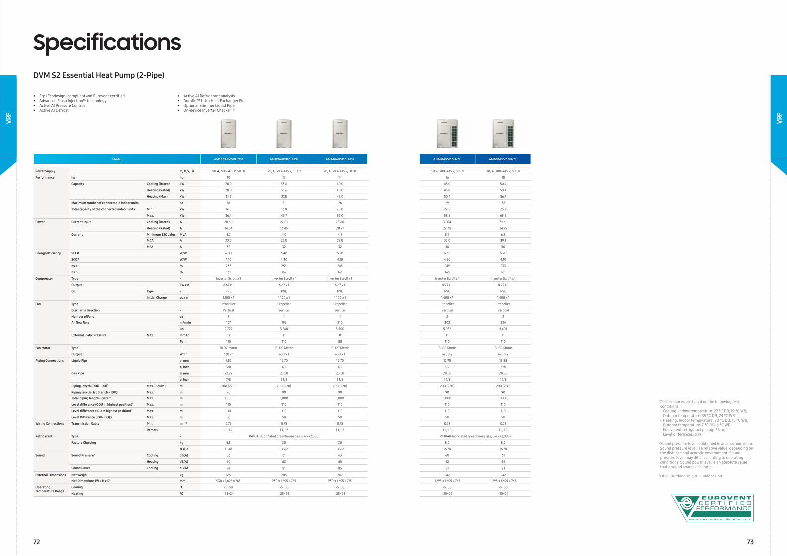
Model AM100AXVDGH/EU AM120AXVDGH/EU AM140AXVDGH/EU AM160AXVDGH/EU AM180AXVDGH/EU
Power Supply Φ, #, V, Hz 3Φ, 4, 380–415 V, 50 Hz 3Φ, 4, 380–415 V, 50 Hz 3Φ, 4, 380–415 V, 50 Hz 3Φ, 4, 380–415 V, 50 Hz 3Φ, 4, 380–415 V, 50 Hz
Performance hp hp 10 12 14 16 18
Capacity Cooling (Rated) kW 28.0 33.6 40.0 45.0 50.4
Heating (Rated) kW 28.0 33.6 40.0 45.0 50.4
Heating (Max) kW 31.5 37.8 45.0 50.4 56.7
Maximum number of connectable indoor units ea 18 21 26 29 32
Total capacity of the connected indoor units Min. kW 14.0 16.8 20.0 22.5 25.2
Max. kW 36.4 43.7 52.0 58.5 65.5
Power Current Input Cooling (Rated) A 20.50 22.01 28.60 31.04 37.61
Heating (Rated) A 14.34 16.45 20.91 22.38 24.75
Current Minimum SSC value MVA 3.7 4.0 4.6 5.2 6.3
MCA A 23.0 25.0 29.0 32.0 39.2
MFA A 32 32 32 40 50
Energy effi ciency¹ SEER W/W 6.00 6.40 6.20 6.30 5.90
SCOP W/W 4.10 4.30 4.10 4.20 4.10
ηs.c % 237 253 245 249 233
ηs.h % 161 169 161 165 161
Compressor Type - Inverter Scroll x 1 Inverter Scroll x 1 Inverter Scroll x 1 Inverter Scroll x 1 Inverter Scroll x 1
Output kW x n 6.67 x 1 6.67 x 1 6.67 x 1 8.93 x 1 8.93 x 1
Oil Type - PVE PVE PVE PVE PVE
Initial Charge cc x n 1,100 x 1 1,100 x 1 1,100 x 1 1,400 x 1 1,400 x 1
Fan Type - Propeller Propeller Propeller Propeller Propeller
Discharge direction - Vertical Vertical Vertical Vertical Vertical
Number of Fans ea 1 1 1 2 2
Airfl ow Rate m³/min 167 196 210 303 324
l/s 2,779 3,260 3,500 5,052 5,401
External Static Pressure Max. mmAq 11 11 8 11 11
Pa 110 110 80 110 110
Fan Motor Type - BLDC Motor BLDC Motor BLDC Motor BLDC Motor BLDC Motor
Output W x n 630 x 1 630 x 1 630 x 1 620 x 2 620 x 2
Piping Connections Liquid Pipe ø, mm 9.52 12.70 12.70 12.70 15.88
ø, inch 3/8 1/2 1/2 1/2 5/8
Gas Pipe ø, mm 22.22 28.58 28.58 28.58 28.58
ø, inch 7/8 1 1/8 1 1/8 1 1/8 1 1/8
Piping length (ODU-IDU)³ Max. (Equiv.) m 200 [220] 200 [220] 200 [220] 200 [220] 200 [220]
Piping length (1st Branch - IDU)³ Max. m 90 90 90 90 90
Total piping length (System) Max. m 1,000 1,000 1,000 1,000 1,000
Level difference (ODU in highest position)³ Max. m 110 110 110 110 110
Level difference (IDU in highest position)³ Max. m 110 110 110 110 110
Level Difference (IDU-IDU)3 Max. m 50 50 50 50 50
Wiring Connections Transmission Cable Min. mm² 0.75 0.75 0.75 0.75 0.75
Remark - F1, F2 F1, F2 F1, F2 F1, F2 F1, F2
Refrigerant Type - R410A(Fluorinated greenhouse gas, GWP=2,088) R410A(Fluorinated greenhouse gas, GWP=2,088)
Factory Charging kg 5.5 7.0 7.0 8.0 8.0
tCO₂e 11.48 14.62 14.62 16.70 16.70
Sound Sound Pressure2 Cooling dB(A) 56 61 63 60 61
Heating dB(A) 60 63 65 62 64
Sound Power Cooling dB(A) 78 81 85 81 83
External Dimensions Net Weight kg 185 205 207 242 242
Net Dimensions (W x H x D) mm 930 x 1,695 x 765 930 x 1,695 x 765 930 x 1,695 x 765 1,295 x 1,695 x 765 1,295 x 1,695 x 765
Operating Temperature Range
Cooling ℃ -5~50 -5~50 -5~50 -5~50 -5~50
Heating ℃ -25~24 -25~24 -25~24 -25~24 -25~24
SpecificationsDVM S2 Essential Heat Pump (2-Pipe)
• Erp (Ecodesign) compliant and Eurovent certifi ed• Advanced Flash Injection™ technology• Active AI Pressure Control• Active AI Defrost
• Active AI Refrigerant analysis• Durafi n™ Ultra Heat Exchanger Fin• Optional Slimmer Liquid Pipe• On-device Inverter Checker™
1 Performances are based on the following test conditions:- Cooling: Indoor temperature: 27 °C DB, 19 °C WB, Outdoor temperature: 35 °C DB, 24 °C WB - Heating: Indoor temperature: 20 °C DB, 15 °C WB, Outdoor temperature: 7 °C DB, 6 °C WB- Equivalent refrigerant piping: 7.5 m, Level differences: 0 m
2 Sound pressure level is obtained in an anechoic room. Sound pressure level is a relative value, depending on the distance and acoustic environment. Sound pressure level may differ according to operating conditions. Sound power level is an absolute value that a sound source generates.
3ODU: Outdoor Unit, IDU: Indoor Unit
72 73
VRF
VRF
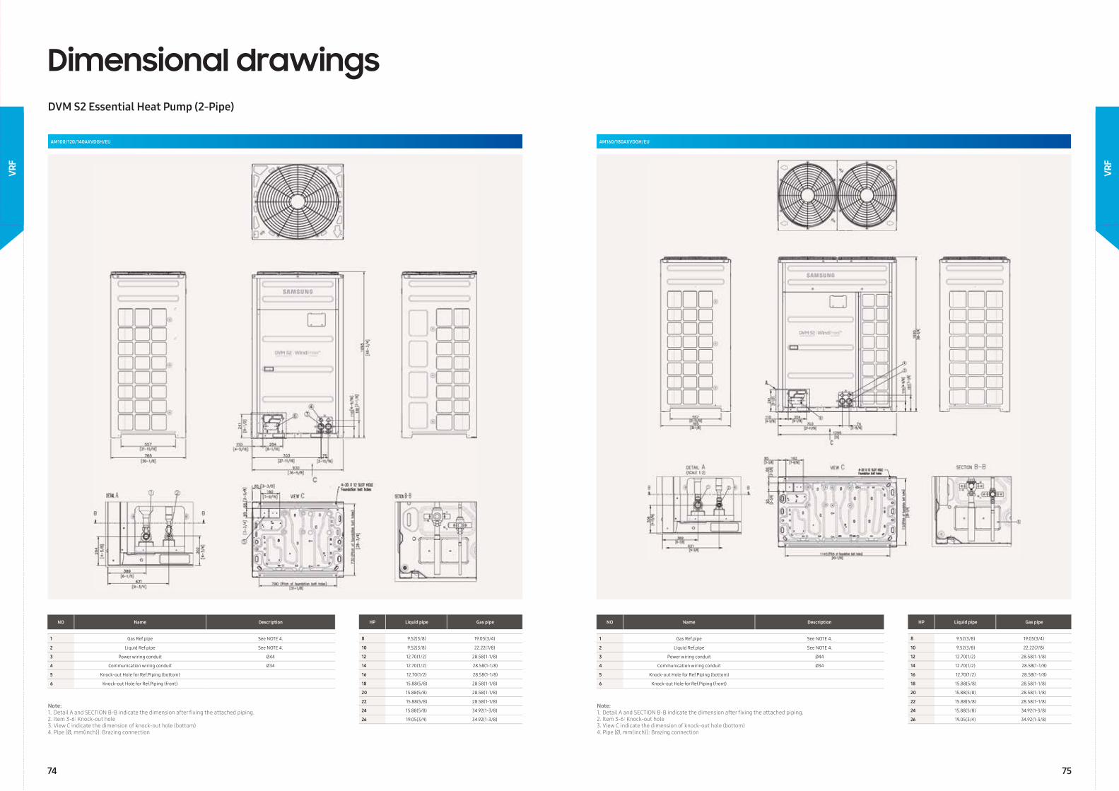
Dimensional drawingsDVM S2 Essential Heat Pump (2-Pipe)
AM100/120/140AXVDGH/EU AM160/180AXVDGH/EU
NO Name Description
1 Gas Ref.pipe See NOTE 4.
2 Liquid Ref.pipe See NOTE 4.
3 Power wiring conduit Ø44
4 Communication wiring conduit Ø34
5 Knock-out Hole for Ref.Piping (bottom)
6 Knock-out Hole for Ref.Piping (front)
NO Name Description
1 Gas Ref.pipe See NOTE 4.
2 Liquid Ref.pipe See NOTE 4.
3 Power wiring conduit Ø44
4 Communication wiring conduit Ø34
5 Knock-out Hole for Ref.Piping (bottom)
6 Knock-out Hole for Ref.Piping (front)
HP Liquid pipe Gas pipe
8 9.52(3/8) 19.05(3/4)
10 9.52(3/8) 22.22(7/8)
12 12.70(1/2) 28.58(1-1/8)
14 12.70(1/2) 28.58(1-1/8)
16 12.70(1/2) 28.58(1-1/8)
18 15.88(5/8) 28.58(1-1/8)
20 15.88(5/8) 28.58(1-1/8)
22 15.88(5/8) 28.58(1-1/8)
24 15.88(5/8) 34.92(1-3/8)
26 19.05(3/4) 34.92(1-3/8)
HP Liquid pipe Gas pipe
8 9.52(3/8) 19.05(3/4)
10 9.52(3/8) 22.22(7/8)
12 12.70(1/2) 28.58(1-1/8)
14 12.70(1/2) 28.58(1-1/8)
16 12.70(1/2) 28.58(1-1/8)
18 15.88(5/8) 28.58(1-1/8)
20 15.88(5/8) 28.58(1-1/8)
22 15.88(5/8) 28.58(1-1/8)
24 15.88(5/8) 34.92(1-3/8)
26 19.05(3/4) 34.92(1-3/8)
Note:1. Detail A and SECTION B-B indicate the dimension after fi xing the attached piping.2. Item 3-6: Knock-out hole3. View C indicate the dimension of knock-out hole (bottom)4. Pipe [Ø, mm(inch)]: Brazing connection
Note:1. Detail A and SECTION B-B indicate the dimension after fi xing the attached piping.2. Item 3-6: Knock-out hole3. View C indicate the dimension of knock-out hole (bottom)4. Pipe [Ø, mm(inch)]: Brazing connection
74 75
VRF
VRF
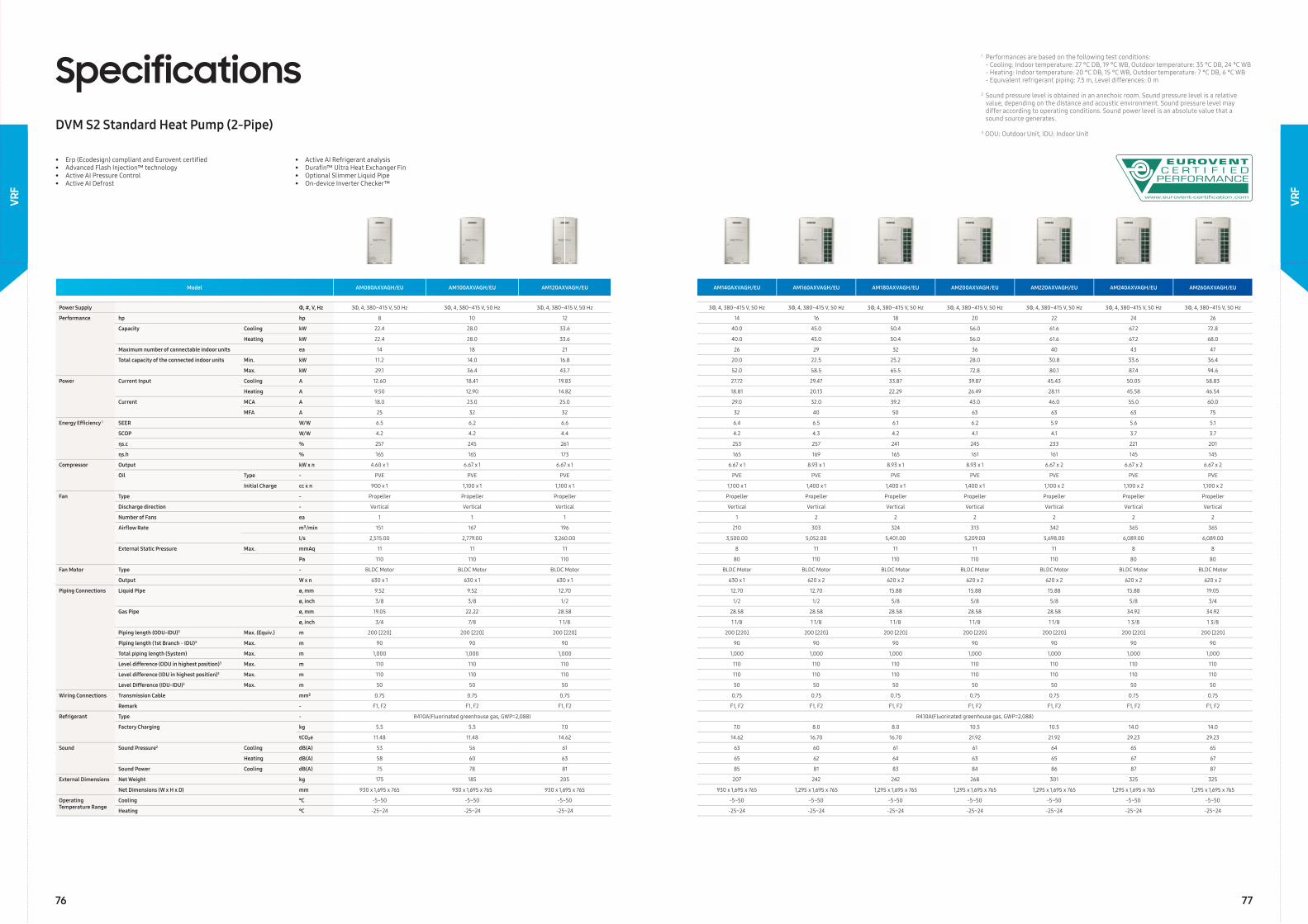
• Erp (Ecodesign) compliant and Eurovent certifi ed• Advanced Flash Injection™ technology• Active AI Pressure Control• Active AI Defrost
• Active AI Refrigerant analysis• Durafi n™ Ultra Heat Exchanger Fin• Optional Slimmer Liquid Pipe• On-device Inverter Checker™
Model AM080AXVAGH/EU AM100AXVAGH/EU AM120AXVAGH/EU AM140AXVAGH/EU AM160AXVAGH/EU AM180AXVAGH/EU AM200AXVAGH/EU AM220AXVAGH/EU AM240AXVAGH/EU AM260AXVAGH/EU
Power Supply Φ, #, V, Hz 3Φ, 4, 380–415 V, 50 Hz 3Φ, 4, 380–415 V, 50 Hz 3Φ, 4, 380–415 V, 50 Hz 3Φ, 4, 380–415 V, 50 Hz 3Φ, 4, 380–415 V, 50 Hz 3Φ, 4, 380–415 V, 50 Hz 3Φ, 4, 380–415 V, 50 Hz 3Φ, 4, 380–415 V, 50 Hz 3Φ, 4, 380–415 V, 50 Hz 3Φ, 4, 380–415 V, 50 Hz
Performance hp hp 8 10 12 14 16 18 20 22 24 26
Capacity Cooling kW 22.4 28.0 33.6 40.0 45.0 50.4 56.0 61.6 67.2 72.8
Heating kW 22.4 28.0 33.6 40.0 45.0 50.4 56.0 61.6 67.2 68.0
Maximum number of connectable indoor units ea 14 18 21 26 29 32 36 40 43 47
Total capacity of the connected indoor units Min. kW 11.2 14.0 16.8 20.0 22.5 25.2 28.0 30.8 33.6 36.4
Max. kW 29.1 36.4 43.7 52.0 58.5 65.5 72.8 80.1 87.4 94.6
Power Current Input Cooling A 12.60 18.41 19.83 27.72 29.47 33.87 39.87 45.43 50.05 58.83
Heating A 9.50 12.90 14.82 18.81 20.13 22.29 26.49 28.11 45.58 46.54
Current MCA A 18.0 23.0 25.0 29.0 32.0 39.2 43.0 46.0 55.0 60.0
MFA A 25 32 32 32 40 50 63 63 63 75
Energy Effi ciency 1 SEER W/W 6.5 6.2 6.6 6.4 6.5 6.1 6.2 5.9 5.6 5.1
SCOP W/W 4.2 4.2 4.4 4.2 4.3 4.2 4.1 4.1 3.7 3.7
ηs.c % 257 245 261 253 257 241 245 233 221 201
ηs.h % 165 165 173 165 169 165 161 161 145 145
Compressor Output kW x n 4.60 x 1 6.67 x 1 6.67 x 1 6.67 x 1 8.93 x 1 8.93 x 1 8.93 x 1 6.67 x 2 6.67 x 2 6.67 x 2
Oil Type - PVE PVE PVE PVE PVE PVE PVE PVE PVE PVE
Initial Charge cc x n 900 x 1 1,100 x 1 1,100 x 1 1,100 x 1 1,400 x 1 1,400 x 1 1,400 x 1 1,100 x 2 1,100 x 2 1,100 x 2
Fan Type - Propeller Propeller Propeller Propeller Propeller Propeller Propeller Propeller Propeller Propeller
Discharge direction - Vertical Vertical Vertical Vertical Vertical Vertical Vertical Vertical Vertical Vertical
Number of Fans ea 1 1 1 1 2 2 2 2 2 2
Airfl ow Rate m³/min 151 167 196 210 303 324 313 342 365 365
l/s 2,515.00 2,779.00 3,260.00 3,500.00 5,052.00 5,401.00 5,209.00 5,698.00 6,089.00 6,089.00
External Static Pressure Max. mmAq 11 11 11 8 11 11 11 11 8 8
Pa 110 110 110 80 110 110 110 110 80 80
Fan Motor Type - BLDC Motor BLDC Motor BLDC Motor BLDC Motor BLDC Motor BLDC Motor BLDC Motor BLDC Motor BLDC Motor BLDC Motor
Output W x n 630 x 1 630 x 1 630 x 1 630 x 1 620 x 2 620 x 2 620 x 2 620 x 2 620 x 2 620 x 2
Piping Connections Liquid Pipe ø, mm 9.52 9.52 12.70 12.70 12.70 15.88 15.88 15.88 15.88 19.05
ø, inch 3/8 3/8 1/2 1/2 1/2 5/8 5/8 5/8 5/8 3/4
Gas Pipe ø, mm 19.05 22.22 28.58 28.58 28.58 28.58 28.58 28.58 34.92 34.92
ø, inch 3/4 7/8 1 1/8 1 1/8 1 1/8 1 1/8 1 1/8 1 1/8 1 3/8 1 3/8
Piping length (ODU-IDU)3 Max. (Equiv.) m 200 [220] 200 [220] 200 [220] 200 [220] 200 [220] 200 [220] 200 [220] 200 [220] 200 [220] 200 [220]
Piping length (1st Branch - IDU)3 Max. m 90 90 90 90 90 90 90 90 90 90
Total piping length (System) Max. m 1,000 1,000 1,000 1,000 1,000 1,000 1,000 1,000 1,000 1,000
Level difference (ODU in highest position)3 Max. m 110 110 110 110 110 110 110 110 110 110
Level difference (IDU in highest position)3 Max. m 110 110 110 110 110 110 110 110 110 110
Level Difference (IDU-IDU)3 Max. m 50 50 50 50 50 50 50 50 50 50
Wiring Connections Transmission Cable mm² 0.75 0.75 0.75 0.75 0.75 0.75 0.75 0.75 0.75 0.75
Remark - F1, F2 F1, F2 F1, F2 F1, F2 F1, F2 F1, F2 F1, F2 F1, F2 F1, F2 F1, F2
Refrigerant Type - R410A(Fluorinated greenhouse gas, GWP=2,088) R410A(Fluorinated greenhouse gas, GWP=2,088)
Factory Charging kg 5.5 5.5 7.0 7.0 8.0 8.0 10.5 10.5 14.0 14.0
tCO₂e 11.48 11.48 14.62 14.62 16.70 16.70 21.92 21.92 29.23 29.23
Sound Sound Pressure2 Cooling dB(A) 53 56 61 63 60 61 61 64 65 65
Heating dB(A) 58 60 63 65 62 64 63 65 67 67
Sound Power Cooling dB(A) 75 78 81 85 81 83 84 86 87 87
External Dimensions Net Weight kg 175 185 205 207 242 242 268 301 325 325
Net Dimensions (W x H x D) mm 930 x 1,695 x 765 930 x 1,695 x 765 930 x 1,695 x 765 930 x 1,695 x 765 1,295 x 1,695 x 765 1,295 x 1,695 x 765 1,295 x 1,695 x 765 1,295 x 1,695 x 765 1,295 x 1,695 x 765 1,295 x 1,695 x 765
Operating Temperature Range
Cooling ℃ -5~50 -5~50 -5~50 -5~50 -5~50 -5~50 -5~50 -5~50 -5~50 -5~50
Heating ℃ -25~24 -25~24 -25~24 -25~24 -25~24 -25~24 -25~24 -25~24 -25~24 -25~24
SpecificationsDVM S2 Standard Heat Pump (2-Pipe)
1 Performances are based on the following test conditions: - Cooling: Indoor temperature: 27 °C DB, 19 °C WB, Outdoor temperature: 35 °C DB, 24 °C WB - Heating: Indoor temperature: 20 °C DB, 15 °C WB, Outdoor temperature: 7 °C DB, 6 °C WB - Equivalent refrigerant piping: 7.5 m, Level differences: 0 m
2 Sound pressure level is obtained in an anechoic room. Sound pressure level is a relative value, depending on the distance and acoustic environment. Sound pressure level may differ according to operating conditions. Sound power level is an absolute value that a sound source generates.
3 ODU: Outdoor Unit, IDU: Indoor Unit
76 77
VRF
VRF
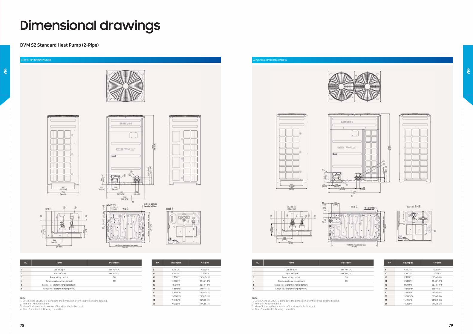
Dimensional drawingsDVM S2 Standard Heat Pump (2-Pipe)
AM080/100/120/140AXVAGH/EU AM160/180/200/240/260AXVAGH/EU
NO Name Description
1 Gas Ref.pipe See NOTE 4.
2 Liquid Ref.pipe See NOTE 4.
3 Power wiring conduit Ø44
4 Communication wiring conduit Ø34
5 Knock-out Hole for Ref.Piping (bottom)
6 Knock-out Hole for Ref.Piping (front)
NO Name Description
1 Gas Ref.pipe See NOTE 4.
2 Liquid Ref.pipe See NOTE 4.
3 Power wiring conduit Ø44
4 Communication wiring conduit Ø34
5 Knock-out Hole for Ref.Piping (bottom)
6 Knock-out Hole for Ref.Piping (front)
HP Liquid pipe Gas pipe
8 9.52(3/8) 19.05(3/4)
10 9.52(3/8) 22.22(7/8)
12 12.70(1/2) 28.58(1-1/8)
14 12.70(1/2) 28.58(1-1/8)
16 12.70(1/2) 28.58(1-1/8)
18 15.88(5/8) 28.58(1-1/8)
20 15.88(5/8) 28.58(1-1/8)
22 15.88(5/8) 28.58(1-1/8)
24 15.88(5/8) 34.92(1-3/8)
26 19.05(3/4) 34.92(1-3/8)
HP Liquid pipe Gas pipe
8 9.52(3/8) 19.05(3/4)
10 9.52(3/8) 22.22(7/8)
12 12.70(1/2) 28.58(1-1/8)
14 12.70(1/2) 28.58(1-1/8)
16 12.70(1/2) 28.58(1-1/8)
18 15.88(5/8) 28.58(1-1/8)
20 15.88(5/8) 28.58(1-1/8)
22 15.88(5/8) 28.58(1-1/8)
24 15.88(5/8) 34.92(1-3/8)
26 19.05(3/4) 34.92(1-3/8)
Note:1. Detail A and SECTION B-B indicate the dimension after fi xing the attached piping.2. Item 3-6: Knock-out hole3. View C indicate the dimension of knock-out hole (bottom)4. Pipe [Ø, mm(inch)]: Brazing connection
Note:1. Detail A and SECTION B-B indicate the dimension after fi xing the attached piping.2. Item 3-6: Knock-out hole3. View C indicate the dimension of knock-out hole (bottom)4. Pipe [Ø, mm(inch)]: Brazing connection
78 79
VRF
VRF
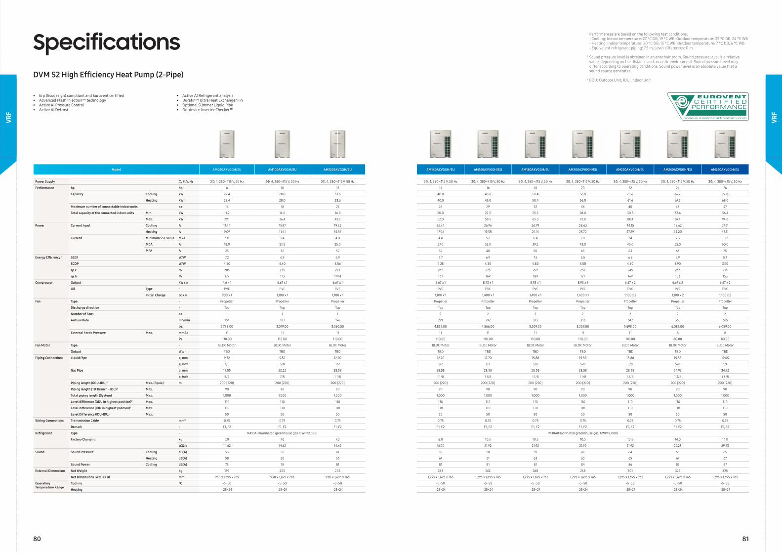
• Erp (Ecodesign) compliant and Eurovent certifi ed• Advanced Flash Injection™ technology• Active AI Pressure Control• Active AI Defrost
• Active AI Refrigerant analysis• Durafi n™ Ultra Heat Exchanger Fin• Optional Slimmer Liquid Pipe• On-device Inverter Checker™
SpecificationsDVM S2 High Effi ciency Heat Pump (2-Pipe)
Model AM080AXVGGH/EU AM100AXVGGH/EU AM120AXVGGH/EU AM140AXVGGH/EU AM160AXVGGH/EU AM180AXVGGH/EU AM200AXVGGH/EU AM220AXVGGH/EU AM240AXVGGH/EU AM260AXVGGH/EU
Power Supply Φ, #, V, Hz 3Φ, 4, 380–415 V, 50 Hz 3Φ, 4, 380–415 V, 50 Hz 3Φ, 4, 380–415 V, 50 Hz 3Φ, 4, 380–415 V, 50 Hz 3Φ, 4, 380–415 V, 50 Hz 3Φ, 4, 380–415 V, 50 Hz 3Φ, 4, 380–415 V, 50 Hz 3Φ, 4, 380–415 V, 50 Hz 3Φ, 4, 380–415 V, 50 Hz 3Φ, 4, 380–415 V, 50 Hz
Performance hp hp 8 10 12 14 16 18 20 22 24 26
Capacity Cooling kW 22.4 28.0 33.6 40.0 45.0 50.4 56.0 61.6 67.2 72.8
Heating kW 22.4 28.0 33.6 40.0 45.0 50.4 56.0 61.6 67.2 68.0
Maximum number of connectable indoor units ea 14 18 21 26 29 32 36 40 43 47
Total capacity of the connected indoor units Min. kW 11.2 14.0 16.8 20.0 22.5 25.2 28.0 30.8 33.6 36.4
Max. kW 29.1 36.4 43.7 52.0 58.5 65.5 72.8 80.1 87.4 94.6
Power Current Input Cooling A 11.44 15.97 19.25 25.44 26.96 26.79 38.63 44.15 48.62 57.61
Heating A 9.09 11.41 14.37 17.06 19.35 21.14 25.72 27.29 44.20 45.11
Current Minimum SSC value MVA 3.0 3.4 4.0 4.4 5.2 6.4 7.0 7.4 9.3 10.2
MCA A 18.0 21.2 25.0 27.0 32.0 39.2 43.0 46.0 55.0 60.0
MFA A 25 32 32 32 40 50 63 63 63 75
Energy Effi ciency 1 SEER W/W 7.2 6.9 6.9 6.7 6.9 7.5 6.5 6.2 5.9 5.4
SCOP W/W 4.50 4.40 4.56 4.25 4.30 4.80 4.50 4.30 3.90 3.90
ηs.c % 285 273 273 265 273 297 257 245 233 213
ηs.h % 177 173 179.4 167 169 189 177 169 153 153
Compressor Output kW x n 4.6 x 1 6.67 x 1 6.67 x 1 6.67 x 1 8.93 x 1 8.93 x 1 8.93 x 1 6.67 x 2 6.67 x 2 6.67 x 2
Oil Type - PVE PVE PVE PVE PVE PVE PVE PVE PVE PVE
Initial Charge cc x n 900 x 1 1,100 x 1 1,100 x 1 1,100 x 1 1,400 x 1 1,400 x 1 1,400 x 1 1,100 x 2 1,100 x 2 1,100 x 2
Fan Type - Propeller Propeller Propeller Propeller Propeller Propeller Propeller Propeller Propeller Propeller
Discharge direction - Top Top Top Top Top Top Top Top Top Top
Number of Fans ea 1 1 1 2 2 2 2 2 2 2
Airfl ow Rate m³/min 164 181 196 291 292 313 313 342 365 365
l/s 2,738.00 3,019.00 3,260.00 4,852.00 4,866.00 5,209.00 5,209.00 5,698.00 6,089.00 6,089.00
External Static Pressure Max. mmAq 11 11 11 11 11 11 11 11 8 8
Pa 110.00 110.00 110.00 110.00 110.00 110.00 110.00 110.00 80.00 80.00
Fan Motor Type - BLDC Motor BLDC Motor BLDC Motor BLDC Motor BLDC Motor BLDC Motor BLDC Motor BLDC Motor BLDC Motor BLDC Motor
Output W x n TBD TBD TBD TBD TBD TBD TBD TBD TBD TBD
Piping Connections Liquid Pipe ø, mm 9.52 9.52 12.70 12.70 12.70 15.88 15.88 15.88 15.88 19.05
ø, inch 3/8 3/8 1/2 1/2 1/2 5/8 5/8 5/8 5/8 3/4
Gas Pipe ø, mm 19.05 22.22 28.58 28.58 28.58 28.58 28.58 28.58 34.92 34.92
ø, inch 3/4 7/8 1 1/8 1 1/8 1 1/8 1 1/8 1 1/8 1 1/8 1 3/8 1 3/8
Piping length (ODU-IDU)3 Max. (Equiv.) m 200 [220] 200 [220] 200 [220] 200 [220] 200 [220] 200 [220] 200 [220] 200 [220] 200 [220] 200 [220]
Piping length (1st Branch - IDU)3 Max. 90 90 90 90 90 90 90 90 90 90
Total piping length (System) Max. 1,000 1,000 1,000 1,000 1,000 1,000 1,000 1,000 1,000 1,000
Level difference (ODU in highest position)3 Max. 110 110 110 110 110 110 110 110 110 110
Level difference (IDU in highest position)3 Max. 110 110 110 110 110 110 110 110 110 110
Level Difference (IDU-IDU)3 Max. 50 50 50 50 50 50 50 50 50 50
Wiring Connections Transmission Cable mm² 0.75 0.75 0.75 0.75 0.75 0.75 0.75 0.75 0.75 0.75
Remark - F1, F2 F1, F2 F1, F2 F1, F2 F1, F2 F1, F2 F1, F2 F1, F2 F1, F2 F1, F2
Refrigerant Type - R410A(Fluorinated greenhouse gas, GWP=2,088) R410A(Fluorinated greenhouse gas, GWP=2,088)
Factory Charging kg 7.0 7.0 7.0 8.0 10.5 10.5 10.5 10.5 14.0 14.0
tCO₂e 14.62 14.62 14.62 16.70 21.92 21.92 21.92 21.92 29.23 29.23
Sound Sound Pressure2 Cooling dB(A) 53 56 61 58 58 59 61 64 65 65
Heating dB(A) 58 60 63 61 61 63 63 65 67 67
Sound Power Cooling dB(A) 75 78 81 81 81 81 84 86 87 87
External Dimensions Net Weight kg 194 205 205 233 262 268 268 301 325 325
Net Dimensions (W x H x D) mm 930 x 1,695 x 765 930 x 1,695 x 765 930 x 1,695 x 765 1,295 x 1,695 x 765 1,295 x 1,695 x 765 1,295 x 1,695 x 765 1,295 x 1,695 x 765 1,295 x 1,695 x 765 1,295 x 1,695 x 765 1,295 x 1,695 x 765
Operating Temperature Range
Cooling ℃ -5~50 -5~50 -5~50 -5~50 -5~50 -5~50 -5~50 -5~50 -5~50 -5~50
Heating -25~24 -25~24 -25~24 -25~24 -25~24 -25~24 -25~24 -25~24 -25~24 -25~24
1 Performances are based on the following test conditions: - Cooling: Indoor temperature: 27 °C DB, 19 °C WB, Outdoor temperature: 35 °C DB, 24 °C WB - Heating: Indoor temperature: 20 °C DB, 15 °C WB, Outdoor temperature: 7 °C DB, 6 °C WB - Equivalent refrigerant piping: 7.5 m, Level differences: 0 m
2 Sound pressure level is obtained in an anechoic room. Sound pressure level is a relative value, depending on the distance and acoustic environment. Sound pressure level may differ according to operating conditions. Sound power level is an absolute value that a sound source generates.
3 ODU: Outdoor Unit, IDU: Indoor Unit
80 81
VRF
VRF

Dimensional drawingsDVM S2 High Effi ciency Heat Pump (2-Pipe)
AM080/100/120AXVGGH/EU AM140/160/180/200/240/260AXVGGH/EU
NO Name Description
1 Gas Ref.pipe See NOTE 4.
2 Liquid Ref.pipe See NOTE 4.
3 Power wiring conduit Ø44
4 Communication wiring conduit Ø34
5 Knock-out Hole for Ref.Piping (bottom)
6 Knock-out Hole for Ref.Piping (front)
NO Name Description
1 Gas Ref.pipe See NOTE 4.
2 Liquid Ref.pipe See NOTE 4.
3 Power wiring conduit Ø44
4 Communication wiring conduit Ø34
5 Knock-out Hole for Ref.Piping (bottom)
6 Knock-out Hole for Ref.Piping (front)
HP Liquid pipe Gas pipe
8 9.52(3/8) 19.05(3/4)
10 9.52(3/8) 22.22(7/8)
12 12.70(1/2) 28.58(1-1/8)
14 12.70(1/2) 28.58(1-1/8)
16 12.70(1/2) 28.58(1-1/8)
18 15.88(5/8) 28.58(1-1/8)
20 15.88(5/8) 28.58(1-1/8)
22 15.88(5/8) 28.58(1-1/8)
24 15.88(5/8) 34.92(1-3/8)
26 19.05(3/4) 34.92(1-3/8)
HP Liquid pipe Gas pipe
8 9.52(3/8) 19.05(3/4)
10 9.52(3/8) 22.22(7/8)
12 12.70(1/2) 28.58(1-1/8)
14 12.70(1/2) 28.58(1-1/8)
16 12.70(1/2) 28.58(1-1/8)
18 15.88(5/8) 28.58(1-1/8)
20 15.88(5/8) 28.58(1-1/8)
22 15.88(5/8) 28.58(1-1/8)
24 15.88(5/8) 34.92(1-3/8)
26 19.05(3/4) 34.92(1-3/8)
Note:1. Detail A and SECTION B-B indicate the dimension after fi xing the attached piping.2. Item 3-6: Knock-out hole3. View C indicate the dimension of knock-out hole (bottom)4. Pipe [Ø, mm(inch)]: Brazing connection
Note:1. Detail A and SECTION B-B indicate the dimension after fi xing the attached piping.2. Item 3-6: Knock-out hole3. View C indicate the dimension of knock-out hole (bottom)4. Pipe [Ø, mm(inch)]: Brazing connection
82 83
VRF
VRF
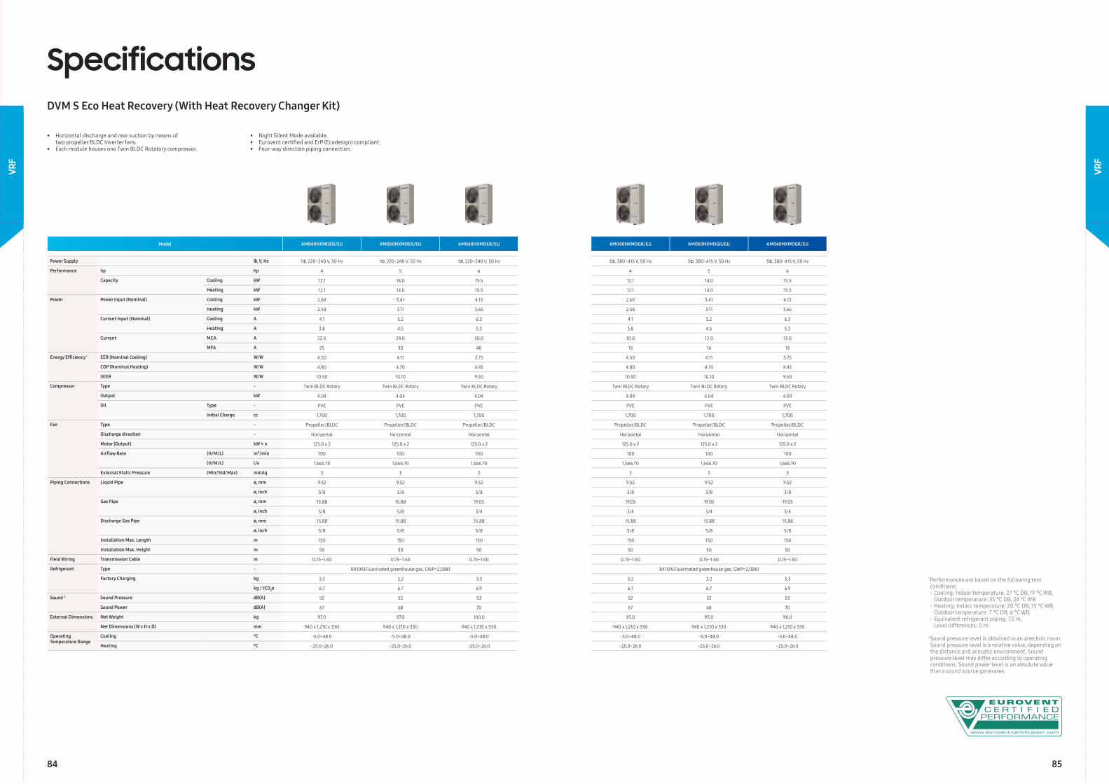
Model AM040NXMDER/EU AM050NXMDER/EU AM060NXMDER/EU AM040NXMDGR/EU AM050NXMDGR/EU AM060NXMDGR/EU
Power Supply Φ, V, Hz 1Φ, 220~240 V, 50 Hz 1Φ, 220~240 V, 50 Hz 1Φ, 220~240 V, 50 Hz 3Φ, 380~415 V, 50 Hz 3Φ, 380~415 V, 50 Hz 3Φ, 380~415 V, 50 Hz
Performance hp hp 4 5 6 4 5 6
Capacity Cooling kW 12.1 14.0 15.5 12.1 14.0 15.5
Heating kW 12.1 14.0 15.5 12.1 14.0 15.5
Power Power Input (Nominal) Cooling kW 2.69 3.41 4.13 2.69 3.41 4.13
Heating kW 2.58 3.11 3.65 2.58 3.11 3.65
Current Input (Nominal) Cooling A 4.1 5.2 6.3 4.1 5.2 6.3
Heating A 3.8 4.5 5.3 3.8 4.5 5.3
Current MCA A 22.0 24.0 30.0 10.0 12.0 12.0
MFA A 25 30 40 16 16 16
Energy Effi ciency 1 EER (Nominal Cooling) W/W 4.50 4.11 3.75 4.50 4.11 3.75
COP (Nominal Heating) W/W 4.80 4.70 4.45 4.80 4.70 4.45
SEER W/W 10.50 10.10 9.50 10.50 10.10 9.50
Compressor Type - Twin BLDC Rotary Twin BLDC Rotary Twin BLDC Rotary Twin BLDC Rotary Twin BLDC Rotary Twin BLDC Rotary
Output kW 4.04 4.04 4.04 4.04 4.04 4.04
Oil Type - PVE PVE PVE PVE PVE PVE
Initial Charge cc 1,700 1,700 1,700 1,700 1,700 1,700
Fan Type - Propeller/BLDC Propeller/BLDC Propeller/BLDC Propeller/BLDC Propeller/BLDC Propeller/BLDC
Discharge direction - Horizontal Horizontal Horizontal Horizontal Horizontal Horizontal
Motor (Output) kW × n 125.0 x 2 125.0 x 2 125.0 x 2 125.0 x 2 125.0 x 2 125.0 x 2
Airfl ow Rate (H/M/L) m³/min 100 100 100 100 100 100
(H/M/L) l/s 1,666.70 1,666.70 1,666.70 1,666.70 1,666.70 1,666.70
External Static Pressure (Min/Std/Max) mmAq 3 3 3 3 3 3
Piping Connections Liquid Pipe ø, mm 9.52 9.52 9.52 9.52 9.52 9.52
ø, inch 3/8 3/8 3/8 3/8 3/8 3/8
Gas Pipe ø, mm 15.88 15.88 19.05 19.05 19.05 19.05
ø, inch 5/8 5/8 3/4 3/4 3/4 3/4
Discharge Gas Pipe ø, mm 15.88 15.88 15.88 15.88 15.88 15.88
ø, inch 5/8 5/8 5/8 5/8 5/8 5/8
Installation Max. Length m 150 150 150 150 150 150
Installation Max. Height m 50 50 50 50 50 50
Field Wiring Transmission Cable m 0.75~1.50 0.75~1.50 0.75~1.50 0.75~1.50 0.75~1.50 0.75~1.50
Refrigerant Type - R410A(Fluorinated greenhouse gas, GWP=2,088) R410A(Fluorinated greenhouse gas, GWP=2,088)
Factory Charging kg 3.2 3.2 3.3 3.2 3.2 3.3
kg / tCO2e 6.7 6.7 6.9 6.7 6.7 6.9
Sound 2 Sound Pressure dB(A) 52 52 53 52 52 53
Sound Power dB(A) 67 68 70 67 68 70
External Dimensions Net Weight kg 97.0 97.0 100.0 95.0 95.0 98.0
Net Dimensions (W x H x D) mm 940 x 1,210 x 330 940 x 1,210 x 330 940 x 1,210 x 330 940 x 1,210 x 330 940 x 1,210 x 330 940 x 1,210 x 330
Operating Temperature Range
Cooling ℃ -5.0~48.0 -5.0~48.0 -5.0~48.0 -5.0~48.0 -5.0~48.0 -5.0~48.0
Heating ℃ -25.0~26.0 -25.0~26.0 -25.0~26.0 -25.0~26.0 -25.0~26.0 -25.0~26.0
SpecificationsDVM S Eco Heat Recovery (With Heat Recovery Changer Kit)
1 Performances are based on the following test conditions:- Cooling: Indoor temperature: 27 °C DB, 19 °C WB, Outdoor temperature: 35 °C DB, 24 °C WB - Heating: Indoor temperature: 20 °C DB, 15 °C WB, Outdoor temperature: 7 °C DB, 6 °C WB- Equivalent refrigerant piping: 7.5 m, Level differences: 0 m
2 Sound pressure level is obtained in an anechoic room. Sound pressure level is a relative value, depending on the distance and acoustic environment. Sound pressure level may differ according to operating conditions. Sound power level is an absolute value that a sound source generates.
• Horizontal discharge and rear suction by means of two propeller BLDC Inverter fans.• Each module houses one Twin BLDC Rotatory compressor.
• Night Silent Mode available.• Eurovent certifi ed and ErP (Ecodesign) compliant. • Four-way direction piping connection.
84 85
VRF
VRF
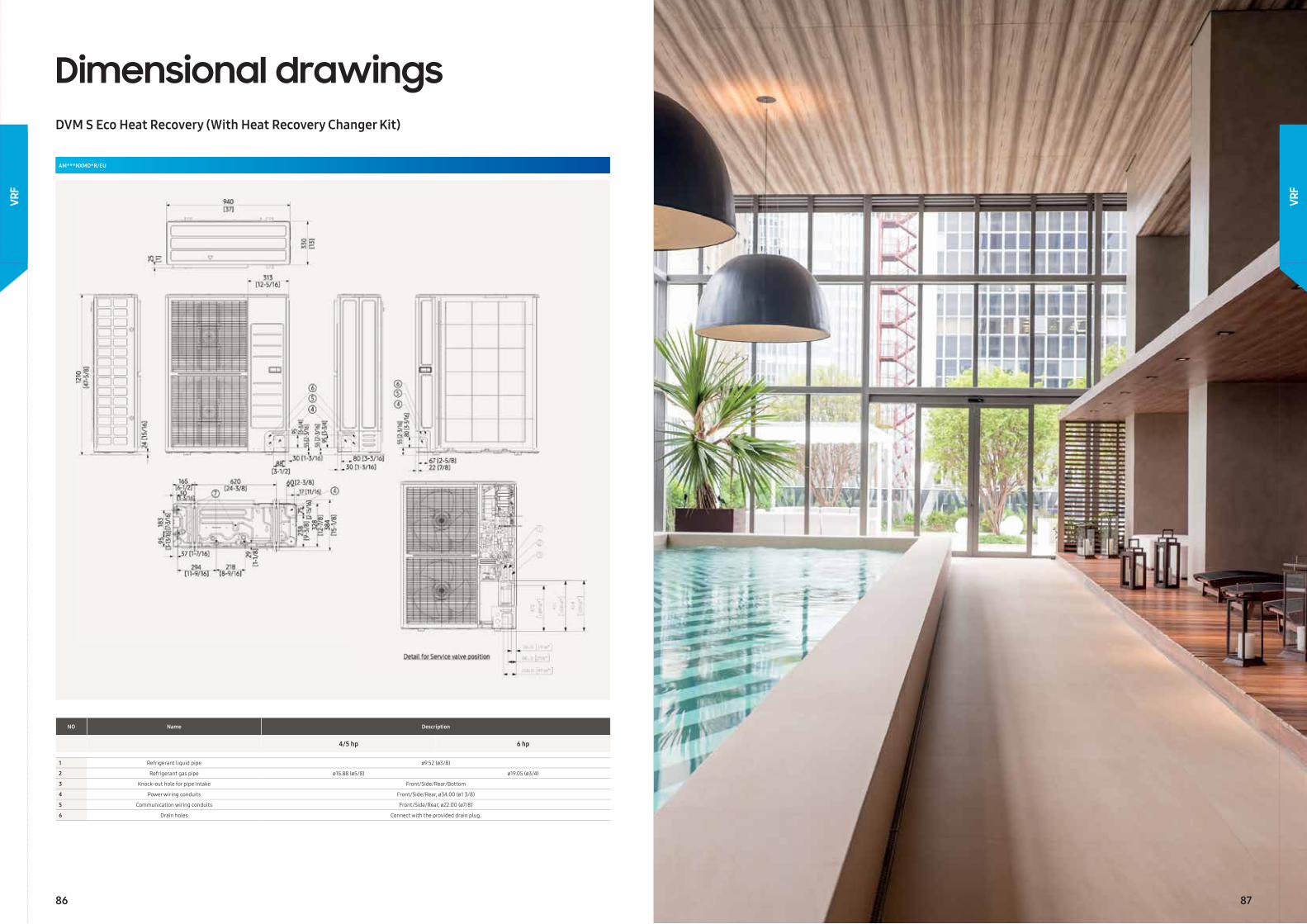
Dimensional drawingsDVM S Eco Heat Recovery (With Heat Recovery Changer Kit)
AM***NXMD*R/EU
NO Name Description
4/5 hp 6 hp
1 Refrigerant liquid pipe ø9.52 (ø3/8)
2 Refrigerant gas pipe ø15.88 (ø5/8) ø19.05 (ø3/4)
3 Knock-out hole for pipe intake Front/Side/Rear/Bottom
4 Power wiring conduits Front/Side/Rear, ø34.00 (ø1 3/8)
5 Communication wiring conduits Front/Side/Rear, ø22.00 (ø7/8)
6 Drain holes Connect with the provided drain plug.
86 87
VRF
VRF
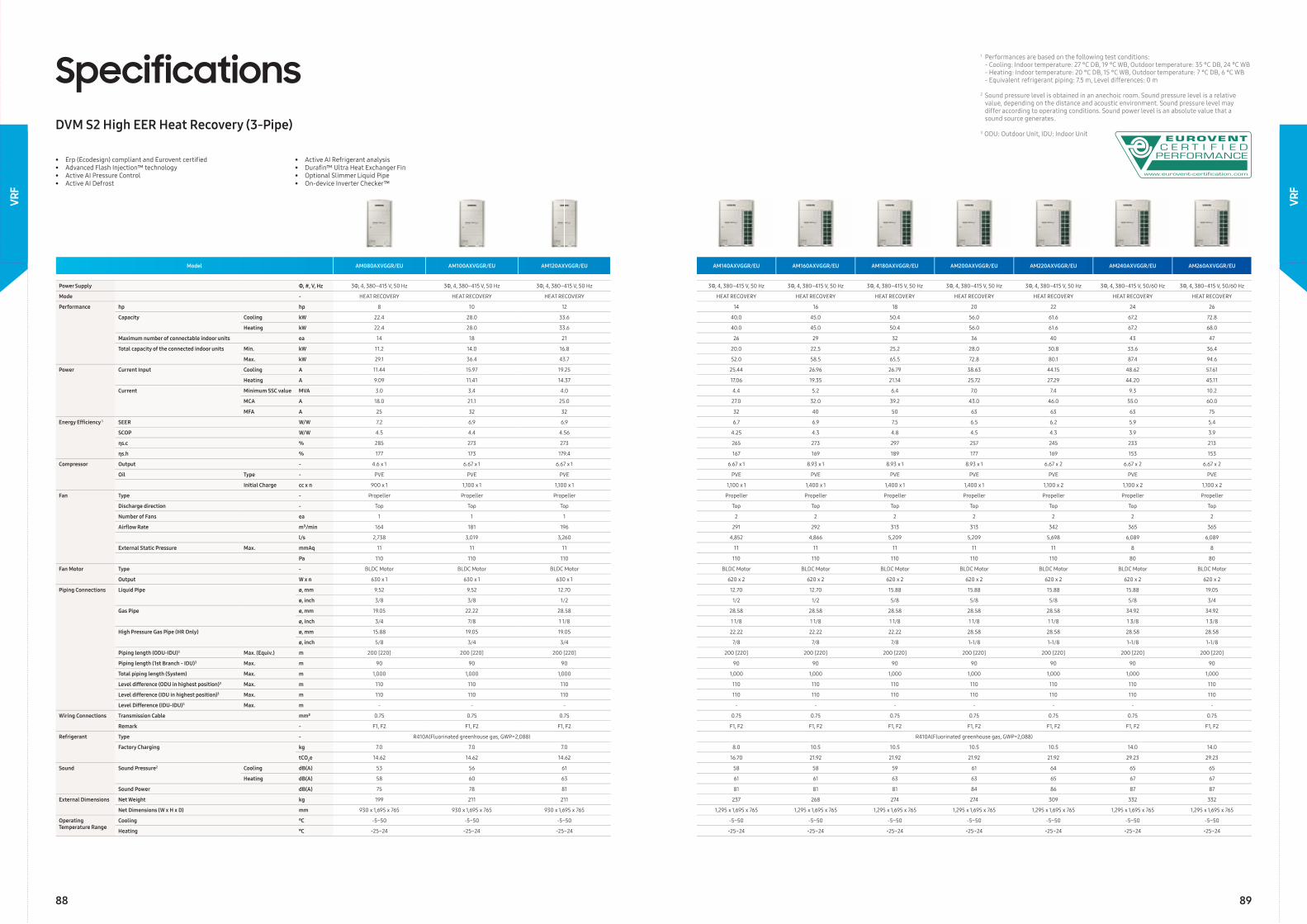
• Erp (Ecodesign) compliant and Eurovent certifi ed• Advanced Flash Injection™ technology• Active AI Pressure Control• Active AI Defrost
• Active AI Refrigerant analysis• Durafi n™ Ultra Heat Exchanger Fin• Optional Slimmer Liquid Pipe• On-device Inverter Checker™
SpecificationsDVM S2 High EER Heat Recovery (3-Pipe)
Model AM080AXVGGR/EU AM100AXVGGR/EU AM120AXVGGR/EU AM140AXVGGR/EU AM160AXVGGR/EU AM180AXVGGR/EU AM200AXVGGR/EU AM220AXVGGR/EU AM240AXVGGR/EU AM260AXVGGR/EU
Power Supply Φ, #, V, Hz 3Φ, 4, 380–415 V, 50 Hz 3Φ, 4, 380–415 V, 50 Hz 3Φ, 4, 380–415 V, 50 Hz 3Φ, 4, 380–415 V, 50 Hz 3Φ, 4, 380–415 V, 50 Hz 3Φ, 4, 380–415 V, 50 Hz 3Φ, 4, 380–415 V, 50 Hz 3Φ, 4, 380–415 V, 50 Hz 3Φ, 4, 380–415 V, 50/60 Hz 3Φ, 4, 380–415 V, 50/60 Hz
Mode - HEAT RECOVERY HEAT RECOVERY HEAT RECOVERY HEAT RECOVERY HEAT RECOVERY HEAT RECOVERY HEAT RECOVERY HEAT RECOVERY HEAT RECOVERY HEAT RECOVERY
Performance hp hp 8 10 12 14 16 18 20 22 24 26
Capacity Cooling kW 22.4 28.0 33.6 40.0 45.0 50.4 56.0 61.6 67.2 72.8
Heating kW 22.4 28.0 33.6 40.0 45.0 50.4 56.0 61.6 67.2 68.0
Maximum number of connectable indoor units ea 14 18 21 26 29 32 36 40 43 47
Total capacity of the connected indoor units Min. kW 11.2 14.0 16.8 20.0 22.5 25.2 28.0 30.8 33.6 36.4
Max. kW 29.1 36.4 43.7 52.0 58.5 65.5 72.8 80.1 87.4 94.6
Power Current Input Cooling A 11.44 15.97 19.25 25.44 26.96 26.79 38.63 44.15 48.62 57.61
Heating A 9.09 11.41 14.37 17.06 19.35 21.14 25.72 27.29 44.20 45.11
Current Minimum SSC value MVA 3.0 3.4 4.0 4.4 5.2 6.4 7.0 7.4 9.3 10.2
MCA A 18.0 21.1 25.0 27.0 32.0 39.2 43.0 46.0 55.0 60.0
MFA A 25 32 32 32 40 50 63 63 63 75
Energy Effi ciency 1 SEER W/W 7.2 6.9 6.9 6.7 6.9 7.5 6.5 6.2 5.9 5.4
SCOP W/W 4.5 4.4 4.56 4.25 4.3 4.8 4.5 4.3 3.9 3.9
ηs.c % 285 273 273 265 273 297 257 245 233 213
ηs.h % 177 173 179.4 167 169 189 177 169 153 153
Compressor Output - 4.6 x 1 6.67 x 1 6.67 x 1 6.67 x 1 8.93 x 1 8.93 x 1 8.93 x 1 6.67 x 2 6.67 x 2 6.67 x 2
Oil Type - PVE PVE PVE PVE PVE PVE PVE PVE PVE PVE
Initial Charge cc x n 900 x 1 1,100 x 1 1,100 x 1 1,100 x 1 1,400 x 1 1,400 x 1 1,400 x 1 1,100 x 2 1,100 x 2 1,100 x 2
Fan Type - Propeller Propeller Propeller Propeller Propeller Propeller Propeller Propeller Propeller Propeller
Discharge direction - Top Top Top Top Top Top Top Top Top Top
Number of Fans ea 1 1 1 2 2 2 2 2 2 2
Airfl ow Rate m³/min 164 181 196 291 292 313 313 342 365 365
l/s 2,738 3,019 3,260 4,852 4,866 5,209 5,209 5,698 6,089 6,089
External Static Pressure Max. mmAq 11 11 11 11 11 11 11 11 8 8
Pa 110 110 110 110 110 110 110 110 80 80
Fan Motor Type - BLDC Motor BLDC Motor BLDC Motor BLDC Motor BLDC Motor BLDC Motor BLDC Motor BLDC Motor BLDC Motor BLDC Motor
Output W x n 630 x 1 630 x 1 630 x 1 620 x 2 620 x 2 620 x 2 620 x 2 620 x 2 620 x 2 620 x 2
Piping Connections Liquid Pipe ø, mm 9.52 9.52 12.70 12.70 12.70 15.88 15.88 15.88 15.88 19.05
ø, inch 3/8 3/8 1/2 1/2 1/2 5/8 5/8 5/8 5/8 3/4
Gas Pipe ø, mm 19.05 22.22 28.58 28.58 28.58 28.58 28.58 28.58 34.92 34.92
ø, inch 3/4 7/8 1 1/8 1 1/8 1 1/8 1 1/8 1 1/8 1 1/8 1 3/8 1 3/8
High Pressure Gas Pipe (HR Only) ø, mm 15.88 19.05 19.05 22.22 22.22 22.22 28.58 28.58 28.58 28.58
ø, inch 5/8 3/4 3/4 7/8 7/8 7/8 1-1/8 1-1/8 1-1/8 1-1/8
Piping length (ODU-IDU)3 Max. (Equiv.) m 200 [220] 200 [220] 200 [220] 200 [220] 200 [220] 200 [220] 200 [220] 200 [220] 200 [220] 200 [220]
Piping length (1st Branch - IDU)3 Max. m 90 90 90 90 90 90 90 90 90 90
Total piping length (System) Max. m 1,000 1,000 1,000 1,000 1,000 1,000 1,000 1,000 1,000 1,000
Level difference (ODU in highest position)3 Max. m 110 110 110 110 110 110 110 110 110 110
Level difference (IDU in highest position)3 Max. m 110 110 110 110 110 110 110 110 110 110
Level Difference (IDU-IDU)3 Max. m - - - - - - - - - -
Wiring Connections Transmission Cable mm² 0.75 0.75 0.75 0.75 0.75 0.75 0.75 0.75 0.75 0.75
Remark - F1, F2 F1, F2 F1, F2 F1, F2 F1, F2 F1, F2 F1, F2 F1, F2 F1, F2 F1, F2
Refrigerant Type - R410A(Fluorinated greenhouse gas, GWP=2,088) R410A(Fluorinated greenhouse gas, GWP=2,088)
Factory Charging kg 7.0 7.0 7.0 8.0 10.5 10.5 10.5 10.5 14.0 14.0
tCO2e 14.62 14.62 14.62 16.70 21.92 21.92 21.92 21.92 29.23 29.23
Sound Sound Pressure2 Cooling dB(A) 53 56 61 58 58 59 61 64 65 65
Heating dB(A) 58 60 63 61 61 63 63 65 67 67
Sound Power dB(A) 75 78 81 81 81 81 84 86 87 87
External Dimensions Net Weight kg 199 211 211 237 268 274 274 309 332 332
Net Dimensions (W x H x D) mm 930 x 1,695 x 765 930 x 1,695 x 765 930 x 1,695 x 765 1,295 x 1,695 x 765 1,295 x 1,695 x 765 1,295 x 1,695 x 765 1,295 x 1,695 x 765 1,295 x 1,695 x 765 1,295 x 1,695 x 765 1,295 x 1,695 x 765
Operating Temperature Range
Cooling ℃ -5~50 -5~50 -5~50 -5~50 -5~50 -5~50 -5~50 -5~50 -5~50 -5~50
Heating ℃ -25~24 -25~24 -25~24 -25~24 -25~24 -25~24 -25~24 -25~24 -25~24 -25~24
1 Performances are based on the following test conditions: - Cooling: Indoor temperature: 27 °C DB, 19 °C WB, Outdoor temperature: 35 °C DB, 24 °C WB - Heating: Indoor temperature: 20 °C DB, 15 °C WB, Outdoor temperature: 7 °C DB, 6 °C WB - Equivalent refrigerant piping: 7.5 m, Level differences: 0 m
2 Sound pressure level is obtained in an anechoic room. Sound pressure level is a relative value, depending on the distance and acoustic environment. Sound pressure level may differ according to operating conditions. Sound power level is an absolute value that a sound source generates.
3 ODU: Outdoor Unit, IDU: Indoor Unit
88 89
VRF
VRF
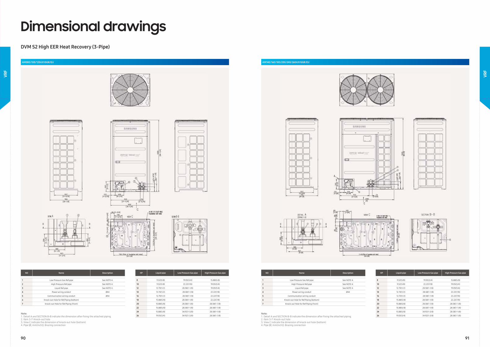
Dimensional drawingsDVM S2 High EER Heat Recovery (3-Pipe)
AM080/100/120AXVGGR/EU AM140/160/180/200/240/260AXVGGR/EU
NO Name Description
1 Low Pressure Gas Ref.pipe See NOTE 4.
2 High Pressure Ref.pipe See NOTE 4.
3 Liquid Ref.pipe See NOTE 4.
4 Power wiring conduit Ø44
5 Communication wiring conduit Ø34
6 Knock-out Hole for Ref.Piping (bottom)
7 Knock-out Hole for Ref.Piping (front)
NO Name Description
1 Low Pressure Gas Ref.pipe See NOTE 4.
2 High Pressure Ref.pipe See NOTE 4.
3 Liquid Ref.pipe See NOTE 4.
4 Power wiring conduit Ø44
5 Communication wiring conduit
6 Knock-out Hole for Ref.Piping (bottom)
7 Knock-out Hole for Ref.Piping (front)
HP Liquid pipe Low Pressure Gas pipe High Pressure Gas pipe
8 9.52(3/8) 19.05(3/4) 15.88(5/8)
10 9.52(3/8) 22.22(7/8) 19.05(3/4)
12 12.70(1/2) 28.58(1-1/8) 19.05(3/4)
14 12.70(1/2) 28.58(1-1/8) 22.22(7/8)
16 12.70(1/2) 28.58(1-1/8) 22.22(7/8)
18 15.88(5/8) 28.58(1-1/8) 22.22(7/8)
20 15.88(5/8) 28.58(1-1/8) 28.58(1-1/8)
22 15.88(5/8) 28.58(1-1/8) 28.58(1-1/8)
24 15.88(5/8) 34.92(1-3/8) 28.58(1-1/8)
26 19.05(3/4) 34.92(1-3/8) 28.58(1-1/8)
HP Liquid pipe Low Pressure Gas pipe High Pressure Gas pipe
8 9.52(3/8) 19.05(3/4) 15.88(5/8)
10 9.52(3/8) 22.22(7/8) 19.05(3/4)
12 12.70(1/2) 28.58(1-1/8) 19.05(3/4)
14 12.70(1/2) 28.58(1-1/8) 22.22(7/8)
16 12.70(1/2) 28.58(1-1/8) 22.22(7/8)
18 15.88(5/8) 28.58(1-1/8) 22.22(7/8)
20 15.88(5/8) 28.58(1-1/8) 28.58(1-1/8)
22 15.88(5/8) 28.58(1-1/8) 28.58(1-1/8)
24 15.88(5/8) 34.92(1-3/8) 28.58(1-1/8)
26 19.05(3/4) 34.92(1-3/8) 28.58(1-1/8)Note:1. Detail A and SECTION B-B indicate the dimension after fi xing the attached piping.2. Item 3-7: Knock-out hole3. View C indicate the dimension of knock-out hole (bottom)4. Pipe [Ø, mm(inch)]: Brazing connection
Note:1. Detail A and SECTION B-B indicate the dimension after fi xing the attached piping.2. Item 3-7: Knock-out hole3. View C indicate the dimension of knock-out hole (bottom)4. Pipe [Ø, mm(inch)]: Brazing connection
90 91
VRF
VRF
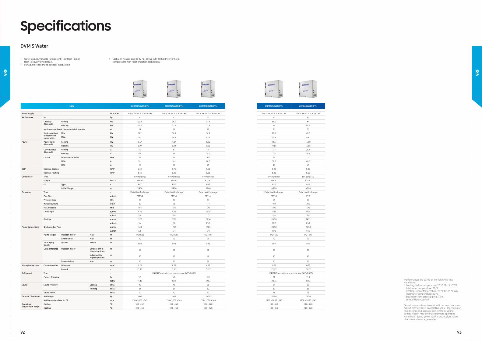
MkW AM080MXWANR/EU AM100MXWANR/EU AM120MXWANR/EU AM200MXWANR/EU AM300KXWANR/EU
Power Supply Φ, #, V, Hz 3Φ, 4, 380–415 V, 50/60 Hz 3Φ, 4, 380–415 V, 50/60 Hz 3Φ, 4, 380–415 V, 50/60 Hz 3Φ, 4, 380–415 V, 50/60 Hz 3Φ, 4, 380–415 V, 50/60 Hz
Performance hp hp 8 10 12 20 30
Capacity (Nominal)
Cooling kW 22.4 28.0 33.6 56.0 84
Heating kW 25.2 31.5 37.8 63 94.5
Maximum number of connectable indoor units ea 14 18 22 36 55
Total capacity of the connected indoor units
Min. kW 11.2 14.0 16.8 28.0 42.0
Max. kW 29.1 36.4 43.7 72.8 109.2
Power Power Input (Nominal)
Cooling kW 3.67 4.87 6.00 10.77 16.80
Heating kW 3.97 5.04 6.25 10.86 16.88
Current Input (Nominal)
Cooling A 5.9 8.1 9.6 17.3 26.4
Heating A 6.4 8.4 10.0 17.4 26.5
Current Minimum SSC value MVA 3.9 3.9 4.8 7.7 -
MCA A 16.1 16.1 20.0 32.2 48.0
MFA A 20 20 25 40 63
COP1 Nominal Cooling W/W 6.10 5.75 5,60 5.20 5.00
Nominal Heating W/W 6.35 6.25 6.05 5.80 5.60
Compressor Type - Inverter Scroll Inverter Scroll Inverter Scroll Inverter Scroll SSC Scroll x 2
Output kW × n 4.96 x 1 4.96 x 1 6.13 x 1 4.96 x 2 6.75 x 2
Oil Type - PVE PVE PVE PVE PVE
Initial Charge cc 3,900 3,900 3,900 6,200 6,200
Condenser Type - Plate Heat Exchanger Plate Heat Exchanger Plate Heat Exchanger Plate Heat Exchanger Plate Heat Exchanger
Pipe Size ø, inch PT 1 1/4 PT 1 1/4 PT 1 1/4 PT 1 1/4 PT 2
Pressure Drop kPa 22 30 43 54 50
Water Flow Rate l/min 80 96 114 190 285
Max. Pressure MPa 1.96 1.96 1.96 1.96 1.96
Liquid Pipe ø, mm 9.52 9.52 12.70 15.88 19.05
ø, inch 3/8 3/8 1/2 5/8 3/4
Gas Pipe ø, mm 19.05 22.22 28.58 28.58 34.92
ø, inch 3/4 7/8 1 1/8 1 1/8 1 3/8
Piping Connections Discharge Gas Pipe ø, mm 15.88 19.05 19.05 28.58 28.58
ø, inch 5/8 3/4 3/4 1 1/8 1 1/8
Piping length Outdoor-Indoor Max. m 170 (190) 170 (190) 170 (190) 170 (190) 170 (190)
After branch Max. m 90 90 90 90 90
Total piping length
System Actual m 500 500 500 500 500
Level difference Outdoor-Indoor Outdoor unit in highest position
m 50 50 50 50 50
Indoor unit in highest position
m 40 40 40 40 40
Indoor-Indoor Max. m 50 50 50 50 50
Wiring Connections Communication Minimum mm² 0.75 0.75 0.75 0.75 0.75
Remark - F1, F2 F1, F2 F1, F2 F1, F2 F1, F2
Refrigerant Type - R410A(Fluorinated greenhouse gas, GWP=2,088) R410A(Fluorinated greenhouse gas, GWP=2,088)
Factory Charging kg 5.5 5.8 6.0 9.8 11.0
tCO2e 11.48 12.11 12.53 20.46 22.96
Sound Sound Pressure2 Cooling dB(A) 48 48 50 51 55
Heating dB(A) 51 51 52 52 58
Sound Power dB(A) 70 70 70 73 75
External Dimensions Net Weight kg 160.0 160.0 160.0 240.0 280.0
Net Dimensions (W x H x D) mm 770 x 1,000 x 545 770 x 1,000 x 545 770 x 1,000 x 545 1,100 x 1,000 x 545 1,100 x 1,000 x 545
Operating Temperature Range
Cooling °C 10.0~45.0 10.0~45.0 10.0~45.0 10.0~45.0 10.0~45.0
Heating °C 10.0~45.0 10.0~45.0 10.0~45.0 10.0~45.0 10.0~45.0
1 Performances are based on the following test conditions: - Cooling: Indoor temperature: 27 °C DB, 19 °C WB, Inlet water temperature: 30 °C - Heating: Indoor temperature: 20 °C DB, 15 °C WB, Inlet water temperature: 20 °C - Equivalent refrigerant piping: 7.5 m, Level differences: 0 m
2 Sound pressure level is obtained in an anechoic room. Sound pressure level is a relative value, depending on the distance and acoustic environment. Sound pressure level may differ according to operating conditions. Sound power level is an absolute value that a sound source generates.
SpecificationsDVM S Water
• Water Cooled, Variable Refrigerant Flow Heat Pump/ Heat Recovery Unit R410A.• Suitable for indoor and outdoor installation
• Each unit houses one (8~12 hp) or two (20~30 hp) Inverter Scroll compressors with Flash Injection technology.
92 93
VRF
VRF
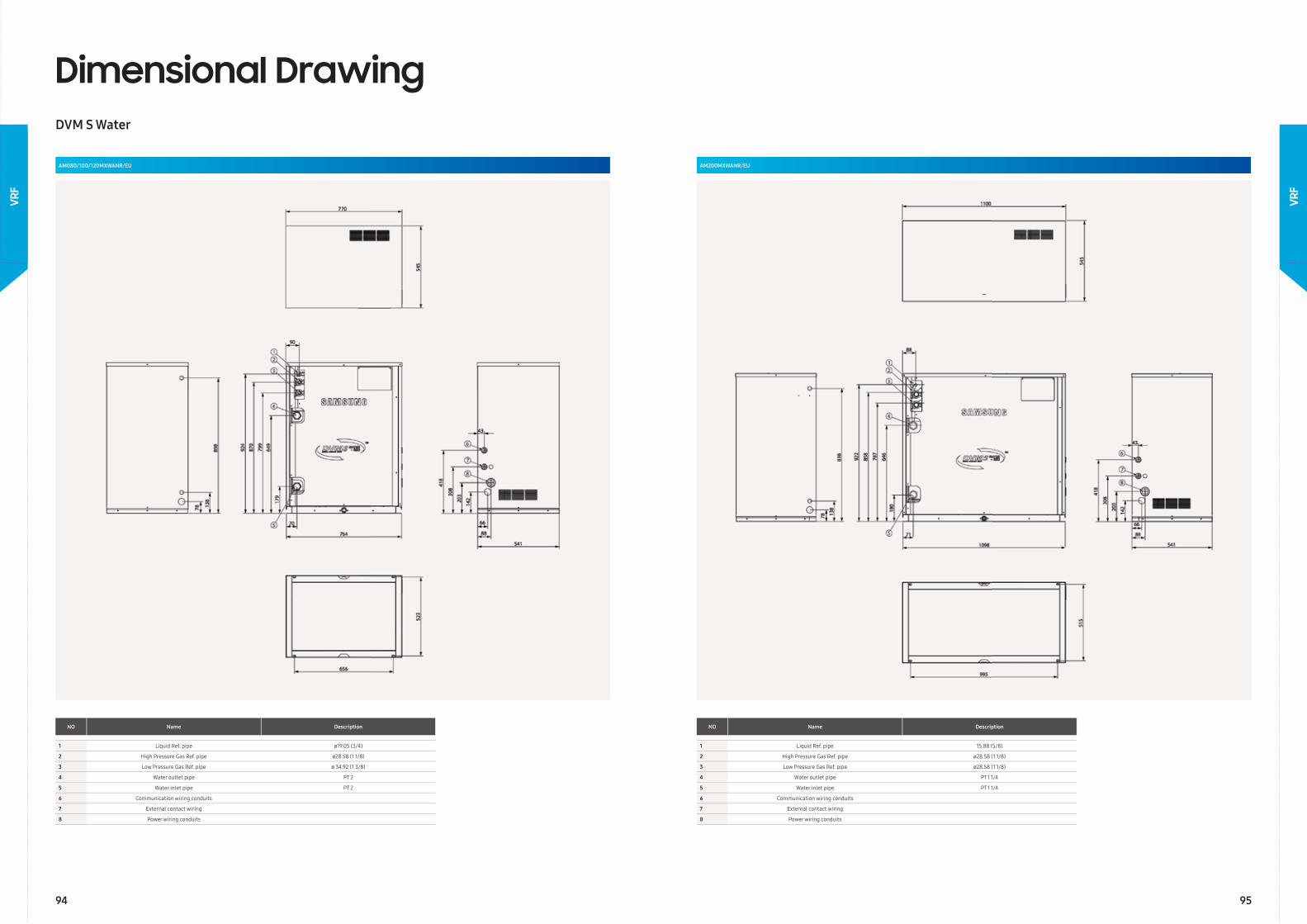
AM080/100/120MXWANR/EU
Dimensional DrawingDVM S Water
AM200MXWANR/EU
NO Name Description
1 Liquid Ref. pipe ø19.05 (3/4)
2 High Pressure Gas Ref. pipe ø28.58 (1 1/8)
3 Low Pressure Gas Ref. pipe ø 34.92 (1 3/8)
4 Water outlet pipe PT 2
5 Water inlet pipe PT 2
6 Communication wiring conduits
7 External contact wiring
8 Power wiring conduits
NO Name Description
1 Liquid Ref. pipe 15.88 (5/8)
2 High Pressure Gas Ref. pipe ø28.58 (1 1/8)
3 Low Pressure Gas Ref. pipe ø28.58 (1 1/8)
4 Water outlet pipe PT 1 1/4
5 Water inlet pipe PT 1 1/4
6 Communication wiring conduits
7 External contact wiring
8 Power wiring conduits
94 95
VRF
VRF
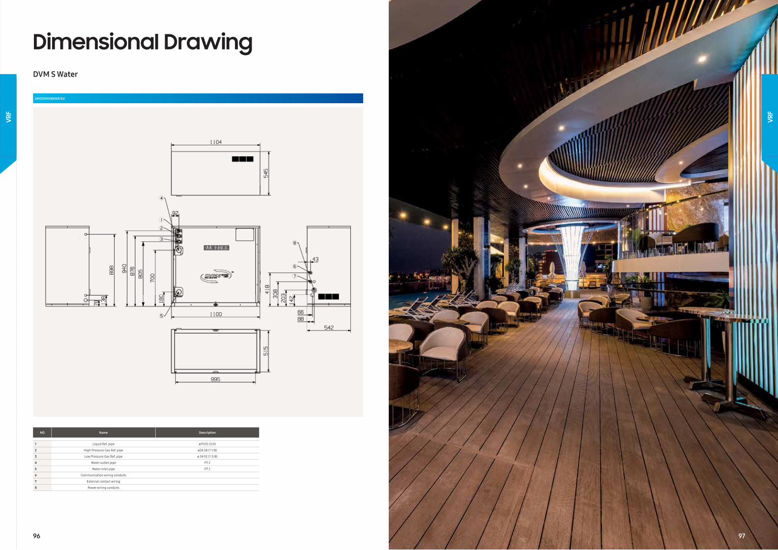
AM300MXWANR/EU
Dimensional DrawingDVM S Water
NO Name Description
1 Liquid Ref. pipe ø19.05 (3/4)
2 High Pressure Gas Ref. pipe ø28.58 (1 1/8)
3 Low Pressure Gas Ref. pipe ø 34.92 (1 3/8)
4 Water outlet pipe PT 2
5 Water inlet pipe PT 2
6 Communication wiring conduits
7 External contact wiring
8 Power wiring conduits
96
VRF
VRF
97
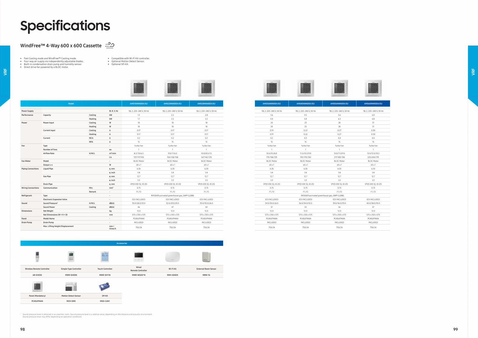
Model AM015NNNDEH/EU AM022NNNDEH/EU AM028NNNDEH/EU AM036NNNDEH/EU AM045NNNDEH/EU AM056NNNDEH/EU AM060NNNDEH/EU
Power Supply Φ, #, V, Hz 1Φ, 2, 220–240 V, 50 Hz 1Φ, 2, 220–240 V, 50 Hz 1Φ, 2, 220–240 V, 50 Hz 1Φ, 2, 220–240 V, 50 Hz 1Φ, 2, 220–240 V, 50 Hz 1Φ, 2, 220–240 V, 50 Hz 1Φ, 2, 220–240 V, 50 Hz
Performance Capacity Cooling kW 1.5 2.2 2.8 3.6 4.5 5.6 6.0
Heating kW 1.7 2.5 3.2 4.0 5.0 6.3 6.8
Power Power Input Cooling W 18 18 18 20 23 28 31
Heating W 18 18 18 20 23 28 31
Current Input Cooling A 0.17 0.17 0.17 0.19 0.22 0.27 0.30
Heating A 0.17 0.17 0.17 0.19 0.22 0.27 0.30
Current MCA A 0.2 0.2 0.2 0.2 0.3 0.4 0.4
MFA A 15 15 15 15 15 15 15
Fan Type - Turbo Fan Turbo Fan Turbo Fan Turbo Fan Turbo Fan Turbo Fan Turbo Fan
Number of Fans ea 1 1 1 1 1 1 1
Airfl ow Rate H/M/L m³/min 8.2/7.0/6.3 9.0/7.7/6.5 10.0/8.5/7.5 10.5/9.5/8.0 11.5/10.2/9.0 13.0/11.0/9.5 13.5/12.0/10.2
l/s 137/117/105 150/128/108 167/142/125 175/158/133 192/170/150 217/183/158 225/200/170
Fan Motor Model - BLDC Motor BLDC Motor BLDC Motor BLDC Motor BLDC Motor BLDC Motor BLDC Motor
Output x n W 65 x 1 65 x 1 65 x 1 65 x 1 65 x 1 65 x 1 65 x 1
Piping Connections Liquid Pipe ø, mm 6.35 6.35 6.35 6.35 6.35 6.35 6.35
ø, inch 1/4 1/4 1/4 1/4 1/4 1/4 1/4
Gas Pipe ø, mm 12.7 12.7 12.7 12.7 12.7 12.7 12.7
ø, inch 1/2 1/2 1/2 1/2 1/2 1/2 1/2
Drain Pipe ø, mm VP25 (OD 32, ID 25) VP25 (OD 32, ID 25) VP25 (OD 32, ID 25) VP25 (OD 32, ID 25) VP25 (OD 32, ID 25) VP25 (OD 32, ID 25) VP25 (OD 32, ID 25)
Wiring Connections Communication Min. mm2 0.75 0.75 0.75 0.75 0.75 0.75 0.75
Remark - F1, F2 F1, F2 F1, F2 F1, F2 F1, F2 F1, F2 F1, F2
Refrigerant Type - R410A(Fluorinated greenhouse gas, GWP=2,088) R410A(Fluorinated greenhouse gas, GWP=2,088)
Electronic Expansion Valve - EEV INCLUDED EEV INCLUDED EEV INCLUDED EEV INCLUDED EEV INCLUDED EEV INCLUDED EEV INCLUDED
Sound Sound Pressure¹ H/M/L dB(A) 30.0/28.0/23.0 32.0/29.0/25.0 33.0/30.0/26.0 34.0/30.0/26.0 36.0/34.0/32.0 39.0/36.0/33.0 40.0/38.0/35.0
Sound Power Cooling dB(A) 46 47 50 51 53 56 57
Dimensions Net Weight kg 12.0 12.0 12.0 12.0 12.0 12.0 12.0
Net Dimensions (W × H × D) mm 575 x 250 x 575 575 x 250 x 575 575 x 250 x 575 575 x 250 x 575 575 x 250 x 575 575 x 250 x 575 575 x 250 x 575
Panel Model Name - PC4SUFMAN PC4SUFMAN PC4SUFMAN PC4SUFMAN PC4SUFMAN PC4SUFMAN PC4SUFMAN
Drain Pump Drain Pump - INCLUDED INCLUDED INCLUDED INCLUDED INCLUDED INCLUDED INCLUDED
Max. Lifting Height/Displacement mm / litres/h 750/24 750/24 750/24 750/24 750/24 750/24 750/24
SpecificationsWindFree™ 4-Way 600 x 600 Cassette
• Fast Cooling mode and WindFree™ Cooling mode.• Four-way air supply via independently adjustable blades.• Built-in condensation drain pump and humidity sensor.• Direct drive fan powered by a BLDC motor.
• Compatible with Wi-Fi Kit controller.• Optional Motion Detect Sensor.• Optional SPi Kit.
Accessories
Wireless Remote Controller Simple Type Controller Touch ControllerWired
Remote ControllerWi-Fi Kit External Room Sensor
AR-EH03E MWR-SH00N MWR-SH11N MWR-WG00*N MIM-H04EN MRW-TA
Panel (Mandatory) Motion Detect Sensor SPi Kit
PC4SUFMAN MCR-SMD MSD-CAN1
1 Sound pressure level is obtained in an anechoic room. Sound pressure level is a relative value, depending on the distance and acoustic environment. Sound pressure level may differ depending on operation conditions.
98 99
VRF
VRF
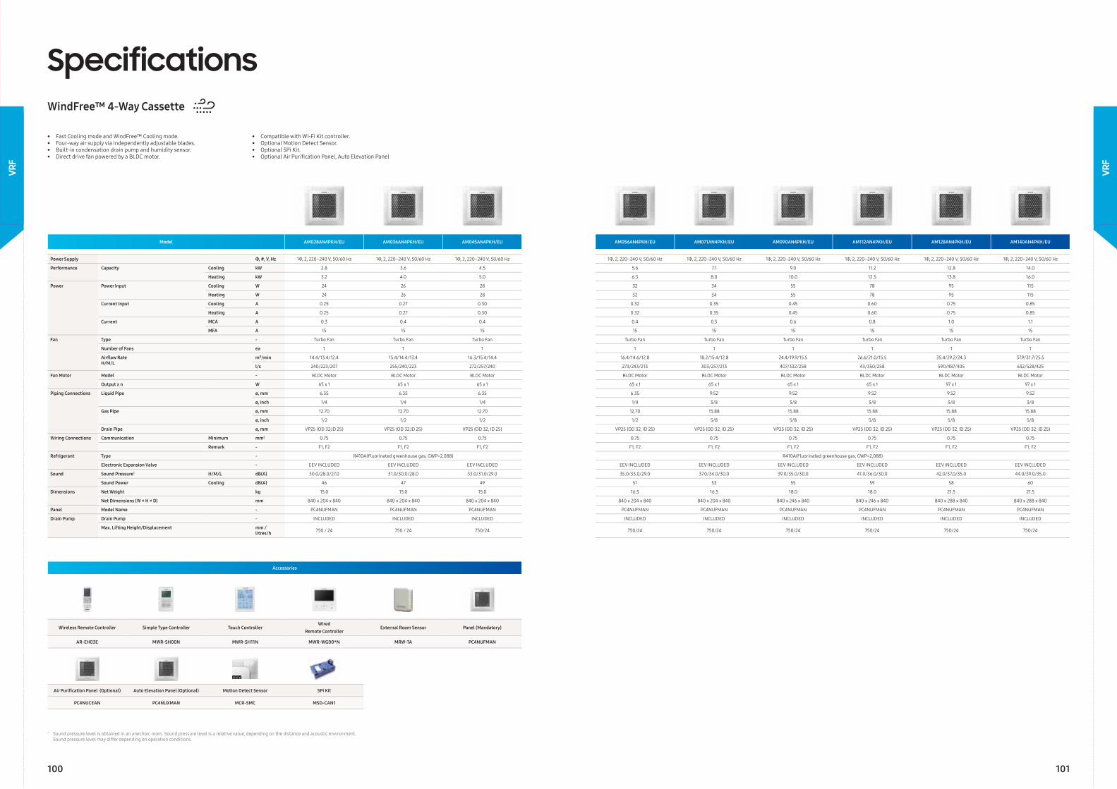
Model AM028AN4PKH/EU AM036AN4PKH/EU AM045AN4PKH/EU AM056AN4PKH/EU AM071AN4PKH/EU AM090AN4PKH/EU AM112AN4PKH/EU AM128AN4PKH/EU AM140AN4PKH/EU
Power Supply Φ, #, V, Hz 1Φ, 2, 220–240 V, 50/60 Hz 1Φ, 2, 220–240 V, 50/60 Hz 1Φ, 2, 220–240 V, 50/60 Hz 1Φ, 2, 220–240 V, 50/60 Hz 1Φ, 2, 220–240 V, 50/60 Hz 1Φ, 2, 220–240 V, 50/60 Hz 1Φ, 2, 220–240 V, 50/60 Hz 1Φ, 2, 220–240 V, 50/60 Hz 1Φ, 2, 220–240 V, 50/60 Hz
Performance Capacity Cooling kW 2.8 3.6 4.5 5.6 7.1 9.0 11.2 12.8 14.0
Heating kW 3.2 4.0 5.0 6.3 8.0 10.0 12.5 13.8 16.0
Power Power Input Cooling W 24 26 28 32 34 55 78 95 115
Heating W 24 26 28 32 34 55 78 95 115
Current Input Cooling A 0.25 0.27 0.30 0.32 0.35 0.45 0.60 0.75 0.85
Heating A 0.25 0.27 0.30 0.32 0.35 0.45 0.60 0.75 0.85
Current MCA A 0.3 0.4 0.4 0.4 0.5 0.6 0.8 1.0 1.1
MFA A 15 15 15 15 15 15 15 15 15
Fan Type - Turbo Fan Turbo Fan Turbo Fan Turbo Fan Turbo Fan Turbo Fan Turbo Fan Turbo Fan Turbo Fan
Number of Fans ea 1 1 1 1 1 1 1 1 1
Airfl ow RateH/M/L
m³/min 14.4/13.4/12.4 15.4/14.4/13.4 16.3/15.4/14.4 16.4/14.6/12.8 18.2/15.4/12.8 24.4/19.9/15.5 26.6/21.0/15.5 35.4/29.2/24.3 37.9/31.7/25.5
l/s 240/223/207 255/240/223 272/257/240 273/243/213 303/257/213 407/332/258 43/350/258 590/487/405 632/528/425
Fan Motor Model - BLDC Motor BLDC Motor BLDC Motor BLDC Motor BLDC Motor BLDC Motor BLDC Motor BLDC Motor BLDC Motor
Output x n W 65 x 1 65 x 1 65 x 1 65 x 1 65 x 1 65 x 1 65 x 1 97 x 1 97 x 1
Piping Connections Liquid Pipe ø, mm 6.35 6.35 6.35 6.35 9.52 9.52 9.52 9.52 9.52
ø, inch 1/4 1/4 1/4 1/4 3/8 3/8 3/8 3/8 3/8
Gas Pipe ø, mm 12.70 12.70 12.70 12.70 15.88 15.88 15.88 15.88 15.88
ø, inch 1/2 1/2 1/2 1/2 5/8 5/8 5/8 5/8 5/8
Drain Pipe ø, mm VP25 (OD 32,ID 25) VP25 (OD 32,ID 25) VP25 (OD 32, ID 25) VP25 (OD 32, ID 25) VP25 (OD 32, ID 25) VP25 (OD 32, ID 25) VP25 (OD 32, ID 25) VP25 (OD 32, ID 25) VP25 (OD 32, ID 25)
Wiring Connections Communication Minimum mm2 0.75 0.75 0.75 0.75 0.75 0.75 0.75 0.75 0.75
Remark - F1, F2 F1, F2 F1, F2 F1, F2 F1, F2 F1, F2 F1, F2 F1, F2 F1, F2
Refrigerant Type - R410A(Fluorinated greenhouse gas, GWP=2,088) R410A(Fluorinated greenhouse gas, GWP=2,088)
Electronic Expansion Valve - EEV INCLUDED EEV INCLUDED EEV INCLUDED EEV INCLUDED EEV INCLUDED EEV INCLUDED EEV INCLUDED EEV INCLUDED EEV INCLUDED
Sound Sound Pressure1 H/M/L dB(A) 30.0/28.0/27.0 31.0/30.0/28.0 33.0/31.0/29.0 35.0/33.0/29.0 37.0/34.0/30.0 39.0/35.0/30.0 41.0/36.0/30.0 42.0/37.0/35.0 44.0/39.0/35.0
Sound Power Cooling dB(A) 46 47 49 51 53 55 59 58 60
Dimensions Net Weight kg 15.0 15.0 15.0 16.5 16.5 18.0 18.0 21.5 21.5
Net Dimensions (W × H × D) mm 840 x 204 x 840 840 x 204 x 840 840 x 204 x 840 840 x 204 x 840 840 x 204 x 840 840 x 246 x 840 840 x 246 x 840 840 x 288 x 840 840 x 288 x 840
Panel Model Name - PC4NUFMAN PC4NUFMAN PC4NUFMAN PC4NUFMAN PC4NUFMAN PC4NUFMAN PC4NUFMAN PC4NUFMAN PC4NUFMAN
Drain Pump Drain Pump - INCLUDED INCLUDED INCLUDED INCLUDED INCLUDED INCLUDED INCLUDED INCLUDED INCLUDED
Max. Lifting Height/Displacement mm / litres/h 750 / 24 750 / 24 750/24 750/24 750/24 750/24 750/24 750/24 750/24
SpecificationsWindFree™ 4-Way Cassette
• Fast Cooling mode and WindFree™ Cooling mode.• Four-way air supply via independently adjustable blades.• Built-in condensation drain pump and humidity sensor.• Direct drive fan powered by a BLDC motor.
• Compatible with Wi-Fi Kit controller.• Optional Motion Detect Sensor.• Optional SPi Kit.• Optional Air Purifi cation Panel, Auto Elevation Panel
Accessories
Wireless Remote Controller Simple Type Controller Touch ControllerWired
Remote ControllerExternal Room Sensor Panel (Mandatory)
AR-EH03E MWR-SH00N MWR-SH11N MWR-WG00*N MRW-TA PC4NUFMAN
Air Purifi cation Panel (Optional) Auto Elevation Panel (Optional) Motion Detect Sensor SPi Kit
PC4NUCEAN PC4NUXMAN MCR-SMC MSD-CAN1
1 Sound pressure level is obtained in an anechoic room. Sound pressure level is a relative value, depending on the distance and acoustic environment. Sound pressure level may differ depending on operation conditions.
100 101
VRF
VRF
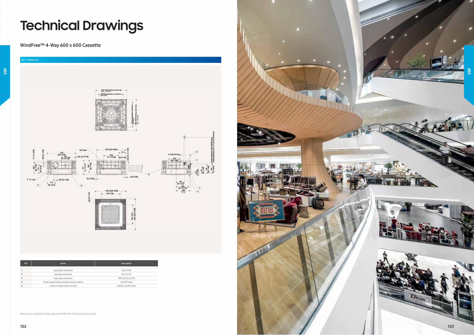
Technical DrawingsWindFree™ 4-Way 600 x 600 Cassette
AM***NNNDEH/EU
Note: As for suspension bolt, please use M8~M10. (Procured at local site)
NO Name Description
1 Liquid pipe connection ø6.35 (1/4)
2 Gas pipe connection ø12.70 (1/2)
3 Drain pipe connection VP25 (OD 32, ID 25)
4 Power supply/communication wiring conduits Use M4 Screw
5 Fresh air intake knock-out hole ø10 [4], use M4 Screw
102 103
VRF
VRF
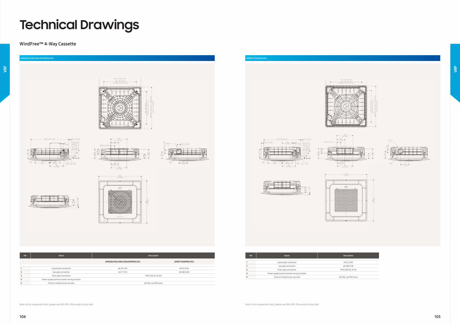
AM028/036/045/056/071AN4PKH/EU
Technical DrawingsWindFree™ 4-Way Cassette
Note: As for suspension bolt, please use M8~M10. (Procured at local site)
AM090/112AN4PKH/EU
Note: As for suspension bolt, please use M8~M10. (Procured at local site)
NO Name Description
AM028/036/045/056AN4PKH/EU AM071AN4PKH/EU
1 Liquid pipe connection ø6.35 (1/4) ø9.52 (3/8)
2 Gas pipe connection ø12.7 (1/2) ø15.88 (5/8)
3 Drain pipe connection VP25 (OD 32, ID 25)
4 Power supply/communication wiring conduits
5 Fresh air intake knock-out hole ø10 [4], use M4 Screw
NO Name Description
1 Liquid pipe connection ø9.52 (3/8)
2 Gas pipe connection ø15.88 (5/8)
3 Drain pipe connection VP25 (OD 32, ID 25)
4 Power supply/communication wiring conduits
5 Fresh air intake knock-out hole ø10 [4], use M4 Screw
104 105
VRF
VRF
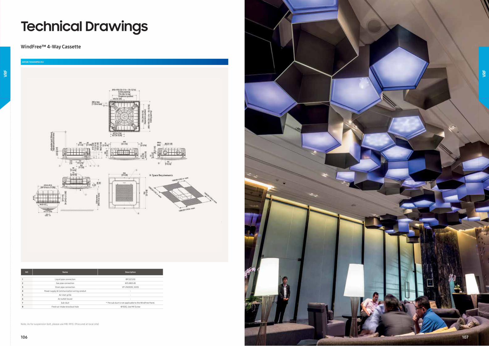
Technical DrawingsWindFree™ 4-Way Cassette
AM128/140AN4PKH/EU
Note: As for suspension bolt, please use M8~M10. (Procured at local site)
NO Name Description
1 Liquid pipe connection Φ9.52(3/8)
2 Gas pipe connection Φ15.88(5/8)
3 Drain pipe connection VP-25(OD32, ID25)
4 Power supply & Communication wiring conduit -
5 Air inlet grille -
6 Air outlet louver -
7 Sub-duct * The sub duct is not applicable to the WindFree Panel.
8 Fresh air intake knockout hole Φ10[4], Use M4 Screw
106
VRF
VRF
107
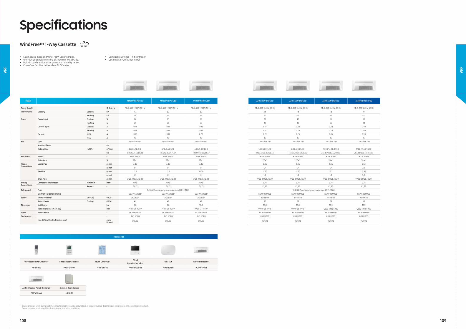
Model AM017NN1PEH/EU AM022NN1PEH/EU AM022NN1DKH/EU AM028NN1DKH/EU AM036NN1DKH/EU AM056NN1DEH/EU AM071NN1DEH/EU
Power Supply Φ, #, V, Hz 1Φ, 2, 220–240 V, 50 Hz 1Φ, 2, 220–240 V, 50 Hz 1Φ, 2, 220–240 V, 50 Hz 1Φ, 2, 220–240 V, 50 Hz 1Φ, 2, 220–240 V, 50 Hz 1Φ, 2, 220–240 V, 50 Hz 1Φ, 2, 220–240 V, 50 Hz
Performance Capacity Cooling kW 1.7 2.2 2.2 2.8 3.6 5.6 7.1
Heating kW 1.9 2.5 2.5 3.2 4.0 6.3 8.0
Power Power Input Cooling W 24 25 29 32 40 55 80
Heating w 24 25 29 32 40 55 80
Current Input Cooling A 0.14 0.15 0.16 0.17 0.20 0.28 0.40
Heating A 0.14 0.15 0.16 0.17 0.20 0.28 0.40
Current MCA A 0.18 0.19 0.20 0.21 0.25 0.35 0.50
MFA A 15 15 15 15 15 15 15
Fan Type - Crossfl ow Fan Crossfl ow Fan Crossfl ow Fan Crossfl ow Fan Crossfl ow Fan Crossfl ow Fan Crossfl ow Fan
Number of Fans ea 1 1 1 1 1 1 1
Airfl ow Rate H/M/L m³/min 4.80/4.30/4.10 5.10/4.60/4.30 6.00/5.00/4.00 7.00/6.00/5.00 8.00/7.00/6.00 16.00/14.00/12.50 17.00/15.50/14.00
l/s 80.00/71.67/68.33 85.00/76.67/71.67 100.00/83.33/66.67 116.67/100.00/83.33 133.33/116.67/100.00 266.67/233.33/208.33 283.33/258.33/233.33
Fan Motor Model - BLDC Motor BLDC Motor BLDC Motor BLDC Motor BLDC Motor BLDC Motor BLDC Motor
Output x n W 27 x 1 27 x 1 27 x 1 27 x 1 27 x 1 54 x 1 54 x 1
Piping Connections
Liquid Pipe ø, mm 6.35 6.35 6.35 6.35 6.35 6.35 9.52
ø, inch 1/4 1/4 1/4 1/4 1/4 1/4 3/8
Gas Pipe ø, mm 12.7 12.7 12.70 12.70 12.70 12.7 15.88
ø, inch 1/2 1/2 1/2 1/2 1/2 1/2 5/8
Drain Pipe ø, mm VP20 (OD 25, ID 20) VP20 (OD 25, ID 20) VP20 (OD 25, ID 20) VP20 (OD 25, ID 20) VP20 (OD 25, ID 20) VP20 (OD 25, ID 20) VP20 (OD 25, ID 20)
Wiring Connections
Connection with Indoor Minimum mm² 0.75 0.75 0.75 0.75 0.75 0.75 0.75
Remark - F1, F2 F1, F2 F1, F2 F1, F2 F1, F2 F1, F2 F1, F2
Refrigerant Type - R410A(Fluorinated greenhouse gas, GWP=2,088) R410A(Fluorinated greenhouse gas, GWP=2,088)
Electronic Expansion Valve - EEV INCLUDED EEV INCLUDED EEV INCLUDED EEV INCLUDED EEV INCLUDED EEV INCLUDED EEV INCLUDED
Sound Sound Pressure¹ (H/M/L) dB(A) 28/26/24 29/26/24 29/26/24 32/28/24 37/33/30 41/38/35 42/39/36
Sound Power Cooling dB(A) 46 47 47 50 55 59 60
Dimension Net Weight kg 8.0 8.0 10.0 10.0 10.0 13.5 13.5
Net Dimensions (W x H x D) mm 740 x 135 x 360 740 x 135 x 360 970 x 135 x 410 970 x 135 x 410 970 x 135 x 410 1,200 x 138 x 450 1,200 x 138 x 450
Panel Model Name - PC1MWFMAN PC1MWFMAN PC1NWFMAN PC1NWFMAN PC1NWFMAN PC1BWFMAN PC1BWFMAN
Drain pump - INCLUDED INCLUDED INCLUDED INCLUDED INCLUDED INCLUDED INCLUDED
Max. Lifting Height/Displacement mm / litres/h 750/24 750/24 750/24 750/24 750/24 750/24 750/24
SpecificationsWindFree™ 1-Way Cassette
• Fast Cooling mode and WindFree™ Cooling mode.• One-way air supply by means of a 100 mm wide blade.• Built-in condensation drain pump and humidity sensor.• Cross-fl ow fan direct driven by a BLDC motor.
• Compatible with Wi-Fi Kit controller• Optional Air Purifi cation Panel
Accessories
Wireless Remote Controller Simple Type Controller Touch ControllerWired
Remote ControllerWi-Fi Kit Panel (Mandatory)
AR-EH03E MWR-SH00N MWR-SH11N MWR-WG00*N MIM-H04EN PC1*WFMAN
Air Purifi cation Panel (Optional) External Room Sensor
PC1*WCMAN MRW-TA
1 Sound pressure level is obtained in an anechoic room. Sound pressure level is a relative value, depending on the distance and acoustic environment. Sound pressure level may differ depending on operation conditions.
108 109
VRF
VRF
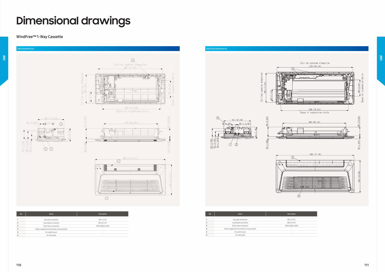
AM022/028/036NN1DKH/EUAM017/022NN1PEH/EU
Dimensional drawingsWindFree™ 1-Way Cassette
NO Name Description
1 Gas pipe connection Ø12.7 (1/2")
2 Liquid pipe connection Ø6.35 (1/4")
3 Drain hose connection VP20 (OD26, ID20)
4 Power supply/Communication wiring conduit -
5 Air outlet louver -
6 Air inlet grille -
NO Name Description
1 Gas pipe connection Ø12.7 (1/2")
2 Liquid pipe connection Ø6.35 (1/4")
3 Drain hose connection VP20 (OD26, ID20)
4 Power supply/Communication wiring conduit -
5 Air outlet louver -
6 Air inlet grille -
110 111
VRF
VRF
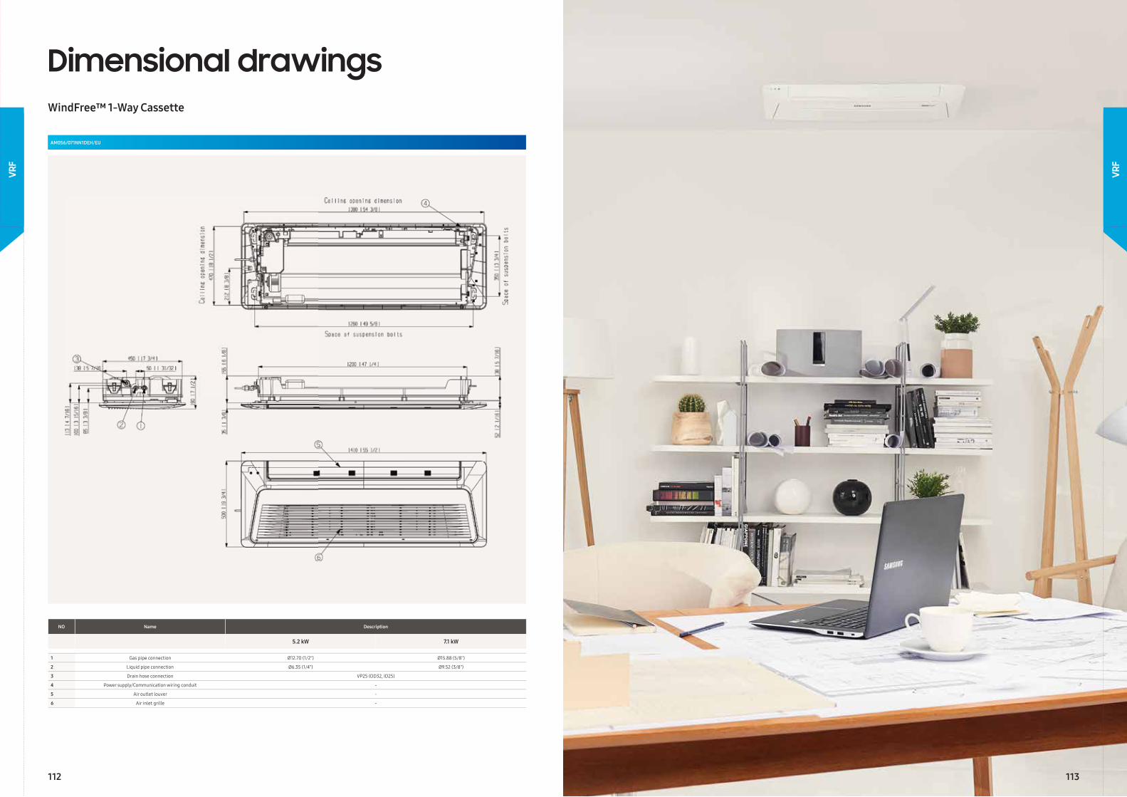
AM056/071NN1DEH/EU
Dimensional drawingsWindFree™ 1-Way Cassette
NO Name Description
5.2 kW 7.1 kW
1 Gas pipe connection Ø12.70 (1/2") Ø15.88 (5/8")
2 Liquid pipe connection Ø6.35 (1/4") Ø9.52 (3/8")
3 Drain hose connection VP25 (OD32, ID25)
4 Power supply/Communication wiring conduit -
5 Air outlet louver -
6 Air inlet grille -
112 113
VRF
VRF
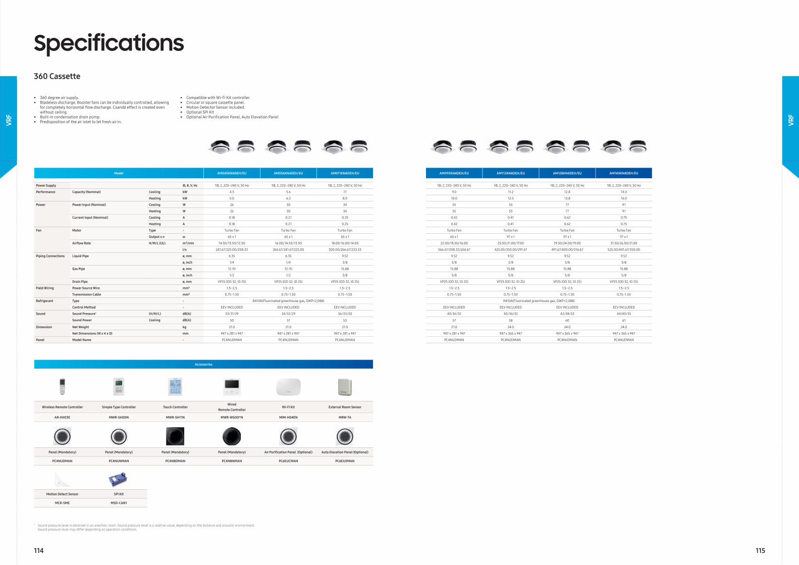
• 360 degree air supply.• Bladeless discharge. Booster fans can be individually controlled, allowing for completely horizontal fl ow discharge. Coandă effect is created even without ceiling.• Built-in condensation drain pump.• Predisposition of the air inlet to let fresh air in.
• Compatible with Wi-Fi Kit controller.• Circular or square cassette panel.• Motion Detector Sensor included.• Optional SPi Kit• Optional Air Purifi cation Panel, Auto Elevation Panel
Model AM045KN4DEH/EU AM056KN4DEH/EU AM071KN4DEH/EU AM090KN4DEH/EU AM112KN4DEH/EU AM128KN4DEH/EU AM140KN4DEH/EU
Power Supply Φ, #, V, Hz 1Φ, 2, 220–240 V, 50 Hz 1Φ, 2, 220–240 V, 50 Hz 1Φ, 2, 220–240 V, 50 Hz 1Φ, 2, 220–240 V, 50 Hz 1Φ, 2, 220–240 V, 50 Hz 1Φ, 2, 220–240 V, 50 Hz 1Φ, 2, 220–240 V, 50 Hz
Performance Capacity (Nominal) Cooling kW 4.5 5.6 7.1 9.0 11.2 12.8 14.0
Heating kW 5.0 6.3 8.0 10.0 12.5 13.8 16.0
Power Power Input (Nominal) Cooling W 26 30 34 55 53 77 91
Heating W 26 30 34 55 53 77 91
Current Input (Nominal) Cooling A 0.18 0.21 0.25 0.42 0.41 0.62 0.75
Heating A 0.18 0.21 0.25 0.42 0.41 0.62 0.75
Fan Motor Type - Turbo Fan Turbo Fan Turbo Fan Turbo Fan Turbo Fan Turbo Fan Turbo Fan
Output x n w 65 x 1 65 x 1 65 x 1 65 x 1 97 x 1 97 x 1 97 x 1
Airfl ow Rate H/M/L (UL) m³/min 14.50/13.50/12.50 16.00/14.50/13.50 18.00/16.00/14.00 22.00/18.50/16.00 25.50/21.00/17.50 29.50/24.00/19.00 31.50/26.50/21.00
l/s 241.67/225.00/208.33 266.67/241.67/225.00 300.00/266.67/233.33 366.67/308.33/266.67 425.00/350.00/291.67 491.67/400.00/316.67 525.00/441.67/350.00
Piping Connections Liquid Pipe ø, mm 6.35 6.35 9.52 9.52 9.52 9.52 9.52
ø, inch 1/4 1/4 3/8 3/8 3/8 3/8 3/8
Gas Pipe ø, mm 12.70 12.70 15.88 15.88 15.88 15.88 15.88
ø, inch 1/2 1/2 5/8 5/8 5/8 5/8 5/8
Drain Pipe ø, mm VP25 (OD 32, ID 25) VP25 (OD 32, ID 25) VP25 (OD 32, ID 25) VP25 (OD 32, ID 25) VP25 (OD 32, ID 25) VP25 (OD 32, ID 25) VP25 (OD 32, ID 25)
Field Wiring Power Source Wire mm² 1.5–2.5 1.5–2.5 1.5–2.5 1.5–2.5 1.5–2.5 1.5–2.5 1.5–2.5
Transmission Cable mm² 0.75–1.50 0.75–1.50 0.75–1.50 0.75–1.50 0.75–1.50 0.75–1.50 0.75–1.50
Refrigerant Type - R410A(Fluorinated greenhouse gas, GWP=2,088) R410A(Fluorinated greenhouse gas, GWP=2,088)
Control Method - EEV INCLUDED EEV INCLUDED EEV INCLUDED EEV INCLUDED EEV INCLUDED EEV INCLUDED EEV INCLUDED
Sound Sound Pressure1 (H/M/L) dB(A) 33/31/29 34/32/29 36/33/30 40/36/32 40/36/32 42/38/33 44/40/35
Sound Power Cooling dB(A) 50 51 53 57 58 60 61
Dimension Net Weight kg 21.0 21.0 21.0 21.0 24.0 24.0 24.0
Net Dimensions (W x H x D) mm 947 x 281 x 947 947 x 281 x 947 947 x 281 x 947 947 x 281 x 947 947 x 365 x 947 947 x 365 x 947 947 x 365 x 947
Panel Model Name - PC4NUDMAN PC4NUDMAN PC4NUDMAN PC4NUDMAN PC4NUDMAN PC4NUDMAN PC4NUDMAN
Specifications360 Cassette
Accessories
Wireless Remote Controller Simple Type Controller Touch ControllerWired
Remote ControllerWi-Fi Kit External Room Sensor
AR-KH03E MWR-SH00N MWR-SH11N MWR-WG00*N MIM-H04EN MRW-TA
Panel (Mandatory) Panel (Mandatory) Panel (Mandatory) Panel (Mandatory) Air Purifi cation Panel (Optional) Auto Elevation Panel (Optional)
PC4NUDMAN PC4NUNMAN PC4NBDMAN PC4NBNMAN PC6EUCMAN PC6EUXMAN
Motion Detect Sensor SPi Kit
MCR-SME MSD-CAN1
1 Sound pressure level is obtained in an anechoic room. Sound pressure level is a relative value, depending on the distance and acoustic environment. Sound pressure level may differ depending on operation conditions.
114 115
VRF
VRF
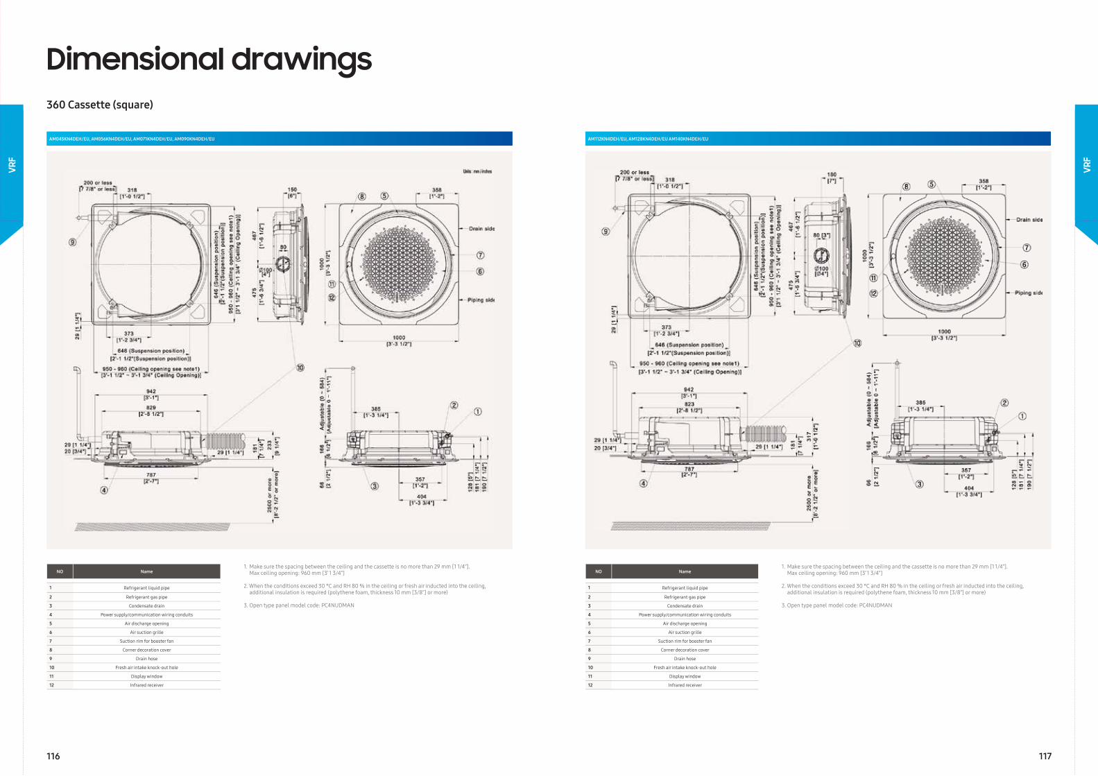
AM045KN4DEH/EU, AM056KN4DEH/EU, AM071KN4DEH/EU, AM090KN4DEH/EU AM112KN4DEH/EU, AM128KN4DEH/EU AM140KN4DEH/EU
NO Name
1 Refrigerant liquid pipe
2 Refrigerant gas pipe
3 Condensate drain
4 Power supply/communication wiring conduits
5 Air discharge opening
6 Air suction grille
7 Suction rim for booster fan
8 Corner decoration cover
9 Drain hose
10 Fresh air intake knock-out hole
11 Display window
12 Infrared receiver
1. Make sure the spacing between the ceiling and the cassette is no more than 29 mm [1 1/4”]. Max ceiling opening: 960 mm [3’ 1 3/4”]
2. When the conditions exceed 30 °C and RH 80 % in the ceiling or fresh air inducted into the ceiling, additional insulation is required (polythene foam, thickness 10 mm [3/8”] or more)
3. Open type panel model code: PC4NUDMAN
Dimensional drawings360 Cassette (square)
116 117
VRF
VRF
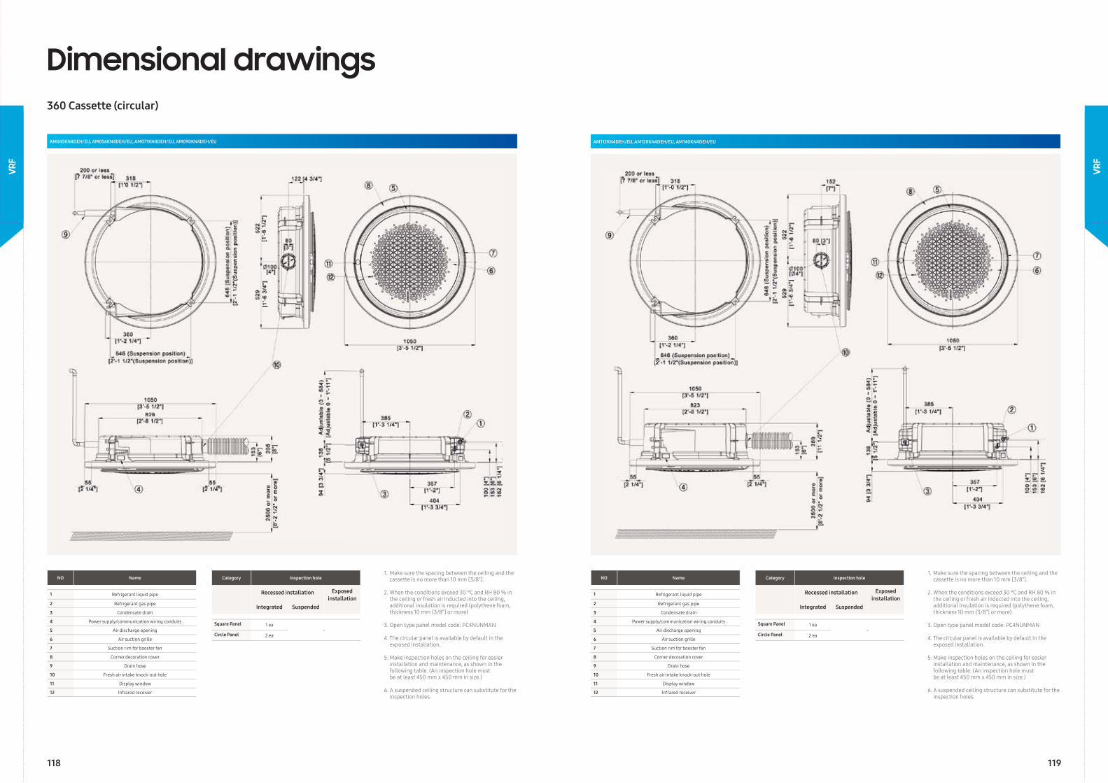
AM045KN4DEH/EU, AM056KN4DEH/EU, AM071KN4DEH/EU, AM090KN4DEH/EU
Dimensional drawings360 Cassette (circular)
AM112KN4DEH/EU, AM128KN4DEH/EU, AM140KN4DEH/EU
NO Name
1 Refrigerant liquid pipe
2 Refrigerant gas pipe
3 Condensate drain
4 Power supply/communication wiring conduits
5 Air discharge opening
6 Air suction grille
7 Suction rim for booster fan
8 Corner decoration cover
9 Drain hose
10 Fresh air intake knock-out hole
11 Display window
12 Infrared receiver
1. Make sure the spacing between the ceiling and the cassette is no more than 10 mm [3/8”].
2. When the conditions exceed 30 °C and RH 80 % in the ceiling or fresh air inducted into the ceiling, additional insulation is required (polythene foam, thickness 10 mm [3/8”] or more)
3. Open type panel model code: PC4NUNMAN
4. The circular panel is available by default in the exposed installation.
5. Make inspection holes on the ceiling for easier installation and maintenance, as shown in the following table. (An inspection hole must be at least 450 mm x 450 mm in size.)
6. A suspended ceiling structure can substitute for the inspection holes.
Category Inspection hole
Recessed installation Exposedinstallation
Integrated Suspended
Square Panel 1 ea-
Circle Panel 2 ea
Category Inspection hole
Recessed installation Exposedinstallation
Integrated Suspended
Square Panel 1 ea-
Circle Panel 2 ea
118 119
VRF
VRF
VRF
VRF
120 121
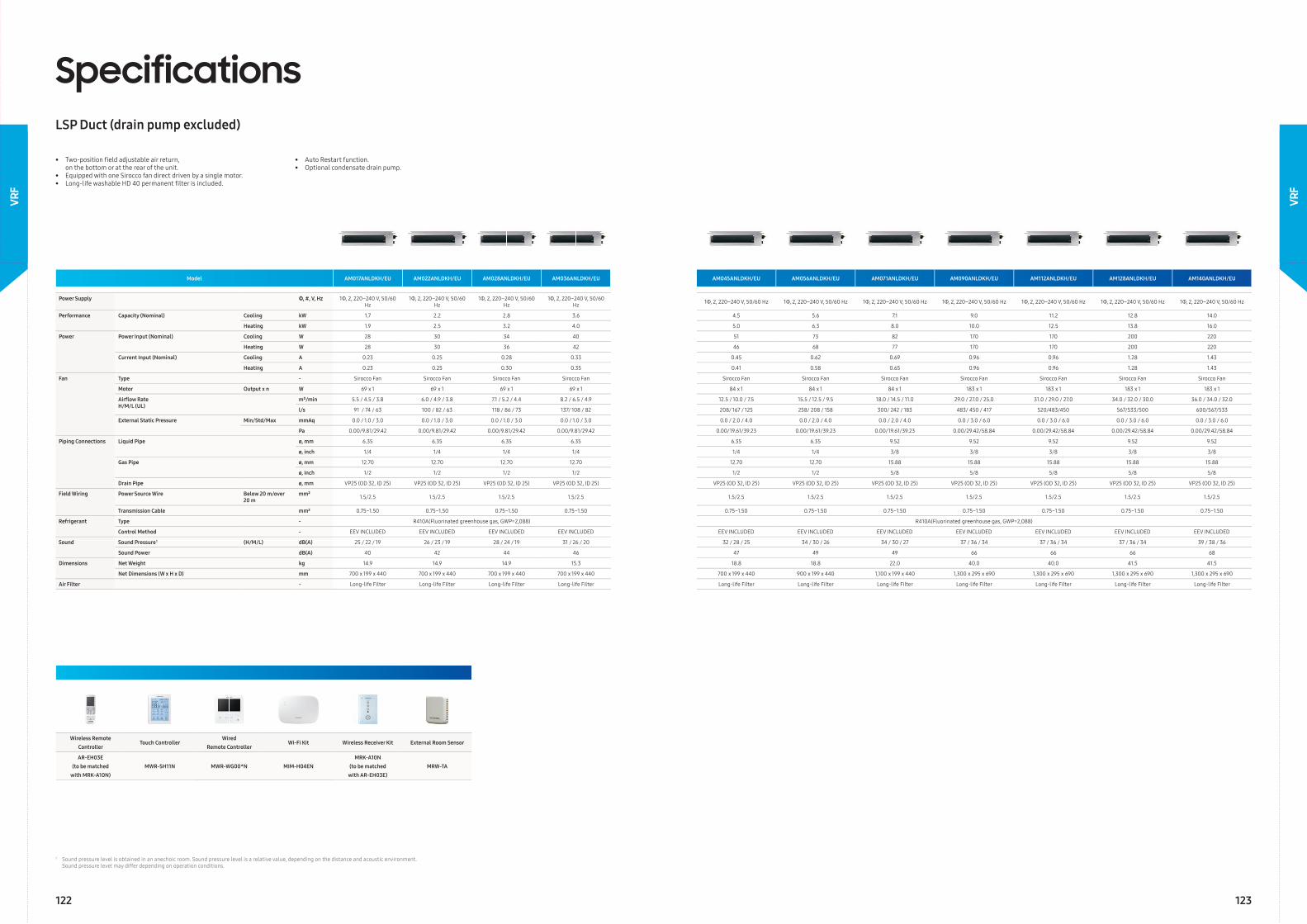
Model AM017ANLDKH/EU AM022ANLDKH/EU AM028ANLDKH/EU AM036ANLDKH/EU AM045ANLDKH/EU AM056ANLDKH/EU AM071ANLDKH/EU AM090ANLDKH/EU AM112ANLDKH/EU AM128ANLDKH/EU AM140ANLDKH/EU
Power Supply Φ, #, V, Hz 1Φ, 2, 220–240 V, 50/60 Hz
1Φ, 2, 220–240 V, 50/60 Hz
1Φ, 2, 220–240 V, 50/60 Hz
1Φ, 2, 220–240 V, 50/60 Hz 1Φ, 2, 220–240 V, 50/60 Hz 1Φ, 2, 220–240 V, 50/60 Hz 1Φ, 2, 220–240 V, 50/60 Hz 1Φ, 2, 220–240 V, 50/60 Hz 1Φ, 2, 220–240 V, 50/60 Hz 1Φ, 2, 220–240 V, 50/60 Hz 1Φ, 2, 220–240 V, 50/60 Hz
Performance Capacity (Nominal) Cooling kW 1.7 2.2 2.8 3.6 4.5 5.6 7.1 9.0 11.2 12.8 14.0
Heating kW 1.9 2.5 3.2 4.0 5.0 6.3 8.0 10.0 12.5 13.8 16.0
Power Power Input (Nominal) Cooling W 28 30 34 40 51 73 82 170 170 200 220
Heating W 28 30 36 42 46 68 77 170 170 200 220
Current Input (Nominal) Cooling A 0.23 0.25 0.28 0.33 0.45 0.62 0.69 0.96 0.96 1.28 1.43
Heating A 0.23 0.25 0.30 0.35 0.41 0.58 0.65 0.96 0.96 1.28 1.43
Fan Type - Sirocco Fan Sirocco Fan Sirocco Fan Sirocco Fan Sirocco Fan Sirocco Fan Sirocco Fan Sirocco Fan Sirocco Fan Sirocco Fan Sirocco Fan
Motor Output x n W 69 x 1 69 x 1 69 x 1 69 x 1 84 x 1 84 x 1 84 x 1 183 x 1 183 x 1 183 x 1 183 x 1
Airfl ow RateH/M/L (UL)
m³/min 5.5 / 4.5 / 3.8 6.0 / 4.9 / 3.8 7.1 / 5.2 / 4.4 8.2 / 6.5 / 4.9 12.5 / 10.0 / 7.5 15.5 / 12.5 / 9.5 18.0 / 14.5 / 11.0 29.0 / 27.0 / 25.0 31.0 / 29.0 / 27.0 34.0 / 32.0 / 30.0 36.0 / 34.0 / 32.0
l/s 91 / 74 / 63 100 / 82 / 63 118 / 86 / 73 137/ 108 / 82 208/ 167 / 125 258/ 208 / 158 300/ 242 / 183 483/ 450 / 417 520/483/450 567/533/500 600/567/533
External Static Pressure Min/Std/Max mmAq 0.0 / 1.0 / 3.0 0.0 / 1.0 / 3.0 0.0 / 1.0 / 3.0 0.0 / 1.0 / 3.0 0.0 / 2.0 / 4.0 0.0 / 2.0 / 4.0 0.0 / 2.0 / 4.0 0.0 / 3.0 / 6.0 0.0 / 3.0 / 6.0 0.0 / 3.0 / 6.0 0.0 / 3.0 / 6.0
Pa 0.00/9.81/29.42 0.00/9.81/29.42 0.00/9.81/29.42 0.00/9.81/29.42 0.00/19.61/39.23 0.00/19.61/39.23 0.00/19.61/39.23 0.00/29.42/58.84 0.00/29.42/58.84 0.00/29.42/58.84 0.00/29.42/58.84
Piping Connections Liquid Pipe ø, mm 6.35 6.35 6.35 6.35 6.35 6.35 9.52 9.52 9.52 9.52 9.52
ø, inch 1/4 1/4 1/4 1/4 1/4 1/4 3/8 3/8 3/8 3/8 3/8
Gas Pipe ø, mm 12.70 12.70 12.70 12.70 12.70 12.70 15.88 15.88 15.88 15.88 15.88
ø, inch 1/2 1/2 1/2 1/2 1/2 1/2 5/8 5/8 5/8 5/8 5/8
Drain Pipe ø, mm VP25 (OD 32, ID 25) VP25 (OD 32, ID 25) VP25 (OD 32, ID 25) VP25 (OD 32, ID 25) VP25 (OD 32, ID 25) VP25 (OD 32, ID 25) VP25 (OD 32, ID 25) VP25 (OD 32, ID 25) VP25 (OD 32, ID 25) VP25 (OD 32, ID 25) VP25 (OD 32, ID 25)
Field Wiring Power Source Wire Below 20 m/over 20 m
mm² 1.5/2.5 1.5/2.5 1.5/2.5 1.5/2.5 1.5/2.5 1.5/2.5 1.5/2.5 1.5/2.5 1.5/2.5 1.5/2.5 1.5/2.5
Transmission Cable mm² 0.75~1.50 0.75~1.50 0.75~1.50 0.75~1.50 0.75~1.50 0.75~1.50 0.75~1.50 0.75~1.50 0.75~1.50 0.75~1.50 0.75~1.50
Refrigerant Type - R410A(Fluorinated greenhouse gas, GWP=2,088) R410A(Fluorinated greenhouse gas, GWP=2,088)
Control Method - EEV INCLUDED EEV INCLUDED EEV INCLUDED EEV INCLUDED EEV INCLUDED EEV INCLUDED EEV INCLUDED EEV INCLUDED EEV INCLUDED EEV INCLUDED EEV INCLUDED
Sound Sound Pressure1 (H/M/L) dB(A) 25 / 22 / 19 26 / 23 / 19 28 / 24 / 19 31 / 26 / 20 32 / 28 / 25 34 / 30 / 26 34 / 30 / 27 37 / 36 / 34 37 / 36 / 34 37 / 36 / 34 39 / 38 / 36
Sound Power dB(A) 40 42 44 46 47 49 49 66 66 66 68
Dimensions Net Weight kg 14.9 14.9 14.9 15.3 18.8 18.8 22.0 40.0 40.0 41.5 41.5
Net Dimensions (W x H x D) mm 700 x 199 x 440 700 x 199 x 440 700 x 199 x 440 700 x 199 x 440 700 x 199 x 440 900 x 199 x 440 1,100 x 199 x 440 1,300 x 295 x 690 1,300 x 295 x 690 1,300 x 295 x 690 1,300 x 295 x 690
Air Filter - Long-life Filter Long-life Filter Long-life Filter Long-life Filter Long-life Filter Long-life Filter Long-life Filter Long-life Filter Long-life Filter Long-life Filter Long-life Filter
SpecificationsLSP Duct (drain pump excluded)
Wireless Remote Controller
Touch ControllerWired
Remote ControllerWi-Fi Kit Wireless Receiver Kit External Room Sensor
AR-EH03E(to be matched
with MRK-A10N)MWR-SH11N MWR-WG00*N MIM-H04EN
MRK-A10N (to be matched
with AR-EH03E)MRW-TA
• Two-position fi eld adjustable air return, on the bottom or at the rear of the unit.• Equipped with one Sirocco fan direct driven by a single motor.• Long-life washable HD 40 permanent fi lter is included.
• Auto Restart function.• Optional condensate drain pump.
1 Sound pressure level is obtained in an anechoic room. Sound pressure level is a relative value, depending on the distance and acoustic environment. Sound pressure level may differ depending on operation conditions.
122 123
VRF
VRF
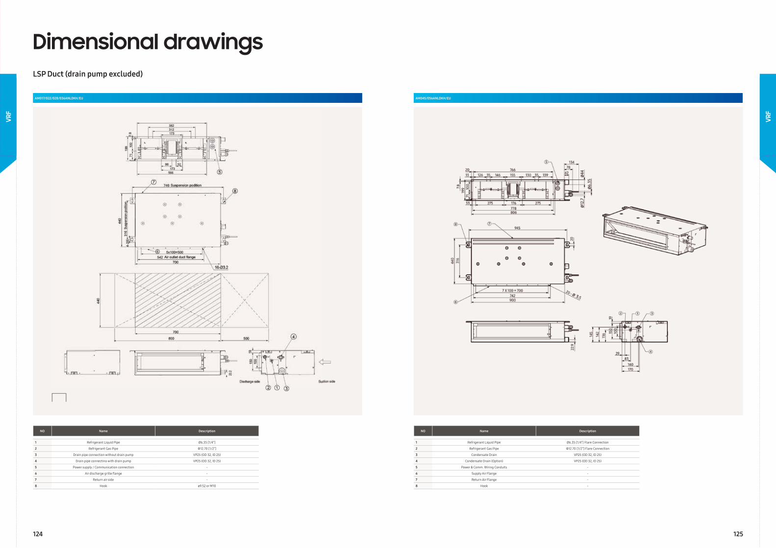
AM017/022/028/036ANLDKH/EU
Dimensional drawingsLSP Duct (drain pump excluded)
NO Name Description
1 Refrigerant Liquid Pipe Ø6.35 [1/4”]
2 Refrigerant Gas Pipe Φ12.70 [1/2”]
3 Drain pipe connection without drain pump VP25 (OD 32, ID 25)
4 Drain pipe connectino with drain pump VP25 (OD 32, ID 25)
5 Power supply / Communication connection -
6 Air discharge grille fl ange -
7 Return air side -
8 Hook ø9.52 or M10
AM045/056ANLDKH/EU
NO Name Description
1 Refrigerant Liquid Pipe Ø6.35 [1/4”] Flare Connection
2 Refrigerant Gas Pipe Φ12.70 [1/2”] Flare Connection
3 Condensate Drain VP25 (OD 32, ID 25)
4 Condensate Drain (Option) VP25 (OD 32, ID 25)
5 Power & Comm. Wiring Conduits -
6 Supply Air Flange -
7 Return Air Flange -
8 Hook -
124 125
VRF
VRF
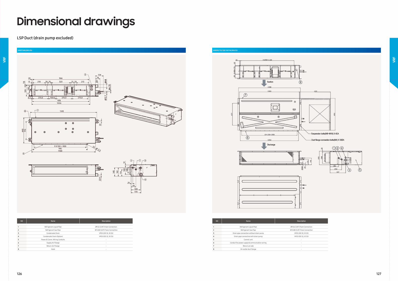
AM071ANLDKH/EU
Dimensional drawingsLSP Duct (drain pump excluded)
NO Name Description
1 Refrigerant Liquid Pipe Ø9.52 [3/8”] Flare Connection
2 Refrigerant Gas Pipe Φ15.88 [5/8”] Flare Connection
3 Condensate Drain VP25 (OD 32, ID 25)
4 Condensate Drain (Option) VP25 (OD 32, ID 25)
5 Power & Comm. Wiring Conduits -
6 Supply Air Flange -
7 Return Air Flange -
8 Hook -
AM090/112/128/140*NLDKH/EU
NO Name Description
1 Refrigerant Liquid Pipe Ø9.52 [3/8”] Flare Connection
2 Refrigerant Gas Pipe Φ15.88 [5/8”] Flare Connection
3 Drain pipe connection without drain pump VP25 (OD 32, ID 25)
4 Drain pipe connectino with drain pump VP25 (OD 32, ID 25)
5 Control unit -
6 Conduit for power supply & communication wiring -
7 Return air side -
8 Air outlet duct fl ange -
126 127
VRF
VRF
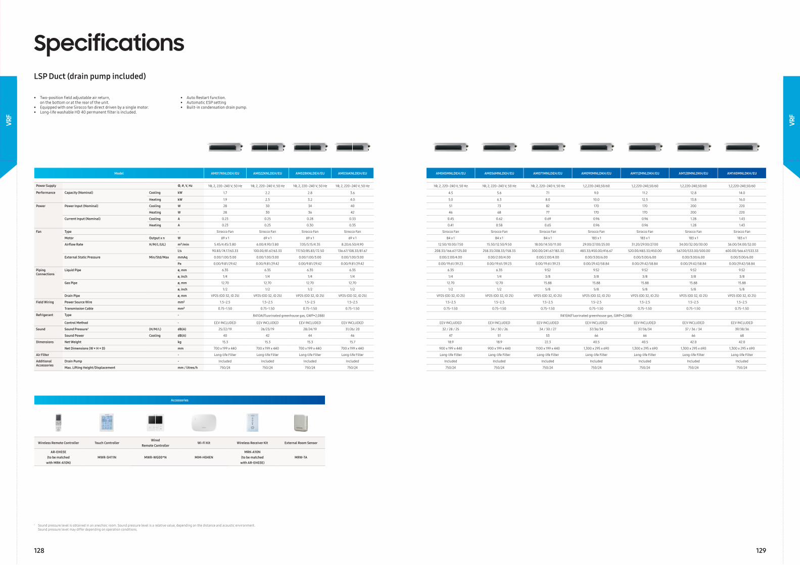
SpecificationsLSP Duct (drain pump included)
Model AM017KNLDEH/EU AM022KNLDEH/EU AM028KNLDEH/EU AM036KNLDEH/EU AM045MNLDEH/EU AM056MNLDEH/EU AM071MNLDEH/EU AM090MNLDKH/EU AM112MNLDKH/EU AM128MNLDKH/EU AM140MNLDKH/EU
Power Supply Φ, #, V, Hz 1Φ, 2, 220–240 V, 50 Hz 1Φ, 2, 220–240 V, 50 Hz 1Φ, 2, 220–240 V, 50 Hz 1Φ, 2, 220–240 V, 50 Hz 1Φ, 2, 220–240 V, 50 Hz 1Φ, 2, 220–240 V, 50 Hz 1Φ, 2, 220–240 V, 50 Hz 1,2,220-240,50/60 1,2,220-240,50/60 1,2,220-240,50/60 1,2,220-240,50/60
Performance Capacity (Nominal) Cooling kW 1.7 2.2 2.8 3.6 4.5 5.6 7.1 9.0 11.2 12.8 14.0
Heating kW 1.9 2.5 3.2 4.0 5.0 6.3 8.0 10.0 12.5 13.8 16.0
Power Power Input (Nominal) Cooling W 28 30 34 40 51 73 82 170 170 200 220
Heating W 28 30 36 42 46 68 77 170 170 200 220
Current Input (Nominal) Cooling A 0.23 0.25 0.28 0.33 0.45 0.62 0.69 0.96 0.96 1.28 1.43
Heating A 0.23 0.25 0.30 0.35 0.41 0.58 0.65 0.96 0.96 1.28 1.43
Fan Type - Sirocco Fan Sirocco Fan Sirocco Fan Sirocco Fan Sirocco Fan Sirocco Fan Sirocco Fan Sirocco Fan Sirocco Fan Sirocco Fan Sirocco Fan
Motor Output x n W 69 x 1 69 x 1 69 x 1 69 x 1 84 x 1 84 x 1 84 x 1 183 x 1 183 x 1 183 x 1 183 x 1
Airfl ow Rate H/M/L (UL) m³/min 5.45/4.45/3.80 6.00/4.90/3.80 7.05/5.15/4.35 8.20/6.50/4.90 12.50/10.00/7.50 15.50/12.50/9.50 18.00/14.50/11.00 29.00/27.00/25.00 31.20/29.00/27.00 34.00/32.00/30.00 36.00/34.00/32.00
l/s 90.83/74.17/63.33 100.00/81.67/63.33 117.50/85.83/72.50 136.67/108.33/81.67 208.33/166.67/125.00 258.33/208.33/158.33 300.00/241.67/183.33 483.33/450.00/416.67 520.00/483.33/450.00 567.00/533.00/500.00 600.00/566.67/533.33
External Static Pressure Min/Std/Max mmAq 0.00/1.00/3.00 0.00/1.00/3.00 0.00/1.00/3.00 0.00/1.00/3.00 0.00/2.00/4.00 0.00/2.00/4.00 0.00/2.00/4.00 0.00/3.00/6.00 0.00/3.00/6.00 0.00/3.00/6.00 0.00/3.00/6.00
Pa 0.00/9.81/29.42 0.00/9.81/29.42 0.00/9.81/29.42 0.00/9.81/29.42 0.00/19.61/39.23 0.00/19.61/39.23 0.00/19.61/39.23 0.00/29.42/58.84 0.00/29.42/58.84 0.00/29.42/58.84 0.00/29.42/58.84
Piping Connections
Liquid Pipe ø, mm 6.35 6.35 6.35 6.35 6.35 6.35 9.52 9.52 9.52 9.52 9.52
ø, inch 1/4 1/4 1/4 1/4 1/4 1/4 3/8 3/8 3/8 3/8 3/8
Gas Pipe ø, mm 12.70 12.70 12.70 12.70 12.70 12.70 15.88 15.88 15.88 15.88 15.88
ø, inch 1/2 1/2 1/2 1/2 1/2 1/2 5/8 5/8 5/8 5/8 5/8
Drain Pipe ø, mm VP25 (OD 32, ID 25) VP25 (OD 32, ID 25) VP25 (OD 32, ID 25) VP25 (OD 32, ID 25) VP25 (OD 32, ID 25) VP25 (OD 32, ID 25) VP25 (OD 32, ID 25) VP25 (OD 32, ID 25) VP25 (OD 32, ID 25) VP25 (OD 32, ID 25) VP25 (OD 32, ID 25)
Field Wiring Power Source Wire mm² 1.5~2.5 1.5~2.5 1.5~2.5 1.5~2.5 1.5~2.5 1.5~2.5 1.5~2.5 1.5~2.5 1.5~2.5 1.5~2.5 1.5~2.5
Transmission Cable mm² 0.75~1.50 0.75~1.50 0.75~1.50 0.75~1.50 0.75~1.50 0.75~1.50 0.75~1.50 0.75~1.50 0.75~1.50 0.75~1.50 0.75~1.50
Refrigerant Type - R410A(Fluorinated greenhouse gas, GWP=2,088) R410A(Fluorinated greenhouse gas, GWP=2,088)
Control Method - EEV INCLUDED EEV INCLUDED EEV INCLUDED EEV INCLUDED EEV INCLUDED EEV INCLUDED EEV INCLUDED EEV INCLUDED EEV INCLUDED EEV INCLUDED EEV INCLUDED
Sound Sound Pressure1 (H/M/L) dB(A) 25/22/19 26/23/19 28/24/19 31/26/ 20 32 / 28 / 25 34 / 30 / 26 34 / 30 / 27 37/36/34 37/36/34 37 / 36 / 34 39/38/36
Sound Power Cooling dB(A) 40 42 44 46 47 51 53 66 66 66 68
Dimensions Net Weight kg 15.3 15.3 15.3 15.7 18.9 18.9 22.3 40.5 40.5 42.0 42.0
Net Dimensions (W × H × D) mm 700 x 199 x 440 700 x 199 x 440 700 x 199 x 440 700 x 199 x 440 900 x 199 x 440 900 x 199 x 440 1100 x 199 x 440 1,300 x 295 x 690 1,300 x 295 x 690 1,300 x 295 x 690 1,300 x 295 x 690
Air Filter - Long-life Filter Long-life Filter Long-life Filter Long-life Filter Long-life Filter Long-life Filter Long-life Filter Long-life Filter Long-life Filter Long-life Filter Long-life Filter
Additional Accessories
Drain Pump - Included Included Included Included Included Included Included Included Included Included Included
Max. Lifting Height/Displacement mm / litres/h 750/24 750/24 750/24 750/24 750/24 750/24 750/24 750/24 750/24 750/24 750/24
Accessories
Wireless Remote Controller Touch ControllerWired
Remote ControllerWi-Fi Kit Wireless Receiver Kit External Room Sensor
AR-EH03E(to be matched
with MRK-A10N)MWR-SH11N MWR-WG00*N MIM-H04EN
MRK-A10N (to be matched
with AR-EH03E)MRW-TA
• Two-position fi eld adjustable air return, on the bottom or at the rear of the unit.• Equipped with one Sirocco fan direct driven by a single motor.• Long-life washable HD 40 permanent fi lter is included.
• Auto Restart function. • Automatic ESP setting• Built-in condensation drain pump.
1 Sound pressure level is obtained in an anechoic room. Sound pressure level is a relative value, depending on the distance and acoustic environment. Sound pressure level may differ depending on operation conditions.
128 129
VRF
VRF
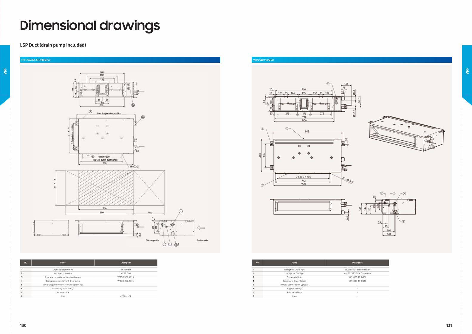
NO Name Description
1 Refrigerant Liquid Pipe Ø6.35 [1/4”] Flare Connection
2 Refrigerant Gas Pipe Φ12.70 [1/2”] Flare Connection
3 Condensate Drain VP25 (OD 32, ID 25)
4 Condensate Drain (Option) VP25 (OD 32, ID 25)
5 Power & Comm. Wiring Conduits -
6 Supply Air Flange -
7 Return Air Flange -
8 Hook -
AM017/022/028/036KNLDEH/EU
Dimensional drawingsLSP Duct (drain pump included)
NO Name Description
1 Liquid pipe connection ø6.35 Flare
2 Gas pipe connection ø12.70 Flare
3 Drain pipe connection without drain pump VP25 (OD 32, ID 25)
4 Drain pipe connection with drain pump VP25 (OD 32, ID 25)
5 Power supply/communication wiring conduits
6 Air discharge grille fl ange
7 Return air side
8 Hook ø9.52 or M10
AM045/056MNLDEH/EU
130 131
VRF
VRF
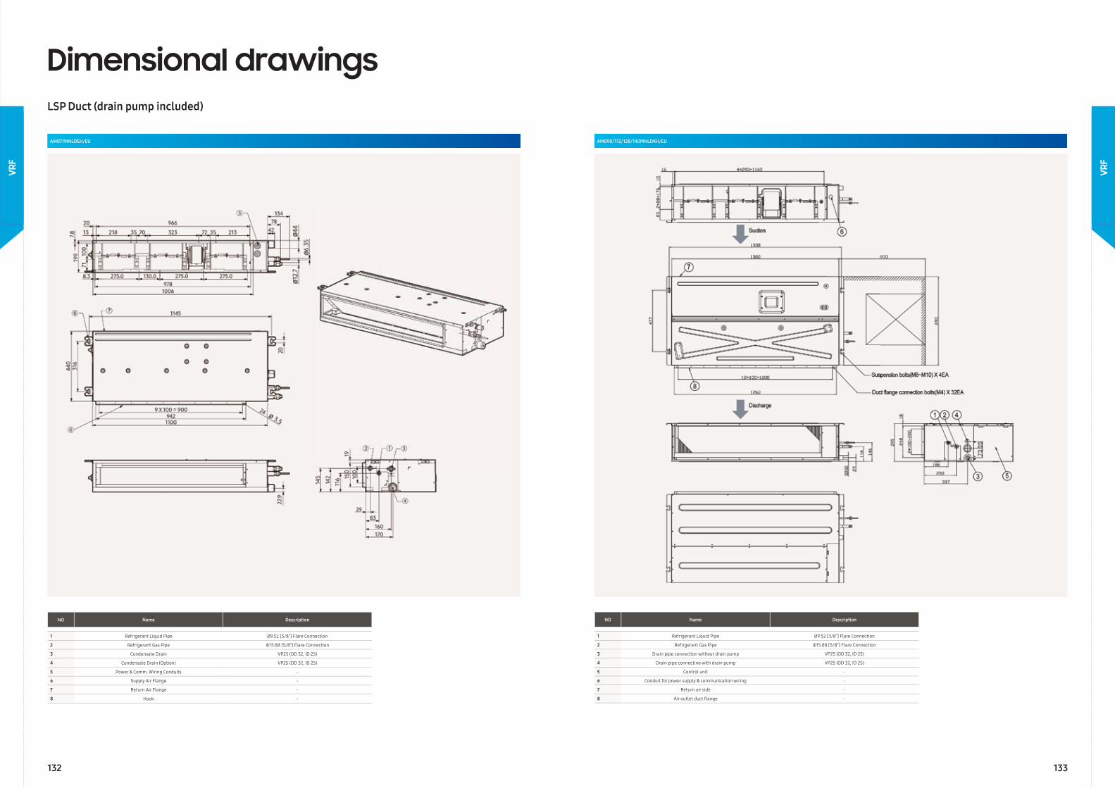
NO Name Description
1 Refrigerant Liquid Pipe Ø9.52 [3/8”] Flare Connection
2 Refrigerant Gas Pipe Φ15.88 [5/8”] Flare Connection
3 Condensate Drain VP25 (OD 32, ID 25)
4 Condensate Drain (Option) VP25 (OD 32, ID 25)
5 Power & Comm. Wiring Conduits -
6 Supply Air Flange -
7 Return Air Flange -
8 Hook -
AM090/112/128/140MNLDKH/EU
NO Name Description
1 Refrigerant Liquid Pipe Ø9.52 [3/8”] Flare Connection
2 Refrigerant Gas Pipe Φ15.88 [5/8”] Flare Connection
3 Drain pipe connection without drain pump VP25 (OD 32, ID 25)
4 Drain pipe connectino with drain pump VP25 (OD 32, ID 25)
5 Control unit -
6 Conduit for power supply & communication wiring -
7 Return air side -
8 Air outlet duct fl ange -
AM071MNLDEH/EU
Dimensional drawingsLSP Duct (drain pump included)
132
VRF
VRF
133
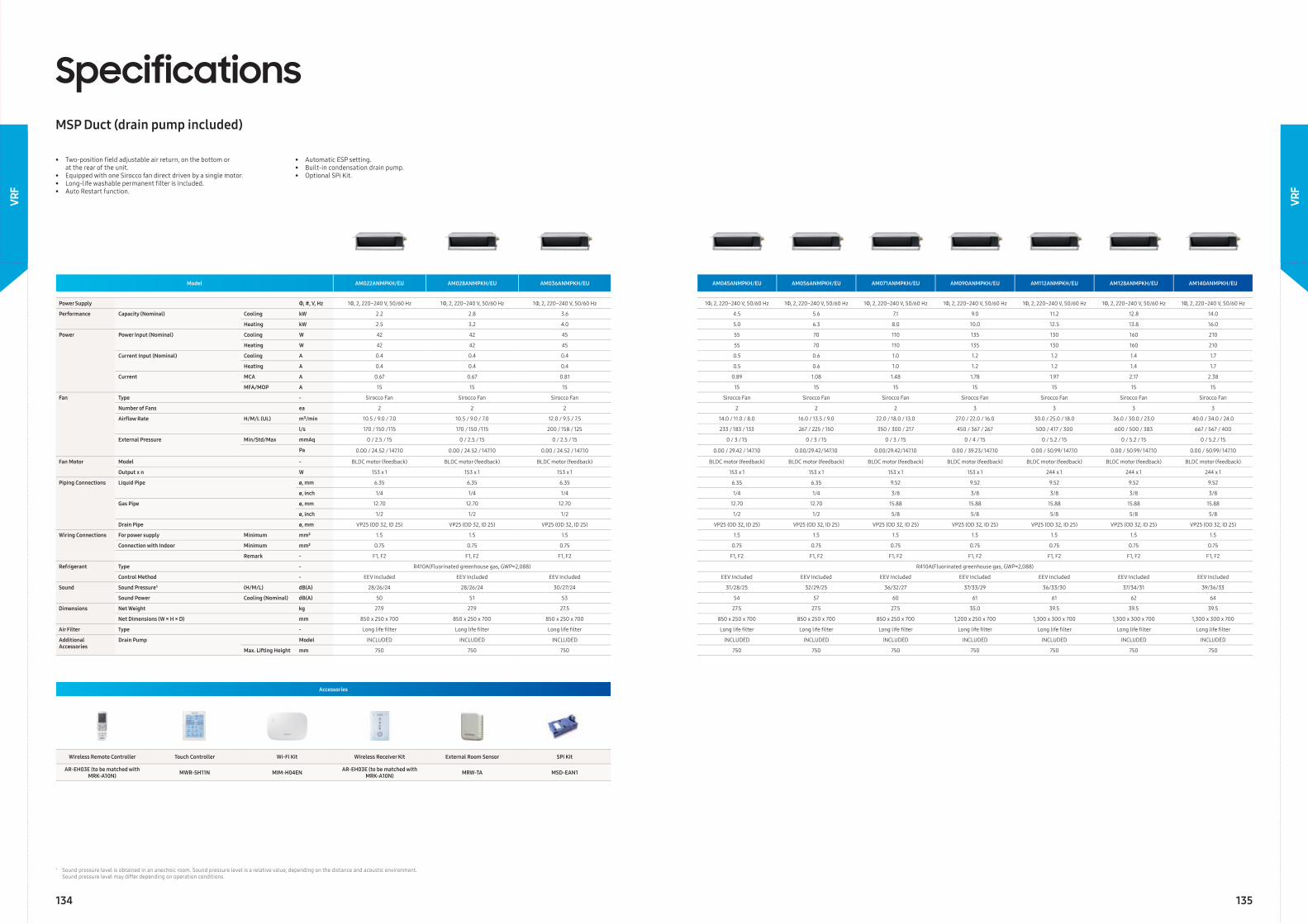
SpecificationsMSP Duct (drain pump included)
Accessories
Wireless Remote Controller Touch Controller Wi-Fi Kit Wireless Receiver Kit External Room Sensor SPi Kit
AR-EH03E (to be matched with MRK-A10N) MWR-SH11N MIM-H04EN AR-EH03E (to be matched with
MRK-A10N) MRW-TA MSD-EAN1
• Two-position fi eld adjustable air return, on the bottom or at the rear of the unit.• Equipped with one Sirocco fan direct driven by a single motor.• Long-life washable permanent fi lter is included.• Auto Restart function.
• Automatic ESP setting.• Built-in condensation drain pump.• Optional SPi Kit.
Model AM022ANMPKH/EU AM028ANMPKH/EU AM036ANMPKH/EU AM045ANMPKH/EU AM056ANMPKH/EU AM071ANMPKH/EU AM090ANMPKH/EU AM112ANMPKH/EU AM128ANMPKH/EU AM140ANMPKH/EU
Power Supply Φ, #, V, Hz 1Φ, 2, 220~240 V, 50/60 Hz 1Φ, 2, 220~240 V, 50/60 Hz 1Φ, 2, 220~240 V, 50/60 Hz 1Φ, 2, 220~240 V, 50/60 Hz 1Φ, 2, 220~240 V, 50/60 Hz 1Φ, 2, 220~240 V, 50/60 Hz 1Φ, 2, 220~240 V, 50/60 Hz 1Φ, 2, 220~240 V, 50/60 Hz 1Φ, 2, 220~240 V, 50/60 Hz 1Φ, 2, 220~240 V, 50/60 Hz
Performance Capacity (Nominal) Cooling kW 2.2 2.8 3.6 4.5 5.6 7.1 9.0 11.2 12.8 14.0
Heating kW 2.5 3.2 4.0 5.0 6.3 8.0 10.0 12.5 13.8 16.0
Power Power Input (Nominal) Cooling W 42 42 45 55 70 110 135 130 160 210
Heating W 42 42 45 55 70 110 135 130 160 210
Current Input (Nominal) Cooling A 0.4 0.4 0.4 0.5 0.6 1.0 1.2 1.2 1.4 1.7
Heating A 0.4 0.4 0.4 0.5 0.6 1.0 1.2 1.2 1.4 1.7
Current MCA A 0.67 0.67 0.81 0.89 1.08 1.48 1.78 1.97 2.17 2.38
MFA/MOP A 15 15 15 15 15 15 15 15 15 15
Fan Type - Sirocco Fan Sirocco Fan Sirocco Fan Sirocco Fan Sirocco Fan Sirocco Fan Sirocco Fan Sirocco Fan Sirocco Fan Sirocco Fan
Number of Fans ea 2 2 2 2 2 2 3 3 3 3
Airfl ow Rate H/M/L (UL) m³/min 10.5 / 9.0 / 7.0 10.5 / 9.0 / 7.0 12.0 / 9.5 / 7.5 14.0 / 11.0 / 8.0 16.0 / 13.5 / 9.0 22.0 / 18.0 / 13.0 27.0 / 22.0 / 16.0 30.0 / 25.0 / 18.0 36.0 / 30.0 / 23.0 40.0 / 34.0 / 24.0
l/s 170 / 150 /115 170 / 150 /115 200 / 158 / 125 233 / 183 / 133 267 / 225 / 150 350 / 300 / 217 450 / 367 / 267 500 / 417 / 300 600 / 500 / 383 667 / 567 / 400
External Pressure Min/Std/Max mmAq 0 / 2.5 / 15 0 / 2.5 / 15 0 / 2.5 / 15 0 / 3 / 15 0 / 3 / 15 0 / 3 / 15 0 / 4 / 15 0 / 5.2 / 15 0 / 5.2 / 15 0 / 5.2 / 15
Pa 0.00 / 24.52 / 147.10 0.00 / 24.52 / 147.10 0.00 / 24.52 / 147.10 0.00 / 29.42 / 147.10 0.00/29.42/147.10 0.00/29.42/147.10 0.00 / 39.23/ 147.10 0.00 / 50.99/ 147.10 0.00 / 50.99/ 147.10 0.00 / 50.99/ 147.10
Fan Motor Model - BLDC motor (feedback) BLDC motor (feedback) BLDC motor (feedback) BLDC motor (feedback) BLDC motor (feedback) BLDC motor (feedback) BLDC motor (feedback) BLDC motor (feedback) BLDC motor (feedback) BLDC motor (feedback)
Output x n W 153 x 1 153 x 1 153 x 1 153 x 1 153 x 1 153 x 1 153 x 1 244 x 1 244 x 1 244 x 1
Piping Connections Liquid Pipe ø, mm 6.35 6.35 6.35 6.35 6.35 9.52 9.52 9.52 9.52 9.52
ø, inch 1/4 1/4 1/4 1/4 1/4 3/8 3/8 3/8 3/8 3/8
Gas Pipe ø, mm 12.70 12.70 12.70 12.70 12.70 15.88 15.88 15.88 15.88 15.88
ø, inch 1/2 1/2 1/2 1/2 1/2 5/8 5/8 5/8 5/8 5/8
Drain Pipe ø, mm VP25 (OD 32, ID 25) VP25 (OD 32, ID 25) VP25 (OD 32, ID 25) VP25 (OD 32, ID 25) VP25 (OD 32, ID 25) VP25 (OD 32, ID 25) VP25 (OD 32, ID 25) VP25 (OD 32, ID 25) VP25 (OD 32, ID 25) VP25 (OD 32, ID 25)
Wiring Connections For power supply Minimum mm² 1.5 1.5 1.5 1.5 1.5 1.5 1.5 1.5 1.5 1.5
Connection with Indoor Minimum mm² 0.75 0.75 0.75 0.75 0.75 0.75 0.75 0.75 0.75 0.75
Remark - F1, F2 F1, F2 F1, F2 F1, F2 F1, F2 F1, F2 F1, F2 F1, F2 F1, F2 F1, F2
Refrigerant Type - R410A(Fluorinated greenhouse gas, GWP=2,088) R410A(Fluorinated greenhouse gas, GWP=2,088)
Control Method - EEV Included EEV Included EEV Included EEV Included EEV Included EEV Included EEV Included EEV Included EEV Included EEV Included
Sound Sound Pressure¹ (H/M/L) dB(A) 28/26/24 28/26/24 30/27/24 31/28/25 32/29/25 36/32/27 37/33/29 36/33/30 37/34/31 39/36/33
Sound Power Cooling (Nominal) dB(A) 50 51 53 54 57 60 61 61 62 64
Dimensions Net Weight kg 27.9 27.9 27.5 27.5 27.5 27.5 35.0 39.5 39.5 39.5
Net Dimensions (W × H × D) mm 850 x 250 x 700 850 x 250 x 700 850 x 250 x 700 850 x 250 x 700 850 x 250 x 700 850 x 250 x 700 1,200 x 250 x 700 1,300 x 300 x 700 1,300 x 300 x 700 1,300 x 300 x 700
Air Filter Type - Long life fi lter Long life fi lter Long life fi lter Long life fi lter Long life fi lter Long life fi lter Long life fi lter Long life fi lter Long life fi lter Long life fi lter
Additional Accessories
Drain Pump Model INCLUDED INCLUDED INCLUDED INCLUDED INCLUDED INCLUDED INCLUDED INCLUDED INCLUDED INCLUDED
Max. Lifting Height mm 750 750 750 750 750 750 750 750 750 750
1 Sound pressure level is obtained in an anechoic room. Sound pressure level is a relative value, depending on the distance and acoustic environment. Sound pressure level may differ depending on operation conditions.
134 135
VRF
VRF

AM022/028ANMPKH/EU
Dimensional drawingsDimensional drawingsMSP Duct (drain pump included)
NO Name Description
1 Liquid pipe connection ø6.35 Flare
2 Gas pipe connection ø12.70 Flare
3 Drain pipe connection without drain pump VP25 (OD 32, ID 25)
4 Drain pipe connection with drain pump VP25 (OD 32, ID 25)
5 Control unit
6 Power supply/communication wiring conduits
7 Return air side
8 Air outlet duct fl ange
AM036/045/056/071ANMPKH/EU
NO Name Description
AM036/045/056ANMPKH/EU AM071ANMPKH/EU
1 Refrigerant Liquid Pipe ø6.35 Flare ø9.52 Flare
2 Refrigerant Gas Pipe ø12.70 Flare ø15.88 Flare
3 Condensate Drain VP25 (OD 32, ID 25)
4 Power & Comm. Wiring Conduits -
5 Supply Air Flange -
6 Return Air Flange -
7 Hook -
136 137
VRF
VRF
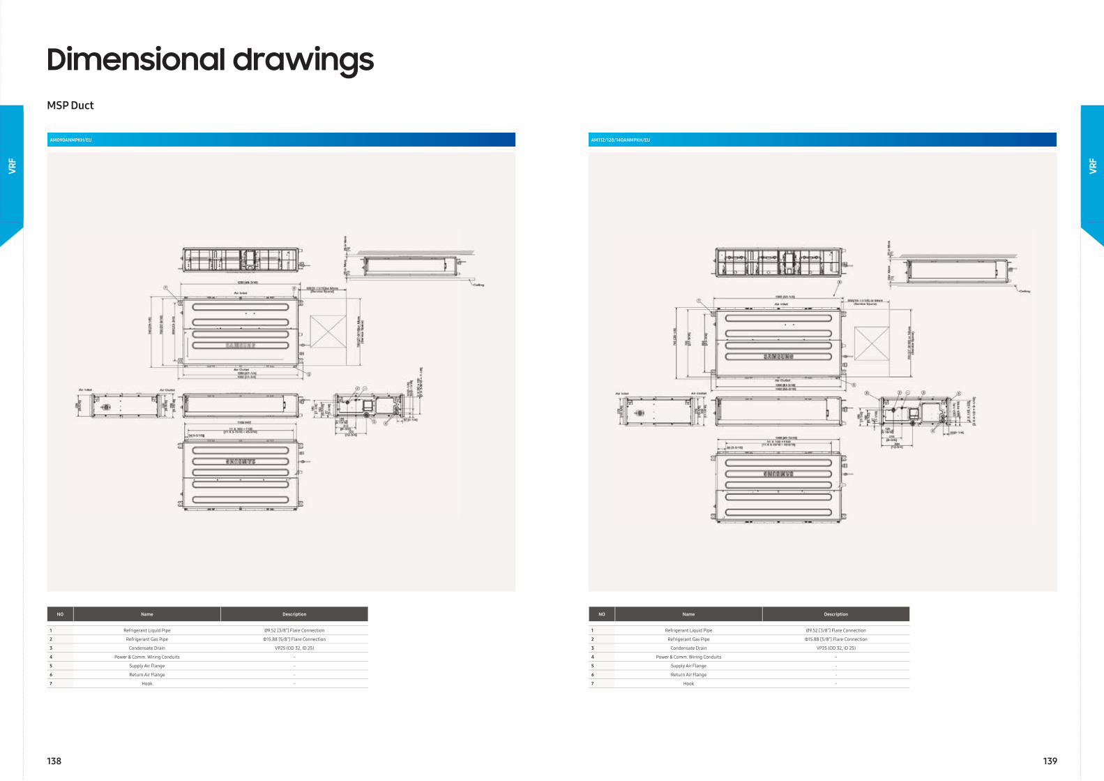
Dimensional drawingsMSP Duct
AM090ANMPKH/EU
NO Name Description
1 Refrigerant Liquid Pipe Ø9.52 [3/8”] Flare Connection
2 Refrigerant Gas Pipe Φ15.88 [5/8”] Flare Connection
3 Condensate Drain VP25 (OD 32, ID 25)
4 Power & Comm. Wiring Conduits -
5 Supply Air Flange -
6 Return Air Flange -
7 Hook -
AM112/128/140ANMPKH/EU
NO Name Description
1 Refrigerant Liquid Pipe Ø9.52 [3/8”] Flare Connection
2 Refrigerant Gas Pipe Φ15.88 [5/8”] Flare Connection
3 Condensate Drain VP25 (OD 32, ID 25)
4 Power & Comm. Wiring Conduits -
5 Supply Air Flange -
6 Return Air Flange -
7 Hook -
138 139
VRF
VRF
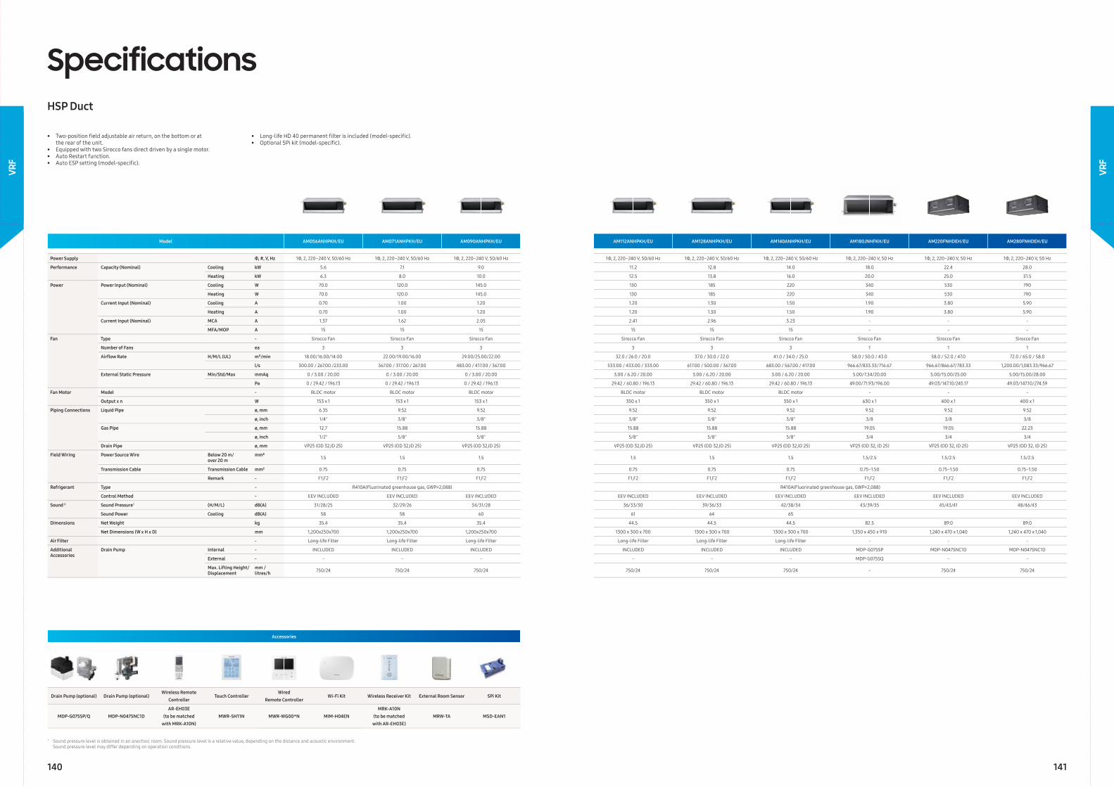
SpecificationsHSP Duct
Accessories
Drain Pump (optional) Drain Pump (optional) Wireless Remote
ControllerTouch Controller
Wired Remote Controller
Wi-Fi Kit Wireless Receiver Kit External Room Sensor SPi Kit
MDP-G075SP/Q MDP-N047SNC1DAR-EH03E
(to be matchedwith MRK-A10N)
MWR-SH11N MWR-WG00*N MIM-H04ENMRK-A10N
(to be matched with AR-EH03E)
MRW-TA MSD-EAN1
• Two-position fi eld adjustable air return, on the bottom or at the rear of the unit.• Equipped with two Sirocco fans direct driven by a single motor.• Auto Restart function.• Auto ESP setting (model-specifi c).
• Long-life HD 40 permanent fi lter is included (model-specifi c).• Optional SPi kit (model-specifi c).
Model AM056ANHPKH/EU AM071ANHPKH/EU AM090ANHPKH/EU AM112ANHPKH/EU AM128ANHPKH/EU AM140ANHPKH/EU AM180JNHFKH/EU AM220FNHDEH/EU AM280FNHDEH/EU
Power Supply Φ, #, V, Hz 1Φ, 2, 220–240 V, 50/60 Hz 1Φ, 2, 220–240 V, 50/60 Hz 1Φ, 2, 220–240 V, 50/60 Hz 1Φ, 2, 220–240 V, 50/60 Hz 1Φ, 2, 220–240 V, 50/60 Hz 1Φ, 2, 220–240 V, 50/60 Hz 1Φ, 2, 220–240 V, 50 Hz 1Φ, 2, 220–240 V, 50 Hz 1Φ, 2, 220–240 V, 50 Hz
Performance Capacity (Nominal) Cooling kW 5.6 7.1 9.0 11.2 12.8 14.0 18.0 22.4 28.0
Heating kW 6.3 8.0 10.0 12.5 13.8 16.0 20.0 25.0 31.5
Power Power Input (Nominal) Cooling W 70.0 120.0 145.0 130 185 220 340 530 790
Heating W 70.0 120.0 145.0 130 185 220 340 530 790
Current Input (Nominal) Cooling A 0.70 1.00 1.20 1.20 1.30 1.50 1.90 3.80 5.90
Heating A 0.70 1.00 1.20 1.20 1.30 1.50 1.90 3.80 5.90
Current Input (Nominal) MCA A 1.37 1.62 2.05 2.41 2.96 3.23 - - -
MFA/MOP A 15 15 15 15 15 15 - - -
Fan Type - Sirocco Fan Sirocco Fan Sirocco Fan Sirocco Fan Sirocco Fan Sirocco Fan Sirocco Fan Sirocco Fan Sirocco Fan
Number of Fans ea 3 3 3 3 3 3 1 1 1
Airfl ow Rate H/M/L (UL) m³/min 18.00/16.00/14.00 22.00/19.00/16.00 29.00/25.00/22.00 32.0 / 26.0 / 20.0 37.0 / 30.0 / 22.0 41.0 / 34.0 / 25.0 58.0 / 50.0 / 43.0 58.0 / 52.0 / 47.0 72.0 / 65.0 / 58.0
l/s 300.00 / 267.00 /233.00 367.00 / 317.00 / 267.00 483.00 / 417.00 / 367.00 533.00 / 433.00 / 333.00 617.00 / 500.00 / 367.00 683.00 / 567.00 / 417.00 966.67/833.33/716.67 966.67/866.67/783.33 1,200.00/1,083.33/966.67
External Static Pressure Min/Std/Max mmAq 0 / 3.00 / 20.00 0 / 3.00 / 20.00 0 / 3.00 / 20.00 3.00 / 6.20 / 20.00 3.00 / 6.20 / 20.00 3.00 / 6.20 / 20.00 5.00/7.34/20.00 5.00/15.00/25.00 5.00/15.00/28.00
Pa 0 / 29.42 / 196.13 0 / 29.42 / 196.13 0 / 29.42 / 196.13 29.42 / 60.80 / 196.13 29.42 / 60.80 / 196.13 29.42 / 60.80 / 196.13 49.00/71.93/196.00 49.03/147.10/245.17 49.03/147.10/274.59
Fan Motor Model - BLDC motor BLDC motor BLDC motor BLDC motor BLDC motor BLDC motor - - -
Output x n W 153 x 1 153 x 1 153 x 1 350 x 1 350 x 1 350 x 1 630 x 1 400 x 1 400 x 1
Piping Connections Liquid Pipe ø, mm 6.35 9.52 9.52 9.52 9.52 9.52 9.52 9.52 9.52
ø, inch 1/4" 3/8" 3/8" 3/8" 3/8" 3/8" 3/8 3/8 3/8
Gas Pipe ø, mm 12.7 15.88 15.88 15.88 15.88 15.88 19.05 19.05 22.23
ø, inch 1/2" 5/8" 5/8" 5/8" 5/8" 5/8" 3/4 3/4 3/4
Drain Pipe ø, mm VP25 (OD 32,ID 25) VP25 (OD 32,ID 25) VP25 (OD 32,ID 25) VP25 (OD 32,ID 25) VP25 (OD 32,ID 25) VP25 (OD 32,ID 25) VP25 (OD 32, ID 25) VP25 (OD 32, ID 25) VP25 (OD 32, ID 25)
Field Wiring Power Source Wire Below 20 m/over 20 m
mm² 1.5 1.5 1.5 1.5 1.5 1.5 1.5/2.5 1.5/2.5 1.5/2.5
Transmission Cable Transmission Cable mm² 0.75 0.75 0.75 0.75 0.75 0.75 0.75~1.50 0.75~1.50 0.75~1.50
Remark - F1,F2 F1,F2 F1,F2 F1,F2 F1,F2 F1,F2 F1,F2 F1,F2 F1,F2
Refrigerant Type - R410A(Fluorinated greenhouse gas, GWP=2,088) R410A(Fluorinated greenhouse gas, GWP=2,088)
Control Method - EEV INCLUDED EEV INCLUDED EEV INCLUDED EEV INCLUDED EEV INCLUDED EEV INCLUDED EEV INCLUDED EEV INCLUDED EEV INCLUDED
Sound 2 Sound Pressure1 (H/M/L) dB(A) 31/28/25 32/29/26 34/31/28 36/33/30 39/36/33 42/38/34 43/39/35 45/43/41 48/46/43
Sound Power Cooling dB(A) 58 58 60 61 64 65
Dimensions Net Weight kg 35.4 35.4 35.4 44.5 44.5 44.5 82.5 89.0 89.0
Net Dimensions (W x H x D) mm 1,200x250x700 1,200x250x700 1,200x250x700 1300 x 300 x 700 1300 x 300 x 700 1300 x 300 x 700 1,350 x 450 x 910 1,240 x 470 x 1,040 1,240 x 470 x 1,040
Air Filter - Long-life Filter Long-life Filter Long-life Filter Long-life Filter Long-life Filter Long-life Filter - - -
Additional Accessories
Drain Pump Internal - INCLUDED INCLUDED INCLUDED INCLUDED INCLUDED INCLUDED MDP-G075SP MDP-N047SNC1D MDP-N047SNC1D
External - - - - - - - MDP-G075SQ - -
Max. Lifting Height/ Displacement
mm / litres/h 750/24 750/24 750/24 750/24 750/24 750/24 - 750/24 750/24
1 Sound pressure level is obtained in an anechoic room. Sound pressure level is a relative value, depending on the distance and acoustic environment. Sound pressure level may differ depending on operation conditions.
140 141
VRF
VRF
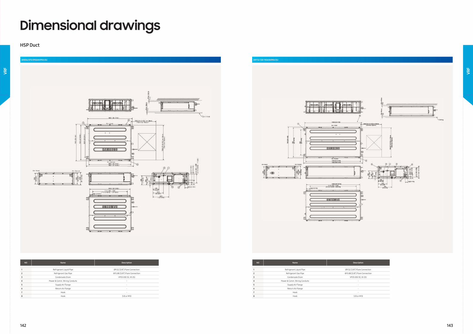
NO Name Description
1 Refrigerant Liquid Pipe Ø9.52 [3/8”] Flare Connection
2 Refrigerant Gas Pipe Φ15.88 [5/8”] Flare Connection
3 Condensate Drain VP25 (OD 32, ID 25)
4 Power & Comm. Wiring Conduits -
5 Supply Air Flange -
6 Return Air Flange -
7 Hook -
8 Hook 3/8 or M10
NO Name Description
1 Refrigerant Liquid Pipe Ø9.52 [3/8”] Flare Connection
2 Refrigerant Gas Pipe Φ15.88 [5/8”] Flare Connection
3 Condensate Drain VP25 (OD 32, ID 25)
4 Power & Comm. Wiring Conduits -
5 Supply Air Flange -
6 Return Air Flange -
7 Hook -
8 Hook 3/8 or M10
Dimensional drawingsHSP Duct
AM056/070/090ANHPKH/EU AM112/128/140ANHPKH/EU
142 143
VRF
VRF
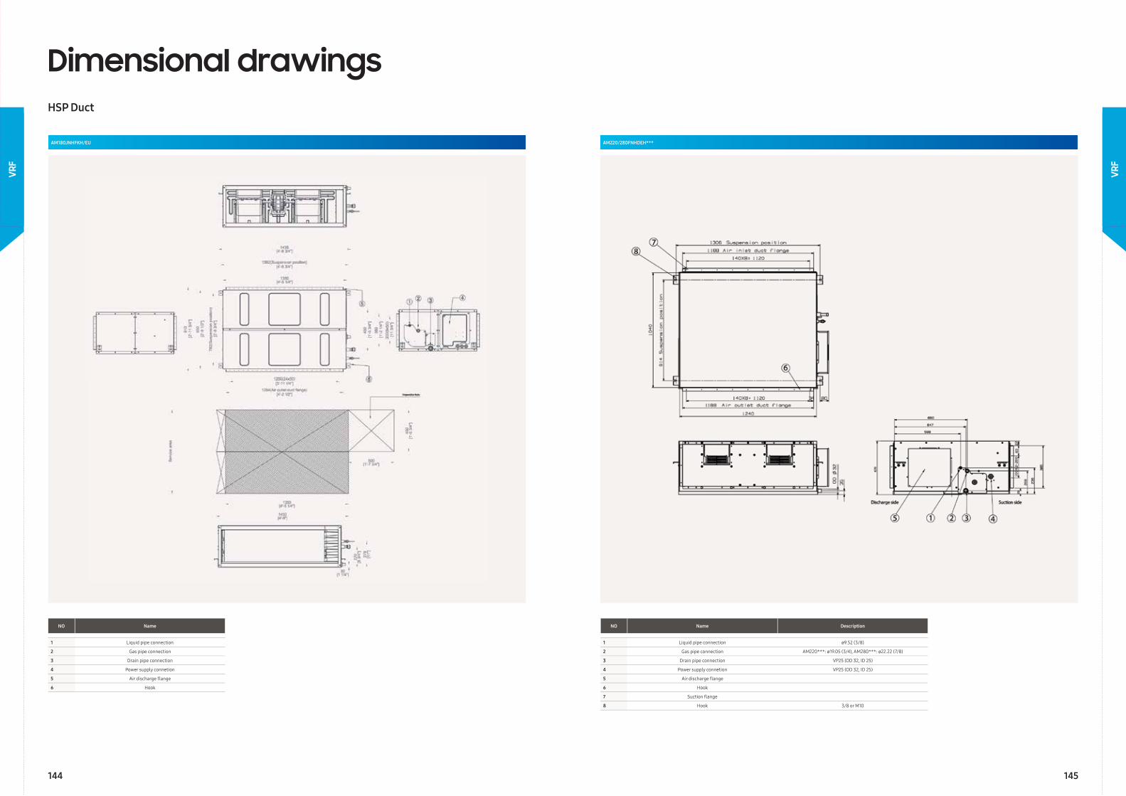
Dimensional drawingsHSP Duct
AM180JNHFKH/EU
NO Name
1 Liquid pipe connection
2 Gas pipe connection
3 Drain pipe connection
4 Power supply connetion
5 Air discharge fl ange
6 Hook
AM220/280FNHDEH***
NO Name Description
1 Liquid pipe connection ø9.52 (3/8)
2 Gas pipe connection AM220***: ø19.05 (3/4), AM280***: ø22.22 (7/8)
3 Drain pipe connection VP25 (OD 32, ID 25)
4 Power supply connetion VP25 (OD 32, ID 25)
5 Air discharge fl ange
6 Hook
7 Suction fl ange
8 Hook 3/8 or M10
144 145
VRF
VRF
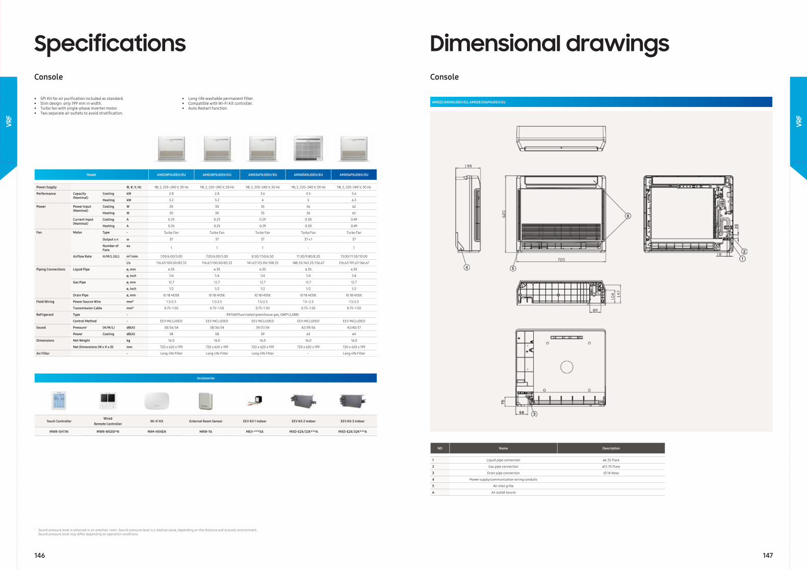
Model AM028FNJDEH/EU AM028FNJDEH/EU AM036FNJDEH/EU AM045KNJDEH/EU AM056FNJDEH/EU
Power Supply Φ, #, V, Hz 1Φ, 2, 220~240 V, 50 Hz 1Φ, 2, 220~240 V, 50 Hz 1Φ, 2, 220~240 V, 50 Hz 1Φ, 2, 220–240 V, 50 Hz 1Φ, 2, 220~240 V, 50 Hz
Performance Capacity (Nominal)
Cooling kW 2.8 2.8 3.6 4.5 5.6
Heating kW 3.2 3.2 4 5 6.3
Power Power Input (Nominal)
Cooling W 30 30 35 36 62
Heating W 30 30 35 36 62
Current Input (Nominal)
Cooling A 0.25 0.25 0.29 0.30 0.49
Heating A 0.25 0.25 0.29 0.30 0.49
Fan Motor Type - Turbo Fan Turbo Fan Turbo Fan Turbo Fan Turbo Fan
Output x n w 37 37 37 37 x 1 37
Number of Fans
ea 1 1 1 - 1
Airfl ow Rate H/M/L (UL) m³/min 7.00/6.00/5.00 7.00/6.00/5.00 8.50/7.50/6.50 11.30/9.80/8.20 13.00/11.50/10.00
l/s 116.67/100.00/83.33 116.67/100.00/83.33 141.67/125.00/108.33 188.33/163.33/136.67 216.67/191.67/166.67
Piping Connections Liquid Pipe ø, mm 6.35 6.35 6.35 6.35 6.35
ø, inch 1/4 1/4 1/4 1/4 1/4
Gas Pipe ø, mm 12.7 12.7 12.7 12.7 12.7
ø, inch 1/2 1/2 1/2 1/2 1/2
Drain Pipe ø, mm ID 18 HOSE ID 18 HOSE ID 18 HOSE ID 18 HOSE ID 18 HOSE
Field Wiring Power Source Wire mm² 1.5/2.5 1.5/2.5 1.5/2.5 1.5–2.5 1.5/2.5
Transmission Cable mm² 0.75~1.50 0.75~1.50 0.75~1.50 0.75–1.50 0.75~1.50
Refrigerant Type - R410A(Fluorinated greenhouse gas, GWP=2,088)
Control Method - EEV INCLUDED EEV INCLUDED EEV INCLUDED EEV INCLUDED EEV INCLUDED
Sound Pressure1 (H/M/L) dB(A) 38/36/34 38/36/34 39/37/34 42/39/36 43/40/37
Power Cooling dB(A) 58 58 59 63 64
Dimensions Net Weight kg 16.0 16.0 16.0 16.0 16.0
Net Dimensions (W x H x D) mm 720 x 620 x 199 720 x 620 x 199 720 x 620 x 199 720 x 620 x 199 720 x 620 x 199
Air Filter - Long-life Filter Long-life Filter Long-life Filter - Long-life Filter
SpecificationsConsole
• SPi Kit for air purifi cation included as standard.• Slim design: only 199 mm in width.• Turbo fan with single-phase inverter motor.• Two separate air outlets to avoid stratifi cation.
• Long-life washable permanent fi lter.• Compatible with Wi-Fi Kit controller.• Auto Restart function.
Accessories
Touch ControllerWired
Remote ControllerWi-Fi Kit External Room Sensor EEV Kit 1 Indoor EEV Kit 2 Indoor EEV Kit 3 Indoor
MWR-SH11N MWR-WG00*N MIM-H04EN MRW-TA MEV-***SA MXD-E24/32K***A MXD-E24/32K***A
Dimensional drawingsConsole
AM022/045KNJDEH/EU, AM028/036FNJDEH/EU
NO Name Description
1 Liquid pipe connection ø6.35 Flare
2 Gas pipe connection ø12.70 Flare
3 Drain pipe connection ID 18 Hose
4 Power supply/communication wiring conduits
5 Air inlet grille
6 Air outlet louvre
1 Sound pressure level is obtained in an anechoic room. Sound pressure level is a relative value, depending on the distance and acoustic environment. Sound pressure level may differ depending on operation conditions.
146 147
VRF
VRF
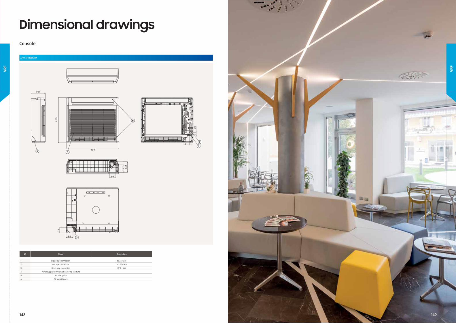
Dimensional drawingsConsole
AM056FNJDEH/EU
NO Name Description
1 Liquid pipe connection ø6.35 Flare
2 Gas pipe connection ø12.70 Flare
3 Drain pipe connection ID 18 Hose
4 Power supply/communication wiring conduits
5 Air inlet grille
6 Air outlet louvre
148 149
VRF
VRF
149
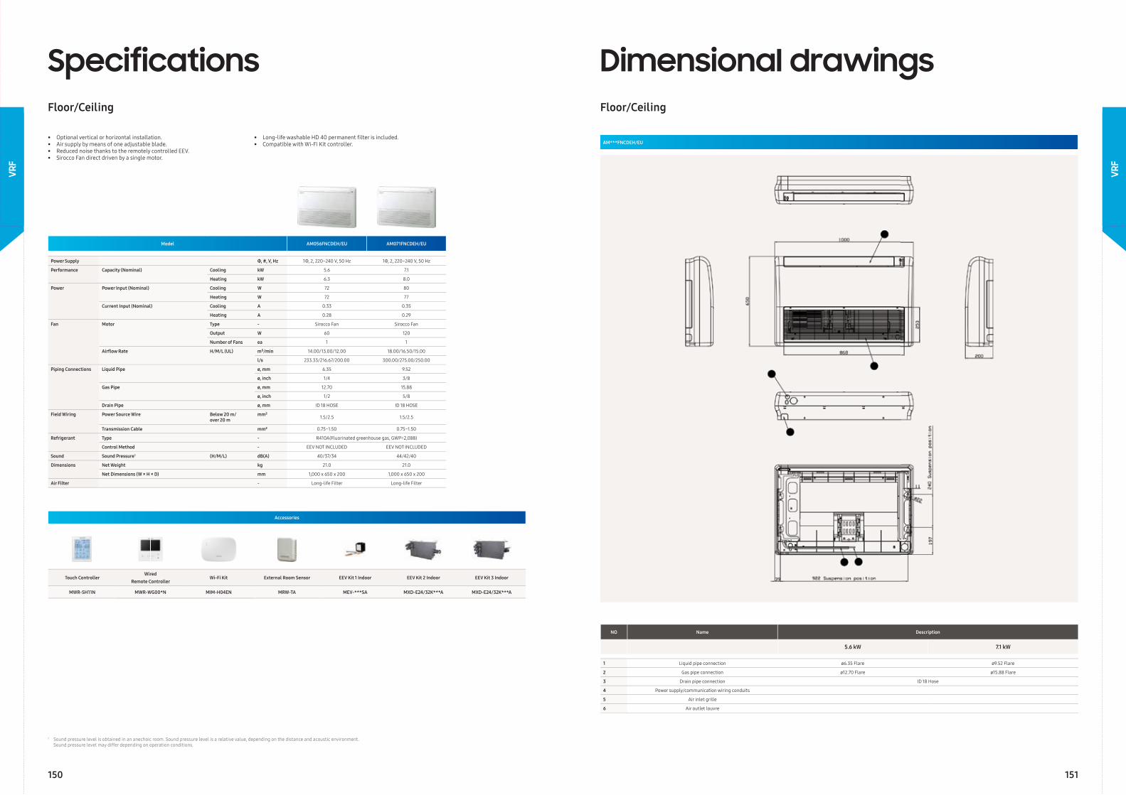
Model AM056FNCDEH/EU AM071FNCDEH/EU
Power Supply Φ, #, V, Hz 1Φ, 2, 220~240 V, 50 Hz 1Φ, 2, 220~240 V, 50 Hz
Performance Capacity (Nominal) Cooling kW 5.6 7.1
Heating kW 6.3 8.0
Power Power Input (Nominal) Cooling W 72 80
Heating W 72 77
Current Input (Nominal) Cooling A 0.33 0.35
Heating A 0.28 0.29
Fan Motor Type - Sirocco Fan Sirocco Fan
Output W 60 120
Number of Fans ea 1 1
Airfl ow Rate H/M/L (UL) m³/min 14.00/13.00/12.00 18.00/16.50/15.00
l/s 233.33/216.67/200.00 300.00/275.00/250.00
Piping Connections Liquid Pipe ø, mm 6.35 9.52
ø, inch 1/4 3/8
Gas Pipe ø, mm 12.70 15.88
ø, inch 1/2 5/8
Drain Pipe ø, mm ID 18 HOSE ID 18 HOSE
Field Wiring Power Source Wire Below 20 m/over 20 m
mm² 1.5/2.5 1.5/2.5
Transmission Cable mm² 0.75~1.50 0.75~1.50
Refrigerant Type - R410A(Fluorinated greenhouse gas, GWP=2,088)
Control Method - EEV NOT INCLUDED EEV NOT INCLUDED
Sound Sound Pressure1 (H/M/L) dB(A) 40/37/34 44/42/40
Dimensions Net Weight kg 21.0 21.0
Net Dimensions (W × H × D) mm 1,000 x 650 x 200 1,000 x 650 x 200
Air Filter - Long-life Filter Long-life Filter
SpecificationsFloor/Ceiling
• Optional vertical or horizontal installation.• Air supply by means of one adjustable blade.• Reduced noise thanks to the remotely controlled EEV.• Sirocco Fan direct driven by a single motor.
• Long-life washable HD 40 permanent fi lter is included.• Compatible with Wi-Fi Kit controller.
Accessories
Touch ControllerWired
Remote ControllerWi-Fi Kit External Room Sensor EEV Kit 1 Indoor EEV Kit 2 Indoor EEV Kit 3 Indoor
MWR-SH11N MWR-WG00*N MIM-H04EN MRW-TA MEV-***SA MXD-E24/32K***A MXD-E24/32K***A
Dimensional drawingsFloor/Ceiling
AM***FNCDEH/EU
NO Name Description
5.6 kW 7.1 kW
1 Liquid pipe connection ø6.35 Flare ø9.52 Flare
2 Gas pipe connection ø12.70 Flare ø15.88 Flare
3 Drain pipe connection ID 18 Hose
4 Power supply/communication wiring conduits
5 Air inlet grille
6 Air outlet louvre
1 Sound pressure level is obtained in an anechoic room. Sound pressure level is a relative value, depending on the distance and acoustic environment. Sound pressure level may differ depending on operation conditions.
150 151
VRF
VRF
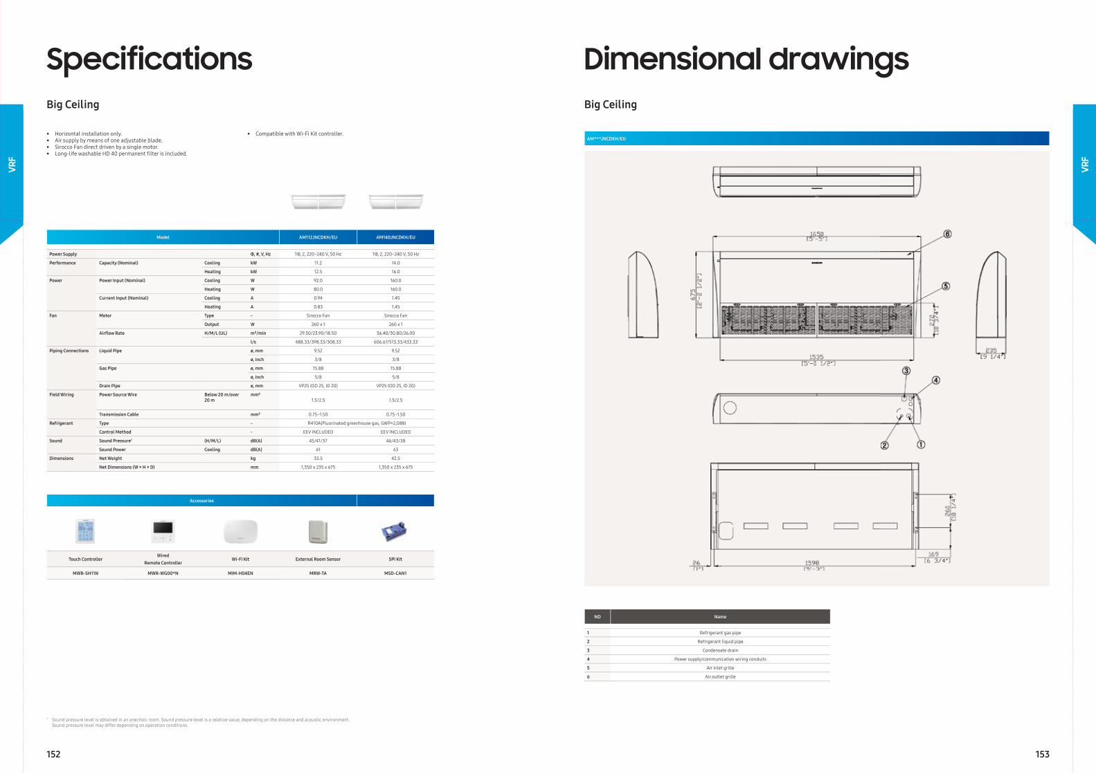
Model AM112JNCDKH/EU AM140JNCDKH/EU
Power Supply Φ, #, V, Hz 1Φ, 2, 220~240 V, 50 Hz 1Φ, 2, 220~240 V, 50 Hz
Performance Capacity (Nominal) Cooling kW 11.2 14.0
Heating kW 12.5 16.0
Power Power Input (Nominal) Cooling W 92.0 160.0
Heating W 80.0 160.0
Current Input (Nominal) Cooling A 0.94 1.45
Heating A 0.83 1.45
Fan Motor Type - Sirocco Fan Sirocco Fan
Output W 260 x 1 260 x 1
Airfl ow Rate H/M/L (UL) m³/min 29.30/23.90/18.50 36.40/30.80/26.00
l/s 488.33/398.33/308.33 606.67/513.33/433.33
Piping Connections Liquid Pipe ø, mm 9.52 9.52
ø, inch 3/8 3/8
Gas Pipe ø, mm 15.88 15.88
ø, inch 5/8 5/8
Drain Pipe ø, mm VP25 (OD 25, ID 20) VP25 (OD 25, ID 20)
Field Wiring Power Source Wire Below 20 m/over 20 m
mm²1.5/2.5 1.5/2.5
Transmission Cable mm² 0.75~1.50 0.75~1.50
Refrigerant Type - R410A(Fluorinated greenhouse gas, GWP=2,088)
Control Method - EEV INCLUDED EEV INCLUDED
Sound Sound Pressure1 (H/M/L) dB(A) 45/41/37 46/43/38
Sound Power Cooling dB(A) 61 63
Dimensions Net Weight kg 33.5 42.5
Net Dimensions (W × H × D) mm 1,350 x 235 x 675 1,350 x 235 x 675
SpecificationsBig Ceiling
• Horizontal installation only.• Air supply by means of one adjustable blade.• Sirocco Fan direct driven by a single motor.• Long-life washable HD 40 permanent fi lter is included.
• Compatible with Wi-Fi Kit controller.
Accessories
Touch ControllerWired
Remote ControllerWi-Fi Kit External Room Sensor SPi Kit
MWR-SH11N MWR-WG00*N MIM-H04EN MRW-TA MSD-CAN1
Dimensional drawingsBig Ceiling
AM***JNCDKH/EU
NO Name
1 Refrigerant gas pipe
2 Refrigerant liquid pipe
3 Condensate drain
4 Power supply/communication wiring conduits
5 Air inlet grille
6 Air outlet grille
1 Sound pressure level is obtained in an anechoic room. Sound pressure level is a relative value, depending on the distance and acoustic environment. Sound pressure level may differ depending on operation conditions.
152 153
VRF
VRF
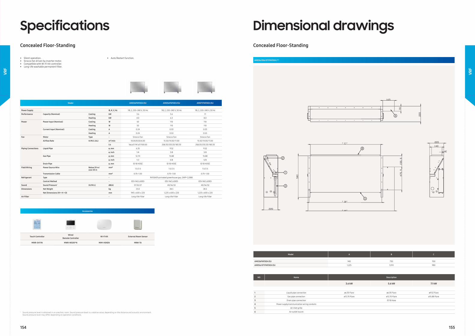
Model AM036FNFDEH/EU AM056FNFDEH/EU AM071FNFDEH/EU
Power Supply Φ, #, V, Hz 1Φ, 2, 220~240 V, 50 Hz 1Φ, 2, 220~240 V, 50 Hz 1Φ, 2, 220~240 V, 50 Hz
Performance Capacity (Nominal) Cooling kW 3.6 5.6 7.1
Heating kW 4.0 6.3 8.0
Power Power Input (Nominal) Cooling W 50 110 110
Heating W 50 110 110
Current Input (Nominal) Cooling A 0.24 0.53 0.53
Heating A 0.24 0.53 0.53
Fan Motor Type - Sirocco Fan Sirocco Fan Sirocco Fan
Airfl ow Rate H/M/L (UL) m³/min 10.00/8.50/6.00 15.50/14.00/11.00 15.50/14.00/11.00
l/s 166.67/141.67/100.00 258.33/233.33/183.33 258.33/233.33/183.33
Piping Connections Liquid Pipe ø, mm 6.35 9.52 9.52
ø, inch 1/4 3/8 3/8
Gas Pipe ø, mm 12.70 15.88 15.88
ø, inch 1/2 5/8 5/8
Drain Pipe ø, mm ID 18 HOSE ID 18 HOSE ID 18 HOSE
Field Wiring Power Source Wire Below 20 m/over 20 m
mm² 1.5/2.5 1.5/2.5 1.5/2.5
Transmission Cable mm² 0.75~1.50 0.75~1.50 0.75~1.50
Refrigerant Type - R410A(Fluorinated greenhouse gas, GWP=2,088)
Control Method - EEV INCLUDED EEV INCLUDED EEV INCLUDED
Sound Sound Pressure1 (H/M/L) dB(A) 37/32/27 40/36/32 40/36/32
Dimensions Net Weight kg 23.0 28.5 28.5
Net Dimensions (W × H × D) mm 945 x 600 x 220 1,225 x 600 x 220 1,225 x 600 x 220
Air Filter - Long-life Filter Long-life Filter Long-life Filter
SpecificationsConcealed Floor-Standing
• Silent operation.• Sirocco fan driven by inverter motor.• Compatible with Wi-Fi Kit controller.• Long-life washable permanent fi lter.
• Auto Restart function.
Accessories
Touch ControllerWired
Remote ControllerWi-Fi Kit External Room Sensor
MWR-SH11N MWR-WG00*N MIM-H04EN MRW-TA
Dimensional drawingsConcealed Floor-Standing
AM036/056/071FNFDEH/**
NO Name Description
3.6 kW 5.6 kW 7.1 kW
1 Liquid pipe connection ø6.35 Flare ø6.35 Flare ø9.52 Flare
2 Gas pipe connection ø12.70 Flare ø12.70 Flare ø15.88 Flare
3 Drain pipe connection ID 18 Hose
4 Power supply/communication wiring conduits
5 Air inlet grille
6 Air outlet louvre
Model A B C
AM036FNFDEH/EU 945 730 700
AM056/071FNFDEH/EU 1,225 1,010 980
1 Sound pressure level is obtained in an anechoic room. Sound pressure level is a relative value, depending on the distance and acoustic environment. Sound pressure level may differ depending on operation conditions.
154 155
VRF
VRF
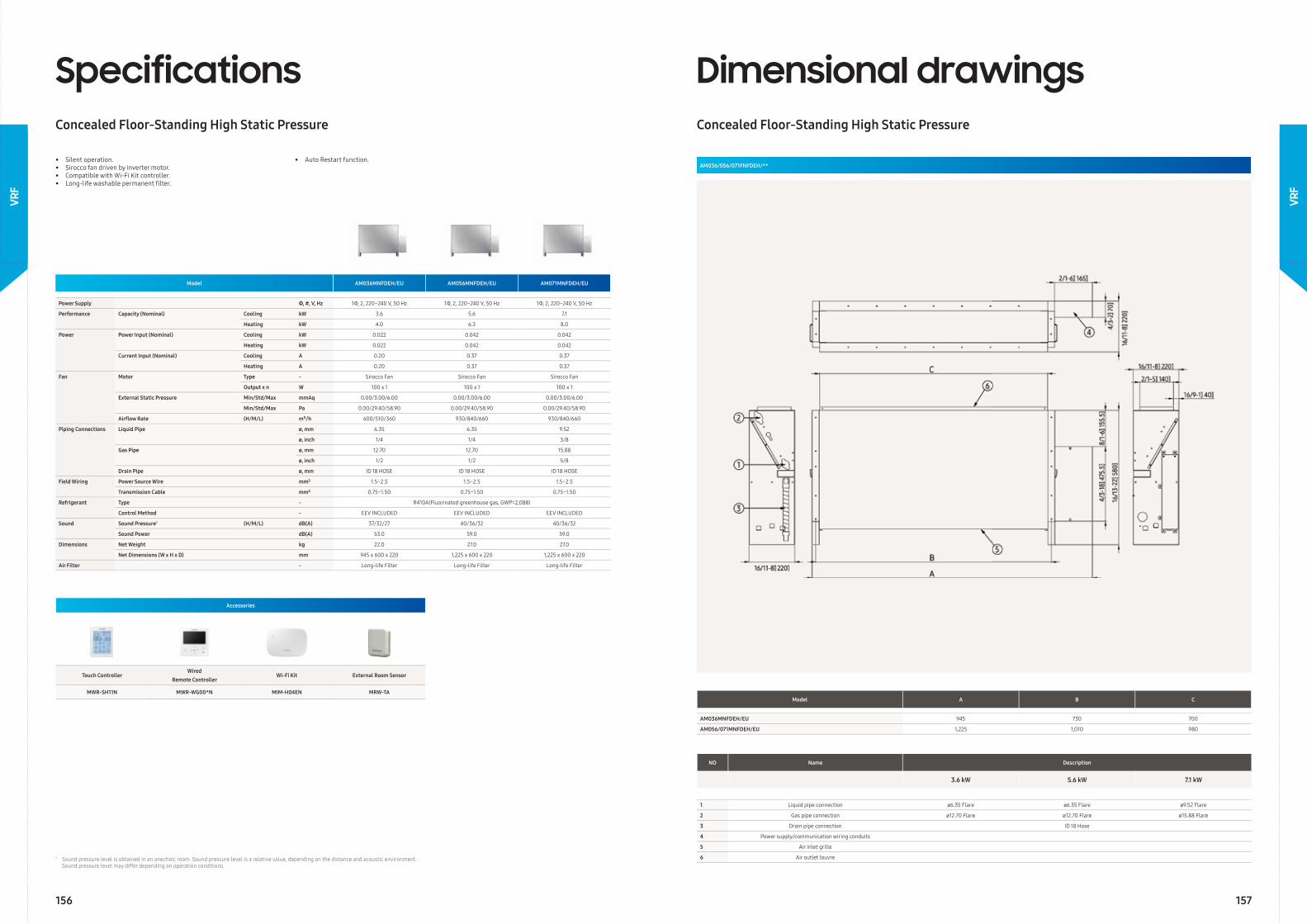
Model AM036MNFDEH/EU AM056MNFDEH/EU AM071MNFDEH/EU
Power Supply Φ, #, V, Hz 1Φ, 2, 220~240 V, 50 Hz 1Φ, 2, 220~240 V, 50 Hz 1Φ, 2, 220~240 V, 50 Hz
Performance Capacity (Nominal) Cooling kW 3.6 5.6 7.1
Heating kW 4.0 6.3 8.0
Power Power Input (Nominal) Cooling kW 0.022 0.042 0.042
Heating kW 0.022 0.042 0.042
Current Input (Nominal) Cooling A 0.20 0.37 0.37
Heating A 0.20 0.37 0.37
Fan Motor Type - Sirocco Fan Sirocco Fan Sirocco Fan
Output x n W 100 x 1 100 x 1 100 x 1
External Static Pressure Min/Std/Max mmAq 0.00/3.00/6.00 0.00/3.00/6.00 0.00/3.00/6.00
Min/Std/Max Pa 0.00/29.40/58.90 0.00/29.40/58.90 0.00/29.40/58.90
Airfl ow Rate (H/M/L) m³/h 600/510/360 930/840/660 930/840/660
Piping Connections Liquid Pipe ø, mm 6.35 6.35 9.52
ø, inch 1/4 1/4 3/8
Gas Pipe ø, mm 12.70 12.70 15.88
ø, inch 1/2 1/2 5/8
Drain Pipe ø, mm ID 18 HOSE ID 18 HOSE ID 18 HOSE
Field Wiring Power Source Wire mm² 1.5~2.5 1.5~2.5 1.5~2.5
Transmission Cable mm² 0.75~1.50 0.75~1.50 0.75~1.50
Refrigerant Type - R410A(Fluorinated greenhouse gas, GWP=2,088)
Control Method - EEV INCLUDED EEV INCLUDED EEV INCLUDED
Sound Sound Pressure1 (H/M/L) dB(A) 37/32/27 40/36/32 40/36/32
Sound Power dB(A) 53.0 59.0 59.0
Dimensions Net Weight kg 22.0 27.0 27.0
Net Dimensions (W x H x D) mm 945 x 600 x 220 1,225 x 600 x 220 1,225 x 600 x 220
Air Filter - Long-life Filter Long-life Filter Long-life Filter
SpecificationsConcealed Floor-Standing High Static Pressure
• Silent operation.• Sirocco fan driven by inverter motor.• Compatible with Wi-Fi Kit controller.• Long-life washable permanent fi lter.
• Auto Restart function.
Accessories
Touch ControllerWired
Remote ControllerWi-Fi Kit External Room Sensor
MWR-SH11N MWR-WG00*N MIM-H04EN MRW-TAModel A B C
AM036MNFDEH/EU 945 730 700
AM056/071MNFDEH/EU 1,225 1,010 980
NO Name Description
3.6 kW 5.6 kW 7.1 kW
1 Liquid pipe connection ø6.35 Flare ø6.35 Flare ø9.52 Flare
2 Gas pipe connection ø12.70 Flare ø12.70 Flare ø15.88 Flare
3 Drain pipe connection ID 18 Hose
4 Power supply/communication wiring conduits
5 Air inlet grille
6 Air outlet louvre
Dimensional drawingsConcealed Floor-Standing High Static Pressure
AM036/056/071FNFDEH/**
1 Sound pressure level is obtained in an anechoic room. Sound pressure level is a relative value, depending on the distance and acoustic environment. Sound pressure level may differ depending on operation conditions.
156 157
VRF
VRF
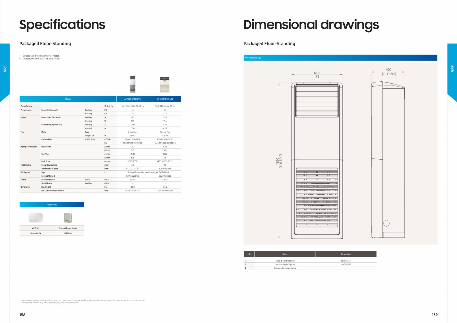
Model AM140RNPDKH/EU AM280RNPDKH/EU
Power Supply Φ, #, V, Hz 1Φ, 2, 220–240 V, 50/60 Hz 1Φ, 2, 220–240 V, 50 Hz
Performance Capacity (Nominal) Cooling kW 14 28
Heating kW 16 31.5
Power Power Input (Nominal) Cooling W 190 955
Heating W 190 955
Current Input (Nominal) Cooling A 0.90 4.73
Heating A 0.90 4.73
Fan Motor Type - Sirocco Fan Sirocco Fan
Output x n W 154 x 1 700 x 1
Airfl ow Rate H/M/L (UL) m³/min 35.00/30.50/27.50 70.00/60.00/50.00
l/s 583.33/508.33/458.33 1,166.67/1,000.00/833.33
Piping Connections Liquid Pipe ø, mm 9.52 9.52
ø, inch 3/8 3/8
Gas Pipe ø, mm 15.88 22.22
ø, inch 5/8 7/8
Drain Pipe ø, mm ID 18 HOSE VP25 (OD 32, ID 25)
Field Wiring Power Source Wire mm² 2.5 2.5
Transmission Cable mm² VCTF 0.75–1.50 VCTF 0.75–1.50
Refrigerant Type - R410A(Fluorinated greenhouse gas, GWP=2,088)
Control Method - EEV INCLUDED EEV INCLUDED
Sound Sound Pressure1 (H/L) dB(A) 54/47 58/54
Sound Power Cooling dB(A) - -
Dimension Net Weight kg 48.0 115.0
Net Dimensions (W x H x D) mm 650 x 1,850 x 400 1,100 x 1,800 x 485
SpecificationsPackaged Floor-Standing
• Sirocco fan driven by inverter motor.• Compatible with Wi-Fi Kit controller.
Accessories
Wi-Fi Kit External Room Sensor
MIM-H04EN MRW-TA
Dimensional drawingsPackaged Floor-Standing
AM140RNPDKH/EU
NO Name Description
1 Gas piping refrigerant ø15.88 (5/8)
2 Liquid piping refrigerant ø9.52 (3/8)
3 Condensation drain piping -
1 Sound pressure level is obtained in an anechoic room. Sound pressure level is a relative value, depending on the distance and acoustic environment. Sound pressure level may differ depending on operation conditions.
158 159
VRF
VRF
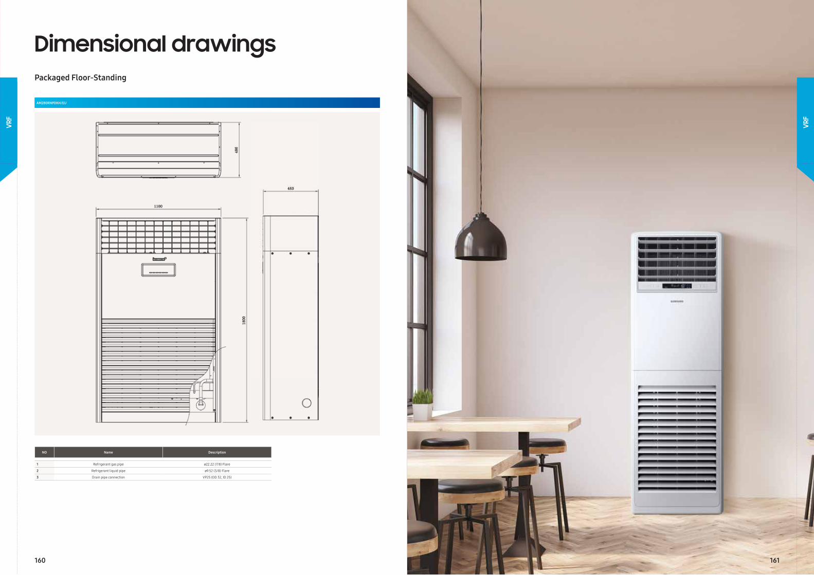
Dimensional drawingsPackaged Floor-Standing
AM280RNPDKH/EU
NO Name Description
1 Refrigerant gas pipe ø22.22 (7/8) Flare
2 Refrigerant liquid pipe ø9.52 (3/8) Flare
3 Drain pipe connection VP25 (OD 32, ID 25)
160 161
VRF
VRF
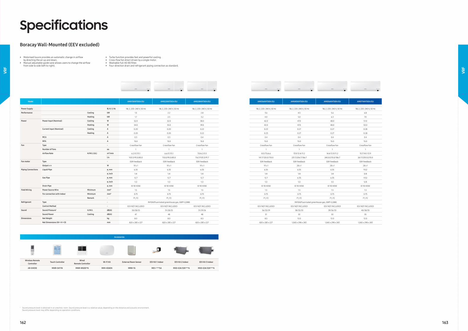
Model AM015KNTDEH/EU AM022KNTDEH/EU AM028KNTDEH/EU AM036KNTDEH/EU AM045KNTDEH/EU AM056KNTDEH/EU AM071KNTDEH/EU
Power Supply Φ, #, V, Hz 1Φ, 2, 220–240 V, 50 Hz 1Φ, 2, 220–240 V, 50 Hz 1Φ, 2, 220–240 V, 50 Hz 1Φ, 2, 220–240 V, 50 Hz 1Φ, 2, 220–240 V, 50 Hz 1Φ, 2, 220–240 V, 50 Hz 1Φ, 2, 220–240 V, 50 Hz
Performance Cooling kW 1.5 2.2 2.8 3.6 4.5 5.6 6.8
Heating kW 1.7 2.5 3.2 4.0 5.0 6.3 7.0
Power Power Input (Nominal) Cooling W 32.0 32.0 38.0 42.0 47.0 48.0 51.0
Heating W 34.0 35.0 39.0 42.0 47.0 48.0 53.0
Current Input (Nominal) Cooling A 0.20 0.20 0.22 0.23 0.27 0.27 0.28
Heating A 0.20 0.20 0.22 0.23 0.27 0.27 0.28
MCA A 0.3 0.3 0.4 0.4 0.4 0.4 0.4
MFA A 15.0 15.0 15.0 15.0 15.0 15.0 15.0
Fan Type - Crossfl ow Fan Crossfl ow Fan Crossfl ow Fan Crossfl ow Fan Crossfl ow Fan Crossfl ow Fan Crossfl ow Fan
Number of Fans ea 1 1 1 1 1 1 1
Airfl ow Rate H/M/L (UL) m³/min 6.2/5.7/5.1 6.6/5.7/5.1 7.0/6.2/5.5 8.5/7.5/6.6 13.9/12.4/11.2 14.4/12.9/11.2 15.7/14.1/12.9
l/s 103.3/95.0/85.0 110.0/95.0/85.0 116.7/103.3/91.7 141.7/125.0/110.0 231.7/206.7/186.7 240.0/215.0/186.7 261.7/235.0/215.0
Fan motor Type - SSR Feedback SSR Feedback SSR Feedback SSR Feedback SSR Feedback SSR Feedback SSR Feedback
Output x n W 19 x 1 19 x 1 19 x 1 19 x 1 28 x 1 28 x 1 28 x 1
Piping Connections Liquid Pipe ø, mm 6.35 6.35 6.35 6.35 6.35 6.35 9.52
ø, inch 1/4 1/4 1/4 1/4 1/4 1/4 3/8
Gas Pipe ø, mm 12.7 12.7 12.7 12.7 6.35 6.35 9.52
ø, inch 1/2 1/2 1/2 1/2 1/2 1/2 5/8
Drain Pipe ø, mm ID 18 HOSE ID 18 HOSE ID 18 HOSE ID 18 HOSE ID 18 HOSE ID 18 HOSE ID 18 HOSE
Field Wiring Power Source Wire Minimum mm² 1.5 1.5 1.5 1.5 1.5 1.5 1.5
For connection with indoor Minimum mm² 0.75 0.75 0.75 0.75 0.75 0.75 0.75
Remark - F1, F2 F1, F2 F1, F2 F1, F2 F1, F2 F1, F2 F1, F2
Refrigerant Type - R410A(Fluorinated greenhouse gas, GWP=2,088) R410A(Fluorinated greenhouse gas, GWP=2,088)
Control Method - EEV NOT INCLUDED EEV NOT INCLUDED EEV NOT INCLUDED EEV NOT INCLUDED EEV NOT INCLUDED EEV NOT INCLUDED EEV NOT INCLUDED
Sound Sound Pressure1 H/M/L dB(A) 30/28/25 31/28/25 31/29/26 36/33/29 38/35/33 39/36/33 40/38/35
Sound Power Cooling dB(A) 47 48 48 51 53 53 55
Dimensions Net Weight kg 8.0 8.0 8.5 8.5 12.0 12.0 12.0
Net Dimensions (W × H × D) mm 820 x 285 x 227 820 x 285 x 227 820 x 285 x 227 820 x 285 x 227 1,065 x 298 x 243 1,065 x 298 x 243 1,065 x 298 x 243
SpecificationsBoracay Wall-Mounted (EEV excluded)
• Motorised louvre provides an automatic change in airfl ow by directing the air up and down.• Manual adjustable guide vane allows users to change the airfl ow from side to side (left to right).
• Turbo function provides fast and powerful cooling.• Cross-fl ow fan direct driven by a single motor.• Washable Full HD 80 fi lter.• Four-direction drain and refrigerant piping connection as standard.
Accessories
Wireless Remote Controller
Touch ControllerWired
Remote ControllerWi-Fi Kit External Room Sensor EEV Kit 1 Indoor EEV Kit 2 Indoor EEV Kit 3 Indoor
AR-EH03E MWR-SH11N MWR-WG00*N MIM-H04EN MRW-TA MEV-***SA MXD-E24/32K***A MXD-E24/32K***A
1 Sound pressure level is obtained in an anechoic room. Sound pressure level is a relative value, depending on the distance and acoustic environment. Sound pressure level may differ depending on operation conditions.
163
VRF
162
VRF
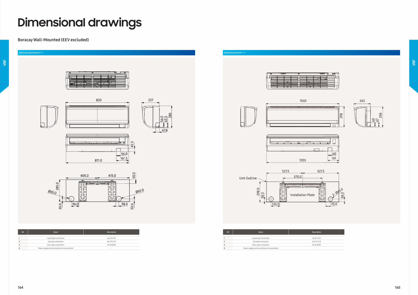
Dimensional drawingsBoracay Wall-Mounted (EEV excluded)
AM015/022/028/036KNTD****
NO Name Description
1 Liquid pipe connection ø6.35 (1/4)
2 Gas pipe connection ø12.70 (1/2)
3 Drain pipe connection ID 18 HOSE
4 Power supply/communication wiring conduits -
AM045/056/071KNTD*****
NO Name Description
1 Liquid pipe connection ø6.35 (1/4)
2 Gas pipe connection ø12.70 (1/2)
3 Drain pipe connection ID 18 HOSE
4 Power supply/communication wiring conduits -
164 165
VRF
VRF
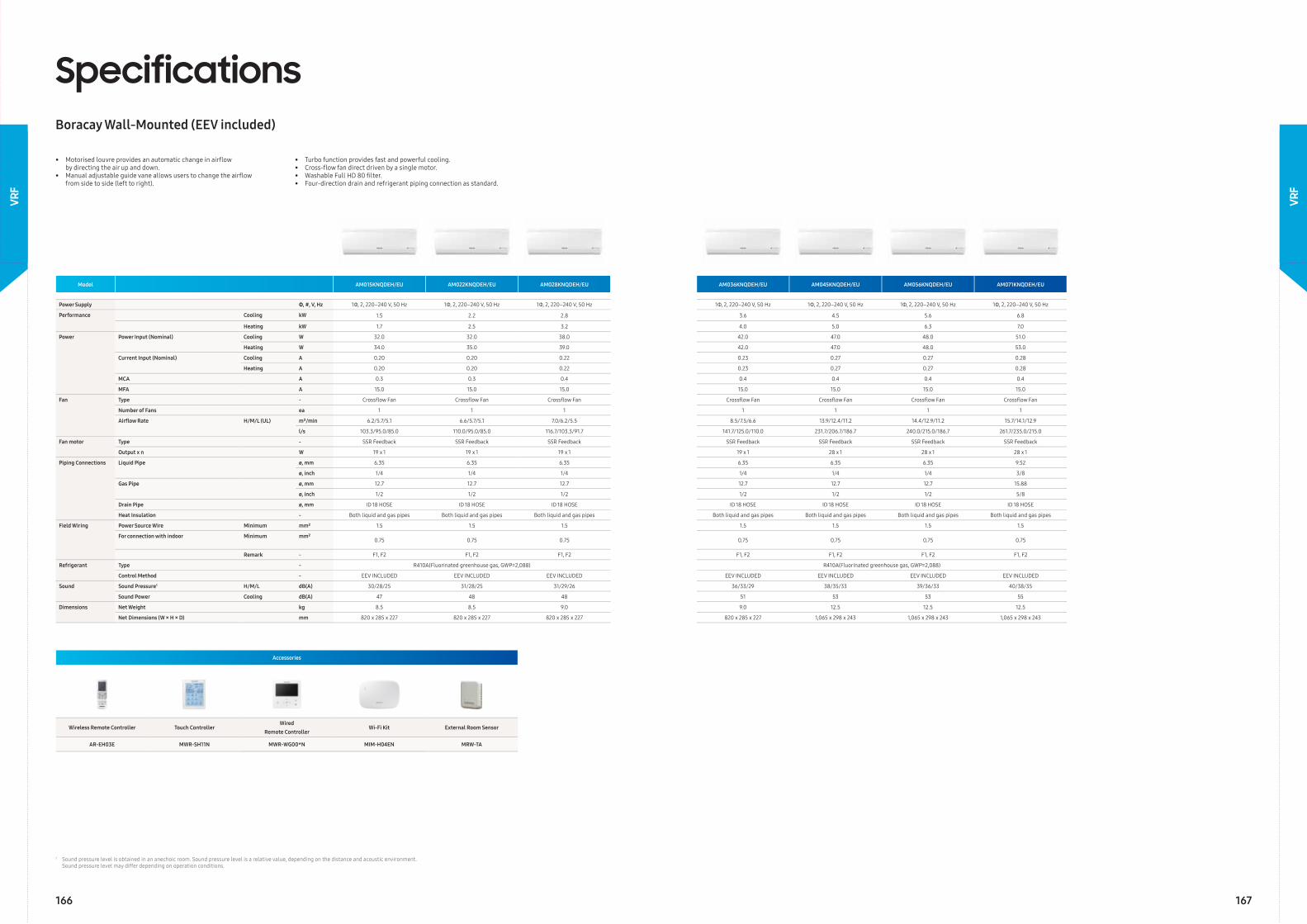
Model AM015KNQDEH/EU AM022KNQDEH/EU AM028KNQDEH/EU AM036KNQDEH/EU AM045KNQDEH/EU AM056KNQDEH/EU AM071KNQDEH/EU
Power Supply Φ, #, V, Hz 1Φ, 2, 220–240 V, 50 Hz 1Φ, 2, 220–240 V, 50 Hz 1Φ, 2, 220–240 V, 50 Hz 1Φ, 2, 220–240 V, 50 Hz 1Φ, 2, 220–240 V, 50 Hz 1Φ, 2, 220–240 V, 50 Hz 1Φ, 2, 220–240 V, 50 Hz
Performance Cooling kW 1.5 2.2 2.8 3.6 4.5 5.6 6.8
Heating kW 1.7 2.5 3.2 4.0 5.0 6.3 7.0
Power Power Input (Nominal) Cooling W 32.0 32.0 38.0 42.0 47.0 48.0 51.0
Heating W 34.0 35.0 39.0 42.0 47.0 48.0 53.0
Current Input (Nominal) Cooling A 0.20 0.20 0.22 0.23 0.27 0.27 0.28
Heating A 0.20 0.20 0.22 0.23 0.27 0.27 0.28
MCA A 0.3 0.3 0.4 0.4 0.4 0.4 0.4
MFA A 15.0 15.0 15.0 15.0 15.0 15.0 15.0
Fan Type - Crossfl ow Fan Crossfl ow Fan Crossfl ow Fan Crossfl ow Fan Crossfl ow Fan Crossfl ow Fan Crossfl ow Fan
Number of Fans ea 1 1 1 1 1 1 1
Airfl ow Rate H/M/L (UL) m³/min 6.2/5.7/5.1 6.6/5.7/5.1 7.0/6.2/5.5 8.5/7.5/6.6 13.9/12.4/11.2 14.4/12.9/11.2 15.7/14.1/12.9
l/s 103.3/95.0/85.0 110.0/95.0/85.0 116.7/103.3/91.7 141.7/125.0/110.0 231.7/206.7/186.7 240.0/215.0/186.7 261.7/235.0/215.0
Fan motor Type - SSR Feedback SSR Feedback SSR Feedback SSR Feedback SSR Feedback SSR Feedback SSR Feedback
Output x n W 19 x 1 19 x 1 19 x 1 19 x 1 28 x 1 28 x 1 28 x 1
Piping Connections Liquid Pipe ø, mm 6.35 6.35 6.35 6.35 6.35 6.35 9.52
ø, inch 1/4 1/4 1/4 1/4 1/4 1/4 3/8
Gas Pipe ø, mm 12.7 12.7 12.7 12.7 12.7 12.7 15.88
ø, inch 1/2 1/2 1/2 1/2 1/2 1/2 5/8
Drain Pipe ø, mm ID 18 HOSE ID 18 HOSE ID 18 HOSE ID 18 HOSE ID 18 HOSE ID 18 HOSE ID 18 HOSE
Heat Insulation - Both liquid and gas pipes Both liquid and gas pipes Both liquid and gas pipes Both liquid and gas pipes Both liquid and gas pipes Both liquid and gas pipes Both liquid and gas pipes
Field Wiring Power Source Wire Minimum mm² 1.5 1.5 1.5 1.5 1.5 1.5 1.5
For connection with indoor Minimum mm²0.75 0.75 0.75 0.75 0.75 0.75 0.75
Remark - F1, F2 F1, F2 F1, F2 F1, F2 F1, F2 F1, F2 F1, F2
Refrigerant Type - R410A(Fluorinated greenhouse gas, GWP=2,088) R410A(Fluorinated greenhouse gas, GWP=2,088)
Control Method - EEV INCLUDED EEV INCLUDED EEV INCLUDED EEV INCLUDED EEV INCLUDED EEV INCLUDED EEV INCLUDED
Sound Sound Pressure1 H/M/L dB(A) 30/28/25 31/28/25 31/29/26 36/33/29 38/35/33 39/36/33 40/38/35
Sound Power Cooling dB(A) 47 48 48 51 53 53 55
Dimensions Net Weight kg 8.5 8.5 9.0 9.0 12.5 12.5 12.5
Net Dimensions (W × H × D) mm 820 x 285 x 227 820 x 285 x 227 820 x 285 x 227 820 x 285 x 227 1,065 x 298 x 243 1,065 x 298 x 243 1,065 x 298 x 243
SpecificationsBoracay Wall-Mounted (EEV included)
• Motorised louvre provides an automatic change in airfl ow by directing the air up and down.• Manual adjustable guide vane allows users to change the airfl ow from side to side (left to right).
• Turbo function provides fast and powerful cooling.• Cross-fl ow fan direct driven by a single motor.• Washable Full HD 80 fi lter.• Four-direction drain and refrigerant piping connection as standard.
Accessories
Wireless Remote Controller Touch ControllerWired
Remote ControllerWi-Fi Kit External Room Sensor
AR-EH03E MWR-SH11N MWR-WG00*N MIM-H04EN MRW-TA
1 Sound pressure level is obtained in an anechoic room. Sound pressure level is a relative value, depending on the distance and acoustic environment. Sound pressure level may differ depending on operation conditions.
166 167
VRF
VRF
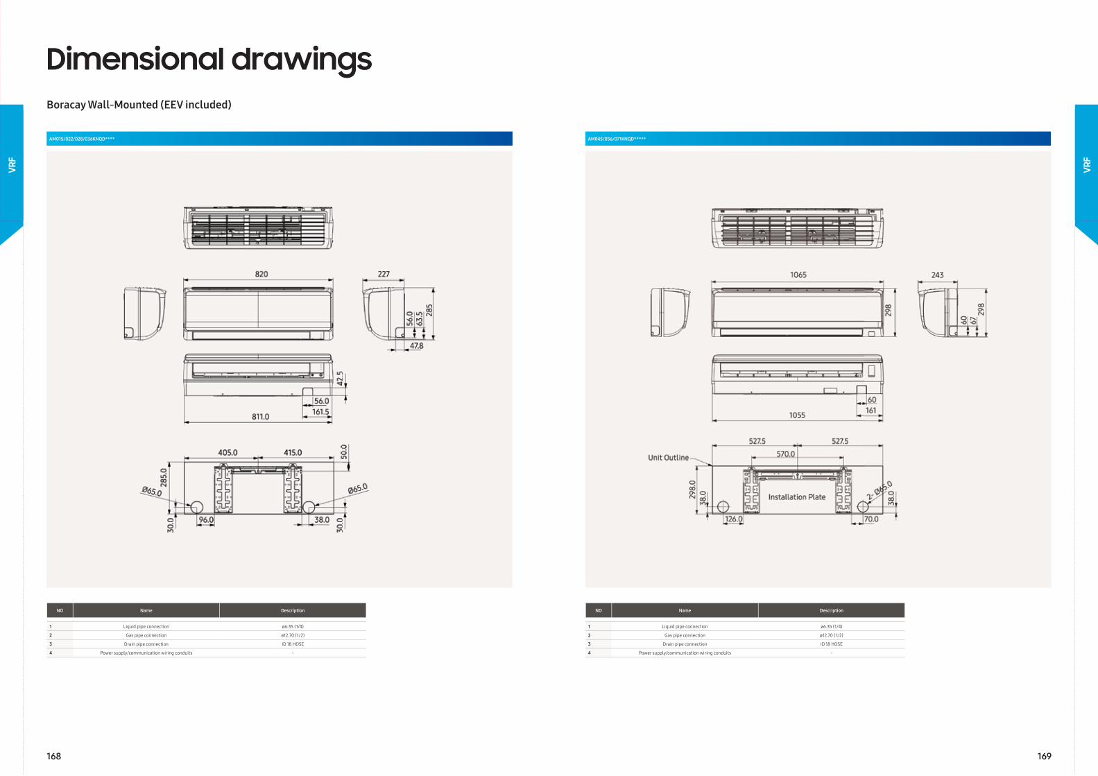
Dimensional drawingsBoracay Wall-Mounted (EEV included)
AM015/022/028/036KNQD****
NO Name Description
1 Liquid pipe connection ø6.35 (1/4)
2 Gas pipe connection ø12.70 (1/2)
3 Drain pipe connection ID 18 HOSE
4 Power supply/communication wiring conduits -
AM045/056/071KNQD*****
NO Name Description
1 Liquid pipe connection ø6.35 (1/4)
2 Gas pipe connection ø12.70 (1/2)
3 Drain pipe connection ID 18 HOSE
4 Power supply/communication wiring conduits -
168 169
VRF
VRF
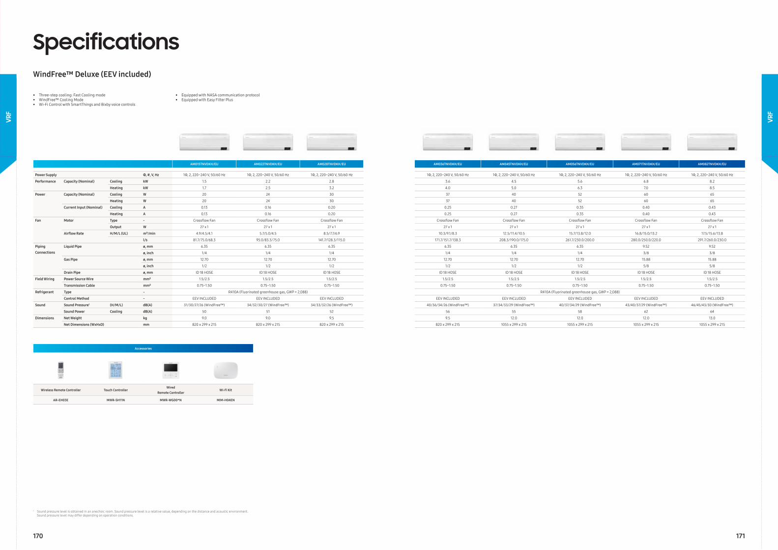
SpecificationsWindFree™ Deluxe (EEV included)
Accessories
Wireless Remote Controller Touch ControllerWired
Remote ControllerWi-Fi Kit
AR-EH03E MWR-SH11N MWR-WG00*N MIM-H04EN
• Three-step cooling: Fast Cooling mode• WindFree™ Cooling Mode• Wi-Fi Control with SmartThings and Bixby voice controls
• Equipped with NASA communication protocol • Equipped with Easy Filter Plus
AM015TNVDKH/EU AM022TNVDKH/EU AM028TNVDKH/EU AM036TNVDKH/EU AM045TNVDKH/EU AM056TNVDKH/EU AM071TNVDKH/EU AM082TNVDKH/EU
Power Supply Φ, #, V, Hz 1Φ, 2, 220~240 V, 50/60 Hz 1Φ, 2, 220~240 V, 50/60 Hz 1Φ, 2, 220~240 V, 50/60 Hz 1Φ, 2, 220~240 V, 50/60 Hz 1Φ, 2, 220~240 V, 50/60 Hz 1Φ, 2, 220~240 V, 50/60 Hz 1Φ, 2, 220~240 V, 50/60 Hz 1Φ, 2, 220~240 V, 50/60 Hz
Performance Capacity (Nominal) Cooling kW 1.5 2.2 2.8 3.6 4.5 5.6 6.8 8.2
Heating kW 1.7 2.5 3.2 4.0 5.0 6.3 7.0 8.5
Power Capacity (Nominal) Cooling W 20 24 30 37 40 52 60 65
Heating W 20 24 30 37 40 52 60 65
Current Input (Nominal) Cooling A 0.13 0.16 0.20 0.25 0.27 0.35 0.40 0.43
Heating A 0.13 0.16 0.20 0.25 0.27 0.35 0.40 0.43
Fan Motor Type - Crossfl ow Fan Crossfl ow Fan Crossfl ow Fan Crossfl ow Fan Crossfl ow Fan Crossfl ow Fan Crossfl ow Fan Crossfl ow Fan
Output W 27 x 1 27 x 1 27 x 1 27 x 1 27 x 1 27 x 1 27 x 1 27 x 1
Airfl ow Rate H/M/L (UL) m³/min 4.9/4.5/4.1 5.7/5.0/4.5 8.5/7.7/6.9 10.3/9.1/8.3 12.5/11.4/10.5 15.7/13.8/12.0 16.8/15.0/13.2 17.5/15.6/13.8
l/s 81.7/75.0/68.3 95.0/83.3/75.0 141.7/128.3/115.0 171.7/151.7/138.3 208.3/190.0/175.0 261.7/230.0/200.0 280.0/250.0/220.0 291.7/260.0/230.0
Piping
Connections
Liquid Pipe ø, mm 6.35 6.35 6.35 6.35 6.35 6.35 9.52 9.52
ø, inch 1/4 1/4 1/4 1/4 1/4 1/4 3/8 3/8
Gas Pipe ø, mm 12.70 12.70 12.70 12.70 12.70 12.70 15.88 15.88
ø, inch 1/2 1/2 1/2 1/2 1/2 1/2 5/8 5/8
Drain Pipe ø, mm ID 18 HOSE ID 18 HOSE ID 18 HOSE ID 18 HOSE ID 18 HOSE ID 18 HOSE ID 18 HOSE ID 18 HOSE
Field Wiring Power Source Wire mm² 1.5/2.5 1.5/2.5 1.5/2.5 1.5/2.5 1.5/2.5 1.5/2.5 1.5/2.5 1.5/2.5
Transmission Cable mm² 0.75~1.50 0.75~1.50 0.75~1.50 0.75~1.50 0.75~1.50 0.75~1.50 0.75~1.50 0.75~1.50
Refrigerant Type - R410A (Fluorinated greenhouse gas, GWP = 2,088) R410A (Fluorinated greenhouse gas, GWP = 2,088)
Control Method - EEV INCLUDED EEV INCLUDED EEV INCLUDED EEV INCLUDED EEV INCLUDED EEV INCLUDED EEV INCLUDED EEV INCLUDED
Sound Sound Pressure1 (H/M/L) dB(A) 31/30/27/26 (WindFree™) 34/32/30/27 (WindFree™) 34/33/32/26 (WindFree™) 40/36/34/26 (WindFree™) 37/34/33/29 (WindFree™) 40/37/34/29 (WindFree™) 43/40/37/29 (WindFree™) 46/45/43/30 (WindFree™)
Sound Power Cooling dB(A) 50 51 52 56 55 58 62 64
Dimensions Net Weight kg 9.0 9.0 9.5 9.5 12.0 12.0 12.0 13.0
Net Dimensions (WxHxD) mm 820 x 299 x 215 820 x 299 x 215 820 x 299 x 215 820 x 299 x 215 1055 x 299 x 215 1055 x 299 x 215 1055 x 299 x 215 1055 x 299 x 215
1 Sound pressure level is obtained in an anechoic room. Sound pressure level is a relative value, depending on the distance and acoustic environment. Sound pressure level may differ depending on operation conditions.
170 171
VRF
VRF
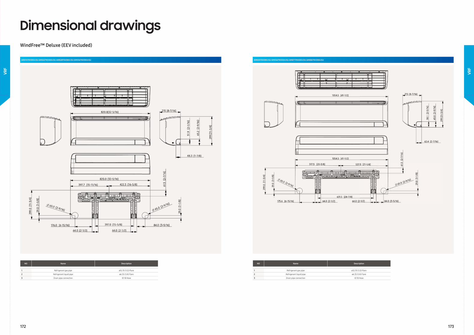
Dimensional drawingsWindFree™ Deluxe (EEV included)
AM015TNVDKH/EU AM022TNVDKH/EU AM028TNVDKH/EU AM036TNVDKH/EU
NO Name Description
1 Refrigerant gas pipe ø12.70 (1/2) Flare
2 Refrigerant liquid pipe ø6.35 (1/4) Flare
3 Drain pipe connection ID 18 Hose
AM045TNVDKH/EU AM056TNVDKH/EU AM071TNVDKH/EU AM082TNVDKH/EU
NO Name Description
1 Refrigerant gas pipe ø12.70 (1/2) Flare
2 Refrigerant liquid pipe ø6.35 (1/4) Flare
3 Drain pipe connection ID 18 Hose
172 173
VRF
VRF
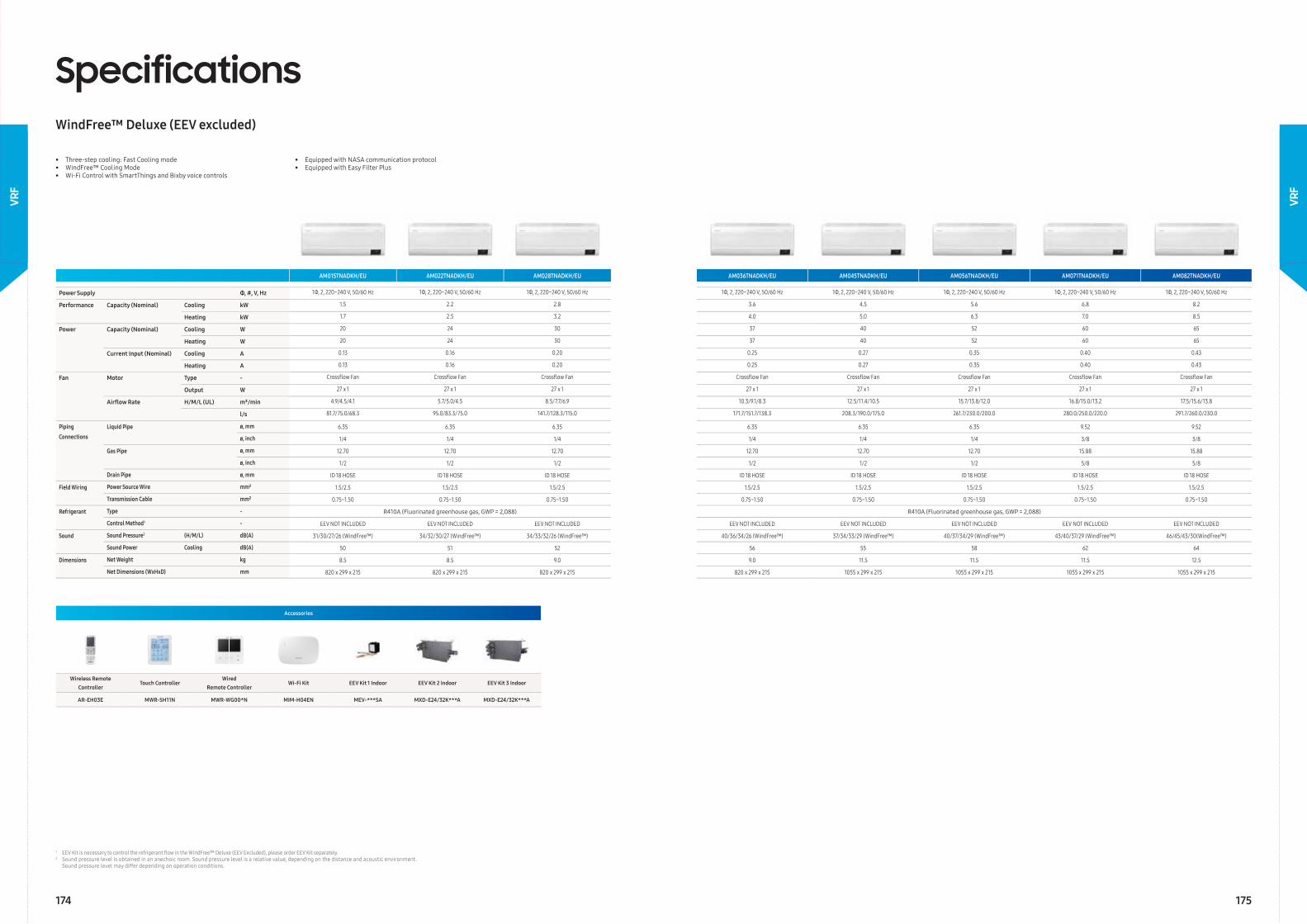
SpecificationsWindFree™ Deluxe (EEV excluded)
Accessories
Wireless Remote Controller
Touch ControllerWired
Remote ControllerWi-Fi Kit EEV Kit 1 Indoor EEV Kit 2 Indoor EEV Kit 3 Indoor
AR-EH03E MWR-SH11N MWR-WG00*N MIM-H04EN MEV-***SA MXD-E24/32K***A MXD-E24/32K***A
• Three-step cooling: Fast Cooling mode• WindFree™ Cooling Mode• Wi-Fi Control with SmartThings and Bixby voice controls
• Equipped with NASA communication protocol • Equipped with Easy Filter Plus
AM015TNADKH/EU AM022TNADKH/EU AM028TNADKH/EU AM036TNADKH/EU AM045TNADKH/EU AM056TNADKH/EU AM071TNADKH/EU AM082TNADKH/EU
Power Supply Φ, #, V, Hz 1Φ, 2, 220~240 V, 50/60 Hz 1Φ, 2, 220~240 V, 50/60 Hz 1Φ, 2, 220~240 V, 50/60 Hz 1Φ, 2, 220~240 V, 50/60 Hz 1Φ, 2, 220~240 V, 50/60 Hz 1Φ, 2, 220~240 V, 50/60 Hz 1Φ, 2, 220~240 V, 50/60 Hz 1Φ, 2, 220~240 V, 50/60 Hz
Performance Capacity (Nominal) Cooling kW 1.5 2.2 2.8 3.6 4.5 5.6 6.8 8.2
Heating kW 1.7 2.5 3.2 4.0 5.0 6.3 7.0 8.5
Power Capacity (Nominal) Cooling W 20 24 30 37 40 52 60 65
Heating W 20 24 30 37 40 52 60 65
Current Input (Nominal) Cooling A 0.13 0.16 0.20 0.25 0.27 0.35 0.40 0.43
Heating A 0.13 0.16 0.20 0.25 0.27 0.35 0.40 0.43
Fan Motor Type - Crossfl ow Fan Crossfl ow Fan Crossfl ow Fan Crossfl ow Fan Crossfl ow Fan Crossfl ow Fan Crossfl ow Fan Crossfl ow Fan
Output W 27 x 1 27 x 1 27 x 1 27 x 1 27 x 1 27 x 1 27 x 1 27 x 1
Airfl ow Rate H/M/L (UL) m³/min 4.9/4.5/4.1 5.7/5.0/4.5 8.5/7.7/6.9 10.3/9.1/8.3 12.5/11.4/10.5 15.7/13.8/12.0 16.8/15.0/13.2 17.5/15.6/13.8
l/s 81.7/75.0/68.3 95.0/83.3/75.0 141.7/128.3/115.0 171.7/151.7/138.3 208.3/190.0/175.0 261.7/230.0/200.0 280.0/250.0/220.0 291.7/260.0/230.0
Piping
Connections
Liquid Pipe ø, mm 6.35 6.35 6.35 6.35 6.35 6.35 9.52 9.52
ø, inch 1/4 1/4 1/4 1/4 1/4 1/4 3/8 3/8
Gas Pipe ø, mm 12.70 12.70 12.70 12.70 12.70 12.70 15.88 15.88
ø, inch 1/2 1/2 1/2 1/2 1/2 1/2 5/8 5/8
Drain Pipe ø, mm ID 18 HOSE ID 18 HOSE ID 18 HOSE ID 18 HOSE ID 18 HOSE ID 18 HOSE ID 18 HOSE ID 18 HOSE
Field Wiring Power Source Wire mm² 1.5/2.5 1.5/2.5 1.5/2.5 1.5/2.5 1.5/2.5 1.5/2.5 1.5/2.5 1.5/2.5
Transmission Cable mm² 0.75~1.50 0.75~1.50 0.75~1.50 0.75~1.50 0.75~1.50 0.75~1.50 0.75~1.50 0.75~1.50
Refrigerant Type - R410A (Fluorinated greenhouse gas, GWP = 2,088) R410A (Fluorinated greenhouse gas, GWP = 2,088)
Control Method1 - EEV NOT INCLUDED EEV NOT INCLUDED EEV NOT INCLUDED EEV NOT INCLUDED EEV NOT INCLUDED EEV NOT INCLUDED EEV NOT INCLUDED EEV NOT INCLUDED
Sound Sound Pressure2 (H/M/L) dB(A) 31/30/27/26 (WindFree™) 34/32/30/27 (WindFree™) 34/33/32/26 (WindFree™) 40/36/34/26 (WindFree™) 37/34/33/29 (WindFree™) 40/37/34/29 (WindFree™) 43/40/37/29 (WindFree™) 46/45/43/30(WindFree™)
Sound Power Cooling dB(A) 50 51 52 56 55 58 62 64
Dimensions Net Weight kg 8.5 8.5 9.0 9.0 11.5 11.5 11.5 12.5
Net Dimensions (WxHxD) mm 820 x 299 x 215 820 x 299 x 215 820 x 299 x 215 820 x 299 x 215 1055 x 299 x 215 1055 x 299 x 215 1055 x 299 x 215 1055 x 299 x 215
1 EEV Kit is necessary to control the refrigerant fl ow in the WindFree™ Deluxe (EEV Excluded), please order EEV Kit separately.2 Sound pressure level is obtained in an anechoic room. Sound pressure level is a relative value, depending on the distance and acoustic environment. Sound pressure level may differ depending on operation conditions.
174 175
VRF
VRF
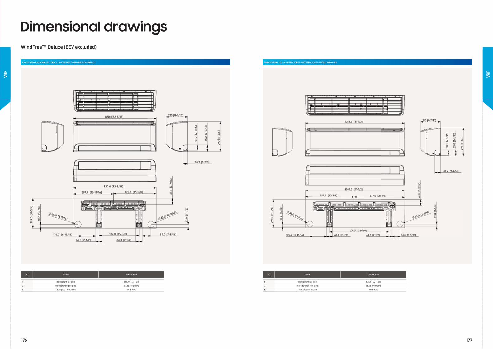
Dimensional drawingsWindFree™ Deluxe (EEV excluded)
AM015TNADKH/EU AM022TNADKH/EU AM028TNADKH/EU AM036TNADKH/EU
NO Name Description
1 Refrigerant gas pipe ø12.70 (1/2) Flare
2 Refrigerant liquid pipe ø6.35 (1/4) Flare
3 Drain pipe connection ID 18 Hose
AM045TNADKH/EU AM056TNADKH/EU AM071TNADKH/EU AM082TNADKH/EU
NO Name Description
1 Refrigerant gas pipe ø12.70 (1/2) Flare
2 Refrigerant liquid pipe ø6.35 (1/4) Flare
3 Drain pipe connection ID 18 Hose
176 177
VRF
VRF
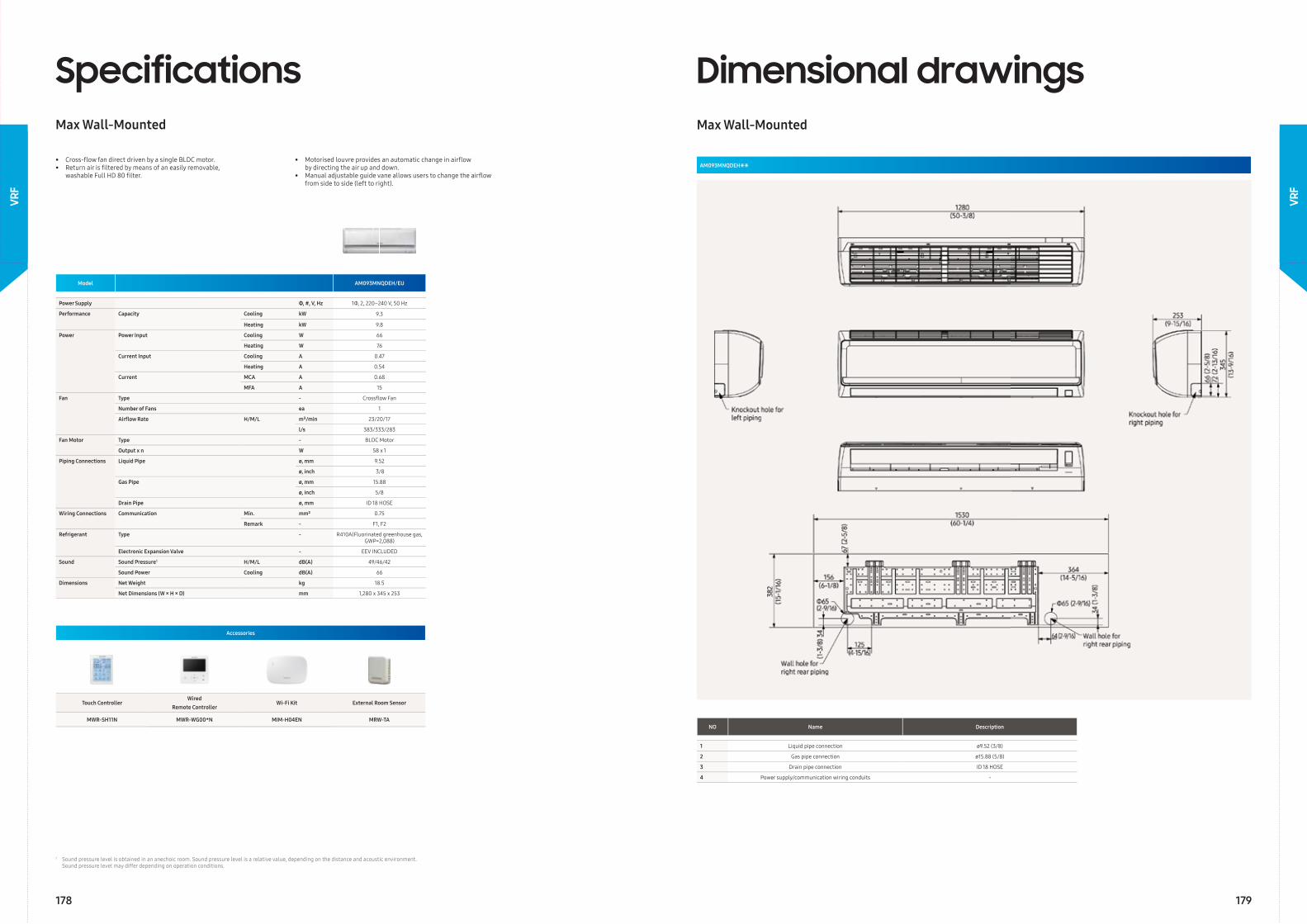
Model AM093MNQDEH/EU
Power Supply Φ, #, V, Hz 1Φ, 2, 220–240 V, 50 Hz
Performance Capacity Cooling kW 9.3
Heating kW 9.8
Power Power Input Cooling W 66
Heating W 76
Current Input Cooling A 0.47
Heating A 0.54
Current MCA A 0.68
MFA A 15
Fan Type - Crossfl ow Fan
Number of Fans ea 1
Airfl ow Rate H/M/L m³/min 23/20/17
l/s 383/333/283
Fan Motor Type - BLDC Motor
Output x n W 58 x 1
Piping Connections Liquid Pipe ø, mm 9.52
ø, inch 3/8
Gas Pipe ø, mm 15.88
ø, inch 5/8
Drain Pipe ø, mm ID 18 HOSE
Wiring Connections Communication Min. mm² 0.75
Remark - F1, F2
Refrigerant Type - R410A(Fluorinated greenhouse gas, GWP=2,088)
Electronic Expansion Valve - EEV INCLUDED
Sound Sound Pressure1 H/M/L dB(A) 49/46/42
Sound Power Cooling dB(A) 66
Dimensions Net Weight kg 18.5
Net Dimensions (W × H × D) mm 1,280 x 345 x 253
SpecificationsMax Wall-Mounted
• Cross-fl ow fan direct driven by a single BLDC motor.• Return air is fi ltered by means of an easily removable, washable Full HD 80 fi lter.
• Motorised louvre provides an automatic change in airfl ow by directing the air up and down.• Manual adjustable guide vane allows users to change the airfl ow from side to side (left to right).
Accessories
Touch ControllerWired
Remote ControllerWi-Fi Kit External Room Sensor
MWR-SH11N MWR-WG00*N MIM-H04EN MRW-TA
Dimensional drawingsMax Wall-Mounted
AM093MNQDEH∗∗
NO Name Description
1 Liquid pipe connection ø9.52 (3/8)
2 Gas pipe connection ø15.88 (5/8)
3 Drain pipe connection ID 18 HOSE
4 Power supply/communication wiring conduits -
1 Sound pressure level is obtained in an anechoic room. Sound pressure level is a relative value, depending on the distance and acoustic environment. Sound pressure level may differ depending on operation conditions.
178 179
VRF
VRF
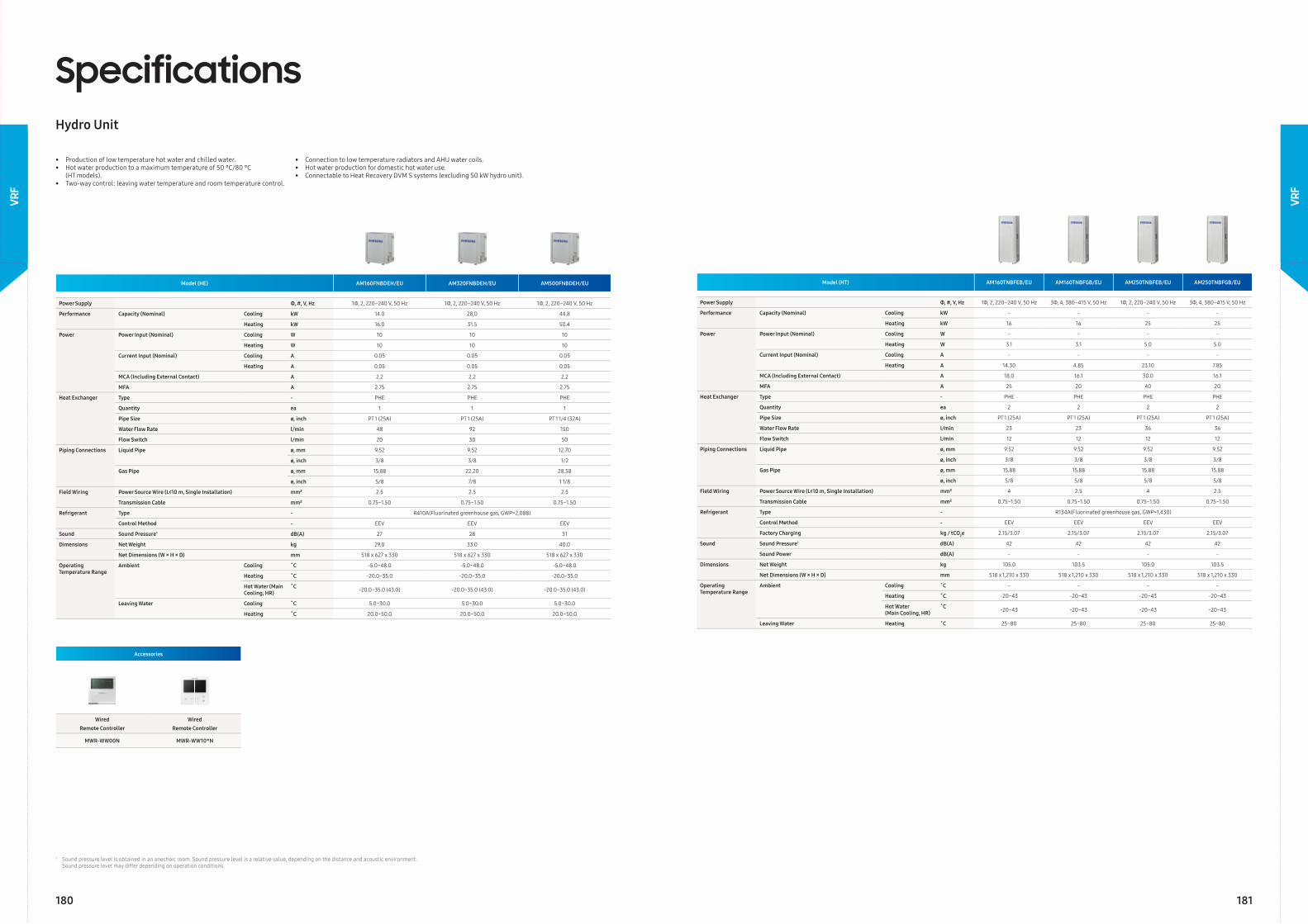
Model (HE) AM160FNBDEH/EU AM320FNBDEH/EU AM500FNBDEH/EU
Power Supply Φ, #, V, Hz 1Φ, 2, 220–240 V, 50 Hz 1Φ, 2, 220–240 V, 50 Hz 1Φ, 2, 220–240 V, 50 Hz
Performance Capacity (Nominal) Cooling kW 14.0 28,0 44.8
Heating kW 16.0 31.5 50.4
Power Power Input (Nominal) Cooling W 10 10 10
Heating W 10 10 10
Current Input (Nominal) Cooling A 0.05 0.05 0.05
Heating A 0.05 0.05 0.05
MCA (Including External Contact) A 2.2 2.2 2.2
MFA A 2.75 2.75 2.75
Heat Exchanger Type - PHE PHE PHE
Quantity ea 1 1 1
Pipe Size ø, inch PT 1 (25A) PT 1 (25A) PT 1 1/4 (32A)
Water Flow Rate l/min 48 92 150
Flow Switch l/min 20 30 50
Piping Connections Liquid Pipe ø, mm 9.52 9.52 12.70
ø, inch 3/8 3/8 1/2
Gas Pipe ø, mm 15.88 22.20 28.58
ø, inch 5/8 7/8 1 1/8
Field Wiring Power Source Wire (L<10 m, Single Installation) mm² 2.5 2.5 2.5
Transmission Cable mm² 0.75~1.50 0.75~1.50 0.75~1.50
Refrigerant Type - R410A(Fluorinated greenhouse gas, GWP=2,088)
Control Method - EEV EEV EEV
Sound Sound Pressure1 dB(A) 27 28 31
Dimensions Net Weight kg 29.0 33.0 40.0
Net Dimensions (W × H × D) mm 518 x 627 x 330 518 x 627 x 330 518 x 627 x 330
Operating Temperature Range
Ambient Cooling ˚C -5.0~48.0 -5.0~48.0 -5.0~48.0
Heating ˚C -20.0~35.0 -20.0~35.0 -20.0~35.0
Hot Water (Main Cooling, HR)
˚C -20.0~35.0 (43.0) -20.0~35.0 (43.0) -20.0~35.0 (43.0)
Leaving Water Cooling ˚C 5.0~30.0 5.0~30.0 5.0~30.0
Heating ˚C 20.0~50.0 20.0~50.0 20.0~50.0
SpecificationsHydro Unit
• Production of low temperature hot water and chilled water.• Hot water production to a maximum temperature of 50 °C/80 °C (HT models).• Two-way control: leaving water temperature and room temperature control.
• Connection to low temperature radiators and AHU water coils.• Hot water production for domestic hot water use.• Connectable to Heat Recovery DVM S systems (excluding 50 kW hydro unit).
Accessories
Wired Remote Controller
Wired Remote Controller
MWR-WW00N MWR-WW10*N
Model (HT) AM160TNBFEB/EU AM160TNBFGB/EU AM250TNBFEB/EU AM250TNBFGB/EU
Power Supply Φ, #, V, Hz 1Φ, 2, 220–240 V, 50 Hz 3Φ, 4, 380–415 V, 50 Hz 1Φ, 2, 220–240 V, 50 Hz 3Φ, 4, 380–415 V, 50 Hz
Performance Capacity (Nominal) Cooling kW - - - -
Heating kW 16 16 25 25
Power Power Input (Nominal) Cooling W - - - -
Heating W 3.1 3.1 5.0 5.0
Current Input (Nominal) Cooling A - - - -
Heating A 14.30 4.85 23.10 7.85
MCA (Including External Contact) A 18.0 16.1 30.0 16.1
MFA A 25 20 40 20
Heat Exchanger Type - PHE PHE PHE PHE
Quantity ea 2 2 2 2
Pipe Size ø, inch PT 1 (25A) PT 1 (25A) PT 1 (25A) PT 1 (25A)
Water Flow Rate l/min 23 23 36 36
Flow Switch l/min 12 12 12 12
Piping Connections Liquid Pipe ø, mm 9.52 9.52 9.52 9.52
ø, inch 3/8 3/8 3/8 3/8
Gas Pipe ø, mm 15.88 15.88 15.88 15.88
ø, inch 5/8 5/8 5/8 5/8
Field Wiring Power Source Wire (L<10 m, Single Installation) mm² 4 2.5 4 2.5
Transmission Cable mm² 0.75~1.50 0.75~1.50 0.75~1.50 0.75~1.50
Refrigerant Type - R134A(Fluorinated greenhouse gas, GWP=1,430)
Control Method - EEV EEV EEV EEV
Factory Charging kg / tCO2e 2.15/3.07 2.15/3.07 2.15/3.07 2.15/3.07
Sound Sound Pressure1 dB(A) 42 42 42 42
Sound Power dB(A) - - - -
Dimensions Net Weight kg 105.0 103.5 105.0 103.5
Net Dimensions (W × H × D) mm 518 x 1,210 x 330 518 x 1,210 x 330 518 x 1,210 x 330 518 x 1,210 x 330
Operating Temperature Range
Ambient Cooling ˚C - - - -
Heating ˚C -20~43 -20~43 -20~43 -20~43
Hot Water(Main Cooling, HR)
˚C -20~43 -20~43 -20~43 -20~43
Leaving Water Heating ˚C 25~80 25~80 25~80 25~80
1 Sound pressure level is obtained in an anechoic room. Sound pressure level is a relative value, depending on the distance and acoustic environment. Sound pressure level may differ depending on operation conditions.
180 181
VRF
VRF
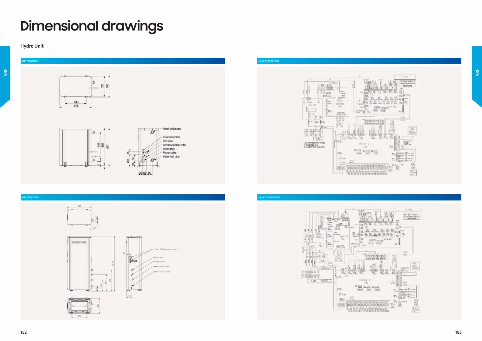
AM160/250TNBFEB/EU
AM160/250TNBFGB/EU
Dimensional drawingsHydro Unit
AM***FNBDEH/EU
AM***TNBF*B/EU
182 183
VRF
VRF
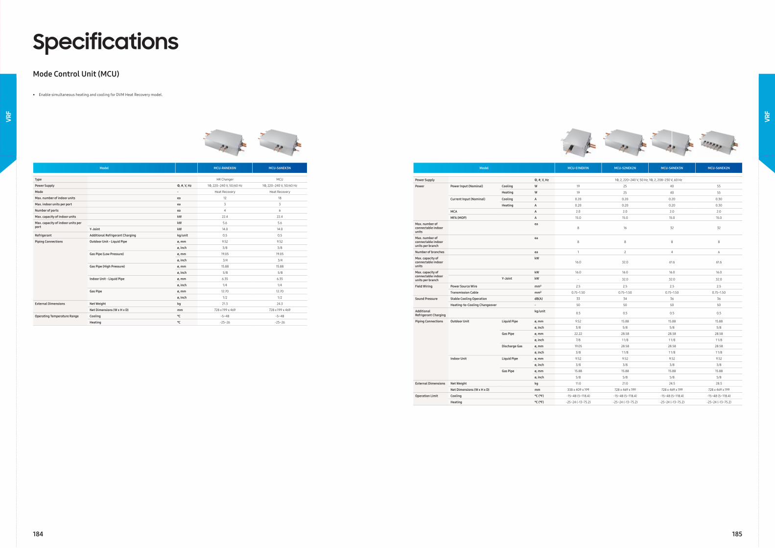
Model MCU-R4NEK0N MCU-S6NEK3N
Type HR Changer MCU
Power Supply Φ, #, V, Hz 1Φ, 220–240 V, 50/60 Hz 1Φ, 220–240 V, 50/60 Hz
Mode - Heat Recovery Heat Recovery
Max. number of indoor units ea 12 18
Max. indoor units per port ea 3 3
Number of ports ea 4 6
Max. capacity of indoor units kW 22.4 22.4
Max. capacity of indoor units per port
kW 5.6 5.6
Y-Joint kW 14.0 14.0
Refrigerant Additional Refrigerant Charging kg/unit 0.5 0.5
Piping Connections Outdoor Unit - Liquid Pipe ø, mm 9.52 9.52
ø, inch 3/8 3/8
Gas Pipe (Low Pressure) ø, mm 19.05 19.05
ø, inch 3/4 3/4
Gas Pipe (High Pressure) ø, mm 15.88 15.88
ø, inch 5/8 5/8
Indoor Unit - Liquid Pipe ø, mm 6.35 6.35
ø, inch 1/4 1/4
Gas Pipe ø, mm 12.70 12.70
ø, inch 1/2 1/2
External Dimensions Net Weight kg 21.3 24.3
Net Dimensions (W x H x D) mm 728 x 199 x 469 728 x 199 x 469
Operating Temperature Range Cooling ℃ -5~48 -5~48
Heating ℃ -25~26 -25~26
SpecificationsMode Control Unit (MCU)
• Enable simultaneous heating and cooling for DVM Heat Recovery model.
Model MCU-S1NEK1N MCU-S2NEK2N MCU-S4NEK3N MCU-S6NEK2N
Power Supply Φ, #, V, Hz 1Φ, 2, 220~240 V, 50 Hz, 1Φ, 2, 208~230 V, 60 Hz
Power Power Input (Nominal) Cooling W 19 25 40 55
Heating W 19 25 40 55
Current Input (Nominal) Cooling A 0.20 0.20 0.20 0.30
Heating A 0.20 0.20 0.20 0.30
MCA A 2.0 2.0 2.0 2.0
MFA (MOP) A 15.0 15.0 15.0 15.0
Max. number of connectable indoor units
ea8 16 32 32
Max. number of connectable indoor units per branch
ea8 8 8 8
Number of branches ea 1 2 4 6
Max. capacity of connectable indoor units
kW16.0 32.0 61.6 61.6
Max. capacity of connectable indoor units per branch
kW 16.0 16.0 16.0 16.0
Y-Joint kW - 32.0 32.0 32.0
Field Wiring Power Source Wire mm² 2.5 2.5 2.5 2.5
Transmission Cable mm² 0.75~1.50 0.75~1.50 0.75~1.50 0.75~1.50
Sound Pressure Stable Cooling Operation dB(A) 33 34 36 36
Heating-to-Cooling Changeover - 50 50 50 50
Additional Refrigerant Charging
kg/unit 0.5 0.5 0.5 0.5
Piping Connections Outdoor Unit Liquid Pipe ø, mm 9.52 15.88 15.88 15.88
ø, inch 3/8 5/8 5/8 5/8
Gas Pipe ø, mm 22.22 28.58 28.58 28.58
ø, inch 7/8 1 1/8 1 1/8 1 1/8
Discharge Gas ø, mm 19.05 28.58 28.58 28.58
ø, inch 3/8 1 1/8 1 1/8 1 1/8
Indoor Unit Liquid Pipe ø, mm 9.52 9.52 9.52 9.52
ø, inch 3/8 3/8 3/8 3/8
Gas Pipe ø, mm 15.88 15.88 15.88 15.88
ø, inch 5/8 5/8 5/8 5/8
External Dimensions Net Weight kg 11.0 21.0 24.5 28.5
Net Dimensions (W x H x D) mm 338 x 409 x 199 728 x 469 x 199 728 x 469 x 199 728 x 469 x 199
Operation Limit Cooling ℃ (℉) -15~48 (5~118.4) -15~48 (5~118.4) -15~48 (5~118.4) -15~48 (5~118.4)
Heating ℃ (℉) -25~24 (-13~75.2) -25~24 (-13~75.2) -25~24 (-13~75.2) -25~24 (-13~75.2)
184 185
VRF
VRF
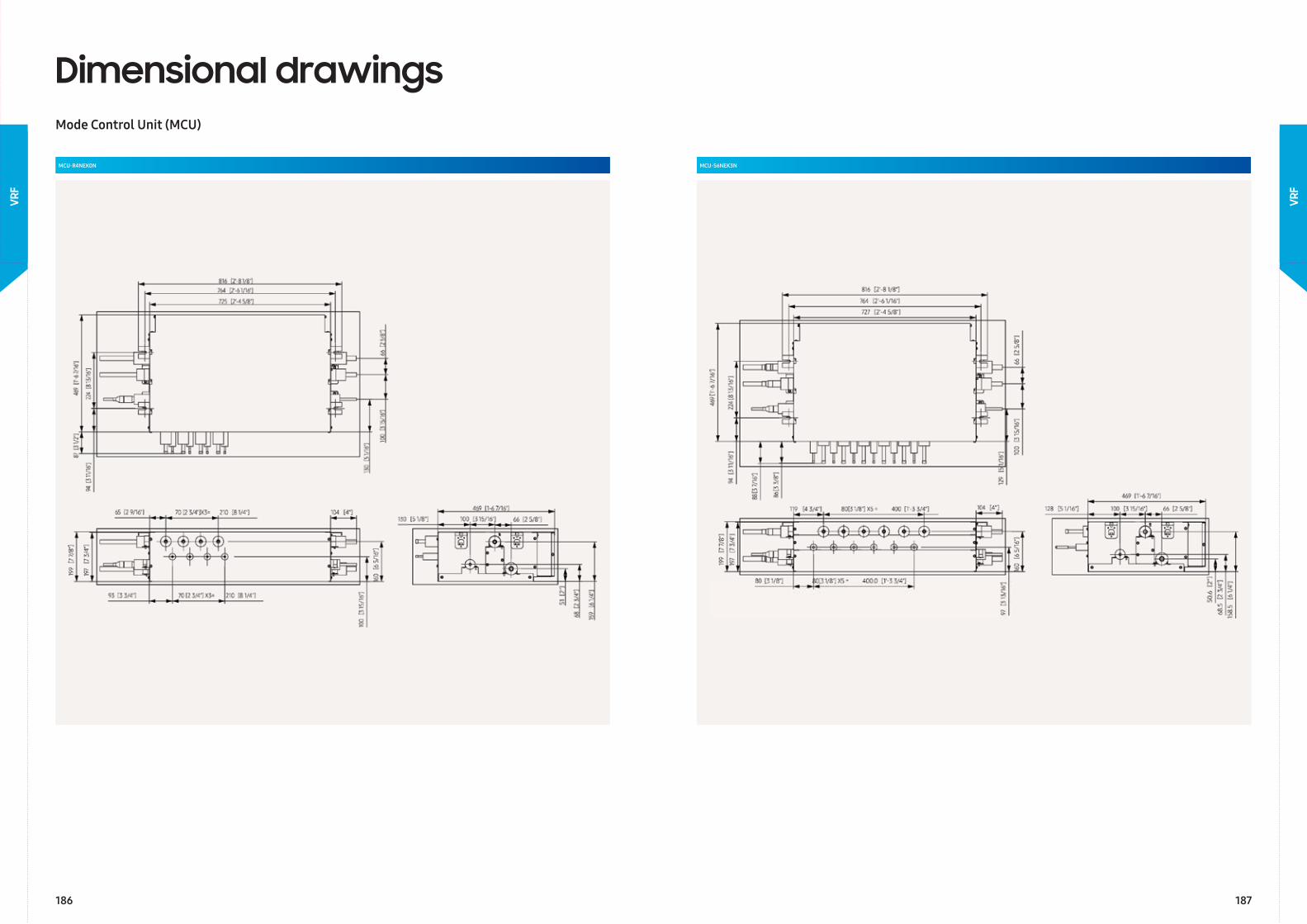
MCU-R4NEK0N
Dimensional drawingsMode Control Unit (MCU)
MCU-S6NEK3N
186 187
VRF
VRF
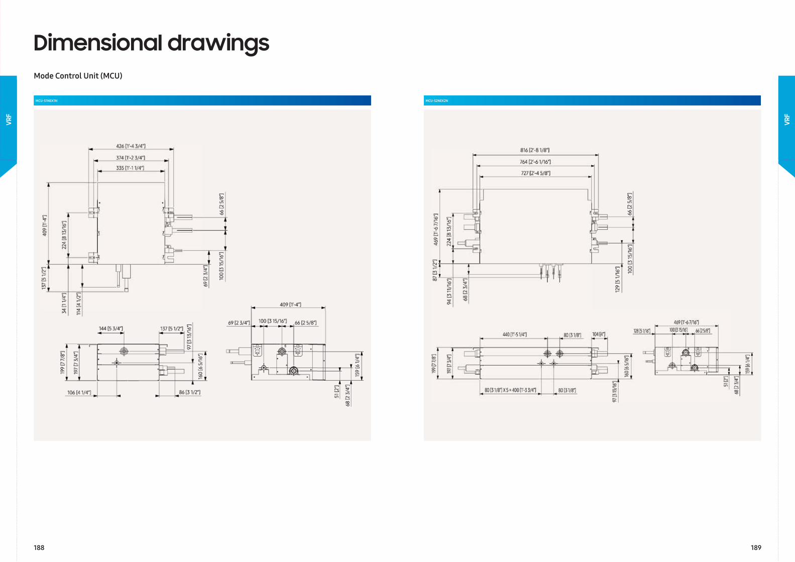
Dimensional drawingsMode Control Unit (MCU)
MCU-S1NEK1N MCU-S2NEK2N
188 189
VRF
VRF
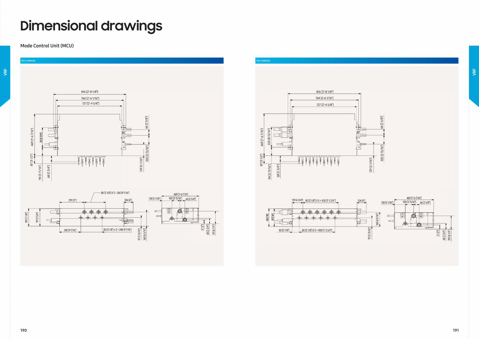
Dimensional drawingsMode Control Unit (MCU)
MCU-S4NEK3N MCU-S6NEK2N
190 191
VRF
VRF
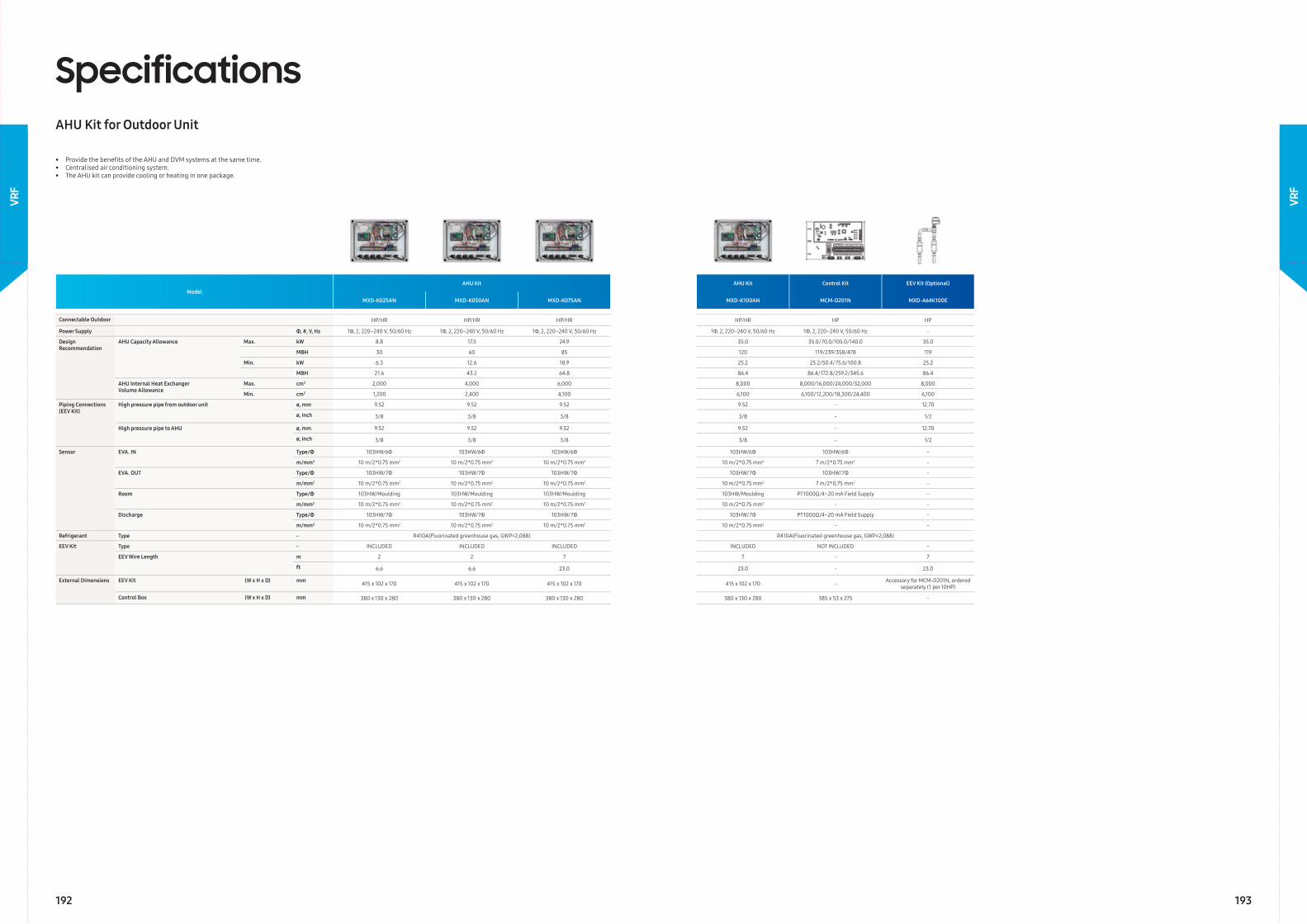
ModelAHU Kit AHU Kit Control Kit EEV Kit (Optional)
MXD-K025AN MXD-K050AN MXD-K075AN MXD-K100AN MCM-D201N MXD-A64K100E
Connectable Outdoor HP/HR HP/HR HP/HR HP/HR HP HP
Power Supply Φ, #, V, Hz 1Φ, 2, 220–240 V, 50/60 Hz 1Φ, 2, 220–240 V, 50/60 Hz 1Φ, 2, 220–240 V, 50/60 Hz 1Φ, 2, 220–240 V, 50/60 Hz 1Φ, 2, 220–240 V, 50/60 Hz -
Design Recommendation
AHU Capacity Allowance Max. kW 8.8 17.5 24.9 35.0 35.0/70.0/105.0/140.0 35.0
MBH 30 60 85 120 119/239/358/478 119
Min. kW 6.3 12.6 18.9 25.2 25.2/50.4/75.6/100.8 25.2
MBH 21.6 43.2 64.8 86.4 86.4/172.8/259.2/345.6 86.4
AHU Internal Heat Exchanger Volume Allowance
Max. cm3 2,000 4,000 6,000 8,000 8,000/16,000/24,000/32,000 8,000
Min. cm3 1,200 2,400 4,100 6,100 6,100/12,200/18,300/24,400 6,100
Piping Connections (EEV Kit)
High pressure pipe from outdoor unit ø, mm 9.52 9.52 9.52 9.52 - 12.70
ø, inch 3/8 3/8 3/8 3/8 - 1/2
High pressure pipe to AHU ø, mm 9.52 9.52 9.52 9.52 - 12.70
ø, inch 3/8 3/8 3/8 3/8 - 1/2
Sensor EVA. IN Type/Φ 103HW/6Φ 103HW/6Φ 103HW/6Φ 103HW/6Φ 103HW/6Φ -
m/mm2 10 m/2*0.75 mm2 10 m/2*0.75 mm2 10 m/2*0.75 mm2 10 m/2*0.75 mm2 7 m/2*0.75 mm2 -
EVA. OUT Type/Φ 103HW/7Φ 103HW/7Φ 103HW/7Φ 103HW/7Φ 103HW/7Φ -
m/mm2 10 m/2*0.75 mm2 10 m/2*0.75 mm2 10 m/2*0.75 mm2 10 m/2*0.75 mm2 7 m/2*0.75 mm2 -
Room Type/Φ 103HW/Moulding 103HW/Moulding 103HW/Moulding 103HW/Moulding PT1000Ω/4~20 mA Field Supply -
m/mm2 10 m/2*0.75 mm2 10 m/2*0.75 mm2 10 m/2*0.75 mm2 10 m/2*0.75 mm2 - -
Discharge Type/Φ 103HW/7Φ 103HW/7Φ 103HW/7Φ 103HW/7Φ PT1000Ω/4~20 mA Field Supply -
m/mm2 10 m/2*0.75 mm2 10 m/2*0.75 mm2 10 m/2*0.75 mm2 10 m/2*0.75 mm2 - -
Refrigerant Type - R410A(Fluorinated greenhouse gas, GWP=2,088) R410A(Fluorinated greenhouse gas, GWP=2,088)
EEV Kit Type - INCLUDED INCLUDED INCLUDED INCLUDED NOT INCLUDED -
EEV Wire Length m 2 2 7 7 - 7
ft 6.6 6.6 23.0 23.0 - 23.0
External Dimensions EEV Kit (W x H x D) mm 415 x 102 x 170 415 x 102 x 170 415 x 102 x 170 415 x 102 x 170 - Accessory for MCM-D201N, ordered separately (1 per 10HP)
Control Box (W x H x D) mm 380 x 130 x 280 380 x 130 x 280 380 x 130 x 280 380 x 130 x 280 385 x 53 x 275 -
SpecificationsAHU Kit for Outdoor Unit
• Provide the benefi ts of the AHU and DVM systems at the same time.• Centralised air conditioning system.• The AHU kit can provide cooling or heating in one package.
192 193
VRF
VRF
VRF ChillerVRF Chiller
VRF
Chi
ller
194
VRF
194 195
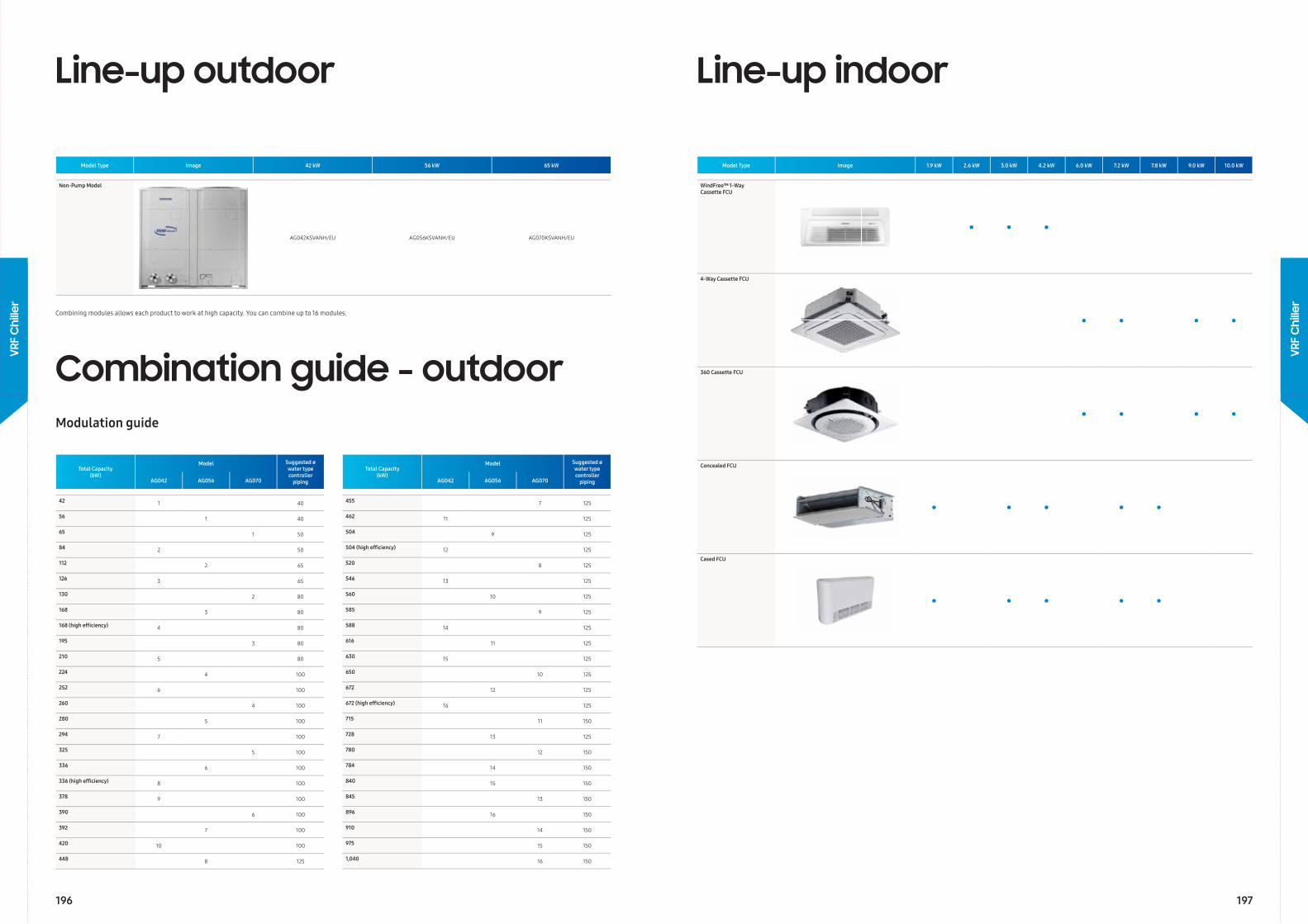
Model Type Image 42 kW 56 kW 65 kW
Non-Pump Model
AG042KSVANH/EU AG056KSVANH/EU AG070KSVANH/EU
Combining modules allows each product to work at high capacity. You can combine up to 16 modules.
Combination guide - outdoorModulation guide
Total Capacity (kW)
Model Suggested øwater type controller
pipingAG042 AG056 AG070
42 1 40
56 1 40
65 1 50
84 2 50
112 2 65
126 3 65
130 2 80
168 3 80
168 (high effi ciency) 4 80
195 3 80
210 5 80
224 4 100
252 6 100
260 4 100
280 5 100
294 7 100
325 5 100
336 6 100
336 (high effi ciency) 8 100
378 9 100
390 6 100
392 7 100
420 10 100
448 8 125
Total Capacity (kW)
Model Suggested øwater type controller
pipingAG042 AG056 AG070
455 7 125
462 11 125
504 9 125
504 (high effi ciency) 12 125
520 8 125
546 13 125
560 10 125
585 9 125
588 14 125
616 11 125
630 15 125
650 10 125
672 12 125
672 (high effi ciency) 16 125
715 11 150
728 13 125
780 12 150
784 14 150
840 15 150
845 13 150
896 16 150
910 14 150
975 15 150
1,040 16 150
Line-up outdoor
Model Type Image 1.9 kW 2.6 kW 3.0 kW 4.2 kW 6.0 kW 7.2 kW 7.8 kW 9.0 kW 10.0 kW
WindFree™ 1-Way Cassette FCU
• • •
4-Way Cassette FCU
• • • •
360 Cassette FCU
• • • •
Concealed FCU
• • • • •
Cased FCU
• • • • •
Line-up indoor
196 197
VRF
Chi
ller
VRF
Chi
ller
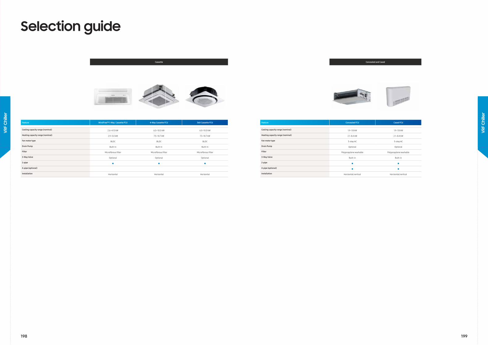
Selection guide
Cassette
w
Feature WindFree™ 1-Way Cassette FCU 4-Way Cassette FCU 360 Cassette FCU
Cooling capacity range ( nominal) 2.6–4.15 kW 6.0–10.0 kW 6.0–10.0 kW
Heating capacity range ( nominal) 2.9–5.0 kW 7.3–10.7 kW 7.3–10.7 kW
Fan motor type BLDC BLDC BLDC
Drain Pump Built-in Built-in Built-in
Filter Microfi brous fi lter Microfi brous fi lter Microfi brous fi lter
3-Way Valve Optional Optional Optional
2-pipe • • •4-pipe (optional)
Installation Horizontal Horizontal Horizontal
Concealed and Cased
w
Feature Concealed FCU Cased FCU
Cooling capacity range ( nominal) 1.9–7.8 kW 1.9–7.8 kW
Heating capacity range ( nominal) 2.1–8.4 kW 2.1–8.4 kW
Fan motor type 3-step AC 3-step AC
Drain Pump Optional Optional
Filter Polypropylene washable Polypropylene washable
3-Way Valve Built-in Built-in
2-pipe • •4-pipe (optional) • •Installation Horizontal/vertical Horizontal/vertical
198 199
VRF
Chi
ller
VRF
Chi
ller
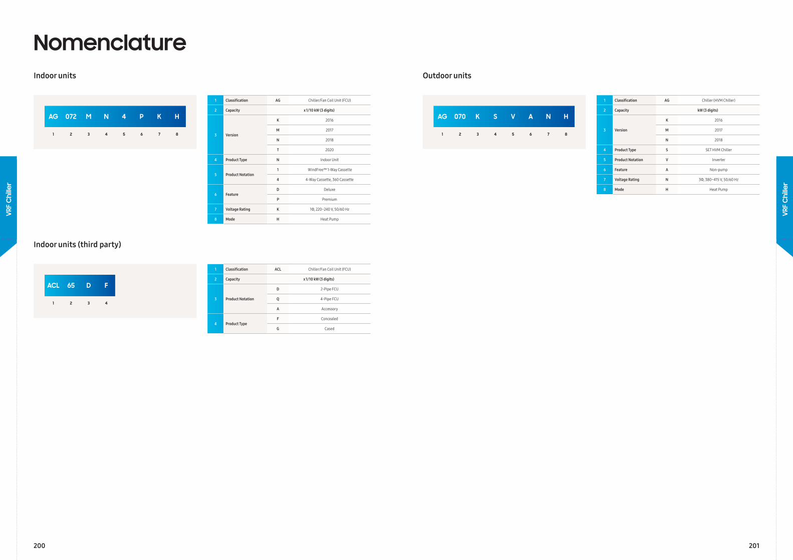
AG 072 M N 4 P K H
1 2 3 4 5 6 7 8
ACL 65 D F
1 2 3 4
1 Classification AG Chiller/Fan Coil Unit (FCU)
2 Capacity x 1/10 kW (3 digits)
3 Version
K 2016
M 2017
N 2018
T 2020
4 Product Type N Indoor Unit
5 Product Notation1 WindFree™ 1-Way Cassette
4 4-Way Cassette, 360 Cassette
6 FeatureD Deluxe
P Premium
7 Voltage Rating K 1Φ, 220~240 V, 50/60 Hz
8 Mode H Heat Pump
1 Classification ACL Chiller/Fan Coil Unit (FCU)
2 Capacity x 1/10 kW (3 digits)
3 Product Notation
D 2-Pipe FCU
Q 4-Pipe FCU
A Accessory
4 Product TypeF Concealed
G Cased
NomenclatureIndoor units
Indoor units (third party)
AG 070 K S V A N H
1 2 3 4 5 6 7 8
1 Classification AG Chiller (HVM Chiller)
2 Capacity kW (3 digits)
3 Version
K 2016
M 2017
N 2018
4 Product Type S SET HVM Chiller
5 Product Notation V Inverter
6 Feature A Non-pump
7 Voltage Rating N 3Φ, 380~415 V, 50/60 Hz
8 Mode H Heat Pump
Outdoor units
200 201
VRF
Chi
ller
VRF
Chi
ller
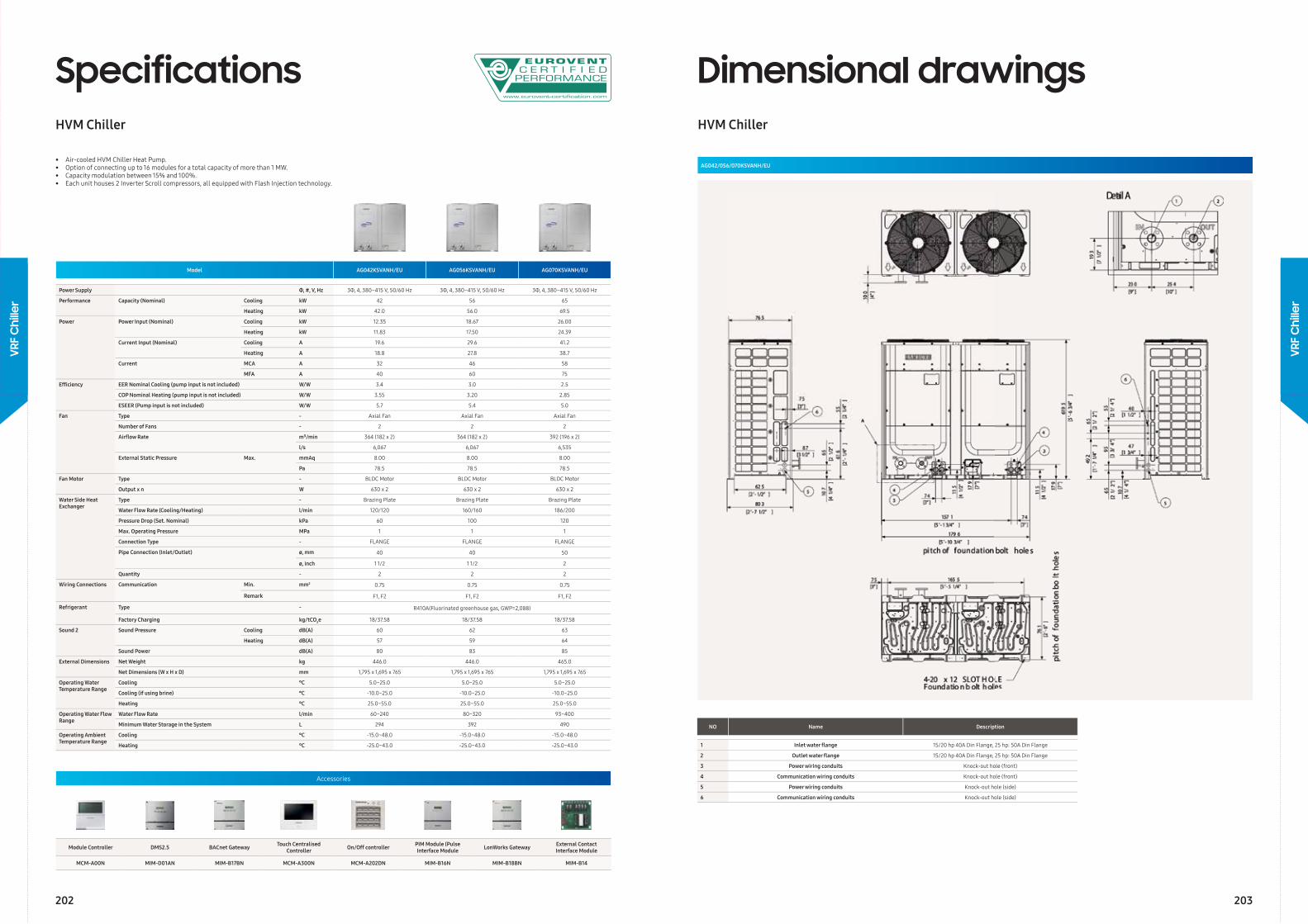
Model AG042KSVANH/EU AG056KSVANH/EU AG070KSVANH/EU
Power Supply Φ, #, V, Hz 3Φ, 4, 380–415 V, 50/60 Hz 3Φ, 4, 380–415 V, 50/60 Hz 3Φ, 4, 380–415 V, 50/60 Hz
Performance Capacity (Nominal) Cooling kW 42 56 65
Heating kW 42.0 56.0 69.5
Power Power Input (Nominal) Cooling kW 12.35 18.67 26.00
Heating kW 11.83 17.50 24.39
Current Input (Nominal) Cooling A 19.6 29.6 41.2
Heating A 18.8 27.8 38.7
Current MCA A 32 46 58
MFA A 40 60 75
Effi ciency EER Nominal Cooling (pump input is not included) W/W 3.4 3.0 2.5
COP Nominal Heating (pump input is not included) W/W 3.55 3.20 2.85
ESEER (Pump input is not included) W/W 5.7 5.4 5.0
Fan Type - Axial Fan Axial Fan Axial Fan
Number of Fans - 2 2 2
Airfl ow Rate m³/min 364 (182 x 2) 364 (182 x 2) 392 (196 x 2)
l/s 6,067 6,067 6,535
External Static Pressure Max. mmAq 8.00 8.00 8.00
Pa 78.5 78.5 78.5
Fan Motor Type - BLDC Motor BLDC Motor BLDC Motor
Output x n W 630 x 2 630 x 2 630 x 2
Water Side Heat Exchanger
Type - Brazing Plate Brazing Plate Brazing Plate
Water Flow Rate (Cooling/Heating) l/min 120/120 160/160 186/200
Pressure Drop (Set. Nominal) kPa 60 100 120
Max. Operating Pressure MPa 1 1 1
Connection Type - FLANGE FLANGE FLANGE
Pipe Connection (Inlet/Outlet) ø, mm 40 40 50
ø, inch 1 1/2 1 1/2 2
Quantity - 2 2 2
Wiring Connections Communication Min. mm2 0.75 0.75 0.75
Remark F1, F2 F1, F2 F1, F2
Refrigerant Type - R410A(Fluorinated greenhouse gas, GWP=2,088)
Factory Charging kg/tCO2e 18/37.58 18/37.58 18/37.58
Sound 2 Sound Pressure Cooling dB(A) 60 62 63
Heating dB(A) 57 59 64
Sound Power dB(A) 80 83 85
External Dimensions Net Weight kg 446.0 446.0 465.0
Net Dimensions (W x H x D) mm 1,795 x 1,695 x 765 1,795 x 1,695 x 765 1,795 x 1,695 x 765
Operating Water Temperature Range
Cooling °C 5.0~25.0 5.0~25.0 5.0~25.0
Cooling (if using brine) °C -10.0~25.0 -10.0~25.0 -10.0~25.0
Heating °C 25.0~55.0 25.0~55.0 25.0~55.0
Operating Water Flow Range
Water Flow Rate l/min 60~240 80~320 93~400
Minimum Water Storage in the System L 294 392 490
Operating Ambient Temperature Range
Cooling °C -15.0~48.0 -15.0~48.0 -15.0~48.0
Heating °C -25.0~43.0 -25.0~43.0 -25.0~43.0
Accessories
Module Controller DMS2.5 BACnet Gateway Touch Centralised Controller On/Off controller PIM Module (Pulse
Interface Module LonWorks Gateway External Contact Interface Module
MCM-A00N MIM-D01AN MIM-B17BN MCM-A300N MCM-A202DN MIM-B16N MIM-B18BN MIM-B14
SpecificationsHVM Chiller
• Air-cooled HVM Chiller Heat Pump.• Option of connecting up to 16 modules for a total capacity of more than 1 MW.• Capacity modulation between 15% and 100%.• Each unit houses 2 Inverter Scroll compressors, all equipped with Flash Injection technology.
Dimensional drawingsHVM Chiller
AG042/056/070KSVANH/EU
NO Name Description
1 Inlet water fl ange 15/20 hp 40A Din Flange, 25 hp: 50A Din Flange
2 Outlet water fl ange 15/20 hp 40A Din Flange, 25 hp: 50A Din Flange
3 Power wiring conduits Knock-out hole (front)
4 Communication wiring conduits Knock-out hole (front)
5 Power wiring conduits Knock-out hole (side)
6 Communication wiring conduits Knock-out hole (side)
202 203
VRF
Chi
ller
VRF
Chi
ller
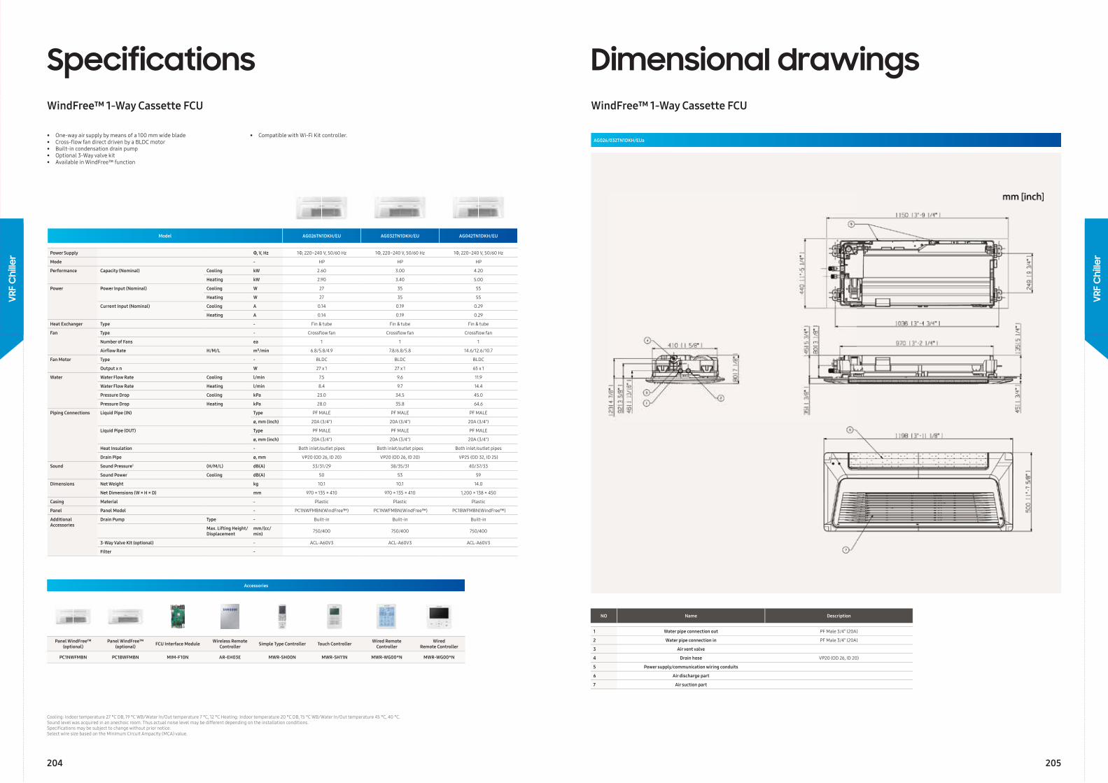
Model AG026TN1DKH/EU AG032TN1DKH/EU AG042TN1DKH/EU
Power Supply Φ, V, Hz 1Φ, 220~240 V, 50/60 Hz 1Φ, 220~240 V, 50/60 Hz 1Φ, 220~240 V, 50/60 Hz
Mode - HP HP HP
Performance Capacity (Nominal) Cooling kW 2.60 3.00 4.20
Heating kW 2.90 3.40 5.00
Power Power Input (Nominal) Cooling W 27 35 55
Heating W 27 35 55
Current Input (Nominal) Cooling A 0.14 0.19 0.29
Heating A 0.14 0.19 0.29
Heat Exchanger Type - Fin & tube Fin & tube Fin & tube
Fan Type - Crossfl ow fan Crossfl ow fan Crossfl ow fan
Number of Fans ea 1 1 1
Airfl ow Rate H/M/L m³/min 6.8/5.8/4.9 7.8/6.8/5.8 14.6/12.6/10.7
Fan Motor Type - BLDC BLDC BLDC
Output x n W 27 x 1 27 x 1 65 x 1
Water Water Flow Rate Cooling l/min 7.5 9.6 11.9
Water Flow Rate Heating l/min 8.4 9.7 14.4
Pressure Drop Cooling kPa 23.0 34.5 45.0
Pressure Drop Heating kPa 28.0 35.8 64.6
Piping Connections Liquid Pipe (IN) Type PF MALE PF MALE PF MALE
ø, mm (inch) 20A (3/4") 20A (3/4") 20A (3/4")
Liquid Pipe (OUT) Type PF MALE PF MALE PF MALE
ø, mm (inch) 20A (3/4") 20A (3/4") 20A (3/4")
Heat Insulation - Both inlet/outlet pipes Both inlet/outlet pipes Both inlet/outlet pipes
Drain Pipe ø, mm VP20 (OD 26, ID 20) VP20 (OD 26, ID 20) VP25 (OD 32, ID 25)
Sound Sound Pressure1 (H/M/L) dB(A) 33/31/29 38/35/31 40/37/33
Sound Power Cooling dB(A) 50 53 59
Dimensions Net Weight kg 10.1 10.1 14.0
Net Dimensions (W × H × D) mm 970 × 135 × 410 970 × 135 × 410 1,200 × 138 × 450
Casing Material - Plastic Plastic Plastic
Panel Panel Model - PC1NWFMBN(WindFree™) PC1NWFMBN(WindFree™) PC1BWFMBN(WindFree™)
Additional Accessories
Drain Pump Type - Built-in Built-in Built-in
Max. Lifting Height/Displacement
mm/(cc/min) 750/400 750/400 750/400
3-Way Valve Kit (optional) - ACL-A60V3 ACL-A60V3 ACL-A60V3
Filter -
Cooling: Indoor temperature 27 °C DB, 19 °C WB/Water In/Out temperature 7 °C, 12 °C Heating: Indoor temperature 20 °C DB, 15 °C WB/Water In/Out temperature 45 °C, 40 °C.Sound level was acquired in an anechoic room. Thus actual noise level may be different depending on the installation conditions.Specifi cations may be subject to change without prior notice.Select wire size based on the Minimum Circuit Ampacity (MCA) value.
Accessories
Panel WindFree™ (optional)
Panel WindFree™ (optional) FCU Interface Module Wireless Remote
Controller Simple Type Controller Touch Controller Wired Remote Controller
Wired Remote Controller
PC1NWFMBN PC1BWFMBN MIM-F10N AR-EH03E MWR-SH00N MWR-SH11N MWR-WG00*N MWR-WG00*N
SpecificationsWindFree™ 1-Way Cassette FCU
• One-way air supply by means of a 100 mm wide blade• Cross-fl ow fan direct driven by a BLDC motor• Built-in condensation drain pump• Optional 3-Way valve kit• Available in WindFree™ function
• Compatible with Wi-Fi Kit controller.
Dimensional drawingsWindFree™ 1-Way Cassette FCU
AG026/032TN1DKH/EUa
NO Name Description
1 Water pipe connection out PF Male 3/4” (20A)
2 Water pipe connection in PF Male 3/4” (20A)
3 Air vent valve
4 Drain hose VP20 (OD 26, ID 20)
5 Power supply/communication wiring conduits
6 Air discharge part
7 Air suction part
204 205
VRF
Chi
ller
VRF
Chi
ller
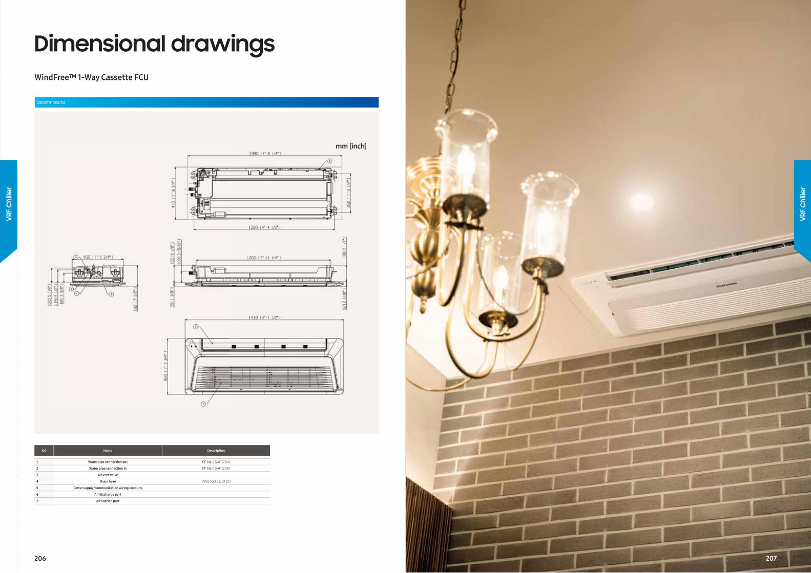
Dimensional drawingsWindFree™ 1-Way Cassette FCU
AG042TN1DKH/EU
NO Name Description
1 Water pipe connection out PF Male 3/4” (20A)
2 Water pipe connection in PF Male 3/4” (20A)
3 Air vent valve
4 Drain hose VP25 (OD 32, ID 25)
5 Power supply/communication wiring conduits
6 Air discharge part
7 Air suction part
206
VRF
Chi
ller
VRF
Chi
ller
207
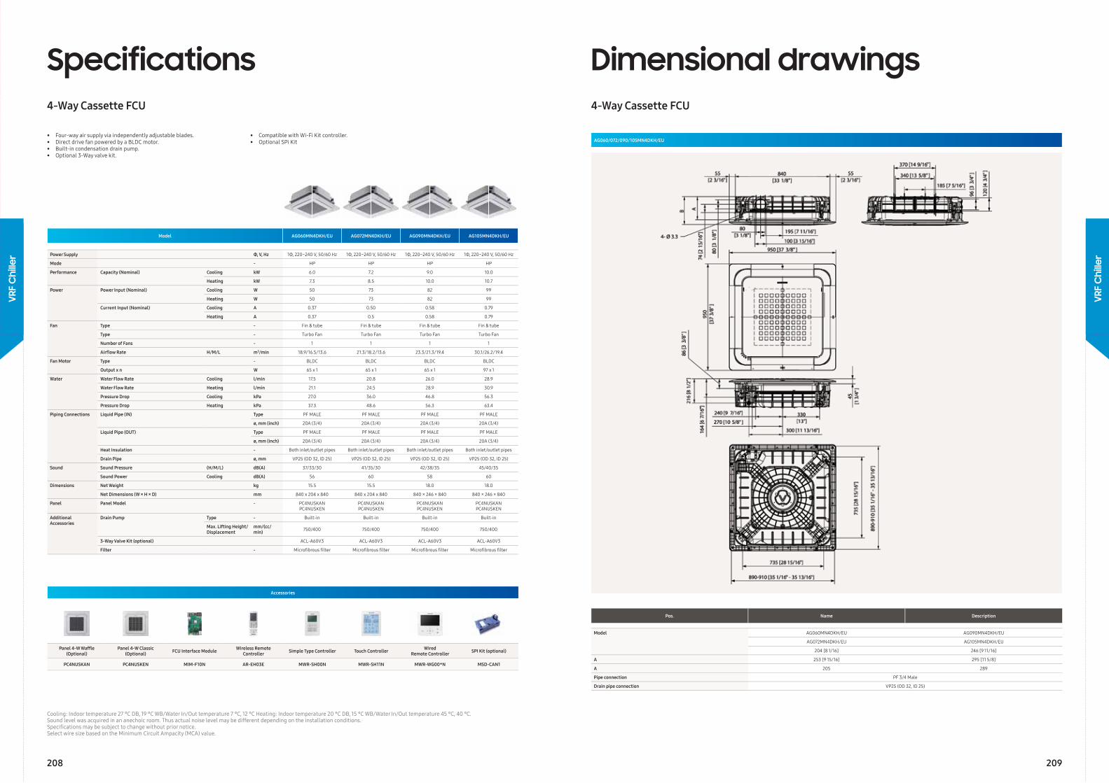
Model AG060MN4DKH/EU AG072MN4DKH/EU AG090MN4DKH/EU AG105MN4DKH/EU
Power Supply Φ, V, Hz 1Φ, 220~240 V, 50/60 Hz 1Φ, 220~240 V, 50/60 Hz 1Φ, 220~240 V, 50/60 Hz 1Φ, 220~240 V, 50/60 Hz
Mode - HP HP HP HP
Performance Capacity (Nominal) Cooling kW 6.0 7.2 9.0 10.0
Heating kW 7.3 8.5 10.0 10.7
Power Power Input (Nominal) Cooling W 50 73 82 99
Heating W 50 73 82 99
Current Input (Nominal) Cooling A 0.37 0.50 0.58 0.79
Heating A 0.37 0.5 0.58 0.79
Fan Type - Fin & tube Fin & tube Fin & tube Fin & tube
Type - Turbo Fan Turbo Fan Turbo Fan Turbo Fan
Number of Fans - 1 1 1 1
Airfl ow Rate H/M/L m3/min 18.9/16.5/13.6 21.3/18.2/13.6 23.3/21.3/19.4 30.1/26.2/19.4
Fan Motor Type - BLDC BLDC BLDC BLDC
Output x n W 65 x 1 65 x 1 65 x 1 97 x 1
Water Water Flow Rate Cooling l/min 17.5 20.8 26.0 28.9
Water Flow Rate Heating l/min 21.1 24.5 28.9 30.9
Pressure Drop Cooling kPa 27.0 36.0 46.8 56.3
Pressure Drop Heating kPa 37.3 48.6 56.3 63.4
Piping Connections Liquid Pipe (IN) Type PF MALE PF MALE PF MALE PF MALE
ø, mm (inch) 20A (3/4) 20A (3/4) 20A (3/4) 20A (3/4)
Liquid Pipe (OUT) Type PF MALE PF MALE PF MALE PF MALE
ø, mm (inch) 20A (3/4) 20A (3/4) 20A (3/4) 20A (3/4)
Heat Insulation - Both inlet/outlet pipes Both inlet/outlet pipes Both inlet/outlet pipes Both inlet/outlet pipes
Drain Pipe ø, mm VP25 (OD 32, ID 25) VP25 (OD 32, ID 25) VP25 (OD 32, ID 25) VP25 (OD 32, ID 25)
Sound Sound Pressure (H/M/L) dB(A) 37/33/30 41/35/30 42/38/35 45/40/35
Sound Power Cooling dB(A) 56 60 58 60
Dimensions Net Weight kg 15.5 15.5 18.0 18.0
Net Dimensions (W × H × D) mm 840 x 204 x 840 840 x 204 x 840 840 × 246 × 840 840 × 246 × 840
Panel Panel Model - PC4NUSKANPC4NUSKEN
PC4NUSKANPC4NUSKEN
PC4NUSKANPC4NUSKEN
PC4NUSKANPC4NUSKEN
Additional Accessories
Drain Pump Type - Built-in Built-in Built-in Built-in
Max. Lifting Height/Displacement
mm/(cc/min) 750/400 750/400 750/400 750/400
3-Way Valve Kit (optional) ACL-A60V3 ACL-A60V3 ACL-A60V3 ACL-A60V3
Filter - Microfi brous fi lter Microfi brous fi lter Microfi brous fi lter Microfi brous fi lter
Cooling: Indoor temperature 27 °C DB, 19 °C WB/Water In/Out temperature 7 °C, 12 °C Heating: Indoor temperature 20 °C DB, 15 °C WB/Water In/Out temperature 45 °C, 40 ° C.Sound level was acquired in an anechoic room. Thus actual noise level may be different depending on the installation conditions.Specifi cations may be subject to change without prior notice.Select wire size based on the Minimum Circuit Ampacity (MCA) value.
Specifications4-Way Cassette FCU
• Four-way air supply via independently adjustable blades.• Direct drive fan powered by a BLDC motor.• Built-in condensation drain pump.• Optional 3-Way valve kit.
• Compatible with Wi-Fi Kit controller.• Optional SPi Kit
Accessories
Panel 4-W Waffl e (Optional)
Panel 4-W Classic (Optional) FCU Interface Module Wireless Remote
Controller Simple Type Controller Touch Controller Wired Remote Controller SPI Kit (optional)
PC4NUSKAN PC4NUSKEN MIM-F10N AR-EH03E MWR-SH00N MWR-SH11N MWR-WG00*N MSD-CAN1
Dimensional drawings4-Way Cassette FCU
Pos. Name Description
Model AG060MN4DKH/EU AG090MN4DKH/EU
AG072MN4DKH/EU AG105MN4DKH/EU
204 [8 1/16] 246 [9 11/16]
A 253 [9 15/16] 295 [11 5/8]
A 205 289
Pipe connection PF 3/4 Male
Drain pipe connection VP25 (OD 32, ID 25)
AG060/072/090/105MN4DKH/EU
208 209
VRF
Chi
ller
VRF
Chi
ller
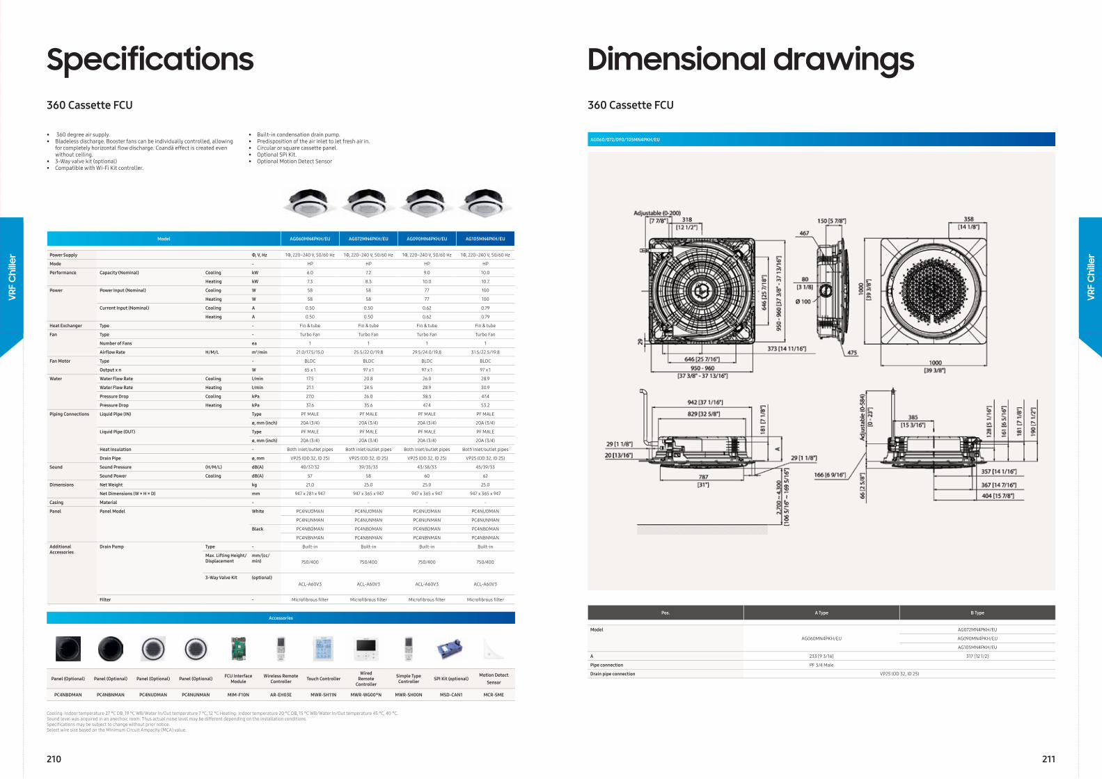
Model AG060MN4PKH/EU AG072MN4PKH/EU AG090MN4PKH/EU AG105MN4PKH/EU
Power Supply Φ, V, Hz 1Φ, 220~240 V, 50/60 Hz 1Φ, 220~240 V, 50/60 Hz 1Φ, 220~240 V, 50/60 Hz 1Φ, 220~240 V, 50/60 Hz
Mode - HP HP HP HP
Performance Capacity (Nominal) Cooling kW 6.0 7.2 9.0 10.0
Heating kW 7.3 8.5 10.0 10.7
Power Power Input (Nominal) Cooling W 58 58 77 100
Heating W 58 58 77 100
Current Input (Nominal) Cooling A 0.50 0.50 0.62 0.79
Heating A 0.50 0.50 0.62 0.79
Heat Exchanger Type - Fin & tube Fin & tube Fin & tube Fin & tube
Fan Type - Turbo Fan Turbo Fan Turbo Fan Turbo Fan
Number of Fans ea 1 1 1 1
Airfl ow Rate H/M/L m3/min 21.0/17.5/15.0 25.5/22.0/19.8 29.5/24.0/19.8 31.5/22.5/19.8
Fan Motor Type - BLDC BLDC BLDC BLDC
Output x n W 65 x 1 97 x 1 97 x 1 97 x 1
Water Water Flow Rate Cooling l/min 17.5 20.8 26.0 28.9
Water Flow Rate Heating l/min 21.1 24.5 28.9 30.9
Pressure Drop Cooling kPa 27.0 26.0 38.5 47.4
Pressure Drop Heating kPa 37.6 35.6 47.4 53.2
Piping Connections Liquid Pipe (IN) Type PF MALE PF MALE PF MALE PF MALE
ø, mm (inch) 20A (3/4) 20A (3/4) 20A (3/4) 20A (3/4)
Liquid Pipe (OUT) Type PF MALE PF MALE PF MALE PF MALE
ø, mm (inch) 20A (3/4) 20A (3/4) 20A (3/4) 20A (3/4)
Heat Insulation - Both inlet/outlet pipes Both inlet/outlet pipes Both inlet/outlet pipes Both inlet/outlet pipes
Drain Pipe ø, mm VP25 (OD 32, ID 25) VP25 (OD 32, ID 25) VP25 (OD 32, ID 25) VP25 (OD 32, ID 25)
Sound Sound Pressure (H/M/L) dB(A) 40/37/32 39/35/33 43/38/33 45/39/33
Sound Power Cooling dB(A) 57 58 60 62
Dimensions Net Weight kg 21.0 25.0 25.0 25.0
Net Dimensions (W × H × D) mm 947 x 281 x 947 947 x 365 x 947 947 x 365 x 947 947 x 365 x 947
Casing Material - - - - -
Panel Panel Model White PC4NUDMAN PC4NUDMAN PC4NUDMAN PC4NUDMAN
PC4NUNMAN PC4NUNMAN PC4NUNMAN PC4NUNMAN
Black PC4NBDMAN PC4NBDMAN PC4NBDMAN PC4NBDMAN
PC4NBNMAN PC4NBNMAN PC4NBNMAN PC4NBNMAN
Additional Accessories
Drain Pump Type - Built-in Built-in Built-in Built-in
Max. Lifting Height/Displacement
mm/(cc/min) 750/400 750/400 750/400 750/400
3-Way Valve Kit (optional)ACL-A60V3 ACL-A60V3 ACL-A60V3 ACL-A60V3
Filter - Microfi brous fi lter Microfi brous fi lter Microfi brous fi lter Microfi brous fi lter
Specifications360 Cassette FCU
Cooling: Indoor temperature 27 °C DB, 19 °C WB/Water In/Out temperature 7 °C, 12 °C Heating: Indoor temperature 20 °C DB, 15 °C WB/Water In/Out temperature 45 °C, 40 ° C.Sound level was acquired in an anechoic room. Thus actual noise level may be different depending on the installation conditions.Specifi cations may be subject to change without prior notice.Select wire size based on the Minimum Circuit Ampacity (MCA) value.
• 360 degree air supply.• Bladeless discharge. Booster fans can be individually controlled, allowing for completely horizontal fl ow discharge. Coandă effect is created even without ceiling.• 3-Way valve kit (optional)• Compatible with Wi-Fi Kit controller.
• Built-in condensation drain pump. • Predisposition of the air inlet to let fresh air in.• Circular or square cassette panel.• Optional SPi Kit.• Optional Motion Detect Sensor
Accessories
Panel (Optional) Panel (Optional) Panel (Optional) Panel (Optional) FCU Interface Module
Wireless Remote Controller Touch Controller
Wired Remote
Controller
Simple Type Controller SPI Kit (optional)
Motion Detect Sensor
PC4NBDMAN PC4NBNMAN PC4NUDMAN PC4NUNMAN MIM-F10N AR-EH03E MWR-SH11N MWR-WG00*N MWR-SH00N MSD-CAN1 MCR-SME
Pos. A Type B Type
Model
AG060MN4PKH/EU
AG072MN4PKH/EU
AG090MN4PKH/EU
AG105MN4PKH/EU
A 233 [9 3/16] 317 [12 1/2]
Pipe connection PF 3/4 Male
Drain pipe connection VP25 (OD 32, ID 25)
Dimensional drawings360 Cassette FCU
AG060/072/090/105MN4PKH/EU
210 211
VRF
Chi
ller
VRF
Chi
ller
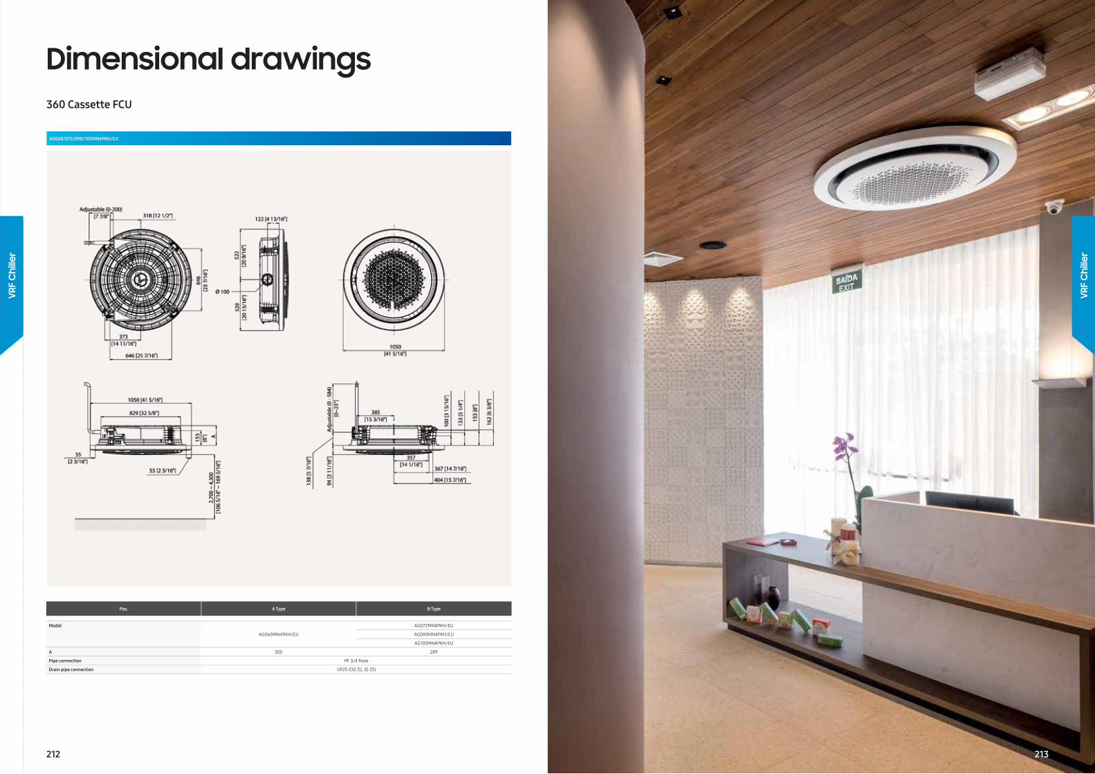
Dimensional drawings360 Cassette FCU
Pos. A Type B Type
Model
AG060MN4PKH/EU
AG072MN4PKH/EU
AG090MN4PKH/EU
AG105MN4PKH/EU
A 205 289
Pipe connection PF 3/4 Male
Drain pipe connection VP25 (OD 32, ID 25)
AG060/072/090/105MN4PKH/EU
212
VRF
Chi
ller
VRF
Chi
ller
213
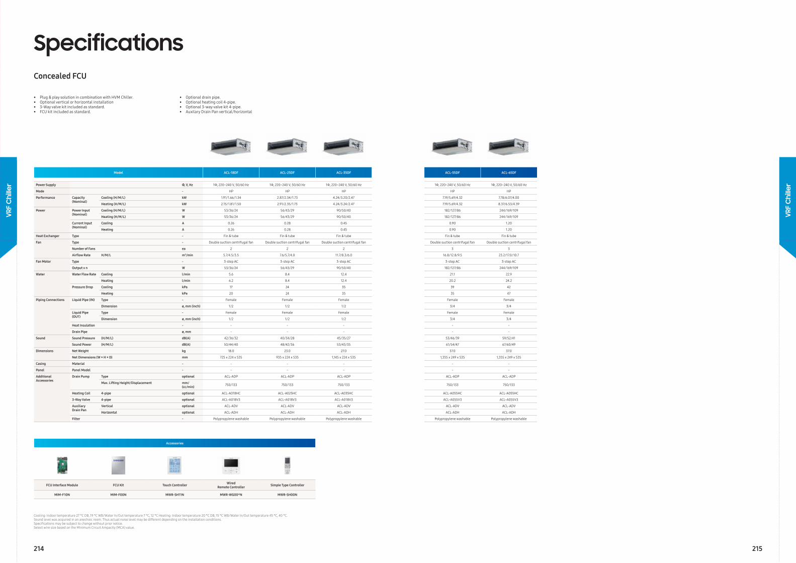
Model ACL-18DF ACL-25DF ACL-35DF ACL-55DF ACL-65DF
Power Supply Φ, V, Hz 1Ф, 220~240 V, 50/60 Hz 1Ф, 220~240 V, 50/60 Hz 1Ф, 220~240 V, 50/60 Hz 1Ф, 220~240 V, 50/60 Hz 1Ф, 220~240 V, 50/60 Hz
Mode - HP HP HP HP HP
Performance Capacity (Nominal)
Cooling (H/M/L) kW 1.91/1.66/1.34 2.87/2.34/1.73 4.24/3.20/2.47 7.19/5.69/4.32 7.78/6.07/4.00
Heating (H/M/L) kW 2.15/1.81/1.50 2.91/2.35/1.73 4.24/3.24/2.47 7.19/5.69/4.32 8.37/6.53/4.39
Power Power Input (Nominal)
Cooling (H/M/L) W 53/36/24 56/43/29 90/50/40 182/127/86 244/169/109
Heating (H/M/L) W 53/36/24 56/43/29 90/50/40 182/127/86 244/169/109
Current Input (Nominal)
Cooling A 0.26 0.28 0.45 0.90 1.20
Heating A 0.26 0.28 0.45 0.90 1.20
Heat Exchanger Type - Fin & tube Fin & tube Fin & tube Fin & tube Fin & tube
Fan Type - Double suction centrifugal fan Double suction centrifugal fan Double suction centrifugal fan Double suction centrifugal fan Double suction centrifugal fan
Number of Fans ea 2 2 2 3 3
Airfl ow Rate H/M/L m3/min 5.7/4.5/3.5 7.6/5.7/4.0 11.7/8.3/6.0 16.8/12.8/9.5 23.2/17.0/10.7
Fan Motor Type - 3-step AC 3-step AC 3-step AC 3-step AC 3-step AC
Output x n W 53/36/24 56/43/29 90/50/40 182/127/86 244/169/109
Water Water Flow Rate Cooling l/min 5.6 8.4 12.4 21.1 22.9
Heating l/min 6.2 8.4 12.4 20.2 24.2
Pressure Drop Cooling kPa 17 24 35 39 42
Heating kPa 20 24 35 35 47
Piping Connections Liquid Pipe (IN) Type - Female Female Female Female Female
Dimension ø, mm (inch) 1/2 1/2 1/2 3/4 3/4
Liquid Pipe (OUT)
Type - Female Female Female Female Female
Dimension ø, mm (inch) 1/2 1/2 1/2 3/4 3/4
Heat Insulation - - - - - -
Drain Pipe ø, mm - - - - -
Sound Sound Pressure (H/M/L) dB(A) 42/36/32 40/34/28 45/35/27 53/46/39 59/52/41
Sound Power (H/M/L) dB(A) 50/44/40 48/42/36 53/43/35 61/54/47 67/60/49
Dimensions Net Weight kg 18.0 23.0 27.0 37.0 37.0
Net Dimensions (W × H × D) mm 725 x 224 x 535 935 x 224 x 535 1,145 x 224 x 535 1,355 x 249 x 535 1,355 x 249 x 535
Casing Material - - - - - -
Panel Panel Model - - - - - -
Additional Accessories
Drain Pump Type optional ACL-ADP ACL-ADP ACL-ADP ACL-ADP ACL-ADP
Max. Lifting Height/Displacement mm/(cc/min) 750/133 750/133 750/133 750/133 750/133
Heating Coil 4-pipe optional ACL-A018HC ACL-A025HC ACL-A035HC ACL-A055HC ACL-A055HC
3-Way Valve 4-pipe optional ACL-A018V3 ACL-A018V3 ACL-A018V3 ACL-A055V3 ACL-A055V3
Auxiliary Drain Pan
Vertical optional ACL-ADV ACL-ADV ACL-ADV ACL-ADV ACL-ADV
Horizontal optional ACL-ADH ACL-ADH ACL-ADH ACL-ADH ACL-ADH
Filter - Polypropylene washable Polypropylene washable Polypropylene washable Polypropylene washable Polypropylene washable
SpecificationsConcealed FCU
Cooling: Indoor temperature 27 °C DB, 19 °C WB/Water In/Out temperature 7 °C, 12 °C Heating: Indoor temperature 20 °C DB, 15 °C WB/Water In/Out temperature 45 °C, 40 ° C.Sound level was acquired in an anechoic room. Thus actual noise level may be different depending on the installation conditions.Specifi cations may be subject to change without prior notice.Select wire size based on the Minimum Circuit Ampacity (MCA) value.
• Plug & play solution in combination with HVM Chiller.• Optional vertical or horizontal installation• 3-Way valve kit included as standard.• FCU kit included as standard.
Accessories
FCU Interface Module FCU Kit Touch Controller Wired Remote Controller Simple Type Controller
MIM-F10N MIM-F00N MWR-SH11N MWR-WG00*N MWR-SH00N
• Optional drain pipe.• Optional heating coil 4-pipe.• Optional 3-way valve kit 4-pipe.• Auxilary Drain Pan vertical/horizontal
214 215
VRF
Chi
ller
VRF
Chi
ller
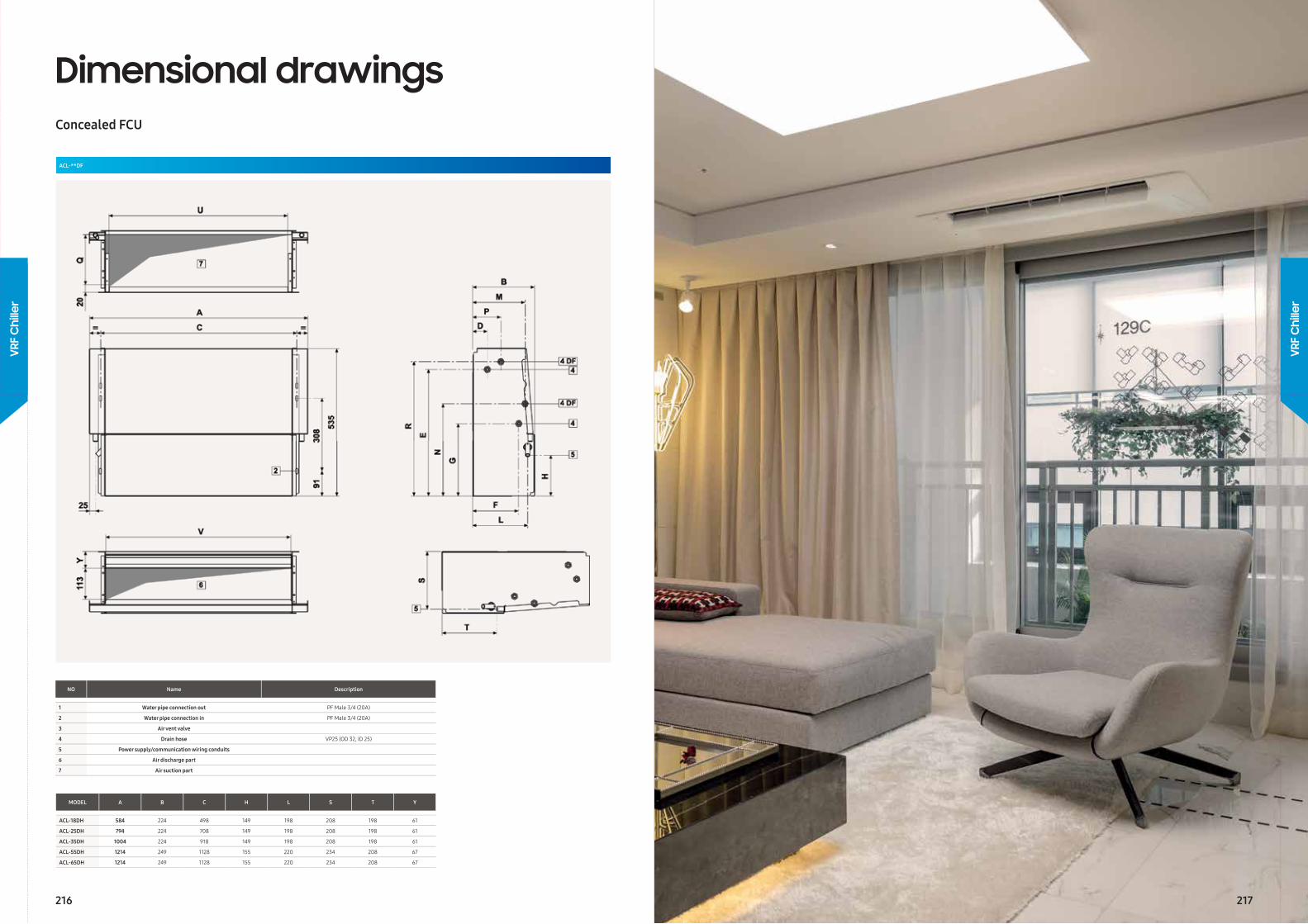
Dimensional drawingsConcealed FCU
ACL-**DF
NO Name Description
1 Water pipe connection out PF Male 3/4 (20A)
2 Water pipe connection in PF Male 3/4 (20A)
3 Air vent valve
4 Drain hose VP25 (OD 32, ID 25)
5 Power supply/communication wiring conduits
6 Air discharge part
7 Air suction part
MODEL A B C H L S T Y
ACL-18DH 584 224 498 149 198 208 198 61
ACL-25DH 794 224 708 149 198 208 198 61
ACL-35DH 1004 224 918 149 198 208 198 61
ACL-55DH 1214 249 1128 155 220 234 208 67
ACL-65DH 1214 249 1128 155 220 234 208 67
216 217
VRF
Chi
ller
VRF
Chi
ller
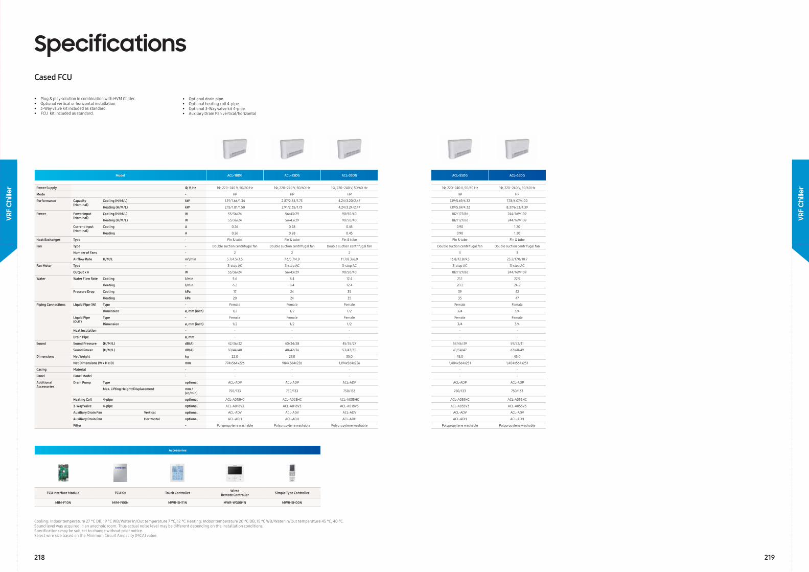
Model ACL-18DG ACL-25DG ACL-35DG ACL-55DG ACL-65DG
Power Supply Φ, V, Hz 1Ф, 220~240 V, 50/60 Hz 1Ф, 220~240 V, 50/60 Hz 1Ф, 220~240 V, 50/60 Hz 1Ф, 220~240 V, 50/60 Hz 1Ф, 220~240 V, 50/60 Hz
Mode - HP HP HP HP HP
Performance Capacity (Nominal)
Cooling (H/M/L) kW 1.91/1.66/1.34 2.87/2.34/1.73 4.24/3.20/2.47 7.19/5.69/4.32 7.78/6.07/4.00
Heating (H/M/L) kW 2.15/1.81/1.50 2.91/2.35/1.73 4.24/3.24/2.47 7.19/5.69/4.32 8.37/6.53/4.39
Power Power Input (Nominal)
Cooling (H/M/L) W 53/36/24 56/43/29 90/50/40 182/127/86 244/169/109
Heating (H/M/L) W 53/36/24 56/43/29 90/50/40 182/127/86 244/169/109
Current Input (Nominal)
Cooling A 0.26 0.28 0.45 0.90 1.20
Heating A 0.26 0.28 0.45 0.90 1.20
Heat Exchanger Type - Fin & tube Fin & tube Fin & tube Fin & tube Fin & tube
Fan Type - Double suction centrifugal fan Double suction centrifugal fan Double suction centrifugal fan Double suction centrifugal fan Double suction centrifugal fan
Number of Fans - 2 2 2 3 3
Airfl ow Rate H/M/L m3/min 5.7/4.5/3.5 7.6/5.7/4.0 11.7/8.3/6.0 16.8/12.8/9.5 23.2/17.0/10.7
Fan Motor Type - 3-step AC 3-step AC 3-step AC 3-step AC 3-step AC
Output x n W 53/36/24 56/43/29 90/50/40 182/127/86 244/169/109
Water Water Flow Rate Cooling l/min 5.6 8.4 12.4 21.1 22.9
Heating l/min 6.2 8.4 12.4 20.2 24.2
Pressure Drop Cooling kPa 17 24 35 39 42
Heating kPa 20 24 35 35 47
Piping Connections Liquid Pipe (IN) Type - Female Female Female Female Female
Dimension ø, mm (inch) 1/2 1/2 1/2 3/4 3/4
Liquid Pipe (OUT)
Type - Female Female Female Female Female
Dimension ø, mm (inch) 1/2 1/2 1/2 3/4 3/4
Heat Insulation - - - - - -
Drain Pipe ø, mm - - - - -
Sound Sound Pressure (H/M/L) dB(A) 42/36/32 40/34/28 45/35/27 53/46/39 59/52/41
Sound Power (H/M/L) dB(A) 50/44/40 48/42/36 53/43/35 61/54/47 67/60/49
Dimensions Net Weight kg 22.0 29.0 35.0 45.0 45.0
Net Dimensions (W x H x D) mm 774x564x226 984x564x226 1,194x564x226 1,404x564x251 1,404x564x251
Casing Material - - - - - -
Panel Panel Model - - - - - -
Additional Accessories
Drain Pump Type optional ACL-ADP ACL-ADP ACL-ADP ACL-ADP ACL-ADP
Max. Lifting Height/Displacement mm /(cc/min) 750/133 750/133 750/133 750/133 750/133
Heating Coil 4-pipe optional ACL-A018HC ACL-A025HC ACL-A035HC ACL-A055HC ACL-A055HC
3-Way Valve 4-pipe optional ACL-A018V3 ACL-A018V3 ACL-A018V3 ACL-A055V3 ACL-A055V3
Auxiliary Drain Pan Vertical optional ACL-ADV ACL-ADV ACL-ADV ACL-ADV ACL-ADV
Auxiliary Drain Pan Horizontal optional ACL-ADH ACL-ADH ACL-ADH ACL-ADH ACL-ADH
Filter - Polypropylene washable Polypropylene washable Polypropylene washable Polypropylene washable Polypropylene washable
SpecificationsCased FCU
Cooling: Indoor temperature 27 °C DB, 19 °C WB/Water In/Out temperature 7 °C, 12 °C Heating: Indoor temperature 20 °C DB, 15 °C WB/Water In/Out temperature 45 °C, 40 ° C.Sound level was acquired in an anechoic room. Thus actual noise level may be different depending on the installation conditions.Specifi cations may be subject to change without prior notice.Select wire size based on the Minimum Circuit Ampacity (MCA) value.
• Plug & play solution in combination with HVM Chiller.• Optional vertical or horizontal installation• 3-Way valve kit included as standard.• FCU kit included as standard.
Accessories
FCU Interface Module FCU Kit Touch Controller Wired Remote Controller Simple Type Controller
MIM-F10N MIM-F00N MWR-SH11N MWR-WG00*N MWR-SH00N
• Optional drain pipe.• Optional heating coil 4-pipe.• Optional 3-Way valve kit 4-pipe.• Auxilary Drain Pan vertical/horizontal
218 219
VRF
Chi
ller
VRF
Chi
ller
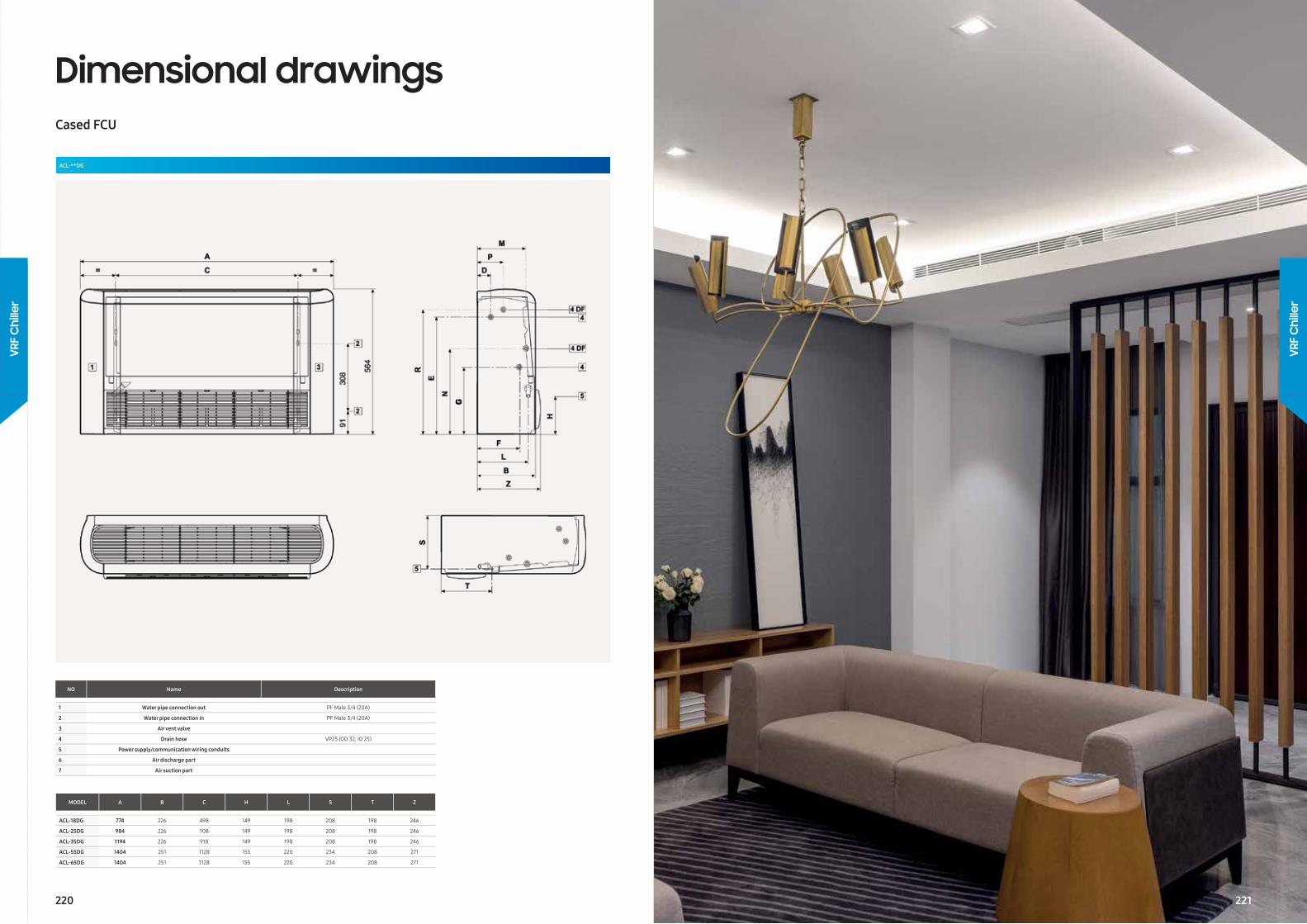
Dimensional drawingsCased FCU
ACL-**DG
NO Name Description
1 Water pipe connection out PF Male 3/4 (20A)
2 Water pipe connection in PF Male 3/4 (20A)
3 Air vent valve
4 Drain hose VP25 (OD 32, ID 25)
5 Power supply/communication wiring conduits
6 Air discharge part
7 Air suction part
MODEL A B C H L S T Z
ACL-18DG 774 226 498 149 198 208 198 246
ACL-25DG 984 226 708 149 198 208 198 246
ACL-35DG 1194 226 918 149 198 208 198 246
ACL-55DG 1404 251 1128 155 220 234 208 271
ACL-65DG 1404 251 1128 155 220 234 208 271
220
VRF
Chi
ller
VRF
Chi
ller
221
Ventilation
Ventilation
Vent
ilatio
n
222 223
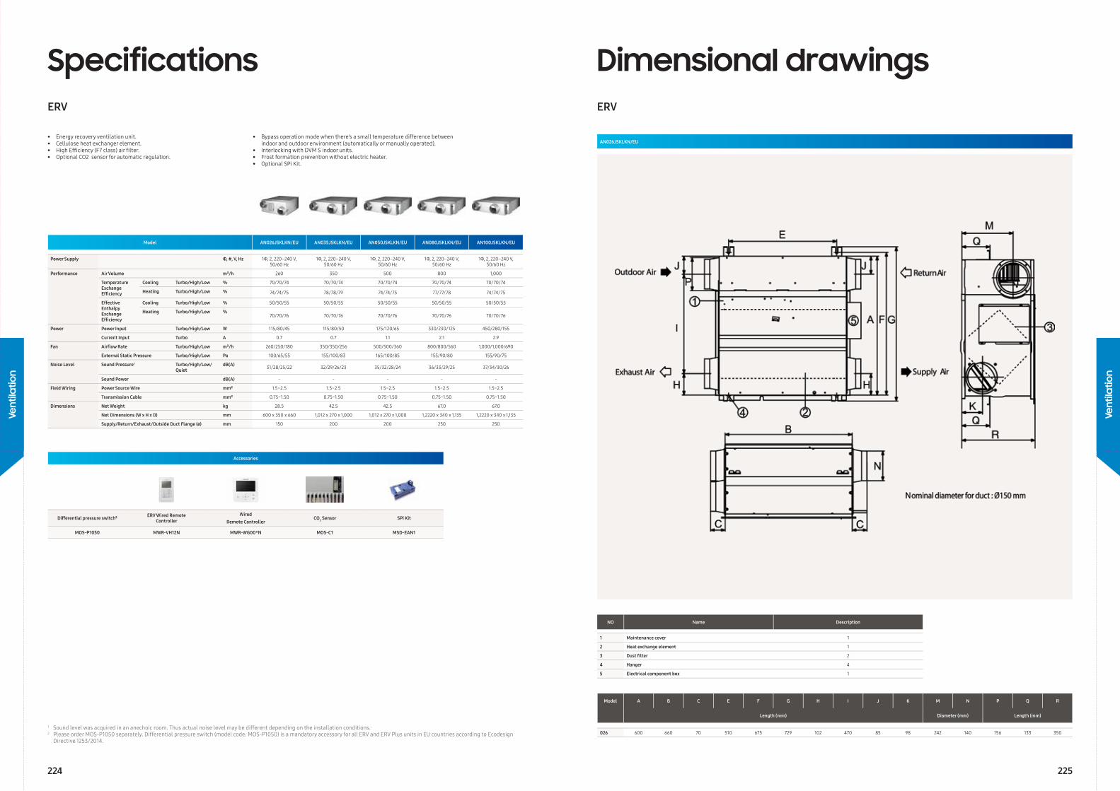
Model AN026JSKLKN/EU AN035JSKLKN/EU AN050JSKLKN/EU AN080JSKLKN/EU AN100JSKLKN/EU
Power Supply Φ, #, V, Hz 1Φ, 2, 220–240 V, 50/60 Hz
1Φ, 2, 220–240 V, 50/60 Hz
1Φ, 2, 220–240 V, 50/60 Hz
1Φ, 2, 220–240 V, 50/60 Hz
1Φ, 2, 220–240 V, 50/60 Hz
Performance Air Volume m³/h 260 350 500 800 1,000
Temperature Exchange Effi ciency
Cooling Turbo/High/Low % 70/70/74 70/70/74 70/70/74 70/70/74 70/70/74
Heating Turbo/High/Low % 74/74/75 78/78/79 74/74/75 77/77/78 74/74/75
Effective Enthalpy Exchange Effi ciency
Cooling Turbo/High/Low % 50/50/55 50/50/55 50/50/55 50/50/55 50/50/55
Heating Turbo/High/Low %70/70/76 70/70/76 70/70/76 70/70/76 70/70/76
Power Power Input Turbo/High/Low W 115/80/45 115/80/50 175/120/65 330/230/125 450/280/155
Current Input Turbo A 0.7 0.7 1.1 2.1 2.9
Fan Airfl ow Rate Turbo/High/Low m³/h 260/250/180 350/350/256 500/500/360 800/800/560 1,000/1,000/690
External Static Pressure Turbo/High/Low Pa 100/65/55 155/100/83 165/100/85 155/90/80 155/90/75
Noise Level Sound Pressure1 Turbo/High/Low/Quiet
dB(A) 31/28/25/22 32/29/26/23 35/32/28/24 36/33/29/25 37/34/30/26
Sound Power dB(A) - - - - -
Field Wiring Power Source Wire mm² 1.5~2.5 1.5~2.5 1.5~2.5 1.5~2.5 1.5~2.5
Transmission Cable mm² 0.75~1.50 0.75~1.50 0.75~1.50 0.75~1.50 0.75~1.50
Dimensions Net Weight kg 28.5 42.5 42.5 67.0 67.0
Net Dimensions (W x H x D) mm 600 x 350 x 660 1,012 x 270 x 1,000 1,012 x 270 x 1,000 1,2220 x 340 x 1,135 1,2220 x 340 x 1,135
Supply/Return/Exhaust/Outside Duct Flange (ø) mm 150 200 200 250 250
SpecificationsERV
• Energy recovery ventilation unit.• Cellulose heat exchanger element.• High Effi ciency (F7 class) air fi lter.• Optional CO2 sensor for automatic regulation.
• Bypass operation mode when there’s a small temperature difference between indoor and outdoor environment (automatically or manually operated).• Interlocking with DVM S indoor units.• Frost formation prevention without electric heater.• Optional SPi Kit.
Accessories
Differential pressure switch² ERV Wired Remote Controller
Wired Remote Controller
CO2 Sensor SPi Kit
MOS-P1050 MWR-VH12N MWR-WG00*N MOS-C1 MSD-EAN1
1 Sound level was acquired in an anechoic room. Thus actual noise level may be different depending on the installation conditions.2 Please order MOS-P1050 separately. Differential pressure switch (model code: MOS-P1050) is a mandatory accessory for all ERV and ERV Plus units in EU countries according to Ecodesign Directive 1253/2014.
Model A B C E F G H I J K M N P Q R
Length (mm) Diameter (mm) Length (mm)
026 600 660 70 510 675 729 102 470 85 98 242 140 156 133 350
Dimensional drawingsERV
AN026JSKLKN/EU
NO Name Description
1 Maintenance cover 1
2 Heat exchange element 1
3 Dust fi lter 2
4 Hanger 4
5 Electrical component box 1
224 225
Vent
ilatio
n
Vent
ilatio
n
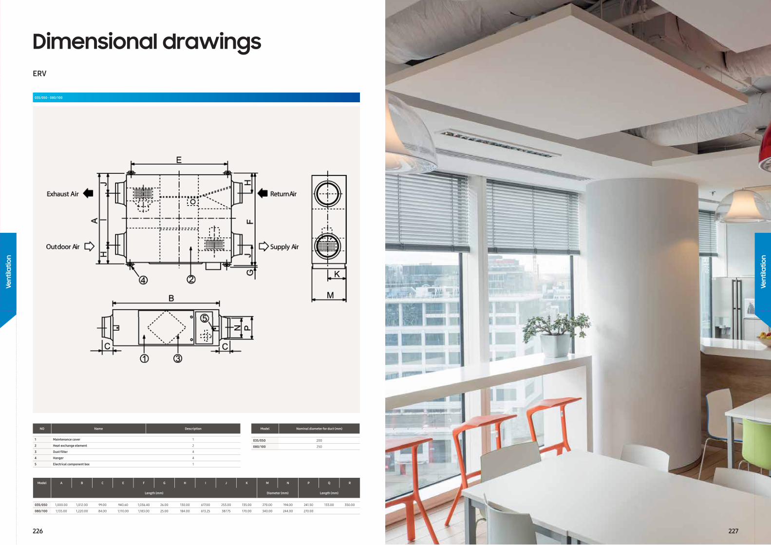
Model Nominal diameter for duct (mm)
035/050 200
080/100 250
Model A B C E F G H I J K M N P Q R
Length (mm) Diameter (mm) Length (mm)
035/050 1,000.00 1,012.00 99.00 940.60 1,036.40 26.00 130.00 617.00 253.00 135.00 270.00 194.00 241.50 133.00 350.00
080/100 1,135.00 1,220.00 84.00 1,110.00 1,183.00 25.00 184.00 613.25 387.75 170.00 340.00 244.00 270.00
Dimensional drawingsERV
035/050 - 080/100
NO Name Description
1 Maintenance cover 1
2 Heat exchange element 2
3 Dust fi lter 4
4 Hanger 4
5 Electrical component box 1
226 227
Vent
ilatio
n
Vent
ilatio
n
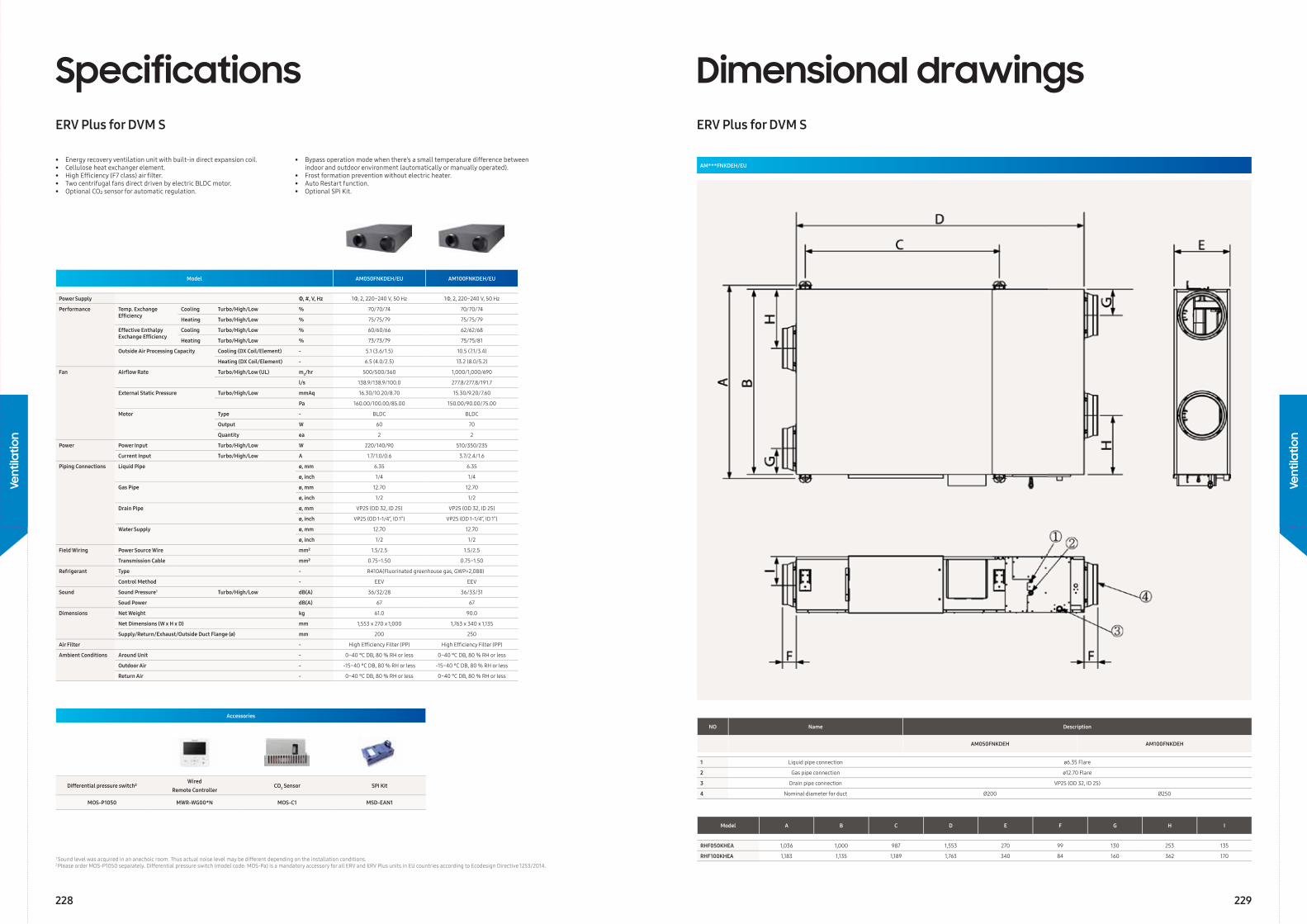
Model AM050FNKDEH/EU AM100FNKDEH/EU
Power Supply Φ, #, V, Hz 1Φ, 2, 220~240 V, 50 Hz 1Φ, 2, 220~240 V, 50 Hz
Performance Temp. Exchange Effi ciency
Cooling Turbo/High/Low % 70/70/74 70/70/74
Heating Turbo/High/Low % 75/75/79 75/75/79
Effective Enthalpy Exchange Effi ciency
Cooling Turbo/High/Low % 60/60/66 62/62/68
Heating Turbo/High/Low % 73/73/79 75/75/81
Outside Air Processing Capacity Cooling (DX Coil/Element) - 5.1 (3.6/1.5) 10.5 (7.1/3.4)
Heating (DX Coil/Element) - 6.5 (4.0/2.5) 13.2 (8.0/5.2)
Fan Airfl ow Rate Turbo/High/Low (UL) m3/hr 500/500/360 1,000/1,000/690
l/s 138.9/138.9/100.0 277.8/277.8/191.7
External Static Pressure Turbo/High/Low mmAq 16.30/10.20/8.70 15.30/9.20/7.60
Pa 160.00/100.00/85.00 150.00/90.00/75.00
Motor Type - BLDC BLDC
Output W 60 70
Quantity ea 2 2
Power Power Input Turbo/High/Low W 220/140/90 510/350/235
Current Input Turbo/High/Low A 1.7/1.0/0.6 3.7/2.4/1.6
Piping Connections Liquid Pipe ø, mm 6.35 6.35
ø, inch 1/4 1/4
Gas Pipe ø, mm 12.70 12.70
ø, inch 1/2 1/2
Drain Pipe ø, mm VP25 (OD 32, ID 25) VP25 (OD 32, ID 25)
ø, inch VP25 (OD 1-1/4”, ID 1”) VP25 (OD 1-1/4”, ID 1”)
Water Supply ø, mm 12.70 12.70
ø, inch 1/2 1/2
Field Wiring Power Source Wire mm² 1.5/2.5 1.5/2.5
Transmission Cable mm² 0.75~1.50 0.75~1.50
Refrigerant Type - R410A(Fluorinated greenhouse gas, GWP=2,088)
Control Method - EEV EEV
Sound Sound Pressure1 Turbo/High/Low dB(A) 36/32/28 36/33/31
Soud Power dB(A) 67 67
Dimensions Net Weight kg 61.0 90.0
Net Dimensions (W x H x D) mm 1,553 x 270 x 1,000 1,763 x 340 x 1,135
Supply/Return/Exhaust/Outside Duct Flange (ø) mm 200 250
Air Filter - High Effi ciency Filter (PP) High Effi ciency Filter (PP)
Ambient Conditions Around Unit - 0~40 °C DB, 80 % RH or less 0~40 °C DB, 80 % RH or less
Outdoor Air - -15~40 °C DB, 80 % RH or less -15~40 °C DB, 80 % RH or less
Return Air - 0~40 °C DB, 80 % RH or less 0~40 °C DB, 80 % RH or less
SpecificationsERV Plus for DVM S
Accessories
Differential pressure switch²Wired
Remote ControllerCO2 Sensor SPi Kit
MOS-P1050 MWR-WG00*N MOS-C1 MSD-EAN1
1 Sound level was acquired in an anechoic room. Thus actual noise level may be different depending on the installation conditions.2 Please order MOS-P1050 separately. Differential pressure switch (model code: MOS-Pa) is a mandatory accessory for all ERV and ERV Plus units in EU countries according to Ecodesign Directive 1253/2014.
• Energy recovery ventilation unit with built-in direct expansion coil.• Cellulose heat exchanger element.• High Effi ciency (F7 class) air fi lter.• Two centrifugal fans direct driven by electric BLDC motor.• Optional CO₂ sensor for automatic regulation.
• Bypass operation mode when there’s a small temperature difference between indoor and outdoor environment (automatically or manually operated).• Frost formation prevention without electric heater.• Auto Restart function.• Optional SPi Kit.
Model A B C D E F G H I
RHF050KHEA 1,036 1,000 987 1,553 270 99 130 253 135
RHF100KHEA 1,183 1,135 1,189 1,763 340 84 160 362 170
Dimensional drawingsERV Plus for DVM S
AM***FNKDEH/EU
NO Name Description
AM050FNKDEH AM100FNKDEH
1 Liquid pipe connection ø6.35 Flare
2 Gas pipe connection ø12.70 Flare
3 Drain pipe connection VP25 (OD 32, ID 25)
4 Nominal diameter for duct Ø200 Ø250
228 229
Vent
ilatio
n
Vent
ilatio
n
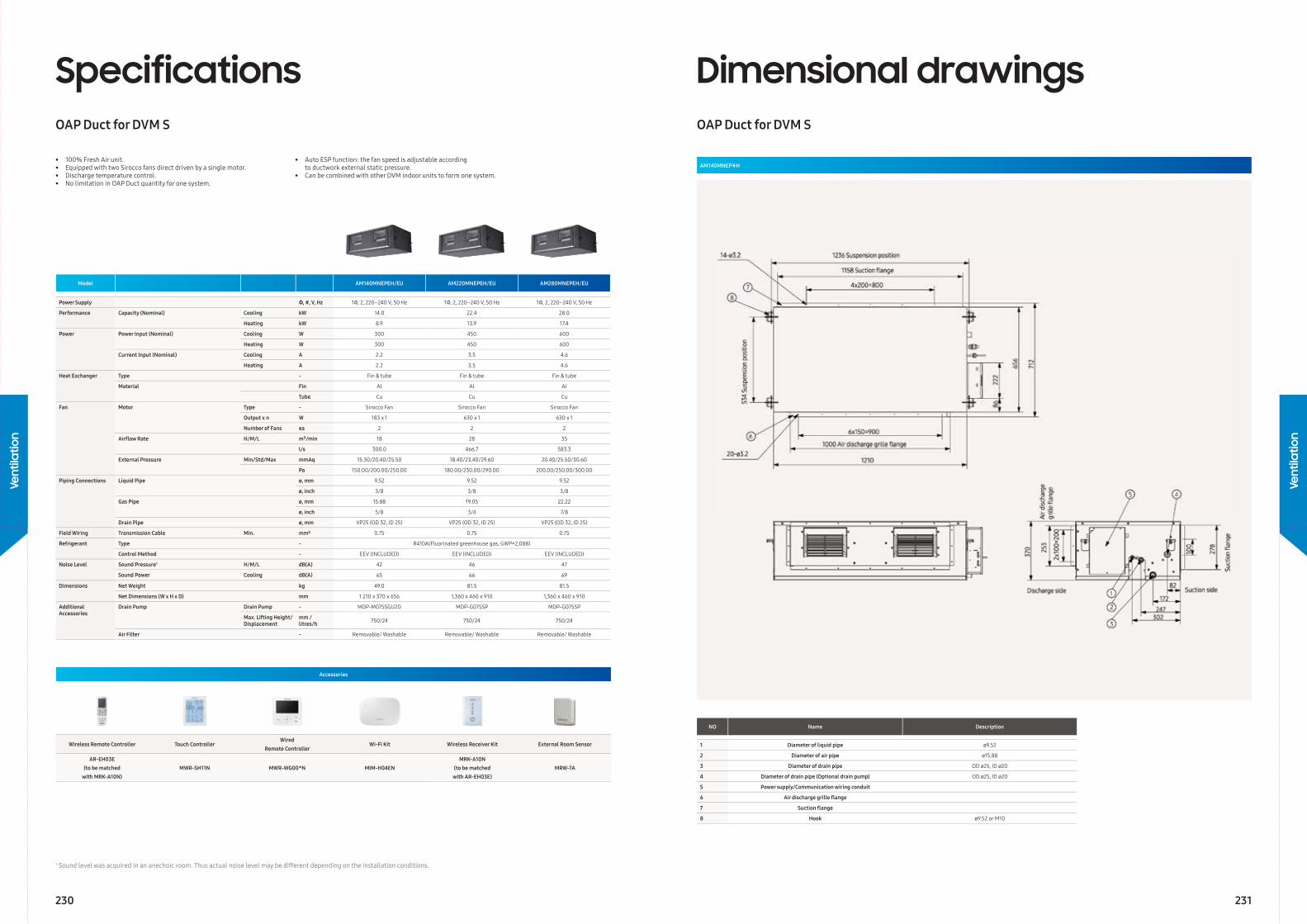
SpecificationsOAP Duct for DVM S
Model AM140MNEPEH/EU AM220MNEPEH/EU AM280MNEPEH/EU
Power Supply Φ, #, V, Hz 1Φ, 2, 220–240 V, 50 Hz 1Φ, 2, 220–240 V, 50 Hz 1Φ, 2, 220–240 V, 50 Hz
Performance Capacity (Nominal) Cooling kW 14.0 22.4 28.0
Heating kW 8.9 13.9 17.4
Power Power Input (Nominal) Cooling W 300 450 600
Heating W 300 450 600
Current Input (Nominal) Cooling A 2.2 3.5 4.6
Heating A 2.2 3.5 4.6
Heat Exchanger Type - Fin & tube Fin & tube Fin & tube
Material Fin Al Al Al
Tube Cu Cu Cu
Fan Motor Type - Sirocco Fan Sirocco Fan Sirocco Fan
Output x n W 183 x 1 630 x 1 630 x 1
Number of Fans ea 2 2 2
Airfl ow Rate H/M/L m³/min 18 28 35
l/s 300.0 466.7 583.3
External Pressure Min/Std/Max mmAq 15.30/20.40/25.50 18.40/23.40/29.60 20.40/25.50/30.60
Pa 150.00/200.00/250.00 180.00/230.00/290.00 200.00/250.00/300.00
Piping Connections Liquid Pipe ø, mm 9.52 9.52 9.52
ø, inch 3/8 3/8 3/8
Gas Pipe ø, mm 15.88 19.05 22.22
ø, inch 5/8 3/4 7/8
Drain Pipe ø, mm VP25 (OD 32, ID 25) VP25 (OD 32, ID 25) VP25 (OD 32, ID 25)
Field Wiring Transmission Cable Min. mm² 0.75 0.75 0.75
Refrigerant Type - R410A(Fluorinated greenhouse gas, GWP=2,088)
Control Method - EEV (INCLUDED) EEV (INCLUDED) EEV (INCLUDED)
Noise Level Sound Pressure1 H/M/L dB(A) 42 46 47
Sound Power Cooling dB(A) 65 66 69
Dimensions Net Weight kg 49.0 81.5 81.5
Net Dimensions (W x H x D) mm 1 210 x 370 x 656 1,360 x 460 x 910 1,360 x 460 x 910
Additional Accessories
Drain Pump Drain Pump - MDP-M075SGU2D MDP-G075SP MDP-G075SP
Max. Lifting Height/Displacement
mm / litres/h 750/24 750/24 750/24
Air Filter - Removable/ Washable Removable/ Washable Removable/ Washable
1 Sound level was acquired in an anechoic room. Thus actual noise level may be different depending on the installation conditions.
Accessories
Wireless Remote Controller Touch ControllerWired
Remote ControllerWi-Fi Kit Wireless Receiver Kit External Room Sensor
AR-EH03E(to be matched
with MRK-A10N)MWR-SH11N MWR-WG00*N MIM-H04EN
MRK-A10N (to be matched
with AR-EH03E)MRW-TA
• 100% Fresh Air unit.• Equipped with two Sirocco fans direct driven by a single motor.• Discharge temperature control.• No limitation in OAP Duct quantity for one system.
• Auto ESP function: the fan speed is adjustable according to ductwork external static pressure.• Can be combined with other DVM indoor units to form one system.
Dimensional drawingsOAP Duct for DVM S
AM140MNEP∗H
NO Name Description
1 Diameter of liquid pipe ø9.52
2 Diameter of air pipe ø15.88
3 Diameter of drain pipe OD ø25, ID ø20
4 Diameter of drain pipe (Optional drain pump) OD ø25, ID ø20
5 Power supply/Communication wiring conduit
6 Air discharge grille fl ange
7 Suction fl ange
8 Hook ø9.52 or M10
230 231
Vent
ilatio
n
Vent
ilatio
n
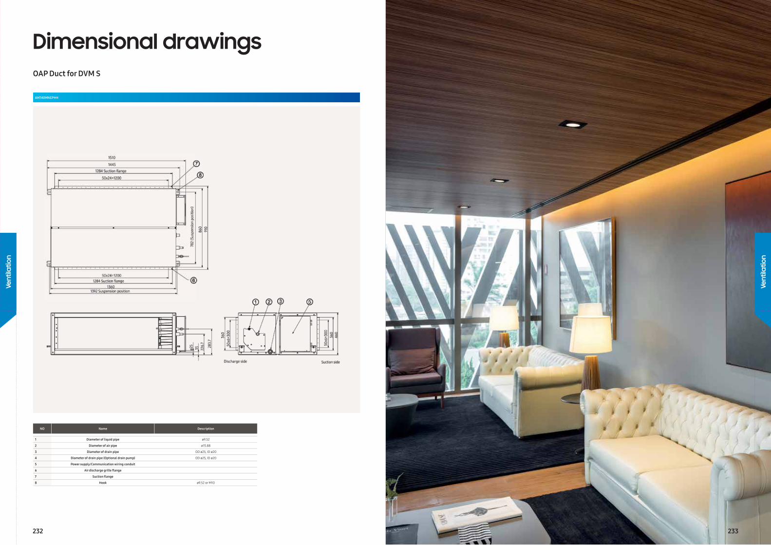
Dimensional drawingsOAP Duct for DVM S
AM140MNEP∗H
NO Name Description
1 Diameter of liquid pipe ø9.52
2 Diameter of air pipe ø15.88
3 Diameter of drain pipe OD ø25, ID ø20
4 Diameter of drain pipe (Optional drain pump) OD ø25, ID ø20
5 Power supply/Communication wiring conduit
6 Air discharge grille fl ange
7 Suction fl ange
8 Hook ø9.52 or M10
232 233
Vent
ilatio
n
Vent
ilatio
n
Controls
Con
trol
s
234
Controls
235
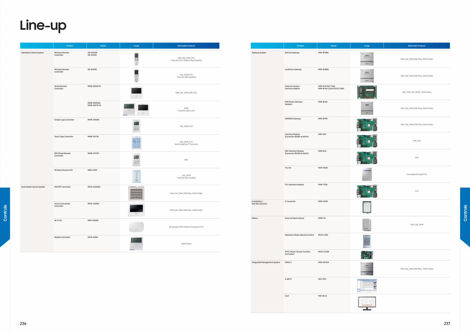
Line-upProduct Model Image Matchable Products
Individual Control System Wireless RemoteController
AR-EH03MAR-EH03E
FJM, CAC, DVM, FCU *only for FCU 1-Way/4-Way Cassette
Wireless RemoteController
AR-KH03E
CAC, DVM, FCU*only for 360 Cassette
Wired RemoteController
MWR-WG00*N
FJM, CAC, DVM, ERV, FCU
MWR-WW00N, MWR-WW10*N
DVM *only for Hydro unit
Simple Type Controller MWR-SH00N
CAC, DVM, FCU
Touch Type Controller MWR-SH11N
CAC, DVM, FCU(with WindFree™ function)
ERV Wired RemoteController
MWR-VH12N
ERV
Wireless Receiver Kit MRK-A10N
CAC, DVM*only for duct models
Centralised Control System ON/OFF Controller MCM-A202DN
FJM, CAC, DVM, ERV Plus, HVM Chiller
Touch CentralisedController
MCM-A300N
FJM, CAC, DVM, ERV Plus, HVM Chiller
Wi-Fi Kit MIM-H04EN
All (except HVM Chiller & 3rd party FCU)
Module Controller MCM-A00N
HVM Chiller
Product Model Image Matchable Products
Gateway System BACnet Gateway MIM-B17BN
FJM, CAC, DVM, ERV Plus, HVM Chiller
LonWorks Gateway MIM-B18BN
FJM, CAC, DVM, ERV Plus, HVM Chiller
External ContactInterface Module
MIM-B14 (KEY TAG)MIM-B14A (LEAK DETECTION)
RAC, FJM, CAC, DVM, HVM Chiller
PIM (Pulse InterfaceModule)
MIM-B16N
FJM, CAC, DVM, ERV Plus, HVM Chiller
MODBUS Gateway MIM-B19N
FJM, CAC, DVM, ERV Plus, HVM Chiller
Interface Module (Converter RS485 to NASA)
MIM-N01
FJM, CAC
ERV Interface Module (Converter RS485 to NASA)
MIM-N10
ERV
FCU Kit MIM-F00N
Concealed & Cased FCU
FCU Interface Module MIM-F10N
FCU
Installation/Test Run Solution
S-Converter MIM-C02N
Others External Room Sensor MRW-TA
FJM, CAC, DVM
Operation Mode Selection Switch MCM-C200
MTFC (Multi-Tenant Function Controller)
MCM-C210N
Integrated Management System DMS2.5 MIM-D01AN
FJM, CAC, DVM, ERV Plus, HVM Chiller
S-NET3 MST-P3P
b.IoT MST-BL1A
236 237
Con
trol
s
Con
trol
s
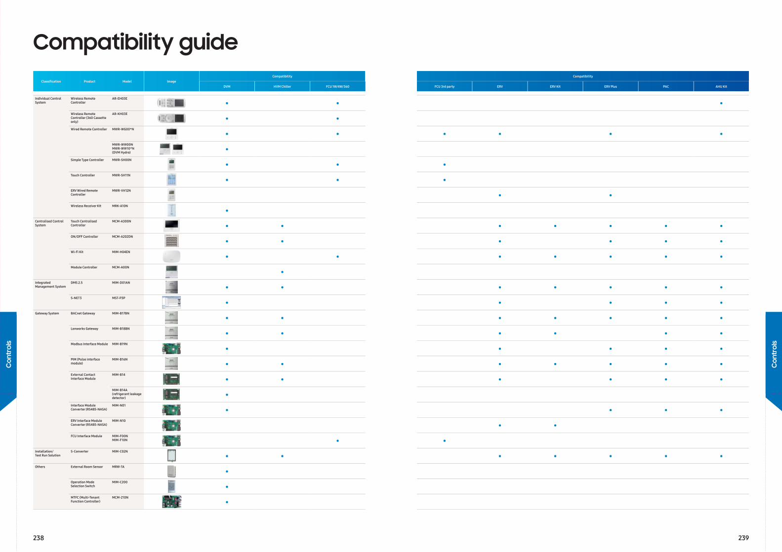
Compatibility guideClassifi cation Product Model Image
Compatibility Compatibility
DVM HVM Chiller FCU 1W/4W/360 FCU 3rd party ERV ERV Kit ERV Plus PAC AHU Kit
Individual Control System
Wireless Remote Controller
AR-EH03E
• • • Wireless Remote Controller (360 Cassette only)
AR-KH03E
• • Wired Remote Controller MWR-WG00*N
• • • • • •MWR-WW00NMWR-WW10*N(DVM Hydro) •
Simple Type Controller MWR-SH00N
• • • Touch Controller MWR-SH11N
• • •ERV Wired Remote Controller
MWR-VH12N
• •Wireless Receiver Kit MRK-A10N
•Centralised Control System
Touch Centralised Controller
MCM-A300N
• • • • • • •ON/OFF Controller MCM-A202DN
• • • • • •Wi-Fi Kit MIM-H04EN
• • • • • • •Module Controller MCM-A00N
•Integrated Management System
DMS 2.5 MIM-D01AN
• • • • • • •S-NET3 MST-P3P
• • • • •Gateway System BACnet Gateway MIM-B17BN
• • • • • • •Lonworks Gateway MIM-B18BN
• • • • • •Modbus Interface Module MIM-B19N
• • • • •PIM (Pulse interface module)
MIM-B16N
• • • • • • •External Contact Interface Module
MIM-B14
• • • • • •MIM-B14A(refrigerant leakage detector) •
Interface Module Converter (RS485-NASA)
MIM-N01
• • • •ERV Interface Module Converter (RS485-NASA)
MIM-N10
• •FCU Interface Module MIM-F00N
MIM-F10N • •Installation/Test Run Solution
S-Converter MIM-C02N
• • • • • • •Others External Room Sensor MRW-TA
•Operation Mode Selection Switch
MIM-C200
•MTFC (Multi-Tenant Function Controller)
MCM-210N
•
238 239
Con
trol
s
Con
trol
s
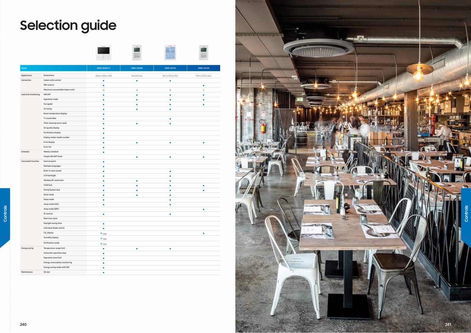
Selection guide
Model MWR-WG00*N MWR-SH00N MWR-SH11N MWR-VH12N
Appearance Dimensions 120.0 x 120.0 x 19.0 75x 122x 16.6 94.2 x 122.0 x 19.5 75.0 x 122.0 x 16.6
Connection Indoor units control • • •ERV control • • Maximum connectable indoor units 16 16 16 6
Control & monitoring ON/OFF • • • •Operation mode • • • •Fan speed • • • •Air swing • • •Room temperature display • °C convertible • •Filter cleaning alarm reset • • •Air quality display •Purifi cation display •Display indoor model number •Error display • • • •Error list •
Schedule Weekly schedule • -
Simple ON/OFF timer • • •Convenient function Dual set point •
Multiple languages •Built-in room sensor • •LCD backlight • •Wireless RC restriction • • •Child lock • • • •Partial button lock • • • •Quiet mode • • •Sleep mode • •Away mode (SAC) • •Away mode (ERV) •IR receiver • •Real-time clock
Daylight saving time •Individual blade control •CO2 display • ERV •Humidity display • ERV
Purifi cation mode • ERV
Energy saving Temperature range limit • • •Automatic operation stop •Operation time limit •Energy consumption monitoring •Energy saving mode with ERV •
Maintenance SD slot •
240
Con
trol
s
Con
trol
s
241

Features and Dimensional drawings
Individual Control System
Wireless Remote Controller AR-EH03E
• Operation ON/OFF control• Fan speed control• Operation temperature setting• WindFree™ Cooling function• Filter replacement alarm reset• Air swing control• Simple ON/OFF timer• Indoor unit option code setting• Option/Setting selection
Wireless Remote ControllerAR-KH03E
• 360 Cassette airfl ow direction control• Operation ON/OFF control• Fan speed control• Operation temperature setting• Filter replacement alarm reset• Simple ON/OFF timer• Indoor unit option code setting
Wired Remote ControllerMWR-WG00*N
Air conditioner/ERV control• AC control: ON/OFF, operation mode, temperature setting, fan speed,
airflow direction• ERV control: ON/OFF, operation mode, fan speed• AC/ERV error monitoring• Filter cleaning alert and reset alert time• ontrol a maximum of 16 “Indoor unit + ERV” in a group with a single wired
controller
Energy saving operation• Upper/lower temperature limit setting• Automatically stops operating when not used for certain period of time as
set by user
Weekly operation schedule setting• Weekly operating schedule (A/C only, ERV only, A/C+ERV)• Set desired AC operation mode, temperature and fan speed to operate
based on a weekly schedule• Apply schedule exception day• Energy consumption monitoring• Operation time limit
User convenience function• Child lock• Different button permission levels• Room temperature display• Dual set point• Built-in room temperature sensor• Real-time clock: displays current time and day (summer time support)• Multiple language support• Service mode support• Indoor unit cycle data monitoring• Indoor unit option code setting and monitoring• Indoor unit address setting and monitoring• SD card slot
120.
0 (4
.72)
19.0(0.75)120.0 (4.72)
[Unit : mm(inch)]
Simple Type ControllerMWR-SH00N
• Simplifi ed wired remote controller• AC operation ON/OFF control• Fan speed control• Setting operation mode and temperature• Reset fi lter cleaning alert indicator• Adjust airfl ow direction• Operation ON/OFF timer function
Touch ControllerMWR-SH11N
• Bigger display: clear & bright backlight screen with big fonts• WindFree™ button: control WindFree™ function with just one click• Room temperature monitor and room temperature display thanks to the
built-in temperature sensor• Icon/Function Lock: option of restricting icon/function on the display• Sleep Mode: help users to sleep better by controlling temperature• Outing Feature: keep room temperature above/below specifi c set value
when the user is out of the room
Wireless Receiver KitMRK-A10N
• Concealed wireless signal receiver• Filter replacement sign• Fan operation display• Operation Timer setting display• Operation ON/OFF button• Operation On display LED (blue)• Defrost operation display LED (red)
Centralised Control System
ON/OFF ControllerMCM-A202DN
• Maximum 16-group controller (Max. 128 units)• Whole/Group/Individual indoor unit control (ON/OFF)• Restriction on the use of wireless/wired remote controllers and external
contact control• Cooling and heating mode control• Indoor unit error display
Touch Centralised ControllerMCM-A300N
• 7-inch touch LCD controller• Controls a maximum of 128 indoor units• Controls a maximum of 12 zones• Schedule control, Indoor unit usage restriction, View indoor unit error
history
Wi-Fi KitMIM-H04EN
• Controls and monitoring system air conditioner by mobile phone. (Max. 16 units)
• Weekly schedule setting• Group control and monitoring (ON/OFF)• Current/daily/weekly/monthly energy usage data of outdoor unit. (This
function is available in certain outdoor unit models)
Module ControllerMCM-A00N
• DVM CHILLER ON/OFF control (Module/Group)• Operation mode, water outlet temperature setting• Optional operation setting• Module/Group setting• Weekly operation schedule setting
242 243
Con
trol
s
Con
trol
s
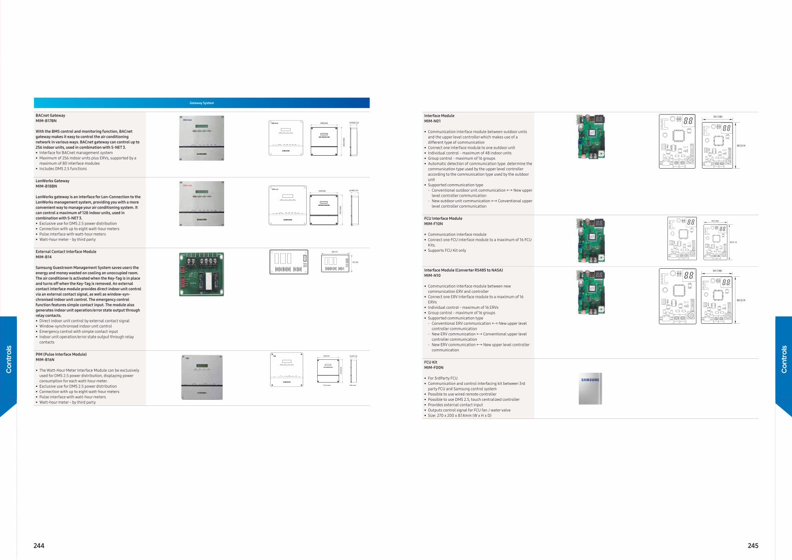
Gateway System
BACnet GatewayMIM-B17BN
With the BMS control and monitoring function, BACnet gateway makes it easy to control the air conditioning network in various ways. BACnet gateway can control up to 256 indoor units, used in combination with S-NET 3.• Interface for BACnet management system• Maximum of 256 indoor units plus ERVs, supported by a
maximum of 80 interface modules• Includes DMS 2.5 functions
LonWorks GatewayMIM-B18BN
LonWorks gateway is an interface for Lon-Connection to the LonWorks management system, providing you with a more convenient way to manage your air conditioning system. It can control a maximum of 128 indoor units, used in combination with S-NET 3.• Exclusive use for DMS 2.5 power distribution• Connection with up to eight watt-hour meters• Pulse interface with watt-hour meters• Watt-hour meter - by third party
External Contact Interface ModuleMIM-B14
Samsung Guestroom Management System saves users the energy and money wasted on cooling an unoccupied room. The air conditioner is activated when the Key-Tag is in place and turns off when the Key-Tag is removed. An external contact interface module provides direct indoor unit control via an external contact signal, as well as window-syn-chronised indoor unit control. The emergency control function features simple contact input. The module also generates indoor unit operation/error state output through relay contacts.• Direct indoor unit control by external contact signal• Window-synchronised indoor unit control• Emergency control with simple contact input• Indoor unit operation/error state output through relay
contacts
PIM (Pulse Interface Module)MIM-B16N
• The Watt-Hour Meter Interface Module can be exclusively used for DMS 2.5 power distribution, displaying power consumption for each watt-hour meter.
• Exclusive use for DMS 2.5 power distribution• Connection with up to eight watt-hour meters• Pulse interface with watt-hour meters• Watt-hour meter - by third party
Interface ModuleMIM-N01
• Communication interface module between outdoor units and the upper level controller which makes use of a different type of communication
• Connect one interface module to one outdoor unit• Individual control - maximum of 48 indoor units• Group control - maximum of 16 groups• Automatic detection of communication type: determine the
communication type used by the upper level controller according to the communication type used by the outdoor unit
• Supported communication type‐ Conventional outdoor unit communication ←→ New upper
level controller communication‐ New outdoor unit communication ←→ Conventional upper
level controller communication
FCU Interface ModuleMIM-F10N
• Communication interface module• Connect one FCU interface module to a maximum of 16 FCU
Kits.• Supports FCU Kit only
Interface Module (Converter RS485 to NASA)MIM-N10
• Communication interface module between new communication ERV and controller
• Connect one ERV interface module to a maximum of 16 ERVs
• Individual control - maximum of 16 ERVs• Group control - maximum of 16 groups• Supported communication type
‐ Conventional ERV communication ←→ New upper level controller communication
‐ New ERV communication ←→ Conventional upper level controller communication
‐ New ERV communication ←→ New upper level controller communication
FCU KitMIM-F00N
• For 3rdParty FCU• Communication and control interfacing kit between 3rd
party FCU and Samsung control system• Possible to use wired remote controller• Possible to use DMS 2.5, touch centralized controller• Provides external contact input• Outputs control signal for FCU fan / water valve• Size: 270 x 200 x 87.4mm (W x H x D)
244 245
Con
trol
s
Con
trol
s
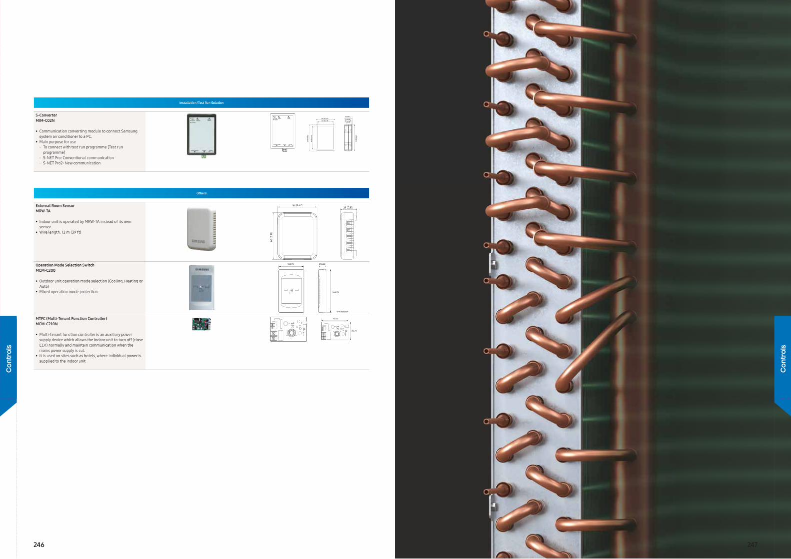
Installation/Test Run Solution
S-ConverterMIM-C02N
• Communication converting module to connect Samsung system air conditioner to a PC.
• Main purpose for use‐ To connect with test run programme [Test run
programme]‐ S-NET Pro: Conventional communication‐ S-NET Pro2: New communication
Others
External Room SensorMRW-TA
• Indoor unit is operated by MRW-TA instead of its own sensor.
• Wire length: 12 m (39 ft)
Operation Mode Selection SwitchMCM-C200
• Outdoor unit operation mode selection (Cooling, Heating or Auto)
• Mixed operation mode protection
MTFC (Multi-Tenant Function Controller)MCM-C210N
• Multi-tenant function controller is an auxiliary power supply device which allows the indoor unit to turn off (close EEV) normally and maintain communication when the mains power supply is cut.
• It is used on sites such as hotels, where individual power is supplied to the indoor unit
246 247
Con
trol
s
Con
trol
s
Accessories
249
Acce
ssor
ies
248
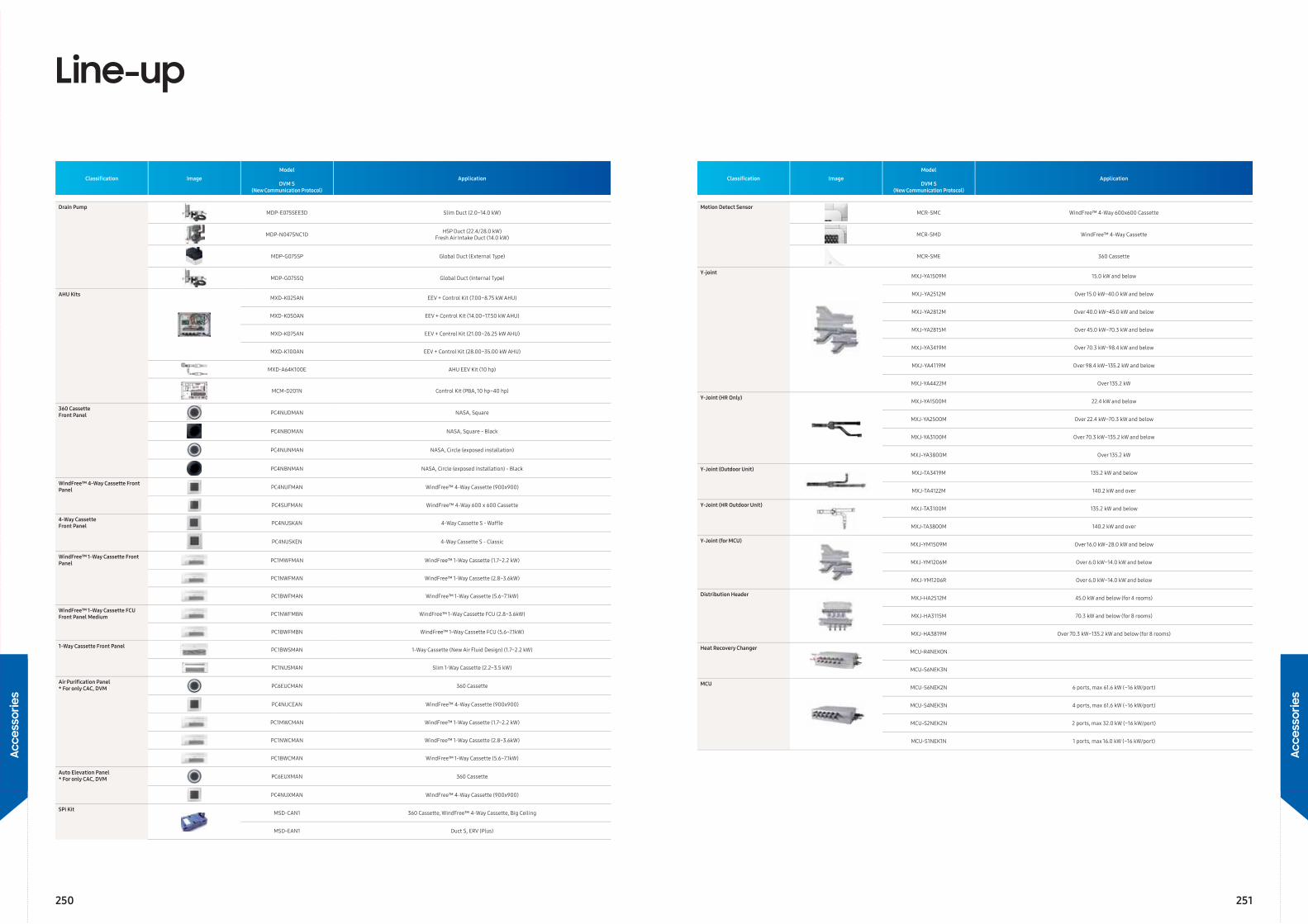
Line-up
Classifi cation ImageModel
ApplicationDVM S
(New Communication Protocol)
Drain PumpMDP-E075SEE3D Slim Duct (2.0~14.0 kW)
MDP-N047SNC1D HSP Duct (22.4/28.0 kW)Fresh Air Intake Duct (14.0 kW)
MDP-G075SP Global Duct (External Type)
MDP-G075SQ Global Duct (Internal Type)
AHU KitsMXD-K025AN EEV + Control Kit (7.00~8.75 kW AHU)
MXD-K050AN EEV + Control Kit (14.00~17.50 kW AHU)
MXD-K075AN EEV + Control Kit (21.00~26.25 kW AHU)
MXD-K100AN EEV + Control Kit (28.00~35.00 kW AHU)
MXD-A64K100E AHU EEV Kit (10 hp)
MCM-D201N Control Kit (PBA, 10 hp~40 hp)
360 Cassette Front Panel PC4NUDMAN NASA, Square
PC4NBDMAN NASA, Square - Black
PC4NUNMAN NASA, Circle (exposed installation)
PC4NBNMAN NASA, Circle (exposed installation) - Black
WindFree™ 4-Way Cassette Front Panel PC4NUFMAN WindFree™ 4-Way Cassette (900x900)
PC4SUFMAN WindFree™ 4-Way 600 x 600 Cassette
4-Way Cassette Front Panel PC4NUSKAN 4-Way Cassette S - Waffl e
PC4NUSKEN 4-Way Cassette S - Classic
WindFree™ 1-Way Cassette Front Panel PC1MWFMAN WindFree™ 1-Way Cassette (1.7~2.2 kW)
PC1NWFMAN WindFree™ 1-Way Cassette (2.8~3.6kW)
PC1BWFMAN WindFree™ 1-Way Cassette (5.6~7.1kW)
WindFree™ 1-Way Cassette FCU Front Panel Medium PC1NWFMBN WindFree™ 1-Way Cassette FCU (2.8~3.6kW)
PC1BWFMBN WindFree™ 1-Way Cassette FCU (5.6~7.1kW)
1-Way Cassette Front PanelPC1BWSMAN 1-Way Cassette (New Air Fluid Design) (1.7~2.2 kW)
PC1NUSMAN Slim 1-Way Cassette (2.2~3.5 kW)
Air Purifi cation Panel* For only CAC, DVM PC6EUCMAN 360 Cassette
PC4NUCEAN WindFree™ 4-Way Cassette (900x900)
PC1MWCMAN WindFree™ 1-Way Cassette (1.7~2.2 kW)
PC1NWCMAN WindFree™ 1-Way Cassette (2.8~3.6kW)
PC1BWCMAN WindFree™ 1-Way Cassette (5.6~7.1kW)
Auto Elevation Panel* For only CAC, DVM PC6EUXMAN 360 Cassette
PC4NUXMAN WindFree™ 4-Way Cassette (900x900)
SPi KitMSD-CAN1 360 Cassette, WindFree™ 4-Way Cassette, Big Ceiling
MSD-EAN1 Duct S, ERV (Plus)
Classifi cation ImageModel
ApplicationDVM S
(New Communication Protocol)
Motion Detect SensorMCR-SMC WindFree™ 4-Way 600x600 Cassette
MCR-SMD WindFree™ 4-Way Cassette
MCR-SME 360 Cassette
Y-jointMXJ-YA1509M 15.0 kW and below
MXJ-YA2512M Over 15.0 kW~40.0 kW and below
MXJ-YA2812M Over 40.0 kW~45.0 kW and below
MXJ-YA2815M Over 45.0 kW~70.3 kW and below
MXJ-YA3419M Over 70.3 kW~98.4 kW and below
MXJ-YA4119M Over 98.4 kW~135.2 kW and below
MXJ-YA4422M Over 135.2 kW
Y-Joint (HR Only)MXJ-YA1500M 22.4 kW and below
MXJ-YA2500M Over 22.4 kW~70.3 kW and below
MXJ-YA3100M Over 70.3 kW~135.2 kW and below
MXJ-YA3800M Over 135.2 kW
Y-Joint (Outdoor Unit)MXJ-TA3419M 135.2 kW and below
MXJ-TA4122M 140.2 kW and over
Y-Joint (HR Outdoor Unit)MXJ-TA3100M 135.2 kW and below
MXJ-TA3800M 140.2 kW and over
Y-Joint (for MCU)MXJ-YM1509M Over 16.0 kW~28.0 kW and below
MXJ-YM1206M Over 6.0 kW~14.0 kW and below
MXJ-YM1206R Over 6.0 kW~14.0 kW and below
Distribution HeaderMXJ-HA2512M 45.0 kW and below (for 4 rooms)
MXJ-HA3115M 70.3 kW and below (for 8 rooms)
MXJ-HA3819M Over 70.3 kW~135.2 kW and below (for 8 rooms)
Heat Recovery ChangerMCU-R4NEK0N
MCU-S6NEK3N
MCUMCU-S6NEK2N 6 ports, max 61.6 kW (~16 kW/port)
MCU-S4NEK3N 4 ports, max 61.6 kW (~16 kW/port)
MCU-S2NEK2N 2 ports, max 32.0 kW (~16 kW/port)
MCU-S1NEK1N 1 ports, max 16.0 kW (~16 kW/port)
250 251
Acce
ssor
ies
Acce
ssor
ies
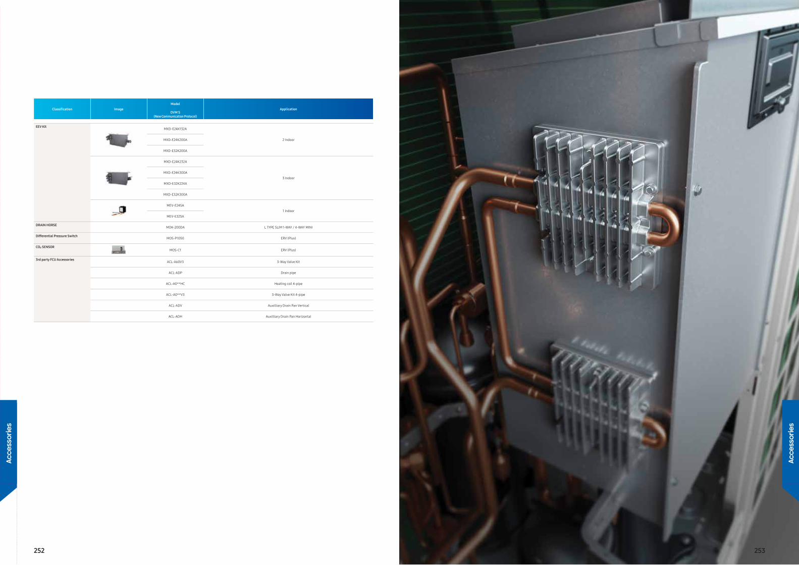
Classifi cation ImageModel
ApplicationDVM S
(New Communication Protocol)
EEV KitMXD-E24K132A
2 IndoorMXD-E24K200A
MXD-E32K200A
MXD-E24K232A
3 IndoorMXD-E24K300A
MXD-E32K224A
MXD-E32K300A
MEV-E24SA1 Indoor
MEV-E32SA
DRAIN HORSEMOK-200DA L TYPE SLIM 1-WAY / 4-WAY MINI
Differential Pressure SwitchMOS-P1050 ERV (Plus)
CO₂ SENSORMOS-C1 ERV (Plus)
3rd party FCU AccessoriesACL-A60V3 3-Way Valve Kit
ACL-ADP Drain pipe
ACL-A0**HC Heating coil 4-pipe
ACL-A0**V3 3-Way Valve Kit 4-pipe
ACL-ADV Auxilliary Drain Pan Vertical
ACL-ADH Auxilliary Drain Pan Horizontal
252 253
Acce
ssor
ies
Acce
ssor
ies
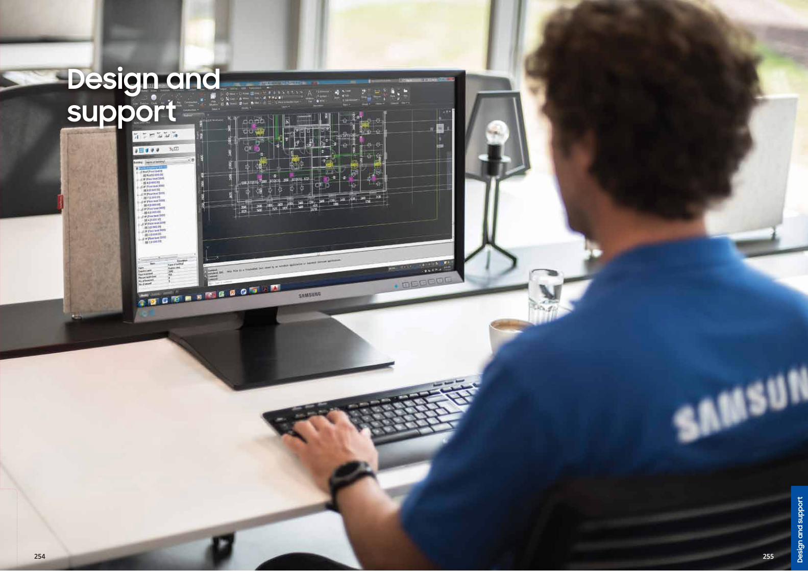
Design and support
Desi
gn a
nd s
uppo
rt
254 255
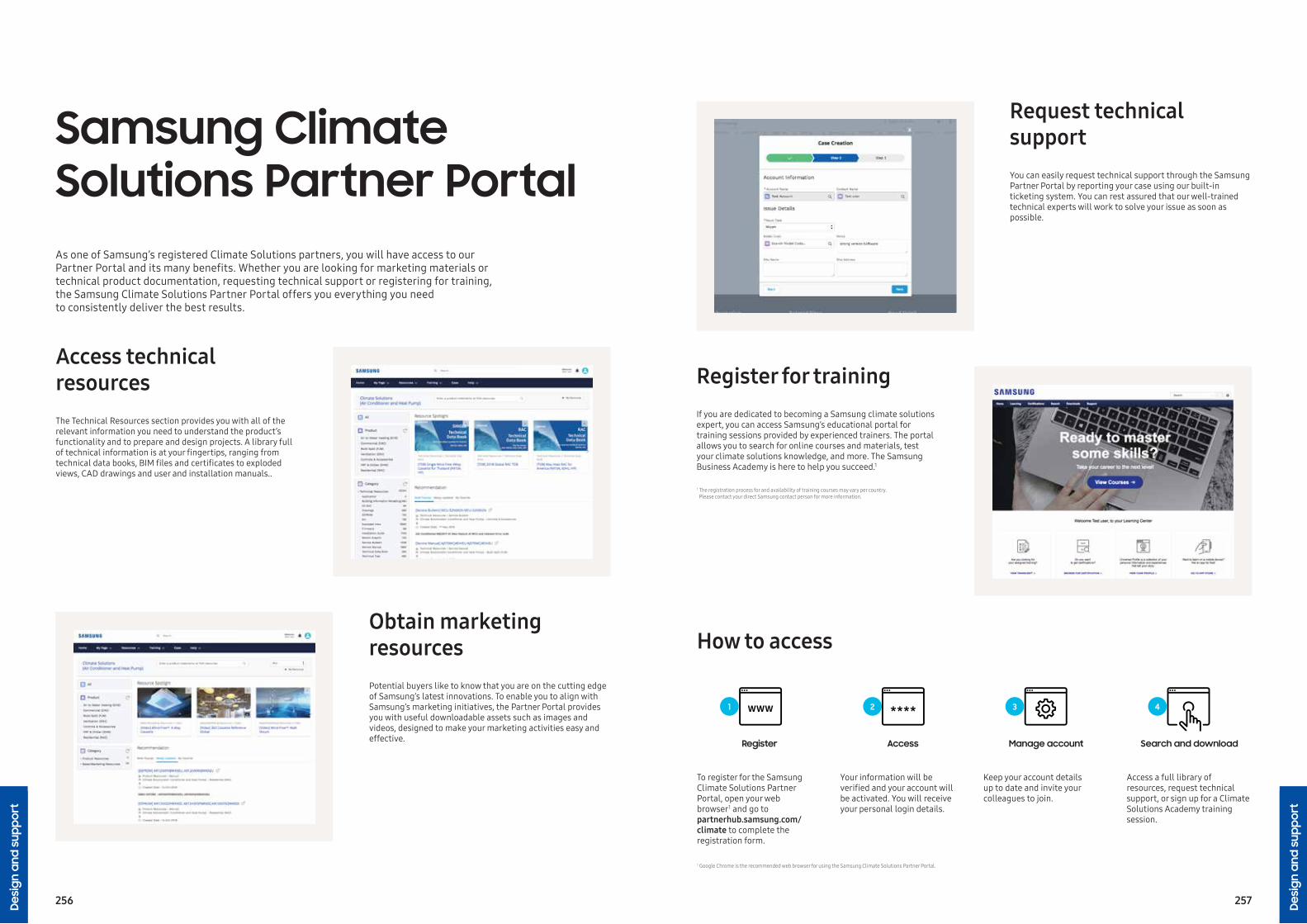
The Technical Resources section provides you with all of the relevant information you need to understand the product’s functionality and to prepare and design projects. A library full of technical information is at your fi ngertips, ranging from technical data books, BIM fi les and certifi cates to exploded views, CAD drawings and user and installation manuals..
Access technical resources
Potential buyers like to know that you are on the cutting edge of Samsung’s latest innovations. To enable you to align with Samsung’s marketing initiatives, the Partner Portal provides you with useful downloadable assets such as images and videos, designed to make your marketing activities easy and effective.
Obtain marketing resources
You can easily request technical support through the Samsung Partner Portal by reporting your case using our built-in ticketing system. You can rest assured that our well-trained technical experts will work to solve your issue as soon as possible.
To register for the Samsung Climate Solutions Partner Portal, open your web browser 1 and go to partnerhub.samsung.com/climate to complete the registration form.
Your information will be verifi ed and your account will be activated. You will receive your personal login details.
Keep your account details up to date and invite your colleagues to join.
Access a full library of resources, request technical support, or sign up for a Climate Solutions Academy training session.
1 Google Chrome is the recommended web browser for using the Samsung Climate Solutions Partner Portal.
Request technical support
How to access
Register Access Manage account Search and download
3 421
If you are dedicated to becoming a Samsung climate solutions expert, you can access Samsung’s educational portal for training sessions provided by experienced trainers. The portal allows you to search for online courses and materials, test your climate solutions knowledge, and more. The Samsung Business Academy is here to help you succeed. 1
Register for training
1 The registration process for and availability of training courses may vary per country.Please contact your direct Samsung contact person for more information.
As one of Samsung’s registered Climate Solutions partners, you will have access to our Partner Portal and its many benefi ts. Whether you are looking for marketing materials or technical product documentation, requesting technical support or registering for training, the Samsung Climate Solutions Partner Portal offers you everything you needto consistently deliver the best results.
Samsung Climate Solutions Partner Portal
256 257Desi
gn a
nd s
uppo
rt
Desi
gn a
nd s
uppo
rt
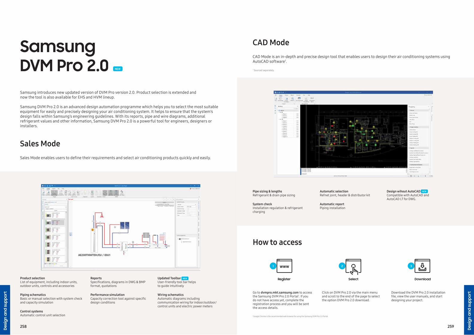
Product selectionList of equipment, including indoor units, outdoor units, controls and accessories
Piping schematicsBasic or manual selection with system check and capacity simulation
Wiring schematics Automatic diagrams including communication wiring for indoor/outdoor/control units and electric power meters
Updated Toolbar User-friendly tool bar helpsto guide intuitively
Control systemsAutomatic control unit selection
Performance simulationCapacity correction tool against specifi c design conditions
ReportsSpecifi cations, diagrams in DWG & BMP format, quotations
Sales ModeSales Mode enables users to defi ne their requirements and select air conditioning products quickly and easily.
Samsung DVM Pro 2.0 NEW
Samsung introduces new updated version of DVM Pro version 2.0. Product selection is extended andnow the tool is also available for EHS and HVM lineup.
Samsung DVM Pro 2.0 is an advanced design automation programme which helps you to select the most suitable equipment for easily and precisely designing your air conditioning system. It helps to ensure that the system’s design falls within Samsung’s engineering guidelines. With its reports, pipe and wire diagrams, additional refrigerant values and other information, Samsung DVM Pro 2.0 is a powerful tool for engineers, designers or installers.
NEW
Design wihout AutoCADCompatible with AutoCAD andAutoCAD LT for DWG.
CAD ModeCAD Mode is an in-depth and precise design tool that enables users to design their air conditioning systems using AutoCAD software1.
Pipe sizing & lengthsRefrigerant & drain pipe sizing
Automatic selection Refnet joint, header & distributor kit
System check Installation regulation & refrigerant charging
Automatic reportPiping installation
How to access
1 Sourced separately.
NEW
Go to dvmpro.mkt.samsung.com to access the Samsung DVM Pro 2.0 Portal1. If you do not have access yet, complete the registration process and you will be sentthe access details.
Click on DVM Pro 2.0 via the main menuand scroll to the end of the page to select the option DVM Pro 2.0 download.
Download the DVM Pro 2.0 installationfi le, view the user manuals, and start designing your project.
Register Select Download
321
1 Google Chrome is the recommended web browser for using the Samsung DVM Pro 2.0 Portal.
258 259Desi
gn a
nd s
uppo
rt
Desi
gn a
nd s
uppo
rt
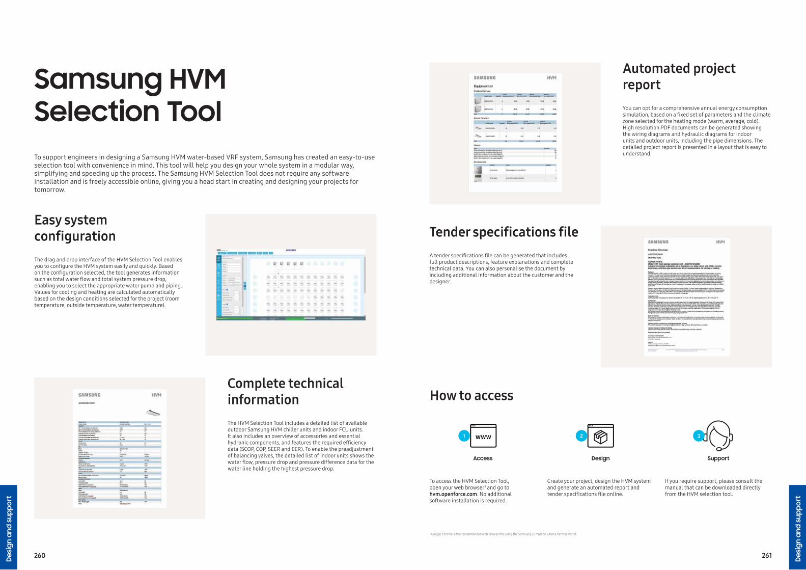
Samsung HVM Selection ToolTo support engineers in designing a Samsung HVM water-based VRF system, Samsung has created an easy-to-use selection tool with convenience in mind. This tool will help you design your whole system in a modular way, simplifying and speeding up the process. The Samsung HVM Selection Tool does not require any software installation and is freely accessible online, giving you a head start in creating and designing your projects for tomorrow.
To access the HVM Selection Tool,open your web browser1 and go to hvm.openforce.com. No additionalsoftware installation is required.
Create your project, design the HVM system and generate an automated report and tender specifi cations fi le online.
If you require support, please consult the manual that can be downloaded directly from the HVM selection tool.
Access Design Support
321
The drag and drop interface of the HVM Selection Tool enables you to confi gure the HVM system easily and quickly. Based on the confi guration selected, the tool generates information such as total water fl ow and total system pressure drop, enabling you to select the appropriate water pump and piping. Values for cooling and heating are calculated automatically based on the design conditions selected for the project (room temperature, outside temperature, water temperature).
Easy system confi guration
The HVM Selection Tool includes a detailed list of available outdoor Samsung HVM chiller units and indoor FCU units. It also includes an overview of accessories and essential hydronic components, and features the required effi ciency data (SCOP, COP, SEER and EER). To enable the preadjustment of balancing valves, the detailed list of indoor units shows the water fl ow, pressure drop and pressure difference data for the water line holding the highest pressure drop.
Complete technical information
You can opt for a comprehensive annual energy consumption simulation, based on a fi xed set of parameters and the climate zone selected for the heating mode (warm, average, cold). High resolution PDF documents can be generated showing the wiring diagrams and hydraulic diagrams for indoor units and outdoor units, including the pipe dimensions. The detailed project report is presented in a layout that is easy to understand.
1 Google Chrome is the recommended web browser for using the Samsung Climate Solutions Partner Portal.
Automated project report
How to access
A tender specifi cations fi le can be generated that includes full product descriptions, feature explanations and complete technical data. You can also personalise the document by including additional information about the customer and the designer.
Tender specifi cations fi le
260 261Desi
gn a
nd s
uppo
rt
Desi
gn a
nd s
uppo
rt
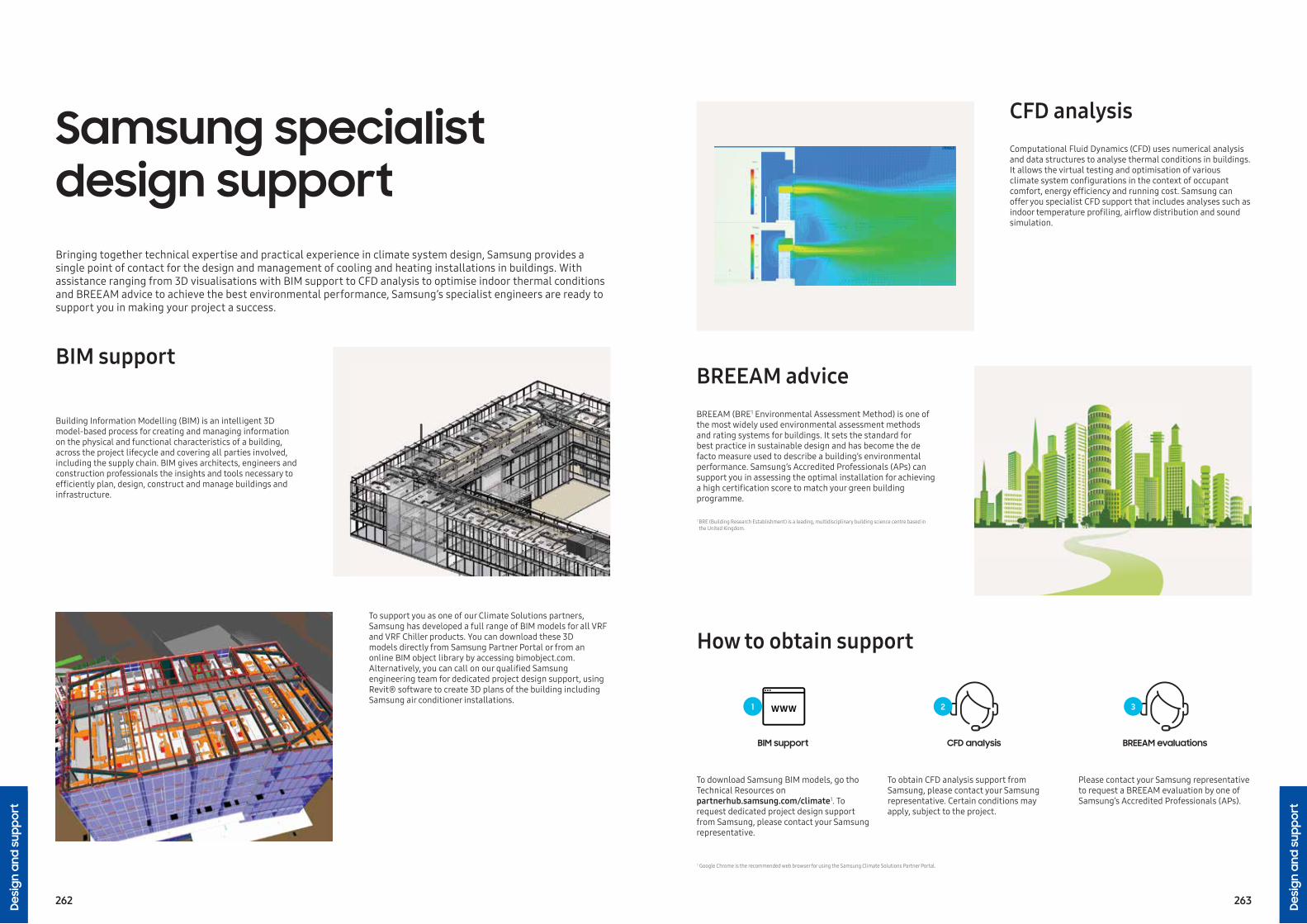
1 BRE (Building Research Establishment) is a leading, multidisciplinary building science centre based in the United Kingdom.
Samsung specialist design supportBringing together technical expertise and practical experience in climate system design, Samsung provides a single point of contact for the design and management of cooling and heating installations in buildings. With assistance ranging from 3D visualisations with BIM support to CFD analysis to optimise indoor thermal conditions and BREEAM advice to achieve the best environmental performance, Samsung’s specialist engineers are ready to support you in making your project a success.
To download Samsung BIM models, go tho Technical Resources on partnerhub.samsung.com/climate1. To request dedicated project design support from Samsung, please contact your Samsung representative.
To obtain CFD analysis support from Samsung, please contact your Samsung representative. Certain conditions may apply, subject to the project.
Please contact your Samsung representative to request a BREEAM evaluation by one of Samsung’s Accredited Professionals (APs).
BIM support CFD analysis BREEAM evaluations
321
Building Information Modelling (BIM) is an intelligent 3D model-based process for creating and managing information on the physical and functional characteristics of a building, across the project lifecycle and covering all parties involved, including the supply chain. BIM gives architects, engineers and construction professionals the insights and tools necessary to effi ciently plan, design, construct and manage buildings and infrastructure.
BIM support
To support you as one of our Climate Solutions partners, Samsung has developed a full range of BIM models for all VRF and VRF Chiller products. You can download these 3Dmodels directly from Samsung Partner Portal or from an online BIM object library by accessing bimobject.com.Alternatively, you can call on our qualifi ed Samsung engineering team for dedicated project design support, using Revit® software to create 3D plans of the building including Samsung air conditioner installations.
Computational Fluid Dynamics (CFD) uses numerical analysis and data structures to analyse thermal conditions in buildings. It allows the virtual testing and optimisation of various climate system confi gurations in the context of occupant comfort, energy effi ciency and running cost. Samsung can offer you specialist CFD support that includes analyses such as indoor temperature profi ling, airfl ow distribution and sound simulation.
1 Google Chrome is the recommended web browser for using the Samsung Climate Solutions Partner Portal.
CFD analysis
How to obtain support
BREEAM (BRE 1 Environmental Assessment Method) is one of the most widely used environmental assessment methods and rating systems for buildings. It sets the standard for best practice in sustainable design and has become the de facto measure used to describe a building’s environmental performance. Samsung’s Accredited Professionals (APs) can support you in assessing the optimal installation for achieving a high certifi cation score to match your green building programme.
BREEAM advice
262 263Desi
gn a
nd s
uppo
rt
Desi
gn a
nd s
uppo
rt

Available training modules
Samsung Climate Solutions AcademySamsung Climate Solutions Academy is committed to providing engineers with the technical skills required to install a Samsung product effi ciently, and to help relay necessary information to users. All courses are designed to provide attendees with the opportunity to develop both theoretical and practical knowledge of Samsung’s vast range of equipment and solutions.
• The product line-up, accessoriesand available controls
• The unique features ofSamsung products
• Installation considerations
• How to correctly install and confi gure a system
• Commissioning: common issues during commissioning and how to resolve any challenges
• Troubleshooting and fault-fi nding(by use of E-codes)
• Control logic• Case studies
Essential courses: Basic commercial training
Advanced courses: Technical training
• Understanding customers’ needsand offering possible solutions
• DVM Pro 2.0 - Samsung’s advanceddesign tool
• Case studies
Advanced courses: Design training
Note: the registration process for and availability of training courses may vary per country. Please contact your Samsung representative for more information.
The Netherlands - Amsterdam
Poland - Warsaw
United Kingdom - Mansfi eldUnited Kingdom - Chertsey
Greece - Athens
Portugal - Lisbon
France - LyonItaly - Milan
Spain - Madrid
To check for available training courses, go to Samsung Business Academy (SBA) via the Samsung Climate Solutions Partner Portal 1: partnerhub.samsung.com/climate. Search the online event calendar and select the training course you would like to attend.
After identifying the trainingcourse you would like to attend, follow the registration process. Once you have registered successfully you will receive a confi rmation e-mail.
Following confi rmation of your registration, we will invite you to one of our training centres. You will be trained by one of our specialised Master Trainers or Product Specialists, and receive a Certifi cate of Completion.
How to register for training
Search Register Get certified
321
Samsung training centres in Europe
1 Google Chrome is the recommended web browser for using the Samsung Climate Solutions Partner Portal.
264 265Desi
gn a
nd s
uppo
rt
Desi
gn a
nd s
uppo
rt

Notes Notes
266 267

Notes Notes
268 269

Notes Notes
270 271

Notes Notes
272 273
Notes Notes
274 275

Learn more about Samsung Climate Solutions at:www.samsung.com/climate
Samsung Electronics Air Conditioner Europe B.V.Evert van de Beekstraat 310, 1118 CX SchipholP.O. Box 75810, 1118 ZZ Schiphol+31 (0)8 81 41 61 00The Netherlands
Samsung Electronics Co., Ltd. participates in the Eurovent Certification Programme (ECP) for Air Conditioners (AC), Variable Refrigerant Flow (VRF) and Liquid Chilling Packages Heat Pump (LCP-HP). To check the ongoing validity of certification, please visit: www.eurovent-certification.com
Copyright © 2021 Samsung Electronics Air Conditioner Europe B.V. All rights reserved. Samsung is a registered trademark of Samsung Electronics Co., Ltd. Specifications and designs are subject to change without notice and may include preliminary information. Non-metric weights and measurements are approximate. All data was deemed correct at the time of creation. Samsung is not liable for errors or omissions. Some images may be digitally altered. All brand, product, service names and logos are trademarks and/or registered trademarks of their respective owners and are hereby recognised and acknowledged.